Suzhou Sate Auto Electronic RTGTPMS RIRE PRESSURE MONITORING SYSTEM User Manual USERS MANUAL
Suzhou Sate Auto Electronic Co., Ltd RIRE PRESSURE MONITORING SYSTEM USERS MANUAL
USERS MANUAL

RTG-TPMS INSTALL MANUAL
Page 1 of 1
RTG-TPMS-8
INSTALL MANUAL
Revision:V 1.04
Suzhou Sate Auto Electronic Co.,Ltd

RTG-TPMS INSTALL MANUAL
Page 2 of 2
Content
RTG-TPMS OVERVIEW
1. Instruction for Master Installation--------------------------------3
1) Master Overview------------------------------------------------3
2) Instruction for led indication----------------------------------5
3) Setting------------------------------------------------------------6
2. Instruction for Repeater Installation------------------------------8
3. Instruction for Sensors Installation-------------------------------9
4. Instruction for Maintenance--------------------------------------11
RTG-TPMS INSTALL MANUAL
Page 3 of 3
RTG-TPMS-8 OVERVIEW
RTG-TPMS-8 is the tire pressure monitoring system for the gantry crane, it monitors the
pressure of tire full-time and alerters the driver with sound and light, at the same time the system
can mutually interchange information with PLC, PC via communication socket.
The system is made up of sensors, repeater and master. It can offer monitoring for 8 tires at
most.
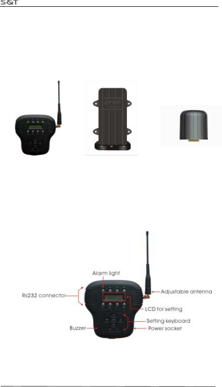
Figure 1 Master Figure 2 Repeater Figure 3 Sensor
1. Master Install Manual
1.1 Master overview
Figure 4 Master
RTG-TPMS INSTALL MANUAL
Page 4 of 4
2. Accessories of Master
(1)Power Wire
3-metre long power wire
(2)Communication Wire
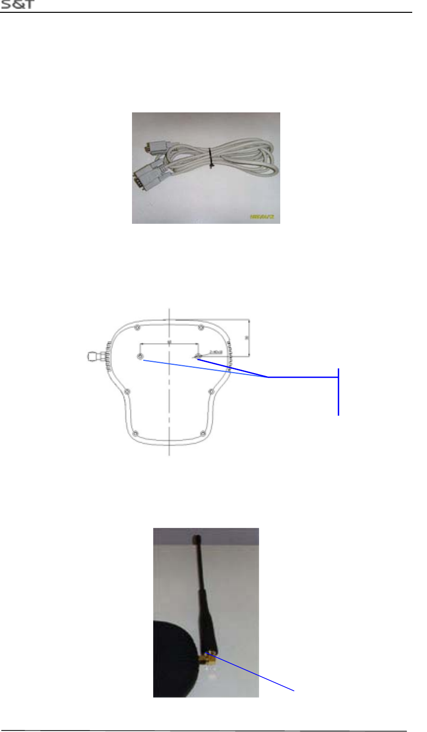
Figure 4 Communication Wire
3. Installation Step
1.Fasten the Master on right position in the cab
Figure 6 Screw Positions for Installing the Master
2. Adjust the angle of antenna to be vertical to master, screw the locknut on
the antenna tightly.
Locknut
Screw Position
M3X10
RTG-TPMS INSTALL MANUAL
Page 5 of 5
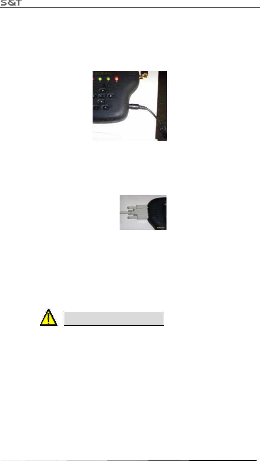
3.Connect the power wire
Plug power plug into master power socket, and fasten power wire with tie.
Note: Connect the red wire to anode 24V and black wire to cathode, screw the nut tightly.
Figure 8 Power Wire Socket
4.Connect the communication wire
Plug DB9 connector into the Master socket, screw the nut tightly
Figure 9 Communication Wire Socket
Note: If no request, communication wire may not be installed.
5.Error sign wire connection with PLC
Connect one end (DB9 pin) of the error sign wire to the DB9 socket and fasten the screw.
another end to the PLC I/O contact.
Note: Connect the red wire to contact end of the PLC I/O module, black wire to the PLC GND.
Caution Power Polar!
4.Introduction of LED indication
When the pressure information transmitted by Sensors inside 1-8 tires are received,
LED corresponding with tires on the Master will offer the corresponding indication. LED
indicates green when pressure is normal. When pressure of any tire is lower than the low
threshold of pressure, LED corresponding with tire will indicate red, at the same time
LED light will flash with buzzer beep.
When buzzer alarm, press any key on Master to stop beep, red LED will return into
green until pressure of tire recover normality and Master receive data of normal pressure.
When one of the sensors fails to work or Master could not receive the data for the
interference from RF in the certain time, LED corresponding with the sensor will go out
RTG-TPMS INSTALL MANUAL
Page 6 of 6
automatically. LED light will return into green or red depended on pressure value until
information of the sensor can be received.
5.Setting Guide
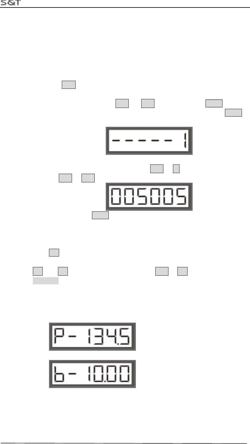
1)Sensor ID Setting
1) Press ID key and hold it for 3 seconds long, then release the key, as shown
below. Digital “1” began to flash, at this time you can adjust it to the tire number
you want by key ,such as ↑ 、 ↓ , and then press ENTR . If you
want to exit the setting of ID modified, adjust to” E” and then press ENTR to
exit.
2) Then come into the interface of the tire unique ID you have chosen, the first digit
on the right will flash, adjust the digit by ↑ 、↓ and adjust the position of
digit by → 、 ←
After adjustment, press ENTR to save the specified unique ID, then automatically
come into next tire number, repeat step 1 to set other ID.
2)Low Threshold Pressure Setting
Press P Key and hold it for 3 seconds long, then release it, picture will be shown
like as below, the first digit on the right will flash, adjust the digit flashing by
↑ 、 ↓ and adjust the position of digit by → 、 ← After adjustment, press
ENTR to save current setting.
Note:
1. Unit of pressure is indicated to be P or b, representing Psi or bar.
2. Value set is relative pressure value.
3. It is suggested that pressure value of tire on crane is set to be 9.50bar.
RTG-TPMS INSTALL MANUAL
Page 7 of 7
3)Setting Pressure Unit
Press ENTR key and hold it 3 seconds long, then release it. picture like down will
be shown, digit 1 will flash, at this time adjust the digit to 2 by ↑ 、 ↓ , then
press ENTR 。
At this time enter the step as below. You can press ↑ 、 ↓ key to choose one
from two alternation pressure unite in Psi (abbr. P) and bar (abbr. b),then press
ENTR to exit 。
4)Setting PLC type
Press ENTR key for more than 3 seconds, picture like down will be shown, digit
1 will flash, at this time adjust the code of function you require by ↑ 、
↓ ,then press ENTR 。
Then come into the picture shown down, select the code of PLC required by ↑ 、
↓ ,then press ENTR 。
Index Index Type of PLC PLC Model
1 0 PC
2 1 Anchun PLC- CP370
3 2 Fiji PLC(not support currently)
RTG-TPMS INSTALL MANUAL
Page 8 of 8
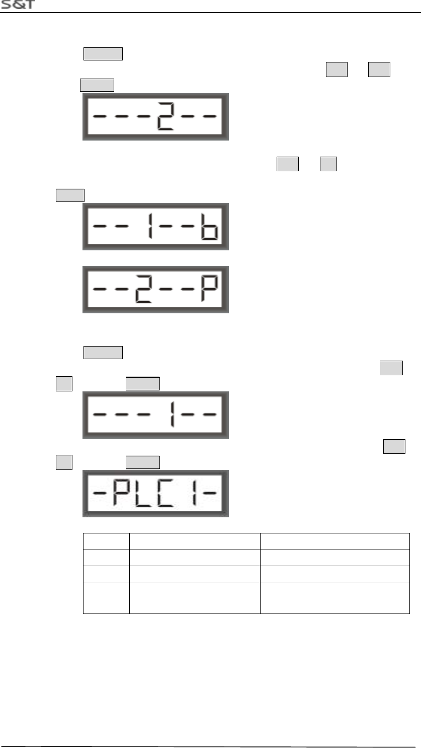
5)Display Pressure Value in turn
Pressure value of all tires will be displayed in turn when no action of pressing key
on Master. The first digit on the left indicates current tire number (1-8). The second
digit indicates current unit of pressure, “P” stands for “psi”, “b” for “bar”. The back
four digits indicate current pressure.
RTG-TPMS INSTALL MANUAL
Page 9 of 9
2. Repeater Installation Manual
1. Assemble position sketch map
The four repeaters should be installed on the I-section Beam of the equipment. They are on upper and
lower side of the RTG separately.
2. Installation Step:
Prepare Tool: screwer, M13 aid-spanner, M10 spanner, 3M insulating tape, fastening tie.
1. Fixing repeater at bottom board of the I-section beam, place proof-water connector adown. Fill
up rubber gasket and fasten screws.
2. Connect the power wire, then fasten power wire and avoid wire loosing。
Note
:
Brown wire stand for +24V, Blue wire stand for cathode.
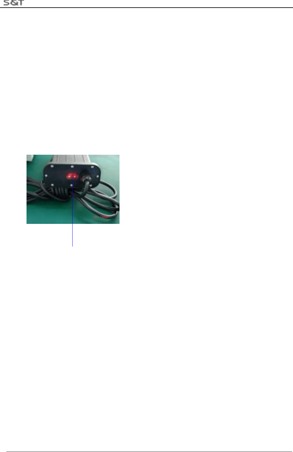
3. Indicator Light
Indicator Light Position
There are three red LED lights on the side cover of the repeater. As shown in the above figure, from left to
right, they are Power Indicator Light, Emitting Indicator Light and Receiving Indicator Light.
Power Indicator Light: It will be on all the time when the repeater is connected with the power and the
system is powered on.
Emitting Indicator Light: It flashes rapidly when the repeater is under emitting status.
Receiving Indicator Light: It flashes when the system receives effective RF information.
RTG-TPMS INSTALL MANUAL
Page 10 of 10
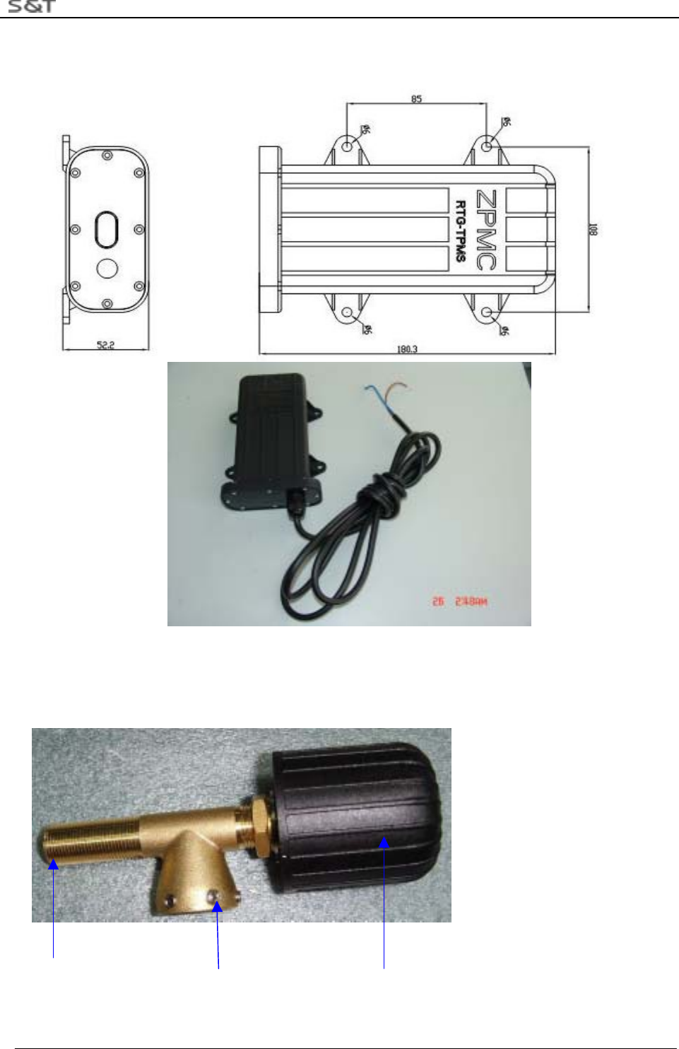
4.Mechanism Characteristic
Figure 10 Repeater Size
3. Sensor Installation Manual
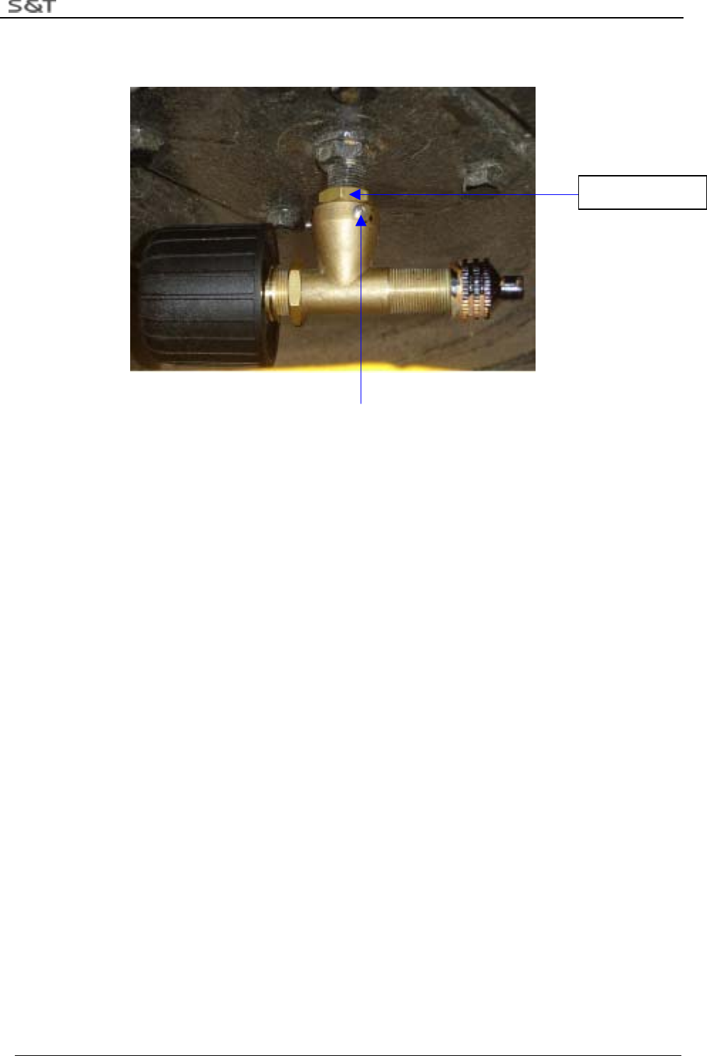
1. Installing the triple-valve accessories
End for inflating Locknut Sensor
Figure 11 Sensor with Triple-Vale Accessories
RTG-TPMS INSTALL MANUAL
Page 11 of 11
2. Installation Step
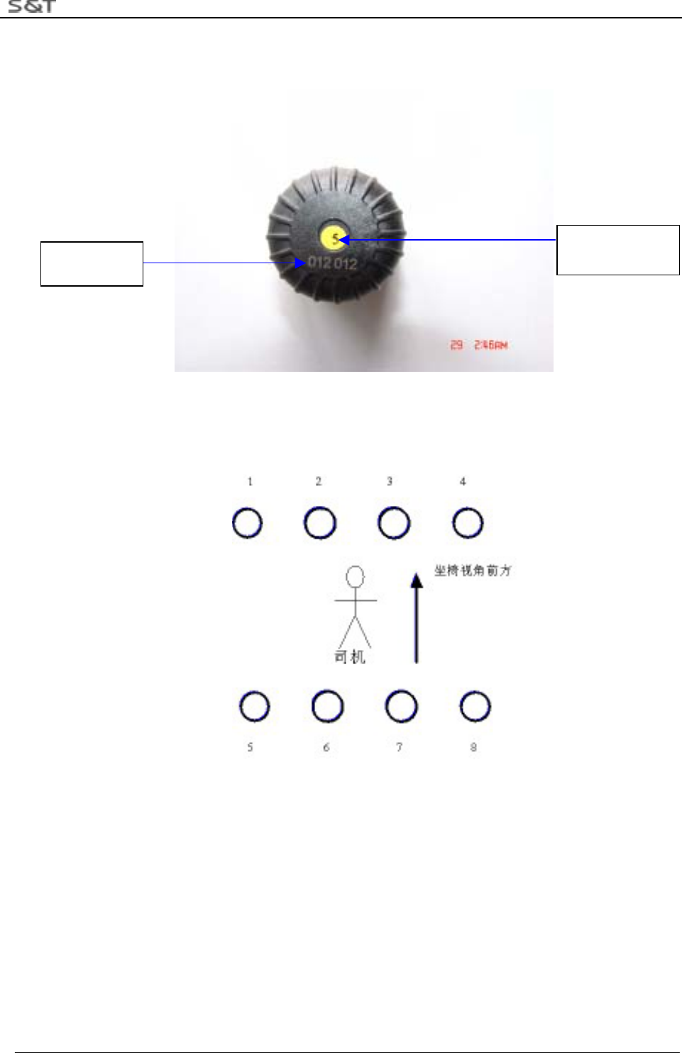
1) All the 8 Sensors are labeled with tire position numbers and ID code numbers, shown as below:
Figure 12 ID Code: 012012
2) Enter the corresponding Sensor ID Codes into the Master according to the tire position numbers shown
below. Refer to Step 5.1 for the way to enter the codes.
Figure 13 Tire Position Number
3) Screw the cap off the valve, then screw on the provided M14 locknut toward the tire valve. Next, screw
on the triple-valve assembly to the tire valve until it is against the M14 locknut. Screw the M14 locknut
reversely until it is against the top surface of the triple-valve.
ID Code Sensor for tire
number 5
RTG-TPMS INSTALL MANUAL
Page 12 of 12
4) Use M3 socket head wrench to tighten the 6 locknuts.
Locknut
Figure 14 Installation of the triple-valve assembly for Sensor
5) Screw on the tire valve cap to the inflating end of the triple-vale.
6) Check if there is air leakage through soap bubbles.
3. Notes:
1)Check if all accessories are all ready before installation and if it is tight between rubber washer and plug,
whether it is trim on the side.
2)If it is not airproof, screw sensor off, and screw it on again to ensure airproof.
3)Sensors must be installed after the installation of the Master and transmitter.
4. Maintenance Guide
1.Sensor
1)Master issues Sensor trouble alarm
Reason:
A.Sensor hasn’t transmitted the data during the 24 hours
B.The signal transmitted by sensor is very weak, not being received.
Solution:
1.Connect RTG-TPMS to the power.
2.Screw off the sensor and wait for 30 seconds.
3.Ask the driver if Master offers alarm. (At this time LED corresponded with tire number is red.)
4. If not, then screw the sensor on the valve, redo the operation several time. If there is no alarm yet, the
sensor must fail to work. Please change the Sensor.
2.Repeater
1. power indication light does not light
M14 Locknut

RTG-TPMS INSTALL MANUAL
Page 13 of 13
Reason:
1. The power of repeater does not connect well
2. Light fails to work.
Solution:
1. Measure by multimeter whether input voltage is 24V.
(1) No, check the power supply of system (2)Yes, next step
2. Replace transmitter, and hand it in the technologist.
3.Master
1. No display and No sound of Key
Reason: power is not connected well.
Solution
1.Check the power
a. yes, replace the Master b. no. check system of power supply.
2. LED light has no indication.
Reason:
IC of LED driver fails to work
Solution:
1. Return to repair
FCC Caution
This device complies with Part 15 of the FCC Rules. Operation is subject to the following two conditions:
(1) this device may not cause harmful interference, and (2) this device must accept any interference received,
including interference that may cause undesired operation.
FCC Notes:
The manufacturer is not responsible for and radio or TV interference caused by unauthorized modifications to this
equipment. Such modifications could void the user's authority to operate the equipment.