Suzhou Sate Auto Electronic TPMS1209B Tire Pressure Monitoring System User Manual
Suzhou Sate Auto Electronic Co., Ltd Tire Pressure Monitoring System Users Manual
users manual

T P M S 1 2 0 9 B
TIRE PRESSURE MONITORING SYSTEM
USER MANUAL
1. Please do read this Manual carefully before using the product.
2. The system can monitor the tire pressure effectively, but does not warrant
to avoid any sudden accidents. User should utilize the system to ensure the
tire to be used under a standard pressure and avoid using the poor quality
or badly abraded tires.
3. Users are not allowed to open, repair and refit the products by themselves,
otherwise the warranty service will be invalid.
4. Users must fill the Warranty Card correctly after buying the product for
maintaining their own rights and interests.
5. The final right to interpret the product is reserved by Sate Auto Electronic
Co., Ltd.
6. Although equipped with S&T TPMS1209B, we still strongly suggest the
User check and adjust the Tire Pressure at least once a month.
NOTICE
www.satetpms.com

S&T TPMS1209B, Full-time Direct TPMS---------------------------------------1
Parts of TPMS1209B---------------------------------------------------------------1
Installation---------------------------------------------------------------------------3
Master Programming--------------------------------------------------------------5
Function------------------------------------------------------------------------------8
Auto Switch Function--------------------------------------------------------------11
Special Annex----------------------------------------------------------------------12
Specification----------------------------------------------------------------------17
Warranty Term---------------------------------------------------------------------18
CATALOGUE
S&T TPMS1209B, FULL-TIME DIRECT TPMS
TPMS1209B is a full-time direct tire pressure monitoring system which includes one wireless Master and four
screw-on Sensors.
The sensor can be screw inside the tire instead of the valve to sense the pressure and the temperature inside
the tire all the time and transmits the pressure information data to the master by RF technology.
The master can receive and deal with the data and issue different alarms if the tire pressure or temperature is
in an improper state .
S&T TPMS1209B can sense and display the tire pressure and the temperature all the time and can issue an
alarm when the tire pressure or the temperature is at an improper level, so as to notify the driver to treat the
problem and avoid tire busting or tire damage. Through TPMS, the driver can keep the tire running at a proper
pressure so as to avoid excess gasoline consumption and keep the vehicle in an easily controlled state.
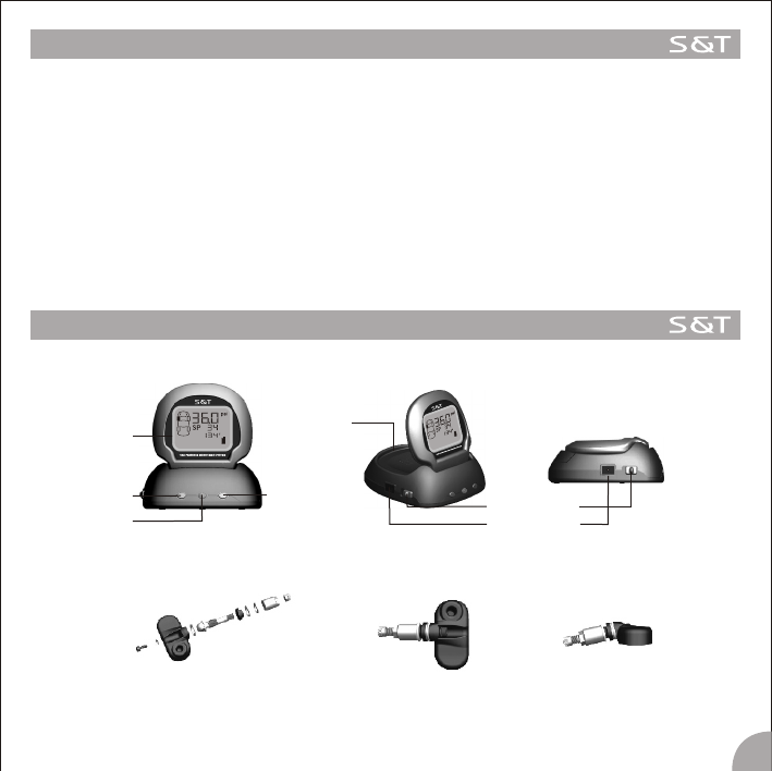
S&T TPMS1209B PARTS
Master
1
Display
Select key Enter key
Alarm lamp Power switch
Power socket
Cover of
battery box
Sonser
3M Dual Lock Fastener
Display
S&T TPMS1209B PARTS
Lighter Plug
2
Big end
Small end
Pressure
Pressure unit,psi
Pressure unit,kPa
Battery power
Temperature unit, F
Quick leakage alarm icon
Level of low pressure alarm icon
Pressure alarm icon
High pressure alarm icon
Tire position
Sensor trouble alarm icon
Pressure unit,bar
Temperature
High Temperature Alarm Icon
Standard Pressure Icon
Standard Pressure
INSTALLATION
Master
2. There are 4 pieces of the 3M Dual Lock Fastener in the packing box, you can choose one to affix on
the bottom of the Master and choose another one to put it on the dashboard, with the remaining two
as spare.
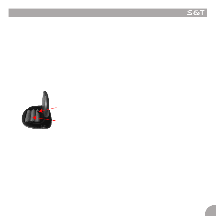
Note 1. If you don't want or you are not convenient to use the lighter plug, the rechargeable battery is an optional
for powering the master. The operation process for battery power is as follow:
1) Take off the cover of the battery box on the back of the Master; 2) Put three rechargeable batteries into
the battery box; 3) Cover the battery box; 4) Turn on the Master.
2. The lighter plug is a special plug with a transformer inside.
3. On some vehicles, the cigarette lighter will power off when the engine powers off. If this happens, or if the
user accidentally pulls out the lighter plug from the lighter, if the rechargeable batteries are already
emplaced inside the Master, and the power of the batteries is enough to operate the Master, the Master
can switch to the battery power mode automatically, with no detriment to the system.
4. If you turn off the Master, the Master can not receive, treat, display and alarm at all.
5.If the Lighter Plug connects to the vehicle power while the car is not used for about 3 months, the vehicle
power maybe exhausted and the car perhaps can not start as usual. So we strongly suggest the user to
pull out the Lighter Plug or turn off the Master if the vehicle will not be used for a whole month or longer.
3.Plug the small end of the Lighter Plug into the socket on the side of the Master, and put the big end of the lighter
plug into the lighter socket of the vehicle.
4.Turn on the Master by moving the power switch.
5.Once the Master starts to work, the screen starts to display the pressure of the four tires in turn. Before
installing the sensors, the pressure & the unit information shown on the screen as “ ---psi”.
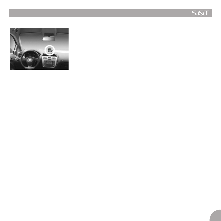
1.Take out the Master from the box.
2.Choose a suitable location for the Master on the dashboard platform.
Make sure to first Scrub the surface of the platform with alcohol .Next, strip
off the liner of the 3M Dual Lock Fastener, put the sticky side onto the
suitable location, then fix the Master with another side of the 3M Dual Lock
Fastener on the platform.
Note : 1. In order to stick the Master firmly on to the dashboard, we
strongly suggest the user to scrub the location with alcohol.
3
Note : 1. This product is not applicable to those tires with inner tubes.
2. We strongly suggest the user to go to an Auto Service Shop to install the system.
3. If one of the sensors is broken or fails to work, the others can still function properly, only the broken one
need to be replaced. please detach the broken sensor and follow the above steps to install the new
sensor. Then please follow the ID Number programming steps on page14 to set the ID Number of the
new sensor on the master.
4. The tires need to be Re-balanced after installing the TPMS1209B sensors.
INSTALLATION
Sensor
4
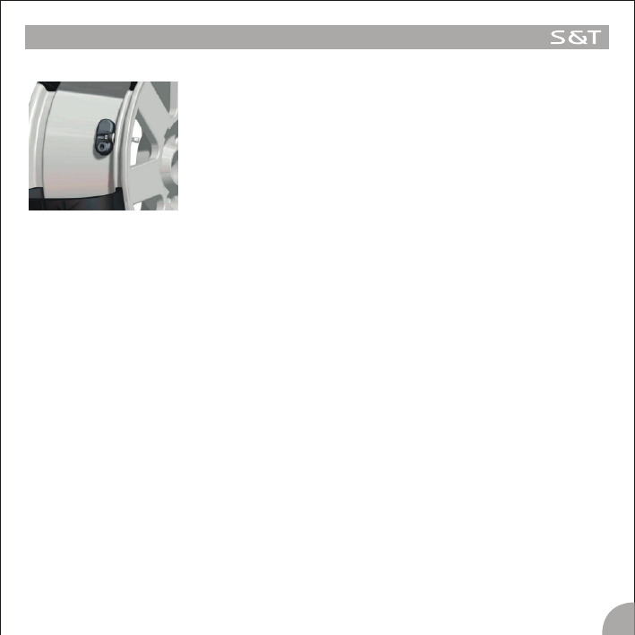
1. First dismount the tires from the vehicle. Clean the rim and the inner wall of
the rubber tubes.
2. Detach the valve of the tire.
3. Install the Sensors on the valve positions according to the Position Labels:
“FL” is for the Front Left tire; “FR” is for the Front Right tire; “RL” is for the
Rear Left tire; “RR” is for the Rear Right tires.
4. Mount the rubber tubes.
5. Inflate the tires to the Standard Pressure, and the re-balance the tires.
6. Fix the tires to the vehicle according to the labels.
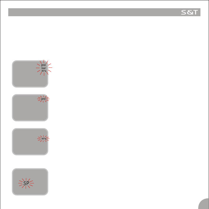
Under the operation mode, press the E key and hold it for 3 seconds to access the Programming interface. Then
press the S key, the interface will switch between the interface of “Pressure Unit Switch” and “Standard Pressure
Programming”. If there is no operation for 5 minutes, the system will exit the Programming interface and return to
the normal operating mode.
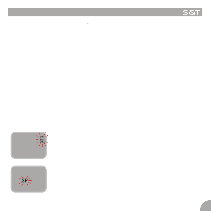
1. Pressure Unit Switch
The system provides 3 pressure units “psi” “Bar” and “kPa”. Users can choose the unit as following:
Under the operation mode, press the E key and hold it for 3 seconds to access the
Programming interface. Then press the S key to select the “Pressure Unit”
interface, the three Pressure Unit flash ,as shown in figure 1-1.
Then press the E key to access the “Pressure Unit Switch” interface, first the
Pressure Unit “psi” appears on the display and flashes, as shown in figure 1-2.
Press the S key to switch the Pressure Unit between the “psi” , “Bar” and “kPa”,
when the needed Pressure Unit appears on the display ,press the E key to confirm
it and the system returns to the normal mode automatically.
Under the operation mode, press the E key and hold it for 3 seconds to access the
Programming interface. Then press the S key to select the “Standard Pressure
Programming” interface, the “SP” icon flashes as shown in figure 2-1.
MASTER PROGRAMMING
Figure 1-1
Figure 1-2
Figure 1-3
2. Standard Pressure Programming
Figure 2-1
5
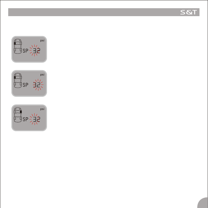
Figure 2-2
Figure 2-3
Figure 2-4
6
MASTER PROGRAMMING
The programming of the Standard Pressure is different according to the selection of the Pressure Unit.
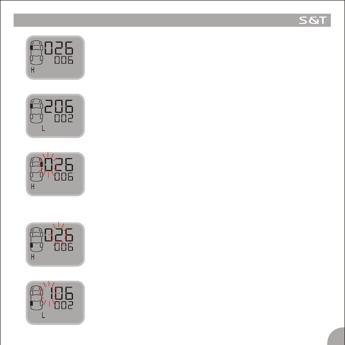
2.1 The Steps of Standard Pressure Programming for Unit “psi” are as follow:
Press the S key to adjust it and Press the E key to confirm the adjusted value.
Then the second number flashes, as shown in figure 2-3.
Press the S key to adjust it and t Press the E key to confirm the adjusted value.
Then the first number of the Standard Pressure of the Front Right Tire flashes,
as shown in figure 2-4.
Follow the above steps to set the Standard Pressure of the other tires.
2.2 The programming of the Standard Pressure for Unit “Bar” is almost the same as the Standard
Pressure Programming for Unit “Psi”. Please follow the above steps to program the Standard
Pressure for Unit bar.
2.3 The Steps of the Standard Pressure Programming for Unit “kPa” are also the same as the Standard
Pressure programming for Unit “psi” and “bar”. But please pay attention that when choose “kPa”as
the Pressure Unit , the pressure has three numbers and the third number of the Standard pressure is
“0”, it cannot be adjusted, you can just Press the E key to confirm it.
Press the E key to access this program. The first number of the Standard
Pressure of the Front Left tire is flashing, as shown in figure2-2..
7
MASTER PROGRAMMING
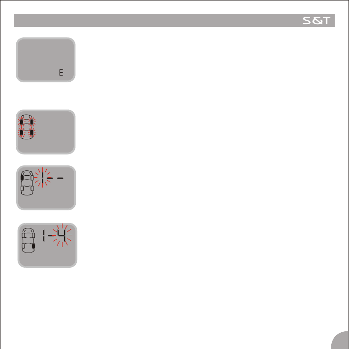
3. Tire Rotating Programming
Under the operation mode, press the E key and hold it for 3 seconds to access
the Programming interface. Then pressure the S key to select the “Tire rotation
Programming” interface, the Four Tire icons flash shown in figure 3-1.
Figure 3-1
Then the third number flashes, it stands for the Target Tire Position to rotate.
Press the S key to select the Tire Position and Press the E key to confirm it and
the system will return to the normal mode automatically. For example, in figure
3-3, it shows that Tire 1 and Tire 4 are rotated.
Figure 3-2
Then press the E key to access this program and the first number flashes. I t
standards for the Number of the Tire Position needs to be rotated. Press the S
key to select the Tire Position to be rotated and press the E key to confirm it. As
shown in figure 3-2.
Figure 3-3
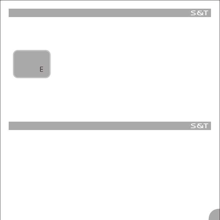
When the Standard Pressure for all the tires are programmed, the letter E will
appear on the display, as shown in the figure 2-5. Then press the E key here,
the system will return to the normal mode.
Figure 2-5
FUNCTION
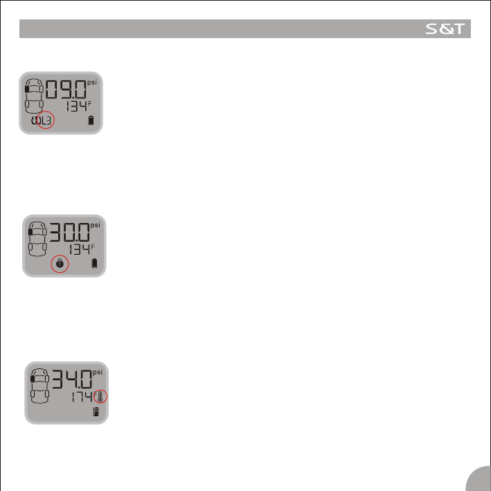
High Pressure Alarm
Function: The system will issue a High Pressure Alarm when the tire pressure is
25% higher than the standard.
Alarm mode: The alarm lamp, High Pressure Warning Icon and the audible alarm
turn on together.
Treatment: Press any key to stop the audible alarm. The red alarm lamp remains
on and the display reverts to the normal mode. The red alarm lamp
goes off only when the tire pressure returns to the standard level.
Low Pressure Level 1 Alarm
Function: The system will issue a Low Pressure Level 1 Alarm when the tire
pressure is 12.5% lower than the standard.
Alarm mode: The alarm lamp, Low Pressure Level 1 Warning Icon and the Audible
alarm turn on together.
Treatment: Press any key to stop the audible alarm. The red alarm lamp remains
on and the display reverts to the normal mode. The red alarm lamp
goes off automatically only when the tire pressure returns to the
standard level.
8
Low Pressure Level 2 Alarm
Function: The system will issue a Low Pressure Level 2 Alarm when the tire
pressure is 25% lower than the standard.
Alarm mode: The alarm lamp, Low Pressure Level 2 Warning Icon and the Audible
alarm turn on together.
Treatment: Press any key to stop the audible alarm. The red alarm lamp remains
on and the display reverts to the normal mode. The red alarm lamp
goes off automatically only when the tire pressure returns to the
standard level.
Quick leaking Alarm
Function: The system will issue a Quick Leaking Alert when the pressure dropping
exceeds 2.8psi within 12 seconds.
Alert Mode: The alarm lamp and the audible alarm turn on, the Quick leaking Alarm
Icon flashes continuously.
Treatment: Press any key to stop the audible alarm. The red alarm lamp remains on
and the display reverts to the normal mode. Slow down the vehicle and
stop at a safe place to inspect the tire. The red alarm lamp goes off
automatically only when the tire pressure returns to the standard level.
9
FUNCTION
Low Pressure Level 3 Alarm
Function: The system will issue a Low Pressure Level 3 Alarm when the tire
pressure is 50% lower than the standard.
Alarm mode: The alarm lamp, Low Pressure Level 3 Warning Icon and the Audible
alarm turn on together.
Treatment: Press any key to stop the audible alarm. The red alarm lamp remains
on and the display reverts to the normal mode. The red alarm lamp
goes off automatically only when the tire pressure returns to the
standard level.
Function: The system will issue a High Pressure Alarm if the temperature inside
the tire exceeds 168F.
Alert Mode: The red alarm lamp and the audible alarm turn, the High Pressure
Alarm Icon flashes continuously.
Treatment: Press any key to stop the audible alarm. The red alarm lamp goes off
Only when the temperature inside the tire returns to normal.
High Temperature Alarm
Sensor Trouble Alarm
Function: If one Sensor fails to work, or the Master can't receive the data
because of the RF interference for a certain time, the system will issue
a Sensor Trouble Alarm.
Alert Mode: The red alarm lamp, the Sensor Trouble Alarm Icon and the audible
alarm turn on together.
Treatment: Press the any key to stop the audible alarm. The red alarm lamp goes
off only when the Master can receive the signals from this tire position
again.
Warning of Low Battery Power
Function: The system will issue a warning alarm when the battery power is not
enough to afford the Master to work when the Master powered by the
battery group.
Alert mode: The audible alarm turns on and the Battery Icon flashes .
Treatment: Recharge the batteries or connect the Master to the lighter plug
immediately.
10
FUNCTION
NOTE:
Usually , the Temperature in the tires will be displayed in turn on the screen. If
need, the Standard Pressure can be displayed on the screen. At this time, the
Temperature will disappear from the screen.

Power Switch automatically
The Master will work normally when powered by batteries rather than the vehicle, in identical fashion.
Auto Sleep mode of the Master
The master can be powered by the vehicle power through the lighter plug or the rechargeable battery.
Vehicle power is strongly recommended.
If the lighter plug inserted the power socket of the Master, even the battery group is also inside the Master
battery box and the power is enough to operate the Master, the Master will still draw power from vehicle power.
But when the vehicle power is off for some reason, the system will switch to the battery power automatically.
If the car parks for more than 10 minutes when powered by the rechargeable batteries, the Master will be
switched into a sleep mode, this can save the battery power. And the alarm for Low Pressure Level 3 can still be
received by the Master within in 7 minutes and issue the alarm when the Master is activated . If powered by
vehicle power, the Master will not switch into the sleep mode, only the LCD shutdown and all kinds of alarm
information can be received by the Master , which can issue the alarm accordingly.
The rechargeable batteries recharged once can work 10~15 days, if the car runs no more than 2 hours a day.
AUTO SWITCH FUNCTION
11

SPECIAL ANNEX
1. LCD operating temperature
For all of the LCD, the lowest limitation operating temperature is-30C, the upper temperature limit for working
mode is 70 for storage the temperature limit is 85 . This is determined by the character of the LCD.
If the LCD works under -30 for a long time, the LCD may be destroyed entirely.
On the Master, there is a LCD screen for displaying the information. In order to use the LCD properly, we strongly
recommend the user to power off the display if the temperature inside the vehicle will be lower than -30 for a
long time.
2. The power consumption
The Master power consumption is very small, only 10-12mAh under the normal mode and 22mAh under the
alarming mode, if the vehicle be used under a usual state, the power consumption can even be ignored.
But if the vehicle parks for some long time, for example three to six month or more, the Master connected to the
vehicle power through the Lighter Plug is still operating, it may consume much power of the vehicle, or even
exhaust the vehicle power. So we strongly recommend the user to pull out the plug and power off the Master if
the vehicle will park for a long time.
3. The work life of the battery group
Under a normal working mode, if the battery volume is 2300mAh. If the car runs for 2 hours and is powered by the
battery every day, the battery group can last 15 days once recharged.
4. Charging the battery
(1) The Batteries can only be charged by a Single-cell charger.
(2) You Can NOT recharge the batteries by plugging the unit into the vehicle's 12V adapter directly.
(3) You can NOT recharge the batteries by removing the Master from the vehicle and plugging the Master
unit directly into an AC adapter.
(4) You MUST recharge the batteries by removing them from the unit and placing them into a battery
charger powered by AC. It takes 16 hours to recharge the batteries back to full power.
(5) The batteries can be recharged with a customer's existing battery charger, because the Master
contains 3 pcs of batteries, the charging requests odd charging positions.
Note : If frequent alarms and frequent pressing the keys happen when powered by the rechargeable batteries,
the working time of the battery group will reduce.
12
SPECIAL ANNEX
5. Checking and inflating the tire pressure once a certain time
In order to keep your tires' pressure under a standard level, to avoid the slight damage or frequent alarming
while the pressure near the alarm limit, we strongly recommend you to check and adjust the tire every month to
keep the tire pressure under a proper state.
6.The instruction for rechargeable Battery and the usual guide
The battery Specification
Nominal Voltage: 1.2V
Capacity: 2300 mAh,
o
Charging Condition: 220mA for 16 hrs at 20 C
Service Life: >500 cycles (IEC standard), Up to 1000 cycles
oo o o
Ambient Temperature Range: standard Charging: 0 C~45 C, Discharging: -20 C ~ 50 C
Rechargeable battery
Ribbon
1) On the base of the Master, there is a box with a cover for the battery group.
2) Lay the batteries in a correct polarity, leave the ribbon out of the outer battery.
3) When the batteries need to be recharged, take them out of the battery box by the ribbon and put them
into the charger in correct polarity.
4) Once the charging completed, put the batteries into the battery box or put them in a proper position on
the vehicle as is necessary.
Note
1) Make sure to lay the batteries into the by correct polarity;
2) Charge the battery to full capacity before using it;
3) Get the batteries out of the power box if the batteries will not be used for a long time;
4) Keep the batteries away from the children. If any child swollen the battery, see the doctor immediately;
13
SPECIAL ANNEX
14
5) DO NOT charge the battery over capacity, that will shorten the span of the battery;
6) DO NOT incinerate or unseal the battery, or cause it short circuit;
7) DO NOT put the battery into the fire as a method of disapproval;
8) DO NOT put the battery without package inside the pocket, or put the battery together with the metal
product such as coin, lap or hair pin, in order to avoid the short circuiting of the battery and lengthen the
work life of the battery.
o
9) If working under -20 C, the battery capacity will become smaller, the working time will be shorter. Once up
to the normal temperature, the battery capacity can be back to the normal.
10) DO NOT charge together with other kind of battery in order to avoid bursting, dumping, destroying and
damaging.
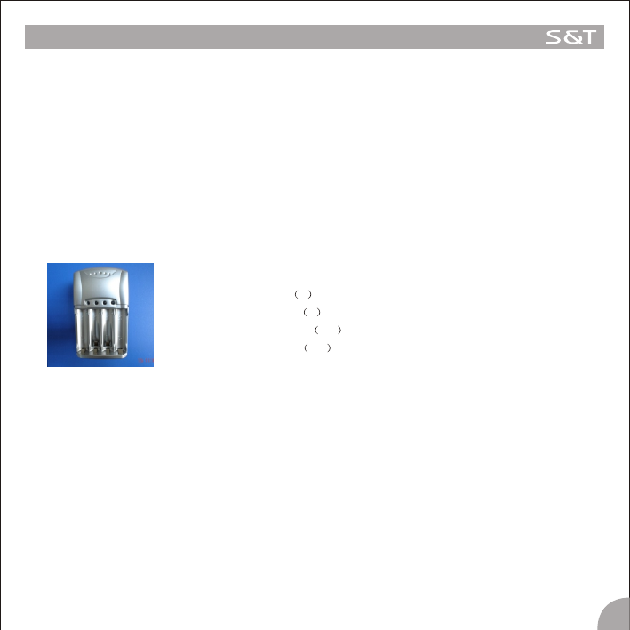
7.The Charger
The Charger MD 6B1Specification
Input voltage V 110V or 220V
Output voltage V 1.5V
Charging current mA 150
Trickle Current mA 90
1) Lay the batteries in a correct polarity;
2) Power the charger with an AC power;
3) LED on the charge can indicate the charging status clearly, “red” means the under charging, “red” lamp off
indicate the charging is finished;
4) The safety time for the charging is 15 hours, the charge has a Timer control to ensure the safety;
5) This charger is suitable for Ni-MH and Ni-CD battery;
6) This charger is compatible for AA and AAA battery size;
Note
1) The new battery should use two or three times, for maximum effectiveness .
2) If loaded for a week or more, the current will automation to be off. So when you want to use, you should
charge the batteries again.
SPECIAL ANNEX
15
3) This product is just for AA/AAA size, Ni-MH Ni-CD battery. Don't insert any other batteries in the charger. It
may damage the device, destroy the batteries and cause injury to the user.
4) Don't charge the batteries directly exposed to the sunlight. It can affect the charging result.
o
5) The working temperature is under 55 C while charging.
8. How to change a new Sensor
When need to change a new sensor
If one of the sensors is broken or the sensor fails to work, you should change a new Sensor for the tire.
The broken Sensor will not influence the other Sensors' work, only the broken one need to be replaced. User can
buy a new Sensor and change it according to the following steps.
8.1 Remove the broken Sensor
1. First dismount the tire from the car.
2. Detach the broken sensor from the tire.
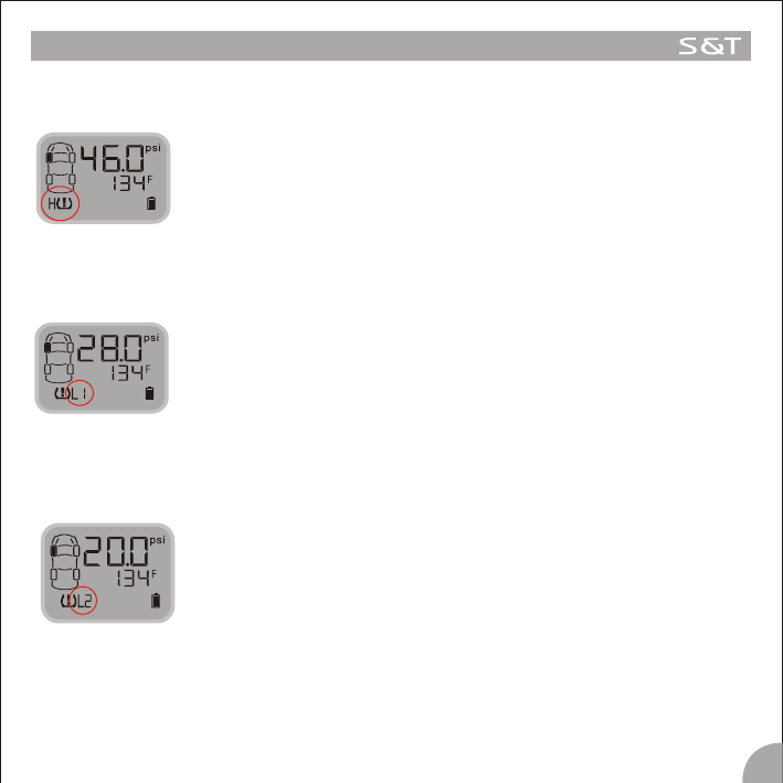
8.2 Find out the ID number of the new Sensor
Take out the new Sensor from the packing PKG, the ID number of the new single Sensor should be printed on the
Introduction Manual or the Color Packing Board, the ID number has 12 digits.
8.3 Select the Tire Position for the new Sensor on the display
Screw on the new Sensor at first, then mount the tire.
Then operate as the following steps on the Master.
Under the operation mode, press the E key and hold it for 3 seconds to access the
Programming interface. At this time, the pressure unit information appears on the
interface as Figure 8-1.
Figure 8-1.
Press the S key to select the “Standard Pressure Programming” interface, the
“SP” icon flashes as shown in Figure 8-2.
Figure 8-2
SPECIAL ANNEX
16
Then press the E key and hold it for 3 seconds to access the ID Number
Programming interface. At this time, the first 6 digit of ID Number of the First tire
appears, as shown in Figure 8-3.The letter “H” standards for the first 6 digit of ID
number of the Sensor.
Figure 8-3
Press the S key to shift the interface, the Last 6 ID Numbers of the First tire appears
on the display, as shown in Figure 8-4. The letter “L” standards for the Last 6 digit
of the ID number of the Sensor.
Figure 8-4
Press the S key to shift the interface, the First 6 digit and the Last 6 digit of the ID
Number of each Sensor displayed in turn,
On the interface of the position which needs to change the Sensor, press the E key
and hold it for 3 seconds to confirm and the first number of the first 6 ID Number
flashes, as shown in figure 8-5.
Figure 8-5
8.4 Program the ID Number of the Sensor on the Selected Tire Position
Press the S key to adjust the first digit of the ID number and press the E key to
confirm it. Then the second number flashes, press the S key to adjust it and press
the E key to confirm, as shown in Figure 8-6. Then the following number flashes
one by one.
When the 6th digit of the First 6 digit of ID number are adjusted, Press the E key to
confirm and shift to the next interface, the Last 6 digit of ID number appears on the
display with a letter “L”. And the first number flashes , as shown in Figure 8-7.
Figure 8-6
Figure 8-7
SPECIAL ANNEX
17
9.5 Exit the ID Number Programming Interface
When the ID Number of the new Sensor are programmed, press the S key to shift
the interface, when the letter “E” appears on the display, press the E key to exit the
Number Programming Interface and return to the normal mode, as shown in Figure
8-8.
Figure 8-8
Note : 1.Under the ID Programming interface, if no operation for 5 minutes, the system will return to the normal
mode automatically.
2. Because this operation need to detach the tire from the car, we strongly suggest the user to go to an
Auto Service Shop to change the broken sensor.
Follow the above steps to adjust all the rest ID Numbers of the new Sensor. When the 12th number are
adjusted, press the E key and hold it for 3 seconds to confirm it, and this can also save all the adjusted 12 ID
numbers of this tire. Then the ID Number programming of this tire are finished.
SPECIFICATION
00
Operating Temperature of the Master: -20 C+50 C
00
Operating Temperature of the Sensor: -40 C+125 C
Pressure Scale of the Sensor: 0~6Bar/ 0~87psi
Accuracy of the Pressure Measurement: ±1.5psi
Modulation type: FSK
RF Frequency: 434.1Mhz
Emission Output Power: -10dbm
Receiving Sensitivity: -105dBm
Input Voltage: 4.3V (cigarette lighter adapter)
1.2×3V (rechargeable battery group)

www.satetpms.com
SUZHOU SATE AUTO ELECTRONIC CO.,LTD
TIRE PRESSURE MONITORING SYSTEM