Suzhou Sate Auto Electronic TSB23 TPMS Transmitter User Manual TSB23 25 Sersor
Suzhou Sate Auto Electronic Co., Ltd TPMS Transmitter TSB23 25 Sersor
users manual
TSB23 Sensor User Manual V1.0
1 of 5
TSB23 Sensor User Manual
1 General Description
1.1 Purpose
It is a Valve Stem Device that works on air pressure.This manual is to make
sure the reliability of communication between receiver and sensor, and tightness
between sensor and wheel hub.
2 Basic Requirements
2.1 Tire valve
2.1.1 Suitable pore size for tire valve
The valve is suitable for wheel hub with tire valve pore size of Φ11.5±
0.2mm.
2.1.2 Valve nut dimension
Valve nut O.D. is Φ14mm, length is 19mm。
2.2 Housing
Housing of the sensor must be sealed to meet water proof and dust proof
requirement, with protection degree IP54. The housing material should make the parts
meet vibration, shock and drop requirement, and tests for vibration, shock and drop
should comply with test requirements of IS016750-3 2007 《 Road Vehicles ─
Environmental conditions and testing for electrical and electronic equipment》.
Housing material: PA6+GF30 (black)
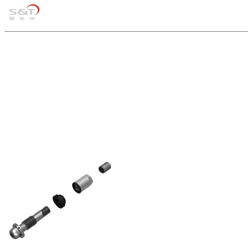
2.3 Dimension requirement
TSB23 dimension is as below:
TSB23 Sensor User Manual V1.0
2 of 5
Item Size Remark
Length 76mm
Width 63mm
Height 26mm
Including tire valve
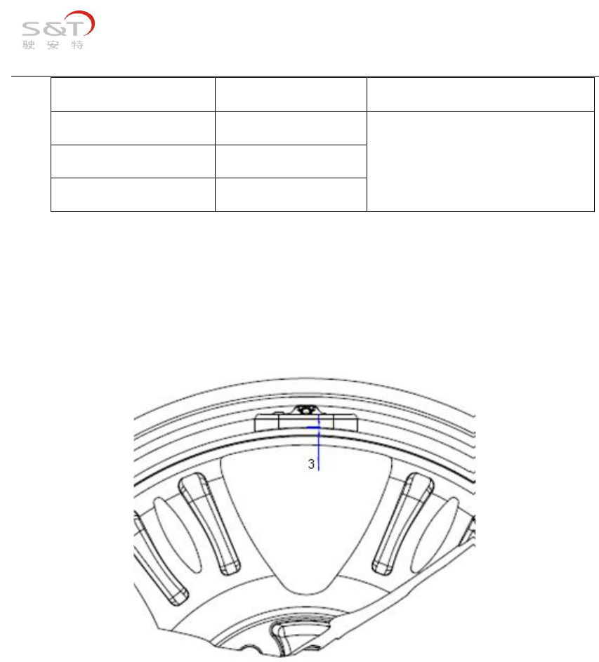
2.4 Installation requirement
4N.m(±0.5 N)torque force should be employed to screw tire valve nut when install
TSB23 sensor to make sure the installation reliability. After installation, there
should be 0-3mm space between sensor camber side and wheel hub camber side, as below:
Installation environment requirement:
1 Sensor dropped from height above 1m can’t be applied on vehicle any more;
2 There shouldn’t be static electricity above 6KV in sensor installation site;
Installation steps:
① Screw the sensor valve nut off, and get the valve through wheel hub valve pore.
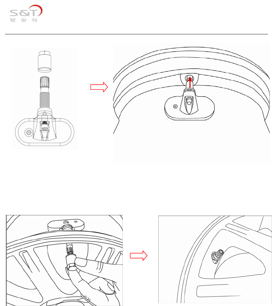
TSB23 Sensor User Manual V1.0
3 of 5
② Screw the sensor nut by hand, and employ 12mm sleeve to tighten it(torque force
4N.M).
③ Mount the rubber tubes;
④ Inflate the tires to standard pressure, and check whether there is leakage
between the valve and lock nut with soap water;
⑤ Screw the valve cap on to finish sensor installation;
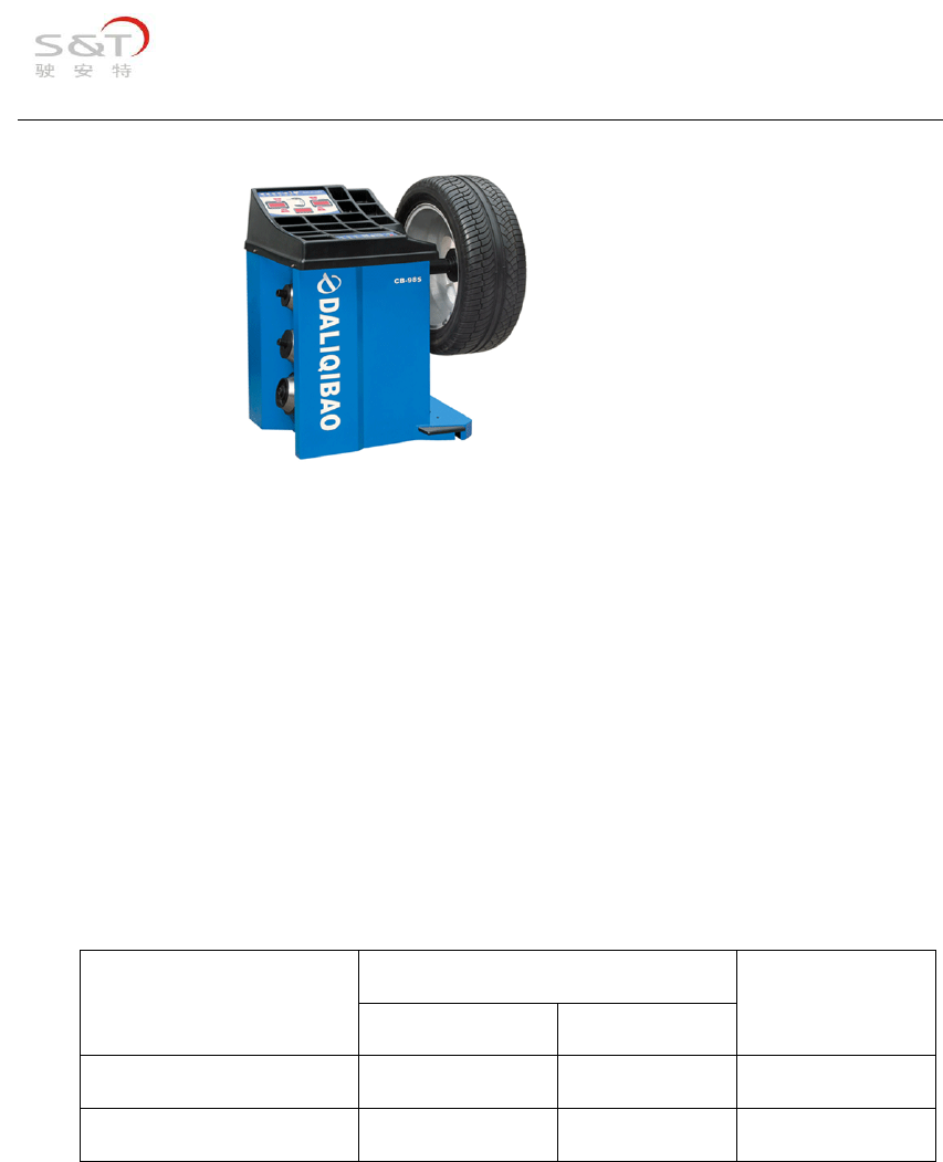
⑥ Check the tire’s dynamic balance after sensor installation, and then install
the other three sensors one by one, and mount the tire.
Note: After sensor installation, the tires need to be re-balanced.
TSB23 Sensor User Manual V1.0
4 of 5
Note: During installation, the sensor need to be clean, not polluted by lubricant
oil, etc;
During tire mounting and dismounting, the sensor shouldn't be touched;
During tire inflation and deflation, no force should be employed to the sensor;
2.5 Temperature requirement
Operation temperature and storage temperature range of TSB23 sensor are as
below:
Temperature range
Parameter
Minimum Maximum
Unit
Operation temperature -40 125 ℃
Storage temperature -40 85 ℃
2.6 Sealing requirement
Sealing test of TSB23 sensor after installation complies with standards of
GBT12836.2(Tubeless valves--Part 2: Clamp-in valves)-7.2.2.

TSB23 Sensor User Manual V1.0
5 of 5
FCC WARNING
This device complies with Part 15 of the FCC Rules. Operation is subject to the
following two conditions:
(1) This device may not cause harmful interference, and
(2) this device must accept any interference received, including interference that
may cause
undesired operation.
NOTE 1: Any changes or modifications to this unit not expressly approved by the party
responsible for compliance could void the user's authority to operate the equipment.