Suzhou Switek Electronics and Technology AS-317191TLG CAT5 LCD CONTROL PLATFORM User Manual USERS MANUAL

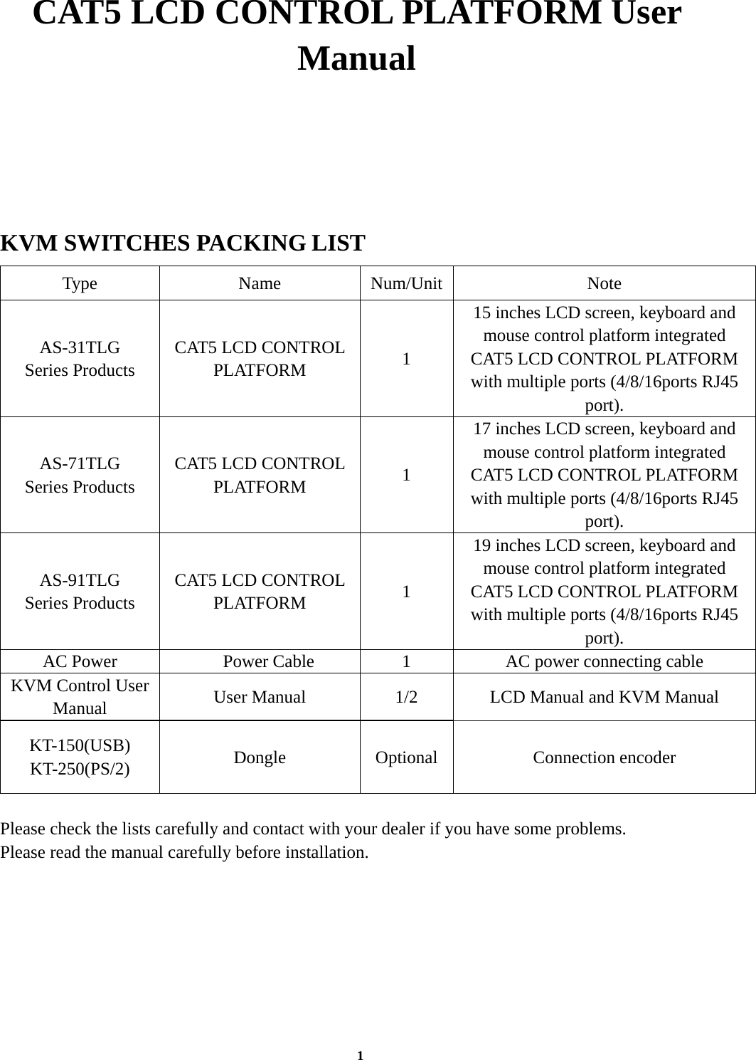
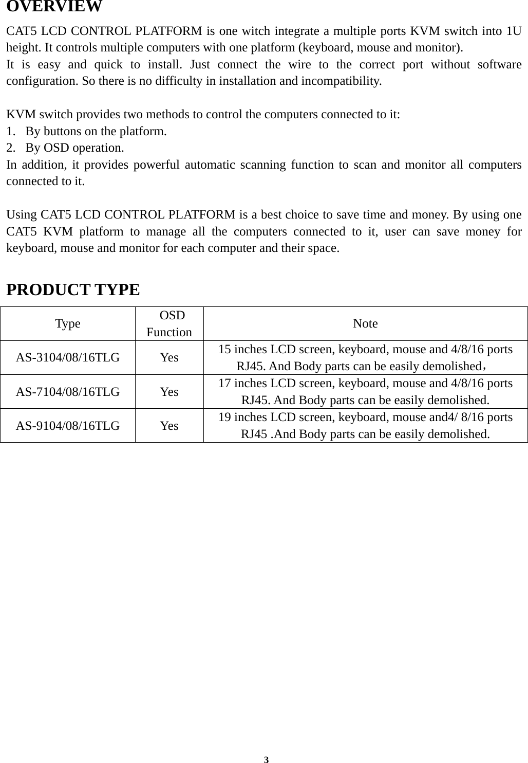
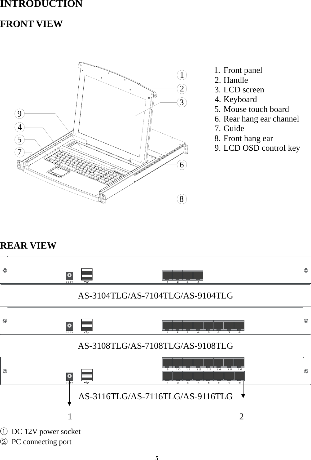
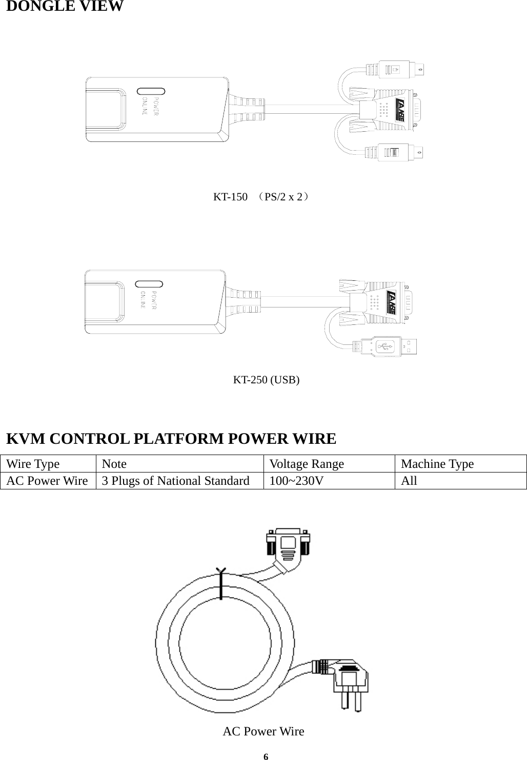
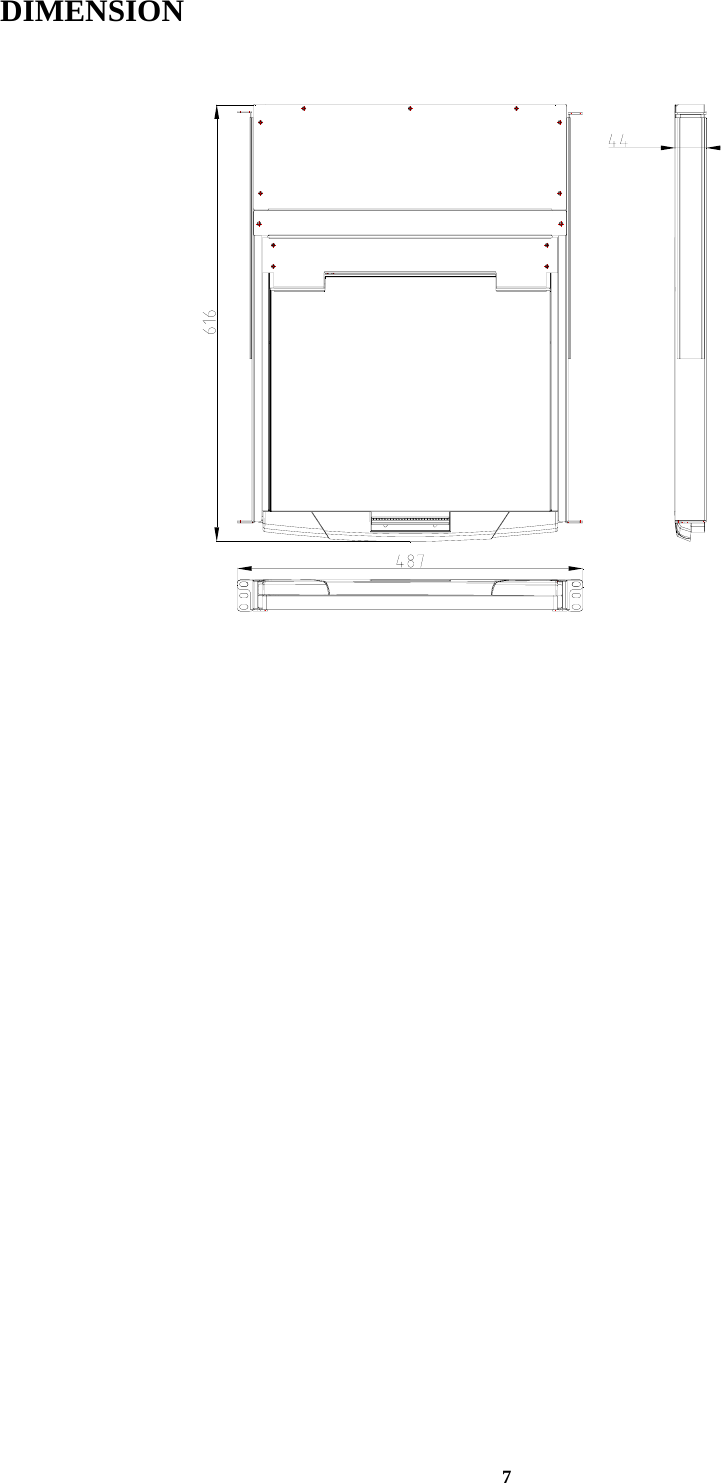
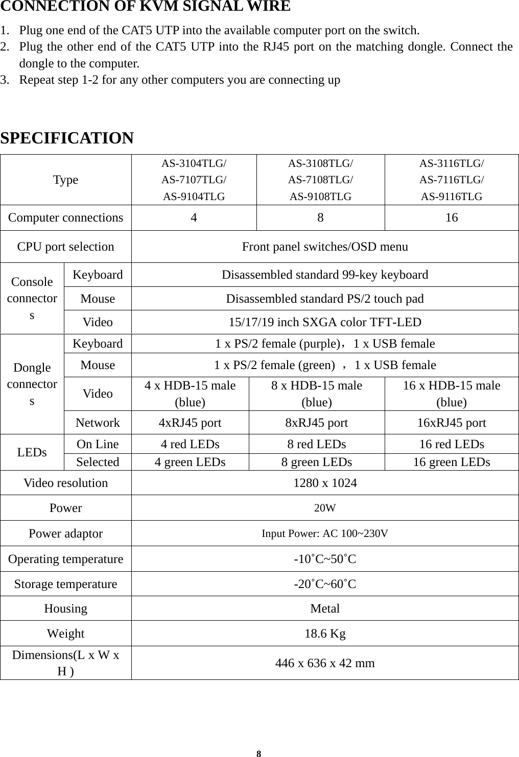
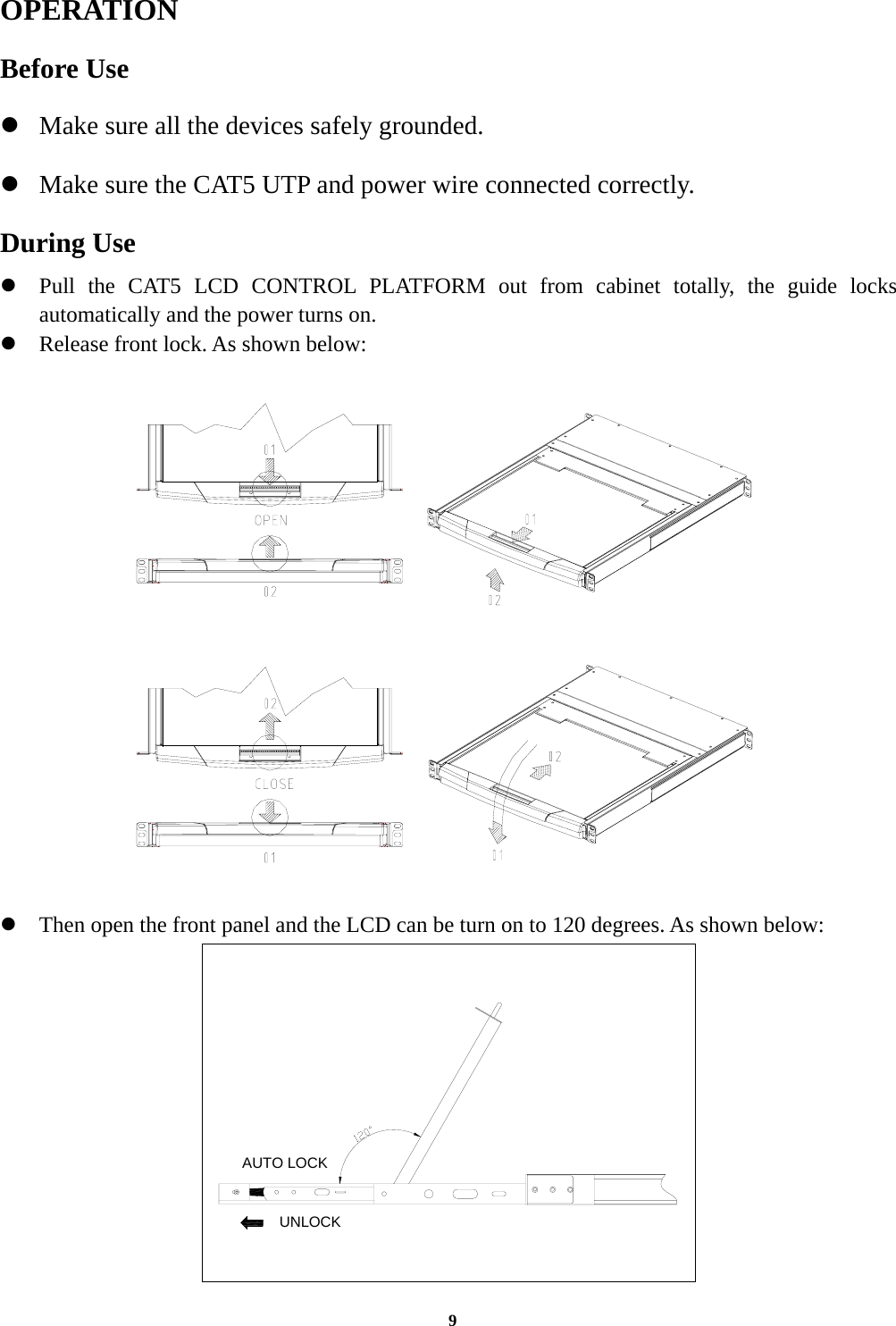
Suzhou Switek Electronics & Technology Co., Ltd. CAT5 LCD CONTROL PLATFORM USERS MANUAL

USERS MANUAL

  1  CAT5 LCD CONTROL PLATFORM User Manual   KVM SWITCHES PACKING LIST Type Name Num/Unit Note AS-31TLG   Series Products CAT5 LCD CONTROL PLATFORM  1 15 inches LCD screen, keyboard and mouse control platform integrated CAT5 LCD CONTROL PLATFORM with multiple ports (4/8/16ports RJ45 port). AS-71TLG   Series Products CAT5 LCD CONTROL PLATFORM  1 17 inches LCD screen, keyboard and mouse control platform integrated CAT5 LCD CONTROL PLATFORM with multiple ports (4/8/16ports RJ45 port). AS-91TLG   Series Products CAT5 LCD CONTROL PLATFORM  1 19 inches LCD screen, keyboard and mouse control platform integrated CAT5 LCD CONTROL PLATFORM with multiple ports (4/8/16ports RJ45 port). AC Power  Power Cable  1  AC power connecting cable KVM Control User   Manual  User Manual  1/2  LCD Manual and KVM Manual KT-150(USB) KT-250(PS/2)  Dongle Optional  Connection encoder  Please check the lists carefully and contact with your dealer if you have some problems. Please read the manual carefully before installation.
  2  Content OVERVIEW .............................................................................................................................................................. 3 PRODUCT TYPE...................................................................................................................................................... 3 FEATURES ............................................................................................................................................................... 4 INTRODUCTION..................................................................................................................................................... 5 FRONT VIEW........................................................................................................................................................... 5 REAR VIEW ............................................................................................................................................................. 5 DONGLE VIEW ....................................................................................................................................................... 6 KVM CONTROL PLATFORM POWER WIRE ...................................................................................................... 6 DIMENSION............................................................................................................................................................. 7 CONNECTION OF KVM SIGNAL WIRE .............................................................................................................. 8 SPECIFICATION ...................................................................................................................................................... 8 OPERATION............................................................................................................................................................. 9 Before Use................................................................................................................................................................. 9 During Use................................................................................................................................................................. 9 After Use ................................................................................................................................................................. 10 Hot Plug................................................................................................................................................................... 10 Power On/Off and Reboot ....................................................................................................................................... 10 Assembling & Disassembling.................................................................................................................................. 11 STANDARD RACK INSTALLATION .................................................................................................................. 13 INTERFACE SELECTION..................................................................................................................................... 15 HOTKEY................................................................................................................................................................. 15 FCC NOTE.............................................................................................................................................................. 15
  3  OVERVIEW CAT5 LCD CONTROL PLATFORM is one witch integrate a multiple ports KVM switch into 1U height. It controls multiple computers with one platform (keyboard, mouse and monitor). It is easy and quick to install. Just connect the wire to the correct port without software configuration. So there is no difficulty in installation and incompatibility.  KVM switch provides two methods to control the computers connected to it: 1. By buttons on the platform. 2. By OSD operation. In addition, it provides powerful automatic scanning function to scan and monitor all computers connected to it.    Using CAT5 LCD CONTROL PLATFORM is a best choice to save time and money. By using one CAT5 KVM platform to manage all the computers connected to it, user can save money for keyboard, mouse and monitor for each computer and their space.  PRODUCT TYPE Type  OSD Function  Note AS-3104/08/16TLG Yes 15 inches LCD screen, keyboard, mouse and 4/8/16 ports RJ45. And Body parts can be easily demolished, AS-7104/08/16TLG Yes 17 inches LCD screen, keyboard, mouse and 4/8/16 ports RJ45. And Body parts can be easily demolished. AS-9104/08/16TLG Yes 19 inches LCD screen, keyboard, mouse and4/ 8/16 ports RJ45 .And Body parts can be easily demolished.
  4  FEATURES Control Platform  Control platform with LCD, keyboard, mouse and multiple ports CAT5 LCD CONTROL PLATFORM.  1U height, suitable for 19’’ standard cabinet installation and metal structure.  15/17/19’’ LCD screen with high brightness, high clear and high resolution.  Control platform can be totally pulled out from the cabinet and the LCD screen can be turned on to 120 degrees.  Ultra thin keyboard with keypad.  Mouse touch board with two function button.  Front panel with lock to prevent damage by accident.  Built-in power.  Automatic power on/off. When pulling control platform out from cabinet, the power turns off automatically. When pushing it into the cabinet, the power turns on automatically.  An easy to use OSD menu.  Switch  One control platform can control 4/8/16 computers by direct connection.  Be compatible with USB standard interface.  Support VGA, SVGA, XGA video input.  Accord with DDC, DDC2, DDC2B standard and VESA standard.  Support maximum resolution of 1280 * 1024  Support multiple operating systems: WIN95/98/98SE/ME/200/XP、WIN NT、UNIX、LINUX.
  5  INTRODUCTION FRONT VIEW 1. Front panel2. Handle3. LCD screen4. Keyboard5. Mouse touch board6. Rear hang ear channel7. Guide8. Front hang ear9. LCD OSD control key123456789 REAR VIEW  AS-3104TLG/AS-7104TLG/AS-9104TLG  AS-3108TLG/AS-7108TLG/AS-9108TLG AS-3116TLG/AS-7116TLG/AS-9116TLG                1                                     2 ① DC 12V power socket ② PC connecting port
  6  DONGLE VIEW             KT-150  (PS/2 x 2)                                              KT-250 (USB)  KVM CONTROL PLATFORM POWER WIRE Wire Type  Note  Voltage Range  Machine Type AC Power Wire  3 Plugs of National Standard  100~230V  All    AC Power Wire
  7  DIMENSION
  8  CONNECTION OF KVM SIGNAL WIRE 1. Plug one end of the CAT5 UTP into the available computer port on the switch. 2. Plug the other end of the CAT5 UTP into the RJ45 port on the matching dongle. Connect the dongle to the computer. 3. Repeat step 1-2 for any other computers you are connecting up  SPECIFICATION Type AS-3104TLG/ AS-7107TLG/ AS-9104TLG AS-3108TLG/ AS-7108TLG/ AS-9108TLG AS-3116TLG/ AS-7116TLG/ AS-9116TLG Computer connections  4  8  16 CPU port selection  Front panel switches/OSD menu Keyboard  Disassembled standard 99-key keyboard Mouse  Disassembled standard PS/2 touch pad Console connectors  Video  15/17/19 inch SXGA color TFT-LED Keyboard  1 x PS/2 female (purple),1 x USB female Mouse  1 x PS/2 female (green)  ,1 x USB female Video  4 x HDB-15 male (blue) 8 x HDB-15 male (blue) 16 x HDB-15 male (blue) Dongle connectors Network  4xRJ45 port  8xRJ45 port  16xRJ45 port On Line  4 red LEDs  8 red LEDs  16 red LEDs LEDs  Selected  4 green LEDs  8 green LEDs  16 green LEDs Video resolution  1280 x 1024 Power  20W Power adaptor  Input Power: AC 100~230V Operating temperature  -10˚C~50˚C Storage temperature  -20˚C~60˚C Housing Metal Weight 18.6 Kg Dimensions(L x W x H )  446 x 636 x 42 mm
  9  OPERATION Before Use z Make sure all the devices safely grounded. z Make sure the CAT5 UTP and power wire connected correctly. During Use z Pull the CAT5 LCD CONTROL PLATFORM out from cabinet totally, the guide locks automatically and the power turns on. z Release front lock. As shown below:  z Then open the front panel and the LCD can be turn on to 120 degrees. As shown below: UNLOCKAUTO LOCK
  10  z Press LCD power key (red), the LCD is on. After Use z Press LCD power key, the LCD is power off. z Close LCD panel and lock the front panel. z Release guide lock. z Push the control panel into the cabinet totally, and then it is power off. Hot Plug The CAT5 LCD CONTROL PLATFORM supports hot plug. It can be connected and disconnected without power off. Please follow the steps:  Hot plug PC connecting port: When hot plugging PC port: 1. The connecting wire must be plugged into the port from which it is pulled out. 2. Plug the mouse before the keyboard. Note: The CAT5 LCD CONTROL PLATFORM must be power on before PC.  Power On/Off and Reboot If user needs to cut off the power of CAT5 LCD CONTROL PLATFORM, please follow the steps before power on again. 1. Cut off the power supply of all computers. Note:  1) The power wire of computer with keyboard power on function must be pulled out. Otherwise, the CAT5 KVM still receives the power signal from computer. 2) If the control unit uses the external power, please pull out external power. 2. After about 10 seconds, power on the CAT5 LCD CONTROL PLATFORM. 3. After the CAT5 LCD CONTROL PLATFORM starts, power on the computers.
  11  Assembling & Disassembling   The device can be assembled and disassembled as following.
  12
  13  STANDARD RACK INSTALLATION 1.   Screw the front flange to the rack first.    Slide the bars with the rear flange towards the rack until the flanges make contact with the rack, then screw the rear flanges to the rack.  2. Slide the switch onto the support flanges.    Use the screws supplied with this package to loosely attach the front of the switch to the front of the rack.  3. Slide the rear attachment sliding brackets along the slide bars until they contact the rear of the switch.
  14   4. Use the screws supplied with this package to attach the bars to the rear of the switch.
  15  INTERFACE SELECTION There are two ways to select: Hot key and OSD menu.  HOTKEY The hotkey let the user control the connected computers by keyboard. Please check CAT5 LCD CONTROL PLATFORM user manual.  FCC NOTE This equipment has been tested and found to comply with the limits for a Class B digital device, pursuant to Part 15 of the FCC Rules. These limits are designed to provide reasonable protection against harmful interference in a residential installation. This equipment generates, uses and can radiate radio frequency energy and, if not installed and used in accordance with the instructions, may cause harmful interference to radio communications. However, there is no guarantee that interference will not occur in a particular installation. If this equipment does cause harmful interference to radio or television reception, which can be determined by turning the equipment off and on, the user is encouraged to try to correct the interference by one or more of the following measures: -- Reorient or relocate the receiving antenna -- Increase the separation between the equipment and receiver. -- Connect the equipment into an outlet on a circuit different from that to which the receiver is connected. -- Consult the dealer or an experienced radio/TV technician for help.  This device complies with Part 15 of the FCC Rules. Operation is subject to the following two conditions: (1) this device may not cause harmful interference, and (2) this device must accept any interference received, including interference that may cause undesired operation.    The manufacturer is not responsible for any radio or TV interference caused by unauthorized modifications to this equipment. Such modifications could void the user's authority to operate the equipment.

Navigation menu