Suzuki 2010 Sx4 Owners Manual
Suzuki-2010-Sx4-Owners-Manual-227085 suzuki-2010-sx4-owners-manual-227085
2010 SX4 Sport to the manual 26e0f4f3-8b52-495d-b689-e88de8a58c21
2015-10-24
: Suzuki Suzuki-2010-Suzuki-Sx4-Owners-Manual-819275 suzuki-2010-suzuki-sx4-owners-manual-819275 suzuki pdf
Open the PDF directly: View PDF ![]() .
.
Page Count: 297 [warning: Documents this large are best viewed by clicking the View PDF Link!]
80J23-03E
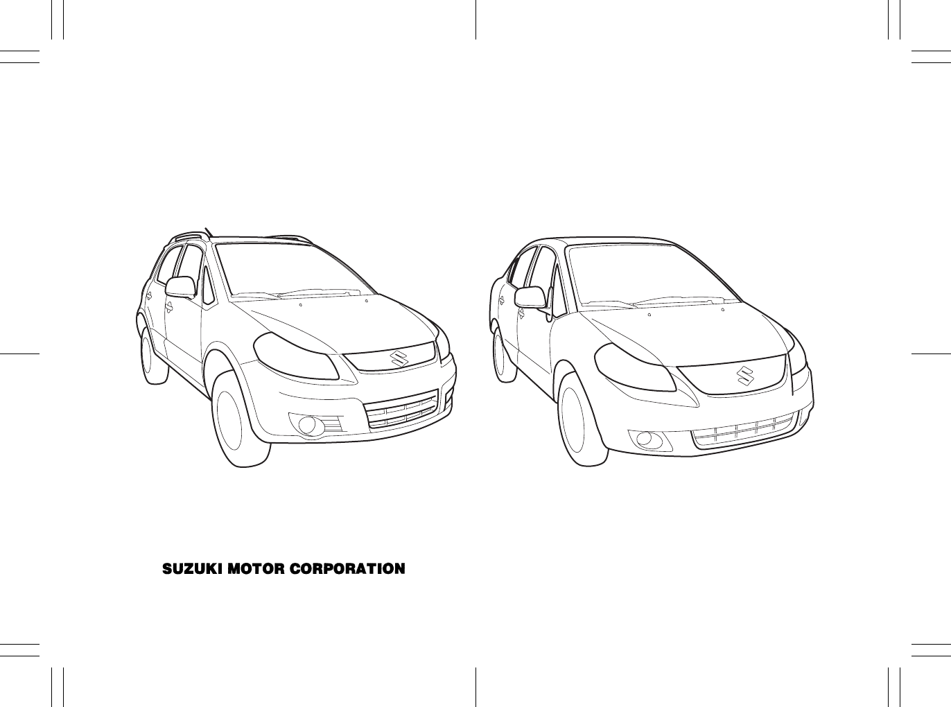
This owner’s manual applies to the SX4 series:
80J2059
NOTE: The illustrated models are examples of the SX4 series.
© 2009 All rights reserved.
No part of this document may be reproduced or transmitted in any form or by any means, electronic or
mechanical, for any purpose, without the express written permission of Suzuki Motor Corporation.
SX4 SX4 SEDAN
80J23-03E
FOREWORD
All information in this manual is based
on the latest product information avail-
able at the time of publication. Due to
improvements or other changes, there
may be discrepancies between informa-
tion in this manual and your vehicle.
SUZUKI MOTOR CORPORATION
reserves the right to make production
changes at any time, without notice and
without incurring any obligation to
make the same or similar changes to
vehicles previously built or sold.
SUZUKI MOTOR CORPORATION
believes in conservation and protection of
Earth’s natural resources.
To that end, we encourage every vehicle
owner to recycle, trade in, or properly dis-
pose of, as appropriate, used motor oil,
coolant, and other fluids, batteries and
tires.
IF YOU HAVE ANY PROBLEMS WITH
YOUR SUZUKI:
Please review the New Vehicle Warranty
Information booklet supplied with your
SUZUKI. Should you have a question or
problem regarding the warranty or service
of your vehicle, please take the following
action:
Consult the Service Manager and the
Owner of the Suzuki Automotive Dealer-
ship. Explain your problem and ask for
their assistance in resolving your problem.
The Owner of the dealership is in the very
best position to assist you as he or she is
vitally concerned with your continued satis-
faction.
If you are still in need of additional informa-
tion, or if you are dissatisfied, request that
your dealer arrange a meeting with your
District Service Manager.
If, after doing so, you still require further
assistance, and you purchased your
SUZUKI in the continental United States,
please contact the American Suzuki Cus-
tomer Relations Department by telephone
at 1-800-934-0934 or in writing at:
American Suzuki Motor Corporation
Automotive Customer Relations
3251 East Imperial Highway
Brea, CA 92821-6795
If you purchased your SUZUKI in Canada
please contact the Suzuki Canada Cus-
tomer Relations Department by telephone
at 1-905-889-2677 extension 2254 or in
writing at:
Suzuki Canada Inc.
Customer Relations
100 East Beaver Creek Road
Richmond Hill, On
L4B 1J6
In the event you require assistance related
to your SUZUKI, while temporarily travel-
ling in either the United States or Canada,
you may wish to contact the Suzuki Cus-
tomer Relations Department directly of the
country in which you are temporarily oper-
ating your vehicle.
Please be certain to provide us with the fol-
lowing information: the model, Vehicle
Identification Number, mileage, accesso-
ries involved, event dates, your concern,
and any other comments which you may
have. When we receive your correspon-
dence, we will be pleased to contact the
Owner of your dealership and assist in
resolving your concern.
For owners outside the continental United
States, please refer to the distributor’s
address listed in your Warranty Information
booklet.
80J23-03E
IMPORTANT
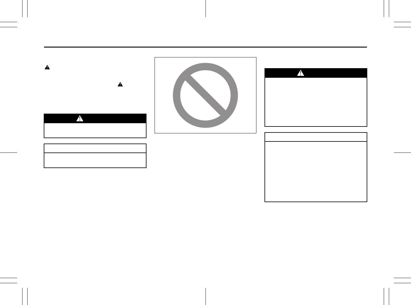
WARNING/CAUTION/NOTE
Please read this manual and follow its
instructions carefully. To emphasize spe-
cial information, the symbol and the
words WARNING, CAUTION and NOTE
have special meanings. Pay special atten-
tion to the messages highlighted by these
signal words:
NOTE:
Indicates special information to make
maintenance easier or instructions clearer.
75F135
The circle with a slash in this manual
means “Don’t do this” or “Don’t let this hap-
pen”.
MODIFICATION WARNING
WARNING
Indicates a potential hazard that
could result in death or injury.
CAUTION
Indicates a potential hazard that
could result in vehicle damage.
WARNING
Do not modify this vehicle. Modifica-
tion could adversely affect safety,
handling, performance or durability
and may violate governmental regula-
tions. In addition, damage or perfor-
mance problems resulting from
modification may not be covered
under warranty.
CAUTION
Improper installation of mobile com-
munication equipment such as cellu-
lar telephones or CB (Citizen’s Band)
radios may cause electronic interfer-
ence with your vehicle’s ignition sys-
tem, resulting in vehicle performance
problems. Consult your SUZUKI
dealer or qualified service technician
for advice on installing such mobile
communication equipment.

80J23-03E
LEAK DETECTION PUMP
NOTE:
Your vehicle has a pump to regularly check
the vehicle’s evaporative emission control
system for leaks. This check is performed
approximately five hours after the engine is
turned off. During this leak check, you may
hear a sound coming from the vehicle for
several minutes. This sound is normal and
does not indicate a malfunction.

80J23-03E
MEMO
80J23-03E
INTRODUCTION
Thank you for choosing SUZUKI and welcome to our growing family. Your choice was a wise one; SUZUKI products are a great value
that will give you years of driving pleasure.
This Owner’s Manual was prepared to help you have a safe, enjoyable, and trouble-free experience with your SUZUKI. In it you will learn
about the vehicle’s operation, its safety features and maintenance requirements. Please read it carefully before operating your vehicle.
Afterwards, keep this Manual in the glove box for future reference.
Should you resell the vehicle, please leave this Manual with it for the next owner.
In addition to the Owner’s Manual, the other booklets provided with your SUZUKI explain the vehicle’s warranties. We recommend you
read them as well to familiarize yourself with this important information.
When planning the regular scheduled maintenance of your SUZUKI, we recommend you visit your local SUZUKI dealership. Their fac-
tory-trained technicians will provide the best possible service and use only genuine SUZUKI parts and accessories.
80J23-03E
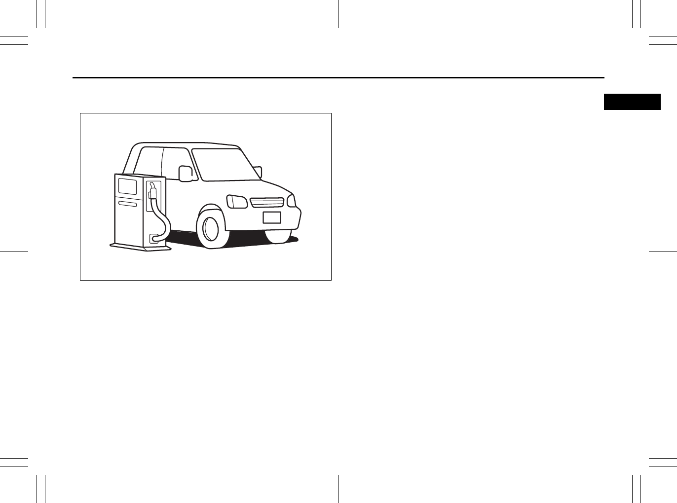
SERVICE STATION GUIDE
1. Fuel (see section 1)
2. Engine hood (see section 5)
3. Tire changing tools (see section 8)
4. Engine oil dipstick <Yellow>
(see section 7)
5. CVT fluid dipstick <Red or Orange>
(see section 7)
6. Engine coolant (see section 7)
7. Windshield washer fluid
(see section 7)
8. Battery (see section 7)
9. Tire pressure (see Tire Information
Label on driver’s door lock pillar)
10. Spare tire (see section 7)
80J2007
2
2
7
1
9
3
10
8
4
65
80J23-03E
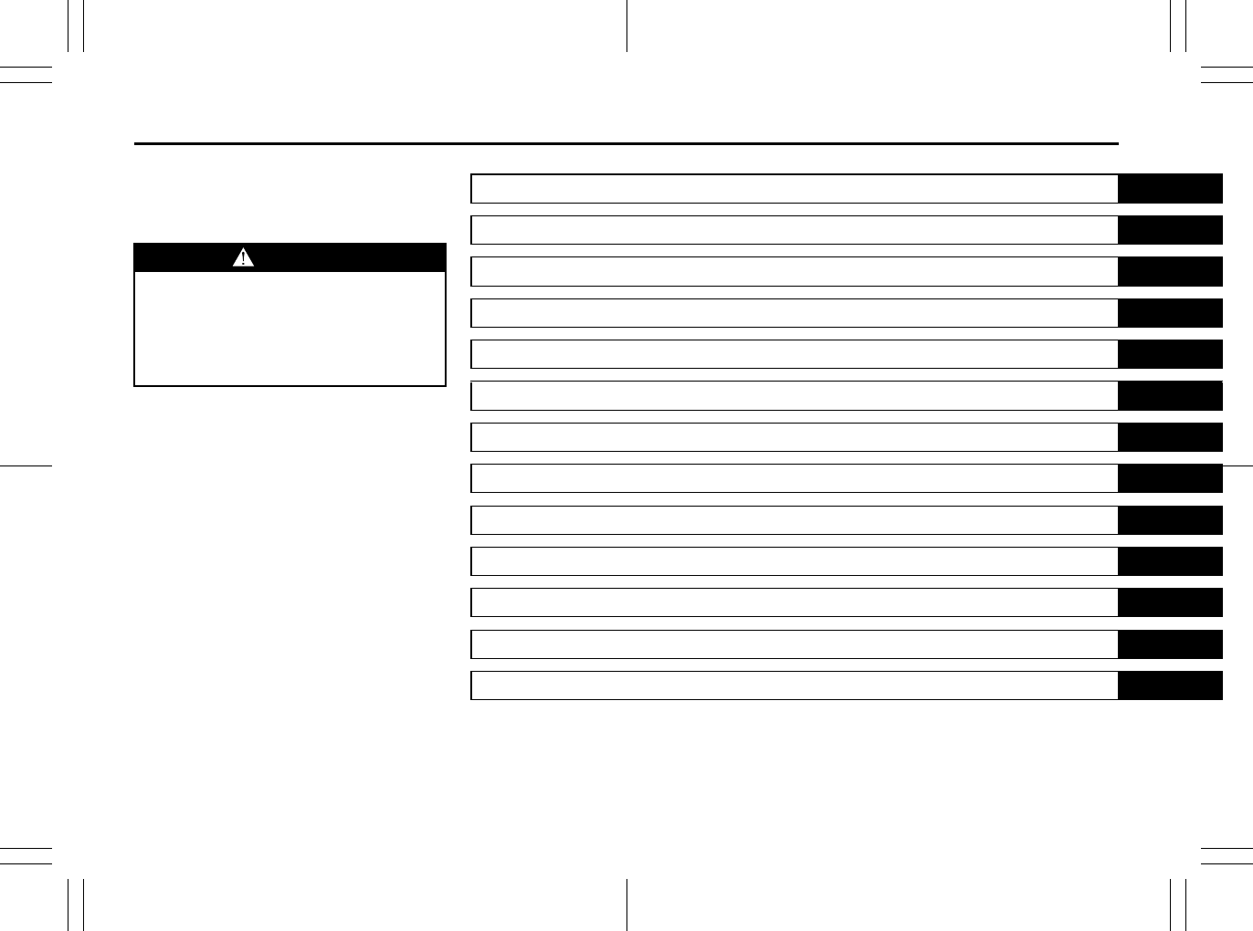
TABLE OF CONTENTS
California Proposition 65 Warning
WARNING
Engine exhaust, some of its constitu-
ents, and certain product compo-
nents contain or emit chemicals
known to the State of California to
cause cancer and birth defects or
other reproductive harm.
FUEL RECOMMENDATION 1
BEFORE DRIVING 2
OPERATING YOUR VEHICLE 3
DRIVING TIPS 4
OTHER CONTROLS AND EQUIPMENT 5
VEHICLE LOADING AND TOWING 6
INSPECTION AND MAINTENANCE 7
EMERGENCY SERVICE 8
APPEARANCE CARE 9
GENERAL INFORMATION 10
FUSES AND PROTECTED CIRCUITS 11
SPECIFICATIONS 12
INDEX 13
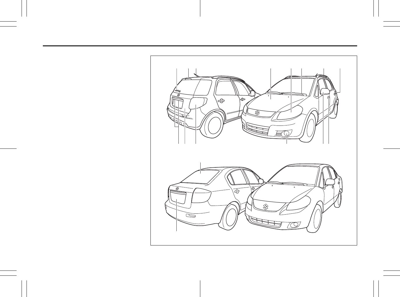
ILLUSTRATED TABLE OF CONTENTS
80J23-03E
EXTERIOR
1. Rear Window Wiper (if equipped)
(P.2-80)
2. High-mount Stop Light (if equipped)
(P.7-45)
3. Radio Antenna (P.5-15)
4. Engine Hood (P.5-44)
5. Head Light (P2-75, P7-41)
6. Windshield Wiper (P.2-78)
7. Roof Rail (if equipped) (P.5-55)
8. Fuel Filler Cap (P.5-43)
9. License Plate Light (P.7-44)
10. Tailgate (if equipped) (P.2-3)
11. Rear Combination Light (P.7-43)
12. Front Fog Light (if equipped)
(P.2-77, 7-42)
13. Outside Rearview Mirror (P.2-20)
14. Door Locks (P.2-1)
15. Trunk (if equipped) (P.2-4)
80J2058
1
15
14
13
84
3
3
2567
SX4
SX4 SEDAN
10 119 12
EXAMPLE
ILLUSTRATED TABLE OF CONTENTS
80J23-03E
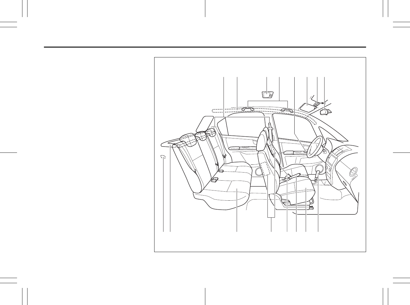
INTERIOR
1. Seat Belts (P.2-28)
2. Side Curtain Air Bags (if equipped)
(P.2-50)
3. Interior Light (P.5-45, 7-40)
4. Assist Grip (if equipped) (P.5-48)
5. Power Mirror Control Switch
(if equipped) (P.2-20)/
Power Window Controls (P.2-17)
6. Sun Visor (P.5-45)
7. Spot Light (P.5-47, 7-40)
8. Inside Rearview Mirror (P.2-19)
9. Luggage Compartment Light
(if equipped) (P.5-46, 7-45)
10. Luggage Compartment Cover
(if equipped) (P.5-52)
11. Rear Seat (P.2-24)
12. Side Air Bags (if equipped) (P.2-50)
13. Armrest (if equipped) (P. 5-51)
14. Parking Brake Lever (P.3-6)
15. Front Seats (P.2-21)
16. Gearshift Lever (P.3-10)
80J2062
1 42 53 6
10 11 1413 15 1612
7 8
9
EXAMPLE
ILLUSTRATED TABLE OF CONTENTS
80J23-03E
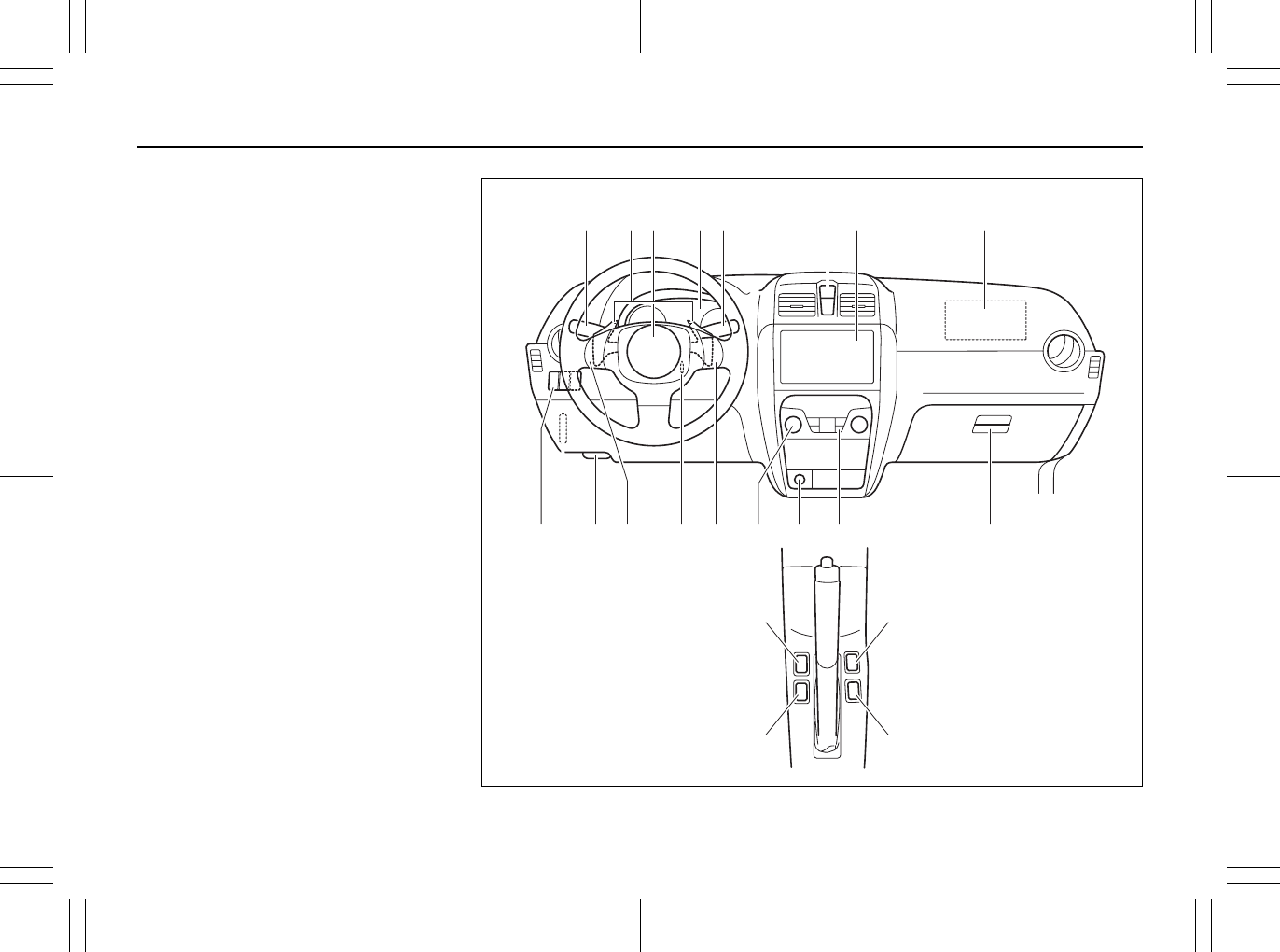
INSTRUMENT PANEL
1. Lighting Control Lever (P.2-75)/
Turn Signal Control Lever (P.2-77)
2. Shift Paddles (if equipped) (P.3-14)
3. Front Air Bags (P.2-49)
4. Instrument Cluster (P.2-59)
5. Windshield Wiper and Washer Lever
(P.2-78)/Rear Window Wiper and
Washer Switch (if equipped) (P.2-80)
6. Hazard Warning Switch (P.2-78)
7. Audio (P.5-15)
8. Front Fog Light Switch (if equipped)
(P.2-77)
9. Fuse Box (P.7-36)
10. Engine Hood Release Handle
(P.5-44)
11. Remote Audio Controls (if equipped)
(P.5-37)
12. Ignition Switch (P.3-2)
13. Cruise Control Switch (if equipped)
(P.3-18)
14. Heating and Air Conditioning System
(P.5-1)
15. Accessory Socket (if equipped)
(P.5-47)/Cigarette Lighter
(if equipped) (P.5-47)
16. Heated Rear Window and Heated
Outside Rearview Mirrors Switch
(if equipped) (P.2-81)
17. Glove Box (P.5-49)
18. ESP OFF Switch (if equipped)
(P.3-26)
19. 2WD/i-AWD (intelligent All Wheel
Drive) Switch (if equipped) (P.3-16)
20. Front Seat Heater Switch
(if equipped) (P.2-23) 80J2074
1
9
18
32 4 5 6 7 3
12 13 14 15 16 1710 118
19
20 20
EXAMPLE
ILLUSTRATED TABLE OF CONTENTS
80J23-03E
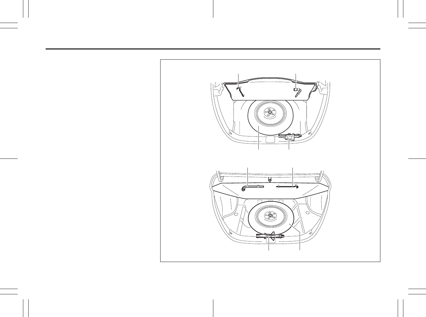
TIRE CHANGING TOOL
1. Jack Handle (P.8-1)
2. Wheel Brace (P.8-1)
3. Spare Tire (P.7-31, 8-1)
4. Jack (P.8-1)
80JM121
12
21
SX4
SX4 SEDAN
34
43EXAMPLE
80J23-03E
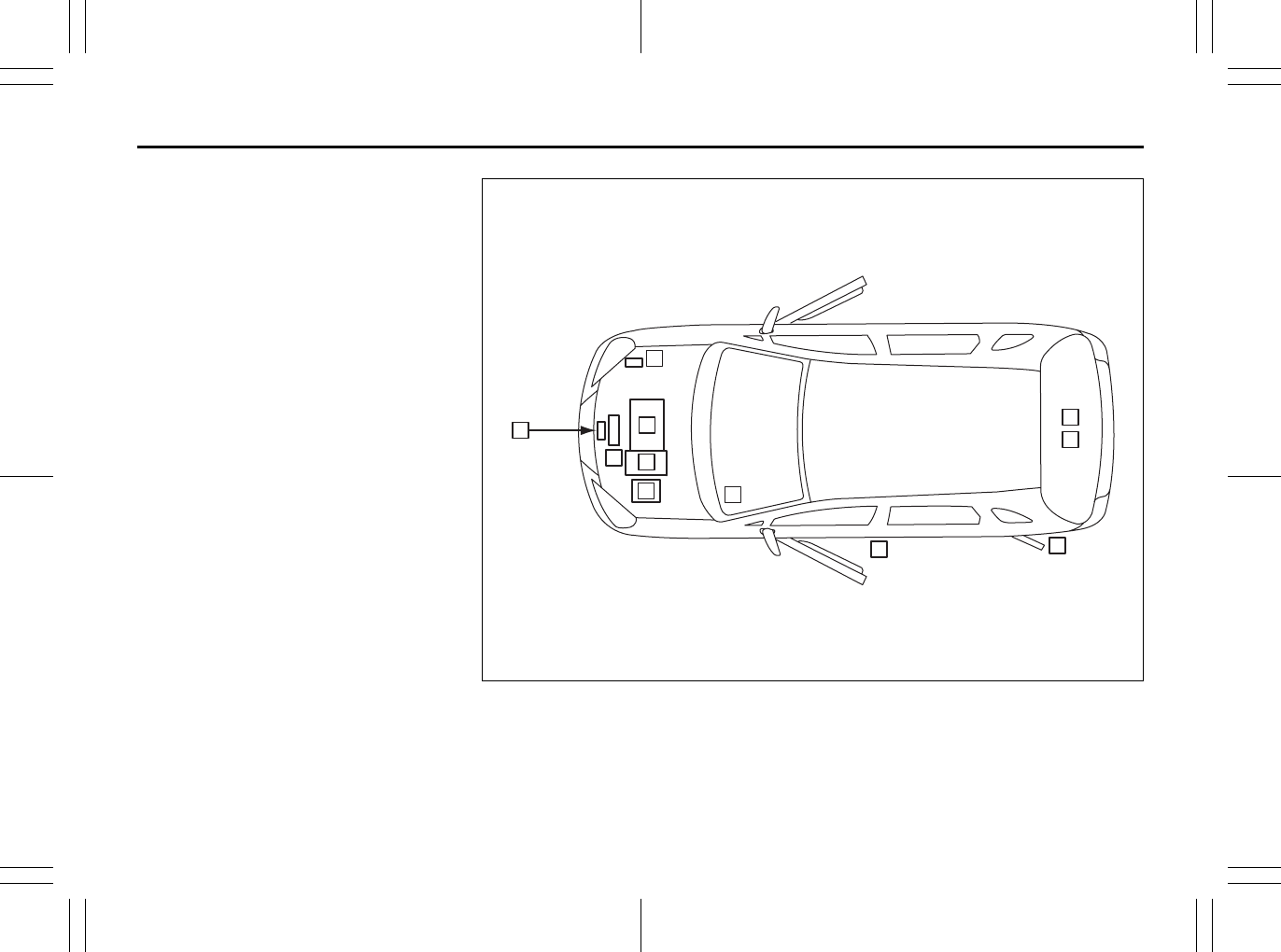
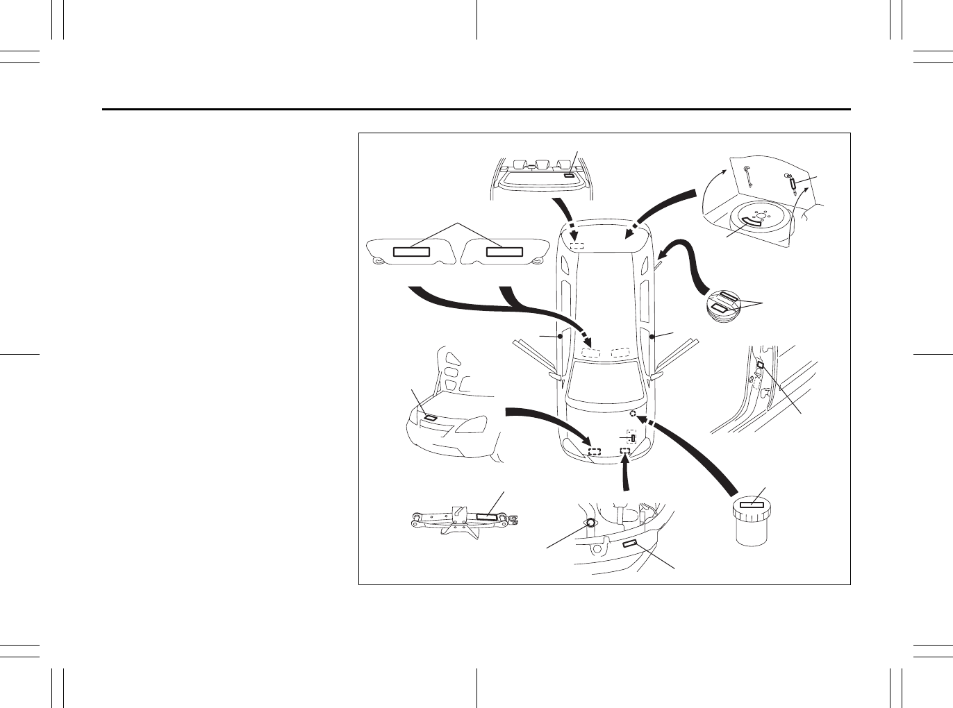
LOCATION OF WARNING
MESSAGES
Read and follow all of the warnings (labels
etc.) on your vehicle. Make sure you
understand all of them. Keep them on the
vehicle. Do not remove the messages for
any reason. If a label comes off or the
messages become difficult to be read,
have it corrected by your SUZUKI dealer.
1. Air bag warning labels
(on both sun visors)
2. Jacking warning label
3. Fuel filler cap message
4. Brake fluid cap message
5. Engine cooling fan warning label
6. Radiator cap warning label
7. Air conditioner warning label
8. Battery label
9. Compact spare tire warning label
10. Side air bag warning label
11. Luggage compartment cover warning
label
12. Jacking instruction warning label
80J2075
4
6
5
7
2
11
10
3
8
1
9
10 10
12
Driver Passenger
FUEL RECOMMENDATION
1
80J23-03E
65D394
FUEL RECOMMENDATION
Fuel Recommendation ........................................................ 1-1
1-1
FUEL RECOMMENDATION
80J23-03E
Fuel Recommendation
60A004
Your vehicle requires regular unleaded
gasoline with a minimum rating of 87 pump
octane ((R + M)/2 method). In some areas,
the only fuels that are available are oxy-
genated fuels.
Oxygenated fuels which meet the mini-
mum octane requirement and the require-
ments described below may be used in
your vehicle without jeopardizing the New
Vehicle Limited Warranty.
NOTE:
Oxygenated fuels are fuels which contain
oxygen-carrying additives such as MTBE
or alcohol.
Gasoline Containing MTBE
Unleaded gasoline containing MTBE
(methyl tertiary butyl ether) may be used in
your vehicle if the MTBE content is not
greater than 15%. This oxygenated fuel
does not contain alcohol.
Gasoline/Ethanol blends
Blends of unleaded gasoline and ethanol
(grain alcohol), also known as gasohol,
may be used in your vehicle if the ethanol
content is not greater than 10%.
Gasoline/Methanol blends
Fuels containing 5% or less methanol
(wood alcohol) may be suitable for use in
your vehicle if they contain cosolvents and
corrosion inhibitors. Do NOT USE fuels
containing more than 5% methanol under
any circumstances. Fuel system damage
or vehicle performance problems resulting
from the use of such fuels are not the
responsibility of SUZUKI and may not be
covered under the New Vehicle Limited
Warranty.
Fuel Pump Labeling
In some states, pumps that dispense oxy-
genated fuels are required to be labeled for
the type and percentage of oxygenate and
whether important additives are present.
Such labels may provide enough informa-
tion for you to determine if a particular
blend of fuel meets the requirements listed
above. In other areas, pumps may not be
clearly labeled as to the content or type of
oxygenate and additives. If you are not
sure that the fuel you intend to use meets
these requirements, check with the service
station operator or the fuel supplier.
NOTE:
To help clean the air, SUZUKI recom-
mends you use the oxygenated fuels.
However, if you are not satisfied with the
driveability or fuel economy of your vehicle
when you are using an oxygenated fuel,
switch back to the regular unleaded gaso-
line.
CAUTION
Be careful not to spill fuel containing
alcohol while refueling. If fuel is
spilled on the vehicle body, wipe it up
immediately. Fuels containing alco-
hol can cause paint damage, which is
not covered under the New Vehicle
Limited Warranty.
Fuel Recommendation: 1, 2
BEFORE DRIVING
2
80J23-03E
60G404
BEFORE DRIVING
Keys ...................................................................................... 2-1
Door Locks .......................................................................... 2-1
Keyless Start System Remote Controller/
Keyless Entry System Transmitter .................................... 2-6
Theft Deterrent Light ........................................................... 2-17
Windows .............................................................................. 2-17
Mirrors .................................................................................. 2-19
Front Seats .......................................................................... 2-21
Front Seat Heater (if equipped) .......................................... 2-23
Rear Seats ............................................................................ 2-24
Seat Belts and Child Restraint Systems ........................... 2-28
Supplemental Restraint System (air bags) ....................... 2-47
Instrument Cluster .............................................................. 2-59
Warning and Indicator Lights ............................................ 2-60
Speedometer ....................................................................... 2-68
Tachometer .......................................................................... 2-69
Fuel Gauge ........................................................................... 2-69
Temperature Gauge ............................................................ 2-70
Information display ............................................................. 2-70
Lighting Control Lever ........................................................ 2-75
Front Fog Light Switch (if equipped) ................................ 2-77
Turn Signal Control Lever .................................................. 2-77
Hazard Warning Switch ...................................................... 2-78
Windshield Wiper and Washer Lever ................................ 2-78
Tilt Steering Lock Lever (if equipped) ............................... 2-81
Horn ...................................................................................... 2-81
Heated Rear Window and Heated Outside Rearview
Mirrors (if equipped) Switch ............................................... 2-81
2-1
BEFORE DRIVING
80J23-03E
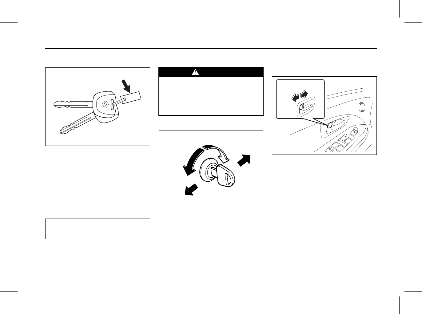
Keys
54G489
Your vehicle comes with a pair of identical
keys. Keep the spare key in a safe place.
One key can open all of the locks on the
vehicle.
The key identification number is stamped
on a metal tag provided with the keys.
Keep the tag in a safe place. If you lose
your keys, you will need this number to
have new keys made. Write the number
below for your future reference.
Ignition Key Reminder
A buzzer sounds to remind you to remove
the ignition key if it is in the ignition switch
when the driver’s door is opened.
Door Locks
Side Door Locks
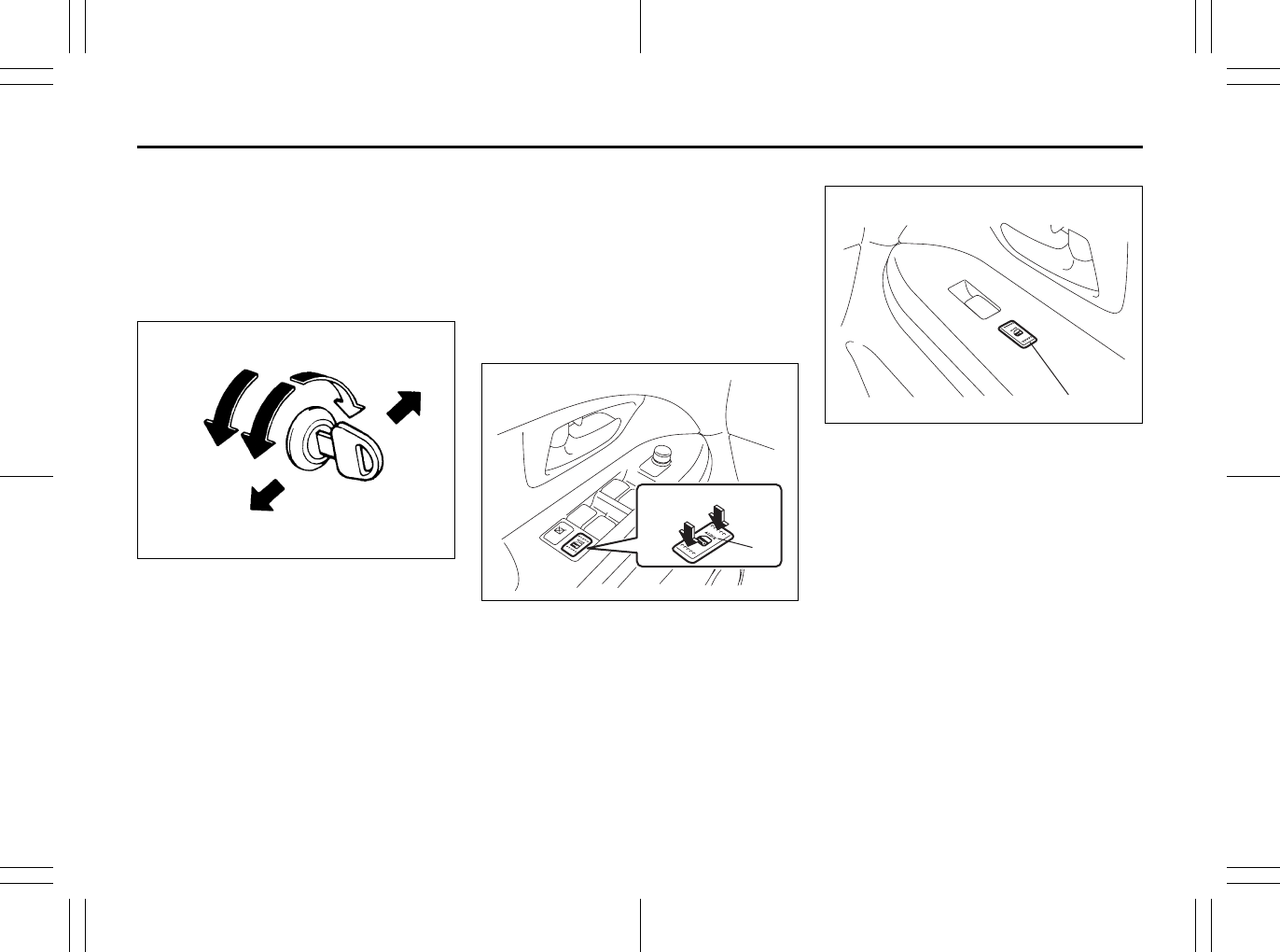
60A009
To lock a front door from outside the vehi-
cle:
• Insert the key and turn the top of the key
toward the rear of the vehicle, or
• Turn the lock knob forward, then pull and
hold the door handle as you close the
door.
To unlock a front door from outside the
vehicle, insert the key and turn the top of
the key toward the front of the vehicle.
79J021
To lock a door from inside the vehicle, turn
the lock knob forward. Turn the lock knob
rearward to unlock the door.
To lock a rear door from outside the vehi-
cle, turn the lock knob forward and close
the door. You do not need to pull and hold
the door handle as you close the door.
KEY NUMBER:
EXAMPLE WARNING
Always lock all doors when driving.
Locking the doors helps to prevent
occupants from being thrown from
the vehicle in the event of an acci-
dent. It also helps prevent unin-
tended opening of the doors.
Rear
Front
UNLOCK
LOCK
UNLOCK LOCK
EXAMPLE
Keys: 8
Door Locks: 3, 5, 8
2-2
BEFORE DRIVING
80J23-03E
Power Door Locking System
You can lock and unlock all the doors
(including the tailgate of SX4) simulta-
neously by:
• Turning the key in a front door lock, or
• Pushing the power door locking switch
located on the driver’s side or the front
passenger’s side door panel.
54G294
(when using the key)
To lock all the doors simultaneously, insert
the key in a front door lock and turn the top
of the key toward the rear of the vehicle
once.
To unlock all the doors simultaneously,
insert the key in a front door lock and turn
the top of the key toward the front of the
vehicle twice.
To unlock only one of the front doors, insert
the key in that door lock and turn the top of
the key toward the front of the vehicle
once.
Driver’s side
80JC091
Front passenger’s side
80JC092
(when using the power door locking
switch)
To lock or unlock all the doors simulta-
neously, depress the front or rear of the
switch (1) or (2), respectively.
LOCK
Rear
Front
UNLOCK
(1)
UNLOCK LOCK
EXAMPLE
(2)
EXAMPLE
Door Locks: 3, 5, 8
2-3
BEFORE DRIVING
80J23-03E
NOTE:
• If your vehicle is equipped with the key-
less entry system, you can also lock or
unlock all doors by operating the remote
controller/transmitter. Refer to “Keyless
Start System Remote Controller/Key-
less Entry System Transmitter” in this
section.
• If your vehicle is equipped with the key-
less start system, you can also lock or
unlock all doors by pushing the request
switch on the door handle. Refer to “Key-
less Start System Remote Controller/
Keyless Entry System Transmitter” in
this section.
Child Lock System (rear doors)
80JM019
(1) LOCK
(2) UNLOCK
Each of the rear doors is equipped with a
child lock which can be used to help pre-
vent unwanted opening of the door from
inside the vehicle. When the lock lever is in
the “LOCK” position (1), the rear door can
only be opened from outside. When the
lock lever is in the “UNLOCK” position (2),
the rear door can be opened from inside or
outside.
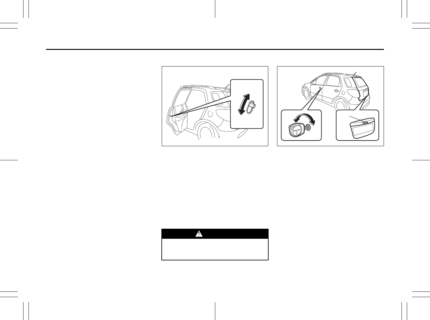
Tailgate (SX4)
80JC059
(1) Tailgate unlatch switch
You can lock and unlock the tailgate by
using the key in the driver’s door lock.
To open the tailgate, push and hold the tail-
gate unlatch switch (1) and lift the tailgate.
NOTE:
When the tailgate is closed incompletely,
follow the procedure below:
1) Push the tailgate unlatch switch (1) and
open the tailgate a little.
2) After a few seconds, close the tailgate.
3) Make sure that the tailgate is closed
completely.
WARNING
Be sure to place the child lock in the
“LOCK” position whenever children
are seated in the rear.
EXAMPLE
(2)
(1)
(1)
EXAMPLE
Door Locks: 3, 5, 8
2-4
BEFORE DRIVING
80J23-03E
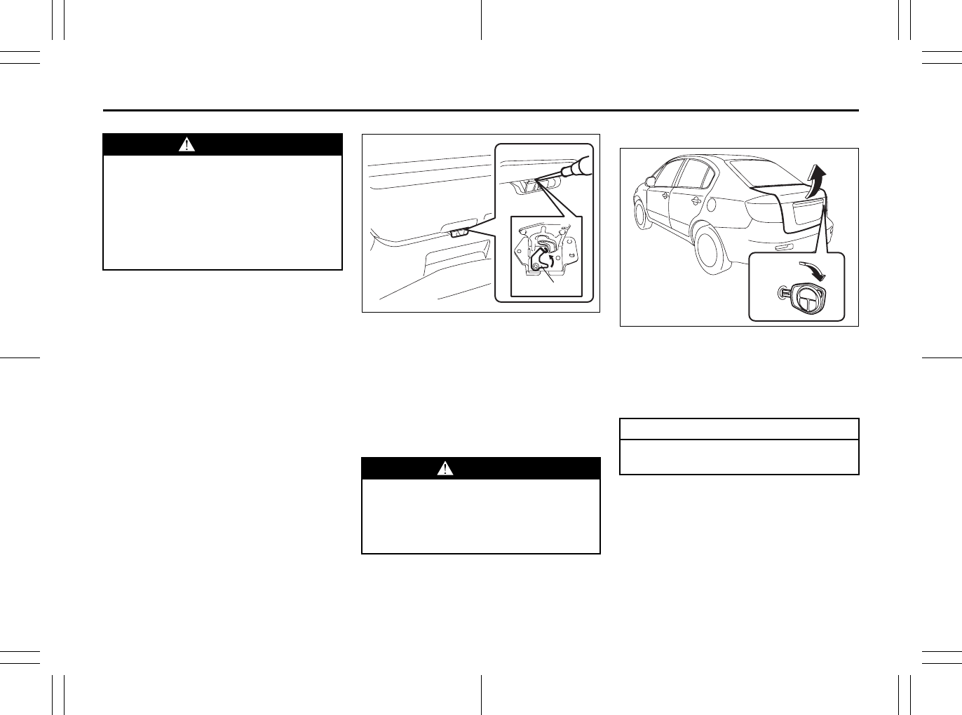
If you cannot unlatch the tailgate by push-
ing the unlatch switch (1) due to a dis-
charged battery or malfunction, follow the
procedures below to unlatch the tailgate
from inside the vehicle.
1) Fold the rear seat forward for easier
access. Refer to “Folding Rear Seats”
section for details on how to fold the
rear seat forward.
80J092
2) Push open the tailgate from inside by
pushing up on the emergency lever (2)
using a flat blade screwdriver or the
jack handle. The tailgate will be latched
again by closing the tailgate simply.
If the tailgate cannot be unlatched by push-
ing the unlatch switch (1), have the vehicle
inspected by your SUZUKI dealer.
Trunk Lid (SX4 SEDAN)
55KS005
If your vehicle is equipped with a trunk lid
key lock, you can open the trunk lid by
using the key in the trunk lid lock. To open
the trunk lid, insert the key and turn it
clockwise to unlatch and lift the trunk lid.
WARNING
Always make sure that the tailgate is
closed and latched securely. Com-
pletely closing the tailgate helps pre-
vent occupants from being thrown
from the vehicle in the event of an
accident. Completely closing it also
helps keep exhaust gases from enter-
ing the car.
WARNING
• To avoid injury, do not use your fin-
ger to push the emergency lever.
• Make sure there is no one near the
tailgate when pushing open the tail-
gate from inside the vehicle.
(2)
CAUTION
Do not use the key to lift up the lid, or
the key may break off in the lock.
EXAMPLE
Door Locks: 3, 5, 8
2-5
BEFORE DRIVING
80J23-03E
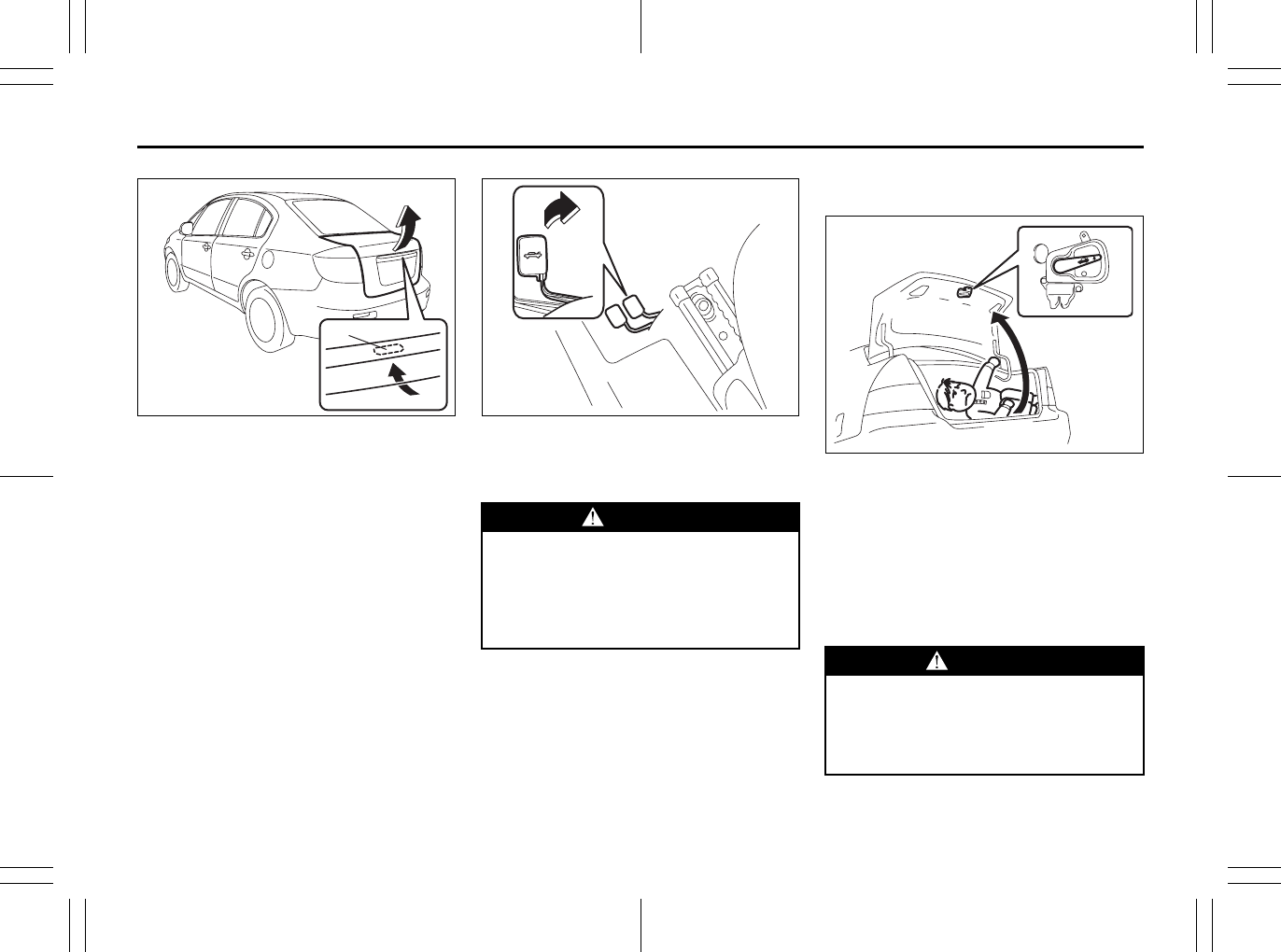
56KN010
If your vehicle is equipped with a trunk lid
unlatch switch (1), push and hold the trunk
lid unlatch switch (1) and lift the trunk lid to
open the trunk lid.
The trunk lid unlatch switch (1) operates
when the keyless start system remote con-
troller is within the switch’s operating
range.
The trunk lid unlatch switch (1) operates
only to open the trunk lid.
If you close the trunk lid with the keyless
start system remote controller left in the
trunk with all the doors locked, the trunk
will be automatically unlatched.
80JC005
You can unlock the lid by pulling the
release lever located to the outboard side
of the driver’s seat.
Internal Trunk Release
(SX4 SEDAN)
54G297
There is a release lever located inside the
trunk, on the rear part of the trunk lid. This
lever is for emergency use so that if a per-
son, such as a child, gets trapped in the
trunk compartment, he can exit the vehicle.
The lever glows in the dark, after a brief
exposure to ambient light, so it can be
found easily. It is operated by pushing it
down in the direction of the arrow.
(1)
EXAMPLE
WARNING
Always make sure that the trunk lid is
closed and latched securely. Other-
wise, it may open unexpectedly while
driving. Completely closing it also
helps keep exhaust gases from enter-
ing the car.
WARNING
To help avoid situations where some-
one might get trapped in the trunk,
keep your vehicle locked when unat-
tended, and do not allow anyone to
play in the trunk.
EXAMPLE
Door Locks: 3, 5, 8

2-6
BEFORE DRIVING
80J23-03E
Keyless Start System Remote
Controller/Keyless Entry
System Transmitter
66J111
Your vehicle is equipped with either a key-
less start system remote controller (Type
A) or a keyless entry system transmitter
(Type B). The remote controller has a key-
less entry system and a keyless start sys-
tem. The transmitter has only a keyless
entry system. For details, refer to the fol-
lowing explanations.
Keyless Start System Remote
Controller (Type A)
The remote controller enables the following
operations:
• You can lock or unlock the doors by
operating the LOCK/UNLOCK buttons
on the remote controller. Refer to the
explanation in this section.
• You can lock or unlock the doors by
pushing the request switch on the door
handle. For details, refer to the explana-
tion in this section.
• You can start the engine without using
an ignition key. For details, refer to “Igni-
tion Switch” in the “OPERATING YOUR
VEHICLE” section.
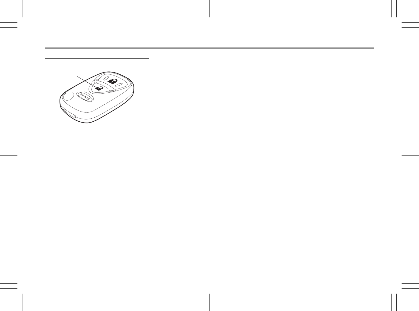
66J114
(1) “LOCK” button
(2) “UNLOCK” button
(3) “PANIC” button
“LOCK” button (1) / “UNLOCK” button
(2) function
You can lock or unlock all doors (including
the tailgate of SX4) simultaneously by
operating the remote controller near the
vehicle.
• To lock the doors, push the “LOCK” but-
ton (1).
• To unlock the driver’s door, push the
“UNLOCK” button (2) once.
• To unlock other doors, wait a second or
two, then push the “UNLOCK” button (2)
a second time. If you “double-click” too
fast, the doors will not unlock.
The turn signal lights will flash once when
the doors are locked.
When the doors are unlocked:
• The turn signal lights will flash twice.
• If the interior light switch is in the
“DOOR” position, the interior light will
turn on for about 15 seconds and then
fade out. If you push in the ignition
switch or insert the key during this time,
the light will start to fade out immedi-
ately.
Be sure the doors are locked after you
operate the “LOCK” button (1).
If no door is opened within about 30 sec-
onds after the “UNLOCK” button (2) is
operated, the doors will automatically lock
again.
Type A Type B
(1)
(2)
(3)
Door Locks: 3, 5, 8
2-7
BEFORE DRIVING
80J23-03E
NOTE:
• The maximum operating distance of the
remote controller is about 5 m (16 ft.),
but this can vary depending on the sur-
roundings, especially near other trans-
mitting devices such as radio towers or
CB (Citizen’s Band) radios.
• The door locks cannot be operated with
the remote controller if the ignition switch
is in a position other than “LOCK”, or the
ignition key is inserted in the ignition
switch, or if any door is open.
If any door is open, you cannot lock the
door by operating the remote controller,
however unlock the door.
• You cannot lock the door unless all of the
door are closed completely.
• If you lose one of the remote controllers,
ask your SUZUKI dealer as soon as pos-
sible for a replacement. Be sure to have
your dealer program the new remote
controller code in your vehicle’s memory
so that the old code is erased, or per-
form the programming procedure your-
self according to the instructions in this
section.
“PANIC” button (3) function
This function is to get the attention of oth-
ers.
Press the “PANIC” button (3) for more than
1 second. The headlights and taillights will
blink for about 30 seconds. Also, the horn
will sound intermittently for about 30 sec-
onds at the same time.
To cancel the “PANIC” mode, press any
button (PANIC, LOCK or UNLOCK) on the
remote controller. You can also insert the
key in the ignition switch and turn to the
“ON” position to cancel the “PANIC” mode.
NOTE:
The “PANIC” button function will not acti-
vate when the key is in the ignition switch.
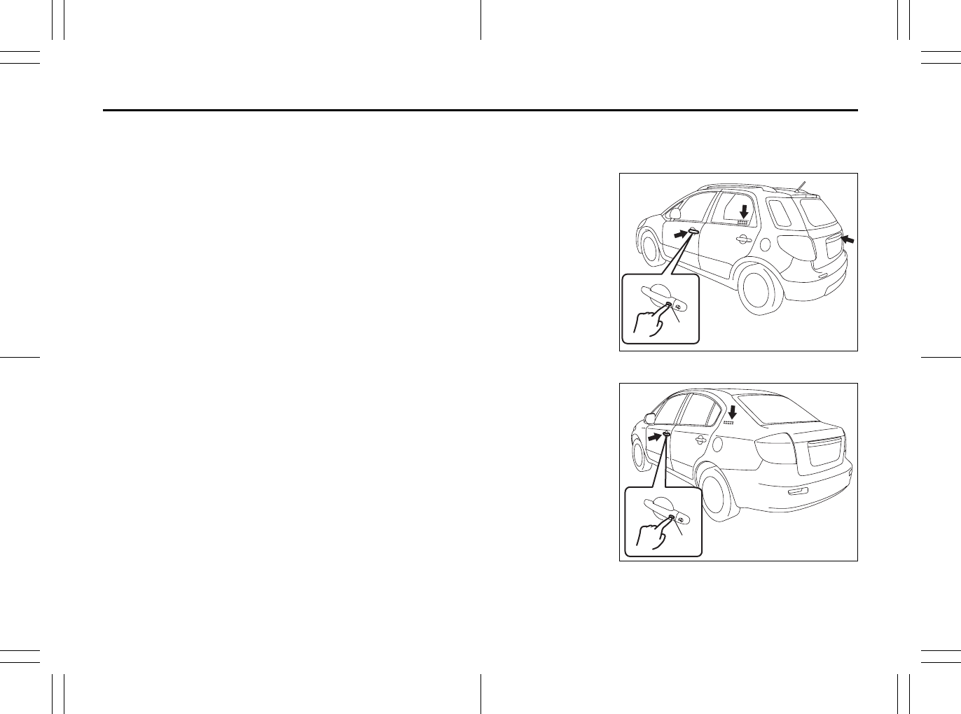
Keyless unlocking/locking using the
request switches
SX4
80JC054
SX4 SEDAN
56KN008
(1) EXAMPLE
(1) EXAMPLE
Door Locks: 3, 5, 8
2-8
BEFORE DRIVING
80J23-03E
When the remote controller is within the
operating range described in this section,
you can lock or unlock the doors by push-
ing the request switch (1) on the door han-
dle of the driver’s door, front passenger’s
door or tailgate of SX4.
To lock all doors when all doors are
unlocked:
• Push the request switch on one of the
door handles once.
The turn signal lights will flash once when
the doors are locked.
To unlock a door or all doors:
• Push the request switch on the door
handle once to unlock only one door.
• Push the request switch on the door
handle twice to unlock all doors.
When the doors are unlocked:
• The turn signal lights will flash twice.
• If the interior light switch is in the
“DOOR” position, the interior light will
turn on for about 15 seconds and then
fade out. If you push in the ignition
switch or insert the key during this time,
the light will start to fade out immedi-
ately.
Be sure the doors are locked after you
operate the request switch to lock the
doors.
NOTE:
• The door locks cannot be operated by
the request switch under the following
conditions:
– If any door is open or is not completely
closed.
– If the ignition switch is in a position
other than “LOCK”.
– If the ignition key is inserted in the igni-
tion switch.
• If no doors are opened within about 30
seconds after unlocking the doors by
pushing the request switch, the doors
will be locked again automatically.
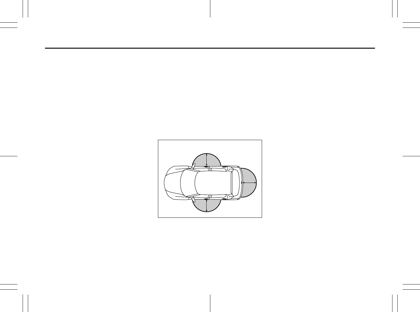
80JM020
(1) 80 cm (2 1/2 feet)
When the remote controller is within
approximately 80 cm (2 1/2 feet) from a
front door handle or the tailgate switch, you
can lock or unlock the doors by pushing
the request switch.
NOTE:
• If the remote controller is outside the
request switch operating range
described above, you will not be able to
operate the request switch.
• If the battery of the remote controller
runs down or there are strong radio
waves or noise, the request switch oper-
ating range may be reduced or the
remote controller may be inoperative.
• If the remote controller is too close to the
door glass, the request switches may not
operate.
• If a spare remote controller is in the vehi-
cle, the request switches may not oper-
ate normally.
• The remote controller will only operate a
request switch if it is within the switch’s
operating range. For example, if the
remote controller is within the operating
range of the driver’s door request switch
but not the front passenger’s door
request switch or the tailgate request
switch, the driver’s door switch can be
operated but the front passenger’s door
switch or tailgate switch cannot be oper-
ated.
(1)
(1)
(1)
EXAMPLE
Windows: 3, 8
2-9
BEFORE DRIVING
80J23-03E
NOTE:
The keyless start system may not function
correctly in certain environments or under
certain operating conditions such as the
following:
• When there are strong signals coming
from a television, power station or a cel-
lular phone.
• When the remote controller is in contact
with or covered by a metal object.
• When a radio wave type remote keyless
entry is used nearby.
• When the remote controller is placed
near an electronic device such as per-
sonal computer.
Some additional precautions you should
take and information you should be aware
of are:
• Make sure the ignition key is stowed in
the remote controller. If the remote con-
troller becomes unreliable, you will not
be able to lock or unlock the doors or
start the engine.
• Be sure that the driver always carries the
remote controller.
• If you lose one of the remote controllers,
ask your SUZUKI dealer as soon as pos-
sible for a replacement. Be sure to have
your dealer program the new remote
controller code in your vehicle’s memory
so that the old code is erased, or per-
form the programming procedure your-
self according to the instructions in this
section.
• You can use up to four remote controllers
and ignition keys for your vehicle. Ask
your SUZUKI dealer for details.
• The battery life of the remote controller
is about two years, but it can vary
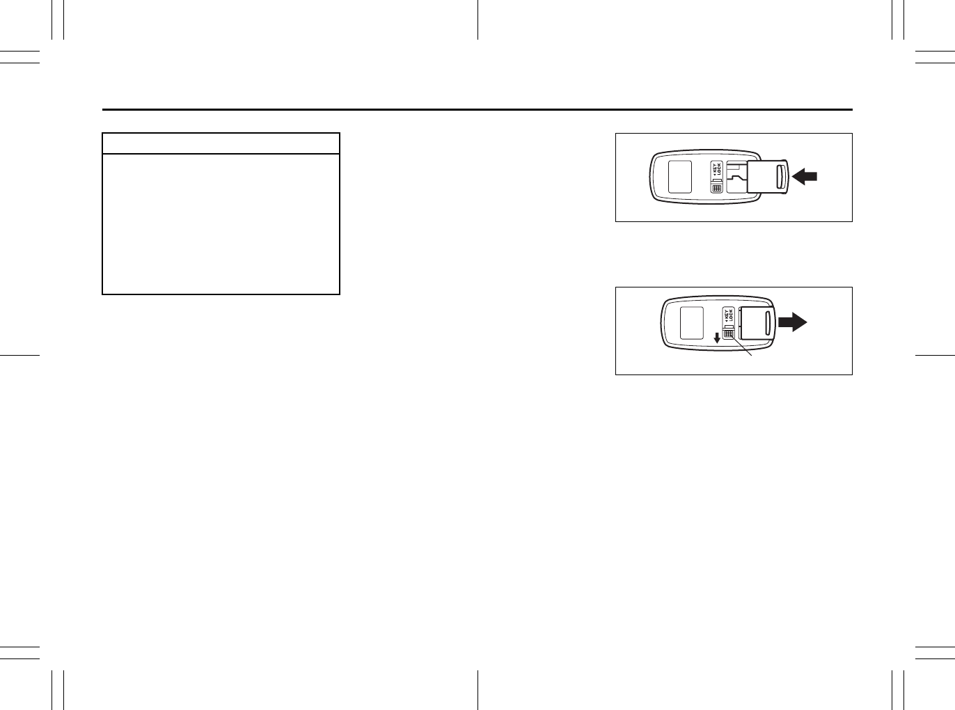
depending on usage conditions.
80JC026
To stow the ignition key into the remote
controller, push the key in the remote con-
troller until you hear a click.
80JC027
To remove the key from the remote control-
ler, push the button (A) in the direction of
the arrow and pull the key out from the
remote controller.
CAUTION
The remote controller is a sensitive
electronic instrument. To avoid dam-
aging the remote controller:
• Do not expose it to impacts, mois-
ture or high temperature such as by
leaving it on the dashboard under
direct sunlight.
• Keep the remote controller away
from magnetic objects such as a
television.
(A)
Windows: 3, 8
2-10
BEFORE DRIVING
80J23-03E
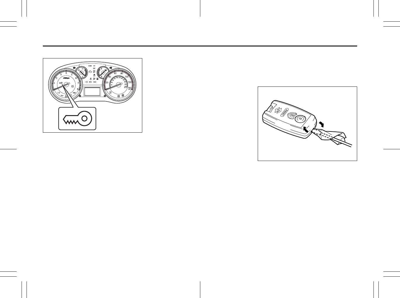
Reminder function
80J2016
If the remote controller is not in the vehicle
under the following conditions, a buzzer
sounds intermittently for about 2 seconds
and the keyless start system indicator light
on the instrument cluster blinks in red:
• When the vehicle speed is over 10 km/h
(6 mph).
• When one or more doors are opened
and all of the doors are later closed with
the ignition switch in a position other
than “LOCK”.
The red indicator light will turn off within
several seconds after the remote controller
is returned to an area of the vehicle other
than the rear luggage area.
If the remote controller is left in the vehicle
and you lock the driver’s door or front pas-
senger’s door as described below, the door
will be automatically unlocked.
• If you open the driver’s door and lock the
door by turning the lock knob forward or
pushing the power door locking switch,
the driver’s door will be automatically
unlocked.
• If you open a door other than the driver’s
door and lock the front passenger’s door
by turning the lock knob forward or push-
ing the power door locking switch, the
front passenger’s door will be automati-
cally unlocked.
For SX4 SEDAN, if you close the trunk lid
with the remote controller left in the trunk
with all the doors locked, the trunk will be
automatically unlatched.
NOTE:
• The reminder will not operate when the
remote controller is on the instrument
panel, in the glove box, in a storage
compartment, in the sun visor or on the
floor etc.
• Be sure that the driver always carries the
remote controller.
• Do not leave the remote controller in the
vehicle when leaving the vehicle.
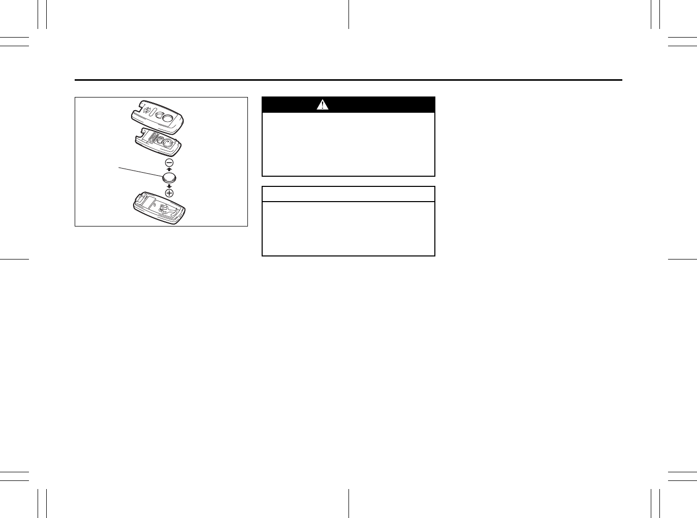
Replacement of the battery
If the remote controller becomes unreli-
able, replace the battery.
To replace the battery of the remote con-
troller:
66J016
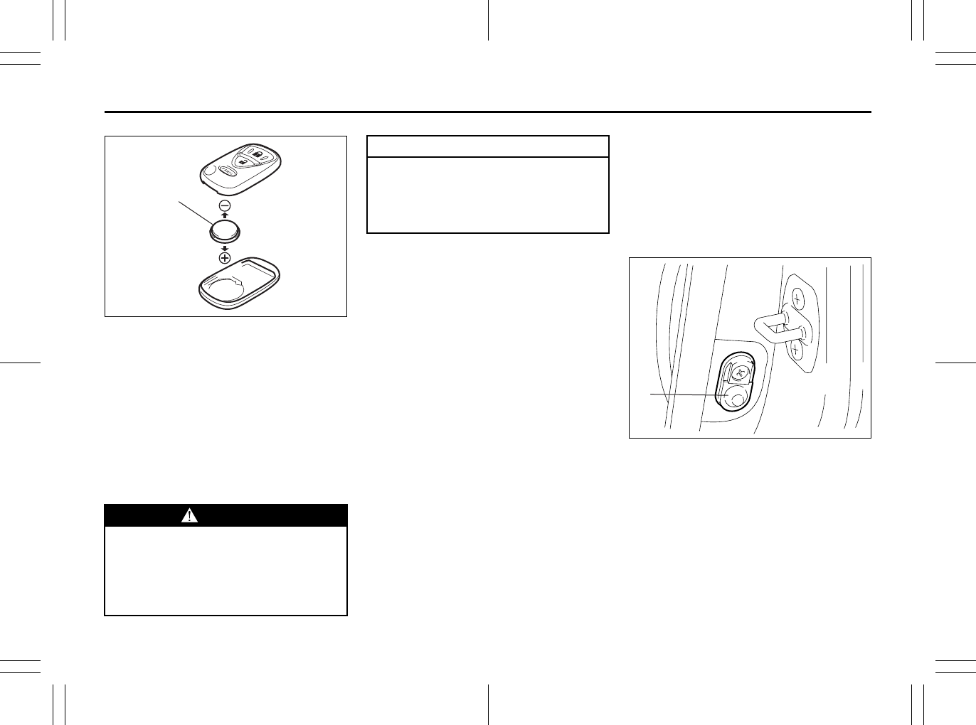
1) Insert a flat blade screwdriver covered
with a soft cloth in the slot of the remote
controller and pry it open.
EXAMPLE
Windows: 3, 8
Mirrors: 3, 8
2-11
BEFORE DRIVING
80J23-03E
80J2076
(1) Lithium disc type battery:
CR2032 or equivalent
2) Replace the battery (1) so its + terminal
faces the bottom of the case as shown
in the illustration.
3) Close the remote controller firmly.
4) Make sure the door locks can be oper-
ated with the remote controller.
5) Dispose of the used battery properly
according to applicable rules or regula-
tions. Do not dispose of lithium batter-
ies with ordinary household trash.
Programming/erasing the remote con-
troller code yourself
Your new vehicle was originally equipped
with two remote controllers.
If you have lost one of the remote control-
lers, you should change the remote con-
troller code in your vehicle’s memory as
soon as possible for security. If you pur-
chase additional remote controllers, the
new remote controllers need to be pro-
grammed into your vehicle’s memory. You
can perform this yourself by using the fol-
lowing procedure:
NOTE:
• You can program up to four remote con-
troller codes into your vehicle’s memory.
The four codes may be the same or dif-
ferent.
• If you try to program a fifth code, the four
remote controller codes that are pro-
grammed will be cleared automatically.
• If you program a new remote controller
code, all of the old remote controller
codes that are in your vehicle’s memory
will be erased automatically. When you
program a new remote controller, you
should reprogram any additional remote
controllers at the same time.
• To purchase new remote controllers, see
your SUZUKI dealer.
• Before you begin programming, have all
of your remote controllers available.
(1)
WARNING
Swallowing a lithium battery may
cause serious internal injury. Do not
allow anyone to swallow a lithium
battery. Keep lithium batteries away
from children and pets. If swallowed,
contact a physician immediately.
CAUTION
The transmitter/remote controller is a
sensitive electronic instrument. To
avoid damaging it, do not expose it to
dust or moisture or tamper with inter-
nal parts.
Mirrors: 3, 8
Seat Adjustment: 3
2-12
BEFORE DRIVING
80J23-03E
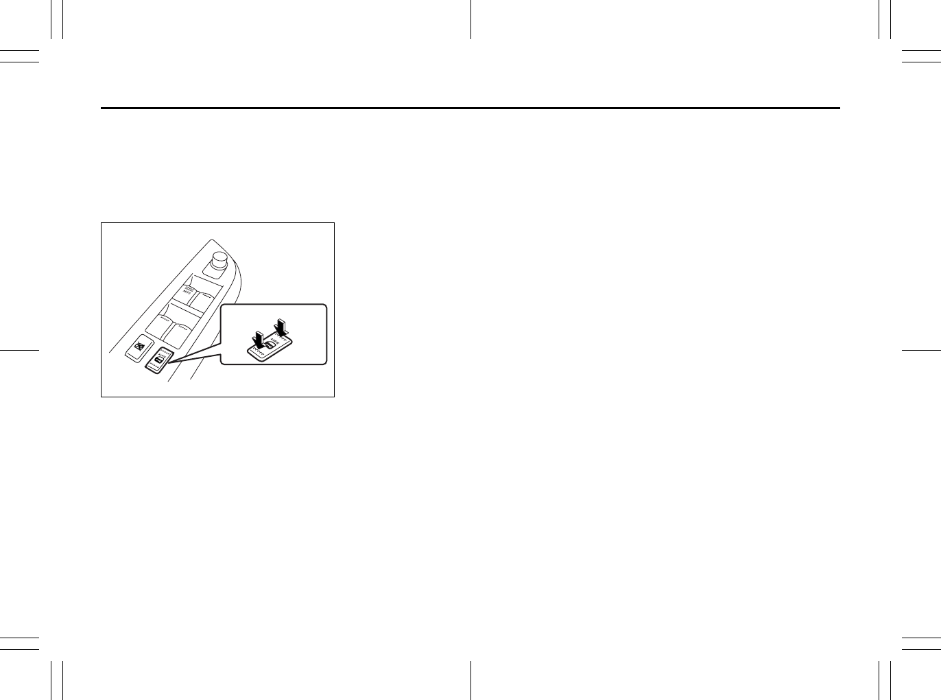
To program a new remote controller
1) Close all the doors of the vehicle.
2) Sit in the driver’s seat and confirm that
the driver’s door is unlocked.
3) Insert the key into the ignition switch.
4) Complete steps 1 through 6 described
below within 25 seconds after step 3).
80JC093
1. Push the power door locking switch
of the driver’s door to the lock posi-
tion and then push it to the unlock (2)
position.
2. Repeat step 1 two more times.
3. Push the power door locking switch
of the driver’s door to the lock (1)
position.
4. Remove the key from the ignition
switch and then insert it again.
5. Repeat step 4 three more times.
6. To start the engine, turn the ignition
switch to the “START” position.
Wait for 3 seconds.
7. Proceed to step 5) within 60 seconds
after the engine has started.
NOTE:
You cannot program the remote controller
if you don’t complete steps 1 through 6
within 25 seconds.
You cannot program the remote controller
if you do not proceed to step 5) within 60
seconds after the engine has started.
5) Turn the ignition switch to the “LOCK”
position.
A buzzer will sound twice and the door
lock switch will be activated from the
lock position to the unlock position
automatically.
6) Press the “LOCK”, “UNLOCK” or
“PANIC” button on the remote controller.
A buzzer will sound twice and the door
lock switch will be activated from the
lock position to the unlock position
automatically.
If you want to program an additional
remote controller, repeat the procedure
of step 6) using the additional remote
controller.
NOTE:
Complete step 6) within 30 seconds.
You can program up to four remote control-
lers.
7) To complete programming, remove the
key from the ignition switch or turn the
ignition switch to the “ON” position.
8) Make sure that the keyless start system
and keyless entry system operate prop-
erly by operating each remote control-
ler.
If you cannot operate the keyless start sys-
tem and/or keyless entry system, repeat
this programming procedure again.
If you still cannot operate the systems, see
your SUZUKI dealer.
UNLOCK
(2)
LOCK
(1)
Seat Adjustment: 3
2-13
BEFORE DRIVING
80J23-03E
To change the old remote controller
codes in your vehicle’s memory
If you have lost one of the remote control-
lers, you should change the remote con-
troller codes in your vehicle’s memory as
soon as possible for security.
To erase the remote controller code(s) in
your vehicle’s memory, you should pro-
gram the new remote controller code. The
old codes in your vehicle’s memory will be
erased automatically. If you have more
remote controller(s), you must program all
of the remote controller codes at the same
time. You cannot operate the keyless start
system and keyless entry system using
any remote controller that is not pro-
grammed at the same time.
For details on how to program, refer to the
programming procedure in this section.
When you complete programming, make
sure that the keyless start system and key-
less entry system operate properly by
operating each remote controller.
1. For USA
This device complies with Part 15 of the
FCC Rules. Operation is subject to the fol-
lowing two conditions:
1) This device may not cause harmful
interference, and
2) This device must accept any interfer-
ence received, including interference
that may cause undesired operation.
NOTE:
Changes or modifications not expressly
approved by the party responsible for com-
pliance could void the user’s authority to
operate the equipment.
2. For Canada
This device complies with Industry Canada
Standard RSS-210. Operation is subject to
the following two conditions:
1) This device may not cause interference,
and
2) This device must accept any interfer-
ence, including interference that may
cause undesired operation of the
device.
The term “IC:” before the certification/reg-
istration number only signifies that the
Industry Canada technical specifications
were met.
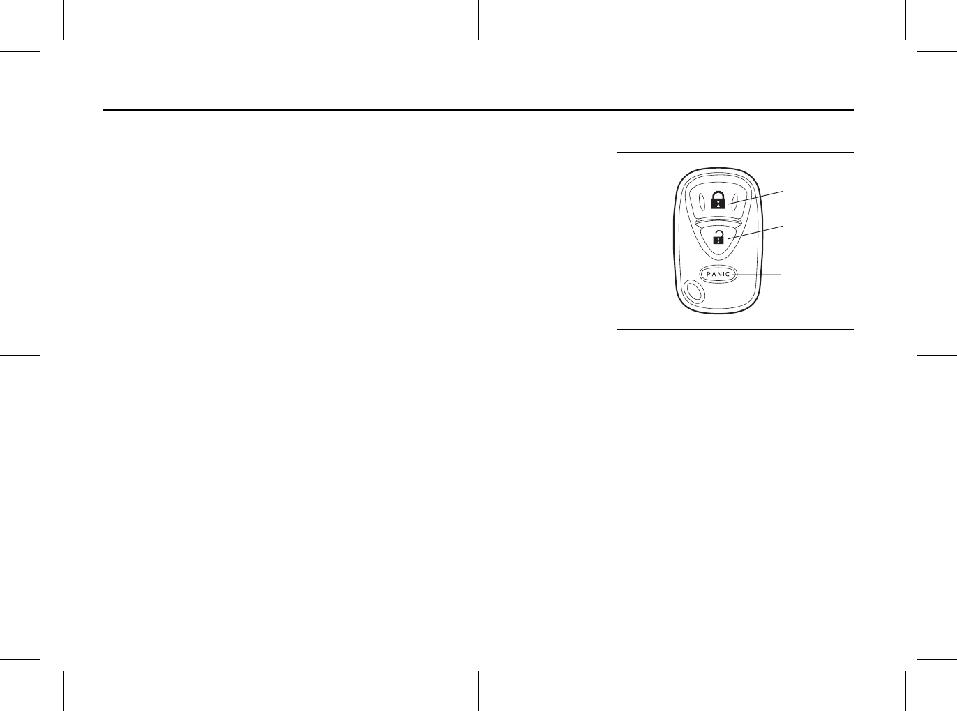
Keyless Entry System Transmitter
(Type B)
52D209
(1) “LOCK” button
(2) “UNLOCK” button
(3) “PANIC” button
“LOCK” button (1) / “UNLOCK” button
(2) function
You can lock or unlock all doors (including
the tailgate of SX4) simultaneously by
operating the transmitter near the vehicle.
• To lock the doors, push the “LOCK” but-
ton (1).
• To unlock the driver’s door, push the
“UNLOCK” button (2) once.
• To unlock other doors, wait a second or
two, then push the “UNLOCK” button (2)
a second time. If you “double-click” too
fast, the doors will not unlock.
(1)
(2)
(3)
Seat Adjustment: 3
Head Restraints: 3
2-14
BEFORE DRIVING
80J23-03E
The turn signal lights will flash once when
the doors are locked.
When the doors are unlocked:
• The turn signal lights will flash twice.
• If the interior light switch is in the
“DOOR” position, the interior light will
turn on for about 15 seconds and then
fade out. If you insert the key into the
ignition switch during this time, the light
will start to fade out immediately.
Be sure the doors are locked after you
operate the “LOCK” button (1).
If no door is opened within about 30 sec-
onds after the “UNLOCK” button (2) is
operated, the doors will automatically lock
again.
NOTE:
• The maximum operating distance of the
keyless entry system transmitter is about
5 m (16 ft.), but this can vary depending
on the surroundings, especially near
other transmitting devices such as radio
towers or CB (Citizen’s Band) radios.
• The door locks cannot be operated with
the transmitter, if the ignition key is
inserted in the ignition switch.
• If you lose one of the transmitters, ask
your SUZUKI dealer as soon as possible
for a replacement. Be sure to have your
dealer program the new transmitter code
in your vehicle’s memory so that the old
code is erased, or perform the program-
ming procedure yourself according to the
instructions in this section.
“PANIC” button (3) function
This function is to get the attention of oth-
ers.
Press the “PANIC” button (3) for more than
1 second. The headlights and taillights will
blink for about 30 seconds. Also, the horn
will sound intermittently for about 30 sec-
onds at the same time.
To cancel the “PANIC” mode, press any
button (PANIC, LOCK or UNLOCK) on the
transmitter. You can also insert the key in
the ignition switch and turn to the “ON”
position to cancel the “PANIC” mode.
NOTE:
The “PANIC” button function will not acti-
vate when the key is in the ignition switch.
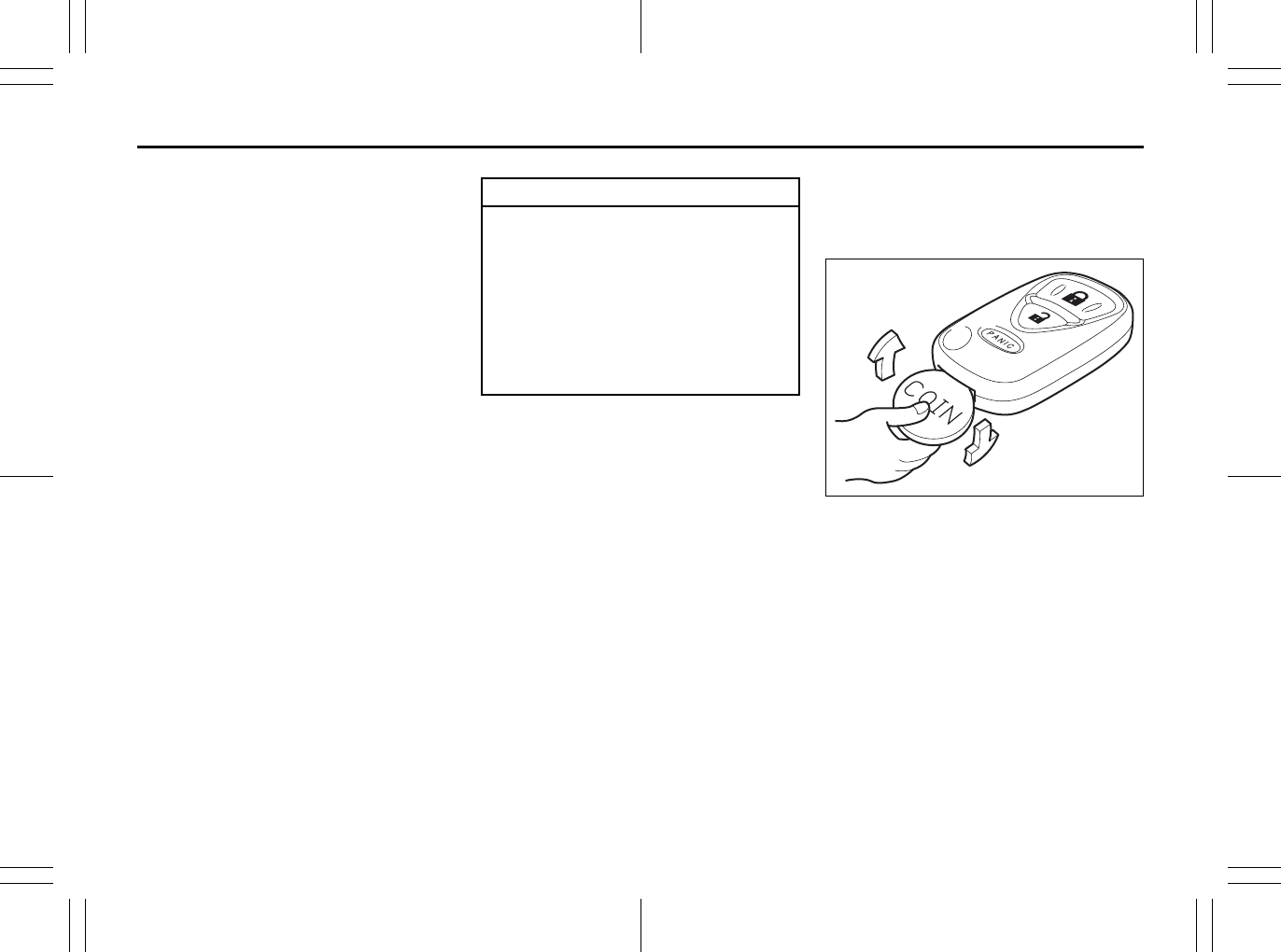
Replacement of the battery
If the transmitter becomes unreliable,
replace the battery.
To replace the battery of the transmitter:
52D210
1) Put the edge of a coin or a flat blade
screwdriver in the slot of the transmitter
and pry it open.
CAUTION
The transmitter is a sensitive elec-
tronic instrument. To avoid damaging
the transmitter:
• Do not expose it to impacts, mois-
ture or high temperature such as by
leaving it on the dashboard under
direct sunlight.
• Keep the transmitter away from
magnetic objects such as a televi-
sion.
Head Restraints: 3
Seat Belts and Child Restraint Systems: 3
2-15
BEFORE DRIVING
80J23-03E
80J2077
(1) Lithium disc type battery:
CR2025 or equivalent
2) Replace the battery (1) so its + terminal
faces the “+” mark of the transmitter.
3) Close the transmitter firmly.
4) Make sure the door locks can be oper-
ated with the transmitter.
5) Dispose of the used battery properly
according to applicable rules or regula-
tions. Do not dispose of lithium batter-
ies with ordinary household trash.
Programming/removing a transmitter
code yourself
Your new vehicle was originally equipped
with two transmitters.
If you have lost one of the transmitters, you
should change the transmitter code in your
vehicle’s memory as soon as possible for
security. If you purchase additional trans-
mitters, the new transmitters need to be
programmed into your vehicle’s memory.
You can perform this yourself by using the
following procedure:
NOTE:
• You can program up to three transmitter
codes into your vehicle’s memory. The
three codes may be the same or differ-
ent.
• If you try to program a fourth code, the
oldest code will be cleared automatically.
• To purchase new transmitters, see your
SUZUKI dealer.
• Before you begin programming, have all
of your transmitters available.
To program a new transmitter
1) Confirm that all the doors are closed
and the ignition key is out of the ignition
switch.
2) Open the driver’s door.
3) Insert the key, turn the ignition switch to
the “ON” position, turn the ignition
switch to the “LOCK” position and
remove the key within 10 seconds.
66J018
4) Push and release the driver’s door
switch (1) 3 times, insert the key, and
turn the ignition switch to the “ON” posi-
tion within 20 seconds.
5) Turn the ignition switch to the “LOCK”
position and remove the key within 10
seconds. All doors will lock/unlock to
confirm that this procedure has been
properly completed.
WARNING
Swallowing a lithium battery may
cause serious internal injury. Do not
allow anyone to swallow a lithium
battery. Keep lithium batteries away
from children and pets. If swallowed,
contact a physician immediately.
(1)
CAUTION
The transmitter/remote controller is a
sensitive electronic instrument. To
avoid damaging it, do not expose it to
dust or moisture or tamper with inter-
nal parts.
(1)
Seat Belts and Child Restraint Systems: 3
2-16
BEFORE DRIVING
80J23-03E
52D212
6) Press the “UNLOCK” button (2) on the
transmitter one time within 20 seconds
(after step 5). All the doors will lock/
unlock to confirm that the procedure
has been completed and the transmitter
has been programmed.
7) If you want to program an additional
transmitter, repeat the procedure from
step 1) through step 6).
8) Make sure that the keyless entry sys-
tem operates properly by operating
each transmitter.
To change the old transmitter codes in
your vehicle’s memory
If you have lost one of the transmitters, you
should change the transmitter codes in
your vehicle’s memory as soon as possible
for security.
To remove one of the transmitter codes
from your vehicle’s memory, first replace all
three of the transmitter codes in your vehi-
cle’s memory, then program additional
transmitters as follows:
1) Program one of your transmitters three
times, by repeating the programming
procedure shown in this section. This
will replace all the old transmitter codes
in the vehicle’s memory with the code
for the transmitter you are using.
2) If you want to program up to two addi-
tional transmitters, repeat the program-
ming procedure shown in this section.
3) Make sure that the keyless entry sys-
tem operates properly by operating
each transmitter.
1. For USA
This device complies with Part 15 of the
FCC Rules. Operation is subject to the fol-
lowing two conditions:
1) This device may not cause harmful
interference, and
2) This device must accept any interfer-
ence received, including interference
that may cause undesired operation.
NOTE:
Changes or modifications not expressly
approved by the party responsible for com-
pliance could void the user’s authority to
operate the equipment.
2. For Canada
This device complies with Industry Canada
Standard RSS-210. Operation is subject to
the following two conditions:
1) This device may not cause interference,
and
2) This device must accept any interfer-
ence, including interference that may
cause undesired operation of the
device.
The term “IC:” before the certification/reg-
istration number only signifies that the
Industry Canada technical specifications
were met.
(2)
Seat Belts and Child Restraint Systems: 3
2-17
BEFORE DRIVING
80J23-03E
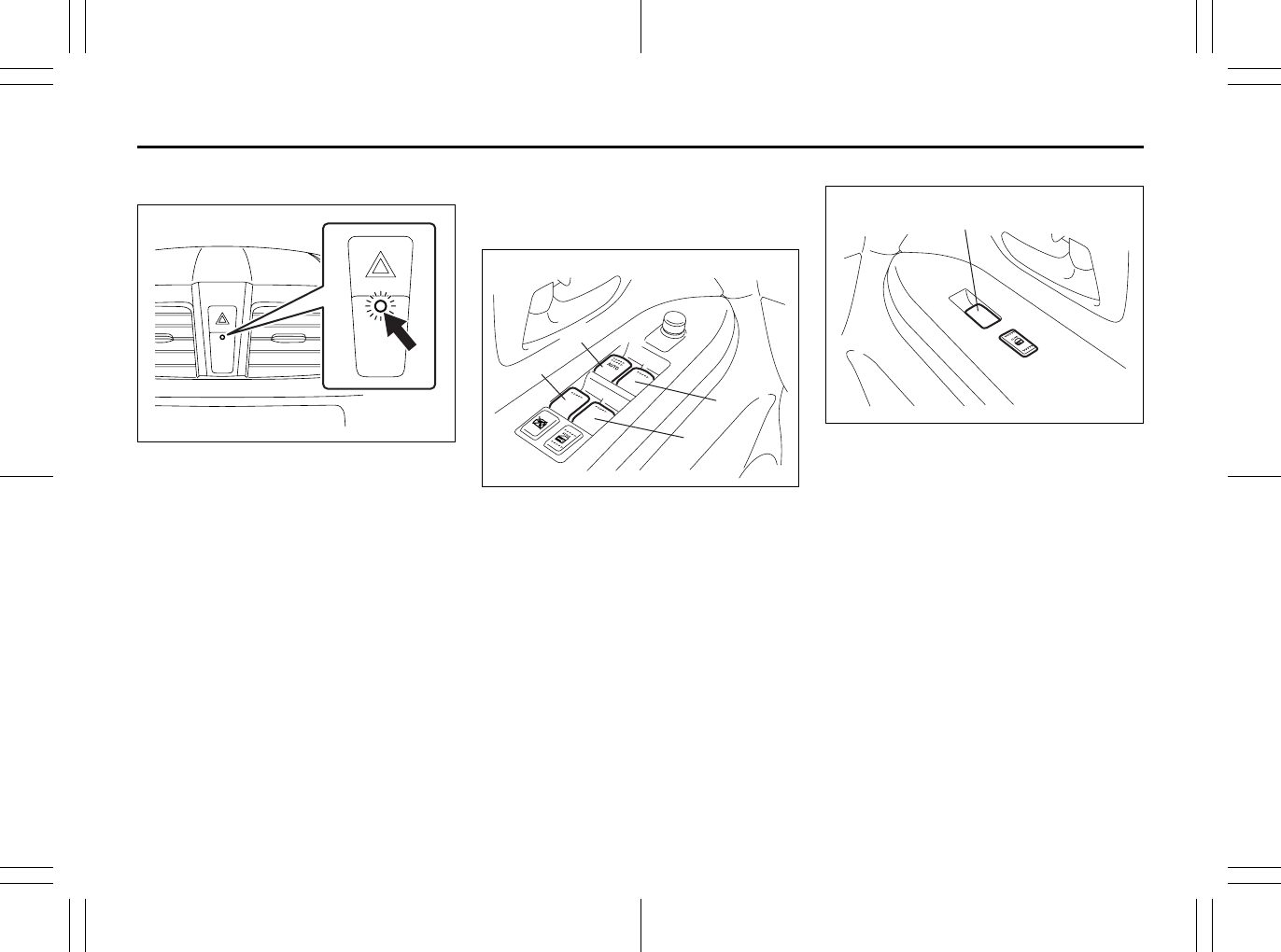
Theft Deterrent Light
80JM022
This light will blink with the ignition switch
in the “OFF” or “ACC” position. The blink-
ing light is intended to deter theft by lead-
ing others to believe that the vehicle is
equipped with a security system.
Windows
Power Window Controls
Driver’s side
80JC095
The power windows can only be operated
when the ignition switch is in the “ON” posi-
tion.
The driver’s door has switches (1), (2), (4),
(5), to operate the driver’s window, the
front passenger’s window, the rear left win-
dow and the rear right window, respec-
tively.
Passenger’s door
80JC096
The passenger’s door has a switch (3) to
operate the passenger’s window.
(1)
(2)
(4)
(5)
EXAMPLE
(3)
EXAMPLE
Seat Belts and Child Restraint Systems: 3
2-18
BEFORE DRIVING
80J23-03E
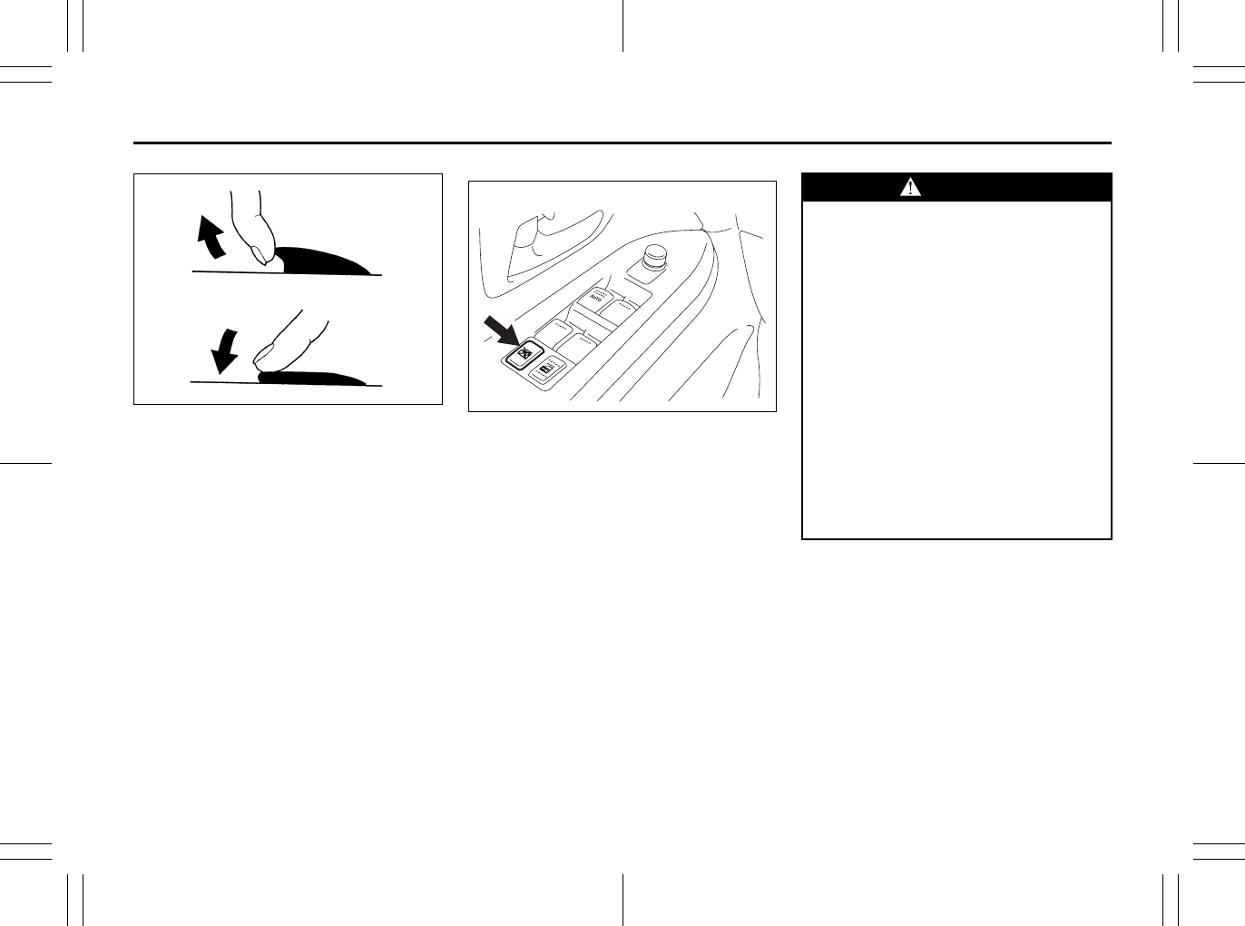
81A009
To open a window, push the top part of the
switch and to close a window lift up the top
part of the switch.
The driver’s window has an auto-down fea-
ture for added convenience (at toll booths
or drive-through restaurants, for example).
This means you can open the window with-
out holding the window switch in the
“Down” position. Press the driver’s window
switch completely down and release it. To
stop the window before it reaches the bot-
tom, pull the switch up briefly.
Lock switch
80JC097
The driver’s door also has a lock switch for
the passenger’s window(s). When you
push in the lock switch, the passenger’s
window(s) cannot be raised or lowered by
operating any of the switches (2), (3), (4) or
(5). To restore normal operation, release
the lock switch by pushing the switch
again.
CLOSE
OPEN
EXAMPLE WARNING
• You should always lock the passen-
ger’s window operation when there
are children in the vehicle. Children
can be seriously injured if they get
part of their body caught by the
window during operation.
• To avoid injuring an occupant by
window entrapment, be sure no
part of the occupant’s body such
as hands or head is in the path of
the electric windows when closing
them.
• Always remove the ignition key
when leaving the vehicle even if
only for a short time. Also do not
leave children alone in a parked
vehicle. Unattended children could
use the electric window switches
and get trapped by the window.
Seat Belts and Child Restraint Systems: 3
2-19
BEFORE DRIVING
80J23-03E
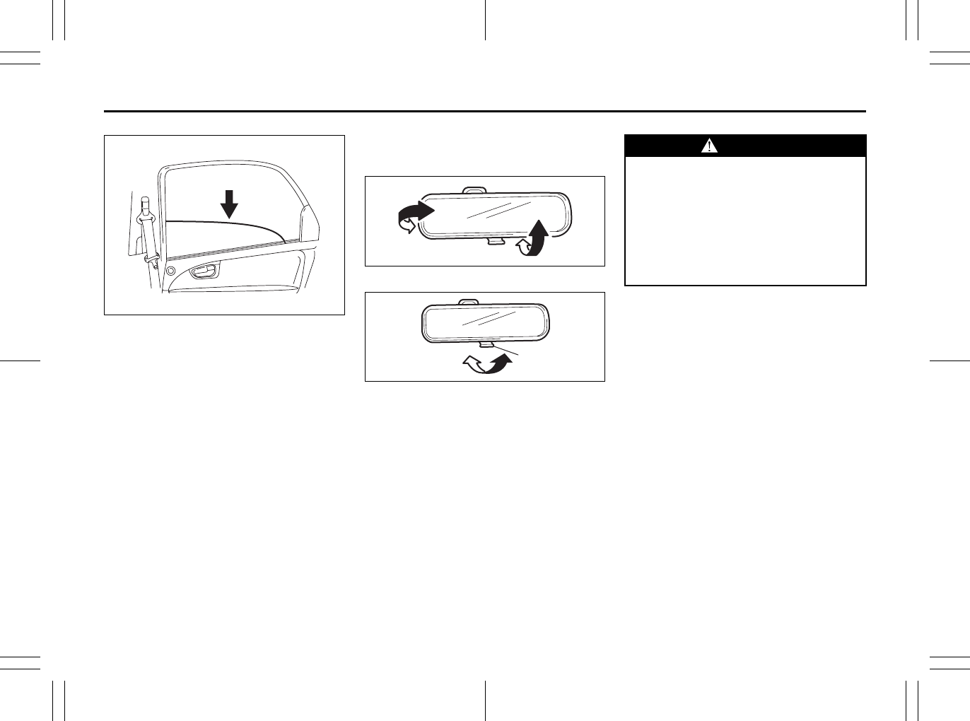
52LM012
NOTE:
The rear door windows are not designed to
open fully. They can be opened about 2/3
of the way down.
NOTE:
If you drive with one of the rear windows
open, you may hear a loud sound caused
by air vibration. To reduce the sound, open
the driver’s or front passenger’s window, or
narrow the rear window opening.
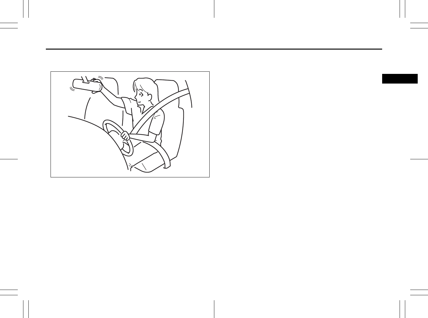
Mirrors
Inside Rearview Mirror
65D410
65D409
You can adjust the inside rearview mirror
by hand so as to see the rear of your vehi-
cle in the mirror. To adjust the mirror, set
the selector tab (1) to the day position,
then move the mirror up, down or sideways
by hand to obtain the best view.
When driving at night, you can move the
selector tab to the night position to reduce
glare from the headlights of vehicles
behind you.
EXAMPLE
(1)
Day driving Night driving
WARNING
• Always adjust the mirror with the
selector set to the day position.
• Only use the night position if it is
necessary to reduce glare from the
headlights of vehicles behind you.
Be aware that in this position you
may not be able to see some
objects that could be seen in the
day position.
Seat Belts and Child Restraint Systems: 3
2-20
BEFORE DRIVING
80J23-03E
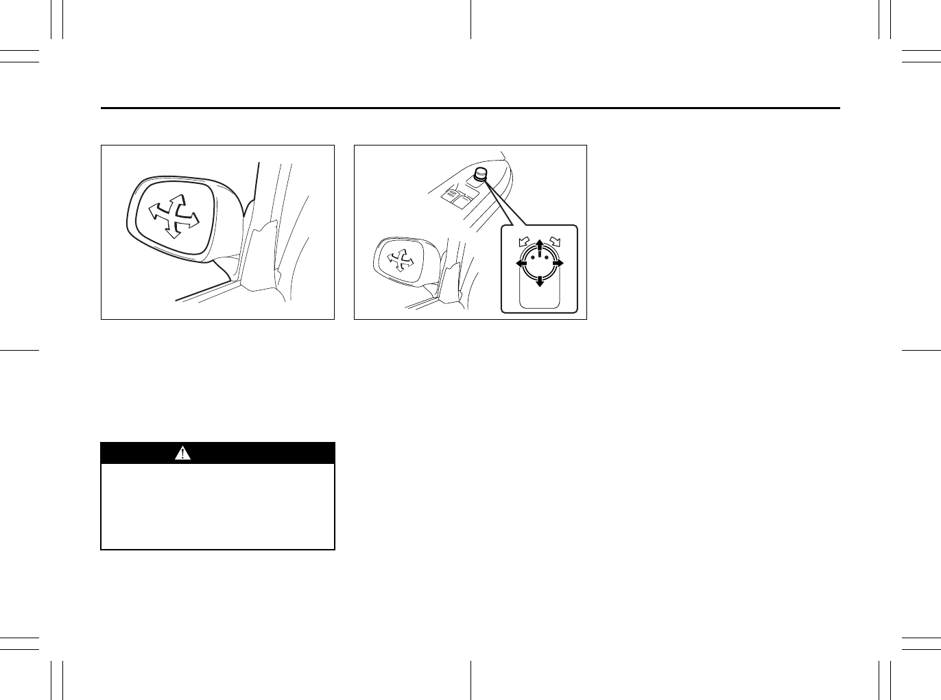
Outside Rearview Mirrors
79J033
Adjust the outside rearview mirrors so you
can just see the side of your vehicle in the
mirrors.
The passenger’s side mirror is a convex
(curved surface) mirror. Objects seen in
this mirror will look smaller and appear far-
ther away than when seen in a flat mirror.
Power Mirror Control (if equipped)
79J034
The switch to control the power rearview
mirrors is located on the driver’s door
panel. You can adjust the mirrors when the
ignition switch is in the “ACC” or “ON” posi-
tion. To adjust the mirrors:
1) Move the selector switch to the left or
right to select the mirror you wish to
adjust.
2) Press the outer part of the switch that
corresponds to the direction you wish to
move the mirror.
3) Return the selector switch to the center
position to help prevent unintended
adjustment.
NOTE:
If your vehicle is equipped with the heated
outside rearview mirrors, refer to “Heated
Rear Window and Heated Outside Rear-
view Mirrors (if equipped) Switch” in this
section.
WARNING
Be careful when judging the size or
distance of a vehicle or other object
seen in the side convex mirror. Be
aware that objects look smaller and
appear farther away than when seen
in a flat mirror.
(2)
(4)
(3)
(1) (1)
(3)(2)
(4)
Seat Belts and Child Restraint Systems: 3
2-21
BEFORE DRIVING
80J23-03E
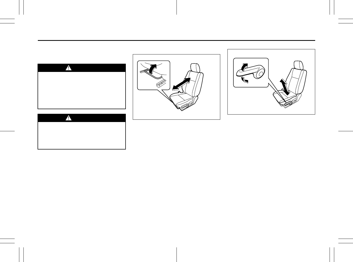
Front Seats
Seat Adjustment
Adjusting Seat Position
80JM023
The adjustment lever for each front seat is
located under the front of the seat. To
adjust the seat position, pull up on the
adjustment lever and slide the seat forward
or rearward. After adjustment, try to move
the seat forward and rearward to ensure
that it is securely latched.
80JM024
If the driver’s seat is equipped with a seat
height adjuster lever on the outboard side
of the seat, raise or lower the seat by pull-
ing up or down the adjuster lever.
WARNING
Never attempt to adjust the driver’s
seat or seatback while driving. The
seat or seatback could move unex-
pectedly, causing loss of control.
Make sure that the driver’s seat and
seatback are properly adjusted
before you start driving.
WARNING
To avoid excessive seat belt slack,
which reduces the effectiveness of
the seat belts as a safety device,
make sure that the seats are adjusted
before the seat belts are fastened.
Seat Belts and Child Restraint Systems: 3
2-22
BEFORE DRIVING
80J23-03E
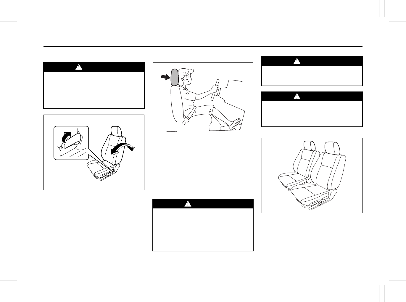
Adjusting Seatbacks
80JM025
To adjust the seatback angle of front seats,
pull up the lever on the outboard side of
the seat, move the seatback to the desired
position, and release the lever to lock the
seatback in place. After adjustment, try
moving the seatback to make sure it is
securely locked.
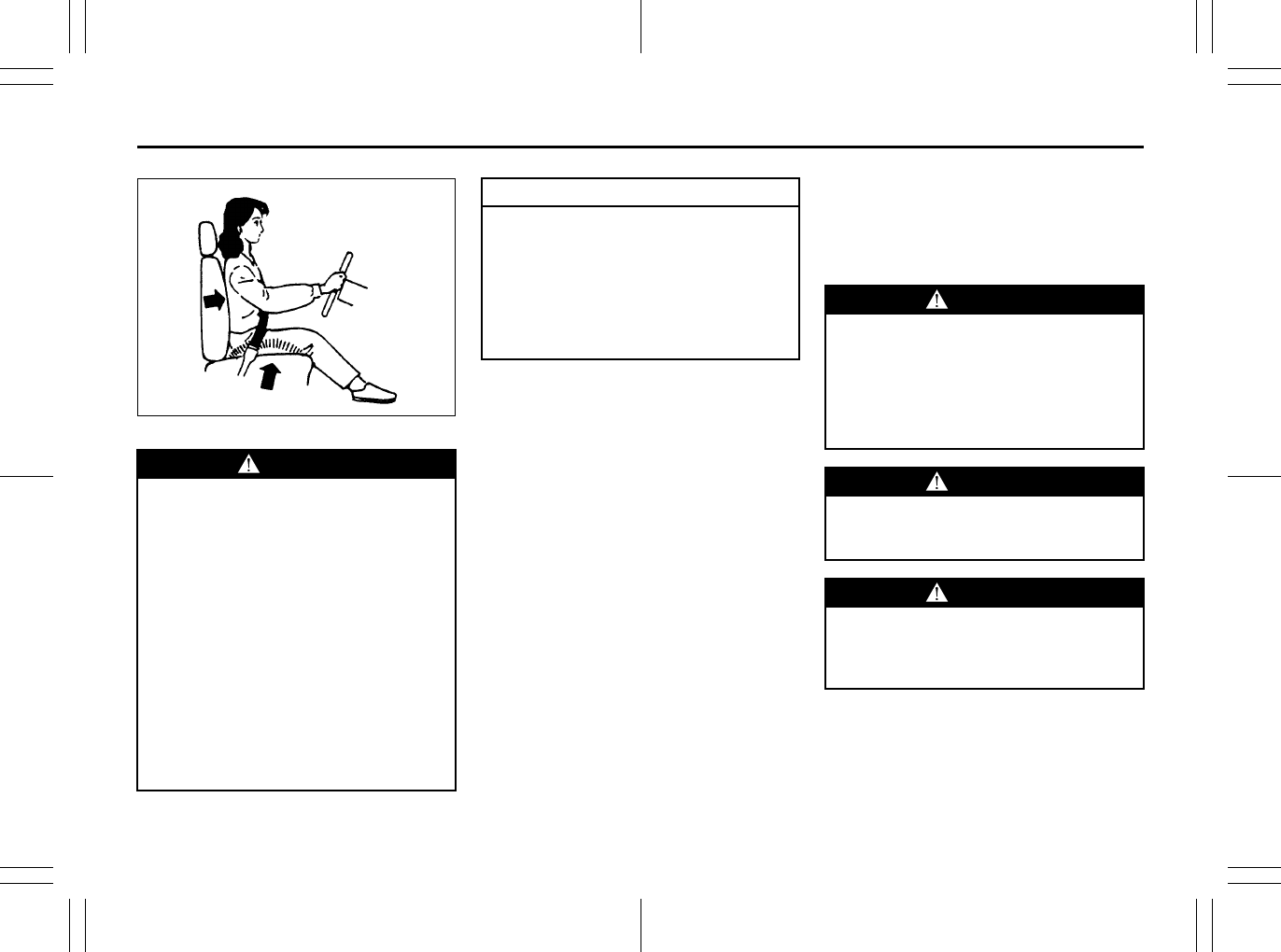
Head Restraints
80J001
Head restraints are designed to help
reduce the risk of neck injuries in case of
an accident.
Adjust the head restraint to the position
which places the center of the head
restraint closest to the top of your ears. If
this is not possible for very tall passengers,
adjust the head restraint as high as possi-
ble.
Front
80J2060
Each front seats is equipped with a head
restraint.
WARNING
All seatbacks should always be in an
upright position when driving, or seat
belt effectiveness may be reduced.
Seat belts are designed to offer maxi-
mum protection when seatbacks are
in the upright position.
WARNING
All occupants, including the driver,
should not operate a vehicle or sit in
a vehicle’s seat until the head
restraints are placed in their proper
positions in order to minimize the
risk of severe injury in the event of a
crash.
WARNING
All head restraints must be rein-
stalled to properly protect vehicle
occupants.
WARNING
• Never drive the vehicle with the
head restraints removed.
• Do not attempt to adjust the head
restraint while driving.
Seat Belts and Child Restraint Systems: 3
2-23
BEFORE DRIVING
80J23-03E
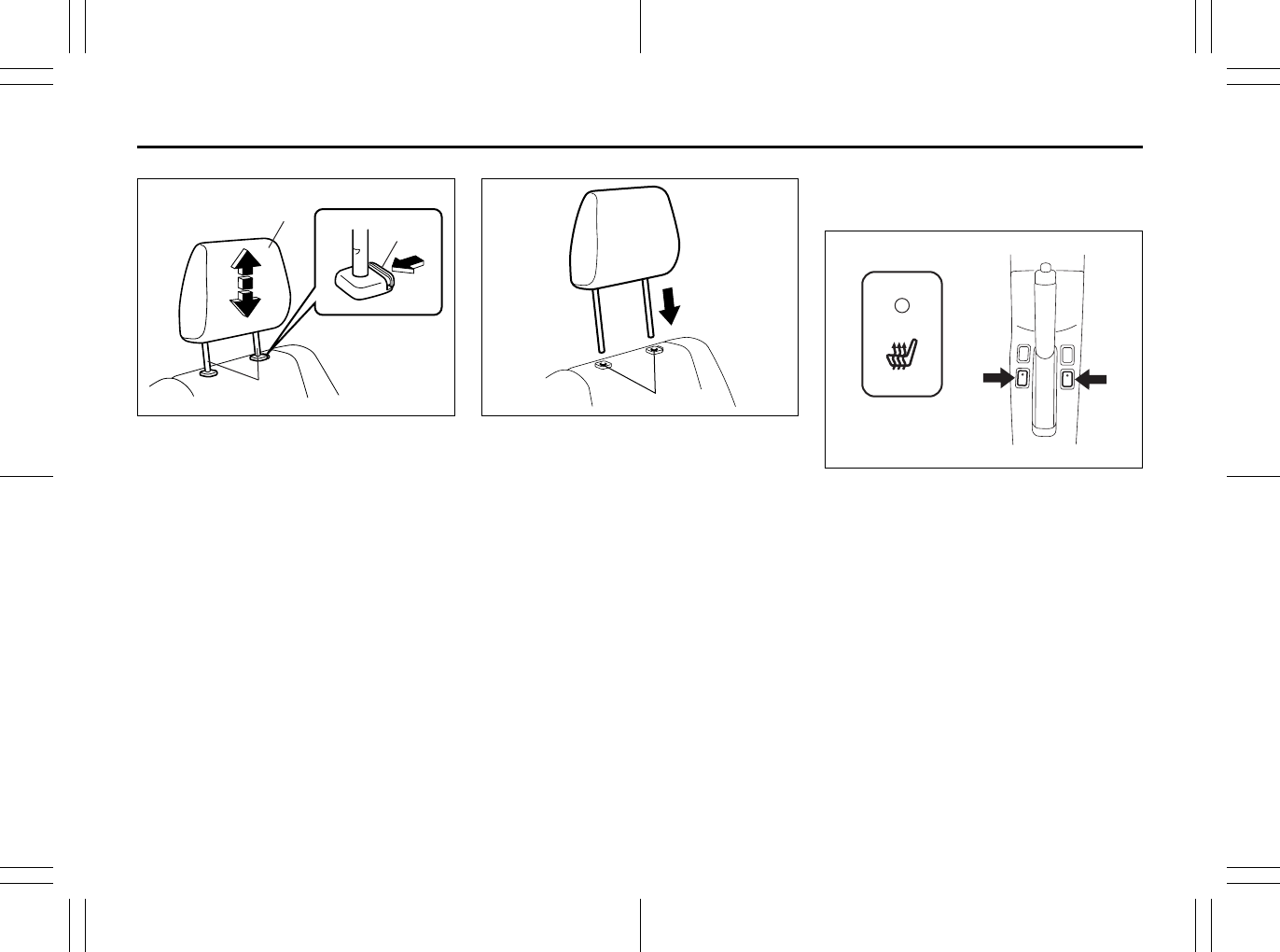
80J2012
(1) head restraint
(2) bars
(3) release knob
To raise the head restraint, pull upward on
the restraint until it clicks. To lower the
restraint, push down on the restraint while
holding in the release knob (3). If a head
restraint must be removed (for cleaning,
replacement, etc.), push in the release
knob and pull the head restraint all the way
out.
NOTE:
It may be necessary to recline the seat-
back to provide enough overhead clear-
ance to remove the head restraint.
80J2013
To reinstall the head restraint, insert the
head restraint bars into the holes (4) and
push the head restraint down.
Front Seat Heater
(if equipped)
79J076
With the ignition switch in the “ON” posi-
tion, push in one or both of the seat heater
switches to warm the corresponding
seat(s). The indicator light below the switch
will also come on. To turn off the seat
heater, push in the switch again. The indi-
cator light below the switch will go off.
(3)
(1)
(2)
EXAMPLE
(4)
Seat Belts and Child Restraint Systems: 3
2-24
BEFORE DRIVING
80J23-03E
86G064
Rear Seats
Head Restraints
Head restraints are designed to help
reduce the risk of neck injuries in the case
of an accident.
WARNING
Improperly using the seat heater can
be hazardous. An occupant can suf-
fer burns even if the heating tempera-
ture is fairly low, if the occupant is
wearing thin pants, a thin skirt or
shorts and leaves the heater on for
long periods.
Avoid using the seat heater for these
occupants:
• People who have reduced feeling in
their legs, including the elderly or
those with certain disabilities.
• Small children, or anyone with sen-
sitive skin.
• People who are asleep or under the
influence of alcohol or other drugs
which make them tired.
CAUTION
To avoid damaging the heater ele-
ment:
• Do not subject the front seats to
heavy impacts, such as children
jumping on them.
• Do not cover the seat with any
insulating materials such as blan-
kets or cushions.
WARNING
All occupants, including the driver,
should not operate a vehicle or sit in
a vehicle’s seat until the head
restraints are placed in their proper
positions in order to minimize the
risk of severe injury in the event of a
crash.
WARNING
All head restraints must be rein-
stalled to properly protect vehicle
occupants.
WARNING
• Never drive the vehicle with the
head restraints removed.
• Do not attempt to adjust the head
restraint while driving.
Seat Belts and Child Restraint Systems: 3
2-25
BEFORE DRIVING
80J23-03E
NOTE:
It may be necessary to fold forward the
seatback to provide enough overhead
clearance to remove the head restraint.
Adjust the head restraint to the position
which places the center of the head
restraint closest to the top of your ears. If
this is not possible for very tall passengers,
adjust the head restraint as high as possi-
ble.
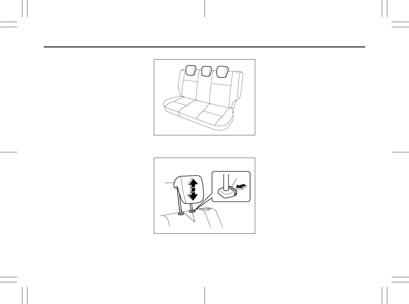
Rear
80J2061
Your vehicle is equipped with three head
restraints on the rear seat.
80J2005
(1) head restraint
(2) bars
(3) release knob
To raise the rear head restraint, pull
upward on the restraint until it clicks. To
lower the restraint, push down on the
restraint while holding in the release knob
(3). If a head restraint must be removed
(for cleaning, replacement, etc.), push in
the release knob and pull the head
restraint all the way out.
When installing a child restraint system,
raise the head restraint to the most upper
position.
For SX4 SEDAN, if the distance between
the child restraint system and the anchor
bracket is too close to properly tighten the
child restraint top strap, lower the head
restraint to the lowest position and connect
the top strap to the anchor bracket by
passing it over the top of the head
restraint.
EXAMPLE
(1)
(3)
(2)
EXAMPLE
Seat Belts and Child Restraint Systems: 3
2-26
BEFORE DRIVING
80J23-03E
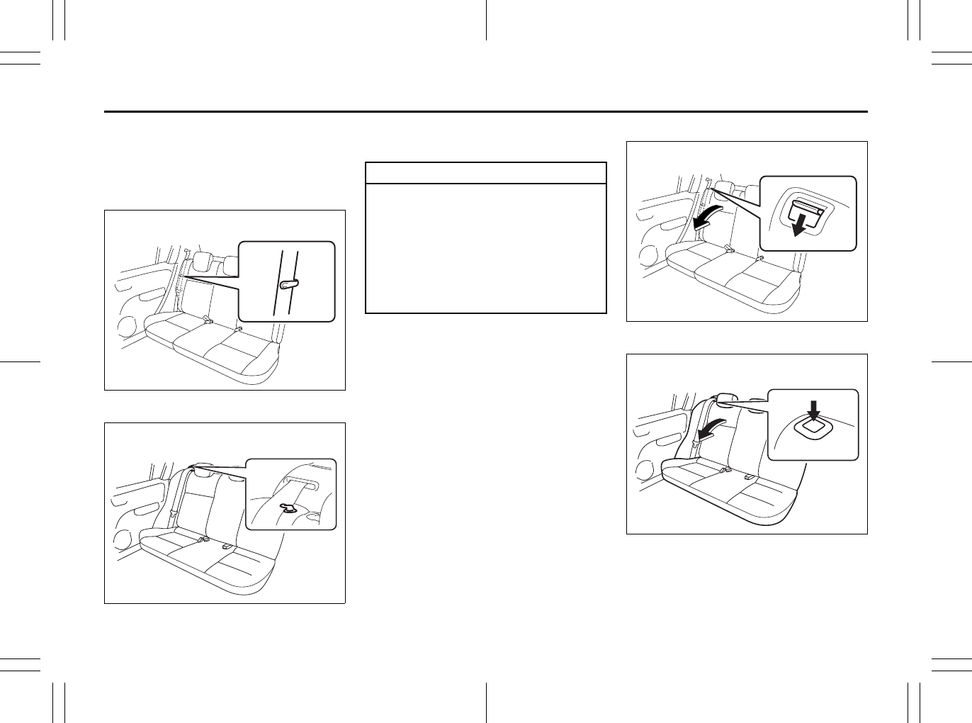
Folding Rear Seats
The rear seats of your vehicle can be folded
forward to provide additional cargo space.
To fold the rear seats forward:
SX4
80JM026
SX4 SEDAN
80JC086
1) Hook the webbing of the outboard lap-
shoulder belts in the belt hangers.
2) Lower the adjustable head restraint
fully.
SX4
80JM027
SX4 SEDAN
80JC087
EXAMPLE
EXAMPLE
CAUTION
• When you move a seatback, make
sure the belt webbing is hooked in
the seat belt hangers so the seat
belts are not caught by the seat-
back, seat hinge, or seat latch. This
helps prevent damage to the belt
system.
• Make sure the belt webbing is not
twisted.
EXAMPLE
EXAMPLE
Seat Belts and Child Restraint Systems: 3

2-27
BEFORE DRIVING
80J23-03E
3) For SX4, pull the release lever on the
top of each split seat, and fold the seat-
backs forward.
For SX4 SEDAN, push the release but-
ton on the top of each split seat, and
fold the seatbacks forward.
To return the seat to the normal position,
follow the procedure below.
SX4
80J1219
SX4 SEDAN
80J1022
Raise the seatback until it locks into place.
After returning the seat, try moving the
seatback to make sure they are securely
latched.
CAUTION
After folding the rear seatback for-
ward, do not allow any foreign mate-
rial to enter the lock opening. This
may cause damage to the inside of
the lock and prevent the seatback
from being locked securely.
WARNING
Luggage or other cargo should be
stowed in the luggage compartment
with the rear seat in an upright posi-
tion, whenever possible. If you need
to carry cargo in the passenger com-
partment with the rear seat back
folded forward, be sure to secure the
cargo or it may be thrown about,
causing injury. Never pile cargo
higher than the seatbacks.
WARNING
When returning the rear seatback to
the normal position, be careful that
your finger is not caught between the
lock and the striker.
CAUTION
When returning the rear seatback to
the normal position, make sure that
there is nothing around the striker.
Any foreign materials prevent the
seatback from being locked securely.
UNLOCK
Red
LOCK
EXAMPLE
UNLOCK
Red
LOCK
EXAMPLE
Seat Belts and Child Restraint Systems: 3
2-28
BEFORE DRIVING
80J23-03E
Seat Belts and Child Restraint
Systems
65D231
65D606
WARNING
Do not put your hand into the rear
seatback lock opening, or your finger
may get caught and be injured.
CAUTION
After securing the rear seatback,
make sure that it is locked securely. If
it is not, red will appear in the release
lever (SX4) or around the release but-
ton (SX4 SEDAN).
CAUTION
• When returning the rear seatback
to the normal position, do not allow
any foreign material to enter the
lock opening. This may prevent the
seatback from being locked
securely.
• When returning the rear seatback
to the normal position, be sure to
handle it carefully by hand to avoid
any damage to the lock itself. Do
not push it by using some material
or by applying excessive force.
• As the lock is designed exclusively
for securing the rear seatback, do
not use it for any other purpose.
Incorrect use of it may cause dam-
age to the inside of the lock and
prevent the seatback from being
locked securely.
WARNING
An air bag supplements, or adds to,
the frontal crash protection offered
by seat belts. The driver and all pas-
sengers must be properly restrained
by wearing seat belts at all times,
whether or not an air bag is mounted
at their seating position, to minimize
the risk of severe injury or death in
the event of a crash.
WARNING
• Never allow persons to ride in the
cargo area of a vehicle. In the event
of an accident, there is a much
greater risk of injury for persons
who are not riding in a seat with
their seat belt securely fastened.
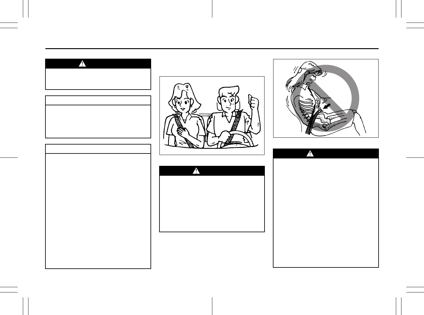
• Seat belts should always be
adjusted as follows:
– the lap portion of the belt should
be worn low across the pelvis,
not across the waist.
– the shoulder straps should be
worn on the outside shoulder
only, and never under the arm.
– the shoulder straps should be
away from your face and neck,
but not falling off your shoulder.
(Continued)
Above the pelvis
Seat Belts and Child Restraint Systems: 3
2-29
BEFORE DRIVING
80J23-03E
65D201 65D199
WARNING
(Continued)
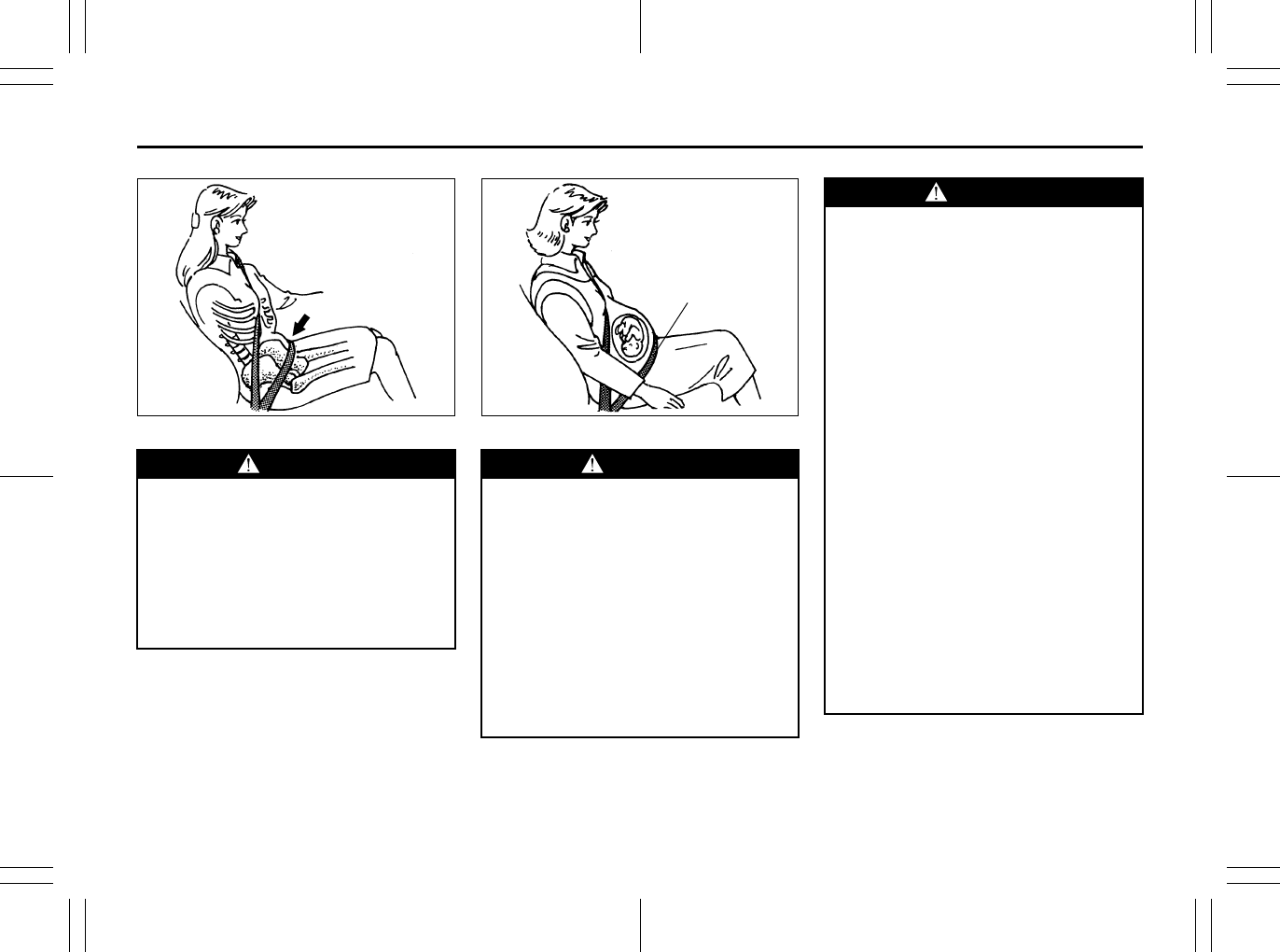
• Seat belts should never be worn
with the straps twisted and should
be adjusted as tightly as is com-
fortable to provide the protection
for which they have been designed.
A slack belt will provide less pro-
tection than one which is snug.
(Continued)
Across the pelvis
WARNING
(Continued)
• Pregnant women should use seat
belts, although specific recommen-
dations about driving should be
made by the woman’s medical advi-
sor. Remember that the lap portion
of the belt should be worn as low
as possible across the hips, as
shown in the diagram.
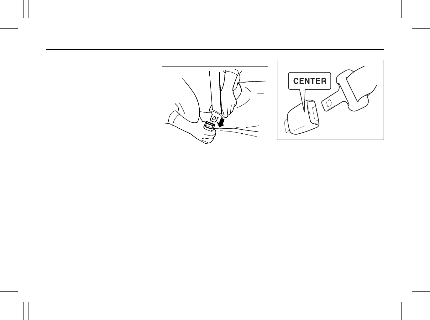
• Make sure that each seat belt
buckle is inserted into the proper
buckle catch. It is possible to cross
the buckles in the rear seat.
(Continued)
as low as possible
across the hips
WARNING
(Continued)
• Do not wear your seat belt over
hard or breakable objects in your
pockets or on your clothing. If an
accident occurs, objects such as
glasses, pens, etc. under the seat
belt can cause injury.
• Never use the same seat belt on
more than one occupant and never
attach a seat belt over an infant or
child being held on an occupant’s
lap. Such seat belt use could cause
serious injury in the event of an
accident.
• Periodically inspect seat belt
assemblies for excessive wear and
damage. Seat belts should be
replaced if webbing becomes
frayed, contaminated, or damaged
in any way. It is essential to replace
the entire seat belt assembly after it
has been worn in a severe impact,
even if damage to the assembly is
not obvious.
• Children age 12 and under should
ride properly restrained in the rear
seat, if equipped.
(Continued)
Seat Belts and Child Restraint Systems: 3
2-30
BEFORE DRIVING
80J23-03E
Lap-Shoulder Belt
Emergency Locking Retractor (ELR)
The seat belt has an emergency locking
retractor (ELR), which is designed to lock
the seat belt only during a sudden stop or
impact. It also may lock if you pull the belt
across your body very quickly. If this hap-
pens, let the belt go back to unlock it, then
pull the belt across your body more slowly.
Automatic Locking Retractor (ALR)
The front passenger’s seat belt and the
rear seat belts have emergency locking
retractors (ELRs) that can be temporarily
converted to function as automatic locking
retractors (ALRs). The ALR mode should
be used if you need to secure a child
restraint system in the seat. Refer to the
“Child Restraint Systems” section for
details.
Safety reminder
60A038
60A040
WARNING
(Continued)
• Infants and small children should
never be transported unless they
are properly restrained. Restraint
systems for infants and small chil-
dren can be purchased commer-
cially and should be used. Make
sure that the system you purchase
meets Federal Motor Vehicle Safety
Standards. Read and follow all the
directions provided by the manu-
facturer.
• Avoid contamination of seat belt
webbing by polishes, oils, chemi-
cals and particularly battery acid.
Cleaning may safely be carried out
using mild soap and water.
• For children, if the shoulder belt
irritates the neck or face, move the
child closer to the center of the
vehicle.
• All seatbacks should always be in
an upright position when driving,
or seat belt effectiveness may be
reduced. Seat belts are designed to
offer maximum protection when
seatbacks are in the upright posi-
tion.
Sit up straight and
fully back
Low on hips
Low on hips
Seat Belts and Child Restraint Systems: 3
2-31
BEFORE DRIVING
80J23-03E
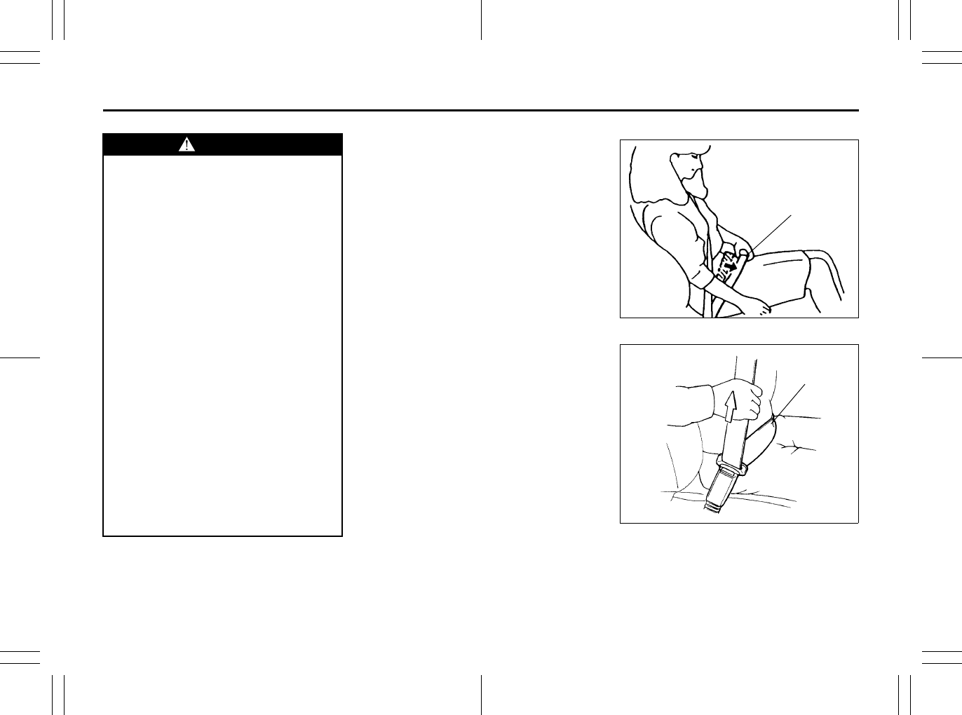
To reduce the risk of sliding under the belt
during a collision, position the lap portion
of the belt across your lap as low on your
hips as possible and adjust it to a snug fit
by pulling the shoulder portion of the belt
upward through the latch plate. The length
of the diagonal shoulder strap adjusts itself
to allow freedom of movement.
All Seat Belts
60A036
To fasten the seat belt, sit up straight and
well back in the seat, pull the latch plate
attached to the seat belt across your body
and press it into the buckle until you hear a
“click”.
80J2008
NOTE:
The word “CENTER” is molded into the
buckle for the rear center belt. The buckles
are designed so a latch plate cannot be
inserted into the wrong buckle.
EXAMPLE
Seat Belts and Child Restraint Systems: 3
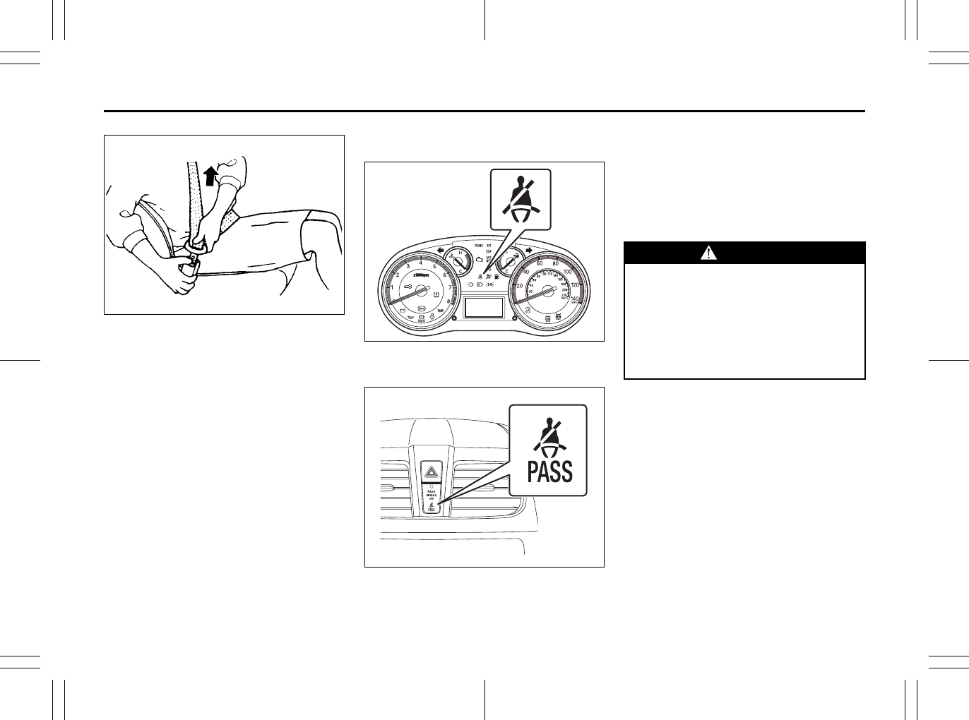
2-32
BEFORE DRIVING
80J23-03E
60A039
To unfasten the belt, push the red
“PRESS” button on the buckle and allow
the belt to retract.
Seat Belt Reminder
Driver’s seat belt reminder light
80J2017
Front passenger’s seat belt reminder
light
80J2018
When the driver and front passenger don’t
buckle their seat belts, the driver’s seat belt
reminder light in the instrument cluster and
the front passenger’s seat belt reminder
light in the information display will come on
and a buzzer will sound as a reminder to
the driver and front passenger to buckle
their seat belts.
The seat belt reminder functions as shown
in the figure below. There are some differ-
ences between the driver’s seat belt
reminder and the front passenger’s seat
belt reminder. For more details, refer to the
explanation below.
WARNING
It is absolutely essential that the
driver and passengers wear their seat
belts at all times. Persons who are
not wearing seat belts have a much
greater risk of injury if an accident
occurs. Make a regular habit of buck-
ling your seat belt before putting the
key in the ignition.
Seat Belts and Child Restraint Systems: 3
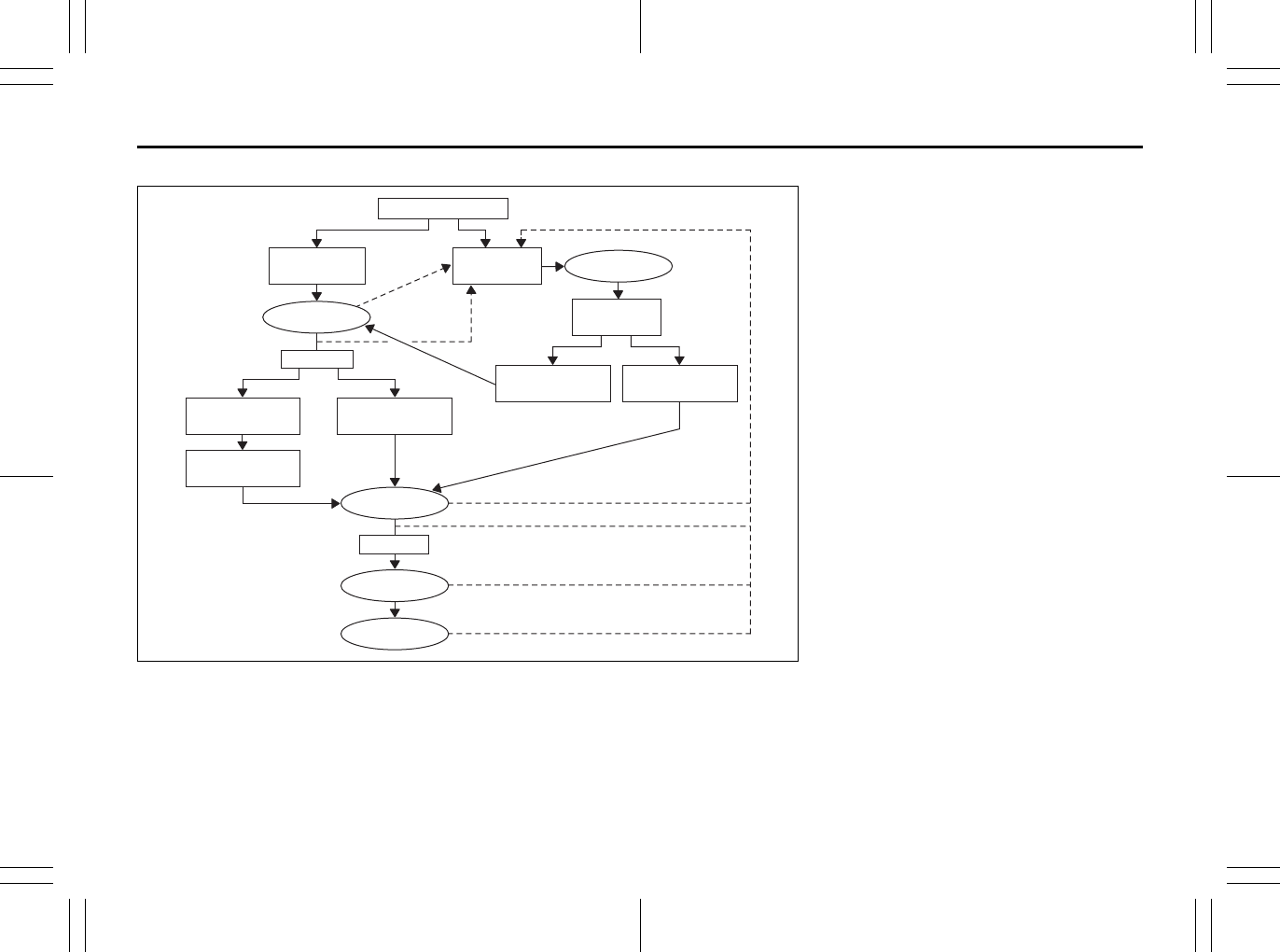
2-33
BEFORE DRIVING
80J23-03E
Flow chart
52D219
Reminder 1 – 3
For each reminder 1 – 3, the reminder light comes on for about 20 seconds, then blinks for
about 55 seconds. When the reminder light first comes on, a buzzer sounds intermittently
for about 6 seconds.
Ignition Switch “ON”
Seat belt is
buckled
30 sec.
Vehicle speed:
increase to 8 km/h
Seat belt is
unbuckled
Vehicle speed:
below 8 km/h
Vehicle speed:
over 8 km/h
Reminder 3
3 min.
No reminder
Seat belt is
unbuckled
Vehicle speed:
below 8 km/h
Vehicle speed:
over 8 km/h
No reminder
Reminder 2
Reminder 1
Driver’s seat belt reminder
If the driver’s seat belt remains unbuckled
with the ignition key in the “ON” position,
the driver’s seat belt reminder works as fol-
lows:
1) The driver’s seat belt reminder light will
come on for about 20 seconds when
the ignition key is turned to the “ON”
position then will blink for about 55 sec-
onds. When the light comes on, a
buzzer will also sound intermittently for
about 6 seconds (Reminder 1).
2) If the vehicle is driven (vehicle speed >
8 km/h), Reminder 2 will operate about
30 seconds after Reminder 1 has fin-
ished.
If the vehicle is not driven (vehicle
speed < 8 km/h), Reminder 2 will oper-
ate when driving starts (vehicle speed >
8 km/h).
3) Reminder 3 will operate about 3 min-
utes after Reminder 2 has finished.
4) Even if the driver’s seat belt remains
unbuckled after Reminder 3, there will
be no further reminders.
If the driver has buckled his or her seat belt
and later unbuckles the seat belt, the
reminder system will be activated from
Reminder 1 or Reminder 2 according to
the vehicle speed. (Refer to the flow chart.)
The driver’s seat belt reminder will be auto-
matically canceled when the driver’s seat
belt is buckled or the ignition switch is
turned off.
Seat Belts and Child Restraint Systems: 3
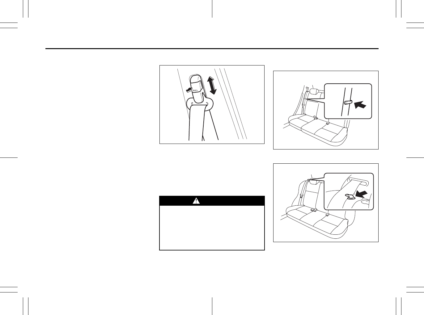
2-34
BEFORE DRIVING
80J23-03E
Front passenger’s seat belt reminder
The front passenger’s seat belt reminder
will activate only when there is a passen-
ger sitting in the front seat. In some situa-
tions, however, such as when you place
heavy objects in the front seat, the seat
belt reminder can be activated as if there
were a passenger present. The front pas-
senger’s seat belt reminder works in the
same manner as the driver’s seat belt
reminder, except that it is not activated
until 10 seconds after the ignition switch is
turned to the “ON” position.
Shoulder Anchor Height Adjuster
64J198
Adjust the shoulder anchor height so that
the shoulder belt rides on the center of the
outside shoulder. To upward, slide the
anchor up. To downward, slide the anchor
down while pulling the lock knob out. After
adjustment, make sure that the anchor is
securely locked.
Seat Belt Hanger (if equipped)
SX4
80JM140
SX4 SEDAN
80JM141
WARNING
Be sure that the shoulder belt is posi-
tioned on the center of the outside
shoulder. The belt should be away
from your face and neck, but not fall-
ing off your shoulder. Misadjustment
of the belt could reduce the effective-
ness of the safety belt in a crash.
EXAMPLE EXAMPLE
EXAMPLE
Seat Belts and Child Restraint Systems: 3
Supplemental Restraint System (advanced air bags):
3, 9, 12
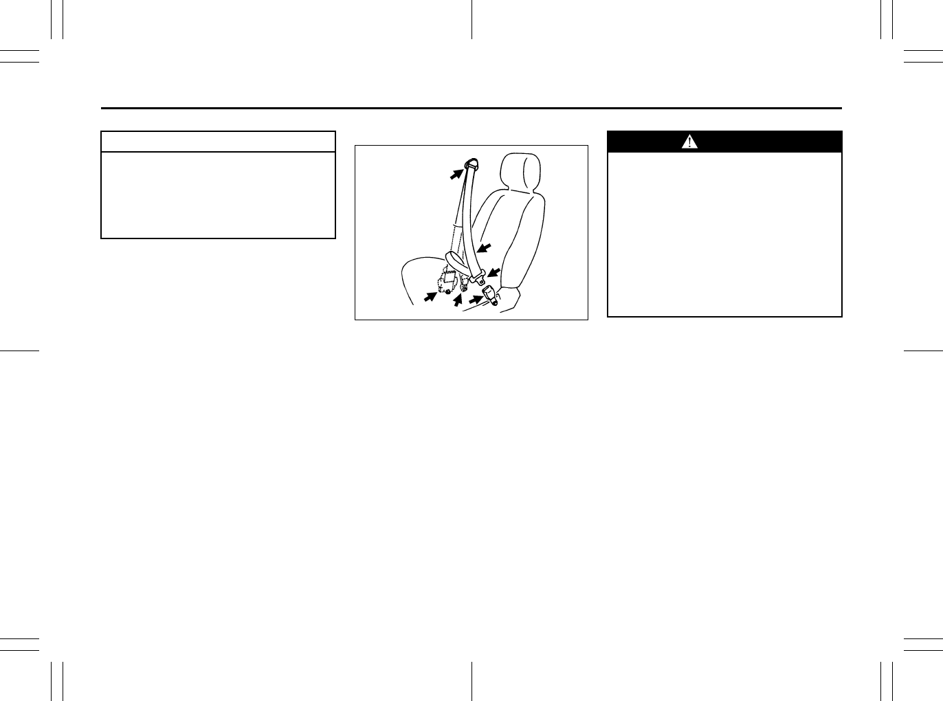
2-35
BEFORE DRIVING
80J23-03E
Seat Belt Inspection
65D209S
Periodically inspect the seat belts to make
sure they work properly and are not dam-
aged. Check the webbing, buckles, latch
plates, retractors, anchorages and guide
loops. Replace any seat belts which do not
work properly or are damaged.
CAUTION
When you move a seatback, make
sure the belt webbing is hooked in
the seat belt hangers so the seat
belts are not caught by the seatback,
seat hinge, or seat latch. This helps
prevent damage to the belt system.
EXAMPLE
WARNING
Be sure to inspect all seat belt
assemblies after any collision. Any
seat belt assembly which was in use
during a collision (other than a very
minor one) should be replaced, even
if damage to the assembly is not
obvious. Any seat belt assembly
which was not in use during a colli-
sion should be replaced if it does not
function properly, it is damaged in
any way or the seat belt pretension-
ers were activated.
Supplemental Restraint System (advanced air bags):
3, 9, 12
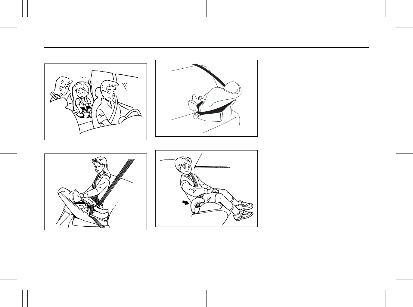
2-36
BEFORE DRIVING
80J23-03E
Child Restraint Systems
60G332
Infant restraint - rear seat only
65D202
Infant restraint - rear seat only
80JC007
Booster seat
80JC008
SUZUKI highly recommends that you use
a child restraint system to restrain infants
and small children. Many different types of
child restraint systems are available; make
sure that the restraint system you select
meets Federal Motor Vehicle Safety Stan-
dards.
All child restraint systems are designed to
be secured in vehicle seats by either seat
belts (lap belts or the lap portion of lap-
shoulder belts) or by special rigid lower
anchor bars built into the seats. Whenever
possible, SUZUKI recommends that child
restraint systems be installed on the rear
seat. According to accident statistics, chil-
dren are safer when properly restrained in
rear seating positions than in front seating
positions.
If you must use a front-facing child restraint
in the front passenger’s seat, be sure to
move the front passenger’s seat as far
back as possible.
EXAMPLE
EXAMPLE
EXAMPLE
Supplemental Restraint System (advanced air bags):
3, 9, 12
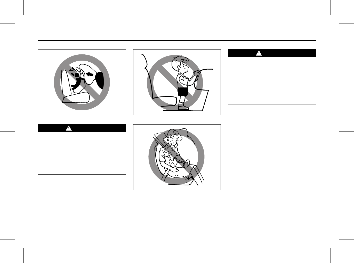
2-37
BEFORE DRIVING
80J23-03E
65D607 65D608
65D609
WARNING
Do not install a rear-facing child
restraint in the front passenger’s
seat. If the passenger’s air bag
inflates, a child in a rear-facing child
restraint could be killed or seriously
injured. The back of a rear-facing
child restraint would be too close to
the inflating air bag.
WARNING
Children could be endangered in a
crash if their child restraints are not
properly secured in the vehicle.
When installing a child restraint sys-
tem, be sure to follow the instruc-
tions below. Be sure to secure the
child in the restraint system accord-
ing to the manufacturer’s instruc-
tions.
Supplemental Restraint System (advanced air bags):
3, 9, 12
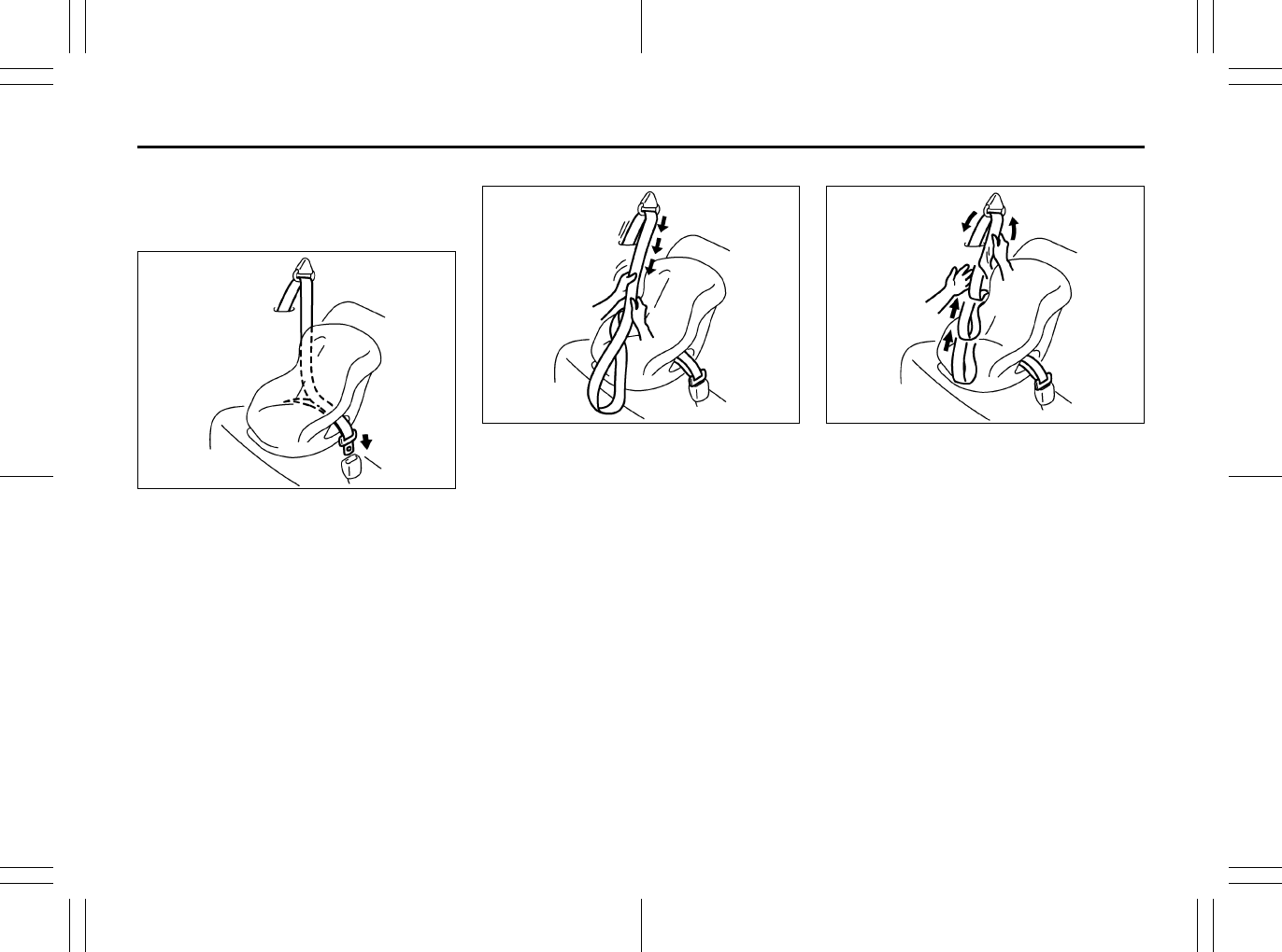
2-38
BEFORE DRIVING
80J23-03E
Installation with Lap-Shoulder Seat
Belts (child restraint with no top
strap)
A-ELR type belt
83E031
Install your child restraint system accord-
ing to the instructions provided by the child
restraint system manufacturer. If you install
the child restraint system in the front seat,
be sure to slide the seat to the rearmost
position. After making sure that the seat
belt is securely latched:
A-ELR type belt
83E035
1) Pull all of the remaining webbing out of
the retractor. You will hear a click, which
means that the emergency locking
retractor (ELR) has converted to func-
tion as an automatic locking retractor
(ALR).
A-ELR type belt
83E032
2) Allow the extra webbing to retract, and
pull the webbing toward the retractor to
take up any slack. Make sure that the
lap portion of the belt is tight around the
child restraint system and the shoulder
portion of the belt is positioned so that it
cannot interfere with the child’s head or
neck.
EXAMPLE
EXAMPLE EXAMPLE
Supplemental Restraint System (advanced air bags):
3, 9, 12
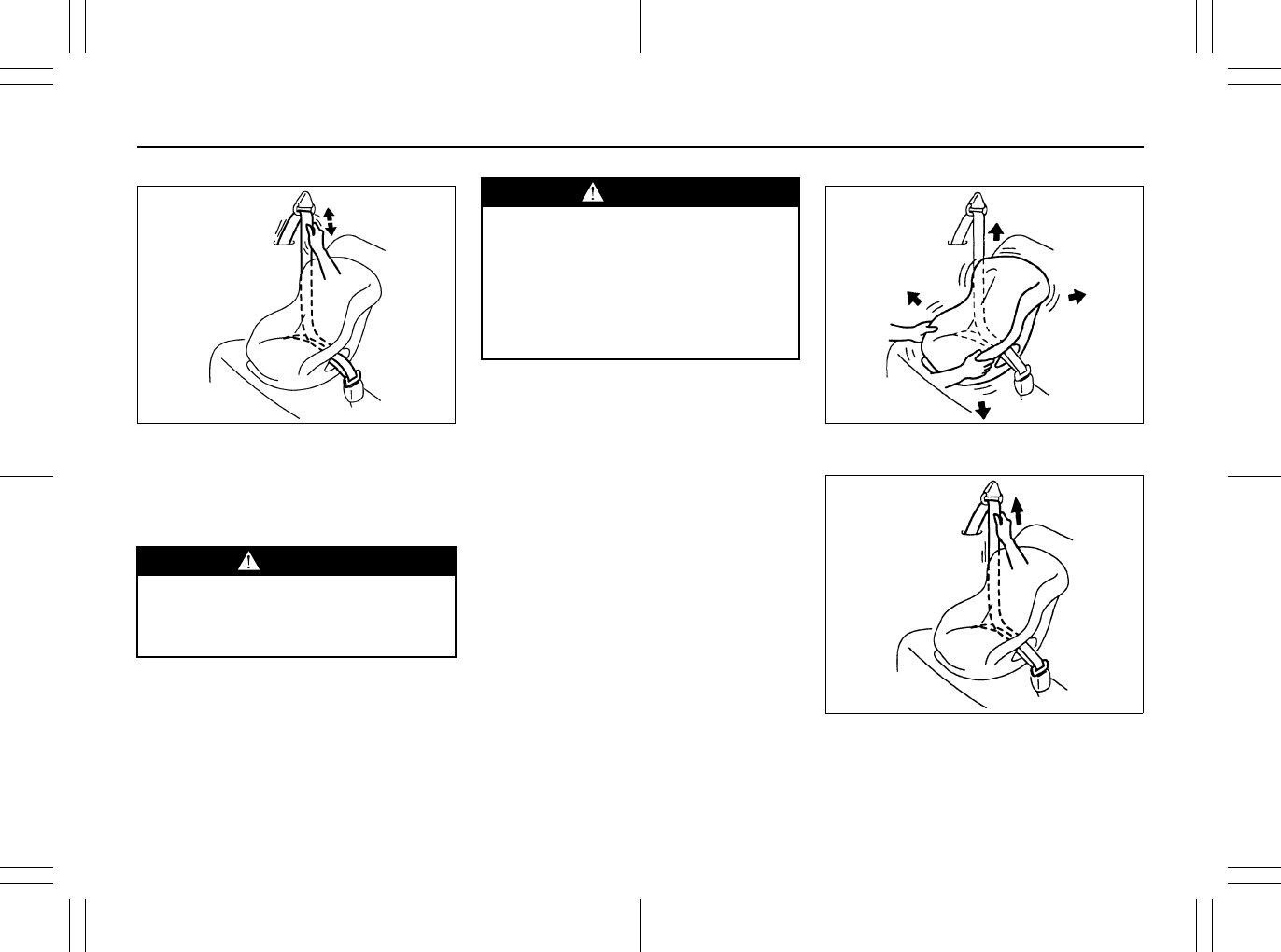
2-39
BEFORE DRIVING
80J23-03E
A-ELR type belt
83E036
3) Make sure that the retractor has con-
verted to the ALR mode by trying to pull
webbing out of the retractor. If the
retractor is in the ALR mode, the belt
will be locked.
A-ELR type belt
65D234
A-ELR type belt
65D235
4) Try moving the child restraint system in
all directions, to make sure it is securely
installed. If you need to tighten the belt,
pull more webbing toward the retractor.
WARNING
If the retractor is not in the ALR
mode, the child restraint system can
move or tip over when your vehicle
turns or stops abruptly.
EXAMPLE WARNING
Before installing a child restraint in
the rear center seat, follow these
steps for secure installation:
• Make sure the detachable connec-
tor is securely latched and the web-
bing is not twisted.
• Make sure the seat belt is passed
through the seat belt guide.
EXAMPLE
Move to check
EXAMPLE
Pull to tighten
Supplemental Restraint System (advanced air bags):
3, 9, 12
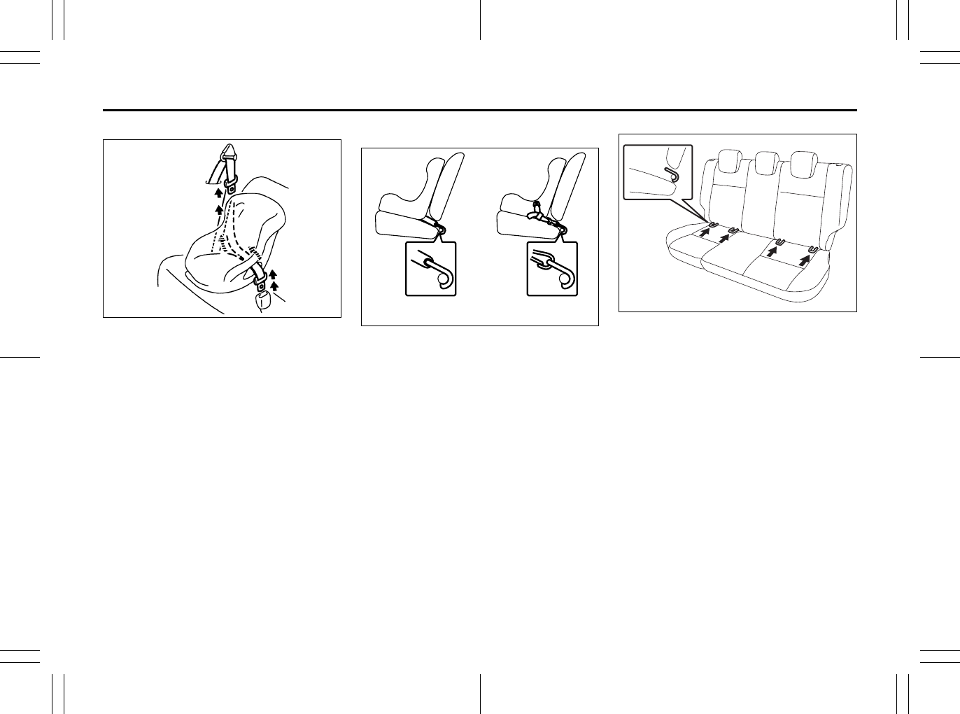
2-40
BEFORE DRIVING
80J23-03E
To revert from ALR to ELR
65D267
When you unbuckle the seat belt and allow
it to retract to a certain length, the retractor
will automatically revert back to the normal
ELR mode.
Installation with the LATCH System
65D337
80JM080
Your vehicle is equipped with lower
anchors for securing up to one or two stan-
dard LATCH-type child restraint(s) in the
rear seats. (LATCH stands for Lower
Anchors and Tethers for Children.)
The anchors are located where the rear of
the seat cushion meets the bottom of the
seatback.
EXAMPLE
Rigid lower connecting
bar type
Flexible lower connecting
strap type
EXAMPLE
Supplemental Restraint System (advanced air bags):
3, 9, 12
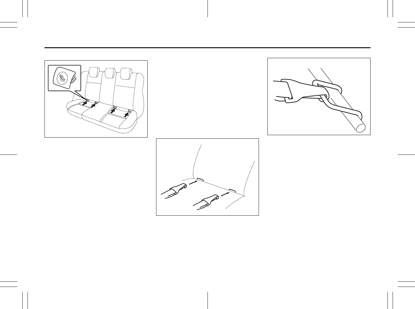
2-41
BEFORE DRIVING
80J23-03E
SX4 SEDAN
80JC028
For SX4 SEDAN, the covers marked with
the child restraint symbol as shown in the
illustration indicate the presence of lower
anchors. Remove the covers before install-
ing the child restraint system. Cover the
lower anchors when not in use.
Install the LATCH-type child restraint sys-
tem according to the instructions provided
by the child restraint system manufacturer.
After installing, try moving the child
restraint system in all directions, especially
forward to make sure the flexible straps or
rigid connecting bars are securely latched
to the anchors.
NOTE:
Although there are three rear seating posi-
tions, you cannot install three LATCH type
child restraints in the rear seats. You can
install one or two LATCH restraint(s). Be
sure to install the LATCH type child
restraint(s) in the outboard seating posi-
tions.
If your LATCH restraint has flexible lower
connecting straps, these general instruc-
tions apply:
1) If possible, fold the seatback rearward
for easier installation.
73K017
2) Place the child restraint in the rear seat,
feeding the strap hooks through the
slots in the seat cushion or the slots in
the seatback bottom.
65D340
3) Snap the strap hooks to the anchors.
Take care not to pinch your fingers.
EXAMPLE
EXAMPLE
EXAMPLE
Supplemental Restraint System (advanced air bags):
3, 9, 12
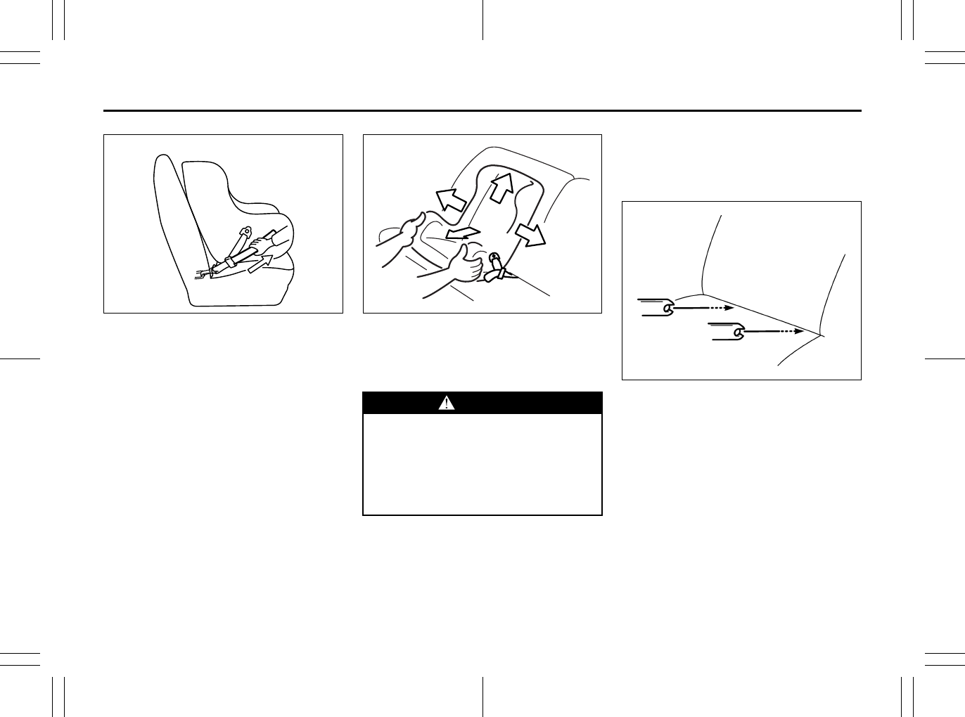
2-42
BEFORE DRIVING
80J23-03E
65D341
4) Return the seatback to the normal,
upright position. Tighten the lower
straps as described in the child restraint
owner’s manual. Attach the top tether
strap, if applicable.
65D342
5) Make sure the child restraint is securely
fastened by trying to move the child
restraint system in all directions, espe-
cially forward.
If your LATCH restraint has rigid lower con-
necting bars, these general instructions
apply:
1) If possible, fold the seatback rearward
for easier installation.
78F114
2) Place the child restraint in the rear seat,
inserting the connecting bars through
the slots in the seat cushion or the slots
in the seatback bottom.
EXAMPLE
WARNING
The seatback should always be
securely latched in a fairly upright
position when any type of child seat
is installed. An unlatched or reclined
seatback will reduce the intended
effectiveness of the child restraint
system.
EXAMPLE
EXAMPLE
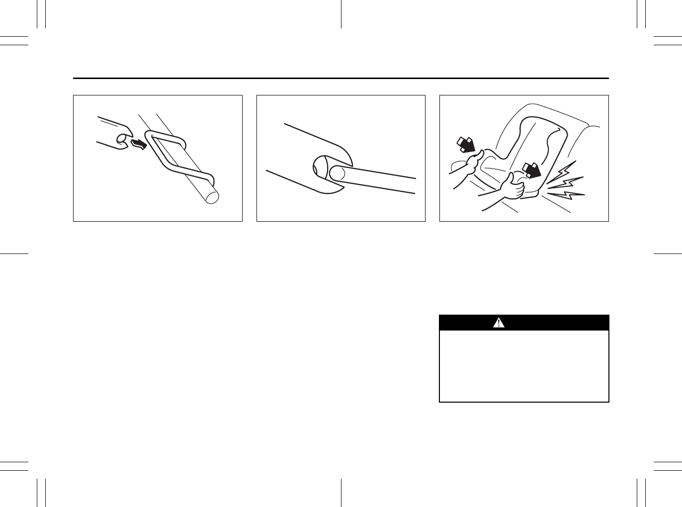
2-43
BEFORE DRIVING
80J23-03E
54G183
3) Use your hands to carefully align the
connecting bar tips with the anchors.
Take care not to pinch your fingers.
54G184
4) Push the child restraint toward the
anchors so that the connecting bar tips
are partially hooked to the anchors.
Use your hands to confirm the position.
54G185
5) Grasp the front of the child restraint and
push the child restraint forcefully to
latch the connecting bars. Make sure
they are securely latched by trying to
move the child restraint system in all
directions, especially forward.
6) Return the seatback if folded. Attach
the top tether strap, if applicable.
EXAMPLE EXAMPLE
WARNING
The seatback should always be
securely latched in a fairly upright
position when any type of child seat
is installed. An unlatched or reclined
seatback will reduce the intended
effectiveness of the child restraint
system.
EXAMPLE

2-44
BEFORE DRIVING
80J23-03E
Installation of Child Restraint with
Top Strap
SX4
80JS072
SX4 SEDAN
80JC102
Some child restraint systems require the
use of a top strap. Top strap anchor brack-
ets are provided in your vehicle at the loca-
tions shown in the illustrations. Install the
child restraint system as follows:
1) For SX4, remove the luggage compart-
ment cover.
2) Secure the child restraint on the rear
seat using the procedure described
above for securing a restraint system
that does not require a top strap.
3) For SX4 SEDAN, open the cover that is
marked with the anchor bracket symbol
to access the anchor bracket. Close the
cover when not using the anchor
bracket.
4) Hook the top strap to the anchor
bracket and tighten the top strap
according to the instructions provided
by the child restraint system manufac-
turer. Be sure to attach the top strap to
the corresponding anchor located
directly behind the child restraint. Do
not attach the top strap to the luggage
restraint loops (if equipped).
80JC029
EXAMPLE
Front
EXAMPLE Front
WARNING
Do not attach the child restraint top
strap to the luggage restraint loops
(if equipped). Incorrectly attached top
strap will reduce the intended effec-
tiveness of the child restraint system.
Type 2
Type 1
Type 3
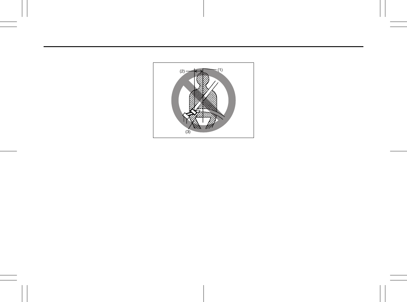
2-45
BEFORE DRIVING
80J23-03E
5) When routing the top strap, be sure to
pass the top strap as shown in the illus-
tration. For SX4 SEDAN, if the top strap
cannot be properly tightened when
passed under the head restraint as
shown in the Type 1 and Type 2 illustra-
tions, pass the top strap over the top of
the head restraint as shown in the Type
3 illustration. (Refer to “Head
Restraints” section for details on how to
raise or lower the head restraint.)
6) Make sure that cargo does not interfere
with routing of the top strap.
Seat Belt Extender
65D613
(1) Center of body
(2) Less than 152 mm (6 inches)
(3) Open end of extender buckle
If a seat belt cannot be fastened securely
because it is not long enough, see your
authorized SUZUKI dealer for a seat belt
extender. Seat belt extenders are available
for each seating position except for the
rear center position. After inspecting the
relationship between the seat belt length,
the occupant’s body size, and the seat
adjustment (the driver’s seat should always
be adjusted as far back as possible while
still maintaining control of the vehicle, and
other adjustable seats should be adjusted
as far back as possible), your dealer can
select the appropriate seat belt extender.
• A seat belt extender should only be used
for the person, vehicle and seating loca-
tion it was provided for.
• When using the extender, ensure that
both ends are latched securely. Do not
use the extender if the open end of the
extender’s buckle is within 152 mm (6
inches) of the center of the occupant’s
body (See diagram). Use of the extender
when the buckle is too close to the cen-
ter of the body could increase the risk of
abdominal injury in the event of an acci-
dent, and could cause the shoulder belt
to be positioned incorrectly.
• Make sure to use the correct buckle cor-
responding to your seating position.
• Seat belt extenders are not intended for
use by pregnant women, and should
only be used upon approval by their
medical advisors.
• Remove and stow the extender when it
is not being used.
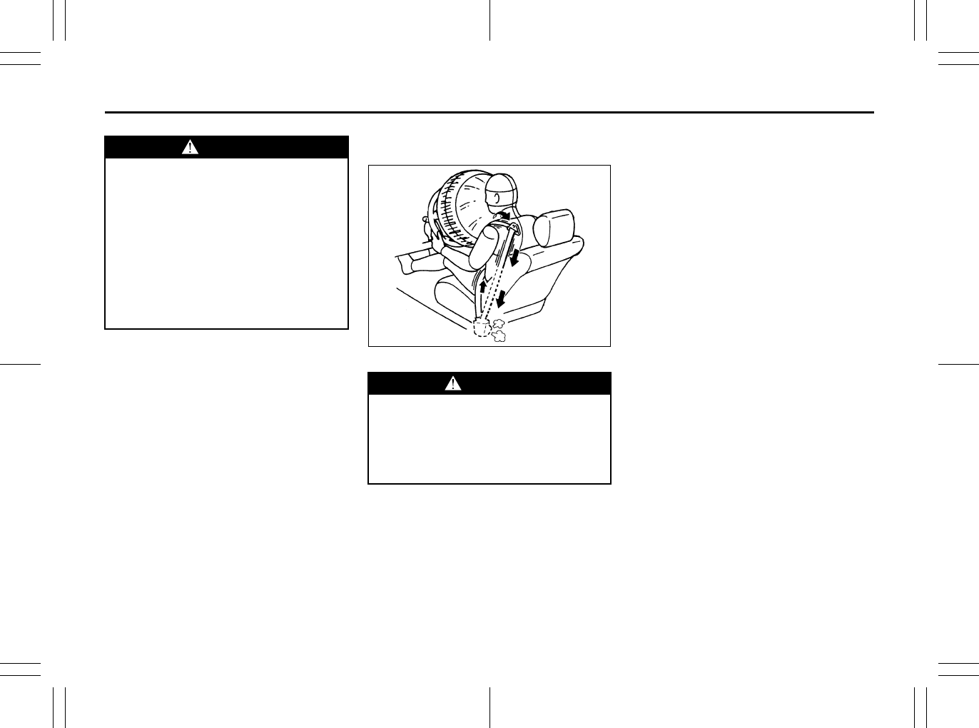
2-46
BEFORE DRIVING
80J23-03E
Seat Belt Pretensioner System
(for front seat belt only)
52D011
Your vehicle is equipped with a seat belt
pretensioner system at the front seating
positions. You can use the pretensioner
seat belts in the same manner as ordinary
seat belts.
The seat belt pretensioner system works
with the SUPPLEMENTAL RESTRAINT
SYSTEM (advanced air bags). The crash
sensors and the electronic controller of the
air bag system also control the seat belt
pretensioners. The pretensioners are trig-
gered only when there is a frontal or side
crash severe enough to trigger the air bags
and the seat belts are fastened. If the seat
belts are not fastened, the respective pre-
tensioner system will not be activated. For
precautions and general information
including servicing the pretensioner sys-
tem, refer to the “Supplemental Restraint
System (air bags)” section in addition to
this “Seat Belt Pretensioner System” sec-
tion, and follow all those precautions.
The pretensioner is located in each front
seat belt retractor. The pretensioner tight-
ens the seat belt so the belt fits the occu-
pant’s body more snugly in the event of a
frontal or side crash. The retractors will
remain locked after the pretensioners are
activated. Upon activation, some noise will
occur and some smoke may be released.
These conditions are not harmful and do
not indicate a fire in the vehicle.
WARNING
Failure to follow these instructions
may increase the risk of injury in a
crash.
• Only use an extender for the per-
son, vehicle and seating position it
was provided for.
• Do not use if open end of
extender’s buckle is within 152 mm
(6 inches) of center of occupant’s
body (See diagram).
• Remove and stow the extender
when it is not being used.
WARNING
This section of the owner’s manual
describes your SUZUKI’s SEAT BELT
PRETENSIONER SYSTEM. Please
read and follow ALL these instruc-
tions carefully to minimize your risk
of severe injury or death.
EXAMPLE
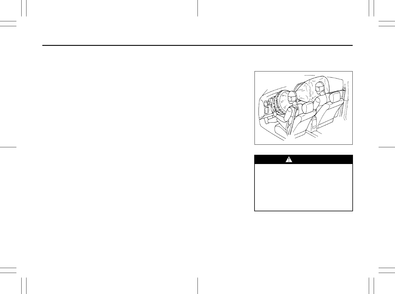
2-47
BEFORE DRIVING
80J23-03E
The driver and all passengers must be
properly restrained by wearing seat belts
at all times, whether or not a pretensioner
is equipped at their seating position, to
help minimize the risk of severe injury or
death in the event of a crash.
Sit fully back in the seat; sit up straight; do
not lean forward or sideways. Adjust the
belt so the lap portion of the belt is worn
low across the pelvis, not across the waist.
Please refer to the “Seat Adjustment” sec-
tion and the instructions and precautions
about the seat belts in this “Seat Belts and
Child Restraint Systems” section for details
on proper seat and seat belt adjustments.
Please note that the pretensioners along
with the air bags will activate only in severe
frontal or side collisions. They are not
designed to activate in rear impacts, roll-
overs or minor frontal collisions. The pre-
tensioners can be activated only once. If
the pretensioners are activated (that is, if
the air bags are activated), have the pre-
tensioner system serviced by an autho-
rized SUZUKI dealer as soon as possible.
If the AIR BAG light on the instrument clus-
ter does not blink or come on briefly when
the ignition switch is turned to the “ON”
position, stays on for more than 10 sec-
onds, or comes on while driving, the pre-
tensioner system or the air bag system
may not work properly. Have both systems
inspected by an authorized SUZUKI dealer
as soon as possible.
Service on or around the pretensioner sys-
tem components or wiring must be per-
formed only by an authorized SUZUKI
dealer who is specially trained. Improper
service could result in unintended activa-
tion of pretensioners or could render the
pretensioner inoperative. Either of these
two conditions may result in personal
injury.
To prevent damage or unintended activa-
tion of the pretensioners, be sure the bat-
tery is disconnected and the ignition switch
has been in the “LOCK” position for at least
90 seconds before performing any electri-
cal service work on your SUZUKI. Do not
touch pretensioner system components or
wiring. The wires are wrapped with yellow
tape or yellow tubing, and the couplers are
yellow. When scrapping your SUZUKI, ask
your SUZUKI dealer, body repair shop or
scrap yard for assistance.
Supplemental Restraint
System (air bags)
54G022
Your vehicle has advanced front air bags
and side air bags for the driver and right
front passenger. Your vehicle also has side
curtain air bags.
WARNING
This section of the owner’s manual
describes the protection provided by
your SUZUKI’s SUPPLEMENTAL
RESTRAINT SYSTEM (air bags).
Please read and follow ALL these
instructions carefully to minimize
your risk of severe injury or death in
the event of a collision.
EXAMPLE

2-48
BEFORE DRIVING
80J23-03E
80J2085
1
7
2
10
9
9
6
3
11
12
4
14
11
5
3
8
8
EXAMPLE
80J2086
Your vehicle is equipped with a Supple-
mental Restraint System consisting of the
following components in addition to a lap-
shoulder belt at each front seating position.
1. Driver’s front air bag
2. Front passenger’s front air bag
3. Seat belt pretensioners
4. Air bag controller
5. Driver’s seat position sensors
6. Occupant classification module
7. “PASS AIR BAG OFF” indicator
8. Forward crash sensors
9. Side air bags
10.Side curtain air bags
11.Side crash sensors
12.Rear side crash sensors
13.Front passenger’s sensor mat
14.Seat belt buckle sensors
13
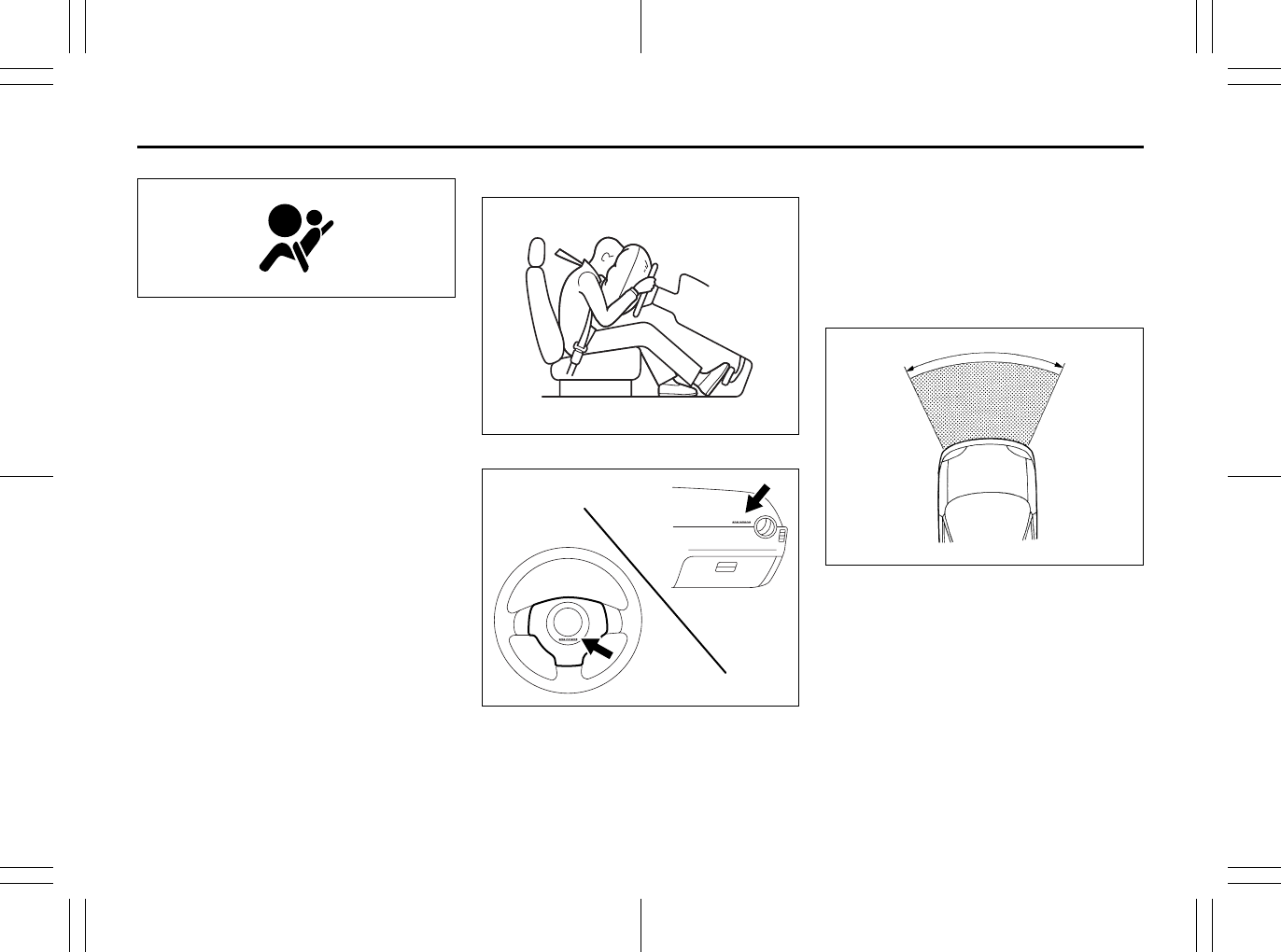
2-49
BEFORE DRIVING
80J23-03E
63J030
If the AIR BAG light on the instrument clus-
ter does not blink or come on when the
ignition switch is first turned to the “ON”
position, or the AIR BAG light stays on, or
comes on while driving, the air bag system
(or the seat belt pretensioner system) may
not work properly. Have the air bag system
inspected by an authorized SUZUKI dealer
as soon as possible.
Front Air Bags
80JS026
80J2009
The driver’s front air bag is located behind
the center pad of the steering wheel and
the front passenger’s front air bag is
located behind the passenger’s side of the
dashboard. The words “SRS AIRBAG” are
molded into the air bag covers to identify
the location of the air bags.
Frontal collision range
60G032
Front air bags are designed to inflate only
in severe frontal collisions.
EXAMPLE
EXAMPLE
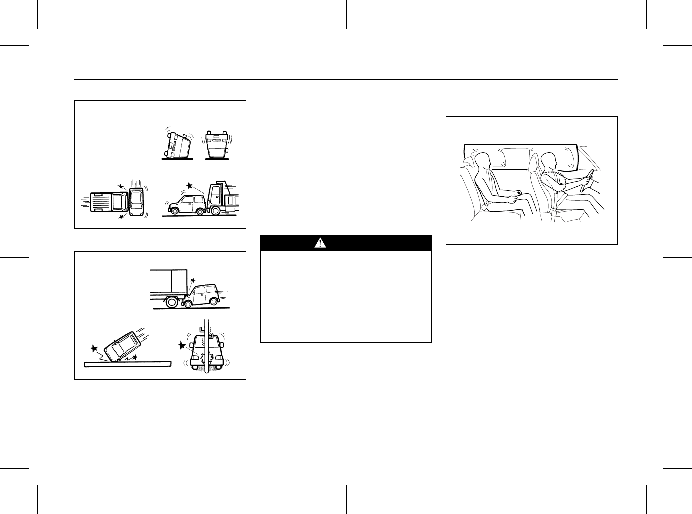
2-50
BEFORE DRIVING
80J23-03E
Front air bags will not inflate
65D236
Front air bags will probably not inflate
65D237
Front air bags are not designed to inflate in
rear impacts, side impacts, rollovers or
minor frontal collisions, since they would
offer no protection in those types of acci-
dents. Remember, since air bags deploy
only one time during an accident, seat
belts are needed to restrain occupants
from further movements during the acci-
dent.
Therefore, an air bag is NOT a substitute
for seat belts. To maximize your protection,
ALWAYS WEAR YOUR SEAT BELTS. Be
aware that no system can prevent all pos-
sible injuries that may occur in an accident.
Your vehicle has “dual stage” front air
bags, which adjust the air bag inflation
force according to crash severity, driver’s
seat fore/aft position and whether or not
the front passenger’s seat belt is fastened.
Also, your vehicle has a front passenger
sensing system, which turns off the front
passenger’s front air bag and seat belt pre-
tensioner under certain conditions.
Side Air Bags and Side Curtain Air
Bags
68KM090
WARNING
An air bag supplements, or adds to,
the crash protection offered by seat
belts. The driver and all passengers
must be properly restrained by wear-
ing seat belts at all times, whether or
not air bags are mounted at their
seating position, to minimize the risk
of severe injury or death in the event
of a crash.
EXAMPLE
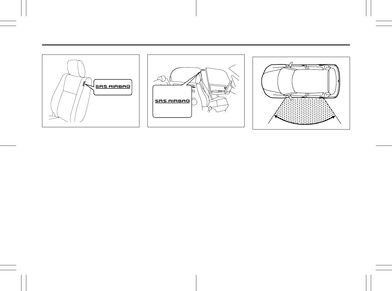
2-51
BEFORE DRIVING
80J23-03E
80J2078
Side air bags are located in the part of the
front seatbacks closest to the doors. The
words “SRS AIRBAG” are indicated on the
tag to identify the location of the side air
bags.
80JM146
Side curtain air bags are located in the roof
lining. The words “SRS AIRBAG” are
molded into the pillar to identify the loca-
tion of the side curtain air bags.
Side collision range
80JM032
Side air bags and side curtain air bags are
designed to inflate only in severe side
impact collisions.
EXAMPLE EXAMPLE
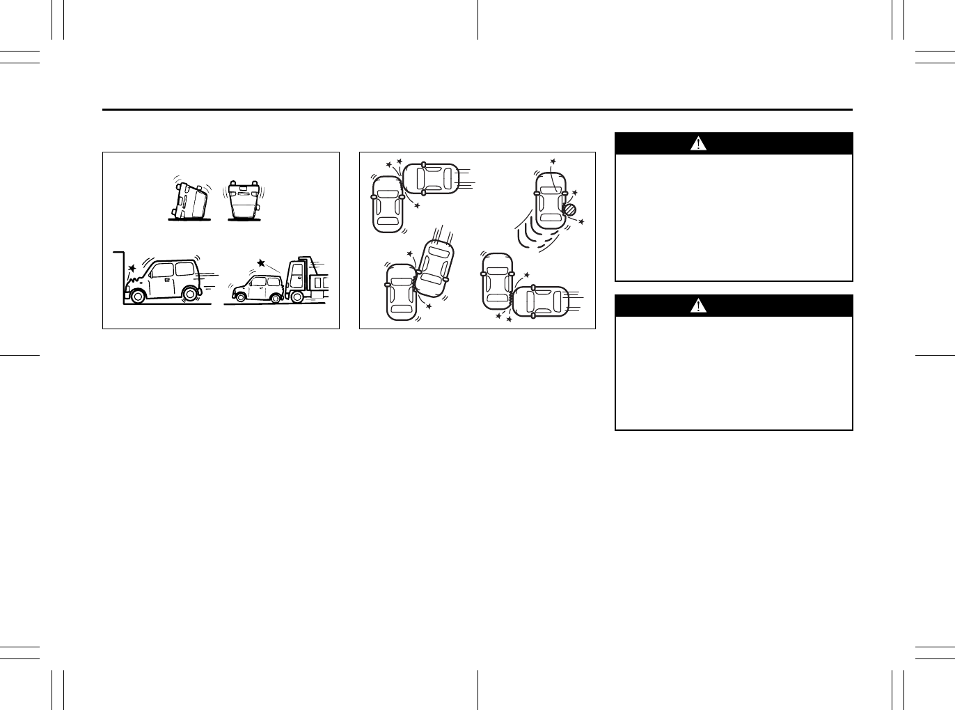
2-52
BEFORE DRIVING
80J23-03E
Side air bags and side curtain air bags
will not inflate
54G027
Side air bags and side curtain air bags
will probably not inflate
54G028
Side air bags and side curtain air bags are
not designed to inflate in frontal or rear col-
lisions, rollovers or minor side collisions,
since they would offer no protection in
those types of accidents. Only the side air
bag and side curtain air bag on the side of
the vehicle that is struck will inflate.
Remember, since an air bag deploys only
one time during an accident, seat belts are
needed to restrain occupants from further
movements during the accident.
Therefore, an air bag is NOT a substitute
for seat belts. To maximize your protection,
ALWAYS WEAR YOUR SEAT BELTS. Be
aware that no system can prevent all pos-
sible injuries that may occur in an accident.
WARNING
An air bag supplements, or adds to,
the crash protection offered by seat
belts. The driver and all passengers
must be properly restrained by wear-
ing seat belts at all times, whether or
not air bags are mounted at their
seating position, to minimize the risk
of severe injury or death in the event
of a crash.
WARNING
If the AIR BAG light in the instrument
cluster ever comes on and stays on,
it means that something may be
wrong with the air bag system. If this
ever happens, have the vehicle ser-
viced immediately, because the air
bags may not offer the protection for
which they were designed.
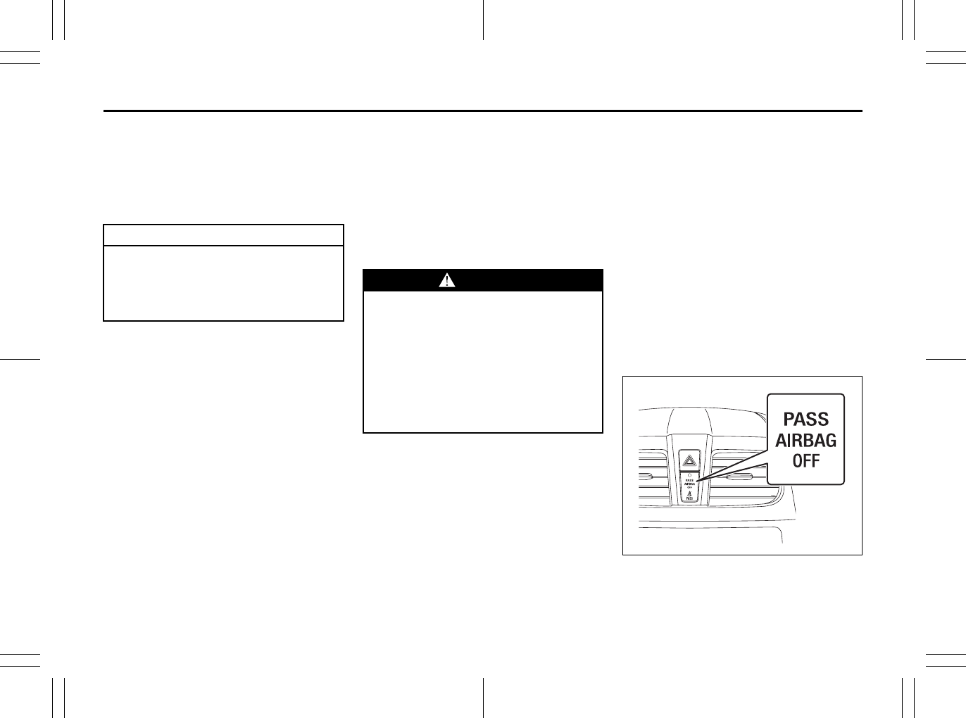
2-53
BEFORE DRIVING
80J23-03E
Driver’s Seat Position Sensor
The driver’s seat is equipped with a seat
position sensor to monitor the driver seat
fore/aft position. The seat position sensor
provides information which is used to
judge if the driver’s front air bag should
deploy at reduced power or at full power.
When the seat position sensor has a prob-
lem, the AIR BAG light on the instrument
cluster will turn on. If this happens, deploy-
ment of the driver’s front air bag will not
include consideration of seat fore/aft posi-
tion. Have the air bag system inspected by
an authorized SUZUKI dealer as soon as
possible.
Front Passenger’s Seat Belt Buckle
Sensor
The front passenger’s seat belt buckle is
equipped with a sensor to monitor whether
or not the front passenger’s seat belt is fas-
tened. The front passenger’s seat belt
buckle sensor provides information which
is used to judge if the front passenger’s air
bag should deploy at reduced power or at
full power.
Front Passenger Sensing System
The front passenger sensing system will
turn off the front passenger’s front air bag
and seat belt pretensioner under certain
conditions. This system works using a sen-
sor mat that is part of the front passenger’s
seat. The front passenger sensing system
is designed to detect whether an occupant
is present in the seat and, if an occupant is
present, to determine whether the front
passenger’s front air bag and seat belt pre-
tensioner should be enabled or disabled
(turned off).
NOTE:
The front passenger’s side air bag and the
side curtain air bag are not controlled by
the front passenger sensing system.
80J2019
CAUTION
Do not put any cargo or metal objects
under the seat. The seat position sen-
sor may not work properly or may be
damaged if it is covered with some-
thing.
WARNING
When the buckle sensor has a prob-
lem, the AIR BAG light on the instru-
ment cluster will turn on. If this
happens, deployment of the front
passenger’s air bag will not include
consideration of whether the front
passenger’s seat belt is fastened or
not. Have the air bag system
inspected by an authorized SUZUKI
dealer as soon as possible.
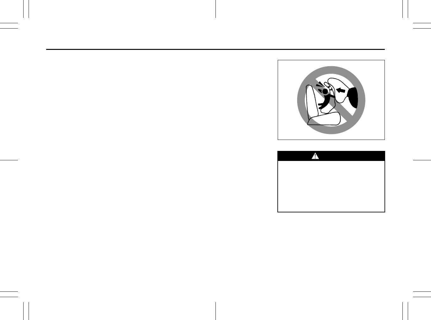
2-54
BEFORE DRIVING
80J23-03E
When the ignition switch is turned to the
“ON” position, the “PASS AIR BAG OFF”
indicator comes on for several seconds to
let you know the system is working. When
the front passenger sensing system has
turned off the front passenger’s front air
bag including the seat belt pretensioner,
the “PASS AIR BAG OFF” indicator will
come on and stay on to remind you that
the front passenger’s front air bag is off.
The front passenger sensing system uses
front seat pressure measurements and
pressure locations to determine whether to
activate or deactivate the front passenger’s
front air bag. The front passenger sensing
system may or may not turn off the front air
bag, depending on the front passenger’s
seating posture and body build. The air
bag should be turned off in the following
situations:
• There is no occupant in the front pas-
senger seat.
• The occupant of the front passenger
seat lifts his or her weight off of the seat
for a period of time.
• The occupant of the front passenger
seat is an infant or small child in a child
restraint system or a small child in a
booster seat.
• A smaller person, such as a child who
has outgrown child restraints or a very
small adolescent is seated in the front
passenger seat.
NOTE:
If the front passenger seat is unoccupied,
the “PASS AIR BAG OFF” indicator will not
come on but the front passenger’s front air
bag will not deploy and the seat belt pre-
tensioner will not operate.
If you have secured a child in the front pas-
senger seat in a forward-facing child
restraint system or booster seat and the
“PASS AIR BAG OFF” indicator light is not
on, turn the vehicle off, remove the child
restraint or booster seat from the vehicle
and reinstall it following the child restraint
or booster seat manufacturer’s directions.
Also refer to “Seat Belts and Child
Restraint Systems” in this section. If, after
reinstalling the child restraint and restart-
ing the vehicle, the “PASS AIR BAG OFF”
indicator is still not lit, check to make sure
that the vehicle’s seatback is not pressing
the child restraint into the seat cushion. If
this happens, slightly recline the vehicle’s
seatback and adjust the seat cushion if
possible. Also make sure the child restraint
is not trapped under the vehicle head
restraint. If this happens, adjust the head
restraint. If the “PASS AIR BAG OFF” indi-
cator is still not on, secure the child in the
child restraint or booster seat in a rear seat
position in the vehicle and check with your
dealer.
65D607
According to accident statistics, children
are safer when properly restrained in rear
seating positions than in front seating posi-
tions. Whenever possible, SUZUKI recom-
mends you install child restraints in the
rear seat.
WARNING
Do not install a rear-facing child
restraint in the front passenger’s
seat. If the passenger’s front air bag
inflates, a child in a rear-facing child
restraint could be seriously injured.
The back of a rear-facing child
restraint would be too close to the
inflating air bag.
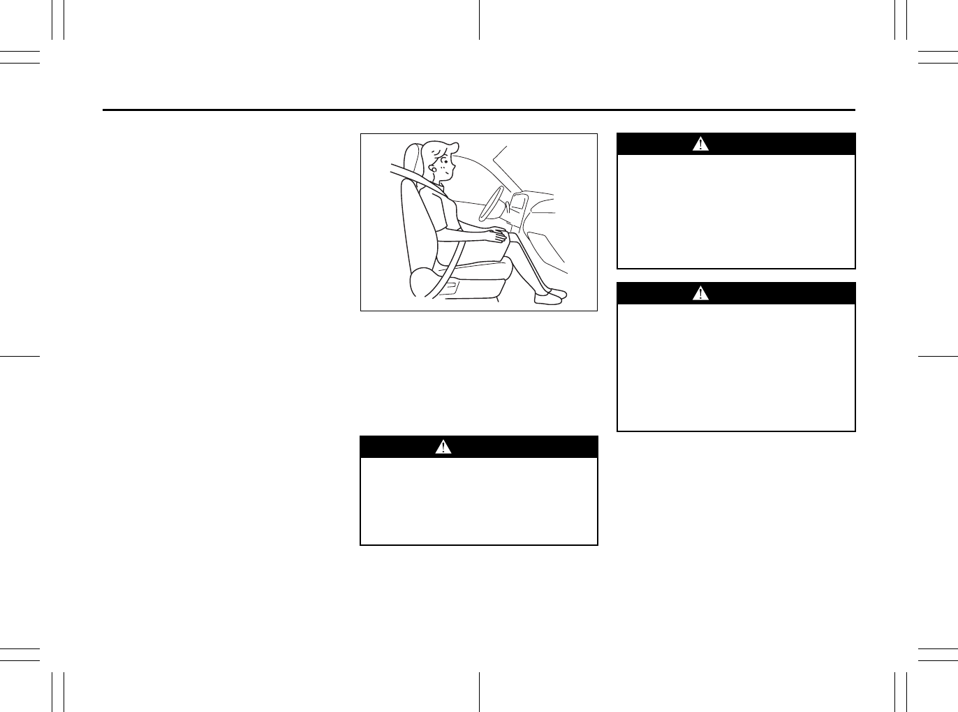
2-55
BEFORE DRIVING
80J23-03E
The front passenger sensing system is
designed to enable the front passenger’s
front air bag when the system senses a
properly-seated adult in the front passen-
ger’s seat. When the passenger sensing
system has allowed the air bag to be
enabled, the “PASS AIR BAG OFF” indica-
tor will remain off to remind you that the air
bag is active.
If a person of adult size is sitting in the
front passenger’s seat and the “PASS AIR
BAG OFF” indicator comes on, it could be
because that person isn’t sitting properly in
the seat. If this happens, unfasten the seat
belts, sit upright in the center of the seat
with the seatback nearly vertical and your
legs outstretched, and refasten the seat
belt.
52D258
When seated as shown in the above illus-
tration, the front passenger sensing sys-
tem senses a properly-seated occupant
and enables the air bag.
When using a seat belt extender, follow the
instructions in the “Seat Belt Extender”
section.
WARNING
Do not place any heavy objects on
the front passenger’s seat. The pres-
sure sensors in the sensor mat could
be damaged and the front passenger
sensing system may not work prop-
erly.
WARNING
The front passenger sensing system
may not work properly in the follow-
ing situations:
• The occupant is sitting near the
dashboard or is not sitting in the
proper position.
• Objects placed under the seat are
pushing up on the seat cushion.
WARNING
If the “PASS AIR BAG OFF” indicator
on the instrument panel turns on
even though there is no occupant or
an adult occupant in the front pas-
senger’s seat, it means that some-
thing may be wrong with the
passenger sensing system. Have the
system inspected by an authorized
SUZUKI dealer as soon as possible.

2-56
BEFORE DRIVING
80J23-03E
How the System Works
In a frontal collision, the crash sensors will
detect rapid deceleration and send a signal
to the controller. If the controller judges
that the deceleration represents a severe
frontal crash, the controller will trigger the
inflators. The controller also judges:
• Whether the front air bags should deploy
at reduced power or at full power accord-
ing to crash severity.
• Whether the air bags should deploy at
reduced power or at full power according
to crash severity, driver’s seat fore/aft
position and whether or not the front
passenger’s seat belt is fastened.
• Whether the front passenger’s front air
bag should deploy or not based on clas-
sification of the occupant of the front
passenger’s seat.
Since your vehicle is equipped with side air
bags, and side curtain air bags, crash sen-
sors will detect a side collision, and if the
controller judges that the side collision is
severe enough, it will trigger the side air
bag and side curtain air bag inflators.
The inflators inflate the appropriate air
bags with nitrogen or argon gas. The
inflated air bags provide a cushion for your
head (front air bags and side curtain air
bags only) and upper body. The air bag
inflates and deflates so quickly that you
may not even realize that it has activated.
The air bag will neither hinder your view
nor make it harder to exit the vehicle.
Air bags must inflate quickly and forcefully
in order to reduce the chance of serious or
fatal injuries. However, an unavoidable
consequence of the quick inflation is that
the air bag may irritate bare skin, such as
the facial area against a front air bag. Also,
upon inflation, a loud noise will occur and
some powder and smoke will be released.
These conditions are not harmful and do
not indicate a fire in the car. Be aware,
however, that some air bag components
may be hot for a while after inflation.
A seat belt helps keep you in the proper
position for maximum protection when an
air bag inflates. Adjust your seat as far
back as possible while still maintaining
control of the vehicle. Sit fully back in your
seat; sit up straight; do not lean over the
steering wheel or dashboard. Front occu-
pants should not lean on or sleep against
the door. Please refer to the “Seat Adjust-
ment” section and the “Seat Belts and
Child Restraint Systems” section in the
“BEFORE DRIVING” section for details on
proper seat and seat belt adjustments.
WARNING
• Do not spill any liquids on the seat.
Liquids can damage the sensors
under the front seat.
• Have the driver’s seat position sen-
sor and the front passenger’s sen-
sor mat inspected by your dealer
after a collision.
• Do not replace the front seats. If
you replace them, the air bags and
front passenger sensing system
may not work properly.
• Do not use a seat cover. If you use
a seat cover, the front passenger
sensing system may not work prop-
erly.
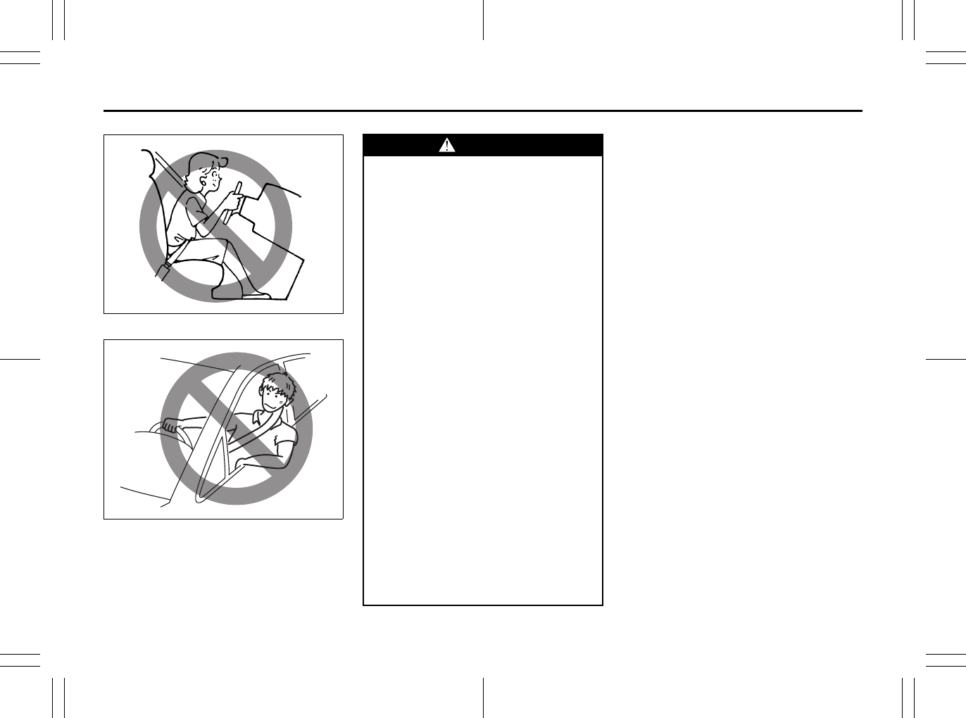
2-57
BEFORE DRIVING
80J23-03E
65D610
54G582
Note that even though your vehicle may be
moderately damaged in a collision, the col-
lision may not have been severe enough to
trigger the front, side, or side curtain air
bags to inflate. If your car sustains ANY
front-end or side damage, have the air bag
system inspected by an authorized
SUZUKI dealer to ensure it is in proper
working order.
Your vehicle is equipped with a diagnostic
module which records information about
the air bag system if the air bags deploy in
a crash. The module records information
about overall system status, which sensors
activated the deployment, and whether the
front seat belts were in use.
WARNING
• The driver should not lean over the
steering wheel. The front passen-
ger should not rest his or her body
against the dashboard, or other-
wise get too close to the dash-
board. For vehicles with side air
bags and side curtain air bags,
occupants should not lean on or
sleep against the door. In these sit-
uations, the out-of-position occu-
pant would be too close to an
inflating air bag, and may suffer
severe injury.
• Do not attach any objects to, or
place any objects over, the steering
wheel or dashboard. Do not place
any objects between the air bag
and the driver or front passenger.
These objects may interfere with air
bag operation or may be propelled
by the air bag in the event of a
crash. Either of these conditions
may cause severe injury.
• For vehicles with side air bags, do
not place seat covers on the front
seats, because seat covers could
restrict the air bag’s inflation. Also,
do not place any cup holders or
other objects on the door, as these
objects could be propelled by the
air bag in the event of a crash.
Either of these conditions may
cause severe injury.

2-58
BEFORE DRIVING
80J23-03E
Servicing the Air Bag System
If the air bags inflate, have the air bags and
related components replaced by an autho-
rized SUZUKI dealer as soon as possible.
If your vehicle ever gets in deep water and
the driver’s floor is submerged, the air bag
controller could be damaged. If this hap-
pens, have the air bag system inspected
by the SUZUKI dealer as soon as possible.
Special procedures are required for servic-
ing or replacing an air bag. For that reason,
only an authorized SUZUKI dealer should
be allowed to service or replace your air
bags. Please remind anyone who services
your SUZUKI that it has air bags.
Service on or around air bag components
or wiring must be performed only by an
authorized SUZUKI dealer. Improper ser-
vice could result in unintended air bag
deployment or could render the air bags
inoperative. Either of these two conditions
may result in severe injury.
To prevent damage or unintended inflation
of the air bag system, be sure the battery
is disconnected and the ignition switch has
been in the “LOCK” position for at least 90
seconds before performing any electrical
service work on your SUZUKI. Do not
touch air bag system components or wires.
The wires are wrapped with yellow tape or
yellow tubing, and the couplers are yellow
for easy identification.
Scrapping a car that has an undeployed air
bag can be hazardous. Ask your dealer,
body repair shop or scrap yard for help
with disposal.
If it is necessary to modify the advanced
front air bag system to accommodate a
person with disabilities, owners in the con-
tinental United States can call American
Suzuki toll-free at 1-800-934-0934, or write
to:
American Suzuki Motor Corporation
Automotive Customer Relations
3251 East Imperial Highway
Brea, CA 92821-6795
If you purchased your SUZUKI in Canada
please contact the Suzuki Canada Cus-
tomer Relations Department by telephone
at 1-905-889-2677 extension 2254 or in
writing at:
Suzuki Canada Inc.
Customer Relations
100 East Beaver Creek Road
Richmond Hill, On
L4B 1J6
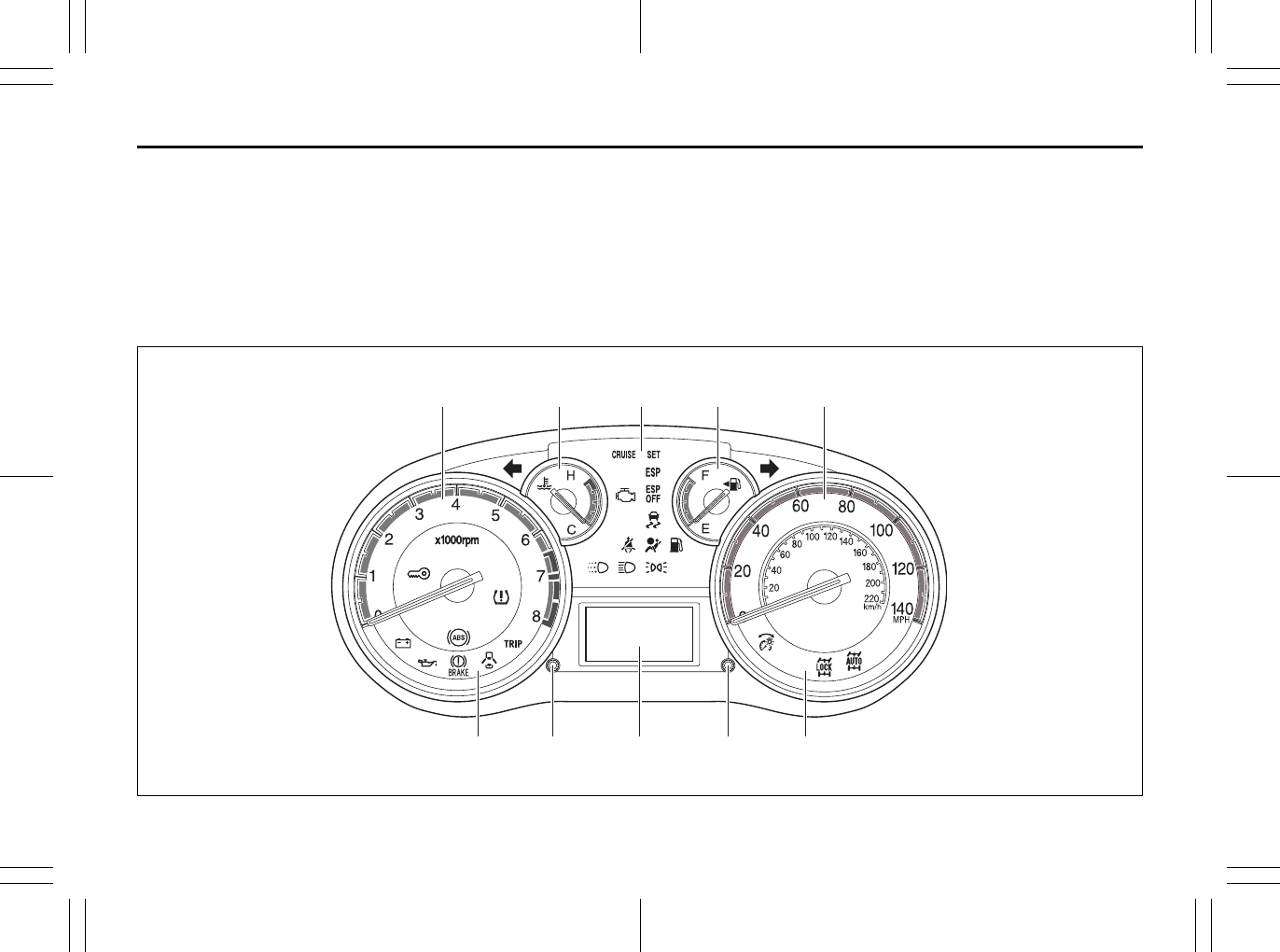
2-59
BEFORE DRIVING
80J23-03E
Instrument Cluster
1. Speedometer
2. Tachometer
3. Fuel gauge
4. Temperature gauge
5. Information display
6. Trip meter selector knob
7. Indicator selector knob
8. Warning and indicator lights
80J2020
5 7 88 6
12 384
EXAMPLE
2-60
BEFORE DRIVING
80J23-03E
Warning and Indicator Lights
Low Tire Pressure Warning Light
52D305
As an added safety feature, your vehicle
has been equipped with a tire pressure
monitoring system (TPMS) that uses a low
tire pressure warning light to inform you
when one or more of your tires is signifi-
cantly under-inflated.
When the ignition switch is turned to the
“ON” position, this light comes on briefly so
you can check that the light is working.
When the low tire pressure warning light is
lit, one or more of your tires is significantly
under-inflated. You should stop and check
your tires as soon as possible, and inflate
them to the proper pressure as indicated
on the vehicle’s tire information placard.
Driving on a significantly under-inflated tire
causes the tire to overheat and can lead to
tire failure. Under-inflation also reduces
fuel efficiency and tire tread life, and may
affect the vehicle’s handling and stopping
ability. Each tire, including the spare,
should be checked at least once a month
when cold and set to the recommended
inflation pressure as specified in the vehi-
cle placard and owner’s manual.
The low tire pressure warning light is also
used to inform you of a TPMS malfunction.
When the system detects a malfunction,
this light will flash for approximately one
minute and then remain continuously illu-
minated. This sequence will be repeated
approximately ten minutes after subse-
quent the ignition switch is turned on as
long as the malfunction exists.
NOTE:
The low tire pressure warning light may not
come on immediately if you have a sudden
loss of air pressure.
WARNING
If the low tire pressure warning light
does not come on when the ignition
is turned to the “ON” position, or
comes on and blinks while driving
there may be a problem with the tire
pressure monitoring system. Have
your vehicle inspected by an autho-
rized SUZUKI dealer. Even if the light
turns off after blinking, indicating
that monitoring system has recov-
ered, make sure to have an autho-
rized SUZUKI dealer check the
system.
WARNING
The load rating of your tires is
reduced at lower inflation pressures.
If your tires become even moderately
under-inflated, the vehicle load may
exceed the load rating of the tires,
which can lead to tire failure. The low
tire pressure warning light will not
alert you of this condition. The warn-
ing light will only come on when one
or more of your tires become signifi-
cantly under-inflated. Check and
adjust your tire inflation pressure at
least once a month. Refer to “Tires”
in the “INSPECTION AND MAINTE-
NANCE” section.
2-61
BEFORE DRIVING
80J23-03E
Refer to “Tire Pressure Monitoring System”
in the “OPERATING YOUR VEHICLE” sec-
tion for additional details on the tire pres-
sure monitoring system. Refer to “Tires” in
the “INSPECTION AND MAINTENANCE”
section for information on maintaining
proper tire pressure.
Brake System Warning Light
65D477
This light comes on briefly when the igni-
tion switch is turned to the “ON” position.
The light also comes on under the follow-
ing conditions: 1) when the parking brake
is engaged and 2) when the fluid in the
brake fluid reservoir falls below the speci-
fied level. The light should go out after fully
releasing the parking brake, if the fluid
level in the brake fluid reservoir is ade-
quate.
If this light and the ABS warning light stay
on, or come on simultaneously when driv-
ing, then there may be something wrong
with both the rear brake proportioning
valve function and anti-lock function of the
ABS.
If the brake system warning light comes on
while you are driving the vehicle, it may
mean that there is something wrong with
the vehicle’s brake system. If this happens,
you should:
WARNING
If the low tire pressure warning light
comes on and stays on, reduce your
speed and avoid abrupt steering and
braking. Stop in a safe place as soon
as possible and check your tires.
• If you have a flat tire, replace it with
the spare tire. Refer to “Jacking
Instructions” in the “EMERGENCY
SERVICE” section. Refer to
“Replacing Tires and/or Wheels”
for instructions on how to restore
normal operation of the tire pres-
sure monitoring system after you
have had a flat tire.
• If one or more of your tires is
under-inflated, adjust the inflation
pressure in all of your tires to the
recommended inflation pressure as
soon as possible.
Be aware that driving on a signifi-
cantly under-inflated tire can cause
the tire to overheat and can lead to
tire failure, and may affect steering
control and brake effectiveness. This
could lead to an accident, resulting in
severe injury or death.
2-62
BEFORE DRIVING
80J23-03E
1) Pull off the road and stop carefully.
2) Test the brakes by carefully starting and
stopping on the shoulder of the road.
3) If you determine that it is safe, drive
cautiously at low speed to the nearest
dealer for repairs,
or
4) Have the vehicle towed to the nearest
dealer for repairs.
NOTE:
Because the disc brake system is self-
adjusting, the fluid level will drop as the
brake pads become worn.
Replenishing the brake fluid reservoir is
considered normal periodic maintenance.
Anti-Lock Brake System (ABS)
Warning Light
65D529
When the ignition switch is turned to the
“ON” position, the light comes on briefly so
you can check that the light is working. If
the light stays on, or comes on when driv-
ing, there may be something wrong with
the ABS.
If the ABS light and the brake system
warning light stay on, or come on simulta-
neously when driving, then there may be
something wrong with both the rear brake
proportioning valve function and anti-lock
function of the ABS.
If one of these happens, have the system
inspected by your SUZUKI dealer. If the
ABS becomes inoperative, the brake sys-
tem will function as an ordinary brake sys-
tem that has no ABS.
For details of the ABS, refer to “Anti-Lock
Brake System (ABS)” in the “OPERATING
YOUR VEHICLE” section.
SLIP Indicator Light (if equipped)
52KM133
ESP® is a registered trademark of Daimler
AG.
This light blinks 5 times per second when
one of the ESP® systems other than ABS
is activated. If this light blinks, drive care-
fully.
When the ignition switch is turned to the
“ON” position, the light comes on briefly so
you can check that the light is working. If
the light stays on, or comes on when driv-
ing and remains on, there may be some-
thing wrong with the ESP® systems (other
than ABS). You should have the system
inspected by an authorized SUZUKI
dealer.
WARNING
Remember that stopping distance
may be longer, you may have to push
harder on the pedal, and the pedal
may go down farther than normal.
WARNING
If any of the following conditions
occur, you should immediately ask
your SUZUKI dealer to inspect the
brake system.
• If the brake system warning light
does not go out after the parking
brake has been fully released.
• If the brake system warning light
does not come on when the igni-
tion switch is turned to the “ON”
position.
• If the brake system warning light
comes on at any time during vehi-
cle operation.
2-63
BEFORE DRIVING
80J23-03E
NOTE:
When you disconnect and re-connect the
battery, ESP® system functions other than
ABS will be deactivated and the slip indica-
tor light will blink 1 time per second. For
details on how to reactive the ESP® sys-
tems, refer to “SLIP Indicator Light” in the
“OPERATING YOUR VEHICLE” section.
For details of the ESP® systems, refer to
“Electronic Stability Program (ESP®)” in
the “OPERATING YOUR VEHICLE” sec-
tion.
“ESP” (Electronic Stability
Program) Warning Light
(if equipped)
66J031
When the ignition switch is turned to the
“ON” position, the light comes on briefly so
you can check that the light is working. If
the light stays on, or comes on when driv-
ing, there may be something wrong with
the ESP® systems (other than ABS). You
should have the system inspected by an
authorized SUZUKI dealer.
For details of the ESP® systems, refer to
“Electronic Stability Program (ESP®)” in
the “OPERATING YOUR VEHICLE” sec-
tion.
“ESP OFF” Indicator Light
(if equipped)
66J032
When the ignition switch is turned to the
“ON” position, this light comes on briefly so
you can check that the light is working.
When the “ESP OFF” switch is pushed to
turn off the ESP® systems (other than
ABS), the “ESP OFF” light comes on and
stays on.
For details of the ESP® systems, refer to
“Electronic Stability Program (ESP®)” in
the “OPERATING YOUR VEHICLE” sec-
tion.
WARNING
The ESP® systems cannot prevent
accidents. Always drive carefully.
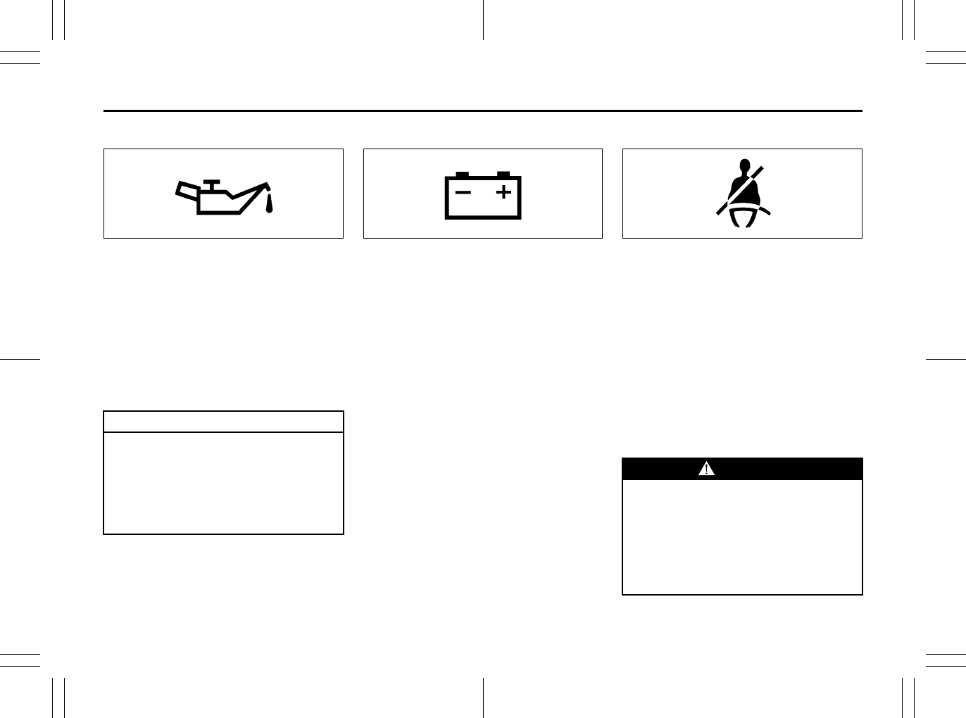
2-64
BEFORE DRIVING
80J23-03E
Oil Pressure Light
50G051
This light comes on when the ignition
switch is turned to the “ON” position, and
goes out when the engine is started. The
light will come on and remain on if there is
insufficient oil pressure. If the light comes
on when driving, pull off the road as soon
as you can and stop the engine. Check the
oil level and add oil if necessary. If there is
enough oil, the lubrication system should
be inspected by your SUZUKI dealer
before you drive the vehicle again.
Charging Light
50G052
This light comes on when the ignition
switch is turned to the “ON” position, and
goes out when the engine is started. The
light will come on and remain on if there is
something wrong with the battery charging
system. If the light comes on when the
engine is running, the charging system
should be inspected immediately by your
SUZUKI dealer.
Driver’s Seat Belt Reminder Light
60G049
If the driver’s seat belt is unbuckled when
the ignition switch is turned to the “ON”
position, this light will come on and then
blink. When the light comes on, a buzzer
will also sound intermittently for about 6
seconds. The reminder will repeat several
times under certain conditions until the
driver’s seat belt is buckled. After repeating
several times, the reminder will be can-
celed even if the driver’s seat belt remains
unbuckled.
For details about the seat belt reminder,
refer to “Seat Belts and Child Restraint
Systems” in this section.
CAUTION
• If you operate the engine with this
light on, severe engine damage can
result.
• Do not rely on the Oil Pressure
Light to indicate the need to add
oil. Be sure to periodically check
the engine oil level.
WARNING
It is absolutely essential that the
driver and passengers wear their seat
belts at all times. Persons who are
not wearing seat belts have a much
greater risk of injury if an accident
occurs. Make a regular habit of buck-
ling your seat belt before putting the
key in the ignition.
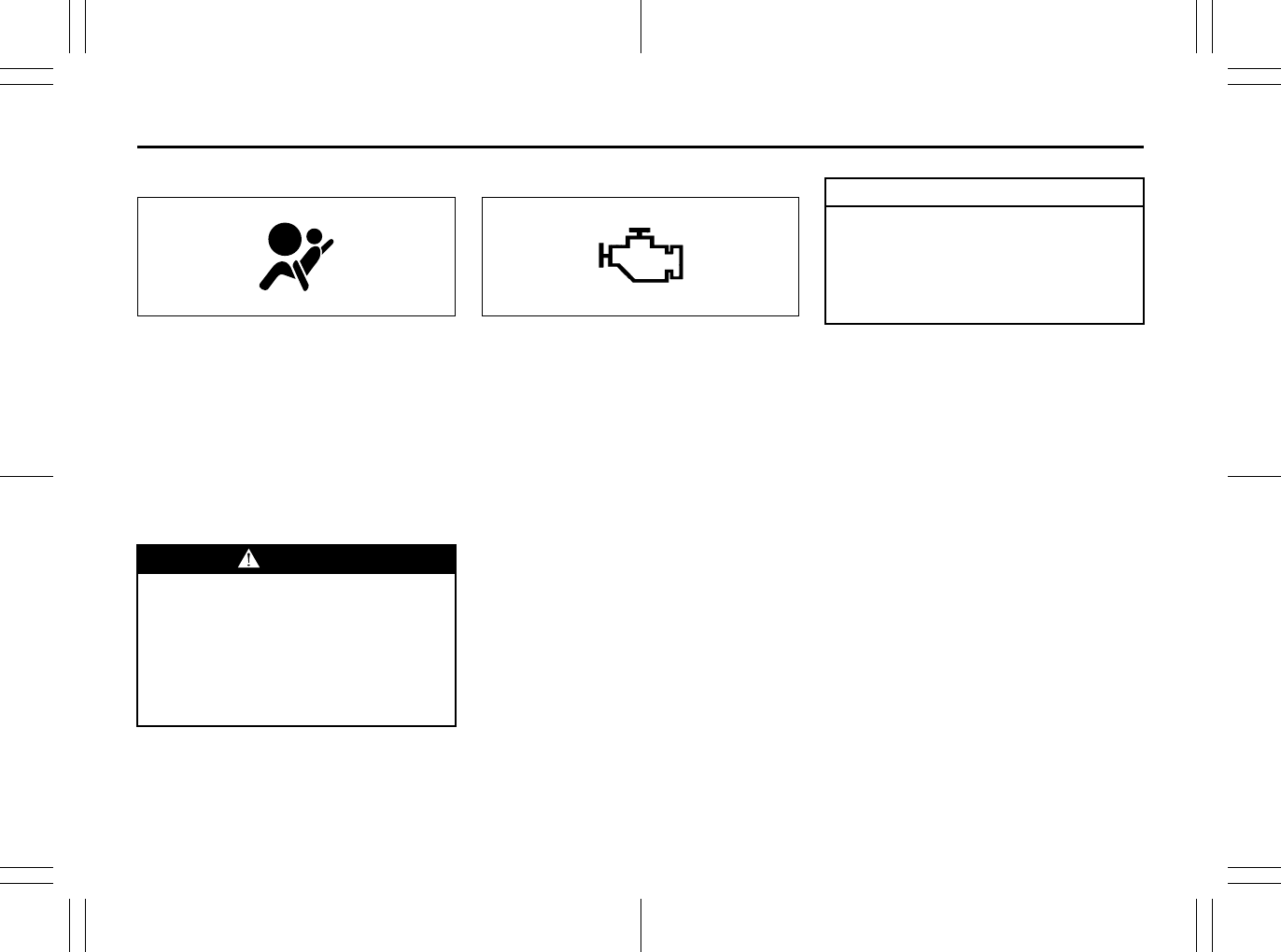
2-65
BEFORE DRIVING
80J23-03E
AIR BAG Light
63J030
This light monitors inflators, crash sensors,
seat belt pretensioners, the front passen-
ger sensing system, and corresponding
electrical circuits.
This light blinks or comes on for several
seconds when the ignition switch is turned
to the “ON” position so you can check if the
light is working. The light will come on and
stay on if there is a problem in the air bag
system or the seat belt pretensioner sys-
tem.
Malfunction Indicator Light
65D530
Your vehicle has a computer-controlled
emission control system. A malfunction
indicator light is provided on the instrument
panel to indicate when it is necessary to
have the emission control system serviced.
The malfunction indicator light comes on
when the ignition switch is turned to the
“ON” position to let you know the light is
working and goes out when the engine is
started.
If the malfunction indicator light comes on
or blinks when the engine is running, ser-
vice to the emission control system is nec-
essary. Bring the vehicle to your SUZUKI
dealer to have the emission control system
serviced right away and avoid hard accel-
eration until the service is performed.
Also, if the light comes on, there may be
something wrong with the continuously
variable transaxle system. Have the sys-
tem inspected by an authorized SUZUKI
dealer.
NOTE:
If the fuel filler cap is not installed fully, the
electrical system gets wet (such as by driv-
ing through a deep puddle of water) or the
fuel tank gets nearly empty, the malfunc-
tion indicator light may come on. If so, the
light will go off after driving a few times
after the fuel filler cap is installed fully, the
electrical system dries out or the fuel tank
is filled.
WARNING
If the AIR BAG light does not blink or
come on when the ignition switch is
turned to the “ON” position or stays
on or comes on when driving, the air
bag system or the seat belt preten-
sioner system may not work properly.
Have both systems inspected by an
authorized SUZUKI dealer.
CAUTION
Continuing to drive the vehicle when
the malfunction indicator light is on
or blinking can cause permanent
damage to the vehicle’s emission
control system, and can affect fuel
economy and driveability.
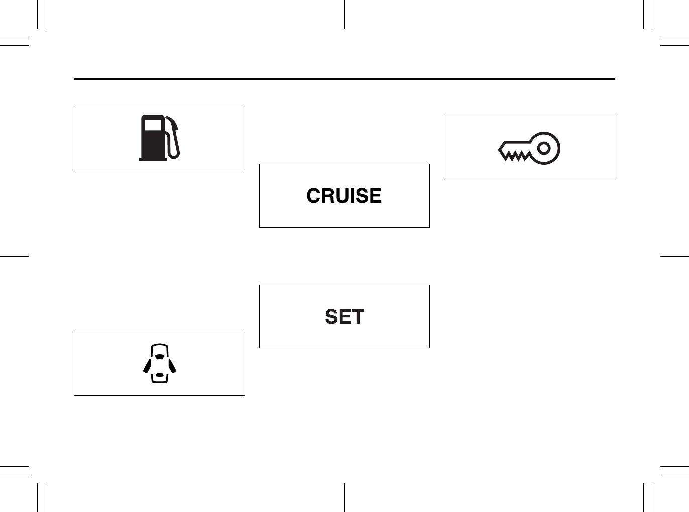
2-66
BEFORE DRIVING
80J23-03E
Low Fuel Warning Light
54G343
If this light comes on, fill the fuel tank
immediately.
When this light comes on, a ding sounds
once to remind you to fill the fuel.
If you do not fill the fuel, a ding sounds
every time when the ignition switch is
turned to “ON”.
NOTE:
The activation point of this light varies
depending on road conditions (for exam-
ple, slope or curve) and driving conditions
because of fuel moving in the tank.
Open Door Warning Light
54G391
This light remains on until all doors (includ-
ing the tailgate of SX4) are completely
closed.
If any door (including the tailgate of SX4) is
open when the vehicle is moving, a ding
sounds to remind you to close all doors
completely.
“CRUISE” Indicator Light
(if equipped)
52D113
When the cruise control system is on, this
light will be on.
“SET” Indicator Light (if equipped)
65D474
When the vehicle’s speed is controlled by
the cruise control system, this light will be
on.
Keyless Start System Indicator
Light (if equipped)
80JM122
When you push the ignition switch for vehi-
cle with the keyless start system, this light
will come on in blue or red. If this light
comes on in blue, you can turn the ignition
switch without using an ignition key. If this
light comes on in red, you cannot turn the
ignition switch without using an ignition
key. For details, refer to “Ignition Switch” in
the “OPERATING YOUR VEHICLE” sec-
tion.
If this light blinks in red, it reminds you that
the remote controller is not in the vehicle.
For details, refer to “Keyless Start System
Remote Controller/Keyless Entry System
Transmitter” in this section.
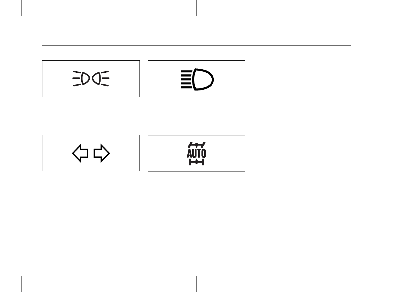
2-67
BEFORE DRIVING
80J23-03E
Illumination Indicator Light
64J045
This indicator light comes on while the
position lights, tail light and/or the head-
lights are on.
Turn Signal Indicators
50G055
When you turn on the left or right turn sig-
nals, the corresponding green arrow on the
instrument panel will flash along with the
respective turn signal lights.
When you turn on the hazard warning
switch, both arrows will flash along with all
of the turn signal lights.
High Beam Indicator Light
50G056
This indicator comes on when headlight
high beams are turned on.
intelligent All Wheel Drive (i-AWD)
AUTO Indicator Light (if equipped)
79J040
When the ignition switch is turned to the
“ON” position, the light comes on briefly so
you can check that the light is working.
When the 2WD/i-AWD switch is in the “i-
AWD AUTO” mode with the ignition switch
in the “ON” position, the light comes on
and stays on.
If the light and the “i-AWD LOCK” indicator
light stay on or come on simultaneously
when driving, there may be something
wrong with the i-AWD system. Have the
system inspected by an authorized
SUZUKI dealer.
If the oil temperature of the parts for i-AWD
system is high, this light will blink. The “i-
AWD AUTO” or “i-AWD LOCK” mode will
be changed to the “2WD” mode automati-
cally to prevent a damage of the parts for i-
AWD system.
NOTE:
If you restart the engine, the light will stop
blinking temporarily.
For details, refer to “Using the 2WD/i-AWD
Switch” in the “OPERATING YOUR VEHI-
CLE” section.
NOTE:
When the vehicle speed is increased, the
“i-AWD LOCK” mode will be changed to
the “i-AWD AUTO” mode automatically.
The “i-AWD AUTO” indicator light will come
on and stay on.
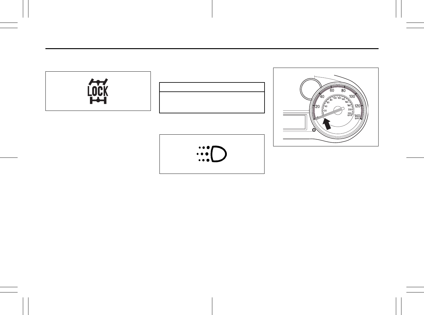
2-68
BEFORE DRIVING
80J23-03E
intelligent All Wheel Drive (i-AWD)
LOCK Indicator Light (if equipped)
79J100
When the ignition switch is turned to the
“ON” position, this light comes on briefly so
you can check that the light is working.
The light comes on when the 2WD/i-AWD
switch is changed to the “i-AWD LOCK”
mode from the “i-AWD AUTO” mode.
If the light and the “i-AWD AUTO” indicator
light stay on or come on simultaneously
when driving, there may be something
wrong with the i-AWD system. Have the
system inspected by an authorized
SUZUKI dealer.
NOTE:
• When the vehicle speed is increased,
the “i-AWD LOCK” mode will be changed
to the “i-AWD AUTO” mode automati-
cally. The “i-AWD AUTO” indicator light
will come on and stay on.
• When the ignition switch is turned to the
“OFF” position, the “i-AWD LOCK” mode
is canceled.
For details of the “i-AWD LOCK” mode,
refer to “Using the 2WD/i-AWD Switch” in
the “OPERATING YOUR VEHICLE” sec-
tion.
Daytime Running Light (D.R.L.) Indi-
cator Light (if equipped)
60B245
With the D.R.L. system, the headlights
light, but are dimmer than the low beam,
when the following three conditions are all
met. Whenever the D.R.L. system is oper-
ating, the D.R.L. indicator light remains on.
Conditions for D.R.L. system operation
1) The engine is running.
2) The parking brake is released.
3) The headlights are off.
Speedometer
80J2063
The speedometer indicates vehicle speed
in km/h and mph.
CAUTION
Do not operate your vehicle in “i-
AWD LOCK” mode on dry hard sur-
faces.
EXAMPLE
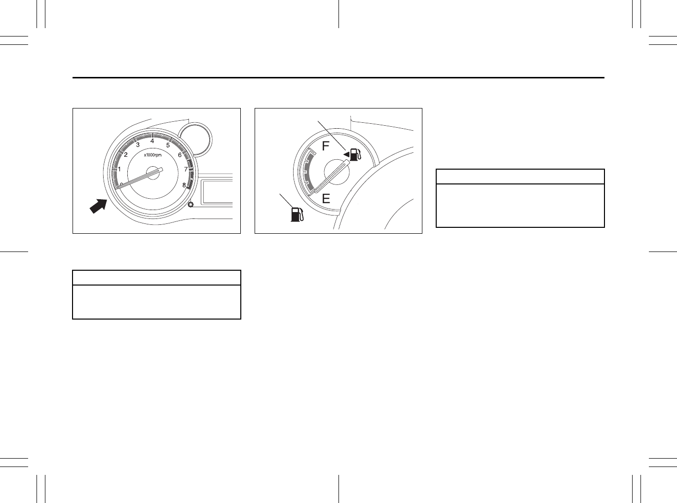
2-69
BEFORE DRIVING
80J23-03E
Tachometer
80JM101
The tachometer indicates engine speed in
revolutions per minute.
Fuel Gauge
80JM102
When the ignition switch is in the “ON”
position, this gauge gives an approximate
indication of the amount of fuel in the fuel
tank. “F” stands for full and “E” stands for
empty.
If the indicator gets off the graduation of
“E” (not character “E”), refill the tank as
soon as possible.
NOTE:
The indicator moves a little depending on
road conditions (for example, slope or
curve) and driving conditions because of
fuel moving in the tank.
If the low fuel warning light (1) comes on,
fill the fuel tank immediately.
When the low fuel warning light (1) comes
on, a ding sounds once to remind you to fill
the fuel.
If you do not fill the fuel, a ding sounds
every time when the ignition switch is
turned to “ON”.
NOTE:
The activation point of the low fuel warning
light (1) varies depending on road condi-
tions (for example, slope or curve) and
driving conditions because of fuel moving
in the tank.
The mark (2) indicates that the fuel filler
door is located on the left side of the vehi-
cle.
CAUTION
Never drive with the engine speed
indicator in the red zone or severe
engine damage can result.
EXAMPLE (2)
(1)
CAUTION
Avoid driving with an extremely low
fuel level. Running out of fuel could
cause the engine to misfire, damag-
ing the catalytic converter.
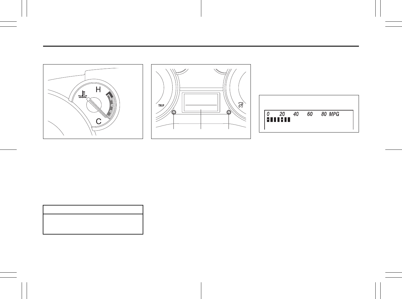
2-70
BEFORE DRIVING
80J23-03E
Temperature Gauge
80JM103
When the ignition switch is in the “ON”
position, this gauge indicates the engine
coolant temperature. Under normal driving
conditions, the indicator should stay within
the normal, acceptable temperature range
between “H” and “C”. If the indicator
approaches “H”, overheating is indicated.
Follow the instructions for engine overheat-
ing in the “EMERGENCY SERVICE” sec-
tion.
Information display
80JM104
(1) Trip meter selector knob
(2) Indicator selector knob
(3) Information display
When the ignition switch is in the “ON”
position, the information display shows the
following information.
Display (A)
Instantaneous fuel consumption
Display (B)
Trip meter / Average fuel consumption /
Driving range / Thermometer
Display (C)
Transaxle selector position indicator
(for CVT)
Display (D)
Odometer / Illumination control setting
Display (E)
Clock (if equipped)
Instantaneous Fuel Consumption
The display (A) shows instantaneous fuel
consumption with a bar graph only when
the vehicle is moving.
80J2026
NOTE:
• The display does not show the bar graph
unless the vehicle is moving.
• The indicated maximum value of instan-
taneous fuel consumption is 80. No
more than 80 will be indicated on the dis-
play even if the actual instantaneous fuel
consumption is higher.
• The indication on the display may be
delayed if fuel consumption is greatly
affected by driving conditions.
• The display shows estimated values.
Indications may not be the same as
actual values.
CAUTION
Continuing to drive the vehicle when
engine overheating is indicated can
result in severe engine damage.
(1) (2)(3)
(D)
(B)
(A) (C)
(E)
EXAMPLE
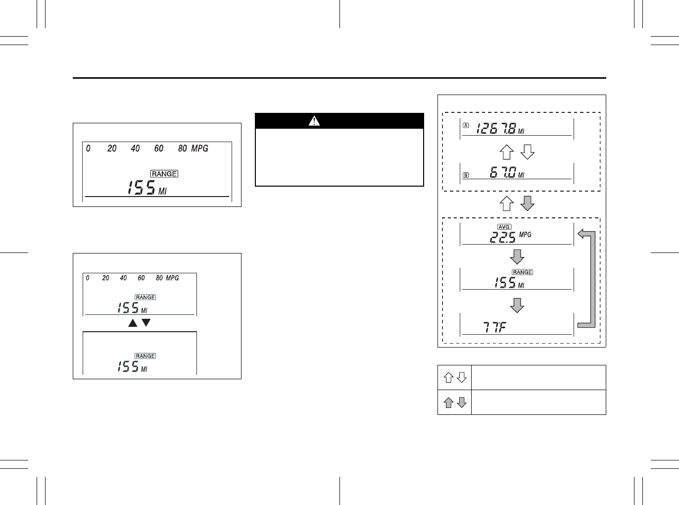
2-71
BEFORE DRIVING
80J23-03E
You can turn off or on the indication of
instantaneous fuel consumption according
to the following instruction.
80J2027
1) Change the display (B) to the driving
range by pushing the indicator selector
knob (2).
80J2028
2) While pushing and holding the trip
meter selector knob (1), turn the indica-
tor selector knob (2) to turn off or on the
indication of instantaneous fuel con-
sumption.
NOTE:
When you reconnect the negative (–) ter-
minal to the battery, the indication of the
instantaneous fuel consumption will be
reinitialized. Change the indication again to
your preference.
Trip meter / Average Fuel Consumption /
Driving Range / Thermometer
When the ignition switch is in the “ON”
position, the display (B) shows one of the
following five indications, trip meter A, trip
meter B, average fuel consumption, driving
range or thermometer.
To switch the display indication (B), push
the trip meter selector knob (1) or the indi-
cator selector knob (2) quickly. 80J2029
EXAMPLE
EXAMPLE
(Initial
setting)
WARNING
If you attempt to adjust the display
while driving, you could lose control
of the vehicle.
Do not attempt to adjust the display
while driving.
Push the trip meter selector
knob (1).
Push the indicator selector
knob (2).
(a)
(b)
(c)
(d)
(e)
EXAMPLE

2-72
BEFORE DRIVING
80J23-03E
(a) Trip meter A
(b) Trip meter B
(c) Average fuel consumption
(d) Driving range
(e) Thermometer
NOTE:
• Indications will change when you push
and release a knob.
• The display shows estimated values.
Indications may not be the same as
actual values.
Trip meter
The trip meter can be used to measure the
distance traveled on short trips or between
fuel stops.
You can use the trip meter A or trip meter B
independently.
To reset the trip meter to zero, push and
hold the trip meter selector knob (1) for a
while when the display shows the trip
meter.
NOTE:
The indicated maximum value of the trip
meter is 9999.9. When you run past the
maximum value, the indicated value will
return to 0.0.
Average fuel consumption
If you selected average fuel consumption
the last time you drove the vehicle, the dis-
play shows the last value of average fuel
consumption from previous driving when
the ignition switch is turned to the “ON”
position. Unless you reset the value of
average fuel consumption, the display indi-
cates the value of average fuel consump-
tion which includes average fuel
consumption during previous driving.
To reset the average fuel consumption to
zero, push and hold the indicator selector
knob (2) for a while when the display
shows the average fuel consumption.
NOTE:
When you reset the indication or reconnect
the negative (–) terminal to the battery, the
value of average fuel consumption will be
shown after driving for a while.
Driving range
If you selected driving range the last time
you drove the vehicle, the display indicates
“---” for a few seconds and then indicates
the current driving range when the ignition
switch is turned to the “ON” position.
The driving range shown in the display is
the approximate distance you can drive
until the fuel gauge indicates “E”, based on
current driving conditions.
When the remaining fuel in fuel tank
reaches a low level, the display “---” will
appear.
If the low fuel warning light comes on, fill
the fuel tank immediately regardless of the
value of driving range shown in the display.
As the driving range after refueling is cal-
culated based on the most recent driving
condition, the value is different each time
you refuel.
NOTE:
• If you refuel when the ignition switch is in
the “ON” position, the driving range may
not indicate the correct value.
• When you reconnect the negative (–) ter-
minal to the battery, the value of driving
range will be shown after driving for a
while.
WARNING
If you attempt to adjust the display
while driving, you could lose control
of the vehicle.
Do not attempt to adjust the display
while driving.
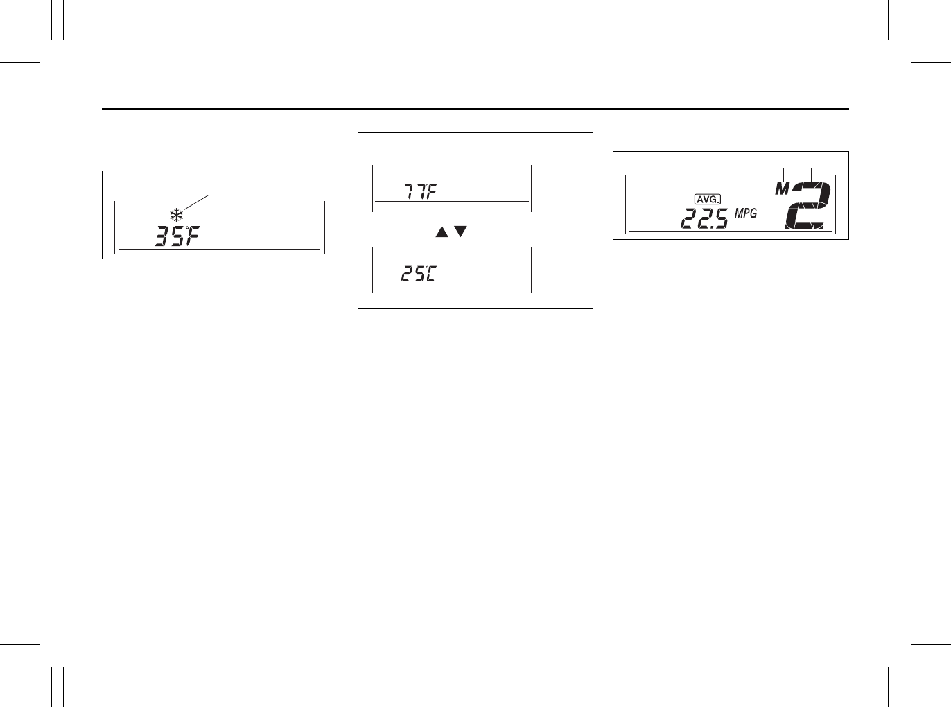
2-73
BEFORE DRIVING
80J23-03E
Thermometer
The thermometer indicates the outside
temperature.
80J2030
If the outside temperature nears freezing,
the mark (f) will appear on the display.
NOTE:
• The outside temperature indication is not
the actual outside temperature when
driving at low speed, or when stopped.
• If there is something wrong with the ther-
mometer, or just after the ignition switch
is turned to the “ON” position, the display
may not indicate the outside tempera-
ture.
• The mark (f) will appear whenever the
outside temperature is near freezing,
even if the display does not show the
thermometer.
To change the unit of temperature, while
pushing and holding the trip meter selector
knob (1), turn the indicator selector knob
(2).
80J2031
NOTE:
When you reconnect the negative (–) ter-
minal to the battery, the unit of temperature
will be reinitialized. Change the unit again
to your preference.
Transaxle selector position indicator
(for CVT)
80J2032
When the ignition switch is in the “ON”
position, the display (C) indicates the gear
position (g).
When using the manual mode, the display
(C) indicates the manual mode indicator
(h).
For details on how to use the transaxle,
refer to “Using the Transaxle” in the
“OPERATING YOUR VEHICLE” section.
(f)
EXAMPLE
EXAMPLE
(Initial
setting)
(h) (g)
EXAMPLE
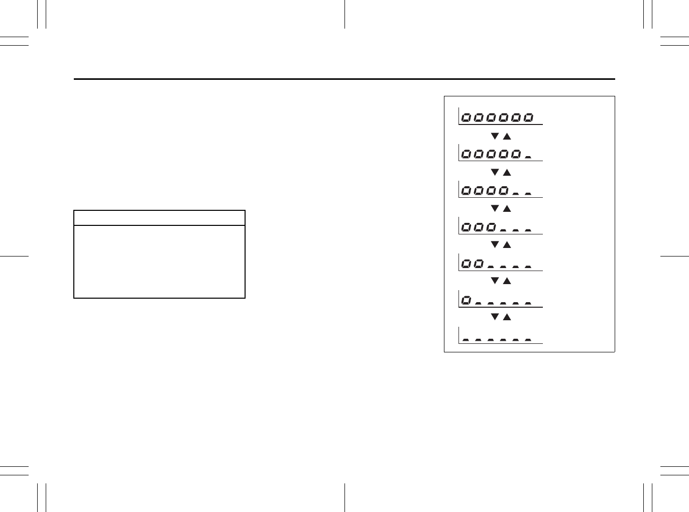
2-74
BEFORE DRIVING
80J23-03E
Odometer / Illumination Control Setting
When the ignition switch is in the “ON”
position, the display (D) shows the odome-
ter.
If you turn the indicator selector knob (2)
clockwise or counterclockwise, the display
will change to the illumination control set-
ting.
Odometer
The odometer records the total distance
the vehicle has been driven.
Illumination control setting
When the ignition switch is turned to the
“ON” position, the instrument panel lights
come on.
Your vehicle has a system to automatically
dim the brightness of the instrument panel
lights when the position lights or headlights
are on.
You can change the brightness of the
instrument panel lights regardless of
whether the position lights or headlights
are off or on.
To increase the brightness of the instru-
ment panel lights, turn the indicator selec-
tor knob (1) clockwise.
To reduce the brightness of the instrument
panel lights, turn the indicator selector
knob (1) counterclockwise.
80JM039
CAUTION
Keep track of your odometer reading
and check the maintenance schedule
regularly for required services.
Increased wear or damage to certain
parts can result from failure to per-
form required services at the proper
mileage intervals.
(Brightest)
(Initial setting)
(Dimmest)
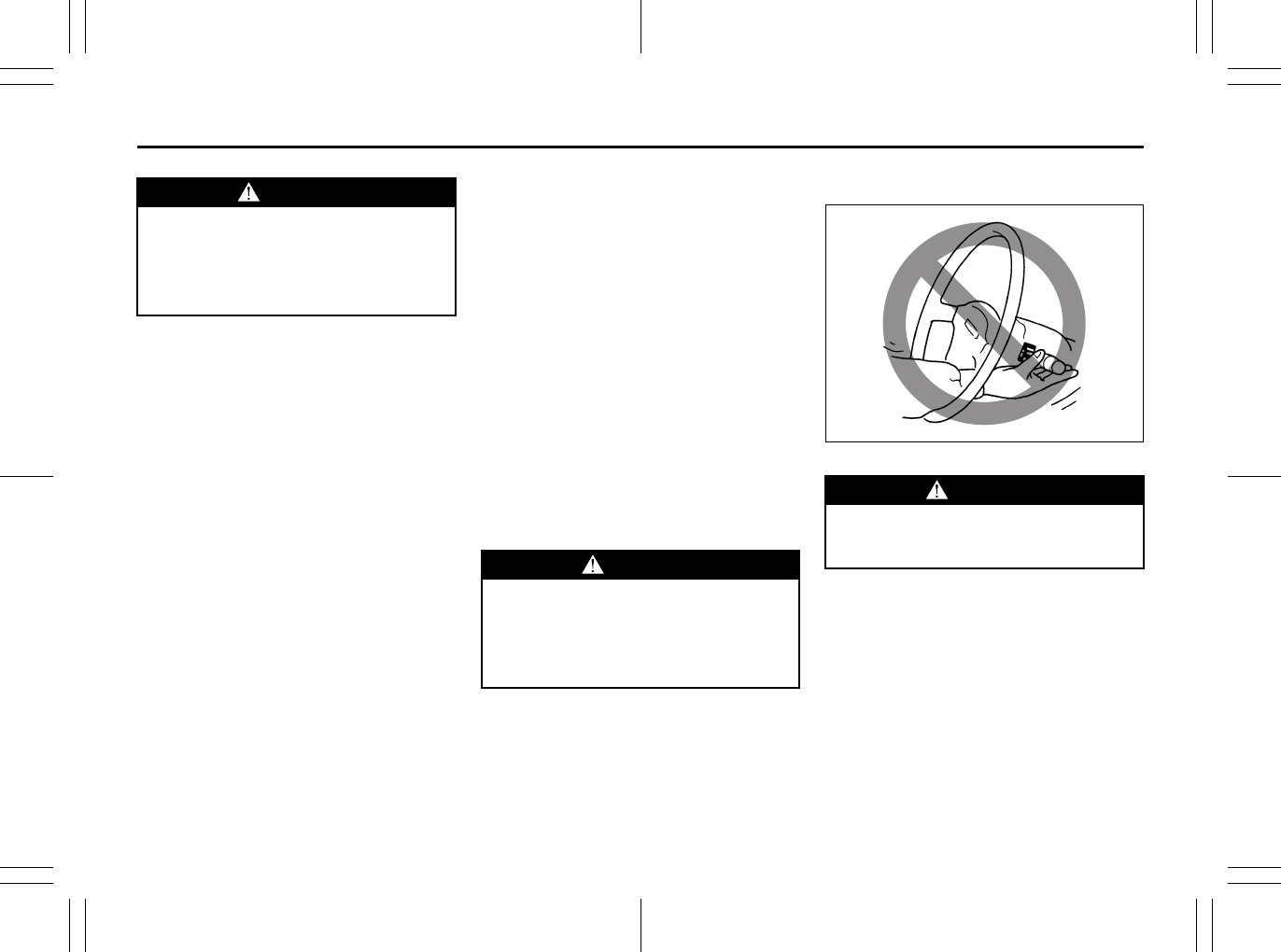
2-75
BEFORE DRIVING
80J23-03E
NOTE:
• If you push the indicator selector knob or
do not turn the knob for more than 5 sec-
onds while activating the illumination
control, the illumination control will be
canceled automatically and the display
(D) will show the odometer indication.
• You can change the brightness when the
position lights or headlights are on even
if the ignition switch is in the “ACC” or
“LOCK” position.
• When you reconnect the negative (–) ter-
minal to the battery, the brightness of the
instrument panel lights will be reinitial-
ized. Readjust the brightness according
to your preference.
NOTE:
If you select the lowest brightness level
when the position lights or headlights are
on, the instrument panel lights other than
meter lights are turned off.
Clock (if equipped)
When the ignition switch is in the “ON”
position, the display (E) shows the time.
To change the time indication:
1) Push the trip meter selector knob (1)
and the indicator selector knob (2)
together.
2) To change the hour indication, turn the
indicator selector knob (2) left or right
repeatedly when the hour indication
flashes. To change the hour indication
quickly, turn and hold the indicator
selector knob (2). To set the hour indi-
cation, push the the indicator selector
knob (2) and the minute indication will
flash.
3) To change the minute indication, turn
the indicator selector knob (2) left or
right repeatedly when the minute indi-
cation flashes. To change the minute
indication quickly, turn and hold the
indicator selector knob (2). To set the
minute indication, push the indicator
selector knob (2).
NOTE:
When you reconnect the negative (–) ter-
minal to the battery, the clock indication will
be reinitialized. Change the indication
again to your preference.
Lighting Control Lever
65D611
WARNING
If you attempt to adjust the display
while driving, you could lose control
of the vehicle.
Do not attempt to adjust the display
while driving.
WARNING
If you attempt to adjust the display
while driving, you could lose control
of the vehicle.
Do not attempt to adjust the display
while driving.
WARNING
To avoid possible injury, do not oper-
ate controls by reaching through the
steering wheel.
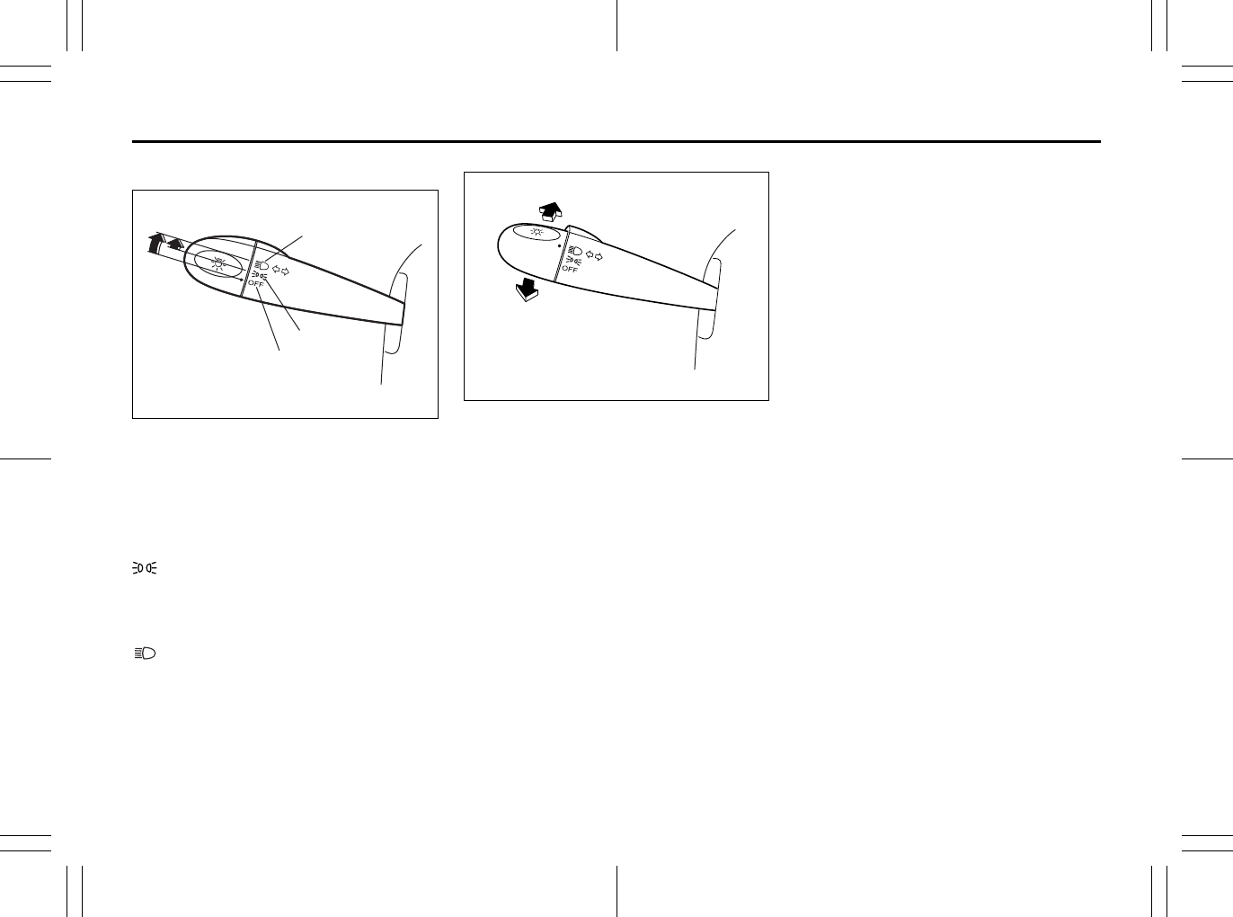
2-76
BEFORE DRIVING
80J23-03E
Lighting Operation
63J308
To turn the lights on or off, twist the knob
on the end of the lever. There are three
positions:
OFF (1)
All lights are off.
(2)
Front position lights, tail lights, license
plate light and instrument lights are on, but
headlights are off.
(3)
Front position lights, tail lights, license
plate light, instrument lights and head
lights are on.
63J309
With the headlights on, push the lever for-
ward to switch to the high beams (main
beams) or pull the lever toward you to
switch to the low beams. When the high
beams (main beams) are on, a light on the
instrument panel will come on. To momen-
tarily activate the high beams (main
beams) as a passing signal, pull the lever
slightly toward you and release it when you
have completed the signal.
Daytime Running Light (D.R.L.)
System
The headlights light, but are dimmer than
the low beam, when the following three
conditions are all met. Also, the D.R.L. indi-
cator light on the instrument panel comes
on.
Conditions for D.R.L. system operation:
1) The engine is running.
2) The parking brake is released.
3) The headlights are off.
NOTE:
Be sure to turn the headlights on at night
or at any time of the day when driving or
weather conditions require the headlights
to operate at full brightness and the tail-
lights to be on.
Lights “On” reminder (if equipped)
A buzzer/chime sounds to remind you to
turn off the lights if they are left on when
the ignition key is removed and the driver’s
door is opened.
(1)
(2)
(3)
EXAMPLE
EXAMPLE
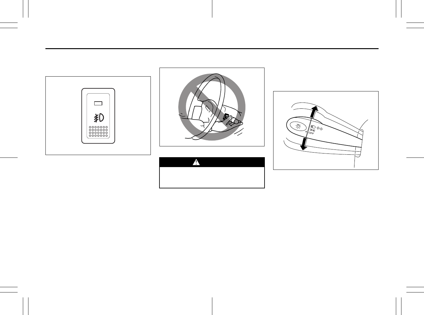
2-77
BEFORE DRIVING
80J23-03E
Front Fog Light Switch
(if equipped)
64J058
The front fog light comes on when the fog
light switch is pushed in with the headlights
are on and the beams set to the low beam
position.
Turn Signal Control Lever
65D611
Turn Signal Operation
With the ignition switch in the “ON” posi-
tion, move the lever up or down to activate
the right or left turn signals.
Normal turn signal
63J310
Move the lever all the way upward or down-
ward to signal. When the turn is com-
pleted, the signal will cancel and the lever
will return to its normal position.
WARNING
To avoid possible injury, do not oper-
ate controls by reaching through the
steering wheel.
EXAMPLE
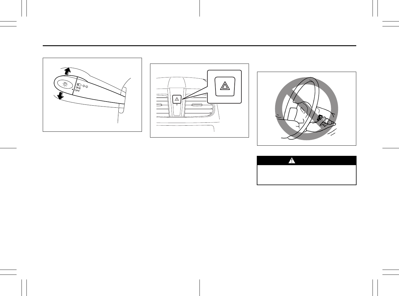
2-78
BEFORE DRIVING
80J23-03E
Lane change signal
63J311
Some times, such as when changing
lanes, the steering wheel is not turned far
enough to cancel the turn signal. For con-
venience, you can flash the turn signal by
moving the lever part way and holding it
there. The lever will return to its normal
position when you release it.
Hazard Warning Switch
80JM041
Push in the hazard warning switch to acti-
vate the hazard warning lights. All turn sig-
nal lights and both turn signal indicators
will flash simultaneously. To turn off the
lights, push the switch again.
Use the hazard warning lights to warn
other traffic during emergency parking or
when your vehicle could otherwise become
a traffic hazard.
Windshield Wiper and Washer
Lever
65D611
EXAMPLE
WARNING
To avoid possible injury, do not oper-
ate controls by reaching through the
steering wheel.
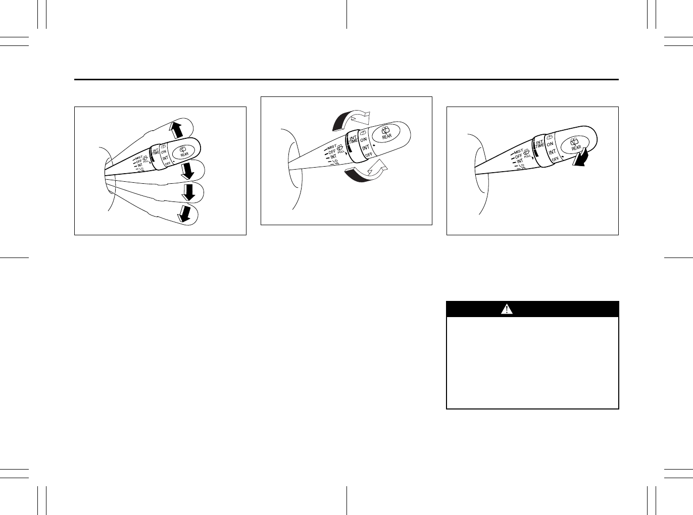
2-79
BEFORE DRIVING
80J23-03E
Windshield Wipers
63J301
To turn the windshield wipers on, move the
lever down to one of the three operating
positions. In the “INT” position (if
equipped), the wipers operate intermit-
tently. The “INT” position is very convenient
for driving in mist or light rain. In the “LO”
position, the wipers operate at a steady
low speed. In the “HI” position, the wipers
operate at a steady high speed. To turn off
the wipers, move the lever back to the
“OFF” position.
Move the lever up and hold it to the “MIST”
position, the windshield wipers will turn on
continuously at low speed.
63J302
If the lever is equipped with the “INT TIME”
control, turn the control forward or rear-
ward to adjust the intermittent wiper opera-
tion to the desired interval.
Windshield Washer
63J303
To spray windshield washer fluid, pull the
lever toward you. The windshield wipers
will automatically turn on at low speed if
they are not already on and the “INT” posi-
tion is equipped.
MIST
OFF
INT
LO
HI
EXAMPLE
EXAMPLE
WARNING
• To prevent windshield icing in cold
weather, turn on the defroster to
heat the windshield before and dur-
ing windshield washer use.
• Do not use radiator antifreeze in
the windshield washer reservoir. It
can severely impair visibility when
sprayed on the windshield, and can
also damage your vehicle’s paint.
EXAMPLE
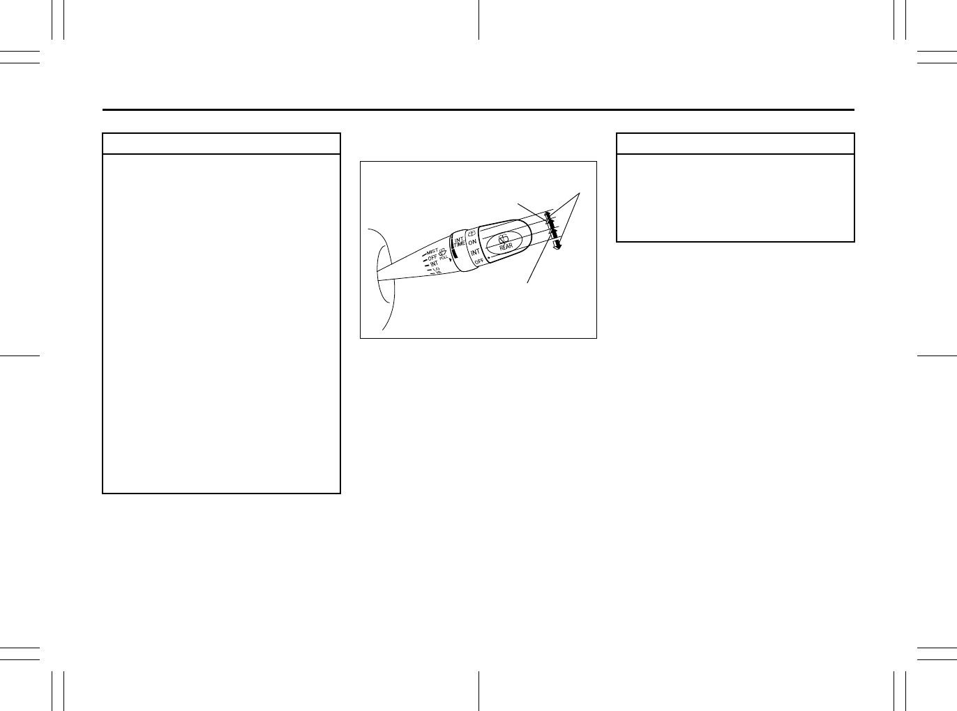
2-80
BEFORE DRIVING
80J23-03E
Rear Window Wiper/Washer Switch
(if equipped)
63J304
To turn the rear wiper on, twist the rear
wiper switch on the end of the lever for-
ward to the “ON” position. If your vehicle is
equipped the “INT” position, the rear wiper
operates intermittently when you twist the
switch forward to the “INT” position. To turn
the rear wiper off, twist the switch rearward
to the “OFF” position.
To spray window washer fluid, twist the
switch rearward from the “OFF” position, or
twist the switch forward from the “ON” posi-
tion. The rear wiper will turn on automati-
cally while spraying the window washer
fluid.
CAUTION
To help prevent damage to the wind-
shield wiper and washer system
components, you should take the fol-
lowing precautions:
• Do not continue to hold in the lever
when there is no windshield
washer fluid being sprayed or the
washer motor can be damaged.
• Do not attempt to remove dirt from
a dry windshield with the wipers or
you can damage the windshield
and the wiper blades. Always wet
the windshield with washer fluid
before operating the wipers.
• Clear ice or packed snow from the
wiper blades before using the wip-
ers.
• Check the washer fluid level regu-
larly. Check it often when the
weather is bad.
• Only fill the washer fluid reservoir
3/4 full during cold weather to allow
room for expansion if the tempera-
ture falls low enough to freeze the
solution.
EXAMPLE
Intermittent wiper
Washer
Wiper
CAUTION
Clear ice or snow from the rear win-
dow and rear wiper blade before
using the rear wiper. Accumulated ice
or snow could prevent the wiper
blade from moving, causing damage
to the wiper motor.
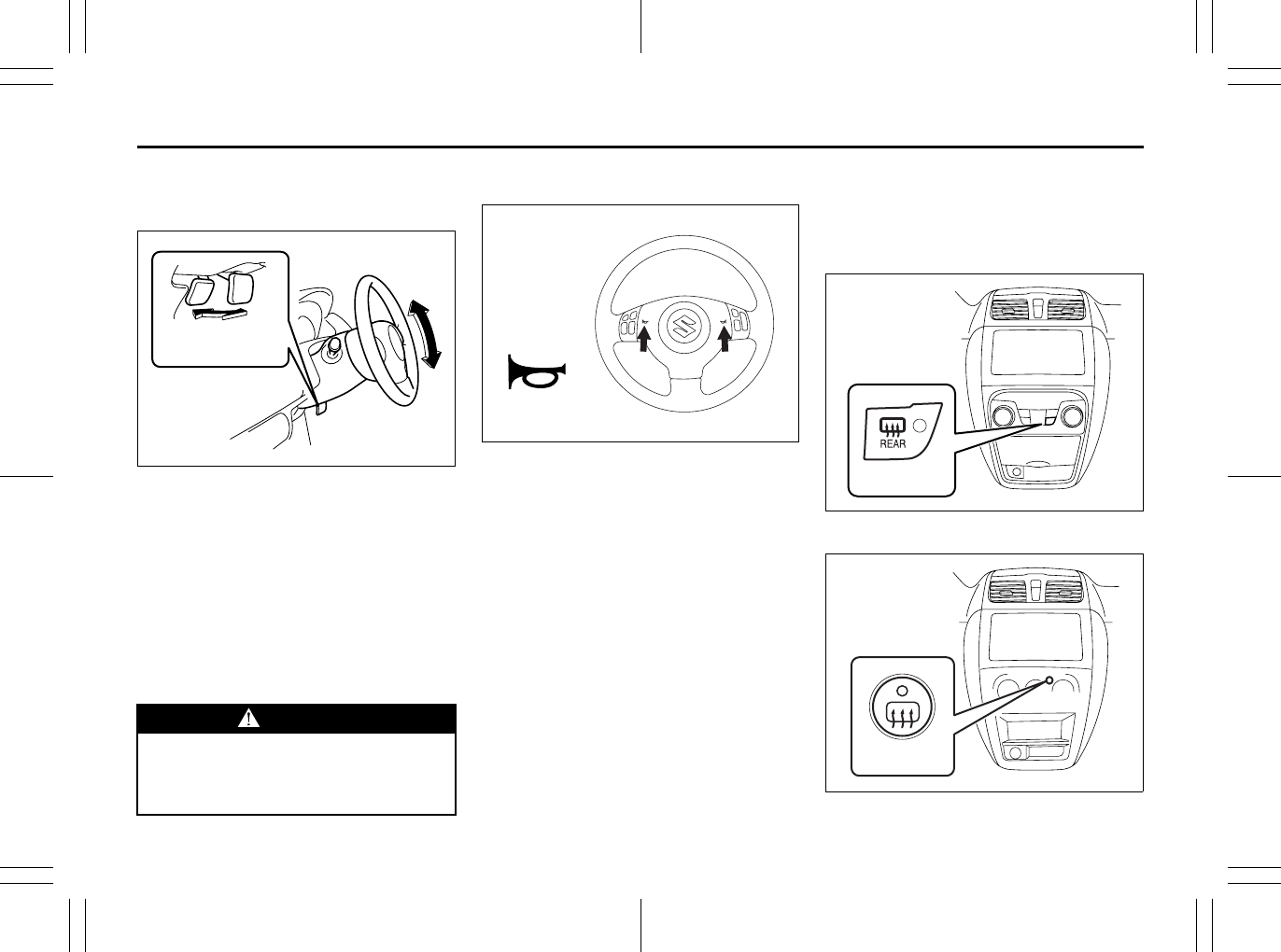
2-81
BEFORE DRIVING
80J23-03E
Tilt Steering Lock Lever
(if equipped)
63J026
The lock lever is located under the steering
column. To adjust the steering wheel
height:
1) Pull up the lock lever to unlock the
steering column.
2) Adjust the steering wheel to the desired
height and lock the steering column by
push down the lock lever.
3) Try moving the steering wheel up and
down to make sure it is securely locked
in position.
Horn
80J2010
Press the horn pad on the steering wheel
to sound the horn. The horn will sound with
the ignition switch in any position.
Heated Rear Window and
Heated Outside Rearview
Mirrors (if equipped) Switch
Type 1
80JM042
Type 2
80JM043
WARNING
Never attempt to adjust the steering
wheel height while the vehicle is
moving or you could lose control of
the vehicle.
LOCK UNLOCK
EXAMPLE
EXAMPLE
(1)
EXAMPLE
(1)
EXAMPLE
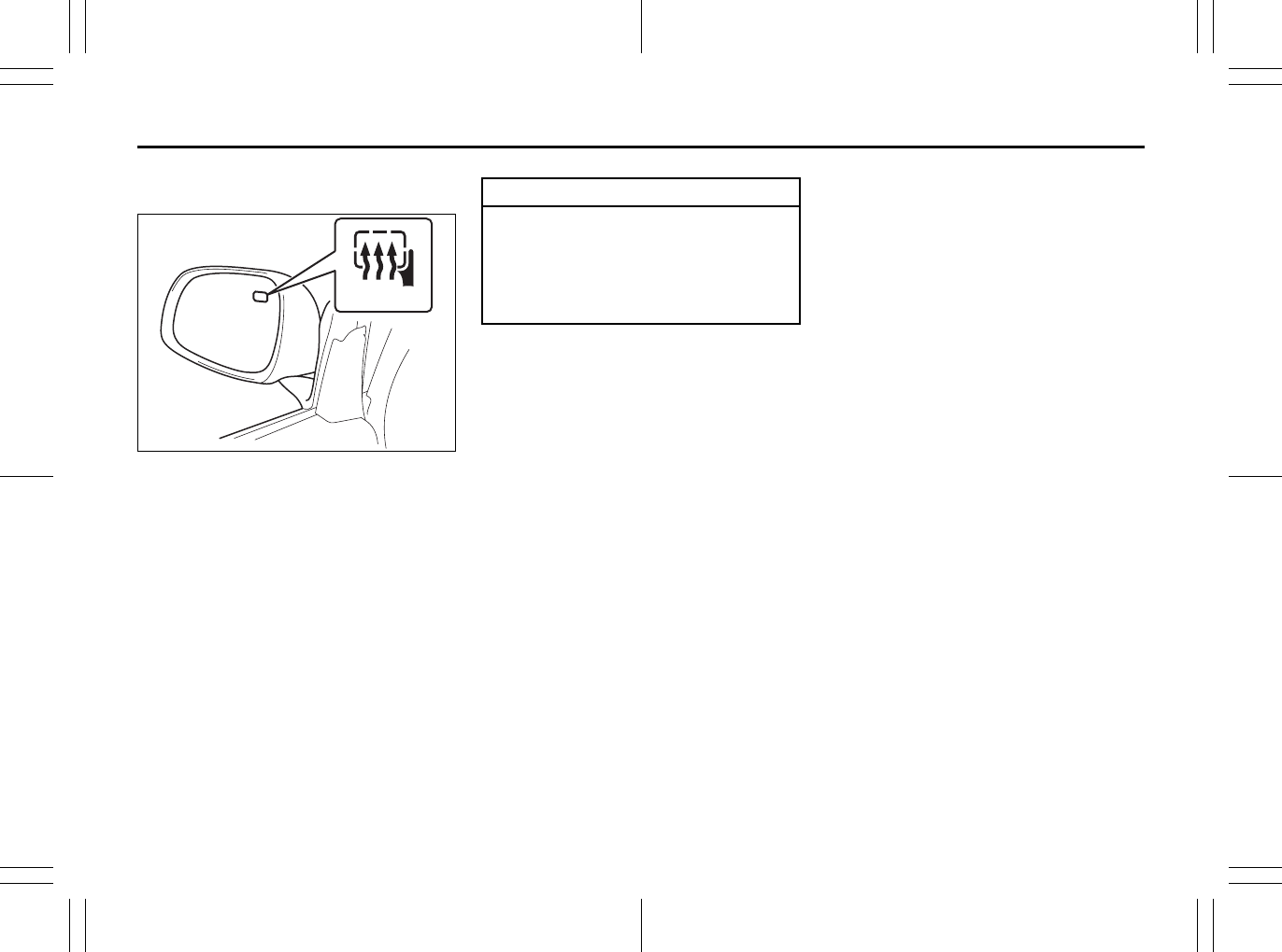
2-82
BEFORE DRIVING
80J23-03E
When the rear window is misted, push this
switch (1) to clear the window.
80JC040
If the outside rearview mirror has the mark
(2), it is also equipped with the heated out-
side rearview mirrors. When you push the
switch (1), both the heated outside rear-
view mirrors and the heated rear window
will operate simultaneously.
An indicator light will be lit when the defog-
ger is on. The defogger will work only
when the engine is running. To turn off the
defogger, push the switch (1) again.
NOTE:
• The defogger will work only when the
engine is running.
• The defogger will automatically turn off
after the defogger remains on for 15 min-
utes to prevent discharging of the bat-
tery.
(2)
CAUTION
The heated rear window and the
heated outside rearview mirrors (if
equipped) use a large amount of elec-
tricity. Be sure to turn off after the
window and mirrors have become
clear.

2-83
BEFORE DRIVING
80J23-03E
MEMO
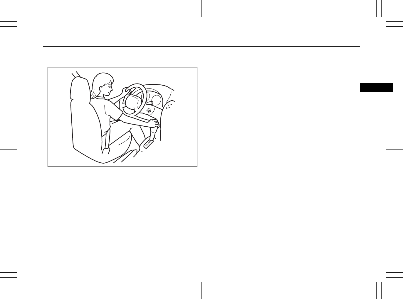
OPERATING YOUR VEHICLE
3
80J23-03E
60G408
OPERATING YOUR VEHICLE
Exhaust Gas Warning ......................................................... 3-1
Daily Inspection Checklist .................................................. 3-1
Ignition Switch ..................................................................... 3-2
Parking Brake Lever ........................................................... 3-6
Pedals ................................................................................... 3-7
Starting the Engine ............................................................. 3-8
Engine Block Heater (if equipped) ..................................... 3-9
Using the Transaxle ............................................................ 3-10
Using the 2WD/i-AWD (intelligent All Wheel Drive)
Switch (if equipped) ............................................................ 3-16
Cruise Control (if equipped) ............................................... 3-18
Braking ................................................................................. 3-20
Electronic Stability Program (ESP®) (if equipped) ........... 3-23
Tire Pressure Monitoring System (TPMS) ........................ 3-26
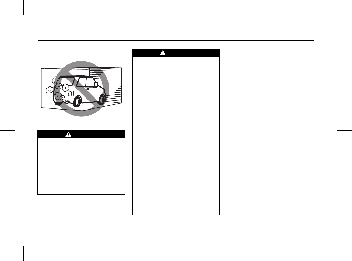
3-1
OPERATING YOUR VEHICLE
80J23-03E
Exhaust Gas Warning
52D334
Daily Inspection Checklist
Before Driving
1) Make sure that windows, mirrors, lights
and reflectors are clean and unob-
structed.
2) Visually check the tires for the following
points:
– the depth of the tread groove
– abnormal wear, cracks and damage
– loose wheel nuts
– existence of foreign material such as
nails, stones, etc.
Refer to “Tires” in “INSPECTION AND
MAINTENANCE” section for details.
3) Look for fluid, oil leaks.
NOTE:
It is normal for water to drip from the air
conditioning system after use.
4) Make sure the hood is fully closed and
latched.
5) Check the headlights, turn signal lights,
brake lights and horn for proper opera-
tion.
6) Lock all doors.
7) Adjust the seat and adjustable head
restraints (if equipped).
8) Check the brake pedal.
9) Adjust the mirrors.
10)Make sure that you and all passengers
have properly fastened your seat belts.
11)Make sure that all warning lights come
on as the key is turned to the “ON” posi-
tion.
WARNING
Avoid breathing exhaust gases.
Exhaust gases contain carbon mon-
oxide, a potentially lethal gas that is
colorless and odorless. Since carbon
monoxide is difficult to detect by
itself, be sure to take the following
precautions to help prevent carbon
monoxide from entering your vehicle.
• Do not leave the engine running in
garages or other confined areas.
(Continued)
WARNING
(Continued)
• Do not park with the engine run-
ning for a long period of time, even
in an open area. If it is necessary to
sit for a short time in a parked vehi-
cle with the engine running, make
sure the air intake selector is set to
“FRESH AIR” and the blower is at
high speed.
• Avoid operating the vehicle with
the tailgate or trunk open. If it is
necessary to operate the vehicle
with the tailgate or trunk open,
make sure the sunroof (if equipped)
and all windows are closed, and the
blower is at high speed with the air
intake selector set to “FRESH AIR”.
• To allow proper operation of your
vehicle’s ventilation system, keep
the air inlet grille in front of the
windshield clear of snow, leaves or
other obstructions at all times.
• Keep the exhaust tailpipe area clear
of snow and other material to help
reduce the buildup of exhaust
gases under the vehicle. This is
particularly important when parked
in blizzard conditions.
• Have the exhaust system inspected
periodically for damage and leaks.
Any damage or leaks should be
repaired immediately.
Ignition Switch: 8
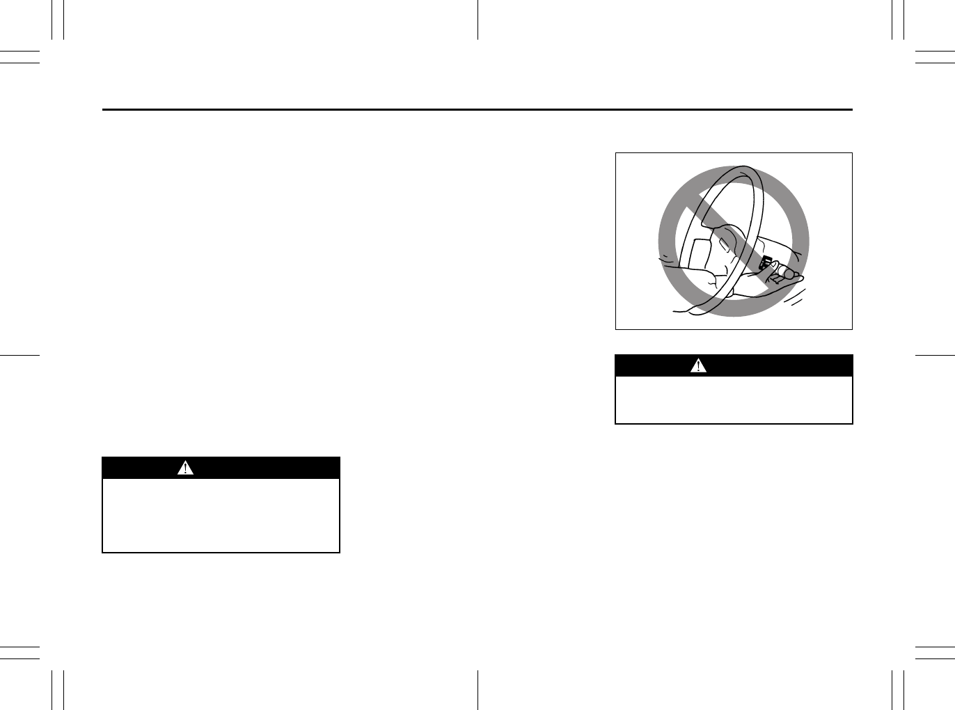
3-2
OPERATING YOUR VEHICLE
80J23-03E
12)Check all gauges.
13)Make sure that the BRAKE light turns
off when the parking brake is released.
Once a week, or each time you fill your fuel
tank, perform the following under-hood
checks:
1) Engine oil level
2) Coolant level
3) Brake fluid level
4) Power steering (if equipped) fluid level
5) Windshield washer fluid level
6) Hood latch operation
Pull the hood release handle inside the
vehicle. Make sure that you cannot
open the hood all the way without
releasing the secondary latch. Be sure
to close the hood securely after check-
ing for proper latch operation. See the
item “All latches, hinges and locks” of
“CHASSIS AND BODY” in the “Periodic
Maintenance Schedule” section in the
“INSPECTION AND MAINTENANCE”
section for lubrication schedule.
Once a month, or each time you fill your
fuel tank, check the tire pressure using a
tire pressure gauge. Also check the tire
pressure of the spare tire.
Ignition Switch
65D611
WARNING
Make sure the hood is fully closed
and latched before driving. If it is not,
it can fly up unexpectedly during
driving, obstructing your view and
resulting in an accident.
WARNING
To avoid possible injury, do not oper-
ate controls by reaching through the
steering wheel.
Ignition Switch: 8
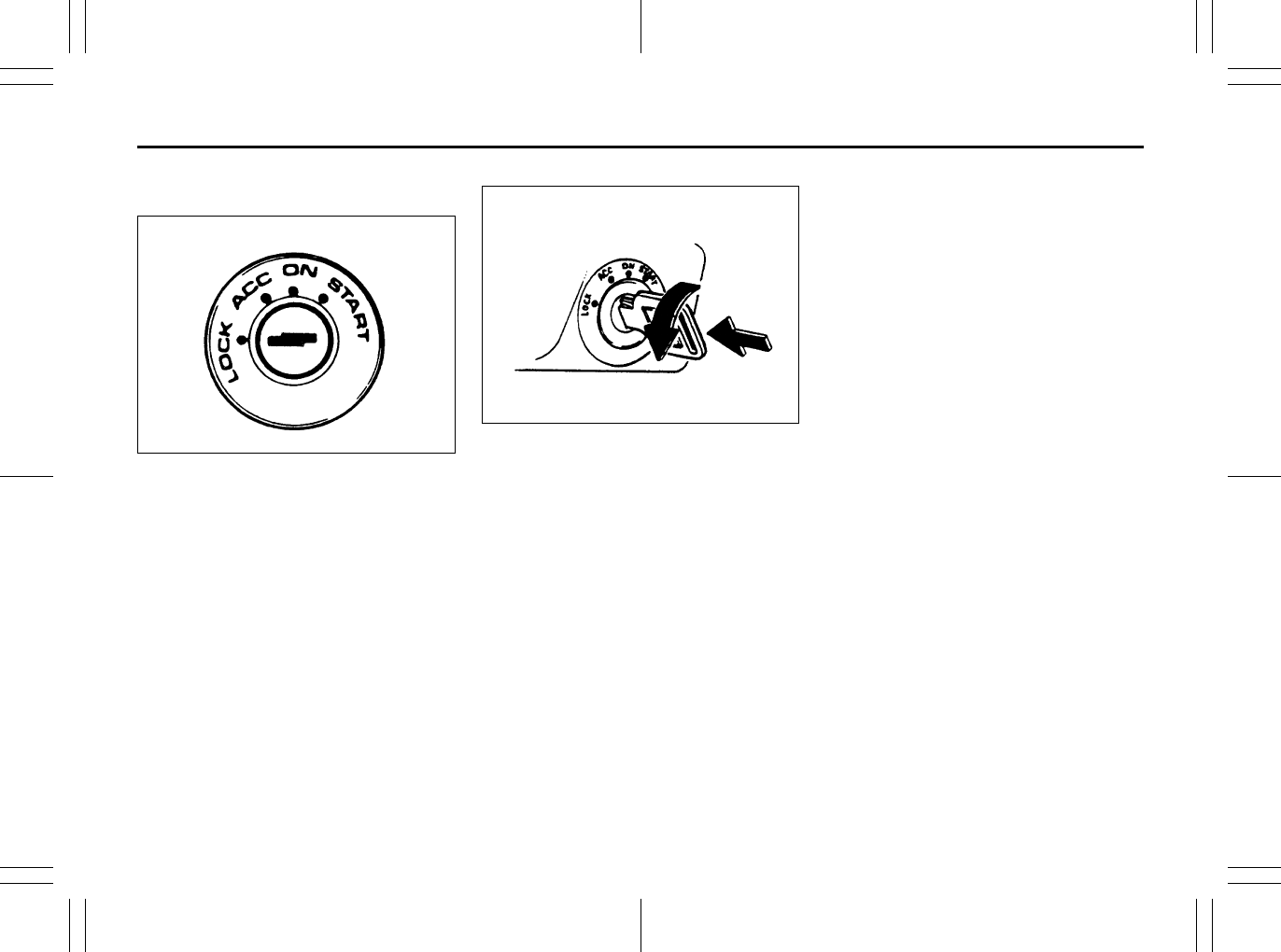
3-3
OPERATING YOUR VEHICLE
80J23-03E
Vehicle Without Keyless Start
System
60B041
The ignition switch has the following four
positions:
LOCK
This is the normal parking position. It is the
only position in which the key can be
removed.
Manual transaxle
60A055
•Manual transaxle vehicles
You must push in the key to turn it to the
“LOCK” position. It locks the ignition, and
prevents normal use of the steering
wheel after the key is removed.
•CVT vehicles
The gearshift lever must be in the “P”
(Park) position to turn the key to the
“LOCK” position. It locks the ignition and
prevents normal use of the steering
wheel and gearshift lever.
To release the steering lock, insert the key
and turn it clockwise to one of the other
positions. If you have trouble turning the
key to unlock the steering, try turning the
steering wheel slightly to the right or left
while turning the key.
ACC
Accessories such as the radio can oper-
ate, but the engine is off.
ON
This is the normal operating position. All
electrical systems are on.
START
This is the position for starting the engine
using the starter motor. The key should be
released from this position as soon as the
engine starts.
Ignition key reminder
A buzzer sounds intermittently to remind
you to remove the ignition key if it is in the
ignition switch when the driver’s door is
opened.
Push
Turn to “LOCK”
Lighting/Turn Signal Control Lever: 8
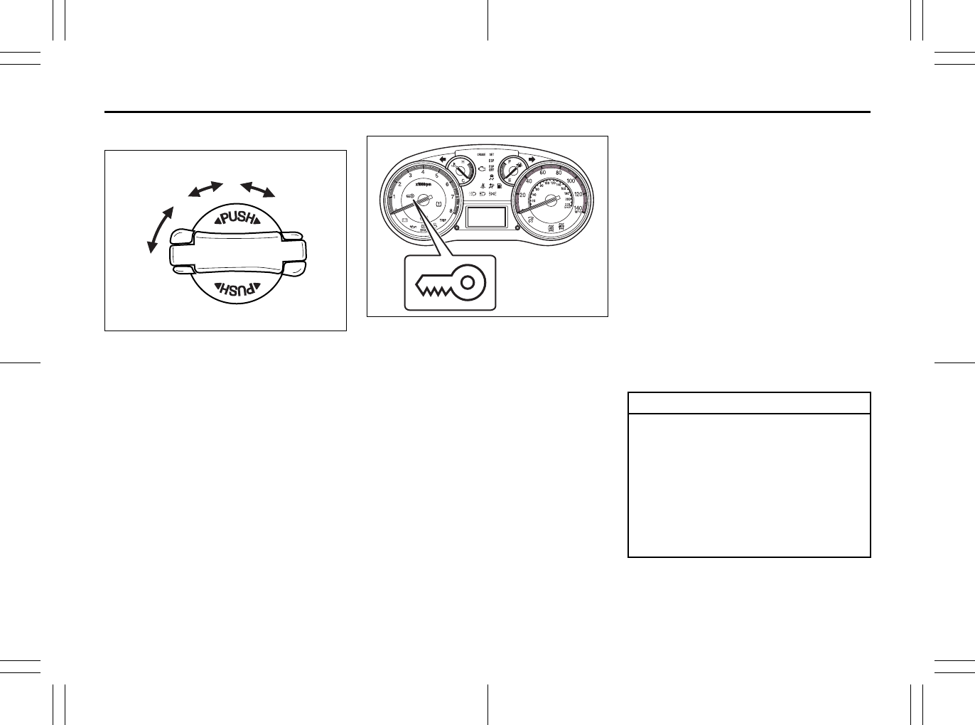
3-4
OPERATING YOUR VEHICLE
80J23-03E
Vehicle With Keyless Start System
56KN076
The ignition switch can be operated with-
out using an ignition key when the remote
controller is in an area of the vehicle other
than the rear luggage area. To turn the
ignition switch, first push in the switch.
• Manual transaxle vehicle
You must push in the ignition switch to
turn it from the “LOCK” position to the
“ACC” position. To return to the “LOCK”
position from the “ACC” position, turn the
ignition switch counterclockwise while
pushing in the switch.
•CVT vehicle
To turn the ignition switch, push the
switch.
80J2016
If the keyless start system blue indicator
light illuminates on the instrument cluster,
you can turn the ignition switch. If the red
indicator light illuminates, you cannot turn
the ignition switch.
NOTE:
• The ignition switch can be turned to the
“ACC” position when the keyless start
system blue indicator light illuminates.
The blue indicator light will illuminate for
several seconds when you push in the
ignition switch and then will turn off to
protect the system. In this case, you
must release the ignition switch and
push it in again to illuminate the blue
indicator light.
• If the keyless start system red indicator
light illuminates, the remote controller
may not be in the vehicle or the battery
of the remote controller may be unreli-
able.
NOTE:
• If the battery of the remote controller
runs down or there are strong radio
waves or noise, the operating range may
be narrower or the remote controller may
be inoperative.
• If the remote controller is too close to the
door glass, it may not operate.
• The ignition switch may not turn when
the remote controller is on the instru-
ment panel, in the glove box, in a stor-
age compartment, in the sun visor or on
the floor.
(1)
(2)
(3)
(4)
EXAMPLE
CAUTION
The remote controller is a sensitive
electronic instrument. To avoid dam-
aging the remote controller:
• Do not expose it to impacts, mois-
ture or high temperature such as by
leaving it on the dashboard under
direct sunlight.
• Keep the remote controller away
from magnetic objects such as a
television.
Lighting/Turn Signal Control Lever: 8
Windshield Wiper and Washer Lever: 8
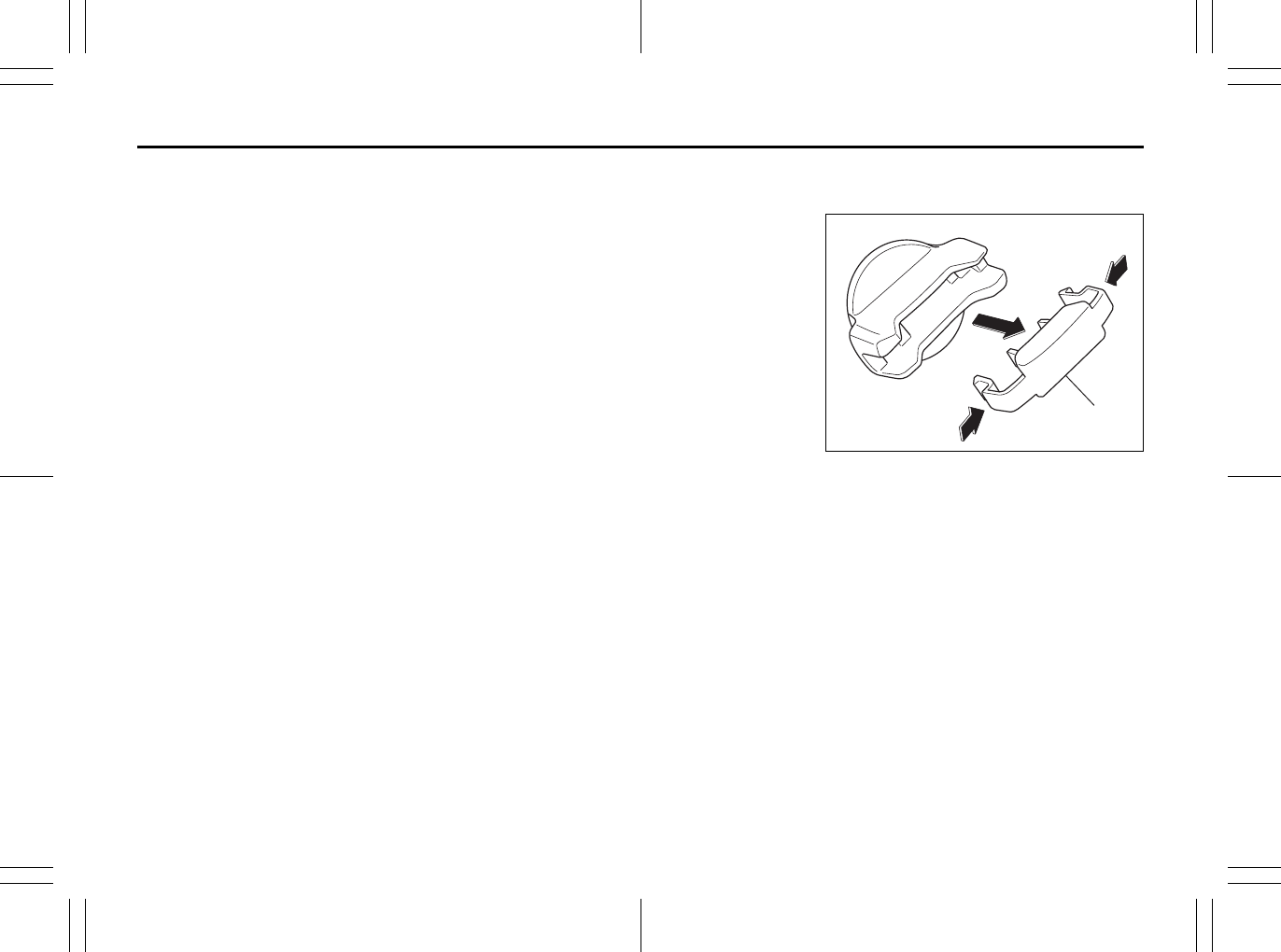
3-5
OPERATING YOUR VEHICLE
80J23-03E
If you leave any of the doors open with the
ignition switch in the “ACC” position for a
while (and no key inserted), the engine
may not start when you turn the ignition
switch to “START”. If the engine does not
start, close all doors completely or turn the
ignition switch back to the “LOCK” position,
then start the engine.
The ignition switch has the following four
positions:
LOCK (1)
This is the normal parking position. It is the
only position in which the key can be
removed. It locks the ignition, and prevents
normal use of the steering wheel.
For vehicles with a CVT, the gearshift lever
must be in the “P” (Park) position to turn
the key to the “LOCK” position.
To release the steering lock, turn the igni-
tion switch clockwise to one of the other
positions. If you have trouble turning the
ignition switch to unlock the steering, try
turning the steering wheel slightly to the
right or left while turning the switch.
• Manual transaxle vehicle
You must push in the ignition switch to
turn it from the “LOCK” position to the
“ACC” position. To return to the “LOCK”
position from the “ACC” position, turn the
ignition switch counterclockwise while
pushing in the switch.
•CVT vehicle
To turn the ignition switch, push the
switch.
ACC (2)
Accessories such as the radio can oper-
ate, but the engine is off.
ON (3)
This is the normal operating position. All
electrical systems are on.
START (4)
This is the position for starting the engine
using the starter motor. The switch should
be released from this position as soon as
the engine starts.
Ignition switch reminder
(When using the keyless start system)
A buzzer sounds intermittently to remind
you to return the ignition switch to the
“LOCK” position if it is in the “ACC” position
when the driver’s door is opened.
You can also turn the ignition switch by
inserting the ignition key into the slot.
80JM139
The ignition switch cap (1) is installed to
make the ignition switch turn easily.
If you use the ignition key to turn the igni-
tion switch, remove the cap (1) by pinching
both side of the cap and pull it out.
NOTE:
If you remove the cap, be careful not to
lose it.
Ignition key reminder
(When using the ignition key)
A buzzer sounds intermittently to remind
you to remove the ignition key if it is in the
ignition switch when the driver’s door is
opened.
(1)
Windshield Wiper and Washer Lever: 8
Rear Window Wiper/Washer Switch: 8

3-6
OPERATING YOUR VEHICLE
80J23-03E
81A297S
Parking Brake Lever
52D122
(1) To set
(2) To release
(3) To release
The parking brake lever is located between
the seats. To set the parking brake, hold
the brake pedal down and pull the parking
brake lever all the way up. To release the
parking brake, hold the brake pedal down,
pull up slightly on the parking brake lever,
push the button on the end of the lever with
your thumb and lower the lever to its origi-
nal position.
WARNING
• For manual transaxle vehicles,
never remove the ignition key while
the vehicle is moving. The steering
wheel will lock and you will not be
able to steer the vehicle.
• Always remove the ignition key
when leaving the vehicle even if
only for a short time. Also do not
leave children or pets alone in a
parked vehicle. Unattended chil-
dren could cause accidental move-
ment of the vehicle or could tamper
with power windows. Children or
pets could suffer from heatstroke
in warm or hot weather, which
could result in severe injury or
even death.
CAUTION
• Do not turn the starter motor for
more than 15 seconds at a time. If
the engine does not start, wait 15
seconds before trying again. If the
engine does not start after several
attempts, check the fuel and igni-
tion systems or consult your
SUZUKI dealer.
• Do not leave the ignition switch in
the “ON” position if the engine is
not running or the battery will dis-
charge.
Rear Window Wiper/Washer Switch: 8
Tilt Steering Lock Lever: 6
Cruise Control: 7, 8
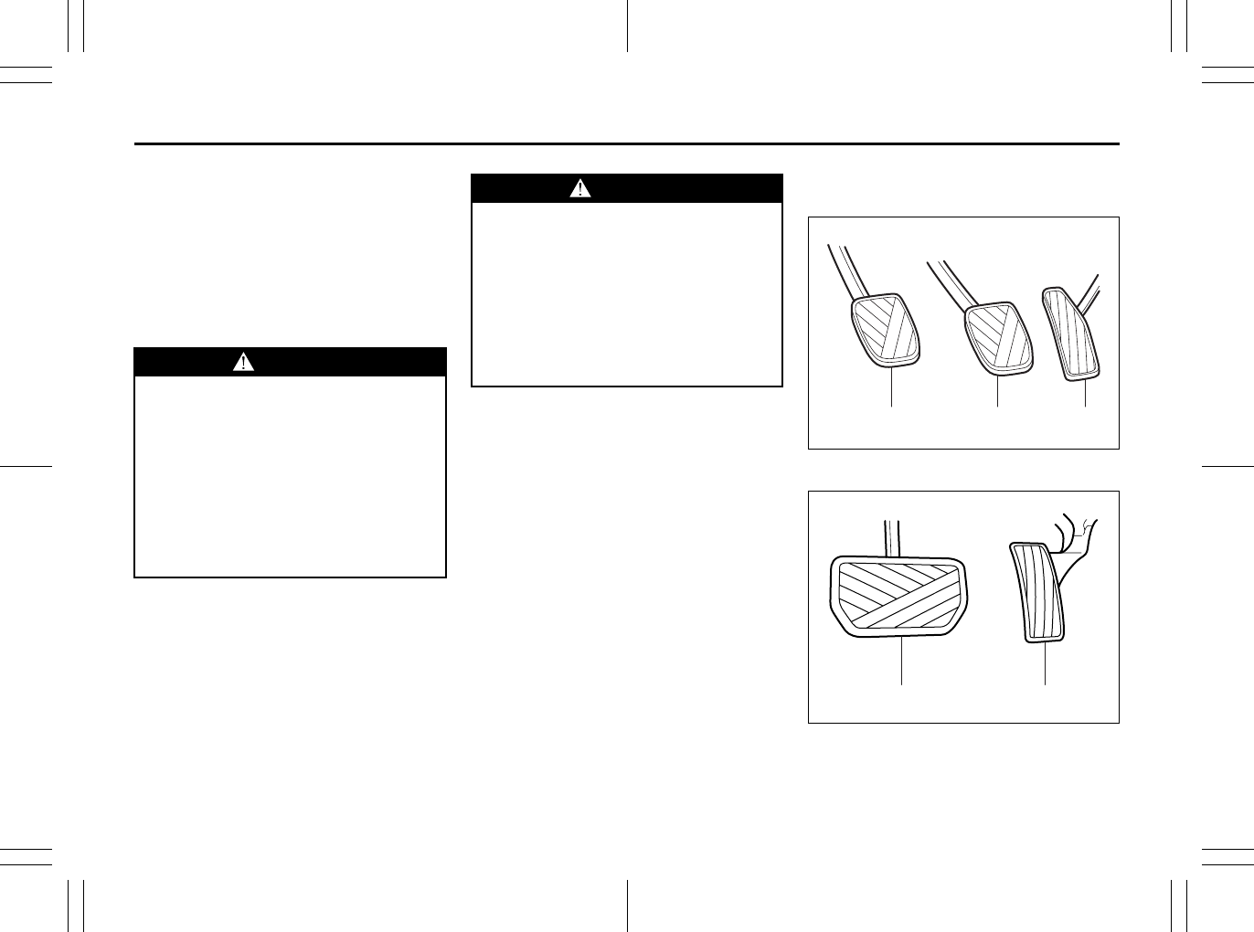
3-7
OPERATING YOUR VEHICLE
80J23-03E
For CVT vehicles, always set the parking
brake before moving the gearshift lever to
the “P” (Park) position. If you park on an
incline and shift into “P” before you set the
parking brake, the weight of the vehicle
may make it difficult to shift out of “P” when
you are ready to drive the vehicle. When
preparing to drive the vehicle, move the
gearshift lever out of the “P” position before
releasing the parking brake.
Pedals
Manual transaxle
79J072
CVT
79J154
WARNING
• Never drive your vehicle with the
parking brake set: rear brake effec-
tiveness can be reduced from over-
heating, brake life may be
shortened or permanent brake
damage may result.
• If the parking brake does not hold
the vehicle securely or does not
fully release, have your vehicle
inspected immediately by an autho-
rized SUZUKI dealer.
WARNING
Always set the parking brake fully
before leaving your vehicle or it may
roll, causing injury or damage. When
parking, make sure the gearshift
lever for manual transaxle vehicles is
in 1st gear or “R” (Reverse) and the
gearshift lever for CVT vehicles is in
“P” (Park). Remember, even though
the transaxle is in gear or in Park, you
must set the parking brake fully.
(1) (2) (3)
EXAMPLE
(2) (3)
EXAMPLE
Cruise Control: 7, 8
3-8
OPERATING YOUR VEHICLE
80J23-03E
Clutch Pedal (1)
(For manual transaxle)
The clutch pedal is used to disengage the
drive to the wheels when starting the
engine, stopping or shifting the gearshift
lever. Depressing the pedal disengages
the clutch.
Brake Pedal (2)
Your SUZUKI vehicle is equipped with
either front and rear disc brakes or front
disc brakes and rear drum brakes.
Depressing the brake pedal applies both
sets of brakes.
You may hear occasional brake squeal
when you apply the brakes. This is a nor-
mal condition caused by environmental
factors such as cold, wet, snow, etc.
Accelerator Pedal (3)
This pedal controls the speed of the
engine. Depressing the accelerator pedal
increases power output and speed.
Starting the Engine
Before Starting the Engine
1) Make sure the parking brake is set fully.
2) Manual Transaxle – Shift into “N” (Neu-
tral) and depress the clutch pedal all
the way to the floor. Hold the clutch
pedal while starting the engine.
CVT – If the gearshift lever is not in “P”
(Park) position, shift into “P”. (If you
need to re-start the engine while the
vehicle is moving, shift into “N”.)
NOTE:
The engine of manual transaxle vehicle will
not start unless the clutch pedal is
depressed.
NOTE:
CVT vehicles have a starter interlock
device which is designed to keep the
starter from operating if the transaxle is in
any of the drive positions.
CAUTION
Do not drive with your foot resting on
the clutch pedal. It could result in
excessive clutch wear, clutch dam-
age, or unexpected loss of engine
braking.
WARNING
If brake squeal is excessive and
occurs each time the brakes are
applied, you should have the brakes
checked by your SUZUKI dealer.
WARNING
Do not “ride” the brakes by applying
them continuously or resting your
foot on the pedal. This will result in
overheating of the brakes which
could cause unpredictable braking
action, longer stopping distances or
permanent brake damage.
WARNING
Make sure that the parking brake is
set fully and the transaxle is in Neu-
tral (or Park for vehicles with a CVT)
before attempting to start the engine.
Cruise Control: 7, 8
Remote Audio Controls:
Horn: 6
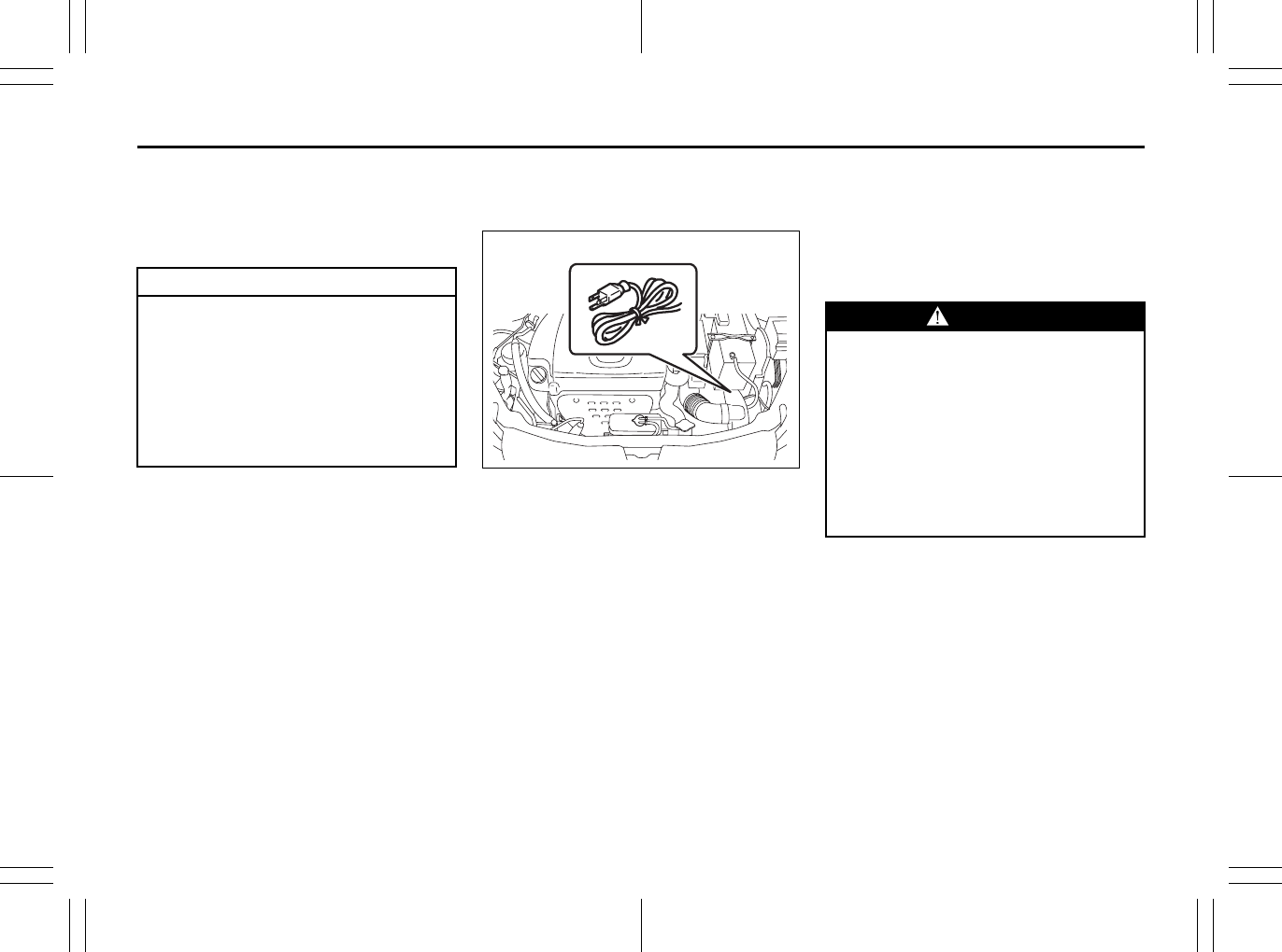
3-9
OPERATING YOUR VEHICLE
80J23-03E
Starting a Cold Engine
With your foot off the accelerator pedal,
crank the engine by turning the ignition key
to “START”. Release the key when the
engine starts.
If the engine does not start after 15 sec-
onds of cranking, wait about 15 seconds,
then press down the accelerator pedal to
1/3 of its travel and try cranking the engine
again. Release the key and accelerator
pedal when the engine starts.
If the engine still does not start, try holding
the accelerator pedal all the way to the
floor while cranking. This should clear the
engine if it is flooded.
If you are unable to start the engine using
this procedure, consult your SUZUKI
dealer.
Starting a Warm Engine
Use the same procedure as for “Starting a
Cold Engine”.
Engine Block Heater
(if equipped)
80J2064
The engine block heater will help you start
the engine more easily in very cold
weather (–18°C (0°F) or below). To use the
engine block heater:
1) Turn off the engine.
2) Open the engine hood.
3) Untie the block heater cord and remove
the block heater plug cap. When the
engine block heater is not in use,
ensure the heater cord is secured to
prevent contact with any moving parts.
4) Using a heavy-duty, three-prong
grounded extension cord, plug the
female end into the block heater socket
and the male end into a normal,
grounded 110-volt AC outlet.
NOTE:
Activate the heater at least four hours
before you start the engine. However, as
the heating time varies depending on the
ambient temperature and other factors,
adjust the time by observing the engine
cranking condition.
After using the block heater:
1) Unplug the extension cord and reinstall
the plug cap.
2) Tie the block heater cord back to its
original position.
CAUTION
• Stop turning the starter immedi-
ately after the engine has started or
the starter system can be dam-
aged.
• Do not crank the engine for more
than 15 seconds at a time. If the
engine doesn’t start on the first try,
wait about 15 seconds before try-
ing again.
EXAMPLE
WARNING
To avoid serious personal injury
caused by electrical shock or fire:
• Do not plug the cord into a non-
grounded outlet. Only use a prop-
erly grounded three-prong 110-volt
AC outlet.
• Do not use a 2-wire (non-grounded)
extension cord.
• Only use a heavy-duty, three-prong
extension cord rated for at least 15
amps.
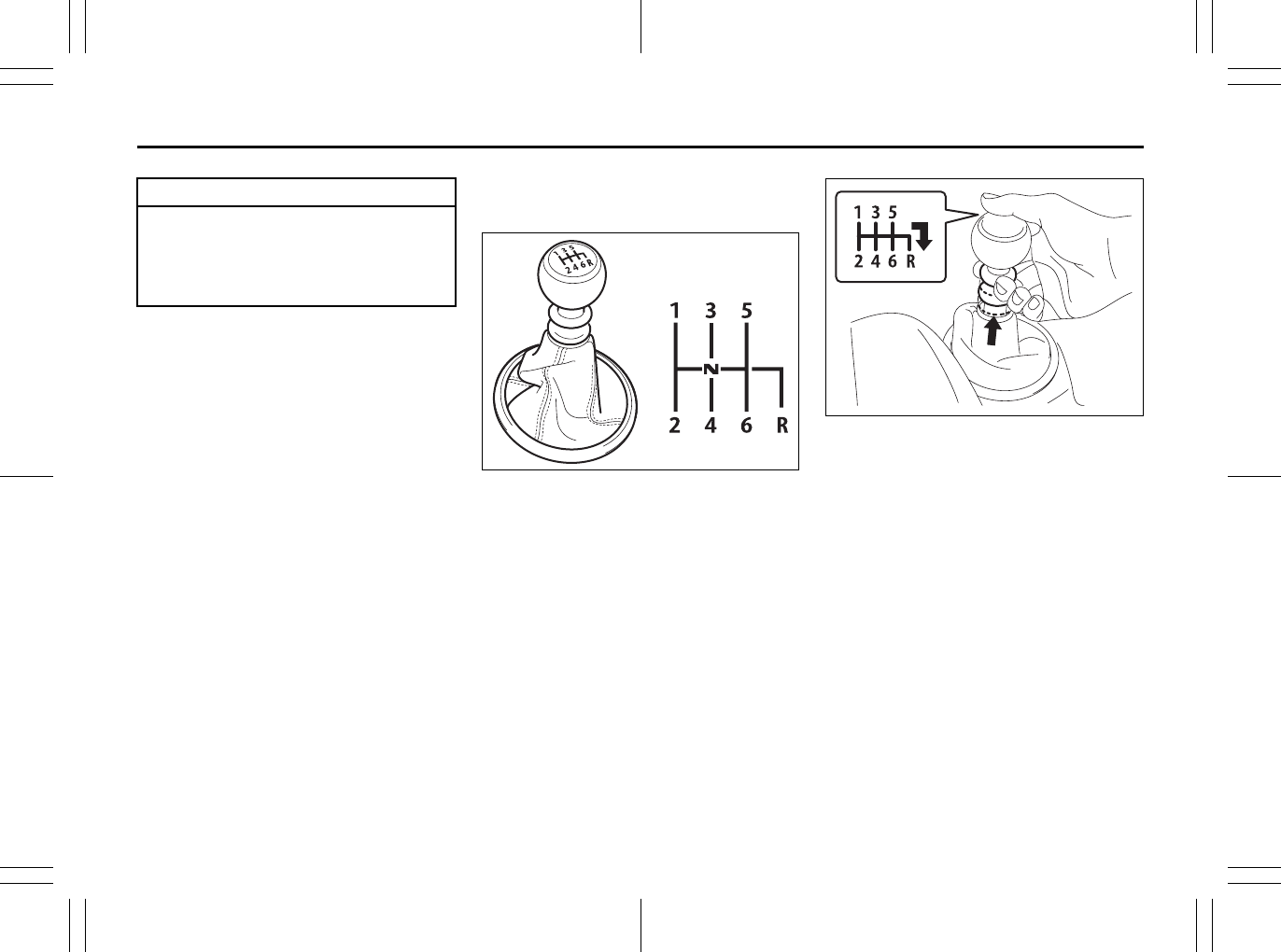
3-10
OPERATING YOUR VEHICLE
80J23-03E
3) Close the engine hood securely before
starting the engine.
Using the Transaxle
Manual Transaxle
80J2081
Starting off
To start off, depress the clutch pedal all the
way to the floor and shift into 1st gear.
After releasing the parking brake, gradually
release the clutch. When you hear a
change in the engine’s sound, slowly press
the accelerator while continuing to gradu-
ally release the clutch.
Shifting
All forward gears are synchronized, which
provides for quiet, and easy shifting.
Always depress the clutch pedal all the
way to the floor before shifting gears. Keep
the engine speed does not rise into the red
zone of the tachometer.
80J2082
Reverse gear: with lifting up ring, shift the
gearshift lever to the right, engage gear.
CAUTION
Secure the block heater cord back to
its original position or to the routed
position. A loose cord could get
caught in the engine accessory drive
belt(s) or other moving parts.
EXAMPLE
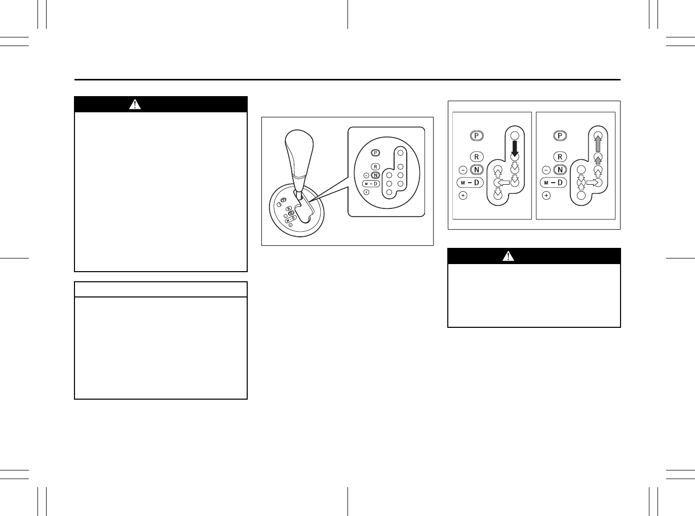
3-11
OPERATING YOUR VEHICLE
80J23-03E
Continuously Variable Transaxle
(CVT)
80J2065
Gearshift lever
80J2035
WARNING
• Reduce your speed and downshift
to a lower gear before going down
a long or steep hill. Downshifting
will allow the engine to provide
braking. Avoid riding the brakes or
they may overheat, resulting in
brake failure.
• When driving on slippery roads, be
sure to slow down before down-
shifting. Large and sudden
changes in engine speed may
cause loss of traction, which could
cause you to lose control.
• Make sure that the vehicle is com-
pletely stopped before you shift
into reverse.
CAUTION
• To help avoid clutch damage, do
not use the clutch pedal as a foot-
rest while driving or use the clutch
to keep the vehicle stationary on a
slope. Depress the clutch fully
when shifting.
• When shifting or starting off, do not
race the engine. Racing the engine
can shorten engine life and affect
smooth shifting.
WARNING
Always depress the brake pedal
before shifting from “P” (Park) (or
“N” (Neutral) if the vehicle is station-
ary) to a forward or reverse gear, to
help prevent the vehicle from moving
unexpectedly when you shift.
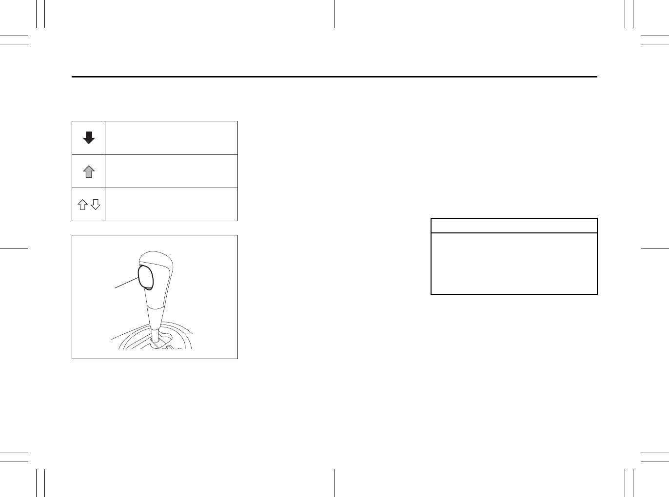
3-12
OPERATING YOUR VEHICLE
80J23-03E
The gearshift lever has a lock mechanism
to help prevent accidental shifting. To shift
the gearshift lever:
80J2036
NOTE:
• Always shift the gearshift lever without
pushing in the lock button (1) except
when you shift from “P” to “R”, from “N”
to “R” or from “R” to “P”. If you always
push in the lock button (1) when shifting
the gearshift lever, you could shift into
“P” or “R” by mistake.
• If driver’s or passenger’s knee hits the
gearshift lever while driving, the lever
could move and the gear could be
changed unexpectedly.
Use the gearshift lever positions as
described below:
P (Park)
Use this position to lock the transaxle
when the vehicle is parked or when start-
ing the engine. Shift into Park only when
the vehicle is completely stationary.
R (Reverse)
Use this position to reverse the vehicle
from stop. Make sure that vehicle is com-
pletely stationary before shifting into
Reverse.
N (Neutral)
Use this position for starting the engine if
the engine stalls and you need to restart it
while the vehicle is moving. You may also
shift into Neutral and depress the brake
pedal to hold the vehicle stationary during
idling.
Shift with the lock button (1)
pushed in and the brake pedal
depressed.
Shift with the lock button (1)
pushed in.
Shift without the lock button (1)
pushed in.
(1)
CAUTION
Do not shift the gearshift lever into
“R” while moving forward, or the
transaxle may be damaged. If you
shift into “R” when the vehicle speed
is over 6mph (10km/h), the transaxle
will not shift into reverse.
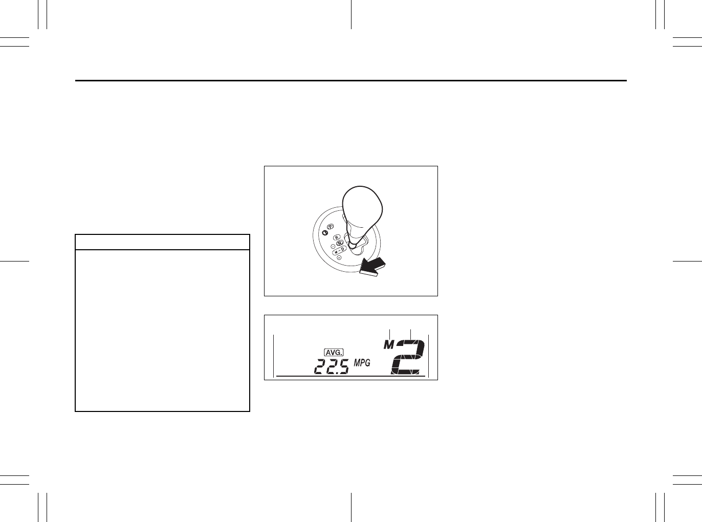
3-13
OPERATING YOUR VEHICLE
80J23-03E
D (Drive)
Use this position for all normal driving.
With the gearshift lever in “D” range you
can get an automatic downshift by press-
ing the accelerator pedal. The higher the
vehicle speed is, the more you need to
press the accelerator pedal to get a down-
shift.
M (manual mode)
Use this position for driving in the manual
mode.
Refer to “Manual mode” later in this section
for details on how to use the manual mode.
Manual mode
The CVT can shift gears automatically.
When using the manual mode, you can
shift gears in the same manner as conven-
tional manual transaxle.
To use the manual mode, shift the gearshift
lever from “D” to “M”.
80J2037
80J2073
(1) Manual mode indicator
(2) Gear position
The information display shows the manual
mode indicator (1) and the current gear
position (2).
NOTE:
• The indicated gear position on the infor-
mation display when you shift from “D” to
“M” is the gear position that was selected
automatically when the gearshift lever
was in “D”.
• You can change to the manual mode
temporarily by pulling the shift paddle (if
equipped) on the steering wheel toward
you when the gearshift lever is in “D”.
Shifting in the manual mode
You can shift gears from 1st to 6th depend-
ing on driving speed.
NOTE:
• When the engine is revved, the gear is
shifted up automatically to prevent dam-
age to the engine and the transaxle. If
the CVT fluid becomes hot such as
when driving on up hill, the engine speed
at which shifting occurs may be lower
than usual.
• When the driving speed becomes slow,
the gear shifts down automatically, and
when the vehicle stops, the gear position
will be in 1st gear without shifting the
gearshift lever.
• If you depress the accelerator pedal a
certain amount, the gear shifts down
automatically even if the gearshift lever
is in the manual mode.
CAUTION
Be sure to take the following precau-
tions to help avoid damage to the
CVT:
• Make sure that the vehicle is com-
pletely stationary before shifting
into “P” or “R”.
• Do not shift from “P” or “N” to “R”,
“D” or “M” when the engine is run-
ning above idle speed.
• Do not rev the engine with the tran-
saxle in a drive position (“R”, “D”
or “M”) and the front wheels not
moving.
• Do not use the accelerator to hold
the vehicle on a hill. Use the vehi-
cle’s brakes.
(1) (2)
EXAMPLE
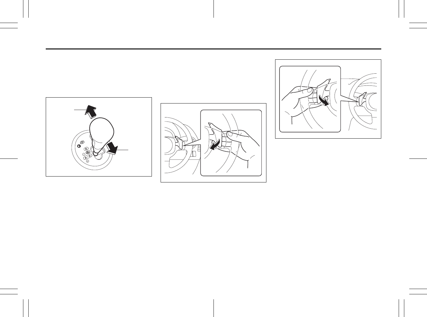
3-14
OPERATING YOUR VEHICLE
80J23-03E
NOTE:
When you shift gears, the gear may not
shift to the desired position. This is to
maintain good drivability and to protect the
transaxle.
Using the gearshift lever
80J2039
(1) “+” side (shift up)
(2) “–” side (shift down)
To shift up, pull the gearshift lever to the “+”
side (rearward). When you remove your
hand from the gearshift lever, the lever will
return to the “M” position automatically.
To shift down, push the gearshift lever to
the “–” side (forward). When you remove
your hand from the gearshift lever, the
lever will return to the “M” position auto-
matically.
NOTE:
To shift gears continuously, remove your
hand from the gearshift lever, then shift the
lever again. You cannot shift gears continu-
ously while holding the lever in the “+” or
“–” position.
Using the shift paddle (if equipped)
80J1358
To shift up, pull the “+” side shift paddle,
located on right side of the steering wheel,
toward you. When you remove your finger
from the switch, the switch will return to the
original position.
80J1359
To shift down, pull the “–” side shift paddle,
located on left side of the steering wheel,
toward you. When you remove your finger
from the switch, the switch will return to the
original position.
NOTE:
• To shift gears continuously, remove your
finger from the shift paddle, then pull the
shift paddle again. You cannot shift
gears continuously while holding the
shift paddle toward you.
• When you pull the both “+” and “–” shift
paddle simultaneously, the gear may not
shift.
(1)
(2)
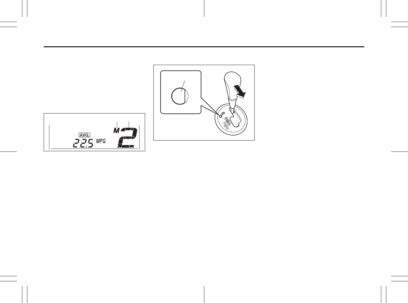
3-15
OPERATING YOUR VEHICLE
80J23-03E
Canceling the manual mode
To cancel the manual mode, shift the gear-
shift lever from “M” to “D”.
Temporary manual mode
Pull the shift paddle (if equipped) toward
you when driving with the gearshift lever in
the “D” position. The information display
shows the manual mode indicator (1) and
the current gear position (2).
80J2073
(1) Manual mode indicator
(2) Gear position
The temporary manual mode will be can-
celed automatically in the following situa-
tions.
• When you press and hold the accelera-
tor pedal for a certain period of time with-
out shifting gears.
• When driving speed becomes slow.
If You Cannot Shift CVT Gearshift Lever
Out of “P” (PARK)
80J2040
Vehicles with a CVT have an electrically
operated park-lock feature. If the vehicle’s
battery is discharged, or there is some
other electrical failure, the CVT cannot be
shifted out of Park in the normal way. Jump
starting may correct the condition. If not,
follow the procedure described below. This
procedure will permit changing the tran-
saxle out of Park.
1) Be sure the parking brake is firmly
applied.
2) If the engine is running, stop the
engine.
3) Make sure the key is in the “ON” or
“ACC” position.
4) Remove the cover (1) over the button.
5) With pushing the release button by the
key or the flat end rod, shift the gear-
shift lever to the desired position.
This procedure is for emergency use only.
If repeated use of this procedure is neces-
sary, or the procedure does not work as
described, take the vehicle to your dealer
for repair.
(1) (2)
EXAMPLE
(1)
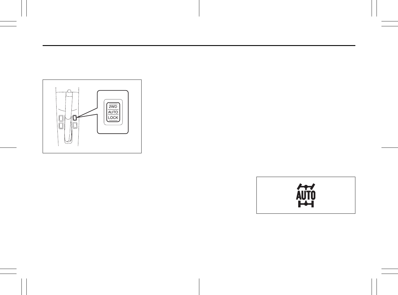
3-16
OPERATING YOUR VEHICLE
80J23-03E
Using the 2WD/i-AWD
(intelligent All Wheel Drive)
Switch (if equipped)
80J009
This i-AWD system enables you to select
the driving mode according to the driving
conditions by operating the 2WD/i-AWD
switch. With this feature, you can select 3
mode positions, “2WD”, “i-AWD AUTO”
and “i-AWD LOCK” by operating the 2WD/
i-AWD switch even when the vehicle is
moving, provided the front wheels are in
the straight ahead position.
Description of 3 Mode 4 x 4 System
Positions
2WD
In this position, engine power is supplied to
the front axle only. Use this position for
normal driving (on dry, hard surfaces).
i-AWD AUTO
In this position, engine power is supplied to
the front and rear axles at normal speed,
providing greater traction than 2-wheel
drive. Use this position for driving on paved
roads or on slippery roads (icy, snow-cov-
ered, muddy, etc.).
In the AUTO mode, the i-AWD controller
judges the driving conditions using signals
from sensors.
When slipping of the front wheels is
detected, the electronically controlled cou-
pling supplies optimum driving force to the
rear wheels. This function improves driving
stability and running through performance
on rough roads and stabilizes driving per-
formance even on a snow covered up-hill
road or the like.
Also, during normal driving on paved
roads, torque distribution to the rear
wheels is reduced to achieve the nearly
front wheel drive condition, thereby fuel
consumption is improved.
i-AWD LOCK
In this position, engine power is supplied to
the front and rear axles at reduced speed.
Use this position when it is hard to start off
in the “i-AWD AUTO” mode such as in
mud, sand or on snow.
NOTE:
• Avoid operating your vehicle in the “i-
AWD LOCK” on wet pavement as much
as possible. Operating your vehicle in
the “i-AWD LOCK” on wet pavement
may cause severe damage to the drive
train.
• As the vehicle speed increases, the “i-
AWD LOCK” mode is automatically can-
celed and the “i-AWD AUTO” mode is
selected.
• When the ignition switch is turned to the
“OFF” position, the “i-AWD LOCK” mode
is canceled.
2WD/i-AWD Switch Operation
Operate the 2WD/i-AWD switch according
to the appropriate procedure described
below:
How to turn on 2WD/i-AWD switch
2WD/i-AWD switch will activate when the
ignition switch is turned on.
From 2WD to i-AWD AUTO
Turn the 2WD/i-AWD switch to the neutral
position, and the “i-AWD AUTO” indicator
will come on.
79J040
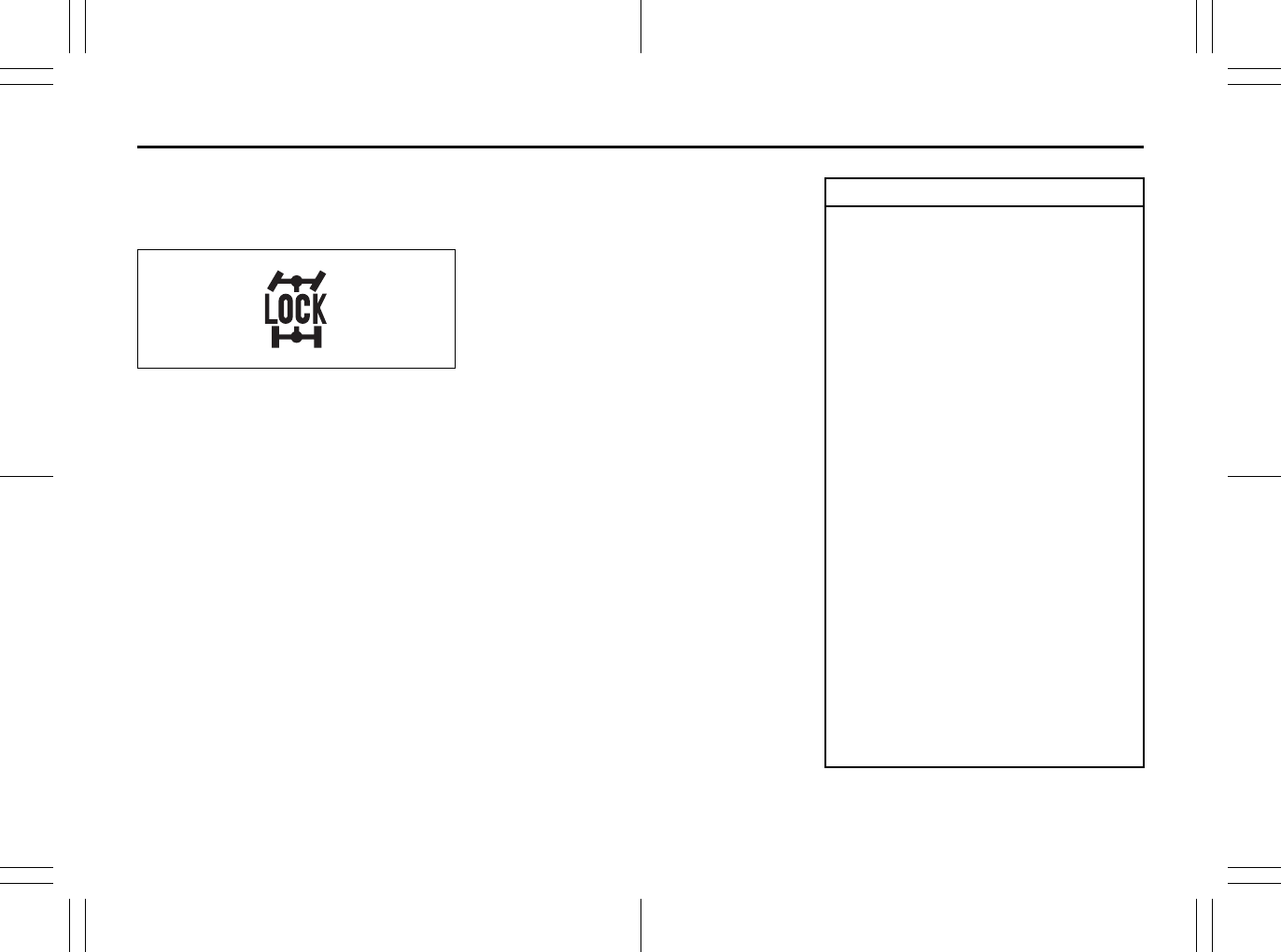
3-17
OPERATING YOUR VEHICLE
80J23-03E
From i-AWD AUTO to i-AWD LOCK
Push the “i-AWD LOCK” switch for a few
seconds until the “i-AWD LOCK” indicator
will come on.
79J100
From i-AWD LOCK to i-AWD AUTO
Push the “i-AWD LOCK” switch, and the “i-
AWD AUTO” indicator will come on.
From i-AWD AUTO or LOCK to 2WD
Push the “2WD” switch, and the “i-AWD
AUTO” or “i-AWD LOCK” indicator will turn
off.
NOTE:
• The 2WD/i-AWD switch can be operated
when the vehicle is either stopped or
moving.
• Make sure that the front wheels are in
the straight ahead position when operat-
ing the 2WD/i-AWD switch.
• While making turns or accelerating and
decelerating, operating the 2WD/i-AWD
switch or turning off the key switch in the
“i-AWD AUTO” or “i-AWD LOCK” mode
may cause a shock, but this is not a sys-
tem malfunction.
• While driving in the “i-AWD LOCK”
mode, as the vehicle speed increases,
the driving mode changes to the “i-AWD
AUTO” mode automatically. Even when
the vehicle speed reduces, on the other
hand, the driving mode does not return
to the “i-AWD LOCK” mode automati-
cally. You should press the “i-AWD
LOCK” switch according to the driving
conditions.
• Any forcible operation while driving off-
road in the sand or water or when a
wheel has run off the road, the difference
of the revolution between front wheels
and rear wheels increases (wheels run
idle). If this state continues, the oil tem-
perature of the driving system parts
rises.
In such case, the “i-AWD AUTO” indica-
tor light blinks and the driving mode
changes to the 2WD mode to protect the
driving system parts.
When you operate your vehicle in the i-
AWD mode continuously, park the vehi-
cle at a safe place and run the engine
idle. After some time, the “i-AWD AUTO”
indicator light turns on again and the
driving mode returns to the “i-AWD
AUTO” mode.
CAUTION
• Never use the “i-AWD LOCK” mode
when driving on dry paved roads.
Avoid using the “i-AWD LOCK”
mode when driving on wet paved
roads as much as possible. Use of
the “i-AWD LOCK” mode in above
conditions will apply excessive
force to the driving system and
may cause a critical failure. Also,
the tires may wear faster and fuel
consumption may be affected
adversely.
• Note that i-AWD vehicles are not
all-around vehicles. Be sure to
observe following instructions
when driving your vehicle.
– Do not drive through water like
crossing a river.
– Do not drive continuously where
front wheels tend to race in
places such as sand and mud.
– When any wheel is in the air for
such reason as running off the
road, do not race it needlessly.
• If the “i-AWD AUTO” and the “i-
AWD LOCK” indicator lights stay
on and come on simultaneously
when driving, there may be some-
thing wrong the i-AWD system.
Have the system inspected by an
authorized SUZUKI dealer.
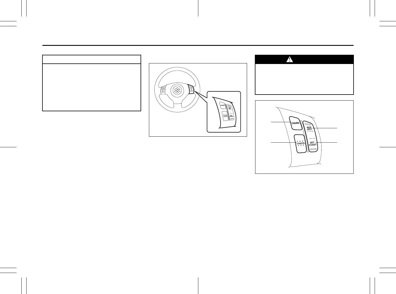
3-18
OPERATING YOUR VEHICLE
80J23-03E
Cruise Control (if equipped)
79JM005
The cruise control system allows you to
maintain a steady speed without keeping
your foot on the accelerator pedal. The
controls for operating the cruise control
system are on the steering wheel.
You can use the cruise control system with
the following conditions:
• For manual transaxle vehicle, the gear
position is in 4th, 5th or 6th.
• For CVT vehicle, the gearshift lever is in
“D” position, or the gear position is in
3rd, 4th, 5th or 6th in the manual mode.
• The vehicle speed is about 25 mph (40
km/h) or higher.
79JM006
(1) “CRUISE” switch
(2) “CANCEL” switch
(3) “SET/COAST” switch
(4) “RES/ACC” switch
CAUTION
Unevenly worn tires can cause prob-
lems in the operation of the 2WD/i-
AWD switch. Be sure to rotate the
tires according to the maintenance
schedule. Refer to “Tires” and “Main-
tenance Schedule” in the “INSPEC-
TION AND MAINTENANCE” section
for proper tire rotation procedures.
WARNING
To help avoid loss of vehicle control,
do not use the cruise control system
when driving in heavy traffic, on slip-
pery or winding roads, or on steep
downgrades.
(1)
(2) (3)
(4)
3-19
OPERATING YOUR VEHICLE
80J23-03E
To Set Cruising Speed
1) Turn on the cruise control system by
pushing the “CRUISE” switch (1). When
the “CRUISE” indicator light comes on,
you can set cruising speed.
2) Accelerate or decelerate to the desired
speed.
3) Push the “SET/COAST” switch (3) and
turn on the “SET” indicator light. Take
your foot off the accelerator pedal and
the set speed will be maintained.
“CRUISE” indicator light
52D113
When you push the “CRUISE” switch, the
system is on and a “CRUISE” indicator
light on the instrument cluster will be on.
“SET” indicator light
65D474
When the vehicle’s speed is controlled by
the cruise control system, a “SET” indica-
tor light on the instrument cluster will be
on.
To Change Speed Temporarily
When the cruising speed is maintained,
you can temporarily accelerate or deceler-
ate.
To accelerate, depress the accelerator
pedal. When you take your foot off the
pedal, your vehicle will return to the set
speed.
To decelerate, depress the brake pedal.
The set speed will be canceled and “SET”
indicator light will go off.
To resume the previously set speed, push
the “RES/ACC” switch (4) and turn on the
“SET” indicator light again when vehicle
speed is above 25 mph (40 km/h). The
vehicle will accelerate to and maintain the
previously set speed.
NOTE:
For CVT vehicle, when the cruising speed
is maintained, you cannot decelerate by
using the engine brake if you downshift
from higher gear to 3rd in the manual
mode.
To decelerate while the cruise control is on,
depress the brake pedal or push the “SET/
COAST” switch (3).
WARNING
If the cruising speed is set by acci-
dent, you cannot decelerate or could
loose control of the vehicle. This
could lead to an accident, resulting in
severe injury or death.
Turn off the cruise control system
and make sure the “CRUISE” indica-
tor light is off when the system is not
in use.
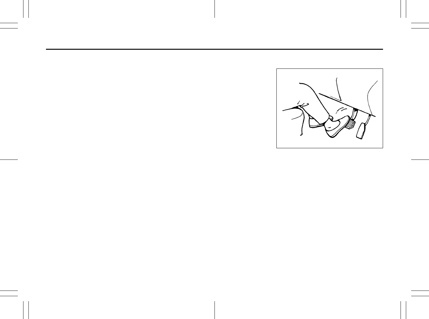
3-20
OPERATING YOUR VEHICLE
80J23-03E
To Change Cruising Speed
Using the accelerator pedal
To reset at a faster cruising speed, acceler-
ate to the desired speed using the acceler-
ator pedal and push the “SET/COAST”
switch (3). The new speed will be main-
tained.
Using the brake pedal
To reset at a slower cruising speed, decel-
erate to the desired speed using the brake
pedal and push the “SET/COAST” switch
(3). The new speed will be maintained.
NOTE:
When the brake pedal is depressed, the
“SET” indicator light goes off until reset the
cruising speed.
Using the cruise control switch
To reset at a faster cruising speed, press
repeatedly or hold in the “RES/ACC”
switch (4). Vehicle speed will steadily
increase. When you release the switch, the
new speed will be maintained.
To reset at a slower cruising speed, press
repeatedly or hold in the “SET/COAST”
switch (3) until the vehicle has slowed to
the desired speed, then release the switch.
The new speed will be maintained.
NOTE:
You can adjust the set speed by approxi-
mately 1.0 mph (1.6 km/h) by pushing a
cruise control switch quickly.
Cancellation of the Cruise Control
The “SET” indicator light will go off and the
cruise control will be canceled temporarily
with following procedures:
• Push the “CANCEL” switch (2).
• Depress the brake pedal.
• For manual transaxle, depress the clutch
pedal.
• For CVT, downshift from 3rd to 2nd in the
manual mode.
• The vehicle speed falls more than about
20 percent from the set speed.
• Any time the vehicle speed falls below
25 mph (40 km/h).
• When the vehicle skids and ESP® (if
equipped) is activated.
To resume the previously set speed, push
the “RES/ACC” switch (4) and turn on the
“SET” indicator light. Besides, the vehicle
speed has to be above 25 mph (40 km/h)
when the vehicle is not in the above condi-
tions.
To turn off the cruise control system, push
the “CRUISE” switch (1) and make sure
the “CRUISE” indicator light is off.
Also, if the malfunction indicator light in the
instrument cluster comes on or blinks, the
cruise control system will be turned off.
NOTE:
If you turn off the cruise control system, the
previously set speed in the memory is
cleared. Reset your cruising speed again.
Braking
60G165
The distance needed to bring any vehicle
to a halt increases with the speed of the
vehicle. The braking distance needed, for
example, at 60 km/h (37 mph) will be
approximately 4 times greater than the
braking distance needed at 30 km/h (19
mph). Start to brake the vehicle when there
is plenty of distance between your vehicle
and the stopping point, and slow down
gradually.
3-21
OPERATING YOUR VEHICLE
80J23-03E
Power-Assisted Brakes
Your vehicle has power-assisted brakes. If
power assistance is lost due to a stalled
engine or other failures, the system is still
fully operational on reserve power and you
can bring the vehicle to a complete stop by
pressing the brake pedal once and holding
it down. The reserve power is partly used
up when you depress the brake pedal and
reduces each time the pedal is pressed.
Apply smooth and even pressure to the
pedal. Do not pump the pedal.
Brake Assist System
When you slam the brakes on, the brake
assist system judges as an emergency
stop and provides more powerful braking
for a driver who cannot hold down the
brake pedal firmly.
NOTE:
If you quickly and forcefully depress the
brakes, you may hear a clicking sound in
the brake pedal. This is normal and indi-
cates that the brake assist system is acti-
vated properly.
Anti-Lock Brake System (ABS)
(if equipped)
ABS will help you avoid skidding by elec-
tronically controlling braking pressure. It
will also help you maintain steering control
when braking on slippery surfaces or when
braking hard.
The ABS works automatically, so you do
not need any special braking technique.
Just push the brake pedal down without
pumping. The ABS will operate whenever it
senses that the wheels are locking up.
You may feel the brake pedal pulsate while
the ABS is operating.
NOTE:
The ABS will not work if vehicle speed is
under about 6 km/h (4mph).
WARNING
If water gets into the brake drums,
brake performance may become poor
and unpredictable.
After driving through water or wash-
ing the underside of the vehicle, test
the brakes while driving at a slow
speed to see if they have maintained
their normal effectiveness. If the
brakes are less effective than normal,
dry them by repeatedly applying the
brakes while driving slowly until the
brakes have regained their normal
effectiveness.
WARNING
Even without reserve power in the
brake system, you can still stop the
vehicle by pressing the brake pedal
harder than normally required. How-
ever, the stopping distance may be
longer.
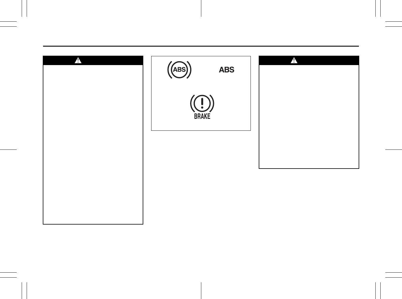
3-22
OPERATING YOUR VEHICLE
80J23-03E
65D451
(1) ABS warning light Type 1
(2) ABS warning light Type 2
(3) Brake system warning light
WARNING
• On some types of loose surfaces
(such as gravel, snow-covered
roads, etc.), the stopping distance
required for an ABS-equipped vehi-
cle may be slightly greater than for
a comparable vehicle with a con-
ventional brake system. With a
conventional brake system, skid-
ding tires are able to “plow” the
gravel or snow layer, shortening
the stopping distance. ABS mini-
mizes this resistance effect. Allow
for extra stopping distance when
driving on loose surfaces.
• On regular paved roads, some driv-
ers may be able to obtain slightly
shorter stopping distances with
conventional brake systems than
with ABS.
• In both of the above conditions,
ABS will still offer the advantage of
helping you maintain directional
control. However, remember that
ABS will not compensate for bad
road or weather conditions or poor
driver judgment. Use good judg-
ment and do not drive faster than
conditions will safely allow.
(1) (2)
(3)
WARNING
If the ABS warning light ((1) or (2)) on
the instrument panel comes on and
stays on while driving, there may be a
problem with the ABS system.
If this happens:
1) Pull off the road and stop care-
fully.
2) Turn the ignition switch to “LOCK”
and then start the engine again.
If the warning light comes on briefly
then turns off, the system is normal.
If the warning light still stays on,
have the system inspected by your
SUZUKI dealer immediately. If the
ABS system becomes inoperative,
the brake system will function as an
ordinary brake system that has no
ABS.
3-23
OPERATING YOUR VEHICLE
80J23-03E
How the ABS Works
A computer continuously monitors wheel
speed. The computer compares the
changes in wheel speed when braking. If
the wheels slow suddenly, indicating a
skidding situation, the computer will
change braking pressure several times
each second to prevent the wheels from
locking. When you start your vehicle or
when you accelerate after a hard stop, you
may hear a momentary motor or clicking
noise as the system resets or checks itself.
Electronic Stability Program
(ESP®) (if equipped)
ESP® is a registered trademark of Daimler
AG.
The Electronic Stability Program (ESP®)
helps to control the vehicle during corner-
ing if front wheels or rear wheels skid. It
also assists you in maintaining traction
while accelerating on loose or slippery
road surfaces. It does this by regulating the
engine’s output, and by selectively apply-
ing the brakes. In addition, ESP® helps to
avoid skidding by controlling braking pres-
sure.
WARNING
If the ABS warning light ((1) or (2))
and the Brake system warning light
(3) on the instrument panel simulta-
neously stay on or come on when
driving, both anti-lock function and
rear brake force control function (pro-
portioning valve function) of the ABS
system may have failed. This could
cause the rear wheels to skid or the
vehicle to spin during braking on a
slippery road or hard braking on a
dry paved road. If both warning lights
come on, drive carefully, avoiding
hard braking as much as possible,
and ask your SUZUKI dealer to
inspect the ABS system immediately.
WARNING
The ABS may not work properly if
tires or wheels other than those
specified in the owner’s manual are
used. This is because the ABS works
by comparing changes in wheel
speed. When replacing tires or
wheels, use only the size and type
specified in this owner’s manual.
WARNING
The ESP® cannot enhance the vehi-
cle’s driving stability in all situations
and does not control your vehicle’s
entire braking system. The ESP® can-
not prevent accidents, including
those resulting from excessive speed
in turns, or hydroplaning. Only a safe
and attentive driver can prevent acci-
dents. The capabilities of an ESP®-
equipped vehicle must never be used
as a substitute for careful driving.
3-24
OPERATING YOUR VEHICLE
80J23-03E
The ESP® has the following three systems:
Stability Control System
The vehicle stability control system helps
provide integrated control of systems such
as anti-lock brakes, traction control, engine
control, etc. This system automatically
controls the brakes and engine to help pre-
vent the vehicle from skidding when cor-
nering on a slippery road surface or when
turning the steering wheel abruptly.
Traction Control System
The traction control system automatically
helps prevent the spinning of wheels when
the vehicle is started or accelerated on
slippery road surfaces. The system oper-
ates only if it senses that some of the
wheels are spinning or beginning to lose
traction. When this happens, the system
operates the front or rear brakes and
reduces engine power to limit wheel spin.
NOTE:
You may hear a clicking sound in the
engine compartment for a few seconds
when you start the engine or just after the
vehicle begins to move. This means that
the above systems are in the self-check
mode. This sound does not indicate a mal-
function.
Anti-Lock Braking System (ABS)
ABS will help you avoid skidding by elec-
tronically controlling braking pressure. It
will also help you maintain steering control
when braking on slippery surfaces or when
braking hard. The ABS works automati-
cally, so you do not have to use any special
braking technique. Just push the brake
pedal down without pumping. The ABS will
operate whenever it senses that wheels
are locking up. You may feel the brake
pedal pulsate while the ABS is operating.
(For more information on ABS, see “Brak-
ing” in the “OPERATING YOUR VEHICLE”
section.)
NOTE:
If the ABS system is activated, you may
hear a clunking noise and/or feel pulsating
in the brake pedal. This is normal and indi-
cates that the brake fluid pressure is being
controlled properly.
WARNING
• The ESP® may not work properly if
tires or wheels other than those
specified in the Owner’s Manual are
used. When replacing tires or
wheels, use only the size and type
specified in this Owner’s Manual.
• The ESP® may not work properly if
tires are not inflated to the recom-
mended tire inflation pressure.
• The ESP® may not work properly if
tires are fitted with tire chains.
• The ESP® may not work properly if
the tires are excessively worn. Be
sure to replace tires when the tread
wear indicators in the grooves
appear on the tread surface.
• The ESP® is not a substitute for
winter tires or tire chains on a snow
covered road.
WARNING
• The ESP® may not work properly if
engine related parts such as the
muffler are not equivalent to stan-
dard equipment or are extremely
deteriorated.
• Do not modify the vehicle’s sus-
pension since the ESP® may not
operate correctly.
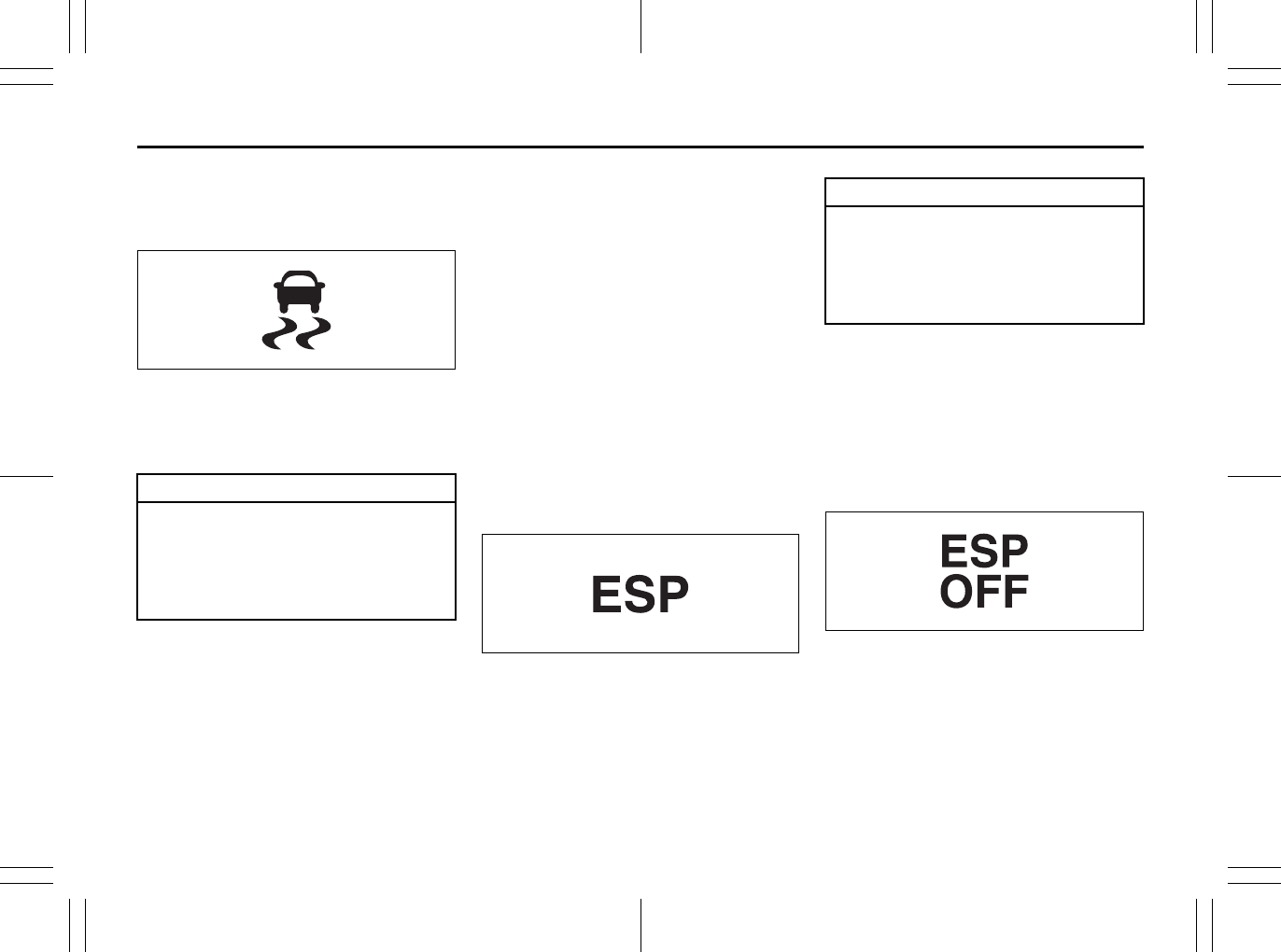
3-25
OPERATING YOUR VEHICLE
80J23-03E
The ESP® indicator lights are described
below:
SLIP Indicator Light
52KM133
When one of the ESP® systems other than
ABS is activated, the SLIP indicator light in
the instrument cluster blinks 5 times per
second.
NOTE:
When the SLIP indicator light comes on
and stays on while driving, indicating a
malfunction of the ESP® systems (other
than ABS), the brake system will function
as an ordinary ABS with no additional
ESP® functions.
NOTE:
When you disconnect and re-connect the
battery, ESP® system functions other than
ABS will be deactivated and the slip indica-
tor light will blink 1 time per second. In this
case, use the following procedure to re-
activate the ESP® systems:
1) Drive your vehicle straight ahead with-
out tire slippage at a speed until the slip
indicator is turned off. (Drive straight for
approximately 35 km/h (22 mph) or
more and 10 seconds or more.)
2) The slip indicator light will go out and
the ESP® systems (other than ABS) will
be re-activated.
It may take more than few seconds before
the slip indicator light goes out depending
on the road surface condition.
“ESP” Warning Light
66J031
When the ESP® systems (other than ABS)
have a system malfunction, the “ESP”
warning light in the instrument cluster
comes on.
NOTE:
When the “ESP” warning light comes on,
or stays on while driving, indicating a mal-
function of the ESP® systems (other than
ABS), the brake system will function as an
ordinary ABS that has no additional ESP®
functions.
“ESP OFF” Indicator Light
66J032
You should turn the ESP® on during your
ordinary driving, so that you have the ben-
efits of all of the ESP® systems.
It may be required to turn the ESP® sys-
tems (other than ABS) off if your vehicle is
stuck in sand, mud, or snow, where wheel
spin is necessary.
CAUTION
If the SLIP indicator light comes on
and stays on while driving, there may
be a malfunction of the ESP® sys-
tems (other than ABS). You should
have the systems inspected by an
authorized SUZUKI dealer.
CAUTION
If the “ESP” warning light comes on,
or stays on while driving, there may
be a malfunction of the ESP® sys-
tems (other than ABS). You should
have the systems inspected by an
authorized SUZUKI dealer.
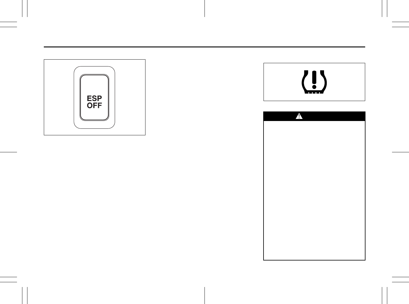
3-26
OPERATING YOUR VEHICLE
80J23-03E
“ESP OFF” switch
62J142
When the “ESP OFF” switch located at the
center console is pushed and held to turn
off the ESP® systems (other than ABS),
the “ESP OFF” indicator light in the instru-
ment cluster comes on.
When you have turned the ESP® systems
(other than ABS) off, make sure to turn
them back on before resuming ordinary
driving.
When you push the “ESP OFF” switch
again, the “ESP OFF” indicator light will go
out and all of the ESP® systems will be
activated.
ABS Warning Light / Brake System
Warning Light
See “Braking” in the “OPERATING YOUR
VEHICLE” section.
Tire Pressure Monitoring
System (TPMS)
The tire pressure monitoring system is
designed to alert you when one or more of
the tires on your vehicle is significantly
under-inflated. A Tire Pressure Monitoring
System (TPMS) sensor containing a
unique identification code is mounted on
each wheel. The TPMS sensors transmit
tire pressure signals to a central receiver
which relays the information to a tire pres-
sure monitoring system controller. When
the inflation pressure of one or more tires
indicates significant under-inflation, the low
tire pressure warning light shown below
comes on.
Low Tire Pressure Warning Light
52D305
WARNING
Each tire, including the spare (if pro-
vided), should be checked monthly
when cold and inflated to the inflation
pressure recommended by the vehi-
cle manufacturer on the vehicle plac-
ard or tire inflation pressure label. (If
your vehicle has tires of a different
size than the size indicated on the
vehicle placard or tire inflation pres-
sure label, you should determine the
proper tire inflation pressure for
those tires.)
As an added safety feature, your
vehicle has been equipped with a tire
pressure monitoring system (TPMS)
that illuminates a low tire pressure
telltale when one or more of your
tires is significantly under-inflated.
Accordingly, when the low tire pres-
sure telltale illuminates, you should
stop and check your tires as soon as
possible, and inflate them to the
proper pressure.
(Continued)
3-27
OPERATING YOUR VEHICLE
80J23-03E
WARNING
(Continued)
Driving on a significantly under-
inflated tire causes the tire to over-
heat and can lead to tire failure.
Under-inflation also reduces fuel effi-
ciency and tire tread life, and may
affect the vehicle’s handling and
stopping ability.
Please note that the TPMS is not a
substitute for proper tire mainte-
nance, and it is the driver’s responsi-
bility to maintain correct tire
pressure, even if under-inflation has
not reached the level to trigger illumi-
nation of the TPMS low tire pressure
telltale.
WARNING
The tire pressure monitoring system
is not a substitute for regular tire
pressure inspections. Check tire
inflation pressures monthly when
cold and set to the recommended
inflation pressure as specified on the
vehicle’s tire information placard and
in the owner’s manual. Refer to
“Tires” in the “INSPECTION AND
MAINTENANCE” section.
WARNING
If the low tire pressure warning light
does not come on when the ignition
is turned to the “ON” position, or
comes on and blinks while driving
there may be a problem with the tire
pressure monitoring system. Have
your vehicle inspected by an autho-
rized SUZUKI dealer. Even if the light
turns off after blinking, indicating
that the monitoring system has
recovered, make sure to have an
authorized SUZUKI dealer check the
system.
WARNING
The load rating of your tires is
reduced at lower inflation pressures.
If your tires become even moderately
under-inflated, the vehicle load may
exceed the load rating of the tires,
which can lead to tire failure. The low
tire pressure warning light will not
alert you of this condition. The warn-
ing light will only come on when one
or more of your tires become signifi-
cantly under-inflated. Check and
adjust your tire inflation pressure at
least once a month. Refer to “Tires”
in the “INSPECTION AND MAINTE-
NANCE” section.
WARNING
If the low tire pressure warning light
comes on and stays on, reduce your
speed and avoid abrupt steering and
braking. Stop in a safe place as soon
as possible and check your tires.
• If you have a flat tire, replace it with
the spare tire. Refer to “Jacking
Instructions” in the “EMERGENCY
SERVICE” section. Refer to
“Replacing Tires and/or Wheels”
for instructions on how to restore
normal operation of the tire pres-
sure monitoring system after you
have had a flat tire.
• If one or more of your tires is
under-inflated adjust the inflation
pressure in all of your tires to the
recommended inflation pressure as
soon as possible.
Be aware that driving on a signifi-
cantly under-inflated tire can cause
the tire to overheat and can lead to
tire failure, and may affect steering
control and brake effectiveness. This
could lead to an accident, resulting in
severe injury or death.
3-28
OPERATING YOUR VEHICLE
80J23-03E
The low tire pressure warning light can
come on due to normal causes such as
natural air leaks and pressure changes
caused by changes in temperature or
atmospheric pressure. Adjusting the air
pressure in the tires to the pressure shown
on the tire information placard should
cause the low tire pressure warning light to
turn off.
If the light turns on again shortly after
adjusting the pressure in your tires, you
may have a flat tire. If you have a flat tire,
replace it with the spare tire. Refer to
“Jacking Instructions” in the “EMER-
GENCY SERVICE” section. Refer to
“Replacing Tires and/or Wheels” for
instructions on how to restore normal oper-
ation of the tire pressure monitoring sys-
tem after you have had a flat tire.
NOTE:
• When the tire inflation pressure is
adjusted in high altitude areas, the low
tire pressure light may not turn off even
after tire inflation pressure adjustment.
In this case, adjust the inflation pressure
to a slightly higher pressure than is
shown on the tire information placard.
• The low tire pressure warning light may
turn off temporarily after coming on. This
could be due to surface temperature
increases after long distance driving or
traveling to a high temperature area.
Even if the tire pressure warning light
turns off after coming on, make sure to
check the inflation pressure of all tires.
• To reduce the chance that the low tire
pressure warning light will come on due
to normal changes in temperature and
atmospheric pressure, it is important to
check and adjust the tire pressures
when the tires are cold. Tires that
appear to be at the specified pressure
when checked after driving, when the
tires are warm, could have pressure
below the specification when the tires
cool down. Also, tires that are inflated to
the specified pressure in a warm garage
may have pressure below the specifica-
tion when the vehicle is driven outside in
very cold temperature. If you adjust the
tire pressure in a garage that is warmer
than the outside temperature, you
should add 1 psi to the recommended
cold tire inflation pressure for every 10°F
difference between garage temperature
and outside temperature.
For tire inflation pressure information, refer
to “Tire Inflation Pressure” in the “INSPEC-
TION AND MAINTENANCE” section.
TPMS Malfunction Indicator
WARNING
Your vehicle has also been equipped
with a TPMS malfunction indicator to
indicate when the system is not oper-
ating properly.
WARNING
The TPMS malfunction indicator is
combined with the low tire pressure
telltale. When the system detects a
malfunction, the telltale will flash for
approximately one minute and then
remain continuously illuminated.
This sequence will continue upon
subsequent vehicle start-ups as long
as the malfunction exists.
3-29
OPERATING YOUR VEHICLE
80J23-03E
When you turn off the engine, however, the
malfunction indicator resets. It takes about
ten minutes after restarting the engine for
the malfunction to be detected again and
for the light to start flashing.
TPMS Limitations
The tire pressure monitoring system may
not function properly under certain circum-
stances. In the following situations, the low
tire pressure warning light may come on
and remain on or may blink.
• When you replace a flat tire with the
spare tire.
• When you include the spare tire during a
tire rotation.
• When the TPMS sensor is damaged dur-
ing a tire replacement or liquid sealants
are used to repair a flat tire.
• When the TPMS sensor’s electronic sig-
nal is disturbed in one of the following
ways:
– Electric devices or facilities using simi-
lar radio wave frequencies are nearby.
– A lot of snow or ice covers the vehicle,
in particular, around the wheels or
wheel housings.
– Snow tires or tire chains are used.
• When you use non-genuine SUZUKI
wheels or tires.
Replacing Tires and/or Wheels
If you get a flat tire, Suzuki recommends
that you have an authorized SUZUKI
dealer mount a new tire on the wheel that
had the flat tire, and reinstall this tire on the
vehicle in place of the spare. The TPMS is
already set up to recognize the ID code of
the original wheel, and normal TPMS oper-
ation will be restored.
If you need to replace original wheels on
your vehicle, your dealer must make sure
that TPMS sensors are installed in the new
wheels and must set up the TPMS to rec-
ognize the new sensors.
NOTE:
A TPMS sensor is not installed in the spare
tire. You should use the spare tire only in
an emergency situation, and should
replace the spare tire as soon as possible
to restore normal TPMS operation.
WARNING
When the malfunction indicator is
illuminated, the system may not be
able to detect or signal low tire pres-
sure as intended. TPMS malfunctions
may occur for a variety of reasons,
including the installation of replace-
ment or alternate tires or wheels on
the vehicle that prevent the TPMS
from functioning properly. Always
check the TPMS malfunction telltale
after replacing one or more tires or
wheels on your vehicle to ensure that
the replacement or alternate tires and
wheels allow the TPMS to continue to
function properly.
CAUTION
• The tire pressure sensors can be
damaged by the installation or
removal of tires. When tires must
be repaired or replaced, we highly
recommend that you have them
repaired or replaced by an autho-
rized SUZUKI dealer.
• Do not use liquid sealants for a flat
tire as air pressure sensors can be
damaged.
• If the low tire pressure warning
light comes on frequently, there
may be something wrong with one
of the tires or with the monitoring
system. Have your vehicle
inspected by an authorized SUZUKI
dealer.

3-30
OPERATING YOUR VEHICLE
80J23-03E
For Vehicles Sold in U.S.A.
This device complies with Part 15 of the
FCC Rules.
Operation is subject to the following two
conditions:
1) This device may not cause harmful
interference.
2) This device must accept any interfer-
ence received, including interference
that may cause undesired operation.
NOTE:
Changes or modifications not expressly
approved by the party responsible for com-
pliance could void the user’s authority to
operate the equipment.
Traveling to CANADA
Please note that service for the tire pres-
sure monitoring system may not be avail-
able in CANADA should there be any
problems or malfunctions in the system.
WARNING
Only use tires and wheels recom-
mended by SUZUKI as standard or
optional equipment for your vehicle.
Use of tires or wheels not recom-
mended by SUZUKI can result in
TPMS failure. Refer to “Tires” in the
“INSPECTION AND MAINTENANCE”
section for additional information.

3-31
OPERATING YOUR VEHICLE
80J23-03E
MEMO
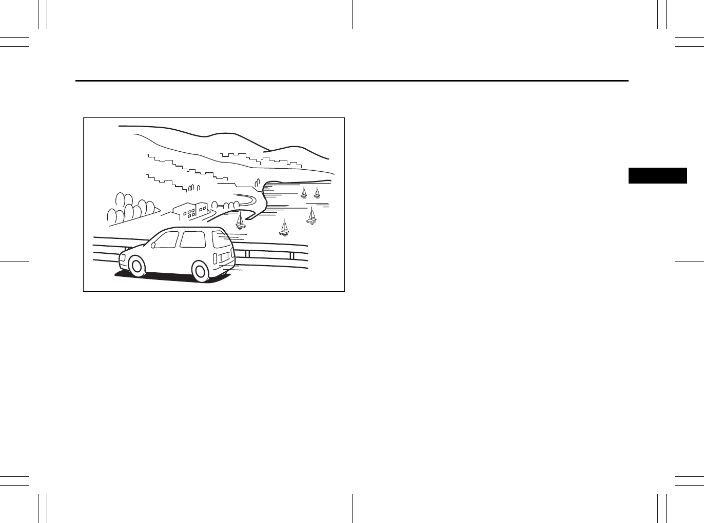
DRIVING TIPS
4
80J23-03E
60G409
DRIVING TIPS
Break-In ................................................................................ 4-1
Catalytic Converter ............................................................. 4-1
Improving Fuel Economy ................................................... 4-2
Highway Driving .................................................................. 4-3
Driving on Hills .................................................................... 4-3
Driving on Slippery Roads ................................................. 4-4
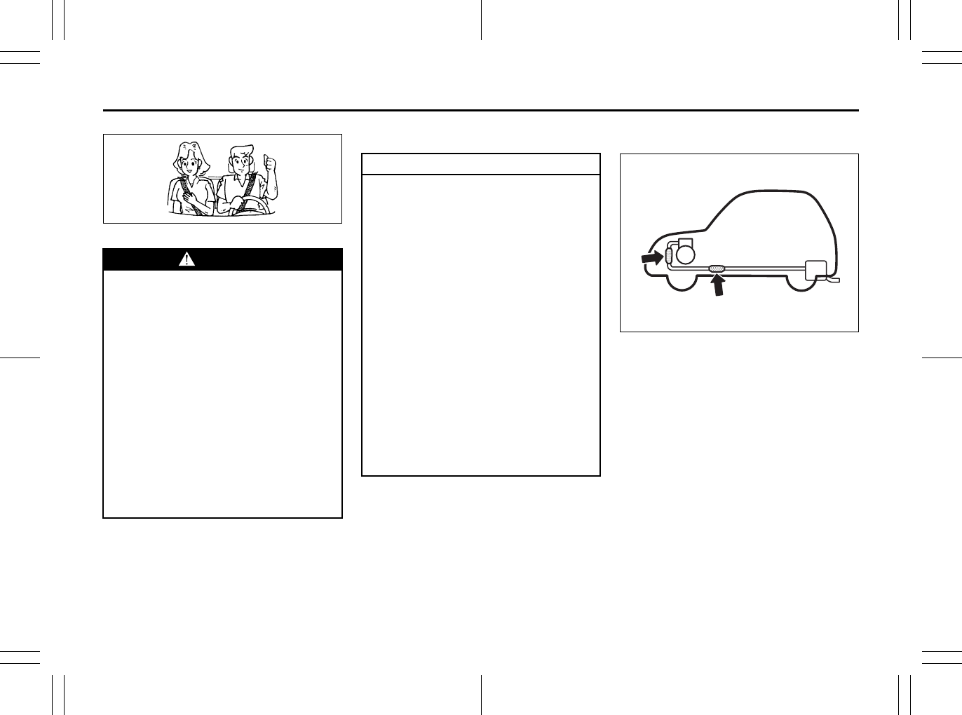
4-1
DRIVING TIPS
80J23-03E
52D078S
Break-In Catalytic Converter
68KM085
The purpose of the catalytic converter is to
minimize the amount of harmful pollutants
in your vehicle’s exhaust. Use of leaded
fuel in vehicles equipped with catalytic
converters is prohibited by federal law,
because lead deactivates the pollutant-
reducing components of the catalyst sys-
tem.
The converter is designed to last the life of
the vehicle under normal usage and when
unleaded fuel is used. No special mainte-
nance is required on the converter. How-
ever, it is very important to keep the engine
properly tuned. Engine misfiring, which
can result from an improperly tuned
engine, may cause overheating of the cat-
alyst. This may result in permanent heat
damage to the catalyst and other vehicle
components.
WARNING
• Wear Your Seat Belts at All Times.
Even though air bags are equipped
at the front seating positions, the
driver and all passengers should
be properly restrained at all times,
using the seat belts provided. Refer
to the “Seat Belts and Child
Restraint Systems” section for
instructions on proper use of the
seat belts.
• Never drive while under the influ-
ence of alcohol or other drugs.
Alcohol and drugs can seriously
impair your ability to drive safely,
greatly increasing the risk of injury
to yourself and others. You should
also avoid driving when you are
tired, sick, irritated or under stress.
CAUTION
The future performance and reliabil-
ity of the engine depends on the care
and restraint exercised during its
early life. It is especially important to
observe the following precautions
during the initial 960 km (600 miles)
of vehicle operation.
• After starting, do not race the
engine. Warm it up gradually.
• Avoid prolonged vehicle operation
at a constant speed. Moving parts
will break in better if you vary your
speed.
• Start off from a stop slowly. Avoid
full throttle starts.
• Avoid hard stopping, especially
during the first 320 km (200 miles)
of driving.
• Do not drive slowly with the tran-
saxle in a high gear.
• Drive the vehicle at moderate
engine speeds.
Instrument Panel: 3, 8
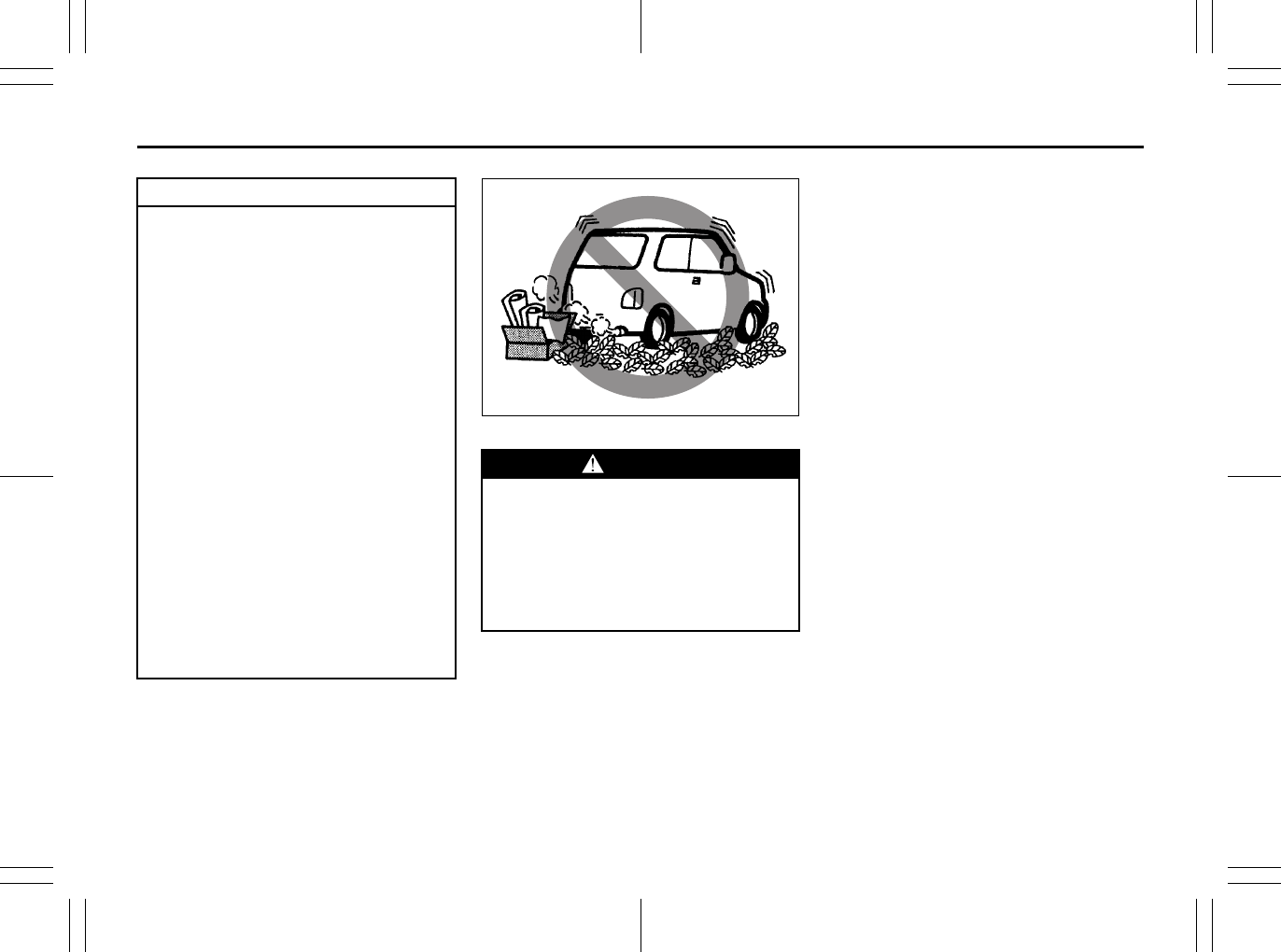
4-2
DRIVING TIPS
80J23-03E
54G584S
Improving Fuel Economy
The following instructions will help you
improve fuel economy.
Avoid excessive idling
If you are to wait for more than a minute
while you are parked, stop the engine and
start it again later. When warming up a
cold engine, allow the engine to idle until
the temperature gauge pointer comes up
to the “C” position. In this position, the
engine is sufficiently warm for starting off.
Avoid “jackrabbit” starts
Fast starts away from lights or stop signs
will consume fuel unnecessarily and
shorten engine life. Start off slowly.
Avoid unnecessary stops
Avoid unnecessary deceleration and stop-
ping. Try to maintain a slow, steady speed
whenever possible. Slowing down and then
accelerating again uses more fuel.
Keep a steady cruising speed
Keep as constant a speed as road and traf-
fic conditions will permit.
CAUTION
To minimize the possibility of catalyst
or other vehicle damage:
• Maintain the engine in the proper
operating condition.
• In the event of an engine malfunc-
tion, particularly one involving
engine misfire or other apparent
loss of performance, have the vehi-
cle serviced promptly.
• Do not shut off the engine or inter-
rupt the ignition when the transaxle
is in gear and the vehicle is in
motion.
• Do not try to start the engine by
pushing or towing the vehicle or
coasting down a hill.
• Do not idle the engine with any
spark plug wires disconnected or
removed, such as during diagnos-
tic testing.
• Do not idle the vehicle for pro-
longed periods if idling seems
rough or there are other malfunc-
tions.
• Do not allow the fuel tank to get
near the empty level.
WARNING
Be careful where you park and drive;
the catalytic converter and other
exhaust components can get very
hot. As with any vehicle, do not park
or operate this vehicle in areas where
combustible materials such as dry
grass or leaves can come in contact
with a hot exhaust system.
Instrument Cluster: 8
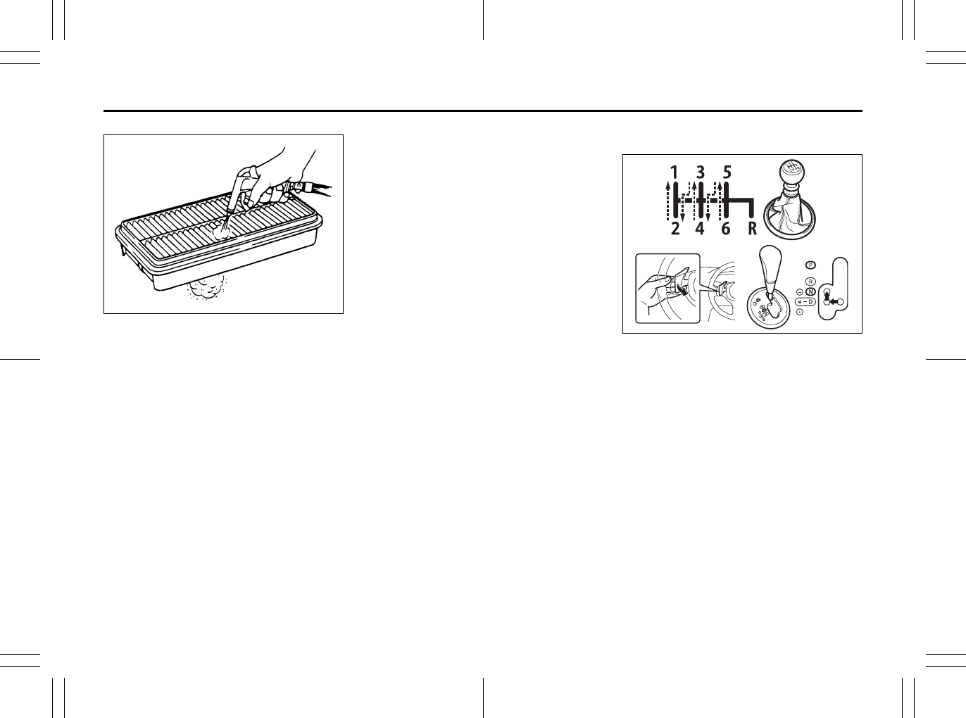
4-3
DRIVING TIPS
80J23-03E
60A183S
Keep the air cleaner clean
If the air cleaner is clogged with dust, there
will be greater intake resistance, resulting
in decreased power output and increased
fuel consumption.
Keep weight to a minimum
The heavier the load, the more fuel the
vehicle consumes. Take out any luggage
or cargo when it is not necessary.
Keep tire pressure correct
Underinflation of the tires can waste fuel
due to increased running resistance of the
tires. Keep your tires inflated to the correct
pressure shown on the label located below
the driver’s side door latch striker.
Highway Driving
When driving at highway speeds, pay
attention to the following:
• Stopping distance progressively
increases with vehicle speed. Apply the
brakes far enough ahead of the stopping
point to allow for the extra stopping dis-
tance.
• On rainy days, “Hydroplaning” can occur.
“Hydroplaning” is the loss of direct con-
tact between the road surface and the
vehicle’s tires due to a water film forming
between them. Steering or braking the
vehicle while “Hydroplaning” can be very
difficult, and loss of control can occur.
Keep speed down when the road surface
is wet.
• At high speeds, the vehicle may be
affected by side winds. Therefore,
reduce speed and be prepared for unex-
pected buffeting, which can occur at the
exits of tunnels, when passing by a cut of
a hill, or when being overtaken by large
vehicles, etc.
Driving on Hills
80J2066
• When climbing steep hills, the car may
begin to slow down and show a lack of
power. If this happens, you should shift
to a lower gear so that the engine will
again be operating in its normal power
range. Shift rapidly to prevent the car
from losing momentum.
• When driving down a hill, the engine
should be used for braking by shifting to
next lower gear. (Do this with EITHER a
CVT or manual transaxle.)
EXAMPLE
Warning and Indicator Lights: 8
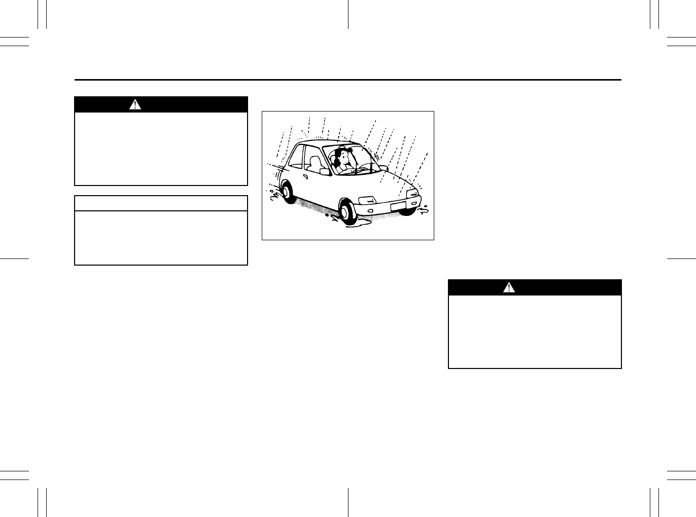
4-4
DRIVING TIPS
80J23-03E
Driving on Slippery Roads
60G089S
Under wet road conditions you should
drive at a lower speed than on dry roads
due to possible slippage of tires during
braking. When driving on icy, snow-cov-
ered, or muddy roads, reduce your speed
and avoid sudden acceleration, abrupt
braking, or sharp steering movements.
intelligent All Wheel Drive (i-AWD)
Models
Your i-AWD provides greater traction on
slippery roads than 2-wheel drive models.
However, your i-AWD will not have as
much traction in deep snow, mud or sand
as multipurpose 4WD vehicles. You should
not attempt to drive your i-AWD in deep
snow, mud or sand. i-AWD models are not
sport/utility vehicles, and are not designed
for off-road use.
If Your Vehicle Gets Stuck
If your vehicle gets stuck in snow, mud or
sand, follow the directions below:
1) Shift the transaxle back and forth
between a forward range (or first gear
for manual transaxle) and reverse. This
will create a rocking motion which may
give you enough momentum to free the
vehicle. Press gently on the accelerator
to keep wheel spinning to a minimum
wheel rpm. Remove your foot from the
accelerator while shifting.
Do not race the engine. Excessive
wheel spin will cause the tires to dig
deeper, making it more difficult to free
the vehicle.
2) If your vehicle remains stuck after a few
minutes of rocking, get another vehicle
to pull your vehicle out.
WARNING
Try not to hold the brake pedal down
too long or too often while going
down a steep or long hill. This could
cause the brakes to overheat, result-
ing in reduced braking efficiency.
Failure to take this precaution could
result in loss of vehicle control.
CAUTION
When descending a down hill,
NEVER turn the ignition key to the
“OFF” position. Emission control
system and CVT (if equipped) dam-
age may result.
WARNING
Do not allow anyone to stand near the
vehicle when you are rocking it, and
do not spin the wheels faster than an
indicated 40 km/h (25 mph) on the
speedometer. Personal injury and/or
vehicle damage may result from spin-
ning the wheels too fast.
Warning and Indicator Lights: 8
4-5
DRIVING TIPS
80J23-03E
Tire Chains
Tire chains should only be used if they are
needed to increase traction or are required
by law. Make sure that the chains you use
are small-link chains or cable-type chains
and are the correct size for your vehicle’s
tires. Also make sure that there is enough
clearance between the fenders and the
chains as installed on the tires.
Install the chains on the front tires tightly,
according to the chain manufacturer’s
instructions. Retighten the chains after
driving about 1.0 km (1/2 mile) if neces-
sary. With the chains installed, drive slowly.
Do not drive through deep or rushing
water
Driving in deep or rushing water can be
hazardous. You could lose control of the
vehicle and the occupants could drown.
Also, your vehicle could be seriously dam-
aged. To avoid these risks, observe the fol-
lowing instructions and precautions.
• Do not drive through deep or rushing
water. Deep or rushing water, such as
fast-moving streams or floodwaters,
could carry your vehicle away from your
intended path. The water is too deep if it
covers your wheel hubs, axles or
exhaust tailpipe. Know the depth of the
water before you attempt to drive
through it.
• If water blocks the tailpipe, the engine
may not start or run. If the water is deep
enough to get drawn into the engine
intake system, the engine will be badly
damaged.
• Submerged brakes will have poor brak-
ing performance. Drive slowly and care-
fully. Driving slowly will also help avoid
water splashing onto the ignition system,
which could cause the engine to stall.
• Even when driving through shallow or
still waters, drive carefully since the
water may be hiding ground hazards
such as holes, ditches or bumps.
54G638S
CAUTION
Do not continue rocking the vehicle
for more than a few minutes. Pro-
longed rocking can cause engine
overheating, transaxle or transfer
case damage or tire damage.
CAUTION
If you hear the chains hitting against
the vehicle body while driving, stop
and tighten them.
If your vehicle is equipped with full
wheel caps, remove the wheel caps
before installing the chains or the
wheel caps can be damaged by the
chain bands.
Warning and Indicator Lights: 8
4-6
DRIVING TIPS
80J23-03E
WARNING
In addition to following the driving
tips in this section, it is important to
observe the following precautions.
• Make sure your tires are in good
condition and always maintain the
specified tire pressure. Refer to
“Tires” in the “INSPECTION AND
MAINTENANCE” section for
details.
• Do not use tires other than those
specified by SUZUKI. Never use dif-
ferent sizes or types of tires on the
front and rear wheels. For informa-
tion regarding the specified tires,
refer to the Tire Information Label
located on the driver’s side door
pillar.
• Never use oversized tires or special
shocks and springs to raise (jack
up) your vehicle. This will change
its handling characteristics. Over-
sized tires may also rub against the
fender over bumps, causing vehicle
damage or tire failure.
(Continued)
WARNING
(Continued)
• After driving through water, test the
brakes while driving at a slow
speed to see if they have main-
tained their normal effectiveness. If
the brakes are less effective than
normal, dry them by repeatedly
applying the brakes while driving
slowly until the brakes have
regained their normal effective-
ness.
Warning and Indicator Lights: 8

4-7
DRIVING TIPS
80J23-03E
MEMO
Warning and Indicator Lights: 8
A/T Selector Position Indicator: 8
Speedometer/Odometer/Trip meter: 8
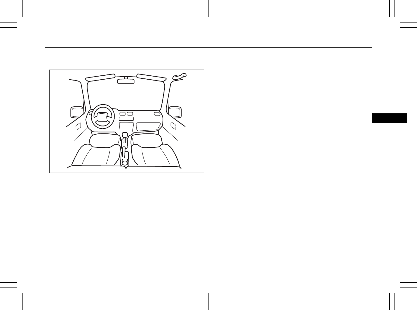
OTHER CONTROLS AND EQUIPMENT
5
80J23-03E
60G407
OTHER CONTROLS AND EQUIPMENT
Heating and Air Conditioning System ............................... 5-1
Radio Antenna ..................................................................... 5-15
Audio Systems .................................................................... 5-15
Fuel Filler Cap ..................................................................... 5-43
Engine Hood ........................................................................ 5-44
Sun Visor ............................................................................. 5-45
Interior Light Switch ........................................................... 5-45
Luggage Compartment Light (SX4) ................................... 5-46
Trunk Light (SX4 SEDAN) ................................................... 5-46
Spot Light ............................................................................ 5-47
Accessory Socket (if equipped) ......................................... 5-47
Cigarette Lighter and Ashtray (if equipped) ..................... 5-47
Assist Grips (if equipped) .................................................. 5-48
Glove Box ............................................................................ 5-49
Cup Holder and Storage Area (if equipped) ..................... 5-49
Front Seat Back Pocket (if equipped) ............................... 5-50
Armrest (if equipped) .......................................................... 5-51
Shopping Hook (if equipped) ............................................. 5-51
Floor Mats (if equipped) ..................................................... 5-51
Luggage Compartment Cover (if equipped) ..................... 5-52
Luggage Compartment Board (if equipped) ..................... 5-53
Roof Rails or Roof Rack Anchors (if equipped) ............... 5-55
Frame Hooks ....................................................................... 5-56
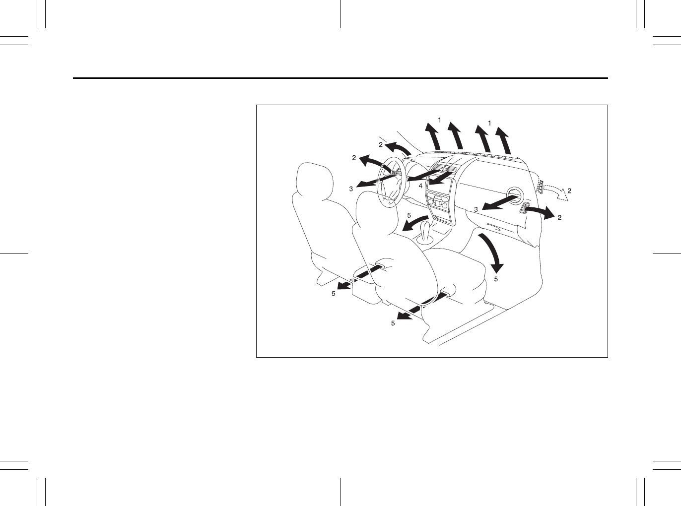
5-1
OTHER CONTROLS AND EQUIPMENT
80J23-03E
Heating and Air Conditioning
System
There are three types of heating and air
conditioning systems as follows:
• Heating System
• Manual Heating and Air Conditioning
System
• Automatic Heating and Air Conditioning
System (Climate Control)
Air Outlet
80JM044
1. Windshield defroster outlet
2. Side defroster outlet
3. Side outlet
4. Center outlet
5. Floor outlet
EXAMPLE
Parking Brake Lever: 6
Pedals: 6
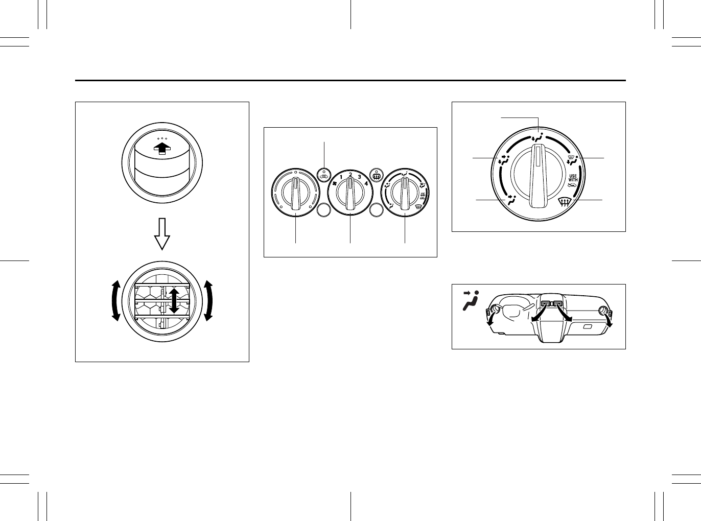
5-2
OTHER CONTROLS AND EQUIPMENT
80J23-03E
Side outlet
63J045
When “Open”, air comes out regardless of
the air flow selector position.
Heating System
Description of Controls
63J193
Temperature selector (1)
This is used to select the temperature by
turning the selector.
Blower speed selector (2)
This is used to turn on the blower and to
select blower speed by turning the selec-
tor.
Air flow selector (3)
63J048
This is used to select one of the functions
described below.
Ventilation (a)
79J065
Temperature-controlled air comes out of
the center and side air outlets.
(1) (2) (3)
(4)
(a)
(b)
(e)
(d)
(c)
Pedals: 6
Gearshift Lever: 10
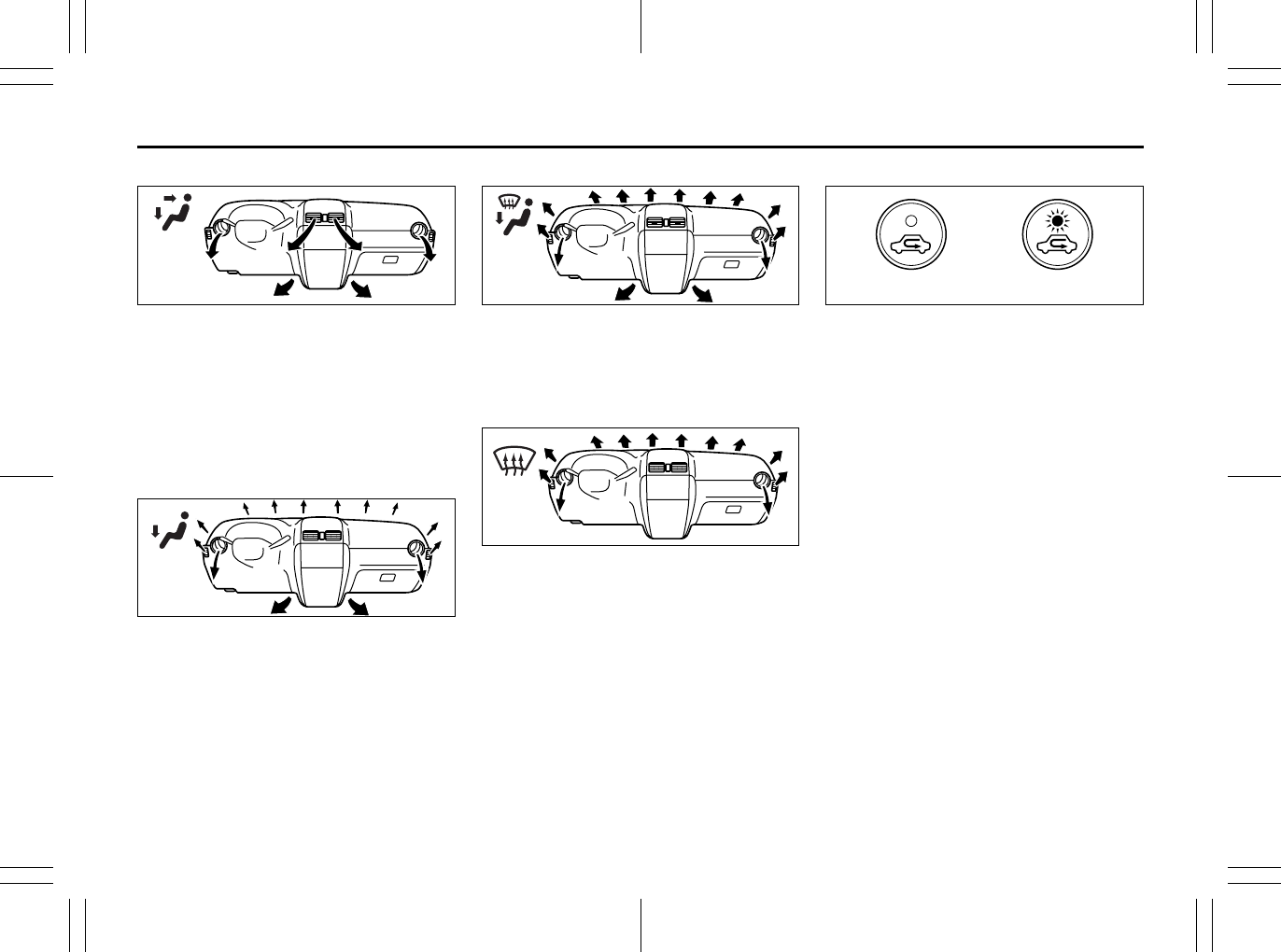
5-3
OTHER CONTROLS AND EQUIPMENT
80J23-03E
Bi-level (b)
79J066
Temperature-controlled air comes out of
the floor outlets and cooler air comes out
of the center and side outlets. When the
temperature selector (1) is in the fully
COLD position or fully HOT position, how-
ever, the air from the floor outlets and the
air from the center and side outlets will be
the same temperature.
Heat (c)
79J067
Temperature-controlled air comes out of
the floor outlets and the side outlets, also
comes out of the windshield defroster out-
lets and also comes slightly out of the side
defroster outlets.
Heat & defrost (d)
79J068
Temperature-controlled air comes out of
the floor outlets, the windshield defroster
outlets, the side defroster outlets and the
side outlets.
Defrost (e)
79J069
Temperature-controlled air comes out of
the windshield defroster outlets, the side
defroster outlets and the side outlets.
Air intake selector (4)
63J047
This selector is used to select the following
modes.
Fresh Air (f)
When this mode is selected, the indicator
light will go off and outside air is used.
Recirculated Air (g)
When this mode is selected, the indicator
light will come on, outside air is shut out
and inside air is recirculated. This mode is
suitable when driving through dusty or pol-
luted air such as in a tunnel, or when
attempting to quickly cool down the inte-
rior.
“FRESH AIR” and “RECIRCULATED AIR”
are switched alternately each time the air
intake selector is pushed.
NOTE:
If you select “RECIRCULATED AIR” for an
extended period of time, the air in the vehi-
cle can become contaminated. Therefore,
you should occasionally select “FRESH
AIR”.
(g)(f)
Gearshift Lever: 10
Fuel Filler Cap: 5
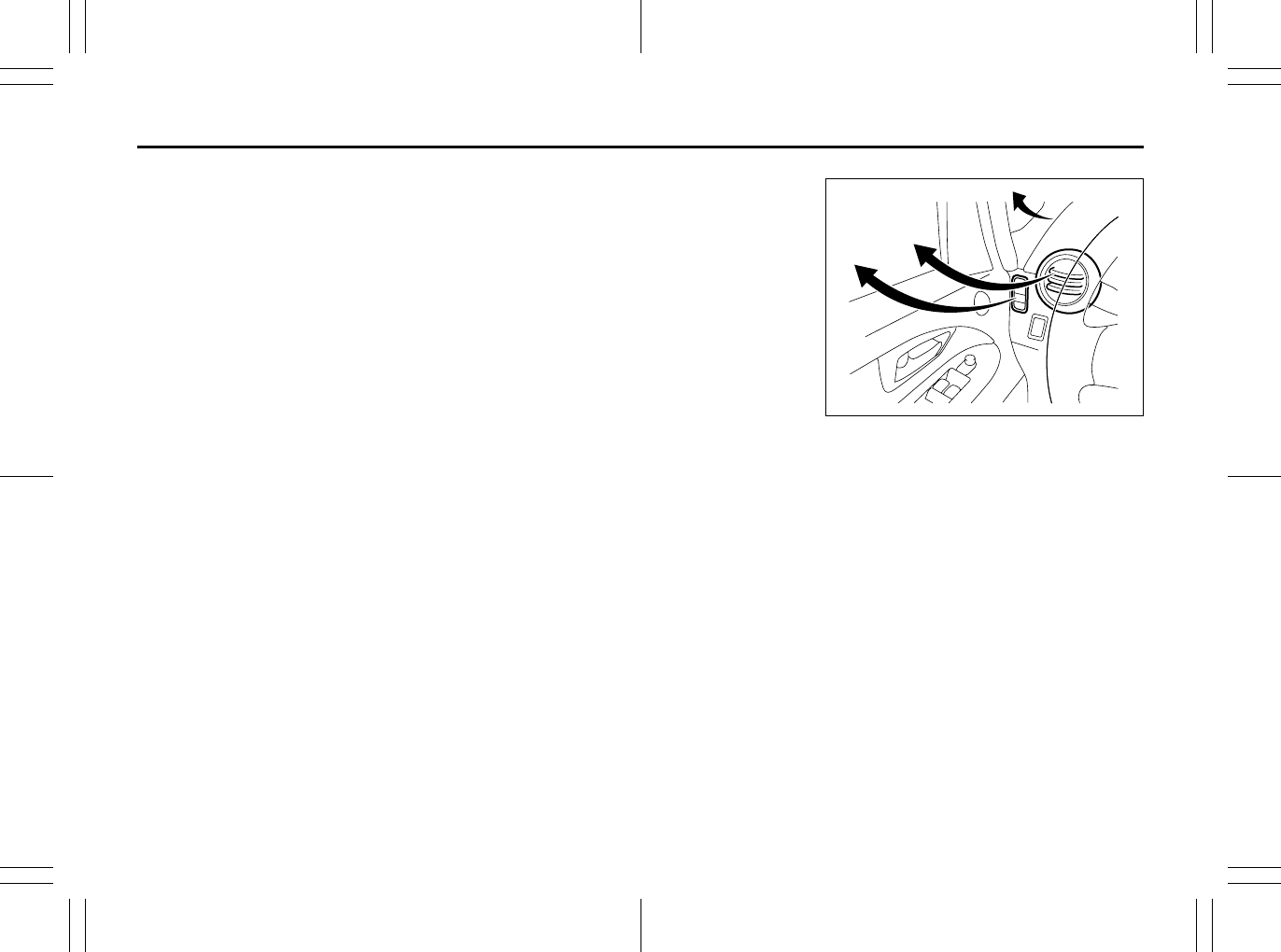
5-4
OTHER CONTROLS AND EQUIPMENT
80J23-03E
System Operating Instructions
Natural ventilation
Select “VENTILATION” and “FRESH AIR”,
the temperature selector to the desired
temperature position, and the blower
speed selector to “OFF”. Fresh air will flow
through the vehicle during driving.
Forced ventilation
The control settings are the same as for
natural ventilation except you set the
blower speed selector to a position other
than “OFF”.
Normal heating (using outside air)
Select “HEAT” and “FRESH AIR”, the tem-
perature selector to the desired tempera-
ture position and the blower speed selector
to the desired blower speed position. Set-
ting the blower speed selector to a higher
blower speed position increases heating
efficiency.
Quick heating (using recirculated air)
The control settings are the same as for
normal heating except you select “RECIR-
CULATED AIR”. If you use this heating
method for an extended period of time, the
air in the vehicle can become contami-
nated and the windows can become misty.
Therefore, use this method only for quick
heating and change to the normal heating
method as soon as possible.
Head cooled/Feet warmed heating
Select “BI-LEVEL” and “FRESH AIR”, the
temperature selector to the desired tem-
perature position, and the blower speed
selector to the desired blower speed posi-
tion. Unless the temperature selector is in
the fully COLD position or fully HOT posi-
tion, the air that comes out of the center
and side outlets will be cooler than the air
that comes out of the floor outlets.
Defrosting/Feet warmed heating
Select “HEAT & DEFROST” and “FRESH
AIR”, the temperature selector to the
desired temperature position, and the
blower speed selector to HIGH. When the
windshield has become clear, set the
blower speed selector to the desired
blower speed position.
Defrosting
Select “DEFROST” and “FRESH AIR”, the
temperature selector to the desired tem-
perature position (higher temperature pro-
vides more efficient defrosting), and the
blower speed selector to HIGH. When the
windshield has become clear, set the
blower speed selector to the desired
blower speed position.
79J070
NOTE:
If you need maximum defrosting, adjust the
temperature selector to the HOT end and
adjust the side outlets so the air blows on
the side window, in addition to the above
Defrosting steps.
EXAMPLE
Fuel Filler Cap: 5
Folding Rear Seats: 3
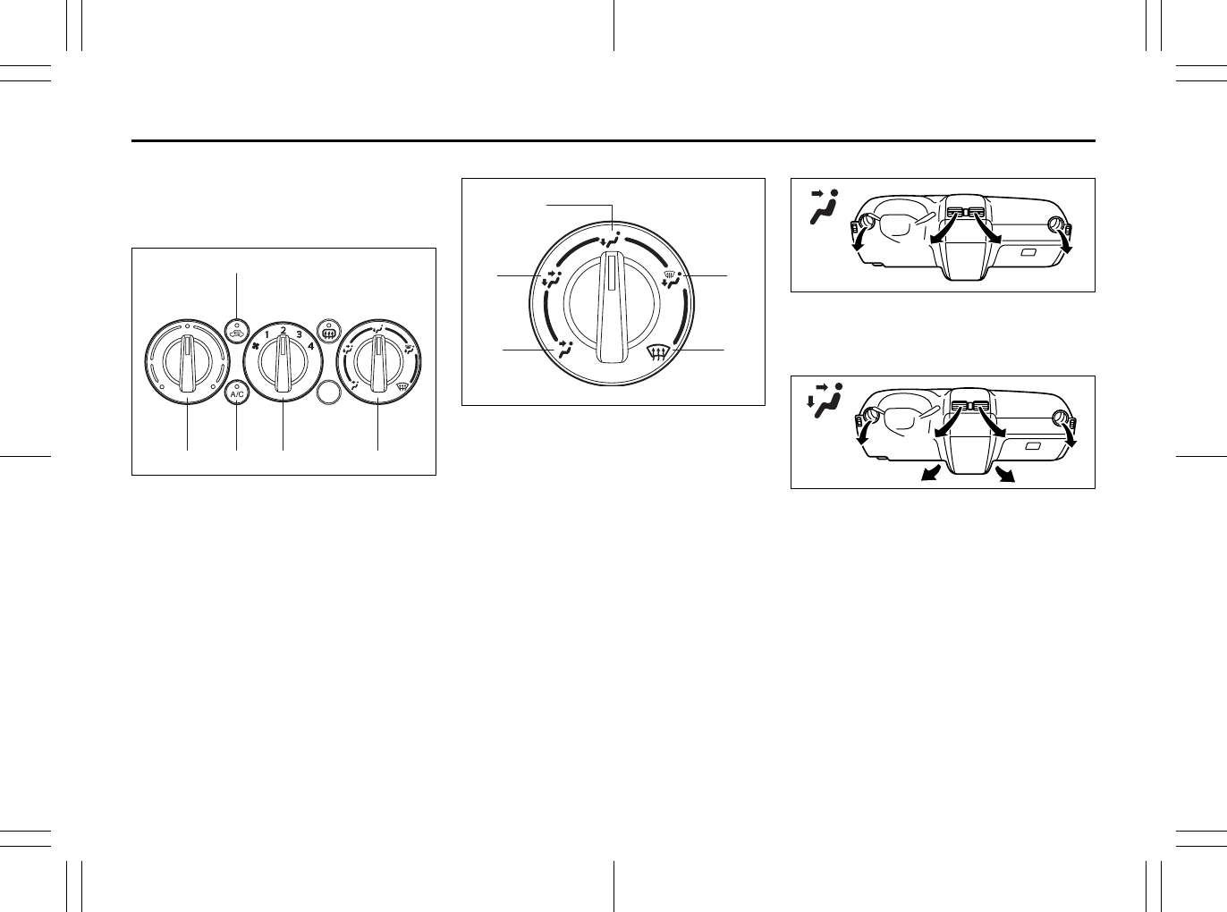
5-5
OTHER CONTROLS AND EQUIPMENT
80J23-03E
Manual Heating and Air
Conditioning System
Description of Controls
80JC042
Temperature selector (1)
This is used to select the temperature by
turning the selector.
Blower speed selector (2)
This is used to turn on the blower and to
select blower speed by turning the selec-
tor.
Air flow selector (3)
80JC043
This is used to select one of the functions
described below.
Ventilation (a)
79J065
Temperature-controlled air comes out of
the center and side air outlets.
Bi-level (b)
79J066
Temperature-controlled air comes out of
the floor outlets and cooler air comes out
of the center and side outlets. When the
temperature selector (1) is in the fully
COLD position or fully HOT position, how-
ever, the air from the floor outlets and the
air from the center and side outlets will be
the same temperature.
(1) (2)(5) (3)
(4)
(a)
(b)
(e)
(d)
(c)
Folding Rear Seats: 3
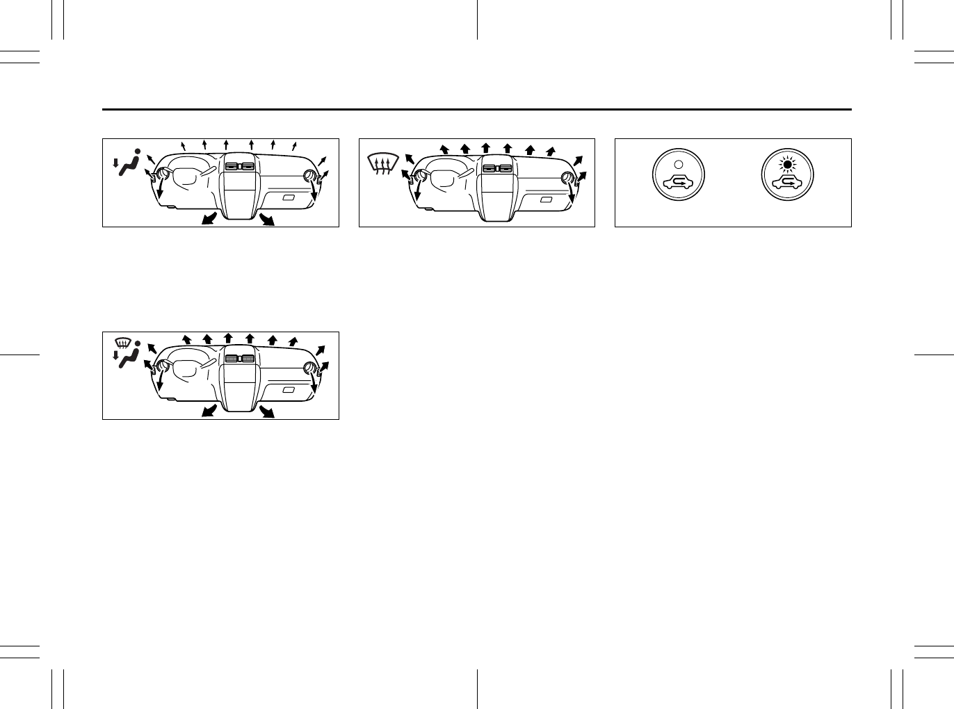
5-6
OTHER CONTROLS AND EQUIPMENT
80J23-03E
Heat (c)
79J067
Temperature-controlled air comes out of
the floor outlets and the side outlets, also
comes out of the windshield defroster out-
lets and also comes slightly out of the side
defroster outlets.
Heat & defrost (d)
79J068
Temperature-controlled air comes out of
the floor outlets, the windshield defroster
outlets, the side defroster outlets and the
side outlets.
Defrost (e)
79J069
Temperature-controlled air comes out of
the windshield defroster outlets, the side
defroster outlets and the side outlets.
NOTE:
When the air flow selector (3) is turned
either to “Heat & defrost (d)” or “Defrost
(e)”, the air conditioning system will come
on and the “FRESH AIR” mode will be
selected automatically.
Air intake selector (4)
63J047
This selector is used to select the following
modes.
Fresh Air (f)
When this mode is selected, the indicator
light will go off and outside air is used.
Recirculated Air (g)
When this mode is selected, the indicator
light will come on, outside air is shut out
and inside air is recirculated. This mode is
suitable when driving through dusty or pol-
luted air such as in a tunnel, or when
attempting to quickly cool down the inte-
rior.
“FRESH AIR” and “RECIRCULATED AIR”
are switched alternately each time the air
intake selector is pushed.
NOTE:
If you select “RECIRCULATED AIR” for an
extended period of time, the air in the vehi-
cle can become contaminated. Therefore,
you should occasionally select “FRESH
AIR”.
(g)(f)
Folding Rear Seats: 3

5-7
OTHER CONTROLS AND EQUIPMENT
80J23-03E
Air conditioning switch (5)
To turn on the air conditioning system,
push in the “A/C” switch and set the blower
speed selector to a position other than
“OFF”. With this “A/C” switch operation, a
indicator light will come on when the air
conditioning system is on. To turn off the
air conditioning system, push the “A/C”
switch again.
During operation of the air conditioner, you
may notice slight changes in engine
speed. These changes are normal, the
system is designed so that the compressor
turns on or off to maintain the desired tem-
perature.
Less operation of the compressor results
in better fuel economy.
System Operating Instructions
Natural ventilation
Select “VENTILATION” and “FRESH AIR”,
the temperature selector to the desired
temperature position, and the blower
speed selector to “OFF”. Fresh air will flow
through the vehicle during driving.
Forced ventilation
The control settings are the same as for
natural ventilation except you set the
blower speed selector to a position other
than “OFF”.
Normal heating (using outside air)
Select “HEAT” and “FRESH AIR”, the tem-
perature selector to the desired tempera-
ture position and the blower speed selector
to the desired blower speed position. Set-
ting the blower speed selector to a higher
blower speed position increases heating
efficiency.
Quick heating (using recirculated air)
The control settings are the same as for
normal heating except you select “RECIR-
CULATED AIR”. If you use this heating
method for an extended period of time, the
air in the vehicle can become contami-
nated and the windows can become misty.
Therefore, use this method only for quick
heating and change to the normal heating
method as soon as possible.
Head cooled/Feet warmed heating
Select “BI-LEVEL” and “FRESH AIR”, the
temperature selector to the desired tem-
perature position, and the blower speed
selector to the desired blower speed posi-
tion. Unless the temperature selector is in
the fully COLD position or fully HOT posi-
tion, the air that comes out of the center
and side outlets will be cooler than the air
that comes out of the floor outlets.
Normal cooling
Turn on the “A/C” switch, set the air flow
selector to “VENTILATION”, the tempera-
ture selector to the desired temperature
position and the blower speed selector to
the desired blower speed position. Setting
the blower speed selector to a higher
blower speed position increases cooling
efficiency.
You can switch the air intake selector to
either “FRESH AIR” or “RECIRCULATED
AIR” as you desire. Choosing “RECIRCU-
LATED AIR” increases cooling efficiency.
Folding Rear Seats: 3
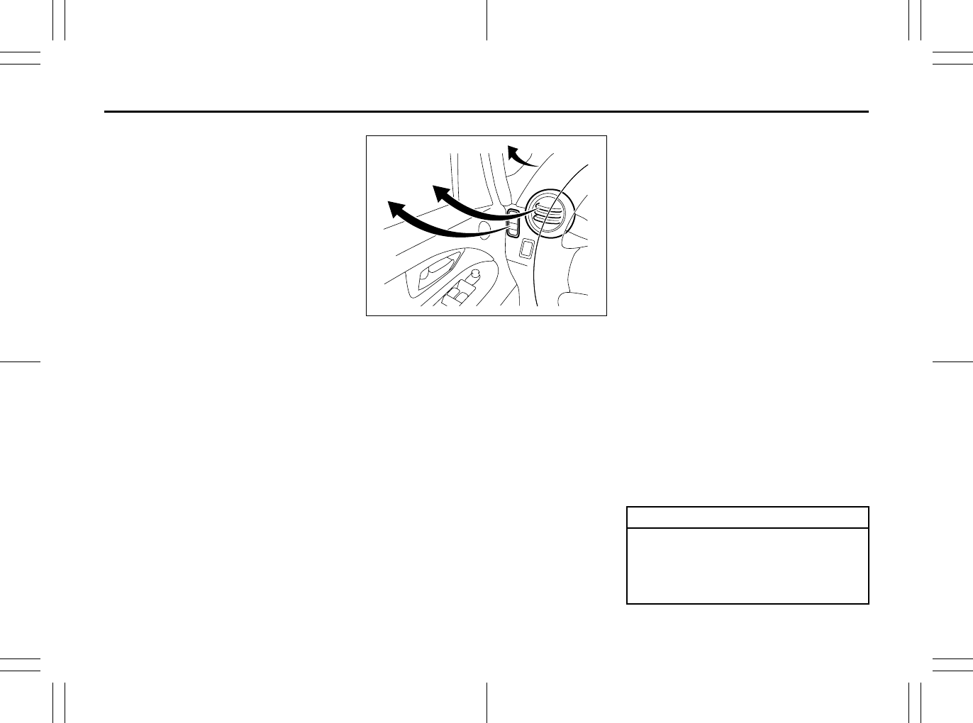
5-8
OTHER CONTROLS AND EQUIPMENT
80J23-03E
Quick cooling (using recirculated air)
The control settings are the same as for
normal cooling except you select “RECIR-
CULATED AIR” and the highest blower
speed.
NOTE:
• If you select “RECIRCULATED AIR” for
an extended period of time, the air in the
vehicle can become contaminated.
Therefore, you should occasionally
select “FRESH AIR”.
• If your vehicle has been left in the sun
with the windows closed, it will cool
faster if you open the windows briefly
while you operate the air conditioner with
the air intake selector at “FRESH AIR”
and the blower at high speed.
Dehumidifying
Turn on the “A/C” switch, set the air flow
selector to a desired air flow selector posi-
tion, and select “FRESH AIR”, the temper-
ature selector to the desired temperature
position, and the blower speed selector to
the desired blower speed position.
NOTE:
Because the air conditioner dehumidifies
the air, turning it on will help keep the win-
dows clear, even when blowing heated air
using the “DEFROST” or “HEAT &
DEFROST” functions.
79J070
NOTE:
If you need maximum defrosting:
• select “DEFROST” and “FRESH AIR”,
• turn on the “A/C” switch,
• set the blower speed selector to HIGH,
• adjust the temperature selector to the
HOT end, and
• adjust the side outlets so the air blows
on the side windows.
Maintenance
If you do not use the air conditioner for a
long period, such as during winter, it may
not give the best performance when you
start using it again. To help maintain opti-
mum performance and durability of your air
conditioner, it needs to be run periodically.
Operate the air conditioner at least once a
month for one minute with the engine
idling. This circulates the refrigerant and oil
and helps protect the internal components.
Your air conditioner is equipped with air fil-
ters. Clean or replace them as specified in
the “Maintenance Schedule” in the
“INSPECTION AND MAINTENANCE” sec-
tion. Have this job done by your SUZUKI
dealer as the lower glove box must be low-
ered for this job.
NOTE:
Your vehicle uses the air conditioning
refrigerant HFC-134a, commonly called
“R-134a”. R-134a replaced R-12 around
1993 for automotive applications. Other
refrigerants are available, including recy-
cled R-12, but only R-134a should be used
in your vehicle.
EXAMPLE
CAUTION
Using the wrong refrigerant may
damage your air conditioning sys-
tem. Use R-134a only. Do not mix or
replace the R-134a with other refrig-
erants.
Folding Rear Seats: 3
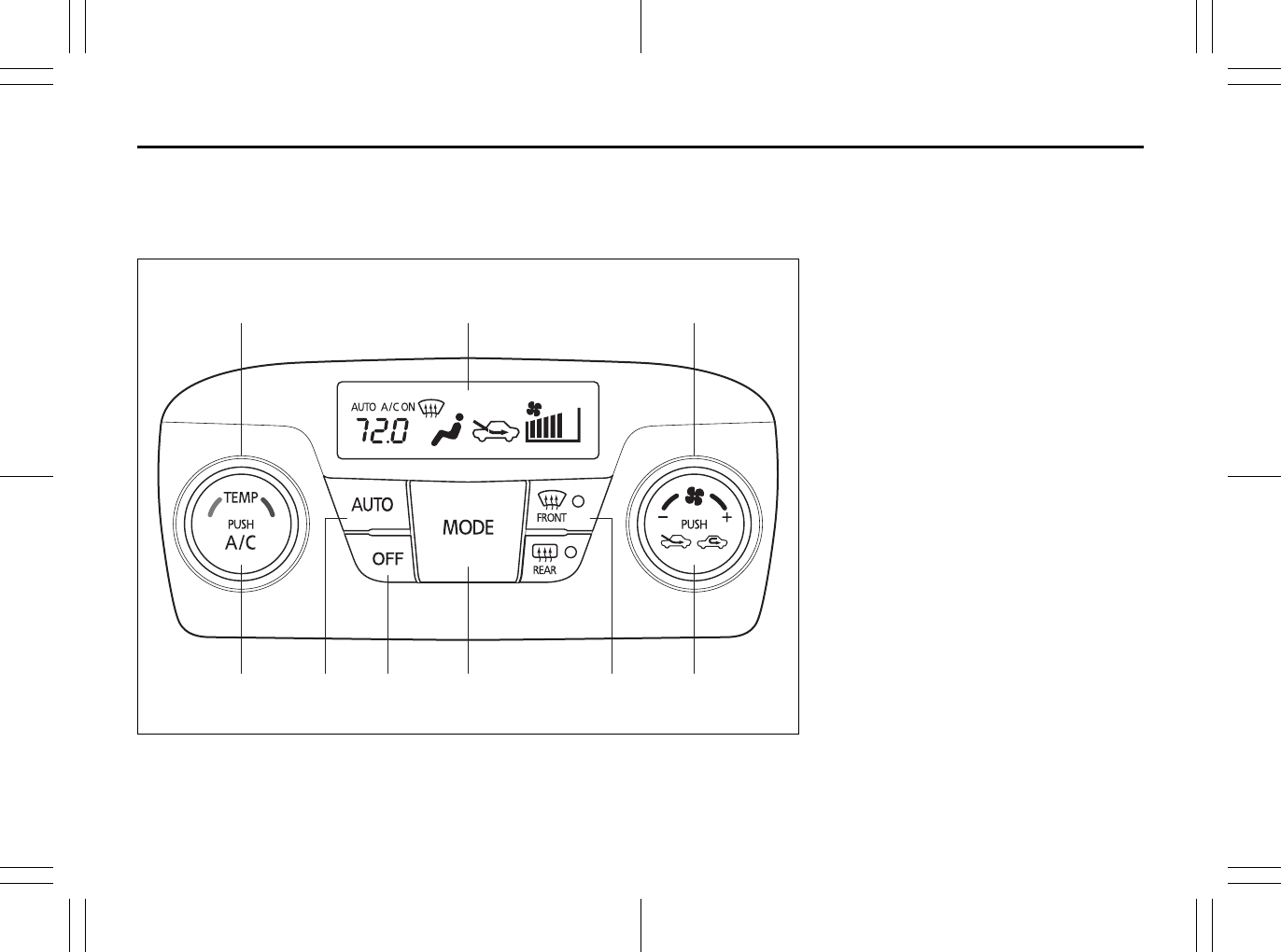
5-9
OTHER CONTROLS AND EQUIPMENT
80J23-03E
Automatic Heating and Air Conditioning System
(Climate Control)
Description of Controls
80J2042
(1) (9) (2)
(
7
) (
3
)(
5
)(
4
)(
6
)(
8
)
(1) Temperature selector
(2) Blower speed selector
(3) Air intake selector
(4) Air flow selector
(5) Defrost switch
(6) “OFF” switch
(7) Air conditioning switch
(8) “AUTO” switch
(9) Display
Folding Rear Seats: 3
Armrest: 3
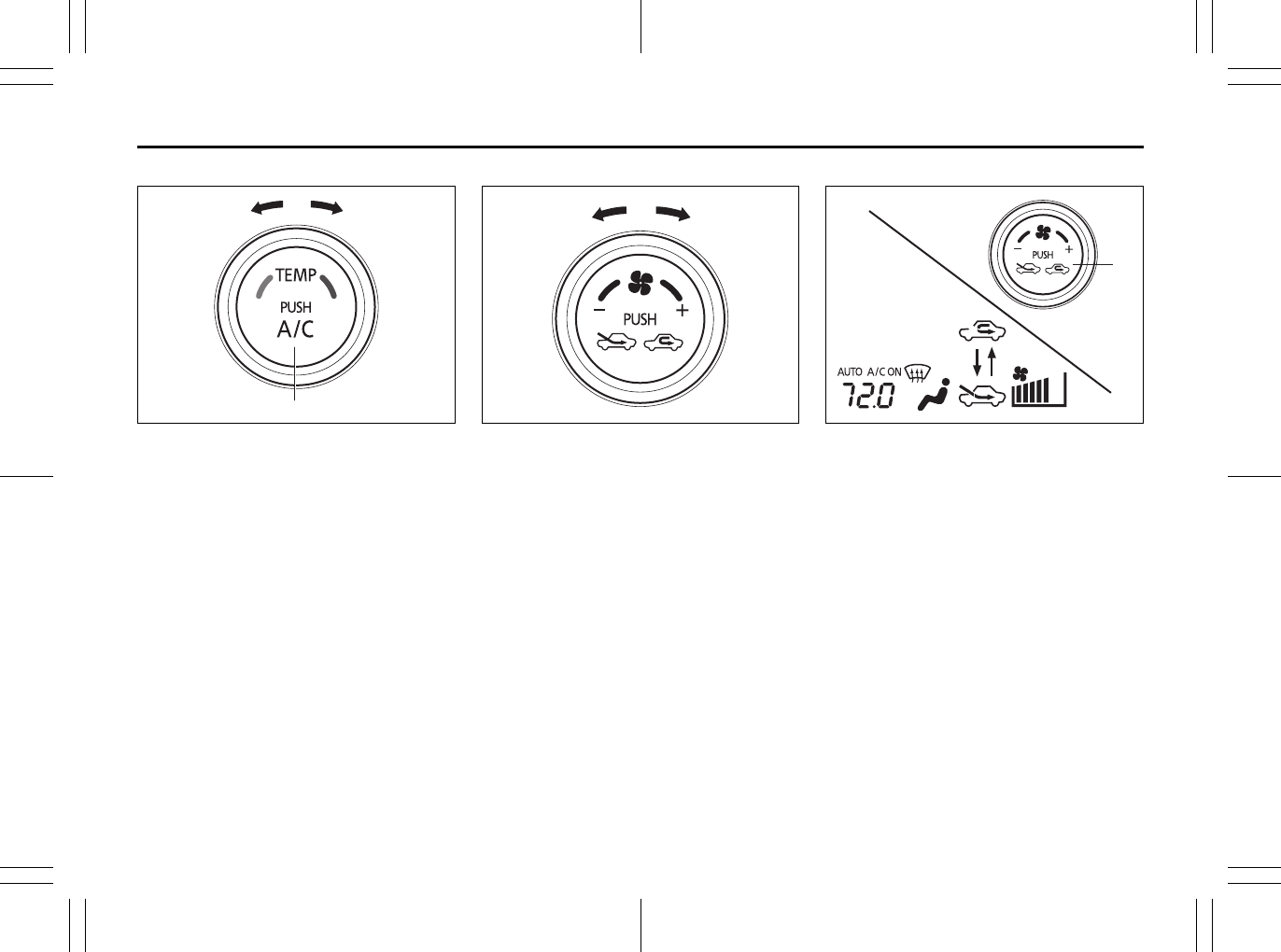
5-10
OTHER CONTROLS AND EQUIPMENT
80J23-03E
Temperature selector (1)
80J2043
Turn the temperature selector (1) to adjust
the temperature.
Air conditioning switch (7)
The air conditioning switch (7) is used to
turn on and off the air conditioning system.
To turn on the air conditioning system,
push in the switch and “A/C ON” will
appear on the display. To turn off the air
conditioning system, push in the switch
again and “A/C ON” will go off.
Blower speed selector (2)
80JM047
The blower speed selector (2) is used to
turn on the blower and to select blower
speed.
If the “AUTO” switch (8) is pushed, the
blower speed will vary automatically as the
climate control system maintains the
selected temperature.
Air intake selector (3)
80J2044
Push the air intake selector (3) to change
between the following modes.
If the “AUTO” switch (8) is pushed, the air
intake will vary automatically as the climate
control system maintains the selected tem-
perature.
RECIRCULATED AIR (a)
When this mode is selected, outside air is
shut off and inside air is recirculated. This
mode is suitable when driving through an
area with polluted air such as a tunnel, or
when attempting to quickly cool down the
vehicle.
FRESH AIR (b)
When this mode is selected, outside air is
introduced.
(1)
(
7
)
(2)
(3)
(a)
(b)
Sun Visor: 5
Interior Light Switch: 7
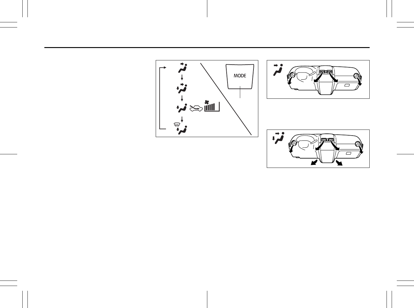
5-11
OTHER CONTROLS AND EQUIPMENT
80J23-03E
“FRESH AIR” and “RECIRCULATED AIR”
are selected alternately each time the air
intake selector is pushed.
NOTE:
If you select “RECIRCULATED AIR” for an
extended period of time, the air in the vehi-
cle can become contaminated. Therefore,
you should occasionally select “FRESH
AIR”.
Air flow selector (4)
80JM049
Push the air flow selector (4) to change
among the following functions. The indica-
tion of the selected mode appears on the
display.
If the “AUTO” switch (8) is pushed, the air
flow will vary automatically as the climate
control system maintains the selected tem-
perature.
Ventilation (c)
79J065
Temperature-controlled air comes out of
the center and side air outlets.
Bi-level (d)
79J066
Temperature-controlled air comes out of
the floor outlets and cooler air comes out
of the center and side outlets. When the
temperature selector (1) is in the fully
COLD position or fully HOT position, how-
ever, the air from the floor outlets and the
air from the center and side outlets will be
the same temperature.
(4)
(c)
(d)
(e)
(f)
Spot Light: 7
Assist Grips: 3
Coat Hooks:
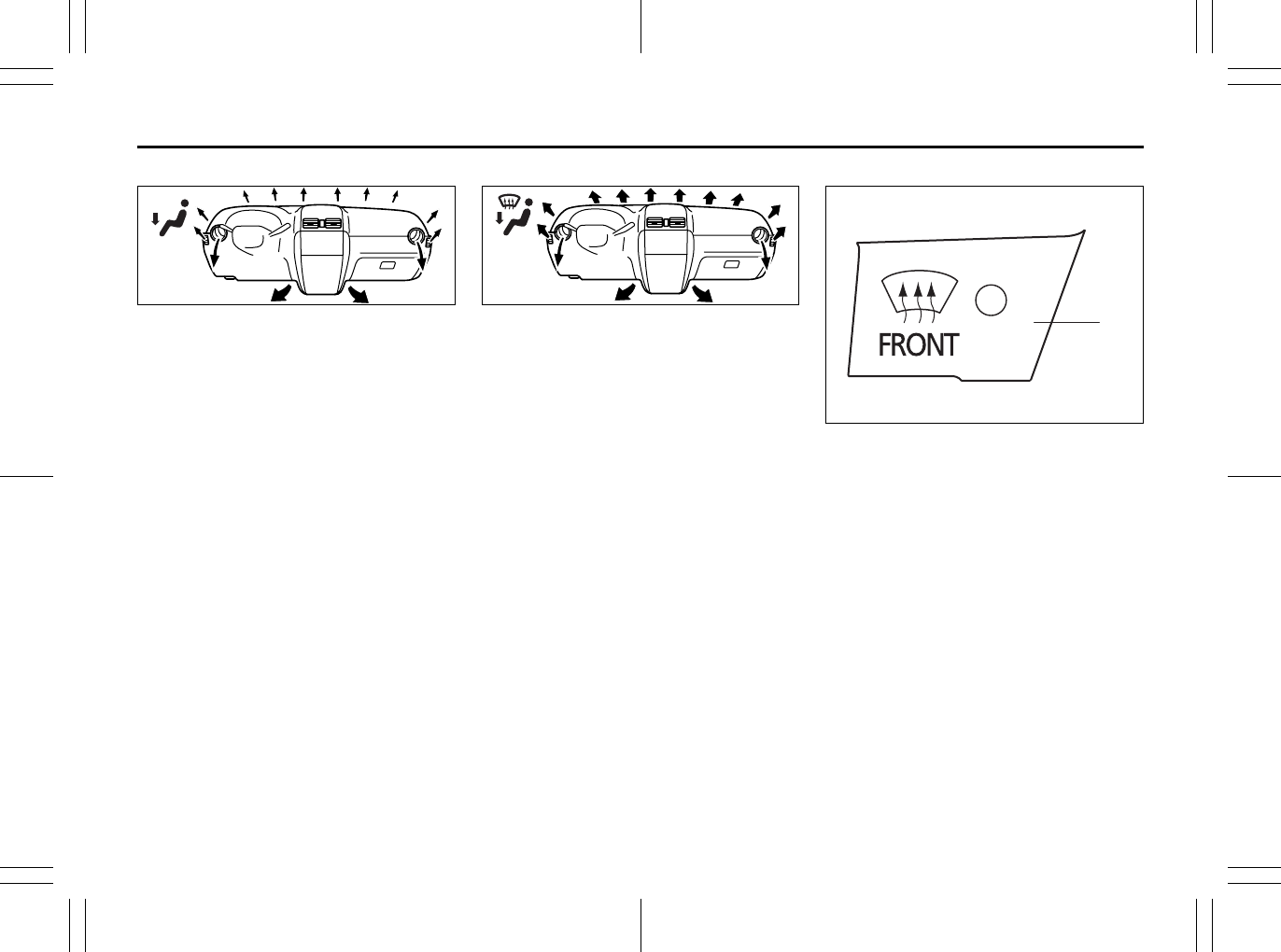
5-12
OTHER CONTROLS AND EQUIPMENT
80J23-03E
Heat (e)
79J067
Temperature-controlled air comes out of
the floor outlets and the side outlets, a
small amount of air comes out of the wind-
shield defroster outlets and also comes
slightly out of the side defroster outlets.
Heat & defrost (f)
79J068
Temperature-controlled air comes out of
the floor outlets, the windshield defroster
outlets, the side defroster outlets and the
side outlets.
NOTE:
When the heat & defrost (f) is selected, the
air conditioning system will come on and
the “FRESH AIR” mode will be selected
automatically. The “RECIRCULATED AIR”
mode cannot be selected. In very cold
weather, however, the air conditioning sys-
tem will not turn on.
Defrost switch (5)
80JM050
Push the defrost switch (5) to turn on the
defroster.
(5
)
Eyeglasses Holder:
Engine Hood: 5
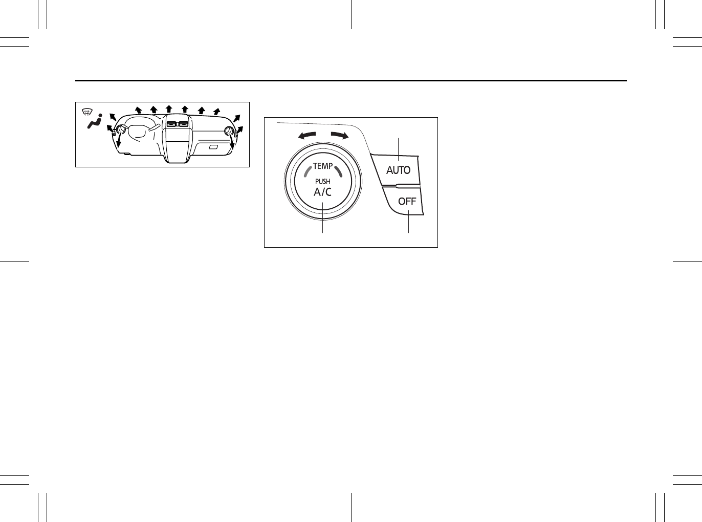
5-13
OTHER CONTROLS AND EQUIPMENT
80J23-03E
Defrost
80JM051
Temperature-controlled air comes out of
the windshield defroster outlets, the side
defroster outlets and the side outlets.
NOTE:
When the defrost switch (5) is pushed to
turn on the defroster, the air conditioning
system will come on and the “FRESH AIR”
mode will be selected automatically. In
very cold weather, however, the air condi-
tioning system will not turn on.
System Operating Instructions
Automatic operation
80JM126
You can let the climate control system work
automatically. To set the system for fully-auto-
matic operation, follow the procedure below.
1) Start the engine.
2) Push the “AUTO” switch (8).
3) Set the desired temperature by turning
the temperature selector (1).
The blower speed, air intake and air flow
are controlled automatically to maintain the
set temperature.
You can use the air conditioning switch (7)
to manually turn the air conditioner on or off
according to your preference. When you
turn the air conditioning switch off, the cli-
mate control system cannot lower the inside
temperature below outside temperature.
To turn the climate control system off, push
the “OFF” switch (6).
NOTE:
If the “AUTO” on the display blinks, there is
a problem in the heating system and/or air
conditioning system. You should have the
system inspected by an authorized
SUZUKI dealer.
NOTE:
• To find the temperature at which you are
most comfortable, start with the 72°F
(22°C) setting.
• If you turn the temperature selector (1)
until “HI” or “LO” appears on the display,
the climate control system will operate at
the maximum cooling or heating and the
blower will run at full speed.
• To avoid blowing cold air in cold weather
or hot air in hot weather, the system will
delay turning on the blower until warmed
or chilled air is available.
• If your vehicle has been left in the sun
with the windows closed, it will cool
faster if you open the windows briefly.
• Even under the automatic operation, you
can set individual selectors to the man-
ual mode. The manually selected func-
tions are maintained, and the other
functions remain under automatic opera-
tion.
• To return the blower speed selector (2),
air intake selector (3), and air flow selec-
tor (4) to automatic operation, push the
“AUTO” switch (8).
(
7
) (
6
)
(8)
(1)
Cup Holder and Storage Area: 3
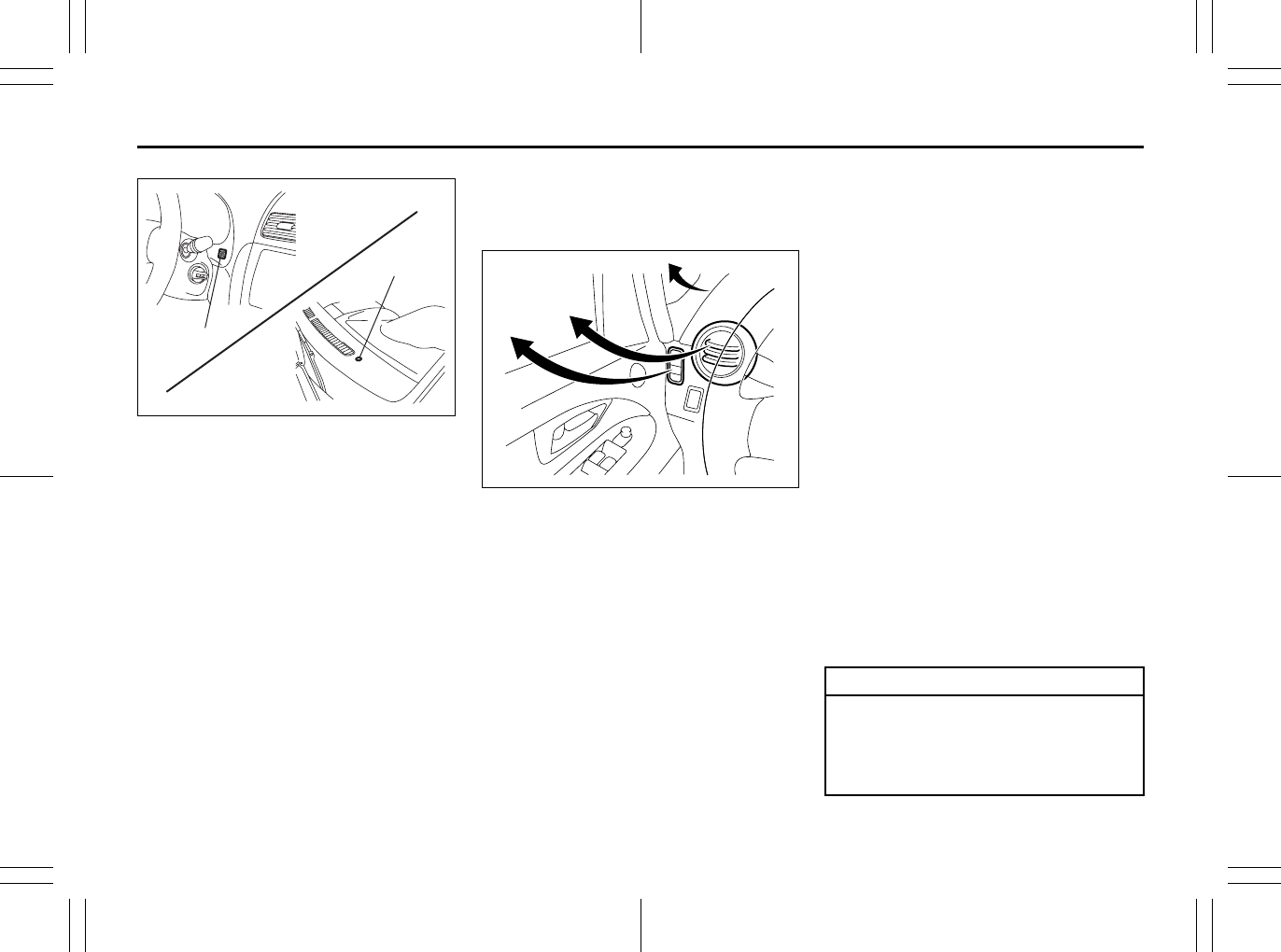
5-14
OTHER CONTROLS AND EQUIPMENT
80J23-03E
80JM127
Be careful not to cover the interior temper-
ature sensor (10) located between the
steering wheel and the climate control
panel, or the solar sensor (11) located at
the top of the driver’s side dashboard.
These sensors are used by the automatic
system to regulate temperature.
Manual operation
You can manually control the climate con-
trol system. Set the selectors to the
desired positions.
79J070
NOTE:
If you need maximum defrosting:
• push the defrost switch (5) to turn on the
defroster (the air conditioning system will
come on and the “FRESH AIR” mode will
be selected automatically),
• set the blower speed selector to HIGH,
• adjust the temperature selector to the
“HI” indication on the display, and
• adjust the side outlets so the air blows
on the side windows.
Maintenance
If you do not use the air conditioner for a
long period, such as during winter, it may
not give the best performance when you
start using it again. To help maintain opti-
mum performance and durability of your air
conditioner, it needs to be run periodically.
Operate the air conditioner at least once a
month for one minute with the engineidling.
This circulates the refrigerant and oil and
helps protect the internal components.
Your air conditioner is equipped with air fil-
ters. Clean or replace them as specified in
the “Maintenance Schedule” in the
“INSPECTION AND MAINTENANCE” sec-
tion. Have this job done by your SUZUKI
dealer as the lower glove box must be low-
ered for this job.
NOTE:
Your vehicle uses the air conditioning
refrigerant HFC-134a, commonly called
“R-134a”. R-134a replaced R-12 around
1993 for automotive applications. Other
refrigerants are available, including recy-
cled R-12, but only R-134a should be used
in your vehicle.
(11)
(10)
EXAMPLE
EXAMPLE
CAUTION
Using the wrong refrigerant may
damage your air conditioning sys-
tem. Use R-134a only. Do not mix or
replace the R-134a with other refrig-
erants.
Accessory Socket: 8
Frame Hooks: 5, 6
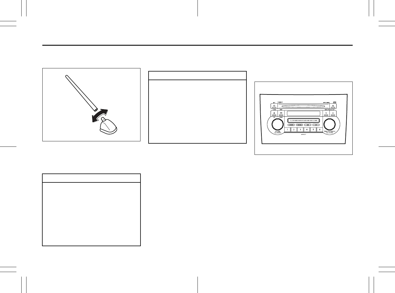
5-15
OTHER CONTROLS AND EQUIPMENT
80J23-03E
Radio Antenna
SX4
63J055
The radio antenna on the roof is remov-
able. To remove the antenna, turn it coun-
terclockwise. To reinstall the antenna, turn
it clockwise firmly by hand.
SX4 SEDAN
The radio antenna wire is printed inside
the rear window.
Audio Systems
There are two types of audio system as
shown below:
Type 1
80J059
AM/FM/XM CD PLAYER
WITH CD CHANGER CONTROL
CAUTION
To avoid damage to the radio
antenna:
• Remove the antenna before using
an automatic car wash.
• Remove the antenna when it is pos-
sible for the antenna to hit some-
thing such as a low ceiling in a
parking garage or putting a car
cover over your car.
• Remove the antenna before put-
ting a car cover over your vehicle.
EXAMPLE CAUTION
• Do not attach any metal objects to
the rear window glass, or place
metallic film near it. Either of these
conditions may cause poor recep-
tion or noise.
• When cleaning the inside of the
rear window, be careful not to
scratch or damage the rear window
antenna. Wipe the rear window
lightly along the antenna with a
dampened soft cloth.
Frame Hooks: 5, 6
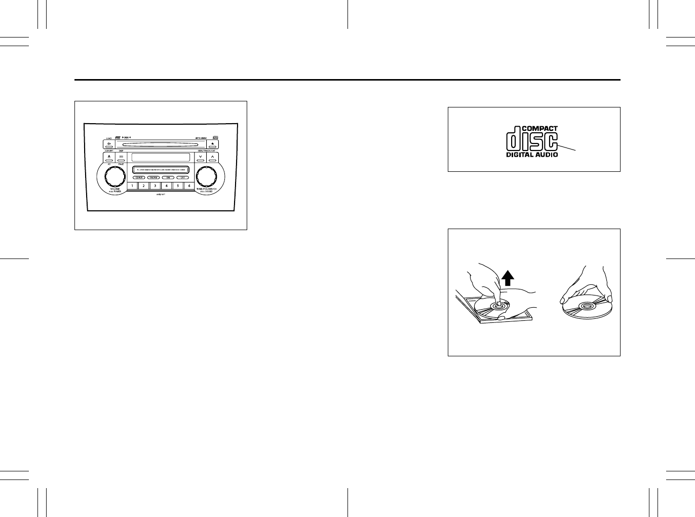
5-16
OTHER CONTROLS AND EQUIPMENT
80J23-03E
Type 2
80J060
AM/FM/XM 6-CD PLAYER
WITH CD CHANGER CONTROL
Precautions
• When the inside of the car is very cold
and the player is used soon after switch-
ing on the heater, moisture may form on
the disc or the optical parts of the player
and proper playback may not be possi-
ble. If moisture forms on the disc, wipe it
off with a soft cloth. If moisture forms on
the optical parts of the player, do not use
the player for about one hour. This will
allow the condensation to disappear nor-
mally.
• Driving on extremely bumpy roads which
cause severe vibrations may cause
sound to skip.
• This unit uses a precision mechanism.
Even in the event that trouble arises,
never open the case, disassemble the
unit, or lubricate the rotating parts.
Please bring the unit to an authorized
SUZUKI dealer or a Clarion service
Department.
Cautions on Handling
52D274
This unit has been designed specifically for
playback of compact discs bearing the
mark (A).
No other discs can be played.
52D275
To remove the compact disc from its stor-
age case, press down on the center of the
case and lift the disc out, holding it care-
fully by the edges.
Always handle the compact disc by the
edges.
Never touch the surface.
(A)
Removing the disc Proper way to hold
the compact disc
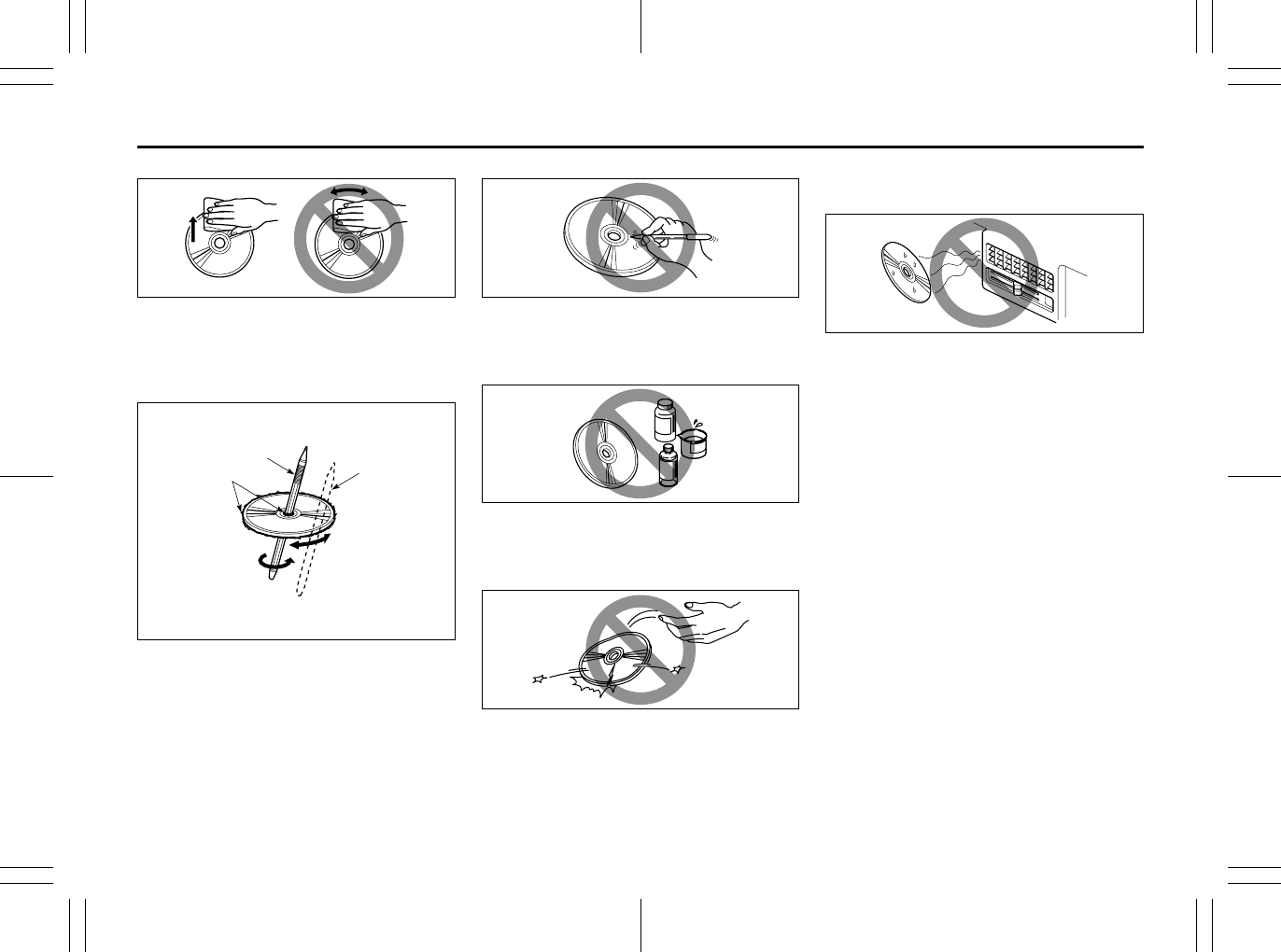
5-17
OTHER CONTROLS AND EQUIPMENT
80J23-03E
52D347
To remove fingermarks and dust, use a
soft cloth, and wipe in a straight line from
the center of the compact disc to the cir-
cumference.
52D277
New discs may have some roughness
around the edges. The unit may not work
or the sound may skip if such discs are
used. Use a ball-point pen (B), etc. to
remove the roughness (C) from edges of
the disc before insertion inside the unit.
52D348
Never stick labels on the surface of the
compact disc or mark the surface with a
pencil or pen.
52D349
Do not use any solvents such as commer-
cially available cleaners, anti-static spray,
or thinner to clean compact discs.
52D350
Do not use compact discs that have large
scratches, are misshaped, or cracked, etc.
Use of such discs will cause damage or
prevent the system from operating prop-
erly.
52D351
Do not expose compact discs to direct sun-
light or any heat source.
NOTE:
• Do not use commercially available CD
protection sheets or discs equipped with
stabilizers, etc.
These may get caught in the internal
mechanism and damage the disc.
• CD-R discs may not be able to playback
in this unit due to the recording condi-
tions.
• CD-RW discs cannot playback in this
unit.
(B)
(B)
(C)
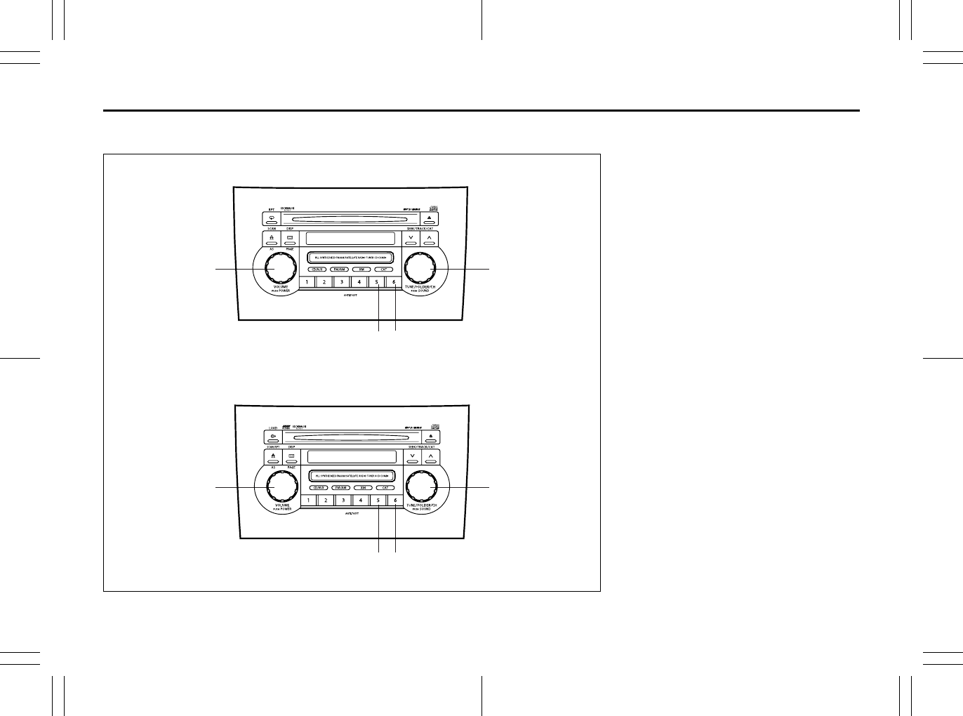
5-18
OTHER CONTROLS AND EQUIPMENT
80J23-03E
Basic Operations
80J061
(1) (2)
(3) (4)
(1) (2)
(3) (4)
Type 1 AM/FM/XM CD PLAYER WITH CD CHANGER CONTROL
Type 2 AM/FM/XM 6-CD PLAYER WITH CD CHANGER CONTROL
(1) Power on/off knob
Volume control knob
(2) Tone/balance/fader control knob
(3) Preset button 5
(4) Preset button 6
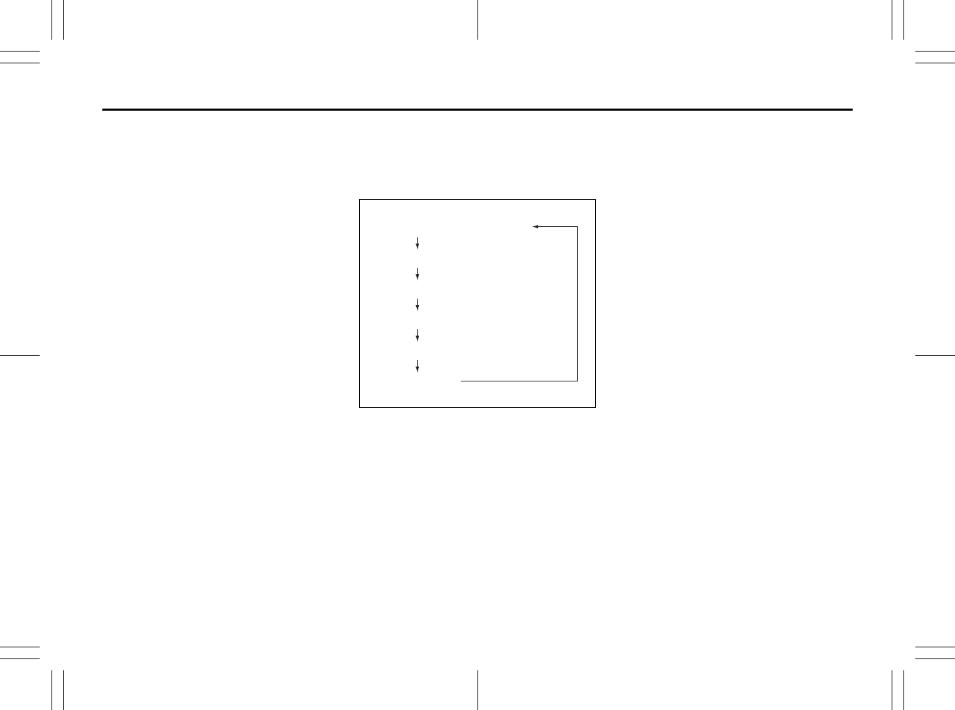
5-19
OTHER CONTROLS AND EQUIPMENT
80J23-03E
Turning power on/off
Press the power on/off knob (1).
The unit starts in the function mode it was
in when the power was turned off last.
Adjusting the volume
Turn the volume control knob (1).
Turning it clockwise increases the volume;
turning it counterclockwise decreases the
volume.
NOTE:
While driving, adjust the volume to an
extent that sound and/or noise coming
from outside the car can be heard.
Adjusting bass/treble/balance/fader
1) Press the tone/balance/fader control
knob (2).
Each time it is pressed, sound adjust-
ment is changed as follows:
66J224
2) Turn the tone/balance/fader control
knob (2) to adjust the sound.
Adjusting the AVC (Auto volume con-
trol)
The Automatic Volume Control (AVC) func-
tion automatically adjusts (increases/
decreases) the sound volume in accor-
dance with vehicle speed. The AVC control
is provided with three selectable levels
(LEVEL OFF, 1, 2, 3). The range of volume
adjustment increases together with the
LEVEL number,
1) Press the tone/balance/fader control
knob (2) until the AVC adjustment mode
is selected.
2) Turn the tone/balance/fader control
knob (2) to select the desired AVC
adjustment level. (Initial setting: LEVEL
2)
Adjusting the contrast of the display
1) Press the tone/balance/fader/control
knob (2) and preset button 5 (3), preset
button 6 (4) simultaneously.
2) To adjust the contrast of the display,
turn the power on/off knob (1).
Cancel the dimmer condition
Each time you press the power on/off knob
(1) for two seconds with the lighting switch
on, the background brightness of the audio
display will switch between normal and
dimmed.
Bass adjustment (BASS 0)
Treble adjustment (TREBLE 0)
Balance adjustment (BALANCE 0)
Fader adjustment (FADER 0)
AVC adjustment (AVC LEVEL 2)
Original mode
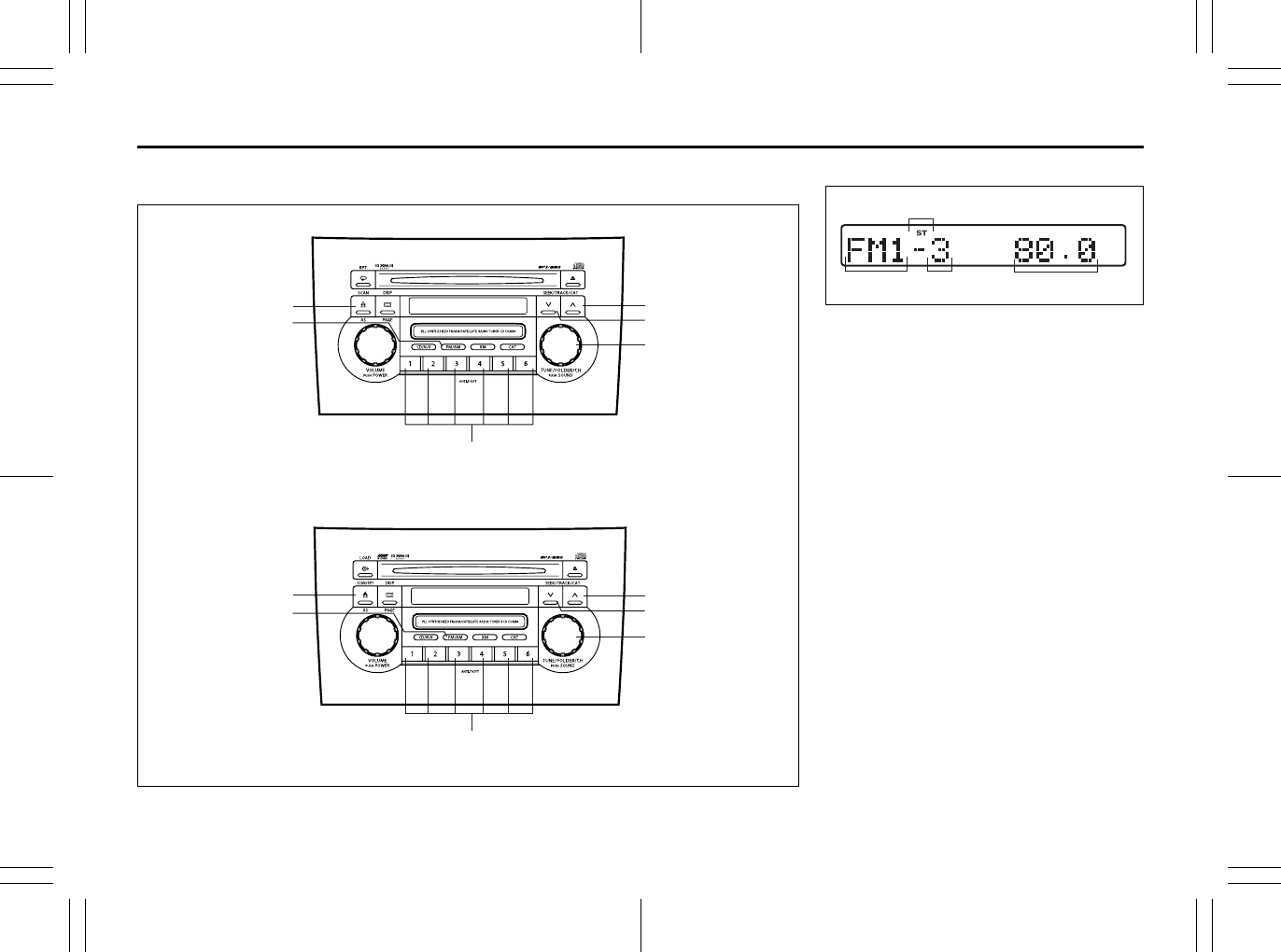
5-20
OTHER CONTROLS AND EQUIPMENT
80J23-03E
Listening to the Radio
80J062
(1)
(4)
(6) (2)
(3)
(5)
(5)
(1)
(4)
(6) (2)
(3)
Type 1 AM/FM/XM CD PLAYER WITH CD CHANGER CONTROL
Type 2 AM/FM/XM 6-CD PLAYER WITH CD CHANGER CONTROL
Display
66J097
(1) Band switch button (FM/AM)
(2) Seek up button
(3) Seek down button
(4) Manual tuning knob
(5) Preset buttons (1 to 6)
(6) Auto store button (AS)/
Scan button (SCAN)
(A) Band
(B) Preset channel number
(C) Stereo indicator
(D) Frequency
(
A
)
(
B
)
(C)
(
D
)
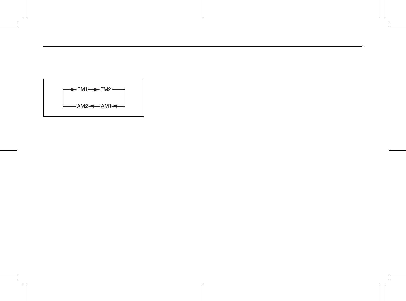
5-21
OTHER CONTROLS AND EQUIPMENT
80J23-03E
Selecting the reception band
Press the band switch button (1).
Each time the button is pressed, the recep-
tion band is switched as follows:
66J098
Seek tuning
Press the seek up button (2) or the seek
down button (3).
The unit stops searching for a station at a
frequency where a broadcast station is
available.
Manual tuning
Turn the manual tuning knob (4).
The frequency being received is displayed.
Preset memory
1) Select the desired station.
2) Select the preset button (5) to which
you want to store the station and press
and hold the button for 2 seconds or
longer.
Auto store
Press and hold the auto store button (6) for
2 seconds or longer.
Six stations in total are automatically
stored to the preset buttons (5) in sequen-
tial order, starting from the lower frequen-
cies.
NOTE:
• When the auto store is performed, the
station previously stored in the memory
at the position is overwritten.
• When there are fewer than 6 stations
that can be stored even if 2 rounds of
auto store operation are performed, the
stations previously stored at the remain-
ing preset buttons (5) are not overwrit-
ten.
Scan tuning
1) Press the scan button (6).
Stations are automatically sought for in
a sequential order, starting from a sta-
tion being currently received, and scan
stops for 5 seconds at a frequency
where there is a station available.
2) Press the scan button (6) again to stop
scanning at the frequency being cur-
rently received.
Receiving a stereo broadcast station
If a stereo broadcast station is received,
the stereo indicator will light.
Radio Reception
Radio reception can be affected by envi-
ronment, atmospheric conditions, or radio
signal’s power and distance from the sta-
tion. Nearby mountains and buildings may
interfere or deflect radio reception, causing
poor reception. Poor reception or radio
static can also be caused by electric cur-
rent from overhead wires or high voltage
power lines.
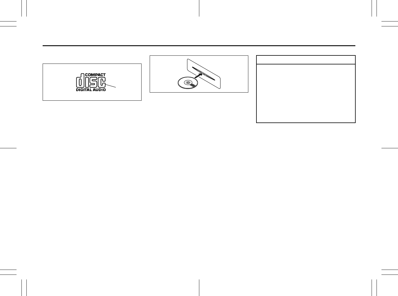
5-22
OTHER CONTROLS AND EQUIPMENT
80J23-03E
Listening to a CD
52D274
• CDs or CD-ROMs carrying no mark (A)
cannot be used.
• Some discs previously recorded in CD-
R\CD-RW format may not be used.
52D291
• A CD is inserted with its label facing
upward.
• When there is a CD already loaded in
the unit, another CD cannot be loaded at
the same time. Do not use force when
inserting the CD into the CD insertion
slot.
• If a blank disc (non-recorded CD-R) is
loaded in the unit, the disc will be
ejected.
(A)
CAUTION
• Never insert your finger or hand
into the CD insertion slot. Never
insert foreign objects.
• Never insert a CD with glue coming
out from adhesive tape or a rental
CD label or with a trace indicating
that adhesive tape or a rental CD
label has been removed. This may
cause the CD not to eject or result
in a malfunction.

5-23
OTHER CONTROLS AND EQUIPMENT
80J23-03E
Type 1
AM/FM/XM CD PLAYER WITH CD CHANGER CONTROL (Built in CD Player)
80J063
(3)
(6)
(4)
(2)
(1)
(5)
Display
66J100
(1) CD insertion slot
(2) CD eject button
(3) Disc button (CD/AUX)
(4) Track up button/Fast forward button
(5) Track down button/Rewind button
(6) Repeat button (RPT)
(A) Mode indicator
(B) Track number
(C) Play time
(D) Repeat indicator
(A) (B) (C)
(D)
5-24
OTHER CONTROLS AND EQUIPMENT
80J23-03E
NOTE:
About Single CDs (8 cm CDs)
• No adapter is required to play a single
CD.
• A single CD is inserted from the center
of the CD insertion slot.
• Since an ejected single CD is not auto-
matically reloaded, be sure to remove
the ejected single CD.
Loading a CD
Insert a CD in the CD insertion slot (1).
When a CD is loaded, play starts and the
CD indicator (A) lights.
Ejecting a CD
Press the CD eject button (2).
If you left a CD ejected for a period of
about 15 seconds, it will be automatically
drawn inside the unit. (Auto reload func-
tion)
The backup eject function:
This function allows you to eject a CD with
the power turned off by pressing the CD
eject button (2).
Listening to a CD
When a CD is inserted, it is automatically
played back.
When a CD is already inside the unit,
press the disc button (3) to play back the
CD. When a CD is inside the unit, the CD
indicator (A) is lit on the display unit.
Selecting a track
• Press the track up button (4) to listen to
the next track.
• Press the track down button (5) twice to
listen to the previous track.
When the track down button (5) is
pressed once, the track being currently
played will return to the beginning.
Fast forwarding/Rewinding a track
• Hold in the fast forward button (4) to
advance a track rapidly.
• Hold in the rewind button (5) to rewind a
track.
Repeat play
Press the repeat button (6).
The repeat indicator (D) lights and the
track currently being played is played
repeatedly.
Press the repeat button (6) again to cancel
repeat play.
CAUTION
If you forcefully try to push an ejected
CD inside the unit before auto reload-
ing, the disc surface might be
scratched.
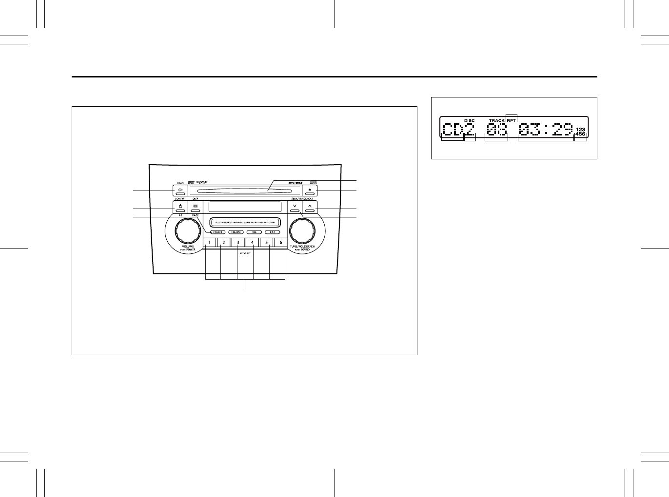
5-25
OTHER CONTROLS AND EQUIPMENT
80J23-03E
Type 2
AM/FM/XM 6-CD PLAYER WITH CD CHANGER CONTROL (Built-in CD Changer)
66J064
(2)
(5)
(1)
(8) (6)
(4)
(3)
(7)
Display
66J102
(1) Load button (LOAD)
(2) Disc select buttons (1 to 6)
(3) CD insertion slot
(4) CD eject button
(5) Disc button (CD/AUX)
(6) Track up button/Fast forward button
(7) Track down button/Rewind button
(8) Repeat button (RPT)
(A) Mode indicator
(B) Disc number
(C) Track number
(D) Play time
(E) CD indicator
(F) Repeat indicator
(A) (C) (D)
(F)
(B) (E)
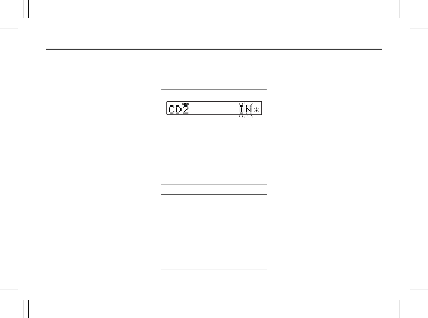
5-26
OTHER CONTROLS AND EQUIPMENT
80J23-03E
NOTE:
About Single CDs (8 cm CDs)
• Since the unit is not compatible with a
single CD, do not load it into the unit.
• Keep in mind the fact that a single CD
cannot be played even using a single CD
adaptor for the unit.
• When a single CD is loaded into the unit
accidentally, it will be ejected immedi-
ately. Please be sure to remove it.
If you forcefully try to push it into the unit
without removing it, the CD cannot be
ejected. This will result in a damage to
the mechanism. Please never do this.
Loading one CD
1) Press the load button (1), then press
one of the disc select buttons (2) that
corresponds to the slot into which you
want to load a CD.
66J143
Both the indication “In” and the selected
disc number in the CD indicator will blink
for about 15 seconds.
2) Load the CD into the CD insertion slot
(3). When the CD is loaded, play starts.
The disk number in the CD indicator will
light.
Loading multiple CDs
1) Press the load button (1) for 2 seconds
or longer.
The indication “CD ALL” appears in the
display, and then the indication “In” and
a disc number in the CD indicator will
blink for about 15 seconds.
2) Load a CD into the CD insertion slot
(3).
3) The indication “In” and the next disc
number will blink in the display. Load
the next CD.
4) After loading the required number of
CD’s, press any disc select button (2) to
select the desired CD to listen to. If no
select button is pressed, play will start
from the first loaded CD.
Only the numbers in the CD indicator that
correspond to the loaded slots will light.
Ejecting one CD
1) Select the CD you want to remove with
the disc select buttons (2).
2) Press the CD eject button (4).
If you leave the ejected CD without
removing it, it will be drawn into the unit
automatically after about 15 seconds.
(Auto reload function)
The buck up eject mechanism:
This function allows you to eject the CD
loaded in the unit with the unit turned off
only by pressing the CD eject button (4).
CAUTION
You can load a CD only while the indi-
cation “In” is blinking for about 15
seconds. During that period, the
shutter located in the depth of the CD
insertion slot (3) is opened. After 15
seconds time has elapsed, the indi-
cation “In” disappears from the dis-
play and the shutter closes, making it
impossible to load a CD. If you try to
load the CD with the shutter closed,
the CD may damage the shutter.
Never do this.
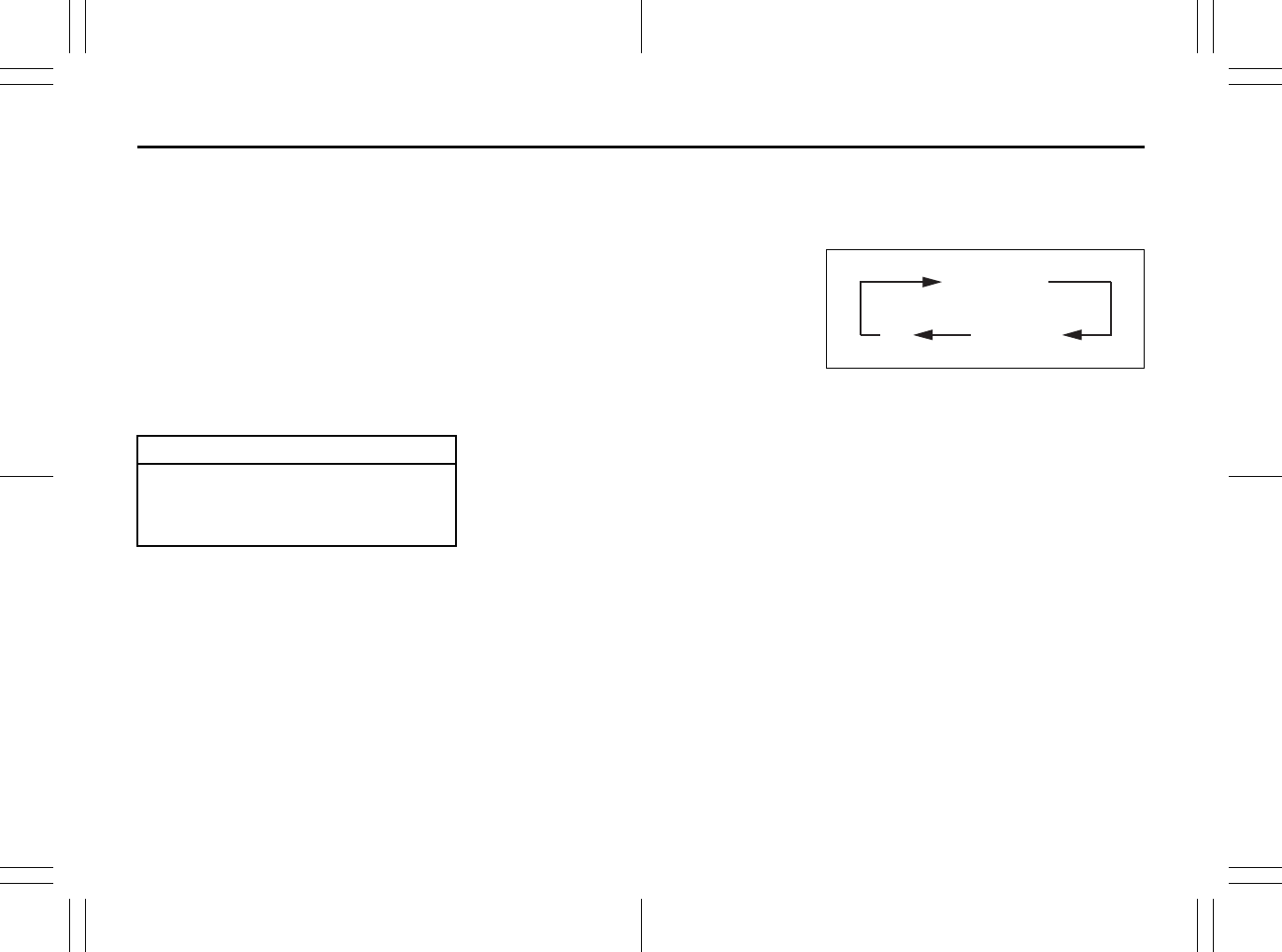
5-27
OTHER CONTROLS AND EQUIPMENT
80J23-03E
Ejecting all the CDs
Press the CD eject button (4) for 2 seconds
or longer. All the CDs will be ejected from
the unit in a sequential manner.
• Please prepare a location where
removed CDs can be stored.
• If you leave the ejected CD without
removing it, it will be drawn into the unit
automatically after about 15 seconds.
(Auto reload function)
The buck up eject mechanism:
This function allows you to eject the CD
loaded in the unit with the unit turned off
only by pressing the CD eject button (4).
Listening to a CD
1) When a CD is inserted, it is automati-
cally played back.
When a CD is already inside the unit,
press the disc button (5) to play back
the CD. When a CD is inside the unit,
the CD indicator (A) is lit on the display
unit.
2) If you want to play another CD, select it
with the disc select buttons (2).
Play starts from the point on the disc
that the unit played last (Last position
memory).
Selecting a track
• Press the track up button (6) to listen to
the next track.
• Press the track down button (7) twice to
listen to the previous track.
When the track down button (7) is
pressed once, the track being currently
played will return to the beginning.
Fast forwarding/Rewinding a track
• Hold in the fast forward button (6) to
advance a track rapidly.
• Hold in the rewind button (7) to rewind a
track.
Repeat play
Press the repeat button (8).
Each time the button is pressed, repeat
play mode changes as follows:
66J144
NOTE:
This operation should be performed within
2 seconds.
To cancel repeat play, press the repeat but-
ton (8) several times to change the repeat
play mode to OFF.
• TRACK REPEAT
The indication “TRACK RPT” appears in
the display for 2 seconds and then the
repeat indicator (F) lights.
The track currently being played is
played repeatedly.
• DISC REPEAT
The indication “DISC RPT” appears in
the display for 2 seconds and then the
repeat indicator (F) lights.
When all the tracks on the disc currently
being played finish playing, play starts
again at the beginning of the disc.
CAUTION
If you try to push an ejected CD
inside the unit forcibly before auto
reloading, the disc surface might be
scratched.
TRACK REPEAT
DISC REPEAT
OFF
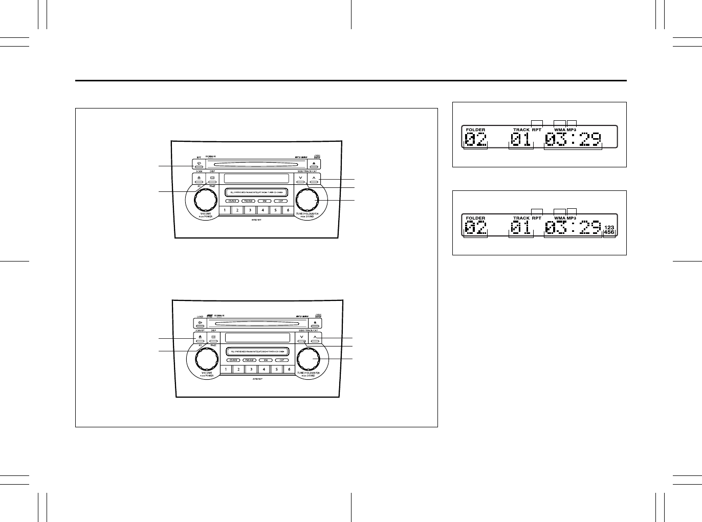
5-28
OTHER CONTROLS AND EQUIPMENT
80J23-03E
Listening to an MP3/WMA Disc
80J065
(1)
(2)
(3)
(4)
(1)
(3)
(4)
(5)
(2)
(5)
Type 1 AM/FM/XM CD PLAYER WITH CD CHANGER CONTROL
Type 2 AM/FM/XM 6-CD PLAYER WITH CD CHANGER CONTROL
Display (Type 1)
66J104
Display (Type 2)
66J105
(1) Sound control knob
(2) Repeat button (RPT)
(3) Track up button/Fast forward button
(4) Track down button/Rewind button
(5) Display button (DISP)
(A) Folder number
(B) Track number
(C) Play time
(D) Repeat indicator
(E) WMA indicator
(F) MP3 indicator
(G) CD indicator
(A) (B)
(E) (D)
(C)
(F)
(A) (B) (G)
(E) (D)
(C)
(F)

5-29
OTHER CONTROLS AND EQUIPMENT
80J23-03E
What is MP3/WMA?
MP3 (MPEG1/2 Audio Layer-III) and WMA
(Windows MediaTM Audio) are the com-
pression formats of digital audio. The
former is developed by MPEG (Motion Pic-
ture Experts Group), and the latter is
developed by Microsoft Corporation. Using
these compression formats, you can
record the contents of about 10 music CDs
on a single CD media (This figures refer to
data recorded on a 650 MB CD-R or CD-
RW at a fixed bit rate of 128 kbps and a
sampling frequency of 44.1 kHz).
Points to remember when making MP3/
WMA files
Common
• High bit rate and high sampling fre-
quency are recommended for high qual-
ity sounds.
• Selecting VBR (Variable Bit Rate) is not
recommended because playing time is
not displayed properly and sound may
be skipped.
• The playback sound quality differs
depending on the encoding circum-
stances. For details, refer to the user
manual of your own encoding software
and writing software.
MP3
• It is recommended to set the bit rate to
“128 kbps or more” and “fixed”.
WMA
• It is recommended to set the bit rate to
“64 kbps or more” and “fixed”.
• Do not set the copy protect attribute on
the WMA file to enable this unit to play
back.
NOTE:
Never assign the “.mp3”, or “.wma” file
name extension to a file that is not in the
MP3/WMA format. This may not only pro-
duce noise from the speaker damage, but
also damage your hearing.
Recording MP3/WMA files on a CD-
media
• You are recommended to minimize the
chances of making a disc that contains
both CD-DA files and MP3/WMA files.
• If CD-DA files are on the same disc as
MP3 or WMA files, the songs may not
play in the intended order, or some
songs may not play at all.
• When storing MP3 data and WMA data
on the same disc, use different folders
for each data.
• Do not record files other than MP3/WMA
files and unnecessary folder on a disc.
• The name of an MP3/WMA file should
be added by rules as shown in the fol-
lowing descriptions and also comply with
the rules of each file system.
• The file extension “.mp3” or “.wma”
should be assigned to each file depend-
ing on the file format.
• You may encounter trouble in playing
MP3/WMA files or displaying the infor-
mation of MP3/WMA files recorded with
certain writing software or CD recorders.
• This unit does not have a play list func-
tion.
• Although Multi-session recording is sup-
ported, the use of Disc-at-Once is rec-
ommended.
Compression formats
MP3
• Bit rate
MPEG1 Audio Layer III : 32 k – 320 kbps
MPEG2 Audio Layer III : 8 k – 160 kbps
• Sampling frequency
MPEG1 Audio Layer III : 44.1 k/48 k/32
kHz
MPEG2 Audio Layer III :
22.05 k/24 k/16 kHz
WMA (Ver.7, Ver.8, Ver. 9*)
• Bit rate
32 k – 192 kbps
• Sampling frequency
44.1 k/48 k/32 kHz
* WMA 9 Professional/LossLess/Voice
are not supported.
Supported file systems
ISO 9660 Level 1/Level 2, Apple Extension
to ISO 9660, Joliet, Romeo
Maximum number of files/folders
• Maximum number of files:
CD Player: 999(files + folders)
6-CD Player: 512(files + folders)
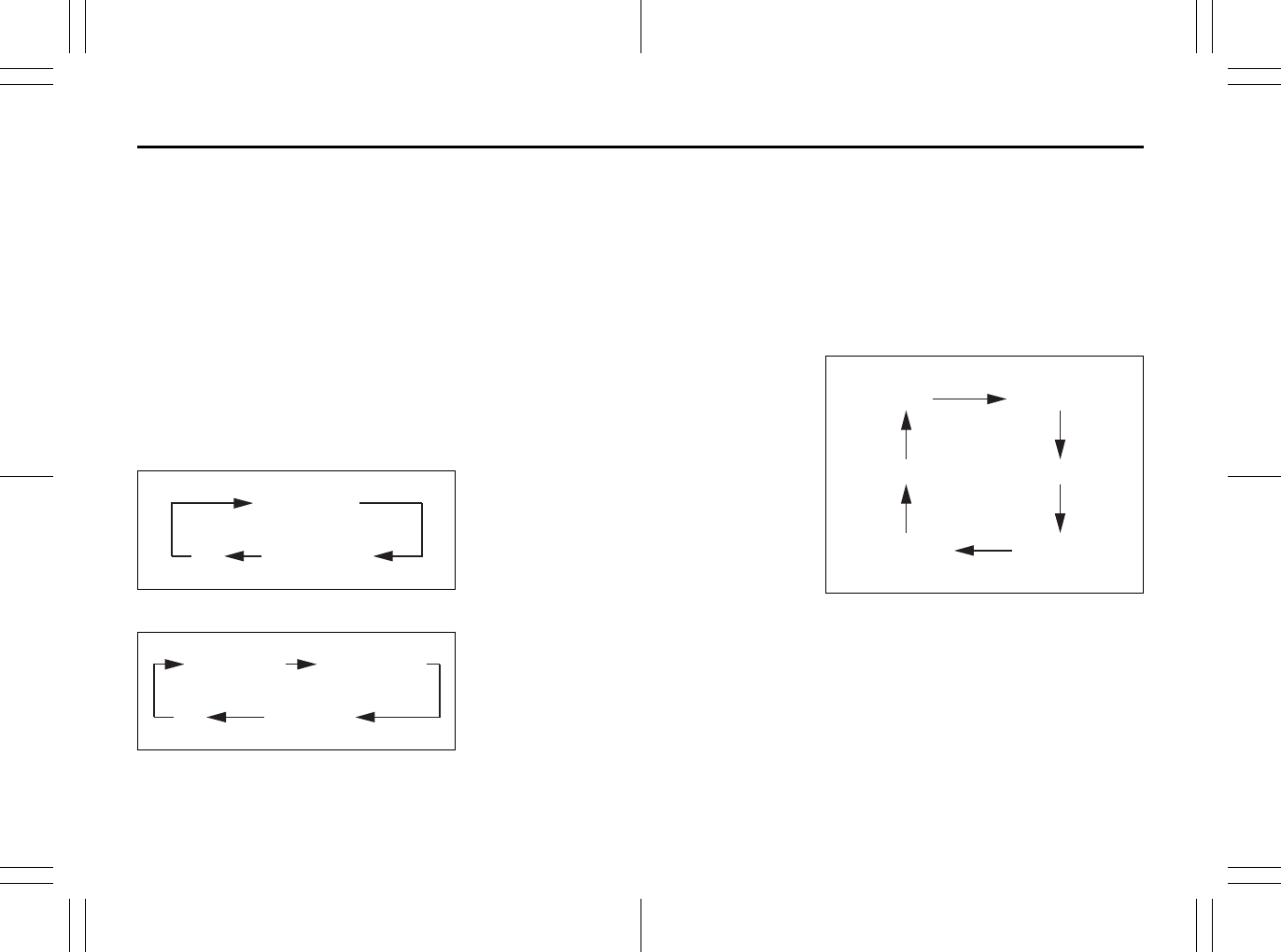
5-30
OTHER CONTROLS AND EQUIPMENT
80J23-03E
• Maximum number of files in one folder:
255
• Maximum depth of trees: 8
• Maximum number of folders: 255
(Root folder is included.)
MP3/WMA MODE
Selecting a folder
Turn the sound control knob (1) to select a
folder.
Repeat play
Press the repeat button (2).
Each time the button is pressed, repeat
play mode changes as follows:
Type 1
66J128
Type 2
66J145
NOTE:
This operation should be performed within
2 seconds.
To cancel repeat play, press the repeat but-
ton (2) several times to change the repeat
play mode to OFF.
• TRACK REPEAT
The indication “TRACK RPT” appears in
the display for 2 seconds and then the
repeat indicator (D) lights.
The track currently being played is
played repeatedly.
• FOLDER REPEAT
The indication “FOLDER RPT” appears
in the display for 2 seconds and then the
repeat indicator (D) lights.
All the tracks in the folder currently being
played are played repeatedly.
• DISC REPEAT
The indication “DISC RPT” appears in
the display for 2 seconds and then the
repeat indicator (D) lights.
When all the tracks on the disc currently
being played finish playing, play starts
again at the beginning of the disc.
Selecting a track
• Press the track up button (3) to listen to
the next track.
• Press the track down button (4) twice to
listen to the previous track.
When the track down button (4) is
pressed once, the track currently being
played will start again at the beginning.
Fast forwarding/Rewinding a track
• Hold in the fast forward button (3) to
advance a track rapidly.
• Hold in the rewind button (4) to rewind a
track.
Displaying CD titles
Press the display button (5).
Each time the button is pressed, the title
changes as follows:
66J146
Forwarding a title
If there is a title with 12 letters or more,
each press will show next letters in the dis-
play. (No scrolling is made.)
Press and hold the display button (5) for 2
seconds or longer. A title is changed.
TRACK REPEAT
FOLDER REPEAT
OFF
TRACK REPEAT FOLDER REPEAT
DISC REPEAT
OFF
TRACK TITLE
FOLDER TITLE
ARTIST TITLE
OFF
FILE TITLEALBUM TITLE
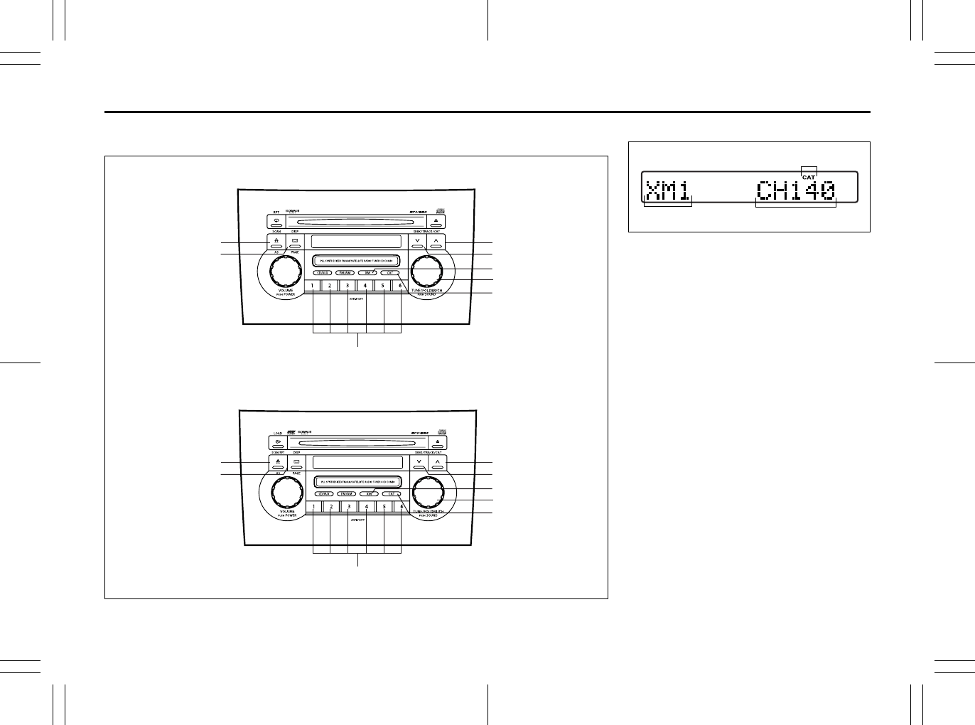
5-31
OTHER CONTROLS AND EQUIPMENT
80J23-03E
Listening to a XM Satellite Radio (Option)
80J066
(5)
(2)
(8)
(6)
(3)
(4)
(7)
(1)
(5)
(2)
(8)
(6)
(3)
(4)
(7)
(1)
Type 1 AM/FM/XM CD PLAYER WITH CD CHANGER CONTROL
Type 2 AM/FM/XM 6-CD PLAYER WITH CD CHANGER CONTROL
Display
66J107
(1) XM button
(2) Category button (CAT)
(3) Seek up button
(4) Seek down button
(5) Manual tuning knob
(6) Display button (DISP)
(7) Preset button (1 to 6)
(8) Scan button (SCAN)
(A) Band
(B) Channel number
(C) Category indicator
If you want to purchase XM Satellite Radio
Service, contact your SUZUKI dealer.
It is necessary to buy a special tuner to
receive XM broadcasting.
Your vehicle is capable of receiving XM
Satellite Radio anywhere in the United
States except Hawaii, Alaska, and Can-
ada.
(A) (B)
(C)
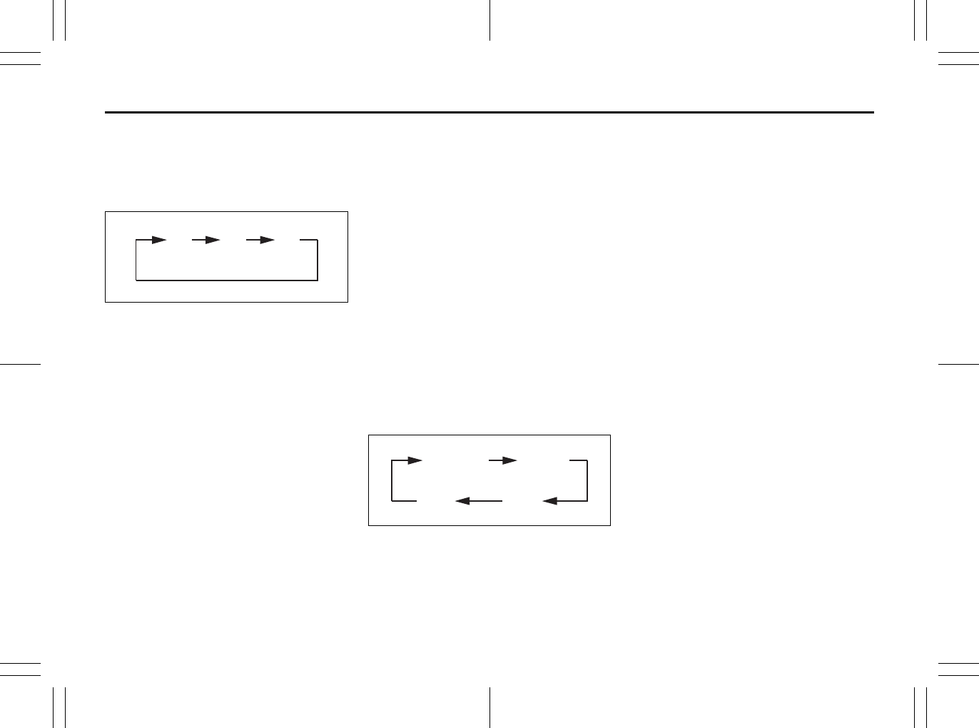
5-32
OTHER CONTROLS AND EQUIPMENT
80J23-03E
XM MODE
Selecting a band
Press the XM button (1).
Each time the button is pressed, the band
changes in the following order.
66J129
Selecting a category
Press the seek up button (3) or the seek
down button (4). The category is changed.
Turning the category function on/off
Press and hold the category button (2) for
2 seconds or longer, and “CATEGORY
ON” appears on the display, the CAT indi-
cator (c) lights up and the CATEGORY
function is activated.
Press and hold the category button (2) for
2 seconds or longer again, and “CATE-
GORY OFF” appears on the display and
the CAT indicator turns off, indicating that
the CATEGORY function has been turned
off.
NOTE:
The first time you use the radio, turn the
category function on.
Selecting a category
Press the seek up button (3) or seek down
button (4) to select a category.
Displaying the category
Press the category button (2) to have the
currently selected category appear on the
display.
Selecting a channel
Turn the manual tuning knob (5) to select a
channel.
NOTE:
When the category function is on, only
those channels included in the selected
category can be selected.
Selecting the item to be displayed
Press the display button (6).
Each time the button is pressed, the item
on display changes in the following order.
66J130
Preset memory
1) Select the desired station.
2) Select the preset button (7) to which
you want to store the station and press
and hold the button for 2 seconds or
longer.
Scan tuning
1) Press the scan button (8).
Stations are automatically searched for
in a sequential order, starting from the
station being currently received, and
scan tuning stops for 5 seconds at the
frequency where there is a station avail-
able.
2) Press the scan button (8) again to stop
scanning at the frequency currently
being received.
Satellite Radio Reception
Satellite radio receives signals from two
satellites in orbit over the equator. There-
fore, satellite radio reception can be inter-
rupted when there are objects south of
your vehicle. To help compensate for this,
ground-based repeaters are placed in
major metropolitan areas, but depending
on the geographic situation (for example, if
mountains or buildings are on the south
side of your vehicle), you may experience
reception problems.
XM1 XM2 XM3
CH NUMBER CH NAME
NAMETITLE
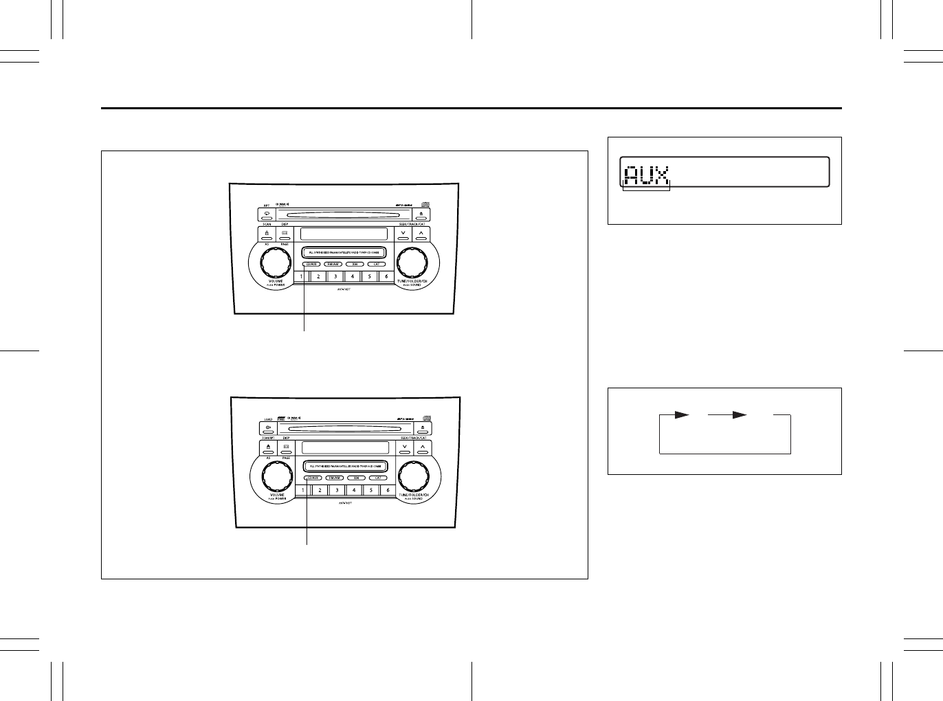
5-33
OTHER CONTROLS AND EQUIPMENT
80J23-03E
Listening to Audio for AUX (Option)
80J067
(1)
(1)
Type 1 AM/FM/XM CD PLAYER WITH CD CHANGER CONTROL
Type 2 AM/FM/XM 6-CD PLAYER WITH CD CHANGER CONTROL
Display
66J221
(1) Aux button (CD/AUX)
(A) Mode indicator
Aux function
This system has an external input terminal
so you can listen to audio from an external
device connected to this unit.
Press the aux button (1).
Each time the button is pressed, the
selected mode is switched as follows:
66J123
(A)
CD AUX
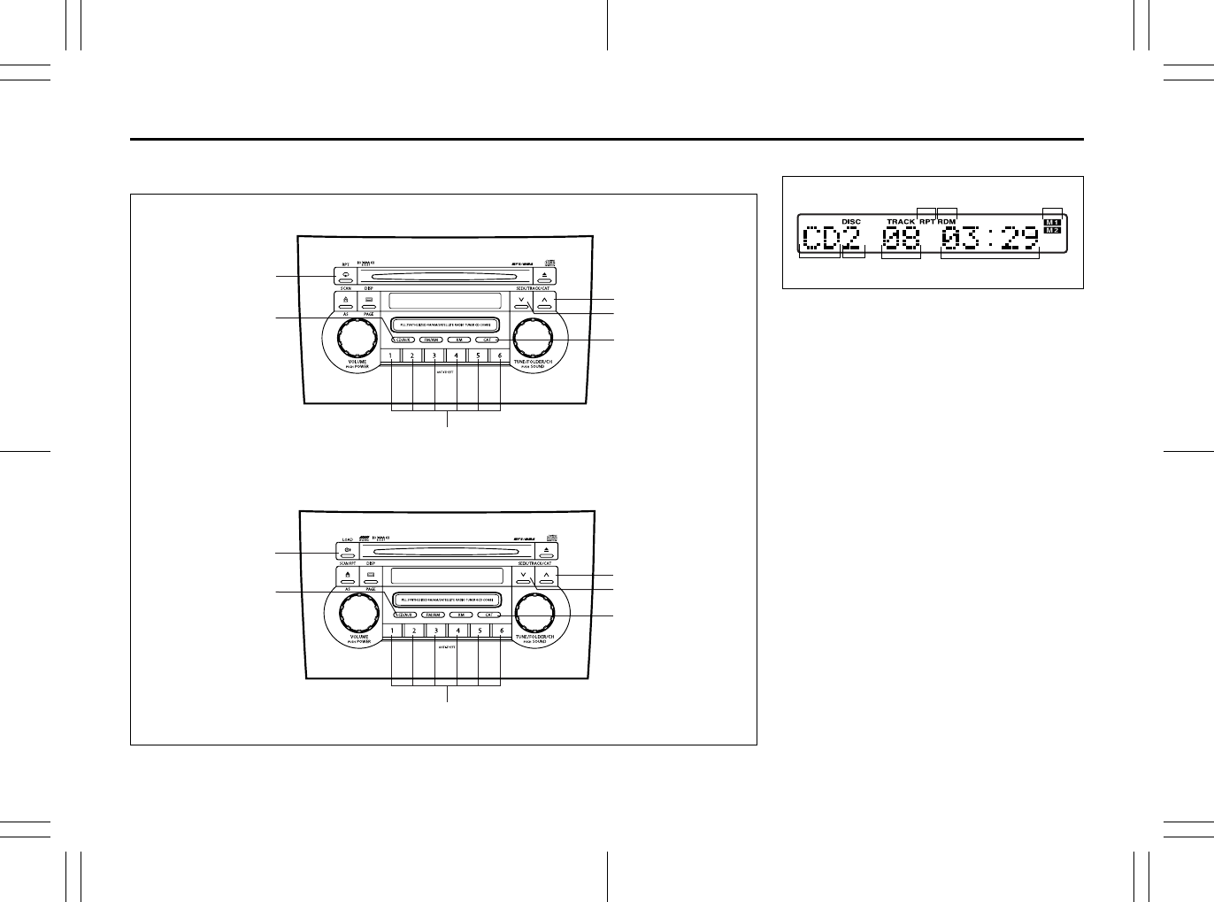
5-34
OTHER CONTROLS AND EQUIPMENT
80J23-03E
Listening to a CD from an External CD Changer (Option)
80J068
(6)
(5)
(1)
(3)
(4)
(1)
(2)
(2)
(6)
(5)
(3)
(4)
Type 1 AM/FM/XM CD PLAYER WITH CD CHANGER CONTROL
Type 2 AM/FM/XM 6-CD PLAYER WITH CD CHANGER CONTROL
Display
66J113
(1) Disc button (CD/AUX)
(2) Disc select buttons (1 to 6)
(3) Track up button/Fast forward button
(4) Track down button/Rewind button
(5) Repeat button (RPT)
(6) Category button (CAT)
(A) Mode indicator
(B) Disc number
(C) Track number
(D) Play time
(E) Repeat indicator
(F) Random indicator
(G) CD changer number
(A) (B)
(E)
(D)
(F)
(C)
(G)
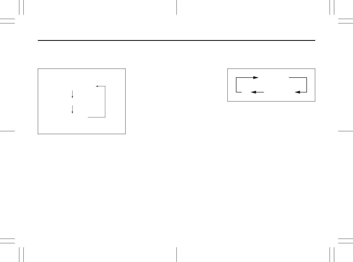
5-35
OTHER CONTROLS AND EQUIPMENT
80J23-03E
Selecting a CD changer mode
Press the disc button (1).
Each time the button is pressed, the
selected CD plays as follows:
52D300
• When only one CD changer is con-
nected to this unit, CD changer 2 is
skipped.
• When no CD is loaded in the built-in CD
player, the built-in CD player is skipped.
Selecting a disc
Press the disc select button (2) corre-
sponding to the disc number you want to
listen to.
Play starts from the first track on the disc. If
a disc number having no disc is pressed,
the selection will be invalid.
Selecting a track
• Press the track up button (3) to listen to
the next track.
• Press the track down button (4) twice to
listen to the previous track.
When the track down button (4) is
pressed once, the track currently being
played will start again at the beginning.
Fast forwarding/Rewinding a track
• Hold in the fast forward button (3) to
advance a track rapidly.
• Hold in the rewind button (4) to rewind a
track.
Random play
Press the category button (6).
Each time the button is pressed, the mode
changes in the following order.
66J131
NOTE:
This operation should be performed within
2 seconds.
To cancel random play, press the category
button (6) several times to change the ran-
dom play mode to OFF.
• TRACK RANDOM
The tracks in the disc that is loaded are
played at random.
• DISC RANDOM
The tracks in all discs are played at ran-
dom.
NOTE:
The random play can be operated with the
External CD Changer (Option) only.
Built-in CD player
CD changer 1
CD changer 2
TRACK RANDOM
DISC RANDOM
OFF
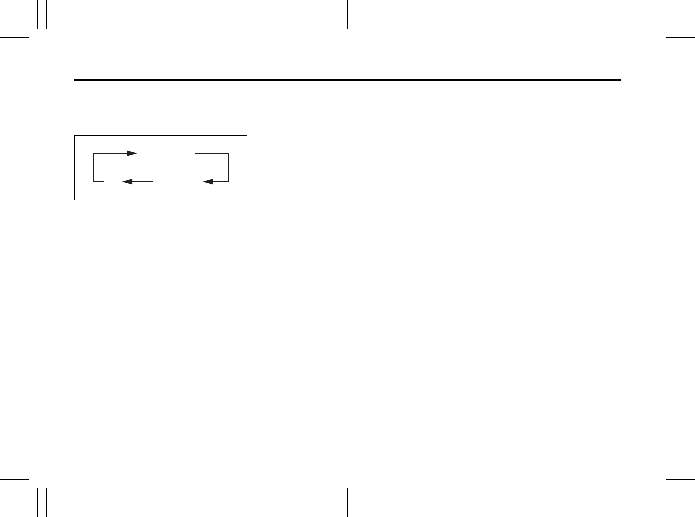
5-36
OTHER CONTROLS AND EQUIPMENT
80J23-03E
Repeat play
Press the repeat button (5).
Each time the button is pressed, repeat
play mode changes as follows:
66J144
NOTE:
This operation should be performed within
2 seconds.
To cancel repeat play, press the repeat but-
ton (5) several times to change the repeat
play mode to OFF.
• TRACK REPEAT
The indication “TRACK RPT” appears in
the display for 2 seconds and then the
repeat indicator (E) lights.
The track being currently played is
played repeatedly.
• DISC REPEAT
The indication “DISC RPT” appears in
the display for 2 seconds and then the
repeat indicator (E) lights.
When all the tracks on a disc being cur-
rently played finish playing, play starts
again at the beginning of the disc.
TRACK REPEAT
DISC REPEAT
OFF
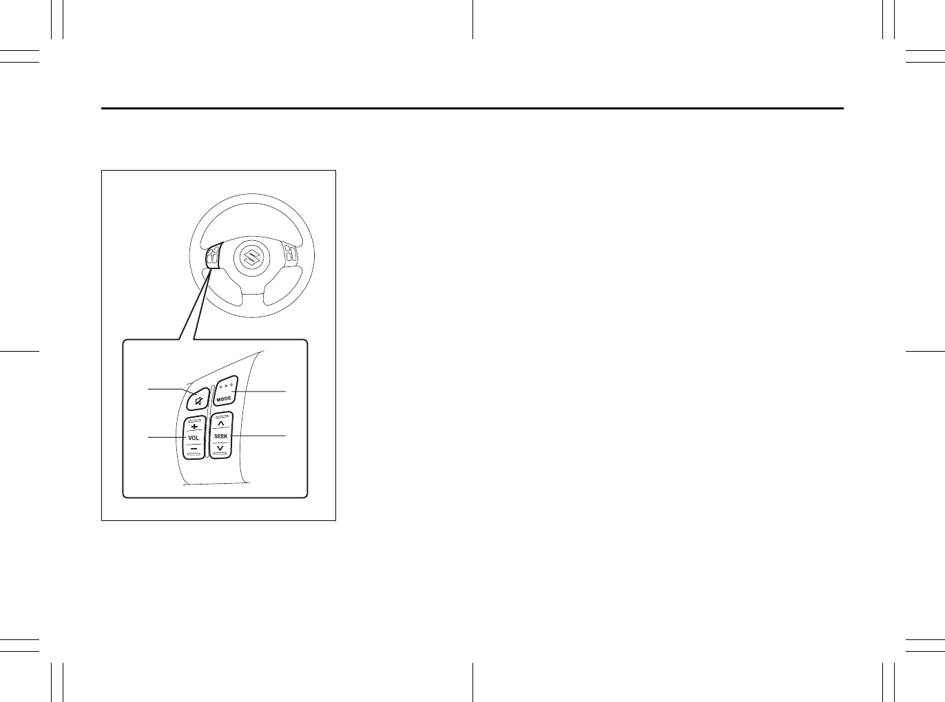
5-37
OTHER CONTROLS AND EQUIPMENT
80J23-03E
Remote Audio Controls
(if equipped)
80JC099
You can control basic functions of the
audio system with the switches on the
steering wheel.
To control the volume:
• To increase the volume, push the upper
part of the switch (1). The volume contin-
ues to increase until you release the
switch.
• To decrease the volume, push the lower
part of the switch (1). The volume contin-
ues to decrease until you release the
switch.
• To mute, push the switch (2).
To select the mode (AM1, AM2, FM1, FM2,
XM (option), CD, External CD-changer
(option), AUX (option)), push the switch
(3).
You can also turn on the audio system by
pushing the switch (3).
To change the radio station:
• To advance to the next preset station,
push the upper part of the switch (4)
briefly.
• To select the previous preset station,
push the lower part of the switch (4)
briefly.
• To scan to a higher frequency radio sta-
tion, push and hold the upper part of the
switch (4).
• To scan to a lower frequency radio sta-
tion, push and hold the lower part of the
switch (4).
To change the selection on a CD:
• To advance to the next track on a CD,
push the upper part of the switch (4)
briefly.
• To select the previous track on a CD,
push the lower part of the switch (4).
(1)
(2) (3)
(4)
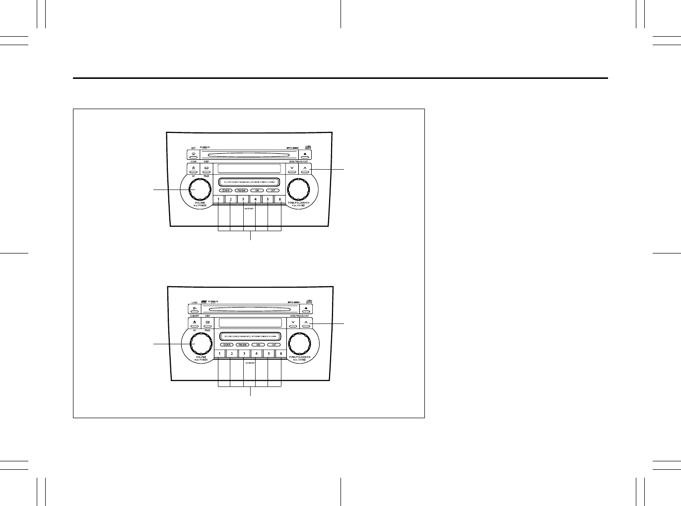
5-38
OTHER CONTROLS AND EQUIPMENT
80J23-03E
Anti-Theft Feature
80J069
(1)
(2)
(3)
(1)
(2)
(3)
Type 1 AM/FM/XM CD PLAYER WITH CD CHANGER CONTROL
Type 2 AM/FM/XM 6-CD PLAYER WITH CD CHANGER CONTROL
(1) Power on/off knob
(2) Track up button/Fast forward button
(3) Preset buttons (1 to 6)
The anti-theft feature is intended to dis-
courage theft or the audio system by pre-
venting the system from operating when it
is moved to a different vehicle.
This feature works by allowing you to enter
a Personal Identification Number (PIN).
When the audio system is disconnected
from its power source, such as when the
audio system is removed or the battery is
disconnected, the system will not operate
again unless the PIN is reentered.
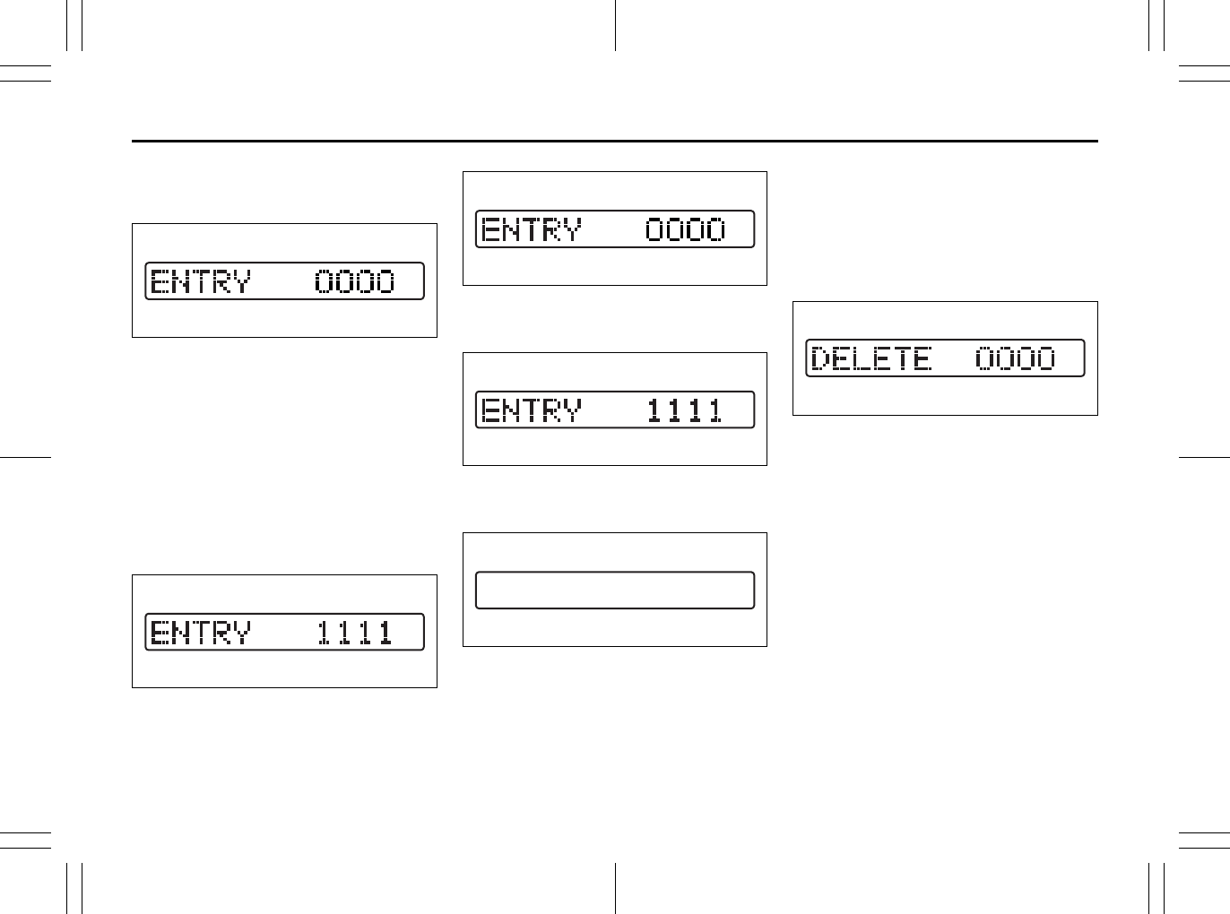
5-39
OTHER CONTROLS AND EQUIPMENT
80J23-03E
Setting the Anti-Theft Function
1) Turn off the power by pressing the
power on/off knob (1).
66J118
2) Press the power on/off knob (1) while
pressing and holding the track up but-
ton (2). The “ENTRY 0000” will blink
and the audio system enter PIN-input
mode.
NOTE:
Establish your PIN by combining numbers
from 1 to 6 into any 4-digit number. If you
forget your PIN, when you remove the bat-
tery for repair etc., you will no longer be
able to operate the audio system.
66J117
3) Input the four digit PIN using preset but-
tons 1 to 6.
66J118
4) After you enter your four digit PIN, the
display will return to “0000”.
66J117
5) Input the same 4-digit number you pre-
viously entered.
66J120
6) The power of the audio system will turn
off.
NOTE:
Write down your PIN for the future use.
Canceling Your Established PIN
Setting
This operation is to be done when you
want to cancel the anti-theft function or
change your PIN.
1) Turn off the power by pressing the
power on/off knob (1).
66J121
2) Press the power on/off knob (1) while
pressing and holding the track up but-
ton (2). The “DELETE 0000” will blink
and the audio system will enter the can-
cel mode.
EXAMPLE
EXAMPLE
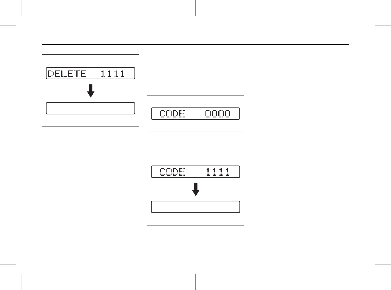
5-40
OTHER CONTROLS AND EQUIPMENT
80J23-03E
66J124
3) Input your PIN. The power of the audio
system will turn off and your PIN will be
deleted.
To change your PIN, first delete your
current PIN, then set a new one.
Confirming Your Personal Identifi-
cation Number (PIN)
When the main power source is discon-
nected such as when you exchange your
battery, etc, you will have to confirm your
PIN to be able to use the audio system.
To confirm your PIN:
66J122
1) Turn the ignition switch to the “ACC”
position.
66J125
2) Input your PIN.
If the PIN that you input matches the
registered PIN, the power of the audio
system will turn off, and you will be able
to operate the audio system.
NOTE:
• If you input your PIN incorrectly, “----” will
be displayed and the anti-theft function
lock mode is entered. If you enter an
incorrect PIN fewer than 6 times, the
locking time will be for 15 seconds; if you
enter an incorrect PIN more than 6
times, the locking time will be for 15 min-
utes.
• If you forget your PIN and enter a wrong
PIN, you cannot perform any further
operation.
EXAMPLE
EXAMPLE
5-41
OTHER CONTROLS AND EQUIPMENT
80J23-03E
Troubleshooting
Applicable to every device
Radio
CD
Phenomenon Cause Remedy
Power is not turned on.
(No sound is produced)
Fuse is blown. Contact your authorized SUZUKI dealer.
Connections are not properly made. Contact your authorized SUZUKI dealer.
Phenomenon Cause Remedy
Too much noise. Not tuned correctly to the frequency of a sta-
tion.
Tune correctly to the station frequency.
Stations cannot be selected by
seek tuning.
There is no station with strong radio waves. Select stations by manual tuning.
Phenomenon Cause Remedy
Compact disc cannot be loaded. Another compact disc is already loaded. Eject the compact disc before loading a new
one.
Sound skips or is noisy. Compact disc is dirty. Clean the compact disc with a soft cloth.
Compact disc is heavily scratched or warped. Replace with a compact disc with no scratches.
Sound is bad directly after power
is turned on.
Water droplets may form on the internal lens
when the car is parked in a humid place.
Let dry for about 1 hour with the power on.
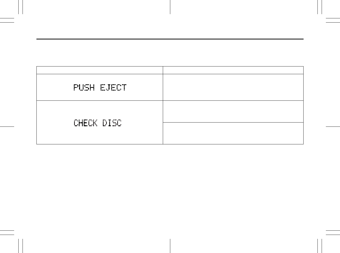
5-42
OTHER CONTROLS AND EQUIPMENT
80J23-03E
Error display
This unit has a number of self-diagnostic functions to protect the system.
If a problem should occur, the display shows the type of error. Refer to the table below and take proper measures to correct the problem.
If the problem is corrected, the unit will operate normally.
If an error display not listed above appears, turn off the unit and contact your SUZUKI dealer.
Error display Measures to be taken
CD/CD changer “Mechanical error”.
This error display indicates a mechanical failure in the CD changer
(failure to change or eject a disc).
The mechanism is probably damaged. Contact your authorized
SUZUKI dealer.
CD/CD changer “Focus error”.
The pick-up-focus is not properly functioning during playback due to
damage on the disc or for other reasons.
Check disc for damage.
CD/CD changer “Disc error”.
The CD is inserted upside down or only an eight-centimeter CD
adapter is equipped.
Check disc for correct loading.
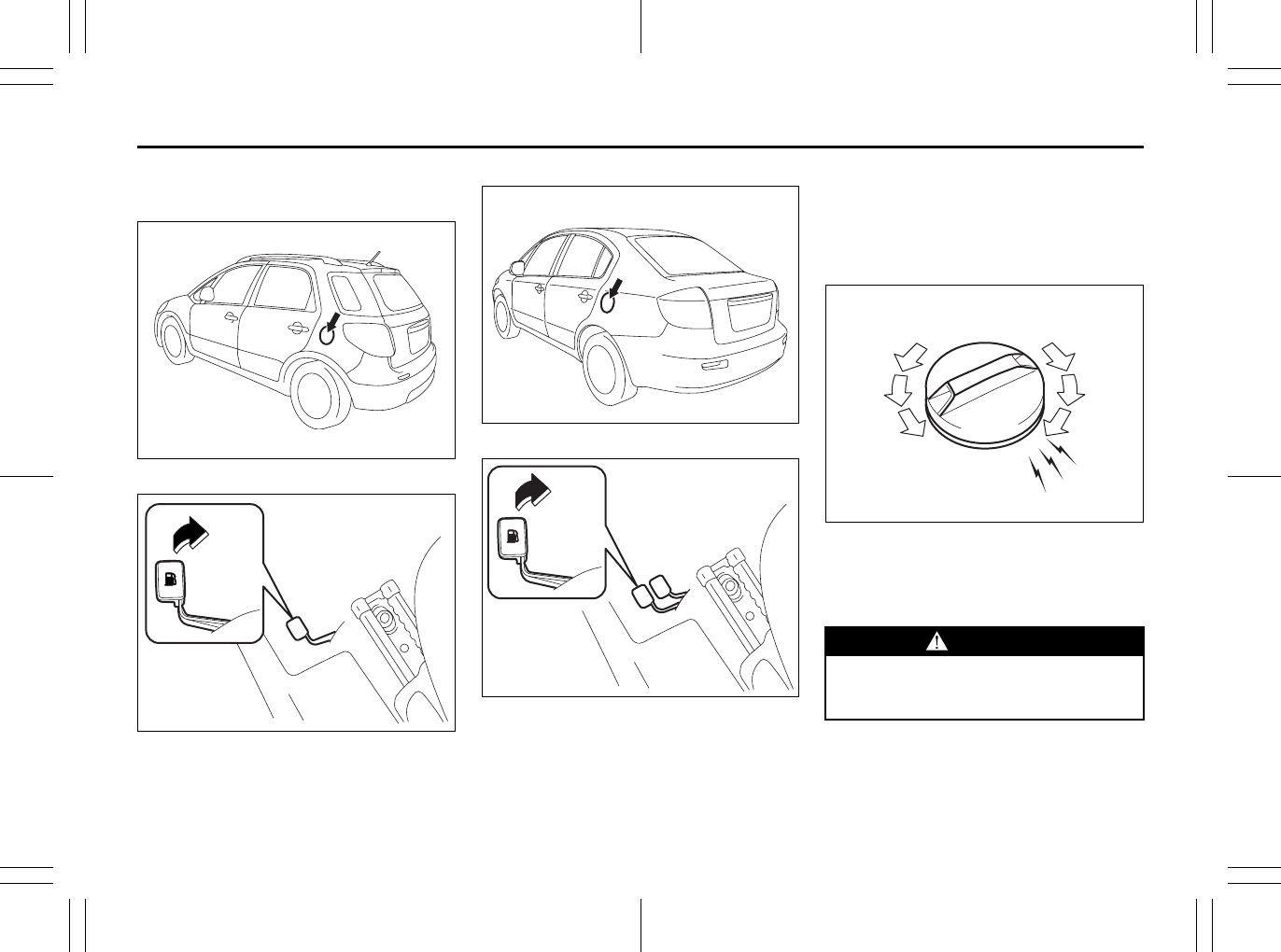
5-43
OTHER CONTROLS AND EQUIPMENT
80J23-03E
Fuel Filler Cap
SX4
80JC060
79J049
SX4 SEDAN
56KN029
56KN030
The fuel filler cap is located on the left rear
side of the vehicle. The fuel filler door can
be unlocked by pulling up the opener lever
located on the outboard side of the driver’s
seat and can be locked by simply closing
the door.
79K053
To remove the fuel filler cap:
1) Open the fuel filler door.
2) Remove the cap by turning it counter-
clockwise.
EXAMPLE
EXAMPLE
EXAMPLE
EXAMPLE
WARNING
Remove the fuel filler cap slowly. The
fuel may be under pressure and may
spray out, causing injury.
Open Close
EXAMPLE
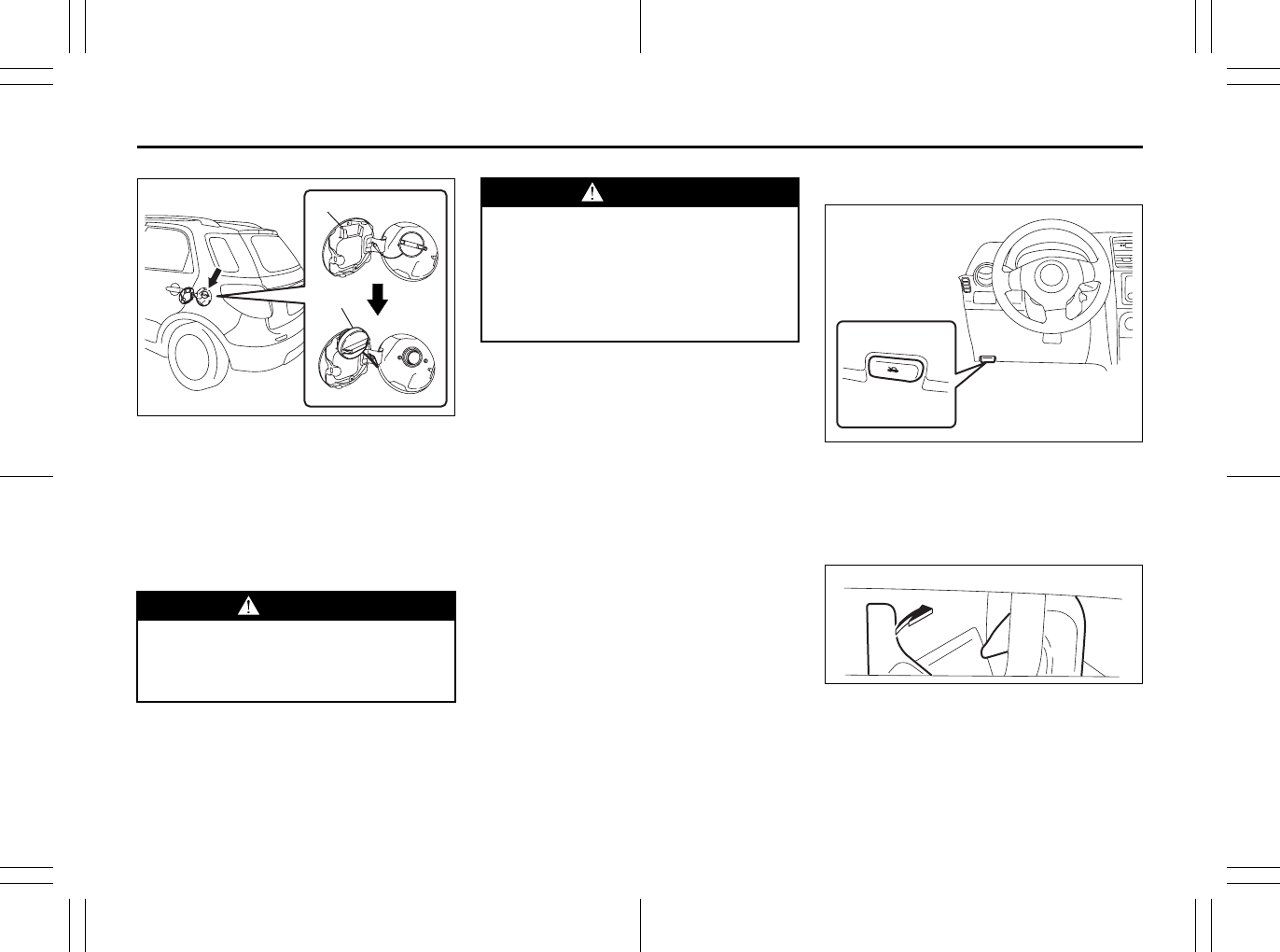
5-44
OTHER CONTROLS AND EQUIPMENT
80J23-03E
56KN078
NOTE:
The cap holder (1) can hold the fuel filler
cap (2) when refueling.
To reinstall the fuel filler cap:
1) Turn the cap clockwise until you hear
several clicks.
2) Close the fuel filler door.
Engine Hood
79J077
To open the engine hood:
1) Pull the hood release handle located on
the outboard side of the driver’s side of
the instrument panel. This will disen-
gage the engine hood lock halfway.
80J045
2) Push the under-hood release lever
sideways with your finger, as shown in
the illustration. While pushing the lever,
lift up the engine hood.
WARNING
Fuel is extremely flammable. Do not
smoke when refueling, and make
sure there are no open flames or
sparks in the area.
(1)
(2)
EXAMPLE WARNING
If you need to replace the fuel cap,
use a genuine SUZUKI cap. Use of an
improper cap can result in a malfunc-
tion of the fuel system or emission
control system. It may also result in
fuel leakage in the event of an acci-
dent.
EXAMPLE
EXAMPLE
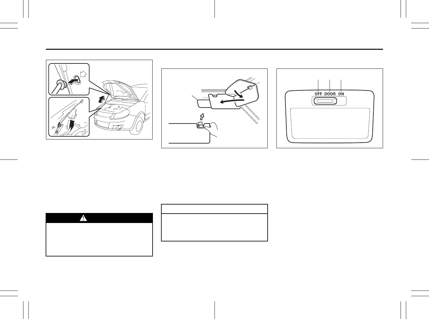
5-45
OTHER CONTROLS AND EQUIPMENT
80J23-03E
80JS024
3) Continue to lift up the hood until it is
high enough to support with the prop
rod.
To close the engine hood:
1) Lift the hood up slightly and remove the
prop rod from the hole. Put the prop rod
back to the holding clip.
2) Lower the hood close to the bumper,
then let it drop down. Make sure the
hood is securely latched after closing.
Sun Visor
79K055
The sun visors can be pulled down to block
glare coming through the windshield, or
they can be unhooked and turned to the
side to block glare coming through the side
window.
The extension (1) can be drawn out to
block glare widely.
Interior Light Switch
64J104
The interior light switch has three posi-
tions, which functions as described below.
ON (1)
The light comes on and stays on regard-
less of whether the door is open or closed.
DOOR (2)
The light comes on when the door is
opened. After closing all doors, the light
will remain on for about 15 seconds and
then fade out. If you push in the ignition
switch or insert the key during this time, the
light will start to fade out immediately. After
removing the key from the ignition switch,
the light will turn on for about 15 seconds
and then fade out.
OFF (3)
The light remains off even when the door is
opened.
WARNING
Make sure the hood is fully closed
and latched before driving. If it is not,
it can fly up unexpectedly during
driving, obstructing your view and
resulting in an accident.
CAUTION
When unhooking and hooking a sun
visor, be sure to handle it by the hard
plastic parts or the sun visor can be
damaged.
(1)
EXAMPLE (1)(2)(3)
EXAMPLE
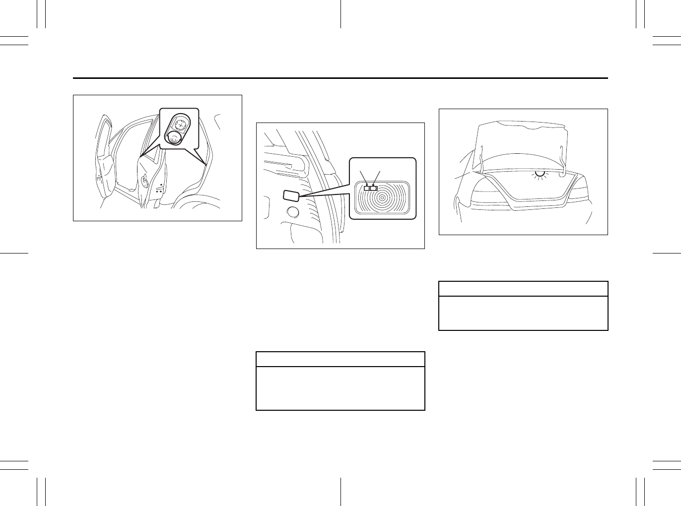
5-46
OTHER CONTROLS AND EQUIPMENT
80J23-03E
79J075
NOTE:
The number of doors involved in the light-
ing operation of the interior light depends
on the vehicle specification. If there is a
switch (rubber projection) at the door
opening as shown, the door is involved in
the lighting operation. The tailgate of SX4
is also involved in this operation even with-
out the rubber projection.
Luggage Compartment Light
(SX4)
79J053
When you open the tailgate with the lug-
gage compartment light switch in the “ON”
position (1), the light comes on and
remains on as long as you keep the tail-
gate open.
When the luggage compartment light
switch is in the “OFF” position (2), the light
remains off regardless of whether the tail-
gate is opened or closed.
Trunk Light (SX4 SEDAN)
56KN038
When you open the trunk lid, the trunk light
comes on and remains on as long as you
keep the lid open.
EXAMPLE
CAUTION
Do not leave the tailgate open with
the luggage compartment light
switch in the “ON” position for a long
time, or the battery will discharge.
(1) (2)
EXAMPLE
CAUTION
Do not leave the trunk lid open for a
long time, or the battery will dis-
charge.
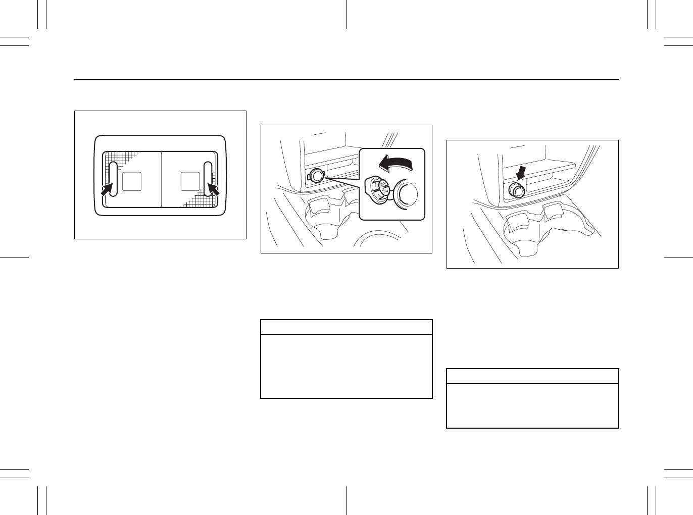
5-47
OTHER CONTROLS AND EQUIPMENT
80J23-03E
Spot Light
79J074
Push the switch to turn on the light and
push it again to turn off the light.
Accessory Socket
(if equipped)
80J2046
The accessory socket will work when the
ignition switch is in the “ACC” or “ON” posi-
tion.
This socket can be used to provide 12 volt/
120 watt power for electrical accessories.
Cigarette Lighter and Ashtray
(if equipped)
Cigarette Lighter (if equipped)
80J2067
The cigarette lighter will work when the
ignition switch is in the “ACC” or “ON” posi-
tion.
To use the cigarette lighter, push it all the
way into the receptacle and release it. It
will automatically heat up and will pop out
to its normal position when it is ready for
use.
CAUTION
Use of inappropriate electrical acces-
sories can cause damage to your
vehicle’s electrical system. Make
sure that any electrical accessories
you use are designed to plug into this
type of socket.
CAUTION
Holding the cigarette lighter in can
overheat and damage the lighter.
Release the lighter after you push it
in.
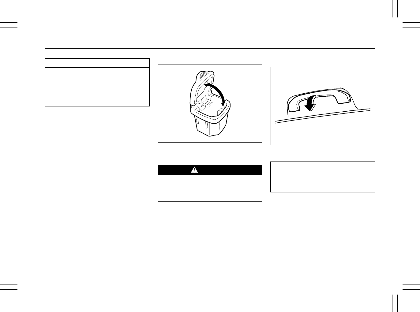
5-48
OTHER CONTROLS AND EQUIPMENT
80J23-03E
Ashtray (if equipped)
79J047
You can fit the ashtray into any of the cup
holders on the center console.
Assist Grips (if equipped)
54G249
Assist grips are provided for convenience.
CAUTION
To avoid damage to the cigarette
lighter socket, do not use it as an
accessory power source. Some
accessories’ power plug can damage
the inner mechanism of the cigarette
lighter socket.
WARNING
Make sure tobacco is fully extin-
guished before closing the ashtrays.
Never throw waste in the ashtrays: it
could create a fire hazard.
EXAMPLE
CAUTION
To avoid damaging the assist grip
and the molded headlining, do not
hang down the assist grip.
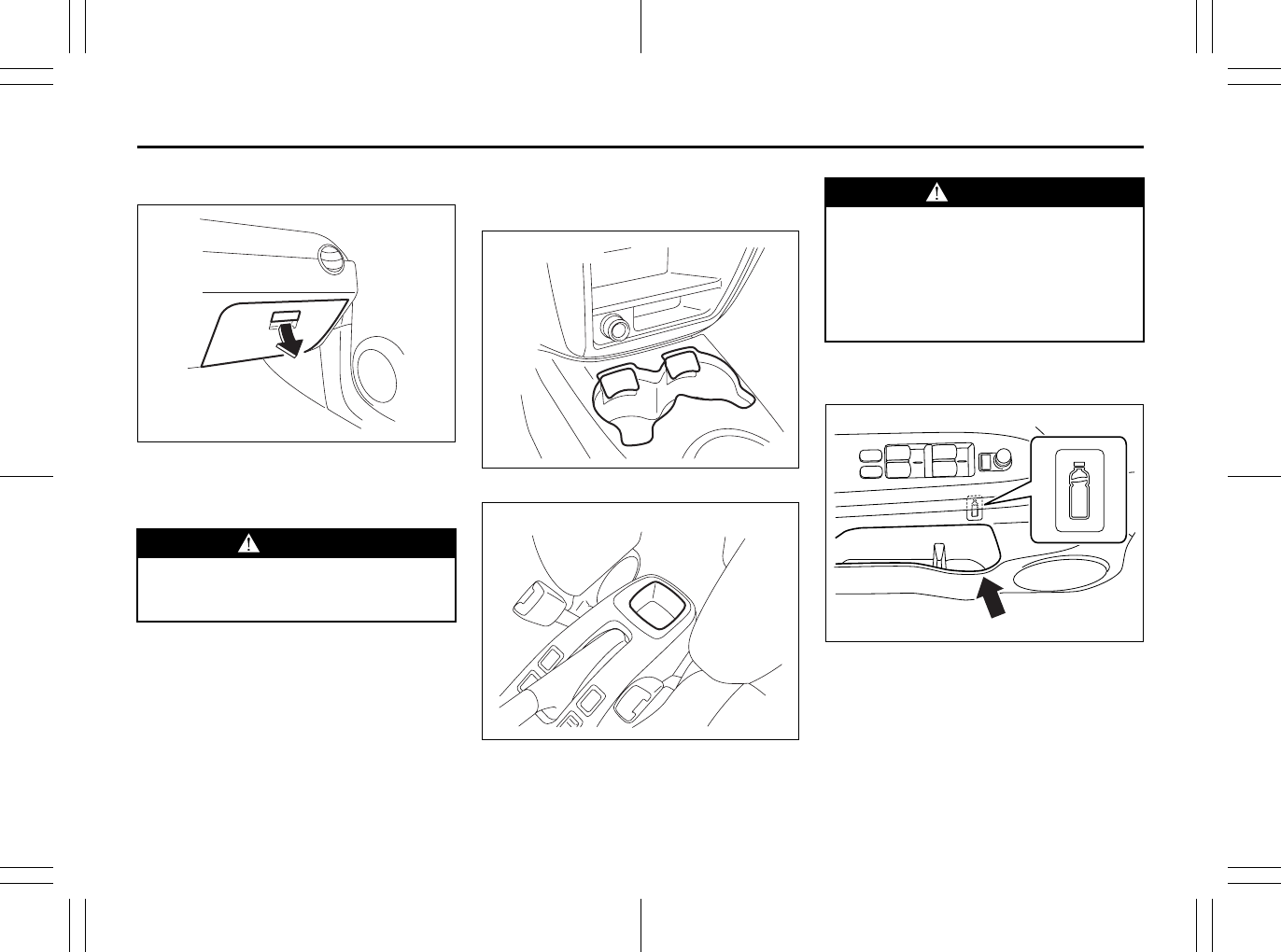
5-49
OTHER CONTROLS AND EQUIPMENT
80J23-03E
Glove Box
79J120
To open the glove box, pull the latch lever.
To close it, push the lid until it latches
securely.
Cup Holder and Storage Area
(if equipped)
80J046
79J052
Cup holders are provided in the center
console.
Bottle holder
Front
80JM055
WARNING
Never drive with the glove box lid
open. It could cause injury if an acci-
dent occurs.
EXAMPLE
EXAMPLE
WARNING
Do not use the cup holder or the stor-
age bin to hold cups containing hot
liquids or sharp-edged, hard or
breakable objects. Objects in these
bins may be thrown about during a
sudden stop or impact, and could
cause personal injury.
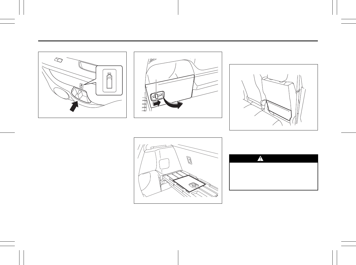
5-50
OTHER CONTROLS AND EQUIPMENT
80J23-03E
Rear
80JM143
You should hold a bottle with a cap in the
holder.
Luggage compartment pocket (SX4)
80JM124
To open the lid, slide the lever (1) and pull
the lid.
80JM108
The lid can be installed on the back of the
luggage compartment board.
Front Seat Back Pocket
(if equipped)
80JC089
This pocket is provided for holding light
and soft things such as gloves, newspa-
pers or magazines.
(1)
WARNING
Do not put hard or breakable objects
in the pocket. If an accident occurs,
objects such as bottles, cans, etc.
can injure the occupants in the rear
seat.
EXAMPLE
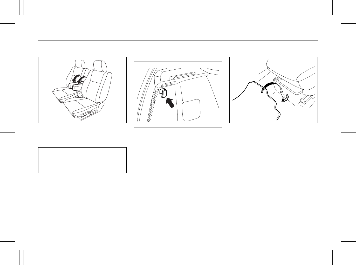
5-51
OTHER CONTROLS AND EQUIPMENT
80J23-03E
Armrest (if equipped)
80J2068
To use the armrest, pivot it down from the
stowed (fully up) position. When not in use,
return the armrest to the stowed position.
Shopping Hook (if equipped)
Luggage compartment
80JM058
You can hang the shopping bag or other
suitable objects on the hook.
This hook is not designed for large or
heavy items.
Floor Mats (if equipped)
80J2014
Your vehicle has a fastener to keep the
driver’s side floor mat from sliding forward
and possibly interfering with the pedals.
Whenever you put the driver’s side floor
mat back in the vehicle after it has been
removed, be sure to hook the floor mat
grommet(s) to the fastener(s) and position
the floor mat properly in the footwell.
When you replace the floor mats in your
vehicle with a different type such as all-
weather floor mats, we highly recommend
using genuine SUZUKI floor mats for
proper fitting.
CAUTION
To avoid damage to the armrest, do
not lean onto it or allow a child ride
on it.
EXAMPLE
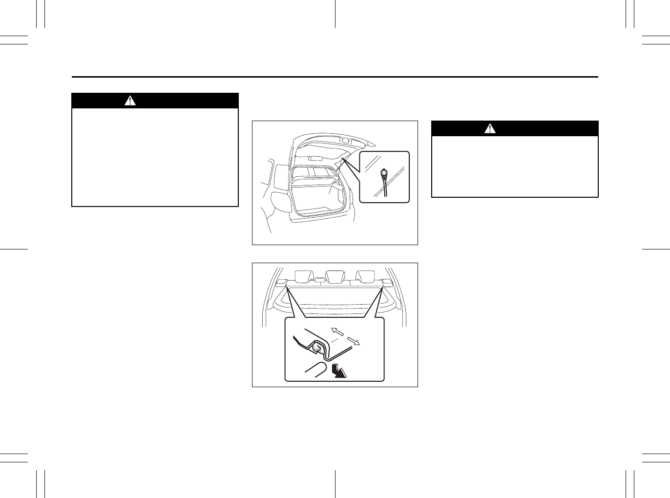
5-52
OTHER CONTROLS AND EQUIPMENT
80J23-03E
Luggage Compartment Cover
(if equipped)
80J049
80JM128
Luggage or other cargo placed in the lug-
gage compartment can be hidden from
view by a luggage compartment cover.
WARNING
Failure to take the following precau-
tions may result in the driver’s side
floor mat interfering with the pedals
and causing a loss of vehicle control
or an accident.
• Make sure that the floor mat grom-
met(s) is(are) hooked to the fas-
tener(s).
• Never place additional floor mats
on top of the existing floor mats.
Front
Rear
WARNING
Do not carry items on top of the lug-
gage compartment cover, even if they
are small and light. Objects on top of
the cover could be thrown about in an
accident, causing injury, or could
obstruct the driver’s rear view.
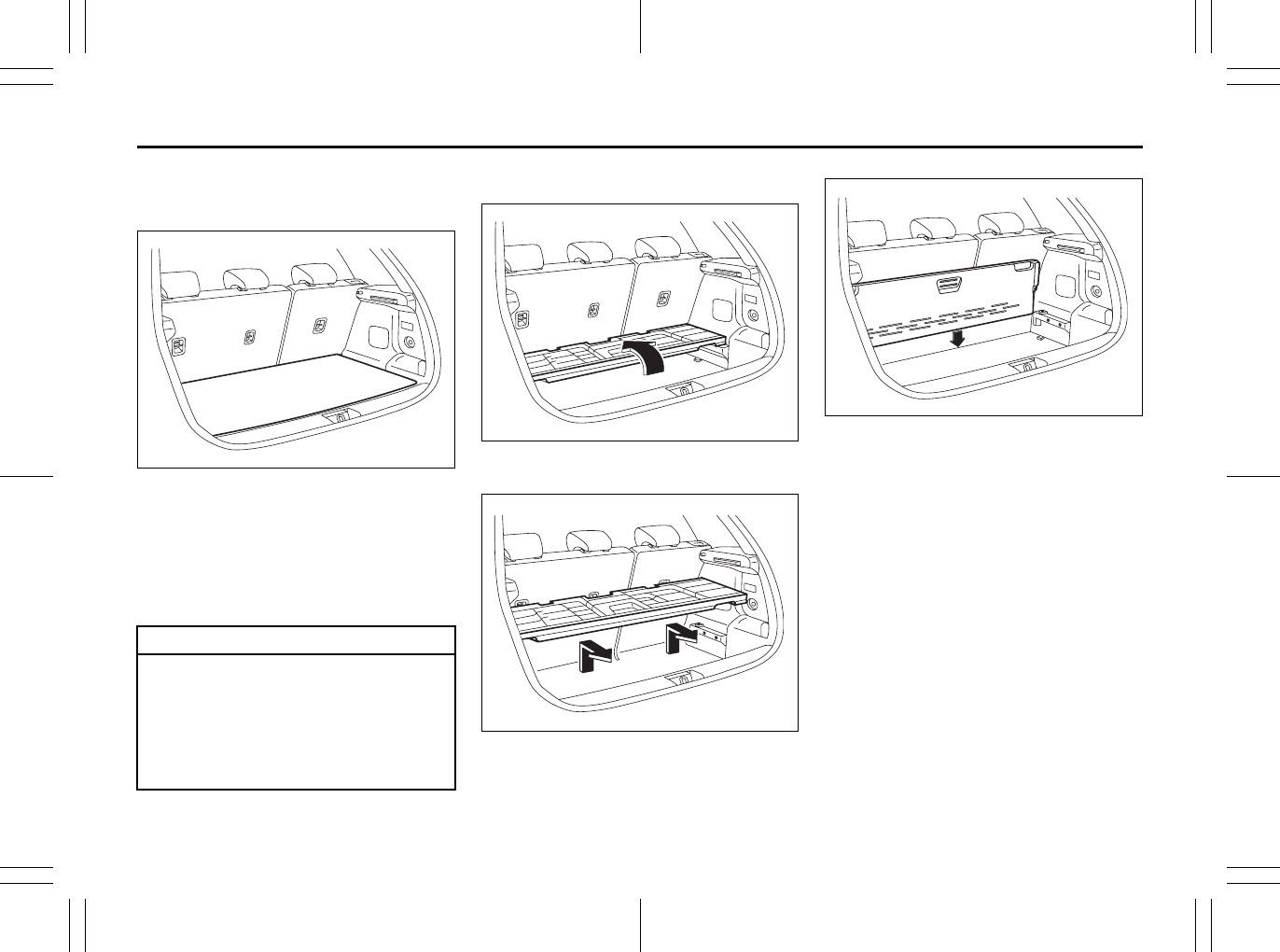
5-53
OTHER CONTROLS AND EQUIPMENT
80J23-03E
Luggage Compartment Board
(if equipped)
80JM059
Your vehicle is equipped with the luggage
compartment board in the luggage com-
partment. You can place luggage or other
cargos on the board or under the board.
You can also place tall luggage by stowing
the board on the floor of the luggage com-
partment.
To remove the luggage compartment
board:
80JM060
1) Fold the board forward.
80JM109
2) Lift the board, and remove the board
from the vehicle.
80JM062
You can stow the board behind the rear
seatback as shown in the illustration.
CAUTION
To avoid injury, handle the board
carefully when removing or installing.
Do not place the objects taller than
the luggage compartment cover
since objects could obstruct the
driver’s rear view or could damage
objects or the tailgate while driving.
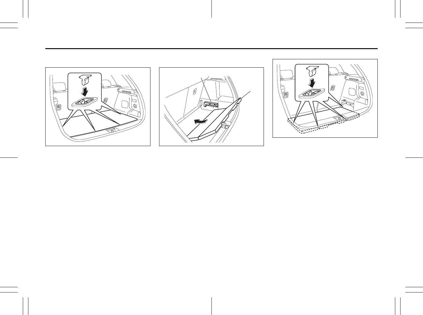
5-54
OTHER CONTROLS AND EQUIPMENT
80J23-03E
To re-install the luggage board to the
normal position:
80JM144
Place the strikers of the luggage board to
the latches on the side and tail end of orig-
inal position.
To install the luggage board on the floor
of the luggage compartment:
80JM129
1) Unfold the luggage compartment board
(1), and insert it along the groove (2) at
both side of the luggage compartment
as shown in the illustration.
2) Slide the board forward.
80JM145
3) Place the strikers of the luggage board
to the latches on the luggage floor.
(1)
(2)
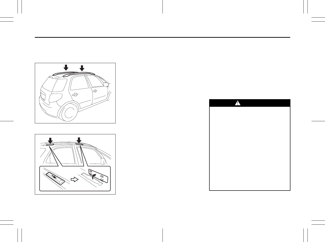
5-55
OTHER CONTROLS AND EQUIPMENT
80J23-03E
Roof Rails or Roof Rack
Anchors (if equipped)
Roof rails
79J167
Roof rack anchors
80J082
You can use the roof rails or the roof rack
anchors to attach the optional roof rack
which is available at your SUZUKI dealer. If
you use a roof rack, observe the instruc-
tions and precautions in this section and
provided with the roof rack.
• Make sure the roof rack is securely
installed.
• To mount various types of cargo (such
as skis, bicycles, etc.) properly, use suit-
able attachments which are available
from your SUZUKI dealer. Be sure to
install the attachments properly and
securely according to the instructions
provided. Do not mount cargo directly on
the roof panel. The cargo can damage
the roof panel.
• The gross weight of the roof rack plus
cargo must not exceed the loading
capacity (50 kg (110 lbs)). Also, do not
let the gross vehicle weight (fully loaded
vehicle including driver, passengers,
cargo, roof load and trailer tongue
weight) exceed the Gross Vehicle
Weight Rating (GVWR) listed in the
driver’s door lock pillar.
• Mount and secure the cargo onto the
roof rack properly according to the
instructions provided. Be sure to stow
the heaviest items at the bottom and dis-
tribute the cargo as evenly as possible.
• Do not carry items so large that they
hang over the bumpers or the sides of
the vehicle, or block your view.
• Secure the front and rear ends of long
items – such as wood panels, surfboards
and so forth – to both the front and rear
of the vehicle. You should protect the
painted surfaces of the vehicle from
scuffing caused by tie-down ropes.
• Check periodically to make sure the roof
rack is securely installed and free from
damage.
• For vehicles with roof rack anchors,
make sure the anchors are covered with
the caps when not in use.
WARNING
• Abrupt maneuvers or failure to
properly secure cargo can allow the
cargo to fly off the vehicle and hit
others, causing personal injury or
property damage.
• Mount cargo securely and avoid
abrupt maneuvers such as “jack-
rabbit” starts, sharp turns, fast cor-
nering and sudden braking. Check
periodically to make sure that
cargo is securely fastened.
• Large, bulky, long, or flat items can
affect vehicle aerodynamics or be
caught by the wind, and can reduce
vehicle control resulting in an acci-
dent and personal injury. Drive cau-
tiously at a safely reduced speed
when carrying this type of cargo.
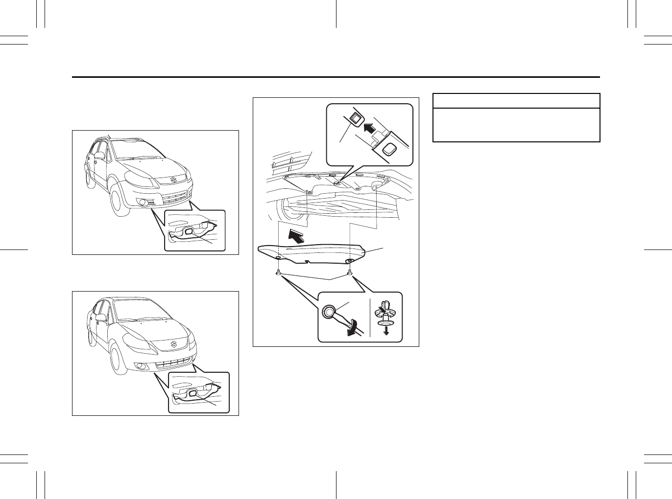
5-56
OTHER CONTROLS AND EQUIPMENT
80J23-03E
Frame Hooks
SX4
Front (1)
80J2049
SX4 SEDAN
Front (1)
80J2050
Front bumper cover (if equipped)
80JM111
To use the frame hook:
1) Insert a flat blade screwdriver into the
hole (b) and remove the clips (a) by
twist the driver as shown in the illustra-
tion.
2) Remove the bumper cover (c).
NOTE:
When return the cover, make sure the
ungual (d) of the cover securely fit to the
slit on under the front bumper of vehicle.
(1)
EXAMPLE
(1)
EXAMPLE
(b)
(c)
(a)
(d)
EXAMPLE
CAUTION
If towing your vehicle, use the frame
hook of removed bumper cover side
to prevent damage to the vehicle.
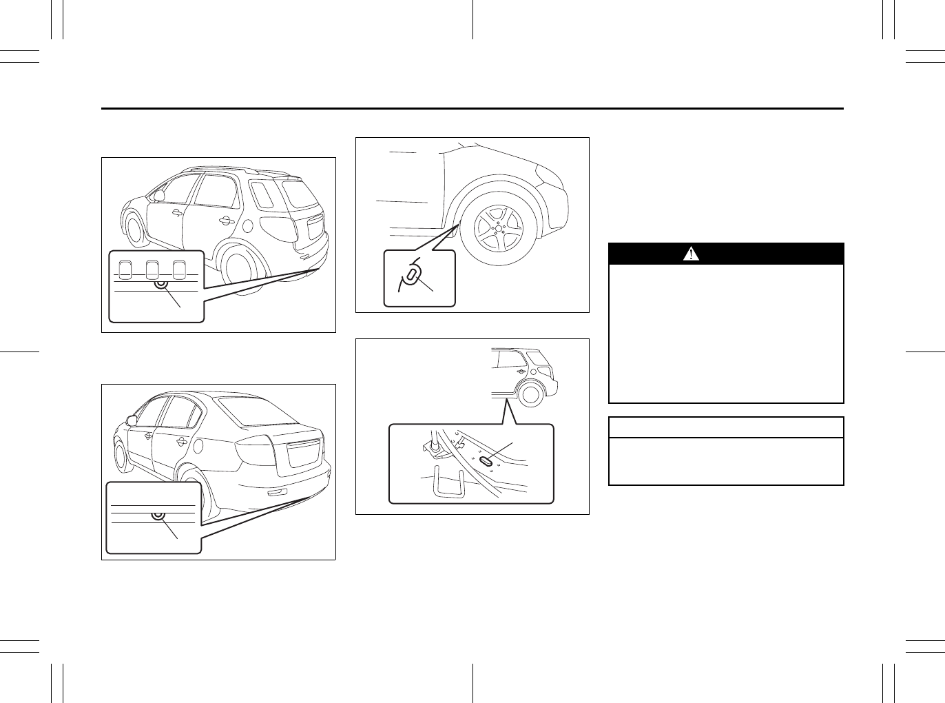
5-57
OTHER CONTROLS AND EQUIPMENT
80J23-03E
SX4
Rear (2)
80JC061
SX4 SEDAN
Rear (2)
56KN033
Side (3)
80JC062
79J132
Frame hooks are provided on the front (1),
rear (2) and side (3) of the vehicle. The
hooks (1) and (2) are used for emergency
situations. The hooks (3) are used for
trailer/train shipping purposes.
To tow your vehicle on the road or highway,
follow the instruction of “Towing” in “EMER-
GENCY SERVICE” section.
(2) EXAMPLE
(2) EXAMPLE
(3) EXAMPLE
(3)
EXAMPLE
WARNING
Do not use the frame hooks to tow
another vehicle or to have your vehi-
cle towed on the road or highway.
The hooks (1) and (2) are designed
for use in emergency situations only,
such as if your vehicle or another
vehicle gets stuck in deep mud or
snow.
The hooks (3) are provided for trailer/
train shipping purposes.
CAUTION
Never use the hooks (1) and (2) for
trailer/train shipping purposes to pre-
vent damage to the vehicle.
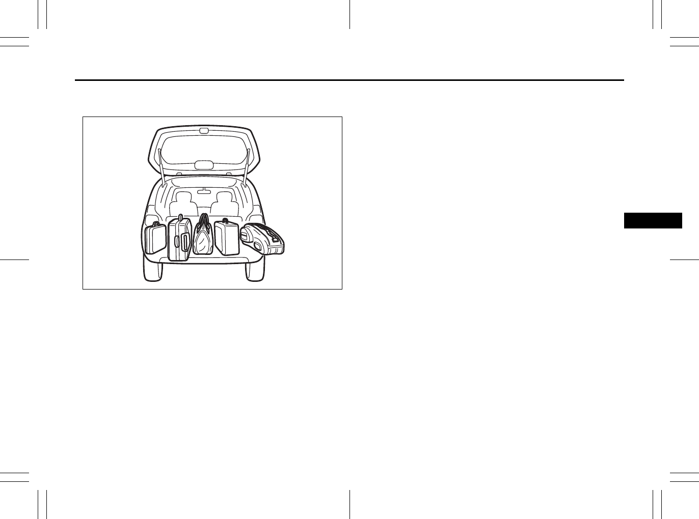
VEHICLE LOADING AND TOWING
6
80J23-03E
54G215
VEHICLE LOADING AND TOWING
Vehicle Loading ................................................................... 6-1
Trailer Towing ...................................................................... 6-2
Towing Your Vehicle (recreational towing) ...................... 6-2
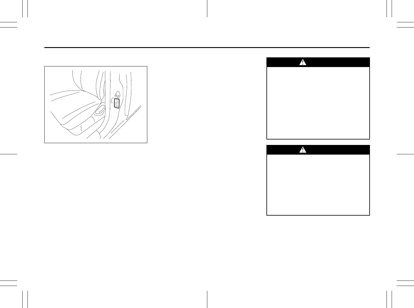
6-1
VEHICLE LOADING AND TOWING
80J23-03E
Vehicle Loading
80JS025
Your vehicle was designed for specific
weight capacities. The weight capacities of
your vehicle are indicated by the Gross
Vehicle Weight Rating (GVWR), the Gross
Axle Weight Rating (GAWR, front and rear)
and the Vehicle Capacity Weight. The
GVWR and GAWR (front and rear) are
listed on the Safety Certification Label
which is located below the driver’s side
door latch striker. The Vehicle Capacity
Weight is listed on the Tire Information
Label which is located below the Safety
Certification Label.
GVWR – Maximum permissible overall
weight of the fully loaded vehicle (including
all the occupants, accessories and cargo).
GAWR – (Front and Rear) Maximum per-
missible weight on an individual axle.
Vehicle Capacity Weight – Maximum per-
missible load weight a vehicle can carry
including the weight of all the occupants,
accessories and cargo.
The weight of any accessories already
installed on your vehicle at the time of pur-
chase, or that you or the dealer install after
purchase, must be subtracted from the
Vehicle Capacity Weight to determine how
much capacity remains available for occu-
pants and cargo. Contact your dealer for
further information.
Actual weight of the loaded vehicle and
actual loads at the front and rear axles can
only be determined by weighing the vehicle
using a vehicle scale. To measure the
weight and load, try taking your vehicle to
a highway weighing station, shipping com-
pany or inspection station for trucks, etc.
Compare these weights to the GVWR and
GAWR (front and rear) listed on the Safety
Certification Label. If the gross vehicle
weight or the load on either axle exceeds
these ratings, you must remove enough
weight to bring the load down to the rated
capacity.
WARNING
Never overload your vehicle. The
gross vehicle weight (sum of the
weights of the loaded vehicle, driver
and passengers) must never exceed
the Gross Vehicle Weight Rating
(GVWR) listed on the Safety Certifica-
tion Label. In addition, never distrib-
ute a load so that the weight on either
the front or rear axle exceeds the
Gross Axle Weight Rating (GAWR)
listed on the Safety Certification
Label.
WARNING
• Always distribute cargo evenly.
• To avoid personal injury or damage
to your vehicle, always secure
cargo to prevent it from shifting if
the vehicle moves suddenly.
• Place heavier objects on the floor
and as far forward in the trunk or in
the cargo area as possible.
• Never pile cargo higher than the
top of the seat backs.
Exhaust Gas Warning: NO
Daily Inspection Checklist: NO
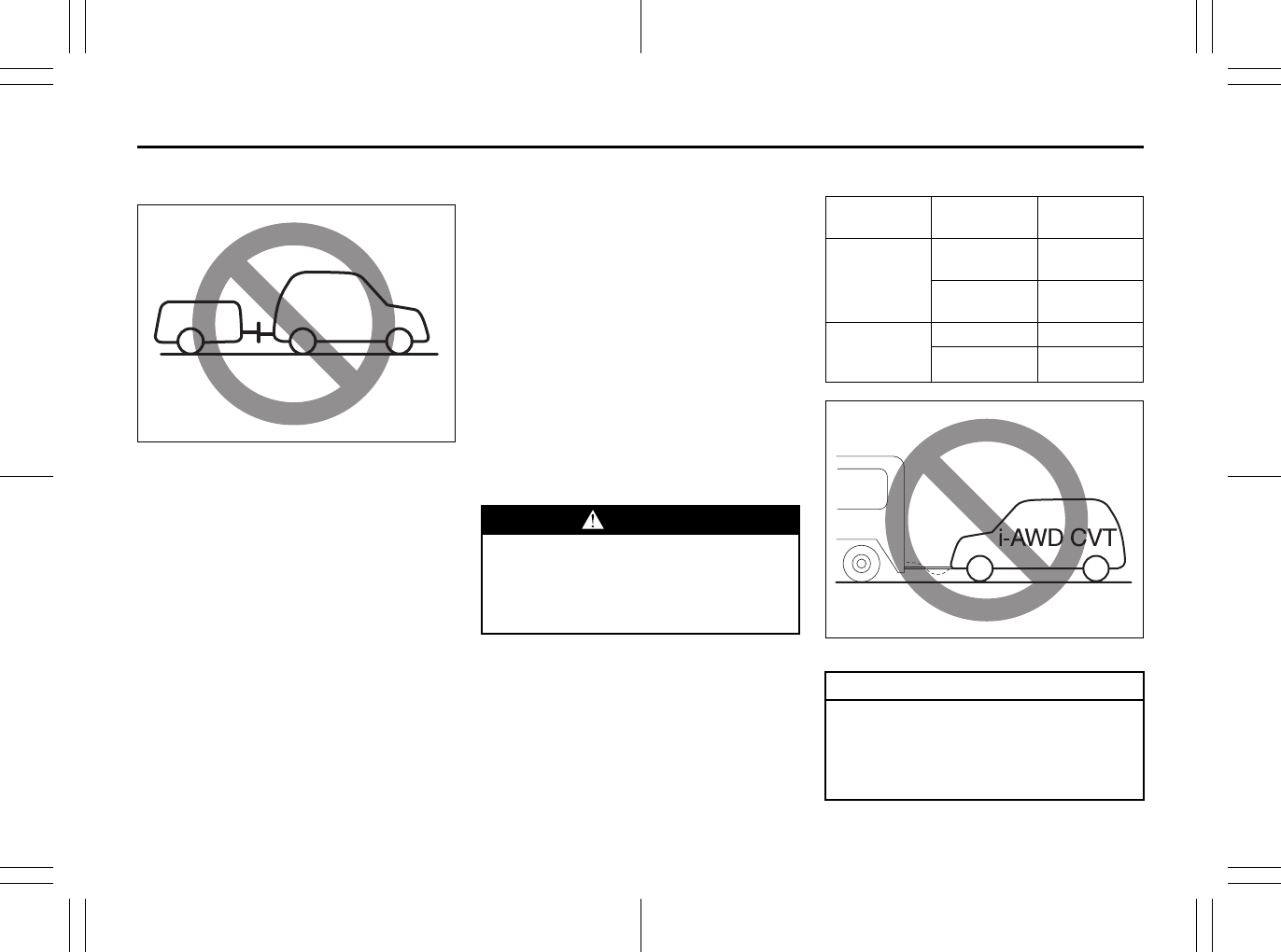
6-2
VEHICLE LOADING AND TOWING
80J23-03E
Trailer Towing
54G639
Do not use your vehicle to tow a trailer. The
vehicle is not designed or intended for
such use. Towing a trailer can adversely
affect handling, durability and fuel econ-
omy.
Towing Your Vehicle
(recreational towing)
Your vehicle may be towed behind another
vehicle (such as a motorhome), provided
you use the proper towing method speci-
fied for your vehicle. The towing method
you must use depends on the specifica-
tions of your vehicle: whether it is a 2-
wheel drive (2WD) or intelligent All Wheel
Drive (i-AWD) vehicle.
Use the towing instruction table to select
the proper towing method for your vehicle,
and carefully follow the corresponding
instructions. Be sure to use proper towing
equipment designed for recreational tow-
ing and make sure that towing speed does
not exceed 90 km/h (55 mph).
TOWING INSTRUCTION TABLE
80J2051
WARNING
Always use a safety chain when tow-
ing your vehicle and be sure to
observe federal, state, and local
requirements for trailer hitches, tow
bars, lights, etc.
DRIVE
TRAIN
TRANS-
AXLE
TOWING
METHOD
2WD
CVT
(AUTO) A
M/T
(MANUAL) A B
i-AWD
including
2WD mode
CVT none
M/T B
CAUTION
For the CVT of intelligent All Wheel
Drive (i-AWD) models, don’t tow your
vehicle behind another vehicle such
as a motorhome, or the drive train
may be seriously damaged.
Daily Inspection Checklist: NO
Starting the Engine: 1
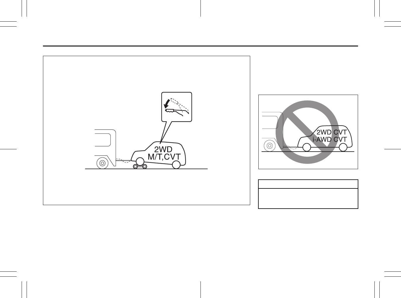
6-3
VEHICLE LOADING AND TOWING
80J23-03E
80J2052
TOWING METHOD A
FROM THE FRONT:
FRONT WHEELS ON A DOLLY
AND REAR WHEELS ON THE GROUND
A: 2WD (except 2WD mode of i-AWD)
VEHICLES WITH MANUAL TRANS-
AXLE OR CVT
1) Secure the front wheels on a towing
dolly according to the instructions pro-
vided by the dolly manufacturer.
2) Release the parking brake.
80J2053
CAUTION
Towing the 2WD or i-AWD CVT vehi-
cles with four wheels on the ground
can result in damage to the CVT.
Engine Block Heater: 1
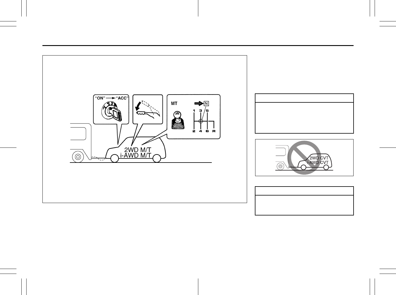
6-4
VEHICLE LOADING AND TOWING
80J23-03E
80J2079
TOWING METHOD B
FROM THE FRONT:
FOUR WHEELS ON THE GROUND
B: 2WD or i-AWD (including 2WD mode)
VEHICLES WITH MANUAL TRANSAXLE
1) Shift the manual transaxle lever into
neutral.
2) Turn the ignition key to the “ACC” posi-
tion to unlock the steering wheel.
3) Release the parking brake.
80J2054
CAUTION
The steering column is not strong
enough to withstand shocks trans-
mitted from the front wheels during
towing. Always unlock the steering
wheel before towing.
CAUTION
Towing the 2WD or i-AWD CVT vehi-
cles with four wheels on the ground
can result in damage to the CVT.
Using the Transaxle: 10

6-5
VEHICLE LOADING AND TOWING
80J23-03E
MEMO
Using the Transaxle: 10
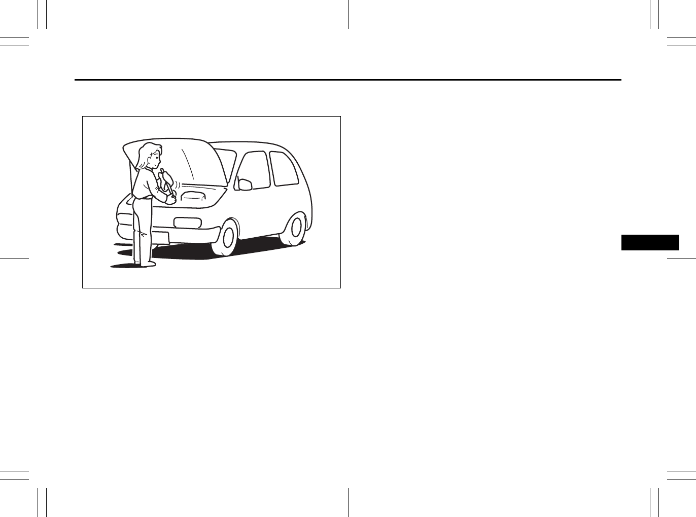
INSPECTION AND MAINTENANCE
7
80J23-03E
60G410
INSPECTION AND MAINTENANCE
Maintenance Schedule ....................................................... 7-2
Periodic Maintenance Schedule ........................................ 7-3
Maintenance Recommended under Severe Driving
Conditions ........................................................................... 7-7
Drive Belt ............................................................................. 7-11
Engine Oil and Filter ........................................................... 7-11
Engine Coolant .................................................................... 7-14
Air Cleaner ........................................................................... 7-16
Spark Plugs ......................................................................... 7-16
Gear Oil ................................................................................ 7-18
Clutch Pedal ........................................................................ 7-19
Continuously Variable Transaxle (CVT) Fluid .................. 7-20
Brakes .................................................................................. 7-21
Steering Wheel .................................................................... 7-23
Tires ...................................................................................... 7-24
Battery .................................................................................. 7-35
Fuses .................................................................................... 7-36
Headlight Aiming ................................................................. 7-39
Bulb Replacement ............................................................... 7-40
Wiper Blades ....................................................................... 7-46
Windshield Washer Fluid ................................................... 7-50
Air Conditioning System .................................................... 7-50
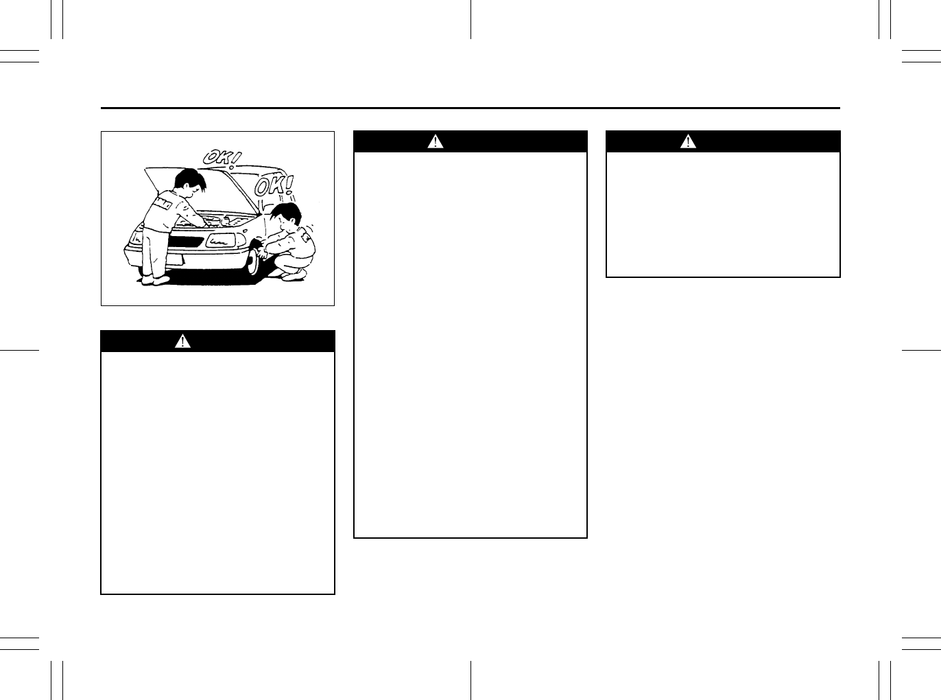
7-1
INSPECTION AND MAINTENANCE
80J23-03E
60A187S
WARNING
You should take extreme care when
working on your vehicle to prevent
accidental injury. Here are a few pre-
cautions that you should be espe-
cially careful to observe:
• To prevent damage or unintended
inflation of the air bag system, be
sure the battery is disconnected
and the ignition switch has been in
the “LOCK” position for at least 90
seconds before performing any
electrical service work on your
SUZUKI. Do not touch air bag sys-
tem components or wires. The
wires are wrapped with yellow tape
or yellow tubing, and the couplers
are yellow for easy identification.
(Continued)
WARNING
(Continued)
• Do not leave the engine running in
garages or other confined areas.
• When the engine is running, keep
hands, clothing, tools and other
objects away from the moving fan
and drive belt.
• When it is necessary to do service
work with the engine running, make
sure that the parking brake is set
fully and the transaxle is in Neutral
(for manual transaxle vehicles) or
Park (for CVT vehicles).
• Do not touch ignition wires or other
ignition system parts when starting
the engine or when the engine is
running, or you could receive an
electric shock.
• Be careful not to touch a hot
engine, exhaust manifold and
pipes, muffler, radiator and water
hoses.
• Do not allow smoking, sparks or
flames around fuel or the battery.
Flammable fumes are present.
• Do not get under your vehicle if it is
supported only with the portable
jack provided in your vehicle.
(Continued)
WARNING
(Continued)
• Be careful not to cause accidental
short circuits between the positive
and negative battery terminals.
• Keep used oil, engine coolant and
other fluids away from children and
pets. Dispose of used fluids prop-
erly; never pour them on the
ground, into sewers, etc.
Highway Driving: NO
Driving on Hills: NO
7-2
INSPECTION AND MAINTENANCE
80J23-03E
NOTICE (for U.S.A.)
Maintenance, replacement or repair of
the emission control devices and sys-
tems may be performed by any automo-
bile repair establishment or individual
using any part which has been certified
under the provisions in the Clean Air
Act sec. 207. (a) (2).
Maintenance Schedule
The following table shows the times when
you should perform regular maintenance
on your vehicle. This table shows in miles,
kilometers and months when you should
perform inspections, adjustments, lubrica-
tion and other services. These intervals
should be shortened if driving is usually
done under severe conditions (refer to
“Maintenance Recommended Under
Severe Driving Conditions”).
WARNING
SUZUKI recommends that mainte-
nance on items marked with an aster-
isk (*) be performed by your
authorized SUZUKI dealer or a quali-
fied service technician. If you are
qualified, you may perform mainte-
nance on the unmarked items by
referring to the instructions in this
section. If you are not sure whether
you can successfully complete any of
the unmarked maintenance jobs, ask
your authorized SUZUKI dealer to do
the maintenance for you.
CAUTION
Whenever it becomes necessary to
replace parts on your vehicle, it is
recommended that you use genuine
SUZUKI replacement parts or their
equivalent.
WARNING
The shock absorbers are filled with
high pressure gas. Never attempt to
disassemble them or throw them into
a fire. Avoid storing them near a
heater or heating device. When
scrapping the absorber, the gas must
be released from the absorber safely.
Ask your dealer for assistance.
Driving on Hills: NO
Driving on Slippery Roads: NO
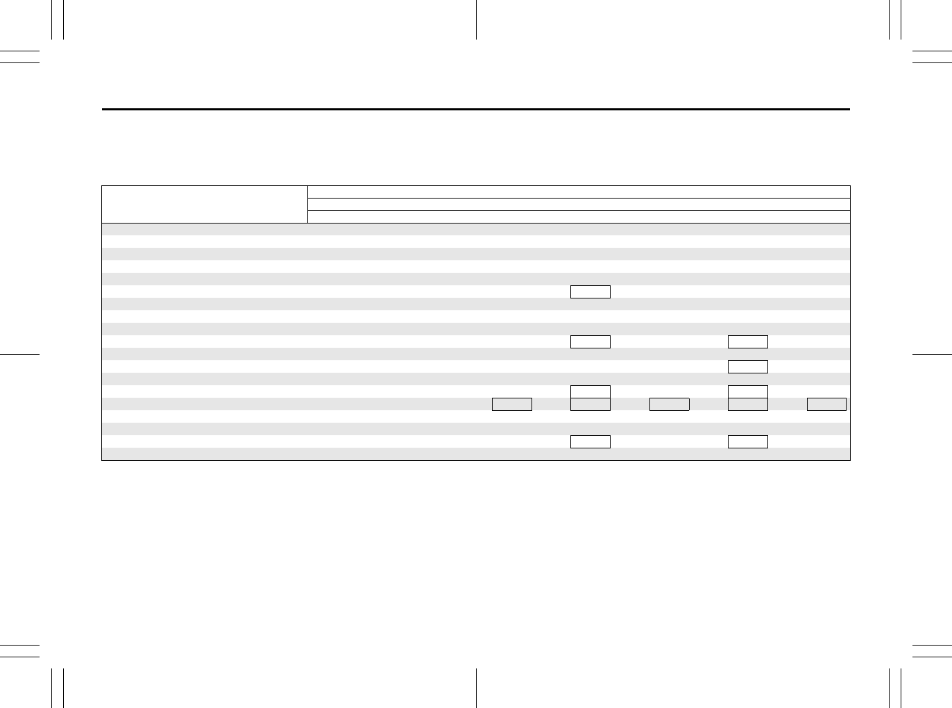
7-3
INSPECTION AND MAINTENANCE
80J23-03E
Periodic Maintenance Schedule
R: Replace or change
I : Inspect, clean, adjust, lubricate or replace as necessary
#1: Be sure to perform the engine coolant level check under the daily inspection in “OPERATING YOUR VEHICLE” section.
If you replace the engine coolant other than the SUZUKI LLC: Super (Blue), follow the schedule of SUZUKI LLC: Standard (Green).
Interval: This interval should be judged by
odometer reading or months, whichever comes
first.
miles (x 1000) 7.5 15 22.5 30 37.5 45 52.5 60 67.5 75
km (x 1000) 12.5 25 37.5 50 62.5 75 87.5 100 112.5 125
months 7.5 15 22.5 30 37.5 45 52.5 60 67.5 75
ENGINE & EMISSION CONTROL
1. Drive belt
Inspect for damage – – – I – – – I – –
*2.Valve lash (clearance) ––––––– I ––
3. Engine oil and oil filter R R R R R R R R R R
*4. Cooling system hoses and connections – – – I – – – I – –
5. Engine coolant SUZUKI LLC: Standard (Green) – – – R – – – R – –
SUZUKI LLC: Super (Blue) (#1) First time only: Replace at 150000 km (90000 miles) or 90 months
Second time and after: Replace every 75000 km (45000 miles) or 45 months
*6. Exhaust pipes and mountings – – – I – – – I – –
*7. EVAP canister Replace every 250000 km (150000 miles) or 180 months
*8.Emission-related hoses & tubes ––––––– I ––
9. Spark plugs – – – – – – – R – –
*10. Ignition coil (plug cap) – – – I – – – I – –
*11. Fuel tank & cap – I – I – I – I – I
12. Air cleaner filter element (paved road) – – – R – – – R – –
*13. Fuel filter – – – – – – – – – –
*14. Fuel lines and connections – – – I – – – I – –
*15. Canister air suction filter Replace every 250000 km (150000 miles) or 180 months
Driving on Slippery Roads: NO
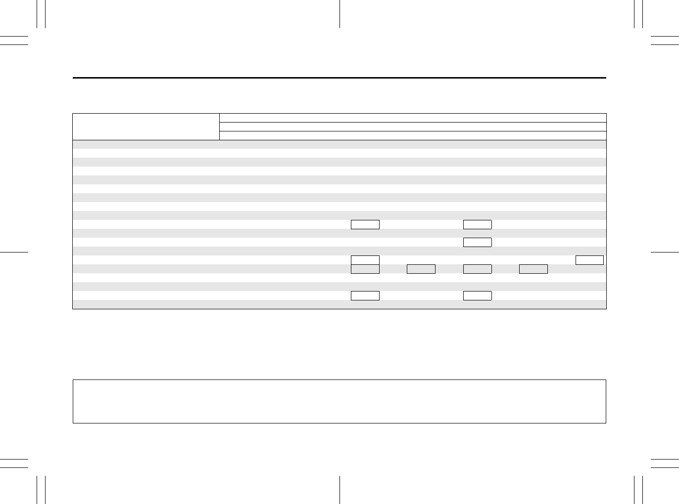
7-4
INSPECTION AND MAINTENANCE
80J23-03E
R: Replace or change
I : Inspect, clean, adjust, lubricate or replace as necessary
#1: Be sure to perform the engine coolant level check under the daily inspection in “OPERATING YOUR VEHICLE” section.
If you replace the engine coolant other than the SUZUKI LLC: Super (Blue), follow the schedule of SUZUKI LLC: Standard (Green).
#2: Inspect at 250000 km (150000 miles) or 180 months.
NOTE:
The maintenance services enclosed with rectangle are recommended maintenance items.
Interval: This interval should be judged by
odometer reading or months, whichever comes
first.
miles (x 1000) 82.5 90 97.5 105 112.5 120 127.5 135 142.5 150
km (x 1000) 137.5 150 162.5 175 187.5 200 212.5 225 237.5 250
months 82.5 90 97.5 105 112.5 120 127.5 135 142.5 150
ENGINE & EMISSION CONTROL
1. Drive belt
Inspect for damage – I – – – I – – – I
*2. Valve lash (clearance) – – – – – I – – – –
3. Engine oil and oil filter R R R R R R R R R R
*4. Cooling system hoses and connections – I – – – I – – – I
5. Engine coolant SUZUKI LLC: Standard (Green) – R – – – R – – – R
SUZUKI LLC: Super (Blue) (#1) First time only: Replace at 150000 km (90000 miles) or 90 months
Second time and after: Replace every 75000 km (45000 miles) or 45 months
*6. Exhaust pipes and mountings – I – – – I – – – I
*7. EVAP canister Replace every 250000 km (150000 miles) or 180 months
*8. Emission-related hoses & tubes – – – – – I – – – I
9. Spark plugs – – – – – R – – – –
*10. Ignition coil (plug cap) – I – – – I – – – I
*11. Fuel tank & cap – I – I – I – I – I (#2)
12. Air cleaner filter element (paved road) – R – – – R – – – R
*13. Fuel filter – – – – – – – – – R
*14. Fuel lines and connections – I – – – I – – – I (#2)
*15. Canister air suction filter Replace every 250000 km (150000 miles) or 180 months
The U.S. Environmental Protection Agency or the California Air Resources Board has determined that the failure to perform recom-
mended maintenance items enclosed with a rectangle will not nullify the emission warranty or limit recall liability prior to the completion
of the vehicle’s useful life. SUZUKI, however, urges that all recommended maintenance services be performed at the indicated inter-
vals and the maintenance recorded.
Driving on Slippery Roads: NO
7-5
INSPECTION AND MAINTENANCE
80J23-03E
R: Replace or change
I : Inspect, clean, adjust, lubricate or replace as necessary
Interval: This interval should be judged by odometer
reading or months, whichever comes first.
miles (x 1000) 7.5 15 22.5 30 37.5 45 52.5 60 67.5 75
km (x 1000) 12.5 25 37.5 50 62.5 75 87.5 100 112.5 125
months 7.5 15 22.5 30 37.5 45 52.5 60 67.5 75
CHASSIS AND BODY
1. Clutch (for manual transaxle)
Pedal and fluid level – I – I – I – I – I
*2. Brake discs and pads (front, rear) I – I – I – I – I –
Brake drums and shoes (rear) I – I – I – I – I –
*3. Brake hoses and pipes I – I – I – I – I –
4. Brake fluid level check, *replacement – I – I – I – R – I
5. Brake pedal stroke check, *adjustment – I – I – I – I – I
6. Parking brake lever and *cable
Lever movement check, *adjustment I – I – I – I – I –
7. Tires (including tire rotation) I I I I I I I I I I
8. Wheel discs I I I I I I I I I I
*9. Suspension system I I I I I I I I I I
*10. Propeller shafts (i-AWD)/Drive axle boots I I I I I I I I I I
*11. Manual transaxle oil
Level check, *replacement I – – I – I – I – I
12. Continuously variable transaxle (CVT) Fluid level – I – I – I – I – I
*Fluid hose ––––– I ––––
*13. Transfer oil (i-AWD) I – – I – I – R – I
*14. Rear differential oil (i-AWD) R – – I – I – I – I
15. Steering system
Steering wheel movement, *linkage I I I I I I I I I I
16. Power steering (if equipped) I I I I I I I I I I
17. All latches, hinges and locks I I I I I I I I I I
18. Air conditioner filter element (if equipped) – I – R – I – R – I

7-6
INSPECTION AND MAINTENANCE
80J23-03E
R: Replace or change
I : Inspect, clean, adjust, lubricate or replace as necessary
NOTE:
This table shows the service schedule up to 250000 km (150000 miles).
Beyond 250000 km (150000 miles), perform the same services at the same intervals shown in the chart.
Beyond 250000 km (150000 miles), the maintenance services enclosed with a rectangle are required.
Interval: This interval should be judged by odometer
reading or months, whichever comes first.
miles (x 1000) 82.5 90 97.5 105 112.5 120 127.5 135 142.5 150
km (x 1000) 137.5 150 162.5 175 187.5 200 212.5 225 237.5 250
months 82.5 90 97.5 105 112.5 120 127.5 135 142.5 150
CHASSIS AND BODY
1. Clutch (for manual transaxle)
Pedal and fluid level – I – I – I – I – I
*2. Brake discs and pads (front, rear) I – I – I – I – I –
Brake drums and shoes (rear) I – I – I – I – I –
*3. Brake hoses and pipes I – I – I – I – I –
4. Brake fluid level check, *replacement – I – I – R – I – I
5. Brake pedal stroke check, *adjustment – I – I – I – I – I
6. Parking brake lever and *cable
Lever movement check, *adjustment I – I – I – I – I –
7. Tires (including tire rotation) I I I I I I I I I I
8. Wheel discs I I I I I I I I I I
*9. Suspension system I I I I I I I I I I
*10. Propeller shafts (i-AWD)/Drive axle boots I I I I I I I I I I
*11. Manual transaxle oil
Level check, *replacement – R – I – I – I – I
12. Continuously variable transaxle (CVT) Fluid level – I – I – I – I – I
*Fluid hose – I ––––– I ––
*13. Transfer oil (i-AWD) – I – I – R – I – I
*14. Rear differential oil (i-AWD) – I – I – I – I – I
15. Steering system
Steering wheel movement, *linkage I I I I I I I I I I
16. Power steering (if equipped) I I I I I I I I I I
17. All latches, hinges and locks I I I I I I I I I I
18. Air conditioner filter element (if equipped) – R – I – R – I – R
7-7
INSPECTION AND MAINTENANCE
80J23-03E
Maintenance Recommended under Severe Driving Conditions
Follow this schedule if your car is mainly operated under one or more of the following conditions:
• When most trips are less than 6 kilometers (4 miles)
• When most trips are less than 16 kilometers (10 miles) and outside temperature remain below freezing.
• Idling and/or low-speed operation in stop-and-go traffic.
• Operating in dusty areas.
Schedule should also be followed if the car is used for delivery service, police, taxi or other commercial applications.
R: Replace or change
I : Inspect, clean, adjust, lubricate or replace as necessary
#1: Be sure to perform the engine coolant level check under the daily inspection in “OPERATING YOUR VEHICLE” section.
If you replace the engine coolant other than the SUZUKI LLC: Super (Blue), follow the schedule of SUZUKI LLC: Standard (Green).
Interval: This interval should be judged by
odometer reading or months, whichever
comes first.
miles (x 1000) 3 6 9 12151821242730333639
km (x 1000) 5 10 15 20 25 30 35 40 45 50 55 60 65
months 3 6 9 12151821242730333639
ENGINE & EMISSION CONTROL
1. Drive belt
Inspect for damage ––––––––– I –––
*2.Valve lash (clearance) –––––––––––––
3. Engine oil and oil filter RRRRRRRRRRRRR
*4. Cooling system hoses and connections – – – – I – – – – I – – –
5. Engine coolant SUZUKI LLC: Standard (Green) –––––––––R–––
SUZUKI LLC: Super (Blue) (#1) First time only: Replace at 150000 km (90000 miles) or 90 months
Second time and after: Replace every 75000 km (45000 miles) or 45 months
*6. Exhaust pipes and mountings – – – – I – – – – I – – –
*7. EVAP canister Replace every 250000 km (150000 miles) or 180 months
*8. Emission-related hoses & tubes – – –––––––––––
9. Spark plugs –––––––––––––
*10.Ignition coil (plug cap) ––––––––– I –––
*11. Fuel tank & cap – – – – I – – – – I – – –
12. Air cleaner filter element (paved road) I I IIIIIIIRIII
*13. Fuel filter Replace every 250000 km (150000 miles) or 150 months
*14. Fuel lines and connections – – – – I – – – – I – – –
*15. Canister air suction filter –––––––––––––
7-8
INSPECTION AND MAINTENANCE
80J23-03E
R: Replace or change
I : Inspect, clean, adjust, lubricate or replace as necessary
#1: Be sure to perform the engine coolant level check under the daily inspection in “OPERATING YOUR VEHICLE” section.
If you replace the engine coolant other than the SUZUKI LLC: Super (Blue), follow the schedule of SUZUKI LLC: Standard (Green).
Interval: This interval should be judged by
odometer reading or months, whichever
comes first.
miles (x 1000) 42 45 48 51 54 57 60 63 66 69 72 75
km (x 1000) 70 75 80 85 90 95 100 105 110 115 120 125
months 42 45 48 51 54 57 60 63 66 69 72 75
ENGINE & EMISSION CONTROL
1. Drive belt
Inspect for damage – – – – – – I – – – – –
*2. Valve lash (clearance) – – – – – – I – – – – –
3. Engine oil and oil filter RRRRRRRRRRRR
*4. Cooling system hoses and connections – I – – – – I – – – – I
5. Engine coolant SUZUKI LLC: Standard (Green) – – – – – – R – – – – –
SUZUKI LLC: Super (Blue) (#1) First time only: Replace at 150000 km (90000 miles) or 90 months
Second time and after: Replace every 75000 km (45000 miles) or 45 months
*6. Exhaust pipes and mountings – I – – – – I – – – – I
*7. EVAP canister Replace every 250000 km (150000 miles) or 180 months
*8. Emission-related hoses & tubes – – – – – – I – – – – –
9. Spark plugs – – – – – – R – – – – –
*10. Ignition coil (plug cap) – – – – – – I – – – – –
*11. Fuel tank & cap – I – – – – I – – – – I
12. Air cleaner filter element (paved road) I I I I I I R I I I I I
*13. Fuel filter Replace every 250000 km (150000 miles) or 150 months
*14. Fuel lines and connections – I – – – – I – – – – I
*15. Canister air suction filter – – – – – – – – – – – R
7-9
INSPECTION AND MAINTENANCE
80J23-03E
R: Replace or change
I : Inspect, clean, adjust, lubricate or replace as necessary
Interval: This interval should be judged by odometer
reading or months, whichever comes first.
miles (x 1000) 3 6 9 12 15 18 21 24 27 30 33 36 39
km (x 1000) 5 101520253035404550556065
months 3 6 9 12151821242730333639
CHASSIS AND BODY
1. Clutch (for manual transaxle)
Pedal and fluid level – – – – I – – – – I – – –
*2. Brake discs and pads (front, rear) – I – I – – – I – – – I –
Brake drums and shoes (rear) – I – I – – – I – – – I –
*3. Brake hoses and pipes – I – I – – – I – – – I –
4. Brake fluid level check, *replacement – – – – I – – – – I – – –
5. Brake pedal stroke check, *adjustment – – – – I – – – – I – – –
6. Parking brake lever and *cable
Lever movement check, *adjustment – I – – I – – – – I – – –
7. Tires (including tire rotation) – I – I – I – I – I – I –
8. Wheel discs – I – I – I – I – I – I –
*9. Wheel bearings – – – I – – – I – – – I –
*10. Suspension system – I – I – I – I – I – I –
*11. Propeller shafts (i-AWD)/Drive axle boots – I – I – I – I – I – I –
*12. Manual transaxle oil
Level check, *replacement – – – – I – – – – I – – –
13. Continuously variable transaxle (CVT) Fluid level – – – – I – – – – I – – –
*Fluid deterioration check*2– – – – I – – – – I – – –
*Fluid hose –––––––––––––
*14. Transfer oil (i-AWD) – – – – R – – – – R – – –
*15. Rear differential oil (i-AWD) – – – – R – – – – R – – –
16. Steering system
Steering wheel movement, *linkage – I – I – I – I – I – I –
17. Power steering (if equipped) – I – I – I – I – I – I –
18. All latches, hinges and locks – I – I – I – I – I – I –
19. Air conditioner filter element (if equipped)*1– I – I – I – I – R – I –
7-10
INSPECTION AND MAINTENANCE
80J23-03E
R: Replace or change
I : Inspect, clean, adjust, lubricate or replace as necessary
NOTE:
This table shows the service schedule up to 125000 km (75000 miles).
Beyond 125000 km (75000 miles), perform the same services at the same intervals shown in the chart.
*1Clean more frequently if the air flow from the air conditioner decreases.
*2Check or replace as necessary if you usually drive with high speed or high engine revolutions.
Interval: This interval should be judged by odometer
reading or months, whichever comes first.
miles (x 1000) 42 45 48 51 54 57 60 63 66 69 72 75
km (x 1000) 70 75 80 85 90 95 100 105 110 115 120 125
months 42 45 48 51 54 57 60 63 66 69 72 75
CHASSIS AND BODY
1. Clutch (for manual transaxle)
Pedal and fluid level – I – – – – I – – – – I
*2. Brake discs and pads (front, rear) – – I – – – I – – – I –
Brake drums and shoes (rear) – – I – – – I – – – I –
*3. Brake hoses and pipes – – I – – – I – – – I –
4. Brake fluid level check, *replacement – I – – – – R – – – – I
5.Brake pedal stroke check, *adjustment – I –––– I –––– I
6. Parking brake lever and *cable
Lever movement check, *adjustment – I –––– I ––––I
7. Tires (including tire rotation) I – I – I – I – I – I –
8.Wheel discs I–I–I–I–I–I–
*9. Wheel bearings – – I – – – I – – – I –
*10. Suspension system I – I – I – I – I – I –
*11. Propeller shafts (i-AWD)/Drive axle boots I – I – I – I – I – I –
*12. Manual transaxle oil
Level check, *replacement – R – – – – I – – – – I
13. Continuously variable transaxle (CVT) Fluid level – I –––– I –––– I
*Fluid deterioration check*2– I – – – – I – – – – I
*Fluid hose – I ––––––––––
*14. Transfer oil (i-AWD) – R – – – – R – – – – R
*15.Rear differential oil (i-AWD) –R––––R––––R
16. Steering system
Steering wheel movement, *linkage I – I – I – I – I – I –
17. Power steering (if equipped) I – I – I – I – I – I –
18. All latches, hinges and locks I – I – I – I – I – I –
19. Air conditioner filter element (if equipped)*1I – I – I – R – I – I –
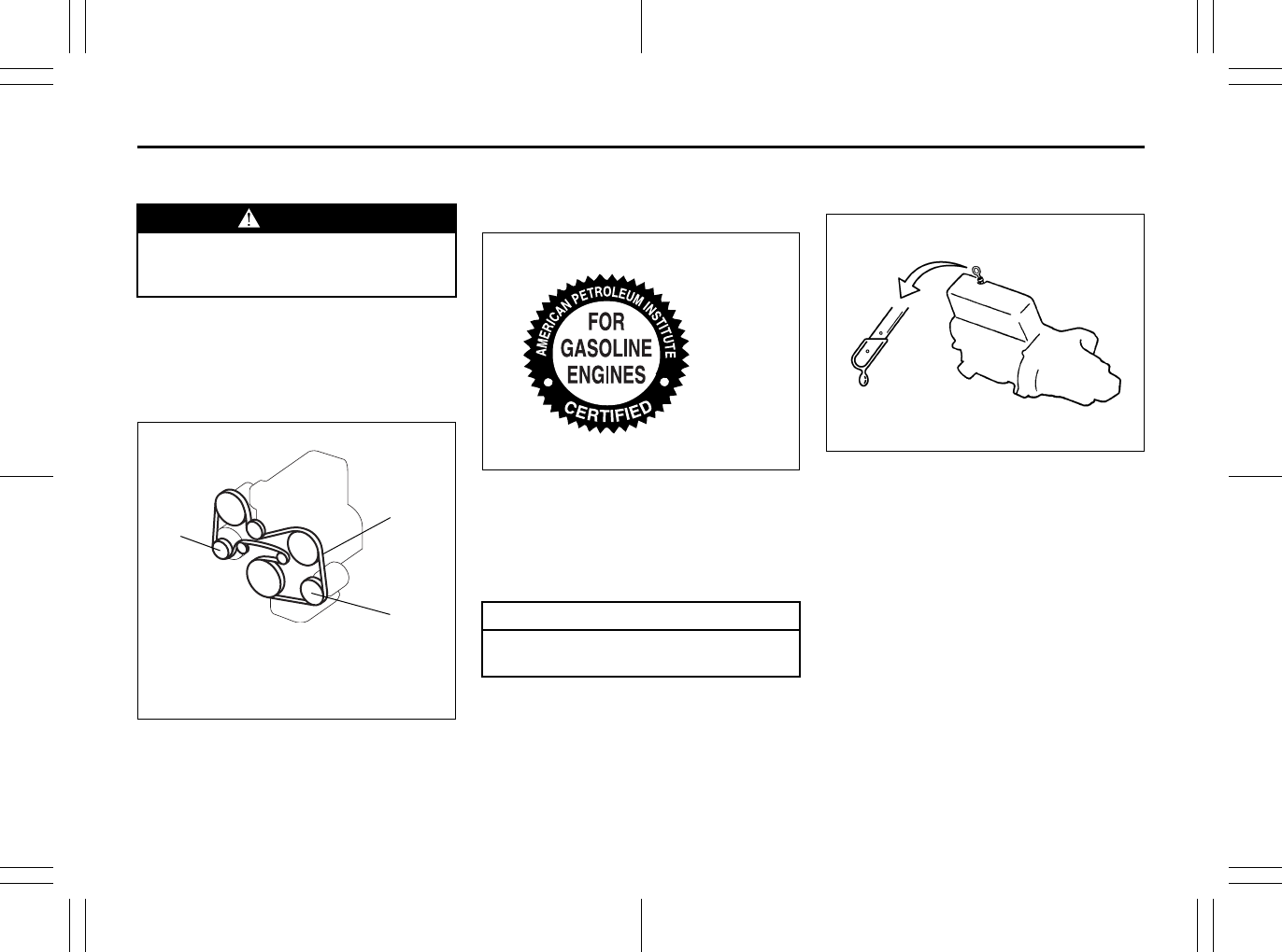
7-11
INSPECTION AND MAINTENANCE
80J23-03E
Drive Belt
Check the accessory drive belt only for
damage. You do not need check it for ten-
sion as it has an automatic tensioner.
If you need to replace or adjust the belt
have it done by your SUZUKI dealer.
80J2055
Engine Oil and Filter
Specified Oil
80JC103
Use engine oil with the American Petro-
leum Institute Certified For Gasoline
Engines “Starburst” symbol.
We highly recommend you use SAE 5W-
30 oil.
Oil Level Check
Engine oil dipstick
80G064
It is important to keep the engine oil at the
correct level for proper lubrication of your
vehicle’s engine. Check the oil level with
the vehicle on a level surface. The oil level
indication may be inaccurate if the vehicle
is on a slope. The oil level should be
checked either before starting the engine
or at least 5 minutes after stopping the
engine.
WARNING
When the engine is running, keep
hands, hair, clothing, tools, etc. away
from the moving fan and drive belts.
→: 100 N (10 kg, 22 lbs) press
ADB: Accessory drive belt
GE: Generator
DEF: Deflection
AC: Air conditioner compressor
L4 2.0L
GE
ADB
AC CAUTION
Failure to use the recommended oil
can result in engine damage.
“Starburst”
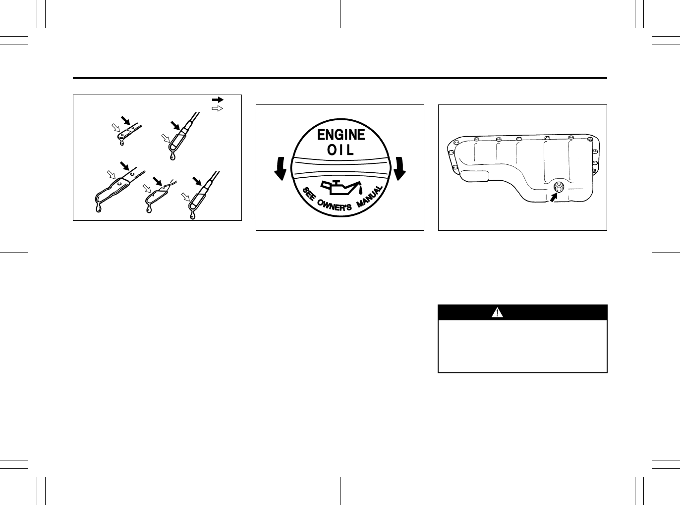
7-12
INSPECTION AND MAINTENANCE
80J23-03E
52D084
The handle of the engine oil dipstick is col-
ored yellow for easy identification.
Pull out the oil dipstick, wipe oil off with a
clean cloth, insert the dipstick all the way
into the engine, then remove it again. The
oil on the stick should be between the
upper and lower limits shown on the stick.
If the oil level indication is near the lower
limit, add enough oil to raise the level to the
upper limit.
Refilling
81A147
Remove the oil filler cap and pour oil slowly
through the filler hole to bring the oil level
to the upper limit on the dipstick. Be careful
not to overfill. Too much oil is almost as
bad as too little oil. After refilling, start the
engine and allow it to idle for about a
minute. Stop the engine, wait about 5 min-
utes and check the oil level again.
Changing Engine Oil and Filter
60G306
Drain the engine oil while the engine is still
warm.
1) Remove the oil filler cap.
2) Place a drain pan under the drain plug.
3) Using a wrench, remove the drain plug
and drain out the engine oil.
EXAMPLE FULL
ADD EXAMPLE
Open Close
WARNING
The engine oil temperature may be
high enough to burn your fingers
when the drain plug is loosened. Wait
until the drain plug is cool enough to
touch with your bare hands.
EXAMPLE
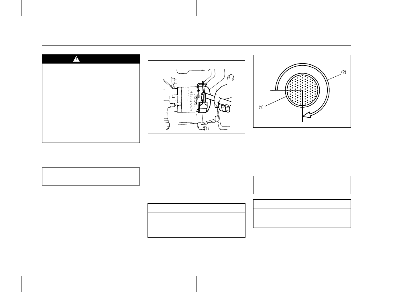
7-13
INSPECTION AND MAINTENANCE
80J23-03E
4) Reinstall the drain plug and gasket.
Tighten the plug with a wrench to the
specified torque.
Replace the Oil Filter
60A198
1) Remove the engine under cover.
2) Using an oil filter wrench, turn the oil fil-
ter counterclockwise and remove it.
3) Using a clean rag, wipe off the mount-
ing surface on the engine where the
new filter will be seated.
4) Smear a little engine oil around the rub-
ber gasket of the new oil filter.
5) Screw on the new filter by hand until the
filter gasket contacts the mounting sur-
face.
54G093
(1) Oil filter
(2) 3/4 turn
6) Tighten the filter 3/4 turn from the point
of contact with the mounting surface (or
to the specified torque) using an oil filter
wrench.
WARNING
New and used oil and solvent can be
hazardous. Children and pets may be
harmed by swallowing new or used
oil or solvent. Repeated, prolonged
contact with used engine oil may
cause [skin] cancer. Brief contact
with used oil or solvent may irritate
skin.
• Keep new and used oil and solvent
away from children and pets.
• Wear a long-sleeve shirt and water-
proof gloves.
• Wash with soap if oil or solvent
contacts your skin.
Tightening torque specification
35 Nm (25.3 lb-ft, 3.5 kg-m)
CAUTION
To tighten the oil filter properly, it is
important to accurately identify the
position at which the filter gasket
first contacts the mounting surface.
EXAMPLE
Tightening torque specification
14 Nm (10.0 lb-ft, 1.4 kg-m)
CAUTION
To prevent oil leakage, make sure
that the oil filter is tight, but do not
overtighten it.
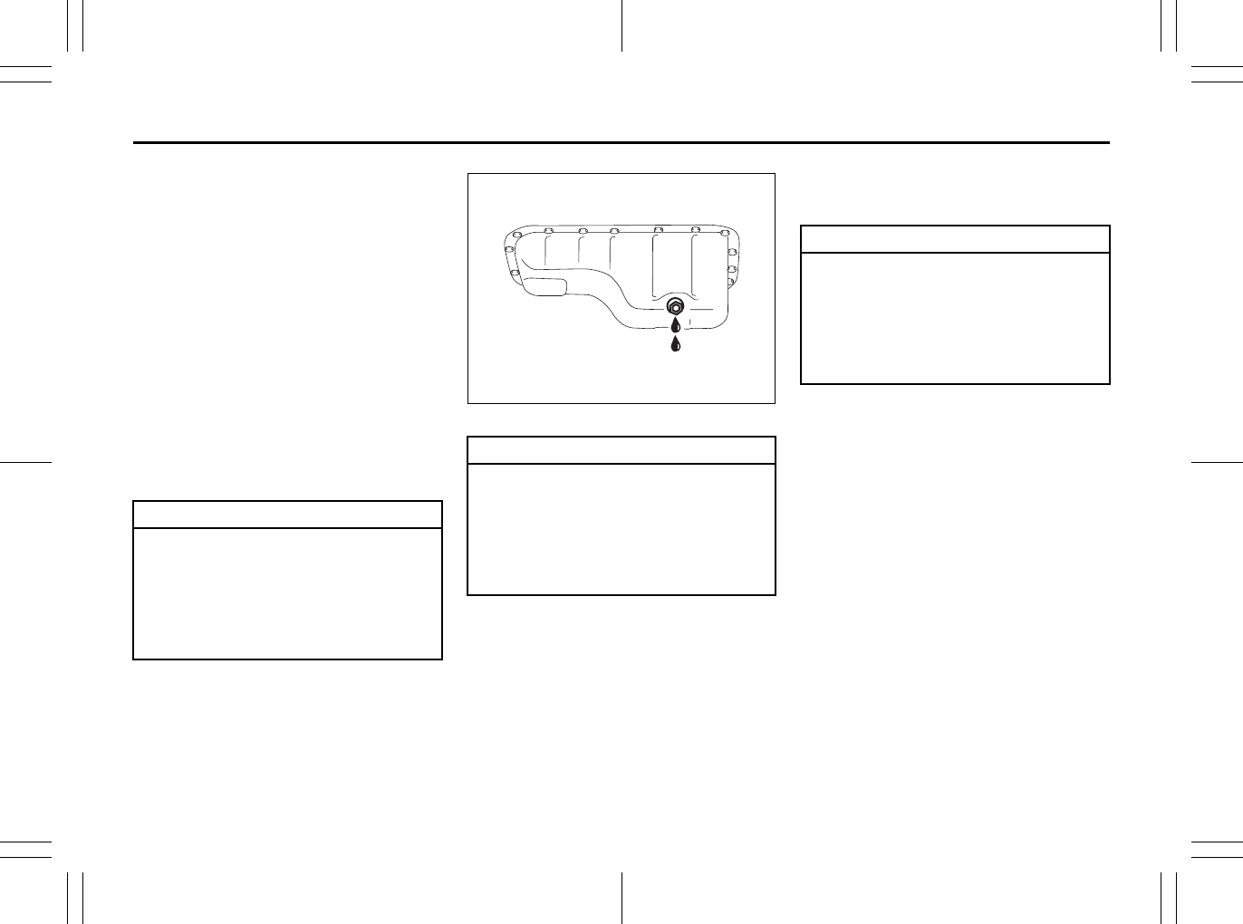
7-14
INSPECTION AND MAINTENANCE
80J23-03E
NOTE:
When it is difficult to remove the oil filter,
we recommend you take your vehicle to
your SUZUKI dealer for oil filter replace-
ment.
Refill with Oil and Check for Leaks
1) Pour oil through the filler hole and
install the filler cap.
For the approximate capacity of the oil,
refer to the “Capacities” item in the
“SPECIFICATIONS” section.
2) Start the engine and look carefully for
leaks at the oil filter and drain plug. Run
the engine at various speeds for at least
5 minutes.
3) Stop the engine and wait about 5 min-
utes. Check the oil level again and add
oil if necessary. Check for leaks again.
80J014
Engine Coolant
Selection of Coolant
To maintain optimum performance and
durability of your engine, use SUZUKI
Genuine Coolant or equivalent.
NOTE:
If you replace the engine coolant other
than the SUZUKI LLC: Super (Blue), follow
the schedule of SUZUKI LLC: Standard
(Green). To see the detail of the mainte-
nance schedule, refer to “Periodic Mainte-
nance Schedule” in this section.
This type of coolant is best for your cooling
system as it:
• Helps maintain proper engine tempera-
ture.
• Gives proper protection against freezing
and boiling.
• Gives proper protection against corro-
sion and rust.
CAUTION
When replacing the oil filter, it is rec-
ommended that you use a genuine
SUZUKI replacement filter. If you use
an after-market filter, make sure it is
of equivalent quality and carefully fol-
low the manufacturer’s instructions
and precautions.
CAUTION
Oil leaks from around the oil filter or
drain plug indicate incorrect installa-
tion or gasket damage. If you find any
leaks or are not sure that the filter
has been properly tightened, have
the vehicle inspected by your SUZUKI
dealer.
EXAMPLE
CAUTION
SUZUKI LLC: Super (Blue) coolant;
SUZUKI LLC: Super (Blue) coolant is
already diluted to the proper percent-
age. Do not dilute with distilled water
additionally. Doing so may result in
the possibility of freezing coolant
and/or overheating.
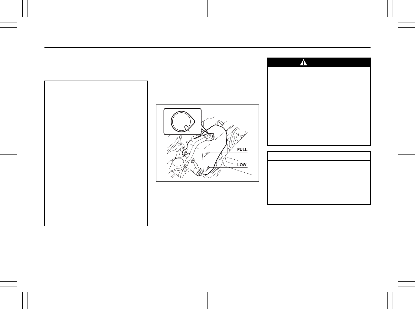
7-15
INSPECTION AND MAINTENANCE
80J23-03E
Failure to use the proper coolant can dam-
age your cooling system. Your authorized
SUZUKI dealer can help you select the
proper coolant.
Coolant Level Check
Check the engine coolant level at the
reserve tank, not at the radiator. With the
engine cool, the engine coolant level
should be between the “FULL” and “LOW”
marks.
Adding Coolant
56KN090
If the engine coolant level is below the
“LOW” mark, more engine coolant should
be added. Remove the reserve tank cap
and add engine coolant until the reserve
tank level reaches the “FULL” mark. Never
fill the reserve tank above the “FULL” mark.
CAUTION
To avoid damaging your cooling sys-
tem:
• Always use a high quality ethylene
glycol base phosphate type coolant
diluted with distilled water at the
correct mixture concentration.
• Make sure that the proper mix is 50/
50 coolant to distilled water and in
no case higher than 70/30. Concen-
trations greater than 70/30 coolant
to distilled water will cause over-
heating conditions.
• Do not use straight coolant nor
plain water (except SUZUKI LLC:
Super (Blue)).
• Do not add extra inhibitors or addi-
tives. They may not be compatible
with your cooling system.
• Do not mix different types of base
coolants. Doing so may result in
accelerated seal wear and/or the
possibility of severe overheating
and extensive engine/CVT damage.
WARNING
Engine coolant is harmful or fatal if
swallowed or inhaled. Do not drink
antifreeze or coolant solution. If swal-
lowed, do not induce vomiting. Imme-
diately contact a poison control
center or a physician. Avoid inhaling
mist or hot vapors; if inhaled, remove
to fresh air. If coolant gets in eyes,
flush eyes with water and seek medi-
cal attention. Wash thoroughly after
handling. Solution can be poisonous
to animals. Keep out of the reach of
children and animals.
CAUTION
SUZUKI LLC: Super (Blue) coolant;
SUZUKI LLC: Super (Blue) coolant is
already diluted to the proper percent-
age. Do not dilute with distilled water
additionally. Doing so may result in
the possibility of freezing coolant
and/or overheating.
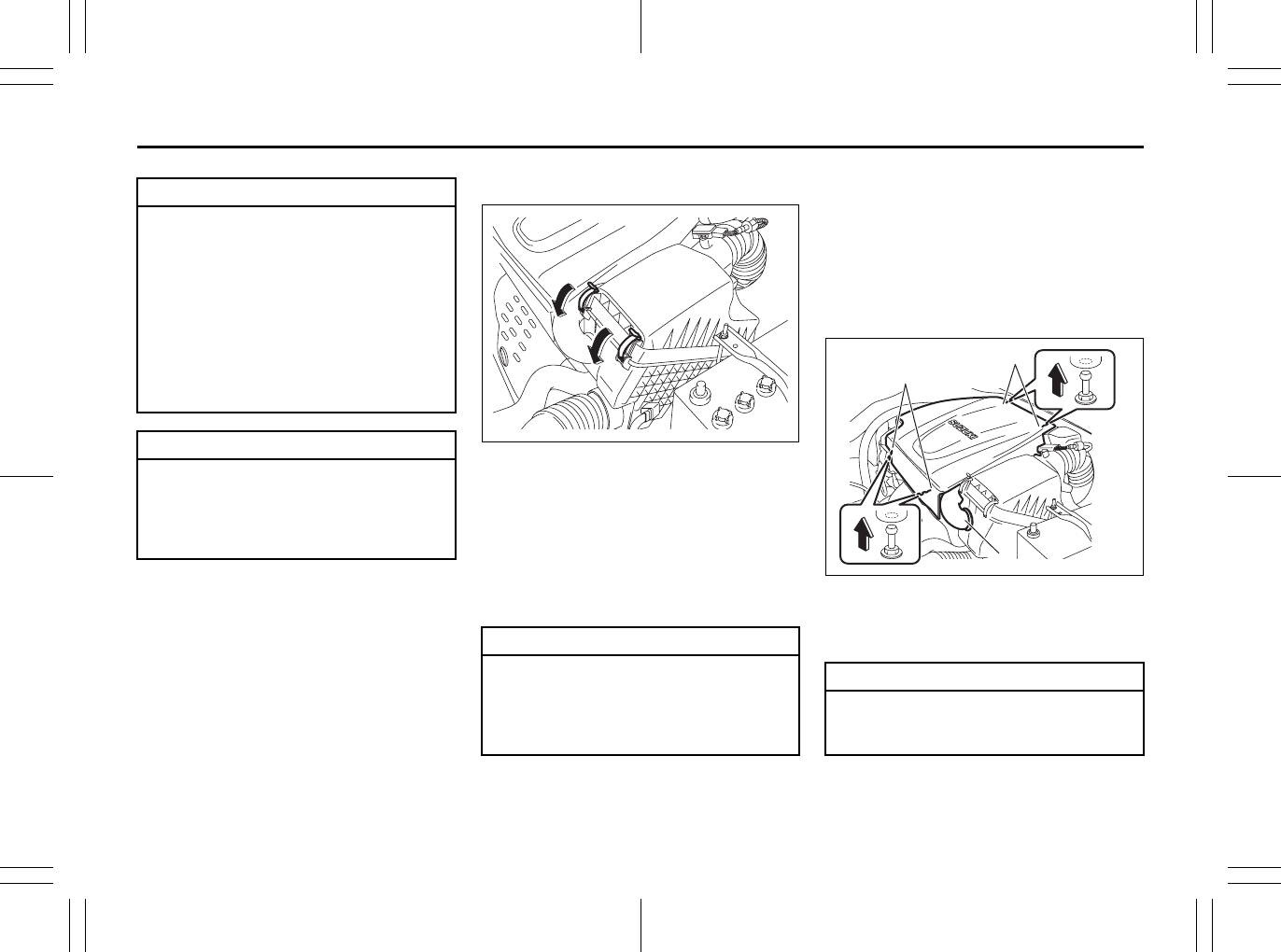
7-16
INSPECTION AND MAINTENANCE
80J23-03E
Coolant Replacement
Since special procedures are required, we
recommend you take your vehicle to your
SUZUKI dealer for coolant replacement.
Air Cleaner
80J2056
If the air cleaner is clogged with dust, there
will be greater intake resistance, resulting
in decreased power output and increased
fuel consumption.
Unclamp the side clamps, and remove the
element from the air cleaner case. If it
appears to be dirty, replace it with a new
one.
Spark Plugs
You should inspect spark plugs periodically
for carbon deposits. When carbon accu-
mulates on a spark plug, a strong spark
may not be produced. Remove carbon
deposits with a wire or pin and adjust the
spark plug gap.
To access the spark plugs,
80J2069
1) Remove the air cleaner inlet hose (1).
Remove the front part (2), then remove
the rear part (3) of the air cleaner case.
CAUTION
SUZUKI LLC: Standard (Green)
coolant;
• The mixture you use should con-
tain 50% concentration of anti-
freeze.
• If the lowest ambient temperature
in your area is expected to be
–35°C (–31°F) or below, use higher
concentrations up to 60% following
the instructions on the antifreeze
container.
CAUTION
When putting the cap on the reser-
voir tank, line up the mark on the cap
and the mark on the tank. Failure to
follow this can result in coolant leak-
age.
CAUTION
The air cleaner element should be
replaced every 50000 km (30000
miles). More frequent replacement is
necessary when you drive under
dusty conditions.
CAUTION
When remove the engine cover, make
sure the cover does not interfere the
vehicle to avoid damage to the cover.
(1)
(2)
(3)
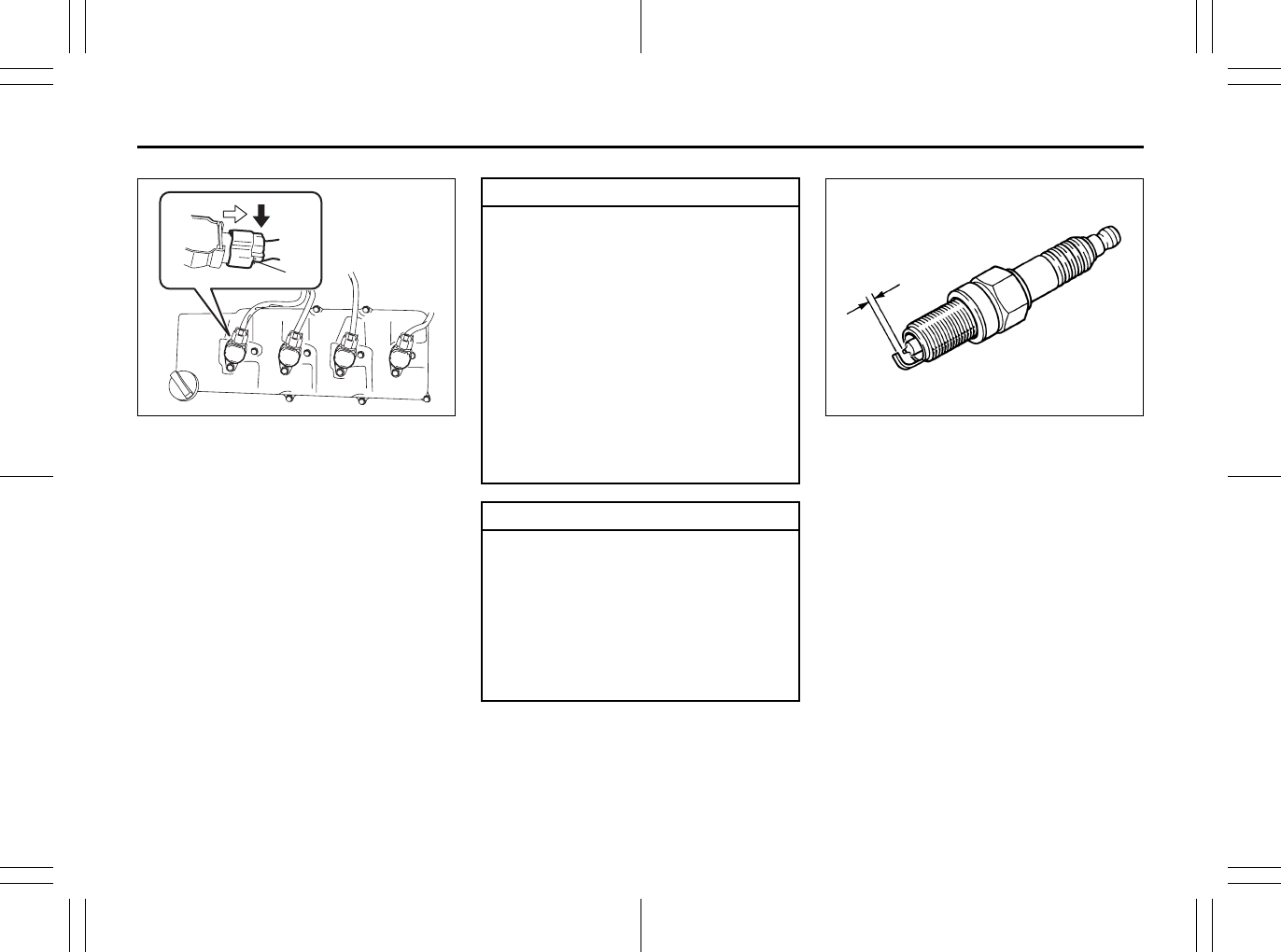
7-17
INSPECTION AND MAINTENANCE
80J23-03E
80J2070
2) Disconnect the coupler (4) while push-
ing the release lever,
3) Remove the bolt, and
4) Pull the ignition coil out.
80G093
(4)
EXAMPLE CAUTION
• When servicing the iridium/plati-
num spark plugs (slender center
electrode type plugs), do not touch
the center electrode, as it is easy to
damage.
• When installing the spark plugs,
screw them in with your fingers to
avoid stripping the threads. Tighten
with a torque wrench to 25 Nm (2.5
kg-m, 18.0 lb-ft). Do not allow con-
taminants to enter the engine
through the spark plug holes when
the plugs are removed.
• Never use spark plugs with the
wrong thread size.
CAUTION
When replacing spark plugs, you
should use the brand and type speci-
fied for your vehicle. For the speci-
fied plugs, refer to the
“SPECIFICATIONS” section at the
end of this book. If you wish to use a
brand of spark plug other than the
specified plugs, consult your SUZUKI
dealer.
1.0 – 1.1 mm
(0.039 – 0.043 in.)
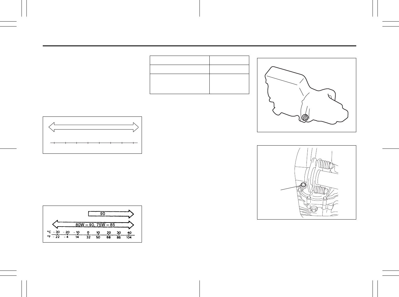
7-18
INSPECTION AND MAINTENANCE
80J23-03E
Gear Oil
Specified Gear Oil
When replacing gear oil, use gear oil with
the appropriate viscosity and grade as
shown in the charts below.
We highly recommend you use:
“SUZUKI GEAR OIL 75W-80” for manual
transaxle gear oil
Manual transaxle (API GL-4)
80J2087
We highly recommend you use:
API GL-5 hypoid gear oil SAE 80W-90 for
rear differential oil (i-AWD) and transfer oil
of CVT model (i-AWD)
Rear differential oil (i-AWD)/Transfer oil
of CVT model (i-AWD)
(API GL-5 Hypoid)
54G096
Manual transaxle
80J2083
Transfer case (i-AWD)
80J007
(1) Oil filler and level plug
C
F
o
o-30
-22
-20
-4
-10
14 32 50 68 86 104
010203040
75W-80, 75W-85, 75W-90
API GRADE
Manual transaxle GL-4
Rear differential oil
(i-AWD)/Transfer oil
(i-AWD CVT)
GL-5 (Hypoid
gear oil)
(1)
EXAMPLE
(1)
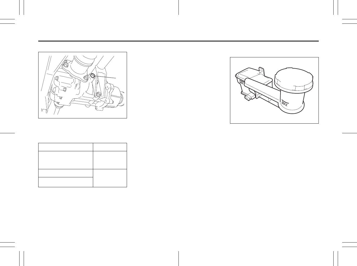
7-19
INSPECTION AND MAINTENANCE
80J23-03E
Rear differential (i-AWD)
80J015
(1) Oil filler and level plug
Tightening torque
Gear Oil Level Check
The manual transaxle, transfer gears (i-
AWD CVT) and rear differential (i-AWD)
are lubricated with gear oil. To check the
gear oil level in any of the above locations,
use the following procedure:
1) Park the vehicle on a level surface. Set
parking brake and stop the engine.
2) Remove the oil filler plug (1).
For the manual transaxle;
3) If gear oil flow from the plug hole, the oil
level is correct. Reinstall the plug.
If gear oil do not flow from the plug
hole, add oil through the filler plug hole
until a little oil flow from the plug hole.
For the transfer and rear differential;
3) Check the inside of the hole with your
finger. If the oil level comes up to the
bottom of the plug hole, the oil level is
correct. If so, reinstall the plug.
4) If the oil level is low, add gear oil
through the filler plug hole (1) until the
oil level reaches the bottom of the filler
hole.
Gear Oil Replacement
Since special procedures, materials and
tools are required, it is recommended that
you trust this job to your authorized
SUZUKI dealer.
Clutch Pedal
80J004
Check the clutch pedal for smooth opera-
tion and clutch fluid level from time to time.
If clutch dragging is felt with the pedal fully
depressed, have the clutch inspected by
your SUZUKI dealer. If the clutch fluid level
is near the “MIN” line, fill it up to the “MAX”
line with SAE J1703 or DOT3 brake fluid.
Oil Filler Plug
Manual transaxle
27 Nm
(19.5 lb-ft)
(2.7 kg-m)
Transfer 23 Nm
(16.6 lb-ft)
(2.3 kg-m)
Rear differential
(1)
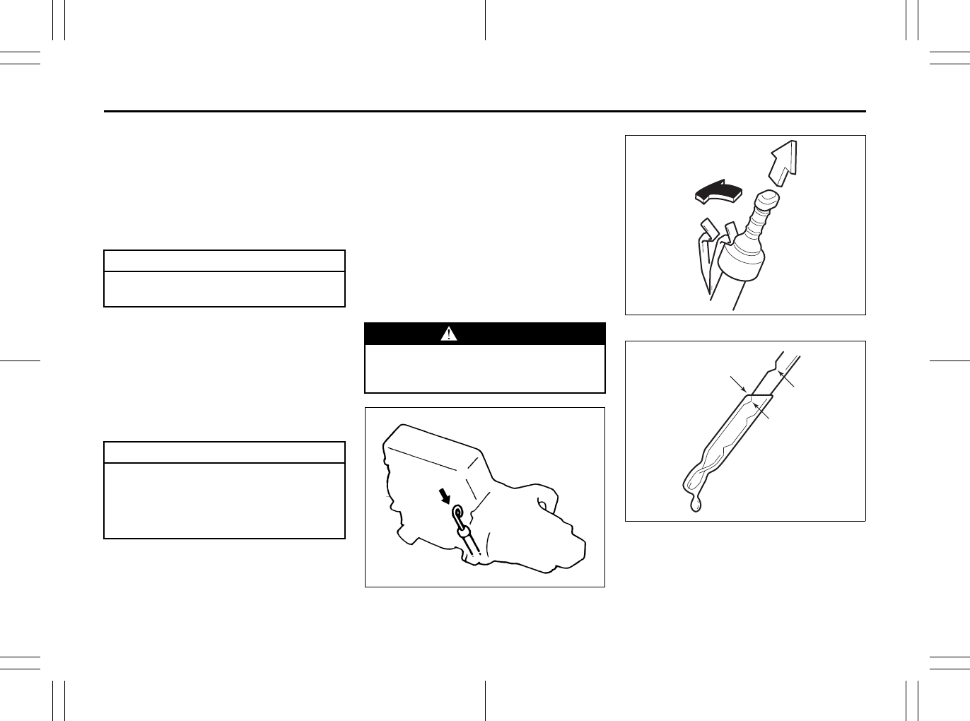
7-20
INSPECTION AND MAINTENANCE
80J23-03E
Continuously Variable
Transaxle (CVT) Fluid
Specified Fluid
Use a CVT fluid SUZUKI CVT FLUID
GREEN-1 or Shell GREEN-1V.
Fluid Level Check
You must check the fluid level with the CVT
fluid at normal operating temperature.
To check the fluid level:
1) To warm up the transaxle fluid, drive the
vehicle or idle the engine until the tem-
perature gauge indicates normal oper-
ating temperature.
2) Then drive for ten more minutes.
NOTE:
Do not check the fluid level if you have just
driven the vehicle for a long time at high
speed, or if you have driven in city traffic in
hot weather. Wait until the fluid cools down
(about 30 minutes), or the fluid level indica-
tion will not be correct.
3) Park your vehicle on level ground.
4) Apply the parking brake and then start
the engine in “P” (Park). Let it idle for
two minutes and keep it running during
the fluid level check.
5) With your foot on the brake pedal, move
the gearshift lever through each gear,
pausing for about three seconds in
each range. Then move it back to the
“P” (Park) position.
75F086
80J2071
80J2072
(1) FULL
(2) LOW
(3) The lowest point = Fluid level
CAUTION
Driving with too much or too little
fluid can damage the transaxle.
CAUTION
Be sure to use the specified CVT
fluid. Using CVT fluid other than
SUZUKI CVT FLUID GREEN-1 or Shell
GREEN-1V may damage the CVT of
your vehicle.
WARNING
Be sure to depress the brake pedal
when moving the gearshift lever, or
the vehicle can move suddenly.
EXAMPLE
EXAMPLE
(2)
H
C
(1)
(3)
EXAMPLE
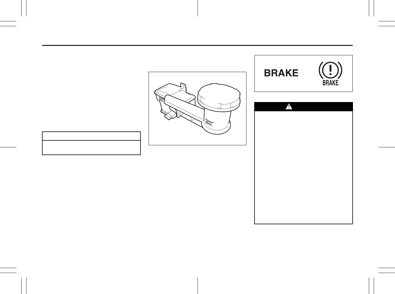
7-21
INSPECTION AND MAINTENANCE
80J23-03E
6) The handle of the CVT fluid dipstick is
colored red or orange for easy identifi-
cation.
Remove the dipstick, clean it and push
it back in until the cap seats. Pull out
the dipstick and read the fluid level.
The fluid level should be between the
two marks in the “HOT” range on the
dipstick.
7) Add just enough specified fluid through
the dipstick hole to fill the transaxle to
the proper level. It takes only 0.6 liters
(1.27 US pt) for CVT to raise the level
from “LOW” to “FULL”.
Deterioration Checking or Chang-
ing Oil
Since special procedures, materials and
tools are required to check the deteriora-
tion of CVT oil or change, it is recom-
mended that you trust this job to your
authorized SUZUKI dealer.
Brakes
Brake Fluid
80J004
Check the brake fluid level by looking at
the reservoir in the engine compartment.
Check that the fluid level is between the
“MAX” and “MIN” lines. If the brake fluid
level is near the “MIN” line, fill it up to the
“MAX” line with SAE J1703 or DOT3 brake
fluid.
80J104
CAUTION
After checking or adding oil, be sure
to insert the dipstick securely.
EXAMPLE
WARNING
Failure to follow the guidelines below
can result in personal injury or seri-
ous damage to the brake system.
• If the brake fluid in the reservoir
drops below a certain level, the
brake warning light on the instru-
ment panel will come on (the
engine must be running with the
parking brake fully disengaged.)
Should the light come on, immedi-
ately ask your SUZUKI dealer to
inspect the brake system.
• A rapid fluid loss indicates a leak in
the brake system which should be
inspected by your SUZUKI dealer
immediately.
• Brake fluid can harm your eyes and
damage painted surfaces. Use cau-
tion when refilling the reservoir.
(Continued)
or
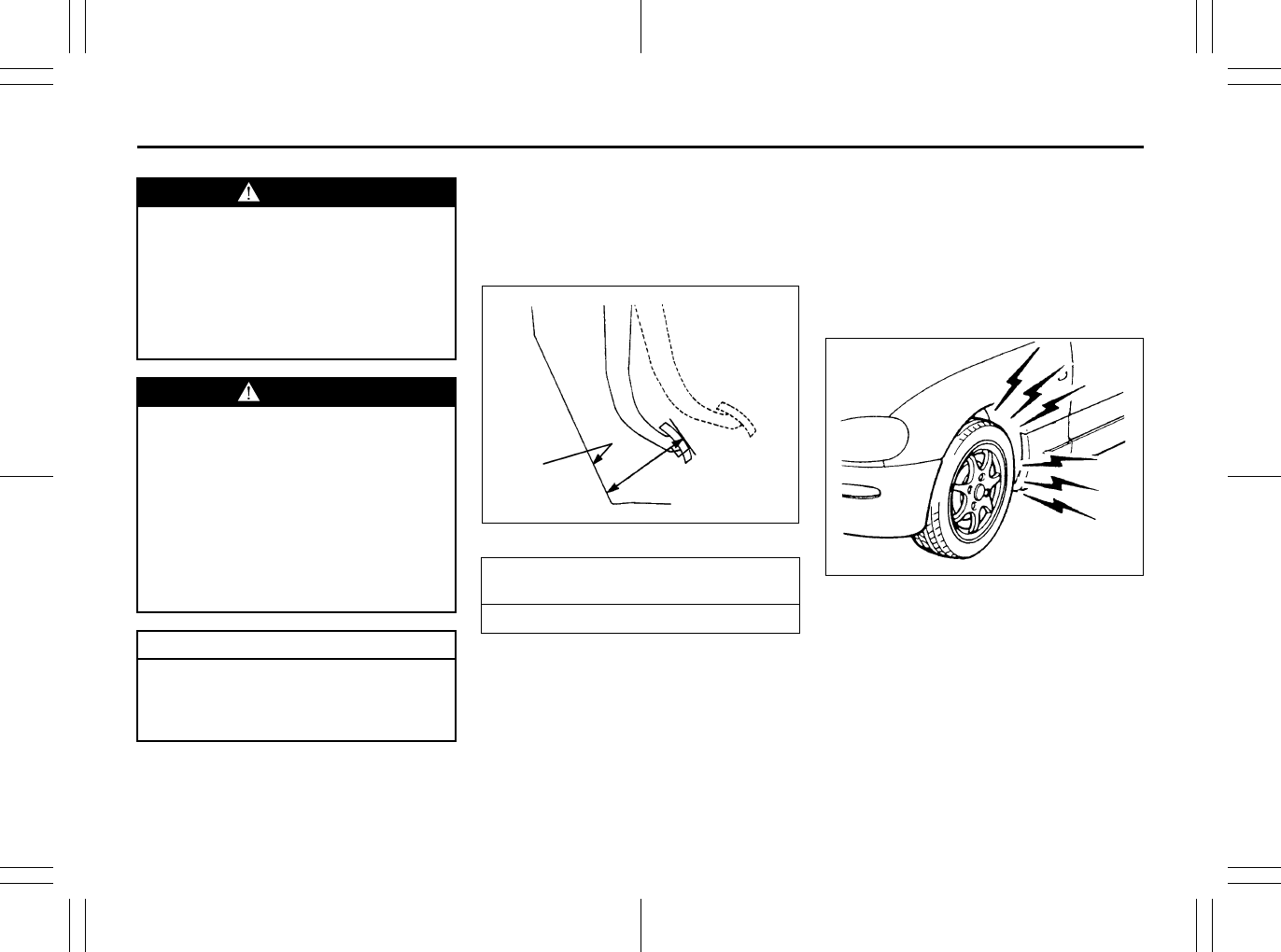
7-22
INSPECTION AND MAINTENANCE
80J23-03E
NOTE:
With disc brakes, the fluid level can be
expected to gradually fall as the brake
pads wear.
Brake Pedal
65D345
With the engine running and the parking
brake set, measure the distance between
the brake pedal and floor carpet when the
pedal is depressed with approximately 300
N (66 lbs, 30 kg) of force. The minimum
distance required is as specified. Since
your vehicle’s brake system is self-adjust-
ing, there is no need for pedal adjustment.
If the pedal to floor carpet distance as
measured above is less than the minimum
distance required, have your vehicle
inspected by your SUZUKI dealer.
NOTE:
When measuring the distance between the
brake pedal and floor wall, be sure not to
include the floor mat or rubber on the floor
wall in your measurement.
60G104
WARNING
(Continued)
• Do not use any fluid other than SAE
J1703 or DOT3 brake fluid. Do not
use reclaimed fluid or fluid that has
been stored in old or open contain-
ers. It is essential that foreign parti-
cles and other liquids are kept out
of the brake fluid reservoir.
WARNING
Brake fluid is harmful or fatal if swal-
lowed, and harmful if it comes in con-
tact with skin or eyes. If swallowed,
do not induce vomiting. Immediately
contact a poison control center or a
physician. If brake fluid gets in eyes,
flush eyes with water and seek medi-
cal attention. Wash thoroughly after
handling. Solution can be poisonous
to animals. Keep out of the reach of
children and animals.
CAUTION
The brake fluid should be replaced
according to the maintenance sched-
ule. Have the brake fluid replaced by
your SUZUKI dealer.
Pedal to floor carpet minimum distance
“a”
40 mm (1.6 in.)
“a”
Floor carpet
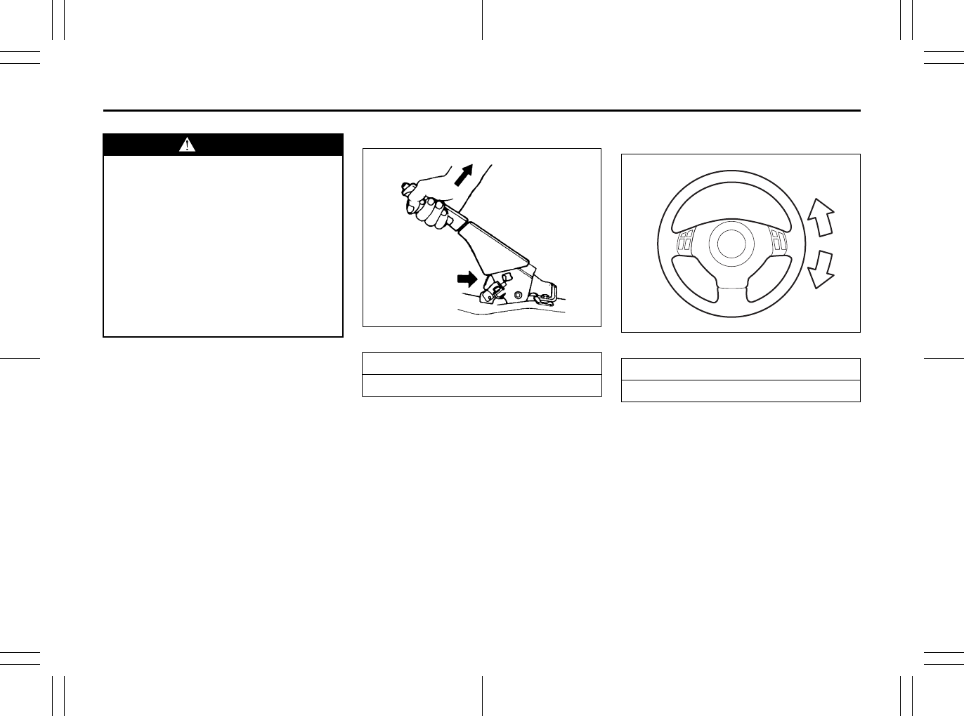
7-23
INSPECTION AND MAINTENANCE
80J23-03E
Parking Brake Lever
60A226
Check the parking brake for proper adjust-
ment by counting the number of clicks
made by the ratchet teeth as you slowly
pull up on the parking brake lever to the
point of full engagement. The parking
brake lever should stop between the speci-
fied ratchet teeth and the rear wheels
should be securely locked. If the parking
brake is not properly adjusted or the
brakes drag after the lever has been fully
released, have the parking brake inspected
and/or adjusted by your SUZUKI dealer.
Steering Wheel
80J005
Check the play of the steering wheel by
gently turning it from left to right and mea-
suring the distance that it moves before
you feel slight resistance. The play should
be between the specified values. Check
that the steering wheel turns easily and
smoothly without rattling by turning it all the
way to the right and to the left while driving
very slowly in an open area. If the amount
of free play is outside the specification or
you find anything else to be wrong, an
inspection must be performed by your
SUZUKI dealer.
WARNING
If you experience any of the following
problems with your vehicle’s brake
system, have the vehicle inspected
immediately by your SUZUKI dealer.
• Poor braking performance
• Uneven braking (brakes not work-
ing uniformly on all wheels.)
• Excessive pedal travel
• Brake dragging
• Excessive noise
• (Except ABS equipped vehicle)
Pedal pulsation (pedal pulsates
when pressed for braking.)
Ratchet tooth specification “b”
4th – 9th
200 N (44 lbs, 20 kg)
“b”
Steering wheel play “c”
0 – 30 mm (0.0 – 1.2 in.)
“c”
EXAMPLE
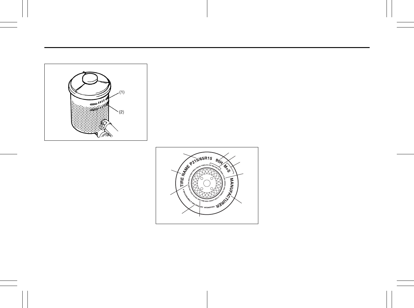
7-24
INSPECTION AND MAINTENANCE
80J23-03E
Power Steering (if equipped)
54G225
(1) UPPER
(2) LOWER
Check the steering box case, vane pump
and hose connections for leaks or damage.
Power Steering Fluid
Check the fluid level by looking at the res-
ervoir in the engine compartment when the
fluid is cold (about room temperature).
Check that the fluid level is between the (1)
and (2) lines. If the fluid level is near the (2)
line, fill it up to the (1) line with an auto-
matic transaxle fluid equivalent to ATF
DEXRON®-II (Esso JWS 2326) or
DEXRON®-III. Do not overfill.
Tires
For safe operation of your vehicle, it is
important that the tires be the correct
type and size, in good condition, and
properly inflated. Be sure to follow the
requirements and recommendations in
this section.
Tire Sidewall Labeling
Useful information about a tire is
molded into its sidewall. The example
below shows a typical passenger car
tire.
Typical Passenger Car Tire Sidewall
67D027
A. Tire Manufacturer
The name of the tire manufacturer
is shown here.
B. Tire Name/Model
The tire name or model is shown
here.
C. Tire Size
The tire size code is a combina-
tion of letters and numbers used
to define a particular tire’s width,
height, aspect ratio, construction
type, and service description. See
the “Tire Size” explanation later in
this section for more details.
D. U.S. DOT Tire Identification Num-
ber
The Department of Transportation
(DOT) marking indicates that the
tire is in compliance with the U.S.
Department of Transportation
Motor Vehicle Safety Standards.
The letters and numbers following
the DOT marking is the Tire Iden-
tification Number (TIN). The TIN
identifies the tire manufacturer
and plant, tire size, and date the
tire was manufactured.
E. Uniform Tire Quality Grading
(UTQG)
Tire manufacturers are required to
grade tires based on three perfor-
mance factors: treadwear, traction
and temperature resistance.
Refer to the “Uniform Tire Quality
Grading” section for more details.
EXAMPLE
A
H
B
G
E
F
D
J
I
C
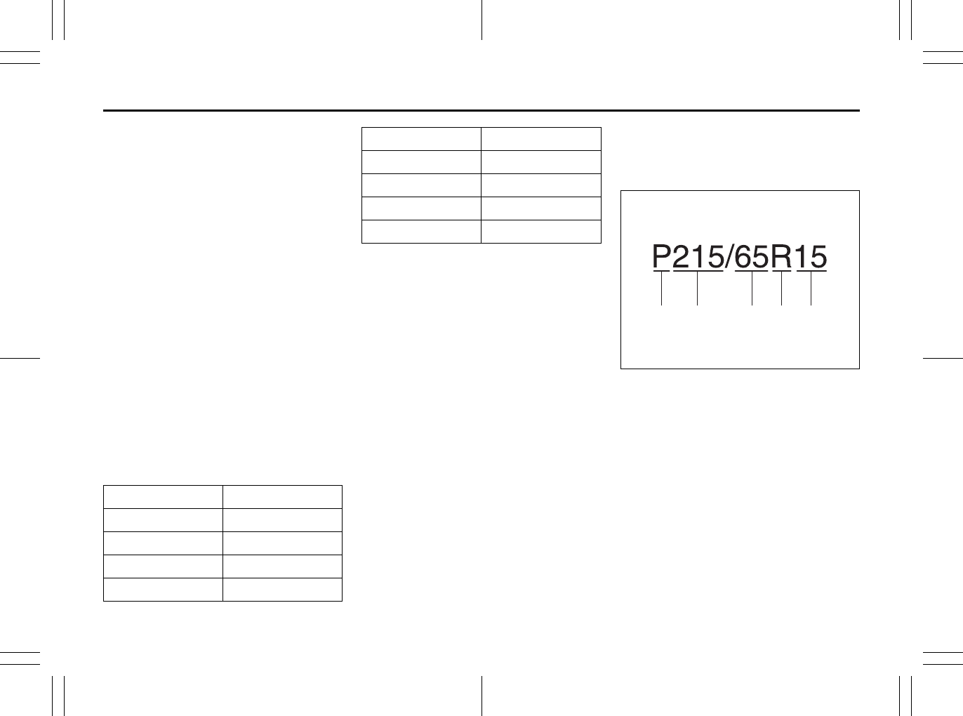
7-25
INSPECTION AND MAINTENANCE
80J23-03E
F. Load Rating
Load rating is the maximum
weight a tire is designed to sup-
port in normal service.
G. Max Inflation Pressure
Max inflation pressure is the max-
imum inflation pressure a tire is
designed for.
H. Tire Ply Material
These tire markings describe the
type of cord and number of plies
in the sidewall and under the
tread.
I. Load Index and Speed Rating
The two- or three-digit number is
the tire’s load index, the maximum
load a tire can carry at the speed
indicated by its speed symbol at
the maximum inflation pressure.
The higher the number is, the
greater the load carrying capacity.
The letter symbol denotes the
speed at which a tire is designed
to be driven for extended periods
of time. (Ratings are listed below.)
*The letters ZR may be used on tires
with a maximum speed capability over
149 mph and will always be used on
tires with a maximum speed capability
over 186 mph.
J. M+S Marking
This marking indicates the tire
has some mud and snow capabili-
ties and is designed for all-season
use.
Tire Size
The following illustration shows an
example of a typical passenger car tire
size.
67D028
A. Tire Type
This letter code indicates the pri-
mary intended use of the tire. The
letter “P” identifies a tire primarily
intended for use on a passenger
vehicle.
B. Tire Width
This three-digit number indicates
the tire section width in millime-
ters from sidewall to sidewall.
C. Aspect Ratio
This two-digit number represents
the tire section height divided by
the tire section width.
Letter Rating Speed Rating
Q99 mph
R 106 mph
S 112 mph
T 118 mph
U 124 mph
H 130 mph
V 149 mph
W 168 mph*
Y 186 mph*
A B C D E
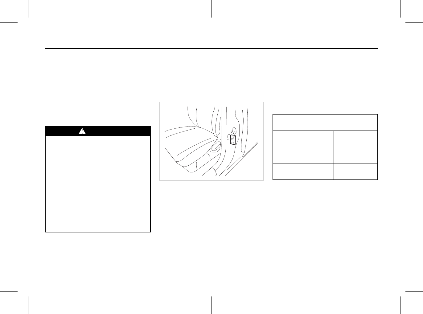
7-26
INSPECTION AND MAINTENANCE
80J23-03E
D. Construction Code
This letter code is used to indicate
the type of ply construction in the
tire. The letter “R” means radial
ply tire construction, the letter “D”
means diagonal or bias ply con-
struction, and the letter “B” means
belted-bias ply construction.
E. Rim Diameter
This two-digit number is the wheel
or rim diameter in inches.
Tire Inflation Pressure
Tire inflation pressure should be
checked when the tire is cold. “Cold
tire inflation pressure” is the pressure
in a tire that has been driven less than
1 mile (1.6 km) or has been standing
for three hours or more.
80JS025
The front and rear tire pressure speci-
fications for your vehicle are shown
below and are listed on the Tire and
Loading Information Label, which is
located on the driver’s door lock pillar.
The Tire and Loading Information
Label contains the following informa-
tion:
• Seating Capacity
• Maximum Allowed Combined
Weight of Occupants and Cargo
• Original Tire Size
• Recommended Cold Tire Inflation
Pressure of Original Tires
• Size of Compact Spare Tire
• Recommended Cold Tire Inflation
Pressure of Compact Spare Tire
WARNING
Your SUZUKI is equipped with
tires which are all the same type
and size. This is important to
ensure proper steering and han-
dling of the vehicle. Never mix
tires of different size or type on
the four wheels of your vehicle.
Mixing tires could cause you to
lose control while driving which
may lead to an accident. The size
and type of tires used should be
only those approved by SUZUKI
Motor Corporation as standard or
optional equipment for your vehi-
cle.
Recommended Cold Tire Inflation
Pressures
Front Tires 230 kPa
33 psi
Rear Tires 230 kPa
33 psi
Compact Spare Tire 420 kPa
60 psi
7-27
INSPECTION AND MAINTENANCE
80J23-03E
NOTE:
The tire inflation pressure will change
due to changes in atmospheric pres-
sure, temperature or tire temperature
when driving. To reduce the chance that
the low tire pressure warning light will
come on due to normal changes in tem-
perature and atmospheric pressure, it is
important to check and adjust the tire
pressures when the tires are cold. Tires
that appear to be at the specified pres-
sure when checked after driving, when
the tires are warm, could have pressure
below the specification when the tires
cool down. Also, tires that are inflated to
the specified pressure in a warm
garage may have pressure below the
specification when the vehicle is driven
outside in very cold temperature. If you
adjust the tire pressure in a garage that
is warmer than the outside tempera-
ture, you should add 1 psi to the recom-
mended cold tire inflation pressure for
every 10°F difference between garage
temperature and outside temperature.
Measuring Air Pressure
Use the following steps to achieve
proper tire inflation:
1) Identify the recommended tire pres-
sure on the vehicle’s Tire and Load-
ing Information Label or in the
owner’s manual.
2) Remove the valve cap from the tire
valve stem.
3) Using a reliable pressure gauge,
measure the tire inflation pressure
by pressing the tire gauge firmly
onto the valve to get a pressure
measurement. Remember that
inflation pressures should be
checked when the tires are “cold”,
meaning before they have been
driven one mile or after sitting for
three hours or more allowing the tire
to cool to ambient air temperature.
4) If the air pressure is too high, slowly
release the air by pressing on the
tire valve stem with the edge of the
tire gauge until you reach the cor-
rect pressure.
5) If the air pressure is too low, fill the
tire with air at a service station until
it reaches the recommended pres-
sure.
6) Make sure all tires have the same
air pressure (unless the owner’s
manual indicates otherwise).
WARNING
• Air pressures should be
checked when the tires are cold
or you may get inaccurate read-
ings.
• Check the inflation pressure
from time to time while inflating
the tire gradually, until the spec-
ified pressure is obtained.
• Never underinflate or overin-
flate the tires.
Underinflation can cause
unusual handling characteristics
or can cause the rim to slip on
the tire bead, resulting in an acci-
dent or damage to the tire or rim.
Underinflation can also cause
tires to overheat, leading to tire
failure.
Overinflation can cause the tire
to burst, resulting in personal
injury.
Overinflation can also cause
unusual handling characteristics
which may result in an accident.
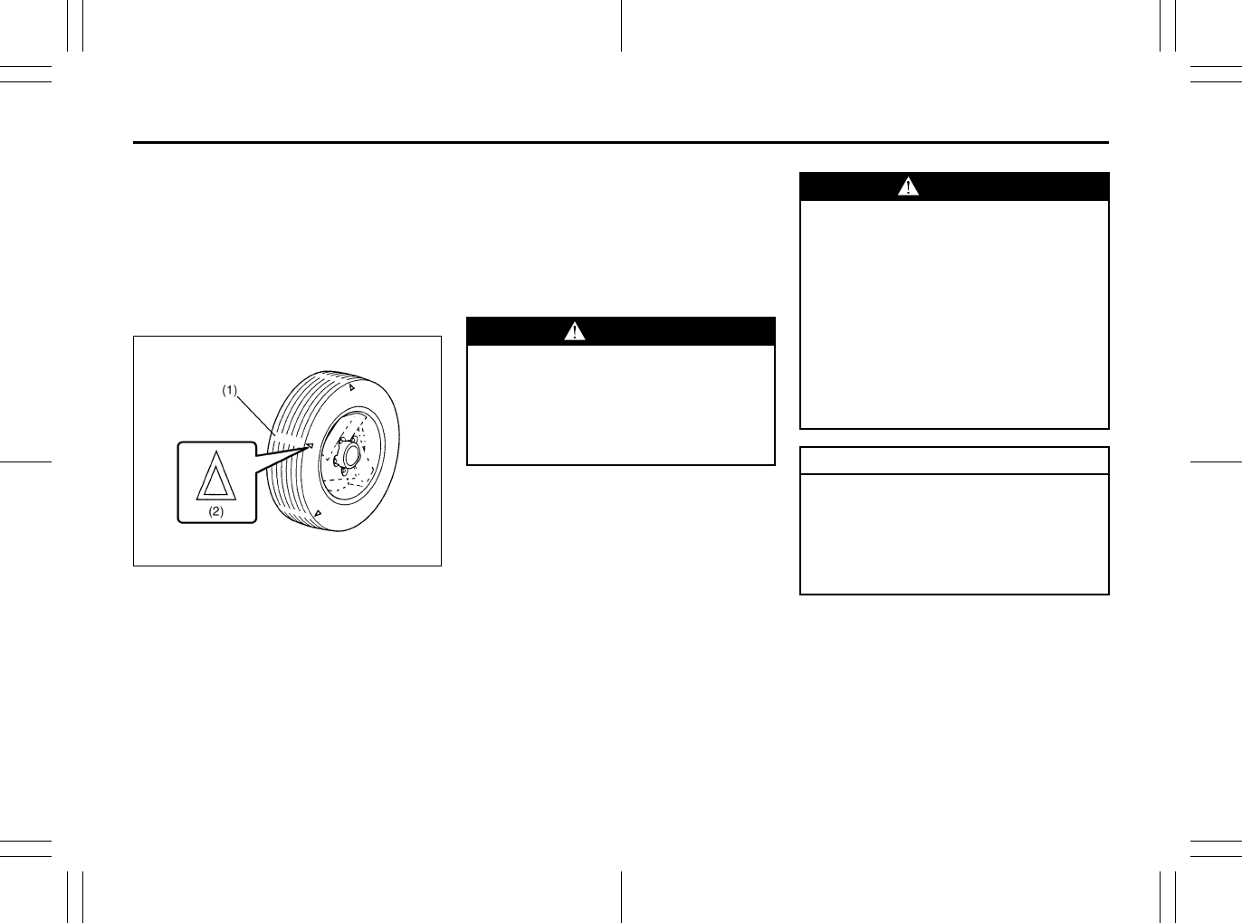
7-28
INSPECTION AND MAINTENANCE
80J23-03E
Tire Inspection
Inspect your vehicle’s tires at least
once a month by performing the fol-
lowing checks:
1) Measure the air pressure with a tire
gauge. Adjust the pressure if nec-
essary. Remember to check the
spare tire, too. Refer to the “Mea-
suring Air Pressure” section.
54G136
(1) Tread wear indicator
(2) Indicator location mark
2) Check that the depth of the tread
groove is more than 1.6 mm (0.06
in.). To help you check this, the tires
have molded-in tread wear indica-
tors in the grooves. When the indi-
cators appear on the tread surface,
the remaining depth of the tread is
1.6 mm (0.06 in.) or less and the
tire should be replaced.
3) Check for abnormal wear, cracks
and damage. Any tires with cracks
or other damage should be
replaced. If any tires show abnor-
mal wear, have them inspected by
your SUZUKI dealer.
4) Check for loose wheel nuts.
5) Check that there are no nails,
stones or other objects sticking into
the tires.
WARNING
Hitting curbs and running over
rocks can damage tires and affect
wheel alignment. Be sure to have
tires and wheel alignment
checked periodically by your
SUZUKI dealer.
WARNING
Your SUZUKI is equipped with
tires which are all the same type
and size. This is important to
ensure proper steering and han-
dling of the vehicle. Never mix
tires of different size or type on
the four wheels of your vehicle.
The size and type of tires used
should be only those approved by
SUZUKI Motor Corporation as
standard or optional equipment
for your vehicle.
CAUTION
For intelligent All Wheel Drive (i-
AWD) models, replacing a tire
with one of a different size, or
using different brands among the
four tires can result in damage to
the drive train.
7-29
INSPECTION AND MAINTENANCE
80J23-03E
Uniform Tire Quality Grading
The U.S. National Highway Traffic
Safety Administration has developed a
grading system for evaluating the per-
formance of passenger car tires. The
following information will help you
understand the grading system, which
applies to vehicles sold in the U.S.
Consult your SUZUKI dealer or tire
retailer for help in choosing the correct
replacement tires for your vehicle.
Quality grades can be found where
applicable on the tire sidewall between
tread shoulder and maximum section
width. For example:
Treadwear 200 Traction AA Tempera-
ture A
DOT Quality Grades
Treadwear
Traction AA A B C
Temperature A B C
All Passenger Car Tires Must Conform
To Federal Safety Requirements in
Addition To These Grades
Treadwear
The treadwear grade is a comparative
rating based on the wear rate of the tire
when tested under controlled condi-
tions on a specified government test
course. For example, a tire graded 150
would wear one and one-half (1 1/2)
times as well on the government course
as a tire graded 100. The relative per-
formance of tires depends upon the
actual conditions of their use, however
and may depart significantly from the
norm due to variations in driving habits,
service practices and differences in
road characteristics and climate.
Traction – AA, A, B, C
The traction grades, from highest to
lowest, are AA, A, B and C. Those
grades represent the tire’s ability to
stop on wet pavement as measured
under controlled conditions on speci-
fied government test surfaces of
asphalt and concrete. A tire marked C
may have poor traction performance.
WARNING
Replacing the wheels and tires
equipped on your vehicle with
certain combinations of aftermar-
ket wheels and tires can signifi-
cantly change the steering and
handling characteristics of your
vehicle. Oversized tires may also
rub against the fender over
bumps, causing vehicle damage
or tire failure. Therefore, use only
those wheel and tire combina-
tions approved by SUZUKI Motor
Corporation as standard or
optional equipment for your vehi-
cle. For information regarding the
specified tires, refer to the Tire
Information Label located on the
driver’s side door pillar or the
“SPECIFICATIONS” section.
CAUTION
Replacing the original tires with
tires of a different size may result
in false speedometer or odometer
readings. Check with your
SUZUKI dealer before purchas-
ing replacement tires that differ in
size from the original tires.
WARNING
The traction grade assigned to
this tire is based on straight-
ahead braking traction tests, and
does not include acceleration,
cornering, hydroplaning or peak
traction characteristics.
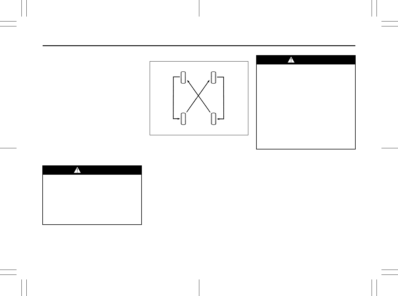
7-30
INSPECTION AND MAINTENANCE
80J23-03E
Temperature – A, B, C
The temperature grades are A (the
highest), B and C, representing the
tire’s resistance to the generation of
heat and its ability to dissipate heat
when tested under controlled condi-
tions on a specified indoor laboratory
test wheel. Sustained high tempera-
ture can cause the material of the tire
to degenerate and reduce tire life, and
excessive temperature can lead to
sudden tire failure. The grade C corre-
sponds to a level of performance
which all passenger car tires must
meet under the Federal Motor Vehicle
Safety Standard No. 109. Grades B
and A represent higher levels of per-
formance on the laboratory test wheel
than the minimum required by law.
Tire Rotation
54G114
To avoid uneven wear of your tires and
to prolong their life, rotate the tires as
illustrated. Tires should be rotated as
recommended in the periodic mainte-
nance schedule. After rotation, adjust
front and rear tire pressures to the
specification listed on your vehicle’s
Tire and Loading Information Label.
WARNING
The temperature grade for this
tire is established for a tire that is
properly inflated and not over-
loaded. Excessive speed, under-
inflation or excessive loading,
either separately or in combina-
tion, can cause heat buildup and
possible tire failure.
WARNING
Rust or dirt on a wheel, or on the
parts to which it is fastened, can
make wheel nuts become loose
after a time. The wheel could
come off and cause an accident.
When you change a wheel,
remove any rust or dirt from
places where the wheel attaches
to the vehicle. In an emergency,
you can use a cloth or a paper
towel to do this; but be sure to
use a scraper or wire brush later,
if you need to, to get all the rust
or dirt off.
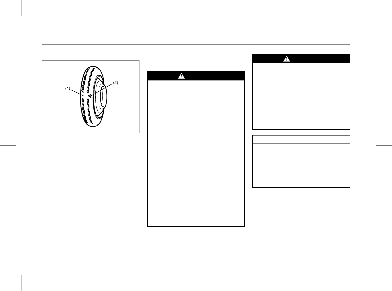
7-31
INSPECTION AND MAINTENANCE
80J23-03E
Compact Spare Tire (if equipped)
54G115
(1) Wear indicator
(2) Indicator location mark
Your vehicle comes equipped with the
compact spare tire. The compact
spare is designed to save space in
your storage area, and its lighter
weight makes it easier to install if a flat
tire occurs. It is only intended for tem-
porary emergency use, until the con-
ventional tire can be repaired or
replaced. The inflation pressure of the
compact spare tire should be checked
at least monthly. Use a quality pocket-
type inflation pressure gauge and set
at 420 kPa (60 psi). At the same time,
check that the tire is stored securely. If
it is not, tighten it.
Note that two or more compact spare
tires should not be used on one vehi-
cle simultaneously.
WARNING
The compact spare tire and wheel
are intended for temporary emer-
gency use only. Continuous use
of this spare can result in tire fail-
ure and loss of control. Always
observe these precautions when
using this spare:
• Your vehicle will handle differ-
ently with this temporary spare.
• Do not exceed 80 km/h (50 mph)
speed.
• Replace this spare with a stan-
dard tire and wheel as soon as
possible.
• Use of this spare will reduce
ground clearance.
• Recommended air pressure for
this spare is 420 kPa (60 psi).
• Do not use tire chains on the
compact spare. If you must use
tire chains, rearrange the
wheels so standard tires and
wheels are fitted to the front
axle.
(Continued)
WARNING
(Continued)
• The compact spare tire has a
much shorter tread life than the
conventional tires on your vehi-
cle. Replace the tire as soon as
the tread wear indicator
appears.
• When replacing the compact
tire, use a replacement tire with
the exact same size and con-
struction.
CAUTION
For intelligent All Wheel Drive (i-
AWD) models, driving with an
underinflated compact spare tire
or over 80 km/h (50 mph) while
using a compact spare tire can
result in damage to the drive
train.

7-32
INSPECTION AND MAINTENANCE
80J23-03E
Snow Tires
Your vehicle is equipped with all-sea-
son tires which are designed for use in
summer and most winter conditions.
For improved traction in severe winter
conditions, SUZUKI recommends
mounting radial snow tires on all four
wheels. Snow tires must be the same
size as the standard tires. Also be sure
to use the tires of the same type and
brand on all four wheels of your vehi-
cle.
GLOSSARY OF TIRE TERMINOL-
OGY
Accessory Weight – the combined
weight (in excess of those standard
items which may be replaced) of CVT,
power steering, power brakes, power
windows, power seats, radio, and
heater, to the extent that these items
are available as factory-installed
equipment (whether installed or not).
Cold Tire Inflation Pressure – the pres-
sure in a tire that has been driven less
than 1 mile or has been standing for
three hours or more.
Curb Weight – the weight of a motor
vehicle with standard equipment
including the maximum capacity of
fuel, oil, and coolant, and, if so
equipped, air conditioning and addi-
tional weight optional engine.
Intended Outboard Sidewall – (1) the
sidewall that contains a whitewall,
bears white lettering or bears manu-
facturer, brand, and/or model name
molding that is higher or deeper than
the same molding on the other side-
wall of the tire, or (2) the outward fac-
ing sidewall of an asymmetrical tire
that has a particular side that must
always face outward when mounted
on a vehicle.
Maximum Inflation Pressure – the max-
imum cold inflation pressure a tire is
designed to support in normal service.
Maximum Loaded Vehicle Weight –
the sum of curb weight, accessory
weight, vehicle capacity weight (total
load capacity), and production options
weight.
Normal Occupant Weight – 68 kilo-
grams times the number of occupants
specified in the second column of
Table 1 (shown below).
Occupant distribution – distribution of
occupants in a vehicle as specified in
the third column of Table 1 (shown
below).
Production Options Weight – the com-
bined weight of those installed regular
production options weighing over 2.3
kilograms in excess of those standard
items which they replace, not previ-
ously considered in curb weight or
accessory weight, including heavy
duty brakes, ride levelers, roof rack,
heavy duty battery, and special trim.
Recommended Inflation Pressure –
the cold tire inflation pressure recom-
mended by a manufacturer.
Rim – metal support for a tire or tire
and tube assembly upon which the tire
beads are seated.

7-33
INSPECTION AND MAINTENANCE
80J23-03E
Vehicle Capacity Weight – the rated
cargo and luggage load plus 68 kilo-
grams (150 lbs) times the vehicle’s
designated seating capacity.
Vehicle Maximum Load on the Tire –
the load on an individual tire that is
determined by distributing to each axle
its share of the maximum loaded vehi-
cle weight and dividing by two.
Vehicle Normal Load on the Tire – the
load on an individual tire that is deter-
mined by distributing to each axle its
share of the curb weight, accessory
weight, and normal occupant weight
(distributed in accordance with Table 1
shown below) and dividing by 2.
TABLE 1 – Occupant Loading and
Distribution For Vehicle Normal
Load For Various Designated Seat-
ing Capacities
Vehicle Loading
Your vehicle was designed for specific
load capacities. The load capacities of
your vehicle are indicated by the
Gross Vehicle Weight Rating (GVWR),
the Gross Axle Weight Rating (GAWR,
front and rear), and the total load
capacity, the seating capacity, and the
cargo load capacity. The GVWR and
GAWR (front and rear) are listed on
the Safety Certification Label which is
located below the driver’s side door
latch striker. The total load capacity
and seating capacity are listed on the
Tire and Loading Information Label
which is located below the Safety Cer-
tification Label. The cargo load capac-
ity can be determined as described
below.
Cargo Load Capacity – Maximum
weight of cargo and luggage that the
vehicle can safely carry. Cargo load
capacity is the difference between the
total load capacity of the vehicle and
the total combined weight of all vehicle
occupants. Refer to “Steps for Deter-
mining Correct Load Limit” for details
on how to determine cargo load
capacity.
GVWR – Maximum permissible overall
weight of the fully loaded vehicle
(including all the occupants, accesso-
ries and cargo plus the trailer tongue
weight if towing a trailer).
GAWR – (Front and Rear) Maximum
permissible weight on an individual
axle.
Seating Capacity – Maximum number
of occupants the vehicle is designed to
carry.
NOTE:
Even though the number of occupants
is within the seating capacity, you still
must make sure that you do not
exceed the total load capacity of the
vehicle.
Total Load Capacity – Maximum per-
missible weight a vehicle can carry
including the weight of all the occu-
pants, accessories, cargo, plus trailer
tongue weight (if towing a trailer).
The weight of any accessories already
installed on your vehicle at the time of
purchase, or that you or the dealer
install after purchase, must be sub-
tracted from the total load capacity to
determine how much capacity remains
available for occupants, cargo, and
trailer tongue weight (if towing a
Designated
seating
capacity,
number of
occupants
Vehicle nor-
mal load,
number of
occupants
Occupant
distribution
in a nor-
mally loaded
vehicle
2 through 4 2 2 in front
5 through 10
3
2 in front,
1 in second
seat
7-34
INSPECTION AND MAINTENANCE
80J23-03E
trailer). Contact your dealer for further
information.
Actual weight of the loaded vehicle
and actual loads at the front and rear
axles can only be determined by
weighing the vehicle using a vehicle
scale. To measure the weight and
load, try making your vehicle to a high-
way weighing station, shipping com-
pany or inspection station for trucks,
etc. Compare these weights to the
GVWR and GAWR (front and rear)
listed on the Safety Certification Label.
If the gross vehicle weight or the load
on either axle exceeds these ratings,
you must remove enough weight to
bring the load down to the rated
capacity.
Steps for Determining Correct Load
Limit
1) Locate the statement “The com-
bined weight of occupants and
cargo should never exceed XXX kg
or XXX lbs” on your vehicle’s plac-
ard.
2) Determine the combined weight of
the driver and passengers that will
be riding in your vehicle.
3) Subtract the combined weight of
the driver and passengers from
XXX kg or XXX lbs.
4) The resulting figure equals the
available amount of cargo and lug-
gage load capacity. For example, if
the “XXX” amount equals 1400 lbs
and there will be five 150 lb passen-
gers in your vehicle, the amount of
available cargo and luggage load
capacity is 650 lbs (1400 – 750 (5 x
150) = 650 lbs).
5) Determine the combined weight of
luggage and cargo being loaded on
the vehicle. That weight may not
safely exceed the available cargo
and luggage load capacity calcu-
lated in Step 4.
6) If your vehicle will be towing a
trailer, load from your trailer will be
transferred to your vehicle. Consult
this manual to determine how this
reduces the available cargo and lug-
gage load capacity of your vehicle.
WARNING
Never overload your vehicle. Over-
loading your vehicle can cause
damage to your tires and lead to
poor steering and braking which
can result in an accident. The
gross vehicle weight (sum of the
weights of the loaded vehicle,
driver and passengers) must
never exceed the Gross Vehicle
Weight Rating (GVWR) listed on
the Safety Certification Label. In
addition, never distribute a load so
that the weight on either the front
or rear axle exceeds the Gross
Axle Weight Rating (GAWR) listed
on the Safety Certification Label.
WARNING
• Always distribute cargo evenly.
• To avoid personal injury or
damage to your vehicle, always
secure cargo to prevent it from
shifting if the vehicle moves
suddenly.
• Place heavier objects on the
floor and as far forward in the
cargo area as possible. Never
pile cargo higher than the top of
the seatbacks.
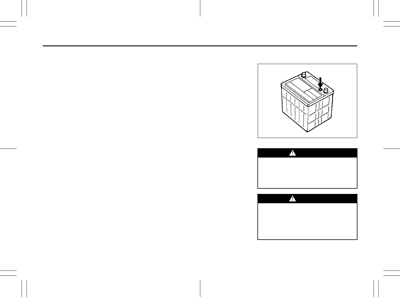
7-35
INSPECTION AND MAINTENANCE
80J23-03E
Vehicle Loading Example
As an example, suppose that the Tire
and Loading Information label on your
vehicle indicates that your vehicle’s
total load capacity is 950 lbs. If you
were to drive your vehicle with one
passenger, and the total combined
weight of you and your passenger was
350 lbs, then the cargo and luggage
capacity of your vehicle would be 600
lbs (950 – 350 = 600 lbs).
If you later added 2 more passengers,
having a combined weight of 325 lbs,
the cargo and luggage capacity of
your vehicle would be reduced from
600 lbs to 275 lbs (600 – 325 = 275
lbs). As you can see, as the number
and combined weight of vehicle occu-
pants increase, the vehicle’s cargo
and luggage capacity decreases.
Suppose again, that you were to take
a trip in your vehicle with the same
three passengers described above,
and you decided to tow a trailer having
a trailer tongue weight of 75 lbs. The
cargo and luggage capacity would be
reduced again, to 200 lbs (275 – 75 =
200 lbs).
Determining Compatibility of Tire
and Vehicle Load Limits
The tires on your vehicle, when they
are inflated to the recommended tire
inflation pressure, have a load-carry-
ing capacity that is greater than the
load that will be on the tires when the
vehicle is at its GVWR or GAWR limit.
Never use replacement tires that have
a load-carrying capacity less than the
original tires on your vehicle. Tire load-
carrying capacity information is
molded into the tire sidewall typically
shown as “Max. Load”. Use of replace-
ment tires with a lower load-carrying
capacity than the original tires, or fail-
ure to keep the tires inflated to recom-
mended tire pressure, may reduce the
GVWR or GAWR limit of your vehicle.
NOTE:
Use of replacement tires with a higher
load-carrying capacity than the origi-
nal tires, or using a tire inflation pres-
sure higher than the recommended
tire inflation pressure, will not increase
the GVWR or GAWR limit of your vehi-
cle.
Battery
60A269
WARNING
Batteries produce flammable hydro-
gen gas. Keep flames and sparks
away from the battery or an explosion
may occur. Never smoke when work-
ing near the battery.
WARNING
When checking or servicing the bat-
tery, disconnect the negative cable.
Be careful not to cause a short circuit
by allowing metal objects to contact
the battery posts and the vehicle at
the same time.
EXAMPLE
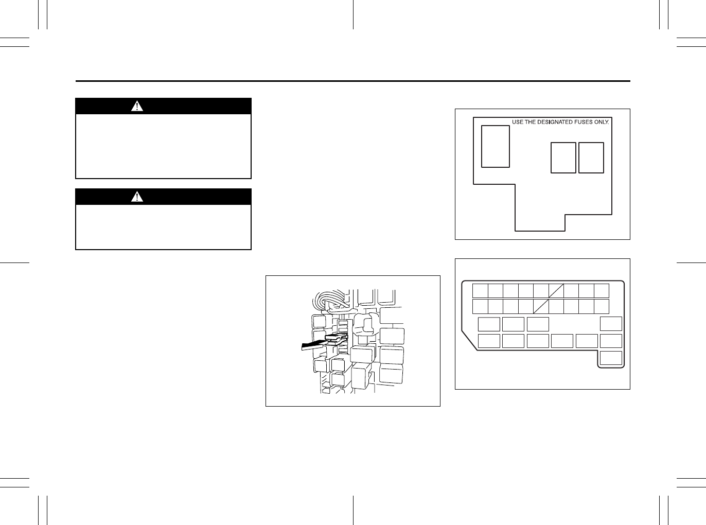
7-36
INSPECTION AND MAINTENANCE
80J23-03E
Your vehicle is equipped with a battery that
requires infrequent maintenance. You will
never have to add water. You should, how-
ever, periodically check the battery, battery
terminals and battery hold-down bracket
for corrosion. Remove corrosion using a
stiff brush and ammonia mixed with water,
or baking soda mixed with water. After
removing corrosion, rinse with clean water.
The test indicator on the top of the battery
provides information on the condition of
the battery.
If your vehicle is not going to be driven for
a month or longer, disconnect the cable
from the negative terminal of the battery to
help prevent discharge.
Fuses
Your vehicle has three types of fuses, as
described below:
Main Fuse – The main fuse takes current
directly from the battery.
Primary Fuses – These fuses are between
the main fuse and individual fuses, and are
for electrical load groups.
Individual Fuses – These fuses are for indi-
vidual electrical circuits.
For details on protected circuits, refer to
the “Fuses and Protected Circuits” section
in this manual.
To remove a fuse, use the fuse puller pro-
vided in the fuse box.
63J095
Fuses in the Engine Compartment
80J051
80J052
WARNING
To avoid harm to yourself or damage
to your vehicle or battery, follow the
jump starting instructions in the
“EMERGENCY SERVICE” section of
this manual if it is necessary to jump
start your vehicle.
WARNING
Battery posts, terminals and related
accessories contain lead and lead
compounds. Wash hands after han-
dling.
(1)
(2) (3)
(28)
(27)(26)(25)
(6) (7) (9) (11)
(15) (16) (17) (18) (19)
(24)
(8)(4) (5) (10)
(22)(21)
(23)
(20)
(12) (13) (14)
(30)
(29)
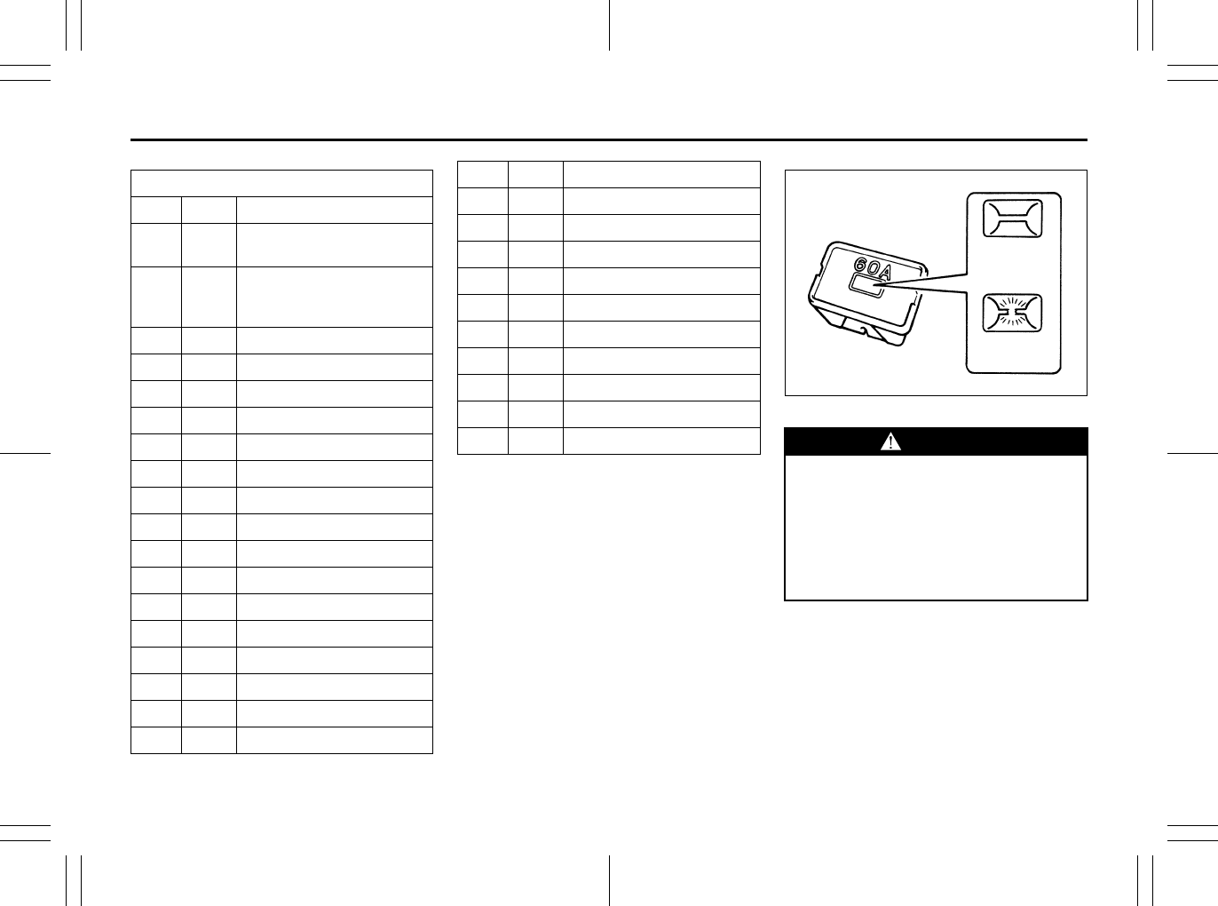
7-37
INSPECTION AND MAINTENANCE
80J23-03E
The main fuse, primary fuses and some of
the individual fuses are located in the
engine compartment. If the main fuse
blows, no electrical component will func-
tion. If a primary fuse blows, no electrical
component in the corresponding load
group will function. When replacing the
main fuse, a primary fuse or an individual
fuse, use a genuine SUZUKI replacement.
To remove a fuse, use the fuse puller pro-
vided in the fuse box. The amperage of
each fuse is shown in the back of the fuse
box cover.
60A243
NOTE:
Make sure that the fuse box always carries
spare fuses.
MAIN FUSE / PRIMARY FUSE
(1) 80A All electric load
(2) 50A Power window, Ignition,
Wiper, Starter
(3) 50A
Tail light, Rear defogger,
Door lock, Hazard/Horn,
Dome
(4) – Blank
(5) – Blank
(6) 15A Head light (Right) fuse
(7) 15A Head light (Left) fuse
(8) 20A Front fog light fuse
(9) – Blank
(10) 40A ABS motor fuse
(11) 30A Radiator fan fuse
(12) 30A ABS solenoid fuse
(13) 30A Starting motor fuse
(14) 50A Ignition switch fuse
(15) 30A Blower fan fuse
(16) 20A Air compressor fuse
(17) 15A Throttle motor fuse
(18) 15A Automatic transaxle fuse
(19) 15A Fuel injection fuse
(20) – Automatic transaxle relay
(21) – Air compressor relay
(22) – Fuel pump relay
(23) – Condenser fan relay
(24) – Front fog light relay
(25) – Throttle motor relay
(26) – FI MAIN relay
(27) – Starting motor relay
(28) – Radiator fan relay
(29) – Radiator fan relay 2
(30) – Radiator fan relay 3 WARNING
If the main fuse or a primary fuse
blows, be sure to have your vehicle
inspected by an authorized SUZUKI
dealer. Always use a genuine SUZUKI
replacement. Never use a substitute
such as a wire even for a temporary
fix, or extensive electrical damage
and a fire can result.
BLOWN
OK
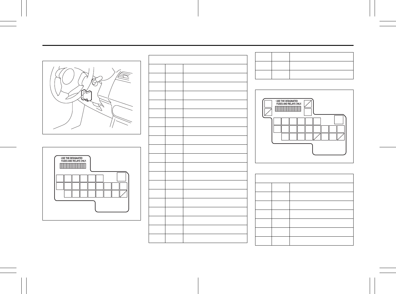
7-38
INSPECTION AND MAINTENANCE
80J23-03E
Fuses under the Dash Board
79J093
SX4
80J053
SX4 SEDAN
80JC003
(1) (2) (3) (4) (5) (6)
(8) (9) (10) (11) (12) (13) (14) (15) (16)
(18)(17) (19) (20)(21) (22) (23)
(7)
MAIN FUSE / PRIMARY FUSE
(1) 15A Rear wiper
(2) 15A Ignition coil
(3) 10A Back-up light
(4) 10A Meter
(5) 15A Accessory
(6) 15A Accessory 2
(7) 30A Power window
(8) 30A Wiper
(9) 10A IG1 SIG
(10) 15A Air bag
(11) 10A Anti-lock brake system
(12) 15A 4WD
(13) 10A Stop light
(14) 20A Door lock
(15) 10A Rear fog light
(16) 10A ST SIG
(17) 15A Seat heater
(18) 10A IG 2 SIG
(19) 10A Tail light
(20) 15A Dome
(21) 30A Rear defogger
(22) 15A Horn / Hazard
(23) – Blank
MAIN FUSE / PRIMARY FUSE
(1) 15A Rear wiper
(2) 15A Ignition coil
(3) 10A Back-up light
(4) 10A Meter
(5) 15A Accessory
(6) 15A Accessory 2
(7) 30A Power window
(1) (2) (3) (4) (5) (6)
(8) (9) (10) (11) (12) (13)
(21)
(24)
(14) (15) (16)
(18)(17) (19) (20) (22) (23)
(7)
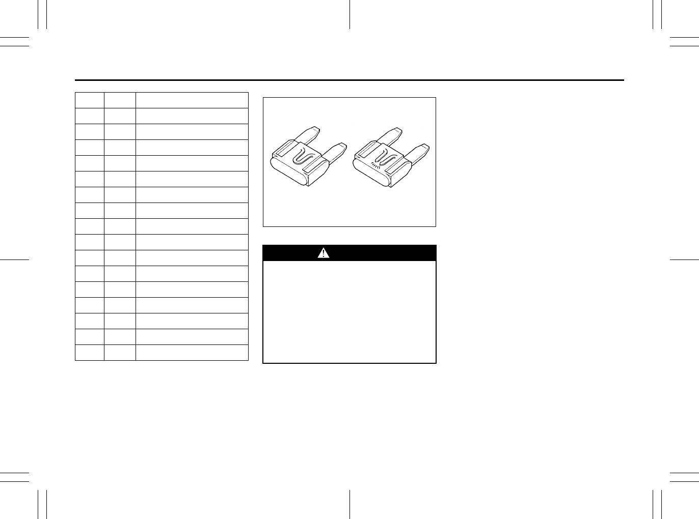
7-39
INSPECTION AND MAINTENANCE
80J23-03E
The fuses are also located under the
driver’s side of the dashboard. Remove the
fuse box cover by pulling it off. The amper-
age of each fuse is shown on the top of the
fuse box cover.
65D046
Headlight Aiming
Since special procedures are required, we
recommend you take your vehicle to your
SUZUKI dealer for headlight alignment.
(8) 30A Wiper
(9) 10A IG1 SIG
(10) 15A Air bag
(11) 10A Anti-lock brake system
(12) – Blank
(13) 10A Stop light
(14) 20A Door lock
(15) 10A Rear fog light
(16) 10A ST SIG
(17) 15A Seat heater
(18) 10A IG 2 SIG
(19) 10A Tail light
(20) 15A Dome
(21) 30A Rear defogger
(22) 15A Horn / Hazard
(23) – Blank
(24) 30A Rear defogger
WARNING
Always be sure to replace a blown
fuse with a fuse of the correct amper-
age. Never use a substitute such as
aluminum foil or wire to replace a
blown fuse. If you replace a fuse and
the new one blows in a short period
of time, you may have a major electri-
cal problem. Have your vehicle
inspected immediately by your
SUZUKI dealer.
BLOWNOK
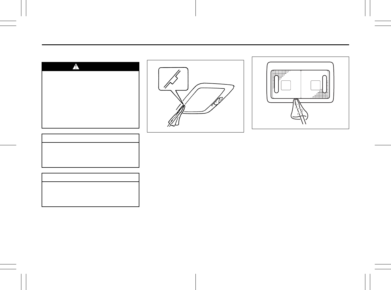
7-40
INSPECTION AND MAINTENANCE
80J23-03E
Bulb Replacement
NOTE:
If it is difficult to replace headlight bulbs or
position light bulbs due to under-hood
components trust this job to your dealer.
Center Interior Light (if equipped)
60G115
Pull down the lens by using a flat blade
screwdriver covered with a soft cloth as
shown. To install it, simply push it back in.
The bulb can be removed by simply pulling
it out. When replacing the bulb, make sure
that the contact springs are holding the
bulb securely.
Spot light
80JM068
Pull down the lens by using a flat blade
screwdriver covered with a soft cloth as
shown. To install it, simply push it back in.
WARNING
• Light bulbs can be hot enough to
burn your finger right after being
turned off. This is true especially
for halogen headlight bulbs.
Replace the bulbs after they
become cool enough.
• The headlight bulbs are filled with
pressurized halogen gas. They can
burst and injure you if they are hit
or dropped. Handle them carefully.
CAUTION
The oils from your skin may cause a
halogen bulb to overheat and burst
when the lights are on. Grasp a new
bulb with a clean cloth.
CAUTION
Frequent replacement of a bulb indi-
cates the need for an inspection of
the electrical system. This should be
carried out by your SUZUKI dealer.
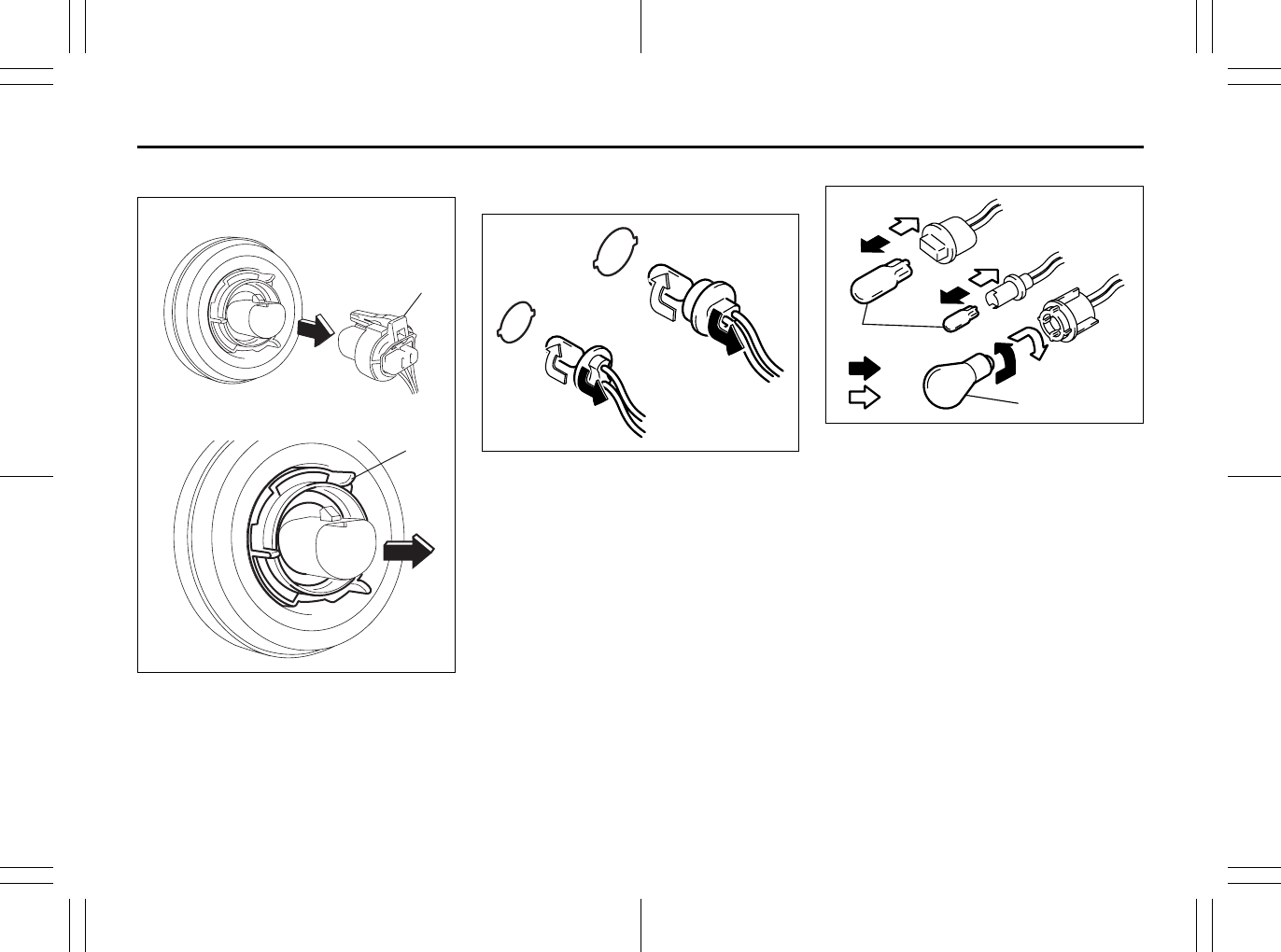
7-41
INSPECTION AND MAINTENANCE
80J23-03E
Headlights
80J2084
Open the engine food. Disconnect the cou-
pler (1). Then remove the socket cover (2)
and replace the bulb. Install a new bulb in
the reverse order of removal.
Other General Lights
Bulb holder
54G123
(1) Removal
(2) Installation
To remove a bulb holder from a light hous-
ing, turn the holder counterclockwise and
pull it out. To install the holder, push the
holder in and turn it clockwise.
Bulb
54G124
(3) Removal
(4) Installation
There are two types of bulb, “Full glass
type” (1) and “Glass/metal type” (2).
To remove and install a full glass type bulb
(1), simply pull out or push in the bulb.
To remove a glass metal type bulb (2) from
a bulb holder, push in the bulb and turn it
counterclockwise. To install a new bulb,
push it in and turn it clockwise.
You can access the individual bulb or bulb
holders as follows.
(1)
(2)
(1)
(1)
(2)
(2)
EXAMPLE
(1)
(2)
(3)
(4)
EXAMPLE
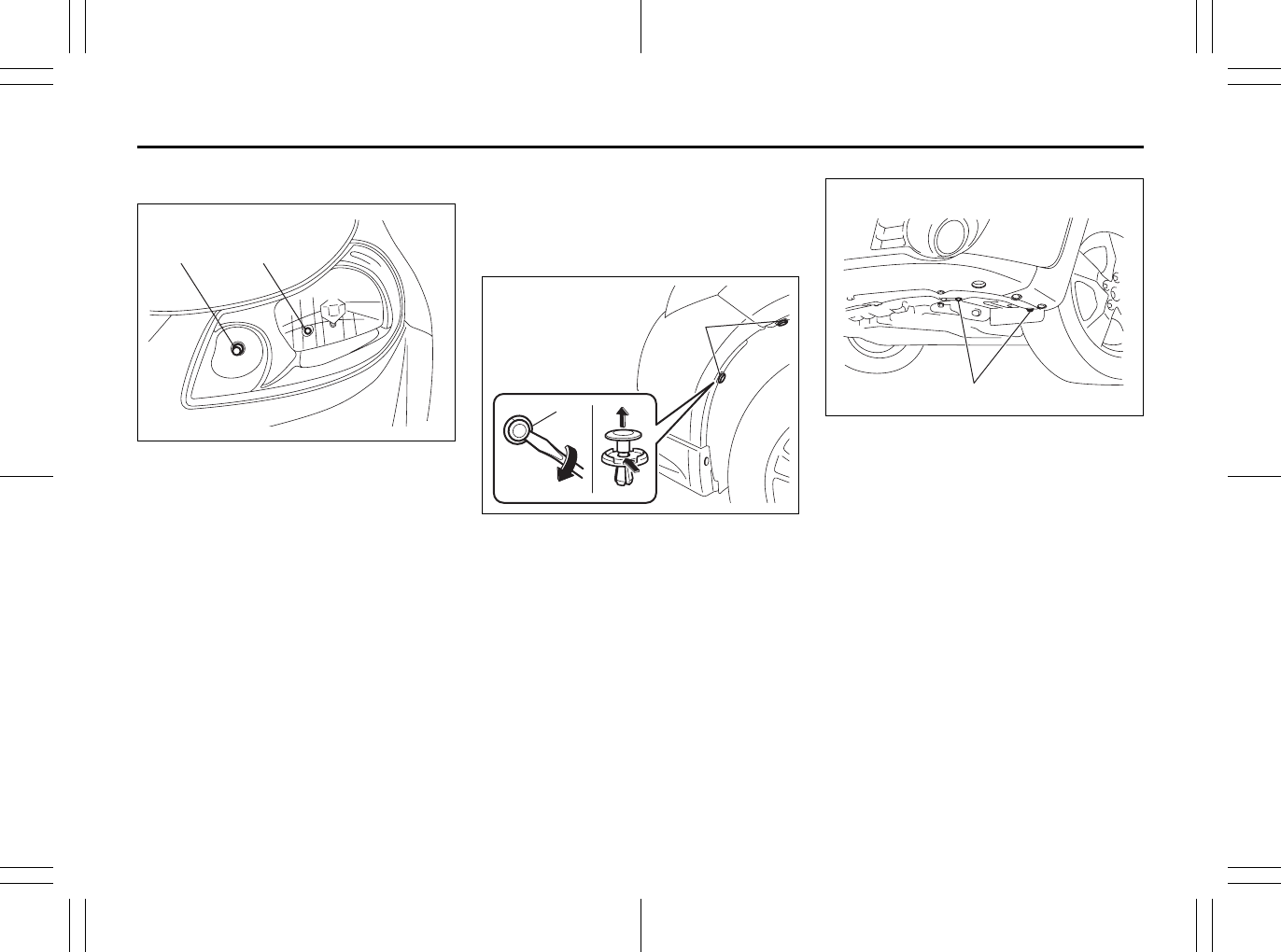
7-42
INSPECTION AND MAINTENANCE
80J23-03E
Front turn signal light (1)
Front position light (2)
80JM123
Front fog light (if equipped)
1) Start the engine. Turn the steering
wheel to the opposite side of the replac-
ing fog light to replace the bulb easily.
Then turn off the engine.
80JM114
2) Insert a flat blade screwdriver into the
hole (2) and remove the clips (1) by
twist the driver as shown in the illustra-
tion.
80JM115
3) Remove the bolts (3).
(1) (2)
(1)
(2)
EXAMPLE
(
3
)
EXAMPLE
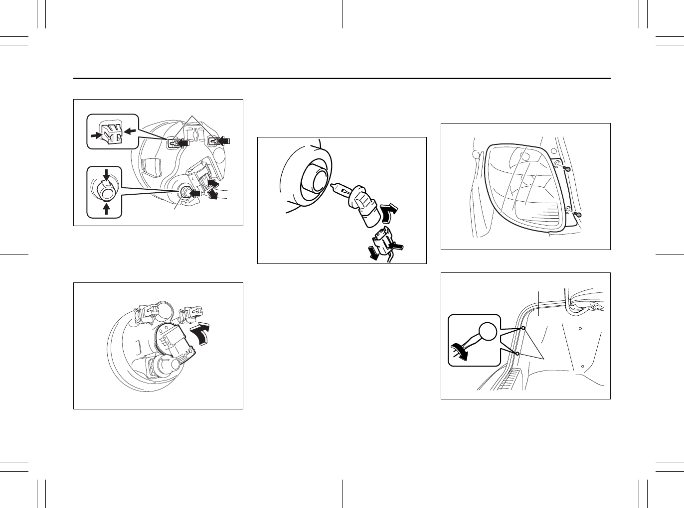
7-43
INSPECTION AND MAINTENANCE
80J23-03E
SX4
80JM116
4) Open the fender cover. Disconnect the
coupler by pushing the lock release.
Pinch both side of the clips (4) and (5),
and push them in.
80JM117
5) Remove the front fog light. Turn the
bulb holder counterclockwise and
remove it.
SX4 SEDAN
80JM071
4) Open the fender cover. Disconnect the
coupler with pushing the lock release.
Turn the bulb holder counterclockwise
and remove it.
Rear combination light
(tail, stop, turn signal, etc.)
SX4
80JM131
SX4 SEDAN
80JM072
(4)
(5)
EXAMPLE
(2)
(1)
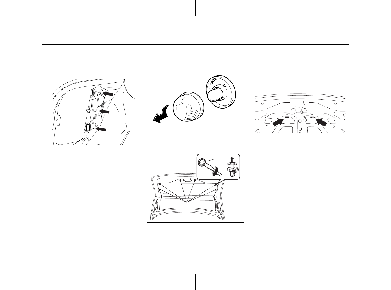
7-44
INSPECTION AND MAINTENANCE
80J23-03E
To open the trim (1), insert a flat blade
screwdriver between the trim and the clips
(2) and remove the clips by twist the driver
as shown in the illustration.
80JM073
License plate light
SX4
80JM079
SX4 SEDAN
80JM074
To open the trim (1), insert a flat blade
screwdriver into the hole (3) and remove
the clips (2) by twist the driver as shown in
the illustration.
80JM075
(3)
(1)
(2)
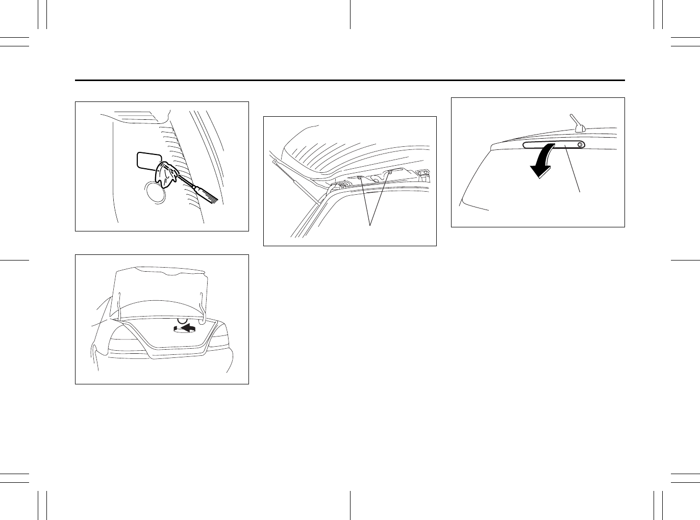
7-45
INSPECTION AND MAINTENANCE
80J23-03E
Luggage compartment light (SX4)
79J015
Trunk room light (SX4 SEDAN)
56KN004
High-mount stop light (if equipped)
SX4
80J100
To remove a high-mounted stop light hous-
ing the following procedure:
1) Open the tailgate, and remove the nuts
(1) as shown in the illustration.
63J127
2) Close the tailgate. Remove a high-
mounted stop light housing (2) from the
tailgate.
(1)
(2)
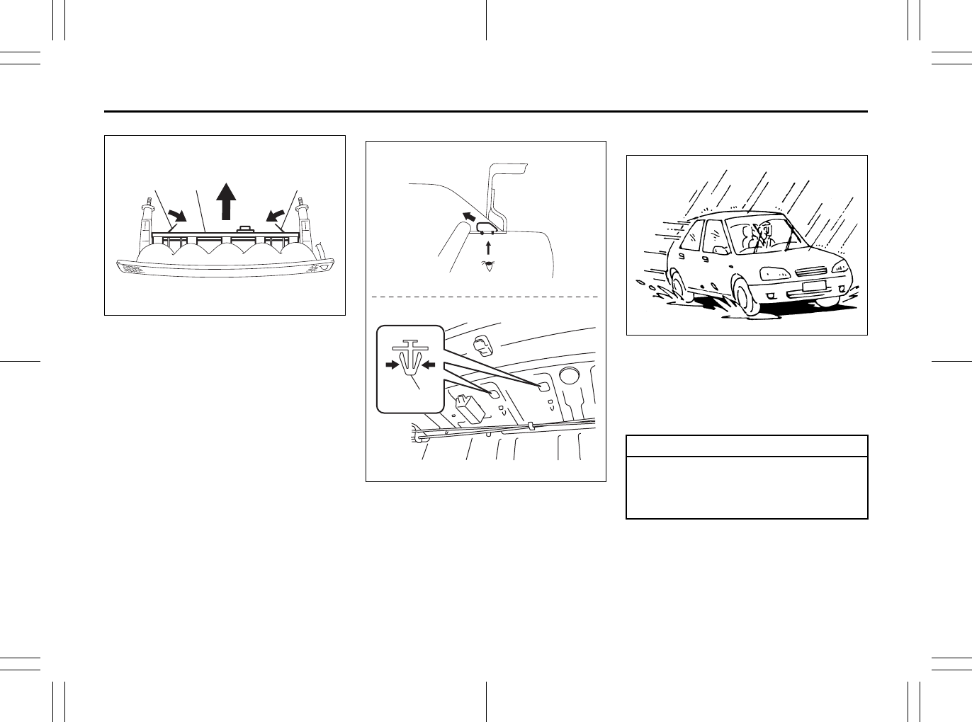
7-46
INSPECTION AND MAINTENANCE
80J23-03E
80JM076
3) Pushing the unguiform prongs (3)
toward inside and remove the bulb
holder (4).
4) Replace the bulbs.
To install a high-mounted stop light
housing in the reverse order of removal.
SX4 SEDAN
80JM132
To remove the high-mounted stop light
housing, pinch both side of the clip (1) and
push it in.
Wiper Blades
80G083
If the wiper blades become brittle or dam-
aged, or make streaks when wiping,
replace the wiper blades.
To install new wiper blades, follow the pro-
cedures below.
NOTE:
Some wiper blades may be different from
the ones described here depending on
vehicle specifications. If so, consult your
SUZUKI dealer for proper replacement
method.
(3)(3) (4)
(1)
CAUTION
To avoid scratching or breaking the
window, do not let the wiper arm
strike the window while replacing the
wiper blade.
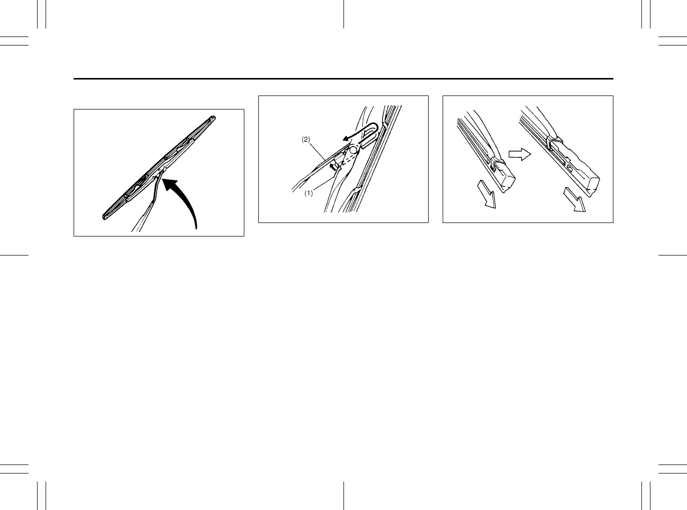
7-47
INSPECTION AND MAINTENANCE
80J23-03E
For windshield wipers and some rear
wipers:
70G119
1) Hold the wiper arm away from the win-
dow.
NOTE:
When raising both of the front wiper arms,
pull the driver’s side wiper arm up first.
When returning the wiper arms, lower the
passenger’s side wiper arm first. Other-
wise, the wiper arms may interfere with
each other.
52D102
2) Squeeze lock lever (1) towards wiper
arm (2) and remove the wiper frame
from the arm as shown.
60A260
3) Pull the locked end of the wiper blade
firmly to unlock the blade and slide the
blade out as shown.
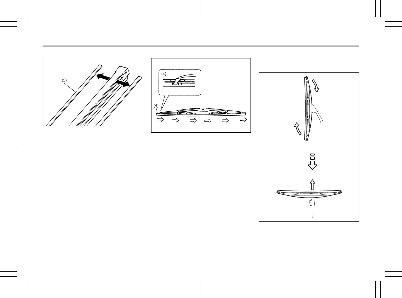
7-48
INSPECTION AND MAINTENANCE
80J23-03E
52D124
(3) Retainer
4) If the new blade is provided without the
two metal retainers, move them from
the old blade to the new one.
Installation
52D125
(4) Locked end
5) Install the new blade in the reverse
order of removal, with the locked end
positioned toward the wiper arm. Make
sure the blade is properly retained by
all the hooks. Grasp the blade near the
locked end and pull in the direction of
the arrows to lock the end into place.
6) Reinstall wiper frame to arm, making
sure that the lock lever is snapped
securely into the arm.
To remove some types of rear wiper
frame from the wiper arm:
1) Hold the arm away from the window.
80G146
2) Remove the wiper frame from the arm
as shown.
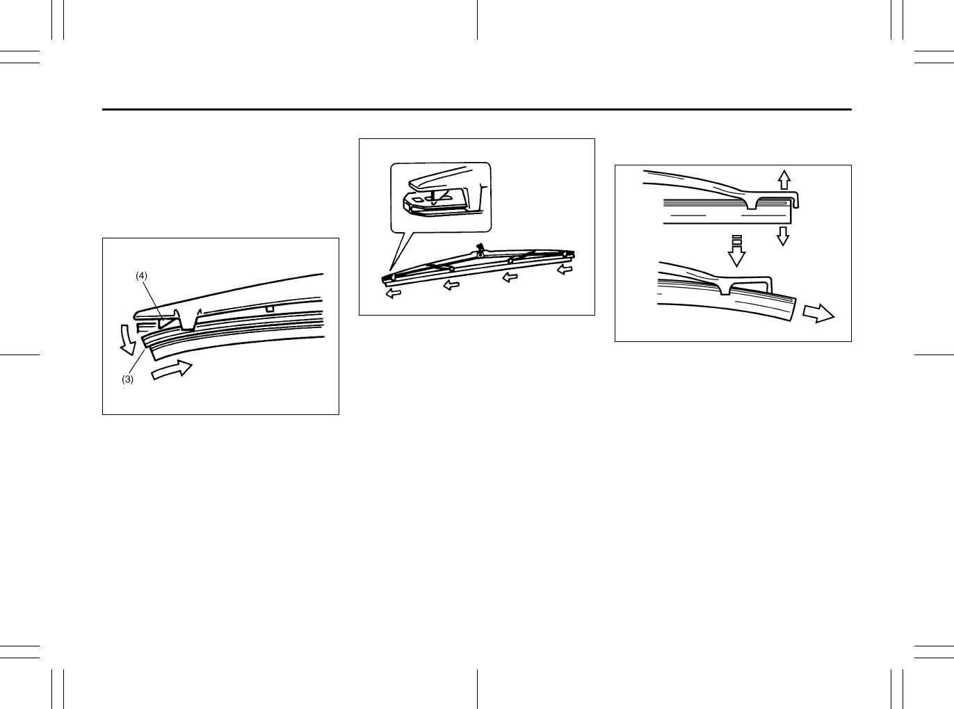
7-49
INSPECTION AND MAINTENANCE
80J23-03E
3) When reinstalling wiper frame to arm,
install the wiper frame in the reverse
order of removal.
To remove and install some types of
rear wiper blade from and to the wiper
frame.
Removal
52D104
1) Flex the locked end of blade (3) away
from retainer (4) to unlock it and slide
the blade out as shown.
Installation
60A265
2) Install the new blade in the reverse
order of removal. Make sure that the
blade is properly retained by all the
hooks and the end is locked in place.
To remove and install some types of
rear wiper blade from and to the wiper
frame.
65D151
1) Flex the ends of blade and frame, and
slide the blade out as shown.
But do not flex the frame end more than
necessary.
If you do, it can break off.
2) Install the new blade in the reverse
order of removal. Make sure that the
blade is properly retained by all the
hooks and both ends are in place.
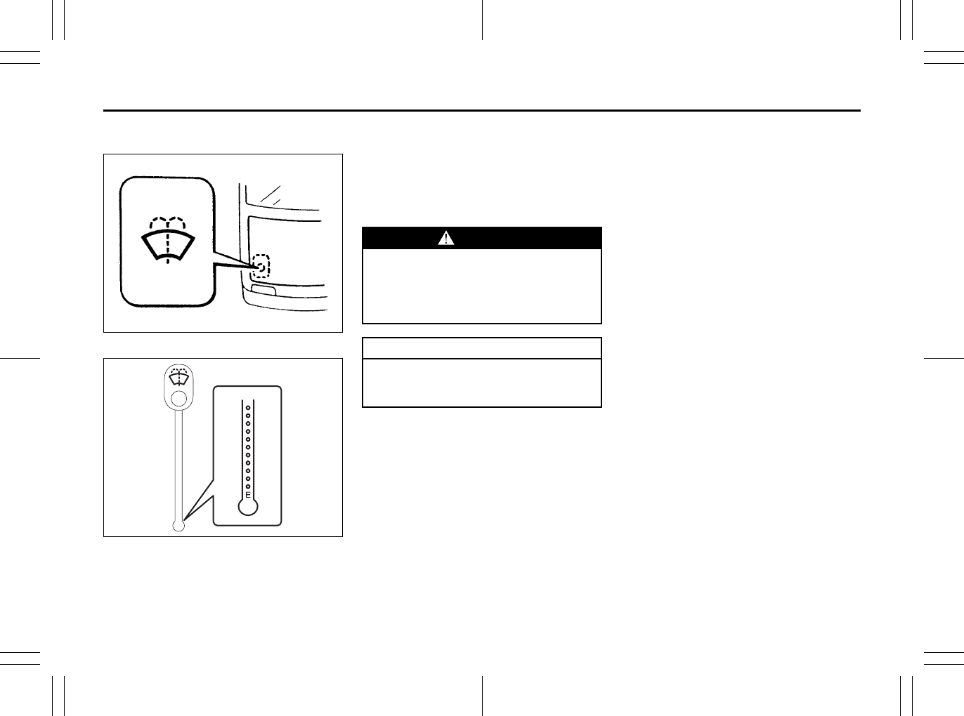
7-50
INSPECTION AND MAINTENANCE
80J23-03E
Windshield Washer Fluid
80JM078
80J008
Check that there is washer fluid in the tank
by looking at the washer fluid level gauge
which is attached to the cap of the washer
fluid tank. If the fluid level is near “E” mark,
refill it.
Use a good quality windshield washer
fluid, diluted with water as necessary.
Air Conditioning System
If you do not use the air conditioner for a
long period, such as during winter, it may
not give the best performance when you
start using it again. To help maintain opti-
mum performance and durability of your air
conditioner, it needs to be run periodically.
Operate the air conditioner at least once a
month for one minute with the engine
idling. This circulates the refrigerant and oil
and helps protect the internal components.
(or opposite side)
WARNING
Do not use “anti-freeze” solution in
the windshield washer reservoir. This
can severely impair visibility when
sprayed on the windshield, and also
damage your vehicle’s paint.
CAUTION
Damage may result if the washer
motor is operated with no fluid in the
washer tank.

7-51
INSPECTION AND MAINTENANCE
80J23-03E
MEMO
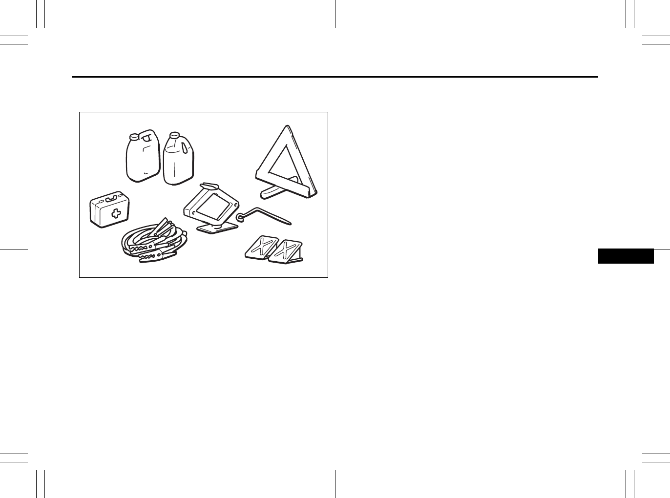
EMERGENCY SERVICE
8
80J23-03E
60G411
EMERGENCY SERVICE
Tire Changing Tool ............................................................. 8-1
Jacking Instructions ........................................................... 8-2
Changing Wheels ................................................................ 8-4
Jump Starting Instructions ................................................ 8-5
Towing a Disabled Vehicle ................................................. 8-6
If the Starter Does Not Operate .......................................... 8-6
If the Engine is Flooded ...................................................... 8-7
If the Engine Overheats ...................................................... 8-7
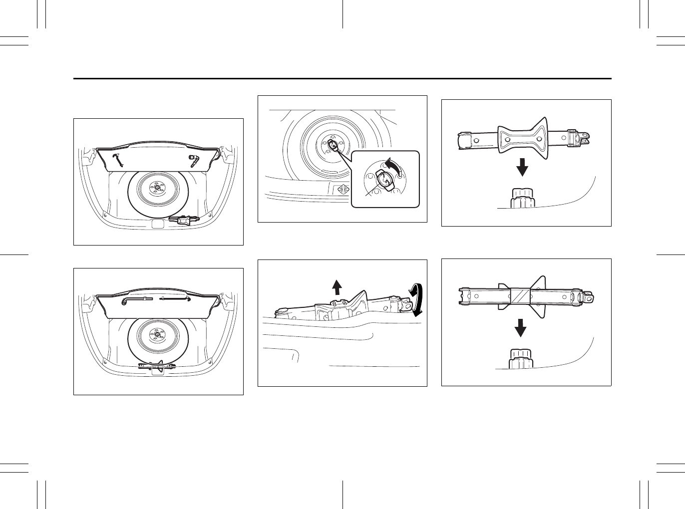
8-1
EMERGENCY SERVICE
80J23-03E
Tire Changing Tool
SX4
80JC014
SX4 SEDAN
80JC045
The jack, wheel brace, jack handle are
stowed in the luggage compartment.
80J048
To remove the spare tire, turn its bolt (1)
counterclockwise and remove it.
79J085
To remove the jack, turn its shaft counter-
clockwise and pull the jack out of the stor-
age bracket.
SX4
79J086
SX4 SEDAN
80JC015
To stow the jack, place it in the storage
bracket and turn the shaft clockwise until
the jack is securely held in place.
EXAMPLE
EXAMPLE
(1)
EXAMPLE
Vehicle Loading: 11
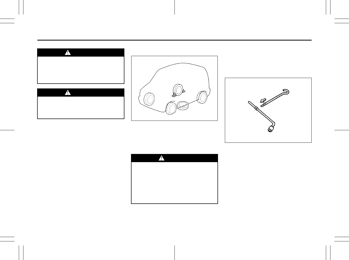
8-2
EMERGENCY SERVICE
80J23-03E
Jacking Instructions
75F062
1) Place the vehicle on level, hard ground.
2) Set the parking brake firmly and shift
into “P” (Park) if your vehicle has a CVT,
or shift into “R” (Reverse) if your vehicle
has a manual transaxle.
3) Turn on the hazard warning flasher if
your vehicle is near traffic.
4) Block the front and rear of the wheel
diagonally opposite of the wheel being
lifted.
5) Place the spare wheel near the wheel
being lifted as shown in the illustration
in case that the jack slips.
54G253
WARNING
The jack should be used only to
change wheels. It is important to read
the jacking instructions in this sec-
tion before attempting to use the
jack.
WARNING
After using the jack, jack handle and
wheel wrench, be sure to stow them
securely or they can cause injury if
an accident occurs.
WARNING
• Be sure to shift into “P” (Park) for a
CVT vehicle, or into “R” (Reverse)
for a manual transaxle vehicle
when you jack up the vehicle.
• Never jack up the vehicle with the
transaxle in “N” (Neutral). Other-
wise, an unstable jack may cause
an accident.
Trailer Towing: 5, 11, 13
Towing Your Vehicle (recreational towing): 13
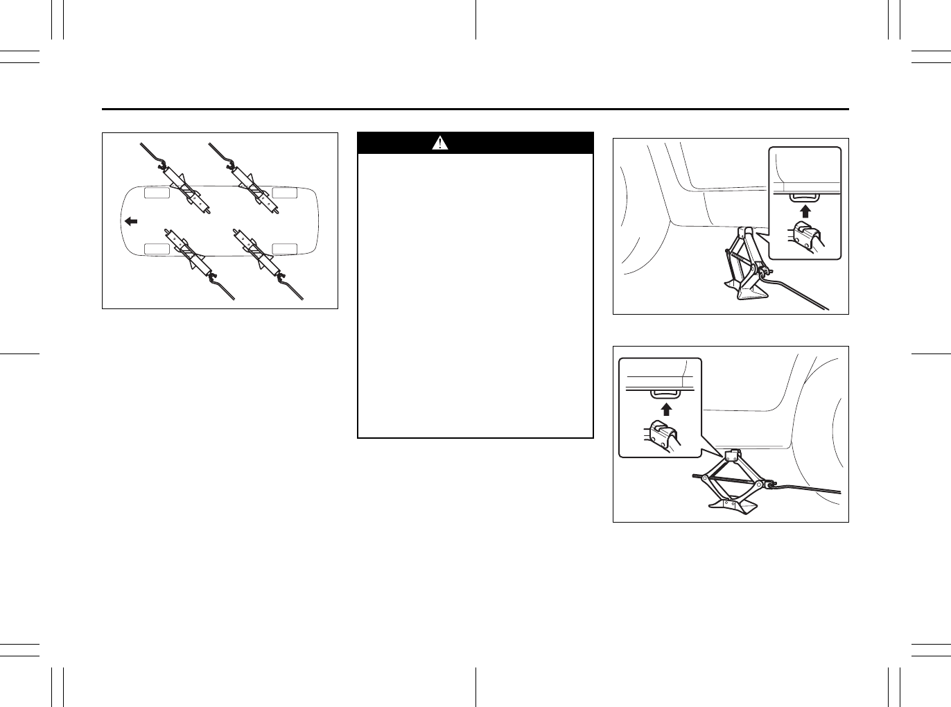
8-3
EMERGENCY SERVICE
80J23-03E
80J085
6) Position the jack at an angle as shown
in the illustration and raise the jack by
turning the jack handle clockwise until
the jack-head groove fits around the
jacking bar beneath the vehicle body.
7) Continue to raise the jack slowly and
smoothly until the tire clears the
ground. Do not raise the vehicle more
than necessary.
Front wheel
80J086
Rear wheel
80J087
front
WARNING
• Use the jack only to change wheels
on level, hard ground.
• Never jack up the vehicle on an
inclined surface.
• Never raise the vehicle with the
jack in a location other than the
specified jacking point (shown in
the illustration) near the wheel to
be changed.
• Make sure that the jack is raised at
least 51 mm (2 inches) before it
contacts the flange. Use of the jack
when it is within 51 mm (2 inches)
of being fully collapsed may result
in failure of the jack.
• Never get under the vehicle when it
is supported by the jack.
• Never run the engine when the
vehicle is supported by the jack
and never allow passengers to
remain in the vehicle.
Towing Your Vehicle (recreational towing): 13
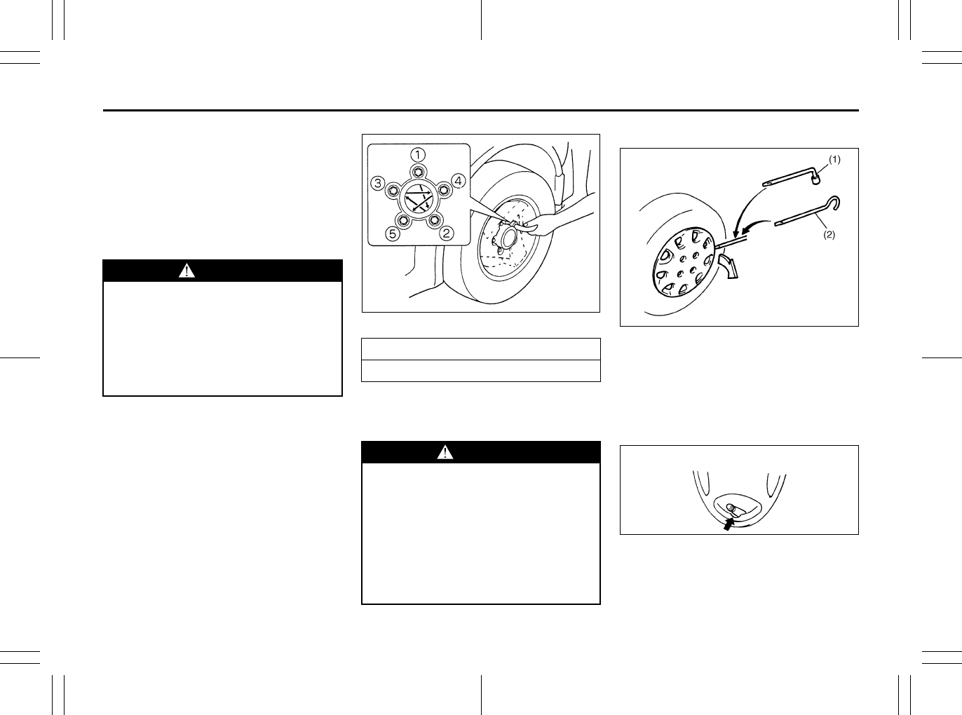
8-4
EMERGENCY SERVICE
80J23-03E
Changing Wheels
To change a wheel, use the following pro-
cedure:
1) Remove the jack, tools and spare wheel
from the vehicle.
2) Loosen, but do not remove the wheel
nuts.
3) Jack up the vehicle (follow the jacking
instructions in this section).
4) Remove the wheel nuts and wheel.
5) Before installing the new wheel, clean
any mud or dirt off from the surface of
the wheel and hub with a clean cloth.
Clean the hub carefully; it may be hot
from driving.
6) Install the new wheel and replace the
wheel nuts with their cone shaped end
facing the wheel. Tighten each nut
snugly by hand until the wheel is
securely seated on the hub.
81A057
7) Lower the jack and fully tighten the nuts
in a crisscross fashion with a wrench as
shown in the illustration.
Full Wheel Cover (if equipped)
60G309
(1) or (2) Flat end tool
Your vehicle includes two tools, a wheel
brace and a jack crank, one of which has a
flat end.
Use the tool with the flat end to remove the
full wheel cap, as shown above.
54G117
When installing the cover, make sure that it
is positioned so that it does not cover or
foul the air valve.
WARNING
• Be sure to shift into “P” (Park) in
CVT, or shift into “R” (Reverse) in
manual transaxle when you jack up
the vehicle.
• Never jack up the vehicle with the
transaxle in “N” (Neutral). Other-
wise, unstable jack may cause an
accident.
Wheel tightening torque
85 Nm (61.5 lb-ft, 8.5 kg-m)
WARNING
Use genuine wheel nuts and tighten
them to the specified torque as soon
as possible after changing wheels.
Incorrect wheel nuts or improperly
tightened wheel nuts may come
loose or fall off, which can result in
an accident. If you do not have a
torque wrench, have the wheel nut
torque checked by an authorized
SUZUKI dealer.
EXAMPLE
EXAMPLE
Towing Your Vehicle (recreational towing): 13
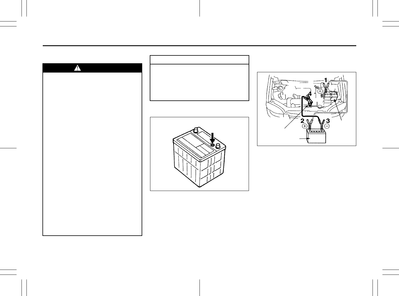
8-5
EMERGENCY SERVICE
80J23-03E
Jump Starting Instructions
When jump starting your vehicle, use
the following procedure:
60A269
1) Use only a 12-volt battery to jump start
your vehicle. Position the good 12-volt
battery close to your vehicle so that the
jumper cables will reach both batteries.
When using a battery installed on
another vehicle, DO NOT LET THE
VEHICLES TOUCH. Set the parking
brakes fully on both vehicles.
2) Turn off all vehicle accessories, except
those necessary for safety reasons (for
example, headlights or hazard lights).
54G079
3) Make jumper cable connections as fol-
lows:
1. Connect one end of the first jumper
cable to the positive (+) terminal of
the discharged battery (1).
2. Connect the other end to the positive
(+) terminal of the booster battery
(2).
3. Connect one end of the second
jumper cable to the negative (–) ter-
minal of the booster battery (2).
4. Make the final connection to an
unpainted, heavy metal part (i.e.
engine hook (3)) of the engine of the
vehicle with the discharged battery
(1).
WARNING
• Never attempt to jump start your
vehicle if the battery appears to be
frozen. Batteries in this condition
may explode or rupture if jump
starting is attempted.
• When making jumper cable con-
nections, be certain that your
hands and the jumper cables
remain clear from pulleys, belts or
fans.
• Batteries produce flammable
hydrogen gas. Keep flames and
sparks away from the battery or an
explosion may occur. Never smoke
when working near the battery.
• If the booster battery you use for
jump starting is installed in another
vehicle, make sure the two vehicles
are not touching each other.
• If your battery discharges repeat-
edly, for no apparent reason, have
your vehicle inspected by an autho-
rized SUZUKI dealer.
• To avoid harm to yourself or dam-
age to your vehicle or battery, fol-
low the jump starting instructions
below precisely and in order. If you
are in doubt, call for qualified road
service.
CAUTION
Your vehicle should not be started by
pushing or towing. This starting
method could result in permanent
damage to the catalytic converter.
Use jumper cables to start a vehicle
with a weak or run-down battery.
12V BATTERY (1)
(3)
(2)
EXAMPLE
8-6
EMERGENCY SERVICE
80J23-03E
4) If the booster battery you are using is
installed on another vehicle, start the
engine of the vehicle with the booster
battery. Run the engine at moderate
speed.
5) Start the engine of the vehicle with the
discharged battery.
6) Remove the jumper cables in the exact
reverse order in which you connected
them.
Towing a Disabled Vehicle
Emergency Towing
If your vehicle is disabled, it may be towed
by a tow truck using one of the following
methods:
1) Tow the vehicle with two wheels lifted
by the tow truck and the other two
wheels on a towing dolly.
2) Use the appropriate towing method
specified for your vehicle in the “Towing
Your Vehicle (recreational towing)” sec-
tion, but with the wheels lifted by the
tow truck instead of on a towing dolly.
Be sure to carefully follow the specific
instructions provided in the “Towing
Your Vehicle (recreational towing)” sec-
tion.
If the Starter Does Not
Operate
1) Try turning the ignition switch to the
“START” position with the headlights
turned on to determine the battery con-
dition. If the headlights go excessively
dim or go off, it usually means that
either the battery has run down or bat-
tery terminal contact is poor. Recharge
the battery or correct battery terminal
contact if necessary.
2) If the headlights remain bright, check
the fuses. If the reason for failure of the
starter is not obvious, there may be a
major electrical problem. Have the vehi-
cle inspected by your authorized
SUZUKI dealer.
WARNING
Never connect the jumper cable
directly to the negative (–) terminal of
the discharged battery, or an explo-
sion may occur.
CAUTION
If vehicle damage (such as steering
or drivetrain damage, etc.) prevents
normal use of the towing procedures
for your vehicle described in the
“Towing Your Vehicle (recreational
towing)” section, have your vehicle
towed with two wheels lifted by the
tow truck and the other two wheels
on a towing dolly.
8-7
EMERGENCY SERVICE
80J23-03E
If the Engine is Flooded
If the engine is flooded with gasoline, it
may be hard to start. If this happens, press
the accelerator pedal all the way to the
floor and hold it there while cranking the
engine. (Do not operate the starter motor
for more than 15 seconds).
If the Engine Overheats
The engine could overheat temporarily
under severe driving conditions. If the
engine coolant temperature gauge indi-
cates overheating during driving:
1) Turn off the air conditioner, if equipped.
2) Take the vehicle to a safe place and
park.
3) Let the engine run at normal idle speed
for a few minutes until the indicator is
within the normal, acceptable tempera-
ture range shown by the white band
between “H” and “C”.
If the temperature indication does not
come down to within the normal, accept-
able range:
1) Turn off the engine and check that the
water pump belt and pulleys are not
damaged or slipping. If any abnormality
is found, correct it.
2) Check the coolant level in the reservoir.
If it is found to be lower than the “LOW”
line, look for leaks at the radiator, water
pump and radiator and heater hoses. If
you locate any leaks that may have
caused the overheating, do not run the
engine until these problems have been
corrected.
3) If you do not find a leak, carefully add
coolant to the reservoir and then the
radiator, if necessary. (Refer to “Engine
Coolant” in the “INSPECTION AND
MAINTENANCE” section.)
WARNING
If you see or hear escaping steam,
stop the vehicle in a safe place and
immediately turn off the engine to let
it cool. Do not open the hood when
steam is present. When the steam
can no longer be seen or heard, open
the hood to see if the coolant is still
boiling. If it is, you must wait until it
stops boiling before you proceed.
Also, be careful not to touch hot
engine parts (radiator, water hoses,
engine etc.).
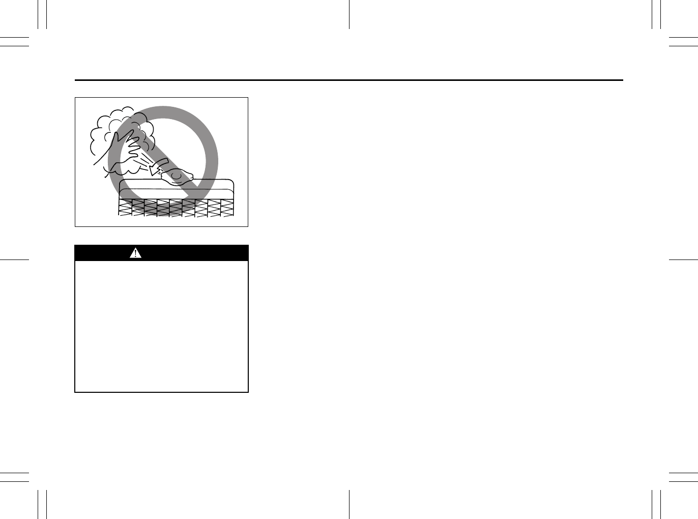
8-8
EMERGENCY SERVICE
80J23-03E
65D614
WARNING
• It is hazardous to remove the radia-
tor cap when the water temperature
is high, because scalding fluid and
steam may be blown out under
pressure. The cap should only be
taken off when the coolant temper-
ature has lowered.
• To prevent personal injury, keep
hands, tools and clothing away
from the engine cooling fan and air-
conditioner fan (if equipped). These
electric fans can automatically turn
on without warning.

8-9
EMERGENCY SERVICE
80J23-03E
MEMO
APPEARANCE CARE
9
80J23-03E
60G412
APPEARANCE CARE
Corrosion Prevention ......................................................... 9-1
Vehicle Cleaning ................................................................. 9-3
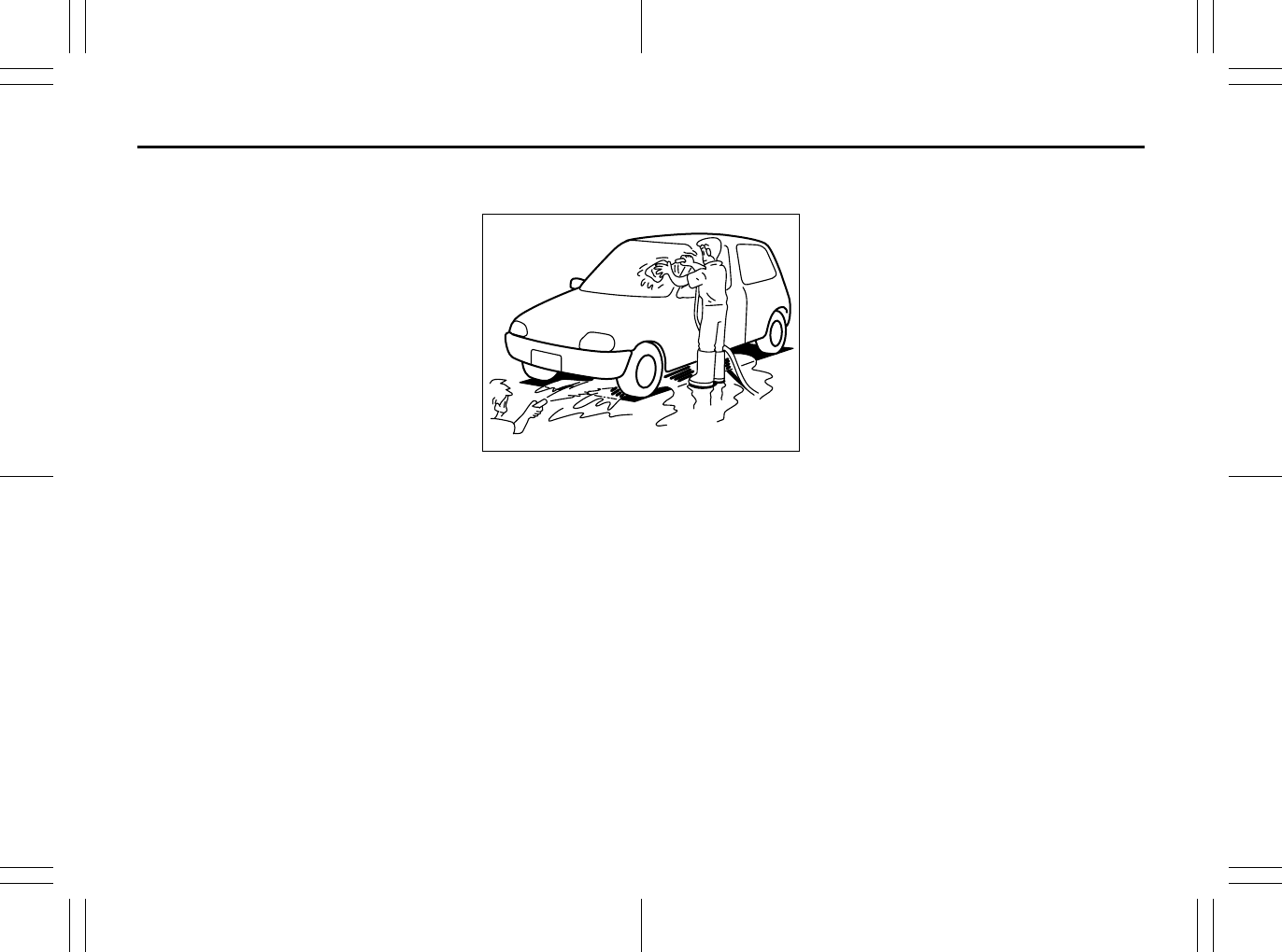
9-1
APPEARANCE CARE
80J23-03E
Corrosion Prevention
It is important to take good care of your
vehicle to protect it from corrosion.
Listed below are instructions for how to
maintain your vehicle to prevent corrosion.
Please read and follow these instructions
carefully.
Important Information About
Corrosion
Common causes of corrosion
1) Accumulation of road salt, dirt, moisture
or chemicals in hard-to-reach areas of
the vehicle underbody or frame.
2) Chipping, scratches and any damage to
treated or painted metal surfaces
resulting from minor accidents or
impact from stones and gravel.
Environmental conditions which accel-
erate corrosion
1) Road salt, dust control chemicals, sea
air or industrial pollution will all acceler-
ate the corrosion of metal.
2) High humidity will increase the rate of
corrosion particularly when the temper-
ature range is just above the freezing
point.
3) Moisture in certain areas of a vehicle
for an extended period of time may pro-
mote corrosion even though other body
sections may be completely dry.
4) High temperatures will cause an accel-
erated rate of corrosion to parts of the
vehicle which are not well ventilated to
permit quick drying.
52D151
This information illustrates the necessity of
keeping your vehicle (particularly the
underbody) as clean and dry as possible. It
is equally important to repair any damage
to the paint or protective coatings as soon
as possible.
How to Help Prevent Corrosion
Wash your vehicle frequently
The best way to preserve the finish on your
vehicle and to help avoid corrosion is to
keep it clean with frequent washing.
Wash your vehicle at least once during the
winter and once immediately after the win-
ter. Keep your vehicle, particularly the
underside, as clean and dry as possible.
If you frequently drive on salted roads, your
vehicle should be washed at least once a
month during the winter. If you live near the
ocean, your vehicle should be washed at
least once a month throughout the year.
For washing instructions, refer to the “Vehi-
cle Cleaning” section.
Remove foreign material deposits
Foreign material such as salts, chemicals,
road oil or tar, tree sap, bird droppings and
industrial fall-out may damage the finish of
your vehicle if it is left on painted surfaces.
Remove these types of deposits as quickly
as possible. If these deposits are difficult to
wash off, an additional cleaner may be
required. Be sure that any cleaner you use
is not harmful to painted surfaces and is
specifically intended for your purposes.
Follow the manufacturer’s directions when
using these special cleaners.
Repair finish damage
Carefully examine your vehicle for damage
to the painted surfaces, especially if it is
used off-road. Should you find any chips or
scratches in the paint, touch them up
immediately to prevent corrosion from
starting. If the chips or scratches have
gone through to the bare metal, have a
qualified body shop make the repair.
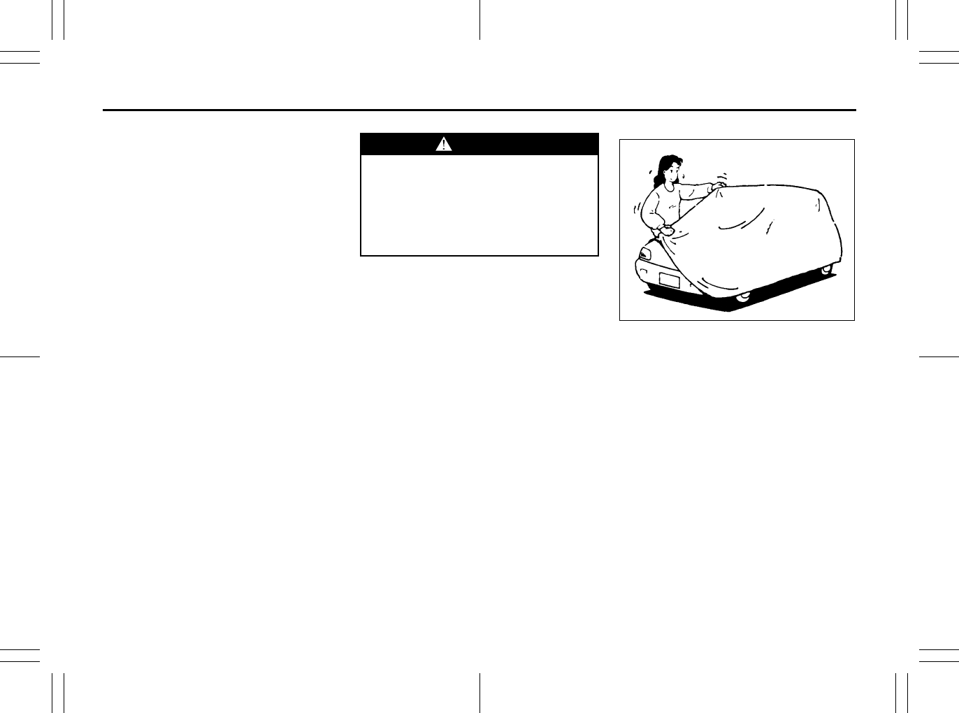
9-2
APPEARANCE CARE
80J23-03E
Keep passenger and cargo compart-
ments clean
Moisture, dirt or mud can accumulate
under the floor mats and may cause corro-
sion. Occasionally, check under these
mats to ensure that this area is clean and
dry. More frequent checks are necessary if
the vehicle is used off road or in wet
weather.
Certain cargo such as chemicals, fertiliz-
ers, cleaners, salts, etc. are extremely cor-
rosive by nature. These products should
be transported in sealed containers. If a
spill or leak does occur, clean and dry the
area immediately.
Use the body trim
The use of the body trim will help protect
your vehicle, especially if you frequently
drive on gravel or salted roads. The fittings
for such guards should also be corrosion
resistant. Please check with your autho-
rized SUZUKI dealer for information on
these guards.
Store your vehicle in a dry, well-venti-
lated area
Do not park your vehicle in a damp, poorly
ventilated area. If you often wash your
vehicle in the garage or if you frequently
drive it in when wet, your garage may be
damp. The high humidity in the garage
may cause or accelerate corrosion. A wet
vehicle may corrode even in a heated
garage if the ventilation is poor.
Cover your vehicle
50G203
If you cannot regularly park your vehicle in
a garage, we recommend you use a vehi-
cle cover. Years of exposure to midday sun
can cause the colors in paint, plastic parts
and fabrics to fade. Covering your vehicle
with a high-quality, “breathable” vehicle
cover can help protect the finish from the
harmful UV rays in sunlight, and can
reduce the amount of dust and air pollution
reaching the surface. Your SUZUKI dealer
can help you select the right cover for your
vehicle.
WARNING
Do not apply additional undercoating
or rust preventive coating on or
around exhaust system components
such as the catalytic converter,
exhaust pipes, etc. A fire could be
started if the undercoating substance
becomes overheated.
Maintenance Schedule: 1, 2, 3, 4, 5, 6, 9, 10
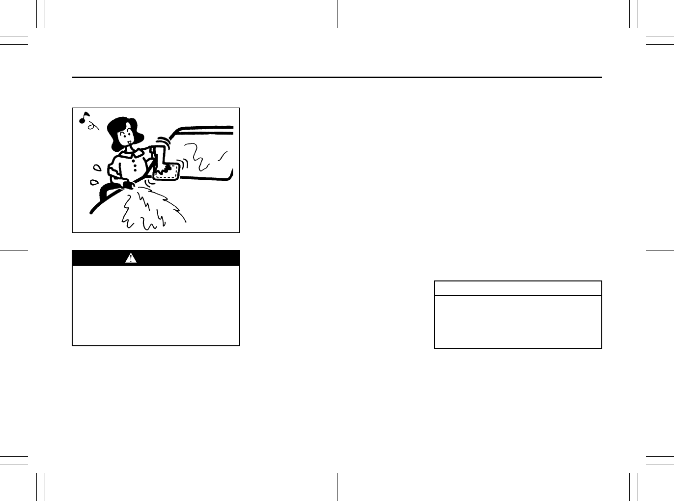
9-3
APPEARANCE CARE
80J23-03E
Vehicle Cleaning
76G044S
Cleaning Interior
Vinyl upholstery
Prepare a solution of soap or mild deter-
gent mixed with warm water. Apply the
solution to the vinyl with a sponge or soft
cloth and let it soak for a few minutes to
loosen dirt. Rub the surface with a clean,
damp cloth to remove dirt and the soap
solution. If some dirt still remains on the
surface, repeat this procedure.
Fabric upholstery
Remove loose dirt with a vacuum cleaner.
Using a mild soap solution, rub stained
areas with a clean damp cloth. To remove
soap, rub the areas again with a cloth
dampened with water. Repeat this until the
stain is removed, or use a commercial fab-
ric cleaner for tougher stains. If you use a
fabric cleaner, carefully follow the manu-
facturer’s instructions and precautions.
Leather upholstery
Remove loose dirt with a vacuum cleaner.
Using a mild soap or saddle soap solution,
wipe dirt off with a clean damp soft cloth.
To remove soap, wipe the areas again with
a soft cloth dampened with water. Wipe the
areas dry with a soft dry cloth. Repeat this
until the dirt or stain is removed, or use a
commercial leather cleaner for tougher dirt
or stains. If you use a leather cleaner, care-
fully follow the manufacture’s instructions
and precautions. Do not use solvent type
cleaners or abrasive cleaners.
Seat belts
Clean seat belts with a mild soap and
water. Do not use bleach or dye on the
belts. They may weaken the fabric in the
belts.
Vinyl floor mats
Ordinary dirt can be removed from vinyl
with water or mild soap. Use a brush to
help loosen dirt. After dirt is loosened,
rinse the mat thoroughly with water and
dry it in the shade.
Carpets
Remove dirt and soil as much as possible
with a vacuum cleaner. Using a mild soap
solution, rub stained areas with a clean
damp cloth. To remove soap, rub the areas
again with a cloth dampened with water.
Repeat this until the stain is removed, or
use a commercial carpet cleaner for
tougher stains. If you use a carpet cleaner,
carefully follow the manufacturer’s instruc-
tions and precautions.
Cleaning the Exterior
WARNING
When cleaning the interior or exterior
of the vehicle, NEVER USE flammable
solvents such lacquer thinners, gas-
oline, benzene or cleaning materials
such as bleaches and strong house-
hold detergents. The materials could
cause personal injury or damage to
the vehicle.
CAUTION
It is important that your vehicle be
kept clean and free from dirt. Failure
to keep your vehicle clean may result
in fading of the paint or corrosion to
various parts of the vehicle body.
Periodic Maintenance Schedule: 1, 2, 3, 4, 5, 6, 9, 10
9-4
APPEARANCE CARE
80J23-03E
Washing
When washing the vehicle, follow the
instructions below:
1) Flush the underside of body and wheel
housings with pressurized water to
remove mud and debris. Use plenty of
water.
2) Rinse the body to loosen the dirt.
Remove dirt and mud from the body
exterior with running water. You may
use a soft sponge or brush. Do not use
hard materials which can scratch the
paint or plastic. Remember that the
headlight covers or lenses are made of
plastic in many cases.
3) Wash the entire exterior with a mild
detergent or car wash soap using a
sponge or soft cloth. The sponge or
cloth should be frequently soaked in the
soap solution.
4) Once the dirt has been completely
removed, rinse off the detergent with
running water.
5) After rinsing, wipe off the vehicle body
with a wet chamois or cloth and allow it
to dry in the shade.
6) Check carefully for damage to painted
surfaces. If there is any damage,
“touch-up” the damage following the
procedure below:
1. Clean all damaged spots and allow
them to dry.
2. Stir the paint and “touch-up” the
damaged spots lightly using a small
brush.
3. Allow the paint to dry completely.
WARNING
• Never attempt to wash and wax
your vehicle with the engine run-
ning.
• When cleaning the underside of the
body and fender, where there may
be sharp-edged parts, you should
wear gloves and a long-sleeved
shirt to protect your hands and
arms from being cut.
• After washing your vehicle, care-
fully test the brakes before driving
to make sure they have maintained
their normal effectiveness.
CAUTION
• When washing the vehicle, avoid
directing steam or hot water of
more than 80°C (176°F) on plastic
parts.
• To avoid damaging engine compo-
nents, do not use pressurized
water in the engine compartment.
CAUTION
To avoid damage to the paint or plas-
tic surface, do not wipe the dirt off
without ample water. Be sure to fol-
low above procedure.
CAUTION
When using a commercial car wash
product, observe the cautions speci-
fied by the manufacturer. Never use
strong household detergents or
soaps.
CAUTION
If you use an automatic car wash,
make sure that your vehicle’s body
parts, such as spoilers, cannot be
damaged. If you are in doubt, consult
the car wash operator for advice.
Periodic Maintenance Schedule: 1, 2, 3, 4, 5, 6, 9, 10
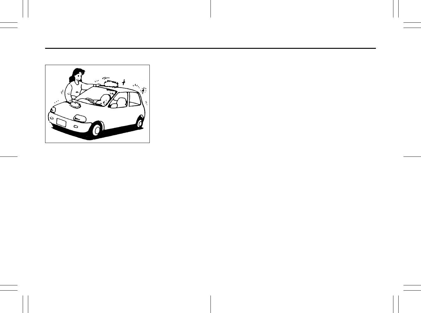
9-5
APPEARANCE CARE
80J23-03E
Waxing
60B211S
After washing the vehicle, waxing and pol-
ishing are recommended to further protect
and beautify the paint.
• Only use waxes and polishes of good
quality.
• When using waxes and polishes,
observe the precautions specified by the
manufacturers.
Maintenance Recommended under Severe Driving Condi-
tions: 1, 2, 3, 4, 5, 6, 9, 10
GENERAL INFORMATION
10
80J23-03E
54G072
GENERAL INFORMATION
Identification Numbers ....................................................... 10-1
Safety Certification Label ................................................... 10-2
Emission Compliance Label (for U.S.A.) ........................... 10-2
Warranties ............................................................................ 10-2
On-Board Vehicle Computers and Event Data
Recorders ............................................................................ 10-3
Reporting Safety Defects ................................................... 10-4
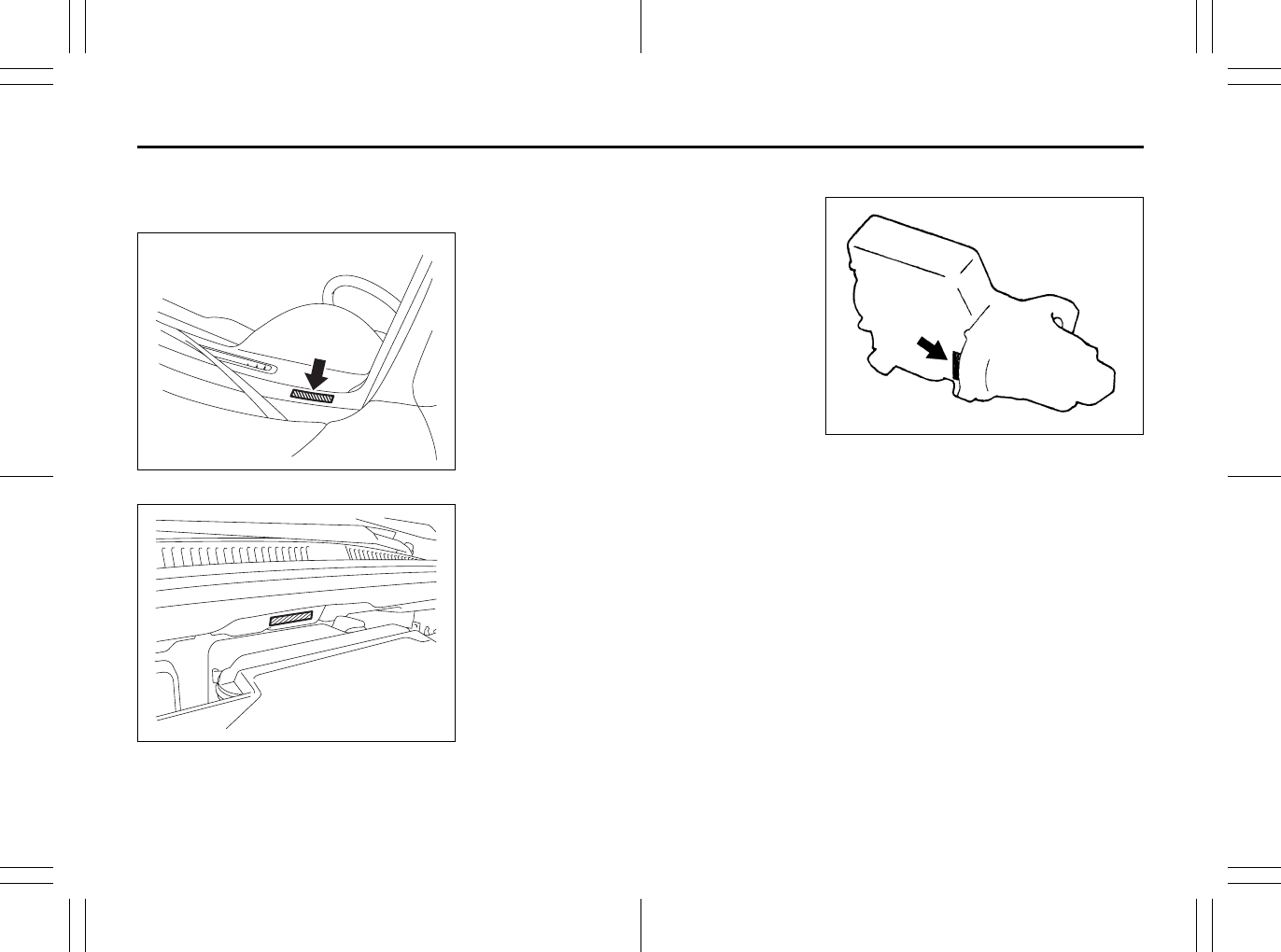
10-1
GENERAL INFORMATION
80J23-03E
Identification Numbers
Vehicle Identification Number
80JC090
79J019
The Vehicle Identification Number (VIN)
may be found in the location shown in the
above illustrations. This number is used to
register the vehicle. It is also used to assist
your dealer when ordering parts or refer-
ring to special service information.
Engine Serial Number
60G128
The engine serial number is stamped on
the cylinder block as shown in the above
illustration.
EXAMPLE (for some vehicles)
Jacking Instructions: 5
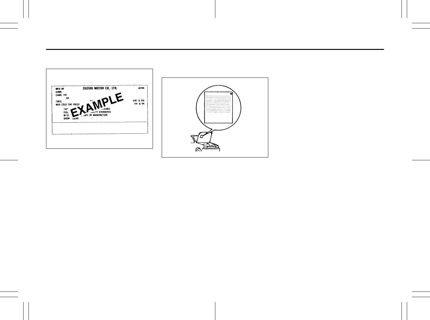
10-2
GENERAL INFORMATION
80J23-03E
Safety Certification Label
52D059
This label contains important safety-
related information about your vehicle. The
label is located on the driver’s door lock pil-
lar.
Emission Compliance Label
(for U.S.A.)
60A412
The EPA emission compliance label is
located under the hood.
Warranties
The warranties covering your vehicle are
explained in a separate New Vehicle War-
ranty Information booklet given to you at
the time of sale. Please read this booklet
carefully so you can understand your rights
and responsibilities.
For U.S.A.
The following warranties are provided with
your vehicle:
• New Vehicle Limited Warranty
• Limited Warranty For SUZUKI Parts or
Accessories
• Emission Components Defect Warranty
• Emission Performance Warranty
EXAMPLE
Jacking Instructions: 5

10-3
GENERAL INFORMATION
80J23-03E
On-Board Vehicle Computers
and Event Data Recorders
Your vehicle is equipped with on-board
computer systems which monitor and
control several aspects of vehicle per-
formance, including the following:
• Emission-related components and
engine parameters such as engine
speed and throttle position are moni-
tored to provide emissions control
and to provide optimum fuel econ-
omy. Your vehicle also has an on-
board diagnostic system which mon-
itors and records information about
emission-related malfunctions.
• Signals from various sensors are
monitored to provide air bag deploy-
ment.
• If your vehicle is equipped with
antilock brakes, conditions such as
vehicle speed and brake perfor-
mance are monitored, so that the
ABS system can provide effective
antilock braking. If your vehicle has
an Electronic Stability Program
(ESP®) system, conditions such as
yaw rate, lateral acceleration, and
brake fluid pressure are monitored,
so that the ESP® system can help
the driver control the vehicle in diffi-
cult driving situations.
Some information may be stored by
the on-board computers during normal
operation of the vehicle. This stored
information can assist technicians in
repairing the vehicle when malfunc-
tions occur. Other information is stored
only in the event of crash, by computer
systems that are commonly called
Event Data Recorders (EDRs).
In a crash event, EDRs such as the
Airbag Sensing and Diagnostic Mod-
ule (SDM) in your vehicle may record
information about the condition of the
vehicle and how it was operated, such
as data related to airbag readiness,
airbag performance, safety belt usage,
and the severity of the collision. These
data can help provide a better under-
standing of the circumstances in which
crashes and injuries occur and lead to
the designing of safer vehicles. The
SDM in your vehicle does not collect
or store personal information.
To read the stored information, special
equipment is needed and access to
the vehicle or storage device is
required. SUZUKI will not access infor-
mation about a crash event or share it
with others other than with the consent
of the vehicle owner or lessee, in
response to an official request from
the police or similar government office,
as part of SUZUKI’s defense of litiga-
tion through the discovery process, or
as required by law.
In addition, once SUZUKI collects or
receives data, SUZUKI may use the
data for research conducted by
SUZUKI, make the data available for
outside research if need is shown and
confidentiality is assured, or make
summary data which does not identify
specific vehicles available for outside
research.
Others, such as law enforcement per-
sonnel, may have access to the spe-
cial equipment that can read the
information if they have access to the
vehicle or storage device.
Jacking Instructions: 5

10-4
GENERAL INFORMATION
80J23-03E
Reporting Safety Defects
If you believe that your vehicle has a
defect which could cause a crash or
could cause injury or death, you
should immediately inform the
National Highway Traffic Safety
Administration (NHTSA) in addition to
notifying American Suzuki Motor Corp.
If NHTSA receives similar complaints,
it may open an investigation, and if it
finds that a safety defect exists in a
group of vehicles, it may order a recall
and remedy campaign. However,
NHTSA cannot become involved in
individual problems between you, your
dealer, or American Suzuki Motor
Corp.
To contact NHTSA, you may call the
Vehicle Safety Hotline toll-free at 1-
888-327-4236 (TTY: 1-800-424-9153);
go to http://www.safercar.gov; or write
to: Administrator, NHTSA, 1200 New
Jersey Ave., SE., Washington, D.C.
20590. You can also obtain other infor-
mation about motor vehicle safety
from http://www.safercar.gov.
To contact American Suzuki, owners
in the continental United States can
call toll-free 1-800-934-0934, or write
to:
American Suzuki Motor Corporation
Automotive Customer Relations
3251 East Imperial Highway
Brea, CA 92821-6795
For owners outside the continental
United States, please refer to the dis-
tributor’s address listed in your War-
ranty Information booklet.
For vehicles registered for use and
principally operated in Canada please
contact Suzuki Canada Inc. at 1-905-
889-2677 extension 2254 or write to:
Suzuki Canada Inc.
Customer Relations
100 East Beaver Creek Road
Richmond Hill, On
L4B 1J6
Jacking Instructions: 5
Jump Starting Instructions: 7

10-5
GENERAL INFORMATION
80J23-03E
MEMO
Jump Starting Instructions: 7
Towing a Disabled Vehicle: 6
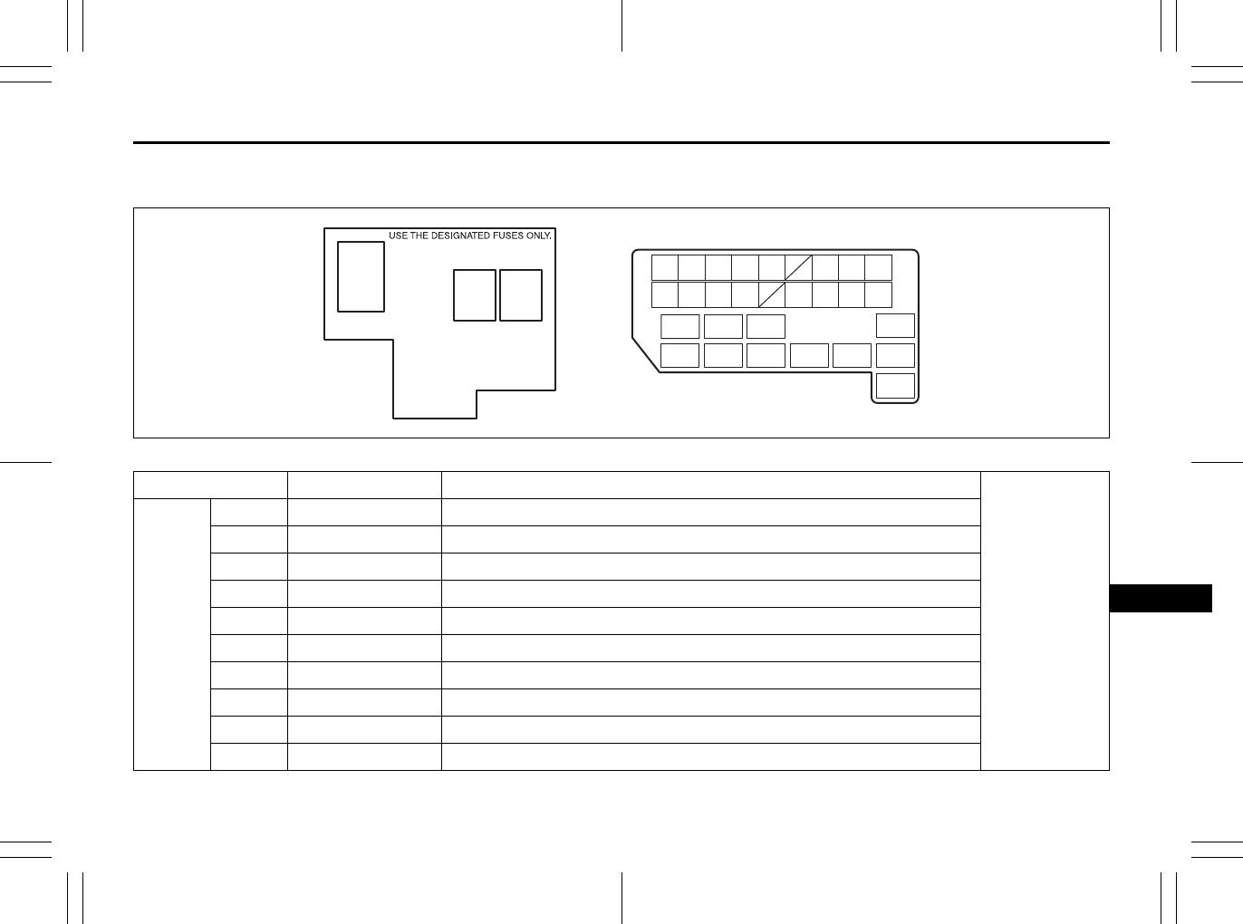
11-1
FUSES AND PROTECTED CIRCUITS
80J23-03E
11
FUSES AND PROTECTED CIRCUITS
80J101
COLOR/SIZE (AMPS) PROTECTED CIRCUIT
In engine
compartment
MAIN
FUSE
BOX
(1) BLACK (80) All electric load
(2) RED (50) Power window, Ignition, Wiper, Starter
(3) RED (50) Tail light, Rear defogger, Door lock, Hazard/Horn, Dome
(4) – Blank
(5) – Blank
(6) BLUE (15) Head light (Right) fuse
(7) BLUE (15) Head light (Left) fuse
(8) YELLOW (20) Front fog light fuse
(9) – Blank
(10) GREEN (40) ABS motor fuse
(1)
(2) (3)
(28)
(27)(26)(25)
(6) (7) (9) (11)
(15) (16) (17) (18) (19)
(24)
(8)(4) (5) (10)
(22)(21)
(23)
(20)
(12) (13) (14)
(30)
(29)
Fuses and Protected Circuits: 7

11-2
FUSES AND PROTECTED CIRCUITS
80J23-03E
80J101
COLOR/SIZE (AMPS) PROTECTED CIRCUIT
In engine
compartment
MAIN
FUSE
BOX
(11) PINK (30) Radiator fan fuse
(12) PINK (30) ABS solenoid fuse
(13) PINK (30) Starting motor fuse
(14) RED (50) Ignition switch fuse
(15) PINK (30) Blower fan fuse
(16) YELLOW (20) Air compressor fuse
(17) BLUE (15) Throttle motor fuse
(18) BLUE (15) Automatic transaxle fuse
(19) BLUE (15) Fuel injection fuse
(20) – Automatic transaxle relay
(1)
(2) (3)
(28)
(27)(26)(25)
(6) (7) (9) (11)
(15) (16) (17) (18) (19)
(24)
(8)(4) (5) (10)
(22)(21)
(23)
(20)
(12) (13) (14)
(30)
(29)
Fuses and Protected Circuits: 7
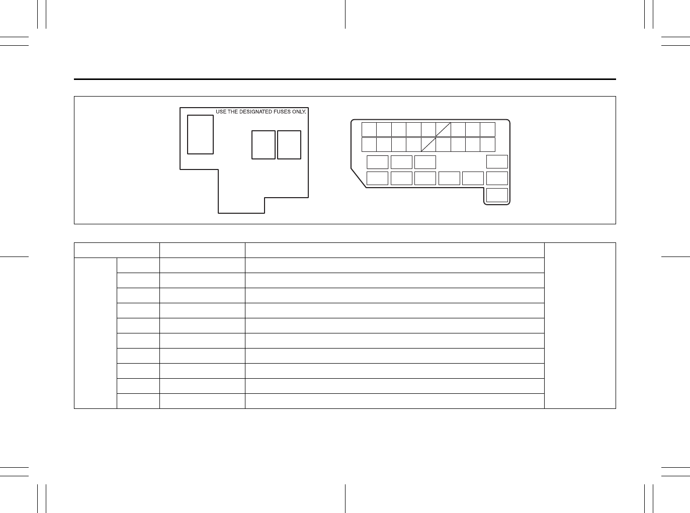
11-3
FUSES AND PROTECTED CIRCUITS
80J23-03E
80J101
COLOR/SIZE (AMPS) PROTECTED CIRCUIT
In engine
compartment
MAIN
FUSE
BOX
(21) – Air compressor relay
(22) – Fuel pump relay
(23) – Condensor fan relay
(24) – Front fog light relay
(25) – Throttle motor relay
(26) – FI MAIN relay
(27) – Starting motor relay
(28) – Radiator fan relay
(29) – Radiator fan relay 2
(30) – Radiator fan relay 3
(1)
(2) (3)
(28)
(27)(26)(25)
(6) (7) (9) (11)
(15) (16) (17) (18) (19)
(24)
(8)(4) (5) (10)
(22)(21)
(23)
(20)
(12) (13) (14)
(30)
(29)
Fuses and Protected Circuits: 7
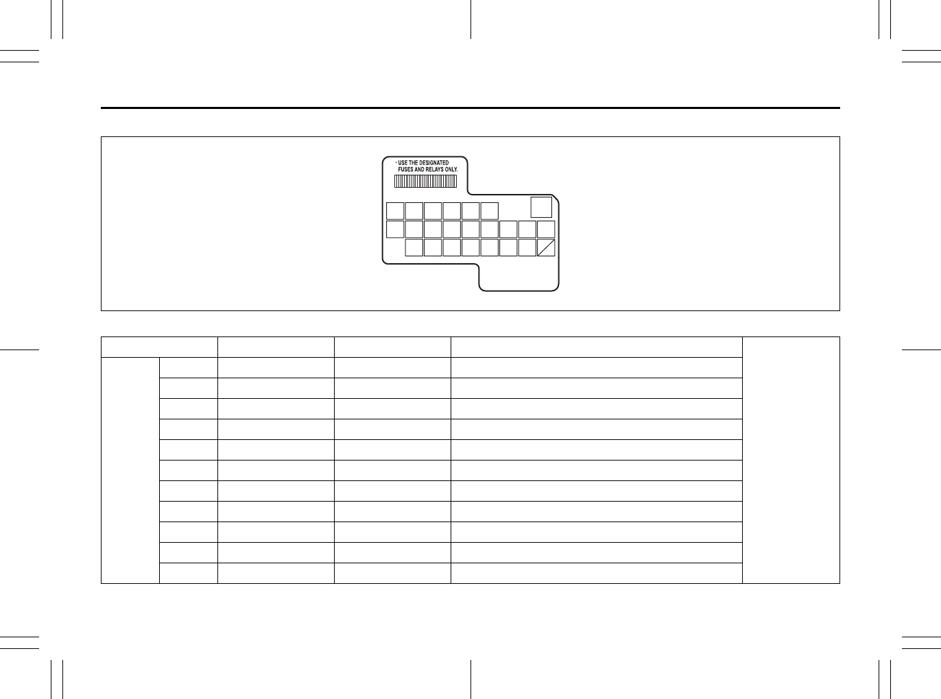
11-4
FUSES AND PROTECTED CIRCUITS
80J23-03E
SX4
80J053
COLOR/SIZE (AMPS) FUSE NAME PROTECTED CIRCUIT
Under the
dashboard
FUSE
BOX
(1) BLUE (15) RR WIP Rear wiper
(2) BLUE (15) IG COIL Ignition coil
(3) RED (10) BACK Back-up light
(4) RED (10) MTR Meter
(5) BLUE (15) ACC Accessory
(6) BLUE (15) ACC2 Accessory 2
(7) PINK (30) P/W Power window
(8) GREEN (30) WIP Wiper
(9) RED (10) IG1 SIG IG1 SIG
(10) BLUE (15) A/B Air bag
(11) RED (10) ABS Anti-lock brake system
(1) (2) (3) (4) (5) (6)
(8) (9) (10) (11) (12) (13) (14) (15) (16)
(18)(17) (19) (20)(21) (22) (23)
(7)
Fuses and Protected Circuits: 7

11-5
FUSES AND PROTECTED CIRCUITS
80J23-03E
80J053
COLOR/SIZE (AMPS) FUSE NAME PROTECTED CIRCUIT
Under the
dashboard
FUSE
BOX
(12) BLUE (15) 4WD 4WD
(13) RED (10) STOP Stop light
(14) YELLOW (20) D/L Door lock
(15) RED (10) RR FOG Rear fog light
(16) RED (10) ST SIG ST SIG
(17) BLUE (15) S/H Seat heater
(18) RED (10) IG2 SIG IG2 SIG
(19) RED (10) TAIL Tail light
(20) BLUE (15) DOME Dome
(21) GREEN (30) RR DEF Rear defogger
(22) BLUE (15) HORN HAZ Horn/Hazard
(23) – – Blank
(1) (2) (3) (4) (5) (6)
(8) (9) (10) (11) (12) (13) (14) (15) (16)
(18)(17) (19) (20)(21) (22) (23)
(7)
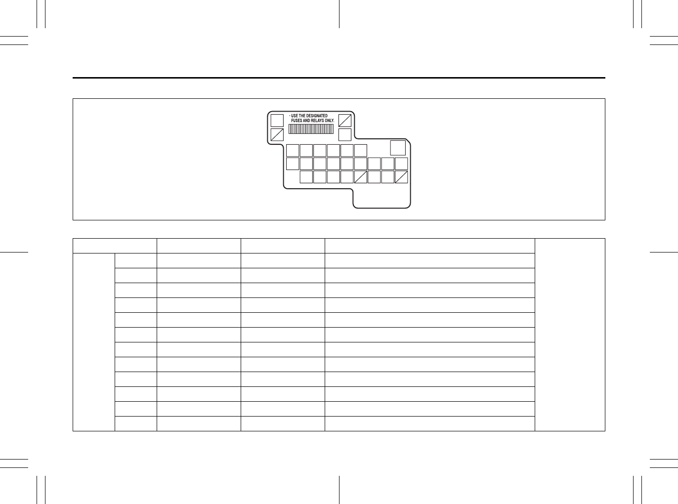
11-6
FUSES AND PROTECTED CIRCUITS
80J23-03E
SX4 SEDAN
80JC003
COLOR/SIZE (AMPS) FUSE NAME PROTECTED CIRCUIT
Under the
dashboard
FUSE
BOX
(1) BLUE (15) RR WIP Rear wiper
(2) BLUE (15) IG COIL Ignition coil
(3) RED (10) BACK Back-up light
(4) RED (10) MTR Meter
(5) BLUE (15) ACC Accessory
(6) BLUE (15) ACC2 Accessory 2
(7) PINK (30) P/W Power window
(8) GREEN (30) WIP Wiper
(9) RED (10) IG1 SIG IG1 SIG
(10) BLUE (15) A/B Air bag
(11) RED (10) ABS Anti-lock brake system
(12) – – Blank
(1) (2) (3) (4) (5) (6)
(8) (9) (10) (11) (12) (13)
(21)
(24)
(14) (15) (16)
(18)(17) (19) (20) (22) (23)
(7)
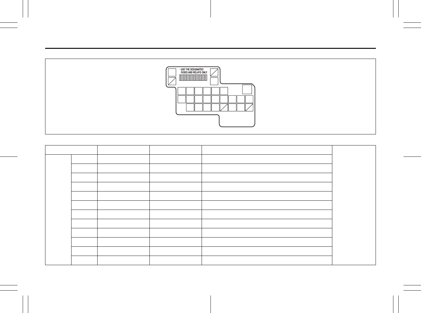
11-7
FUSES AND PROTECTED CIRCUITS
80J23-03E
80JC003
COLOR/SIZE (AMPS) FUSE NAME PROTECTED CIRCUIT
Under the
dashboard
FUSE
BOX
(13) RED (10) STOP Stop light
(14) YELLOW (20) D/L Door lock
(15) RED (10) RR FOG Rear fog light
(16) RED (10) ST SIG ST SIG
(17) BLUE (15) S/H Seat heater
(18) RED (10) IG2 SIG IG2 SIG
(19) RED (10) TAIL Tail light
(20) BLUE (15) DOME Dome
(21) GREEN (30) RR DEF Rear defogger
(22) BLUE (15) HORN HAZ Horn/Hazard
(23) – – Blank
(24) GREEN (30) RR DEF Rear defogger
(1) (2) (3) (4) (5) (6)
(8) (9) (10) (11) (12) (13)
(21)
(24)
(14) (15) (16)
(18)(17) (19) (20) (22) (23)
(7)

11-8
FUSES AND PROTECTED CIRCUITS
80J23-03E
MEMO
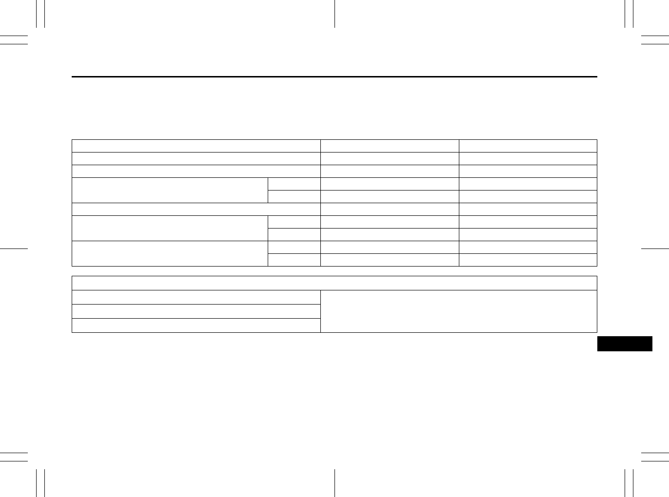
12-1
SPECIFICATIONS
80J23-03E
12
SPECIFICATIONS
NOTE:
Specifications are subject to change with-
out notice.
M/T: Manual transaxle
CVT: Continuously variable transaxle
2WD: 2-wheel drive
i-AWD: intelligent All Wheel Drive
ITEM: Dimensions UNIT: mm (in.) SX4 SX4 SEDAN
Overall length 4115 – 4135 (162.0 – 162.8) 4490 – 4510 (176.8 – 177.6)
Overall width 1730 – 1755 (68.1 – 69.1) 1730 (68.1)
Overall height 195 tire 1575 (62.0) 1545 (60.8)
205 tire 1605 (63.2) 1545 (60.8)
Wheelbase 2500 (98.4) I
Track Front 1500 (59.1) I
Rear 1495 (58.9) I
Ground clearance 195 tire 165 (6.5) I
205 tire 175 (6.9) 160 (6.3)
ITEM: Weight
Gross axle weight rating
See the safety certification label and the tire information label which
are located on the driver’s door lock pillar.
Gross vehicle weight rating
Vehicle capacity weight
Specifications: 1, 2, 5, 6, 7, 10, 11
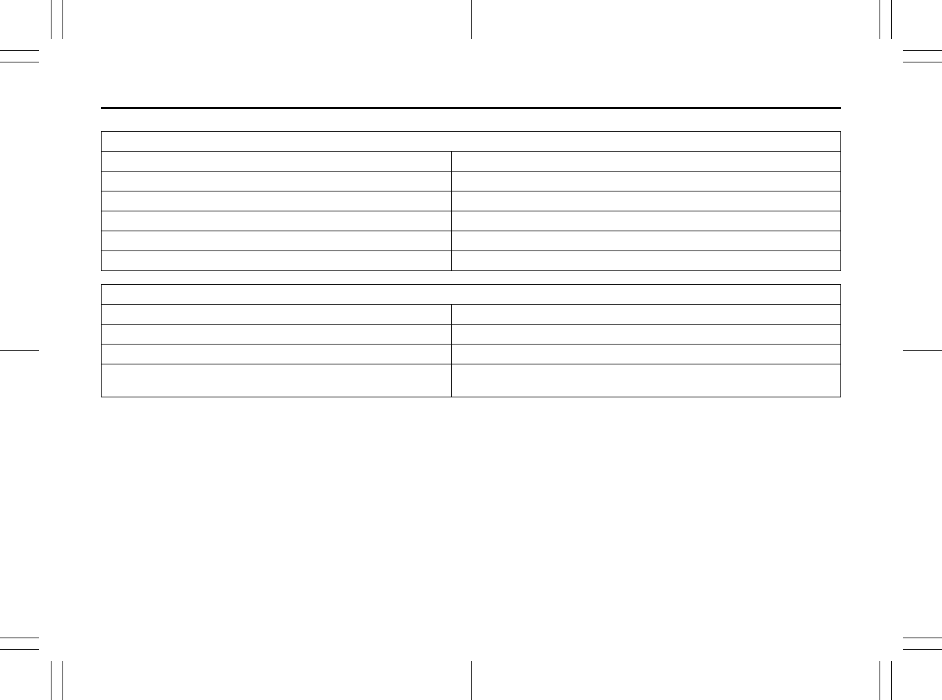
12-2
SPECIFICATIONS
80J23-03E
ITEM: Engine
Type J20B (16V DOHC)
Number of cylinders 4
Bore 84.0 mm (3.31 in.)
Stroke 90.0 mm (3.54 in.)
Piston displacement 1995 cm3 (1995cc, 121.7 cu.in)
Compression ratio 10.2 : 1
ITEM: Electrical
Ignition timing 3° – 17° B.T.D.C. at idle speed
Standard spark plug NGK SILFR5A11
Battery DELKOR 24-700 12V
Fuses See “INSPECTION AND MAINTENANCE” and “FUSES AND PRO-
TECTED CIRCUITS” sections.
Specifications: 1, 2, 5, 6, 7, 10, 11
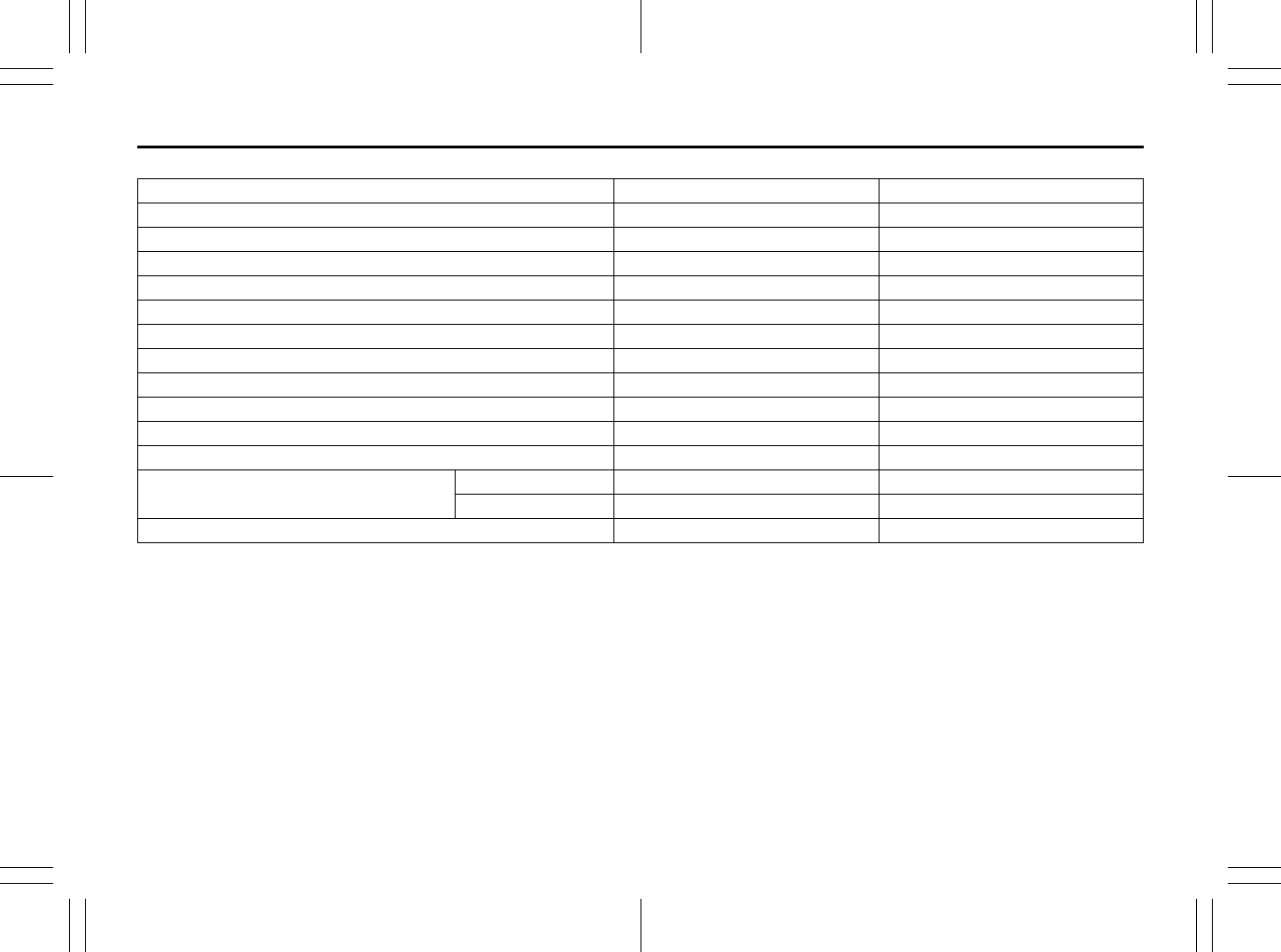
12-3
SPECIFICATIONS
80J23-03E
ITEM: Light WATTAGE BULB No.
Headlight 12V 65/55W HB5
Front fog light 12V 55W H11
Front turn signal light 12V 21W WY21W
Rear turn signal light 12V 21W WY21W
Position light 12V 5W 168
Brake/tail light 12V 21/5W W21/5W
License plate light 12V 5W W5W
Reversing light 12V 21W W21W
Dome light 12V 10W –
Luggage compartment light 12V 5W –
Spot light 12V 8W –
High mount stop light SX4 12V 5W W5W
SX4 SEDAN 12V18W W16W
Side marker light 12V 5W 168
Specifications: 1, 2, 5, 6, 7, 10, 11
12-4
SPECIFICATIONS
80J23-03E
ITEM: Wheel
Tire size, front and rear SX4 P195/65R15, P205/60R16, P205/50R17
SX4 SEDAN P195/65R15, P205/50R17
Tire pressure For the specified tire pressure, see the Tire Information Label located
on the driver’s door lock pillar.
ITEM: Steering
Toe IN 1.0 ± 1.0 mm (0.0393 ± 0.0393 in.)
Camber angle P195/65R15, P205/60R16 –0° 10’ ± 1°
P205/50R17 –0° 17’ ± 1°
Caster angle P195/65R15, P205/60R16 3° 40’ ± 2°
P205/50R17 3° 46’ ± 2°
ITEM: Capacities
Coolant (including reserve tank) M/T 7.1 L (15.0 US pt)
CVT 7.0 L (14.8 US pt)
Fuel tank 2WD 50 L (13.2 US gal)
i-AWD 45 L (11.9 US gal)
Engine oil (replaced with filter) 4.5 L (4.7 quarts)
Transaxle oil Manual transaxle: 2.5 L (5.3 US pt)
CVT: 9.44 L (19.9 US pt) (when overhauling)
Rear differential oil 0.8 L (1.7 US pt)
Transfer gear box oil 0.6 L (1.2 US pt)
Specifications: 1, 2, 5, 6, 7, 10, 11

13-1
INDEX
13
80J23-03E
INDEX
Symbols
“CRUISE” Indicator Light.................................................... 2-66
“ESP OFF” Indicator Light......................................... 2-63, 3-25
“ESP” (Electronic Stability Program) Warning Light ....... 2-63
“ESP” Warning Light........................................................... 3-25
“SET” Indicator Light .......................................................... 2-66
A
Accelerator Pedal .................................................................. 3-8
Accessory Socket................................................................ 5-47
Adding Coolant.................................................................... 7-15
Adjusting Seat Position ...................................................... 2-21
Adjusting Seatbacks ........................................................... 2-22
AIR BAG Light...................................................................... 2-65
Air Cleaner............................................................................ 7-16
Air Conditioning System..................................................... 7-50
All Seat Belts........................................................................ 2-31
Anti-Lock Brake System (ABS) .......................................... 3-21
Anti-Lock Brake System (ABS) Warning Light ................. 2-62
Anti-Lock Braking System (ABS) ....................................... 3-24
Armrest ................................................................................. 5-51
Assist Grips.......................................................................... 5-48
Audio Systems..................................................................... 5-15
Automatic Heating and Air Conditioning System
(Climate Control).................................................................... 5-9
Automatic Locking Retractor (ALR)................................... 2-30
Average fuel consumption.................................................. 2-72
B
Basic Operations ................................................................. 5-18
Battery .................................................................................. 7-35
Brake Assist System............................................................3-21
Brake Fluid............................................................................7-21
Brake Pedal....................................................................3-8, 7-22
Brake System Warning Light ..............................................2-61
Brakes ...................................................................................7-21
Braking..................................................................................3-20
Break-In...................................................................................4-1
Bulb Replacement................................................................7-40
C
Catalytic Converter ................................................................4-1
Changing Engine Oil and Filter...........................................7-12
Changing Wheels...................................................................8-4
Charging Light......................................................................2-64
Child Lock System (rear doors)............................................2-3
Child Restraint Systems......................................................2-36
Cigarette Lighter and Ashtray.............................................5-47
Clock .....................................................................................2-75
Clutch Pedal ..................................................................3-8, 7-19
Compact Spare Tire .............................................................7-31
Continuously Variable Transaxle (CVT).............................3-11
Continuously Variable Transaxle (CVT) Fluid ...................7-20
Coolant Level Check............................................................7-15
Coolant Replacement ..........................................................7-16
Corrosion Prevention ............................................................9-1
Cruise Control ......................................................................3-18
Cup Holder and Storage Area .............................................5-49
D
Daily Inspection Checklist.....................................................3-1
Daytime Running Light (D.R.L.) Indicator Light ................2-68
Daytime Running Light (D.R.L.) System ............................2-76
Door Locks .............................................................................2-1

13-2
INDEX
80J23-03E
Drive Belt .............................................................................. 7-11
Driver’s Seat Belt Reminder Light...................................... 2-64
Driving on Hills ...................................................................... 4-3
Driving on Slippery Roads.................................................... 4-4
Driving range........................................................................ 2-72
E
Electronic Stability Program (ESP®).................................. 3-23
Emergency Locking Retractor (ELR) ................................. 2-30
Emission Compliance Label (for U.S.A.) ........................... 10-2
Engine Block Heater.............................................................. 3-9
Engine Coolant .................................................................... 7-14
Engine Hood......................................................................... 5-44
Engine Oil and Filter............................................................ 7-11
Engine Serial Number ......................................................... 10-1
Exhaust Gas Warning............................................................ 3-1
F
Floor Mats............................................................................. 5-51
Fluid Level Check ................................................................ 7-20
Folding Rear Seats .............................................................. 2-26
Frame Hooks ........................................................................ 5-56
Front Air Bags...................................................................... 2-49
Front Fog Light Switch........................................................ 2-77
Front Seat Back Pocket....................................................... 5-50
Front Seat Heater................................................................. 2-23
Front Seats ........................................................................... 2-21
Fuel Filler Cap...................................................................... 5-43
Fuel Gauge ........................................................................... 2-69
Fuel Pump Labeling............................................................... 1-1
Fuel Recommendation .......................................................... 1-1
Full Wheel Cover.................................................................... 8-4
Fuses .................................................................................... 7-36
FUSES AND PROTECTED CIRCUITS .................................11-1
Fuses in the Engine Compartment.....................................7-36
Fuses under the Dash Board ..............................................7-38
G
Gasoline Containing MTBE ...................................................1-1
Gasoline/Ethanol blends .......................................................1-1
Gasoline/Methanol blends.....................................................1-1
Gear Oil .................................................................................7-18
Gear Oil Level Check ...........................................................7-19
Gear Oil Replacement..........................................................7-19
GLOSSARY OF TIRE TERMINOLOGY ................................7-32
Glove Box .............................................................................5-49
H
Hazard Warning Switch .......................................................2-78
Head Restraints...........................................................2-22, 2-24
Headlight Aiming..................................................................7-39
Heated Rear Window and Heated Outside Rearview
Mirrors Switch ......................................................................2-81
Heating and Air Conditioning System..................................5-1
Heating System ......................................................................5-2
High Beam Indicator Light ..................................................2-67
Highway Driving.....................................................................4-3
Horn.......................................................................................2-81
How the ABS Works.............................................................3-23
I
Identification Numbers ........................................................10-1
If the Engine is Flooded.........................................................8-7
If the Engine Overheats.........................................................8-7
If the Starter Does Not Operate.............................................8-6
If You Cannot Shift CVT Gearshift Lever Out of
“P” (PARK)............................................................................3-15

13-3
INDEX
80J23-03E
If Your Vehicle Gets Stuck .................................................... 4-4
Ignition Key Reminder........................................................... 2-1
Ignition Switch ....................................................................... 3-2
Illumination control setting................................................. 2-74
Illumination Indicator Light................................................. 2-67
Improving Fuel Economy...................................................... 4-2
Information display.............................................................. 2-70
Inside Rearview Mirror ........................................................ 2-19
Installation of Child Restraint with Top Strap................... 2-44
Installation with Lap-Shoulder Seat Belts
(child restraint with no top strap)....................................... 2-38
Installation with the LATCH System .................................. 2-40
Instantaneous Fuel Consumption...................................... 2-70
Instrument Cluster............................................................... 2-59
intelligent All Wheel Drive (i-AWD) AUTO Indicator
Light ...................................................................................... 2-67
intelligent All Wheel Drive (i-AWD) LOCK Indicator
Light ...................................................................................... 2-68
Interior Light Switch ............................................................ 5-45
J
Jacking Instructions.............................................................. 8-2
Jump Starting Instructions ................................................... 8-5
K
Keyless Entry System Transmitter .................................... 2-13
Keyless Start System Indicator Light ................................ 2-66
Keyless Start System Remote Controller............................ 2-6
Keys ........................................................................................ 2-1
L
Lap-Shoulder Belt................................................................ 2-30
Lighting Control Lever ........................................................ 2-75
Lighting Operation............................................................... 2-76
Lights “On” reminder ..........................................................2-76
Listening to a CD..................................................................5-22
Listening to a CD from an External CD Changer
(Option) .................................................................................5-34
Listening to a XM Satellite Radio (Option).........................5-31
Listening to Audio for AUX (Option) ..................................5-33
Listening to the Radio .........................................................5-20
Low Fuel Warning Light ......................................................2-66
Low Tire Pressure Warning Light..............................2-60, 3-26
Luggage Compartment Board ............................................5-53
Luggage Compartment Cover.............................................5-52
Luggage Compartment Light ..............................................5-46
M
Maintenance Recommended under Severe Driving
Conditions ..............................................................................7-7
Maintenance Schedule ..........................................................7-2
Malfunction Indicator Light .................................................2-65
Manual Heating and Air Conditioning System ....................5-5
Manual Transaxle.................................................................3-10
Mirrors...................................................................................2-19
O
Odometer ..............................................................................2-74
Oil Level Check ....................................................................7-11
Oil Pressure Light ................................................................2-64
On-Board Vehicle Computers and Event Data
Recorders .............................................................................10-3
Open Door Warning Light ...................................................2-66
Outside Rearview Mirrors....................................................2-20
P
Parking Brake Lever .....................................................3-6, 7-23
Pedals......................................................................................3-7

13-4
INDEX
80J23-03E
Periodic Maintenance Schedule........................................... 7-3
Power Door Locking System ................................................ 2-2
Power Mirror Control........................................................... 2-20
Power Steering..................................................................... 7-24
Power Steering Fluid ........................................................... 7-24
Power Window Controls ..................................................... 2-17
Power-Assisted Brakes....................................................... 3-21
R
Radio Antenna ..................................................................... 5-15
Rear Seats ............................................................................ 2-24
Rear Window Wiper/Washer Switch .................................. 2-80
Refill with Oil and Check for Leaks.................................... 7-14
Refilling................................................................................. 7-12
Remote Audio Controls....................................................... 5-37
Replace the Oil Filter ........................................................... 7-13
Replacing Tires and/or Wheels .......................................... 3-29
Reporting Safety Defects .................................................... 10-4
Roof Rails or Roof Rack Anchors ...................................... 5-55
S
Safety Certification Label.................................................... 10-2
Seat Adjustment .................................................................. 2-21
Seat Belt Extender ............................................................... 2-45
Seat Belt Hanger .................................................................. 2-34
Seat Belt Inspection ............................................................ 2-35
Seat Belt Pretensioner System........................................... 2-46
Seat Belt Reminder.............................................................. 2-32
Seat Belts and Child Restraint Systems............................ 2-28
Selection of Coolant ............................................................ 7-14
Shopping Hook .................................................................... 5-51
Shoulder Anchor Height Adjuster...................................... 2-34
Side Air Bags and Side Curtain Air Bags .......................... 2-50
Side Door Locks.....................................................................2-1
SLIP Indicator Light ....................................................2-62, 3-25
Snow Tires............................................................................7-32
Spark Plugs ..........................................................................7-16
SPECIFICATIONS .................................................................12-1
Specified Fluid......................................................................7-20
Specified Gear Oil ................................................................7-18
Specified Oil .........................................................................7-11
Speedometer ........................................................................2-68
Spot Light .............................................................................5-47
Stability Control System......................................................3-24
Starting the Engine ................................................................3-8
Steering Wheel .....................................................................7-23
Sun Visor ..............................................................................5-45
Supplemental Restraint System (air bags) ........................2-47
T
Tachometer...........................................................................2-69
Tailgate....................................................................................2-3
Temperature Gauge .............................................................2-70
Theft Deterrent Light............................................................2-17
Thermometer ........................................................................2-73
Tilt Steering Lock Lever ......................................................2-81
Tire Chains..............................................................................4-5
Tire Changing Tool ................................................................8-1
Tire Inflation Pressure .........................................................7-26
Tire Inspection......................................................................7-28
Tire Pressure Monitoring System (TPMS) .........................3-26
Tire Rotation .........................................................................7-30
Tire Sidewall Labeling .........................................................7-24
Tire Size ................................................................................7-25
Tires.......................................................................................7-24

13-5
INDEX
80J23-03E
Towing a Disabled Vehicle.................................................... 8-6
Towing Your Vehicle (recreational towing) ......................... 6-2
Traction Control System..................................................... 3-24
Trailer Towing ........................................................................ 6-2
Transaxle selector position indicator ................................ 2-73
Trip meter ............................................................................. 2-72
Troubleshooting .................................................................. 5-41
Trunk Lid ................................................................................ 2-4
Trunk Light ........................................................................... 5-46
Turn Signal Control Lever................................................... 2-77
Turn Signal Indicators......................................................... 2-67
Turn Signal Operation ......................................................... 2-77
U
Uniform Tire Quality Grading ............................................. 7-29
Using the 2WD/i-AWD (intelligent All Wheel Drive)
Switch ................................................................................... 3-16
Using the Transaxle............................................................. 3-10
V
Vehicle Cleaning.................................................................... 9-3
Vehicle Identification Number ............................................ 10-1
Vehicle Loading ............................................................ 6-1, 7-33
Vehicle With Keyless Start System...................................... 3-4
Vehicle Without Keyless Start System ................................ 3-3
W
Warning and Indicator Lights............................................. 2-60
Warranties ............................................................................ 10-2
Washing.................................................................................. 9-4
Waxing .................................................................................... 9-5
Windows ............................................................................... 2-17
Windshield Washer.............................................................. 2-79
Windshield Washer Fluid .................................................... 7-50
Windshield Wiper and Washer Lever .................................2-78
Windshield Wipers ...............................................................2-79
Wiper Blades ........................................................................7-46
13-6
INDEX
80J23-03E
MEMO
80J23-03E
Prepared by
June, 2009
Part No. 99011-80J23-03E
Printed in Japan
TP294
