Suzuki Gz250 Users Manual
2015-01-26
: Suzuki Suzuki-Gz250-Users-Manual-232294 suzuki-gz250-users-manual-232294 suzuki pdf
Open the PDF directly: View PDF ![]() .
.
Page Count: 230 [warning: Documents this large are best viewed by clicking the View PDF Link!]
FOREWORD
This manual contains an introductory description on
the SUZUKI GZ250 and procedures for its inspec-
tion/service and overhaul of its main components.
Other information considered as generally known is
not included.
Read the GENERAL INFORMATION section to fa-
miliarize yourself with the motorcycle and its mainte-
nance. Use this section as well as other sections as a
guide for proper inspection and service. This
manual will help you know the motorcycle better so
that you can assure your customers of fast and re-
liable service.
This manual has been prepared on the basis
of the latest specifications at the time of pub-
lication. If modifications have been made
since then, differences may exist between
the content of this manual and the actual mo-
torcycle.
Illustrations in this manual are used to show
the basic principles of operation and work
procedures. They may not represent the ac-
tual motorcycle exactly in detail. This
manual is written for persons who have
enough knowledge, skills and tools, includ-
ing special tools, for servicing SUZUKI mo-
torcycles. If you do not have the proper
knowledge and tools, ask your authorized
SUZUKI motorcycle dealer to help you.
GROUP INDEX
GENERAL INFORMATION
PERIODIC MAINTENANCE
ENGINE
FUEL AND LUBRICATION
SYSTEM
CHASSIS
ELECTRICAL SYSTEM
SERVICING INFORMATION
WARNING
Inexperienced mechanics or mechanics
without the proper tools and equipment
may not be able to properly perform the
service described in this manual. Improp-
er repair may result in injury to the me-
chanic and may render the motorcycle un-
safe for the rider and passenger.
SUZUKI MOTOR CORPORATION
Motorcycle Service Department
© COPYRIGHT SUZUKI MOTOR CORPORATION 1998
HOW TO USE THIS MANUAL
TO LOCATE WHAT YOU ARE
LOOKING FOR:
1. The text of this manual is divided into sections.
2. The section titles are listed in the GROUP INDEX.
3. Holding the manual as shown at the right will allow
you to find the first page of the section easily.
4. The contents are listed on the first page of each sec-
tion to help you find the item and page you need.
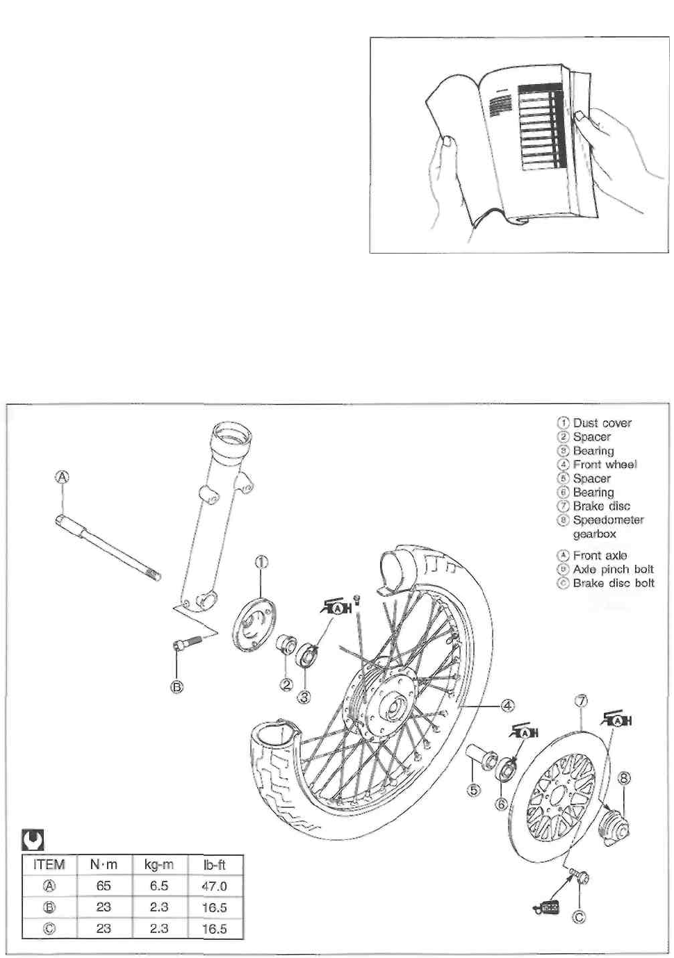
COMPONENT PARTS AND WORK TO BE DONE
Under the name of each system or unit, is its exploded view. Work instructions and other service
information such as the tightening torque, lubricating points and locking agent points, are provided.
Example: Front wheel
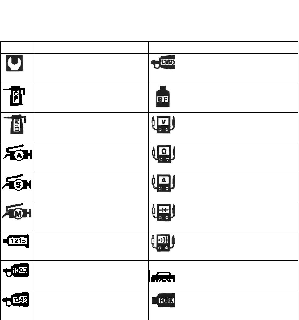
SYMBOL
Listed in the table below are the symbols indicating instructions and other information necessary for
servicing. The meaning of each symbol is also included in the table.
SYMBOL
DEFINITION
SYMBO
L DEFINITION
Torque control required.
Data beside it indicates specified
torque.
Apply THREAD LOCK "1360".
99000-32130
Apply oil. Use engine oil unless
otherwise specified.
Apply or use brake fluid.
Apply molybdenum oil solution (mix-
ture of engine oil and SUZUKI MOLY
PASTE in a ratio of 1 : 1).
Measure in voltage range.
Apply SUZUKI SUPER GREASE
"A".
99000-25010
Measure in resistance range.
Apply SUZUKI SILICONE GREASE.
99000-25100
Measure in current range.
Apply SUZUKI MOLY PASTE.
99000-25140
Measure in diode test range.
Apply SUZUKI BOND "1215".
99000-31110
Measure in continuity test range.
Apply THREAD LOCK SUPER
"1303".
99000-32030
Use special tool.
Apply THREAD LOCK "1342".
99000-32050
Use fork oil. 99000-
99001-SS8

GENERAL INFORMATION
----------------------------------------- CONTENTS ---------------------------------------------- 1
WARNING/CAUTION/NOTE ............................................................... 1- 1
GENERAL PRECAUTIONS ................................................................ 1- 1
SUZUKI GZ250X ('99-MODEL) ........................................................... 1-3
SERIAL NUMBER LOCATION ........................................................... 1-3
FUEL AND OIL RECOMMENDATIONS .............................................. 1-3
FUEL ............................................................................................... 1-3
ENGINE OIL ................................................................................. 1-4
BRAKE FLUID .............................................................................. 1-4
FRONT FORK OIL .......................................................................... 1-4
BREAK-IN PROCEDURES ................................................................. 1-4
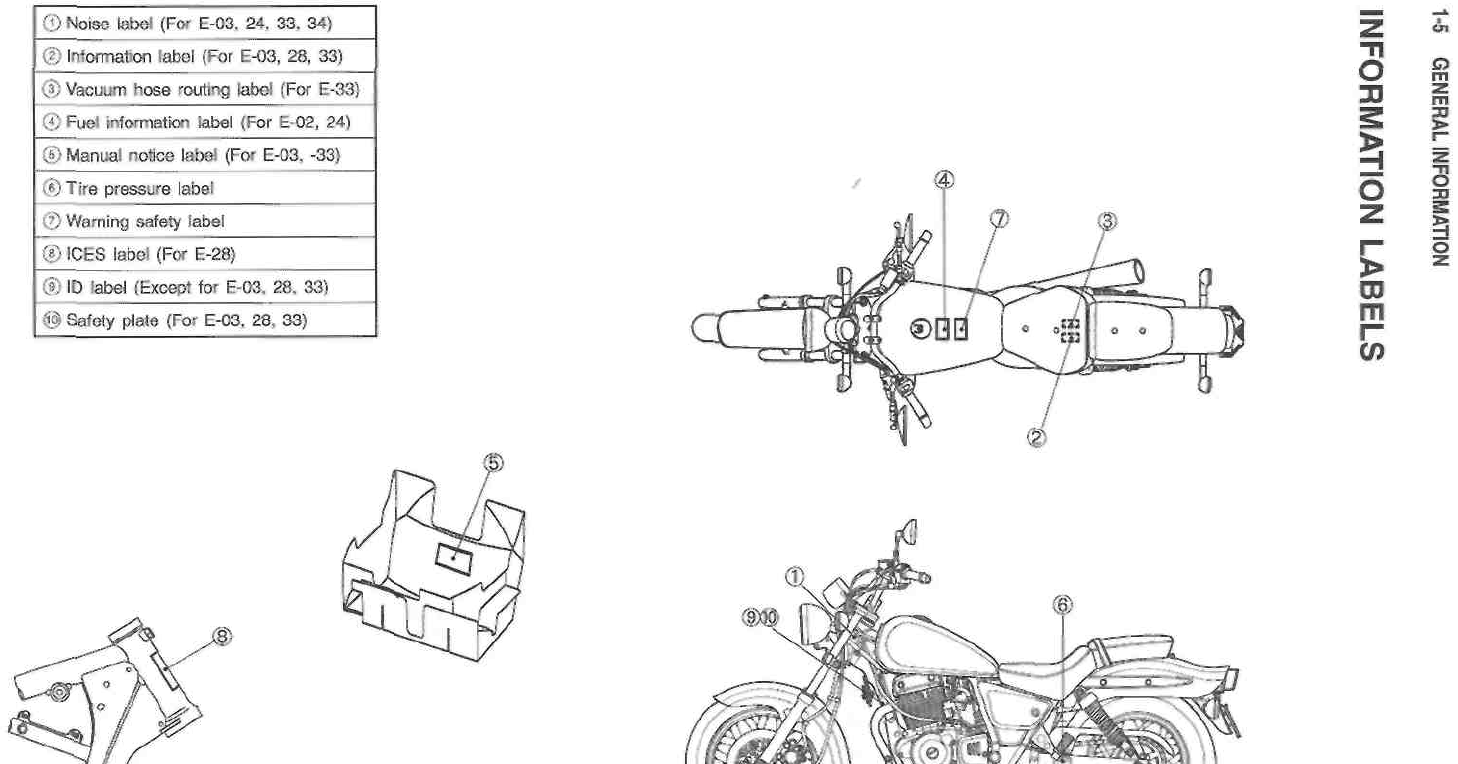
INFORMATION LABELS .................................................................... 1-5
SPECIFICATIONS ............................................................................. 1-6
COUNTRY AND AREA CODES ........................................................ 1-8

1-1 GENERAL INFORMATION
WARNING/CAUTION/NOTE
Please read this manual and follow its instructions carefully. To emphasize special information, the
symbol and the words WARNING, CAUTION and NOTE have special meanings. Pay special attention
to the messages highlighted by these signal words.
WARNING
Indicates a potential hazard that could result in death or injury.
CAUTION
Indicates a potential hazard that could result in motorcycle damage.
NOTE:
Indicates special information to make maintenance easier or instructions clearer.
Please note, however, that the warnings and cautions contained in this manual cannot possibly cover
all potential hazards relating to the servicing, or lack of servicing, of the motorcycle. In addition to the
WARNINGS and CAUTIONS stated, you must use good judgement and basic mechanical safety prin-
ciples. If you are unsure about how to perform a particular service operation, ask a more experienced
mechanic for advice.
GENERAL PRECAUTIONS
WARNING
Proper service and repair procedures are important for the safety of the service me-
chanic and the safety and reliability of the motorcycle.
When 2 or more persons work together, pay attention to the safety of each other.
When it is necessary to run the engine indoors, make sure that exhaust gas is forced
outdoors.
When working with toxic or flammable materials, make sure that the area you work in is
well ventilated and that you follow all of the manufacturer's instructions. Never use
gasoline as a cleaning solvent.
To avoid getting burned, do not touch the engine, engine oil and exhaust system until
they have cooled.
After servicing fuel, oil, exhaust or brake systems, check all of the lines and fittings
related to the system for leaks.

GENERAL INFORMATION 1-2
CAUTION
* If parts replacement is necessary, replace the parts with Suzuki Genuine Parts or their
equivalent.
* When removing parts that are to be reused, keep them arranged in an orderly manner
so that they may be reinstalled in the proper order.
* Be sure to use special tools when instructed.
* Make sure that all parts used in reassembly are clean. Lubricate them when specified.
* Use the specified lubricant, bond, or sealant.
* When removing the battery, disconnect the negative cable first and then the positive
cable.
* When reconnecting the battery, connect the positive cable first and then the negative
cable, and cover the positive terminal with the terminal cover.
* When performing service to electrical parts, disconnect the battery negative cable unless
the service procedure requires the battery power.
* When tightening cylinder head and crankcase bolts and nuts, tighten the larger sizes
first. Always tighten the bolts and nuts from the inside working out, in a crisscross
pattern and to the specified tightening torque.
* Whenever you remove oil seals, gaskets, packing, O-rings, self-locking nuts, locking
washers, cotter pins, circlips, and certain other parts as specified, be sure to replace them
with new ones. Also, before installing these new parts, be sure to remove any left over
material from the mating surfaces.
* Never reuse a circlip. When installing a new circlip, take care not to expand the end gap
larger than required to slip the circlip over the shaft. After installing a circlip, always ensure
that it is completely seated in its groove and securely fitted.
* Use a torque wrench to tighten fasteners to the specified torque. Wipe off grease and
oil if a thread is smeared with them.
* After reassembling, check parts for tightness and proper operation.
CAUTION

* To protect the environment, do not unlawfully dispose of used motor oil and all other fluids,
batteries, and tires.
* To protect the earth's natural resouces, properly dispose of used motorcycles and parts.
1-3 GENERAL INFORMATION
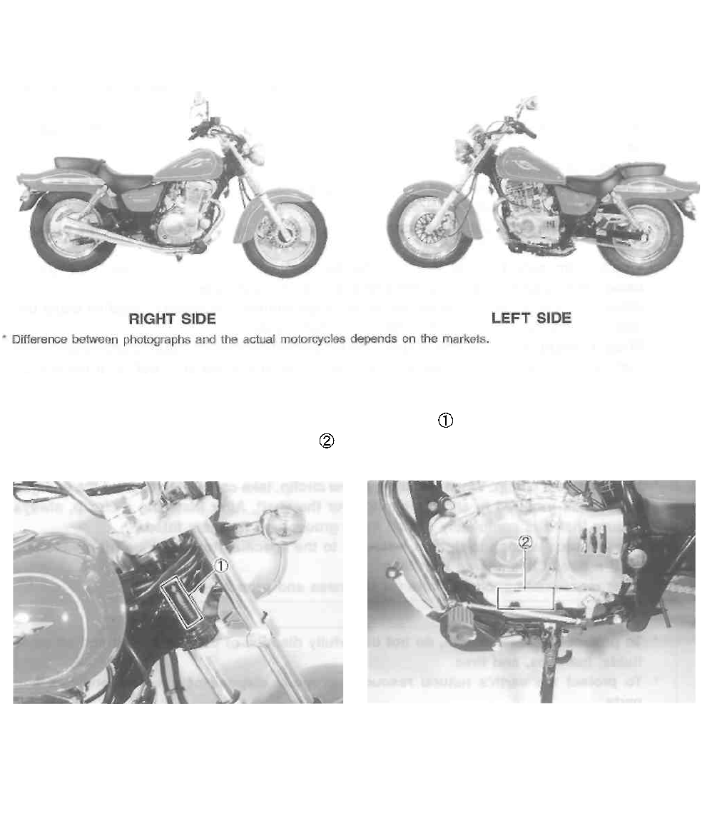
SUZUKI GZ250X ('99-MODEL)
SERIAL NUMBER LOCATION
The frame serial number or V.I.N. (Vehicle Identification Number) is stamped on the right side of the
steering head pipe. The engine serial number is located on the left side of the crankcase. These
numbers are required especially for registering the machine and ordering spare parts.
FUEL AND OIL RECOMMENDATIONS
FUEL
Use unleaded gasoline that is graded 91 octane or higher.
GENERAL INFORMATION 1-4
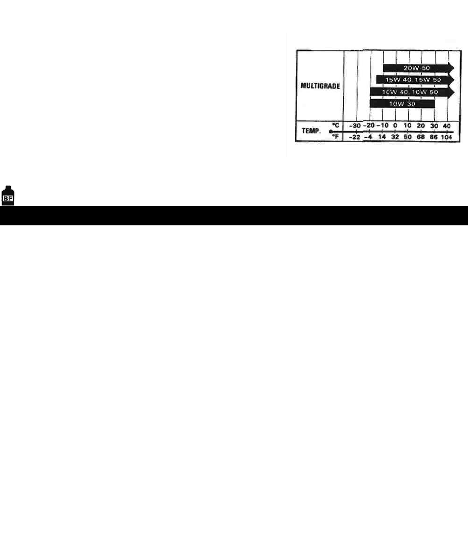
ENGINE OIL
Use only oils which are rated SF or SG under the API clas-
sification. The recommended viscosity is SAE 10W/40. If
SAE 10W/40 engine oil is not available, select an alterna-
tive according to the chart.
BRAKE FLUID
Specification and classification: DOT 4
WARNING
This motorcycle uses a glycol-based brake fluid. Do not use or mix different types of
brake fluid such as silicone-based and petroleum-based fluids for refilling the system,
otherwise serious damage will result to the brake system.
Never use any brake fluid taken from old, used or unsealed containers.
Never re-use brake fluid left over from a last servicing or which has been stored for a long
period of time.
FRONT FORK OIL
Use SUZUKI fork oil SS-08 (#10).
BREAK-IN PROCEDURES
During manufacturing only the best possible materials are used and all machined parts are finished to
a very high standard. It is still necessary to allow the moving parts to "BREAK-IN" before subjecting the
engine to maximum stresses. The future performance and reliability of the engine depends on the care
and restraint exercised during its early life. The general rules are as follows.
• Keep to this break-in throttle position.
Initial 800 km (500 miles) : Less than 1/2 throttle
Up to 1 600 km (1 000 miles): Less than 3/4 throttle
• Upon reaching an odometer reading of 1 600 km you can subject the motorcycle to full throttle
operation for short periods of time.

GENERAL INFORMATION 1-6
SPECIFICATIONS
DIMENSIONS AND DRY MASS
Overall length .............................................
Overall width ................................................
Overall height ..............................................
Wheelbase ....................................................
Ground clearance .........................................
Seat height ....................................................
Dry mass .....................................................
ENGINE
Type ..............................................................
Number of cylinder ........................................
Bore ...............................................................
Stroke ...........................................................
Displacement ................................................
Compression ratio .........................................
Carburetor ...................................................
Air cleaner .....................................................
Starter system ...............................................
Lubrication system .......................................
TRANSMISSION
Clutch ...........................................................
Transmission ...............................................
Gearshift pattern ............................................
Primary reduction ratio ...............................
Final reduction ratio ......................................
Gear ratios, Low .........................................
2nd ........................................
3rd ..........................................
4th ..........................................
Top .......................................
Drive chain ...................................................
2 160 mm (85.0 in)
815 mm (32.1 in)
1 090 mm (42.9 in)
1 450 mm (57.1 in)
125 mm ( 4.9 in)
680 mm (27.8 in)
137 kg (302 lbs)
Four-stroke, air-cooled, OHC
1
72.0 mm (2.835 in)
61.2 mm (2.409 in)
249 cm3 (15.2 cu. in)
9.0 : 1
MIKUNI BSR32SS, single
Non-woven fabric element
Electric
Wet sump
Wet multi-plate type
5-speed constant mesh
1-down, 4-up
3.238 (68/21)
2.733 (41/15)
2.636 (29/11)
1.687 (27/16)
1.263 (24/19)
1.000 (20/20)
0.818 (18/22)
DID 520VC5, 110 links

1-7 GENERAL INFORMATION
ELECTRICAL
Ignition type .............................................................. Electronic ignition (Transistorized)
Ignition timing ........................................................ 10° B.T.D.C. at 1 300 r/min
Spark plug .............................................................. NGK DR8EA or DENSO X24ESR-U
Battery ...................................................................... 12V 21.6 kC (6 Ah)/10 HR
Generator ................................................................. Three-phase A.C. generator
Fuse ......................................................................... 20/15/15/15/10/10A
Headlight .................................................................. 12V 60/55W
Position light .......................................................... 12V 4W ....... Except for E-03, -24, -28, -33
Brake light/Taillight .................................................. 12V 21/5W
Front turn signal light/Running light .......................... 12V 21/5W ....... E-03, -28, -33
Turn signal light ..................................................... 12V 21W
Speedometer light .................................................... 12V 1.7W
Neutral indicator light ................................................ 12V 3.4W
Turn signal indicator light ......................................... 12V 3.4W
High beam indicator light ........................................ 12V 1.7W
CHASSIS
Front suspension ................................................... Telescopic, coil spring, oil damped
Rear suspension ...................................................... Swingarm type, coil spring, oil damped, spring
preload 5-way adjustable
Front fork stroke ....................................................... 120 mm (4.7 in)
Rear wheel travel ..................................................... 90 mm (3.5 in)
Steering angle .......................................................... 40° (right and left)
Caster ...................................................................... 32° 30'
Trail ......................................................................... 140 mm (5.5 in)
Turning radius .......................................................... 2.6 m (8.5 ft)
Front brake ............................................................... Disc brake
Rear brake ................................................................ Internal expanding
Front tire size .......................................................... 110/90-16 59P
Rear tire size ............................................................ 130/90-15M/C 66P
CAPACITIES
Fuel tank, including reserve ..................................... 14 L (3.7/3.1 US/Imp gal)
reserve ................................................ 2.9 L (0.8/0.6 US/Imp gal)
Engine oil, oil change ........................................... 1 300 ml (1.4/1.1 US/Imp qt)
with filter change ................................ 1 400 ml (1.5/1.2 US/Imp qt)
overhaul ............................................. 1 700 ml (1.8/1.5 US/Imp qt)
Front fork oil (each leg) ......................................... 369 ml (12.5/13.0 US/Imp oz)
Specifications are subject to change without notice.

GENERAL INFORMATION 1-8
COUNTRY AND AREA CODES
The following codes stand for the applicable country(-ies) and area(-s).
CODE
COUNTRY OR AREA
E-01
General
E-02
UK
E-03
U.S.A. (Except for California)
E-04
France
E-17
Sweden, Finland (E-15), Norway (E-16), Denmark (E-26)
E-22
Germany
E-24
Australia
E-25
Netherlands
E-28
Canada
E-33
California (U.S.A.)
E-34
Italy, Belgium (E-21), Spain (E-53)

PERIODIC MAINTENANCE
----------------------------------------- CONTENTS ------------------------------------------
PERIODIC MAINTENANCE SCHEDULE ............................................. 2- 1
PERIODIC MAINTENANCE CHART ................................................ 2- 1
LUBRICATION POINTS ................................................................. 2-2
MAINTENANCE AND TUNE-UP PROCEDURES .............................. 2-3
EXHAUST PIPE BOLTS AND MUFFLER MOUNTING BOLTS ......... 2-3
AIR CLEANER ................................................................................ 2- 3
VALVE CLEARANCE ..................................................................... 2-4
SPARK PLUG ................................................................................. 2- 6
FUEL HOSE .................................................................................... 2- 7
ENGINE IDLE SPEED ..................................................................... 2- 7
THROTTLE CABLE PLAY ............................................................... 2- 7
STARTER PLUNGER CABLE PLAY ............................................... 2-9
CLUTCH .......................................................................................... 2-9
ENGINE OIL AND OIL FILTER ........................................................ 2- 9
DRIVE CHAIN .................................................................................. 2-70
BRAKES .......................................................................................... 2-12
TIRE ............................................................................................... 2-15
STEERING ....................................................................................... 2-15
FRONT FORK ................................................................................. 2-16
REAR SUSPENSION ....................................................................... 2-16
CHASSIS BOLTS AND NUTS ......................................................... 2-16
COMPRESSION PRESSURE CHECK ............................................... 2-18
OIL PRESSURE CHECK .................................................................... 2-19

2-1 PERIODIC MAINTENANCE
PERIODIC MAINTENANCE SCHEDULE
The chart below lists the recommended intervals for all the required periodic service work necessary to
keep the motorcycle operating at peak performance and economy. Maintenance intervals are ex-
pressed in terms of kilometers and months, and are dependant on whichever comes first.
NOTE:
More frequent servicing may be performed on motorcycles that are used under severe conditions.
PERIODIC MAINTENANCE CHART
Interval
Item
km
1 000
5 000
10 000
15 000
miles
600
3 000
6 000
9 500
months
3
15
30
45
Exhaust pipe bolts and muffler mounting
bolts
-
T
T
T
Air cleaner element
Clean every 3 000 km (2 000 miles).
Valve clearance
I
I
I
I
Spark plug
-
I
R
I
Fuel hose
-
I
I
I
Replace every 4 years.
Engine idle speed
I
I
I
I
Throttle cable play
I
I
I
I
Clutch
-
I
I
I
Engine oil
R
R
R
R
Engine oil filter
R
-
R
-
Drive chain
I
I
I
I
Clean and lubricate every 1 000 km (600 miles).
Brakes
I
I
I
I
Brake hose
-
I
I
I
Replace every 4 years.
Brake fluid
-
I
I
I
Replace every 2 years.
Tires
-
I
I
I
Steering
I
-
I
-
Front fork
-
-
I
-
Rear suspension
-
-
I
-
Chassis bolts and nuts
T
T
T
T
NOTE:
I: Inspection and adjust, clean, lubricate or replace as necessary
C: Clean R: Replace T: Tighten

PERIODIC MAINTENANCE 2-2
LUBRICATION POINTS
Proper lubrication is important for smooth operation and long life of each working part of the motor-
cycle. Major lubrication points are indicated below.
Side-stand pivot Drive chain
and spring hook
Brake pedal pivot
NOTE:
* Before lubricating each part, clean off any rusty spots and wipe off any grease, oil, dirt or grime.
* Lubricate exposed parts which are subject to rust, with a rust preventative spray especially whenever
the motorcycle has been operated under wet or rainy condition.
Clutch lever holder
Brake lever holder
2-3 PERIODIC MAINTENANCE
MAINTENANCE AND TUNE-UP PROCEDURES
This section describes the servicing procedures for each
item in the Periodic Maintenance chart.
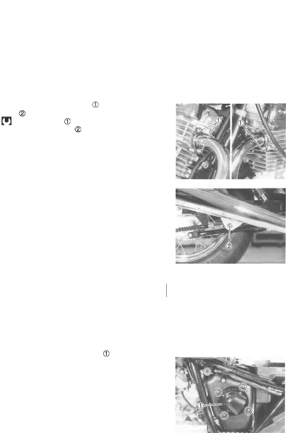
EXHAUST PIPE BOLTS AND MUFFLER
MOUNTING BOLTS
Tighten every 5 000 km (3 000 miles, 15 months).
• Tighten the exhaust pipe bolts and muffler mounting
bolt to the specified torque.
Exhaust pipe bolt : 14 N ■ m (1.4 kg-m, 10.0 Ib-ft)
Muffler mounting bolt : 29 N ■ m (2.9 kg-m, 21.0 Ib-ft)
AIR CLEANER
Clean every 3 000 km (2 000 miles).
If the air cleaner is clogged with dust, intake resistance will
increase, resulting in a decrease in engine output and an
increase in fuel consumption. Check and clean the air
cleaner element in the following manner.
• Remove the front seat. (See p. 5-1.)
• Remove the left frame cover. (See p. 5-1.)
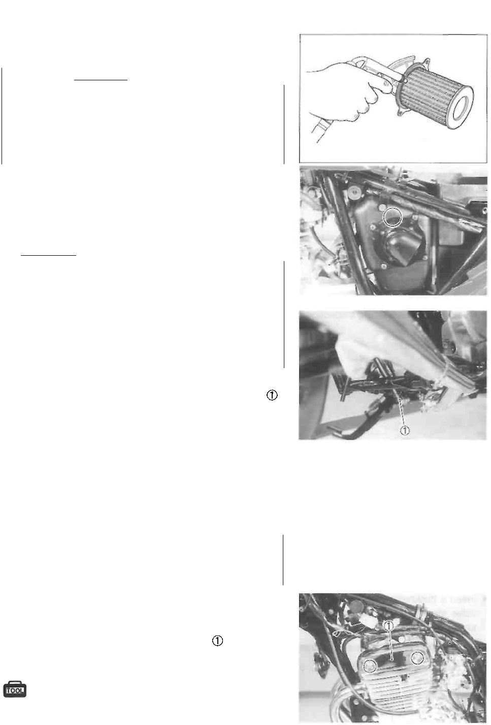
• Remove the air cleaner element .
PERIODIC MAINTENANCE 2-4
• Carefully use compressed air to clean the air cleaner
element.
CAUTION ________________________________
Always apply compressed air to the
outside of the air cleaner element. If compressed
air is applied to the inside, dirt will be forced into
the pores of the air cleaner element, restricting
air flow through the air cleaner element.
• Reinstall the cleaned or new air cleaner element in the
reverse order of removal.
• When installing the air cleaner element into the air clean-
er case, align the triangle marks on the air cleaner ele-
ment and the air cleaner case.
CAUTION
If driving under dusty conditions, clean the air
cleaner element more frequently. The surest way
to accelerate engine wear is to operate the engine
without the element or to use a torn element.
Make sure that the air cleaner is in good condition
at all times. The life of the engine depends largely
on this component!
NOTE:
When cleaning the air cleaner element, remove the plug
and drain any water from the air cleaner drain hose.
VALVE CLEARANCE
Inspect initially at 1 000 km (600 miles, 3 months)
and every 5 000 km (3 000 miles, 15 months) there-
after.
INSPECTION
• Remove the front seat. (See p. 5-1.)
• Remove the fuel tank. (See p. 4-1.)
• Remove the cylinder head cover left cap
• Disconnect the spark plug cap and remove the spark
plug.
09930-10121: Spark plug socket wrench set
CAUTION
2-5 PERIODIC MAINTENANCE
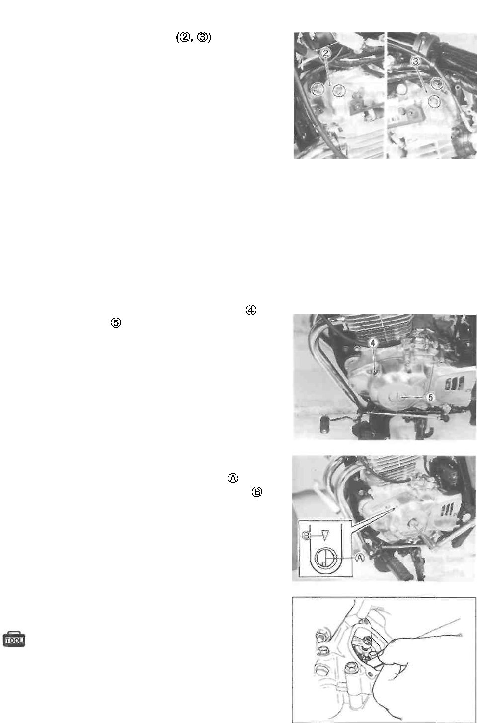
Remove the valve inspection caps
The valve clearance specification is different for intake and
exhaust valves.
Valve clearance adjustment must be checked and adjusted,
1) at the time of periodic inspection, 2) when the valve
mechanism is serviced, and 3) when the camshaft is re-
moved for servicing.
Valve clearance (when cold):
IN. : 0.03-0.08 mm (0.001-0.003 in)
EX.: 0.08-0.13 mm (0.003-0.005 in)
NOTE:
* The piston must be at top dead center (TDC) on the
compression stroke in order to check or adjust the valve
clearance.
* The valve clearance should only be checked when the
engine is cold.
* Remove the valve timing inspection plug and
generator cover cap
Rotate the crankshaft with a box wrench to set the piston
at top dead center (TDC) on the compression stroke.
(Rotate the crankshaft until the "T" line on the
generator rotor is aligned with the triangle mark on
the generator cover.)
Insert a thickness gauge into the clearance between the
valve stem end and the adjusting screw on the rocker
arm.
09900-20803: Thickness gauge
If the clearance is out of specification, adjust it to specifica-
tion as follows.
PERIODIC MAINTENANCE 2-6
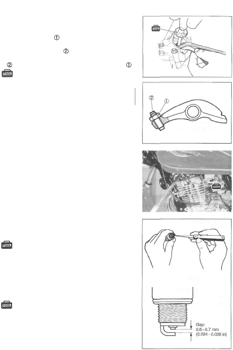
ADJUSTMENT
The clearance is adjusted using the special tool and offset
wrench.
• Loosen the locknuts
• Insert a thickness gauge between the valve stem end
and the adjusting screw on the rocker arm.
• Adjust the valve clearance by turning the adjusting screw
using the special tool while holding the locknuts
09917-14920: Valve adjuster wrench
CAUTION
Both the right and left valve clearances should be as
closely as possible.
• After the adjustment is completed, tighten the locknut se-
curely.
• Rotate the crankshaft 720° with a box wrench and check
that the clearance is within specification.
SPARK PLUG
Inspect every 5 000 km (3 000 miles, 15 months).
Replace every 10 000 km (6 000 miles, 30 months).
Neglecting the spark plug eventually leads to difficult start-
ing and poor engine performance. If the spark plug is used
for a long period, the electrode gradually bums away and
carbon builds up along the inside part of the spark plug. In
accordance with the Periodic Maintenance chart, the spark
plug should be inspected, cleaned and regapped at the rec-
ommended intervals.
• Remove the cylinder head cover left cap.
• Disconnect the spark plug cap and remove the spark
plug.
09930-10121: Spark plug socket wrench set
• Carbon deposits on the spark plug will prevent
good
sparking and may cause the engine to misfire. Be sure to
clean the carbon deposits off periodically.
If the center electrode is fairly worn down, the spark plug
should be replaced and the spark plug gap set to the speci-
fication using a thickness gauge.
09900-20803: Thickness gauge
Spark plug gap: 0.6-0.7 mm (0.024-0.028 in)
2-7 PERIODIC MAINTENANCE
Check the spark plug for burns. If any abnormalities are
found, replace the spark plug as indicated below.
NGK
DENSO
Remarks
DR7EA
X22ESR-U
If the standard spark plug is
apt to get wet, replace with
this plug.
DR8EA
X24ESR-U
Standard
DR9EA
X27ESR-U
If the standard spark plug is
apt to overheat, replace with
this plug.
CAUTION
Confirm the thread size and reach when replacing
the spark plug. If the reach is too short, carbon
will be deposited on the screw portion of the plug
hole and engine damage may result.
CAUTION
Before using a spark plug wrench, carefully turn
the spark plug by finger into the threads of the
cylinder head to prevent damage.
• Tighten the spark plug to the specified torque using the
special tool.
Spark plug: 18 N-m (1.8 kg-m, 13.0 Ib-ft)
09930-10121: Spark plug socket wrench set
FUEL HOSE
Inspect every 5 000 km (3 000 miles, 15 months).
Replace every 4 years.
ENGINE IDLE SPEED
Inspect initially at 1 000 km (600 miles, 3 months)
and every 5 000 km (3 000 miles, 15 months) there-
after.
• Adjust the throttle cable play. (See p. 2-8.)
• Warm up the engine.
NOTE:
Make this adjustment when the engine is hot.
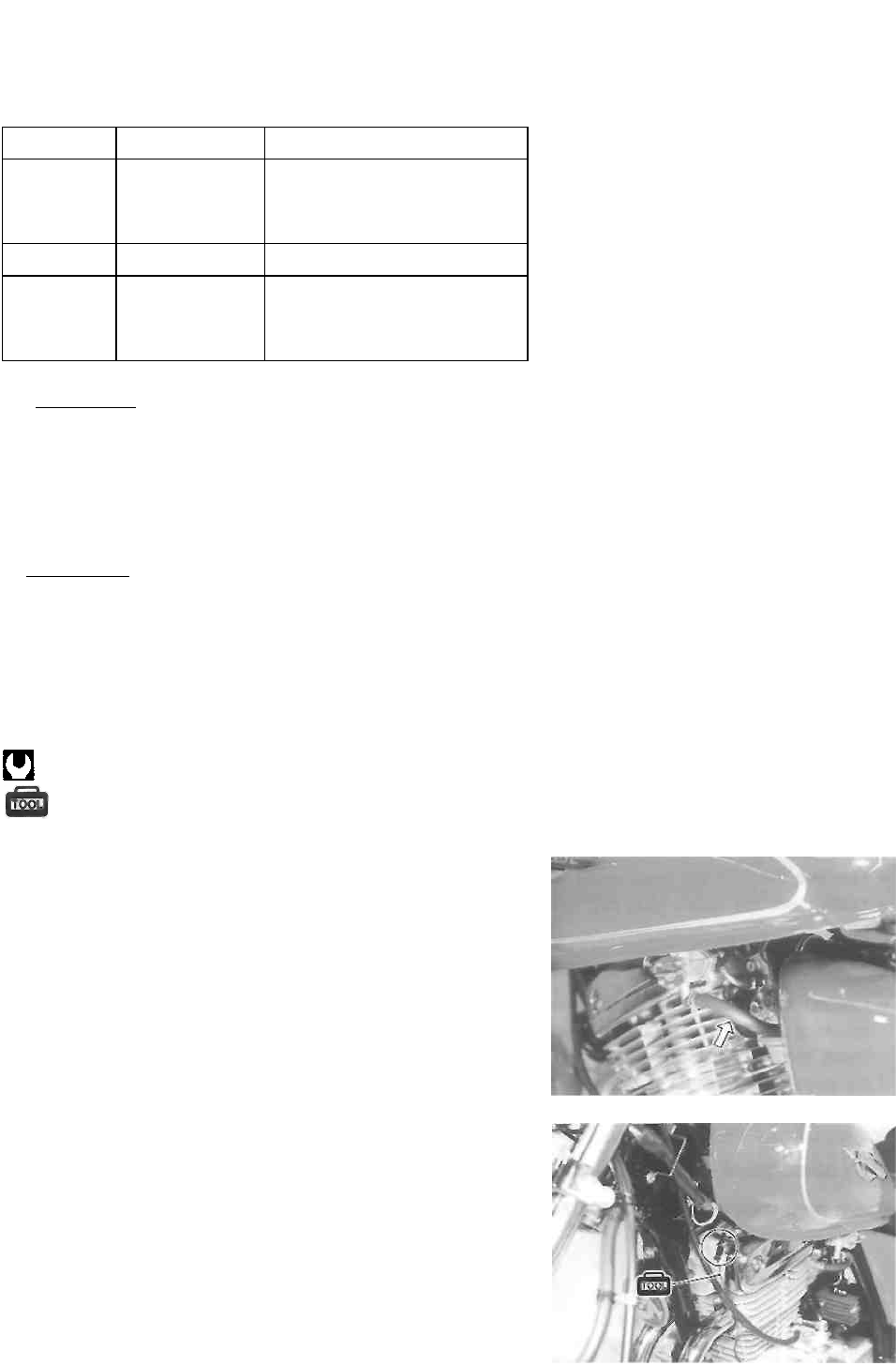
• Connect an electric tachometer to the high tension cord.
PERIODIC MAINTENANCE 2-8
• Start the engine, turn the throttle stop screw and set
the engine idle speed as follows.
Engine idle speed:
1 300 ± 50 r/min .... For E-03, -28, -33
1 300 ±100 r/min ..... For the others
09900-26006: Tachometer
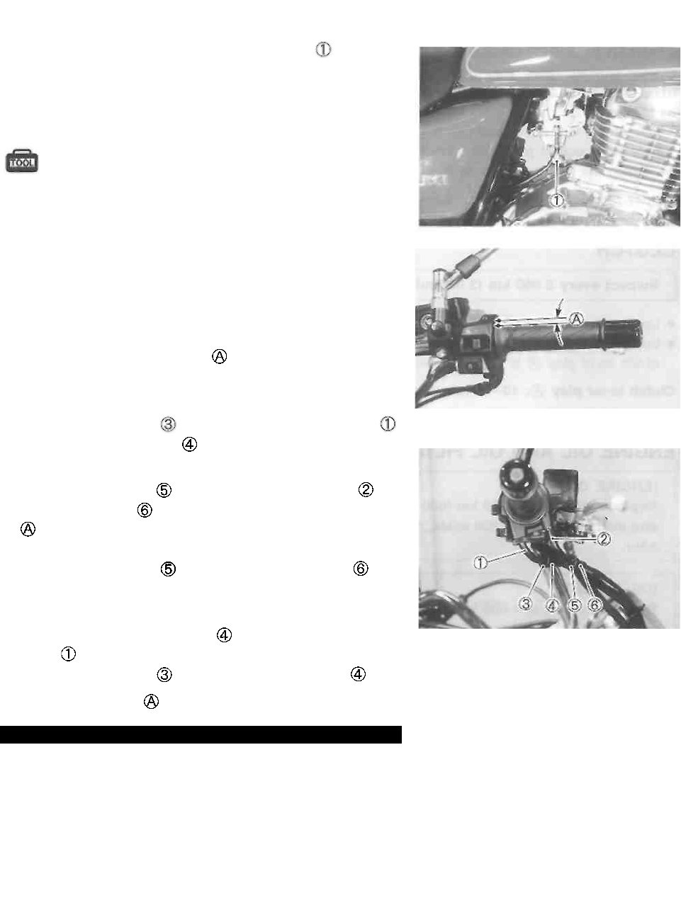
THROTTLE CABLE PLAY
Inspect initially at 1 000 km (600 miles, 3 months)
and every 5 000 km (3 000 miles, 15 months) there-
after.
Adjust the throttle cable play
steps.
First step:
• Loosen the lock nut of the throttle returning cable
and turn in the adjuster fully into the threads.
Second step:
• Loosen the lock nut of the throttle pulling cable
• Turn the adjuster in or out until the throttle cable play
should be 2.0-4.0 mm (0.08-0.16 in) at the throttle
grip.
• Tighten the lock nut while holding the adjuster
Third step:
• While holding the throttle grip at the fully closed position,
slowly turn out the adjuster of the throttle returning
cable to feel resistance.
• Tighten the lock nut while holding the adjuster
Throttle cable play : 2.0-4.0 mm (0.08-0.16 in)
WARNING
After the adjustment is completed, check that
handlebar movement does not raise the engine
idle speed and that the throttle grip returns
smoothly and automatically.
NOTE:
Major adjustment can be made by the carburetor side ad-
juster.
with the following three
2-9 PERIODIC MAINTENANCE
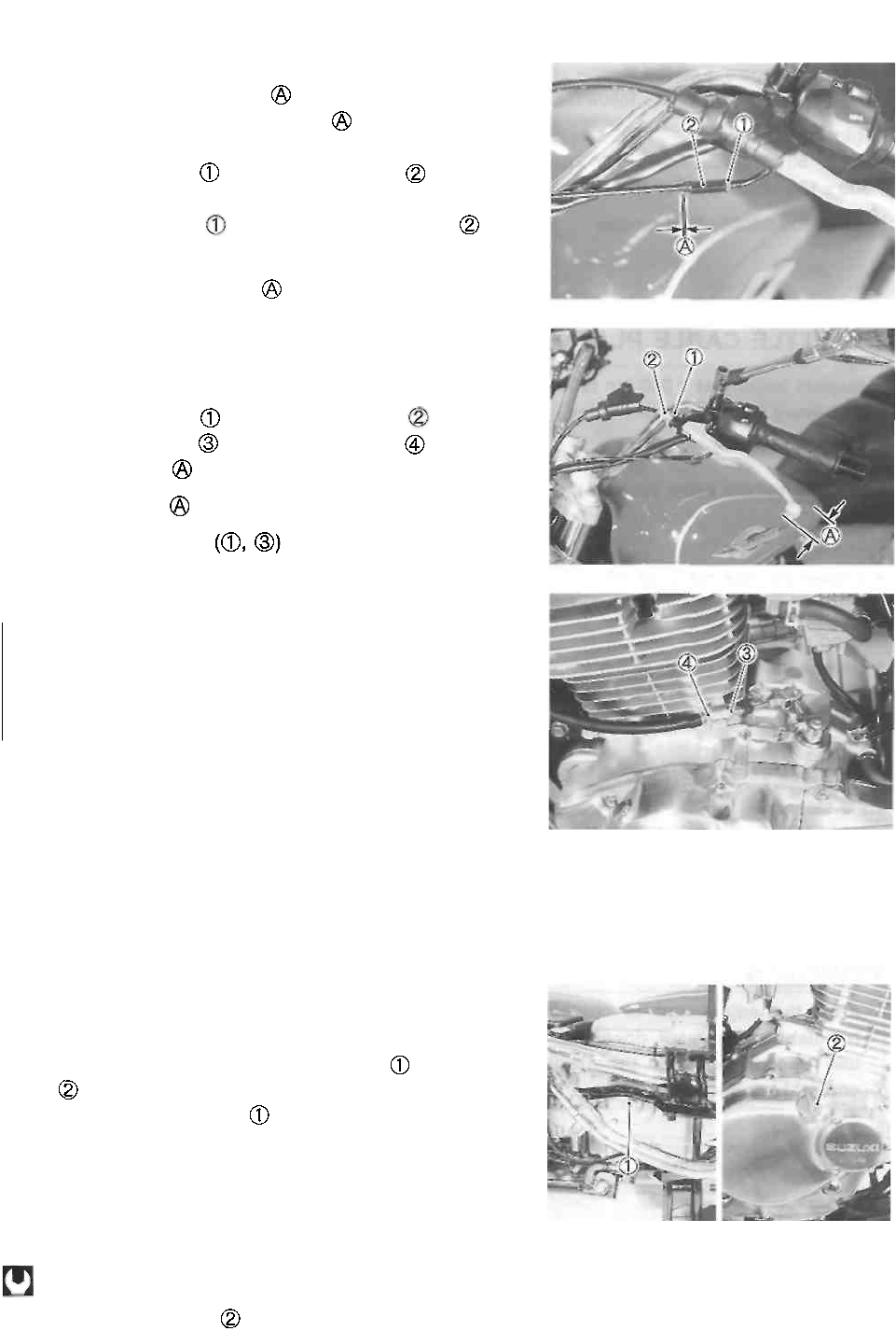
STARTER PLUNGER CABLE PLAY
Starter plunger cable play should be 0.5-1.0 mm
(0.02-0.04 in) as shown. If the play is incorrect, adjust
it as follows:
• Loosen the lock nut and turn the adjuster in or out
until the specified play is obtained.
• Tighten the lock nut while holding the adjuster
Starter plunger cable play
CLUTCH
Inspect every 5 000 km (3 000 miles, 15 months).
• Loosen the lock nut and turn the adjuster fully in.
• Loosen the lock nut and turn the adjuster until the
clutch lever play is within specification.
Clutch lever play : 10-15 mm (0.4-0.6 in)
• Tighten the lock nuts
ENGINE OIL AND OIL FILTER
(ENGINE OIL)
Replace initially at 1 000 km (600 miles, 3 months)
and every 5 000 km (3 000 miles, 15 months) there-
after.
(OIL FILTER)
Replace initially at 1 000 km (600 miles, 3 months)
and every 10 000 km (6 000 miles, 30 months)
thereafter.
The engine oil should be changed while the engine is
warm. Oil filter replacement at the above intervals should
be done together with the engine oil change.
ENGINE OIL REPLACEMENT
• Keep the motorcycle upright.
• Place an oil pan below the engine, and drain the engine
oil by removing the engine oil drain plug and oil filler
cap .
• Tighten the oil drain plug to the specified torque, and
pour new oil through the oil filler. When performing an oil
change (without oil filter replacement), the engine will
hold about 1 300 ml (1.4/1.1 US/Imp qt) of oil. Use SF or
SG classified (API) engine oil with a viscosity rating of
10W-40 (SAE).
Oil drain plug: 28 N-m (2.8 kg-m, 20.0 Ib-ft)
• Install the oil filler cap
0.5-1.0 mm
(0.02-0.04 in)
PERIODIC MAINTENANCE 2-10
• Start up the engine and allow it to run for a few minutes
at idling speed.
• Turn off the engine and wait about one minute, then
check the oil level through the inspection window . If
the level is below the "F" mark, add oil to the proper
level.
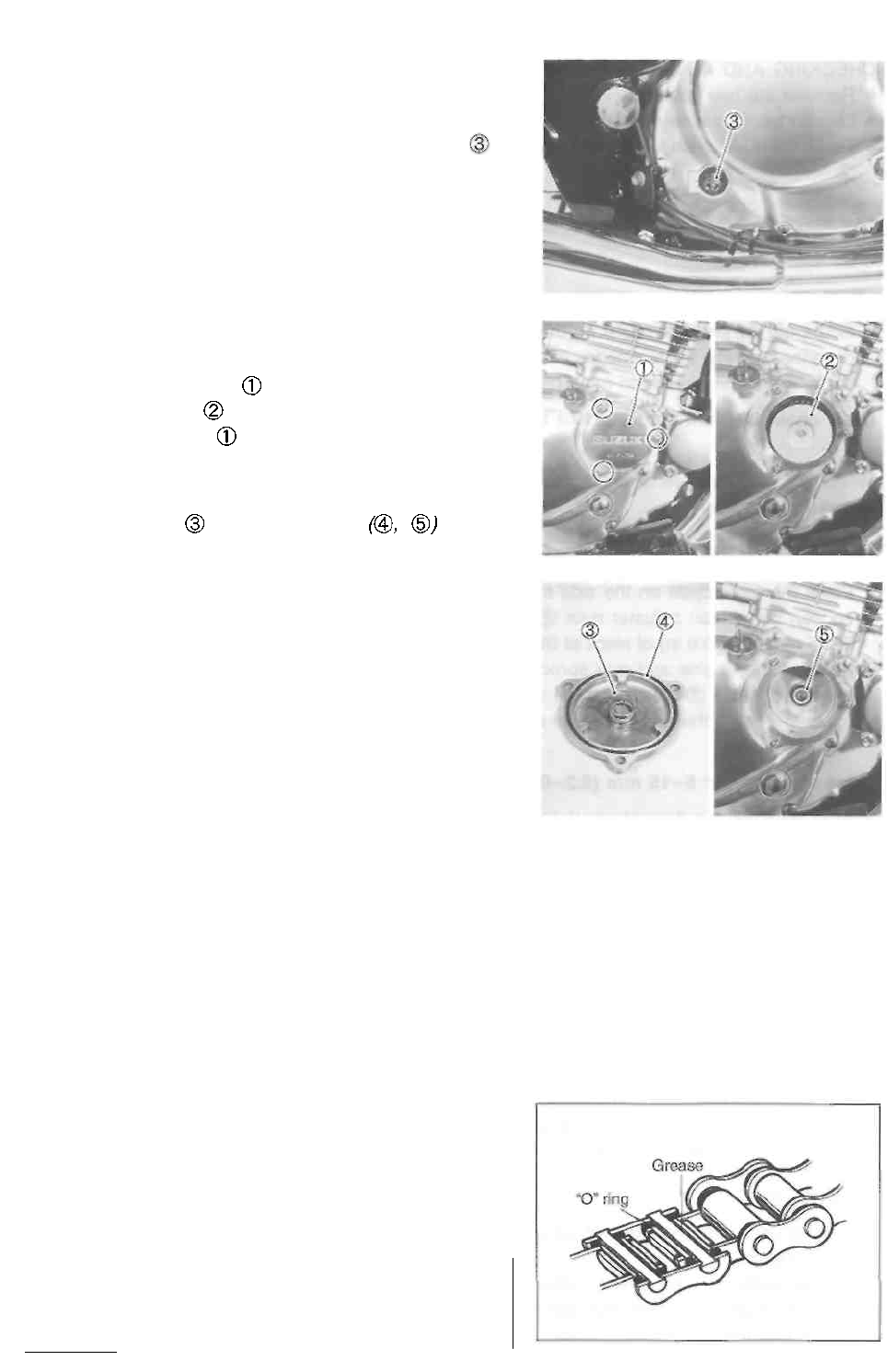
OIL FILTER REPLACEMENT
• Drain the engine oil as described in the engine oil re-
placement procedure.
• Remove the oil filter cap by removing the nuts.
• Remove the oil filter and install a new one.
• Install the oil filter cap and tighten the nuts securely.
NOTE:
Before installing the new oil filter and oil filter cap, make
sure that the spring and new O-rings are
installed correctly.
• Add new engine oil and check the oil level as described
in the engine oil replacement procedure.
Oil viscosity and classification:
10W/40 (SAE)/SF or SG (API)
NECESSARY AMOUNT OF ENGINE OIL
Oil change : 1 300 ml (1.4/1.1 US/Imp qt)
Oil and filter change: 1 400 ml (1.5/1.2 US/Imp qt)
Engine overhaul : 1 700 ml (1.8/1.5 US/Imp qt)
DRIVE CHAIN
Inspect initially at 1 000 km (600 miles, 3 months)
and every 5 000 km (3 000 miles, 15 months) there-
after. Clean and lubricate every 1 000 km (600
miles).
Visually inspect the drive chain for the possible defects
listed below. (Support the motorcycle by a jack and a
wooden block, turn the rear wheel slowly by hand with the
transmission shifted to Neutral.)
• Loose pins * Excessive wear
• Damaged rollers * Kinked or binding links
• Dry or rusted links * Missing O-ring seals
• Twisted or seized links
If any defects are found, the drive chain must be replaced.
CAUTION __________________________________
The standard drive chain is DID520VC5. SUZUKI
recommends to use this standard drive chain as a
The standard drive chain is DID520VC5. SUZUKI
recommends to use this standard drive chain as a
replacement.

replacement.
2-11 PERIODIC MAINTENANCE
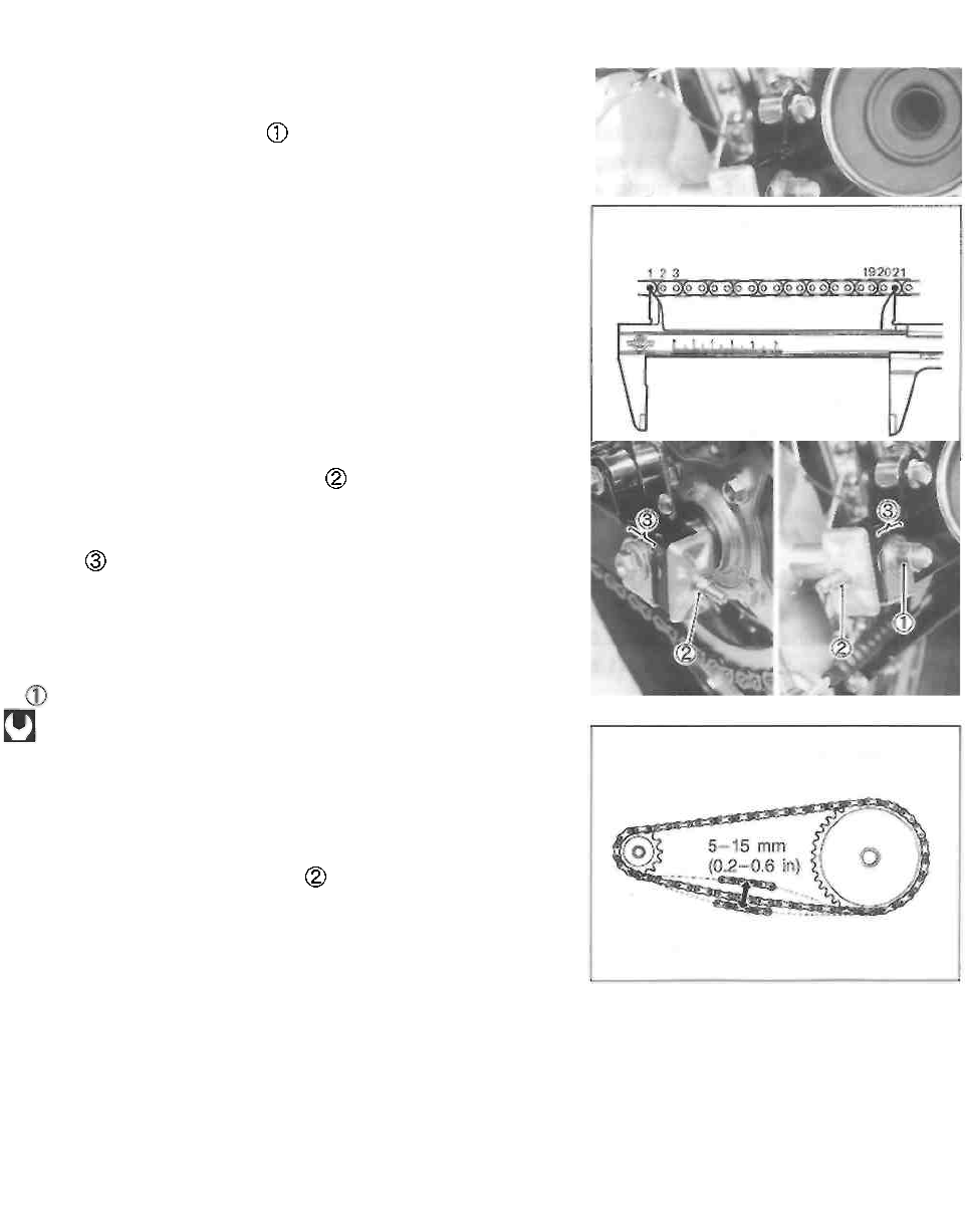
CHECKING AND ADJUSTING
• Remove the rear axle cotter pin. (For E-28 model)
• Loosen the rear axle nut
• Tense the drive chain fully by turning chain adjuster nuts
• Count out 21 pins (20-pitch) on the chain measure the
distance between the two points. If the distance exceeds
the service limit, the chain must be replaced.
Drive chain 20-pitch length: 319.4 mm (12.57 in)
NOTE:
When replacing the drive chain, replace the drive chain and
sprockets as a set.
• Place the motorcycle on the side-stand.
• Loosen both chain adjuster nuts until the chain has 5-15
mm (0.2-0.6 in) of slack at the middle of the chain between
the engine and rear sprockets as shown. The reference
marks must be at the same position on the scale to
ensure that the front and rear wheels are correctly aligned.
Drive chain slack: 5-15 mm (0.2-0.6 in)
• After adjusting the drive chain, tighten the rear axle nut
to the specified torque.
Rear axle nut:
65 N-m (6.5 kg-m, 47.0 Ib-ft) ........ For E-03, -28, -33
78 N-m (7.8 kg-m, 56.5 Ib-ft) ........ For the others
• Recheck the chain slack after tightening the axle nut and
readjust if necessary.
* Tighten both chain adjuster nuts securely.
• Install the new cotter pin. (For E-03, -28, -33 models)
CLEANING AND LUBRICATING
• Clean the drive chain with kerosine. If the drive chain
tends to rust quickly, the intervals must be shortened.
CAUTION
Do not use trichloroethylene, gasoline or any sim-
ilar solvent.
These fluids have too great a dissolving power for
this chain and they can damage the O-rings. Use
only kerosine to clean the drive chain.
PERIODIC MAINTENANCE 2-12
• After cleaning and drying the chain, oil it with a heavy-
weight engine oil.
CAUTION
Do not use any oil sold commercially as "drive
chain oil", this type of oil can such oil can damage
the "0"-rings (or seals).
BRAKES
(BRAKE)
Inspect initially at 1 000 km (600 miles, 3 months)
and every 5 000 km (3 000 miles, 15 months) there-
after.
(BRAKE HOSE AND BRAKE FLUID)
Inspect every 5 000 km (3 000 miles, 15 months).
Replace hose every 4 years. Replace fluid every 2
years.
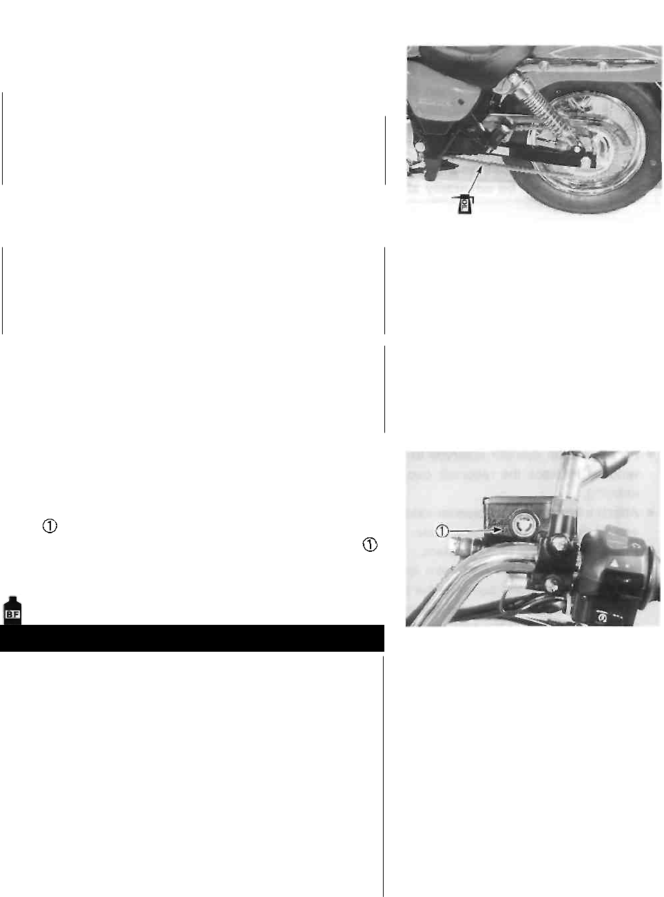
BRAKE FLUID LEVEL
• Keep the motorcycle upright and place the handlebars
straight.
• Check the brake fluid level by observing the lower limit
line on the front brake fluid reservoir.
• When the brake fluid level is below the lower limit line
replenish with brake fluid that meets the following specifi-
cation.
Specification and classification: DOT 4
WARNING
The brake system of this motorcycle is filled
with a glycol-based brake fluid. Do not use or
mix different types of fluid such as silicone-
based and petroleum-based fluids. Do not use
any brake fluid taken from old, used or un-
sealed containers. Never re-use brake fluid left
over from the last servicing or stored for a long
period of time.
Brake fluid, if it leaks, will interfere with safe
running and immediately discolor painted sur-
faces. Check the brake hose and hose joints for
cracks and oil leakage.
2-13 PERIODIC MAINTENANCE
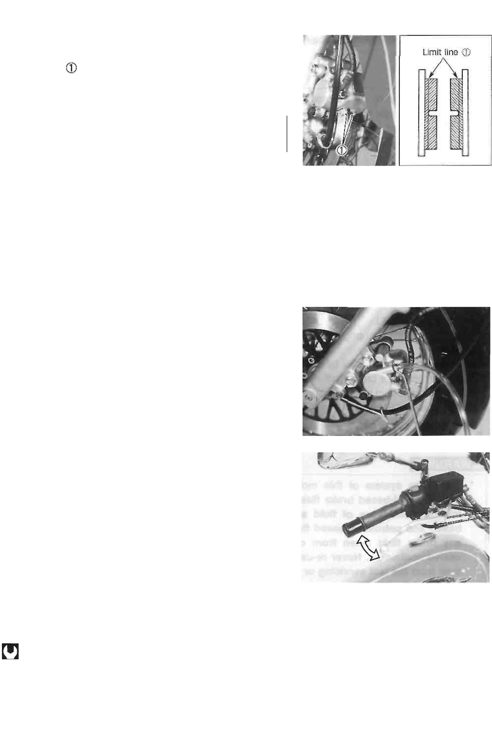
FRONT BRAKE PADS
The extent of brake pad wear can be checked by observing
the limit line on the pad. When the wear exceeds the
limit line, replace the pads with new ones. (See p. 5-8.)
A CAUTION
Replace the brake pad as a set, otherwise braking
performance will be adversely affected.
AIR BLEEDING THE BRAKE FLUID CIRCUIT
Air trapped in the brake fluid circuit acts like a cushion to
absorb a large proportion of the pressure developed by the
master cylinder and thus interferes with the full braking per-
formance of the brake caliper. The presence of air is indi-
cated by "sponginess" of the brake lever and also by lack
of braking force. Considering the danger to which such
trapped air exposes the machine and rider, it is essential
that, after remounting the brake and restoring the brake
system to the normal condition, the brake fluid circuit be
purged of air in the following manner:
• Fill the master cylinder reservoir to top of the inspection
window. Replace the reservoir cap to prevent dirt from
entering.
• Attach a hose to the air bleeder valve, and insert the free
end of the hose into a receptacle.
• Bleed air from the brake system.
• Squeeze and release the brake lever several times in
rapid succession and squeeze the lever fully without re-
leasing it. Loosen the bleeder valve by turning it a quar-
ter of a turn so that the brake fluid runs into the recep-
tacle, this will remove the tension of the brake lever
causing it to touch the handlebar grip. Then, close the air
bleeder valve, pump and squeeze the brake lever, and
open the valve. Repeat this process until the fluid flowing
into the receptacle no longer contains air bubbles.
NOTE:
While bleeding the brake system, replenish the brake fluid
in the reservoir as necessary. Make sure that there is al-
ways some fluid visible in the reservoir.
• Close the air bleeder valve, and disconnect the hose. Fill
the reservoir with brake fluid to the top of the inspection
window.
Air bleeder valve: 7.5 N ■ m (0.75 kg-m, 5.5 Ib-ft)
A CAUTION
Handle brake fluid with care: the fluid reacts
chemically with paint, plastics, rubber materials,
etc.
PERIODIC MAINTENANCE 2-14
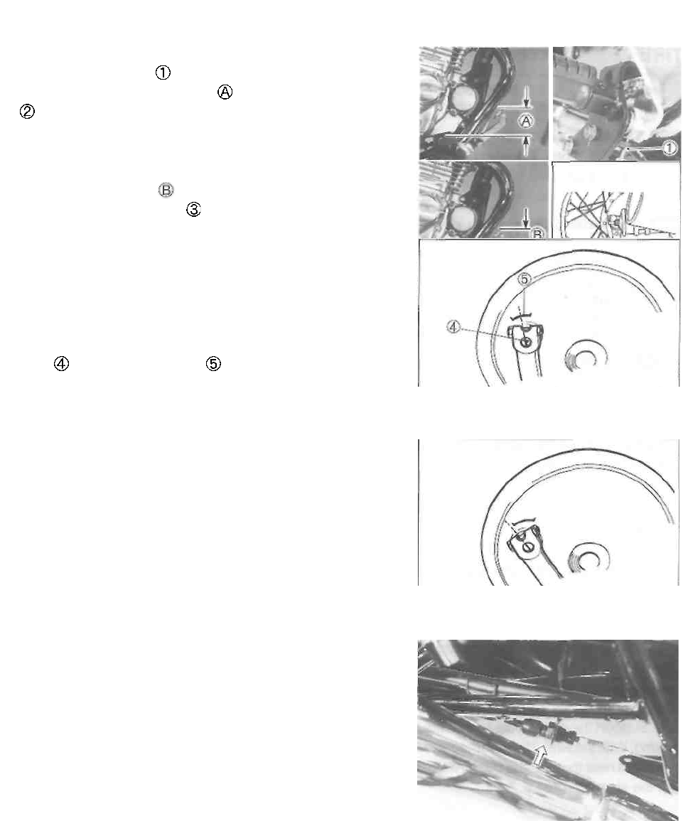
REAR BRAKE PEDAL HEIGHT
• Loosen the lock nut
• Adjust the brake pedal height by turning the adjuster
to locate the pedal 50 mm (2.0 in) above the top face
of the footrest.
REAR BRAKE ADJUSTING
• Adjust the free travel to 20-30 mm (0.8-1.2 in) by
turning the adjusting nut
REAR BRAKE SHOE WEAR
This motorcycle is equipped with brake lining wear limit
indicator on the rear brake.
To check brake lining wear, perform the following steps.
• Make sure that the rear brake is properly adjusted.
• Depress the rear brake pedal. Make sure that the index
mark is within the range embossed on the brake
panel.
• If the index mark goes beyond the range, the brake shoe
assembly should be replaced with a new set of shoes.
The extension line of the index mark is within
the range.
The extension line of the index mark is out of
the ranae.
BRAKE LIGHT SWITCH
Adjust the rear brake light switch so that the brake light will
come on just before pressure is felt when the brake pedal
is depressed.
2-15 PERIODIC MAINTENANCE
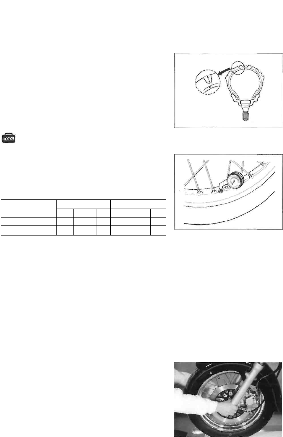
TIRE
Inspect every 5 000 km (3 000 miles, 15 months).
TIRE TREAD CONDITION
Operating the motorcycle with excessively worn tires will
decrease riding stability and consequently invite a danger-
ous situation. It is highly recommended to replace a tire
when the remaining depth of tire tread reaches the follow-
ing specification.
Tire tread depth limit (front): 1.6 mm (0.06 in)
(rear) : 2.0 mm (0.08 in)
09900-20805: Tire depth gauge
TIRE PRESSURE
If the tire pressure is too high or too low, steering will be
adversely affected and tire wear increased. Therefore,
maintain the correct tire pressure for good roadability and a
longer tire life. Cold inflation tire pressure is as follows.
COLD INFLATION
TIRE PRESSURE
SOLO RIDING
DUAL RIDING
kPa
kg/cm2
psi
kPa
kg/cm2
psi
FRONT
175
1.75
25
175
1.75
25
REAR
200
2.00
29
225
2.25
33
CAUTION
The standard tire fitted on this motorcycle is a
110/90-16 59P for the front and a 130/90-15M/C 66P
for the rear. The use of tires other than those speci-
fied may cause instability. It is highly recommended
to use the specified tires.
STEERING
Inspect initially at 1 000 km (600 miles, 3 months)
and every 10 000 km (6 000 miles, 30 months)
thereafter.
The steering should be adjusted properly for smooth turning
of handlebars and safe operation. Overtight steering prevents
smooth turning of the handlebars and too loose steering will
cause poor stability. Check that there is no play in the front
fork. Support the motorcycle so that the front wheel is off the
ground. With the wheel facing straight ahead, grasp the lower
fork tubes near the axle and pull forward. If play is found, read-
just the steering. (See p. 5-27.)
PERIODIC MAINTENANCE 2-16
FRONT FORK
Inspect every 10 000 km (6 000 miles, 30 months).
Inspect the front forks for oil leakage, scoring or scratches
on the outer surface of the inner tubes. Replace any defec-
tive parts, if necessary.
REAR SUSPENSION
Inspect every 10 000 km (6 000 miles, 30 months).
Inspect the rear shock absorber for oil leakage and damage.
Replace any defective parts, if necessary.
CHASSIS BOLTS AND NUTS
Tighten initially at 1 000 km (600 miles, 3 months)
and every 5 000 km (3 000 miles, 15 months) there-
after.
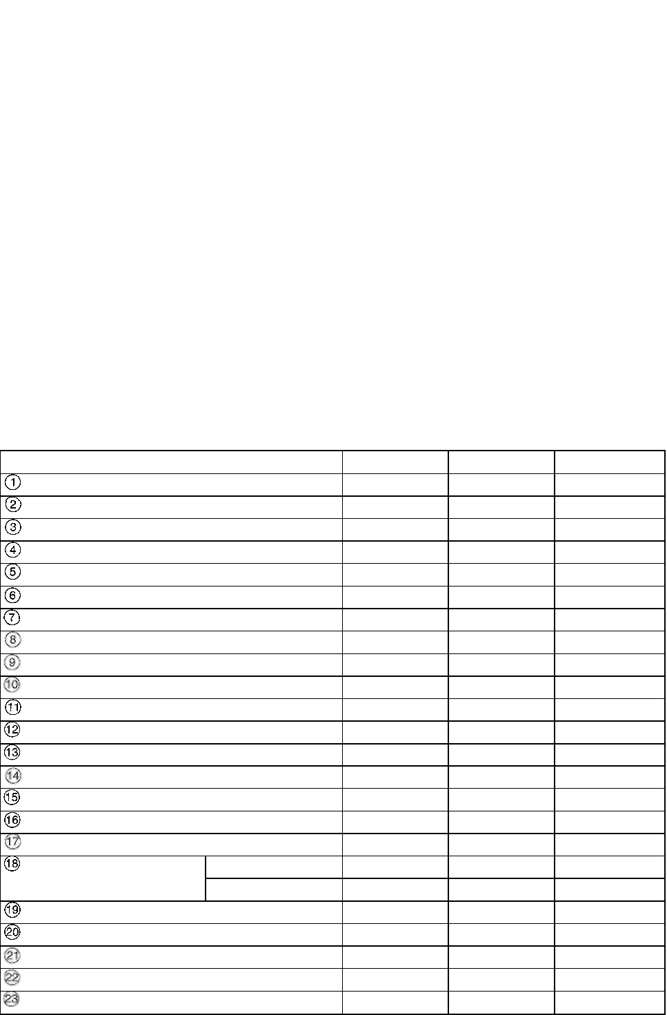
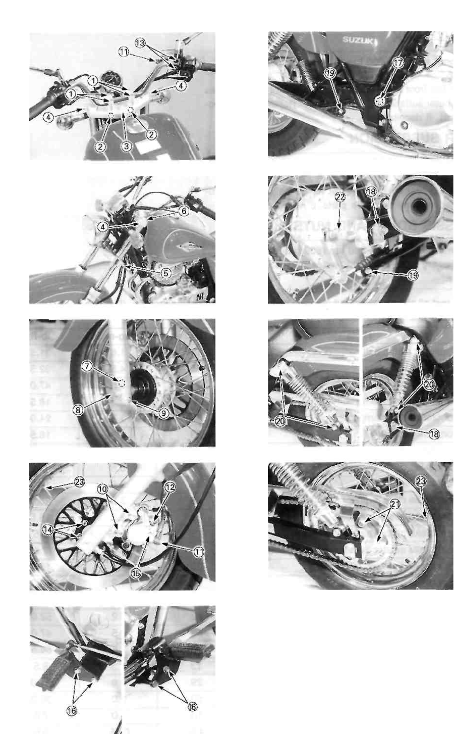
Check that all chassis bolts and nuts are tightened to their specified torque. (Refer to page 2-17 for the
locations of the following nuts and bolts on the motorcycle.)
ITEM
N-m
kg-m
Ib-ft
Handlebar clamp bolt
16
1.6
11.5
Handlebar holder nut
45
4.5
32.5
Steering stem head bolt
65
6.5
47.0
Front fork upper clamp bolt
23
2.3
16.5
Front fork lower clamp bolt
33
3.3
24.0
Front fork cap bolt
23
2.3
16.5
Front fork damper rod bolt
23
2.3
16.5
Front axle
65
6.5
47.0
Front axle pinch bolt
23
2.3
16.5
Front brake caliper mounting bolt
39
3.9
28.0
Front brake hose union bolt
23
2.3
16.5
Front brake caliper air bleeder valve
7.5
0.75
5.5
Front brake master cylinder mounting bolt
10
1.0
7.0
Front brake disc bolt
23
2.3
16.5
Front brake pad mounting bolt
18
1.8
13.0
Front footrest bolt
26
2.6
19.0
Swingarm pivot nut
72
7.2
52.0
Rear axle nut
For E-03, -28, -33
65
6.5
47.0
For the others
78
7.8
56.5
Rear torque link nut (front and rear)
13
1.3
9.5
Rear shock absorber mounting bolt or nut
29
2.9
21.0
Rear sprocket nut
50
5.0
36.0
Rear brake cam lever bolt
10
1.0
7.0
Spoke nipple
4.5
0.45
3.5
2-17 PERIODIC MAINTENANCE
PERIODIC MAINTENANCE 2-18
COMPRESSION PRESSURE CHECK
The compression pressure reading of the cylinder is a good indicator of its internal condition. The
decision to overhaul the cylinder is often based on the results of a compression test. Periodic
maintenance records kept at your dealership should include compression readings for each mainte-
nance service. COMPRESSION PRESSURE SPECIFICATION
Standard
Limit
1 000-1 400 kPa
10.0-14.0 kg/cm2
142-199 psi
800 kPa 8
kg/cm2
114 psi
Low compression pressure can indicate any of the following conditions:
* Excessively worn cylinder wall
* Worn piston or piston rings
* Piston rings stuck in grooves
* Poor valve seating
* Ruptured or otherwise defective cylinder head gasket
COMPRESSION TEST PROCEDURE
NOTE:
• Before testing the engine for compression pressure,
make sure that the cylinder head nuts are tightened to
the specified torque values and valves are properly ad
justed.
• Have the engine warmed-up before testing.
" Make sure that the battery is fully-charged.
Remove the related parts and test the compression pres-
sure in the following manner.
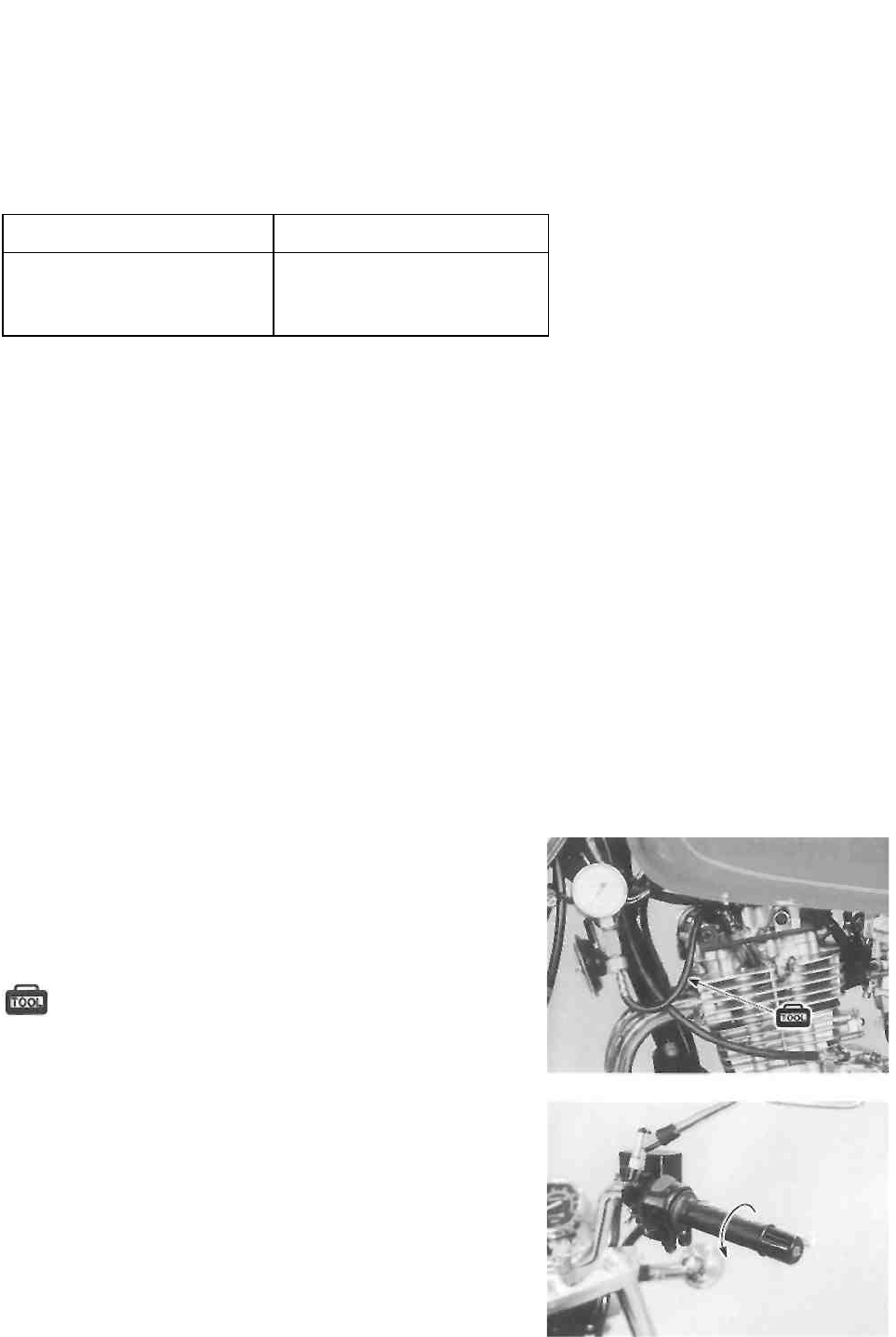
• Install the compression gauge and adaptor in the spark
plug hole. Make sure that the connection is tight.
• Keep the throttle grip in the fully opened position.
• Press the starter button and crank the engine for a few
seconds. Record the maximum gauge reading as the
cylinder compression.
09915-64510: Compression gauge
09918-03810: Adaptor
2-19 PERIODIC MAINTENANCE
OIL PRESSURE CHECK
Check the oil pressure periodically. This will give a good indication of the condition of the moving parts. OIL
PRESSURE SPECIFICATION
Above 30 kPa (0.3 kg/cm2, 4.3 psi)
Below 70 kPa (0.7 kg/cm2, 10.0 psi) at 3 000 r/min., Oil temp, at 60°C (140°F)
If the oil pressure is lower or higher than the specification, the following causes may be considered.
LOW OIL PRESSURE
* Clogged oil filter
* Oil leakage from the oil passage
* Damaged O-ring
* Defective oil pump
* Combination of the above items
HIGH OIL PRESSURE
* Engine oil viscosity is too high
* Clogged oil passage
* Combination of the above items
OIL PRESSURE TEST PROCEDURE
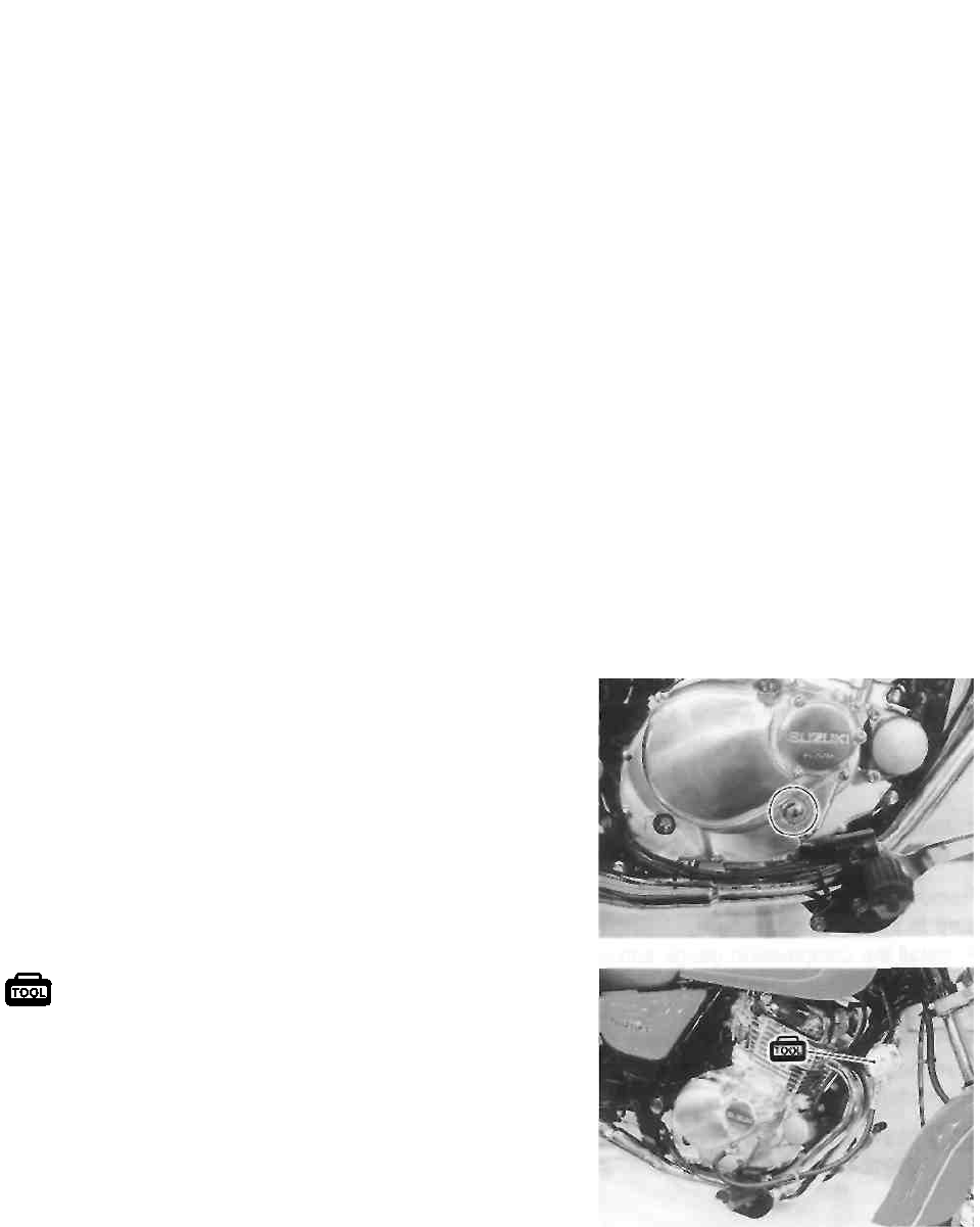
Check the oil pressure in the following manner.
o Install the oil pressure gauge in the position shown.
• Connect an electric tachometer.
• Warm up the engine as follows:
Summer 10 min. at 2 000 r/min.
Winter 20 min. at 2 000 r/min.
• After warm up, increase the engine speed to 3 000 r/min.
and read the oil pressure gauge.
09915-74510: Oil pressure gauge

ENGINE
i ------------------------------------------------ CONTENTS ---------------------------------
ENGINE COMPONENTS REMOVABLE WITH THE ENGINE
IN PLACE ......................................................................................................
.... 3- 1
ENGINE REMOVAL AND REINSTALLATION ............................................
ENGINE REMOVAL .................................................................................
3- 2 .... 3-
2
ENGINE REINSTALLATION .................................................................
ENGINE DISASSEMBLY ......................................................................
3- 6 .... 3-
9
ENGINE COMPONENTS INSPECTION AND SERVICE ......................
.... 3-19
CRANKCASE BEARINGS ..................................................................
__ 3-19
CLUTCH RELEASE CAMSHAFT .......................................................
__ 3-22
CYLINDER HEAD COVER ..................................................................
.... 3-23
CYLINDER HEAD ..............................................................................
.... 3-24
CAM CHAIN GUIDE AND CAM CHAIN TENSIONER ......................
__ 3-32
CAMSHAFT .........................................................................................
__ 3-32
CAM CHAIN TENSION ADJUSTER ...................................................
__ 3-34
CYLINDER ...........................................................................................
__ 3-34
PISTON AND PISTON PIN ..................................................................
__ 3-34
CRANKSHAFT AND CONROD ...........................................................
__ 3-37
BALANCER SHAFT AND BALANCER SHAFT DRIVEN GEAR
STARTER CLUTCH AND STARTER DRIVEN GEAR BEARING
GENERATOR STATOR AND PICK-UP COIL .....................................
3-39
3-40
__ 3-41
TRANSMISSION ................................................................................
__ 3-42
PRIMARY DRIVEN GEAR ...................................................................
__ 3-44
CLUTCH ...............................................................................................
__ 3-45
CLUTCH COVER .................................................................................
__ 3-46
OIL FILTER ..........................................................................................
.... 3-46
OIL SUMP FILTER ...............................................................................
.... 3-47
ENGINE REASSEMBLY .........................................................................
.... 3-48
CRANKSHAFT ....................................................................................
.... 3-48
BALANCER SHAFT ............................................................................
.... 3-48
TRANSMISSION ................................................................................
.... 3-48
GEARSHIFT CAM AND GEARSHIFT FORKS ....................................
.... 3-49
CRANKCASE .....................................................................................
.... 3-50
GENERATOR ROTOR .......................................................................
__ 3-52
DRIVESHAFT RETAINER .................................................................
__ 3-52
PRIMARY DRIVE GEAR .....................................................................
.... 3-52
BALANCER SHAFT BOLT .................................................................
.... 3-53
GEARSHIFT CAM DRIVEN GEAR .....................................................
.... 3-53
OIL PUMP ............................................................................................
.... 3-54
CLUTCH ..............................................................................................
.... 3-55
CLUTCH COVER .................................................................................
__ 3-57
STARTER IDLE GEAR ........................................................................
__ 3-57
GENERATOR COVER .........................................................................
__ 3-57
NEUTRAL SWITCH .............................................................................
__ 3-58
ENGINE SPROCKET SPACER ...........................................................
__ 3-58
STARTER MOTOR ..............................................................................
.... 3-58
PISTON AND PISTON RING ...............................................................
.... 3-59
CYLINDER ...........................................................................................
.... 3-60
CYLINDER HEAD ..............................................................................
.... 3-61
CAMSHAFT .........................................................................................
__ 3-62
CAM CHAIN TENSION ADJUSTER ....................................................
__ 3-63
CYLINDER HEAD COVER ..................................................................
.... 3-64

3-1 ENGINE
ENGINE COMPONENTS REMOVABLE WITH THE ENGINE IN
PLACE
The parts listed below can be removed and reinstalled without removing the engine from the frame. Refer
to the pages listed in each section for removal and reinstallation instructions.
ENGINE CENTER
See page
Exhaust pipe and muffler ............ 3-2 and -8
Carburetor .................................. 3-4 and -7
Cam chain tension adjuster ... 3-9 and -63
Cylinder head cover ..................... 3-9 and -64
Camshaft .................................. 3-10 and -62
Cylinder head ............................ 3-10 and -61
Cylinder ........................................ 3-10 and -60
Piston ........................................ 3-11 and -59
Starter motor ................................ 3-11 and -58
Oil sump filter ............................. 3-47
ENGINE LEFT SIDE ENGINE RIGHT SIDE
See page See page
Gearshift link arm ........................ 3-2 Oil filter .......................................... 3-46
Engine sprocket cover ................. 3-3 Clutch cover .................................. 3-12 and -57
Engine sprocket ......................... 3-3 and -7 Clutch .......................................... 3-12 and -55
Generator cover ......................... 3-12 and -57 Oil pump ....................................... 3-14 and -54
Generator rotor ............................ 3-16 and -52 Gearshift shaft .............................. 3-14 and -54
Starter idle gear .......................... 3-16 and -57 Primary drive gear ....................... 3-15 and -52
Generator stator ......................... 3-41
Pick-up coil .................................. 3-41
Neutral switch ............................. 3-11 and -58
ENGINE 3-2
ENGINE REMOVAL AND
REINSTALLATION
ENGINE REMOVAL
• Remove the front seat. (See p. 5-1.)
• Remove the fuel tank. (See p. 4-1.)
• Remove the right frame cover. (See p. 5-1.)
• Disconnect the battery lead wire.
• Drain the engine oil. (See p. 2-9.)
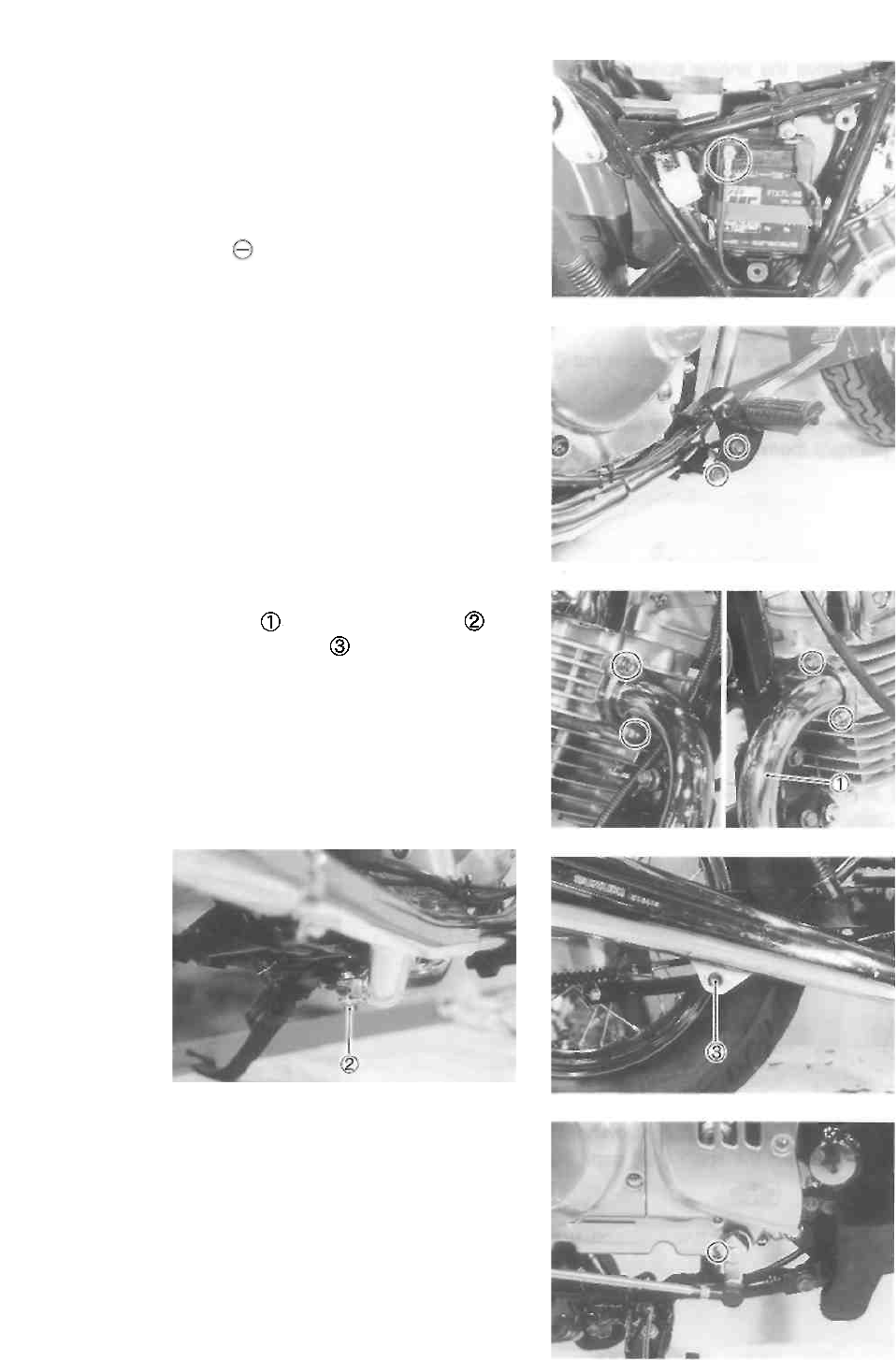
• Remove the right footrest bracket.
• Remove the exhaust pipe bolts.
• Remove the exhaust pipe by removing the bolt
• Remove the muffler mounting bolt
• Remove the gearshift link arm.
3-3 ENGINE
• Remove the engine sprocket cover.
• Flatten the lock washer.
• Remove the engine sprocket nut and washer.
NOTE:
When loosening the engine sprocket nut, temporarily install
the right footrest bracket and depress the brake pedal.
• Remove the engine sprocket.
NOTE:
If it is difficult to remove the engine sprocket, loosen the
rear axle nut and chain adjuster nuts to provide additional
chain slack.
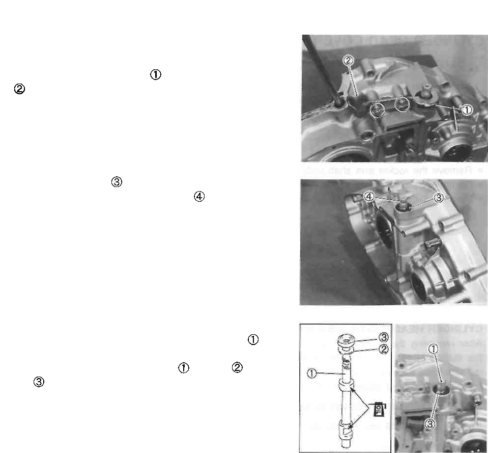
• Remove the clutch release arm .
• Loosen the clutch cable adjuster lock nut and remove
the clutch cable.
• Remove the left and right cylinder head cover caps.
• Disconnect the spark plug cap.
ENGINE 3-4
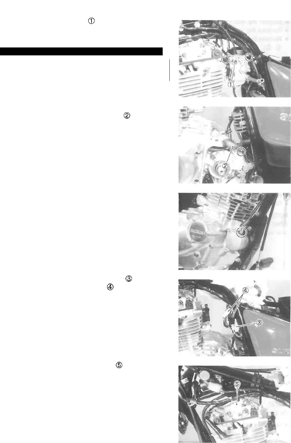
• Remove the starter plunger .
• Loosen the carburetor clamp screws.
• Remove the carburetor.
¿WARNING
Gasoline is very explosive. Extreme care must be
taken.
• Disconnect the engine ground wire.
• Disconnect the crankcase breather hose
• Disconnect the starter motor lead wire.
• Disconnect the side-stand switch coupler
• Disconnect the generator couplers
• Disconnect the neutral switch coupler
3-5 ENGINE
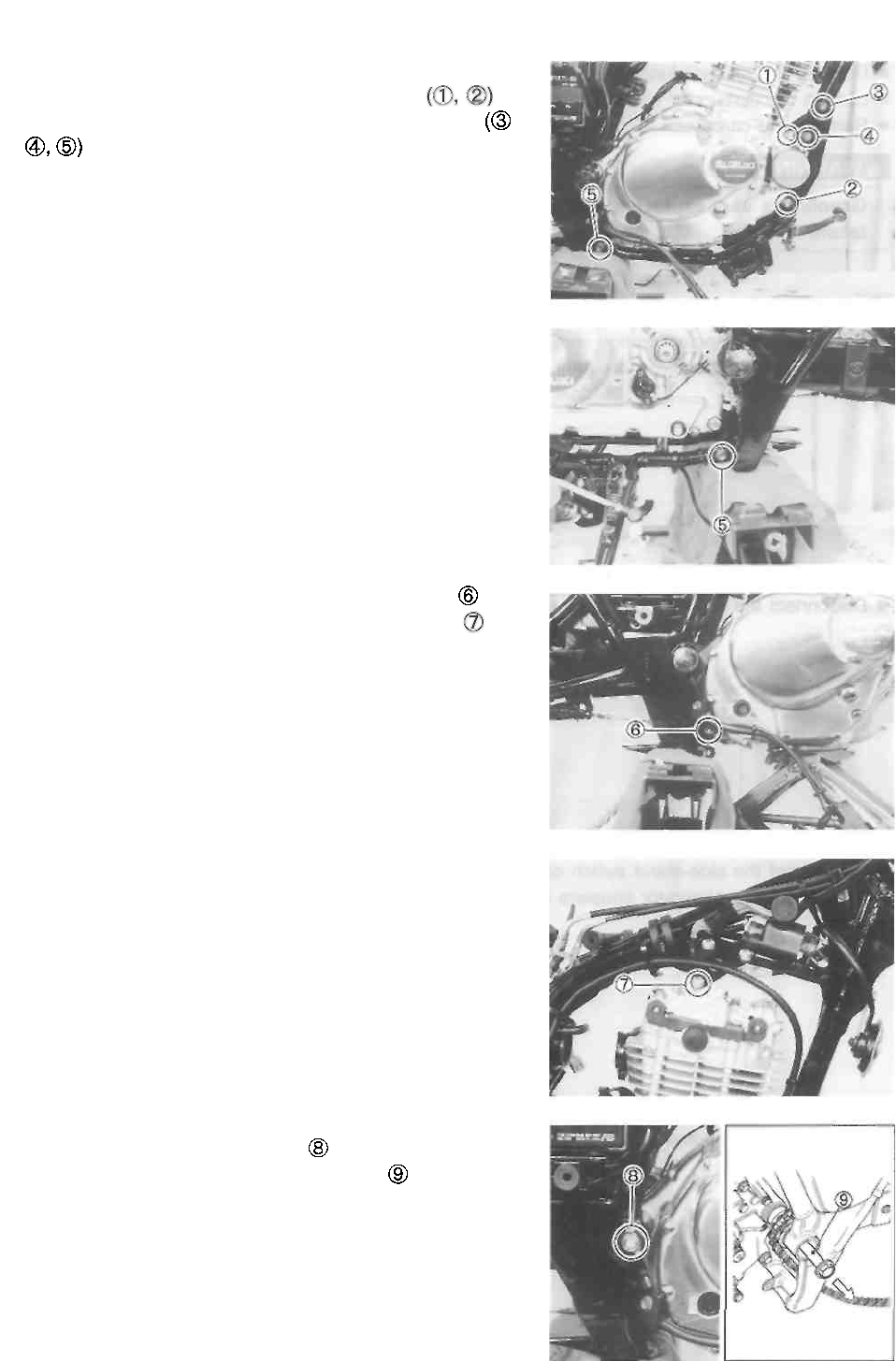
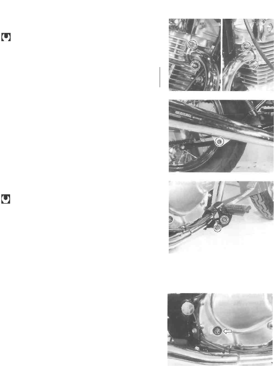
• Support the motorcycle with a jack or wooden block.
• Remove the engine mounting bolts and nuts
• Remove the frame down tube mounting bolts and nuts
• Remove the lower engine mounting bolt and nut
• Remove the upper engine mounting bolt and nut
NOTE:
When removing the upper mounting bolt, support the en-
gine with a jack.
• Remove the left and right swingarm pivot end caps.
• Remove the swingarm pivot nut and washer.
• Partially remove the swingarm pivot shaft so that the
engine can be removed.
NOTE:
Be careful not to draw out the pivot shaft.
• Gradually lower the engine.
ENGINE 3-6
ENGINE REINSTALLATION
Reinstall the engine in the reverse order of engine removal.
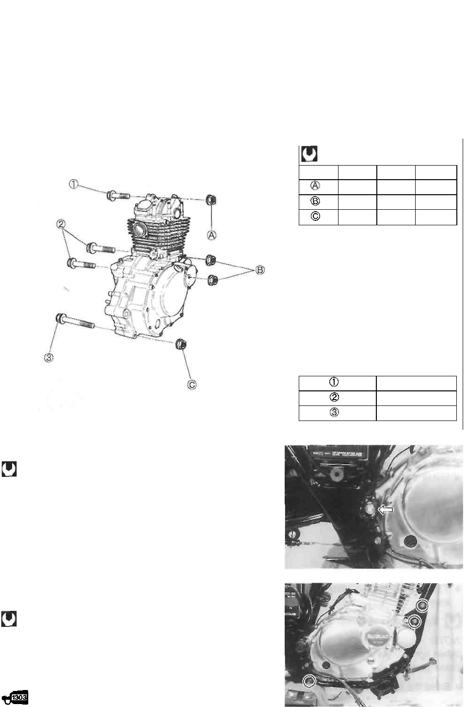
• Install the engine mounting bolts and nuts as shown in the following illustration.
• Tighten the engine mounting nuts to the specified torque.
NOTE:
The engine mounting nuts are self-locking. Once the nuts have been removed, they are no longer of
any use.
ITEM
N-m
kg-m
Ib-ft
41
4.1
29.5
41
4.1
29.5
41
4.1
29.5
BOLT LENGTH
50 mm (2.0 in)
67 mm (2.6 in)
100 mm (3.9 in)
• Tighten the swingarm pivot nut to the specified torque.
Swingarm pivot nut: 72 N-m (7.2 kg-m, 52.0 Ib-ft)
• Tighten the frame down tube mounting bolts and nuts to
the specified torque.
Frame down tube mounting bolt/nut: 23 N-m
(2.3 kg-m, 16.5 Ib-ft)
NOTE;
Apply a small quantity of THREAD LOCK "1303" to the
threads of bolts.
99000-32030: THREAD LOCK SUPER "1303"
3-7 ENGINE
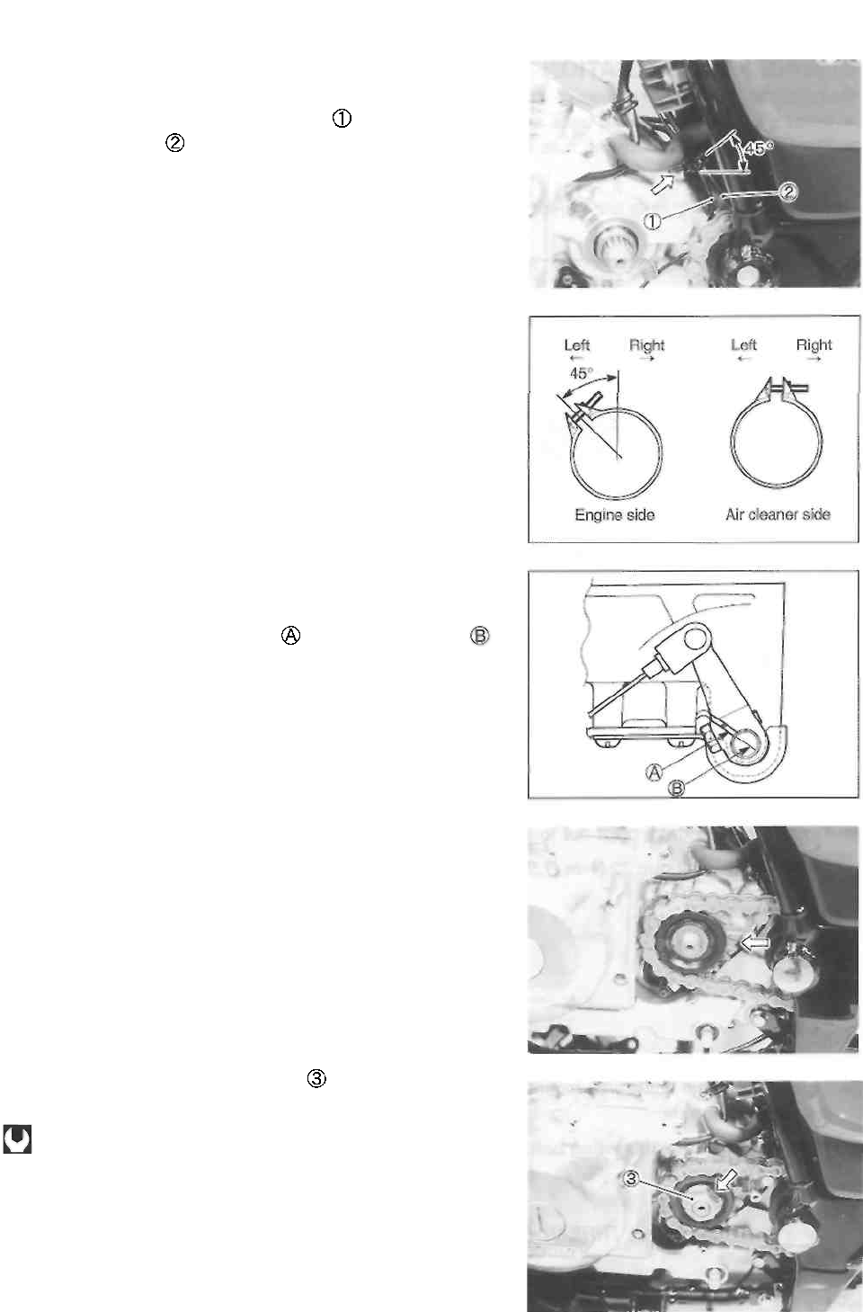
• Tighten the engine ground wire and the clamp by crank-
case bolt as shown.
• Clamp the neutral switch lead wire and side-stand
switch lead wire
• Position the carburetor clamps as shown in the illustra-
tion.
• Install the clutch release arm as shown In the illustration.
NOTE:
Align the release arm slit surface with the notch mark
on the release camshaft.
• Loosen the rear axle nut and drive chain adjuster nuts.
• Install the engine sprocket as shown.
• Install the drive chain.
• Tighten the engine sprocket nut to the specified
torque.
Engine sprocket nut: 90 N-m (9.0 kg-m, 65.0 Ib-ft)
NOTE:
When tightening the engine sprocket nut, depress the rear
brake pedal.
• Bend the lock washer securely.
ENGINE 3-8
• Tighten the exhaust pipe bolts and muffler mounting bolt
to the specified torque.
Exhaust pipe bolt: 14 N-m (1.4 kg-m, 10.0 Ib-ft)
Muffler mounting bolt: 29 N-m (2.9 kg-m, 21.0 Ib-ft)
CAUTION
Check the wire, cable and hose routing.
(See pp. 7-11 to -18.)
• Install the right footrest and tighten its mounting bolts to
the specified torque.
Front footrest bolt: 26 N-m (2.6 kg-m, 19.0 Ib-ft)
• After remounting the engine, the following adjustments
are necessary.
* Engine idling speed ............................... See p. 2-7.
* Throttle cable play ................................. See p. 2-8.
* Starter plunger cable play .................... See p. 2-9.
* Clutch lever play ................................. See p. 2-9.
* Drive chain slack ................................. See p. 2-11.
* Rear brake pedal height and
free travel ............................................ See p. 2-14.
• Pour 1 700 ml (1.8/1.5 US/Imp qt) of SAE 10W/40 en
gine oil, graded SF or SG, into the engine after overhaul
ing it. Start up the engine and allow it run for several
minutes at idle speed. Stop the engine, wait a few min
utes and check the oil level. If the level is below the "L"
line, add oil until the level reaches the "F" line. (See pp.
2-9 and -10.)
3-9 ENGINE
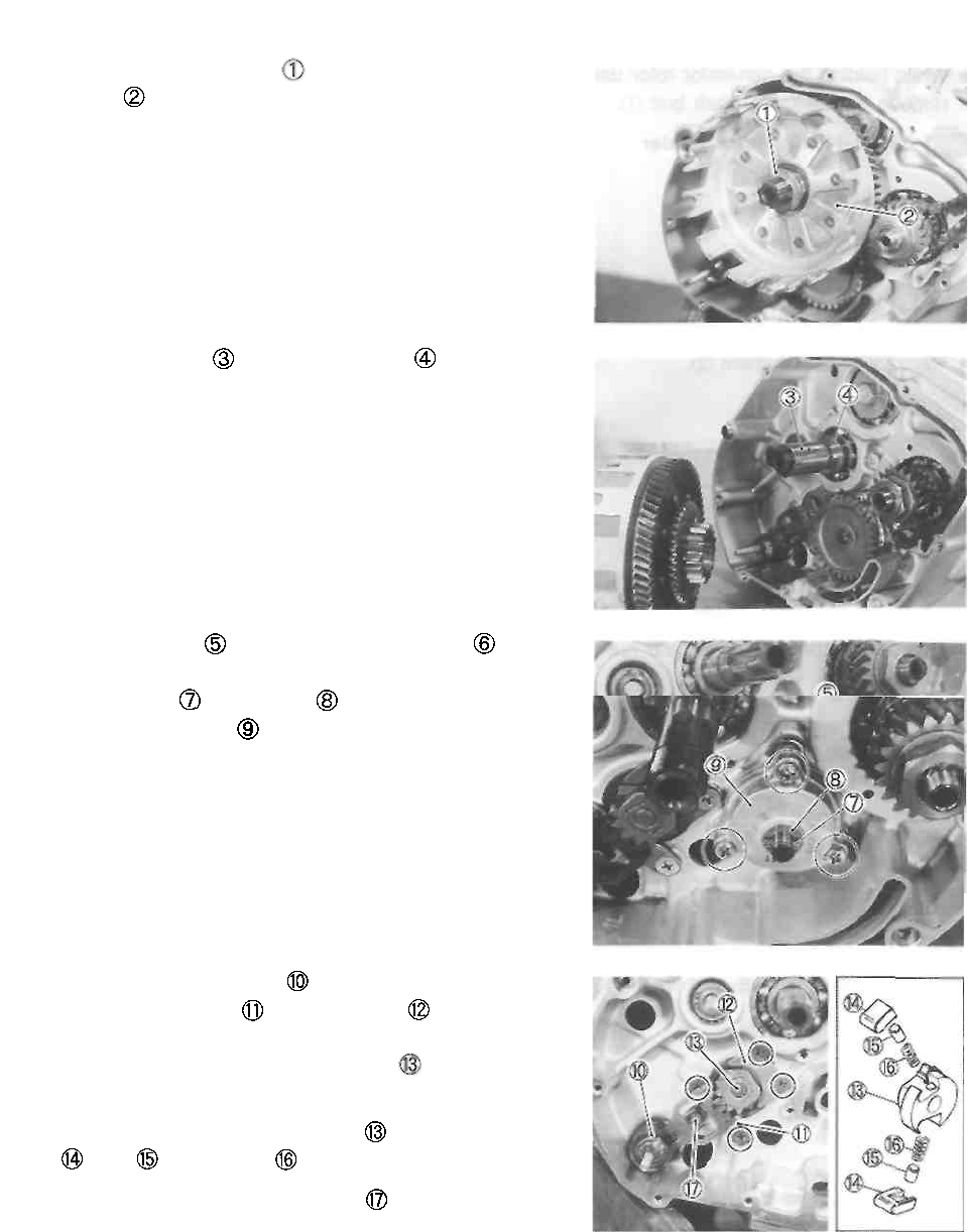
ENGINE DISASSEMBLY
The procedure for engine disassembly is sequentially ex-
plained in the following steps.
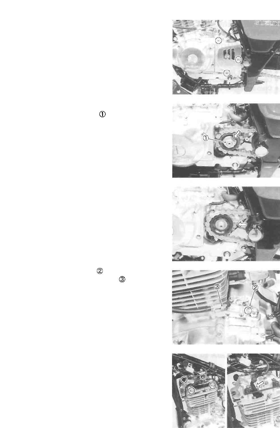
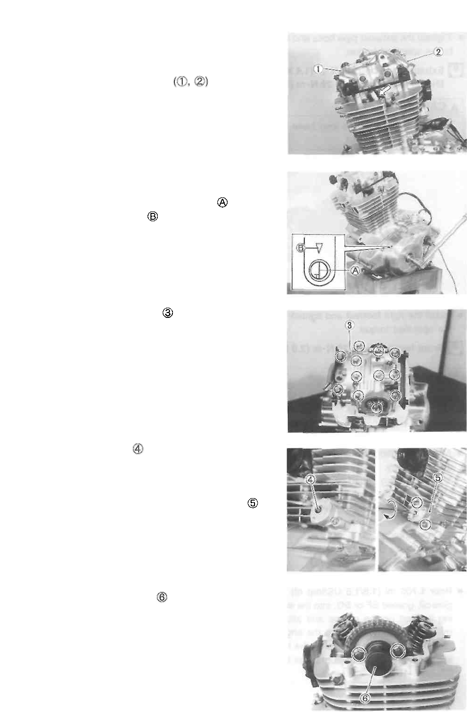
• Remove the valve inspection caps
• Remove the spark plug.
• Remove the valve timing inspection plug and generator
cover cap.
• Rotate the crankshaft and align the "T" line on the
generator rotor with the mark on the generator cover.
• Remove the cylinder head cover
NOTE:
If the cylinder head cover does not come off, lightly tap on
the finless portion of it with a plastic mallet to make the
gasketed joint loose.
• Remove the rubber cap and then turn the slotted
end of cam chain tension adjuster with the flat-head
screwdriver in the clockwise direction and lock the
push rod.
• Remove the cam chain tension adjuster by
removing the mounting bolts.
• Remove the camshaft end cap
• Flatten the lock washer and remove the camshaft
sprocket bolts.
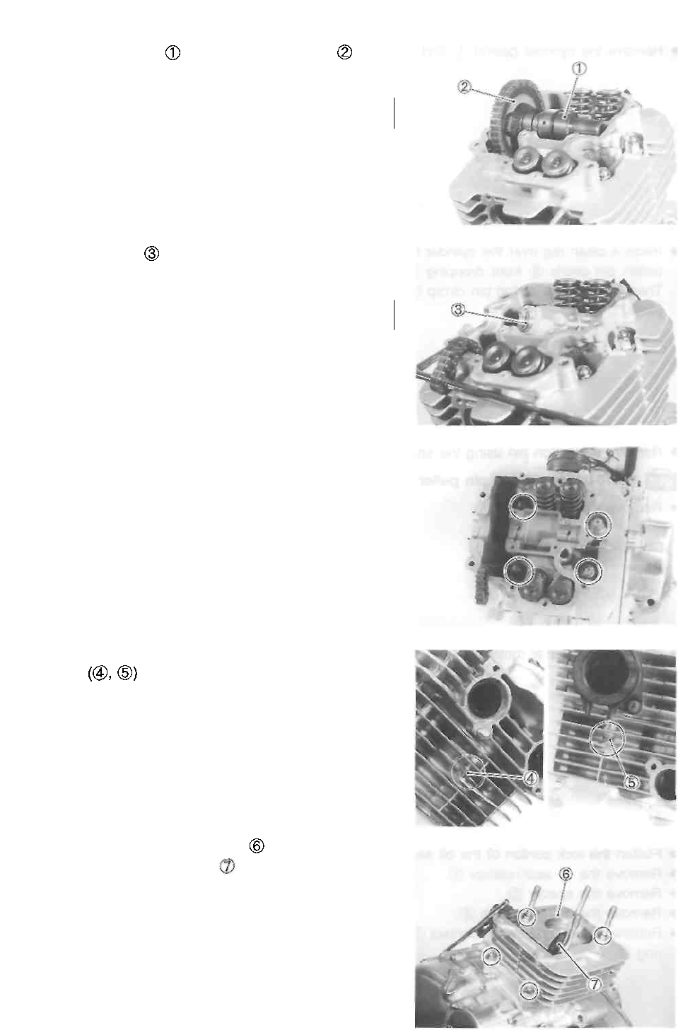
ENGINE 3-10
• Remove the camshaft and camshaft sprocket .
CAUTION
Do not drop the cam chain into the crankcase.
• Remove the C-ring
CAUTION
Do not drop the C-ring into the crankcase.
• Remove the cylinder head nuts diagonally.
• Remove the cylinder head by removing the cylinder
head nuts
NOTE:
If the cylinder head does not come off, lightly tap on the
finless portion of it with a plastic mallet.
• Remove the cylinder head gasket and dowel pins.
• Remove the cam chain guide
• Remove the cylinder by removing the nuts.
NOTE:
If the cylinder does not come off, lightly tap on the Unless
portion of it with a plastic mallet to make the gasketed joint
loose.
3-11 ENGINE
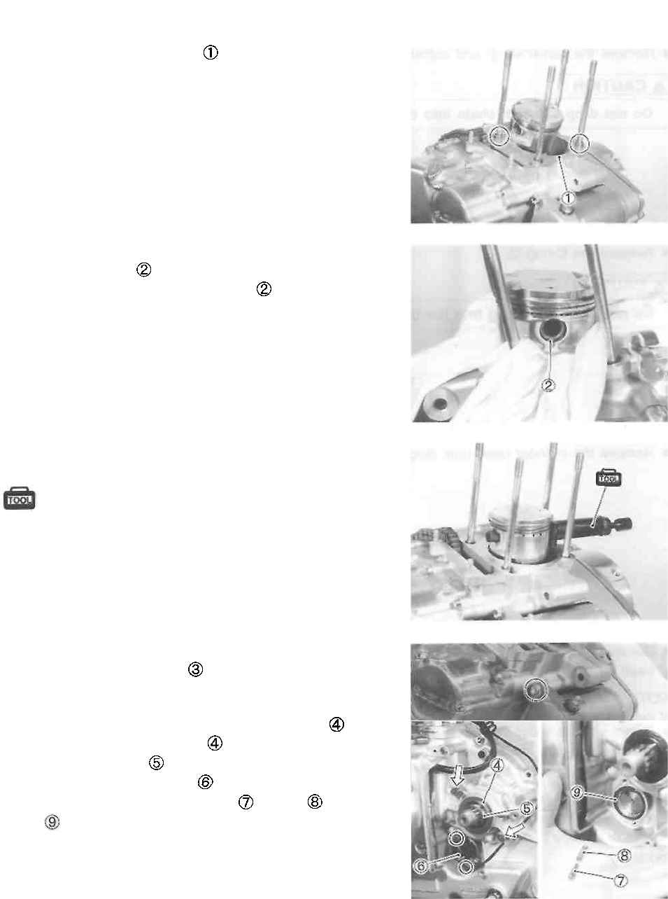
• Remove the cylinder gasket and dowel pins.
• Place a clean rag over the cylinder base to prevent the
piston pin circlip from dropping into the crankcase.
Then, remove the piston pin circlip with a long-nose
pliers.
• Remove the piston pin using the special tool.
09910-34510: Piston pin puller
• Remove the piston.
• Remove the starter motor
• Flatten the lock portion of the oil seal retainer
• Remove the oil seal retainer .
• Remove the spacer
• Remove the neutral switch
• Remove the neutral switch contact , spring and O-
ring
ENGINE 3-12
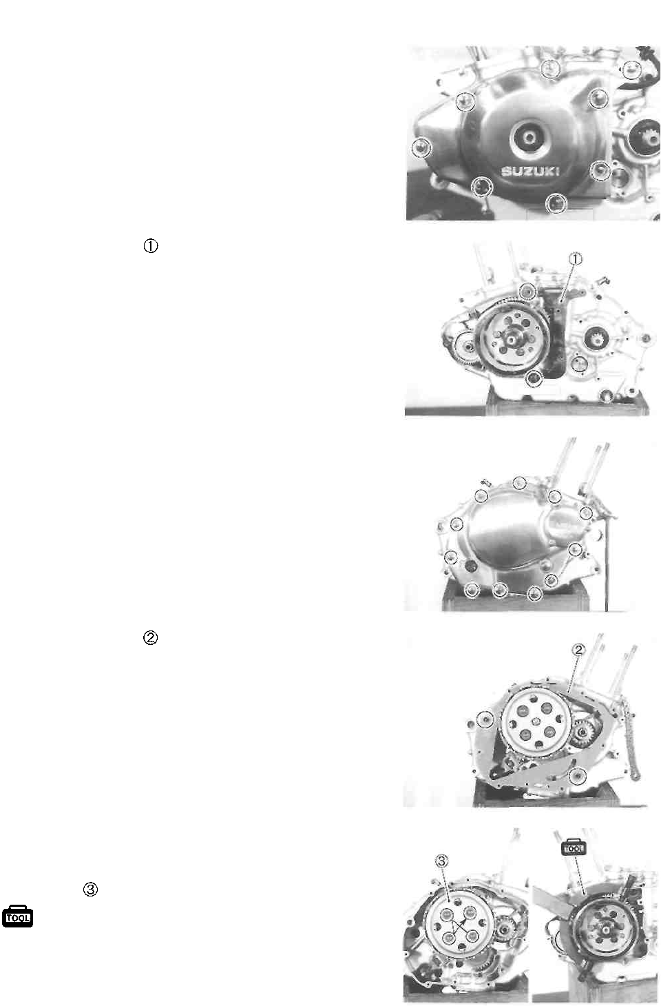
• Remove the generator cover.
• Remove the gasket and dowel pins.
• Remove the clutch cover.
• Remove the gasket and dowel pins.
• While holding the generator rotor using the special tool,
remove the clutch spring mounting bolts in a crisscross
pattern, and remove the clutch springs and clutch pres-
sure plate
09930-44913: Rotor holder
3-13 ENGINE
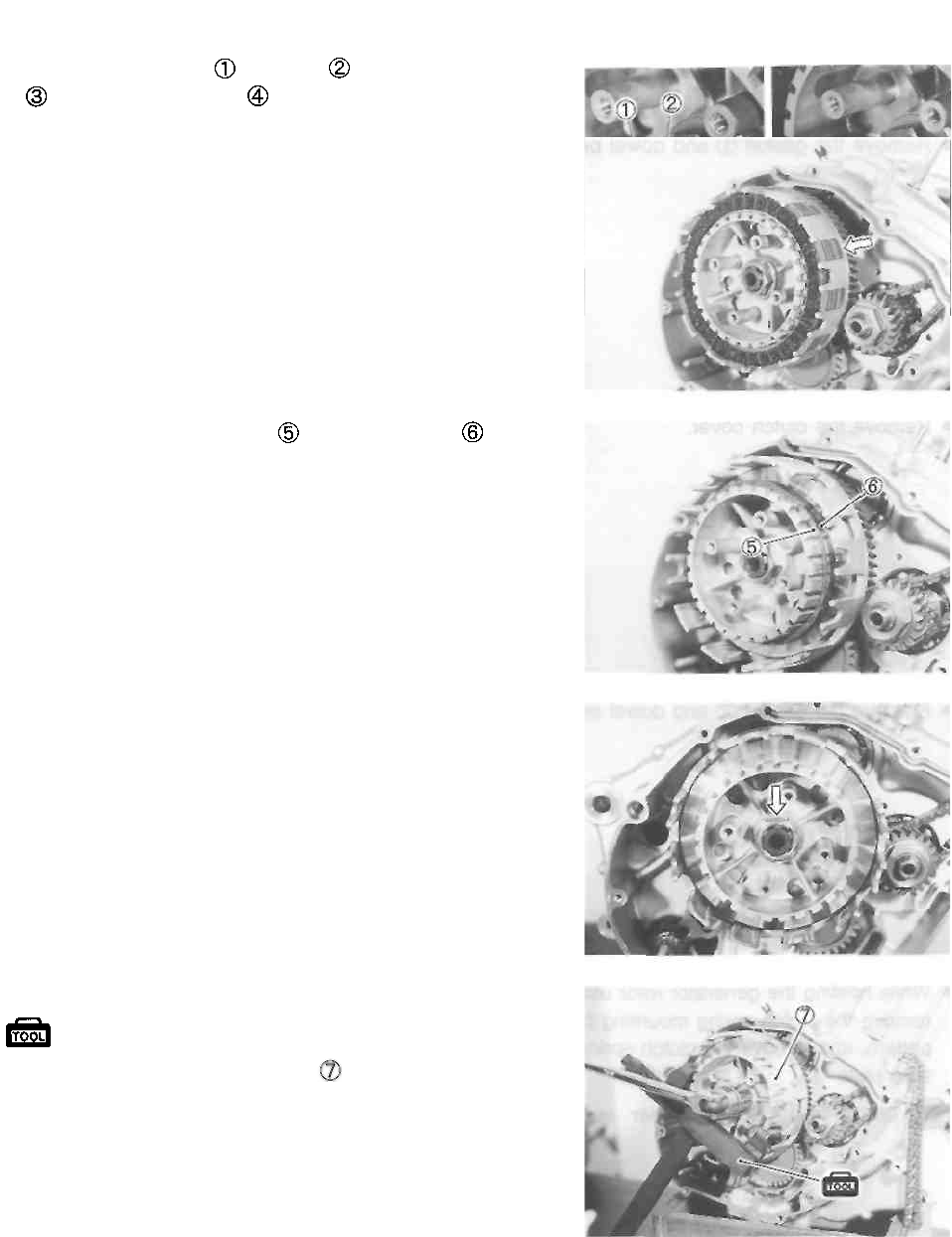
• Remove the washer , bearing , clutch push piece
and clutch push rod
• Remove the clutch drive and driven plates.
• Remove the spring washer and washer seat
• Flatten the lock washer of the clutch sleeve hub nut.
• Remove the clutch sleeve hub nut using the special tool.
09920-53740: Clutch sleeve hub holder
• Remove the clutch sleeve hub
ENGINE 3-14
• Remove the thrust washer and primary driven gear
assembly
• Remove the spacer and thrust washer
• Remove the círclíp and oil pump driven gear
• Remove the pin and washer .
• Remove the oil pump
A CAUTION
Do not attempt to disassemble the oil pump as-
sembly.
• Remove the gearshift shaft
• Remove the pawl lifter and cam guide by removing
the screws.
• Remove the gearshift cam driven gear
NOTE:
When removing the cam driven gear , do not lose the
pawls , pins and springs .
• Remove the gearshift shaft stopper
3-15 ENGINE
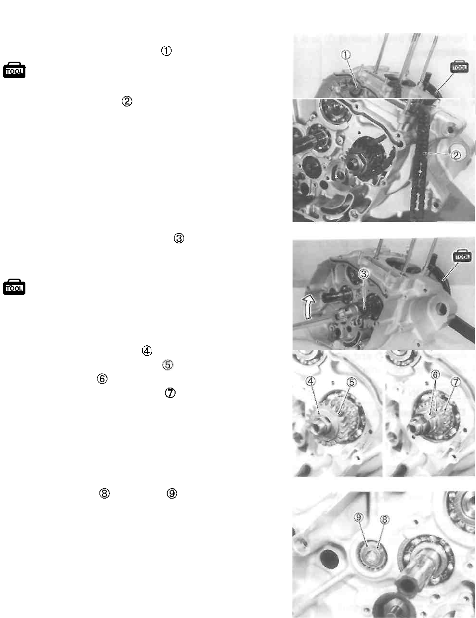
• While holding the generator rotor using the special tool,
remove the balancer shaft bolt
09930-44913: Rotor holder
• Remove the cam chain
• Remove the primary drive gear nut using the special
tool.
09930-44913: Rotor holder
A CAUTION
The primary drive gear nut has left-hand threads.
• Remove the spring washer
• Remove the primary drive gear
• Remove the keys
• Remove the cam chain sprocket
• Remove the circlip and washer
ENGINE 3-16
• Remove the shaft and starter idle gear
• Remove the generator rotor nut using the special tool.
09930-44913: Rotor holder
• Remove the generator rotor using the special tool.
09930-34960: Rotor remover
• Remove the generator rotor key
• Remove the starter driven gear
• Remove the bearing and washer
3-17 ENGINE
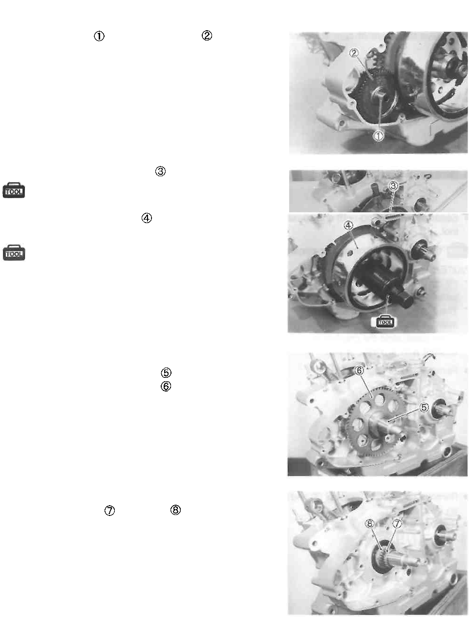
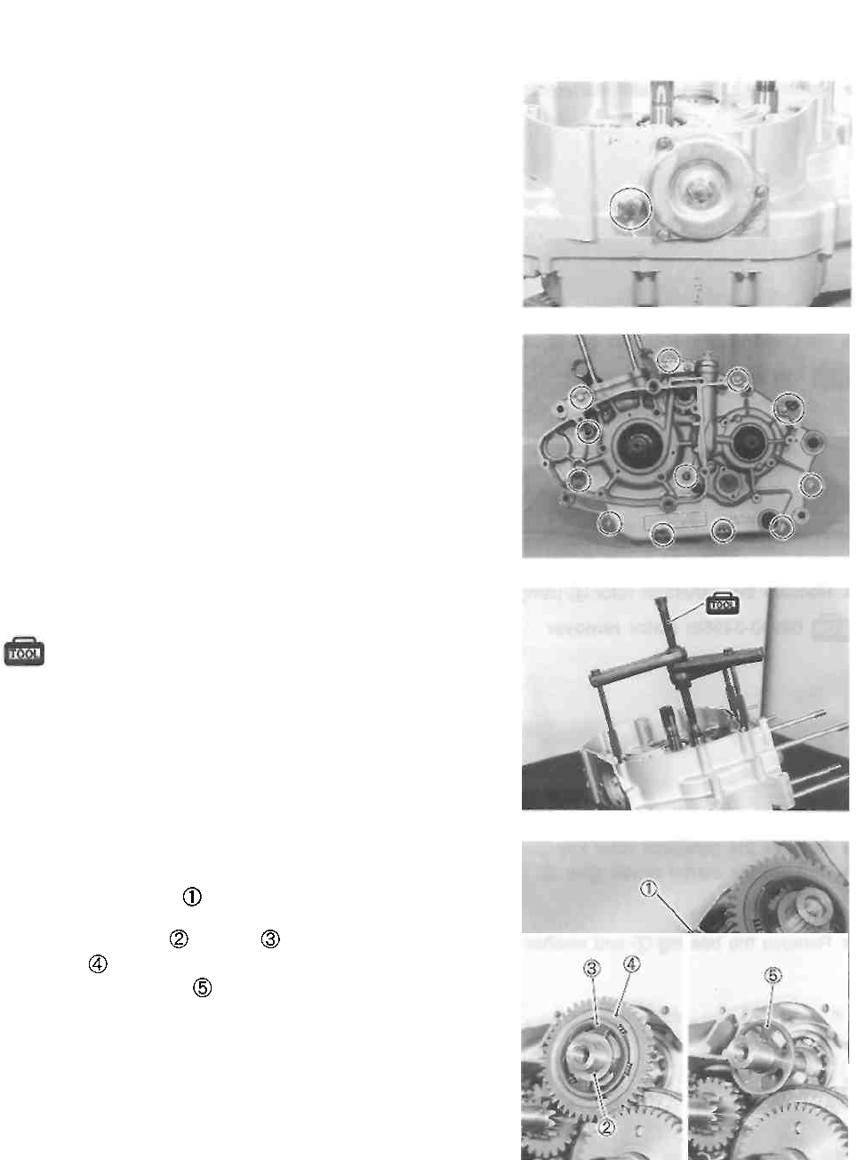
• Remove the gearshift cam stopper.
• Remove the crankcase bolts.
• Separate the left and right crankcases using the special
tool.
09920-13120: Crankcase separator
NOTE:
* Fit the crankcase separator, so that the tool arms are in
parallel with the side of crankcase.
* The crankshaft and transmission components should re-
main in the left crankcase half.
* When separating the crankcase, tap the end of the coun-
tershaft with a plastic mallet.
* Remove the O-ring
• Remove the shim , washer and balancer shaft driv-
en gear
• Remove the washer
ENGINE 3-18
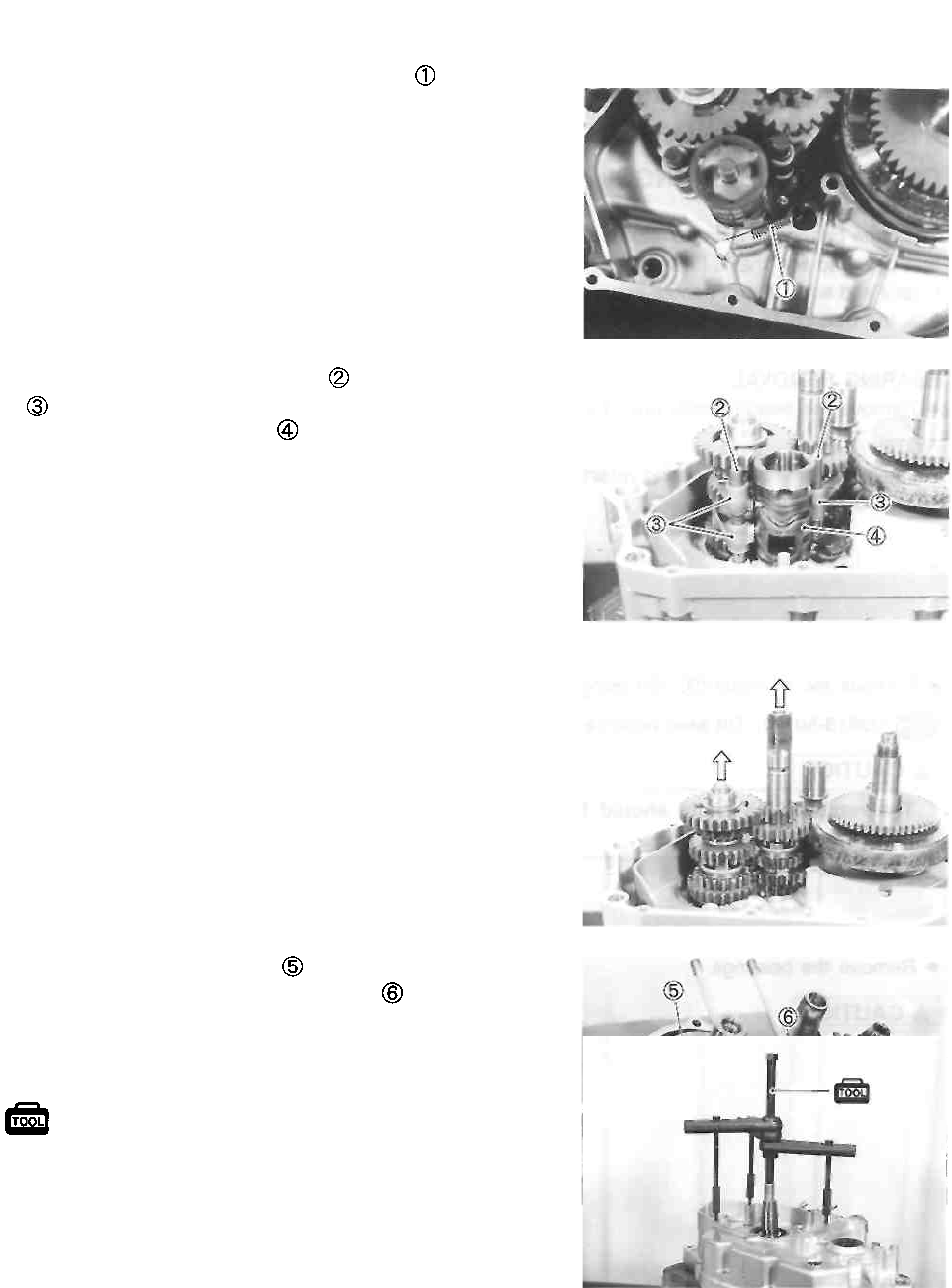
• Remove the gearshift cam stopper spring
• Remove the gearshift fork shafts and gearshift forks
• Remove the gearshift cam
• Remove the transmission.
• Remove the balancer shaft
• Remove the balancer shaft drive gear
• Remove the crankshaft using the special tool.
09920-13120: Crankcase separator
3-19 ENGINE
ENGINE COMPONENTS
INSPECTION AND SERVICE
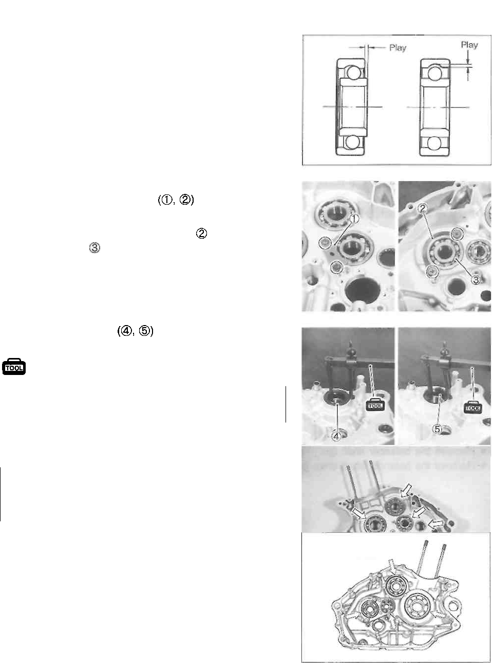
CRANKCASE BEARINGS
BEARING INSPECTION
While the bearing is in the crankcase, rotate its inner race
and check to see that it turns smoothly. If it does not turn
quietly and smoothly, or if there are signs of any abnormali-
ties, the bearing is defective and must be replaced as fol-
lows.
BEARING REMOVAL
• Remove the bearing retainers
NOTE:
Remove the driveshaft bearing retainer along with the
driveshaft bearing
• Remove the oil seals using the special tool.
09913-50121: Oil seal remover
CAUTION
The removed oil seals should be replaced with
new ones.
Remove the bearings.
CAUTION
The removed bearings should be replaced with
new ones.
ENGINE 3-20
• Remove the oil seal using the special tool.
09913-75510: Bearing remover/installer
A CAUTION
The removed oil seal should be replaced with a
new one.
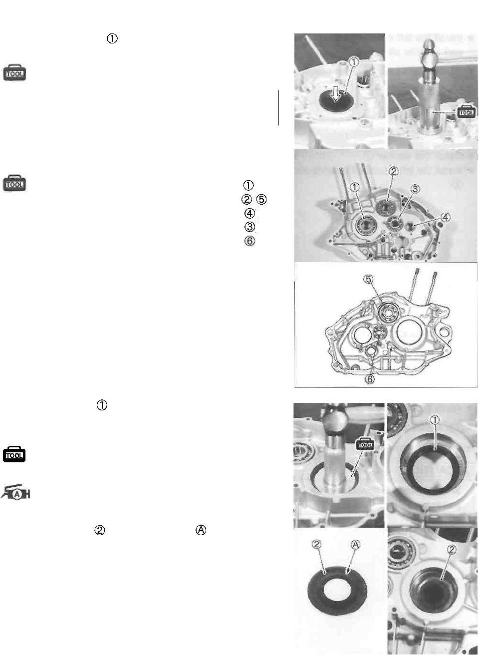
BEARING INSTALLATION
• Install the bearings using the special tools.
09913-75510: Bearing remover/installer (For )
09913-75520: Bearing remover/installer (For , )
09913-75830: Bearing remover/installer (For )
09913-84510: Bearing remover/installer (For )
09913-85210: Bearing remover/installer (For )
• Install the oil seal into the left crankcase using the
special tool.
09913-85210: Bearing remover/installer
• Apply grease to the oil seal lip.
99000-25010: SUZUKI SUPER GREASE "A"
• Place the washer so that the convex of it faces
towards the oil seal.
3-21 ENGINE
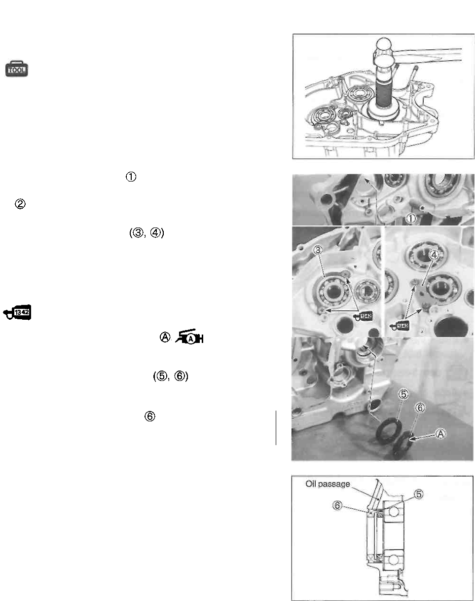
• Install the left crankcase bearing using the special tool
and suitable attachment (used beanng e.g.).
09913-75510: Bearing remover/installer
• Install the washer
• Install the left drlveshaft bearing with the bearing retainer
• Install the bearing retainers
NOTE:
Apply a small quantity of THREAD LOCK "1342" to the
bearing retainer screws.
99000-32050: THREAD LOCK "1342"
• Apply grease to the oil seal lip 99000-
25010: SUZUKI SUPER GREASE "A"
• Install the driveshaft oil seals as shown.
CAUTION
When installing the oil seal , Do not block the oil
passage.
ENGINE 3-22
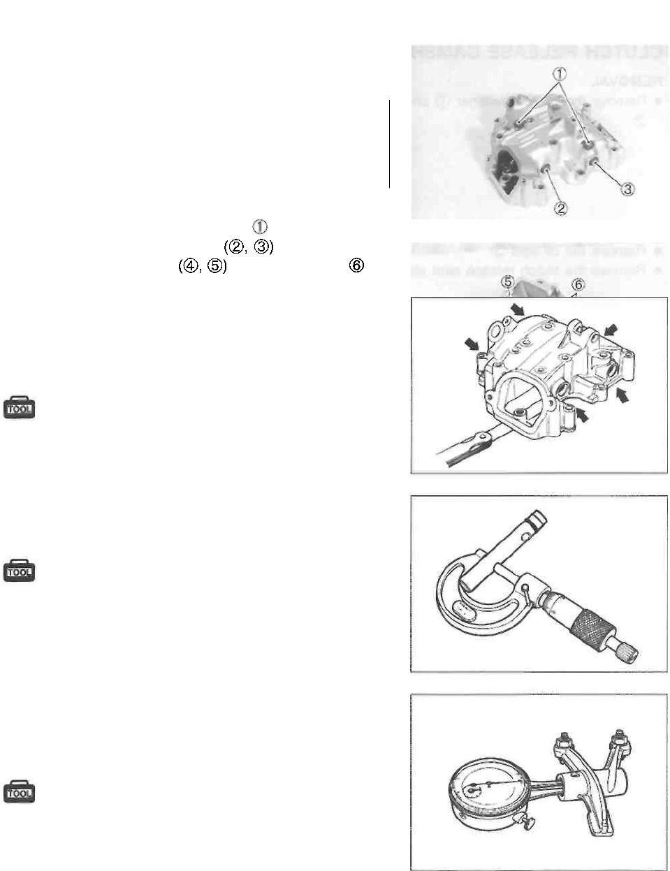
CLUTCH RELEASE CAMSHAFT
REMOVAL
• Remove the oil seal retainer and clutch cable guide
• Remove the oil seal
• Remove the clutch release cam shaft
REASSEMBLY
• Apply engine oil to the clutch release camshaft as
shown in the illustration.
• Install the clutch release camshaft , washer and oil
seal
3-23 ENGINE
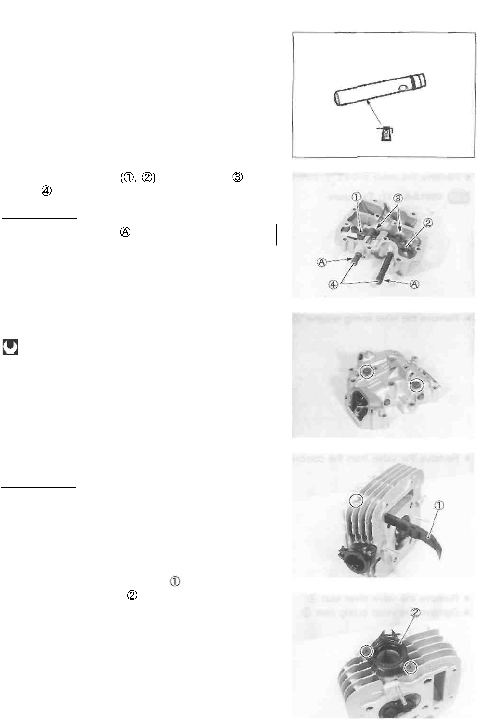
CYLINDER HEAD COVER
CAUTION
Identify the position of each removed part. Organize
the parts in their respective groups (i.e., intake or
exhaust) so that they can be installed in their original
locations.
DISASSEMBLY
• Remove the rocker arm shaft bolts
• Remove the rocker arm shafts
• Remove the rocker arms and wave washers
CYLINDER HEAD COVER DISTORTION
After removing the sealant (SUZUKI BOND "1215") from the
mating surface of the cylinder head cover, place the cylinder
head cover on a surface plate and check for distortion with a
thickness gauge. Check points are shown in Fig.
09900-20803: Thickness gauge
Service Limit: 0.05 mm (0.002 in)
If the distortion exceeds the limit, replace the cylinder head
cover.
ROCKER ARM SHAFT O.D.
Measure the diameter of the rocker arm shafts.
09900-20205: Micrometer (0-25 mm)
Standard (IN. & EX.):
11.966-11.984 mm (0.4711-0.4718 in)
ROCKER ARM I.D.
Measure the inside diameter of the rocker arm and check the
wear of the camshaft contacting surface.
09900-20605: Dial calipers
Standard (IN. & EX.):
12.000-12.018 mm (0.4724-0.4731 in)
ENGINE 3-24
REASSEMBLY
Reassemble the cylinder head cover in the reverse order of
disassembly. Pay attention to the following points: •
Apply engine oil to the rocker arm shafts.
• Install the rocker arms , wave washers and
shafts
[ A CAUTION]
Use the new O-rings to prevent oil leakage.
• Tighten the rocker arm shaft bolts to the specified
torque.
Rocker arm shaft bolt: 10 Nm (1.0 kg-m, 7.0 Ib-ft)
CYLINDER HEAD
I A CAUTION |
Identify the position of each removed part. Orga-
nize the parts in their respective groups (i.e., in-
take or exhaust) so that they can be installed in
their original locations.
DISASSEMBLY
• Remove the cam chain tensioner
• Remove the intake pipe
3-25 ENGINE
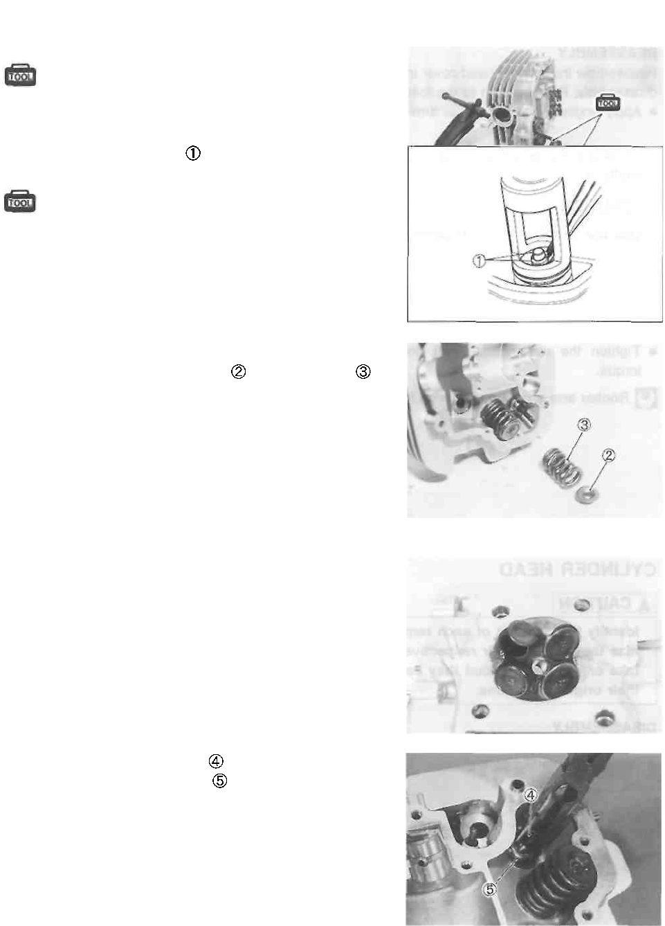
• Compress the valve spring using the special
tools.
09916-14510: Valve lifter 09916-14910:
Valve lifter attachment
• Remove the valve cotters from the valve stem.
09916-84511: Tweezers
• Remove the valve spring retainer and valve spring
• Remove the valve from the combustion chamber side.
• Remove the valve stem seal
• Remove the valve spring seat
ENGINE 3-26
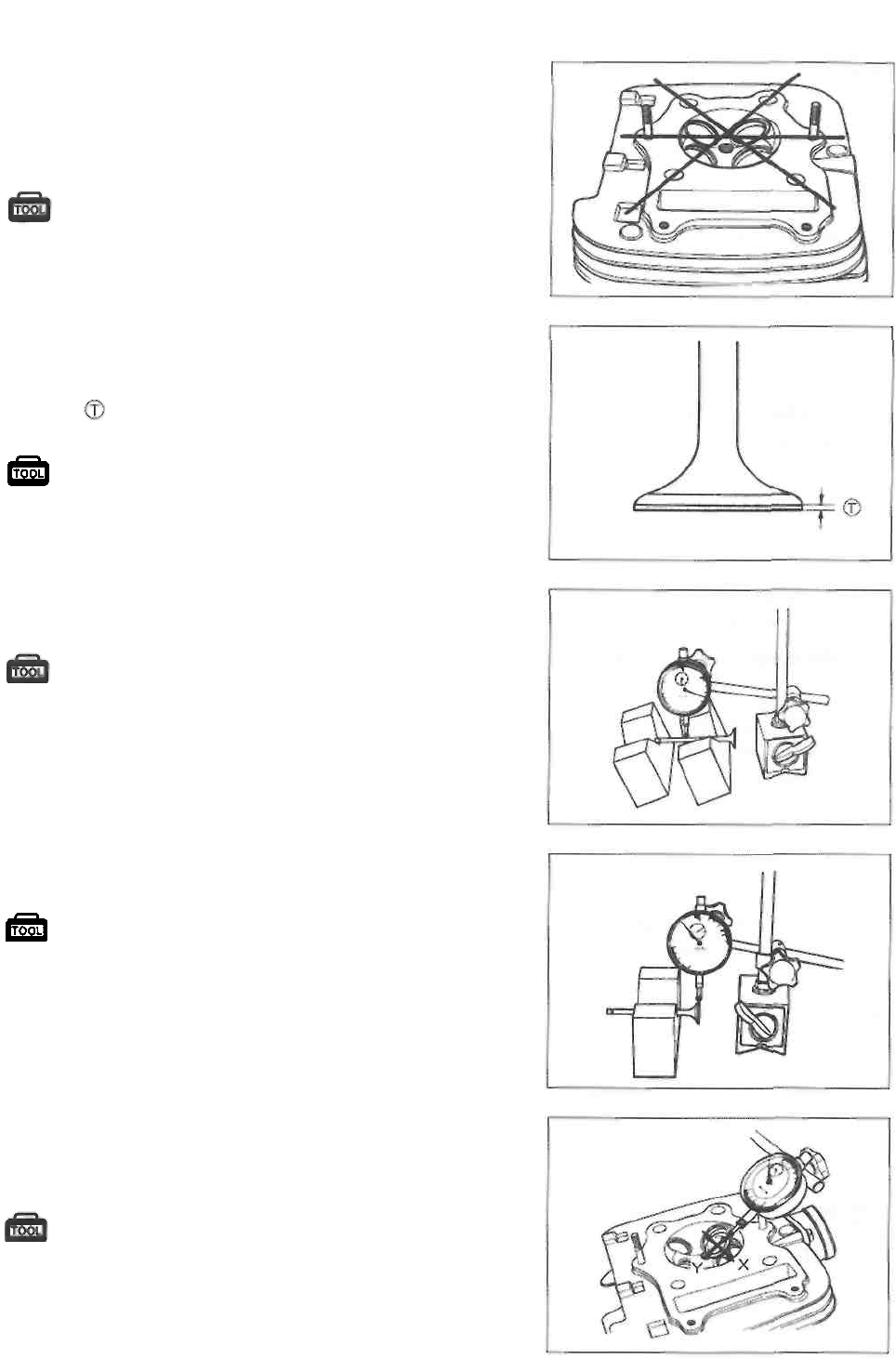
CYLINDER HEAD DISTORTION
Decarbon the combustion chamber. Check the gasket surface
of the cylinder head for distortion using a straightedge and
thickness gauge. Take clearance readings at several places.
If readings exceed the service limit, replace the cylinder head.
09900-20803: Thickness gauge
Service Limit: 0.05 mm (0.002 in)
VALVE FACE WEAR
The thickness of the valve face decreases as the face wears.
Visually inspect each valve face for wear and replace any
valve with an abnormally worn face. Measure the valve face
thickness , if it is out of specification, replace the valve with
a new one.
09900-20101: Vernier calipers
Service Limit: 0.5 mm (0.02 in)
VALVE STEM RUNOUT
Support the valve using V-blocks, as shown, and measure its
runout with the dial gauge. If the runout exceeds the limit,
replace the valve.
09900-20606: Dial gauge (1/100 mm)
09900-20701: Magnetic stand 09900-
21304: V-block (100 mm)
Service Limit: 0.05 mm (0.002 in)
VALVE HEAD RADIAL RUNOUT
Place the dial gauge at a right angle to the valve head face
and measure the valve head radial runout.
If it measures more than the service limit, replace the
valve.
09900-20606: Dial gauge (1/100 mm)
09900-20701: Magnetic stand 09900-21304:
V-block (100 mm)
Service Limit: 0.03 mm (0.001 in)
VALVE STEM DEFLECTION
Lift the valve about 10 mm (0.39 in) from the valve seat.
Measure the valve stem deflection in two directions, "X" and
"Y", perpendicular to each other. Position the dial gauge as
shown. If the deflection exceeds the service limit, then
determine whether the valve or the guide should be replaced
with a new one.
09900-20606: Dial gauge (1/100 mm) 09900-
20701: Magnetic stand
Service Limit
Intake and exhaust valves: 0.35 mm (0.014 in)
3-27 ENGINE
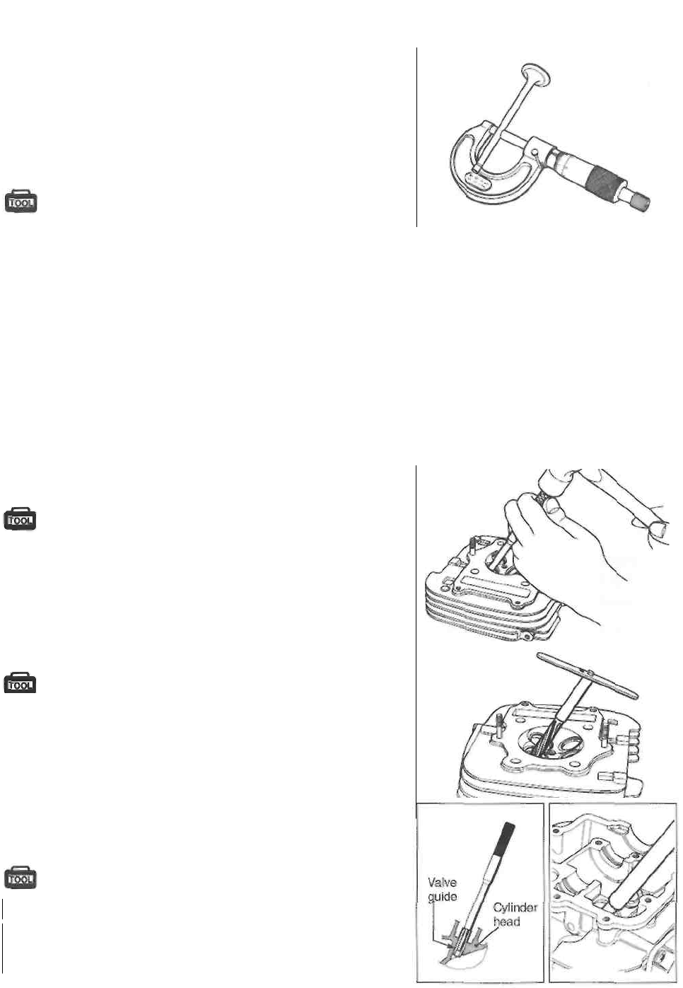
VALVE STEM WEAR
Measure the valve stem O.D. using the micrometer. If it is out
of specification, replace the valve with a new one. If the valve
stem O.D. is within specification but the valve stem deflection
is not, replace the valve guide. After replacing the valve or
valve guide, re-check the deflection.
09900-20205: Micrometer (0-25 mm)
Standard
Valve stem O.D.
IN.: 5.460-5.475 mm (0.2150-0.2156 in)
EX.: 5.445-5.460 mm (0.2144-0.2150 in)
NOTE:
If valve guides have to be replaced, refer to the valve guide
servicing steps below.
VALVE GUIDE SERVICE
* Remove the valve guide using the special tool.
09916-44910: Valve guide remover/installer
NOTE:
* Discard the removed valve guide subassemblies.
* Only oversized valve guides are available as replace-
ment parts.
• Re-finish the valve guide holes in the cylinder head using
the special tools.
09916-34561: Valve guide reamer (11.3 mm)
09916-34542: Handle
NOTE:
Insert the reamer from the combustion chamber side and
always turn the reamer handle clockwise.
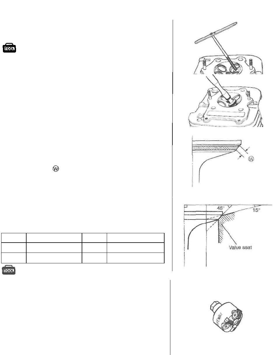
• Install a ring onto each valve guide.
• Oil the stem hole of each valve guide and drive the guide
into the guide hole using the special tool.
09916-44910: Valve guide remover/installer
A CAUTION
Be sure to use a new valve guide ring and valve guide.
ENGINE 3-28
• After installing the valve guides, re-finish their guiding
bores using the special tools. Be sure to clean and oil
the guides after reaming.
09916-34550: Valve guide reamer (5.5 mm)
09916-34542: Handle
VALVE SEAT WIDTH
• Coat the valve seat uniformly with Prussian blue. Install
the valve and attach a valve lapper onto it. Tap the
coated seat with the valve face in a rotating manner, in
order to obtain a clear impression of the seating contact.
• The ring-like dye impression left on the valve face must
be continuous without any breaks. In addition, the width
of the dye ring, which is the valve seat width, must be
within the following specification:
Standard
Valve seat width : 0.9-1.1 mm (0.035-0.043 in)
If the valve seat is out of specification, re-cut the seat.
VALVE SEAT SERVICE
The valve seats for both intake and exhaust valves are ma-
chined to two different angles. (The seat contact surface is
cut 45°.)
INTAKE SIDE
EXHAUST SIDE
45°
N-122
45°
N-122
15°
N-121
15°
N-121
09916-21111: Valve seat cutter set
09916-20610: Valve seat cutter (N-121)
09916-20620: Valve seat cutter (N-122)
09916-24450: Solid pilot (N-100-5.52)
NOTE:
The valve seat contact area must be inspected after each
cut.
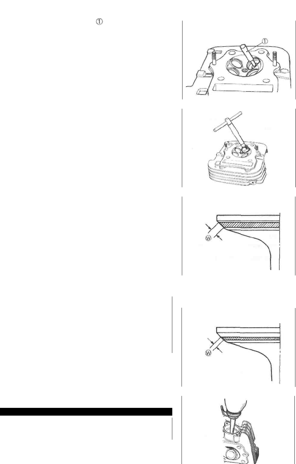
3-29 ENGINE
• When installing the solid pilot , rotate it slightly. Seat
the pilot snugly. Install the 45° cutter, attachment and
T-handle.
• Using the 45° cutter, descale and clean up the seat. Ro-
tate the cutter one or two turns.
• Measure the valve seat width after every cut. If the valve
seat is pitted or burned, use the 45° cutter to condition
the seat same more.
NOTE:
Cut only the minimum amount necessary from the seat to
prevent the possibility of the valve stem becoming too
close to the rocker arm for correct valve contact angle.
If the contact area is too high on the valve, or If it is too
wide, use the 15° cutter to lower and narrow the contact
area.
If the contact area is too low or too narrow, use the 45°
cutter to raise and widen the contact area.
• After the desired seat position and width is achieved, use
the 45° cutter very lightly to clean up any burrs caused
by the previous cutting operations.
CAUTION
Contact area too high and too wide
on face of valve
DO NOT use lapping compound after the final cut
is made. The finished valve seat should have a
velvety smooth finish and not a highly polished or
shiny finish. This will provide a soft surface for
the final seating of the valve which will occur dur-
ing the first few seconds of engine operation.
Clean and assemble the head and valve components.
Fill the intake and exhaust ports with gasoline to check
for leaks. If any leaks occur, inspect the valve seat and
face for burrs or other things that could prevent the valve
from sealing.
WARNING
Always use extreme caution when handling gaso-
line.
NOTE:
After servicing the valve seats, be sure to check the valve
clearance after the cylinder has been reinstalled. (See pp.
2-4 to -6.)

Contact area too low and too narrow on face of valve
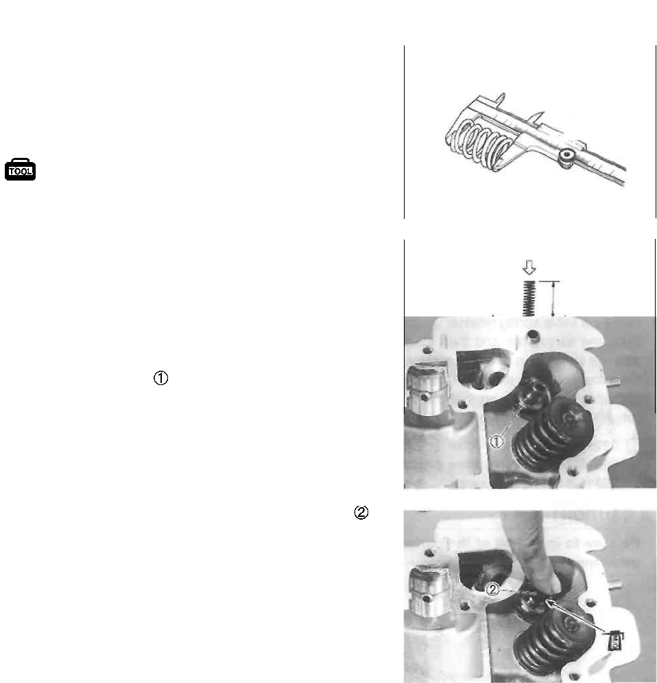
ENGINE 3-30
VALVE SPRINGS
Check the valve springs for proper strength by measuring
their free length and also the force required to compress
them. If the spring length is less than the service limit or if
the force required to compress the spring does not fall with-
in the specified range, replace the spring.
Service Limit
Valve spring free length (IN. & EX.): 40.1 mm (1.58 in)
Standard
Valve spring tension (IN. & EX.): 18.4-21.6 kg/35.0 mm
(40.56-47.62 lbs/1.38 in)
18.4-21.6 kg
(40.56-47.62 lbs)
REASSEMBLY
Reassemble the cylinder head in the reverse order of dis-
assembly. Pay attention to the following points: • Install
each valve spring seat .
• Apply molybdenum oil solution to the valve stem seal,
and press-fit the seal into position by hand.
A CAUTION
Do not reuse the valve stem seals.
09900-20201: Vernier calipers
35.0 mm
(1.38 in)
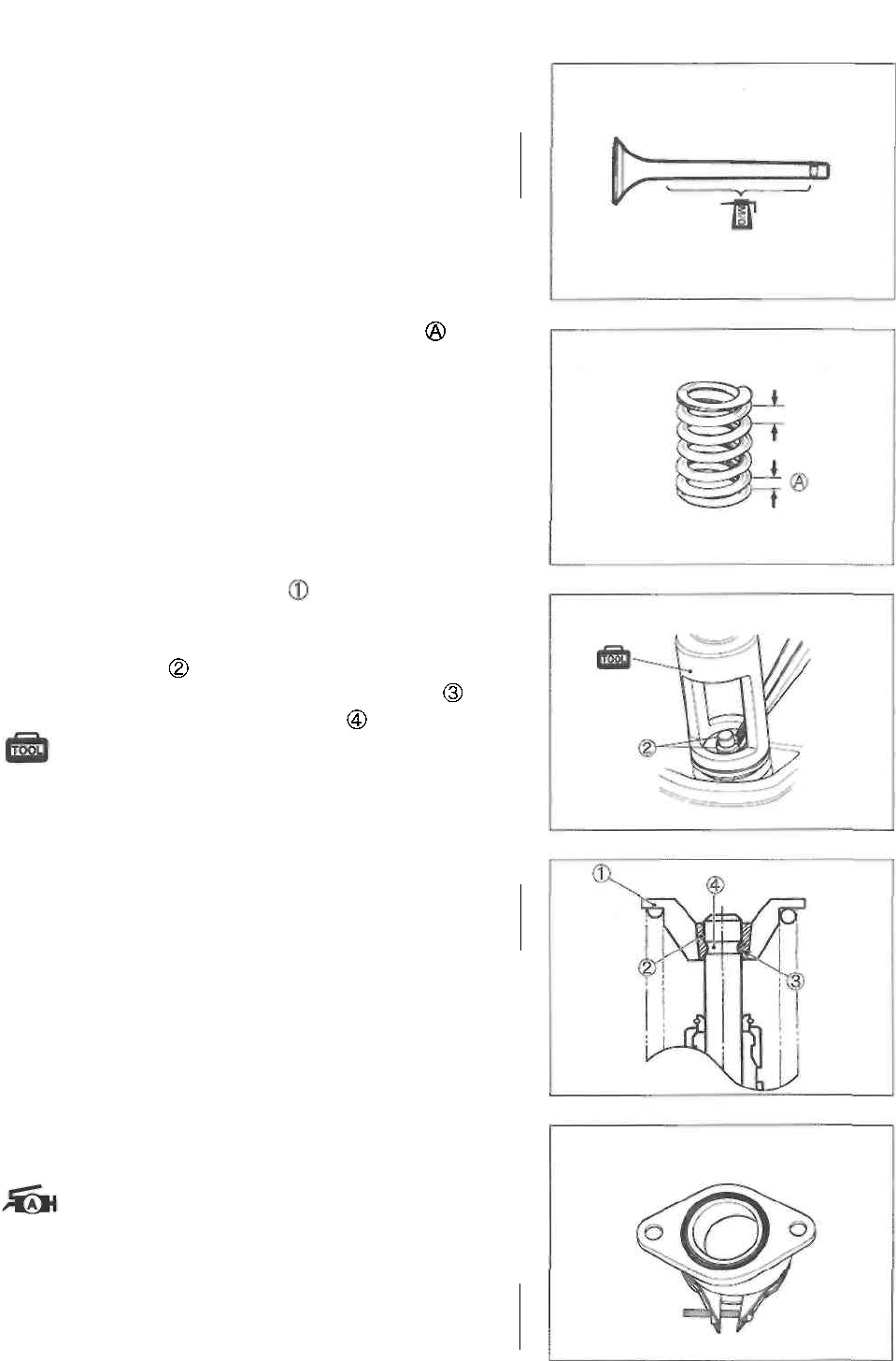
3-31 ENGINE
• Apply molybdenum oil solution to the valve stems.
CAUTION
When inserting each valve, take care not to dam-
age the lip of the stem seal.
• Install the valve springs with the smaller pitch facing
the cylinder head.
• Install the valve spring retainer , press down the spring
using the valve lifter and then install the cotter halves
onto the valve stem end. Then, release the valve lifter to
allow the cotter to wedge between the retainer and
the valve stem. Be sure that the rounded lip of the
cotter fits snugly into the groove in the stem end.
09916-14510: Valve lifter 09916-14910:
Valve lifter attachment 09916-84511:
Tweezers
CAUTION
Be sure to install all of the parts in their original
positions.
INTAKE PIPE
• When installing the intake pipe, apply grease to the CD-
ring.
99000-25010: SUZUKI SUPER GREASE "A"
CAUTION
Use the new O-ring to prevent sucking air from
the joint.
Towards
Head
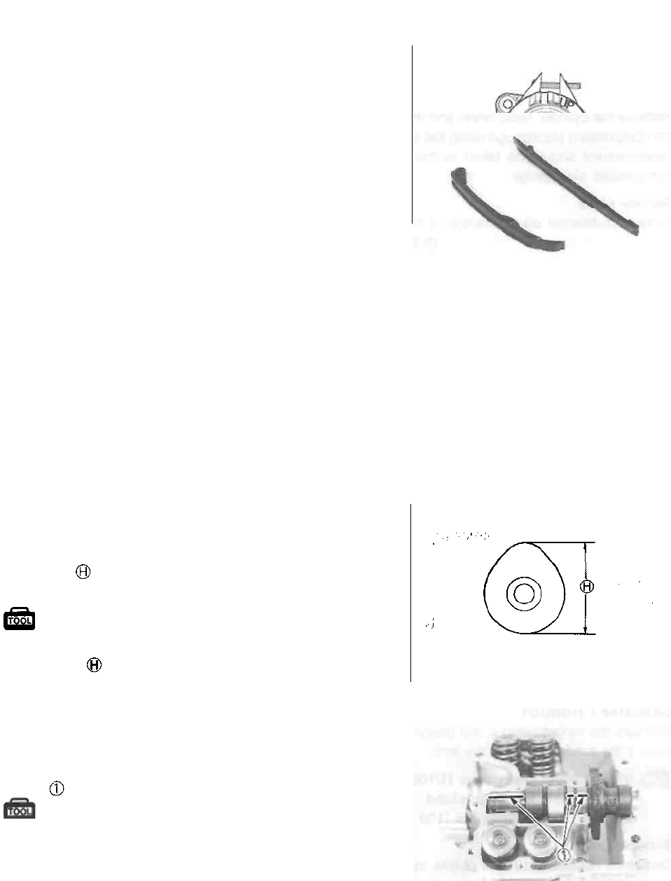
ENGINE 3-32
NOTE:
Make sure that the "UP" mark comes upward.
CAM CHAIN GUIDE AND CAM CHAIN
TENSIONER
Check the cam chain guide and cam chain tensioner for
wear and damage. If it is found to be damaged, replace it
with a new one.
CAMSHAFT
CAMSHAFT INSPECTION
If the engine produces abnormal noises, vibration or lacks
power, a camshaft may be distorted or worn to the service
limit. The camshaft runout should be checked. Also, check
the cams and journals for wear or damage.
CAM WEAR
Worn-down cams are often the cause of mistimed valve
operation resulting in reduced power output. Measure the
cam height using the micrometer. Replace a camshaft if
the cams are worn to the service limit.
09900-20202: Micrometer (25-50 mm)
Service Limit
Cam height (IN.) : 34.690 mm (1.3657 in)
(EX.) : 34.730 mm (1.3673 in)
CAMSHAFT JOURNAL WEAR
Determine whether or not each journal is worn down to the
limit by measuring the oil clearance with the camshaft
installed in place. Measure the clearance using the plasti-
gauge .
09900-22301: Plastigauge
09900-22302: Plastigauge
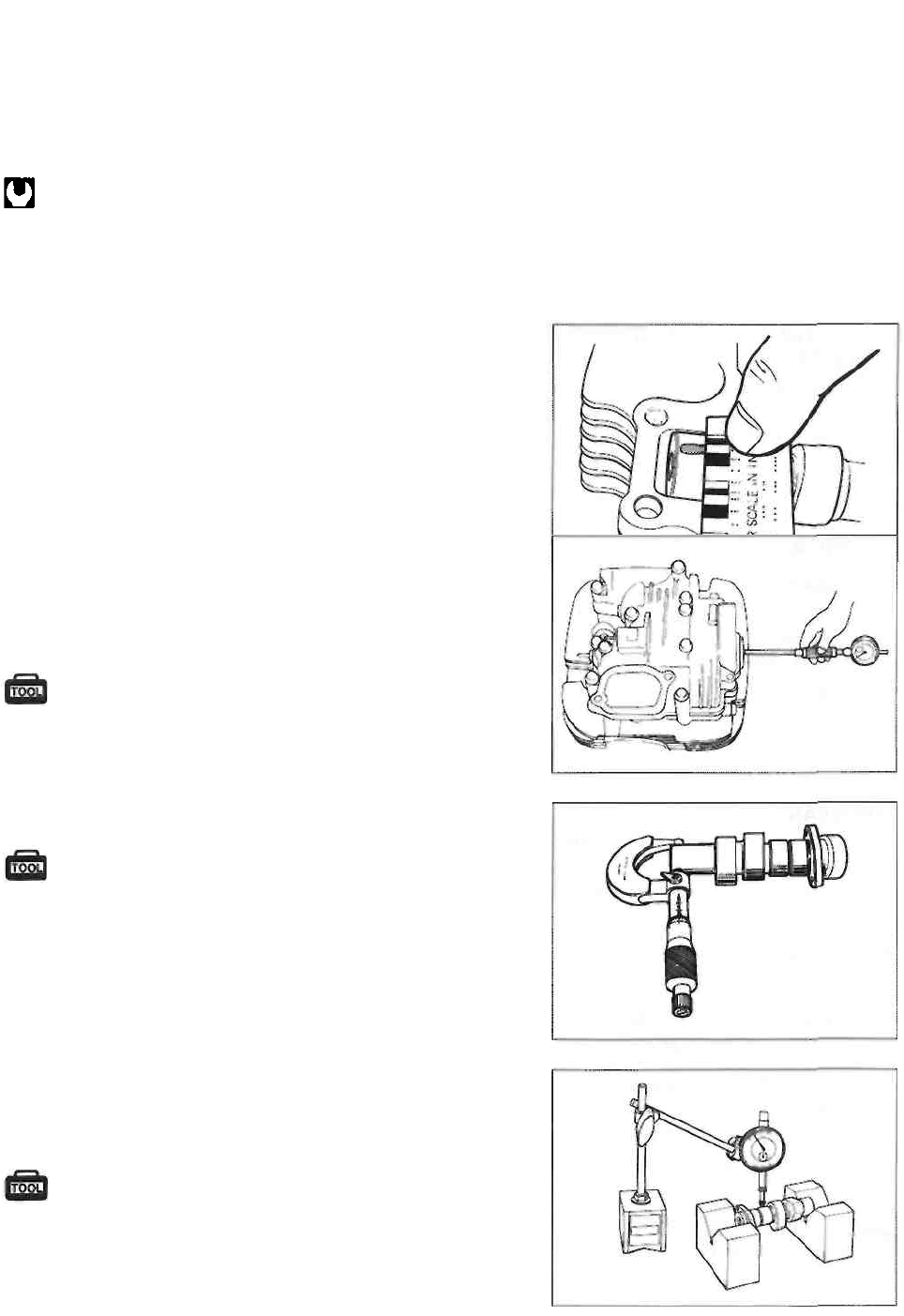
3-33 ENGINE
NOTE:
Install the cylinder head cover to its original position.
Tighten the cylinder head cover bolts evenly and diagonally
to the specified torque.
Cylinder head cover bolt: 10 N ■ m (1.0 kg-m, 7.0 Ib-ft)
NOTE:
Do not rotate the camshaft with the plastigauge in place.
Remove the cylinder head cover and measure the width of the
compressed plastigauge using the envelope scale. This
measurement should be taken at the widest part of the
compressed plastigauge.
Service Limit
Camshaft-Journal oil clearance: 0.150 mm
(0.0059 in)
If the camshaft journal oil clearance exceeds the limit,
measure the inside diameter of the camshaft journal holder
and outside diameter of the camshaft journal. Replace the
camshaft or the cylinder head depending upon which one
exceeds the specification.
09900-22403: Small bore gauge
Standard
Camshaft journal holder I.D.
(Right side) : 25.012-25.025 mm (0.9847-0.9852 in)
(Left side) : 20.012-20.025 mm (0.7879-0.7884 in)
09900-20205: Micrometer (0-25 mm)
Standard
Camshaft journal O.D.
(Right side) : 24.959-24.980 mm (0.9826-0.9835 in)
(Left side) : 19.959-19.980 mm (0.7858-0.7866 in)
CAMSHAFT RUNOUT
Measure the runout using a dial gauge. Replace the camshaft
if the runout exceeds the limit.
09900-20606: Dial gauge (1/100 mm)
09900-20701: Magnetic stand 09900-21304:
V-block set (100 mm)
Service Limit
Camshaft runout: 0.10 mm (0.004 in)
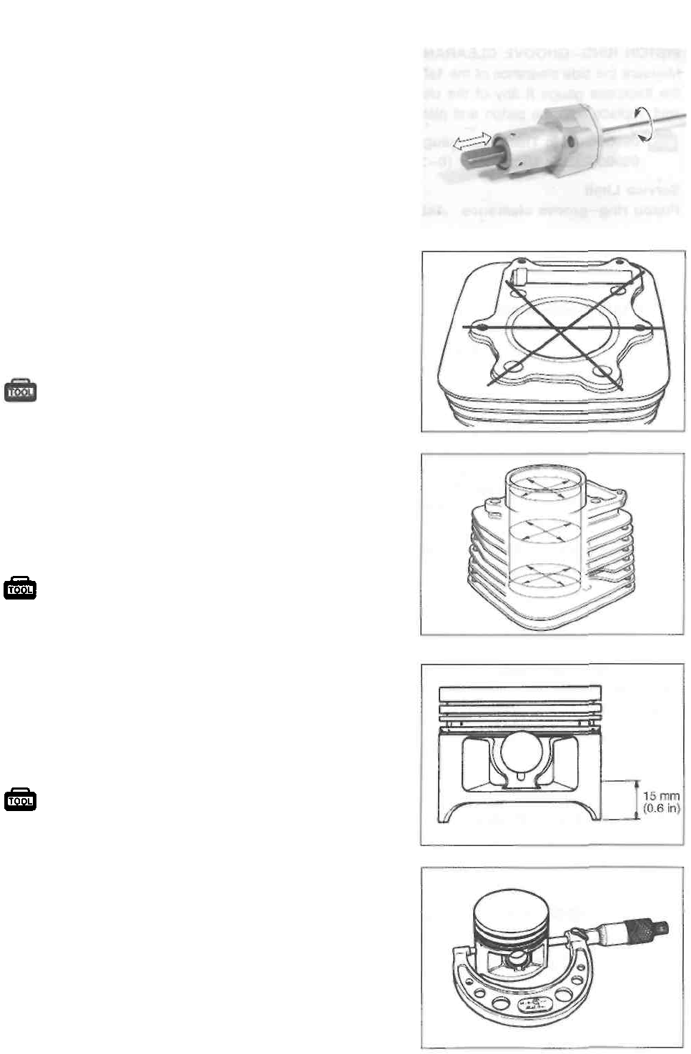
ENGINE 3-34
CAM CHAIN TENSION ADJUSTER
The cam chain tension adjuster is maintained at the proper
tension by an automatically adjusted tensioner. Insert a flat-
head screwdriver into the slotted end of the cam chain ten-
sion adjuster and turn it clockwise to release the tension.
Remove the screwdriver to make sure that the push rod
moves properly. If the push rod is stuck or the spring mech-
anism does not work, replace the cam chain tension adjust-
er assembly with a new one.
CYLINDER
DISTORTION
Check the gasket surface of the cylinder for distortion using
a straightedge and thickness gauge. Take clearance read-
ings at several places. If any reading exceeds the service
limit, replace the cylinder.
09900-20803: Thickness
gauge Service Limit: 0.05 mm (0.002
in)
CYLINDER BORE
Measure the cylinder bore diameter at six places. If any
one of the measurements exceed the limit, overhaul the
cylinder and replace the piston with an oversize piston, or
replace the cylinder.
PISTON AND PISTON PIN
DIAMETER
Measure the piston diameter using the micrometer at 15
mm (0.6 in) from the skirt end.
If the piston diameter is less than the service limit, replace
the piston.
09900-20203: Micrometer (50-75 mm)
Service Limit: 71.880 mm (2.8299
in) Piston oversize: 0.5, 1.0 mm
PISTON-CYLINDER CLEARANCE
Subtract the piston diameter from the cylinder bore diame-
ter. If the piston-to-cylinder clearance exceeds the service
limit, rebore the cylinder and use an oversize piston or re-
place both the cylinder and the piston.
Service Limit: 0.120 mm (0.0047 in)
09900-20508: Cylinder gauge set
Service Limit: 72.085 mm (2.8380 in)
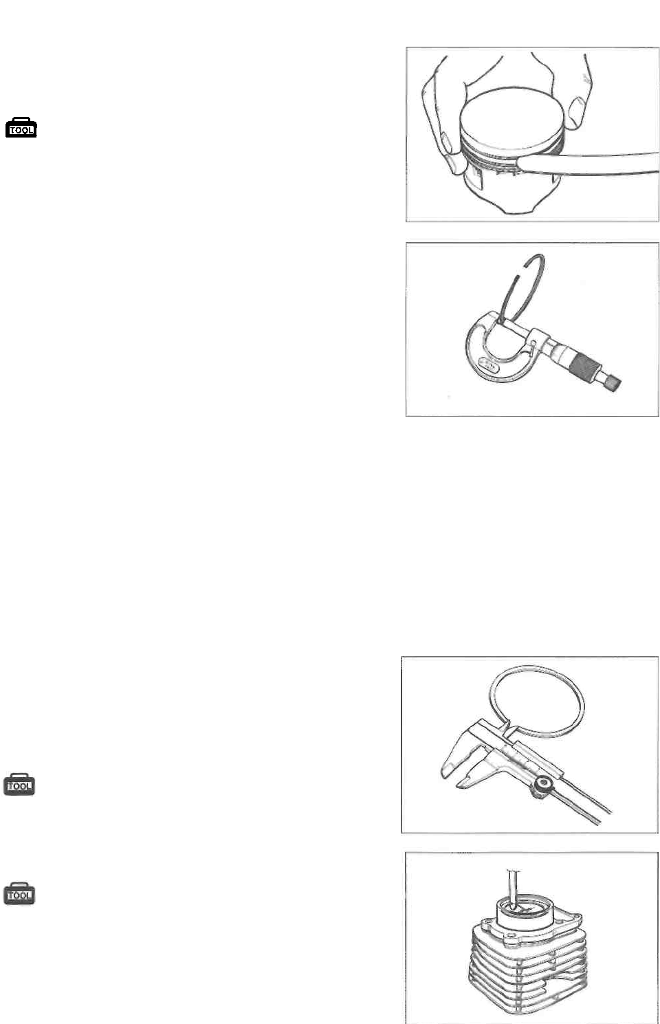
3-35 ENGINE
PISTON RING-GROOVE CLEARANCE
Measure the side clearance of the 1st and 2nd rings using
the thickness gauge If any of the clearances exceed the
limit, replace both the piston and piston rings.
09900-20803: Thickness gauge 09900-
20205: Micrometer (0-25 mm)
Service Limit
Piston ring-groove clearance 1st: 0.180 mm
(0.0071 in)
2nd: 0.150 mm
(0.0059 in)
Standard
Piston ring groove width
1st: 1.01-1.03 mm
(0.040-0.041 in)
2nd: 1.21-1.23 mm
(0.047-0.048 in)
Oil: 2.51-2.53 mm
(0.099-0.100 in)
Standard
Piston ring thickness
1st: 0.975-0.990 mm
(0.0384-0.0390 in)
2nd: 1.170-1.190 mm
(0.0461-0.0469 in)
NOTE:
Remove any carbon from the piston crown and ring
grooves using a soft-metal scraper.
PISTON RING FREE END GAP AND PISTON RING END
GAP
Measure the piston ring free end gap using a vernier calipers.
Next, fit the piston ring squarely into the cylinder and measure
the piston ring end gap using a thickness gauge. If the piston
ring's end gap is out of specification, replace the piston ring.
09900-20101: Vernier calipers
Service Limit
Piston ring free end gap 1st: 7.6 mm (0.30 in)
2nd: 8.8 mm (0.35 in)
09900-20803: Thickness gauge
Service Limit
Piston ring end gap (1st and 2nd): 0.50 mm (0.020 in)
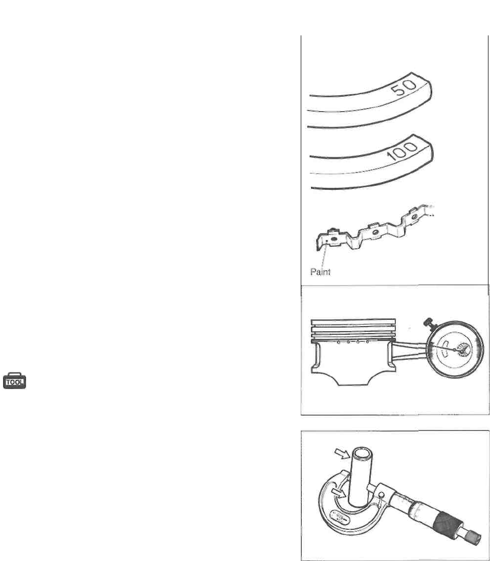
ENGINE 3-36
OVERSIZE RINGS
Oversize piston ring
The following oversize piston ring is used. It bears the fol-
lowing identification number.
Piston ring 1st and 2nd 0.5 mm: 50
1.0 mm: 100
Oversize oil ring
The following oversize oil ring is used. It bears the follow-
ing Identification mark.
Oil ring 0.5 mm: Painted blue 1.0
mm: Painted yellow
Oversize side rail
Measure the outside diameter to identify the side.
0.5mmO.S
I.OmmO.S.
Oil ring
spacer
PIN BORE
Measure the piston pin bore inside diameter using the cali-
per gauge and measure the piston pin outside diameter
using the micrometer. If either is out of specification or the
difference between these two measurements is more than
the limits, replace both piston and piston pin.
09900-20605: Dial calipers 09900-
20205: Micrometer (0-25 mm)
Service Limit
Piston pin bore: 18.030 mm (0.7098 in)
Piston pin O.D.: 17.980 mm (0.7079 in)
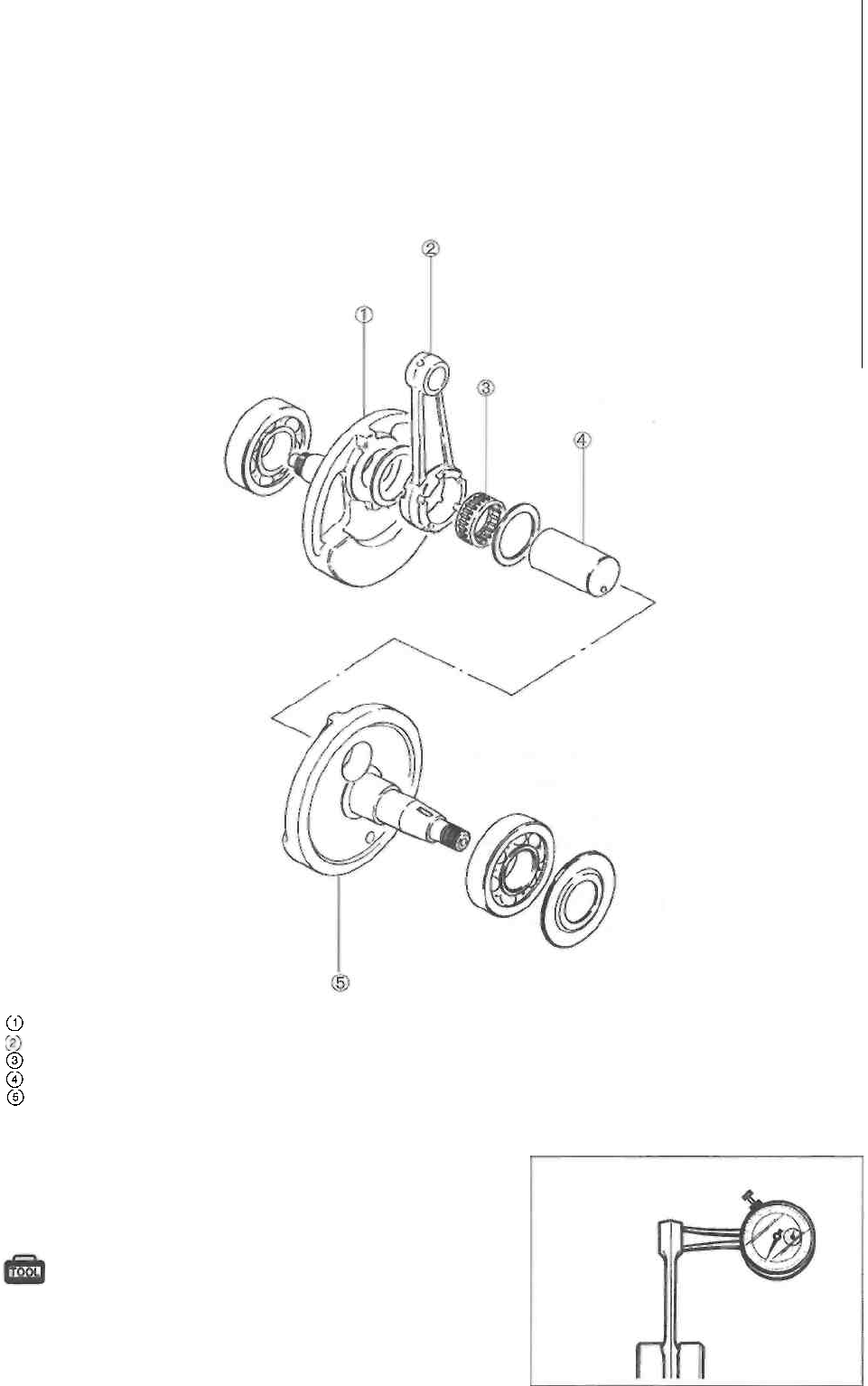
3-37 ENGINE
CRANKSHAFT AND CONROD
Crankshaft,
RH
Conrod
Bearing
Crank pin
Crankshaft,
LH
CONROD SMALL END I.D.
Measure the conrod small end inside diameter using the
dial calipers. If the conrod small end inside diameter ex-
ceeds the service limit, replace the conrod.
09900-20605: Dial calipers
Service Limit: 18.040 mm (0.7102 in)
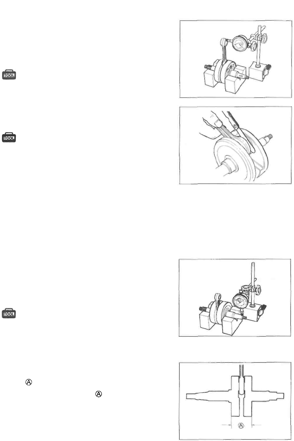
ENGINE 3-38
CONROD DEFLECTION AND CONROD BIG END SIDE
CLEARANCE
Wear on the big end of the conrod can be estimated by
checking the movement of the small end of the rod. This
method can also check the extent of wear on the parts of the
conrod's big end.
09900-20701: Magnetic stand 09900-20606:
Dial gauge (1/100 mm) 09900-21304: V-
block set (100 mm)
Service Limit: 3.0 mm (0.12 in)
Push the big end of the conrod to one side and measure the
side clearance using a thickness gauge.
09900-20803: Thickness gauge
Standard: 0.10-0.65 mm (0.004-0.026 in) Service
Limit: 1.0 mm (0.04 in)
If the service limit is exceeded, replace crankshaft assembly
or bring the deflection and side clearance into specification by
replacing the worn parts, (e.g., conrod, big end bearing and
crank pin)
CRANKSHAFT RUNOUT
Support the crankshaft with V-blocks as shown. Position
the dial gauge, as shown, and rotate the crankshaft slowly
to read the runout. Correct the runout or replace the crank-
shaft assembly if the runout is greater than the service lim-
it.
09900-20701: Magnetic stand 09900-
20606: Dial gauge (1/100 mm) 09900-
21304: V-block set (100 mm)
Service Limit: 0.05 mm (0.002 in)
REASSEMBLY
• When rebuilding the crankshaft, the width between the
webs should be within the standard range.
Standard width between webs : 60.0 + 0.1 mm
(2.362 ±0.004 in)
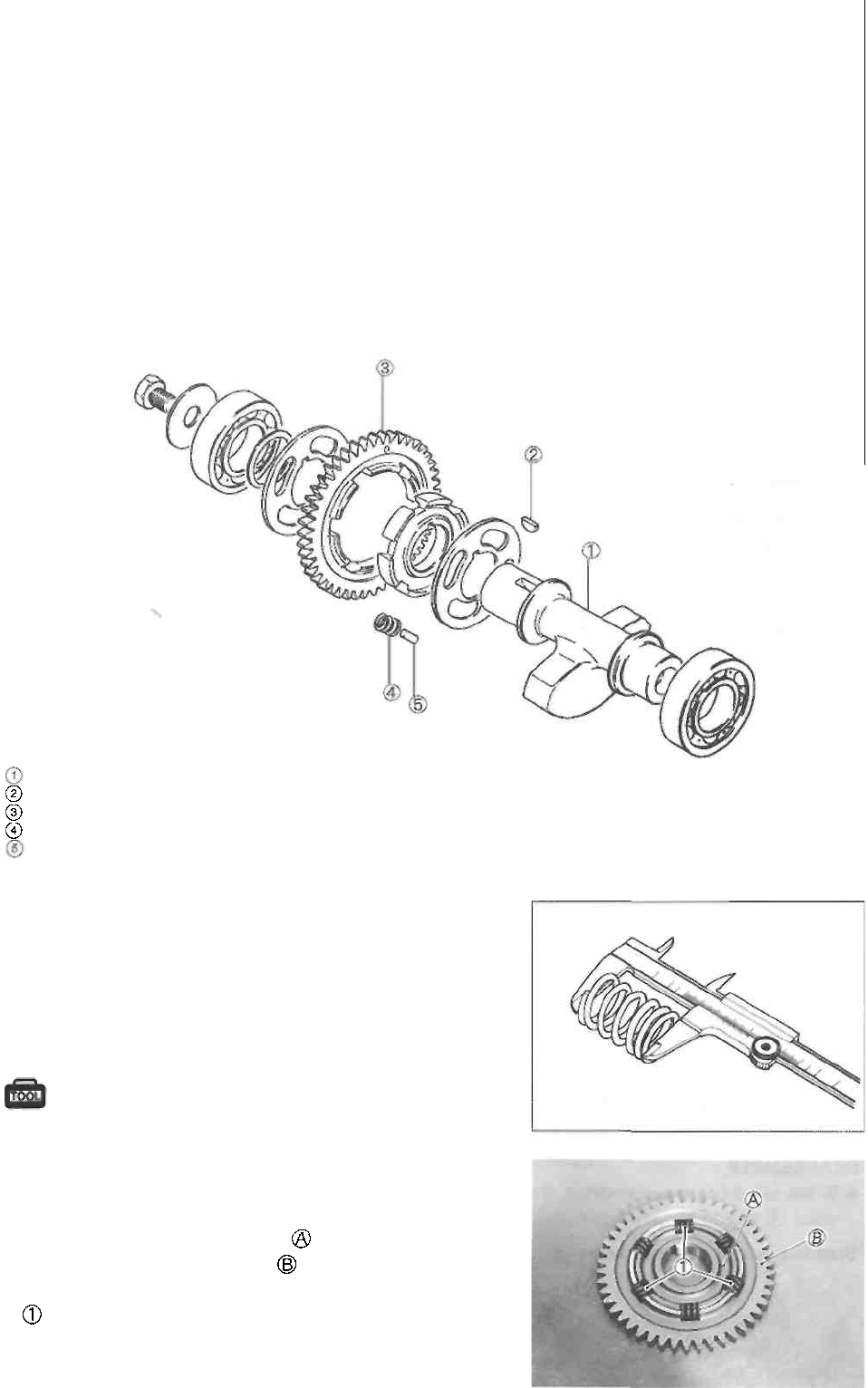
3-39 ENGINE
BALANCER SHAFT AND BALANCER SHAFT DRIVEN GEAR
DISASSEMBLY
• Disassemble the balancer shaft as shown in the illustration.
Balancer shaft
Key
Balancer shaft driven
gear
Spring (6 pcs.)
Pin (3 pcs.)
INSPECTION
Inspect the balancer shaft and balancer shaft driven gear
for wear or damage. If any wear or damage is found, re-
place the defective part.
Measure the free length of each balancer spring using ver-
nier calipers. If any spring is not within the service limit,
replace all of the spring.
09900-20101: Vernier calipers
Service Limit: 10.0 mm (0.39 in)
REASSEMBLY
Reassemble the balancer shaft driven gear in the reverse
order of disassembly. Pay attention to the following points:
• Make sure that the punch mark on the inner race is
aligned with the punch mark on the balancer shaft
driven gear.
: Pin
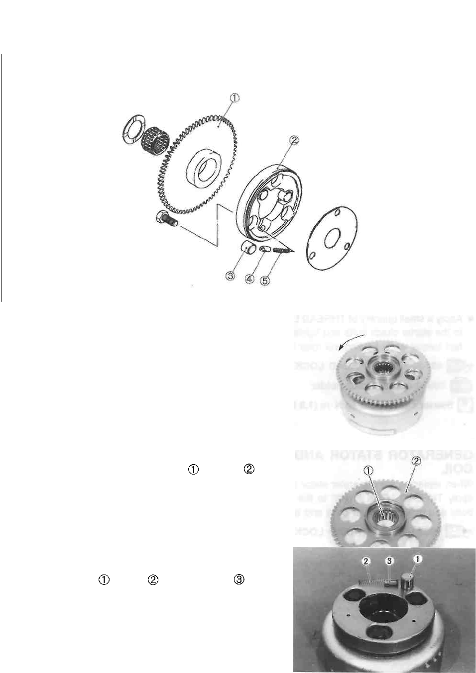
ENGINE 3-40
STARTER CLUTCH AND STARTER DRIVEN GEAR BEARING
1 Starter driven gear
2 Starter clutch
3 Roller
4 Push piece
5 Spring
STARTER CLUTCH
Install the starter driven gear onto the starter clutch and turn
the starter driven gear by hand (the gear turns in only one
direction). The starter driven gear should turn smoothly. If
excessive resistance is felt while turning the starter driven
gear, inspect the starter clutch. Also, inspect the surface of the
starter driven gear which contacts the starter clutch, for wear
or damage. If any wear or damage is found, replace the
defective part(-s).
STARTER DRIVEN GEAR BEARING
Install the starter driven gear bearing and gear onto
the crankshaft and turn the starter driven gear by hand.
Inspect the starter driven gear bearing for smooth rotation
and any abnormal noise. If the bearing does not turn
smoothly or there is any abnormal noise, replace it.
DISASSEMBLY
• Remove the starter driven gear.
• Remove the roller , spring and push piece
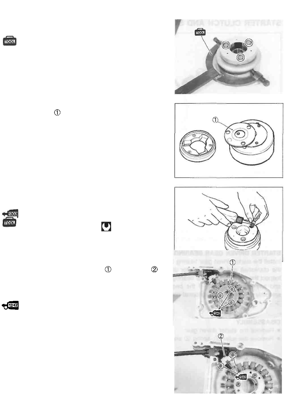
3-41 ENGINE
• Hold the generator rotor with the rotor holder and re-
move the starter clutch bolts.
09930-44913: Rotor holder
REASSEMBLY
• Locate the shim to the proper position.
• Apply a small quantity of THREAD LOCK SUPER "1303" to
the starter clutch bolts and tighten them to the specified
torque while holding the rotor holder.
99000-32030: THREAD LOCK SUPER "1303"
09930-44913: Rotor holder Starter clutch
bolt: 18 N-m (1.8 kg-m, 13.0 Ib-ft)
GENERATOR STATOR AND PICK-UP
COIL
When replacing the generator stator or pick-up coil
apply THREAD LOCK "1342" to the generator stator set
bolts and pick-up coil set bolts and tighten them.
99000-32050: THREAD LOCK "1342"
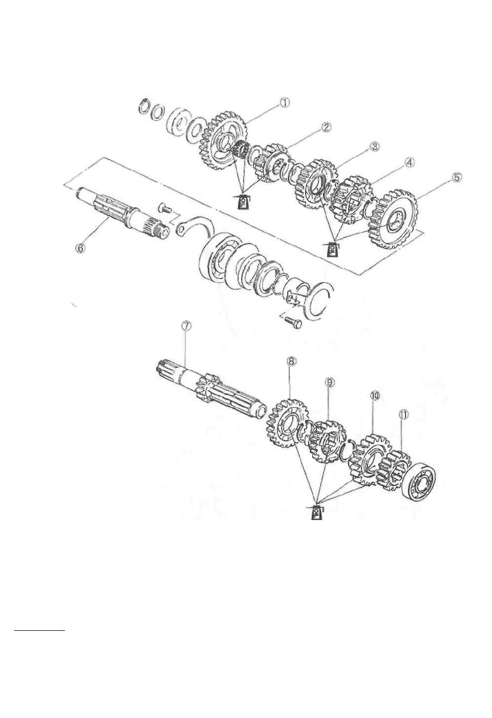
ENGINE 3-42
TRANSMISSION
DISASSEMBLY
• Disassemble the transmission gears as shown in the illustration.
REASSEMBLY
Assemble the countershaft and driveshaft in the reverse order of disassembly. Pay attention to the
following points.
NOTE:
Before installing the gears, apply engine oil to the bearing and inner surface of the each gear.
CAUTION ___________________________________________________________________
* Never reuse a circlip. After a circlip has been removed from a shaft, it should be discarded
and a new circlip must be installed.
* When installing a new circlip, do not expand the end gap larger than required to slip the
circlip over the shaft.
* After installing a circlip, make sure that it is completely seated in its groove and securely
fitted.
1 1st driven gear 2
5th driven gear 3
3rd driven gear 4 4th
driven gear 5 2nd
driven gear 6
Driveshaft 7
Countershaft 8 5th
drive gear 9 3rd
drive gear 10 4th
drive gear 11 2nd
drive gear
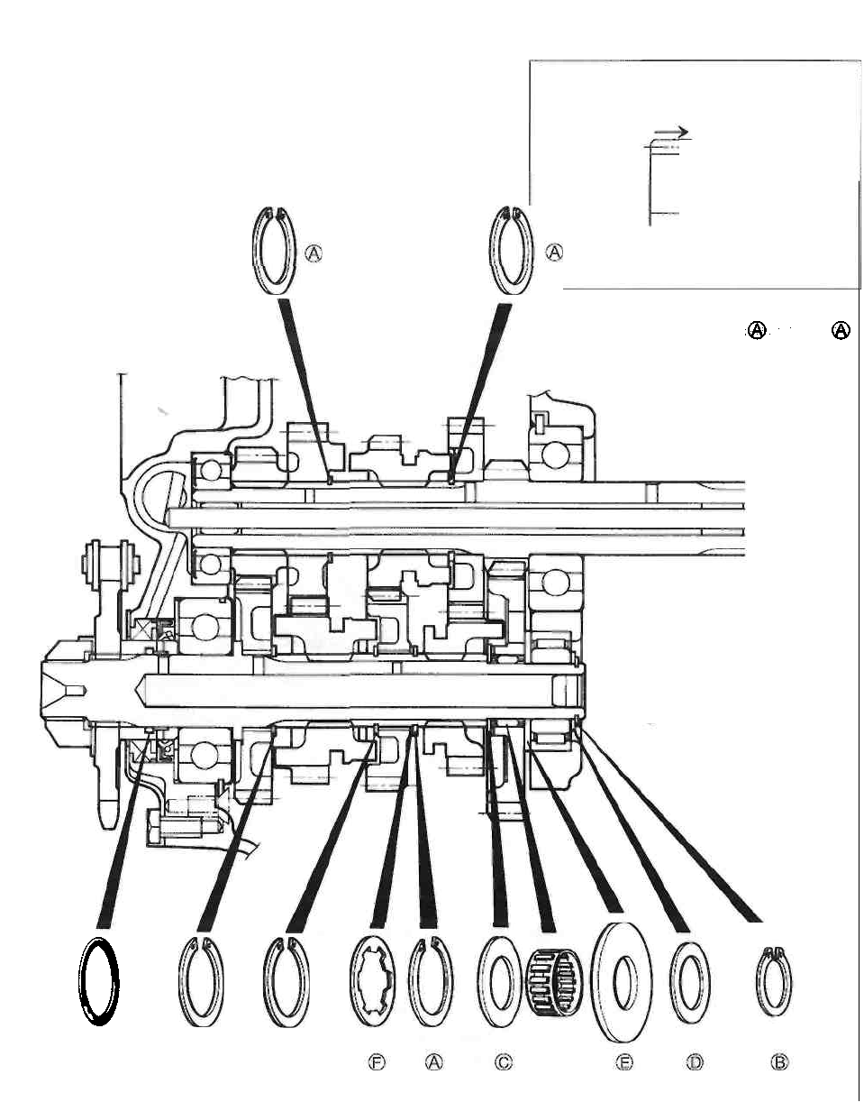
3-43 ENGINE
When installing a new circlip, pay attention to the direc-
tion of the circlip. Fit the circlip to the side where the
thrust is as shown in the illustration. The rounded side
should be against the gear surface.
Thrust
Sharp edge
Washers and circlips thickness
1.2 mm (0.05 in) 1.0 mm
(0.04 in) 1.0 mm (0.04 in)
1.0 mm (0.04 in) 2.0 mm
(0.08 in) 0.5 mm (0.02 in)
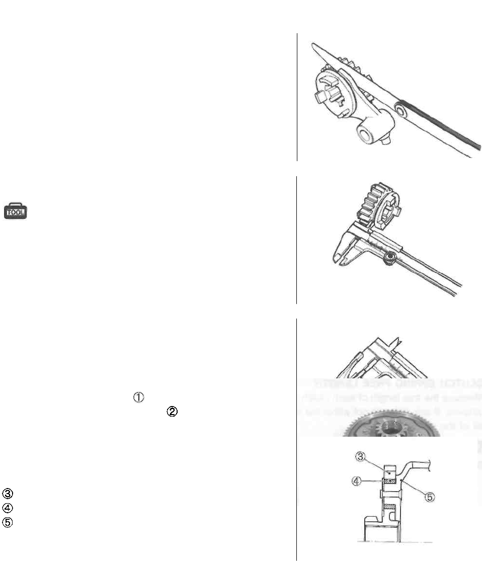
ENGINE 3-44
GEARSHIFT FORKS
Measure the gearshift fork clearance in the groove of its
respective gear using the thickness gauge. The clearance for
each of the two gearshift forks plays an important role in the
smoothness and positiveness of the shifting action. Each fork
has its prongs fitted into the annular groove provided in its
gear. During operation there is sliding contact between the
fork and gear and, when a shifting action is initiated, the fork
pushes the gear axially. If the clearance is too great, the
meshed gears may slip apart.
If the clearance exceeds the specification, replace the fork, its
respective gear or both.
09900-20803: Thickness gauge
Service Limit
Gearshift fork to groove clearance: 0.60 mm (0.024 in)
Standard
Gearshift fork groove width No.1, No.2 & No.3: 4.25-4.35
mm (0.167-0.171 in)
Standard
Shift fork thickness No.1, No.2 & No.3: 3.95-4.05 mm
(0.156-0.159 in)
PRIMARY DRIVEN GEAR
• Remove the stopper ring
• Remove the oil pump drive gear
If the internal damper wears, play is generated between
gear and housing, causing abnormal noise. If the play is
extreme, replace the primary driven gear assembly with a
new one.
Primary driven gear
Damper
Clutch housing
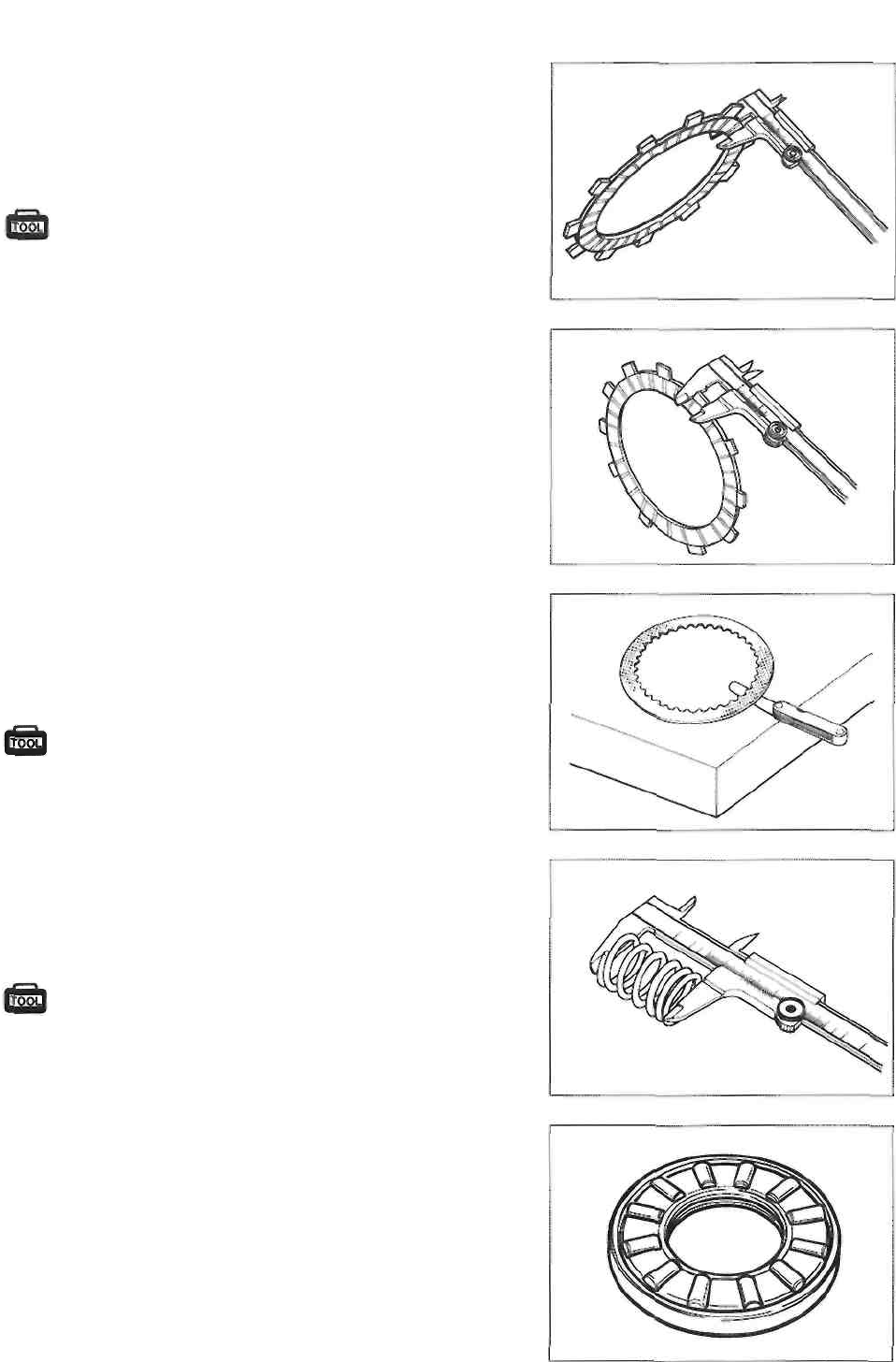
3-45 ENGINE
CLUTCH
CLUTCH DRIVE PLATES
Measure the thickness and claw width of the clutch drive
plates using vernier calipers. If a clutch drive plate is not
within the service limit, replace the clutch plates as a set.
09900-20101: Vernier calipers
Service Limit
Thickness (No.1): 2.62 mm (0.103 in)
(No.2): 3.15 mm (0.124 in) Claw width:
15.0 mm (0.590 in)
CLUTCH DRIVEN PLATES
Measure each clutch driven plates for distortion using the
thickness gauge. If a clutch driven plate is not within the
service limit, replace the clutch plates as a set.
09900-20803: Thickness gauge
Service Limit: 0.10 mm (0.004 in)
CLUTCH SPRING FREE LENGTH
Measure the free length of each clutch spring using vernier
calipers. If any spring is not within the service limit, replace
all of the spring.
09900-20101: Vernier
calipers Service Limit: 40.9 mm (1.61
in)
CLUTCH RELEASE BEARING
Inspect the clutch release bearing for any abnormality, es-
pecially cracks. When removing the bearing from the
clutch, decide whether it can be reused or if it should be
replaced.
Smooth engagement and disengagement of the clutch de-
pends on the condition of this bearing.
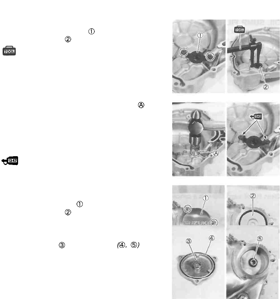
ENGINE 3-46
CLUTCH COVER
• Remove the oil seal retainer
• Remove the oil seal using the special tool.
09913-50121: Oil seal remover
• Install the new oil seal using a suitable socket
• Install the oil seal retainer.
NOTE:
Apply a small quantity of THREAD LOCK "1342" to the oil
seal retainer screws.
99000-32050: THREAD LOCK "1342"
OIL FILTER
• Remove the oil filter cap
• Remove the oil filter and install a new one.
NOTE:
Before installing the new oil filter and oil filter cap, make
sure that the spring and new O-rings are
installed correctly.
• Install the oil filter cap.
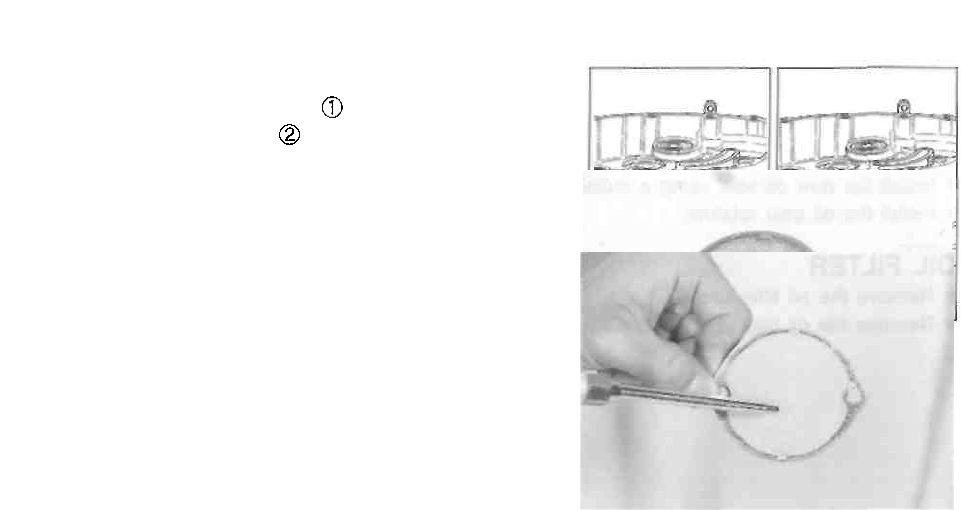
3-47 ENGINE
OIL SUMP FILTER
• Remove the oil sump filter cap
• Remove the oil sump filter
INSPECTION
Check the oil sump filter for any damage or clogs.
CLEANING
Clean the oil sump filter with a compressed air.
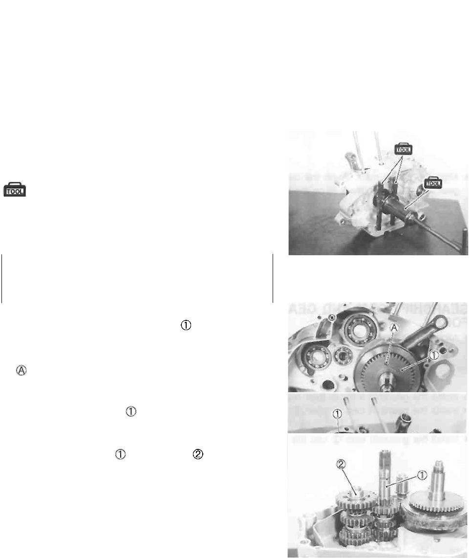
ENGINE 3-48
ENGINE REASSEMBLY
Reassemble the engine in the reverse order of disassembly. The following steps require special atten-
tion or precautionary measures should be taken.
NOTE:
Apply engine oil to each running and sliding part before reassembling.
CRANKSHAFT
• When installing the crankshaft into the crankcase, it is
necessary to pull its left end into the left crankcase with
the special tools.
09910-32812: Crankshaft installer
09910-32840: Attachment 09910-
20116: Conrod holder
CAUTION
Never install the crankshaft into the crankcase by
striking it with a plastic hammer. Always use the spe-
cial tool, otherwise crankshaft may be misaligned.
• Apply engine oil to the crankshaft bearings.
• Install the balancer shaft drive gear .
NOTE:
Make sure that the hole in the drive gear is aligned with the
pin on the crankshaft.
BALANCER SHAFT
• Install the balancer shaft
TRANSMISSION
• Install the countershaft and driveshaft assemblies.
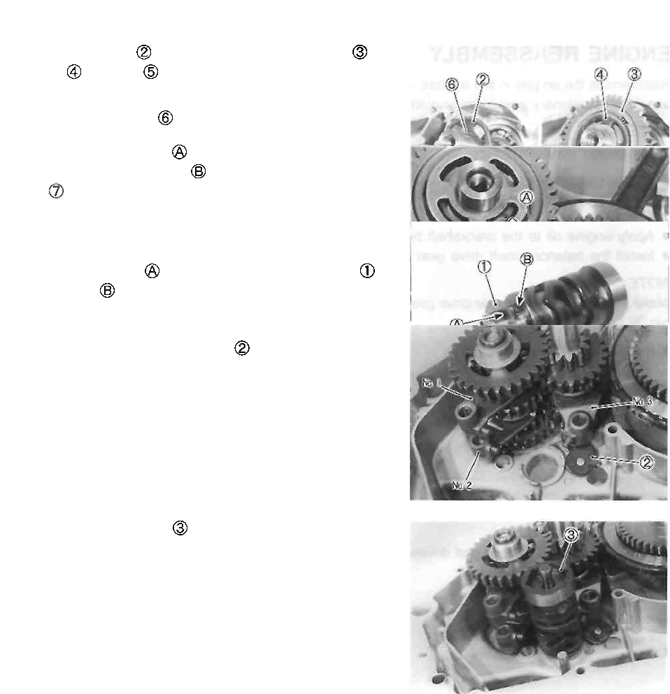
3-49 ENGINE
• Install the washer , balancer shaft driven gear
washer and shim onto the balancer shaft.
NOTE:
Make sure that the key is aligned with the keyway.
• Align the punch mark on the balancer shaft driven
gear with the punch mark on the balancer shaft drive
gear
GEARSHIFT CAM AND GEARSHIFT
FORKS
• Align the pin groove of gearshift cam stopper plate
with the pin on the gearshift cam.
• Install the gearshift forks to their respective gears.
• Install the gearshift cam stopper
• Install the gearshift cam into the crankcase.
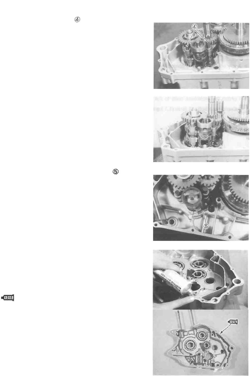
ENGINE 3-50
• Install the gearshift fork shafts
NOTE:
Position the gearshift cam as shown in Fig. so that the
gearshift fork shafts can be installed easily.
• Install the the gearshift cam stopper spring
CRANKCASE
• Wipe both crankcase mating surfaces with a cleaning
solvent.
• Apply SUZUKI BOND "1215" uniformly to the mating
surface of the right crankcase and assemble the cases
within a few minutes.
99000-31110: SUZUKI BOND "1215"
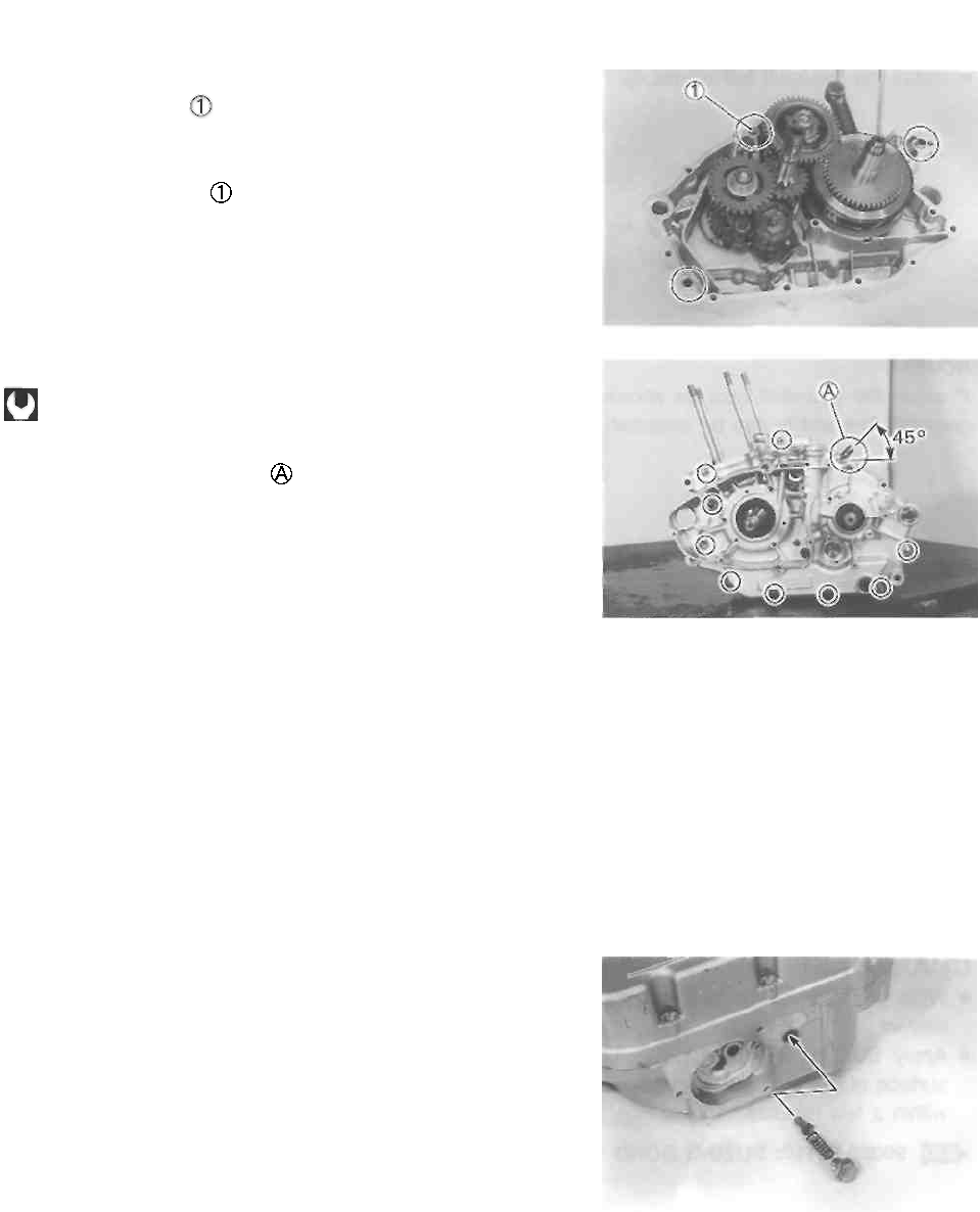
3-51 ENGINE
• Install the dowel pins into the left half of the crankcase.
• Install the O-ring
A CAUTION
Use a new O-ring
• Apply engine oil to the conrod big end and transmission
gears.
• Tighten the crankcase bolts to the specified torque.
Crankcase bolt: 11 N-m (1.1 kg-m, 8,0 Ib-ft)
NOTE:
Install the clamp to the bolt .
NOTE:
* After the crankcase bolts have been tightened, make
sure that the crankshaft, countershaft and driveshaft ro-
tate smoothly.
* If these shafts do not rotate smoothly, try to free it by
tapping with a plastic hammer.
• Install the the gearshift cam stopper.
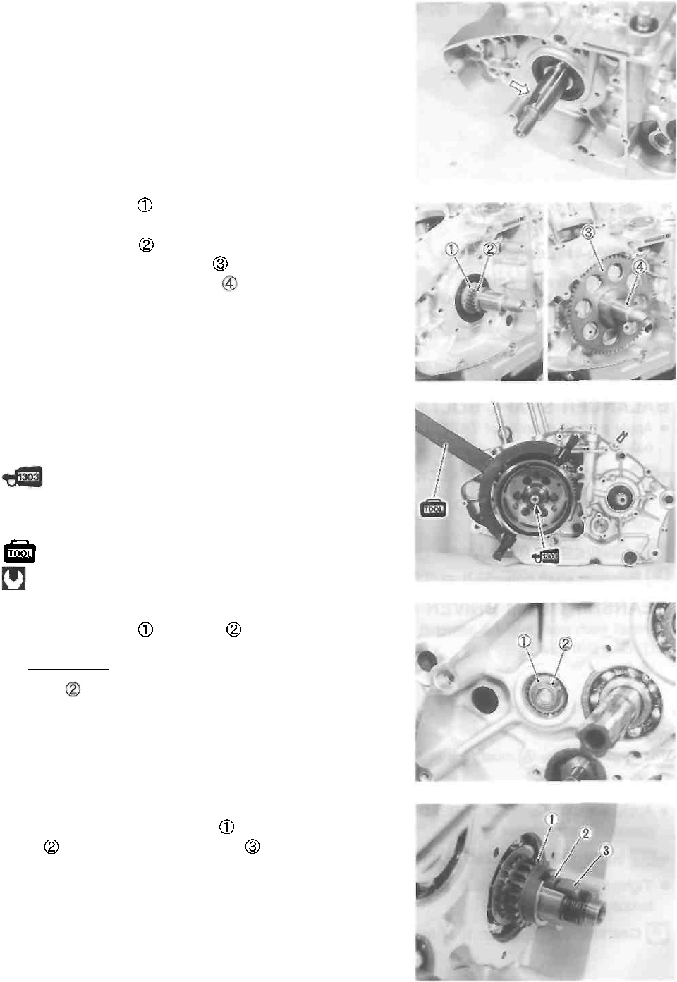
GENERATOR ROTOR
• Remove any grease from the tapered portion of the gen-
erator rotor and crankshaft.
• Install the washer so that the convex side of it faces
the crankcase bearing.
• Install the bearing
• Install the starter driven gear
• Install the generator rotor key onto the crankshaft.
• Install the generator rotor securely.
• Apply a small quantity of THREAD LOCK "1303" to the
generator rotor nut.
99000-32030: THREAD LOCK SUPER "1303"
• Tighten the generator rotor nut to the specified torque
using the special tool.
09930-44913: Rotor holder
Generator rotor nut: 160 N ■ m (16.0 kg-m, 115.5 Ib-ft)
DRIVESHAFT RETAINER
• Install the washer and circlip to the driveshaft.
CAUTION Use a new
circlip
PRIMARY DRIVE GEAR
• Install the cam chain sprocket , cam chain sprocket
key and primary drive gear key
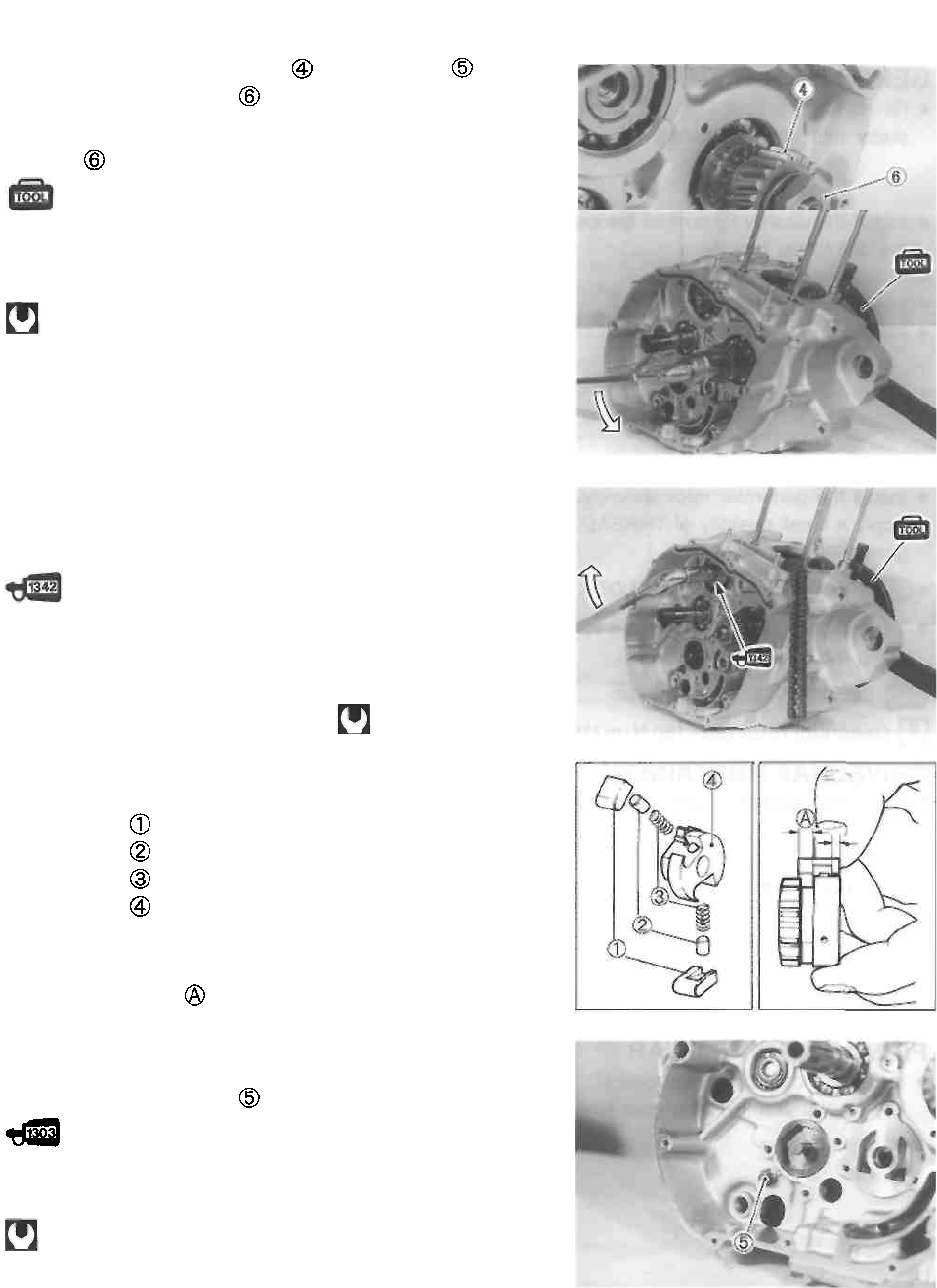
3-53 ENGINE
• Install the primary drive gear , wave washer and
primary drive gear nut
NOTE:
This nut has left hand threads.
09930-44913: Rotor holder
Primary drive gear nut :
100 N-m (10.0 kg-m, 72.5 Ib-ft)
BALANCER SHAFT BOLT
• Apply a small quantity of THREAD LOCK "1342" to the
balancer shaft bolt.
99000-32050: THREAD LOCK "1342"
• Tighten the balancer shaft bolt to the specified torque
using the special tool.
09930-44913: Rotor holder Balancer shaft
bolt: 39 N-m (3.9 kg-m, 28.0 Ib-ft)
GEARSHIFT CAM DRIVEN GEAR
• Install each pawl into the gearshift cam driven gear.
Gearshift pawl
Pin
Spring Gearshift cam
driven gear
NOTE:
The large shoulder must face to the outside.
• Apply a small quantity of THREAD LOCK "1303" to the
gearshift shaft stopper
99000-32030: THREAD LOCK SUPER "1303"
• Tighten the gearshift shaft stopper to the
specified torque.
Gearshift cam stopper: 19 N-m (1.9 kg-m, 13.5 Ib-ft)
• Tighten the primary drive gear nut to the specified
torque using the special tool.
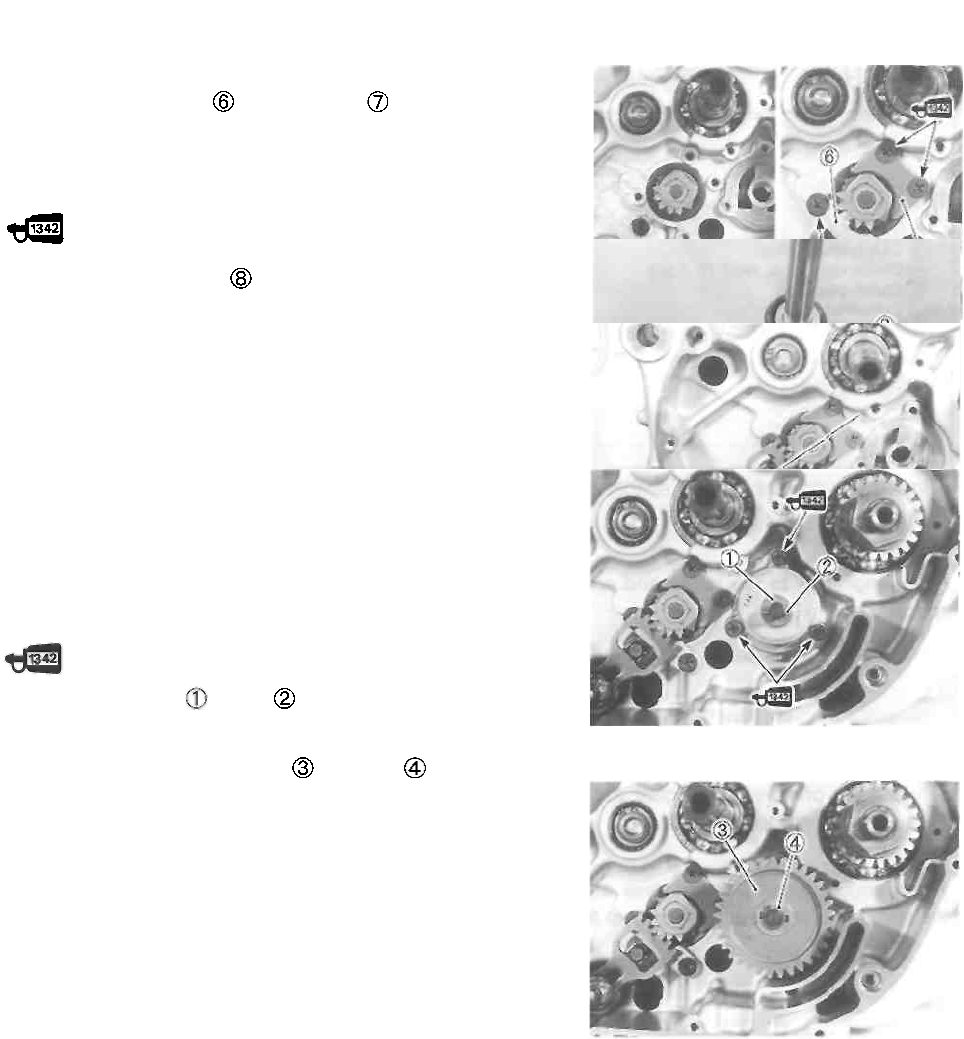
ENGINE 3-54
• Install the gearshift cam driven gear assembly.
• Install the pawl lifter and cam guide
NOTE:
Apply a small quantity of THREAD LOCK "1342" to the
threads of the screws.
• Install the return spring to the gearshift shaft as shown.
• Install the gearshift shaft.
NOTE:
Align the center teeth on the gearshift shaft with the center
teeth on the gearshift cam driven gear.
OIL PUMP
• Apply engine oil to the sliding surfaces of the oil pump
case, outer rotor, inner rotor and shaft, before mounting the
oil pump.
• Apply a small quantity of THREAD LOCK "1342" to the oil
pump mounting screws and tighten them.
99000-32050: THREAD LOCK "1342"
• Install the washer and pin
• Install the oil pump driven gear and circlip
99000-32050: THREAD LOCK "1342"
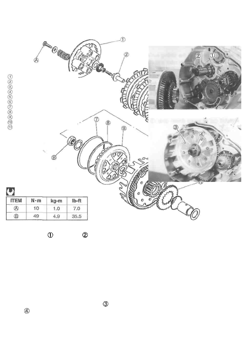
3-55 ENGINE
CLUTCH
• Install the washer and spacer onto the counter-
shaft.
NOTE:
Apply engine oil to the inside and outside surfaces of the
spacer.
• Install the primary driven gear assembly and thrust
washer onto the countershaft.
NOTE:
When engaging the primary drive and driven gears, turn
the primary driven gear assembly to the counterclockwise.
Clutch pressure plate
Push piece
Clutch drive plate No.1 (T: 3.00)
Clutch driven plate
Clutch drive plate No.2 (T: 3.50)
Clutch push rod
Concaved washer
Washer seat
Clutch sleeve hub
Clutch housing
Oil pump drive gear
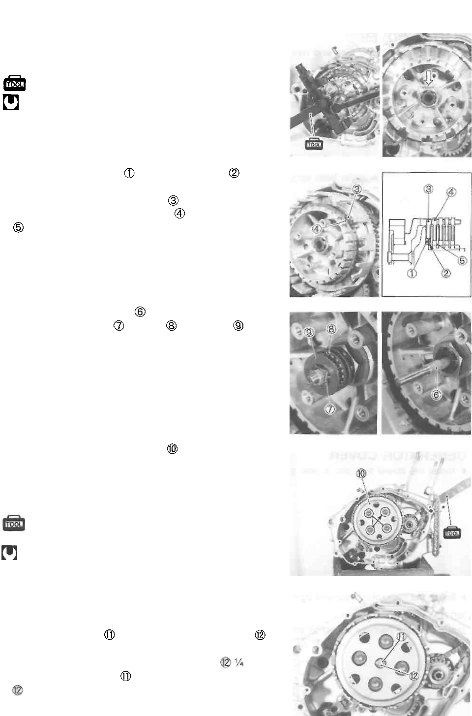
ENGINE 3-56
• Install the clutch sleeve hub and lock washer.
• Install the clutch sleeve hub nut, and tighten it to the
specified torque using the special tool.
09920-53740: Clutch sleeve hub holder
Clutch sleeve hub nut: 50 N-m (5.0 kg-m, 36.0 Ib-ft)
• Bend the lock washer securely.
• Install the washer seat and spring washer as
shown.
• Install the clutch drive plate No.2
• Install the clutch drive plates No.1 and driven plates
one by one into the clutch sleeve hub.
• Install the clutch push rod
• Install the push piece , bearing and washer
• Install the clutch pressure plate , clutch springs and
clutch spring mounting bolts.
• Hold the generator rotor using the special tool and tight-
en the clutch spring mounting bolts to the specified
torque in a crisscross pattern.
09930-44913: Rotor holder
Clutch spring mounting bolt:
10N-m(1.0kg-m, 7.0 Ib-ft)
NOTE:
Make sure that the clutch pressure plate is installed cor-
rectly.
• Loosen the lock nut , and turn in the release screw
to feel resistance.
• From that position, turn out the release screw turn,
and tighten the lock nut by holding the release screw
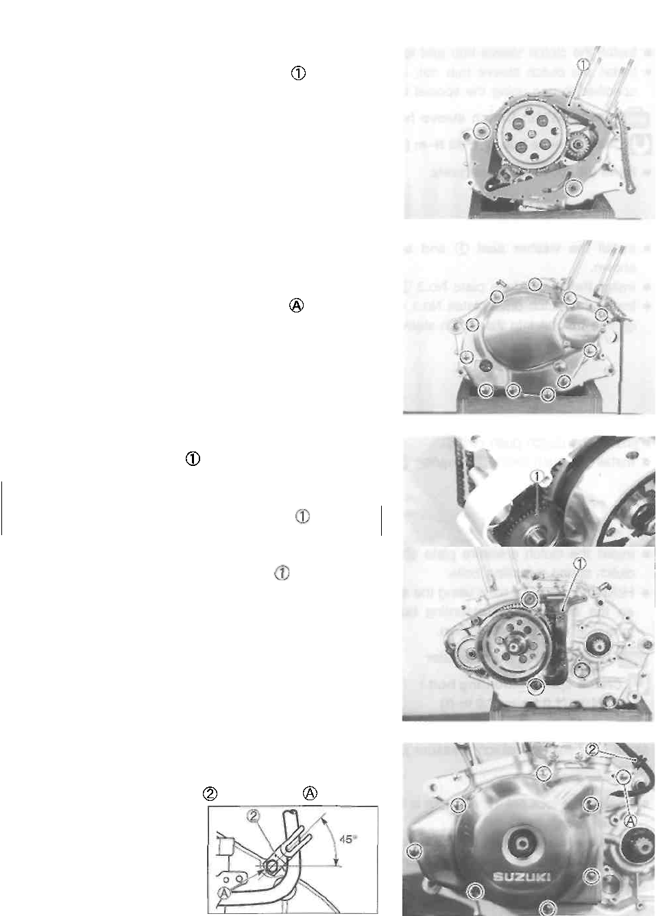
3-57 ENGINE
CLUTCH COVER
• Install the two dowel pins and new gasket
• Tighten the clutch cover bolts securely.
A CAUTION
Install the new gasket washer to the bolt .
STARTER IDLE GEAR
• Install the starter idle gear
A CAUTION
Apply engine oil to the starter idle gear
GENERATOR COVER
• Install the dowel pins and a new gasket
• Install the generator cover and tighten the bolts securely.
NOTE:
Install the wire harness clamp with the bolt
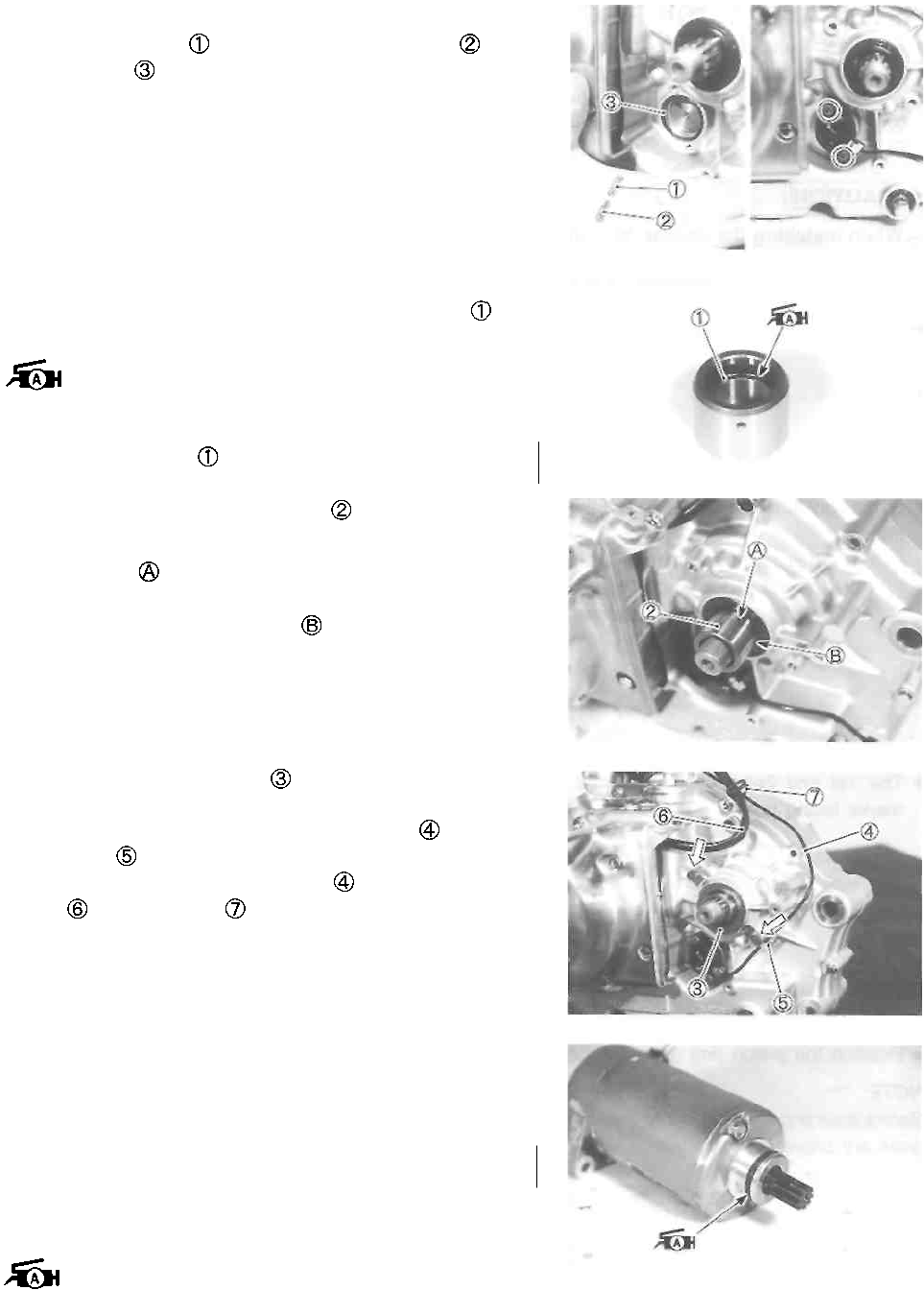
NEUTRAL SWITCH
• Install the spring and neutral switch contact and
new O-ring
• Install the neutral switch.
ENGINE SPROCKET SPACER
• Apply SUZUKI SUPER GREASE "A" to the O-ring of
the engine sprocket spacer and the oil seal lip.
99000-25010: SUZUKI SUPER GREASE "A"
A CAUTION
Use a new O-ring
* Install the engine sprocket spacer onto the driveshaft.
NOTE:
* The oil hole on the spacer should be on the engine
side.
* Be careful that the oil seal lip does not turn in.
• Install the oil seal retainer .
• Bend the tabs on the oil seal retainer to lock the bolts.
• Pass through the neutral switch lead wire inside of
the guide
• Clamp the neutral switch lead wire and generator lead
wire with the clamp
STARTER MOTOR
• Install the starter motor.
A CAUTION
Use a new O-ring.
NOTE:
Apply grease to the O-ring.
99000-25010: SUZUKI SUPER GREASE "A"
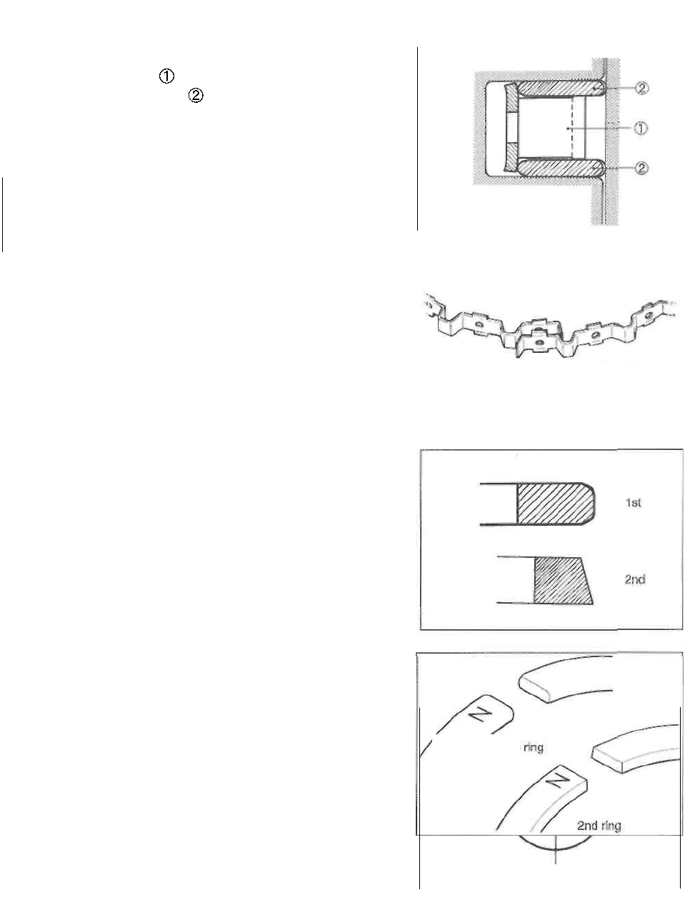
3-59 ENGINE
PISTON AND PISTON RING
• First, install a spacer into the oil ring groove and then
install the two side rails . The spacer and side rails
do not have a specific top or bottom when they are
new. When reassembling used parts, install them in their
original place and direction.
A CAUTION
When installing the spacer, be careful not to allow
its two ends to overlap in the piston ring groove.
INCORRECT
• Same way in which to distinguish the 1st and 2nd piston
rings:
1. Their ring face shapes are different.
2. The 1st piston ring's face is chrome-plated.
3. The 2nd piston ring appears darker in color.
• The 1st and 2nd piston should be installed with their
marks facing up.
• Position the piston ring gaps as shown.
NOTE:
Before inserting the piston into the cylinder, check that the
gaps are properly positioned.
Upper
side
rail
• 1st ring
IN. • Spacer
EX.
• 2nd ring
• Lower side
rail
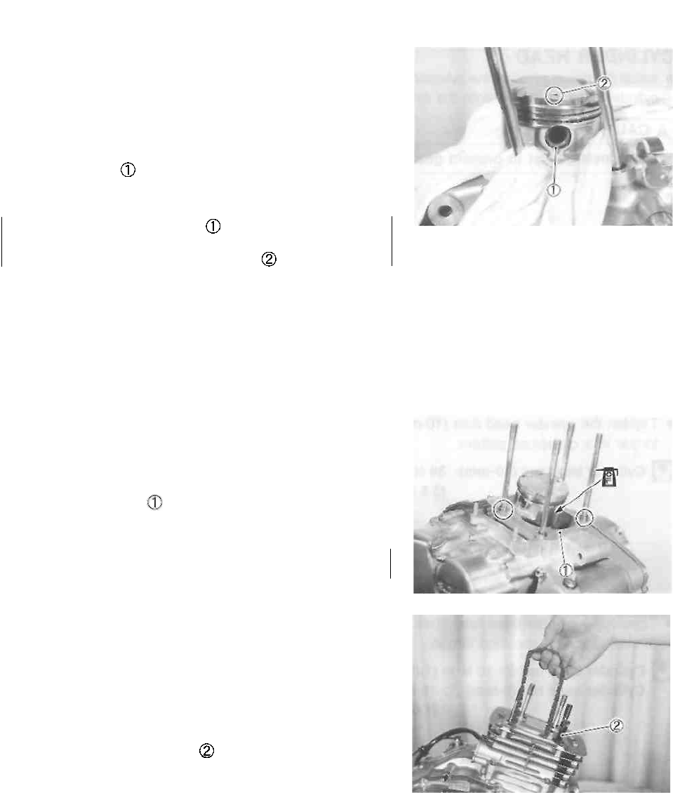
ENGINE 3-60
The following are reminders for piston installation:
• Before Installing the piston pin, apply molybdenum oil
solution onto its surface.
• Apply engine oil to the big and small ends of the conrod.
• Place a clean rag over the cylinder base to prevent the
piston pin circlip from dropping into crankcase. Install the
piston pin circlip with long-nose pliers.
A CAUTION
Use a new piston pin circlip to prevent circlip failure.
• Install the piston with the arrow mark facing towards
the exhaust side.
CYLINDER
Before installing the cylinder, apply engine oil to the sliding
surface of the piston.
• Install the dowel pins into the crankcase and then Install
the cylinder gasket
A CAUTION
Use a new gasket to prevent oil leakage.
• Make sure that the piston rings are properly positioned,
and insert the piston into the cylinder.
NOTE:
When mounting the cylinder, keep the cam chain taut. The
cam chain must not be caught between the cam chain
drive sprocket and crankcase when crankshaft is rotated.
• Temporarily tighten the cylinder base nuts.
• Install the cam chain guide
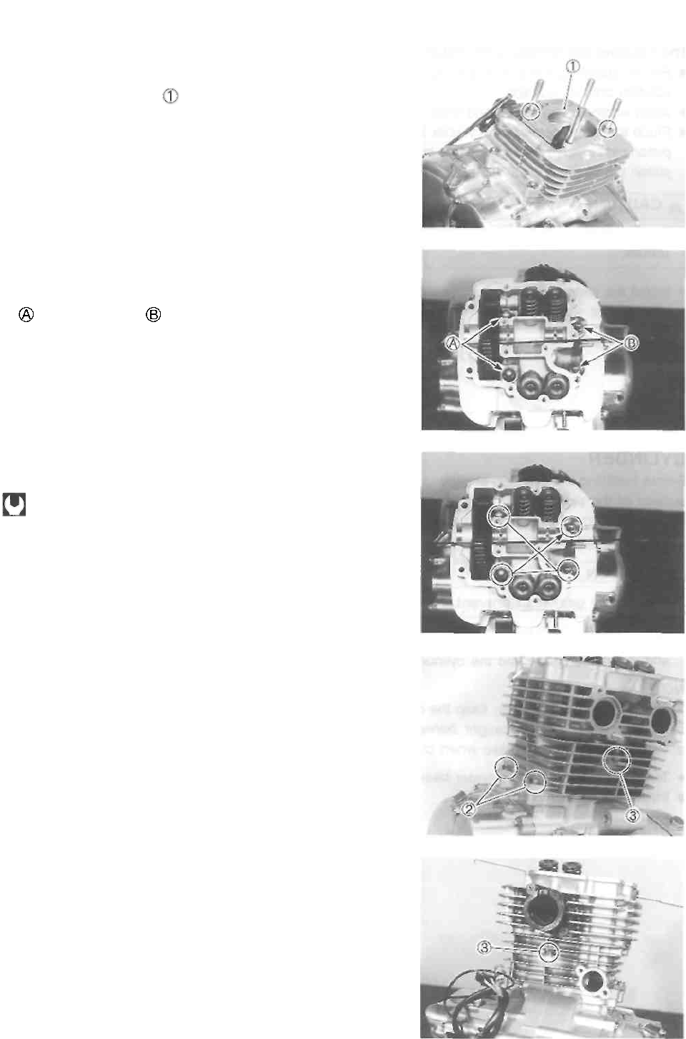
3-61 ENGINE
CYLINDER HEAD
• Install the dowel pins into the cylinder and then install the
cylinder head gasket onto the cylinder.
A CAUTION
Use a new gasket to prevent gas leakage.
• Place the cylinder head onto the cylinder.
• Cylinder head nuts and washers must be installed cor-
rectly as shown.
Copper washer
Steel washer
• Tighten the cylinder head nuts (10-mm) to the specified
torque in a crisscross pattern.
Cylinder head nut (10-mm): 38N-m
(3.8 kg-m, 27.5 Ib-ft)
• Tighten the cylinder base nuts (2) and cylinder head nuts
(6-mm) (D to the specified torque.
H Cylinder base nut ©: 10 N-m (1.0 kg-m, 7.0 Ib-ft)
Cylinder head nut (6-mm) ®: 10 N-m
(1.0 kg-m, 7.0 Ib-ft)
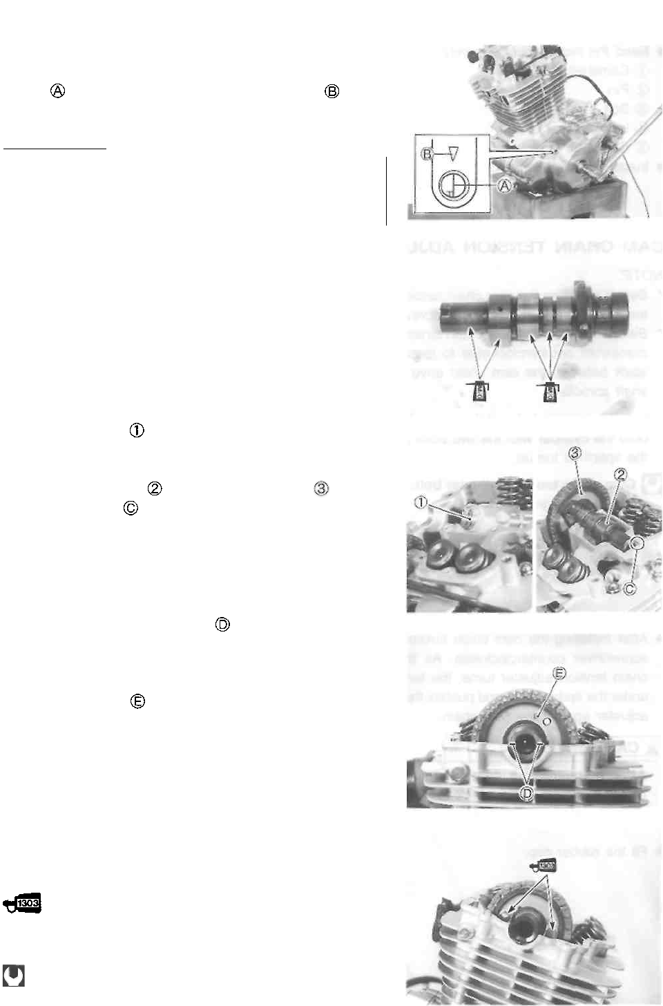
ENGINE 3-62
CAMSHAFT
• Turn the crankshaft counterclockwise, and align the T
line on the generator rotor with the mark on the
generator cover while keeping the cam chain tight.
I A CAUTION]
If the crankshaft is turned without drawing the
cam chain upward, the cam chain will catch be-
tween crankcase and cam chain drive sprocket.
NOTE:
Just before installing the camshaft into the cylinder head,
apply molybdenum oil solution to the camshaft journals and
cam faces. Also, apply engine oil to the camshaft journal
holders.
• Install the C-ring into the ring groove of the cylinder
head.
• Install the cam chain.
• Install the camshaft and camshaft sprocket
• Face the notch on the camshaft towards the intake
side.
• Align the engraved line marks on the camshaft so it is
parallel with mating surface of the cylinder head and cyl-
inder head cover.
• Engage the cam chain on the camshaft sprocket with the
locating pin hole at one o'clock position.
NOTE:
Do not rotate the crankshaft while installing the camshaft or
cam chain.
• Install the lock washer so that it is covering the locating
pin.
NOTE:
Apply a small quantity of THREAD LOCK SUPER "1303" to
the threads of the camshaft sprocket bolts.
99000-32030: THREAD LOCK SUPER "1303"
• Tighten the camshaft sprocket bolts to the specified
torque.
Camshaft sprocket bolt: 15 N-m (1.5 kg-m, 11.0 Ib-ft)
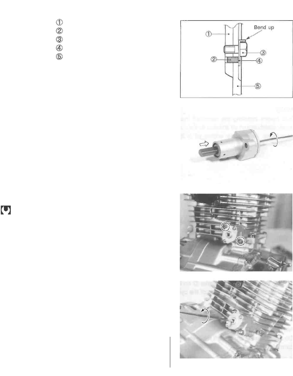
3-63 ENGINE
• Bend the lock washer securely.
Camshaft
Pin
Bolt
Lock washer
Camshaft sprocket
• Install the camshaft end cap.
CAM CHAIN TENSION ADJUSTER
NOTE:
* Before installing the cam chain tension adjuster, lock the
tension spring with a flat-head screwdriver.
* Before installing the cam chain tension adjuster, turn the
crankshaft counterclockwise to remove any cam chain
slack between the cam chain drive sprocket and cam-
shaft sprocket.
* Install a new gasket and the cam chain tension adjuster
onto the cylinder with the two bolts and tighten them to
the specified torque.
Cam chain tension adjuster bolt:
7 N-m (0.7 kg-m, 5.0 Ib-ft)
• After installing the cam chain tension adjuster, turn the
screwdriver counterclockwise. As the slot in the cam
chain tension adjuster turns, the tension rod advances
under the spring force and pushes the cam chain tension
adjuster against the cam chain.
A CAUTION
After installing the cam chain tension adjuster,
check the cam chain slack to make sure that the
cam chain tension adjuster is working properly.
• Fit the rubber cap.
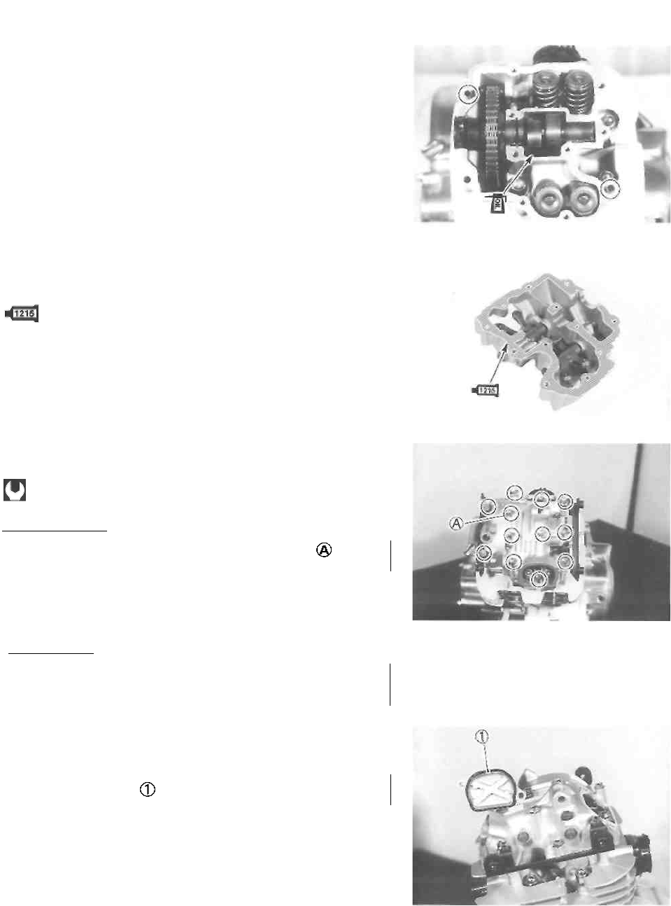
ENGINE 3-64
CYLINDER HEAD COVER
• Pour motor oil in the oil pocket in the cylinder head.
NOTE:
Turn the crankshaft and check that all the moving parts
(e.g., cam follower, camshaft) work properly.
• Clean the mating surfaces of the cylinder head and head
cover.
• Install the dowel pins.
• Apply SUZUKI BOND N0.1215 uniformly to the mating
surface of the cylinder head cover and install it within a
few minutes.
99000-31110: SUZUKI BOND N0.1215
• Tighten the cylinder head cover bolts to the specified
torque.
Cylinder head cover bolt: 10 N ■ m (1.0 kg-m, 7.0 Ib-ft)
I A CAUTION |
Install the new gasket washer to the bolt
A CAUTION
Be sure to check the valve clearance. (See pp. 2-3
and -4.)
• Install the valve timing inspection caps.
CAUTION
Use new O-rings to prevent oil leakage.
FUEL AND LUBRICATION SYSTEM
----------------------------------------- CONTENTS ------------------------------------------
FUEL TANK AND FUEL VALVE ......................................................... 4- 1
REMOVAL ....................................................................................... 4- 1
INSPECTION ................................................................................... 4- 1
REMOUNTING ............................................................................... 4- 1
CARBURETOR ................................................................................... 4- 2
SPECIFICATIONS ......................................................................... 4-2
I.D. NO. LOCATION ......................................................................... 4-2
CONSTRUCTION ............................................................................ 4-3
REMOVAL ....................................................................................... 4- 4
DISASSEMBLY ............................................................................... 4- 4
CLEANING ...................................................................................... 4- 8
INSPECTION AND ADJUSTMENT .................................................. 4-8
REASSEMBLY ................................................................................ 4- 9
REMOUNTING ............................................................................... 4- 9
LUBRICATION SYSTEM ..................................................................... 4-10
OIL PRESSURE ............................................................................... 4-10
OIL FILTER ...................................................................................... 4-10
OIL SUMP FILTER ........................................................................... 4-10
ENGINE LUBRICATION SYSTEM CHART ....................................... 4-11
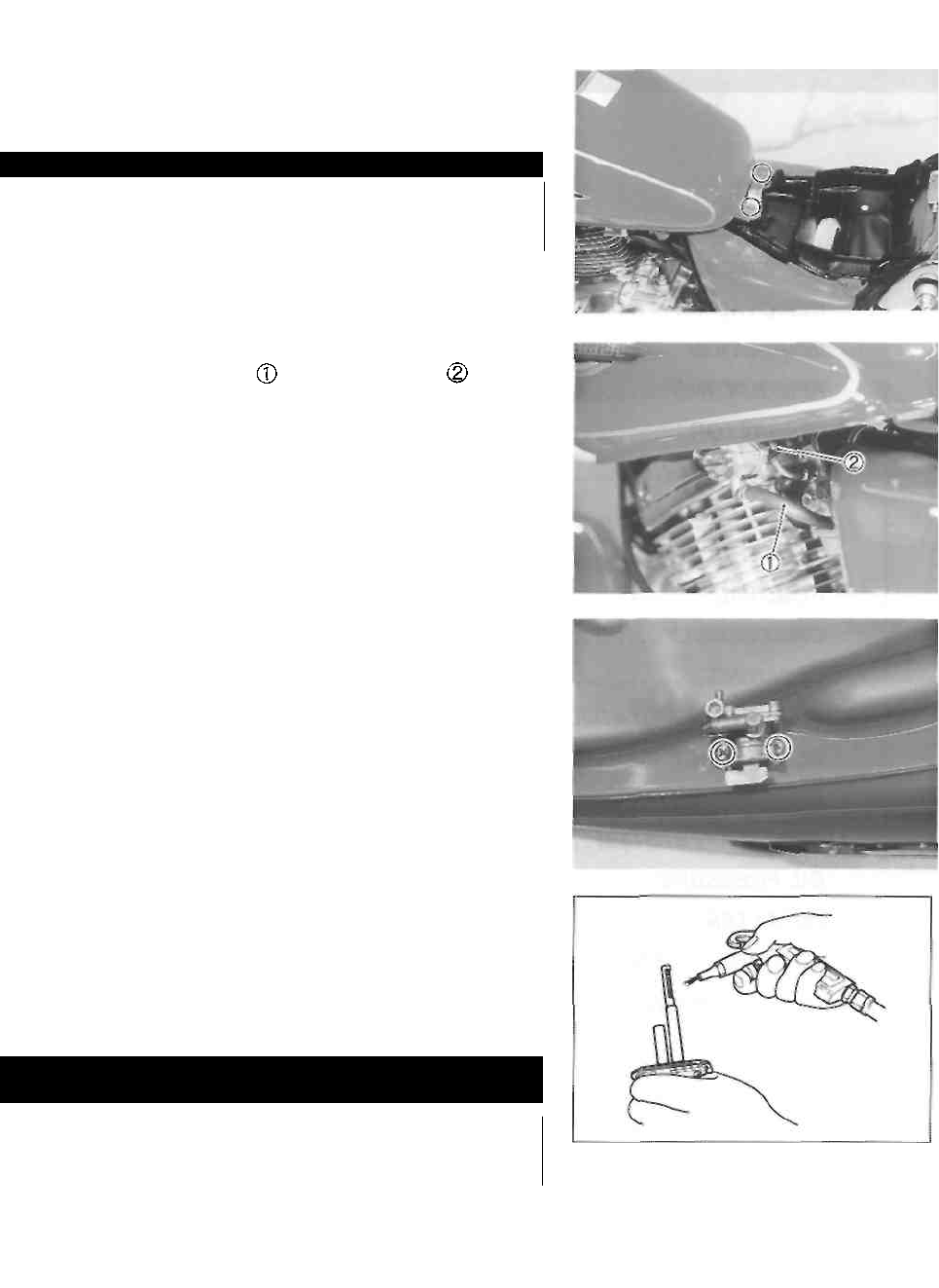
4-1 FUEL AND LUBRICATION SYSTEM
FUEL TANK AND FUEL VALVE
REMOVAL
A WARNING
Gasoline is very explosive. Extreme care must be
taken.
• Remove the front seat. (See p. 5-1.)
• Remove the fuel tank mounting bolts.
• Turn the fuel valve to "ON" or "RES" position.
• Disconnect the fuel hose and vacuum hose
• Remove the fuel tank.
• Remove the fuel valve.
INSPECTION
FUEL VALVE
If the fuel filter is dirty with sediment or rust, fuel will not
flow smoothly and loss in engine power may result. Clean
the fuel filter with compressed air. Also check the fuel filter
for cracks.
AWARNING
Gaskets and O-rings must be replaced with new
ones to prevent fuel leakage.
REMOUNTING
• Remount the fuel tank and fuel valve in the reverse order
of removal.
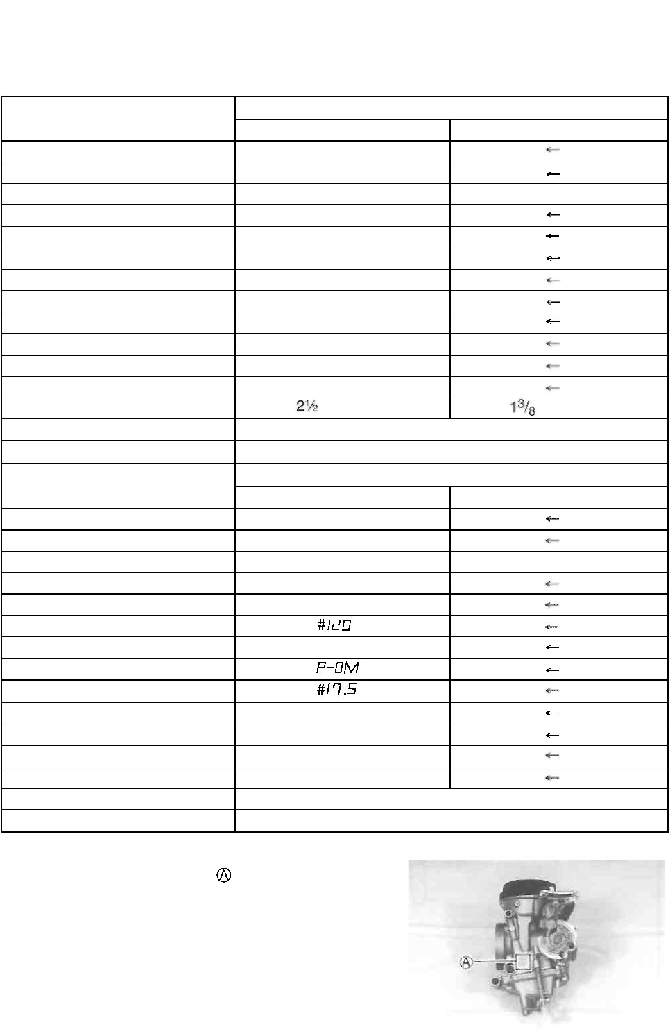
FUEL AND LUBRICATION SYSTEM 4-2
CARBURETOR
SPECIFICATIONS
ITEM
SPECIFICATION
E-01, 02, 04, 25, 34
E-17, 22, 24
Carburetor type
MIKUNI BSR32SS
Bore size
32 mm
I.D. No
13F0
13F2
Idle r/min.
1 300 ± 100 r/min.
Float height
13.0 ±0.5 mm
Main jet (M.J.)
#115
Jet needle (J.N.)
5C60-3rd
Needle jet (N.J.)
P-0
Pilot jet (P.J.)
#17.5
Pilot air jet No. 1 (P.A.J.1)
#87.5
Pilot air jet No.2 (P.A.J.2)
#140
Throttle valve (Th.V.)
#110
Pilot screw (PS.)
turns out
turns out
Throttle cable play
2-4 mm (0.08-0.16 in)
Starter plunger cable play
0.5-1.0 mm (0.02-0.04 in)
ITEM
SPECIFICATION
E-03, 28
E-33
Carburetor type
MIKUNI BSR32SS
Bore size
32 mm
I.D. No
13F3
13F4
Idle r/min.
1 300 ± 50 r/min.
Float height
13.0 ±0.5 mm
Main jet (M.J.)
Jet needle (J.N.)
5C65
Needle jet (N.J.)
Pilot jet (P.J.)
Pilot air jet No. 1 (P.A.J.1)
#87.5
Pilot air jet No.2 (P.A.J.2)
#120
Throttle valve (Th.V.)
#110
Pilot screw (PS.)
PRE-SET
Throttle cable play
2-4 mm (0.08-0.16 in)
Starter plunger cable play
0.5-1.0 mm (0.02-0.04 in)
I.D. NO. LOCATION
The carburetor has I.D. Number stamped on its body
according to its specifications.
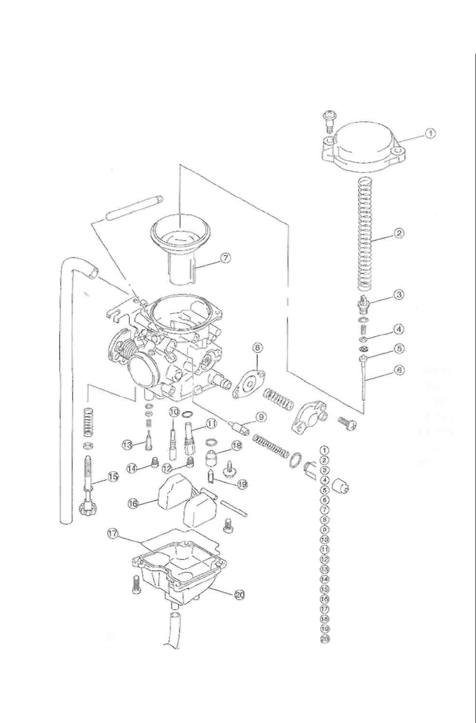
4-3 FUEL AND LUBRICATION SYSTEM
CONSTRUCTION
Top cap
Spring
Jet needle holder
Washer
Spacer
Jet needle
Piston valve/diaphragm
Diaphragm
Starter plunger
Pilot jet
Jet holder
Main jet
Pilot screw
Starter jet
Throttle stop screw
Float
Gasket
Needle valve seat
Needle valve
Float chamber
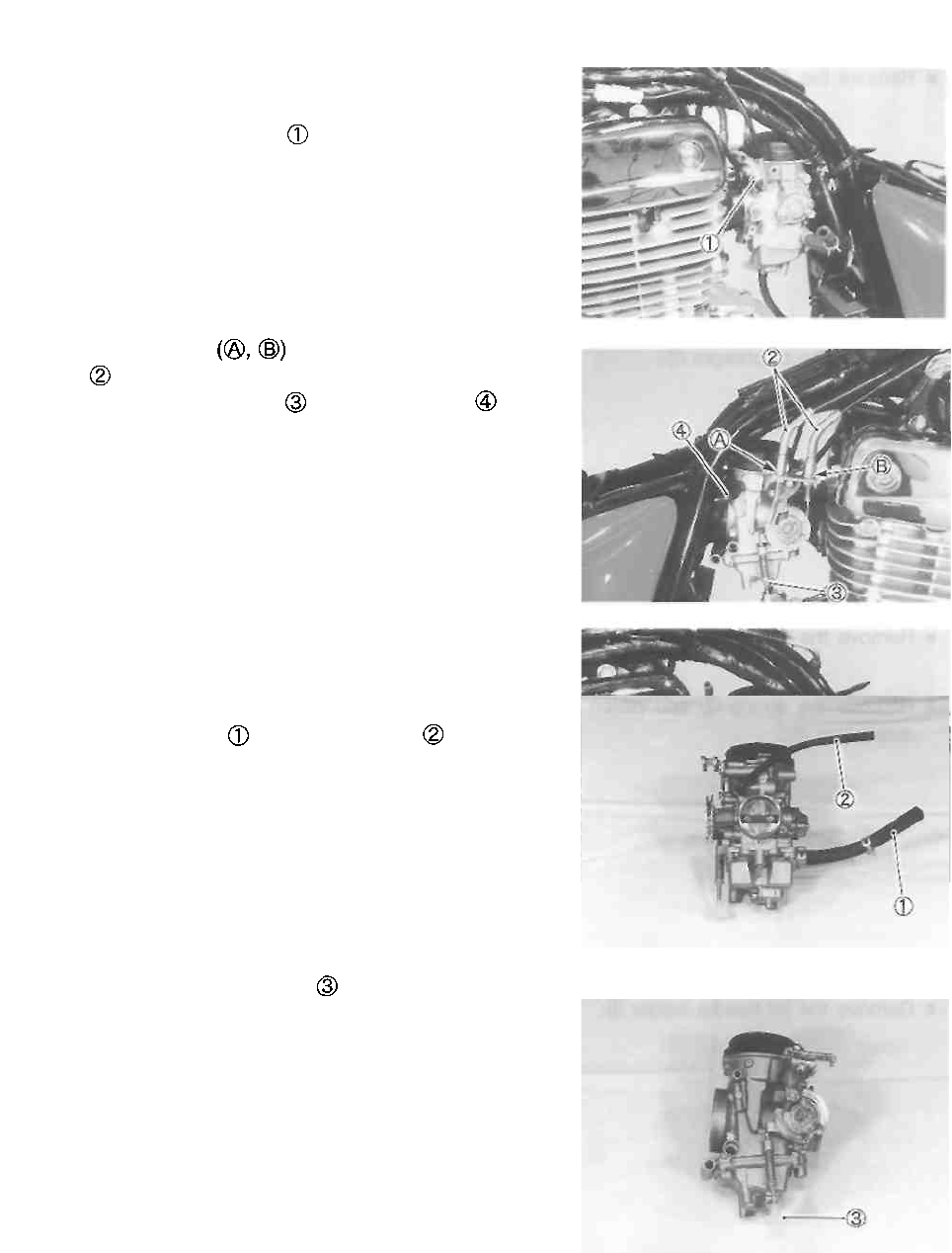
FUEL AND LUBRICATION SYSTEM 4-4
REMOVAL
• Remove the fuel tank. (See p. 4-1.)
• Remove the starter plunger
• Loosen the lock nuts and disconnect the throttle
cables
• Remove the overflow hose and air vent hose
• Loosen the clamp screws.
• Remove the carburetor.
DISASSEMBLY
• Remove the fuel hose and vacuum hose
• Remove the throttle stop screw
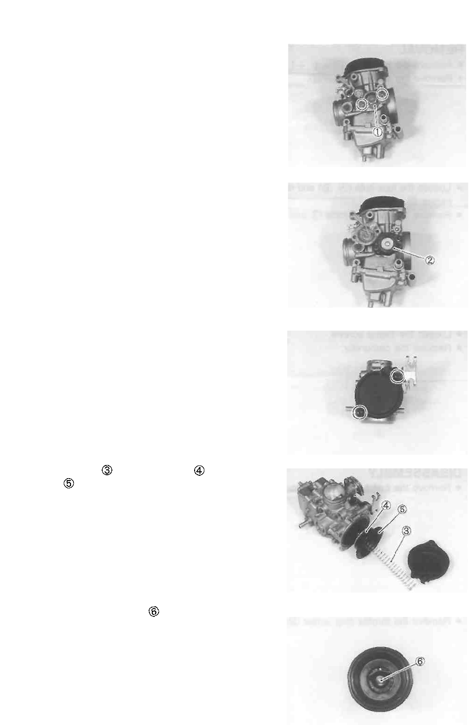
4-5 FUEL AND LUBRICATION SYSTEM
Remove the diaphragm cover ©.
Remove the diaphragm
• Remove the carburetor top cap.
• Remove the spring and piston valve along with
diaphragm
• Remove the jet needle holder .
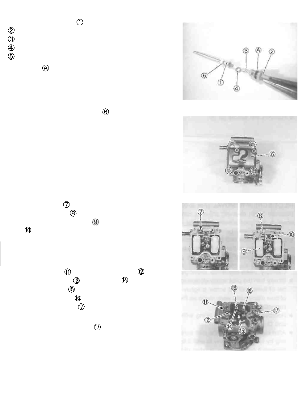
FUEL AND LUBRICATION SYSTEM 4-6
• Remove the jet needle
Holder
Spring
Washer
Spacer
The O-ring should be replaced with a new one.
• Remove the float chamber body .
• Remove the screw
• Remove the float pin
• Remove the float assembly along with the needle
valve .
A CAUTION
Do not use a wire to clean the valve seat.
• Remove the screw and needle valve seat
• Remove the main jet and jet holder
• Remove the pilot jet
• Remove the starter jet
• Remove the pilot screw
NOTE:
Before removing the pilot screw , its setting must be de-
termined. Slowly turn the pilot screw clockwise and count
the number of turns until it is lightly seated. When
reassembling the pilot screw, you will want to set it to its
original position.
A CAUTION
Do not use a wire to clean the passage and jets.
A CAUTION
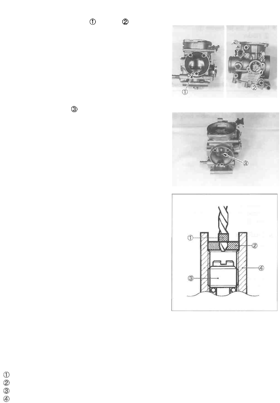
4-7 FUEL AND LUBRICATION SYSTEM
• Remove the pilot air jet No.1 and No.2
• Remove the needle jet
PILOT SCREW REMOVAL (For E-03, -28, -33)
Because harsh cleaning solvents can damage the O-rlng
seals In the pilot system, the pilot system components
should be removed before cleaning.
• Use a 1/8" size drill bit with a drill-stop to remove the
pilot screw plug. Set the drill-stop 6 mm from the end of
the bit to prevent drilling into the pilot screw. Carefully
drill through the plug.
• Thread a self-tapping sheet metal screw into the plug.
Pull on the screw head with pliers to remove the plug.
Carefully clean any metal shavings from the area.
• Slowly turn the pilot screw clockwise and count the num-
ber of turns until the screw is lightly seated. Make a note
of how many turns were made so the screw can be reset
correctly after cleaning.
• Remove the pilot screw along with the spring, washer,
and O-ring.
• After cleaning, reinstall the pilot screw to the original set-
ting by turning the screw in until it lightly seats, and then
backing it out the same number of turns counted during
disassembly.
• Install a new plug by tapping it into place with a punch.
Drill-stop
Plug
Pilot screw
Carburetor body
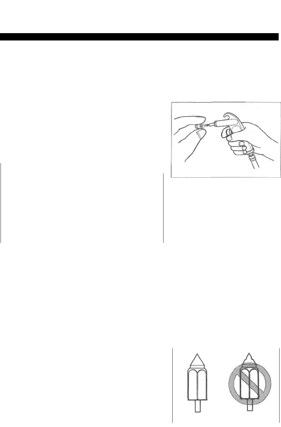
FUEL AND LUBRICATION SYSTEM 4-8
CLEANING
AWARNING
Some carburetor cleaning chemicals, especially
dip-type soaking solutions, are very corrosive and
must be handled carefully. Always follow the
chemical manufacturer's instructions on proper
use, handling and storage.
Clean all jets with a spray-type carburetor cleaner and
dry them using compressed air. Clean all circuits of
the carburetor thoroughly - not just the perceived
problem area. Clean the circuits in the carburetor body
with a spray-type cleaner and allow each circuit to soak,
if necessary, to loosen dirt and varnish. Blow the body
dry using compressed air.
A CAUTION
Do not use a wire to clean the jets or passage-
ways. A wire can damage the jets and passage-
ways. If the components cannot be cleaned with a
spray cleaner it may be necessary to use a dip-
type cleaning solution and allow them to soak. Al-
ways follow the chemical manufacturer's instruc-
tions for proper use and cleaning of the carbure-
tor components.
* After cleaning, reassemble the carburetor with new seals
and gaskets.
INSPECTION AND ADJUSTMENT
Check the following items for any damage or clogging.
* Pilot jet * Needle jet air bleeding hole
* Main jet * Float
* Starter jet * Needle valve
* Diaphragm * Gasket and O-ring
* Pilot screw * Pilot outlet and by-pass holes
NEEDLE VALVE INSPECTION
If foreign matter is caught between the valve seat and the
needle valve, the gasoline will continue flowing and over-
flow. If the valve seat and needle valve are worn beyond
the permissible limits, similar trouble will occur. Converse-
ly, if the needle valve sticks, the gasoline will not flow into
the float chamber. Clean the float chamber and float parts
with gasoline. If the needle valve is worn, as shown in the
illustration, replace it along with a new valve seat. Clean
the fuel passage of the mixing chamber with compressed
air.
CORRECT
INCORRECT
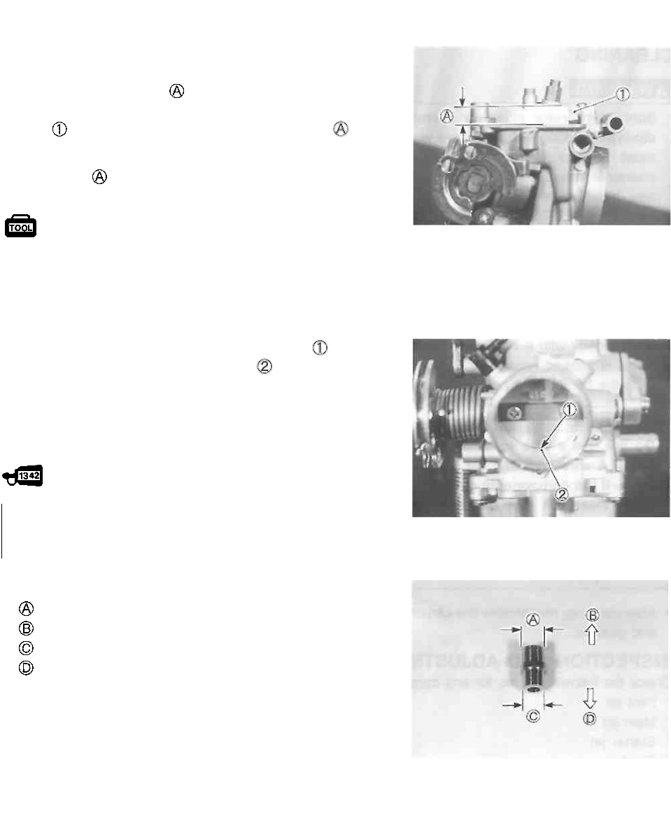
4-9 FUEL AND LUBRICATION SYSTEM
FLOAT HEIGHT ADJUSTMENT
To check the float height, turn the carburetor upside down.
Measure the float height while the float arm is just con-
tacting the needle valve using vernier calipers. Bend the
tongue as necessary to bring the float height to the
specified value.
Float height : 13.0 ±0.5 mm (0.51 ±0.02 in)
09900-20101: Vernier calipers
REASSEMBLY
Reassemble the carburetor in the reverse order of disas-
sembly.
Pay attention to the following points: • Turn the throttle
stop screw until the throttle valve's bottom end is
aligned with the foremost by-pass port
NOTE:
When removing the throttle valve, applying a small quantity
of THREAD LOCK "1342" to the throttle valve mounting
screws and tighten them.
99000-32050: THREAD LOCK "1342"
Face the stamped side of the throttle valve out.
• Install the needle jet as shown.
Large diameter side Bore
side
Small diameter side
Main jet side
REMOUNTING
Remount the carburetor in the reverse order of removal.
* Adjust the following items to the specification.
* Engine idle r/min ........................... See pp. 2-7 and -8.
* Throttle cable play .................................... See p. 2-8.
* Starter plunger cable play ....................... See p. 2-9.
A CAUTION

LUBRICATION SYSTEM
OIL PRESSURE
See p. 2-19.
OIL FILTER
See pp. 2-9 and -10.
OIL SUMP FILTER
When replacing the engine oil, make sure that the oil sump
filter has no tears or damage. Also, be sure to clean the oil
sump filter periodically. (See pp. 3-16, -47 and -51.)
FUEL AND LUBRICATION SYSTEM 4-10
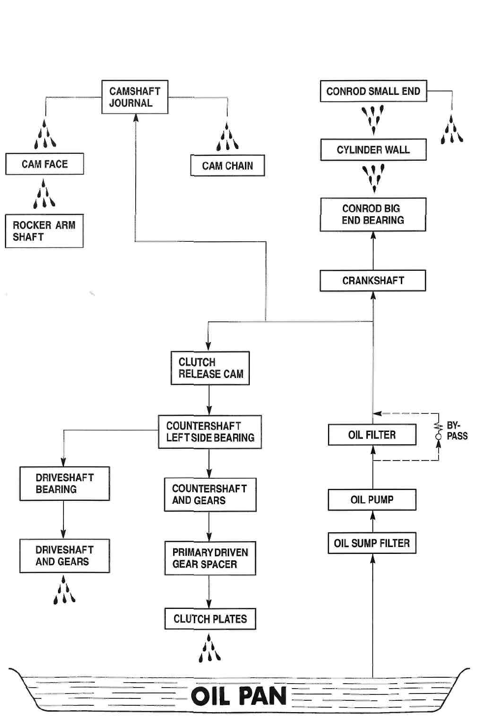
4-11 FUEL AND LUBRICATION SYSTEM
ENGINE LUBRICATION SYSTEM CHART

CHASSIS
----------------------------------------- CONTENTS ------------------------------------------
EXTERIOR PARTS .............................................................................. 5- 1
REMOVAL ........................................................................................ 5- 1
REMOUNTING ............................................................................... 5- 1
FRONT WHEEL ................................................................................. 5-2
CONSTRUCTION ............................................................................. 5-2
REMOVAL ........................................................................................ 5- 3
INSPECTION AND DISASSEMBLY ................................................. 5-3
REASSEMBLY ................................................................................ 5- 5
REMOUNTING ............................................................................... 5- 6
FRONT BRAKE ................................................................................. 5- 7
CONSTRUCTION ............................................................................. 5- 7
BRAKE PAD REPLACEMENT ......................................................... 5-8
BRAKE FLUID REPLACEMENT ...................................................... 5- 8
BRAKE CALIPER REMOVAL AND DISASSEMBLY ......................... 5-9
BRAKE CALIPER INSPECTION ...................................................... 5-10
BRAKE CALIPER REASSEMBLY AND REMOUNTING ................ 5-10
BRAKE DISC INSPECTION .............................................................. 5-11
MASTER CYLINDER REMOVAL AND DISASSEMBLY ..................... 5-11
MASTER CYLINDER INSPECTION ................................................ 5-13
MASTER CYLINDER REASSEMBLY AND REMOUNTING .............. 5-13
FRONT FORK .................................................................................... 5-15
CONSTRUCTION ............................................................................ 5-15
REMOVAL AND DISASSEMBLY .................................................. 5-15
INSPECTION .................................................................................. 5-17
REASSEMBLY AND REMOUNTING ............................................... 5-18
STEERING .......................................................................................... 5-22
CONSTRUCTION ............................................................................ 5-22
REMOVAL AND DISASSEMBLY ................................................... 5-22
INSPECTION ................................................................................... 5-25
REASSEMBLY AND REMOUNTING ............................................... 5-26
REAR WHEEL AND REAR BRAKE ................................................... 5-29
CONSTRUCTION ............................................................................ 5-29
REMOVAL ....................................................................................... 5-30
INSPECTION AND DISASSEMBLY ................................................ 5-31
REASSEMBLY AND REMOUNTING ............................................... 5-33
REAR SUSPENSION .......................................................................... 5-36
CONSTRUCTION ............................................................................ 5-36
REMOVAL ....................................................................................... 5-37
INSPECTION AND DISASSEMBLY ................................................ 5-38
REASSEMBLY AND REMOUNTING ............................................... 5-40

5-1 CHASSIS
EXTERIOR PARTS
REMOVAL
FRONT SEAT
• Remove the seat with the ignition key.
RIGHT FRAME COVER
• Remove the screw.
• Remove the right frame cover.
LEFT FRAME COVER
• Remove the screw.
• Remove the left frame cover.
• Remove the seat lock.
hooked part
hooked part
REAR SEAT
• Remove the rear seat by removing the bolts.
REMOUNTING
Remount the seats, frame covers, front and rear fenders in
the reverse order of removal.
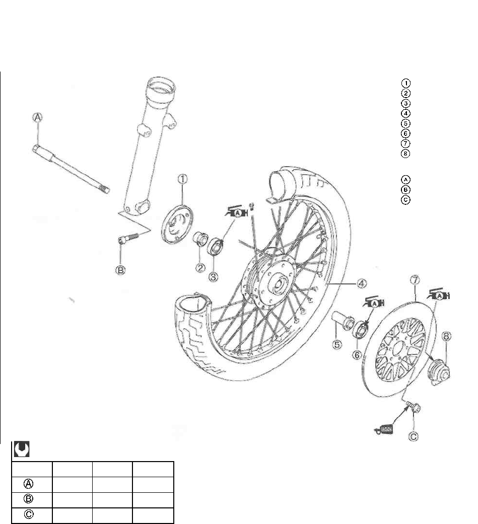
CHASSIS 5-2
FRONT WHEEL
CONSTRUCTION
ITEM
N-m
kg-m
Ib-ft
65
6.5
47.0
23
2.3
16.5
23
2.3
16.5
Dust cover
Spacer
Bearing
Front wheel
Spacer
Bearing
Brake disc
Speedometer
gearbox
Front axle Axle
pinch bolt Brake
disc bolt
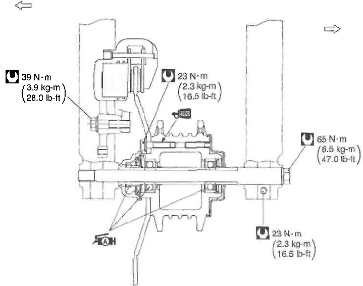
Left
Right
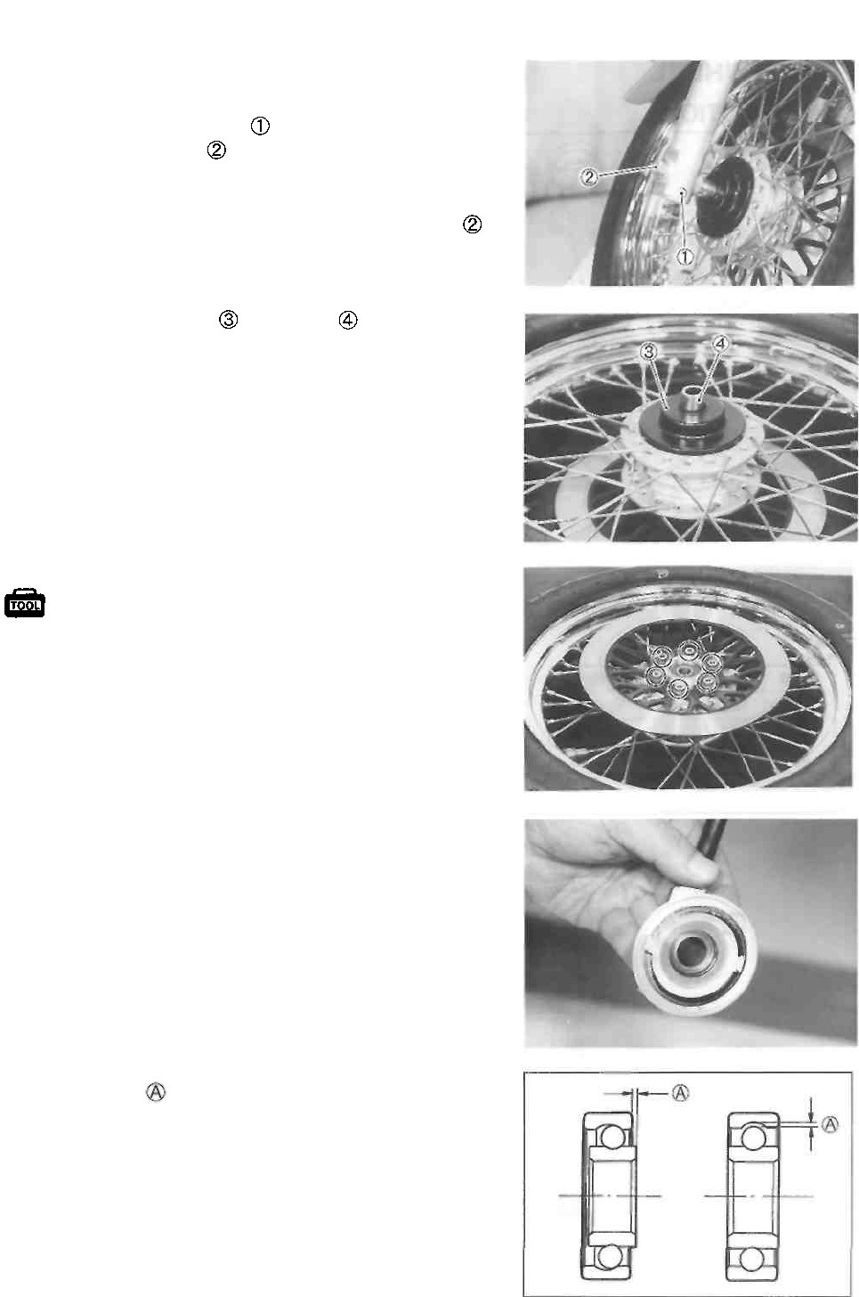
5-3 CHASSIS
REMOVAL
FRONT WHEEL
• Loosen the axle pinch bolt
• Loosen the front axle
• Raise the front wheel off the ground with a jack or wood-
en block.
• Remove the front wheel by removing the front axle
• Remove the dust cover and spacer
• Remove the brake disc.
09900-00410: Hexagon wrench set
INSPECTION AND DISASSEMBLY
SPEEDOMETER GEARBOX
Turn the speedometer gear and check to see that the gear
turns smoothly together with the speedometer pinion.
WHEEL BEARINGS
Inspect the play of the wheel bearings by hand while
they are in the wheel. Rotate the inner race by hand to
inspect it for abnormal noise and smooth rotation. Replace
the wheel bearings if there is anything unusual.
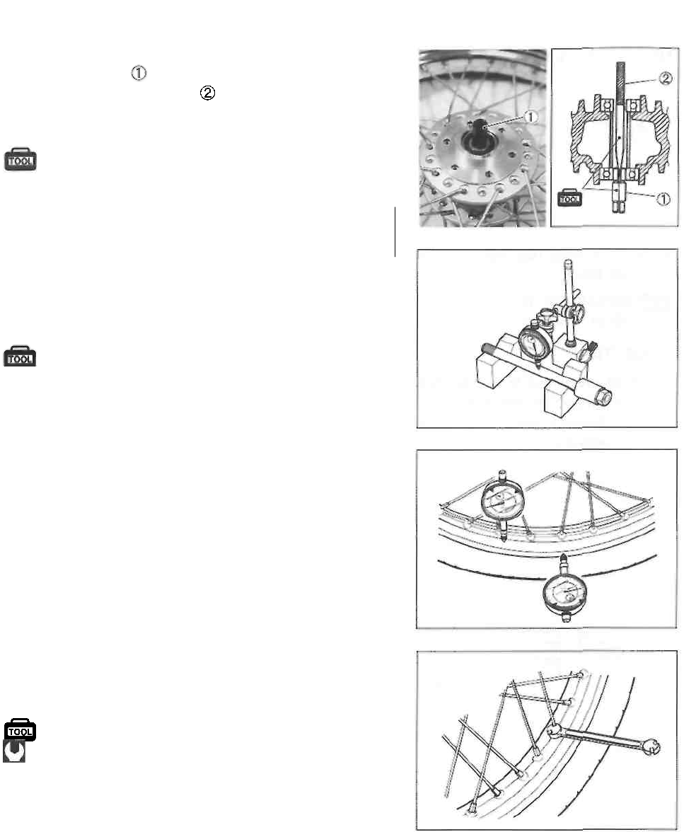
CHASSIS 5-4
Remove the wheel bearings as follows:
• Insert the adapter into the wheel bearing.
• After inserting the wedge bar from the opposite side, lock
the wedge bar into the slit of the adapter.
• Drive out both bearings by striking the wedge bar.
09941-50111: Bearing remover
A CAUTION
The removed bearings should be replaced with new
ones.
FRONT AXLE
Measure the front axle runout using the dial gauge. If the
runout exceeds the limit, replace the front axle.
09900-20606: Dial gauge (1/100) 09900-
20701: Magnetic stand 09900-21304: V-
block set (100 mm)
Service Limit: 0.25 mm (0.010 in)
WHEEL
Make sure that the wheel runout (axial and radial) does not
exceed the service limit when checked as shown. An ex-
cessive amount of runout is usually due to worn or loose
wheel bearings and can be corrected by replacing the
bearings. If bearing replacement fails to reduce the runout,
replace the wheel.
Service Limit (axial and radial): 2.0 mm (0.08 in)
SPOKE NIPPLE
Check to be sure that all nipples are tight, and retighten them
as necessary using a spoke nipple wrench.
09940-60113: Spoke nipple wrench Spoke
nipple: 4.5 N-m (0.45 kg-m, 3.5 Ib-ft)
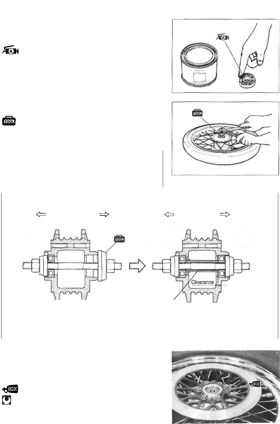
5-5 CHASSIS
REASSEMBLY
• Apply SUZUKI SUPER GREASE "A" to the bearings be-
fore installing.
99000-25010: SUZUKI SUPER GREASE "A"
• Install the wheel bearings using the special tools as de-
scribed below.
09924-84510: Bearing installer set
09924-84521: Bearing installer set
CAUTION
* First install the left wheel bearing, then install the
right wheel bearing.
* The sealed cover on the bearings must face to the
outside.
Left side Right side Left side Right side
Spacer
BRAKE DISC
• Make sure that the brake disc is clean and free of any
grease. Apply THREAD LOCK SUPER "1360" to the
brake disc bolts and tighten them to the specified torque.
99000-32130: THREAD LOCK SUPER "1360"
Brake disc bolt: 23 N-m (2.3 kg-m, 16.5 Ib-ft)
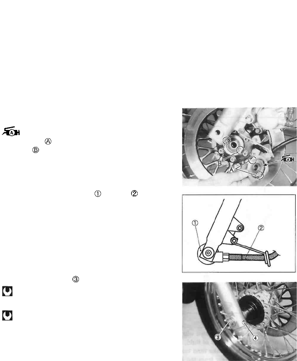
CHASSIS 5-6
REMOUNTING
Remount the front wheel in the reverse order of removal.
Pay attention to the following points:
• Apply SUZUKI SUPER GREASE "A" to the speedometer
gearbox.
99000-25010: SUZUKI SUPER GREASE "A"
• Align the lugs on the speedometer gearbox with the
recesses on the front wheel.
• Set the speedometer gearbox with cable as shown
in the illustration.
• Tighten the front axle to the specified torque.
Front axle: 65 N-m (6.5 kg-m, 47.0 Ib-ft)
• Tighten the axle pinch bolt @ to the specified torque.
Axle pinch bolt: 23 N-m (2.3 kg-m, 16.5 Ib-ft)
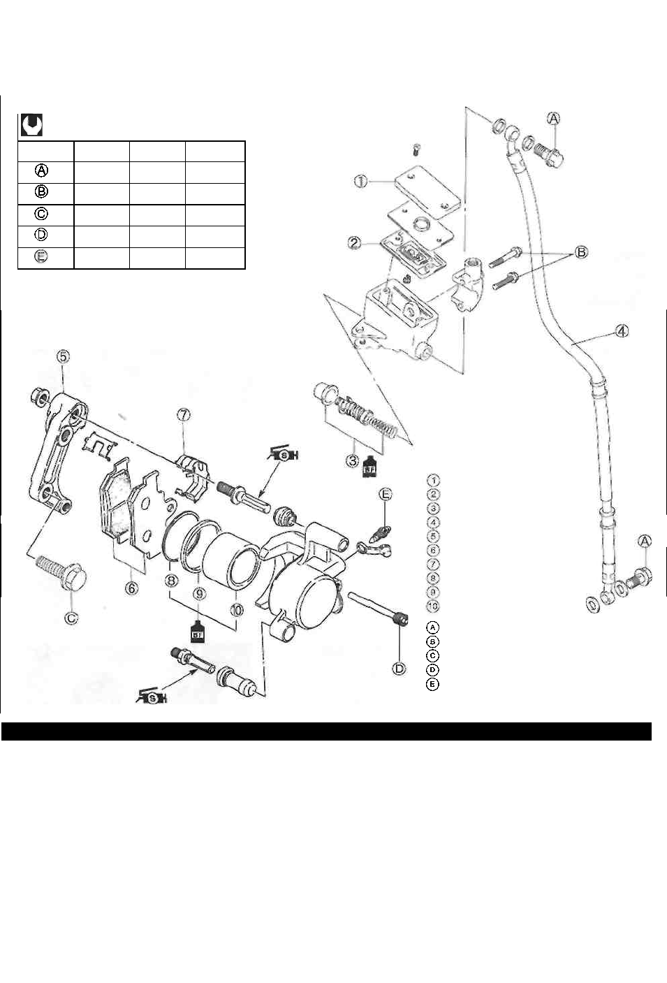
5-7 CHASSIS
FRONT BRAKE
CONSTRUCTION
ITEM
N-m
kg-m
kg-m
23
2.3
16.5
10
1.0
7.0
39
3.9
28.0
18
1.8
13.0
7.5
0.75
5.5
¿WARNING
This brake system is filled with an ethylene glycol-based DOT 4 brake fluid. Do not use or
mix different types of fluid, such as silicone-based or petroleum-based brake fluids. Do not
use any brake fluid taken from old, used or unsealed containers. Never reuse brake fluid
left over from the last servicing or which stored for long periods of time. When storing the
brake fluid, seal the container completely and keep it away from children.
When replenishing brake fluid, take care not to get dust into the fluid. When washing
brake components, use new brake fluid. Never use cleaning solvent. A contaminated
brake disc or brake pad reduces braking performance. Discard contaminated pads and
clean the disc with high quality brake cleaner or a neutral detergent.
A CAUTION
Handle brake fluid with care: the fluid reacts chemically with paint, plastics, rubber materials etc.
Reservoir cap
Diaphragm
Brake piston/primary cup
Brake hose
Brake caliper holder
Brake pad
Spring
Dust seal
Piston seal
Piston
Brake hose union bolt
Brake master cylinder mounting bolt
Brake caliper mounting bolt
Brake pad mounting bolt
Brake caliper air bleeder valve
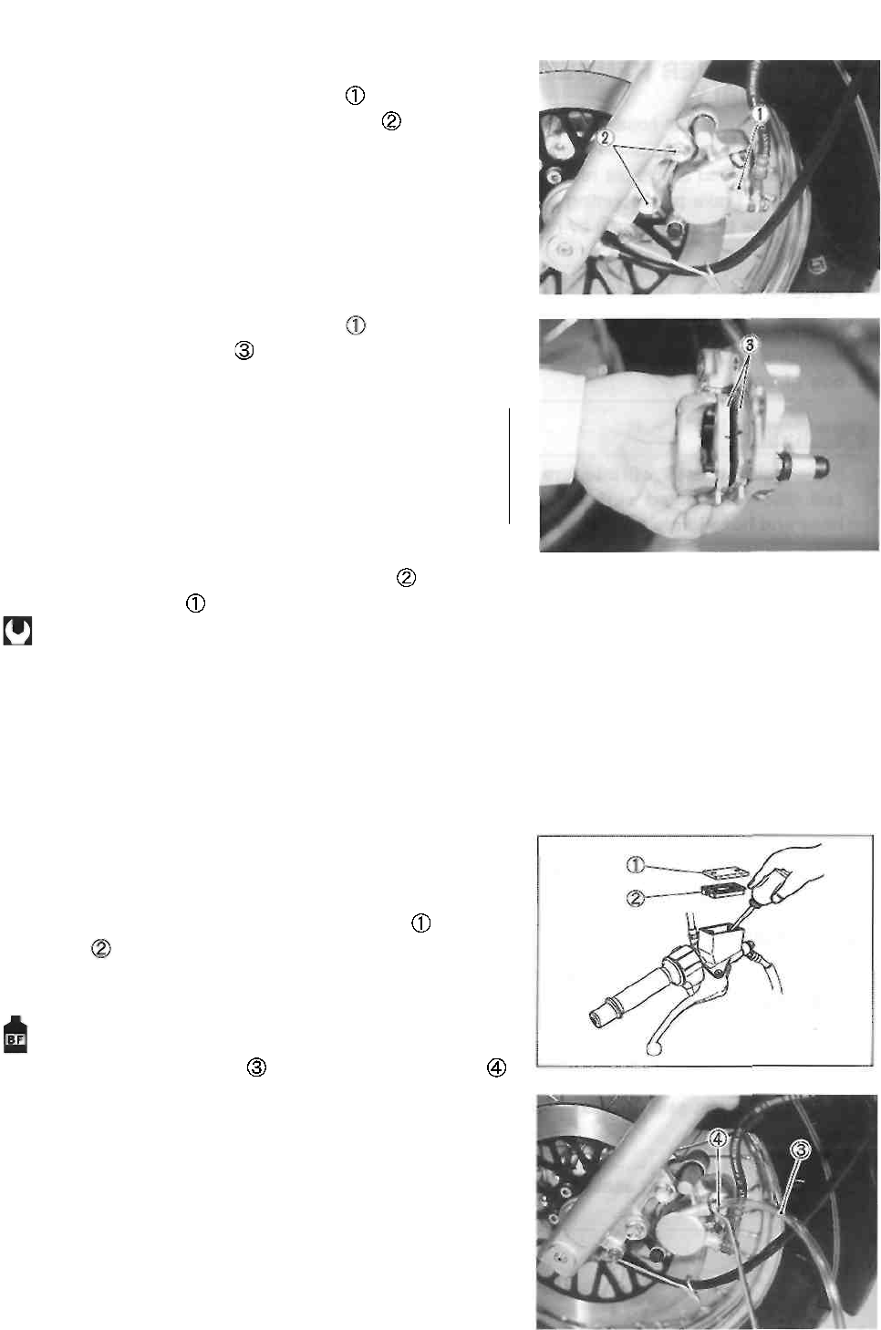
CHASSIS 5-8
BRAKE PAD REPLACEMENT
• Loosen the brake pad mounting bolt
• Remove the brake caliper mounting bolts
• Remove the brake pad mounting bolt
• Remove the brake pads
A CAUTION
* Do not operate the brake lever during or after brake
pad removal.
* Replace the brake pads as a set, otherwise braking
performance will be adversely affected.
• Install the new brake pads and brake pad mounting bolt.
• Tighten the brake caliper mounting bolts and brake
pad mounting bolt to the specified torque.
Brake caliper mounting bolt: 39 N-m
(3.9 kg-m, 28.0 Ib-ft)
Brake pad mounting bolt: 18 N-m
(1.8 kg-m, 13.0 Ib-ft)
NOTE:
After replacing the brake pads, pump with the brake lever a
few times to operate the brake correctly and then check the
brake fluid level.
BRAKE FLUID REPLACEMENT
• Place the motorcycle on a level surface and keep the
handlebars straight.
• Remove the master cylinder reservoir cap and dia-
phragm
• Suck up the old brake fluid as much as possible.
• Fill the reservoir with new brake fluid.
Specification and Classification: DOT 4
• Connect a cleaner hose to the air bleeder valve
and insert the free end of hose into a receptacle.
• Loosen the air bleeder valve and pump the brake lever until
the old brake fluid is completely out of the brake system.
• Close the air bleeder valve and disconnect the clear
hose. Fill the reservoir with new brake fluid to the upper
end of the inspection window.
A CAUTION
Bleed air from the brake system. (See p. 2-13.)
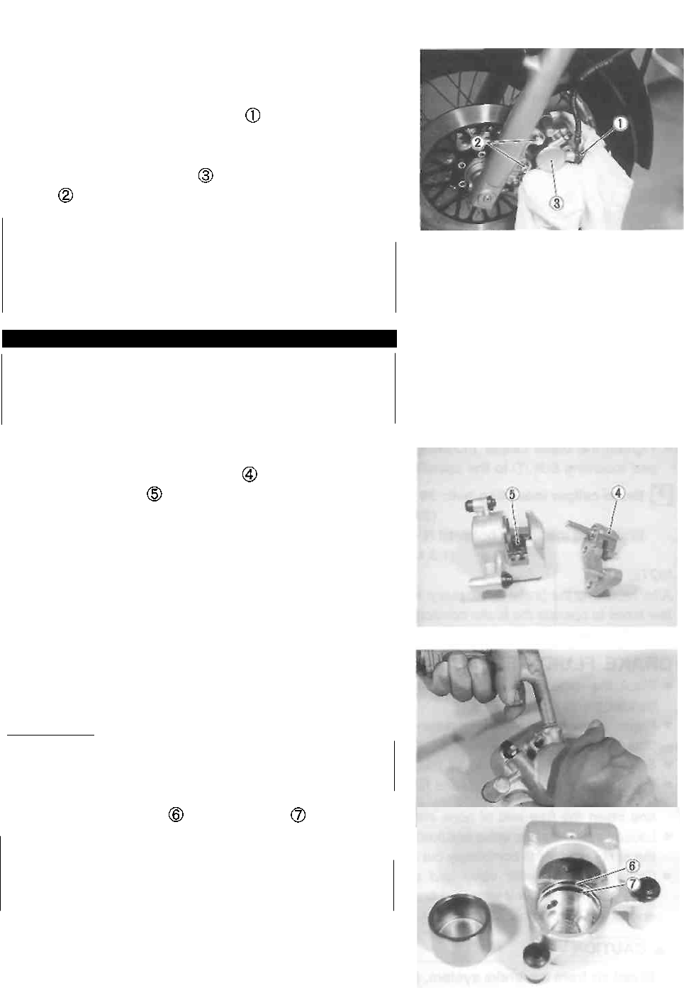
5-9 CHASSIS
BRAKE CALIPER REMOVAL AND
DISASSEMBLY
• Disconnect the brake hose from the brake caliper by re-
moving the brake hose union bolt and allow the brake
fluid to drain into a suitable receptacle.
• Loosen the brake pad mounting bolt.
• Remove the brake caliper by removing the mounting
bolts .
A CAUTION
Never reuse the brake fluid left over from previous
servicing and which has been stored for long peri-
ods of time.
AWARNING
Brake fluid if it leaks, will interfere with safe running
and discolor painted surfaces. Check the brake
hose and hose joints for cracks and oil leakage.
• Remove the brake pads. (See p. 5-8.)
• Remove the brake caliper holder
• Remove the spring
• Place a rag over the brake caliper piston to prevent it
from popping out and then force out the piston using
compressed air.
A CAUTION
Do not use high pressure air to prevent brake cali-
per piston damage.
• Remove the dust seal and piston seal
A CAUTION
Do not reuse the dust seal and piston seal to pre-
vent brake fluid leakage.
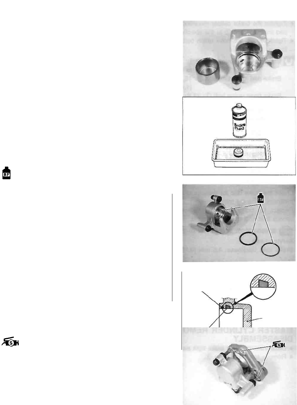
CHASSIS 5-10
BRAKE CALIPER INSPECTION
BRAKE CALIPER
Inspect the brake caliper cylinder wall for nicks, scratches
or other damage.
BRAKE CALIPER PISTONS
Inspect the brake caliper piston for any scratches or other
damage.
BRAKE CALIPER REASSEMBLY AND
REMOUNTING
Reassemble and remount the brake caliper in the reverse
order of removal and disassembly. Pay attention to the fol-
lowing points: • Wash the caliper bore and piston with
the specified
brake fluid. Thoroughly wash the dust seal groove and
piston seal groove.
Specification and Classification: DOT 4
A CAUTION
* Wash the brake caliper components with new
brake fluid before reassembly.
* Do not wipe the brake fluid off after washing the
components.
* When washing the components, use the speci-
fied brake fluid. Never use different types of fluid
or cleaning solvents such as gasoline, ker-osine,
etc.
* Replace the piston seal and dust seal with new
ones.
* Apply brake fluid to all of the seals, brake caliper
bore and piston before reassembly.
• Install the piston seal as shown in the illustration.
• Apply grease to the brake caliper holder.
99000-25100: SUZUKI SILICONE GREASE
Dust seal
Caliper body
Piston seal
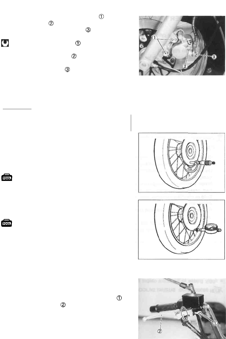
5-11 CHASSIS
• Tighten the brake caliper mounting bolts and brake
pad mounting bolt to the specified torque.
• Tighten the brake hose union bolt to the specified
torque.
Brake caliper mounting bolt
39 N-m (3.9 kg-m, 28.0 Ib-ft)
Brake pad mounting bolt : 18 N-m
(1.8 kg-m, 13.0 Ib-ft)
Brake hose union bolt : 23 N-m
(2.3 kg-m, 16.5 Ib-ft)
NOTE:
Before remounting the brake caliper, push the brake caliper
piston all the way into the caliper.
A CAUTION
Bleed air from the system after reassembling the
brake caliper. (See p. 2-13.)
BRAKE DISC INSPECTION
• Remove the front wheel. (See p. 5-3.)
Check the brake disc for damage or cracks. Measure the
thickness using the micrometer.
Replace the brake disc if the thickness is less than the
service limit or if damage is found.
09900-20205: Micrometer (0-25 mm)
Service Limit Brake disc thickness: 4.5 mm
(0.18 in)
Measure the runout using the dial gauge.
Replace the brake disc if the runout exceeds the service
limit.
09900-20606: Dial gauge (1/100 mm)
09900-20701: Magnetic stand
Service Limit Brake disc runout: 0.30
mm (0.012 in)
• If either measurement exceeds the service limit, replace
the brake disc. (See pp. 5-3 and -5.)
• Install the front wheel. (See p. 5-6.)
MASTER CYLINDER REMOVAL AND
DISASSEMBLY
• Disconnect the front brake light switch lead wires
• Remove the brake lever
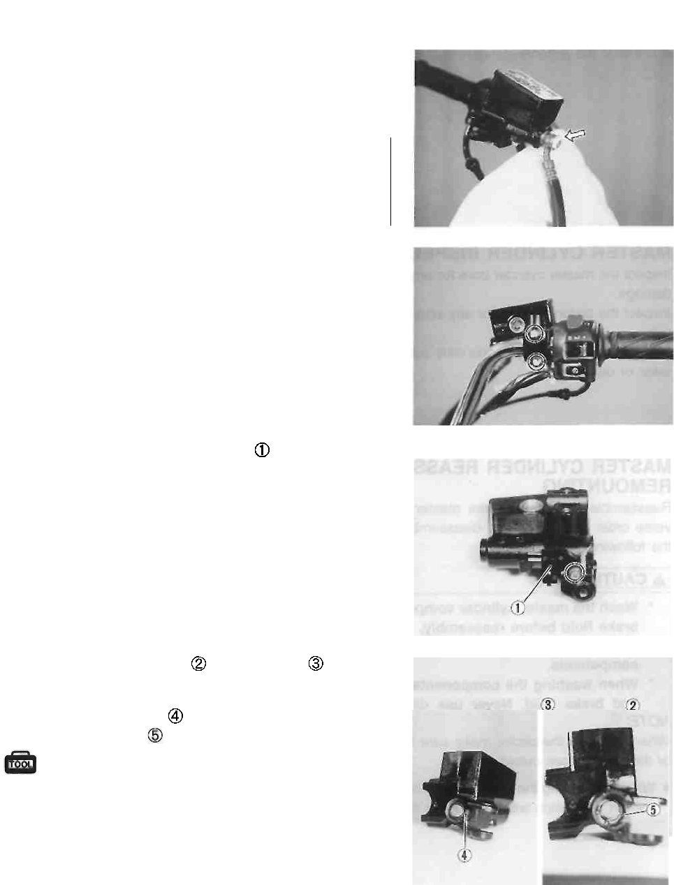
CHASSIS 5-12
• Place a rag underneath the brake hose union bolt on the
master cylinder to catch any spilt brake fluid.
• Remove the brake hose union bolt.
A CAUTION
Immediately wipe off any brake fluid contacting
any part of the motorcycle. The brake fluid reacts
chemically with paint, plastics and rubber materi-
als, etc. and will damage them severely.
• Remove the master cylinder assembly.
• Remove the front brake light switch
• Remove the reservoir cap and diaphragm
• Drain the brake fluid.
• Remove the dust boot
• Remove the circlip using the special tool.
09900-06108: Snap ring pliers
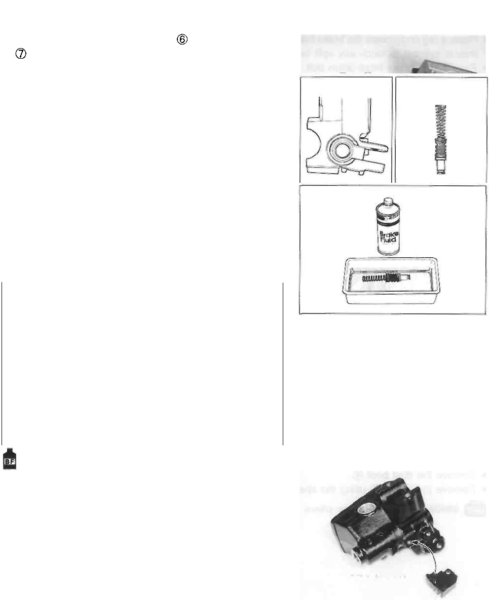
5-13 CHASSIS
• Remove the piston/secondary cup and return spring
MASTER CYLINDER INSPECTION
Inspect the master cylinder bore for any scratches or other
damage.
Inspect the piston surface for any scratches or other dam-
age.
Inspect the primary cup, secondary cup and dust seal for
wear or damage.
MASTER CYLINDER REASSEMBLY AND
REMOUNTING
Reassemble and remount the master cylinder in the re-
verse order of removal and disassembly. Pay attention to
the following points:
A CAUTION
* Wash the master cylinder components with new
brake fluid before reassembly.
* Do not wipe the brake fluid off after washing the
components.
* When washing the components, use the speci-
fied brake fluid. Never use different types of
fluid or cleaning solvents such as gasoline, ker-
osine, etc.
* Apply brake fluid to the master cylinder bore
and all of the master cylinder components be-
fore reassembly.
Specification and Classification: DOT 4
NOTE:
When installing the circlip, make sure that the sharp edge
of the circlip faces outside.
• When reinstalling the brake light switch, align the projec-
tion on the switch with the hole in the master cylinder.
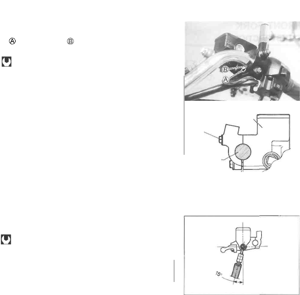
CHASSIS 5-14
• When remounting the master cylinder onto the handle-
bars, align the master cylinder holder's mating surface
with punch mark on the handlebars and tighten the
upper clamp bolt first.
Master cylinder bolt: 10 N-m (1.0 kg-m, 7.0 Ib-ft)
Master cylinder
Clearance
• Install the brake hose union as shown and tighten the
union bolt to the specified torque.
Brake hose union bolt: 23 N-m (2.3 kg-m, 16.5 Ib-ft)
A CAUTION
Bleed air from the brake system after reassem-
bling the master cylinder. (See p. 2-13.)
Upper
clamp
bolt
Handlebars
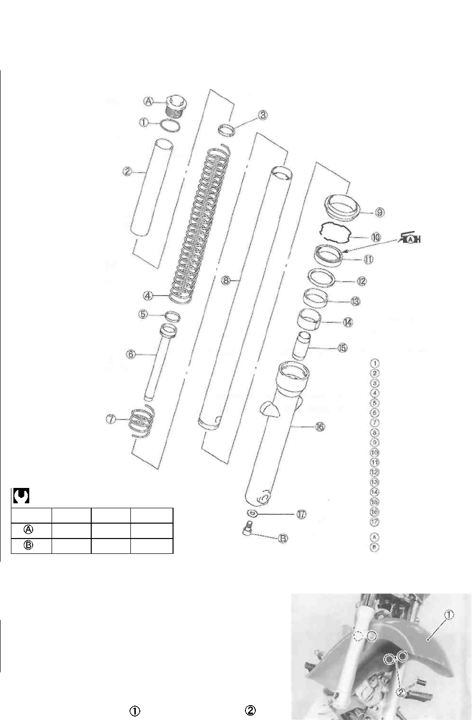
5-15 CHASSIS
FRONT FORK
CONSTRUCTION
ITEM
N-m
kg-m
Ib-ft
23
2.3
16.5
20
2.0
14.5
REMOVAL AND DISASSEMBLY
• Remove the front wheel. (See p. 5-3.)
• Remove the brake caliper. (See p. 5-9.)
A CAUTION
Secure the brake caliper to the frame with a string etc.,
taking care not to bend the brake hose.
• Remove the speedometer cable guide from the left fork
leg.
• Remove the front fender and brake hose guide
O-ring
Spacer
Washer
Front fork spring
Damper rod ring
Damper rod
Rebound spring
Inner tube
Dust seal
Oil seal stopper ring
Oil seal
Washer
Slide metal
Guide bushing
Oil lock piece
Outer tube
Gasket
Front fork cap bolt
Damper rod bolt
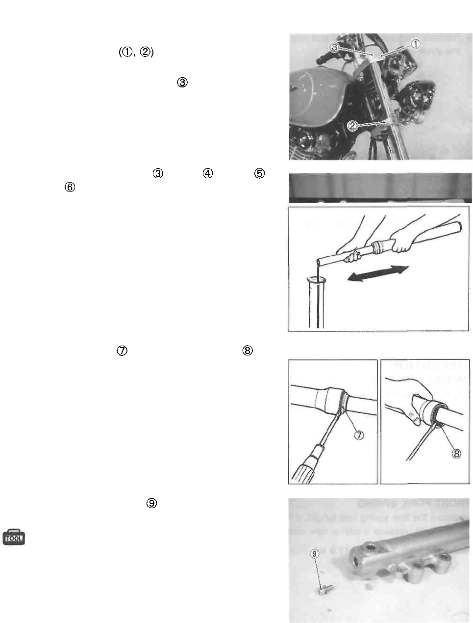
CHASSIS 5-16
• Remove the front fork after loosening the front fork upper
and lower clamp bolts
NOTE:
Slightly loosen the front fork cap bolt to facilitate later
disassembly.
• Remove the front fork cap bolt , spacer , washer
and spring
• Invert the front fork and stroke it several times to drain
out the fork oil.
• Hold the front fork in the inverted position for a few min-
utes to allow the fork oil to fully drain.
• Remove the dust seal and oil seal stopper ring
• Remove the damper rod bolt
09900-00410: Hexagon wrench set
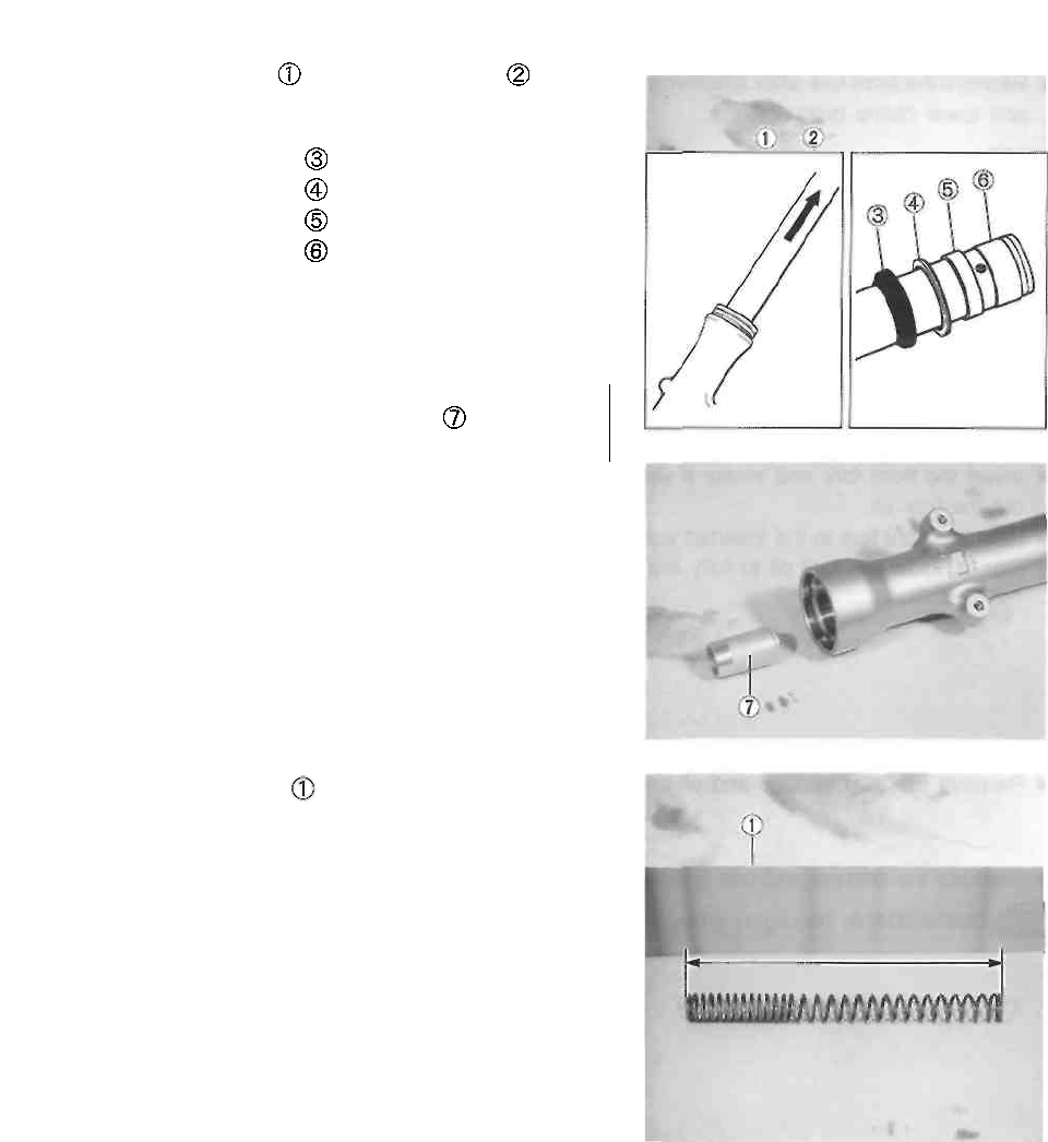
5-17 CHASSIS
• Remove the damper rod and rebound spring from
the inner tube.
• Separate the inner tube from the outer tube.
• Remove the following parts.
Oil seal Washer
Outer tube slide metal
Inner tube slide metal
The removed oil seal and slide metals should be
replaced with new ones.
• Remove the oil lock piece from the
outer tube.
INSPECTION
DAMPER ROD RING
Inspect the damper rod ring for wear or damage. If it is
worn or damaged, replace it with a new one.
FRONT FORK SPRING
Measure the fork spring free length. If it is shorter than the
service limit, replace it with a new one.
Service Limit: 301 mm (11.9 in)
A CAUTION
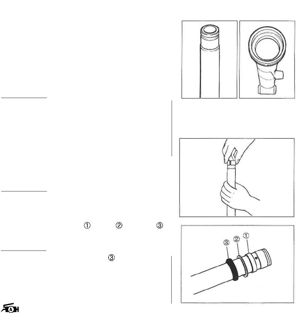
CHASSIS 5-18
INNER AND OUTER TUBES
Inspect the inner tube sliding surface and outer tube sliding
surface for scuffing.
REASSEMBLY AND REMOUNTING
Reassemble and remount the front fork in the reverse order
of removal and disassembly. Pay attention to the following
points:
I A CAUTION!
* Wash each metal part with cleaning solvent be-
fore reassembly.
* Never reuse fork oil left over from the last serv-
icing.
* Replace the oil seal and dust seal with new
ones during reassembly.
• Hold the inner tube vertically, clean the metal groove and
install the slide metal by hand.
I A CAUTION!
Do not damage the Teflon coated surface of the
inner tube's slide metal when mounting it.
• Install the outer tube metal , washer and oil seal
to the inner tube.
IA CAUTION]
* When installing the oil seal onto the inner
tube, protect their seal lips to prevent seal lip
damage.
* Before installing the oil seal, apply SUZUKI SU
PER GREASE "A" to its seal lip lightly.
99000-25010: SUZUKI SUPER GREASE "A"
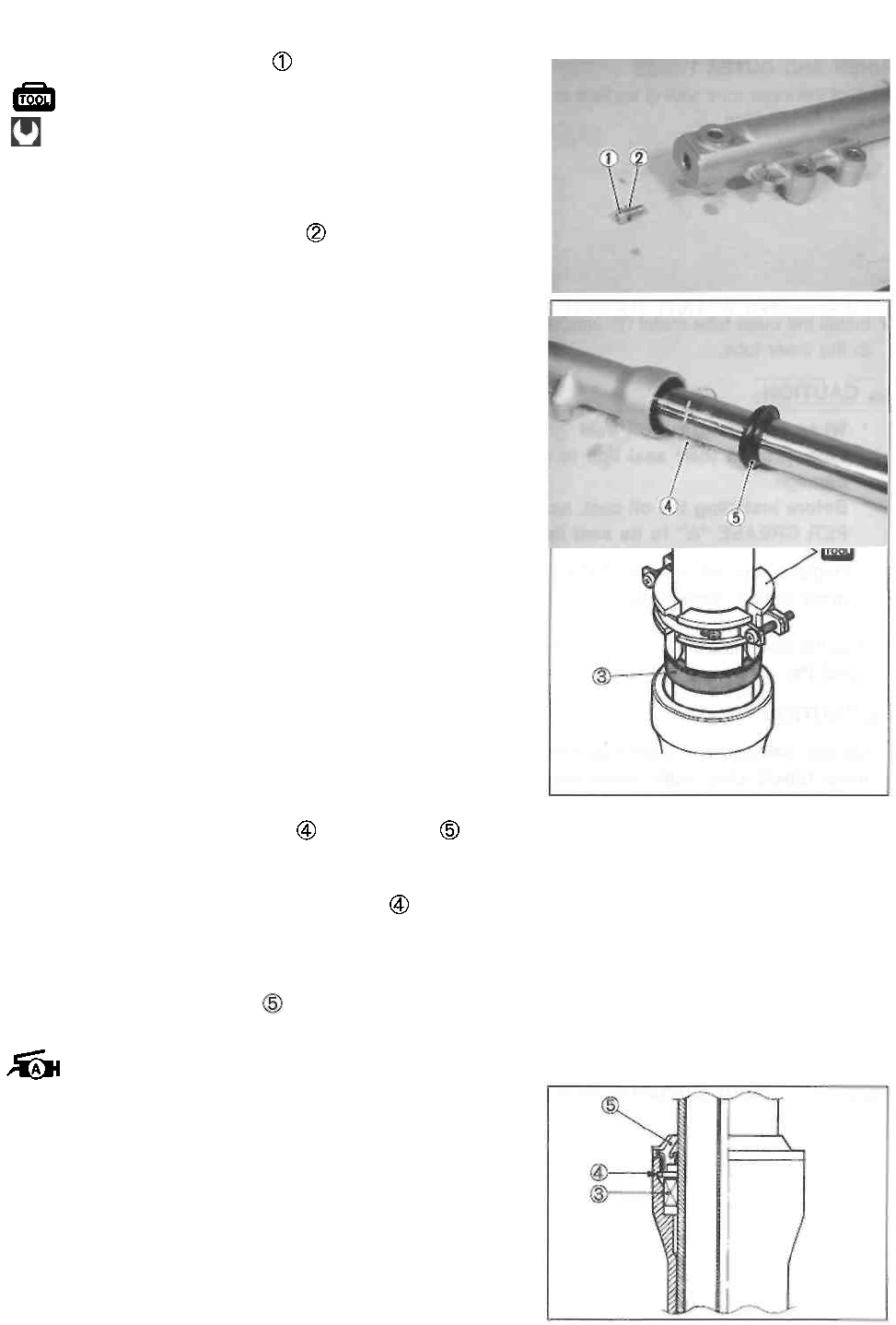
5-19 CHASSIS
• Tighten the damper rod bolt to the specified torque.
09900-00410: Hexagon wrench set
Front fork damper rod bolt: 20 N-m
(2.0 kg-m, 14.5 Ib-ft)
CAUTION
Use a new damper rod gasket to prevent oil
leakage.
• Install the oil seal stopper ring and dust seal
A CAUTION
Make sure that the oil seal stopper ring is fitted
securely.
NOTE:
Before installing the dust seal , apply a small quantity of
SUZUKI SUPER GREASE "A" to the lip of dust seal.
99000-25010: SUZUKI SUPER GREASE "A"
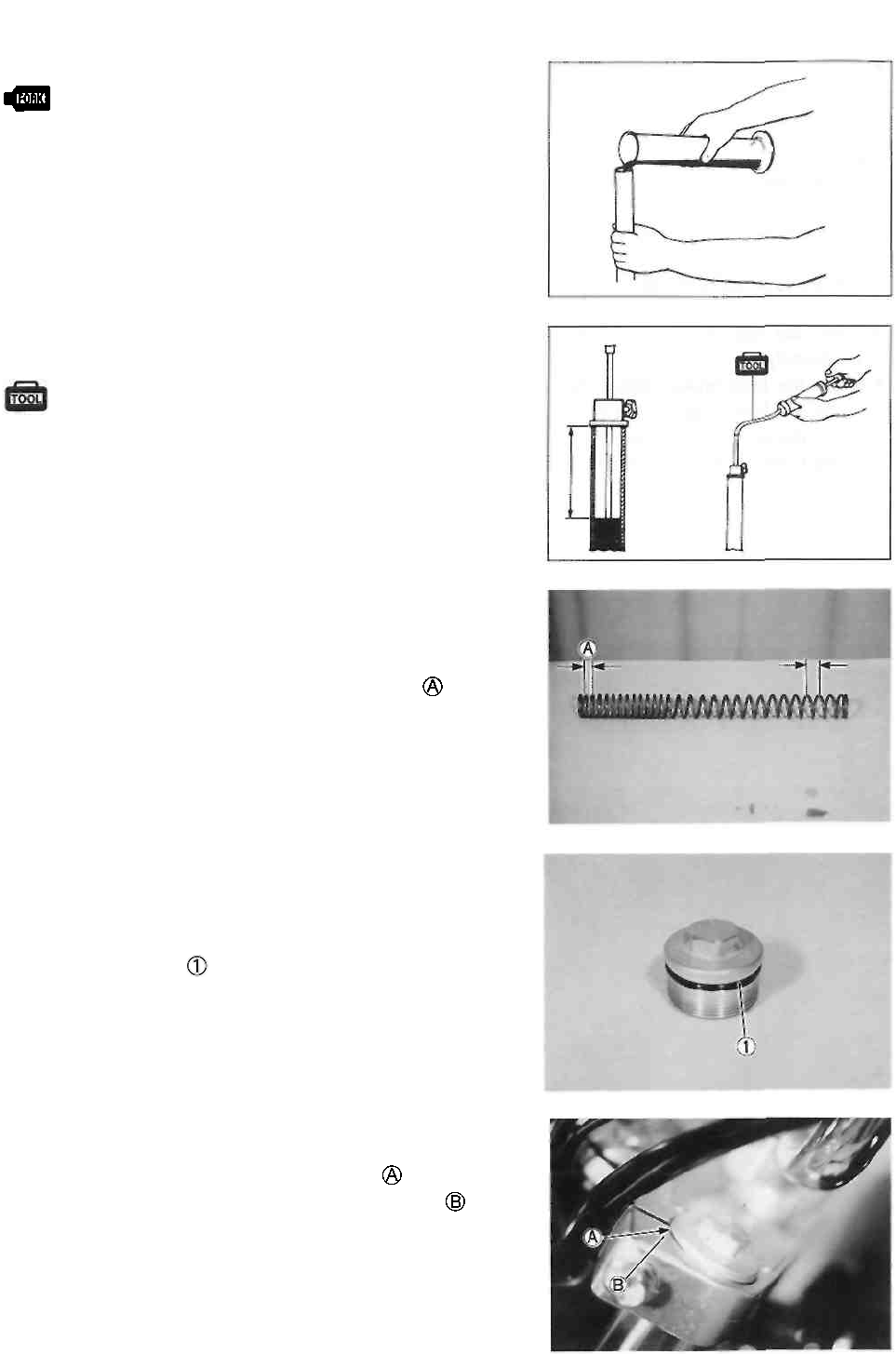
CHASSIS 5-20
• Pour the specified fork oil into the inner tube.
Fork oil type: SUZUKI FORK OIL SS-08 (#10)
99000-99001-SS8: SUZUKI FORK OIL SS-08
Specification
Front fork oil capacity (each leg):
369 ml (12.5/13.0 US/Imp oz)
• Hold the front fork leg in a vertical position and adjust the
fork oil level using the special tool.
09943-74111: Fork oil level gauge
Specification
Front fork oil level: 105 mm (4.1 in)
NOTE:
When adjusting the oil level, remove the fork spring and
compress the inner tube fully.
• Install the fork spring as shown.
NOTE:
The end of the fork spring with the smaller pitch should
be at the bottom of the front fork.
• Install the front fork cap bolt to the inner tube.
A CAUTION
Use a new O-ring to prevent oil leakage.
• Install the front fork to the motorcycle.
• Align the upper surface of the inner tube with the up-
per surface of the steering stem upper bracket
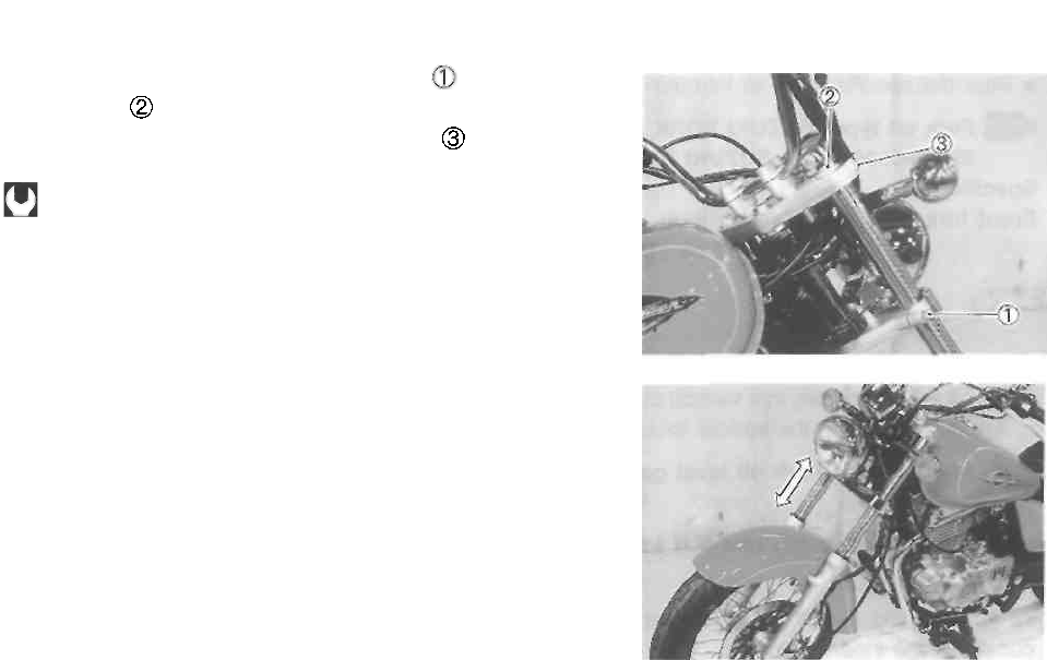
5-21 CHASSIS
• Tighten the front fork lower clamp bolts and front fork
cap bolts to the specified torque.
• Tighten the front fork upper clamp bolts to the speci-
fied torque.
Front fork upper clamp bolt: 23 N-m
(2.3 kg-m, 16.5 Ib-ft)
Front fork lower clamp bolt: 33 N • m
(3.3 kg-m, 24.0 Ib-ft)
Front fork cap bolt: 23 N-m (2.3 kg-m, 16.5 Ib-ft)
• Install the front fender and tighten the mounting bolts
temporarily.
• Install the front brake caliper. (See p. 5-10.)
• Install the front wheel. (See p. 5-8.)
• Move the front fork up and down several times.
• Tighten the front fender mounting bolts securely.
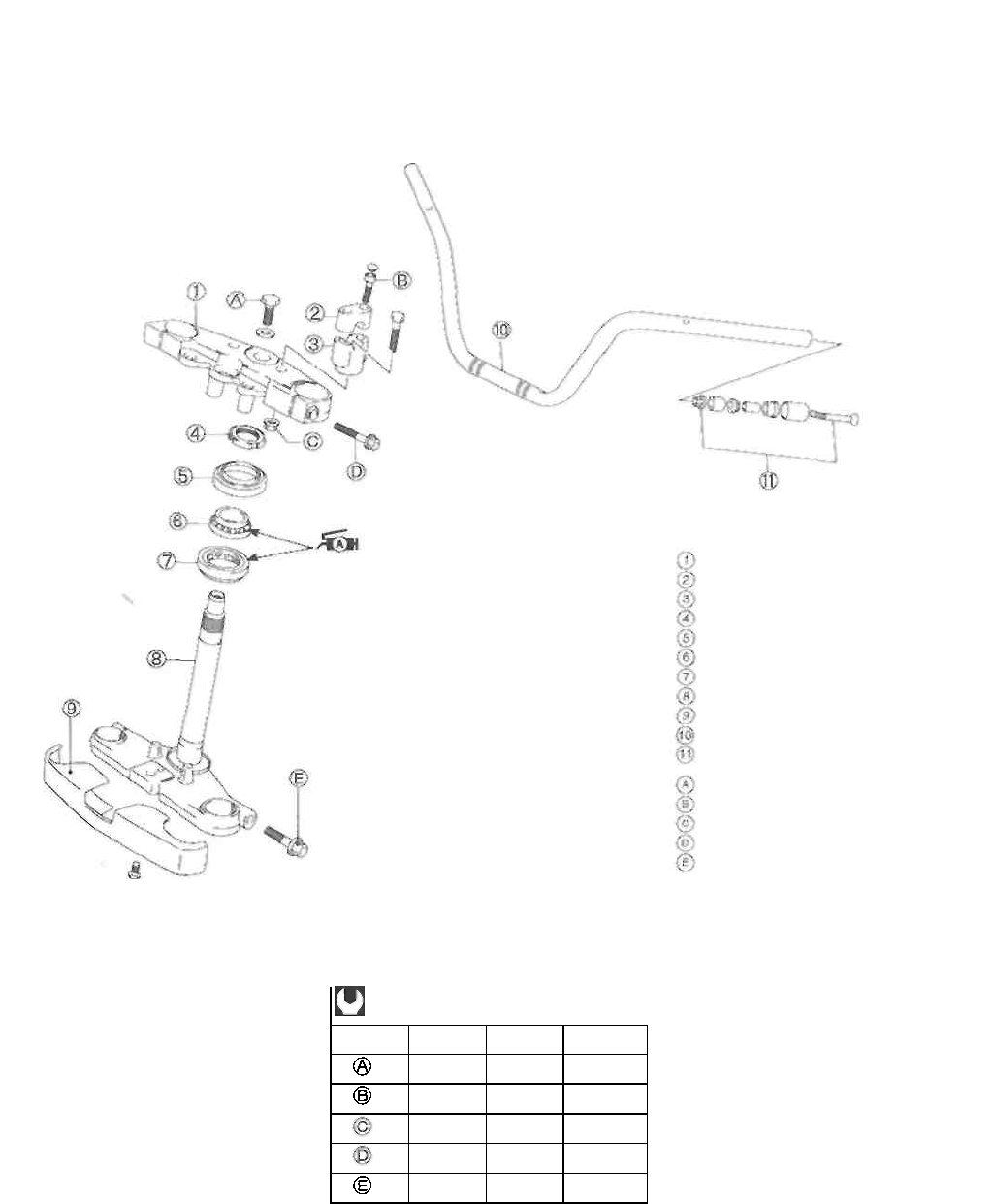
CHASSIS 5-22
STEERING
CONSTRUCTION
ITEM
N-m
kg-m
Ib-ft
65
6.5
47.0
16
1.6
11.5
45
4.5
32.5
23
2.3
16.5
33
3.3
24.0
Steering stem upper bracket
Handlebar clamp
Handlebar holder
Steering stem nut
Dust seal
Bearing, upper
Bearing, lower
Steering stem
Steering stem lower cover
Handlebars
Handlebar balancer
Steering stem head bolt
Handlebar clamp bolt
Handlebar holder nut Front
fork upper clamp bolt Front
fork lower clamp bolt
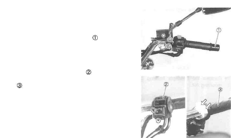
REMOVAL AND DISASSEMBLY
• Remove the front wheel. (See p. 5-4.)
• Remove the front fork. (See p. 5-15.)
• Disconnect the front brake light switch lead wires.
• Remove the front brake master cylinder.
• Remove the right handlebar balancer .
• Remove the handlebar right switch
• Disconnect the throttle cables and remove the throttle
grip .
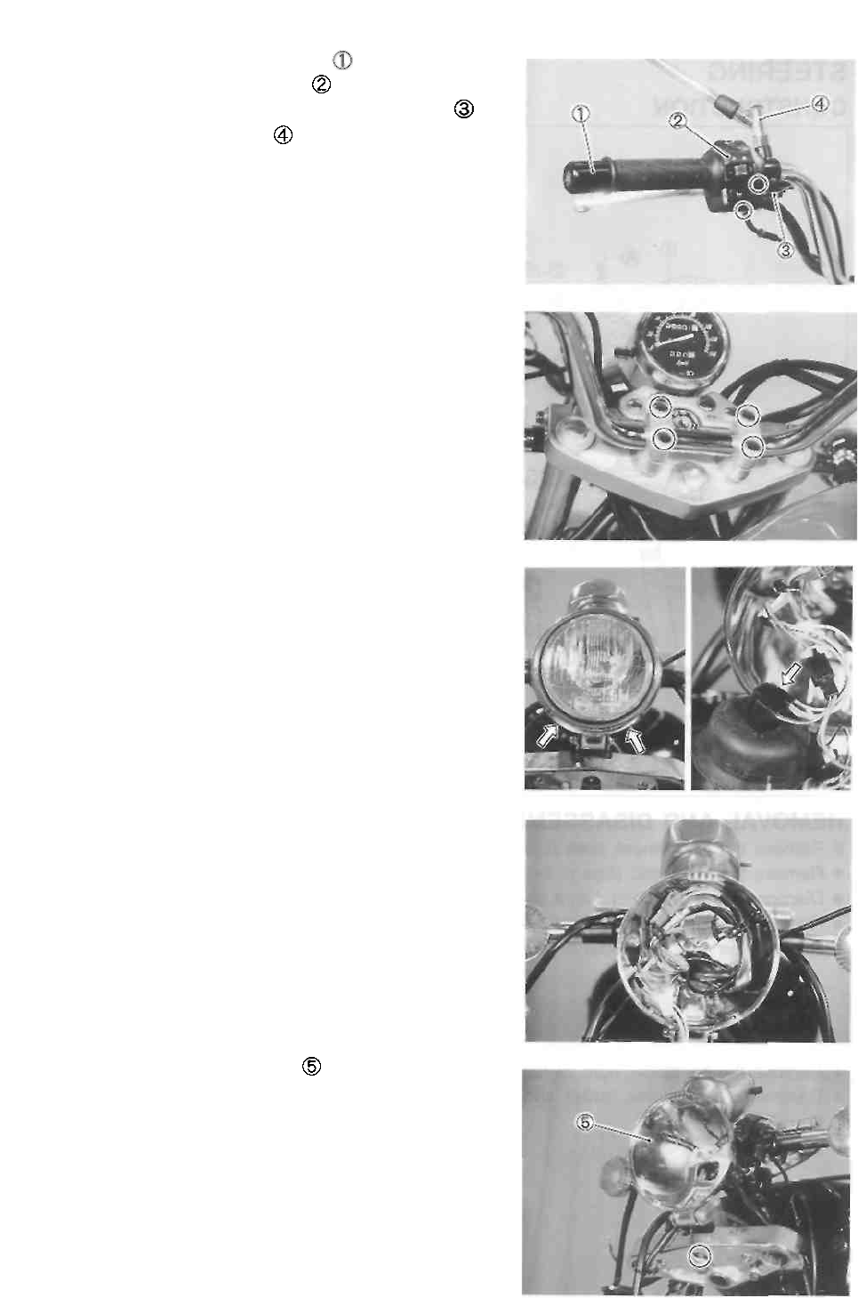
5-23 CHASSIS
• Remove the left handlebar balancer .
• Remove the handlebar left switch
• Disconnect the clutch lever position switch coupler
• Remove the rear view mirror
• Disconnect the clutch cable.
• Remove the handlebar clamp bolt caps.
• Remove the handlebars by removing the handlebar
clamp bolts.
• Remove the headlight.
• Disconnect the headlight coupler.
• Disconnect the lead wire couplers.
• Remove the headlight housing by removing the
mounting nut.
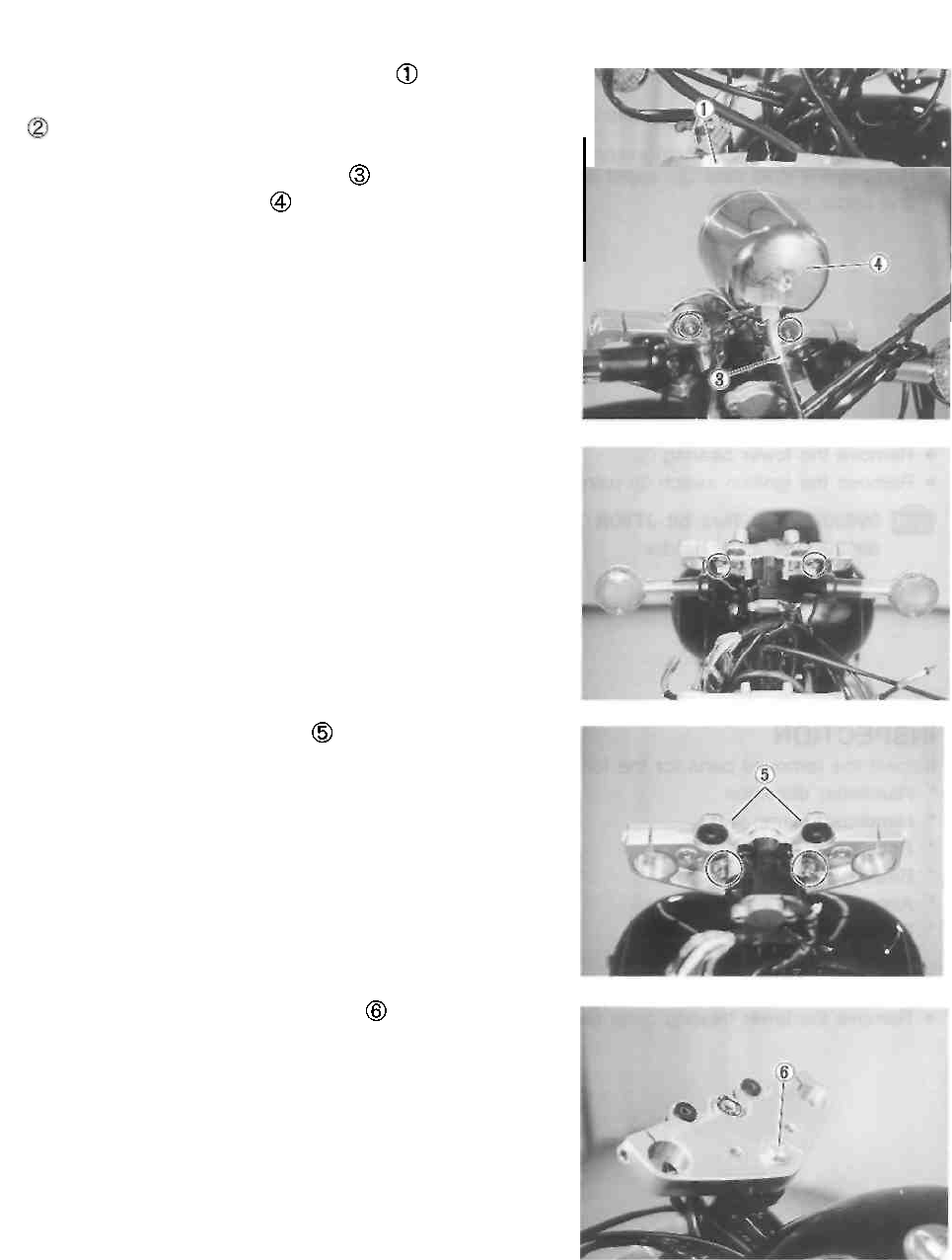
CHASSIS 5-24
• Remove the steering stem lower cover
• Remove the front brake hose/speedometer cable guide
• Disconnect the speedometer cable
• Remove the speedometer .
• Remove the front turn signal light brackets.
• Remove the handlebar holders
• Remove the steering stem head bolt
^5© - TJ«E
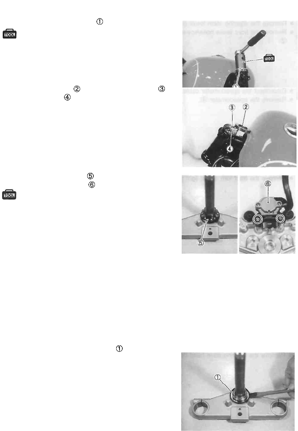
5-25 CHASSIS
• Remove the steering stem nut using the special tool.
09940-14911: Steering stem nut wrench
• Draw out the steering stem lower bracket.
NOTE:
Hold the steering stem lower bracket to prevent it from fal-
ling.
• Remove the dust seal , upper bearing inner race
and upper bearing
• Remove the lower bearing
• Remove the ignition switch using the special tool.
09930-11920: Torx bit JT40H
09930-11940: Bit holder
INSPECTION
Inspect the removed parts for the following abnormalities.
* Handlebar distortion
* Handlebar clamp wear
* Race wear and brinelling
* Bearing wear or damage
* Abnormal bearing noise
* Distortion of the steering stem
• Remove the lower bearing outer race using a chisel.
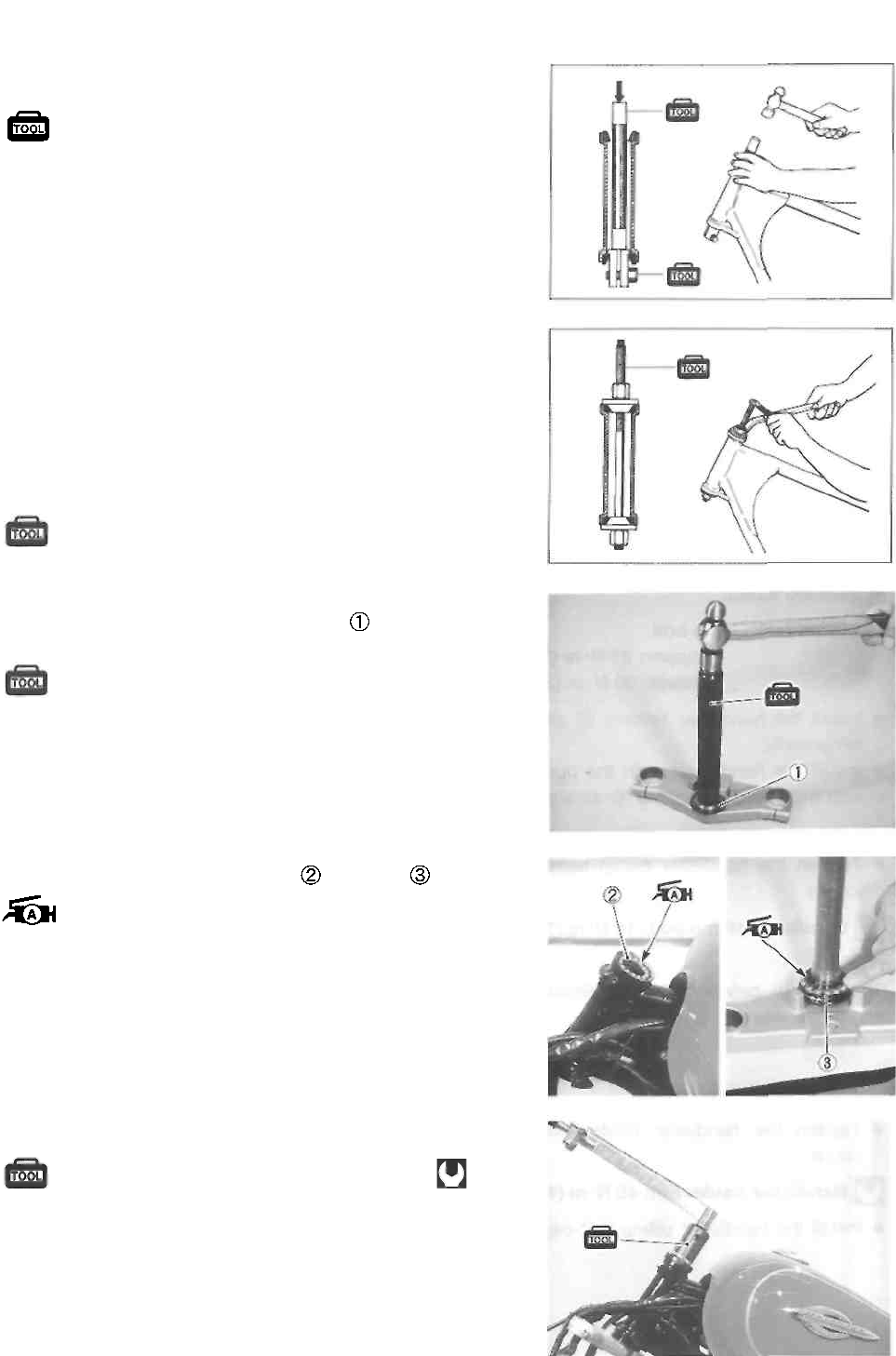
CHASSIS 5-26
• Drive out the steering stem upper and lower bearing
races using the special tool.
09941-54911: Bearing outer race remover
09941-74910: Steering bearing installer
REASSEMBLY AND REMOUNTING
Reassemble and remount the steering stem in the reverse
order of removal and disassembly. Pay attention to the fol-
lowing points:
• Press in the upper and lower outer races using the spe-
cial tool.
09941-34513: Steering race installer
• Press ¡n the steering stem lower race using the spe-
cial tool.
09941-74910: Steering bearing installer
• Apply grease to the upper and lower bearings.
99000-25010: SUZUKI SUPER GREASE "A"
• Tighten the steering stem nut using the special tool.
09940-14911: Steering stem nut wrench
Steering stem nut: 45 N ■ m (4.5 kg-m, 32.5 Ib-ft)
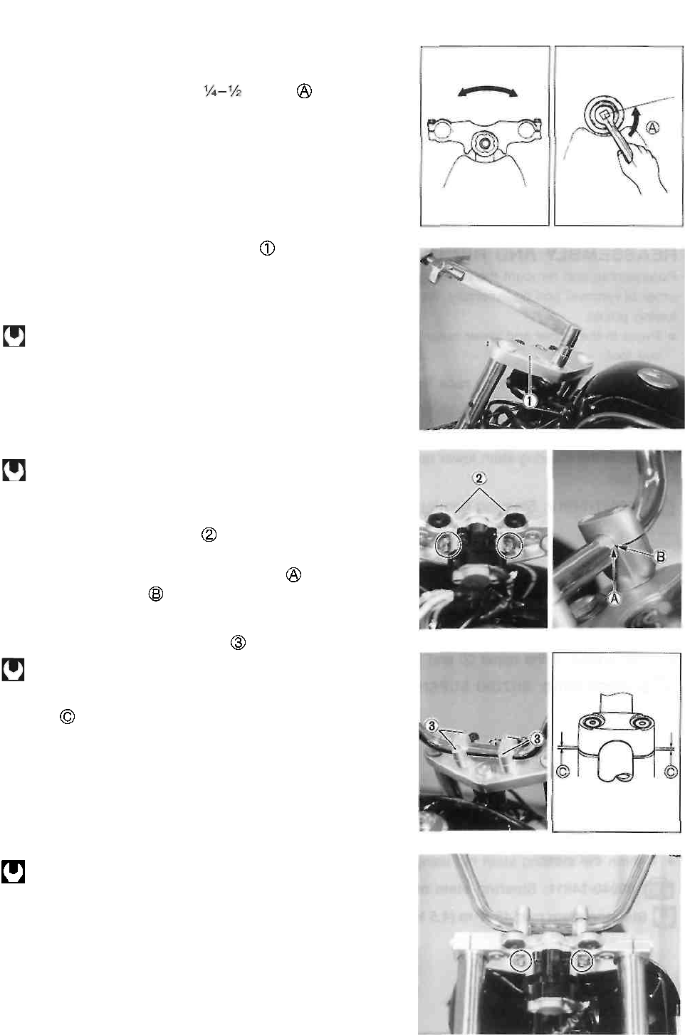
5-27 CHASSIS
• Turn the steering stem lower bracket about five or six times
to the left and right.
• Loosen the steering stem nut of a turn
NOTE:
This adjustment will vary from motorcycle to motorcycle. Make
sure that the steering turns smoothly and easily in both
directions.
• Install the steering stem upper bracket
• Install the right and left front forks.
• Tighten the front fork lower clamp bolts.
• Tighten the steering stem head bolt to the specified torque.
Steering stem head bolt: 65 N ■ m (6.5 kg-m, 47.0 Ib-ft)
• Align the upper surface of the front fork inner tube with the
upper surface of the steering stem upper bracket.
• Tighten the upper and lower front fork clamp bolts to the
specified torque.
_ Front fork clamp bolt
upper: 23 N-m (2.3 kg-m, 16.5 Ib-ft)
lower: 33 N-m (3.3 kg-m, 24.0 Ib-ft)
• Install the handlebar holders and tighten their nuts
temporarily.
• Install the handlebars with the punch mark aligned with
the handlebar clamp as shown.
• Tighten the handlebar clamp bolts to the specified torque.
Handlebar clamp bolt: 16 N-m (1.6 kg-m, 11.5 Ib-ft)
NOTE:
The gap between the handlebar clamp and holder
should be even.
• Tighten the handlebar holder nuts to the specified torque.
Handlebar holder nut: 45 N-m (4.5 kg-m, 32.5 Ib-ft)
• Install the handlebar clamp bolt caps.
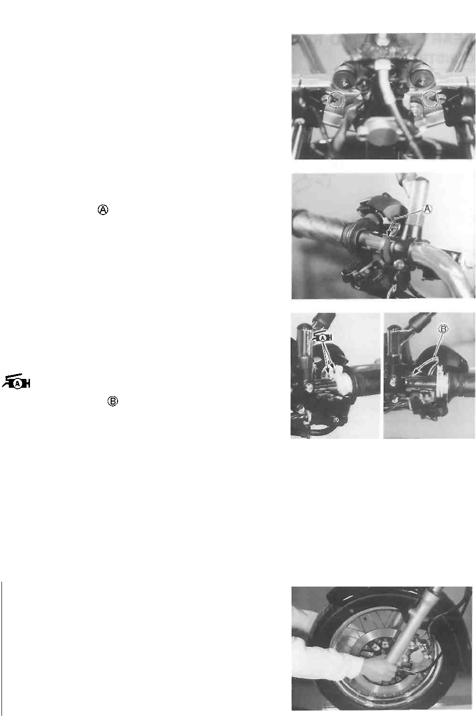
CHASSIS 5-28
NOTE:
When installing the front turn signal lights, insert the projec-
tion on the turn signal light bracket into the hole of steering
stem upper bracket.
• Install the handlebar left switch.
NOTE:
Insert the projection into the hole of the handlebars.
* Install the handlebar right switch.
NOTE:
* Apply SUZUKI SUPER GREASE "A" to the end of the
throttle cable.
99000-25010: SUZUKI SUPER GREASE "A"
* Insert the projection into the hole of the handlebars.
• Install the master cylinder. (See p. 5-13.)
• Install the front brake caliper. (See p. 5-10.)
• Install the front fender and front wheel. (See pp. 5-6 and
-21.)
NOTE:
Hold the front fork legs, move them back and forth and
make sure that the steering is not loose.
A CAUTION
After performing the adjustment and installing the
handlebars, "rock" the front wheel assembly for-
ward and backward to ensure that there is no play
and that the procedure was accomplished correct-
ly. Finally, check to make sure that the steering
stem moves freely from left to right with its own
weight. If play or stiffeness is noticeable, re-adjust
the steering stem nut.
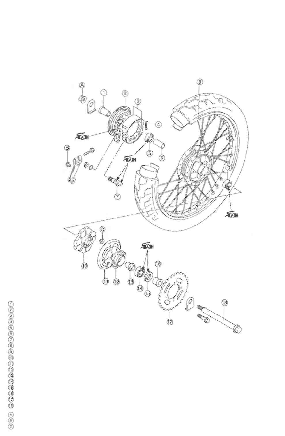
5-29 CHASSIS
REAR WHEEL AND REAR BRAKE
CONSTRUCTION
Spacer
Brake panel
Brake shoe
Spring
Bearing
Spacer
Brake camshaft
Rear wheel
Bearing
Damper
Drive chain guide
Rear sprocket mounting drum
Retainer
Bearing
Dust seal
Spacer
Rear sprocket
Rear axle
Rear axle nut
Rear brake cam lever nut
Rear sprocket mounting nut
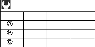
ITEM
N-m
kg-m
kg-m
78
7.8
56.5
10
1.0
7.0
50
5.0
36.0
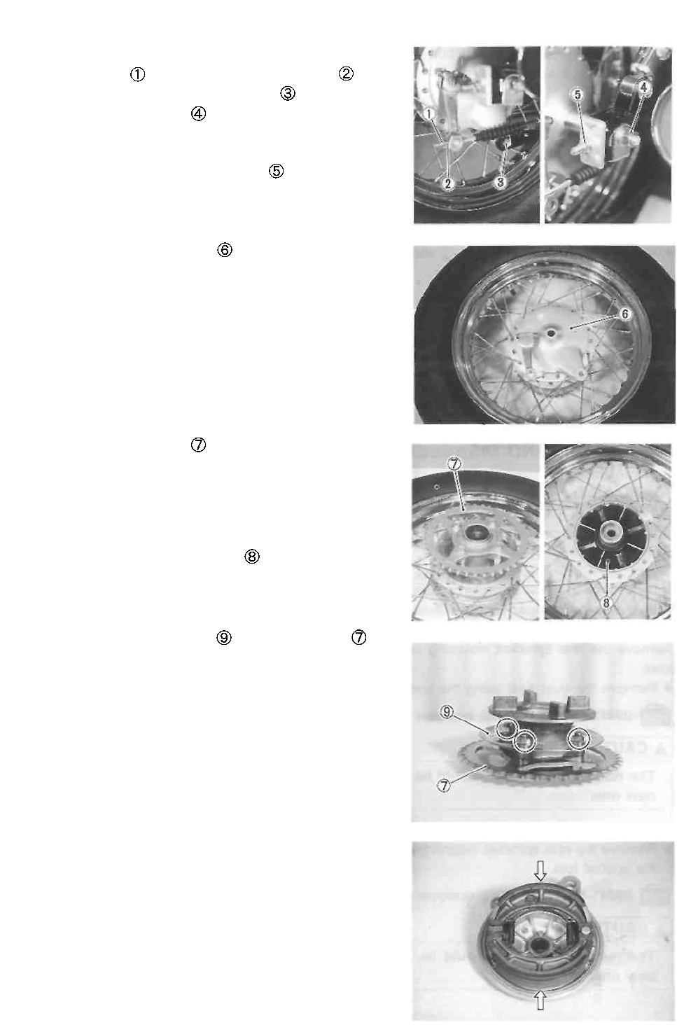
CHASSIS 5-30
REMOVAL
• Remove the clip and rear brake adjusting nut
• Remove the cotter pin, torque link nut and bolt.
• Remove the rear axle nut
• Raise the rear wheel off the ground with a jack or wood-
en block.
• Loosen the drive chain adjusting nuts , left and right.
• Remove the rear axle.
• Disengage the drive chain from the rear sprocket.
• Remove the rear wheel.
• Remove the rear brake panel
• Remove the rear sprocket with mounting drum from
the rear wheel.
NOTE:
Before separating the rear sprocket and mounting drum,
slightly loosen the rear sprocket bolts.
• Remove the rear sprocket damper
• Remove the drive chain guide and rear sprocket
from the rear sprocket mounting drum.
• Remove the brake shoes from the brake panel.
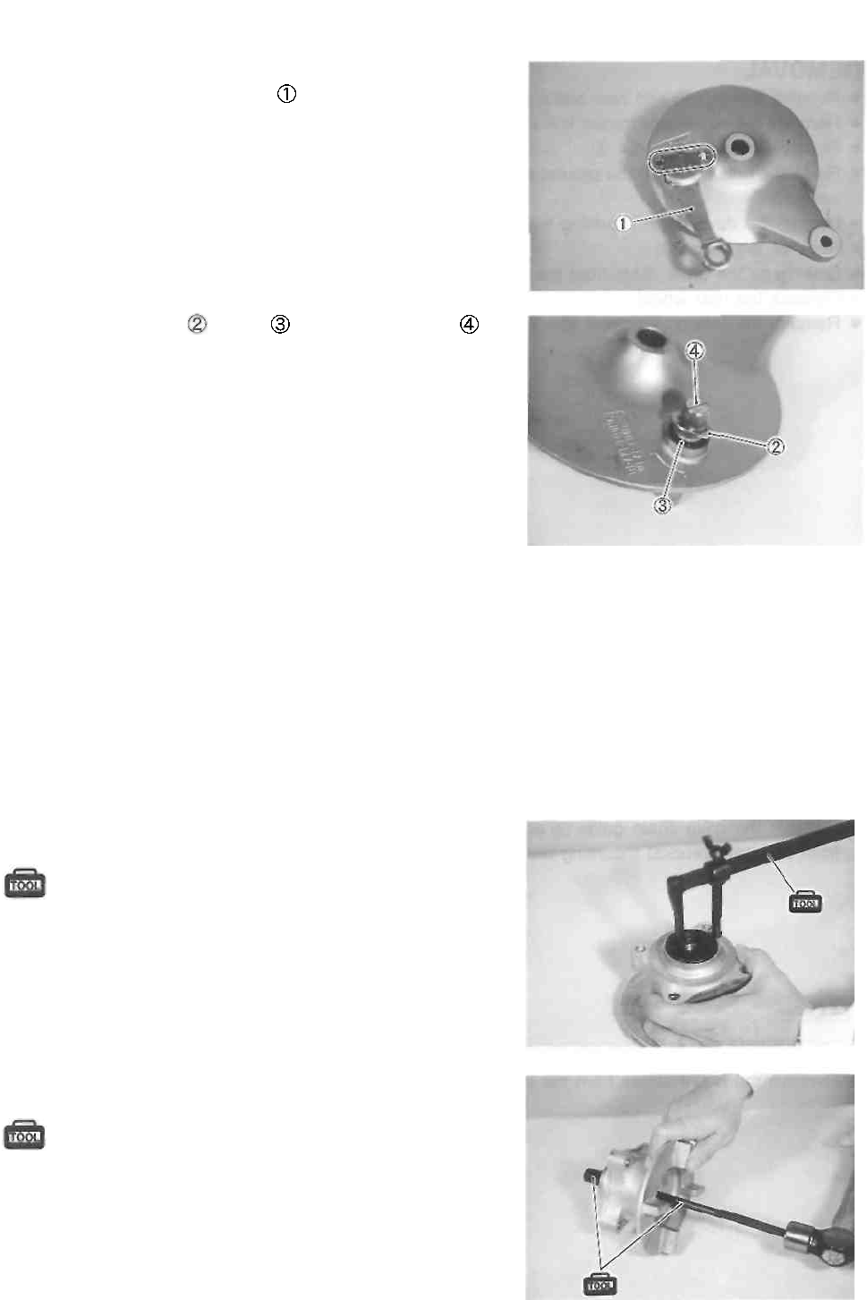
5-31 CHASSIS
• Remove the brake cam lever bolt and nut.
• Remove the brake cam lever
• Remove the washer , O-ring and brake camshaft
INSPECTION AND DISASSEMBLY
WHEEL BEARING ............................ See pp. 5-3 and -4.
WHEEL AXLE ............................................... See p. 5-4.
WHEEL ......................................................... See p. 5-4.
SPOKE NIPPLE .......................................... See p. 5-4.
REAR SPROCKET MOUNTING
DRUM BEARING ........................................ See p. 5-3.
* Inspect of the rear sprocket mounting drum bearing
in the same manner as the wheel bearing.
Remove the rear sprocket mounting drum bearing as fol-
lows. • Remove the dust seal using the special tool.
09913-50121: Oil seal remover
A CAUTION
The removed dust seal should be replaced with a
new one.
• Remove the rear sprocket mounting drum bearing using
the special tool.
09941-50111: Bearing remover
A CAUTION
The removed bearing should be replaced with a
new one.
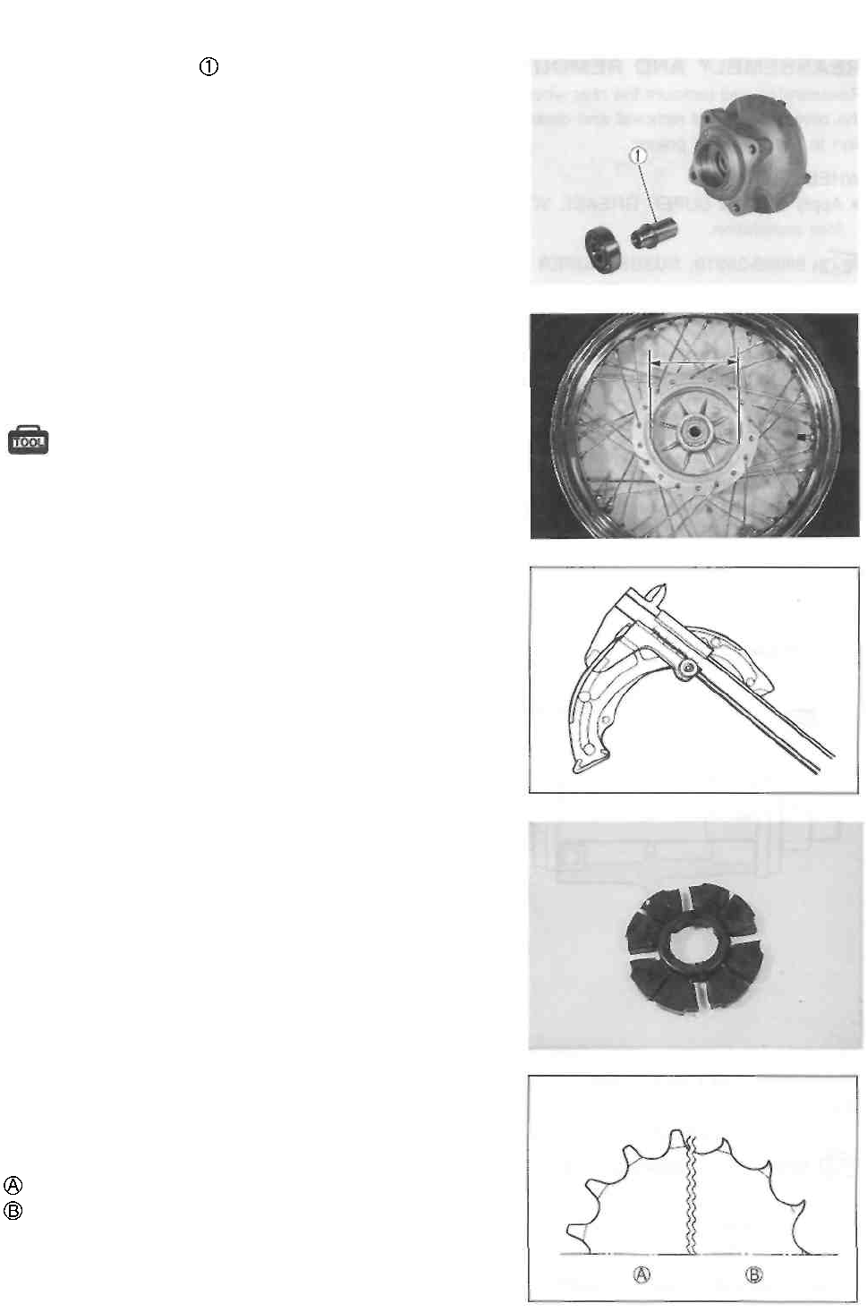
CHASSIS 5-32
• Remove the retainer
BRAKE DRUM
Inspect the brake drum and measure the brake drum I.D. to
determine the extent of wear. Replace the brake drum if the
measurement exceeds the service limit. The value of this
limit is indicated inside the brake drum.
09900-20101: Vernier
calipers Service Limit: 130.7 mm
(5.15 in)
BRAKE SHOES
Check the brake shoes and decide whether it should be
replaced or not from the thickness of the brake shoe lining.
Service Limit: 1.5 mm (0.06 in)
A CAUTION
Replace the brake shoes as a set, otherwise braking
performance will be adversely affected.
REAR SPROCKET DAMPER
Inspect the rear sprocket damper for wear and damage.
Replace the rear sprocket damper if there is anything un-
usual.
REAR SPROCKET
Inspect the sprocket's teeth for wear. If they are worn, re-
place the sprocket and drive chain as a set.
Normal wear
Excessive wear
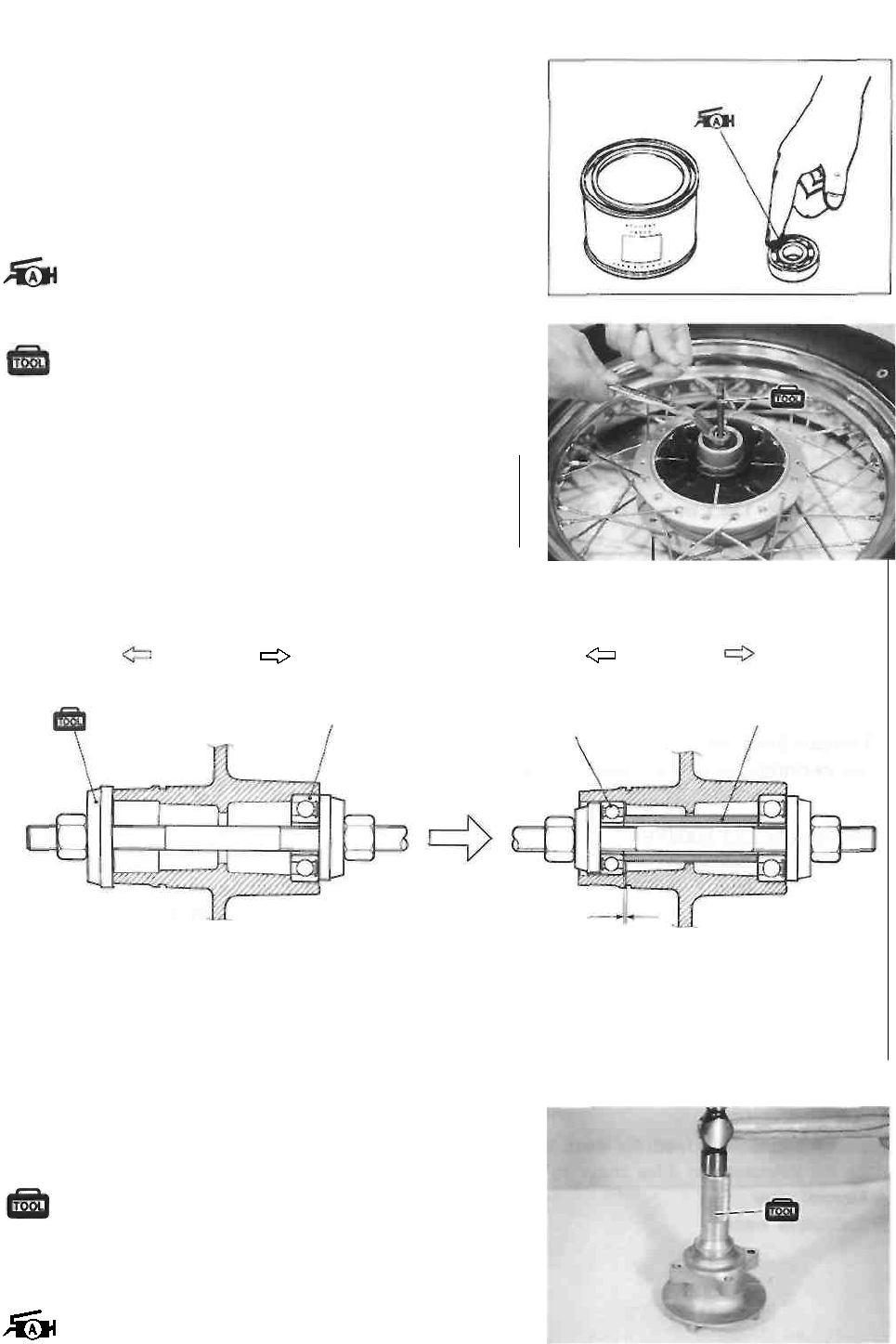
5-33 CHASSIS
REASSEMBLY AND REMOUNTING
Reassemble and remount the rear wheel and rear brake in
the reverse order of removal and disassembly. Pay atten-
tion to the following points:
WHEEL BEARING
• Apply SUZUKI SUPER GREASE "A" to the bearing be
fore installation.
99000-25010: SUZUKI SUPER GREASE "A"
• Press fit the bearing to the wheel using the special tools.
09924-84510: Bearing installer set
09924-84521: Bearing installer set
A CAUTION
* First install the right wheel bearing, then left
wheel bearing.
* The sealed cover on the bearing must face out.
Right side Right side
Right bearing Left bearing
Clearance
Spacer
REAR SPROCKET MOUNTING DRUM BEARING
• Install the rear sprocket mounting drum bearing and dust
seal using the special tool.
09913-76010: Bearing installer
NOTE:
Apply grease to the bearing and dust seal lip before as-
sembling the rear sprocket mounting drum.
99000-25010: SUZUKI SUPER GREASE "A"
Left side
Left side
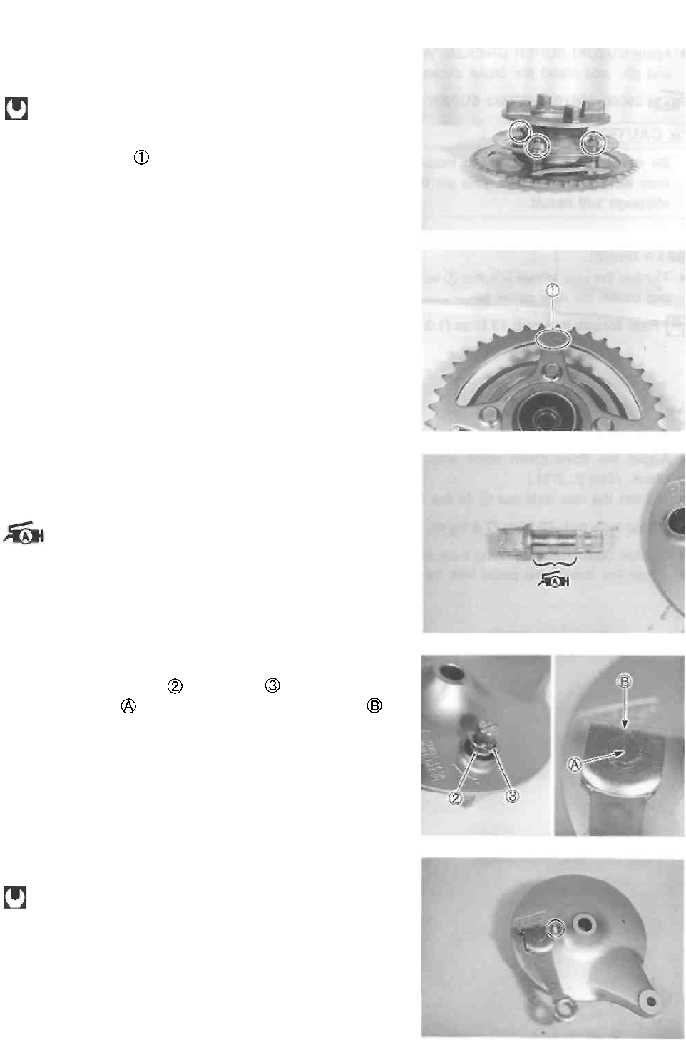
CHASSIS 5-34
REAR SPROCKET
• Tighten the rear sprocket nuts to the specified torque.
Rear sprocket nut: 50 N-m (5.0 kg-m, 36.0 Ib-ft)
NOTE:
The stamped mark on the rear sprocket should face to
the outside.
BRAKE CAMSHAFT
• When installing the brake camshaft, apply SUZUKI SU-
PER GREASE "A" to the camshaft.
99000-25010: SUZUKI SUPER GREASE "A"
BRAKE CAM LEVER
• Install the new O-ring and washer
• Align the notch on the brake camshaft with the slit
in the brake cam lever as shown.
• Tighten the brake cam lever nut to the specified torque.
Brake cam lever nut: 10 N-m (1.0 kg-m, 7.0 Ib-fl)
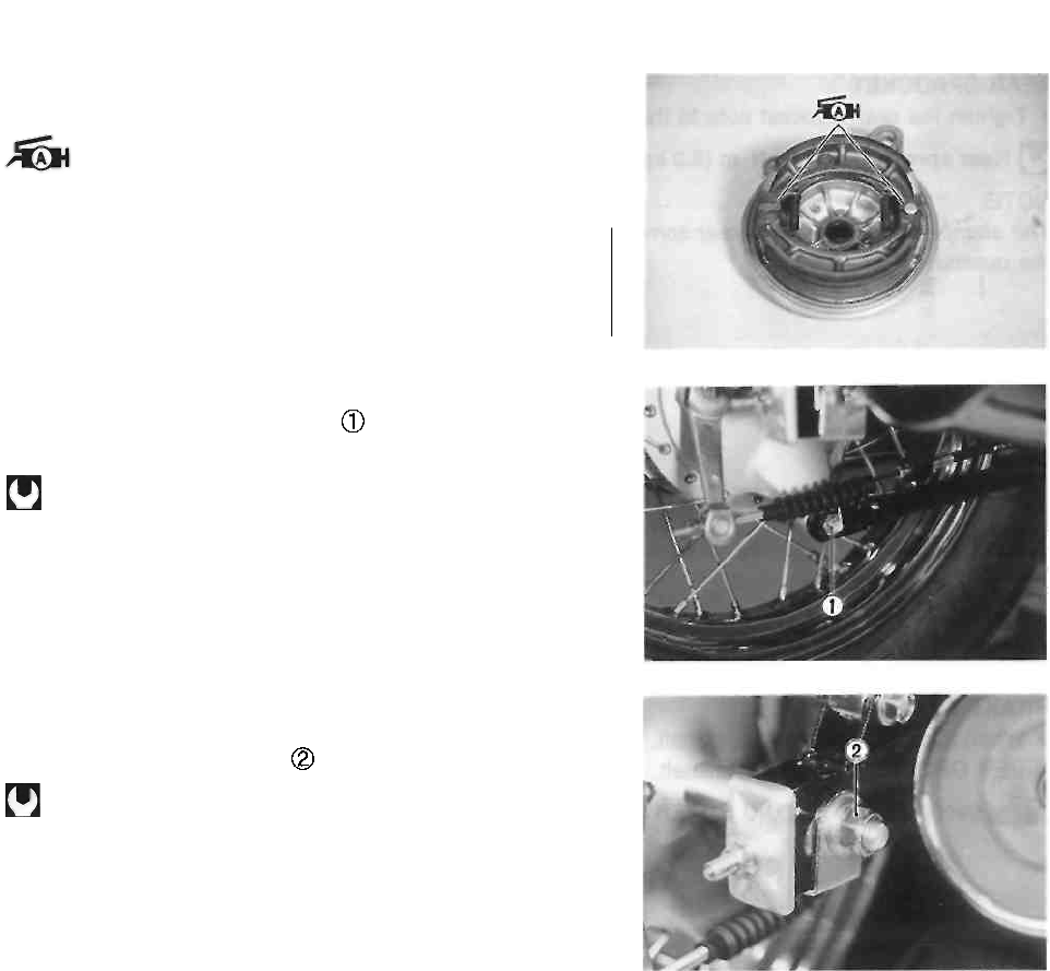
5-35 CHASSIS
• Apply SUZUKI SUPER GREASE "A" to the brake cam
and pin, and install the brake shoes.
99000-25010: SUZUKI SUPER GREASE "A"
A CAUTION
Be careful not to apply too much grease to the
cam and pin. If grease gets on the lining, brake
slippage will result.
REAR WHEEL
• Tighten the rear torque link nut to the specified torque
and install the new cotter pin.
Rear torque link nut: 13 N-m (1.3 kg-m, 9.5 Ib-ft)
• Adjust the drive chain slack after installing the rear
wheel. (See p. 2-11.)
• Tighten the rear axle nut to the specified torque.
Rear axle nut: 78 N-m (7.8 kg-m, 56.5 Ib-ft)
• Tighten both chain adjusting nuts securely.
• Adjust the rear brake pedal free travel. (See p. 2-14.)
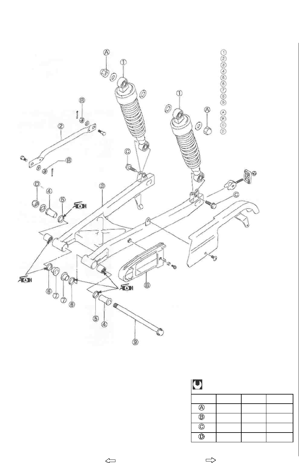
CHASSIS 5-36
REAR SUSPENSION
CONSTRUCTION
ITEM
N-m
kg-m
Ib-ft
29
2.9
21.0
13
1.3
9.5
29
2.9
21.0
72
7.2
52.0
Right side
Rear shock absorber
Rear torque link
Swingarm
Spacer
Dust seal
Dust seal
Spacer
Drive chain buffer
Swingarm pivot shaft
Rear shock absorber nut
Rear torque link nut Rear
shock absorber bolt
Swingarm pivot nut
Left side
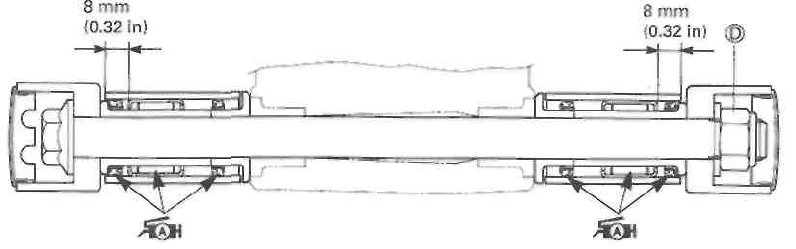
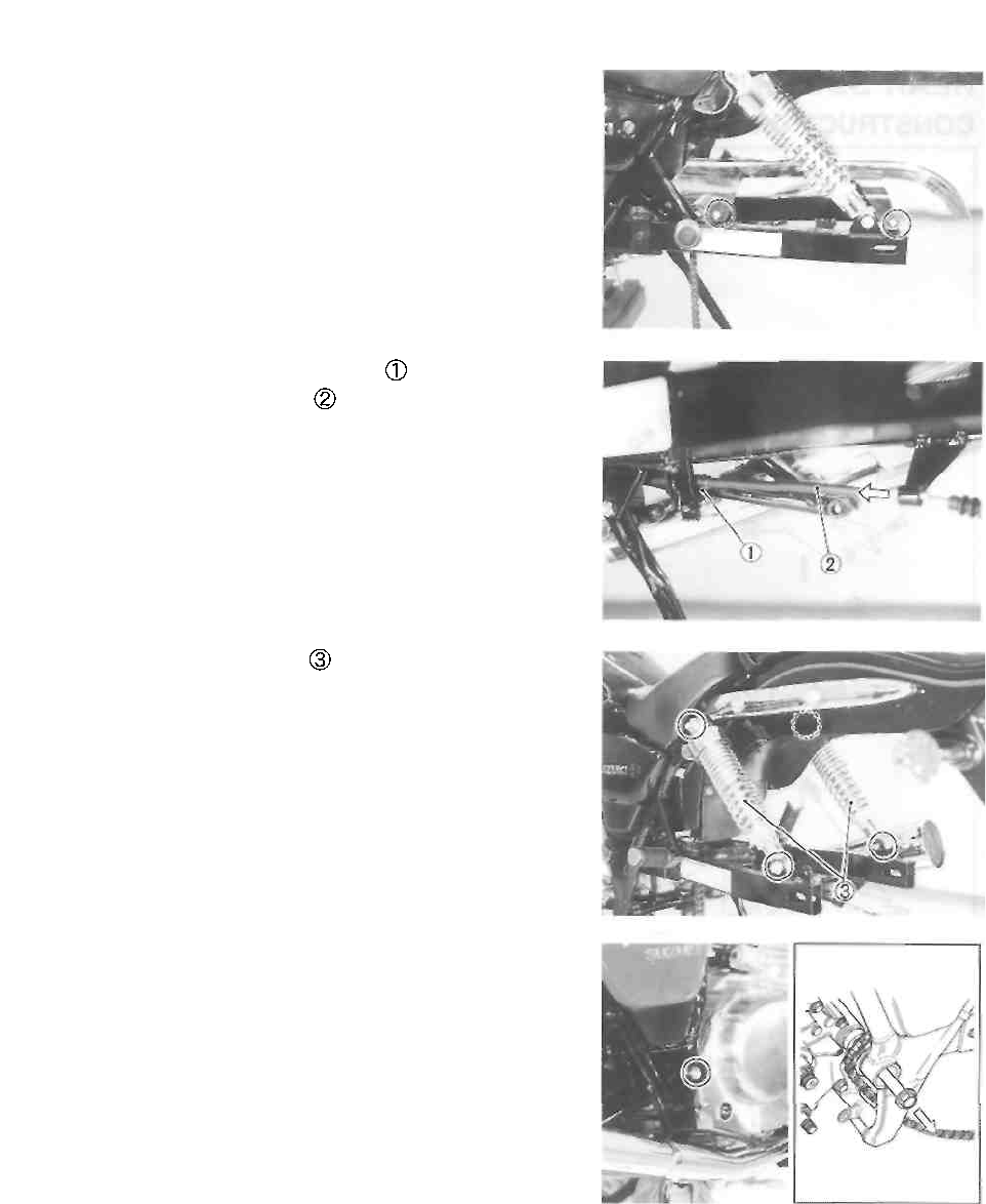
5-37 CHASSIS
REMOVAL
• Remove the rear wheel. (See p. 5-30.)
• Remove the drive chain case.
• Remove the rear brake cable holder
• Remove the rear brake cable from the swingarm.
• Remove the shock absorbers .
• Remove the swingarm pivot shaft end caps.
• Remove the swingarm pivot nut and washer.
• Remove the swingarm by removing the pivot shaft.
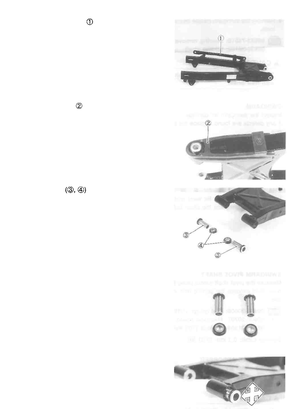
CHASSIS 5-38
• Remove the rear torque link from the swingarm.
• Remove the chain buffer from the swingarm.
• Remove the spacers
INSPECTION AND DISASSEMBLY
SWINGARM PIVOT SPACERS AND DUST SEALS
Inspect the swingarm pivot spacers and dust seals for
damage. If any defects are found, replace the spacer with a
new one.
SWINGARM NEEDLE BEARINGS
Insert the spacers into the needle bearings, move the
spacer up and down and check for any play. If there is
excessive play, replace the bearing(-s) with a new one.
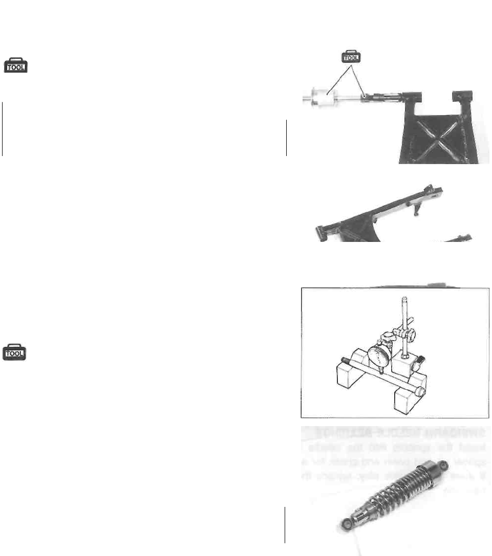
5-39 CHASSIS
• Remove the swingarm needle bearings using the special
tools.
09923-74510: Bearing remover
09930-30102: Sliding shaft
A CAUTION
The removed needle bearings should be replaced with new
ones.
SWINGARM
Inspect the swingarm for damage.
If any defects are found, replace the swingarm with a new
one.
CHAIN BUFFER
Inspect the chain buffer for wear and damage. If any defects
are found, replace the chain buffer with a new one.
SWINGARM PIVOT SHAFT
Measure the pivot shaft runout using the dial gauge. If the
pivot shaft exceeds the service limit, replace it with a new
one.
09900-20606: Dial gauge (1/100 mm) 09900-
20701: Magnetic stand 09900-21304: V-
block (100 mm)
Service Limit: 0.3 mm (0.01 in)
REAR SHOCK ABSORBER
Inspect the rear shock absorber for damage and oil leakage.
If any defects are found, replace the rear shock absorber with
a new one.
A CAUTION
Do not attempt to disassemble the rear shock absorber. It
is unserviceable.
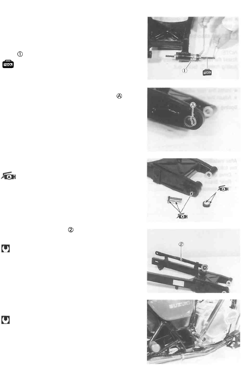
CHASSIS 5-40
REASSEMBLY AND REMOUNTING
Reassemble and remount the swingarm and rear shock
absorber in the reverse order of removal and disassembly.
Pay attention to the following points: • Press the needle
bearings into the swingarm pivot using a suitable
socket and the special tool. (See p. 5-36.)
09924-84521: Bearing installer set
NOTE:
Install the needle bearings with the stamped mark facing
out.
• Apply grease to the spacers, dust seals and needle
bearings.
99000-25010: SUZUKI SUPER GREASE "A"
• Install the rear torque link to the swingarm.
• Tighten the rear torque link nut to the specified torque.
Rear torque link nut: 13 N-m (1.3 kg-m, 9.5 Ib-ft)
• Install the new cotter pin.
• Install the swingarm and tighten the swingarm pivot nut
to the specified torque.
Swingarm pivot nut: 72 N■ m (7.2 kg-m, 52.0 Ib-ft)
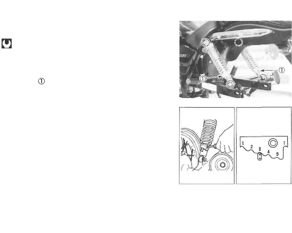
5-41 CHASSIS
• Install the rear shock absorber and tighten the mounting
bolts and nuts to the specified torque.
Shock absorber mounting bolt/nut: 29 N-m
(2.9kg-m,21.0lb-ft)
NOTE:
Install the rear shock absorbers with the spring tension ad-
justing holes facing out.
• Install the rear wheel and rear brake. (See p. 5-35.)
• Adjust the rear shock absorber spring pre-load.
Spring pre-load (STD): 3/5 position
After installing the rear suspension and rear wheel, adjust
the following before riding.
* Drive chain slack ...................................... See p. 2-11
* Rear brake pedal free travel .................... See p. 2-14
* Tire pressure ............................................ See p. 2-15

ELECTRICAL SYSTEM
----------------------------------------- CONTENTS ------------------------------------------
CAUTIONS IN SERVICING ................................................................. 6- 1
LOCATION OF ELECTRICAL COMPONENTS ................................. 6-3
CHARGING SYSTEM ....................................................................... 6-5
DESCRIPTION ................................................................................ 6- 5
TROUBLESHOOTING ..................................................................... 6- 6
INSPECTION ................................................................................... 6- 7
STARTER SYSTEM AND SIDE-STAND/IGNITION INTERLOCK
SYSTEM ............................................................................................. 6-10
STARTER SYSTEM DESCRIPTION ................................................ 6-10
SIDE-STAND/IGNITION INTERLOCK SYSTEM DESCRIPTION ... 6-10
TROUBLESHOOTING ....................................................................... 6-11
STARTER MOTOR REMOVAL AND DISASSEMBLY ...................... 6-12
STARTER MOTOR INSPECTION .................................................... 6-12
STARTER MOTOR REASSEMBLY .................................................. 6-13
STARTER RELAY INSPECTION ..................................................... 6-14
SIDE-STAND/IGNITION INTERLOCK SYSTEM PART
INSPECTION ................................................................................... 6-15
IGNITION SYSTEM ........................................................................... 6-18
DESCRIPTION ............................................................................... 6-18
TROUBLESHOOTING ..................................................................... 6-19
INSPECTION ................................................................................... 6-20
SPEEDOMETER ................................................................................. 6-24
REMOVAL AND DISASSEMBLY .................................................... 6-24
INSPECTION ................................................................................... 6-25
LAMPS ................................................................................................ 6-26
HEADLIGHT AND POSITION LIGHT .............................................. 6-26
BRAKE LIGHT/TAILLIGHT ............................................................. 6-27
TURN SIGNAL LIGHTS ................................................................. 6-28
RELAYS .............................................................................................. 6-29
STARTER RELAY ........................................................................... 6-29
TURN SIGNAL/SIDE-STAND RELAY ............................................... 6-29
SWITCHES ....................................................................................... 6-30
BATTERY ........................................................................................... 6-31
SPECIFICATIONS .......................................................................... 6-31
INITIAL CHARGING ........................................................................ 6-31
SERVICING ..................................................................................... 6-32
RECHARGING OPERATION ........................................................... 6-33
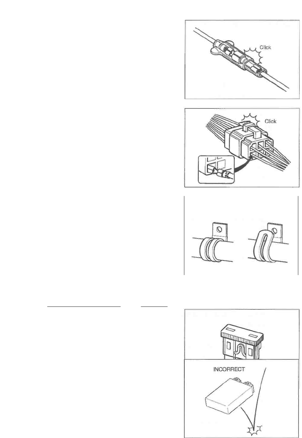
6-1 ELECTRICAL SYSTEM
CAUTIONS IN SERVICING
CONNECTORS
• When disconnecting a connector, be sure to hold the ter-
minals; do not pull the lead wires.
• When connecting a connector, push it in so it is firmly
attached.
• Inspect the connector for corrosion, contamination and
any breakage in the cover.
COUPLERS
• With a lock-type coupler, be sure to release the lock be-
fore disconnecting it. When connecting a connector,
push it in until the lock clicks shut.
• When disconnecting the coupler, be sure to hold the cou-
pler; do not pull the lead wires.
• Inspect each terminal on the coupler for looseness or
bends.
• Inspect each terminal for corrosion and contamination.
CLAMPS
• Refer to "WIRE, CABLE AND HOSE ROUTING" (See
pp. 7-11 to -18.) for proper clamping procedures.
• Bend the clamp properly, as shown in the illustration.
• When clamping the wire harness, do not allow it to hang
down.
• Do not use wire or any other substitute for the band-type
clamp.
CORRECT INCORRECT
FUSES
• When a fuse blows, always investigate the cause, cor-
rect the problem and then replace the fuse.
• Do not use a fuse of a different capacity.
• Do not use any substitute for the fuse (e.g., wire).
SEMI-CONDUCTOR EQUIPPED PARTS
• Do not drop any part that contains a semi-conductor
(e.g., ignitor unit, regulator/rectifier).
• When inspecting the part, follow the inspection instruc-
tions carefully. Neglecting proper procedures may cause
this part to be damaged.
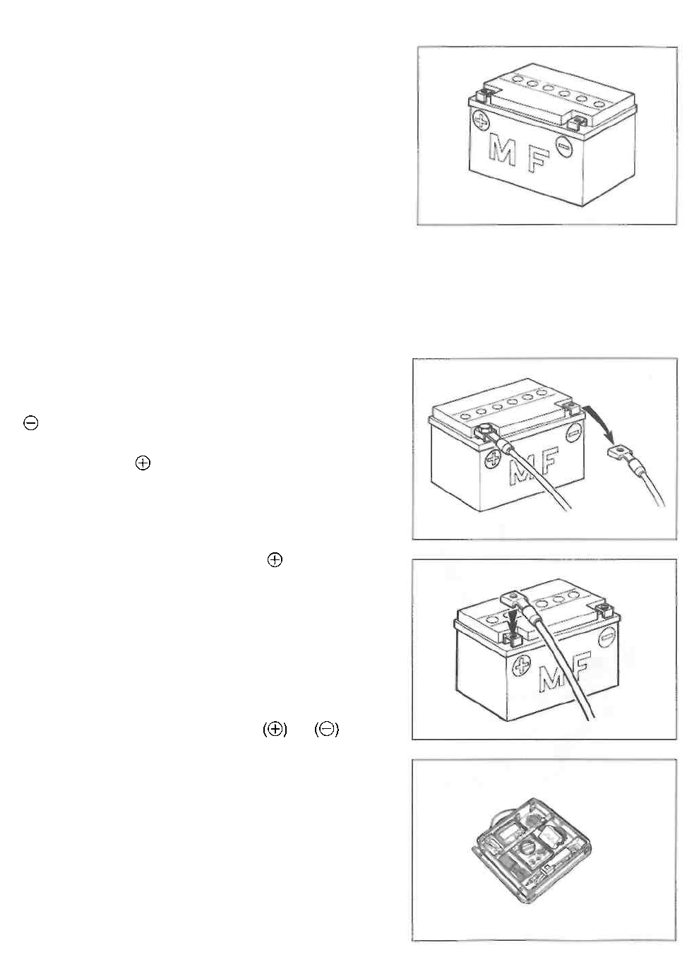
ELECTRICAL SYSTEM 6-2
BATTERY
• The MF battery used in this motorcycle does not require
maintenance (e.g., electrolyte level inspection, distilled
water replenishing).
• During normal charging, no hydrogen gas is produced.
However, if the battery is overcharged, hydrogen gas
may be produced. Therefore, be sure that there are no
fire or spark sources nearby (e.g., short-circuit) when
charging the battery.
• Be sure to recharge the battery in a well-ventilated and
open area.
• Note that the charging system for the MF battery is dif-
ferent from that of a conventional battery. Do not replace
the MF battery with a conventional battery.
CONNECTING THE BATTERY
• When disconnecting terminals from the battery for disas-
sembly or servicing, be sure to disconnect the battery
() lead wire, first.
• When connecting the battery lead wires, be sure to con-
nect the battery () lead wire, first.
• If the terminal is corroded, remove the battery, pour
warm water over it and clean it using a wire brush.
• After connecting the battery, apply a light coat of grease
to the battery terminals.
• Reinstall the cover over the battery () terminal.
WIRING PROCEDURE
• Properly route the wire harness according to "WIRE,
CABLE AND HOSE ROUTING". (See pp. 7-11 to -18.)
USING THE MULTI CIRCUIT TESTER
• Properly use the multi circuit tester and probes.
Improper use can cause damage to the motorcycle and
tester.
• If the voltage and current values are not known, begin
measuring in the highest range.
• When measuring the resistance, make sure that no volt-
age is applied. If voltage is applied, the tester will be
damaged.
• After using the tester, turn the switch to the OFF position.
CAUTION
Before using the multi circuit tester, read its
instruction manual.
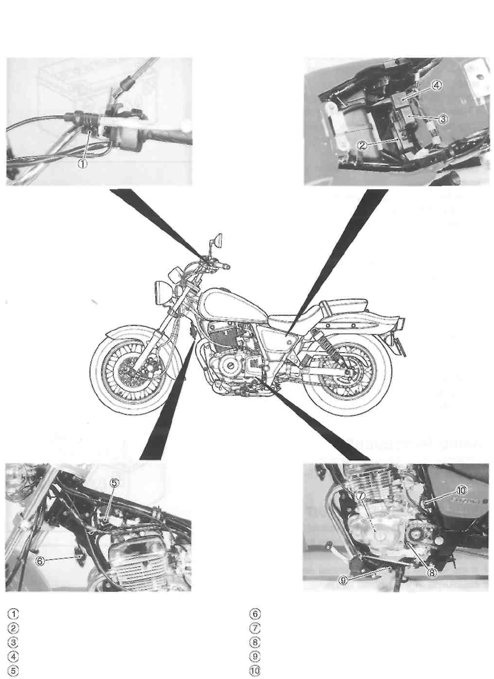
6-3 ELECTRICAL SYSTEM
LOCATION OF ELECTRICAL COMPONENTS
Clutch lever position switch
Ignitor
Turn signal/side-stand relay
Fuse box
Ignition coil
Horn
Generator
Neutral switch
Side-stand switch
Regulator/rectifier
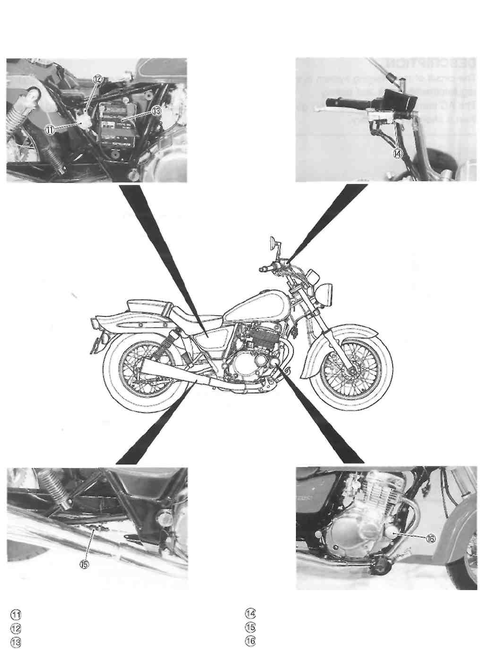
ELECTRICAL SYSTEM 6-4
Front brake light switch
Rear brake light switch
Starter motor
Starter relay
Main fuse
Battery
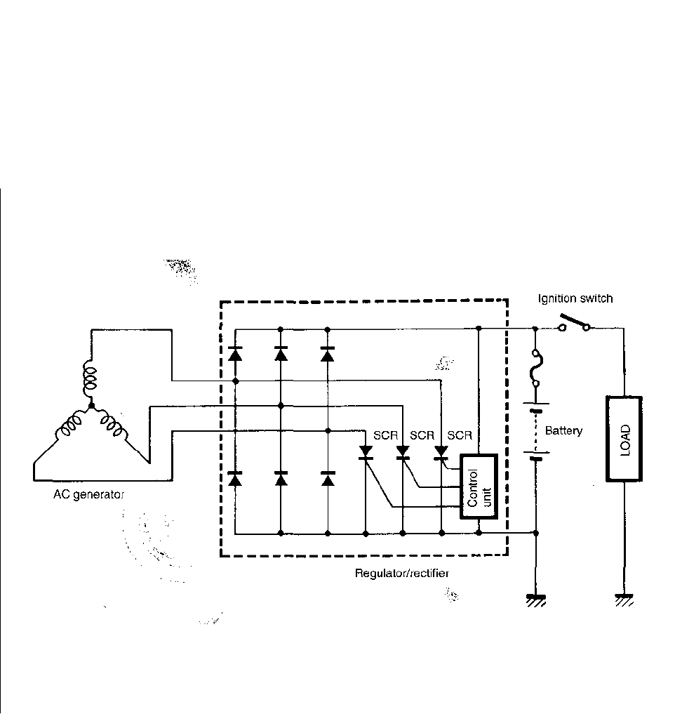
6-5 ELECTRICAL SYSTEM
CHARGING SYSTEM
DESCRIPTION
The circuit of the charging system is indicated in the figure, which is composed of an AC generator,
regulator/rectifier unit and battery.
The AC current generated from AC generator is converted by rectifier and is turned into DC current,
then it charges the battery.
ELECTRICAL SYSTEM 6-6
TROUBLESHOOTING
Battery runs down quickly.
Check accessories which use excessive
amounts of electricity.
Accessories
are installed • Remove accessories.
No accessories
Check the battery for current
leaks. (See p. 6-7.)
No current leaks
Measure the charging voltage
between the battery terminals.
(See p. 6-7.)
Correct
• Short circuit of the wire harness.
• Loose or disconnected wires.
• Faulty battery.
• Faulty battery.
• Abnormal driving condition.
Incorrect
Measure the continuity of the
stator coil. (See p. 6-8.)
No continuity • Faulty stator coils or
disconnected coupler.
Continuity
Inspect generator no-load
voltage. (See p. 6-8.)
No good
• Faulty generator rotor or
stator coil.
Inspect regulator/rectifier.
(See p. 6-9.) • Faulty regulator/rectifier.
Good
Inspect the wirings.
Good
-No good-
• Short circuit of wire harness.
• Poor contact of couplers.
• Faulty battery.
Others
Current leaks
Good
No good

Battery overcharges
• Faulty regulator/rectifier
• Faulty battery
• Poor contact of stator coil coupler
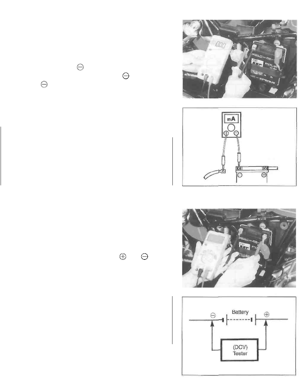
6-7 ELECTRICAL SYSTEM
INSPECTION
BATTERY LEAK CURRENT INSPECTION
• Remove the front seat and right frame cover. (See p.
5-1.)
• Turn the ignition switch to the OFF position.
• Disconnect the battery lead wire.
• Connect the tester between the battery terminal and
the battery lead wire.
NOTE:
Leakage is evident if the reading is over 1mA.
Battery current leak: Under 1mA
A CAUTION
* Because the current leak might be large, turn the
tester to the high range first to avoid tester
damage. * Do not turn the ignition switch to the "ON"
position when measuring the current.
When checking to find the excessive current leak, remove
the couplers and connectors, one by one, checking each
part.
CHARGING OUTPUT INSPECTION
• Remove the front seat and right frame cover. (See p.
5-1.)
• Start the engine, turn the lighting switch to ON and the
dimmer switch to HI, and run the engine at 5 000 r/min.
Measure the DC voltage between the and battery
terminals with a tester. If the tester reads under 13.5V or
over 15.0V, inspect the stator coil and regulator/rectifier.
A CAUTION
If the tester is set for current or resistance readings
and voltage is applied across the test probes,
damage will result. Therefore, it is important that the
tester knob on the tester be set to the proper
position before making any measurements.
NOTE:
When making this test, be sure that the battery is fully-
charged.
Charging output
Standard: 13.5-15.0V at 5 000 r/min.
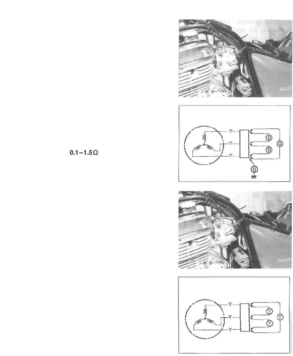
ELECTRICAL SYSTEM 6-8
STATOR COIL RESISTANCE
• Remove the front seat. (See p. 5-1.)
• Remove the fuel tank. (See p. 4-1.)
• Disconnect the stator coil coupler.
Measure the resistance between the three lead wires using
a tester.
Also check that the stator core is insulated.
If the resistance is incorrect, replace the stator coil with a
new one.
Stator coil resistance:
GENERATOR NO-LOAD PERFORMANCE INSPECTION
• Remove the front seat. (See p. 5-1.)
• Remove the fuel tank. (See p. 4-1.)
• Disconnect the stator coil coupler.
• Start the engine and keep it running at 5 000 r/min.
Measure the voltage between the three lead wires using a
tester.
If the tester reads under the specified value, replace the
stator coil and pick-up coil, or the generator rotor with a
new one.
Generator no-load performance:
More than 60V (AC) at 5 000 r/min
(When engine is cold)
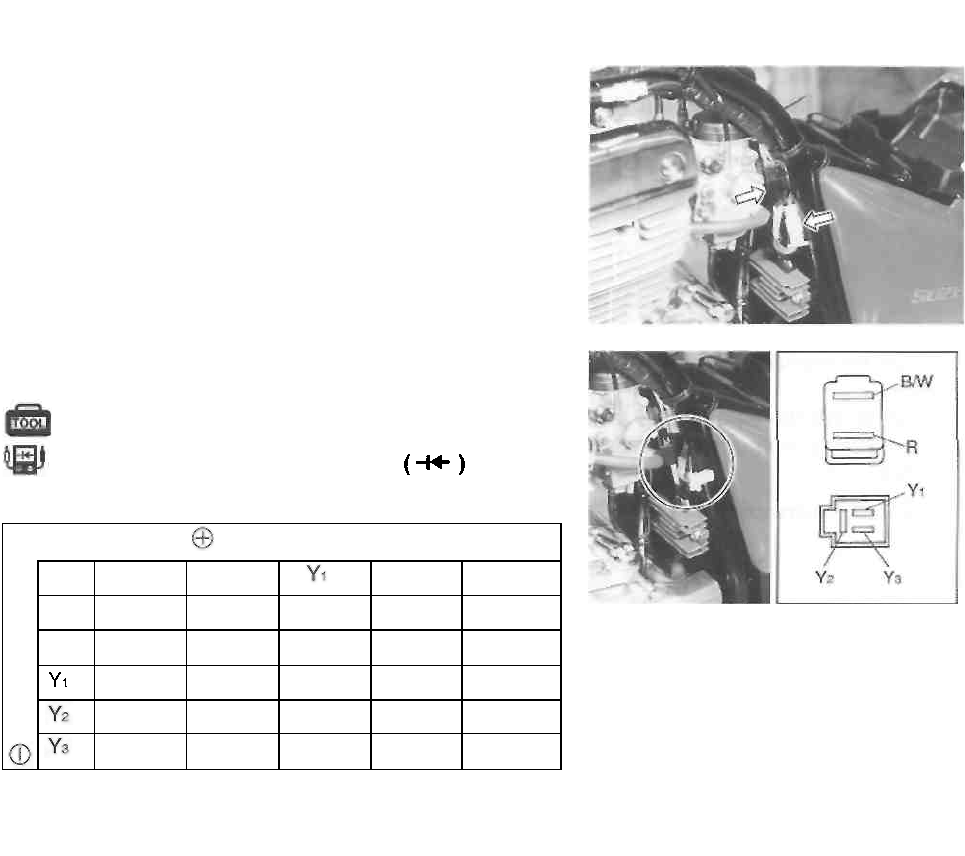
6-9 ELECTRICAL SYSTEM
REGULATOR/RECTIFIER
• Remove the front seat. (See p. 5-1.)
• Remove the fuel tank. (See p. 4-1.)
• Disconnect the regulator/rectifier couplers.
Measure the voltage between the lead wires in the follow-
ing table.
09900-25008: Multi circuit tester set
Tester knob indication: Diode test
Unit: V
Probe of tester to:
Probe of tester to
R
B/W
Y2
Y3
R
0.5-1.0
0.3-0.7
0.3-0.7
0.3-0.7
B/W
1.2-1.5
1.2-1.5
1.2-1.5
1.2-1.5
1.2-1.5
0.3-0.7
1.2-1.5
1.2-1.5
1.2-1.5
0.3-0.7
1.2-1.5
1.2-1.5
1.2-1.5
0.3-0.7
1.2-1.5
1.2-1.5
WIRE COLOR
R: Red
Y: Yellow
B/W: Black with White tracer
NOTE:
If the tester lead under 1.4V, replace the battery of multi
circuit tester when do not connecting the tester probes.
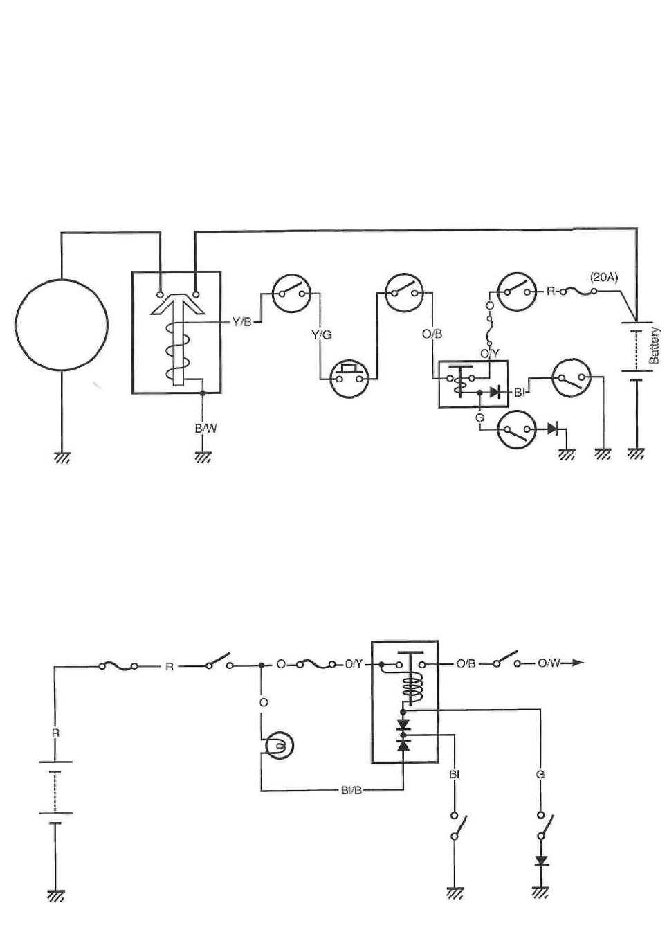
ELECTRICAL SYSTEM 6-10
STARTER SYSTEM AND SIDE-STAND/IGNITION INTERLOCK SYSTEM
STARTER SYSTEM DESCRIPTION
The starter system consists of the following components: the starter motor, starter relay, clutch lever
position switch, side-stand relay, side-stand switch, neutral switch, starter button, engine stop switch,
ignition switch and battery. Pressing the starter button (on the right handlebar switch) energizes the starter
relay, causing the contact points to close, thus completing the circuit from the starter motor to the battery.
The starter motor draws about 80 amperes to start the engine.
SIDE-STAND/IGNITION INTERLOCK SYSTEM DESCRIPTION
This side-stand/ignition interlock system prevents the motorcycle from being started with the side-
stand down. The system is operated by an electric circuit provided between the battery and ignition
coil.
Engine stop
switch
Ignition
switch
Clutch lever
position switch
Fuse
Starter
motor
Neutral
switch
Starter
relay
Starter
button
Side-stand
relay
Side-stand
switch
Engine stop
switch
Side-stand relay
Ignition switch
Fuse
To ignitor
and ignition
coil
Neutral
indicator
light
Battery
Side-stand
switch
Neutral
switch
WIRE COLOR
G : Green
R : Red
Bl : Blue
O : Orange
0/B : Orange with Black tracer
O/W: Orange with White tracer
O/Y : Orange with Yellow tracer
Bl/B: Blue with Black tracer
6-11 ELECTRICAL SYSTEM
TROUBLESHOOTING
Starter motor will not run.
The transmission is in neutral. Grasp
the clutch lever. Turn on the ignition
switch with the engine stop switch in
"RUN" position. Listen for a click from
the starter relay when the starter
button is pushed. Clicks
Check if the starter motor runs
when its terminal is connected to
the battery terminal. (Do not use
a thin "wire" because a large
amount of current flows.)
No click
Run Does not run
• Faulty starter motor
• Faulty starter relay
• Loosen or
disconnected starter motor lead
wire
Measure the starter relay voltage at
the starter relay connectors (be-
tween Y/B and B/W ) when the
starter button is pushed.
No voltage
• Faulty ignition switch
• Faulty engine stop switch
• Faulty clutch lever position switch
• Faulty neutral switch
• Faulty side-stand relay
• Faulty starter button
• Poor contact of connector
• Open circuit in wire harness
Check the starter relay.
(See pp. 6-14 and -15.) No good • Faulty starter relay
OK
• Poor contact of the starter relay
The starter motor runs when the transmission is in neutral, but does not run when the transmission is in
any position other than neutral, with the side-stand up.
Check the side-stand switch.
(See pp. 6-15 and -16.) No good • Faulty side-stand switch
OK
• Open circuit in wire harness
• Poor contact of connector
Others
Engine does not turn though the starter motor runs.
Voltage

• Faulty starter clutch
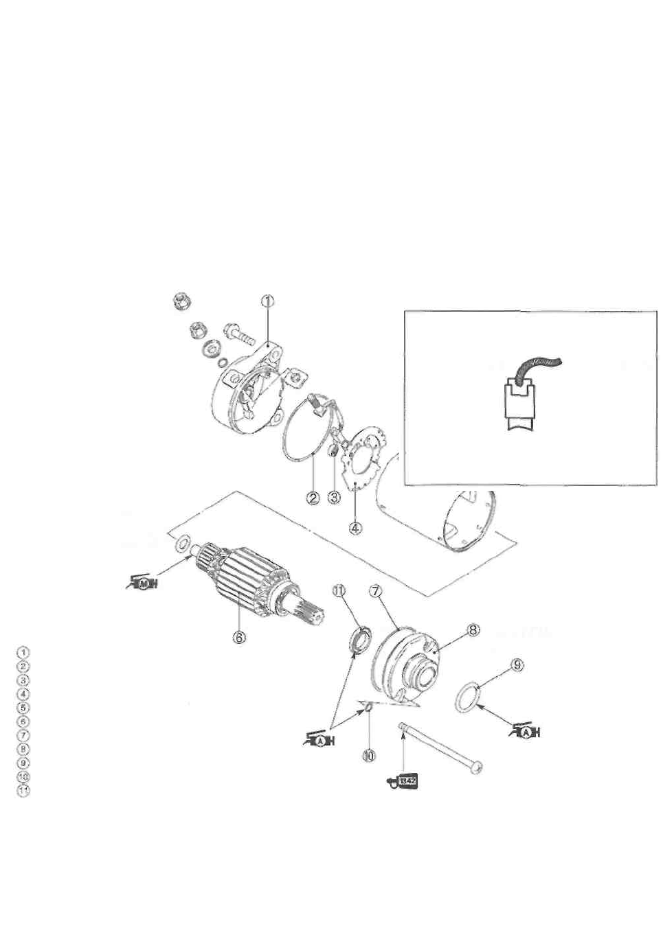
ELECTRICAL SYSTEM 6-12
STARTER MOTOR REMOVAL AND
DISASSEMBLY
• Disconnect the starter motor lead wire.
• Remove the starter motor.
• Disassemble the starter motor, as shown in the illustration.
STARTER MOTOR INSPECTION
CARBON BRUSH
Inspect the brushes for abnormal wear, crack or smooth-
ness in the brush holder.
If either carbon brush is defective, replace the brush as-
sembly.
Housing end (Outside)
O-ring
Brush spring
Brush holder
Starter motor case
Armature
O-ring
Housing end (Inside)
O-ring
O-ring (2 pcs)
Oil seal
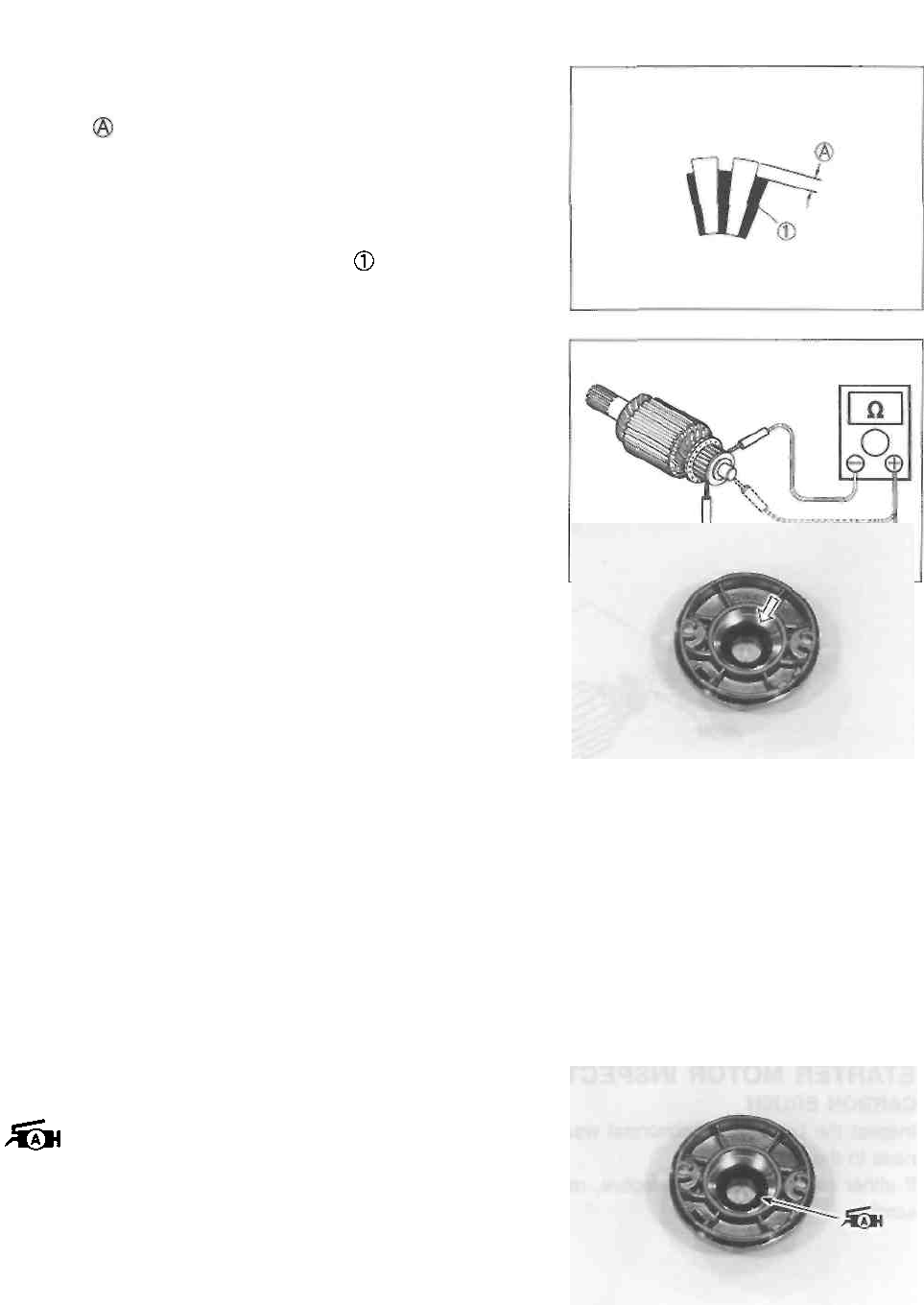
6-13 ELECTRICAL SYSTEM
COMMUTATOR
Inspect the commutator for discoloration, abnormal wear or
undercut
If the commutator is abnormally worn, replace the arma-
ture.
If the commutator surface is discolored, polish it with #400
sandpaper and wipe it using a clean, dry cloth. If there is
no undercut, scrape out the insulator with a saw blade.
ARMATURE COIL INSPECTION
Measure for continuity between each segment. Measure
for continuity between each segment and the armature
shaft.
If there is no continuity between the segments or there is
continuity between the segments and shaft, replace the ar-
mature with a new one.
OIL SEAL INSPECTION
Check the seal lip for damage or leakage.
If any damage is found, replace the housing end (inside).
STARTER MOTOR REASSEMBLY
Reassemble the starter motor in the reverse order of disas-
sembly. Pay attention to the following points:
A CAUTION
Replace the O-rings with new ones to prevent oil
leakage and moisture.
• Apply SUZUKI SUPER GREASE "A" to the lip of the oil
seal.
99000-25010: SUZUKI SUPER GREASE "A"
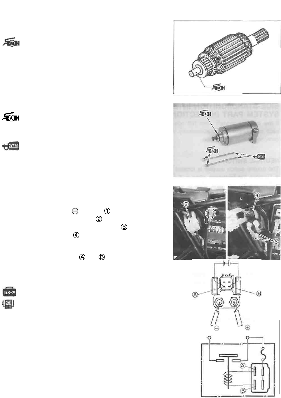
ELECTRICAL SYSTEM 6-14
• Apply a small quantity of SUZUKI MOLY PASTE to the
armature shaft.
99000-25140: SUZUKI MOLY PASTE
• Apply SUZUKI SUPER GREASE "A" to the O-rings.
99000-25010: SUZUKI SUPER GREASE "A"
• Apply a small quantity of THREAD LOCK "1342" to the
starter motor housing bolts.
STARTER RELAY INSPECTION
• Remove the front seat and right frame cover. (See p.
5-1.)
• Disconnect the battery lead wire
• Remove the starter relay cover
• Disconnect the starter motor lead wires and starter
relay lead wire coupler
• Remove the starter relay.
Apply 12 volts to terminals and , and measure for
continuity between the positive and negative terminals. If
the starter relay clicks and continuity is found, the relay is
ok.
09900-25008: Multi circuit tester set
Tester knob indication: Continuity test (•))) )
A CAUTION
To starter motor To battery
Do not apply battery voltage to the starter relay
for more than five secondes.
This may overheat and damage the relay coil.
99000-32050: THREAD LOCK "1342"
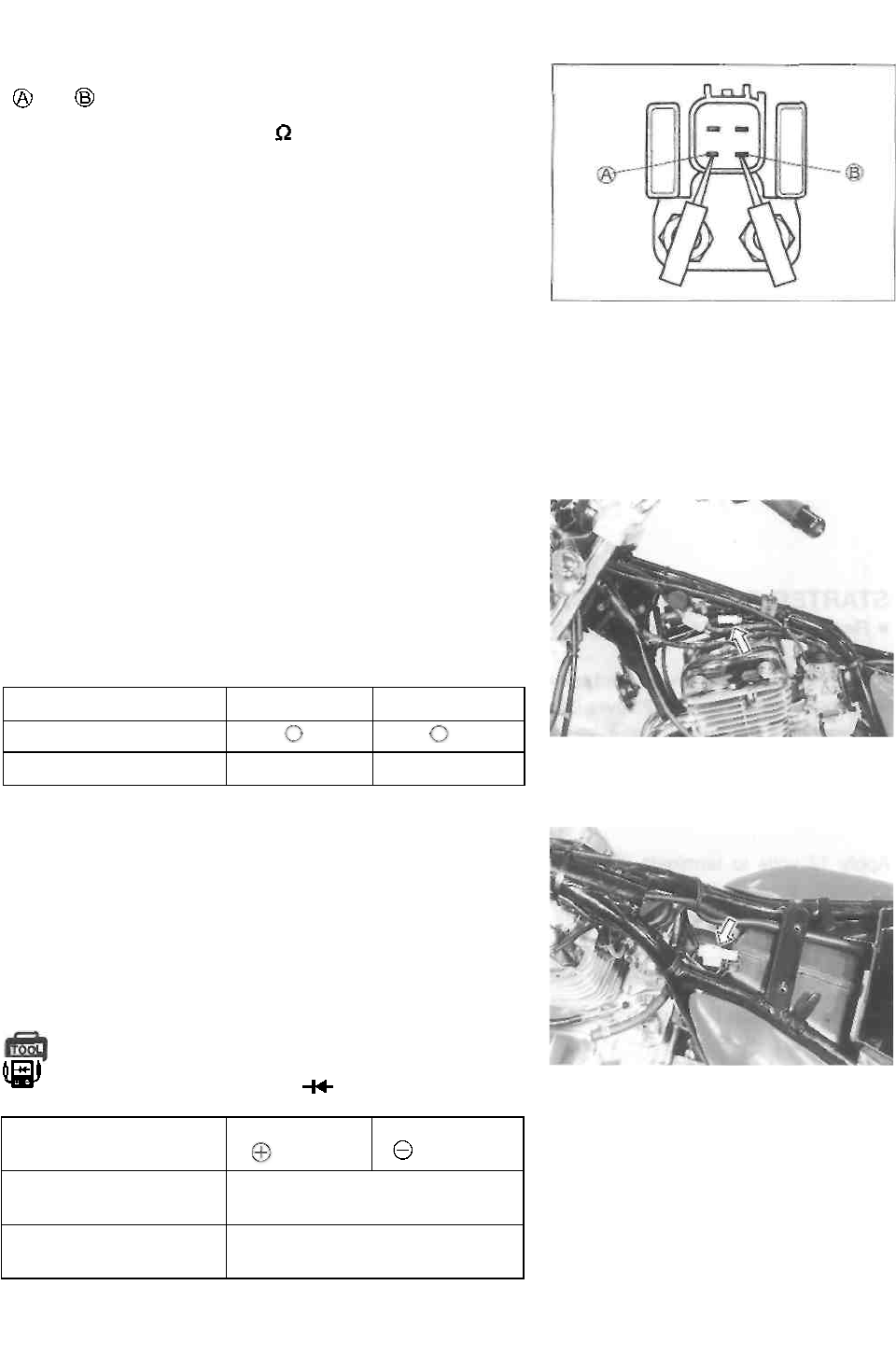
6-15 ELECTRICAL SYSTEM
Measure the starter relay resistance between the terminals
(and ).
Starter relay resistance: 3-6
SIDE-STAND/IGNITION INTERLOCK
SYSTEM PART INSPECTION
If the interlock system does not operate properly, check
each component. If any abnormality is found, replace the
component with a new one.
NEUTRAL SWITCH
The neutral switch coupler is located under the fuel tank.
• Remove the front seat. (See p. 5-1.)
• Remove the fuel tank. (See p. 4-1.)
• Disconnect the neutral switch coupler and measure the
continuity between Blue and Ground with the transmis-
sion in neutral.
Blue
Ground
ON (in neutral)
OFF (not in neutral)
SIDE-STAND SWITCH
The side-stand switch coupler is located under the fuel
tank.
• Remove the front seat. (See p. 5-1.)
• Remove the fuel tank. (See p. 4-1.)
• Disconnect the side-stand switch lead wire coupler and
measure the voltage between Green and Black/White
lead wires.
09900-25008: Multi circuit tester set Tester
knob indication: Diode test ( )
Green
(Probe)
Black/White
( Probe)
ON (UP-
right position)
0.4-0.6 V
OFF
(DOWN position)
1.4-1.5 V
NOTE:
If the tester read under 1.4V, replace the battery of multi
circuit tester when do not connecting the tester probes.
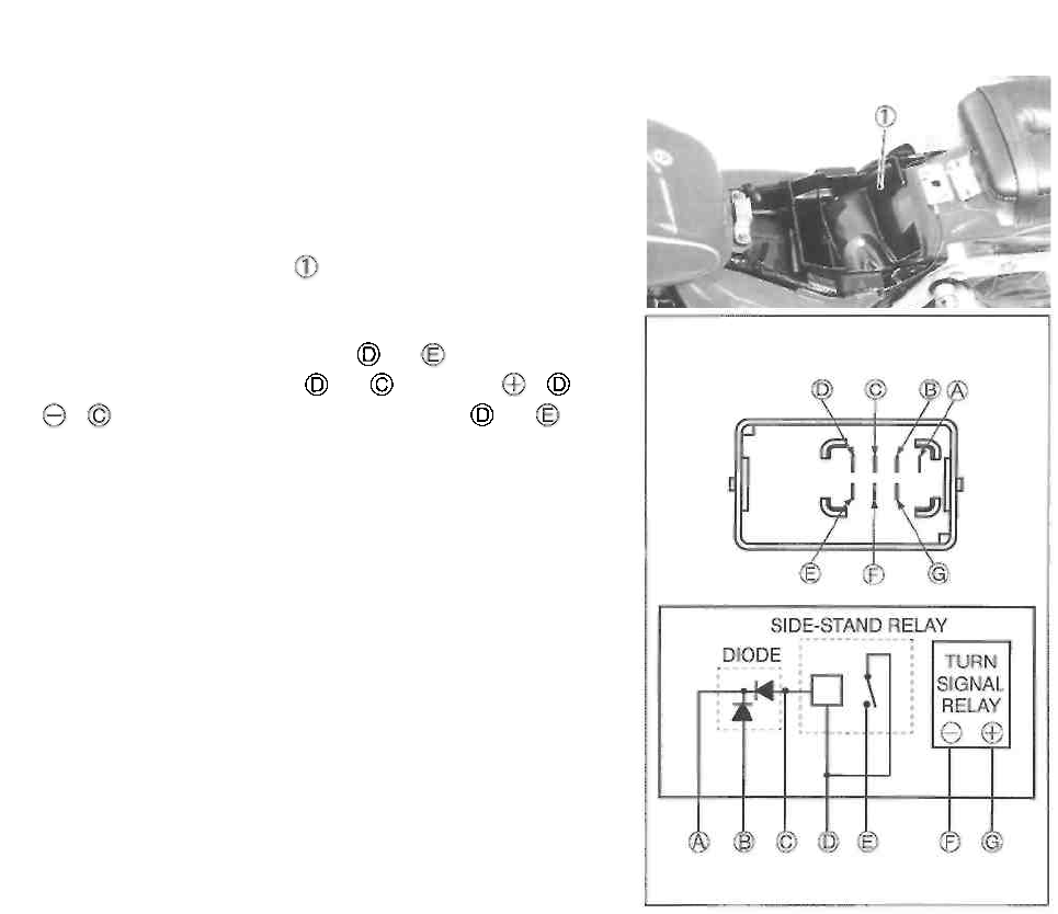
ELECTRICAL SYSTEM 6-16
TURN SIGNAL/SIDE-STAND RELAY
The turn signal relay is corporated with the side-stand relay
and diode to form the one component part which is called
the turn signal/side-stand relay. It is located under the
luggage box.
• Remove the front seat. (See p. 5-1.)
• Remove the luggage box
SIDE-STAND RELAY INSPECTION
First check the insulation between and terminals with
tester. Then apply 12 volts to and terminals, to
and to , and check the continuity between and . If
there is no continuity, replace turn signal/side-stand relay
with a new one.
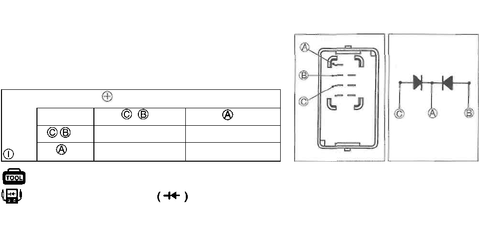
6-17 ELECTRICAL SYSTEM
DIODE INSPECTION
Using multi circuit tester, measure the voltage between the
terminals in the following table.
Unit: V
Probe of tester to:
Probe c
tester to:
,
i
1.4-1.5
0.4-0.6
09900-25008: Multi circuit tester set Tester
knob indication: Diode test
NOTE:
If the tester read under 1.4V, replace the battery of multi
circuit tester when do not connecting the tester probes.
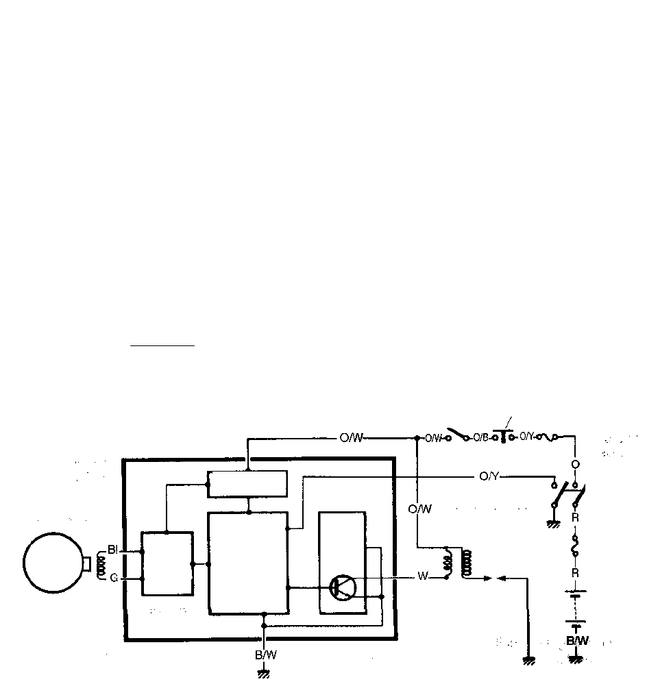
ELECTRICAL SYSTEM 6-18
IGNITION SYSTEM (DIGITAL IGNITOR)
DESCRIPTION
The fully transistorized ignition system consists of the following components: a generator, ignitor, igni-
tion coil and spark plug. The ignition timing is programmed and stored in the ignitor. The pick-up coil
is mounted in the generator. The induced signal in the pick-up coil is sent to the wave-form
arrangement circuit and the CPU receives this signal and calculates the best ignition timing. The CPU
outputs the signal to the transistor of the ignition coil output circuit which is connected to the primary
windings of the ignition coil which is turned "off" and "on" accordingly. Thus, it induces the secondary
current in the ignition coil's secondary winding and produces the spark between the spark plug gap.
Side-stand relay
Engine stop
switch Fuse
Ignitor
Ignitor power
source circuit
Ignition
switch
Transistor
Ignition coil
Main
fuse
CPU
(Central
Processing
Unit)
Wave
foam
arrange-
ment
circuit
Spark plug
Battery
Pick-up
coil
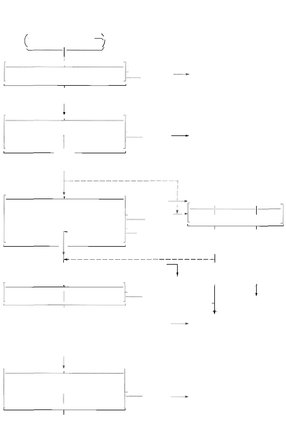
6-19 ELECTRICAL SYSTEM
TROUBLESHOOTING
Check the ignition system couplers for poor
connections.
* Check that the transmission is in neutral and the engine
stop switch is in the "RUN" position. Grasp the clutch
lever. Check that the fuse is not blown and the battery
is fully-charged before diagnosing.
• Poor connection of couplers
Correct
Measure the battery voltage between input
lead wires (O/W and B/W) at the igniter
with the ignition switch in the "ON" position.
Measure the ignition
coil primary peak
voltage. (See p. 6-
20.) NOTE: The ignition coil peak voltage
inspection method is applicable only with
the multi circuit
tester and the peak
volt adaptor.
Inspect the ignition coil.
(See p. 6-21.)
• Faulty
ignition switch
• Faulty turn signal/side-stand
relay
• Faulty engine stop switch
• Broken wire harness or poor
connection of
related circuit
couplers
Inspect the spark plug. (See
p
p. 2-4 and -5.)
Incorrect
Correct
• Faulty igniter unit
• Faulty spark plug
• Poor
conne
ction
of the spark plug cap.
• Faulty ignition coil
Correct
Measure the pick-up coil peak voltage and
resistance. (See pp. 6-22 and -23.) NOTE:
The pick-up coil peak voltage inspection is
applicable only with the multi circuit tester
and the peak volt adaptor.
Incorrect • Faulty generator
Correct
No spark or poor spark
Looseness
Correct
Incorrect
Incorrect
Correct
Incorrect
Incorrect

• Open circuit in wiring harness
• Poor connection of ignition
couplers
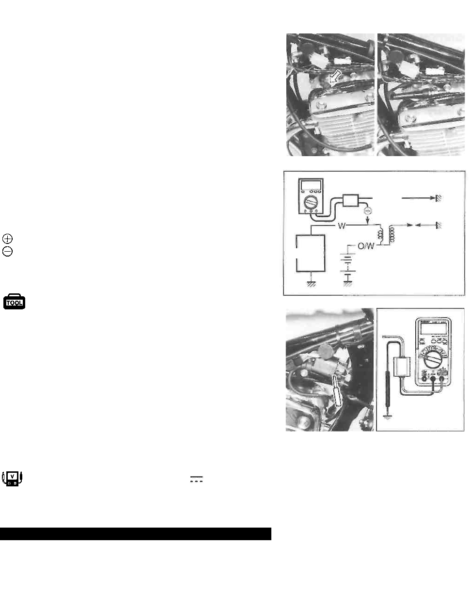
ELECTRICAL SYSTEM 6-20
INSPECTION
IGNITION COIL PRIMARY PEAK VOLTAGE
• Remove the front seat. (See p. 5-1.)
• Remove the fuel tank. (See p. 4-1.)
• Disconnect the spark plug cap.
• Connect new spark plug to the spark plug cap and
ground it to the cylinder head.
NOTE:
Make sure that the spark plug cap and spark plug is con-
nected properly and the battery Is fully-charged.
Measure ignition coil primary peak voltage in the following
procedure.
• Connect the multi circuit tester with the peak volt adaptor
as follows.
Probe: White lead wire connector
Probe: Ground
NOTE:
Do not disconnect the ignition coil primary wire.
09900-25008: Multi circuit tester set
A CAUTION
When using the multi circuit tester and peak volt
adaptor, refer to the appropriate instruction manual.
• Shift the transmission into neutral, turn the ignition
switch to the "ON" position and grasp the clutch lever.
• Press the starter button and allow the engine to crank for
a few seconds, and then measure the Ignition coll prima-
ry peak voltage.
• Repeat the above procedure a few times and measure
the highest ignition coil primary peak voltage.
Tester knob indication: Voltage ( )
Ignition coil primary peak voltage: More than
200 V
AWARNING
While testing, do not touch the tester probes and
spark plug to prevent receiving an electric shock.
If the voltage is lower than the standard value, inspect the
ignition coil and the pick-up coil. (See pp. 6-21 to -23.)
Peak volt adaptor
Ignition
coil
New
spark
plug
Ignitor
Battery
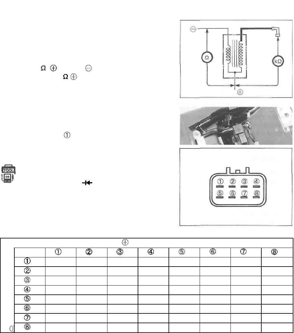
6-21 ELECTRICAL SYSTEM
IGNITION COIL RESISTANCE
Measure the ignition coil resistance in both the primary and
secondary windings. If the windings are in sound condition,
their resistance should be close to the specified values.
Ignition coil resistance
Primary: 3-5 (terminal-terminal)
Secondary: 17-28 k ( terminal-Spark plug cap)
IGNITOR
• Remove the front seat. (See p. 5-1.)
• Remove the luggage box.
• Remove the ignitor
Measure the voltage between the terminals in the following
table.
09900-25008: Multi circuit tester set Tester knob
indication: Diode test ( )
i Probe of tester to: /
Probe of tester to:
1.2-1.5
1.2-1.5
1.2-1.5
1.2-1.5
1.2-1.5
1.2-1.5
1.2-1.5
1.2-1.5
1.1-1.5
1.1-1.5
1.2-1.5
1.2-1.5
1.2-1.5
1.1-1.5
0.9-1.4
1.1-1.5
0
1.2-1.5
1.2-1.5
1.2-1.5
0.5-0.8
0.9-1.4
1.1-1.5
0
1.2-1.5
1.2-1.5
1.2-1.5
0.5-0.8
1.1-1.5
1.1-1.5
0.3-0.6
0.3-0.6
1.2-1.5
1.2-1.5
0.8-1.2
1.2-1.5
1.2-1.5
1.2-1.5
1.2-1.5
1.2-1.5
1.2-1.5
1.2-1.5
1.2-1.5
1.2-1.5
1.2-1.5
1.2-1.5
1.2-1.5
1.2-1.5
1.2-1.5
1.0-1.5
1.1-1.5
0.4-0.6
0.4-0.6
1.2-1.5
1.2-1.5
1.2-1.5
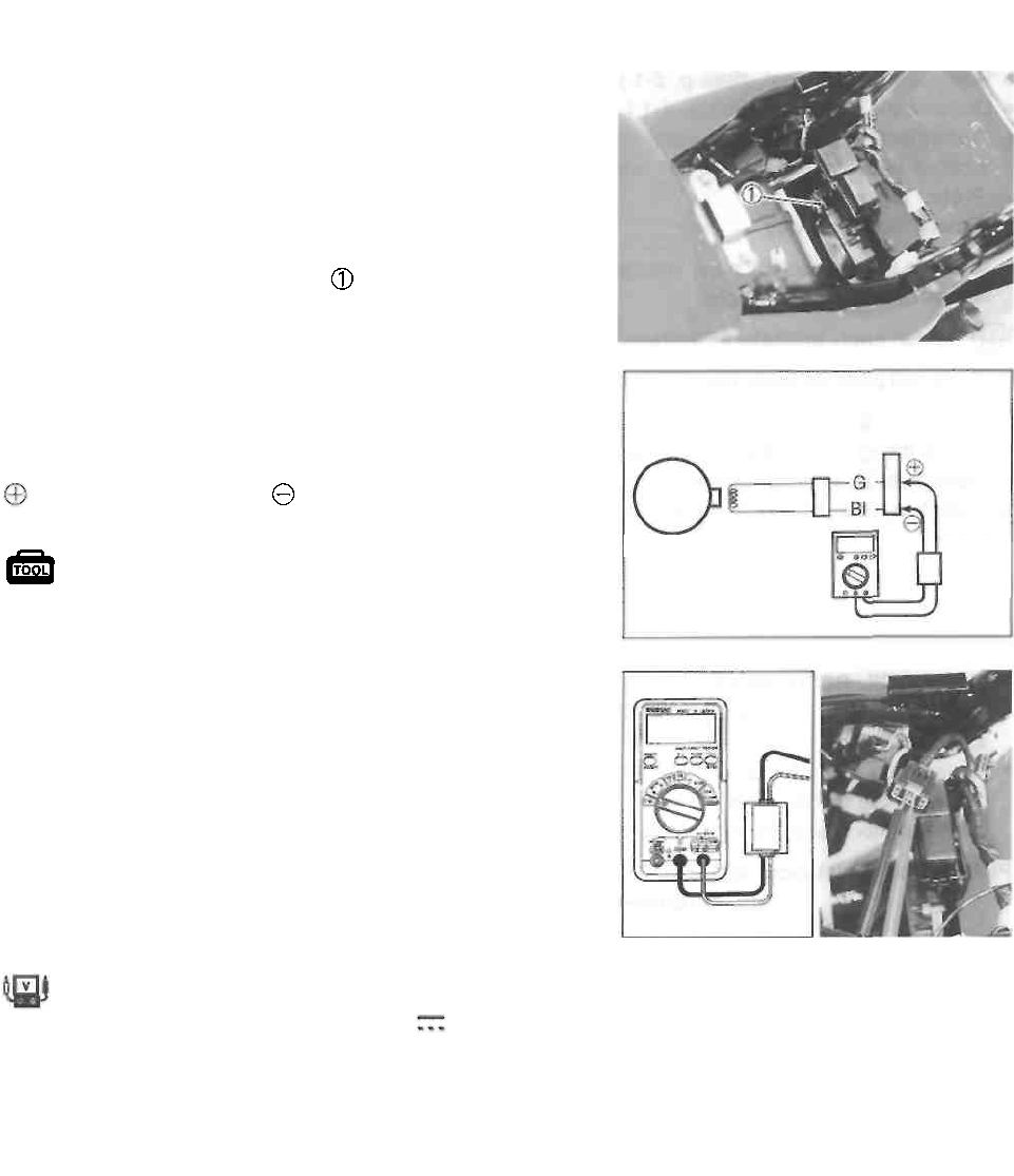
ELECTRICAL SYSTEM 6-22
PICK-UP COIL PEAK VOLTAGE
• Remove the front seat. (See p. 5-1.)
• Remove the luggage box.
NOTE:
Be sure that all of the couplers are connected properly and
the battery is fully-charged.
• Disconnect the ignitor coupler at the ¡gnitor.
• Measure the pick-up coil peak voltage between the
Green and Blue lead wires on the ignitor coupler.
• Connect the multi circuit tester with the peak volt adaptor
as follows.
Probe: Green lead wire
Probe: Blue lead wire
09900-25008: Multi circuit tester set
A CAUTION
When using the multi circuit tester and peak volt
adaptor, refer to the appropriate instruction manual.
• Shift the transmission into neutral, turn the ignition
switch to the "ON" position and grasp the clutch lever.
• Press the starter button and allow the engine to crank for
a few seconds, and then measure the pick-up coil peak
voltage.
• Repeat the above procedure a few times and measure
the highest pick-up coil peak voltage.
Tester knob indication: Voltage ( )
Pick-up coil peak voltage: More than 5.0 V (Green-Blue)
If the peak voltage measured on the ignitor coupler is lower
than the standard value, measure the peak voltage on the
pick-up coil coupler as follows.
Ignitor
coupler
Pick-up
coil
coupler
Generator
Peak
volt
adaptor
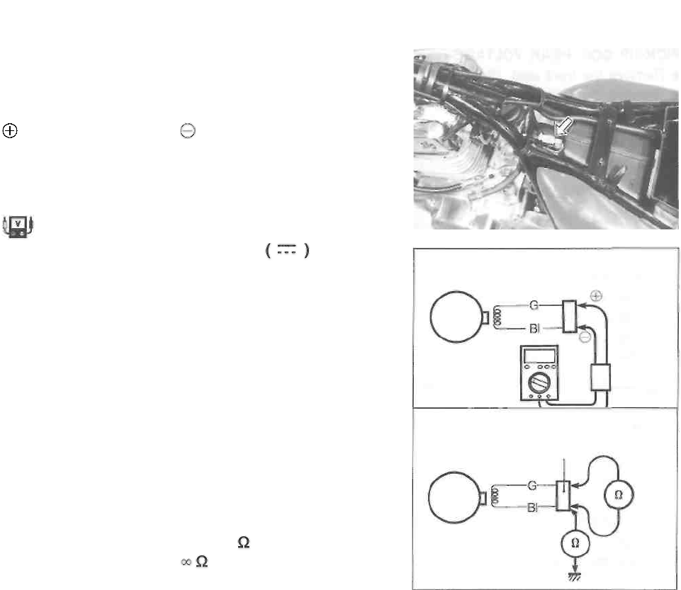
6-23 ELECTRICAL SYSTEM
• Remove the front seat. (See p. 5-1.)
• Remove the fuel tank. (See p. 4-1.)
• Disconnect the pick-up coil coupler and connect the mul-
ti circuit tester with the peak volt adaptor.
Probe: Green lead wire
Probe: Blue lead wire
• Measure the pick-up coil peak voltage in the same man
ner as on the ignitor coupler.
Tester knob indication: Voltage
Pick-up coil peak voltage: More than 5.0 V (Green-Blue)
If the peak voltage on the pick-up coil lead wire coupler is
ok but on the ignitor coupler is out of specification, the wire
harness must be replaced. If both peak voltages are out of
specification, the generator must be replaced and re-
checked.
PICK-UP COIL RESISTANCE
• Remove the seat and fuel tank and disconnect the pick-
up coil coupler.
• Measure the resistance between the lead wires and
ground. If the resistance is not within the specified value,
the generator stator must be replaced.
Pick-up coil resistance: 400-650 (Blue-Green)
(Blue-Ground)
Pick-up
coil
coupler
Generator
Peak volt
adaptor
Pick-up
coil
coupler
Generator
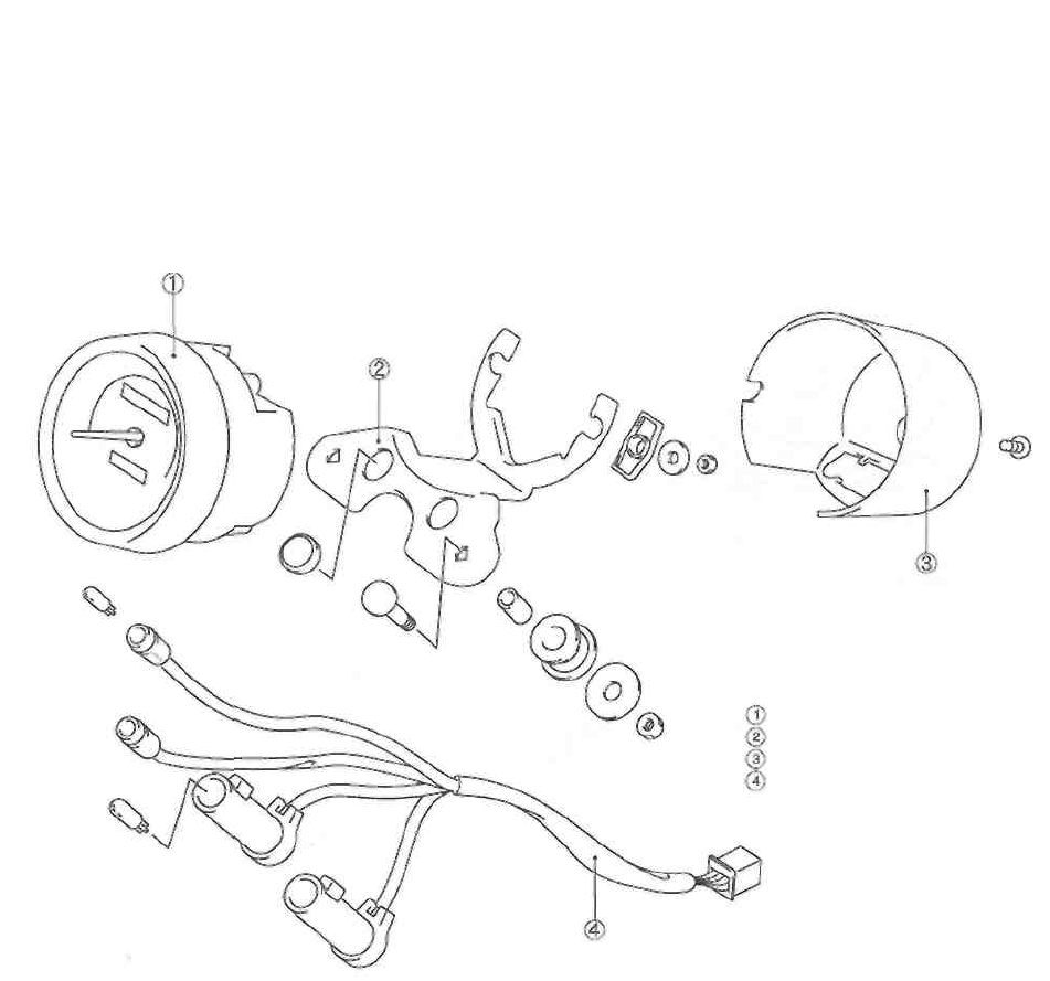
ELECTRICAL SYSTEM 6-24
SPEEDOMETER
REMOVAL AND DISASSEMBLY
• Remove the speedometer.
• Disassemble the speedometer as follows.
Speedometer
Speedometer bracket
Speedometer cover
Socket assy.
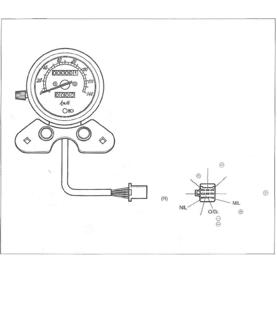
6-25 ELECTRICAL SYSTEM
INSPECTION
Check the continuity between lead wires.
If there is no continuity, replace the respective parts.
NOTE:
When checking for continuity, it is not necessary to remove
the speedometer.
WIRE COLOR
B : Black B/W : Black with White tracer
Gr : Gray Bl/B : Blue with Black tracer
Lg : Light green O/G : Orange with Green tracer
Y : Yellow
Bl/B: Neutral
B: Turn signal (L)
Y: High beam
Lg: Turn signal
Gr: Illumination
Neutral
B/W: High beam
illumination
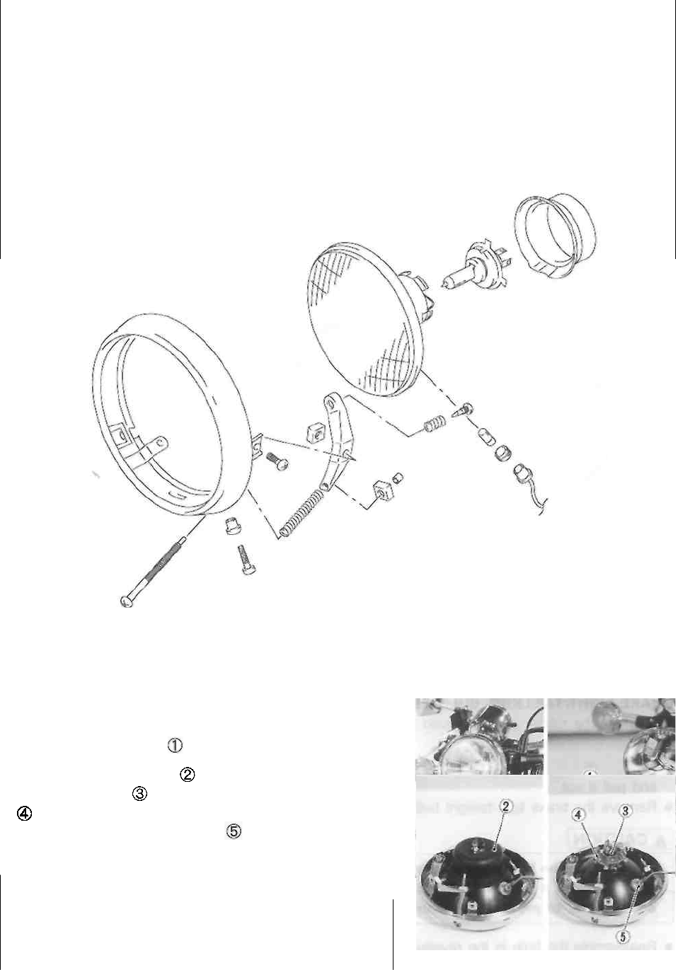
ELECTRICAL SYSTEM 6-26
LAMPS
HEADLIGHT AND POSITION LIGHT
Headlight: 12V 60/55W
Position light: 12V 4W ..... Except for E-03, -24, -28 and -33 models
HEADLIGHT BULB REPLACEMENT
• Remove the headlight.
• Disconnect the socket
• Remove the rubber cap
• Remove the bulb by removing the bulb holder spring
• Remove the position light bulb
• Reassemble the bulb in the reverse order of removal.
A CAUTION
If you touch the bulb with your bare hands, clean
the bulb with a cloth moistened with alcohol or
soapy water to prevent premature bulb failure.
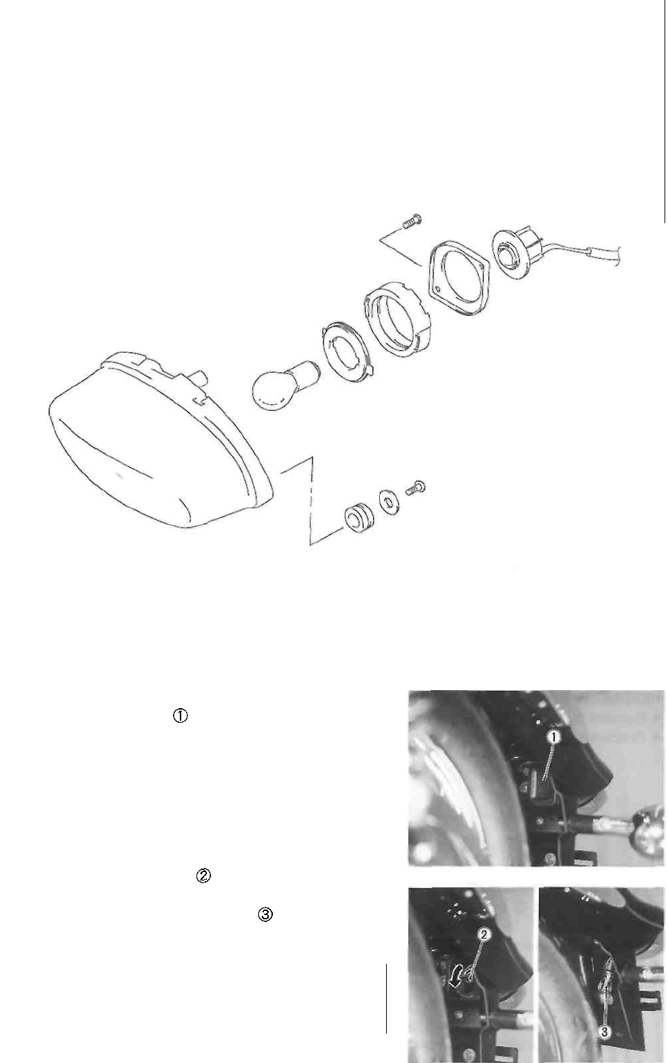
6-27 ELECTRICAL SYSTEM
BRAKE LIGHT/TAILLIGHT
Brake light/Taillight: 12V 21/5W
BRAKE LIGHT/TAILLIGHT BULB REPLACEMENT
• Remove the rubber cap behind the rear fender.
• Push in on the bulb socket , turn it counterclockwise,
and pull it out.
• Remove the brake light/taillight bulb
A CAUTION
If you touch the bulb with your bare hands, clean
the bulb with a cloth moistened with alcohol or
soapy water to prevent premature bulb failure.
• Reassemble the bulb in the reverse order of removal.
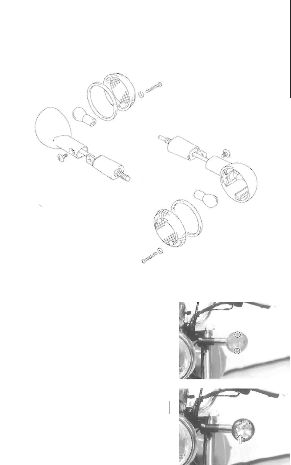
ELECTRICAL SYSTEM 6-28
TURN SIGNAL LIGHTS
Turn signal light/Running light: 12V 21/5W ..... For E-03, -28 and -33 models
Turn signal light: 12V 21W ..... For the others
TURN SIGNAL LIGHT BULB REPLACEMENT
• Remove the lens by removing the screws.
• Remove the bulb.
CAUTION ________________________________
If you touch the bulb with your bare hands, clean
the bulb with a cloth moistened with alcohol or
soapy water to prevent premature bulb failure.
• Reassemble the bulb in the reverse order of removal.
CAUTION
Do not overtighten the lens fitting screws.
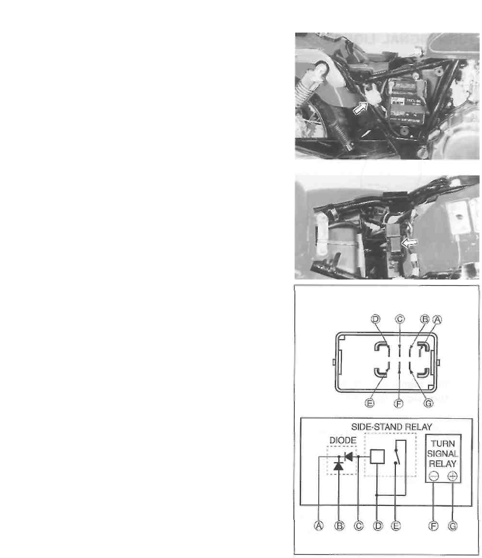
6-29 ELECTRICAL SYSTEM
RELAYS
STARTER RELAY
The starter relay is located behind the right frame cover.
(See pp. 6-14 and -15.)
TURN SIGNAL/SIDE-STAND RELAY
The turn signal relay is corporated with the side-stand relay
and diode to form the one component part which is called
the turn signal/side-stand relay. It is located under the
luggage box.
• Remove the front seat. (See p. 5-1.)
• Remove the luggage box.
INSPECTION
Before removing the turn signal/side-stand relay, check the
operation of the turn signal light.
If the turn signal light does not light, inspect the bulb, turn
signal switch and circuit connection.
If the bulb, turn signal switch and circuit connection
checked are all right, the turn signal relay may be faulty,
replace it with a new one.
NOTE:
Be sure that the battery is full-charged.
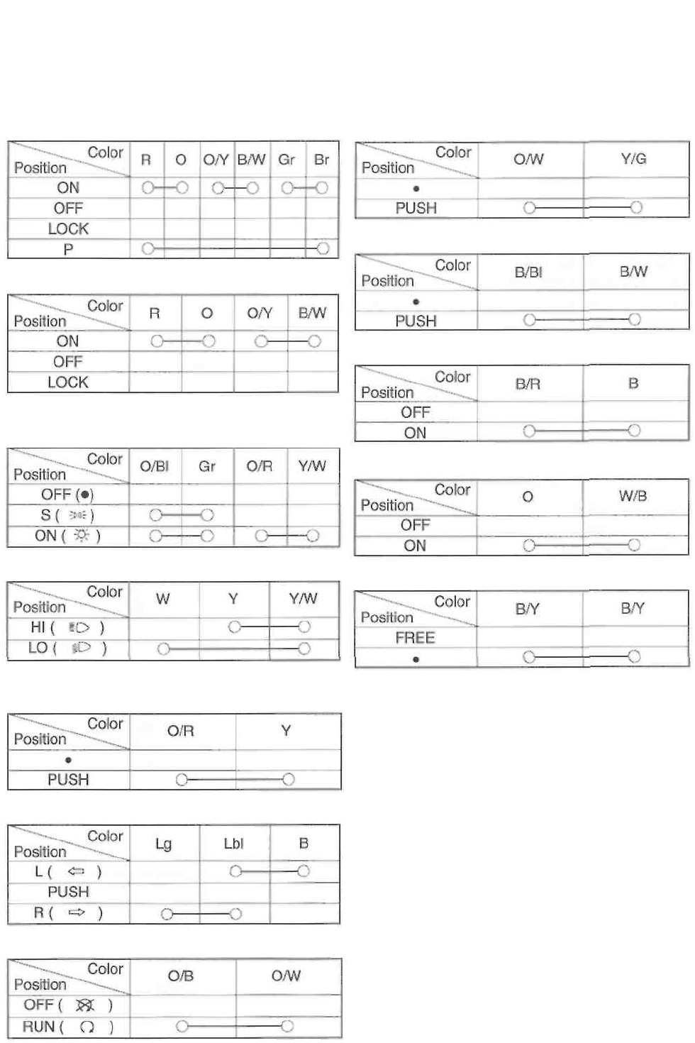
ELECTRICAL SYSTEM 6-30
SWITCHES
Measure each switch for continuity using a tester.
switch assemblies with new ones.
IGNITION SWITCH
If any abnormality is found, replace the respective
STARTER BUTTON
For E-24
LIGHTING SWITCH
(Except for E-03, -24, -28, -33)
HORN BUTTON
FRONT BRAKE LIGHT SWITCH
DIMMER SWITCH
PASSING LIGHT SWITCH
(Except for E-03, -28, -33)
TURN SIGNAL SWITCH
ENGINE STOP SWITCH
WIRE COLOR
B : Black O : Orange
Br : Brown R : Red
Gr : Gray Y : Yellow
Lbl : Light blue W : White
Lg : Light green B/W : Black with
White tracer B/Y : Black with
Yellow tracer B/R : Black with Red
tracer O/B : Orange with Black
tracer O/BI : Orange with Blue
tracer O/R : Orange with Red tracer
O/W : Orange with White tracer O/Y
: Orange with Yellow tracer W/B :
White with Black tracer Y/W :
Yellow with White tracer Y/G :
Yellow with Green tracer
REAR BRAKE LIGHT
SWITCH
CLUTCH LEVER
POSITION SWITCH
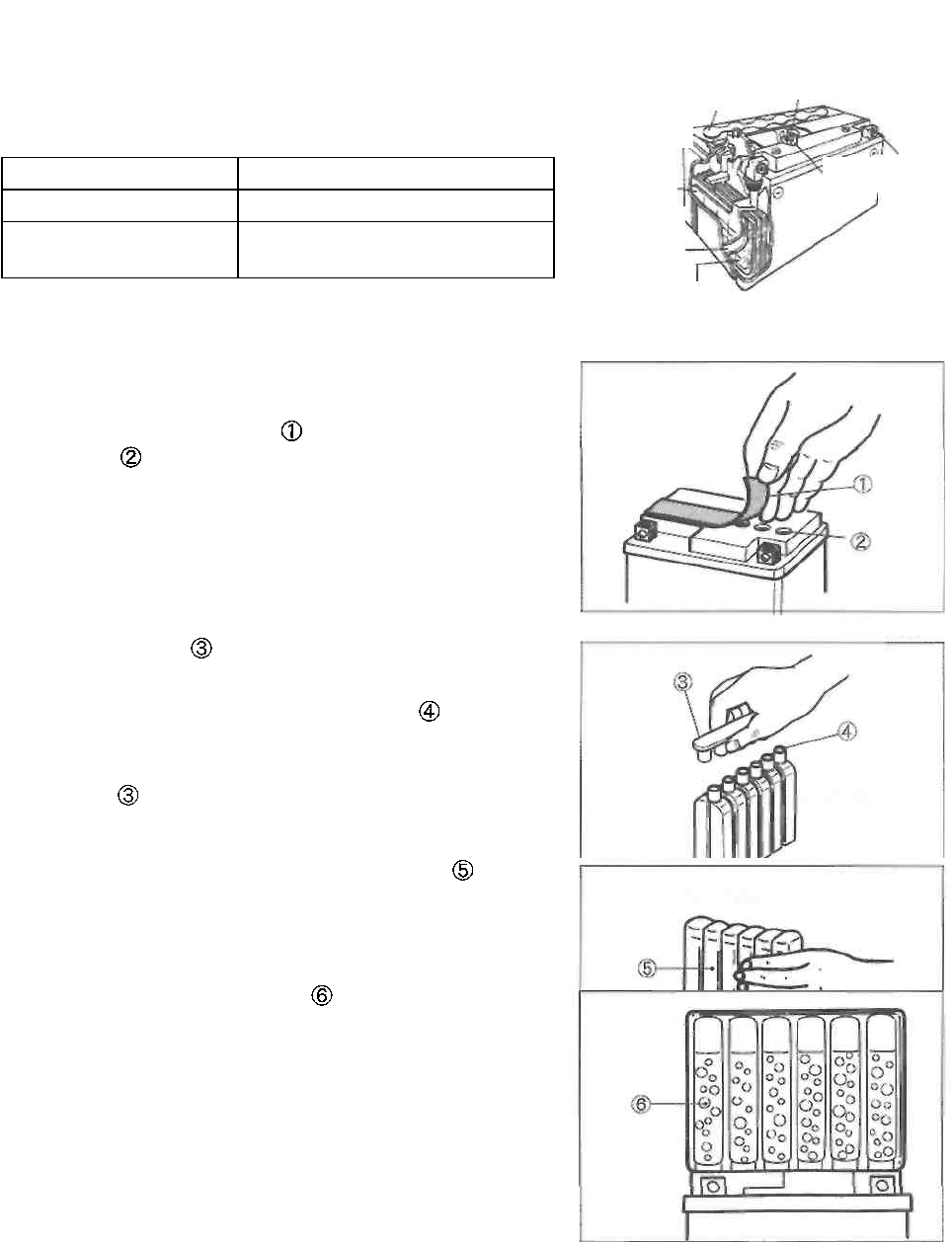
6-31 ELECTRICAL SYSTEM
BATTERY
SPECIFICATIONS
Type designation
FTX7L-BS
Capacity
12V, 21.6 kC(6Ah)/10HR
Standard electrolyte
S.G.
1.320 at 20°C (68°F)
Stopper
Anode
plates
Filter
INITIAL CHARGING
FILLING ELECTROLYTE
• Remove the aluminum tape which seals the battery
filler holes
* Remove the caps from the electrolyte container.
NOTE:
* Do not remove or pierce the sealed areas of the elec-
trolyte container.
* After completely filling the battery with electrolyte, use
the caps from the electrolyte container to seal the
battery filler holes.
• Insert the nozzles of the electrolyte container into the
battery's electrolyte filler holes. Hold the electrolyte con-
tainer firmly so that it does not fall. Do not allow any of
the electrolyte to spill.
• Make sure that the air bubbles rise to the top of each
electrolyte container and leave the electrolyte container
in this position for more than 20 minutes.
Upper cover
breather
Terminal
Safety valve
Cathode
plates
Separator
(fiberglass
plate)
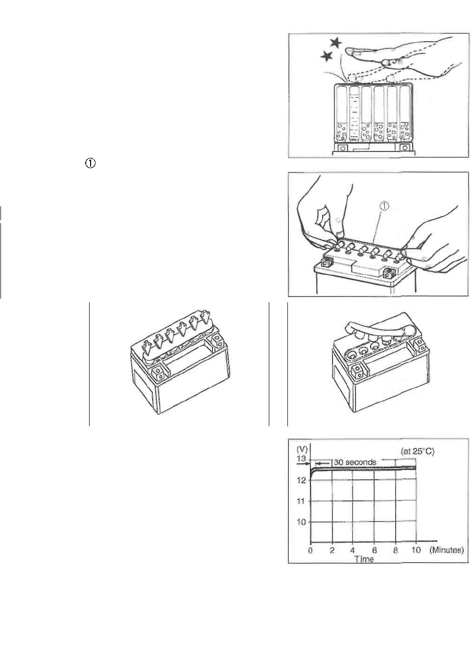
ELECTRICAL SYSTEM 6-32
NOTE:
If air bubbles do not rise from any one of the filler ports, tap
the bottom of the electrolyte container two or three times.
Never remove the electrolyte container from the battery
while there is still electrolyte in the container.
• After the electrolyte container is completely empty, re-
move it from the battery and wait about 20 minutes.
• Insert the caps firmly into the filler holes, so that the
top of the caps do not protrude above the upper surface
of the battery's top cover.
A CAUTION
* The charging system for a MF battery is differ-
ent from that of a conventional battery. Only
use the specified MF battery.
* Do not remove the caps once they are installed
in the battery
CORRECT INCORRECT
• Measure the battery voltage using a tester. The tester
should indicate more than 12.5-12.6V (DC), as shown.
If the battery voltage is lower than specification, charge
the battery with a battery charger.
NOTE:
Initial charging for a new battery is recommended if two
years have elapsed since the date of manufacture.
SERVICING
Visually inspect the surface of the battery container. If any
signs of cracking or electrolyte leakage from the sides of
the battery have occurred, replace the battery with a new
one. If the battery terminals are found to be coated with
rust or an acidic white powdery substance, clean the bat-
tery terminals with sandpaper.
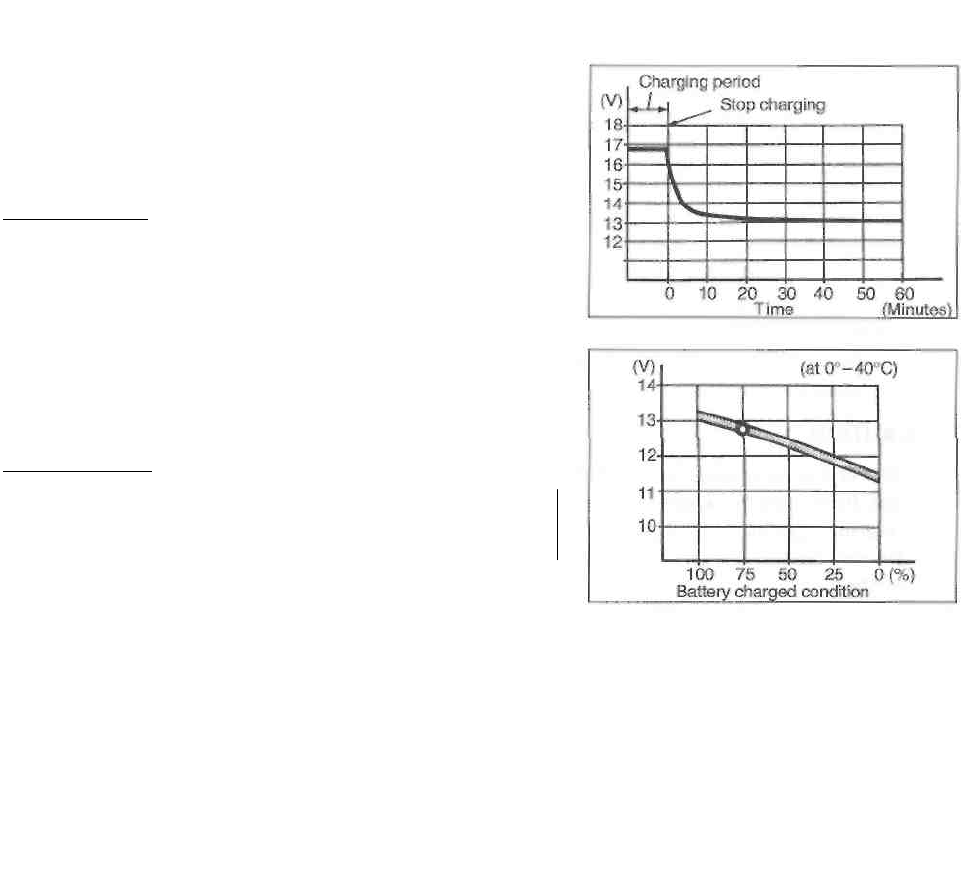
6-33 ELECTRICAL SYSTEM
RECHARGING OPERATION
• Measure the battery voltage using a tester. If the voltage
reading is less than 12.0V (DC), recharge the battery
with a battery charger.
I A CAUTION! ________________________
When recharging the battery, remove the battery
from the motorcycle.
NOTE:
While recharging, do not remove the caps on the top of the
battery.
Recharging time: 0.7A for 5 to 10 hours or 3A for 1 hour
I A CAUTION]
Be careful not to permit the charging current to
exceed 3A at any time.
• After recharging, wait at least 30 minutes and then mea-
sure the battery voltage using a tester.
• If the battery voltage is less than 12.5V, recharge the
battery again.
• If the battery voltage is still less than 12.5V after recharg-
ing, replace the battery with a new one.
• When a battery is left unused for a long time, its voltage
needs to be regularly measured. When the motorcycle is
not used for more than one month (especially during the
winter season), measure the battery voltage at least
once a month.

SERVICING INFORMATION
---------------------------------------- CONTENTS ------------------------------------------
TROUBLESHOOTING ......................................................................... 7- 1
WIRING DIAGRAM ............................................................................. 7- 8
WIRE, CABLE AND HOSE ROUTING .................................................. 7-11
FRAME REAR COVER SET-UP ........................................................ 7-19
SPECIAL TOOLS ................................................................................ 7-20
TIGHTENING TORQUE ...................................................................... 7-23
SERVICE DATA ................................................................................ 7-26

7-1 SERVICING INFORMATION
TROUBLESHOOTING
ENGINE
Complaint
Symptom and possible causes
Remedy
Engine will not start, or
is hard to start.
s
Compression too low
1. Worn cylinder.
2. Worn piston ring.
3. Worn valve guide or improper valve seating.
4. Loose spark plug.
5. Broken, cracked or damaged piston
6. Slow cranking starter motor.
7. Mistimed valves.
8. Valve clearance out of adjustment.
Spark plug not sparking
1. Damaged spark plug.
2. Damaged spark plug cap.
3. Fouled spark plug.
4. Wet spark plug.
5. Defective ignition coil.
6. Open or short in high-tension cord.
7. Defective pick-up coil or ignitor unit.
No fuel reaching the carburetor
1. Clogged or defective fuel valve.
2. Defective carburetor needle valve.
3. Clogged fuel hose.
4. Clogged fuel filter.
Rebore or replace.
Replace.
Repair or replace
Tighten.
Replace
See electrical section.
Adjust.
Adjust.
Replace.
Replace.
Clean or replace.
Clean and dry or replace.
Replace.
Replace.
Replace.
Clean or replace. Replace
with carburetor needle valve
seat. Clean or replace.
Clean or replace.
Engine stalls easily.
1. Fouled spark plug.
2. Defective pick-up coil or ignitor unit.
3. Clogged fuel hose.
4. Clogged carburetor jet.
5. Valve clearance out of adjustment.
Clean or replace.
Replace.
Clean.
Clean.
Adjust.

SERVICING INFORMATION 7-2
Complaint
Symptom and possible causes
Remedy
Engine is noisy.
Excessive valve chatter
Noisy engine.
1. Excessive valve clearance.
Adjust.
2. Weak or broken valve spring.
Replace.
3. Worn cam surface.
Replace.
4. Worn or burnt camshaft journal. Noise
seems to come from the piston
Replace camshaft.
1. Worn piston.
Replace.
2. Worn cylinder.
Rebore or replace.
3. Carbon build-up in combustion chamber.
Clean.
4. Worn piston pin or piston pin bore.
Replace.
5. Worn piston ring or ring groove. Noise
seems to come from the cam chain
Replace.
1. Stretched cam chain.
Replace cam chain and
sprocket.
2. Worn cam chain sprocket.
Replace cam chain and
sprocket.
3. Improperly working cam chain tension adjuster.
Noise seems to come from the clutch
Repair or replace.
1. Worn countershaft spline.
Replace countershaft.
2. Worn clutch hub spline.
Replace clutch hub.
3. Worn clutch plate teeth.
Replace clutch plate.
4. Distorted clutch plate.
Replace.
5. Worn clutch release bearing.
Replace.
6. Weak clutch damper.
Replace primary driven
gear.
7. Weak clutch spring. Noise seems to come
from the crankshaft
Replace.
1. Rattling bearing.
Replace.
2. Worn or burnt crank pin bearing.
Replace.
3. Worn or burnt ball bearing. Noise seems to
come from the transmission
Replace.
1. Worn or rubbing gear.
Replace.
2. Worn countershaft spline.
Replace countershaft.
3. Worn driveshaft spline.
Replace driveshaft.
4. Worn or rubbing primary gear.
Replace.
5. Worn bearing.
Replace.
Clutch slips.
1. Clutch cable out of adjustment.
Adjust.
2. Weak or broken clutch spring.
Replace.
3. Worn or distorted clutch pressure plate.
Replace.
4. Distorted clutch plate.
Replace.
Clutch drags.
1. Clutch out of adjustment.
Adjust.
2. Some clutch springs are weak, while others are
not.
3. Worn or distorted clutch pressure plate.
Replace.
Replace.
4. Distorted clutch plate.
Replace.
Transmission will
1. Broken gearshift cam.
Replace.
not shift.
2. Distorted gearshift fork.
Replace.
3. Worn gearshift pawl.
Replace.

7-3 SERVICING INFORMATION
Complaint
Symptom and possible causes
Remedy
Transmission will
not shift back.
1. Broken gearshift shaft return spring.
2. Rubbing or stuck gearshift shaft.
3. Worn or distorted gearshift fork.
Replace.
Repair or replace.
Replace.
Transmission jumps
out of gear.
1. Worn gear.
2. Worn or distorted gearshift fork.
3. Weakened gearshift cam stopper spring.
4. Worn gearshift pawl.
Replace.
Replace.
Replace.
Replace.
Engine idles poorly.
1. Valve clearance out of adjustment.
2. Improper valve seating.
3. Worn valve guide.
4. Worn cam surface.
5. Excessive spark plug gap.
6. Defective ignition coil.
7. Defective pick-up coil or ignitor unit.
8. Spark plug too cold.
9. Incorrect float chamber fuel level.
10. Clogged carburetor jet.
11. Defective generator.
Adjust.
Repair or replace.
Replace.
Replace.
Adjust or replace.
Replace.
Replace.
Replace by hot type
plug.
Adjust float height.
Clean.
Replace.
Engine runs poorly in
high-speed range.
1. Weak valve spring.
2. Worn camshaft.
3. Insufficient spark plug gap.
4. Mistimed valves.
5. Ignition not advanced sufficiently due to poorly
working timing advance circuit.
6. Defective ignition coll.
7. Defective pick-up coil or ignitor unit.
8. Low float chamber fuel level.
9. Clogged air cleaner element.
10. Clogged fuel hose, resulting in inadequate fuel
supply to carburetor.
Replace.
Replace.
Regap or replace.
Adjust.
Replace ignitor unit.
Replace. Replace.
Adjust float height.
Clean or replace.
Clean and prime.
Exhaust smoke is
dirty or thick.
1. Excessive amount of engine oil.
2. Worn cylinder.
3. Worn piston ring.
4. Worn valve guide.
5. Scored or scuffed cylinder wall.
6. Worn valve stem.
7. Defective valve stem oil seal.
8. Worn oil ring side rail.
Check level and drain.
Rebore or replace.
Replace.
Replace.
Rebore or replace.
Replace valve.
Replace.
Replace oil ring.
Engine lacks power.
1. Insufficient valve clearance.
2. Weak valve spring.
3. Mistimed valves.
4. Worn cylinder.
5. Worn piston ring.
6. Improper valve seating.
7. Fouled spark plug.
8. Incorrect spark plug.
9. Clogged carburetor jet.
10. Incorrect float chamber fuel level.
11. Clogged air cleaner element.
12. Worn camshaft.
13. Air leaked from intake pipe.
14. Excessive amount of engine oil.
Adjust.
Replace.
Adjust.
Rebore or replace.
Replace.
Repair or replace.
Clean or replace.
Replace.
Clean.
Adjust float height.
Clean or replace.
Replace.
Tighten or replace.
Check level and drain.

SERVICING INFORMATION 7-4
Complaint
Symptom and possible causes
Remedy
Engine overheats.
1. Heavy carbon deposit on piston crown.
Clean.
2. Not enough oil in the engine.
Add oil.
3. Defective oil pump or clogged oil circuit.
Replace or clean.
4. Too low in float chambers fuel level.
Adjust.
5. Sucking air from intake pipe.
Retighten or replace.
6. Use incorrect engine oil.
Change.
7. Clogged air Intake with dust.
Clean.
CARBURETOR
Complaint
Symptom and possible causes
Remedy
Starting difficulty.
1. Clogged fuel pipe.
2. Air leaking from joint between starter body and car
buretor.
3. Air leaking from carburetor joint.
4. Improperly working starter plunger.
Clean.
Tighten, adjust or replace
gasket. Tighten or replace
defective parts. Adjust.
Idling or low-speed
trouble.
1. Clogged or loose pilot jet.
2. Air leaking from carburetor joint.
3. Clogged pilot outlet port.
4. Clogged bypass port.
5. Starter plunger not fully closed.
Clean or tighten. Tighten or
replace defective part.
Clean. Clean. Adjust.
Medium-or high
speed trouble.
1. Clogged main jet.
2. Clogged needle jet.
3. Improperly working throttle valve.
4. Clogged fuel filter.
Clean. Clean.
Adjust. Clean or
replace.
Overflow and fuel
level fluctuations.
1. Worn or damaged needle valve.
2. Broken needle valve spring.
3. Improperly working float.
4. Foreign matter on the needle valve.
5. Incorrect float chamber fuel level.
Replace. Replace.
Adjust or replace. Clean or
replace with needle valve
seat. Adjust float height.
CHASSIS
Complaint
Symptom and possible causes
Remedy
Steering is heavy.
1. Overtightened steering stem nut.
2. Broken bearing/race in steering stem.
3. Distorted steering stem.
4. Low tire pressure.
Adjust.
Replace.
Replace.
Regulate.
Handlebars
wobbles.
1. Loss of balance between right and left front fork
legs.
2. Distorted front fork.
3. Distorted front axle.
4. Twisted tire.
Adjust or replace.
Repair or replace.
Replace.
Replace.

7-5 SERVICING INFORMATION
Complaint
Symptom and possible causes
Remedy
Front wheel
wobbles.
1. Distorted wheel rim.
2. Worn front wheel bearing.
3. Defective or incorrect tire.
4. Loose front axle.
5. Incorrect front fork oil level.
6. Loose wheel spoke.
Replace.
Replace.
Replace.
Tighten.
Adjust.
Tighten.
Front suspension
too soft.
1. Weak spring.
2. Insufficient fork oil.
Replace.
Check level and add.
Front suspension
too stiff.
1. Excessively viscous fork oil.
2. Excessive fork oil.
Replace.
Check level and drain.
Front suspension
too noisy.
1. Insufficient fork oil.
2. Loose front suspension fastener.
Check level and add.
Tighten.
Rear wheel wobbles.
1. Distorted wheel rim.
2. Worn rear wheel bearing.
3. Defective or incorrect tire.
4. Worn swingarm bearing.
5. Loose rear axle nut or swingarm pivot nut.
6. Loosen wheel spokes.
7. Loosen rear suspension fastener.
Replace.
Replace.
Replace.
Replace.
Tighten.
Tighten.
Tighten.
Rear suspension
too soft.
1. Weak rear shock absorber spring.
2. Rear shock absorber leaks oil.
3. Improper suspension setting.
Replace.
Replace.
Adjust.
Rear suspension
too stiff.
1. Improperly adjusted rear suspension.
2. Bent swingarm.
3. Worn swingarm and rear suspension related
bearings.
Adjust.
Replace.
Replace.
Rear suspension too
noisy.
1. Loose rear suspension fastener.
2. Worn swingarm bearing.
Tighten.
Replace.
BRAKES
Complaint
Symptom and possible causes
Remedy
Brake power
1. Leakage of brake fluid.
Repair or replace.
insufficient.
2. Worn brake pad.
Replace.
3. Oil in brake pad surface.
Clean brake disc and
brake pads.
4. Worn brake disc.
Replace.
5. Air in hydraulic system.
Bleed.
6. Worn brake shoe.
Replace.
7. Oil in brake shoe surfaces.
Clean.
8. Excessively worn brake drum.
Replace.
9. Excessive brake pedal play.
Adjust.

SERVICING INFORMATION 7-6
Complaint
Symptom and possible causes
Remedy
Brake squeaks.
1. Carbon adhesion on brake pad surface.
2. Tilted brake pad.
3. Damaged wheel bearing.
4. Worn brake pad.
5. Foreign material in brake fluid.
6. Clogged return port of master cylinder.
7. Brake shoe surface glazed.
8. Worn brake shoe.
9. Loose front axle or rear axle nut.
Clean surface with sand-
paper.
Readjust brake pad position
or replace. Replace.
Replace.
Change brake fluid.
Disassemble and clean
master cylinder. Clean
surface with sandpaper.
Replace. Tighten.
Brake lever or pedal
stroke excessive.
1. Air in hydraulic system.
2. Insufficient brake fluid.
3. Incorrect brake fluid.
4. Worn brake camshaft.
5. Excessively worn brake shoes and/or brake drum.
Bleed.
Check level and add.
Bleed any air.
Change.
Replace.
Replace.
Brake fluid leaks.
1. Loose connection joint.
2. Cracked brake hose.
3. Worn piston seal.
Tighten.
Replace.
Replace
ELECTRICAL
Complaint
Symptom and possible causes
Remedy
No sparking or poor
sparking.
1. Defective ignition coil.
2. Defective spark plug.
3. Defective pick-up coil.
1. Defective ignitor unit.
Replace.
Replace.
Replace.
Replace.
Spark plug is wet or
quickly becomes
fouled with carbon.
1. Excessively rich air/fuel mixture.
2. Excessively high idling speed.
3. Incorrect gasoline.
4. Clogged air cleaner element.
5. Incorrect spark plug (cold type).
Adjust carburetor
Adjust carburetor
Change.
Clean or replace.
Change to hot type spark
plug.
Spark plug quickly
becomes fouled with
oil or carbon.
1. Worn piston ring.
2. Worn piston.
3. Worn cylinder.
4. Excessive valve-stem-to-valve-guide clearance.
5. Worn valve stem oil seal.
Replace.
Replace.
Rebore or replace.
Replace.
Replace.
Spark plug electrodes
overheat or burn.
1. Incorrect spark plug (hot type).
2. Overheated engine.
3. Loose spark plug.
4. Excessively lean air/fuel mixture.
Change to cold type
spark plug.
Tune-up.
Tighten.
Adjust carburetor.
Generator does not
charge.
1. Open or short in lead wires, or loose lead connec
tions.
2. Shorted, grounded or open stator coil.
3. Shorted or panctured regulator/rectifier.
Repair, replace or
connect properly.
Replace. Replace.

7-7 SERVICING INFORMATION
Complaint
Symptom and possible causes
Remedy
Generator charges
but charging rate is
below the
specification.
1. Lead wires tend to get shorted or open-circuited or
loosely connected at terminal.
2. Grounded or open-circuited stator coils or genera
tor.
3. Defective regulator/rectifier.
4. Defective battery cell plates.
Repair or tighten.
Replace.
Replace. Replace
battery.
Generator
overcharges.
1. Internal short-circuit in the battery.
2. Damaged or defective regulator/rectifier.
3. Poorly grounded regulator/rectifier.
Replace battery.
Replace.
Clean, repair or replace.
Unstable charging.
1. Lead wire insulation frayed due to vibration,
resulting in intermittent shorting.
2. Internally shorted generator.
3. Defective regulator/rectifier.
Repair or replace.
Replace. Replace.
Starter button does
not work.
1. Run down battery.
2. Defective switch contact.
3. Brushes do not seat properly on the commutator in
the starter motor.
4. Defective starter relay.
Recharge or replace.
Replace.
Repair or replace.
Replace.
BATTERY
Complaint
Symptom and possible causes
Remedy
Sulfation or spots on
surfaces of cell
plates.
1. Cracked battery case.
2. Battery has been left In a run-down condition for a
long time.
Replace battery.
Replace.
Battery runs down
quickly.
1. Incorrect charging method.
2. Battery cell plates have lost much of their active ma
terial as a result of overcharging.
3. Internally shorted battery.
4. Excessively low battery voltage.
5. Battery is too old.
Check generator or regu-
lator/rectifier circuit con-
nections, and make nec-
essary adjustment to obtain
specified charging
operation.
Replace battery and correct
charging system. Replace.
Recharge Replace.
Battery sulfation.
1. Incorrect charging rate.
(When not in use, the battery should be checked at least
once a month and properly charged if necessary, to avoid
sulfation.)
2. The battery was left unused in a cold climate for
too long.
Replace battery.
Replace battery if badly
sulfated.
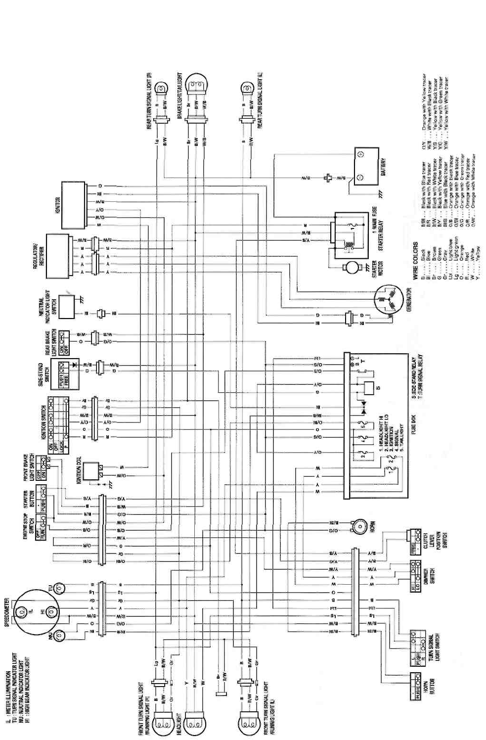
WIRING DIAGRAM
FOR E-03, -28 and -33
SERVICING INFORMATION 7-8
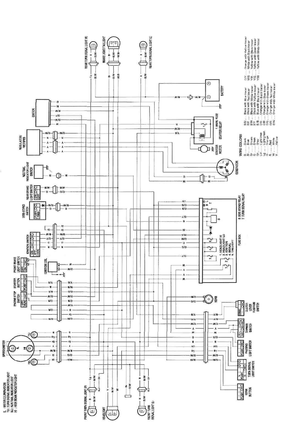
7-9 SERVICING INFORMATION
FOR E-24
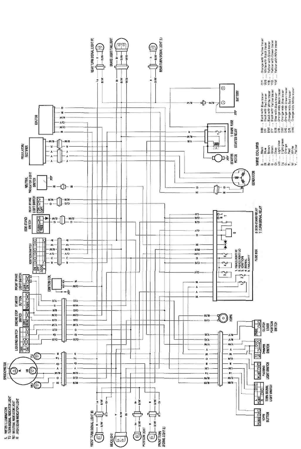
FOR THE OTHERS
SERVICING INFORMATION 7-10
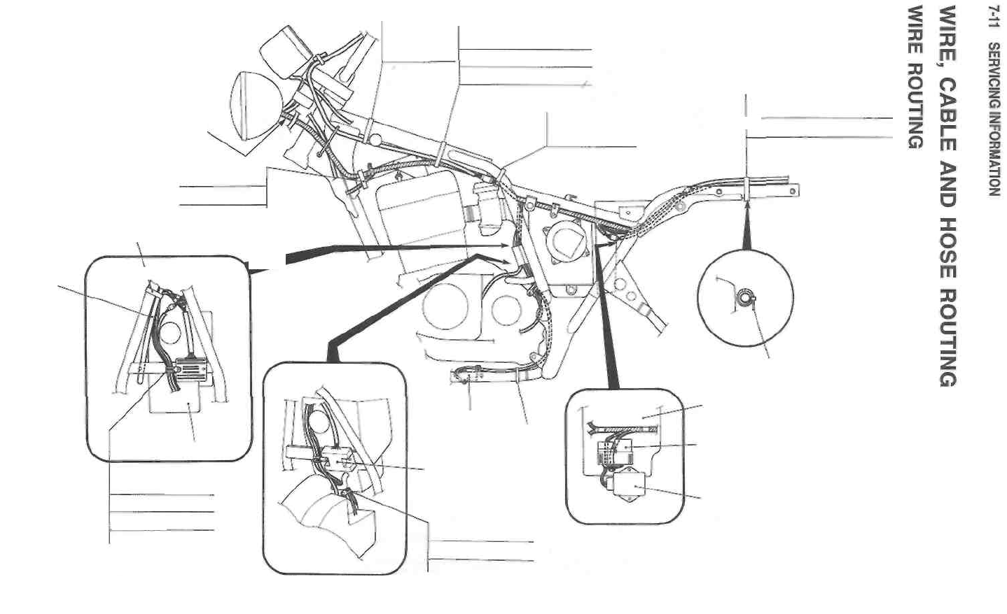
Clamp
Clamp
Wiring harness
Clamp
Pass through the wiring harness
right side of the clutch cable,
speedometer cable and brake
hose.
Clamp
Brake light/Taillight
Rear turn signal light (L)
Wiring harness
Wiring harness
Starter motor
Clamp
Clamp
Starter motor
lead wire
Clamp
Rear fender
Turn signal/side-stand relay
Air cleaner
Generator
Ignitor
Neutral switch
Side-stand switch
Clamp
Handlebar
switch (L&R)
Handlebar switch (L&R)
Starter motor
Clamp
Side-stand
switch
Clamp
Regulator/rectifier
Neutral switch
Side-stand switch
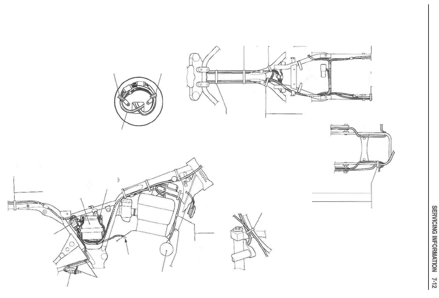
Clamp
Wiring
harness
Clamp
Starter motor
Wiring harness
High tension cord
(Ignition coil)
Handlebar switch
(L&R) ________
Clamp
Pass through the handlebar
switch (R) lead wire under the
brake hose.
Clamp
Clamp
Clamp
Clamp
Battery
terminal
Rear turn signal
light (R)
Rear turn signal
light (L)
Battery
Brake
light/Taillight
Starter relay
Engine ground
Starter motor
Clamp
Rear brake
switch
Wiring harness
Handlebar switch (L&R)
Starter motor
Generator
Wiring harness
Clamp
Starter motor
Clamp
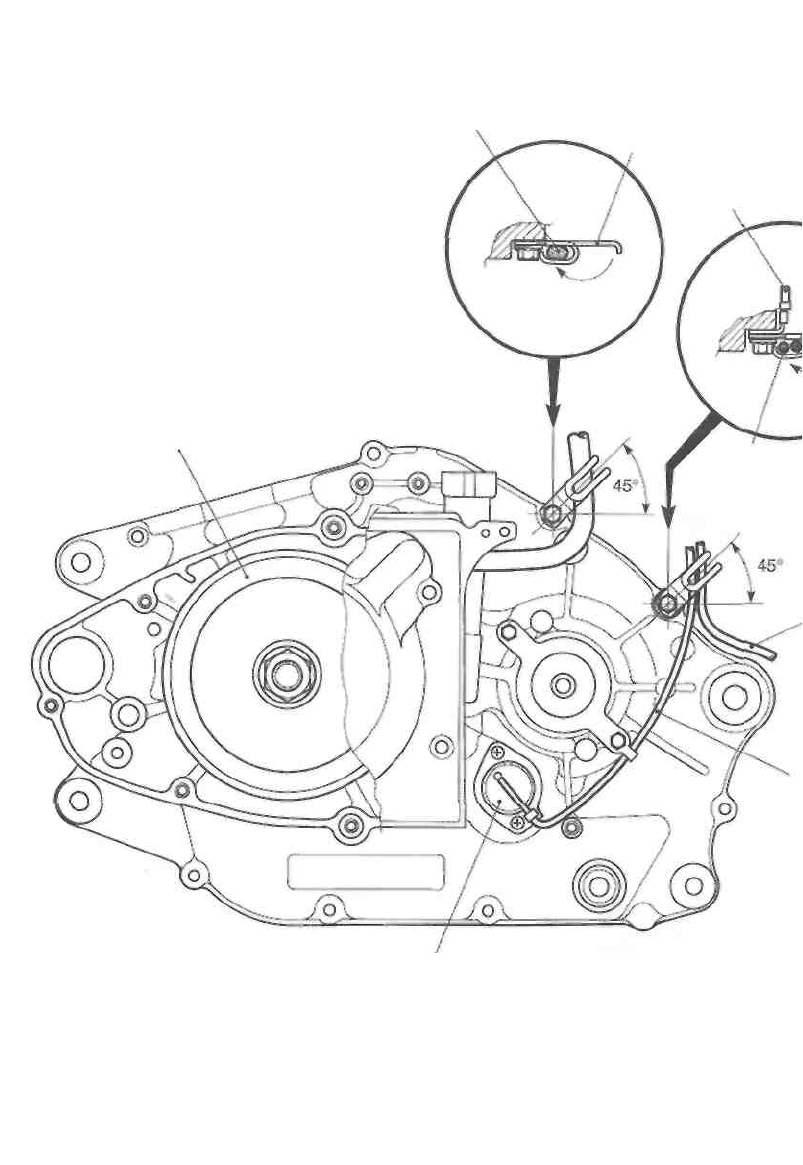
7-13 SERVICING INFORMATION
Generator lead wire
Neutral switch
Pick-up coil
Clamp
Engine
ground wire
Side-stand switch
lead wire
Clamp
Generator rolor
Neutral switch
lead wire
Side-stand
switch lead wire
Neutral switch
lead wire
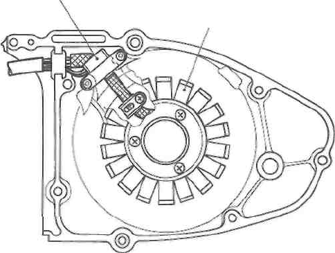
Stator coil
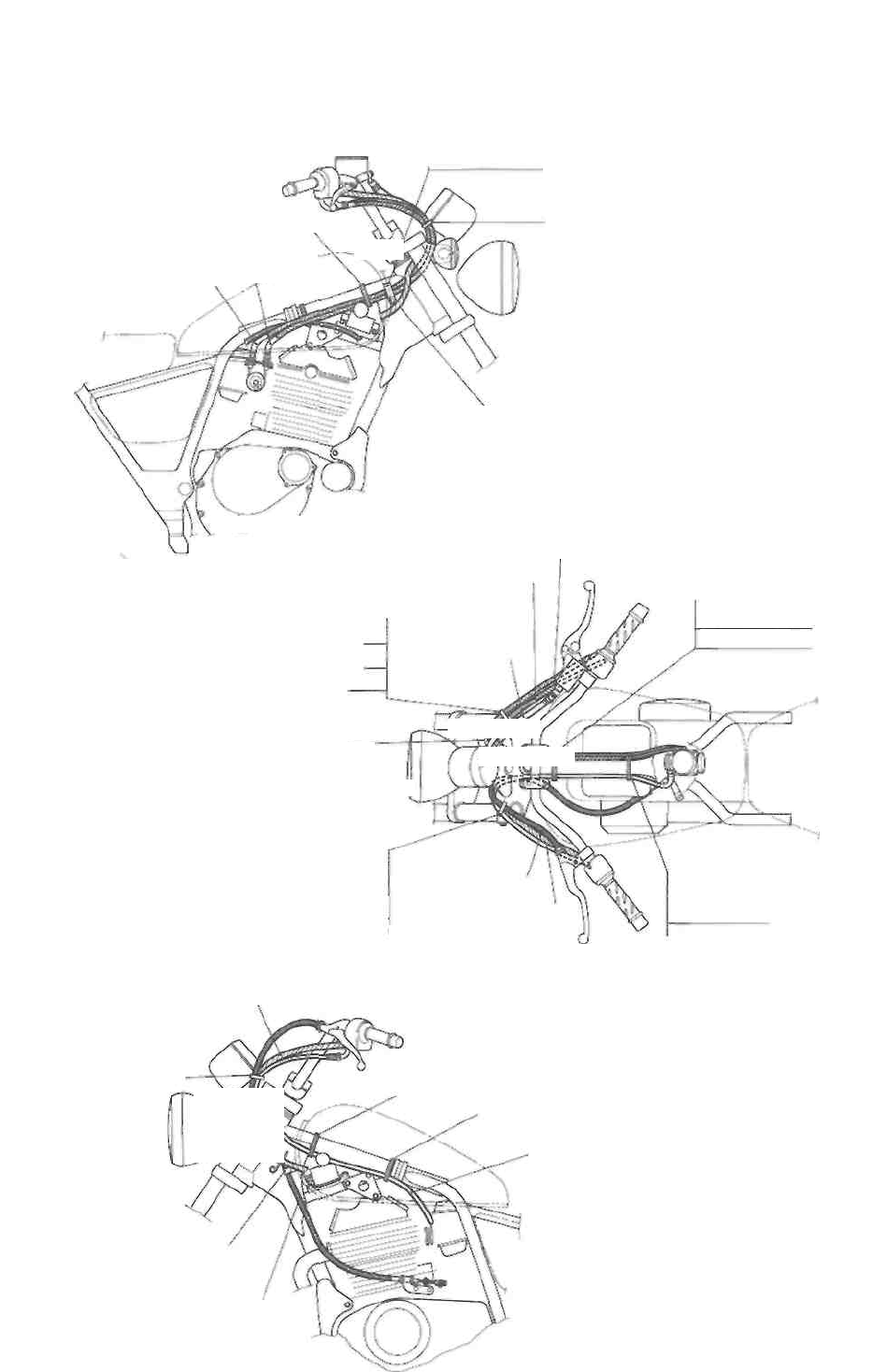
SERVICING INFORMATION 7-14
CABLE ROUTING
Clamp
Throttle
cables
Throttle cable (pulling
cable) Throttle cable (returning cable)
Throttle cables
Brake hose
Clamp
Wiring harness
Starter cable
Clamp \ Throttle cable (returning
cable)
Throttle cable (pulling cable)
Clamp
Throttle cables
Starter cable
Pass the throttle cables
outside of the brake hose.
Starter cable
Clamp
Wiring harness
Clamp
Brake hose
Handlebar switch (R)
Clutch cable
Clutch cable
Starter cable
Handlebar switch (L)
Starter cable
Clamp
Clamp
Clamp
Clamp
Clamp
Clutch cable
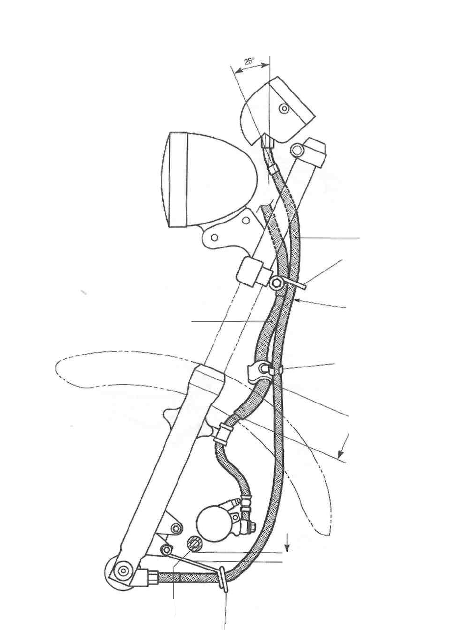
7-15 SERVICING INFORMATION
Caliper
rubber
bushing Guide
Speedometer cable
Guide
Pass the speedometer cable
outside of the brake hose.
Brake hose
Clamp
100 mm (4.0 in)
Max. 10 mm (0.4 in) 4 Do not
contact the guide to the caliper
rubber bushing.
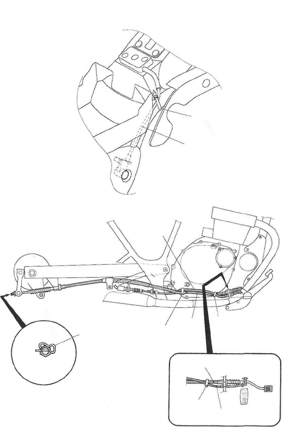
SERVICING INFORMATION 7-16
Clamp
Seat lock cable
Rear brake
switch cable
Clamp
Rear brake
cable
Rear brake
cable clip
Clamp
Rear brake cable
Clamp
Rear brake
switch cable
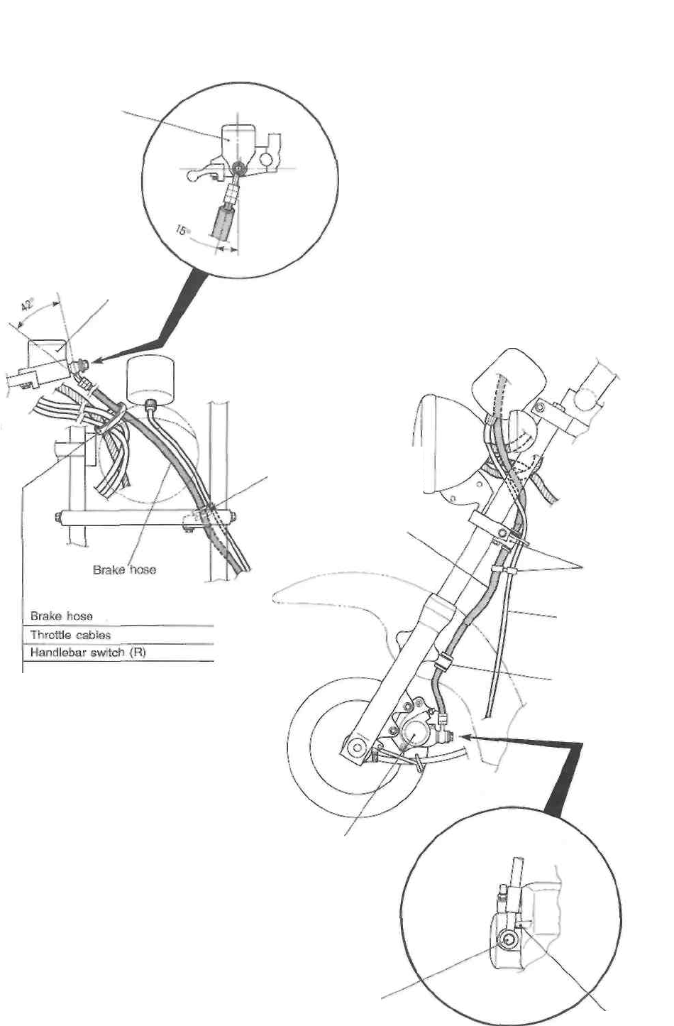
7-17 SERVICING INFORMATION
FRONT BRAKE HOSE ROUTING
Clamp
Master
cylinder
Master
cylinder
Clamp
/ Clamp the brake \
\ hose securely. /
Brake hose
Clamp
Speedometer cable
Clamp
/ Clamp the brake \
\ hose securely. /
Brake
caliper
After touching the brake hose
union to the stopper, tighten the
union bolt to the specified torque.
Stopper
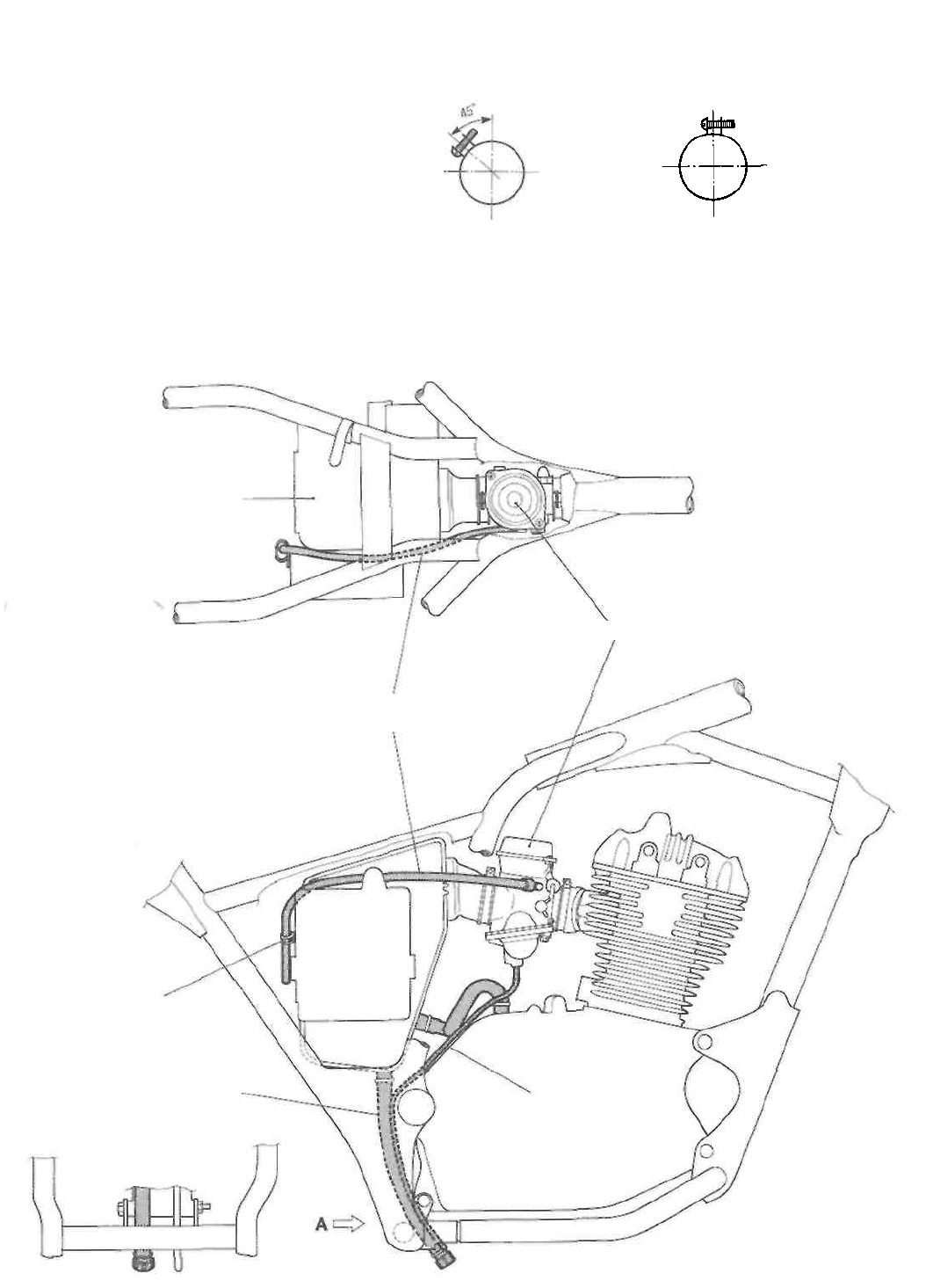
SERVICING INFORMATION 7-18
CARBURETOR HOSE ROUTING
Left
Right Left Right
(Engine side) (Air cleaner side)
Carburetor clamp position
VIEW A
Air cleaner
Carburetor
Carburetor air
vent hose
Battery
case
Clamp
Air cleaner drain hose
Carburetor overflow hose
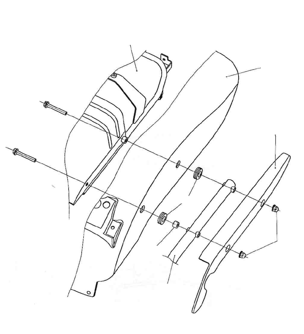
7-19 SERVICING INFORMATION
FRAME REAR COVER SET-UP
Rear fender brace
Rear fender
Frame rear cover
Cushion
Nut
Frame
Spacer
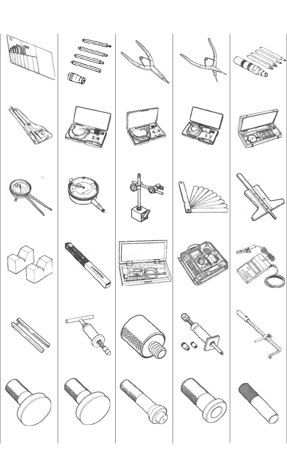
SERVICING INFORMATION 7-20
SPECIAL TOOLS
09900-00401
"L" type hexagon
wrench set
09900-00410 Hexagon
wrench set
09900-06107
Snap ring pliers
09900-06108
Snap ring pliers
09900-09004
Impact driver set
09900-20101
Vernier calipers
(150 mm)
09900-20202
Micrometer
(25-50 mm)
09900-20203
Micrometer
(50-75 mm)
09900-20205
Micrometer
(0-25 mm)
09900-20508
Cylinder gauge set
09900-20605
Dial calipers
09900-20606
Dial gauge
(1/100 mm, 10 mm)
09900-20701
Magnetic stand
09900-20803
Thickness gauge
09900-20805 Tire
depth gauge
09900-21304
V-block set
(100 mm)
09900-22301
09900-22302
Plastigauge
09900-22401
09900-22403 Small
bore gauge
09900-25008 Multi
circuit tester set 09900-26006
Tachometer
09910-20116
Conrod holder
09910-32812
Crankshaft installer
09910-32840
Attachment
09910-34510
Piston pin puller
09913-50121 Oil
seal remover
09913-75510
Bearing installer
09913-75520
Bearing installer
09913-75830
Bearing installer
09913-76010
Bearing installer
09913-84510
Bearing installer
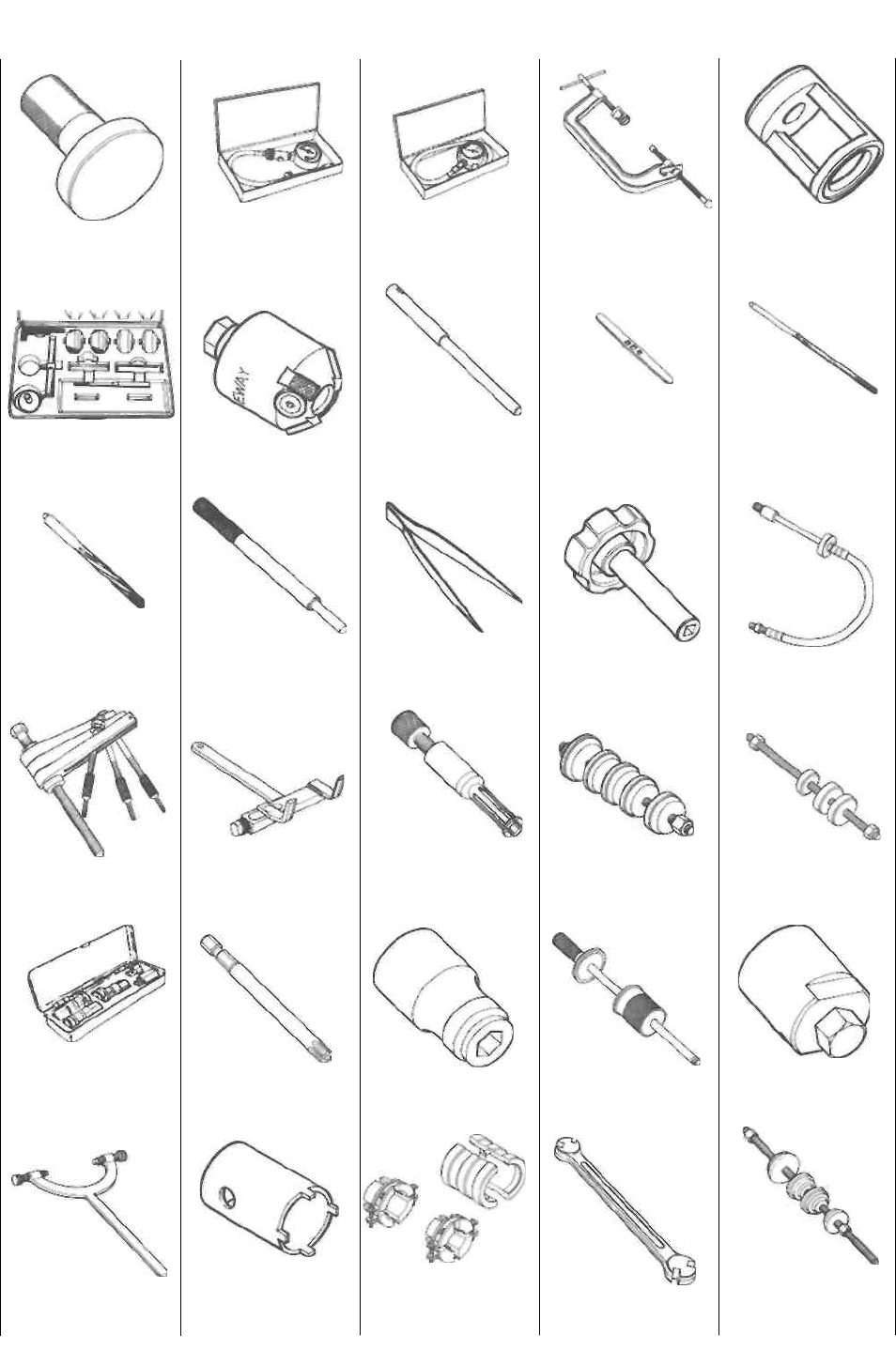
7-21 SERVICING INFORMATION
09913-85210
Bearing installer
09915-64510
Compression gauge
09915-74510
Oil pressure gauge
09916-14510
Valve lifter
09916-14910 Valve
lifter attachment
09916-21111
Valve seat cutter set See p. 3-28.
09916-24450
Solid pilot (N-
100-5.52)
09916-34542 Valve
guide reamer handle
09916-34550 Valve
guide reamer (5.5
mm)
09916-34561
Valve guide reamer
(11.3 mm)
09916-44910
Valve guide remover/
installer
09916-84511
Tweezers
09917-14920
Valve adjuster
wrench
09918-03810
Adaptor
09920-13120
Crankcase separator
09920-53740 Clutch
sleeve hub holder 09923-74510
Bearing remover
09924-84510 Bearing
installer set
09924-84521 Bearing
installer set
09930-10121 Spark
plug socket wrench set 09930-11920
Torx bit JT40H
09930-11940
Bit holder
09930-30102
Sliding shaft
09930-34960
Rotor remover
09930-44913
Rotor holder
09940-14911
Steering stem nut
wrench
09940-52880 Front
fork oil seal installer
set
09940-60113
Spoke nipple wrench
09941-34513 Steering
outer race installer
SERVICING INFORMATION 7-22
09941-50111
Bearing remover
09941-54911
Bearing outer race
remover
09941-74910
Steering bearing
installer
09943-74111 Front
fork oil level gauge
NOTE:
When ordering a special tool, please confirm whether it is available or not.

SERVICING INFORMATION 7-24
CHASSIS
ITEM
N-m
kg-m
Ib-ft
Handlebar clamp bolt
16
1.6
11.5
Handlebar holder nut
45
4.5
32.5
Steering stem head bolt
65
6.5
47.0
Front fork upper clamp bolt
23
2.3
16.5
Front fork lower clamp bolt
33
3.3
24.0
Front fork cap bolt
23
2.3
16.5
Front fork damper rod bolt
20
2.0
14.5
Front axle
65
6.5
47.0
Front axle pinch bolt
23
2.3
16.5
Front brake caliper mounting bolt
39
3.9
28.0
Front brake pad mounting bolt
18
1.8
13.0
Front brake hose union bolt
23
2.3
16.5
Front brake caliper air bleeder valve
7.5
0.75
5.5
Front brake master cylinder mounting bolt
10
1.0
7.0
Front brake disc bolt
23
2.3
16.5
Front footrest bolt
26
2.6
19.0
Swingarm pivot nut
72
7.2
52.0
Rear axle nut
E-03, -28, -33
65
6.5
47.0
The others
78
7.8
56.5
Rear torque link nut (front and rear)
13
1.3
9.5
Rear shock absorber mounting bolt or nut
29
2.9
21.0
Rear sprocket nut
50
5.0
36.0
Rear brake cam lever nut
10
1.0
7.0
Spoke nipple
4.5
0.45
3.5
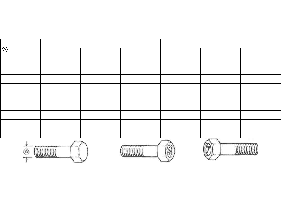
7-25 SERVICING INFORMATION
TIGHTENING TORQUE CHART
For other bolts and nuts listed previously, refer to this chart:
Bolt Diameter
(mm)
Conventional or "4" marked bolt
"7" marked bolt
N-m
kg-m
Ib-ft
N-m
kg-m
Ib-ft
4
1.5
0.15
1.0
2
0.2
1.5
5
3
0.3
2.0
5
0.5
3.5
6
6
0.6
4.5
10
1.0
7.0
8
13
1.3
9.5
23
2.3
16.5
10
29
2.9
21.0
50
5.0
36.0
12
45
4.5
32.5
85
8.5
61.5
14
65
6.5
47.0
135
13.5
97.5
16
105
10.5
76.0
210
21.0
152.0
18
160
16.0
115.5
240
24.0
173.5
Conventional bolt "4" marked bolt "7" marked bolt

SERVICING INFORMATION 7-26
SERVICE DATA
VALVE + GUIDE Unit: mm (in)
ITEM
STANDARD
LIMIT
Valve diam.
IN.
26
(1.0)
EX.
22
(0.9)
Valve clearance (when cold)
IN.
0.03-0.08
(0.001 -0.003)
EX.
0.08-0.13
(0.003-0.005)
Valve guide to valve stem
clearance
IN.
0.025-0.052
(0.0010-0.0020)
EX.
0.040-0.067
(0.0016-0.0026)
Valve stem deflection
IN. & EX.
0.35
(0.014)
Valve guide I.D.
IN. & EX.
5.500-5.512
(0.2165-0.2170)
Valve stem O.D.
IN.
5.460-5.475
(0.2150-0.2156)
EX.
5.445-5.460
(0.2144-0.2150)
Valve stem runout
IN. & EX.
0.05
(0.002)
Valve head thickness
IN. & EX.
0.5
(0.02)
Valve stem end length
IN. & EX.
3.6
(0.14)
Valve seat width
IN. & EX.
0.9-1.1
(0.035-0.043)
Valve head radial runout
IN. & EX.
0.03
(0.001)
Valve spring free length
IN. & EX.
40.1
(1.58)
Valve spring tension
IN. & EX.
18.4-21.6 kg
(40.56-47.62 lbs)
at length 35.0 mm (1.38 in)
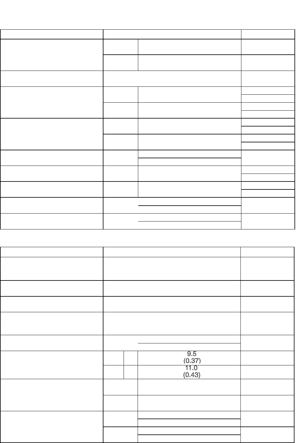
7-27 SERVICING INFORMATION
CAMSHAFT + CYLINDER HEAD
Unit: mm (in)
ITEM
STANDARD
LIMIT
Cam height
IN.
34.990-35.040
(1.3776-1.3795)
34.690
(1.3657)
EX.
35.030-35.080
(1.3791-1.3811)
34.730
(1.3673)
Camshaft journal oil clearance
0.032-0.066
(0.0013-0.0026)
0.150
(0.0059)
Camshaft journal holder I.D.
R. side
25.012-25.025
(0.9847-0.9852)
L. side
20.012-20.025
(0.7879-0.7884)
Camshaft journal O.D.
R. side
24.959-24.980
(0.9826-0.9835)
L. side
19.959-19.980
(0.7858-0.7866)
Camshaft runout
IN. & EX.
0.10
(0.004)
Rocker arm I.D.
IN. & EX.
12.000-12.018
(0.4724-0.4731)
Rocker arm shaft O.D.
IN. & EX.
11.966-11.984
(0.4711-0.4718)
Cylinder head distortion
0.05
(0.002)
Cylinder head cover distortion
0.05
(0.002)
CYLINDER + PISTON + PISTON RING
Unit: mm (in)
ITEM
STANDARD
LIMIT
Compression pressure
1 000-1 400 kPa
/10.0-14.0 kg/cm2\ [
142-199 psi )
800 kPa / 8
kg/cm2 \ {
114 psi j
Piston to cylinder clearance
0.045-0.055
(0.0018-0.0022)
0.120
(0.0047)
Cylinder bore
72.000-72.015
(2.8346-2.8352)
72.085
(2.8380)
Piston diam.
71.950-71.965
(2.8327-2.8333)
Measure at 15 mm (0.6 in) from the skirt end.
71.880
(2.8299)
Cylinder distortion
0.05
(0.002)
Piston ring free end gap
1st
N
Approx.
7.6
(0.30)
2nd
N
Approx.
8.8
(0.35)
Piston ring end gap
1st
0.10-0.30
(0.004-0.012)
0.50
(0.020)
2nd
0.10-0.30
(0.004-0.012)
0.50
(0.020)
Piston ring to groove clearance
1st
0.180
(0.0071)
9nH
0.150
(0.0059)
c.\\\
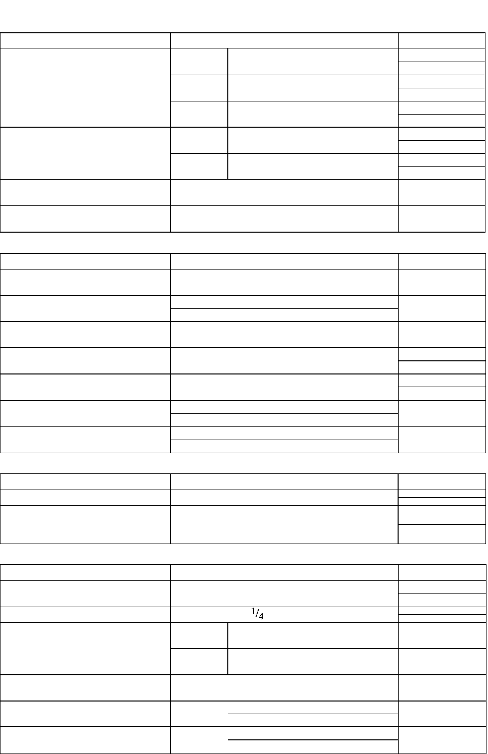
SERVICING INFORMATION 7-28
ITEM
STANDARD
LIMIT
Piston ring groove width
1st
1.01-1.03
(0.040-0.041)
2nd
1.21-1.23
(0.047-0.048)
Oil
2.51-2.53
(0.099-0.100)
Piston ring thickness
1st
0.975-0.990
(0.0384-0.0390)
2nd
1.170-1.190
(0.0461 -0.0469)
Piston pin bore
18.002-18.008
(0.7087-0.7090)
18.030
(0.7098)
Piston pin O.D.
17.992-18.000
(0.7083-0.7087)
17.980
(0.7079)
CONROD + CRANKSHAFT Unit: mm (in)
ITEM
STANDARD
LIMIT
Conrod small end I.D.
18.006-18.014
(0.7089-0.7092)
18.040
(0.7102)
Conrod deflection
3.0
(0.12)
Conrod big end side clearance
0.10-0.65
(0.004-0.026)
1.0
(0.04)
Conrod big end width
20.95-21.00
(0.825-0.827)
Crankshaft web to web width
60.0 + 0.1
(2.362 ± 0.004)
Crankshaft runout
0.05
(0.002)
Balancer spring free length
10.0
(0.39)
OIL PUMP
ITEM
STANDARD
LIMIT
Oil pump reduction ratio
2.812(68/21 x 33/38)
Oil pressure (at 60°C, 140°F)
Above 30 kPa (0.3 kg/cm2, 4.3 psi)
Below 70 kPa (0.7 kg/cm2, 10.0 psi)
at 3 000 r/min.
CLUTCH Unit: mm (in)
ITEM
STANDARD
LIMIT
Clutch cable play
10-15
(0.4-0.6)
Clutch release screw
turn back
Drive plate thickness
No.1
2.92-3.08
(0.115-0.121)
2.62
(0.103)
No.2
3.45-3.55
(0.136-0.140)
3.15
(0.124)
Drive plate claw width
15.9-16.0
(0.626-0.630)
15.0
(0.590)
Driven plate distortion
0.10
(0.004)
Clutch spring free length
40.9
(1.61)
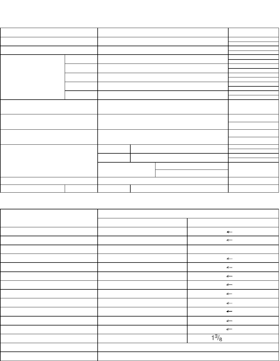
7-29 SERVICING INFORMATION
TRANSMISSION + DRIVE CHAIN Unit: mm (in) Except ratio
ITEM
STANDARD
LIMIT
Primary reduction ratio
3.238(68/21)
Final reduction ratio
2.733(41/15)
Gear ratios
Low
2.636(29/11)
2nd
1.687(27/16)
3rd
1.263(24/19)
4th
1.000(20/20)
Top
0.818(18/22)
Shift fork to groove clearance
0.20-0.40
(0.008-0.016)
0.60
(0.024)
Shift fork groove width
4.25-4.35
(0.167-0.171)
Shift fork thickness
3.95-4.05
(0.156-0.159)
Drive chain
Type
DID520VC5
Links
110
20-pitch length
319.4
(12.57)
Drive chain slack
5-15
(0.2-0.6)
CARBURETOR
ITEM
SPECIFICATION
E-01,02, 04, 25, 34
E-17, 22, 24
Carburetor type
MIKUNI BSR32SS
Bore size
32 mm
I.D. No
13F0
13F2
Idle r/min.
1 300 ± 100 r/min.
Float height
13.0 ±0.5 mm
Main jet (M.J.)
#115
Jet needle (J.N.)
5C60-3rd
Needle jet (N.J.)
P-0
Pilot jet (P.J.)
#17.5
Pilot air jet No. 1 (P.A.J.1)
#87.5
Pilot air jet No.2 (P.A.J.2)
#140
Throttle valve (Th.V.)
#110
Pilot screw (PS.)
2Vá turns out
turns out
Throttle cable play
2-4 mm (0.08-0.16 in)
Starter plunger cable play
0.5-1.0 mm (0.02-0.04 in)
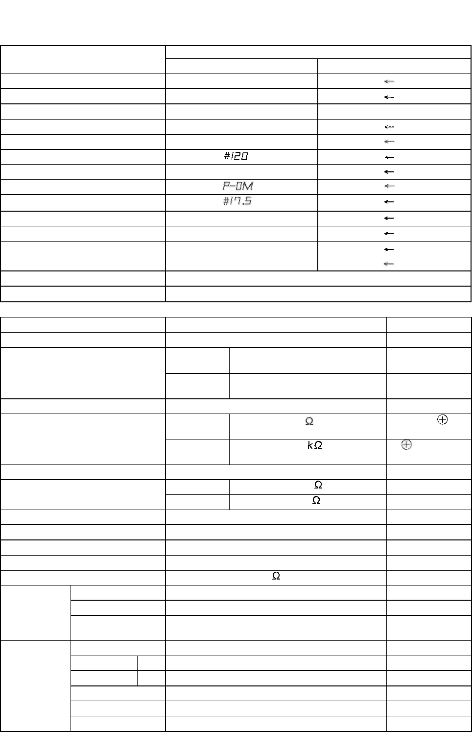
SERVICING INFORMATION 7-30
CARBURETOR
ITEM
SPECIFICATION
E-03, 28
E-33
Carburetor type
MIKUNI BSR32SS
Bore size
32 mm
I.D. No
13F3
13F4
Idle r/min.
1 300 ± 50 r/min.
Float height
13.0 ±0.5 mm
Main jet (M.J.)
Jet needle (J.N.)
5C65
Needle jet (N.J.)
Pilot jet (P.J.)
Pilot air jet No. 1 (P.A.J.1)
#87.5
Pilot air jet No.2 (P.A.J.2)
#120
Throttle valve (Th.V.)
#110
Pilot screw (PS.)
PRE-SET
Throttle cable play
2-4 mm (0.08-0.16 in)
Starter plunger cable play
0.5-1.0 mm (0.02-0.04 in)
ELECTRICAL _________________________________________________ Unit: mm (in)
ITEM
SPECIFICATION
NOTE
Ignition timing
10°B.T.D.C. at1 300r/min.
Spark plug
Type
NGK: DR8EA
DENSO: X24ESR-U
Gap
0.6-0.7
(0.024-0.028)
Spark performance
Over 8 (0.3) at 1 atm.
Ignition coil resistance
Primary
3-5
terminal-
terminal
Secondary
17-28
terminal-
Plug cap
Ignition coil primary peak voltage
More than 200 V
Generator coil resistance
Pick-up
400-650
Bl-G
Charging
0.1-1.5
Y-Y
Pick-up coil peak voltage
More than 5.0 V
Generator Max. output
210Wat5 000r/min.
Generator no-load voltage
More than 60 V (AC) at 5 000 r/min.
Regulated voltage
13.5-15.0 Vat 5 000 r/min.
Starter relay resistance
3-6
Battery
Type designation
FTX7L-BS
Capacity
12V21.6kC(6Ah)/10HR
Standard
electrolyte S.G.
1.320 at 20°C (68°F)
Fuse size
Main
20A
Headlight
HI
15A
Headlight
LO
15A
Turn signal
15A
Ignition
10A
Taillight
10A
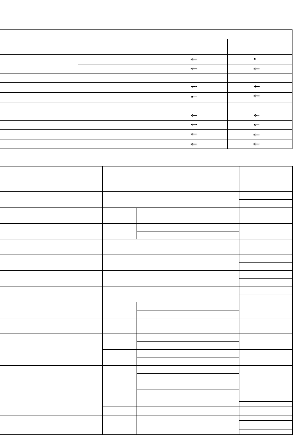
7-31 SERVICING INFORMATION
WATTAGE Unit: W
SPECIFICATION
ITEM
E-01,02, 04,
17,22,25,34
E-24
E-03, 28, 33
Headlight
HI
60
LO
55
Position light
4
Brake light/Taillight
21/5
Turn signal light
21
(rear)
Front turn signal light/Running light
21/5
Speedometer light
1.7
Neutral indicator light
3.4
Turn signal indicator light
3.4
High beam indicator light
1.7
BRAKE + WHEEL Unit: mm (in)
ITEM
STANDARD
LIMIT
Rear brake pedal free travel
20-30
(0.8-1.2)
Rear brake pedal height
50
(2.0)
Brake disc thickness
Front
5.0 ± 0.2
(0.20 ±0.01)
4.5
(0.18)
Brake disc runout
Front
0.30
(0.012)
Master cylinder bore
12.700-12.743
(0.4999-0.5017)
Master cylinder piston diam.
12.657-12.684
(0.4983-0.4994)
Brake caliper cylinder bore
33.960-34.036
(1.3370-1.3400)
Brake caliper piston diam.
33.884-33.934
(1.3340-1.3360)
Brake drum I.D.
Rear
130.7
(5.15)
Brake lining thickness
Rear
1.5
(0.06)
Wheel rim runout
Axial
2.0
(0.08)
Radial
2.0
(0.08)
Wheel axle runout
Front
0.25
(0.010)
Rear
0.25
(0.010)
Wheel rim size
Front
16XMT2.50
Rear
15XMT3.00
Tire size
Front
110/90-16 59P
Rear
130/90-15M/C66P
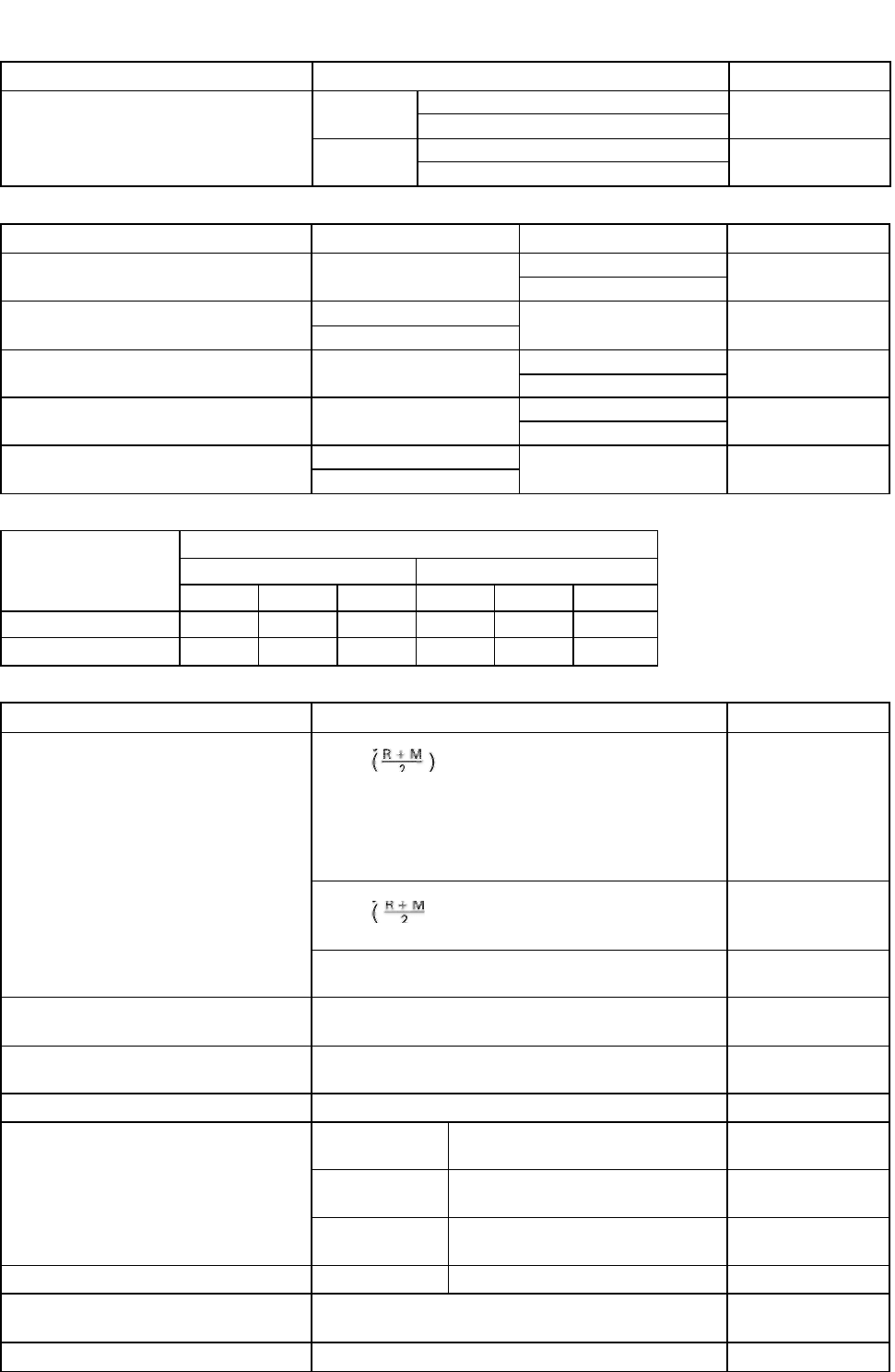
SERVICING INFORMATION 7-32
ITEM
STANDARD
LIMIT
Tire tread depth
Front
1.6
(0.06)
Rear
2.0
(0.08)
SUSPENSION Unit: mm (in)
ITEM
STANDARD
LIMIT
NOTE
Front fork stroke
120
(4.7)
Front fork spring free length
301
(11-9)
Front fork oil level
105
(4.1)
Rear wheel travel
90
(3.5)
Swingarm pivot shaft runout
0.3
(0.01)
TIRE PRESSURE
COLD INFLATION
TIRE PRESSURE
NORMAL RIDING
SOLO RIDING
DUAL RIDING
kPa
kg/cm2
psi
kPa
kg/cm2
psi
FRONT
175
1.75
25
175
1.75
25
REAR
200
2.00
29
225
2.25
33
FUEL + OIL
ITEM
SPECIFICATION
NOTE
Fuel type
Use only unleaded gasoline of at least 87 pump
octane or 91 octane or higher rated by the
research method. Gasoline containing MTBE
(Methyl Tertiary Butyl Ether), less than 10%
ethanol, or less than 5% methanol with
appropriate cosolvents and corrosion inhibitor is
permissible.
E-03, 33
Use only unleaded gasoline of at least 87 pump
octane method) or 91 octane or higher
rated by the Research Method.
E-28
Gasoline used should be graded 91 octane or
higher. An unleaded gasoline is recommended.
The others
Fuel tank including reserve
14 L (3.7/3.1
US/Imp gal)
reserve
2.9 L (0.8/0.6
US/Imp gal)
Engine oil type and grade
SAE10W/40, APISForSG
Engine oil capacity
Change
1 300 ml
(1.4/1.1 US/Imp qt)
Filter change
1 400 ml
(1.5/1.2 US/Imp qt)
Overhaul
1 700 ml
(1.8/1.5 US/Imp qt)
Front fork oil type
SUZU
KlforkoilSS-08(#10)
Front fork oil capacity (each leg)
369 ml
(12.5/13.0 US/Imp oz)
Brake fluid type
DOT 4

Prepared by SUZUKI
MOTOR CORPORATION
Motorcycle Service Department
June, 1998
Part No. 99500-32100-01E
Printed in Japan
224
