American Lincoln 7730 Ride On Sweeper Scrubber Operators Manual
2017-02-01
: Sweepscrub American-Lincoln-7730-Ride-On-Sweeper-Scrubber-Operators-Manual american-lincoln-7730-ride-on-sweeper-scrubber-operators-manual 2188 file product_file
Open the PDF directly: View PDF ![]() .
.
Page Count: 100
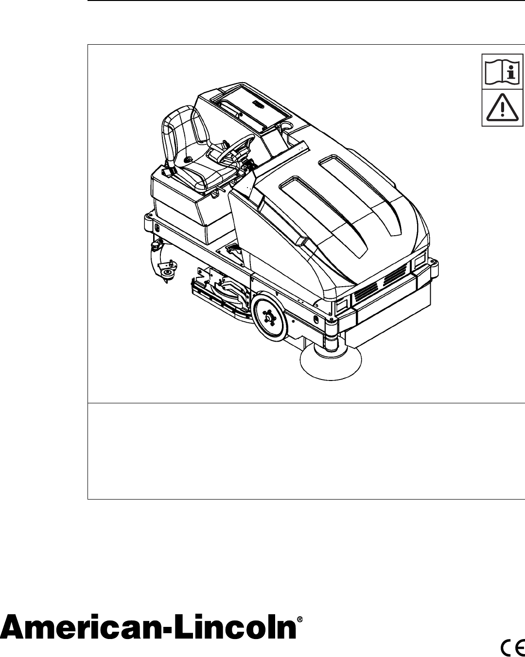
7730
Instructions For Use / Instrucciones de uso
American-Lincoln Models 56515851, 56515853
2/08 revised 4/08 Form No. 56041720
A-English
B- Español

A-2 / ENGLISH
A-2 - FORM NO. 56041720 - 7730
TABLE OF CONTENTS
Introduction ...............................................................................................................A-3
Parts and Service ....................................................................................................... A-3
Nameplate .................................................................................................................. A-3
Uncrating the Machine ................................................................................................A-3
Cautions and Warnings .............................................................................................. A-4
Consignes de prudence et de sécurité .......................................................................A-5
Machine Preparation ...................................................................................... A-6 – A-8
Controls ......................................................................................................... A-9 – A-21
Front Console ........................................................................................................A-9
Key Switch ...........................................................................................................A-10
Forward/Reverse Switch .....................................................................................A-10
Battery Condition & Hour Meter ........................................................................... A-11
Headlight/Taillight Switch (Option) ....................................................................... A-12
Hopper Open Warning Light ................................................................................A-12
Filter Shaker Switch (Dust Control Models) .........................................................A-13
Dust Control Switch .............................................................................................A-13
Scrub Brush Switch ............................................................................................. A-14
Squeegee Switch .................................................................................................A-14
Low Solution & High Recovery Lights .................................................................A-15
Hopper Lift Switch ...............................................................................................A-16
Main & Side Broom Switch ..................................................................................A-16
Spray & Vac Wand Switch (Option) .....................................................................A-17
Esp Switch (Option) .............................................................................................A-17
Main Broom & Side Broom Adjustment Knobs ....................................................A-18
Solution Flow Knob ..............................................................................................A-19
Horn Button .........................................................................................................A-19
Foot Pedal & Parking Brake ................................................................................ A-20
Seat Position Adjustment .....................................................................................A-21
Seat Safety Features ...........................................................................................A-21
Operating Instructions ...............................................................................A-22 – A-30
Pre-Start Checklist ...............................................................................................A-22
Filling Solution Tank .............................................................................................A-22
Starting Machine ..................................................................................................A-23
Transporting Machine ..........................................................................................A-23
The Cleaning Operation ......................................................................................A-23
Standard & Esp Scrubbing Systems ...................................................................A-24
Hints For The Cleaning Operation .......................................................................A-25
Post-Operation Checklist .....................................................................................A-26
Draining The Recovery Tank ....................................................................A-26 – A-27
Inspecting Main Broom & Scrub Brushes ............................................................A-28
Inspecting The Squeegees ..................................................................................A-29
Using The Dust Control Knob ..............................................................................A-30
Checking The Hydraulic Fluid Level ....................................................................A-30
Maintenance ................................................................................................ A-31 – A-45
Service Chart ............................................................................................A-31 – A-32
Maintenance Cautions .........................................................................................A-33
Battery Charging ..................................................................................................A-34
Battery Removal .......................................................................................A-35 – A-36
Replacing Scrub Brushes ....................................................................................A-37
Replacing Rear Squeegee ..................................................................................A-38
Draining Recovery & Solution Tanks ...................................................................A-39
Main Broom Maintenance .........................................................................A-40 – A-42
Side Broom Maintenance .................................................................................... A-43
Dust Control Filter Maintenance ..........................................................................A-44
Dust Flap Maintenance ........................................................................................A-45
Hydraulic System Maintenance ...........................................................................A-45
Troubleshooting ......................................................................................... A-46 – A-47
Technical Specifi cations ........................................................................................A-48

ENGLISH / A-3
FORM NO. 56041720 - 7730 - A-3
INTRODUCTION
This manual will help you get the most from your American-Lincoln Sweeper / Scrubber. Read it thoroughly before operating the machine.
References to “right” and “left” in this manual mean right or left as seen from the driver’s seat.
PARTS AND SERVICE
Repairs, when required, should be performed by your Authorized American-Lincoln Service Center, who employs factory trained service
personnel, and maintains an inventory of American-Lincoln original replacement parts and accessories.
Call the AMERICAN-LINCOLN INDUSTRIAL DEALER named below for repairs or service. Please specify the Model and Serial Number when
discussing your machine.
(Dealer, affi x service sticker here.)
NAMEPLATE
The Model Number and Serial Number of your machine are shown on the Nameplate, located on the wall of the operator’s compartment. This
information is needed when ordering repair parts for the machine. Use the space below to note the Model Number and Serial Number of your
machine for future reference.
MODEL ________________________________________________
SERIAL NUMBER _______________________________________
Note: Reference the separately supplied engine manufacture’s maintenance and operator manual for more detailed engine specifi cation and
service data.
UN-CRATING
Upon delivery, carefully inspect the shipping crate and the machine for damage. If damage is evident, save all parts of the shipping crate so that
they can be inspected by the trucking company that delivered the machine. Contact the trucking company immediately to fi le a freight damage
claim.
1 After removing the crate, remove the wooden blocks next to the wheels and any hold down straps.
2 Check the hydraulic oil level.
3 Read the instructions in the Preparing the Machine For Use section of this manual, then install the battery.
4 Place a ramp next to the front end of the pallet.
5 Read the instructions in the Operating Controls and Operating the Machine sections of this manual. Slowly drive the machine forward down
the ramp to the fl oor. Keep your foot lightly on the brake pedal until the machine is off the pallet.
CAUTION!
Use extreme CAUTION when operating this machine. Be certain that you are thoroughly familiar with all operating instructions before using this
machine. If you have any questions, contact your supervisor or your local American-Lincoln Industrial Dealer.
If the machine malfunctions, do not try to correct the problem unless your supervisor directs you to do so. Have a qualifi ed company mechanic or
an authorized American-Lincoln Dealer service person make any necessary corrections to the equipment.
Use extreme care when working on this machine. Loose clothing, long hair, and jewelry can get caught in moving parts. Turn the Key Switch OFF
and remove the key before servicing the machine. Use good common sense, practice good safety habits and pay attention to the yellow decals on
this machine.
Drive the machine slowly on inclines. The drive pedal will control machine speed while descending inclines. DO NOT turn the machine on an
incline; drive straight up or down.

A-4 / ENGLISH
A-4 - FORM NO. 56041720 - 7730
CAUTIONS AND WARNINGS
SYMBOLS
American-Lincoln uses the symbols below to signal potentially dangerous conditions. Always read this information carefully and take the
necessary steps to protect personnel and property.
DANGER!
Is used to warn of immediate hazards that will cause severe personal injury or death.
WARNING!
Is used to call attention to a situation that could cause severe personal injury.
CAUTION!
Is used to call attention to a situation that could cause minor personal injury or damage to the machine or other property.
Read all instructions before using.
GENERAL SAFETY INSTRUCTIONS
Specifi c Cautions and Warnings are included to warn you of potential danger of machine damage or bodily harm.
WARNING!
* This machine shall be used only by properly trained and authorized persons.
* While on ramps or inclines, avoid sudden stops when loaded. Avoid abrupt sharp turns. Use low speed down hills.
* Keep sparks, fl ame and smoking materials away from battery. Explosive gases are vented during normal operation.
* Charging the battery produces highly explosive hydrogen gas. Charge battery only in well-ventilated areas away from open fl ame. Do not
smoke while charging the battery.
* Remove all jewelry when working near electrical components.
* Turn the key switch off (O) and remove the key, before changing the brushes, and before opening any access panels.
* Never work under a machine without safety blocks or stands to support the machine.
* Do not dispense fl ammable cleaning agents, operate the machine on or near these agents, or operate in areas where fl ammable liquids
exist.
* Do not clean this machine with a pressure washer.
* Only use the brushes provided with the appliance or those specifi ed in the instruction manual. The use of other brushes may impair safety.
CAUTION!
* This machine is not approved for use on public paths or roads.
* This machine is not suitable for picking up hazardous dust.
* Use care when using scarifi er discs and grinding stones. American-Lincoln will not be held responsible for any damage to fl oor surfaces
caused by scarifi ers or grinding stones.
* When operating this machine, ensure that third parties, particularly children, are not endangered.
* Before performing any service function, carefully read all instructions pertaining to that function.
* Do not leave the machine unattended without fi rst turning the key switch off (O), removing the key and applying the parking brake.
* Turn the key switch off (O) before changing the brushes, and before opening any access panels.
* Take precautions to prevent hair, jewelry, or loose clothing from becoming caught in moving parts.
* Use caution when moving this machine in below freezing temperature conditions. Any water in the solution or recovery tanks or in the hose
lines could freeze.
* The battery must be removed from the machine before the machine is scrapped. The disposal of the battery should be safely done in
accordance with your local environmental regulations.
* Do not use on surfaces having a gradient exceeding that marked on the machine.
* All doors and covers are to be positioned as indicated in the instruction manual before using the machine.
SAVE THESE INSTRUCTIONS

ENGLISH / A-5
FORM NO. 56041720 - 7730 - A-5
CONSIGNES DE PRUDENCE ET DE SÉCURITÉ
SYMBOLES
Les symboles reproduits ci-dessous sont utilisés pour attirer l’attention de l’opérateur sur des situations dangereuses. Il est donc conseillé de lire
attentivement ces indications et de prendre les mesures adéquates en vue de protéger le personnel et le matériel.
DANGER!
Ce symbole est utilisé pour mettre l’opérateur en garde contre les risques immédiats pouvant provoquer des dommages corporels graves, voire
entraîner la mort.
ATTENTION!
Ce symbole est utilisé pour attirer l’attention sur une situation susceptible d’entraîner des dommages corporels graves.
PRUDENCE!
Ce symbole est utilisé pour attirer l’attention de l’opérateur sur une situation qui pourrait entraîner des dommages corporels minimes, ou des
dommages à la machine ou à d’autres équipements.
Lire toutes les instructions avant d’utiliser l’appareil.
CONSIGNES GENERALES DE SECURITE
Les consignes spécifi ques de prudence et de sécurité mentionnées ici ont pour but de vous informer de la survenance de tout risque de
dommages matériels ou corporels.
ATTENTION!
* Cette machine ne pourra être utilisée que par du personnel parfaitement entraîné et dûment autorisé.
* Evitez les arrêts subits lorsque la machine est chargée et se trouve sur des rampes ou des plans inclinés. Evitez les virages serrés. Adoptez une
vitesse réduite lorsque la machine est en descente. Ne nettoyez que lorsque la machine monte la pente.
* Eloignez les batteries de toutes fl ammes, étincelles ou substance fumigène. Les gaz explosifs sont ventilés pendant le fonctionnement normal.
* De plus, du gaz hydrogène explosif s’échappe des batteries lorsqu’elles sont en charge. Ne procédez au chargement des batteries que dans une
zone bien ventilée, loin de toute fl amme. Ne fumez pas à proximité des batteries lorsqu’elles sont en charge.
* Otez tous vos bijoux lorsque vous travaillez à proximité de composants électriques.
* Positionnez la clé de contact sur off (O) et déconnectez les batteries avant de procéder à l’entretien des composants électriques.
* Ne travaillez jamais sous une machine sans y avoir placé, au préalable, des blocs de sécurité ou des étais destinés à soutenir la machine
* Ne déversez pas d’agents nettoyants infl ammables, ne faites pas fonctionner la machine à proximité de ces agents ou d’autres liquides
infl ammables.
* Ne nettoyez pas cette machine avec un nettoyeur à pression.
* Utilisez uniquement les brosses fournies avec l’appareil ou celles spécifi ées dans le manuel d’instructions. L’utilisation d’autres brosses peut mettre
la sécurité en péril.
PRUDENCE!
* Cette machine n’est pas conçue pour une utilisation sur les chemins ou voies publics.
* Cette machine n’est pas conçue pour le ramassage des poussières dangereuses.
* N’utilisez pas de disques de scarifi cateur ni de meules. American-Lincoln ne pourra en aucun cas être tenue pour responsable des dommages
occasionnés à vos sols par ce type d’équipement (vous risquez également d’endommager le système d’entraînement des brosses).
* Lors de l’utilisation de cette machine, assurez-vous que des tiers, et notamment des enfants, ne courent pas le moindre risque.
* Avant de procéder à toute opération d’entretien, veuillez lire attentivement toutes les instructions qui s’y rapportent.
* Ne laissez pas la machine sans surveillance sans avoir, au préalable, coupé le contact, enlevé la clé de contact (O) et tiré le frein à main.
* Positionnez la clé de contact sur off (O) avant de remplacer les brosses ou d’ouvrir tout panneau d’accès.
* Prenez toutes les mesures nécessaires pour éviter que les cheveux, les bijoux ou les vêtements amples ne soient entraînés dans les parties
mobiles de la machine.
* Faites attention lorsque vous déplacez cette machine dans un endroit où la température peut descendre sous 0°. Car l’eau contenue dans les
réservoirs de solution ou de récupération ou dans les conduites risquerait de geler et par là même d’endommager les valves et raccords de la
machine. Rincez avec un liquide de lave-glace.
* Prenez soin d’enlever les batteries de la machine avant de mettre cette dernière au rebut. Pour ce qui est de l’élimination des batteries, conformez-
vous aux réglementations locales en matière d’environnement.
* N’utilisez pas sur des surfaces dont la pente dépasse celle mentionnée sur la machine.
* Toutes les portes et couvercles doivent être dans la position mentionnée dans le manuel d’instruction avant de mettre la machine en service.
CONSERVEZ SOIGNEUSEMENT CES INSTRUCTIONS

A-6 / ENGLISH
A-6 - FORM NO. 56041720 - 7730
MACHINE PREPARATION
FIGURE 1
Your 7730 battery machine has been shipped complete, but do not attempt to operate without reading the following instructions:
UNPACKING AND ASSEMBLING MACHINE
The 7730 is shipped on a pallet and held in place with wooden block to stop the machine from moving.
1) Remove wooden blocks holding machine in place.
2) Position a 11° and 48” (121cm) ramp on base of pallet.
11 DEGREE
48 INCHES
FIGURE 2
ENGLISH / A-7
FORM NO. 56041720 - 7730 - A-7
MACHINE PREPARATION
3) Push machine down the ramp onto a fl at surface.
4) Install battery.
- Turn the key to the “O” position
- Lift the hood up and pull the battery lever up to the right.
- Use a battery lifting device with a 2000 LB. (907KG) capacity to place the battery into the battery tray.
- Push battery lever down to the left to lock the battery into place.
- Plug the battery power connector into the machine power connector.
- Lower the hood into place.
5) Charge battery as shown in the manual. Read battery manufacturer literature for battery care and maintenance.
WARNING!
Do not charge batteries on a concrete grounded surface. Hydrogen gas is formed during the charging operation and is explosive. Only
charge batteries in a well ventilated area with the lid open. Avoid any smoking, open fl ame, or electrical sparks.
FIGURE 3 FIGURE 4
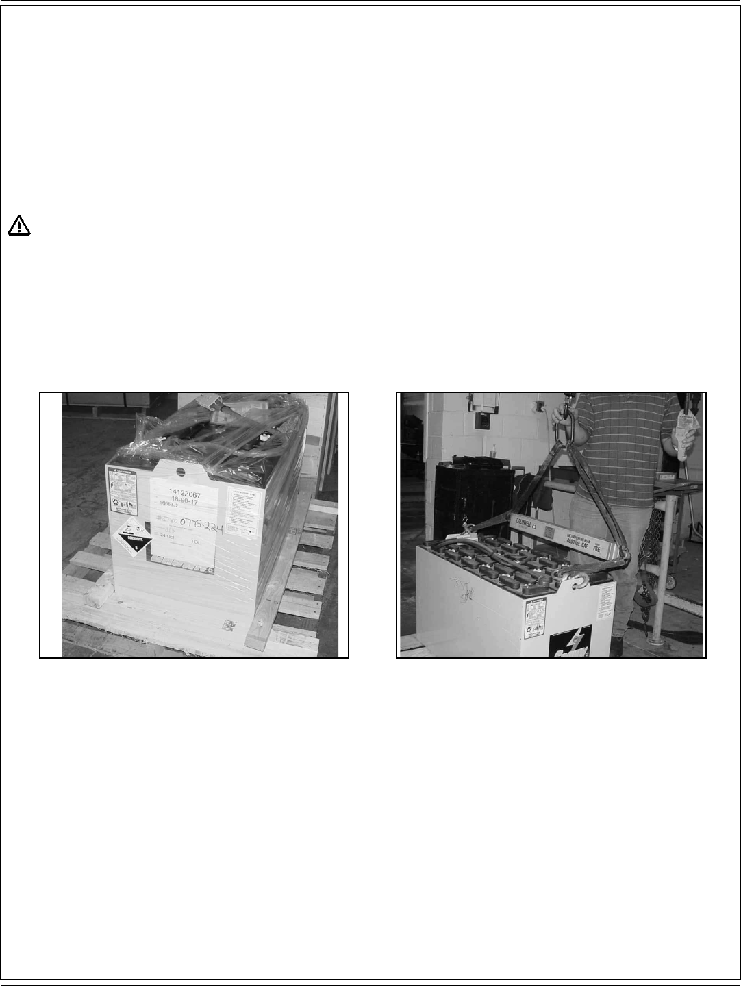
UNPACKING BATTERY
The battery is shipped separately on a pallet wrapped in plastic as shown in fi gure 3. Remove the plastic and use a 2000 LB. (907KG) capacity
lifting device to lower the battery into the battery compartment as shown in fi gure 4.
A-8 / ENGLISH
A-8 - FORM NO. 56041720 - 7730
MACHINE PREPARATION
FIGURE 7 FIGURE 8
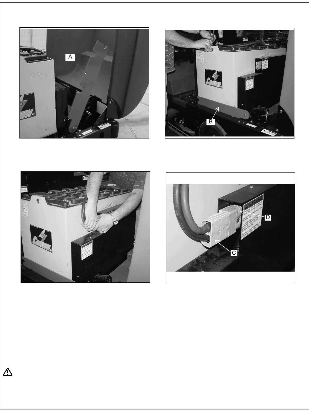
BATTERY INSTALLATION
1. Lift the machine front cover.
2. Fig 5. Rotate the battery lever (A) to the right.
3. Lower the battery into place using a 2000 LB. (907 KG) capacity lifting device.
4. Fig 6. Rotate the battery lever (B) to the left to lock the battery into place.
5. Connect battery wires according to manufacturer’s direction.
6. Fig 7 and 8. Connect the battery power connector (C) to the machine power connector (D).
7. Lower the machine front cover into place.
WARNING!
Do not leave charged batteries on concrete surface, they will discharge.
FIGURE 5 FIGURE 6
ENGLISH / A-9
FORM NO. 56041720 - 7730 - A-9
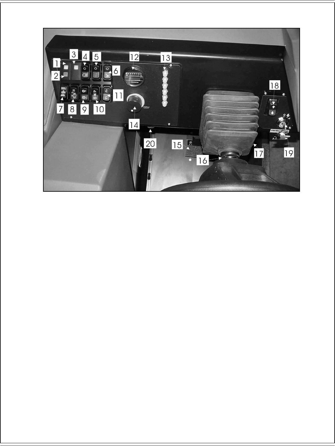
CONTROLS
FIGURE 9
1. High recovery light.
2. Low solution light
3. Hopper open light.
4. Light switch.
5. ESP switch.
6. Spray Vac Wand switch.
7. Scrub brush switch.
8. Squeegee switch.
9. Main side broom switch.
10. Filter shaker/Dust control switch.
11. Hopper switch.
12. Battery condition meter/Hour meter.
13. Circuit breakers.
14. Solution fl ow knob.
15. Parking Brake.
16. Steering wheel adjustment lever.
17. Foot throttle.
18. Forward/Reverse switch.
19. Key switch.
20. Horn

A-10 / ENGLISH
A-10 - FORM NO. 56041720 - 7730
CONTROLS
FIGURE 10
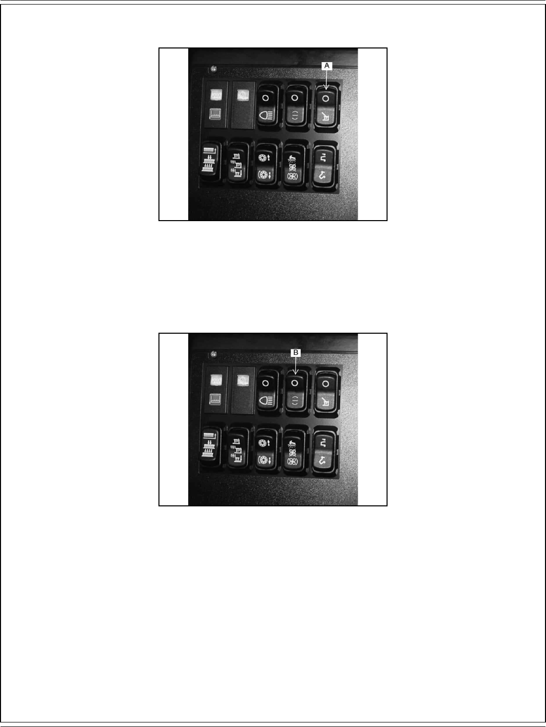
KEY SWITCH
The keyed ignition switch (A) is located on the ioperator’s console as shown in fi gure 10.
The “OFF” position (O position) will shut off the machine. The IGN/ON position (I position) provides power to all machine systems and
accessories.
FIGURE 11
FORWARD / REVERSE SWITCH
The forward/reverse switch (B) is located on the operator’s console as shown in fi gure 11. Pressing the upper half of the forward/reverse switch
will result in the machine moving forward when the foot throttle is depressed. Pressing lower half of the forward/reverse lever switch will result in
the machine moving backward when the foot throttle is depressed.
ENGLISH / A-11
FORM NO. 56041720 - 7730 - A-11
CONTROLS
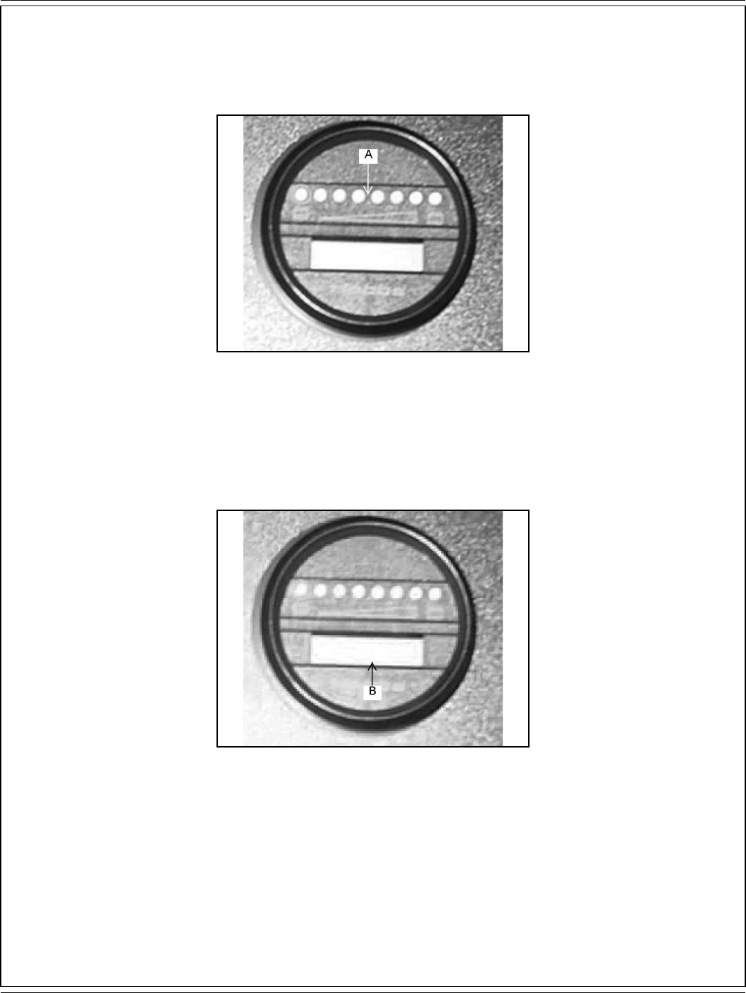
FIGURE 12
BATTERY CONDITION METER
The battery condition meter (A) is located on the instrument panel as shown in fi gure 12. The condition meter indicates the level of charge in
the batteries. The batteries are suffi ciently charged when all of the LED’s are illuminated amber as shown on the ramp illustration. Charge the
batteries when one red LED is illuminated on the left at the bottom of the ramp diagram and the scrub brushes stop. Do not operate the machine.
FIGURE 13
NOTE
To reengage, the key must be returned to the “OFF” position.
HOUR METER
The hour meter (B) is located on the instrument panel as shown in fi gure 13. Tthe diplay will show the total hours the machine has been in
operation. The meter is activated when the key switch is placed in the ignition position. The meter can be used to determine when maintenance
should be done on the machine.
A-12 / ENGLISH
A-12 - FORM NO. 56041720 - 7730
CONTROLS
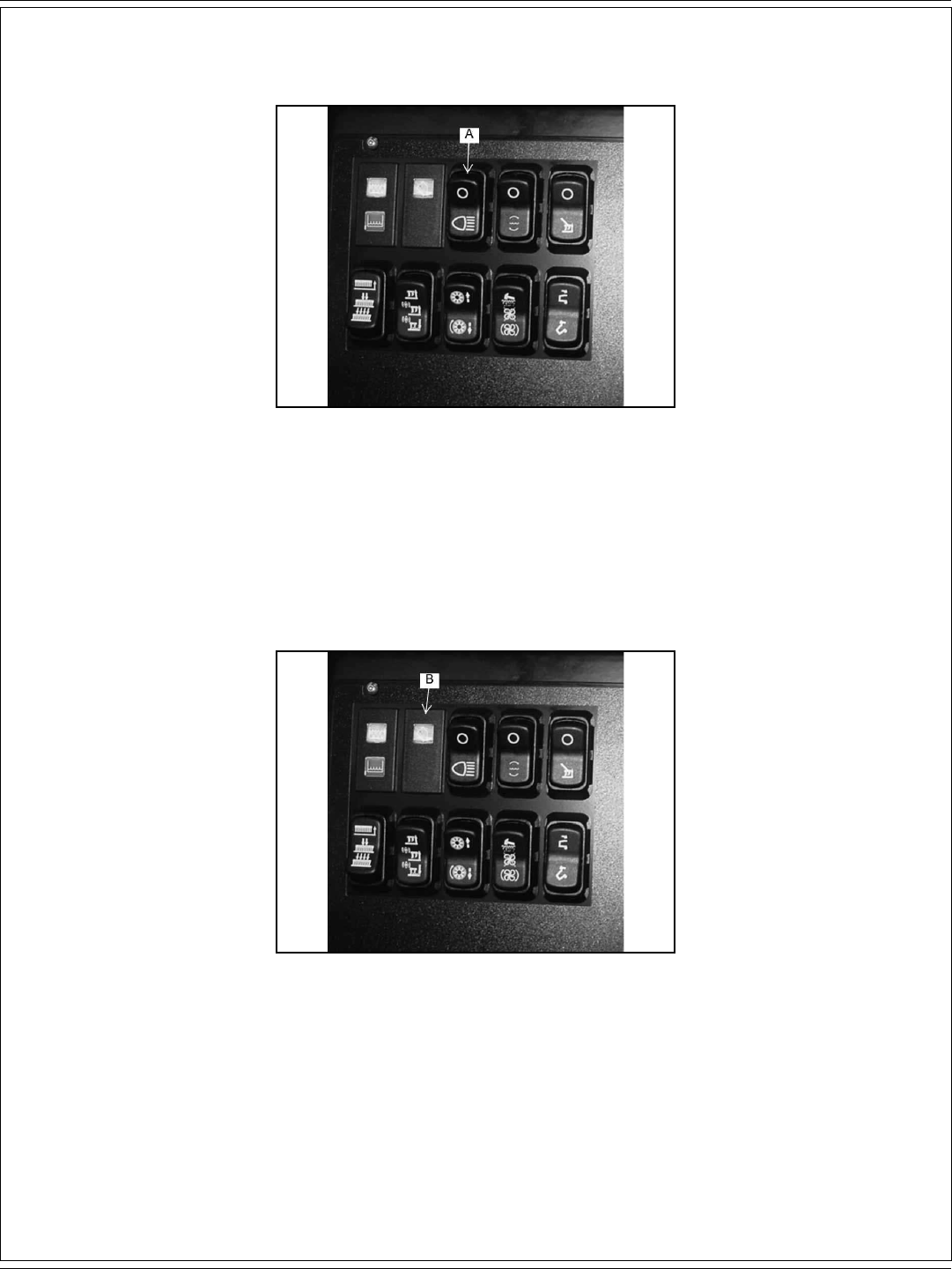
FIGURE 14
HEADLIGHT/TAILIGHT SWITCH (Optional)
The light switch (A) is located on the instrument panel as shown in fi gure 14. By pressing on the lower half of the switch the headlights and
taillights will be activated. Pressing the upper half of the switch will turn off the lights.
FIGURE 15
HOPPER OPEN WARNING LIGHT
The hopper open light switch (B) is located on the instrument panel as shown in fi gure 15. When the hopper is open, the light is illuminated the
broom and the dust control fan will stop.

ENGLISH / A-13
FORM NO. 56041720 - 7730 - A-13
CONTROLS
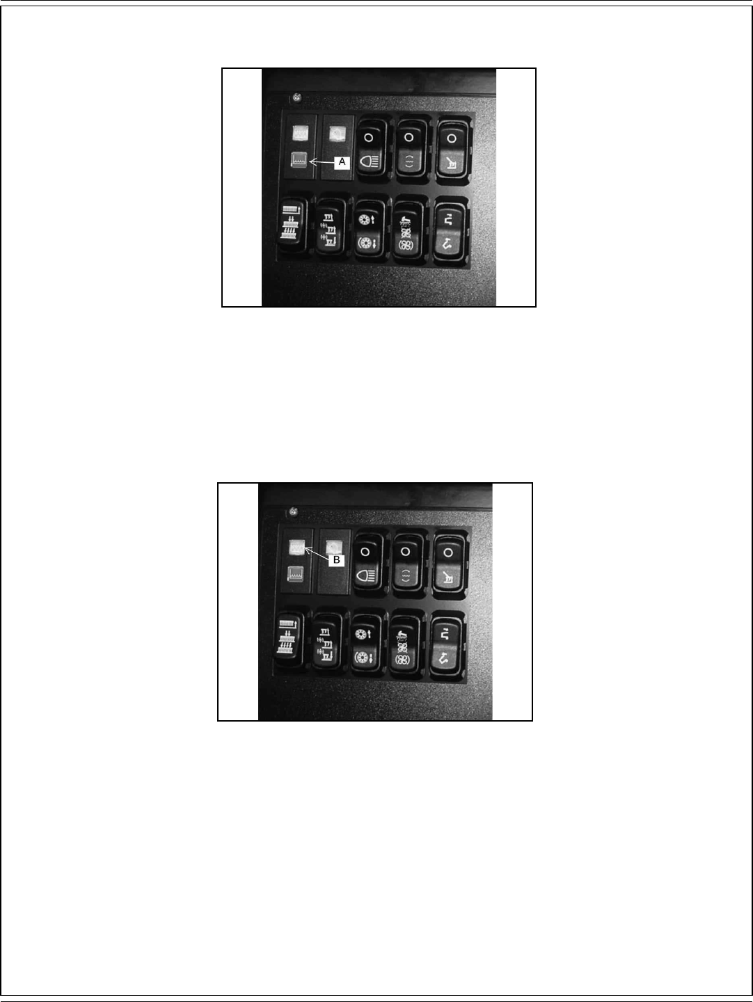
FIGURE 16
FILTER SHAKER SWITCH (Only models with dust control)
The fi lter shaker switch (A) is located on the instrument panel as shown in fi gure 16. By pressing and holding in the upper half of the switch, it will
activate the fi lter shaker motors for 20 to 30 seconds. Releasing the switch, returns to the off position.
The dust control fan will stop when the fi lter shaker has been activated. The fi lter shaker will only operate with the hopper in the “DOWN” position.
FIGURE 17
DUST CONTROL SWITCH
The dust control switch (B) is located on the instrument panel as shown in fi gure 17. To turn on the dust control system for normal sweeping,
press the lower half of the switch.
WARNING!
Turn the dust control switch to the center “OFF” position while wet sweeping. Water will damage the fi lter and cause premature fi lter
failure.

A-14 / ENGLISH
A-14 - FORM NO. 56041720 - 7730
CONTROLS
FIGURE 18
SCRUB BRUSH SWITCH
The scrub brush switch (A) is located on the left of the instrument panel as shown in fi gure 18. Pressing the top half of the switch raises the scrub
deck and turns off the brushes. The middle switch position lowers the brushes to the normal down position for scrubbing. Pressing the lower half
of the switch lowers the scrub deck to the heavy down position, supplying additional downward pressure for extremely dirty surfaces.
NOTE
Lowering the scrub deck does not turn on the brushes. The brushes turn on automatically when the machine moves forward or reverse.
FIGURE 19
SQUEEGEE SWITCH
The squeegee switch (B) is located on the the instrument panel as shown in fi gure 19. Pressing the lower half of the switch lowers the squeegee
and activates the squeegee vacuum. Pressing the upper half of the switch will turn off the squeegee vacuum and raise the squeegee. In the
middle position the switch will raise the squeegee. In this position the vacuum remains on to allow vacuuming the water that is left in the squeegee
recovery hose. This prevents water from dripping on the fl oor with the squeegee raised. If the squeegee is lowered and the direction of the
machine is reversed (activated by the Drive pedal) the squeegee will automatically raise. Moving forward the squeegee will automatically return to
the lowered position.
ENGLISH / A-15
FORM NO. 56041720 - 7730 - A-15
CONTROLS
FIGURE 20
LOW SOLUTION LIGHT
The low solution warning light (A) is located on the instrument panel as shown in fi gure 20. The low solution warning light illuminates when the
solution tank is empty, marking the end of the scrubbing cycle.
FIGURE 21
HIGH RECOVERY LIGHT
The high recovery warning light (B) is located on the instrument panel as shown in fi gure 21. The light will illuminate approximately 5 minutes
before the recovery tank is full, giving ample time to complete the scrubbing cycle, before the mechanical fl oat shuts off the vacuum to the
recovery tank.
A-16 / ENGLISH
A-16 - FORM NO. 56041720 - 7730
CONTROLS
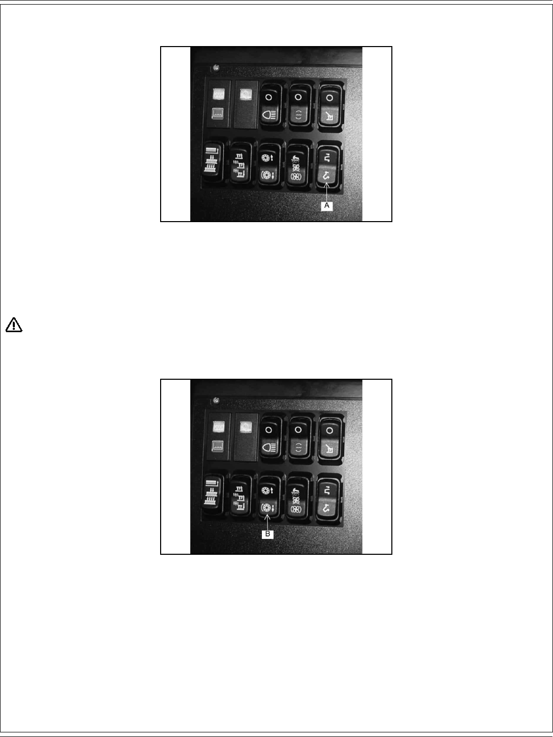
FIGURE 22
HOPPER LIFT SWITCH
The hopper lift switch (A) is located on the instrument panel as shown in fi gure 22. The switch controls the operation of the hopper lift system. To
raise the hopper for dumping, press and hold the lower half of the switch until the hopper reaches the desired height, then release. To close the
hopper press in and hold the upper half of the switch until the hopper closes completely then release.
WARNING!
To prevent the hopper from closing while doing maintenance lock the hopper in the open position into place with the safety arm.
FIGURE 23
SIDE BROOM and MAIN BROOM SWITCH
The side broom and main broom switch (B) is located on the instrument panel as shown in fi gure 23. By pressing in the upper half of the switch,
the side and main broom are raised and turned off. To lower and turn on both brooms, press the lower half of the switch.
ENGLISH / A-17
FORM NO. 56041720 - 7730 - A-17
CONTROLS
FIGURE 24
SPRAY AND VAC WAND SWITCH (Optional)
The spray and vac wand switch (A) is located on the instrument panel as shown in fi gure 24. Pressing the bottom half of switch turns on the
vacuum motor and the solution pump. Pressing the top half of the switch turns the vacuum motor and solution pump off.
FIGURE 25
ESP SWITCH (Optional)
The ESP switch (B) is located on the instrument panel as shown in fi gure 25. The ESP switch transfers water from the recovery tank through a
fi lter and into the solution tank. When the switch is in the down position the pump will operate when the high recovery light is illuminated. Clean
the recovery tank when the tank is emptied.
NOTE
Do not place clean water in the recovery tank when using ESP option, the solution tank could become overfi lled during operation.

A-18 / ENGLISH
A-18 - FORM NO. 56041720 - 7730
CONTROLS
FIGURE 26
SIDE BROOM ADJUSTMENT
The side broom adjustment knob (A) for changing the sweep height to compensate for broom wear, is located in front of the machine to the right of
the dust control fi lter as shown in fi gure 26. Turning the knob to the left (counterclockwise) will lower the side broom.
FIGURE 27
MAIN BROOM ADJUSTMENT
The main broom adjustment knob (B) for changing the sweep height to compensate for broom wear, is located in front of the machine to the right
of the dust control fi lter as shown in fi gure 27. Turning the knob to the left (counterclockwise) will lower the main broom.
ENGLISH / A-19
FORM NO. 56041720 - 7730 - A-19
CONTROLS
FIGURE 28
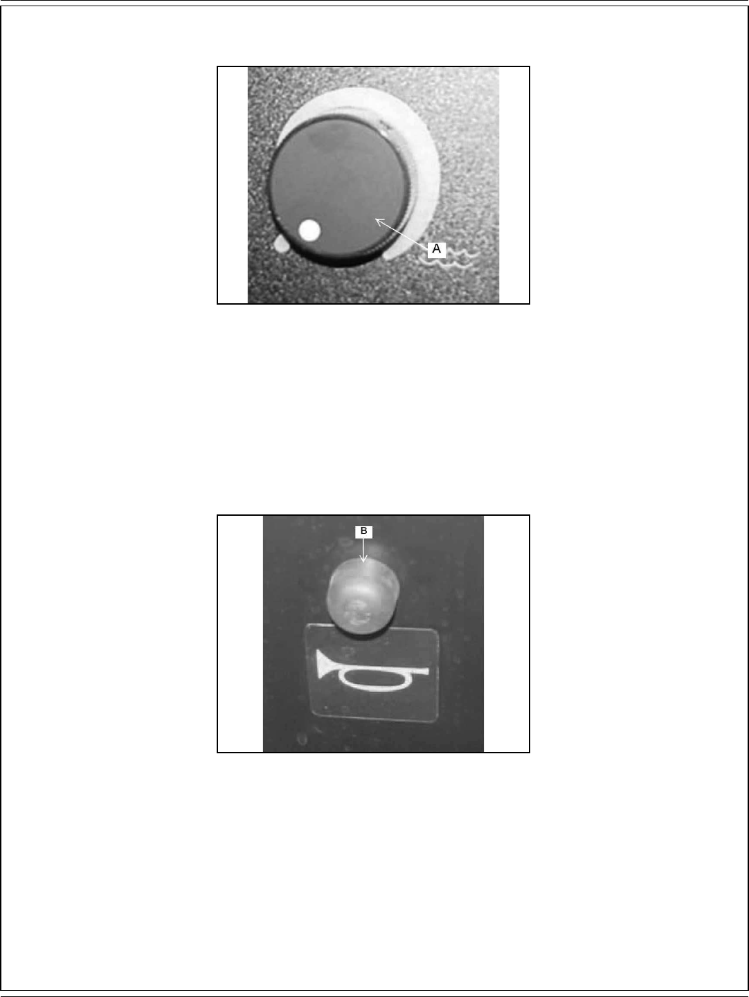
SOLUTION FLOW KNOB
The solution fl ow knob (A) is located on the instrument panel as shown in fi gure 28. Turning the knob clockwise will increase the fl ow of solution
and water. The farther the solution control knob is turned the heavier the fl ow of water and solution will be. Turning the knob counterclockwise will
decrease the fl ow of the water and solution. To turn the water and solution off turn the knob all the way counterclockwise.
NOTE
For best results, discontinue application of solution 10 feet before stopping or making a 90° or 180° turn.
FIGURE 29
HORN BUTTON
The horn button (B) is located on the instrument panel as shown in fi gure 29. The horn button is always active. Pressing the horn button will
sound the horn.
A-20 / ENGLISH
A-20 - FORM NO. 56041720 - 7730
CONTROLS
FIGURE 30
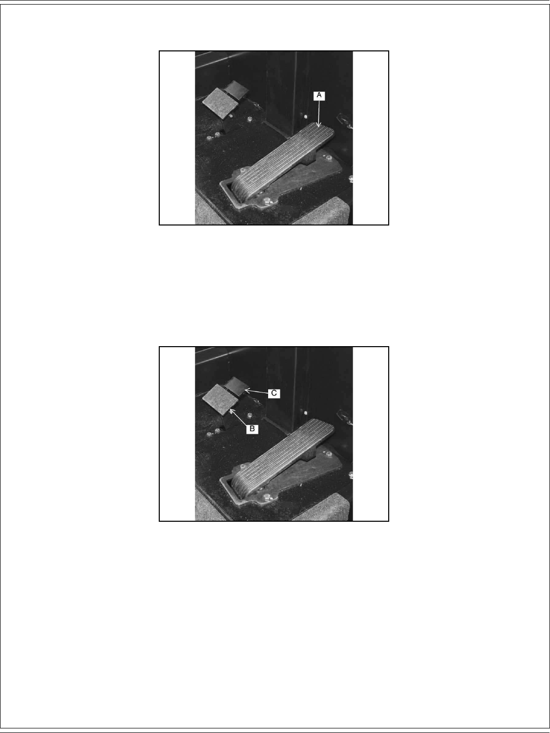
FOOT THROTTLE
The foot throttle (A) is located to the right of the brake pedal on the fl oor of the operator’s compartment as shown in fi gure 30. This pedal controls
the machine travel speed. Press the forward/reverse switch to chose the travel direction, and then press down on the foot throttle to move set the
machine in motion. Increase the foot pressure to increase the travel speed.
FIGURE 31
PARKING BRAKE
The parking brake is located on the fl oor of the machine left of the foot throttle as shown in fi gure 31. To set the parking brake, press down on the
foot pedal (B) and the press down the lock (C). To unlock the parking brake, push down on the upper portion of the foor pedal and release.

ENGLISH / A-21
FORM NO. 56041720 - 7730 - A-21
CONTROLS
FIGURE 34
SEAT POSITION ADJUSTMENT
The seat position adjustment lever (A) is located on the front of the seat to the left as seen in fi gure 34. The lever is spring loaded to the lock
position. To adjust the seat, push the lever to the left and move the seat to the desired position and then release the lever to lock the seat into
place.
SAFETY FEATURES
SEAT SAFETY SWITCH - Machine will not move and parking brake will set if this switch is not activated.
SPEED INTERLOCK - Maximum machine speed will be reduced while scrub brushes are in use.
BRUSHES OFF IN NEUTRAL - Scrub brushes automatically disengage when machine is idle.
AUTOMATIC RECOVERY VACUUM SHUT-OFF - Vacuum fans will shut down when recovery tank is full.

A-22 / ENGLISH
A-22 - FORM NO. 56041720 - 7730
OPERATING INSTRUCTIONS
NOTE
Before starting the engine, perform the pre-start checklist.Before starting the engine, perform the pre-start checklist.
PRE-START CHECKLIST
Check hydraulic fl uid level.
Check all systems for leaks.
Check brakes and controls for proper operation.
Check broom patterns.
Check hydraulic connections for leaks.
Check to ensure that all covers, panels and access doors are securely closed.
FIGURE 35 FIGURE 36
TO FILL SOLUTION TANK
Open the solution lid (A) located on the top left side of the machine as shown in fi gure 36. Fill the solution tank (B) with 55 gallons of water and the
correct mixture of American-Lincoln Commercial cleaner for the job on hand. Close the solution tank.
ENGLISH / A-23
FORM NO. 56041720 - 7730 - A-23
OPERATING INSTRUCTIONS
TO START MACHINE
Turn key to “I” position.
TO TRANSPORT MACHINE
1. Make sure the brushes and squeegees are in the up or raised position with all other controls in the off position.
2. Release the parking brake.
3. Push the forward/reverse switch to desired position (up for forward and down for reverse)
4. Push down on the foot throttle to obtain desired travel speed.
5. Release the foot throttle to slow down or stop when on a fl at surface. To slow the machine when decending down an inclined surface
reduce foot pedal pressure.
NOTE
The pedal proportional braking sytem is designed to regulate machine speed according to the foot thottle position. This sytem is designed to bring
the machine to a stop in controlled manner. When driving down an inclined surface, reduce foot pedal pressure rather than releasing the foot throttle.
This will provide a controlled stop and prevent the drive wheel from locking.
WARNING!
Do not turn the steering wheel sharply when the machine is in motion. The sweeper is very responsive to movement of the steering
wheel. Do not make sudden turns.
FIGURE 38
TO BEGIN THE CLEANING OPERATION
1. Select the operating mode
NORMAL = ESP
2. Lower brushes to the desired position.
SCRUB DECK = NORMAL RANGE OR HEAVY
3. Place the squeegee switch in the lower position.
SQUEEGEE BLADE = LOWER
4. Move solution control knob to the desired setting and begin operation.
SCRUBBING THE AVERAGE FLOOR WITH LIGHT TO MEDIUM SOILAGE
In this operation, cleaning is accomplished in one pass, with simultaneous solution feed, scrubbing and dirty water pick up. The rate of solution
feed and the speed of travel required will vary with fl oor condition. This knowledge will come with operator experience.

A-24 / ENGLISH
A-24 - FORM NO. 56041720 - 7730
OPERATING INSTRUCTIONS
FIGURE 39
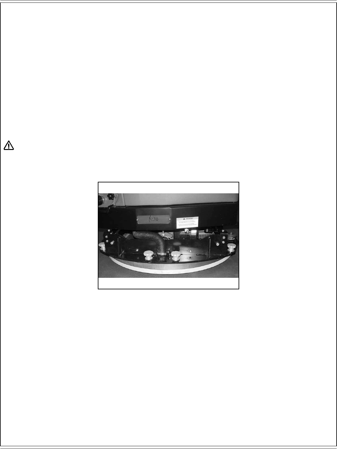
THE NON-RECYCLING OR STANDARD SCRUBBING MODE
During the scrubbing process, detergent solution water from the solution tank (A) is fed to the solution line. There it is fed to the fl oor where
three disc scrubbing brushes (B) work to dislodge soil. After scrubbing, the dirty solution is vacuumed from the fl oor by the squeegee (C) and
discharged into the containment chamber in the forward portion of the recovery tank (D), where a system of baffl es helps to clarify the solution.
Sensors in each tank will indicate, by lights on the control panel, when the water in the solution tank is too low or when the water in the recovery
tank is too high.
FIGURE 40
ESP OPERATING MODE
During the scrubbing process, fi ltered water from the solution tank (A) is fed to the solution line, where it combines with detergent. This mixture
is then fed to the fl oor where two or three disc scrubbing brushes (B) work to dislodge soil. After scrubbing, the dirty solution is vacuumed from
the fl oor by the squeegee (C) and discharged into the recovery tank (D). At intervals, a fl oat switch activates the recycling pump (E), which sends
fi ltered solution from the recovery tank to the solution tank.
ENGLISH / A-25
FORM NO. 56041720 - 7730 - A-25
OPERATING INSTRUCTIONS
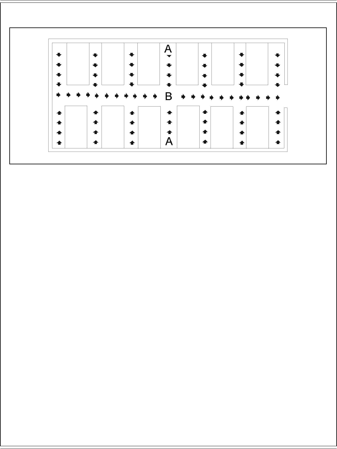
FIGURE 41
SCRUBBING PATH
· Scrub in straight paths. Do not bump posts. Do not scrape the sides of the machine.
· When the machine is in motion, do not push the directional/speed control pedal all the way forward. This is the same as starting in “high” and
will put a strain on the motor and drive system.
· Plan your sweeping and scrubbing in advance. Try to arrange long runs with minimum stopping and starting. Sweep debris from narrow
aisles (A) out into main aisle (B) ahead of time. Do an entire fl oor, or section at on time.
· Pick up oversize debris before sweeping.
· Allow a few inches of overlap of sweep and scrub paths. This will eliminate leaving dirty patches.
· Don’t turn steering wheel to sharply when machine is in motion. The machine is very responsive to movement of the steering wheel; so avoid
sudden turns.
· When placing the machine in motion, avoid slamming the drive pedal all the way forward suddenly. This is equivalent to starting out in
“HIGH” and puts needless strain on the drive system. Periodically, turn the sweeping broom end for end to prevent the bristles from “settling”
in one direction.
TO STOP THE CLEANING OPERATION
Discontinue the cleaning operation when the low solution light or the high recovery light illuminates, this indicates the solution tank is empty or
recovery tank is full. Discontinue the scrubbing cycle, put all controls in the forward position for transport and drive to the drain area.
NOTE
After stopping, perform these post operation checks.
A-26 / ENGLISH
A-26 - FORM NO. 56041720 - 7730
OPERATING INSTRUCTIONS
POST OPERATION CHECKLIST
Check Battery Condition and recharge if necessary.
1. Check all fl aps for wear, damage and adjustment.
2. Drain and clean recovery tank.
3. Clean recovery tank screen and fl oat.
4. Check scrub brushes for wear or damage.
5. Check rear and side squeegee for wear, damage and adjustment.
6. Clean the debris in hopper
7. Check main and side broom for wear or damage.
FIGURE 42 FIGURE 43
FIGURE 44 FIGURE 45
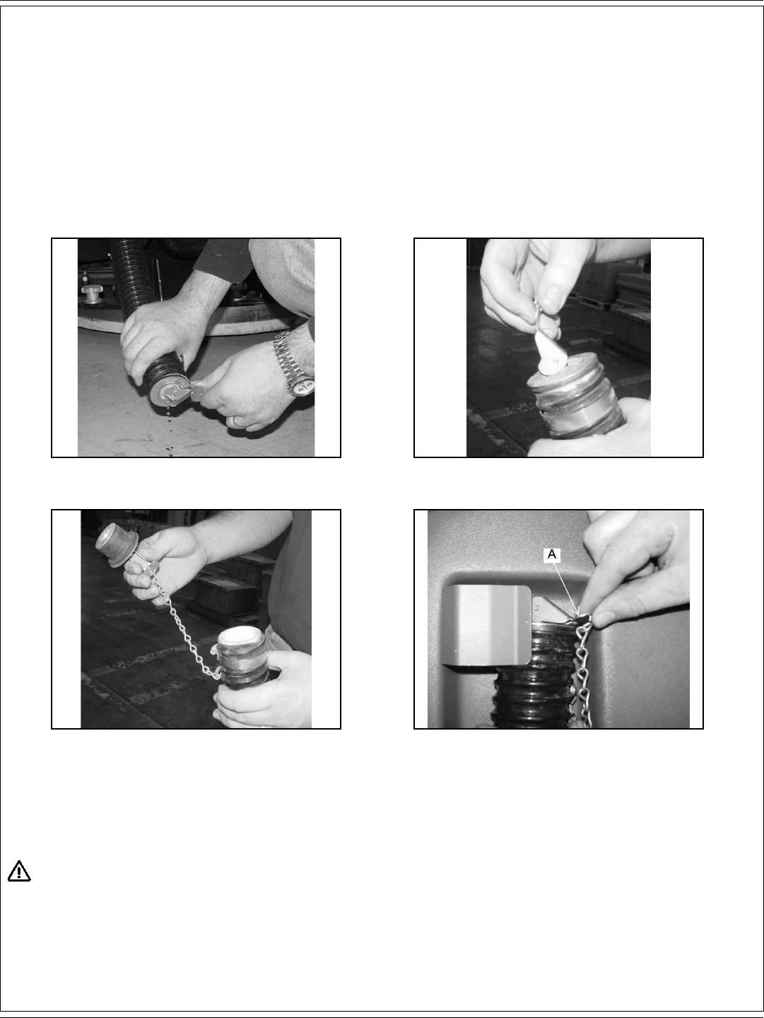
TO DRAIN RECOVERY TANK
The drain hose for the recovery tank is located on the back of the machine. To drain the tank, remove and lower the hose and place in a suitable
fl oor drain as shown in fi gure 42. Open the drain hose plug as shown in fi gure 43 and 44. When replacing the drain hose make sure the clip (A)
on the drain hose plug is facing out as shown in Fig. 45.
IMPORTANT!
Improper discharge of wastewater will damage the environment and is illegal. The U.S. Environmental Protection Agency has
established certain regulations regarding discharge of wastewater. The local city and state regulations regarding wastewater discharge
may be in effect in your area. Understand and follow the regulations in your area. Be aware of the environmental hazards associated
with the substances you dispose of.
ENGLISH / A-27
FORM NO. 56041720 - 7730 - A-27
OPERATING INSTRUCTIONS
FIGURE 46 FIGURE 47
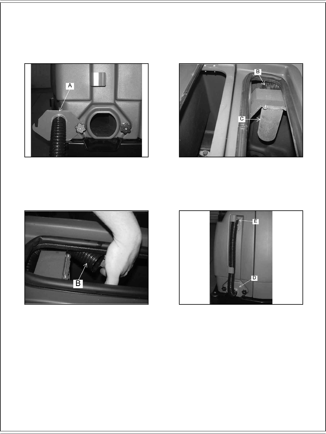
FIGURE 48 FIGURE 49
When the draining operation is complete, open the recovery tank clean out door (A) as shown in fi gure 46 and fl ush the recovery drain hose (B)
as shown in fi gure 47 & 48. Clean the recovery tank and recovery tank screen (C) as shown in fi gure 47. Close the recovery tank clean out door
(D), drain hose plug (E), the recovery tank lid and clip the drain hose into place as shown in fi gure 49.
A-28 / ENGLISH
A-28 - FORM NO. 56041720 - 7730
OPERATING INSTRUCTIONS
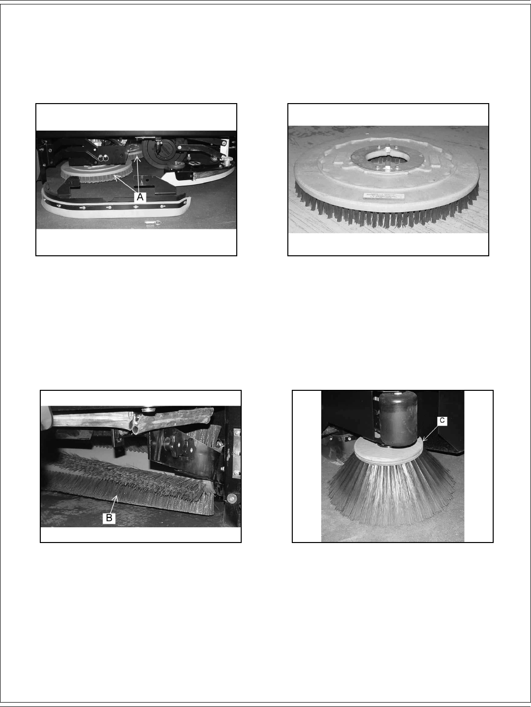
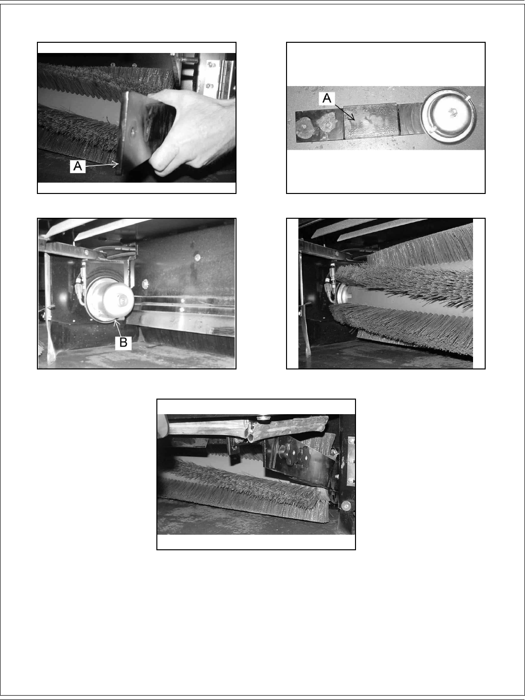
FIGURE 50 FIGURE 51
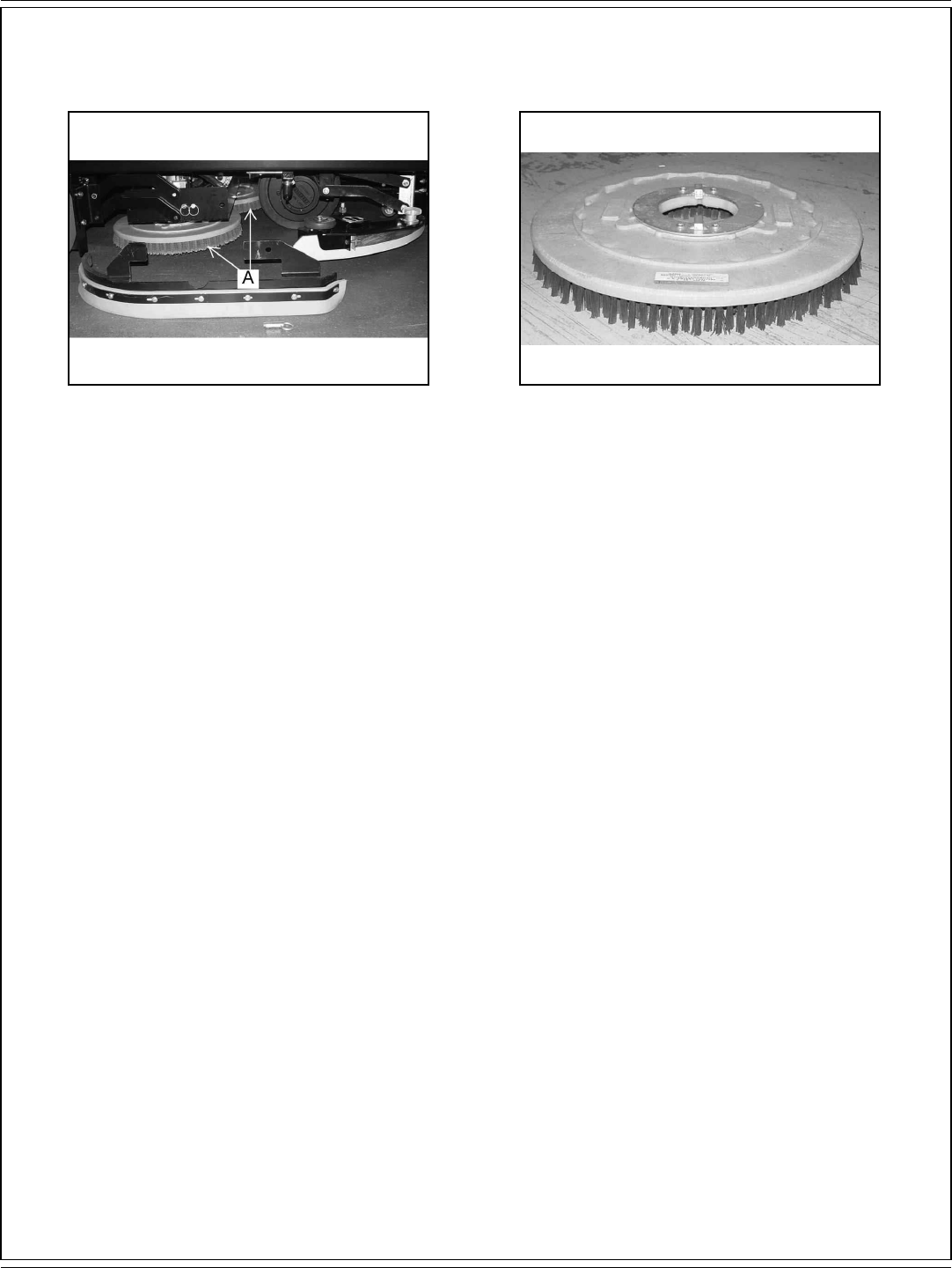
Inspect the disk scrub brushes (A) and replace when the bristles are reduced to 3/4 inch length as shown in fi gure 50 and 51.
FIGURE 52 FIGURE 53
Inspect the main and side brooms. When the bristles are worn to 1.5 inches in length, replace the main broom (B) as shown in fi gure 52. Replace
the side broom (C) when bristles are worn to 3.5 inches as shown in fi gure 53.

ENGLISH / A-29
FORM NO. 56041720 - 7730 - A-29
OPERATING INSTRUCTIONS
FIGURE 54 FIGURE 55
FIGURE 56
Inspect the rear (A) and side squeegee (B) blades for wear. If the wiping edge becomes rounded, remove and reinstall so the unworn edge is
now the wiping edge. This process can be repeated until all four edges are worn. If the squeegee blade has become rippled, it will need to be
replaced.
A-30 / ENGLISH
A-30 - FORM NO. 56041720 - 7730
OPERATING INSTRUCTIONS
FIGURE 57 FIGURE 58
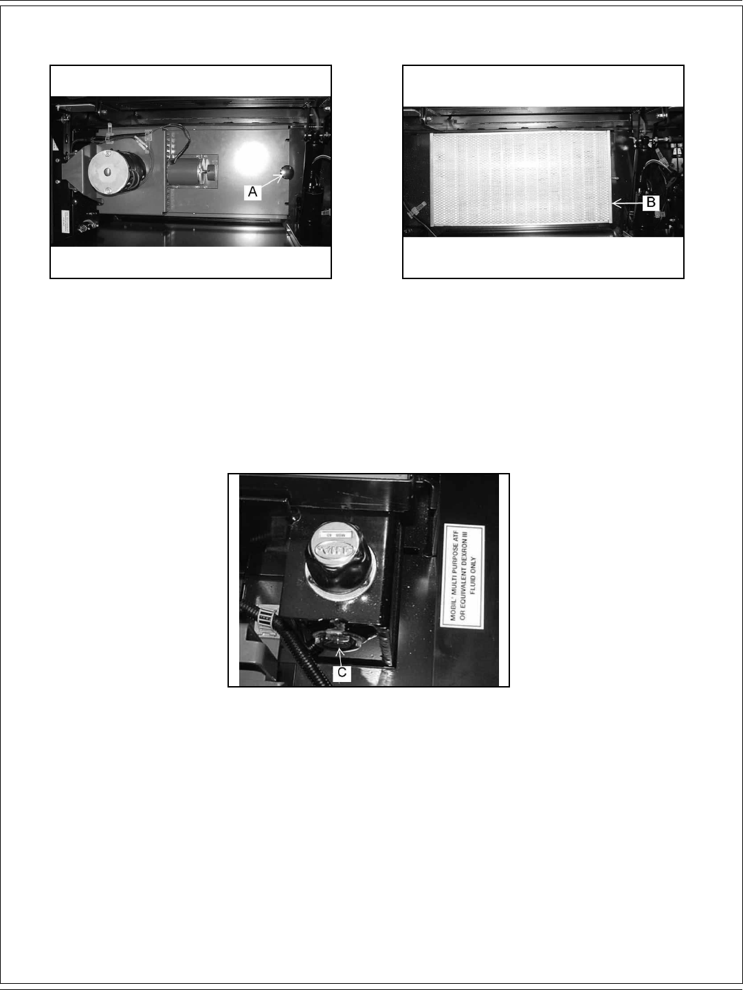
DUST CONTROL KNOB
The dust control knob (A) is used to hold the dust control fi lter cover down as shown in fi gure 57. The dust control fi lter (B) is located under the
front cover and will need to be removed periodically for cleaning or replacement. Removal of the fi lter panel requires no tools. The front cover
must be opened to gain access to the fi lter compartment. The panel fi lter is held in place by a hinged frame and knob. To remove the panel fi lter,
turn the knob counterclockwise and lift the hinged frame. The panel fi lter can now be lifted out and cleaned or replaced. To install the replacement
panel fi lter, place a new fi lter in the machine, lower the frame and twist the knob clockwise to lock the fi lter in place.
FIGURE 59
HYDRAULIC RESERVOIR FLUID LEVEL SIGHT GAUGE
The fl uid level sight gauge (C) is located on the right side of the machine under the front cover as shown in fi gure 59. The sight gauge is used to
indicate the level of fl uid in the reservoir. The fl uid level must be visible in the sight gauge when the hopper is in the down position.

ENGLISH / A-31
FORM NO. 56041720 - 7730 - A-31
MAINTENANCE
SERVICE CHART
Check items for proper operation. If service is required, please contact an authorized American-Lincoln Technology distributor. For best
performance, replace worn parts with genuine American-Lincoln parts.
EVERY eight (8) HOURS or DAILY check and clean/adjust if necessary:
1 Inspect panel fi lter for damage and clean them.
2 Inspect and clean hopper.
3 Inspect and clean recovery tank screens and fi lters.
4 Check hydraulic fl uid level.
5 Check all fl aps for wear or damage.
6 Check brooms for wear or damage, adjust as required.
7 Check brake pedal and parking brake.
8 Check hydraulic oil fi lter.
9 Check battery electrolyte level.
10 Check all fl uid system components for leaks.
50 HOUR (WEEKLY) MAINTENANCE CHECKLIST
11 Check solution tank (recycling or ESP system).
12 Check solution fi lter screen (recycling or ESP system).
13 Check recovery tank.
14 Check recovery tank screens and fi lters.
15 Inspect scrub brushes for wear or damage.
16 Inspect rear and side squeegees for wear or damage.
17 Check battery electrolyte level.
18 Check all hydraulic hoses for wear or cuts.
19 Rotate main brush.
20 Clean or replace panel fi lter.
21 Lubricate squeegee casters.
100 HOUR MAINTENANCE CHECKLIST
22 Lubricate front wheel bearings.
23 Lubricate all moving joints.
250 HOUR MAINTENANCE CHECKLIST
24 Lubricate squeegee casters.
25 Clean solution tank and fi lter screen.
26 Replace hydraulic fi lter element.
27 Clean hydraulic reservoir.

A-32 / ENGLISH
A-32 - FORM NO. 56041720 - 7730
13314 1211 25 65 84 26 27 195
201
6
18
179
7
2421
2322 6
2
5
16
15
16

ENGLISH / A-33
FORM NO. 56041720 - 7730 - A-33
MAINTENANCE
For safety, read and follow the service precautions below. Know the hazards associated with the equipment you are working on to prevent
personal injury or damage to equipment.
For service assistance, consult your nearest American-Lincoln dealer. For best performance replace worn parts with genuine American-Lincoln
parts.
Refer all maintenance and service requirements to qualifi ed maintenance personnel.
DO NOT attempt to service this machine until you have read and understand all safety warnings associated with the equipment you are working
on.
WARNING!
* Maintenance and repairs must be done by authorized personnel only.
* Electrical repairs must be done by authorized personnel only. Consult your American-Lincoln Authorized Service Person to do
service procedures. Use only genuine American-Lincoln parts.
* Always park on a level surface, turn key off, and engage parking brake before working on the machine to keep it from creeping or
rolling.
* Maintenance and repairs must be done by authorized personnel only. Always empty the solution tank and the recovery tank before
doing any maintenance. Keep all fasteners tight. Keep adjustments according to the specifi cations as shown in the Service Manual
for this machine.
* Always wear eye protection and protective clothing when working near batteries. Do not put tools or other metal objects across the
topes of the batteries. NO SMOKING.
* To prevent damage to the machine, and discharge across the tops of the batteries, do not fi ll the batteries above the bottom of the
tube in each cell. Wipe any acid from the machine or the tops of the batteries. Do not add acid to a battery after installation.
* The hopper could fall and cause serious injury. Always engage the hopper safety arm before working under the hopper.
* To maintain the stability of this machine in normal operation, the overhead guard, or similar equipment installed by the
manufacturer as original equipment should not be removed. If it becomes necessary to remove such equipment for repair or
maintenance, this equipment must be reinstalled before machine is placed back in operation.
A-34 / ENGLISH
A-34 - FORM NO. 56041720 - 7730
MAINTENANCE
FIGURE 60 FIGURE 61
FIGURE 62
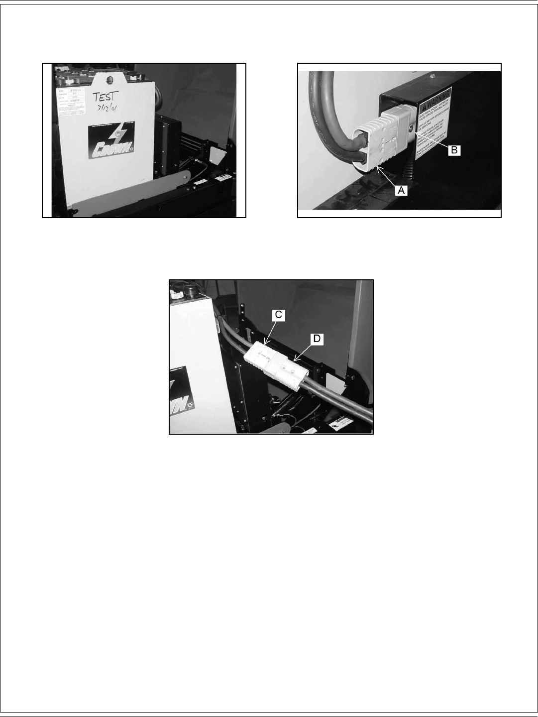
BATTERY CHARGING INSTRUCTIONS
When the battery conditioning meter is illuminated with one red LED light, the battery needs to be recharged. To prevent interruption of the
cleaning cycle, charge the battery after using.
1. Fig. 60. Lift the machine front cover to access the battery.
2. Fig. 61. Disconnect the battery power connector (A) from the machine power connector (B).
3. Fig. 62. Plug the battery power connector (C) into the battery charger (D).
4. Follow manufacturer’s charging instructions provided on the charger.
5. Maintain electrolyte level in battery, check after charging. Add distilled water as needed.
ENGLISH / A-35
FORM NO. 56041720 - 7730 - A-35
MAINTENANCE
WARNING!
* Do not remove the battery from the machine if there is waste in the solution tank.
* Hydrogen gas is formed during the charging operation and is explosive! Only charge batteries in a well-ventilated area with the lid
open. Avoid any open fl ame or electrical sparks. Pulling out the charger plug, with the charger still on, will cause an arc and must
be avoided.
* Batteries are heavy. Use lifting device with specifi ed rated capacity.
* Always remove jewelry, wear protective clothing, and face protection when working near batteries.
* Lead acid batteries generate gases, which cause explosions. Keep sparks and fl ames away from batteries charge the batteries only
in area with good ventilation. NO SMOKING!
* To prevent an explosion, disconnect the AC plug from the receptacle before connection or disconnect the DC plug on the charger.
* The battery box can slide off a forklift and cause severe personal injury or damage to equipment. Ensure that the battery box is
properly secured to the forks of the forklift during transport, drive and stop with caution.
FIGURE 63 FIGURE 64
FIGURE 65 FIGURE 66
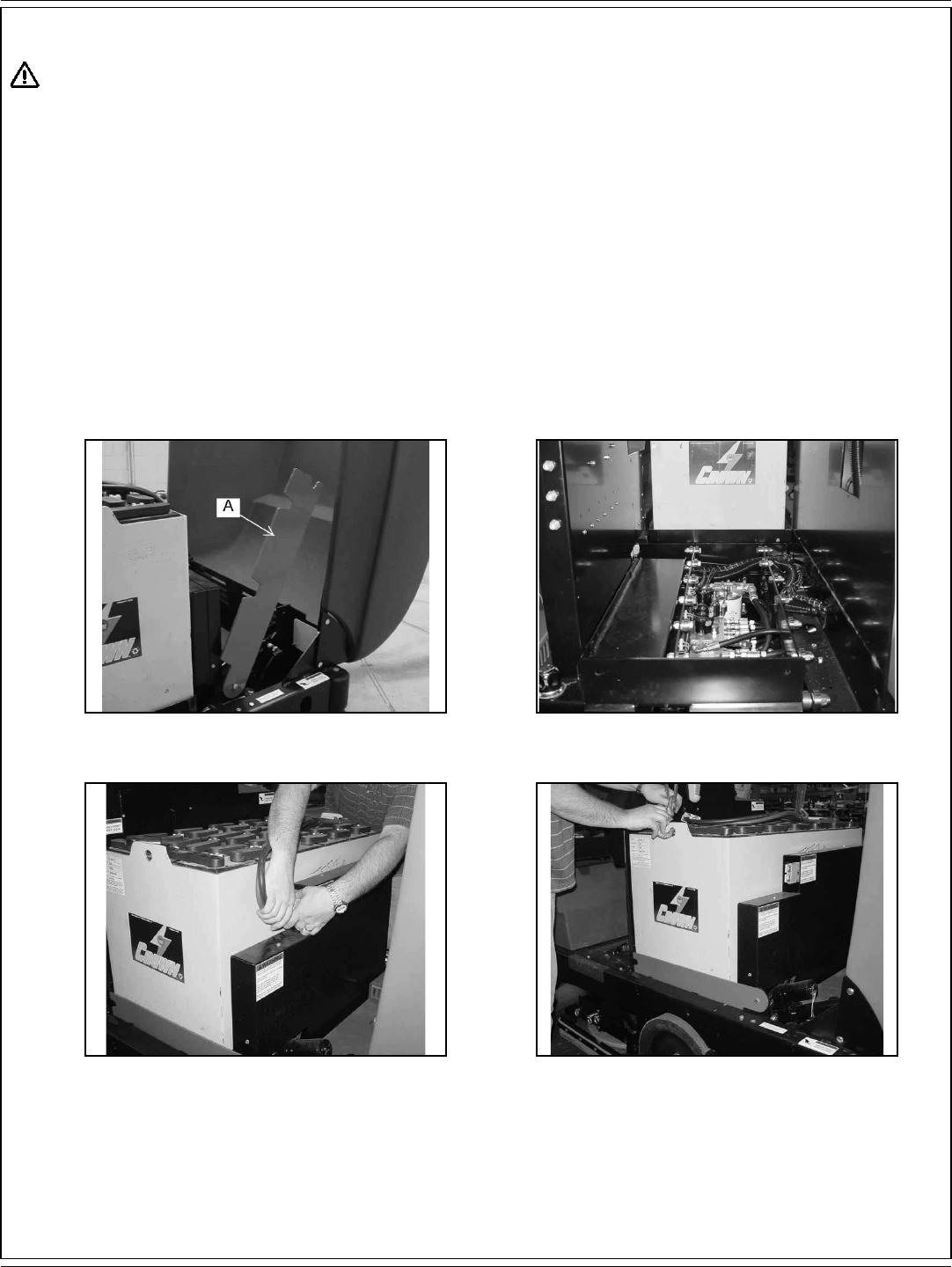
BATTERY REMOVAL
When removing batteries
1. Fig. 63 & 64. Lift the machine front cover to access battery compartment and rotate the battery lever (A) to the right.
2. Fig. 65. Unplug the battery power connector from the machine power connector.
3. Fig. 66. Lift the battery out using a 2000 LB. (907 KG) capacity lifting device.

A-36 / ENGLISH
A-36 - FORM NO. 56041720 - 7730
MAINTENANCE
BATTERY REMOVAL WITH THE BATTERY ROLLOUT OPTION
When removing batteries
1. Lift the machine front cover to access battery compartment.
2. Unplug the battery power connector from the machine power connector.
3. Fig. 68. Line up battery cart locator pins (A) with slots (B) in frame and lock in place.
4. Fig. 69 & 70. Rotate the battery lever (C) to the right and roll battery out on to cart.
FIGURE 67 FIGURE 68
FIGURE 69 FIGURE 70
ENGLISH / A-37
FORM NO. 56041720 - 7730 - A-37
MAINTENANCE
FIGURE 71 FIGURE 72
REPLACING SCRUB BRUSHES
1. Raise the scrub brush deck by pressing the “Scrub Brush” switch on the instrument panel.
2. Press the brush latches in to release the scrub brush.
3. Remove the old scrub brush (A).
4. Snap the new scrub brush into place.
REPLACING PADS ON A PAD DRIVER
Install a new pad when the old one is worn or dirty. The pad driver assembly is removed and installed the same way a standard scrub brush is
(See replacing the scrub brush).
1. The pad driver is held in place by a ring. Pull the pad driver straight down to remove it.
2. Remove the pad holder using the spring wire retainer.
3. Replace the worn pad.
A-38 / ENGLISH
A-38 - FORM NO. 56041720 - 7730
MAINTENANCE
FIGURE 73 FIGURE 74
FIGURE 75
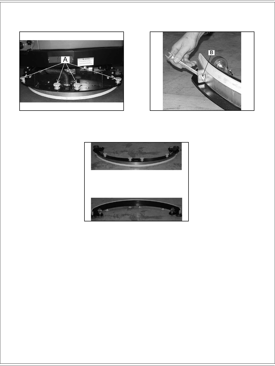
REPLACING REAR SQUEEGEE
The squeegee will require service when the inner edge of the blades become round with wear, impairing the wiping action or water pick up.
1. Fig. 73. Loosen the four aluminum knobs (A).
2. Fig. 74. Remove the squeegee tool and turn upside down to service the blades or the caster wheels. The squeegee blades are
designed to rotate to use an unworn edge. Loosen the clamp bolts (B).
3. Install blades so that the outer blade is 3/16” longer than the inner blades. This is achieved by assembling the top edge of the blade
against the squeegee tool weldment.
4. Reinstall the squeegee clamp band and tighten the clamp bolt.
ENGLISH / A-39
FORM NO. 56041720 - 7730 - A-39
MAINTENANCE
FIGURE 76
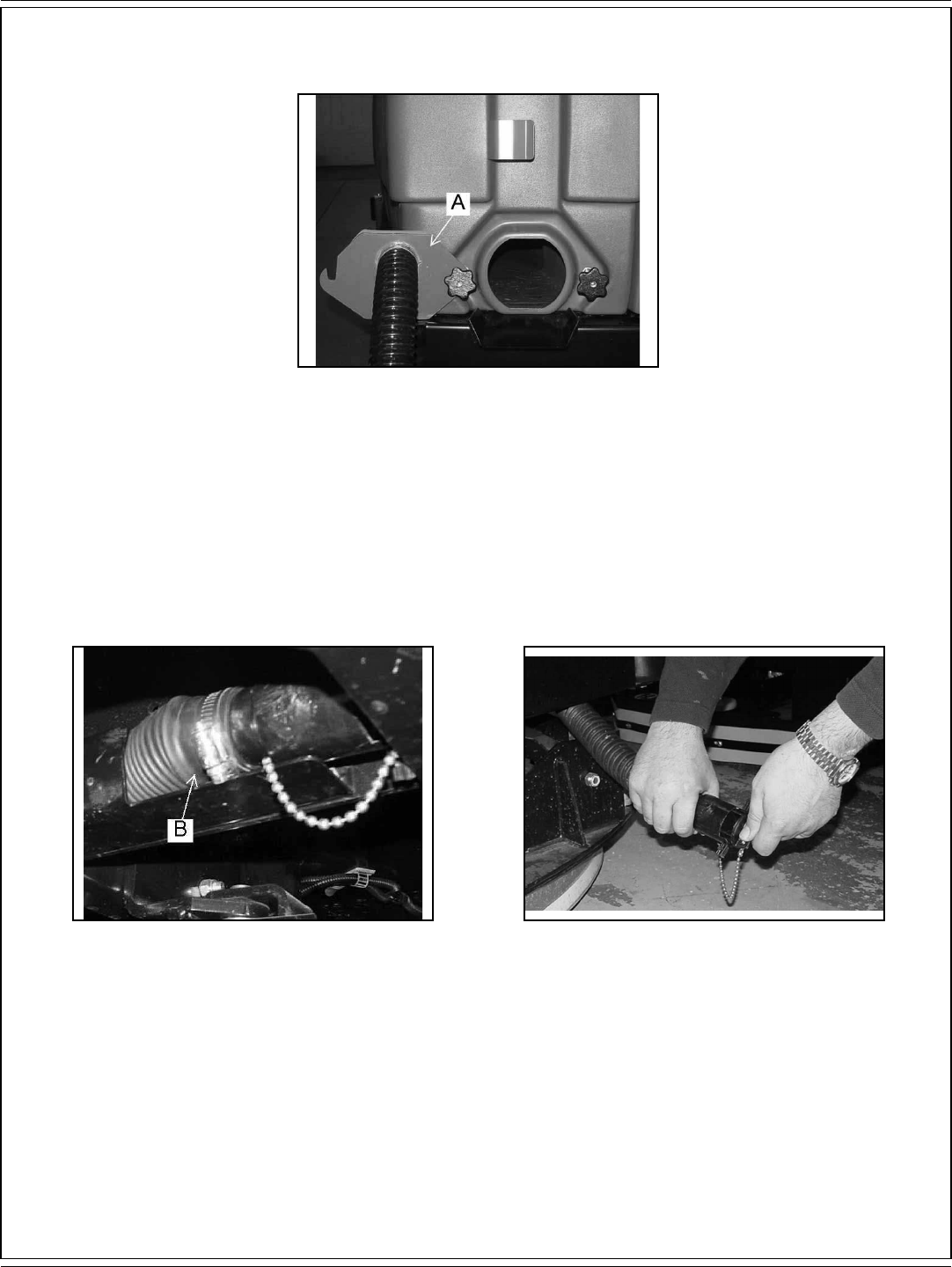
DRAINING THE RECOVERY TANK
Drive the machine to a draining area. Loosen the knobs on the recovery clean out door (A) and pivot the door to the left as shown in fi gure 76.
With the water hose fl ush out the bottom of the recovery tank clean out door to remove larger particles of debris.
FIGURE 77 FIGURE 78
DRAINING THE SOLUTION TANK
Lift the cover on the solution/recovery tank. Locate the solution tank drain hose (B) as shown in fi gure 77. Pull the hose out as shown in fi gure 78.
Open the solution tank drain plug and let the solution tank drain. Clean out and fl ush the solution tank with a water hose. Tighten the solution tank
plug and tuck the solution tank drain hose into place.
A-40 / ENGLISH
A-40 - FORM NO. 56041720 - 7730
MAINTENANCE
FIGURE 79
MAIN BROOM
To prevent the broom from setting in one direction and to provide the maximum life of the broom it is recommended that the broom be turned end
over end periodically.
FIGURE 80
ADJUSTING THE MAIN BROOM HEIGHT
The main broom adjustment knob (A) for changing the sweep height to compensate for broom wear is located in front of the machine as shown
in fi gure 80. Turning the knob to the left (counterclockwise) will lower the main broom. When changing the sweep height adjustment, it is
recommended the knob be adjusted one turn at a time. After adjusting, recheck the sweep pattern to determine if further adjustment is necessary.
TURN KNOB CLOCKWISE = INCREASE SWEEP PATTERN WIDTH
TURN KNOB COUTERCLOCKWISE = DECREASE SWEEP PATTERN WIDTH
ENGLISH / A-41
FORM NO. 56041720 - 7730 - A-41
MAINTENANCE
FIGURE 81
MAIN BROOM ACCESS DOOR
The main broom access door (A) is located in front of the left side tire of the machine as shown in fi gure 81. The door provides access to the
main broom for service or inspection. The hopper must be raised to access.
WARNING!
Engage hopper safety arm while accessing the main broom
FIGURE 82 FIGURE 83
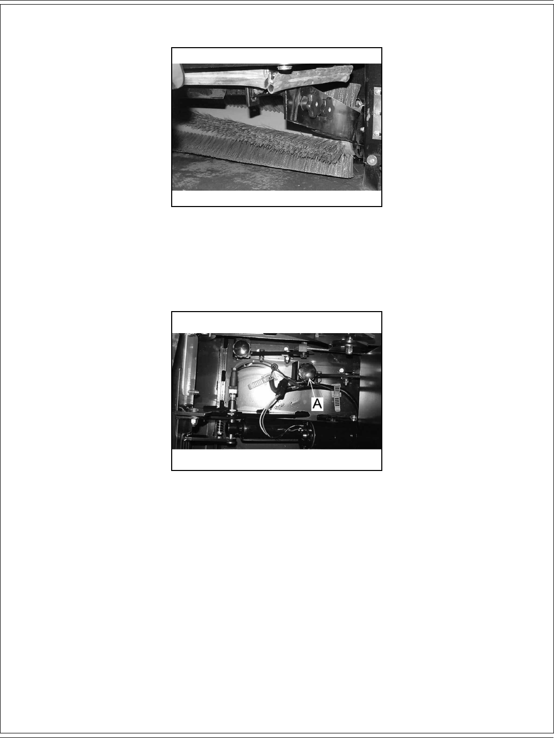
REPLACING THE MAIN BROOM
The Main Broom should be replaced when the bristles become worn to less than 1 1/2”. The main broom is held in place by the right side broom
door. This feature provides for easy removal and installation of the main broom without the need for special tools or equipment. Lift the hopper
to gain access to the main broom compartment. Loosen the main broom access door knob and open the main broom access door. Rotate and
remove the broom lift arm knobs (B) counterclockwise to the left as shown in fi gure 82 and 83.
A-42 / ENGLISH
A-42 - FORM NO. 56041720 - 7730
MAINTENANCE
FIGURE 84 FIGURE 85
FIGURE 86 FIGURE 87
FIGURE 88
Remove broom lift arm (A) as shown in fi gure 84 and 85. Remove the main broom from the from the broom idler (B) exposing the main broom
compartment as shown in fi gure 86. Check and clean out the main broom compartment before installing the new main broom. Slide the main
broom onto the broom idler as shown in fi gure 87. Replace the broom lift arm and rotate the broom lift arm knobs (C) clockwise to tighten into
place as shown in fi gure 88. Adjust the main broom to 1-1/2” to 2” sweep pattern.
ENGLISH / A-43
FORM NO. 56041720 - 7730 - A-43
MAINTENANCE
ADJUSTING THE SIDE BROOM HEIGHT
Turn the side broom adjustment knob (A) (Fig. 90) to change the side broom
sweep height. Recheck for proper sweep pattern after adjustment.
Turn the adjustment knob counterclockwise to INCREASE the sweep pattern
width.
Turn the adjustment knob clockwise to DECREASE the sweep pattern width.
FIGURE 91
SIDE BROOM
The side broom (Fig. 89) sweeping angle is not adjustable. However, the height
of the side broom can be adjusted to compensate as the broom becomes worn
from use. Always check and adjust the sweep pattern after changing the side
broom.
FIGURE 89
FIGURE 90
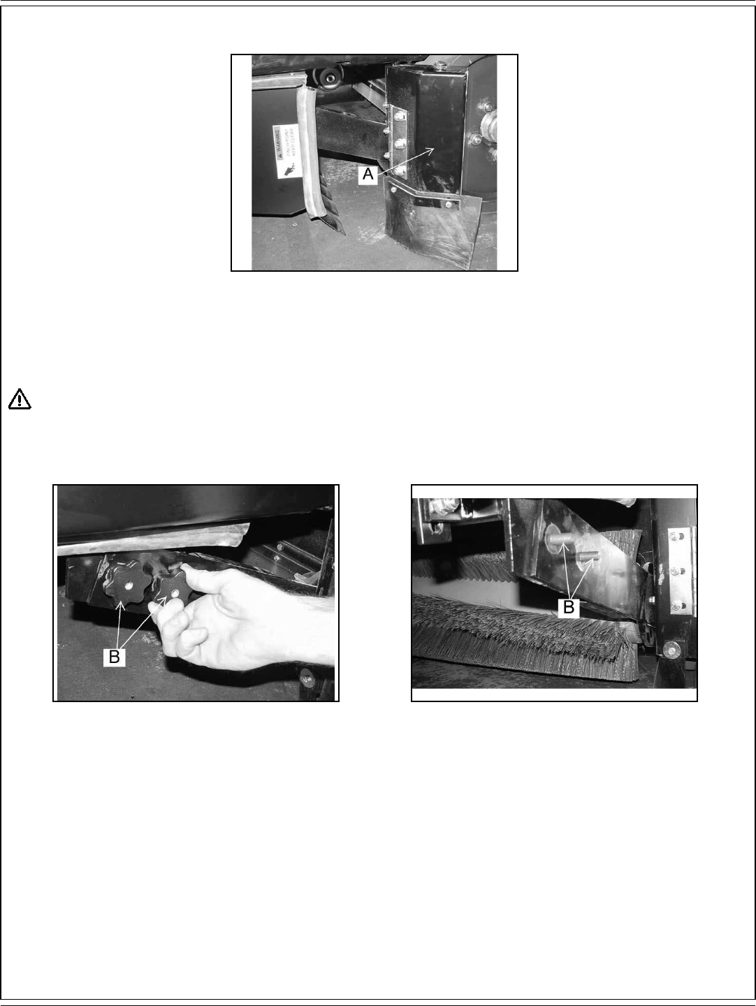
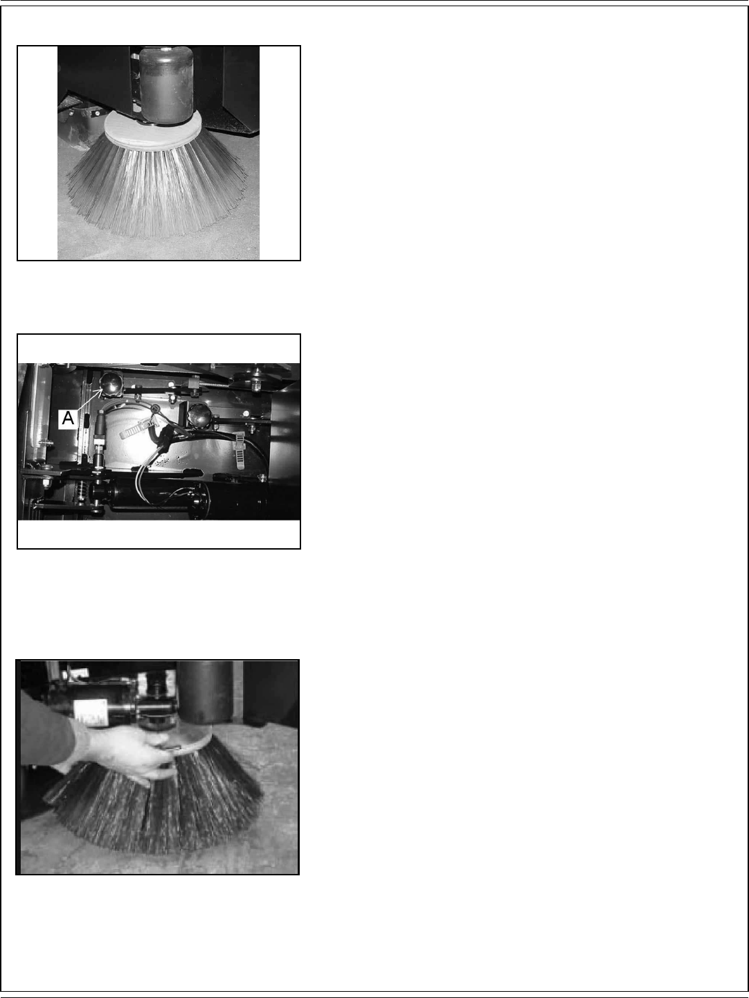
REPLACING THE SIDE BROOM
Change the side broom (Fig. 91) when the bristles become worn to less than 3
inches length.
1. Park the machine on a smooth level surface, turn key switch to “O” Position
and engage parking brake.
2. Place the side brooms switch in the “UP” position.
3. Remove the lock pin that holds the broom fl ange to the motor shaft.
4. Disassemble the fl ange from the broom by removing the screws that hold
the fl ange to the broom.
5. Assemble the fl ange to the replacement broom and fasten using the
hardware removed.
6. Install the replacement broom on the shaft and insert the lock pin.

A-44 / ENGLISH
A-44 - FORM NO. 56041720 - 7730
MAINTENANCE
FIGURE 92 FIGURE 93
HOPPER
The hopper (Fig. 92) houses the debris compartment, the dust control fi lter and the removable dust baffl e. For maximum performance and service
life, keep the hopper clean and inspect the seals and fl aps daily. Clean the hopper prior to parking the sweeper at the end of the day. A clean
hopper will make inspecting the fl aps and seals much easier and will prevent premature deterioration of hopper components. Do not leave the
hopper full of debris while in storage or when parked for extended periods of time. Once the hopper has been emptied the insides of the hopper
should be rinsed out with water.
DUST CONTROL FILTER
The dust control fi lter (Fig. 93) should be checked daily for damage and cleaned if necessary. A damaged fi lter must be replaced to prevent
damage to other dust control system components. Inspect the fi lter for tears in the fi lter media or excessive dirt lodged in the pleats. A tear in
the fi lter media will allow dirt to pass through the fi lter and can be easily seen as a dirty patch on the top side on the fi lter. Cleaning of the fi lter is
necessary when the fi lter shaker fails to adequately clean the pleats.
CHECKING THE DUST CONTROL FILTER
1. Park the machine on a smooth level surface, turn the key switch to the “O” position and engage the parking brake.
2. Raise the hopper lid for access to the fi lter compartment.
3. Turn the fi lter latch, lift the fi lter frame and remove the fi lter.
4. Inspect the panel fi lter for tears and clean or replace if necessary.
5. Reinstall the fi lter, lower the fi lter frame and engage the fi lter latch.
6. Close the hopper cover.
CLEANING THE DUST CONTROL FILTER
Clean the dust control fi lter when the shaker fails to adequately clear the fi lter. The fi lter can be cleaned with compressed air not to exceed 100
PSI. To clean the fi lter with compressed air, apply the compressed air to the top side of the panel to back fl ush the lodged dirt from the fi lter pleats.
Be careful to not damage the fi lter media while cleaning. The fi lter can be cleaned with a solution of soap and water. If this cleaning method is
used do not use the fi lter until it has completely dried.
REPLACING THE DUST CONTROL FILTER WHEN DAMAGE IS EVIDENT
1. Park the machine on a smooth level surface, turn the key switch to the “O” position and engage the parking brake.
2. Open the hopper compartment cover to gain access to the fi lter compartment.
3. Turn the latch on the hinged frame counterclockwise and lift the frame.
4. Remove the fi lter panel.
5. Install replacement fi lter, lower the hinged frame and engage the latch.
6. Lower the fi lter compartment cover.

ENGLISH / A-45
FORM NO. 56041720 - 7730 - A-45
MAINTENANCE
DUST FLAPS
The dust fl aps are very important to sweeping and dust control and are susceptible to damage and should be inspected daily and maintained in
good condition.
CHECKING THE DUST FLAPS
The dust fl aps are used on the wheel well, broom chamber and broom door. Inspect the fl aps daily and replace any fl ap that shows signs of
wear or deterioration. All fl aps should be replaced when worn or damaged to the point that they can no longer perform their normal function. The
adjustable fl aps have slotted mounting holes to facilitate adjustment.
ADJUSTING THE DUST FLAPS
Adjust the fl aps so there is a 1/8” to 1/16” gap between the fl oor and the bottom edge of the fl aps. The rear fl ap adjustment is 1/16” (1.6 mm.)
above the fl oor.
1. Park the machine on a smooth level surface and engage the parking brake.
2. Loosen the fl ap retaining screws and adjust the fl ap to clear the fl oor and leave a 1/16” to 1/8” gap.
3. Tighten fl ap retaining screws while holding fl ap in position.
4. Drive the machine on a smooth surface and recheck the fl aps for proper fl oor clearance.
FILLING THE HYDRAULIC RESERVOIR (Fig. 94)
1. Access to the hydraulic reservoir is located in the engine compartment.
2. Open the hydraulic reservoir breather fi lter cap (A).
3. Remove any debris that is in the breather fi lter cap screen.
4. Fill the reservoir until the fl uid is at the “FULL” line on the hydraulic fl uid sight
gauge (B). The sight gauge is located on the center side of the hydraulic
reservoir.
5. Close the hydraulic reservoir breather fi lter cap.
6. Close the engine compartment cover.
CLEANING THE HYDRAULIC SYSTEM
1. Put a drop cloth on the fl oor.
2. Drive the machine onto the drop cloth.
3. Set the parking brake.
4. Open the hood.
5. Put a container under the reservoir drain to catch the reservoir fl uid. Pivot the
reservoir out.
6. Remove the drain plug. The reservoir fl uid will drain.
Do not use the drained fl uid to refi ll the hydraulic reservoir. Dispose of the used
fl uid.
7. Flush the interior of the hydraulic reservoir with clean fl uid.
8. Put the reservoir plug, removed in step six, back in the hydraulic tank drain and
tighten it. A pipe thread sealer is required on the plug.
9. Open the breather fi lter cap.
10. Fill the reservoir with new MOBIL Multipurpose ATF or equilvalent Dextron III.
The capacity of the tank is 4.7 gal (17.79 liters). Fill to the “FULL” line on the
hydraulic fl uid sight gauge.
11. Close the breather fi lter cap.
12. Replace the hood.
FIGURE 94
FIGURE 95
REPLACING THE RETURN FILTER ELEMENT (Fig. 95)
1. Replace the return fi lter element (C) after 250 hours of machine run time.
2. Unscrew the fasteners from the fi lter assembly cover and retain.
3. Remove the cover and the compression spring and retain.
4. Discard the old fi lter element.
5. Position the new fi lter element inside the fi lter body.
6. Put the compression spring in position. Wipe the cover magnet free of any metal fi lings or debris.
7. Place O-ring (moisten with clean hydraulic fl uid) and cover into position.
8. Reattach fasteners to the fi lter cover.
9. Clean any hydraulic reservoir fl uid spills. The fl uid can damage painted surfaces of the machine.

A-46 / ENGLISH
A-46 - FORM NO. 56041720 - 7730
TROUBLESHOOTING
PROBLEM PROBABLE CAUSE REMEDY
Machine moves slowly or
erratically
1. Battery charge low
2. Brakes dragging
3. Loose connection at foot pedal
4. Drive circuit overloaded
1. Charge
2. Adjust
3. Repair
4. Remove obstruction, put drive pedal in neutral
Machine does not move 1. Blown fuse
2. Battery unplugged
1. Check fuse & replace if necessary
2. Plug in battery
Poor water pickup at
squeegee
1. Recovery tank full
2. Squeegee is worn or damaged
3. Clogged suction hose or pick-up tool
4. Loose connections between suction hose and
squeegee
5. Vacuum motors not running
6. Plugged fi lter
7. Vacuum fl oat cage clogged
8. Vacuum fl oat shut off
9. Air leaks in suction hose and connection
10. Air leaks at recovery tank cover and/or
manifold hose
11. Drain hose or drain plug leakage or not
closed properly
1. Empty tank
2. Examine squeegee rubber blade for cuts or worn spots
& replace if necessary
3. Disconnect suction hose from squeegee, fl ush
squeegee & hoses
4. Check all hose connections for looseness or damage
5. Reset circuit breaker or repair loose connection
6. Clean fi lter element in vacuum manifold
7. Clean perforated metal thoroughly
8. Excessive solution in recovery tank. Excessive foam
buildup, change cleaning chemical mixture (use A-L
approved materials)
9. Repair or replace hose and connection
10. Repair or replace seal or hose
11. Close, repair, or replace drain plug in recovery tank
Water spills from squeegee 1. Side squeegee blades have poor contact with
fl oor
2. Squeegee blades worn or damaged
3. Too much solution being applied before
making turns
4. Brushes rotating opposite direction
1. Readjust blades for proper contact
2. Replace & adjust
3. Shut off solution fl ow 5-10 ft. Before turning
4. Check switch positions
Squeegee leaves wet
spots
1. Lift actuator out of adjustment
2. Squeegee wheels out of adjustment
1. Adjust
2. Adjust
Squeegee makes
excessive noise
1. Blades worn or damaged 1. Replace

ENGLISH / A-47
FORM NO. 56041720 - 7730 - A-47
TROUBLESHOOTING
PROBLEM PROBABLE CAUSE REMEDY
Poor scrubbing action 1. Worn scrubbing brushes
2. Incorrect method of operation
3. Wrong cleaning agent or mixture
4. Poor solution distribution
5. Brushes won’t turn
1. Inspect brushes. Replace if brushes are worn to 3/4” or
less.
2. Check scrubbing procedure, brush pressure, solution
fl ow & cleaning agent used - all are important to the
process
3. Use A-L recommended materials
4. Check solution strainer & feed hoses for obstructions -
clean if necessary. Check valve & rest of solution control
system for proper operation.
5. Check wiring connections
Water splashes from sides
of scrub deck
1. Scrub deck bumpers, poor contact with fl oor
2. Squeegee blades word or damaged
3. Too much solution
1. Readjust blades for proper contact
2. Replace & adjust
3. Shut off solution fl ow 5-10 ft. before making turns
Poor sweeping 1. Broom jammed
2. Hopper full
3. Broom not adjusted properly
4. Worn or damaged fl aps
5. Worn broom
1. Remove any obstruction
2. Empty
3. Refer to broom adjustment in maintenance section
4. Inspect for damage - replace or adjust by referring to
maintenance section
5. Inspect for damage or wear - refer to maintenance
section
Sweep does not function 1. Hopper is raised
2. Hopper switch out of adjustment
1. Lower hopper
2. Adjust hopper switch
Poor dust control at main
broom
1. Broom chamber & hopper fl aps worn
2. Impellor fan failure - shaft key broken or
electric motor not operating
3. Filter plugged
1. Check condition of fl aps. Replace torn or badly worn
fl aps. Side fl aps can be adjusted of not damaged.
2. Check & repair
3. Engage shaker switch or check fi lter
Hopper will not lift 1. Load too heavy
2. Defective lift actuator
1. Low dump partial load
2. Repair or replace actuator

A-48 / ENGLISH
A-48 - FORM NO. 56041720 - 7730
TECHNICAL SPECIFICATIONS (as installed and tested on the unit)
Model 7730 (40”) 7730 (46”)
Model No. 56515851 56515853
Voltage, Battery V 36 36
Battery Capacity AH 720 720
Protection Grade IPX3 IPX3
Sound Pressure Level
(IEC 60335-2-72: 2002 Amend. 1:2005, ISO 11201) dB (A)/20μPa 77.2 77.2
Sound Power Level (ISO 3744) Lwa 103 103
Total Weight lbs/kg 3,690 / 1,661 3,690 / 1,661
Vibrations at the Hand Controls (ISO 5349-1) m/s2 0.80 m/s2 0.80 m/s2
Vibrations at the Seat (EN 1032) m/s2 0.35 m/s2 0.35 m/s2
Gradeability
Transport 14.1% (8°) 14.1% (8°)
Cleaning 10.5% (6°) 10.5% (6°)

B-2 / ESPAÑOL
B-2 - FORM NO. 56041720 - 7730
ÍNDICE
Introducción ..............................................................................................................B-3
Componentes y servicio ............................................................................................. B-3
Placa de identifi cación ................................................................................................B-3
Desembalaje de la máquina .......................................................................................B-3
Precauciones y advertencias ......................................................................................B-4
Preparación de la máquina ............................................................................B-6 – B-8
Controles .......................................................................................................B-9 – B-21
Consola frontal ......................................................................................................B-9
Interruptor de contacto ........................................................................................B-10
Interruptor de avance/marcha atrás ....................................................................B-10
Medidor de estado de la batería y horas de funcionamiento. .............................. B-11
Interruptor de faro delantero/faro trasero (opcional) ............................................B-12
Luz de advertencia de apertura de la tolva .........................................................B-12
Interruptor de agitador del fi ltro (modelos con control de polvo) ......................... B-13
Interruptor de control del polvo ............................................................................B-13
Interruptor de cepillos de fregado ........................................................................B-14
Interruptor de la rasqueta .................................................................................... B-14
Luces de poca solución y mucha recuperación ...................................................B-15
Interruptor de elevación de la tolva .....................................................................B-16
Interruptor de cepillos principal y lateral ..............................................................B-16
Interruptor de la varilla de pulverización y aspiración (opcional) .........................B-17
Interruptor de Esp (opcional) ...............................................................................B-17
Botones de ajuste de altura del cepillo principal y el cepillo lateral .....................B-18
Botón del fl ujo de la solución ...............................................................................B-19
Botón del claxon ..................................................................................................B-19
Pedal y freno de estacionamiento ....................................................................... B-20
Ajuste de la posición del asiento .........................................................................B-21
Características de seguridad el asiento ..............................................................B-21
Instrucciones de uso ..................................................................................B-22 – B-30
Lista de comprobación previa a la puesta en marcha .........................................B-22
Llenado del depósito de la solución ....................................................................B-22
Puesta en marcha de la máquina ........................................................................B-23
Transporte de la máquina ....................................................................................B-23
La operación de limpieza .....................................................................................B-23
Sistemas de fregado estándar y Esp ...................................................................B-24
Consejos para la operación de limpieza ..............................................................B-25
Lista de comprobación tras el funcionamiento .................................................... B-26
Vaciado del depósito de recuperación ......................................................B-26 – B-27
Inspección del cepillo principal y los cepillos fregado .........................................B-28
Inspección de las rasquetas ................................................................................B-29
Uso del pomo de control del polvo ...................................................................... B-30
Comprobación del nivel de líquido hidráulico ......................................................B-30
Mantenimiento ............................................................................................ B-31 – B-45
Tabla de mantenimiento ...........................................................................B-31 – B-32
Precauciones para el mantenimiento: ................................................................. B-33
Carga de la batería ..............................................................................................B-34
Retirada de la batería ...............................................................................B-35 – B-36
Sustitución de los cepillos de fregado ................................................................. B-37
Sustitución de la rasqueta trasera .......................................................................B-38
Vaciado del depósito de recuperación y el depósito de la solución ....................B-39
Mantenimiento del cepillo principal ...........................................................B-40 – B-42
Mantenimiento del cepillo lateral ......................................................................... B-43
Mantenimiento del fi ltro de control del polvo ....................................................... B-44
Mantenimiento de las aletas para el polvo .......................................................... B-45
Mantenimiento del sistema hidráulico .................................................................B-45
Resolución de problemas ..........................................................................B-46 – B-47
Especifi caciones técnicas .....................................................................................B-48

ESPAÑOL / B-3
FORM NO. 56041720 - 7730 - B-3
INTRODUCCIÓN
Este manual le ayudará a sacar el máximo rendimiento a su barredora/fregadora American-Lincoln. Léalo con atención antes de utilizar la
máquina. Las referencias a “derecha” e “izquierda” en el manual han de entenderse desde el punto de vista del asiento del conductor.
COMPONENTES Y SERVICIO
Las reparaciones, cuando sean necesarias, deben ser realizadas por su Centro Autorizado de Servicio Técnico de American-Lincoln, que utiliza
personal de servicio con formación en fábrica y mantiene un inventario de piezas de repuesto y accesorios American-Lincoln originales.
Llame al DISTRIBUIDOR INDUSTRIAL DE AMERICAN-LINCOLN que se indica a continuación para cualquier tema relativo a reparaciones o
mantenimiento. Por favor, especifi que el modelo y el número de serie cuando hable de su máquina.
(Distribuidor, coloque aquí la pegatina de su servicio técnico).
PLACA DE IDENTIFICACIÓN
El número de modelo y el número de serie de la máquina se muestran en la placa de identifi cación, situada en la pared del compartimiento del
operario. Esta información es necesaria a la hora de solicitar repuestos para la máquina. Utilice el espacio situado más adelante para anotar el
número de modelo y el número de serie de la máquina para futuras consultas.
MODELO ______________________________________________
NÚMERO DE SERIE _____________________________________
Nota: si desea datos más detallados sobre especifi caciones y servicio técnico del motor, consulte el manual de uso y mantenimiento del
fabricante del motor que se entrega por separado.
DESEMBALAJE
Tras la entrega, inspeccione con atención la caja de transporte y la máquina para ver si se han producido daños. Si los daños son evidentes,
guarde todas las partes de la caja de transporte, de manera que la compañía de transporte que entregó la máquina puede inspeccionarla.
Póngase en contacto con la compañía de transporte inmediatamente para presentar una reclamación por daños durante el transporte.
1 Tras retirar la caja, retire los bloques de madera situados junto a las ruedas y todos los fl ejes de sujeción.
2 Compruebe el nivel del aceite hidráulico.
3 Lea las instrucciones de la sección “Preparación de la máquina para su utilización” de este manual y, a continuación, instale la batería.
4 Coloque una rampa junto al extremo frontal del palé.
5 Lea las instrucciones de las secciones “Controles de funcionamiento” y “Funcionamiento de la máquina” de este manual. Desplace despacio
la máquina para bajarla por la rampa hasta el suelo. Mantenga el pie pisando ligeramente el pedal del freno hasta que la máquina haya
bajado del palé.
¡PRECAUCIÓN!
Extreme las PRECAUCIONES al utilizar esta máquina. Asegúrese de conocer bien todas las instrucciones de funcionamiento antes de utilizarla.
Si tiene alguna duda, consulte con su supervisor o con el distribuidor industrial de American-Lincoln de su zona.
En caso de mal funcionamiento de la máquina, no intente solucionar el problema a menos que se lo ordene su supervisor. Haga que un
mecánico cualifi cado de su empresa o de una persona del servicio técnico del Distribuidor de American-Lincoln autorizado para que efectúe las
correcciones necesarias en el equipo.
Extreme las precauciones al trabajar en esta máquina. Las prendas amplias, el pelo largo, los anillos y las pulseras pueden quedar atrapados
entre los elementos en movimiento. Apague el interruptor de contacto y quite la llave antes de someter la máquina a reparaciones o
mantenimiento. Utilice el sentido común, respete las normas de seguridad y preste atención a las pegatinas amarillas colocadas en la máquina.
Conduzca la máquina lentamente en pendientes. El pedal de tracción controlará la velocidad de la máquina al descender pendientes. NO gire la
máquina en una pendiente; conduzca en línea recta hacia arriba o hacia abajo.

B-4 / ESPAÑOL
B-4 - FORM NO. 56041720 - 7730
PRECAUCIONES Y ADVERTENCIAS
SÍMBOLOS
American-Lincoln utiliza los símbolos que aparecen a continuación para indicar situaciones potencialmente peligrosas. Lea siempre con atención
esta información y tome las medidas necesarias para la protección de las personas y la propiedad.
¡PELIGRO!
Se utiliza para advertir de riesgos inmediatos que producirán lesiones personales graves o incluso fatales.
¡ADVERTENCIA!
Se utiliza para llamar la atención sobre una situación que podría producir lesiones personales graves.
¡PRECAUCIÓN!
Se utiliza para llamar la atención sobre una situación que podría provocar lesiones personales leves o daños en la máquina u otros objetos.
Lea todas las instrucciones antes de utilizar la máquina.
INSTRUCCIONES GENERALES DE SEGURIDAD
Se incluyen precauciones y advertencias específi cas que advierten de los peligros potenciales de daños a la máquina o lesiones personales.
¡ADVERTENCIA!
* Esta máquina únicamente deben utilizarla personas autorizadas y con la debida formación.
* Al circular sobre rampas o pendientes, evite las paradas bruscas si lleva carga. Evite las curvas muy cerradas. Circule lentamente al bajar
pendientes.
* Mantenga chispas, llamas y materiales humeantes lejos de la batería. Durante el funcionamiento normal se desprenden gases explosivos.
* La carga de la batería produce gas de hidrógeno altamente explosivo. Cargue la batería exclusivamente en áreas bien ventiladas, lejos de
llamas abiertas. No fume mientras carga las baterías.
* Quítese todas las joyas cuando trabaje cerca de componentes eléctricos.
* Apague el interruptor de contacto (O) y quite la llave antes de cambiar los cepillos y antes de abrir cualquiera de los paneles de acceso.
* Nunca trabaje debajo de una máquina sin colocar antes bloques o soportes de seguridad que sostengan la misma.
* No aplique sustancias limpiadoras infl amables ni utilice la máquina sobre estas sustancias o cerca de ellas, ni tampoco en zonas en las que
haya líquidos infl amables.
* No limpie esta máquina con una limpiadora a presión.
* Use solamente los cepillos suministrados junto con el aparato o aquellos especifi cados en el manual de instrucciones. El uso de otros
cepillos puede afectar negativamente a la seguridad.
¡PRECAUCIÓN!
* Esta máquina no ha sido aprobada para su uso en vías públicas.
* Esta máquina no es apta para la recogida de sustancias peligrosas en polvo.
* Tenga cuidado cuando utilice discos escarifi cadores y muelas abrasivas. American-Lincoln no podrá ser considerada responsable por daño
alguno en las superfi cies de los suelos causado por escarifi cadores o muelas abrasivas.
* Cuando utilice la máquina, asegúrese de que no existe peligro para terceras personas, especialmente niños.
* Antes de realizar cualquier función de mantenimiento o reparación, lea con atención todas las instrucciones relativas a la misma.
* No abandone la máquina sin antes apagar el interruptor de contacto (O), retirar la llave y aplicar el freno de estacionamiento.
* Apague el interruptor de contacto (O) antes de cambiar los cepillos y antes de abrir cualquiera de los paneles de acceso.
* Tome las debidas precauciones para evitar que pelo, joyas o prendas amplias queden atrapados entre elementos en movimiento.
* Sea cauto al mover esta máquina con temperaturas bajo cero. El agua en los depósitos de la solución o de recuperación, o en las
conducciones, podría congelarse.
* Retire la batería de la máquina antes de su desmantelamiento. La batería debe desecharse de forma segura, de acuerdo con la
reglamentación medioambiental vigente en su zona.
* No utilice la máquina en superfi cies con pendientes superiores a las indicadas en la máquina.
* Antes de utilizar la máquina, todas las puertas y cubiertas deberían estar colocadas como se indica en el manual de instrucciones.
GUARDE ESTAS INSTRUCCIONES

ESPAÑOL / B-5
FORM NO. 56041720 - 7730 - B-5
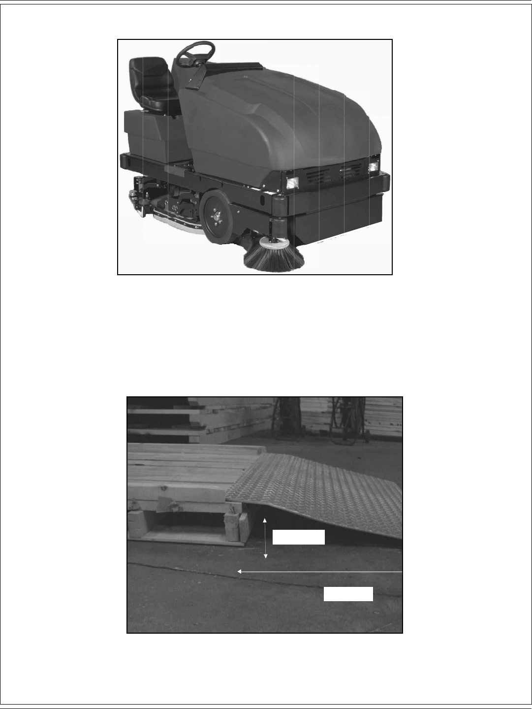
B-6 / ESPAÑOL
B-6 - FORM NO. 56041720 - 7730
PREPARACIÓN DE LA MÁQUINA
FIGURA 1
Su máquina con batería 7730 se ha enviado completa, pero no intente utilizarla sin leer antes las siguientes instrucciones:
DESEMBALAJE Y MONTAJE DE LA MÁQUINA
La 7730 se envía en un palé, en el que se sostiene mediante bloques de madera para evitar que la máquina se mueva.
1) Retire los bloques de madera que mantienen la máquina en su lugar.
2) Coloque una rampa de 11° y 48” (121 cm) en la base del palé.
11 DEGREE
48 INCHES
FIGURA 2

ESPAÑOL / B-7
FORM NO. 56041720 - 7730 - B-7
PREPARACIÓN DE LA MÁQUINA
3) Empuje la máquina hacia abajo por la rampa hasta una superfi cie plana.
4) Instale la batería.
- Gire la llave a la posición “O”.
- Eleve la cubierta y tire de la palanca de la batería hacia arriba y hacia la derecha.
-Use un dispositivo de elevación de baterías con una capacidad de 2000 lb (907 kg) para colocar la batería dentro de la bandeja de la
batería.
- Empuje la palanca de la batería hacia abajo y hacia la izquierda para bloquear la batería en su sitio.
-Conecte el conector de alimentación de la batería en el conector de alimentación de la máquina.
-Baje la cubierta a su sitio.
5) Cargue la batería como se muestra en el manual. Lea la documentación del fabricante de la batería relativa al cuidado y el mantenimiento de
la misma.
¡ADVERTENCIA!
No cargue las baterías sobre una superfi cie de hormigón puesta a tierra. Durante la operación de carga se forma gas de hidrógeno,
que es explosivo. Cargue las baterías únicamente en un área bien ventilada y con la tapa abierta. Evite humo, llamas abiertas o chispas
eléctricas.
FIGURA 3 FIGURA 4
DESEMBALAJE DE LA BATERÍA
La batería se envía por separado en un palé envuelto en plástico, como muestra fi gura 3. Retire el plástico y utilice a un dispositivo de elevación
de baterías con una capacidad de 2000 lb (907 kg) para bajar la batería al compartimento de la batería, como se muestra en la fi gura 4.

B-8 / ESPAÑOL
B-8 - FORM NO. 56041720 - 7730
PREPARACIÓN DE LA MÁQUINA
FIGURA 7 FIGURA 8
INSTALACIÓN DE LA BATERÍA
1. Eleve la cubierta frontal de la máquina.
2. Fig . 5. Gire la palanca de la batería (A) hacia la derecha.
3. Baje la batería a su sitio utilizando un dispositivo de elevación con capacidad para 2000 lb (907 kg).
4. Fig . 6. Gire la palanca de la batería (B) hacia la izquierda para bloquear la batería en su sitio.
5. Conecte los cables de la batería con arreglo a la indicación del fabricante.
6. Fig. 7 y 8. Conecte el conector de alimentación de la batería (C) al conector de alimentación de la máquina (D).
7. Baje la cubierta frontal de la máquina a su sitio.
¡ADVERTENCIA!
No deje las baterías cargadas sobre una superfi cie de hormigón, ya que se descargarán.
FIGURA 5 FIGURA 6

ESPAÑOL / B-9
FORM NO. 56041720 - 7730 - B-9
CONTROLES
FIGURA 9
1. Luz de mucha recuperación.
2. Luz de poca solución.
3. Luz de apertura de la tolva.
4. Interruptor de iluminación.
5. Interruptor de ESP.
6. Interruptor de la varilla de pulverización y aspiración.
7. Interruptor del cepillo de fregado.
8. Interruptor de la rasqueta.
9. Interruptor del cepillo lateral principal.
10. Interruptor de agitador del fi ltro/control de polvo.
11. Interruptor de la tolva.
12. Medidor de estado de la batería/medidor de horas de funcionamiento.
13. Disyuntores.
14. Botón del fl ujo de la solución.
15. Freno de estacionamiento.
16. Palanca de ajuste del volante de la dirección.
17. Acelerador de pedal.
18. Interruptor de avance/marcha atrás.
19. Interruptor de contacto.
20. Claxon
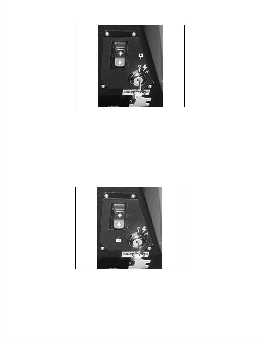
B-10 / ESPAÑOL
B-10 - FORM NO. 56041720 - 7730
CONTROLES
FIGURA 10
INTERRUPTOR DE CONTACTO
El interruptor de contacto (A) está situado en la consola del operador, como se muestra en la fi gura 10.
La posición de desconexión (O) apaga la máquina. La posición de encendido (posición I) suministra alimentación a todos los sistemas y
accesorios de la máquina.
FIGURA 11
INTERRUPTOR DE AVANCE/MARCHA ATRÁS
El interruptor de avance/marcha atrás (B) está situado en la consola del operador, como se muestra en la fi gura 11. Si se presiona la mitad
superior del interruptor de avance/marcha atrás, la máquina avanza al presionar el acelerador de pedal. Si se presiona la mitad inferior del
interruptor de avance/marcha atrás, la máquina va marcha atrás al presionar el acelerador de pedal.

ESPAÑOL / B-11
FORM NO. 56041720 - 7730 - B-11
CONTROLES
FIGURA 12
MEDIDOR DE ESTADO DE LA BATERÍA
El medidor de estado de la batería (A) está situado en el panel de instrumentos, como se muestra en la fi gura 12. El medidor de estado indica el
nivel de carga de las baterías. Las baterías tienen una carga sufi ciente cuando todos los LED están iluminados en ámbar, como se muestra en la
ilustración de la rampa. Cargue las baterías si uno de los LED de color rojo está iluminado a la izquierda, en la parte inferior del diagrama de la
rampa, y los cepillos de fregado se detienen. No utilice la máquina.
FIGURA 13
NOTA
Para volver a encender, la llave debe girarse a la posición de desconexión.
MEDIDOR DE HORAS DE FUNCIONAMIENTO
El medidor de horas de funcionamiento (B) está situado en el panel de instrumentos, como se muestra en la fi gura 13. La pantalla muestra
las horas totales que la máquina ha estado funcionando. El medidor se activa cuando el interruptor de contacto se coloca en la posición de
encendido. El medidor puede utilizarse para determinar cuándo realizar el mantenimiento de la máquina.

B-12 / ESPAÑOL
B-12 - FORM NO. 56041720 - 7730
CONTROLES
FIGURA 14
INTERRUPTOR DE FARO DELANTERO/FARO TRASERO (opcional)
El interruptor de iluminación (A) está situado en el panel de instrumentos, como se muestra en la fi gura 14. Si se presiona la mitad inferior del
interruptor, se activan los faros delanteros y los traseros. Si se presiona la mitad superior del interruptor, se apagan las luces.
FIGURA 15
LUZ DE ADVERTENCIA DE APERTURA DE LA TOLVA
El interruptor de luz de apertura de la tolva (B) está situado en el panel de instrumentos, como se muestra en la fi gura 15. Cuando la tolva está
abierta, la luz se ilumina y se detienen el cepillo y el ventilador de control del polvo.
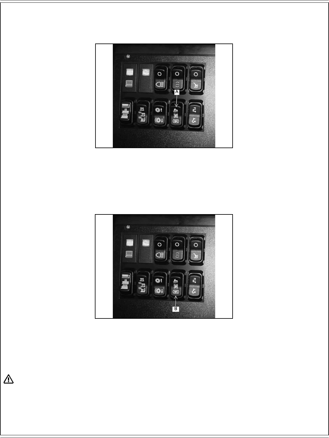
ESPAÑOL / B-13
FORM NO. 56041720 - 7730 - B-13
CONTROLES
FIGURA 16
INTERRUPTOR DEL AGITADOR DEL FILTRO (únicamente modelos con control del polvo)
El interruptor del agitador del fi ltro (A) está situado en el panel de instrumentos, como se muestra en la fi gura 16. Si se presiona y se mantiene
presionada la mitad superior del interruptor, los motores del agitador del fi ltro se activan durante entre 20 y 30 segundos. Si se suelta el
interruptor, vuelve a la posición de desconexión.
El ventilador de control del polvo se detiene cuando se activa del agitador del fi ltro. El agitador del fi ltro únicamente funciona con la tolva en
posición bajada.
FIGURA 17
INTERRUPTOR DE CONTROL DEL POLVO
El interruptor de control del polvo (B) está situado en el panel de instrumentos, como se muestra en la fi gura 17. Para encender el sistema de
control del polvo y barrer de forma normal, presione la mitad inferior de dicho interruptor.
¡ADVERTENCIA!
Gire el interruptor de control del polvo a la posición central de desconexión cuando barra sobre suelos húmedos. El agua daña el fi ltro
y provocará una avería prematura del mismo.
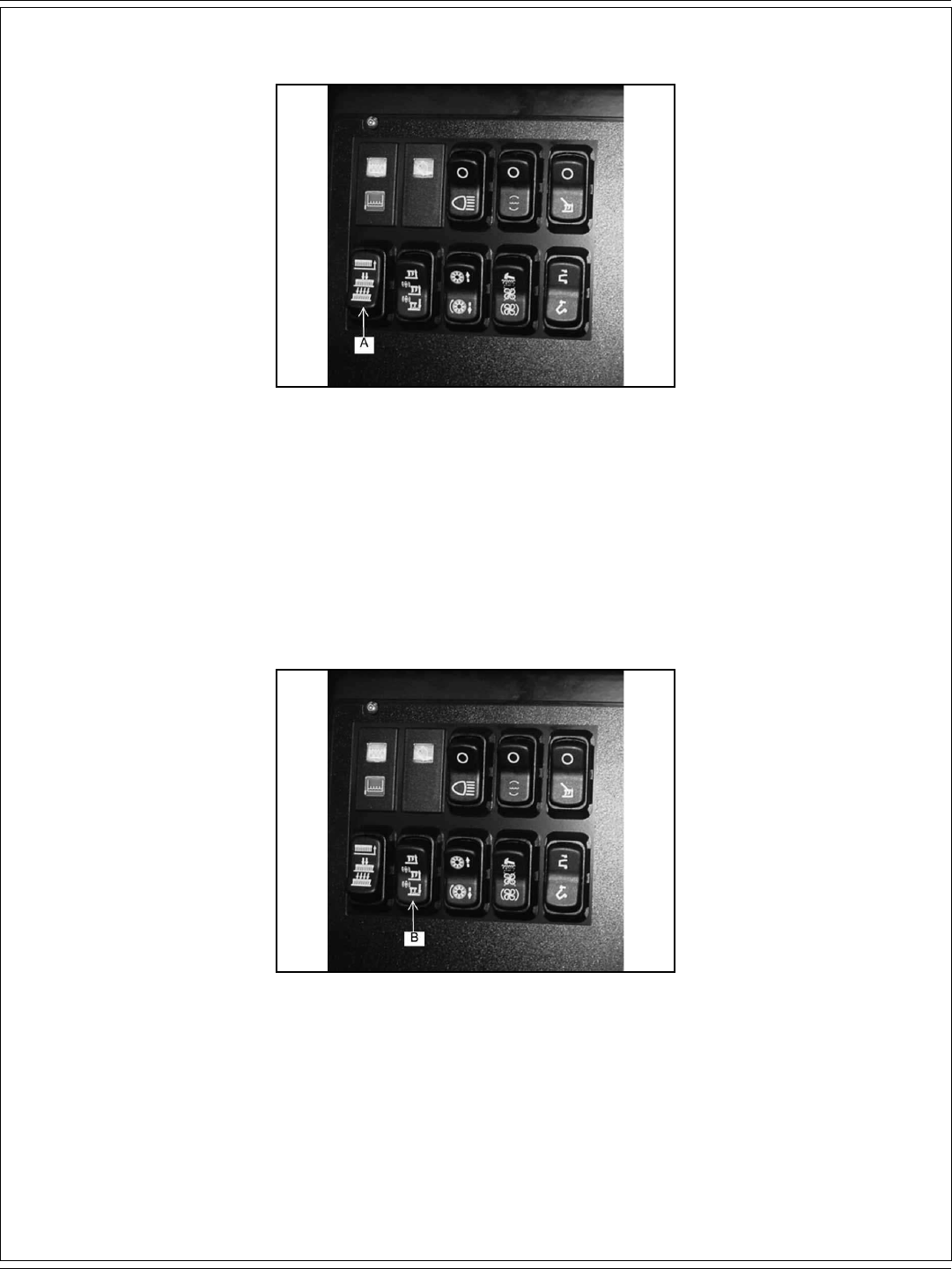
B-14 / ESPAÑOL
B-14 - FORM NO. 56041720 - 7730
CONTROLES
FIGURA 18
INTERRUPTOR DE LOS CEPILLOS DE FREGADO
El interruptor de los cepillos de fregado (A) está situado en el lado izquierdo del panel de instrumentos, como se muestra en la fi gura 18. Si se
presiona la mitad superior del interruptor, se eleva el portacepillos y se apagan los cepillos. La posición media del interruptor baja los cepillos a la
posición bajada normal para fregar. Si se presiona la mitad inferior del interruptor se baja el portacepillos a la posición bajada de alta intensidad,
lo que suministra una presión descendente adicional para superfi cies muy sucias.
NOTA
Bajar el portacepillos no enciende los cepillos. Los cepillos se encienden automáticamente cuando la máquina se mueve hacia
adelante o hacia atrás.
FIGURA 19
INTERRUPTOR DE LA RASQUETA
El interruptor de la rasqueta (B) está situado en el panel de instrumentos, como se muestra en la fi gura 19. Si se presiona la mitad inferior del
interruptor, se baja la rasqueta y se activa la aspiración de la misma. Si se presiona la mitad superior del interruptor, se apaga la rasqueta y se
eleva. En la posición media, el interruptor eleva la rasqueta. En esta posición, la aspiración permanece encendida para permitir aspirar el agua
que quede en el tubo de recuperación de la rasqueta. Esto evita que el agua caiga al suelo con la rasqueta elevada. Si la rasqueta está bajada y
se invierte la dirección de la máquina (lo que se activa mediante el pedal de tracción), la rasqueta se eleva automáticamente. Cuando se avance,
la rasqueta volverá automáticamente a la posición bajada.

ESPAÑOL / B-15
FORM NO. 56041720 - 7730 - B-15
CONTROLES
FIGURA 20
LUZ DE POCA SOLUCIÓN
La luz de advertencia de poca solución (A) está situada en el panel de instrumentos, como se muestra en la fi gura 20. La luz de advertencia de
poca solución se ilumina cuando el depósito de la solución está vacío, lo que marca el fi nal del ciclo de fregado.
FIGURA 21
LUZ DE MUCHA RECUPERACIÓN
La luz de advertencia de mucha recuperación (B) está situada en el panel de instrumentos, como se muestra en la fi gura 21. La luz de
advertencia se ilumina aproximadamente 5 minutos antes de que el depósito de recuperación esté lleno, lo que brinda un amplio margen para
completar el ciclo de fregado antes de que el fl otador mecánico desconecte la aspiración que va al depósito de recuperación.

B-16 / ESPAÑOL
B-16 - FORM NO. 56041720 - 7730
CONTROLES
FIGURA 22
INTERRUPTOR DE ELEVACIÓN DE LA TOLVA
El interruptor de elevación de la tolva (A) está situado en el panel de instrumentos, como se muestra en la fi gura 22. El interruptor controla el
funcionamiento del sistema de elevación de la tolva. Para elevar la tolva con el fi n de descargarla, presione y mantenga presionada la mitad
inferior del interruptor, hasta que la tolva alcance la altura deseada; luego, suelte. Para cerrar la tolva, presione y mantenga presionada la mitad
superior del interruptor, hasta que la tolva se cierre completamente; luego, suelte.
¡ADVERTENCIA!
Para evitar que la tolva se cierre mientras se realiza el mantenimiento, bloquee la misma en la posición abierta con el brazo de seguridad.
FIGURA 23
INTERRUPTOR DEL CEPILLO LATERAL y EL CEPILLO PRINCIPAL
El interruptor del cepillo lateral y el cepillo principal (B) está situado en el panel de instrumentos, como se muestra en la fi gura 23. Si se presiona
la mitad superior del interruptor, el cepillo lateral y el cepillo principal se elevan y se apagan. Para bajar y encender ambos cepillos, presione la
mitad inferior del interruptor.

ESPAÑOL / B-17
FORM NO. 56041720 - 7730 - B-17
CONTROLES
FIGURA 24
INTERRUPTOR DE LA VARILLA DE PULVERIZACIÓN Y ASPIRACIÓN (opcional)
El interruptor de la varilla de pulverización y aspiración (A) está situado en el panel de instrumentos, como se muestra en la fi gura 24. Si se
presiona la mitad inferior del interruptor, se encienden el motor de aspiración y la bomba de la solución. Si se presiona la mitad superior del
interruptor, se apagan el motor de aspiración y la bomba de la solución.
FIGURA 25
INTERRUPTOR DE ESP (opcional)
El interruptor de ESP (B) está situado en el panel de instrumentos, como se muestra en la fi gura 25. El interruptor de ESP transfi ere agua desde
el depósito de recuperación al depósito de la solución a través de un fi ltro. Cuando el interruptor está en la posición bajada, la bomba funciona si
se ilumina la luz de mucha recuperación. Limpie el depósito de recuperación cuando el depósito esté vacío.
NOTA
No ponga agua limpia en el depósito de recuperación al usar la opción ESP, ya que el depósito de la solución se llenaría en exceso durante el
funcionamiento.
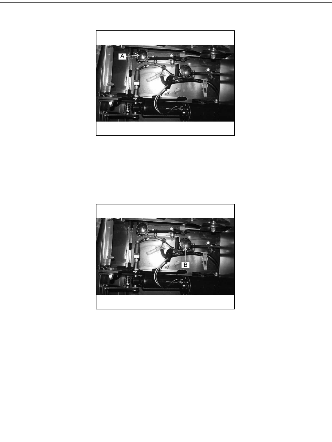
B-18 / ESPAÑOL
B-18 - FORM NO. 56041720 - 7730
CONTROLES
FIGURA 26
AJUSTE DEL CEPILLO LATERAL
El botón de ajuste del cepillo lateral (A), para cambiar la altura de barrido y compensar el desgaste del cepillo, está ubicado en el frontal de la
máquina, a la derecha del fi ltro de control del polvo, como se muestra en la fi gura 26. Gire el botón hacia la izquierda (en sentido contrario a las
agujas del reloj) para bajar el cepillo lateral.
FIGURA 27
AJUSTE DEL CEPILLO PRINCIPAL
El botón de ajuste del cepillo principal (B), para cambiar la altura de barrido y compensar el desgaste del cepillo, está ubicado en el frontal de la
máquina, a la derecha del fi ltro de control del polvo, como se muestra en la fi gura 27. Gire el botón hacia la izquierda (en sentido contrario a las
agujas del reloj) para bajar el cepillo principal.

ESPAÑOL / B-19
FORM NO. 56041720 - 7730 - B-19
CONTROLES
FIGURA 28
BOTÓN DE FLUJO DE LA SOLUCIÓN
El botón de fl ujo de la solución (A) está situado en el panel de instrumentos, como se muestra en la fi gura 28. Gire el botón en el sentido de
las agujas del reloj para aumentar el fl ujo de solución y agua. Cuanto más se gire el botón de control de la solución, más intenso será el fl ujo
de agua y solución. Gire el botón en sentido contrario a las agujas del reloj para reducir el fl ujo de agua y solución. Para apagar el agua y la
solución, gire el botón completamente en sentido contrario a las agujas del reloj.
NOTA
Para obtener los mejores resultados, deje de aplicar solución unos 3 m antes de detenerse o realizar un giro de 90° o 180°.
FIGURA 29
BOTÓN DEL CLAXON
El botón del claxon (B) está situado en el panel de instrumentos, como se muestra en la fi gura 29. El botón del claxon siempre está activo.
Presione el botón del claxon para hacer sonar el claxon.

B-20 / ESPAÑOL
B-20 - FORM NO. 56041720 - 7730
CONTROLES
FIGURA 30
ACELERADOR DE PEDAL
El acelerador de pedal (A) está situado a la derecha del pedal del freno, en el suelo del compartimento del conductor, como se muestra en
la fi gura 30. Este pedal controla la velocidad de desplazamiento de la máquina: Presione el interruptor de avance/marcha atrás para elegir la
dirección del desplazamiento y luego presione el acelerador de pedal para poner la máquina en movimiento. Aumente la presión en el pedal para
aumentar la velocidad de desplazamiento.
FIGURA 31
FRENO DE ESTACIONAMIENTO
El freno de estacionamiento está situado en el suelo de la máquina, a la izquierda del acelerador de pedal, como se muestra en la fi gura 31. Para
activar el freno de estacionamiento, presione el pedal del freno (B) y presione el seguro (C). Para soltar el freno de estacionamiento, presione
hacia abajo la porción superior del pedal y suelte.
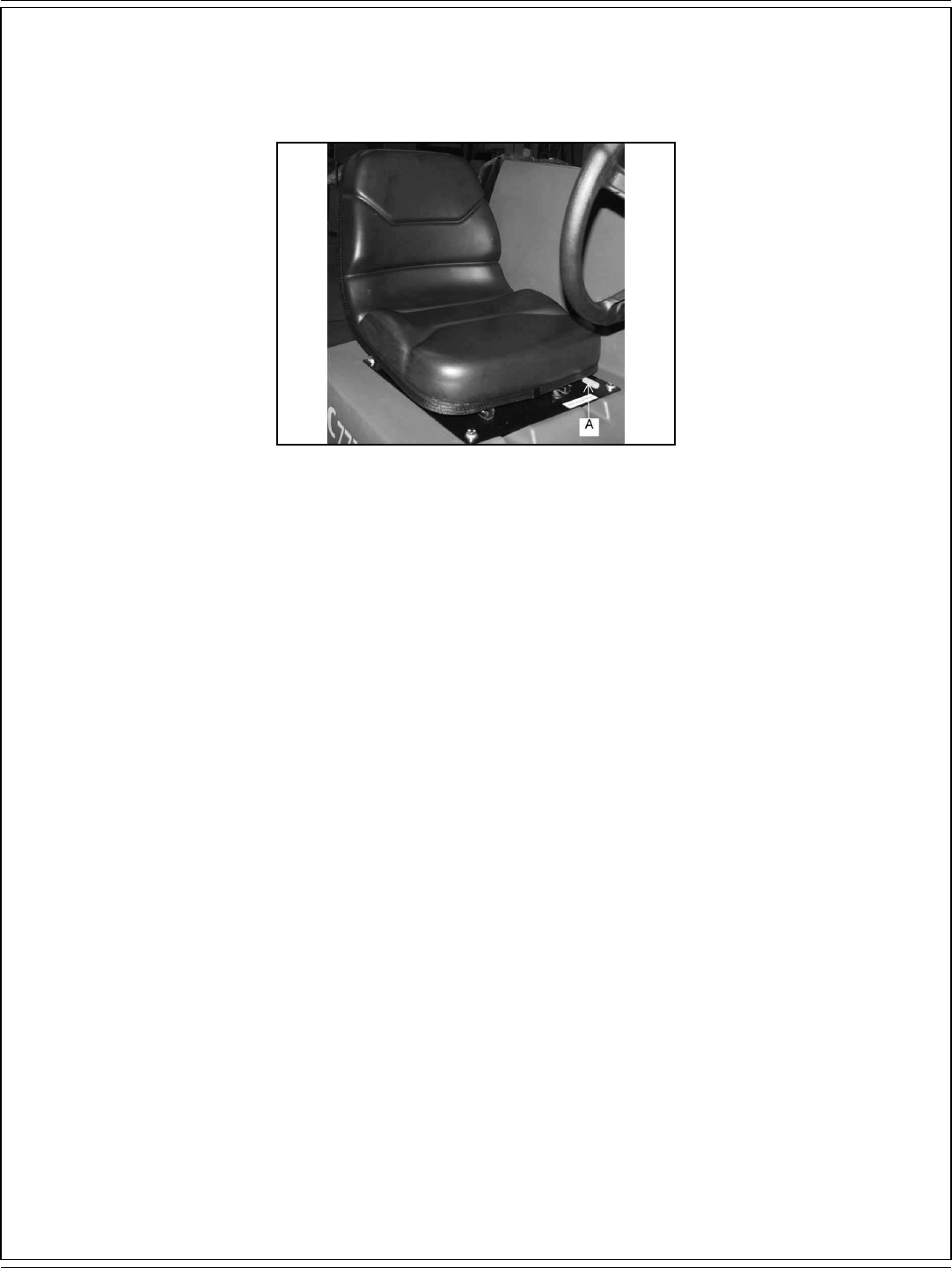
ESPAÑOL / B-21
FORM NO. 56041720 - 7730 - B-21
CONTROLES
FIGURA 34
AJUSTE DE LA POSICIÓN DEL ASIENTO
La palanca de ajuste de la oposición del asiento (A) está situada en el frontal del asiento, hacia la izquierda, como se muestra en la fi gura 34. La
palanca tiene un muelle para la posición de bloqueo. Para ajustar el asiento, empuje la palanca hacia la izquierda y mueva el asiento hasta la
posición deseada, y luego suelte la palanca para bloquear el asiento en su sitio.
CARACTERÍSTICAS DE SEGURIDAD
INTERRUPTOR DE SEGURIDAD DEL ASIENTO: La máquina no se mueve y el freno de estacionamiento se activa si este interruptor no se
activa.
ENCLAVAMIENTO DE VELOCIDAD: la velocidad máxima de la máquina se reduce mientras los cepillos de fregado estén en uso.
CEPILLOS APAGADOS EN POSICIÓN NEUTRAL: los cepillos de fregado se desactivan automáticamente cuando la máquina está al ralentí.
DESCONEXIÓN AUTOMÁTICA DE LA ASPIRACIÓN DE RECUPERACIÓN: los ventiladores de aspiración se desconectan cuando el depósito
de recuperación está lleno.
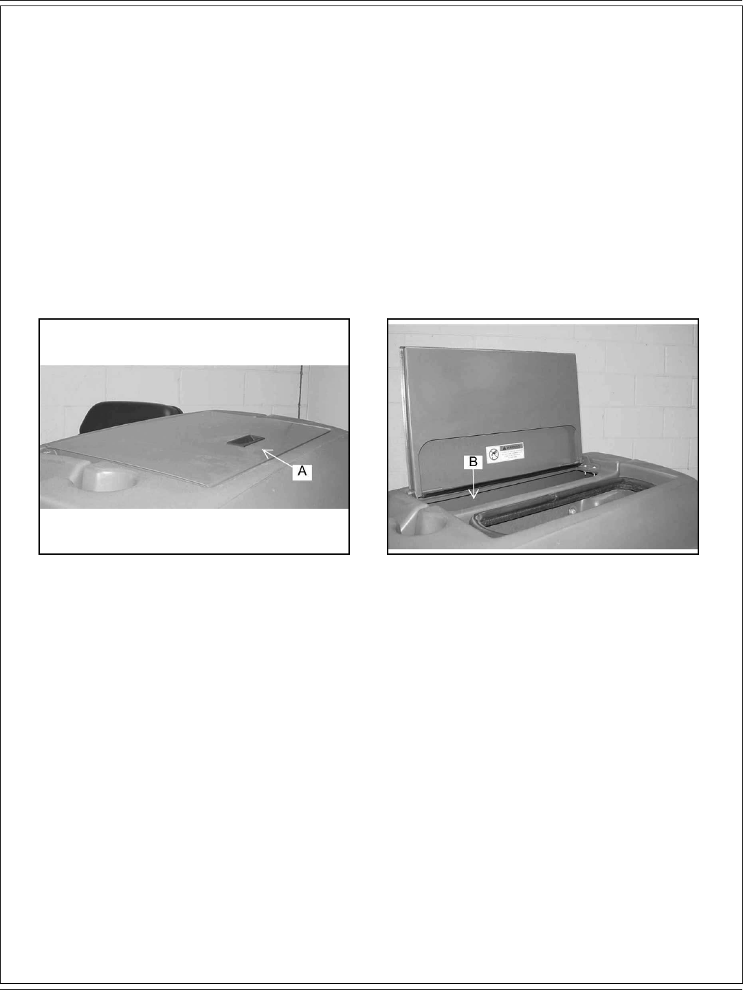
B-22 / ESPAÑOL
B-22 - FORM NO. 56041720 - 7730
INSTRUCCIONES DE USO
NOTA
Antes de poner en marcha el motor, lleve a cabo la lista de comprobación previa a la puesta en marcha.
LISTA DE COMPROBACIÓN PREVIA A LA PUESTA EN MARCHA
Compruebe el nivel del líquido hidráulico.
Compruebe todos los sistemas por si presentan fugas.
Compruebe si los frenos y los controles funcionan correctamente.
Compruebe los patrones de los cepillos.
Compruebe las conexiones hidráulicas por si presentan fugas.
Compruebe que todas las cubiertas, paneles y puertas de acceso están cerradas de forma segura.
FIGURA 35 FIGURA 36
LLENADO DEL DEPÓSITO DE LA SOLUCIÓN
Abra la tapa de la solución (A) situada en el lado superior izquierdo de la máquina, como se muestra en la fi gura 36. Llene del depósito (B) con 55
gallons (208,197 litros) de agua y la mezcla correcta de limpiador industrial American-Lincoln para el trabajo en cuestión. Cierre el depósito de la
solución.

ESPAÑOL / B-23
FORM NO. 56041720 - 7730 - B-23
INSTRUCCIONES DE USO
PARA PONER EN MARCHA LA MÁQUINA
Gire la llave a la posición “I”.
PARA TRANSPORTAR LA MÁQUINA
1. Asegúrese de que los cepillos y las rasquetas están en la posición elevada, con todos los demás controles en la posición de
desconexión.
2. Suelte el freno de estacionamiento.
3. Empuje el interruptor de avance/marcha atrás a la posición deseada (arriba para avance, y abajo para marcha atrás).
4. Presione sobre el acelerador de pedal hasta obtener la velocidad de desplazamiento deseada.
5. Suelte el acelerador de pedal para reducir la velocidad o detenerse si se encuentra en una superfi cie plana. Para reducir la velocidad de
la máquina cuando desciende en una superfi cie inclinada, reduzca la presión del pedal.
NOTA
El sistema de frenado proporcional del pedal se ha diseñado para regular la velocidad de la máquina en función de la posición del acelerador de pedal.
Este sistema se ha diseñado para detener la máquina de forma controlada. Cuando descienda una superfi cie inclinada, reduzca la presión del pedal
en lugar de soltarlo. Esto proporcionará una parada controlada y evitará que se bloquee la rueda motriz.
¡ADVERTENCIA!
No gire el volante de dirección bruscamente cuando la máquina esté en movimiento. La barredora es muy sensible al movimiento de
dicho volante. No realice giros repentinos.
FIGURA 38
PARA COMENZAR LA OPERACIÓN DE LIMPIEZA
1. Seleccione el modo de funcionamiento.
NORMAL = ESP
2. Baje los cepillos a la posición deseada.
PORTACEPILLOS = INTERVALO NORMAL O ALTA INTENSIDAD
3. Coloque la rasqueta en la posición bajada.
HOJA DE LA RASQUETA = BAJADA
4. Mueva el botón de control de la solución al ajuste deseado y comience la operación.
FREGADO DEL SUELO NORMAL CON SUCIEDAD ENTRE LIGERA Y MEDIA
En esta operación, la limpieza se logra en una sola pasada, con suministro de solución, fregado y aspiración de agua sucia simultáneos. La tasa
de suministro de la solución y la velocidad de desplazamiento requeridas varían según el estado del suelo. Saberlo a ciencia cierta depende de
la experiencia del operario.
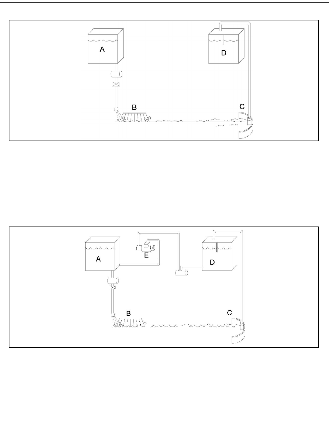
B-24 / ESPAÑOL
B-24 - FORM NO. 56041720 - 7730
INSTRUCCIONES DE USO
FIGURA 39
EL MODO DE FREGADO SIN RECICLAJE O ESTÁNDAR
Durante el proceso de fregado el agua de la solución de detergente que procede del depósito de la solución (A) se suministra a través de la
conducción de la solución. Desde allí se suministra al suelo, donde tres cepillos de fregado de disco (B) funcionan para arrancar la suciedad.
Tras el fregado, la solución sucia es aspirada del suelo por la rasqueta (C) y descargada en la cámara de contención, en la parte delantera
del depósito de recuperación (D), donde un sistema de defl ectores ayuda a clarifi car la solución. En cada depósito hay sensores que indican,
mediante luces en el panel de mando, si el agua en el depósito de la solución está demasiado baja o si el agua en el depósito de la recuperación
está demasiado alta.
FIGURA 40
MODO DE FUNCIONAMIENTO ESP
Durante el proceso de fregado, el agua fi ltrada procedente del depósito de la solución (A) se suministra a la conducción de la solución, donde se
combina con el detergente. A continuación esta mezcla se suministra al suelo, donde dos o tres de pillos de fregado de disco (B) funcionan para
arrancar la suciedad. Tras el fregado, la solución sucia es aspirada del suelo por la rasqueta (C) y descargada en el depósito de recuperación (D).
A intervalos, un interruptor con fl otador activa la bomba de reciclaje (E), que envía solución fi ltrada desde el depósito de recuperación al depósito
de la solución.

ESPAÑOL / B-25
FORM NO. 56041720 - 7730 - B-25
INSTRUCCIONES DE USO
FIGURA 41
RUTA DE FREGADO
· Friegue en línea recta. No choque contra postes. No raye los laterales de la máquina.
· Cuando la máquina esté en movimiento, no pise completamente el pedal de control direccional/velocidad. Esto equivale a comenzar en
velocidad alta y supondrá un gran esfuerzo para el sistema de tracción y el motor.
· Planifi que el barrido y el fregado con antelación. Utilice la máquina en tramos largos, manteniendo al mínimo el número de paradas y
puestas en marcha. Limpie los residuos comenzando por los pasillos estrechos (A) hasta el pasillo principal (A). Limpie un piso completo o
una sección entera cada vez.
· Recoja los residuos de gran tamaño antes del barrido.
· Barra y friegue solapando cada tramo unos centímetros. Esto evita que queden corros de suciedad.
· No gire el volante de dirección bruscamente cuando la máquina esté en movimiento. La máquina es muy sensible movimiento del volante,
de modo que evite giros repentinos.
· Al poner la máquina en movimiento, evite pisar el pedal de tracción a fondo de forma repentina. Esto equivale a poner en marcha en
“HIGH” y exige un esfuerzo innecesario al sistema de tracción. Gire periódicamente el cepillo de barrido de un extremo a otro para evitar
que las cerdas “se asienten” en una dirección.
PARA DETENER LA OPERACIÓN DE LIMPIEZA
Detenga la operación de limpieza cuando se ilumine la luz de poca solución o la luz de alta recuperación; esto indica que el depósito de la
solución está vacío o el depósito de recuperación está lleno. Detenga el ciclo de fregado, sitúe todos los controles en posición de avance para
transporte y conduzca hasta el área de vaciado.
NOTA
Tras detenerse, realice estas comprobaciones posteriores a la operación.

B-26 / ESPAÑOL
B-26 - FORM NO. 56041720 - 7730
INSTRUCCIONES DE USO
LISTA DE COMPROBACIÓN TRAS EL FUNCIONAMIENTO
Compruebe el estado de la batería y recargue si es necesario.
1. Compruebe todas las aletas por si presentan desgaste o daños, o si necesitan ajustes.
2. Vacíe y limpie el depósito de recuperación.
3. Limpie la criba y el fl otador del depósito de recuperación.
4. Compruebe si los cepillos de fregado están desgastados o dañados.
5. Compruebe las rasquetas posterior y lateral por si presentan desgaste o daños, o si necesitan ajustes.
6. Limpie los residuos de la tolva.
7. Compruebe si los cepillos principal y lateral están desgastados o dañados.
FIGURA 42 FIGURA 43
FIGURA 44 FIGURA 45
PARA VACIAR EL DEPÓSITO DE RECUPERACIÓN
El tubo de vaciado para el depósito de recuperación está situado en la parte trasera de la máquina. Para vaciar el depósito, retire y baje dicho
tubo, y sitúelo en un desagüe del suelo adecuado, como se muestra en la fi gura 42. Abra el tapón del tubo de vaciado como se muestra en
las fi guras 43 y 44. Al volver a colocar el tubo de vaciado en su sitio, asegúrese de que la presilla (A) que hay en el tapón de dicho tubo está
orientada como se muestra en la fi gura 45.
¡IMPORTANTE!
Una descarga inadecuada del agua residual dañará el medio ambiente y es ilegal. La agencia de protección medioambiental de Estados
Unidos (EPA) ha establecido ciertos reglamentos relativos a la descarga de aguas residuales. En su zona estarán en vigor reglamentos
locales, autonómicos, estatales y europeos sobre la descarga de aguas residuales. Comprenda y respete los reglamentos vigentes en
su área. Tenga en cuenta los riesgos medioambientales asociados con las sustancias que deseche.

ESPAÑOL / B-27
FORM NO. 56041720 - 7730 - B-27
INSTRUCCIONES DE USO
FIGURA 46 FIGURA 47
FIGURA 48 FIGURA 49
Cuando se complete la operación de vaciado, abra la puerta de limpieza del depósito de recuperación (A), como se muestra en la fi gura 46, y
lave el tubo de vaciado de la recuperación (B) como se muestra en las fi guras 47 y 48. Limpie el depósito de recuperación y la criba de dicho
depósito (C) como se muestra en la fi gura 47. Cierre la puerta de limpieza del depósito de recuperación (D), el tapón del tubo de vaciado (E) y la
tapa del depósito de recuperación, y sujete el tubo de vaciado en su sitio mediante la presilla, como se muestra en la fi gura 49.

B-28 / ESPAÑOL
B-28 - FORM NO. 56041720 - 7730
INSTRUCCIONES DE USO
FIGURA 50 FIGURA 51
Inspeccione los cepillos de disco (A) y sustituya cuando las cerdas se hayan reducido a una longitud de ¾ inch (19,05 mm), como se muestra en
las fi guras 50 y 51.
FIGURA 52 FIGURA 53
Inspeccione los cepillos lateral y principal. Cuando las cerdas se hayan desgastado hasta una longitud de 1,5 inches (3,81 cm), sustituya el
cepillo principal (B), tal y como se muestra en la fi gura 52. Sustituya el cepillo lateral (C) cuando las cerdas se hayan desgastado a 3,5 inches
(8,89 cm) de longitud, tal y como se muestra en la fi gura 53.
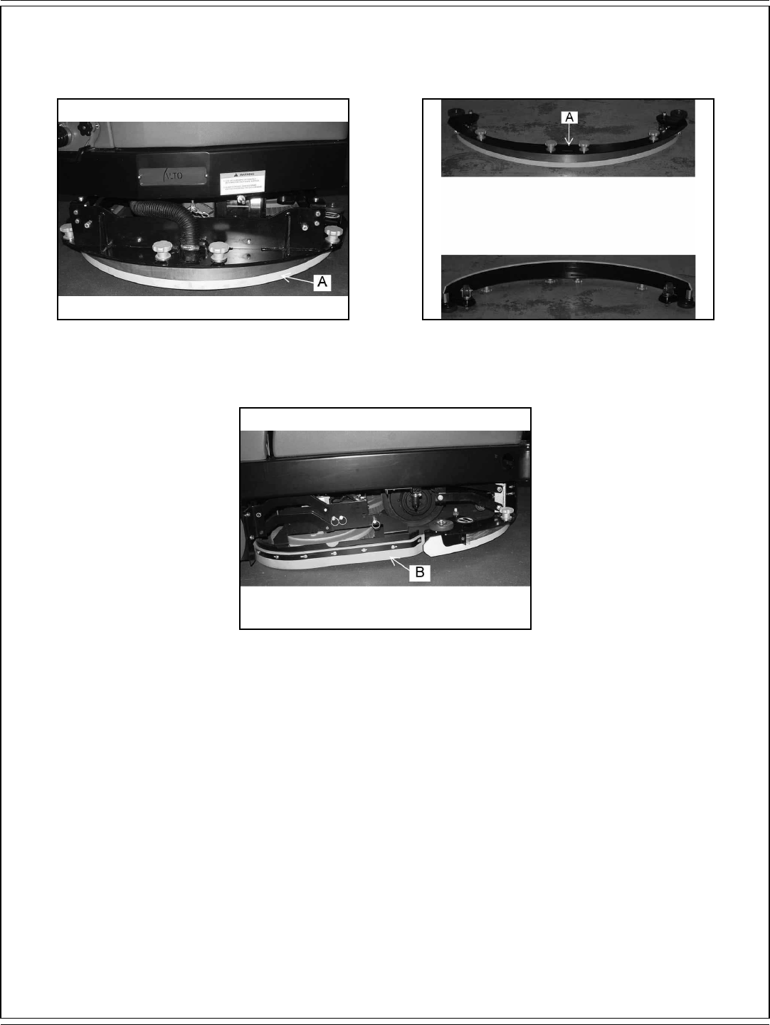
ESPAÑOL / B-29
FORM NO. 56041720 - 7730 - B-29
INSTRUCCIONES DE USO
FIGURA 54 FIGURA 55
FIGURA 56
Inspeccione las hojas de las rasquetas posterior (A) y lateral (B) por si presentan desgaste. Si el borde de limpieza está redondeado, retire y
vuelva a instalar, de manera que el borde sin desgastar sea ahora el borde de limpieza. Este proceso puede repetirse hasta que los cuatro
bordes estén desgastados. Si la hoja de la rasqueta se ha rizado, debe sustituirse.

B-30 / ESPAÑOL
B-30 - FORM NO. 56041720 - 7730
INSTRUCCIONES DE USO
FIGURA 57 FIGURA 58
BOTÓN DE CONTROL DEL POLVO
El botón de control del polvo (A) se utiliza para mantener bajada la cubierta del fi ltro de control del polvo, como se muestra en la fi gura 57. El
fi ltro de control del polvo (B) está situado bajo la cubierta frontal y debe retirarse periódicamente para su limpieza o su sustitución. La retirada
del panel del fi ltro puede hacerse sin ninguna herramienta. Para acceder al compartimento del fi ltro hay que abrir la cubierta frontal. El fi ltro del
panel se mantiene en su sitio mediante un bastidor articulado y un botón. Para retirar el panel del fi ltro, gire el botón en sentido contrario a las
agujas del reloj y eleve el bastidor articulado. Ahora puede sacarse el fi ltro del panel y limpiarlo o sustituirlo. Para instalar el fi ltro de repuesto del
panel, coloque un nuevo fi ltro en la máquina, baje el bastidor y gire el botón en el sentido de las agujas del reloj para bloquear el fi ltro en su sitio.
FIGURA 59
MIRILLA DEL NIVEL DE LÍQUIDO EN EL DEPÓSITO HIDRÁULICO
La mirilla del nivel de líquido (C) está situada en el lado derecho de la máquina, bajo la cubierta frontal, como se muestra en la fi gura 59. La mirilla
se utiliza para indicar el nivel de líquido en el depósito. El nivel de líquido debe ser visible en la mirilla cuando la tolva esté bajada.

ESPAÑOL / B-31
FORM NO. 56041720 - 7730 - B-31
MANTENIMIENTO
TABLA DE MANTENIMIENTO
Compruebe si los elementos funcionan correctamente. Si se necesita servicio técnico, por favor, póngase en contacto con un distribuidor
autorizado de American-Lincoln. Para obtener el mejor rendimiento, sustituya las piezas desgastadas por piezas auténticas de American-Lincoln.
CADA ocho (8) HORAS o A DIARIO, compruebe y limpie/ajuste si es necesario:
1 Inspeccione si el fi ltro del panel presenta daños y limpie.
2 Inspeccione y limpie la tolva.
3 Inspeccione y limpie cribas y fi ltros del depósito de recuperación.
4 Compruebe el nivel del líquido hidráulico.
5 Compruebe si las aletas están desgastadas o dañadas.
6 Compruebe si los cepillos están desgastado o dañados; ajuste si es necesario.
7 Compruebe el pedal del freno y el freno de estacionamiento.
8 Compruebe el fi ltro del aceite hidráulico.
9 Compruebe el nivel de electrolitos de las baterías.
10 Compruebe los componentes de todos los sistemas con líquidos por si presentan fugas.
LISTA DE COMPROBACIÓN DE MANTENIMIENTO CADA 50 HORAS (SEMANAL)
11 Compruebe el depósito de la solución (sistema de reciclaje o ESP).
12 Compruebe la criba del fi ltro de la solución (sistema de reciclaje o ESP).
13 Compruebe el depósito de recuperación.
14 Compruebe las cribas y los fi ltros del depósito de recuperación.
15 Inspeccione los cepillos de fregado por si están desgastados o dañados.
16 Inspeccione las rasquetas posterior y lateral por si están desgastadas o dañadas.
17 Compruebe el nivel de electrolitos de las baterías.
18 Compruebe si los tubos hidráulicos están desgastados o dañados.
19 Gire el cepillo principal.
20 Limpie o sustituya el fi ltro del panel.
21 Lubrique las ruedas pivotantes de las rasquetas.
LISTA DE COMPROBACIÓN DE MANTENIMIENTO CADA 100 HORAS
22 Lubrique los cojinetes de la rueda delantera.
23 Lubrique todas las juntas móviles.
LISTA DE COMPROBACIÓN DE MANTENIMIENTO CADA 250 HORAS
24 Lubrique las ruedas pivotantes de las rasquetas.
25 Limpie el depósito de la solución y la criba del fi ltro.
26 Sustituya el elemento del fi ltro hidráulico.
27 Limpie el depósito hidráulico.
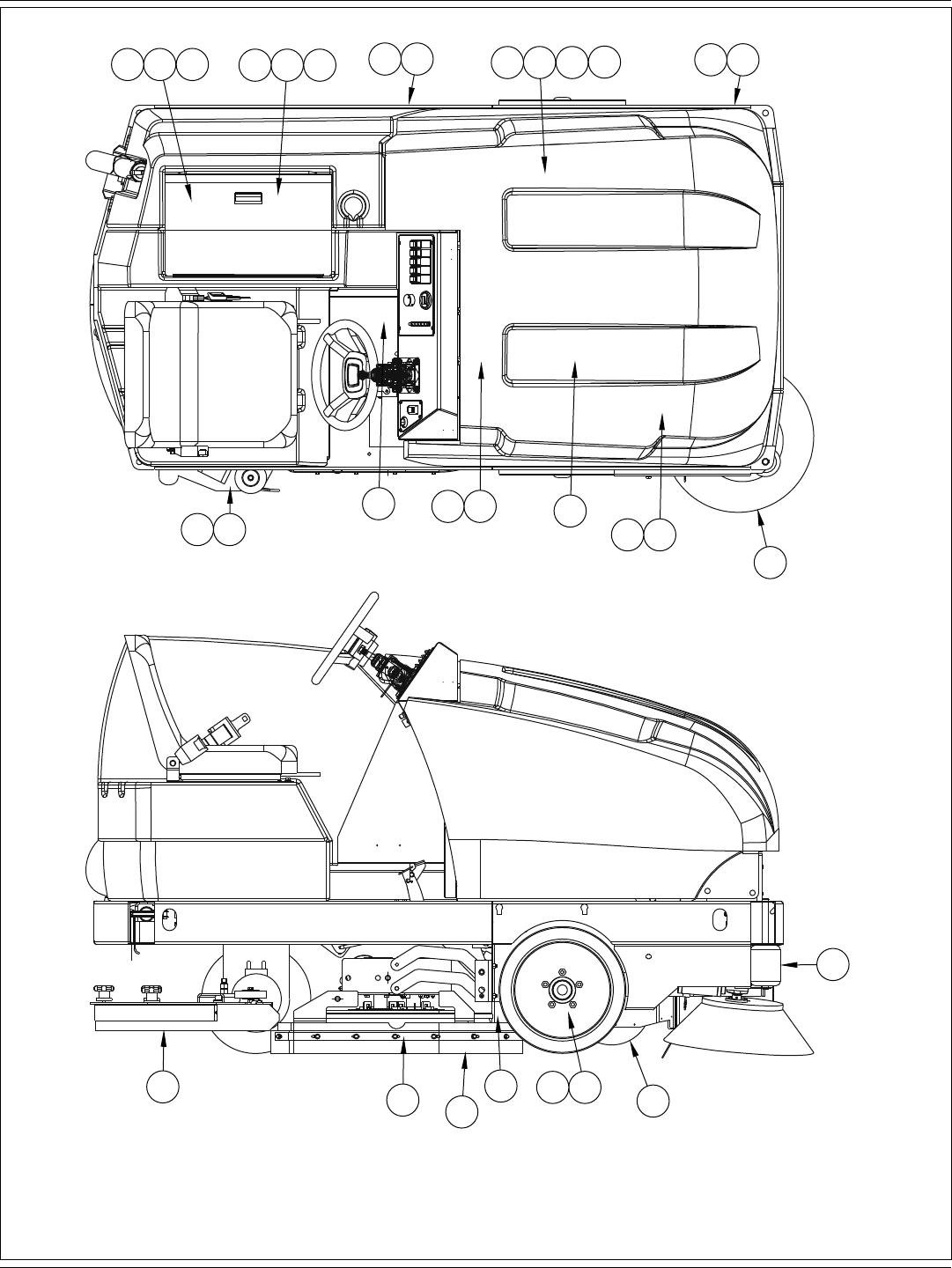
B-32 / ESPAÑOL
B-32 - FORM NO. 56041720 - 7730
13314 1211 25 65 84 26 27 195
201
6
18
179
7
2421
2322 6
2
5
16
15
16

ESPAÑOL / B-33
FORM NO. 56041720 - 7730 - B-33
MANTENIMIENTO
Por motivos de seguridad, lea y respete las precauciones durante el mantenimiento que aparecen más adelante. Conozca los riesgos asociados
con el equipo en el que trabaja para evitar lesiones personales o daños en dicho equipo.
Si necesita ayuda para el mantenimiento, consulte con su distribuidor de American-Lincoln más cercano. Para obtener el mejor rendimiento,
sustituya las piezas desgastadas por piezas auténticas de American-Lincoln.
Consulte todos los requisitos de mantenimiento y reparaciones con personal de mantenimiento cualifi cado.
NO intente reparar la máquina hasta haber leído y comprendido todas las advertencias de seguridad asociadas con el equipo en el que trabaje.
¡ADVERTENCIA!
* El mantenimiento y las reparaciones debe efectuarlas únicamente personal autorizado.
* Las reparaciones de los medios eléctricos debe efectuarlas únicamente personal autorizado. Consulte con el personal de contacto
de su servicio técnico autorizado de American-Lincoln cómo realizar los procedimientos de mantenimiento y reparación. Utilice
únicamente piezas auténticas de American-Lincoln.
* Deténgase siempre sobre una superfi cie nivelada, apague el interruptor de contacto y aplique el freno de estacionamiento antes de
trabajar en la máquina, para evitar que se desplace o ruede.
* El mantenimiento y las reparaciones debe efectuarlas únicamente personal autorizado. Vacíe siempre el depósito de la solución y
el depósito de recogida antes de realizar cualquier mantenimiento. Mantenga todos los elementos de fi jación apretados. Mantenga
los ajustes según las especifi caciones que aparecen en el Manual de mantenimiento correspondiente a esta máquina.
* Utilice protección ocular y ropas de seguridad en todo momento cuando trabaje cerca de las baterías. No coloque herramientas ni
otros objetos metálicos sobre los bornes de las baterías. NO FUME.
* Para evitar daños en la máquina y la descarga en la parte superior de las baterías, no llene dichas baterías por encima del fondo
del tubo de cada célula. Limpie cualquier ácido de la máquina o de la parte superior de las baterías. No añada ácido a ninguna
batería tras su instalación.
* La tolva puede caer y provocar lesiones graves. Enganche siempre el brazo de seguridad de la tolva antes de trabajar bajo dicha
tolva.
* Para mantener la estabilidad de esta máquina durante el funcionamiento normal, no debe retirarse el resguardo elevado o
cualquier equipo similar instalado por el fabricante como equipo original. Si es necesario retirar dicho equipo para reparación o
mantenimiento, deberá instalarse antes de volver a usar la máquina.

B-34 / ESPAÑOL
B-34 - FORM NO. 56041720 - 7730
MANTENIMIENTO
FIGURA 60 FIGURA 61
FIGURA 62
INSTRUCCIONES DE CARGA DE LA BATERÍA
Cuando el medidor de estado de la batería está iluminado con una luz LED roja, es necesario recargar la batería. Para evitar la interrupción del
ciclo de limpieza, cargue la batería tras el uso.
1. Fig. 60. Eleve la cubierta frontal de la máquina para acceder a la batería.
2. Fig. 61. Desconecte el conector de alimentación de la batería (A) del conector de alimentación de la máquina (B).
3. Fig. 62. Enchufe el conector de alimentación de la batería (C) al cargador de la batería (D).
4. Siga las instrucciones de carga del fabricante que se proporcionan junto al cargador.
5. Mantenga el nivel de electrolitos en la batería y compruebe tras la carga. Añada agua destilada si es necesario.
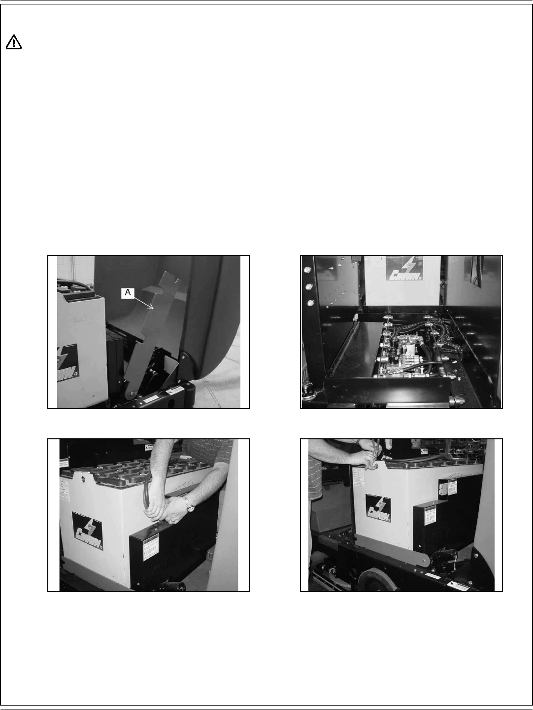
ESPAÑOL / B-35
FORM NO. 56041720 - 7730 - B-35
MANTENIMIENTO
¡ADVERTENCIA!
* No retire la batería de la máquina si hay residuos en el depósito de la solución.
* Durante la operación de carga se forma gas de hidrógeno, que es explosivo. Cargue las baterías únicamente en un área bien ventilada con la tapa
abierta. Evite llamas abiertas o chispas eléctricas. Si se saca el enchufe del cargador con este todavía encendido, se provocará un arco eléctrico
que debe ser evitado.
* Las baterías son pesadas. Utilice un dispositivo de elevación con la capacidad nominal especifi cada.
* Quítese siempre las joyas, y utilice ropas de seguridad y protección facial cuando trabaje cerca de las baterías.
* Las baterías con ácido de plomo generan gases, que provocan explosiones. Mantenga chispas y llamas alejadas de las baterías; cargue las
baterías únicamente en áreas con buena ventilación. NO FUME.
* Para evitar cualquier explosión, desconecte el enchufe de CA del receptáculo antes de conectar o desconectar el enchufe CC del cargador.
* La caja de la batería puede deslizarse fuera de una carretilla elevadora y provocar lesiones personales graves o daños en el equipo. Asegúrese
de que la caja de la batería está asegurada correctamente a las horquillas de la carretilla elevadora durante el transporte; conduzca y pare con
precaución.
FIGURA 63 FIGURA 64
FIGURA 65 FIGURA 66
RETIRADA DE LA BATERÍA
Cuando retire las baterías
1. Fig. 63 y 64. Eleve la cubierta frontal de la máquina para acceder al compartimento de la batería y gire la palanca de la batería (A) a la
derecha.
2. Fig. 65. Desenchufe el conector de alimentación de la batería del conector de alimentación de la máquina.
3. Fig. 66. Eleve la batería para sacarla utilizando un dispositivo de elevación con capacidad para 2000 lb (907 kg).
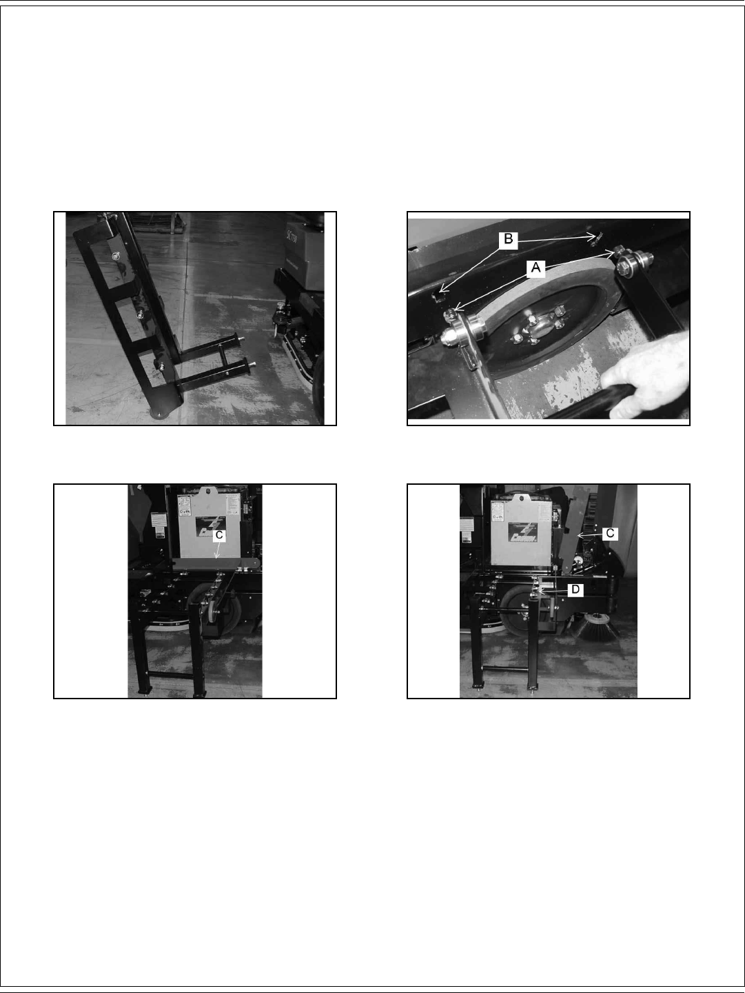
B-36 / ESPAÑOL
B-36 - FORM NO. 56041720 - 7730
MANTENIMIENTO
RETIRADA DE LA BATERÍA CON OPCIÓN DE DESCARGA DE BATERÍA
Cuando retire las baterías
1. Eleve la cubierta frontal de la máquina para acceder al compartimento de la batería.
2. Desenchufe el conector de alimentación de la batería del conector de alimentación de la máquina.
3. Fig. 68. Alinee los pasadores de posicionamiento del carro de la batería (A) con las ranuras (B) en el bastidor, y bloquee en su sitio.
4. Fig. 69 y 70. Gire la palanca de la batería (C) hacia la derecha y deslice la batería fuera del carro.
FIGURA 67 FIGURA 68
FIGURA 69 FIGURA 70

ESPAÑOL / B-37
FORM NO. 56041720 - 7730 - B-37
MANTENIMIENTO
FIGURA 71 FIGURA 72
SUSTITUCIÓN DE LOS CEPILLOS DE FREGADO
1. Eleve el portacepillos de fregado presionando el interruptor “Scrub Brush” (cepillo de fregado) en el panel de instrumentos.
2. Presione los seguros del cepillo hacia dentro para soltar el cepillo de fregado.
3. Retire el cepillo de fregado antiguo (A).
4. Encaje el nuevo cepillo de fregado en su lugar.
SUSTITUCIÓN DE LAS BAYETAS EN UN PORTABAYETAS
Instale una nueva bayeta cuando la antigua esté desgastada o sucia. El conjunto del portabayetas se retira y se instala de la misma forma que
un cepillo de fregado (consulte Sustitución del cepillo de fregado).
1. El portabayetas mantiene en su sitio mediante un anillo. Tire del portabayetas recto y hacia adelante para retirarlo.
2. Retire el portabayetas usando el retén de hilo metálico del muelle.
3. Sustituya la bayeta desgastada.

B-38 / ESPAÑOL
B-38 - FORM NO. 56041720 - 7730
MANTENIMIENTO
FIGURA 73 FIGURA 74
FIGURA 75
SUSTITUCIÓN DE LA RASQUETA TRASERA
La rasqueta requerirá mantenimiento cuando el borde interior de las hojas se vuelva redondeado debido al desgaste, lo que difi cultará la acción
de fregado o la recogida de agua.
1. Fig. 73. Afl oje los cuatro botones de aluminio (A).
2. Fig. 74. Retire la herramienta de la rasqueta y póngala boca abajo para el mantenimiento de las hojas o las ruedas pivotantes. Las
hojas de las rasquetas se han diseñado para girarlas y utilizar un borde sin desgastar. Afl oje los pernos de retención (B).
3. Instale las hojas de manera que la hoja exterior sea 4,76 mm más larga que las hojas interiores. Esto se logra montando el borde
superior de la hoja contra la soldadura de la herramienta de la rasqueta.
4. Vuelva a instalar la banda de fi jación de la rasqueta y apriete el perno de fi jación.

ESPAÑOL / B-39
FORM NO. 56041720 - 7730 - B-39
MANTENIMIENTO
FIGURA 76
VACIADO DEL DEPÓSITO DE RECUPERACIÓN
Lleve la máquina a una zona de vaciado. Afl oje los botones de la puerta de limpieza de la recuperación (A) y gire dicha puerta hacia la izquierda,
como se muestra en la fi gura 76. Mediante la manguera de agua, lave el fondo de la puerta de limpieza del depósito de la solución para retirar las
partículas de residuos de mayor tamaño.
FIGURA 77 FIGURA 78
VACIADO DEL DEPÓSITO DE LA SOLUCIÓN
Eleve la cubierta del depósito de la solución/recuperación. Coloque el tubo de vaciado del depósito de la solución (B) como se muestra en la
fi gura 77. Saque el tubo hacia afuera como se muestra en la fi gura 78. Abra el tapón de vaciado del depósito de recuperación y deje que se vacíe
dicho depósito. Limpie y lave el depósito de la solución con una manguera de agua. Apriete el tapón del depósito de recuperación y guarde el
tubo de vaciado de dicho depósito en su sitio.

B-40 / ESPAÑOL
B-40 - FORM NO. 56041720 - 7730
MANTENIMIENTO
FIGURA 79
CEPILLO PRINCIPAL
Para evitar que el cepillo se fi je en una dirección y conseguir la máxima vida operativa de dicho cepillo, recomendamos girar completamente el
cepillo periódicamente.
FIGURA 80
AJUSTE DE LA ALTURA DEL CEPILLO PRINCIPAL
El botón de ajuste del cepillo principal (A), para cambiar la altura de barrido y compensar el desgaste del cepillo, está ubicado en el frontal de
la máquina, como se muestra en la fi gura 80. Gire el botón hacia la izquierda (en sentido contrario a las agujas del reloj) para bajar el cepillo
principal. Al cambiar el ajuste de la altura de barrido, se recomienda ajustar el botón un giro cada vez. Tras ajustar, vuelva a comprobar el patrón
de barrido para determinar si se necesitan más ajustes.
GIRO DEL BOTÓN EN EL SENTIDO DE LAS AGUJAS DEL RELOJ = AUMENTO DE LA ANCHURA DEL PATRÓN DE BARRIDO
GIRO DEL BOTÓN EN SENTIDO CONTRARIO A LAS AGUJAS DEL RELOJ = REDUCCIÓN DE LA ANCHURA DEL PATRÓN DE BARRIDO

ESPAÑOL / B-41
FORM NO. 56041720 - 7730 - B-41
MANTENIMIENTO
FIGURA 81
PUERTA DE ACCESO AL CEPILLO PRINCIPAL
La puerta de acceso el cepillo principal (A) está situada en el frontal del neumático izquierdo de la máquina, como se muestra en la fi gura 81. La
puerta permite acceder al cepillo principal para mantenimiento o inspección. Para acceder es necesario elevar la tolva.
¡ADVERTENCIA!
Enganche el brazo de seguridad de la tolva mientras accede al cepillo principal.
FIGURA 82 FIGURA 83
SUSTITUCIÓN DEL CEPILLO PRINCIPAL
El cepillo principal debe cambiarse cuando las cerdas estén gastadas hasta una longitud de 1 ½” (3,81 mm). El cepillo principal se mantiene en
su lugar gracias a la puerta del cepillo lateral derecho. Esta característica permite una retirada y una instalación fáciles del cepillo principal sin
necesidad de herramientas ni equipo especial. Eleve la tolva para acceder al compartimento del cepillo principal. Afl oje el botón de la puerta de
acceso al cepillo principal y abra dicha puerta de acceso. Gire y retire los botones del brazo de elevación del cepillo (B) en sentido contrario a las
agujas del reloj, tal y como se muestra en las fi guras 82 y 83.

B-42 / ESPAÑOL
B-42 - FORM NO. 56041720 - 7730
MANTENIMIENTO
FIGURA 84 FIGURA 85
FIGURA 86 FIGURA 87
FIGURA 88
Retire el brazo de elevación del cepillo (A), tal y como se muestra en las fi guras 84 y 85. Retire el cepillo principal del brazo libre del cepillo
(B), dejando a la vista al compartimento del cepillo principal, como se muestra en la fi gura 86. Compruebe y limpie el compartimento del cepillo
principal antes de instalar el nuevo cepillo principal. Deslice el cepillo principal sobre el brazo libre del cepillo, como se muestra en la fi gura 87.
Vuelva a colocar el brazo de elevación y gire los botones de dicho brazo de elevación del cepillo (C) en el sentido de las agujas del reloj, tal y
como se muestra en la fi gura 88. Ajuste el cepillo principal para un patrón de barrido de entre 1-1/2” a 2” (3,81-5,08 mm).

ESPAÑOL / B-43
FORM NO. 56041720 - 7730 - B-43
MANTENIMIENTO
AJUSTE DE LA ALTURA DEL CEPILLO LATERAL
Gire el botón de ajuste del cepillo lateral (A) (Fig. 90) para cambiar la altura
de barrido de dicho cepillo. Vuelva a comprobar que el patrón de barrido es
adecuado tras el ajuste.
Gire el botón de ajuste en sentido contrario las agujas del reloj para AUMENTAR
la anchura del patrón de barrido.
Gire el botón de ajuste en el sentido de las agujas del reloj para REDUCIR la
anchura del patrón de barrido.
FIGURA 91
CEPILLO LATERAL
El ángulo de barrido del cepillo lateral (Fig. 89) no puede ajustarse. Sin embargo,
sí que puede ajustarse la altura del cepillo lateral para compensar el desgaste
por el uso. Compruebe siempre el patrón de barrido y ajuste tras cambiar el
cepillo lateral.
FIGURA 89
FIGURA 90
SUSTITUCIÓN DEL CEPILLO LATERAL
Cambie el cepillo lateral (Fig. 91) cuando las cerdas se desgasten a menos de 3
inches (7,62 cm) de longitud.
1. Estacione la máquina en una superfi cie nivelada y regular, gire el interruptor
de contacto a la posición “O” y aplique el freno de estacionamiento.
2. Coloque el interruptor de los cepillos laterales en la posición “UP” (arriba).
3. Retire el pasador de bloqueo que sujeta la brida del cepillo al árbol del
motor.
4. Desmonte la brida del cepillo retirando los tornillos que sujetan dicha brida
al cepillo.
5. Monte la brida en el cepillo de repuesto y sujete utilizando la tornillería
retirada.
6. Instale el cepillo de repuesto en el árbol e inserte el pasador de bloqueo.

B-44 / ESPAÑOL
B-44 - FORM NO. 56041720 - 7730
MANTENIMIENTO
FIGURA 92 FIGURA 93
TOLVA
La tolva (Fig. 92) alberga el compartimento de residuos, el fi ltro de control del polvo y el defl ector del polvo extraíble. Para lograr el máximo
rendimiento y la mayor vida operativa, mantenga la tolva limpia e inspeccione los sellos y las aletas a diario. Limpie la tolva antes de dejar
estacionada la barredora al fi nal del día. Una tolva limpia hará que inspeccionar las aletas y los sellos sea mucho más fácil y evitará un deterioro
prematuro de los componentes de la tolva. No deje la tolva llena de residuos mientras la máquina se almacena o si va a estar estacionada
durante un período prolongado de tiempo. Cuando la tolva se haya vaciado, el interior de la misma debe aclararse con agua.
FILTRO DE CONTROL DEL POLVO
El fi ltro de control del polvo (Fig. 93) debe comprobarse a diario por si presenta daños y es necesario limpiarlo. Un fi ltro dañado debe sustituirse
para evitar daños en otros componentes del sistema de control del polvo. Inspeccione si el fi ltro tiene roturas en los medios fi ltrantes o excesiva
suciedad alojada en los pliegues. Una rotura en los medios fi ltrantes permitirá que pase la suciedad a través del fi ltro y puede verse fácilmente
como un corro de suciedad en la parte superior del fi ltro. La limpieza del fi ltro es necesaria cuando el agitador del fi ltro no limpia adecuadamente
los pliegues.
COMPROBACIÓN DEL FILTRO DE CONTROL DEL POLVO
1. Estacione la máquina en una superfi cie nivelada y regular, gire el interruptor de contacto a la posición “O” y aplique el freno de
estacionamiento.
2. Eleve la tapa de la tolva para acceder al compartimento del fi ltro.
3. Gire el seguro del fi ltro, eleve el bastidor del fi ltro y retire el fi ltro.
4. Inspeccione si el fi ltro del panel presenta daños y limpie o sustituya si es necesario.
5. Vuelta a instalar el fi ltro, baje el bastidor del fi ltro y enganche del seguro del fi ltro.
6. Cierre la cubierta de la tolva.
LIMPIEZA DEL FILTRO DE CONTROL DEL POLVO
Limpie el fi ltro de control del polvo cuando el agitador del fi ltro no limpie adecuadamente dicho fi ltro. El fi ltro puede limpiarse mediante aire
comprimido que no supere las 100 PSI Para limpiar el fi ltro mediante aire comprimido, aplique el aire comprimido a la parte superior del panel
con el fi n de extraer la suciedad alojada en los pliegues del fi ltro. Tenga cuidado de no dañar los medios fi ltrantes durante la limpieza. El fi ltro
puede limpiarse mediante una solución de jabón y agua. Si se utiliza este método de limpieza, no utilice el fi ltro hasta que se haya secado
completamente.
SUSTITUCIÓN DEL FILTRO DE CONTROL DEL POLVO CUANDO EL DAÑO ES EVIDENTE
1. Estacione la máquina en una superfi cie nivelada y regular, gire el interruptor de contacto a la posición “O” y aplique el freno de
estacionamiento.
2. Abra el compartimento de la tolva para acceder al compartimento del fi ltro.
3. Gire el seguro del fi ltro en el bastidor articulado en sentido contrario a las agujas del reloj y eleve dicho bastidor.
4. Retire el panel del fi ltro.
5. Instale el fi ltro de repuesto, baje el bastidor articulado y enganche el seguro.
6. Baje la cubierta del compartimento del fi ltro.
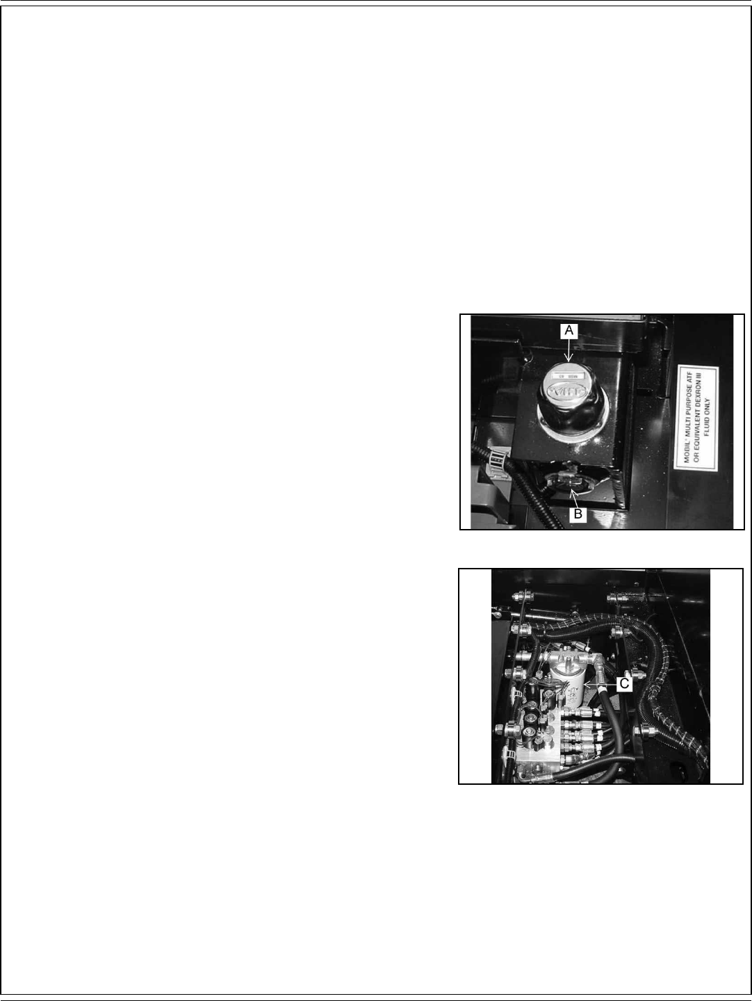
ESPAÑOL / B-45
FORM NO. 56041720 - 7730 - B-45
MANTENIMIENTO
ALETAS PARA EL POLVO
Las aletas para el polvo son muy importantes para el barrido y el control del polvo, son susceptibles de sufrir daños y deben inspeccionarse
regularmente y mantenerse en buen estado.
COMPROBACIÓN DE LAS ALETAS PARA EL POLVO
Las aletas para el polvo se usan en el depósito de la rueda, la cámara del cepillo y la puerta del cepillo. Inspeccione las aletas diariamente, y
sustituya cualquier aleta que muestre señales de desgaste o deterioro. Todas las aletas deben sustituirse cuando estén desgastadas o dañadas
de tal forma que no puedan realizar ya su función normal. Las aletas ajustables tienen orifi cios de montaje con ranuras para facilitar el ajuste.
AJUSTE DE LAS ALETAS PARA EL POLVO
Ajuste las aletas de manera que haya una separación de entre 1/8” y 1/16” (3,175 -1,588 mm) entre el suelo y el borde inferior de las mismas. El
ajuste de la aleta trasera es de 1/16” (1,588 mm) por encima del suelo.
1. Estacione la máquina en una superfi cie nivelada y regular y aplique el freno de estacionamiento.
2. Afl oje los tornillos de retención de las aletas y ajuste la aleta separada del suelo, con una distancia de entre 1/16”-1/8” (1,588-3,175 mm).
3. Aplique los tornillos de retención de la aleta mientras mantiene dicha aleta en su posición.
4. Lleve la máquina a una superfi cie nivelada y regular y vuelva a comprobar si las aletas están separadas del suelo la distancia adecuada.
LLENADO DEL DEPÓSITO HIDRÁULICO (Fig. 94)
1. El acceso al depósito hidráulico se encuentra en el compartimento del motor.
2. Abra el tapón del fi ltro del respiradero del depósito hidráulico (A).
3. Retire cualquier residuo que haya en la criba del tapón del fi ltro del respiradero.
4. Llene el depósito hasta que el líquido alcance la línea “FULL” (lleno) en la mirilla
del líquido hidráulico (B). La mirilla está situada en el lado central del depósito
hidráulico.
5. Cierre el tapón del fi ltro del respiradero del depósito hidráulico.
6. Cierre la cubierta del compartimento del motor.
LIMPIEZA DEL SISTEMA HIDRÁULICO
1. Coloque un paño para goteo sobre el suelo.
2. Lleve la máquina sobre el paño para goteo.
3. Aplique el freno de estacionamiento.
4. Abra la cubierta.
5. Coloque un recipiente bajo el drenaje del depósito para recoger el líquido del
mismo. Gire el depósito para sacarlo.
6. Retire el tapón del drenaje. El líquido del depósito se vacía.
No use el líquido vaciado para rellenar el depósito hidráulico. Deseche el líquido
usado.
7. Lave el interior del depósito hidráulico con líquido limpio.
8. Coloque el tapón del depósito, retirado en el paso 6, en el drenaje del depósito
hidráulico y apriételo. En el tapón se requiere adhesivo para roscas de tubos.
9. Abra el tapón del fi ltro del respiradero.
10. Llene el depósito con MOBIL Multipurpose ATF nuevo o Dextron III equivalente.
La capacidad del depósito es 4,7 gal (17,79 litros). Llene hasta la línea “FULL”
(lleno) en la mirilla del líquido hidráulico.
11. Cierre el tapón del fi ltro del respiradero.
12. Vuelva a colocar la cubierta.
FIGURA 94
FIGURA 95
SUSTITUCIÓN DEL ELEMENTO DEL FILTRO DE RETORNO (Fig. 95)
1. Sustituya el elemento del fi ltro de retorno (C) tras 250 horas de tiempo de funcionamiento de la máquina.
2. Desatornille los elementos de fi jación de la cubierta del fi ltro y consérvelos.
3. Retire la cubierta y el muelle de compresión y consérvelos.
4. Descarte el elemento del fi ltro antiguo.
5. Coloque el nuevo elemento del fi ltro dentro del cuerpo del fi ltro.
6. Coloque el muelle de compresión en su lugar. Limpie el imán de la cubierta de cualquier viruta metálica o residuo.
7. Coloque la junta tórica (humedezca con líquido hidráulico limpio) y la cubierta en su posición.
8. Vuelva a colocar los elementos de fi jación en la cubierta del fi ltro.
9. Limpie cualquier derrame de líquido del depósito hidráulico. El líquido puede dañar las superfi cies pintadas de la máquina.

B-46 / ESPAÑOL
B-46 - FORM NO. 56041720 - 7730
LOCALIZACIÓN DE AVERÍAS
PROBLEMA CAUSA PROBABLE SOLUCIÓN
La máquina se mueve de
manera lenta o errática
1. Carga baja de la batería
2. Resistencia en los frenos
3. Conexión suelta en el pedal
4. Circuito de la transmisión sobrecargado
1. Cargue.
2. Ajuste.
3. Repare.
4. Retire la obstrucción, coloque el pedal de tracción en
posición neutral.
La máquina no se mueve 1. Fusible fundido
2. Batería desenchufada
1. Compruebe el fusible y sustituya si es necesario.
2. Enchufe la batería.
Mala recogida de agua en
la rasqueta
1. Depósito de recuperación lleno
2. Rasqueta desgastada o dañada
3. Obstrucción en el tubo de succión o la
herramienta de recogida
4. Conexiones sueltas entre el tubo de succión y
la rasqueta
5. Los motores de aspiración no funcionan
6. Filtro atascado
7. Caja del fl otador de aspiración obstruida
8. Desconexión por fl otador de aspiración
9. Fugas de aire en el tubo y la conexión de
succión
10. Fugas de aire en la cubierta del depósito de
recuperación, el tubo del colector, o ambas
11. El tubo de vaciado o el tapón de vaciado
tienen fugas o no están bien cerrados.
1. Vacíe el depósito
2. Examine la hoja de goma de la rasqueta por si tiene
cortes o puntos desgastados y cambie si es necesario
3. Desconecte el tubo de succión de la rasqueta; lave la
rasqueta y los tubos.
4. Compruebe las conexiones de todos los tubos por si
están sueltas o dañadas.
5. Restablezca el disyuntor o repare la conexión suelta.
6. Limpie el elemento del fi ltro en el colector de aspiración.
7. Limpie el metal perforado perfectamente
8. Exceso de solución en el depósito de recuperación.
Acumulación excesiva de espuma, cambie la mezcla
de productos químicos de limpieza (utilice materiales
aprobados por N-A).
9. Repare o sustituya el tubo y la conexión.
10. Repare o sustituya la junta o el tubo.
11. Cierre, repare o sustituya el tapón de vaciado en el
depósito de recuperación.
Derrames de agua de la
rasqueta
1. Las hojas de la rasqueta lateral hacen mal
contacto con el suelo.
2. Hojas de la rasqueta desgastadas o dañadas.
3. Se aplica demasiada solución antes de tomar
curvas.
4. Los cepillos giran en la dirección contraria
1. Reajuste las hojas para que hagan un contacto
adecuado.
2. Cambie y ajuste.
3. Desconecte la solución de 5-10ft (1,524-3,048 m) antes
de girar.
4. Compruebe las posiciones de los interruptores.
La rasqueta deja puntos
húmedos
1. Actuador de elevación mal ajustado
2. Ruedas de la rasqueta mal ajustadas.
1. Ajuste
2. Ajuste
La rasqueta hace un ruido
excesivo.
1. Hojas desgastadas o dañadas. 1. Sustituya.

ESPAÑOL / B-47
FORM NO. 56041720 - 7730 - B-47
LOCALIZACIÓN DE AVERÍAS
PROBLEMA CAUSA PROBABLE SOLUCIÓN
Fregado defectuoso 1. Cepillos de fregado desgastados
2. Método de trabajo incorrecto
3. Agente limpiador o mezcla de limpieza
incorrecta
4. Mala distribución de la solución
5. Los cepillos no giran.
1. Inspeccione los cepillos. Cambie los cepillos si se han
desgastado hasta 19 mm o menos.
2. Compruebe el procedimiento de fregado, la presión de
los cepillos, el fl ujo de la solución y el agente limpiador
usados; todos estos elementos son importantes para el
proceso.
3. Use materiales recomendados por N-A.
4. Compruebe el fi ltro de la solución y los tubos de
alimentación por si presentan obstrucciones; limpie si es
necesario. Compruebe la válvula y el resto del sistema de
control de la solución para ver si funcionan correctamente.
5. Compruebe las conexiones de los cables.
Salpicaduras de agua
de los laterales del
portacepillos
1. Parachoques del portacepillos, mal contacto
con el suelo.
2. Hojas de la rasqueta gastadas o dañadas.
3. Demasiada solución.
1. Reajuste las hojas para que hagan un contacto
adecuado.
2. Cambie y ajuste.
3. Desconecte la solución de 5-10ft (1,524-3,048 m) antes
de girar.
Barrido defectuoso 1. Cepillo atascado.
2. Tolva llena.
3. El cepillo no está ajustado adecuadamente.
4. Aletas desgastadas o dañadas.
5. Cepillo desgastado.
1. Retire cualquier obstrucción.
2. Vacíe
3. Consulte el ajuste del cepillo en la sección de
mantenimiento.
4. Inspeccione por si hay daños; sustituya o ajuste
consultando la sección de mantenimiento.
5. Inspeccione por si hay daños o desgaste; consulte la
sección de mantenimiento.
El barrido no funciona 1. La tolva está elevada
2. Interruptor de la tolva mal ajustado
1. Baje la tolva
2. Ajuste el interruptor de la tolva
Control del polvo
defectuoso en el cepillo
principal
1. Aletas de la cámara del cepillo y la tolva
desgastadas.
2. Avería en los ventiladores del propulsor;
chaveta del árbol rota o el motor eléctrico no
funciona.
3. Filtro atascado.
1. Compruebe el estado de las aletas. Cambie las aletas
rotas o muy desgastadas. Las aletas laterales pueden
ajustarse si no están dañadas.
2. Compruebe y repare.
3. Active el interruptor del agitador o compruebe el fi ltro.
La tolva no se eleva 1. Carga demasiado pesada.
2. Actuador de elevación defectuoso.
1. Reduzca la carga parcial de descarga.
2. Repare o sustituya el actuador.

B-48 / ESPAÑOL
B-48 - FORM NO. 56041720 - 7730
ESPECIFICACIONES TÉCNICAS (según la instalación y las pruebas de la unidad)
Modelo 7730 (40”) 7730 (46”)
Nº de modelo 56515851 56515853
Tensión, batería V 36 36
Capacidad de la batería AH 720 720
Grado de protección IPX3 IPX3
Nivel de presión sonora
(IEC 60335-2-72: 2002, enmienda. 1:2005, ISO 11201) dB(A)/20μPa 77.2 77.2
Nivel de potencia acústica (ISO 3744) Lwa 103 103
Peso total lb/kg 3690 / 1661 3690 / 1661
Vibraciones en los controles manuales (ISO 5349-1) m/s2 0,80 m/s2 0,80 m/s2
Vibraciones en el asiento (EN 1032) m/s2 0,35 m/s2 0,35 m/s2
Capacidad de ascenso
Transporte 14,1% (8°) 14,1% (8°)
Limpieza 10,5% (6°) 10,5% (6°)

14600 21st Avenue North
Plymouth, MN 55447-3408
www.americanlincoln.com
Phone: 800-331-7692
Fax: 877-877-2586
©2008 American-Lincoln
