Sweepscrub American Lincoln Moyno 500 Pump Service Manual Moyno® (Service 300 Series: 331,332,333,344,356,367) User
2017-10-05
User Manual: Sweepscrub American-Lincoln-Moyno-500-Pump-Service-Manual american-lincoln-moyno-500-pump-service-manual 2267 file product_file sweepscrub
Open the PDF directly: View PDF ![]() .
.
Page Count: 8
Section:
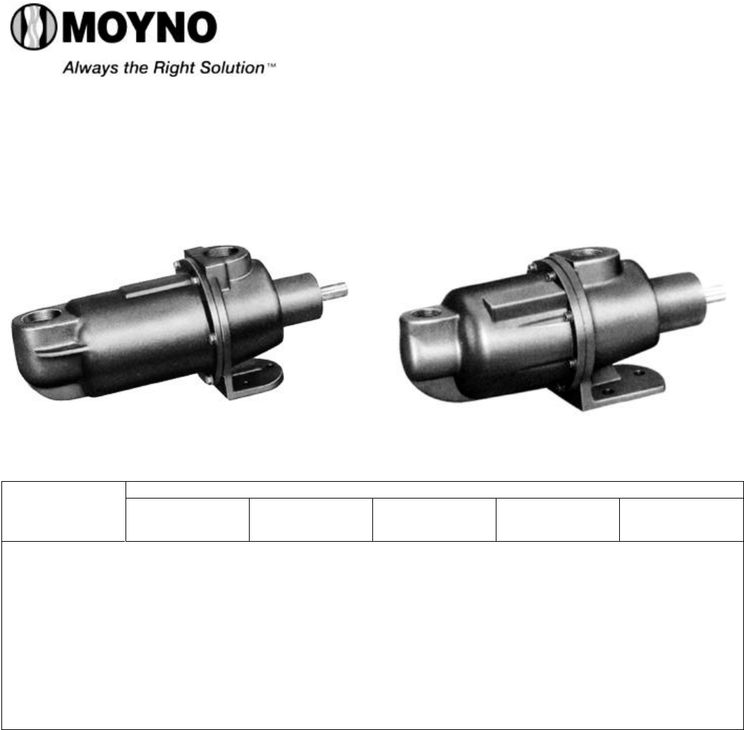
MOYNO® 500 PUMPS
Page: 1 of 8
Date: March 1, 1998
SERVICE MANUAL
MOYNO® 500 PUMPS
300 SERIES
331, 332, 333, 344, 356 AND 367 MODELS
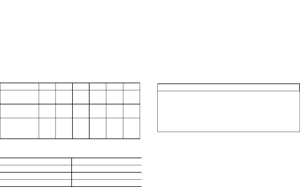
MODELS
DESIGN
FEATURES
33101 34401
33201 35601
33301 36701
33104 34404
33204 35604
33304 36704 33108 33308
33208 34408 34411
35611 35613
Housing: Cast Iron AISI 316 SS Nylon Cast Iron AISI 316 SS
Pump Rotor: Chrome plated
416 SS
Chrome plated
316 SS
Chrome plated
416 SS
Chrome plated
416 SS
Chrome plated
316 SS
Pump Stator: NBR (Nitrile) NBR (Nitrile) NBR (Nitrile) NBR (Nitrile) NBR (Nitrile)
Shaft: 416 SS 316 SS 416 SS 416 SS 316 SS
Flexible Joint: Carbon steel/
NBR
316 SS/
NBR
Carbon steel/
NBR
Carbon steel/
NBR
316 SS/
NBR
Bearings: Ball (sealed) Ball (sealed) Ball (sealed) Ball (sealed) Ball (sealed)
Mechanical Seal: Carbon-ceramic Carbon-ceramic Carbon-ceramic --- ---
Packing: --- --- --- Braided PTFE Braided PTFE
Note: Alternate elastomers available. Refer to Repair/Conversion kit numbers, page 8.
INSTALLATION
Mounting Position. Pump may be mounted in any
position. When mounting vertically, it is necessary to keep
bearings above seals to prevent possible seal leakage into
bearings.
Pre-Wetting. Prior to connecting pump, wet pump
elements and mechanical seal or packing by adding fluid to
be pumped into suction and discharge ports. Turn shaft
over several times in a clockwise direction to work fluid into
elements.
Piping. Piping to pump should be self-supporting to avoid
excessive strain on pump housings. See Table 1 for suction
and discharge port sizes of each pump model. Use pipe
“dope” or tape to facilitate disassembly and to provide seal.
Drive. On belt driven units, adjust belt tension to point of
non-slip. Do not overtighten.
On direct drive units, coupling components should be
aligned and spaced at least 1/16” apart.
Pump rotation must be clockwise when facing shaft to
prevent damage to pump. Check direction of rotation before
startup.
Water Flush of Packing (356 Models Only). The packing
may be either grease lubricated through a grease fitting in
the stuffing box or have plumbing connected to the housing
to allow a water flush.
Maximum speed is 1750 rpm.
When the material being pumped is abrasive in nature, it
may be advantageous to flush the packing to prevent
leakage under packing and excessive shaft wear.
Mechanical Seal Models Packing Gland Models
2-86-00074
Clean water can be injected through a 1/8” NPT tapped
hole that normally houses the grease fitting for lubricating the
packing. The water can be permitted to leak axially along the
shaft in either direction or can be removed from the second
tapped hole in the stuffing box. In both cases, the discharge
from the stuffing box should be throttled slightly to maintain
10-15 PSI higher pressure in the stuffing box than is present
in the discharge housing.
Table 1. Pump Data
Pump Models 331 332 333 344 356 367
Suction Port
(NPT) 3/4* 3/4* 3/4* 3/4* 1-1/2 2
Discharge
Port (NPT) 3/4 3/4 3/4 3/4 1-1/4 2
Discharge
Pressure
(psig) 150 100 50 40 50 50
*08 versions = 1” NPT
Table 2. Temperature Limits
Elastomer Temperature Limits
*NBR 10°-160°F
*EPDM 10°-210°F
*FPM 10°-240°F
*NBR = Nitrile
*EPDM = Ethylene-Propylene-Diene Terpolymer
*FPM = Fluoroelastomer
OPERATION
Self-Priming. With wetted pumping elements, the pump is
capable of 25 feet of suction lift when operating at 1750 rpm
with pipe size equal to port size.
DO NOT RUN DRY. Unit depends on liquid pumped for
lubrication. For proper lubrication, flow rate should be at least
10% of rated capacity.
Pressure and Temperature Limits. See Table 1 for
maximum discharge pressure of each model. Unit is suitable
for service at temperatures shown in Table 2.
Storage. Always drain pump for extended storage periods
by removing suction housing bolts and loosening suction
housing.
TROUBLE SHOOTING
WARNING: Before making adjustments, disconnect
power source and thoroughly bleed
pressure from system. Failure to do so
could result in electric shock or serious
bodily harm.
Failure To Pump.
1. Belt or coupling slip: Adjust belt tension or tighten set
screw on coupling.
2. Stator torn; possibly excessive pressure: Replace stator,
check pressure at discharge port.
3. Wrong rotation: Rotation must be clockwise when facing
shaft.
4. Threads in rotor or on shaft stripped: Replace part. Check
for proper rotation.
5. Excessive suction lift or vacuum.
Pump Overloads.
1. Excessive discharge pressure: Check discharge pressure
for maximum rating given in Table 1. Check for
obstruction in discharge pipe.
2. Fluid viscosity too high: Limit fluid viscosity to 20,000 CP
or 100,000 SSU.
Viscosity CP Limit RPM
1-300 1750
300-1,000 1200
1,000-2,000 700
2,000-5,000 350
5,000-10,000 180
10,000-20,000 100
3. Insufficient motor HP: Check HP requirement.
Noisy Operation.
1. Starved suction: Check fluid supply, length of suction line,
and obstructions in pipe.
2. Bearings worn: Replace parts; check alignment, belt
tension, pressure at discharge port.
3. Broken flexible joint: Replace part, check pressure at
discharge port.
4. Insufficient mounting: Mount to be secure to firm base.
Vibration induced noise can be reduced by using mount
pads and short sections of hose on suction and discharge
ports.
Mechanical Seal Leakage (Mechanical Seal Models
Only).
1. Leakage at startup: If leakage is slight, allow pump to run
several hours to let faces run in.
2. Persistent seal leakage: Faces may be cracked from
freezing or thermal shock. Replace seal.
Packing Leakage (Packing Models Only).
1. Leakage at startup: Adjust packing as outlined in
maintenance instructions.
Note: Slight leakage is necessary for lubrication of packing.
2. Persistent leakage: Packing rings and/or shaft may be
worn. Replace parts as required.
Pump Will Not Prime.
1. Air leak on suction side: Check pipe connections.
MAINTENANCE
General. These pumps have been designed for a minimum
of maintenance, the extent of which is routine lubrication and
adjustment of packing. The pump is one of the easiest to
work on in that the main elements are very accessible and
require few tools to disassemble.
Packing Lubrication (356 Models Only). The zerk
fitting on the side of the suction housing leads to the lantern
ring halves in the mid-section of the packings. At least once a
week, inject a small quantity of good quality grease, such as
MPG-2 Multi Purpose Grease (Du Bois Chemical), or
equivalent, into the zerk fitting to lubricate the packings.
Note: For Model 34411, lubricate packing by applying a
liberal amount of grease during assembly.
Page 2

Packing Adjustment (Packing Models Only).
Packing gland attaching nuts should be evenly adjusted so
they are little more than finger tight. Over-tightening of the
packing gland may result in premature packing failure and
possible damage to the shaft and gland.
When the packing is new, frequent minor adjustments
are recommended for the first few hours of operation in
order to compress and seat the packing. Be sure to allow
slight leakage for lubrication of packing.
When excessive leakage can no longer be regulated by
tightening the gland nuts, remove and replace the packings
in accordance with the DISASSEMBLY and REASSEMBLY
instructions. The entire pump need not be disassembled to
replace the packings.
Bearing Lubrication. The prelubricated, fully sealed
bearings do not require additional lubrication.
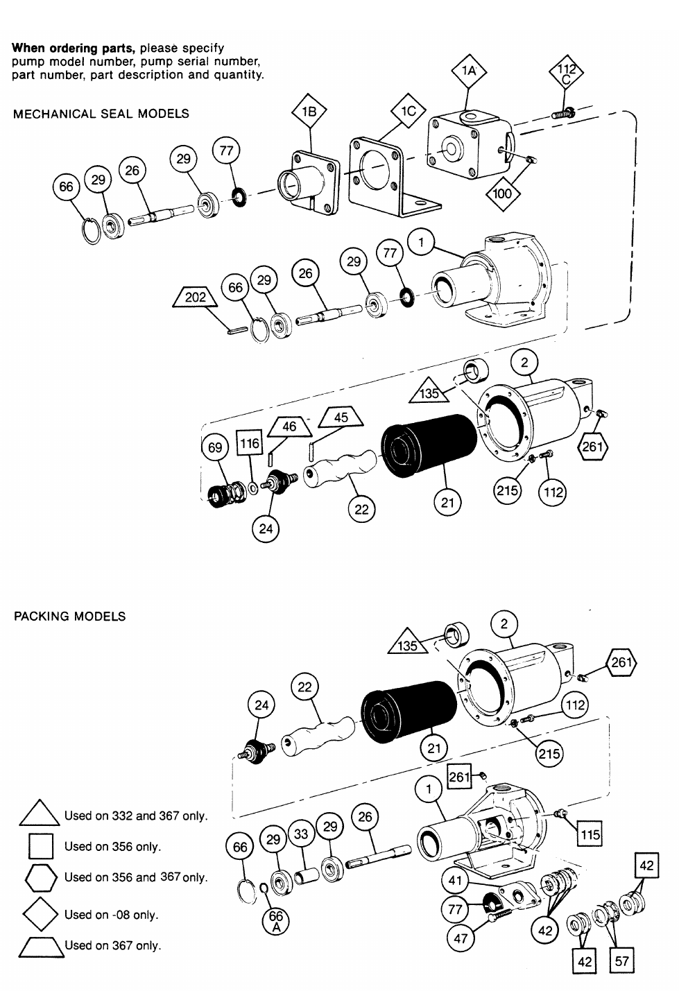
PUMP DISASSEMBLY
WARNING: Before disassembling pump, disconnect
power source and thoroughly bleed
pressure from system. Failure to do so
could result in electric shock or serious
bodily harm.
To Disassemble Mechanical Seal Models:
1. Disconnect suction and discharge piping.
2. Remove screws (112) holding suction housing (2) to
pump body (1). Remove suction housing and stator (21).
3. Remove rotor (22) from flexible joint (24) by turning
counter-clockwise (RH thread). Use 3/16 inch diameter
punch to remove rotor pin (45) on Model 36701.
4. Flexible joint (24) can be removed from shaft (26) by
using a 3/16 inch allen wrench in end of joint (1/4 inch
wrench on 356 Models) and turn counter-clockwise. Use
3/16 inch diameter punch to remove shaft pin (46) on
Model 36701.
5. Carefully slide mechanical seal (69) off shaft (26).
Carefully pry seal seat out of pump body (1). If any parts
of mechanical seal are worn or broken, the complete
seal assembly should be replaced. Seal components are
matched parts and are not interchangeable.
6. The bearings (29) and shaft (26) assembly can be
removed from pump body (1) after snap ring (66) has
been removed. To remove the assembly, lightly tap the
shaft at threaded end using a block of wood to protect
the threads. The bearings may be pressed off the shaft.
To Disassemble Packing Models:
1. Disconnect suction and discharge piping.
2. Remove screws (112) which hold suction housing (2) to
pump body (1). Remove suction housing and stator (21).
3. Remove rotor (22) from flexible joint (24) by turning in a
counter-clockwise direction (RH thread).
4. Flexible joint (24) can be removed by using a 3/16 inch
allen wrench in end of joint (1/4 inch wrench on 356
Models) and turn in a counter-clockwise direction.
5. The packing (42) can be removed without removing the
shaft (26) using the following procedure:
a. Remove gland bolts (47).
b. Slide gland (41) away from packing (42).
c. Pull out packing (42) (and lantern ring halves (57) on
356 Models) using a packing removing tool.
Note:Packing can be removed after shaft has been re-
moved by pushing out from pump side of pump body
after gland (41) has been detached.
6. The bearings (29) and shaft (26) assembly can be
removed from pump body (1) after snap ring (66) has
been removed. To remove the assembly, lightly tap the
shaft at threaded end using a block of wood to protect the
threads.
7. To disassemble shaft assembly, remove snap ring (66A)
from shaft (26) and press bearings (29) and bearing
spacer (33) off the shaft.
PUMP ASSEMBLY
To Assemble Mechanical Seal Models:
1. Press bearings (29) on shaft (26), and locate slinger ring
(77) near bearing on threaded end of shaft.
Note: When replacing bearings, always press on the inner
race when assembling to shaft, and on the outer race
when pressing bearings into the housings.
2. Press shaft assembly into pump body (1) securing with
snap ring (66).
3. Install mechanical seal (69) using the following
procedure:
a. Clean and oil sealing faces using a clean light oil (not
grease).
Caution: Do not use oil on EPDM parts. Substitute
glycerin or soap and water.
b. Oil the outer surface of the seal seat, and push the
assembly into the bore in the pump body (1), seating
it firmly and squarely.
c. After cleaning and oiling the shaft, slide the seal body
along the shaft until it meets the seal seat.
d. Install seal spring and spring retainer on shaft.
4. Thread flexible joint (24) into shaft (26) in a clockwise
direction (RH thread). On 356 Models, install seal spacer
(69A) and washer (116) before threading flexible joint
onto shaft in a clockwise direction. On Model 36701, use
shaft pin (46) to pin flexible joint (24) to shaft.
5. Thread rotor (22) onto flexible joint (24) in a clockwise
direction (RH thread). On Model 36701, pin rotor (22) to
joint using rotor pin (45).
6. Slide stator (21) on rotor (22). On 331 and 332 Models,
insert rounded end of stator ring (135) into end of stator
prior to installing stator on rotor.
7. Secure stator (21) and suction housing (2), with suction
port vertically up, to pump body (1) using screws (112).
8. Proceed as in installation instructions.
To Assemble Packing Models:
1. Press bearings (29), with bearing spacer (33) in between,
on shaft (26) and secure in place using snap ring (66A).
Note: When replacing bearings, always press on the inner
race when assembling to shaft, and on the outer race
when pressing bearings into the housings.
Page 3

2. Install packing (42) before installing shaft assembly
using the following procedure:
a. Lubricate each individual ring of packing with a
grease that is insoluble in the fluid being pumped.
b. Individually assemble each ring of packing loosely
in the packing chamber of the pump body (1).
Stagger splits on rings. (Four rings, 3/16 inch
square required on Model 34411; four rings, 1/4
inch square and two lantern ring halves (57)
assembled between two rings on 356 Models).
c. Loosely install packing gland (41) on pump body (1)
using gland bolts (47).
3. Press shaft assembly into pump body (1) positioning
slinger ring (77) between packing gland (41) and bear-
ing end of pump body. Secure the shaft assembly with
snap ring (66).
4. Thread flexible joint (24) into shaft (26) in a clockwise
direction (RH thread).
5. Thread rotor (22) onto flexible joint (24) in a clockwise
direction (RH thread).
6. Slide stator (21) on rotor (22). On 331 and 332 Models,
insert rounded end of stator ring (135) into end of stator
prior to installing stator on rotor.
7. Secure stator (21) and suction housing (2), with suction
port vertically up, to pump body (1) using screws
(112).
8. Proceed as in installation instructions.
Note: Adjust newly installed packing as described in
maintenance procedure.
WARNING:Replace belt or coupling guards
before reconnecting power.
Page 4
Page 5
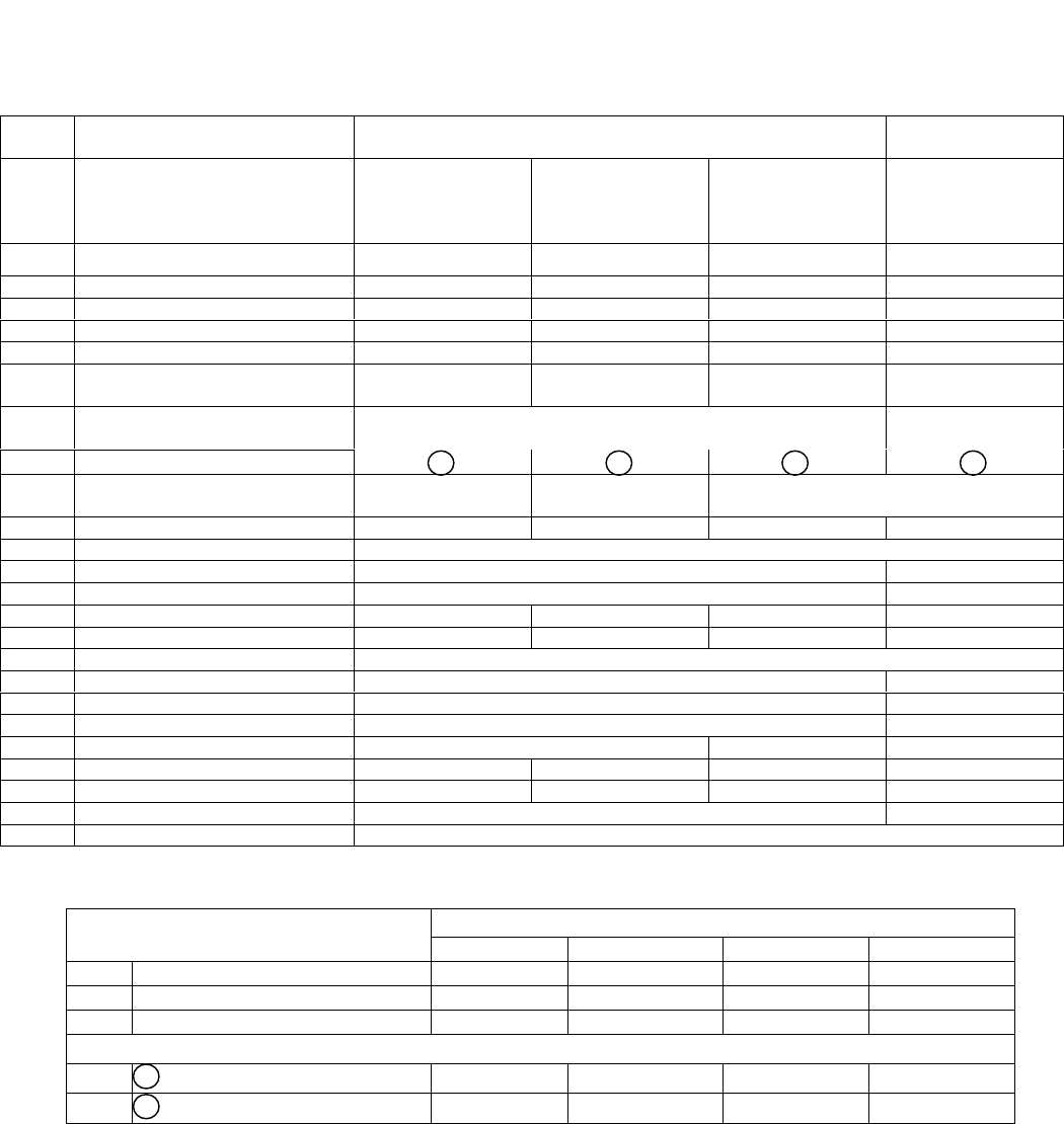
PARTS LIST — 331, 332, 333, AND 344 MODELS
Item
No. Description Mechanical Seal Models Packing Gland
Models
33101
33201
33301
34401
33104
33204
33304
34404
33108
33208
33308
34408 34411
1Pump Body 330-1065-002 330-1910-002 340-1000-001
1A Discharge Housing 340-2362-000
1B Bearing Housing 330-4587-000
1C Pump Base 340-2369-000
2Suction Housing 330-1064-002 330-1911-002 330-4536-000 330-1064-002
*21 Stator See Stator section
below.
*22 Rotor See Rotor section below with circled
numbers for each series.
1211
24 Joint Carbon SteeI/NBR
320-1511-000 316 SS/NBR
320-3759-000 Carbon SteeI/NBR
320-1511-000
26 Drive Shaft 320-1499-000 320-2938-000 320-1499-000 320-2448-000
29 Bearing (2 req.) 630-0502-031
33 Bearing Spacer 320-1900-000
41 Packing Gland 320-0101-004
42 Packing 340-3396-005
47 Gland Bolt 619-1520-161
66 Snap Ring 320-1506-000
66A Snap Ring 320-4182000
69 Mechanical Seal 320-2424-000
77 Slinger Ring 320-6382-000 320-6384-000
100 Pipe Plug (3 req.) 610-0120-021
112 Screws (8 req.) 619-1430-103 320-5968-000 619-0860-081 619-1430-103
112C Screws (4 req.) 61 9-0890-281
135 Stator Ring (331 -332 only) 320-7812-000
215 Lock Washer (8 req.) 320-6464-000
*Recommended spare parts.
ModelsSTATORS 331 332 333 344
21 Standard Stator, NBR All Models 340-3501-120 340-3502-120 340-3503-120 340-3504-120
21 EPDM Stator 340-3501-320 340-3502-320 340-3503-320 340-3504-320
21 FPM Stator 340-3501-520 340-3502-520 340-3503-520 340-3504-520
ROTORS
22 1 416SS - All Models 320-2729-000 330-0906-000 320-1394-000 320-1841-000
22 2 316SS — All Models 320-2933-000 320-2942-000 320-2936-000 320-2934-000
See page 8 for Repair/Conversion Kits
Page 6

Page 7
PARTS LIST — 356 AND 367 MODELS
Mechanical SeaI Models Packing Gland Models Mechanical Seal Model
Item
No. Description 35601 35604 35611 35613 36701 36704
1Pump Body Cast Iron
340-0636-000 316SS
340-1550-000 Cast Iron
350-0420-000 316SS
350-0491-000 Cast Iron
350-0423-000 316SS
350-0423-007
2Suction Housing 350-0280-000 350-0489-000 350-0280-000 350-0489-000 350-0302-000 350-0302-007
*21 Stator NBR
340-3505-120 NBR
340-3505-120 NBR
340-3506-120
22 Rotor 416SS
320-2304-000 316SS
320-4431-000 416SS
320-2304-000 316SS
320-4431-000 416SS
330-2042-000 316SS
330-3077-000
24 Flex Joint Carbon Steel
320-1583-000 316SS
320-4427-000 Carbon Steel
320-1583-000 316SS
320-4427-000 Carbon Steel
320-1749-000 316SS
320-4436-000
26 Drive Shaft 320-1759-000 320-4430-000 320-2765-000 320-4435-000 330-1805-000 330-1805-015
29 Bearing (2 req.) 630-0552-051 630-0552-061
33 Bearing Spacer 320-2764-000
41 Packing Gland 320-0003-004 320-0003-007
*42 Packing 340-3396-008
45 Rotor Pin 320-4439-002
46 Shaft Pin 320-4439-001
47 Gland Bolt 619-1530-241
57 Lantern Ring Half** 320-6585-000
66 Snap Ring 320-1758-000 320-2794-000
66A Snap Ring 320-3533-000
*69 Mechanical Seal 320-3945-000 320-1750-000
69A Seal Spacer 320-4434-000
77 Slinger Ring 320-6383-000 320-6385-000 320-6385-000
112 Screws (6 req.) 619-1530-161 619-1530-161
115 Zerk Fitting 320-2503-001
135 Stator Spacer 330-7594-000
202 Shaft Key 611-0040-240
215 Lock Washer (6 req.) 623-0010-411
261 Pipe Plug 610-0120-011 610-0420-010 610-0120-011 610-0420-010 610-0120-011 610-0420-010
*Recommended spare parts.
**2 Required
See page 8 for Repair/Conversion Kits
Page 8
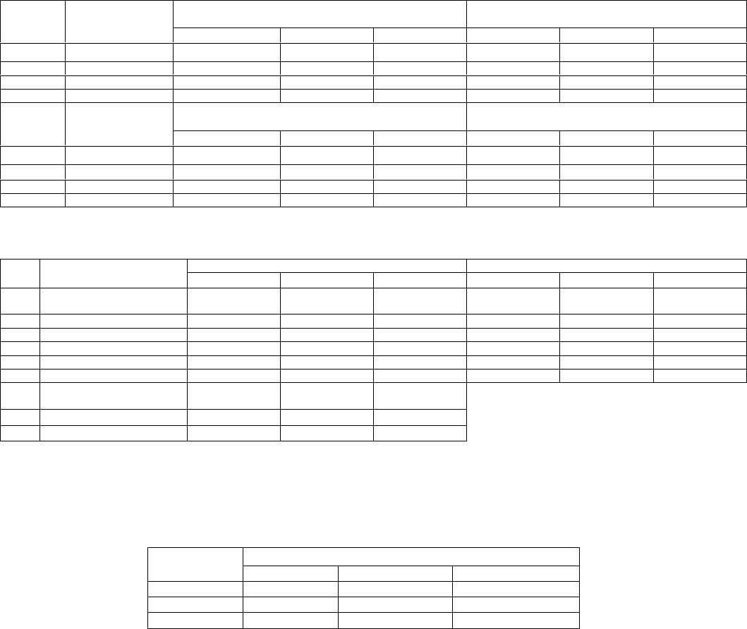
REPAIR/CONVERSION KIT NUMBERS
ELASTOMER REPAIR/CONVERSION KITS
331 Models 332 Models
Item
No. Description
NBR EPDM FPM NBR EPDM FPM
—Kit No. 311-9026-000 311-9025-000 311-9054-000 311-9027-000 311-9038-000 311-9055-000
21 •Stator 340-3501-120 340-3501-320 340-3501-520 340-3502-120 340-3502-320 340-3502-520
24 •Joint 320-1511-000‡ 320-6367-000† 320-4670-000† 320-1511-000‡ 320-6367-000† 320-4670-000†
69 •Seal 320-2424-000 320-6379-000 320-6501-000 320-2424-000 320-6379-000 320-6501-000
333 Models 344 Models
Item
No. Description
NBR EPDM FPM NBR EPDM FPM
—Kit No. 311-9029-000 311-9028-000 311-9056-000 311-9031-000 311-9030-000 311-9057-000
21 •Stator 340-3503-120 340-3503-320 340-3503-520 340-3504-120 340-3504320 340-3504520
24 •Joint 320-1511-000‡ 320-6367-000† 320-4670-000† 320-1511-000‡ 320-6367-000† 320-4670-000†
69 •Seal 320-2424-000 320-6379-000 320-6501-000 320-2424-000 320-6379-000 320-6501-000
t316SS/with appropriate elastomer.
‡Carbon steel. NBR kits are available only with carbon steel joints; a 316SS/NBR joint for 331-344 Models is
available as 320-3759-000.
356 Models 367 Models
Item
No. Description NBR EPDM FPM NBR EPDM FPM
–Kit No. (Mech. Seal
Models) 311-9033-000 311-9032-000 311-9058-000 311-9060-000 311-9036-000 311-9124-000
21 •Stator 340-3505-120 340-3505-320 340-3505-520 340-3506-120 340-3506-320 340-3506-520
24 •Flex Joint 320-1583-000‡ 320-6369-000† 320-4671-000† 320-1749-000‡ 320-6378-000‡ 3206515-000‡
69 •Seal 320-3945-000 320-6380-000 320-6510-000 320-1750-000 320-6390-000 320-6517-000
45 •Rotor Pins 320-4439-002 320-4439-002 320-4439-002
46 •Shaft Pin 320-4439-001 320-4439-001 320-4439-001
–Kit No
(Packing Gland Models) 311-9035-000 311-9034-000 311-9059-000
21 •Stator 340-3505-120 340-3505-320 340-3505-520
24 •Joint 320-1583-000‡ 320-6369-000† 320-4671-000†
†316SS/with appropriate elastomer.
‡Carbon steel. NBR kits are available only with carbon steel joints; a 316SS/NBR joint for Model 35604 and
35613 pumps is available as 320-4427-000; a 316SS/NBR joint for model 36704 is available as 320-4436-000.
ABRASION RESISTANT SEALS
Models
Elastomer 331-344 356 36701
NBR 3206460000 3206505000 3206511000
EPDM 3206502000 3206506000 3206512000
FPM 3206503000 3206507000 3206513000
NBR = Nitrile
EPDM = Ethylene-Propylene-Diene Terpolymer
FPM = Fluoroelastomer
© 1999 by Moyno, Inc. Printed in U.S.A.
® Moyno is a registered trademark of Moyno, Inc.
