86037660 COVER AND PG2 Eng Chariot Iscrub Manual
2018-10-22
: Sweepscrub Chariot-Iscrub-Manual chariot-iscrub-manual 2837 file product_file
Open the PDF directly: View PDF ![]() .
.
Page Count: 167 [warning: Documents this large are best viewed by clicking the View PDF Link!]
- 86037660 - 980228 - Chariot CS24-CSX24-CSE24-CSXE24 ENG - mine
- 86037660 COVER AND PG2 eng
- 86037660 PG 3 AND 1-1
- 86037660 PG 2-1 AND 2-2
- 86037660 PG 2-3 AND 3-1
- 86037660 PG 3-2 AND 3-3
- 86037660 PG 3-4 AND 3-5
- 86037660 PG 3-6 AND 3-7
- 86037660 PG 3-8 AND 3-9
- 86037660 PG 3-10 AND 3-11
- 86037660 PG 3-12 AND 3-13
- 86037660 PG 3-14 AND 3-15
- 86037660 PG 3-16 AND 3-17
- 86037660 PG 3-18 AND 3-19
- 86037660 PG 3-20 AND 4-1
- 86037660 PG 4-2 AND 4-3
- 86037660 PG 4-4 AND 4-5
- 86037660 PG 4-6 AND 4-7
- 86037660 PG 4-8 AND 4-9
- 86037660 PG 4-10 AND 4-11
- 86037660 PG 4-12 AND 4-13
- 86037660 PG 4-14 AND 4-15
- 86037660 PG 4-16 AND 4-17
- 86037660 PG 4-18 AND 4-19
- 86037660 PG 4-20 AND 4-21
- 86037660 PG 4-22 AND 4-23
- 86037660 PG 4-24 AND 4-25
- 86037660 PG 4-26 AND 4-27
- 86037660 PG 4-28 AND 4-29
- 86037660 PG 4-30 AND 4-31
- 86037660 PG 4-32 AND 4-33
- 86037660 - 980228 - Chariot CS24-CSX24-CSE24-CSXE24 parts - mine
- 86037660 PARTS COVER AND 5-1
- 86037660 PG 5-2 AND 5-3
- 86037660 PG 5-4 AND 5-5
- 86037660 PG 5-6 AND 5-7
- 86037660 PG 5-8 AND 5-9
- 86037660 PG 5-10 AND 5-11
- 86037660 PG 5-12 AND 5-13
- 86037660 PG 5-14 AND 5-15
- 86037660 PG 5-16 AND 5-17
- 86037660 PG 5-18 AND 5-19
- 86037660 PG 5-20 AND 5-21
- 86037660 PG 5-22 AND 5-23
- 86037660 PG 5-24 AND 5-25
- 86037660 PG 5-26 AND 5-27
- 86037660 PG 5-28 AND 5-29
- 86037660 PG 5-30 AND 5-31
- 86037660 PG 5-32 AND 5-33
- 86037660 PG 5-34 AND 5-35
- 86037660 PG 5-36 AND 5-37
- 86037660 PG 5-38 AND 5-39
- 86037660 PG 5-40 AND 5-41
- 86037660 PG 5-42 AND 5-43
- 86037660 PG 5-44 AND 5-45
- 86037660 PG 5-46 AND 5-47
- 86037660 PG 5-48 AND 5-49
- 86037660 PG 5-50 AND 5-51
- 86037660 PG 5-52 AND 5-53
- 86037660 PG 5-54 AND 5-55
- 86037660 PG 5-56 AND 5-57
- 86037660 PG 5-58 AND 5-59
- 86037660 PG 5-60 AND 5-61
- 86037660 PG 5-62 AND 5-63
- 86037660 PG 5-64 AND 5-65
- 86037660 PG 5-66 AND 5-67
- 86037660 PG 5-68 AND 5-69
- 86037660 PG 5-70 AND 5-71
- 86037660 PG 5-72 AND 5-73
- 86037660 PG 5-74 AND 5-75
- 86037660 PG 5-76 AND 5-77
- 86037660 PG 5-78 AND 5-79
- 86037660 PG 5-80 AND 5-81
- 86037660 PG 5-82 AND 5-83
- 86037660 PG 5-84 AND 5-85
- 86037660 PG 5-86 AND 5-87
- 86037660 PG 5-88 AND 5-89
- 86037660 PG 5-90 AND 5-91
- 86037660 OPTIONS COVER AND 6-1
- 86037660 PG 6-2 AND 6-3
- 86037660 PG 6-4 AND 6-5
- 86037660 PG 6-6 AND 6-7
- 86037660 PG 6-8 AND 6-9
- 86037660 PG 6-10 AND 6-11
- 86037660 PG 6-12 AND 6-13
- 86037660 PG 6-14 Serial Numbers
- 86037660 - 980228 - Chariot CS24-CSX24-CSE24-CSXE24 parts.pdf
- 86037660 - 980228 - Chariot CS24-CSX24-CSE24-CSXE24 ENG - mine
- 86037660 COVER AND PG2 eng
- 86037660 PG 3 AND 1-1
- 86037660 PG 2-1 AND 2-2
- 86037660 PG 2-3 AND 3-1
- 86037660 PG 3-2 AND 3-3
- 86037660 PG 3-4 AND 3-5
- 86037660 PG 3-6 AND 3-7
- 86037660 PG 3-8 AND 3-9
- 86037660 PG 3-10 AND 3-11
- 86037660 PG 3-12 AND 3-13
- 86037660 PG 3-14 AND 3-15
- 86037660 PG 3-16 AND 3-17
- 86037660 PG 3-18 AND 3-19
- 86037660 PG 3-20 AND 4-1
- 86037660 PG 4-2 AND 4-3
- 86037660 PG 4-4 AND 4-5
- 86037660 PG 4-6 AND 4-7
- 86037660 PG 4-8 AND 4-9
- 86037660 PG 4-10 AND 4-11
- 86037660 PG 4-12 AND 4-13
- 86037660 PG 4-14 AND 4-15
- 86037660 PG 4-16 AND 4-17
- 86037660 PG 4-18 AND 4-19
- 86037660 PG 4-20 AND 4-21
- 86037660 PG 4-22 AND 4-23
- 86037660 PG 4-24 AND 4-25
- 86037660 PG 4-26 AND 4-27
- 86037660 PG 4-28 AND 4-29
- 86037660 PG 4-30 AND 4-31
- 86037660 PG 4-32 AND 4-33
- 86037660 - 980228 - Chariot CS24-CSX24-CSE24-CSXE24 parts - mine
- 86037660 PARTS COVER AND 5-1
- 86037660 PG 5-2 AND 5-3
- 86037660 PG 5-4 AND 5-5
- 86037660 PG 5-6 AND 5-7
- 86037660 PG 5-8 AND 5-9
- 86037660 PG 5-10 AND 5-11
- 86037660 PG 5-12 AND 5-13
- 86037660 PG 5-14 AND 5-15
- 86037660 PG 5-16 AND 5-17
- 86037660 PG 5-18 AND 5-19
- 86037660 PG 5-20 AND 5-21
- 86037660 PG 5-22 AND 5-23
- 86037660 PG 5-24 AND 5-25
- 86037660 PG 5-26 AND 5-27
- 86037660 PG 5-28 AND 5-29
- 86037660 PG 5-30 AND 5-31
- 86037660 PG 5-32 AND 5-33
- 86037660 PG 5-34 AND 5-35
- 86037660 PG 5-36 AND 5-37
- 86037660 PG 5-38 AND 5-39
- 86037660 PG 5-40 AND 5-41
- 86037660 PG 5-42 AND 5-43
- 86037660 PG 5-44 AND 5-45
- 86037660 PG 5-46 AND 5-47
- 86037660 PG 5-48 AND 5-49
- 86037660 PG 5-50 AND 5-51
- 86037660 PG 5-52 AND 5-53
- 86037660 PG 5-54 AND 5-55
- 86037660 PG 5-56 AND 5-57
- 86037660 PG 5-58 AND 5-59
- 86037660 PG 5-60 AND 5-61
- 86037660 PG 5-62 AND 5-63
- 86037660 PG 5-64 AND 5-65
- 86037660 PG 5-66 AND 5-67
- 86037660 PG 5-68 AND 5-69
- 86037660 PG 5-70 AND 5-71
- 86037660 PG 5-72 AND 5-73
- 86037660 PG 5-74 AND 5-75
- 86037660 PG 5-76 AND 5-77
- 86037660 PG 5-78 AND 5-79
- 86037660 PG 5-80 AND 5-81
- 86037660 PG 5-82 AND 5-83
- 86037660 PG 5-84 AND 5-85
- 86037660 PG 5-86 AND 5-87
- 86037660 PG 5-88 AND 5-89
- 86037660 PG 5-90 AND 5-91
- 86037660 OPTIONS COVER AND 6-1
- 86037660 PG 6-2 AND 6-3
- 86037660 PG 6-4 AND 6-5
- 86037660 PG 6-6 AND 6-7
- 86037660 PG 6-8 AND 6-9
- 86037660 PG 6-10 AND 6-11
- 86037660 PG 6-12 AND 6-13
- 86037660 PG 6-14 Serial Numbers
- 86037660 - 980228 - Chariot CS24-CSX24-CSE24-CSXE24 ENG - mine
MODELS: CS24
10060210
CSE24
10060250
CS24SP
10060220
CSX24
10060270
CSXE24
10060290
CSE24SP
10060260
CSXEO24
10060300
Read these instructions before using the machine
iSCRUB
Operating Instructions (ENG)
86037660 10/20/11
DT

MACHINE DATA LOG/OVERVIEW
86037660 CHARIOT 11/09/06
2
OVERVIEW
The Chariot Scrubber is a battery powered, stand-on, hard floor scrubber intended for commercial
use. The appliance applies a cleaning solution onto a hard floor, scrubs the floor with brushes or
pads, and then vacuums the soiled water back into the recovery tank.
MODEL _______________________________________
DATE OF PURCHASE __________________________
SERIAL NUMBER ______________________________
SALES REPRESENTATIVE # _____________________
YOUR DEALER
Name: __________________________________________________________________________________________________
Address: _______________________________________________________________________________________________
Phone Number: _________________________________________________________________________________________

TABLE OF CONTENTS
86037660 CHARIOT 04/15/08 3
Machine Data Log/Overview................................2
Table Of Contents ................................................3
HOW TO USE THIS MANUAL
How To Use This Manual.....................................1-1
SAFETY
Important Safety Instructions ............................2-1
Hazard Intensity Level....................................... 2-2
Safety Label Location........................................ 2-3
OPERATIONS
Technical Specifications....................................3-1
How The Machine Works.................................. 3-3
Components...................................................... 3-4
Drive Controls.................................................... 3-5
Scrub Controls-Basic & Cylindrical ................... 3-9
Scrub Controls-Deluxe ...................................... 3-11
Scrub Controls-Squeegee................................. 3-13
Machine Operation............................................ 3-15
Pre-Run Machine Inspection........................3-15
Starting Machine ..........................................3-15
Emergency Stop Procedures .......................3-15
Filling Solution Tank..................................... 3-16
Normal Scrubbing......................................... 3-16
To Begin Scrubbing...................................... 3-17
Priming Pump............................................... 3-17
To Stop Scrubbing........................................ 3-18
Double Scrub................................................3-18
Emptying And Cleaning Tanks..................... 3-19
MAINTENANCE
Service Schedule ..............................................4-1
Batteries. ...........................................................4-2
Squeegee.......................................................... 4-6
Scrub Brushes...................................................4-9
Scrub Deck-Disk................................................ 4-10
Scrub Deck-Cylindrical...................................... 4-13
Circuit Protection............................................... 4-18
Solution Strainer & Pump-Disk.......................... 4-19
Solution Strainer & Pump-Cylindrical................ 4-20
Vacuum & Float Shut-Off .................................. 4-22
Drive Motor & Brake.......................................... 4-24
Bag Replacement.............................................. 4-27
Transporting Machine........................................ 4-28
Machine Troubleshooting.................................. 4-29
GROUP PARTS LIST
Bumper ..............................................................5-1
Control Panel-Basic-Cylindrical.........................5-3
Control Panel-Deluxe ........................................5-5
Control Panel Housing.......................................5-7
Decal..................................................................5-9
Frame-Lower .....................................................5-11
Frame-Upper .....................................................5-13
Pedal Platform ...................................................5-15
Rear Cover ........................................................5-19
Scrub Brush/Pad Driver.....................................5-21
Scrub Deck - Disk..............................................5-23
Scrub Deck – Cylindrical ...................................5-25
Scrub Deck Aqua-Mizer™.................................5-27
Side Squeegee – Cylindrical .............................5-29
Scrub deck – Side Squeegee – Cylindrical .......5-31
Scrub Deck Skirts..............................................5-33
Scrub Deck Lift ..................................................5-35
Scrub Deck Mounting- Cylindrical .....................5-37
Scrub Deck Actuator – Cylindrical.....................5-39
Solution Cylindrical............................................5-41
Solution Disk......................................................5-43
Squeegee - Disk................................................5-45
Squeegee – Cylindrical......................................5-47
Squeegee Lift-Basic ..........................................5-49
Squeegee Lift-Deluxe........................................5-51
Squeegee Swing ...............................................5-53
Squeegee Lift – Cylindrical................................5-55
Steering .............................................................5-59
Tank...................................................................5-61
Vacuum..............................................................5-63
Wheel-Front Drive, Chain..................................5-65
Wheel-Front Drive, Gear ...................................5-67
Wheel-Front Brake ............................................5-69
Wheel-Rear........................................................5-71
Wiring-Batteries.................................................5-73
Wiring-Components...........................................5-75
Wiring-Control Panel-Basic-Cylindrical .............5-77
Wiring-Control Panel-Deluxe.............................5-79
Wiring-Drive Motor.............................................5-81
Wiring-Main Harness.........................................5-83
Wiring-Pedal Platform........................................5-85
Wiring Diagram-Basic-Cylindrical......................5-87
Wiring-Diagram-Deluxe .....................................5-88
Hose Diagram-Disk ...........................................5-89
Hose Diagram-Cylindrical..................................5-90
Suggested Spare Parts .....................................5-91
OPTIONS
Back-Up Alarm – Option....................................6-1
Battery Cart – Option.........................................6-3
Seat – Option.....................................................6-7
Warning Light – Option......................................6-9
EC Declaration of Conformity............................6-11
Serial Numbers..................................................6-14
Warranty
HOW TO USE THIS MANUAL
86037660 CHARIOT 04/15/08
1-1
This manual contains the following sections:
- HOW TO USE THIS MANUAL
- SAFETY
- OPERATIONS
- MAINTENANCE
- PARTS LIST
The HOW TO USE THIS MANUAL section will tell
you how to find important information for ordering
correct repair parts.
Parts may be ordered from authorized Windsor
dealers. When placing an order for parts, the
machine model and machine serial number are
important. Refer to the MACHINE DATA box which
is filled out during the installation of your machine.
The MACHINE DATA box is located on the inside of
the front cover of this manual.
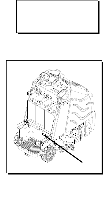
The model and serial number of your machine are
located below the battery compartment of the
machine.
The SAFETY section contains important information
regarding hazard or unsafe practices of the
machine. Levels of hazards are identified that could
result in product or personal injury, or severe injury
resulting in death.
The OPERATIONS section is to familiarize the
operator with the operation and function of the
machine.
The MAINTENANCE section contains preventive
maintenance to keep the machine and its
components in good working condition. They are
listed in this general order:
- Batteries
- Scrub Brushes
- Adjusting Squeegee
- Service Schedule
- Machine Troubleshooting
The PARTS LIST section contains assembled parts
illustrations and corresponding parts list. The parts
lists include a number of columns of information:
- REF – column refers to the reference
number on the parts illustration.
- PART NO. – column lists the part
number for the part.
- PRV NO. - Reference No.
- QTY – column lists the quantity of the
part used in that area of the machine.
- DESCRIPTION – column is a brief
description of the part.
- SERIAL NO. FROM – If this column has
an (*) and a Reference number, see the
SERIAL NUMBERS page in the back of
your manual. If column has two asterisk
(**), call manufacturer for serial number.
The serial number indicates the first
machine the part number is applicable
to. The main illustration shows the most
current design of the machine. When a
boxed illustration is shown, it displays
the older design.
- NOTES – column for information not
noted by the other columns.
NOTE: If a service or option kit is installed on your
machine, be sure to keep the KIT INSTRUCTIONS
which came with the kit. It contains replacement
parts numbers needed for ordering future parts.
NOTE: The number on the lower left corner of the
front cover is the part number for this manual.
MODEL _____________________________________
DATE OF PURCHASE ________________________
SERIAL NUMBER ____________________________
SALES REPRESENTATIVE # ___________________

86037660 CHARIOT 11/09/06 2-1
IMPORTANT SAFETY INSTRUCTIONS
When using an battery powered appliance, basic precaution
must always be followed, including the following:
READ ALL INSTRUCTIONS BEFORE USING THIS MACHINE.
To reduce the risk of fire, electric shock, or injury:
Use only indoors. Do not use outdoors or expose to rain.
Use only as described in this manual. Use only manufacturer’s recommended components and attachments.
If the machine is not working properly, has been dropped, damaged, left outdoors, or dropped into water, return
it to an authorized service center.
Do not operate the machine with any openings blocked. Keep openings free of debris that may reduce airflow.
This machine is not suitable for picking up hazardous dust.
Machine can cause a fire when operating near flammable vapors or materials. Do not operate this machine near
flammable fluids, dust or vapors.
This machine is suitable for commercial use, for example in hotels, schools, hospitals, factories, shops
and offices for more than normal housekeeping purposes.
Maintenance and repairs must be done by qualified personnel.
If foam or liquid comes out of machine, switch off immediately.
Disconnect battery before cleaning or servicing.
Before the machine is discarded, the batteries must be removed and properly disposed of.
Make sure all warning and caution labels are legible and properly attached to the machine.
During operation, attention shall be paid to other persons, especially children.
Before use all covers and doors shall be put in the positions specified in the instructions.
When leaving unattended, secure against unintentional movement.
The machine shall only be operated by instructed and authorized persons.
When leaving unattended, switch off or lock the main power switch to prevent unauthorized use.
Only chemicals recommended by the manufacturer shall be used.
This appliance has been designed for use with the brushes specified by the manufacturer. The fitting of other
brushes may affect its safety.
Do not use on surfaces having a gradient of over 10% (6 degrees).
SAVE THESE INSTRUCTIONS

HAZARD INTENSITY LEVEL
86037660 CHARIOT 11/09/06
2-2
The following symbols are used throughout this guide as indicated in their descriptions:
HAZARD INTENSITY LEVEL
There are three levels of hazard intensity identified by signal words -WARNING and CAUTION and FOR
SAFETY. The level of hazard intensity is determined by the following definitions:
WARNING - Hazards or unsafe practices which COULD result in severe personal injury or death.
CAUTION - Hazards or unsafe practices which could result in minor personal injury or product or property
damage.
FOR SAFETY: To Identify actions which must be followed for safe operation of equipment.
Report machine damage or faulty operation immediately. Do not use the machine if it is not in proper operating
condition. Following is information that signals some potentially dangerous conditions to the operator or the
equipment. Read this information carefully. Know when these conditions can exist. Locate all safety devices on
the machine. Please take the necessary steps to train the machine operating personnel.
FOR SAFETY:
DO NOT OPERATE MACHINE:
Unless Trained and Authorized.
Unless Operation Guide is Read and understood.
In Flammable or Explosive areas.
In areas with possible falling objects.
WHEN SERVICING MACHINE:
Avoid moving parts. Do not wear loose clothing; jackets, shirts, or sleeves when working on the machine. Use
Windsor approved replacement parts.
Batteries emit hydrogen gas. Explosion or fire can result. Keep sparks and open flame away. Keep
solution tank in raised position when charging. Keep sparks and flames away from the batteries. Do not
smoke around batteries.
Disconnect batteries before working on machine. Only qualified personnel should work inside machine.
Always wear eye protection and protective clothing when working on or near batteries. Avoid skin contact
with the acid contained in the batteries.
Never allow metal to lie across battery tops.
SAFETY LABEL LOCATION
86037660 CHARIOT 11/09/06 2-3
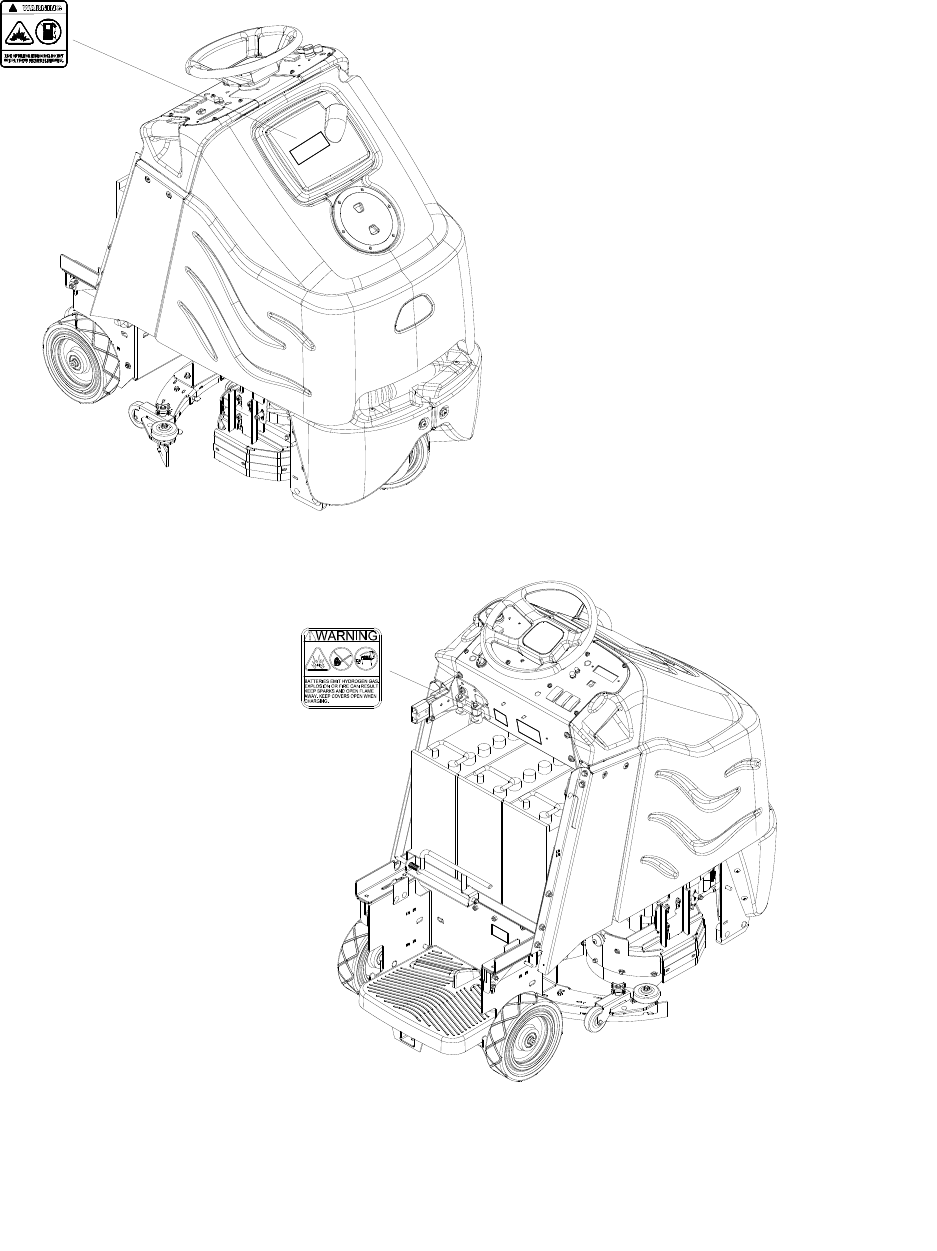
NOTE: These drawings indicate the location of safety labels on the machine. If at any time the labels become
illegible, promptly replace them.
WARNING LABEL
CAUTION
BATTERY
86244300
86252520
PRV NO. 500955
PRV NO. 80885

TECHNICAL SPECIFICATIONS
86037660 CHARIOT 11/09/06
3-1
ITEM DIMENSION/CAPACITY
Nominal power 2100 W
Rated Voltage 36 Volts DC
Rated Amperage 58 amps
Batteries 3 X12 Volt 195-215 AH @ 20 hr. rate
Battery Compartment Dimensions 21 in. x 16 in. x 17 in. tall
(533mm x 406mm x 432mm)
Scrub Brush Motors - Disk Machine 2 x .3 HP (190 W)
Scrub Brush Motors - Cylindrical Machine 2 x .75 HP (560 W)
Vacuum Motor(s) .75 HP (560 W)
Maximum flow rate of vacuum motor 77.0 cfm (36.4 liters per second)
Maximum suction of vacuum motor 81.8 inches of water (20.3 kPa)
Propelling Motor .75 HP (560 W)
Mass (GVW) 1245 lbs (565 kg)
Weight empty without batteries 535 lbs (243 kg)
Solution Control 1.3 GPM pump, fully variable with automatic shut-off
in neutral
Solution capacity 25 gal (95 L)
Recovery capacity 25 gal (95 L)
Scrub brush diameter - Disk Machine 12 inch (305 mm)
Scrub brush diameter - Cylindrical Machine 6 inch (152 mm)
Scrub brush pressure 0-150lbs (0-667N)
Scrub brush speed - Disk Machine 300 rpm
Scrub brush speed - Cylindrical Machine 800 rpm
Tires 10 in. (254mm) Solid Scrubber Compound
Foundation Pressure 104 psi (715 Kpa)
Maximum Speed 3.5 miles/hour (5.6 Km/hour)
Theoretical Coverage 24,200 ft²/hr @ 2.5 mph with 2 in. overlap
Frame Construction Powder coated steel
Brake
Electrical parking brake, sets automatically whenever
operator steps off platform or engages emergency
stop.
Minimum aisle u-turn width 56 in. (1425 mm)
Maximum rated climb and descent angle 7.5 degrees
TECHNICAL SPECIFICATIONS
86037660 CHARIOT 03/27/08 3-2
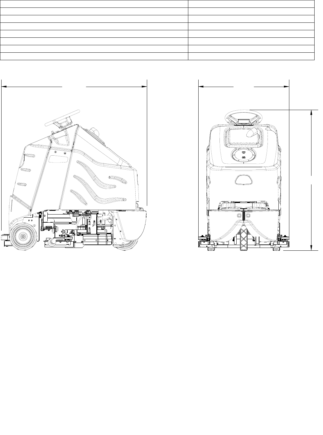
ITEM MEASURE
Height 50.6 inches (1285 mm)
Length 52.5 inches (1330 mm)
Width without squeegee 26.5 inches (670 mm)
Width of squeegee - Disk Machine 32.7 inches (830 mm)
Width of squeegee - Cylindrical Machine 29 inches (737 mm)
Width of scrub path - Disk Machine 24 inches (610 mm)
Width of scrub path - Cylindrical Machine 23 inches (585 mm)
This appliance is not intended for use by persons
(including children) with reduced physical, sensory or
mental capabilities, or lack of experience and
knowledge, unless they have been given supervision
or instruction concerning use of the appliance by a
person responsible for their safety. Children should be
supervised to ensure that they do not play with the
appliance.
SPECIAL NOTES:
The sound pressure level at the operator’s ear was
measured to be 68 dBA. This was a nearfield, broad-
band measurement taken in a typical industrial
environment on a tile floor. This appliance contains no
possible source of impact noise. The instantaneous
sound pressure level is below 63 Pa.
The weighted root mean square acceleration at the
operator’s arms was measured to be below 2.5m/s2 .
This was a tri-axial, third-octave-band measurement
made during normal operation on a composite tile floor.
The measurement and related calculations were made
in accordance with ANSI S3.34-1986.
WIDTH
LENGTH
HEIGHT

HOW THIS MACHINE WORKS
86037660 CHARIOT 11/09/06
3-3
The Chariot® is a battery powered, self-propelled,
hard floor scrubber intended for commercial use.
The appliance applies a cleaning solution onto a
hard floor, scrubs the floor with brushes, and then
vacuums the soiled water back into the recovery
tank.
The machine's primary systems are the solution
system, scrub system, recovery system, and
operator control system.
The function of the solution system is to store
cleaning solution and deliver it to the scrub system.
The solution system consists of the solution tank,
strainer, pump, valve and controls. The solution
tank stores cleaning solution (water and detergent)
until it is delivered to the scrub system. The strainer
protects the pump from debris. The valve
automatically prevents solution flow unless the scrub
brushes are turned on and the machine is being
propelled. The solution control switch controls the
amount of cleaning solution delivered to the scrub
system by controlling the amount of time the pump is
on.
The function of the scrub system is to scrub the
floor. The disk scrub system consists of two rotary
type disk scrub brushes, motors, scrub deck skirt, lift
actuator and controls. The brushes scrub the floor
as the motors drive the brushes. The brush drive
hubs allow the scrub brushes to follow irregularities
and changes in the floor without loosing contact with
the floor. The scrub deck skirts control the cleaning
solution on the floor so that the squeegee can pick it
up. The one touch/brush switch controls the motors
and lift actuator to turn the motors on and lower the
deck, or turn the motors off and raise the deck. The
brush pressure switch controls the down pressure
on the scrub deck.
The scrub plus system consists of two cylindrical
type brushes, motors, scrub deck side squeegees,
hopper, lift actuator, and controls. The cylindrical
scrub head is designed to eliminate debris that may
be caught in the squeegee while scrubbing. Water
is applied to the first scrubbing brush turning in a
clockwise rotation when viewed from the right side of
machine. The first brush scrubs dirt and debris
between the brushes. The second scrubbing brush,
turning in a counter clockwise rotation, picks up
debris and throws it into a removable hopper. Water
is allowed to drain out the hopper into the squeegee
path where it is recovered from the floor.
The scrub deck side squeegees control the cleaning
solution on the floor so that the squeegee can pick it
up. The brush pressure switch controls the motors
and lift actuator to turn the motors on and lower the
deck, or turn the motors off and raise the deck. The
brush pressure switch also controls the down
pressure on the scrub deck.
The function of the recovery system is to vacuum
the soiled water back into the recovery tank. The
recovery system consists of the squeegee, vacuum
motor, float ball filter, recovery bag and controls.
The squeegee wipes the dirty solution off the floor
as the machine moves forward. The vacuum motor
provides suction to draw the dirty solution off the
floor and into the recovery bag. The float ball filter
protects the vacuum fan from debris and foam. The
recovery bag stores the dirty solution.
The function of the operator control system is to
control the direction and speed of the machine. The
directional control system consists of the direction
control switch, throttle pedal, operator presence
pedal, speed control switch, drive reset switch,
emergency stop/brake switch, steering wheel, propel
controller, and drive wheel. The directional control
switch signals forward or reverse direction. The
controller interprets signals from the throttle pedal to
command the drive wheel to propel or slow the
machine. The drive reset switch is to make sure the
operator is on platform before machine will propel.
The operator presence pedal is to make sure the
operator keeps both feet safely on platform while
driving. The steering wheel points the drive wheel in
the direction desired by the operator. The parking
brake automatically engages when the operator
steps off the platform. The emergency stop/brake
can be used to hold the machine on slopes.
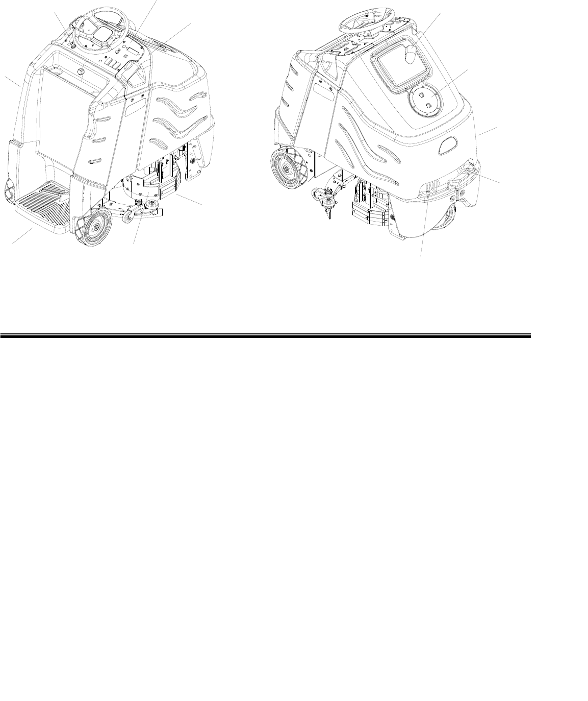
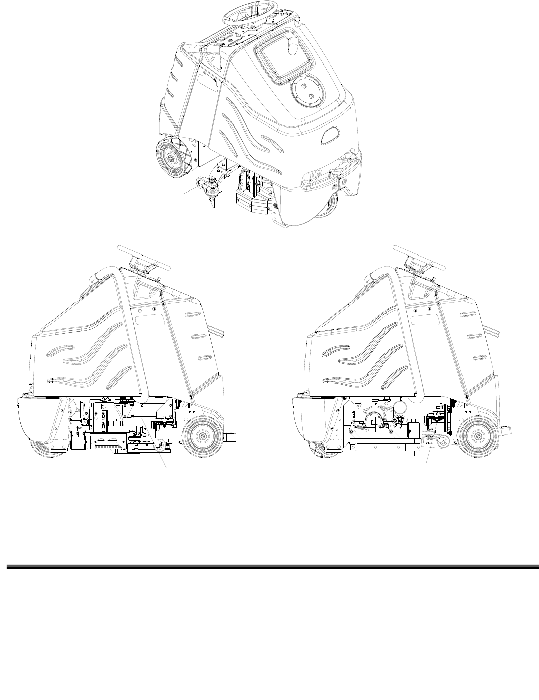
COMPONENTS
86037660 CHARIOT 11/09/06 3-4
1. Control Panel-Drive
2. Control Panel-Scrub
3. Control Housing
4. Pedal Platform
5. Rear Cover
6. Tank
7. Recovery Dome
8. Recovery Drain Hose
9. Scrub Deck Aqua-Mizer
10. Scrub Deck Skirts/Side Squeegees
11. Solution Cover
12. Solution Drain Hose
2
3
4
6
7
8
9
10
11
12
5
1
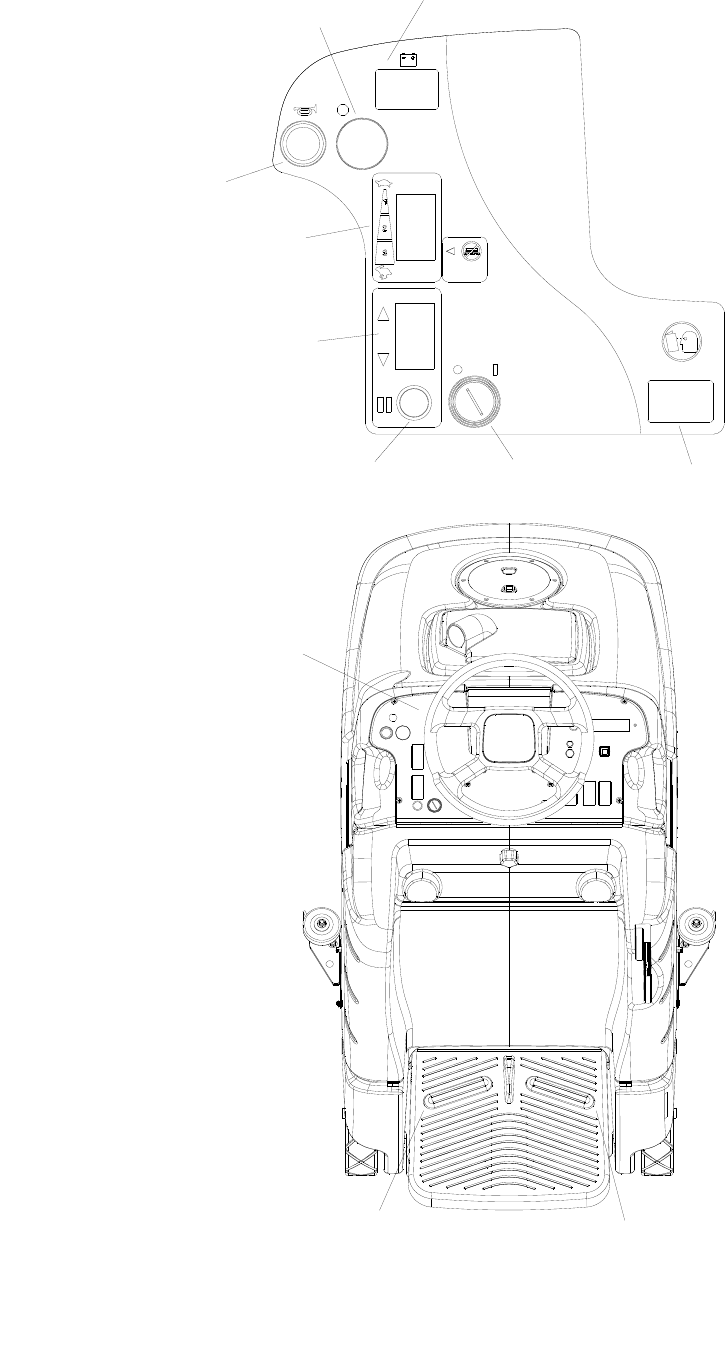
DRIVE CONTROLS
86037660 CHARIOT 11/09/06
3-5
11 (Basic)
10 (Basic)
9
8
7
6
54
3
2
1

DRIVE CONTROLS
86037660 CHARIOT 11/09/06 3-6
1. Key Switch
2. Emergency Stop/Brake Switch
3. Directional Control Switch
4. Throttle Pedal
5. Operator Presence Pedal
6. Speed Control Switch
7. Drive Reset Button
8. Horn Button
9. Steering Wheel
10. Battery Discharge
Indicator (Basic Only)
11. Hour Meter (Basic Only)
1. KEY SWITCH
Controls the power for machine functions.
To turn the machine power on, rotate key clockwise.
To turn the machine off, rotate key counterclockwise.
Deluxe Only: When the key is turned on the battery symbol will flash while the system runs self-diagnostics
and returns scrub deck and squeegee to their raised positions, if necessary. The controller will not respond to
other commands until this routine is complete.
2. EMERGENCY STOP/BRAKE SWITCH
This safety feature is designed to cut all power to the machine at any time and apply parking brake.
To shut the machine power off, push the Emergency Stop Switch, this will also engage the parking brake and
cause the machine to stop immediately.
To reset the machine, rotate the switch clockwise.
3. DIRECTIONAL CONTROL SWITCH
Controls the direction of travel of the vehicle. The position of the switch indicates direction of travel.
To travel forward, press the top of the switch.
To travel in reverse, press the bottom of the switch.
4. THROTTLE PEDAL
Controls the speed of the vehicle within the speed control setting selected. Pressing the pedal causes the
machine to travel in the direction selected by the Directional Control Switch.
To increase speed, increase pressure on the pedal.
To decrease speed, decrease pressure on the pedal.
5. OPERATOR PRESENCE PEDAL
This safety feature is designed to ensure that the operator has their left foot on pedal platform whenever
machine is moving. The operator must have left foot on Operator Presence Pedal for machine to move.

DRIVE CONTROLS
86037660 CHARIOT 11/09/06
3-7
6. SPEED CONTROL SWITCH
Controls the maximum speed of the machine. There are two setting intended for scrubbing, speeds 1 and 2.
Speed 3 is recommended for transport only, not scrubbing.
To increase speed, press the top of the switch.
To decrease speed, press bottom of the switch. Speeds can be adjusted at any time, whether machine is
moving or not.
Basic: The position of the switch indicates speed setting.
Deluxe: The display indicates speed setting. When the key is turned on the controller will automatically
adjust the speed to setting 2.
7. DRIVE RESET SWITCH
This safety feature is designed to ensure safe engagement of propel drive. Each time the machine power is
turned on, and each time an operator steps on to the platform, the Drive Reset Switch must be pushed
before machine will propel.
8. HORN BUTTON
The horn is activated by pressing the horn button.
9. STEERING WHEEL
The steering wheel turns the front wheel causing the machine to change direction.
DRIVE CONTROLS
86037660 CHARIOT 11/09/06 3-8
10A. BATTERY CHARGE LEVEL INDICATOR-BASIC
Indicates the charge level of the batteries.
The meter display is divided into 10 vertical bars. Bars illuminated on the far right indicate full charge. Bars
flashing near the left side indicate the batteries should be recharged. Further operation of the machine
could damage the machine or the batteries.
When the machine is left overnight with less than a full charge, the display may initially indicate a full
charge. It will also indicate a full charge if the batteries are disconnected, then reconnected. After a few
minutes of operation the meter will give the correct charge level.
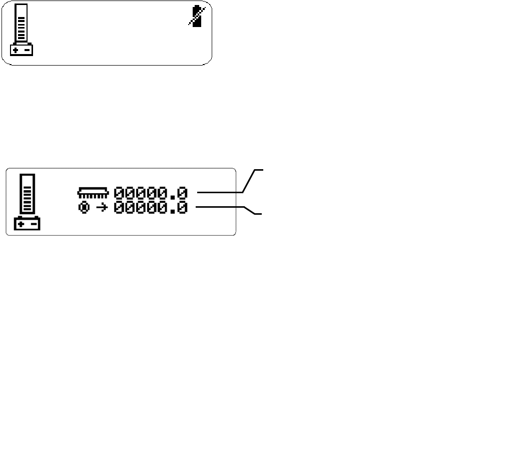
10B. BATTERY CHARGE LEVEL INDICATOR-DELUXE
The battery meter can be viewed at the left side of either information screen 1 or information screen 2. The
level of battery charge is indicated by the horizontal bars in the battery meter box. When the batteries
require charging, the icon will flash and a battery inhibit icon will appear on the right side of either
information screen. Scrub and solution functions that are running when the battery inhibit icon appears will
be automatically shut off. It is not possible to restart scrub functions while the battery inhibit is displayed.
The controller reserves enough battery charge to allow pick-up of residual water and transport back to a
charging station.
11A. HOUR METER-BASIC
Records the number of hours the machine has been in operation. This information is useful in determining
when to service the machine.
11B. HOUR METER-DELUXE
Brush Run Time:
Records the time spent with the brushes running
and gives true brush motor time.
Traction Motor Time:
Records the time spent propelling the machine
and gives true traction motor time.
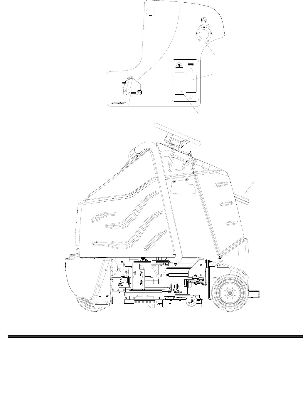
SCRUB CONTROLS-BASIC AND CYLINDRICAL
86037660 CHARIOT 11/09/06
3-9
1. Squeegee Lift Lever 3. Brush Pressure Indicator
2. Scrub Deck Actuator Switch 4. Solution Control Knob
4
3
2
1

SCRUB CONTROLS-BASIC-CYLINDRICAL
86037660 CHARIOT 11/09/06 3-10
1. SQUEEGEE LIFT LEVER
Raises and lowers the squeegee, and turns the vacuum motor on and off.
To lower squeegee and start vacuum motor, lift the lever from its raised position.
To raise squeegee and stop vacuum motor, lift the lever from its lowered position.
2. ACTUATOR SWITCH
Raises and lowers the scrub deck, turns the scrub brush motors on and off, and adjusts the amount of
brush/pad pressure to the floor.
To lower the scrub deck, turn on scrub brush motors, and/or increase brush pressure, press the bottom of
the switch.
To raise the scrub deck, turn off scrub brush motors, and/or decrease brush pressure, press the top of the
switch.
3. BRUSH PRESSURE INDICATOR
The brush pressure indicator corresponds to the amp draw of the scrub brush motors to tell how hard the
motors are working. The blue zone indicates medium or proper brush pressure. The red zone indicates
heavy or excessive brush pressure. Operating in the red zone may cause the brush circuit breakers to trip.
4. SOLUTION CONTROL KNOB
Controls solution flow to scrub deck
To increase flow, rotate knob clockwise.
To decrease flow, rotate knob counterclockwise.
If the brush motors are turned off or the throttle pedal is in neutral, the flow is automatically interrupted until
the motors are turned on again. This feature prevents unintentional draining of the solution tank and allows
the operator to adjust the solution flow to the scrub deck without resetting each time the scrubbing
operation is interrupted.
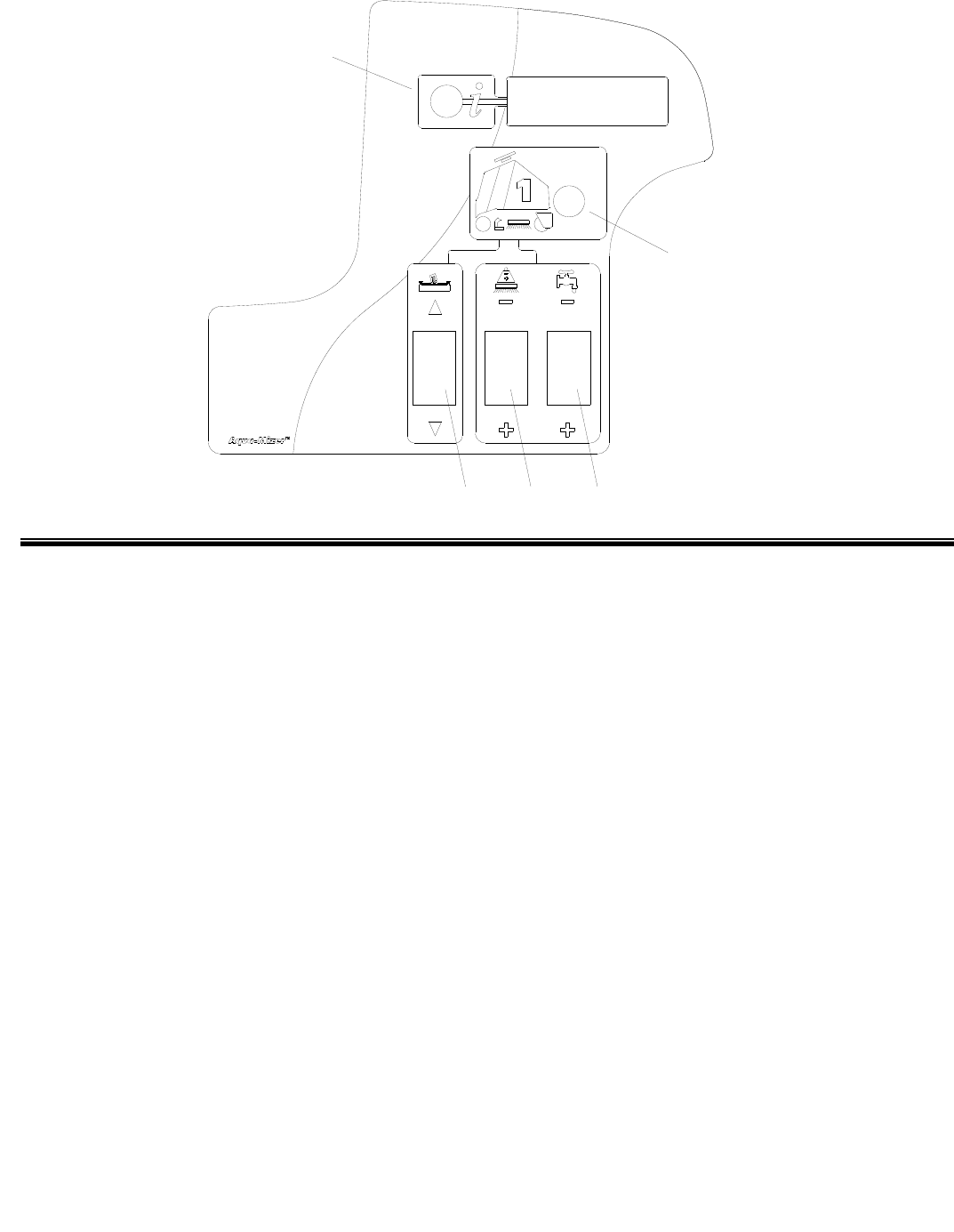
SCRUB CONTROLS-DELUXE
86037660 CHARIOT 11/09/06
3-11
1. One Touch Switch
2. Solution Control Switch
3. Brush Pressure Switch
4. Vacuum/Squeegee Switch
5. Display Toggle Switch
1. ONE TOUCH SWITCH
This switch controls the scrub brushes and vacuum all in one touch.
To start scrubbing, press the one touch switch. The brush drive motors will turn on, the scrub deck will
lower to the "light scrub" position, the solution will flow at “one bar” rate, the squeegee will lower and the
vacuum will turn on. The information display window will show which functions are operating. If the throttle
pedal is in the neutral position for more than two seconds the brushes and solution flow will stop. If the one
touch switch is activated without brushes installed, the brush motors will stop, the scrub deck will rise, and
the brush pressure indicator will display error code 9000.
To stop scrubbing, press the one touch switch. The brush drive motors will turn off, the scrub deck will
raise the solution flow will stop, the squeegee will raise after a 15 second delay, and the vacuum motor will
turn off. This delay is to clear the vacuum hose of recovered solution.
2
1
5
3
4

SCRUB CONTROLS-DELUXE
86037660 CHARIOT 11/09/06 3-12
2. SOLUTION CONTROL SWITCH
This switch controls the amount of solution flow to the scrub deck. The information screen will show the
solution setting. There are 4 different flow settings.
To increase the solution flow, press the bottom of the solution control switch (+).
To decrease solution flow, press the top of the switch (-).
If the brush motors are turned off or the throttle pedal is in neutral, the flow is automatically interrupted until
the motors are turned on again, or the throttle pedal is pressed down. This feature prevents unintentional
draining of the solution tank and allows the operator to adjust the solution flow to the scrub deck without
resetting each time the scrubbing operation is interrupted.
3. BRUSH PRESSURE SWITCH
This switch controls the amount of brush pressure to the floor. The information display screen will show the
amount of pressure. There are 4 different pressure settings.
To decrease the amount of down pressure, press the top of the brush pressure switch (-).
To increase the amount of down pressure, press the bottom of the brush pressure switch (+).
4. VACUUM/SQUEEGEE SWITCH
This switch independently controls the vacuum motor and squeegee position.
To start the vacuum motor and lower the squeegee to the floor, press the bottom of the switch.
To raise the squeegee and turn off the vacuum motor, press the top of the switch. The squeegee will raise
after a 15 second delay, and the vacuum motor will turn off 15 seconds later, in order to clear vacuum hose
of recovered solution.
5. DISPLAY TOGGLE SWITCH
The display toggle switch allows you to change the information displayed screen. Two screens are
available.
Screen 1 displays battery charge level, speed setting, brush pressure setting and solution flow setting, as
well as animated scrub brush and vacuum icons when these functions are engaged.
Screen 2 displays battery charge level and hour meters. Hours are displayed for brush run time and
traction motor time.
SCRUB CONTROLS-SQUEEGEE
86037660 CHARIOT 11/09/06
3-13
1. Squeegee Deflection Adjustment Knobs
2. Squeegee Pitch Adjustment Rod
DISK SCRUBBER CYLINDRICAL SCRUBBER
2
2
1

SCRUB CONTROLS-SQUEEGEE
86037660 CHARIOT 11/09/06 3-14
1. SQUEEGEE DEFLECTION ADJUSTMENT
KNOBS
Adjusts the deflection along the entire length of
the squeegee.
To increase squeegee blade deflection, turn the
two knobs at the ends of the squeegee
counterclockwise.
To decrease squeegee deflection, turn the two
knobs at the ends of the squeegee clockwise.
2. SQUEEGEE PITCH ADJUSTMENT ROD
(DISK SCRUBBER)
Adjusts the deflection at the ends of the
squeegee.
To increase squeegee blade deflection at the
ends, turn rod counterclockwise.
To decrease squeegee blade deflection at the
ends, turn rod clockwise.
SQUEEGEE PITCH ADJUSTMENT KNOB
(CYLINDRICAL)
Adjusts the deflection at the ends of the
squeegee.
To increase squeegee blade deflection at the
ends, turn knob counterclockwise.
To decrease squeegee blade deflection at the
ends, turn knob clockwise.

MACHINE OPERATION
86037660 CHARIOT 11/09/06
3
-
15
PRE-RUN MACHINE INSPECTION
Do a pre-run inspection to find possible problems
that could cause poor performance or lost time from
breakdown. Follow the same procedure each time to
avoid missing steps.
NOTE: See maintenance section for pre-run
machine inspection checklist items.
STARTING MACHINE
NOTE: Perform pre-run machine check before
operating machine.
FOR SAFETY: Before starting machine, make
sure that all safety devices are in place and
operating properly.
1. The operator should be on the pedal platform
with their left foot on the operator presence
pedal. The throttle pedal must be in the neutral
position.
2. Turn the machine power on by turning key
switch clockwise to the “ON” position.
3. Check the position of the Directional Control
Switch to make sure the machine will travel in
the direction intended.
4. Press the Drive Reset Switch.
5. Press lightly on the throttle pedal with right foot.
EMERGENCY STOP PROCEDURES
1. Release the throttle pedal by lifting right foot.
2. Turn machine power off with key switch, by
turning key switch counterclockwise.
3. If an electrical problem is suspected, push in
emergency stop button. This will also engage
the parking brake and cause the machine to
stop immediately.
MACHINE OPERATION
86037660 CHARIOT 11/09/06 3-16
FILLING SOLUTION TANK
FOR SAFETY: Before leaving or servicing
machine; stop on level surface, turn off machine
and remove key.
1. Turn the machine power off.
2. Remove solution cover.
3. Fill the solution tank with clean water, leaving
enough room for the required amount of
cleaning solution. The solution tank capacity
filled to fill inlet is 25 gallons (95 liters). The
water must not be hotter than 140° F (60°C) to
prevent damage to the tank.
4. Measure the chemical into the solution tank.
Liquid chemicals should be added to the
solution tank after filling with water. Dry
chemicals should be thoroughly mixed before
being added into solution tank. Commercially
available, high alkaline floor cleaners, are
suitable for use in the solution system.
NOTE: Read the chemical manufacturers
recommended proportion instructions.
5. Replace solution tank cover.
Flammable materials
can cause an
explosion or fire. Do not use flammable
materials in the tanks.
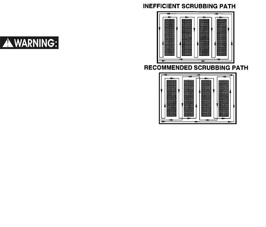
NORMAL SCRUBBING
Plan the scrubbing pattern in advance. The longest
track is around the perimeter of the area to be
cleaned. For efficient operation, the runs should be
the longest possible without turning, stopping, or
raising or lowering scrub deck/squeegee.
In order to achieve the best possible results, the
area which is to be cleaned should be swept before
scrubbing. Large debris, strings and wire must be
removed to prevent being caught in brushes or
squeegee.
If the machine is allowed to stand in neutral with the
scrub deck down for more than 2 seconds, the
solutions flow stops and brush motors stop. If either
forward or reverse travel is selected, the solution
flow will continue in the same setting and the scrub
brush motors will continue in their same setting once
movement of machine begins. Overlap the brush
path and avoid transporting over previously cleaned
areas.

MACHINE OPERATION
86037660 CHARIOT 11/09/06
3-17
TO BEGIN SCRUBBING
When operating the machine around people, pay
close attention for unexpected movement. Use
extra caution around children.
Flammable liquids and/or reactive metals can
cause explosions or fire! Do not pick up.
1. Place left foot on operator presence pedal.
Throttle pedal must be in neutral position.
2. Turn machine power on.
3. Check position of Directional Control Switch to
ensure that machine is set to travel in direction
intended.
4. Press the Drive Reset Switch.
5. BASIC AND CYLINDRICAL
Lower the squeegee.
Lower the scrub deck to floor.
DELUXE
Press the one-touch switch (#1) on the control
panel. The brush motors will start, the scrub
deck will lower to the light scrub position, the
solution will begin to flow, the squeegee will
lower to the floor and the vacuum motors will
start.
6. Drive machine forward to begin scrubbing.
NOTE: Shut machine off immediately if water or
foam is expelled from the machine.
7. Adjust the speed of the machine, solution flow
and scrub brush pressure as necessary.
NOTE: Once solution flow rate is set it is not
necessary to shut off solution when stopping
scrubbing. Solution flow is automatically shut off
when brush motors stop. When brush motors are
activated, flow automatically resumes.
PRIMING PUMP
If the solution system has gone dry or has been
unused for a period of time, it may be necessary to
follow the pump priming procedure.
1. Fill solution tank.
2. Loosen, but do not completely remove the
strainer bowl. Solution should flow out of the
strainer. If it does not, check the strainer screen
inside the solution tank. Insure it is clear of
debris. Tighten the strainer bowl.
3. Disconnect the squeegee hose from the
recovery dome.
4. Begin normal scrubbing and set the solution flow
to maximum setting. Solution flow should begin
within 2 minutes.
5. Connect squeegee hose to recovery dome.
6. Adjust the speed of the machine, solution flow
and scrub brush pressure as necessary.

MACHINE OPERATION
86037660 CHARIOT 11/09/06 3-18
TO STOP SCRUBBING
1. BASIC AND CYLINDRICAL
Raise the scrub deck, turn off scrub
brushes.
Raise squeegee, turn off vacuum.
DELUXE
Press the one-touch switch (#1) on the
control panel. The brush motors will stop
and the scrub deck will rise to the park
position. After 15 seconds the squeegee
will raise, and 15 seconds later the vacuum
motor will turn off. This delay is to clear the
vacuum hose of recovered solution.
2. Allow the throttle pedal to return to neutral.
3. Turn machine power off.
FOR SAFETY: Before leaving or servicing
machine: stop on level surface, turn off machine
and remove key.
DOUBLE SCRUB
For floors which are heavily soiled or have thick
accumulations of floor finish may not clean
sufficiently with one pass. In these cases it will be
necessary to double scrub.
To double scrub, make the first pass over the
surface being cleaned with the squeegee up,
vacuum off, the solution on, Aqua-Mizer removed
and brushes down. This allows the solution to stay in
contact with the soil while loosening the surface
accumulation with the brushes. Allow time for the
first application to stay in contact with the floor.
Length of time between the first and second pass
depends on amount of accumulation and the type of
chemical being used. A second scrubbing with the
squeegee down and again the solution and brushes
on will further loosen soil. The additional application
of solution will further assist the difficult cleaning job.
FOR SAFETY: When using machine, go slow on
inclines and slippery services.
MACHINE OPERATION
86037660 CHARIOT 11/09/06
3-19
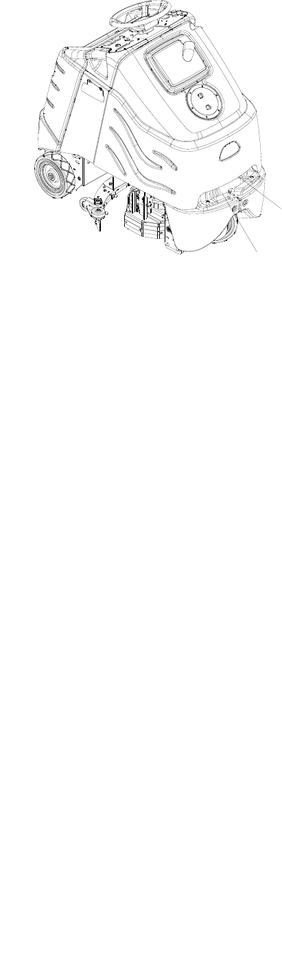
EMPTYING AND CLEANING TANKS
1. Park the machine next to a floor drain. Drain
hoses are at the front of the machine.
2. Turn the machine power off.
RECOVERY TANK
1. Pull the large drain hose from under the front of
the tank. Unscrew cap, then lower hose in
direction of the drain. Do not stand in front of
end of hose. Recovered solution will come out
with force.
2. Remove the recovery tank dome. Flush the
recovery bag out with clean water. Do not use
water hotter than 140°F (60°C) to clean tank.
Damage may occur.
3. Clean debris from dome basket.
4. Clean off the float shut-off system and inspect
for free movement of float. The float shut-off
system is located in the rear of the recovery
tank.
5. Replace the drain cap and secure drain hose
under tank.
6. If machine is to be stored, leave the recovery
tank dome off.
SOLUTION TANK
1. Pull recovery drain hose out to expose the
solution drain hose.
2. Pull the solution drain hose from under front of
the tank. Unscrew the T-handle on plug enough
to loosen plug, then lower hose in direction of
drain. Slowly remove plug from drain hose.
3. Remove the solution tank cover.
4. Flush the solution tank out with clean water and
run several gallons of clean water through
systems. Do not use water hotter than 140°F
(60°C) to clean tank. Damage may occur.
NOTE: Never allow solution to remain in tank.
Damage to tank, seals and valves could occur.
Tuck drain hose under tank and secure with
recovery drain hose by tucking it under tank.
DRAIN HOSE
SOLUTION
RECOVERY
DRAIN HOSE

NOTES:
86037660 CHARIOT 11/09/06 3-20

MAINTENANCE
86037660 CHARIOT 11/09/06
4-1
SERVICE SCHEDULE
MAINTENANCE BEFORE EACH
WORK PERIOD
AFTER EACH
WORK
PERIOD 50
HRS 100
HRS 200
HRS
Check water level of batteries after charging;
add distilled water if necessary. (Wet cell only) *
Check that dome and cover seal tightly. *
Visually check for damaged or worn tires. *
Check brushes or pads for proper installation. *
Check vacuum hose connections. *
Check that squeegee is securely attached and
properly adjusted. *
Check for securely attached drain hoses, plug
and cap. *
Check both pedals, brake and steering for
proper operation. *
Clean out recovery tank and dome basket. *
Clean and inspect float shutoff. *
Clean out solution tank and filter, check flow. *
Clean and inspect solution filter strainer. *
Run vacuum motors to dry. *
Clean brushes or pads and check wear. *
Clean squeegee blades and check wear. *
Clean outside of tanks, check for damage. *
Store with dome off tank. *
Charge batteries. *
Clean off top of batteries. *
Check battery cells with hydrometer. (Wet cell
only) *
Inspect scrub deck skirts and Aqua-Mizers. *
Clean solution strainer inside tank. *
Check battery connections are tight. *
Clean battery cases and battery compartment. *
Clean and check drive tension chain for wear
and tension. *
Check parking brake. *
Clean chains, cables and pulleys for
squeegee lift. *
Clean pivot points on squeegee and scrub
deck. *
Check all motors for carbon brush wear. *
Check motor commutators. *
Check steering chain tensioner. *
NOTE: Traction drive, wheels and batteries should be serviced based on traction drive hour meter
(Deluxe). The scrub brush hour meter should be used for all other service schedule items.
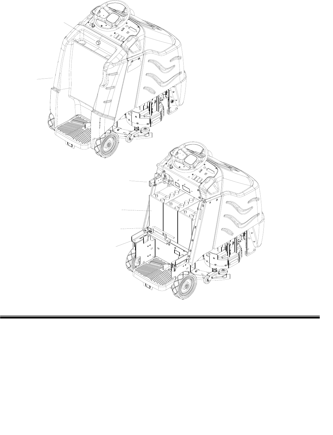
MAINTENANCE-BATTERIES
86037660 CHARIOT 11/09/06 4-2
1. Rear Cover Retainer Knob
2. Rear Cover
3. Battery Connector-Machine
4. Batteries
5. Battery Tray
6. Battery Tray Latch
1
2
3
4
5
6

MAINTENANCE-BATTERIES
86037660 CHARIOT 11/09/06
4-3
BATTERIES (WET CELL ONLY)
The batteries provide the power to operate the
machine. The batteries require regular maintenance
to keep them operating at peak efficiency.
The machine batteries will hold their charge for long
periods of time, but they can only be charged a
certain number of times. To get the greatest life
from the batteries, charge them when their charge
level reaches 25% of a full charge. Use a
hydrometer to check the charge level.
Do not allow the batteries to remain in a discharged
condition for any length of time. Never expose a
discharged battery to temperatures below freezing.
Discharged batteries will freeze causing cracked
cases. Do not operate the machine if the batteries
are in poor condition or if they have a charge level
below 25% (specific gravity below 1.155).
Keep all metallic objects off the top of the batteries,
as they may cause a short circuit. Replace worn or
damaged cables and terminals.
Check the electrolyte level in each battery cell
before and after charging the batteries. Never add
acid to the batteries, use distilled water. Do not
allow water level to fall below the battery plates.
Portions of plates exposed to air will be destroyed.
Do not overfill. Keep plugs firmly in place at all
times.
When servicing machine,
avoid contact with battery
acid.
Batteries emit hydrogen
gas. Explosion or fire can
result. Keep sparks and open flame away. Keep
covers open when charging.
Wear eye protection and
protective clothing when
working with batteries.
Charge batteries in a well
ventilated area.
BATTERY MAINTENANCE
1. When cleaning the batteries, use a solution of
baking soda and water. Do not allow the
cleaning fluid to enter the battery cells,
electrolyte will be neutralized.
2. Maintain the proper electrolyte level in each
battery cell. If a cell should accidentally
overflow, clean immediately.
3. Wipe off the top of the batteries at least once a
week.
4. Test battery condition with a hydrometer at least
once a week.
5. Ensure that all connections are tight and all
corrosion removed.
6. Every 4 to 6 months, remove that batteries from
the machine and clean the battery cases and
battery compartment.
MAINTENANCE-BATTERIES
86037660 CHARIOT 11/09/06 4-4
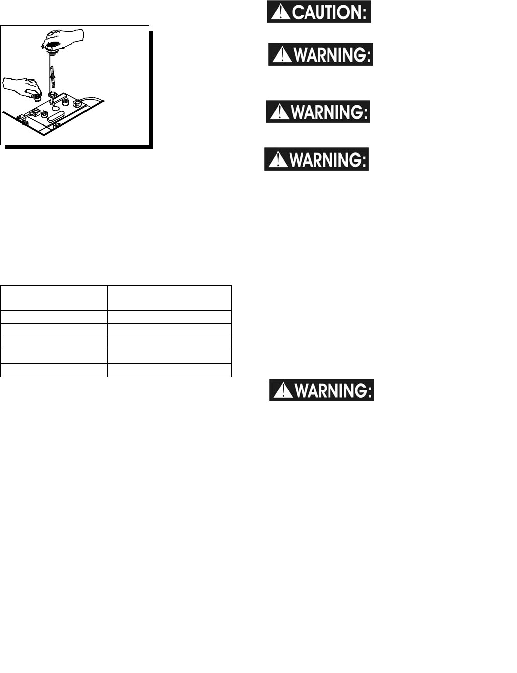
CHECKING BATTERY SPECIFIC GRAVITY
Use a hydrometer to check the battery specific
gravity.
CHECKING GRAVITY
A. Hydrometer
B. Battery
NOTE: Do not take readings immediately after
adding distilled water, if the water and acid are not
thoroughly mixed, the reading may not be accurate.
Check the hydrometer readings against this chart.
SPECIFIC GRAVITY
@ 80
°
F (27
°
C) BATTERY CONDITION
1.265 100% CHARGED
1.225 75% CHARGED
1.190 50% CHARGED
1.155 25% CHARGED
1.120 DISCHARGED
NOTE: If the readings are taken when the battery
electrolyte is any temperature other than 80°F
(27°C), the reading must be temperature corrected.
To find the corrected specific gravity reading when
the temperature of the battery electrolyte is other
than 80°F (27°): Add (+) to the specific gravity
reading 0.004 (4 points), for each 10°F (6°C) above
80° (27°C).
Subtract (-) from the specific reading 0.004 (4
points), for each 10°F (6°C) below 80°F (27°C).
CHARGING BATTERIES
When servicing machine,
avoid contact with battery
acid.
Batteries emit hydrogen
gas. Explosion or fire can
result. Keep sparks and open flame away. Keep
covers open when charging.
Wear eye protection and
protective clothing when
working with batteries.
Charge batteries in a well
ventilated area.
Use a 36 volt, 20 amp maximum output DC charger
which will automatically shut off when the batteries
are fully charged.
1. Stop the machine in a clean, well ventilated area
next to the charger.
2. Turn “OFF” machine.
FOR SAFETY: Before leaving or servicing
machine; stop on level surface, turn off machine
and remove key.
3. Remove rear cover, unplug batteries from
machine, unlatch battery tray and pull out to
expose batteries.
Batteries emit hydrogen
gas. Explosion or fire
can result. Keep sparks and open flame away.
Keep covers open when charging.
4. Check the electrolyte level in each battery cell.
Before charging, add just enough distilled water
to cover the plates. After charging is complete,
add just enough distilled water to bring up the
level to the indicator ring. If the water level is
too high before charging, normal expansion rate
of the electrolyte may cause an overflow
resulting in a loss of battery acid balance and
damage the machine.
Battery Check
MAINTENANCE-BATTERIES
86037660 CHARIOT 11/09/06
4-5
5. Replace the battery caps, and leave them in
place while charging.
6. Unplug the battery connector from the machine.
FOR SAFETY: When charging, connect the
charger to the batteries before connecting the
charger to the AC wall outlet. Never connect the
charger to the AC wall outlet first. Hazardous
sparks may result.
7. Plug the charger connector into the battery
connector. Connect the charger AC plug to a
wall outlet. The charger gauge should indicate
that the batteries are charging.
8. When the batteries are fully charged, disconnect
the charger from the AC wall outlet, then
disconnect the charger from the batteries.
9. Connect the batteries to the machine connector.
10. Check the electrolyte level. It should be up to
the indicator ring. If necessary, add distilled
water.
11. Install the rear cover.
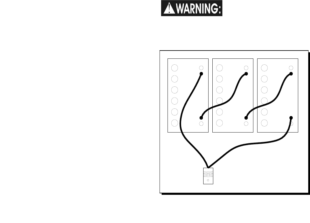
CHANGING BATTERIES
Stop the machine in a clean area next to the
charger. Turn off machine.
FOR SAFETY: Before leaving or servicing the
machine; stop on level surface, turn off machine
and remove key.
1. Remove the rear cover.
2. Disconnect battery pack from machine.
3. Unlatch battery tray from machine and pull out
to expose batteries.
4. Use the proper size open end wrench to
disconnect main ground wire first and secure
cable terminal away from batteries.
5. Disconnect main positive lead and secure cable
terminals away from batteries.
6. Loosen both terminals on each jumper cable
and remove one at a time.
7. Prepare a suitable site to place the batteries.
Attach suitable battery lifting
device and lift batteries from
the machine.
Batteries are a potential environmental hazard.
Consult your battery supplier for safe disposal
methods.
+
--
++
-
RED
BLK
RED
BLK
RED
BLK
REAR OF MACHINE
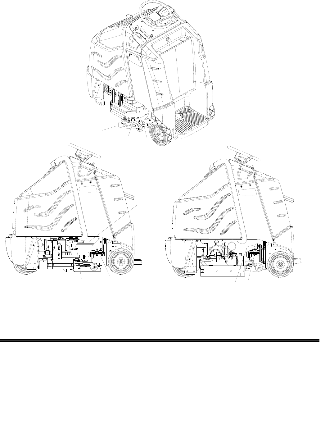
MAINTENANCE-SQUEEGEE
86037660 CHARIOT 11/09/06 4-6
1. Squeegee
2. Squeegee Deflection Adjustment Knobs
3. Squeegee Level Indicator
4. Squeegee Pitch Adjustment
Rod/Cylindrical Knob
5. Squeegee Pitch Adjustment Lock Nut
6. Squeegee Retainer Knob
DISK SCRUBBER CYLINDRICAL SCRUBBER
5646
4
3
2
1
MAINTENANCE-SQUEEGEE
86037660 CHARIOT 11/09/06
4-7
SQUEEGEE BLADES
The front squeegee blade allows solution to pass
through channels in the blade into the squeegee
assembly while maintaining vacuum to provide lift.
The front blade has four wear surfaces and can be
rotated for extended life. The front blade should not
require regular replacement under normal use.
The rear blade wipes the floor to a near dry
condition. It is important the rear blade be in good
condition to properly do its job. As with the front,
each squeegee blade assembly has four wear
surfaces for extended service.
Check both the front and rear squeegee blades for
damage, wear, and adjustment each day in the pre-
run check. Change the front blade if it is torn or has
an uneven edge. Change the rear blade if it is less
than 1/2 the original thickness.
ADJUSTING SQUEEGEE
Adjusting the squeegee is a two-part process. First,
the squeegee assembly must have correct pitch in
order for the squeegee blade to have the same
deflection at each tip as well as the center. The rod
on the squeegee linkage controls the pitch
adjustment. The second adjustment is the
deflection. Knobs on each end of the squeegee
control this.
TO REMOVE SQUEEGEE ASSEMBLY
1. With the squeegee in the up position, turn key
switch “OFF”.
2. Disconnect vacuum hose from squeegee and
loosen knob on left side of squeegee lifting
carrier.
3. Pull squeegee assembly from the lifting carrier.
4. Inspect or repair as necessary and reinstall.
TO REPLACE OR ROTATE REAR SQUEEGEE
BLADES
1. With the squeegee in the up position, turn key
switch “OFF”.
FOR SAFETY: Before leaving or servicing
machine; stop on level surface, turn off machine
and remove key.
2. Remove the squeegee assembly from the
machine. Unlatch and remove blade retainer
strap and remove squeegee blade.
3. Rotate the squeegee to new edge position or
replace as required. Each blade has four new
edge positions.
4. Install blade on locating pins of squeegee
assembly.
5. Install squeegee retainer strap.
6. Fasten and lock latch, adjust latch only tight
enough to take up slack in retaining strap.
TO REPLACE OR ROTATE FRONT SQUEEGEE
BLADE
1. With the squeegee in the up position, turn key
switch “OFF”.
2. Remove the squeegee from the machine.
Loosen thumbscrews and remove the retainer
strap and squeegee blade.
3. Rotate the squeegee to new edge position or
replace as required. Each blade has four new
edge positions. When installing the front blade,
tighten the center thumbscrew first. Insure that
the retainer strap is pressed against the blade
before tightening the outer screws.
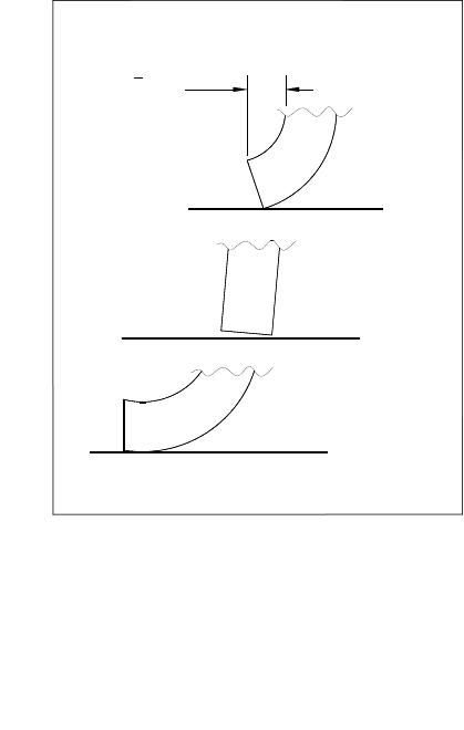
SIDE VIEW OF SQUEEGEE BLADE
SQUEEGEE DEFLECTION
TOO MUCH
CORRECT
NOT ENOUGH
3
8"
(9.5mm)
MAINTENANCE-SQUEEGEE
86037660 CHARIOT 11/09/06 4-8
TO ADJUST SQUEEGEE PITCH
1. Choose a smooth, level surface. Turn “ON” the
key switch. Lower the squeegee and drive
forward at least 2 feet (60cm.).
2. With the squeegee down, stop the machine. Do
not allow machine to roll back.
FOR SAFETY: Before leaving or servicing the
machine; stop on level surface, turn off machine
and remove key.
3. Determine the differences, if any, in deflection of
the squeegee blade between each end and the
middle. Proper adjustment is obtained when
deflection is equal all the way across the
squeegee blade. The bubble level should also
indicate when the squeegee is adjusted
properly. When the air bubble is in the center of
the vial, the deflection should be even across
the squeegee blade.
4. To decrease the deflection of the squeegee
blade at the ends, loosen wing nut and rotate
the rod clockwise. To increase the deflection at
the ends of the squeegee assembly, rotate the
rod counterclockwise knob.
5. Check the deflection of the squeegee blades
again. Repeat steps 1 through 4 until the
deflection is equal across the entire rear
squeegee blade. Tighten wing nut.
TO ADJUST AMOUNT OF REAR SQUEEGEE
DEFLECTION
1. Choose a smooth, level surface. Lower the
squeegee and drive forward at least 2 feet
(60cm).
2. With the squeegee down, stop the machine. Do
not allow machine to roll back.
FOR SAFETY: Before leaving or servicing
machine; stop on level surface, turn off machine
and remove key.
3. Observe the amount of squeegee deflection. It
should deflect 3/8 in. (9.5mm) across the entire
width of the squeegee.
4. To increase the squeegee deflection, turn the 2
knobs at the squeegee ends counter-clockwise.
To decrease the deflection, turn the knobs
clockwise.
NOTE: The deflection should be consistent along
the length of the squeegee. If the deflection varies
from end to end the knobs can be adjusted
independently to correct the variation.
5. Turn on the key switch. Raise, then lower
squeegee assembly. Drive forward at least
2 feet (60cm).
6. Repeat steps 2 through 4 until deflection of
3/8 in. (9.5mm) is reached.
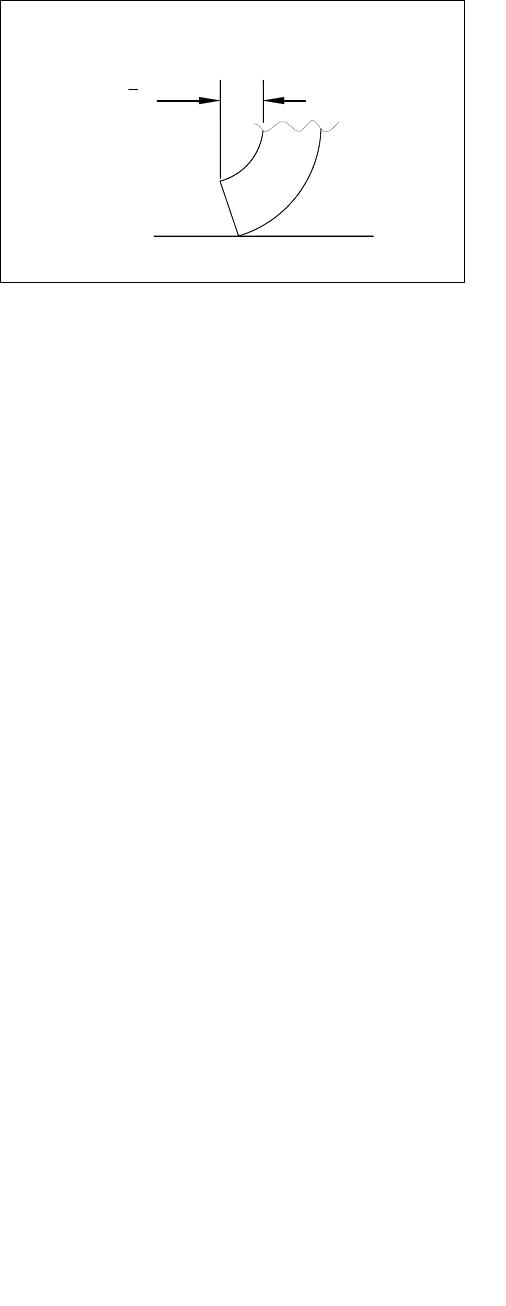
SIDE VIEW OF SQUEEGEE BLADE
SQUEEGEE DEFLECTION
CORRECT
3
8"
(9.5mm)

MAINTENANCE-SCRUB BRUSHES
86037660 CHARIOT 11/09/06
4-9
SCRUB BRUSHES
There are four different types of brushes available to
cover applications from cleaning heavily soiled floors
to polishing. A pad driver is also available to take
advantage of the many cleaning pads on the market.
Please refer to the following to assist in selecting the
proper brush or pad for the work at hand.
UNCOATED FLOORS
Aggressive Grit is a nylon fiber impregnated with
silicone carbide grit. It grinds away stain, soil, and
removes surface material.
Mild Grit is a less aggressive silicone carbide grit
suitable for cleaning medium soil conditions.
Advantages are faster ground speed than nylon
bristles on light solid applications.
Polypropylene is a general-purpose scrub brush
with stiff bristles. Polypropylene works well for
maintaining concrete, wood and tile floors.
FINISHED FLOORS
Nylon bristles are used in a variety of applications
on coated or uncoated surfaces.
White Pads (Polishing) are used for dry polishing to
achieve a high-gloss appearance, or surface
washing on highly polished or burnished floors.
Red Pads (Buffing) are used for light-duty
scrubbing. When used with a mild detergent they
will provide surface cleaning without removing the
finish.
Blue Pads (Scrubbing) are used for heavy-duty
scrubbing and light stripping. The blue pads remove
less finish than brown stripping pads, yet will remove
black marks, stains and dirt.
Black Pads (Stripping) are used for easy and
complete removal of old floor waxes/finishes. They
will quickly remove ground in dirt, black heel marks,
and spills. When used with the proper stripper, this
pad leaves the floor clean and ready for finishing.
The scrub brushes should be checked before each
days work for wire, string, wear and damage.
MAINTENANCE-SCRUB DECK – DISK
86037660 CHARIOT 11/09/06 4-10
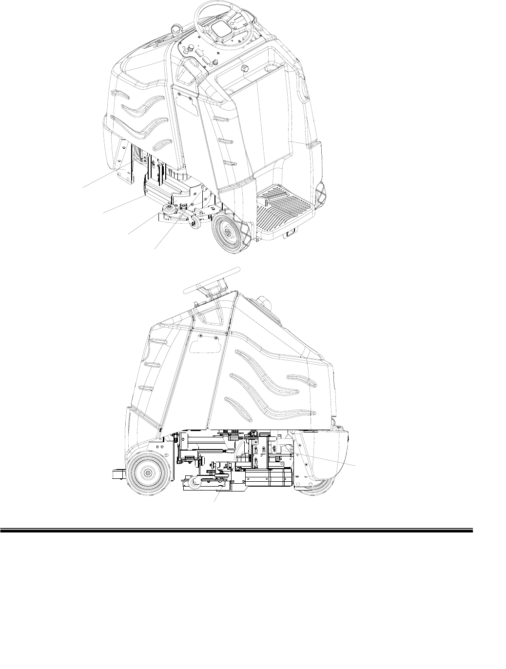
1. Scrub deck Aqua-Mizer™
2. Aqua-Mizer™ retainer knob
3. Scrub deck skirt
4. Scrub deck skirt stop
5. Scrub brush motor
6. Scrub deck lift actuator
6
5
4
3
2
1

MAINTENANCE-SCRUB DECK - DISK
86037660 CHARIOT 11/09/06
4-11
Do not use a pressure
washer to clean around
the brush motors. Use tap pressure only.
TO REPLACE SCRUB BRUSH MOTORS
1. With the scrub deck in the raised position,
disconnect brush motor wiring connector from
harness.
2. Remove skirts from scrub deck to access and
remove scrub brushes or pad drivers.
3. Remove Aqua-Mizers™ from scrub deck.
4. Remove retaining bolt, lock washer, flat washer
and star drive from brush motor shaft.
5. Remove 4 brush motor mounting bolts located
under scrub deck.
6. Lower scrub deck.
7. Remove brush motor.
8. Reverse steps to install.
BRUSH MOTOR CARBON BRUSH
REPLACEMENT
1. Scribe alignment mark on motor barrel to motor
cap. Remove two bolts.
2. Remove end cap from motor.
NOTE: Motors contain two wave washers in
cap. Do not lose these.
3. Release brush from spring tension. Remove
screw connecting brush wire lead to brush
holder. Clean brush holder to insure free
movement.
4. Retract spring and install new brush. Install
connector screw and lead.
5. When all new brushes are installed. Place all in
retracted position, held into brush holder by
spring tension.
6. Carefully place end cap onto bearing on motor
shaft.
NOTE: Use care to assure wave washer
alignment.
7. With end cap in partially installed position,
release all brushes to contact position with
motor commutator.
NOTE: Failure to insure all brushes are released
will result in motor failure.
8. Reset end cap and realign with scribe marks on
motor barrel. Reinstall the two attach bolts from
cap into base.
9. Maintain alignment between motor barrel base
and cap.

MAINTENANCE-SCRUB DECK - DISK
86037660 CHARIOT 11/09/06 4-12
FOR SAFETY: Before leaving or servicing
machine, stop on a level surface. Turn off
machine.
1. Remove the two screws that secure actuator
spring plate and pull actuator barrel from stud on
actuator spring bracket.
2. Remove clevis pin from upper bracket of
actuator.
3. Disconnect actuator from wiring harness.
4. Reverse steps to install.
SCRUB DECK ACTUATOR ADJUSTMENT
The actuator will need to be adjusted when
replaced.
To adjust the actuator:
1. While holding actuator barrel to prevent it from
spinning, apply power to the actuator such that it
is fully extended. Positive power to white wire,
and negative/ground to black. Limit switch
within actuator will stop it.
2. Turn barrel out one or more full turns to assure
that when it is retracted it will not bind against
itself.
3. While holding actuator barrel to prevent it from
spinning, apply power to the actuator such that it
is fully retracted. Positive power to black wire,
and negative/ground to white wire. Limit switch
within actuator will stop it.
4. With actuator fully retracted, turn barrel in until it
touches the base of the threaded shaft.
5. At the bottomed out position, turn the barrel out
1 full turn, then enough more to allow
connection to lift linkage.
6. Connect actuator to lift linkage.
7. Check travel of actuator during operation.
MAINTENANCE-SCRUB DECK - CYLINDRICAL
86037660 CHARIOT 11/09/06
4-13
4-13
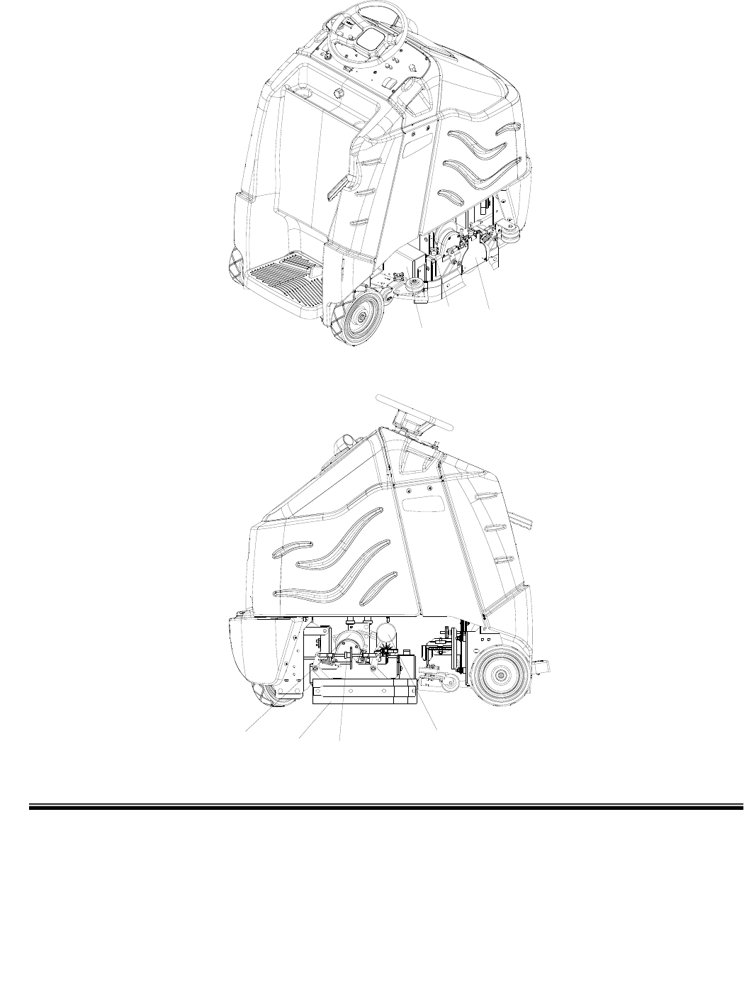
1. Hopper
2. Blade side squeegee
3. Side squeegee adjustment knob
4. Scrub brush motor
5. Scrub deck lift actuator
6. Side squeegee removal knob
7. Brush door
2
435
1
67

MAINTENANCE-SCRUB DECK - CYLINDRICAL
86037660 CHARIOT 11/09/06 4-14
SCRUB HEAD-CYLINDRICAL
The dual cylindrical scrub head is designed to
eliminate debris that may be caught in the squeegee
while scrubbing. Water is applied to the first
scrubbing brush turning in a clockwise rotation when
viewed from the right of operator’s side of machine.
The first brush scrubs dirt and debris between the
brushes. The second scrubbing brush, turning in a
counter clockwise rotation, picks up debris and
throws it into a removable hopper. The larger debris
which might catch under the squeegee is collected
in the hopper. Water is allowed to drain out the
hopper into the squeegee path where it is recovered
from the floor.
MAINTENANCE
The brushes should wear evenly side to side if
properly adjusted. Scrub brushes should be
exchanged front to back every 50 hours to ensure
even wear since the rear brush contacts the floor
with more force. It is not necessary to rotate end for
end since swapping front to back puts the brushes in
the opposite rotation, as well as balancing wear.
Scrub brushes should be replaced as a set when
bristle length wears to height of yellow
PerformAlertTM bristles.
SCRUB BRUSH REMOVAL
The scrub brushes are removed from the side of the
machine. The front is removed from the right side
and the rear is removed from the left side.
1. Unscrew the knob and swing side squeegee out
about 90°
2. Unscrew knob on side door but do not remove.
3. Pull out on top of door until lip on door clears
brush head.
4. Push down on door until hooks on bottom of
door are free of scrub head side.
5. Pull out on door with a rocking motion to free
idler door from end of brush.
6. Pull brush out with a rocking motion to free
brush from drive hub.
SCRUB BRUSH REPLACEMENT
1. Unscrew the knob and swing side squeegee out
about 90°
2. Lift the drive side of the brush. Push brush until
a positive stop is felt. The idler plate cannot be
installed until the brush is fully seated on the
drive hub.
3. Allow brush to drop below scrub deck. Fully
insert plate onto brush.
4. Line up bottom hook on idler door with notches
on side of scrub head.
5. Slide idler door up until lip rests on top of scrub
head.
6. Hand tighten knob to secure door into place.
TO ADJUST SCRUB DECK SIDE SQUEEGEES
These skirts should be adjusted to 3/8” deflection.
To adjust:
1. Lower scrub deck to floor.
2. Stop machine.
3. Loosen scrub deck skirt stop.
4. Adjust stop such that skirt deflection is about
3/8”.
TO REPLACE SCRUB DECK SIDE SQUEEGEES
These skirts have four wear edges.
To use another edge:
1. Remove each of the scrub deck skirt
assemblies.
2. Remove the hardware that retains the blade on
each assembly.
3. Flip the blade vertically or horizontally, or both,
and replace hardware.
4. Re-install each scrub deck assembly.

MAINTENANCE-SCRUB DECK - CYLINDRICAL
86037660 CHARIOT 11/09/06
4-15
DUMPING HOPPER
The removable hopper is located behind the rear
scrub brush. If the hopper becomes full, it will not
accept any more debris. Loosen knob on left side
squeegee and swing open. Remove the hopper by
sliding it out from the operator’s left side of the
machine. The hopper can then be dumped from the
top. Flush the hopper clean with running water.
SCRUB DECK ADJUSTMENT
Scrub deck adjustment consists of two types of
adjustments. The first is to insure the individual
brushes make the same width pattern end to end.
Any tapered brush pattern should be adjusted out.
The second is to make the pattern of equal width
between front and rear brushes. Unequal patterns
are caused by the scrub deck not being parallel to
the floor. Proper adjustment is obtained when the
contact patterns of the brushes on the floor show
two 1” rectangles the width of the brushes. The
rectangles should be parallel to each other.
TESTING, ADJUSTMENT OF INDIVIDUAL
BRUSHES
1. Move the machine to an unfinished area of floor
to avoid marking finish.
2. With water valve off, lower scrub head to floor.
Allow brushes to run until automatic shut off
occurs. It may be necessary to repeat this step
in the same location until a good mark can be
seen on the floor. This can be accomplished by
touching lightly the throttle pedal to restart the
scrub deck without moving the machine.
3. Raise the scrub deck and note the brush
patterns on the floor. There should be two
rectangles with parallel sides. If the pattern is
tapered, proceed as follows.
ADJUSTMENT OF INDIVIDUAL BRUSHES
The brush pattern is adjusted from the motor side
only of both brushes.
1. Determine if motor end is to be moved up or
down to balance the pattern.
2. Loosen the 3 allen head screws on the end of
the housing.
3. Loosen the jam nut on the jack screw and rotate
the jack screw to move the motor assembly up
or down as needed.
4. Tighten the 3 allen head screws.
5. Tighten the jam nut on the jack screw.
6. Re-test and readjust as necessary.
LEVELING THE SCRUB HEAD
Leveling the cylindrical head is accomplished by
adjusting the lower links that attach the deck to the
frame. To increase pattern width on rear brush,
loosen lock nuts and shorten the lower links by
screwing the rod into the threaded ends. To
increase pattern width on front brush, lengthen the
lower links by screwing the rod out of the threaded
ends. After adjustment, be sure to tighten lock nuts.

MAINTENANCE-SCRUB DECK - CYLINDRICAL
86037660 CHARIOT 11/09/06 4-16
Do not use a pressure
washer to clean around
the brush motors. Use tap pressure only.
TO REPLACE SCRUB BRUSH MOTORS
1. With the scrub deck in the raised position,
disconnect brush motor wiring connector from
harness.
2. Remove side squeegee assembly.
3. Remove brushes and brush door.
4. Remove aluminum end housing from deck.
5. Separate brush motor with gear box from end
housing.
6. Reverse to reassemble.
7. Adjust brush levelness as described in earlier
section.
BRUSH MOTOR CARBON BRUSH
REPLACEMENT
1. Scribe alignment mark on motor barrel to motor
cap. Remove two bolts.
2. Remove end cap from motor.
NOTE: Motors contain two wave washers in
cap. Do not lose these.
3. Release brush from spring tension. Remove
screw connecting brush wire lead to brush
holder. Clean brush holder to insure free
movement.
4. Retract spring and install new brush. Install
connector screw and lead.
5. When all new brushes are installed. Place all in
retracted position, held into brush holder by
spring tension.
6. Carefully place end cap onto bearing on motor
shaft.
NOTE: Use care to assure wave washer
alignment.
7. With end cap in partially installed position,
release all brushes to contact position with
motor commutator.
NOTE: Failure to insure all brushes are released
will result in motor failure.
8. Reset end cap and realign with scribe marks on
motor barrel. Reinstall the two attach bolts from
cap into base.
9. Maintain alignment between motor barrel base
and cap.

MAINTENANCE-SCRUB DECK - CYLINDRICAL
86037660 CHARIOT 11/09/06
4-17
ACTUATOR SCRUB DECK
REMOVAL/REPLACEMENT
FOR SAFETY: Before leaving or servicing
machine, stop on a level surface. Turn off
machine.
1. Lower scrub deck.
2. Disconnect spring assembly from actuator slide
link.
3. Remove the clevis pin retaining the top of the
acutator.
4. Remove slide link and actuator as an assembly
by removing the two bolts connecting them to
the deck through the bushings.
5. Either unthread the actuator main lead screw
from the barrel, or remove the two bolts
connecting the barrel to the slide link.
6. Reverse for re-installation.
SCRUB DECK ACTUATOR ADJUSTMENT
The actuator will need to be adjusted when
replaced.
To adjust the actuator:
1. While holding actuator barrel to prevent it from
spinning, apply power to the actuator such that it
is fully extended. Positive power to white wire,
and negative/ground to black. Limit switch
within actuator will stop it.
2. Turn barrel out one or more full turns to assure
that when it is retracted it will not bind against
itself.
3. While holding actuator barrel to prevent it from
spinning, apply power to the actuator such that it
is fully retracted. Positive power to black wire,
and negative/ground to white wire. Limit switch
within actuator will stop it.
4. With actuator fully retracted, turn barrel in until it
touches the base of the threaded shaft.
5. At the bottomed out position, turn the barrel out
only enough to allow connection to slide link.
6. Connect actuator.
7. Check travel of actuator during operation.
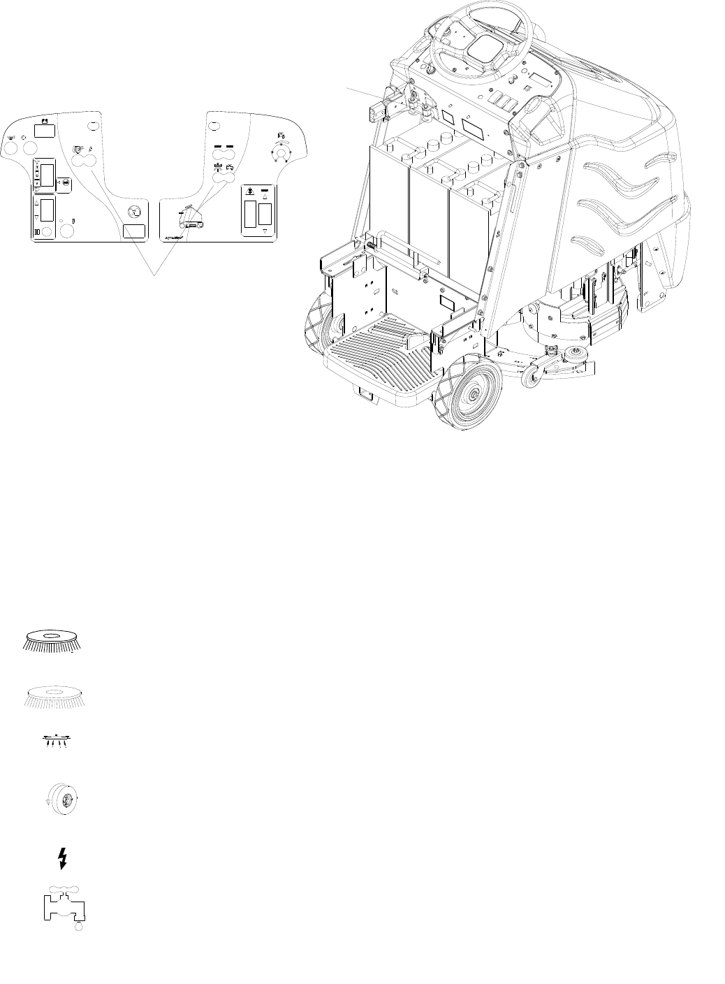
MAINTENANCE-CIRCUIT PROTECTION
86037660 CHARIOT 11/09/06 4-18
2
1
1. CIRCUIT BREAKERS (BASIC PANEL
SHOWN)
Circuit breakers interrupt the flow of power in the
event of an electrical overload. When a circuit
breaker is tripped, reset it by pressing the
exposed button. If a circuit breaker continues to
trip, the cause of the electrical overload should
be found and corrected.
18 Amp. Protects the left scrub
brush motor.
18 Amp. Protects the right scrub
brush motor.
30 Amp. Protects the vacuum
motor (Basic only).
30 Amp. Cylindrical
25 Amp. Disk
Protects the propel motor.
3 Amp. Protects the machine
controls (Basic only).
3 Amp. Protects the pump
(Basic only).
2. FUSE (DELUXE ONLY)
The fuse is a one-time circuit protection device
designed to stop the flow of electrical current in
the event of an electrical overload. If fuse is
blown, it must be replaced.
The fuse is located inside the battery
compartment.
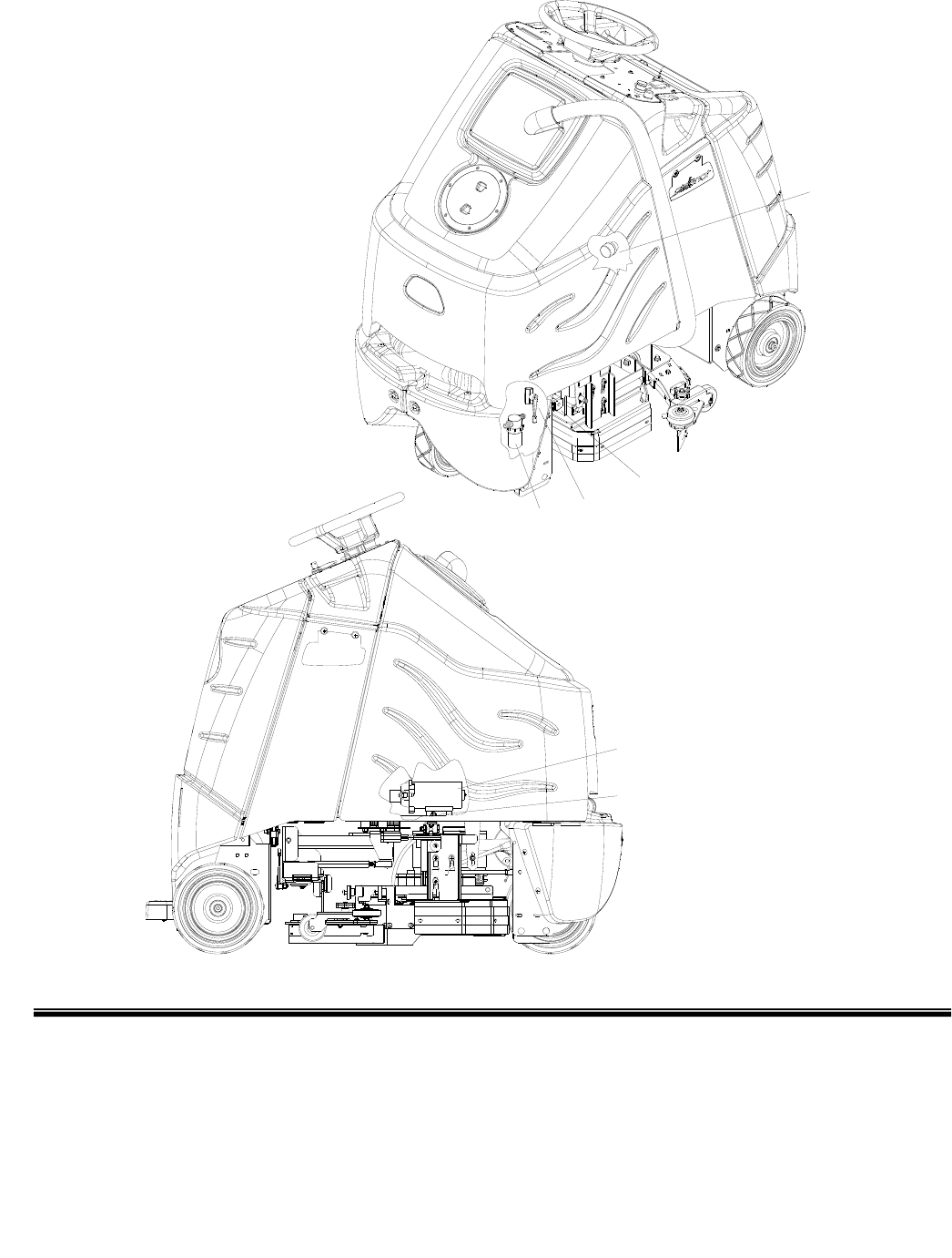
MAINTENANCE-SOLUTION STRAINER & PUMP - DISK MODELS
86037660 CHARIOT 01/03/08
4-19
1. Solution Strainer-Coarse
2. Solution Strainer-Fine
3. Pump
4. Pump Mounting Plate
5. Solenoid Valve
6. Shut-off Valve
5
4
3
1
6
2
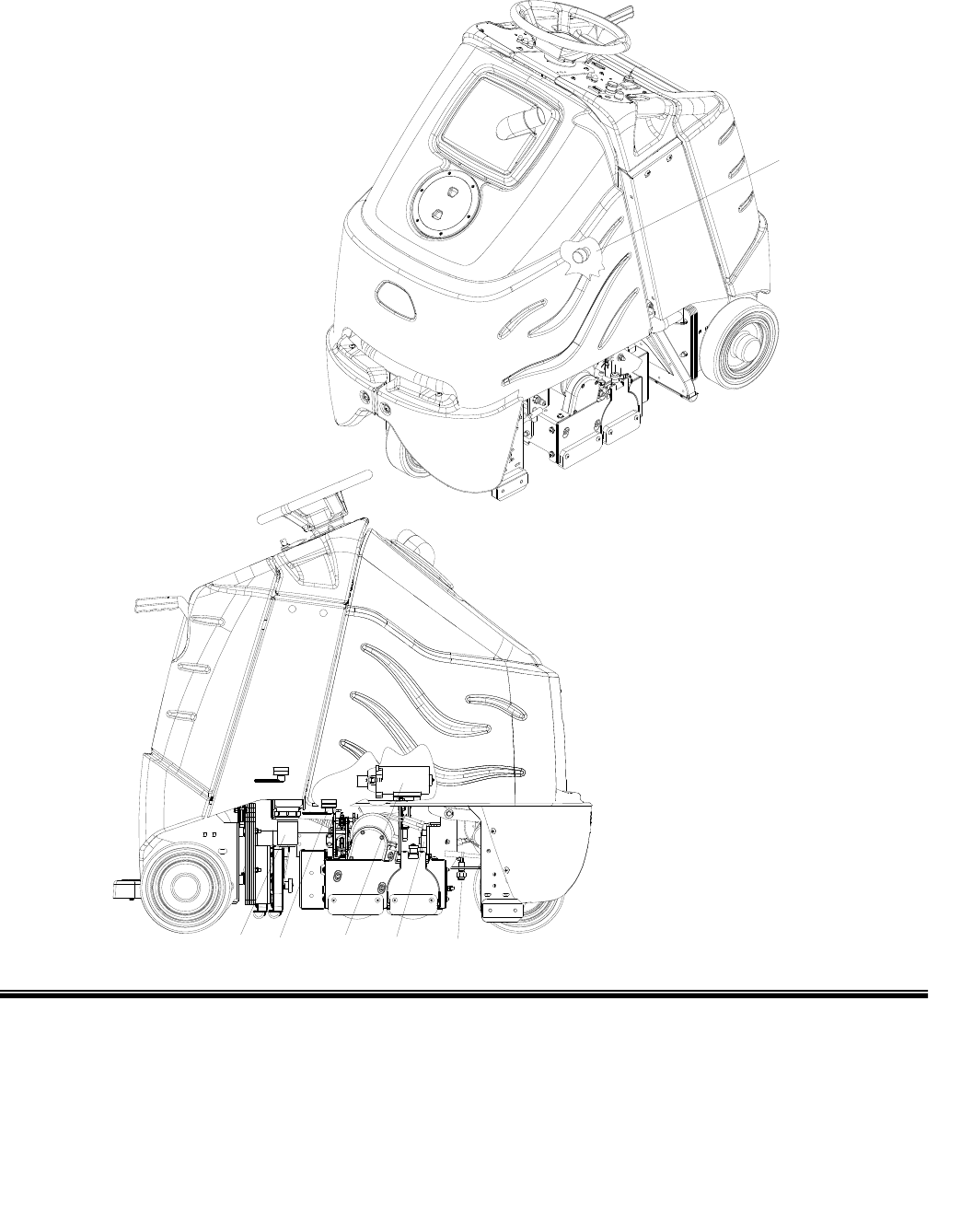
MAINTENANCE-SOLUTION STRAINER & PUMP-CYLINDRICAL MODELS
86037660 CHARIOT 01/03/08 4-20
1. Solution Strainer-Coarse
2. Solution Strainer-Fine
3. Pump
4. Solenoid Valve
5. Jets
6. Shut-off Valve
3
1
5
4
26
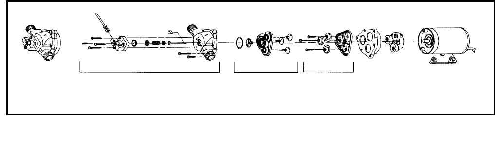
MAINTENANCE-SOLUTION STRAINER & PUMP
86037660 CHARIOT 01/03/08
4-21
1. SOLUTION STRAINER-COARSE
Located in bottom of tank. The coarse strainer
protects the finer strainer from large debris. If
the fine strainer is clean and the pump and
solenoid valve are not working, then check the
coarse strainer for debris. Drain the solution
tank and clean the coarse strainer. To remove
the strainer, rotate the strainer
counterclockwise. Cleanout the debris from wire
mesh and re-assemble.
2. SOLUTION STRAINER (FINE) AND
SHUT-OFF VALVE
The fine strainer is located in front left corner of
machine on disk models and in right rear corner
of cylindrical models. The fine strainer protects
the pump and solenoid valve from debris. If
there is little or no solution flow to the ground,
first check to make sue the shut-off valve is
open. Next, check the strainer for debris. To
remove the strainer, first turn the shut-off valve
to the off position. Then, turn the bottom part of
the strainer counterclockwise until the bottom is
separated. Clean out the debris from the wire
mesh and re-assemble. Make sure the O-ring
gasket is in place when re-assembled. To
resume flow, turn the shut-off valve to the open
position.
3. PUMP
The pump is located under the tank on the right
side of machine. The pump delivers solution
from the tank to the scrub deck.
To repair or replace pump:
1. Remove scrub deck skirts, Aqua-Mizer, and
squeegee from machine.
2. Lower scrub deck to gain access to pump
mounting plate.
3. Remove screw that secures pump mounting
plate to frame.
4. The pump is located under the tank on the
right side of machine. The pump delivers
solution from the tank to the scrub deck. Pull
pump mounting plate forward and down to
expose pump.
5. Reverse steps to install.
4. PUMP MOUNTING PLATE
See graphic representation on previous page.
5. SOLENOID VALVE
The solenoid valve is mounted on the front of
the scrub deck, on left side.
The solenoid valve shuts off solution flow to
scrub deck whenever scrubbing stops. To
repair or replace solenoid valve, cut cable ties
that secure it to deck.
PUMP HEAD REPLACEMENT
(86136450)
(PRV NO. 65151)
VALVE ASM.
(86137240)
(PRV NO. 84145)
DIAPHRAGM ASM.
(86235090)
(PRV NO. 29188)
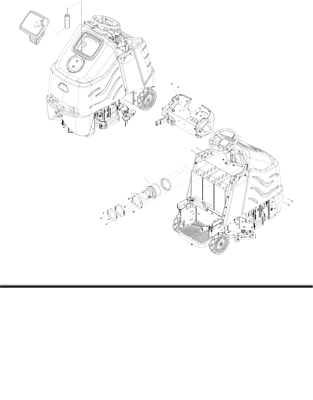
MAINTENANCE-VACUUM & FLOAT SHUT-OFF
86037660 CHARIOT 11/09/06 4-22
1. Recovery tank float shut-off
2. Vacuum motor
1
2
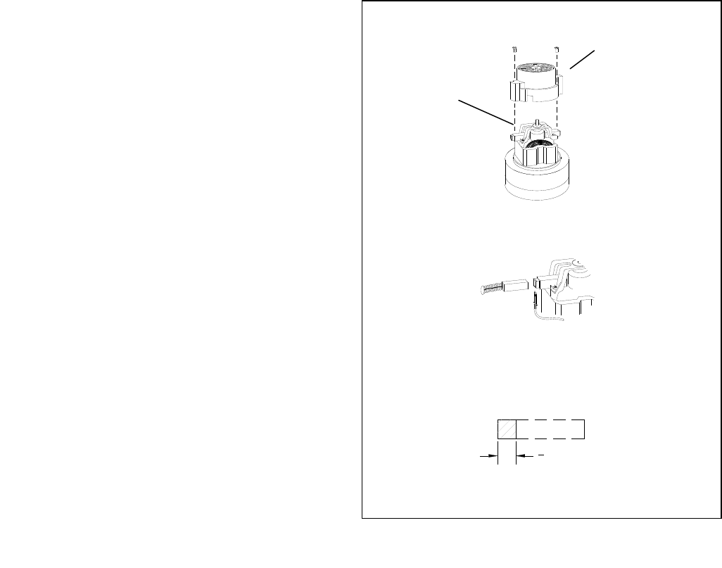
MAINTENANCE-VACUUM & FLOAT SHUT-OFF
86037660 CHARIOT 11/09/06
4-23
RECOVERY TANK FLOAT SHUT-OFF
When water is no longer being vacuumed from
the floor and the vacuum fan is operating, the
ball float has engaged. The vacuum motor will
not vacuum water with recovery tank full. The
recovery tank must be drained.
1. The float shut-off screen can be cleaned in or
out of the machine.
2. To clean the float shut-off while it is inside the
machine wipe material off screen then rinse.
Check that the ball is also clean and moves
freely.
3. To remove the float shut-off, grasp the screen
with one hand and the connected tube with the
other. Tilt and pull the float screen assembly to
pull it off the barb on the tube.
4. To install, place one hand on the tube, and then
tilt and push the float screen assembly over the
barb on the tube.
FOR SAFETY: before leaving or servicing
machine, stop on a level surface, turn off machine
and disconnect power.
TO REPAIR OR REPLACE VACUUM MOTOR
1. Remove rear cover from machine.
2. Remove two screws from top of control
panel and four screws from sides of control
housing.
3. Slide control housing back from tank to
expose vacuum motor.
4. Disconnect electrical connector from the
vacuum motor.
5. Remove three nuts that secure vacuum
motor retaining plate, remove plate and
vacuum motor.
6. Reverse steps to install. Make sure that
gasket is on vacuum so that vacuum seals
against tank
V
acuum Motor Carbon Brushes
End Cap
Carbon
Brushes
If armature commutator is grooved, extremely pitted or not
concentric, the motor will need to be replaced or sent to a
qualified service center.
Important:
These brushes wear quicker as the length shortens due to
increased heat. Spring inside brush housing will damage
motor if brushes are allowed to wear away completely.
Periodically check the length of the carbon brushes. Replace
both carbon brushes when either is less than 3/8" (9.5mm)
long.
3
8 [9.5mm]
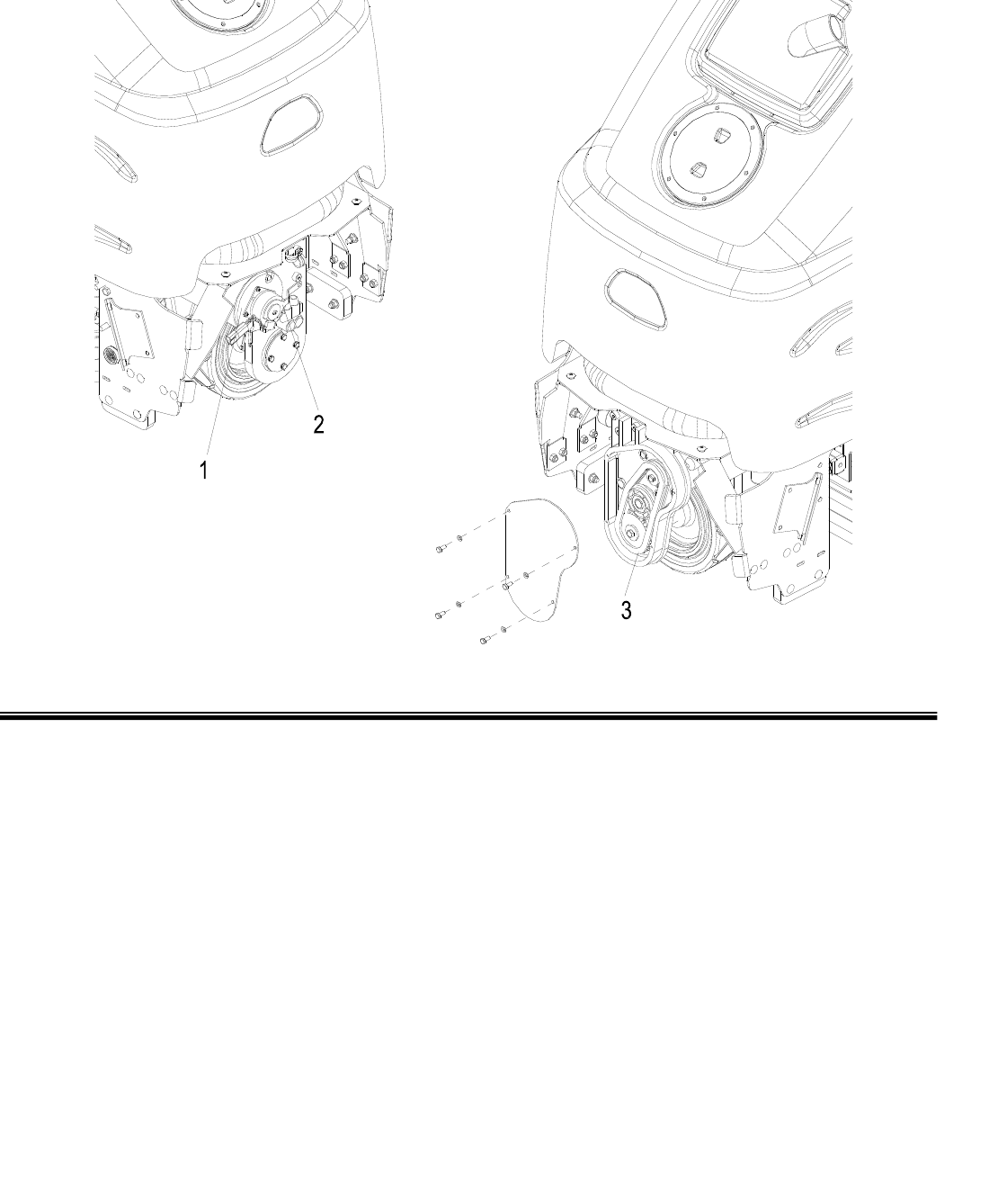
MAINTENANCE-DRIVE MOTOR & BRAKE
86037660 CHARIOT 10/29/08 4-24
1. Drive motor
2. Parking brake
3. Drive chain
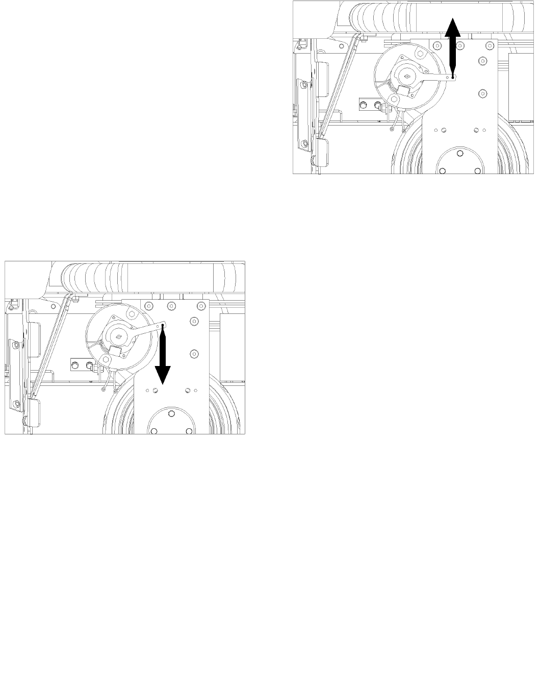
MAINTENANCE-DRIVE MOTOR & BRAKE
86037660 CHARIOT 10/29/08
4-25
ELECTRIC PARKING BRAKE ENGAGEMENT
FOR SAFETY: Before leaving or servicing
machine, stop on a level surface, turn off
machine and remove key.
Electric Brake Engagement
This machine is equipped with an electric parking
brake.
The brake automatically engages and keeps the
machine from moving whenever the operator steps
off the platform or when emergency stop is engaged.
The brake has a mechanical over-ride that can be
engaged so machine can be pushed or towed
(slowly).
When the mechanical over-ride is engaged the
machine cannot be driven.
To engage brake:
1. Mechanical over-ride engaged.
Machine can be pushed or towed (slowly).
2. Push lever firmly in direction of arrow
Note: There is an intermediate stop. Make sure
lever is fully in the down position.
To disengage brake:
1. Mechanical over-ride disengaged
Machine can be driven.
2. Push lever firmly in direction of arrow.
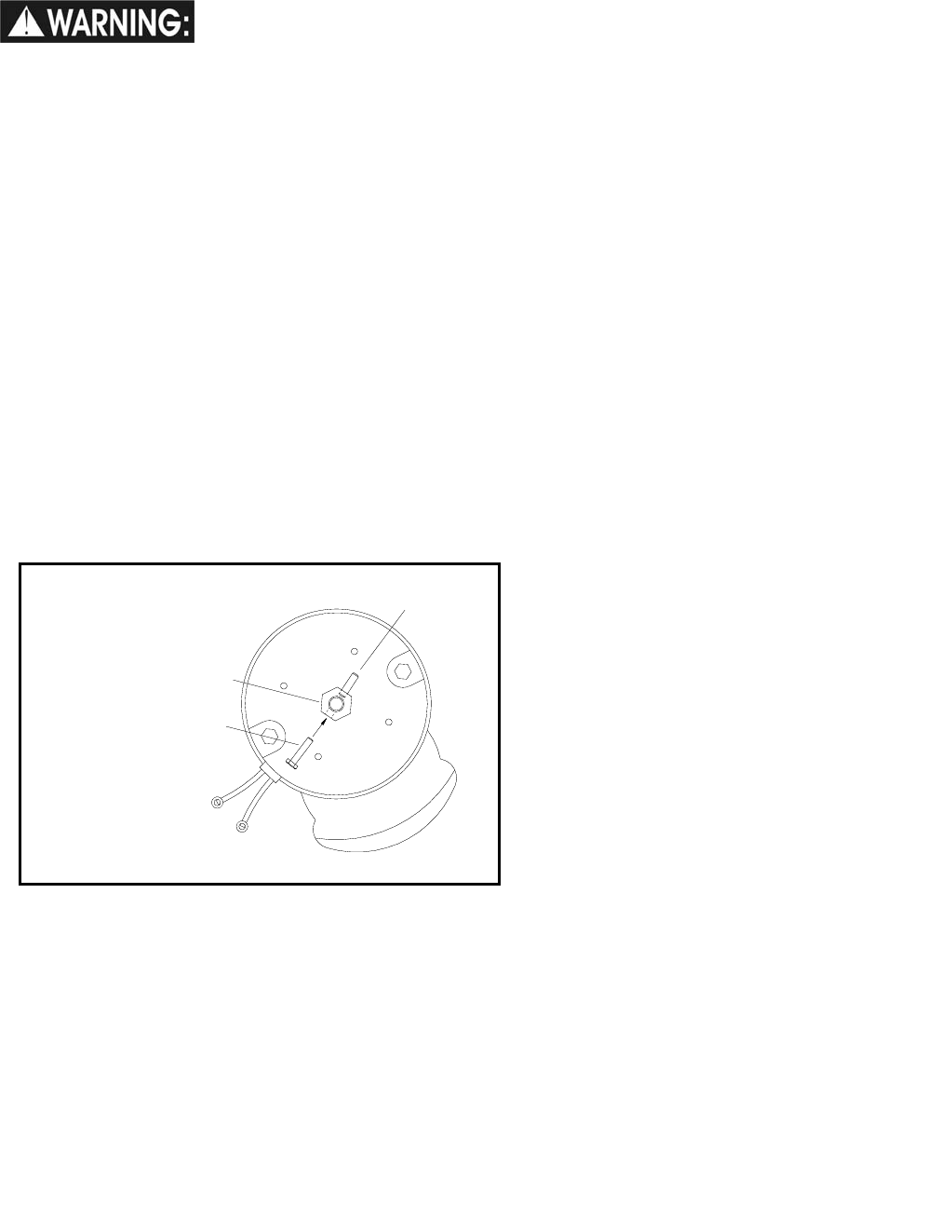
MAINTENANCE-DRIVE MOTOR & BRAKE
86037660 CHARIOT 11/09/06 4-26
DRIVE MOTOR CARBON BRUSH REPLACEMENT
Do not use a pressure
washer to clean around
the motors. Use tap pressure only.
FOR SAFETY: Before leaving or servicing
machine, stop on a level surface, turn off machine
and remove key.
1. Disconnect batteries from machine.
2. Disconnect the electrical connection to the traction
motor.
BRAKE REMOVAL
(Must be done to access carbon brushes)
3. Remove 4 mounting screws and remove brake.
4. Drive roll pin out of the hex hub enough to allow
hex hub to slide off shaft. It is recommended that
the roll pin be left partially in the hex hub.
5. Remove brush cap.
6. Release brush from spring tension. Remove
screw connecting brush wire lead to brush holder.
Clean brush holder to insure free movement.
5. Install new brush and reinstall connecting
screw and lead.
6. When all new brushes are installed. Place all
in retracted position, held into brush holder by
spring tension.
7. Carefully replace brush cap.
Reinstalling:
10. When replacing the hex hub, use a small pin
or screw to help align the holes.
11. Drive the pin into the hub and make sure it is
flush to the hex surface. The brake will not fit
on the hub if the roll pin is protruding from the
hub.
12. Replace the hub and use Lock-Tite on the
screws.
ROLL PIN
HEX HUB
SMALL PIN OR SCREW
ROLL PIN
HEX HUB
SMALL PIN OR SCREW
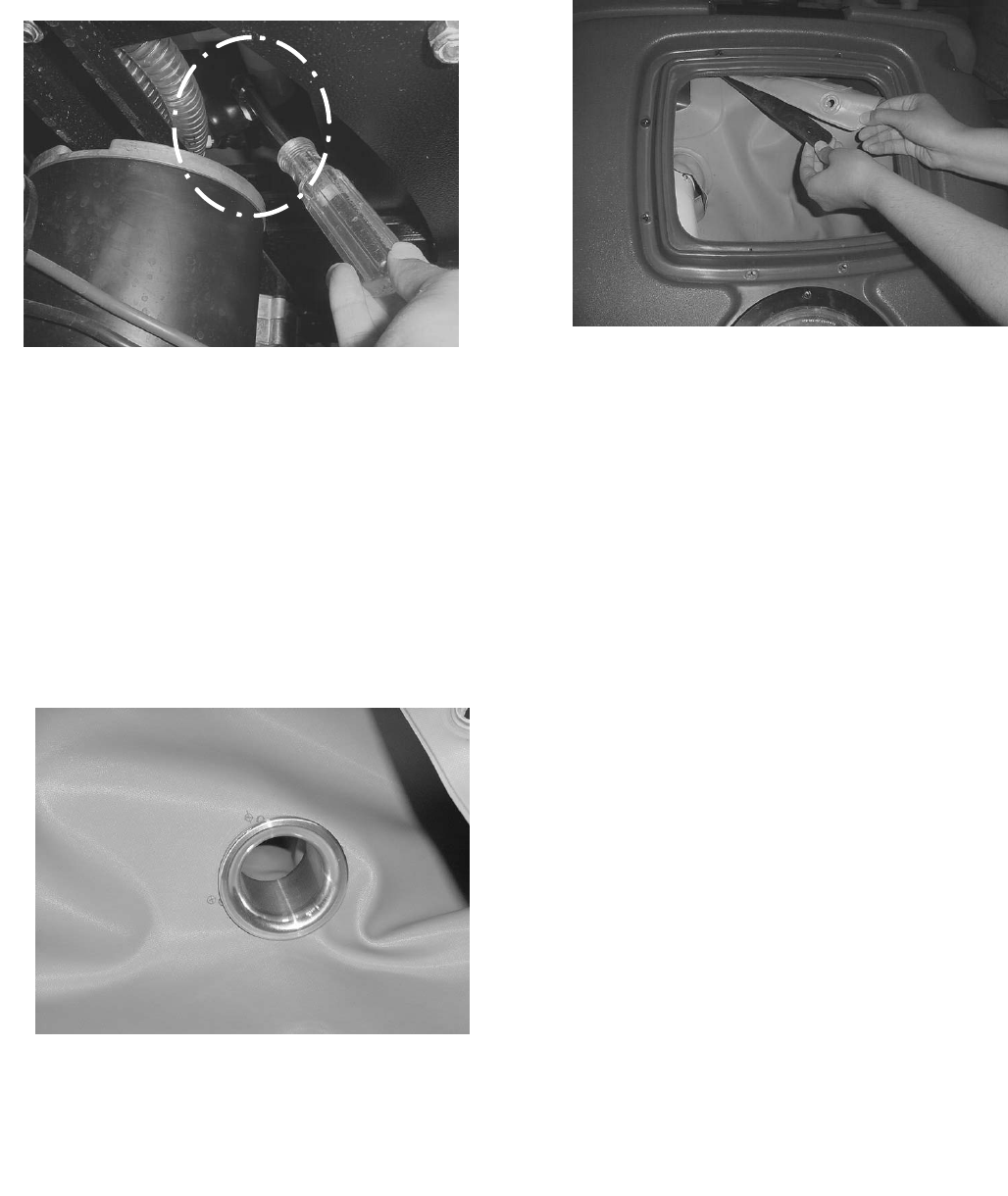
MAINTENANCE-BAG REPLACEMENT
86037660 CHARIOT 11/09/06
4-27
REMOVING BAG
1. Disconnect batteries and make sure parking brake
is not overridden.
2. Under left front side of machine loosen hose
clamp on recovery dump hose. Do not remove
hose.
3. Remove Dome and set aside
4. Remove Float cage, loosen screw on elbow and
remove elbow.
5. Remove the eight screws and nuts holding the bag
clamps and set aside.
6. Remove clamps and set aside.
7. Pull mandrel from bottom of tank. Access can
either be from the dirty water side or the clean
water side or both. When replacing bag with new
one be sure to save mandrel.
REPLACING BAG
1. Install mandrel in bottom of bag.
2. Place new bag in tank making sure hole for
strainer basket is oriented properly.
3. Angle mandrel and bag into tank fitting toward
front of machine. Push mandrel into fitting
until it bottoms out.
4. Attach bag to top of machine by rolling edge of
bag over clamp strips.
5. Replace elbow and float cage.
6. Tighten clamp on bottom of machine.
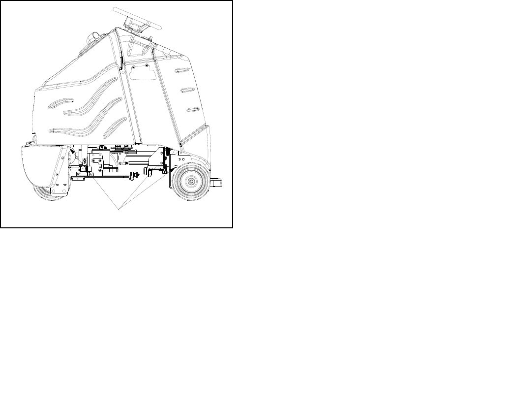
MAINTENANCE-TRANSPORTING
86037660 CHARIOT 11/09/06 4-28
PUSHING MACHINE
The machine may be pushed for short distances at
speeds not to exceed 5 mph. Be careful to avoid
damaging machine. The machine may be pushed by
hand from the rear.
NOTE: To avoid damage caused by regenerative
voltage, disconnect traction motor before towing or
pushing machine.
MACHINE TIE-DOWNS
There are two tie points located at front and each side
of foot box frame and two at the front side of frame.
Tie-down devices must be of the proper type and
strength. The combined strength of all tie-downs must
be strong enough to lift two times the weight of the
machine. Tie-downs must be positioned to prevent
the machine from moving forward, backward, or either
side to side. Use all four corners of the machine with
the tie-downs running out opposite directions. Tie-
downs must be attached to the transporting vehicle
securely.
PREPARATION FOR LOADING /UNLOADING
TRAILER
Before loading or unloading machine from trailer,
remove squeegee, scrub deck, side skirts or side
squeegees, Aqua-Mizers and scrub brushes
(pads) to eliminate interference with tie-downs.
Scrub head must be in the up position before
loading.
NOTE: When transporting the machine on a trailer
or in a truck, in addition to using tie-downs, be
sure to set the parking brake, and block the tires to
prevent the machine from rolling.
TIE DOWN POINTS

MACHINE TROUBLESHOOTING
86037660 CHARIOT 11/09/06
4-29
PROBLEM CAUSE ERROR
CODE
DELUXE SOLUTION
Battery disconnected Check all battery cable
connections
Emergency shut-off activated Reset
Battery cables corroded Clean connections
Main fuse blown (Deluxe Only) Replace fuse
No power to machine
Faulty key switch Replace switch
Low battery charge Charge batteries
Machine turned on with pedal not in
neutral position Allow pedal to return to
neutral.
Restart
Tripped circuit breaker Reset circuit breaker
Wheels spin Decrease brush pressure
Controller overheated 7802/7801 Allow cool down period
Loose motor connection 7800 Check wires and
connections from controller
to motor
Faulty throttle circuit or potentiometer 0814 Check wires and
connections from throttle to
LCD controller and
potentiometer resistance
Faulty drive reset circuit or switch Check wires, connections
and switch
Faulty operator presence pedal
circuit or switch Check wires, connections
and switch
Faulty platform circuit or switch Check wires, connections
and switch
Brake over-ride engaged Disengage brake over-ride
Little or no propel
Faulty brake circuit or over-ride
switch Check wires, connections
and switch
Machine does not change
speeds Faulty speed control circuit or switch Check wires, connections
and switch
Forward speed only
Reverse speed only Faulty forward/reverse switch Replace switch
Squeegee out of adjustment Adjust squeegee
Debris caught on squeegee Remove debris
Worn squeegee blades Rotate or replace
squeegee blades
Vacuum hose clogged Clear obstruction from
hose
Vacuum hose disconnected from
squeegee or recovery tank dome Reconnect vacuum hose
Recovery tank float system dirty Clean float system
Recovery tank not sealed Place recovery tank dome
on tank. Replace
damaged gaskets
Float-ball shut-off engaged Tank full Empty recovery tank
Poor or no water pickup
Foam filling recovery tank Empty recovery tank. Use
less or different detergent.
Use defoamer.
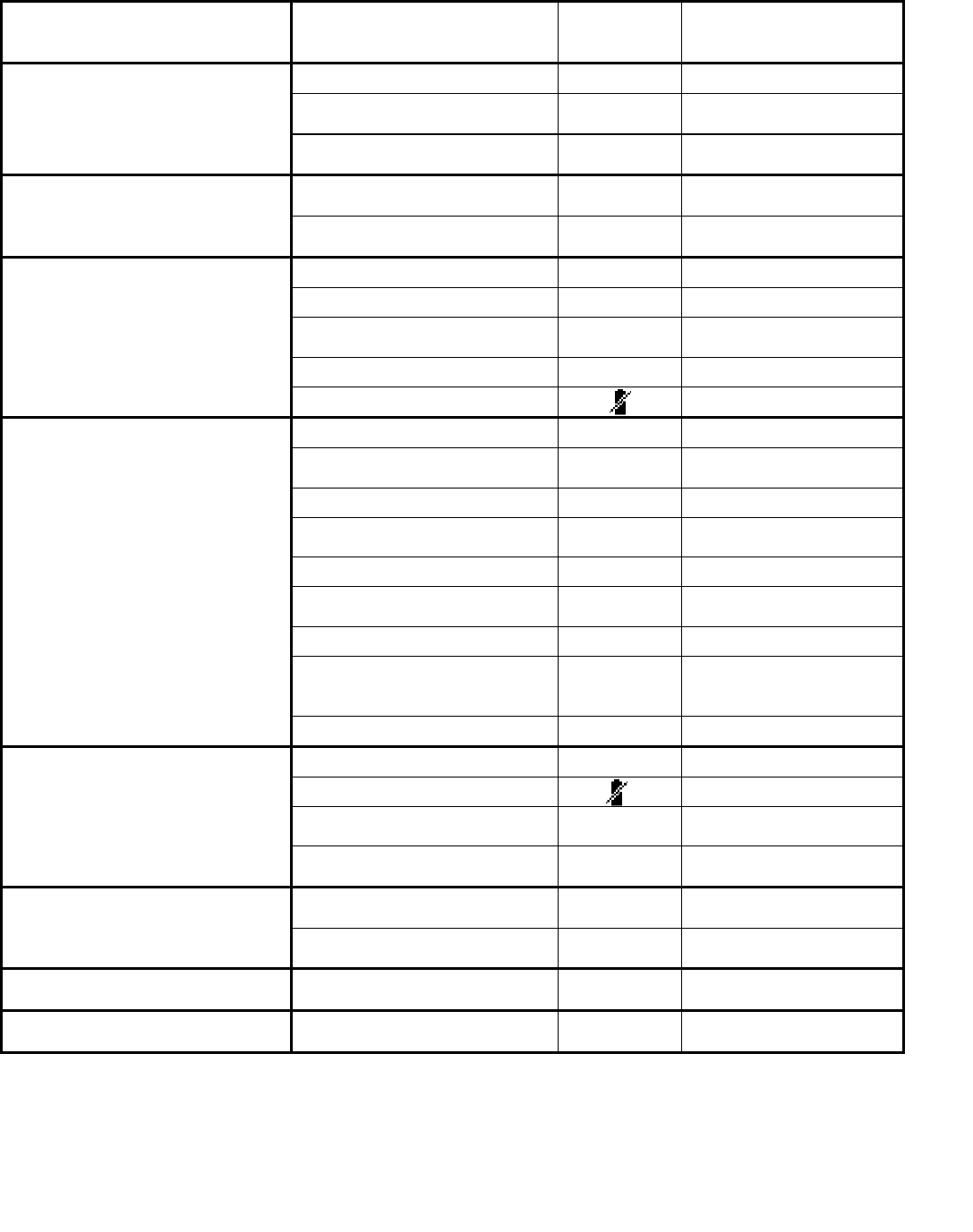
MACHINE TROUBLESHOOTING
86037660 CHARIOT 01/03/08 4-30
PROBLEM CAUSE ERROR
CODE
DELUXE SOLUTION
Circuit breaker tripped (Basic) Reset circuit breaker
Faulty vacuum circuit or switch 7700 Check wires, connections
and switch
Vacuum motor does not run, or
runs slowly
Worn vacuum motor brushes Replace brushes, check
commutator
Faulty circuit or actuator
(Deluxe) Check wires, connectors
and actuator
Squeegee will not go up/down
Faulty cables or pulleys Repair/replace cables or
pulleys
Debris caught in scrub brushes Remove debris
Worn brushes or pads Replace brushes or pads
Improper detergent, brush or
pad used Contact equipment or
application specialists
Low scrub brush down pressure Increase brush pressure
Poor scrubbing performance
Low battery charge Charge batteries
Solution tank empty Fill solution tank
Solution flow turned off or set
too low Turn on or increase flow
setting
Solution strainer plugged Clean solution strainer
Solution system plumbing
obstructed Clear obstruction from
plumbing
Pump obstructed Clean or replace pump
Solution solenoid valve
obstructed or stuck Clean or replace valve
Solution shut-off valve is closed Open shut-off valve
Faulty pump circuit or pump Check wiring, connections,
control broad (Basic) and
pump.
Little or no solution flow to the floor
Faulty solenoid Check solenoid valve
Circuit breaker(s) tripped 7600 Reset circuit beaker(s)
Low battery charge Charge battery
Fault brush circuit or motor 7600 Check wires, connections
and motor
Brush motors do not run, or run
slowly
Worn brush motor brushes Replace brushes, check
commutator
Actuator circuit breaker tripped
(Basic) Reset breaker Scrub deck will not go down/up
Faulty actuator circuit or
actuator Check wires, connections
and actuator
Scrub deck goes down, then raises No brushes or pad drivers on
machine 9000 Install brushes or pad
drivers
Error code not listed is displayed Controller detects electrical
problem Contact service technician

MACHINE TROUBLESHOOTING – DELUXE CONTROLLER FAULT CODES
86037660 CHARIOT 05/27/08
4-31
ERROR
CODE
DELUXE PROBLEM SOLUTION
None LCD display on, but incomplete Disconnect batteries and wait 1 minute before
re-applying power.
0A01 Power down error Disconnect batteries and wait 1 minute before
re-applying power.
0204 Memory corrupt Replace controller.
All 080_ codes Throttle wiring Check for short or open circuits in throttle
wiring.
All 140 _ Codes Check for short circuit between B+ and
traction output.
All 310_ Codes
Possible short circuit of motors, auxiliary
outputs (headlight, recycle pump, or back-
up alarm), wiring or damaged controller
Check for short circuits. If code is present
after short circuits are repaired, replace
controller.
7500 LCD module communications timeout Wiring fault on 6-way serial link between
controller and display.
7501 LCD module settings corrupt Disconnect batteries and wait 1 minute before
re-applying power.
All 760_ Codes Brush motor or brush circuit fault Check for short or open circuits in brush
motors or wiring.
All 770_ Codes Vacuum motor or vacuum circuit fault Check for short or open circuits in vacuum
motor(s) or wiring.
7800 Traction motor open circuit fault Check for open circuit on propel motor or
wiring.
7801 Traction motor overcurrent error Check for short circuit on propel motor or
wiring.
7802 Traction motor in power foldback state Propel motor current has exceeded current
limit for the foldback time.
All 790_ Codes Emergency stop error E-stop input active or wiring fault.
9000 Brush current requirement not satisfied
Check that brushes or pads are installed.
Check for open circuit in scrub lift actuator,
circuit breaker or wiring.

MACHINE TROUBLESHOOTING- CONTROLLER FAULT CODES
86037660 CHARIOT 05/27/08 4-26
4-32
PROPEL CIRCUIT BOARD TROUBLESHOOTING
Curtis 1228 LED DIAGNOSTICS- Basic and Cylindrical
During normal operation, with no faults present, the status LED is steadily on.
If the controller detects a fault, the status LED provides two types of information.
First, it displays a slow flash (2 Hz) or a fast flash (4 Hz) to indicate the
severity of the fault. Slow-flash faults are self-clearing; as soon as the fault is
corrected, the vehicle will operate normally. Fast-flash faults (“.” in Table 2) are
considered to be more serious in nature and require that the key switch be cycled
to resume operation after the fault is corrected.
After the severity indication has been active for 10 seconds, the status
LED flashes a 2-digit fault identification code continuously until the fault is
corrected. For example, code “1,4”—low battery voltage—appears as: one LED flash, followed by a pause, then 4 LED
flashes, and then repeats.
LED
CODE PROGRAMMER LCD
DISPLAY EXPLANATION POSSIBLE CAUSE
1,1
THERMAL CUTBACK over-/under-
temperature cutback
1. Temperature >92°C or < -25°C.
2. Excessive load on vehicle.
3. Operation in extreme environments.
4. Electromagnetic brake not releasing.
1,2
THROTTLE FAULT 1 throttle fault
1. Throttle input wire open or shorted.
2. Throttle pot defective.
3. Wrong throttle type selected.
1,3
SPD LIMIT POT FAULT
speed limit pot fault
1. Speed limit pot wire(s) broken or shorted.
2. Broken speed limit pot.
1,4
LOW BATTERY VOLTAGE
battery voltage too low
1. Battery voltage <17 volts.
2. Bad connection at battery or controller.
1,5
OVERVOLTAGE
battery voltage too high
1. Battery voltage >36 volts.
2. Vehicle operating with charger attached.
3. Intermittent battery connection.
2,1
MAIN OFF FAULT
main contactor driver
Off fault
1. Main contactor driver failed open.
2,3
MAIN CONT FLTS
main contactor fault
1. Main contactor welded or stuck open.
2. Main contactor driver fault.
3. Brake coil resistance too high.
2,4
MAIN ON FAULT
main contactor driver
On fault
1. Main contactor driver failed closed.

MACHINE TROUBLESHOOTING- CONTROLLER FAULT CODES
86037660 CHARIOT 05/27/08
4-33
LED
CODE PROGRAMMER LCD
DISPLAY EXPLANATION POSSIBLE CAUSE
3,1
PROC/WIRING FAULT
HPD fault present for
>10 sec.
1. Misadjusted throttle.
2. Broken throttle pot or throttle mechanism.
3,2
BRAKE ON FAULT
brake On fault
1. Electromagnetic brake driver shorted.
2. Electromagnetic brake coil open.
3,3
PRECHARGE FAULT
precharge fault
1. Low battery voltage.
2. KSI and throttle turned on at same time.
3,4
BRAKE OFF FAULT
brake Off fault
1. Electromagnetic brake driver open.
2. Electromagnetic brake coil shorted.
3,5
HPD
HPD (High Pedal
Disable) fault
1. Improper sequence of throttle and KSI,
push, or inhibit inputs.
2. Misadjusted throttle pot.
4,1
CURRENT SENSE FAULT
current sense fault
1. Short in motor or in motor wiring.
2. Controller failure. *
4,2
HW FAILSAFE
motor voltage fault
(hardware
1. Motor voltage does not correspond to throttle
request.
2. Short in motor or in motor wiring.
3. Controller failure. *
4,3
EEPROM FAULT
EEPROM fault
1. EEPROM failure or fault.
4,4
POWER SECTION FAULT
power section fault
1. EEPROM failure or fault.
2. Short in motor or in motor wiring.
3. Controller failure.

86037660 CHARIOT 11/09/06
PARTS
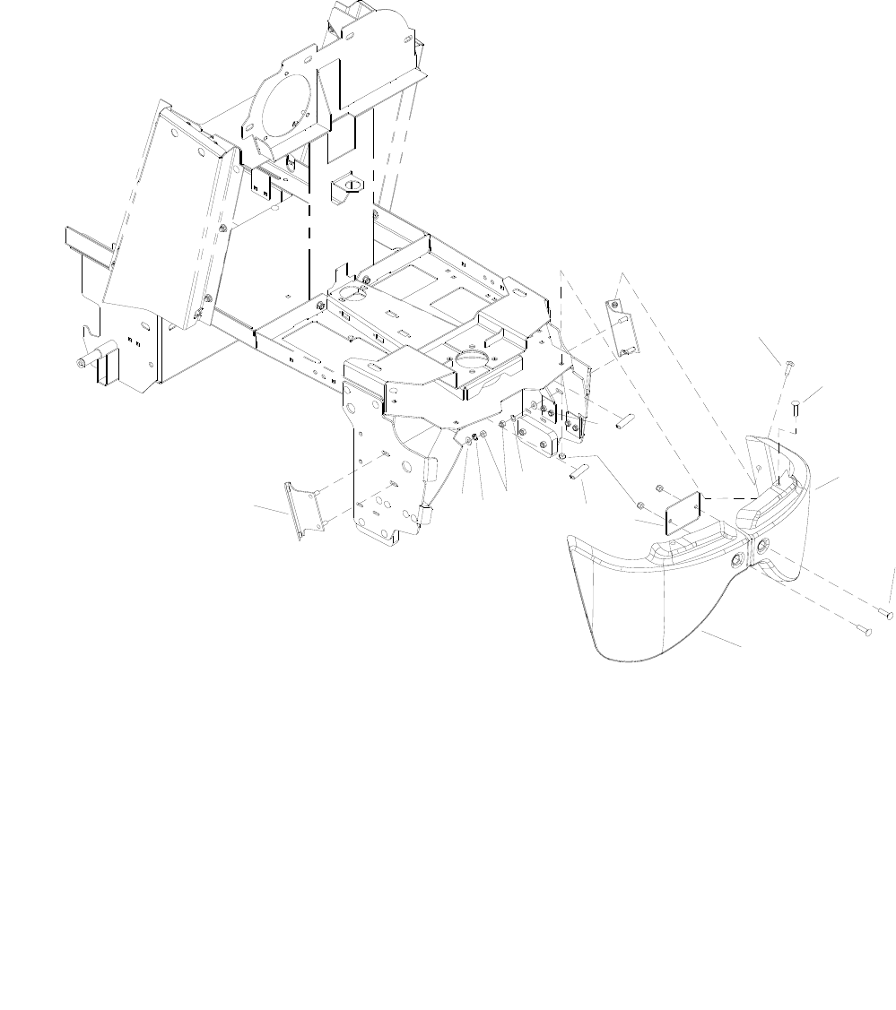
BUMPER
86037660 CHARIOT 11/09/06
5-1
10
7
9
3
4
1
875
1
2
6
10
11

BUMPER
86037660 CHARIOT 11/09/06 5-2
REF PART NO. PRV NO. QTY DESCRIPTION SERIAL NO.
FROM NOTES:
1 86276890 70752 6 SCR, 5/16-18X3/4 PTHMS SS
2 86007070 70849 2 SCR, 5/16-18X1.00 PPHMS SS
3 86063230 140813 1 BUMPER, LEFT
4 86063240 140814 1 BUMPER, RIGHT
5 86071020 140783 1 BRKT, FRONT BUMPER
6 86270830 57023 4 NUT, 5/16-18 HEX NYLOCK SS
7 86010670 87029 4 WASHER, 5/16 FLAT SS
8 86070730 140729 2 BRKT, BUMPER MOUNT, SIDE
9 86197040 57264 4 NUT, 5/16-18 HEX ACORN PLTD
10 86279130 87083 4 WASHER, 5/16 SPLIT LOCK PLTD
11 86251750 67602 2 RISER, BUMPER
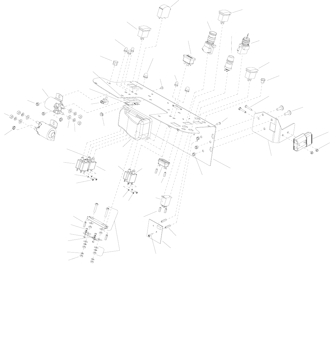
CONTROL PANEL-BASIC-CYLINDRICAL
86037660 CHARIOT 06/25/07
5-3
44
28 35
15
38
33
34
36
39
17
45
42
41
43
2
3
1
8
9
6
15
22
16
21
5
24
23
26
18
10
31
30
4
29
7
12
14
28
19
17
17
13
11
22
22
22
45 17
26
37
27A
40
32
46
20
27B 25A
25B

CONTROL PANEL-BASIC-CYLINDRICAL
86037660 CHARIOT 09/06/07 5-4
REF PART NO. PRV NO. QTY DESCRIPTION SERIAL NO.
FROM NOTES:
1 86007210 72165 1 SWITCH, DPDT 3-POSITION ROCKER
2 86246980 54201 1 METER, 0-50 AMP DC
3 86008900 80845 2 BOOT, SEAL-PUSH BUTTON 7/16-28
4 86002010 14942 1 BOOT, 3/8 CIRCUIT BREAKER
5 86005560 54199 1 METER, 36V LED BATTERY
6 86007180 72160 1 SWITCH, EMERGENCY STOP
7 86257110 72189 1 SWITCH, 4P3T FIXED POS ROCKER
8 86257280 81371 1 SWITCH, PUSH BUTTON
9 86007190 72161 1 SWITCH KEY DPSTN
10 86007140 72130 1 SWITCH, SPST 2-POSITION ROCKER
11 86257140 72196 1 SWITCH, RESET PB ROUND
12 86273820 70019 2 SCR, 1/4-20 X 1.25 HHCS
13 86277480 70850 3 SCR, 5/16-18 X 1/2 PTHMS SS
14 86008760 80682 1 CONN, 175 DCA GRY W/O TERMS
15 86005810 57245 6 NUT, 1/4-20 HEX NYLOCK SS
16 86070720 140728 1 BRKT, BATT CONN, BASIC
17 86273990 70067 8 SCR, 6-32 X 3/8 PPHMS
18 86078150 61475 1 PANEL, BASIC
19 86271840 57285 3 NUT, 5/16-18 HEX NYLOCK THIN SS
20 86005710 57105 2 NUT, 1/4-20 HEX W/STAR WASHER
21 86003250 27944 1 CIRCUIT BOARD, SOL FLOAT WIRED
22 86255900 73538 8 STANDOFF, 6-32 X 5/8 HEX NYL
23 86251410 67506 1 RELAY, 15A 36V MINI
24 86005530 54154 1 METER, 12-48 VDC LED HOUR
25A 86001910 14606 1 BREAKER, 30A 50VDC CIRCUIT *(1) WAS 14607, 25A
25B 86001920 14607 1 BREAKER, 25A 50VDC CIRCUIT *(16) CYLINDRICAL ONLY
26 86002000 14717 2 BREAKER, 3 AMP
27A 86002760 270092 1 CONTROLLER, CHAIN DRIVE BASIC FOR 29269-DRIVE
UNIT (CHAIN)
27B 86027740 27911 1 CONTROLLER, GEAR DRIVE BASIC FOR 29276- DRIVE
UNIT (GEAR)
28 86005700 57104 10 NUT, 10-32 W/STAR WASHER PLTD
29 86271790 57256 2 NUT, 6-32 HEX BRASS
30 86276250 70615 2 SCR, 6-32 X 3/8 SRHMS BR
31 86008190 73988 1 SHUNT, DC AMM. 15 AMP, 50 MV
32 86229770 140805 1 BLOCK, SHUNT MOUNT
33 86001730 140804 2 BREAKER, 18A 250VAC, 50VDC
34 86001910 14606 1 BREAKER, 30A 50VDC CIRCUIT
35 86279130 87083 4 WASHER, 5/16 SPLIT LOCK PLTD
36 86271120 57125 4 NUT, 5/16-18 BRASS
37 86223740 70872 4 SCR, 1/4-20 X .59 PPHMS SS C
38 86006370 67315 2 RELAY, 36VDC 100AMP HVY DUTY
39 86010670 87029 4 WASHER, 5/16 FLAT SS
40 86249290 62283 1 PLATE, METER RETAINING
41 86237830 35264 1 GASKET, AMP METER
42 86242110 48088 1 KNOB, .90 OD X .25 COLLET
43 86002010 14942 3 BOOT, 3/8 CIRCUIT BREAKER
44 86006310 66335 1 POTENTIOMETER, 50K OHMS
45 86279300 87134 4 WASHER, #6 LOCK
46 86010630 87013 2 WASHER, 1/4 ID X 5/8 OD SS
*SEE SERIAL NUMBER PAGE.
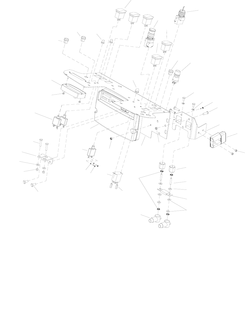
CONTROL PANEL-DELUXE
86037660 CHARIOT 02/21/06
5-5
39
38
28
19
23
14
1
22
24
25
20
21
7
10
9
13
6
4
27
17
5
1
33
11
29
18
12
15
2
3
16
8
31
32
34
30
18
35
36
37
40
SUPPLED WITH
CONTROLLER
26A
26B

CONTROL PANEL-DELUXE
86037660 CHARIOT 02/21/09 5-6
REF PART NO. PRV NO. QTY DESCRIPTION SERIAL NO.
FROM NOTES:
1 86007520 730142 3 SWITCH, SPDT 3-POSITION MOM
2 86007180 72160 2 SWITCH, EMERGENCY STOP
3 86007190 72161 1 SWITCH KEY DPST
4 86007140 72130 1 SWITCH, SPST 2-POSITION ROCKER
5 86257140 72196 2 SWITCH, RESET PB ROUND
6 86257280 81371 1 SWITCH, PUSH BUTTON
7 86273820 70019 2 SCR, 1/4-20 X 1.25 HHCS
8 86273830 70020 2 SCR, 1/4-20 X 1/2 HHCS SS
9 86010780 87162 2 WASHER, 1/4 SPLIT LOCK PLTD
10 86277480 70850 3 SCR, 5/16-18 X 1/2 PTHMS SS
11 86070670 140722 1 BRKT, BATTERY CONNECTOR
12 86008760 80682 1 CONN, 175 DCA GRY W/O TERMS
13 86005810 57245 2 NUT, 1/4-20 HEX NYLOCK SS
14 86271840 57285 3 NUT, 5/16-18 HEX NYLOCK THIN SS
15 86255910 73659 2 STANDOFF, 1/4-20 X 1.0 HEX INS
16 86006850 70393 2 SET SCR, 1/4-20 X 1.25L
17 86008790 80687 1 FUSE, 125 AMP
18 86010630 87013 6 WASHER, 1/4 ID X 5/8 OD SS
19 86008920 80889 2 BOOT, RUBBER TERM. ISOLATOR
20 86005710 57105 4 NUT, 1/4-20 HEX W/STAR WASHER
21 86274410 70195 2 SCR, 10-32 X 1.25 PPHMS SS
22 86078160 61476 1 PANEL, DELUXE
23 86255900 73538 2 STANDOFF, 6-32 X 5/8 HEX NYL
24 86251410 67506 1 RELAY, 15A 36V MINI
25 86270990 57090 2 NUT, 10-32 HEX NYLOCK SS
26A 86002770 270095 1 CONTROLLER, CHAIN DRIVE DELUXE FOR 29269
DRIVE UNIT,
CHAIN
26B 86292580 - 1 CONTROLLER, GEAR DRIVE DELUXE FOR 29276
DRIVE UNIT,
GEAR
27 86271910 57295 2 NUT, 5/16-18 FLEXLOCK
28 86010670 87029 2 WASHER, 5/16 FLAT SS
29 86068850 140219 2 BRKT, CABLE ATTACH
30 86001730 140804 2 BREAKER, 18A 250VAC, 50VDC
31 86270920 57049 2 NUT, 6-32 HEX NYLOCK SS
32 86005570 54200 1 MODULE, LCD DELUXE
33 86007480 730124 1 SWITCH ASM, SEALED PUSHBUTTON
34 86002010 14942 2 BOOT, 3/8 CIRCUIT BREAKER
35 86257130 72195 1 SWITCH, ON –TOUCH PB ROUND
36 86001260 140218 1 BOOT, DB 3/8-27 UNS 2B *(11) WAS 80845
37 86001950 14666 1 BREAKER, 30A W/AUX CONTACT *(11) WAS 14606
38 86279300 87134 2 WASHER, #6 LOCK
39 86273990 70067 2 SCR, 6-32 X 3/8 PPHMS
40 86275760 70540 2 SCR, 5/16-18 X 1 HHCS GR8 PLTD
*SEE SERIAL NUMBER PAGE.
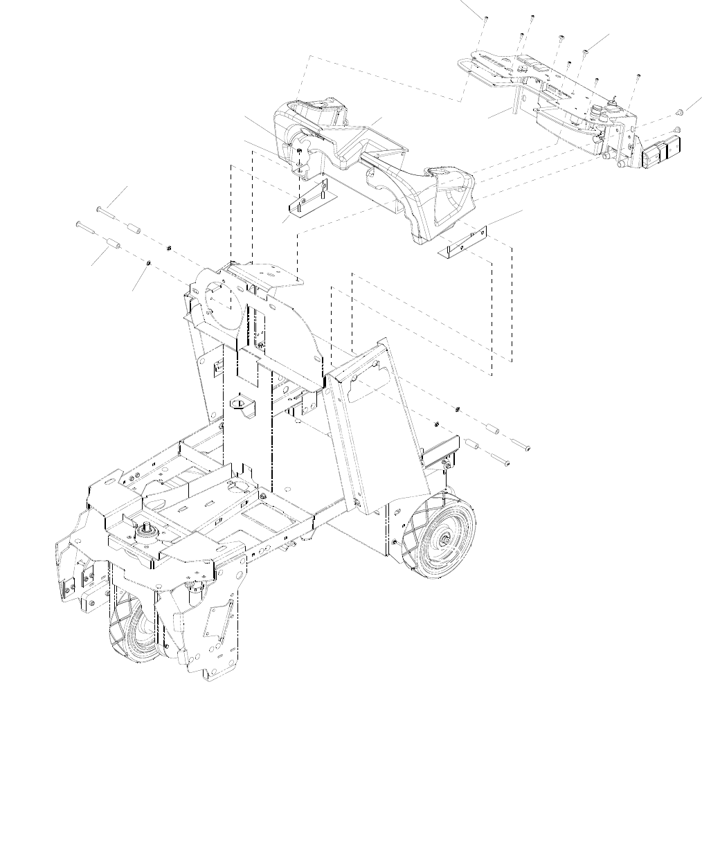
CONTROL PANEL HOUSING
86037660 CHARIOT 11/09/06
5-7
2
3
3
65
11
4
9
10
8
7
1

CONTROL PANEL HOUSING
86037660 CHARIOT 02/20/07 5-8
REF PART NO. PRV NO. QTY DESCRIPTION SERIAL NO.
FROM NOTES:
1 86005810 57245 4 NUT, 1/4-20 HEX NYLOCK SS
2 86290540 - 6 SCR, 10-32 X 1/2 TORX SS BLK NP
3 86277480 70850 6 SCR, 5/16-18 X1/2 PTHMS SS
4 86070710 140726 1 BRKT, LEFT CONSOLE MOUNT
5 86237900 35278 3 GASKET, .125 X .25W X 23L
6 86031730 270084 1 CONSOLE
7 86070700 140725 1 BRKT, RIHGT CONSOLE MOUNT
8 86279750 87252 4 WASHER, RET, PUSHNUT, 5/16 BOLT
9 86089650 78524 4 TUBE, 5/8 OD X .357 ID X 1.57
10 86277420 70841 4 SCR, 5/16-18 X 2.5 PTHMS SS
11 86010630 87013 4 WASHER, 1/4 ID X 5/8 OD SS
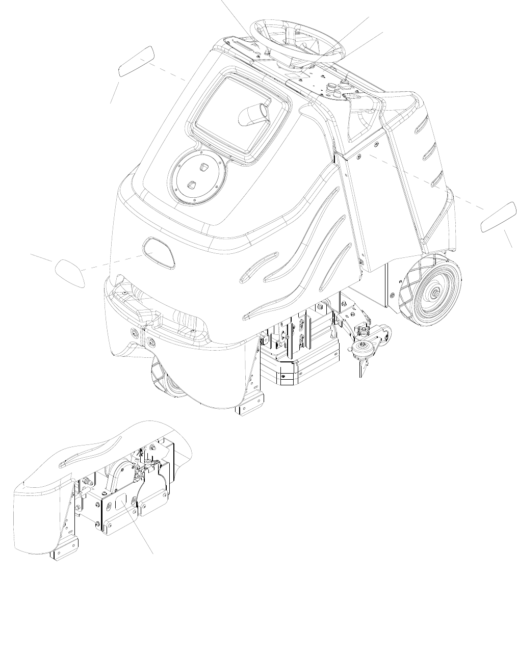
DECAL
86037660 CHARIOT 01/05/09
5-9
4
3
2
1
7
5
9

DECAL
86037660 CHARIOT 01/06/09 5-10
REF PART NO. PRV NO. QTY DESCRIPTION SERIAL NO.
FROM NOTES:
1 86004970 50990 1 LABEL, WINDSOR LOGO DOMED
2 86244740 501222 1 DECAL, CHARIOT, ISCRUB RT WAS 500884
3 86244750 501223 1 DECAL, CHARIOT, ISCRUB LT WAS 500885
4A 86244200 500883 1 LABEL, PANEL BASIC RIGHT
4B 86244180 500881 1 LABEL, PANEL DLX RIGHT
5A 86244190 500882 1 LABEL, PANEL BASIC LEFT
5B 86244170 500880 1 LABEL, PANEL DLX LEFT
6 OPEN
7 86243990 500780 1 LABEL, COVER PANEL
8 OPEN
9 86298970 - 1 LABEL, CLEAN BRUSHES AND DECK CYLINDRICAL
ONLY
NOTE: See “SAFETY LABEL LOCATION” page for safety label information.
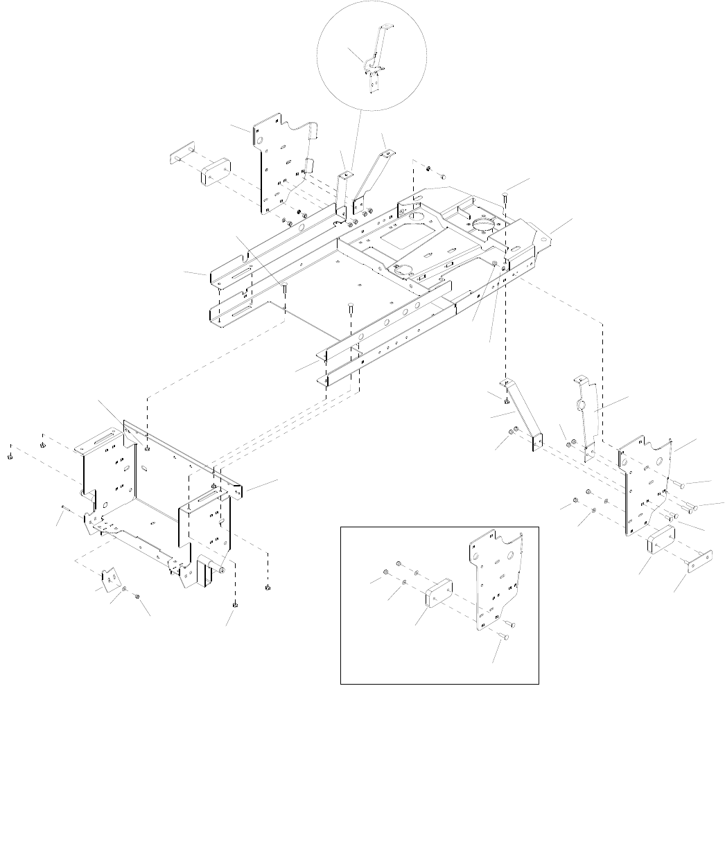
FRAME-LOWER
86037660 CHARIOT 03/04/08
5-11
8
19 20
18
21
2A
3
1
5
7
6
11
4
4
8
17
16
15
8
8
4
4
9
10
8
8
14
13
4
22
13
8
14
12
2B

FRAME-LOWER
86037660 CHARIOT 01/03/08 5-12
REF PART NO. PRV NO. QTY DESCRIPTION SERIAL NO.
FROM NOTES:
1 86070750 140731 1 BRKT, TIP BAR LEFT
2A 86071130 140812 1 BRKT, TIP BRACE, LEFT, REAR CYLINDRICAL
ONLY
2B 86303720 - 1 BRKT, BRACE, LT. REAR SOL DISK ONLY
3 86070760 140733 1 BRKT, TIP BRACE, LEFT
4 86276070 70593 16 SCR, 5/16-18 X 3/4 CARRIAGE SS
5 86092500 34428 1 FRAME, MAIN
6 86197040 57264 4 NUT, 5/16-18 HEX ACORN PLTD
7 86279130 87083 4 WASHER, 5/16 SPLIT LOCK PLTD
8 86270830 57023 16 NUT, 5/16-18 HEX NYLOCK SS
9 86071120 140811 1 BRKT, TIP BRACE, LEFT, REAR
10 86071430 140863 1 BRKT, BRACE RIGHT FRONT
11 86070740 140730 1 BRKT, LINKAGE, RIGHT
12 86277470 70848 4 SCR, 5/16-18 X 1.5 CARRIAGE SS
13 86064300 140790 2 PAD, TIPPING BAR
14 86010670 87029 4 WASHER, 5/16 FLAT SS
15 86091420 05251 1 AXLE, REAR WELDMENT
16 86088760 75458 1 TRAY, SLIDE, LEFT
17 86088750 75457 1 TRAY, SLIDE, RIGHT
18 86079290 620097 2 PLATE, REAR COVER ADJ *(6)
19 86010630 87013 4 WASHER, 1/4 ID X 5/8 OD SS *(6)
20 86271870 57290 4 NUT, 1/4-20 HEX NYLOCK THIN SS *(6)
21 86276950 70772 4 SCR, 1/4-20 X 3/4 CARRIAGE SS *(6)
22 86079320 620101 2 PLATE, PAD RETAINER *(7)
* SEE SERIAL NUMBER PAGE.
** CALL MANUFACTURER FOR SERIAL NUMBER
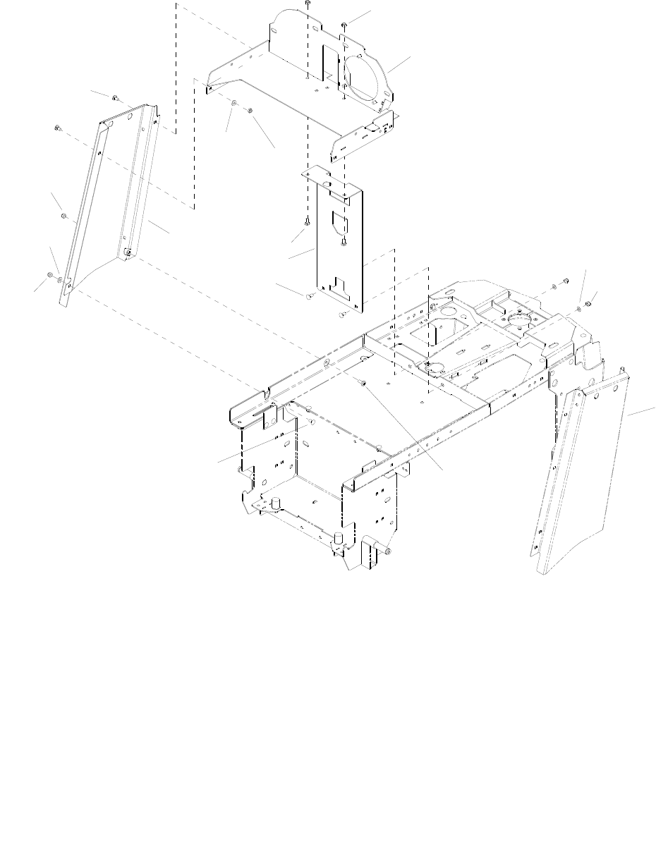
FRAME-UPPER
86037660 CHARIOT 11/09/06
5-13
2
SEE SQUEEGE
1
2
3
LIFT GROUPS
2
4
12
53
6
3
1
2
7
3

FRAME-UPPER
86037660 CHARIOT 11/09/06 5-14
REF PART NO. PRV NO. QTY DESCRIPTION SERIAL NO.
FROM NOTES:
1 86010670 87029 5 WASHER, 5/16 FLAT SS
2 86270830 57023 8 NUT, 5-16-18 HEX NYLOCK SS
3 86276070 70593 7 SCR, 5-16-18 X 3/4 CARRIAGE SS
4 86091750 140727 1 BRKT, HORIZ ELECT
5 86073500 270090 1 BRKT, SIDE CHANNEL L
6 86083080 66437 1 PLATE, VERT BEARING SUPPORT
7 86277460 70847 1 SCR, 5/16-18 X 5/8 BSHCS SS
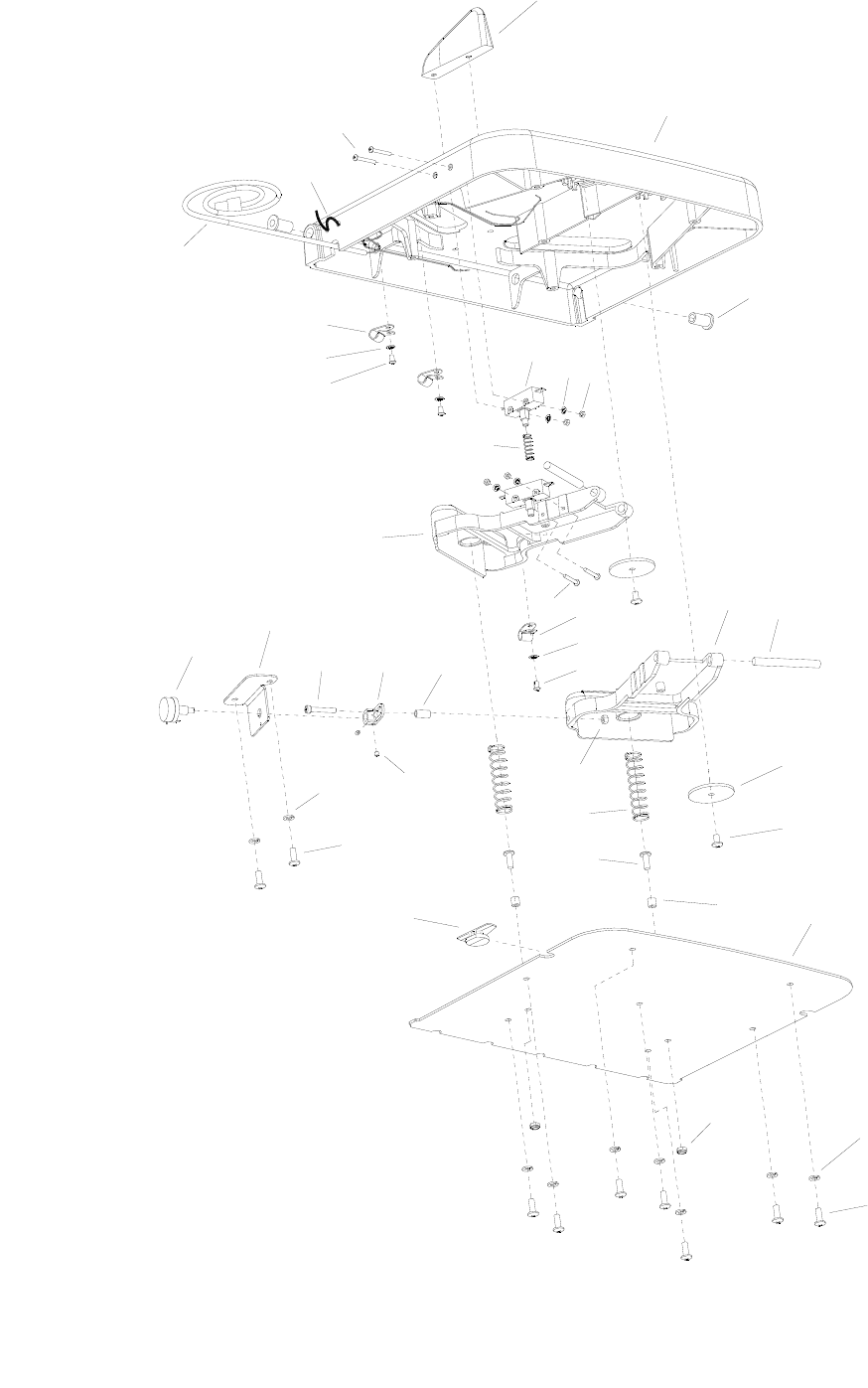
PEDAL PLATFORM
86037660 CHARIOT 10/04/07
5-15
32
31
12
11
10
20
17
17
9
1
2
3
456
7
8
9
10
11
12
13
14
15
16
17
18 19
20
21
22
23
24
25
26 27
28
29
30

PEDAL PLATFORM
86037660 CHARIOT 11/09/06 5-16
REF PART NO. PRV NO. QTY DESCRIPTION SERIAL NO.
FROM NOTES:
1 86217650 34432 1 DIVIDER
2 86222700 34429 1 PLATFORM
3 86216380 140713 2 BUSHING, 8MM X 10LG CLY
4 86007110 72123 2 SWITCH, 25A SPST 125-250V SNAP
5 86279720 87248 4 WASHER, M4 INT STAR
6 86272040 57503 4 NUT, M3.5 X 2.8 HEX
7 86223580 67502 2 ROD, PIVOT, 8.5MM X 77
8 86222520 34431 1 PEDAL, BRAKE
9 86277390 70836 4 SCR, M3.5 X 38 PHMS
10 86233170 20054 3 CLAMP, 3/8 NYLON UL/CSA
11 86279730 87249 4 WASHER, M5 INT STAR
12 86277380 70835 4 SCR, M4.8 X 16 PHTF
13 86222510 34430 1 PEDAL, THROTTLE
14 86254970 730304 2 SPRING, COMP 18MM OD X 83 X 2
15 86222780 620047 2 PLATE, PIVOT
16 86277360 70833 2 SCR, M6 X 10 PH
17 86274340 70179 11 SCR, M6 X 16 PH
18 86224360 730325 2 SPACER 12.7MM ID X 2.78W X 6L
19 86222810 620050 1 PLATE, COVER
20 86279140 87085 9 WASHER, M6 SPLIT LOCK DIN127B
21 86288720 57277 2 NUT, M6 NYLOCK PLATED
22 86250280 66135 1 POTENTIOMETER, 5K OHMS
23 86222790 620048 1 PLATE, THROTTLE
24 86278060 70759 2 SET SCR, M4 X 4MM NP
25 86224350 730305 1 SPACER, 8MM 16L
26 86277370 70834 1 SCR, M5 X 30 SHCS
27 86221850 34433 1 LINK, THROTTLE
28 86218810 23717 1 HARNESS, TWISTER PEDAL
29 86316310 57086 1 NUT, M5 HEX
30 86264920 27049 1 CABLE TIE, 7” UL/CSA
31 86224750 73993 1 SPRING, COMP, .480D X .91 *(16)
32 86223260 66085 1 PLUNGER, PLATFORM SWITCH *(16)
NOTE: Complete platform assembly is available, Part No. 86028310
*SEE SERIAL NUMBER PAGE.
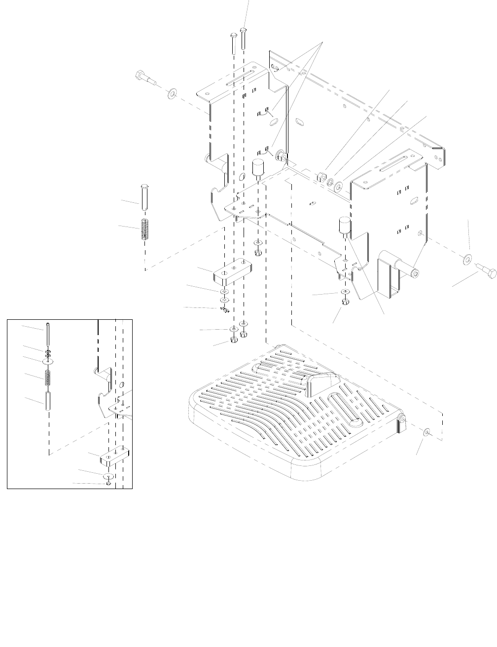
PEDAL PLATFORM
86037660 CHARIOT 11/09/06
5-17
3
9
12
5
20
19
7
8
6
4
14
18
2
11
12
8
17
16
6
5
1
13
14
11
15
10

PEDAL PLATFORM
86037660 CHARIOT 11/09/06 5-18
REF PART NO. PRV NO. QTY DESCRIPTION SERIAL NO.
FROM NOTES:
1 86277430 70843 1 SCR, 1/4-20 X 3.00 SHCS
2 86274690 70258 2 SCR, 5/16-18 X 1.5 HHCS GR5PLT
3 86264920 27049 3 CABLE TIE, 7” UL/CSA
4 86231070 730328 2 BUMPER, 1 X 1.375 RUBBER
5 86010670 87029 5 WASHER, 5/16 FLAT SS
6 86259430 87485 4 M12 FLAT WASHER
7 86010770 87143 2 WASHER, 7/16ID X1D.08 FLT SS
8 86270830 57023 4 NUT, 5/16-18 HEX NYLOCK SS
9 86256470 70852 2 STUB AXLE, M12-1.75 X 45MM
10 86005810 57245 1 NUT, 1/4-20 HEX NYLOCK SS
11 86010810 87191 2 WASHER, 1/4” IDX1.0OD FLAT SS
12 86064480 629993 1 PLATE, SWITCH BASE
13 86286580 47479 1 SPACER, ACTUATOR SWITCH WAS 730334
14 86007780 73576 1 SPRING, COMP .60D X2.0L X .045W
15 86279760 87256 2 WASHER, 1/4 LOCK HICOLLAR PLT
16 86259440 87486 2 WASHER, M12 SPRING LOCK
17 86271190 57142 2 NUT, M12 X 1.75 HEX DIN934 PLT
18 86248920 66487 1 PIN, CLEVIS 1/2 X 2.25 *(16)
19 86278850 80613 2 WASHER, .506 ID X .94D X .064 NYL *(16)
20 86008680 80607 1 COTTER, 1/2” RING *(16)
*SEE SERIAL NUMBER PAGE.
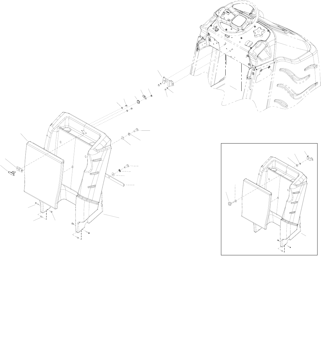
REAR COVER
86037660 CHARIOT 04/16/09
5-19
13
1
2
3
1819
10
7
5
6
14
17A
15
2
3
16 8
9
911 12
4A
21
23
18
22
20
18
4B
17B
17C

REAR COVER
86037660 CHARIOT 04/16/09 5-20
REF PART NO. PRV NO. QTY DESCRIPTION SERIAL NO.
FROM NOTES:
1 86276780 70728 3 SCR, 5/16-18 X 3/4 HHCS SS
2 86279130 87083 5 WASHER, 5/16 SPLIT LOCK PLTD
3 86010670 87029 5 WASHER, 5/16 FLAT SS
4A 86031790 270701 1 COVER, REAR, BASIC
4B 86031780 270082 1 COVER, REAR, DELUXE
5 86005860 57273 2 NUT, 1/4-20 X 12MM HEX BARREL
6 86228980 09152 2 BEARING FLANGED .377ID X .505OD
7 86275870 70556 2 SCR, 1/4-20 X 1.5” PPHMS SS WAS 70697
8 86242140 72193 1 KNOB, 3/8-16 X 1.5
9 86010770 87143 2 WASHER, 7/16ID X 1D X .08FLT SS
10 86248380 66433 1 PAD, FLAT LEANING
11 86005630 57022 1 NUT, 3/8-16 HEX NYLOCK THIN SS
12 86071030 140786 1 BRKT, ASSEMBLY, REAR COVER
13 86010780 87162 2 WASHER, 1/4 SPLIT LOCK
14 86271940 57299 2 NUT, 1/4-20 ACORN SS
15 86006560 70083 2 SCR, 5/16-18 X 1 HHCS SS
16 86066940 140891 1 BAR, COVER
17A 86324660 - 1 REAR COVER, BASIC *(34)
17B 86324320 - 1 REAR COVER, DELUXE *(34)
17C 86324740 - 1 REAR COVER, ORG, DELUXE *(34)
18 86324640 - 1 HANDLE, CAM LATCH *(34)
19 86324760 - 1 PLATE, COVER LATCH *(34)
20 86010630 87013 2 WASHER, 1/4 ID X 5/8 OD SS *(34)
21 86324340 - 1 BRKT, REAR COVER *(34)
22 86005810 57245 2 NUT, 1/4-20 HEX NYLOCK SS *(34)
23 86324650 - 1 PAWL, HANDLE *(34)
*See Serial Number Page

SCRUB BRUSH/PAD DRIVER
86037660 CHARIOT 11/09/06
5-21
5
3
2D
75
6
9
4
8
10D
10B
10A
10C
1
6
9
4
8
5
7
2B
2A
2C

SCRUB BRUSH/PAD DRIVER
86037660 CHARIOT 11/09/06 5-22
REF PART NO. PRV NO. QTY DESCRIPTION SERIAL NO.
FROM NOTES:
1 86000170 02400 2 PAD DRIVER, 12” SD
2A 86000180 02401 2 BRUSH, 12” POLYPROPYLENE SD
2B 86000190 02402 2 BRUSH, 12” NYLON SD
2C 86000200 02404 2 BRUSH, 12” MILD GRIT SD
2D 86283820 02405 2 BRUSH, 12” SUPER AGG SD
3 86005070 51284 1 LOCK, PAD CENTER SNAP, TWO STEP
4 86276590 70695 3 SCR, #12 X 1 PPHSMS SS
5 86276580 70694 1 SCR, 8-32 X 3/4 PTHMS
6 86276600 70696 3 SCR, #10 X 3/4 PTHSMS SS
7 86007910 73817 1 SPRING, EXT .31 D X 2.0 L X .03 W SS
8 86007280 730011 1 SOCKET, DRIVE BRUSH
9 86005940 62852 1 PLATE, BRUSH RELEASE
10A 86283890 02500 2 BRUSH, 24” CYL, H-POLYP
10B 86283900 02501 2 BRUSH, 24” CYL, H-NYLON
10C 86283910 02502 2 BRUSH, 24” CYL, STCD GRIT
10D 86283920 02503 2 BRUSH, 24” CYL, SUP AGR
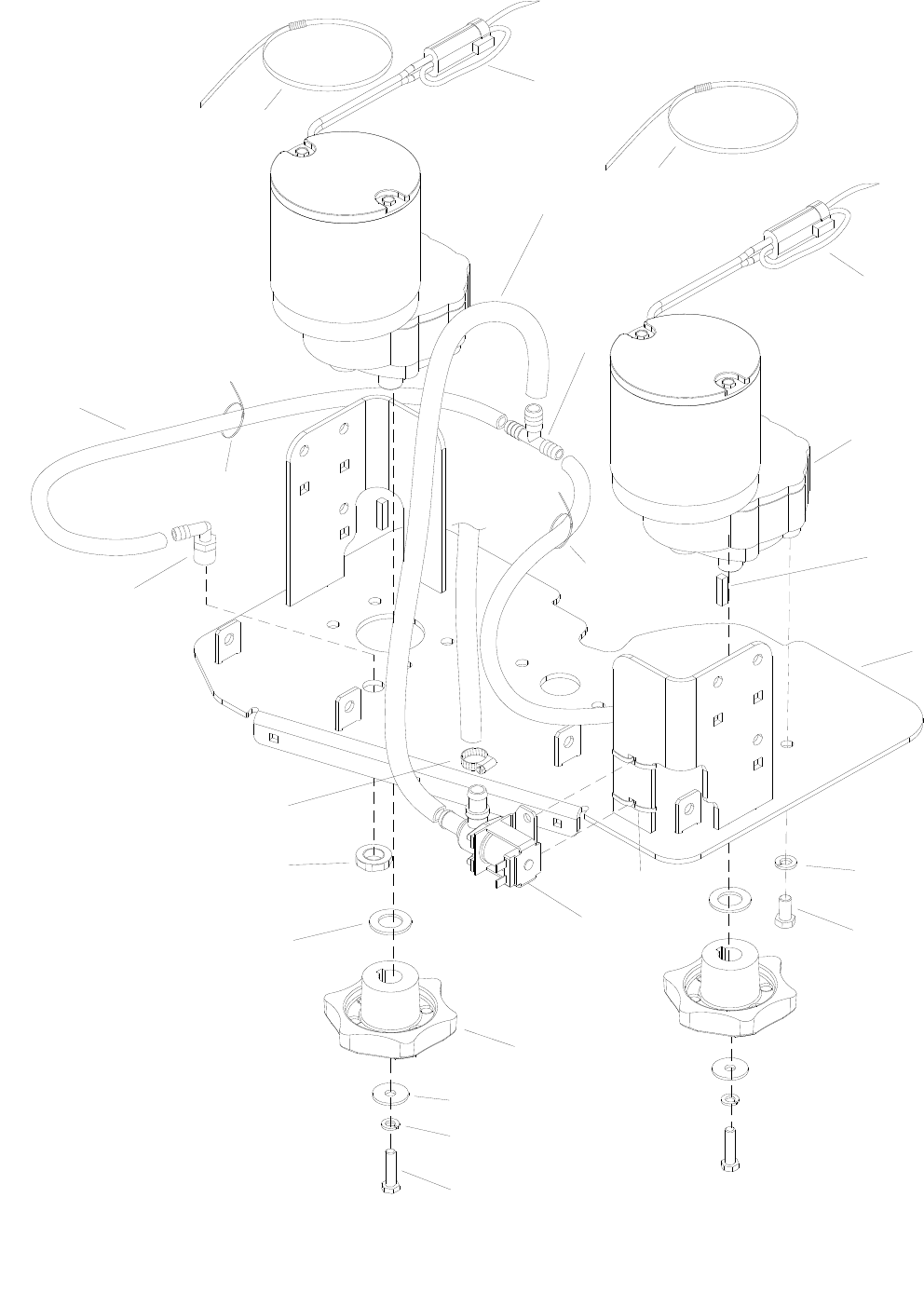
SCRUB DECK – DISK
86037660 CHARIOT 05/11/07
5-23
18
17
14
15
16
12
13
11
10
8
97
6
5
4
3
2
1
FROM
PUMP
8
8
19
19
20
20

SCRUB DECK – DISK
86037660 CHARIOT 05/11/07 5-24
REF PART NO. PRV NO. QTY DESCRIPTION SERIAL NO.
FROM NOTES:
1 86281100 39274 1 HOSE, 1/2ID WIRE BOUND X 8”
2 86003580 34327 1 FITTING, 1/2”X3/8”X3/8” RED
3 86005490 53808 2 MOTOR ASM, 36VDC300RPM GEAR
- 86216200 14739 - BRUSH SET MOTOR 53808
4 86004810 48040 2 KEY, 1/4 SQ X 1.00
5 86093990 730330 1 SCRUBDECK, 24IN
6 86010790 87163 8 WASHER, 3/8 SPLIT LOCK PLTD
7 86276970 70774 8 SCR, 3/8-16 X 3/4 HHCS SS
8 86264920 27049 6 CABLE TIE, 7” UL/CSA
9 86010600 84199 1 VALVE, SOLENOID, 36VDC, 1/2 BARB
- 86003460 29260 - DIAPHRAGM, SRVC PART SLND SERVICE ONLY
- 86136820 47395 - SERVICE SLND SPRG KIT SERVICE ONLY
10 86003420 29220 2 DRIVER, BRUSH SD
11 86279630 87212 2 WASHER, .344IDX1.130DX.09T PLT
12 86279130 87083 2 WASHER, 5/16 SPLIT LOCK PLTD
13 86007020 70673 2 SP SCR, 5/16-18 X 1.25 HHCS SS NP
14 86279530 87173 2 WASHER, .765IDX1.310DX.09T SS
15 86271830 57283 2 NUT, 3/8 NPT PLASTIC
16 86233150 20042 1 CLAMP, 3/8 HOSE (D-SLOT)
17 86004470 40043 2 HOSEBARB, 3/8MPT X 3/8 90D
18 86281310 39326 2 HOSE, 3/8ID WIREBOUND X 8”
19 86002830 27196 2 CABLE TIE, .375 X 24.7
20 86264940 27051 2 CABLE TIE, 11.38” UL/CSA
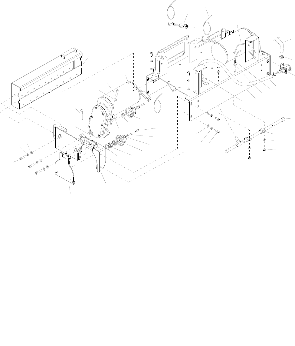
SCRUB DECK – CYLINDRICAL
86037660 CHARIOT 08/14/07
5-25
5-25
33
13
12
7
1
6
9
11
10
32
2
6
FROM PUMP
3
4
5
8
2
31
25
30
17
14
21
22
15
19
18
16
20
23
29
24
27
26
25
28
34

SCRUB DECK - CYLINDRICAL
86037660 CHARIOT 08/14/07 5-26
REF PART NO. PRV NO. QTY DESCRIPTION SERIAL NO.
FROM NOTES:
1 86260400 880212 2 WIRE ASM, REV POLARITY JUMPER
2 86273750 70011 4 SCR, 1/4-20 X 5/8 HHCS SS NP
3 86233150 20042 2 CLAMP, 3/8 HOSE (D-SLOT)
4 86010600 84199 4 VALVE, SOLENOID, 36VDC, 1/2 BARB
5 86282330 39715 1 HOSE, 5/8 ID WIREBOUND X 16”
6 86010630 87013 4 WASHER, 1/4 ID X 5/8 OD SS
7 86092520 34441 1 FRAME, SCRUB DECK 24
8 86233270 20093 2 CLAMP, 7/8” WORM GEAR SS
9 86033230 54203 1 MANIFOLD, SOLUTION DELIVERY
10 86233070 20003 2 CLAMP, 1/2 DIA THINWALL CONDUIT
11 86005810 57245 2 NUT, 1/4-20 HEX NYLOCK SS
12 86277530 70861 12 SCR, M8 X 1.25 X 20 LG BSHCS SS
13 86010670 87029 12 WASHER, M8 FLAT DIN125A PLT
14 86219440 41487 2 HUB, TRI-STAR BRUSH DRIVE
15 86279780 87488 2 WASHER, M16 SMALL OD FLAT PLTD
16 86004820 48041 2 KEY, 3/16 SQ X 7/8 CRS
17 86277870 70854 4 SCREW, M6-1.0 X 20 LG BHSCS SS
18 86279140 87085 4 WASHER, M6 SPLIT LOCK DIN127B
19 86279770 87487 4 WASHER, M6 LARGE OD FLAT PLTD
20 86219450 41488 2 HUB, TRI-STAR BRUSH IDLER
21 86228960 09149 4 BEARING, BALL 15MM X 28MM X 7W
22 86223520 67598 2 RING, 28MM INTERNAL SNAP
23 86219290 34418 2 HOUSING, SCRUB PLUS DRIVE
24 86217710 29268 2 DOOR, CYLINDRICAL BRUSH
25 86277880 70855 8 SCREW, M8-1.25 X 35 LG SHCS SS
26 86137310 87098 6 WASHER, M8 SPLIT LOCK
27 86279790 87489 6 WASHER, M8 (THICK) FLAT PLTD
28 86242120 48090 2 KNOB, 1.0 OD X 5-16-18
29 86277150 70797 2 SCR, 5-16-18 X 2 BSHCS SS
30 86222330 57504 2 NUT, M8 X 1.25 HEX JAM SS
31 86222110 53267 2 MOTOR, SP BRUSH DRIVE, 36V, 3/4HP
- 86001360 140394 - BRUSH SET SRVC ONLY
- 86218170 35369 - GASKET, GEARBOX
32 86092840 41535 1 HOPPER, CYL, DECK
33 86279130 87083 12 WASHER, 5/16 SPLIT LOCK PLTD
34 86264940 27051 3 CABLE TIE, 11.38” UL/CSA
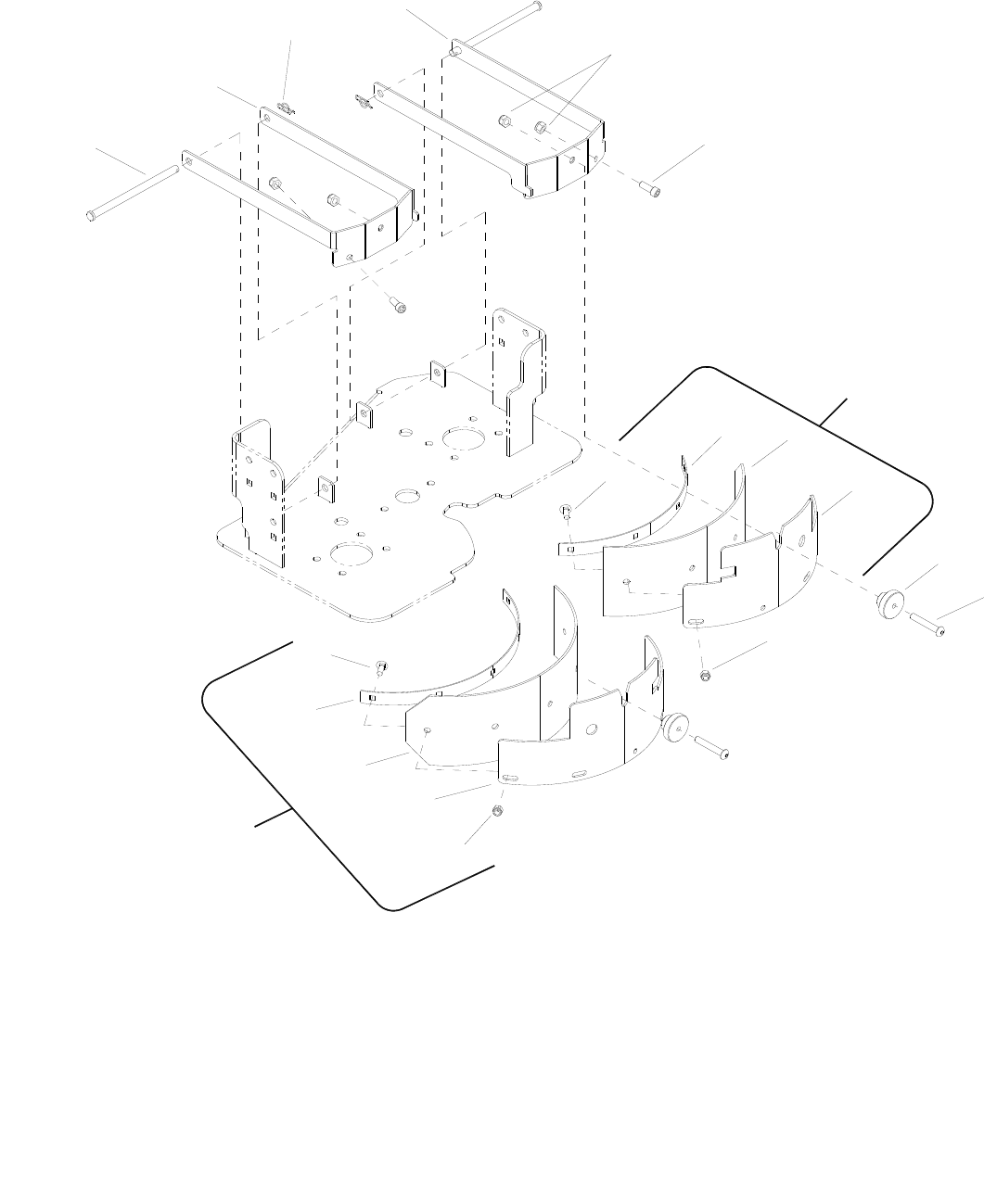
SCRUB DECK AQUA-MIZER™
86037660 CHARIOT 11/09/06
5-27
2
8
7
6
3
4
9
9
10
12
3
1
16
15
14
13
17
18
11B
11A
5A
5B

SCRUB DECK AQUA-MIZER™
86037660 CHARIOT 10/20/11 5-28
REF PART NO. PRV NO. QTY DESCRIPTION
SERIAL NO.
FROM NOTES:
1 86270830 57023 4 NUT, 5/16-18 HEX NYLOCK SS
2 86277050 70782 2 SCR, 5/16-18 X 3/4 SHCS
3 86276950 70772 9 SCR, 1/4-20 X 3/4 CARRIAGE SS
4 86066430 140747 1 BAND, RIGHT AQUAMIZER
5A 86001540 140753 1 BLADE, AQUAMIZER, 12IN RGT
5B 86283550 140939 1 BLADE, AQMZR 12 RT URETHANE
6 86071000 140779 1 BRKT, AQUAMIZER BLADE, RGT
7 86219690 48080 2 KNOB, 1.5 OD X 5/16-18
8 86277230 70815 2 SCR, 5/16-18 X 2.25 BSHCS SS
9 86005810 57245 9 NUT, 1/4-20 HEX NYLOCK SS
10 86070990 140778 1 BRKT, AQUAMIZER BLADE, LEFT
11A 86001520 140752 1 BLADE, AQUAMIZER, 12IN LEFT
11B 86283560 140940 1 BLADE, AQMZR 12 LT URETHATNE
12 86066420 140746 1 BAND, LEFT AQUAMIZER
13 86272540 66465 2 PIN, CLEVIS, 3/8 X 6.12, PLTD
14 86091800 140776 1 BRKT, AQUAMIZER MTG, LEFT
15 86008670 80606 2 COTTER, 3/8” RING
16 86091790 140774 1 BRKT, AQUAMIZER MTG, PIVOT
17 86024990 47456 - AQUAMIZER RIGHT ASM. CHARIOT
18 86025000 47457 - AQUAMIZER LEFT ASM. CHARIOT
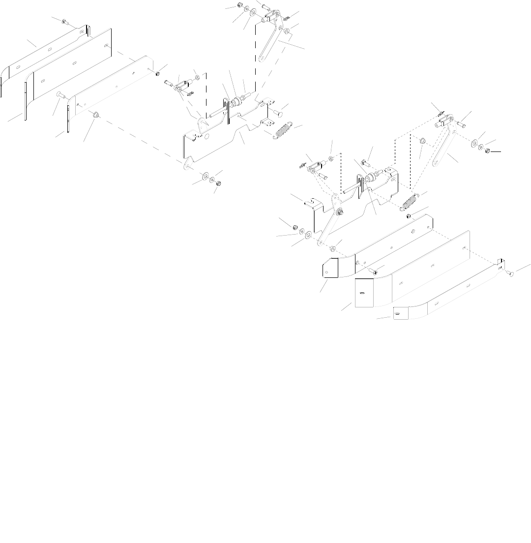
SIDE SQUEEGEE – CYLINDRICAL
86037660 CHARIOT 11/09/06
5-29
19
14
14
16
15
10
9
7
3
5
1
2
4
6815
16
18
20
10
14
21
13
9
7
6
1
22
3
20
10
18
13
10
8
17
12
15
6
6
42
17
15
10
11
10
14
11

SIDE SQUEEGEE - CYLINDRICAL
86037660 CHARIOT 11/09/06 5-30
REF PART NO. PRV NO. QTY DESCRIPTION SERIAL NO.
FROM NOTES:
1 86066510 140838 2 BAND, SIDE SQG, 24
2 86276950 70772 8 SCR, 1/4-20 X 3/4 CARRIAGE SS
3 86283480 140039 2 BLADE, SQUEEGEE, SIDE, 24
4 86277120 70792 4 SCR, 5/16-18 X 1 PFHMS SS
5 86071340 140848 1 BRKT, SKIRT, SQG, LH
6 86228990 09153 8 BEARING, FLNGD, .314 ID X .502 OD
7 86271870 57290 8 NUT, 1/4-20 HEX NYLCK THIN SS
8 86226430 80636 4 CLEVIS, 5/16” YOKE END 5/16-18
9 86271170 57138 4 NUT, 5/16-18 JAM
10 86010670 87029 10 WASHER, 5/16 FLAT SS
11 86242120 48090 2 KNOB, 1.0 OD X 5/16-18
12 86086570 67600 1 ROD, 5/16-18 X 6.5 ADJ
13 86079160 620071 4 PLATE, SQG LINKAGE ARM
14 86259420 87232 8 WASHER, THRUST .51 ID X 1 OD BRO
15 86271840 57285 8 NUT, 5/16-18 HEX NYLOCK THIN SS
16 86272550 66485 4 PIN, CLEVIS, 5/16 X 1.00 PLTD
17 86008660 80605 4 COTTER, 5/16” RING
18 86277130 70795 4 SCR, 5/16-18 X 1.00 CARRIAGE SS
19 86091600 140061 1 BRKT, SIDE SQG, WELDMENT, LH
20 86226830 73268 2 SPRING, EXT .68 D X 3.00 L X .098 W
21 86091570 140021 1 BRKT, SIDE SQG, WELDMENT, RH
22 86071280 140836 1 BRKT, SKIRT, SQG, RH
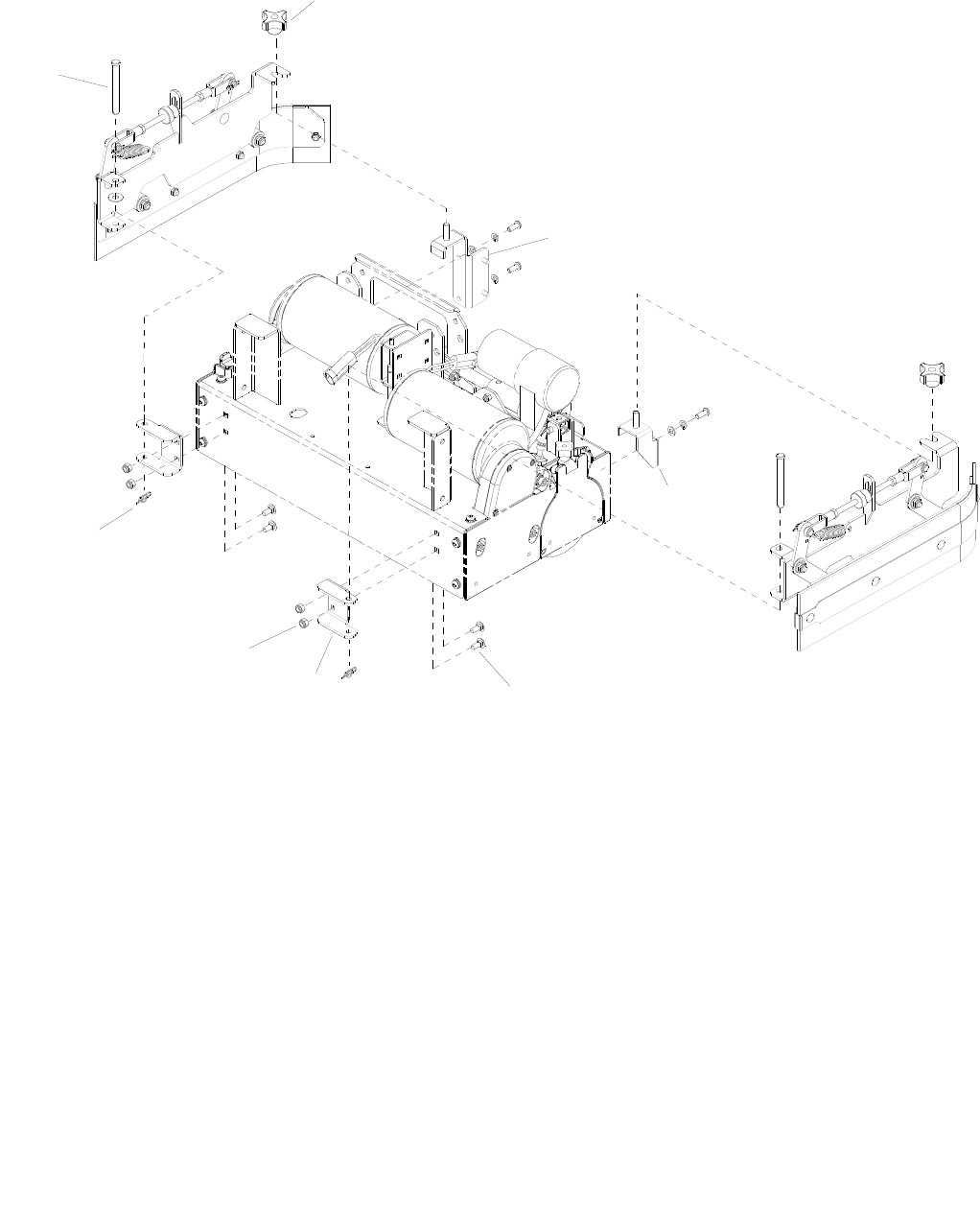
SCRUB DECK - SIDE SQUEEGEE - CYLINDRICAL
86037660 CHARIOT 11/09/06
5-31
4
8
7
5
6
2
1
3

SCRUB DECK - SIDE SQUEEGEE - CYLINDRICAL
86037660 CHARIOT 11/09/06 5-32
REF PART NO. PRV NO. QTY DESCRIPTION SERIAL NO.
FROM NOTES:
1 86249050 82058 2 PIN, CLEVIS 3/8 X 3.50 PLTD
2 86009200 81535 2 KNOB, 3/8-16 4 PRONG ALUM
3 86008670 80606 2 COTTER, 3/8” RING
4 86068570 140050 1 BRKT, HOPPER ALIGNMENT
5 86270830 57023 4 NUT, 5/16-18 HEX NYLOCK SS
6 86071350 140849 2 BRKT, SIDE SQG MOUNT
7 86276070 70593 4 5/16-18 X 3/4 CARRIAGE SS
8 86071440 140864 1 BRKT, SIDE SQUEEGEE, LFT
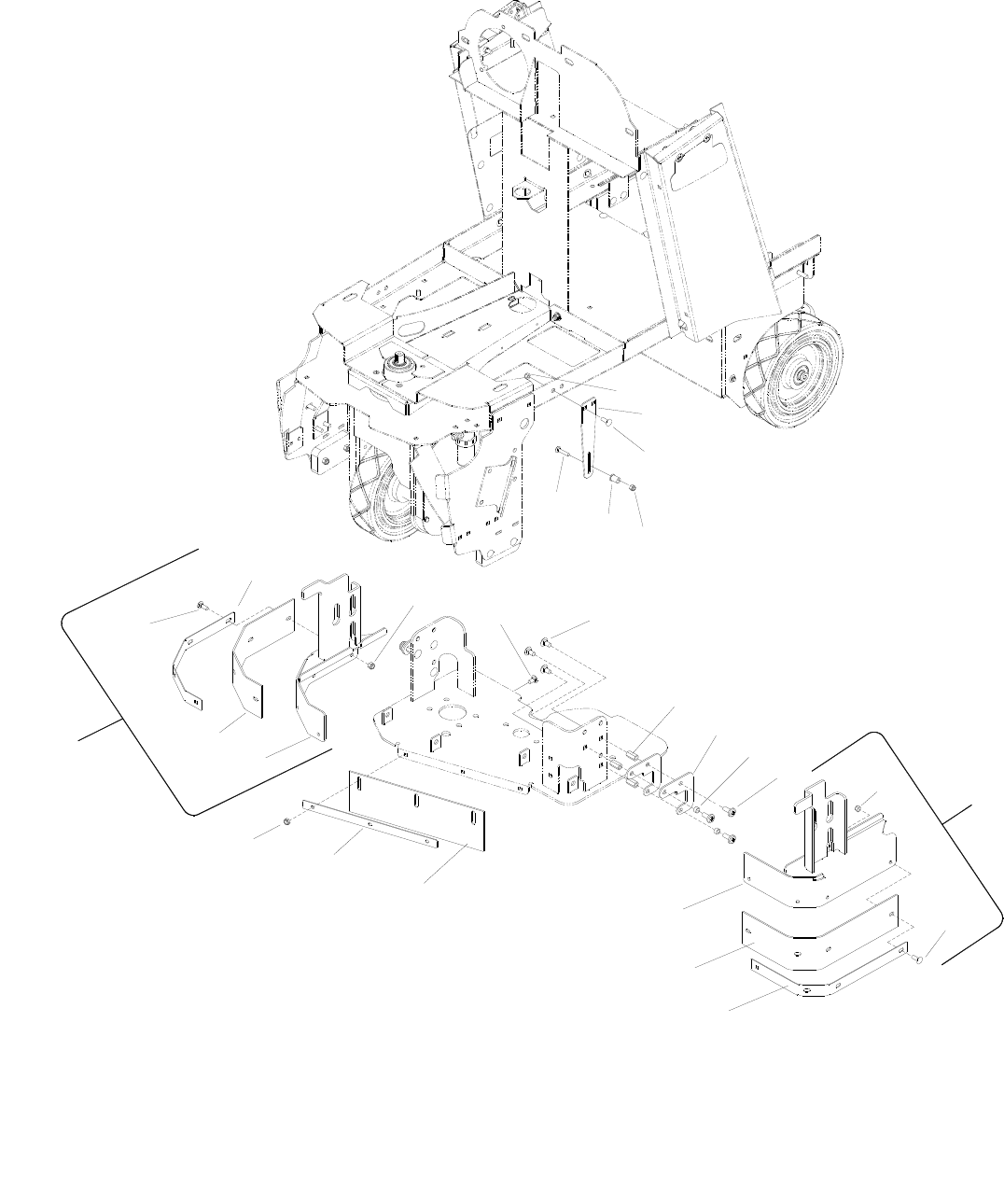
SCRUB DECK SKIRTS
86037660 CHARIOT 11/09/06
5-33
7
7
20
19
18
22 17
16 15
14
13
9
10
11 12 5
21
58
6
5
4
3
2
1
24
23

SCRUB DECK SKIRTS
86037660 CHARIOT 11/09/06 5-34
REF PART NO. PRV NO. QTY DESCRIPTION SERIAL NO.
FROM NOTES:
1 86270830 57023 4 NUT, 5/16-18 HEX NYLOCK SS
2 86070960 140773 2 BRKT, SKIRT STOP, SCRUBDECK
3 86276070 70593 4 SCR, 5/16-18 X 3/4 CARRIAGE SS
4 86228900 09138 2 BEARING FLANGED, .252IDX.503OD
5 86005810 57245 6 NUT, 1/4-20 HEX NYLOCK SS
6 86276330 70634 2 SCR, 1/4-20 X 1.25 CARRIAGE BZ
7 86276950 70772 8 SCR, 1/4-20 X 3/4 CARRIAGE SS
8 86277410 70840 6 SCR, 5/16-18 X 5/8 CARRIAGE SS
9 86271950 57300 6 NUT, 5/16-18 X 1 COUPLING SS
10 86079130 620068 4 PLATE, SKIRT, SPACER
11 86007650 730329 4 SPACER, .438D X .317ID X .25L
12 86007070 70849 6 SCR, 5/16-18 X 1.00 PTMS SS
13 86066460 140769 1 BAND, SKIRT, LEFT
14 86001560 140754 1 BLADE, SKIRT, SCRBDCK, 24IN LFT
15 86091770 140765 1 BRKT, SKIRT SCRUBDECK, LEFT
16 86001700 140780 1 BLADE, SKIRT, SCRUBDECK, FRONT
17 86066480 140781 1 BAND, SKIRT, SCRUBECK, FRONT
18 86091780 140766 1 BRKT, SKIRT, SCRUBDECK, RIGHT
19 86001570 140755 1 BLADE, SKIRT, SCRBDCK, 24IN RGT
20 86066470 140770 1 BANC, SKIRT, RIGHT
21 86277500 70853 3 SCR, 1/4-20 X 5/8 CARR SS
22 86271870 57290 3 NUT, 1/4-20 HEX NYLOCK THIN SS
23 86026470 47459 - KIT, SKIRT LEFT SERVICE ONLY
24 86026460 47458 - KIT, SKIRT RIGHT SERVICE ONLY
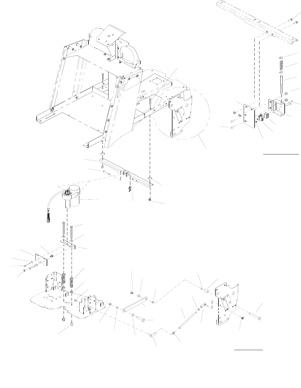
SCRUB DECK LIFT
86037660 CHARIOT 02/12/07
5-35
21
22
11
34
12
DETAIL 'A'
20
24
25
26
23
22
21
19
31
19
18
14
19
15
16
33
10
17
30
28
27
20
39
32
8
35
29
BASIC ONLY
1
2
4
9
5
3
1
8
7
6
SEE DETAIL 'A'
16
16
37
36
38
13

SCRUB DECK LIFT
86037660 CHARIOT 04/15/08 5-36
REF PART NO. PRV NO. QTY DESCRIPTION SERIAL NO.
FROM NOTES:
1 86276950 70772 4 SCR, 1/4-20 X 3/4 CARRIAGE SS
2 86223270 66482 1 PLUNGER, MICRO SWITCH *(13)
3 86276010 70580 2 SCR, 4-40 X 1.0 PPHMS
4 86072460 14387 1 BRKT, MICROSWITCH MOUNT
5 86087520 73456 2 SPACER, L2020B PLUNGER SWITCH
6 86007160 72157 1 SWITCH, 10A ROLLER MINI
7 86271280 57163 2 NUT, 4-40 W/STAR WASHER
8 86005810 57245 6 NUT, 1/4-20 HEX NYLOCK SS
9 86079150 620070 1 PLATE, MTG, DECK LIMIT
10 86277030 70780 2 SCR, 5/16-18 X 1.25 CARRIAGE SS
11 86224370 730335 2 SPACER, 1 OD X .391 ID X .500
12 86270830 57023 2 NUT, 5/16-18 HEX NYLOCK SS
13 86272460 66268 1 PIN, CLEVIS 5/16 X 3.00 PLTD *(26)(27)(28)
(29)(30) WAS 80637
- 86008720 80637 1 PIN, CLEVIS 3/8 X 2.38 *(22) WAS 66369
14 86011950 - 1 ACTUATOR, 36VDC 3.5 STRK *(21) WAS 05250
15 86275510 70494 2 SCR, 3/8-16 X 4.5” HHCS GR5
16 86010770 87143 2 WASHER, 7/16ID X IDX.08 FLT SS
17 86070810 140739 1
BRKT, ACTUATOR SPGS, SCRUBDECK
18 86255450 81376 2 SPRING COMP .96D X 4.0L X .135W
19 86005630 57022 4 NUT, 3/8-16 HEX NYLOCK THIN SS
20 86271530 57216 2 NUT, 3/8-24 HEX NYLOCK
21 86009050 81324 6 BEARING, 1/2 ID X 11/32L NYLON
22 86008460 80102 4 SPACER, .500OD X .391ID C .400
23 86224380 730336 2 SPACER, 1 OD X 0.391 ID X 1.063
24 86274010 70070 2 SCR, 3/8-16 X 2 HHCS
25 86001320 140353 2 BALL JOINT ASSY, 3/8-24 LH
26 86077330 31373 2 LINKAGE, .25 X 1.25 X 9.25
27 86223540 66483 2 ROD, SCRUB LIFT *(17)
28 86005800 57217 2 NUT, 3/8-24 HEX JAM
29 86276920 70755 2 SCR, 3/8-16 X 1 HHCS SS NP
30 86008810 80697 2 BALL JOINT ASY, 3/8-24 RH
31 86273850 70022 2 SCR, 1/4-20 X 2 HHCS
32 86010780 87162 2 WASHER, 1/4 SPILT LOCK PLTD
33 86079030 620058 1
PLATE, ACTUATOR SPR, SCRUBDECK
34 86091760 140741 1 BRKT, ACTUATOR MTG, SCRUBBER
35 86274110 70094 2 SCR, 1/4-20 X 1/2 SHCS
36 86007780 73576 1 SPRING, COMP .60D X 2.0L X .045W
37 86270270 27721 2 CLIP, RETAINING 7/16
38 86005830 57263 2 NUT, 3/8-24 UNF LH
39 86008660 80605 1 COTTER, 5/16” RING *(26)(27)(28)
(29)(30) WAS 80606
- 86008670 80606 1 COTTER, 3/8” RING *(22)
* SEE SERIAL NUMBER PAGE
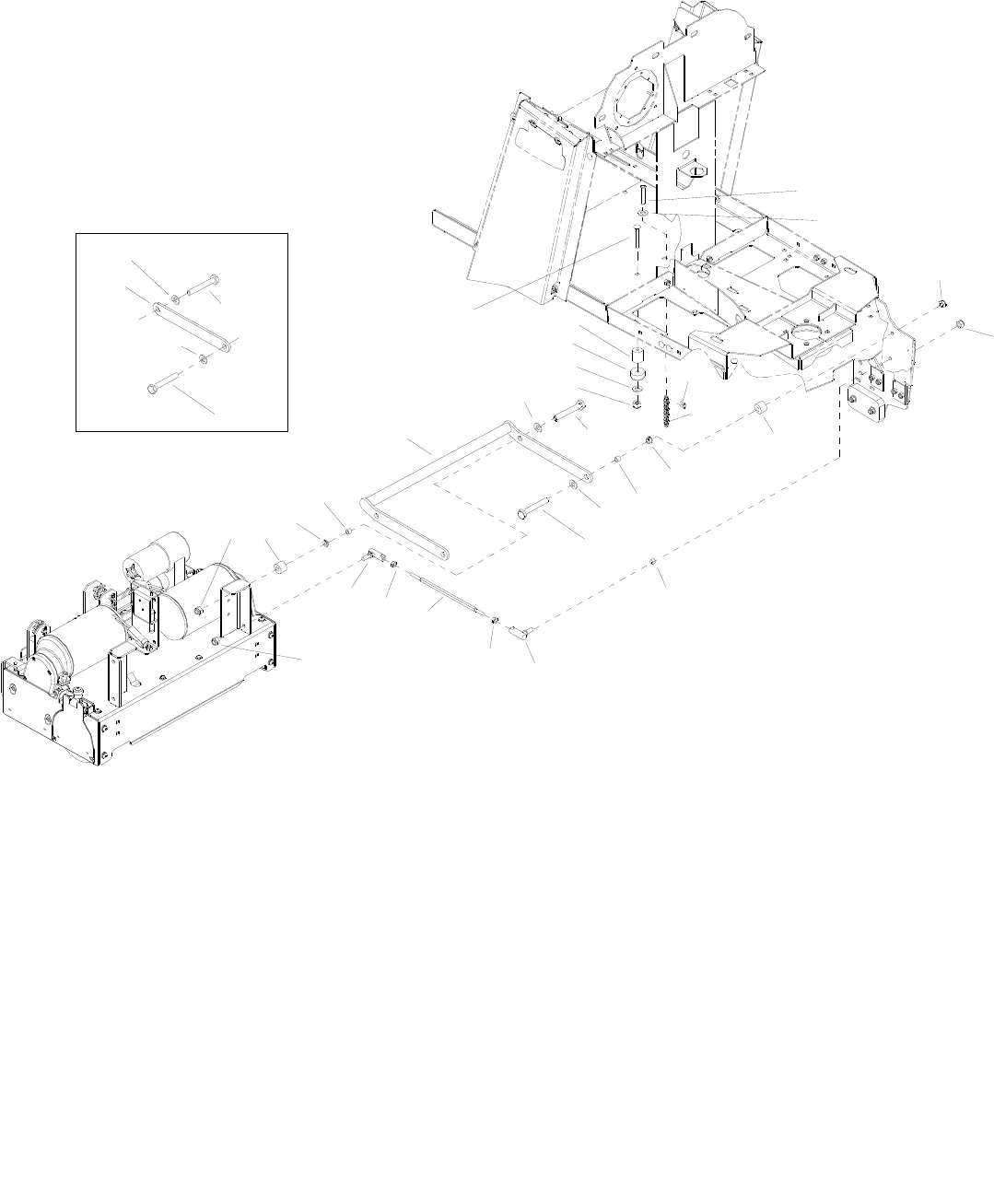
SCRUB DECK MOUNTING- CYLINDRICAL
86037660 CHARIOT 04/15/08
5-37
19
6
7
5
18
21
2
20 4
17
4
17
2
4
9
8
10
2
8
9
12
1
14
11
13
23 22
22
3
16
2
17
17
2
15

SCRUB DECK MOUNTING - CYLINDRICAL
86037660 CHARIOT 11/09/06 5-38
REF PART NO. PRV NO. QTY DESCRIPTION SERIAL NO.
FROM NOTES:
1 86272380 66217 1 PIN, CLEVIS 3/8 X .75 PLTD
2 86010770 87143 5 WASHER, 7/16 ID X 1D X .08 FLT SS
3 86087580 73606 2 SPACER, 1/2 OD X .058 ID X .26 LG CRS
4 86271530 57216 6 NUT, 3/8-24 HEX NYLOCK
5 86224380 730336 2 SPACER, 1 OD X .391 ID X 1.063
6 86232680 270114 REF CHAIN, #41, 1/2” PITCH X 34
7 86009400 81873 1 CHAIN, #41, 1/2” P MASTER LINK
8 86009050 81324 4 PIN, CLEVIS 3/8 X .75 UNPLTD
9 86008460 80102 4 SPACER, .500 0D X .391 ID X .400
10 86005630 57022 2 NUT, 3/8-16 HEX NYLOCK THIN SS
11 86008810 80697 2 BALL JOINT ASY, 3/8-24 RH
12 86005800 57217 2 NUT, 3/8-24 HEX JAM
13 86223540 66483 2 ROD, SCRUB LIFT HEX WAS 67415
ROUND
14 86001320 140353 2 BALL JOINT ASSY, 3/8-24 LH
15 86005830 57263 2 NUT, 3/8-24 UNF LH
16 86077330 31373 2 LINKAGE, .25 X 1.25 X 9.25
17 86274660 70255 4 SCR, 3/8-16 X 1.5 HHCS GR5 PLTD
18 86271840 57285 2 NUT, 5/16-18 HEX NYLOCK THIN SS
19 86010670 87029 2 WASHER, 5/16 FLAT SS
20 86231090 80809 2 BUMPER, RUBBER 5/16” ID X 1.50
21 86276690 70715 2 SCR, 5/16-18 X 1.75 CARR SS
22 86224370 730335 4 SPACER, 1 OD X .391 ID X .500 LG
23 86093180 51415 1 LINKAGE ASM, DECK ARM *(9)
*SEE SERIAL NUMBER PAGE.
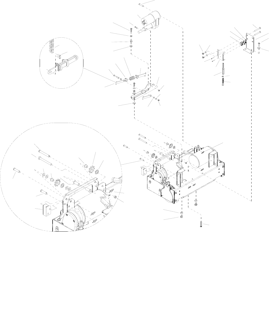
SCRUB DECK ACTUATOR - CYLINDRICAL
86037660 CHARIOT 02/10/07
5-39
6
2
7
36
1
33
37
32
31
30
1
34
30
36
29
39
15
26
13
25
14
23
17
7
24
19
16 14
18 15
21
1
20
11
12
3
45
10 9
8
17
14
38
2
27
28 22 7
40
41

SCRUB DECK ACTUATOR - CYLINDRICAL
86037660 CHARIOT 09/14/07 5-40
REF PART NO. PRV NO. QTY DESCRIPTION SERIAL NO.
FROM NOTES:
1 86248980 81438 3 PIN, CLEVIS 3/8 X 1.75 PLTD
2 86270830 57023 2 NUT, 5/16-18 HEX NYLOCK SS
3 86087520 73456 2 SPACER, L2020B PLUNGER SWITCH
4 86007160 72157 1 SWITCH, 10A ROLLER MINI
5 86271280 57163 2 NUT, 4-40 W/STAR WASHER
6 86276070 70593 2 SCR, 5/16-18 X 3/4 CARRIAGE SS
7 86010670 87029 4 WASHER, 5/16 FLAT SS
8 86270270 27721 2 CLIP, RETAINING 7/16
9 86007780 73576 1 SPRING, COMP .60 D X 2.0 L X .045 W
10 86223270 66482 1 PLUNGER, MICROSWITCH
11 86072460 14387 1 BRKT, MICROSWITCH MOUNT
12 86276010 70580 2 SCR, 4-40 X 1.0 PPHMS
13 86091840 140850 1 BRKT, ACTUATOR SLIDER
14 86005810 57245 5 NUT, 1/4-20 HEX NYLOCK SS
15 86010630 87013 4 WASHER, 1/4 ID X 5/8 OD SS
16 86231360 14744 2 BUSH, BRZ FLG .25 X .38 X .25
17 86259420 87232 4 WASHER, THRUST .51 ID X 1 OD BRO
18 86066910 140851 2 BAR, COMP. SPRING RETAINER, OS
19 86273820 70019 1 SCR, 1/4-20 X 1.25 HHCS SS
20 86090330 87258 2 WASHER, .804 ID X 1.25 OD X .179
21 86066920 140852 1 BAR, COMP. SPRING RETAINER, IS
22 86278400 730351 1 SPRING, COMP., 1.1 OD X 2.25 L X .148
23 86228840 09124 2 BEARING, FLANGED .314 ID X .502 OD
24 86276760 70724 2 SCR, 5/16-18 X 1.25 BSHCS SS
25 86006910 70443 2 SCR, 1/4-20 X 5/8 SHCS
26 86011950 - 1 ACTUATOR, 36VDC, 3.5 IN STRK *(21) WAS 05250
27 86232680 270114 1 CHAIN, #41, 1/2” PITCH X 34D
28 86009400 81873 1 CHAIN, #41, 1/2” MASTER LINK
29 86272520 66392 1 PIN, CLEVIS 3/8 X 2.75 PLTD
30 86229000 09154 2 BEARING FLG .377 ID X .502 OD X .501
31 86255650 81627 2 SPROCKET, #41 1/2”P 9T
32 86222270 57276 2 NUT, PUSH FLAT RD .51 ID
33 86008670 80606 4 COTTER, 3/8” RING
34 86228910 09139 2 BEARING, FLANGED .377 ID X .502 OD
35 OPEN - - -
36 86276400 70642 1 SCR, 3/8-16 X 3 HHCS SS
37 86005630 57022 1 NUT, 3/8-16 HEX NYLOCK THIN SS
38 86277500 70853 2 SCR, 1/4-20 X 5/8 CARR SS
39 86071450 140865 1 BRKT, STRIKER
40 86010680 87030 4 WASHER, 3/8 ID X 3/4 OD NYLON
41 86290090 - 1 GUARD, CHAIN *(1)
*SEE SERIAL NUMBER PAGE.
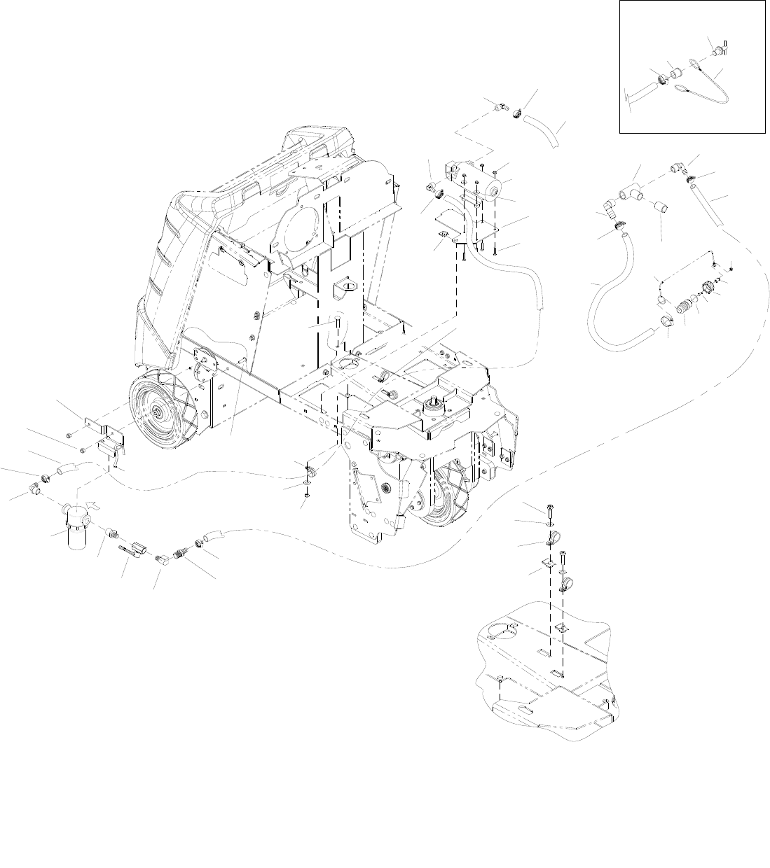
SOLUTION - CYLINDRICAL
86037660 CHARIOT 01/03/08
5-41
SOLENOID
TO
TANK
TO
DETAIL 'A'
SEE
7
2
10
23
1
4
3
5
DETAIL 'A'
5
8
12
13
19
22
24
5
28
11
21
25
69
28
30
32
29
34
13
31
35
33
15
16
13
14
43
37
36
18
520
47
46
44
45
5
42
41
40
39
17
38

SOLUTION- CYLINDRICAL
86037660 CHARIOT 01/03/08 5-42
REF
PART
PRV NO.
QTY
DESCRIPTION SERIAL
NO.
NOTES:
1 86274070 70086 2 SCR, 10-24 X 1/2 PPHMS
2 86010650 87018 2 WASHER, #10 X 9/16 OD
3 86233390 80887 2 CLAMP, 7/8 DIA “P” CUSHIONED
4 86270860 57028 2 NUT, 10-24 U-TYPE SPEED
5 86233150 20042 5 CLAMP, 3/8 HOSE (D-SLOT)
6 86270990 57090 4 NUT, 10-32 HEX NYLOCK SS
7 86282320 39710 1 HOSE, 1/2ID WIRE BOUND X 49”
8 86198050 81923 1 TEE, 3/4 FPT
9 86240390 40075 1 HOSEBARB, 3/4 MPT X 1/2 90D
10 86280910 39174 1 HOSE, 1/2ID WIRE BOUND X 23”
11 86247760 80960 1 NIPPLE, 3/4 CLOSE PVCE
12 86240600 41526 1 HOSEBARB, 3/4 MPTX1, HOSE
90DEG
13 86233110 20018 2 CLAMP, 1.00” WORM GEAR
14 86009700 82267 1 PLUG, 5/8” DRAIN HOSE
15 86270510 51457 1 LANYARD, .093 X 6 NYLON WAS 78499
16 86001600 40076 1 SLEEVE, .63 ID X 1.0 OD
17 86256120 730368 1 STRAINER, 1/2 FPT 100 MESH
- 86005870 59021 - O-RING, FILTER SEAL RON-VIK SERVICE
ONLY
- 86136800 73839 - SCREEN, 80 MESH STRAINER DEEP SERVICE
ONLY
18 86282370 39735 1 HOSE, 1/2ID WIRE BOUND X 40”
19 86004310 39505 1 HOSE, 1.0 X 18.0 DRAIN
20 86264920 27049 2 CABLE, TIE. 7” UL/CSA
21 86274410 70195 4 SCR, 10-32 X 1.25 PPHMS SS
22 86070690 140724 1 BRKT, SOLUTION PUMP
23 86010650 87018 4 WASHER, #10 X 9/16 OD
24 86006100 65176 1 PUMP ASM, 36V
25 86271820 57270 1 NUT, 5/16-18 CAPTIVE “J” PLTD
26 86279130 87083 1 WASHER, 5/16 SPLIT LOCK PLTD
27 86276780 70728 1 SCR, 5/16-18 X 3/4 HHCS SS
28 86197940 40027 2 HOSEBARB, 3/8MPTX1/2 90D DL
29 86246090 51461 1 LANYARD, .093 X 6”, LOOP - .26 EYE *(11)
30 86254320 730400 1 SPACER, .17 ID X .25 OD X 3/16 LG *(11)
31 86259450 87507 1 WASHER, 1.0 D X .1 THK, SEAL *(11)
32 86252730 70887 1 SCR, 8-32 X 1/2 BHCS SST *(11)
33 86248010 57312 1 NUT, 8/32 ACORN CAP, PLATED *(11)
34 86226950 40109 1 1” HOSEBARB X 3/4” GHT NYLON *(11)
35 86073960 22104 1 CAP, 3/4” GHT W/.17 HOLE *(11)
36 86068780 140202 1 BRKT, STRAINER MNT *(25)
37 86270830 57023 2 NUT, 5/16-18 HEX NYLOCK SS *(25)
38 86001530 40039 1 HOSE BARB, 1/2 MPT X 1/2 HOSE 90 *(25)
39 86188210 11-800354 1 NIP, 1/2 X 3/8 HEX BR *(25)
40 86225680 84201 1 VALVE, 3/8” FPT BALL *(25)
41 86197420 31026 1 ELBOW, 3/8” NPT STREET *(25)
42 86197540 40013 1 HOSEBARB, 3/8 MPT X 1/2 DL *(25)
43 86233410 81270 1 CLAMP, 3/4 DIA CUSHION .406 DIA *(25)
44 86270830 57023 1 NUT, 5/16-18 HEX NYLOCK SS *(25)
45 86010670 87029 1 WASHER, 5/16 FLAT SS *(25)
46 86276070 70593 1 SCR, 5/16-18 X 3/4 CARRIAGE SS *(25)
47 86277460 70847 1 SCR, 5/16-18 X 5/8 BSHCS SS *(25)
*SEE SERIAL NUMBER PAGE.
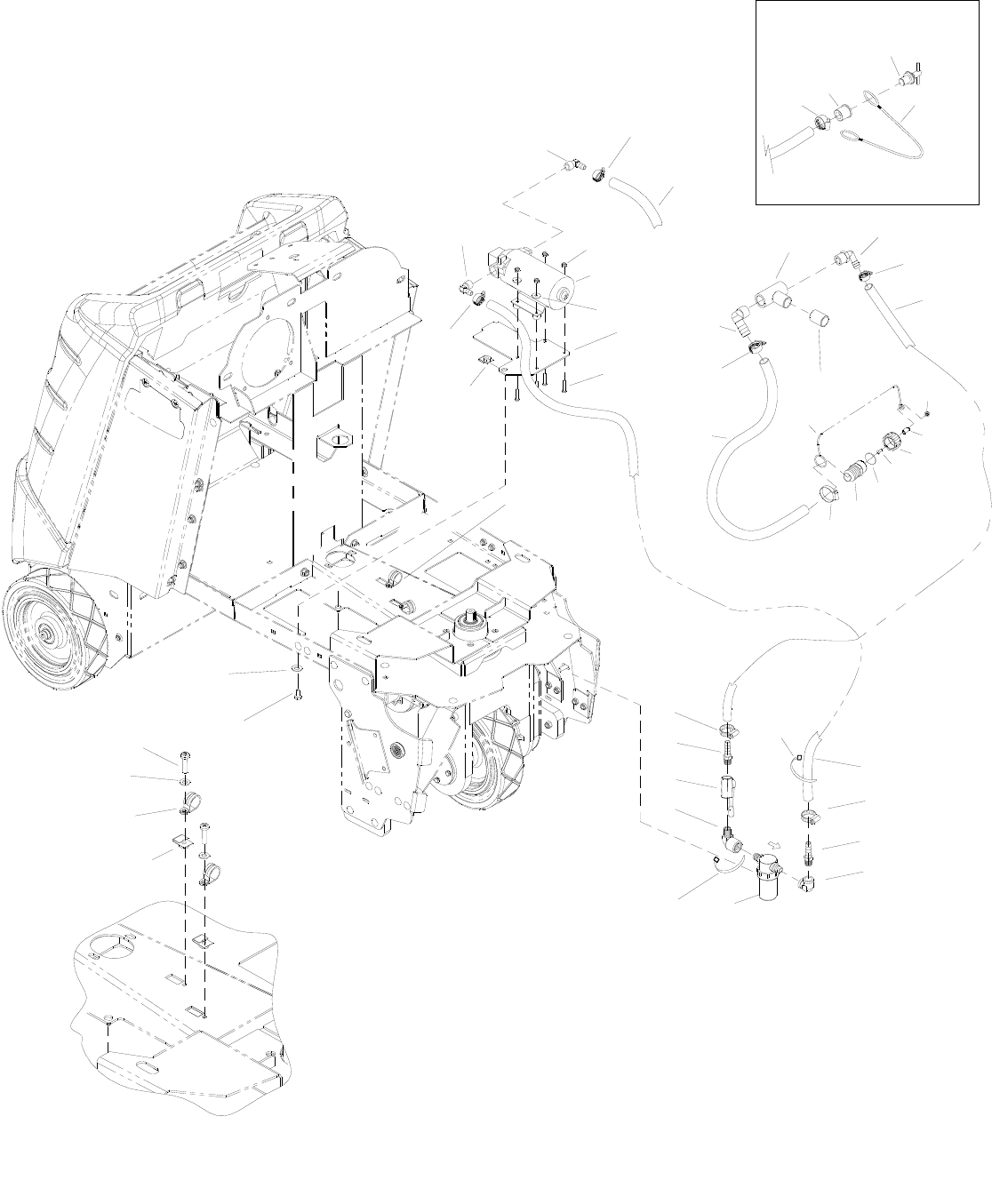
SOLUTION - DISK
86037660 CHARIOT 01/03/08
5-43
SOLENOID
TO
TANK
TO
DETAIL 'A'
SEE
7
26
2
10
23
1
4
3
5
DETAIL 'A'
5
8
12
13
19
22
24
5
28
11
21
25
69
27
28
30
32
29
34
13
31
35
33
15
16
13
14
5
20
18
20
40
39
36
37
38
17
5

SOLUTION - DISK
86037660 CHARIOT 10/13/08 5-44
REF PART NO. PRV NO. QTY DESCRIPTION SERIAL NO.
FROM NOTES:
1 86274070 70086 2 SCR, 10-24 X 1/2 PPHMS
2 86010650 87018 2 WASHER, #10 X 9/16 OD
3 86233390 80887 2 CLAMP, 7/8 DIA “P” CUSHIONED
4 86270860 57028 2 NUT, 10-24 U-TYPE SPEED
5 86233150 20042 5 CLAMP, 3/8 HOSE (D-SLOT)
6 86270990 57090 4 NUT, 10-32 HEX NYLOCK SS
7 86281940 39540 1 HOSE, 1/2ID WIRE BOUND X 40”
8 86198050 81923 1 TEE, 3/4 FPT
9 86240390 40075 1 HOSEBARB, 3/4 MPT X 1/2 90D
10 86282190 39616 1 HOSE, 1/2ID WIRE BOUND X 13”
11 86247760 80960 1 NIPPLE, 3/4 CLOSE PVCE
12 86240600 41526 1 HOSEBARB, 3/4 MPTX1, HOSE 90DEG
13 86233110 20018 2 CLAMP, 1.00” WORM GEAR
14 86009700 82267 1 PLUG, 5/8” DRAIN HOSE
15 86270510 51457 1 LANYARD, .093 X 6 NYLON WAS 78499
16 86001600 40076 1 SLEEVE, .63 ID X 1.0 OD
17 86007940 73836 1 STRAINER, DEEP, 100 MESH
- 86005870 59021 - O-RING, FILTER SEAL RON-VIK SERVICE ONLY
- 86136800 73839 - SCREEN, 100 MESH STRAINER DEEP SERVICE ONLY
18 86281950 39541 1 HOSE, 1/2ID WIRE BOUND X 32”
19 86004310 39505 1 HOSE, 1.0 X 18.0 DRAIN
20 86264920 27049 3 CABLE, TIE. 7” UL/CSA
21 86274410 70195 4 SCR, 10-32 X 1.25 PPHMS SS
22 86070690 140724 1 BRKT, SOLUTION PUMP
23 86010650 87018 4 WASHER, #10 X 9/16 OD
24 86006100 65176 1 PUMP ASM, 36V
25 86271820 57270 1 NUT, 5/16-18 CAPTIVE “J” PLTD
26 86279130 87083 1 WASHER, 5/16 SPLIT LOCK PLTD
27 86276780 70728 1 SCR, 5/16-18 X 3/4 HHCS SS
28 86197940 40027 2 HOSEBARB, 3/8MPTX1/2 90D DL
29 86246090 51461 1 LANYARD, .093 X 6”, LOOP - .26 EYE *(11)
30 86254320 730400 1 SPACER, .17 ID X .25 OD X 3/16 LG *(11)
31 86259450 87507 1 WASHER, 1.0 D X .1 THK, SEAL *(11)
32 86252730 70887 1 SCR, 8-32 X 1/2 BHCS SST *(11)
33 86248010 57312 1 NUT, 8/32 ACORN CAP, PLATED *(11)
34 86226950 40109 1 1” HOSE BARB X 3/4” GHT NYLON *(11)
35 86073960 22104 1 CAP, 3/4” GHT W/.17 HOLE *(11)
36 86235450 31068 1 ELBOW, 3/8 FPT PVC SCH 80 *(25)
37 86001590 40049 1 HOSEBARB, 3/8 MPT X 1/2 NYLON *(25)
38 86197420 31026 1 ELBOW, 3/8 NPT STREET *(25)
39 86225680 84201 1 VALVE, 3/8” FPT BALL *(25)
40 86197540 40013 1 HOSEBARB, 3/8 MPT X 1/2 DL *(25)
*SEE SERIAL NUMBER PAGE.
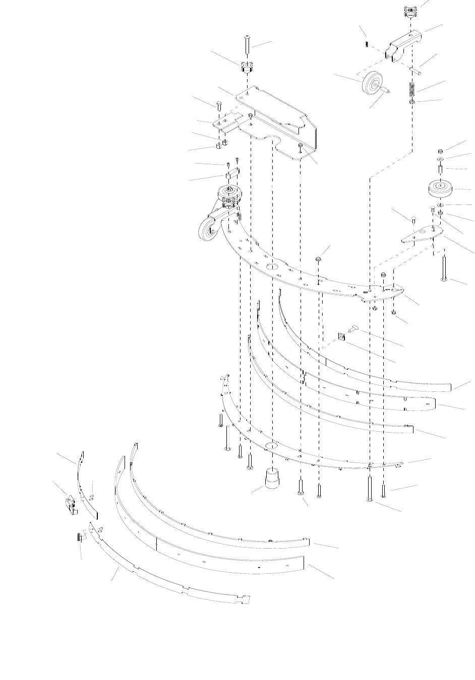
SQUEEGEE - DISK
86037660 CHARIOT 11/09/06
5-45
11
5
11
5
37
2
3
39
10
7
8
9
35
36
17
16
15
14
15
13
12
9
8
7
6
5
4
1
38
34
33
27A
32
31
30 29
28
25
18
19A
20
21
22
23
24
26
27B
19B
6
40

SQUEEGEE - DISK
86037660 CHARIOT 02/20/07 5-46
REF PART NO. PRV NO. QTY DESCRIPTION SERIAL NO.
FROM NOTES:
1 86004890 48095 2 KNOB, ALUM 3/8-16 NYLOCK NUT SS
2 86070920 140759 2 BRKT, SQG WHEEL
3 86006270 66276 2 PIN, CLEVIS 5/16 X 1.63 PLTD
4 86007780 73576 2 SPRING, COMP .60D X 2.0L X .045 W
5 86005630 57022 2 NUT, 3/8-16 HEX NYLOCK THIN SS
6 86270830 57023 3 NUT, 5/16-18 HEX NYLOCK SS
7 86010670 87029 4 WASHER, 5/16 FLAT SS
8 86001350 140390 2 BUSHING, SPANNER .435 X 1.10
9 86011020 89202 4 WHEEL, 3” DIA CUSHION RUBBER
10 86005650 57031 2 NUT, 5/16-18 HEX
11 86276950 70772 4 SCR, 1/4-20 X 3/4 CARRIAGE SS
12 86083290 66463 2 PLATE, SQG WHEEL NMT BUMPER
13 86276710 70717 2 SCR, 5/16-18 X 2.0 CARRIAGE SS
14 86083250 66459 1 PLATE, SQG TOP 33”
15 86271870 57290 4 NUT, 1/4-20 HEX NYLOCK THIN SS
16 86007040 70680 5 SCR, 5/16-18 X 1 THUMB SS TYPE P
17 86271820 57270 5 NUT, 5/16-18 CAPTIVE “J” PLTD
18 86087830 140760 1 STRAP, SQUEEGEE
19A 86001630 140764 1 BLADE, SQU, FRONT 36.7
19B 86283540 140938 1 BLADE, SQU, FRONT 36.7 URETHANE
20 86083270 66461 1 PLATE, SQG VERICAL FILLER (F)
21 86083260 66460 1 PLATE, SQG BOTTOM 33”
22 86277000 70777 4 SCR, 1/4-20 X 1.5 CARRIAGE SS
23 86276990 70776 2 SCR, 3/8-16 X 3.5 CARRIAGE SS
24 86277450 70846 2 SCR, 3/8-16 X 2 LG CARRIAGE SS
25 86008390 78493 1 TUBE ASM, SQUEEGEE VAC
26 86083280 66462 1 PLATE, SQG VERTICAL FILLER
27A 86001580 140763 1 BLADE, SQU, REAR 40.6 LINATEX
27B 86283510 140935 1 BLADE, SQU, REAR 40.6 URETHANE
28 86066440 140761 1 BAND, REAR SQUEEGEE
29 86006400 67380 4 RIVET, 5/32 OF X 1/8 GRIP
30 86009170 81488 1 LATCH, SQUEEGEE STRAP
31 86009180 81489 1 STRIKER, SQUEEGEE STRAP REAR
32 86066450 140762 1 BAND, SQG REAR RH
33 86009910 82576 1 VIAL, LEVEL
34 86274130 70098 2 SCR, 8-32 X 3/8 PHTC ‘F’ PLATD
35 86071070 140795 1 BRKT, SQG QUICK CONNECT LOCK
36 86071060 140794 1 BRKT, SQG QUICK CONNECT MTG
37 86009200 81535 1 KNOB, 3/8-16 4 PRONG ALUM
38 86277440 70845 1 SCR, 3/8-15 X 2.5 LG BSHCS SS
39 86008660 80605 2 COTTER, 5/16 RING
40 86277460 70847 1 SCR, 5/16-18 X 5/8 BSHCS SS
NOTE: Complete Squeegee Assembly available, Part No. 47455
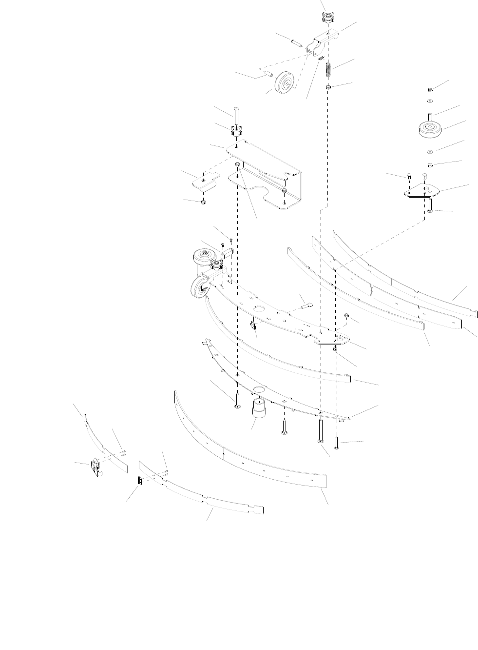
SQUEEGEE - CYLINDRICAL
86037660 CHARIOT 02/20/07
5-47
14B
22B
25
27
24
27
38
7
6
4
5
39
1
2
3
4
18
9
42
4
16
30
10
19
33
31
11
12
21
20
37
28
29
36
32
8
7
6
34
35
17
13
23
26
22A
14A
15

SQUEEGEE - CYLINDRICAL
86037660 CHARIOT 02/20/07 5-48
REF PART NO. PRV NO. QTY DESCRIPTION SERIAL NO.
FROM NOTES:
1 86004890 48095 2 KNOB, ALUM 3/8-16 NYLOCK NUT SS
2 86069870 140531 2 BRKT, SQG WHEEL
3 86007780 73576 2 SPRING, COMP .60 D X 2.0 L X .045 W
4 86005630 57022 6 NUT, 3/8-16 HEX NYLOCK THIN SS
5 86271840 57285 2 NUT, 5/16-18 HEX NYLOCK THIN SS
6 86001350 140390 2 BUSHING, SPANNER .435 X 1.10
7 86011020 89202 4 WHEEL, 3” DIA CUSHION RUBBER
8 86010670 87029 2 WASHER, 5/16 FLAT SS
9 86005650 57031 2 NUT, 5/16-18 HEX
10 86083420 66822 2 PLATE, BUMPER WHEEL MOUNT
11 86276710 70717 2 SCR, 5/16-18 X 2.0 CARRIAGE SS
12 86276950 70772 4 SCR, 1/4-20 x 3/4 CARRIAGE SS
13 86087850 140833 1 STRAP, SQUEEGEE
14A 86283490 140841 1 BLADE, SQU FRONT 29.4
14B 86283530 140937 1 BLADE, SQU FRONT 29.4 URETHANE
15 86083470 66828 1 PLATE, SQG VERTICAL FILLER (F)
16 86005810 57245 4 NUT, 1/4-20 HEX NYLOCK SS
17 86071260 140830 1 BRKT, SQUEEGEE TOP PLATE
18 86083460 66827 1 PLATE, SQG VERTICAL FILLER (R)
19 86083430 66823 1 PLATE, SQUEEGEE BOTTOM 33 IN
20 86277000 70777 2 SCR, 1/4-20 X 1.5 CARRIAGE SS
21 86276990 70776 2 SCR, 3/8-16 X 3.5 CARRIAGE SS
22A 86283500 140842 1 BLADE, SQU REAR 31.3 LINATEX
22B 86283520 140936 1 BLADE, SQU REAR 31.3 URETHANE
23 86066490 140834 1 BAND, REAR SQUEEGEE
24 86009180 81489 1 STRIKER, SQUEEGEE STRAP REAR
25 86009170 81488 1 LATCH, SQUEEGEE STRAP
26 86066500 140835 1 BAND, REAR SQUEEGEE
27 86006400 67380 4 RIVET, 5/32 OF X 1/8 GRIP
28 86277450 70846 2 SCR, 3/8-16 X 3 LG CARRIAGE SS
29 86008390 78493 1 TUBE ASM, SQUEEGEE VAC
30 86271820 57270 4 NUT, 5/16-18 CAPTIVE “J” PLTD
31 86007040 70680 4 SCR, 5/16-1/ X 1 THUMB SS TYPE P
32 86009910 82576 1 VIAL, LEVEL
33 86274130 70098 2 SCR, 8-320X 3/8 PHTC “F” PLTD
34 86071070 140795 1 BRKT, SQG QUICK CONNECT LOCK
35 86071190 140823 1 BRKT, SQG QUICK CONNECT MTG
36 86009200 81535 1 KNOB, 3/8-16 4 PRONG ALUM
37 86277440 70845 1 SCR, 3/8-16 X 2.50 LG BSHCS SS
38 86008660 80605 2 COTTER, 5/16” RING
39 86006270 66276 2 PIN, CLEVIS 5/16 X 1.63 PLTD
40 86277460 70847 1 SCR, 5/1/6-18 x 5/8 BSHCS SS *(5)
41 86270830 57023 1 NUT, 5/16-18 HEX NYLOCK SS *(5)
42 86271870 57290 2 NUT,1/4-20 HEX NYLOCK THIN SS
*SEE SERIAL NUMBER PAGE.
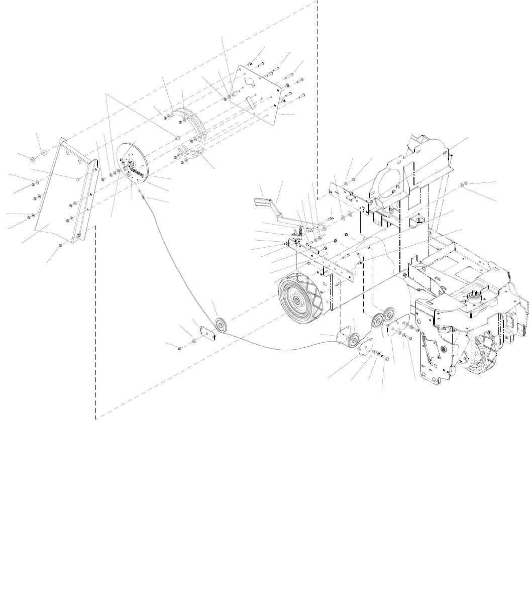
SQUEEGEE LIFT-BASIC
86037660 CHARIOT 08/14/07
5-49
36
26
24
23
3
4
22
4
43
9
21
4
27 4
3
29 30 531
32
17 16 15
13
35
39
1
2
4
34
12
4
4
10
938
411
10
9
83
33
6
3
4
19
3
3
4
14
18
20
28
14
5
4
3
5
3
7
25
37

SQUEEGEE LIFT-BASIC
86037660 CHARIOT 08/14/07 5-50
REF PART NO. PRV NO. QTY DESCRIPTION SERIAL NO.
FROM NOTES:
1 86277490 70851 2 SCR, 6-32 X 1.5 PPHMS SS
2 86259420 87232 2 WASHER, THRUST .51ID X 1 OD
3 86010670 87029 19 WASHER, 5/16 FLAT SS
4 86270830 57023 21 NUT, 5/16-18 HEX NYLOCK SS
5 86276760 70724 9 SCR, 5/16-18 X 1.25 BSHCS SS
6 86277460 70847 1 SCR, 5/16-18 X 5/8 BSHCS SS
7 86274720 70264 1 SCR, 5/16-18 X 1.5 HHCS SS
8 86083490 66831 1 PLATE, PULLEY MOUNT, CORNER *(4)
9 86231150 09151 7 BUSHING FLANGED, .314ID X .502OD
10 86223370 66464 4 PULLEY, PLASTIC 3.0 DIA.
11 86083500 66832 1 PLATE, PULLEY RETAINER, CORNER *(4)
12 86270920 57049 2 NUT, 6-32 HEX NYLOCK SS
13 86257120 72192 1 SWITCH, DPST SNAP ACTION
14 86226630 51010 2 LINK, #35 MASTER
15 86076610 38319 1 HANDLE, SQUEEGEE LIFT
16 86238360 36215 1 GRIP, 3/16 X 1.0 ORANGE
17 86083360 66474 2 PLATE, KEEPER BOTTOM
18 86232670 270099 1 CHAIN, #35, 3/8 PITCH X 29
19 86073890 270096 1 CAM, SQUEEGEE LIFT
20 86231560 270097 1 CABLE, SQUEEGEE LIFT BASIC
21 86279350 87140 1 WASHER, WAVE 1/2ID X 3/4D X .125
22 86091820 140807 1 BRKT, SIDE CHANNEL R
23 86276070 70593 1 SCR, 5/16-18 X 3/4 CARRIAGE SS
24 86066130 89501 1 ASM, HANDLE RETAINER *(15)
25 86295860 - 1 INSULATOR, SWITCH
26 86254280 730331 1 SPACER, 1.00 OD X .32 ID X .375
27 86083350 66473 2 PLATE, KEEPER TOP
28 86270870 57029 2 NUT, 1/4-20 HEX SS
29 86254580 80835 1 SPACER, .32ID X .71OD X .76L NYL
30 86277410 70840 4 SCR, 5/16-18 X 5/8 CARRIAGE SS
31 86277400 70839 1 SCR, 5/16-18 X 1.75 BSHCS SS
32 86083340 66471 1 PLATE, CAM MOUNT
33 86083440 66824 1 PLATE, PULLEY MOUNTING, CENTER
34 86276070 70593 1 SCR, 5/16-18 X 3/4 CARRIAGE SS
35 86007020 70673 1 SCR, 5/16-18 X 1.25 HHCS SS NP
36 86278980 87014 2 WASHER, #8 INT.STAR
37 86279450 87161 4 WASHER, #6 FLAT SAE PLTD
38 86073600 66833 1 BRKT, PULLEY RETAINER, SINGLE *(4)
*SEE SERIAL NUMBER PAGE.
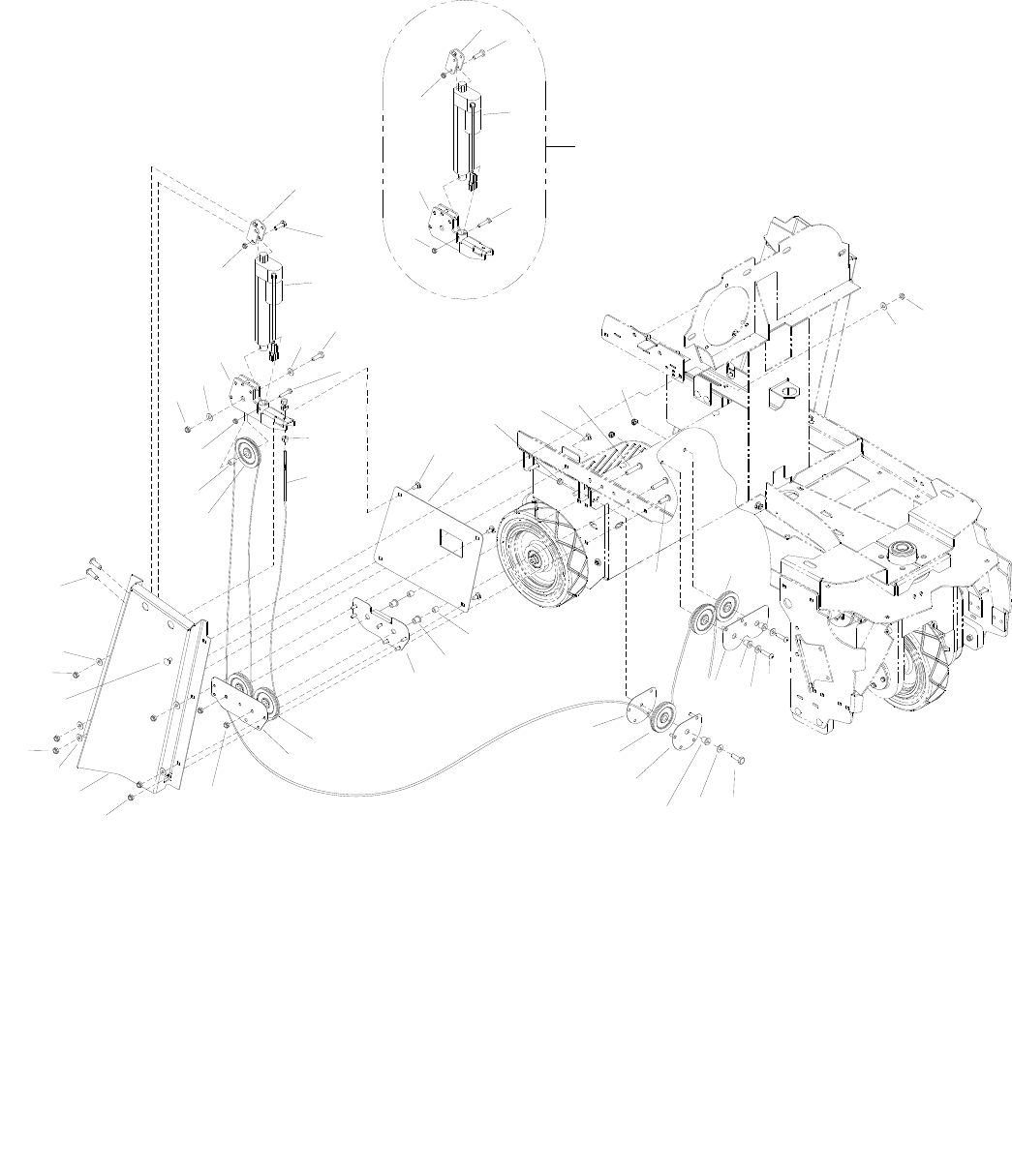
SQUEEGEE LIFT-DELUXE
86037660 CHARIOT 05/26/09
5-51
28
1
5
2
2
3
28
30
14
13
10
7
6
10
10
16
13 10
3
20
8
2
12
11
10
9
2
5
1
28
25
28
16
29
27
11
13
10
26
10
21 17
16
4
16
17
22
13 20
19
18 17
13
13
13
23
24

SQUEEGEE LIFT-DELUXE
86037660 CHARIOT 05/26/09 5-52
REF PART NO. PRV NO. QTY DESCRIPTION SERIAL NO.
FROM NOTES:
1 86068190 140793 1 BRACKET, ACTUATOR MOUNT
2 86273820 70019 1 SCR, 1/4-20 X 1.25 HHCS
3 86316550 - 1 ACTUATOR, 36VDC, 4.5” STROKE *(32) WAS 05254***
4 86083490 66831 1 PLATE, PULLEY MOUNT, CORNER *(4)
5 86068230 140840 1 BRACKET, SQG LIFT PULLEY MOUNT *(4)
6 86270870 57029 3 NUT, 1/4-28 HEX SS
7 86002780 270098 1 CABLE, SQUEEGEE LIFT DELUXE
8 86277410 70840 4 SCR, 5/16-18 X 5/8 CARRIAGE SS
9 86075430 270700 1 COVER, SQUEEGEE LIFT
10 86270830 57023 15 NUT, 5/16-18 HEX NYLOCK SS
11 86276070 70593 3 SCR, 5/16-18 X 3/4 CARRIAGE SS
12 86277400 70839 2 SCR, 5/16-8 X 1.75 BSHCS SS
13 86010670 87029 10 WASHER, 5/16 FLAT SS
14 86277460 70847 1 SCR, 5/16-18 X 5/8 BSHCS SS
15 86259420 87232 1 WASHER, THRUST .51ID X 1 OD BRO
16 86223370 66464 6 PULLEY, PLASTIC 3.0 DIA
17 86231150 09151 5 BUSHING, FLANGE, .314ID X .502OD
18 86083440 66824 1 PLATE, PULLEY MOUNTING, CENTER
19 86276760 70724 2 SCR, 5/16-18 X 1.25 BSHCS SS
20 86274720 70264 2 SCR, 5/16-18 X 1.50 HHCS SS
21 86071300 140843 1 BRACKET, PULLEY RETAINER, DOUBLE *(4)
22 86224290 730008 2 SPACER, .317ID X .5OD X .44 LG
23 86071310 140844 1 BRKT, PULLEY RETAINER, DOUBLE *(4)
24 86083500 66832 1 PLATE, PULLEY RETAINER, CORNER *(4)
25 86271840 57285 1 NUT, 5/16-18 HEX NYLOCK THIN SS
26 86074160 270101 1 CHANNEL, RIGHT DELUXE
27 86277480 70850 2 SCR, 5/16-18 X 1/2 PTHMS SS
28 86271870 57290 2 NUT, 1/4-20 HEX NYLOCK THIN SS
29 86228880 09132 1 BEARING, .314 ID X .503 OD X 1
30 86326650 - - ASM, ACTUATOR AND BRACKETS ***
*SEE SERIAL NUMBER PAGE.
**CALL MANUFACTURER FOR SERIAL NUMBER
*** FOR REPLACEMENT OF 05254
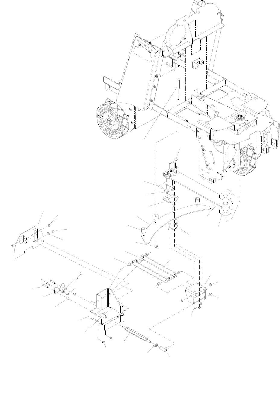
SQUEEGEE SWING
86037660 CHARIOT 05/08/09
5-53
16
15
14
13
17
12
11
69
10
8
11
24
23
22
21
20 3
6
19
18
6
7
6
5
4
25
2
7
26
6
27

SQUEEGEE SWING
86037660 CHARIOT 05/08/09 5-54
REF PART NO. PRV NO. QTY DESCRIPTION SERIAL NO.
FROM NOTES:
1 86276690 70715 7 SCR, 5/16-18 X 1.75 CARR SS
2 86091530 140787 1 BRACKET, SQUEEGEE SIDE PIVOT
3 86090300 87247 2 WASHER, 1.25 ID X .075 OCTAGON
4 86083370 66475 2 PLATE, SQG SWING SPACER
5 86091540 140800 1 BRACKET, H PIVOT MOUNT
6 86270830 57023 9 NUT, 5/16-18 HEX NYLOCK SS
7 86271530 57216 2 NUT, 3/8-24 HEX NYLOCK
8 86008810 80697 1 BALL JOINT ASY, 3/8-24 RH
9 86271980 57303 1 NUT, 3/8-24 WING SS
10 86223590 67510 1 ROD, CAMBER ADJUST
11 86001320 140353 1 BALL JOINT ASSY, 3/8-24 LH
12 86091810 140798 1 BRKT, SQG QUICK CONNECT
13 86224290 730008 2 SPACER, .317ID X .500 X .44LG
14 86083400 66479 1 PLATE, CABLE RETAINING
15 86276760 70724 2 SCR, 5/16-18 X 1.25 BSHCS SS
16 86272630 80771 1 PIN, CLEVIS 1/4 X .88 PLTD
17 86008650 80604 1 COTTER, 1/4 RING
18 86228840 09124 4 BEARING, FLANGED .314 ID X .502 0D
19 86277030 70780 4 SCR, 5/16-18 X 1.25 CARRIAGE SS
20 86224380 730336 4 SPACER, 1 OD X .343 ID X 1.063
21 86083150 66446 2 PLATE, SQUEEGEE SWING
22 86083310 66468 1 PLATE, WHEEL RETAINER
23 86226030 89268 2 WHEEL, 1.000 OD X .323 ID X .750 SS
24 86222580 66466 2 PIN, .312 DIA X 1.250 LG SS
25 86070820 140740 2 BRKT, SQUEEGEE SWING HORIZ
26 86278910 - 1 WASHER, 3/8 ID X 7/8 OD SS *(33)
27 86326670 - 1 PLATE, CABLE GUARD *(33)
*SEE SEERIAL NUMBER PAGE
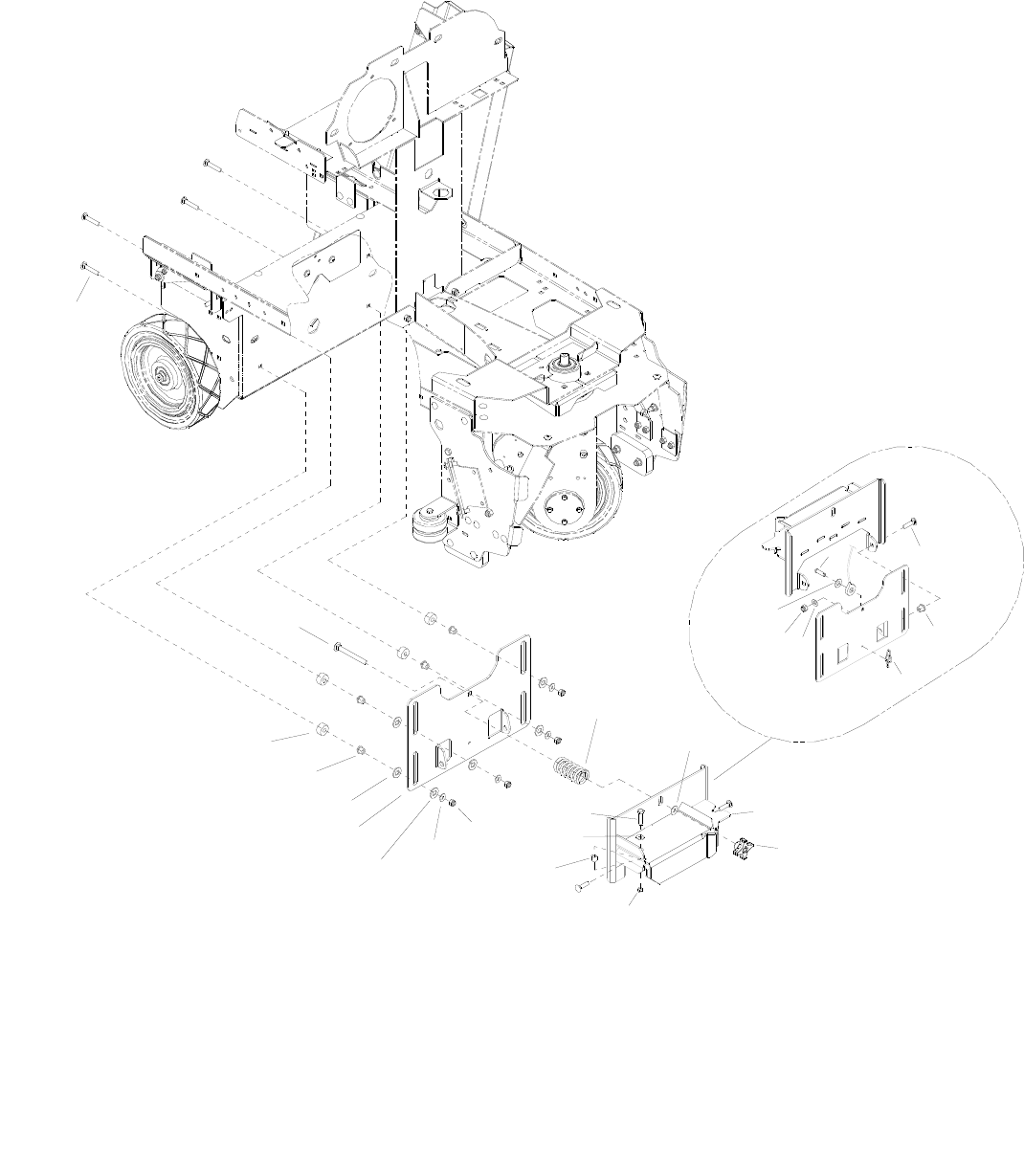
SQUEEGEE LIFT - CYLINDRICAL
86037660 CHARIOT 11/09/06
5-55
7
1
7
8
8
5
12
3
6
5
7
11
15
2
9
813
4
10
14
4
18
16
17

SQUEEGEE LIFT - CYLINDRICAL
86037660 CHARIOT 11/09/06 5-56
REF PART NO. PRV NO. QTY DESCRIPTION SERIAL NO.
FROM NOTES:
1 86276690 70715 4 SCR, 5/16-18 X 1.75 CARR SS
2 86276990 70776 1 SCR, 3/8-16 X 3.5 CARRIAGE SS
3 86224370 730335 4 SPACER, 1 OD X .391 ID X .500
4 86228840 09124 6 BEARING, FLANGED .314 ID X .502 OD
5 86259420 87232 8 WASHER, THRUST .51 ID X 1 OD BRO
6 86071160 140819 1 BRKT, SQG MOUNT VERTICAL
7 86010670 87029 7 WASHER, 5/16 FLAT SS
8 86270830 57023 7 NUT, 5/16-18 HEX NYLOCK SS
9 86007020 70673 1 SCR, 5/16-18 X 1.25 HHCS SS NP
10 86007270 730006 1 SPRING, COMP 1.10 OD X 2.0 L X .148 W
11 86278910 87003 1 WASHER, 3/8 ID X 7/8 OD SS
12 86094270 730344 1 SQG TRACK WHEEL
13 86004890 48095 1 KNOB, ALUM 3/8-16 NYLOCK NUT SS
14 86224290 730008 1 SPACER, .317 ID X .50 D X .44 LG
15 86277030 70780 2 SCR, 5/16-18 X 1.25 CARRIAGE SS
16 86009560 82053 1 PIN, CLEVIS 1/4 X .63 PLTD
17 86010630 87013 1 WASHER, 1/4 ID X 5/8 OD SS
18 86008650 80604 1 COTTER, 1/4” RING
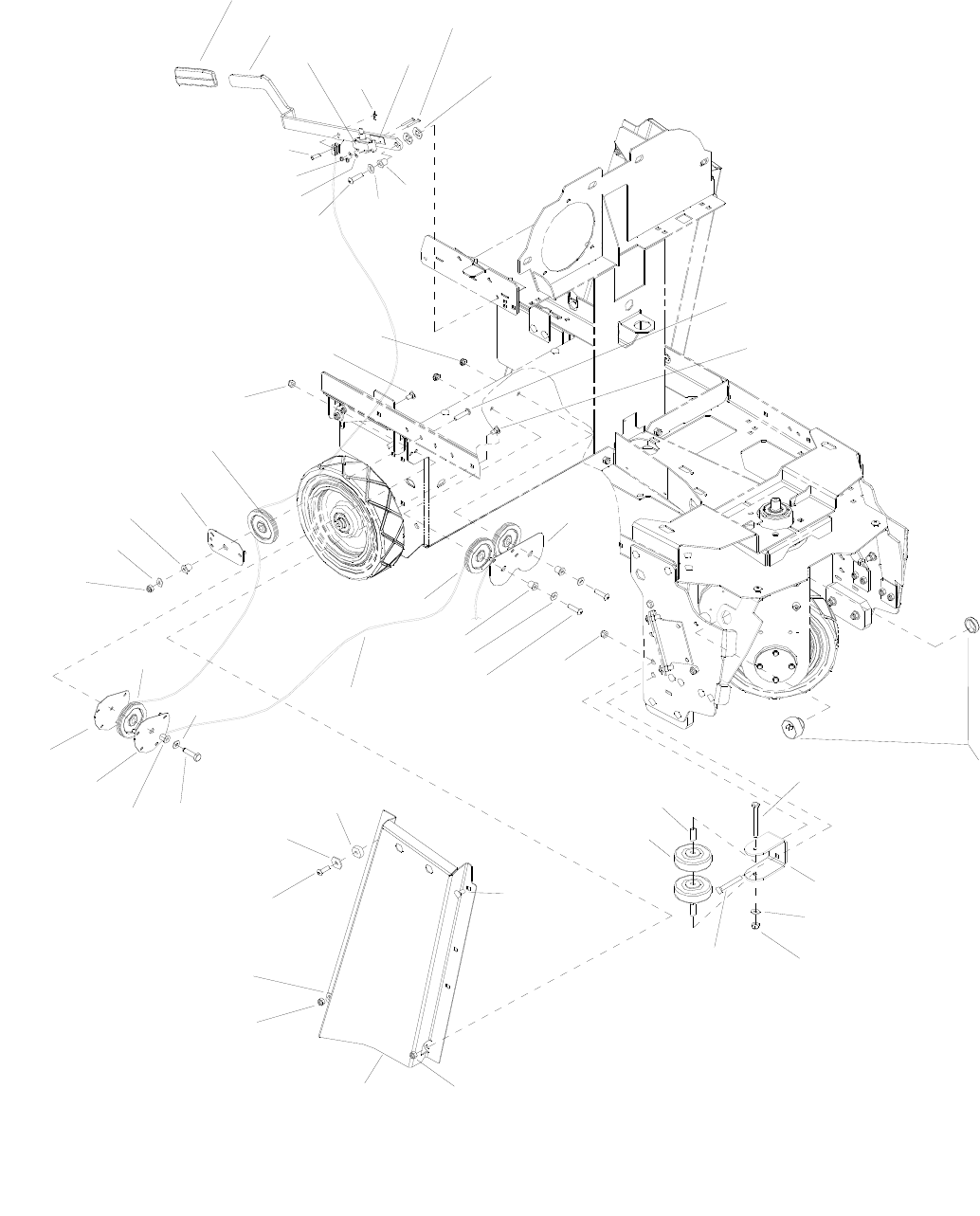
SQUEEGEE LIFT - CYLINDRICAL
86037660 CHARIOT 08/14/07
5-57
29
15
32
19
15
8
4
11
12
11
27
28
15
30
20 31
17
15
16
13
14
15
15
11
24
16
22
21
13
11
12
17
34
11
12
15
17
3
12
5
6
7
11
10
9
2
1
26
18
23
25
33

SQUEEGEE LIFT - CYLINDRICAL
86037660 CHARIOT 08/14/07 5-58
REF PART NO. PRV NO. QTY DESCRIPTION SERIAL NO.
FROM NOTES:
1 86238360 36215 1 GRIP, 3/16 X 1.0 ORANGE
2 86076610 38319 1 HANDLE, SQUEEGEE LIFT
3 86257120 72192 1 SWITCH, DPST SNAP ACTION
4 86008650 80604 1 COTTER, 1/4” RING
5 86279450 87161 2 WASHER, #6 FLAT SAE PLTD
6 86275550 70500 2 SCR, #6-32 X 1.25 PPHMS
7 86259420 87232 2 WASHER, THRUST .51 ID X 1 OD BRO
8 86009560 82053 1 PIN, CLEVIS 1/4 X .63 PLTD
9 86270920 57049 2 NUT, 6-32 HEX NYLOCK SS
10 86007020 70673 1 SCR, 5/16-18 X 1.25 HHCS SS NP
11 86010670 87029 8 WASHER, 5/16 FLAT SS
12 86231150 09151 5 BUSHING, FLANGE, .314 ID X .502 OD
13 86276760 70724 3 SCR, 5/16-18 X 1.25 BSHCS SS
14 86277460 70847 1 SCR, 5/16-18 X 5/8 BSHCS SS
15 86270830 57023 12 NUT, 5/16-18 HEX NYLOCK SS
16 86276070 70593 2 SCR, 5/16-18 X 3/4 CARRIAGE SS
17 86223370 66464 4 PULLEY, PLASTIC 3.0 DIA
18 86073600 66833 1 BRKT, PULLEY RETAINER, SINGLE
19 86083440 66824 1 PLATE, PULLEY MOUNTING, CENTER
20 86276910 70754 2 SCR, 5/16-18 X 3 HHCS SS NP
21 86083500 66832 1 PLATE, PULLEY RETAINER, CORNER
22 86083490 66831 1 PLATE, PULLEY MOUNT, CORNER
23 86279630 87212 1 WASHER, .344 ID X .13 OD X .09 T PLTD
24 86254280 730331 1 SCR, 8-32 X 1/4 SPHMS BLK NYL
25 86006930 70514 1 SCR, 5/16-18 X 1.00 BSHCS SS
26 86091820 140807 1 BRKT, SIDE CHANNEL R
27 86001350 140390 4 BUSHING, SPANNER .435 X 1.10
28 86011020 89202 4 WHEEL, 3” DIA CUSHION RUBBER
29 86277130 70795 4 SCR, 5/16-18 X 1.00 CARRIAGE SS
30 86071290 140837 2 BRKT, SIDE WHEEL MOUNT
31 86239720 41520 1 HORN, 108 DB MINIATURE PIEZO
32 86231570 270105 1 CABLE, SQG LIFT, SCRUBPLUS
33 86295860 - 1 INSULATOR, SWITCH *(23)
34 86274720 70264 1 SCR, 5/16-18 X 1.50 HHCS SS
*SEE SERIAL NUMBER PAGE.
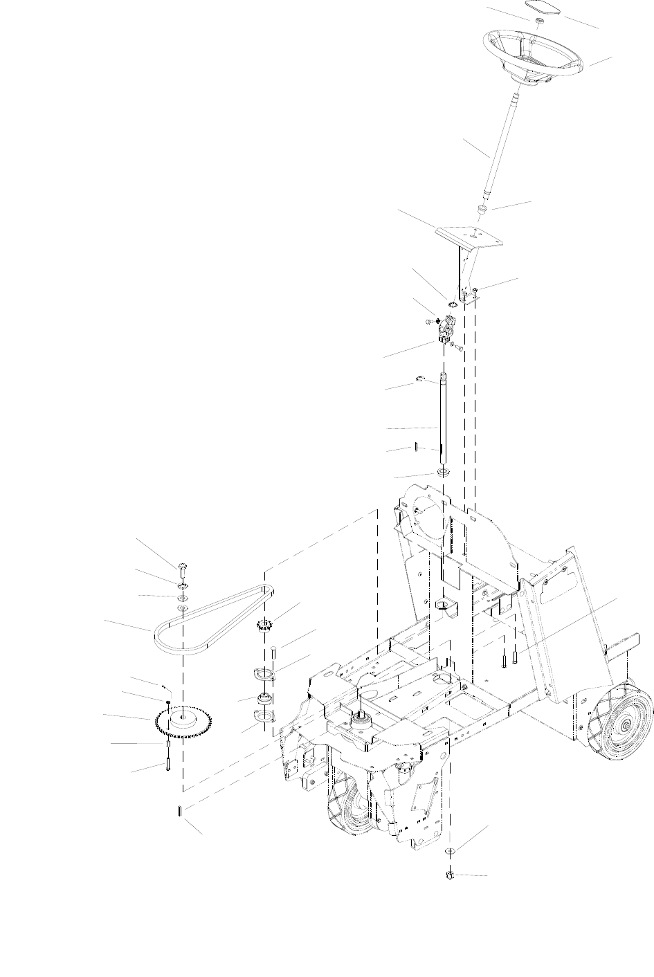
STEERING
86037660 CHARIOT 11/09/06
5-59
28
14
22 20
19
19
15
24
13
11
9
6
1
4
5
3
2
27
26
25
16
7
23
21
18
14
12
10
87
17
29

STEERING
86037660 CHARIOT 11/09/06 5-60
REF PART NO. PRV NO. QTY DESCRIPTION SERIAL NO.
FROM NOTES:
1 86271610 57228 1 NUT, 5/8-16 HEX NYLOCK THN
2 86234810 27945 1 COVER, STEERING WHEEL
3 86259610 730117 1 WHEEL, STEERING 40 SPLINE HUB
4 86224050 730318 1 SHAFT, UPPER STEERING
5 86228790 09111 1 BEARING, FLANGE .88ODX.75IDX.75
6 86091740 140720 1 BRKT, UPPER STEERING
7 86270830 57023 4 NUT, 5/16-18 HEX NYLOCK SS
8 86005610 57016 1 NUT, 7/8 DIA PUSHLOCK
9 86219600 45012 1 JOINT, UNIVERSAL FEMALE
10 86272900 67416 1 RING, 3/4” KLIP
11 86224060 730319 1 SHAFT, LOWER STEERING
12 86219650 48110 1 KEY, 5MM SQ X 39MM L
13 86228670 09072 1 BEARING, 3/4” BORE FLANGED
14 86276070 70593 4 SCR, 5/16-18 X 3/4 CARRIAGE SS
15 86224800 730315 1 SPROCKET, STEERING SHAFT
16 86010670 87029 2 WASHER, 5/16 FLAT SS
17 86135970 48045 1 KEY, 3/16 SQ X 5/8 LONG
18 86275190 70377 1 SCR, 3/8-16 X 1.25 HHCS SS
19 86008610 80595 2 FLANGE, BEARING PRESS STEEL
20 86001030 09148 1 BEARING, BALL 3/4 BORE SPHERED
21 86224320 730221 1 SPACER, .63 OD X .385ID X .64L
22 86224810 730316 1 SPROCKET, DRIVE WHEEL STEERING
23 86005630 57022 1 NUT, 3/8-16 HEX NYLOCK THIN SS
24 86002750 270088 1 CHAIN, ISO 08B, 12.7MM PITCH
25 86278940 87008 2 WASHER, 1/4 ID X 1-1/4OD
26 86010780 87162 1 WASHER, 1/4 SPLIT LOCK PLTD
27 86274330 70175 1 SCR, M6 X 20HHMS PLTD
28 86279130 87083 2 WASHER, 5/16 SPLIT LOCK
29 86253200 70806 1 SET SCR, M6 X 25 NP SERVICE ONLY
- 86232780 279001 - CHAIN, MASTERLINK 12.7MM SERVICE ONLY
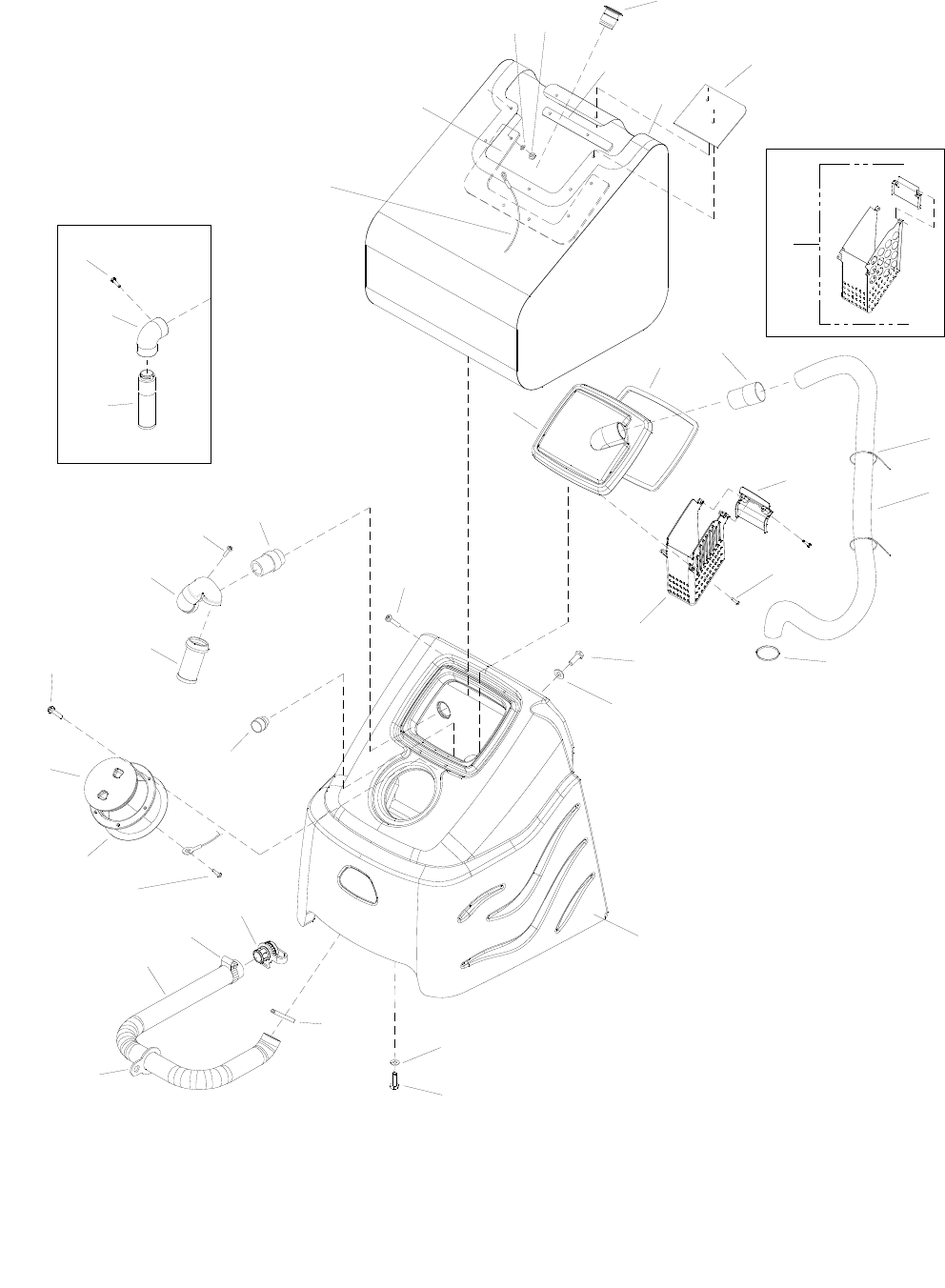
TANK
86037660 CHARIOT 12/12/08
5-61
11
19
6
11
35
36
22
23
11 17
25
18
30
24 26
14
12
9
8
31
32
33
27
29
29
27
13
20
4
21A
2
1
10
3
5
34
7
16
15
28
21B
37

TANK
86037660 CHARIOT 07/05/11 5-62
REF PART NO. PRV NO. QTY DESCRIPTION SERIAL NO.
FROM NOTES:
1 86001510 140712 1 BAG, INNER TANK
2 86006470 67513 1 RETAINER, BACK BAG **
3 86221900 54198 1 MANDREL, BAG
4 86271940 57299 8 NUT, 1/4-20 ACORN SS
5 86010630 87013 8 WASHER, 1/4-20 X 5/8 OD SS
6 86006480 67514 1 RETAINER, MAIN BAG **
7 86246080 51368 1 LANYARD, 18.0 W/LOOP & EYE
8 86004010 35274 1 GASKET, DOME EDGE
9 86003350 28063 1 DOME, COVER, 10X13
10 86310190 - 1 BASKET, STRAINER, DOME *(31)
11 86006860 70403 5 SCR, #10X1/2 PPHST TYPE B
12 86276840 70744 8 SCR, 1/4-20X1 PFH BLK SS
13 86256100 730333 1 STRAINER, 3/4-MNPT, 12 MESH
14 86275800 70546 6 SCR, 8 X 3/4 PFHT/S BLK ZINC
15 86002620 260-64A 1 ACCESS COVER CLEAR 6” W/RIM
16 86004000 35255 1 GASKET, TANK LID
17 86033570 78934 1 TUBE ASM
18 86002390 20063 1 CLAMP, 1.75” WORM GEAR X .312
19 86003010 27759 1 CUFF, HOSE 1.5” BLK A 2161
20 86264950 27746 3 CABLE TIE, .19W X 11.5L BLK
21A 86305960 - 1 HOSE ASM, 1.5 BLK PVC VAC X 67 DISK
21B 86004380 39550 1 HOSE ASM, 1.5 BLK VAC X 50 SCRUB PLUS
22 86197870 31101 1 ELBOW, 1.5 FS X FS 90 DEG
23 86003680 34380 1 FLOAT, SHUT-OFF
24 86311740 - 1 HOSE, 2.0 X 37.0, DRAIN **
- 86004430 39707 1 HOSE ASM, 2 X 37.0 DRAIN, ASM HOSE & CAP
25 86002380 20046 1 CLAMP, 2.25” WORM GEAR
26 86032870 75455 1 TANK
27 86006760 70305 6 SCR, 5/16-18 x 3/4 HHCS GR5 PLTD
28 86177050 03-000176 1 CLAMP, HOSE #20 *(14)
29 86279630 87212 6 WASHER, .344 ID X 1.13 OD X .09T PLT
30 86257570 51407 1 TETHER, DRAIN HOSE, 1.5
31 86310180 - 1 PLATE, STRAINER BASKET *(31)
32 86003710 34447 1 FLAP, TANK DEBRIS *(7)
33 86004440 39717 1 CAP, DRAIN HOSE
34 86277560 70866 1 SCR, #6 X 1/2 SHT MTL SS
35 86025200 31377 1 ELBOW ASM, FLOAT *(19)
36 86199840 090-12A 1 FLOAT SCREEN CAGE ASSY *(19)
37 98406760 - 1 KIT, DOME BASKET
* SEE SERIAL NUMBER PAGE.
** CALL MANUFACTURER FOR SERIAL NUMBER
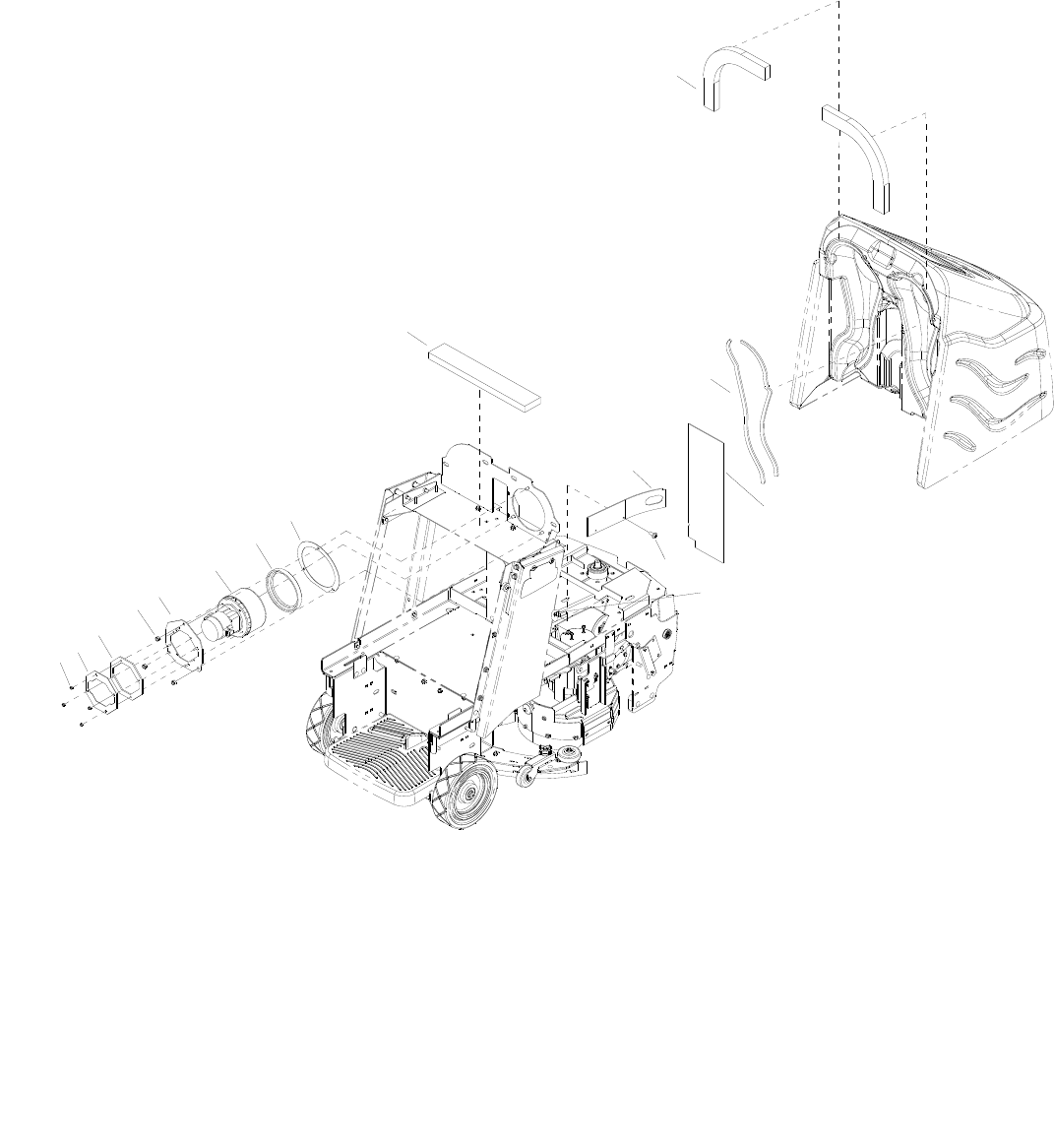
VACUUM
86037660 CHARIOT 11/09/06
5-63
11
12 13
9
8
7
6
5
4
3
2
1
10
14
15

VACUUM
86037660 CHARIOT 11/09/06 5-64
REF PART NO. PRV NO. QTY DESCRIPTION SERIAL NO.
FROM NOTES:
1 86270990 57090 4 NUT, 10-32 HEX NYLOCK SS
2 86083030 66430 1 PLATE, VAC MOTOR ADAPT
3 86083010 66428 1 PLATE, VAC SPACER
4 86270830 57023 3 NUT, 5/16-18 HEX NYLOCK SS
5 86083020 66429 1 PLATE, VAC MOUNTING
6 86005500 53809 1 VAC MOTOR 36VDC 3 STG
- 86135310 140686 - BRUSH SET, 24/36V VAC WINDSOR SERVICE ONLY
7 86237880 35276 1 GASKET, 5.7 VAC MOTOR
8 86237890 35277 1 GASKET, VAC MOUNT
9 86078650 36241 1 GUARD, CHAIN RT
10 86238040 36243 2 GASKET, 1/4 T X 3/4 W X 24 L
11 86064740 270100 1 VAC CHANNEL COVER
12 86274070 70086 2 SCR, 10-24 X 1/2 PPHMS
13 86270860 57028 2 NUT, 10-24 U-TYPE SPEED
14 86236530 34436 1 FOAM, POLYESTER, 1X3X18 *(3)
15 86236540 34437 2 FOAM, POLY, 1X2 CURVED W/ADH *(3)
*SEE SERIAL NUMBER PAGE.
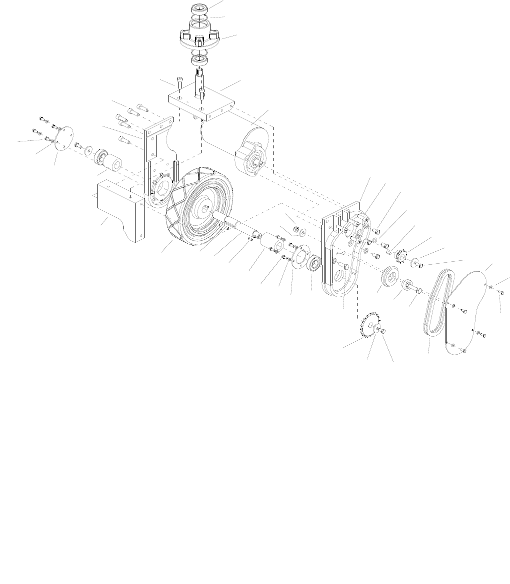
WHEEL-FRONT DRIVE, CHAIN
86037660 CHARIOT 08/19/09
5-65
30A
30B
35
5
4
3
2
1
18
18
17
17
9
9
1
14
10
20
33 32
31
29 28 27 26
25 24
23
22
21
15 19
18
17
16
15
14
13
12
11
9
8
7
6

WHEEL-FRONT DRIVE, CHAIN
86037660 CHARIOT 08/19/09 5-66
REF PART NO. PRV NO. QTY DESCRIPTION SERIAL NO.
FROM NOTES:
1 86223980 09134 4 SEALED BALL BRNG, 25MM X 52MM
2 86223480 67450 2 RING, 52MM INTERNAL SNAP
3 86219420 41510 1 STEERING, HUB
4 86224040 730306 1 SHAFT, ASM, DRIVE PIVOT
5 86005510 53810 1 MOTOR, 36V 180RPM GEAR
- 86216210 53820 - BRUSH SET MOTOR 53810
- 86227440 05261 - ARMATURE 53810 MOTOR
6 86136360 57275 1 NUT, M10X1.5 HEX NYLOCK PLTD
7 86010720 87086 1 WASHER, M10 X 30 PLTD
8 86222730 620038 1 PLATE, DRIVE WHEEL YOKE
9 86318830 - 11 SCR, M10 X 30 SHCS
10 86275640 70515 4 SCR, 3/8-24 X 3/4 HHCS GR5 PLTD
11 86279700 87244 5 WASHER, M10 X 18 FLAT
12 86219620 48106 1 KEY, 1/4 SQ. X .63
13 86007620 730310 1 SPROCKET, MOTOR SHAFT
14 86279710 87245 3 WASHER, M8 (2 THK X 26 OD)
15 86136640 70262 2 SCR, M8-1.25 X 20HHMS PLTD
16 86222710 620036 1 PLATE, CHAIN COVER
17 86279690 87243 12 WASHER, M6 SPLIT LOCK BLK
18 86277340 70830 12 SCR, M6 X 15 HHCS BLK
19 86002730 270085 1 CHAIN, ISO 08B 12.7MM PITCH/LINK
- 86232770 279000 - CHAIN, OFF-SET LINK 12.7MM SERVICE ONLY
- 86232780 279001 - CHAIN, MASTERLINK 12.7MM SERVICE ONLY
20 86222760 620041 1 PLATE, DRIVE YOKE RH
21 86007630 730311 1 SPROCKET, DRIVE WHEEL
22 86002710 270076 1 CHAIN TENSIONER
23 86224270 730293 1 SLEEVE, CHAIN TENSIONER
24 86277330 70829 1 SCR, M10 X 45 HHCS
25 86222720 620037 1 PLATE, BEARING RETAINER
26 86224330 730294 1 SPACER, 25.5ID X 45OD X 65L
27 86219630 48107 1 KEY, 3/16 SQ X .67
28 86000850 05231 1 AXLE, DRIVE
29 86219640 48108 1 KEY, 1/4 SQ X 1.5
30A 86011120 89262 1 WHEEL, 10X2.5X1.06 W/KEYWY
30B 86259920 89273 1 WHEEL, 10X2.5 W/KEYWY GRY OPTIONAL
31 86222750 620040 1 PLATE, DRIVE YOKE FRONT
32 86224340 730295 1 SPACER, 25.5ID X 45OD X 43L
33 86222770 620042 1 PLATE, BEARING COVER
34 86217720 29269 - DRIVE ASM, MOTOR COMPLETE
35 86277320 70828 1 SCR, M10 X 30 HHCS
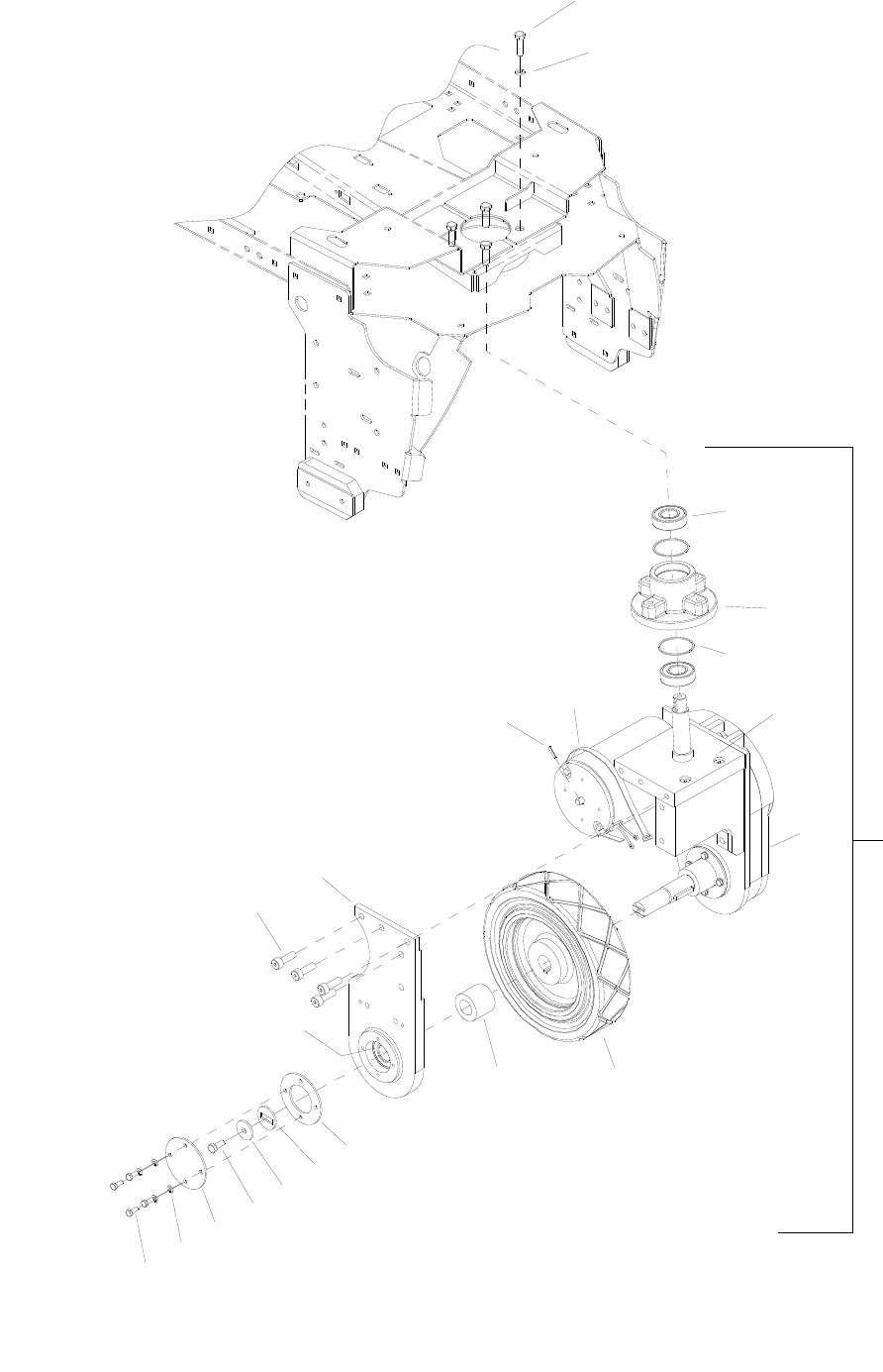
WHEEL-FRONT DRIVE, GEAR
86037660 CHARIOT 02/21/09
5-67
22
1
4
2
10A
9
5
6
7
15
20
18 17
14 13 12
21
16
11
19
10B
8
3

WHEEL-FRONT DRIVE, GEAR
86037660 CHARIOT 08/19/09 5-68
REF PART NO. PRV NO. QTY DESCRIPTION SERIAL NO.
FROM NOTES:
1 86275190 70377 4 SCR, 3/8-16 X 1.25 HHCS SS
2 86010790 87163 4 WASHER, 3/8 SPLIT LOCK PLTD
3 86002830 27196 1 CABLE TIE, .375 X 24.7
4 86006170 66031 1 PIN, ROLL 1/8” X 3/4”L
5 86223980 09134 3 SEALED BALL BRNG, 25MM X 52MM
6 86219420 41510 1 HUB STEERING
7 86223480 67450 2 RING, 52MM INTERNAL SNAP
8 86224020 730233 1 SHAFT ASM, DRIVE PIVOT
9 86317190 - 1 GEAR BOX DRIVE UNIT HELICAL
10A 86011120 89262 1 WHEEL, 10 X 2, 5 X 1.06 W/KEYWAY
10B 86259920 89273 1 WHEEL, 10 X 2. 5 W/KEYWAY, GRY OPTION
11 86224440 730387 1 SPACER, 25.51 ID X 45 OD X 39.1 L
12 86222720 620037 1 PLATE, BEARING RETAINERX
13 86225810 87506 1 WASHER, ANTI-ROTATION
14 86279710 87245 1 WASHER, M8 (2THK X 26 OD)
15 86136640 70262 1 SCR, M8-1.25 X 20 HHMS PLTD
16 86222770 620042 1 PLATE, BEARING COVER
17 86279690 87243 4 WASHER, M6 SPLIT LOCK BLK
18 86277340 70830 4 SCR, M6 X 15 HHCS BLK
19 86223980 09134 3 SEALED BALL BRNG, .25MM X 52MM
20 86318830 - 10 SCR, M10 X 30 SHCS
21 86222760 620041 1 PLATE, DRIVE YOKE RH
22 86317200 - 1 DRIVE MOTOR ASSEMBLY HELICAL WHEEL NOT
INCLUDED
- 86216210 53820 - BRUSH SET MOTOR, 53810 86005510
*SEE SERIAL NUMBER PAGE.
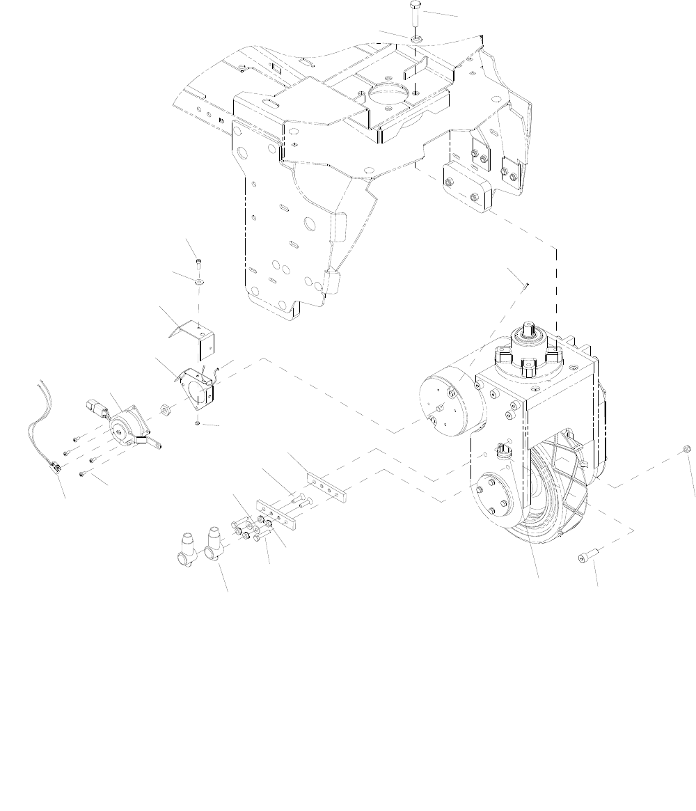
WHEEL-FRONT BRAKE
86037660 CHARIOT 02/21/09
5-69
21
16
15
17
20
19
18
5
2
1
6
3
14
13
7
4
10
11
12
8
9

WHEEL-FRONT BRAKE
86037660 CHARIOT 08/19/09 5-70
REF PART NO. PRV NO. QTY DESCRIPTION SERIAL NO.
FROM NOTES:
1 86010790 87163 4
WASHER, 3/8 SPLIT LOCK
PLTD
2 86275190 70377 4
SCR, 3/8-16 X 1.25 HHCS SS
3 86006170 66031 1
PIN, ROLL 1/8” X 3/4”L SS
4 86005810 57245 2
NUT, 1/4-20 HEX NYLOCK SS
5 86318830 - 1
SCR, M10 X 30 SHCS
6 86233410 81270 1
CLAMP, 3/4 DIA CUSHION
.406DIA
7 86005710 57105 4
NUT, 1/4-20 HEX W/STAR
WASHER
8 86273740 70010 2
SCR, 1/4-20 X 1.50 HHCS
9 86008920 80889 2
BOOT, RUBBER TERM.
ISOLATOR
10 86257490 76155 2
TERMINAL MOUNT
11 86006840 70390 2
SCR, 1/4-20 X 1 FHCS PLTD
12 86010630 87013 2
WASHER, 1/4 ID X 5/8 OD SS
13 86273340 00-000289 4
SCR, 8-32 X 3/8 SHCS SS
14 86001740 140816 1
BRAKE, 36VDC
W/CONNECTOR
15 86270990 57090 3
NUT, 10-32 HEX NYLOCK SS *(24)
16 86301950 1
PLATE, BRAKE SPACER *(24)
17 86264930 27050 1
CABLE TIE, 3.5” UL/CSA
18 86301960 1
SKIRT, BRAKE *(24)
19 86010650 87018 3
WASHER, #10 X 9/16 OD *(24)
20 86274290 70162 3
SCR, 10-32 X 3/8 PPHMS SS *(24)
21 86320870 - 1
SWITCH, 36V BRAKE
* SEE SERIAL NUMBER PAGE.
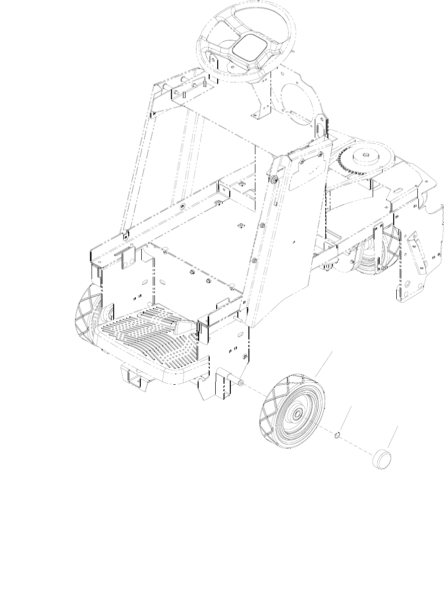
WHEEL-REAR
86037660 CHARIOT 04/07/07
5-71
3
2
1B
1A

WHEEL-REAR
86037660 CHARIOT 04/07/07 5-72
REF PART NO. PRV NO. QTY DESCRIPTION SERIAL NO.
FROM NOTES:
1A 86011110 89261 2 WHEEL, 10X2.5X.787ID BEARINGS
1B 86259930 89274 - WHEEL, 10X2.5, W/BEARINGS, GRY OPTIONAL
2 86008710 80623 2 RING, ¾” EXT SNAP H-D
3 86232130 17309 2 CAP, 2.75 ID X 1.0 L BLK VINYL
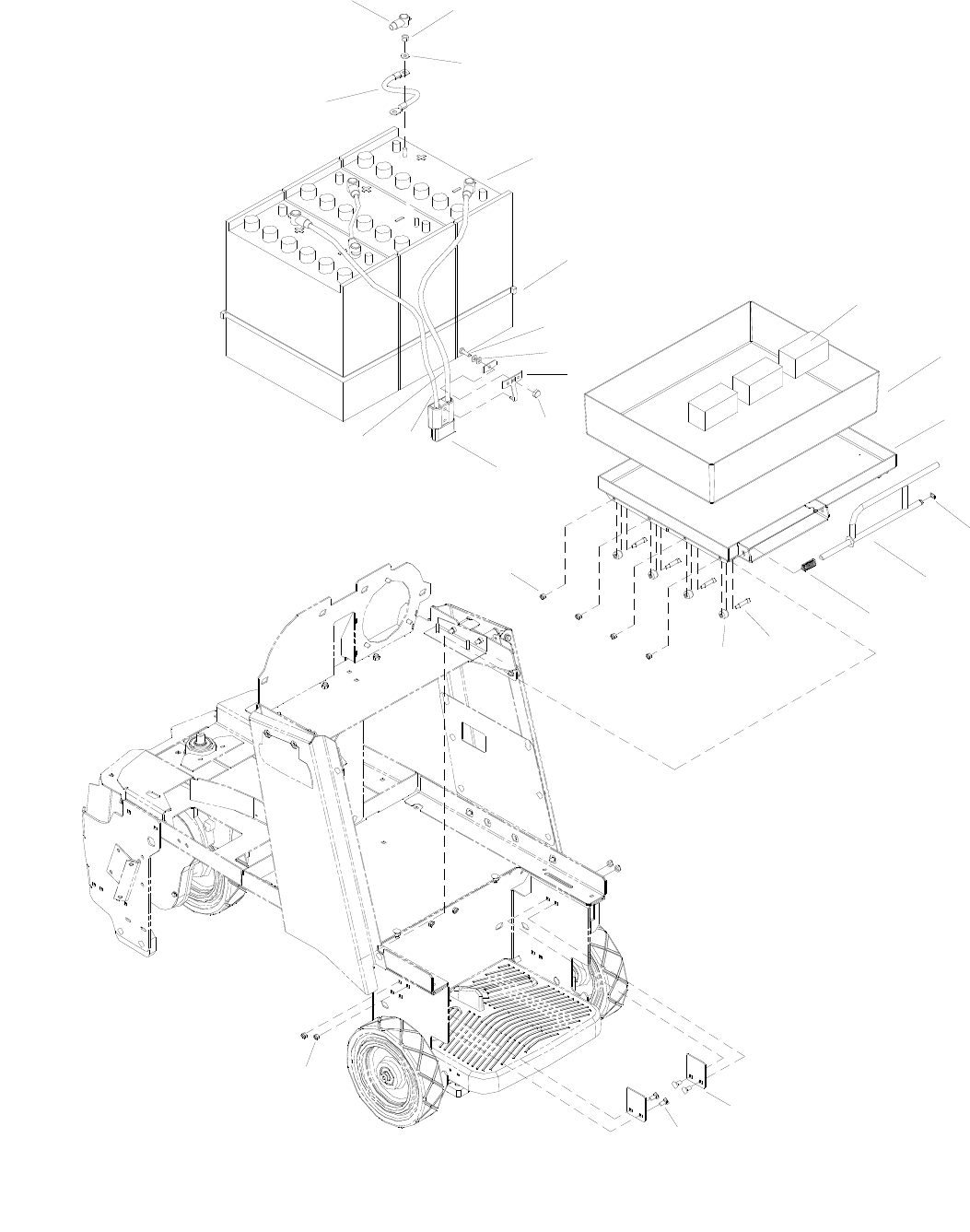
WIRING-BATTERIES
86037660 CHARIOT 02/20/07
5-73
17
18
19
5
7A
1A
4
3
2
6A
8
10
9
11
12
22 13
14
16 15
20A
20B
24
23
20C
1B
6B
7B
26
25

WIRING-BATTERIES
86037660 CHARIOT 10/20/08 5-74
REF PART NO. PRV NO. QTY DESCRIPTION
SERIAL NO.
FROM NOTES:
1A 86260200 80872 2 WIRE, 4X14.5BK 3/8RINGX3/8RING
1B 86002510 23125 2 CABLE ASM, BAT. JUMPER X 15”
2 86008920 80889 6 BOOT, RUBBER TERM. ISOLATOR
3 86271910 57295 6 NUT, 5/16-18 FLEXLOCK
4 86010670 87029 6 WASHER, 5/16 FLAT SS
5 86264960 27915 2 CABLE TIE, .375 X 43”
6A 86260610 880836 1 WIRE, 4X25RD CTERM X 3/8RING *(20)
6B 86002570 23190 1 WIRE, 4X27 RD BCLAMP X CTERM
7A 86260230 80876 1 WIRE, 4X30 BK CTERM X 3/8RING
7B 86002580 23191 1 WIRE, 4X27 BK BCLAMP X CTERM
8 86008760 80682 1 CONN, 175 DCA GRY W/O TERMS
9 86229700 08071 3 BLOCK, 3.0 X 1.5 X 1.5
10 86008300 78242 1 TRAY, BATTERY LINER
11 86008410 78568 1 TRAY, BATTERY
12 86272810 67132 1 RING, 1/2 EXT. SNAP H-D
13 86092910 51396 1 LATCH ROD, BATTERY TRAY
14 86254990 730313 1 SPRING, COMP, 63ODX3.5LX.047W
15 86278150 70117 8 SHOULDER BOLT, 5/16 OD X 1.0 L
16 86259910 89265 8 WHEEL, BATTERY TRAY
17 86088790 78571 2 TRAY, STANDARD STOP
18 86276070 70593 4 SCR, 5/16-18 X 3/4 CARRIAGE SS
19 86270830 57023 4 NUT, 5/16-18 HEX NYLOCK SS
20A 86228410 10023 3 BATTERY, 12V, 205AH
20B 86283410 10030 3 BATTERY, 12V, 225AH
20C 86228430 10032 3 BATTERY, 12V, AGM 198AH
21A 86284090 02456 1 CHARGER, 36V, 20A, 115V, C175 ▲
21B 86000150 02264 1 CHARGER, 36VDC/21A AGM ▲
22 86005810 57245 8 NUT, 1/4-20 HEX NYLOCK SS
23 86233360 28038 1 CLAMP, CABLE KIT SY945 *(12)
24 86273980 70066 1 SCREW, 10-32 X 3/4 PPHMS SS
25 86010650 87018 1 WASHER, #10 X 9/16 OD
26 86270890 57034 1 NUT, ACORN 10-32
▲NOT SHOWN – FOR WET CELL BATTERIES AND AGM BATTERIES
* SEE SERIAL NUMBER PAGE
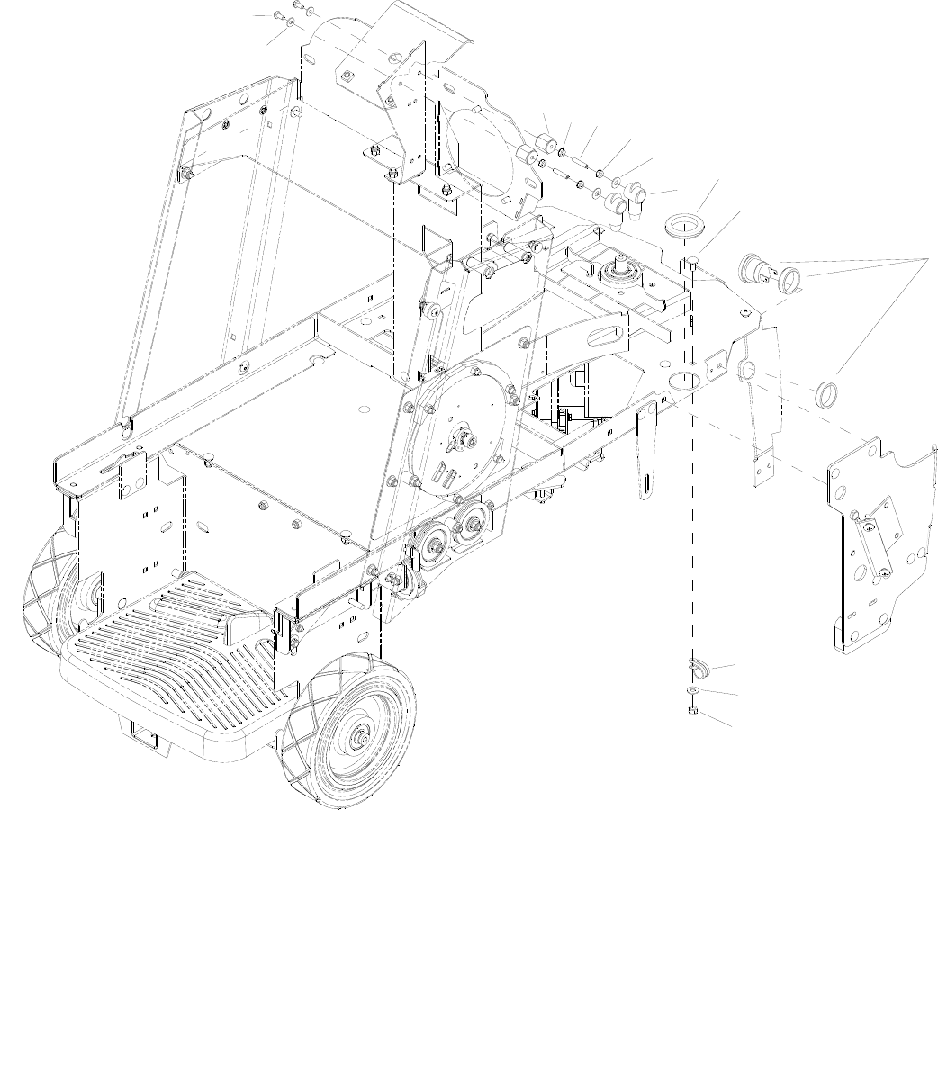
WIRING-COMPONENTS
86037660 CHARIOT 02/03/09
5-75
13
5
9
1
2
3464
78
12
11
10

WIRING-COMPONENTS
86037660 CHARIOT 01/03/08 5-76
REF PART NO. PRV NO. QTY DESCRIPTION SERIAL NO.
FROM NOTES:
1 86010780 87162 2 WASHER, 1/4 SPLIT LOCK PLTD
2 86273830 70020 2 SCR, 1/4-20 X 1/2 HHCS SS NP
3 86255910 73659 2 STANDOFF, 1/4-20 X 1.0 HEX INS
4 86005710 57105 4 NUT, 1/4-20 HEX W/STAR WASHER
5 86010630 87013 2 WASHER, 1/4 ID X 5/8 OD SS
6 86006850 70393 2 SET SCR, 1/4-20 1.25L
7 86008920 80889 2 BOOT, RUBBER TERM. ISOLATOR
8 86238500 81427 1 GROMMET, 1.703IDX2.5ODX.125GRV
9 86276070 70593 1 SCR, 5/16-18 X 3/4 CARRIAGE SS
10 86239720 41520 1 HORN, 108DB MINIATURE PIEZO
11 86233410 81270 1 CLAMP, 3/4 DIA CUSHION .406DIA
12 86270830 57023 1 NUT, 5/16-18 HEX NYLOCK SS
13 86010670 87029 1 WASHER, 5/16 FLAT SS
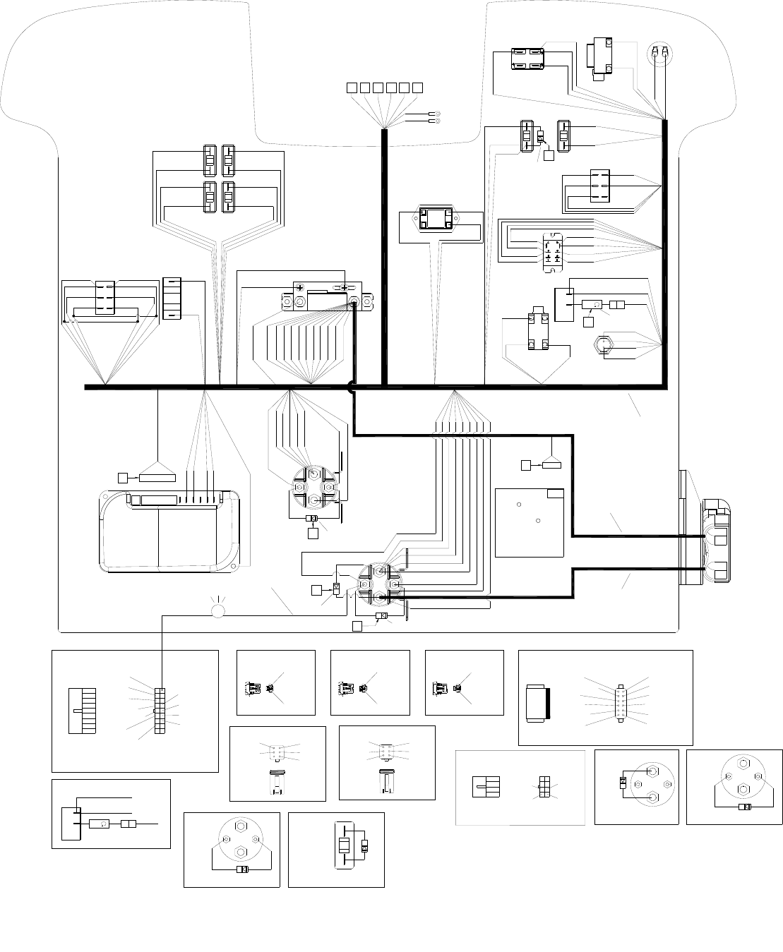
WIRING-CONTROL PANEL-BASIC-CYLINDRICAL
86037660 CHARIOT 07/30/08
5-77
6
L
PRV 67619
5
4
RELAY
MAIN
RELAY
BRUSH
51 RED
4
21 LT BLU
14 WHT/RED
37 RED
50 ORG
49 LT BLU
10 RED
19 WHT/BLK
DIAGRAM E
12
6
7
1
15 YLW 14 WHT/RED
63 BLU
20 WHT
6 BRN
6 BRN
19 WHT/BLK
18 WHT/ORG
17 WHT/YLW16 LT BLU
12 ORG
13 BLK
38 BLK
15 YLW 36 RED
37 RED
DIAGRAM H
2 BLK
1 WHT
30A-BASIC
3A
34 RED
52 RED
9 RED
51 RED
22 RED
39 BLK
33 RED 40 RED
1 WHT
54 BLK
53 RED
55 BLK
2 BLK
A
8 BLK
54 BLK
13 BLK
38 BLK
55 BLK
60 BLK
23 BLK
41 BLK
62 BLK
39 BLK
48 BLK
11 BLU
47 RED
46 RED
6 RED
6 RED
10 RED
10 RED
3A
18A 18A
30A
10 RED
10 RED
14 WHT/RED
14 WHT/RED
47 RED
46 RED
22 RED
22 RED
23 BLK
23 BLK
17 WHT/YLW
18 LT BLU
22 RED
23 BLK
53 RED
52 RED 35 RED
34 RED
36 RED
32 RED 32 RED
49 LT BLU 50 ORG
48 BLK
43 RED
4 RED
44 WHT
45 WHT
24 YLW25 GRN
24 YLW 26 GRN
27 GRN
32 RED
35 RED
12 ORG
12 ORG
41 BLK
42 BLK
40 RED
30 GRN
H
BCDEFG
1
3
2
7 GRN
29 DK BLU
18 WHT/ ORG
30 DK GRN
57 RED
28 GRY
24 YLW
31 RED
6 BRN
5 ORG
21 LT BLU
10 RED
11 BLK
57 RED
56 BLK
59 RED 60 BLK
61 RED 62 BLK
3 BLU
4 RED 5 ORG
6 BRN
7 GRN
DIAGRAM A DIAGRAM B DIAGRAM C
11 BLK
10 RED
DIAGRAM D
8 BLK
9 RED
43
61
DIAGRAM F DIAGRAM G
1
6
3
4
3 LT BLU
DIAGRAM JDIAGRAM I
RELAY
MAIN RELAY
BRUSH
PRV 29273
86261210 PRV 29204
I
J
25A CYLINDRICAL
28 GRY
58 BLK
29 BLU
33
33
29 BLU
58 BLK
28 GRY
DIAGRAM L
86261210 PRV 29204
MAIN
RELAY
DIAGRAM K
K4
86251490
86261250
63 BLK
42 BLK
6 BRN
9 BRN
43 RED
45 WHT
44 WHT
20 WHT
STATUS LED
BLK WHT
7
DIAGRAM M
86261210 PRV 29204
M

WIRING-CONTROL PANEL- BASIC - CYLINDRICAL
86037660 CHARIOT 05/27/08 5-78
REF PART NO. PRV NO. QTY DESCRIPTION SERIAL NO.
FROM NOTES:
1 86239140 41524 1 HARNESS, CONTROL PANEL BASIC
2 86260540 880426 1 WIRE, 4X13 RD C.TERM X 5/16RING
3 86010860 880353 1 WIRE, 4X20 BK CTERM X5/16RING
4 86261210 29204 3 DIODE ASM, 76008, 76008
5 86261250 29273 1 DIODE ASM, FAST RECOVERY *(8)
6 86251490 67619 1 RESISTOR ASM, 1/2 WATT 33 OHM *(18)
7 86311210 - 1 LIGHT ASM, INDICATOR, CODE
* SEE SERIAL NUMBER PAGE
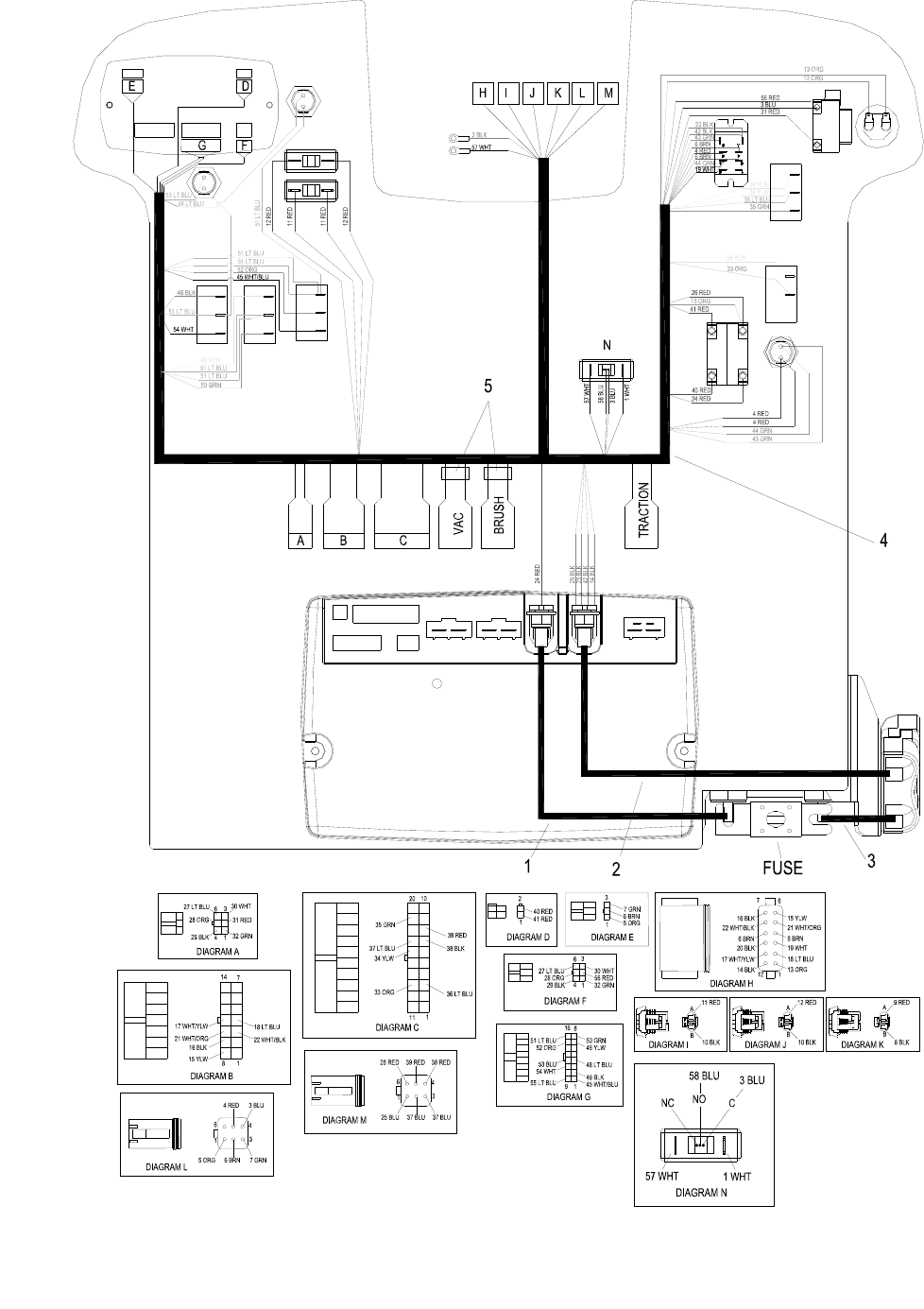
WIRING-CONTROL PANEL-DELUXE
86037660 CHARIOT 03/03/09
5-79

WIRING-CONTROL PANEL-DELUXE
86037660 CHARIOT 01/18/08 5-80
REF PART NO. PRV NO. QTY DESCRIPTION SERIAL NO.
FROM NOTES:
1 86260560 880428 1 WIRE, 4X10RD 5/16RING X 5/16RING
2 86260550 880427 1 WIRE, 4X15BK C. TERM X 5/16 RING
3 86260570 880429 1 WIRE, 4X8RD C. TERM X 5/16RING
4 86239150 41525 1 HARNESS, CONTROL PANEL DELUXE
5 86235780 34164 2 FERRITE CLAMP, 1.14 X 1.28 X .583 CSXE24 &
CSXEO24 ONLY
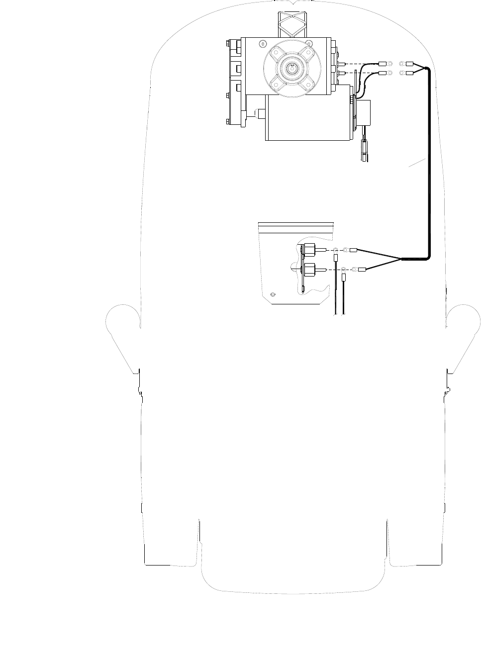
WIRING- DRIVE MOTOR
86037660 CHARIOT 11/09/06
5-81
1
RED
BLK 2 BLK
1 WHT
BLK
WHT
1 WHT 2 BLK
2 BLK
CONTROL PANEL
HARNESS

WIRING-DRIVE MOTOR
86037660 CHARIOT 11/09/06 5-82
REF PART NO. PRV NO. QTY DESCRIPTION SERIAL NO.
FROM NOTES:
1 86239120 41522 1 HARNESS, CHARIOT PROPEL
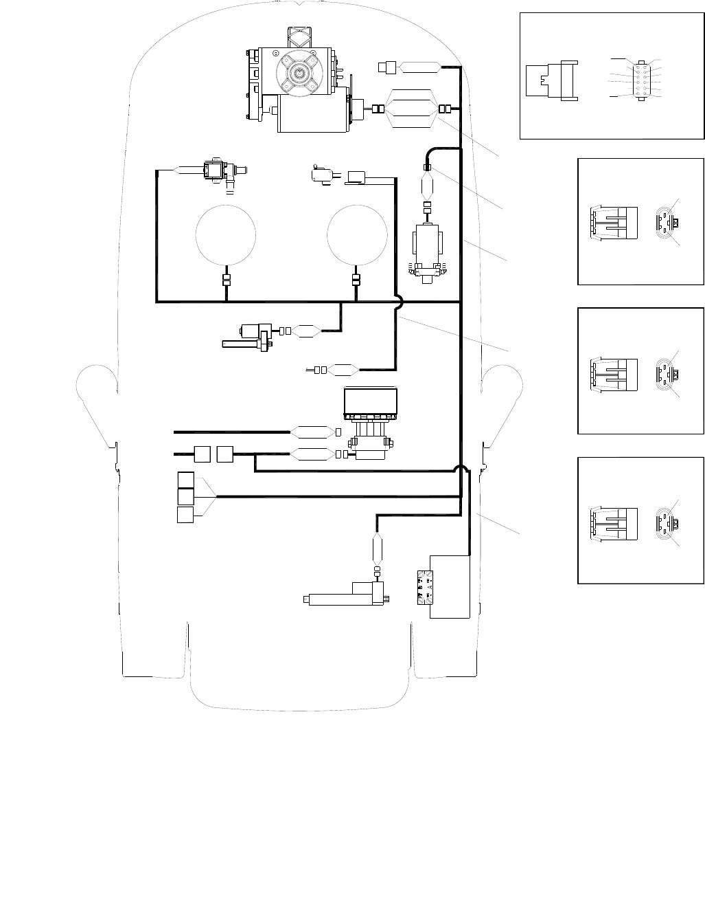
WIRING-MAIN HARNESS
86037660 CHARIOT 11/09/06
5-83
4
3
2
1DIAGRAM B
DIAGRAM A
DIAGRAM C
DIAGRAM D
BRUSH
RIGHT
MOTOR
MOTOR
BRUSH
LEFT
SQUEEGEE LIFT
ACTUATOR
VAC
MOTOR
ACTUATOR
SCRUB LIFT
SOLENOID
VALVE
(DELUXE ONLY)
DRIVE
MOTOR
BRUSH MOTOR
SWITCH
(BASIC ONLY)
PUMP
CONTROL
HARNESS
(BASIC ONLY)
VACUUM
SWITCH
BRAKE
A
B
C
D
HORN 13 ORG
14 BLK
19 WHT
20 BLK
6 BRN
6 BRN
60 WHT/BLK
59 WHT/ORG
15 YLW
16 BLK
11 RED
10 BLK
17 LT BLU
18 WHT/YLW
59 WHT/ORG
60 WHT/BLK
21 WHT/ORG
22 WHT/BLK
13 BLK
18 LG BLU
19 WHT
6 BRN
21 WHT/ORG
15 YLW
12 RED
9 BLK
10 BLK
11 RED
10 BLK
11 RED
CONTROL
HARNESS
DELUXE
CONTROL
HARNESS
BASIC
5
12 ORG
17 WHT/YLW
16 BLK
22 WHT/BLK
6 BRN
20 BLK

WIRING-MAIN HARNESS
86037660 CHARIOT 11/09/06 5-84
REF PART NO. PRV NO. QTY DESCRIPTION SERIAL NO.
FROM NOTES:
1 86239170 41528 1 HARNESS, BRAKE
2 86239130 41523 1 HARNESS, MAIN
3 86239160 41527 1 HARNESS, DECK SWITCH BASIC ONLY
4 86239110 41521 1 HARNESS, VAC BASIC BASIC ONLY
5 86235820 34376 1 FERRITE, .72 X .70 X 1.28 CSE24 ONLY
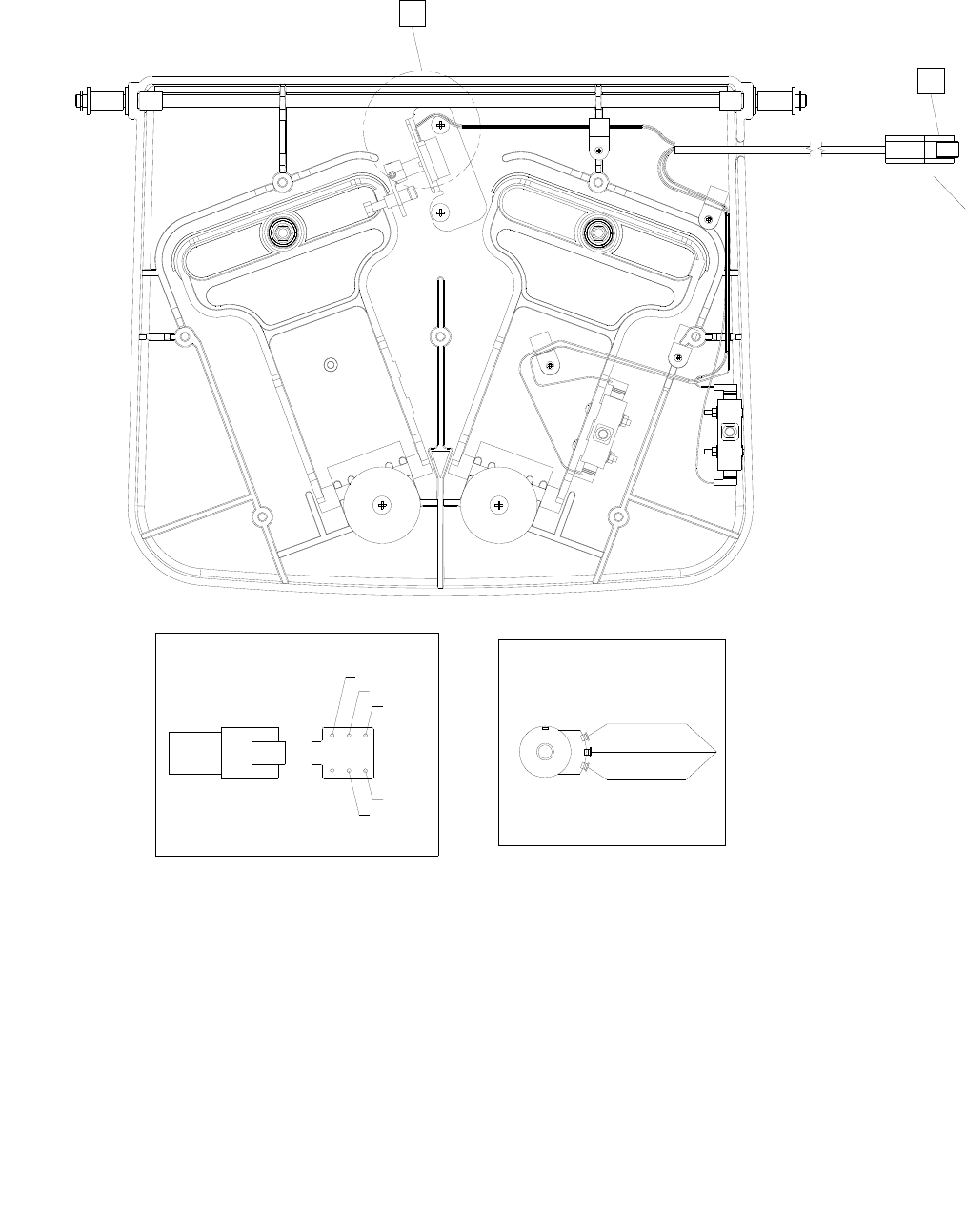
WIRING-PEDAL PLATFORM
86037660 CHARIOT 11/09/06
5-65 5-85
5 ORG
6 BRN
7 GRN
3 LT BLU
4 RED
DIAGRAM A
B
A
DIAGRAM B
6 ORG
10 BRN
5 GRN
BRN
BRN
BLU
RED
1

WIRING-PEDAL PLATFORM
86037660 CHARIOT 11/09/06 5-86
REF PART NO. PRV NO. QTY DESCRIPTION SERIAL NO.
FROM NOTES:
1 86218810 23717 1 HARNESS, TWISTER PEDAL
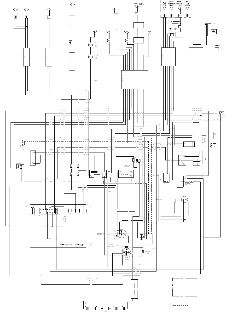
WIRING DIAGRAM-BASIC-CYLINDRICAL
86037660 CHARIOT 07/30/08
5-87
2/BLK
1/WHT
6/BRN
29/BLU
31/RED
21/LT BLU
5/ORG
7/GRN
18/WHT-ORG
30/GRN
57/RED
24/YLW
SOLENOID RBRUSH LBRUSH
VACUUM
BLK
BLK
DECK
SWITCH
OPERATOR PLATFORM
31/RED
32/BLK
23/RED
26/BLK
29/RED
30/BLK
TRACTION
28/GRY
SHUNT
48/BLK
SOLUTION
CONTROL
BOARD
28/GRY
29/BLU
58/BLK
PUMP
3A
BRUSH
18A BRUSH
18A
VACCUM
30A
12 PIN DEUTSCH
58/BLK
4/RED
4/RED
44/WHT
45/WHT
43/RED
KEY
SWITCH
RESET
SWITCH
3/LT-BLUE
FORWARD/REV
SWITCH
34/RED
12/ORG
33/RED
61/RED
SPEED
SWITCH
SOLUTION
CONTROL
POTENTIOMETER
6 PIN
DEUTSCH
38/BLK
15/YLW
36/RED 61/RED
37/RED
36/RED
BATTERY
METER
40/RED
40/RED
27/GRN
26/GRN
25/GRN
6 PIN
DEUTSCH
100K
200K
5/ORG
40/BLK
6/BRN
6/BRN
15/YLW
HEADLIGHT
SWITCH
59/RED
59/RED
12/ORG
56/RED
41/BLK
30/GRN
39/BLK
BRUSH
RELAY
RUN/RESET
RELAY
49/LT-BLU
DECK
ACTUATOR
23/BLK
22/RED
16/LT BLU
17/WHT-YLW
17/WHT-YLW
18/LT BLU
10/RED
11/BLK
11/BLK
10/RED
7/GRN
20/WHT
57/RED
14/WHT-RED
9/RED
8/BLK
60/BLK
18/WHT-ORG
6/BRN
63/BLK
PUMP
SOLUTION
DECK LIFT
ACTUATOR
62/BLK
13/ORG
14/BLK
6/BRN
6/BRN
20/BLK
19/WHT
16/BLK
15/YLW
17/WHT-YLW
18/LT-BLU
TRACTION
AMP
METER
OPERATION
PRESENT
SWITCH
PLATFORM
SWITCH
THROTTLE
POT
19/WHT-BLK
13/BLK
10/BLK
11/RED
10/BLK
11/RED
9/BLK
12/RED
BLK
RED
VAL
SWITCH
RED
2/BLK
1/WHT
63/BLK
20/WHT
42/BLK
6/BRN
6/BRN
32/RED
32/RED
220K
3/LT-BLUE
32/RED
32/RED
36/RED
19/WHT-BLK
10/RED
14/WHT-RED
14/WHT-RED
53/RED
54/BLK
46/RED
46/RED
47/RED
47/RED
50/ORG
52/RED
34/RED
53/RED
35/RED
52/RED
51/RED
9/RED
14/WHT-RED
INDICATES OPTIONAL
EQUIPMENT
22/RED
9/RED
50/ORG
37/RED
21/LT-BLU
4 PIN
DEUTSCH
4 PIN
DEUTSCH
2 PIN DEUTSCH
2 PIN DEUTSCH2 PIN DEUTSCH
2 PIN DEUTSCH
2 PIN DEUTSCH
INDICATES WIRING
NOT IN HARNESS
21/WHT-ORG
22/WHT-BLK
WHTBLK
WHT
BLK
86310910
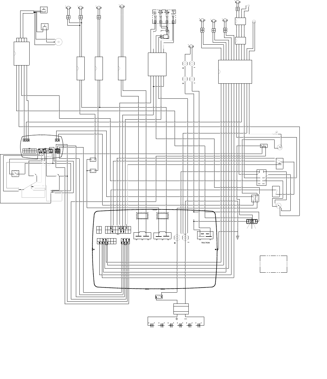
WIRING DIAGRAM-DELUXE
86037660 CHARIOT 03/03/09 5-88
FLASHER
UNIT
2/BLK
57/WHT
OPERATOR PLATFORM
2 PIN PACKARD
2 PIN PACKARD
PRESENCE
4 PIN
DEUTSCH
OPERATOR
DEUTSCH
4 PIN
9/RED
8/BLK
10/BLK
12/RED
12 PIN DEUTSCH
DEUTSCH
6 PIN
2 PIN PACKARD
6/BRN
DEUTSCH
6 PIN
SOLENOID BRAKE
SWITCH
BRAKE
SQUEGEE
ACTUATOR
THROTTLE POT
SWITCH
PUMP
SOLUTION
DECK LIFT
TRACTION
VACUUM 1
RBRUSH LBRUSH
HORN
PLATFORM SWITCH
ACTUATOR
RED
BLU
BRN
ORG
BRN
GRN
BREAKER
30 AMP
1/WHT
57/WHT
20/BLK
19/WHT
19/WHT
26/RED
2/BLK
1/WHT
SWITCH
51/DK-BLU
53/LT-BLU
52/ORG
51/LT-BLU
51/LT-BLU
INDICATES OPTIONAL EQUIPMENT
42/BLK
45/WHT-BLU
51/DK-BLU
11/RED
4/RED
58/BLU
BATTERY
CONN
55/LT-BLU
49/YLW
50/GRN
48/LT-BLU
51/DK-BLU
54/WHT
46/BLK
41/RED
40/RED
10/BLK
11/RED
2W 220 RES
9/RED
10/BLK
8/BLK
25/BLK
23/BLK
14/BLK
24/RED
3/BLU
42/BLK
36/RED
31/RED
41/RED
24/RED
13/ORG
40/RED
27/BLU
30/WHT
28/0RG
32/GRN
29/BLK
31/RED
7/GRN
HORN
6/BRN
6/BRN
4/RED
4/RED
44/GRN
43/GRN
4/RED
LIGHT
5/ORG
SWITCH
34/YLW
33/ORG
FWD/REV
RESET SWITCH
BRUSH
VACUUM
35/LT-GRN
39/RED
37/BLU
38/BLK
34/YLW
36/LT-BLU
33/ORG
HEAD
22/WHT-BLK
21/WHT-ORG
18/LT-BLU
17/WHT-YLW
15/YLW
16/BLK
2
1
RELAY
RUN/RESET
SPEED
KEY
18 AMP
BREAKER
INFO
LCD
VACUUM
WATER
FLOW
18 AMP
BREAKER
TOUCH
ONE
BRUSH
PRESS
10
1
1 7 1 3
36v
EMERGENCY STOP
BRUSH
BRUSH
FERRITE
BEAD
BEAD
FERRITE
125 AMP
FUSE
TRACTION
3/BLU
58/BLU
NC NO C
18/LT-BLU
17/WHT-YLW
21/WHT-ORG
22/WHT-BLK
15/YLW
16/BLK
19/WHT
20/BLK
6/BRN
6/BRN
14/BLK
13/ORG
16/LT BLU
17/WHT-YLW
19/WHT-BLK
18/WHT-ORG
14/WHT-RED
15/YLW
20/WHT
63/BLK
6/BRN
6/BRN
13/BLK
12/ORG
31/RED
32/BLK
23/RED
26/BLK
29/RED
30/BLK
38/BLK
37/BLU
26/RED
25/BLK
39/RED
58/BLK
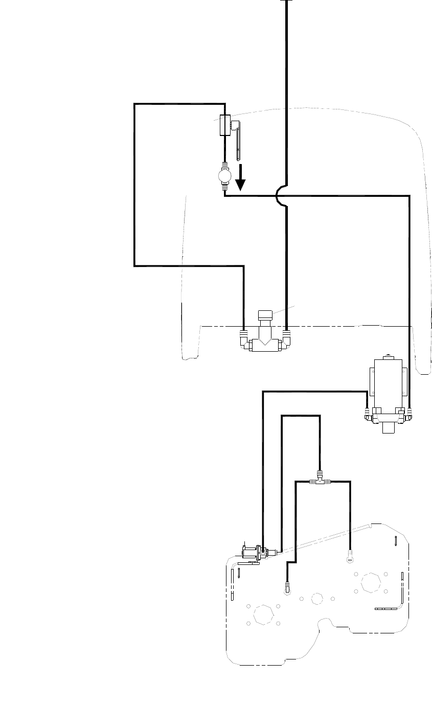
HOSE DIAGRAM - DISK
86037660 CHARIOT 01/03/08
5-89
STAINER
12 MESH (COARSE)
STRAINER
80 MESH (FINE)
DRAIN HOSE
VALVE
PUMP
SOLENOID
86281310 (8") PRV 39326
86281310 (8")
86281100 (8")
SCRUB DECK
PRV 39540
PRV 39541
86282190 (13")
PRV 39505
TANK
PRV 39616
86004310 (18")
86281950 (32")
86281940 (40")
PRV 39274
PRV 39326
VALVE
SHUT-OFF
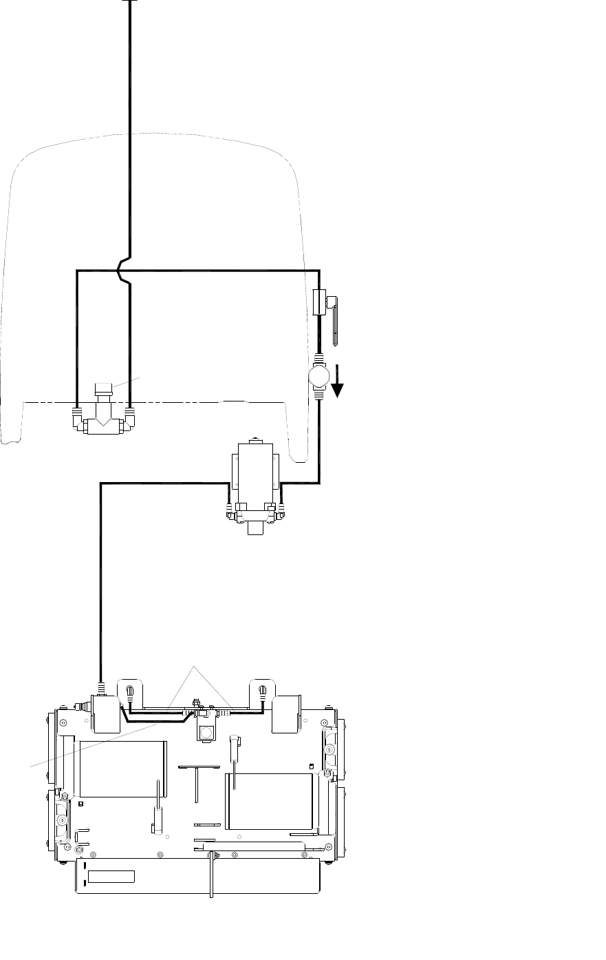
HOSE DIAGRAM - CYLINDRICAL
86037660 CHARIOT 01/03/08 5-90
PRV 39274
86281100
PRV 39282
SHUT-OFF
PRV 39735
86282370 (58")
PRV 39734
86282360 (28")
86004310 (18")
TANK
PRV 39505
VALVE
DRAIN HOSE
80 MESH (FINE)
STRAINER
12 MESH (COARSE)
STAINER
86281940 (40")
PRV 39540
PUMP
SOLENOID
VALVE

SUGGESTED SPARE PARTS
86037660 CHARIOT 10/13/08
5-91
PART NO. PRV NO. DESCRIPTION SERIAL NO.
FROM NOTES:
86001910 14606 BREAKER, 30A 50VDC CIRCUIT BASIC ONLY
86001920 14607 BREAKER, 25BA 50VDC CIRCUIT BASIC ONLY
86002000 14717 BREAKER, 3 AMP 1681-090-300 BASIC ONLY
86002010 14942 BOOT, 3/8 CIRCUIT BREAKER
86232130 17309 CAP, 2.75 X 1.0L BLACK VINYL
86003680 34380 FLOAT, SHUT OFF
86004010 35274 GASKET, DOME EDGE
86305960 - HOSE ASM., 1.5” BLK PVC VAC X 67
86004860 48073 KEY, SWITCH
86004890 48095 KNOB, ALUM 3/8-16 NYLOCK NUT SS
86006340 66347 RECOVERY DRAIN PLUG 1-3/4
86251410 67506 RELAY, 15A 36V MINI
86007140 72130 SWITCH, SPST 2-POSITION ROCKER
86007170 72159 SWITCH, 2 POSITION KEY BASIC ONLY
86007190 72161 SWITCH, DPST KEY DELUXE ONLY
86007240 72190 SWITCH, SEALED PB ROUND
86008790 80687 FUSE, 125 AMP
86009200 81535 KNOB, 3/8-16 4 PRONG ALUM
86009700 82267 PLUG, 5/8” DRAIN HOSE
86069880 140534 BRKT, CABLE ATTACH DELUXE ONLY
86001510 140712 BAG, INNER TANK
86001520 140752 BLADE, AQUAMIZER, 12IN LEFT
86001540 140753 BLADE, AQUAMIZER, 12IN RIGHT
86001560 140754 BLADE, SKIRT, SCRUB DECK, 24 IN LEFT
86001570 140755 BLADE, SKIRT, SCRUB DECK, 24 IN RIGHT
86001580 140763 BLADE, SQG REAR 40.6IN LINATEX
86001630 140764 BLADE, SQG FRONT 36.7IN RED GUM
86001700 140780 BLADE, SKIRT, SCRUB DECK, FRONT
86001730 140804 BREAKER, 18A 250VAC, 50VDC
86001740 140816 BRAKE, 36 VDC W/CONNECTOR
86002730 270085 CHAIN, ISO 08B 12.7 MM PITCH
86231560 270097 CABLE, SQUEEGEE LIFT BASIC
86002780 270098 CABLE, SQUEEGEE LIFT DELUXE
86007940 73836 STRAINER, DEEP, 100 MESH DISK ONLY
86256120 730368 STRAINER, 1/2 FPT 100 MESH CYLINDRICAL
ONLY
86313170 - CAP, STRAINER TALL

OPTIONS
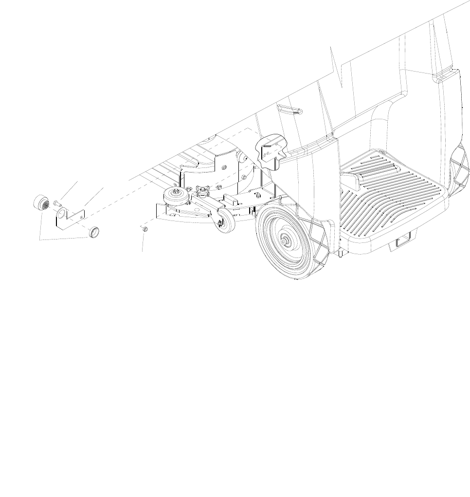
BACK-UP ALARM - OPTION
86037660 CHARIOT 11/09/06
6-1
2
1
3
4

BACK-UP ALARM - OPTION
86037660 CHARIOT 11/09/06 6-2
REF PART NO. PRV NO. QTY DESCRIPTION SERIAL NO.
FROM NOTES:
1 86071140 140817 1 BRKT, BACK UP ALARM
2 86231500 80882 1 BUZZER, PIEZO 6-28VCD
3 86276780 70728 1 SCR, 5/16-18 X 3/4 HHCS SS
4 86271840 57285 1 NUT, 5/16-18 HEX NYLOCK THN SS
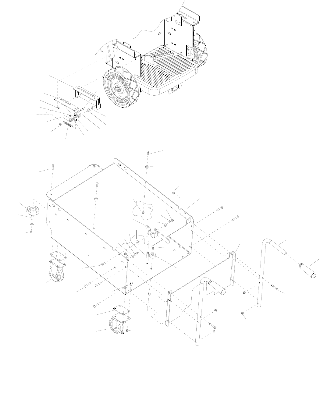
BATTERY CART - OPTION
86037660 CHARIOT 09/17/09
6-3
3
3
15
16
3
3
11
3
3
3
3
3
5
5
5
9
24
8
6
30
29
28
27
26
25
2
23
22
21
20
19
18
17
31
15
14
13
12
10
987
65
4
3
2
1

BATTERY CART - OPTION
86037660 CHARIOT 09/17/09 6-4
REF PART NO. PRV NO. QTY DESCRIPTION SERIAL NO.
FROM NOTES:
1 86006930 70514 2 SCR, 5/16-18 X 1.00 BSHCS SS
2 86254290 730338 4 SPACER, 10D X .343ID, .5 LG
3 86270830 57023 33 NUT, 5/16-18 HEX NYLOCK SS
4 86077010 41517 1 HOUSING, BATTERY CART
5 86010670 87029 7 WASHER, 5/16 FLAT SS
6 86228840 09124 3 BEARING, FLANGED .314D X .502OD
7 86259410 87206 1 WASHER, THRUST, .51 ID X 1 OD X .063
8 86259400 730331 4 WASHER, THRUST .51 ID X 1 OD
9 86254890 730018 3 SPRING, EXT, .50D X 4.0L
10 86068490 140019 1 BRKT, TRAY CATCH
11 86231090 80809 1 BUMPER, RUBBER 5/16" ID X 1.50
12 86083120 66442 1 PLATE, BATTERY CART BACK
13 86076600 38318 2 HANDLE, BATTERY CART
14 86004070 36196 2 GRIP, POLISHER HANDLE
15 86276790 70732 4 SCR, 5/16-18 X 1.75 HHCS SS
16 86276690 70715 7 SCR, 5/16-18 X 1.75 CARR SS
17 86199430 040-03 2 CASTER SWIVEL 4” 250# CPCTY
18 86078890 620020 8 PLATE, CASTER SPACER
19 86277130 70795 16 SCR, 5/16-18 X 1.00 CARRIAGE SS
20 86007020 70673 1 SP SCR, 5/16-18 X 1.25 HHCS SS NP
21 86232590 18032 2 CASTER, 4” HARD RUBBER RIGID
22 86001350 140390 2 BUSHING, SPANNER .435 X 1.10
23 86011020 89202 2 WHEEL, 3” DIA CUSHION RUBBER
24 86271840 57285 2 NUT, 5/16-18 HEX NYLOCK THIN SS
25 86008130 73958 2 SPACER, 3/8OD X .62W X .312L, AL
26 86274730 70265 2 SCR, 1/4-20 X 3/4 SHCS PLTD
27 86070790 140737 2 BRKT, BATTERY LOCK MOUNT
28 86087340 730339 2 SPACER, LATCH GUIDE
29 86070800 140738 2 BRKT, BATTERY TRAY LOCK
30 86271870 57290 2 NUT, 1/4-20 HEX NYLOCK THIN SS
31 86276070 70593 1 SCR, 5/16-18 X 3/4 CARRIAGE SS
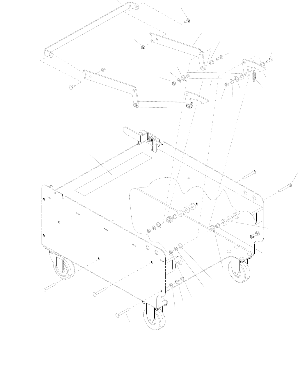
BATTERY CART - OPTION
86037660 CHARIOT 11/09/06
6-5
11
13
14
15
6
3
10
12
9
17
3
310
10
6
6
8
57
7
5
4
3
2
1
10 3
16

BATTERY CART - OPTION
86037660 CHARIOT 11/09/06 6-6
REF PART NO. PRV NO. QTY DESCRIPTION SERIAL NO.
FROM NOTES:
1 86078330 66478 1 PEDAL, BATTERY CART
2 86276070 70593 2 SCR, 5/16-18 X 3/4 CARRIAGE SS
3 86270830 57023 12 NUT, 5/16-18 HEX NYLOCK SS
4 86087800 730307 2 STIFFENER, PEDAL, BATTERY CART
5 86228840 09124 4 BEARING, FLANGED .314ID X .502OD
6 86259410 87206 6 WASHER, THRUST .51 ID X 1 OD X .063
7 86006560 70083 4 SCR, 5/16-18 X 1 HHCS SS
8 86077140 51404 2 LATCH, BATTERY CART
9 86226830 73268 2 SPRING, EXT .68D X 3.00L X .098W
10 86010670 87029 10 WASHER, 5/16 FLAT SS
11 86244280 500934 1 LABEL, BATTERY CART OPERATION
12 86276060 70590 4 SCR, 5/16-18 X 2.5 CARR GR5
13 86254280 730331 12 SPACER, 1.00 ODX .32ID X .375
14 86231150 09151 4 BUSHING FLANGE, .314 X .502 OD
15 86259400 87205 8 WASHER, THRUST .51 ID X 1 OD
16 86276690 70715 16 SCR, 5/16-18 X 1.75 CARR SS
17 86077530 51403 2 LINKAGE, LATCH, BATT CART
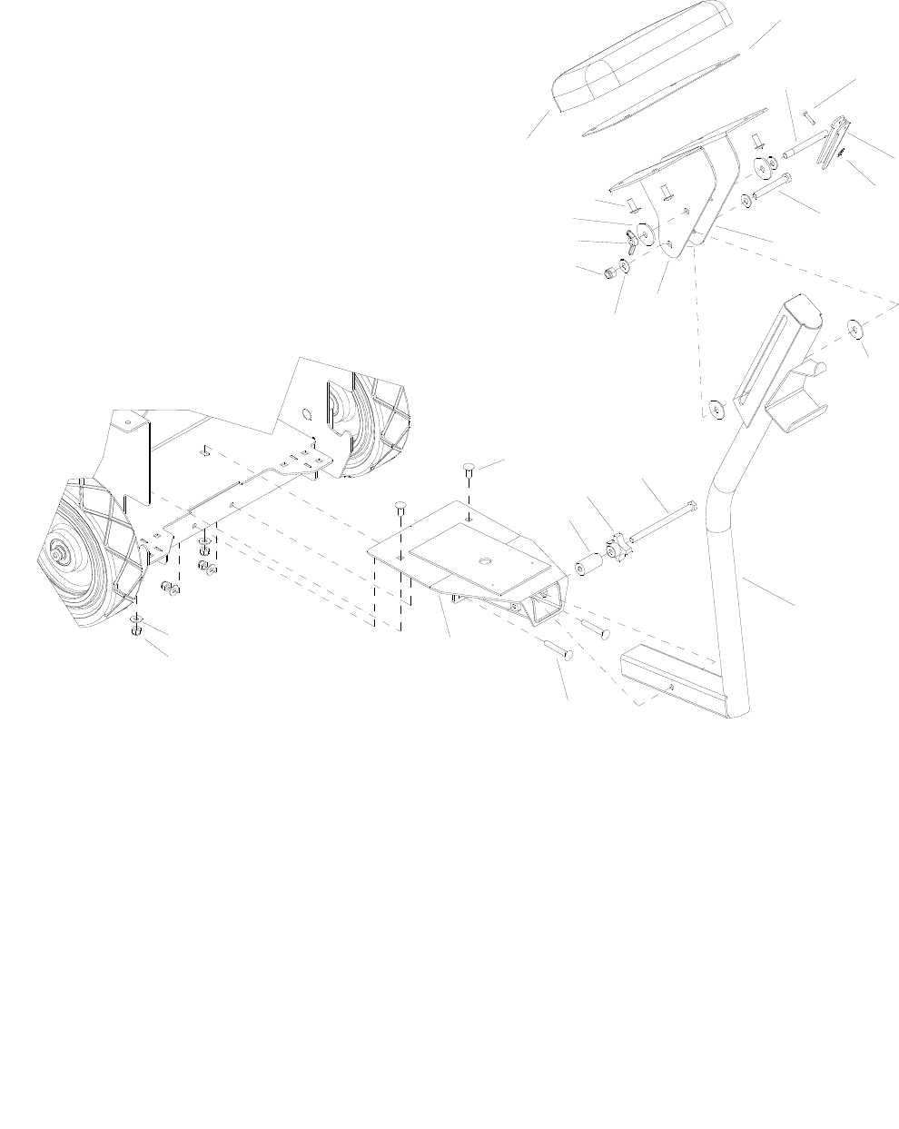
SEAT - OPTION
86037660 CHARIOT 11/09/06
6-7
2
14 13
12
11
10
9
7
8
6
5
43
1
15
17
16
18
19
22
21
20
23
24

SEAT - OPTION
86037660 CHARIOT 11/09/06 6-8
REF PART NO. PRV NO. QTY DESCRIPTION SERIAL NO.
FROM NOTES:
1 86248390 730324 1 PAD, REAR REST
2 86082640 629995 1 PLATE, SEAT COVER
3 86276890 70752 4 SCR, 5/16-18 X 3/4 PTHMS SS
4 86279460 87164 2 WASHER, 1/2 SPLIT LOCK
5 86270710 01-000277 1 NUT, WING 3/8-16
6 86271930 57297 1 NUT, 3/8-16 HEX NYLOCK SS
7 86278910 87003 3 WASHR, 3/8 ID X 7/8 OD SS
8 86070830 140742 1 BRKT, LEFT REAR SEAT
9 86070840 140743 1 BRKT, RIGHT REAR SEAT
10 86277710 730347 1 SCR, 3/8-16 X 2.75 HHCS SS
11 86008650 80604 1 COTTER, 1/4” RING
12 86246320 51142 1 LEVER, HANDLE LOCK
13 86272300 66133 1 PIN, CLEVIS 3/16 X .88 PLTD
14 86251860 66481 1 ROD, ARM HANDLE LOCK 4” LG
15 86279620 87200 2 WASHER, .4ID X 1.3OD NYLON
16 86276070 70593 2 SCR, 5/16-18 X 3/4 CARRIAGE SS
17 86277510 70857 1 SCR, 3/8-16 X 5.0 HHCS SS FT
18 86009200 81535 1 KNOB, 3/8-16 4 PRONG ALUM
19 86254300 730350 1 SPACER, SEAT LOCK
20 86094000 05246 1 SEAT MOUNT POST
21 86276710 70717 2 SCR, 5/16-18 X 2.0 CARRIAGE SS
22 86093790 05247 1 RECEIVER ASSY, SEAT MOUNT
23 86010670 87029 4 WASHER, 5/16 FLAT SS
24 86270830 57023 4 NUT, 5/16-18 HEX NYLOCK SS
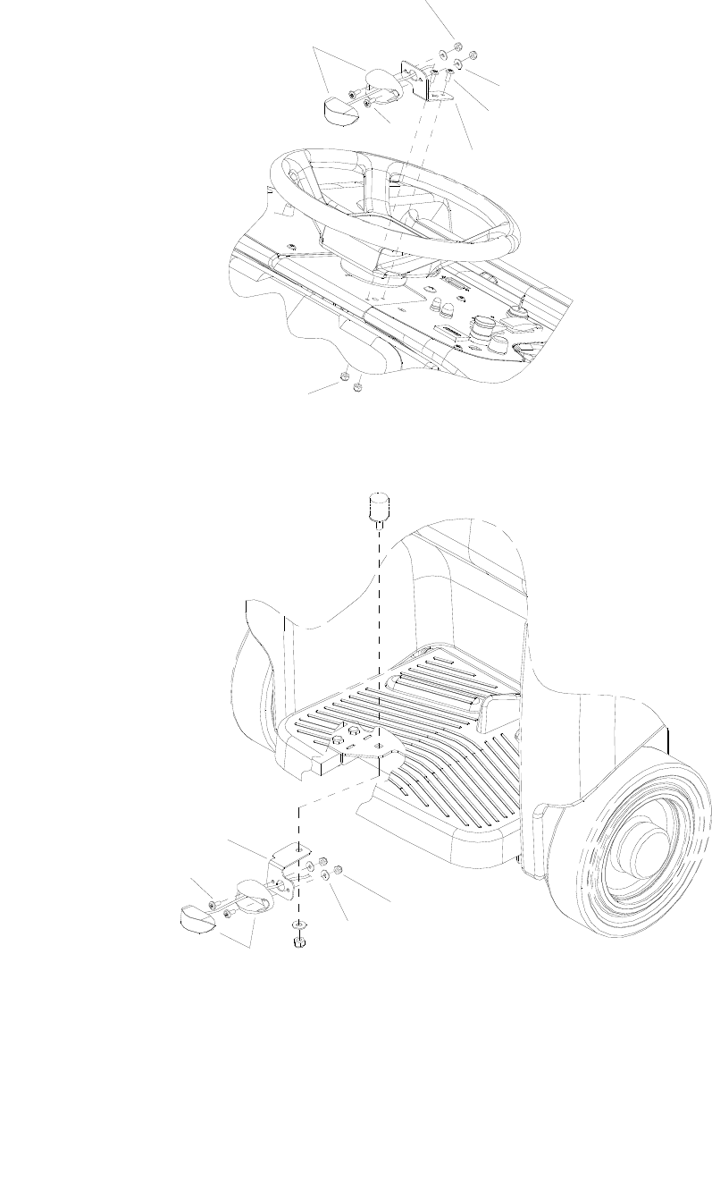
WARNING LIGHTS - OPTION
86037660 CHARIOT 11/09/06
6-9
REAR
FRONT
1
6
3
4
3
2
5
1
2
6
7
3

WARNING LIGHTS - OPTION
86037660 CHARIOT 11/09/06 6-10
REF PART NO. PRV NO. QTY DESCRIPTION SERIAL NO.
FROM NOTES:
1 86270990 57090 4 NUT, 10-32 HEX NYLOCK SS
2 86010650 87018 4 WASHER, #10 X 6/16 OD
3 86276820 70740 4 SCR, 10-32 X 1/2 PTHMS BLK
4 86071490 140871 1 BRKT, UPPER WARNING LIGHT
5 86270990 57090 2 NUT, 10-32 HEX NYLOCK SS
6 86246200 51454 2 LED AMBER LIGHT, 12V
7 86071500 140872 1 BRKT, LOWER WARNING LIGHT
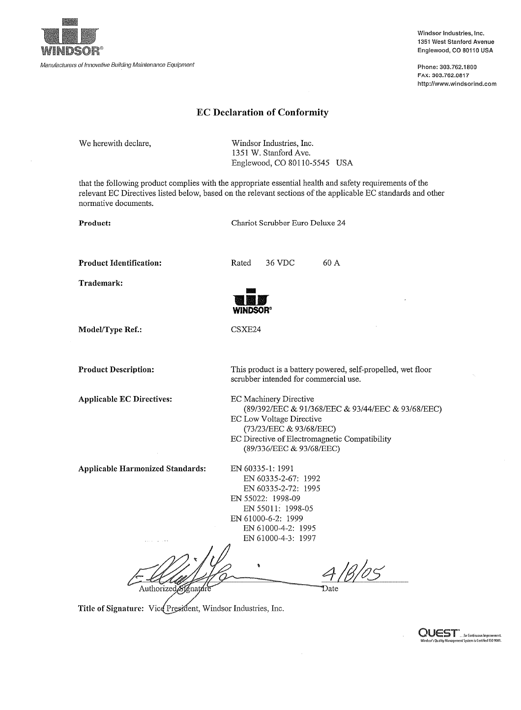
86037660 CHARIOT 11/09/06
6-11
86037660 CHARIOT 11/09/06 6-12
86037660 CHARIOT 11/09/06
6-13

SERIAL NUMBERS
86037660 CHARIOT 04/21/09 6-14
REF.
NO. MODEL: SERIAL #
1 CS24, CSE24, CSX24, CSXE24, CSXE024, CSE24SP, CS24SP : 1000170494
2 CS24, CSE24, CSX24, CSXE24, CSXE024, CSE24SP, CS24SP : 1000140332
3 CS24, CSE24, CSX24, CSXE24, CSXE024, CSE24SP, CS24SP : 1000143553
4 CS24, CSE24, CSX24, CSXE24, CSXE024, CSE24SP, CS24SP : 1000143906
5 CS24, CSE24, CSX24, CSXE24, CSXE024, CSE24SP, CS24SP : 1000144785
6 CS24, CSE24, CSX24, CSXE24, CSXE024, CSE24SP, CS24SP : 1000149450
7 CS24, CSE24, CSX24, CSXE24, CSXE024, CSE24SP, CS24SP : 1000149664
8 CS24, CSE24, CSX24, CSXE24, CSXE024, CSE24SP, CS24SP : 1000150256
9 CS24, CSE24, CSX24, CSXE24, CSXE024, CSE24SP, CS24SP : 1000150384
10 CS24, CSE24, CSX24, CSXE24, CSXE024, CSE24SP, CS24SP : 1000151588
11 CS24, CSE24, CSX24, CSXE24, CSXE024, CSE24SP, CS24SP : 1000154281
12 CS24, CSE24, CSX24, CSXE24, CSXE024, CSE24SP, CS24SP : 1000154660
13 CS24, CSE24, CSX24, CSXE24, CSXE024, CSE24SP, CS24SP : 1000155938
14 CS24, CSE24, CSX24, CSXE24, CSXE024, CSE24SP, CS24SP : 1000156273
15 CS24, CSE24, CSX24, CSXE24, CSXE024, CSE24SP, CS24SP : 1000157499
16 CS24, CSE24, CSX24, CSXE24, CSXE024, CSE24SP, CS24SP : 1000157501
17 CS24, CSE24, CSX24, CSXE24, CSXE024, CSE24SP, CS24SP : 1000157685
18 CS24, CSE24, CSX24, CSXE24, CSXE024, CSE24SP, CS24SP : 1000159164
19 CS24, CSE24, CSX24, CSXE24, CSXE024, CSE24SP, CS24SP : 1000159653
20 CS24, CSE24, CSX24, CSXE24, CSXE024, CSE24SP, CS24SP : 1000160355
21 CS24, CSE24, CSX24, CSXE24, CSXE024, CSE24SP, CS24SP : 1000168941
22 CS24, CSE24, CSX24, CSXE24, CSXE024, CSE24SP, CS24SP : 1000170203
23 CS24, CSE24, CSX24, CSXE24, CSXE024, CSE24SP, CS24SP : 10060140000046
24 CS24 : 10060210000104
25 CS24 : 10060210000143
26 CS24 : 10060210000178
27 CSE24 : 10060250000006
28 CSX24 : 10060270000498
29 CSXE24 : 10060290000001
30 CSXE024 : 10060300000001
31 CSE24: 10060250000007, CSE24SP: 10060260000003, CSXEO24: 10060300000001, CSX24: 10060270000736,
CSX24X: 10060280000078, CS24: 1006021000252, CS24SP: 10060220000080, CS24SPX: 10060230000003,
CS24X 100602400000018
32 CSX24: 10060270000837, CSXE24: 10060290000028, CSXE024: 10060300000001
33 CSE24: 10060250000007, CSXEO24: 10060300000001, CSX24: 10060270000837, CSX24X: 10060280000085,
CS24: 1006021000317, CS24X 100602400000024, CSXE24 10060290000029
34 CS24: 10060210000315, CSX24: 10060270000845, CSXEO24: 10030300000001, CSE24: 10060250000007,
CSXE24: 10060290000029, CS24SP: 10060220000091, CSE24SP: 10060260000003
