Clarke Focus Ii Large Walk Behind Floor Scrubber Service Manual
2018-06-21
: Sweepscrub Clarke-Focus-Ii-Large-Walk-Behind-Floor-Scrubber-Service-Manual clarke-focus-ii-large-walk-behind-floor-scrubber-service-manual 2794 file product_file
Open the PDF directly: View PDF ![]() .
.
Page Count: 76
- Introduction
- Control Panel
- Functional Description
- Description of Indicators
- Main Controller
- Main Control Board Programming
- Troubleshooting Guide
- Solution System
- Scrub System
- Recovery System
- Squeegee System
- Wheel Drive System
- Electrical System
6/12 revised 11/13 FORM NO. 56043162
Clarke Focus II Large
Service Manual
Clarke Models: 56381796 (Focus II D-C AUS), 56381825 (Focus II D), 56381828
(Focus II D-C)

ii - 56043162 - Focus II Large
Table of Contents
Table of Contents
. . . . . . . . . . . . . . . . . . . . . . . . . . . . . . . . . . . . . . . . . . . . . . . . . . .5
Nameplate . . . . . . . . . . . . . . . . . . . . . . . . . . . . . . . . . . . . . . . . . . . . . . . . . . 5
Other Manuals Available For Your Machine . . . . . . . . . . . . . . . . . . . . . . . . . . . . . . . . 5
. . . . . . . . . . . . . . . . . . . . . . . . . . . . . . . . . . . . . . . . . . . . . . . . . .5
. . . . . . . . . . . . . . . . . . . . . . . . . . . . . . . . . . . . . . . . . . 5
. . . . . . . . . . . . . . . . . . . . . . . . . . . . . . . . . . . . . . . . . . . 6
Symbols . . . . . . . . . . . . . . . . . . . . . . . . . . . . . . . . . . . . . . . . . . . . . . . . . . . . . . 6
. . . . . . . . . . . . . . . . . . . . . . . . . . . . . . . . . . . . . . . . . . . . 7
. . . . . . . . . . . . . . . . . . . . . . . . . . . . . . . . . . . . . . . . . . . 8
. . . . . . . . . . . . . . . . . . . . . . . . . . . . . . . . . . . . . . . . . . . 10
. . . . . . . . . . . . . . . . . . . . . . . . . . . . . . . . . . . . . . . . . . . . 10
. . . . . . . . . . . . . . . . . . . . . . . . . . . . . . . . . . . . . . . . . . . . 10
PM Checklist . . . . . . . . . . . . . . . . . . . . . . . . . . . . . . . . . . . . . . . . . . . . . . . . 11
Know Your Machine . . . . . . . . . . . . . . . . . . . . . . . . . . . . . . . . . . . . . . . . . . . . 12
Control Panel . . . . . . . . . . . . . . . . . . . . . . . . . . . . . . . . . . . . . . . . . . . . . . . . . 15
. . . . . . . . . . . . . . . . . . . . . . . . . . . . . . . . . . . . . . . . . . . 16
. . . . . . . . . . . . . . . . . . . . . . . . . . . . . . . . . . . . . . . . . . 17
. . . . . . . . . . . . . . . . . . . . . . . . . . . . . . . . . . . . . . . . . . . . . 18
. . . . . . . . . . . . . . . . . . . . . . . . . . . . . . . . . . . . . . . . 18
Main Controller. . . . . . . . . . . . . . . . . . . . . . . . . . . . . . . . . . . . . . . . . . . . . . . 19
. . . . . . . . . . . . . . . . . . . . . . . . . . . . . . . . . . . . 19
. . . . . . . . . . . . . . . . . . . . . . . . . . . . . . . . . 20
. . . . . . . . . . . . . . . . . . . . . . . . . . . . . . . . . . . . . . . . . . 20
. . . . . . . . . . . . . . . . . . . . . . . . . . . . . . . . . . . . . . 20
. . . . . . . . . . . . . . . . . . . . . . . . . . . . . . . . . . . . . . . . . 21
. . . . . . . . . . . . . . . . . . . . . . . . . . . . . . . . . . 22
. . . . . . . . . . . . . 23
. . . . . . . . . . . . . . . . . . . . . . . 23
. . . . . . . . . . . . . . . . . . . . . . . . . . . . . . . . . . . . . 23
. . . . . . . . . . . . . . . . . . . . . . . . . . . . . . . . . . . . . 24
. . . . . . . . . . . . . . . . . . . . . . . . . . . . . . . . . . . . 24
. . . . . . . . . . . . . . . . . . . . . . . . . . . . . . . . . . . . . . . . . . 25
. . . . . . . . . . . . . . . . . . . . . . . . . . . . . . . . . . . . . . . . . . 25
. . . . . . . . . . . . . . . . . . . . . . . . . . . . . . . . . . . . . . . . . . . . 27
. . . . . . . . . . . . . . . . . . . . . . . . . . . . . . . . . . . . . . . . . . . . . . . . 28
. . . . . . . . . . . . . . . . . . . . . . . . . . . . . . . . . . . . . . . . . . . 28
. . . . . . . . . . . . . . . . . . . . . . . . . . . . . . . . . . . . . . . . . . . . . . . 28
. . . . . . . . . . . . . . . . . . . . . . . . . . . . . . . . . . . . . . . . . . 28
. . . . . . . . . . . . . . . . . . . . . . . . . . . . . . . . . . . . . . . . . . 28
. . . . . . . . . . . . . . . . . . . . . . . . . . . . . . . . . . . . . . . . . . . . . . . . 28
. . . . . . . . . . . . . . . . . . . . . . . . . . . . . . . . . . . . . . . . . . 29
. . . . . . . . . . . . . . . . . . . . . . . . . . . . . . . . . . . . . . 29
. . . . . . . . . . . . . . . . . . . . . . . . . . . . . . . . . . . . . . . . . . . . . . . .32
. . . . . . . . . . . . . . . . . . . . . . . . . . . . . . . . . . . . . . . . . . . . 32
Circuit Overview . . . . . . . . . . . . . . . . . . . . . . . . . . . . . . . . . . . . . . . . . . . . . . 33
. . . . . . . . . . . . . . . . . . . . . . . . . . . . . . . . . . . . . . . . . . . . . 33
Maintenance . . . . . . . . . . . . . . . . . . . . . . . . . . . . . . . . . . . . . . . . . . . . . . . . 34
. . . . . . . . . . . . . . . . . . . . . . . . . . . . . . . . . . . . . . . . . . . 34
. . . . . . . . . . . . . . . . . . . . . . . . . . . . . . . . . . . . . . . . . 34

iii - 56043162 - Focus II Large
Table of Contents
. . . . . . . . . . . . . . . . . . . . . . . . . . . . . . . . . . . . . . . . . . 35
. . . . . . . . . . . . . . . . . . . . . . . . . . . . . . . . . . . . . . . . . . . . . 35
. . . . . . . . . . . . . . . . . . . . . . . . . . . . . . . . . . . 35
. . . . . . . . . . . . . . . . . . . . . . . . . . . . . . . . . . . . . 36
. . . . . . . . . . . . . . . . . . . . . . . . . . . . . . . . . . . . . . . . . . . . . . . . . 37
. . . . . . . . . . . . . . . . . . . . . . . . . . . . . . . . . . . . . . . . . . . . 37
. . . . . . . . . . . . . . . . . . . . . . . . . . . . . . . . . . 37
. . . . . . . . . . . . . . . . . . . . . . . . . . . . . . . . 37
. . . . . . . . . . . . . . . . . . . . . . . . . . . . . . . . . 37
. . . . . . . . . . . . . . . . . . . . . . . . . . . . . . . . . . . . . . . . . . . . . . . . 38
. . . . . . . . . . . . . . . . . . . . . . . . . . . . . . . . . . . . . . . . . . 39
. . . . . . . . . . . . . . . . . . . . . . . . . . . . . . . . . . . . . . . . . . . . . . . . . . . . . . . . . 39
. . . . . . . . . . . . . . . . . . . . . . . . . . . . . . . . . . . . . . . . . . . . . . . . 40
. . . . . . . . . . . . . . . . . . . . . . . . . . . . . . . . . . . . . . . . . . . . 41
. . . . . . . . . . . . . . . . . . . . . . . . . . . . . . . . . . . . . . . . . . 42
. . . . . . . . . . . . . . . . . . . . . . . . . . . . . . . . . . . . . . . . . . . . . . . 43
. . . . . . . . . . . . . . . . . . . . . . . . . . . . . . . . . . . . . . . . . . . . . . . . . . . . . . 43
. . . . . . . . . . . . . . . . . . . . . . . . . . . 44
Maintenance . . . . . . . . . . . . . . . . . . . . . . . . . . . . . . . . . . . . . . . . . . . . . . . . 45
. . . . . . . . . . . . . . . . . . . . . . . . . . . . . . . . . . . . . . . . . 45
. . . . . . . . . . . . . . . . . . . . . . . . . . . . . . . . . . . . . . . . . . . . . 45
. . . . . . . . . . . . . . . . . . . . . . . . . . . . . . . 46
. . . . . . . . . . . . . . . . . . . . . . . . . . . . . . . . . 47
. . . . . . . . . . . . . . . . . . . . . . . . . . . . . . . . . . . . . . . . . . 48
. . . . . . . . . . . . . . . . . . . . . . . . . . . . . . . . . . . . . . . . . . . . 48
. . . . . . . . . . . . . . . . . . . . . . . . . . . . . . . . . . . . . . . . . . . . . 49
. . . . . . . . . . . . . . . . . . . . . . . . . . . . . . . . . . . . . . . . . . . . . . .50
Maintenance . . . . . . . . . . . . . . . . . . . . . . . . . . . . . . . . . . . . . . . . . . . . . . . . 50
. . . . . . . . . . . . . . . . . . . . . . . . . . . . . . . . . . . . . . . 50
. . . . . . . . . . . . . . . . . . . . . . . . . . . . . . . . . . . . . . . . . . . . . 51
. . . . . . . . . . . . . . . . . . . . . . . . . . . . . . . . . . . . . . . . . . . . . . . . . . . 51
. . . . . . . . . . . . . . . . . . . . . . . . . . . . . . . . . . . . . . . . . . 52
. . . . . . . . . . . . . . . . . . . . . . . . . . . . . . . . . . . . . 52
. . . . . . . . . . . . . . . . . . . . . . . . . . . . . . . . . . . . . . . . . . . . . 53
. . . . . . . . . . . . . . . . . . . . . . . . . . . . . . . . . . . . . . . . . . . . . 54
. . . . . . . . . . . . . . . . . . . . . . . . . . . . . . . . . . . . . . . . . . . . 54
. . . . . . . . . . . . . . . . . . . . . . . . . . . . . . . . . . . . . . . . . . 54
. . . . . . . . . . . . . . . . . . . . . . . . . . . . . . . . . . . . . . . . . . . . . . . . 55
. . . . . . . . . . . . . . . . . . . . . . . . . . . . . . . . . . . . . . . 56
. . . . . . . . . . . . . . . . . . . . . . . . . . . . . . . . . . . 57
. . . . . . . . . . . . . . . . . . . . . . . . . . . . . . . . . . . . . . . . . . 58
. . . . . . . . . . . . . . . . . . . . . . . . . . . . . . . . . . . . . . . . 58
. . . . . . . . . . . . . . . . . . . . . . . . . . . . . . . . . 59
. . . . . . . . . . . . . . . . . . . . . . . . . . . . . . . . . . . . . . . . . . . . . . 60
. . . . . . . . . . . . . . . . . . . . . . . . . . . . . . . . . . . . . . . . . 61
. . . . . . . . . . . . . . . . . . . . . . . . . . . . . . . . . . . . . . . . 62
. . . . . . . . . . . . . . . . . . . . . . . . . . . . . . . . . . . . . . . . . . . 63
. . . . . . . . . . . . . . . . . . . . . . . . . . . . . . . . . . . . . . . . . . 64
. . . . . . . . . . . . . . . . . . . . . . . . . . . . . . . . 65
. . . . . . . . . . . . . . . . . . . . . . . . . . . . . . . 65

iv - 56043162 - Focus II Large
Table of Contents
. . . . . . . . . . . . . . . . . . . . . . . . . . . . . . . . . . . . . . . . . . . . . . . 67
. . . . . . . . . . . . . . . . . . . . . . . . . . . . . . . . . . . . . . . . . . 67
. . . . . . . . . . . . . . . . . . . . . . . . . . . . . . . . 68
. . . . . . . . . . . . . . . . . . . . . . . . . . . . . . . . . . . . . . . . . . . . . . . . . . . 69
. . . . . . . . . . . . . . . . . . . . . . . . . . . . . . . 69
. . . . . . . . . . . . . . . . . . . . . . . . . . . . .69
. . . . . . . . . . . . . . . . . . . . . . . . . . . . . . . . . . . . . 69
. . . . . . . . . . . . . . . . . . . . . . . . . . . . . . . . . . . . . . . . . . . . 70
. . . . . . . . . . . . . . . . . . . . . . . . . . . . . . . . . . . . . . . . . . . . . . . . 70
. . . . . . . . . . . . . . . . . . . . . . . . . . . . . . . . . . . . . . . . . . . . . . 70
. . . . . . . . . . . . . . . . . . . . . . . . . . . . . . . . . . . . . . . . . . . . 71
. . . . . . . . . . . . . . . . . . . . . . . . . . . . . . . . . . . . . . . . . . . . . . . . . . 71
. . . . . . . . . . . . . . . . . . . . . . . . . . . . . . . . . . . . . . . 72
. . . . . . . . . . . . . . . . . . . . . . . . . . . . . . . . . . . . . . . . . 72
. . . . . . . . . . . . . . . . . . . . . . . . . . . . . . . . . . . . . . . 74
. . . . . . . . . . . . . . . . . . . . . . . . . . 74
. . . . . . . . . . . . . . . . . . . . . . . . . . . . . 74
. . . . . . . . . . . . . . . . . . . . . . . . . . . . . . . . . . . . . . . . . . . . . . . . . . . 74
. . . . . . . . . . . . . . . . . . . . . . . . . . . . . . . . . . . . . . . . . . 75
. . . . . . . . . . . . . . . . . . . . . . . . . . . . . . . . . . . 76
. . . . . . . . . . . . . . . . . . . . . . . . . . . . . 76
. . . . . . . . . . . . . . . . . . . . . . . . . . . . . . . . . . . . . 76
. . . . . . . . . . . . . . . . . . . . . . . . . . . . . . . . . . . . . . . . . . . . . . . . . . . 76

5 - FORM NO. 56043162 - Focus II Large
Introduction
Introduction
This manual will help you get the most from your Clarke Focus II Large Autoscrubber. Read it thoroughly
before servicing the machine.
Note: Bold numbers and letters in parentheses indicate illustrated items.
Note: All references to right, left, front, or rear in this manual are as seen from the operator’s standpoint.
Nameplate
The Model Number and Serial Number of your machine are shown on the Nameplate on the machine. This
information is needed when ordering repair parts for the machine. Use the space below to note the Model Number
and Serial Number of your machine for future reference.
MODEL NUMBER ________________________________________
SERIAL NUMBER ________________________________________
Other Manuals Available For Your Machine
The following manuals are available at Clarke Literature Service Department:
Instructions for Use (English/Español/Francais) – Form Number 56091028
Parts List – Form Number 56042584
Conventions
Forward, backward, front, rear, left or right are intended with reference to the operator’s position, that is to say in
operating position with the hands on the handlebar.
Transporting the Machine
Caution! Before transporting the machine on an open truck or trailer, make sure that
• The machine is tied down securely.
• All access doors and covers are secured (tape and strap as needed).
Caution! If the machine must be towed or pushed, make sure the Master On/Off Key Switch
(A) is in the OFF position and do not move the machine faster than a normal walking
pace (2-3 mph, 3-5kph) and for short distances only. Note: Disconnecting the wheel
drive motor wiring connector will make a disabled machine easier to push.

6 - FORM NO. 56043162 - Focus II Large
Introduction
Cautions and Warnings
Symbols
It is important for you to read and understand this manual. The information it contains relates to protecting your
safety and preventing problems. The symbols below are used to help you recognize this information.
Danger! Indicates a potentially hazardous situation which, if not avoided, will result in
death or serious injury.
Warning! Indicates a potentially hazardous situation which, if not avoided, could result in
death or serious injury.
Caution! Indicates a potentially hazardous situation which, if not avoided, could result in
minor or moderate injury.
Caution! When used without the Safety Alert Symbol, indicates a potential situation which,
if not avoided, could result in property or machine damage.

7 - FORM NO. 56043162 - Focus II Large
Introduction
General Safety Instructions
Warning!
This machine should be used only by properly trained and authorized persons.
Never work under a machine without safety blocks or stands to support the machine.
during normal operation.
Remove all jewelry when working near electrical components.
Caution!:
When operating this machine, ensure that third parties, particularly children, are not
endangered.
Turn the key switch off (O) and disconnect the batteries before servicing electrical components.
Turn the key switch off (O) and remove the key, before changing the brushes, and before
opening any access panels.
This machine is not suitable for picking up hazardous dust.
While on ramps or inclines, avoid sudden stops when loaded. Avoid abrupt sharp turns. Use low
speed down hills. Clean only while ascending (driving up) the ramp.
Before performing any service function, carefully read all instructions pertaining to that
function.
(O), removing the
key and securing the machine.
Take precautions to prevent hair, jewelry, or loose clothing from becoming caught in moving
parts.
The use of other brushes may impair safety.
warnings.
Caution!:
This machine is not approved for use on public paths or roads.
Turn the key switch off (O) and remove the key, before changing the brushes, and before
opening any access panels.
Use caution when moving this machine in below freezing temperature conditions. Any water
in the solution, recovery or detergent tanks or in the hose lines could freeze, causing damage to
The batteries must be removed from the machine before the machine is scrapped. The disposal
of the batteries should be safely done in accordance with your local environmental regulations.
Do not clean this machine with a pressure washer.
All doors and covers are to be positioned as indicated in the instruction manual before using the
machine.

8 - FORM NO. 56043162 - Focus II Large
Introduction
Technical Specifications
Voltage 36-Volt
Power Source (6) 6-volt Batteries (wet acid and gel cell available)
Battery Capacity 305 amp-hrs.
Protection Grade IPX3
Onboard Battery Charger 36-volt, 25-amp Wet/Gel Compatible
Solution Control Pulse-control gravity feed
Solution Tank 30 gal. (114 L)
Recovery Tank 30 gal. (114 L)
Scrub Motors (2) 0.75 HP (560-watt)
Vacuum Motor 0.75 HP (560-watt) three-stage
Sound Pressure Level (IEC 60704-1) 74.5 dB(A)/20µPa
Drive System 0.5 HP (375-watt) variable forward and reverse; max. speed = 3 mph (4.83 km/hr)
Drive Wheels
Scrub Head Type Disc
Scrub Path 34 inches (86 cm)
Gradeability Transport 2% (1.15º)
Cleaning 2% (1.15º)
Max. Productivity @ 3.0 mph 44,880 ft2/hr (4,169 m2/hr)
Max. Productivity @ 1.5 mph 22,440 ft2/hr (2,085 m2/hr)
Scrub Head Size and Type (2) 17 in,(43 cm) Brushes or Pad Holders
Scrub
Pressure
(1) Regular Scrub Max. 90 lbs (40.8 kg)
(2) Heavy Scrub Max. 175 lbs (79.4 kg)
(3) Extreme Scrub Max. 250 lbs (113.4 kg)
Scrub Head Speed 220 RPM
Solution
Flow Rate
(1) Regular Scrub 0.30 gal/min (1.1 L/min) or 100 minutes per solution tank
(2) Heavy Scrub 0.60 gal/min (2.3 L/min) or 50 minutes per solution tank
(3) Extreme Scrub 0.90 gal/min (3.4 L/min) or 33 minutes per solution tank
Squeegee Width 41.9 in (106 cm)
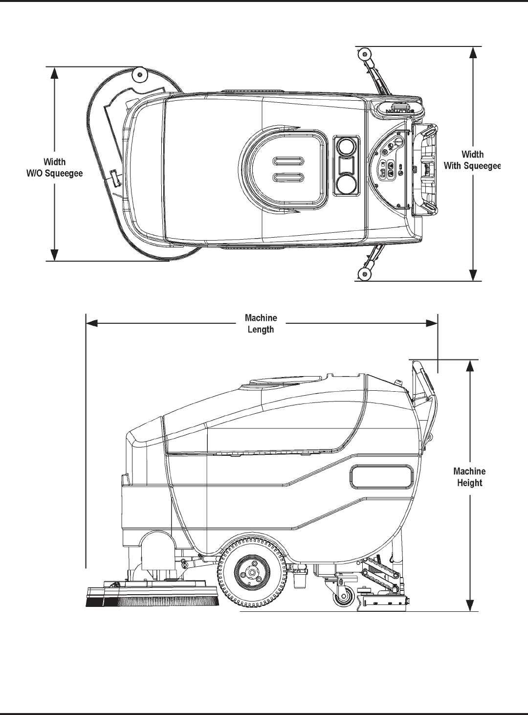
Dimensions (w/o Squeegee) W = 35.5 in (90 cm); L = 62.5 in (159 cm); H = 45 in (114 cm)
Gross Weight w/Standard Batteries 1,245 lbs (565 kg)
Battery Compartment Size See Illustration below; W = 25.5 in (65 cm), L = 29.5 in (75 cm), H = 15 in (38 cm)
14.5"
15"
25.5"
29.5"
9 - FORM NO. 56043162 - Focus II Large
Introduction
Technical Specifications (continued)
10 - FORM NO. 56043162 - Focus II Large
Introduction
Maintenance Schedule
Maintenance intervals given are for average operating conditions. Machines used in severe operational
MAINTENANCE ITEM Daily Weekly Monthly Yearly
Charge the Batteries X
Check/Clean Tanks and Hoses (clean recovery tank switch and vacuum inlet screen) X
Check/Clean/Rotate the Brushes/Pads X
Check/Clean the Squeegee X
Check the Water Level in each Battery Cell (does not apply to gel cell batteries) X
Inspect the Brush Housings X
Inspect and Clean the Solution Filter X
Lubricate the Machine X
* Check the Carbon Brushes X
Note: See the individual machine system sections in this manual for maintenance information.
Warning! Turn the key switch off and disconnect the batteries before servicing the
machine.
* Carbon brush inspection intervals and replacement recommendations:
Check the vacuum motor carbon brushes (two per motor) once a year or after 300 operating hours.
Check the carbon brushes on the brush and wheel drive motors (four per motor) once a year or after 500 operating
hours.
drive motors.
brushes.
Important! Motor damage resulting from failure to service the carbon brushes is not
covered under warranty. See the Limited Warranty Statement.
Batteries and Chargers
Attention: See the Electrical System/Batteries
section in this manual for battery installation,
battery maintenance and charger system
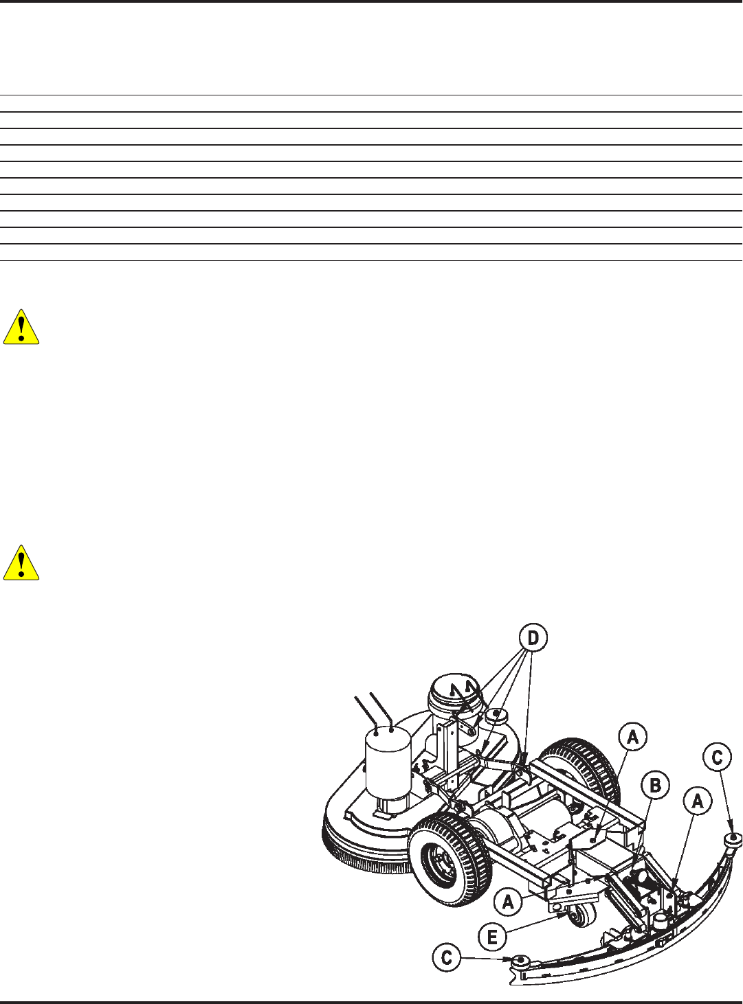
Lubricating the Machine
Once a month, apply light machine oil to lubricate
the:
(A).
knob (B).
(C).
General pivot points for the brush linkage (D).
of the two caster swivels (E).

Advance 34 RST Models
PM Checklist
Defect Codes
Customer A needs adjustment
B binding
Address C dirty or contaminated
D damaged, bent or torn
City St Zip L leaks
M missing
Model Serial No. Hours W worn out
Ref
OPERATIONAL INSPECTION ITEMS
OK
Defect Codes
(circle)
Does
Not
Work
1 Palm Drive Button and Reverse Button Operation (check for Fwd/Rev Drive) B D W
2 Drive System Performance (Speed Changes Min/Max) noisy sluggish
3 Scrub System (Raise/Lower, Brush Motor On/Off) A B D
4 Scrub Brush Pressure settings (1-3) A B
5 Squeegee System (Raise/Lower and Squeegee Tool pick-up Performance) A B D
6 Vacuum Performance (Sealed water lift and 1” open hole adapter, 36v-68/12) C L W
7 Solution Control (Auto On/Off and Flow Volume settings 1, 2 and 3 A B L
8 Battery Charger (Auto turn ON and OFF) D
9 Main Controller Special Program Options (see Electrical System/Main Control
Programming Options). Check all applicable machine settings. Examples: Scrub
mode pressure settings, service test mode, low voltage cut-out, etc.
A
Ref
VISUAL INSPECTION ITEMS
Comments OK
Defect Codes
(circle)
Does
Not
Work
10 Scrub Brushes, check for wear and rotate D M W
11 Scrub Brush Motor(S), check for carbon brush wear 500 Hours B C W
12 Scrub Brush Motor(S), check gearboxes B D L
13 Brush Drive Motor Gimbals C D M
14 Scrub Deck Lift Motor, Brush Housings and Side Wheel D M W
15 Solution Solenoid Valve C L W
16 Solution Tank, Delivery Hoses and Filter C L
17 Vacuum Motor Carbon Brushes (wear limit 3/8” [9.5 mm]) 300 Hours B C W
18 Vacuum Motor Inlet Filter (located in recovery tank) clean screen C D M
19 Recovery Tank Cover Gasket L M W
20 Recovery Tank Drain Hose and Cap C D L
21 Squeegee Pick-up Hose C D L
22 Squeegee Tool and Blades (clean, rotate and adjust) A D W
23 Squeegee Tool End Wheels and Squeegee Mount Wheels
(lubricate)
2 mount wheels
and 2 end wheels
A D W
24 Battery Condition (load test, clean and water) C W
25 Drive Wheel Transaxle Motor Check Carbon Brushes 500 Hours B C D W
26 Transaxle Drive Tires tread wear W
27 Rear chassis Caster Wheel (grease the zerks) tread wear W
Note: For additional service information, see the individual machine system sections and the Instructions for Use, form #56041706.
WORK COMPLETED BY: ACKNOWLEDGED BY:
Service Technician Signature Date Customer Signature Date
12 - FORM NO. 56043162 - Focus II Large
Introduction
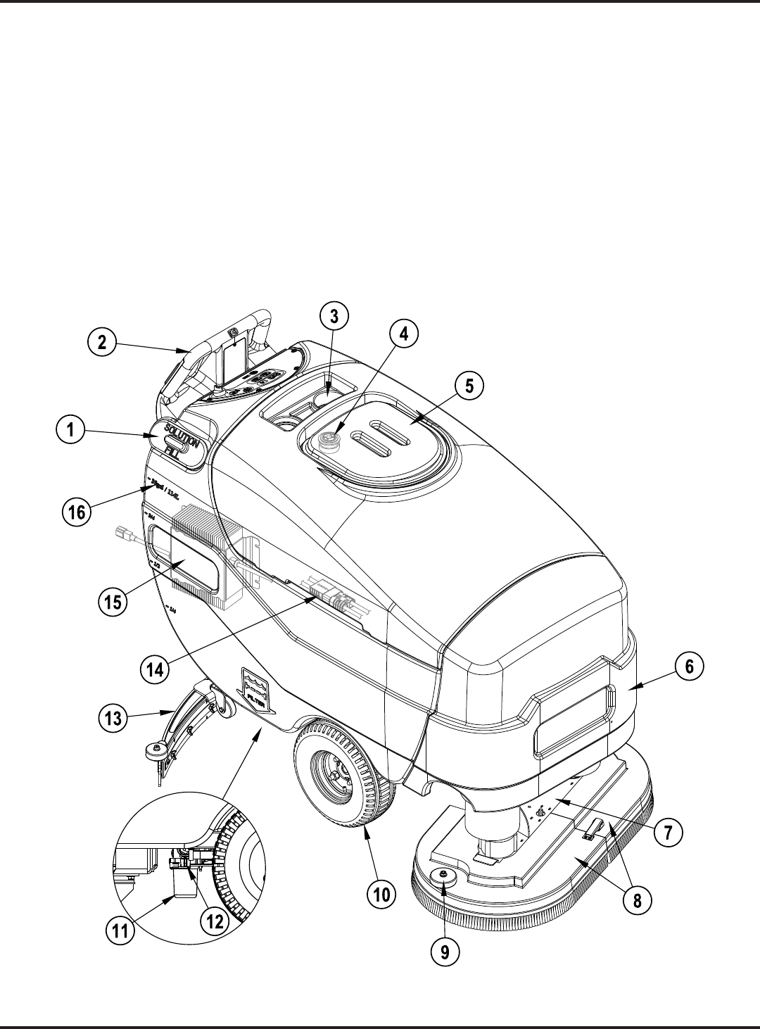
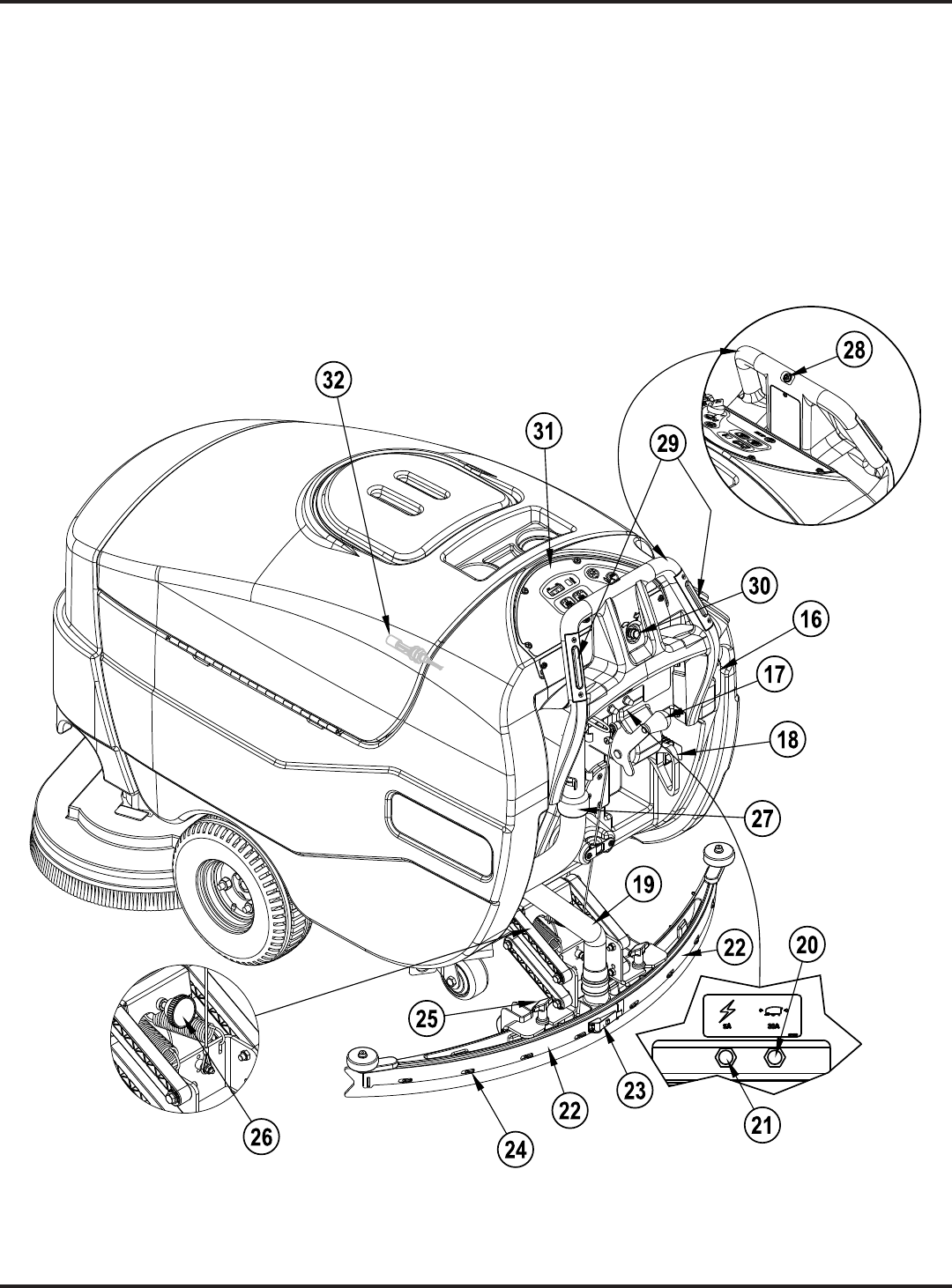
Know Your Machine
(2).
These numbers refer to items shown on the following pages unless otherwise noted. Refer to these pages for the
1 Solution Tank Fill
2 Operator Control Handle
3 Bottle Holders
4 Vacuum Motor Inlet Screen
5 Recovery Tank Cover
6 Nose Cone
7 Scrub Deck
8 Brush Housings (includes Bristle Skirt)
9 Scrub Deck Bumper Wheel
10 Drive Wheel
11 Solution Filter
12 Solution Shutoff Valve
13 Squeegee Assembly
14 Battery Pack Connector (onboard charger models only)
15 Onboard Battery Charger (not found on all models)
16 Solution Drain Hose/Level Indicator
13 - FORM NO. 56043162 - Focus II Large
Introduction
16 Solution Drain Hose/Level Indicator
17 Squeegee Raise/Lower Lever
18 Battery Pack Connector (non onboard charger models only)
19 Recovery Hose
20 Wheel Drive Circuit Breaker
21 Circuit Breaker for the Control Circuit
22 Squeegee Blade Tension Strap
23 Squeegee Blade Latch
24 Squeegee Blade Alignment Pins
25 Squeegee Mount Thumb Nut
26 Squeegee Adjustment Knob
27 Recovery Tank Drain Hose
28 Reverse Button
29 Palm Drive Buttons
30 Speed Limit Control Knob
31 Control Panel
32 Vacuum Shutoff Switch
14 - FORM NO. 56043162 - Focus II Large
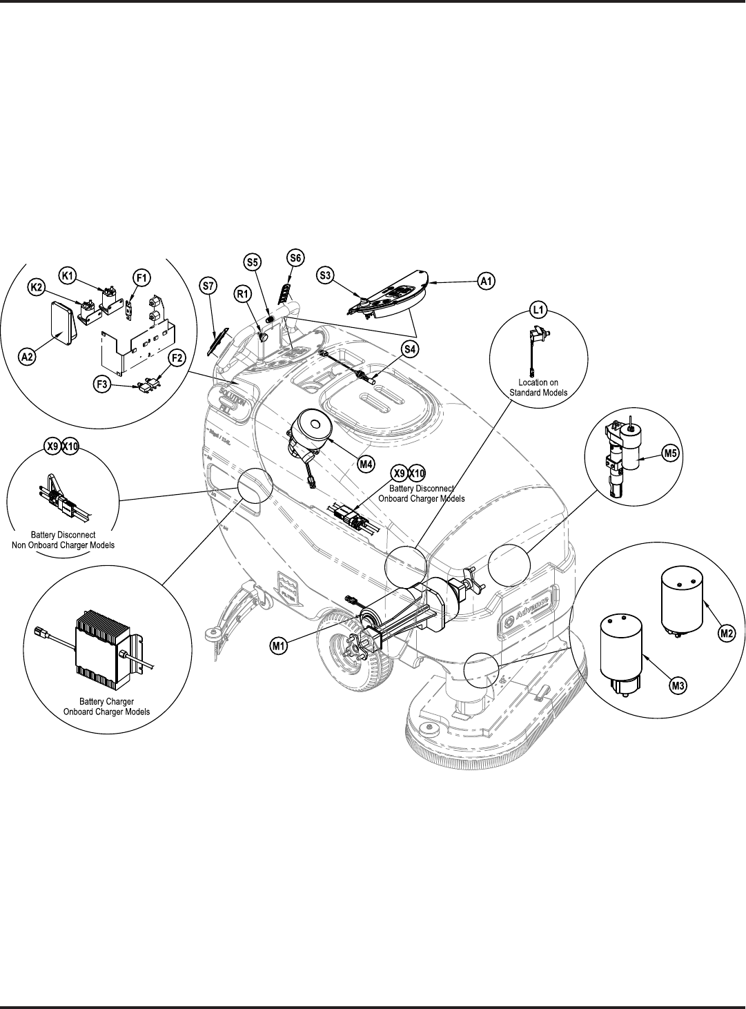
Introduction
A1 Control Panel Assy
A2 Speed Control
BT1 Battery (Not Shown)
F1 Fuse, 150 Amp
F2 Circuit Breaker, 5 Amp
F3 Circuit Breaker, 30 Amp
K1 Contactor, Brush Motor
K2 Contactor, Vac Motor
L1 Solenoid, Solution
M1 Motor, Wheel Drive
M2 Motor, Left Brush
M3 Motor, Right Brush
M4 Motor, Vac
M5 Motor, Brush Actuator
R1 Potentiometer, 100K Ohm, Speed Limit
S3 Switch, Key
S4 Switch, Float (Recovery Tank Full)
S5 Switch, Reverse
S6 Switch, Palm Assy
S7 Switch, Palm Assy
X9 Battery Disconnect
X10 Battery Disconnect
15 - FORM NO. 56043162 - Focus II Large
Control Panel
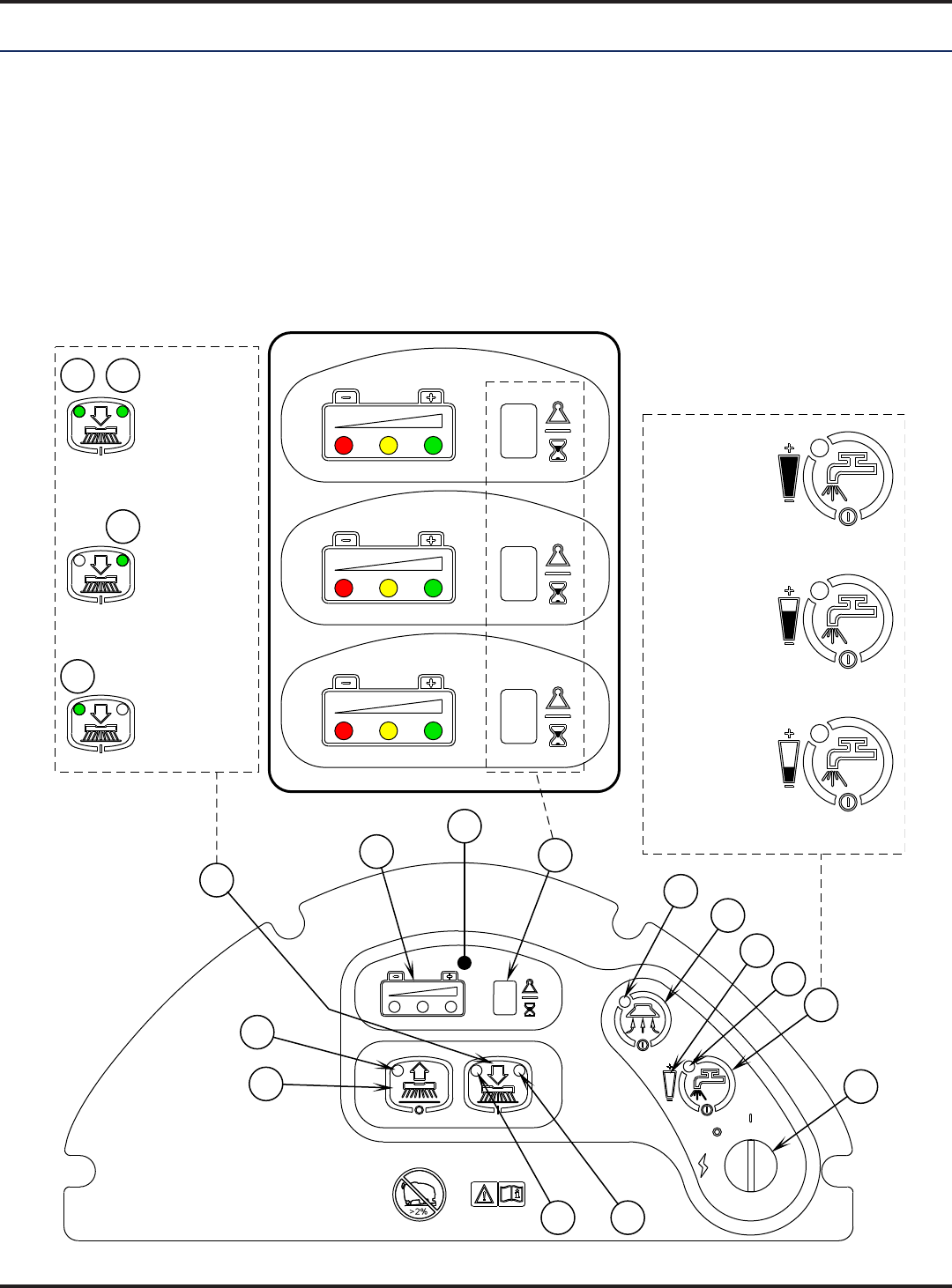
Control Panel
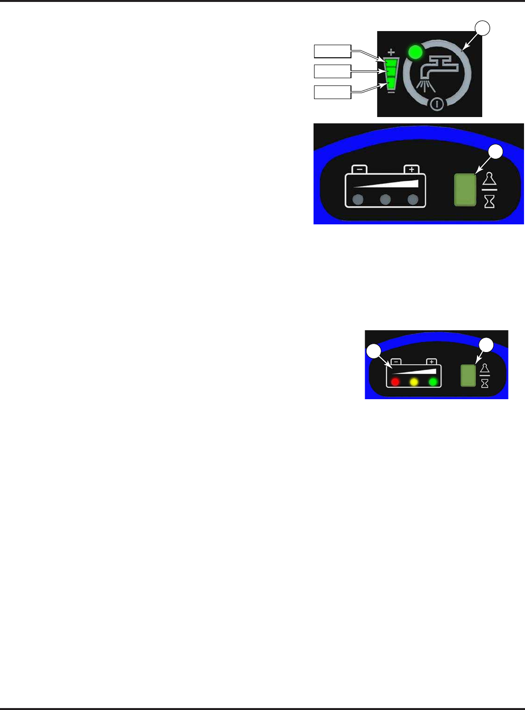
A Key Switch (Main Power)
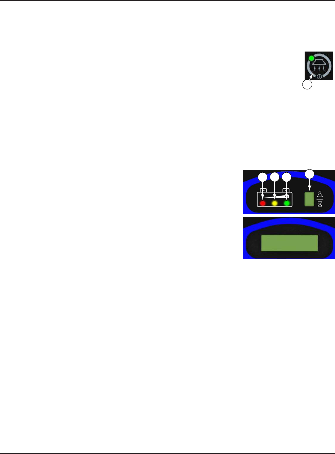
B Solution Switch
B1 Solution Indicator
D1 Solution Flow Indicator
C Vacuum Switch
C1 Vacuum System Indicator
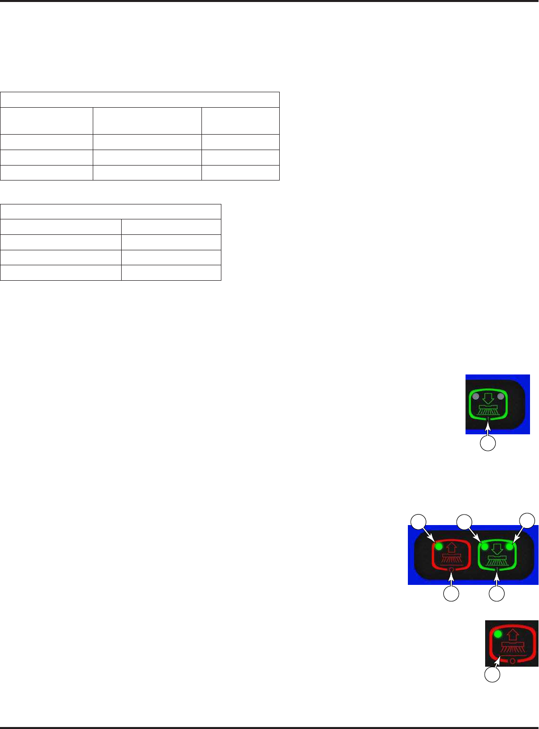
H Scrub OFF Switch
H1 Scrub OFF Indicator
I- Scrub ON Switch
I1 – Regular Scrub ON Indicator
I2 – Heavy Scrub ON Indicator
I1 and I2 – Extreme Scrub ON Indicators
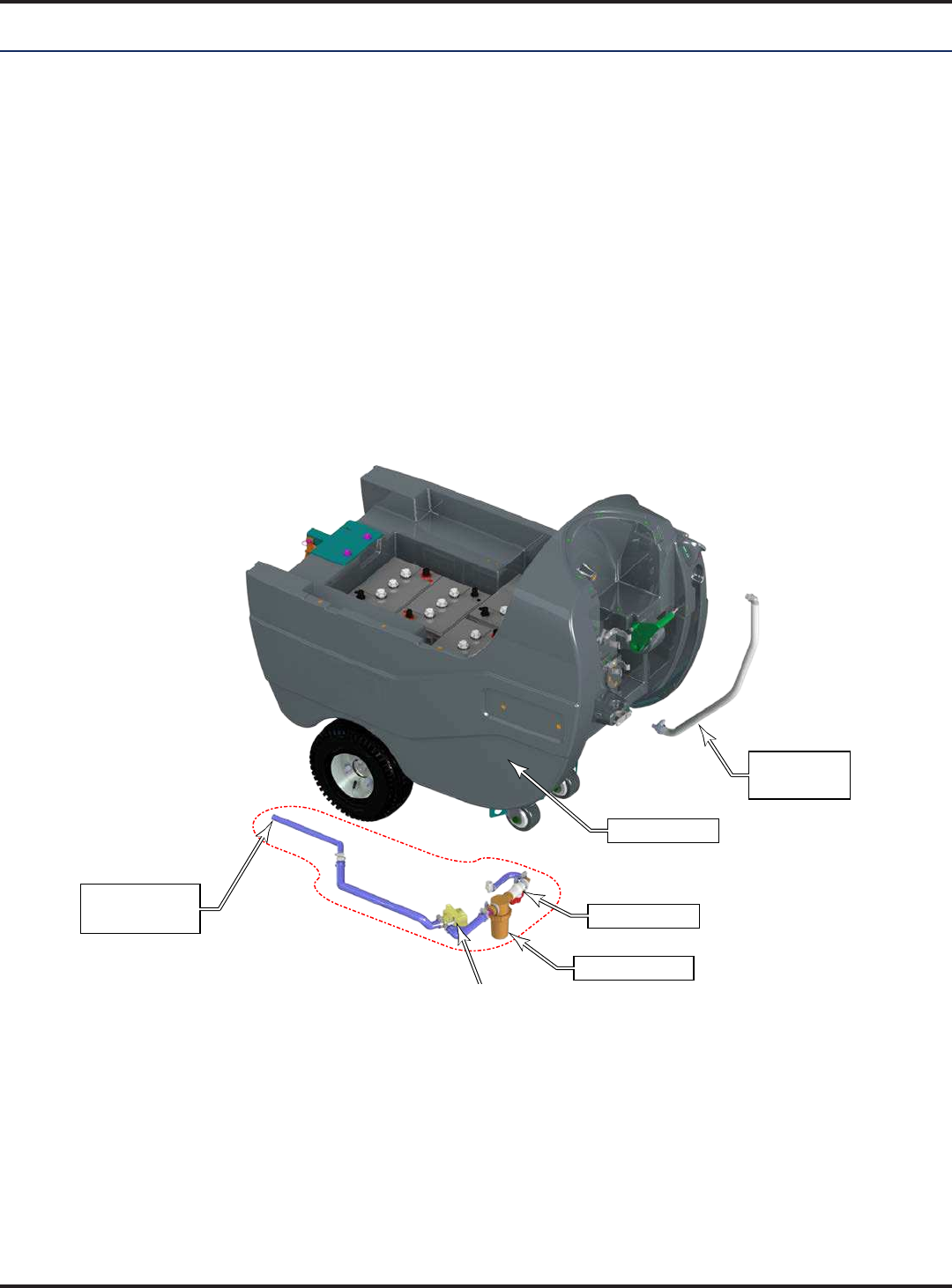
J Display
J1 Battery Indicator
J2 Hour Meter / Scrub Pressure Indicator / Fault Code
Display / Recovery Tank FULL Indicator
A
B
C
H
I
J
J1 J2
1
2
3
D1
H1
I1 I2
I1
I2
I2
I1
C1
B1
Extreme
Scrub
Pressure
Heavy
Scrub
Pressure
Regular
Scrub
Pressure
High
Solution
Flow
Low
Solution
Flow
Medium
Solution
Flow

16 - FORM NO. 56043162 - Focus II Large
Control Panel
Functional Description
The control panel is an integral component with the Main controller (A1) circuit board. The controls on the 34 RST
were designed with one touch operation
only need to use the middle switches on the control panel. These are the Scrub System OFF and Scrub System ON
switches.
Key Switch (A): The key switch serves as a main control switch to enable or disable operation of the machine.
The key is removable to prevent unwanted operation when not in use. The key switch doesn’t disconnect any power
circuits, but instead, sends a signal to both the Main controller and Curtis Drive controller to indicate the On/Off
function.
Solution Switch (B)
on the Solution Flow Indicator (D1)Palm Drive Button (29) is pressed
Palm Drive
Buttons (29) are released. Pressing the Solution Switch (B) when the scrub system is off will momentarily turn
Solution Switch (B)
depressed.
Scrub OFF Switch (H)
The scrub brushes will turn off and the scrub deck will be raised to the up position.
remaining water may be picked up without having to turn the vacuum back on. If this switch is pressed a second
second delay.
Scrub ON Switch (I) – If the scrub system is off, pressing this switch once will cause the following to occur:
The scrub system will be enabled with the scrub pressure set to the “Regular” (“Normal”) mode (#1) and the scrub
The vacuum system will be enabled.
The solution system will be enabled.
As soon as either of the Palm Drive Buttons (29) is pressed, the scrub brushes will start turning and the
Reverse Button (28)
Scrub
Pressure Indicator (J2) on the panel display will show the current scrub pressure setting (1, 2 or 3).
Note:
Vacuum Switch (C) – This switch is used to turn the vacuum system on or off. Pressing this switch will alternate
between on and off. The vacuum will only turn on when a Palm Drive Button (29) is pressed. It will remain on
for 10 seconds after the Palm Drive Buttons (29) are released.
The vacuum also has an automatic shutoff feature that will turn the vacuum and scrub systems off if the recovery tank becomes full.
Wand Switch (E):
turn the vacuum on continuously without regard to the throttle position. If the scrub system was on it will be turned
Note: automatic
17 - FORM NO. 56043162 - Focus II Large
Control Panel
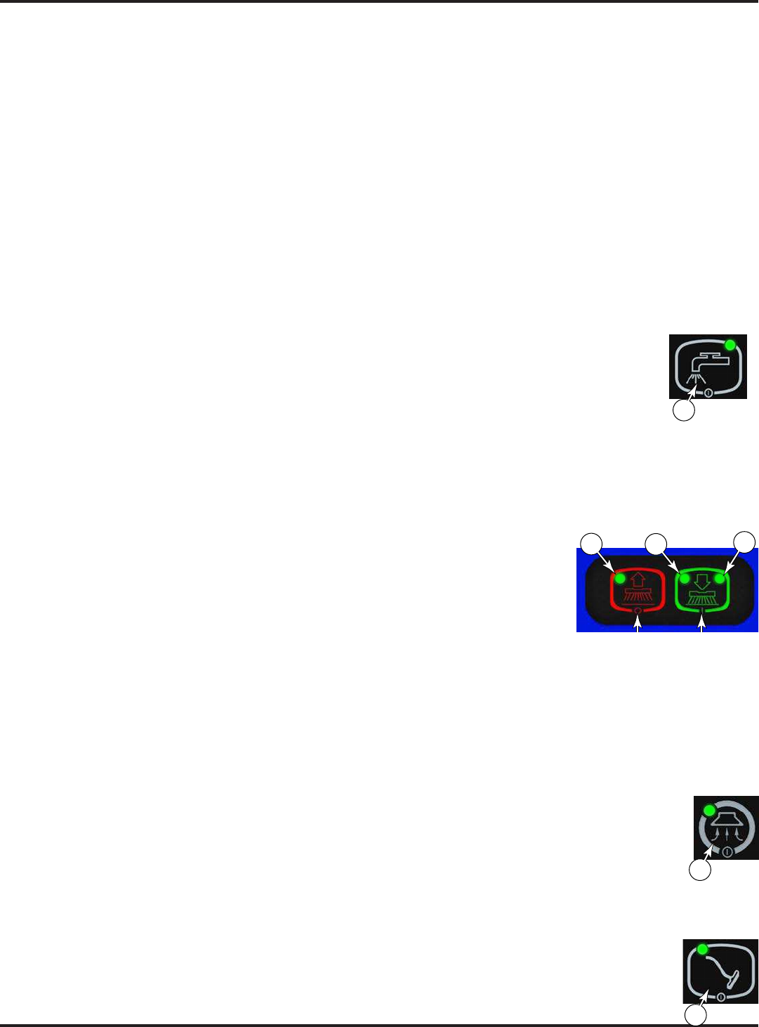
Description of Indicators
Each of the switches on the control panel have an indicator LED adjacent to the switch. Most LEDs are dual
channel and provide two colors within the same LED. In general, the following guidelines apply to the control panel
A steady green indicator means that the particular system or function is on.
A
when a scrub mode is selected and the throttle goes from forward or reverse to neutral. When this happens the
delay period.
A steady yellow indicator means that the particular function has been enabled and in a ready state, but is not
and solution indicators will all be yellow indicating that the systems are enabled and ready to turn on when the
throttle is moved to forward and/or reverse.
A
Solution System (B) Indicator:
This indicator will be off if the solution is disabled and turned off.
This indicator will be green if the solution is on.
This indicator will be yellow if the solution is enabled but the drive paddle is in neutral.
Scrub ON Indicators (I1 & I2):
For Regular scrub mode, the (I1) LED will be active.
(I2) LED will be active.
(I1&I2) LED’s will be active.
the neutral position, the LED’s (I1 and/or I2) will be solid yellow.
the drive position, the LED’s (I1 and/or I2) will be solid green.
Both indicators will be off if the scrub system has been turned off.
Scrub OFF Indicator (H1):
This indicator has green and red colors.
The indicator will be green if the scrub system is off and ready to be activated.
The indicator will be red if the scrub system has been turned off and the scrub deck is not up yet.
The indicator will be off if the scrub system has been activated.
Vacuum System (C) Indicator:
This indicator will be off if the vacuum is disabled and turned off.
This indicator will be green if the vacuum is on.
This indicator will be yellow if the vacuum is enabled but the drive pedal is in neutral.
Wand Switch (E) Indicator:
This indicator uses green color only.
This indicator will be green if the Wand Switch has been turned ON.
This indicator will be off if the Wand Switch has been turned OFF.
Curtis Drive controller (See the Wheel System, Traction chapter for details).
B
I1 I2
H1
C
E
18 - FORM NO. 56043162 - Focus II Large
Control Panel
Scrub Mode Indicators
The Solution system and Scrub system have three scrub modes
controlled when the Scrub On Switch (I) is pressed, but the
Solution system can be controlled separately by pressing the
Solution Switch (B).
Pressing the Scrub On Switch (I) once will set both the scrub
mode and solution mode to regular (and clear any solution
system overrides).
Pressing the Scrub On Switch (I) twice will set both the scrub
mode and solution mode to heavy (and clear any solution system
overrides).
Pressing the Scrub On Switch (I) for 5 seconds will set both
solution system overrides).
Pressing the Solution Switch (B) once, twice, or for 5 seconds;
will change the solution mode accordingly, but without changing
the scrub mode.
The solution mode is displayed in a bar graph adjacent to the solution switch (B), and the scrub mode is indicated in
the display (J2) with a number representing the mode.
Battery Indicator
The charge state of the battery is shown in the main display area of the control
panel. This is is indicated by three colored LED’s (J1).
Hour Meter: The (J2)
are 135.6 total hours on the machine.
2
B
J2
Regular
Heavy
Extreme
2
J1 J2
19 - FORM NO. 56043162 - Focus II Large
Control Panel
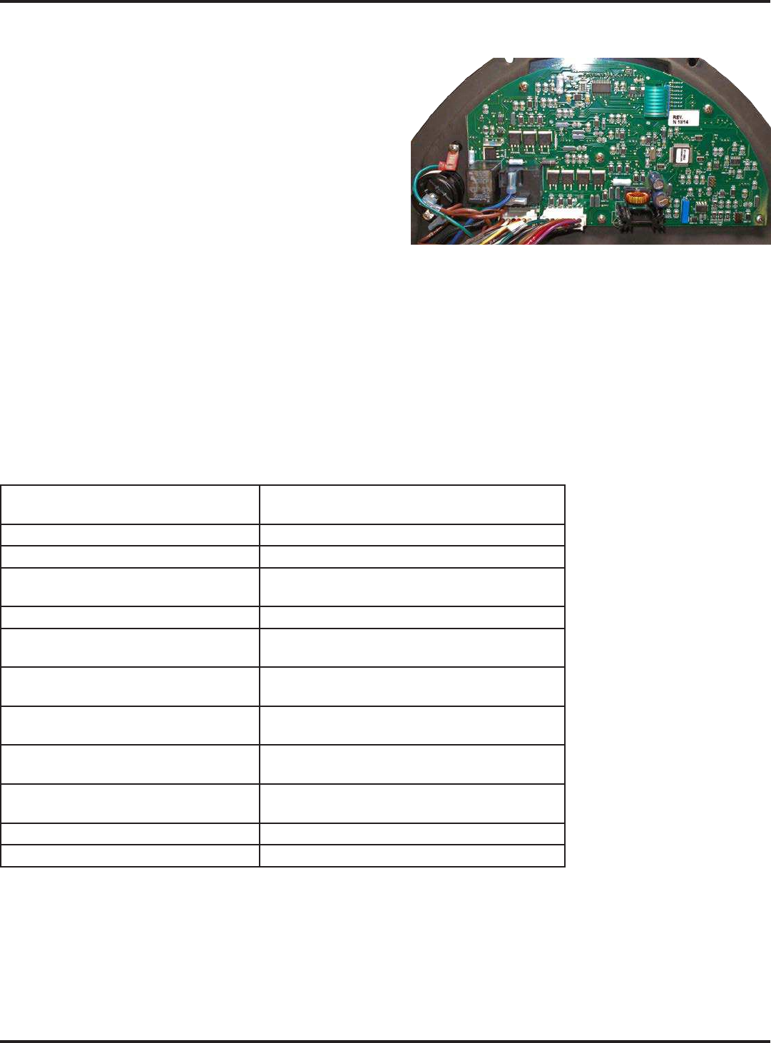
Main Controller
The Main controller (A1), which includes the control board
and the display, is the primary electronic control for the
contoller chip to regulate function. The controller receives and
interprets user inputs, sensor inputs, and even some motor
amperage readings, and controls device output for the user
display, solenoid operation, and motor control. Most low and
medium power outputs are controlled with power MOSFET
transistors, with some moderately high power devices
contactors.
Another function of the main controller is to detect any system failures and display an error code on the display
panel or store it in the main control board’s memory. The error code(s) are used to help the service person determine
further information. An additional special feature of the main control board is to change program settings for a set of
section in this chapter for further information.
Main Control Board Programming
replacing the controller with a new controller. The table below and following sections describe the parameters to be
programmed.
Programming Option Button(s) to Hold While Turning Key
Switch to On
Enter Service Test Mode Vacuum Switch (C)
Low-voltage Cut-out Threshold Scrub OFF Switch (H)
Enable/Disable Fault Detection Scrub OFF Switch (H)
Solution Switch (B)
Recall/Clear Stored Error Codes Solution Switch (B)
Controller Software Revision
Level Solution Switch (B) Vacuum Switch (C)
Scrub Deck Down Time Scrub OFF Switch (H)
Vacuum Switch (C)
Regular Scrub Setting Scrub OFF Switch (H)
Scrub ON Switch (I)
Heavy Scrub Setting Scrub ON Switch (I)
Vacuum Switch (C)
Extreme Scrub Setting Scrub ON Switch (I)
Solution Switch (B)
Restore Factory Default Scrub Settings Scrub ON Switch (I)
Recovery Tank-full Switch Orientation N/A
20 - FORM NO. 56043162 - Focus II Large
Control Panel
Displaying the Control Board Revision Level
During machine service, it may be helpful to know the control board revision level to determine machine
1. Turn the key switch to the off position.
2. While holding the Solution (B) and Vacuum (C) switches depressed, turn on the key
switch.
3.
4. The LED display will show the revision level (letter) of the controller software.
5.
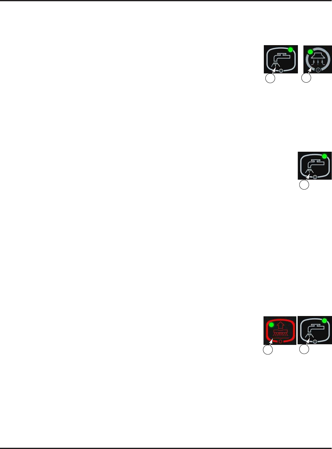
Recall of Stored Error Codes
To assist with service troubleshooting, the controller maintains a list of past error codes. To recall and/or clear the
stored error codes perform the following steps:
1. Turn the key switch to the off position.
2. While holding the Solution Switch (B) depressed, turn the key switch to the on position.
3. Continue to hold the solution switch until the solution indicator turns green.
If there are no error codes stored, the display will show “—”.
If any error codes are stored, the scrub off indicator will be red and the display will show the error code
4. To clear the stored codes, press the scrub off switch. (It is recommended that error codes are cleared after
servicing so that future error codes represent only errors that occur between service intervals.)
The display will now show “—”.
5.
Turning Fault Detection On or Off:
If a fault occurs in a particular system, that system (and possibly others) will be shut down. This can make
Important: Make sure to turn Fault Detection back on before returning the machine to normal operation. To turn
the fault checking on or off:
1. Turn the key switch to the off position.
2. While holding the Scrub System Off (H) and the Solution (B) switches depressed, turn
on the key switch.
3. Continue to hold both switches until the indicators for both switches turn green.
4. Release both switches. The scrub off indicator will turn red.
5. Pressing the solution switch will toggle between fault detection enabled and disabled.
The LED display will toggle between “E” (enabled) and “d” (disabled).
6. To save the setting, press the scrub off switch.
The scrub off indicator will turn green.
7. Turn the key switch to the off position. The new setting will be saved and will remain in effect until it is
changed again.
C
B
B
HB

21 - FORM NO. 56043162 - Focus II Large
Control Panel
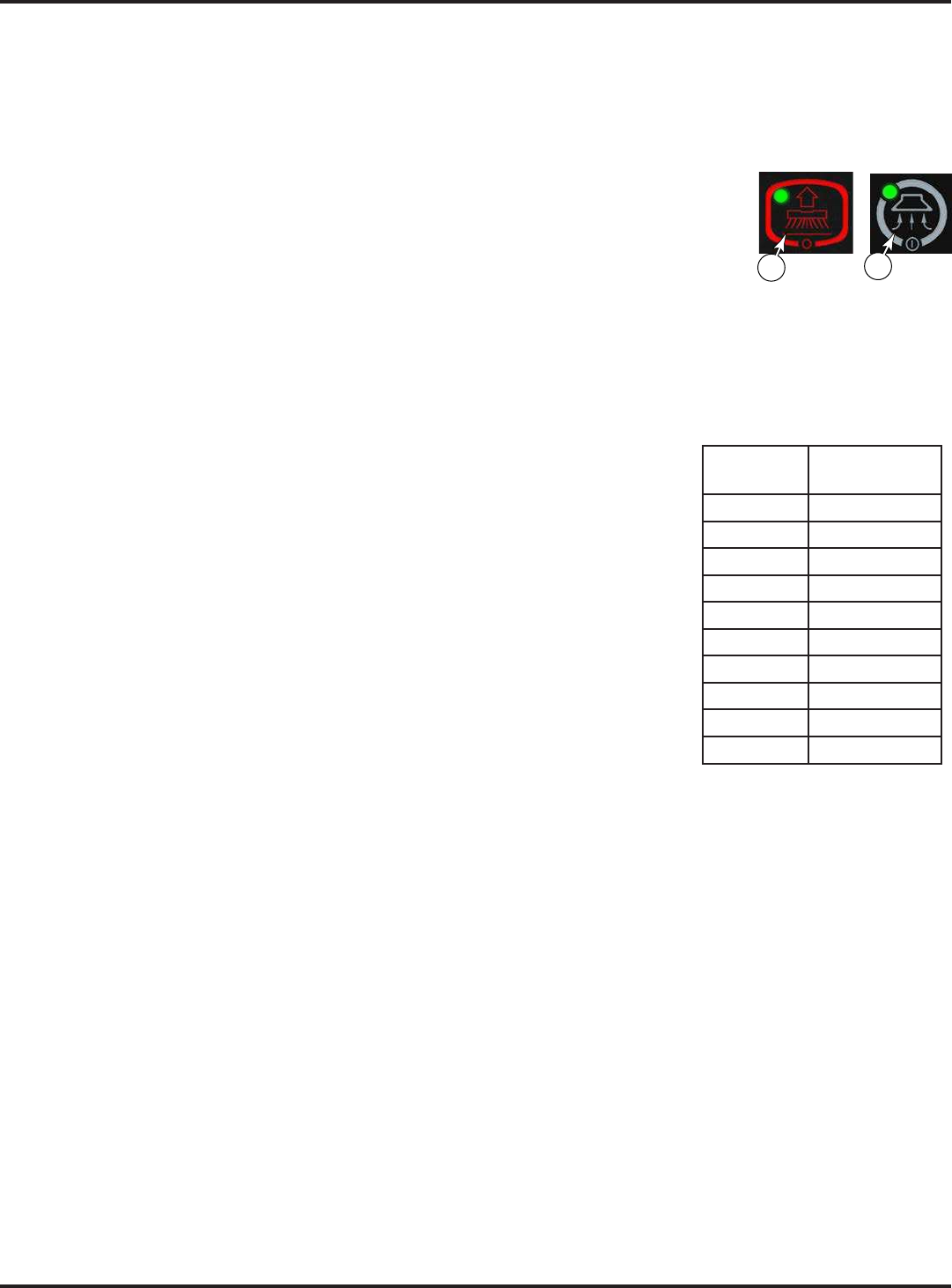
Low-voltage Cutout Threshold
will automatically shut down the scrub system when the battery voltage falls to the selected threshold. The cutout
threshold has two levels: Standard and Alternate. The Standard setting is 30.96 volts (5.16 volts per battery), and is
for standard lead acid batteries. The Alternate setting is 32.58 volts (5.43 volts per battery), and is for typical gelled
Factory
Default: 30.96V (Standard Battery)
To select between the two cutout levels:
1. Turn the key switch (A) to the off position.
2. While holding the Scrub Off switch (H) turn the key switch (A) to the on position.
3. Continue to hold the Scrub Off switch until the Scrub Off indicator (H1) turns green, and then
release the Scrub Off switch.
The Scrub Off indicator will turn red.
4. To toggle between Standard and Alternate, press the Scrub On switch (I). The two modes
The Scrub On Regular (I1)(I2) LED’s will toggle green and yellow, as
shown to the right.
The status display will show an “S” (standard) or an “A” (alternate).
5. To save the new setting, press the scrub off switch. The scrub off indicator will turn green.
6. Turn the key switch to the off position to commit the settings to permanent memory.
H
Alternate
Standard
I2II1
22 - FORM NO. 56043162 - Focus II Large
Control Panel
Scrub Deck Down Time Period Adjustment
The initial lowering of the scrub deck is timed, because there will not be any brush motor amperage to monitor for
determining when to stop lowering the deck. The time that the deck is lowered is adjustable from 3.5 seconds to 4.4
perform the following steps:
1. Turn the key switch to the off position.
2. While holding the Scrub Off (H) and the Vacuum (C) switches depressed, turn the key
switch to the on position.
3. Continue to hold both switches until the indicators for both switches turn green.
4.
and the Scrub Off indicator will turn red.
The LED display will show the number corresponding to the deck down time as listed in the table shown on
the right.
5. Press the Scrub On (I) switch to toggle through the deck down time period values. These values represent the
times shown in the table to the right.
6. To save the new setting, press scrub off switch.
The scrub off indicator will turn green.
7. Turn the key switch to the off position to commit the settings to permanent
memory.
HC
Number in
Display
Scrub Deck
Down Time
0 3.5 sec
1 3.6 sec
2 3.7 sec
3 3.8 sec
4 3.9 sec
5 4.0 sec
6 4.1 sec
7 4.2 sec
8 4.3 sec
9 4.4 sec
23 - FORM NO. 56043162 - Focus II Large
Control Panel
Scrub Deck Pressure, Solution Flow Rate, and Chemical Flow Rate Adjustments
These settings are adjustable. The default values are shown in the tables below. The scrub pressures are determined
Scrub Pressure & Amperage Specifications Chart
Scrub Mode Default Pressure
Indicator
Brush Motor
Amperage
Regular Scrub 1 bar(#1) 16 AMPS
Heavy Scrub 2 bars(#2) 24 AMPS
Extreme Scrub 3 bars(#3) 38 AMPS
Default Solution Flow Rate Chart
Solution Flow Indicator Flow Rate
One bar gauge(#1) 0.3 g/m
Two bar gauge(#2) 0.6 g/m
Three bar gauge(#3) 0.9 g/m
Restoring the Scrub Pressures to Factory Default Settings
Use this procedure to restore all of the scrub deck pressure settings to their factory default values.
1. Turn the key switch to the off position.
2. While holding the Scrub On switch (I) depressed, turn the key switch to the on position.
The display will show ”d” to indicate that the factory default scrub pressures have been
restored.
3. Release the switch and turn the key switch to the off position.
Regular Scrub Setting Adjustment
Use this procedure to adjust the scrub deck pressure and solution rate that are used for the Regular scrub mode.
1. Turn the key switch to the off position.
2. While holding the Scrub On (I) and Scrub Off (H) switches depressed, turn the
key switch to the on position.
3. Continue to hold the both switches until the switch indicators turn green.
4. Release both switches. The scrub off indicator will turn red and the regular scrub
indicator will turn yellow. Also:
The LED display will show the level number of the current scrub pressure
setting.
5. Pressing the Scrub On switch (I) will scroll through the 3 scrub pressure settings.
6. Pressing Scrub Off switch (H) will save the pressure setting and move to solution rate setting.
7. Solution Rate Setting: The Regular Scrub indicator (I1) will turn from yellow to green and the
Solution indicator will turn yellow.
8. Press the Solution switch (B) to scroll through the 3 solution rate settings.
I
I1 I2
H1
H I
H

24 - FORM NO. 56043162 - Focus II Large
Control Panel
9. Press the Scrub Off switch (H) to save the new setting and move to the end of the program mode .
10. Turn the key switch to the off position. The new settings will be saved and will remain in effect until they are
changed again.
Heavy Scrub Setting Adjustment:
1. Turn the key switch to the off position.
a. While holding the Scrub On (I) and Vacuum (C) switches depressed, turn the key
switch to the on position.
b. Continue to hold both switches until the heavy scrub on indicator turns green and
the vacuum indicator light switches on.
2. Release both switches. The scrub off indicator will turn red and the heavy scrub indicator (I2) will turn yellow.
Also:
The LED display will show the level number of the current scrub pressure setting.
3. Press the Scrub On switch (I) to scroll through the 3 scrub pressure settings.
4. Press the Scrub Off switch (H) to save the pressure setting and move to solution rate setting.
5. Solution Rate Setting:(I2) will turn from yellow to green and the
Solution indicator will turn yellow.
6. Press the Solution switch (B) to scroll through the 3 solution rate settings.
7. Press the Scrub Off switch (H) to save the new setting and move to the end of the program mode.
8. Turn the key switch to the off position. The new settings will be saved and will remain in effect
until they are changed again.
Extreme Scrub Setting Adjustment
scrub mode.
1. Turn the key switch to the off position.
a. While holding the Scrub On (I) and Solution (B) switches depressed, turn the key
switch to the on position.
b.
Scrub indicators turn green.
2.
turn yellow. Also:
The LED display will show the level number of the current scrub pressure setting.
3. Press the Scrub On switch (I) to scroll through the 3 scrub pressure settings.
4. Press the Scrub Off switch (H) to save the pressure setting and move to solution rate setting.
5. Solution Rate Setting: The Regular Scrub Indicator (I1)(I2) will
turn from yellow to green and the Solution indicator will turn yellow.
6. Press the Solution switch (B) to scroll through the 3 solution rate settings.
7. Press the Scrub Off switch (H) to save the new setting and move to the end of the program mode.
8. Turn the key switch to the off position. The new settings will be saved and will remain in effect
until they are changed again.
IC
H
B
IB
H
B

25 - FORM NO. 56043162 - Focus II Large
Control Panel
Troubleshooting Guide
Any error codes detected by the main control board will be displayed on the display
(J2) will
When troubleshooting any “Fault Description” noted with a double asterisk (**)
follow the instructions for entering the Service Test Mode in the control board’s
special programs. See the section in this manual.
Main Controller Error Codes
Error Description Comments
E03 Drive system fault.
code from the Curtis Drive controller. See the Wheel System,
Traction
E04 Scrub deck lift actuator overload.
connected.
If the no-load current remains high, then the actuator or wiring is
faulty.
E06 Scrub motor overload
E07 Vacuum motor overload
Check the vacuum discharge for obstruction (inlet obstruction will
Defective motor bearings.
E08 Solenoid Bank Coil Circuit
Overload
Brush Motor Contactor (K1)
Vacuum Motor contactor (K2)
Solution Solenoid (L1)
The sum of the currents through these coils is too high
for negative battery voltage. This error will occur if B-3 is
disconnected.
good), the control board is defective
Check resistance on all contactor/solenoid coils. If the value is less
Brush motor contactor coil (K1):
Vacuum motor contactor coil (K2)
Solution solenoid coil (L1)
E
J2

26 - FORM NO. 56043162 - Focus II Large
Control Panel
E017 Scrub deck lift actuator circuit
The controller’s internal circuitry is not seeing any voltage change.
(F2)
voltage.
Check for disconnected actuator wiring or defective actuator
motor.
Battery-Negative and the other should be non-zero (PWM of B-2)
to Battery-Negative. If both remain near 36 volts, it indicates a
controller failure.
E018 Scrub deck lift actuator short The controller’s internal circuitry is seeing maximum voltage in the
current sensing circuit.
Check the lift actuator limit adjustment
E021 The controller’s internal circuitry is not seeing any voltage change.
circuits
E022) Scrub motor short The controller’s internal circuitry is seeing maximum voltage in the
current sensing circuit.
Same troubleshooting as E06
E023) The controller’s internal circuitry is not seeing any voltage change.
E024) Vacuum motor short The controller’s internal circuitry is seeing maximum voltage in the
current sensing circuit.
Same troubleshooting as E07

27 - FORM NO. 56043162 - Focus II Large
Control Panel
Main Controller I/O Table
B- = Battery Negative B+ = Battery Positive
Designation
Pin Wire Color Description Signal
Type
Nominal
Value
Reference
To: Range Comments
Input J1-4 ORN/BLU Speed Control Status VDC -36V B+ 37.6 - 30.6V
Pulsed Signal equal to the Fault
Control Built-in Status LED
Input J1-5 RED/BLK Forward/Reverse VDC -36V B+ 37.6 - 30.6V Machine is not in Neutral (a palm
drive switch is pressed)
Input J1-6 BLU/BLK Direction VDC -36V B+ 37.6 - 30.6V Machine is traveling in Reverse
Ground J1-7 BLK Power Supply VDC -36V B+ 37.6 - 30.6V
Ground J1-9 BLK Power Supply VDC -36V B+ 37.6 - 30.6V
Output J1-11 RED/GRN
Solution Solenoid
Note: Coil resistance spec -
72Ω ±20%
Pulsed
Voltage B+ 37.6 - 30.6V
Solenoid voltage is pulsed
between 36V and 0V at a rate of
seconds.
Output J1-12 BLK/YEL
Vacuum Contactor
Note: Coil resistance
spec - 102Ω ±20%
PWM
Voltage B- (Gnd) +/- .7V depending
on battery voltage
5000 Hz freq, 80% duty cycle
Vacuum Motor is Active (~6.9V),
0% duty cycle Vacuum Motor is
off (~36V)
Power J1-13 BRN Power Supply VDC +36V B- (Gnd) 37.6 - 30.6V Key is switched On
Output J1-14 VIO/BLK
Brush Contactor
Note: Coil resistance
spec - 98.5Ω ±20%
PWM
Voltage +7.2V B- (Gnd) +/- .7V depending
on battery voltage
5000 Hz freq, 80% duty cycle
Brush Motor is Active (~6.9V),
0% duty cycle Brush Motor is off
(~36V)
Output J2-1 VIO/YEL Actuator VDC 36V J2-8 37.6 - 30.6V +36V while lowering, -36 while
raising
Input J2-4 GRA/WHT Recovery Tank Float Switch VDC -36V B+ 37.6 - 30.6V Recovery Tank is not Full
-31V B+ 31.6 - 25.6V Recovery Tank is Full
Input J2-5 WHT/GRA Brush Current Sense Analog
Voltage B- (Gnd) 0.20 - 0.05V Brush Motors are Active
Ground J2-6 BLK Power Supply VDC -36V B+ 37.6 - 30.6V
Power J2-7 BRN Power Supply VDC +36V B- (Gnd) 37.6 - 30.6V
Output J2-8 WHT/GRN Actuator VDC 36V J2-1 37.6 - 30.6V -36V while lowering, +36 while
raising
Ground J2-9 BLK Power Supply VDC -36V B+ 37.6 - 30.6V
Input J2-10 ORN Vacuum Current Sense Analog
Voltage +0.12V B- (Gnd) 0.13 - 0.11V Vacuum Motor is Active
28 - FORM NO. 56043162 - Focus II Large
Control Panel
Service Test Mode
To assist in the troubleshooting and servicing of the electrical system and related components, a special test mode
allows independent control of the various outputs and monitoring of the various inputs. To enter the service test
mode perform the following step:
1. Turn the key switch to the off position.
2. While holding the Vacuum switch (C) depressed, turn the key switch to the on position.
3. Continue to hold the Vacuum switch until the Vacuum indicator turns green.
The Display will show “t” for Test Mode.
4.
Test Mode Input Indicators
Battery Voltage
The battery voltage, as detected by the controller, is shown in the display. If this displayed voltage differs
The LED display (J2)
Speed Controller Status
This is a Main controller input from the Curtis Drive controller. The indicator is
passed through the Main controller without interpretation, and represents the error
code from the Drive controller.
The green light in the battery indicator (j5) will light whenever the key is on. If
the speed controller.
Refer to the speed control section for details on these codes. If the indicator does not
display, disconnect the Orn/Blu wire from the speed controller and main controller
and check the continuity of the wire. If the wire tests open repair or replace the wire
or plug. If wire tests OK, the fault is likely with the Drive controller.
Forward/Reverse Status
This indicator comes from the Curtis Drive controller, and indicates that the Curtis Drive Controller is trying to
(J4) will be yellow when the “machine moving” signal is present.
Reverse Status
This indicator comes from the Curtis Drive controller and indicates when the Curtis Drive Controller is trying to
The red battery indicator (J3) will light when the “reverse” signal is present. (The machine moving signal should
also be present when the machine is moving in reverse, so the yellow battery indicator should also be on. )
C
t
SVCTEST
36.5V
F/R
REV SCS
J2
J3 J4 J5

29 - FORM NO. 56043162 - Focus II Large
Control Panel
Test Mode Output Controls
The control panel switches are used to control various output functions of the Main controller while in Test Mode.
Below is a list of each switch and the function it controls. Following the list is a detailed description of each function.
Scrub off Switch (H): Controls the brush motors.
Scrub on Switch (I): Controls the scrub deck lift actuator.
Vacuum Switch (C): Controls the vacuum motor.
Wand Switch (E): Jogs the scrub deck lift actuator.
Solution Switch (B): Turns on the solution solenoid valve.
Detergent System Switch (F): Turns on the chemical pump (If available).
Description of Output Controls
Scrub System Off Switch (H):
This switch is used to toggle the state of the brush motor contactor. Pressing and releasing this switch will
alternately turn the brush motor contactor on and off. The indicator provides the following status information:
Off – Brush motor output is off and there is no brush motor current sensed.
Steady Green – Brush motor output is on and there is normal brush motor current sensed.
Brief On Green Flash – Brush motor output is off and brush motor current is being sensed (abnormal condition).
Check for voltage at the Wht wire on K1 contactor to battery ground.
If any voltage is present, replace K1 contactor.
NO voltage, replace the Main control board.
Brief Off Green Flash – Brush motor output is on and brush motor current is not being sensed (abnormal condition).
Check brush motor wiring plugs.
Check one of the Blk wires of the main harness connector at the brush motor to battery Positive. If no voltage
repair or replace wire.
Check one of the Wht wires of the main harness connector at the brush motor to battery Neg. If no voltage repair
or replace wire.
Check for voltage at the Red wire on K1 contactor to battery ground. If no voltage is present repair the Red wire.
Check for voltage at the Wht wire on K1 contactor to battery ground. If no voltage is present replace the K1
contactor.
Flashing Red – Brush motor overload has occurred.
Check to see that the proper brush programming type is selected (disc or cyl).
Check for binding in rotation of brushes or improper scrub brush type installed. (Amp. Test) See Pressure Chart
in this Manual.
Check for short circuit* in brush motor or wiring.

30 - FORM NO. 56043162 - Focus II Large
Control Panel
Scrub On Switch (I)
This switch is used to control the output to the scrub deck lift actuator. Pressing and releasing this switch will cycle
the actuator output through 4 states. These are:
1 – Output off, direction = up
2 – Output on, direction = down
The normal scrub on indicator will be green.
3 – Output off, direction = down
4 – Output on, direction = up
The normal scrub on indicator will be yellow.
When the output is in state 1, the actuator output is turned off. The scrub pressure decrease indicator should be
(shorted output driver, control error). If the scrub pressure decrease switch was the last switch pressed, it is possible
to momentarily activate the actuator output using the wand switch. This can be used to jog the actuator to allow
precise positioning of the actuator. Note: the actuator can only move in this situation if it is not at its up limit.
When the output is in state 2, the actuator output is turned on. The scrub pressure decrease indicator should be
switch has no effect in this state.
When the output is in state 3, the actuator output is turned off. The scrub pressure decrease indicator should be
(shorted output driver, control error). If the scrub pressure decrease switch was the last switch pressed, it is possible
to momentarily activate the actuator output using the wand switch. This can be used to jog the actuator to allow
precise positioning of the actuator. Note: the actuator can only move in this situation if it is not at its down limit.
When the output is in state 4, the actuator output is turned on. The scrub pressure decrease indicator should be
switch has no effect in this state.
Vacuum Switch (C)
This switch is used to toggle the state of the vacuum motor. Pressing and releasing this switch will alternately turn
the vacuum motor on and off. The indicator provides the following status information:
Brief On Green Flash – Vacuum motor output is off and vacuum motor current is being sensed (abnormal condition).
Check for voltage at the Blu wire on K2 contactor to battery ground.
If any voltage is present, replace K2 contactor.
NO voltage, replace the Main control board.
Brief Off Green Flash – Vacuum motor output is on and vacuum motor current is not being sensed (abnormal
condition).
Check Vacuum Motor wiring plug, disconnection.
Check for voltage at the Red wire on K2 contactor to battery ground. If no voltage is present repair the Red wire.
Check for voltage at the Blu wire on K2 contactor to battery ground. If no voltage is present replace the K2
contactor.
Check the Blu wire of the main harness connector at the vacuum motor to battery Negative. If no voltage repair
or replace wire.

31 - FORM NO. 56043162 - Focus II Large
Control Panel
Check the Blk wire of the main harness connector at the vacuum motor to battery Positive. If no voltage repair or
replace wire.
Flashing Yellow – Vacuum motor overload has occurred.
Check for an open in the small ORG current sense wire.
Check for debris in the vacuum motor.
Worn carbon brushes.
Defective motor bearings.
Check for short circuit* in vacuum motor or wiring. Repair or replace.
Solution Switch (B)
This switch is used to toggle the state of the solution solenoid. Pressing and releasing this switch will alternately
turn the solution solenoid (L1) on and off. The indicator provides the following status information:
Flashing Yellow – Solution solenoid overload has occurred.
Detergent Switch (F)
this switch will alternately turn the chemical pump on and off. The indicator provides the following status
information:
Off – Chemical pump and valve off.
Steady Green – Chemical output is on.
32 - FORM NO. 56043162 - Focus II Large
Solution System
Solution System
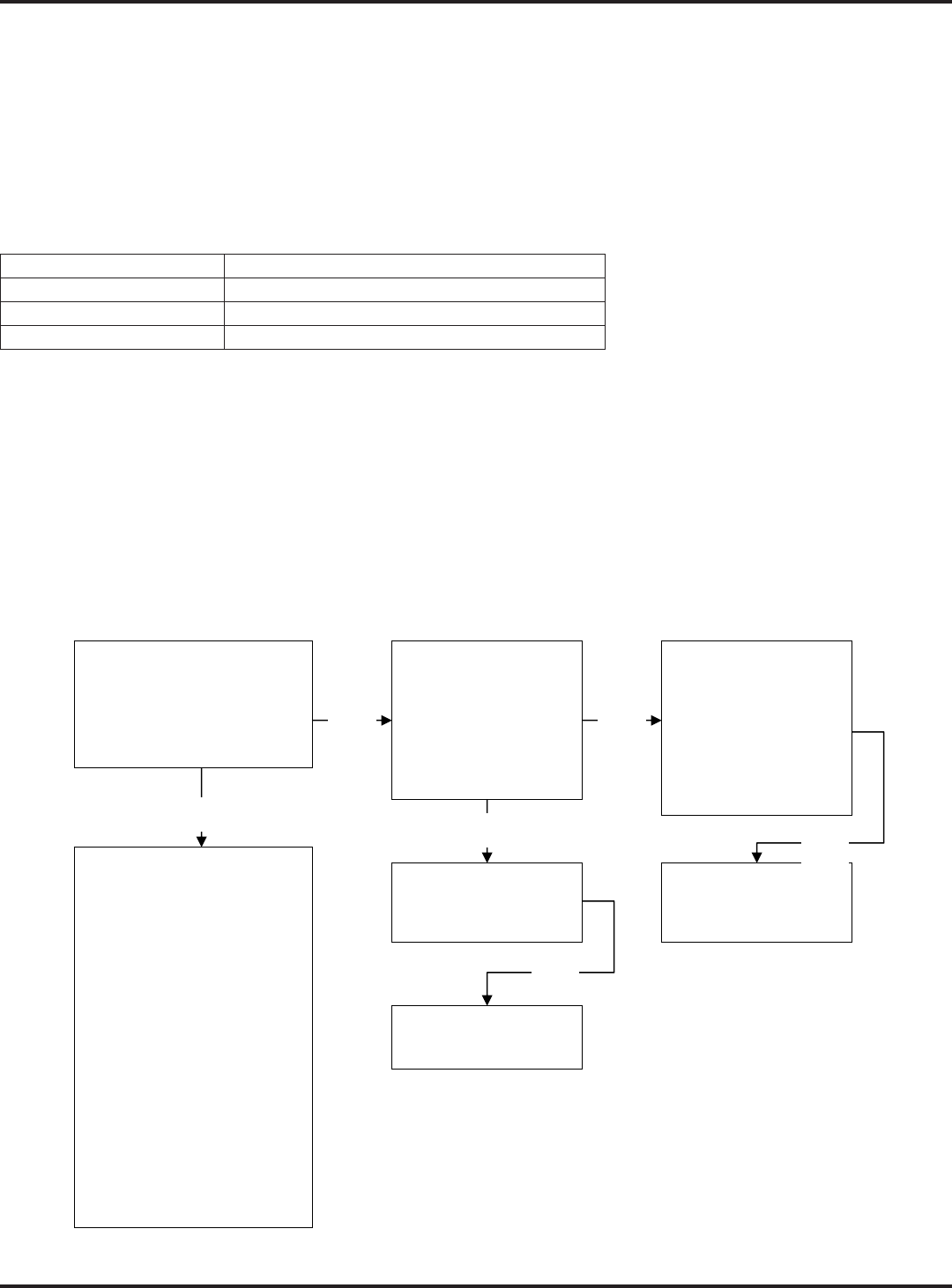
Functional Overview
The solution system uses an electrical Solenoid Valve (L1)
brushes. The electrical circuit that turns on (energizes) the solenoid coil is activated through the (A1) control
panel’s solution switch button input and the FWD / REV (A2) Speed Controller voltage output signals. Note: See
the
During normal machine scrubbing, the solution system’s Auto Mode is selected and works in conjunction with the
wheel drive speed controller and the (A1) main controller’s scrub system outputs to turn the (L1) solenoid valve
pressed. Note
down and a palm drive button is pressed.
Water Level
Sight Tube
Shutoff Valve
Solution Filter
Solution Out
To Scrub Deck
Solution Tank

33 - FORM NO. 56043162 - Focus II Large
Solution System
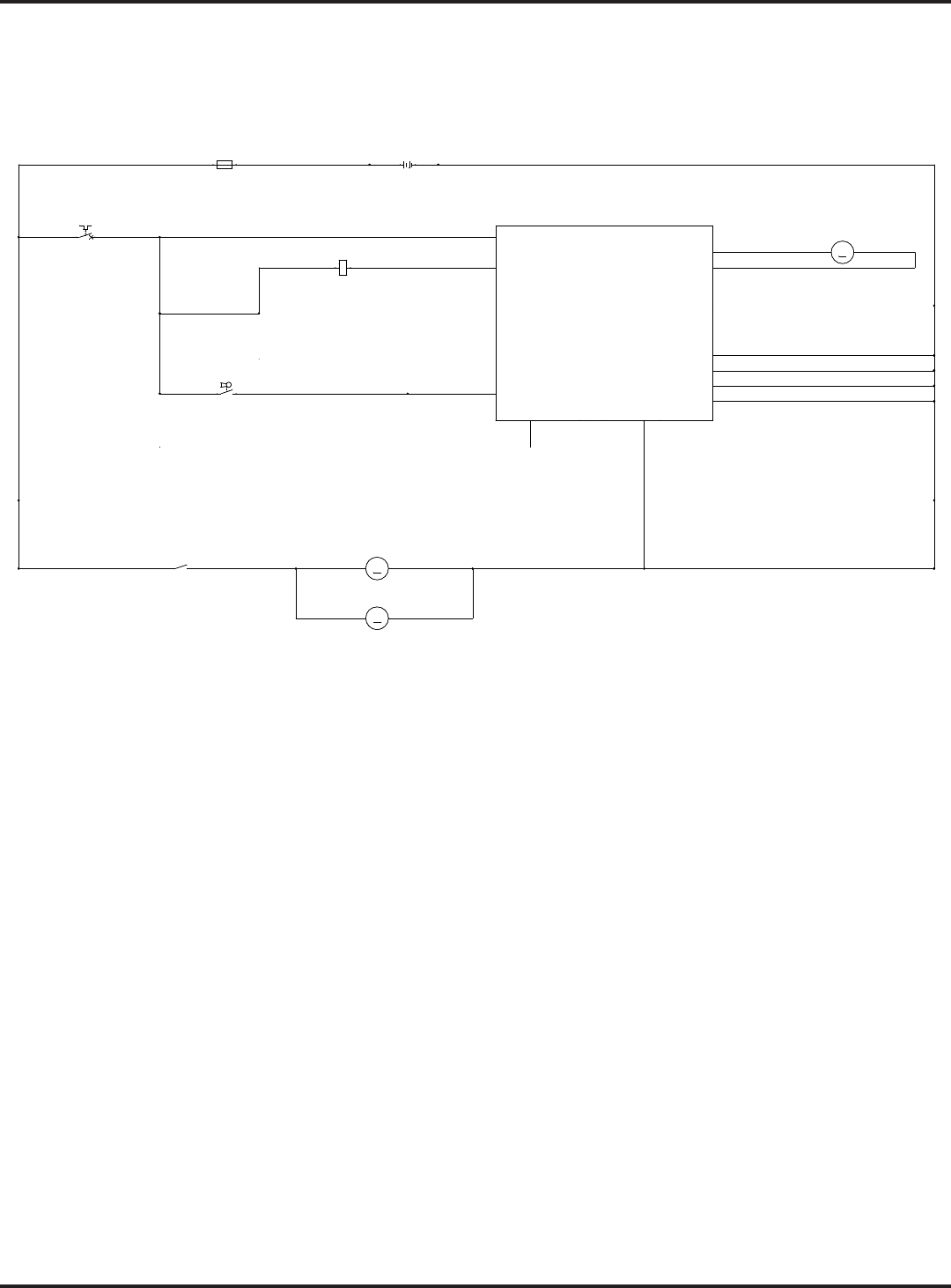
Circuit Overview
(A2)
Solution Indicator Flow Rate Solenoid On Time Solenoid Off Time
One-bar gauge 0.3 g/m 2 sec. 4 sec.
Two-bar gauge 0.6 g/m 4 sec. 2 sec.
Three-bar gauge 0.9 g/m 6 sec. 0 sec.
Electrical Diagram
Note:
36VDC
B+2
B+1
BRUSHCONTACTOR
VACUUMCONTACTOR
SOLUTIONSOLENOID
FOR/REV.
BRUSH MOTOR SENSE
VACUUM MOTOR SENSE
J2-7
J1-13
J1-14
J1-12
J1-11
REVERSE
B-1
BRUSHACTUATOR1
BRUSHACTUATOR2
B-3
B-4
B-2
A1
CONTROLBOARD
J1-5
J2-5
J2-10
J1-6
J2-4
J1-7
J2-8
J2-1
J2-6
J1-9
J2-9
RECOVERYTANKFULL
A2
B+ B-
1228SPEEDCONTROLLER
PIN 5- KSI
PIN 16 - REV
PIN 6- BRAKE(-)
STATUS
PIN 9- STATUS
J1-4
BT1
BATTERY
BT1
BATTERY
+ -
L1
COIL, SOLUTIONSOLENOID
L1
COIL, SOLUTIONSOLENOID
1 2
F1
FUSE,150A.
F1
FUSE,150A.
1 2
S3
SW, SPSTKEY
S3
SW, SPSTKEY
F3
CIRCUITBREAKER, 30 AMP
F3
CIRCUITBREAKER, 30 AMP
1 2
F2
CIRCUITBREAKER, 5AMP
F2
CIRCUITBREAKER, 5AMP
1 2
BLK
RED/BLK
BLK
ORN/BLU
BLU/BLK
BLK
BLK
BLK
RED/GRN
BRN
BRN
BRN
RED
BRN
BRN
BRN
RED
BRN
RED
RED WHT/YEL
RED/VIO
BLK
ORN/BLU
RED/BLK
BLU/BLK
BRN
BLK
34 - FORM NO. 56043162 - Focus II Large
Solution System
Maintenance
Solution Tank:
with clean water.
Solution Filter:
tighten only). Service Tip: The solution manual shutoff valve must be placed in the OFF (Closed) position. This
Troubleshooting Guide
Problem Possible Cause
No solution in the tank
Electrical Troubleshooting
Possible Symptom -
Note: Activate the Service Test Mode Program. See the Electrical System/Service Test Mode section in this manual for instructions.
All testing will be performed in the Service Test Mode Program.
Symptom
No solution flow when scrubbing in the auto solution mode.
Note: Activate the Service Test Mode Program. See optional program section for instructions.
While in the Service Test
Mode activate the solution
button. Does the L1 solenoid
click turn on & off, pulse as
designed ?
Inspect the solution system
components listed below to
help locate the cause for the
solution not feeding through
an electrically (good)
functional L1 valve.
•No solution in tank.
•Solution tank shut-off valve
closed.
•Clogged solution filter,
fittings & or hoses.
•Clogged L1 solenoid valve.
Disassemble clean, repair or
replace.
Separate the wiring
harness connector
that feeds the L1
solenoid ( 2 wires
Brn & Red/Grn).
Activate the solution
button & test for 36V.
Test the L1 coil
resistance (spec. 75
ohms).
Replace the L1
solenoid valve.
Test the continuity of
the wiring to coil L1
(Brn & Red/Grn
wires). Repair or
replace damaged
wires. Is there
voltage @ the L1
coil?
Replace the A1
control board
Yes Yes
No
NoNo
No
35 - FORM NO. 56043162 - Focus II Large
Solution System
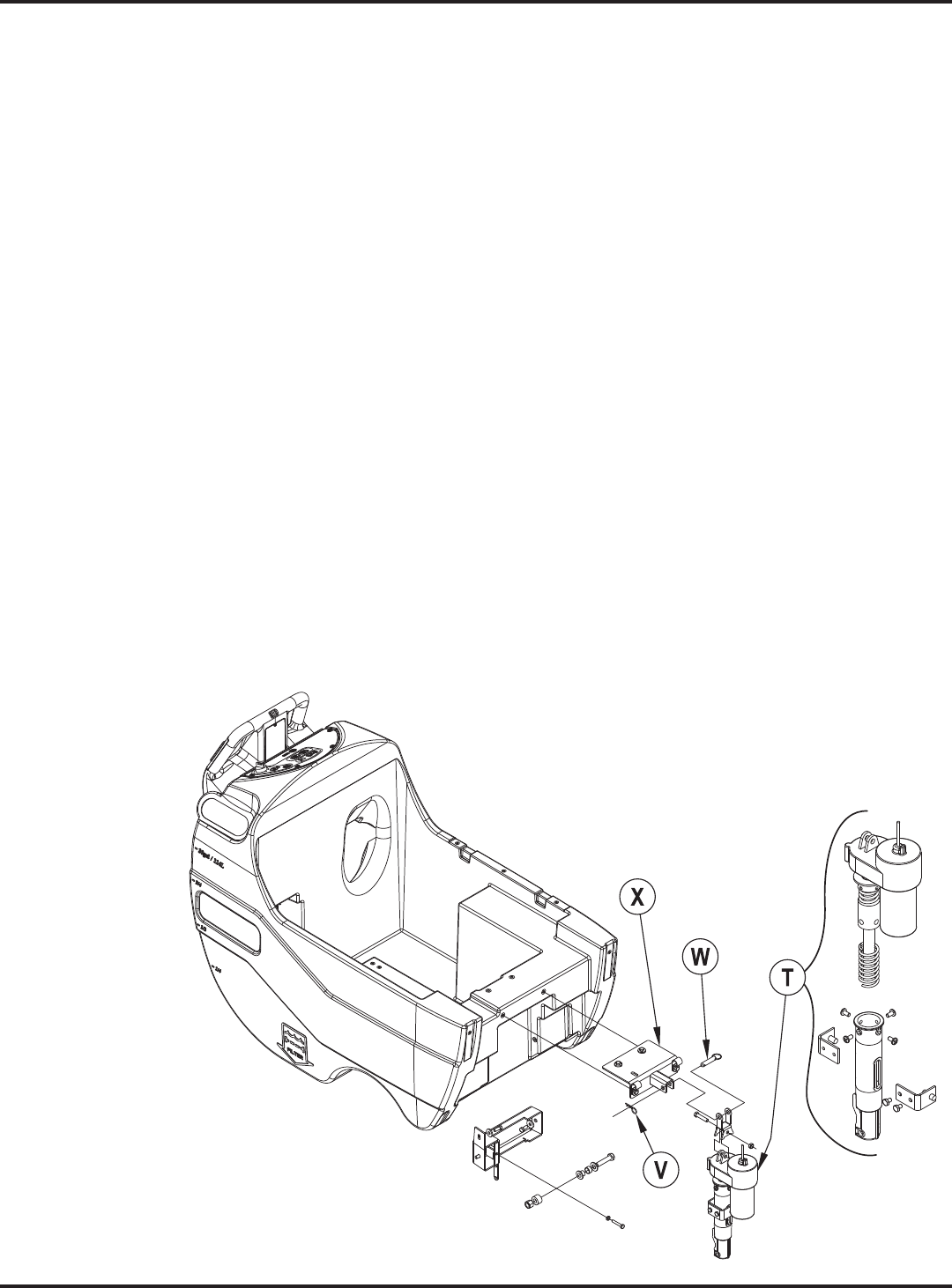
Removal and Installation
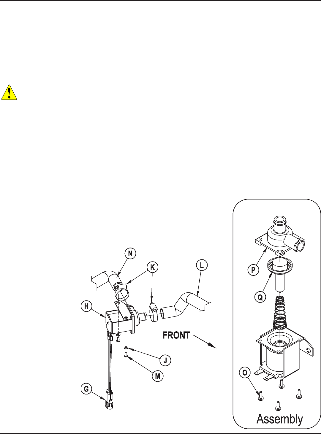
Solenoid Valve Removal
1. Drain the solution tank or turn off the solution ball valve to prevent solution loss.
2. Shut off the key switch and disconnect the battery connector.
Note: (H) and associated
Warning! Never work under machine without safety stands or blocking to support the machine.
3. Unplug the L1 solenoid valve Connector Assembly (G) from the machine harness. Note that you may need to
cut the wire tie.
Note: (H)
4. (K)(N)(L) to the Solenoid Valve (H).
5. (L)(H).
6. (M) and Washers (J) holding the valve to the machine frame.
7. (N)(H) and remove the
Solenoid Valve (H) from the machine.
Solenoid Valve Disassembly and Cleaning
1. Remove the Solenoid Valve (H). See the
section above for instructions.
2. Remove the 4 Screws
(O) and disassemble the
Solenoid Valve (H). Be
careful not to lose any
internal parts.
3. Thoroughly wash any
dirt or debris from
the Block (P) and
Diaphragm (Q).
4. After reassembling, test
the Solenoid Valve (H)
for correct operation.
36 - FORM NO. 56043162 - Focus II Large
Solution System
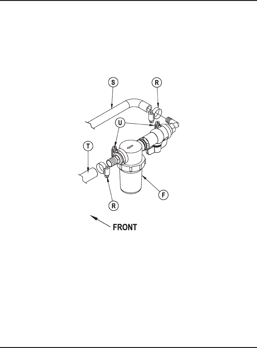
Solution Filter and Ball Valve Removal
1. Drain the solution tank using the solution drain hose (B).
2. (R)(S)(T)
from the Filter/Valve Assembly (F).
3. (U) that secure the Filter/Valve Assembly (F) to the chassis and remove the Filter/
Valve Assembly (F) from the machine.

37 - FORM NO. 56043162 - Focus II Large
Scrub System
Scrub System
Functional Overview
Note: Recovery Tank Full switch must be open (Tank empty). On all models the scrub deck platform
machine’s scrub functions are activated when the operator selects (presses) the scrub on (mode) panel button. The
(pressure) while operating the machine. Note: See the
section in this manual for more detailed operation and instructions on how to change the factory default regular
scrub pressure settings.
The machine’s main scrub system input and output operating functions are regulated (managed) by the display
panel and combined main control board A1. The major scrub system functions are:
M2/M3 - Scrub Brush Motor Run Function
Scrub Brush Motor Circuit Overview
+ (Positive) circuit input starts with:
− A closed S3 key switch supplies the needed positive voltage to the A1 control board #J1-13 (Brn wire).
− A closed 5-amp circuit breaker (F2) supplies positive battery voltage (Brn wire) to the control side of the brush motor contactor coil (K1).
− Once the load side of K1 is closed, the needed positive battery voltage is supplied to motors M2 and M3.
- (Negative) circuit input starts with:
− Negative battery voltage is supplied to the A1 control board at terminals B1 (J1-7) Blk, B2 (J1-9) Blk, B3 (J2-9) and B4 (J2-6) Blk.
− Note: The A1 control board scrub-on button must also be depressed (enabled).
− When a palm drive switch is pressed (S6/S7), Pin 6 – Brake on the speed controller (A2) supplies negative voltage to J1-5 – For/Rev. on A1
(Red/Blk wire).
− A negative voltage output from J1-14 – Brush Contactor (Vio/Blk wire) is supplied to the K1 solenoid coil control circuit and pulls in the load
contacts on K1.
− The negative load voltage is supplied from the battery negative to motors M2 and M3.
M5 - Scrub Brush Actuator Lift Motor Function
lowers the scrub deck for installing, removing and controlling the scrub brushes’ selected current load. The large
is developed across it which is proportional to the motor current. This voltage change is inputted to the A1 control
motor wire affects its resistance so the temperature is sensed by a thermistor built into the control board A1. This
allows the controller to provide error correction for the temperature resistance changes. When the controller senses
a current draw out of the desired range, it automatically turns on the M5 actuator motor to raise or lower the scrub
deck. This process is ongoing in maintaining the operator’s selected scrub motor current load setting to sustain the
desired brush working pressure.
Scrub System Low-voltage Cut-out Function
raised and the brush motors and solution solenoid valve will turn OFF automatically and cease to function when the
(S)(A) setting (gel/maintenance free)
is 32.63 volts or 1.81 volts per cell. Note: See the section in
Special Service Note: There is a minimum battery charge level that the must be reached before the low-voltage cut-out function will reset and allow
the machine to function again. On the 34 RST, the batteries must be charged to a minimum of 37.6 volts (2.09 volts per cell) in order to reset the low-
voltage cut-out function.
38 - FORM NO. 56043162 - Focus II Large
Scrub System
Electrical Diagram
FIGURE 1
BLK
BLK
ORN
BLK
BLK
BLK
VIO/YEL
WHT/GRN
WHT/GRA
BLK
BRN
BRNBRN
VIO/BLK
BRN
BRN
BRN
RED
BRN
RED
RED
RED WHT
WHT BLK
BLK BLK
WHT/GRA
-
-+
+
36VDC
B+2
B+1
BRUSHCONTACTOR
VACUUMCONTACTOR
SOLUTIONSOLENOID
FOR/REV.
BRUSH MOTOR SENSE
VACUUM MOTOR SENSE
J2-7
J1-13
J1-14
J1-12
J1-11
REVERSE
B-1
BRUSHACTUATOR1
BRUSHACTUATOR2
B-3
B-4
B-2
A1
CONTROLBOARD
J1-5
J2-5
J2-10
J1-6
J2-4
J1-7
J2-8
J2-1
J2-6
J1-9
J2-9
RECOVERYTANKFULL
STATUS
J1-4
CHEMICAL
PUMP
J2-11
M4M4
M
M5
MOTOR, BRUSHACTUATOR
M
M5
MOTOR, BRUSHACTUATOR
K1
COIL, BRUSHMOTORCONTACTOR
K1
COIL, BRUSHMOTORCONTACTOR
BT1
BATTERY
BT1
BATTERY
+ -
F1
FUSE,150A.
F1
FUSE,150A.
1 2
M
M2
MOTOR, LEFT BRUSH
M
M2
MOTOR, LEFT BRUSH
S3
SW, SPSTKEY
S3
SW, SPSTKEY
M
M3
MOTOR, RIGHT BRUSH
M
M3
MOTOR, RIGHT BRUSH
1K1K
F2
CIRCUITBREAKER, 5AMP
F2
CIRCUITBREAKER, 5AMP
1 2
39 - FORM NO. 56043162 - Focus II Large
Scrub System
Removal and Installation
Motor Gimbal
1. Make sure the scrub brush deck is in its raised position, then turn the key switch off and disconnect the battery
pack.
Caution! Disconnect the battery pack connector before servicing machine.
2. See Figure 2.(A and B).
3. Push the brushes/pads straight down to remove them from the Motor Gimbals (C).
4. (D)(C), Brush
Driver Collar (E) and Key (F) from the scrub motor shaft.
Special Service Note:(D)
5. To reinstall the Motor Gimbal (C), follow the above
steps in reverse order. Note: Apply a small
Seez®” to the scrub motor shaft when
reinstalling the Motor Gimbal (C),
Brush Drive Collar (E) and
Key (F).
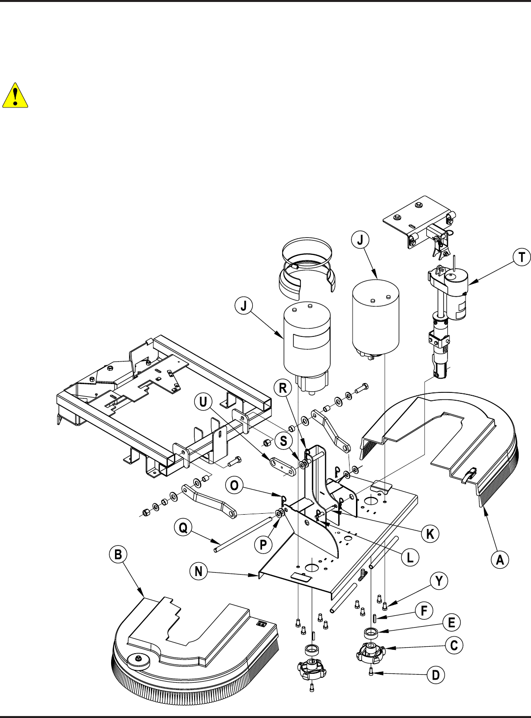
FIGURE 2

40 - FORM NO. 56043162 - Focus II Large
Scrub System
Scrub Brush Deck
1. With scrub brushes installed, lower the scrub brush deck, turn the key switch off and disconnect the battery
pack.
Caution! Disconnect the battery pack connector before servicing machine.
Note:
2.
3. See Figure 2.(A and B).
4. See Figure 3.(G) from the Coupler Barb (H).
5. See Figure 2. Unplug both Motor/Gear Unit Assemblies (M2 and M3) (J). Note: Cable ties may need to be
cut.
Service Note
(K)
6. (L) and remove the Pin (K) to detach the Lift Actuator Assembly (T)
from the lower mount on the Deck Weldment (N). Note: Lift up on the scrub brush deck to take pressure off
the Pin (K).
Service Note
(T)
7. (O) and Washers (P) on either side of the Linkage Pivot Pin (Q) and remove the
Linkage Pivot Pin (Q).
8. (R) and Washer (S) from the mounting boss on the Deck Weldment (N).
9. Make sure the Lift Actuator Assembly (T) is clear of the scrub brush deck, then carefully slide the scrub brush
deck toward the right (operator’s left) to disengage the mounting boss from the Linkage Arm (U).
10. Slide the deck toward the front to remove it from the machine.
11. To reinstall the scrub brush deck, follow the above steps in reverse order.
Service Note(T)
41 - FORM NO. 56043162 - Focus II Large
Scrub System
Scrub Brush lift Actuator
1. See Figure 3. With scrub brushes installed, lower the scrub brush deck, turn the key switch off and disconnect
the battery pack.
Note:
(T)
2.
3. Disconnect the actuator motor wiring harness pigtail connector.
Service Note
T)
4. See Figures 2 and 3.(L) and remove the Pin (K) to detach the Lift
Actuator Assembly (T) from the lower mount on the Deck Weldment (N). Note: Lift up on the scrub brush deck
to take pressure off the Pin (K).
5. See Figure 3.(V) from the Ring Pin (W).
6. (T) securely, remove the Ring Pin (W) from the Actuator Mount Weldment (X),
then remove the Lift Actuator Assembly (T) from the machine.
*Important Service Note:
7. After setting the correct actuator “IN” and “OUT” travel limits, follow the above removal steps in reverse order
to reassemble.
FIGURE 3

42 - FORM NO. 56043162 - Focus II Large
Scrub System
Scrub Brush Motor/Gearbox
1. Remove the scrub deck from the machine following the steps in the section.
2. Turn the brush deck on its back.
3. See Figure 2. Remove the brushes/pads from the Motor Gimbals (C). If removing both Motor / Gear Unit
Assemblies (J), mark the location of the Assemblies on the Deck Weldment (N) for correct reassembly.
4. (D) holding the Motor Gimbal (C) to the motor output shaft, then
remove the Motor Gimbal (C), Brush Driver Collar (E) and Key (F). Make sure to save the Key (F).
5. (Y) holding the Motor / Gear Unit Assembly (J) to the Deck
Weldment (N) and remove the Motor / Gear Unit Assembly (J).
6. Reinstall the Motor / Gear Unit Assembly (J) by following the above steps in reverse order, then test for correct
operation. Note
Motor / Gear Unit Assembly (J) when reinstalling the Motor Gimbals (C), Brush Drive Collars (E) and Keys
(F).
7. Reinstall the scrub deck by following the steps in the section.
43 - FORM NO. 56043162 - Focus II Large
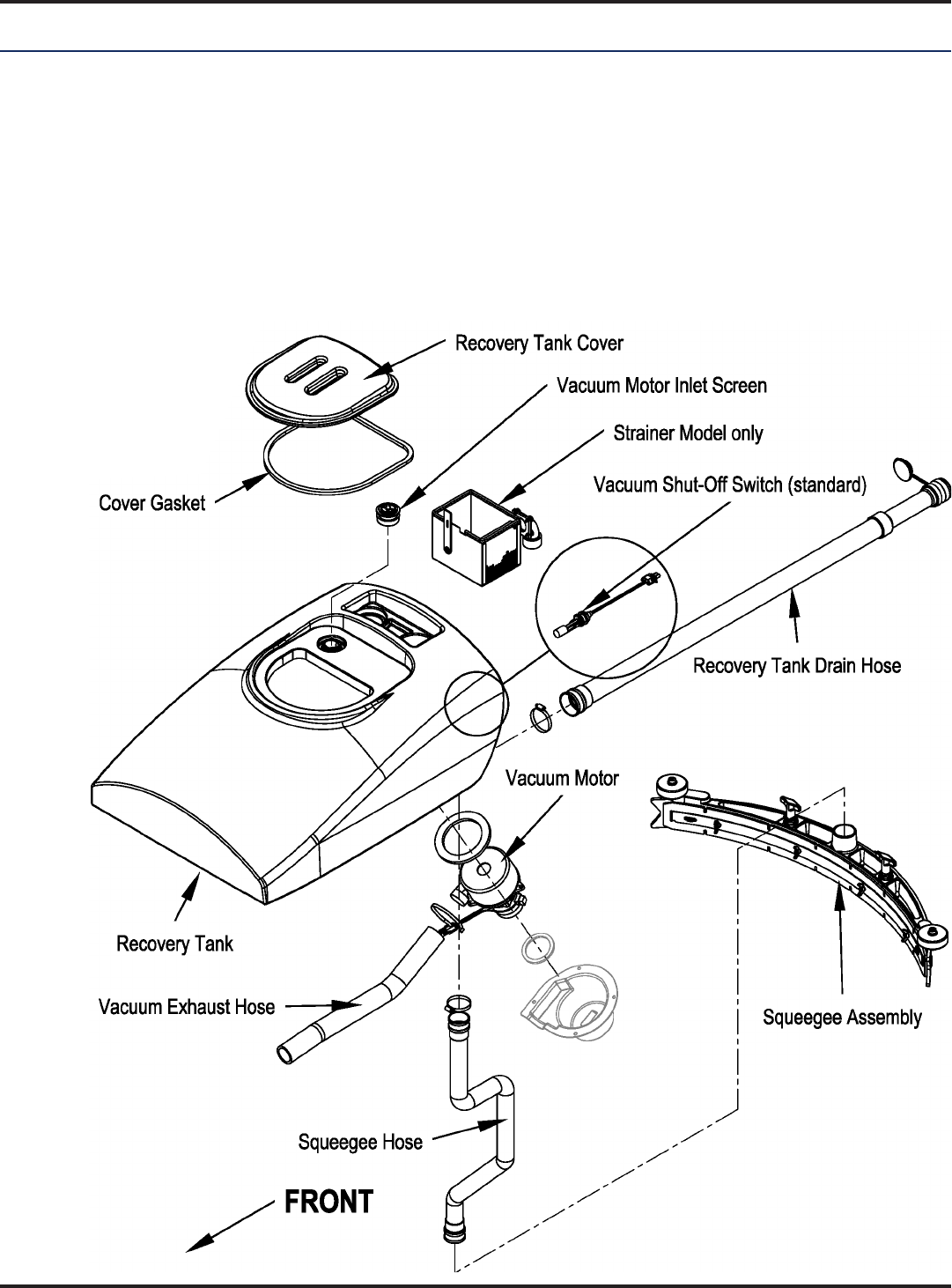
Recovery System
Recovery System
Functional Overview
See Figure 1
because of the increased volume (large size) of the tank. With the decreased air speed, the heavier water falls to the
just the working air.
FIGURE 1
44 - FORM NO. 56043162 - Focus II Large
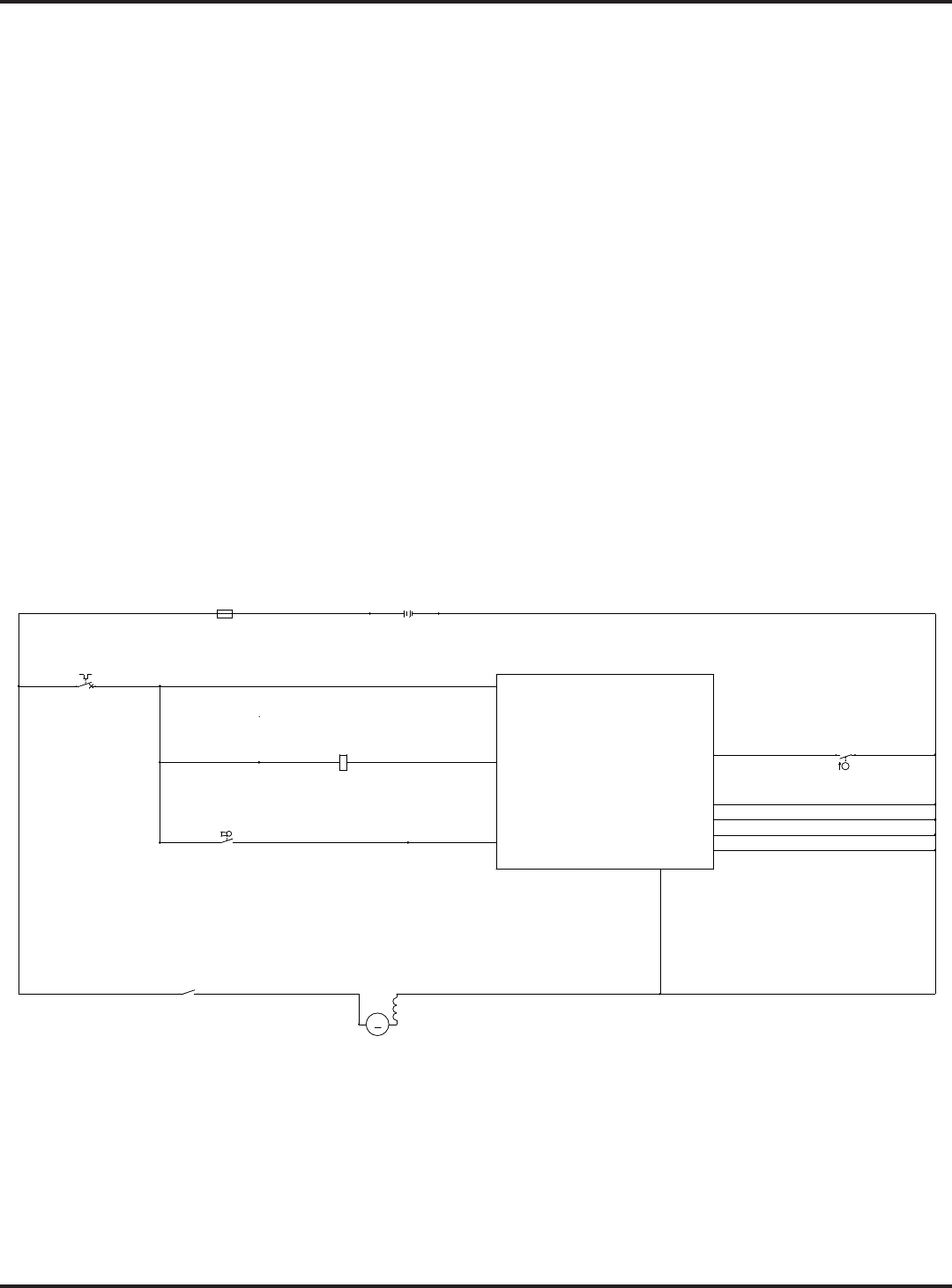
Recovery System
Vacuum Motor Control Circuit Overview (Auto Mode)
+ (Positive) Circuit input starts with:
Note: The
deck.
(F2) supplies positive battery voltage (Brn wire) to the control side of the vacuum
motor contactor coil (K2).
Once the load side of K2 is closed, the needed positive battery voltage is supplied to motor M4.
A negative voltage output from the A2 speed controller’s (pin #6) Brake Neg. to the A1 control boards Red/Blk
Note: The A2 speed control brake output (pin #6) occurs whenever a palm drive switch (S6/
S7) is pressed. This operator command happens when a palm drive button is pressed to run the wheel drive
(S4) must be open (in its lowered position) in order for a negative
Neg.) and pulls in the solenoid load contact K2 making the vacuum motor run.
The Neg. M4 load voltage is supplied from the battery Neg.
Note:
FIGURE 2
BLK
BLK
BLK
ORN
BLK
BLK
BLK
GRA/WHT
BRN
BRNBRN
BLK/YEL
BRNBRN
BRN
RED
BRN
RED
RED
RED BLU BLK BLK
ORN
36VDC
B+2
B+1
BRUSHCONTACTOR
VACUUMCONTACTOR
SOLUTIONSOLENOID
FOR/REV.
BRUSH MOTOR SENSE
VACUUM MOTOR SENSE
J2-7
J1-13
J1-14
J1-12
J1-11
REVERSE
B-1
BRUSHACTUATOR1
BRUSHACTUATOR2
B-3
B-4
B-2
A1
CONTROLBOARD
J1-5
J2-5
J2-10
J1-6
J2-4
J1-7
J2-8
J2-1
J2-6
J1-9
J2-9
RECOVERYTANKFULL
STATUS
J1-4
CHEMICAL
PUMP
J2-11
M
M4
MOTOR, VAC
M
M4
MOTOR, VAC
1 2
BT1
BATTERY
BT1
BATTERY
+ -
F1
FUSE,150A.
F1
FUSE,150A.
1 2
2K2K
S4
SWITCH, FLOAT
S4
SWITCH, FLOAT
1 2
S3
SW, SPSTKEY
S3
SW, SPSTKEY
K2
COIL, VACMOTORCONTACTOR
K2
COIL, VACMOTORCONTACTOR
F2
CIRCUITBREAKER, 5AMP
F2
CIRCUITBREAKER, 5AMP
1 2

45 - FORM NO. 56043162 - Focus II Large
Recovery System
Maintenance
Service Maintenance Checklist
Whenever there is a vacuum problem, it’s best to check over the entire system. Use the checklist below as a guide to
thoroughly check the vacuum system.
Clean built-up dirt from the inside of the squeegee tool.
Replace the squeegee blades if they are nicked or torn.
Inspect the hose between the squeegee tool and the recovery tank and rinse any built-up dirt from the hose. Replace the hose if it is kinked or
damaged.
Inspect and make sure the gasket on the recovery tank cover is sealing and not damaged.
Make sure that the recovery tank drain hose cap seals airtight.
Troubleshooting Guide
working correctly. When a vacuum system performs poorly it is usually because of one of the following problems:
Vacuum Leaks
drain valve. A vacuum leak below the water line will create turbulence in the recovery tank, causing water to enter
the vacuum motor.
Restrictions
sharp turn.
46 - FORM NO. 56043162 - Focus II Large
Recovery System
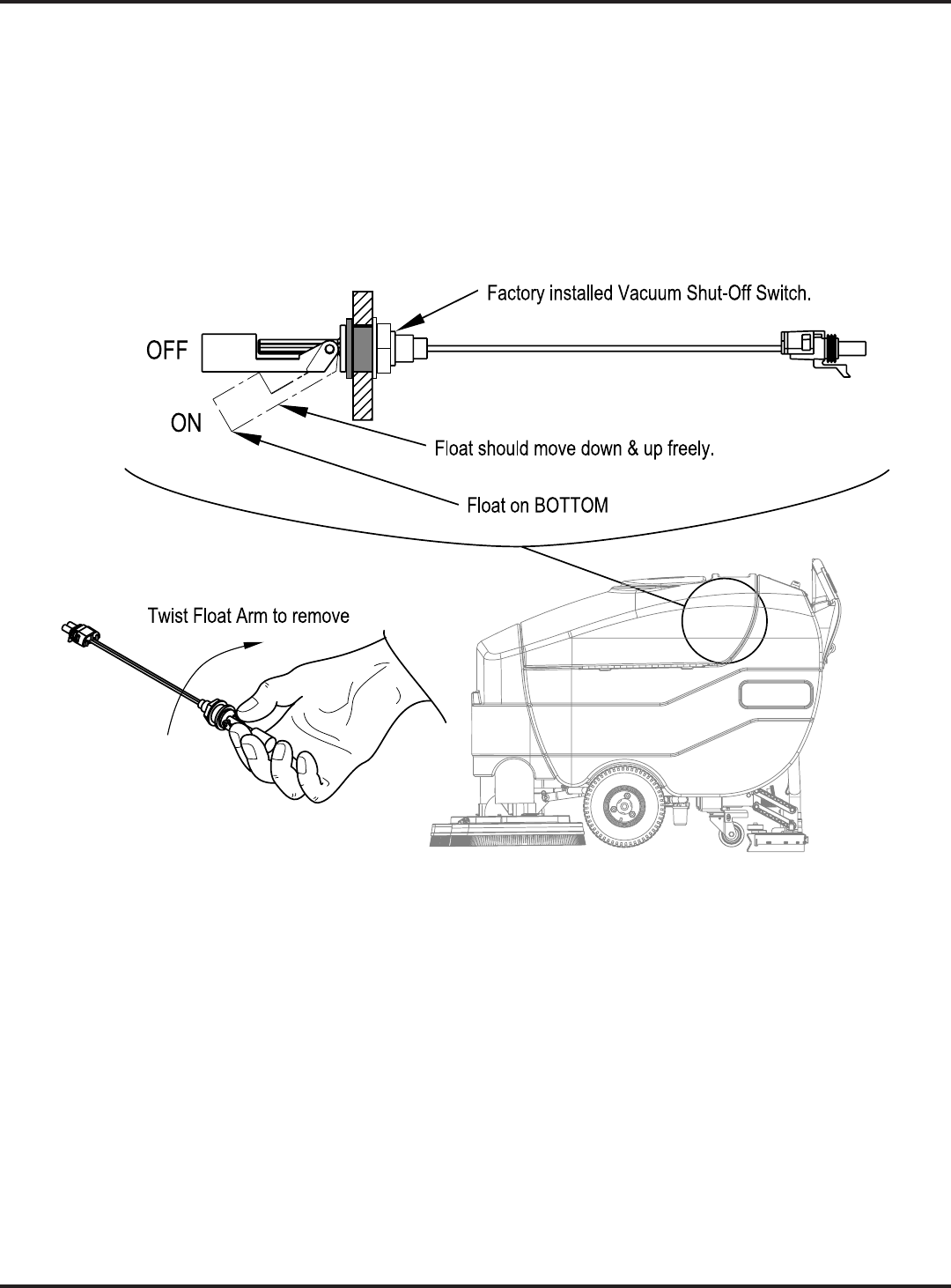
Maintenance of the Recovery Tank Float Switch
shutoff switch can cause the vacuum motor to not function at all, or fail to shut off when the tank is full.
Figure 3 for the correct
FIGURE 3
47 - FORM NO. 56043162 - Focus II Large
Recovery System
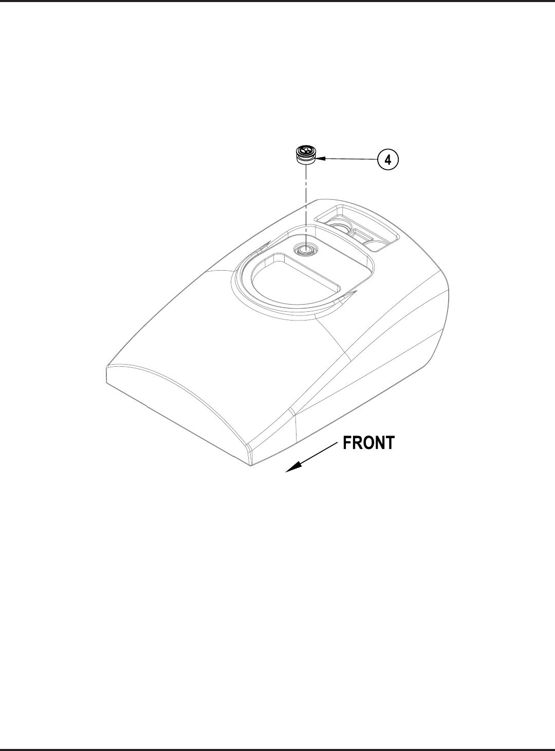
Maintenance of Vacuum Motor Inlet Screen
See Figure 4. The Vacuum Motor Inlet Screen (4) should be cleaned on a daily basis. DO NOT run water down the
screen in an attempt to clean it. If you do this you will be running water directly into the vacuum motor.
To remove the Vacuum Motor Inlet Screen (4) from the recovery tank, grip, twist and pull up on the Vacuum Motor
Inlet Screen (4).
FIGURE 4
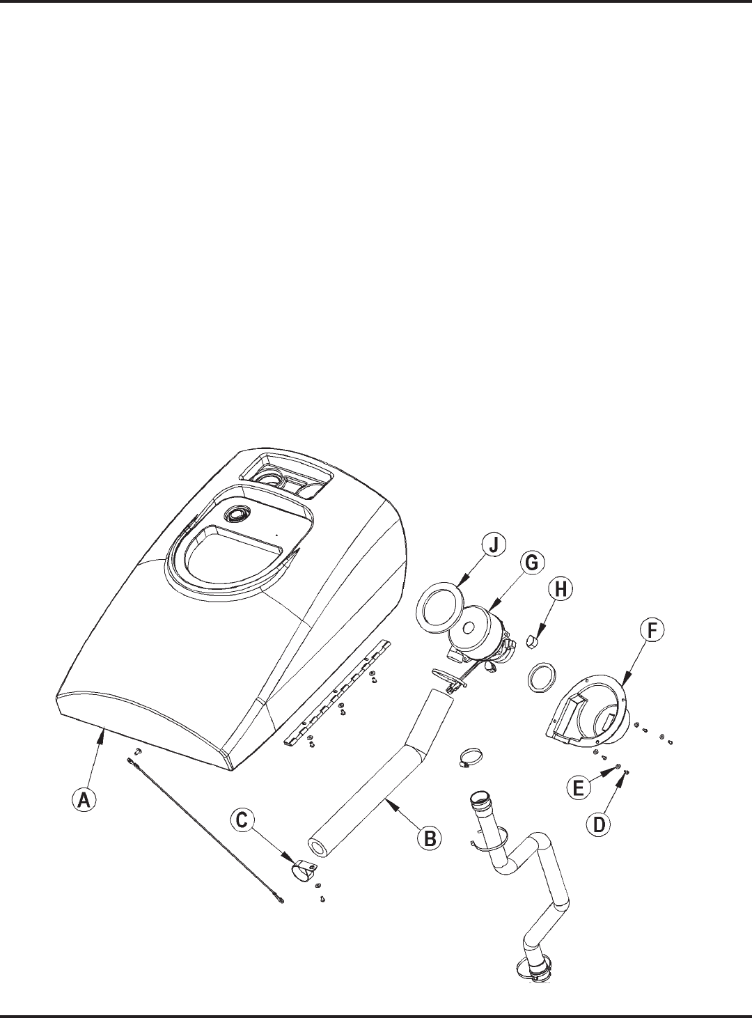
48 - FORM NO. 56043162 - Focus II Large
Recovery System
Removal and Installation
Vacuum Motor Removal
1. Drain the Recovery Tank (A) using the drain hose.
2. Turn the key switch off and disconnect the battery pack.
3. Swing open the recovery tank and disconnect the vacuum motor harness connector.
4. See Figure 5.(B)(C) on the
Recovery Tank (A).
5. (D) and Flat Washers (E) holding the Vacuum Motor Shroud (F) to
the bottom of the Recovery Tank (A), then remove the Vacuum Motor Shroud (F).
6. Carefully remove the Vacuum Motor Assembly (G)(B)
from the Recovery Tank (A). Note: Take care not to lose the three Vibration Mounts (H).
7. Inspect the condition of the vacuum motor Gasket (J), and the gasket on the inside of the Vacuum Motor
Shroud (F).
8. Make service repairs to the vacuum motor and reinstall by following the above steps in reverse order.
FIGURE 5
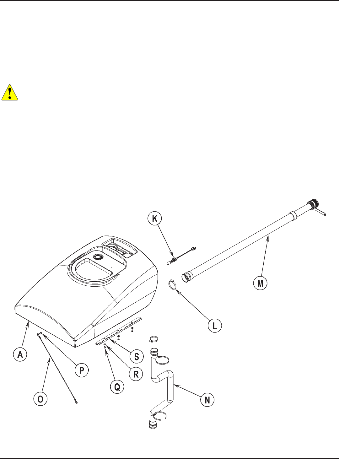
49 - FORM NO. 56043162 - Focus II Large
Recovery System
Recovery Tank Removal
1. If you wish to remove the vacuum motor from the Recovery Tank (A)
section.
2. Disconnect the electrical connector to the Float Switch (K). Note that you may need to cut a cable tie to access
the connector.
3. (L)(M) from the Recovery Tank (A).
4. (N) from the Recovery Tank (A).
Caution! The Recovery Tank is relatively heavy. You may choose to get some assistance when swinging
the Recovery Tank down after disconnecting the Cable Assembly, and when removing it from the
machine.
5. See Figure 6.(P) and tank Cable Assembly (O) and allow the Recovery
Tank (A)
6. Support the Recovery Tank (A)(Q)(R) that
(S) and remove the Recovery Tank (A) from the machine.
7. Reinstall the Recovery Tank (A) by following the above steps in reverse order.
FIGURE 6

50 - FORM NO. 56043162 - Focus II Large
Squeegee System
Maintenance
Squeegee Lift Linkage Adjustment
See the
rear control panel mounted Lever (17).
Squeegee Lift Lever Adjustment
1.
2. See Figure 1.(A) for changing the up /
3. Remove the Nyloc Nut (B)(C)(C)
(D), Cable Bushing (E)
4. (C)(D) Cable Bushing (E) and attached cable assembly into the
(B).
5. Note: This allows
FIGURE 1
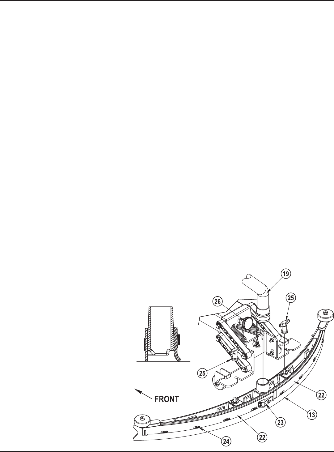
51 - FORM NO. 56043162 - Focus II Large
Servicing the Squeegee
under warm water and inspect the blades. Reverse or replace the blades if they are cut, torn, wavy or worn.
1. See Figure 2. (23)
tool.
2. Remove the Tension Straps (22).
3. Slip the rear blade off the Alignment Pins (24).
4.
of the machine. Replace the blade if all four edges are nicked, torn or worn to a large radius.
5.
1. (25)(19) and
(13) from the mount.
2. First remove both rear Tension Straps (22).
3. Remove all the wing nuts that hold the front blade in place, and then remove the front tension strap and front
blade.
4.
of the machine. Replace the blade if all four edges are nicked, torn or worn to a large radius.
5.
Adjusting the Squeegee
To Adjust the Squeegee Angle:
1.
2. While moving the machine forward
Knob (26)
folds over evenly across the entire width
FIGURE 2
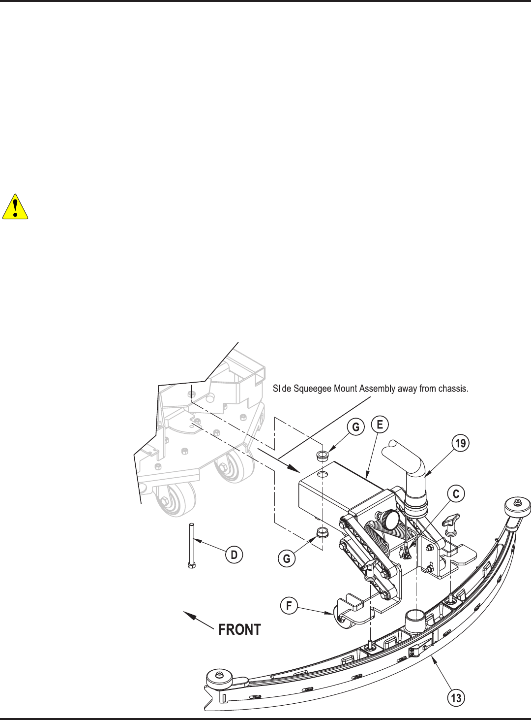
52 - FORM NO. 56043162 - Focus II Large
Removal and Installation
Squeegee Mount Assembly Removal
1. Turn the key switch off and disconnect the battery pack.
2. See Figure 3.(19)(13) from the machine.
3. (17)(C)
Service Note:
(F)
Note:
Warning! Never work under machine without safety stands or blocking to support the machine.
4. Remove the Screw (D)
Assembly (E) away from the chassis.
5. Reinstall by following the above steps in reverse order. Make sure the spacer bushing is installed on the Screw
(D), and the top and bottom Flange Bearings (G)(E)
before reinstalling and tightening the Screw (D).
Service Note:
(E)
(D)
FIGURE 3
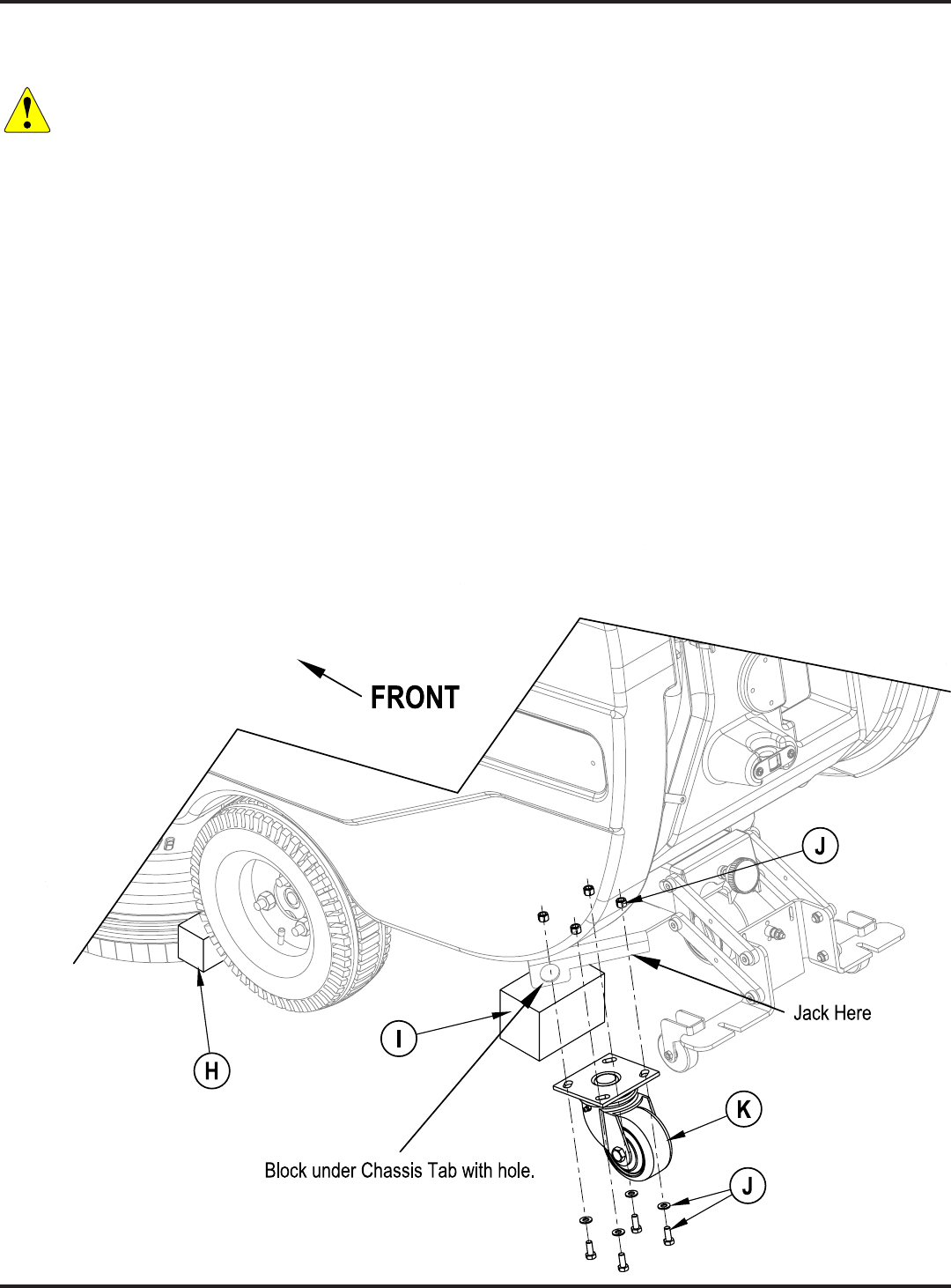
53 - FORM NO. 56043162 - Focus II Large
Caster Wheel Removal
1. Turn the key switch off and disconnect the battery pack.
Warning! Never work under machine without safety stands or blocking to support the machine.
2.
the up (stored) position with the scrub brushes installed.
3. See Figure 4. Place Wood Blocking (H) in front of the drive wheels to prevent the machine from rolling.
4.
5. Place Blocking (I) under the chassis tab as shown.
6. Remove the (4) Screws, Nuts and Washers (J) then remove the Caster Assembly (K).
7. Reinstall in reverse order.
FIGURE 4

54 - FORM NO. 56043162 - Focus II Large
Wheel Drive System
Wheel Drive System
Functional Overview
See Figures 1 and 2.(M1) is used for the wheel
drive on all machines. A Curtis PMC solid state speed controller (A2) regulates the variable speed and Fwd/Rev
wheel drive motor functions. The controller is located in the rear electrical compartment (accessible by removing the
drive motor. A reverse button controls the machine reverse. A speed limit pot R1 (knob adjusted) mounted in the
Drive Motor System Function
See Figures 2 and 3. With the key switch S3 closed the Brn wire inputs 36V to the A2 speed controller (Pin
the positive load circuit voltage input to the B+ controller terminal (Wht/Yel wire). The black wire from the battery
Pressing either palm drive switch (S6 or S7) activates the operator input to the speed control which generates the
voltage level outputs at the M1 and M2 terminals.
wheel motor operating speed range. Turning the knob (counterclockwise) increases the resistance and the motor
speed range is reduced.
FIGURE 1
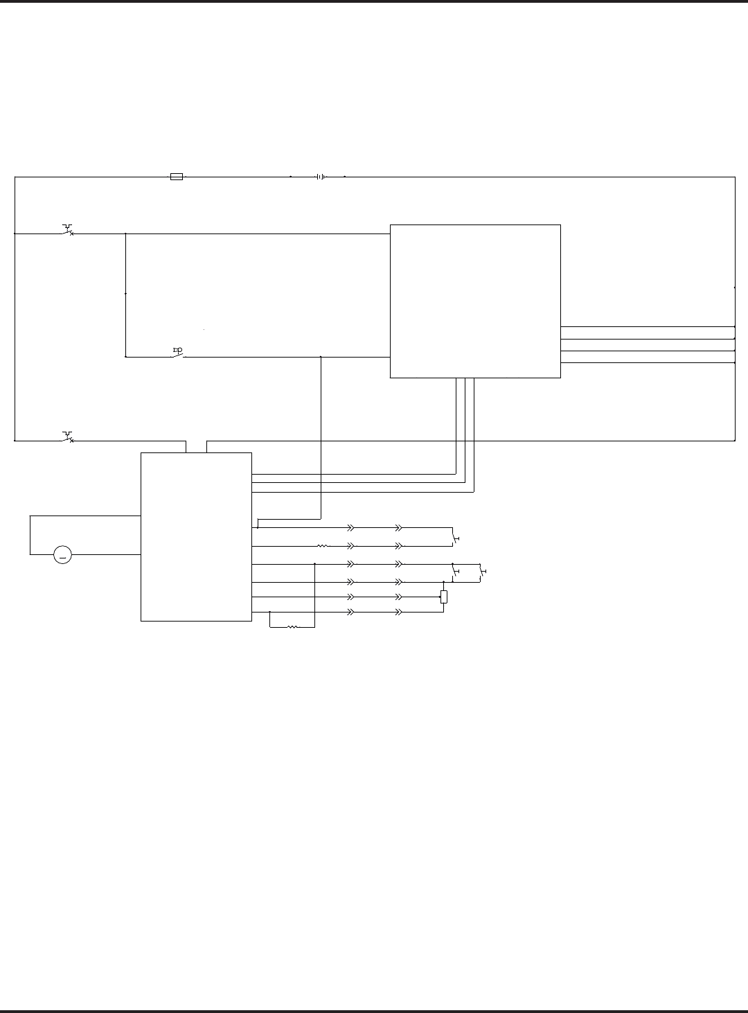
55 - FORM NO. 56043162 - Focus II Large
Wheel Drive System
Electrical Diagram
Note: For a complete description of all callouts see the section in
this manual.
FIGURE 2
BLK
RED/BLK
BLK
ORN/BLU
BLU/BLK
ORN
BLK
BLK
BLK
WHT/GRA
BLK
BRN
BRNBRN
BRN
RED
BRN
RED
RED
BRN/BLK
YEL/RED
RED WHT/YEL
RED/VIO
BLK
ORN/BLU
RED/BLK
BLU/BLK
BRN
GRN/VIO
BLU/VIO
BLK/VIO
ORN/VIO
WHT/VIO
BLK
BLKRED
GRN
BLKBLU
BLK
BRNORN
BLK
WHT WHT
+
36VDC
-
B+2
B+1
BRUSHCONTACTOR
VACUUMCONTACTOR
SOLUTIONSOLENOID
FOR/REV.
BRUSH MOTOR SENSE
VACUUM MOTOR SENSE
J2-7
J1-13
J1-14
J1-12
J1-11
REVERSE
B-1
BRUSHACTUATOR1
BRUSHACTUATOR2
B-3
B-4
B-2
A1
CONTROLBOARD
J1-5
J2-5
J2-10
J1-6
J2-4
J1-7
J2-8
J2-1
J2-6
J1-9
J2-9
RECOVERYTANKFULL
A2
B+ B-
1228SPEEDCONTROLLER
M1
M2
PIN 3- POT.HI
PIN 4- POT.WIPER
PIN 13 - POT.LO
PIN 5- KSI
PIN 16 - REV
PIN 6- BRAKE(-)
STATUS
PIN 9- STATUS
PIN 18 - SPEEDLIMITPOT
J1-4
PIN 17 - REV
CHEMICAL
PUMP
J2-11
M
M1
MOTOR, WHEELDRIVE
M
M1
MOTOR, WHEELDRIVE
R3
100OHM
R3
100OHM
BT1
BATTERY
BT1
BATTERY
+ -
F1
FUSE,150A.
F1
FUSE,150A.
1 2
S3
SW, SPSTKEY
S3
SW, SPSTKEY
5S5S
1
2
R2
4.75KOHM
R2
4.75KOHM
6S6S
1
2
F3
CIRCUITBREAKER, 30 AMP
F3
CIRCUITBREAKER, 30 AMP
1 2
R1
POT. 100KOHMSPEEDLIMIT
R1
POT. 100KOHMSPEEDLIMIT
1
2
3
F2
CIRCUITBREAKER, 5AMP
F2
CIRCUITBREAKER, 5AMP
1 2
7S7S
1
2

56 - FORM NO. 56043162 - Focus II Large
Wheel Drive System
FIGURE 3
WHEEL DRIVE SYSTEM
A1 Speed Control
Pin Connection
3
5
1
3
18
9
1
6
4
POT HIGH
S6
S7
100K Ohms
R1 Speed Limit
BRN
BLK
WHT
BLK
1
2
3
4.7K
1710
1
POT LOW
POT WIPER
S5
KSI
BLK
setting, with the wiper pin #18 shorted to the pot high pin #3.
A2 Speed Controller Pin Key Detail
PIN# WIRE COLOR CONTROLLER DESCRIPTION and FUNCTION
1 - Open - not used
2 - Open - not used
3 Blk/Vio Throttle Pot R1 pot high input (+) 5V ref
4 Blu/Vio Throttle Pot R1 pot wiper input
5 Brn & Red/Vio KSI (key switch input): Battery (+) powers up controller logic circuits.
6 Red/Blk Brake Auxiliary Driver: Battery (-) output to main controller (A1), to turn on (activate) all auto scrub
functions (its open when in neutral).
7 - Open - not used
8 - Open - not used
9 Orn/Blu Status Fault: Speed controller fault output to main control panel fault indicator light (Regular Scrub On).
10 - Open - not used
11 - Open - not used
12 - Open - not used
13 White/Vio Throttle Pot R1 pot low input (-)
14 - Open – not used
15 - Open - not used
16 Blu/Blk Reverse/Horn output to A1 controller board to control solution solenoid (L1)
17 Grn/Vio Reverse Directional Input: Battery (+) signal active with S5 closed
18 Orn/Vio Speed limit pot input connection.

57 - FORM NO. 56043162 - Focus II Large
Wheel Drive System
Wheel Drive Troubleshooting guide
Problem Possible Cause
No wheel drive in Forward or Reverse • Wheel drive motor circuit breaker (F3) tripped (reset 30A circuit breaker).
• Control circuit breaker (F2) tripped (reset 5A circuit breaker).
• Defective S6 & S7 palm drive switches and or circuit wiring (repair or
replace).
• Defective A2 speed control, replace.
• Defective M1 wheel drive motor (repair or replace).
No wheel drive in reverse only • Defective S5 reverse directional switch or circuit wiring (repair or replace).
• Speed control can’t change electrical polarity to wheel motor. Replace the
A2 speed control.
No variable wheel drive speed (will run @ its slowest
speed only).
• Defective R1 speed limit potentiometer, test for an open in both the pot
and circuit wiring (repair or replace).
Operator control panel displays error 03 fault code • Speed controller has sensed an operational error code fault. See Drive
Status LED fault codes (table 1) in the Electrical System section.
Additional wheel drive circuit information
Circuit Function Test Correct Circuit Test Values
Test for forward throttle input:
• W/key on check pin#13 to pin #4 with palm drive switches open.
• W/key on check pin#13 to pin #4 with palm drive switches closed.
• .578 DCV
• 4.12 DCV
Test for R1 speed limiting pot input:
• W/key on check the R1 Min speed input voltage signal pin#13 to
pin#18. Note: Have the R1 pot knob turned fully CCW.
• W/key on check the R1 Max speed input voltage signal pin#13 to
pin#18. Note: Have the R1 pot knob turned fully CW.
• 0 VDC
• 5 VDC
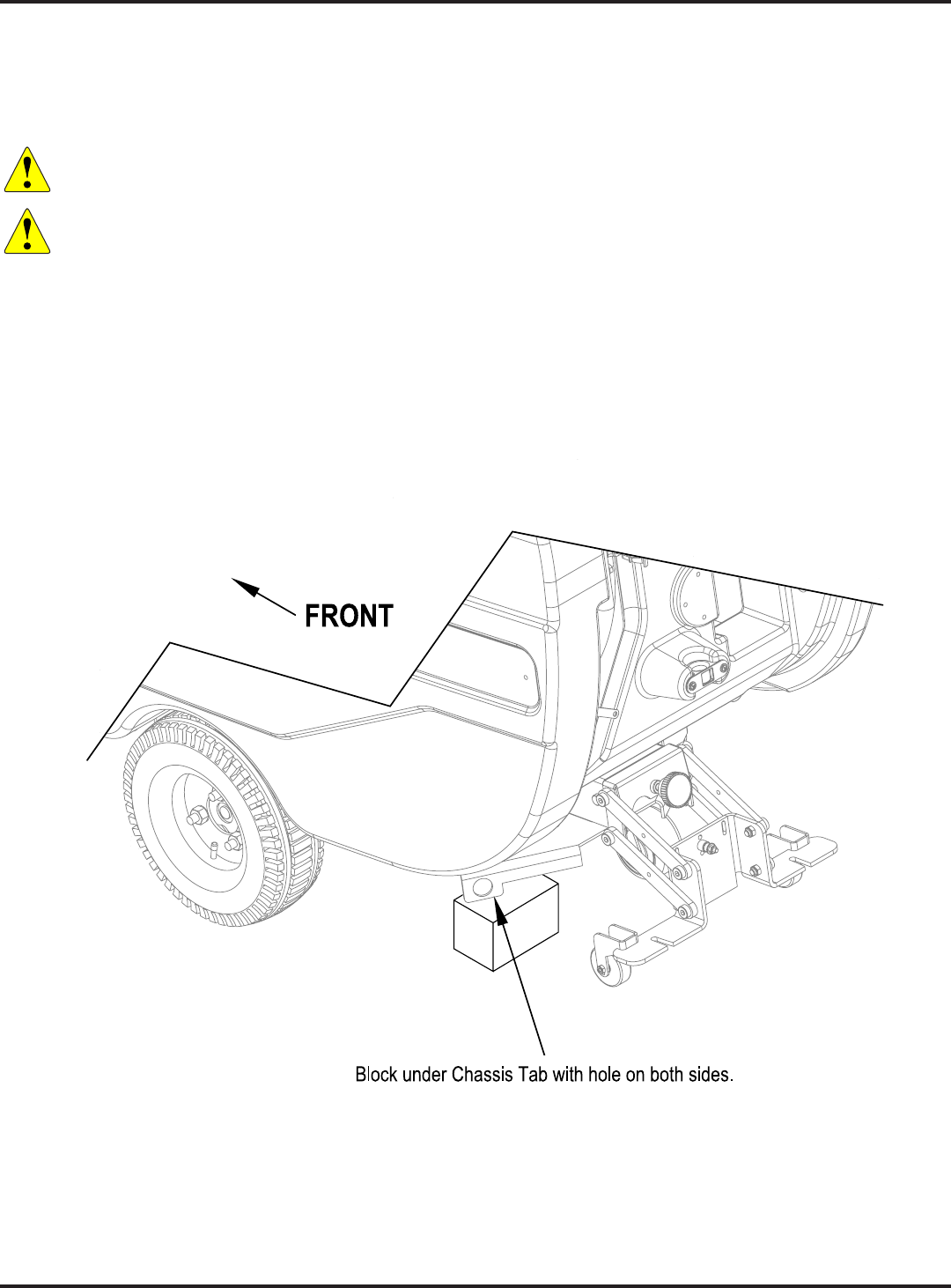
58 - FORM NO. 56043162 - Focus II Large
Wheel Drive System
Removal and Installation
Drive Motor Transaxle Removal
1. Turn the key switch off and disconnect the battery pack.
Warning! Disconnect the battery pack before servicing machine.
Warning! Never work under machine without safety stands or blocking to support the machine.
2.
3. Remove the Scrub deck by following the instructions in the section in this manual.
4. Block the rear of the machine. See Figure 4 for correct placement of the wood blocking.
FIGURE 4
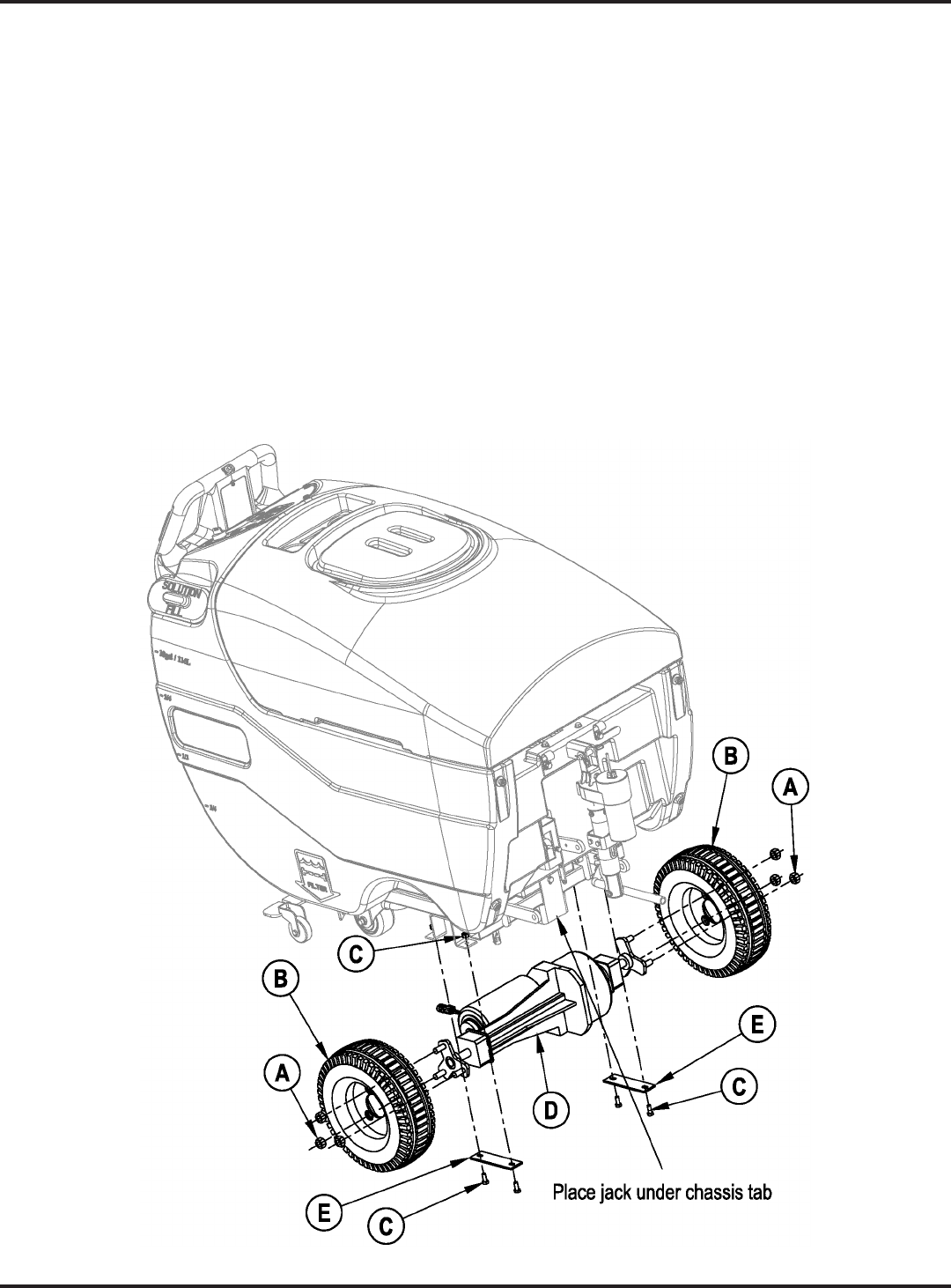
59 - FORM NO. 56043162 - Focus II Large
Wheel Drive System
Drive Motor Transaxle Removal (continued)
Service Note(A)
5. See Figure 5.
the ground.
6. Remove the (6) wheel Nuts (A) and remove the (2) Drive Wheels (B)(D).
7. Disconnect the drive motor wiring connector.
8. Remove the (4) Motor Mount Bolts and Nuts (C)(E) and carefully slide
(D) away from the machine.
9. (D) by following the above steps in reverse order. Note that the tapered ends of
the wheel Nuts (A) go against the Drive Wheels (B).
FIGURE 5
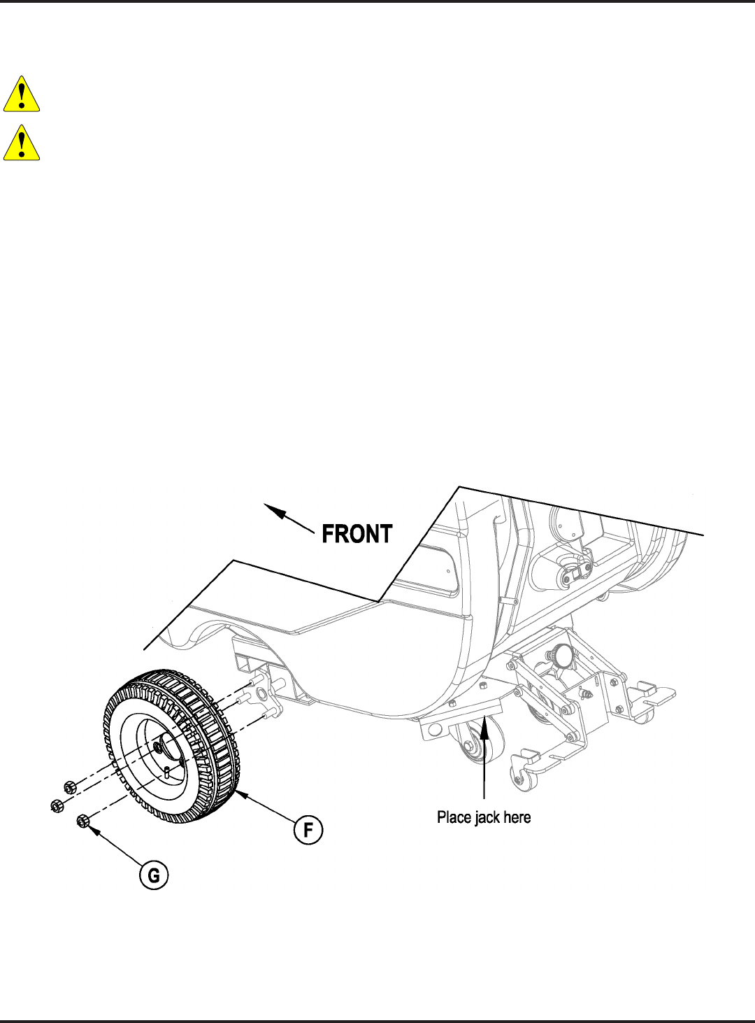
60 - FORM NO. 56043162 - Focus II Large
Wheel Drive System
Drive Wheel Removal
1. Turn the key switch off and disconnect the battery pack.
Warning! Disconnect the battery pack before servicing machine.
Warning! Never work under machine without safety stands or blocking to support the machine.
2.
3. Place wood blocking in the front and rear of the Drive Wheel (F) opposite of the one that you are removing to
prevent the machine from rolling.
Service Note(G)
4. Using a scissors jack, raise the machine until the Drive Wheel (F) is off the ground. See Figure 6 for jack
placement.
5. Remove the (3) wheel Nuts (G) and Drive Wheel (F).
6. Reinstall the Drive Wheel (F) by following the above steps in reverse order. Note that the tapered ends of the
wheel Nuts (G) go against the Drive Wheels (F).
FIGURE 6
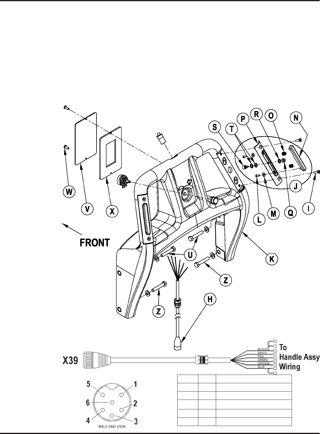
61 - FORM NO. 56043162 - Focus II Large
Wheel Drive System
Testing the Palm Drive Buttons
1. See Figure 7(H)
raise/lower handle.
2. See Figure 8. Use a continuity checker or ohmmeter to check the continuity between pins 4 and 6 on the
(H). When the palm drive buttons are working correctly:
The circuit through pins 4 and 6 should be open when both palm drive buttons are released.
buttons is pressed.
3. See Figure 7(H) to the
connector on the machine.
FIGURE 7
FIGURE 8
Pin 1 Wht Pot Low
Pin 2 Orn Pot Wiper
Pin 3 Red Rev Sw
Pin 4 Blk Pot High L&R Palm Sw
Pin 5 Grn Rev Sw
Pin 6 Blu L&R Palm Sw

62 - FORM NO. 56043162 - Focus II Large
Wheel Drive System
Palm Drive Button Replacement
Note:
1. See Figure 7(I) and remove the Palm Switch Assembly (J) from
(K).
2. See the detail in Figure 7(L) and Flat Washers (M) and remove
the Palm Button Switch (N) and (2) Switch Springs (O)(P). Be careful not to
lose the Switch Springs (O).
3. Remove the Retaining Nut (Q) and Star Washer (R) from the SPST Momentary Switch (S), then remove the
SPST Momentary Switch (S) and the other (2) Star Washers (T)(P).
4. (U & Z).
5. (H)
(H) and connector when the
(K) is swung down to remove the Access Plate (V).)
6. (Z)(K) to the machine.
7. (U)(K) to the machine, then
(K)(W) holding the Access Plate
(V).
8. (W) and remove the Access Plate (V) and attached Access Panel
Gasket (X)(K).
9. Note the wire colors and connector locations, then disconnect the SPST Momentary Switch leads from the
connectors in the access area and remove the old SPST Momentary Switch (S). Note that you may need to cut a
cable tie to access the wires and connectors.
10. Thread the leads from the replacement SPST Momentary Switch (S)(K) and to the
access area, then plug them into the corresponding connectors. Replace the cable tie if necessary.
11. Reinstall the Access Plate (V) and attached Access Panel Gasket (X)(K), then reinstall and
(W).
12. (K)
(U)(Z).
13. Install the (2) Star Washers (T) onto the SPST Momentary Switch (S), then fasten the SPST Momentary Switch
(S)(P) with the remaining Star Washer (R) and Retaining Nut (Q).
14. Reassemble the Palm Button Switch (N) and (2) Switch Springs (O)(P), then
(L) and Flat Washers (M). Check the function of the Palm Button
Switch (N) to make sure the Switch Springs (O) are assembled correctly.
15. Reassemble the Palm Switch Assembly (J)(K), then reinstall and tighten the (2) Phillips Flat
(I).
16. (H) to the connector on the machine.
17.
18. Check the machine drive functions (forward, reverse, speed control) to make sure the controls are working
correctly.

63 - FORM NO. 56043162 - Focus II Large
Wheel Drive System
Testing the Reverse Button
1. See Figure 9(H)
raise/lower handle.
2. See Figure 8. Use a continuity checker or ohmmeter to check the continuity between pins 3 and 5 on the
(H). When the reverse button is working correctly:
The circuit through pins 3 and 5 should be open when the reverse button is released.
pressed.
3. See Figure 9(H) to the
connector on the machine.
FIGURE 9

64 - FORM NO. 56043162 - Focus II Large
Wheel Drive System
Reverse Button Replacement
1. Turn the key switch off and disconnect the battery pack.
Note: It’s recommended that you empty the Recovery Tank before replacing the Reverse Button.
2. (U & Z).
3. (H)
(H) and connector when the
(K) is swung down to remove the Access Plate (V).)
4. (Z)(K) to the machine.
5. (U)(K) to the machine, then
(K)(W) holding the Access Plate
(V).
6. (W) and remove the Access Plate (V) and attached Access Panel
Gasket (X)(K).
7. Note the wire colors and connector locations, then disconnect the leads on the reverse button SPST Momentary
Switch (Y) from the connectors in the access area. Note that you may need to cut a cable tie to access the wires
and connectors.
8. (K).
9. Insert the leads from the replacement reverse button SPST Momentary Switch (Y) through the hole in the top
(K)(K).
10. Plug the leads from the reverse button SPST Momentary Switch (Y) into the corresponding connectors. Replace
the cable tie if necessary.
11. Reinstall the Access Plate (V) and attached Access Panel Gasket (X)(K), then reinstall and
(W).
12. (K)
(U)(Z).
13. (H) to the connector on the machine.
14.
15. Check the machine drive functions (forward, reverse, speed control) to make sure the controls are working
correctly.

65 - FORM NO. 56043162 - Focus II Large
Wheel Drive System
Testing the Speed Limit Control Potentiometer
1. See Figure 9(H)
raise/lower handle.
2. See Figure 8. Use an ohmmeter on pins 1 and 4 to check the total resistance of the potentiometer. If the
ohms.
3. Use an ohmmeter to measure the resistance across pins 2 and 4. If the potentiometer is working correctly:
The resistance across pins 2 and 4 should measure 100K ohms with the Speed Limit Control Knob rotated all
the way counterclockwise (slow speed).
The resistance across pins 2 and 4 should measure close to zero ohms with the Speed Limit Control Knob
rotated all the way clockwise (fast speed).
The resistance values across pins 2 and 4 should change proportionately between 100K ohms to zero ohms as
the Speed Limit Control Knob is rotated between slow and fast speed. Note that any “dead spots” or spikes in
the resistance values could indicate a problem with the potentiometer.
4. See Figure 9
(H) to the connector on the machine.
Speed Limit Control Potentiometer Replacement
1. Turn the key switch off and disconnect the battery pack.
2. See Figure 9. Loosen the setscrew in the Knob (AA), then remove the Knob (AA) from the Potentiometer (AB)
shaft.
3. (U & Z).
4. (H)
(H) and connector when the
(K) is swung down to remove the Access Plate (V).)
5. (Z)(K) to the machine.
6. (U)(K) to the machine, then
(K)(W) holding the Access Plate
(V).
7. (W) and remove the Access Plate (V) and attached Access Panel
Gasket (X)(K).
8. Note the wire colors and connector locations, then disconnect the three Potentiometer leads from the connectors
in the access area. Note that you may need to cut a cable tie to access the wires and connectors.
9. Note the position of the Potentiometer (AB)(K), then remove the retaining nut and star washer
and remove the old Potentiometer (AB)(K).
10. Insert the leads from the replacement Potentiometer (AB)(K) and
to the access area, then plug them into the corresponding connectors. Replace the cable tie if necessary.
11. Install the new Potentiometer (AB)(K), then reinstall the star washer and retaining nut.
12. Reinstall the Access Plate (V) and attached Access Panel Gasket (X)(K), then reinstall and
(W).
13. (K)
(U)(Z).
14. Reinstall the Knob (AA) onto the Potentiometer (AB) shaft, then tighten the setscrew.

66 - FORM NO. 56043162 - Focus II Large
Wheel Drive System
15. Check the position of the gray indicator on the Knob (AA) with the Potentiometer (AB) set to both the full
clockwise (fast) and full counterclockwise (slow) positions. Readjust the rotational position of the Knob (AA) on
the Potentiometer (AB)(K).
16. (H) to the connector on the machine.
17.
18. Check the machine drive functions (forward, reverse, speed control) to make sure the controls are working
correctly.
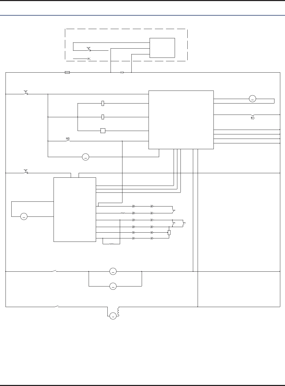
67 - FORM NO. 56043162 - Focus II Large
Electrical System
Electrical System
Wiring (Ladder) Diagram
BLK
RED/BLK
BLK
ORN/BLU
BLU/BLK
BLK
ORN
BLK
BLK
BLK
VIO/YEL
WHT/GRN
GRA/WHT
WHT/GRA
BLK
BRN
RED/GRN
BRNBRN
VIO/BLK
BLK/YEL
BRN
BRN
BRN
BRN
BRN
RED
BRN
BRN YEL/VIO
GRN
RED
RED
BLK/WHT
RED
RED
BRN/BLK
YEL/RED
RED WHT/YEL
RED/VIO
BLK
ORN/BLU
RED/BLK
BLU/BLK
BRN
GRN/VIO
BLU/VIO
BLK/VIO
ORN/VIO
WHT/VIO
BLK
BLKRED
GRN
BLKBLU
BLK
BRNORN
BLK
WHT WHT
RED
RED WHT
WHT
BLU
BLK
BLK
BLK
BLK
BLK
ORN
WHT/GRA
+
-
-+
+
36VDC
-
B+2
B+1
BRUSHCONTACTOR
VACUUMCONTACTOR
SOLUTIONSOLENOID
FOR/REV.
BRUSH MOTOR SENSE
VACUUM MOTOR SENSE
J2-7
J1-13
J1-14
J1-12
J1-11
REVERSE
B-1
BRUSHACTUATOR1
BRUSHACTUATOR2
B-3
B-4
B-2
A1
CONTROLBOARD
J1-5
J2-5
J2-10
J1-6
J2-4
J1-7
J2-8
J2-1
J2-6
J1-9
J2-9
RECOVERYTANKFULL
A2
B+ B-
1228SPEEDCONTROLLER
M1
M2
PIN 3- POT.HI
PIN 4- POT.WIPER
PIN 13 - POT.LO
PIN 5- KSI
PIN 16 - REV
PIN 6- BRAKE(-)
STATUS
PIN 9- STATUS
PIN 18 - SPEEDLIMITPOT
ONBOARDBATTERY
CHARGER
(OPTIONAL)
B+
B-
INTERLOCK
NOTE: CONNECT GRNWIRETOF2 ANDDISCONNECT
REDWIREFROMF2FORCHARGEROPTION
J1-4
PIN 17 - REV
CHEMICAL
PUMP
J2-11
+
M
M4
MOTOR, VAC
M
M4
MOTOR, VAC
1 2
F2
CIRCUITBREAKER, 5AMP
F2
CIRCUITBREAKER, 5AMP
1 2
M
M1
MOTOR, WHEELDRIVE
M
M1
MOTOR, WHEELDRIVE
R3
100OHM
R3
100OHM
M
M5
MOTOR, BRUSHACTUATOR
M
M5
MOTOR, BRUSHACTUATOR
K1
COIL, BRUSHMOTORCONTACTOR
K1
COIL, BRUSHMOTORCONTACTOR
BT1
BATTERY
BT1
BATTERY
+ -
L1
COIL, SOLUTIONSOLENOID
L1
COIL, SOLUTIONSOLENOID
1 2
F1
FUSE,150A.
F1
FUSE,150A.
1 2
2K2K
M
M2
MOTOR, LEFT BRUSH
M
M2
MOTOR, LEFT BRUSH
S4
SWITCH, FLOAT
S4
SWITCH, FLOAT
1 2
S3
SW, SPSTKEY
S3
SW, SPSTKEY
5S5S
1
2
M
M3
MOTOR, RIGHT BRUSH
M
M3
MOTOR, RIGHT BRUSH
1K1K
R2
4.75KOHM
R2
4.75KOHM
K2
COIL, VACMOTORCONTACTOR
K2
COIL, VACMOTORCONTACTOR
6S6S
1
2
F3
CIRCUITBREAKER, 30 AMP
F3
CIRCUITBREAKER, 30 AMP
1 2
R1
POT. 100KOHMSPEEDLIMIT
R1
POT. 100KOHMSPEEDLIMIT
1
2
3
M
M6
MOTOR, CHEMICALPUMP
M
M6
MOTOR, CHEMICALPUMP
F2
CIRCUITBREAKER, 5AMP
F2
CIRCUITBREAKER, 5AMP
1 2
7S7S
1
2
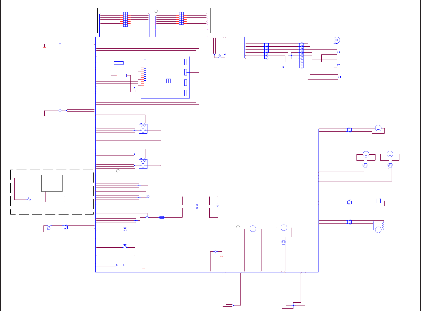
68 - FORM NO. 56043162 - Focus II Large
Electrical System
Wiring Harness Diagram 56315926 Rev. C
BLK 4-2
RED 10-1
BRN 16-3
RED 4-2
BLK/YEL 18-1
RED 10-1
BRN 16-7
BLK 12-2
BRN 16-2
RED 16-1
BRN 16-7
VIO/BLK 18-1
RED 10-3
BRN 16-8
RED 10-3
WHT
ORN/BLU 20-1
RED 10-2
BLK 16-2
BLU 12-1
WHT 12-1
BLK 10-3
BRN/BLK 10-1
BRN/BLK 10-1
YEL/RED 10-1
YEL/RED 10-1
WHT/YEL 10-1
WHT/YEL 10-1
GRA/WHT 18-1
BLK
ORN 18-1
WHT 12-2
WHT/GRA 18-1
BLK 12-4
BLK 12-3
GRN/YEL 18-1
GRN
GRA/WHT 18-1
WHT/GRA 18-1
WHT/GRN 18-1
BRN 16-8 VIO/YEL 18-1
RED/BLK 20-1
BLU/BLK 20-1
BLK 16-2
BRN 16-1
RED/GRN 18-1
BLK/YEL 18-1
VIO/BLK 18-1
BLK 10-2
BLK 18-6
BLK 18-1
BLK 18-4
BLK 18-5
BLK 18-1
BLK 18-4
GRN/YEL 18-2
GRN/YEL 18-3
BRN 16-1
BRN 20-1
BRN 16-2
BRN 16-3
BLK 10-3
BLK 10-2
BRN 16-6
BRN 16-6
RED/GRN 18-1
BLK 18-6
WHT 12-2
BLK 12-3
BLK 12-4
WHT 12-1
BLK 12-1
BLU 12-1
BLK
VIO/YEL 18-1
WHT/GRN 18-1
RED
BLK 12-2
ORN 18-1
BLK 12-1
BLK 4-1
RED 4-1
RED/VIO 20-1
ORN/VIO 20-1
WHT/VIO 20-1 WHITE
ORANGE
RED
BLK/VIO 20-1
RED 16-1
RED 10-2
BLK 18-5
GRN/YEL 18-2
GRN/YEL 18-1
GRN/YEL 18-3
BRN 20-1
RED/VIO 20-1
ORN/VIO 20-1
GRN/VIO 20-1
ORN/BLU 20-1
BLU/BLK 20-1
RED/BLK 20-1
BLK/VIO 20-1
BLU/VIO 20-1
WHT/VIO 20-1
GRN/VIO 20-1
BLU/VIO 20-1 BLUE
GREEN
BLACK
BROWN
BLACK
WHITE
BLACK
BLACK
BLACK
BLACK
BLACK
BLACK
BRN 18-1
YEL/VIO 18-1
BRN 18-1
YEL/VIO 18-1
CONTROLS
WHEEL DRIVE
A1
CONTROL BOARD
OPTIONAL ONBOARD CHARGER
INTERLOCK
B+ B-
TO X4 TERMINAL BLOCK (+)
NOTE: DISCONNECT RED 16-1
WIRE FROM F2 AND CONNECT
GRN WIRE TO F2
TO B- ON BATTERY PACK
BATTERY DISCONNECT
GRN/VIO 20-2
C
C
C
X10X10
(+)
(-)
X17X17
A B
K2
CONTACTOR, VACUUM MOTOR
K2
CONTACTOR, VACUUM MOTOR
12
34
F1
FUSE, 150 A.
F1
FUSE, 150 A.
1
2
X12X12
A
B
1
2
3
4
5
6
7
8
9
M
M4
MOTOR, VAC
M
M4
MOTOR, VAC
1 2
F3
30 A. CIR. BR.
F3
30 A. CIR. BR.
1 2
X48X48
A
B
L1
COIL, SOLUTION SOLENOID
L1
COIL, SOLUTION SOLENOID
1 2
F2
5 A. CIR. BR.
F2
5 A. CIR. BR.
1 2
X61X61
A
B
M
M3
MOTOR, RIGHT BRUSH
M
M3
MOTOR, RIGHT BRUSH
-+
TERMINAL BLOCK, (+)
X4
TERMINAL BLOCK, (+)
X4
1
2
3
1
18
14
P2
P1
PROGRAMMER
23
B-
B-
POT HIGH
POT WIPER
KSI
BRAKE-
PUSH
MODE(M1, M2)
STATUS
B+
B+
INHIBIT
POT LOW
BRAKE+
BDI
HORN
REVERSE
SPEED LIMIT POT
A2
SPEED CONTROLLER
1
18
14
P2
P1
PROGRAMMER
23
B-
B-
POT HIGH
POT WIPER
KSI
BRAKE-
PUSH
MODE(M1, M2)
STATUS
B+
B+
INHIBIT
POT LOW
BRAKE+
BDI
HORN
REVERSE
SPEED LIMIT POT
A2
SPEED CONTROLLER
B-
M1
M2
B+
X45X45
A
B
SP2SP2
1
1
2
2
S5
REVERSE SWITCH
S5
REVERSE SWITCH
1
2
X8X8
A B
M
M2
MOTOR, LEFT BRUSH
M
M2
MOTOR, LEFT BRUSH
- +
X15X15
A
B
R2
4.75K OHM
R2
4.75K OHM
12
M
M6
MOTOR, CHEMICAL PUMP
M
M6
MOTOR, CHEMICAL PUMP
-+
X19X19
1
2
3
4
5
6
7
8
9
10
11
12
13
14
15
16
17
18
X25X25
A
B
TERMINAL BLOCK, (-)
X5
TERMINAL BLOCK, (-)
X5
2
3
45
1
S6
RIGHT PALM SWITCH
S6
RIGHT PALM SWITCH
1
2
S3
SW, SPST KEY
S3
SW, SPST KEY
12
X47X47
A
B
X60X60
A
B
K1
CONTACTOR, BRUSH MOTOR
K1
CONTACTOR, BRUSH MOTOR
1 2
34
SP3SP3
1
2
2
S7
LEFT PALM SWITCH
S7
LEFT PALM SWITCH
1
2
J2J2
1
2
3
4
5
6
8
9
10
11
12
7
CIR BREAKER PANEL BONDING
X3
CIR BREAKER PANEL BONDING
X3
21
F2
5 A. CIR. BR.
F2
5 A. CIR. BR.
12
X16X16
A
B
BT1
36V BATTERY
BT1
36V BATTERY
+ -
S4
RECOVERY TANK FULL SWITCH
S4
RECOVERY TANK FULL SWITCH
12
J1J1
1
2
3
4
5
6
7
8
9
10
11
12
13
14
X24X24
A
B
CHASSIS BONDING
X2
CHASSIS BONDING
X2
2
1
M
M5
MOTOR, BRUSH ACTUATOR
M
M5
MOTOR, BRUSH ACTUATOR
- +
PANEL BONDING
X1
PANEL BONDING
X1
2 1
R3
100 OHM
R3
100 OHM
1 2
1
2
3
4
5
6
7
8
9
X46X46
A
B
M
M1
MOTOR, WHEEL DRIVE
M
M1
MOTOR, WHEEL DRIVE
-+
CONTROL BOARD BONDING
X6
CONTROL BOARD BONDING
X6
21
X9X9
(+)
(-)
X11X11
A
B
X39X39
1
2
3
4
5
6
POT. 100K OHM SPEED LIMIT
R1
POT. 100K OHM SPEED LIMIT
R1
1
2
3
X38X38
1
2
3
4
5
6
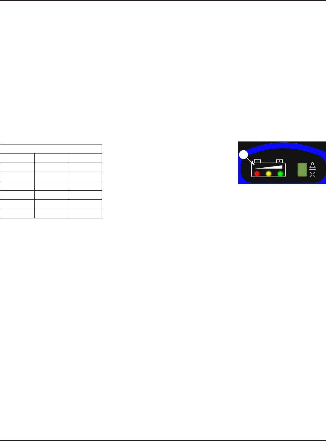
69 - FORM NO. 56043162 - Focus II Large
Electrical System
Batteries
Description of the Low Voltage Cut-Out Feature
All models discussed in this manual are equipped with a low voltage cut-out feature to prevent over-discharging of the batteries. When a machine’s
adjustable. The standard lead-acid battery (wet cell) setting is 31.34 volts or 1.74 volts per cell. The alternate maintenance free battery (gel cell)
higher cut-out voltage.
Special Service Note: There is a minimum battery charge level that the must be reached before the low-voltage cut-out function will reset and allow
the machine to function again. On the 34 RST, the batteries must be charged to a minimum of 37.6 volts (2.09 volts per cell) in order to reset the low-
voltage cut-out function.
Description Of The Battery Condition Indicators
The Battery Condition Indicator will give an indication of the state of charge of the batteries based on the voltage of
the batteries. The display has three colored LED’s (J1)
Display
LEDs On Standard Alternate
Grn
Grn & Yel 33.0-34.0 34.0-34.5
Yel 32.0-33.0 33.5-34.0
Yel & Red 31.5-32.0 33.0-33.5
Red 31.0-31.5 32.5-33.0
Flash Red <31.0 <32.5
Specific Wet Cell Battery Information
Note: The
.
being used.
When selecting a battery charger always follow the recommendation of the battery supplier to match the correct
charger DC output amperage to the amp/hour rating of the batteries being installed. This will prevent the
battery pack from being overcharged or undercharged.
J1
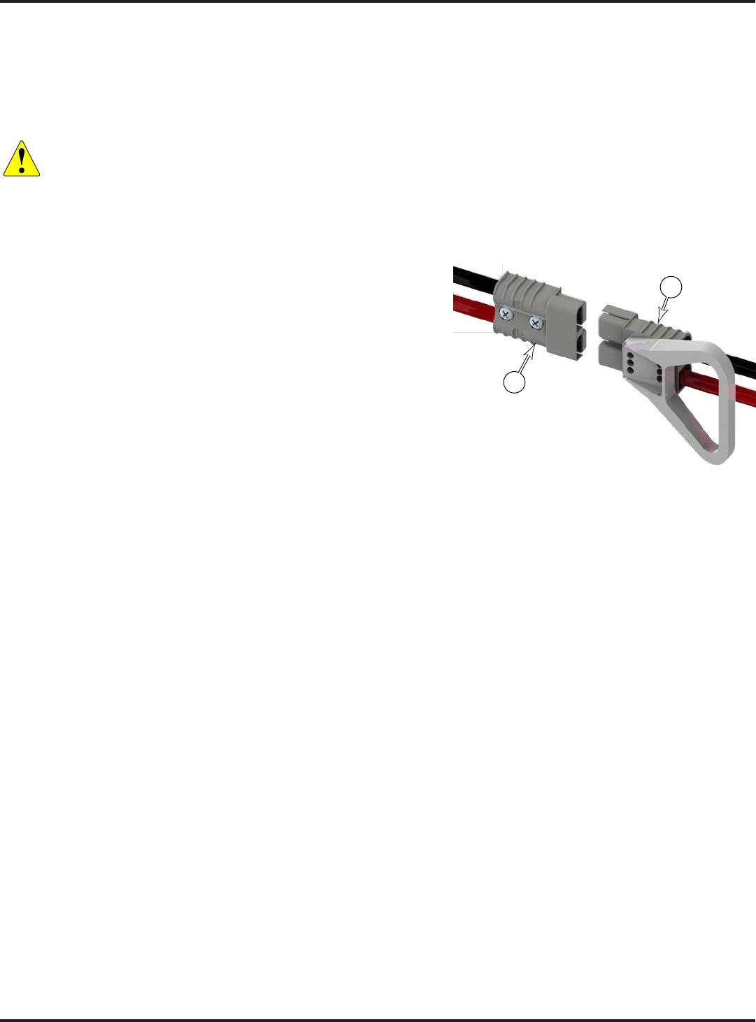
70 - FORM NO. 56043162 - Focus II Large
Electrical System
Battery Maintenance
Charging Batteries
Charge the batteries each time the machine is used or when the battery indicator (1 or 3) is reading less than full.
Caution!
• Charge batteries in a well-ventilated area.
• Do not smoke while servicing the batteries.
• Remove all jewelry
• Wear safety glasses, rubber gloves and a rubber apron
• Do not allow tools to touch more than one battery terminal at a time
• To avoid damage to floor surfaces, wipe water and acid from the top of the batteries after charging.
If your machine shipped with an onboard battery charger, turn
the Key Switch off. Unwind the electrical cord from the side of the
onboard charger and plug it into a properly grounded outlet. Refer to
the OEM product manual for more detailed operating instructions.
connector (4) from the machine connector (5), and plug the battery
connector into the charger. Follow the instructions on the battery charger.
Note: (4)
Extending Battery Life
discharging will shorten battery life and limit performance. Be sure to follow proper charging instructions.
charger is recommended.
Important! Do not attempt to open sealed gel batteries or add water. Doing so will damage the battery and void
the warranty.
For wet batteries, maintain proper electrolyte level and check weekly. Use distilled water in batteries whenever
possible. If the batteries are discharged, add just enough water to cover the plates in each cell, and recheck the
Keep the Batteries Charged. Batteries should be charged each time that a machine is used for more than 1 hour.
how long the batteries should be charged. Even when a machine is stored, the batteries should be charged once
a month to prevent the batteries from “sulfating”. Most battery caps are vented, so there’s no need to loosen or
remove them for charging.
Keep the Batteries Clean. Use a damp cloth to wipe dirt from the top of the batteries. Battery terminals must be
Note: If there is acid on the batteries, wash the tops of the batteries with a solution of baking soda
5
4
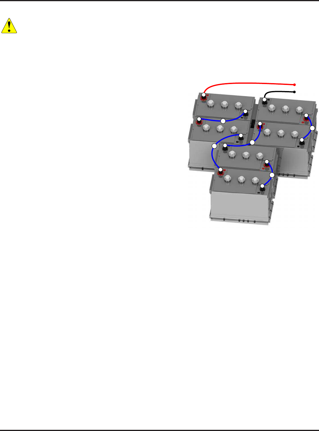
71 - FORM NO. 56043162 - Focus II Large
Electrical System
Removal and Installation
Caution!
• Use extreme caution when working with batteries. Sulfuric acid in batteries can cause severe injury if
allowed to contact the skin or eyes.
• Explosive hydrogen gas is vented from the batteries through openings in the battery caps. Do not smoke
while servicing the batteries.
• Remove all jewelry. Wear safety glasses, rubber gloves and a rubber apron
• Do not allow tools to touch more than one battery terminal at a time
• Electrical components in this machine can be severely damaged if the batteries are not installed and
connected properly.
1. Turn the Key Switch to the off position and open the recovery
tank.
2. Remove the cables from the batteries, and remove the
batteries. Make note of the battery polarity and cable locations.
3. Install the new batteries into the compartment. Note the
orientation of the batteries shown to the right. Not all of the
batteries are oriented the same way.
4. Put a rubber boot over each end of the battery cables.
5. Connect the battery cables.
There are 3 short cables (S), 2 long cables (L), and the main
positive (Bat+) and negative (Bat-) cables leading to the
machine.
connection between all 6 batteries.
Position the cables so the battery caps can be easily removed
for battery service.
6.
7. Put one of the black rubber boots over each of the terminals and connect the Battery Pack Connector (14 or 18).
Battery Testing
A battery problem is usually recognized by the machine operator as a decrease in the machine’s running time. This
condition is usually caused by one or more “dead cells” in the battery system.
reads 50 points (or more) lower than the other cells.
Use a volt meter to check the voltage of each battery. Look for a battery with a voltage that is 1 or 2 volts less
than the other batteries. Check under the following conditions:
With the batteries fully charged,
With the scrub and drive motors running,
With the batteries discharged, but still above the voltage cutoff threshold.
If the batteries in the machine are more than 1 year old, it’s usually best to replace the whole set, rather than
replacing just one battery.
BAT+
BAT-
+
−
+
−
+
−
+
−
+
−
+
−
L
S
S
S
L
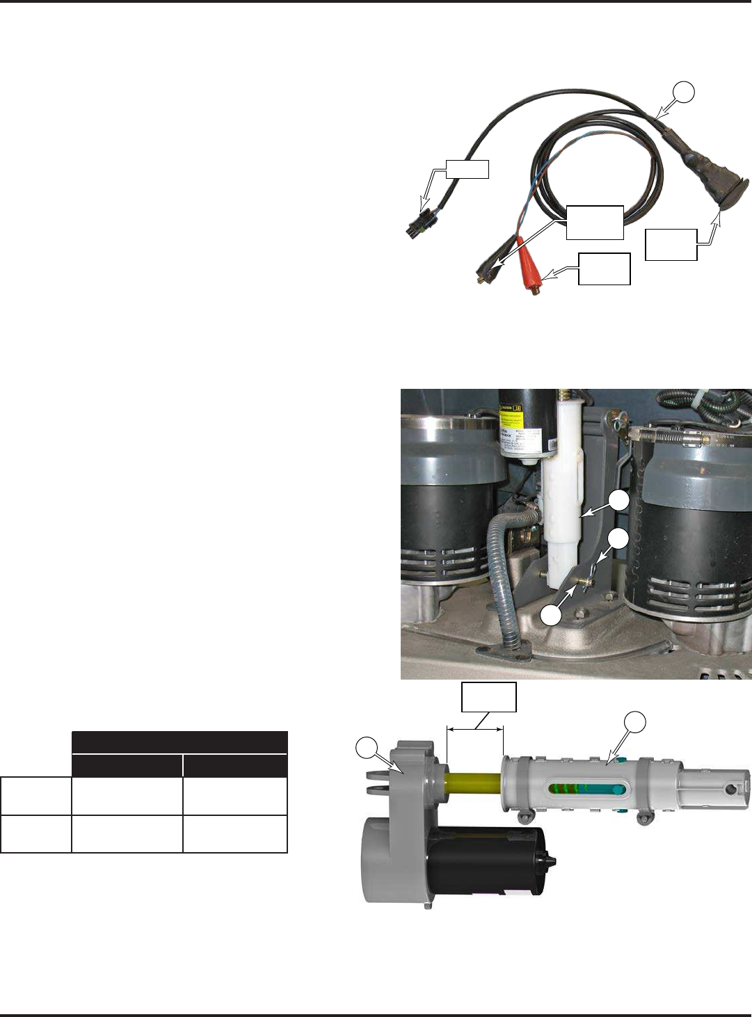
72 - FORM NO. 56043162 - Focus II Large
Electrical System
Maintenance and Adjustment
Lift Actuator Limit Adjustment
To protect the lift actuator from traveling too far, it contains
travel. The minimum travel is adjusted by turning the
adjusted by turning the dial at the top of the leadscrew motor.
Adapter (1) (PN 56407502) shown to the right.
1. Remove the front nose from the machine.
2. Connect the Power Cord Adapter (1) to the positive and
negative battery terminals of the machine.
3. Disconnect the power cable of the lift actuator from the
machine, and connect the Power Cord Adapter into the
cable leading to the lift actuator motor.
4. Press the For/Rev switch on the Adapter (1)
in a neutral position (no tension/pressure on the actuator).
5. Remove the retaining key (2) and link pin (3) that
secures the spring housing (4) to the scrub deck to permit
the actuator to swing freely.
6. While holding the spring housing (4) from turning, press
the For/Rev switch on the Adapter (1) to raise the spring
housing (4) toward the actuator gear housing (5) until
the motor stops (minimum limit switch engaged).
7. Rotate the spring housing (4) until the distance between
the spring housing and gear housing (5) is within the
Upper Limit range listed in the table below.
The “Old Style” spring housing (4)
The “New Style” spring housing (4)
split down the center.
Housing Distances
Lower Limit
New Style ⁄" - ⁄"
(21 - 23 mm)
4 ⁄" - 5"
(124 - 127 mm)
Old Style ⁄" - ⁄"
(2 - 5 mm)
4 ⁄" - 4 ¼"
(105 - 108 mm)
Housing
Distance
5
4
8. (1) to lower the actuator to
9.
values shown in the table. If necessary, adjust the lower limit as described below.
1
Battery
Positive
Motor
Battery
Negative For/Rev
Switch
2
3
4
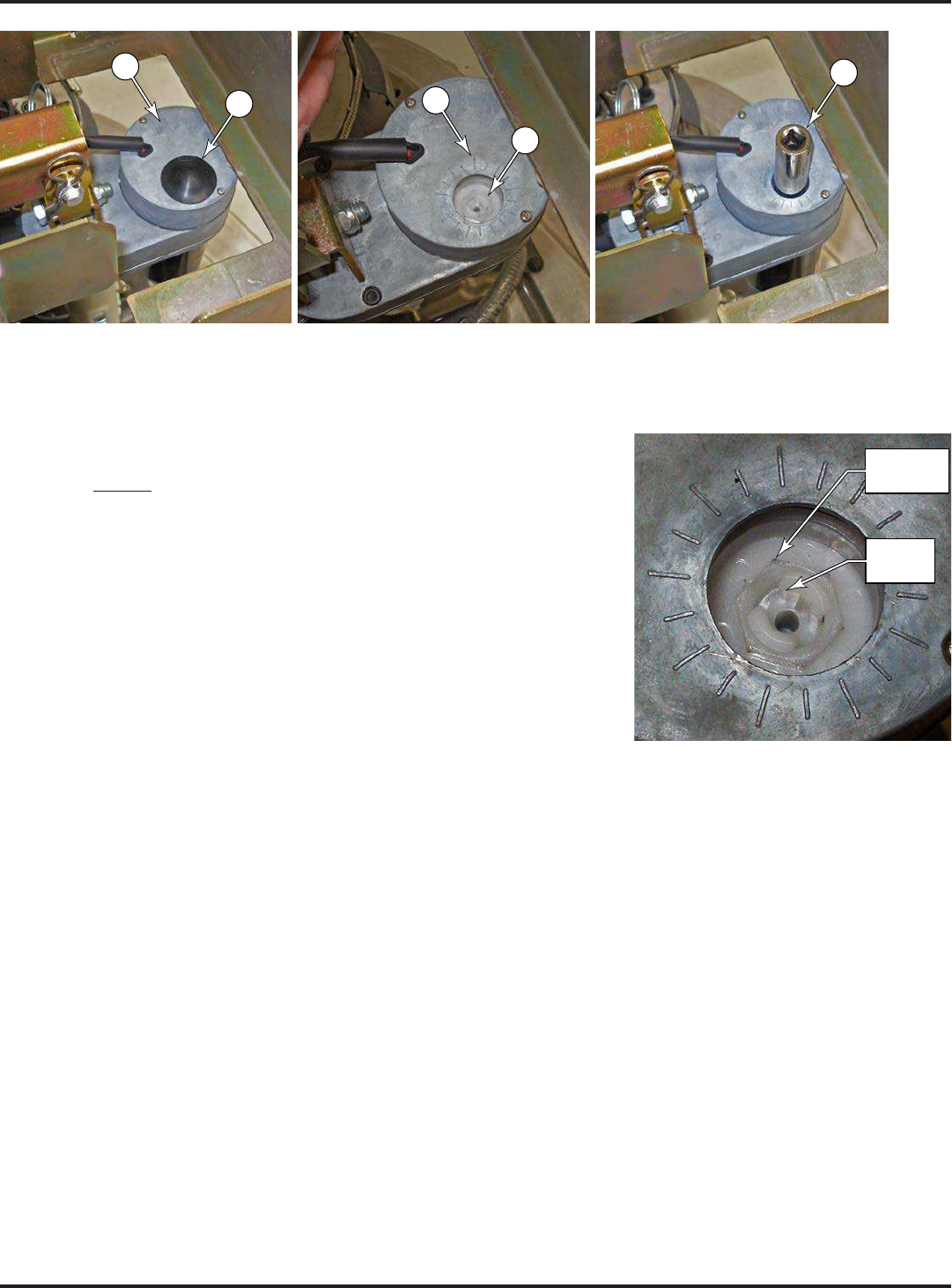
73 - FORM NO. 56043162 - Focus II Large
Electrical System
6
7
9
5
8
10. Remove the dust cap (6) from the top of the gear housing (5)
11. Place a 1/2” socket (9) over the limit adjustment nut (7) to turn the nut, and increase or decrease the lower limit
as follows:
Important: Even though the center of the adjustment nut looks like it
will accept a screwdriver blade, this is the retainer for the adjustment
nut. Do Not
If you need to make large adjustments, it is recommended to move the
12.
13.
limits by cycling the actuator to the upper and then lower limit.
14. Before disconnecting the Adapter cord (1), lower the lift actuator down to the scrub deck to make it easier to
reinsert the link pin (3) and retaining key (2).
15. Reassemble the machine.
Do Not
Turn!
Turn Outer
Nut Only

74 - FORM NO. 56043162 - Focus II Large
Electrical System
Curtis Controller Diagnostics
Diagnostics Method A: Uses the machine’s LED display and the Regular Scrub ON indicator.
Function of the Speed Controller Status Light and Display
The Curtis 1228 speed control will output a fault code if there is a problem
associated with the speed control and wheel drive system. When the Curtis
controller presents an error to the main controller, the display will indicate an “E03” error designated as a drive
controller error. The single character display (J2)
(I1).
See the Table 1 below for a description of these drive fault code
indicators.
Service Note:
Diagnostics Method B: Uses the optional handheld Curtis programmer model 1311 MP1101.
Diagnostics Using the Curtis Handheld Programmer
Note: Also refer to the Curtis Programmer Manual, Clarke form number 56043101, for more details on programmer operation.
With a Curtis programmer, diagnostics and troubleshooting is more direct than with the LEDs alone. The
programmer presents complete diagnostic information in plain language with no codes to decipher. Faults are
displayed on the “Faults” screen, and the status of the controller inputs/outputs is displayed on the “Monitor”
(1) visually inspect the vehicle for obvious problems; (2) diagnose the problem using the programmer; (3) test the
circuitry with the programmer, and (4) correct the problem. Repeat the last three steps as necessary until the
vehicle is operational.
Example: A vehicle that does not operate in “forward” is brought in for repair.
1.
2. Connect the programmer, navigate to the “Faults” screen, then read the displayed fault information. In this
of the norm.
3. Navigate to the “Monitor” screen and observe the status of inputs and outputs in the forward direction. In this
switch was pressed, which means there is a problem with the palm drive switches or the palm drive switch
wiring.
4. Check and replace/repair the palm drive switches and wiring, then repeat the test. If the programmer shows
the palm drive switch circuit closing and the vehicle now drives normally, the problem has been corrected.
Fault History
by operator habits or by overloading. After a problem has been diagnosed and corrected, it’s advisable to clear the
• To clear the fault history, press the “+” (YES) key. The programmer will display the message “Deleted”.
• If you decide not to clear the fault history, press the “-“ (NO) key. The programmer will return to the expanded “Faults” screen.
E
J2
I1

75 - FORM NO. 56043162 - Focus II Large
Electrical System
Drive Status LED Fault Codes
TABLE 1
LED
Code
Status Light
Display Explanation Possible Cause
1,1 0 0 over-/under-temperature cutback 1. Temperature >92°C or < -25°C.
2. Excessive load on vehicle.
3. Operation in extreme environments.
1,2 0 00 throttle fault 1. Palm drive switch wires open or shorted.
2. Palm switches defective.
3. Wrong throttle type selected.
1,3 0 000 speed limit pot fault 1. Speed limit pot wire(s) broken or shorted.
2. Broken speed limit pot.
1,4 0 0000 battery voltage too low 1. Battery voltage <17 volts.
2. Bad connection at battery or controller.
1,5 0 00000 battery voltage too high 1. Battery voltage >48 volts.
2. Vehicle operating with charger attached.
3. Intermittent battery connection.
2,1 00 0 main contactor driver Off fault 1. Main contactor driver failed open.
2,3 00 000 main contactor fault 1. Main contactor welded or stuck open.
2. Main contactor driver fault.
2,4 00 0000 main contactor driver On fault 1. Main contactor driver failed closed.
3,1 000 0 fault present for >10 sec. 1. Broken palm drive switch.
2. Broken speed limiting pot.
3,2 000 00 brake On fault 1. Electromagnetic brake driver shorted.
2. Electromagnetic brake coil open.
3,3 000 000 pre-charge fault 1. Low battery voltage.
2. KSI and palm drive switch turned on at same
time.
3,4 000 0000 brake Off fault 1. Electromagnetic brake driver open.
2. Electromagnetic brake coil shorted
3,5 000 00000 HPD (High Pedal Disable) fault 1. Incorrect sequence of palm drive switch and
KSI.**
2. Faulty or shorted palm drive switch.
4,1 0000 O current sense fault 1. Short in motor or in motor wiring.
2. Controller failure. *
4,2 0000 00 motor voltage fault (hardware
failsafe)
1. Motor voltage does not correspond to throttle
request.
2. Short in motor or in motor wiring.
3. Controller failure. *
4,3 0000 000 EEPROM fault 1. EEPROM failure or fault.
4,4 0000 0000 power section fault 1. EEPROM failure or fault.
2. Short in motor or in motor wiring.
3. Controller failure. *
**Note:
drive switch before turning on the main key switch. This can be cleared by releasing both palm drive switches and cycling the key switch OFF
and ON.

76 - FORM NO. 56043162 - Focus II Large
Electrical System
Speed Control Programming Options
Following are the two speed control parameters that can be adjusted using a Curtis handheld programmer:
M1 MAX SPD – Forward Transport/Scrub maximum speed limit (% of full throttle)
M1 REV MAX SPD – Reverse Transport/Scrub maximum speed limit (% of full throttle)
Installation Checkout for the Curtis Speed Controller
After installing a controller and before operating the vehicle, carefully complete the following checkout procedure.
section for further information.
You can perform the installation checkout with or without the handheld programmer. The checkout procedure is
easier with a programmer. Otherwise, observe the yellow Regular Scrub ON or Wand indicator LED for codes. The
Curtis handheld programmer part number is 56409441.
protection, avoiding loose clothing and jewelry, and using insulated wrenches.
Put the vehicle up on blocks to get the drive wheels off the ground before beginning these tests.
Turn the key switch off and make sure that both palm drive switches are released.
Do not stand, or allow anyone else to stand, directly in front of or behind the vehicle during the tests.
1.
2. Turn the key switch on. The programmer should “power up” and display “Loading…”. If neither happens, check
for continuity in the key switch circuit and controller ground.
3. If you are using a programmer, navigate to the “Faults”/”System Faults” screen. The display should read
message. If you are conducting the checkout without a programmer, look up the LED fault code in Table 1 in
the Electrical System section.
When the problem has been corrected, it may be necessary to cycle the key switch to clear the fault code.
4. Press one of the palm drive switches. The motor should begin to turn in the selected direction. If it does not,
verify the wiring to the controller and to the motor. The motor speed should correspond to the speed limit pot
setting. If not, refer to Table 1 in the Electrical System section.
5.
“REVERSE INPUT” screens to observe the status of the palm switches and the reverse button. Cycle each
switch in turn, observing the programmer. Each input should show the correct state on the programmer.
6. Take the vehicle off the blocks and drive it in an open area. It should have smooth acceleration and good top
speed.
Programming Vehicle Speed Changes
change a speed parameter using the programmer, select the “Program” screen.
Maintenance
controller. Opening the controller may damage it and will void the warranty. It is recommended however that the
