Nilfisk Advance Sc750 Sc800 Walk Behind Floor Scrubber Service Manual
2018-06-21
: Sweepscrub Nilfisk-Advance-Sc750-Sc800-Walk-Behind-Floor-Scrubber-Service-Manual nilfisk-advance-sc750-sc800-walk-behind-floor-scrubber-service-manual 2801 file product_file
Open the PDF directly: View PDF ![]() .
.
Page Count: 164 [warning: Documents this large are best viewed by clicking the View PDF Link!]
- General Information
- Service Manual Purpose and Application
- Other Reference Manuals
- Conventions
- Transporting the Machine
- Towing
- Cautions and Warnings
- General Safety Instructions
- General Machine Description
- Nameplate
- Know Your Machine
- Machine Specifications – SC750 and SC750 ST
- Machine Specifications – SC800 and SC800 ST
- Machine Maintenance
- Chassis System
- Control system
- Electrical System
- Functional Description
- Maintenance and Adjustments
- Troubleshooting
- Removal and Installation
- Battery Charger - Delta-Q.
- Wiring Diagram - Non-ST, 56112170 Rev D, Early (before SN 4000077687)
- Wiring Diagram - Non-ST, 56383889 Rev E, Late (Since SN 4000077687)
- Wiring Diagram - ST, 56112180 REV C, Early (before SN 4000077687)
- Wiring Diagram - ST, 56383366 REV E, Late (since SN 4000077687)
- Wiring Harness Configuration Diagram - Non-ST, 56112171 REV D, Early (before SN 4000077687)
- Wiring Harness Configuration Diagram - Non-ST, 56383890 Rev A, Late (since SN 4000077687)
- Wiring Harness Configuration Diagram - ST, 56112181 REV C, Early (before SN 4000077687)
- Wiring Harness Configuration Diagram - ST, 56383367 REV B, Late (since SN 4000077687)
- TrackClean Connections, With Access Control 56384628 Rev A
- TrackClean Electrical Connections, Without Access Control 56384627 Rev A
- Options and Accessories
- Recovery System
- Scrub System – Cylindrical
- Scrub System, Disc
- Scrub System, Rev
- Solution System
- Squeegee System
- Wheel System Non-Traction
- Wheel System, Traction
- Functional Description
- Component Locations
- Troubleshooting
- Removal and Installation
- Speed Limit Potentiometer – ST models
- Speed Limit Potentiometer – Non-ST models
- Reverse Switch – ST models
- Handle Wiring Connections - ST models
- Paddle Position Sensor – Non-ST models - SC750, SC800
- Paddle Centering Springs - Non-ST models - SC750, SC800
- Drive Wheel
- Transaxle
- Transaxle Drive Motor Carbon Brushes
- Specifications
- _GoBack
Advance: SC750, SC750 ST, SC800,
SC800 ST
Nilsk: SC800
Service Manual
Advance Models: 56112000(SC750-26D), 56112004(SC750-28D), 56112006(SC750-28C),
56112012(SC750 ST-26D), 56112013(SC750 ST-28C), 56112016(SC800-28D), 56112018(SC800-
28C), 56112024(SC800-32C), 56112028(SC800-34D), 56112032(SC800 ST-34D), 56112780 (SC70-
28R)
Nilsk Models: 56112034(SC800-71), 56112035(SC800-86),
56112036(SC800-71C)
11/10 Revised 12/16 Form Number 56043150
Service Manual: SC750, SC800, SC 750 ST, SC800 ST
Form Number 56043150 Page ii
Contents
General Information . . . . . . . . . . . . . . . . . . . . . . . . . . . . . . . . . . . . . . . . . . . . . . . . . .6
Service Manual Purpose and Application . . . . . . . . . . . . . . . . . . . . . . . . . . . . . . . . . . . . . . . 6
Other Reference Manuals . . . . . . . . . . . . . . . . . . . . . . . . . . . . . . . . . . . . . . . . . . . . . . . 7
Conventions . . . . . . . . . . . . . . . . . . . . . . . . . . . . . . . . . . . . . . . . . . . . . . . . . . . . . . .7
Transporting the Machine . . . . . . . . . . . . . . . . . . . . . . . . . . . . . . . . . . . . . . . . . . . . . . . 7
Towing. . . . . . . . . . . . . . . . . . . . . . . . . . . . . . . . . . . . . . . . . . . . . . . . . . . . . . . . . .7
Cautions and Warnings. . . . . . . . . . . . . . . . . . . . . . . . . . . . . . . . . . . . . . . . . . . . . . . . .7
Symbols . . . . . . . . . . . . . . . . . . . . . . . . . . . . . . . . . . . . . . . . . . . . . . . . . . . . . . . 7
General Safety Instructions . . . . . . . . . . . . . . . . . . . . . . . . . . . . . . . . . . . . . . . . . . . . . . 8
General Machine Description . . . . . . . . . . . . . . . . . . . . . . . . . . . . . . . . . . . . . . . . . . . . . 9
Nameplate. . . . . . . . . . . . . . . . . . . . . . . . . . . . . . . . . . . . . . . . . . . . . . . . . . . . . . . .9
Know Your Machine . . . . . . . . . . . . . . . . . . . . . . . . . . . . . . . . . . . . . . . . . . . . . . . . . 10
Control Panel – SC750 and SC800 (Membrane Switch Control Panel) . . . . . . . . . . . . . . . . . . . . 10
Control Panel – SC750 ST and SC800 ST (Toggle Switch Control Panel). . . . . . . . . . . . . . . . . . . 13
Machine Specications – SC750 and SC750 ST . . . . . . . . . . . . . . . . . . . . . . . . . . . . . . . . . . . 15
Machine Specications – SC800 and SC800 ST . . . . . . . . . . . . . . . . . . . . . . . . . . . . . . . . . . . 16
Machine Maintenance . . . . . . . . . . . . . . . . . . . . . . . . . . . . . . . . . . . . . . . . . . . . . . . . 17
Lubricating the Machine . . . . . . . . . . . . . . . . . . . . . . . . . . . . . . . . . . . . . . . . . . . . . 18
Chassis System . . . . . . . . . . . . . . . . . . . . . . . . . . . . . . . . . . . . . . . . . . . . . . . . . . . . 19
Functional Description . . . . . . . . . . . . . . . . . . . . . . . . . . . . . . . . . . . . . . . . . . . . . . . . 19
Control system. . . . . . . . . . . . . . . . . . . . . . . . . . . . . . . . . . . . . . . . . . . . . . . . . . . . .20
Functional Description . . . . . . . . . . . . . . . . . . . . . . . . . . . . . . . . . . . . . . . . . . . . . . . . 20
Component Locations . . . . . . . . . . . . . . . . . . . . . . . . . . . . . . . . . . . . . . . . . . . . . . . . . 21
Troubleshooting . . . . . . . . . . . . . . . . . . . . . . . . . . . . . . . . . . . . . . . . . . . . . . . . . . . . 22
Fault Codes . . . . . . . . . . . . . . . . . . . . . . . . . . . . . . . . . . . . . . . . . . . . . . . . . . . . 22
Fault Code Table . . . . . . . . . . . . . . . . . . . . . . . . . . . . . . . . . . . . . . . . . . . . . . . . . 22
Service Test Mode. . . . . . . . . . . . . . . . . . . . . . . . . . . . . . . . . . . . . . . . . . . . . . . . . 26
Programming Options –SC750 ST and SC800 ST Models (control panel with rocker switches) . . . . . . . 29
Programming Options – SC750 and SC800 models (Control Panel with membrane switches) . . . . . . . . 33
Removal and Installation. . . . . . . . . . . . . . . . . . . . . . . . . . . . . . . . . . . . . . . . . . . . . . . 38
Main Machine Controller SC750 ST and SC800 ST Models (Early Build) . . . . . . . . . . . . . . . . . . 38
Main Machine Controller SC750 ST and SC800 ST Models (Later Build) . . . . . . . . . . . . . . . . . . 40
Main Machine Controller SC750 and SC800 Models (Early Build) . . . . . . . . . . . . . . . . . . . . . . 40
Main Machine Controller SC750 and SC800 Models (Later build) . . . . . . . . . . . . . . . . . . . . . . 44
Rocker Switches - ST Models. . . . . . . . . . . . . . . . . . . . . . . . . . . . . . . . . . . . . . . . . . . 50
Specications . . . . . . . . . . . . . . . . . . . . . . . . . . . . . . . . . . . . . . . . . . . . . . . . . . . . . 51
Shop Measurements – Main Machine Controller . . . . . . . . . . . . . . . . . . . . . . . . . . . . . . . . 51
Electrical System . . . . . . . . . . . . . . . . . . . . . . . . . . . . . . . . . . . . . . . . . . . . . . . . . . . 54
Functional Description . . . . . . . . . . . . . . . . . . . . . . . . . . . . . . . . . . . . . . . . . . . . . . . . 54
General . . . . . . . . . . . . . . . . . . . . . . . . . . . . . . . . . . . . . . . . . . . . . . . . . . . . . . 54
On-board Battery Charger . . . . . . . . . . . . . . . . . . . . . . . . . . . . . . . . . . . . . . . . . . . . 55
Delta-Q IC650 Battery Charging Prole Table . . . . . . . . . . . . . . . . . . . . . . . . . . . . . . . . . 57
Electrical Panel Components . . . . . . . . . . . . . . . . . . . . . . . . . . . . . . . . . . . . . . . . . . 59
Maintenance and Adjustments. . . . . . . . . . . . . . . . . . . . . . . . . . . . . . . . . . . . . . . . . . . . 60
Battery Maintenance and Recharging . . . . . . . . . . . . . . . . . . . . . . . . . . . . . . . . . . . . . . 60
Troubleshooting . . . . . . . . . . . . . . . . . . . . . . . . . . . . . . . . . . . . . . . . . . . . . . . . . . . . 60
Insufcient Machine Operation Time . . . . . . . . . . . . . . . . . . . . . . . . . . . . . . . . . . . . . . 60
The Battery Charger Does Not Charge. . . . . . . . . . . . . . . . . . . . . . . . . . . . . . . . . . . . . . 60
Removal and Installation. . . . . . . . . . . . . . . . . . . . . . . . . . . . . . . . . . . . . . . . . . . . . . . 61
Service Manual: SC750, SC800, SC 750 ST, SC800 ST
Form Number 56043150 Page iii
Batteries. . . . . . . . . . . . . . . . . . . . . . . . . . . . . . . . . . . . . . . . . . . . . . . . . . . . . . 61
Battery Charger - S.P.E. . . . . . . . . . . . . . . . . . . . . . . . . . . . . . . . . . . . . . . . . . . . . . 62
Battery Charger - Delta-Q. . . . . . . . . . . . . . . . . . . . . . . . . . . . . . . . . . . . . . . . . . . . . . 63
Low Voltage Cut Out Threshold Voltages . . . . . . . . . . . . . . . . . . . . . . . . . . . . . . . . . . . . 64
Battery Run Time. . . . . . . . . . . . . . . . . . . . . . . . . . . . . . . . . . . . . . . . . . . . . . . . . 64
Battery Compartment Dimensions . . . . . . . . . . . . . . . . . . . . . . . . . . . . . . . . . . . . . . . . 64
Wiring Diagram - Non-ST, 56112170 Rev D, Early (before SN 4000077687) . . . . . . . . . . . . . . . . . . . 65
Wiring Diagram - Non-ST, 56383889 Rev E, Late (Since SN 4000077687) . . . . . . . . . . . . . . . . . . . . 66
Wiring Diagram - ST, 56112180 REV C, Early (before SN 4000077687). . . . . . . . . . . . . . . . . . . . . . 67
Wiring Diagram - ST, 56383366 REV E, Late (since SN 4000077687) . . . . . . . . . . . . . . . . . . . . . . . 68
Wiring Harness Conguration Diagram - Non-ST, 56112171 REV D, Early (before SN 4000077687) . . . . . . 69
Wiring Harness Conguration Diagram - Non-ST, 56383890 Rev A, Late (since SN 4000077687) . . . . . . . 70
Wiring Harness Conguration Diagram - ST, 56112181 REV C, Early (before SN 4000077687). . . . . . . . . 71
Wiring Harness Conguration Diagram - ST, 56383367 REV B, Late (since SN 4000077687) . . . . . . . . . . 72
TrackClean Connections, With Access Control 56384628 Rev A . . . . . . . . . . . . . . . . . . . . . . . . . . 73
TrackClean Electrical Connections, Without Access Control 56384627 Rev A . . . . . . . . . . . . . . . . . . 74
Options and Accessories . . . . . . . . . . . . . . . . . . . . . . . . . . . . . . . . . . . . . . . . . . . . . . . 75
Battery Fill Indicator . . . . . . . . . . . . . . . . . . . . . . . . . . . . . . . . . . . . . . . . . . . . . . . . . 75
Battery Watering Kit . . . . . . . . . . . . . . . . . . . . . . . . . . . . . . . . . . . . . . . . . . . . . . . . . 75
Hour Meter . . . . . . . . . . . . . . . . . . . . . . . . . . . . . . . . . . . . . . . . . . . . . . . . . . . . . . 76
On-board Battery Charger . . . . . . . . . . . . . . . . . . . . . . . . . . . . . . . . . . . . . . . . . . . . . . 76
Wiring for On-board Charger . . . . . . . . . . . . . . . . . . . . . . . . . . . . . . . . . . . . . . . . . . 76
Parking Brake . . . . . . . . . . . . . . . . . . . . . . . . . . . . . . . . . . . . . . . . . . . . . . . . . . . . 78
Laser. . . . . . . . . . . . . . . . . . . . . . . . . . . . . . . . . . . . . . . . . . . . . . . . . . . . . . . . . . 78
TrackClean . . . . . . . . . . . . . . . . . . . . . . . . . . . . . . . . . . . . . . . . . . . . . . . . . . . . . . 78
Recovery System . . . . . . . . . . . . . . . . . . . . . . . . . . . . . . . . . . . . . . . . . . . . . . . . . . . 79
Functional Description . . . . . . . . . . . . . . . . . . . . . . . . . . . . . . . . . . . . . . . . . . . . . . . . 79
Component Locations . . . . . . . . . . . . . . . . . . . . . . . . . . . . . . . . . . . . . . . . . . . . . . . . . 80
Troubleshooting . . . . . . . . . . . . . . . . . . . . . . . . . . . . . . . . . . . . . . . . . . . . . . . . . . . . 81
Vacuum Motor Does Not Turn On (Scrub function works) . . . . . . . . . . . . . . . . . . . . . . . . . . . 81
Insufcient Water Pickup. . . . . . . . . . . . . . . . . . . . . . . . . . . . . . . . . . . . . . . . . . . . . 81
Removal and Installation. . . . . . . . . . . . . . . . . . . . . . . . . . . . . . . . . . . . . . . . . . . . . . . 83
Vacuum Motor . . . . . . . . . . . . . . . . . . . . . . . . . . . . . . . . . . . . . . . . . . . . . . . . . . 83
Specications . . . . . . . . . . . . . . . . . . . . . . . . . . . . . . . . . . . . . . . . . . . . . . . . . . . . . 85
Vacuum Motor . . . . . . . . . . . . . . . . . . . . . . . . . . . . . . . . . . . . . . . . . . . . . . . . . . 85
Vacuum Performance: . . . . . . . . . . . . . . . . . . . . . . . . . . . . . . . . . . . . . . . . . . . . . . 85
Vacuum Motor Amp Draw . . . . . . . . . . . . . . . . . . . . . . . . . . . . . . . . . . . . . . . . . . . . 85
Special Tools . . . . . . . . . . . . . . . . . . . . . . . . . . . . . . . . . . . . . . . . . . . . . . . . . . . . . 85
Scrub System – Cylindrical . . . . . . . . . . . . . . . . . . . . . . . . . . . . . . . . . . . . . . . . . . . . . 86
Functional Description . . . . . . . . . . . . . . . . . . . . . . . . . . . . . . . . . . . . . . . . . . . . . . . . 86
Component Locations . . . . . . . . . . . . . . . . . . . . . . . . . . . . . . . . . . . . . . . . . . . . . . . . . 89
Troubleshooting . . . . . . . . . . . . . . . . . . . . . . . . . . . . . . . . . . . . . . . . . . . . . . . . . . . . 91
Scrub Motors Do Not Turn On . . . . . . . . . . . . . . . . . . . . . . . . . . . . . . . . . . . . . . . . . . 91
Brush Head Will Not Raise or Lower . . . . . . . . . . . . . . . . . . . . . . . . . . . . . . . . . . . . . . 91
Removal and Installation. . . . . . . . . . . . . . . . . . . . . . . . . . . . . . . . . . . . . . . . . . . . . . . 93
Scrub Brush. . . . . . . . . . . . . . . . . . . . . . . . . . . . . . . . . . . . . . . . . . . . . . . . . . . . 93
Brush Drive Belt . . . . . . . . . . . . . . . . . . . . . . . . . . . . . . . . . . . . . . . . . . . . . . . . . 95
Brush Head Actuator. . . . . . . . . . . . . . . . . . . . . . . . . . . . . . . . . . . . . . . . . . . . . . . 96
Brush Motor . . . . . . . . . . . . . . . . . . . . . . . . . . . . . . . . . . . . . . . . . . . . . . . . . . . 97
Motor Carbon Brushes . . . . . . . . . . . . . . . . . . . . . . . . . . . . . . . . . . . . . . . . . . . . . . 99
Specications . . . . . . . . . . . . . . . . . . . . . . . . . . . . . . . . . . . . . . . . . . . . . . . . . . . . .101
Scrub Motor Total Amp Draw . . . . . . . . . . . . . . . . . . . . . . . . . . . . . . . . . . . . . . . . . .101
Service Manual: SC750, SC800, SC 750 ST, SC800 ST
Form Number 56043150 Page iv
Scrub Motor Speed . . . . . . . . . . . . . . . . . . . . . . . . . . . . . . . . . . . . . . . . . . . . . . . . 101
Scrub Force . . . . . . . . . . . . . . . . . . . . . . . . . . . . . . . . . . . . . . . . . . . . . . . . . . . .101
Brush Head Actuator Amp Draw . . . . . . . . . . . . . . . . . . . . . . . . . . . . . . . . . . . . . . . . 101
Brush Contactor . . . . . . . . . . . . . . . . . . . . . . . . . . . . . . . . . . . . . . . . . . . . . . . . . 101
Scrub System, Disc . . . . . . . . . . . . . . . . . . . . . . . . . . . . . . . . . . . . . . . . . . . . . . . . . 102
Functional Description . . . . . . . . . . . . . . . . . . . . . . . . . . . . . . . . . . . . . . . . . . . . . . . .102
Scrubbing . . . . . . . . . . . . . . . . . . . . . . . . . . . . . . . . . . . . . . . . . . . . . . . . . . . . .102
Brush Disc Remove Feature . . . . . . . . . . . . . . . . . . . . . . . . . . . . . . . . . . . . . . . . . . . 105
Component Locations . . . . . . . . . . . . . . . . . . . . . . . . . . . . . . . . . . . . . . . . . . . . . . . . .107
Troubleshooting . . . . . . . . . . . . . . . . . . . . . . . . . . . . . . . . . . . . . . . . . . . . . . . . . . . .108
Scrub Motors Do Not Turn On . . . . . . . . . . . . . . . . . . . . . . . . . . . . . . . . . . . . . . . . . .108
Scrub Deck Will Not Raise or Lower . . . . . . . . . . . . . . . . . . . . . . . . . . . . . . . . . . . . . . .108
Removal and Installation. . . . . . . . . . . . . . . . . . . . . . . . . . . . . . . . . . . . . . . . . . . . . . .110
Scrub Brush. . . . . . . . . . . . . . . . . . . . . . . . . . . . . . . . . . . . . . . . . . . . . . . . . . . .110
Brush Head . . . . . . . . . . . . . . . . . . . . . . . . . . . . . . . . . . . . . . . . . . . . . . . . . . . .110
Scrub Motor Carbon Brushes . . . . . . . . . . . . . . . . . . . . . . . . . . . . . . . . . . . . . . . . . . 111
Brush Head Actuator . . . . . . . . . . . . . . . . . . . . . . . . . . . . . . . . . . . . . . . . . . . . . . .112
Specications . . . . . . . . . . . . . . . . . . . . . . . . . . . . . . . . . . . . . . . . . . . . . . . . . . . . .113
Scrub Motor Amp Draw . . . . . . . . . . . . . . . . . . . . . . . . . . . . . . . . . . . . . . . . . . . . . 113
Scrub Motor Total Amp Draw . . . . . . . . . . . . . . . . . . . . . . . . . . . . . . . . . . . . . . . . . .113
Scrub Motor Speed . . . . . . . . . . . . . . . . . . . . . . . . . . . . . . . . . . . . . . . . . . . . . . . . 113
Scrub Force . . . . . . . . . . . . . . . . . . . . . . . . . . . . . . . . . . . . . . . . . . . . . . . . . . . .113
Brush Head Actuator Amp Draw . . . . . . . . . . . . . . . . . . . . . . . . . . . . . . . . . . . . . . . . 113
Brush Contactor . . . . . . . . . . . . . . . . . . . . . . . . . . . . . . . . . . . . . . . . . . . . . . . . .113
Gas Spring . . . . . . . . . . . . . . . . . . . . . . . . . . . . . . . . . . . . . . . . . . . . . . . . . . . . 113
Scrub System, Rev. . . . . . . . . . . . . . . . . . . . . . . . . . . . . . . . . . . . . . . . . . . . . . . . . . 114
Functional Description . . . . . . . . . . . . . . . . . . . . . . . . . . . . . . . . . . . . . . . . . . . . . . . .114
Scrubbing . . . . . . . . . . . . . . . . . . . . . . . . . . . . . . . . . . . . . . . . . . . . . . . . . . . . .114
Functional Circuit Diagram, Scrub System - REV . . . . . . . . . . . . . . . . . . . . . . . . . . . . . . .116
Component Locations . . . . . . . . . . . . . . . . . . . . . . . . . . . . . . . . . . . . . . . . . . . . . . . . .117
Troubleshooting . . . . . . . . . . . . . . . . . . . . . . . . . . . . . . . . . . . . . . . . . . . . . . . . . . . .118
Scrub Motors Do Not Turn On . . . . . . . . . . . . . . . . . . . . . . . . . . . . . . . . . . . . . . . . . .118
Scrub Deck Will Not Raise or Lower . . . . . . . . . . . . . . . . . . . . . . . . . . . . . . . . . . . . . . .118
Removal and Installation. . . . . . . . . . . . . . . . . . . . . . . . . . . . . . . . . . . . . . . . . . . . . . .120
Brush Head . . . . . . . . . . . . . . . . . . . . . . . . . . . . . . . . . . . . . . . . . . . . . . . . . . . .120
Brush Motor. . . . . . . . . . . . . . . . . . . . . . . . . . . . . . . . . . . . . . . . . . . . . . . . . . . .121
Drive Motor, Bearing and Eccentric . . . . . . . . . . . . . . . . . . . . . . . . . . . . . . . . . . . . . . . . . . . . . 122
Motor Plate and Isolators . . . . . . . . . . . . . . . . . . . . . . . . . . . . . . . . . . . . . . . . . . . . 123
Scrub Motor Carbon Brushes . . . . . . . . . . . . . . . . . . . . . . . . . . . . . . . . . . . . . . . . . . 125
Brush Head Actuator . . . . . . . . . . . . . . . . . . . . . . . . . . . . . . . . . . . . . . . . . . . . . . .128
Specications . . . . . . . . . . . . . . . . . . . . . . . . . . . . . . . . . . . . . . . . . . . . . . . . . . . . .129
Scrub Motor Amp Draw . . . . . . . . . . . . . . . . . . . . . . . . . . . . . . . . . . . . . . . . . . . . . 129
Scrub Motor Total Amp Draw . . . . . . . . . . . . . . . . . . . . . . . . . . . . . . . . . . . . . . . . . .129
Scrub Motor Speed . . . . . . . . . . . . . . . . . . . . . . . . . . . . . . . . . . . . . . . . . . . . . . . . 129
Scrub Force . . . . . . . . . . . . . . . . . . . . . . . . . . . . . . . . . . . . . . . . . . . . . . . . . . . .129
Brush Head Actuator Amp Draw . . . . . . . . . . . . . . . . . . . . . . . . . . . . . . . . . . . . . . . . 129
Brush Contactor . . . . . . . . . . . . . . . . . . . . . . . . . . . . . . . . . . . . . . . . . . . . . . . . .129
Gas Spring . . . . . . . . . . . . . . . . . . . . . . . . . . . . . . . . . . . . . . . . . . . . . . . . . . . . 129
Solution System . . . . . . . . . . . . . . . . . . . . . . . . . . . . . . . . . . . . . . . . . . . . . . . . . . . 130
Functional Description . . . . . . . . . . . . . . . . . . . . . . . . . . . . . . . . . . . . . . . . . . . . . . . .130
Component Locations . . . . . . . . . . . . . . . . . . . . . . . . . . . . . . . . . . . . . . . . . . . . . . . . .132
Maintenance and Adjustments. . . . . . . . . . . . . . . . . . . . . . . . . . . . . . . . . . . . . . . . . . . .133
Service Manual: SC750, SC800, SC 750 ST, SC800 ST
Form Number 56043150 Page v
Solution Filter Cleaning . . . . . . . . . . . . . . . . . . . . . . . . . . . . . . . . . . . . . . . . . . . . . 133
Troubleshooting . . . . . . . . . . . . . . . . . . . . . . . . . . . . . . . . . . . . . . . . . . . . . . . . . . . .134
Insufcient Solution Flow . . . . . . . . . . . . . . . . . . . . . . . . . . . . . . . . . . . . . . . . . . . . 134
Solution Leaks After Machine Is Shut Off . . . . . . . . . . . . . . . . . . . . . . . . . . . . . . . . . . . .134
Detergent Is Not Being Added to the Solution (Machines with optional detergent mixing system) . . . . . .134
Removal and Installation. . . . . . . . . . . . . . . . . . . . . . . . . . . . . . . . . . . . . . . . . . . . . . .135
Solution Valve . . . . . . . . . . . . . . . . . . . . . . . . . . . . . . . . . . . . . . . . . . . . . . . . . .135
Solution Tank. . . . . . . . . . . . . . . . . . . . . . . . . . . . . . . . . . . . . . . . . . . . . . . . . . .135
Specications . . . . . . . . . . . . . . . . . . . . . . . . . . . . . . . . . . . . . . . . . . . . . . . . . . . . .136
Squeegee System . . . . . . . . . . . . . . . . . . . . . . . . . . . . . . . . . . . . . . . . . . . . . . . . . . 137
Functional Description . . . . . . . . . . . . . . . . . . . . . . . . . . . . . . . . . . . . . . . . . . . . . . . .137
Component Locations . . . . . . . . . . . . . . . . . . . . . . . . . . . . . . . . . . . . . . . . . . . . . . . . .137
Maintenance and Adjustments. . . . . . . . . . . . . . . . . . . . . . . . . . . . . . . . . . . . . . . . . . . .138
Adjusting Squeegee Tilt . . . . . . . . . . . . . . . . . . . . . . . . . . . . . . . . . . . . . . . . . . . . .138
Troubleshooting . . . . . . . . . . . . . . . . . . . . . . . . . . . . . . . . . . . . . . . . . . . . . . . . . . . .138
Leaving Streaks on the Floor. . . . . . . . . . . . . . . . . . . . . . . . . . . . . . . . . . . . . . . . . . .138
Removal and Installation. . . . . . . . . . . . . . . . . . . . . . . . . . . . . . . . . . . . . . . . . . . . . . .139
Squeegee Tool . . . . . . . . . . . . . . . . . . . . . . . . . . . . . . . . . . . . . . . . . . . . . . . . . . .139
Squeegee Support . . . . . . . . . . . . . . . . . . . . . . . . . . . . . . . . . . . . . . . . . . . . . . . . .139
Squeegee Blades . . . . . . . . . . . . . . . . . . . . . . . . . . . . . . . . . . . . . . . . . . . . . . . . . 140
Wheel System Non-Traction . . . . . . . . . . . . . . . . . . . . . . . . . . . . . . . . . . . . . . . . . . . . 141
Functional Description . . . . . . . . . . . . . . . . . . . . . . . . . . . . . . . . . . . . . . . . . . . . . . . .141
Component Locations . . . . . . . . . . . . . . . . . . . . . . . . . . . . . . . . . . . . . . . . . . . . . . . . .141
Wheel System, Traction . . . . . . . . . . . . . . . . . . . . . . . . . . . . . . . . . . . . . . . . . . . . . . 142
Functional Description . . . . . . . . . . . . . . . . . . . . . . . . . . . . . . . . . . . . . . . . . . . . . . . .142
Drive Motor Circuit Description - SC750 ST and SC800 ST models. . . . . . . . . . . . . . . . . . . . . .142
Drive Motor Circuit Description - SC750 and SC800 models. . . . . . . . . . . . . . . . . . . . . . . . . .145
Component Locations . . . . . . . . . . . . . . . . . . . . . . . . . . . . . . . . . . . . . . . . . . . . . . . . .148
Troubleshooting . . . . . . . . . . . . . . . . . . . . . . . . . . . . . . . . . . . . . . . . . . . . . . . . . . . .149
Reading LED Trip Type Values . . . . . . . . . . . . . . . . . . . . . . . . . . . . . . . . . . . . . . . . .149
Does Not Propel Forward or Reverse with No Trip Type set . . . . . . . . . . . . . . . . . . . . . . . . . .155
Removal and Installation. . . . . . . . . . . . . . . . . . . . . . . . . . . . . . . . . . . . . . . . . . . . . . .156
Speed Limit Potentiometer – ST models . . . . . . . . . . . . . . . . . . . . . . . . . . . . . . . . . . . . .156
Speed Limit Potentiometer – Non-ST models . . . . . . . . . . . . . . . . . . . . . . . . . . . . . . . . . .156
Reverse Switch – ST models . . . . . . . . . . . . . . . . . . . . . . . . . . . . . . . . . . . . . . . . . . .157
Handle Wiring Connections - ST models . . . . . . . . . . . . . . . . . . . . . . . . . . . . . . . . . . . . 158
Paddle Position Sensor – Non-ST models - SC750, SC800 . . . . . . . . . . . . . . . . . . . . . . . . . . .159
Paddle Centering Springs - Non-ST models - SC750, SC800. . . . . . . . . . . . . . . . . . . . . . . . . .161
Drive Wheel . . . . . . . . . . . . . . . . . . . . . . . . . . . . . . . . . . . . . . . . . . . . . . . . . . . .162
Transaxle . . . . . . . . . . . . . . . . . . . . . . . . . . . . . . . . . . . . . . . . . . . . . . . . . . . . .162
Transaxle Drive Motor Carbon Brushes . . . . . . . . . . . . . . . . . . . . . . . . . . . . . . . . . . . . .163
Specications . . . . . . . . . . . . . . . . . . . . . . . . . . . . . . . . . . . . . . . . . . . . . . . . . . .164
Service Manual: SC750, SC800, SC 750 ST, SC800 ST
Form Number 56043150 Page 6
General Information
Service Manual Purpose and Application
-
-

Service Manual: SC750, SC800, SC 750 ST, SC800 ST
Form Number 56043150 Page 7
Other Reference Manuals
•
•
•
•
Conventions
Transporting the Machine
•
•
Towing
Cautions and Warnings
Symbols

Service Manual: SC750, SC800, SC 750 ST, SC800 ST
Form Number 56043150 Page 8
-
erty.
General Safety Instructions
•
•
• -
•
•
•
•
•
•
•
•
•
•
•
•
Service Manual: SC750, SC800, SC 750 ST, SC800 ST
Form Number 56043150 Page 9
•
•
the machine.
•
panels.
•
•
•
•
•
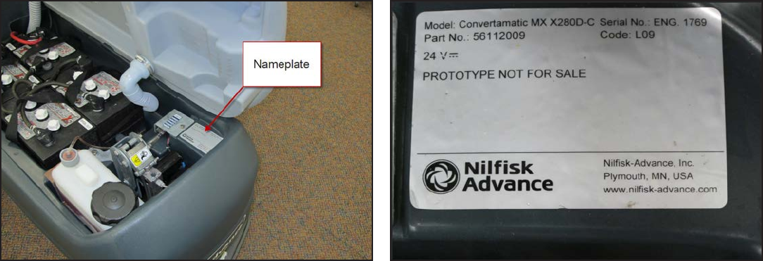
General Machine Description
Nameplate
Service Manual: SC750, SC800, SC 750 ST, SC800 ST
Form Number 56043150 Page 10
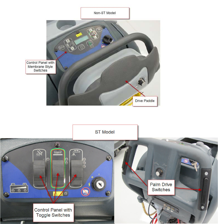
Know Your Machine
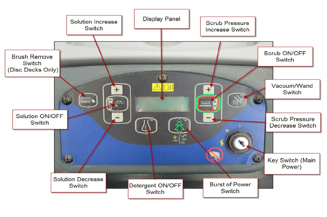
Control Panel – SC750 and SC800 (Membrane Switch Control Panel)
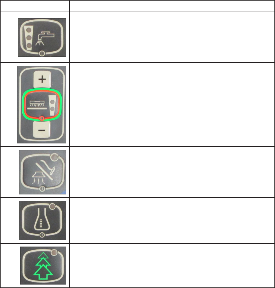
Switch Identification
• Key Switch (Main Power)
• Soluon ON/OFF Switch
• Soluon Increase Switch
• Soluon Decrease Switch
• Detergent ON/OFF Switch
system.
• Display Panel
• Scrub ON/OFF Switch-
Service Manual: SC750, SC800, SC 750 ST, SC800 ST
Form Number 56043150 Page 11
• Scrub Pressure Increase Switch
• Scrub Pressure Decrease Switch
• Burst of Power Switch -
• Brush Remove Switch
remove the discs.
• Vacuum/Wand Switch
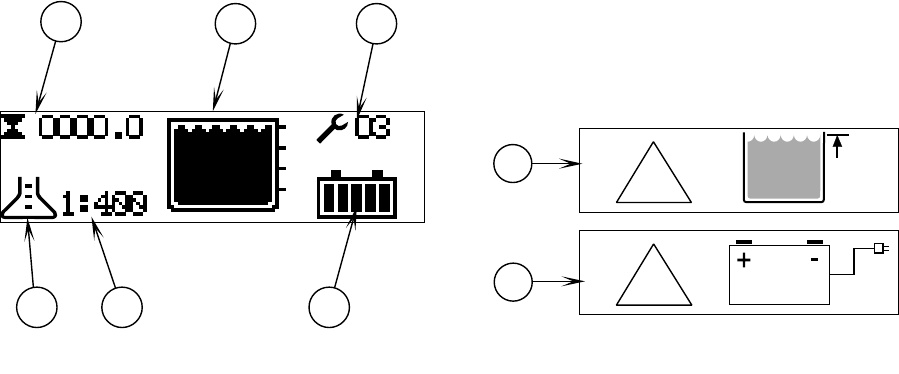
LCD Display
•
•
•
•
•
•
•
•
!
!
F1 F2 F3
F4 F5 F6
F7
F8
Service Manual: SC750, SC800, SC 750 ST, SC800 ST
Form Number 56043150 Page 12
Indicator Lights
Indicator Name Descripon
•
•
•
•
•
lit
•
Vacuum Indicator •
•
•
•
•
•
•
•
Service Manual: SC750, SC800, SC 750 ST, SC800 ST
Form Number 56043150 Page 13
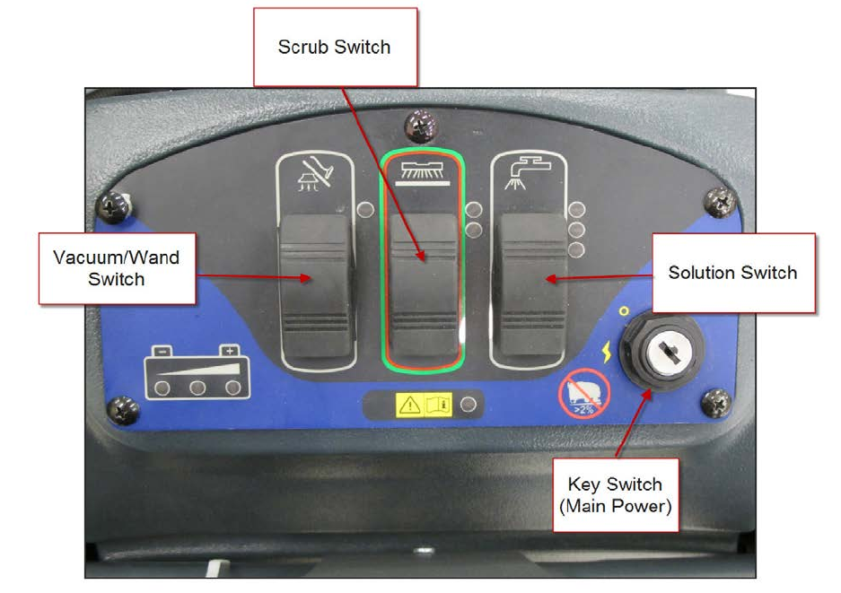
Control Panel – SC750 ST and SC800 ST (Toggle Switch Control Panel)
-
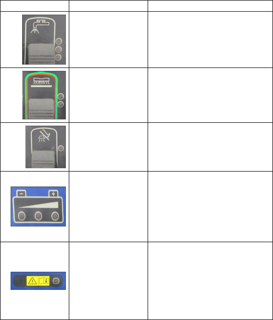
Switch Identification
• Key Switch
• Soluon Switch
• Vacuum/Wand Switch
• Scrub Switch
o
o -
Service Manual: SC750, SC800, SC 750 ST, SC800 ST
Form Number 56043150 Page 14
Indicator Lights
Indicator Name Descripon
•
•
•
•
•
lit
•
Vacuum Indicator •
•
•
•
o
o
o
o
•
o
o
•
•

Service Manual: SC750, SC800, SC 750 ST, SC800 ST
Form Number 56043150 Page 15
Machine Specifications – SC750 and SC750 ST
Model Name SC750
SC 750 ST
Volts
Sound Pressure Level
-
-

Service Manual: SC750, SC800, SC 750 ST, SC800 ST
Form Number 56043150 Page 16
Machine Specifications – SC800 and SC800 ST
Model Name SC 800
SC800 ST
V
Sound Pressure Level
-
-
-

Service Manual: SC750, SC800, SC 750 ST, SC800 ST
Form Number 56043150 Page 17
Machine Maintenance
MAINTENANCE ITEM Daily Weekly Monthly Yearly
X
X
-
X
X
X
-
X
System X
X
X
X
X
X
X
X
X
•
•
hours.
•
drive motors.
•
Important
-
ranty Statement.
Service Manual: SC750, SC800, SC 750 ST, SC800 ST
Form Number 56043150 Page 18
Lubricating the Machine
•
•
•
•
•
•
Service Manual: SC750, SC800, SC 750 ST, SC800 ST
Form Number 56043150 Page 19
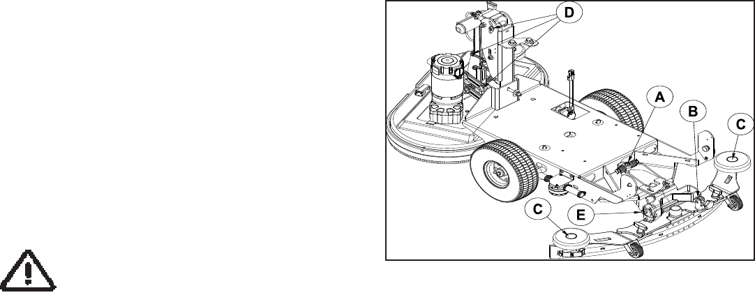
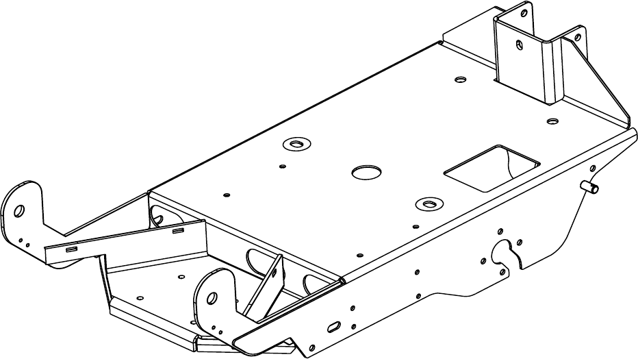
Chassis System
Functional Description
The chassis is made up of heavy gauge steel and supports the drive transaxle, caster wheel, brush deck, squeegee assem-
bly and machine body.
Service Manual: SC750, SC800, SC 750 ST, SC800 ST
Form Number 56043150 Page 20
Control system
Functional Description
There are two controllers on the machine, a Main Machine Controller and a Drive Motor Controller.
The Main Machine Controller operates the oor cleaning funcons of scrub, soluon and vacuum based on operator
requests and other inputs. It is located directly behind the operator control panel. It is capable of storing and display-
ing many fault codes. In addion to fault codes, it supports special modes of operaon called “Programming Mode” and
“Service Test Mode”. The programming mode is used primarily for “telling” the controller how the machine is equipped
so that it can operate accordingly. The service test mode is a powerful and convenient diagnosc feature that allows a
technician to request specic outputs to operate regardless of current inputs.
The Drive Motor Controller (Speed Controller) operates the drive motor that propels the machine based on operator
requests. (See the secon on Wheel System, Tracon for more informaon)
Service Manual: SC750, SC800, SC 750 ST, SC800 ST
Form Number 56043150 Page 21
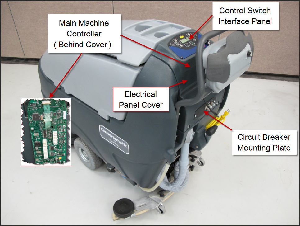
Component Locations
• Electrical Panel Cover
• Circuit Breaker Mounng Plate
• Control Switch Interface Panel
• Main Machine Controller

Service Manual: SC750, SC800, SC 750 ST, SC800 ST
Form Number 56043150 Page 22
Troubleshooting
Fault Codes
SC750 and SC800 models - Any error codes detected by the Main Machine Controller will be displayed on the LCD display
as they occur.
SC750 ST and SC800 ST models – Acve faults are displayed as a blink code on the fault code indicator light. The code will
be a two digit code. The rst digit will ash out followed by a short pause. Then the second digit will ash out followed
by a long pause. (On, short pause, On, On, long pause is a code 1,2)
If mulple codes are present, the codes will appear in order unl all have been displayed. Then the sequence will repeat
again.
Fault Code Table
For SC750 and SC800 models, refer to the column “LCD Display Code”. For SC750 ST and SC800 ST models, refer to the
“ST Blink Code” column.
LCD
Display
Code
ST
Blink
Code
Code
Denion
Explanaon / Code Seng Condions / Flash Indicator
/ Disables / Check
31,1 Drive Motor Controller
Fault
The Drive Motor Controller has seen a problem and
has set a “Trip Code”. Trip codes are grouped into “Trip
Types” (On “Non-ST” models, count the Detergent LED
ashes to obtain the specic Drive system “Trip Type”
value. On “ST” models, count the High Soluon Flow LED
ashes. See the Wheel System, Tracon chapter, Trouble-
shoong secon for addional informaon)
Disables: Detergent, Soluon, Brush Motors.
41,2 Scrub Deck Li Actuator
Circuit Over Current
Excessive current draw was sensed. Code sets at approxi-
mately 5.8 amps or more.
Disables: Brush Head Actuator.
Check for shorted actuator, mechanical binding of actua-
tor linkage, shorted wiring.

Service Manual: SC750, SC800, SC 750 ST, SC800 ST
Form Number 56043150 Page 23
LCD
Display
Code
ST
Blink
Code
Code
Denion
Explanaon / Code Seng Condions / Flash Indicator
/ Disables / Check
5 1,3 Brush Motor Circuit
Over Current
Excessive current draw was sensed. Code sets at approxi-
mately 60 amps or more.
Check for shorted motor, mechanical binding of motor
sha, current sense wire connecons, ground connec-
ons.
7 1,4 Vacuum Motor Circuit
Over Current
Excessive current draw was sensed. Code sets at approxi-
mately 25 amps or more.
Check for shorted motor, current sense wire connecons,
ground connecons.
8 1,5 Soluon Solenoid Circuit
Over Current
Excessive current draw was sensed. Code sets at approxi-
mately 0.7 amps or more.
Check for shorted solenoid winding, shorted wiring.
92,1 Vacuum Contactor Coil
Circuit Over Current
Excessive current draw was sensed. Code sets at approxi-
mately 0.1 amps or more.
Check for shorted contactor winding, shorted wiring.
10 2,2 Brush Contactor Coil
Circuit Over Current
Excessive current draw was sensed. Code sets at approxi-
mately 0.7 amps or more.
Check for shorted contactor winding, shorted wiring.
11 (N/A) Detergent Pump Circuit
Over Current
Excessive current draw was sensed.
Check for shorted pump winding, shorted wiring.
12 (N/A) Brush Remove Contactor
Coil Over Current
Excessive current draw was sensed. Code sets at approxi-
mately 0.1 amps or more.
Check for shorted contactor winding, shorted wiring
30 2,3 Soluon Solenoid Circuit
Open
The Main Machine Controller has turned the soluon
solenoid circuit on but it is not sensing any current ow.
(Senses <= 20mAmps for 5 seconds).
Check for open solenoid winding, open wiring.
31 2,4 Brush Motor Circuit
Open
The Main Machine Controller has energized the Brush
Contactor but it is not sensing any current ow through
the brush motor ground circuit for at least 5 seconds.
(Senses <= 4 Amps for 5 seconds and code 35 is not ac-
ve)
Check Motor, Contactor contacts, Wiring.

Service Manual: SC750, SC800, SC 750 ST, SC800 ST
Form Number 56043150 Page 24
LCD
Display
Code
ST
Blink
Code
Code
Denion
Explanaon / Code Seng Condions / Flash Indicator
/ Disables / Check
32 2,5 Scrub Deck Li Actuator
Circuit Open
The Main Machine Controller is trying to move the actua-
tor but it is not sensing any current ow. (Senses <= 100
m Amps for 5 seconds).
Check Actuator, wiring.
33 3,1 Vacuum Motor Circuit
Open
The Main Machine Controller has energized the Vacuum
Contactor but it is not sensing any current ow through
the vacuum motor ground circuit for at least 5 seconds.
(Senses<= 3 Amps for 5 second and Fault Code 36 is not
acve)
Check motor, wiring.
35 3,2 Brush Contactor Coil
Circuit Open
The Main Machine Controller has aempted to energize
the Brush Contactor but it is not seeing any current ow.
(Senses <= 20 m Amps for 5 seconds).
Check for open Contactor winding, wiring.
36 3,3 Vacuum Contactor Coil
Circuit Open
The Main Machine Controller has aempted to energize
the Vacuum Contactor but it is not seeing any current
ow. if (Senses <= 20 m Amps for 5 seconds)
Check for open Contactor winding, wiring.
37 (N/A) Detergent Pump Circuit
Open
The Main Machine Controller has energized the deter-
gent pump but it is not sensing any current ow. (Senses
<= 30 m Amps for 5 seconds).
Check for open pump winding, wiring.
38 (N/A) Brush Remove Contactor
Coil Circuit Open
The Main Machine Controller has aempted to energize
the Brush Remove Contactor but it is not seeing any cur-
rent ow. (Senses <= 20 m Amps for 5 seconds)
Check for open Contactor winding, wiring.
60 3,4 Brush Motor Contactor
Stuck Closed
The Main Machine Controller is sensing current ow
through the Brush Motor ground circuit when it has not
energized the Brush Motor Contactor (Senses >= 4 Amps
for 5 seconds and Fault Code 63 is not acve)
Check for “welded” contacts.
61 3,5 Vacuum Motor Contactor
Stuck Closed
The Main Machine Controller is sensing current ow
through the Vacuum Motor ground circuit when it has
not energized the Vacuum Motor Contactor (Senses >=
3 Amps for 5 seconds and Fault Code 64 and 65 are not
acve)
Check for “welded” contacts.

Service Manual: SC750, SC800, SC 750 ST, SC800 ST
Form Number 56043150 Page 25
LCD
Display
Code
ST
Blink
Code
Code
Denion
Explanaon / Code Seng Condions / Flash Indicator
/ Disables / Check
62 4,1 Soluon Solenoid Circuit
Stuck On
The Main Machine controller is sensing current ow
through its internal switch for the soluon solenoid cir-
cuit when it has not requested that the switch be turned
on. (Senses >= 20 m Amps for 5 seconds).
63 4,2 Brush Contactor Coil
Circuit Stuck On
The Main Machine controller is sensing current ow
through its internal switch for the Brush Contactor Coil
circuit when it has not requested that the switch be
turned on. (Senses >= 20 m Amps for 5 seconds).
64 4,3 Vacuum Contactor Coil
Circuit Stuck On
The Main Machine controller is sensing current ow
through its internal switch for the Vacuum Contactor
Coil circuit when it has not requested that the switch be
turned on. (Senses >= 20 m Amps for 5 seconds).
65 (N/A) Brush Remove Contactor
Coil Circuit Stuck On
The Main Machine controller is sensing current ow
through its internal switch for the Brush Remove Contac-
tor Coil circuit when it has not requested that the switch
be turned on. (Senses >= 20 m Amps for 5 seconds).
70 4,4 Corrupt Communicaon
From On-Board Baery
Charger
The Baery Charger did not properly repeat the charging
prole message back to the Main Machine Controller.
Service Manual: SC750, SC800, SC 750 ST, SC800 ST
Form Number 56043150 Page 26
Service Test Mode
Some outputs (like the scrub brush motors) are only turned on when other condions are met, such as when the ma-
chine is moving. It can be dicult to check for voltage to the scrub brush motors while the machine is moving. Also, if
voltage is not present, it leaves in queson what other condions may not have been met yet. The Service Test Mode
solves these problems for the technician. In Service Test Mode the technician can request that the Main Machine Con-
troller ignore all other condions and directly turn on the scrub brush motors as well as other outputs. Service Test
mode can also be used to verify that certain inputs are seen by the controller. The concept is the same for all models
but the procedure is very dierent depending on whether you are working on an” ST” model (control panel with rocker
switches – SC750 ST and SC800 ST) or a “non-ST” model (control panel with membrane switches – SC750 and SC800).
See appropriate secons below.
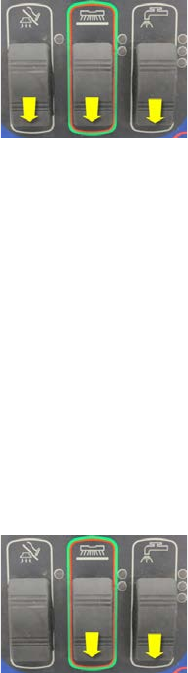
Service Test Mode –SC750 ST and SC800 ST Models (Control Panel with rocker switches)
To enter the service test mode: (Start with the baery charger unplugged and the key o)
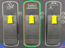
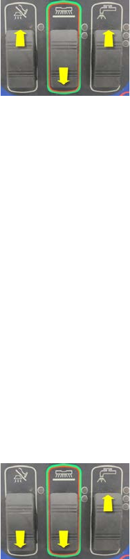
1. Hold all three switches (Vacuum, Scrub and Soluon) in the up (forward) posion while turning the key on.
2. Wait approximately 3 seconds unl all of the LEDs light up and then turn o. The low soluon ow indicator light
should remain on to conrm that you are in the service test mode.
Now that you are in service test mode, you can request that the controller operate the various outputs and verify certain
inputs via the indicator light operaon. If a fault occurs the Fault LED will display the fault.
To exit the service test mode: Turn the Key Switch o.
Output Tests
Brush Deck Li Actuator – Press the Scrub Switch forward to move the actuator downward to the next posion. Watch
for the actuator to move. Press the Scrub Switch backward to move the actuator up one posion. The Scrub Indicator
LEDs indicate the current actuator posion. Neither LED is ON when deck is raised, lower LED is ON when deck is at
low scrub pressure, both are on for high pressure. Machines with disc scrub decks have three posions while cylindrical
decks have only two. Note: If the switch inputs are not reporng correct informaon, the controller will not understand
the current actuator posion and will not aempt to move the actuator.
Soluon Solenoid – Press the Soluon Switch forward to cycle the soluon solenoid on and o. The high soluon ow
indicator will be on while in the test mode. Listen for the Solenoid to click on and o. Press the Soluon Switch forward
again to stop cycling the solenoid.
Brush Motor Contactor – Press the Soluon Switch backward to energize the brush motor contactor. The medium
soluon ow indicator will be ON when energizing the contactor. Listen for the contactor to click and look to see if the
brushes are rotang. Press the Soluon Switch backward again to de-energize the contactor.
Vacuum Motor Relay – Press the Vacuum Switch forward to energize the Vacuum Motor Relay. The Vacuum Indicator
will be ON when energizing the relay. The vacuum motor should come ON. Press the Vacuum Switch backward to de-
energize the relay.
Service Manual: SC750, SC800, SC 750 ST, SC800 ST
Form Number 56043150 Page 27
Input Tests
Speed Control Forward/Reverse Signal –The yellow Baery LED turns on when in the service test mode whenever the
speed controller tells the Main Machine Controller that it is aempng to drive the machine either forward or reverse.
This is useful when diagnosing a no drive problem. If the light comes on when you aempt to drive the machine forward,
it means that the Drive Controller has seen the request and responded to it.
Speed Control Reverse Signal – The green Baery LED turns on when in the service test mode whenever the speed con-
troller tells the Main Machine Controller that it is aempng to drive the machine in reverse.
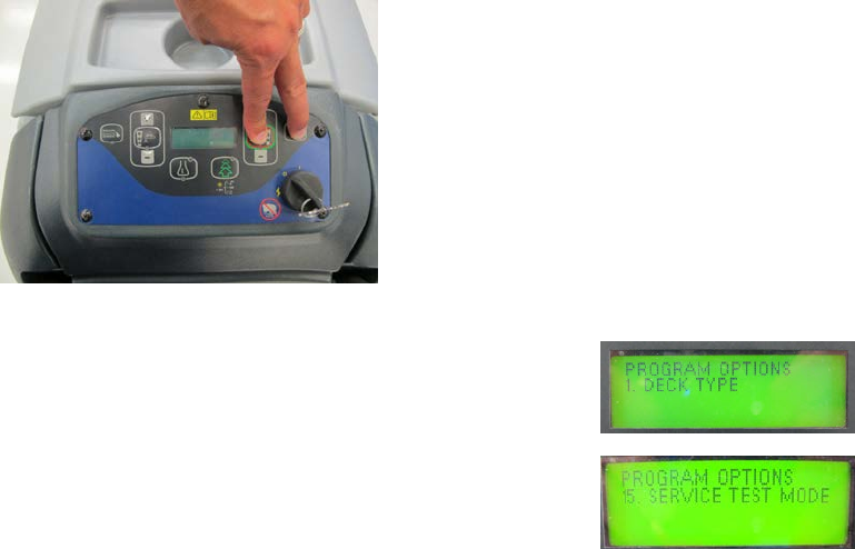
Service Test Mode – SC750 and SC 800 Models (Control Panel with membrane switches)
To enter the service test mode: (Start with the baery charger unplugged and the key o)
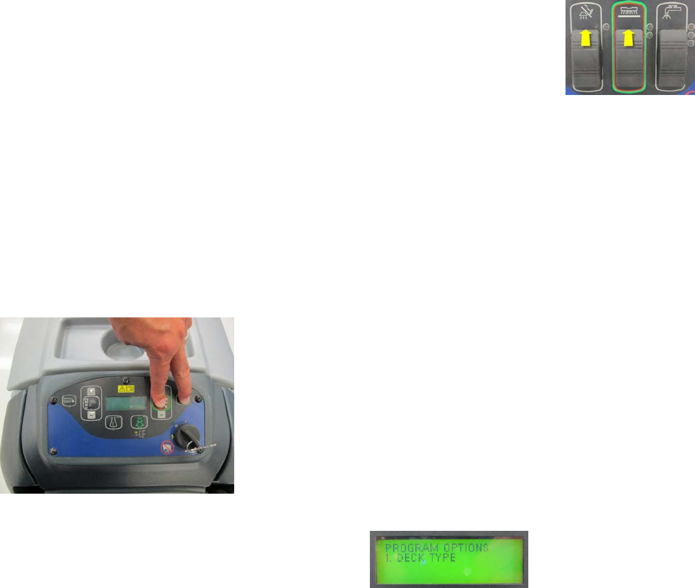
1. Press and hold the scrub on/o switch and vacuum/wand switch together.
2. While holding both switches, turn the main power key switch to the on posion.
3. Connue to hold both switches about 3 seconds unl the
display shows “Programming Opons”, then release the
switches.
4. Press the soluon decrease buon unl you see “SERVICE
TEST MODE” then press the soluon on/o switch to
enter the Service Test Mode. (Note: Turn Key Switch o to
exit mode).
Now that you are in service test mode, you can request that the controller operate the various outputs and verify certain
inputs via the LCD display. If any faults occur during tesng, they will be displayed as well.
Output Tests
Brush Deck Li Actuator – Press the Scrub Increase Switch to move the actuator downward to the next posion. Watch
for the actuator to move. Press the Scrub Decrease Switch to move the actuator up one posion. The LCD display for
“DECK” will show “On” when the controller is trying to move the actuator and “O” when it is not. Machines with disc
scrub decks have three posions while cylindrical decks have only two. Note: If the switch inputs are not reporng cor-
rect informaon, the controller will not understand the current actuator posion and will not aempt to move the actua-
tor.
Brush Remove Contactor (Relay) – Press the Brush Remove Switch to energize the brush remove relay. (During this test
the Brush Motor Contactor will be de-energized) Listen closely for the relay to click. (It is a so click. It won’t be heard
in a noisy room.) Press the switch again to de-energize the relay. The LCD display for “BREM” will show “On” when the
controller is trying to energize the relay and “O” when it is not.
Service Manual: SC750, SC800, SC 750 ST, SC800 ST
Form Number 56043150 Page 28
Soluon Solenoid – Press the Soluon Switch to cycle the soluon solenoid on and o. Listen for the Solenoid to click on
and o. Press the switch again to stop cycling the solenoid. The LCD display for “SOL” will show “On” as long as the test
mode is running; that is when the controller is trying to cycle the solenoid both on and o. The LCD display for “SOL” will
show “O” when the test mode is ended.
Brush Motor Contactor – Press the Scrub On/O Switch to energize the brush motor contactor. Listen for the contactor
to click and look to see if the brushes are rotang. Press the switch again to de-energize the contactor. The LCD display
for “BR” will show “On” when the controller is trying to energize the contactor and “O” when it is not.
Vacuum Motor Relay – Press the Vacuum/Wand Switch to energize the Vacuum Motor Relay. The vacuum motor should
come on. Press the switch again to de-energize the relay. The LCD display for “VAC” will show “On” when the controller is
trying to energize the relay and “O” when it is not.
Detergent Pump – Press the Detergent On/O Switch to cycle the detergent pump on and o. Listen for the pump to op-
erate. Press the switch again to stop cycling the pump. The LCD display for “CP” will show “On” as long as the test mode
is running; that is when the controller is trying to cycle the pump both on and o. The LCD display for “CP” will show
“O” when the test mode is ended.
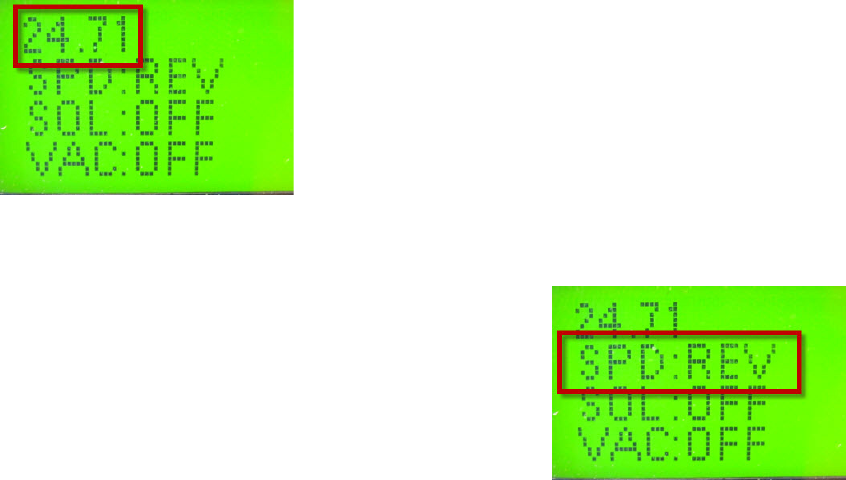
Input Tests
When in the service test mode the LCD display can be used to validate certain inputs.
Baery Voltage – The LCD will display the baery voltage seen by the Main Machine Controller when in the Service test
mode.
Speed Control Forward/Reverse Signal AND Reverse Signal – The Main Machine controller interprets these two signals
that it receives from the Drive Motor Controller and displays the informaon on the LCD.
• OFF = Neutral
• FWD = Forward
• REV = Reverse
Move the drive paddle in all three direcons. If all 3 values
are displayed correctly both of these inputs are working
correctly.
Service Manual: SC750, SC800, SC 750 ST, SC800 ST
Form Number 56043150 Page 29
Programming Options –SC750 ST and SC800 ST Models (control panel with rocker switches)
Main Machine Controller special program opons allow the service repairperson to match the control board to the
specic model equipment and to user preferences. They also allow adjustments to some machine funcons, and provide
a way to see the controller’s revision level. On ST models each program opon mode is accessed by pressing a specic
conguraon of buons while turning the key on.
Mandatory Program Options
These opons are used to “inform” the Main Machine Controller how the machine is equipped. They must be set any-
me the Main Machine Controller is replaced and they must be set correctly for the machine to operate as it should.
Scrub Deck Type – There are 3 scrub deck opons. This funcon congures the control unit current sengs, ow rate
sengs, and scrub pressure sengs for each of the scrub deck types.
To check or change the seng:
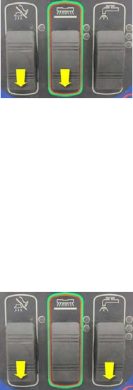
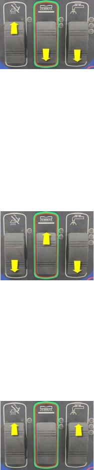
1. While pressing and holding the vacuum, scrub and soluon switches backward, turn the
key switch on.
2. Wait about 3 seconds unl all of the LEDs light up and then go o. Release the switches.
The Regular Scrub Pressure and Heavy Scrub Pressure Indicators will remain on and the fault indicator will be ashing a
numeric value that represents the current seng. To change the seng, press the soluon switch forward to increase
the value or backwards to decrease the value. To save the seng, press the scrub switch forward (All LEDs will turn on)
then turn o the key switch.
• 1 blink = 28 Inch Cylindrical Brushes
• 2 blinks = 26 Inch Disc Brushes
• 3 blinks = 34 Inch Disc Brushes
Baery Charger Selecon –This funcon is used to inform the Main Machine Controller whether or not the machine
is equipped with the oponal S.P.E. on-board baery charger (The S.P.E charger was used on early machines. Later
machines use the Delta-Q IC650 baery charger). It is also used to inform the controller of what kind of baeries the
machine is equipped with. The Main Machine Controller will request a specic charging prole from the S.P.E baery
charger to match the baeries.
To check or change the seng:
1. While pressing and holding the scrub and soluon switches backward, turn the key
switch on.
2. Wait about 3 seconds unl all of the LEDs light up and then go o. Release the switches.
The red baery Indicator will remain on and the fault indicator will be ashing a numeric value that represents the cur-
rent seng. To change the seng, press the soluon switch forward to increase the value or backwards to decrease the
value. To save the seng, press the scrub switch forward (All LEDs will turn on) then turn o the key switch.
• 1 blink = Not equipped with on-board charger
• 2 blinks = On-board charger with WET 25A baeries (Use with 242 AH WET Baeries 56206079 or 310 AH WET
Baeries 56391391)
Service Manual: SC750, SC800, SC 750 ST, SC800 ST
Form Number 56043150 Page 30
• 3 blinks = On-board charger with AGM DISCOVER 25A baeries (Use with 312 AH AGM Baeries 56315959)
• 4 blinks = On-board charger with GEL EXIDE 25A baeries
• 5 blinks = On-board charger with GEL-AGM 25A baeries
• 6 blinks = On-board charger with WET 15A baeries
• 7 blinks = On-board charger with GEL-AGM 15A baeries
Additional Program Options
The following opons can be used by the technician or to set user preferences.
Low Voltage Cut Out Selecon –The purpose of the low baery voltage cutout funcon is to help prolong baery life.
The scrub deck will be raised and the brush motors, vacuum motor, and soluon solenoid valve will turn OFF automa-
cally and cease to funcon when the baeries discharge to the selected cutout level. The cutout level is adjustable be-
tween two sengs. The standard seng (wet cell/lead acid) is 20.55 volts and alternate seng
(AGM) is 21.75 volts.
To check or change the seng:
1. While pressing and holding the vacuum and scrub switches backward, turn the key switch
on.
2. Wait about 3 seconds unl all of the LEDs light up and then go o. Release the switches.
The yellow Baery Indicator will remain on and the fault indicator will be ashing a numeric value that represents the
current seng. To change the seng, press the soluon switch forward to increase the value or backwards to decrease
the value. To save the seng, press the scrub switch forward (All LEDs will turn on) then turn o the key switch.
• 1 blink = Wet Baery 80%, 20.55V
• 2 blinks = Maintenance Free Baery 70%, 21.75V
Lock Out Brush Pressure - It is possible to lock out either brush pressure seng: Low or High.
During normal operaon, the brush pressure that is locked out will not be able to be selected.
To check or change the seng:
1. While pressing and holding the vacuum and soluon switches backward, turn the key
switch on.
2. Wait about 3 seconds unl all of the LEDs light up and then go o. Release the switches.
The green Baery Indicator will remain on and the fault indicator will be ashing a numeric value that represents the cur-
rent seng. To change the seng, press the soluon switch forward to increase the value or backwards to decrease the
value. To save the seng, press the scrub switch forward (All LEDs will turn on) then turn o the key switch.
• 1 blink = No pressure seng locked out.
• 2 blinks = Low pressure seng locked out.
• 3 blinks = High pressure seng locked out.
Service Manual: SC750, SC800, SC 750 ST, SC800 ST
Form Number 56043150 Page 31
Lock Out Soluon Flow Rate - It is possible to lock out any one or more of the soluon ow rate sengs. During normal
operaon, the ow rate(s) that are locked out will not be able to be selected.
To check or change the seng:
1. While pressing and holding the vacuum and soluon switches forward and the scrub
switch backwards, turn the key switch on.
2. Wait about 3 seconds unl all of the LEDs light up and then go o. Release the switches.
The Vacuum Indicator will remain on and the Fault Indicator will be ashing a numeric value that represents the cur-
rent seng. To change the seng, press the soluon switch forward to increase the value or backwards to decrease the
value. To save the seng press the scrub switch forward (All LEDs will turn on) then turn o the key switch.
• 1 blink = No ow rate locked out.
• 2 blinks = Low ow rate locked out.
• 3 blinks = Medium ow rate locked out.
• 4 blinks = High ow rate locked out.
• 5 blinks = Low and medium ow rates locked out.
• 6 blinks = Low and high ow rates locked out.
• 7 blinks = Medium and high ow rates locked out.
Recovery Tank Full Enable/Disable – It is possible to enable or disable the Recovery Tank Full automac shuto feature.
Enable means that the automac shuto feature is turned on; disable means that the automac shuto feature is turned
o.
To check or change the seng:
1. While pressing and holding the vacuum and scrub switches backward and the soluon
switch forward, turn the key switch on.
2. Wait about 3 seconds unl all of the LEDs light up and then go o. Release the switches.
The Heavy Scrub Pressure Indicator will remain on and the Fault Indicator will be ashing a numeric value that repre-
sents the current seng. To change the seng, press the soluon switch forward to increase the value or backwards to
decrease the value. To save the seng, press the scrub switch forward (All LEDs will turn on) then turn o the key switch.
• 1 blink = Enabled
• 2 blinks = Disabled
Service Manual: SC750, SC800, SC 750 ST, SC800 ST
Form Number 56043150 Page 32
Restore Factory Defaults – This funcon is used to reset all sengs to factory default values. If this is done, the next
me the key is turned on, it will act as though a new controller has been installed and “force” you to set the mandatory
program opons before the machine will operate normally.
To check or change the seng:
1. While pressing and holding the vacuum switch forward and scrub and soluon switches
backward, turn the key switch on.
2. Wait about 3 seconds unl all of the LEDs light up and then go o. Release the switches.
The Regular Scrub Pressure Indicator will remain on and the Fault Indicator will be ashing a numeric value that repre-
sents the current seng. To change the seng, press the soluon switch forward to increase the value or backwards to
decrease the value. To save the seng, press the scrub forward (All LEDs will turn on) then turn o the key switch.
• 1 blink = No
• 2 blinks = Yes
Fault Recall – The fault indicator normally ashes out “current” codes only. This funcon is used by a technician to check
for “historical codes” and clear them.
To check or clear historical codes:
1. While pressing and holding the vacuum and soluon switches backward and the scrub
switch forward, turn the key switch on.
2. Wait about 3 seconds unl all of the LEDs light up and then go o. Release the switches.
The High Soluon Flow Indicator will remain on and the Fault Indicator will be ashing out all historical codes set since
the last me they were cleared. To exit this funcon without clearing codes, press the scrub switch forward. To clear
historical codes press the soluon switch forward.
Fault Detecon - Normally, the Main Machine Controller will perform checks of the electrical system during operaon. If
a fault occurs in a parcular system, that system (and possibly others) will be shut down. This can make troubleshoong
the system dicult. This opon will allow service personnel to disable some of the fault detecon checks to facilitate
troubleshoong. This will not disable the over-current protecon on any of the systems.
To check or change the seng:
1. While pressing and holding the vacuum and soluon switches forward, turn the key
switch on.
2. Wait about 3 seconds unl all of the LEDs light up and then go o. Release the switches.
The Medium Soluon Flow Indicator will remain on and the Fault Indicator will be ashing a numeric value that repre-
sents the current seng. To change the seng, press the soluon switch forward to increase the value or backwards to
decrease the value. To save the seng, press the scrub switch forward (All LEDs will turn on) then turn o the key switch.
• 1 blink = Fault Detecon Enabled
• 2 blinks = Fault Detecon Disabled
Service Manual: SC750, SC800, SC 750 ST, SC800 ST
Form Number 56043150 Page 33
Soware Revision Code – This funcon is used to display the soware revision. The Fault LED blinks a two-part code to
indicate the revision of the soware that is currently programmed into the microcontroller program memory. The rst
part of the code indicates the released revision leer: 1 blink = revision A, 2 blinks = revision B, etc.
To check the revision:
1. While pressing and holding the vacuum and scrub switches forward, turn the key switch
on.
2. Wait about 3 seconds unl all of the LEDs light up and then go o. Release the switches.
The Low, Medium and High Soluon Flow indicators will remain on and the fault indicator will ash out the revision code.
Programming Options – SC750 and SC800 models (Control Panel with membrane switches)
Main Machine Controller special program opons allow the service repairperson to match the control board to the spe-
cic model equipment and to user preferences. They also allow adjustments to some machine funcons, and provide a
way to see the controller’s revision level. On SC750 and SC800 models, all program opon modes are entered through a
“hidden menu” that is displayed on the LCD.
To enter the Programming Opons mode: (Start with the baery charger unplugged and the key o)
1. Press and hold the scrub ON/OFF switch and Vacuum/Wand switch together.
2. While holding both switches, turn the Key Switch to the ON posion.
3. Connue to hold both switches about 3 seconds unl the
display shows “Programming Opons”, then release the
switches.
4. Scroll through the menu using the Soluon Increase and Decrease switches unl you get to the desired program-
ming opon.
5. Press the Soluon On/O switch to enter the mode.
Service Manual: SC750, SC800, SC 750 ST, SC800 ST
Form Number 56043150 Page 34
Mandatory Program Options
These opons must be set to correctly match the Main Machine Controller to the machine.
DECK TYPE – There are 5 possible scrub deck opons (Early model display names are dierent). This funcon congures
the control unit current sengs, ow rate sengs, and scrub pressure sengs for each of the scrub deck types.
• REV 2 Deck
• 28 INCH / 71 cm CYL or 28 INCH CYL / BA756C (Early models)
• 32 INCH / 81 cm CYL or 32 INCH CYL (Early models)
• 26 INCH / 66 cm DISC or 26 INCH DISC (Early models)
• 28 INCH / 71 cm DISC or 28 INCH DISC / BA756 (Early models)
• 34 INCH / 86 cm DISC or 34 INCH DISC / BA856 (Early models)
To change the seng:
1. Scroll through the menu using the Soluon Increase and Decrease switches unl you get to the desired value.
2. To save and go back to the main menu, press the scrub ON/OFF switch.
MACHINE PLATFORM – This funcon congures the control unit for the machine size (Early model display names are
dierent). Select between 21-gallon medium-plaorm machine (SC750, SC750 ST) or 25-gallon large-plaorm machine
(SC800, SC800 ST). This seng will aect the soluon level, soluon, and chemical ow rate calculaons in the rmware.
• SC750 (21 GAL / 80 LTR) or MX (21 GAL / 80 LITRE) (Early models)
• SC800 (25 GAL / 95 LTR or LX (25 GAL / 95 LITRE) (Early models)
To change the seng:
1. Scroll through the menu using the Soluon Increase and Decrease switches unl you get to the desired value.
2. To save and go back to the main menu, press the scrub ON/OFF switch.
CHEMICAL SELECTION – This funcon is used to let the controller know whether or not the machine is equipped with the
oponal Detergent (Chemical) Mixing system and what brand to display upon power up. If it is equipped, it also needs to
know what geographic locaon the machine is used in for displaying the detergent rao as expected in that region. North
America mode: Shows chemical rao using X: XXX notaon (example 1: 300) and the “Advance” brand upon power
up for the “Americas market” (North, South and Central America). Global mode: (Outside of North, South and Central
America) Shows chemical rao using percentage notaon (example 0.3%) and the “Nilsk-Advance” brand upon power
up. In o mode, the chemical icon and rao are not displayed on the LCD.
• NO ONBOARD CHEMICAL
• N.AMERICA CHEM MODE
• GLOBAL CHEM MODE
To change the seng:
1. Scroll through the menu using the Soluon Increase and Decrease switches unl you get to the desired value.
2. To save and go back to the main menu, press the scrub ON/OFF switch.
Service Manual: SC750, SC800, SC 750 ST, SC800 ST
Form Number 56043150 Page 35
DETERGENT MODE – This funcon is used to congure the way the EcoFlex system behaves or to disable it. Dierent
geographic locaons desire dierent EcoFlex behavior. This mode provides the ability to match the behavior to market
area desires.
• OFF – Disables EcoFlex feature
• MODE 1 – Expected to be used in combinaon with N.AMERICA CHEM MODE.
• MODE 2 – Expected to be used alone or in combinaon with GLOBAL CHEM MODE.
To change the seng:
1. Scroll through the menu using the Soluon Increase and Decrease switches unl you get to the desired value.
2. To save and go back to the main menu, press the scrub ON/OFF switch.
BATTERY CHARGER SELECTION –This funcon is used to inform the Main Machine Controller whether or not the ma-
chine is equipped with the oponal S.P.E. on-board baery charger (The S.P.E charger was used on early machines. Later
machines use the Delta-Q IC650 baery charger). It is also used to inform the controller of what kind of baeries the
machine is equipped with. The Main Machine Controller will request a specic charging prole from the S.P.E baery
charger to match the baeries.
• NONE (Use when not equipped with on-board baery charger)
• WET 25A (Use with 242 AH WET Baeries 56206079 or 310 AH WET Baeries 56391391)
• AGM DISCOVER 25A (Use with 312 AH AGM Baeries 56315959)
• GEL EXIDE 25A
• GEL-AGM 25A
• WET 15A
• GEL-AGM 15A
To change the seng:
1. Scroll through the menu using the Soluon Increase and Decrease switches unl you get to the desired value.
2. To save and go back to the main menu, press the scrub ON/OFF switch.
LOW VOLT CUTOUT - The purpose of the low baery voltage cutout funcon is to help prolong baery life. The scrub
deck will be raised and the brush motors, vacuum motor, and soluon solenoid valve will turn OFF automacally and
cease to funcon when the baeries discharge to the selected cutout level. The cutout level is adjustable between two
sengs. The standard seng (wet cell/lead acid) is 20.55 volts and alternate seng (AGM) is 21.75 volts.
• WET BATTERY 80%, LVC = 20.55V
• MAIN FREE BATTERY 70%, LVC = 21.75V
To change the seng:
1. Scroll through the menu using the Soluon Increase and Decrease switches unl you get to the desired value.
2. To save and go back to the main menu, press the scrub ON/OFF switch.
Service Manual: SC750, SC800, SC 750 ST, SC800 ST
Form Number 56043150 Page 36
Additional Program Options
The following opons can be used to set user preferences.
LOCKOUT BRUSH PRE - - For disc brush decks only, it is possible to lock out either the Low or High Brush Pressure seng.
During normal operaon the pressure seng(s) that are locked out will not be able to be selected.
• NONE
• LOW
• HIGH
To change the seng:
1. Scroll through the menu using the Soluon Increase and Decrease switches unl you get to the desired value.
2. To save and go back to the main menu, press the scrub ON/OFF switch.
LOCKOUT SOL FLOWS - - It is possible to lock out any one or more of the Soluon Flow Rate sengs. During normal op-
eraon, the ow rate(s) that are locked out will not be able to be selected.
• NONE
• LOW
• MEDIUM
• HIGH
• LOW & MEDIUM
• LOW & HIGH
• MEDIUM & HIGH
To change the seng:
1. Scroll through the menu using the Soluon Increase and Decrease switches unl you get to the desired value.
2. To save and go back to the main menu, press the scrub ON/OFF switch.
RECOVER TANK FULL - – It is possible to enable or disable the Recovery Tank Full automac shuto feature. Enable
means that the automac shuto feature is turned on. The system will shut o the vacuum motor if it senses the tank
is full. Disable means that the automac shuto feature is turned o. The system will not automacally shut o the
vacuum motor if it senses the tank is full.
• ENABLED
• DISABLED
To change the seng:
1. Scroll through the menu using the Soluon Increase and Decrease switches unl you get to the desired value.
2. To save and go back to the main menu, press the scrub ON/OFF switch.
Service Manual: SC750, SC800, SC 750 ST, SC800 ST
Form Number 56043150 Page 37
CHEMICAL RATE BIAS – This funcon allows a ne tuning of the detergent rao.
• NONE
• +10% MORE CHEMICAL
• -10% LESS CHEMICAL
To change the seng:
1. Scroll through the menu using the Soluon Increase and Decrease switches unl you get to the desired value.
2. To save and go back to the main menu, press the scrub ON/OFF switch.
RESTORE DEFAULTS - This funcon is used to reset all sengs to factory default values. If this is done, the next me the
key is turned on, it will act as though a new controller has been installed and “force” you to set the mandatory program
opons before the machine will operate normally.
• NO
• YES
To change the seng:
1. Scroll through the menu using the Soluon Increase and Decrease switches unl you get to the desired value.
2. To save and go back to the main menu, press the scrub ON/OFF switch.
DISPLAY REV LEVEL – Used to display the soware revision.
This is not a seng that can be changed. Aer viewing the revision value, press the scrub on/o switch to return to the
main menu.
FAULT RECALL - This funcon is used by a technician to check for “historical codes” and clear them. If no fault code is
present, the display should show a dash symbol ( - ). If the soluon on/o buon is pressed in the Fault Recall submenu,
the fault history shall be erased. Press the scrub on/o switch to return to the main menu.
FAULT DETECTION - Normally, the Main Machine Controller will perform checks of the electrical system during operaon.
If a fault occurs in a parcular system, that system (and possibly others) will be shut down. This can make troubleshoot-
ing the system dicult. This opon will allow service personnel to disable some of the fault detecon checks to facilitate
troubleshoong. This will not disable the over-current protecon on any of the systems.
• ENABLED
• DISABLED
To change the seng:
1. Scroll through the menu using the Soluon Increase and Decrease switches unl you get to the desired value.
2. To save and go back to the main menu, press the scrub ON/OFF switch.
Service Manual: SC750, SC800, SC 750 ST, SC800 ST
Form Number 56043150 Page 38
Removal and Installation
Main Machine Controller SC750 ST and SC800 ST Models (Early Build)
Note: Electronic devices like the Main Machine Controller are sensive to Electrostac Discharge (ESD). Before handling
the controller, touch a metal bench or shelf to discharge any electrical charge that may have built up in your body. Do not
walk around with a controller in your hands.
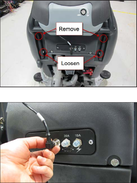
1. Empty recovery tank. Turn o key.
2. Remove upper handle mounng bolts, loosen lower mounng bolts and pivot handle assembly downward.
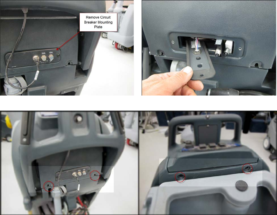
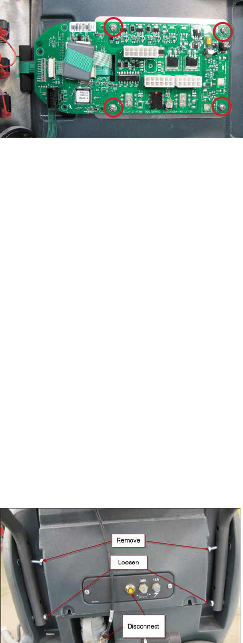
3. Remove circuit breaker mounng nuts.
4. Remove circuit breaker mount plate screws. Parally remove plate. Remove breakers from plate, then turn plate
and insert into cover opening.
5. Remove electrical panel cover mounng screws.
Service Manual: SC750, SC800, SC 750 ST, SC800 ST
Form Number 56043150 Page 39
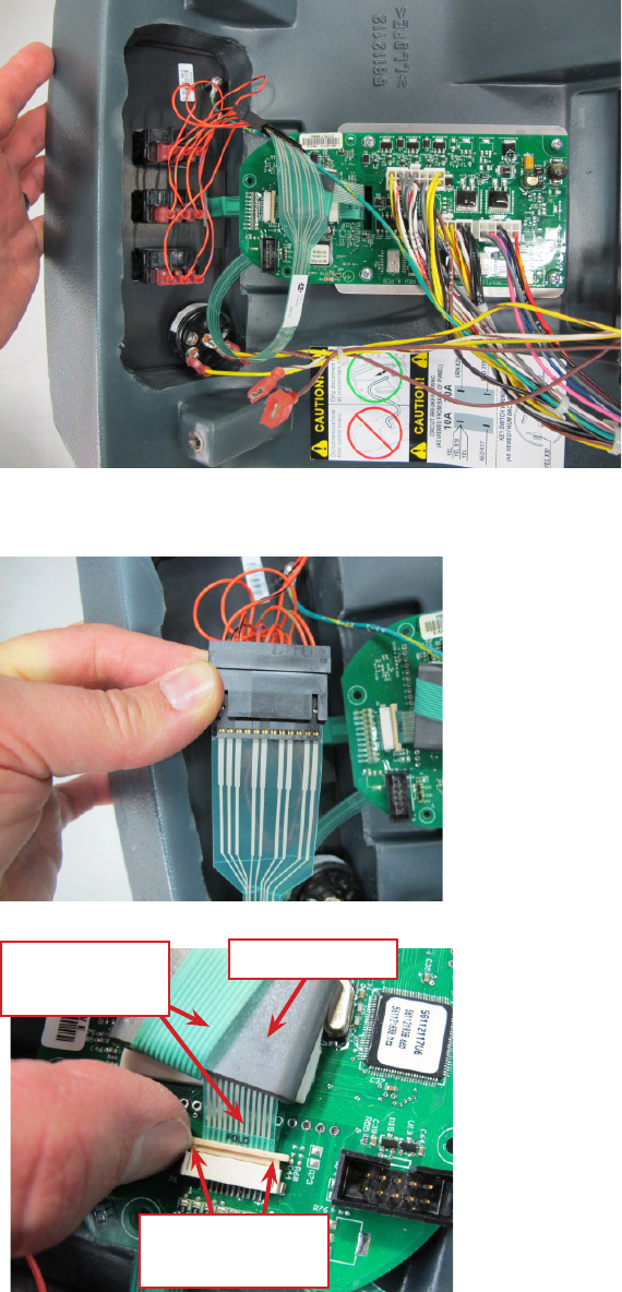
6. Tip cover away from machine and disconnect electrical connectors from the Main Machine Controller and Key
Switch. Remove the control switch interface panel ground screw.
7. Place electrical panel cover on work bench. Disconnect the “ribbon” connector to the control switches. (Note the
orientaon of the ribbon to the wiring connector. )
8. Release the control panel ribbon connecon and pull the ribbon free. Gently pull ribbon out of the ferrite bead.
Gently push to
release
Ferrite Bead
Control Panel
Ribbon
Service Manual: SC750, SC800, SC 750 ST, SC800 ST
Form Number 56043150 Page 40
9. Remove 4 screws securing the Main Machine Controller and remove it from the cover.
10. Reassemble in reverse order, taking care not to damage the printed circuit ribbons used to connect the circuit
board to the control switch interface panel.
11. Set Mandatory Program Opons - IMPORTANT! When a new controller is installed, it must rst be told how the
machine is equipped before it will work. The rst me the key is turned on, the controller wakes up in the pro-
gramming opon mode to “force” you to complete the sengs. In this special case, you will be walked through
seng the Scrub Deck Type and Baery Charger Selecon before the machine will operate. See Programming
Opons – SC750 ST and SC800 ST Models (Control Panel with rocker switches) - Mandatory Program Opons.
Main Machine Controller SC750 ST and SC800 ST Models (Later Build)
Minor changes were made to the electrical panel cover and circuit breaker panel to make the machine easier to
service. Follow the instructions for “Main Machine Controller SC750 and SC800 Models (control Panel with
membrane switches) Later build “ with the realization that some of the photos will not exactly match the ma-
chine you are working on.
Main Machine Controller SC750 and SC800 Models (Early Build)
Note: Electronic devices like the Main Machine Controller are sensive to Electrostac Discharge (ESD). Before handling
the controller, touch a metal bench or shelf to discharge any electrical charge that may have built up in your body. Do not
walk around with a controller in your hands.
1. Completely drain soluon tank. This is important for the soluon level sensor to work properly upon reassembly.
2. Turn o and remove key.
3. Disconnect Handle electrical connector. Remove top two handle bolts and loosen the lower two. Rotate Handle
Assembly down.
Service Manual: SC750, SC800, SC 750 ST, SC800 ST
Form Number 56043150 Page 41
4. Remove circuit breaker mounng plate screws. Parally remove plate. Remove breakers from plate, then turn
plate and insert into cover opening.
5. Remove electrical panel cover mounng screws.
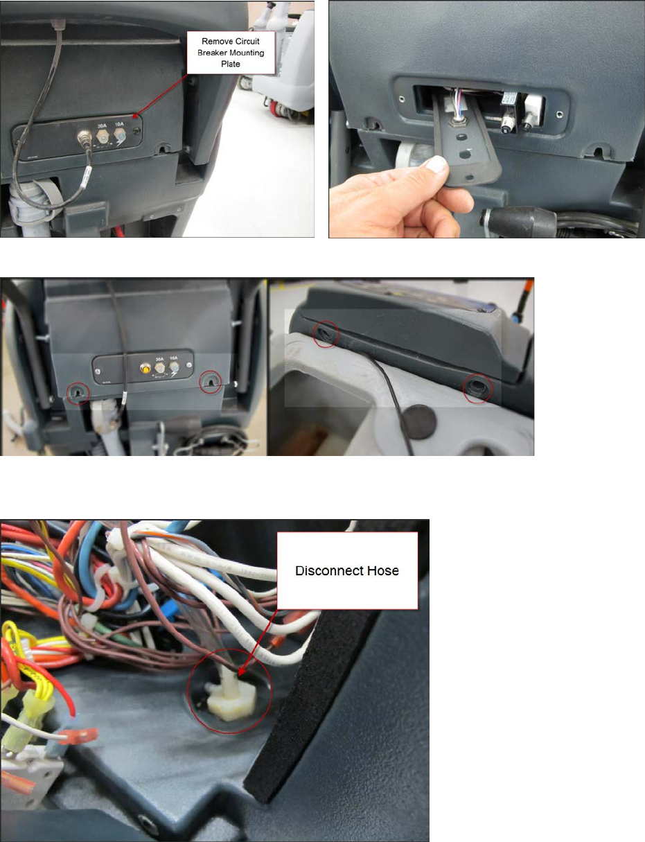
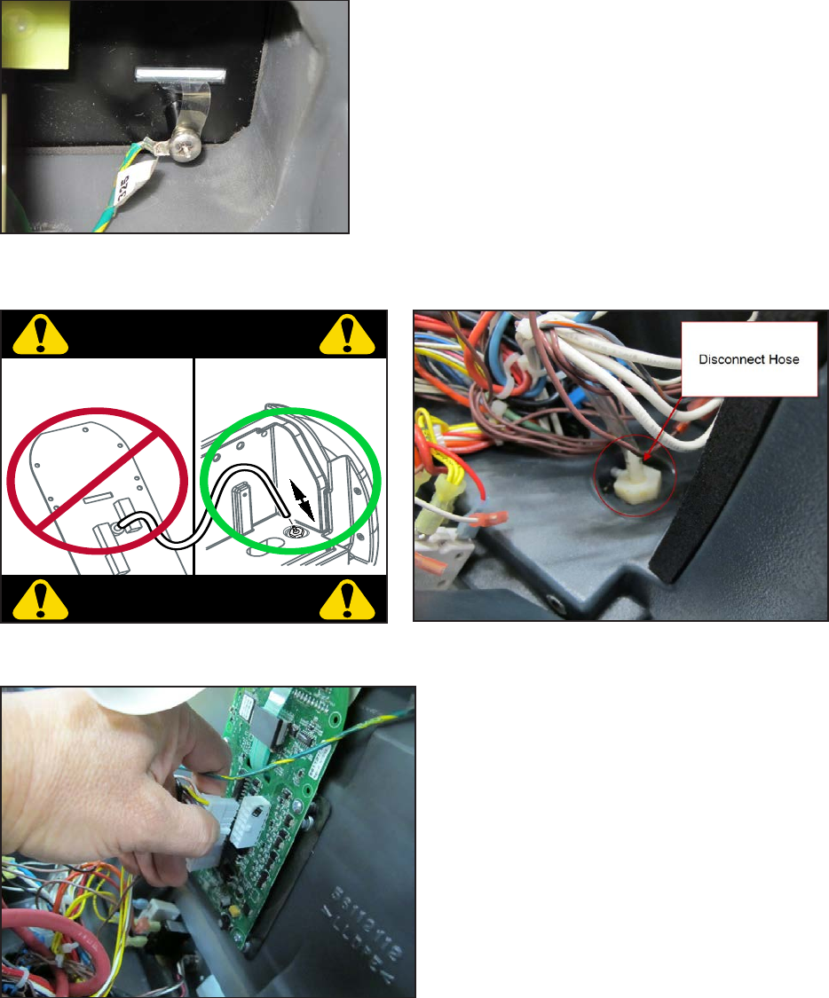
6. Tip cover away from machine and disconnect the clear pressure sensor hose from the ng at the soluon tank.
DO NOT TRY TO DISCONNECT THE HOSE FROM THE CIRCUIT BOARD.
Service Manual: SC750, SC800, SC 750 ST, SC800 ST
Form Number 56043150 Page 42
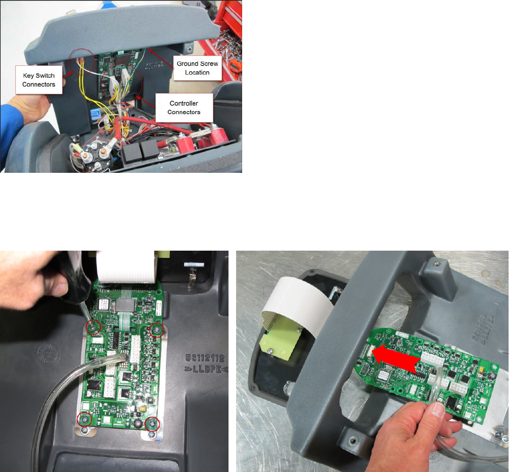
7. Disconnect electrical connectors from the Main Machine Controller and Key Switch. Remove screw securing
ground wire to control switch interface panel.
8. Remove the electrical panel cover and place on a work bench.
9. Remove the 5 screws securing the switch panel interface and carefully turn the cover over. Remove 4 screws
securing circuit board (Main Machine Controller) to cover. Remove the control switch interface panel and circuit
board together through the cover opening.
10. If the board is being replaced you will need to use a new pressure sensor tube or transfer the exisng tube from
the old board. Follow the steps below to transfer the tube.

Service Manual: SC750, SC800, SC 750 ST, SC800 ST
Form Number 56043150 Page 43
a. Use a small sharp knife to cut the tube o, near the sensor on the board (1 mm from sensor).
b. Make a shallow slit with the knife along the length of the clear tube that is sll aached to the sensor
port. Do not press too hard, and avoid cung into the sensor port. Make 3 or 4 passes with the knife,
pressing soly, rather than one hard cut. See the photos below.
c. To install the sensor onto a new PCB assembly, grasp the tube near the end with your ngers, and slowly
push the tube onto the sensor port. Do not push too hard or the sensor may break.
Service Manual: SC750, SC800, SC 750 ST, SC800 ST
Form Number 56043150 Page 44
11. Reassemble in reverse order, taking care not to damage the printed circuit ribbons used to connect the circuit
board to the control switch interface panel. If you did not drain the soluon tank earlier, you must do so before
connecng the pressure sensor hose in order for the soluon level “gauge” to work properly.
Main Machine Controller SC750 and SC800 Models (Later build)
Note: Electronic devices like the Main Machine Controller are sensive to Electrostac Discharge (ESD). Before handling
the controller, touch a metal bench or shelf to discharge any electrical charge that may have built up in your body. Do not
walk around with a controller in your hands.
Summary: Remove the electrical panel cover as an assembly and place on a bench. Then remove the main machine con-
troller from the cover. Do not remove the control switch interface panel before the cover is removed from the machine.
1. Completely drain soluon tank. This is important for the soluon level sensor to work properly upon reassembly.
2. Turn o and remove key.
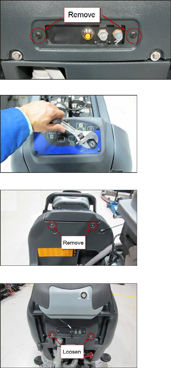
3. Remove top two handle bolts and loosen the lower two. Rotate Handle Assembly down.
4. Disconnect handle wiring lead (Note photo is of early build).
Service Manual: SC750, SC800, SC 750 ST, SC800 ST
Form Number 56043150 Page 45
5. Remove circuit breaker plate aaching screws.
6. Remove nut securing key switch.
7. Remove electrical panel cover upper mounng screws.
8. Loosen electrical panel cover lower mounng screws.
Service Manual: SC750, SC800, SC 750 ST, SC800 ST
Form Number 56043150 Page 46
9. Tip cover away from machine
a. Remove the screw securing the ground wire to the back of the control switch interface panel.
b. Disconnect the clear pressure sensor hose from the ng at the soluon tank. DO NOT TRY TO DISCON-
NECT THE HOSE FROM THE CIRCUIT BOARD.
c. Unplug main machine controller electrical connectors.
d. Free circuit breakers, handle switch connector and key switch from cover assembly.
CIRCUIT BREAKER WIRING
(AS VIEWED FROM BACK OF PANEL)
YEL
YEL X18-1
YEL
RED X17-1 RED X19-1
ORN X20-1
KEY SWITCH WIRING
(AS VIEWED FROM BACK OF SWITCH)
B1
3
WHT/BRN X72-1
BRN X52-1
YEL X51-1
CAUTION!
CAUTION!
Do not remove hose
from control board. Only disconnect hose
at solution tank fitting.
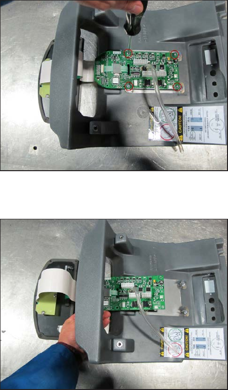
Service Manual: SC750, SC800, SC 750 ST, SC800 ST
Form Number 56043150 Page 47
10. Remove the electrical panel cover assembly and place on a work bench.
a. Remove the 5 screws securing the switch panel interface and carefully turn the cover over.
b. Remove 4 screws securing circuit board (Main Machine Controller) to cover.
c. Remove the control switch interface panel and main machine controller circuit board together through
the cover opening.
11. If the board is being replaced you will need to use a new pressure sensor tube or transfer the exisng tube from
the old board. Follow the steps below to transfer the tube.
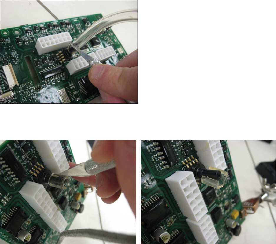
Service Manual: SC750, SC800, SC 750 ST, SC800 ST
Form Number 56043150 Page 48
a. Use a small sharp knife to cut the tube o, near the sensor on the board (1 mm from sensor).
b. Make a shallow slit with the knife along the length of the clear tube that is sll aached to the sensor
port. Do not press too hard, and avoid cung into the sensor port. Make 3 or 4 passes with the knife,
pressing soly, rather than one hard cut. See the photos below.
c. To install the sensor onto a new PCB assembly, grasp the tube near the end with your ngers, and slowly
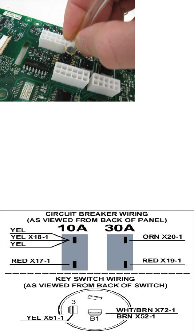
Service Manual: SC750, SC800, SC 750 ST, SC800 ST
Form Number 56043150 Page 49
push the tube onto the sensor port. Do not push too hard or the sensor may break.
12. Reassemble in reverse order nong the following:
a. Take care not to damage the printed circuit ribbons used to connect the circuit board to the control
switch interface panel.
b. Reinstall and secure the key switch, circuit breakers and handle wiring connector before fastening the
cover down.
c. If you did not drain the soluon tank earlier, you must do so before connecng the pressure sensor hose
in order for the soluon level “gauge” to work properly.
d. Refer to the wiring connecon decal on the back of the cover to reconnect any wires that may have
come loose. Double check all electrical connecons.
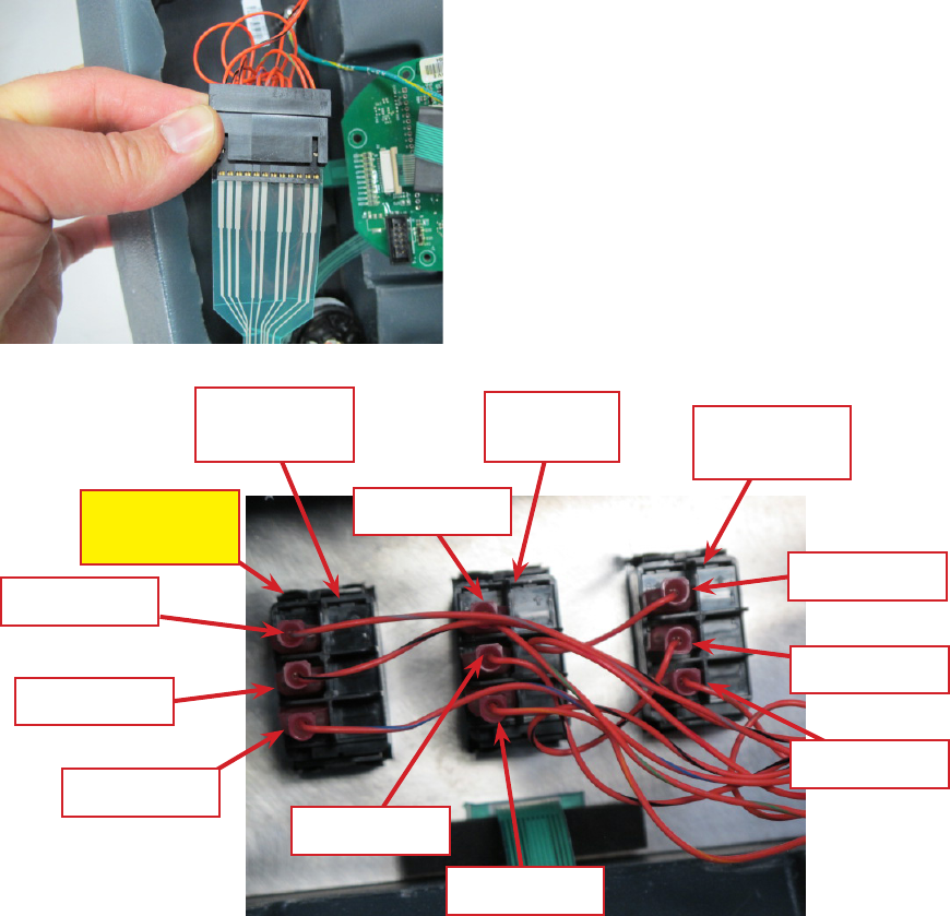
Service Manual: SC750, SC800, SC 750 ST, SC800 ST
Form Number 56043150 Page 50
Rocker Switches - ST Models
1. Remove the electrical panel cover to access the back side of the rocker switches. DO NOT try to access the
switches by removing the switch plate as you may damage a “ribbon” wiring strip.
2. Disconnect the ribbon strip connector to the switches. (Note the orientation of the ribbon and connector for
reassembly).
3. Disconnect the wiring from the switch you are removing.
4. Push on the switch retaining lock tabs located at each corner and push the switch back through the cover.
5. Install the switch by pressing it into place.
6. Reinstall the wiring and nish reassembling in the reverse order of disassembly.
Retaining
Lock Tab
Solution
Switch Scrub
Switch Vacuum/Wand
Switch
3. ORG/GRY
1. ORG/BLU
2. ORG/BLK
2. ORG/BLK
2. ORG/BLK
3. ORG/GRN
1. ORG/YEL
3. ORG/RED
1. ORG/BRN

Service Manual: SC750, SC800, SC 750 ST, SC800 ST
Form Number 56043150 Page 51
Specifications
Shop Measurements – Main Machine Controller
The following tables contain some “real world” shop voltage measurements to help you recognize what “normal” looks
like. All voltage values were measured with the black (Negave) voltmeter lead connected to the main baery negave
terminal unless otherwise specied. (Non ST = SC750 and SC800 models. ST = SC750 ST and SC800 ST models)
J1 Connector
Pin # Circuit Descripon Value Comments
Used
on Non
ST or ST
1 Chemical Pump “+” output Non ST
2 Not used Both
3Chemical Pump “-“ output Non ST
4Brush Head Actuator motor “+” output 24v
down
-24v up
With red lead at pin #4 and black
lead at pin #5
Both
5 Brush Head Actuator motor “-“ output Both
6 Not used Both
7 Not used Both
8 Baery Negave (Ground) 0.5mV With vacuum motor running Both
9Not used Both
10 Not used Both
J2 Connector
Pin # Circuit Descripon Value Comments
Used
on Non
ST or ST
1 Baery Negave (Ground) 0.5mV With vacuum motor running Both
2 Baery Negave (Ground) 0.5mV With vacuum motor running Both
3Input from Brush Deck actuator posion switch
#0. Switch oats open when actuator is fully
retracted (corresponding to a raised deck), and
is closed to GND otherwise.
4.95V Up Posion. Other posions 0.5mV Both
4Not used Both
5 Not used Both
6 Not used Both
7 Baery Negave (Ground) 0.5mV With vacuum motor running Both

Service Manual: SC750, SC800, SC 750 ST, SC800 ST
Form Number 56043150 Page 52
Pin # Circuit Descripon Value Comments
Used
on Non
ST or ST
8 Baery Negave (Ground) 0.5mV With vacuum motor running Both
9Vacuum Motor Current Sense input (voltage on
this wire represents the motor current)
181 mV Vacuum motor running with solu-
on cover open. Dropped to 157 mV
when ball oat was seated.
Both
10 Brush Motor Current Sense input (voltage on
this wire represents the motor current)
30mV Brushes free running – not contacng
oor
Both
11 Input from Brush Deck actuator posion switch
#1. Switch oats open when actuator is par-
ally extended (corresponding to normal scrub
pressure), and is closed to GND otherwise.
4.96V Normal scrub posion. Other posi-
ons 0.5mV
Both
12 Pin has 2 funcons:
1) Input from Brush Deck actuator posion
switch #2. Switch oats open when actuator
is fully extended (corresponding to maximum
scrub pressure), and is closed to GND other-
wise.
2) When an S.P.E. on-board baery charger is
installed and plugged into an AC outlet, the
input funcon of this signal is overridden and
instead becomes a 1-wire, bidireconal serial
communicaon line between the PC board and
the on-board charger.
2.91V Extra scrub pressure posion. Other
posions 795mV.
If the S.P.E. Baery Charger is plugged
in, voltage pulses then seles in
around 12V
Both
J3 Connector
Pin # Circuit Descripon Value Comments
Used
on Non
ST or ST
1 Baery “+“ lead 24.0v With vacuum motor running Both
2 Baery “-“ lead 0.5mV With vacuum motor running Both
3Brush Remove contactor output 28mV When energized. Otherwise 24V Non ST
4On-Board Charger Interlock input (input = key
switch voltage when on-board baery charger
is not plugged into AC outlet, oats open when
on-board charger is plugged in.)
25V Key on and Charger NOT plugged in.
When Charger is plugged in, drops to
116mV
Both
5 Reverse Direcon input from Speed Controller
(input = GND when moving in reverse)
2mV
23V
In Reverse.
In Neutral or Forward
Both

Service Manual: SC750, SC800, SC 750 ST, SC800 ST
Form Number 56043150 Page 53
Pin # Circuit Descripon Value Comments
Used
on Non
ST or ST
6 Fwd/Reverse input from Speed Controller (input
= GND when moving in forward or reverse)
4mV
24.1V
In Forward or Reverse
In Neutral
Both
7 Speed Controller Status input (input pulses
between B+ and GND to indicate error status
from Speed Controller)
121mV Normal (No faults). Voltage pulses
when fault is present.
Both
8 Baery “+“ lead 24.0v With vacuum motor running Both
9Not used Both
10 Not used Both
11 Soluon Solenoid Valve winding 116mV When energized (Hold soluon but-
ton down)
Both
12 Vacuum Contactor winding 4.9V When energized, voltage inially
drops to 90mV then seles at 4.9v.
This is due to 100% “on” me at rst
to pull in the contactor, which is then
reduced to 80% to hold it in.
Both
13 Brush Motor Contactor winding 4.9V When energized, voltage inially
drops to 90mV then seles at 4.9v.
This is due to 100% “on” me at rst
to pull in the contactor, which is then
reduced to 80% to hold it in.
Both
14 Key Switch input (input = B+ voltage when key is
turned on)
24.9V Key On or O with on-board baery
charger
Both
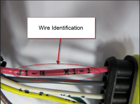
Service Manual: SC750, SC800, SC 750 ST, SC800 ST
Form Number 56043150 Page 54
Electrical System
Functional Description
General
The electrical system is powered by four 6 volt baeries for a total of 24 volts. Heavy cables connect the baeries in
series. A large red Main Baery Pack Connector provides baery power to the machine wiring. On machines without
an on-board baery charger, the Main Baery Pack Connector is used for hooking up the baeries to a “shelf” baery
charger unit. To prevent damage to the baeries due to excessive discharging, the control system will turn o the scrub
system and the recovery system as the baery voltage drops too low.
A steel plate at the back of the soluon tank serves as an “electrical panel” and provides a mounng surface for the vari-
ous relays, fuses and the Drive Motor Controller. Circuit breakers and a main fuse protect various circuits from excessive
current. The machine wiring is color coded and the ends of each wire have the wire idencaon printed on them (such
as “J1-4 X1-1”). The wiring idencaon informaon can be used to more easily trace wiring in the machine because it is
also shown on the wiring harness conguraon diagram.
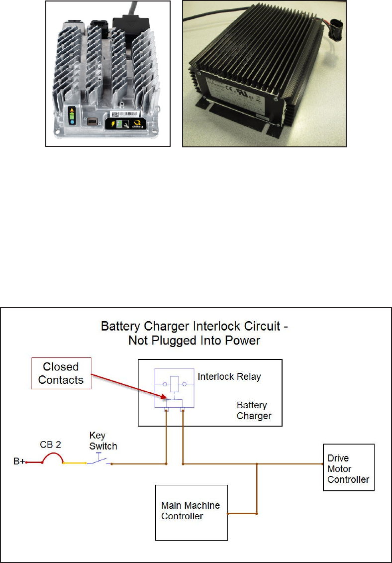
Service Manual: SC750, SC800, SC 750 ST, SC800 ST
Form Number 56043150 Page 55
On-board Battery Charger
An oponal on-board baery charger is available. Early machines used an S.P.E. charger and later machines use a Delta-
Q IC650 baery charger. Some early machines may have been updated to replace the S.P.E. charger with the Delta-Q
charger.
When equipped, the charger is mounted on the boom of the machine. Both chargers have an internal relay that inter-
rupts a power supply when the charger is plugged into an AC power outlet. This is called the “Interlock” circuit on the
wiring diagram. It prevents the machine from being operated while the baeries are charging. The interlock circult for
the S.P.E. charger is illustrated below. The Delta-Q interlock circuit is similar but it relies on the main baery posive con-
necon for the power source rather than a separate wire.
Here is how the baery charger interlock circuit works. The interlock relay contacts inside the charger are normally
closed, allowing the current to pass in and out of the charger to the Main Machine Controller and the Drive Motor Con-
troller. When the AC power cord is plugged in, the relay is energized and opens the relay contacts opening the circuit.
Delta-Q Charger S.P.E. Charger
Service Manual: SC750, SC800, SC 750 ST, SC800 ST
Form Number 56043150 Page 56
S.P.E Battery Charger Details
When the S.P.E baery charger is plugged in, “Non-ST” models will display text on the LCD screen describing the type of
baery charging prole in use. They will aslso communicate charging progress with an ICON on the LCD display. When
the S.P.E. baery charger is plugged in on ST models, charging progress is communicated using the Baery Indicator
LEDs. The charging prole in use is communicated using one of the other control panel LEDs.
ST Charging Prole in Use:
Wet 25A = Vacuum LED
AGM Discover 25A = Scrub High LED
Gel Excide 25A = Scrub Low LED
Gel-AGM 25A = Soluon High LED
Wet 15A = Soluon Medium LED
Gel-AGM 15A = Soluon Low LED
The S.P.E. baery charger and Main Machine Controller communicate with one another on the WHT/BLU wire that runs
between them. (This same circuit is also used for the brush head actuator posion 2 switch input) Each me the baery
charger is plugged in, the charger contacts the controller by sending out a posive voltage on the communicaon wire
to nd out what kind of baeries are on the machine. It needs to know this in order to use the correct charging prole.
The controller responds and provides the baery type informaon it has stored in memory. The charger then tells the
controller which charging prole it will use and begins charging the baeries. See the Control System, Program Opons
secon for informaon on how to tell the controller what kind of baeries are used in the machine. If the charger is un-
able to communicate with the controller it will use the prole for a wet baery at a 25 Amp rate as a default.
Delta-Q IC650 Battery Charger Details
The Delta-Q baery charger does not communicate with the main machine controller. It is a “stand-alone” unit. Models
that have the Delta-Q charger have a separate LED on a bracket to communicate charging progress. By pressing a buon
on the charger you can see what charging prole is in use. If you replace the baeries with a dierent type of baery or
replace the baery charger, you must select the correct charging prole to be compable with the baeries. There are a
set of proles stored inside the charger. You can interface directly with the charger to select the prole to be used from
that set. See the Delta-Q Product Manual (710-0138-Delta-Q.pdf) for complete instrucons on selecng the prole. Use
the Baery Charging Prole Table below to choose the prole to match the baeries that are in the machine.

Service Manual: SC750, SC800, SC 750 ST, SC800 ST
Form Number 56043150 Page 57
Battery Manufacturer Voltage Battery Model # 20 Hour Rating N-A P/N Profile to use
DISCOVER 6 EV250A-AGM 260 40953A P-0-4-3
DISCOVER 6 EV305A-A 312 56112546 P-0-4-3
DISCOVER 6 EV305A-A 312 56315959 P-0-4-3
DISCOVER 6 EV305A-AGM 312 40964A P-0-4-3
DISCOVER 6 EVGT6A 255 56112545 P-0-4-3
DISCOVER 6 EVGT6A 255 56315772 P-0-4-3
DISCOVER 6 EVL 16A-A 390 56388582 P-0-4-3
DISCOVER 12 EV12A-A 140 56380239 P-0-4-2
DISCOVER 12 EV185A- A 234 56393912 P-0-4-3
DISCOVER 12 EV185A-A 234 41023A P-0-4-3
EAST PENN MFG. CO. 6 8GGC 2/T881 (GEL CELL) 180 56206987 P-0-2-6
EAST PENN MFG. CO. 12 8G27MM/T876 86.4 56206988 P-0-2-6
FULL RIVER 6 DC 250-6 250 56112545 P-1-5-1
FULL RIVER 6 DC 335-6 335 56112546 P-1-4-1
TROJAN 6 J -305G 285 56391391 P-0-0-7
TROJAN 6 J-250-2992-41 250 56026200 P-0-0-3
TROJAN 6 L16-5592-41 395 56388582 NOT RECOMMENDED
TROJAN 6 T-125LPT 235 56206079 P-0-0-3
TROJAN 6 T-605LPT 195 56206117 P-0-0-3
TROJAN 12 J185-2292-42 195 56206078 P-0-0-3
US BATTERY 6 L16 375 40602A P-0-7-3
US BATTERY 6 L16 375 40704A P-0-7-3
US BATTERY 6 L16HC 415 56388582 P-0-7-3
US BATTERY 6 US-125 235 331318 P-0-1-1
US BATTERY 6 US-125 235 881317 P-0-1-1
US BATTERY 6 US-125 235 56206079 P-0-1-1
US BATTERY 6 US-125 235 40136A P-0-1-1
US BATTERY 6 US-125 235 40136B P-0-1-1
US BATTERY 6 US-14 5XC 251 56317154 P-0-7-2
US BATTERY 6 US1800 201 56206117 P-0-1-1
US BATTERY 6 US250HC 275 56026200 P-0-1-1
US BATTERY 6 US-305 305 891384 P-0-7-2
US BATTERY 6 US-305 305 891385 P-0-7-2
US BATTERY 6 US-305 305 56391391 P-0-7-2
US BATTERY 12 UB27 86 40070A P-0-0-6
US BATTERY 12 US-185 195 871334 P-0-1-1
US BATTERY 12 US-185 195 871335 P-0-1-1
US BATTERY 12 US-185 195 56206078 P-0-1-1
US BATTERY 12 US-31TMX 130 40605A P-0-7-1
US BATTERY 12 US-31TMX 130 40606A P-0-7-1
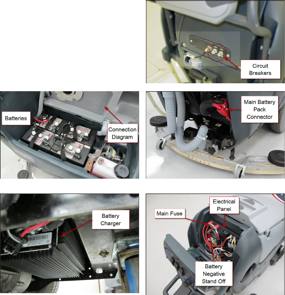
Service Manual: SC750, SC800, SC 750 ST, SC800 ST
Form Number 56043150 Page 58
Component Locations
• Baeries
• Main Baery Pack Connector
• Baery Charger (Oponal)
• Electrical Panel
• Main Fuse
• Baery Negave Stand O
• Circuit Breakers
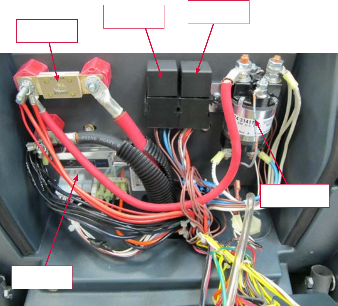
Service Manual: SC750, SC800, SC 750 ST, SC800 ST
Form Number 56043150 Page 59
150 Amp Fuse
F1
Brush Remove
Relay K3
Vacuum Relay
K1
Brush Contactor
K2
Drive Motor
Controller A2
Electrical Panel Components
Service Manual: SC750, SC800, SC 750 ST, SC800 ST
Form Number 56043150 Page 60
Maintenance and Adjustments
Battery Maintenance and Recharging
See Instrucons for Use Manual
Possible Causes:
• Incorrect low-voltage cutout seng
• Baeries not fully charged.
o If there is any queson whether the baeries are fully charged, they should be charged for at least 16
hours.
• One or more weak baeries
o To determine if one of the baeries is weak, measure the voltage across each individual baery while
operang the machine. Write down the values and compare them. A baery that has a dead cell will
typically be 1 – 2 volts lower than the others.
o Use a baery load tester to test each baery.
o For wet baeries, a hydrometer can be used to check the specic gravity of the electrolyte in each cell. A
dead cell is one that reads 50 points or more lower than the other cells.
• Baery cable connecons
Possible Causes:
• Baery Charger
• Wiring/Connecons
• Baeries
Note: The oponal S.P.E. on-board baery charger will charge, even if it cannot communicate with the Main Machine
Controller.

Service Manual: SC750, SC800, SC 750 ST, SC800 ST
Form Number 56043150 Page 61
Removal and Installation
Batteries
If the set of baeries has 50 or more cycles on them, do not put a new baery into the set. Either replace with all new
baeries or use a good used baery. Baery maintenance requirements change as they age. As they age they usually
require longer charging me and a higher nish rate. The newer baery mixed in with old baeries will end up being
overcharged, which will cause it to fail prematurely.
WARNING!
Use extreme cauon when working with baeries. Sulfuric acid in baeries can cause severe injury if allowed to contact
the skin or eyes. Explosive hydrogen gas is vented from the baeries through openings in the baery caps. This gas can
be ignited by any electrical arc, spark or ame. Do not install any lead-acid baery in a sealed container or enclosure.
Hydrogen gas from overcharging must be allowed to escape.
When servicing baeries
• Remove all jewelry
• Do not smoke
• Wear safety glasses, rubber gloves and a rubber apron
• Work in a well-venlated area
• Do not allow tools to touch more than one baery terminal at a me
• ALWAYS disconnect the negave (ground) cable rst when replacing baeries to prevent sparks.
• ALWAYS connect the negave cable last when installing baeries.
CAUTION!
Electrical components in this machine can be severely damaged if the baeries are not installed and connected properly.
Only Nilsk-Advance, a qualied electrician, or the baery manufacturer should install baeries.
1. Empty the recovery tank and p it up.
2. Turn the key switch o and disconnect the main baery pack connector.
3. Remove the baery cables.
a. Do not allow metal tools to connect between baery cables or posts.
b. Prevent cable ends from touching other cable ends or posts.
4. Remove baery.
5. Install baery.
6. Reconnect baery cables making sure that they are connected properly. Refer to the diagram molded into the
lower side of the recovery tank.
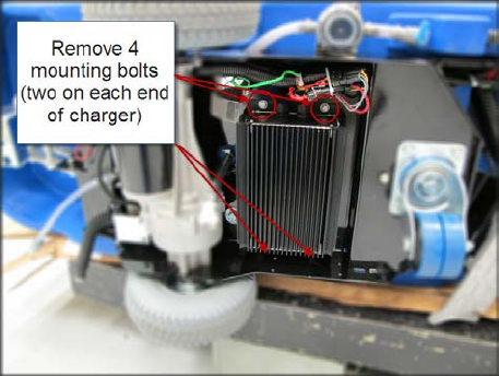
Service Manual: SC750, SC800, SC 750 ST, SC800 ST
Form Number 56043150 Page 62
Battery Charger - S.P.E.
The baery charger is mounted to the boom of the frame
with 4 bolts that are screwed into threaded holes.
1. Drain the soluon tank and recovery tank.
2. Disconnect and remove the baeries, then lay the
machine on its side using a so surface to prevent
scratching the machine.
3. Cut e straps securing AC power cable.
4. Cut e straps securing electrical connectors.
5. Disconnect electrical connectors.
6. Remove 4 baery charger mounng bolts.
7. Remove charger, thread AC power cable through
opening.
8. Reassemble in the reverse order. Tie wiring in same
locaons using new e straps.
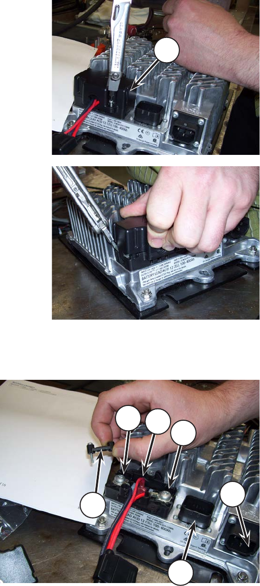
Service Manual: SC750, SC800, SC 750 ST, SC800 ST
Form Number 56043150 Page 63
Battery Charger - Delta-Q.
1. Drain the soluon tank and recovery tank.
2. Disconnect and remove the baeries, then lay the
machine on its side using a so surface to prevent
scratching the machine.
3. Cut e straps securing AC power cable.
4. Cut e straps securing electrical connectors.
5. Remove the DC connector cover (B).
6. Remove the clamp (C). Disconnect the baery posi-
ve and negave wires (6) and the interlock wire (7)
7. Disconnect the AC power cable (E) and the baery
temperature sensor connector (D). Remove 4 bat-
tery charger mounng bolts.
8. Remove charger
9. Reassemble in the reverse order. Tie wiring in same
locaons using new e straps.
B
E
D
6
C
76

Service Manual: SC750, SC800, SC 750 ST, SC800 ST
Form Number 56043150 Page 64
The Main Machine Controller intenonally shuts down machine funcons in two stages if the baery voltage drops too
low. This is called “Low Voltage Cut Out”. It is done to preserve the life of the baeries. The rst stage of low voltage cut
out shuts o the scrub funcon by turning o the scrub brush motors and raising the brush deck. It also shuts o the so-
luon and detergent. The vacuum is sll allowed to run in order to recover soluon that is on the oor. The second stage
of low voltage cut out turns o the vacuum. Wet baeries and Gel baeries use dierent voltage thresholds.
Stage Threshold (volts) Shuts Down
1
Wet Baeries – 20.55 V
Gel Baeries – 21.75 V
Brushes, soluon, detergent and
raises brush deck
2
Wet Baeries – 20.40 V
Gel Baeries – 21.60 V
Vacuum
Typical baery run mes may be around 2-4 hours.
Battery Compartment Dimensions
Length = 24.5” (62.23 cm), Width = 14.25” (36.2 cm), Height = 14.25” (36.2 cm)
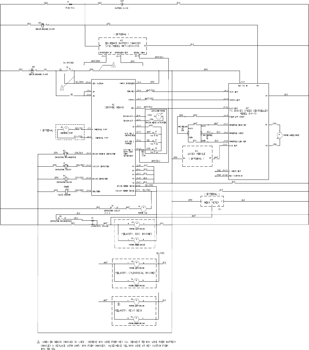
Service Manual: SC750, SC800, SC 750 ST, SC800 ST
Form Number 56043150 Page 65
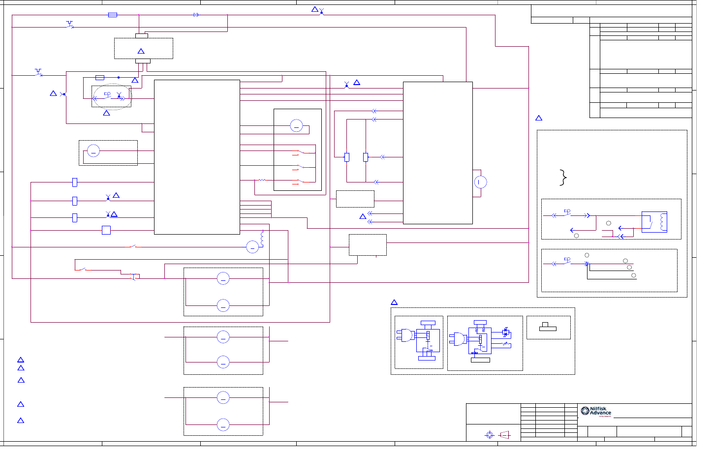
Service Manual: SC750, SC800, SC 750 ST, SC800 ST
REVISIONS
A
REV ECO DATE DFTM APPD
RELEASE
DWG. NO. SHEET
AGREES TO RETURN IT UPON REQUEST.
PLYMOUTH, MINNESOTA AND IT HAS BEEN ISSUED W ITH THE UNDERSTANDING THAT IT WILL NOT BE REPRO-
DUCED NOR COPIED NOR USED FOR ANY PURPOSE OTHER THAN FOR WHICH IT WAS ISSUED AND RECIPIENT
THIS DRAWING AND THE DESIGN REPRESENTED HEREON IS THE PROPERTY OF NILFISK-ADVANCE, INC.,
CONFIDENTIAL
AS NOTED.
UNITS IN [ ] ARE ISO METRIC
DIM. IN [ ] ARE MM.
NOTES UNLESS OTHERWISE
SPECIFIE D
1. ALL DIMENSIONS IN INCHES.
2. DO NOT SCALE DRAWING.
3. ALL DIMENSIONS APPLY AFTER
PLATING AND HEAT T REATING,
BUT BEFORE PAINTING.
4. REMOVE ALL BURRS AND SHARP
EDGES.
APPROVED
APPROVED
APPROVED
CHECKED
FIRST USED ON
SHEETASSY.
SIZE CODE
REV.DWG. NO.
TITLE
D
SCALE
PLYMOUTH, MINNESOTA 55447-3408
DRAW N
PROJ ENG
E
NILFISK-ADVANCE, INC.
ORCAD
A
1
B C D E F G
A B C D E F G
2
3
4
5
1
2
3
4
5
56383889
56383889
A-10397 4-17-14 PMO WCR
1 OF 1
DIAGRAM-LADDER AXP
SC750 AXP
NONE
56112E05 1 OF 1
KEY SWITCH
B+
B+
A1
CONTROL BOARD
+ CHEMICAL PUMP
- CHEMICAL PUMP
BRUSH REMOVE
CONTACTOR
VACUUM CONTACTOR
SOLUTION
CHARGER INTERLOCK
FOR/REV
STATU S
REV
BRUSH ACT +
BRUSH ACT -
B-
ACT POS 0
(RETRACTED)
ACT POS 1
(MIDDLE)
ACT POS 2 /
BATT CHGR COMM
(EXTENDED)
B-
B-
B-
B-
B-
BRUSH SENSE
A2
PG DRIVES SPEED
CONTROLLER
MODEL I24-70
B-
B+
AUX2 OUT
STATUS OUT
AUX3 OUT
SPEED LMT WIPER
THROTTLE HIGH REF
THROTTLE WIPER
THROTTLE LOW REF
AUX1 OUT
0 VOLTS OUT
REV SWITCH IN
M1
M2
A5
LASER MODULE
(OPTIONAL)
B-B+
CHARGER OPTIONAL
ACTUATOR MOTOR
( OPTIONAL ) J1-1
J1-3
J3-14
J3-1
J3-8
BRUSH CONTACTOR
J3-3
J3-12
J3-13
J3 -11
J1-8
J2-1
J2-7
J2-8
J3-2
J2-10
J2-9
J3-4
J3-6
J3-7
J3-5
KEY SW IN
J1-4
J1-5
J2-2
J2-3
J2 -11
J2-12
POLARITY, DISC BRUSHES
(OPTIONAL)
A4
HOUR METER
1
2
34
N.C.
J4-13
J4-12
J5-2
J4-8
J4-1
J4-2
J4-9
J4 -11
J4-10
J4-3
J4-5
POT.
SPEED
LMT
POT.
THROTTLE
SLOWSLOW
FASTFAST
POLARITY, CYLINDRICAL BRUSHES
POLARITY, REV2 DECK
B
A-10639 7-03-14 JDK
REDRAWN INTO ORCAD
UPDATE: ASSY FROM 56383890 TO 56112E05,
NOTES 1, 2, AND 3
ADD: CHARGER OPTIONS & TRACKCLEAN
CONNECTIONS, TRACKCLEAN TAPS,
CONTACTOR INDICATORS, NOTES 4 & 5,
MOD: SYMBOL L1 AND R3
DETAIL A - WITH ACCESS CONTROL
X004
NO CONN.
X008
X009
TRACKCLEAN CONNECTIONS (OPTIONAL)
AB
123
DETAIL B - WITHOUT ACCESS CONTROL
X004
X001 - B+ (RED)
X002 - B- (BLUE)
X003 - SCRUB (WHITE)
X004 - KEY SWITCH (BROWN)
X005 - VACUUM (GRAY)
X006 - DRIVE (PINK)
X007
X008 SEE DETAIL DIAGRAMS
X009
4-16-14 PMO
2
2
2
2
2
TO 1B3
TO 1A4
TO 1A3
TO 1A3
TO 1B4
TO 1A3
4-16-14 WCR
OPTION 1 OPTION 2 OPTION 3
1 2 3
JUMPER X83
NO CHARGER
CHARGER OPTIONS
1 2 3
PMO
3
3
4
J6
4
NOTES:
1. REF DRAWING 56383890 DIAGRAM AXP WIRING.
2. CONNECTORS WITH X00X ARE TRACKCLEAN CONNECTIONS.
3. IF TRACKCLEAN OPTION IS INSTALLED, REFER TO TRACKCLEAN
CONNECTIONS AND EITHER DETAIL A OR B.
4. REFER TO CHARGER CONNECTIONS FOR ONBOARD CHARGER
CONFIGURATIONS.
5. CONTACTORS WILL HAVE THE SHEET NUMBER, THEN GRID LOCATION
OF THEIR SECOND HALF NEXT TO THEIR SYMBOL.
6. SEE KEY SWITCH DETAIL FOR TRACK CLEAN CONNECTIONS.
7. REFERENCE 56384627 AND 56384628 FOR TRACK CLEAN SCHEMATICS.
8. USED FOR REVERSE SWITCH ON ST MACHINE
C
ADD: BLK WIRE TO M5, JUNCTION TO M3 & M4,
X004, KEY SWITCH DETAIL
A-11690 10-05-15
MG
KWK
X004
6
VACUUM SENSE
D
UPDATE: A2, AUX2 OUT J4-3 WAS J4-9
ADD: NOTE 8
A-11686 01-21-16 SMJ SMJ
8
BRN
(MACHINE)
BRN
(MACHINE)
BRN (TRACKCLEAN)
E
A-11911 02-09-16
MG MG
UPDATE: TRACKCLEAN CONNECTIONS
(DETAIL A, DETAIL B)
E
E
E
BRN (MACHINE)
BRN (MACHINE)
E
E
E
BRN
BLK
BLK
BLK
BLK
YEL/ORG
YEL/REDGRA/BRN
GRA/RED
BRN
BLK
GRA
PINK
WHT/ORG
WHT/BLK
WHT
BLK
GRN
BLU/GRA
RED/YEL
GRA/BLK
GRA/ORG
BRN
BRN
BRN
BRN
PINK
GRA
YEL
WHT/BLU
WHTRED
RED BLK
RED
BLK
ORN
BLK
YELRED BRN
WHT
BRN
BLK
YEL
WHT/BLU
BRN
WHT
BRN
WHT
BLU
PINK BRN
WHT
BRN
BLK
WHT
WHT
YEL/ORG
YEL/ORG
BLK
RED
BLU
GRA
WHT/RED
BRN
BRN
BLK
ORN
BLK
BLK
RED
BRN
BLK YEL/BRN
BLK
BLK
BLK BLK
BLK
BLK
K2
CONTACTOR, BRUSH
BAT
BATTERY, 24 Vdc
+ -
M
M4
MOTOR, RIGHT BRUSH
-+
AB
123
~
B+ B-
GND
CHARGER S.P.E.
K2
DPST, NOCO
M
M4
CHEMICAL, PUMP
-+
S3
SW, SPST KEY
1 2
S1
POS 1 SW
L1
SOLENOID, SOLUTION
1 2
X005
K1
CONTACTOR, VACUUM
X002
M
M5
MOTOR, VAC S3
SW, SPST KEY
1 2
~
B+ B-
GND
LEDS
TEMP
SENSE
C3
12
13
5
14
A B
WHT
BLK
CHARGER DELTA Q WITH LED
M
M3
MOTOR, LEFT BRUSH
- +
M
M3
MOTOR, LEFT BRUSH
- +
R2 R1
F1
FUSE, 150 A.
1 2
S3
SW, SPST KEY
1 2
X007
X001
R3
3.9k
X006
K3
CONTACTOR, BRUSH REMOVE
M
M4
MOTOR, RIGHT BRUSH
- +
S2
POS 0 SW
K1
CONTACTOR, VACUUM
SP2
CB1
CIRCUIT BREAKER, 30 A.
1 2
F2
INLINE FUSE 3A
M
M4
MOTOR, RIGHT BRUSH
- +
M
M1
MOTOR, WHEELDRIVE
-
+
IMMOBILIZER RELAY
M
M3
MOTOR, LEFT BRUSH
-+
CB2
CIRCUIT BREAKER, 10 A.
1 2
X003
K3
CONTACTOR, BRUSH REMOVE
M
M2
BRUSH HEAD ACTUATOR
-+
S0
POS 2 SW
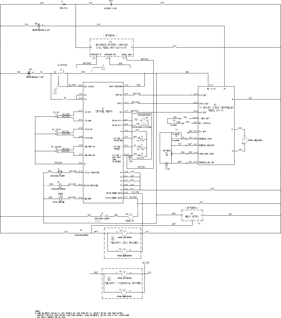
Service Manual: SC750, SC800, SC 750 ST, SC800 ST
Form Number 56043150 Page 67
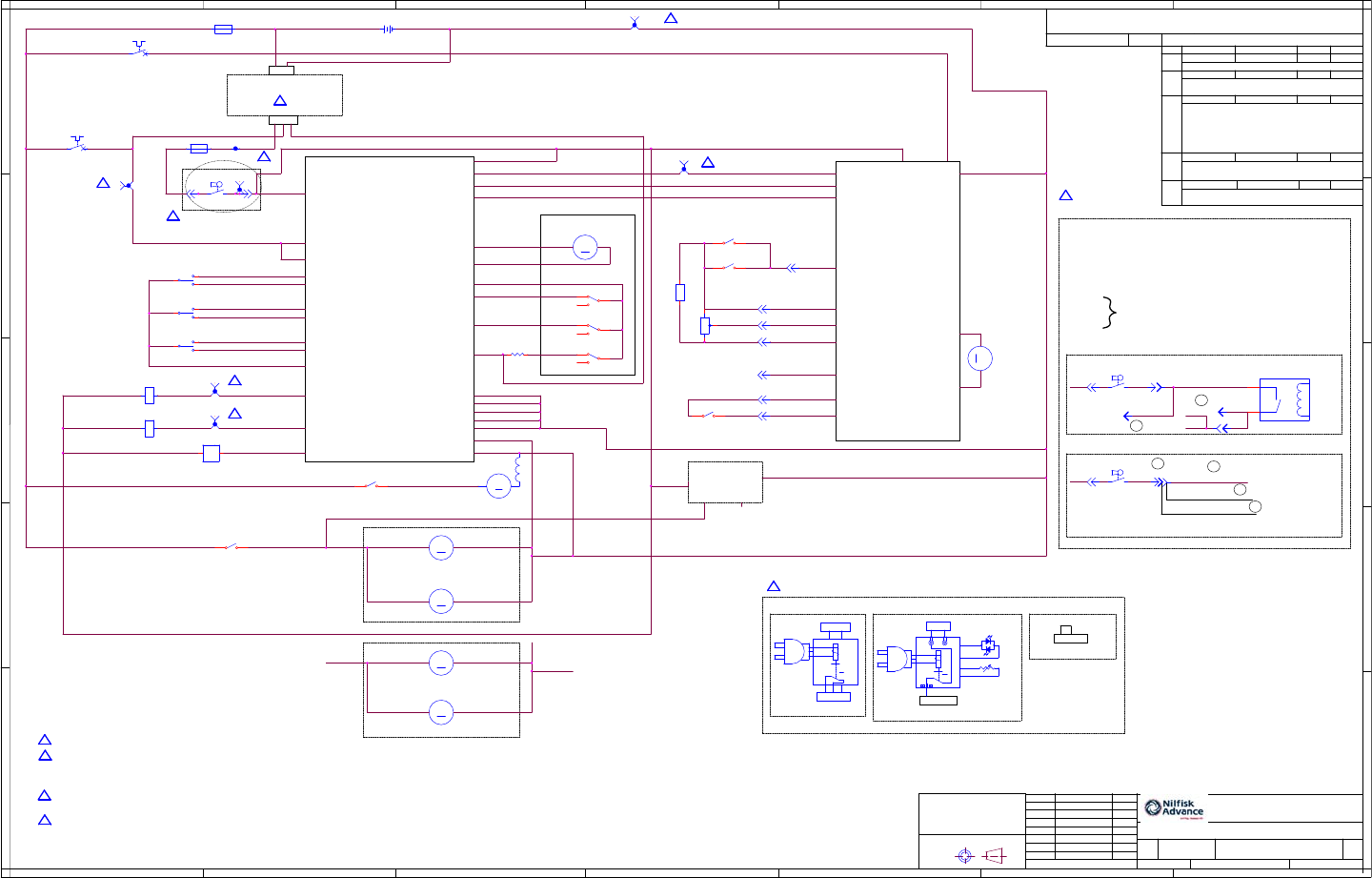
REVISIONS
A
REV ECO DATE DFTM APPD
RELEASE
DWG. NO. SHEET
AGREES TO RETURN IT UPON REQUEST.
PLYMOUTH, MINNESOTA AND IT HAS BEEN ISSUED W ITH THE UNDERSTANDING THAT IT WILL NOT BE REPRO-
DUCED NOR COPIED NOR USED FO R ANY PURPOSE OTHER THAN FOR WHICH IT WAS ISSUED AND RECIPIENT
THIS DRAWING AND THE DESIGN REPRESENTED HEREON IS THE PROPERTY OF NILFISK-ADVANCE, INC.,
CONFIDENTIAL
AS NOTED.
UNITS IN [ ] ARE ISO METRIC
DIM. IN [ ] ARE MM.
NOTES UNLESS OTHERWISE
SPECIFIE D
1. ALL DIMENSIONS IN INCHES.
2. DO NOT SCALE DRAWING.
3. ALL DIMENSIONS APPLY AFTER
PLATING AND HEAT TREATING,
BUT BEFORE PAINTING.
4. REMOVE ALL BURRS AND SHARP
EDGES.
APPROVED
APPROVED
APPROVED
CHECKED
FIRST USED ON
SHEETASSY.
SIZE CODE
REV.DWG. NO.
TITLE
D
SCALE
PLYMOUTH, MINNESOTA 55447-3408
DRAW N
PROJ ENG
E
NILFISK-ADVANCE, INC.
ORCAD
A
1
B C D E F G
A B C D E F G
2
3
4
5
1
2
3
4
5
56383366
56383366
A-09302 4-22-13 PMO
HH
1 OF 1
DIAGRAM-LADDER ST
SC750 ST
NONE
56112E06 1 OF 1
KEY SWITCH
B+
B+
A1
CONTROL BOARD
VACUUM CONTACTOR
SOLUTION
CHARGER INTERLOCK
FOR/REV
STATU S
REV
BRUSH ACT +
BRUSH ACT -
B-
ACT POS 0
(RETRACTED)
ACT POS 1
(MIDDLE)
ACT POS 2 /
BATT CHGR COMM
(EXTENDED)
B-
B-
B-
B-
B-
BRUSH SENSE
VACUUM SENSE
A2
PG DRIVES SPEED
CONTROLLER
MODEL i24-70
B-
B+
AUX2 OUT
STATUS OUT
AUX3 OUT
THROTTLE HIGH REF
THROTTLE WIPER
THROTTLE LOW REF
AUX1 OUT
0 VOLTS OUT
REV SWITCH IN
M1
M2
CHARGER OPTIONAL
ACTUATOR MOTOR
J3-14
J3-1
J3-8
BRUSH CONTACTOR
J3-12
J3-13
J3 -11
J1-8
J2-1
J2-7
J2-8
J3-2
J2-10
J2-9
J3-4
J3-6
J3-7
J3-5
KEY SW IN
J1-4
J1-5
J2-2
J2-3
J2 -11
J2-12
POLARITY, DISC BRUSHES
(OPTIONAL)
A4
HOUR METER
1
2
34
N.C.
J4-13
J4-12
J5-2
J4-8
J4-1
J4-2
J4 -11
J4-10
J4-9
J4-5
POT.
SPD
LMT
100K
POLARITY, CYLINDRICAL BRUSHES
B
A-10397 4-29-14
DEL: BATTERY CHARGER, NOTE 1
ADD: INLINE FUSE
AB
123
NOTES:
1. REF DRAWING 56383367 DIAGRAM, ST WIRING
2. CONNECTORS WITH X00X ARE TRACKCLEAN CONNECTIONS OR TAPS
3. IF TRACKCLEAN OPTION IS INSTALLED, SEE DETAILS A, B, C, OR D.
4. CONTACTORS WILL HAVE THE SHEET NUMBER THEN GRID LOCATION
OF THEIR SECOND HALF NEXT TO THEIR SYMBOL.
5. REFER TO CHARGER CONNECTIONS FOR ONBOARD CHARGER
CONFIGURATIONS.
6. SEE KEY SWITCH DETAIL FOR TRACK CLEAN CONNECTION.
7. REFERENCE 56384627 AND 56384628 FOR TRACK CLEAN SCHEMATICS.
TRACKCLEAN (OPTIONAL)
SEE DETAILS RIGHT
J5-1 B-
J5-4
J5-2
J5-8
J5-10
J5-6
J5-7 VAC O N
VAC OFF
SCRUB INC
SCRUB DEC
SOLUTION INC
SOLUTION DEC
RES,
4.75K
MOTOR,
WHEELDRIVE
J4-1
WCRPMO
C
A-10639 7-29-14 JDK
21.2 A
DETAIL A - WITH ACCESS CONTROL
X004
NO CONN.
X008
X001 - B+ (RED)
X002 - B- (BLUE)
X003 - SCRUB (WHITE)
X004 - KEY SWITCH (BROWN)
X005 - VACUUM (GRAY)
X006 - DRIVE (PINK)
X007
X008 SEE DETAIL DIAGRAMS
X009
TRACKCLEAN CONNECTIONS (OPTIONAL)
X009
DETAIL B - WITHOUT ACCESS CONTROL
X004
4-22-13 PMO
2
2
2
2
TO 1B3
TO 1B4
TO 1A3
TO 1B3
2
4-22-13
HH
OPTION 1 OPTION 2 OPTION 3
1 2 3
JUMPER
NO CHARGER
CHARGER OPTIONS
1 2 3
REDRAWN INTO ORCAD
UPDATE: NOTES 2 AND 3
ADD: CHARGER OPTIONS & TRACKCLEAN
CONNECTIONS, TRACKCLEAN TAPS,
CONTACTOR INDICATORS, NOTES 1, 4, & 5
MOD: SYMBOL L1 & R3
PMO
3
3
5
5
D
A-11690 10-5-15
MG
KWK
ADD: BLK WIRE TO M5, JUNCTION TO M3 & M4,
X004, KEY SWITCH DETAIL
X004
6
BLK
E
A-11911 02-09-16
MG MG
BRN (MACHINE)
BRN (MACHINE)
BRN (TRACKCLEAN)
BRN
(MACHINE)
BRN
(MACHINE)
E
E
E
E
E
E
UPDATE: TRACKCLEAN CONNECTIONS
(DETAIL A, DETAIL B)
BRN
BLK
BLK
BLK
BLK
YEL/ORG
YEL/REDGRA/BRN
GRA/RED
BRN
BLK
GRA
PINK
WHT/ORG
WHT/BLK
WHT
BLK
GRN
GRA
GRA/ORG
BRN
BRN
BRN
RED
GRA
YEL
WHT/BLU
WHTRED
RED BLK
RED
BLK
ORN
BLK
YELRED BRN
WHT
BRN
BLK
WHT/BLU
BRN
WHT
BRN
BRN
BLK WHT
BRN
BLKWHT
WHT
YEL/ORG
RED
WHT/RED
BLK
BLK
YEL
RED
BRN
BLK YEL/BRN
ORG/BLK
ORG/GRY
ORG/BLU
ORG/GRN
ORG/YEL
ORG/RED
ORG/BRN
GRA
PINK
BLUBLU
BRN
BRN ORN
BLK
BLK
BLK
BLK
R4
X001
X007
S3
SW, SPST KEY
1 2
AB
123
~
B+ B-
GND
CHARGER S.P.E.
M
M1
-
+
M
M4
MOTOR, RIGHT BRUSH
- +
K2
CONTACTOR, BRUSH
M
M5
MOTOR, VAC
M
M3
MOTOR, LEFT BRUSH
-+
M
M4
MOTOR, RIGHT BRUSH
- +
SP2
S9
SW, SOLUTION
L1
SOLENOID, SOLUTION
1 2
X003
F1
FUSE, 150 A.
1 2
K2
CONTACTOR, BRUSH
~
B+ B-
GND
LEDS
TEMP
SENSE
C3
12
13
5
14
A B
WHT
BLK
CHARGER DELTA Q WITH LED
X005
S0
POS 2 SW
K1
CONTACTOR, VACUUM
S3
SW, SPST KEY
1 2
S2
POS 0 SW
CB1
CIRCUIT BREAKER, 30 A.
1 2
M
M3
MOTOR, LEFT BRUSH
- +
BAT
BATTERY, 24 Vdc
+ -
S5
SW, TRACTION
X002
IMMOBILIZER RELAY
S7
SW, VAC
M
M2
BRUSH HEAD ACTUATOR
-+
CB2
CIRCUIT BREAKER, 10 A.
1 2
K1
CONTACTOR, VACUUM
S1
POS 1 SW
S3
SW, SPST KEY
1 2
X006
R3
3.9k
R2
S4
SW, TRACTION
S6
SW, REVERSE
F2
INLINE FUSE 3A
S8
SW, SCRUB
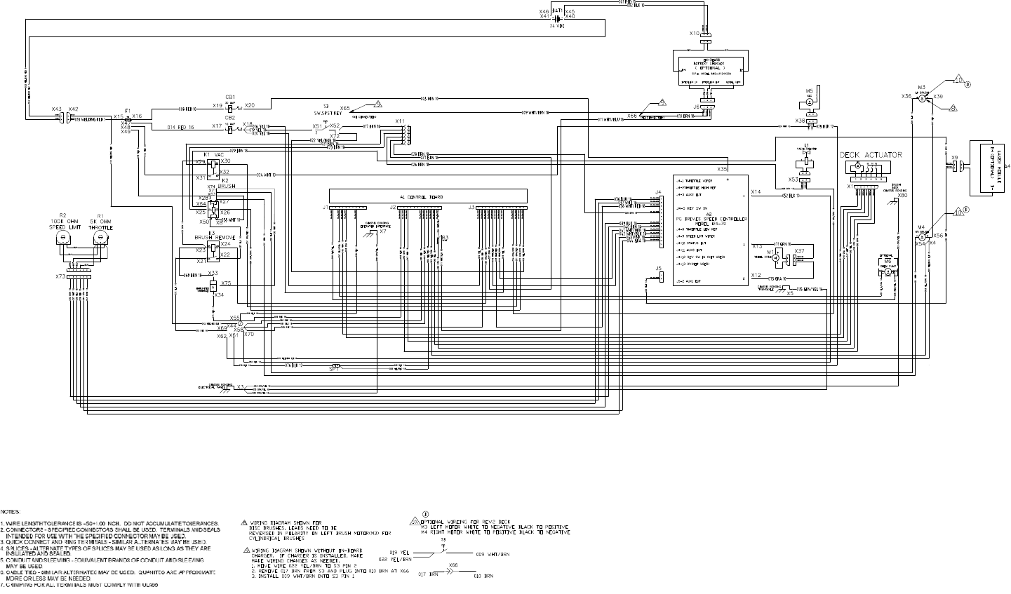
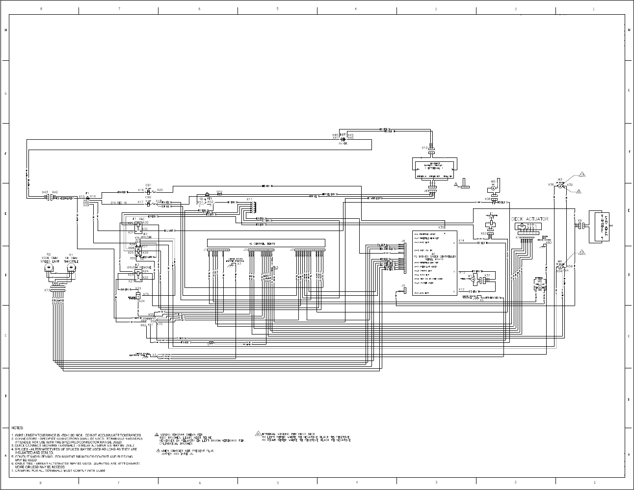
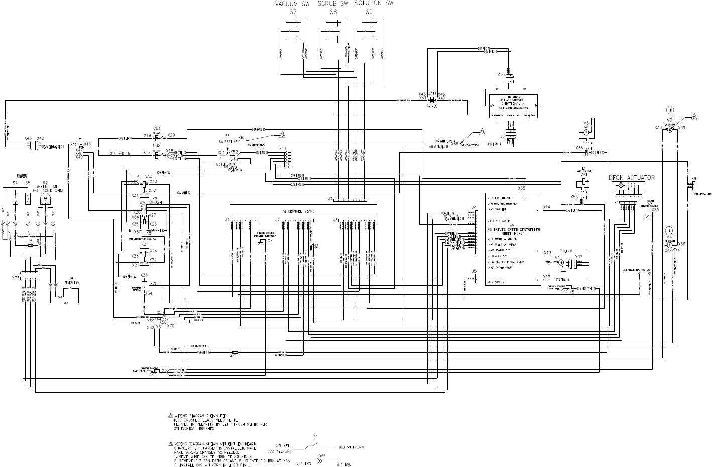
Service Manual: SC750, SC800, SC 750 ST, SC800 ST
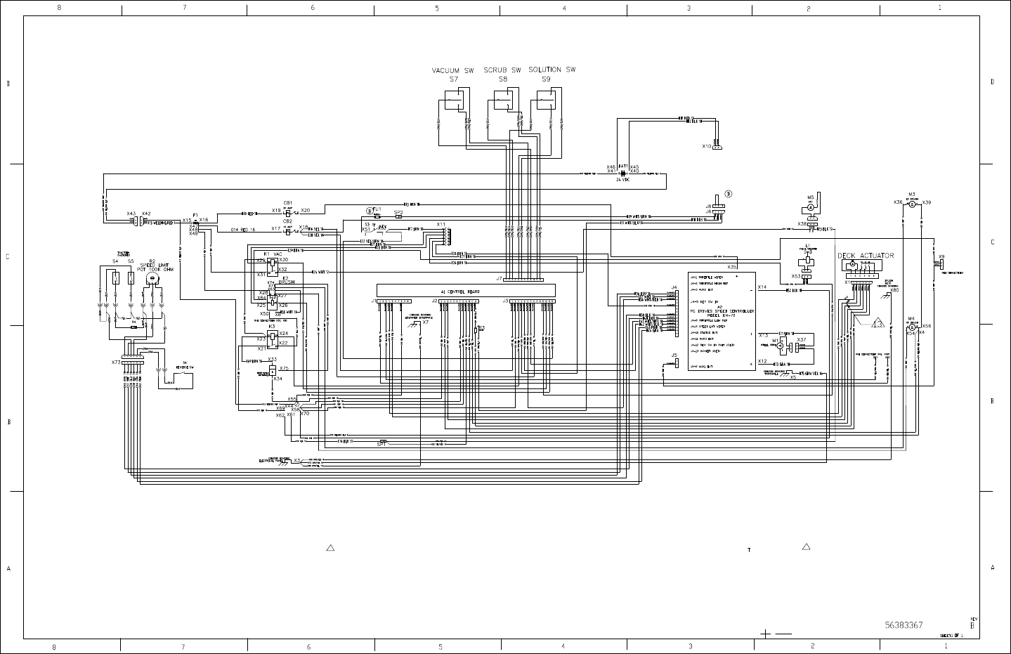
Service Manual: SC750, SC800, SC 750 ST, SC800 ST
10. K2 CONTACTOR CHANGED TO SPS
11. K3 RELAY NOT INSTALLED IN SOCKET
12. REFERENCE DRAWING 56383366 DIAGRAM-LADDER ST
13. PLACE BIDIRECTIONAL DIODE(LITTLEFUSE P6KE36CA)
BETWEEN WIRES 045 PINK AND 046 GRAY ON CONNECTOR X1
8. WIRING DIAGRAM SHOWN FOR
DISC BRUSHES. LEADS NEED TO BE
FLIPPED IN POLARITY ON LEFT BRUSH MOTOR FOR
CYLINDRICAL BRUSHES.
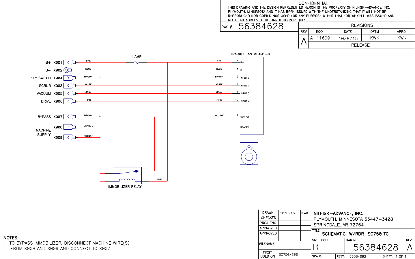
Service Manual: SC750, SC800, SC 750 ST, SC800 ST
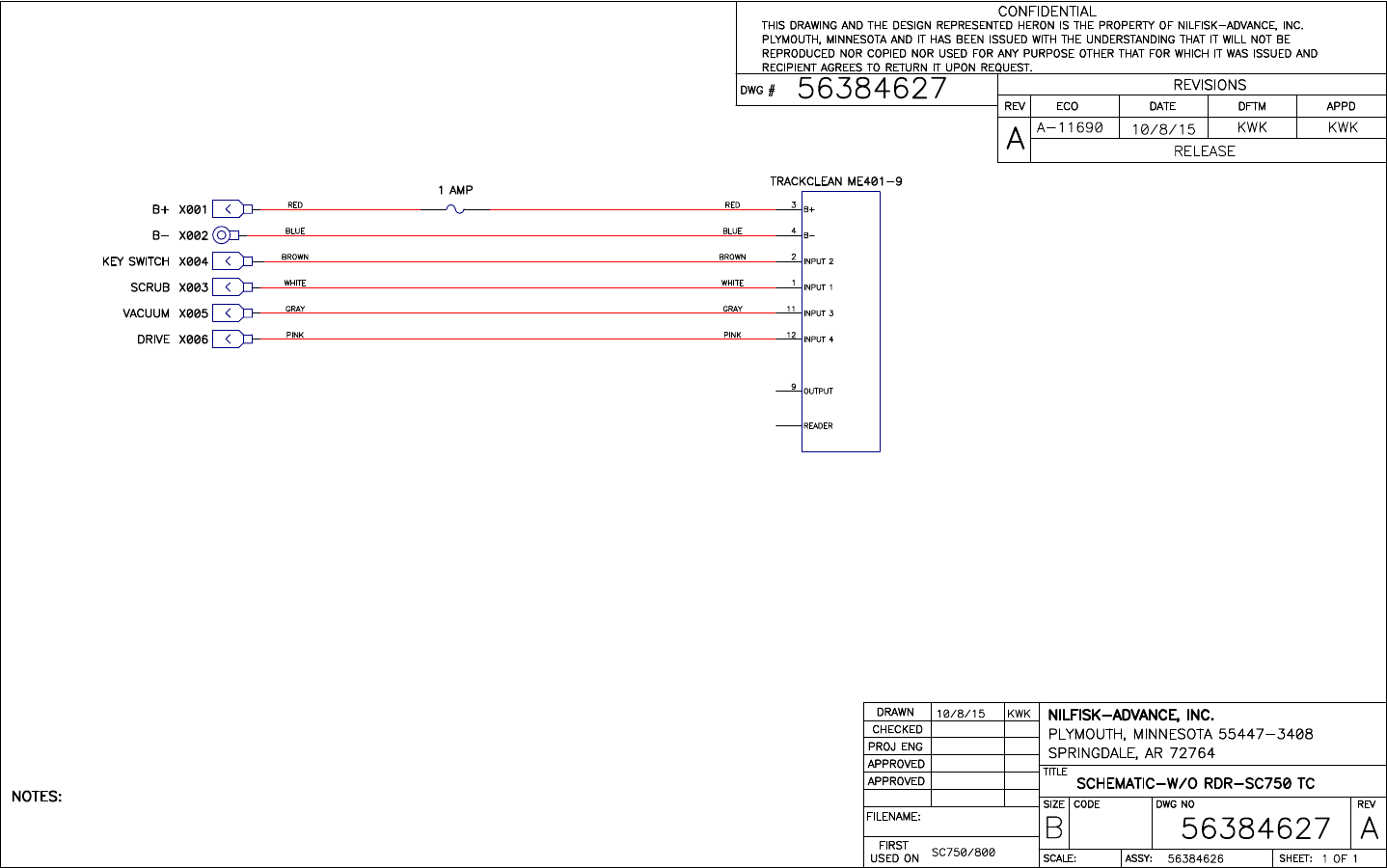
Service Manual: SC750, SC800, SC 750 ST, SC800 ST
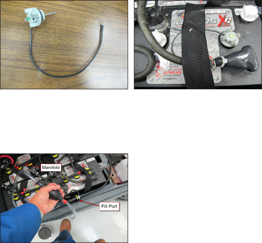
Service Manual: SC750, SC800, SC 750 ST, SC800 ST
Form Number 56043150 Page 75
Options and Accessories
Battery Fill Indicator
The Baery Fill Indicator provides a quick visual indicaon of when one of the baery cells is low and needs water
added. It is installed in place of one of the baery ll caps. The wire lead goes to the baery negave terminal. When the
level is Okay, the green LED is lit.
Battery Watering Kit
The baery watering kit provides a convenient way to add water from a jug into all baery cells at once. Each baery has
a manifold that replaces the ll caps. The manifolds are connected with rubber hoses to one another and to a ll port.
A separate ller tool is connected to the ll port on one end and the other end goes into a container of dislled water.
Squeezing and releasing the bulb pumps the water into all of the baeries simultaneously. As each baery cell becomes
full, a shut o valve closes in its baery cap. Once all of the valves are closed, the pump bulb will feel hard since it can no
longer pump water.
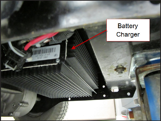
Service Manual: SC750, SC800, SC 750 ST, SC800 ST
Form Number 56043150 Page 76
Hour Meter
The hour meter keeps track of the run me of the scrub motors.
On-board Battery Charger
An oponal on-board baery charger is available. It aaches to the boom of the machine. See the Electrical System
chapter for more informaon. Early models used an S.P.E. charger. Later models use a Delta-Q charger. Early models can
be retroed to use the Delta-Q charger.
Wiring for On-board Charger
When the S.P.E charger is installed, the machine wiring at the Key Switch must be modied for the “interlock” circuit to
funcon properly. See the Electrical System chapter for more informaon.
To modify the Key Switch Wiring: (See Instrucon Sheet Form No. 56090019)
1. Move wire 022 (YEL/BRN) from Key Switch pin 1 to Key Switch pin 2.
2. Remove wire 017 (BRN) from the Key Switch and plug it into wire 010 (BRN) at connector X66.
3. Install wire 009 (WHT/BRN) on the Key Switch pin 1.
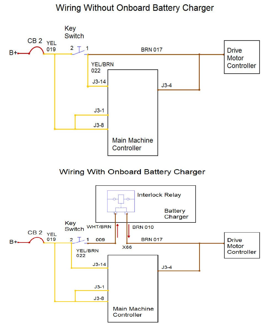
Service Manual: SC750, SC800, SC 750 ST, SC800 ST
Form Number 56043150 Page 77
S.P.E Charger Only
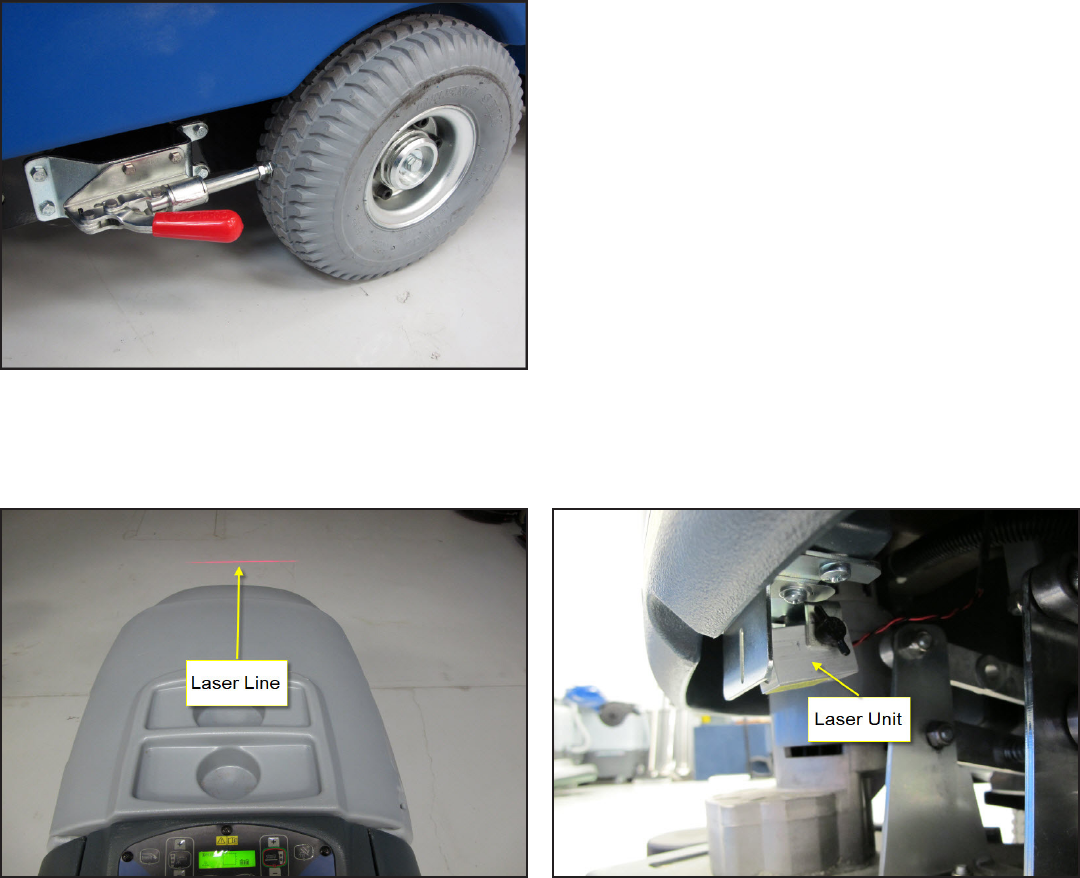
Service Manual: SC750, SC800, SC 750 ST, SC800 ST
Form Number 56043150 Page 78
Parking Brake
The oponal parking brake kit has a manually operated lever that presses a plunger against a drive wheel to act as a
brake.
Laser
The laser provides a visual cue of the cleaning path width and provides an early warning that a machine is approaching.
TrackClean
TrackClean is an add on opon that provides machine locaon and operaon data to the machine owner. It may have
a magnec key reader which will prevent machine operaon unless a valid magnec key is inserted. Several addional
electrical connecons are made when the kit is installed to monitor machine operaon in order to provide data. See wir-
ing and connecon diagrams in the electrical system chapter.
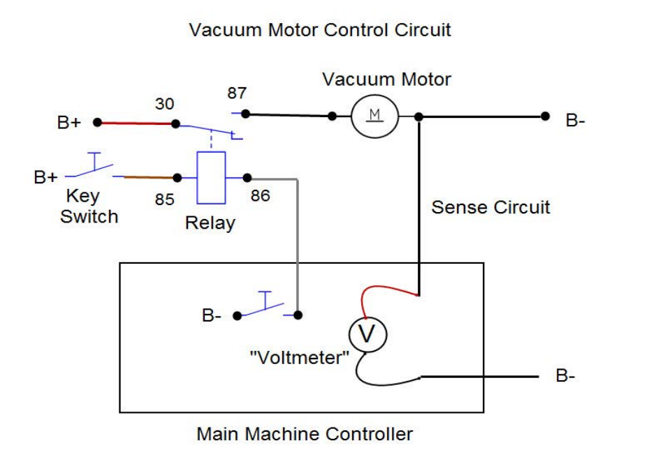
Service Manual: SC750, SC800, SC 750 ST, SC800 ST
Form Number 56043150 Page 79
Recovery System
Functional Description
The job of the recovery system is to remove the dirty water from the oor and store it in the recovery tank. The dirty
water is then disposed of. Dirt and water are lied o the oor into the recovery tank by airow created by a vacuum
motor. The wastewater and air enter the vacuum system at the squeegee tool, through notches in the front squeegee
blade. The air and wastewater move through the squeegee vacuum hose at high speed unl it reaches the recovery
tank. The heavier water falls to the boom of the recovery tank. The airow connues through the vacuum fan inlet
port, vacuum motor and exhaust port. A debris tray inside the recovery tanks helps to redirect the water downward and
catches large parcles. No wastewater ever actually moves through the vacuum motor, just the working air. A oang
ball in a cage seals o the vacuum port when the tank is full to protect the vacuum motor from water ingeson. When
the oat ball seats, the amp draw of the motor is reduced and the Main Machine Controller shuts o the vacuum motor.
The squeegee is raised and lowered manually using the squeegee li lever. Springs apply downward pressure on the
squeegee.
Here is how the vacuum motor circuit works. The relay winding is fed baery voltage on terminal 85. The other side of
the relay coil (terminal 86) is connected to a switch inside the controller. To energize the relay, the controller closes the
switch which completes the path to B-. The relay contact terminal 30 is connected to B+. When the relay is energized, the
contacts close connecng 30 to 87 which sends baery voltage to the vacuum motor. Since the other side of the motor is
connected to baery negave, the motor turns on. The Main Machine Controller also monitors the current draw of the
vacuum motor via a “vacuum motor sense” wire. The controller has an internal “voltmeter” that measures the voltage
dierence (drop) between the sense wire and baery negave. A calibrated ground wire of a specic size and length is
used for the motor ground. At a given amperage ow, there is a correlang voltage drop. As the amperage increases the
voltage drop also increases. The controller translates the voltage drop measured into amperage.
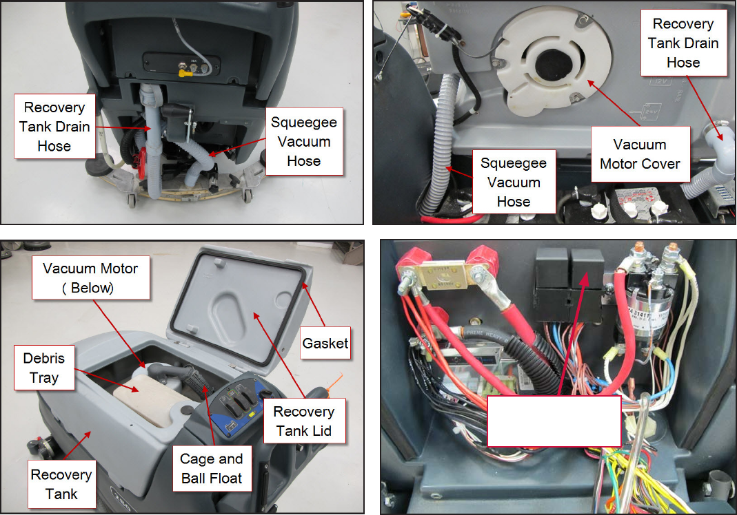
Service Manual: SC750, SC800, SC 750 ST, SC800 ST
Form Number 56043150 Page 80
The vacuum contactor (relay) is turned on when the following inputs are met:
• Operator request
o Scrub On/O switch has been pressed or
o Vacuum/Wand switch has been pressed
• Machine Moving Signal is received from the Drive Motor Controller
The vacuum relay is de-energized when the operator turns o the scrub system following a med delay.
Component Locations
• Recovery Tank
• Recovery Tank Lid
• Gasket, Recovery Lid
• Recovery Tank Drain Hose
• Squeegee Vacuum Hose
• Vacuum Motor Cover
• Vacuum Motor
• Vacuum Relay (Contactor) K1
• Debris Tray
• Cage and Ball Float
Vacuum Relay
K1
Service Manual: SC750, SC800, SC 750 ST, SC800 ST
Form Number 56043150 Page 81
Troubleshooting
Vacuum Motor Does Not Turn On (Scrub function works)
Possible Causes:
• Defecve Vacuum Motor
• Defecve Vacuum Motor Contactor (Relay) K1
• Defecve Wiring
• Defecve
Good water pick up performance depends on the proper amount of air owing through the squeegee pickup tool. Air
entering the vacuum system before the pickup tool will reduce its ability to pick up water. Anything that restricts the
movement of air through the system will also reduce its ability to pick up water.
Possible Causes:
• Restricted air ow
o Clogged or kinked squeegee vacuum hose
o Clogged vacuum motor inlet or outlet port
• Damaged squeegees
• Air leaks
o Recovery tank lid gasket is not sealing
o Cracked squeegee vacuum hose
o Cracked recovery tank
• Vacuum motor is weak
Begin with a good visual inspecon of the system. Check the condion of the squeegees and the recovery hose. Take the
recovery hose o and rinse it out. Check the recover tank cover gasket condion. Repair any problems found.
If no visual problems are found, test the system using a vacuum gauge PN 56205281 and open- hole adapter. (See the
Special Tools Secon below. The adapter can be made from a piece of PVC pipe.)
1. Remove the vacuum hose from the squeegee tool.
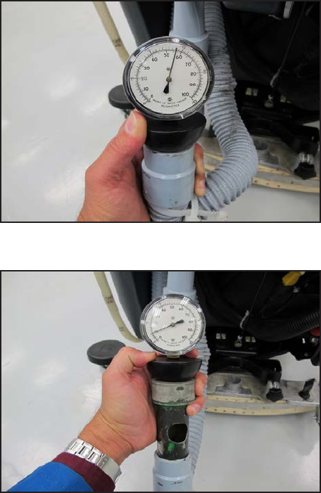
Service Manual: SC750, SC800, SC 750 ST, SC800 ST
Form Number 56043150 Page 82
2. Hold the vacuum gauge against the end of the hose and turn on the vacuum motor. Note the reading on the
gauge. If it is within 10% of specs, go to the next step. If it is too low, check for air leaks in the system.
3. Install a one inch open-hole adapter between the hose end and the vacuum gauge.
4. Turn the vacuum motor on and measure the vacuum. If it is within 10% of the specs, the vacuum system is work-
ing properly. If the reading is too low, check for a restricon in the system.
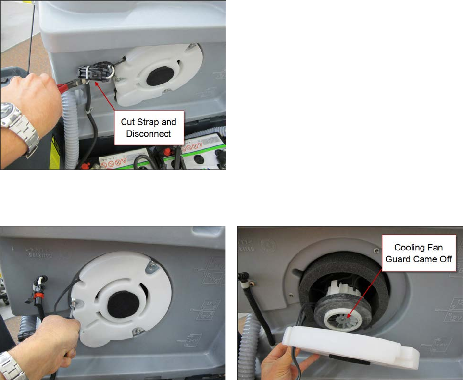
Service Manual: SC750, SC800, SC 750 ST, SC800 ST
Form Number 56043150 Page 83
Removal and Installation
Vacuum Motor
1. Turn o key switch, drain recovery tank and li recovery tank up.
2. Cut e straps securing wiring and disconnect vacuum motor electrical connecon.
3. Remove vacuum motor cover mounng screws and cover. Note: The vacuum motor cooling fan guard may come
o the end of the motor. Do not run the motor without the guard in place. Make sure that it is put back on dur-
ing reassembly.
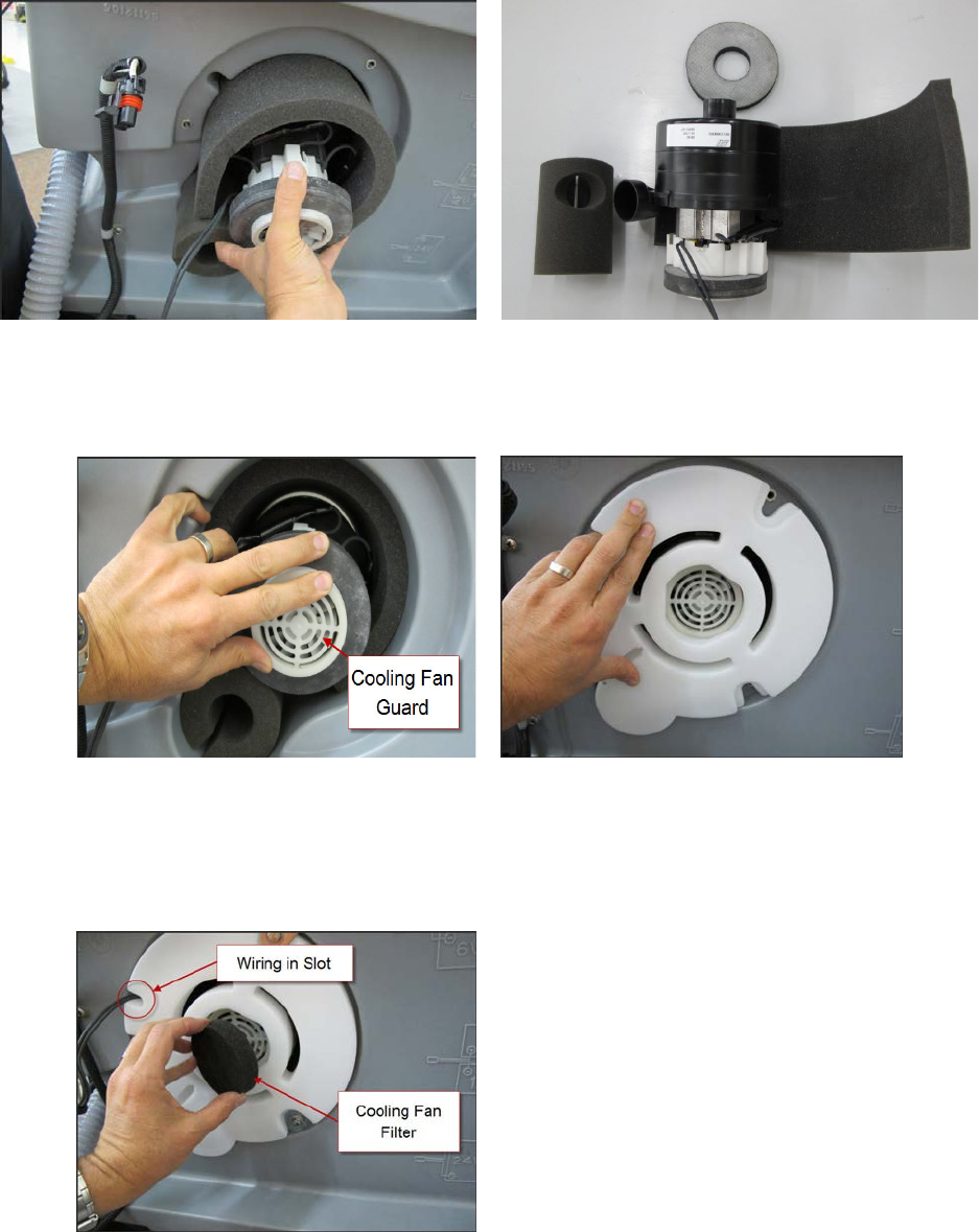
Service Manual: SC750, SC800, SC 750 ST, SC800 ST
Form Number 56043150 Page 84
4. Remove vacuum motor and foam pieces. Pay aenon to how the foam pieces are posioned.
5. Reassemble in reverse order.
a. Install the cooling fan guard if it is not in place.
b. Take care to posion all the foam pieces correctly.
c. Make sure the ends of the vacuum motor are seated correctly. (If you have diculty seang all of the
pieces, remove the recovery tank and place it upside down so that the vacuum motor goes in vercally.
This way you will not be ghng gravity.)
d. Route the vacuum motor wiring lead in the slot of vacuum motor cover and install foam cooling fan lter.
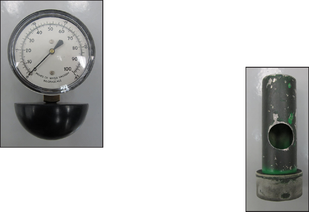
Service Manual: SC750, SC800, SC 750 ST, SC800 ST
Form Number 56043150 Page 85
Vacuum Motor
.66 HP (490 wa) three-stage
• Blocked o - measured at squeegee hose end 51.2“ H20 minimum
• With 1 inch hole measured approximately 8.7” H2O minimum
Vacuum Motor Amp Draw
With everything assembled and squeegee o the oor - 17 Amps
Special Tools
• Water Li Gauge, part number 56205281
• 1 inch open hole adaptor – This can be fabricated from a short secon of PVC pipe.
Service Manual: SC750, SC800, SC 750 ST, SC800 ST
Form Number 56043150 Page 86
Scrub System – Cylindrical
Functional Description
The scrub system moves the scrub head up and down and turns the scrub motors on and o at the operator’s request, to
provide oor scrubbing acon. The brushes spin toward one another at the boom. The head is moved up and down by
an electric actuator motor that has integrated posion switches. The weight of the scrub head provides the downward
pressure for scrubbing. The actuator linkage is sloed to allow the brush head to “oat” when going over low and high
spots on the oor. A spring is used to li just a bit of weight in order to obtain opmal scrub pressure weight. Note: The
cylindrical scrub system does not have an “extreme pressure” mode.
• The Main Machine Controller energizes the brush solenoid to turn on the brush motors when the following
inputs have been met:
o Key switch on
o Operator request
o Machine moving signal (FOR/REV)is received from the Drive Motor Controller (A2 PG Drives Speed Con-
troller)
Approximately 24 volts received from the main controller (J3 Pin 6) is switched to baery nega-
ve by the Drive Motor Controller, dropping the voltage to 0 volts.
Here is how the circuit works for the scrub motors: The Main Machine Controller turns on the scrub motors indirectly
by energizing the Brush Contactor. The brush contactor coil is fed baery posive voltage through the key switch. The
voltage goes through the coil and on to the controller. Inside the controller, it switches the circuit to baery negave to
energize the relay. When the relay energizes, posive baery voltage is applied through its contacts to the brush motors.
Since the other side of the motors is connected to baery negave, they turn on.
The Main Machine Controller also monitors the amount of electrical current (Amps) that is owing through the brush
motor ground circuit. If it is higher or lower than expected a fault code will be set. It monitors the amperage indirectly
on a “sense” wire by measuring the dierence in voltage (Voltage Drop) between a point near the motors and the main
baery negave terminal. As actual current increases, the voltage drop measured increases. The controller then converts
the voltage value to “Amps”. The monitoring circuit relies on a calibrated ground wire that is a specic gauge and length.
An electric actuator is used to move the scrub head up and down. The actuator has a DC permanent magnet electric mo-
tor which is driven by the Main Machine Controller. The motor turns a threaded sha. When the threaded sha turns, it
moves a threaded rod up and down. Since the rod is aached to the deck, it moves the deck up and down.
Inside the actuator housing, there are also three posion switches which are monitored by the Main Machine Controller.
One for the “retracted” posion, one for the “middle” posion (Normal scrub pressure) and one for the “Extended” posi-
on (Extreme scrub pressure). Each switch is normally closed. The threaded rod has a collar on it that opens each switch
as it passes by it. When the Main Machine Controller sees the middle posion switch open, it knows that the deck is in
the normal scrub posion. If that was its goal posion, the controller turns o the motor to stop the deck in that posi-
on.

Service Manual: SC750, SC800, SC 750 ST, SC800 ST
Form Number 56043150 Page 87
Here is how the circuit works for the actuator. The Main Machine Controller directly drives the brush head actuator mo-
tor. It applies system voltage across the two actuator motor wires to move the motor up. It reverses polarity to move the
motor down. Each posion switch receives a 5 volt feed through a resistor from the controller which returns back to bat-
tery negave on a common wire to connector J2 pin 2. The controller has “internal voltmeters” which monitor the signal
voltage of each switch circuit. When the switch is closed, the voltage signal is approximately 0 volts. When the switch is
open, the voltage is approximately 5 volts.
1. Deck up - Retracted Posion switch = 5v (Other two switches = 0v)
2. Normal Scrub mode - Middle Posion switch = 5v (Other two switches = 0v)
3. Extreme Scrub mode is not used on Cylindrical Deck
Note: The actuator “extended” posion switch circuit is unique because it is also used as a communicaon line between
the Main Machine Controller and the baery charger. The addion of the baery charger on the circuit drops the 5v that
is normally seen when the switch is open to approximately 3 volts. This is normal.
When the key is turned o, if the brush head is down, the Main Machine Controller will raise the brush head to the full
“up” posion. When the operator requests the scrub mode, the controller drives the actuator down unl it sees the
Middle Posion switch open (5v). When the operator turns o the scrub funcon, the controller drives the actuator mo-
tor up unl it sees the Retracted Posion switch open again (5v). If more than one posion switch is open (5v) at a me,
the controller does not know which one to believe. It realizes there must be a problem and will not move the actuator.
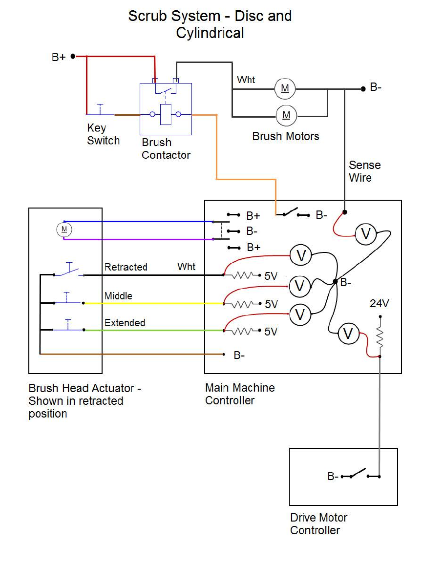
Service Manual: SC750, SC800, SC 750 ST, SC800 ST
Form Number 56043150 Page 88
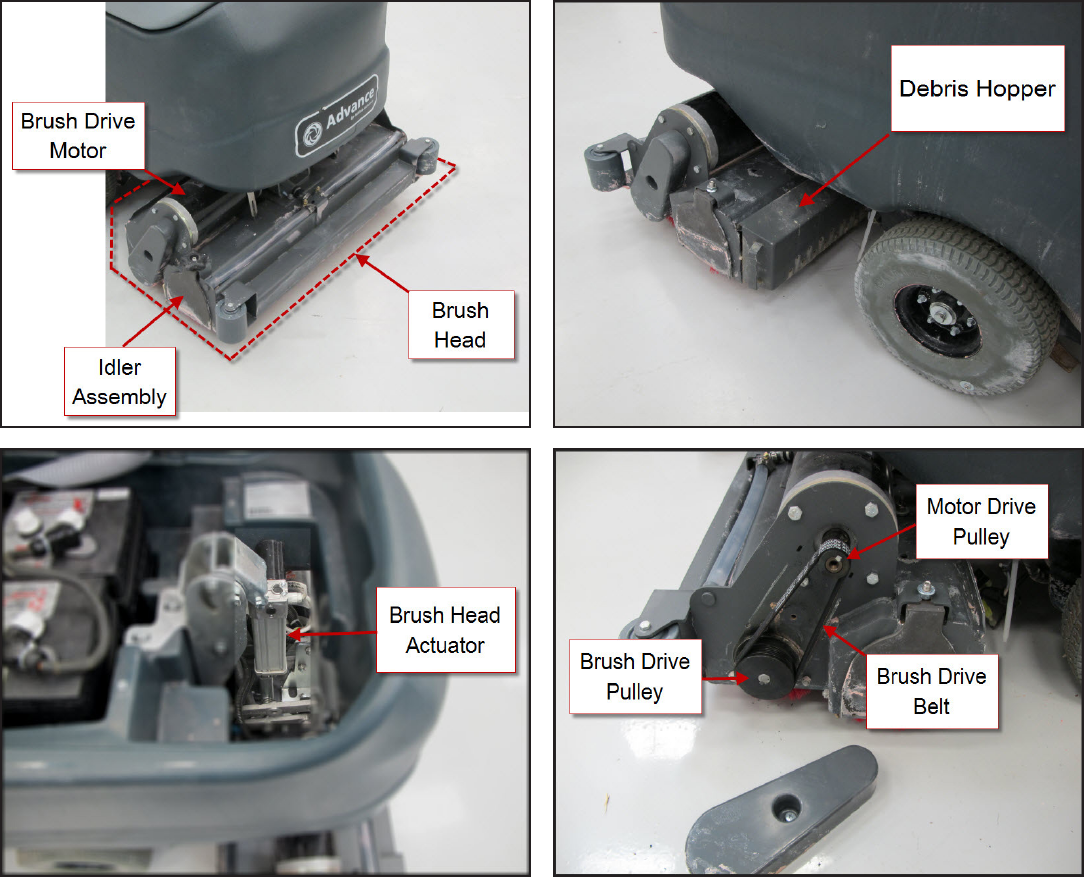
Service Manual: SC750, SC800, SC 750 ST, SC800 ST
Form Number 56043150 Page 89
Component Locations
• Brush Head
• Debris Hopper
• Idler Assembly
• Brush Drive Belt
• Brush Head Actuator
• Brush Contactor
• Brush Drive Motor
• Motor Drive Pulley
• Brush Drive Pulley
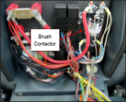
Service Manual: SC750, SC800, SC 750 ST, SC800 ST
Form Number 56043150 Page 90
Service Manual: SC750, SC800, SC 750 ST, SC800 ST
Form Number 56043150 Page 91
Troubleshooting
Scrub Motors Do Not Turn On
Possible Causes
• Brush Contactor
o Open or shorted winding
o Burned contacts
• Wiring
• Main Machine Controller – Not energizing the brush contactor.
• Drive Motor Controller – Not providing “machine moving signal”
Brush Head Will Not Raise or Lower
Possible Causes
• Mechanical binding for the actuator linkage
• Brush Head Actuator – Check both the motor and the posion switches. Only one posion switch should be open
at a me and it should open at the correct posion.
o Actuator Motor
Unplug the actuator connector and momentarily supply fused 24v power and ground to the
two motor terminals to see if the motor will operate. (Machine harness wire color Pink wire and
Gray wire). Reverse the polarity to drive it in both direcons. If the motor will not drive in both
direcons, replace the actuator. If it does drive in both direcons, proceed to check the posion
switches.
o Posion Switches
Access the Main Machine Controller and unplug the electrical connectors.
Check the retracted posion switch.
• Put the black ohmmeter lead on the Brown wire at the J2 connector pin 2.
• Put the red ohmmeter lead on the White wire at the J2 connector pin 3.
Service Manual: SC750, SC800, SC 750 ST, SC800 ST
Form Number 56043150 Page 92
• Drive the actuator motor all the way up and down using jumper wires powered by bat-
tery posive and negave. Connect them to the two actuator motor wires at the Main
Machine Controller connector. (Pink wire at connector J1 pin 4 and Gray wire at connec-
tor J1 pin 5.) Change polarity to change direcon. Immediately remove jumper wires at
the end of motor travel.
• Monitor the ohmmeter. It should show an open circuit (no connuity) only when the
actuator is in the retracted posion. In all other posions it should show a closed circuit
(connuity).
Check the middle posion switch.
• Put the black ohmmeter lead on the Brown wire at the J2 connector pin 2.
• Put the red ohmmeter lead on the Yellow wire at the J2 connector pin 11.
• Drive the actuator motor all the way up and down using jumper wires powered by bat-
tery posive and negave. Connect them to the two actuator motor wires at the Main
Machine Controller connector. (Pink wire at connector J1 pin 4 and Gray wire at connec-
tor J1 pin 5.) Change polarity to change direcon. Immediately remove jumper wires at
the end of motor travel.
• Monitor the ohmmeter. It should show an open circuit (no connuity) only when the
actuator is in the middle posion. In all other posions it should show a closed circuit
(connuity).
Check the extended posion switch.
• Put the black ohmmeter lead on the Brown wire at the J2 connector pin 2.
• Put the red ohmmeter lead on the Green wire at the J2 connector pin 12.
• Drive the actuator motor all the way up and down using jumper wires powered by bat-
tery posive and negave. Connect them to the two actuator motor wires at the Main
Machine Controller connector. (Pink wire at connector J1 pin 4 and Gray wire at connec-
tor J1 pin 5.) Change polarity to change direcon. Immediately remove jumper wires at
the end of motor travel.
• Monitor the ohmmeter. It should show an open circuit (no connuity) only when the
actuator is in the extended posion. In all other posions it should show a closed circuit
(connuity).
• Wiring
• Main Machine Controller
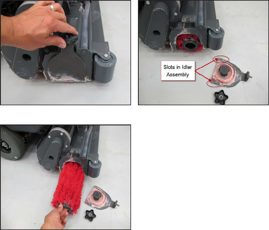
Service Manual: SC750, SC800, SC 750 ST, SC800 ST
Form Number 56043150 Page 93
Removal and Installation
Scrub Brush
1. Turn the key switch o and wait for the Brush Head to rise.
2. Disconnect the Baery Pack Connector.
3. Loosen the hand wheel nut several turns unl the idle cover lowers far enough that the slots clear and allow the
cover to be pulled outward. If the cover is stuck, push down on the hand wheel.
4. Pull brush out of housing.

Service Manual: SC750, SC800, SC 750 ST, SC800 ST
Form Number 56043150 Page 94
5. Slide new brush into housing. Rotate and li the end to engage the drive hub anges with the slots in the end of
the brush.
6. Posion idler pulley in brush end and seat the idler cover at against the brush head
7. Tighten the hand wheel nut, making sure that the slots in the idle cover line up and engage the brush head.

Service Manual: SC750, SC800, SC 750 ST, SC800 ST
Form Number 56043150 Page 95
Brush Drive Belt
The drive belt is a “stretch belt” and may appear “too short”. It is not tensioned with a sloed adjustment but instead is
stretched on much like a vacuum cleaner belt.
1. Remove belt cover.
2. Pry the brush drive belt o the drive motor pulley using a screw driver.
3. Install the belt on the brush drive pulley rst.
4. Use a screwdriver to pry the belt onto the motor pulley using a rolling acon.
5. If the belt grooves are not quite in place, push on the side of the belt while rotang the pulley unl the belt
grooves are properly seated in the pulley.
6. Reinstall the belt cover.

Service Manual: SC750, SC800, SC 750 ST, SC800 ST
Form Number 56043150 Page 96
Brush Head Actuator.
1. Empty recovery tank.
2. Press the scrub buon to lower the brush head.
3. If the actuator does not move, slightly raise the brush head with a jack to take tension o of the mounng hard-
ware.
4. Li recovery tank up.
5. Disconnect electrical connector so the actuator will not move and then turn the key o.
6. Remove upper and lower fasteners.
7. Remove actuator.
8. Reassemble in reverse order.
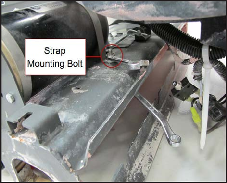
Service Manual: SC750, SC800, SC 750 ST, SC800 ST
Form Number 56043150 Page 97
Brush Motor
1. Remove the rear Scrub Brush.
2. Remove the Debris Hopper.
3. Remove the Brush Drive Belt.
4. Lower Brush Head.
5. Reconnect Baery Pack Connector.
6. Turn the key on, press the scrub switch and wait for brush head to lower.
7. Unplug Brush Head Actuator electrical connector, turn the key o and unplug the Baery Pack connector.
8. Remove the motor strap.
9. Remove the motor end mounng bolts.
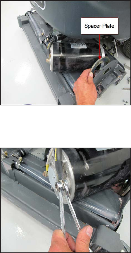
Service Manual: SC750, SC800, SC 750 ST, SC800 ST
Form Number 56043150 Page 98
10. Parally remove motor for beer access to the wiring terminals.
11. Do not lose the spacer plate.
12. Record the wiring connecons so that you will be able to reconnect it properly upon reassembly.
13. Remove wiring.
14. Use a backup wrench when removing aaching nuts to prevent the terminals from spinning.
15. Reassemble in reverse order.
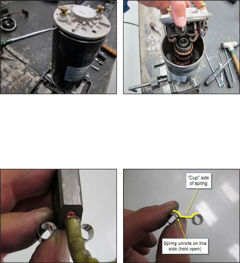
Service Manual: SC750, SC800, SC 750 ST, SC800 ST
Form Number 56043150 Page 99
Motor Carbon Brushes
1. Remove the brush drive motor.
2. Mark the posion of the endplate to the motor casing for reassembly.
3. Remove the 2 through bolts and pry o the endplate assembly.
4. Replace the carbon brushes.
a. Observe how the springs roll when the brush is pushed back before taking it apart.
b. Remove a brush and spring.
c. Install a new brush and spring into the brush holder. Thread the brush wire lead through the brush
holder. Posion the back end of the brush in the “cup” of the spring so that the spring will unroll as the
brush is pushed back once it is installed.
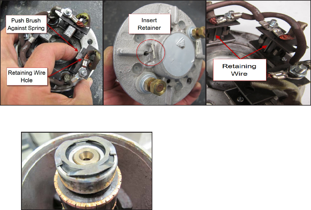
Service Manual: SC750, SC800, SC 750 ST, SC800 ST
Form Number 56043150 Page 100
d. Push brush back against the spring and insert a s temporary retaining wire (paper clip) through the ac-
cess hole in the end cover. (Remove silicone sealer from the holes) The wire must go through the holes in
the brush holder just in front of the brush to hold the brush back against the spring pressure.
5. Install the other three brushes.
6. Install the wave washer.
7. Install the end cover in stages, aligning the marks made earlier.
a. Install it far enough so that the brushes will contact the commutator when the temporary retaining wires
are removed, then remove the wires.
b. Fully seat the end cover.
8. Install the through bolts.
9. Seal the retaining wire holes in the end cover with silicone sealant.
Service Manual: SC750, SC800, SC 750 ST, SC800 ST
Form Number 56043150 Page 101
Specifications
Scrub Motor Total Amp Draw
Typical total amp draw for both 28 inch and 32 inch decks ranges from 45 Amps to 65 Amps when scrubbing with low
soluon ow, depending on the type of oor.
Scrub Motor Speed
830-840 RPM
Scrub Force
80 lbs. (36.3 kg)
Brush Head Actuator Amp Draw
Upward with weight of deck - Approximately 1-2 Amps
Brush Contactor
Winding Resistance – 55 ohms
Service Manual: SC750, SC800, SC 750 ST, SC800 ST
Form Number 56043150 Page 102
Scrub System, Disc
Functional Description
Scrubbing
The scrub system moves the scrub head up and down and turns the scrub motors on and o at the operator’s request
to provide oor scrubbing acon. The discs spin toward the center at the front edge of each disc. The head is moved up
and down by an electric actuator motor that has integrated posion switches. The weight of the scrub head provides the
downward pressure in the normal scrub mode. When extreme pressure is requested, the actuator moves down farther
causing a gas spring to exert addional downward pressure on the oor.
The Main Machine Controller energizes the brush solenoid to turn on the brush motors when the following inputs have
been met:
• Key switch on
• Operator request
• Machine moving signal (FOR/REV) is received from the Drive Motor Controller (A2 PG Drives Speed Controller)
o Approximately 24 volts received from the main controller (J3 Pin 6) is switched to baery negave by the
Drive Motor Controller, dropping the voltage to 0 volts.
Here is how the circuit works for the scrub motors. The Main Machine Controller turns on the scrub motors indirectly
by energizing the brush contactor. The brush contactor coil is fed baery posive voltage through the key switch. The
voltage goes through the coil and on to the controller. Inside the controller, it switches the circuit to baery negave to
energize the relay. When the relay energizes, posive baery voltage is applied through its contacts to the brush motors.
Since the other side of the motors is connected to baery negave, they turn on.
The Main Machine Controller also monitors the amount of electrical current (Amps) that is owing through the brush
motor ground circuit. If it is higher or lower than expected, a fault code will be set. It monitors the amperage indirectly
on a “sense” wire by measuring the dierence in voltage (Voltage Drop) between a point near the motors and the main
baery negave terminal. As actual current increases, the voltage drop measured increases. The controller then converts
the voltage value to “Amps”. The monitoring circuit relies on a calibrated ground wire that is a specic gauge and length.
An electric actuator is used to move the scrub head up and down. The actuator has a DC permanent magnet electric mo-
tor which is driven by the Main Machine Controller. The motor turns a threaded sha. When the threaded sha turns, it
moves a threaded rod up and down. Since the rod is aached to the deck, it moves the deck up and down.
Inside the actuator housing there are also three posion switches which are monitored by the Main Machine Controller.
One is for the “retracted” posion, one for the “middle” posion (Normal scrub pressure) and one for the “Extended”
posion (Extreme scrub pressure). Each switch is normally closed. The threaded rod has a collar on it that opens each
switch as it passes by it. When the Main Machine Controller sees the middle posion switch open, it knows that the deck
is in the normal scrub posion. If that was its goal posion, the controller turns o the motor to stop the deck in that
posion.
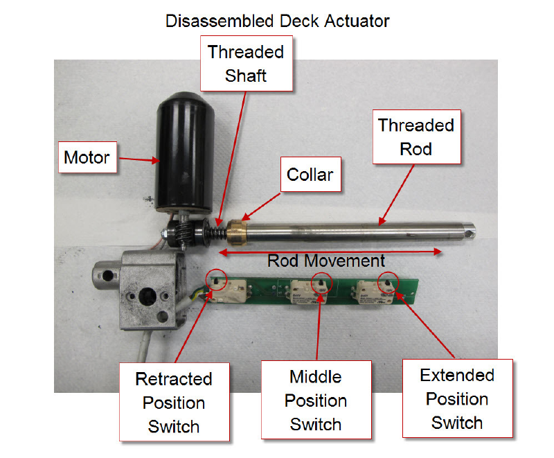
Service Manual: SC750, SC800, SC 750 ST, SC800 ST
Form Number 56043150 Page 103
Here is how the circuit works for the actuator. The Main Machine Controller directly drives the brush head actuator
motor. It applies system voltage across the two actuator motor wires to move the motor up. It reverses polarity to move
the motor down. Each posion switch receives a 5 volt feed through a resistor from the controller, which returns back
to baery negave on a common wire to connector J2 pin 2. The controller has “internal voltmeters” which monitor the
signal voltage of each switch circuit. When the switch is closed, the voltage signal is approximately 0 volts. When the
switch is open, the voltage is approximately 5 volts.
1. Deck up - Retracted Posion switch = 5v (Other two switches = 0v)
2. Normal Scrub mode - Middle Posion switch = 5v (Other two switches = 0v)
3. Extreme Scrub mode – Extended Posion switch = 5v (Other two switches = 0v)
Note: The actuator “extended” posion switch circuit is unique because it is also used as a communicaon line between
the Main Machine Controller and the baery charger. The addion of the baery charger on the circuit drops the 5v
that is normally seen when the switch is open to approximately 3 volts. This is normal.
When the key is turned o, if the brush head is down, the Main Machine Controller will raise the brush head to the
full up posion. When the operator requests the scrub mode, the controller drives the actuator down unl it sees the
Middle Posion switch open (5v). When the operator turns o the scrub funcon, the controller drives the actuator mo-
tor up unl it sees the Retracted Posion switch open again (5v). If more than one posion switch is open (5v) at a me,
the controller does not know which one to believe. It realizes there must be a problem and will not move the actuator.
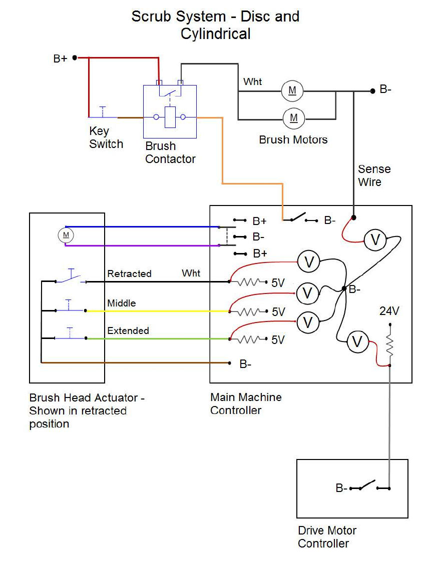
Service Manual: SC750, SC800, SC 750 ST, SC800 ST
Form Number 56043150 Page 104
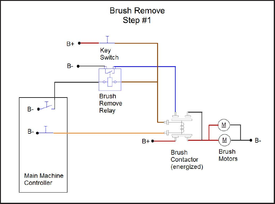
Service Manual: SC750, SC800, SC 750 ST, SC800 ST
Form Number 56043150 Page 105
Brush Disc Remove Feature
The brush disc remove feature spins the brushes and then brings them to an abrupt stop to release the brushes from the
brush plate retaining springs. To accomplish this, a series of events takes place.
Step #1
First the Main Machine Controller checks to make sure that the scrub deck is fully raised, the charger is not plugged in
and that the machine is not moving. If all of this is true, the controller energizes the brush motor contactor to supply
baery posive through its normally open (Closed when energized) contacts to power up the brushes. The brush motor
contactor has a second set of contacts which are normally closed (Open when energized).
Step #2
While the brushes are running, the Main Machine Controller energizes the brush remove relay. This provides a baery
negave connecon to one of the “open when energized” contacts. Since that side of the contactor is open at this me,
nothing changes but the system is “armed” and ready.
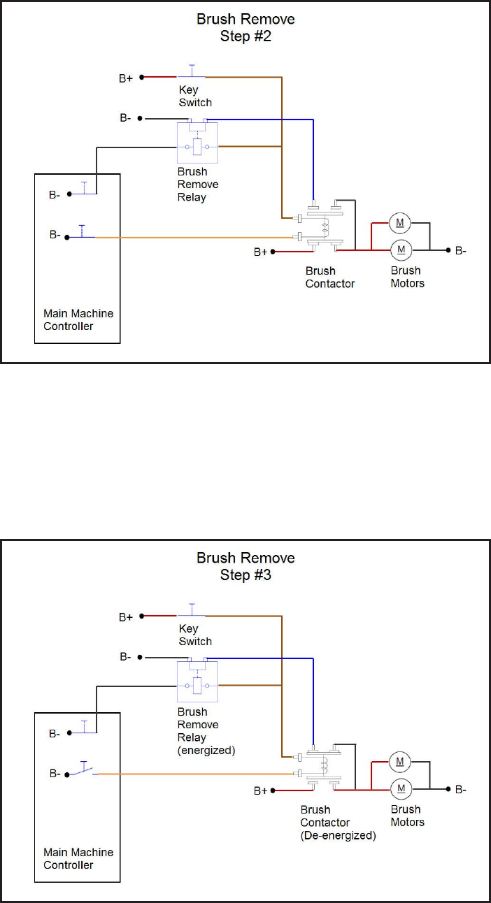
Service Manual: SC750, SC800, SC 750 ST, SC800 ST
Form Number 56043150 Page 106
Step #3
Next the brush motor relay is de-energized. This removes the baery posive power source from the motor AND instead
connects the motor to baery negave through the normally closed contacts. The motor stops abruptly when both sides
are connected to baery negave. It is the abrupt stop that releases the brush lugs from the plate retaining spring. Aer
a me out period the Main Machine Controller de-energizes the brush remove relay.
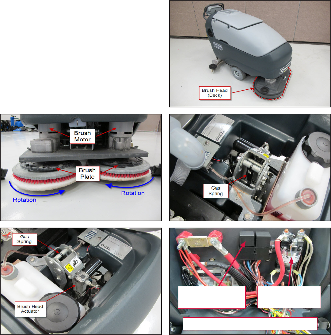
Service Manual: SC750, SC800, SC 750 ST, SC800 ST
Form Number 56043150 Page 107
Component Locations
• Brush Head (Deck)
• Brush Plate
• Brush Motor
• Gas Spring
• Brush Head Actuator
• Brush Contactor
• Brush Remove Relay
Brush Contactor
K2
Brush Remove
Relay K3
Electrical Panel
Service Manual: SC750, SC800, SC 750 ST, SC800 ST
Form Number 56043150 Page 108
Troubleshooting
Scrub Motors Do Not Turn On
Possible Causes
• Brush contactor
o Open or shorted winding
o Burned contacts
• Wiring
• Main Machine Controller – Not energizing the brush contactor.
• Drive Motor Controller – Not providing “machine moving signal”
Scrub Deck Will Not Raise or Lower
Possible Causes
• Mechanical binding for the actuator linkage
• Brush Head Actuator – Check both the motor and the posion switches. Only one posion switch should be open
at a me and it should open at the correct posion.
o Actuator Motor
Unplug the actuator connector and momentarily supply fused 24v power and ground to the
two motor terminals to see if the motor will operate. (Machine harness wire color Pink wire and
Gray wire). Reverse the polarity to drive it in both direcons. If the motor will not drive in both
direcons, replace the actuator. If it does drive in both direcons, proceed to check the posion
switches.
o Posion Switches
Access the Main Machine Controller and unplug the electrical connectors.
Check the retracted posion switch.
• Put the black ohmmeter lead on the Brown wire at the J2 connector pin 2.
• Put the red ohmmeter lead on the White wire at the J2 connector pin 3.
• Drive the actuator motor all the way up and down using jumper wires powered by bat-
tery posive and negave. Connect them to the two actuator motor wires at the Main
Machine Controller connector. (Pink wire at connector J1 pin 4 and Gray wire at connec-
tor J1 pin 5.) Change polarity to change direcon. Immediately remove jumper wires at
the end of motor travel.
• Monitor the ohmmeter. It should show an open circuit (no connuity) only when the
actuator is in the retracted posion. In all other posions it should show a closed circuit
(connuity).
Service Manual: SC750, SC800, SC 750 ST, SC800 ST
Form Number 56043150 Page 109
Check the middle posion switch.
• Put the black ohmmeter lead on the Brown wire at the J2 connector pin 2.
• Put the red ohmmeter lead on the Yellow wire at the J2 connector pin 11.
• Drive the actuator motor all the way up and down using jumper wires powered by bat-
tery posive and negave. Connect them to the two actuator motor wires at the Main
Machine Controller connector. (Pink wire at connector J1 pin 4 and Gray wire at connec-
tor J1 pin 5.) Change polarity to change direcon. Immediately remove jumper wires at
the end of motor travel.
• Monitor the ohmmeter. It should show an open circuit (no connuity) only when the
actuator is in the middle posion. In all other posions it should show a closed circuit
(connuity).
Check the extended posion switch.
• Put the black ohmmeter lead on the Brown wire at the J2 connector pin 2.
• Put the red ohmmeter lead on the Green wire at the J2 connector pin 12.
• Drive the actuator motor all the way up and down using jumper wires powered by bat-
tery posive and negave. Connect them to the two actuator motor wires at the Main
Machine Controller connector. (Pink wire at connector J1 pin 4 and Gray wire at connec-
tor J1 pin 5.) Change polarity to change direcon. Immediately remove jumper wires at
the end of motor travel.
• Monitor the ohmmeter. It should show an open circuit (no connuity) only when the
actuator is in the extended posion. In all other posions it should show a closed circuit
(connuity).
• Wiring
• Main Machine Controller
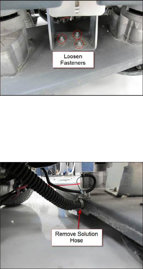
Service Manual: SC750, SC800, SC 750 ST, SC800 ST
Form Number 56043150 Page 110
Removal and Installation
Scrub Brush
Brush Head
1. Remove plasc brush head covers.
2. Remove scrub brushes.
3. Loosen, but do not remove the 3 brush head mounng fasteners.
4. Turn the key on and press the scrub on/o buon to lower the brush head to the oor. Then turn the key o
leaving the brush head on the oor.
5. Disconnect scrub motor electrical connectors.
6. Disconnect the soluon hose.
7. Remove the 3 brush head mounng fasteners.
8. Pull brush head out from under the machine.
9. Reassemble in reverse order.
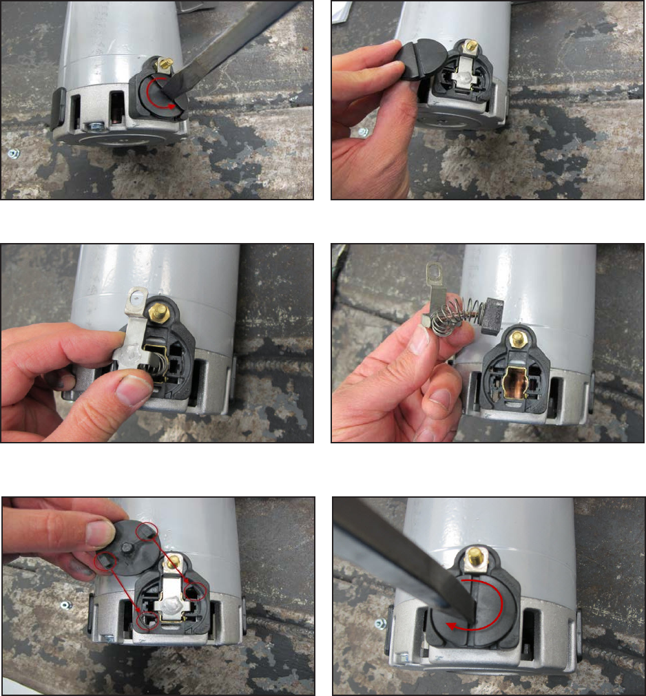
Service Manual: SC750, SC800, SC 750 ST, SC800 ST
Form Number 56043150 Page 111
Scrub Motor Carbon Brushes
Note: Photos in this secon were taken with the motor removed from the machine for beer clarity.
1. Remove the plasc motor cover.
2. Remove wiring from motor connectors.
3. Remove one of the round plasc brush caps using a large sloed screw driver.
4. Pull the brush and spring assembly out.
5. Reassemble in reverse order lining up the two locking tabs of the brush cap when installing the brush cap. Re-
peat for second carbon brush.
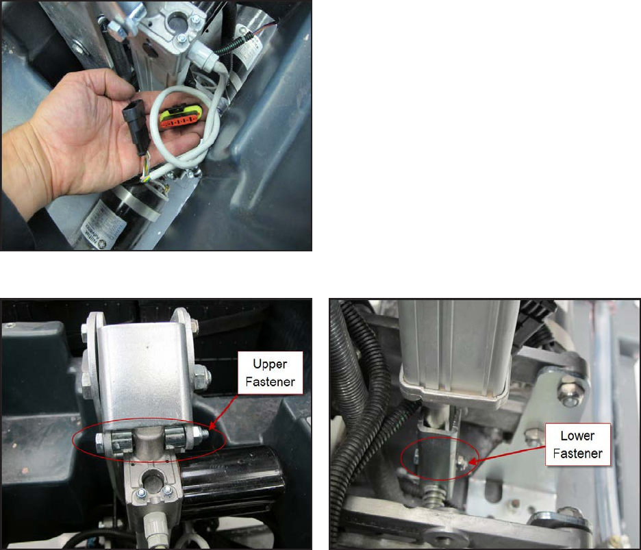
Service Manual: SC750, SC800, SC 750 ST, SC800 ST
Form Number 56043150 Page 112
Brush Head Actuator
1. Empty recovery tank.
2. Press the scrub buon to lower the brush head.
a. If the actuator does not move, slightly raise the brush head with a jack to take tension o of the mount-
ing hardware.
3. Li recovery tank up.
4. Disconnect electrical connector so the actuator will not move and then turn the key o.
5. Remove upper and lower fasteners.
6. Remove actuator.
7. Reassemble in reverse order.
Service Manual: SC750, SC800, SC 750 ST, SC800 ST
Form Number 56043150 Page 113
Specifications
Scrub Motor Amp Draw
No Load - Approximately 4 Amps
Scrub Motor Total Amp Draw
Total amp draw in regular scrub mode with low soluon ow for all size decks ranges from 15-30 Amps depending on the
oor surface. Total amp draw in extreme scrub mode with low soluon ow for all size decks ranges from 30-45 Amps
depending on the oor surface.
Scrub Motor Speed
260-270 RPM
Scrub Force
Regular Scrub = 80 lbs. (36.3 kg)
Extreme Scrub = 170 lbs. (77.1 kg)
Brush Head Actuator Amp Draw
Upward with weight of deck – Approximately 2-3 Amps
Brush Contactor
Winding Resistance – 55 ohms
Gas Spring
Force – 112 pounds (500 N)
Service Manual: SC750, SC800, SC 750 ST, SC800 ST
Form Number 56043150 Page 114
Scrub System, Rev
Functional Description
Scrubbing
The scrub system moves the scrub head up and down and turns the scrub motors on and o at the operator’s request
to provide oor scrubbing acon. The discs spin toward the center at the front edge of each disc. The head is moved up
and down by an electric actuator motor that has integrated posion switches. The weight of the scrub head provides the
downward pressure in the normal scrub mode. When extreme pressure is requested, the actuator moves down farther
causing a gas spring to exert addional downward pressure on the oor.
The Main Machine Controller energizes the brush solenoid to turn on the brush motors when the following inputs have
been met:
• Key switch on
• Operator request
• Machine moving signal (FOR/REV) is received from the Drive Motor Controller (A2 PG Drives Speed Controller)
o Approximately 24 volts received from the main controller (J3 Pin 6) is switched to baery negave by the
Drive Motor Controller, dropping the voltage to 0 volts.
Here is how the circuit works for the scrub motors. The Main Machine Controller turns on the scrub motors indirectly
by energizing the brush contactor. The brush contactor coil is fed baery posive voltage through the key switch. The
voltage goes through the coil and on to the controller. Inside the controller, it switches the circuit to baery negave to
energize the relay. When the relay energizes, posive baery voltage is applied through its contacts to the brush motors.
Since the other side of the motors is connected to baery negave, they turn on.
The Main Machine Controller also monitors the amount of electrical current (Amps) that is owing through the brush
motor ground circuit. If it is higher or lower than expected, a fault code will be set. It monitors the amperage indirectly
on a “sense” wire by measuring the dierence in voltage (Voltage Drop) between a point near the motors and the main
baery negave terminal. As actual current increases, the voltage drop measured increases. The controller then converts
the voltage value to “Amps”. The monitoring circuit relies on a calibrated ground wire that is a specic gauge and length.
An electric actuator is used to move the scrub head up and down. The actuator has a DC permanent magnet electric mo-
tor which is driven by the Main Machine Controller. The motor turns a threaded sha. When the threaded sha turns, it
moves a threaded rod up and down. Since the rod is aached to the deck, it moves the deck up and down.
Inside the actuator housing there are also three posion switches which are monitored by the Main Machine Controller.
One is for the “retracted” posion, one for the “middle” posion (Normal scrub pressure) and one for the “Extended”
posion (Extreme scrub pressure). Each switch is normally closed. The threaded rod has a collar on it that opens each
switch as it passes by it. When the Main Machine Controller sees the middle posion switch open, it knows that the deck
is in the normal scrub posion. If that was its goal posion, the controller turns o the motor to stop the deck in that
posion.

Service Manual: SC750, SC800, SC 750 ST, SC800 ST
Form Number 56043150 Page 115
Here is how the circuit works for the actuator. The Main Machine Controller directly drives the brush head actuator
motor. It applies system voltage across the two actuator motor wires to move the motor up. It reverses polarity to move
the motor down. Each posion switch receives a 5 volt feed through a resistor from the controller, which returns back
to baery negave on a common wire to connector J2 pin 2. The controller has “internal voltmeters” which monitor the
signal voltage of each switch circuit. When the switch is closed, the voltage signal is approximately 0 volts. When the
switch is open, the voltage is approximately 5 volts.
1. Deck up - Retracted Posion switch = 5v (Other two switches = 0v)
2. Normal Scrub mode - Middle Posion switch = 5v (Other two switches = 0v)
3. Extreme Scrub mode – Extended Posion switch = 5v (Other two switches = 0v)
Note: The actuator “extended” posion switch circuit is unique because it is also used as a communicaon line between
the Main Machine Controller and the baery charger. The addion of the baery charger on the circuit drops the 5v
that is normally seen when the switch is open to approximately 3 volts. This is normal.
When the key is turned o, if the brush head is down, the Main Machine Controller will raise the brush head to the
full up posion. When the operator requests the scrub mode, the controller drives the actuator down unl it sees the
Middle Posion switch open (5v). When the operator turns o the scrub funcon, the controller drives the actuator mo-
tor up unl it sees the Retracted Posion switch open again (5v). If more than one posion switch is open (5v) at a me,
the controller does not know which one to believe. It realizes there must be a problem and will not move the actuator.

Service Manual: SC750, SC800, SC 750 ST, SC800 ST
Form Number 56043150 Page 116
Functional Circuit Diagram, Scrub System - REV
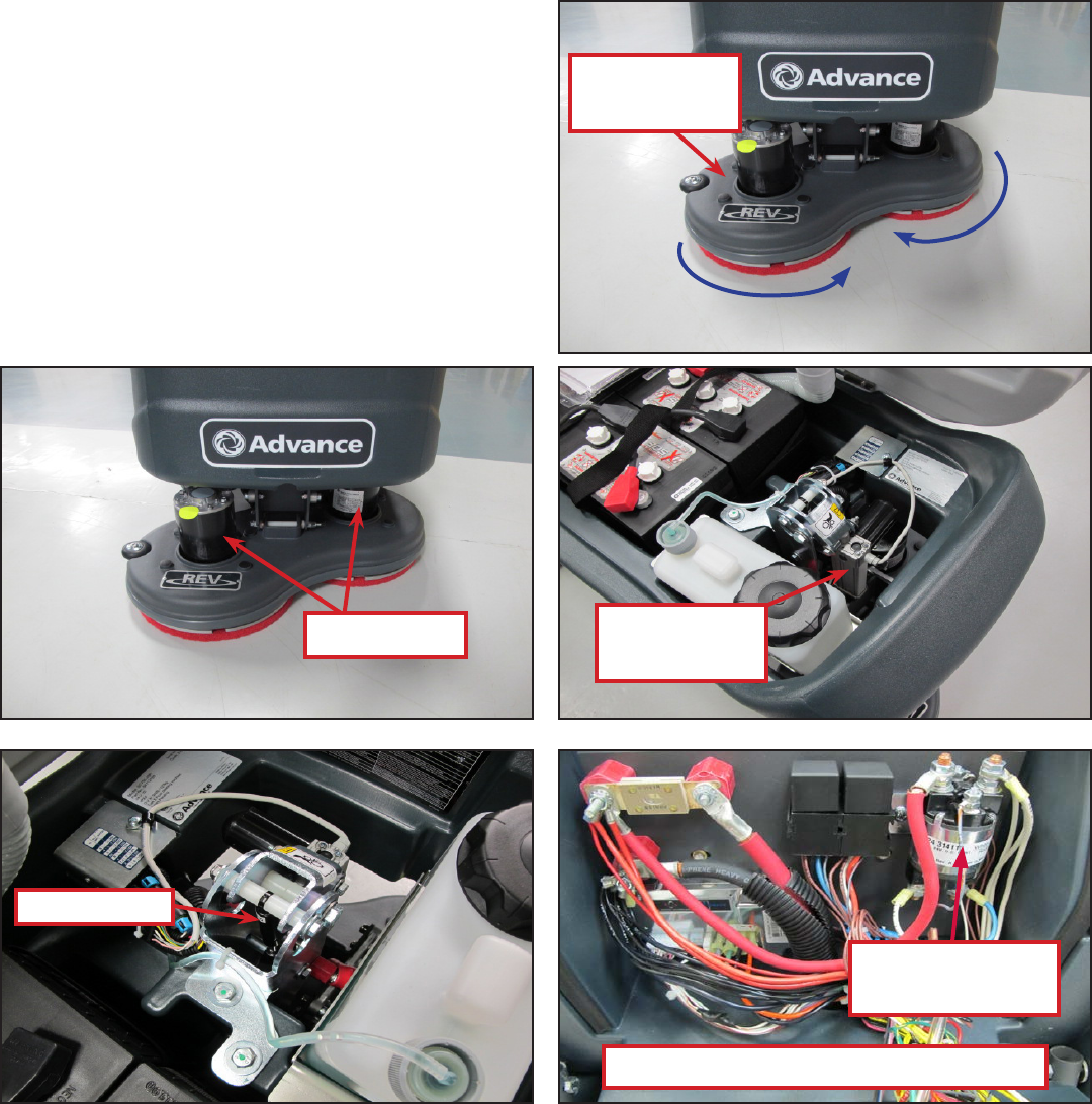
Service Manual: SC750, SC800, SC 750 ST, SC800 ST
Form Number 56043150 Page 117
Component Locations
• Brush Head (Deck)
• Brush Motor
• Gas Spring
• Brush Head Actuator
• Brush Contactor (K2)
Rotation
Rotation
Brush Head
(Deck)
Brush Motor
Gas Spring
Brush Head
Actuator
Brush Contactor
K2
Electrical Panel
Service Manual: SC750, SC800, SC 750 ST, SC800 ST
Form Number 56043150 Page 118
Troubleshooting
Scrub Motors Do Not Turn On
Possible Causes
• Brush contactor
o Open or shorted winding
o Burned contacts
• Wiring
• Main Machine Controller – Not energizing the brush contactor.
• Drive Motor Controller – Not providing “machine moving signal”
Scrub Deck Will Not Raise or Lower
Possible Causes
• Mechanical binding for the actuator linkage
• Brush Head Actuator – Check both the motor and the posion switches. Only one posion switch should be open
at a me and it should open at the correct posion.
o Actuator Motor
Unplug the actuator connector and momentarily supply fused 24v power and ground to the
two motor terminals to see if the motor will operate. (Machine harness wire color Pink wire and
Gray wire). Reverse the polarity to drive it in both direcons. If the motor will not drive in both
direcons, replace the actuator. If it does drive in both direcons, proceed to check the posion
switches.
o Posion Switches
Access the Main Machine Controller and unplug the electrical connectors.
Check the retracted posion switch.
• Put the black ohmmeter lead on the Brown wire at the J2 connector pin 2.
• Put the red ohmmeter lead on the White wire at the J2 connector pin 3.
• Drive the actuator motor all the way up and down using jumper wires powered by bat-
tery posive and negave. Connect them to the two actuator motor wires at the Main
Machine Controller connector. (Pink wire at connector J1 pin 4 and Gray wire at connec-
tor J1 pin 5.) Change polarity to change direcon. Immediately remove jumper wires at
the end of motor travel.
• Monitor the ohmmeter. It should show an open circuit (no connuity) only when the
actuator is in the retracted posion. In all other posions it should show a closed circuit
(connuity).
Service Manual: SC750, SC800, SC 750 ST, SC800 ST
Form Number 56043150 Page 119
Check the middle posion switch.
• Put the black ohmmeter lead on the Brown wire at the J2 connector pin 2.
• Put the red ohmmeter lead on the Yellow wire at the J2 connector pin 11.
• Drive the actuator motor all the way up and down using jumper wires powered by bat-
tery posive and negave. Connect them to the two actuator motor wires at the Main
Machine Controller connector. (Pink wire at connector J1 pin 4 and Gray wire at connec-
tor J1 pin 5.) Change polarity to change direcon. Immediately remove jumper wires at
the end of motor travel.
• Monitor the ohmmeter. It should show an open circuit (no connuity) only when the
actuator is in the middle posion. In all other posions it should show a closed circuit
(connuity).
Check the extended posion switch.
• Put the black ohmmeter lead on the Brown wire at the J2 connector pin 2.
• Put the red ohmmeter lead on the Green wire at the J2 connector pin 12.
• Drive the actuator motor all the way up and down using jumper wires powered by bat-
tery posive and negave. Connect them to the two actuator motor wires at the Main
Machine Controller connector. (Pink wire at connector J1 pin 4 and Gray wire at connec-
tor J1 pin 5.) Change polarity to change direcon. Immediately remove jumper wires at
the end of motor travel.
• Monitor the ohmmeter. It should show an open circuit (no connuity) only when the
actuator is in the extended posion. In all other posions it should show a closed circuit
(connuity).
• Wiring
• Main Machine Controller
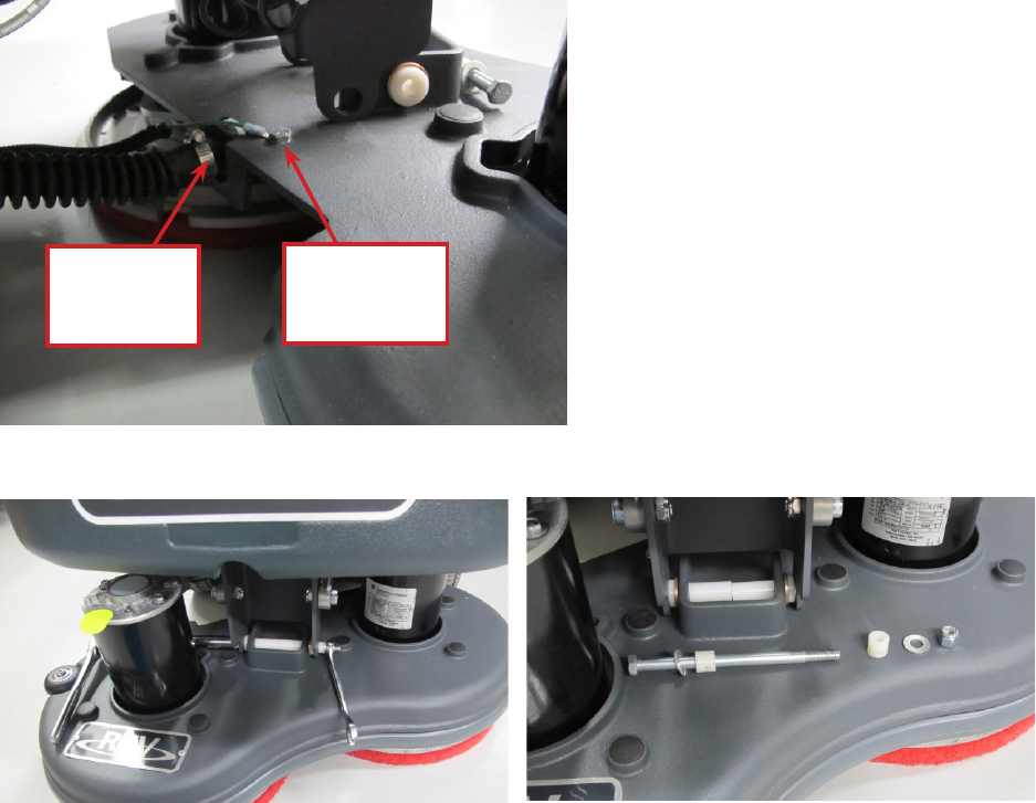
Service Manual: SC750, SC800, SC 750 ST, SC800 ST
Form Number 56043150 Page 120
Removal and Installation
Brush Head
1. Turn key on and push scrub on/o switch to lower the brush head to the oor. Then turn the key o and discon-
nect the main baery pack connector.
2. Disconnect the wiring for both brush motors. Note: the wiring connectors near one motor are not both for the
same motor. They are one posive for each motor or one negave for each motor, depending on which side you
are working.
3. Loosen the soluon hose clamp and remove the hose from the brush head. Remove the nut and bolt aaching
the ground wire to the brush head.
4. Remove the through bolt that aaches the brush head to the li mechanism bracket. Pay aenon to the
orientaon of the washers and bushings.
5. Carefully cut the e straps around the brush motor wire loops. (Do not damage the wires)
6. Raise the li bracket mechanism with your hand and slide the brush head assembly forward unl it clears the
machine.
7. Reassemble in reverse order.
Remove
Hose Clamp
and Hose
Remove
Ground Wire
Fastener
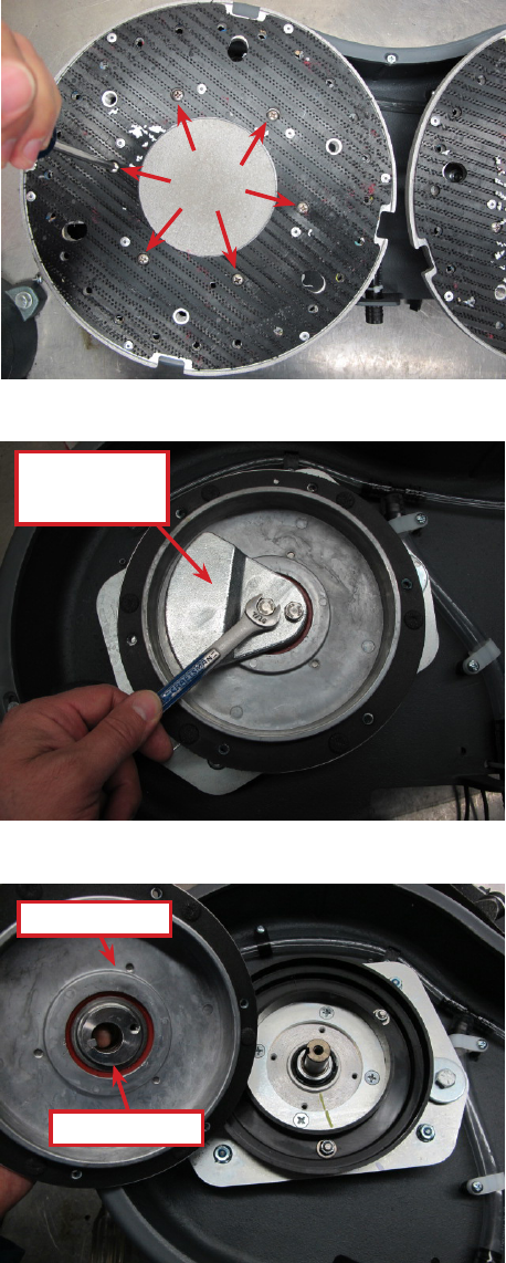
Service Manual: SC750, SC800, SC 750 ST, SC800 ST
Form Number 56043150 Page 121
Brush Motor
1. Remove the Brush Head from the machine. (See Removal and Installaon, Brush Head.)
2. Flip the deck disc side up and remove the pads.
3. Remove the pad holder by removing the 6 aaching screws.
4. Remove the counter weight by removing the two aaching bolts.
5. Li the driver motor with the eccentric from the brush motor sha being careful not to lose the square-cut key.
Counter
Weight
Driver Motor
Eccentric
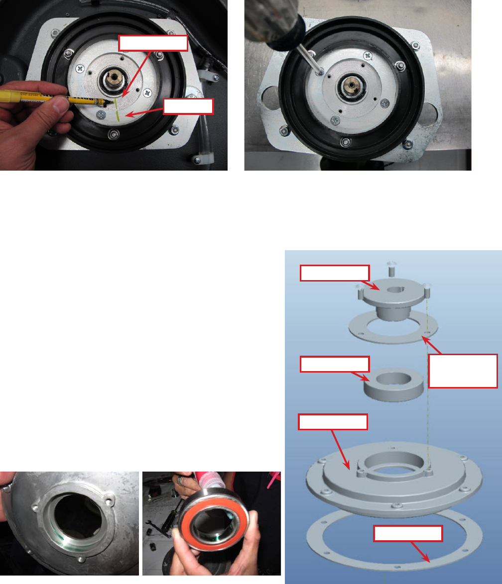
Service Manual: SC750, SC800, SC 750 ST, SC800 ST
Form Number 56043150 Page 122
6. Note the orientaon of the brush motor electrical leads relave to the deck to make sure you install the motor in
the same posion. You may want to mark the orientaon of the brush motor to the motor plate. Then separate
the brush motor from the motor plate by removing the 4 aaching screws and remove the motor.
7. Reassemble in reverse order nong the following:
8. Use a small amount of Locte Threadlocker blue 243 or equivalent on all fasteners.
9. Apply Locte An-seize (90101A) to the bore of the eccentric before installing eccentric on brush motor sha.
Drive Motor, Bearing and Eccentric
Removal
1. Remove the brush head and brush motor according to the pre-
vious secons.
2. Press the eccentric out of the bearing inner race using an arbor
press.
3. Remove the bearing retainer by removing the three fasteners.
4. Press the bearing out of the driver motor using an arbor press.
Installation
1. Apply Locte 609 retaining compound to the bearing bore in
the driver motor and to the surface of the inner bearing race.
Plate
Motor
Driver Motor
Bearing
Eccentric
Bearing
Retainer
Gasket
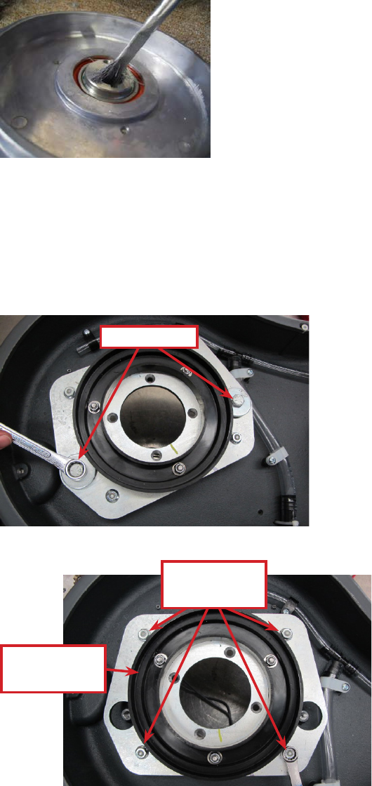
Service Manual: SC750, SC800, SC 750 ST, SC800 ST
Form Number 56043150 Page 123
2. Press the bearing into the driver motor.
3. Install the bearing retainer.
4. Press the eccentric into the bearing.
5. Install a new gasket on the driver motor with the adhesive side toward the driver motor.
6. Apply Locte An-seize (90101A) to the bore of the eccentric.
Motor Plate and Isolators
Removal
1. Remove the brush head from the machine.
2. Remove the brush motor.
3. Remove the retaining bolts, large washers and sleeves.
4. Remove the motor plate by removing the 4 isolator nuts.
Remove
Remove 4
isolator nuts
Inspect Splash
Shield
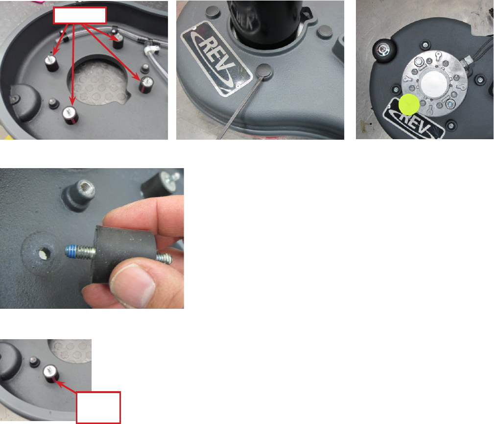
Service Manual: SC750, SC800, SC 750 ST, SC800 ST
Form Number 56043150 Page 124
5. Inspect the splash shield and replace if damaged.
6. Flip the scrub head upright and remove each of the isolators from the brush head by removing the plasc cover
and the aaching nut.
Installation
1. Apply Locte blue 243 threadlocker or equivalent to the threads of each isolator.
2. Install the isolators in the brush head. Posion each one so that the color stripe it will be visible when the motor
plate is installed. Torque each nut to 8-10 . lbs. (10.8- 13.5 N m). Install the 4 plasc covers over the nuts.
3. Apply Locte blue 243 threadlocker or equivalent to the threads of each isolator. Install the motor plate and 4
isolator nuts. Torque each nut to 8-10 . lbs. (10.8- 13.5 N m). Ensure that the isolator rubber does not twist
when you ghten the nuts. Visually inspect the color stripe to make sure that it is straight line and not twisted.
If it is twisted, loosen the nut and repeat the procedure. It may be necessary to hold the isolator in posion with
your hand while ghten the nut.
Isolators
Color
Stripe
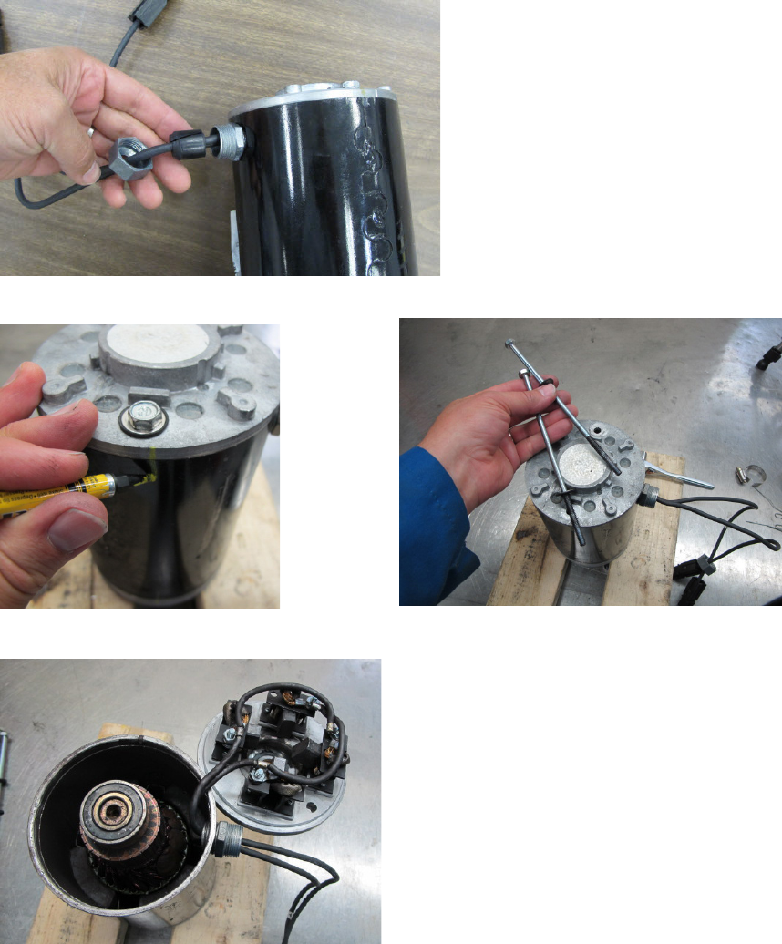
Service Manual: SC750, SC800, SC 750 ST, SC800 ST
Form Number 56043150 Page 125
Scrub Motor Carbon Brushes
1. Remove the brush head from the machine.
2. Remove wire retaining nut and rubber packing.
3. Mark orientaon of end plates to motor housing and remove both through bolts.
4. Remove end plate.
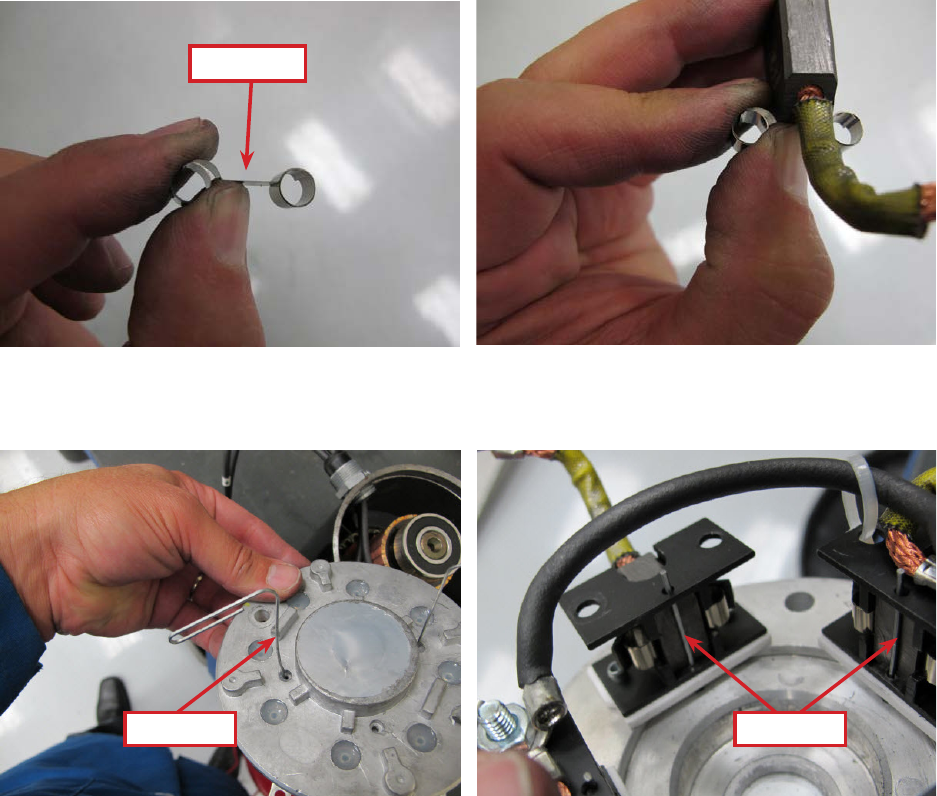
Service Manual: SC750, SC800, SC 750 ST, SC800 ST
Form Number 56043150 Page 126
5. Replace the carbon brushes.
a. Observe how the springs roll when the brush is pushed back before taking it apart.
b. Remove a brush and spring.
c. Install a new brush and spring into the brush holder. Thread the brush wire lead through the brush
holder. Posion the back end of the brush in the “cup” of the spring so that the spring will unroll as the
brush is pushed back once it is installed.
d. Push brush back against the spring and insert a s temporary retaining wire (Paper clip) through the
access hole in the end cover. (Remove silicone sealer from the holes) The wire must go through the holes
in the brush holder just in front of the brush to hold the brush back against the spring pressure.
e. Install the other three brushes.
Cup Side
Paper ClipPaper Clip
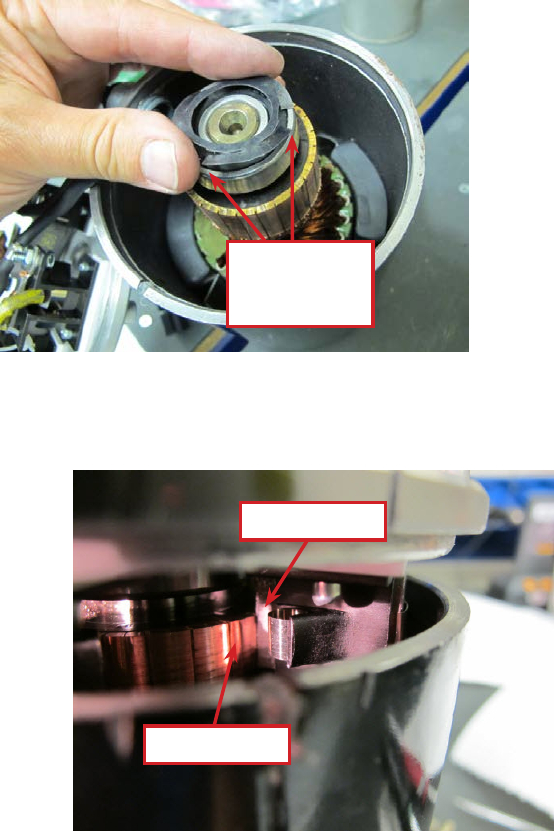
Service Manual: SC750, SC800, SC 750 ST, SC800 ST
Form Number 56043150 Page 127
6. Install the spring washer so that the “ngers” will press against the outside bearing race.
7. Install the end cover in stages.
a. Install it far enough so that the brushes will contact the commutator when the temporary retaining wires
are removed. Then remove the wires.
b. Fully seat the end cover.
c. Install the through bolts.
d. Seal the retaining wire holes in the end cover with silicone sealant.
Fingers
against Outer
Race
Carbon Brush
Commutator
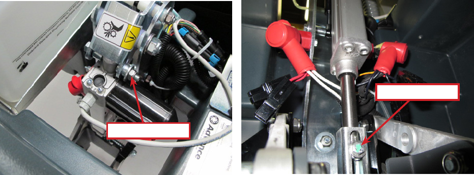
Service Manual: SC750, SC800, SC 750 ST, SC800 ST
Form Number 56043150 Page 128
Brush Head Actuator
1. Empty recovery tank.
2. Press the scrub buon to lower the brush head.
a. If the actuator does not move, slightly raise the brush head with a jack to take tension o of the mount-
ing hardware.
3. Tip the recovery tank up.
4. Disconnect electrical connector so the actuator will not move and then turn the key o.
5. Remove upper and lower fasteners.
6. Remove actuator.
7. Reassemble in reverse order.
8. Tighten the upper actuator nut and bolt unl it is snug and then back o approximately 1/2 turn. This joint must
be allowed to move freely.
Lower Fastener
Upper Fastener
Service Manual: SC750, SC800, SC 750 ST, SC800 ST
Form Number 56043150 Page 129
Specifications
Scrub Motor Amp Draw
No Load - Approximately 16-19 Amps (one motor).
Note: Only run the test for a few seconds. Remove the pads before tesng no load amp draw as the motor will spin the
pad driver around 2,000 RPM and may throw the pad.
Scrub Motor Total Amp Draw
Total amp draw will vary widely based on oor surface, soluon ow and pad type. You may see anywhere from 12 - 32
Amps (both motors) when stripping or scrubbing.
Epoxy oor and red pads, normal scrub mode. Measured 25-26 Amps.
Epoxy oor and red pads, extreme scrub mode. Measured 28-10 Amps.
Scrub Motor Speed
Approximately 2,000 RPM
Scrub Force
Regular Scrub = 70.4 lbs. (31.9 kg)
Extreme Scrub = 170 lbs. (77.1 kg)
Brush Head Actuator Amp Draw
Upward with weight of deck – Approximately 2 Amps
Brush Contactor
Winding Resistance – 55 ohms
Gas Spring
Force – 112 pounds (500 N)
Service Manual: SC750, SC800, SC 750 ST, SC800 ST
Form Number 56043150 Page 130
Solution System
Functional Description
The soluon system dispenses water and detergent to the scrub brush head for scrubbing the oor. The soluon tank
holds the soluon and serves as the main body of the scrubber. Soluon from the tank ows through a manual shut o
valve, lter, soluon valve (solenoid), manifold and out to the deck. Disc decks deliver the soluon on top of the disc
near the center. On Cylindrical decks the soluon is delivered through several small holes in manifold hoses along the
front of the deck. The soluon then drips through holes in the deck in front of the forward brush. The lter protects the
soluon valve from debris which can damage the valve. The manual shut o valve makes it possible to service plumbing
components without draining the soluon tank.
The standard soluon system requires the operator to mix a cleaning detergent with the water in the soluon tank. An
electric solenoid valve is used to turn the soluon ow on and o as well as to meter the amount of soluon used. The
soluon valve is controlled by the Main Machine Controller.
SC750 and SC800 models report soluon tank liquid level informaon to the operator on the Control Panel LCD. The
system does not measure the level of the water directly. It measures the pressure the water exerts on a pressure sensor
through a sealed hose. The higher the liquid level, the more pressure is exerted on the sensor. There is a pressure sensor
mounted on the main machine control board with a clear hose that connects to a ng on the soluon tank. On the
other side of the ng another hose goes into the tank. When the tank is lled with water/detergent, the liquid tries to
ll the hose but since the hose is sealed o it cannot displace the air in the hose and consequently cannot ll the hose
with liquid. It does exert pressure on the sensor which is converted to a voltage and “read” by the controller. This is like
holding your thumb over the top end of a drinking straw and inserng the straw into your so drink. The liquid does not
enter the straw because the air cannot escape out of the straw. What you don’t noce with your thumb is that the air
inside the straw is actually slightly pressurized by the liquid trying to displace the air.
On all machines, the Main Machine Controller turns the soluon ow on and o and meters the amount that ows via
an electric solenoid valve based on operator request and whether or not the machine is moving. The soluon solenoid
valve is spring loaded closed and must be energized to pull the valve open and allow soluon to ow. To control the
amount of soluon, the controller cycles the solenoid on and o at a slow rate. For low ow, the valve is on for about 1/3
of the me and o for 2/3 of the me. For medium ow, it is on about 2/3 of the me. For high ow it is on constantly.
The soluon is intenonally shut o whenever the machine stops moving.
The oponal detergent mixing system automacally mixes water from the soluon tank with detergent from a separate
detergent container. The operator lls the soluon tank with water only. The machine then automacally mixes the
correct amount of detergent and water and delivers it to the scrub brush head. A piston type detergent pump is used
to “inject” the detergent into the soluon hose. The controller keeps track of how many mes it has stroked the piston
pump and can calculate the level of liquid remaining in the detergent tank based on how many strokes it has counted. In
order for this to work though, the operator must “tell” the controller when a full detergent tank is installed so that the
controller can reset its counter and start again at the beginning. The detergent is injected into the soluon hose “before”
the soluon solenoid valve. The water and detergent mixture is then regulated by the solenoid valve.
Here is how the soluon electrical circuit works. In order to understand whether the machine is moving or not, the Main
Machine Controller sends 24v out through a resistor on a WHT/RED wire to the drive motor controller. The drive motor
controller has an internal switch that switches the circuit to baery negave whenever the machine is moving. The Main
Machine Controller has an internal voltmeter that monitors the circuit. When it sees 24 volts, it knows the machine is
standing sll. When it sees the voltage drop to near zero it knows the machine is moving and it then turns on the solu-
on ow. To make the soluon ow, the key switch provides baery posive (B+) voltage to the soluon solenoid valve.
The voltage goes through the solenoid winding and on to the Main Machine Controller. The controller completes the
circuit to baery negave (B-) through an internal switch causing the solenoid to energize and open the valve. If the
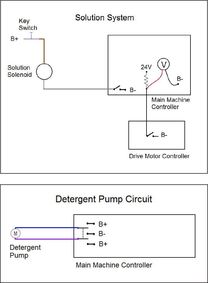
Service Manual: SC750, SC800, SC 750 ST, SC800 ST
Form Number 56043150 Page 131
machine has the oponal detergent mixing system, the Main Machine Controller also operates the addional detergent
pump. The two wires for the pump are wired directly to the Main Machine Controller. The Main Machine Controller sup-
plies baery posive on one wire and baery negave on the other for a short period of me to stroke the piston in one
direcon. It then immediately reverses polarity and does it again to stroke the piston back in the other direcon.
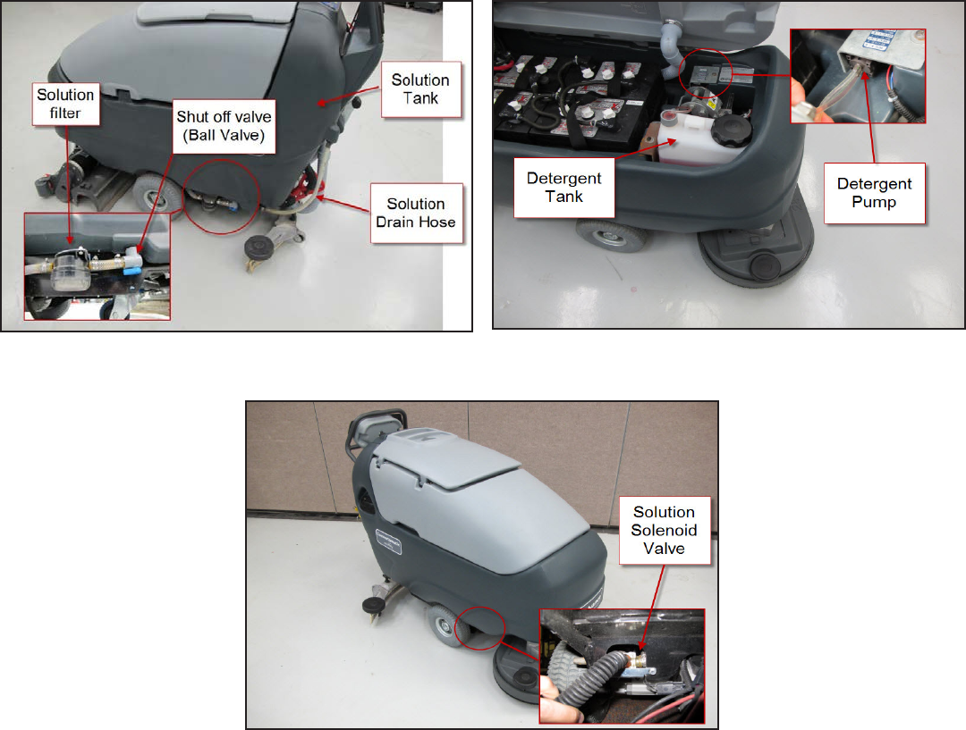
Service Manual: SC750, SC800, SC 750 ST, SC800 ST
Form Number 56043150 Page 132
Component Locations
• Soluon tank
• Shut o valve (Ball Valve)
• Soluon lter
• Soluon solenoid valve
• Detergent pump
• Detergent tank
• Soluon drain hose
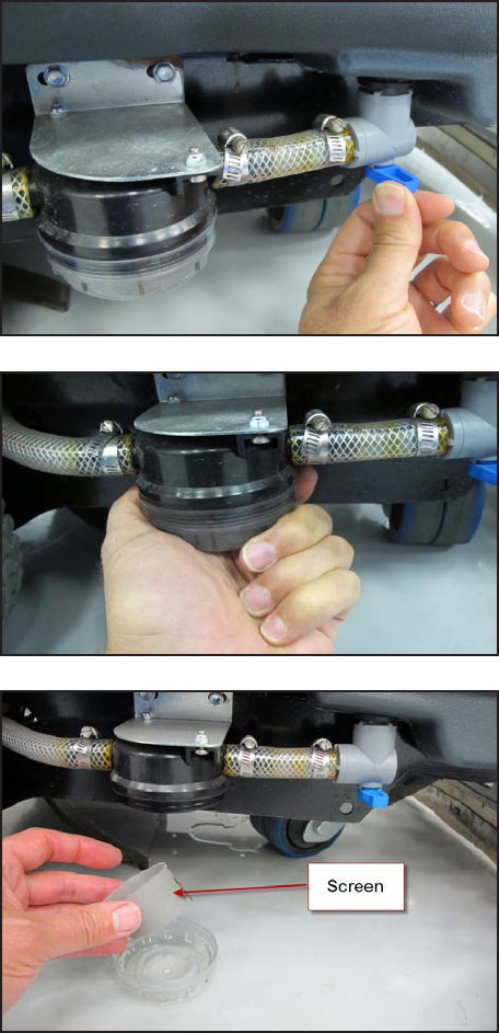
Service Manual: SC750, SC800, SC 750 ST, SC800 ST
Form Number 56043150 Page 133
Maintenance and Adjustments
Solution Filter Cleaning
1. Work near a oor drain for convenient clean up if
possible.
2. Turn the key switch o.
3. Close the shut o valve (The valve is closed when
the lever is NOT in line with the hose).
4. Unscrew the soluon lter cover.
5. Remove and clean the screen.
6. Reassemble in reverse order. Note: Over-ghtening
the cover will cause it to crack.
7. Open the shut o valve.
Service Manual: SC750, SC800, SC 750 ST, SC800 ST
Form Number 56043150 Page 134
Troubleshooting
Possible Causes
• Restricted soluon lter
• Debris/sludge in soluon tank clogging ng to shut o valve
• Pinched hose
• Restricted soluon valve
Solution Leaks After Machine Is Shut Off
Possible Causes
• Soluon valve not sealing (Worn or debris holding it open.)
• Hose or ng leak before soluon valve
Possible Causes
• Detergent tank empty
• Detergent hose blocked or leaking
• Detergent pump
• Wiring
• Main machine controller
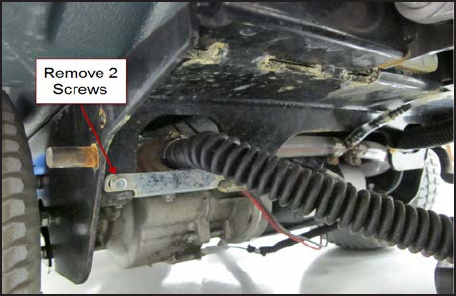
Service Manual: SC750, SC800, SC 750 ST, SC800 ST
Form Number 56043150 Page 135
Removal and Installation
Solution Valve
1. Work near a oor drain for convenient clean up if possible.
2. Turn the key switch on and lower the brush head by pushing the Scrub On/O switch.
3. Unplug the deck actuator to prevent deck from rising.
4. Turn the key switch o.
5. Close soluon shut o valve.
6. Remove soluon mounng plate screws.
7. Remove hose clamps and hoses.
8. Disconnect electrical connector.
9. Reassemble in reverse order.
Solution Tank
1. Empty recovery and soluon tanks.
2. Remove brush head.
3. Remove brush head actuator.
4. Remove recovery tank.
5. Remove baeries.
6. Remove brush head actuator support
a. Remove two top bolts.
b. Remove lower through bolt and nut.
7. Remove handle assembly.
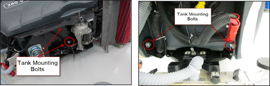
Service Manual: SC750, SC800, SC 750 ST, SC800 ST
Form Number 56043150 Page 136
8. Remove control panel cover.
9. Disconnect wiring from electrical components on electrical panel.
10. Disconnect the pressure sensor hose at the soluon tank end.
11. Thread wiring out of soluon tank.
12. Remove squeegee li cable.
13. Remove soluon tank shut o valve elbow from tank.
14. Remove 4 soluon tank mounng bolts.
15. Separate tank from frame.
• Soluon valve winding resistance – 54 ohms
• Soluon ow – Maximum = 0.75 gallons/minute
• Detergent pump winding resistance –37 ohms
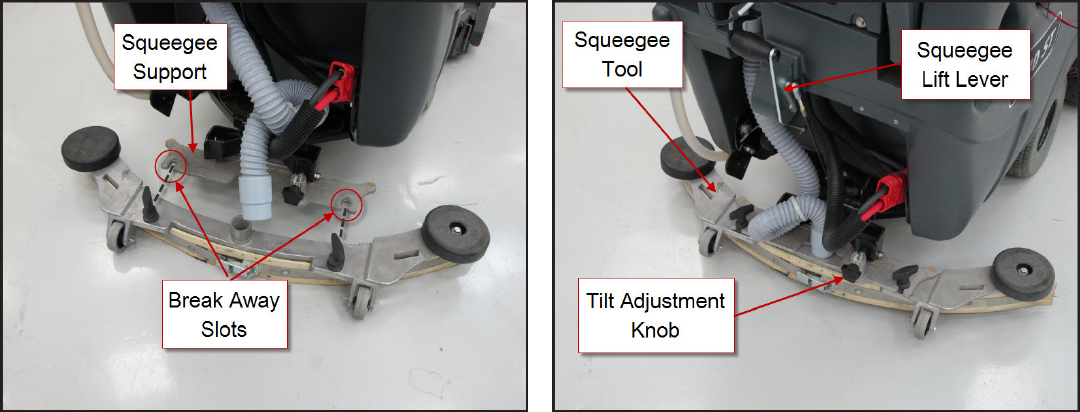
Service Manual: SC750, SC800, SC 750 ST, SC800 ST
Form Number 56043150 Page 137
Squeegee System
Functional Description
The squeegee collects the water so that the recovery system vacuum can suck it up o the oor and store it in the recov-
ery tank. The squeegee support is spring loaded downward to push the squeegee against the oor, and has a pivot point
that allows the squeegee to “swing” around corners. The squeegee tool rides along the oor on two small wheels and
is raised and lowered with a hand operated lever. To prevent damage to the squeegee tool in the event that the tool is
caught by an obstacle, it is mounted to the support frame in sloed holes and is fastened by two hand ghtened “wing
nuts”. The squeegee angle can be adjusted for opmum oor wiping. The squeegee tool has a front and a rear blade.
Each blade has 4 working edges that can be used before the blade is replaced. The front squeegee blade has slots along
the boom edge to allow the necessary air ow to carry the water. The rear squeegee blade edge is at.
Component Locations
• Squeegee Support
• Squeegee Tool
• Squeegee Li Lever
• Break Away Slots
• Tilt Adjustment Knob
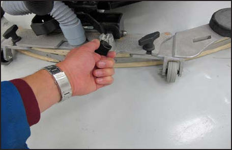
Service Manual: SC750, SC800, SC 750 ST, SC800 ST
Form Number 56043150 Page 138
Maintenance and Adjustments
Adjusting Squeegee Tilt
The lt of the squeegee causes the rear blade to rise up in the center or on the ends, depending on which direcon the
lt is changed.
1. Park the machine on a at, even surface and lower the squeegee.
2. While moving the machine forward slowly, turn the Squeegee Tilt Adjustment Knob unl the rear squeegee
blade ares evenly across the enre width of the squeegee.
Troubleshooting
Leaving Streaks on the Floor
Possible Causes
• Debris between squeegee blade and oor
• Squeegee blade edges are torn or worn
• Incorrect squeegee lt
• Broken squeegee springs
• Bent squeegee support
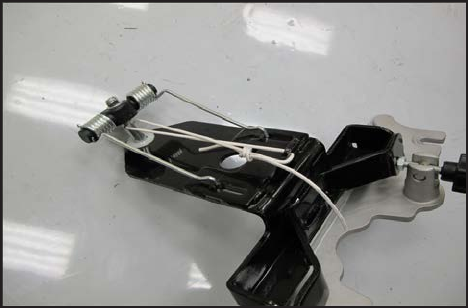
Service Manual: SC750, SC800, SC 750 ST, SC800 ST
Form Number 56043150 Page 139
Removal and Installation
Squeegee Tool
1. Remove vacuum hose from tool.
2. Loosen both wing nuts.
3. Remove squeegee tool.
4. Reassemble in reverse order. Note: Over-ghtening the wing nuts can lead to damaging the squeegee tool by
defeang the breakaway feature.
Squeegee Support
1. Remove squeegee tool.
2. Remove squeegee li cable from support.
3. Service Tip: The force of the springs against the pivot bolt causes it to p backwards and makes it dicult to get
the assembly removed and back into place. Neutralize the spring force by liing the support up a bit against the
spring tension and e it up with a wire. See photo.
4. Remove the lower pivot mounng nut.
5. Remove squeegee support assembly.
6. Reassemble in reverse order.
a. Cut wire used to hold spring tension.
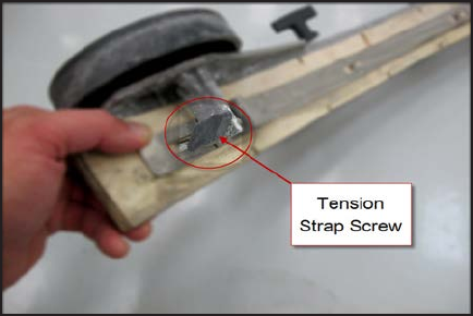
Service Manual: SC750, SC800, SC 750 ST, SC800 ST
Form Number 56043150 Page 140
Squeegee Blades
Squeegee blades have 4 working edges. As an edge becomes worn, the blade should be removed and rotated so that a
new edge is against the oor facing forward.
Front Squeegee Blade
1. Remove squeegee tool.
2. Loosen the tension strap screw
3. Remove the tension strap.
4. Remove the blade.
5. Install blade on tool being careful to match the alignment
slots.
6. Install the tension strap.
7. Tighten the tension strap screw.
Rear Squeegee Blade
1. Remove squeegee tool.
2. Unsnap the center latch.
3. Remove the tension straps.
4. Remove the blade.
5. Install blade on tool, being careful to match the alignment slots.
6. Install the tension straps.
7. Snap the center latch closed.
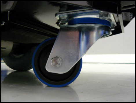
Service Manual: SC750, SC800, SC 750 ST, SC800 ST
Form Number 56043150 Page 141
Wheel System Non-Traction
Functional Description
A single caster wheel mounted to the back of the frame allows the machine to pivot easily. The wheel is aached with 4
bolts that are screwed into threaded holes in the frame.
Component Locations
• Caster Wheel
Service Manual: SC750, SC800, SC 750 ST, SC800 ST
Form Number 56043150 Page 142
Wheel System, Traction
Functional Description
A permanent magnet motor transaxle is used to propel the machine in both forward and reverse direcons. The con-
trols for forward, reverse and speed are dierent between the “ST” (SC 750 ST, SC800 ST) and “Non-ST”(SC750, SC800)
Models. The SC750 and SC800 models use a drive paddle with an angle sensor (potenometer) as an input for forward
and reverse with a variable speed signal. They also have a separate speed limit potenometer to control the maximum
speed. The SC750 ST and SC800 ST models use a combinaon of two switches. There are 2 “Palm Drive Buons” and a
Reverse Buon. When either palm drive buon is pressed, the machine will go forward. If the reverse buon is pressed
while a palm drive buon is pressed the machine will move in reverse. ST models also have a separate speed control
potenometer. It controls the speed of travel. On both models, the speed in reverse is intenonally less than in forward.
The Drive Motor Controller varies the amount of voltage it applies to the drive motor to control speed. It reverses the
polarity to change direcon. The Drive Motor Controller is capable of informing the Main Machine Controller that it sees
a problem, but there are no specic drive system codes to retrieve.
Drive Motor Circuit Description - SC750 ST and SC800 ST models.
Powering up the Drive Motor Controller:
The controller is connected directly to baery posive (B+) and baery negave (B-). These supply the power that the
controller uses to send out to the drive motor. The controller “wakes up” when it receives voltage from the key switch.
On machines with an oponal on-board baery charger, the voltage rst goes through the key switch and then through
the interlock circuit in the baery charger when the charger is not plugged into an AC power supply. When the charger is
plugged in, the voltage is interrupted by the built in interlock relay and the drive system will not wake up even if the key
is turned on.
Drive Motor Controller Inputs
To drive forward, the operator presses either palm drive buon and rotates the speed control potenometer to achieve
the desired speed. The drive motor controller has internal “voltmeters” that are monitoring 3 inputs.
1. Palm Switches - To know when to move.
2. Speed Request - To know how fast to move
3. Reverse Switch - To know which direcon to move
The palm drive buons are fed 5 volts from the controller. When either switch closes, the 5 volts goes through the switch
and back to the controller where an internal voltmeter “sees” the 5 volts and “recognizes” it as a request to move. (Note:
There is an internal “diagnosc voltage” of a lile more than 2 volts that will be seen when both switches are open.)
The speed limit potenometer is fed 5 volts from the controller on one side of its resisve strip. The voltage goes
through the resisve strip and returns to baery negave inside the controller. The “wiper” inside the potenometer will
return a voltage back to the controller as a speed request input. If the wiper is close to the supply side, the voltage will
be high (4.6v = Maximum speed request). If it is close to the baery negave return side, the voltage will be low (0.2v =
Minimum speed request).
The reverse switch provides the “direconal request input.” Here is how it works. The Drive Motor Controller sends ap-
proximately 2.8v through an internal resistor out to the reverse switch. An “internal voltmeter” monitors the voltage.
When the reverse switch is open, 2.8v is seen. This is interpreted as a “forward direcon” request. When the reverse
switch closes, it connects the voltage to baery negave through the Drive Motor Controller. This drops the voltage from
2.5v to nearly 0v. This is interpreted as a “reverse direcon” request.
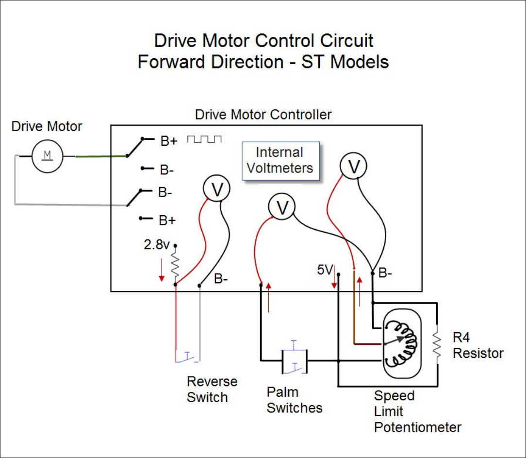
Service Manual: SC750, SC800, SC 750 ST, SC800 ST
Form Number 56043150 Page 143
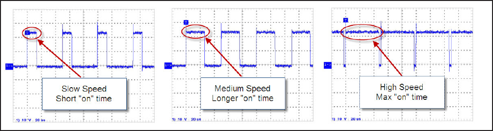
Service Manual: SC750, SC800, SC 750 ST, SC800 ST
Form Number 56043150 Page 144
Drive Motor Controller Outputs
The primary job of the Drive Motor Controller is to operate the electric transaxle drive motor. It does this by regulang
current ow through the drive motor to control speed, and by changing polarity to control direcon. The secondary job is
to nofy the Main Machine Controller when the machine is moving and which direcon it is moving. The Main Machine
Controller uses this informaon to start and stop the soluon ow and scrub funcons.
To move the machine forward, the controller connects terminal M2 to baery negave AND connects terminal M1 to
baery posive. To regulate the speed, the controller pulses the baery posive voltage out to terminal M1 at a xed
frequency called a “duty cycle”. The greater the percentage of “on” me that the circuit is connected to baery posive,
the faster the machine will go.
To move the machine in reverse, terminal M1 is connected to ground and terminal M2 is pulsed to baery posive volt-
age. The speed in reverse is intenonally reduced.
The Drive Motor Controller tells the Main Machine Controller when the machine is moving and what direcon it is mov-
ing. Two circuits are used for this purpose, the FOR/REV and the REV circuit. Here is how the FOR/REV circuit works: The
Main Machine Controller sends 24 volts out through an internal resistor to the Drive Motor Controller. The Drive Motor
Controller has an internal switch to baery negave (B-). When the machine is not moving, the switch is open. There
is an internal voltmeter inside the Main Machine Controller that sees 24 volts on the circuit. When the machine moves
in either direcon, the switch closes and the voltage drops to 0 volts. This tells the main machine controller that the
machine is moving. However, the main machine controller does not know what direcon the machine is moving. There
is another circuit called the REV circuit that provides direcon informaon. It works similar to the FOR/REV circuit. When
the machine is staonary or moving forward, the switch remains open so the main machine controller “sees” 24v. The
switch closes when the machine moves in reverse, dropping the voltage to 0v.
• Staonary Machine - Both Inputs=24v
• Machine Moving Forward = FOR/REV=0v, REV = 24v
• Machine Moving in Reverse - FOR/REV=0v, REV = 0v
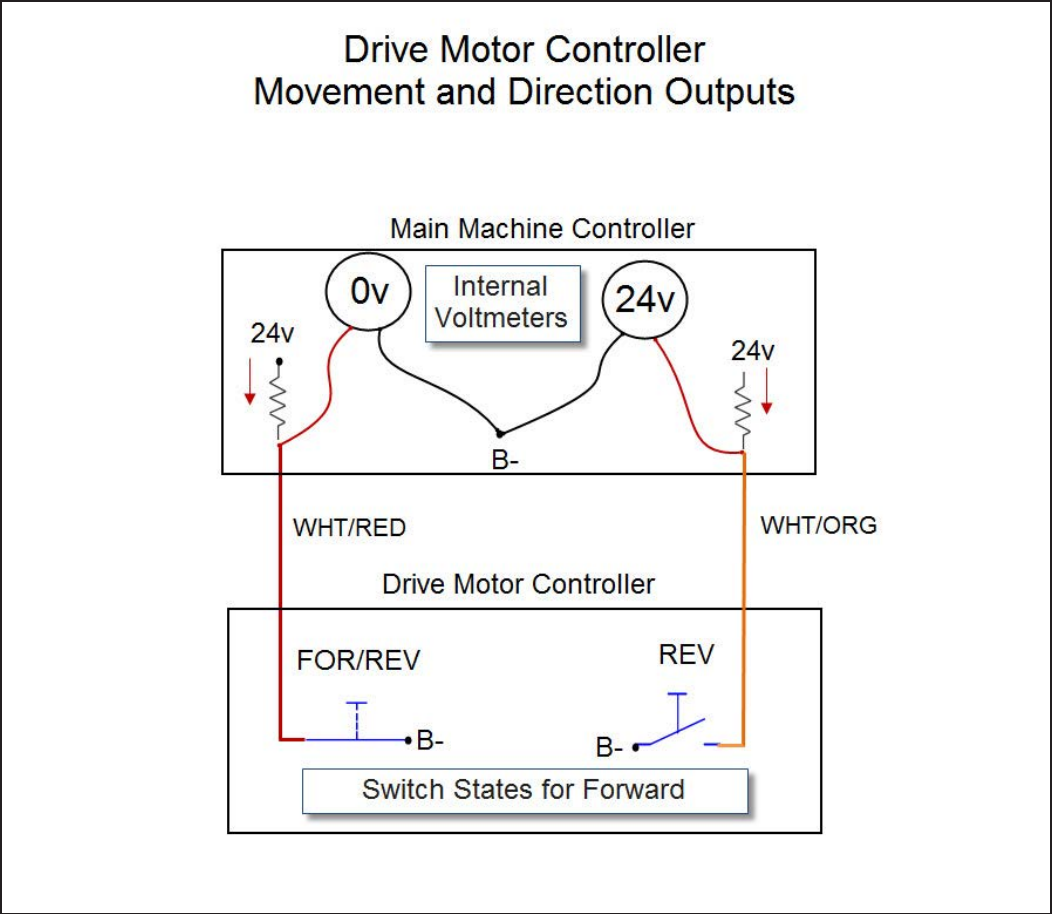
Service Manual: SC750, SC800, SC 750 ST, SC800 ST
Form Number 56043150 Page 145
Drive Motor Circuit Description - SC750 and SC800 models.
Service Manual: SC750, SC800, SC 750 ST, SC800 ST
Form Number 56043150 Page 146
Powering up the Drive Motor Controller:
This is the same as the “ST” models. See above secon.
Drive Motor Controller Inputs
To drive forward, the operator pushes on a drive paddle which rotates the Speed Control Potenometer inside the
paddle. A separate Speed Limit Potenometer is rotated to control the maximum speed.
The drive motor controller has internal “voltmeters” that are monitoring 2 inputs.
1. Drive Paddle Posion - To know when to move and which direcon.
2. Speed Limit - To know what the maximum speed should be.
The drive paddle Posion potenometer is fed 5 volts from the controller on one side of its resisve strip. The voltage
goes through the resisve strip and returns to baery negave inside the controller. The “wiper” inside the potenom-
eter will return a voltage back to the controller as a direcon request input. If the wiper is exactly in the middle, as it
should be when drive paddle is in the spring loaded posion, the return voltage will be ½ of the supply voltage (2.5v).
As the paddle is pushed forward, the wiper moves closer to the supply side, resulng in an increase in voltage. Volt-
age above 2.5v is interpreted as a forward request. The same input is also used for more or less speed. As the paddle is
pushed farther forward, the voltage will increase and it will be interpreted as a request for more speed in the forward di-
recon. (When the drive paddle is pulled back, the voltage will drop below 2.5v. and is interpreted as a reverse request).
The Speed Limit Potenometer is fed 5 volts from the controller on one side of its resisve strip. The voltage goes
through the resisve strip and returns to baery negave inside the controller. The “wiper” inside the potenometer will
return a voltage back to the controller as a speed request input. If the wiper is close to the supply side, the voltage will
be high (4.6v = Maximum speed request). If it is close to the baery negave return side, the voltage will be low (0.2v =
Minimum speed request).
The combinaon of the drive paddle posion potenometer input and the speed limit potenometer input allows the
operator to hold the paddle all the way forward for normal operaon while sll being able to adjust the travel speed.
Drive Motor Controller Outputs
• This is the same as the ST models. See secon above.
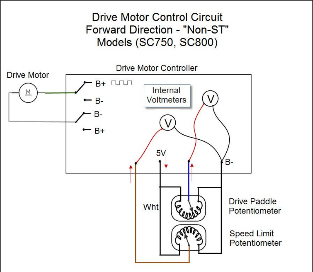
Service Manual: SC750, SC800, SC 750 ST, SC800 ST
Form Number 56043150 Page 147
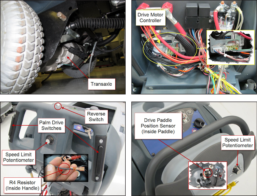
Service Manual: SC750, SC800, SC 750 ST, SC800 ST
Form Number 56043150 Page 148
Component Locations
• Transaxle (Wheel Drive Motor)
• Drive Motor Controller
• Speed Limit Potenometer – SC750 and SC800
• Drive Paddle Posion Sensor – SC750 and SC800
• Speed Limit Potenometer –ST
• Palm Drive Switches - ST
• Reverse Switch – ST
• R4 Resistor - ST
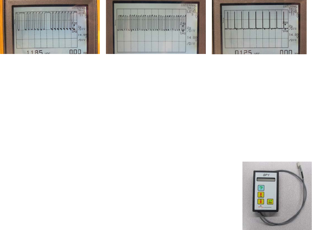
Service Manual: SC750, SC800, SC 750 ST, SC800 ST
Form Number 56043150 Page 149
Troubleshooting
The Drive Motor Controller is a PG Drives Technology controller from the I-Drive family. It performs onboard diagnosis
of itself and related circuits. If it sees a problem it sets a “Trip Code”. Trip codes are grouped by “Trip Types”. Either the
Trip Type or the Trip Code can be used to focus troubleshoong into a certain area. Trip Codes are more specic than Trip
Types.
The Drive Motor Controller uses the status wire to inform the Main Machine Controller when it has set a Trip Code and
which Trip Type the code belongs to. The main machine controller in turns displays an error code (3 on “Non-ST” models
and “1,1” on “ST” models) and it ashes out the Trip TYPE using one of the LEDs on the control panel.
Reading LED Trip Type Values
Trip types are represented by a single digit. “Non-ST” models use the Detergent LED to ash out the Trip Type value and
“ST” models use the High Soluon ow LED. A trip type 7 will ash the LED 7 mes, stay o for a brief pause and then re-
peat the cycle. The main machine controller turns on the LED whenever the voltage on the status line is low and turns it
o when the status voltage is high. These photos of a graphing voltmeter monitoring the status line can help you under-
stand what to expect for the LED ash out.
Trip Type 7 Trip Type 1 Throttle Input at Key-On
Note: If the Drive Motor Controller sees a “throle request” at pin 1 when the key is turned on, it will “ignore” the
request and tell the Main Machine Controller that there is a problem. The LED used to display the trip type value ashes
at a steady rate. It appears to momentarily ash o , then stay on for a bit longer period of me. This should not be
confused with a Trip Type 1 where there is more “o me” with a brief “on me”.When the throle request input is cor-
rected, the LED stops ashing and normal operaon is restored without the need to cycle the key o and back on.
Trip Code Table
Informaon in the following table is provided by PG Drive Technologies. It includes informaon on codes that may never
be seen in the Nilsk-Advance machine. For example, the SC750/800 model family does not ulize a solenoid brake, so
theorecally you should not ever see a trip type 9 (Solenoid Brake Trip), but in the event that you do, the table will
provide you with the informaon you need.
A specic Trip Code can only be obtained by using a PGDT (PG Drives Technology) program-
mer. This programmer is not required to troubleshoot drive system problems. If you have a
drive system problem, check to see if an LED on the control panel is ashing out the “Trip
Type” value. Use the table below to nd the trip type descripon. One Trip Type may be
related to mulple Trip Codes. You need to refer to the Code Descripon and Possible Causes
for ALL Trip Codes for a given Trip Type.
PGDT Programmer

Service Manual: SC750, SC800, SC 750 ST, SC800 ST
Form Number 56043150 Page 150
Trip Type Type Description Trip Code Code Description and Possible Causes
1Low Battery Voltage 2C00 Low Battery Voltage.
This occurs when the controller detects that the battery volt-
age has fallen below approximately 13.5V. Check the condi-
tion of the batteries, connectors and relevant wiring to the
i-Drive.
If the trip is still present after the batteries, connectors and
wiring have been checked, the controller may be defective.
Refer to Section 3
1Low Battery Voltage 2C01 Very Low Battery Voltage.
This occurs when the controller detects a sudden drop in bat-
tery voltage. Check the condition of the batteries, connectors
and relevant wiring to the i-Drive.
If the trip is still present after the batteries, connectors and
wiring have been checked, the controller may be defective.
Refer to Section 3.
2 Motor Open Circuit 3B01 Motor Open Circuit.
This occurs when the controller detects that the motor has be-
come disconnected at start-up or in standby. Check the motor,
connectors and relevant wiring to the i-Drive.
If the trip is still present after the motor, connectors and wir-
ing have been checked, the controller may be defective. Refer
to Section 3.
3Motor Wiring Trip 3D02 Motor Shorted To Battery Positive.
This occurs when the controller detects that the motor wiring
has been shorted to Battery Positive. Check the motor, con-
nectors and relevant wiring to the i-Drive.
If the trip is still present after the motor, connectors and wir-
ing have been checked, the controller may be defective. Refer
to Section 3.
3Motor Wiring Trip 3D03 Motor Shorted To Battery Negative.
This occurs when the controller detects that the motor wiring
has been shorted to Battery Negative. Check the motor, con-
nectors and relevant wiring to the i-Drive.
If the trip is still present after the motor, connectors and wir-
ing have been checked, the controller may be defective. Refer
to Section 3.
4 Not Used

Service Manual: SC750, SC800, SC 750 ST, SC800 ST
Form Number 56043150 Page 151
Trip Type Type Description Trip Code Code Description and Possible Causes
5 Not Used
6Inhibit Active 0A00 Sleep Mode.
This occurs when the controller enters Sleep Mode. Turn the
controller off and then on to awake the system. To disable
Sleep Mode, program the parameter Sleep Timer to 0 min-
utes.
6Inhibit Active 1E08* Inhibit 1 Active.
This occurs when the controller detects that the Inhibit 1 in-
put is active, Inhibit 1 Speed has been set to ‘0’ and Inhibit 1
Operation has been set to ‘Latched’. This input is located on
pin 6 of the 14-way Tiller Connector. Check the state of the
input, Inhibit 1 programming, connectors and relevant wiring
to the i-Drive.
If the trip is still present after the state of the input, program-
ming, connectors and wiring have been checked, the control-
ler may be defective. Refer to Section 3.
6Inhibit Active 1E09* Inhibit 2 Active.
This occurs when the controller detects that the Inhibit 2 in-
put is active, Inhibit 2 Speed has been set to ‘0’ and Inhibit 2
Operation has been set to ‘Latched’. This input is located on
pin 14 of the 14-way Tiller Connector. Check the state of the
input, Inhibit 2 programming, connectors and relevant wiring
to the i-Drive.
If the trip is still present after the state of the input, program-
ming, connectors and wiring have been checked, the control-
ler may be defective. Refer to Section 3.
7Throttle Trip 0815 Throttle Trip.
This occurs when the controller detects an error with one of
the throttle references, either high or low. The throttle refer-
ences are located on pins 2 and 8 of the 14-way Tiller Con-
nector, respectively. Check the throttle potentiometer, con-
nectors and relevant wiring to the i-Drive.
If the trip is still present after the potentiometer, connectors
and wiring have been checked, the controller may be defec-
tive. Refer to Section 3.

Service Manual: SC750, SC800, SC 750 ST, SC800 ST
Form Number 56043150 Page 152
Trip Type Type Description Trip Code Code Description and Possible Causes
7Throttle Trip 0E07 Throttle Trip.
This occurs when the controller detects that the Series Speed
Limit Potentiometer Wiper is shorted to one of the throttle
references, either high or low. The Series Speed Limit Poten-
tiometer Wiper input is located on pin 1 of the 14-way Tiller
Connector. The trip is only applicable if an ISO-test resistor
is tted and programmed correctly. Check the throttle poten-
tiometer, programming, connectors and relevant wiring to the
i-Drive.
If the trip is still present after the potentiometer, program-
ming, connectors and wiring have been checked, the control-
ler may be defective. Refer to Section 3.
7Throttle Trip 2F01* Throttle Displaced At Start-Up.
This occurs when the controller detects that the Throttle Po-
tentiometer has been displaced at start-up and the parameter
Throttle Operated At Power-Up has been set to ‘Trip’. Check
that the operator is not deecting the throttle at power-up, the
throttle potentiometer, connectors and relevant wiring to the
i-Drive.
If the trip is still present after the operator use, potentiometer,
connectors and wiring have been checked, the controller may
be defective. Refer to Section 3.
7Throttle Trip 7901 Belly Button Active At Start-Up.
This occurs when the controller detects that the Belly Button
Switch has been operated at power-up. The Belly Button In-
put is located on pin 9 of the 14-way Tiller Connector. Check
the Belly Button Switch, connectors and relevant wiring to
the i-Drive.
If the trip is still present after the switch, connectors and wir-
ing have been checked, the controller may be defective. Refer
to Section 3.
8 Possible Controller
Fault 5300 Programmable Setting Changed.
This occurs whenever the value of a parameter is altered us-
ing a programmer. Turn the controller off and then on to reset
the trip.

Service Manual: SC750, SC800, SC 750 ST, SC800 ST
Form Number 56043150 Page 153
Trip Type Type Description Trip Code Code Description and Possible Causes
8 Possible Controller
Fault All Other
Codes Possible Controller Fault.
This occurs when the controller suspects an internal prob-
lem. Check the batteries, motor, connectors and wiring to the
i-Drive.
If the trip is still present after these checks have been con-
ducted, the controller may be defective. Refer to Section 3.
9Solenoid Brake Trip 1500 Short Circuit In Solenoid Brake.
This occurs when the controller detects a short circuit in the
solenoid brake. Check the solenoid brake, connectors and
relevant wiring to the i-Drive.
If the trip is still present after the brake, connectors and wir-
ing have been checked, the controller may be defective. Refer
to Section 3.
9Solenoid Brake Trip 1502 Open Circuit In Solenoid Brake.
This occurs when the controller detects an open circuit in the
solenoid brake at start-up or in standby. Check the solenoid
brake, connectors and relevant wiring to the i-Drive.
If the trip is still present after the brake, connectors and wir-
ing have been checked, the controller may be defective. Refer
to Section 3.
10 High Battery Voltage 1600 High Battery Voltage.
This occurs when the controller detects that the battery volt-
age has exceeded approximately 35V on 24V i-Drives and
approximately 45V on 36V i-Drives. Check the condition of
the batteries, connectors and relevant wiring to the i-Drive.
If the trip is still present after the batteries, connectors and
wiring have been checked, the controller may be defective.
Refer to Section 3.
10 High Battery Voltage 1601 Very High Battery Voltage. Refer to Section 2.10.2
This occurs when the controller detects that the battery volt-
age has exceeded approximately 45V on 24V i-Drives and
approximately 49.5V on 36V i-Drives. Check the condition
of the batteries, connectors and relevant wiring to the i-Drive.
If the trip is still present after the batteries, connectors and
wiring have been checked, the controller may be defective.
Refer to Section 3.

Service Manual: SC750, SC800, SC 750 ST, SC800 ST
Form Number 56043150 Page 154
Trip Type Type Description Trip Code Code Description and Possible Causes
Undened 300 Parallel Speed Pot. Wiper Error
This occurs when the controller detects that the Parallel
Speed Limit Potentiometer Wiper is open circuit or has been
shorted to one of the throttle references. The Parallel Speed
Limit Potentiometer Wiper input is located on pin 9 of the
14-way Tiller Connector. If this error occurs, the controller
will allow drive to continue but at the minimum programmed
speed. Check the parallel speed potentiometer, connections
and relevant wiring to the i-Drive.
If the trip is still present after the potentiometer, connectors
and wiring have been checked, the controller may be defec-
tive. Refer to Section 3.
Undened 4401 Record Of Possible Control Fault.
‘4401’ is not actually a trip code but rather a historical record
of the number of times the i-Drive has tripped with a suspect-
ed controller fault. Each time the i-Drive trips with an error
not shown in the table above, it records one instance of the
code ‘4401’ in the controller’s System Log. The actual con-
troller trip code is also recorded in the i-Drive’s Control Log.
The number of ‘4401’ trips shown in the System Log should
therefore equal the cumulative number of trip occurrences
shown in the Control Log. More information on the i-Drive’s
diagnostic logs can be found in Chapter 3, Section 12. Check
the batteries, motor, connectors and wiring to the i-Drive.
Please contact PGDT for further advice before returning a
controller based solely on the presence of historical ‘4401’
trips in the System Log.
* Dependant on programming
Trip Types 4 and 5 not used for i-Drive
Section 3 Servicing Of Defective Units
There are no serviceable parts within the controller. Opening or making any unauthorized adjustments or modi-
caons to the controller or its components will invalidate any warranty and may result in hazards to the operator
and is strictly forbidden.
Service Manual: SC750, SC800, SC 750 ST, SC800 ST
Form Number 56043150 Page 155
Does Not Propel Forward or Reverse with No Trip Type set
In the event the machine will not propel and there are no Trip Codes or Trip Types to narrow down the problem area,
systemacally check the Drive Motor Controller power supplies, inputs and outputs. Use the Service Test Mode to speed
your diagnosis. Check to see if the Drive Motor Controller is sending signals to the Main Machine Controller that indicate
it is trying to move the machine. If it is, that conrms that the input requests to the Drive Motor Controller are good
and that it is trying to respond to them. Next, check to see if there is voltage across the motor terminals. If the voltage is
above 6 volts and the motor is not turning, the motor is the problem (Check the carbon brushes). If there is no voltage to
the motor, the controller or wiring has failed.
Possible Causes
• Baery voltage too low
• Controller not receiving input requests for travel
• Drive motor
• Drive motor controller
• Wiring
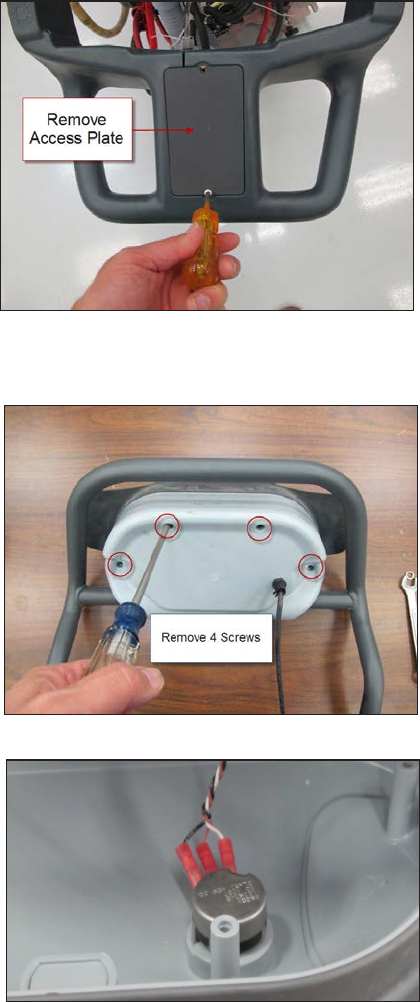
Service Manual: SC750, SC800, SC 750 ST, SC800 ST
Form Number 56043150 Page 156
Removal and Installation
Speed Limit Potentiometer – ST models
1. Loosen set screw and remove knob.
2. Remove potenometer mounng nut and washer.
3. Remove upper handle bolts.
4. Loosen lower handle bolts and rotate handle down.
5. Disconnect handle electrical connector.
6. Remove the access plate.
7. Disconnect 3 electrical connectors. Make sure you
carefully record the wire colors and their posions
so that you will be able to reconnect them correctly.
8. Remove potenometer.
9. Reassemble in reverse order.
Speed Limit Potentiometer – Non-ST models
1. Remove upper handle bolts.
2. Loosen lower handle bolts and rotate handle down.
3. From the back side of the paddle, remove the 4
screws securing the front cover. Parally remove the
front cover.
4. Disconnect the wiring from the speed limit poten-
ometer. Make sure you carefully record the wire
colors and their posions so that you will be able to
reconnect them correctly.
5. Remove front cover.
6. Remove the potenometer knob and mounng nut.
7. Reassemble in reverse order.
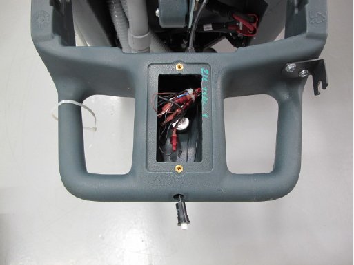
Service Manual: SC750, SC800, SC 750 ST, SC800 ST
Form Number 56043150 Page 157
Palm Buon Switches – ST models
1. Remove two switch mounng screws.
2. Remove upper handle bolts.
3. Loosen lower handle bolts and rotate handle down.
4. Remove access plate.
5. Disconnect wiring. Make sure you carefully record
the wire colors and their posions so that you will
be able to reconnect them correctly.
6. Remove switch and wiring.
a. Tip – To make it easier to install a new
switch, use a spare piece of wire aached
to the wires of the old switch when you pull
it out. Aach the new switch wires to the
spare wire to pull the wiring back through
the handle.
7. Reassemble in reverse order.
Reverse Switch – ST models
1. Remove upper handle bolts.
2. Loosen lower handle bolts and rotate handle down.
3. Remove access plate.
4. From inside the handle area, push the reverse
switch out of the handle.
5. Disconnect wiring and remove. Make sure you care-
fully record the wire colors and their posions so
that you will be able to reconnect them correctly.
6. Reassemble in reverse order.
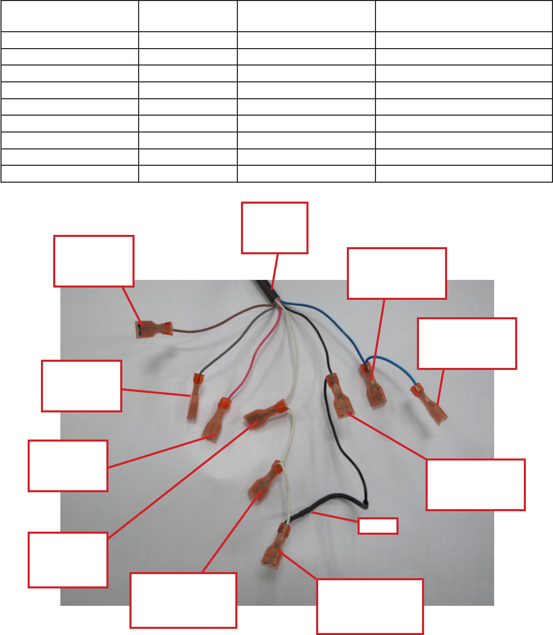
Service Manual: SC750, SC800, SC 750 ST, SC800 ST
Form Number 56043150 Page 158
Handle Wiring Connections - ST models
Component Wire color -
Component Side Wire Color - Harness
side To Main Machine Controller
(A1) Pin
Reverse Switch Black GRA J4-13
Reverse Switch Black PNK J4-12
Speed Pot. (Low Ref.) White BLK, BLK (R4) J4-8
Speed Pot. (Wiper) Brown BRN J4-9
Speed Pot. (Hi) Black WHT, WHT J4-2
Right Traction Switch Black BLU, BLU J4-1
Right Traction Switch Black WHT, WHT J4-2
Left Traction Switch Black BLU J4-1
Left Traction Switch Black WHT, BLK (R4) J4-2
Speed Pot
(Wiper)
BRN
Handle
Wiring
Harness Right Traction
Switch
BLU, BLU
Left Traction
Switch
BLU
Speed Pot.
(Low Ref.)
BLK, BLK (R4)
R4
Left Traction
Switch
WHT, BLK (R4)
Right Traction
Switch
WHT, WHT
Reverse
Switch
GRA
Reverse
Switch
PNK
Speed Pot
(Hi)
WHT, WHT
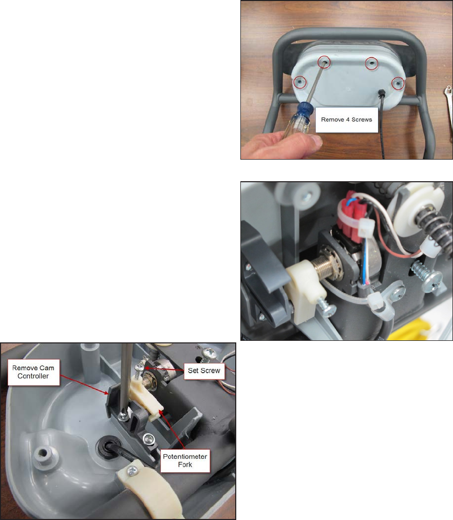
Service Manual: SC750, SC800, SC 750 ST, SC800 ST
Form Number 56043150 Page 159
Paddle Position Sensor – Non-ST models - SC750,
SC800
Photos are shown working on a bench top but this can be
done on the machine.
1. Remove top two handle mounng bolts.
2. Loosen the boom two handle mounng bolts and
rotate handle down.
3. From the back side of the paddle, remove the 4
screws securing the front cover. Remove the front
cover.
4. Disconnect wiring from the potenometer. Make
sure you carefully record the wire colors and their
posions so that you will be able to reconnect them
correctly.
5. Remove the cam controller.
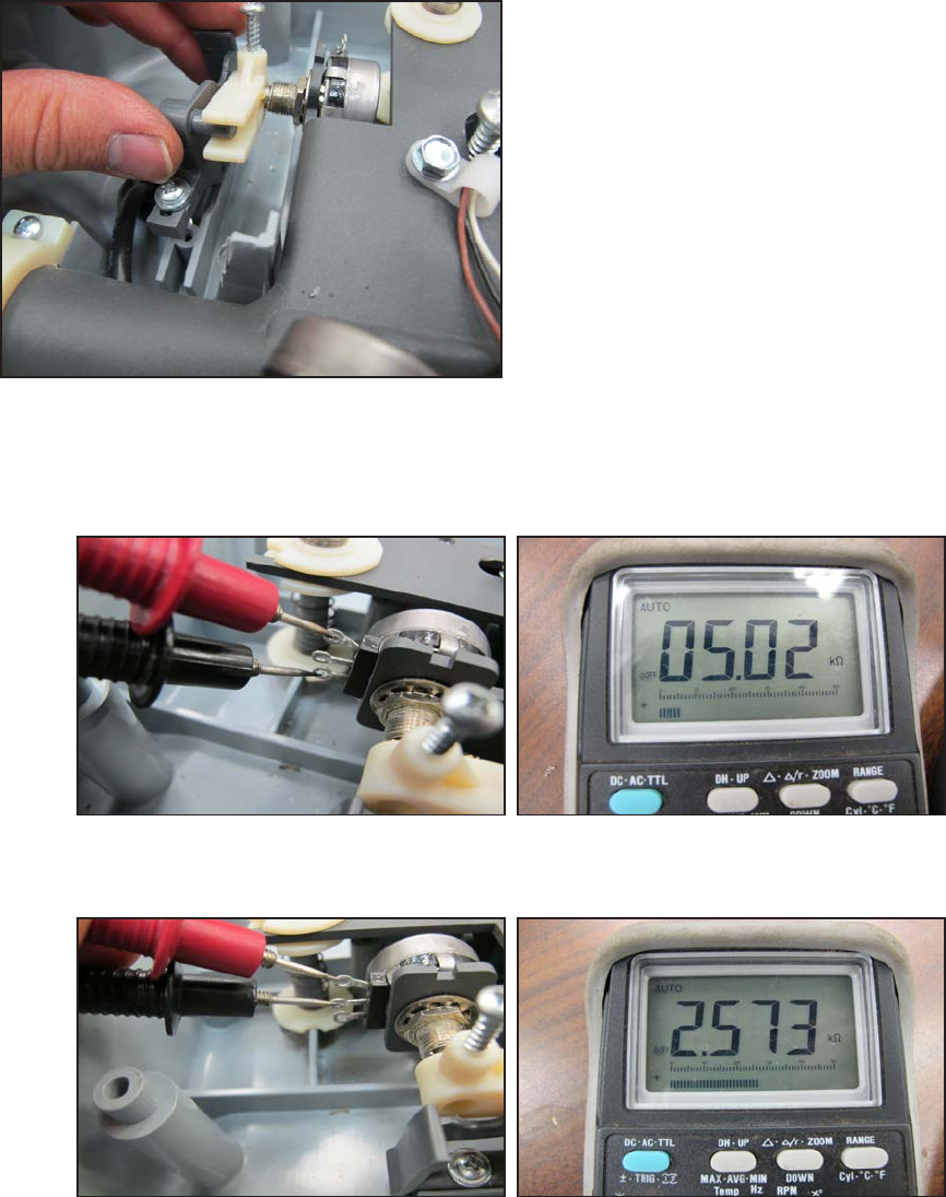
Service Manual: SC750, SC800, SC 750 ST, SC800 ST
Form Number 56043150 Page 160
6. Loosen set screw and remove the potenometer fork.
7. Remove the potenometer mounng nut and washer.
8. Install the potenometer.
9. Loosely install the potenometer fork.
10. Install the cam controller inserng the pin end into the fork.
11. Adjust the potenometer posion.
a. Measure the resistance between the two outer terminals and write the value down.
b. Hook up your ohmmeter leads between the center terminal and one of the outer terminals. Using a
small sloed screwdriver in the end of the potenometer sha, rotate the sha unl the value on the
ohmmeter is exactly ½ of the value wrien down in step a.
c. Tighten the fork set screw.
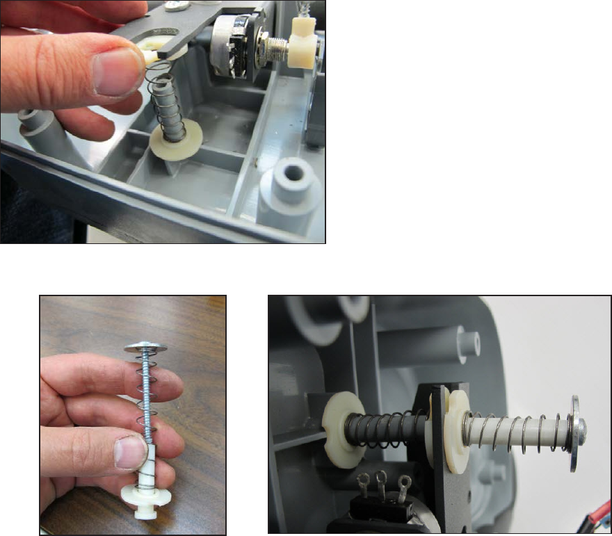
Service Manual: SC750, SC800, SC 750 ST, SC800 ST
Form Number 56043150 Page 161
12. Reconnect the wiring.
13. Reinstall the paddle cover. (Reconnect the speed limit potenometer wiring.)
14. Rotate the handle assembly back up into posion and loosely install the top mounng bolts.
15. Tighten all 4 handle mounng bolts.
Paddle Centering Springs - Non-ST models - SC750, SC800
In the event that the paddle centering springs and hardware need to be replaced, these photos will help you assemble it
correctly.
1. Carefully remove the aaching screw. Pieces will y apart if you do not retain the springs.
2. When reassembling, install the “lower stack” rst. The shoulder of the nylon washers goes toward the spring.
Carefully posion the pieces so that they stay in place.
3. Next, prepare the upper stack for assembly as shown. Install it and ghten the screw. (Do not over-ghten the
screw or it will strip out the tower).
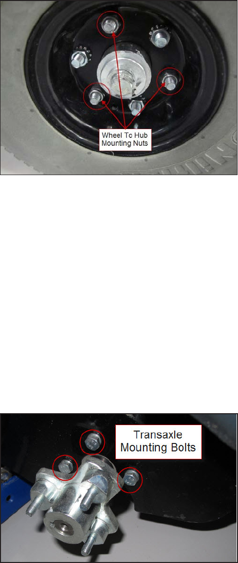
Service Manual: SC750, SC800, SC 750 ST, SC800 ST
Form Number 56043150 Page 162
Drive Wheel
1. Loosen the three nuts securing the wheel to the hub ange.
a. There are 6 nuts on the outer rim of the wheel. Three are for holding the two rim halves together. These
have standard nuts with “star” lock washers. The other three are for securing the wheel to the hub.
These have Nylock style nuts.
2. Raise the wheel o the ground with a jack and remove the 3 mounng nuts.
3. Remove the wheel.
4. Reassemble in reverse order.
Transaxle
1. Empty soluon and recovery tanks.
2. Remove the squeegee tool.
3. Remove the baeries.
4. Remove one drive wheel and remove the transaxle mounng bolts behind it.
5. With the help of an assistant, lay the machine on its side. Lay it on the side that has the wheel o and be sure to
protect the side from damage.
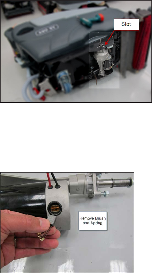
Service Manual: SC750, SC800, SC 750 ST, SC800 ST
Form Number 56043150 Page 163
6. Remove the other drive wheel and the transaxle mounng bolts behind it.
7. Disconnect the transaxle motor electrical connector.
8. Make a note of how the transaxle is oriented in the frame before removing it so that it is reassembled correctly.
9. Remove the transaxle by sliding it out of the frame slots.
10. Reassemble in reverse order.
Transaxle Drive Motor Carbon Brushes
1. Remove transaxle.
2. Remove round black plasc brush cap.
3. Remove carbon brush and spring.
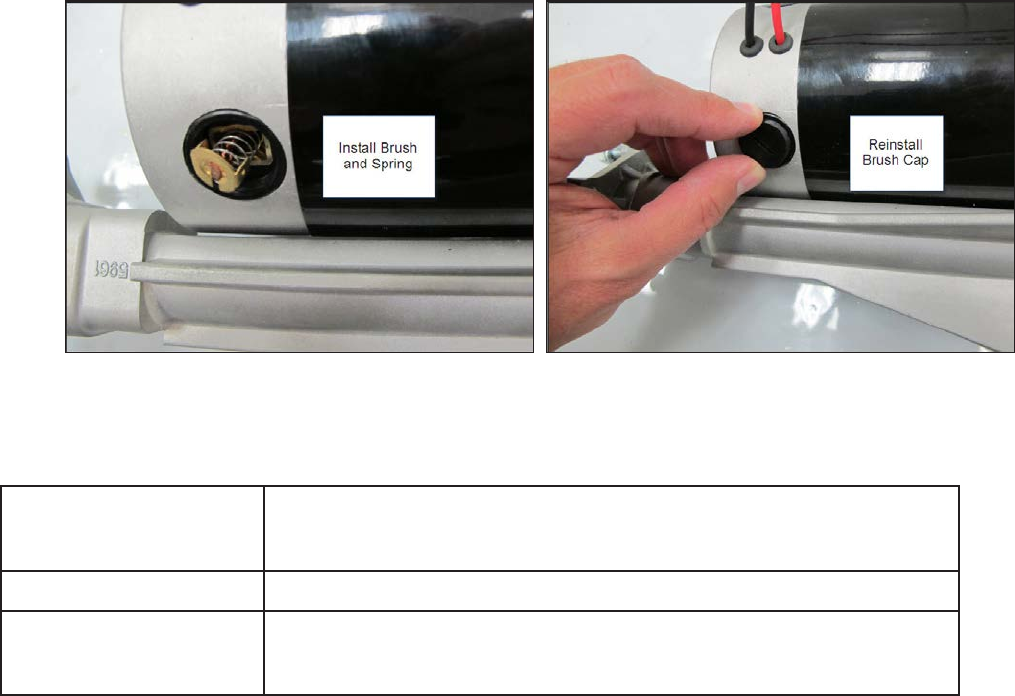
Service Manual: SC750, SC800, SC 750 ST, SC800 ST
Form Number 56043150 Page 164
4. Install brush and spring. Install and ghten cap with a screwdriver.
5. Repeat steps for all 4 carbon brushes.
Specifications
Drive Wheels Diameter: 10 in (25.4 cm) Width: 3 in (7.62 cm)
Type/Material: Polyurethane Foam - molded
Drive Motor .4 HP (298 was)
Max. Transport Speed Fwd: 5.75 km/h (3.57 mph)
Rev: 4.36 km/h (2.71 mph)
Drive Motor
Amp Draw Measurements
• No load (one wheel jacked up), jumped directly to baery- Approximately 1.8 amps
• Traversing on level oor with empty tanks driven by Drive Motor Controller at highest speed – Approximately 4-5
amps (Note: Amp draw is higher when geng up to speed – approximately 10 – 12 amps.)
Potentiometers
Speed Limit Potenometer – 100K ohms
Paddle Posion Potenometer – 5K ohms
