9094029 Rally 1200 Operation Manual Nss Carpet Extractor Operator
2016-12-22
: Sweepscrub Nss-Rally-1200-Carpet-Extractor-Operator-Manual nss-rally-1200-carpet-extractor-operator-manual 1649 file product_file
Open the PDF directly: View PDF ![]() .
.
Page Count: 8
Designed, manufactured and assembled in the U.S.A.
3115 Frenchmens Road
I
Toledo, OH 43607
I
Ph:(419)531-2121
I
Fax:(419)531-3761
I
www.nss.com
OWNER’S MANUAL
RALLY 1200
Specifications
RALLY 1200

2
Table of Contents
12- Gallon Quick Start Guide .................................................................................................................... 3
Grounding Instructions ............................................................................................................................. 4
Parts and Service ...................................................................................................................................... 4
Name Plate ................................................................................................................................................. 4
Unpacking the Machine ............................................................................................................................ 4
Caution / Warning symbols ...................................................................................................................... 4
Reducing risk of fire, electrical shock or Injury ..................................................................................... 4
Preparation ................................................................................................................................................. 5
Operating Instructions .............................................................................................................................. 5
Maintenance Schedule ............................................................................................................................. 6
Filter Maintenance ..................................................................................................................................... 6
Vacuum Stack filters ................................................................................................................................. 6
Pump filters & In-line Filter ....................................................................................................................... 6
Trouble shooting ........................................................................................................................................ 6
Pump does not work properly..................................................................................................................... 6
Vacuum motor does not work properly ..................................................................................................... 6
Limited warranty policy ................................................................................................................................ 7
Return Material Authorization (RMA) Procedure .................................................................................. 7
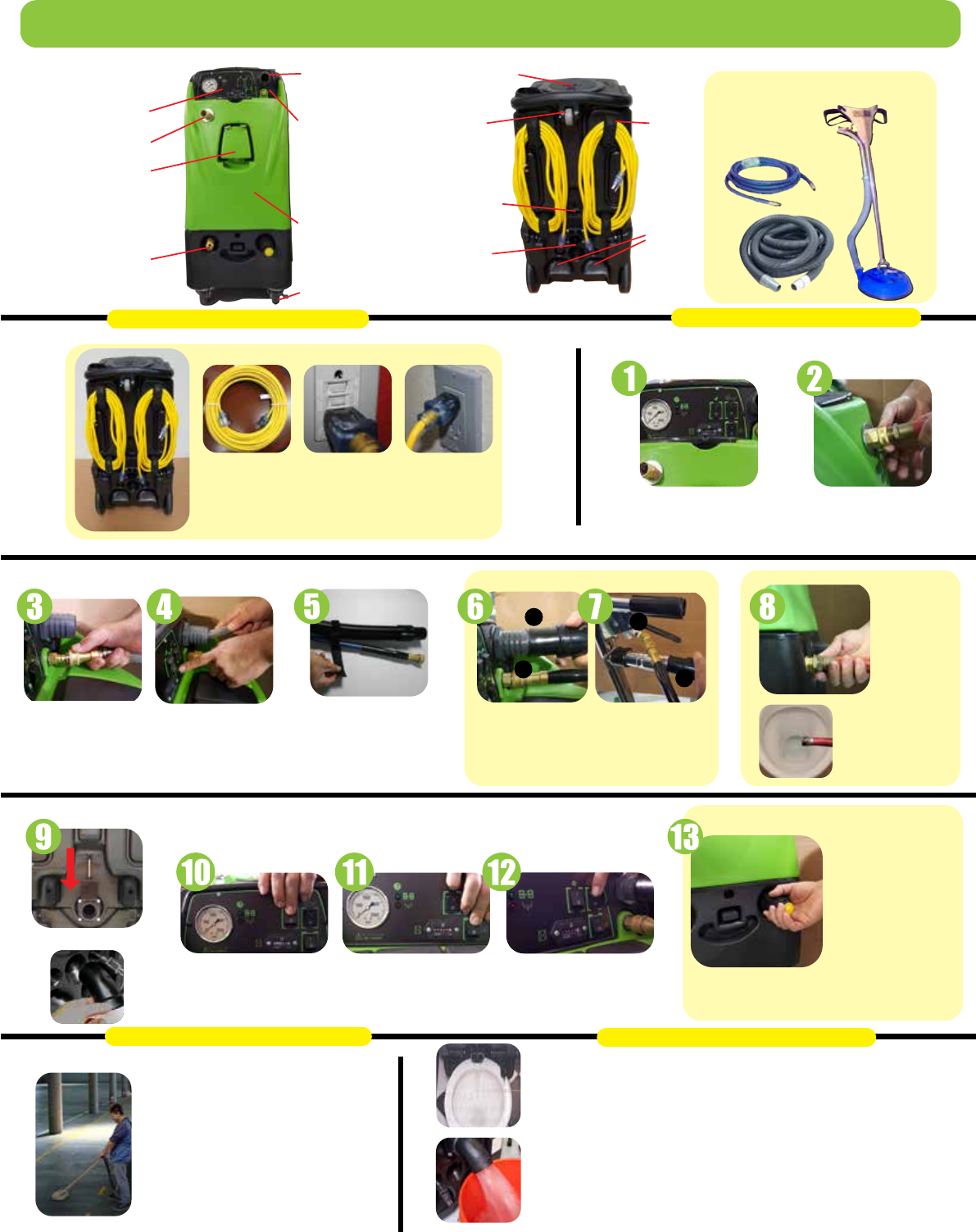
Connect Auto dump
with a garden hose
& run hose to the
toilet before turning
on the waste pump
GFI’s
1st plug in one cord.
2nd Cord must be on a separate circuit. A light and
sound pulse will activate when you plug into a 2nd
circuit. If you do not hear a pulse tone move cord to other
outlet until you obtain a 2nd pulse. Pump will not run
unless 2nd circuit light is on, no GFI outlets.
Assemble your vacuum
& Solution hose. Small loop
goes over small hose Velcro
over hose. Large 5 straps,
one every five feet.
Adjusting the pressure
Do not adjust the
pressure lower
than 400psi
Pressure adjustment
Make sure all
Switches are in
the OFF position.
1. Solution hose
2. Connect your hose to vacuum
3. Push back locking sleeve, insert brass post,
let locking sleeve cover spring back covering
retaining balls
4. Push vacuum hose & cuff over 1.5” hose barb
Prime machineConnect Prime Hose
Switches
Auto dump connectionHoses & Straps Vacuum & Solution hose
No Power Dual Cord Machine
Insert prime hose inside the recovery tank
before turning on the pump to prime the unit.
Fill the solution tank to the top making sure the
machine is primed.
Hard Surface Cleaning and wand use
1
2
4
Clean Water
Turn on Pump, Vacuum & Waste Pump
Dump valve
extender
Dump valve closed
position
Electrical Connection
2 Cord Extractor
When You’re finished
1. Take the vacuum hose off the wand
and put it into the front tank and
vacuum out the remaining cleaning
chemicals to the recovery tank, dump
the water into a bucket or toilet.
2. Run clean water (warm if possible)
throughout the machine to remove
cleaning chemicals from coating
internal hoses/jets.
3. Unplug the equipment, wipe it down
with clean cloth and soap and return
it to a safe storage area.
Disposing of dirty water
1. Unplug the extractor and back it
over a toilet or bucket
2. Slowly pull the dump-valve up
and dispose of the water to
the sewer system.
3. Remember to close it when done.
4. Never dispose of liquids on to
the soil, outdoor gutter or into
the environment.
After start sequence above
1. Start in the far corner and plan your exit.
2. Do a series of 4’x6’ area spraying overlap
by 2” on each stroke.
Disposal of Water & You’re Finished
12-gallon QUICK START GUIDE
Quick Start Machine Preparation
Recovery tank access
Vacuum
hose
connection
Hose
solution
connect
Indestructible
molded
body
Control panel
Optional wand holder
Hose connection
Waste water connection
Locking caster
Dump valve
Roller
wheel
Motor
Cool-air
Intake
Cord
wrap
Dump
valve
extender
Complete hose & wand kit
(25 ft. vac & solution hoses)
Wand is
sold
separate
3
Connect water hose to
solution tank and turn
on to fill the tank with
clean water.
The unloader valve will chatter
if you run the pump lower than 400psi
Rally 1200
4
Dear Customer:
Congratulations on the purchase of your new 12 Gallon Extractor.
Like any other piece of machinery or technology, extractors require the
proper maintenance and care to keep the product working over extended
use. Neglecting your machine, abusing it or not operating it properly can
void its warranty and prevent the machine from performing to the quality
and standard you’d expect.
If you have any warranty concerns or questions, please review this manual
thoroughly or do not hesitate to contact your distributor. If there are
questions regarding maintenance, replacement or ordering parts please
contact an authorized Service Center.
Before using your extractor, please read this manually thoroughly.
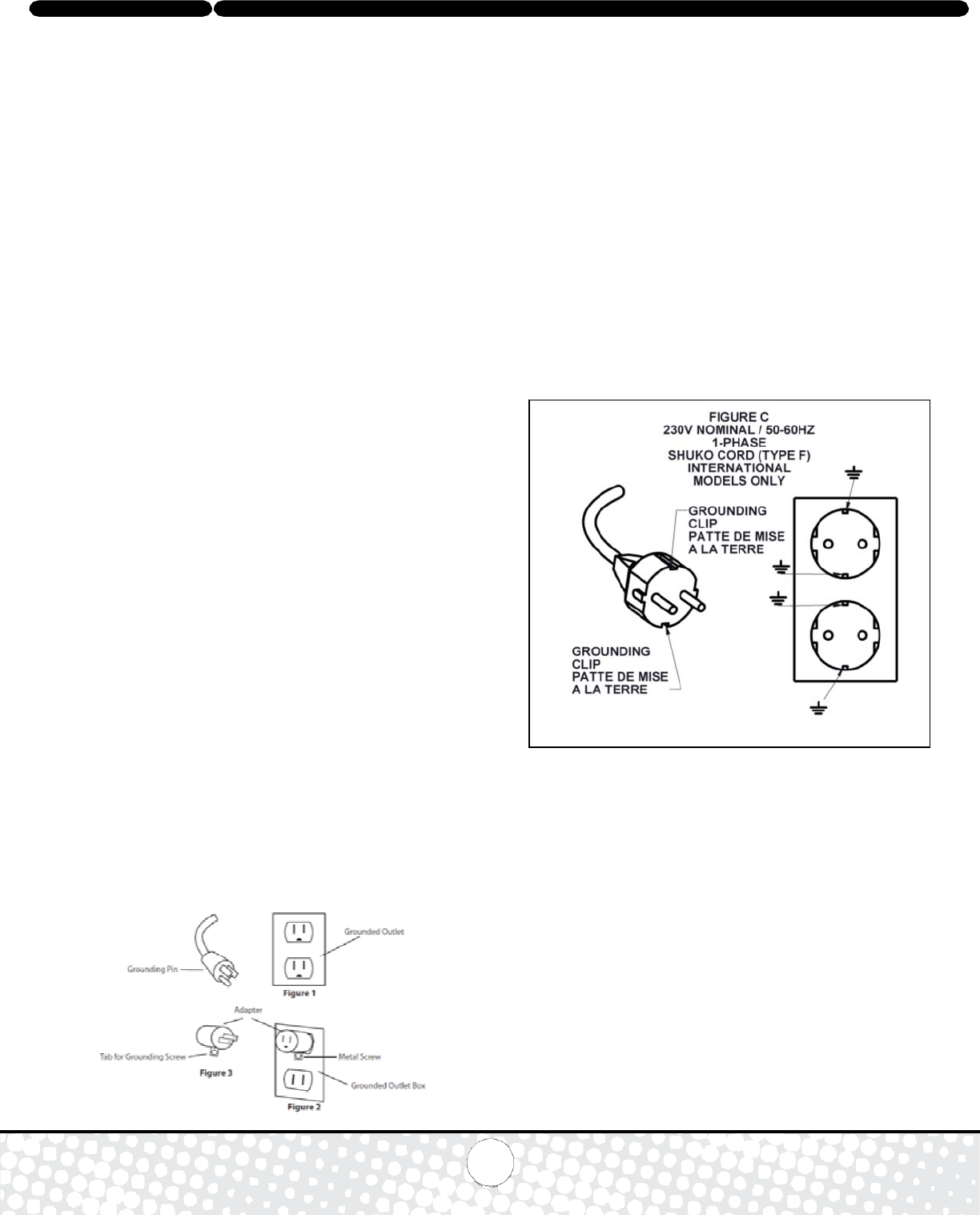
120 Volt Grounding Instructions
This machine must be grounded. If it should malfunction or break-down,
grounding provides a path of least resistance for electrical shock. This
machine is equipped with a cord having an equipment grounding conductor
and grounding plug. The plug must be plugged into an appropriate outlet
that is properly installed in accordance with all local codes and ordinances.
Do not remove ground pin; if missing, replace plug before use.
Improper installation of the equipment-grounding conductor can result
in a risk of electric shock. Be sure to check with a qualified electrician
or service person if you are in doubt as to whether the outlet is properly
grounded. If the plug will not fit in the outlet do not modify either the
plug or the machine’s cord, instead have a proper outlet installed by
a qualified technician.
This machine is for use on a nominal 120-volt circuit and with a grounding
plug similar to the one in Figure 1 below. If a proper outlet is not available,
follow the illustrations of Figure 2 & 3 to install a temporary-grounding
plug. This temporary work-around should be used only until a proper
outlet (Figure 1) can be installed by a qualified electrician. When and if
this type of adapter is employed, screw the adapter’s extended tab into
place with a metal screw. However, grounding adapters are not approved
for use in Canada. Again, be sure to check the grounding pin for damages
and replace if necessary. The Green, or Green-Yellow, wire in the cord is
the grounding wire. When replacing a plug, this wire must be attached to
only the grounding pin.
220-240 Volt Grounding Instructions
This machine must be grounded. If it should malfunction or break-down,
grounding provides a path of least resistance for electrical shock. This machine is
equipped with a cord having an equipment grounding conductor and grounding
plug. The plug must be plugged into an appropriate outlet that is properly installed
in accordance with all local codes and ordinances. Do not remove ground pin; if
missing, replace plug before use.
Improper installation of the equipment-grounding conductor can result
in a risk of electric shock. Be sure to check with a qualified electrician
or service person if you are in doubt as to whether the outlet is properly
grounded. If the plug will not fit in the outlet have a qualified electrician or
service person install the proper plug on to the cord.
This machine is for use on a nominal 220-240 volt circuit with a grounding plug
similar to the one in Figure C shown below. Changes to the attachment plug or
use of adaptors to other plugs must be done in accordance with local
regulations.
Parts and Service
Please contact service personnel or authorized Service Center using
original replacement parts and accessories for repairs. When calling
for support please have your Model and Serial Number available
for faster assistance.
Name Plate
The Model and Serial Number are located on the Name Plate. The Name
Plate is located on the back of the machine above the dump valve.
Unpacking the Machine
When your new machine is delivered, please carefully inspect both the
shipping carton and the machine for damages. If damage is evident,
save both the shipping carton and the machine for inspection by the
shipping company. Contact the carrier immediately to file a freight claim
if there is damage.

Rally
1200
5
WARNING: Failure to observe these
instructions
can cause personal injury to the machine
operator, and/or
bystanders.
Caution warnings are used to warn of immediate hazards
that cause severe personal injury or death.
Always wear eye protection, gloves, long sleeve shirt and pants.
To reduce the risk of fire, electrical shock, or injury:
1. Read quick start guide and manual prior to use.
2. Unplug machine before service.
3. Use only manufacturer recommended attachments
and replacement parts.
4. Never upgrade or repair this equipment without
authorization from the manufacturer.
5. Do not unplug the unit by pulling on the cord.
6. Do not run over the cord with any wheeled product.
7. Do not pull or carry by the cord.
8. Do not use if the cord is damaged.
9. Do not use in areas with flammable or combustible
material are present.
10. Do not allow to freeze.
11. Do not store on its side with liquids in the recovery or solution tanks.
12. Use only the appropriate handles to move and lift unit. Do not use
any other parts of this machine for this purpose.
13. Keep hair, loose clothing, fingers, and all parts of the body away from
all openings and moving parts.
14. Use extra care when using on stairs.
15. To reduce the risk of fire or electric shock, do not use this machine with
a solid-state speed control device.
16. The voltage and frequency indicated on the name plate must
correspond to the wall receptacle supply voltage.
17. When cleaning and servicing the machine, local or national regulations
may apply to the safe disposal of liquids which may contain: chemicals,
grease, oil, acid, alkaline, or other dangerous liquids.
Preparation
1. Remove furniture and other items from the area you are going to clean.
2. Vacuum carpet and upholstery, and remove debris.
3. Protect cabinets, walls and painted surfaces with drop cloths or plastic.
4. Inspect power cords for damage.
Operating Instructions
1. Fill Solution Tank. To use the Auto-Fill feature, hook up the male end
of a garden hose to the female adapter on the outside of the
solution tank and turn on the water supply. The float valve in the
tank will automatically turn off when the tank is full.
2. Plug in power cords: Extractor Model: Using two separate circuits/
breakers, plug in the grounded power cables as previously instructed
using the proper grounding techniques. The green indicator to the
right of the PSI gauge will illuminate and sound a tone when plugged
into separate circuits/breakers.
i. Activate the switched using the following steps:
ii. When the hoses and tool are attached, turn pump switch on.
iii. Pull the trigger on the wand until water runs through the lines.
If the pump does not prime, turn the pump switch off and
disconnect the hoses. Connect the supplied priming hose
and put the open end into the vacuum barb and turn on the
vacuum motor and solution pump. Seal the hose to the barb
with your hand until water is visible running through the hose.
Turn both switches on and repeat from step i.
3. If using the Pump-Out feature hook up the female end of a garden
hose to the male adapter on the motor base and run it to a sewer drain
(ex. Toilet, janitors sink). Turn on the Waste Pump switch.
4. Pressure Adjustment: Pressure will only show on the gauge while the
tool is being sprayed. When the tool is not being sprayed the
pressure will read 0 psi.
i. To decrease pressure, turn the black knob on the motor
base counter-clockwise.
ii. To increase pressure, turn the black knob on
the motor base clockwise.
iii. Make your adjustment and spray the tool to check the
pressure. Re-adjust as needed to set the desired
pressure.
5. To prevent motor or internal damage, use a foam control solution in the
recovery tank. Remember to check for buildup in both the recovery
and solution tanks!
6. Empty the recovery tank when the internal shut off switch disengages
the vacuum. Attach the 45° drain elbow to the drain spout located in
the back and lift the dump valve to empty the tank.
7. Squeeze the wand or tool’s trigger for 5 seconds after turning the
power
switches off to relive and existing line pressure.
8. When the machine is off: unplug the power cables, remove solution,
vacuum, auto-fill and auto-dump hoses, and empty the recovery tank
by attaching the 45° drain elbow.
Machine Storage
1. Before storing the machine, drain, rinse and dry both the tanks and
vacuum hoses of any residual water.
2. Store standing upright in a dry enclosed area.
3. Leave the recovery tank lid open for better air circulation.
4. If storing in freezing temperatures, take extra precautions to make
sure the machine and solution systems are completely drained and
dry.

Rally 1200
6
Maintenance Schedule
To keep machine in good working condition, follow the below recommended
daily and weekly maintenance procedures. Relief valves should be replaced
annually. Unscrew the front screw to open the tank for internal
maintenance.
Filter Maintenance
The Rally 1200 has four filters that need to be checked and
cleaned after each week of use. Regular filter maintenance is a
simple way to extend the life of your machine.
Vacuum Stack Filter:
Located inside of the black vacuum tank is one vacuum stack. It has one
foam filter to help prevent waste material from getting into the vacuums and
cause damage. To maintain this filters:
1. Remove the recovery tank lid.
2. Reach in and pull out the black filters located in the top of
the vacuum stack.
3. Clean the filters under a faucet of any debris and check for
damage. If the filter is not damaged, place it back in the stack. If
filters is damaged and falling apart, replace it.
Pump Filter
The pump filter is a half-circle shaped screen located on the inside
bottom of the solution tank. To maintain filter:
1. Open solution tank lid.
2. Reach into solution tank and rotate the dome-shaped filter from
its brass nipple by rotating it counter clockwise.
3. Check filter for any debris or damage to screen. Rinse filter of
any debris or replace if damaged.
4. Place new or cleaned filter back onto brass nipple by
rotating it clockwise.
(Additional inline filter inside the machine)
Inline Pump Filter (additional Instructions)
1. Remove the screw that holds the solution tank and the base
together from the front of the machine.
2. Locate the inline filter on the clear solution hose, from the
solution tank to the pump. Take off the clear housing of the filter
by turning it counter clockwise
3. Check filter for any debris or damage to screen. Rinse filter of
any debris or replace if damaged.
4. Place new or cleaned filter back into housing and install housing back
into base by rotating it.
Pump Out Filter
1. Remove recovery tank lid.
2. Remove pump out filter by turning counter-clockwise.
3. Rinse the filter with water from the inside out.
4. Replace filter by turning clockwise.
5. Replace recovery tank lid.
Trouble Shooting
There is no power.
1. Plug power cord(s) in proper outlet(s).
2. If using two cords, make sure each is plugged into a separate circuit.
3. Check circuit breaker and reset if tripped. There should not be any
additional items in use on the same circuit as the machine and the
outlet must be a 20-amp circuit.
Pump does not work properly
1. Snap quick disconnects firmly together.
2. Check solution tank; may be empty.
3. Jets clogged, remove jet and flush clean.
4. Filters clogged, remove filters and rinse clean with water. One filter is
in the bottom of the recovery tank and the secondary filter is located in
the motor area. Be sure to unplug the machine and turn all switches to
the off position prior to cleaning.
5. If brass check valve is stuck, replace valve.
6. Check pump wire. May need to reconnect wire.
7. Switch plate may need to be replaced.
8. If pump motor brushes are worn, replace pump.
Vacuum motor does not work properly
1. Check that hose is tightly connected.
2. Close drain valve completely.
3. Secure the vacuum tank lid tightly.
4. If water is coming out of the vacuum motor, use a
low foaming detergent.
5. Clean upholstery tool or floor wand jets.
Maintenance item Daily Once a week
Clean and inspect tanks. X
Clean and inspect hoses. X
Check and clean internal filters by twisting off,
rinsing with clean water and replacing. X
Check power supply cable. X
Clean machine with all-purpose cleaner
and cloth. X
Check spray nozzles. X
Flush solution system with clean water X
Remove float and shut-off screen from
tank and clean. Simply pull off.
X
Inspect vacuum hoses for holes and loose
cuffs.
X
Inspect spray pattern for clogging. If
clogged, remove spray tips and soak them in
a recommended liquid neutralizer for up to six
hours. To remove spray tip, twist spray tip body
counter-clockwise.
X
Lubricate wheels with water resistant oil. X
Inspect machine for water leaks and loose
hardware.
X
Rally
1200
7
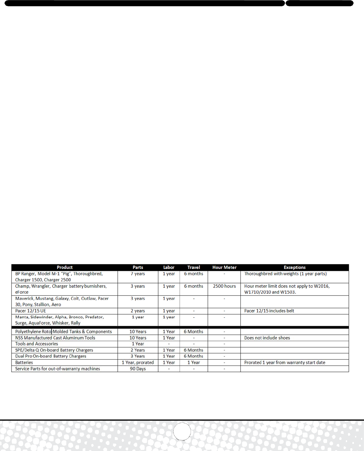
NSS® Enterprises, Inc. Limited Warranty
Effective for machines purchased after August 1, 2015 (Revision S)
Warranty Registration
Register your new product by visiting www.nss.com and clicking on the “Product Registration” link.
Warranty Policy
NSS Enterprises, Inc. (NSS) warrants its new machines against defects in material and workmanship under normal use, service and maintenance (defined in the
NSS Operation and Maintenance Manuals) for the warranty period as detailed below. This warranty is limited to machines and products that are purchased from
an NSS Authorized Distributor or directly from NSS and is limited to the original end-user. Under this warranty, NSS will repair or replace, at its option, any covered
part which is found defective in material or workmanship during the applicable warranty term or until the hour meter reaches the specified amount, whichever is
first. This repair or replacement shall only be performed by an NSS Authorized Distributor or Service Center. All shipping charges for replacement parts or repaired
machines will be the responsibility of the original end-user. When requested, machines and/or parts must be returned to NSS for inspection to obtain this warranty.
NSS reserves the right for final determination of warranty coverage. Parts repaired or replaced under this warranty are warranted for the remainder of the original
warranty period. When covered, a maximum of 4 hours travel time will be allowed. When out of the continental USA, Labor, Freight and Travel may have different
considerations.
NSS will not be liable for any other or additional damages, including but not limited to indirect or special consequential damages arising out of or in connection with
the furnishing, performance, use or inability to use the machine. The buyer agrees and understands that the remedies provided under this limited warranty are the
sole and exclusive remedies available to the buyer. NSS reserves the right to change its warranty policy without notice.
Start date of warranty for MACHINES
The start date of this warranty is the purchase date by the original user, or six months from the date the machine was shipped from the factory, whichever is earlier.
Start date of warranty for BATTERIES, including those installed in machines at time of purchase
The warranty period for the batteries starts on the date of sale or 90 days after the machine was shipped from the factory, whichever is earlier. Batteries must be
recharged at least once every 90 days.
Exclusions
This warranty shall not apply to: (1) Damage incurred during shipment. (2) Any product that has been subject to misuse, abuse, negligence, overloading or
accident. (3) Improperly used products or use of the product for other than its intended purpose. (4) Failures due to lack of mandatory maintenance as described
in NSS Operation and Maintenance Manuals, Videotapes and/or Wall Charts. (E.g., lack of scheduled lubrication or inadequate flushing of chemical solutions.) (5)
Any machine modified from its original design (unless authorized by NSS) or repair services performed by non-authorized service centers. (6) Damage or failure
resulting from the use of corrosive or incompatible chemicals. (7) Replacement of ordinary wear items including but not limited to: bumpers, belts, carbon motor
brushes, electrical components exposed to moisture, filter bags, hoses, casters, wheels, gaskets, seals, cords, circuit breakers, switches, check valves, solenoids,
pumps, squeegee blades, M-1 fans and fan hoods, and shoes on NSS manufactured cast aluminum tools. (8) Machines using after-market parts not supplied by
NSS, including the ordinary wear items listed above.

Icon Definitions
Caution
Readmanual
VacuumMotor
Pump
Heater
DualCircuitIndicator
ListenforTone
RecoveryTankPump‐out‐Pump
RecoveryTankFull‐DrainTank
RALLY1200SPECIFICATIONS
CAPACITY
SOLUTIONTANK12GALLONS(45.5LITERS)
RECOVERYTANK12GALLONS(45.5LITERS)
SOLUTIONPUMP
ADJUSTABLE,400TO1200PSI
VACUUMMOTORS
One2‐STAGE,TAPEREDFAN,2.1HP
SOUNDLEVEL
75Dba(ISO11201)
DIMENSIONS
HEIGHT39in(99cm)
LENGTH26in(66cm)
WIDTH17in(43cm)
WEIGHT
150lbs(68kg)
RALLY 1200 OPERATION MANUAL ORG 11-15 REV B 5-16 9094029
NSS
®
Enterprises, Inc.
3115 Frenchmens Road, Toledo, Ohio 43607
PHONE (419) 531-2121 FAX (419) 531-3761
mailus@nss.com www.nss.com
