Pioneer Eclipse 300bu Floor Burnisher Operator Parts Manual
Pioneer-Eclipse-300Bu-30X-Walk-Behind-Floor-Burnisher-Operator-Parts-Manual pioneer-eclipse-300bu-30x-walk-behind-floor-burnisher-operator-parts-manual pioneer-eclipse-300bu-30x-walk-behind-floor-burnisher-operator-parts-manual 1969 file product_file sweepscrub
2017-01-09
: Sweepscrub Pioneer-Eclipse-300Bu-Floor-Burnisher-Operator-Parts-Manual pioneer-eclipse-300bu-floor-burnisher-operator-parts-manual 1968 file product_file
Open the PDF directly: View PDF ![]() .
.
Page Count: 48
UHS Battery Burnisher
PE300BU
Operator’s Manual
NOTICE
Proper maintenance is necessary with all battery powered floor machines.
Following the scheduled maintenance procedures found in your operation
manual will provide many years of uninterrupted service.
In addition to the scheduled maintenance procedures listed it is
recommended to have your machine serviced by certified service personnel
every three months. This service should include an emissions check.
Instructions For Use
Failure to read and understand this manual before operating this machine or performing service
on this machine may result in injury to the operator or nearby personnel or result in damage to the
machine or nearby property. Each operator must be trained in the operation of this machine before
being allowed to use it. Contact Amano Pioneer Eclipse Customer Service at 1-800-367-3550 or
+1-336-372-8080 or an authorized Amano Pioneer Eclipse Distributor to inquire about training or to
request a replacement manual.

In this Operation Manual you will find three statements that you must read and observe to ensure
safe operation of this machine.
DANGER! indicates that the possibility of severe bodily injury or death can occur if DANGER!
statements are ignored. Read and observe all DANGER! statements included in the Operation
Manual and attached to the machine.
WARNING! indicates that the possibility of bodily injury to the operator and other people can occur
if WARNING! statements are ignored. Read and observe all WARNING! statements included in
the Operation Manual and attached to the machine.
CAUTION! indicates that the possibility of damage to the machine or other property can occur if
CAUTION! statements are ignored. Read and observe all CAUTION! statements included in the
Operation Manual and attached to the machine.
! FOR YOUR SAFETY !
DO NOT store or use gasoline or other flammable vapors and
liquids in the vicinity of this or any or other appliance.
Record This Important Information
Date of Purchase
Purchased From
Address
City State Zip
Phone Contact
Machine Model
Machine Serial Number
Important Phone Numbers
Medical Emergency
Police
Fire Department

Quick Reference Specifications..........................................5
Safety Precautions..............................................................6
Operator Responsibility.......................................................7
Test for Operator-Ear Sound Pressure Level.................7
Test for Hand Arm Vibration...............................................7
Machine Preparation...........................................................8
Unpacking the Machine..................................................8
Machine Storage.............................................................8
Repacking the Machine..................................................8
Transporting the Machine...............................................8
Connecting the Batteries................................................9
Installing the Skirt...........................................................9
Machine Components.......................................................10
Traction Model..............................................................11
Key Switch................................................................11
Handle Lever.............................................................11
Burnish Switch..........................................................11
Reverse Switch.........................................................11
Traction Speed Control.............................................11
Hour / Battery Meter..................................................11
Alarm LED................................................................11
Pad Assist Model..........................................................11
Key Switch................................................................11
Handle Lever............................................................11
Burnish Switch..........................................................11
Hour / Battery Meter..................................................11
Over Current Protection...............................................11
Onboard Battery Charger.............................................12
Battery Charger Controls..............................................12
Battery Charger Settings.............................................13
Battery Charger Fault Codes.......................................13
How the Machine Works...................................................14
Pre-Operation Checklist....................................................14
Turning on the Machine...................................................14
Changine Direction...........................................................14
Stopping & Turning off Machine........................................14
Operation on Inclines........................................................14
Installing / Changing Burnishing Pad................................14
Dust Bag Removal............................................................15
Caster Parking Brake.......................................................15
Pad Pressure Adjustment................................................15
Post Operation Checklist..................................................15
Maintenance...............................................................16
Scheduled Maintenance...........................................16
Body & Battery Cover..............................................17
Battery Maintenance................................................17
Lead Acid Batteries.................................................17
Rear Casters.............................................................18
Belt Maintenance.....................................................18
Belt Replacement....................................................18
Alarm Codes.....................................................................19
Machine Troubleshooting..................................................20
Machine Specifications.....................................................21
Parts Manual.....................................................................23
Electrical Schematic - Pad Assist.............................24
Electrical Schematic - Traction.................................25
Connections - Pad Assist..........................................26
Connections - Traction.............................................28
Skirt, Deck & Axle Bracket Assembly......................30
Main Bottom Assembly - Pad Assist........................32
Main Bottom Assembly - Traction...........................34
Main Rear Assembly...............................................36
Main Top Assembly..................................................38
Main Front Assembly...............................................40
30” Deck Assembly..................................................42
30” Skirt, Pulley & Tensioner Assembly...................44
Manufacturer’s Warranty...................................................46
Table of Contents
4

5
Quick Reference
Specifications:
l Voltage: 36VDC (Qty. 3 - 12VDC Batteries)
l Burnish Rate: ±26,000 ft2/hr (2415 m2/hr) [20”]
±31,200 ft2/hr (2899 m2/hr) [24”]
±42,900 ft2/hr (3985 m2/hr) [30”]
l Overload Protection: Resettable Breakers
l Operating Time: Approximately 3 hours
l Pad Pressure: Adjustable
Routine Maintenance Parts:
l Cloth Dust Bag: MP414100
l Paper Dust Bap: MP414200 (3 Per Pack)
l Pad Holder: MP414000 [20”]
MP435000 [24”]
MP448100 [30”] Qty. 2
l Pad Retainer: MP432400
l 3A Glass Fuse: MP234700
l Charger Fuse: MP265100 (115V)
MP289100 (230V)
l Steel Skirt: MP425200 [20”]
MP434200 [24”]
MP456300 [30”]
l Skirt Edging: MP139800 - 6 ft (183 cm) [20”]
MP139800 - 7 ft (214 cm) [24”]
MP449200 [30”]
l Battery: MP223500 (12V Lead Acid) Qty. 3
MP413600 (12V AGM) Qty. 3
l Gas Spring: MP415200 [20”]
MP434500 [24”]
MP450300 [30”]
l Deck Belt: MP449100 [30”]
l Burnish Motor Brush Kit: MP433200
l Transaxle Motor Brush Kit: MP433300
Your Authorized Amano Pioneer Eclipse Distributor: _____________________________________
Authorized Amano Pioneer Eclipse Distributor Phone Number: _____________________________
Amano Pioneer Eclipse Phone Number: +1-336-372-8080

6
Safety Precautions
Anyone operating the machine should read the
following carefully and be informed of potentially
dangerous operating conditions. Operators should
be familiar with the location and use of all safety
devices on the machine. DO NOT use the machine
if it is not in proper operating condition, and report
any damage or operation faults immediately.
DANGER! This machine has parts including the pad/
brush assemblies that can cause severe injury if these
parts are contacted while they are moving. DO NOT
allow any part of the body or clothing to come in contact
with these parts while they are moving. DO NOT try to
change the pads/brushes while the machine is running.
DO NOT allow other people to come near the machine
while it is in operation. DO NOT allow the machine to
run unattended. DO NOT leave the machine in a place
where unauthorized or untrained personnel could use
the machine. DO NOT run the machine with the pads/
brushes off center, damaged or missing. DO NOT
operate the machine if the machine has loose parts.
WARNING! Batteries emit hydrogen gas. Explosion or
fire can result. Keep sparks and open flame away. Keep
covers open when charging. DO NOT smoke around
batteries. Avoid skin contact with the acid contained in
the batteries. Never allow metal objects to lay across
battery tops.
WARNING! Operate from the rear of the machine only.
WARNING! Inspect pad holders regularly. A fractured pad
holder may result in pad fragments causing injury.
WARNING! Use caution when operating the machine on
a ramp or incline. DO NOT turn the machine, or leave it
unattended, on a ramp or incline.
WARNING! Store machine inside. Keep the electrical
components of the machine dry. DO NOT PRESSURE
WASH MACHINE.
WARNING! Modifications or alterations to this machine
can lead to personal injury or damage to the machine.
DO NOT make unauthorized modifications or alterations
to this machine. Amano Pioneer Eclipse assumes
no liabilities for injury or damage resulting from an
unauthorized modification or alteration to the machine.
Any unauthorized modification or alteration to this
machine voids all warranties.
WARNING! The motor and motor controller become hot
enough while the machine is in operation, and for a
long time after the machine is shut off, to cause severe
burns. DO NOT touch these parts of the machine until
they have cooled.
WARNING! Injury can occur to the eyes and body while
using the machine. Safety goggles, safety shoes, and
safety clothing are recommended while operating the
machine.
WARNING! Machine vibration may cause tingling
or numbness in the fingers or hands. Gloves are
recommended to reduce machine vibration. If tingling or
numbness persists, shut off the machine. If the vibration
is caused by loose parts such as an off center pad/
brush, adjust or tighten these parts before using the
machine again.
WARNING! DO NOT burnish on an incline. This machine
is designed to burnish on a flat level floor.
CAUTION! DO NOT operate machine unless trained and
authorized. DO NOT operate machine unless you have
read and understand the operation manual. DO NOT
operate machine in flammable or explosive areas.
CAUTION! Before starting machine ensure all safety
devices are in place and functioning properly. Before
starting machine check for proper operation.
CAUTION! When using machine, go slowly on inclines
or slippery surfaces. Use care when operating machine
in reverse. Follow all manufacturers instructions on
chemical product containers when handling, mixing, or
using chemical products.
CAUTION! When servicing machine, stay clear of
moving parts. DO NOT wear loose clothing when
working on machine. Block machine wheels before
raising or jacking up machine. Use hoist stands that
will support the weight of the machine. Wear eye and
ear protection when using pressurized air. Disconnect
battery connections before servicing machine. Use only
replacement parts supplied by Amano Pioneer Eclipse
or a Amano Pioneer Eclipse Authorized Distributor or
Service Center.

7
This machine is manufactured for
commercial use only.
This machine is designed and manufactured for
burnishing indoor hard floor surfaces. Amano Pioneer
Eclipse does not recommend use of this machine in any
environment other than an indoor environment.
Battery powered floor equipment is designed and
manufactured for commercial use only. These machines
are designed to burnish most modern types of floors
including composition tile, stone, marble, terrazzo, and
resilient floor covering, and some coated wood floors.
These machines should not be used
l By unqualified or untrained personnel.
l Unless properly maintained and adjusted.
l On areas with obstructions such as thresholds, floor
outlet boxes, etc.
l In areas where loose debris or other objects are
present.
Operator Responsibility
The operator is responsible for performing the
recommended daily maintenance and checkups of
the machine to keep it in good working condition. The
operator must inform the service mechanic or supervisor
when recommended maintenance procedures are
required as described in the “MAINTENANCE” section
of this manual.
lRead this manual carefully before operating this
machine.
lFOR SAFETY: DO NOT operate machine before
reading and understanding the operation manual.
lCheck the machine for shipping damage.
Keep your machine regularly maintained by following
the maintenance information in this manual. Order parts
and supplies only from an Authorized Amano Pioneer
Eclipse Distributor. Use the parts illustration section
of your manual when ordering parts. During and after
operation, perform the recommended daily and hourly
procedures outlined in the Maintenance Chart.
Test for Operator-Ear Sound Pressure Level
Amano Pioneer Eclipse measures and rates the
operator-ear sound pressure level for hand-guided floor
treatment and floor cleaning machines for industrial use.
All tests are performed in accordance with European
Machinery Directive (2006/42/EC).
lOutdoor test area consists of a flat open space free
from effects of signboards, buildings or hillsides for at
least 15 m (50 ft) from the center of the test surface.
Indoor tests are conducted in a semi-anechoic or
sound deadening room.
lThe test surface is a single sheet of floor covering
at least 1 m (3.3 ft) wider and longer than the
equipment being tested. In order to not affect the
sound reading, the observer taking readings is at
least 2 m (6.6 ft.) from the equipment being tested, or
standing directly behind the operator.
lAll machines are tested while stationary and centered
on the test surface. With the traction drive in neutral
(where applicable) the test is conducted with the
machine at maximum engine or motor speed as
specified by the manufacturer.
lThe operator is located in the normal operating
position with the microphone or meter supported
independent of the machine, 1,68 m (66 in) above
the test surface, 25 cm (10 in) to the right and left
centerline of the operators position, and 20 cm (8 in)
to the rearmost point of the handle, with the handle in
the most forward position.
lThe sound level meter is observed for a minimum of
5 seconds or until a stabilized reading is obtained.
The maximum repeatable sound level observed
during the test at each microphone position is
recorded and documented.
Test for Hand-Arm Vibration at the Grip
Surface of Hand-Guided Machinery
Amano Pioneer Eclipse measures and rates the
vibration at the machine-hand contact surface of
hand-guided machines that are provided with handles
in accordance with European Machinery Directive
(2006/42/EC).
lThe test area consists of a flat open floor area that
allows the machine to be operated normally.
lThe transducer is mounted firmly at a point halfway
along the length of the handle where the handle
would normally be held.
lMachines are tested while stationary, with all
mechanisms necessary for the equipment to perform
its intended functions engaged and the traction drive
in neutral (if applicable). The machine will be tested
at maximum engine or motor speed as specified by
the manufacturer of the subject machine.
lThe measurements are recorded from the dominant
axis.

8
Unpacking the Machine
The machine is shipped boxed on a wooden pallet. To
unpack machine:
1. Cut and remove bands holding the box to the pallet.
2. Remove staples attaching the box to the platform at
the bottom edge of the box.
3. With two people, one at either end of the box, lift box
straight up and off machine.
4. Remove loose accessories from the top of machine.
5. Cut and remove bands securing the machine to the
pallet.
6. Lower the attached ramp
7. If the machine has batteries then remove the
battery cover and plug the battery pack plug into the
machine, turn on the key, drive the machine down
the ramp off the pallet. If the machine does not have
batteries, pull the machine down the ramp and off the
pallet. See the “Connecting the Batteries” section of
the manual.
8. Carefully back the machine off of the pallet.
Machine Storage
1. Machine should be stored in a dry environment.
2. Store machine away from objects that may fall and
damage it.
3. Never store burnisher near an open flame or heat
producing device.
4. Make sure burnisher is cleaned properly by wiping
machine down with damp cloth before storing.
CAUTION! NEVER PRESSURE WASH MACHINE!
5. Disconnect batteries before storage.
Repacking the Machine
Refer to Unpacking section on page 8 and repack
machine using original packing materials and container.
Transporting the Machine
When shipping the machine, make sure the batteries
are disconnected and the machine is secured in the
transporting vehicle.
Machine Preparation
9
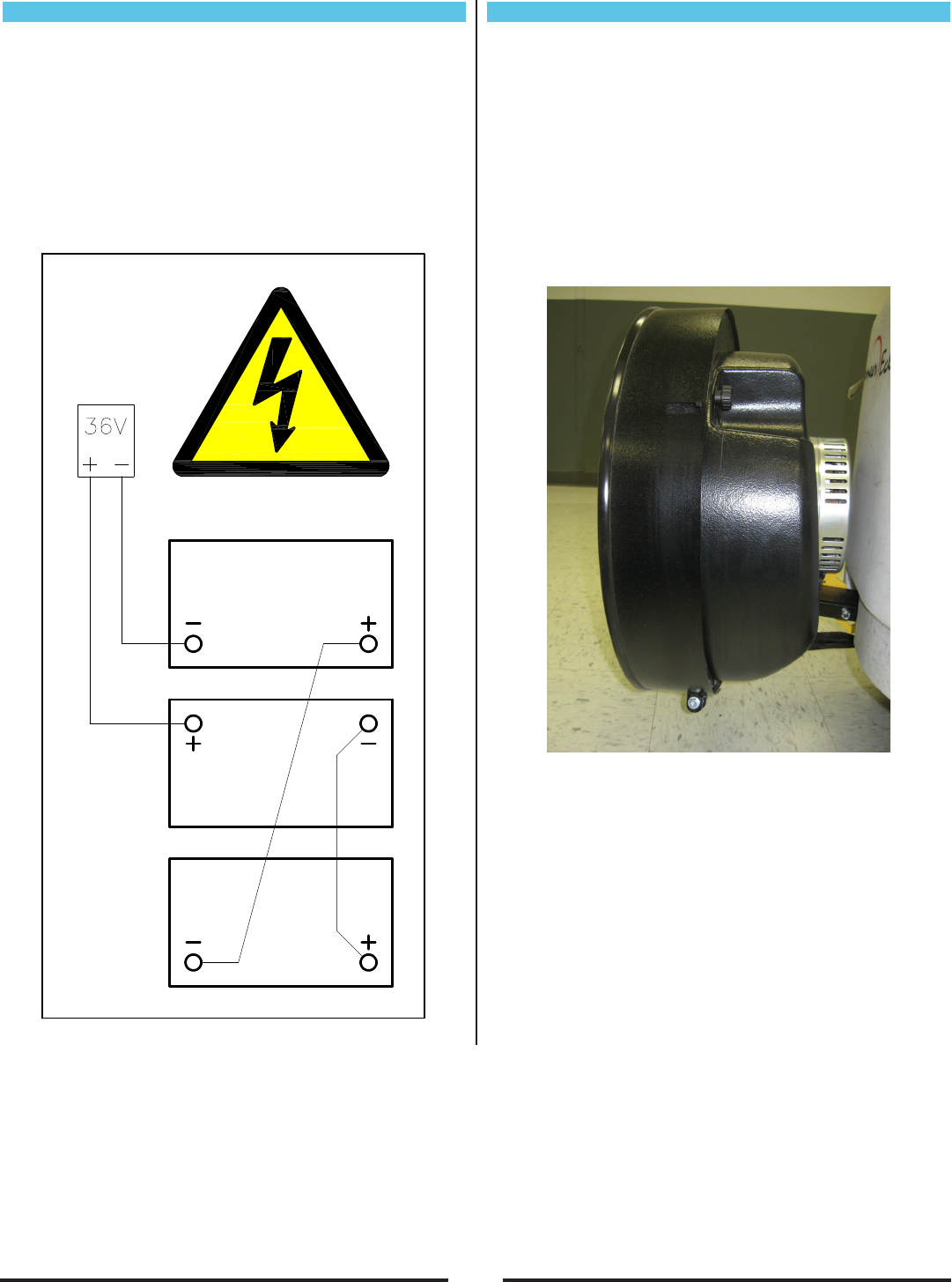
Connecting the Batteries
1. Place the batteries in the machine oriented as
shown in diagram.
2. Connect the batteries as shown in the battery
connection diagram.
3. DANGER! Incorrect connection of batteries can
cause explosion and/or serious injury.
4. Double check battery connections.
5. Connect the battery pack plug to the machine.
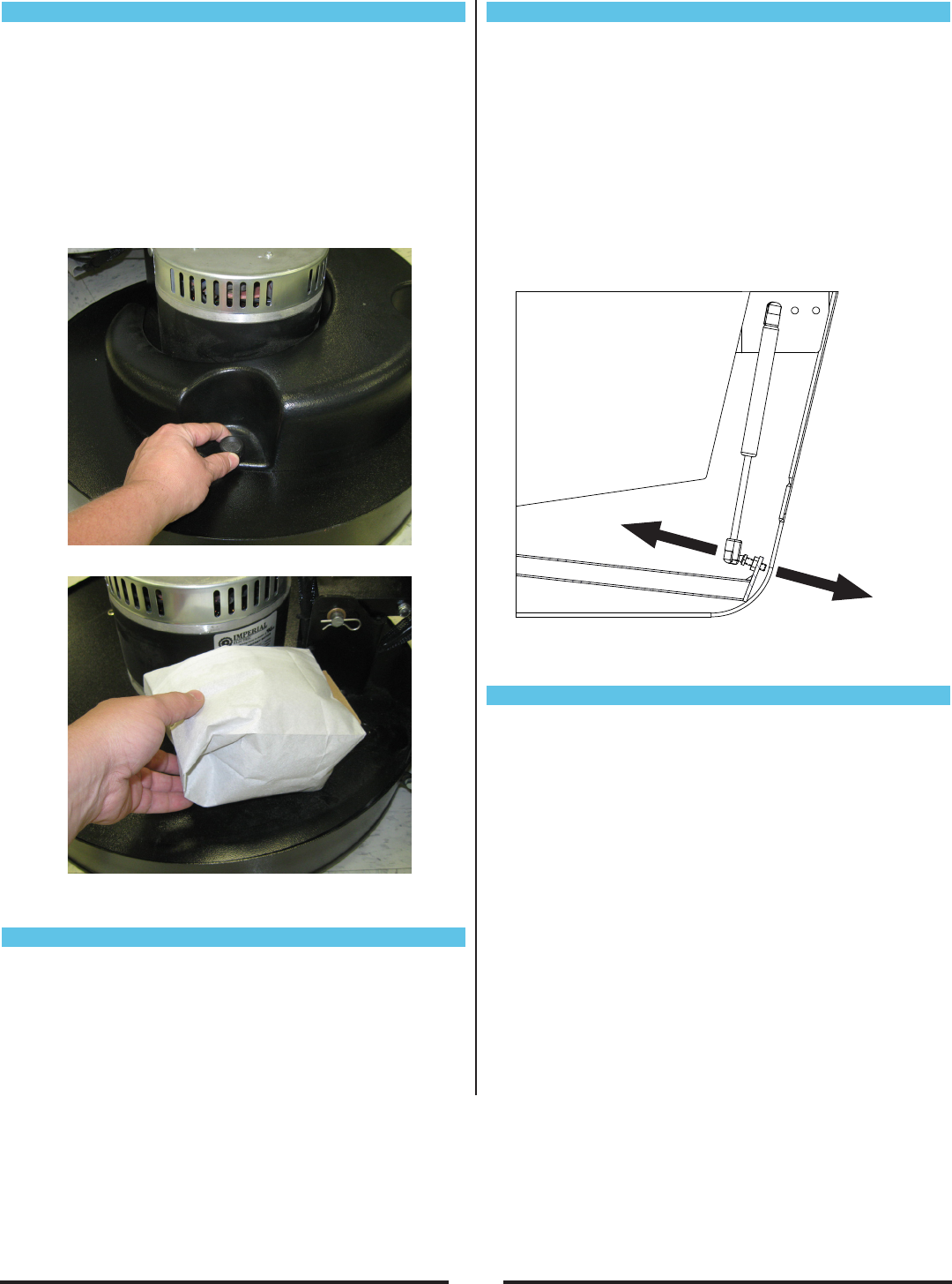
Installing the Skirt
1. Lift the deck upward about 90 degrees by pulling up
on the front of the deck. At this point, the tilt latch
will hold the deck in the pad change position. (Ref.
Machine Operation - Installing/Changing Burnishing
Pad)
2. Remove steel skirt from bubble wrap packing and on
the outside of the skirt, loosen the 1/4” hex bolt with
jam.
3. Slide the skirt onto the burnish head aligning the
slots in the skirt with the tabs on the deck. Make
sure the 1/4” bolt is at the back of the shroud.
4. Tighten the 1/4” bolt until the skirt is snug around the
deck but also floats up and down freely.
5. Tighten jam nut and lower deck to burnish position.
(Ref. Machine Operation: Installing/Changing
Burnishing Pad)
10
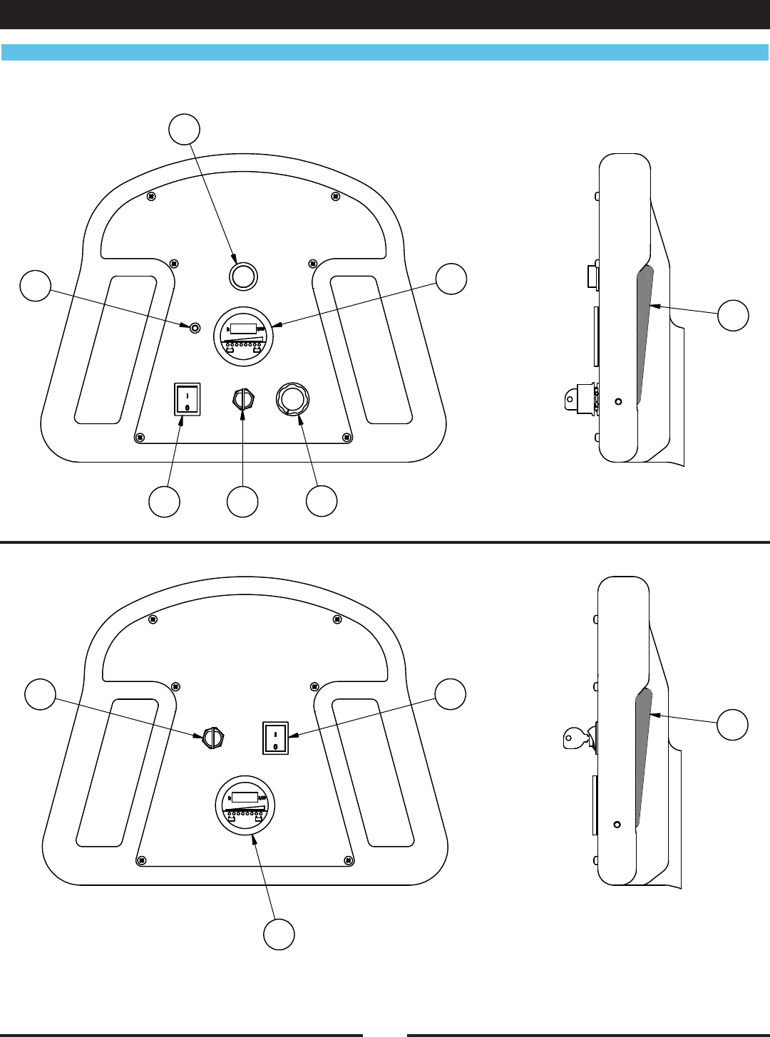
Controls and Instruments
RF044800 051112
2
4
7
3 1 5
6
2
13
4
Machine Components
Traction
Pad Assist
11
300BU Traction Model
1. Key Switch - Turns the machine on/off.
2. Handle Lever - When the lever is engaged the
machine will move forward. If the Burnish switch is
on, the pad will also start turning. If the burnish head
is tilted up into the pad change position, the burnish
motor will not engage.
NOTE: The machine needs to be moving when the
burnish switch is turned on or off in order to keep from
burning the oor.
3. Burnish Switch - Turns burnish function on/off. The
burnish motor will not engage unless the burnish
switch is on and the handle lever is engaged. If the
burnish head is tilted up into the pad change position,
the burnish motor will not engage.
4. Reverse Switch - Hold down this switch while the
handle lever is engaged and the machine will move
in reverse. Once the reverse switch is released the
machine will start moving forward.
5. Traction Speed Control - Turn the knob clockwise to
increase speed. Turn the knob counter-clockwise to
decrease speed.
6. Hour Meter / Battery Discharge Indicator - The
LCD displays the number of burnishing hours. The
machine will only count hours while burnishing. The
row of LEDs display the charge level of the battery
pack. When all the yellow LEDs are lit, the battery
pack is fully charged. In order to protect the battery
pack, when the red LED is lit, the burnish motor will
stop and the machine should be recharged.
7. Alarm LED - Displays trouble codes as a blink
pattern. In normal operation this LED will be off. If it
comes on, refer to the troubleshooting section.
300BU Pad Assist Model
1. Key Switch - Turns the machine on/off.
2. Handle Lever - When the lever is engaged, if the
burnish switch is on, the pad will start turning. If the
burnish head is tilted up into the pad change position,
the burnish motor will not engage.
NOTE: The machine needs to be moving when the
burnish switch is turned on or off in order to keep from
burning the oor.
3. Burnish Switch - Turns burnish function on/off. The
burnish motor will not engage unless the burnish
switch is on and the handle lever is engaged. If the
burnish head is tilted up into the pad change position,
the burnish motor will not engage.
4. Hour Meter / Battery Discharge Indicator - The
LCD displays the number of burnishing hours. The
machine will only count hours while burnishing. The
row of LEDs display the charge level of the battery
pack. When all the yellow LEDs are lit the battery
pack is fully charged. In order to protect the battery
pack, when the red LED is lit the burnish motor will
stop and the machine should be recharged.
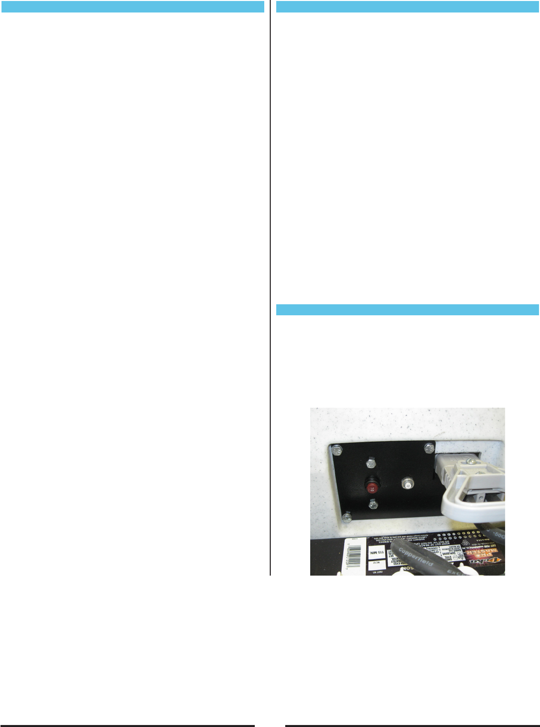
Over Current Protection
1. 70A Breaker - Over current protection for the burnish
motor. Push to reset.
2. 40A Breaker - Over current protection for the traction
drive. Push to reset (Only on Traction models).
3. 3A Fuse In-Line holder - Over current protection for
key switch.
12
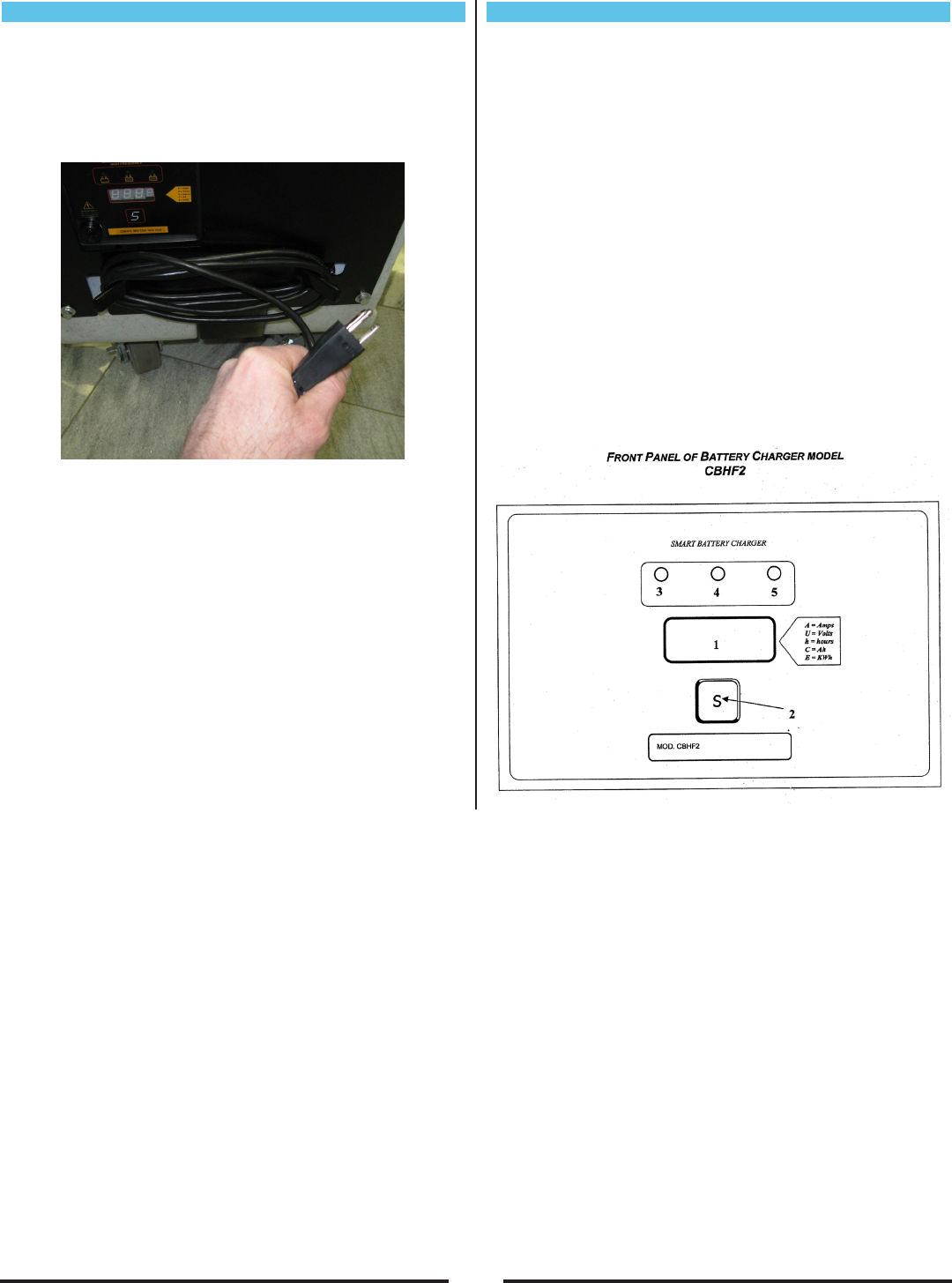
Onboard Battery Charger
To charge the batteries, first drive the machine to a flat,
dry, well-ventilated area then turn the machine off. If
using lead acid batteries, check the water level in all the
battery cells (see Battery Maintenance section). If the
level is low, add just enough distilled water to cover the
plates. **DO NOT OVERFILL!**
Then plug the charger cord into a wall socket. The
battery charger will initialize and then soft start the
charging cycle.
WARNING! Batteries emit hydrogen gas when
charging. Explosion or fire can result. Keep sparks
and open flame away when charging.
CAUTION! When servicing machine, wear protective
gloves and goggles when handling batteries or battery
cables. Avoid contact with battery acid.
Battery Charger Controls
1. Three-digit display + symbol (1), to view A=charging
current, U=battery voltage, h=charging time,
C=charging ampere-hours (AH), E=energy used to
charge (KWh)
2. Button for the Selection of the display mode (2): A, U,
h, C, E. After 10 seconds the display returns to the
display of charging current.
3. Red control indicator (3): when it is on, the charging
cycle has started.
4. Yellow control indicator (4): when it is on, the final
phase of the charging cycle has started.
5. Green control indicator (5): when it is on, the
charging cycle has finished.
Once the charge cycle is complete, the charger will
remain active in a trickle charge mode to maintain the
charge on the batteries until the charger is unplugged
from the wall socket.
13
Battery Charger Fault Codes
Fault Description Remedy
No
Display
No display on the charger, no LED
indicators.
Check that the plug is connected to an operating wall
outlet. Check fuse. 20A fuse MP265100.
aIncorrect battery connection or no battery
connection.
Check the connection and the polarity of the battery
connection.
The maximum voltage admissible by the
battery has been exceeded. The charge
cycle was interrupted.
Restart the charge cycle. If problem persists, battery
pack may be damaged.
The maximum temperature has been
exceeded. The charge cycle was
interrupted.
Restart the charge cycle. If problem persists, battery
pack may be damaged.
The maximum time for the charging phase
has been exceeded. The charge cycle was
interrupted.
Restart the charge cycle. If problem persists, battery
pack may be damaged.
The total safety time has interrupted the
charge cycle.
Restart the charge cycle. If problem persists, battery
pack may be damaged.
Internal charger fault. Replace battery charger.
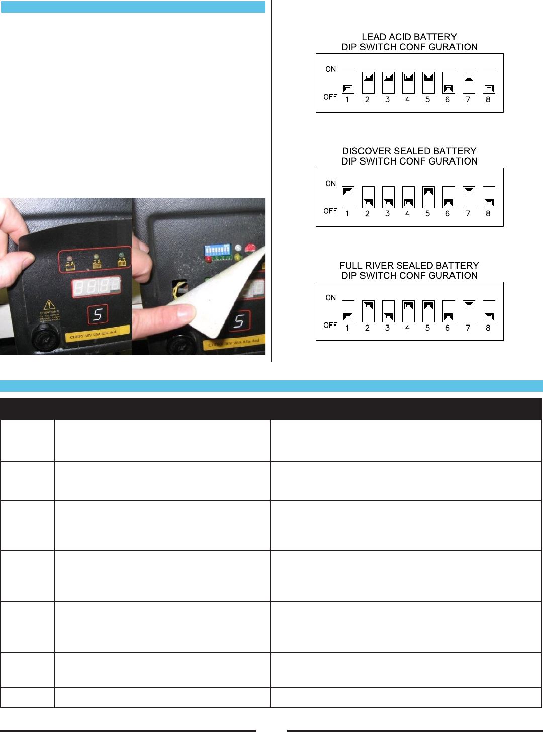
Charger Settings
The On-Board battery charger settings need to be set
for your battery type before charging. Failure to properly
set will result in battery damage.
To determine your battery type, see battery label or
contact your battery supplier.
To change charger settings:
1. Unplug the charger.
2. Peel back the corner of the display label.
3. Set the DIP switches, according to your battery pack,
as shown below. If your battery pack type is not
listed please call Amano Pioneer Eclipse at
+1 -336-372-8080 for correct setting.
14
How the Machine Works
The Burnish components of the machine are:
l Burnish pad holder
l Burnish pad
l Burnish motor
l Dust Collection Bag
As the machine moves forward, the burnish pad shines
the floor. Any excess dirt or wax gets picked up by the
pad and distributed into the dust collection bag via the
dust collection system.
Pre-Operation Checklist
Before operating the machine:
l Check that the Burnish Switch is in the off position.
l Check the pad holder to ensure there are no breaks
or cracks.
l Check correct connection of the batteries.
l Check that the Dust Collection Bag is empty.
l Release caster breaks.
Turning on the Machine
1. Complete pre-operation check.
2. Turn the Key to the ON position.
3. Turn on the burnish switch and engage the handle
levers.
4. Adjust speed as needed with traction speed control
knob. (Traction Models Only)
Changing Direction
When the handle levers are engaged the machine will
travel in the forward direction. To travel in reverse, while
the handle levers are engaged, hold down the reverse
switch. The machine will change from forward direction
to reverse direction. The machine will continue in the
reverse direction until the reverse switch is released.
Stopping & Turning Off Machine
To stop the machine, release the handle levers and
the machine will smoothly break to a stop and after 3
seconds the burnish motor will stop. When turning the
machine off, turn off the burnish switch and then turn off
the key switch.
Operation on Inclines
CAUTION! When the machine is traversing on an
incline, up or down, move slowly.
CAUTION! Do not run burnish pad on an incline. The
maximum rated climb and descent incline is 6°.
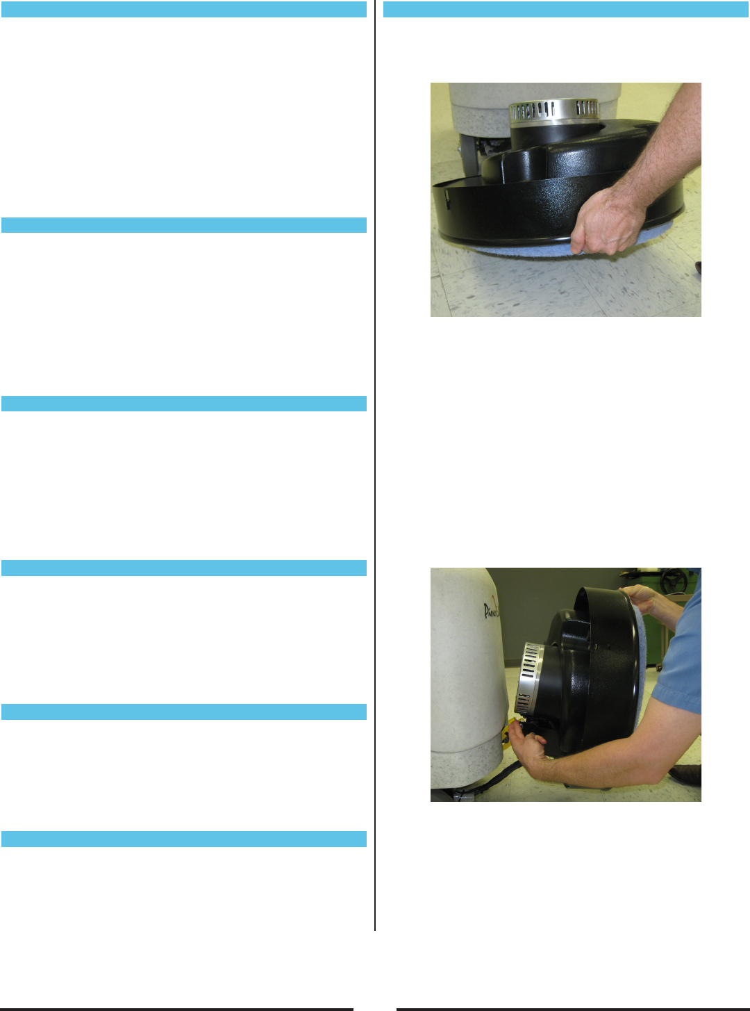
Installing / Changing Burnishing Pad
1. Make sure the Burnish Switch is OFF.
2. Lift on the front of the deck and tilt deck into the pad
change position.
3. Remove the center device by turning counter-
clockwise and carefully remove the old pad from the
Velcro material.
CAUTION! CAREFULLY INSPECT THE PAD
HOLDER FOR CRACKS OR DAMAGE! REPLACE
IF NECESSARY.
4. Pull center from new pad, align pad on pad holder
and secure with centering device by turning
clockwise.
5. Press pad firmly onto pad holder face.
6. Lift the front of the shroud and lift the shroud release
lever and SLOWLY let the shroud return to the down
position.
CAUTION! KEEP HOLD OF THE DECK TO
AVOID INJURY!
15
Dust Bag Removal
The machine has two dust bag options. A re-usable cloth
bag and a disposable paper bag. Monitor the dust bag
carefully and empty/change as needed. The dust
collection system will not operate effectively when the
dust bag is full. Under heavy burnishing conditions the
dust bag should be emptied/changed every hour.
1. Turn off the Burnish Motor.
2. Unscrew the knobs holding the dust bag cover to the
shroud.
3. Pull the dust bag off the dust tube.
4. Empty/Change dust bag.
Caster Parking Brake
The two rear casters are equipped with brakes. To set
the brake, push down the “ON” side of the brake lever.
To release the brake push down the “OFF” side of the
brake lever. The caster breaks should only be used as
a parking brake if needed. Before moving the machine
make sure both breaks are released.
Pad Pressure Adjustment
The pad pressure is set at the factory for optimal burnish
performance in most conditions. If the pad pressure
needs to be adjusted, follow the procedure outlined
below.
NOTE: Pad pressure adjustments should only be
performed by a qualified technician.
1. Turn burnish switch off.
2. Remove back panel.
3. Adjust ball end to increase or decrease pad pressure
as shown in diagram.
Post Operation Checklist
Turn the machine OFF and perform the following
checks:
lCheck for wire, string, or twine wrapped around the
burnish pad.
l Check for frayed wires or damage.
lEmpty the dust collection bag.
lInspect batteries.
l Plug in on-board battery charger.
RF044900 051112
Increase Pad
Pressure
Decrease Pad
Pressure

16
Maintenance
Interval
Operation Daily Every
25 Hrs
Every
50 Hrs
Every
100 Hrs
Every
200 Hrs
Every
500 Hrs
Every
1000 Hrs
Empty/Clean Dust Bag l
Inspect Pad Holder l
Inspect Battery water level (Lead Acid only) l
Check wiring harness for fray or cut l
Check for loose/missing nuts or screws l
Tighten nuts and screws l
Check brushes on transaxle motor and burnish motor l
Lubricate rear casters l
Check Burnish motor ampere draw l
Replace the gas shock l
Inspect Burnishing Head Assembly (30”) l
Inspect Deck Drive Belt (30”) l
Replace Drive Belt (30”) As Required
Scheduled Maintenance
These items must be performed with the proper tools and training. Contact a Amano Pioneer Eclipse
Factory Certified Technician unless you have the proper equipment and mechanical proficiency.
17
Body & Battery Cover
The body may be cleaned with a damp cloth to remove
dust and scuff marks. More stubborn scuff marks on the
tank exterior can be removed with a vinyl cleaner
Battery Maintenance
The batteries are deep cycle 12 volt batteries. The
lifetime of the batteries is limited by the number of
charges the batteries receive. To get the most life from
the batteries, charge them when the battery discharge
LED (Red) starts to blink (20% charge left). Use only
the on-board battery charger supplied to charge the
batteries.
Periodically clean the top surface of the batteries and
the terminals, and check for loose connections. Use a
strong solution of baking soda and water. Brush the
solution sparingly over the battery tops, terminals, and
cable clamps.
CAUTION! DO NOT ALLOW ANY BAKING SODA
SOLUTION TO ENTER THE BATTERIES!
Use a wire brush to clean the terminal posts and cable
connectors. After cleaning, apply a coating of clear
battery post protectant to the terminals and the cable
connectors. Keep the tops of the batteries clean and dry.
To prevent a possible short circuit, keep all metallic
objects off the top of the batteries. Replace any worn or
damaged wires.
Lead Acid Batteries
Sealed batteries no additional maintenance required.
CAUTION! When working with batteries, always wear
eye protection and protective clothing.
CAUTION! Batteries emit hydrogen gas. NO
SMOKING!
Never add acid to the batteries, only distilled water.
Always keep the battery caps on, except when adding
water or taking hydrometer readings.
CAUTION! Never use tap water to fill battery cells.
Tap water contains contaminants that will damage the
battery. Only use distilled water to fill battery cells.
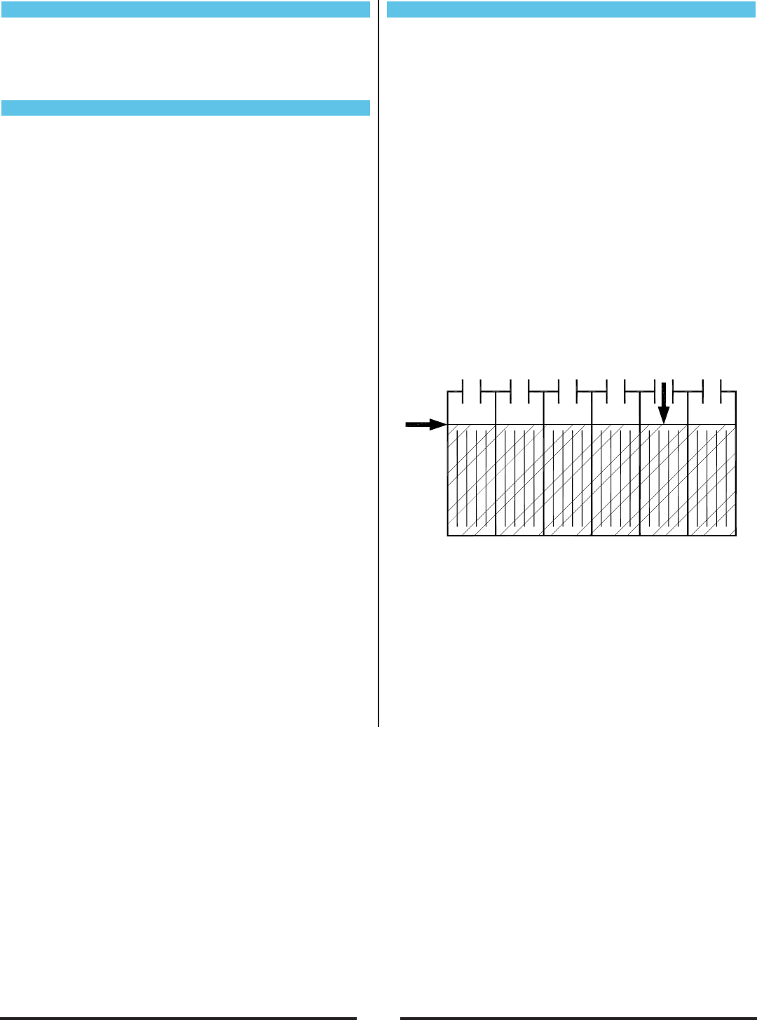
Check the electrolyte level in each battery cell before
and after charging, and after every 50 hours of
operation. Do not charge the batteries unless the fluid
is slightly above the battery plates. If needed, add just
enough distilled water to cover the plates. Never add
acid to the batteries.
CAUTION! DO NOT OVERFILL!
Measuring the specific gravity, using a hydrometer, is a
way to determine the charge level and condition of the
batteries. If one or more of the battery cells test lower
than the other battery cell (0.050 or more), the cell is
damaged, shorted, or is about to fail.
CAUTION! Battery damage will occur if the electrolyte
level does not cover the battery plates.
CAUTION! Machine and/or battery damage can occur
if the electrolyte level is above the bottom of the tube
in each cell.
18
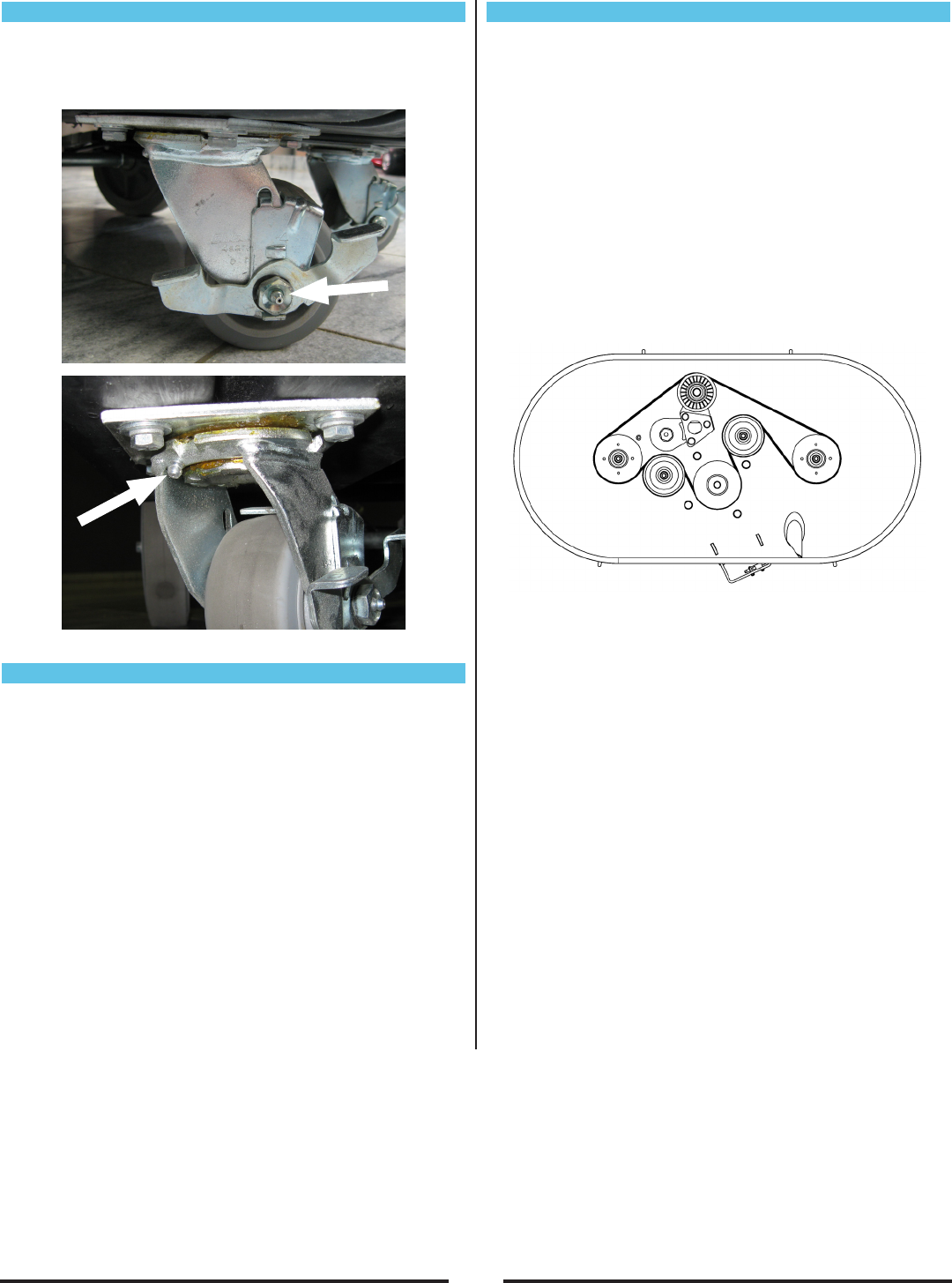
Rear Casters
Each of the two rear casters has two grease fittings.
Lubricate each caster with a grease gun every 100
hours of machine operation
Belt Maintenance (30” Models)
1. Push machine to level surface.
2. Turn machine off and disconnect the battery pack.
3. Lift up on the front of the deck, placing the deck in
the pad change position.
4. Remove the pad retainer and pads from the pad
holders.
5. Remove the pad holders from each of the drive
pulleys, by removing the (4) bolts in the center of the
pad holder.
6. Locate and remove the (4) bolts that fasten the pulley
cover to the deck.
7. Rotate the deck belt. If there are excessive cracks in
the belt ribs and chunks that have broken off the ribs,
the belt needs to be replaced.
Belt Replacement
Part No: MP449100
1. Place a 9/16” wrench on the bolt of the tensioner
idler pulley and rotate the tensioner downward.
2. With the tension removed, remove the belt from the
tensioner pulley.
3. Slowly allow the tensioner to rotate to a natural
position.
4. Remove the belt from the deck.
5. With belt removed, inspect all of the fasteners for
proper tightness. Also check the bearings for wear
and the condition of each pulley.
6. Install the new belt using the belt diagram.
7. Use a 9/16” wrench to rotate the tensioner down so
the new belt can be installed.
8. Slowly allow the tensioner to tighten against the belt.
9. Turn the belt through several revolutions to make
sure the belt tracks properly.
10. Reinstall the pulley cover.
11. Reinstall the pad holders on to the drive pulleys.
12. Turn the pad holders to verify that there is no
interference.
13. Install pads onto the pad holders.
14. Slowly lower the deck back to the operating position.

19
*Given the following alarm codes, troubleshooting should only be done by a Amano Pioneer Eclipse
Factory Certified Technician. A programming handset may be required for troubleshooting.
Number of
Flashes Description Possible Cause
1 (fast) Low Battery Voltage
The battery needs charging or there is a bad connection to the battery.
Check the connections to the battery. If the connections are good, try
charging the battery.
1 (medium) Handle lever engaged at key on Disengage the handle lever, key off and key back on to clear
1 (slow) Machine Time Out The machine has been left with the key on. Turn the key off and then back
on again.
2Motor Disconnected The motor has a bad connection. Check all the connections and leads
between the motor and the controller.
3Motor Wiring Trip The motor has a short circuit to a battery. Check all the connections and
leads between the motor and the battery.
6 Inhibit Active The controller is being inhibited from driving. Check the state of the Inhibit
unputs.
7Throttle Trip A throttle trip is indicated. Make sure that the throttle is in the rest position
before switching on the vehicle.
8Possible Controller Trip A possible controller trip is indicated. Make sure that all connections are
secure.
9Solenoid Brake Trip The parking brakes have a bad connection. Check the parking brake and
motor connections. Make sure the controller connections are secure.
10 High Battery Voltage An excessive voltage has been applied to the controller. This is usually
caused by a poor battery connection. Check the battery connections.
Alarm Codes (Traction Only)

20
Machine Troubleshooting
Problem Possible Cause Remedy
Machine will not turn on
Breaker Tripped Push breaker button to reset
Incorrect battery connection Check batteries are wired together correctly via the battery connection diagram,
check the Anderson connectors are plugged together
On-board battery charger plugged in Unplug the charging cord from the machine
Key switch failure Check key switch is functioning and wiring to the key switch is correct
Failed Fuse Check the fuse in the in line fuse holder.
Burnish motor will not
start
Deck tilted into pad change position Lower the deck to the burnish position
Speed control knob turned all the way counter-
clockwise (off) Turn speed control knob clockwise to increase speed
Burnish switch off Turn on burnish switch
Handle levers not engaged Engage handle levers
70A breaker tripped
Push 70A breaker to reset. DO NOT use round pads on the PE300BU30X. Using
round pads will shorten the run time and trip the breaker. The use of round pads on
this machine will damage the burnish motor and void the warranty.
Battery lockout Batteries need to be charged
Red LED Flashing on
Dash Check alarm code reference sheet Troubleshoot accordingly
Machine exhibits poor
burnishing performance
Pad dirty Remove debris or string/twine from pads; clean pad; replace pad
Incorrect pad Use more aggressive burnishing pad
Pad worn down Replace pad
Machine exhibits very
aggressive burnish
performance
Gas Spring faulty Check ampere draw of burnish motor (should not be above 50 amps); replace gas
spring
Incorrect pad Use less aggressive burnishing pad
Dust collection not
working properly
Dust collection bad, is not collecting dust
Empty dust bag
Check the dust tube to see if there is an obstruction
Skirt is not sealing to the oor
Skirt is bent or damaged. Replace if necessary.
Adjust the skirt to t tightly against the seal, but still able to move freely
Check wear edge on bottom of the skirt and replace if necessary
(30”) Smell of burnt
rubber Belt out of adjustment Check the automatic tensioner

21
Voltage: 36VDC (Qty. 3 - 12VDC Batteries)
Sound Level: < 70 dB(A)
Vibration: Less than 2.5 m/s2
Forward Speed: 3.25 mph (5.23 km/h) Traction Only
Reverse Speed: 1.5 mph (2.4 km/h) Traction Only
Burnish Motor: 2.5 hp (1.86 kw) Permanent Magnet
Transaxle: .25 hp (186 watts) Traction Only
Battery Charger: 36V 25A On-Board
Wheels: 8 in. (20.3 cm) Solid
Battery: 12VDC Lead Acid 228 Ah (Qty. 3)
Weight 126 lbs (57 kg) each - Total Battery Weight 378 lbs (171.5 kg)
12VDC AGM 235 Ah (Qty. 3)
Weight 140 lbs (63.5 kg) each - Total Battery Weight 418 lbs (189.6 kg)
20” Machines 24” Machines
Pad Size: 20” (51 cm) Pad Size: 24” (61.0 cm)
Pad Speed: 2000 RPM Pad Speed: 1800 RPM
Deck Width: 22” (56 cm) Deck Width: 26” (66 cm)
Length: 49” (124 cm) Head Up Length: 49” (124 cm) Head Up
58” (147 cm) Head Down 61” (155 cm) Head Down
Height: 45” (114 cm) Height: 45” (114 cm)
Weight: w/o Batteries Weight: w/o Batteries
200 lbs (91 kg) Pad-Assist 212 lbs (96 kg) Pad-Assist
219 lbs (99 kg) Traction 231 lbs (105 kg) Traction
30” Machines
Pad Size: 16” (41 cm) Qty. 2
Pad Speed: 2000 RPM
Deck Width: 33” (84 cm)
Length: 51” (130 cm) Head Up
60” (152 cm) Head Down
Height: 45” (114 cm)
Weight: w/o Batteries
245 lbs (111 kg) Traction
Machine Specications

22

23
PE300BU
Battery Burnisher
Parts Manual
Notes:
________________________________________________
________________________________________________
________________________________________________
________________________________________________
________________________________________________
________________________________________________
________________________________________________
________________________________________________
________________________________________________
________________________________________________
________________________________________________
________________________________________________
________________________________________________
________________________________________________
________________________________________________
________________________________________________
________________________________________________
________________________________________________
________________________________________________
________________________________________________
________________________________________________
________________________________________________
________________________________________________
24
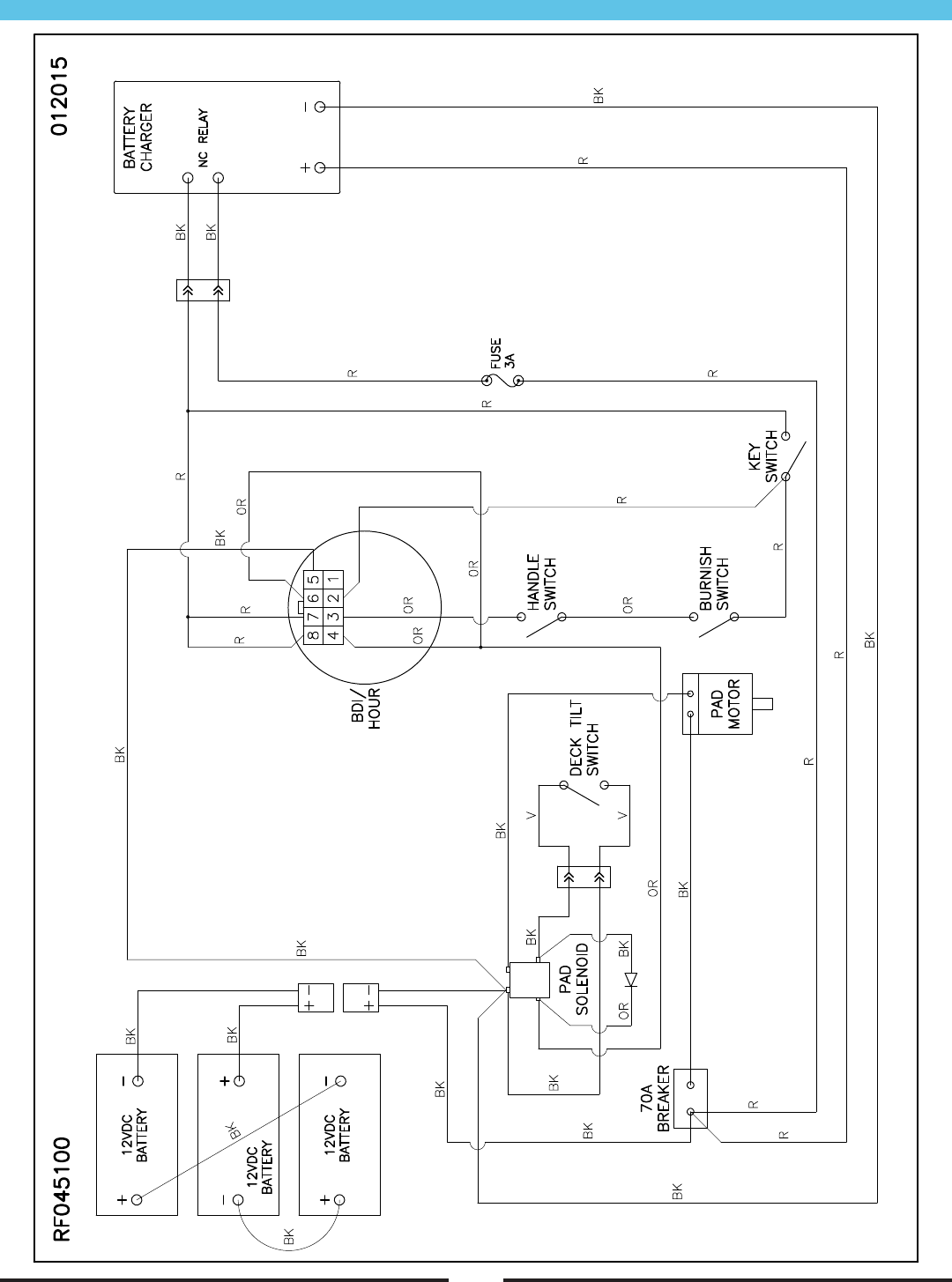
Electrical Schematic - Pad Assist
25
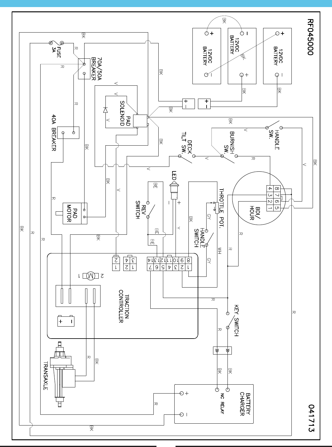
Electrical Schematic - Traction
26
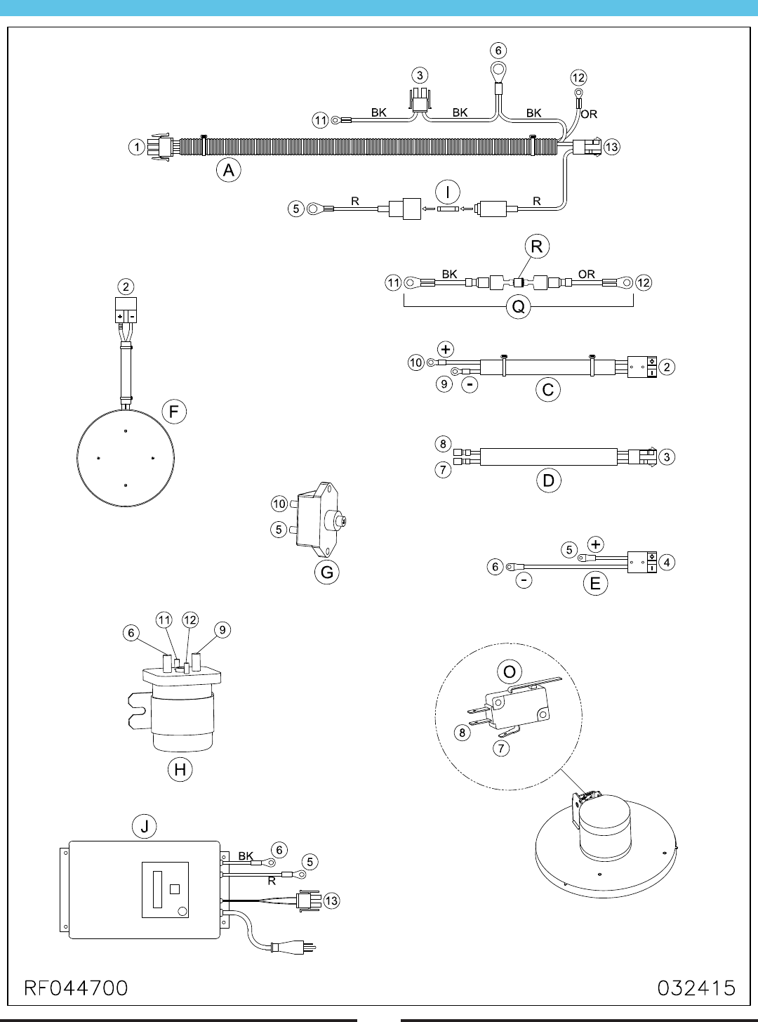
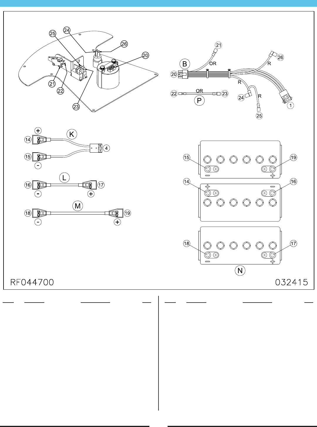
Connections - Pad Assist
27
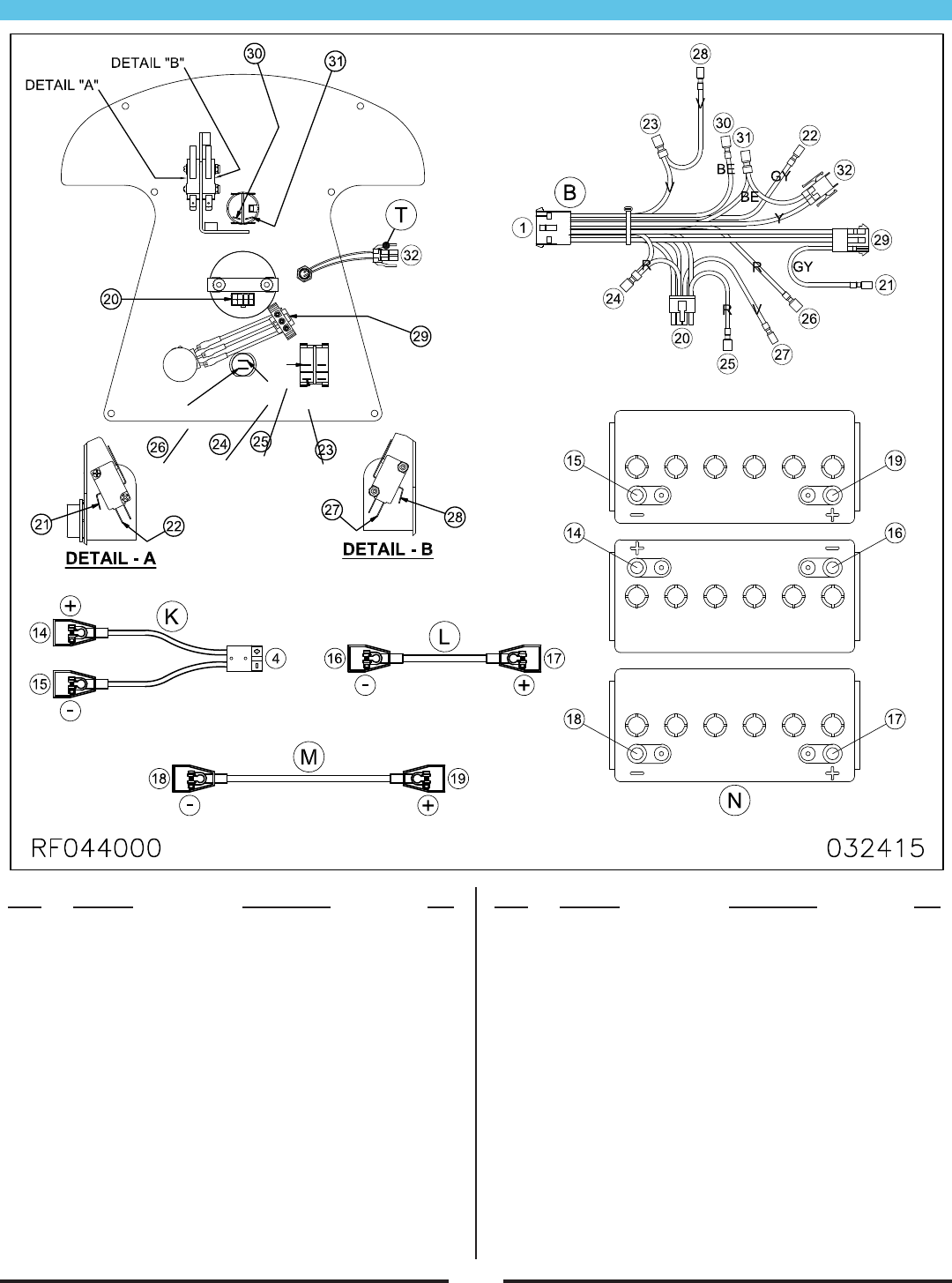
Connections - Pad Assist (Continued)
Item Ref. No. Description Qty
A MP426500 HARNESS, MAIN, PAD ASSIST 1
B MP426700 HARNESS, C.PANEL, PAD ASST. 1
C MP426800 HARNESS, MOTOR, BURNISH 1
D MP427000 HARNESS, SWITCH, TILT 1
E MP427200 CABLE, BATTERY, SOLENOID 1
F1 MP424200 MOTOR, 2000 RPM, ASM. (20”/30”) 1
F2 MP434100 MOTOR, 1800 RPM, ASM. (24”) 1
G MP414800 BREAKER, CIRCUIT, 70A 1
H MP207000 SOLENOID, 36VDC, SPNO 1
I MP234700 FUSE, 3A, GLASS 1
J1 SA027500 CHARGER, 110V, 36V, ASM. 1
J2 SA027600 CHARGER, 220V, 36V, ASM. 1
Item Ref. No. Description Qty
K MP279700 CABLE, BATTERY, w/ PLUG 1
L MP238200 CABLE, BATTERY, 13.5” 1
M MP279800 CABLE, BATTERY 1
N1 MP223500 BATTERY, 12V, LEAD ACID 3
N2 MP413600 BATTERY, 12V, SEALED 3
O MP318400 SWITCH, MICRO, 12V 1
P MP427800 WIRE, SWITCH, 3” 1
Q MP482400 WIRE, DIODE, ASM. 1
R MP254600 DIODE, 6A, ASM. 1
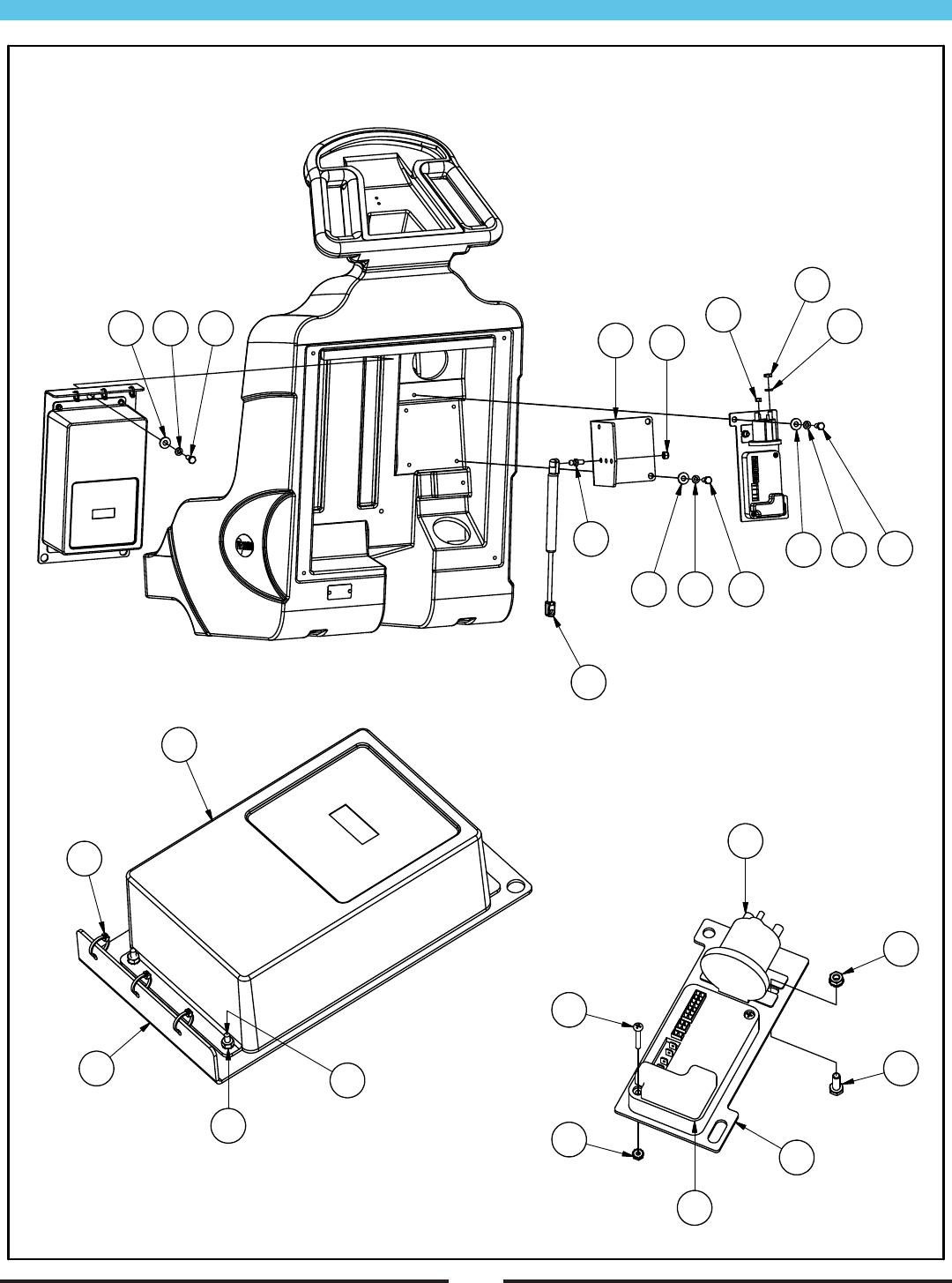
28
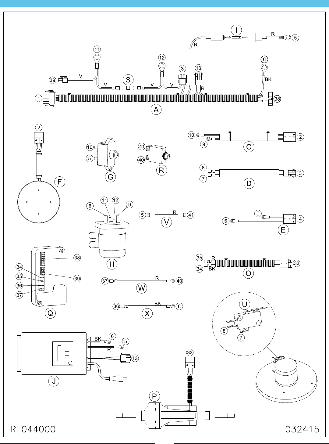
Connections - Traction
29
Connections - Traction (Continued)
Item Ref. No. Description Qty
A MP432200 HARNESS, MAIN, TRACTION 1
B MP432100 HARNESS, C.PANEL, TRACTION 1
C MP426800 HARNESS, MOTOR, BURNISH 1
D MP427000 HARNESS, SWITCH, TILT 1
E MP427200 CABLE, BATTERY, SOLENOID 1
F1 MP424200 MOTOR, 2000 RPM, ASM. (20”/30”) 1
F2 MP434100 MOTOR, 1800 RPM, ASM. (24”) 1
G MP414800 BREAKER, CIRCUIT, 70A 1
H MP207000 SOLENOID, 36VDC, SPNO 1
I MP234700 FUSE, 3A, GLASS 1
J1 SA027500 CHARGER, 110V, 36V, ASM. 1
J2 SA027600 CHARGER, 220V, 36V, ASM. 1
K MP279700 CABLE, BATTERY, w/ PLUG 1
L MP238200 CABLE, BATTERY, 13.5” 1
Item Ref. No. Description Qty
M MP279800 CABLE, BATTERY 1
N1 MP223500 BATTERY, 12V, LEAD ACID 3
N2 MP413600 BATTERY, 12V, SEALED 3
O MP426900 HARNESS, WIRING, TR. AXLE 1
P MP424500 TRANSAXLE, 36V, ASM. 1
Q MP409401 CONTROLLER, TRACTION 1
R MP414900 BREAKER, CIRCUIT, 40A 1
S MP254600 DIODE, 6A, ASM. 1
T SA028000 LED, RED, REPLACEMENT 1
U MP318400 SWITCH, MICRO, 12V 1
V MP427500 WIRE, 10AWG, RED, 3”L 1
W MP427600 WIRE, 10AWG, REG, 16”L 1
X MP427700 WIRE, 10AWG, BLK, 12”L 1
30
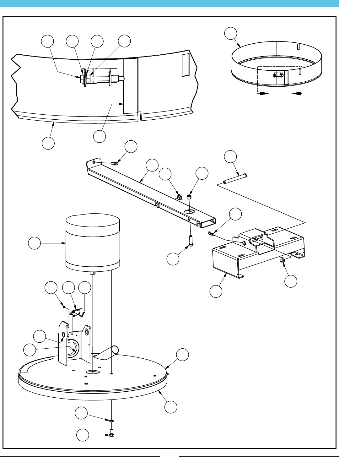
Skirt, Deck & Axle Bracket Assembly
RF044600 093013
12
10
9
11
13
14
9
7
8
23
20 18 19
25
24
22
16
17
21
2 3 3 4
5
1
6

31
Item Ref. No. Description Qty
1A MP425200 SKIRT, 20”, ASM. 1
1B MP434200 SKIRT, 24”, ASM. 1
2 NB050600 BOLT, HEX, 1/4” X 2-1/2” 1
3 NB3350 WASHER, FLAT, 1/4” 2
4 MX1045 NUT, HEX, 1/4” 1
5A MP139800 EDGING, WEAR, SKIRT (20”) 6 FT
5B MP139800 EDGING, WEAR, SKIRT (24”) 7 FT
6 MP6600 FELT, VELCRO, BLK, 2” 2 (4”)
7 MP423700 BRACKET, AXLE / TRANSAXLE 1
8 MP423800 TUBE, MOUNT, SHROUD 1
9 MP237100 BUSHING, FLANGED, 1/2” 6
10 NB039704 PIN, CLEVIS, 1/2” X 4-1/2” 1
11 NB025600 PIN, PRESTO, 3/32” X 1-5/8” 1
12 MP414300 BALL, STUD, 10MM 1
13A NB068900 BOLT, HEX, 1/2” X 1-1/2” (20”) 1
13B NB068800 BOLT, HEX, 7/16” X 1-1/2” (24”/ 30”) 1
Skirt, Deck & Axle Bracket Assembly (continued)
Item Ref. No. Description Qty
14A NB014600 NUT, LOCK, 1/2” (20”) 1
14B NB067700 NUT, LOCK, 7/16” (24”) 1
15 N/A N/A -
16A MP432600 SHROUD, 20”, ASM. 1
16B MP438800 SHROUD, 24”, ASM. 1
17 MP237100 BUSHING, FLANGED, 1/2” 2
18 MP318400 SWITCH, MICRO, 12V 1
19 NB9625 SCREW, #4 X 3/4” 2
20 NB007000 NUT, LOCK, #4 2
21 NB043800 GROMMET, 2” ID 1
22A MP415100 FELT, VELCRO, BLK, 1” (20”) 6 FT
22B MP415100 FELT, VELCRO, BLK, 1” (24”) 7 FT
23A MP424200 MOTOR, 2000 RPM, ASM. (20”/30”) 1
23B MP434100 MOTOR, 1800 RPM, ASM. (24”) 1
24 NB6851 BOLT, HEX, 3/8” X 3/4” 4
25 MX1075 WASHER, LOCK, 3/8” 4
32
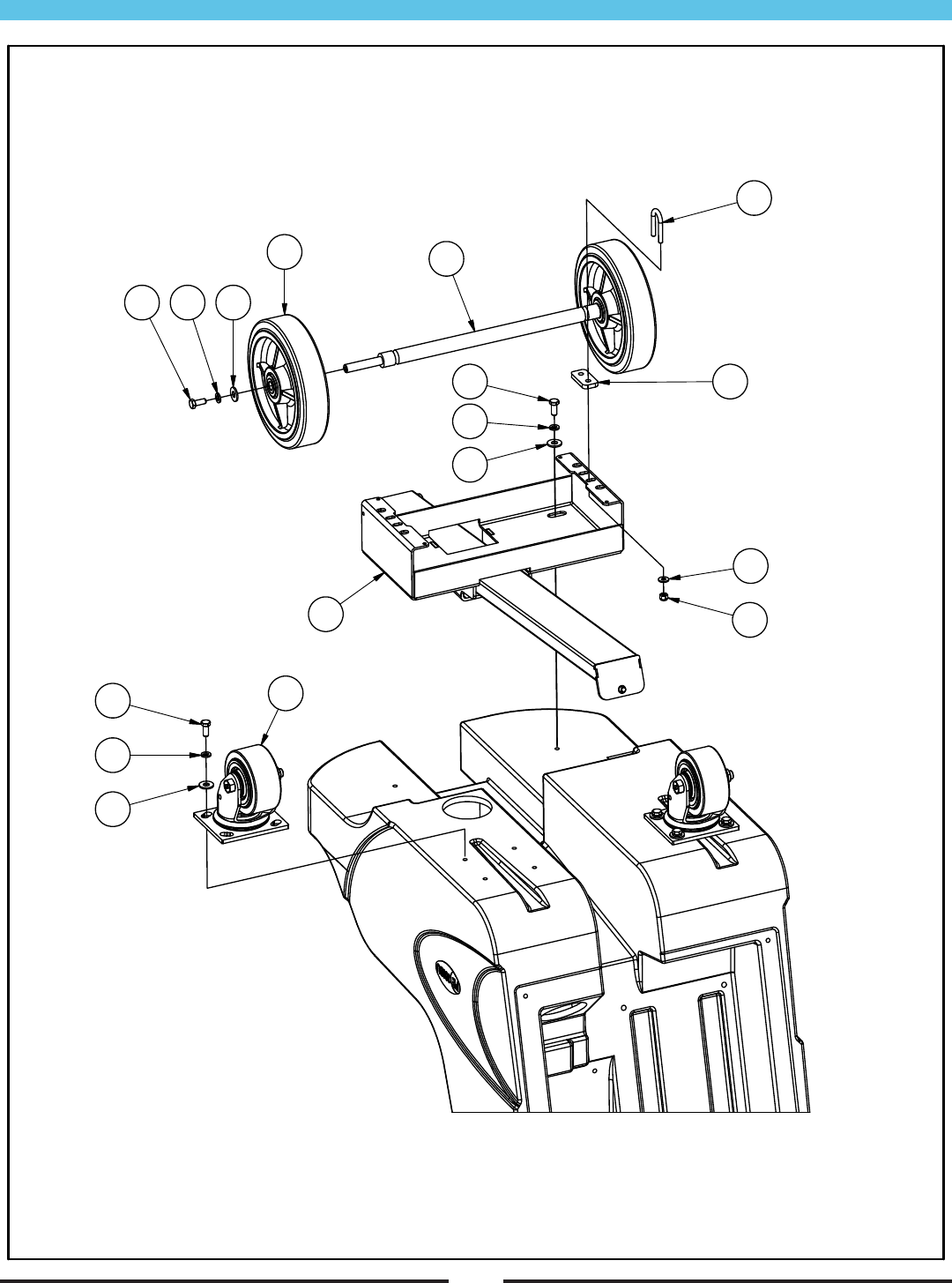
Main Bottom Assembly - Pad Assist
RF044500 073112
9
8
10
5
4
3
6
11
7
34
5
1
2
5
4
3

33
Main Bottom Assembly - Pad-Assist (continued)
Item Ref. No. Description Qty
1A MP424400 BRACKET, AXLE, ASM. (20”) 1
1B MP440800 BRACKET, AXLE, ASM. (24”) 1
2 MP432500 CASTER, 4”, w/ BRAKE 2
3 NB9267 WASHER, FLAT, 5/16” 14
4 NB6111 WASHER, LOCK, 5/16” 14
5 NB9745 BOLT, HEX, 5/16” X 3/4” 14
6 NB3350 WASHER, FLAT, 1/4” 4
7 MP409900 WHEEL, 8” X 2” 2
8 MP423500 AXLE 1
9 NB061600 BOLT, U, 1/4” 2
10 MP425301 SPACER, AXLE 2
11 NB3275 NUT, LOCK, 1/4” 4
34
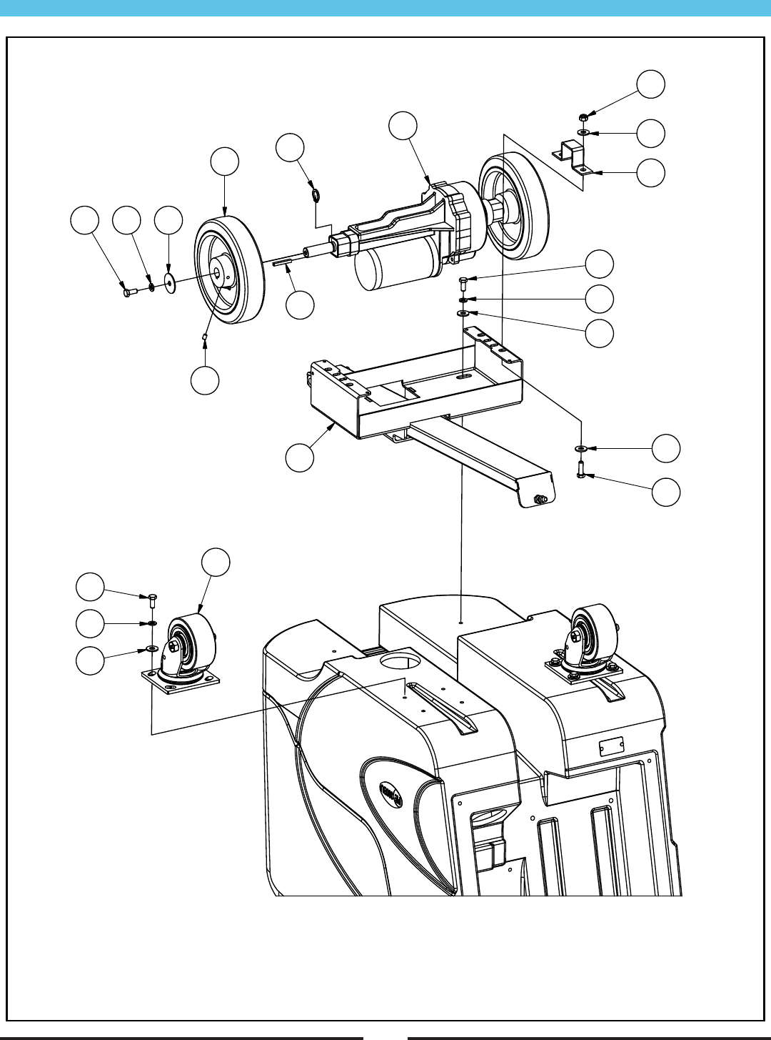
Main Bottom Assembly - Traction
RF044400 041713
5
12
3
2
7
6
9
101314
14
13
12
12
4
1
11
14
13
12
8

35
Main Bottom Assembly - Traction (continued)
Item Ref. No. Description Qty
1A MP424400 BRACKET, AXLE, ASM. (20”) 1
1B MP440800 BRACKET, AXLE, ASM. (24”) 1
2 MP424500 TRANSAXLE, 36V, ASM. 1
3 PG001801 BRACKET, TRANSAXLE 2
4 NB6545 BOLT, HEX, 5/16” X 1” 4
5 NB3265 NUT, LOCK, 5/16” 4
6 BA003300 KEY, 3/16” X 1-1/2” 2
7 NB018500 RING, RETAINING, 3/4” 2
8 MP409800 WHEEL, 8” X 2” 2
9 NB9302 SCREW, SET, 1/4” X 3/8” 4
10 NB9505 WASHER, FLAT, 5/16” X 1-1/2” 2
11 MP432500 CASTER, 4”, w/ BRAKE 2
12 NB9267 WASHER, FLAT, 5/16” 20
13 NB6111 WASHER, LOCK, 5/16” 14
14 NB9745 BOLT, HEX, 5/16” X 3/4” 14
36
Main Rear Assembly
RF044100 013113
567
7
6
5
4
2
7
6
5
3
1
10
11
12
14
13
20
21
17
18
16
19
15
9
8
6

37
Main Rear Assembly (continued)
Item Ref. No. Description Qty
1 MP422901 PLATE, MOUNT, SHOCK 1
2 MP206000 BALL, STUD, 10MM 1
3 NB3265 NUT, LOCK, 5/16” 1
4A MP415200 SPRING, GAS (20”) 1
4B MP434500 SPRING, GAS (24”) 1
4C MP450300 SPRING, GAS (30”) 1
5 NB9267 WASHER, FLAT, 5/16” 9
6 NB6111 WASHER, LOCK, 5/16” 11
7 NB9745 BOLT, HEX, 5/16” X 3/4” 9
8 NB005700 NUT, JAM, 5/16” 2
9 NB006600 NUT, KEPS, #10 2
10A SA027500 CHARGER, 110V, 36V, ASM. 1
10B SA027600 CHARGER, 220V, 36V, ASM. 1
Item Ref. No. Description Qty
11 MP423101 PLATE, MOUNT, CHARGER 1
12 NB6035 TIE, CABLE, 1/8” X 4” 3
13 NB040400 SCREW, PH, #10 X 3/4” 4
14 NB006600 NUT, KEPS, #10 4
15 MP423001 PLATE, MOUNT, SOLENOID 1
16 MP207000 SOLENOID, 36VDC, SPNO 1
17 NB6535 BOLT, HEX, 1/4” X 3/4” 2
18 NB9845 NUT, KEPS, 1/4” 2
19 MP409401 CONTROLLER, TRACTION 1
20 MX1011 SCREW, #8 X 1-1/4” (TRACTION) 2
21 NB9710 NUT, KEPS, #8 (TRACTION) 2
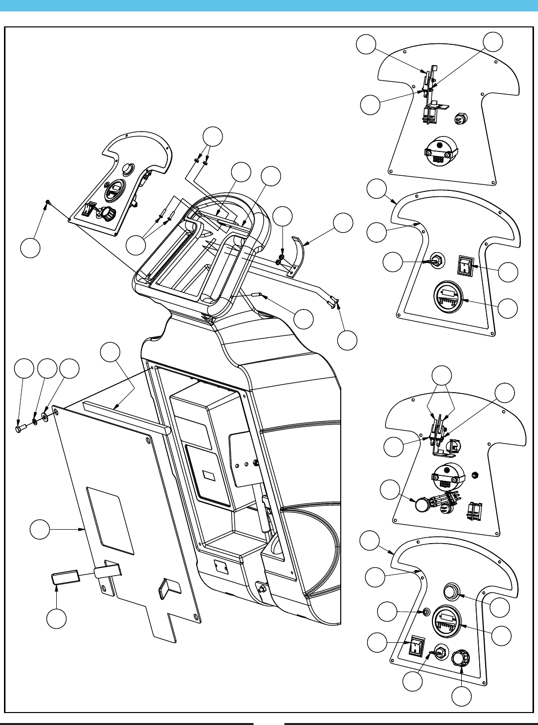
Main Top Assembly
38
RF044300 041913
10
4
5
6
7
11 9
8
12
3
22
19
18
26
17
20
21
24
25
23
17
18
19
29
23 25
16
15
28
27
12
14
13
30

Main Top Assembly (continued)
39
Item Ref. No. Description Qty
1 MP423201 LEVER, HANDLE, LEFT 1
2 MP423202 LEVER, HANDLE, RIGHT 1
3 NB6390 PIN, ROLL, 1/4” X 1-1/8” 2
4 MP431401 PLATE, COVER, REAR 1
5 NB9267 WASHER, FLAT, 5/16” 4
6 NB6111 WASHER, LOCK, 5/16” 4
7 NB9745 BOLT, HEX, 5/16” X 3/4” 4
8 NB9710 NUT, KEPS, #8 2
9 NB041200 SCREW, PH, #8 X 3/4” 2
10 MP077400 COVER, VINYL 2
11 NB043600 SCREW, PH, #8 X 3/8” 6
12 MP432900 SPRING, LEVER, HANDLE 1
13 MX1025 SCREW, PH, #10 X 3/4” 2
14 NB9510 NUT, FLANGE, #10 2
15 MP431600 PANEL, CONTROL, TRACTION 1
16 MP426200 DECAL, C.PANEL, TRACTION 1
Item Ref. No. Description Qty
17 MP414501 METER, HOUR / BATTERY 1
18 MP414600 SWITCH, ROCKER, DPST 1
19A MP411300 SWITCH, 36V 1
19B KC4834001 KEY, SWITCH (NOT SHOWN) 1
20 MP415000 SWITCH, PUSH (TRACTION) 1
21 PG016400 POTENTIOMETER (TRACTION) 1
22 MP418000 KNOB (TRACTION) 1
23 MP318400 SWITCH, MICRO, 12V 1
24 NB051000 SCREW, #4 X 1” 2
25 NB007000 NUT, LOCK, #4 4
26 SA028000 LED, RED, 36V 1
27 MP424100 PANEL, CONTROL, PAD ASSIST 1
28 MP426300 DECAL, C.PANEL, PAD ASSIST 1
29 NB9625 SCREW, #4 X 3/4” 2
30 MP038300 MOLDING, TRIM 16”
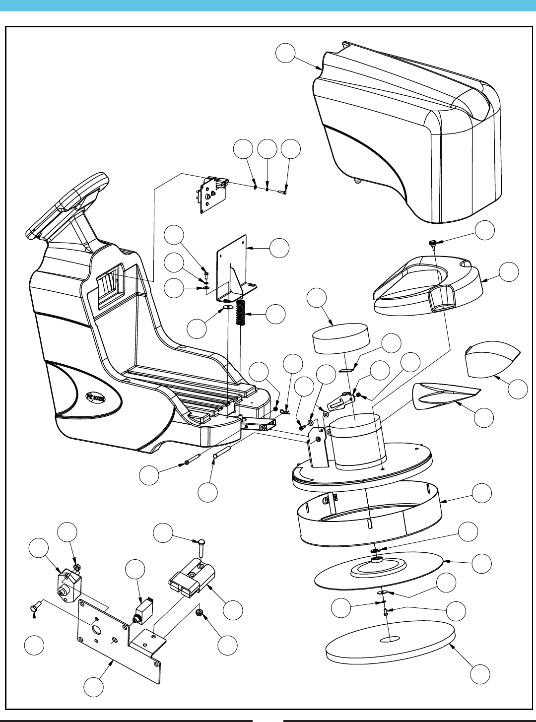
Main Front Assembly
40
RF044200 102813
22 23 24
20
19
18
5
1
16
17
62
15
14
12
13
11
8
7
10
19 20
9
4
21 36
30
34
31
33
28
32
27
33
27
10*
25
26

Main Front Assembly (continued)
41
Item Ref. No. Description Qty
1 NB039704 PIN, CLEVIS, 1/2” X 4-1/2” 1
2 NB025600 PIN, PRESTO, 3/32” X 1-5/8” 1
3 MP423301 LATCH, TILT 1
4 NB026200 BOLT, SHLD, 3/8” X 1/2” 1
5 NB038600 BOLT, SHLD, 3/8” X 3-1/2” 1
6 NB3265 NUT, LOCK, 5/16” 2
7A MP414000 PAD HOLDER, 20” 1
7B MP435000 PAD HOLDER, 24” 1
7C MP432400 RETAINER, PAD (NOT SHOWN) 1
8 NB018600 WASHER, FLAT, 3/4” 1
9 N/A N/A -
10 NB9505 WASHER, FLAT, 5/16” X 1-1/2” 1
11A MP425200 SKIRT, 20”, ASM. 1
11B MP434200 SKIRT, 24”, ASM. 1
12 MP414100 BAG, DUST, CLOTH 1
13 MP414200 BAG, DUST, PAPER 1
14 MP431300 COVER, BAG, DUST 1
15 MP155600 KNOB, 1/4” X 3/4” 2
16 MP423900 RETAINER, BATTERY 1
17A MP415300 SPRING, COMP., .90” ID (20”) 1
17B MP434400 SPRING, COMP., .81” ID (24”) 1
17C MP448800 SPRING, COMP., .83” ID (30”) 1
Item Ref. No. Description Qty
18 NB9267 WASHER, FLAT, 5/16” 2
19 NB6111 WASHER, LOCK, 5/16” 3
20 NB9745 BOLT, HEX, 5/16” X 3/4” 3
21 NB025200 WASHER, FLAT, 3/8” 2
22 NB3350 WASHER, FLAT, 1/4” 4
23 NB6110 WASHER, LOCK, 1/4” 4
24 NB6530 BOLT, HEX, 1/4” X 1” 4
25 MP8300 HOOK, VELCRO, 1” 2”
26 MP464800 FILTER, DUST, MOTOR 1
27 MP432700 COVER, BATTERY, ASM. 1
28 MP422801 PLATE, MOUNT, PLUG 1
29 MP414800 BREAKER, CIRCUIT, 70A 1
30 MP414900 BREAKER, CIRCUIT, 40A (TRAC.) 1
31 MP427200 CABLE, BATTERY, SOLENOID 1
32 NB6535 BOLT, HEX, 1/4” X 3/4” 2
33 NB9845 NUT, KEPS, 1/4” 4
34 NB9000 BOLT, HEX, 1/4” X 1-1/2” 2
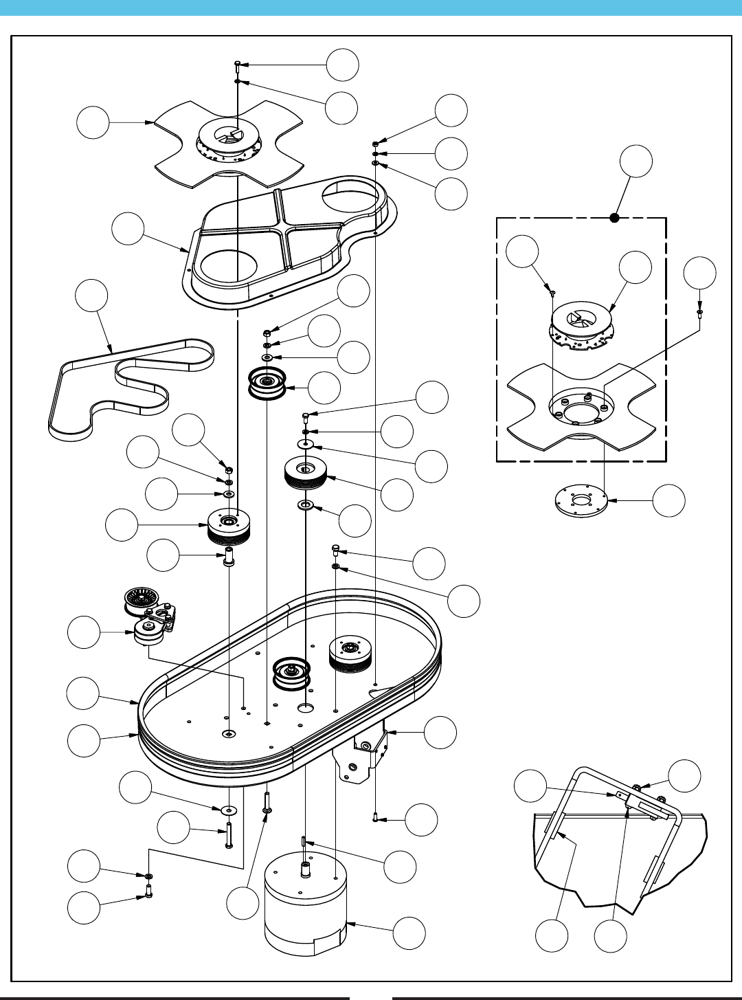
30” Deck Assembly
42
RF047700 093013
11
34
15
27
13
12
24
31
26
30
26
25
28
20
22
17
19
8
18
16 9
8
21
18
8
19
14
23
8
29
10
32
33
2
3
4
5
6
7
36 39
37
38
35
1

30” Deck Assembly (continued)
Item Ref. No. Description Qty
1 MP456700 SHROUD, 30”, ASM. 1
2 MP237100 BUSHING, FLANGED, 1/2” 2
3 MP318400 SWITCH, MICRO, 12V 1
4 NB9625 SCREW, #4 X 3/4” 2
5 NB007000 NUT, LOCK, #4 2
6 MP424200 MOTOR, 2000 RPM, ASM. 1
7 BA003200 KEY, 3/16” X 1” 1
8 MX1075 WASHER, LOCK, 3/8” 9
9 NB6851 BOLT, HEX, 3/8” X 3/4” 4
10 NB018600 WASHER, FLAT, 3/4” 1
11 MP445600 PULLEY, 4” 1
12 NB9505 WASHER, FLAT, 5/16” X 1-1/2” 1
13 NB6111 WASHER, FLAT, 5/16” 1
14 NB9745 BOLT, HEX, 5/16” X 3/4” 1
15 NB1588 BOLT, HEX, 3/8” X 2-1/2” 2
16 MP453300 SPACER, PULLEY 2
17 MP453500 PULLEY, 4”, ASM. 2
18 NB3450 WASHER, FLAT, 3/8” 4
19 NB046200 NUT, HEX, 3/8” 4
20 NB010100 BOLT, CARRIAGE, 3/8” X 2” 2
Item Ref. No. Description Qty
21 MP262400 IDLER, FLAT, 3.2” 2
22 MP449500 TENSIONER, BELT, ASM. 1
23 NB6042 BOLT, HEX, 3/8” X 1” 1
24 MP449100 BELT, K060620 1
25 MP450100 PAD HOLDER, 16”, ASM. 2
26 NB6110 WASHER, LOCK, 1/4” 12
27 NB6530 BOLT, HEX, 1/4” X 1” 8
28 MP454100 COVER, BELT, ASM. 1
29 NB049000 SCREW, BH, 1/4” X 3/4” 4
30 NB3350 WASHER, FLAT, 1/4” 4
31 MX1045 NUT, HEX, 1/4” 4
32 MP415100 FELT, VELCRO, 1” 87”
33 MP285500 SEAL, TRIM, w/ BULB 87”
34 NB034800 WASHER, FLAT, 3/8” X 1-1/2” 2
35 MP448100 PAD HOLDER, 16” 1
36 MP432400 RETAINER, PAD 1
37 NB064900 SCREW, #10 X 1/2” 3
38 MP448301 PLATE, PAD HOLDER, ADAPTER 1
39 NB068200 SCREW, SH, 1/4” X 3/4” 6
43
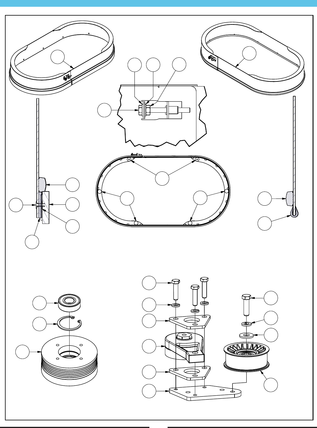
30” Skirt, Pulley & Tensioner Assembly
44
1A 1B
RF047800 081213
6
5
7
4
3
3
2
1A
16
19
15
13
15
14
20
21
17
18
22
24
23
9
88
1B
10
6
11
12

30” Skirt, Pulley & Tensioner Assembly (continued)
45
Item Ref. No. Description Qty
1A MP456300 SKIRT, 30”, ASM. (w/ FELT) 1
1B MP459800 SKIRT, 30”, ASM. (w/ EDGING) 1
2 NB050600 BOLT, HEX, 1/4” X 2-1/2” 1
3 NB3350 WASHER, FLAT, 1/4” 2
4 MX1045 NUT, HEX, 1/4” 1
5 MP8300 HOOK, VELCRO, 1” 90”
6 MP449300 MOLDING, BLK 90”
7 MP449200 EDGE, WEAR, FELT 1
8 MP140000 DOT, FELT 4
9 MP373100 WASHER, RUBBER 2
10 MP139800 EDGING, WEAR 90”
11 NB023600 RIVET, 1/8” X 5/16” 12
12 NB048300 WASHER, FLAT, #4 12
Item Ref. No. Description Qty
13 MP449000 BODY, TENSIONER 1
14 MP452401 PLATE, EXT., TENSIONER 1
15 MP448501 PLATE, MOUNT, TENSIONER 2
16 MP448900 IDLER, FLAT, 3.24” X 1” 1
17 NB3450 WASHER, FLAT, 3/8” 1
18 MX1075 WASHER, LOCK, 3/8” 1
19 NB051800 BOLT, HEX, 3/8” X 1-1/4” 1
20 NB6111 WASHER, LOCK, 5/16” 3
21 NB001800 BOLT, HEX, 5/16” X 1-1/4” 3
22 MP453400 PULLEY, 4” 1
23 MP453200 BEARING, 6203 2
24 NB017000 RING, RETAINING, 40MM 2

46
TO QUALIFY FOR THIS WARRANTY
(1) Machine must be registered at the time of purchase on a form
provided by Amano Pioneer Eclipse Corporation. Your Amano
Pioneer Eclipse Distributor is responsible for the registration
of your machine. Please cooperate with your Distributor in
supplying necessary information on the card.
(2) The machine must have been purchased from Amano Pioneer
Eclipse Corporation or an authorized Amano Pioneer Eclipse
Distributor.
(3) This warranty extends to the original purchaser only and is not
transferable to subsequent owners.
TIME PERIODS
(1) Rotational molded parts are warranted for eight (8) years.
(2) Batteries warranted by battery manufacturer for one (1) year.
(3) THREE (3) YEAR WARRANTY - For parts on the PE300BU.
Warranted to be free from defects in material and workmanship
for a period of three (3) years from the date of purchase by the
original owners. (See Exclusions)
(4) ONE (1) YEAR WARRANTY - For labor necessary to make
warranty repairs.
EXCLUSIONS (Not Covered by Warranty)
(1) Parts that fail through normal wear by reason of their
characteristics (cords, pads, belts, skirt, wheels, pad holder, or
other consumable parts).
(2) This warranty does not extend to parts affected by misuse,
neglect, abuse or improper maintenance. All defective parts
must be returned to the distributor for credit.
THE OBLIGATION OF AMANO PIONEER ECLIPSE
CORPORATION
(1) The obligation of Amano Pioneer Eclipse under this warranty
is limited to repairing or replacing, at its option, any part which
is proven to be defective in material or workmanship under
normal use for the applicable period stated above.
(2) Warranty repairs will be made by your Amano Pioneer Eclipse
Distributor without charge for parts and labor. They will be
compensated with a warranty labor rate of $45.00 per hour, for
the first year of ownership.
(3) Parts repaired or replaced under this warranty are warranted
only during the balance of the original warranty period. All
defective parts replaced under these warranties become the
property of Amano Pioneer Eclipse.
WARRANTY SERVICE
To obtain warranty service, take your machine and proof of
purchase to any authorized Amano Pioneer Eclipse Distributor.
Amano Pioneer Eclipse will not reimburse expenses for service
calls or travel. For the Distributor in your area, call Amano Pioneer
Eclipse Customer Service Department at 800-367-3550 or 336-372-
8080. If you are dissatisfied with the service that you receive, call
or write Amano Pioneer Eclipse Customer Service Department for
further assistance.
INSTRUCTIONS AND CONDITIONS FOR WARRANTY
REIMBURSEMENT
l Order replacement part: Orders will be processed and charged,
as normal procedure.
l Call Amano Pioneer Eclipse for R/A number.
l You will need the Machine Serial Number and the Machine
Model Number.
l Parts must be returned, accompanied with the R/A number to
be eligible for warranty credit.
l All Warranty Parts will be shipped prepaid UPS Ground, any
other method will be at the recipients expense.
l Freight on any Warranty Part after 30 days must be paid for by
the Purchaser.
l Warranty labor rate is $45.00 per hour.
l Credit will be issued upon completion of the above steps, at the
above rates.
DISCLAIMER OF CONSEQUENTIAL
AMANO PIONEER ECLIPSE DISCLAIMS ANY RESPONSIBILITY
FOR LOSS OF USER TIME OF THE AMANO PIONEER ECLIPSE
MACHINE OR ANY OTHER INCIDENTAL OR CONSEQUENTIAL
DAMAGE EXCEPT AS STATED IN THE WARRANTY
APPLICABLE TO EACH MACHINE. EXCEPT AS STATED IN
SUCH WARRANTIES, THE COMPANY DOES NOT OTHERWISE
WARRANT ANY MACHINE AND NO WARRANTY, EXPRESS,
IMPLIED OR STATUTORY IS MADE BY THE COMPANY.
Copyright 2016 Amano Pioneer Eclipse Corporation
Limited Warranty
PE300BU
LT063500_F; 031116

Amano Pioneer Eclipse Corporation
1 Eclipse Rd l PO Box 909
Sparta, North Carolina 28675 l USA
www.pioneereclipse.com
+1-336-372-8080
1-800-367-3550
Fax +1-336-372-2913
© 2016 Amano Pioneer Eclipse Corporation
LT063500
300BU_F
EC Machinery Directive 2006/42/EC,
EC Restriction of Hazardous Substances Directive (2011/65/EU)
Harmonized Standards Applied: EN 12100-1, EN12100-2
