Powerboss Admiral 38 Ride On Disk Floor Scrubber Operators Manual
2017-01-12
: Sweepscrub Powerboss-Admiral-38-Ride-On-Disk-Floor-Scrubber-Operators-Manual powerboss-admiral-38-ride-on-disk-floor-scrubber-operators-manual 2020 file product_file
Open the PDF directly: View PDF ![]() .
.
Page Count: 88

Admiral 38C Scrubber PB# 4100055UM Rev.* 08/10
PowerBoss, Inc. Copyright 2010
Page 1
User Manual
Admiral 38C Cylindrical
Sweeper/Scrubber
PowerBoss, Inc.
A Member Of The Hako Group
PB# 4100055UM Rev.* 08/10

PowerBoss, Inc. Copyright 2010
Admiral 38C Scrubber PB# 4100055UM Rev.* 08/10
Page 2
Intended use
The Admiral 38C is a large-area scrubber-
drier designed for wet cleaning rough and
structured hard oors inside buildings,
such as in multistorey car parks or logistics
and industrial areas. Any use beyond this
is regarded as improper use. The manu-
facturer is not considered liable for any
damage resulting from improper use; the
user is solely responsible for all the risks.
The Admiral 38C has not been
approved for use on public paths
and roads.
Intended use also includes maintaining
and observing the operating, maintenance
and repair conditions prescribed by the
manufacturer.
The Admiral 38C may only be operated,
serviced and repaired by personnel who
are familiar with the work involved and are
aware of the risks.
The applicable accident prevention laws
must be observed and any generally ac-
cepted health and safety directives must
be maintained.
Introduction
Introduction
Preface
Dear Customer,
Please read this original manual thor-
oughly before starting the vehicle for the
rst time and keep it in the vicinity of the
vehicle for future reference or subsequent
owners.
We are certain that the excellent qualities
of the vehicle will justify the faith you have
shown in us through your purchase.
Please read the Chapter “Safety Informa-
tion” prior to starting the vehicle to ensure
it is operated and used safely. Your safety,
and that of others, basically lies in your
ability to control and operate the vehicle.
Therefore, read the operating manual
thoroughly before starting the vehicle up
for the rst time. The operating manual
contains all the most important informa-
tion regarding operation, maintenance and
service. Throughout this operating manual,
texts which concern safety are indicated
by corresponding symbols.
Should you have any questions in respect
of the vehicle or operating manual, your
authorized PowerBoss dealer is available
to provide help at any time. We would like
to emphasize that no legal claims can
be asserted in respect of any information
provided in this manual. Please pay atten-
tion that only original spare parts should
be used for any necessary maintenance
and repair work. Only original spare parts
can guarantee long, reliable equipment
operation. We reserve the right to make
technical improvements.
Valid as of: January 2010
PowerBoss Inc.
175 Anderson Street
NC 28315 U.S.A.
Telephone: (910) 944-2105
Fax: (910) 944-740

Admiral 38C Scrubber PB# 4100055UM Rev.* 08/10
PowerBoss, Inc. Copyright 2010
Page 3
Based on the conception, design and con-
struction of the vehicle introduced onto the
market by us, the vehicle complies with the
applicable basic safety and health require-
ments stipulated in the EC Directive (refer
to the Declaration of Conformity). This
declaration is no longer considered valid
in the event of modications to the vehicle
not authorized by us. The manufacturer is
not deemed liable for any damage result-
ing from unauthorized modications to the
vehicle.
Introduction
Notes on warranty
The terms dened in the purchase agree-
ment apply. Claims for compensation
related to damage are excluded from the
terms of warranty when the damage is
the result of failure to observe regulations
concerning service and maintenance.
Maintenance work must be performed at
authorized PowerBoss service centers and
conrmed in the “Maintenance Report”
which serves as a warranty logbook.
The following are excluded from the terms
of warranty: wear and tear through over-
use, defective fuses, improper handling or
unauthorized modications. Claims under
the terms of warranty are annulled when
damage occurs to the vehicle resulting
from the use of parts or accessories not
explicitly approved by us or from failure to
observe maintenance regulations.
Acceptance of the vehicle
The vehicle must be inspected directly af-
ter delivery for signs of transport damage.
Replacement will be made when conr-
mation is provided immediately by the
German Federal Railway (Deutsche Bahn
AG) or the freight carrier with regard to the
damage and the damage report is sent to
us together with the consignment note:
PowerBoss Inc.
175 Anderson Street
NC 28315 U.S.A.
Telephone: (910) 944-2105
Fax: (910) 944-740

PowerBoss, Inc. Copyright 2010
Admiral 38C Scrubber PB# 4100055UM Rev.* 08/10
Page 4
Introduction . . . . . . . . . . . . .2
Preface ....................2
Intended use . . . . . . . . . . . . . . .2
Notes on warranty . . . . . . . . . . .3
Acceptance of the vehicle . . . . .3
1 Safety Information. . . . . . . .6
1.1 Safety and warning labels . . . . .6
1.2 General information . . . . . . . . . .7
1.3 Operating information. . . . . . . . .7
1.4 Maintenance information . . . . . .9
1.5 Particular risks . . . . . . . . . . . . . .10
1.5.1 Electronics . . . . . . . . . . . . . . . . .10
1.5.2 Batteries . . . . . . . . . . . . . . . . . . .10
1.6 Environmental protection . . . . . .11
1.7 Labels on the vehicle . . . . . . . . .12
2 Starting Up . . . . . . . . . . . . . .15
2.1 Instruction. . . . . . . . . . . . . . . . . .15
2.2 Initial battery charge. . . . . . . . . .15
2.3 Prior to starting up for the
rst time ...................16
2.3.1 Installing the rotary brushes . . . .16
2.3.2 Installing and adjusting the
squeegee . . . . . . . . . . . . . . . . . .19
2.3.3 Adjusting the driver’s seat . . . . .20
2.4 Before starting up daily . . . . . . .20
3 Operation . . . . . . . . . . . . . . .21
3.1 Method of operation . . . . . . . . . .21
3.1.1 Rotary brush head . . . . . . . . . . .21
3.1.2 Squeegee. . . . . . . . . . . . . . . . . .23
3.1.3 Suction turbines (suction). . . . . .24
3.1.4 Solution tank . . . . . . . . . . . . . . .24
3.1.5 Recovery tank . . . . . . . . . . . . . .24
3.1.6 Traction drive . . . . . . . . . . . . . . .25
3.1.7 Brakes ....................25
3.1.8 Batteries and charger. . . . . . . . .25
3.1.9 Options ....................26
3.2 Operating and indicator
elements. . . . . . . . . . . . . . . . . . .29
3.2.1 Operating elements in the
driver’s cab. . . . . . . . . . . . . . . . .29
3.2.2 Left-hand operating panel . . . . .32
3.2.3 Right-hand operating panel . . . .36
3.2.4 Operating elements on the
vehicle ....................39
3.3 Operation . . . . . . . . . . . . . . . . . .43
3.3.1 Switching the vehicle on. . . . . . .43
3.3.2 Accelerating . . . . . . . . . . . . . . . .43
3.3.3 Stopping and parking . . . . . . . . .44
3.3.4 Cleaning . . . . . . . . . . . . . . . . . . .44
3.3.5 Switching the vehicle off. . . . . . .46
3.3.6 Loading and transporting
the vehicle . . . . . . . . . . . . . . . . .46
Table of Contents
3.4 After nishing work. . . . . . . . . . .47
3.5 Function faults . . . . . . . . . . . . . .48
3.5.1 Error code table . . . . . . . . . . . . .48
3.5.2 Other function faults . . . . . . . . . .49
4 Technical Data . . . . . . . . . . .50
5 Maintenance and Service . .56
5.1 PowerBoss system
maintenance . . . . . . . . . . . . . . . .56
5.2 Maintenance report . . . . . . . . . .57
5.3 Maintenance schedule . . . . . . . .58
5.3.1 PowerBoss system
maintenance, customer . . . . . . .58
5.3.2 PowerBoss system
maintenance I. . . . . . . . . . . . . . .60
5.3.3 PowerBoss system
maintenance II . . . . . . . . . . . . . .63
5.3.4 PowerBoss system
maintenance III/S
(safety check). . . . . . . . . . . . . . .64

Admiral 38C Scrubber PB# 4100055UM Rev.* 08/10
PowerBoss, Inc. Copyright 2010
Page 5
Table of Contents
5.4 Battery system . . . . . . . . . . . . . .65
5.4.1 Charging batteries . . . . . . . . . . .66
5.4.2 Servicing the driving batteries 67
5.4.3 Disassembling the batteries . . . .67
5.4.4 Installing the batteries . . . . . . . .67
5.4.5 Disposing of batteries. . . . . . . . .69
5.4.6 Total discharge signal
transducer (TSG) . . . . . . . . . . . .69
5.5 Solution tank . . . . . . . . . . . . . . .70
5.5.1 Filling the solution tank . . . . . . . . 71
5.5.2 Emptying the solution tank . . . . .71
5.5.3 Cleaning the draining
hose cap. . . . . . . . . . . . . . . . . . .71
5.5.4 Cleaning the lter in the
solution feed ................71
5.6 Recovery tank . . . . . . . . . . . . . .72
5.6.1 Emptying the recovery tank . . . .73
5.6.2 Cleaning the recovery tank . . . .73
5.6.3 Cleaning the draining
hose cap. . . . . . . . . . . . . . . . . . .74
5.6.4 Cleaning the air intake lter . . . .74
5.6.5 Cleaning the openings to the
solution tank . . . . . . . . . . . . . . . .74
5.7 Rotary brush head . . . . . . . . . . .75
5.7.1 Emptying and cleaning the
waste container . . . . . . . . . . . . .76
5.7.2 Changing the rotary
brushes. . . . . . . . . . . . . . . . . . . .77
5.7.3 Cleaning the contact
surfaces ...................78
5.7.4 Adjusting the locking lever
for the brush holder ..........78
5.7.5 Installing new rubber
deector strips . . . . . . . . . . . . . .79
5.7.6 Adjusting the rotary
brush head . . . . . . . . . . . . . . . . .79
5.7.7 Direction of rotation of
the rotary brushes . . . . . . . . . . .80
5.8 Squeegee. . . . . . . . . . . . . . . . . .81
5.8.1 Cleaning the squeegee . . . . . . .81
5.8.2 Disassembling the
squeegee . . . . . . . . . . . . . . . . . .81
5.8.3 Installing the squeegee . . . . . . .81
5.8.4 Changing the sealing strips . . . .82
5.9 Wheels ....................82
5.9.1 Front wheel. . . . . . . . . . . . . . . . .82
5.9.2 Rear wheels . . . . . . . . . . . . . . . .82
5.10 Electrical installation. . . . . . . . . .83
5.10.1 Red control lamps . . . . . . . . . . .83
5.10.2 Error codes. . . . . . . . . . . . . . . . .83
5.10.3 Fuses .....................83
5.10.4 Drive control relay . . . . . . . . . . .83
5.11 Cleaning the vehicle. . . . . . . . . .84
5.12 Transporting and towing
Loading ...................84
6 WARRANTY . . . . . . . . . . . . .86
PowerBoss, Inc. Copyright 2010
Admiral 38C Scrubber PB# 4100055UM Rev.* 08/10
Page 6
Safety Information
1 Safety Information
1.1 Safety and warning labels
All texts related to personal safety, safety of
the vehicle and environmental protection are
assigned the following symbols throughout
the operating manual:
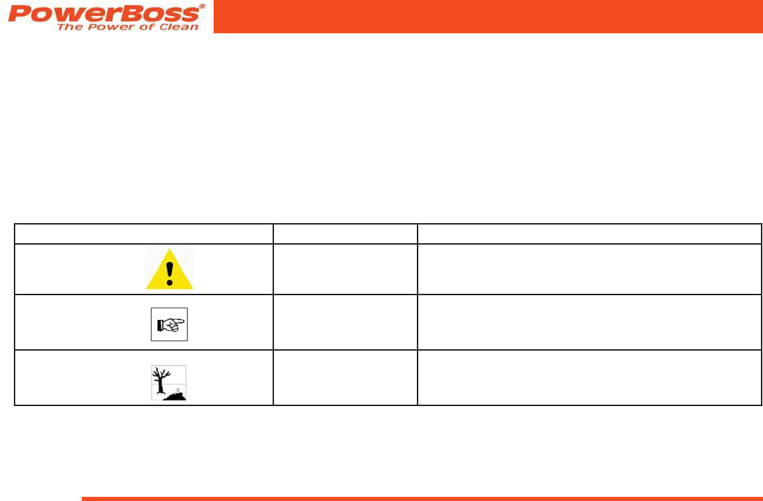
Symbol Hazardous for ... Denition
Danger persons or property Safety information to prevent the development of hazardous
situations resulting from ignoring or failing to follow instruc-
tions or prescribed work procedures.
Note the equipment Important information on handling the equipment in order to
maintain its operability.
Ecological hazard the environment Risk to the environment through using substances which
represent a health or pollution hazard.

Admiral 38C Scrubber PB# 4100055UM Rev.* 08/10
PowerBoss, Inc. Copyright 2010
Page 7
Safety Information
1.2 General information
• The Admiral 38C fullls all the appli-
cable safety and health requirements
stipulated in the EU directives with
regard to its planning, constructional
design and nal construction as intro-
duced by us onto the market. In the
case of modications to the vehicle not
approved by us, the EC Declaration of
Conformity enclosed in this operating
manual loses its validity.
• In addition to the information provided
in this operating manual, all legally
applicable health and safety provisions
must be observed.
• Before starting up the vehicle for the
rst time, read the operating manual
supplied with it thoroughly as well as
any separate manuals provided with
additional or attachment devices and
observe all the information during work.
• The vehicle may only be operated,
maintained and repaired by persons
trained by PowerBoss or authorized to
do so by PowerBoss.
• Particular attention should be paid to
the information regarding safety. Tech-
nical expertise is the key to preventing
errors when operating the equipment
and ensuring trouble-free operation.
• The operating manual must always be
kept at the operating location of the
vehicle and, as a result, should kept in
a safe place on the vehicle.
• If the equipment is sold or rented out,
these documents should be transferred
to the new owner/operator. The transfer
should be conrmed!
• The warning labels attached to the
equipment provide important informa-
tion concerning safe operation. Labels
which are illegible or missing must be
replaced.
• Original spare parts must be used to
ensure safety.
• If you want to shut the vehicle down,
render it inoperable. It must not repre-
sent a source of danger for children.
1.3 Operating information
• Before starting the vehicle up for
the rst time, the battery to be used
must be fully charged, properly, by
implementing the initial battery charge
routine. Please pay attention to the op-
erating manual provided with the charg-
ing unit as well as the manual from
the battery manufacturer. PowerBoss
assumes no liability for damage to the
battery caused by a fault when the bat-
tery is charged for the rst time.
• Before starting the vehicle up, always
check it is in a proper condition and
that it is safe to drive and operate.
Clear up any faults and defects im-
mediately! Never operate the vehicle
without functional safety equipment.
• Warning: Do not use the vehicle without
a protective roof structure (refer to “Ac-
cessories”, “Cab safety roof”) in areas
where the driver is at risk of being hit
by falling objects (e.g. warehouses).
Contact the trade association respon-
sible for you as to whether obliga-
tions exist in this respect.

PowerBoss, Inc. Copyright 2010
Admiral 38C Scrubber PB# 4100055UM Rev.* 08/10
Page 8
Safety Information
• The Admiral 38C must be subjected to
an inspection in respect of its opera-
tionally safe condition at least once a
year by an authorized technical expert.
The results of the inspection must be
documented in writing and kept safe at
least until the next inspection.
• Floor cleaning vehicles may only be op-
erated by suitable personnel who have
been trained to operate the equipment,
have proven their capability to operate
the vehicle to the contractor or per-
son appointed by him and have been
explicitly charged by him to operate the
vehicle.
• Before starting work, operating person-
nel must be fully familiar with all adjust-
ment, operating and control elements
as well as their respective function! It is
too late to do this when the vehicle is
actually in operation!
• The warning labels attached to the
Admiral provide important information
concerning safe operation.
• Wet oors are a potential risk for slip-
ping! Ensure to provide the correspond-
ing information and warning signs.
• If the oor is excessively wet, check the
vehicle for leaks and that the sealing
strips are in a good condition. If the
sealing strips are damaged, change
them immediately.
• Only use cleaning agents suitable for
the vendor (non-foaming) and observe
all the use, disposal and warning infor-
mation provided by the cleaning agent
manufacturer.
• It is forbidden to use the vehicle in
potentially explosive atmospheres.
• The machine is not suitable for clearing
up health-hazardous, inammable or
explosive uids, dust or substances.
• Ride-on equipment may only be set
into motion from the seat (seat contact
switch).
• The seat contact switch must never be
bypassed or the function immobilized in
any way (e.g. by placing a heavy load
on the seat).
• It is forbidden to transport people on
the vehicle!
• Always wear heavy duty, non-slip foot-
wear when working with the vehicle.
• Start driving immediately after switch-
ing on the brush head drive, otherwise
imprints of the brush could be produced
on the oor.
• The machine may only be driven on
and the equipment used on those
surfaces which have been approved
by the contractor or person appointed
by him.
• The manner of driving must be adapted
to the local conditions (oor charac-
teristics, presence of persons in the
vicinity, obstacles, etc.).
• When using the vehicle, it is essential
to pay attention to third parties, espe-
cially children.
• Never leave the vehicle unattended
while motors are still running and it has
not been locked against unintended
movement.
• To prevent authorized used of the
vehicle, lock the drive by removing
the key from the key switch.
• When transporting the vehicle, the
motors must be shutdown.
• Only open empty recovery tanks.
• The vehicle may only be driven on
gradients to a maximum of 6% for
a maximum of ve minutes. Do not
drive the vehicle on slopes with a
gradient steeper than the limit gra-
dient indicated on the machine.

Admiral 38C Scrubber PB# 4100055UM Rev.* 08/10
PowerBoss, Inc. Copyright 2010
Page 9
Safety Information
1.4 Maintenance information
Properly completed vehicle maintenance
is an important protective measure for
preventing accidents.
• The maintenance work and mainte-
nance intervals prescribed in the oper-
ating manual must be adhered to.
• Operating personnel must complete
the necessary daily and weekly
maintenance work. All other mainte-
nance work must be completed at your
nearest authorized PowerBoss service
center.
• Before starting any cleaning and main-
tenance work or replacing parts, switch
off the engine and motors, remove the
key from the key switch and pull out the
battery plug. This is particularly impor-
tant in respect of work on the electrical
system!
• Before working on the brushes, switch
off the scrubbing unit, set the key
switch to position 0 and remove the
key.
• The scrubbing unit may only be disas-
sembled and installed by service
personnel.
• Suitable tools must be used for clean-
ing and maintenance work.
• Spare parts must comply with the mini-
mum technical requirements stipulated
by the manufacturer! This is ensured by
the use of original spare parts.
• When working in the area of the raised
seat console, it must be pivoted up fully
to prevent it accidentally closing or sud-
denly slamming shut.
• It is not permitted to clean the vehicle
with a pressure washer or steam
blaster.
• Clean the recovery tank regularly to
protect it from the accumulation of dirt,
viruses, bacteria, etc.
• It is not permitted to use aggressive
and corrosive cleaning agents.
• Allow the vehicle to dry after being
cleaned, e.g. over the weekend.
• The vehicle must be checked by a
recognized technical expert in respect
of operational safety at reasonable
intervals (we recommend at least one a
year), particularly with regard to protec-
tive equipment and locks and following
modications or repair.
• Only start the vehicle up when all the
safety equipment has been installed, is
functional and brought to its protecting
position.
• The vehicle has been set up for op-
eration using low-maintenance trough
batteries. If other battery types are to
be used, the vehicle must be adjusted
for them at an authorized PowerBoss
service center.
• Observe the information in the operat-
ing manual provided by the battery
manufacturer. It must be available to
operating and maintenance personnel
at all times.
• Batteries may only be handled and
changed by properly skilled mainte-
nance personnel.
• When installing the trough battery, use
appropriate lifting gear.
• Only use the batteries prescribed by us
and original chargers to charge them.
The full terms of warranty can only be
accepted when these units are used.
• Pay attention that the insulation on the
charger is not initially damaged and not
damaged during the charging pro-
cess. The cable must not rub against

PowerBoss, Inc. Copyright 2010
Admiral 38C Scrubber PB# 4100055UM Rev.* 08/10
Page 10
Safety Information
anything. Do not use the charger if the
insulation is damaged.
• Always wear appropriate protective
clothing when handling the battery (e.g.
protective gloves, nger stalls, protec-
tive goggles).
• The seat console must be pivoted open
during the battery charging process to
prevent the development of explosive
oxyhydrogen!
• Never leave the batteries in a dis-
charged state but recharge them as
soon as possible.
• Only rell distilled water.
• When the cells are in good condition,
never rell the battery acid.
• Spilled battery acid must never enter
the sewage system in its initial form, it
must be neutralized beforehand.
• Pay attention to legal requirements and
local directives.
• For further safety information, see
supplementary sheet 88-60-2554
“Notes on driving batteries”.
1.5 Particular risks
• The following applies when locating
the cause of faults and clearing them:
Switch the vehicle off, remove the key
and disconnect the battery plug!
• In the case of faults involving the
traction drive, stop the vehicle immedi-
ately and remove the key from the key
switch!
1.5.1 Electronics
• Always disconnect the battery plug be-
fore starting any work on the electrical
installations.
• Only use original fuses with the pre-
scribed amperage.
• In the case of defects in the electrical
installation, switch the vehicle off im-
mediately and clear the fault.
• Work on the electrical equipment may
only be carried out by electricians who
have received the necessary training
and in accordance with the electrical
engineering regulations.
• The vehicle’s electrical equipment
must be inspected/checked at regular
intervals. Defects, such as loose con-
nections and cable damage, must be
rectied immediately.
1.5.2 Batteries
• Due to a change in the center of grav-
ity, only approved batteries may be
installed at the intended position.
• To prevent creeping currents, always
keep the batteries clean and dry and
protect them from contamination, e.g.
from metal dust.
• Never lay any metallic objects or tools
on batteries. Risk of short circuit and
deagration!
• Ensure sufcient ventilation in the
charging area when charging the
batteries. Otherwise there is a risk of
explosion!
• The seat console must be pivoted open
during the battery charging process to
prevent the development of explosive
oxyhydrogen!
• Only use the original charger! Pay at-
tention that the insulation is not initially
damaged and not damaged during the
charging process. The cable must not
rub against anything. Do not use the
charger if the insulation is damaged.

Admiral 38C Scrubber PB# 4100055UM Rev.* 08/10
PowerBoss, Inc. Copyright 2010
Page 11
Safety Information
• Ensure there are no naked ames
nearby when handling batteries, par-
ticularly when checking the acidity. Risk
of explosion!
• Do not inhale battery gases.
• Battery acid is very corrosive; keep
away from children.
• Wear protective goggles when control-
ling the acid level.
• In the event of acid splashing in the
eyes, rinse them with water for approx.
15 minutes and seek medical attention
immediately.
• Also pay attention to the information in
Section 1.4.
1.6 Environmental protection
• A certain factual expertise is required
in order to use substances which could
represent a risk to health and the envi-
ronment.
• Always observe legal regulations and
local directives when disposing of
cleaning agents.
• Used batteries with the recycling
symbol contain reusable commodities.
The heavy metals contained represent
a major risk both to people’s health
and to the environment. Never open or
damage batteries. Never touch, inhale
or swallow the content of batteries.
Health hazard! Do not allow batteries
to get into the environment. Risk of
contaminating the ground and water!
In accordance with the symbol with
the crossed out garbage bin, these
batteries must not be disposed of in
domestic waste. Return and recycling
of old batteries must be agreed on with
PowerBoss‘ authorized dealers.
• Dispose of the equipment in accor-
dance with local regulations. For further
information on handling and recycling,
please contact the authorized Power-
Boss dealer where you purchased the
equipment.

PowerBoss, Inc. Copyright 2010
Admiral 38C Scrubber PB# 4100055UM Rev.* 08/10
Page 12
Safety Information
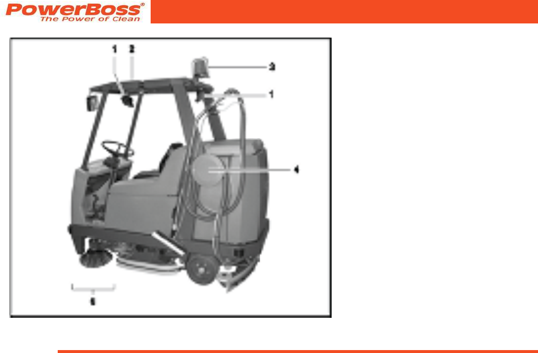
1.7 Labels on the vehicle
The following safety and warning labels are
attached to the vehicle where easily legible.
Refer to Fig 1 to Fig 3 for item locations.
Missing or illegible labels must be
replaced immediately.
(1) Company logo
Fig 1 Label locations 1
(3) Rating plate, The rating plate is in the
driver’s cab, at the bottom, on the ap of
the left-hand electrical compartment.
(2) Read the operating
manual, maximum gradient
and ban on cleaning using
a high-pressure washer.
Admiral 38C Scrubber PB# 4100055UM Rev.* 08/10
PowerBoss, Inc. Copyright 2010
Page 13
Safety Information
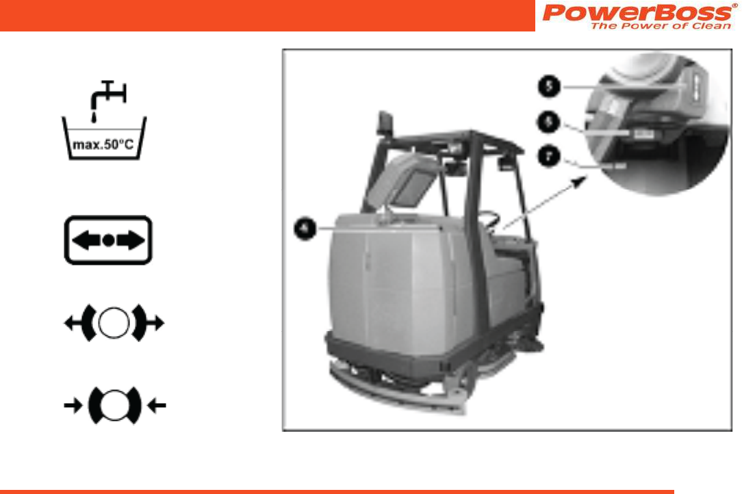
(4) Maximum water temperature for solu-
tion to be lled
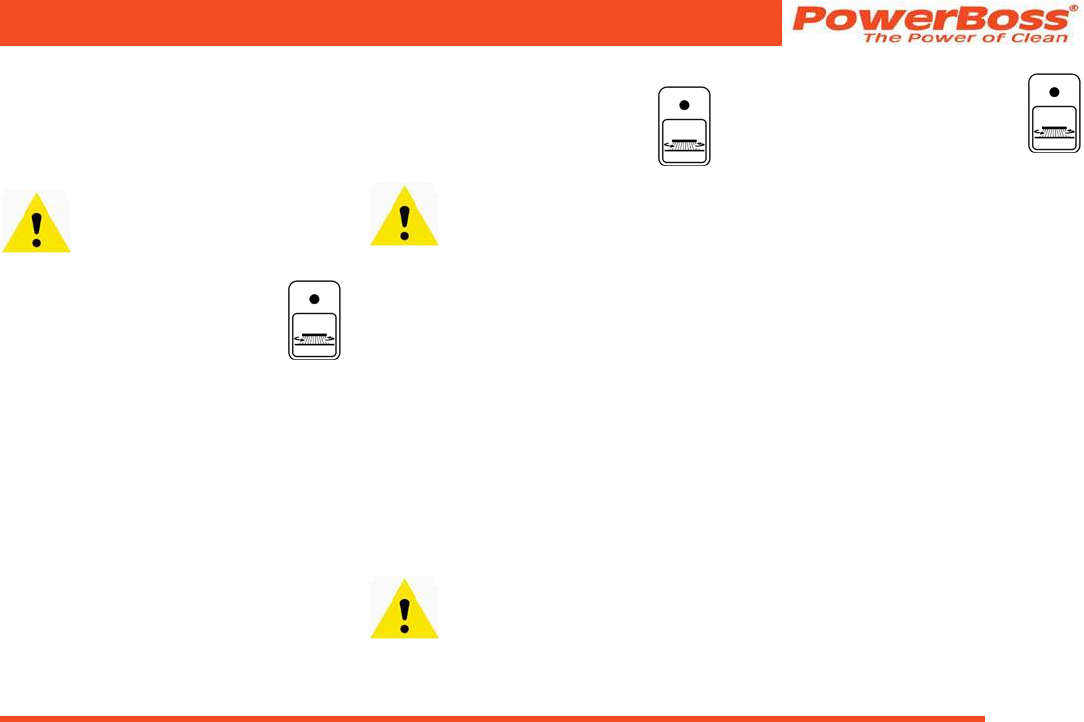
(5) Drive direction selector:
Forward or reverse
(6) Release parking brake
(7) Apply parking brake
Fig 2 Label locations 2
PowerBoss, Inc. Copyright 2010
Admiral 38C Scrubber PB# 4100055UM Rev.* 08/10
Page 14
Safety Information
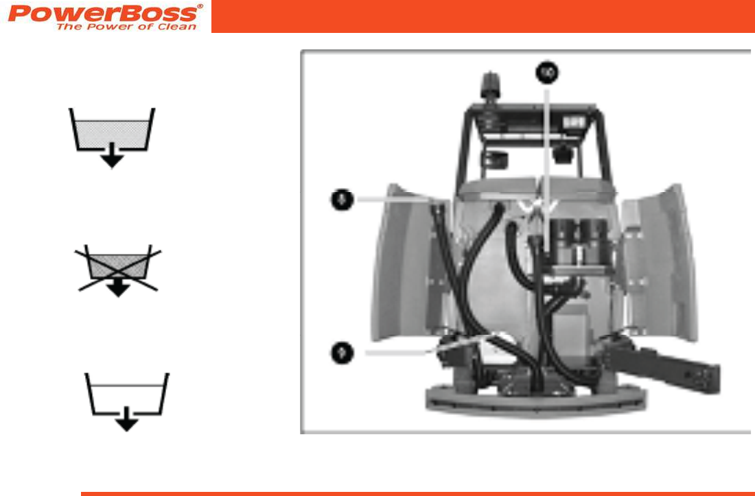
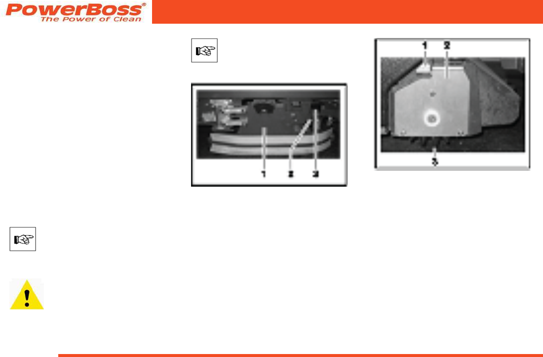
(8) Waste water drainage
The waste water is drained via the hose
which hangs to the right of this label.
(9) No waste water drainage
The ap serves exclusively for cleaning and
maintenance of the waste water tank.
(10) Solution drainage
The solution is drained via the hose which
hangs to the left of this label.
Fig 3 Label locations 3
Admiral 38C Scrubber PB# 4100055UM Rev.* 08/10
PowerBoss, Inc. Copyright 2010
Page 15
Starting Up
2 Starting Up
Pay attention to persons in the
vicinity of the vehicle when complet-
ing any work.
2.1 Instruction
Instructions to operators are required before
putting the vehicle into service. Only techni-
cians from your local authorized PowerBoss
dealer are allowed to provide initial instruc-
tion on the vehicle. The manufacturing plant
will notify the dealer immediately after deliv-
ering the vehicle and the dealer will contact
you to arrange a date.
2.2 Initial battery charge
An initial battery charge must be performed
in order for it to provide an optimum perfor-
mance and service life. A battery charger is
available which is specially adapted to the
batteries.
Only use the batteries and charger
prescribed by us to charge the bat-
tery. The full terms of warranty can
only be accepted when these units
are used.
Before starting the vehicle up
for the rst time, the batteries to
be used must be fully charged,
properly, by implementing the
initial battery charge routine.
PowerBoss assumes no liability
for damage to the battery caused
by a fault when the battery is
charged for the rst time.
The seat console must be pivoted
open during the battery charging
process to prevent the develop-
ment of explosive oxyhydrogen!
Only use the original charger!
Pay attention that the insulation
is not initially damaged and not
damaged during the charging
process. The cable must not rub
against anything. Do not use the
charger if the insulation is dam-
aged.
Do not inhale battery gases.
Please pay attention to the operating
manual provided with the charging unit
as well as the manual from the battery
manufacturer. Powering up the batter-
ies is described in such detail in the
manufacturer’s documents that further
information on the subject is considered
unnecessary for this manual.
PowerBoss, Inc. Copyright 2010
Admiral 38C Scrubber PB# 4100055UM Rev.* 08/10
Page 16
Starting Up
2.3 Prior to starting up for the
rst time
The following work must be completed
before starting the vehicle up for the rst
time:
2.3.1 Installing the rotary brushes
Two rotary brushes must be tted in the
rotary brush head. These rotary brushes
are not part of the scope of delivery sup-
plied with the vehicle. Choose the rotary
brushes separately according to the task
to be completed (refer to Section 4). If you
ordered the rotary brushes together with
the vehicle, the rotary brushes are nor-
mally already installed by the authorized
PowerBoss dealer prior to delivery.
Check whether rotary brushes
are tted.
If no rotary brushes are installed, proceed
as follows to install them.
The following applies to all work
on the rotary brushes: Turn the
key switch to position 0, remove
the key and apply the parking
brake (Fig. 14/8).
The front rotary brush is changed
from the right-hand side of the
vehicle, the rear rotary brush from
the left-hand side of the vehicle.
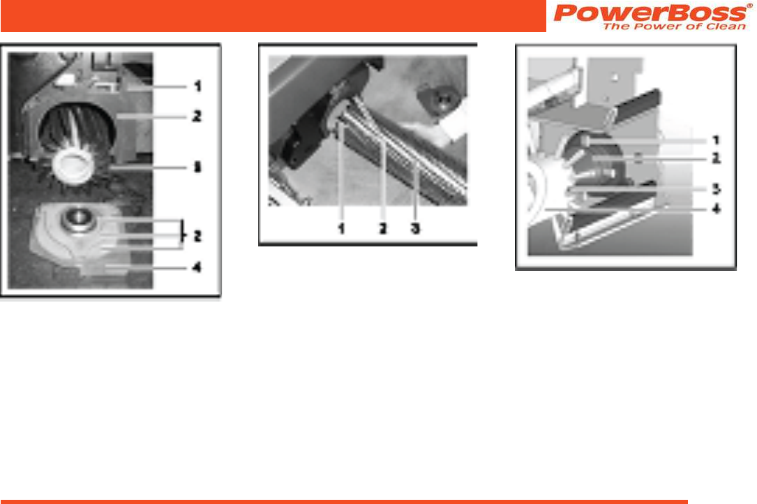
Fig 4
(1) Deector
(2) Deector lock
(3) Grip
1. Open the deector (Fig. 4/1):
take hold of the grip (Fig. 4/3), raise
the deector (Fig. 4/1), pivot open to-
wards the front and set it down (service
position).
Fig 5
(1) Locking lever
(2) Brush holder
(3) Rotary brush
2. Slide the locking lever (Fig. 5/1) for the
brush holder (Fig. 5/2) to the middle of
the device and hold it there.
3. Allow the brush holder (Fig. 5/2) to
lower down and remove it.
4. Release the locking lever (Fig. 5/1).
5. If necessary, remove the existing rotary
brush (Fig. 5/13) from the housing
(Fig. 6/1).
Admiral 38C Scrubber PB# 4100055UM Rev.* 08/10
PowerBoss, Inc. Copyright 2010
Page 17
Starting Up
Fig 6
(1) Housing
(2) Contact surfaces
(3) Rotary brush
(4) Brush holder (removed)
Fig 7
(1) Catch
(2) Housing
(3) Rotary brush
6. Lay one hand under the rotary brush
(Fig. 7/3) and slide it together with the
catches (Fig. 7/1) into the housing (Fig.
7/2).
Fig 8
(1) Pin
(2) Brush support
(3) Catch
(4) Rotary brush
7. To slide the rotary brush (Fig. 8/4) on
the facing brush support (Fig. 8/2),
raise the rotary brush (Fig. 8/4) a little
and turn slightly, if necessary, until the
catches (Fig. 8/3) perceptibly slide
from the rotary brush (Fig. 8/4) onto
the pins (Fig. 8/1) of the brush support
(Fig. 8/2).

PowerBoss, Inc. Copyright 2010
Admiral 38C Scrubber PB# 4100055UM Rev.* 08/10
Page 18
Starting Up
Ensure that the contact surfaces
(Fig. 6/2) are clean. Clean them
thoroughly, if ne essary, before
tting them on the brush holder
(Fig. 6/4).
8. Slide the locking lever (Fig. 5/1) to
the middle of the device and hold
it there.
9. Mount the brush holder (Fig. 6/4)
on the rotary brush (Fig. 6/3), press
against the housing (Fig. 6/1) and
then slide upwards.
10. Pivot the locking lever (Fig. 5/1)
back under the brush holder (Fig.
6/4) to the stop.
11. Close the deector (Fig. 4/1):
Take hold of the grip (Fig. 4/3),
raise the deector (Fig. 4/1), pivot
to the device and lower into the de-
ector lock (Fig. 4/2). The deec-
tor (Fig. 4/1) is now in its working
position.
Admiral 38C Scrubber PB# 4100055UM Rev.* 08/10
PowerBoss, Inc. Copyright 2010
Page 19
Starting Up
2.3.2 Installing and adjusting the
squeegee
Installing the squeegee
1. Switch on the key switch.
2. Lower the squeegee holding attach-
ment: Press the button for the squee-
gee and suction turbine so that the
green control lamp lights up.
3. Switch off the key switch and remove
the key.
4. Open the rear doors.
5. Slide the squeegee from the rear under
the lowered holding attachment and x
the squeegee to it with the four wing
nuts (Fig. 9/1).
6. Attach the suction hose to the connec-
tion nozzle (Fig. 9/2) of the squeegee.
7. Insert the key in the key switch and
turn the key switch on.
8. The squeegee is then lifted automati-
cally.
9. Close the rear doors.
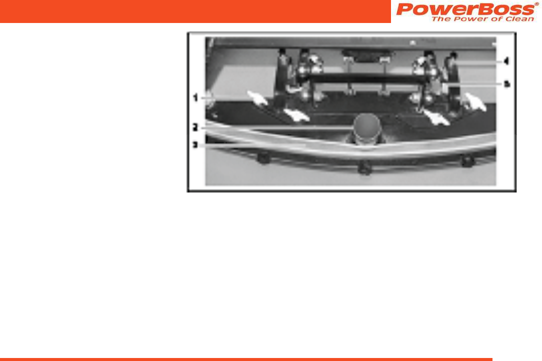
Fig 9
Adjusting the squeegee
The squeegee must be set up on a level
oor according to the conditions in which
it is to be used. The squeegee must stand
vertically on the oor (adjusted at the fac-
tory). The sealing strip (Fig. 9/3) should
bend slightly to the rear when the vehicle
is in operation. Supporting rollers (Fig.
9/5) limit its movement toward the oor. To
increase the squeegee contact pressure,
the supporting rollers must be adjusted:
• Loosen the counternuts (Fig. 9/4) and
raise the supporting rollers on the left
and right evenly (turn screw counter-
clockwise and lock again).
The sealing strip now bends a little more
towards the rear. An adjustment of the
supporting rollers is also necessary when
the edge of the sealing strip is worn.
PowerBoss, Inc. Copyright 2010
Admiral 38C Scrubber PB# 4100055UM Rev.* 08/10
Page 20
Starting Up
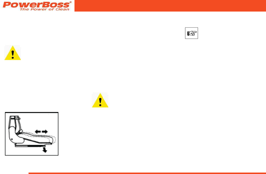
2.3.3 Adjusting the driver’s seat
The driver’s seat (Fig. 10) must be adjust-
ed so that the driver is seated comfortably
and can reach all the operating elements
with ease.
The vehicle is equipped with a
seat contact switch. The vehicle
can only be operated when the
operating person is seated on the
seat.
The Admiral 38C is equipped with a
driver’s seat which can be adjusted in a
longitudinal direction (forward and back):
1. Force the lever on the right of the seat
outwards slightly.
2. Slide the seat forward or back in steps
of 0.6 in.
Fig 10
2.4 Before starting up daily
Carry out the following checks before start-
ing the vehicle up for its daily operation
(also refer to Section 5.3.2):
1. Check the recovery tank, empty as
necessary. Clean it as necessary. Re-
fer to Sections 5.6.1 and 5.6.2.
2. Check the waste container; empty and
clean it, if necessary; refer to Section
5.7.1.
3. Fill the solution tank and cleaning
agent in accordance with the manu-
facturer’s mixing directives. Refer to
Section 3.1.4 and Section 5.5.1.
Only use cleaning agents (non-
foaming) suitable for the vehicle’s
vendor. We recommend using our
clean and care products which
are specially balanced for the
vehicles. These products meet
the requirements stipulated in
the washing and cleaning agent
directive (WRMG - Wasch- und
Reinigungsmittelgesetzes).
4. Check the battery charge and recharge
as necessary; refer to Section 5.4.1.
Before starting the vehicle for its
rst working operation, carry out
an initial battery charging routine;
refer to Section 2.2.
5. Check the area where the vehicle was
parked for signs of leaks. Hoses, lines
and tanks must show no signs of leaks
or damage. If necessary, clear up any
defects before putting the vehicle
into operation.
Admiral 38C Scrubber PB# 4100055UM Rev.* 08/10
PowerBoss, Inc. Copyright 2010
Page 21
Operation
3 Operation
Operating personnel must read
the operating manual through
carefully. Operating personnel
should complete their initial test
drive on open ground or a test
track until they are familiar with
the individual operating elements
and the respective functions.
3.1 Method of operation
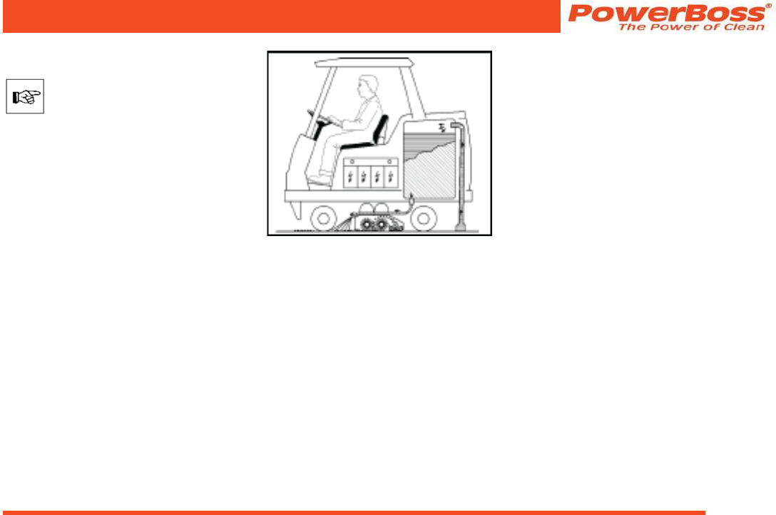
The Admiral 38C is a scrubber-drier
designed for wet cleaning rough and struc-
tured hard oors inside buildings, such as
multi-storey car parks or in logistics and
industrial areas (refer to Fig. 11). It cleans
oors by means of intensive scrubbing
with the aid of a water and cleaning agent
solution. The squeegee at the rear of the
vehicle vacuums up the waste water into
the recovery tank in the same working
process. The Admiral 38C is a ride-on
machine designed for the economic clean-
ing of large oor areas in buildings. A seat
contact ensures that the vehicle can only
be operated when an operator is seated
on the driver’s seat.
Fig 11
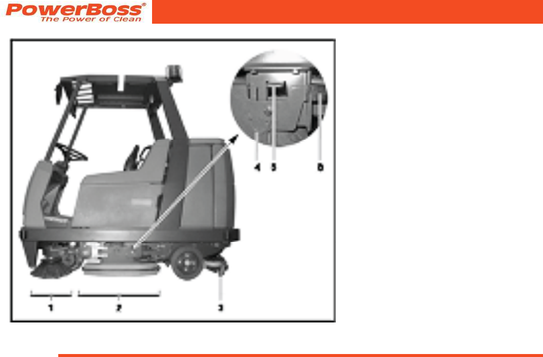
The most important vehicle elements are
described below:
3.1.1 Rotary brush head
(Fig. 12/2)
The two rotary brushes, which can be
changed without the need for any tools,
in the rotary brush head provide a high
cleaning performance. The solution sup-
ply starts automatically when the rotary
brush head is lowered. The solution is
sprayed onto the oor to be cleaned by
means of three nozzles. At the same time,
the contra-rotating rotary brushes start to
rotate. They then scrub the oor in such a
way that even dirt which has penetrated
more deeply is removed. The two rotary
brushes are each driven by a splashproof
electric motor. The contra-rotating motion
of the rotary brushes also picks up coarse
dirt and throws it into the downstream
waste container (sweeping function). In
addition to the cleaning effect, this also
ensures that coarse dirt, such as cable
ties, cigarette ends etc., does not slide
under the sealing strip of the squeegee
and, thus, impair the vacuuming results.
The waste water left over is then removed
by the squeegee which follows on.
PowerBoss, Inc. Copyright 2010
Admiral 38C Scrubber PB# 4100055UM Rev.* 08/10
Page 22
Operation
Fig 12
Deectors (Fig. 12/2)
To the right and left of the rotary brush
head, near the oor, are two deectors
which, when in their working position,
prevent water splashing to the sides and
guide the waste water to the center of the
vehicle so that it can be vacuumed up
better.
The deectors can be raised, if neces-
sary. This is the case for basic cleaning,
for example, where the oor only needs to
be scrubbed when wet and the solution is
not vacuumed up but allowed to soak in
instead. To raise the deector, take hold of
the grip (Fig. 12/6), raise it and hook the
locking hooks (Fig. 12/4) in the recesses in
the grip above it (Fig. 12/5). Proceed in the
same way on the other side of the side of
the vehicle.
Side brush unit (Fig. 12/1)
In order to be able to sweep up coarse dirt
close to walls and beyond the width of the
squeegee, a side brush unit, consisting of
two side brushes (right and left) can be
installed as an option at the front, refer to
Section 3.1.9.
Admiral 38C Scrubber PB# 4100055UM Rev.* 08/10
PowerBoss, Inc. Copyright 2010
Page 23
Operation
3.1.2 Squeegee
(Fig. 12/3)
The squeegee, which projects at the sides,
is xed to the Admiral 38C so that it can
pivot and swing. This enables it to evade
obstacles in the current cleaning track
and pivot back. Its strong suction capacity
ensures the waste water is vacuumed up
fully even on uneven oors and in bends,
leaving the oor dry enough to be walked
on. The squeegee must be checked prior
to starting work, when disposing of waste
water and/or lling the solution tank and
cleared of any foreign bodies which have
been vacuumed up. Check that the sealing
strips are in perfect condition. The rollers
serve to support the squeegee to prevent
excessive bending of the sealing strips.
The squeegee is automatically raised
when reversing.
Fig 13

PowerBoss, Inc. Copyright 2010
Admiral 38C Scrubber PB# 4100055UM Rev.* 08/10
Page 24
Operation
3.1.3 Suction turbines (suction)
(Fig. 13/3)
The two suction turbines are located on
the rear panel of the solution tank and can
be accessed after opening the rear doors.
The suction turbines are switched on
and off automatically when lowering and
raising the squeegee, respectively. A oat
switch in the recovery tank switches the
suction turbine off automatically on reach-
ing the maximum ll height.
3.1.4 Solution tank
(Fig. 13/2)
The solution tank is located behind the
driver’s seat, on the right-hand side (when
facing the front). It has a capacity of ap-
prox. 174 liters. Pivot the gray tank cap
open and lock to ll. Fill water, max. 50 °C,
and add the cleaning agent in accordance
with the manufacturer’s instructions. Pivot
the tank cap back down.
Only use cleaning agents (non-
foaming) suitable for the vehicle’s
vendor.
We recommend using our clean and care
products which are specially balanced for
the Admiral 38C. These products meet the
requirements stipulated in the washing and
cleaning agent directive (WRMG - Wasch-
und Reinigungsmittelgesetzes). Observe
the correct dosage of the cleaning agent.
The correct dosage helps to reduce costs
and protect the environment. The devel-
opment of excessive foam impairs the
machine’s function. It indicates overdos-
age of the cleaning agent; components of
the cleaning agent which are fed back to
the waste water cause foaming. Informa-
tion on dosage is provided on the cleaning
agent container. Use the manufacturer’s
information as an initial guideline. Practi-
cal experience will ensure that you quickly
nd out which is the right cleaning agent
and the optimum dosage to suit your
needs. The solution feed to the brushes
is automatically opened when the scrub-
bing program is activated. If necessary, the
feed can be stopped manually by means
of the ball cock.
Operating times with one tankful:
•at 2 l/min. approx. 87 minutes
•at 4 l/min. approx. 43 minutes
•at 7 l/min. approx. 24 minutes
3.1.5 Recovery tank
(Fig. 13/1)
The recovery tank is located behind the
driver’s seat, on the left-hand side (when
facing the front). It has a capacity of ap-
prox. 174 liters. The waste water is fed
to the recovery tank via the squeegee
by means of a vacuum. A oat switch at
the top of the recovery tank switches the
suction turbine off automatically as soon
as the maximum tank ll level is reached.
In this case, the control lamp (Fig. 15/2)
on the left operating panel lights up. An
acoustic signal is also issued. A vacuum-
ing tool (refer to Section 4), which can
be connected to the vehicle, is optionally
available with which to clean and vacuum
up water from areas difcult to access.

Admiral 38C Scrubber PB# 4100055UM Rev.* 08/10
PowerBoss, Inc. Copyright 2010
Page 25
Operation
3.1.6 Traction drive
The traction drive is provided by a drive
motor on the steerable front wheel. The
driving speed can be continuously regu-
lated via the accelerator by means of the
electronic drive control (pulse contact con-
trol). The axle gear is a low maintenance
gear train which runs in an oil bath: The
gear oil need not be changed.
In the case of faults involving the
traction drive, stop the vehicle
immediately and remove the key
from the key switch!
3.1.7 Brakes
The Admiral 38C is equipped with a ser-
vice brake and a parking brake. The ser-
vice brake relates to a drum brake which
acts hydraulically on the rear wheels. It
is actuated by a foot pedal. The parking
brake is actuated mechanically via brake
cables. It is applied by means of the foot
pedal to the left of the steering column
and released using the safety catch in the
steering column.
3.1.8 Batteries and charger
The vehicle is equipped with low-main-
tenance batteries. The batteries concern
6 individual cells with an output of 36
Volt/320 Ah5. They are located under the
seat console.
To ensure protection against total dis-
charge, the Admiral 38C is equipped with
a total discharge signal transducer (TSG).
It is integrated in the electronic system and
set up at the factory.
If other batteries are used, the
total discharge signal trans-
ducer must be adjusted. This
adjustment work should only be
performed at an authorized Pow-
erBoss service center.
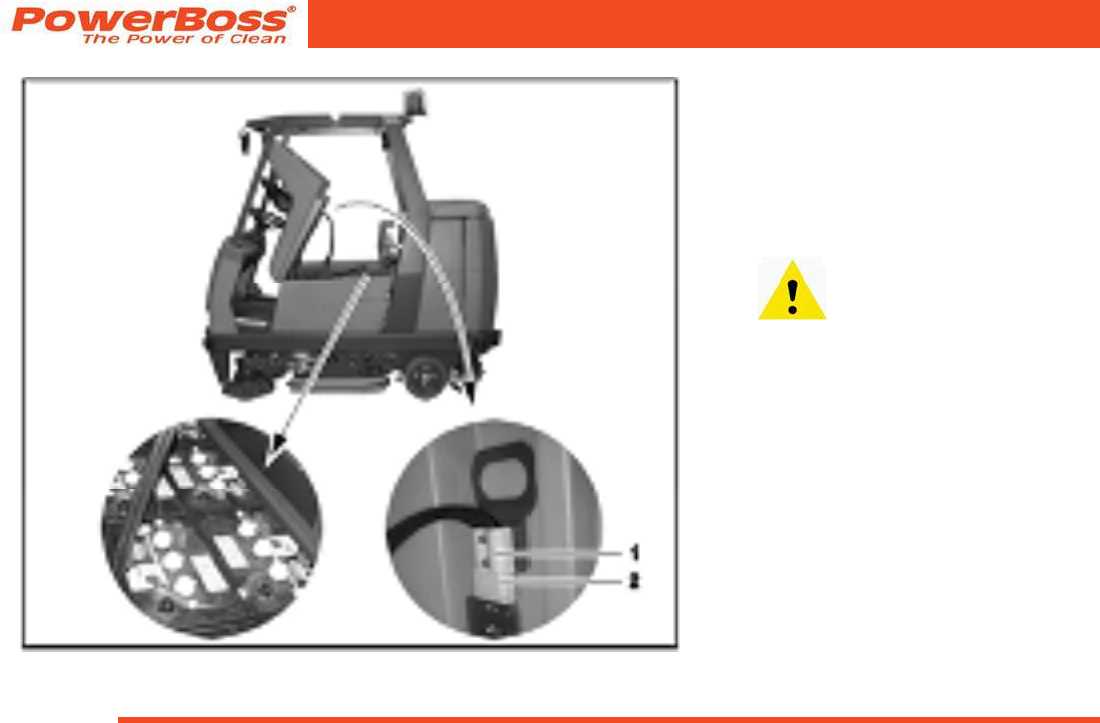
The battery is provided with a connection
cable with battery plug (Fig. 14/1). When
the battery plug is plugged into the vehicle
socket (Fig. 14/2), the vehicle is ready to
operate. To charge the battery, insert the
battery plug in the charger. The vehicle
includes a battery charger. Pay attention
to the safety information of the producer of
battery and battery charger.
PowerBoss, Inc. Copyright 2010
Admiral 38C Scrubber PB# 4100055UM Rev.* 08/10
Page 26
Operation
Fig 14
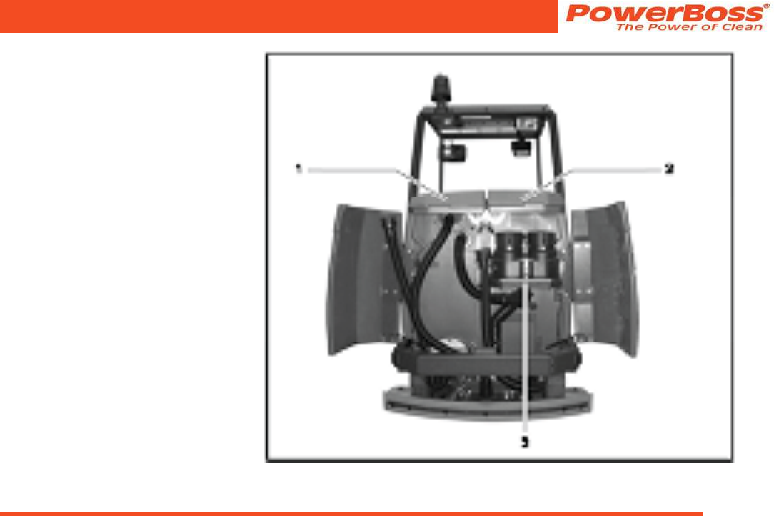
3.1.9 Options
The basic vehicle can be supplemented by
further components. The order and spare
parts numbers of these components are in
brackets.
• Cab safety roof
(7582) (Fig. 15/2)
Purpose: To protect the driver,
e.g. from objects falling from
warehouse shelving. Ensure that
assembly of a cab safety roof
is made compulsory when the
vehicle is operated in such risk
areas.
• Flashing beacon
(7585.02 Assembly on the cab safety roof)
(7585.10 Assembly on a pole / without cab
safety roof) (Fig. 15/3)
Purpose: To recognize the vehicle more
clearly when in use, even in the dark.
• Working lights
(7584.02) (Fig. 15/1)
Purpose: To be able to use the vehicle in
dark lighting conditions.

Admiral 38C Scrubber PB# 4100055UM Rev.* 08/10
PowerBoss, Inc. Copyright 2010
Page 27
Operation
• Side brush unit
(7586.10) (Fig. 15/5)
Comprised of two side brushes, one for
the right and one for the left side of the
vehicle, which can be pivoted out.
Purpose: To enable effective cleaning
along borders and sweep coarse dirt to the
center of the vehicle.
• Set of non-slip wheels
Purpose: For safe, reliable operation of the
vehicle on particularly slippery oors.
• Spraying-vacuuming tool
(Fig. 15/4)
Purpose: For the manual cleaning of areas
difcult to access using scrubbing and
vacuuming tools. A holder can be installed
on the left- hand side of the vehicle to x
the vacuuming tool. Two holes are already
drilled in the left-hand side of the vehicle
for this. The corresponding switch is pro-
vided on the right-hand operating panel to
operate the vacuuming tool.
The following belong to the spraying-vacu-
uming tool:
- Floor scrubbing and vacuuming tool
(7009)
- Suction and spraying hose (7766)
- Tool holder and attachment parts
(7311.10)
• Hand-held vacuum cleaner
(Fig. 15/4)
Purpose: To vacuum up water manually in
areas difcult to access using the vacuum-
ing tool. The hand-held vacuum cleaner
can be xed to the tool holder (refer to
spraying-vacuuming tool). The hand-held
vacuum cleaner contains:
- Adapter to connect the following
tools (7893)
- Flexible plastic extension hose,
length: 3 m (7880)
- Suction pipe (for connection to the
plastic extension hose), length: 1.3 m
(7881)
- Suction nozzle with rubber lips
(7883)
With regard to accessories such
as rotary brushes, suction lips
etc., (Fig. 15/4) please refer to
our spare parts catalog in the
Internet at
www.powerboss.com.
PowerBoss, Inc. Copyright 2010
Admiral 38C Scrubber PB# 4100055UM Rev.* 08/10
Page 28
Operation
Fig 15
(1) Working lights
(2) Cab safety roof
(3) Flashing beacon
(4) Vacuuming tool
(5) Side brush unit
Admiral 38C Scrubber PB# 4100055UM Rev.* 08/10
PowerBoss, Inc. Copyright 2010
Page 29
Operation
3.2 Operating and indicator
elements
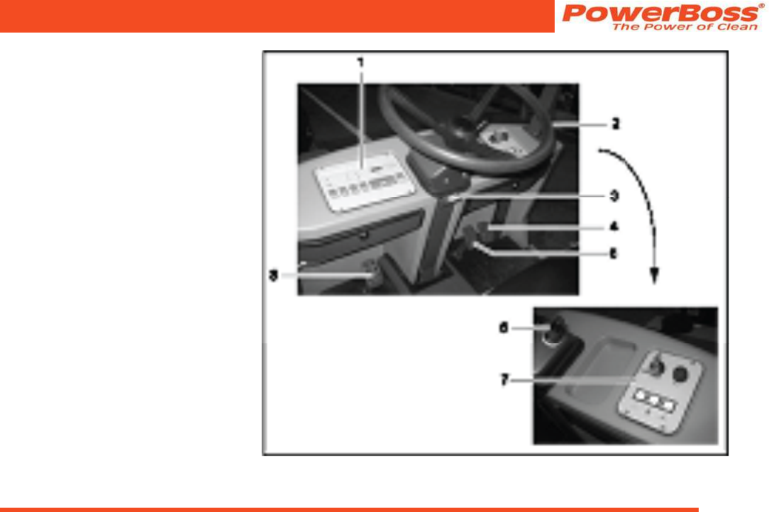
3.2.1 Operating elements in the
driver’s cab
(1) Left-hand operating panel
(2) Steering wheel
(3) Safety catch
(to release the parking brake)
(4) Accelerator
to drive forwards or backwards
(5) Service brake
(6) Driving direction selection switch
(forwards/reverse)
(7) Right-hand operating panel
(8) Parking brake
Fig 16

PowerBoss, Inc. Copyright 2010
Admiral 38C Scrubber PB# 4100055UM Rev.* 08/10
Page 30
Operation
Left-hand operating panel
(Fig. 16/1)
• This operating panel contains all the
buttons for the electronically controlled
standard cleaning programs.
• Individual functions can be added or
removed from the cleaning process, as
necessary.
• All the buttons are provided with clearly
descriptive labels.
• The green control lamps in the operat-
ing buttons serve as function indicators.
• The signicance and functioning
method of the individual buttons on
this operating panel are described in
paragraph 3.2.2.
Steering wheel
(Fig. 16/2)
• The Admiral 38C is steered by the
steering wheel.
Safety catch
(Fig. 16/3)
• The safety catch serves to release the
parking brake when applied.
• Operating sequence to release brake:
- Tread on the pedal slightly.
- Press the catch down.
- Release the pedal.
Accelerator to drive forwards and
backwards
(Fig. 16/4)
• The pedal on the right serves to control
the driving speed (as in a normal
vehicle).
• Before actuating the accelerator, use
the driving direction selection switch
(Fig. 16/6) to set the direction of travel:
forwards or reverse.
• Forward or reverse drive (according to
the driving direction selection switch
setting): Tread the accelerator down,
forwards, slowly.
• Release the pedal: The vehicle auto-
matically decelerates. The vehicle rolls
to a stop until reaching its zero setting.
• To stop securely, apply the service
brake (Fig. 16/5).
• The speed for forward drive is approx.
8 kph and for reverse drive approx.
4 kph.
• The working speed with the brushes
switched on and squeegee lowered is
approx. 7.5 kph.
An acoustic warning signal
(buzzer) is issued should the
hydraulic motor overload. At the
same time, the red alarm lamp
(Fig. 16/4) lights up in the left-
hand operating panel (Fig. 17/1)
and the driving speed is reduced
by approx. 50%. In addition, an
error code appears in the service
indicator (Fig. 17/5).
Service brake
(Fig. 16/5)
• In order to slow down the vehicle and
bring the Admiral 38C to a stop, tread
on the foot pedal to the left of the ac-
celerator (as with a normal vehicle) to
actuate the hydraulic service brake.
Admiral 38C Scrubber PB# 4100055UM Rev.* 08/10
PowerBoss, Inc. Copyright 2010
Page 31
Operation
Driving direction selection switch
(forwards/reverse)
(Fig. 16/6)
• It serves to select the driving direction:
- Drive forward:
Control lever forward
- Reverse drive:
Control lever back
- Standstill:
Control lever in center
(neutral position)
• To change the driving direction, bring
the machine to a stop by applying the
service brake, select the new direction
and accelerate again.
Right-hand operating panel
(Fig. 16/7)
• This operating panel contains the key
switch to switch the vehicle on and
off, the horn and three switches for
the optionally available working lights,
spraying/vacuuming tool and ashing
beacon; also refer to paragraph 3.2.3.
Parking brake
(Fig. 16/8)
• The pedal to the left of the steering col-
umn serves to apply the parking brake
to the rear wheels.
• When the parking brake is applied, the
corresponding control lamp on the op-
erating panel (Fig. 17/3) lights up red.
• If the driving direction selection switch
is actuated while the parking brake is
applied, a pulsating “beep” is issued.
Before getting out of the vehicle
apply the parking brake, set the
driving direction selection switch
(Fig. 16/6) to its neutral position
and switch the key switch to off.
PowerBoss, Inc. Copyright 2010
Admiral 38C Scrubber PB# 4100055UM Rev.* 08/10
Page 32
Operation
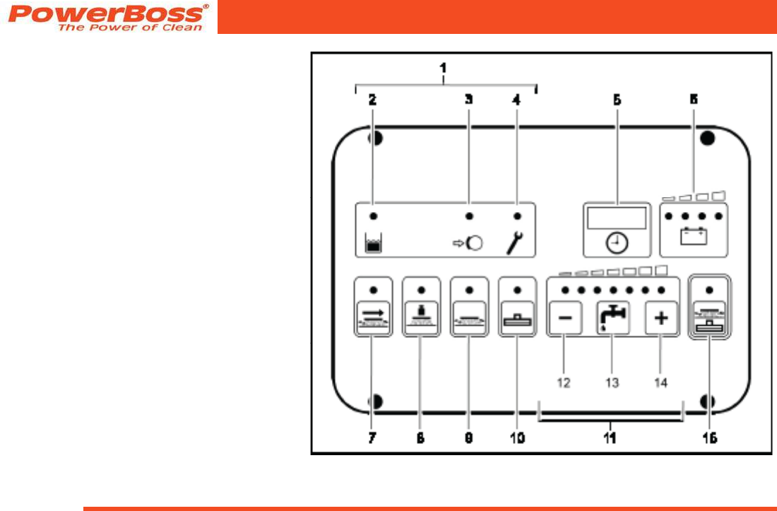
3.2.2 Left-hand operating panel
(Fig. 2)
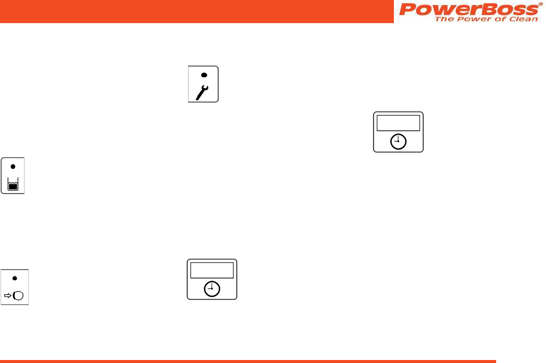
(1) Indicator eld
(2) Recovery tank indicator: When the control
lamp is on (yellow), the maximum ll level
has been reached.
(3) Indicator for parking brake: When the
control lamp is on (red), the parking brake is
applied.
(4) Indicator for error message: When the con-
trol lamp is on (red), a functional fault has
occurred.
(5) Operating hours counter and service indica-
tor
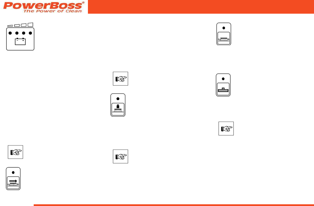
(6) Battery and charge control indicator
(7) Button for side brush unit (option)
(8) Button for brush pressure
(9) Button for brush drive
(10) Button for squeegee and suction turbine
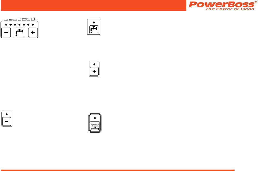
(11) Buttons for controlling the solution supply
(12) Button to reduce solution quantity
(13) Button to switch solution supply on and off
(14) Button to increase solution quantity
(15) Green PowerBoss button for simultaneous
activation of scrubbing unit and vacuuming
function Fig 17
Admiral 38C Scrubber PB# 4100055UM Rev.* 08/10
PowerBoss, Inc. Copyright 2010
Page 33
Operation
Indicator eld
(Fig. 17/1) The indicator eld enables the
Admiral 38C to provide feedback on the
operating status of the vehicle. This only
relates to operating states which cannot be
switched on or off via the operating panel:
recovery tank full, parking brake applied
and error messages.
The individual buttons and functions are
described in detail below:
Indicator for recovery tank
maximum ll level
(Fig. 17/2) The yellow control
lamp lights up when the recovery
tank has reached its maximum ll level.
Also, a “beep” signal is issued every
15 seconds. In this case, a oat switch
switches the suction turbine off and the
squeegee is raised.
Indicator for parking brake
applied
(Fig. 17/3) The control lamp lights
up red when the parking brake
has been actuated via the pedal to the left
of the steering column. If the traction drive
is switched on, an acoustic signal is also
issued.
Indicator for function faults
(Fig. 17/4)
The control lamp lights up red
when one of the following faults
occurs:
• The thermostatic switch disconnects
from the brush or hydraulic motor.
• One of the safety fuses is defective or
an electronic fuse has been tripped.
• Another fault has occurred.
At the same time, a four-digit code ap-
pears in the display of the service indicator
(Fig. 17/5). This error code infers which
fault has occurred (refer to Section 3.5.1).
At the same time, the control lamps ash
and an acoustic, pulsating signal is issued.
Operating hours counter
(Fig. 17/5) The four-digit
LED serves to display the
operating hours. When the
key in the key switch is turned on, one and
then two four-digit codes appear in suc-
cession (for further details, refer to Page
36, Key Switch (Fig. 18/1)). The operating
hours appear after this.
The counter only operates when consum-
ers are switched on (e.g. hydraulic or
brush motor, suction turbine). At the same
time, a red dot ashes at the bottom right
of the display.
Service indicator
(Fig. 17/5) The same LED
also serves for a more
accurate determination of
function faults. If a fault
occurs during operation, a four-digit code
(error code) appears in the service indica-
tor display. At the same time, the four
dots of the error code ash in the display
and a pulsating acoustic signal is issued.
The control lamp in the functional fault
display lights up red. Section 3.5 provides
an overview of the error codes which
help you clear functional faults yourself.
Clear the fault before starting to use the
vehicle again. If you cannot clear the fault
yourself, note down the error code and
inform the authorized PowerBoss dealer
responsible for your vehicle.
PowerBoss, Inc. Copyright 2010
Admiral 38C Scrubber PB# 4100055UM Rev.* 08/10
Page 34
Operation
Battery and charge control
indicator
(Fig. 17/6) After switching
on the key switch, all four
lamps light up when the
battery is fully charged. As the battery is
discharged during operation, the three
right-hand lamps indicate the level of dis-
charge by going out in sequence from right
to left. When the left, red lamp ashes, it
indicates that work must come to an end.
Approximately three minutes later, the
brushes will return to their home position.
After a further three minutes, the suction
turbines are deactivated and the squeegee
is raised. When the red lamp lights up
continuously, approximately one minute
remains until the entire vehicle shuts down
automatically.
Drive back to the charger in good
time. Take the distance to the
charger into account.
Button for side brush unit
(Fig. 17/7) This button is used
to activate the side brush unit.
After pressing the button, the
two brushes start or stop rotating and the
brush is lowered or raised accordingly.
If the side brush unit is switched on, the
green control lamp lights up.
The side brush unit is an optional acces-
sory. If it is not installed, the button has no
function.
The side brush unit can only
be switched on when the rotary
brushes are also switched on.
Button for brush pressure
(Fig. 17/8) This button is used to
increase the brush pressure. This
may be necessary when the area
to be cleaned is extremely dirty. The press-
ing force can be increased to max. 104 lb.
If the function is active, the green control
lamp lights up.
Working with an increased brush
pressure also means increased
brush wear. Therefore, only press
this button when necessary.
Button for rotary brush drive
(Fig. 17/9) This button serves to
switch the rotary brushes and
solution feed on and off with si-
multaneous, respective lowering or raising
of the brush head. If the function is active,
the green control lamp lights up.
Button for squeegee and
suction turbine
(Fig. 17/10) This button serves to
switch the suction turbine on and
off with simultaneous lowering and
raising of the squeegee. If the function is
active, the green control lamp lights up.
This button must also be pressed
when working with optional tools
connected to a suction hose.
Operating personnel must not be
seated on the driver’s seat in this
case (seat contact is bypassed).
Only the suction turbine is acti-
vated at this point, the squeegee
remains raised.
Admiral 38C Scrubber PB# 4100055UM Rev.* 08/10
PowerBoss, Inc. Copyright 2010
Page 35
Operation
Buttons controlling
the solution supply
(Fig. 17/11) The
solution consumption
used during cleaning
can be regulated in seven stages. Accord-
ingly, there are seven green control lamps
on the keypad. Each lamp relates to one
stage. The maximum quantity which can
be used for cleaning is 5.5 l/min (all seven
lamps are on). The minimum quantity is
1.25 l/min (only the left lamp is on). The
last solution quantity selected is always
used. When the scrubbing program is
switched on for the rst time, a solution
quantity of approx. 3.5 l/min is automati-
cally set.
Button to reduce solution
quantity
(Fig. 17/12) The button serves
to reduce the solution quantity
supplied to the brushes. The solution
quantity can be reduced in seven stages
(see above). The selected stage remains
programmed (last station memory) even if
the vehicle is switched off temporarily.
Button to switch the solution
supply on and off
(Fig. 17/13) This button serves to
switch the solution feed on and off
when the brush head is lowered. The so-
lution quantity previously set remains
unaltered (last station memory).
Button to increase solution
quantity
(Fig. 17/14) This button serves
to increase the solution quantity
supplied to the brushes. The solution
quantity can be increased in seven stages
(see above). The selected stage remains
programmed (last station memory) even if
the vehicle is switched off temporarily.
Green PowerBoss button for
simultaneous activation of
scrubbing unit and vacuuming
function
(Fig. 17/15) After pressing the
green PowerBoss button, the most impor-
tant basic functions for standard cleaning
are switched on and off automatically in
the correct sequence for the respective
technical application: suction turbines,
brush rotation, solution feed and lowering
or raising of the brushes and squeegee.
When the vehicle is ready for use in accor-
dance with requirements, it can be set into
operation simply and quickly by pressing
the PowerBoss button. When the Power-
Boss button has been pressed, the green
control lamp lights up.
PowerBoss, Inc. Copyright 2010
Admiral 38C Scrubber PB# 4100055UM Rev.* 08/10
Page 36
Operation
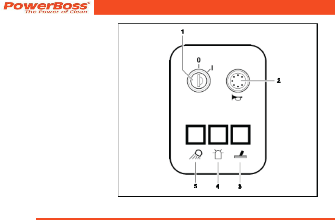
3.2.3 Right-hand operating panel
(Fig. 3)
(1) Key switch
(2) Horn
(3) Switch for spraying/vacuuming tool
(4) Switch for ashing beacon
(5) Switch for working lights
Fig 18
Admiral 38C Scrubber PB# 4100055UM Rev.* 08/10
PowerBoss, Inc. Copyright 2010
Page 37
Operation
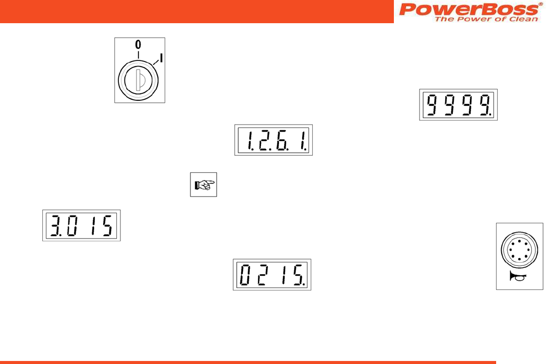
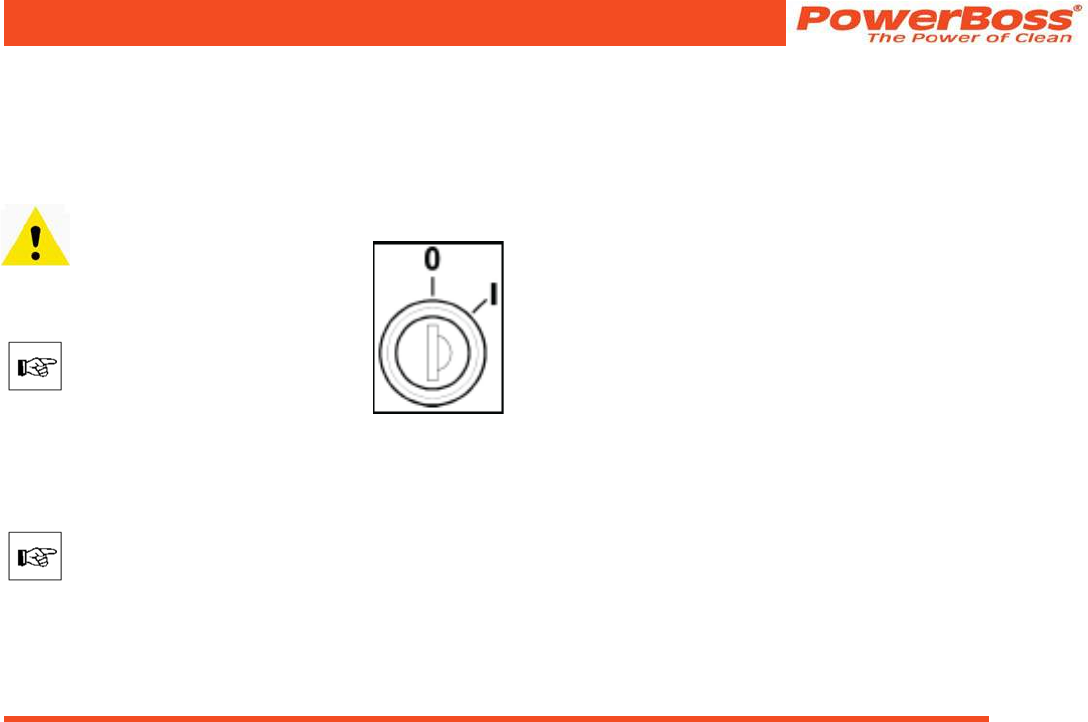
Key switch
(Fig. 18/1)
It serves to switch the elec-
trical installations on and off
and to secure the vehicle
against unauthorized use.
When the key switch is switched on (lock
position 1), the following appear in the
operating hour counter display (lefthand
operating panel, refer to Paragraph “Oper-
ating hours counter” in paragraph 3.2.2):
1 Software version
Displayed for approx. 1 second.
Example:
2 Error code
Indicates the last fault which occurred,
displayed for approx. 2 seconds.
The display serves as information for the
service technician so that the fault can be
cleared quickly. For an overview of the er-
ror codes, refer to Section 3.5.1.
Example:
When a functional fault actually
occurs, an acoustic signal is also
issued and the red control lamp
on the alarm indicator (Fig. 17/4)
lights up.
3 Operating hour indicator
Continual display.
Example:
During operation, the dots ash in the
display.
4 Control digits (optional)
In the case of brand new vehicles, it is
possible that after switching on the
key switch, the following display also
appears:
The control digits are for internal
control purposes. The display changes
to zero operating hours after one hour
at the latest. The Admiral 38C is ready
for use while this display appears. The
alarm indicator is activated.
Horn
(Fig. 18/2)
An acoustic warning sig-
nal is issued on actuating
the horn knob.

PowerBoss, Inc. Copyright 2010
Admiral 38C Scrubber PB# 4100055UM Rev.* 08/10
Page 38
Operation
Switch for spraying/
vacuuming tool
(Fig. 18/3)
This switch switches the
vacuuming tool on or off. The
suction tool is an optional ac-
cessory. If it is not installed,
the switch has no function.
Switch for ashing
beacon
(Fig. 18/4)
The ashing beacon is an
optional accessory. If no
ashing beacon is installed,
the switch has no function.
Switch for working lights
(Fig. 18/5)
This switch switches the
working lights on or off. This
occurs even without the key
switch being turned on.
The working lights are op-
tional accessories. If no working lights are
installed, the switch has no function.
Admiral 38C Scrubber PB# 4100055UM Rev.* 08/10
PowerBoss, Inc. Copyright 2010
Page 39
Operation
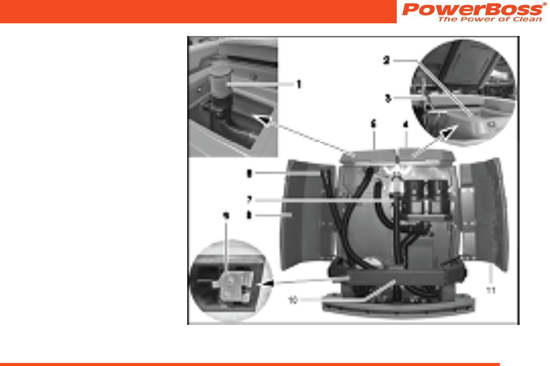
3.2.4 Operating elements on the
vehicle
(1) Waste water lter
(2) Solution tank lling neck
(3) Lid lock
(4) Cover, solution tank
(5) Cover, recovery tank
(6) Waste water draining hose
(7) Solution draining hose
(8) Left-hand rear door
(9) Rear panel frame lock
(10) Rear panel frame
(11) Right-hand rear door
Fig 19

PowerBoss, Inc. Copyright 2010
Admiral 38C Scrubber PB# 4100055UM Rev.* 08/10
Page 40
Operation
Recovery tank
(Fig. 19/1+5)
The waste water lter (Fig. 19/1) is located
under the recovery tank lid (Fig. 19/5) at
the top of the recovery tank and is con-
nected to the end of the suction pipe. It
lters large particle dirt from the waste
water and must be inspected or cleaned
daily, refer to Section 5.6.4.
Solution tank
(Fig. 19/2+4)
In order to ll fresh water and cleaning
agent, pivot up the lid of the solution tank
(Fig. 19/4) and lock it. The tank is lled
through the lling neck (Fig. 19/2) at the
top, refer to Section 5.5.1.
Lid lock
(Fig. 19/3)
The lock prevents the lid falling shut. To
lock the lid, move the bar and latch in
place. The lid lock functions in the same
way on the solution tank and recovery
tank.
Rear doors
(Fig. 19/8+11)
Open the rear doors to access the draining
hoses for waste water and solution.
Waste water draining hose
(Fig. 19/6)
The draining hose for waste water hooked
is in the left-hand rear door. Only drain off
waste water through this hose at an appro-
priate location, refer to Section 5.6.1.
Solution draining hose
(Fig. 19/7)
The draining hose for solution hangs to the
left of the suction turbines. Only drain off
the solution through this hose at an appro-
priate location, refer to Section 5.5.2.
Rear panel frame
(Fig. 19/9+10)
In order, for example, to access the ap
to clean the recovery tank, the rear panel
frame doors must be opened. To do this,
pull the lock lever (Fig. 19/9) up and open
the unlocked rear panel frame doors (Fig.
19/10).

Admiral 38C Scrubber PB# 4100055UM Rev.* 08/10
PowerBoss, Inc. Copyright 2010
Page 41
Operation
(12) Seat console
(13) Electrical compartments
(14) Side door
(15) Battery trough
Fig 20

PowerBoss, Inc. Copyright 2010
Admiral 38C Scrubber PB# 4100055UM Rev.* 08/10
Page 42
Operation
Seat console
(Fig. 20/12)
The driver’s seat is mounted on the seat
console. The seat console can be pivoted
up using the handle in order to access the
batteries and electric system.
Electrical compartments
(Fig. 20/13)
In the driver’s cab, to the left and right of
the steering column, are two electrical
compartments which must be opened by
means of a special square wrench.
The electrical compartments are
not provided in the sense of glove
compartments.
Side door
(Fig. 20/14)
The side doors are located to the left and
right of the trough battery. The doors must
be pivoted open in order to change the
battery trough, refer to Sections 5.4.3 and
5.4.4.
Battery trough
(Fig. 20/15)
The battery trough contains the 18 indi-
vidual battery cells and serves to enable a
quick change of battery. The battery trough
is provided with tting holes in order to be
able to change it using suitable tools, also
refer to Sections 5.4.3 and 5.4.4.
Admiral 38C Scrubber PB# 4100055UM Rev.* 08/10
PowerBoss, Inc. Copyright 2010
Page 43
Operation
3.3 Operation
The Admiral 38C can be driven for a
maximum of 5 minutes on surfaces
which have a gradient in excess of
6%.
Adapt your driving style to the
local conditions (oor charac-
teristics, persons in the vicinity,
obstacles etc.).
3.3.1 Switching the vehicle on
Please read Section 1 before
switching the vehicle on.
Carry out the following steps so that
the vehicle is ready to operate:
• Disconnect the battery plug from the
charger and connect it to the vehicle.
When connecting the battery
plug to the vehicle, switch the
key switch to off (lock position 0)
beforehand.
• The vehicle is equipped with a safety
shutdown via a seat contact (dead
man’s switch). This means that it is
essential for operating personnel to be
seated in the driver’s seat to be able to
operate the vehicle.
• Ensure that the driving direction selec-
tion switch is in its zero setting, refer
to accelerator for driving forwards and
backwards in Section 3.2.1.
Fig 21
• Actuate the service brake with your foot
in order to prevent accidentally acceler-
ating the vehicle, refer to Service Brake
in Section 3.2.1.
• Insert the key in the key switch
(Fig. 21).
• Turn the key from lock position 0 to
position 1.
The vehicle is ready to operate.
3.3.2 Accelerating
• Use the direction switch to select
the required driving direction: Move
the switch forwards for forward
drive, move the switch back for
reverse drive.
• Release the parking brake, refer to
Safety Catch in Section 3.2.1.
• Press the accelerator down slowly
with your right foot until you reach
the required driving speed.
PowerBoss, Inc. Copyright 2010
Admiral 38C Scrubber PB# 4100055UM Rev.* 08/10
Page 44
Operation
3.3.3 Stopping and parking
• Remove your right foot from the accel-
erator to slow down. When the foot is
fully removed from the accelerator, the
vehicle rolls to a stop.
• Now press the right foot on the service
brake pedal to stop the vehicle and
bring it to a stop.
• Turn the key in the key switch counter-
clockwise to lock position 0 and remove
the key.
• Press the left foot on the parking brake
pedal to park the vehicle.
Always apply the parking brake
and remove the key before get-
ting out of the vehicle!
3.3.4 Cleaning
There are four cleaning programs avail-
able for selection:
1. Wet scrubbing and vacuuming dry
2. Wet scrubbing (basic cleaning)
3. Vacuuming dry
4. Vacuuming with the hand-held suction
hose (option)
The cleaning programs are activated via
the left-hand operating panel, refer to Sec-
tions 3.2.2. Press the required button as
soon as the Admiral 38C is ready to drive
(see above).
Wet scrubbing and vacuuming dry
This program is the standard cleaning
program for this vehicle.
• Press the green PowerBoss
button on the left-hand oper-
ating panel.
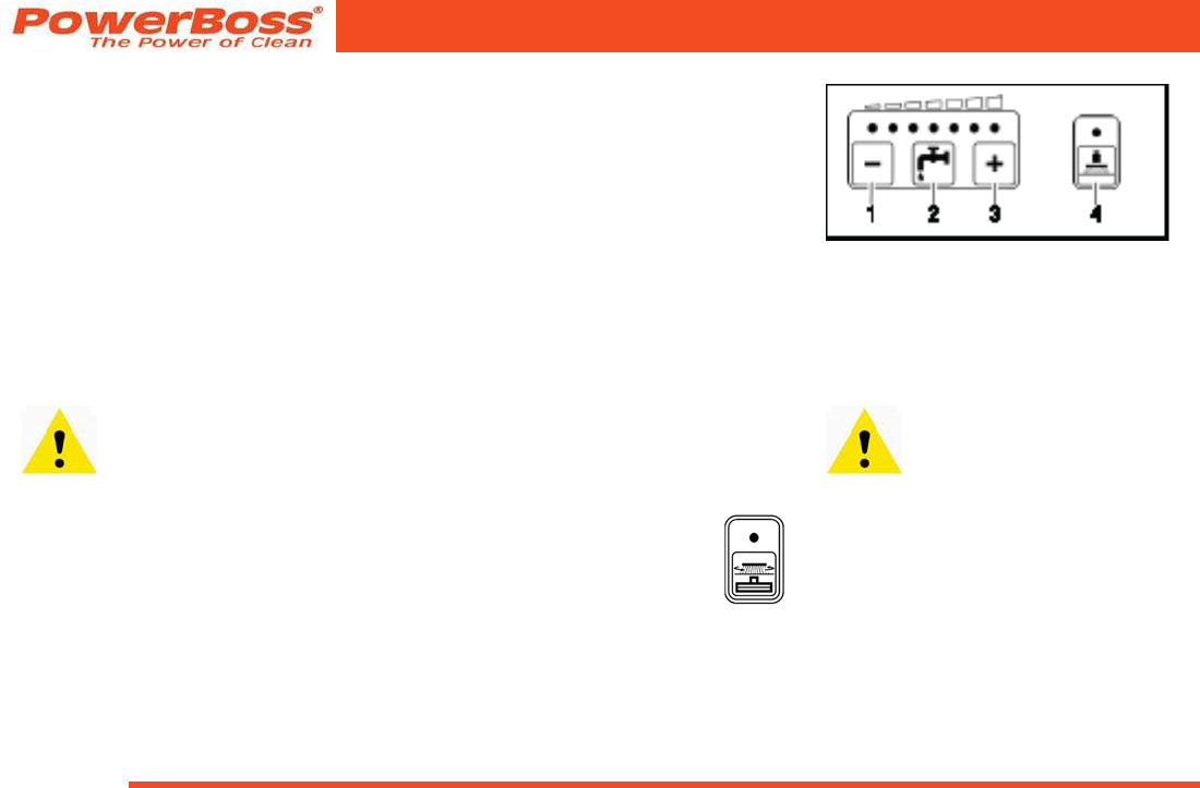
Various functions can be switched on or off
with the following buttons according to the
conditions at the location of use:
Fig 22
• Reduce solution quantity (Fig. 22/1)
• Increase solution quantity (Fig. 22/3)
• Solution on/off (Fig. 22/2)
• Increase brush pressure (Fig. 22/4)
Check whether the oor is suf-
ciently dry at regular intervals,
otherwise people could slip. If the
oor is excessively wet, check
the vehicle for leaks and that
the sealing strips are in a good
condition. If the sealing strips are
damaged, change them; refer to
Section 5.8.4.
Admiral 38C Scrubber PB# 4100055UM Rev.* 08/10
PowerBoss, Inc. Copyright 2010
Page 45
Operation
Wet scrubbing (basic cleaning)
If you do not want to vacuum the oor dry
in the same working procedure because
you want the solution to soak into the dirt,
for example, activate this program.
Wet oors are a potential risk for
slipping! Ensure to provide the
corresponding information and
warning signs.
• Press the “Button for rotary
brush drive” button (Fig. 15/9)
on the left-hand operating
panel.
Various functions can be switched on or off
with the following buttons according to the
conditions at the location of use:
• Reduce solution quantity (Fig. 22/1)
• Increase solution quantity (Fig. 22/3)
• Solution on/off (Fig. 22/2)
• Increase brush pressure (Fig. 22/4)
Vacuuming dry
• Press the “Button for squee-
gee and suction turbine” on
the left-hand operating panel.
Check whether the oor is suf-
ciently dry at regular intervals,
otherwise people could slip. If the
oor is excessively wet, check
the vehicle for leaks and that
the sealing strips are in a good
condition. If the sealing strips are
damaged, change them; refer to
Section 5.8.4.
Vacuuming with the hand-held suction
hose
The hand-held suction hose is an optional
accessory.
Vacuuming with the hand-held suction
hose only works when the operator is not
seated on the driver’s seat (seat contact
switch is not actuated).
Always apply the parking brake
before getting out of the vehicle!
• Press the “Button for squee-
gee and suction turbine” on
the left-hand operating panel.
The squeegee remains raised.
Useful tips for cleaning
• Sweep the oor before starting wet
cleaning. This not only improves the
cleaning effect but also reduces the
vehicle‘s liability to wear.
• The oor should be treated twice in
the case of particularly dirty oors or to
remove wax (basic cleaning).
- During the rst cleaning process,
the oor is scrubbed with a cleaning
agent dosage appropriate to the de-
gree of soiling, whereby the squee-
gee is raised.
- Let the cleaning solution work into
the oor for 5 to 10 minutes accord-
ing to the manufacturer’s information.
- Then scrub the oor again with the
squeegee lowered.
• Observe the correct dosage of the
cleaning agent. Information on dos-
age is provided on the cleaning agent
container.
• Use the manufacturer’s information
PowerBoss, Inc. Copyright 2010
Admiral 38C Scrubber PB# 4100055UM Rev.* 08/10
Page 46
Operation
as an initial basis. Practical experience will
ensure that you quickly nd out which is
the right PowerBoss cleaning agent and
the optimum dosage to suit your needs.
The correct dosage helps to
reduce costs and protect the
environment.
The development of excessive
foam impairs the machine’s func-
tion.
• Cause: Too much cleaning agent leads
to certain component parts of it getting
into the waste water resulting in the
development of foam. This indicates
that the amount and mixture of solution
do not match the level of dirt.
3.3.5 Switching the vehicle off
• Turn the key from lock position 1 to po-
sition 0. The vehicle is no longer ready
to operate.
• Remove the key from the key switch.
Apply the parking brake!
3.3.6 Loading and transporting the
vehicle
Refer to Section 5.12.
Admiral 38C Scrubber PB# 4100055UM Rev.* 08/10
PowerBoss, Inc. Copyright 2010
Page 47
Operation
3.4 After nishing work
1. Drive to a suitable service or parking
area.
An appropriate service and park-
ing area must have a solid oor,
have a roof and ensure that no
hazardous substances (e.g. oils,
battery acid, cleaning agents,
etc.) can get onto the oor or in
the sewage system.
2. Stop the vehicle and switch it off.
Before getting out of the vehicle
apply the parking brake, switch
off the key switch and remove the
key.
3. Empty and clean the waste container,
refer to Section 5.7.1.
4. Empty the recovery tank and rinse it
out, refer to Sections 5.6.1 and 5.6.2.
Observe the applicable laws and
local regulations when disposing
of cleaning agents.
5. Check the solution lter, refer to Sec-
tion 5.5.4.
6. Check the sealing strips and suction
hose, refer to Section 5.8.
7. Check the electrical equipment, func-
tions and settings.
8. Clean the vehicle, refer to Section
5.11.
It is not permitted to clean the
vehicle with a pressure washer or
steam blaster.
9. Charge the batteries, refer to Section
5.4.1.
The seat console must remain
open during the charging process
(otherwise there is a risk of oxy-
hydrogen developing).
If the vehicle is to be shutdown
for a longer period, the solution
tank must be emptied.

PowerBoss, Inc. Copyright 2010
Admiral 38C Scrubber PB# 4100055UM Rev.* 08/10
Page 48
Operation
3.5 Function faults
The following applies when locat-
ing the cause of functional faults
and clearing them:
Switch the vehicle off, remove the
key and disconnect the battery
plug!
3.5.1 Error code table
In the case of system errors, a four-digit
error code appears in the left-hand operat-
ing panel in addition to the service indica-
tor (wrench symbol).
The dots in the error/service code ash.
Clear the fault or note down the error/
service code and inform your authorized
PowerBoss dealer.
Error code Fault Cause Solution
1.2.5.2. The brushes remain stopped be-
cause the thermostatic switch has
been tripped.
The motor has over-
heated;
foreign bodies have pos-
sibly jammed between
the brush and shaft (e.g.
tape and such).
• Check the brushes for foreign bodies
and remove them, as necessary.
• Allow the motor to cool down.
• If the problem reoccurs, determine
the cause of overheating; contact an
authorized PowerBoss service center, if
necessary.
1.2.6.1. The brushes remain stopped
because the anti-blocking system
has been tripped.
Foreign bodies
(e.g. tape or such)
block the brushes
• Check the brushes for foreign bodies
and remove them, as necessary.
1.2.6.1. The rotary brush holding attach-
ment and brush motors have been
switched off because the anti-
blocking system has been tripped
Foreign bodies between
the brush head and
vehicle.
• Check the brush head for foreign bod-
ies and remove them, as necessary.

Admiral 38C Scrubber PB# 4100055UM Rev.* 08/10
PowerBoss, Inc. Copyright 2010
Page 49
Operation
Table 1 3.5.2 Other function faults
The vehicle does not work
Check the fuses, refer to Section
5.10.3.
In the event of faults in the trac-
tion drive, stop the vehicle imme-
diately, apply the parking brake
and remove the key!
Error code Fault Cause Solution
2.3.5.1 The side brushes remain stopped
because the thermostatic switch
has been tripped.
The motor has overheat-
ed. Foreign bodies have
possibly jammed be-
tween the side brushes
and shaft (e.g. tape and
such).
• Check the side brushes for foreign bodies
and remove them, as necessary.
• Allow the motor to cool down.
• If the problem reoccurs, determine the
cause of overheating; contact an authorized
PowerBoss service center, if necessary.
2.3.6.1. The side brushes remain stopped
because the anti-blocking system
has been tripped.
Foreign bodies (e.g.
tape or such) are block-
ing the side brushes
• Check the side brushes for foreign bod-
ies and remove them, as necessary.
2.3.6.4. The side brush holding attachment has
been switched off because the anti-
blocking system has been tripped.
Foreign bodies between
the side brush unit and
vehicle
• Check the side brush unit for foreign
bodies and remove them, as necessary.
1.4.6.1. The squeegee holding attachment has
been switched off because the anti-
blocking system has been tripped.
• Foreign bodies between
the squeegee and
vehicle.
• Squeegee is jammed
• Check the holding attachment for foreign
bodies and remove them, as necessary.
• Free the squeegee.

PowerBoss, Inc. Copyright 2010
Admiral 38C Scrubber PB# 4100055UM Rev.* 08/10
Page 50
Technical Data
4 Technical Data
Dimensions
Vehicle length (with brush head and squeegee)
Vehicle height, without/with cab safety roof
Vehicle width, without/with squeegee
Vehicle width with side brush unit (option)
in
in
in
in
84.7
55.1/78.7
44.5/49.6
53.5
Working width
Brush head
Squeegee
With side brush unit (option)
in
in
in
37.4
49.6
53.5
Area coverage
Theoretical at 7.5 kph ft²/h 76693
Weights
Dead weight (without driving batteries, without options, without driver)
Total weight, operational, wet (with cab safety roof and side brush unit, without driver)
Gross total weight
Transport weight including driving batteries, without options, without solution, without driver
lbs
lbs
lbs
lbs
1561
2919
3631
2372
Axle loads
Ready to use, front
Ready to use, rear
lbs
lbs
1303
1616

Admiral 38C Scrubber PB# 4100055UM Rev.* 08/10
PowerBoss, Inc. Copyright 2010
Page 51
Technical Data
Driving performance
Driving speed, forwards/reverse
Working speed, maximum, forwards
Climbing capacity, driving mode (max. 1 min)
Climbing capacity, work mode (max. 5 min)
Turning circle diameter, outer
Lock in aisle: minimum width of aisle
Operating time with one battery charge
kph
kph
%
%
m
m
h
5.0/2.5
4.7
15
6
3.35
2.40
Approx. 3.8
Traction drive
Drive motor (P2) W 1400
Axles and wheels
Wheelbase
Gauge, rear
Front wheel, diameter/width
Rear wheel, diameter/width
Specic wheel pressure at permissible gross total weight, front/rear
Tightening torque of wheel nuts on rear wheels
in
in
in
in
ksi
lb ft
45.3
34.7
11.8/3.9
12.2/4.7
0.186/0.135
103.3

PowerBoss, Inc. Copyright 2010
Admiral 38C Scrubber PB# 4100055UM Rev.* 08/10
Page 52
Technical Data
Brakes
Service brake:
Rear drum brake, with automatic adjustment: diameter/width
Brake uid (e.g. ATE)
Parking brake:
Rear cable brake, adjustable: diameter/width
in
gallon
in
Hydraulic
7.1/1.6
0.1
7.1/1.6
Tank volume
Fixed panel tank: solution / waste water
Flow rate, adjustable from/to
gallon
gallon/min.
46.0/46.0
0.3/1.5
Rotary brush head
No. of rotary brushes
Rotary brush diameter
Rotary brush speed
Brush pressure, min./max.
Specic contact pressure, min./max. (with brush PA6 0.7)
Pieces
in
rpm
lb
psi
2
5.4
900
79/104
0.73/0.87
Suction turbines
Power consumption/speed
Air ow rate
Vacuum
W/rpm
ft3/h
psi (mmwc)
635/13867
8476
2.94 (2030)

Admiral 38C Scrubber PB# 4100055UM Rev.* 08/10
PowerBoss, Inc. Copyright 2010
Page 53
Technical Data
Electrical installation
Power supply
Type of current
Nominal power, total
Protection class
Battery compartment: length/width/height
VDC
W
VDE 0700
in
36
DC
5500
III
37.4/24.0/18.3
Noise emission value
The sound power level (LWAd) measured according to EN 60335-2-72 under normal under
working conditions is:
The sound pressure level (LpA) measured according to DIN EN 60335-2-72 (at the driver's ear)
under normal working conditions is:
Inaccuracy factor (KpA):
dB (A)
dB (A)
dB (A)
90
76.5
2
Vibration
The weighted, effective value of the vibration, established in accordance with ISO 5349-1 to
which the upper limbs (hand-arm) are exposed under normal working conditions is:
The weighted, effective value of the vibration and shock, established in accordance with ISO
2631-1, to which the body (feet and seat area) are exposed under normal working conditions is:
m/s2
m/s2
< 2.5
< 0.5

PowerBoss, Inc. Copyright 2010
Admiral 38C Scrubber PB# 4100055UM Rev.* 08/10
Page 54
Technical Data
Special equipment:
Driving batteries
block battery
Cab safety roof (including rear-view mirror)
Order number
V/Ah5
Order number
4202
6x6/320 (CR395)
7582
Working lights, 2 pieces Order number
V/W
7584.02
2 x 24/70
Flashing beacon
For installation on the cab safety roof
For installation on a pole (when no cab safety roof is available)
V
Order number
Order number
36
7585.02
7585.10
Side brush unit
Brush speed
Brush motor: power consumption/speed
Order number
rpm
W/rpm
7586.10
80
70/3000
Rotary brushes
Plastic PA 0.7 for light to medium accumulations of dirt
SIC PA 6.12 grain 500 for medium to heavy accumulations of dirt
SIC PA 6.12 grain 180 for heavy to extreme accumulations of dirt
SIC PA 6.12 grain 80 for extreme accumulations of dirt
SIC PA 6.12 grain 46 for extreme accumulations of dirt
Order number
Order number
Order number
Order number
Order number
7887
7846
7890
7848
7847

Admiral 38C Scrubber PB# 4100055UM Rev.* 08/10
PowerBoss, Inc. Copyright 2010
Page 55
Technical Data
Additional scrubbing and vacuuming tools (spraying-vacuuming tool)
Floor scrubbing and vacuuming tool
Vacuuming and spraying hose (length: 5 m)
Tool holder and attachment part
Order number
Order number
Order number
7009
7766
7311.10
Additional tools for using the suction hose (hand-held vacuum cleaner)
Adapter to connect the following tools
Suction hose (length: 3 m)
Suction pipe (length: 1.3 m)
Suction nozzle with rubber lips
Order number
Order number
Order number
Order number
7893
7880
7881
7883

PowerBoss, Inc. Copyright 2010
Admiral 38C Scrubber PB# 4100055UM Rev.* 08/10
Page 56
Maintenance and Service
5 Maintenance and Service
General information
It is essential to pay attention to
the information in Chapter “Safety
Information” before completing
any service or maintenance work!
By adhering to the maintenance work
recommended by us, you can be sure that
the vehicle is always ready to be put into
operation.
Maintenance and repair work necessary
on a daily and weekly basis can be carried
out by a driver trained to complete the
work, all other PowerBoss system mainte-
nance may only be completed by person-
nel who are correspondingly qualied and
trained. In case of doubt, please contact
your nearest PowerBoss service center or
authorized PowerBoss dealer. Failure to
observe this annuls any rights to claims
under the terms of warranty in respect of
resulting damage or consequential dam-
age.
Always specify the serial number, indicat-
ed on the rating plate, when making any
inquiries and orders for spare parts, refer
to Section 1.7.
5.1 PowerBoss system
maintenance
PowerBoss system maintenance:
• ensures the PowerBoss working
vehicle is always ready for operation
(preventive maintenance),
• minimizes operating costs, mainte-
nance and repair costs,
• ensures the vehicle has a long service
life.
PowerBoss system maintenance de-
scribes the specic technical work neces-
sary for the individual modules and denes
the intervals for the maintenance tasks.
Individual parts which must be changed
during maintenance tasks are dened and
stipulated in spare parts kits.
PowerBoss system maintenance,
customer:
Work to be carried out by the customer
according to the service and maintenance
instructions in the operating manual (daily
and weekly). Operating personnel are
given the necessary instruction by special-
ists when the vehicle is delivered.
PowerBoss system maintenance I:
(Every 250 operating hours)
Must be completed by a skilled technician
in an authorized PowerBoss service center
according to the vehiclespecic system
maintenance with a spare parts kit.
PowerBoss system maintenance II:
(Every 500 operating hours)
Must be completed by a skilled technician
in an authorized PowerBoss service center
according to the vehiclespecic system
maintenance with a spare parts kit.
PowerBoss system maintenance III/S:
(Every 1000 operating hours safety check)
Must be completed by a skilled technician
in an authorized PowerBoss service center
according to the vehiclespecic system
maintenance with a spare parts kit.

Admiral 38C Scrubber PB# 4100055UM Rev.* 08/10
PowerBoss, Inc. Copyright 2010
Page 57
Maintenance and Service
5.2 Maintenance report
Handover
Upgrading
Test drive
Handover to customer
Instruction
completed on:
at _____________ operating hours
PowerBoss System
Maintenance I
250 operating hours
Workshop Stamp
completed on:
at _____________ operating hours
PowerBoss System
Maintenance II
500 operating hours
Workshop Stamp
completed on:
at _____________ operating hours
PowerBoss System
Maintenance II
750 operating hours
Workshop Stamp
completed on:
at _____________ operating hours
PowerBoss System
Maintenance III/S
1000 operating hours
Workshop Stamp
completed on:
at _____________operating hours
PowerBoss System
Maintenance I
1250 operating hours
Workshop Stamp
completed on:
at _____________ operating hours
PowerBoss System
Maintenance II
1500 operating hours
Workshop Stamp
completed on:
at _____________ operating hours
PowerBoss System
Maintenance II
1750 operating hours
Workshop Stamp
completed on:
at _____________ operating hours
PowerBoss System
Maintenance III/S
2000 operating hours
Workshop Stamp
completed on:
at _____________ operating hours
PowerBoss System
Maintenance I
2250 operating hours
Workshop Stamp
completed on:
at _____________ operating hours
PowerBoss System
Maintenance II
2500 operating hours
Workshop Stamp
completed on:
at _____________ operating hours
PowerBoss System
Maintenance II
2750 operating hours
Workshop Stamp
completed on:
at _____________ operating hours

PowerBoss, Inc. Copyright 2010
Admiral 38C Scrubber PB# 4100055UM Rev.* 08/10
Page 58
Maintenance and Service
5.3 Maintenance schedule
5.3.1 PowerBoss system
maintenance, customer
The following maintenance work must be
completed by the customer at the intervals
stipulated.
It relates to the daily and weekly mainte-
nance work.
Activity Interval
Daily
Directly prior to starting operation:
Fill the solution tank (dose the cleaning agent, ll fresh water) o
Before or after operation: o
Check the properties of the deectors to the right and left and repair them or replace the deector rubber (left and right)
as necessary
o
Check the service brake in terms of its functionality and for signs of leaks; repair as necessary o
Check the parking brake in terms of its functionality and for signs of leaks; repair as necessary o
Check the squeegee is clean and undamaged o
After the end of operation: o
Empty the waste container on the rotary brush head (several times a day, if necessary, depending on the working
conditions)
o
Clean the waste container on the rotary brush head o
Empty the recovery tank o
Clean the recovery tank o
Clean the large particle suction lter o
Clean the fresh water lter o
Check the battery charge; recharge as necessary o

Admiral 38C Scrubber PB# 4100055UM Rev.* 08/10
PowerBoss, Inc. Copyright 2010
Page 59
Maintenance and Service
Before completing the weekly
maintenance work described
below,subject all the operating el-
ements to a function test in order
to check whether the vehicle is
ready for operation.
Activity Interval
Weekly
Check the acid level of the battery and rell distilled water as necessary o
Check the electrical system (including working lights) and repair any defects o
Check the rotary brushes are tted properly and inspect them for signs of wear (limit dimension for brush diameter
is approx. 3.9 in) and damage. Check if any objects have caught in the rotary brushes. Remove any foreign bodies,
repair or replace rotary brushes.
o
Check the solution feed to the brushes (water lter and function of the relief valve/pump).
Note: The solution tank must be empty in this case!
o
Check the spraying pattern of the nozzles, clean the nozzles if necessary o
Check the squeegee, particularly the rear sealing strip, is clean and for signs of damage and wear and complete any
repairs or order spare parts and replace them as necessary
o
Check the recovery tank through the inspection hole at the top for signs of premature wear (due to glass splinters,
metal chips, grit, etc.) or damage and clean it
o
Check the condition of the side brush unit and replace the side brushes as necessary o
Check the vehicle is clean; clean it, if necessary o
Complete a test drive and function test (including brake tests) o

PowerBoss, Inc. Copyright 2010
Admiral 38C Scrubber PB# 4100055UM Rev.* 08/10
Page 60
Maintenance and Service
5.3.2 PowerBoss system
maintenance I
The following maintenance work must be
completed by an authorized PowerBoss
service center.
Activity Interval
Every 250 operating hours
Check the battery in terms of acid level, acid density and voltage per cell; clear up any defects as
necessary
o
Grease the pivoting joints o
Check the service brake for leaks, check the main brake cylinder and actuating rods, clear any
defects
o
Check the brake uid in the service brake; rell and bleed as necessary o
Subject the service brake to a brake tests; clear any defects as necessary o
Check the parking brake for actuating play; repair as necessary o
Subject the safety catch to a function test (to release the parking brake) o
Check the steering for steering play and adjust as necessary o
Lubricate and grease the steering o
Check the torque of the rear wheel nuts; adjust as necessary o
Check the rotary brush head, repair as necessary:
Check the rotary brushes are tted properly and inspect them for signs of wear (limit dimension for
brush diameter is approx. 3.9 in), replace as necessary.
Check the properties and condition of the brush catches and side cover with thrust bearing, clean
and repair as necessary.
o

Admiral 38C Scrubber PB# 4100055UM Rev.* 08/10
PowerBoss, Inc. Copyright 2010
Page 61
Maintenance and Service
Activity Interval
Every 250 operating hours
Check the rotary brush head, repair as necessary (continued):
Check the spraying pattern of the nozzles, clean the nozzles if necessary
Check the drive belt seal for cleanliness and no leakage. To do this, clean any dirt and uff from the
drive belt chamber, check the ventilation of the rotary brush motors in the belt chamber, clean as
necessary. Then always replace the seals
Check the parallel alignment of the holding attachment by inspecting the imprints of the brush and
power consumption, repair as necessary
o
Check the waste container and repair as necessary o
Grease the joints and connecting rods on the rotary brush head o
Check the functionality and correct adjustment (left and right) of the side brush; change as neces-
sary
o
Check the recovery tank, particularly the lid sealing quality and lter sieve o
Change the O-rings in the draining hose and dosing valves o
Check the suction hose is tted properly and for signs of damage; clear any defects as necessary o
Test the function of the squeegee: pivoting, raising/lowering, deecting rollers o
Check front and rear sealing lips of the squeegee; change as necessary o
Check the knurled nuts on the squeegee; change as necessary o
Grease the joints and connection rods of the waste water vacuuming system o
Adjust the support wheels on the squeegee o
Check the vacuum at the suction hose; clear any defects o

PowerBoss, Inc. Copyright 2010
Admiral 38C Scrubber PB# 4100055UM Rev.* 08/10
Page 62
Maintenance and Service
Activity Interval
Every 250 operating hours
Check the electrical safety functions:
parking brake, recovery tank oat switch
o
Check the visual appearance of the vehicle:
color, corrosion and presence of all signs and labels
o
Check the vehicle is clean; clean it, if necessary o
Test drive and test all function and safety-relevant components including brake tests o
Produce test report o
Inspection label o
Logbook o
On request against separate account: driver training o

Admiral 38C Scrubber PB# 4100055UM Rev.* 08/10
PowerBoss, Inc. Copyright 2010
Page 63
Maintenance and Service
5.3.3 PowerBoss system
maintenance II
The following maintenance work must be
completed by an authorized PowerBoss
service center.
Activity Interval
Every 500 operating hours
Complete all activities in PowerBoss system maintenance I, see paragraph 5.3.2 o
In addition:
Check the output of the hydraulic motor (forwards, reverse); clear defects as necessary o
Check the carbon brushes of the hydraulic motor; replace, if necessary o
Check the brush motor output (left and right); clear defects as necessary o
Check the carbon brushes of the brush motors; replace, if necessary o
Check the timing belt of the rotary brush drive, if necessary, have the timing belt tension adjusted
or change the timing belt (178 Hz +-15 Hz)
Change the timing belt after 1000 operating hours.
o
Check the side brush unit drive; clear defects as necessary o
Check the carbon brushes of the side brush drive; replace, if necessary o
Including visual inspection, test drive, test report, inspection label and logbook see paragraph 5.3.2 o

PowerBoss, Inc. Copyright 2010
Admiral 38C Scrubber PB# 4100055UM Rev.* 08/10
Page 64
Maintenance and Service
5.3.4 PowerBoss system
maintenance III/S (safety
check)
The following maintenance work must be
completed by an authorized PowerBoss
service center at least once a year.
Activity Interval
Every 1000 operating
hours
Complete all activities in PowerBoss system maintenance I and II, see paragraph 5.3.2 and para-
graph 5.3.3
o
In addition:
Check the brake linings on the rear wheels; change as necessary o
Change the brake uid in the service brake o
Including visual inspection, test drive, test report, inspection label and logbook see paragraph 5.3.2 o
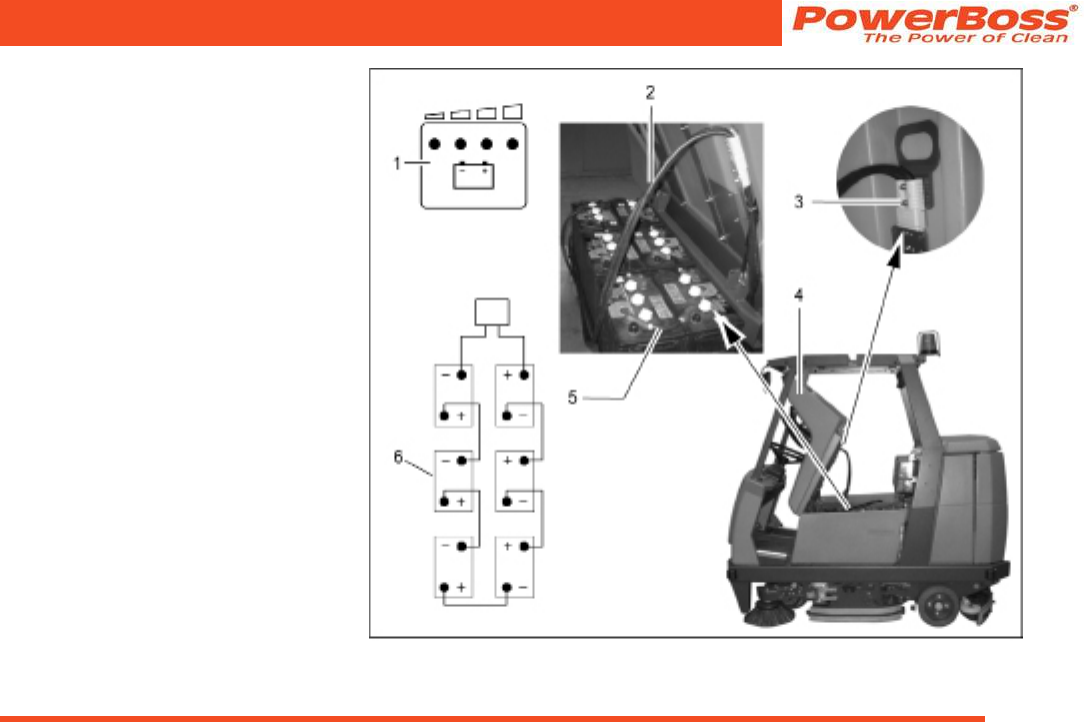
Admiral 38C Scrubber PB# 4100055UM Rev.* 08/10
PowerBoss, Inc. Copyright 2010
Page 65
Maintenance and Service
5.4 Battery system
The Admiral 38C is equipped with six low-
maintenance block batteries, see para-
graph 3.1.8 and 4.
(1) Battery and charge control indicator
(including TSG indicator) in lefthand
operating panel
(2) Battery connection cable
(3) Battery plug in vehicle socket
(4) Seat console, open
(5) Battery interconnection cable
(6) Wiring diagram
Fig 23
PowerBoss, Inc. Copyright 2010
Admiral 38C Scrubber PB# 4100055UM Rev.* 08/10
Page 66
Maintenance and Service
General information on handling
batteries
Pay attention to the safety infor-
mation n paragraph 1.4 and 1.5.2
as well as the information on
servicing and maintenance in the
battery documents.
• Always disconnect the battery plug be-
fore starting any work on the electrical
installation.
• Batteries may only be handled and
changed by properly skilled mainte-
nance personnel.
• Pay attention to legal requirements and
local directives.
5.4.1 Charging batteries
Before starting the vehicle up for
the rst time, the batteries to be
used must be properly charged
by implementing the initial battery
charge routine, see paragraph
2.2. PowerBoss assumes no
liability for damage to the battery
caused by a fault when the bat-
tery is charged for the rst time.
There must be sufcient ventila-
tion in the charging area - risk of
explosion!
The seat console (Fig. 23/4)
must be open during the battery
charging process to prevent the
development of explosive oxyhy-
drogen!
Only use the original charger!
Pay attention that the insulation
is not initially damaged and not
damaged during the charging
process. The cable must not rub
against anything. Do not use the
charger if the insulation is dam-
aged.
We recommended charging the bat-
tery when at least one dot of the battery
indicator has gone out after operating
the vehicle. The indicator (Fig. 23/1) also
indicates the charge status of the batteries
during the charging process.
• Connect the battery plug (Fig. 23/3) to
the battery charger supplied.
• Pay attention to the information in the
operating manual supplied with the
charger and the manual from battery
manufacturer.
Do not inhale battery gases.
Admiral 38C Scrubber PB# 4100055UM Rev.* 08/10
PowerBoss, Inc. Copyright 2010
Page 67
Maintenance and Service
5.4.2 Servicing the driving batteries
Checking the acid level
The Admiral 38C is tted with a main-
tenance-free battery. However, if a wet
battery is used instead, the acid level must
be checked by the customer on a weekly
basis and distilled water must be topped
up, if necessary; also see paragraph 5.3.1.
There must be no naked ames
used in the vicinity when han-
dling batteries, particularly when
checking the acid level.
The battery cells are provided with ll level
indicators which ensure the correct height
of electrolyte is maintained: Rell distilled
water, if required. Details on the lling pro-
cess are contained in the manual provided
by the battery manufacturer.
Spilled battery acid must never
enter the sewage system in its
initial form, it must be neutral-
ized beforehand: e.g. diluted with
plenty of water or absorbed with
granulate.
Checking the acid density and voltage
of each battery
These points must be checked and cor-
rected at regular intervals within the scope
of PowerBoss system maintenance by an
authorized service center.
5.4.3 Disassembling the batteries
1. Park the vehicle on a level area of
oor.
Turn the key switch to position 0
and remove the key.
2. Open the side doors to the left and
right (Fig. 24/3).
3. Positioned on the right-hand side of the
vehicle, take hold of the seat console
at the handle (Fig. 24/2) and pivot up
towards the front.
Pivot the seat console (Fig. 24/1)
open from the right-hand side of
the vehicle otherwise your hands
could be crushed between the
seat console and cab safety roof
(if tted).
4. Disconnect the battery and vehicle
plug (Fig. 24/5+6).
When disassembling the batter-
ies, use appropriate lifting gear.
The battery may only be disas-
sembled using lifting gear by
properly trained personnel.
If the Admiral 38C is equipped
with a cab safety roof, lift the bat-
teries out on the left-hand side of
the battery. The cab safety roof
has a recess (Fig. 24/4) for the
lifting gear rope.
5. Disconnect the battery connection
cable.
6. Lift the battery out of the vehicle using
the lifting gear.
5.4.4 Installing the batteries
Set the key switch to position 0
(refer to „Key switch“ in para-
graph 3.2.3) and remove the key.
1. Open the side doors to the left and
right (Fig. 24/3).
2. Take hold of the seat console (Fig.
24/1) at the handle (Fig. 24/2) and
pivot it forwards to open it.
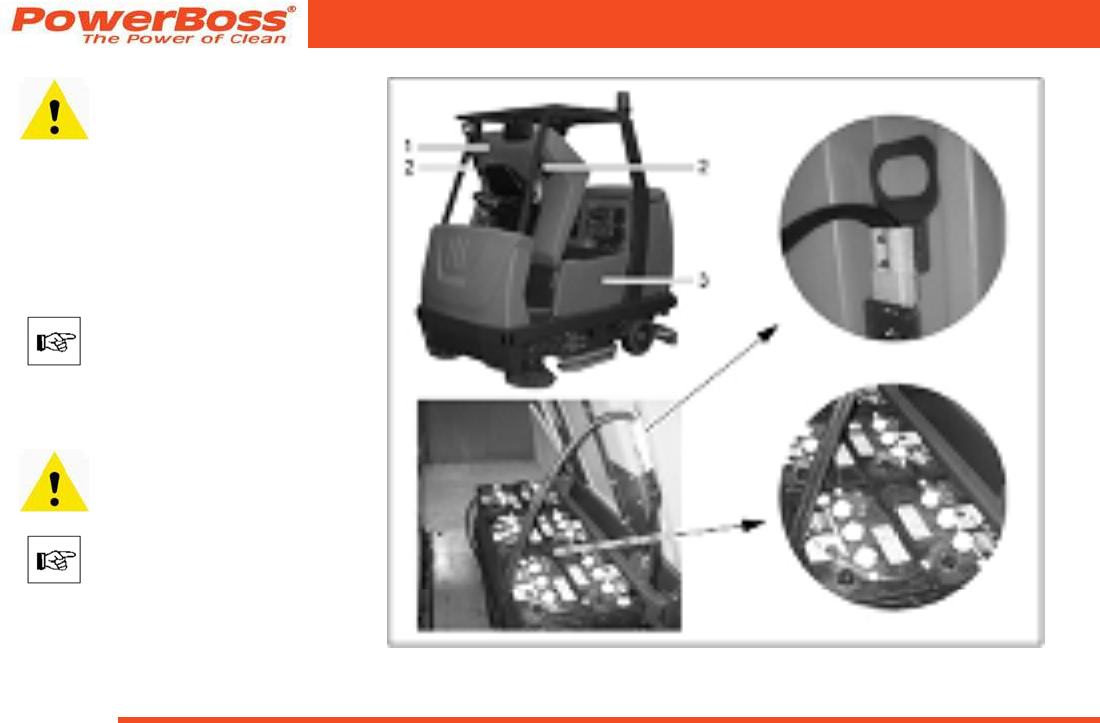
PowerBoss, Inc. Copyright 2010
Admiral 38C Scrubber PB# 4100055UM Rev.* 08/10
Page 68
Maintenance and Service
If a cab safety roof is tted,
open the seat console from the
right-hand side of the vehicle
otherwise your hands could be
crushed between the seat con-
sole and cab safety roof.
Install the batteries in the vehicle from the
left-hand side of the vehicle using lifting
gear or a fork-lift truck according to the
connection diagram or adjacent gure.
If the Admiral 40CS is tted with
a cab safety roof, the batteries
can only be installed from the
left-hand side of the vehicle; the
cab safety roof is provided with a
recess for the lifting gear rope.
When installing the battery, use
appropriate lifting gear.
The batteries may only be
installed using lifting gear by
properly trained personnel.
Connect the battery poles to the connec-
tion cable according to the connection
diagram. Ensure they are connected rmly. Fig 24

Admiral 38C Scrubber PB# 4100055UM Rev.* 08/10
PowerBoss, Inc. Copyright 2010
Page 69
Maintenance and Service
5.4.5 Disposing of batteries
Used batteries with the recycling symbol
contain reusable commodities. The heavy
metals contained simultaneously represent
a serious risk to health and to the environ-
ment. Never open batteries or damage
them. Never touch, inhale or swallow any
material inside batteries. Health hazard!
Never allow batteries to pollute the envi-
ronment. Risk of contaminating the ground
and water! In accordance with symbol with
the crossed out bin, these batteries must
not be disposed of in domestic waste.
5.4.6 Total discharge signal
transducer (TSG)
The Admiral 38C is equipped with a
charge control for protection against total
discharge of the batteries. The total dis-
charge signal transducer (TSG) is inte-
grated in the electronic system and setup
at the factory. If other batteries are used,
the total discharge signal transducer must
be adjusted.
The total discharge signal trans-
ducer may only be adjusted by
an authorized PowerBoss service
center.
Also see paragraph 3.1.8.
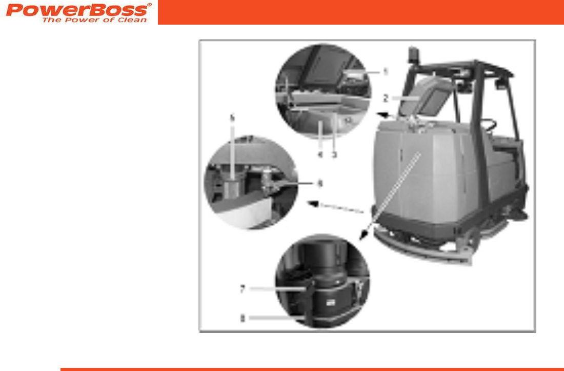
PowerBoss, Inc. Copyright 2010
Admiral 38C Scrubber PB# 4100055UM Rev.* 08/10
Page 70
Maintenance and Service
5.5 Solution tank
(1) Lid seal
(2) Tank cap
(3) Opening to recovery tank
(airing and venting)
(4) Solution tank
(5) Solution lter
(6) Ball cock
(7) Screw cap
(8) Draining hose
Fig 25

Admiral 38C Scrubber PB# 4100055UM Rev.* 08/10
PowerBoss, Inc. Copyright 2010
Page 71
Maintenance and Service
5.5.1 Filling the solution tank
Fill the solution tank (Fig. 25/4) with fresh
water and cleaning agent before starting
with the work, also refer to Section 3.1.4.
1. Park the machine on a level oor area.
2. Open the tank cap (Fig. 25/2) and lock
in place.
3. Fill the solution tank to the maximum
mark.
5.5.2 Emptying the solution tank
If the vehicle is to be left unused for a
longer period, the solution tank should be
emptied.
1. Park the vehicle so that the draining
hose can be positioned over a drain in
the oor.
2. Open the left and right rear doors
3. Detach the solution draining hose (Fig.
25/8) and lower it slowly.
4. Unscrew the cap (Fig. 25/7) to open it.
The quantity drained can be regulated
by turning the cap and pivoting the cap
open fully, if necessary.
5. When the solution tank has been com-
pletely emptied, screw the cap shut
again and attach the draining hose
again.
6. Close the left and right rear doors.
When disposing of the waste
water containing the cleaning
agent, observe all applicable
legal regulations.
5.5.3 Cleaning the draining hose cap
• The cap (Fig. 25/7) at the end of the
draining hose (Fig. 25/8) should be
cleaned at regular intervals.
• Lubricate the O-ring lightly, if neces-
sary.
5.5.4 Cleaning the lter in the
solution feed
The solution feed is equipped with a lter
(Fig. 25/5) which must be cleaned dirt
appears on the container. This is located
on the left-hand side of the vehicle at the
height of the brushes behind the side
panel.
1. Pivot the right-hand side panel up.
2. Close the ball cock (Fig. 25/6) to
prevent solution being supplied from
the tank.
3. Unscrew the container by hand and
pull the sieve insert out downwards.
4. Clean both parts with water and reas-
semble them.
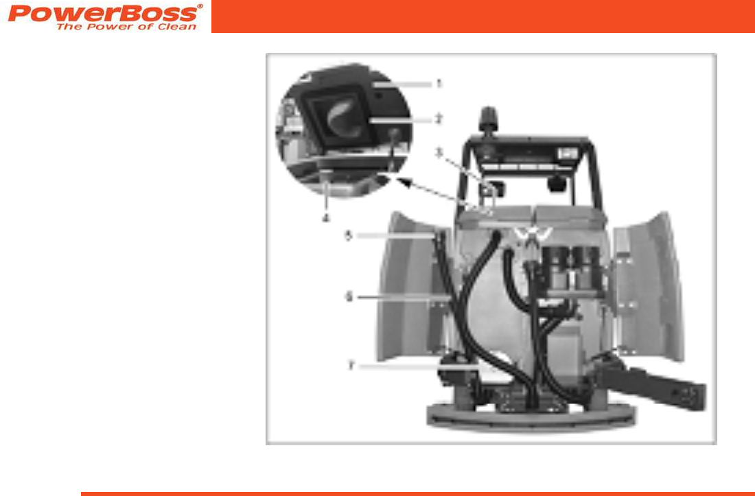
PowerBoss, Inc. Copyright 2010
Admiral 38C Scrubber PB# 4100055UM Rev.* 08/10
Page 72
Maintenance and Service
5.6 Recovery tank
(1) Tank cap
(2) Lid seal
(3) Recovery tank
(4) Air intake lter
(5) Screw cap
(6) Waste water draining hose
(7) Cleaning ap
Fig 26
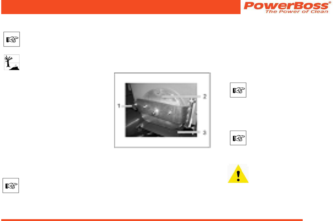
Admiral 38C Scrubber PB# 4100055UM Rev.* 08/10
PowerBoss, Inc. Copyright 2010
Page 73
Maintenance and Service
5.6.1 Emptying the recovery tank
The recovery tank (Fig. 26/3)
must be emptied and ushed
clean after nishing work.
Observe the applicable laws and
local regulations when disposing
of waste water containing clean-
ing agents!
1. Park the vehicle so that the draining
hose can be positioned over a drain in
the oor.
2. Open the left and right rear doors
3. Detach the waste water draining hose
(Fig. 26/6) and lower it slowly.
4. Unscrew the cap (Fig. 26/5) to open it.
The quantity drained can be regulated
by turning the cap and pivoting the cap
open fully, if necessary.
5. When the recovery tank has been
completely emptied, screw the cap
shut again and attach the draining
hose again.
If the recovery tank is extremely
dirty, begin cleaning the tank
straight away.
6. Close the left and right rear doors.
5.6.2 Cleaning the recovery tank
Clean the recovery tank (Fig. 26/3) every
day or as necessary. The cleaning ap
(Fig. 26/7) is available for this.
1. Open the left and right rear doors
2. Empty the recovery tank, refer to Sec-
tion 5.6.1.
Fig 27
3. Pull out the run-off plate (Fig. 27/3)
4. Release the ap lock: Turn the wing
nut (Fig. 27/1) counterclockwise
5. Open the cleaning ap (Fig. 27/2).
6. Open the recovery tank cap (Fig. 26/1).
7. Flush the recovery tank with water
lled from the top through the open
tank neck.
Cleaning may only be carried
out using a water hose (operat-
ing pressure approx. 5 to 6 bar)
and only from top to bottom. Do
not aim the jet of water directly at
openings, slits, electronic compo-
nents, operating panels or seals.
It is not permitted to clean the ve-
hicle with a high-pressure washer
or with a steam blaster because
the temperature is in excess of
100 °C.
Wear appropriate gloves for
protection against dirt, viruses,
bacteria etc. when cleaning the
container.
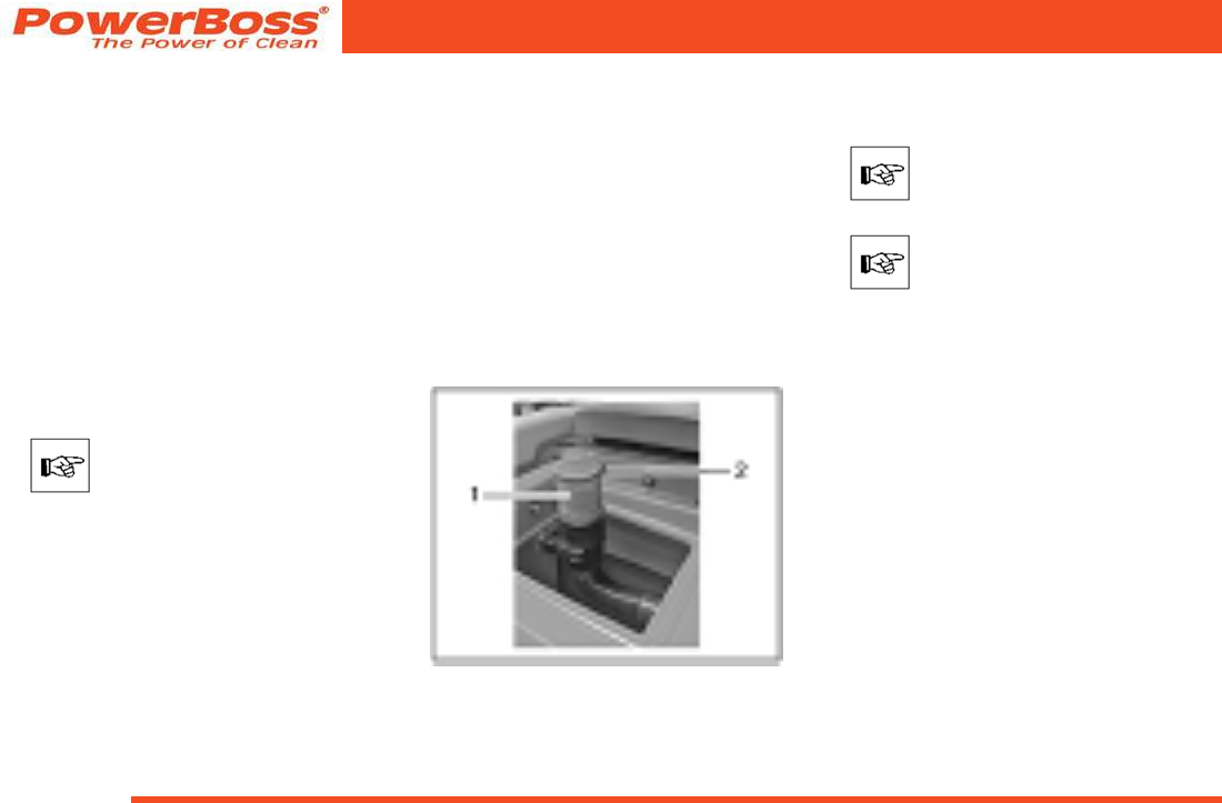
PowerBoss, Inc. Copyright 2010
Admiral 38C Scrubber PB# 4100055UM Rev.* 08/10
Page 74
Maintenance and Service
8. After nishing cleaning the tank, close
the ap and push the run-off plate back
in place.
9. Unhook the waste water draining hose
(Fig. 26/6), lower it slowly and open the
cap (Fig. 26/5).
10. Run fresh water in the recovery tank
through the open tank neck using a
water hose (output pressure approx. 5
to 6 bar) and, in doing so, also ushing
the draining hose (see above).
11. Screw the cap shut again and hook the
draining hose back in place.
12. Close the left and right rear doors.
The cleaning ap must not be
used to drain off waste water.
5.6.3 Cleaning the draining hose cap
• Clean the draining hose cap on a daily
basis.
• Lubricate the O-ring lightly, if neces-
sary.
5.6.4 Cleaning the air intake lter
The lter sieve (Fig. 28/1) is located in the
recovery tank above the maximum water
level on the suction pipe. The accumu-
lation of dirt in the lter sieve must be
checked daily and cleaned as necessary:
Fig 28
1. Pull the lter sieve from the suction
pipe and clean with water.
Remove the lter sieve complete-
ly to clean it.
During cleaning and operation,
pay attention that no water and
no particles of dirt get into the
suction pipe and into the suction
turbines.
2. Dry the lter sieve after cleaning. Do
not replace when dripping wet!
5.6.5 Cleaning the openings to the
solution tank
The openings between the recovery and
solution tank (Fig. 28/2) serve for ventila-
tion between the two tanks. They must be
checked regularly for accumulations of dirt
and cleaned as necessary.
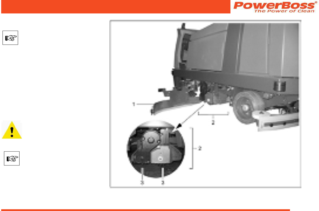
Admiral 38C Scrubber PB# 4100055UM Rev.* 08/10
PowerBoss, Inc. Copyright 2010
Page 75
Maintenance and Service
5.7 Rotary brush head
The rotary brush head (Fig. 29/2)
may only be assembled, disas-
sembled and adjusted by properly
trained service personnel.
The two rotary brushes (Fig. 29/3) are
not component parts of the delivery. They
must be selected separately according to
the task they are intended to fulll (refer
to Section 4) and installed according to
the instructions on the rotary brush head
(Fig. 29/2), refer to Section 2.3.1. Nor-
mally, however, the authorized PowerBoss
workshop will install them for you prior to
delivery.
Before working on the rotary
brushes, switch off the rotary
brush head, turn the key switch to
Position 0 and remove the key.
The following applies prior to
starting any maintenance work on
the rotary brush head: Open the
deectors and move them to their
service position (Fig. 29/1) (also
refer to Section 2.3.1, Point 1).
Fig 29
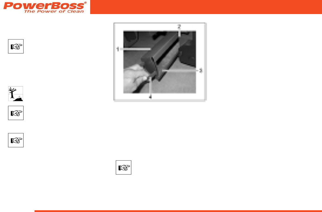
PowerBoss, Inc. Copyright 2010
Admiral 38C Scrubber PB# 4100055UM Rev.* 08/10
Page 76
Maintenance and Service
5.7.1 Emptying and cleaning the
waste container
The waste container must be
emptied and cleaned at least
once a day. If the vehicle is used
for several hours a day, the waste
container must be checked and
correspondingly more frequently
emptied.
Observe the applicable laws and
local regulations in respect of
disposal!
Only remove the container in the
direct vicinity of the refuse dump.
Removing the waste container
The waste container (Fig. 30/1)
can only be removed on the right-
hand side of the vehicle.
1. Take hold of the waste container (Fig.
30/1) by the handle (Fig. 30/4) and
pivot it back to the left a little to unlock
it.
2. Pull the waste container (Fig. 30/1) out
using the handle (Fig. 30/4).
Fig 30
(1) Waste tank
(2) Guide edge
(3) Throw-in edge
(4) Handle
Emptying the waste container
The waste container cannot be
lled higher than the throw-in
edge (Fig. 30/3).
Empty the waste container (Fig. 30/1)
regularly at a suitable location.
Cleaning the waste container
Wash and clean the waste container (Fig.
30/1) with water.
Installing the waste container
Position the waste container (Fig. 30/1)
on the guide edge (Fig. 30/2) and slide in,
from the right-hand side, until it will 3 go
no further.
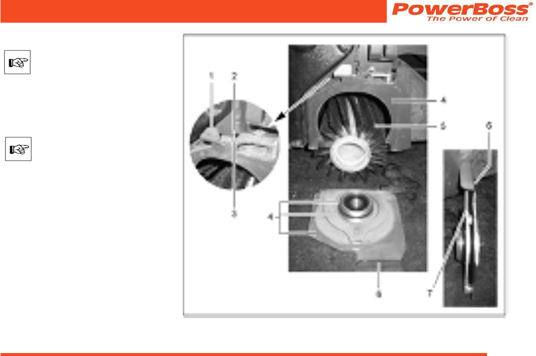
Admiral 38C Scrubber PB# 4100055UM Rev.* 08/10
PowerBoss, Inc. Copyright 2010
Page 77
Maintenance and Service
5.7.2 Changing the rotary brushes
Check the rotary brushes on a
weekly basis for signs of wear.
When a rotary brush has worn to a diam-
eter of approx. 3.9 in, the rotary brushes
must be replaced by new ones (diameter
of new rotary brush: 5.4 in).
To protect the oor surface, the
rotary brushes are equipped
with a wear restriction facility.
When the minimum diameter is
reached, the rotary brush head
lowers onto a vertical stop. The
full cleaning performance can no
longer be achieved when in this
position.
(1) Locking lever
(2) Oval-head screws
(3) Hex nut
(4) Contact surfaces
(5) Rotary brush
(6) Brush holder
(7) Contact surface between brush
holder and oval-head screws Fig 31

PowerBoss, Inc. Copyright 2010
Admiral 38C Scrubber PB# 4100055UM Rev.* 08/10
Page 78
Maintenance and Service
Removing the brush holder
1. Slide the locking lever (Fig. 31/1) to the
middle of the device and hold it there.
2. Allow the brush holder (Fig. 31/6) to
lower under its own weight and then
pull out.
3. Release the locking lever (Fig. 31/1).
Disassembling the rotary brushes
Pull out the rotary brush (Fig. 31/5), over-
coming its resistance. Also refer to Section
2.3.1 (reverse working sequence).
Installing the rotary brushes
Refer to Section 2.3.1.
Mounting the brush holder
1. Slide the locking lever (Fig. 31/1) to the
middle of the device and hold it there.
2. Mount the brush holder (Fig. 31/6) on
the rotary brush, press against the
housing and then slide upwards as far
as possible.
3. Pivot the locking lever (Fig. 31/1) back
under the brush holder as far as pos-
sible.
5.7.3 Cleaning the contact surfaces
Each time the rotary brushes are changed,
all the contact surfaces (Fig. 31/4 and Fig.
29/7) must be thoroughly cleaned with a
damp cloth, with a little cleaning agent
added, if necessary.
Also clean the small contact
surfaces!
5.7.4 Adjusting the locking lever for
the brush holder
1. Remove the brush holder (Fig. 31/6)
(refer to paragraph ”Removing the
brush holder”).
2. Loosen the counternut (Fig. 31/3).
3. Screw the oval-head screw (Fig. 31/2)
in or out.
4. Close the brush holder (refer to para-
graph ”Mounting the brush holder”) on
a trial basis.
The oval-head screw (Fig. 31/2)
is adjusted correctly when it
lightly scrapes under the brush
holder (Fig. 31/7).
5. Remove the brush holder (Fig. 31/6)
(refer to paragraph ”Removing the
brush holder”) and adjust the oval-
head screw (Fig. 31/2) until it is at the
correct height (repeat Step 4 several
times if necessary).
6. Tighten the counternut (Fig. 31/3).
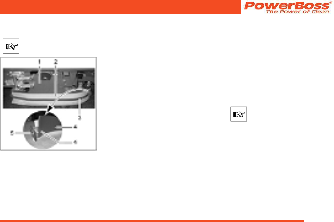
Admiral 38C Scrubber PB# 4100055UM Rev.* 08/10
PowerBoss, Inc. Copyright 2010
Page 79
Maintenance and Service
5.7.5 Installing new rubber deector
strips
The deector (Fig. 32/1) must be
xed in its service position (refer
to Section 2.3.1, Point 1).
Fig 32
(1) Deector
(2) Rubber deector strips
(3) Clamping rail
(4) Clamping rail hooks
(5) Wing nut
1. Loosen the wing nut (Fig. 32/5) at the
end of the deector.
2. Slide the clamping rail (Fig. 32/3) in the
vehicle’s driving direction (forwards)
until the clamping rail hooks (Fig. 32/4)
are freed and the clamping rail can be
removed away from the vehicle.
3. Remove the old rubber deector strips
(Fig. 32/2).
4. Position the new rubber deector strips
(Fig. 32/2) in place.
5. Mount the clamping rail (Fig. 32/3)
from the outside and slide back by
hand so that the clamping rail hooks
(Fig. 32/4) engage.
6. Tighten the wing nut (Fig. 32/5) so that
it engages in the thread of the clamp-
ing rail (Fig. 32/3) and tightens the
clamping rail rmly.
5.7.6 Adjusting the rotary brush
head
If you notice that the cleaning performance
of the vehicle is no longer regular, make
a visual inspection as to whether the
rotary brush head has a greater clearance
from the ground on one side compared
to the other. If this is the case, contact an
authorized PowerBoss service center to
have the rotary brush head readjusted. A
PowerBoss service center has the tools
necessary to do this.
This work may only be completed
by an authorized PowerBoss
service center!

PowerBoss, Inc. Copyright 2010
Admiral 38C Scrubber PB# 4100055UM Rev.* 08/10
Page 80
Maintenance and Service
5.7.7 Direction of rotation of the
rotary brushes
Controlling and adjusting the
direction of rotation may only
be carried out at an authorized
PowerBoss service center.
When viewing the front left side of the
vehicle, the front rotary brush (Fig. 33/ 1),
viewed in the driving direction, must rotate
counterclockwise and the rear rotary brush
(Fig. 33/2) clockwise.
Fig 33
(1) Front rotary brush
(2) Rear rotary brush
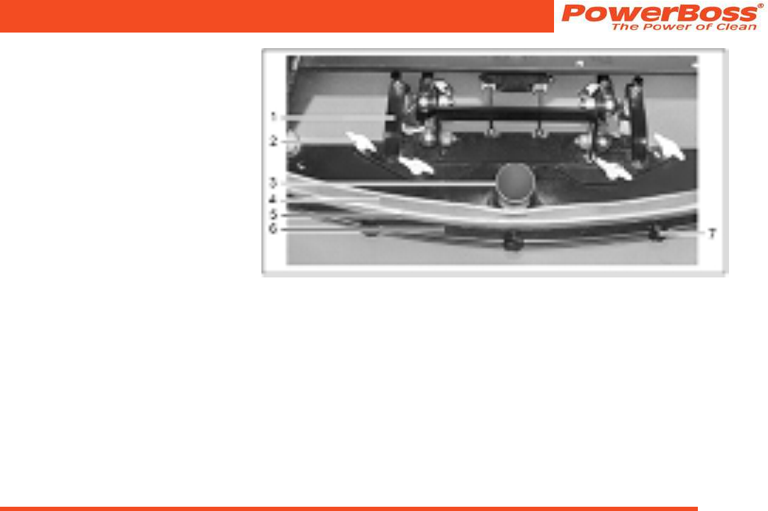
Admiral 38C Scrubber PB# 4100055UM Rev.* 08/10
PowerBoss, Inc. Copyright 2010
Page 81
Maintenance and Service
5.8 Squeegee
1 Squeegee holding attachment
2 Wing nuts
3 Connection nozzle
4 Sealing strip (rear)
5 Support strip (rear)
6 Clamping rail (rear)
7 Knurled nut
The squeegee is also equipped with front
sealing and support strips and clamping
rail (Fig. 35).
5.8.1 Cleaning the squeegee
Inspect the squeegee when raised daily
and clean as necessary.
5.8.2 Disassembling the squeegee
1. Insert the key in the key switch and
turn the key switch on.
2. Lower the squeegee: Press the button
for the squeegee and suction turbine
so that the green control lamp lights
up.
3. Switch off the key switch and remove
the key.
4. Open the rear doors.
5. Pull the suction hose from the connec-
tion nozzle (Fig. 34/3) of the squeegee.
6. Loosen the wing nuts (Fig. 34/2) on the
holding attachment.
7. Pull the squeegee away to the rear
under the holding attachment.
8. Insert the key in the key switch and
turn the key switch on.
9. The squeegee is lifted automatically.
10. Close the rear doors.
5.8.3 Installing the squeegee
Refer to Section 2.3.2.
Fig 34
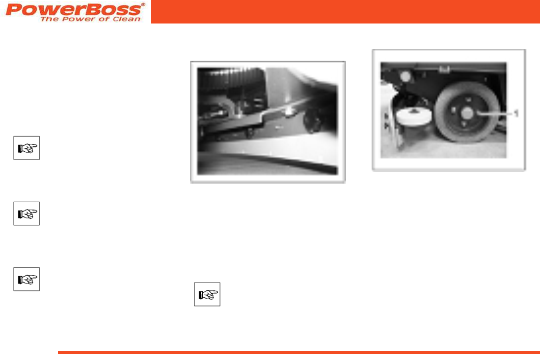
PowerBoss, Inc. Copyright 2010
Admiral 38C Scrubber PB# 4100055UM Rev.* 08/10
Page 82
Maintenance and Service
5.8.4 Changing the sealing strips
The sealing strips can be changed without
the need for tools:
1. Disassemble the squeegee, refer to
Section 5.8.2
2. Unscrew the knurled nuts (Fig. 34/7).
3. Remove the clamping rail, support strip
and sealing strip (Fig. 34/4-6).
Both sides of the sealing strip can
be used.
4. Install the new or reversed sealing
strips in the reverse working sequence.
Pay attention that both sealing
strips (front and rear) touch the
oor when mounted.
5. Tighten the knurled nuts evenly, start-
ing from the center and working on
alternate sides.
There must be no bends in the
sealing strip.
Disassemble the front sealing strip (Fig.
35) in the same way.
Fig 35
5.9 Wheels
5.9.1 Front wheel
In the case of problems with the front
wheel, please contact an authorized Pow-
erBoss service center.
The front wheel may only be
changed at an authorized Power-
Boss service center.
5.9.2 Rear wheels
Fig 36
• The wheel nuts on the rear wheels
(Fig. 36/1) must be subject to their rst
check after 100 operating hours and
subsequently every 200 hours.
Admiral 38C Scrubber PB# 4100055UM Rev.* 08/10
PowerBoss, Inc. Copyright 2010
Page 83
Maintenance and Service
The tightening torque for the
wheel nuts (Fig. 36/1) is 140 Nm.
Changing the rear wheels
• To change the rear wheels, the Admiral
38C must be jacked up on the right or
left side.
• The contact points for the jack (lifting
force: 2.0 t) are on the vehicle frame in
front of the rear wheels.
Removing the rear wheels
• Remove the wheel nuts (Fig. 36/1).
• Remove the wheel.
Mounting the rear wheels
• Install the wheel in place.
• Screw on and tighten the wheel nuts
(Fig. 36/1).
5.10 Electrical installation
5.10.1 Red control lamps
Refer to Section 3.2.2.
5.10.2 Error codes
Refer to Sections 3.5.1 and 3.2.2.
5.10.3 Fuses
The fuses are located in the electronic
system underneath the seat console. Take
hold of the seat console by the handle and
pivot it up.
Always disconnect the battery
plug before starting any work on
the electrical installations.
All the lifting elements and brush motors in
the Admiral 38C are equipped with safety
fuses and electronic fuses.
Safety fuses are installed in:
• The suction turbines (35A high current
fuse)
• The water pump and relief valve for the
water supply (10A plug-in fuse)
• The hydraulic motor (160A current
limiter in the drive control) and
• The working lights and ashing beacon,
the key switch and horn (10 A plug-in
fuse (F51)).
When these fuses blow, the
vehicle is out of operation. This is
not indicated by an alarm signal
on the operating panel!
5.10.4 Drive control relay
The drive control is located in the left hand
part of the driver’s cab underneath the foot
plate.
Always disconnect the battery
plug before starting any work on
the electrical installations.
• Loosen the screws in the foot plate and
remove the foot plate.
• Relay K3 (main contactor) is mounted
in front of the drive control.
• Replace a defect relay with a new one.
• Replace the foot plate and x by means
of the screws.
PowerBoss, Inc. Copyright 2010
Admiral 38C Scrubber PB# 4100055UM Rev.* 08/10
Page 84
Maintenance and Service
5.11 Cleaning the vehicle
• Clean the vehicle on a weekly basis,
refer to Section 5.3.1.
• Park the vehicle in an appropriate
washing area.
Observe the applicable laws and
local regulations when dispos-
ing of water containing cleaning
agents and dirt!
• Switch the vehicle off and remove the
key.
• The vehicle may only be cleaned using
a water hose (operating pressure ap-
prox. 5 to 6 bar) and only from top to
bottom.
It is not permitted to clean the
vehicle with a pressure washer or
steam blaster.
• Do not aim the jet of water directly at
openings, slits, electronic components,
operating panels or seals.
• It is not permitted to use aggressive
and corrosive cleaning agents.
• Allow the vehicle to dry after cleaning.
It is preferable to allow the vehicle to
dry over a longer period of time, e.g.
the weekend.
5.12 Transporting and towing
Loading
Check the load bearing capacity
of the loading platform prior to
loading.
• Dead weight of the Admiral 38C without
battery, without options and without
driver: 1561 lbs
• Total weight of the Admiral 38C with
battery and lled solution tank, with
cab safety roof and side scrubbing unit,
without driver: 2919 lbs
• When loading onto a truck or some-
thing similar by means of a loading
ramp, the ramp angle must not exceed
20%.
• The squeegee and brush head must be
raised.
Transporting the vehicle
• When transporting the vehicle us-
ing lifting gear to the site of use, the
squeegee and rotary brush head must
be raised.
• When the vehicle is to be transported
on another vehicle or trailer, it must be
secured against rolling away. Lash the
vehicle down securely.
• There are attachment points for this on
the left as well as on the right: At the
rear on the frame and at the sides near
the entry point.
• The attachment points are bolts (Fig.
37/1+2) which can be pulled out from
the sides of the frame. The bolts are
locked in their projecting position by
turning them.
• The bolts also serve for loading by a
crane.
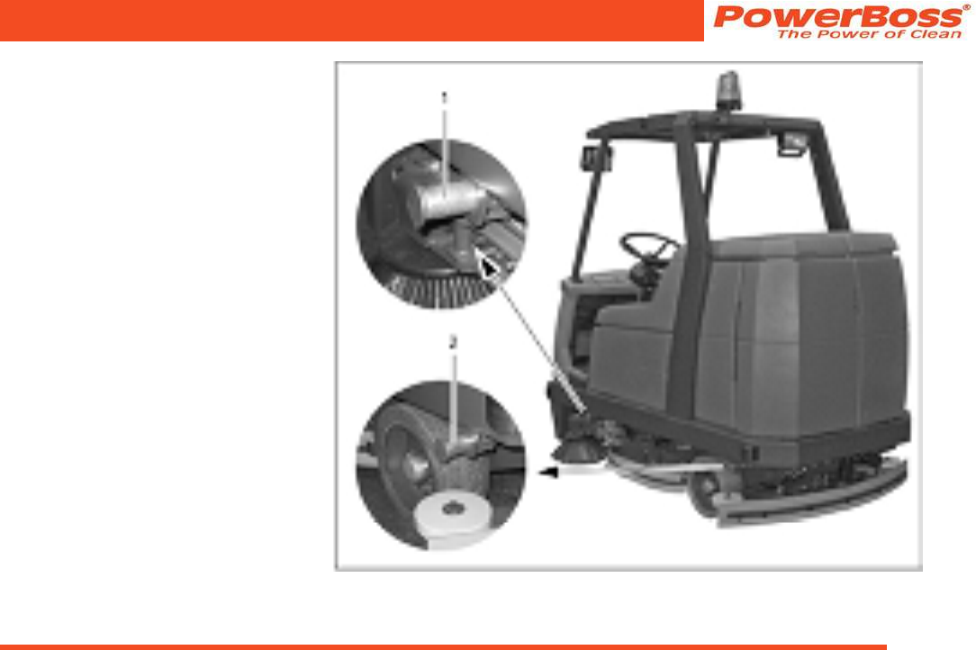
Admiral 38C Scrubber PB# 4100055UM Rev.* 08/10
PowerBoss, Inc. Copyright 2010
Page 85
Maintenance and Service
Towing the vehicle
If it should become necessary to tow the
Admiral 38C, only do it on a level oor and
at a maximum towing speed of 4 kph. The
tow rope must be attached at the front
lashing points.
Fig 37

PowerBoss, Inc. Copyright 2010
Admiral 38C Scrubber PB# 4100055UM Rev.* 08/10
Page 86
6 WARRANTY
Revision F
Effective November 1, 2008
PowerBoss Made Simple Industrial Limited Warranty
Minuteman International owner of PowerBoss warrants to the original purchaser/user that the product is free from defects in workmanship and materials
under normal use. PowerBoss will, at its option, repair or replace without charge, parts that fail under normal use and service when operated and maintained
in accordance with the applicable operation and instruction manuals. All warranty claims must be submitted through and approved by factory authorized
repair stations.
This warranty does not apply to normal wear, or to items whose life is dependent on their use and care. Parts not manufactured by PowerBoss are covered by and subject to
the warranties and/or guarantees of their manufacturers. Please contact Minuteman International for procedures in warranty claims against these manufacturers.
Special warning to purchaser -- Use of replacement parts not manufactured by PowerBoss or its designated licensees, will void all warranties expressed or
implied. A potential health hazard exits without original equipment replacement.
All warranted items become the sole property of Minuteman International or PowerBoss or its original manufacturer, whichever the case may be.
PowerBoss disclaims any implied warranty, including the warranty of merchantability and the warranty of fitness for a particular purpose. PowerBoss
assumes no responsibility for any special, incidental or consequential damages.
This limited warranty is applicable only in the U.S.A. and Canada, and is extended only to the original user/purchaser of this product. Customers outside the
U.S.A. and Canada should contact their local distributor for export warranty policies. PowerBoss is not responsible for costs or repairs performed by persons
other than those specifically authorized by PowerBoss. This warranty does not apply to damage from transportation, alterations by unauthorized persons,
misuse or abuse of the equipment, use of non-compatible chemicals, or damage to property, or loss of income due to malfunctions of the product. If a
difficulty develops with this machine, you should contact the dealer from whom it was purchased.
This warranty gives you specific legal rights, and you may have other rights, which vary from state to state. Some states do not allow the exclusion or
limitation of special, incidental or consequential damages, or limitations on how long an implied warranty lasts, so the above exclusions and limitations may
not apply to you.
Travel* Labor Parts Engine Extended Warranty Costs
Walk behinds
Battery sweepers Ninety days One year One year N/A 2 years Parts + Labor (or 2000 Hours)
2%
IC sweepers Ninety days One year One year Through manufacturer 2 years Parts + Labor (or 2000 Hours)
2%
Battery scrubbers Ninety days Two years Three years N/A 3 Years Parts + Labor (or 3000 Hours)
2%
Riders
Battery scrubbers Ninety days Two years Three years/2000 hrs N/A 3 Years Parts + Labor (or 3000 Hours)
2%
IC sweeper/scrubbers Ninety days Six months Two years/2000 hrs Two years/3000 hrs** 2 years Parts + Labor (or 2000 Hours)
3%
IC sweepers Ninety days Six months Four years/3000 hrs Five years/3000 hrs**
Exceptions
Apex series sweeper Ninety days One year One year/1000 hrs One year/1000 hrs** 2 years Parts + Labor (or 2000 Hours)
3%
6X sweeper Ninety days Six months Two years/2000 hrs Two years/2000 hours** 2 years Parts + Labor (or 2000 Hours)
3%
4 Years Parts + 2 Years Labor (or 4000
Hours)
3%
Tank Bladders Eight years/ no additional labor
Polypropylene plastic tanks Ten years/ no additional labor
Batteries 0-3 months full replacement, 4-12 prorated credit
Chargers One-year replacement
Replacement parts Ninety days
*Two-hour cap
**Through engine manufacturer. See section 3 of warranty manual for engine warranty exceptions
*** Based upon dealer’s certification status
Extended Warranty MUST be signed up within 30 days of delivery to End User (Dealer has 1Year from Receiving Machine to Sign up extended Warranty)
Extended Warranty Cost is based on Invoice Price multiplied by the Percentage listed in the Extended Warranty Column
All above labor and travel reimbursed at 65 or 75% of the published shop rate.
WARRANTY
Admiral 38C Scrubber PB# 4100055UM Rev.* 08/10
PowerBoss, Inc. Copyright 2010
Page 87
Revision F
Effective November 1, 2008
PowerBoss Made Simple Industrial Limited Warranty
Minuteman International owner of PowerBoss warrants to the original purchaser/user that the product is free from defects in workmanship and materials
under normal use. PowerBoss will, at its option, repair or replace without charge, parts that fail under normal use and service when operated and maintained
in accordance with the applicable operation and instruction manuals. All warranty claims must be submitted through and approved by factory authorized
repair stations.
This warranty does not apply to normal wear, or to items whose life is dependent on their use and care. Parts not manufactured by PowerBoss are covered by and subject to
the warranties and/or guarantees of their manufacturers. Please contact Minuteman International for procedures in warranty claims against these manufacturers.
Special warning to purchaser -- Use of replacement parts not manufactured by PowerBoss or its designated licensees, will void all warranties expressed or
implied. A potential health hazard exits without original equipment replacement.
All warranted items become the sole property of Minuteman International or PowerBoss or its original manufacturer, whichever the case may be.
PowerBoss disclaims any implied warranty, including the warranty of merchantability and the warranty of fitness for a particular purpose. PowerBoss
assumes no responsibility for any special, incidental or consequential damages.
This limited warranty is applicable only in the U.S.A. and Canada, and is extended only to the original user/purchaser of this product. Customers outside the
U.S.A. and Canada should contact their local distributor for export warranty policies. PowerBoss is not responsible for costs or repairs performed by persons
other than those specifically authorized by PowerBoss. This warranty does not apply to damage from transportation, alterations by unauthorized persons,
misuse or abuse of the equipment, use of non-compatible chemicals, or damage to property, or loss of income due to malfunctions of the product. If a
difficulty develops with this machine, you should contact the dealer from whom it was purchased.
This warranty gives you specific legal rights, and you may have other rights, which vary from state to state. Some states do not allow the exclusion or
limitation of special, incidental or consequential damages, or limitations on how long an implied warranty lasts, so the above exclusions and limitations may
not apply to you.
Travel* Labor Parts Engine Extended Warranty Costs
Walk behinds
Battery sweepers Ninety days One year One year N/A 2 years Parts + Labor (or 2000 Hours)
2%
IC sweepers Ninety days One year One year Through manufacturer 2 years Parts + Labor (or 2000 Hours)
2%
Battery scrubbers Ninety days Two years Three years N/A 3 Years Parts + Labor (or 3000 Hours)
2%
Riders
Battery scrubbers Ninety days Two years Three years/2000 hrs N/A 3 Years Parts + Labor (or 3000 Hours)
2%
IC sweeper/scrubbers Ninety days Six months Two years/2000 hrs Two years/3000 hrs** 2 years Parts + Labor (or 2000 Hours)
3%
IC sweepers Ninety days Six months Four years/3000 hrs Five years/3000 hrs**
Exceptions
Apex series sweeper Ninety days One year One year/1000 hrs One year/1000 hrs** 2 years Parts + Labor (or 2000 Hours)
3%
6X sweeper Ninety days Six months Two years/2000 hrs Two years/2000 hours** 2 years Parts + Labor (or 2000 Hours)
3%
4 Years Parts + 2 Years Labor (or 4000
Hours)
3%
Tank Bladders Eight years/ no additional labor
Polypropylene plastic tanks Ten years/ no additional labor
Batteries 0-3 months full replacement, 4-12 prorated credit
Chargers One-year replacement
Replacement parts Ninety days
*Two-hour cap
**Through engine manufacturer. See section 3 of warranty manual for engine warranty exceptions
*** Based upon dealer’s certification status
Extended Warranty MUST be signed up within 30 days of delivery to End User (Dealer has 1Year from Receiving Machine to Sign up extended Warranty)
Extended Warranty Cost is based on Invoice Price multiplied by the Percentage listed in the Extended Warranty Column
All above labor and travel reimbursed at 65 or 75% of the published shop rate.
WARRANTY

“The Power of Clean”
PowerBoss Is A Full Line Manufacturer Of Sweepers and Scrubbers For
Industrial Facilities.
PowerBoss,Inc 175 Anderson Street P.O. Box 1227- Aberdeen North Carolina 28315
Phone: 800-982-7141 - Fax: 1-800-277-7141 Local: 910-944-2105 Fax: 910-944-7409 e-mail:techsupport@powerboss.com
A Member Of The Hako Group
