Sweepscrub Powr Flite Pfx3S Carpet Extractor Operators Manual User
Powr-Flite-Pfx3S-Carpet-Extractor-Operators-Manual powr-flite-pfx3s-carpet-extractor-operators-manual powr-flite-pfx3s-carpet-extractor-operators-manual 2486 file product_file sweepscrub
2017-11-05
User Manual: Sweepscrub Powr-Flite-Pfx3S-Carpet-Extractor-Operators-Manual powr-flite-pfx3s-carpet-extractor-operators-manual 2485 file product_file sweepscrub
Open the PDF directly: View PDF ![]() .
.
Page Count: 10
OPERATOR’S MANUAL & PARTS LIST
WARNING: OPERATOR MUST READ AND UNDERSTAND THIS MANUAL
COMPLETELY BEFORE OPERATING THIS EQUIPMENT.
©Tacony, Inc., All rights reserved
Save These Instructions
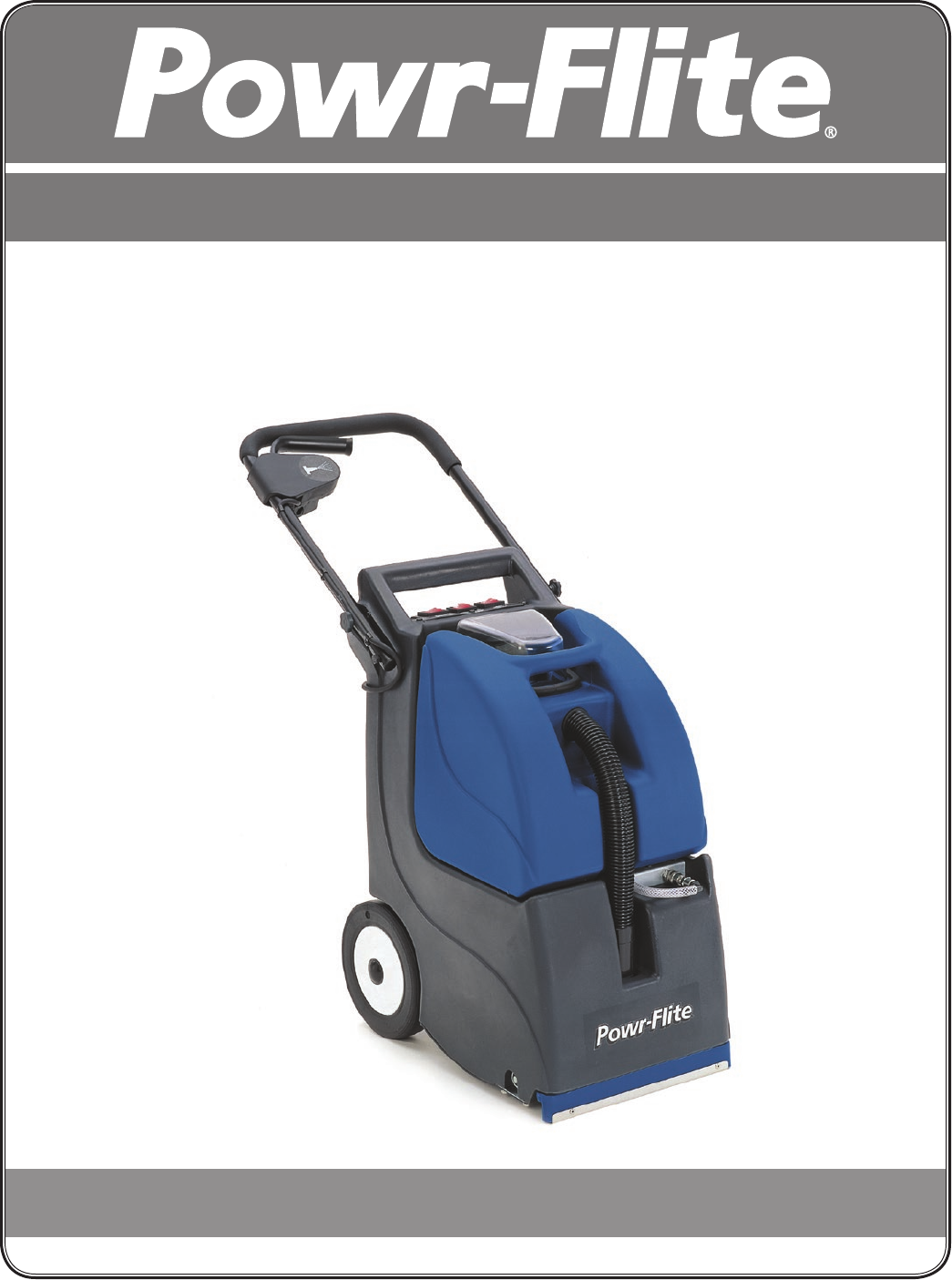
Self-Contained Carpet Extractor
Model PFX3S
X8490 PFX3S-Man 2/2016

2
READ ALL INSTRUCTIONS BEFORE USING!
CARE OF THIS SELF-CONTAINED EXTRACTOR
Treat this unit as you would any other high grade precision
made product. Dropping, unreasonable bumping across
thresholds and other misuses may result in a damaged
unit which will not be covered by warranty. When not in
use, power cord should be wrapped around handle for
storage.
Read this manual completely before operating this
extractor. It is important to follow instructions in this
manual to prevent the possibility of injury or damage to the
user and/or machine.
Congratulations on purchasing a Powr-Flite self-contained
extractor. Given proper care, this product will afford
you many years of trouble-free operation. All parts
have passed rigid quality control standards before being
assembled to produce the finished product.
Prior to packaging, the extractor is again inspected for
assurance of flawless assembly. This unit is protectively
packed to prevent damage in shipment. We recommend
removal and inspection of unit upon delivery for possible
damage in transit. Only a visual examination will reveal
damage that may have occurred.
If damage is discovered, immediately notify the
transportation company that delivered your extractor. As
a shipper, we are unable to report claims for concealed
damage. You must originate any claim within 5 days of
delivery.
This manual is for your protection and information.
PLEASE READ CAREFULLY since failure to follow
precautions could result in discomfort or injury. When
using electrical equipment, basic safety precautions should
always be followed.
TABLE OF CONTENTS
INTRODUCTION ..................................................... 2
SAFETY PRECAUTIONS (English) .............................. 3
SAFETY PRECAUTIONS (Spanish) (French)................ 4-5
GROUNDING INSTRUCTIONS ................................ 6
GENERAL INSTRUCTIONS ....................................... 7-8
Pre-operation Checks .................................... 7
Machine Operation ...................................... 7
Storage ........................................................ 8
Routine Care & Maintenance ........................ 8
ILLUSTRATED PARTS LIST ......................................... 9-10
MAINTENANCE GUIDE........................................... 11

3
IMPORTANT SAFETY PRECAUTIONS
WARNING!: To reduce the risk of fire, electric shock, or injury
When using this self contained extractor, basic precautions
should always be followed, including the following:
1. DO NOT leave unit when plugged in. Unplug from
outlet when not in use and before servicing.
2. DO NOT allow unit to be used as a toy. Close
attention is necessary when used around or near
children.
3. Use only as described in this manual. Use only
manufacturer’s recommended attachments.
4. DO NOT use with damaged cord or plug. If unit is
not working properly because it has been dropped,
dropped into water, left outdoors, or damaged in any
way, contact a service center of Powr-Flite®.
5. DO NOT pull or carry by cord, use cord as a handle,
close door on cord, or pull cord around sharp edges
or corners. DO NOT run unit over cord. Keep cord
away from heated surfaces.
6. DO NOT unplug by pulling on cord. To unplug, grasp
the plug, not the cord.
7. DO NOT handle plug or appliance with wet hands.
8. DO NOT put any objects into openings. DO NOT use
with any opening blocked: keep free of dust, lint, hair,
or anything that may reduce air flow.
9. Keep hair, loose clothing, fingers, and all parts of body
away from openings and moving parts.
10. DO NOT pick up anything that is smoking or
burning such as cigarettes, matches, or hot ashes.
11. DO NOT use to pick up hazardous chemicals.
12. Turn off all controls before unplugging.
13. Turn unit off immediately if foam or liquid comes from
machine exhaust. Empy & clean out recovery (dirty)
tank and use defoamer to correct the problem.
14. DO NOT use to pick up flammable or combustible
liquids such as gasoline or use in areas where they
may be present.
15. DO NOT use where oxygen or anesthetics are used.
16. DO NOT use an extension cord unless absolutely
necessary. If an extension cord is used, then wire
size must be #14 or larger and should not exceed
25 ft. in length. Extension cord must be a three-wire
type to insure grounding protection.
17. Replace damaged or worn parts immediately with
genuine original equipment parts to maintain safety.
18. This unit must be connected to a properly grounded
outlet only. See grounding instruction.
WARNING
To avoid fire, DO NOT
use with a flammable
or combustible liquid to
clean floor.
WARNING
To avoid electric shock,
DO NOT expose to rain.
Store Indoors.
4
5
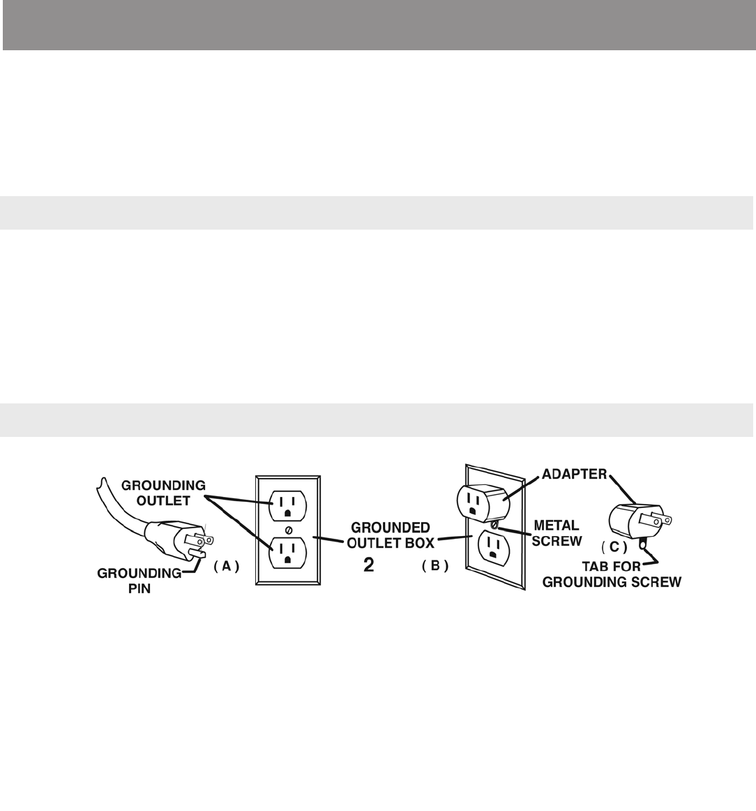
GROUNDING INSTRUCTIONS
DANGER:
Improper use of the grounding plug can result
in a risk of electric shock.
This self-contained extractor must be properly grounded. If
it should malfunction or breakdown, grounding provides a
path of least resistance for electrical current to reduce the
risk of electric shock. This machine is equipped with a cord
having an equipment-grounding conductor and grounding
plug. The plug must be inserted into an appropriate outlet
that is properly installed and grounded in accordance with
all local codes and ordinances. If repair or replacement
of the cord or plug is necessary, DO NOT connect the
grounding wire to either flat blade terminal. The wire with
insulation having an outer surface that is green with or
without stripes is the grounding wire.
This unit is for use on a nominal 120 volt circuit, and
has a grounded plug that looks like the plug illustrated in
(Fig. A). A temporary adapter that looks like the adapter
illustrated in (Fig. B&C) may be used to connect the plug
to a 2-pole receptacle as shown in (Fig. B) if a properly
grounded outlet is not available.
The temporary adapter should be used only until a
properly grounded outlet (Fig. A) can be installed by a
qualified electrician. The green color rigid ear, lug, or the
like extending from the adapter must be connected to a
permanent ground such as a properly grounded outlet box
cover. Whenever the adapter is used, it must be held in
place by a metal screw.
NOTE: In Canada, the use of a temporary adapter is not permitted by the Canadian Electrical Code.
WARNING!
Improper connection of the equipment-grounding conductor can result in a risk of electric
shock. Check with a qualified electrician or service person if you are in doubt as to
whether the outlet is properly grounded.
DO NOT modify the plug provided with the appliance. If it will not fit the outlet, have a
proper outlet installed by a qualified electrician.
GROUNDING METHODS
GROUNDING INSTRUCTIONS
6
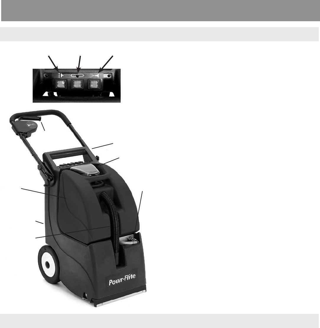
SOLUTION
SWITCH
VACUUM
SWITCH BRUSH
SWITCH
FIG. 1C
1. Prepare room for cleaning, moving furniture as need to
provide a clear working area. Cover bottoms of furniture
legs where possible. (Aluminum foil or foam blocks are
ideal for this purpose.) Pin up curtains and drapes.
2. Gather cleaning supplies: a clean, suitable sized bucket,
carpet cleaning solution, and pretreat solutions for heavily
soiled traffic areas such as Powr-Flite’s Fast Lane.
3. Disconnect vacuum hose from recovery tank and lift the
RECOVERY TANK off of the SOLUTION TANK.
4. Measure carpet cleaning solution, per manufacturers
recommended ratio, into the SOLUTION TANK and fill
with hot water. DO NOT use the RECOVERY TANK to fill
the SOLUTION TANK. Debris remaining in the tank could
damage the pump or block the jet. WARNING: DO NOT
exceed water temperature of 150º (65º C).
5. Replace RECOVERY TANK on machine. Add defoamer
solution, per manufacturer’s instructions as needed, in
RECOVERY TANK.
6. Replace the transparent cover on the RECOVERY
TANK and connect the vacuum hose to the front of the
RECOVERY TANK.
7. Pre-treat heavily soiled carpet areas as required.
PRE-OPERATION INSTRUCTIONS for PFX3S
NOTE - FOR COLOR FASTNESS: Before using carpet
cleaning chemicals, test on an inconspicuous part of the
carpet for color fastness. Place the solution on a small piece
of clean white cloth or tissue. Rub the carpet area vigorously
with the cleaning chemical. Excessive amounts of dye
showing on the material would indicate that the colors are not
colorfast, and should not be wet cleaned.
RECOVERY
(WASTE)
TANK
SOLUTION
(CLEAN WATER)
TANK
CARRYING
HANDLE
TANK COVER
& HANDLE
VACUUM HOSE
SOLUTION
HOSE
SOLUTION
LEVER
FIG. 1A
OPERATION OF SELF-CONTAINED CARPET CLEANER
1. Plug the power cord into an outlet. WARNING: This machine must be properly grounded. See Grounding
Instructions on page 4 for additional information.
2. Press the VACUUM switch “on” and the BRUSH switch to the “right” position. See FIG C for a diagram on
operational switches.
3. To clean the carpet, squeeze and hold the SOLUTION LEVER (FIG A) to apply the cleaning solution, pulling the
machine backwards at the same time. Stop spraying the solution approximately 12 inches (30 cm) before the
end of your pass, so that the extractor will vacuum up all of the solution. Slightly overlap the next cleaning pass
to prevent streaking. To avoid overwetting, it is recommended that a maximum of only two wet passes (spraying
solution) be done. One dry pass without spraying solution will also aid in drying time. After a few passes, check
the RECOVERY TANK to verify that no foam is present. Add extra defoamer if necessary.
4. Empty the RECOVERY TANK when it is approximately 3/4 full. Do not refill the SOLUTION TANK without emptying
all of the contents of the RECOVERY TANK first.
GENERAL INSTRUCTIONS
7
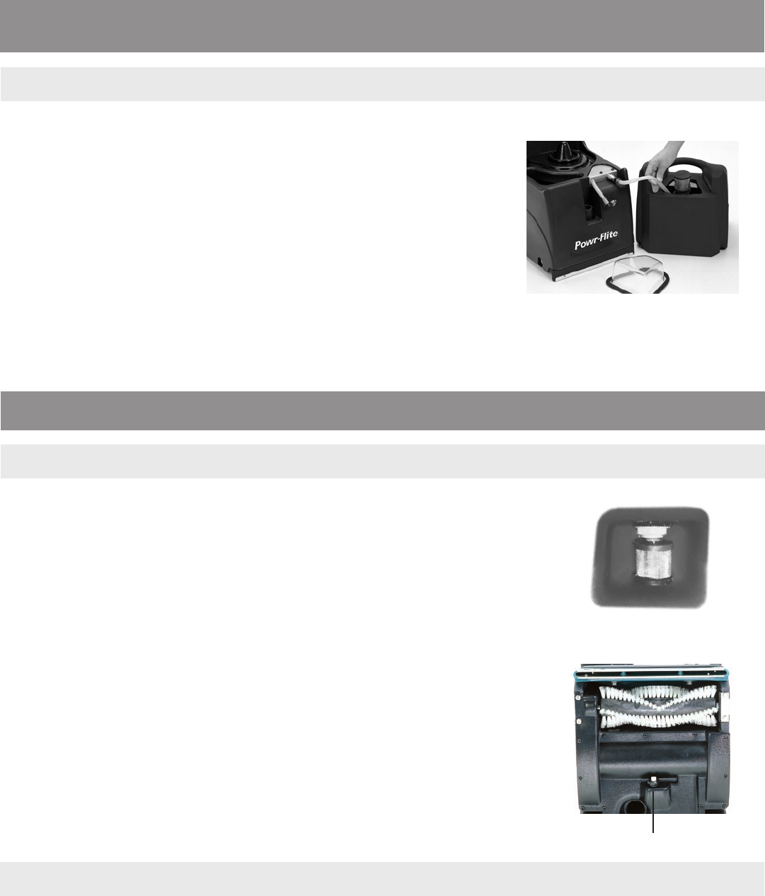
1. The filter in the solution tank (FIG 3) should be kept clean. It can be removed if
necessary. A damaged filter should be replaced, otherwise blockages and/or
damage to the pump head and spray jet can occur.
2. Check the spray jet (FIG 4) for blockage and a uniform spray pattern. Remove jet
and blow through to clean. Do not use a pin or other sharp objects as this may
cause damage to the jet.
3. Check and remove any debris or lint build-up from the vacuum head, brush, and
brush housing.
4. Always wash out the tanks with clean water after use. To do this, pour clean
water into the solution tank and spray through spray tip to clear chemical residue
from the pump, lines, and spray tip. Allow the vacuum to run for a few minutes
after use to aid the machine in drying out and to help prevent bacteria and
odors.
5. Wash out mesh filter in RECOVERY TANK of dirt and carpet fibers after dumping
waste from recovery tank. Failure to clean filter may cause damage to vacuum
motor.
1. Inspect hoses (unseen blockages sometimes occur), hose cuffs, and the rubber seal on the recovery tank lid. The main
cable, plug, and switches should also be examined for damage.
NOTE: It is advisable to store the unit with the recovery tank lid removed.
CAUTION: THIS UNIT MUST BE PROTECTED FROM FREEZING. Damage from freezing could cause machine to malfunction.
ROUTINE MAINTENANCE INSTRUCTIONS
STORAGE
DAILY / INTERVAL
WEEKLY
WHEN CLEANING IS FINISHED:
1. Disconnect the SOLUTION HOSE on the front of the machine by pushing in on
the ring of the solution fitting.
2. Connect the drain hose (clipped to the back) to the SOLUTION HOSE fitting
and place the other end into the RECOVERY TANK. Press the SOLUTION
switch to the “right” position. This will activate the motor to pump any
remaining solution into the RECOVERY TANK for easy drainage.
3. When all of the solution is pumped from the SOLUTION TANK, turn the
SOLUTION switch off, remove the power plug from the outlet and empty the
RECOVERY TANK. Leave the RECOVERY TANK open when storing.
4. Disconnect the DRAIN HOSE by pushing in on the ring of the SOLUTION
HOSE fitting. Replace the DRAIN HOSE in the clip on the back of the machine,
and re-connect the SOLUTION HOSE.
FIG. 2
FIG. 3
FIG. 4
SOLUTION SPRAY JET
GENERAL INSTRUCTIONS

8
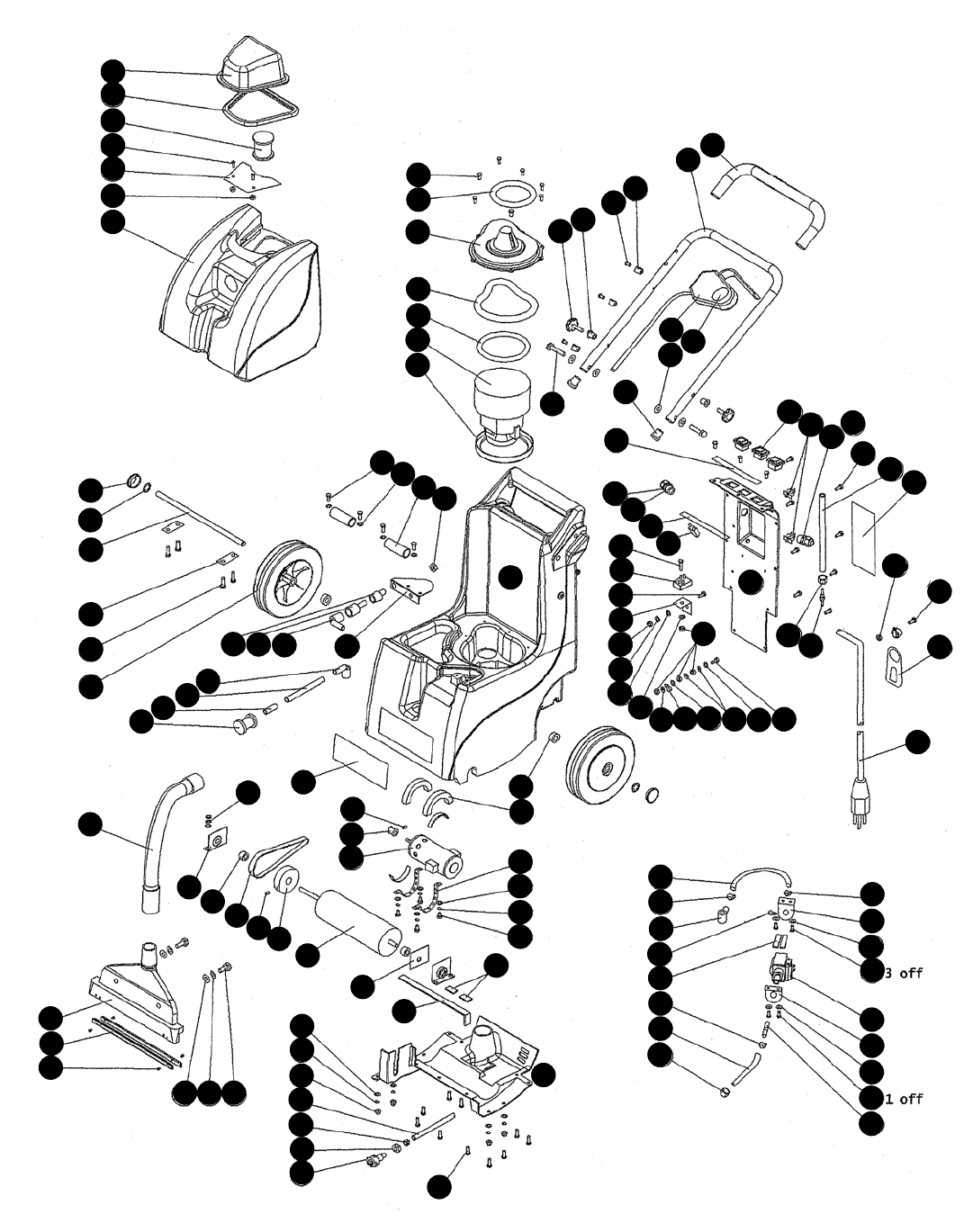
SELF-CONTAINED EXTRACTOR PFX3S PARTS
ref # order # description
I SC276 Silicon hose
2 SC339 Wheel with Cap (Complete)
3 SC340 Starlock washer
4 2-3124 Wheel Cap (Spares Only)
6 SC301 Cable restraint
7 2-3417 Nylon Washer
8 SC302 1/4” Elbow Barb Black (P B.)
9 SC231 1/8” male barb
10 SC303 Bulkhd coupling Metal
11 SC304 Female coupling Metal
12 SC305 drain hose conn. Male
13 SC306 Spray Nozzle
14 SC307 Spray Nozzle Retaining nut
15 SC308 Motor Pulley
16 SC334 Brush Pulley
17 SC309 Brush Drive Belt
18 SC310 1/4” BSPT Metal Elbow Male
19 2-3457* Tube End Cap
20 SC336 Handle Grip
21 SC311 Handle lock knob
22 SC312 Vac pick-up hose
23 SC313 Nylon Brush Spacer 5~3/ 3
24 02-3478-0000 Purnp Out Hose Clips
25 SC275 1/4” BSPT Grey Elbow Male
26 3-5589 Wheel spacer
27 SC314 Bearing Housing
28 SC315 Back Electrical Cover
29 SC316 Vac motor cover
30 SC317 Vac Lid
31 SC318 Bottom cover
32 3-5991* Axle retain brackets
33 SC341 Fluid Coupling Bracket
34 SC319 Brush Body
35 SC320 Handle
36 SC147 Pick up Strip
37 SC335 Filter element-waste tank
38 3-6000* Axle
39 3-6001* Rectifier heat sink
40 TW091052* Powr-Flite Label
41 SC131 Gasket Strip (Bck + bot cvrs + Pum-
42 3-6010* Gasket bot 10 mm pads
43 3-6011* Champ Compact Sprayjet Label
44 3-6012* Champ Compact Pictorial Label
45 SC154 Solution Tank
46 SC321 Kecovery Tank
47 3-6015 Pick-up
48 SC342 Silicone Tube Tank Spacer
49 3-6018* Switch Label
50 SC322 Bearing protector seal
51 SC323 Vac Lid Seal
52 SC212 Water path deflector plate
53 SC214 Brush Motor Clamp Strip
54 3-6033* Motor Spacer
55 4-286* P clip
56 SC324 Handle Switch
57 SC325 BrushMotor (110 volt Version)
ref # order # description
58 19020S Vac Motor (110 volt Version)
59 SC327 Switch with cover
60 FJ5082 Solenoid Pump (110 volt Version)
61 SC329 Cut Out (110 volt Version)
62 4-3212* Cable gland
63 4-3213* Cable gland back nut
65 SC330 Motor cover seal (egg)
66 SC130 Vac Motor lip seal
69 SC333 Filter Element
70 SC337 Vac seal bottom
71 SC331 Vac seal top
72 SC12 Rectifier (brush Motor)
73 SC20 red nylon tube
74 M1400E Powr-Flite Cordset
75 TW023055* P-clip (internal)
76 SC98 6 mm bore hose
77 SC144 Jubilee clip
78 PX42 O-Clip Steel
FASTENERS
90 2-3032* Nylon Screw
91 M5-R-ZN* M5 Shakeproof Washers for Bondin
92 SC137 M6 Spring Washers Stainless
93 2-3463* Stainless Rivets
94 2-3464* Screw for p clip
95 FD66 Roto small tapper
96 2-3466 Roto intermediate tapper
97 SC347 Roto large tapper
98 SC225 Housing Domenut
99 SC116 M6 Handle Insert
100 SC132 Brush Pulley Grub screw
101 SC132 Motor Pulley Grub screw
102 M4-I-ZN* Nut for Nylon screw
103 M5-16-BP-SS* Deflector plate bolt -csk
104 M5-16-CP-ZN* Cable restraint bolt
105 M5-20-CP-ZN* Rectifier bolt
106 M5-25-CP-ZN* Earth Bonding Screw
107 M5-I-ZN* Rectifier nut
108 M5-LN-SS* Deflector plate nut
109 M5-l-ZN* Cable restraint nut
110 SC226 Housing washer
111 SC266 Rectifier washer
112 7CL003 Housing spring washer
113 M5-OHG-ZN* Earth Bonding Screw Washers
114 M5-P-ZN* Rectifier spring washer
115 PAS167 Pick-Up Bolt
116 SC338 Handle Pivot Bolt
117 SC136 M6 Motor Mounting Screws
118 7CM003 M6 Motor Mounting Washers
119 M8-OHG-SS* M8 Pick-Up Mounting Washers
120 X8217 M8 Shakeproof Washer for Pick-Up
121 M4-OLG-ZN* M4 Rectifler Washer
122 M4-P-ZN* M4 Rectif1er Spring Washer
123 2-3485* M5 Black Plastic Washer
NOT ILLUSTRATED
PFX3S-KNS tool kit
SC139 solution hose end, tool end
SC145 solution hose end, machine end
SC150 vacuum and solution hose assembly
SC151 hose bag
SC153 hand tool
SC158 spray tip for hand tool
PX48 brass bulk head, through tank
72274A washer for PX48
*call for pricing and availability of all referenced parts
9
SELF-CONTAINED EXTRACTOR PFX3S PARTS
Self-Contained Extractor Parts - PFX3S
14
13
15
16
17
18
19
20
22
21
23
24
25
26
27
28
30
29
31
32
33
34
35
36
38
37
39
40
41
42
43
41
44
41
46
45
47
48
49
50
51
52
54
53
55
56
55
57
58
59
60
60
60
21
3
4
6
7
8
10
10
9
11 12
62
61
63
62
63
65
66
70
69
71
72
73
74
75
76
78
76
76
77 77
77
77
76
78
90
91
91
95
92
94
96
95
93
95
96
95
97
98
99
104
101
102
103
100
105
106
110
110
110
112
113
113
114
115
121
122
119 120
107
108
123
109
110
116
117
118

A Tacony Company
3101 Wichita Court • Ft. Worth, TX 76140-1755
1-800-880-2913 • Fax: 1-817-551-0719 • www.Powr-Flite.com
SAVE THESE INSTRUCTIONS
MAINTENANCE GUIDE
WARRANTY
The manufacturer warrants to the original purchaser that products manufactured are free from
defects of workmanship and material, provided such goods are installed, operated and maintained in
accordance with written manuals or other instructions for a period of 1 year from date of purchase on
parts and workmanship. In case you as our customer, meet any trouble with your machine, contact
your Powr-Flite® representative who will be happy to be of service to you and will take care of the
warranty settlement.
NOTE: Alterations and changes made to the machine without written approval of the
manufacturer and use of unapproved spare parts will not be covered by warranty.
Motors not running
CAUSE: SOLUTION:
1. Power not reaching main switch. 1. Check power supply. Check fuses/circuit
breaker. Contact service center.
2. Defective power cord. 2. Contact manufacturer or service center.
3. Faulty switches or wiring. 3. Contact manufacturer or service center.
4 . Blown fuse or tripped circuit breaker. 4. Reset circuit breaker according to operating
instructions or replace fuse if qualified..
5. Problem with brushes, field windings, 5. Repair or replace defective part.
or armatures. (vacuum or brush motor)
6. Reset switch on back. 6. Push reset switch.
Loss of vacuum suction
CAUSE: SOLUTION:
1. Vacuum head blocked. 1. Visually inspect and clear blockage.
2. Hoses blocked. 2. Visually inspect and clear blockage.
3. Recovery tank not sealed properly. 3. Check tank for damage or adjust
for proper fit.
Brush not functioning properly
CAUSE: SOLUTION:
1. Belt broken. 1. Replace belt.
2. Brush jammed. 2. Visually inspect and clear blockage.
3. Brush pulley broken. 3. Replace pulley.
Spray jet not functioning properly
CAUSE: SOLUTION:
1. Jet blocked 1. Visually inspect and clean according to
operating instructions.
2. Solution filter blocked. 2. Visually inspect and clean according to
operating instructions.
