8200 / 8210 Service Manual Tennant Rider Floor Sweeper Scrubber
2018-06-13
: Sweepscrub Tennant-8200-8210-Rider-Floor-Sweeper-Scrubber-Service-Manual tennant-8200-8210-rider-floor-sweeper-scrubber-service-manual 2755 file product_file
Open the PDF directly: View PDF ![]() .
.
Page Count: 634 [warning: Documents this large are best viewed by clicking the View PDF Link!]
330065
Rev. 03 (3--02)
Service Manual
8200/8210
Gas/LP/Diesel
*330065*

This service manual is intended to be an aid for the disassembly and reassembly of your TENNANT
Model 8200/8210 sweeper/scrubber.
The set is organized into 8 major groups: General Information, Chassis, Sweeping, Scrubbing, Electrical,
Hydraulics, Engine--G/LP, and Engine--D.
General Information: Safety precautions, machine transport, machine jacking, machine storage, chassis
lubrication, machine specifications, and machine maintenance chart.
Chassis: Tire/wheel replacement, brake adjustment and replacement, steering adjustment and
replacement, and machine cab information.
Sweeping: Hopper repair/replacement, brush repair/replacement, skirt/seal repair/replacement, and
sweeping troubleshooting.
Scrubbing: Scrub head repair/replacement, brush repair/replacement, skirt/seal repair/replacement,
squeegee repair/replacement, solution and recovery tank repair/replacement, and scrubbing
troubleshooting.
Electrical: Battery maintenance and replacement, electrical schematics, and electrical troubleshooting.
Hydraulics: Valve replacement, motor replacement/repair, cylinder replacement/repair, pump
replacement/repair, filter replacement, hydraulic schematic, and hydraulic troubleshooting.
Engine -- G/LP: Air filter replacement, oil changing, cooling system maintenance/repair, engine repair,
engine troubleshooting, engine removal, and engine repairs.
Engine -- D: Air filter replacement, oil changing, cooling system maintenance/repair, engine repair,
engine troubleshooting, engine removal, and engine repairs.
Manual Number -- 330065
Revision: 03
Published: 3--02
CALIFORNIA PROPOSITION 65 WARNING:
Engine exhaust from this product contains chemicals known to the State of
California to cause cancer, birth defects, or other reproductive harm.
Copyright E2001, 2002 TENNANT, Printed in U.S.A.

GENERAL INFORMATION
1-1
8200/8210 330065 (6--01)
CONTENTS
Page
SAFETY PRECAUTIONS 1--3..............
SPECIFICATIONS 1--7....................
GENERAL MACHINE PERFORMANCE1--7
POWER TYPE 1--8.....................
STEERING 1--9........................
HYDRAULIC SYSTEM 1--9..............
BRAKING SYSTEM 1--9................
TIRES 1--9............................
MACHINE DIMENSIONS 1--10...........
MAINTENANCE 1--12.....................
MAINTENANCE CHART 1--12...........
PUSHING, TOWING, AND TRANSPORTING
THE MACHINE 1--14...................
PUSHING OR TOWING THE
MACHINE 1--14.......................
TRANSPORTING THE MACHINE 1--15...
MACHINE JACKING 1--17...............
STORING MACHINE 1--17..............
MACHINE TROUBLESHOOTING 1--18......
HARDWARE INFORMATION 1--20.......
STANDARD BOLT TORQUE CHART 1--20
METRIC BOLT TORQUE CHART 1--20...
BOLT IDENTIFICATION 1--20............
THREAD SEALANT AND LOCKING
COMPOUNDS 1--20.................
HYDRAULIC FITTING INFORMATION 1--21..
HYDRAULIC TAPERED PIPE FITTING
(NPT) TORQUE CHART 1--21........
HYDRAULIC TAPERED SEAT FITTING
(JIC) TORQUE CHART 1--21.........
HYDRAULIC O--RING FITTING
TORQUE CHART 1--21..............

GENERAL INFORMATION
1-2 8200/8210 330065 (6--01)

GENERAL INFORMATION
1-3
8200/8210 330065 (6--01)
SAFETY PRECAUTIONS
The following precautions are used throughout
this manual as indicated in their description:
WARNING: To warn of hazards or
unsafe practices that could result in
severe personal injury or death.
FOR SAFETY: To identify actions that
must be followed for safe operation of
equipment.
The machine is suited to sweep disposable
debris. Do not use the machine other than
described in this Operator Manual. The machine
is not designed for use on public roads.
The following information signals potentially
dangerous conditions to the operator or
equipment:
FOR SAFETY:
1. Do not operate machine:
-- Unless trained and authorized.
-- Unless operator manual is read and
understood.
-- If it is not in proper operating
condition.
-- In flammable or explosive areas unless
designed for use in those areas.
-- In areas with possible falling objects
unless equipped with overhead guard.
2. Before starting machine:
-- Check for fuel, oil, and liquid leaks.
-- Keep sparks and open flame away
from refueling area.
-- Make sure all safety devices are in
place and operate properly.
-- Check brakes and steering for proper
operation.
3. When starting machine:
-- Keep foot on brake and directional
pedal in neutral.
4. When using machine:
-- Use brakes to stop machine.
-- Go slow on inclines and slippery
surfaces.
-- Use care when reversing machine.
-- Move machine with care when hopper
is raised.
-- Make sure adequate clearance is
available before raising hopper.
-- Do not carry passengers on machine.
-- Always follow safety and traffic rules.
-- Report machine damage or faulty
operation immediately.
-- Follow mixing and handling
instructions on chemical containers.
5. Before leaving or servicing machine:
-- Stop on level surface.
-- Set parking brake.
-- Turn off machine and remove key.
6. When servicing machine:
-- Avoid moving parts. Do not wear loose
jackets, shirts, or sleeves.
-- Block machine tires before jacking
machine up.
-- Jack machine up at designated
locations only. Block machine up with
jack stands.
-- Use hoist or jack that will support the
weight of the machine.
-- Wear eye and ear protection when
using pressurized air or water.
-- Disconnect battery connections before
working on machine.
-- Avoid contact with battery acid.
-- Avoid contact with hot engine coolant.
-- Allow engine to cool.
-- Keep flames and sparks away from
fuel system service area. Keep area
well ventilated.
-- Use cardboard to locate leaking
hydraulic fluid under pressure.
-- Use Tennant supplied or approved
replacement parts.
7. When loading/unloading machine
onto/off truck or trailer:
-- Turn off machine.
-- Use truck or trailer that will support
the weight of the machine.
-- Use winch. Do not drive the machine
onto/off the truck or trailer unless the
load height is 380 mm (15 in) or less
from the ground.
-- Set parking brake after machine is
loaded.
-- Block machine tires.
-- Tie machine down to truck or trailer.

GENERAL INFORMATION
1-4 8200/8210 330065 (6--01)
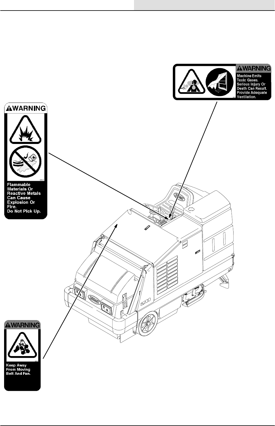
WARNING: Engine emits toxic gases.
Severe respiratory damage or
asphyxiation can result. Provide
adequate ventilation. Consult with your
regulatory authorities for exposure
limits. Keep engine properly tuned.
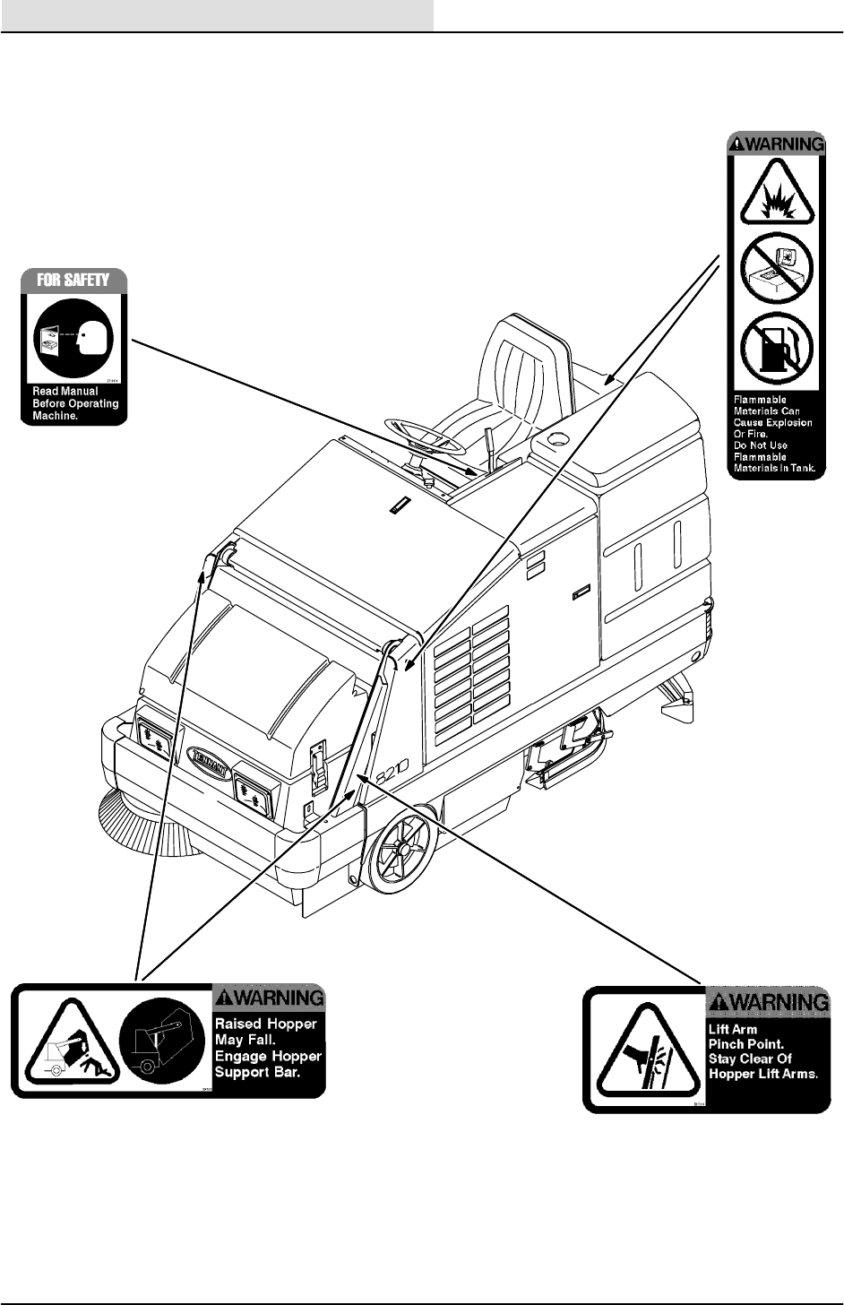
WARNING: Raised hopper may fall.
Engage hopper support bar.
WARNING: Lift arm pinch point. Stay
clear of hopper lift arms.
WARNING: Moving belt and fan. Keep
away.
WARNING: Flammable materials can
cause an explosion or fire. Do not use
flammable materials in tank(s).
WARNING: Flammable materials or
reactive metals can cause explosion or
fire. Do not pick up.
GENERAL INFORMATION
1-5
8200/8210 330065 (1--98)
The following safety labels are mounted on the
machine in the locations indicated. If these or any
label becomes damaged or illegible, install a new
label in its place.
ENGINE FAN AND BELT LABEL -- LOCATED
ON THE RADIATOR SHROUD.
EMISSIONS LABEL -- LOCATED ON THE SIDE
PANEL OF THE OPERATOR COMPARTMENT.
FLAMMABLE SPILLS LABEL -- LOCATED
ON THE SIDE PANEL OF THE OPERATOR
COMPARTMENT.
GENERAL INFORMATION
1-6 8200/8210 330065 (1--98)
HOPPER LIFT ARMS LABEL -- LOCATED
ON BOTH HOPPER LIFT ARMS.
FOR SAFETY LABEL -- LOCATED ON
THE SIDE PANEL OF THE OPERATOR
COMPARTMENT.
HOPPER SUPPORT BAR LABEL -- LOCATED
ON THE HOPPER SUPPORT BAR AND ON
BOTH HOPPER LIFT ARMS.
351551
FLAMMABLE MATERIALS LABEL -- LOCATED
ON THE SOLUTION TANK COVER & ON THE
BATTERY TRAY ON MACHINES WITH THE
DETERGENT TANK OPTION.

GENERAL INFORMATION
1-7
8200/8210 330065 (6--01)
SPECIFICATIONS
GENERAL MACHINE DIMENSIONS/CAPACITIES
Item Dimension/capacity
Length 2553 mm (100.5 in)
Width with side brush 1397 mm (55 in)
Width with Maxpathtside brush 1473 mm (58 in)
Height 1466 mm (57.7 in)
Height with overhead guard 2083 mm (82 in)
Track 1083 mm (42.6 in)
Wheelbase 1511 mm (59.5 in)
Main sweeping brush diameter 355 mm (14 in)
Main sweeping brush length 914 mm (36 in)
Scrub brush diameter -- 2 brushes 508 mm x 2 brushes (20 in x 2 brushes)
Scrub brush diameter -- 3 brushes (option) 406 mm x 3 brushes (16 in x 3 brushes) (option)
Side brush diameter 584 mm (23 in)
Sweeping path width 914 mm (36 in)
Sweeping path width with side brush 1270 mm (50 in)
Squeegee width 1219 mm (48 in)
Scrubbing path width -- two scrub brushes 1016 mm (40 in)
Scrubbing path width -- three scrub brushes
(option)
1219 mm (48 in)
Main sweeping brush pattern width 64 mm (2.5 in) -- adjustable
Hopper weight capacity 159 kg (350 lb)
Hopper volume capacity 220L(7.8ft
3)
Dust filter area 5.85 m2(63sqft)
Solution tank 196.8 L (52 gal)
Recovery tank 265 L (70 gal)
Detergent tank 17.8 L (4.7 gal)
Total capacity with ESt(option) 303 L (80 gal)
GVWR 1937 kg (4270 lb)
Ceiling height minimum dumping clearance 2286 mm (90 in )
GENERAL MACHINE PERFORMANCE
Item Measure
Maximum forward speed 9.7 kmh (6 mph)
Maximum reverse speed 4.8 kmh (3 mph)
Minimum aisle turn width, left 3.01 m (9 ft 9 in)
Minimum aisle turn width, right 4.3m(14ft10in)
Minimum turning radius, left 0.98 m (38.75 in)
Minimum turning radius, right 1.91 m (75.25 in)
Maximum rated incline for transport of machine (8_-- 14%)
Maximum rated incline for scrubbing/sweeping (6_-- 10.5%)
GENERAL INFORMATION
1-8 8200/8210 330065 (6--01)
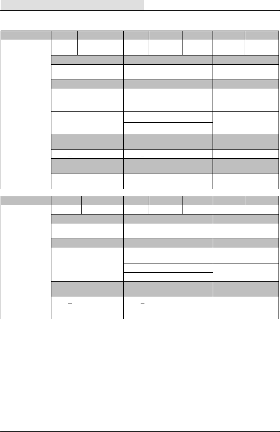
POWER TYPE
Engine Type Ignition Cycle Aspiration Cylinders Bore Stroke
Ford VSG1.3 L Piston Distributerless-
type spark
4Natural 473.94 mm
(2.91 in)
75.44 mm
(2.97 in)
Displacement Net power, governed Net power, maximum
1300 cc (79 cid) 23.2 kw (32 hp) @ 2400 rpm 39.5 kw (53 hp)@
4000 rpm
Fuel Cooling system Electrical system
Gasoline, 87 octane
minimum, unleaded. Fuel
tank: 37.9 L (10 gal)
Water/ethylene glycol
antifreeze
12 V nominal
LPG,
F
u
e
l
t
a
n
k
:
1
5
k
g
(
3
3
l
b
)
Total: 16.7 L (4.4 gal) 50 A alternator
F
ue
l
t
an
k
:
1
5
k
g
(
3
3
l
b
)
19.5 kg (43 lb) Radiator: 6 L (1.6 gal)
Idle speed, no load (Fast) governed speed, under
load
Firing order
1200 + 50 rpm 2400 + 50 rpm 1--2--4--3
Spark plug gap Valve clearance, cold Engine lubricating oil
with filter
1 mm (0.04 in) 0.020 mm (0.008 in) intake
0.050 mm (0.020 in) exhaust
3.7L(4qt)
10W30 SAE--SG/SH
Engine Type Ignition Cycle Aspiration Cylinders Bore Stroke
Kubota
V
1
5
0
5
B
6
1
Piston Diesel 4Natural 478 mm 78.4 mm
V
1505B--61 Displacement Net power, governed Net power, maximum
1498 cc (91.44 cid) 20.0 kw @ 2400 rpm (26.8 hp) 27.9 kw@ 2800 rpm
(37.5 hp)
Fuel Cooling system Electrical system
Diesel
Fuel tank: 37.9 L(10 gal)
Water/ethylene glycol
antifreeze
12 V nominal
(
g
)
Total: 16.7 L (4.4 gal) 50 A alternator
Radiator: 6 L (1.6 gal)
Idle speed, no load (Fast) governed speed, under
load
Engine lubricating oil
without filter
1400 +25 rpm 2400 +25 rpm 6.15 L (6.5 qt)
diesel rating above CD
grade only

GENERAL INFORMATION
1-9
8200/8210 330065 (6--01)
STEERING
Type Power source Emergency steering
Rear wheel, hydraulic cylinder
and rotary valve controlled
Hydraulic accessory pump Manual
HYDRAULIC SYSTEM
System Capacity Fluid Type
Hydraulic reservoir
capacity
25.4 L (6.7 gal)
Fill to FULL line only
TENNANT part no. 65869 -- above 7_C(45_F)
TENN
A
NT
p
art no. 65870 -- below 7_C
(
45_F
)
Hydraulic total (all
components, plumbing)
28.4 L (7.5 gal)
T
E
N
N
A
N
T
p
a
r
t
n
o
.
6
5
8
7
0
-
-
b
e
l
o
w
7
C
(
4
5
F
)
BRAKING SYSTEM
Type Operation
Service brakes Mechanical drum brakes (2), one per front wheel,
linkage actuated
Parking brake Utilize service brakes, linkage actuated
TIRES
Location Type Size Pressure
Front (2) Solid 406 x 89 x 308 mm
(16x3.5 x12.125 in)
--
Rear (1) Solid 413 x 152 mm
(16.25 x 6 in)
--
GENERAL INFORMATION
1-10 8200/8210 330065 (9--99)
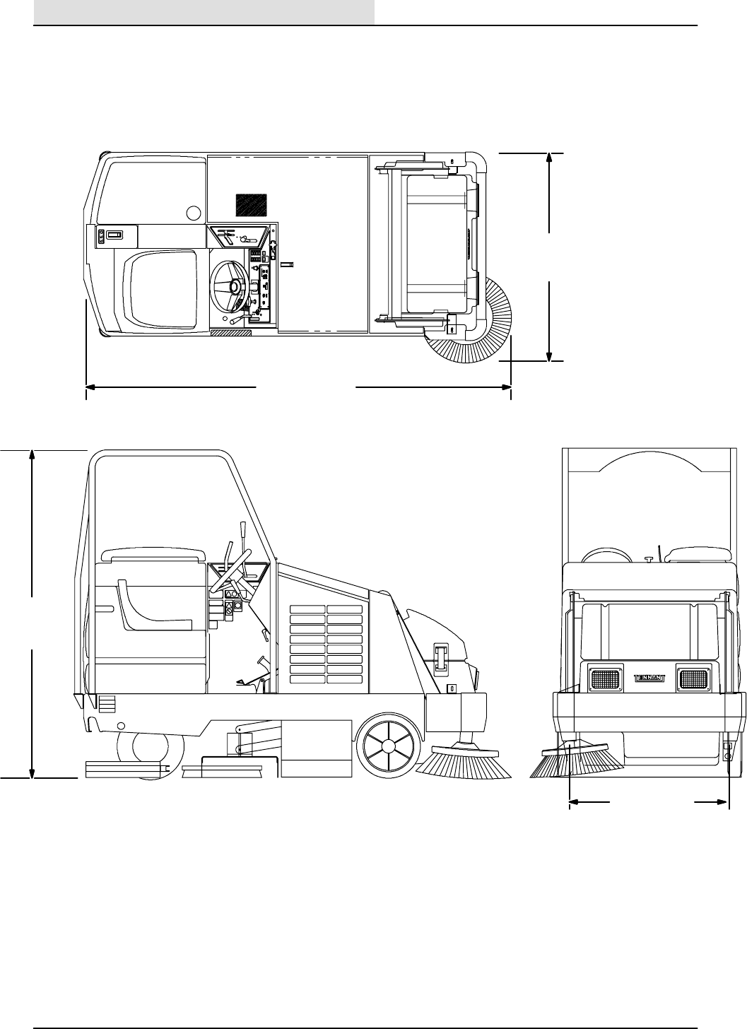
TOP VIEW
SIDE VIEW
2083 mm
82 in
1397 mm
55 in
2553 mm
105.5 in
1083 mm
42.6 in
351664
MACHINE DIMENSIONS

GENERAL INFORMATION
1-11
8200/8210 330065 (6--01)
GENERAL INFORMATION
1-12 8200/8210 330065 (3--01)
MAINTENANCE
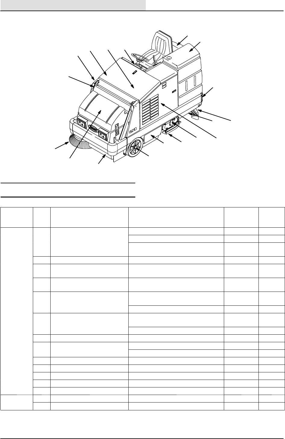
1
2
3
5
8
10
11
9
4
7
6
12
13
14
15
16
17
18
MAINTENANCE CHART
Interval Key Description Procedure
Lubricant/
Fluid
No. of
Service
Points
Daily 1Engine air filter Check indicator -- 1
D
a
i
l
y
1
E
n
g
i
n
e
a
i
r
f
i
l
t
e
r
Empty dust cap -- 1
Clean / change filter element as
necessary
-- 1
1Engine crankcase Check oil level EO 1
2Brush compartment skirts Check for damage, wear and ad-
justment
-- 5
3Hopper lip skirts Check for damage, wear and ad-
justment
-- 3
4Main sweep brush Check for damage, wear, and ad-
justment
-- 1
Check brush pattern -- 1
5Side brush Check for damage, wear, and ad-
justment
-- 1
Check brush pattern -- 1
6Hopper dust filter Shake to clean -- 2
7Rear Squeegee Check for damage and wear -- 1
7
R
e
a
r
S
q
u
e
e
g
e
e
Check deflection -- 1
8Side Squeegees Check for damage and wear -- 2
9Scrub brushes Check for damage and wear -- 1
10 Recovery tank Clean -- 1
10 Recovery tank, EStmode Clean EStfilter -- 1
11 Solution tank, EStmode Clean -- 1
50 Hours 1Engine crankcase Change oil and filter element EO 1
4Main sweep brush Rotate end-for-end -- 1

GENERAL INFORMATION
1-13
8200/8210 330065 (6--01)
Interval Key Description Procedure
Lubricant/
Fluid
No. of
Service
Points
100 hours 13 Radiator Clean core exterior -- 1
1
0
0
h
o
u
r
s
1
3
R
a
d
i
a
t
o
r
Check coolant level WG 1
1Engine Check belt tension -- 1
6Hopper dust filter Check for damage, clean or re-
place
-- 1
14 Hydraulic fluid reservoir Check fluid level HYDO 1
15 Tires Check all for damage, check rear
tire pressure
-- 3
2,6 Main sweep brush and
hopper seals
Check for damage or wear -- 8
7Rear squeegee Check leveling -- 1
10,
11
Tank cover seals Check for damage or wear -- 2
12 Scrub head drag link arm
pivot points
Lubricate SPL 4
200 Hours 13 Radiator hoses and clamps Check for tightness and wear -- 2
2
0
0
H
o
u
r
s
16 Parking brake Check adjustment -- 1
16 Brake pedal Check and adjust travel -- 1
17 Rear wheel support
bearings
Lubricate SPL 1
18 Hopper lift arm pivots Lubricate SPL 2
400 Hours 1Engine Change fuel filter -- 2
4
0
0
H
o
u
r
s
1
E
n
g
i
n
e
Clean or replace and re--gap
spark plugs (G/LP)
-- 2
15 Front wheel bearings Check, lubricate, and adjust SPL 2
1
5
1Valve clearance (first 400
hours of machine use)
Check / adjust valve clearance -- 2
800 hours 1Engine Replace PCV valve. Clean PCV
h
t
b
d
f
i
t
t
i
(
G
/
L
P
)
-- 4
g
p
hoses, tubes, and
f
ittings (G
/
LP) -- 1
Torque intake manifold bolts -- 8
13 Cooling system Flush WG 2
14 Hydraulic fluid reservoir Change hydraulic fluid HYDO 1
1
4
H
y
d
r
a
u
l
i
c
f
l
u
i
d
r
e
s
e
r
v
o
i
r
Replace suction strainer 1
Replace hydraulic breather 1
Replace cap 1
14 Hydraulic fluid filter Change filter element -- 1
-- Hydraulic hoses Check for wear and damage -- All
1Propelling motor HTorque shaft nut -- 1
17 Rear wheel HTorque wheel nuts -- 1
1Battery HClean and tighten battery cable
connections
-- 1
LUBRICANT/FLUID
EO Engine oil, 10W30 SAE--SG/SH only (G/LP)....
EO Engine oil, diesel rating above CD grade only. (Diesel)....
HYDO Tennant or approved hydraulic fluid.
WG Water and permanent-type ethylene glycol anti-freeze, --34_C(--30_F)...
SPL Special lubricant, Lubriplate EMB grease (Tennant part number 01433--1)...
NOTE: Also check procedures indicted (H) after
the first 50-hours of operation.
NOTE: More frequent intervals may be required
in extremely dusty conditions.
GENERAL INFORMATION
1-14 8200/8210 330065 (6--01)
PUSHING, TOWING, AND TRANSPORTING
THE MACHINE
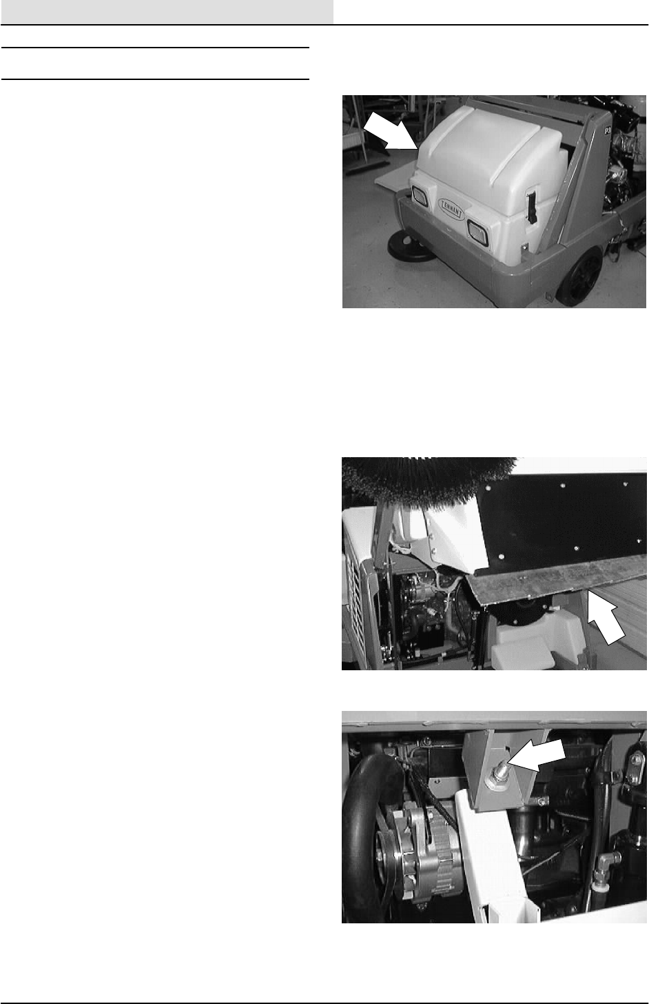
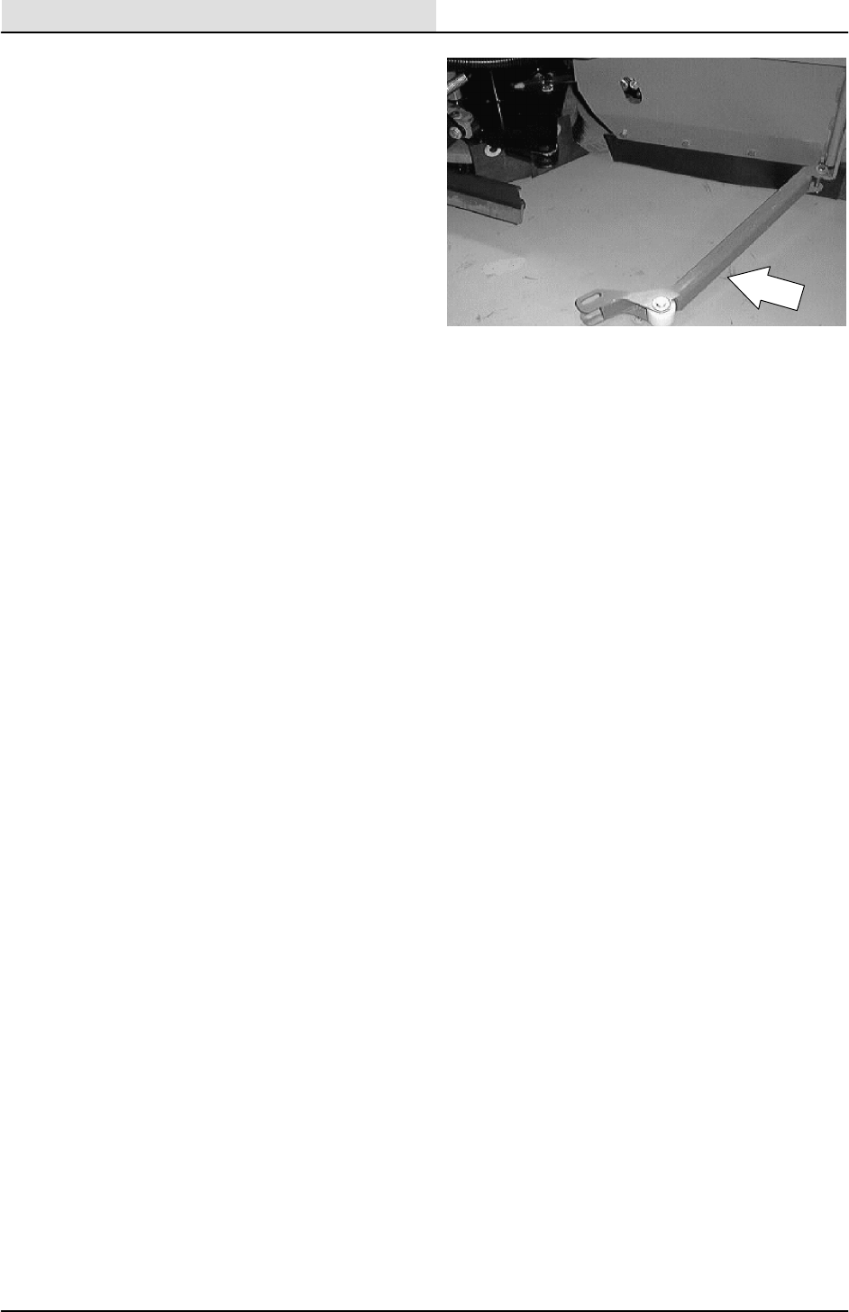
PUSHING OR TOWING THE MACHINE
If the machine becomes disabled, it can be
pushed from the front or rear, but towed only from
the rear.
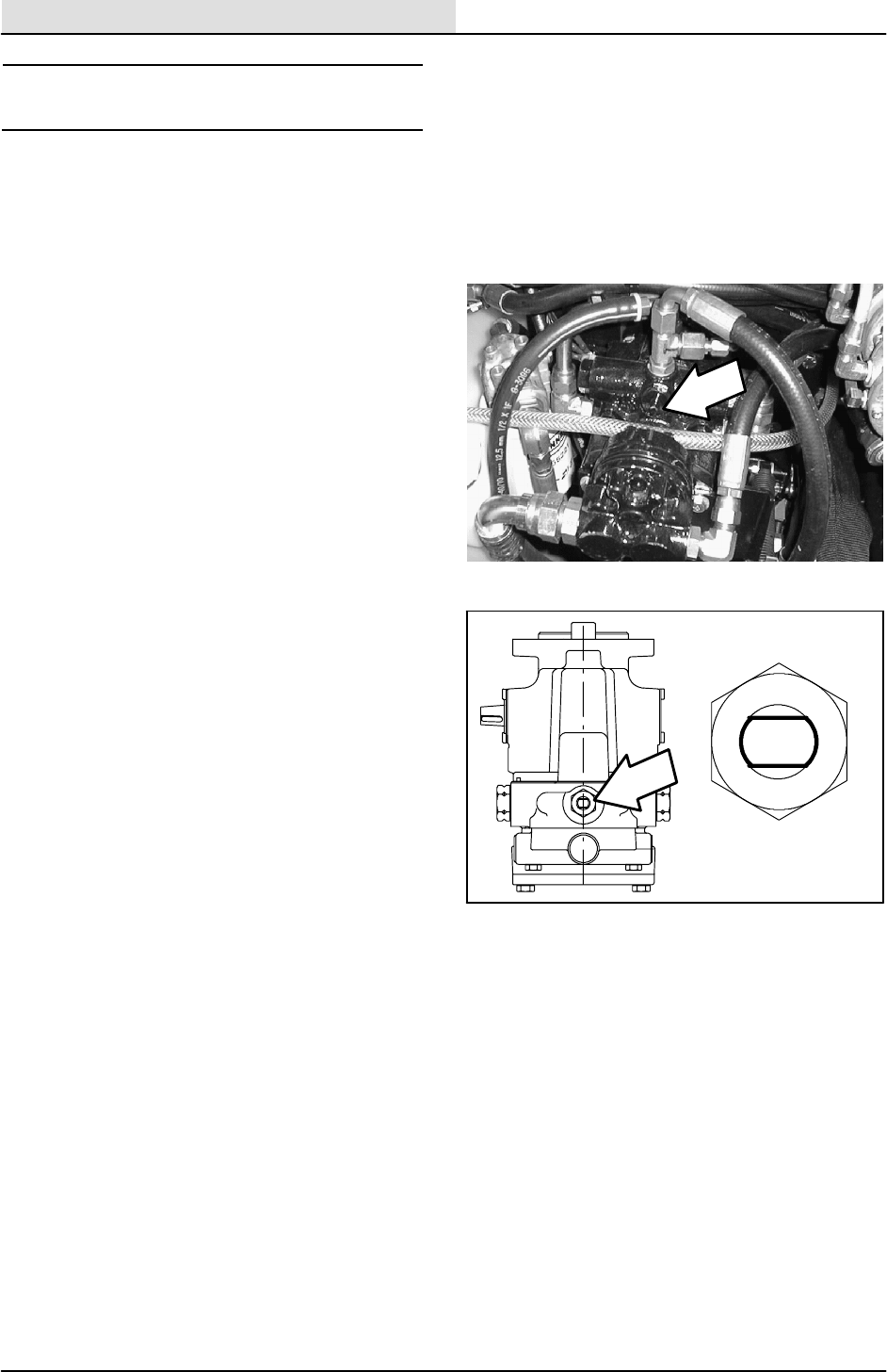
The propelling pump has a bypass valve to
prevent damage to the hydraulic system when the
machine is being pushed or towed. This valve
allows a disabled machine to be moved for a very
short distance and at a speed to not exceed 1.6
kp/h (1 mph). The machine is NOT intended to be
pushed or towed a long distance or at a high
speed.
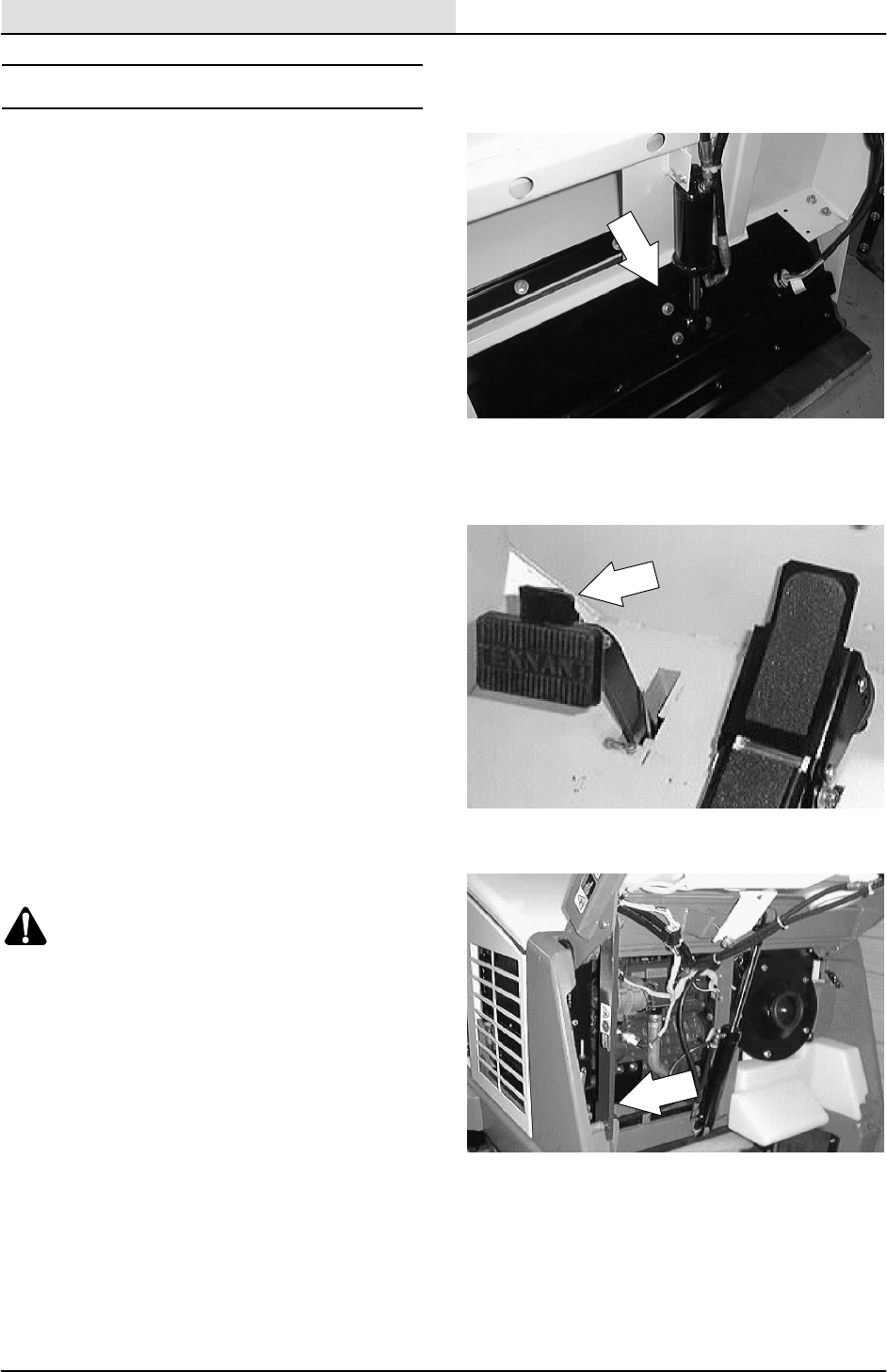
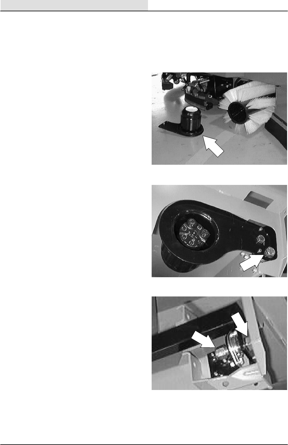
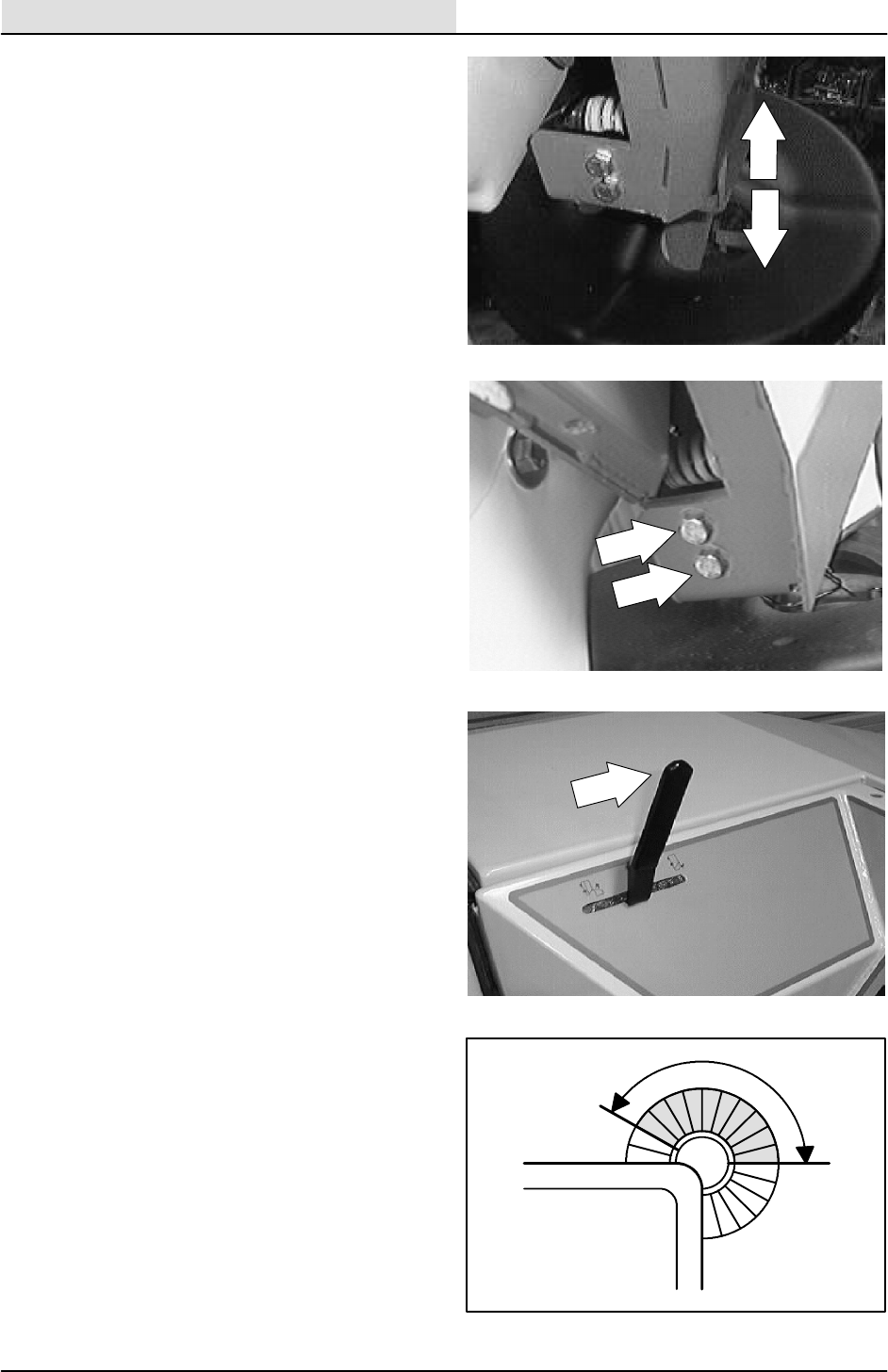
ATTENTION! Do not push or tow
machine for a long distance and without
using the bypass valve, or the machine
hydraulic system may be damaged.
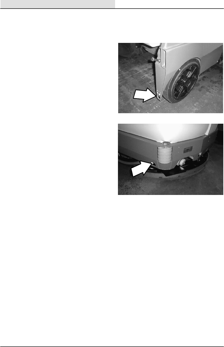
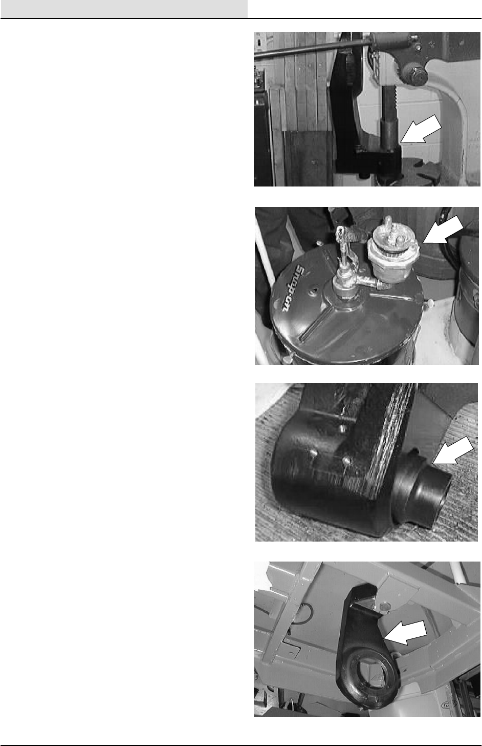
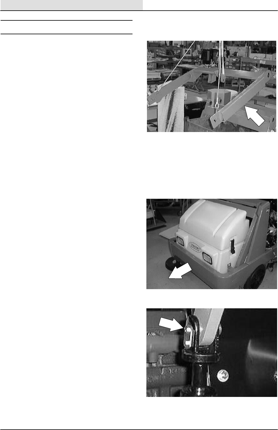
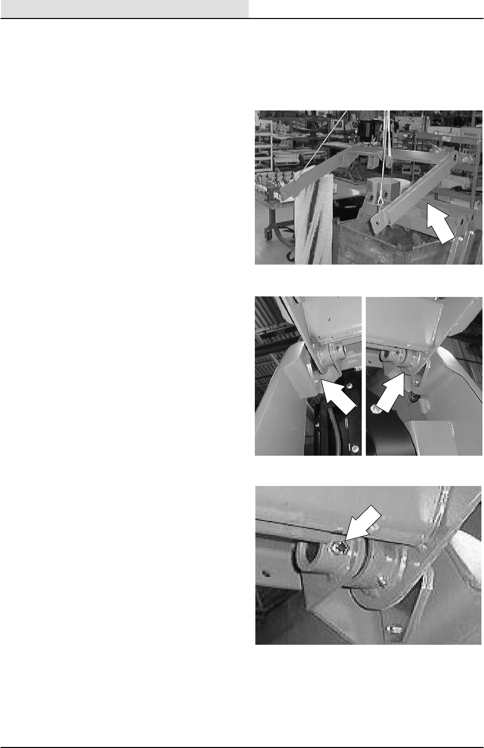
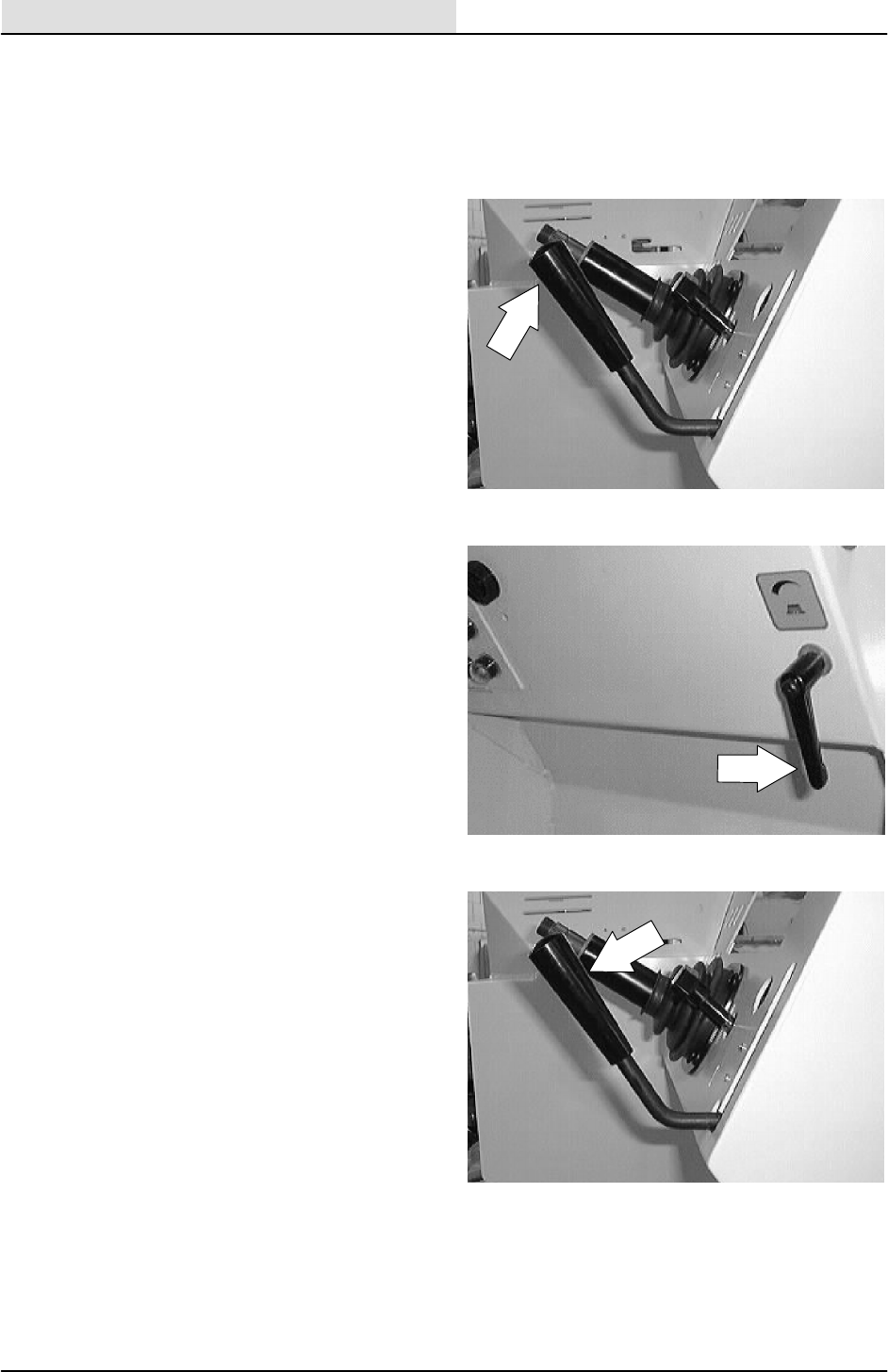
Turn the bypass valve 90_from the normal
position before pushing or towing the machine.
The illustration shows the bypass valve in the
pushing or towing position.
GENERAL INFORMATION
1-15
8200/8210 330065 (6--01)
TRANSPORTING THE MACHINE
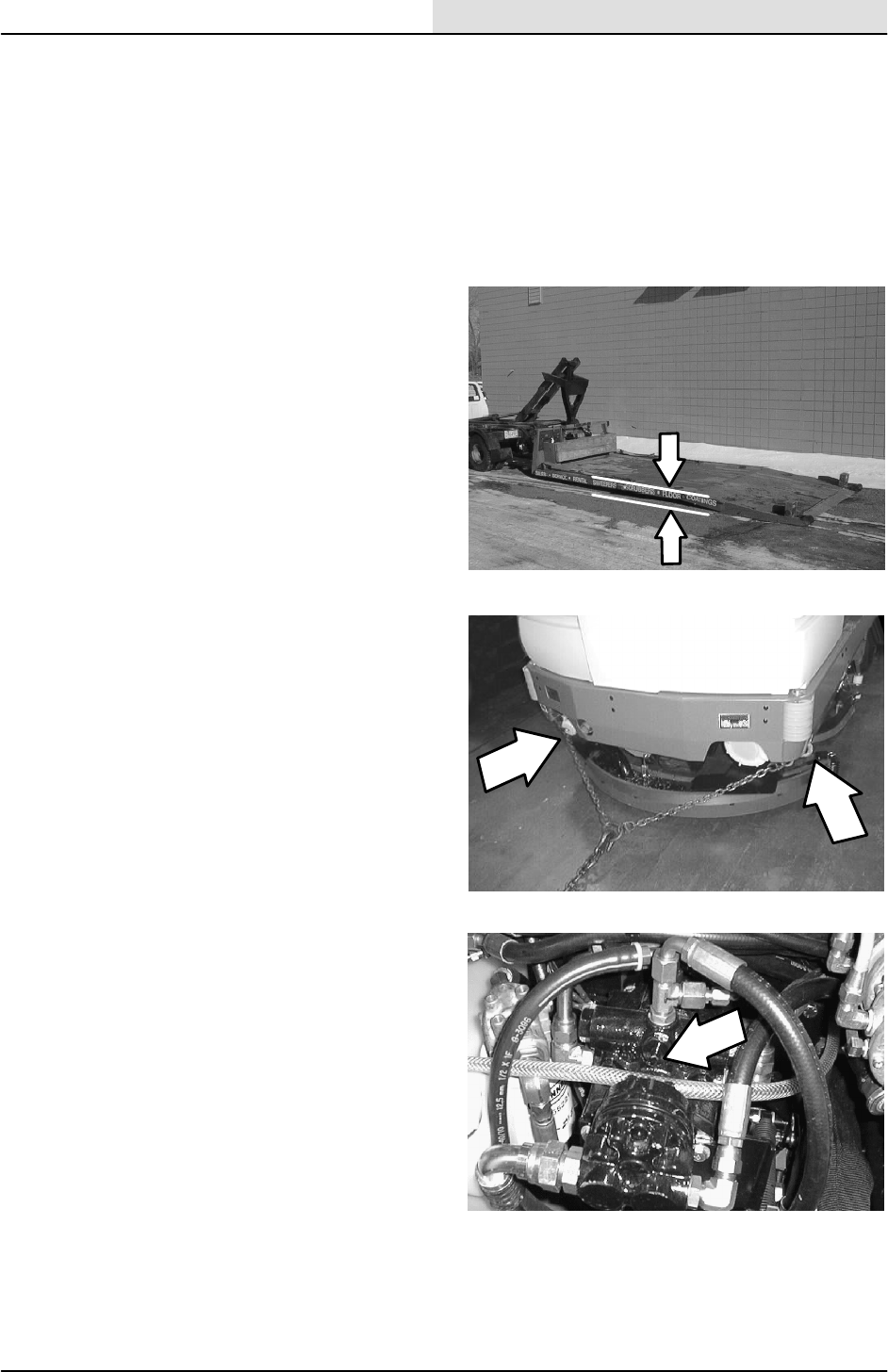
1. Position the rear of the machine at the
loading edge of the truck or trailer.
FOR SAFETY: Use truck or trailer that
will support the weight of the machine.
NOTE: Empty the hopper, recovery tank, and
solution tank before transporting the machine.
2. If the loading surface is not horizontal or is
higher than 380 mm (15 in) from the ground,
use a winch to load machine.
If the loading surface is horizontal AND is
380 mm (15 in) or less from the ground, the
machine may be driven onto the truck or
trailer.
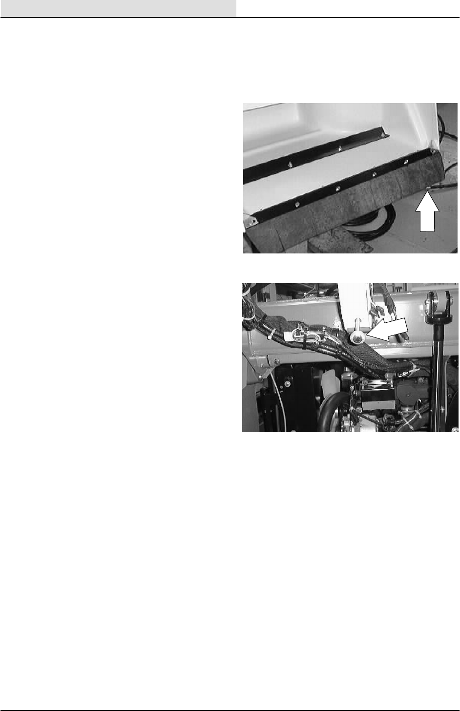
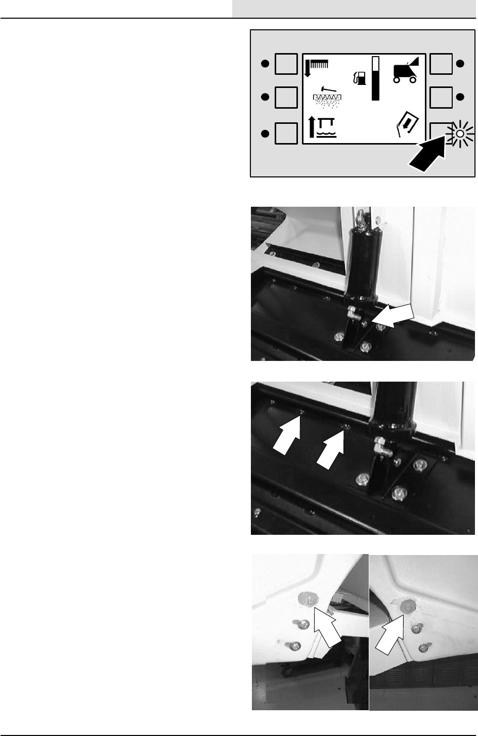
3. To winch the machine onto the truck or
trailer, attach the winching chains to the rear
tie down locations. The rear tie-down
locations are the bottom lips at each corner
of the rear bumper.
4. Turn the bypass valve 90_from the normal
position before winching the machine onto
the truck or trailer. See PUSHING OR
TOWING THE MACHINE section of this
manual. Make sure the machine is centered.
FOR SAFETY: When loading machine
onto truck or trailer, use winch. Do not
drive the machine onto the truck or
trailer unless the loading surface is
horizontal AND is 380 mm (15 in) or less
from the ground.
5. Position the machine onto the truck or trailer
as far as possible. If the machine starts to
veer off the centerline of the truck or trailer,
stop and turn the steering wheel to center
the machine.
GENERAL INFORMATION
1-16 8200/8210 330065 (6--01)
6. Set the parking brake, lower the scrub head
and block the machine tires. Tie down the
machine to the truck or trailer before
transporting.
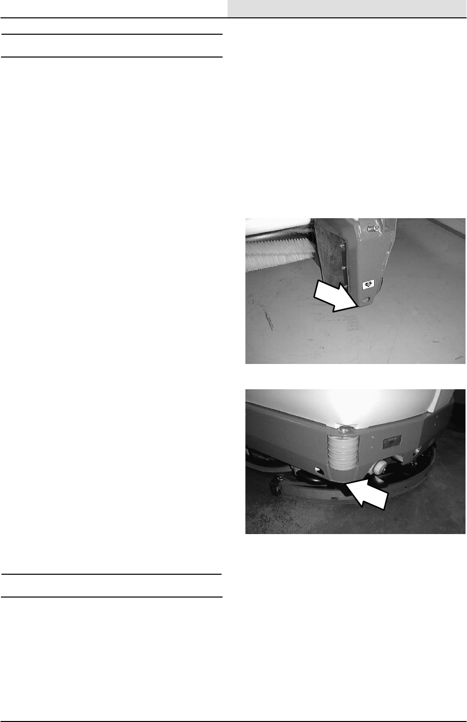
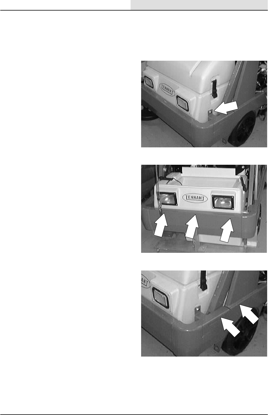
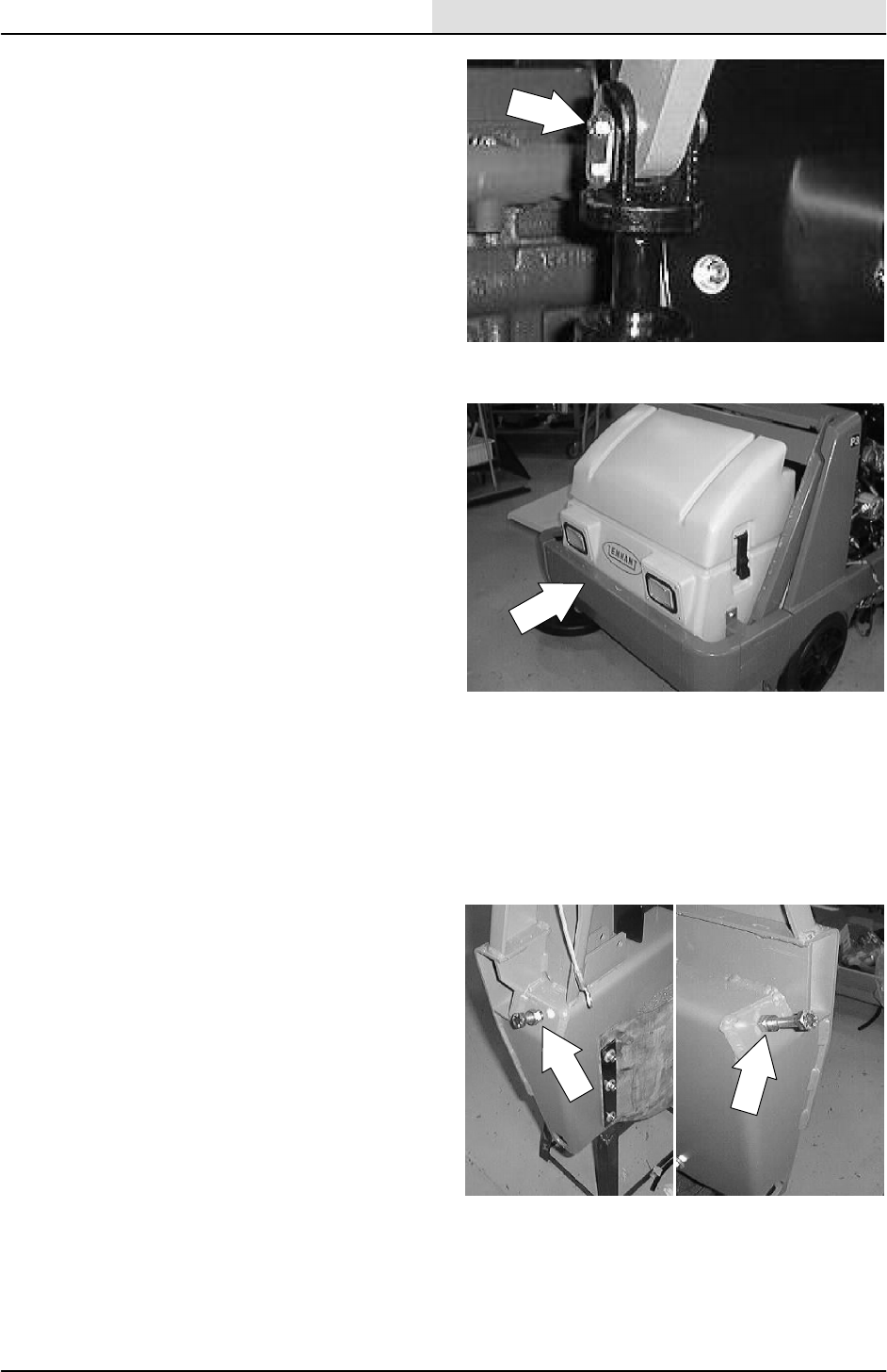
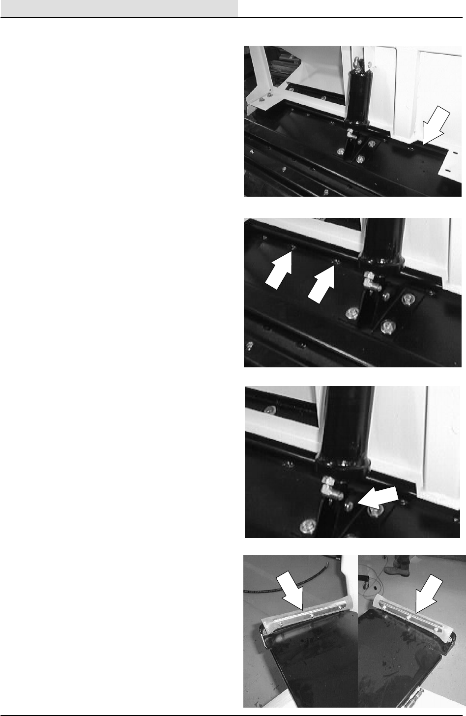
The front tie-down locations are the holes in
the wheel pockets at the front of the
machine frame.
The rear tie-down locations are the bottom
lips at each corner of the rear bumper.
7. If the loading surface is not horizontal or is
higher than 380 mm (15 in) from the ground,
use a winch to unload machine.
If the loading surface is horizontal AND is
380 mm (15 in) or less from the ground, the
machine may be driven off the truck or
trailer.
FOR SAFETY: When unloading machine
off truck or trailer, use winch. Do not
drive the machine off the truck or trailer
unless the loading surface is horizontal
AND 380 mm (15 in) or less from the
ground.
GENERAL INFORMATION
1-17
8200/8210 330065 (6--01)
MACHINE JACKING
Empty the hopper, recovery tank, and solution
tank before jacking the machine. You can jack up
the machine for service at the designated
locations. Use a hoist or jack that will support the
weight of the machine. Always stop the machine
on a flat, level surface and block the tires before
jacking the machine up.
FOR SAFETY: Before leaving or
servicing machine; stop on level
surface, set parking brake, turn off
machine and remove key.
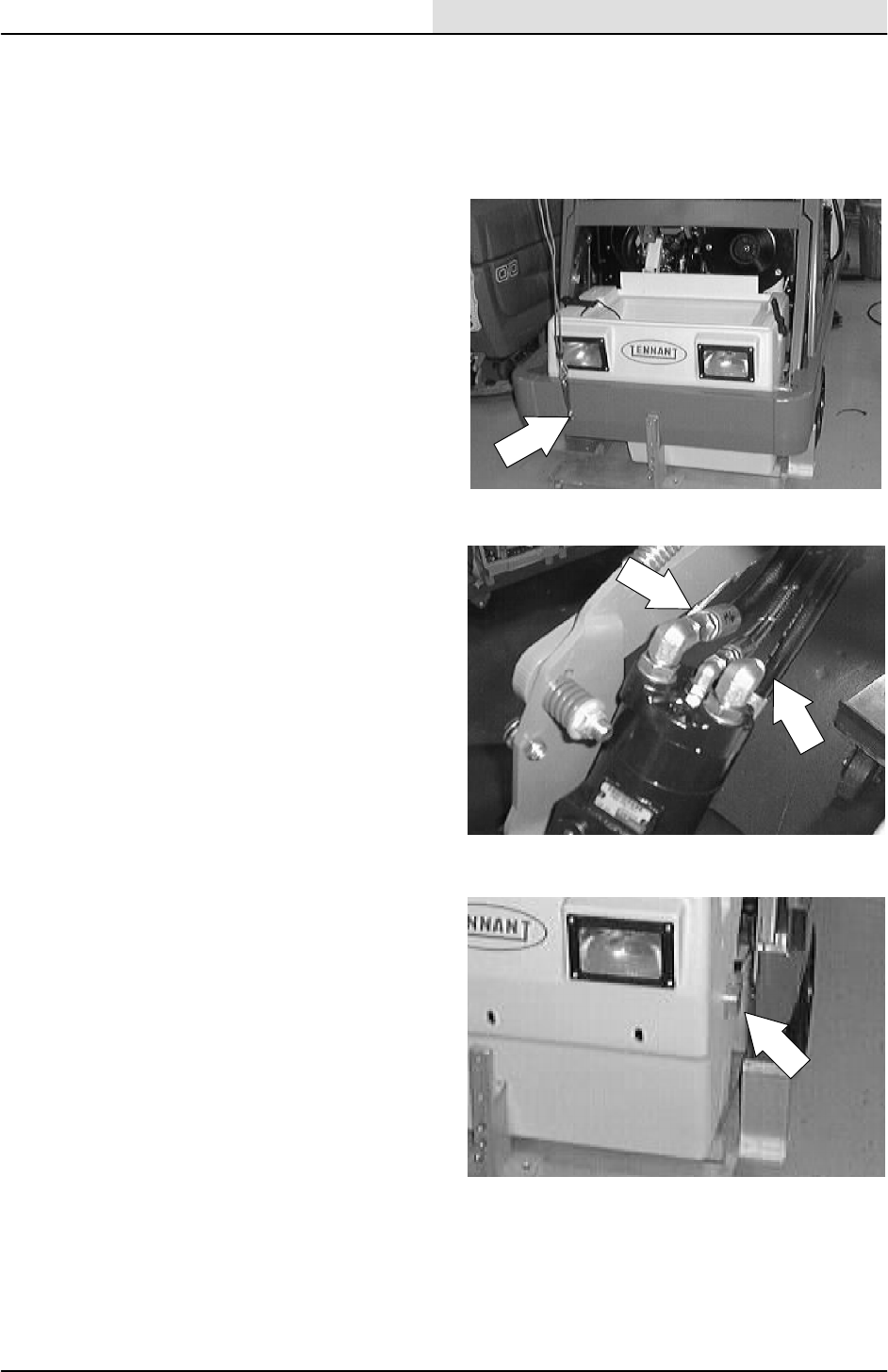
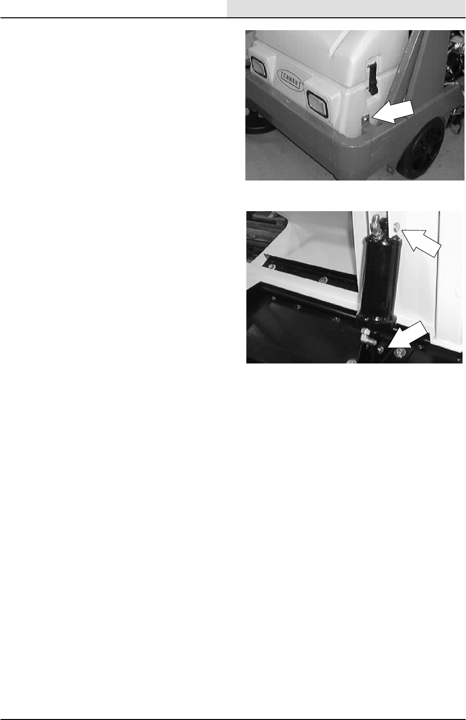
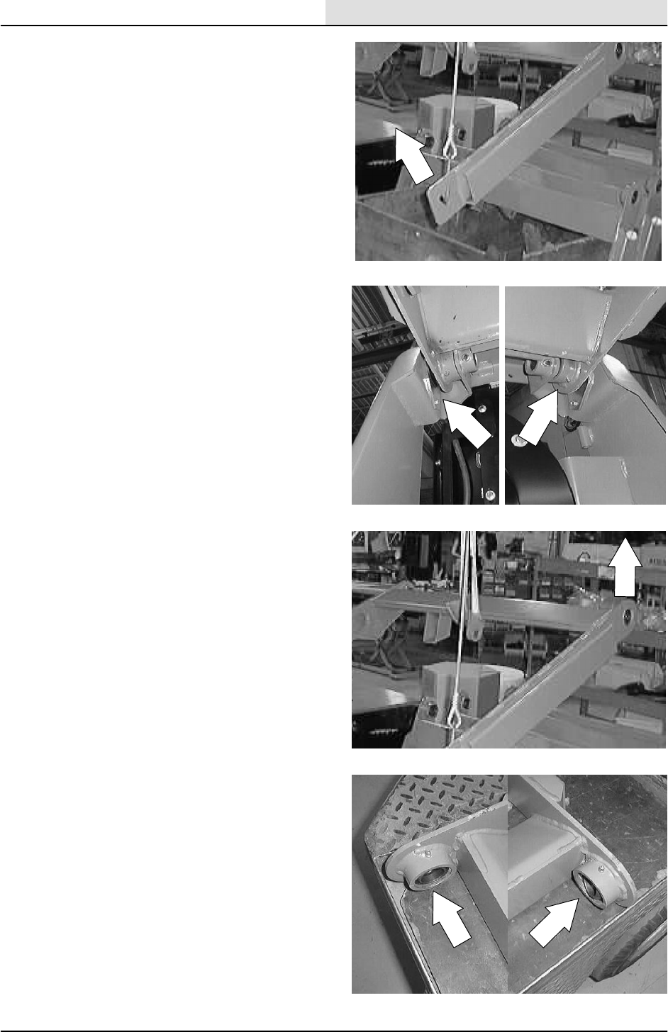
The front jacking locations are on the flat bottom
edge of the front of the machine frame next to the
front tires.
The rear jacking location is under the left side of
the rear bumper.
FOR SAFETY: When servicing machine,
jack machine up at designated locations
only. Block machine up with jack
stands.
STORING MACHINE
Before storing the machine for an extended time,
the machine needs to be prepped to lessen the
chance of rust, sludge, and other undesirable
deposits from forming. Contact Tennant service
personnel.

GENERAL INFORMATION
1-18 8200/8210 330065 (6--01)
MACHINE TROUBLESHOOTING
Problem Cause Remedy
Excessive dusting Brush skirts and dust seals worn,
damaged, out of adjustment
Replace or adjust brush skirts or
dust seals
Hopper dust filter clogged Shake and/or clean or replace
dust filter
Vacuum fan seal damaged Replace vacuum seal
Vacuum fan failure Call TENNANT service personnel
Thermo Sentryttripped Allow Thermo Sentrytto cool
Hopper dump door closed Open hopper dump door
Poor sweeping performance Brush bristles worn Replace brushes
Main and side brushes not
adjusted properly
Adjust main and side brushes
Debris caught in main brush drive
mechanism
Free drive mechanism of debris
Main brush drive failure Call TENNANT service personnel
Side brush drive failure Call TENNANT service personnel
Hopper full Empty hopper
Hopper lip skirts worn or damaged Replace lip skirts
Wrong sweeping brush Call TENNANT representative
Hopper dump door closed Open hopper dump door
Trailing water -- poor or no
t
i
k
Worn rear squeegee blades. Rotate or replace blades
water pickup. Rear squeegee out of adjustment Adjust rear squeegee
Worn side squeegee blades. Replace side squeegee blades
Side squeegees out of adjustment Adjust side squeegees
Recovery tank cover not seated Reseat tank cover
Recovery tank cover seal worn Replace seal
Too much solution flow to floor Reduce solution flow to floor
Vacuum hose clogged Flush vacuum hoses
Rear squeegee tube clogged Flush squeegee tube
Recovery tank full Drain recovery tank
Check EStpump and filter
Float stuck shutting off vacuum Clean float
Debris caught on rear squeegee Remove debris
Foam filling recovery tank Empty recovery tank; use less or
change detergent
Vacuum hose to rear squeegee
disconnected
Reconnect
Vacuum--fan--to--recovery--tank--
hose damaged
Replace hose
Too much solution flow for floor
conditions / machine speed
Adjust manual flow control valve
to reduce total solution flow

GENERAL INFORMATION
1-19
8200/8210 330065 (6--01)
Problem Cause Remedy
Littleornosolutionflowtothe
f
l
Solution tank empty. Fill solution tank.
f
loor. Solution flow switch turned off. Turn solution flow switch on.
Solution supply lines plugged. Flush solution supply lines.
EStswitch off. Turn EStswitch on.
Manual control valve nearly closed Open valve more
Poor scrubbing performance. Debris caught on scrub brushes. Remove debris.
Improper detergent or brushes
used.
Check with TENNANT
representative for advice.
Worn scrub brushes. Replace scrub brushes.
EStsystem does not fill
l
t
i
t
k
Clogged solution pump or lines. Flush EStsystem.
solution tank. EStfloat stuck. Clean floats of debris.
Clogged EStpump filter. Clean filter.
Water levels too low in tanks. Add water.
GENERAL INFORMATION
1-20 8200/8210 330065 (6--01)
HARDWARE INFORMATION
The following charts state standard plated
hardware tightening ranges for normal assembly
applications. Decrease the specified torque by
20% when using a thread lubricant. Do not
substitute lower grade hardware for higher grade
hardware. If higher grade hardware than specified
is substituted, tighten only to the specified
hardware torque value to avoid damaging the
threads of the part being threaded into, as when
threading into speed nuts or weldments.
STANDARD BOLT TORQUE CHART
Thread
Size
SAE Grade 5
Torque ft lb
(Nm)
SAE Grade 8
Torque ft lb
(Nm)
0.25 in 7--10 (9--14) 10--13 (14--38)
0.31 in 15--20 (20--27) 20--26 (27--35)
0.38 in 27--35 (37--47) 36--47 (49--64)
0.44 in 43--56 (58--76) 53--76 (72--103)
0.50 in 65--85 (88--115) 89--116
(121--157)
0.62 in 130--170
(176--231)
117--265
(159--359)
0.75 in 215--280
(291--380)
313--407
(424--552)
1.00 in 500--650
(678--881)
757--984
(1026--1334)
NOTE: Decrease torque by 20% when using a
thread lubricant.
METRIC BOLT TORQUE CHART
Thread
Size
Class 8.8
Torque ft lb
(Nm)
Class 10.9
Torque ft lb
(Nm)
M4 2(3) 3(4)
M5 4(5) 6(8)
M6 7(9) 10 (14)
M8 18 (24) 25 (34)
M10 32 (43) 47 (64)
M12 58 (79) 83 (112)
M14 94 (127) 133 (180)
M16 144 (195) 196 (265)
M20 260 (352) 336 (455)
M24 470 (637) 664 (900)
NOTE: Decrease torque by 20% when using a
thread lubricant.
Exceptions to the above chart:
Check the machine for exceptions!
BOLT IDENTIFICATION
Identification
Grade Marking
Specification and
Grade
SAE--Grade 5
SAE--Grade 8
ISO--Grade 8.8
ISO--Grade 10.9
01395
THREAD SEALANT AND LOCKING
COMPOUNDS
Thread sealants and locking compounds may be
used on this machine. They include the following:
Locktite 515 sealant -- gasket forming
material. TENNANT Part No. 75567,15 oz
(440 ml) cartridge.
Locktite 242 blue -- medium strength thread
locking compound. TENNANT Part No.
32676, 0.5 ml tube.
Locktite 271 red -- high strength thread
locking compound. TENNANT Part No.
19857, 0.5 ml tube.

GENERAL INFORMATION
1-21
8200/8210 330065 (6--01)
HYDRAULIC FITTING INFORMATION
HYDRAULIC TAPERED PIPE FITTING (NPT)
TORQUE CHART
NOTE: Ratings listed are when using teflon
thread seal.
Size Minimum
Torque
Maximum
Torque
1/4 NPT 10 ft lb (14 Nm) 30 ft lb (41 Nm)
1/2 NPT 25 ft lb (34 Nm) 50 ft lb (68 Nm)
3/4 NPT 50 ft lb (68 Nm) 100 ft lb (136
Nm)
HYDRAULIC TAPERED SEAT FITTING (JIC)
TORQUE CHART
Tube O.D.
(in)
Thread Size Maximum
Torque
0.25 0.44--20 9ftlb(12Nm)
0.38 0.56--18 20 ft lb (27 Nm)
0.50 0.75--16 30 ft lb (41 Nm)
0.62 0.88--14 40 ft lb (54 Nm)
0.75 1.12--12 70 ft lb (95 Nm)
1.0 1.31--12 90 ft lb (122 Nm)
HYDRAULIC O--RING FITTING TORQUE
CHART
Tube
O.D.
(in)
Thread
Size
Minimum
Torque
Maximum
Torque
0.25 0.44--20 6ftlb(8Nm) 9ftlb
(12 Nm)
0.38 0.56--18 13 ft lb
(18 Nm)
20 ft lb
(27 Nm)
*10 ft lb
(14 Nm)
12 ft lb
(16 Nm)
0.50 0.75--16 20 ft lb
(27 Nm)
30 ft lb
(41 Nm)
*21 ft lb
(28 Nm)
24 ft lb
(33 Nm)
0.62 0.88--14 25 ft lb
(34 Nm)
40 ft lb
(54 Nm)
0.75 1.12--12 45 ft lb
(61 Nm)
70 ft lb
(95 Nm)
1.0 1.31--12 60 ft lb
(81 Nm)
90 ft lb
(122 Nm)
NOTE: Do not use sealant on o--ring threads.
*Aluminum bodied components

GENERAL INFORMATION
1-22 8200/8210 330065 (6--01)

CHASSIS
2-1
8200/8210 330065 (3--01)
CONTENTS
Page
INTRODUCTION 2--3......................
BRAKES AND TIRES 2--4..................
SERVICE BRAKES 2--4....................
TO REPLACE BRAKE SHOES 2--4.......
PARKING BRAKE 2--7.....................
TO ADJUST BRAKES 2--8..............
FRONT TIRES AND WHEELS 2--11.........
TO REPLACE FRONT WHEEL
BEARINGS 2--11....................
REAR TIRE AND WHEEL, AND
WHEEL SUPPORT 2--14.............
TO REPLACE REAR WHEEL
HOUSING PIVOT BEARINGS 2--14...

CHASSIS
2-2 8200/8210 330065 (3--01)

CHASSIS
2-3
8200/8210 330065 (3--01)
INTRODUCTION
This section includes information on the main
chassis related components for example the
brakes, wheel support, and tires.
CHASSIS
2-4 8200/8210 330065 (3--01)
BRAKES AND TIRES
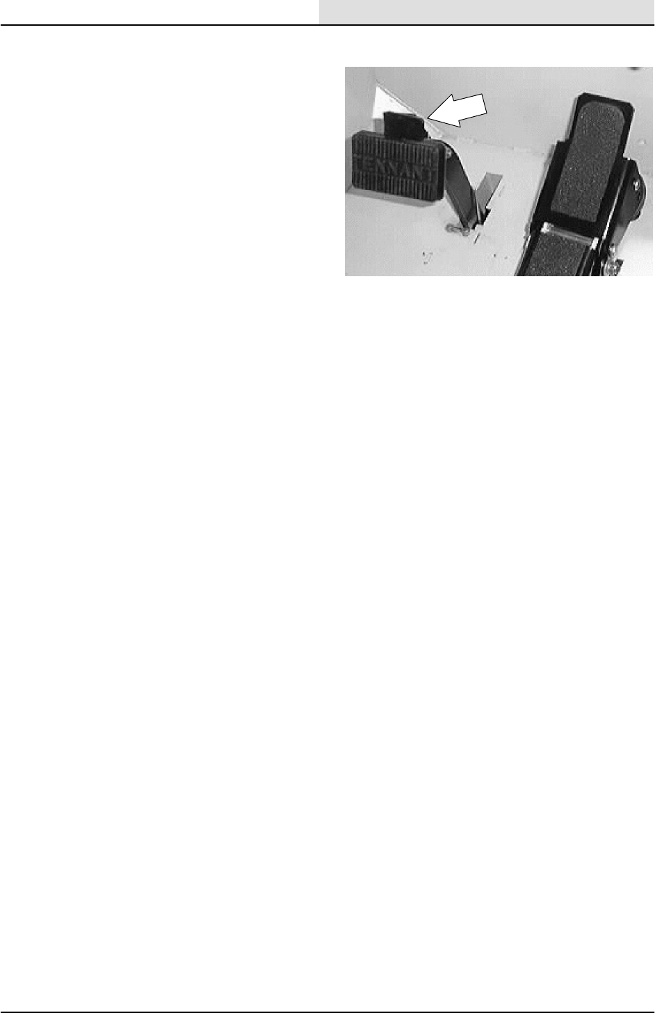
SERVICE BRAKES
The mechanical service brakes are located on the
front wheels. The brakes are operated by the foot
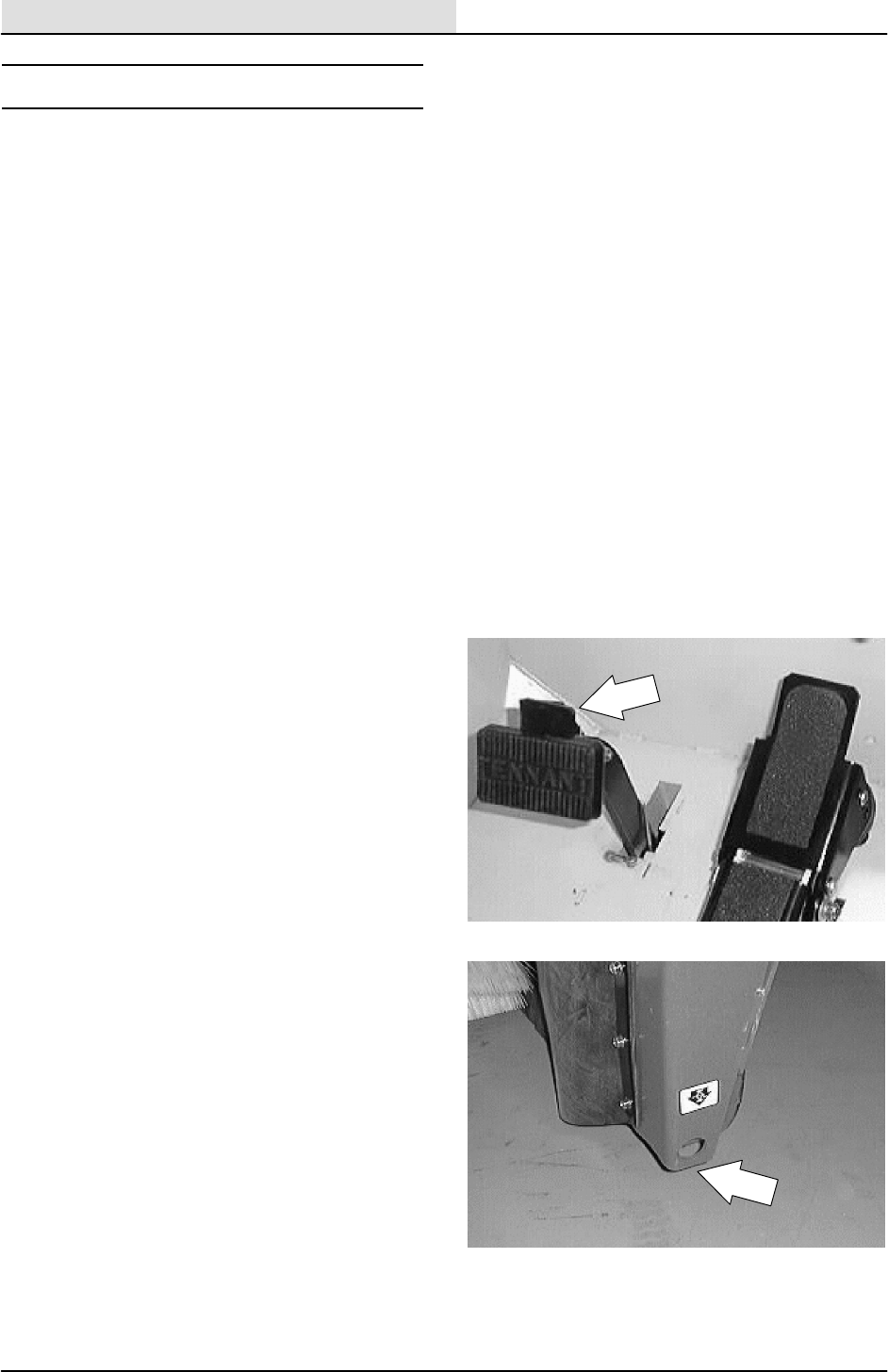
brake pedal and connecting rods.
Check the brake adjustment every 200 hours of
operation. The brake pedal should not travel more
than 25 mm (1 in) to fully engage the brakes.
TO REPLACE BRAKE SHOES
FOR SAFETY: Before Leaving Or
Servicing Machine; Stop On Level
Surface, Set Parking Brake, Turn Off
Machine And Remove Key.
1. Disengage the parking brake if activated.
2. Jack up one front corner of the machine.
Place jack stands under machine frame.
FOR SAFETY: Block machine tires
before jacking machine up. Jack
machine up at designated locations
only. Block machine up with jack
stands.

CHASSIS
2-5
8200/8210 330065 (3--01)
3. Remove the hub cap in the center of front
wheel.
4. Remove the cotter pin, slotted nut, and flat
washer.
5. Slide the wheel off the axle.
6. Remove the one large ”C” shaped tension
spring holding the old brake shoes together.
Remove the old brake shoes.
7. Replace the old brake shoes with new brake
shoes.
CHASSIS
2-6 8200/8210 330065 (3--01)
8. Reinstall the one large ”C” shaped brake
tension spring on the new brake shoes.
9. Slide the wheel back on the axle.
10. Reinstall the flat washer and nut on the axle
shaft.
11. Tighten the nut with a hand wrench until the
wheel binds, then back the nut off to nearest
cotter pin hole.
12. Insert a new cotter pin through nut and hole.
13. After making sure the wheel spins freely,
carefully reinstall the hub cap.
14. Repeat the procedure on the other wheel.
15. Remove the jackstands and lower the
machine.
16. Drive the machine and operate the brakes.
Check for proper operation.
CHASSIS
2-7
8200/8210 330065 (3--01)
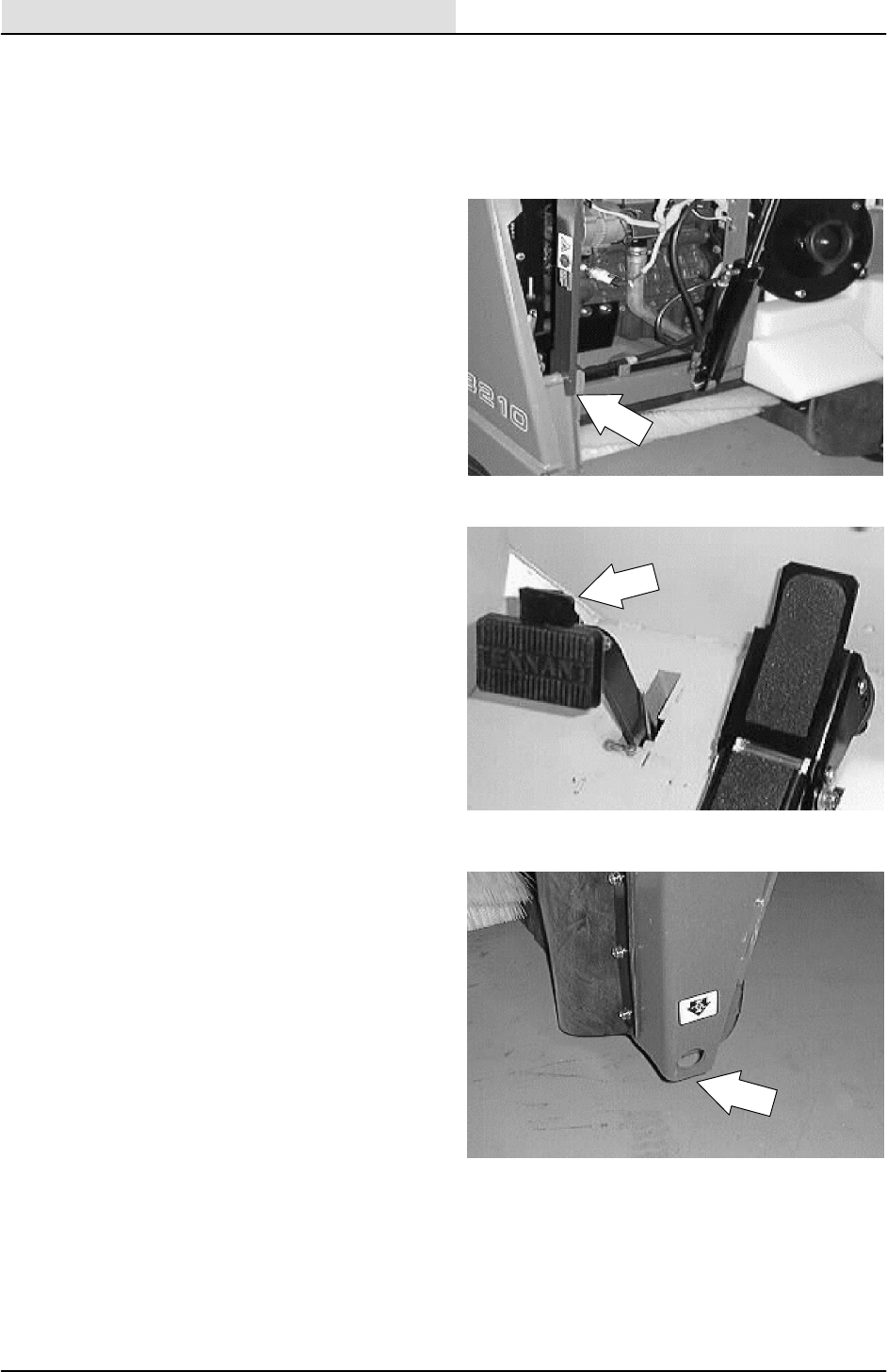
PARKING BRAKE
The parking brake is set with the parking brake
lever that activates the service brakes.
Adjust the parking brake whenever it becomes
very easy to set, when the machine rolls after
setting the parking brake, and after every 200
hours of operation. The parking brake may be
tightened by adjusting the brake rod clevis on the
ends of the brake cross shaft. See TO ADJUST
BRAKES instructions. Adjust the parking brake so
it will hold the machine on a smooth 8 degree
incline. The brake pedal should not travel more
than 25 mm (1 in) to fully engage the brakes.
CHASSIS
2-8 8200/8210 330065 (3--01)
TO ADJUST BRAKES
FOR SAFETY: Before Leaving Or
Servicing Machine; Stop On Level
Surface, Set Parking Brake, Turn Off
Machine And Remove Key.
1. Raise the hopper and engage the support
bar. Open the engine side door.
2. Disengage the parking brake if activated.
3. Jack up one front corner of the machine.
Place jack stands under machine frame.
FOR SAFETY: Block machine tires
before jacking machine up. Jack
machine up at designated locations
only. Block machine up with jack
stands.
CHASSIS
2-9
8200/8210 330065 (3--01)
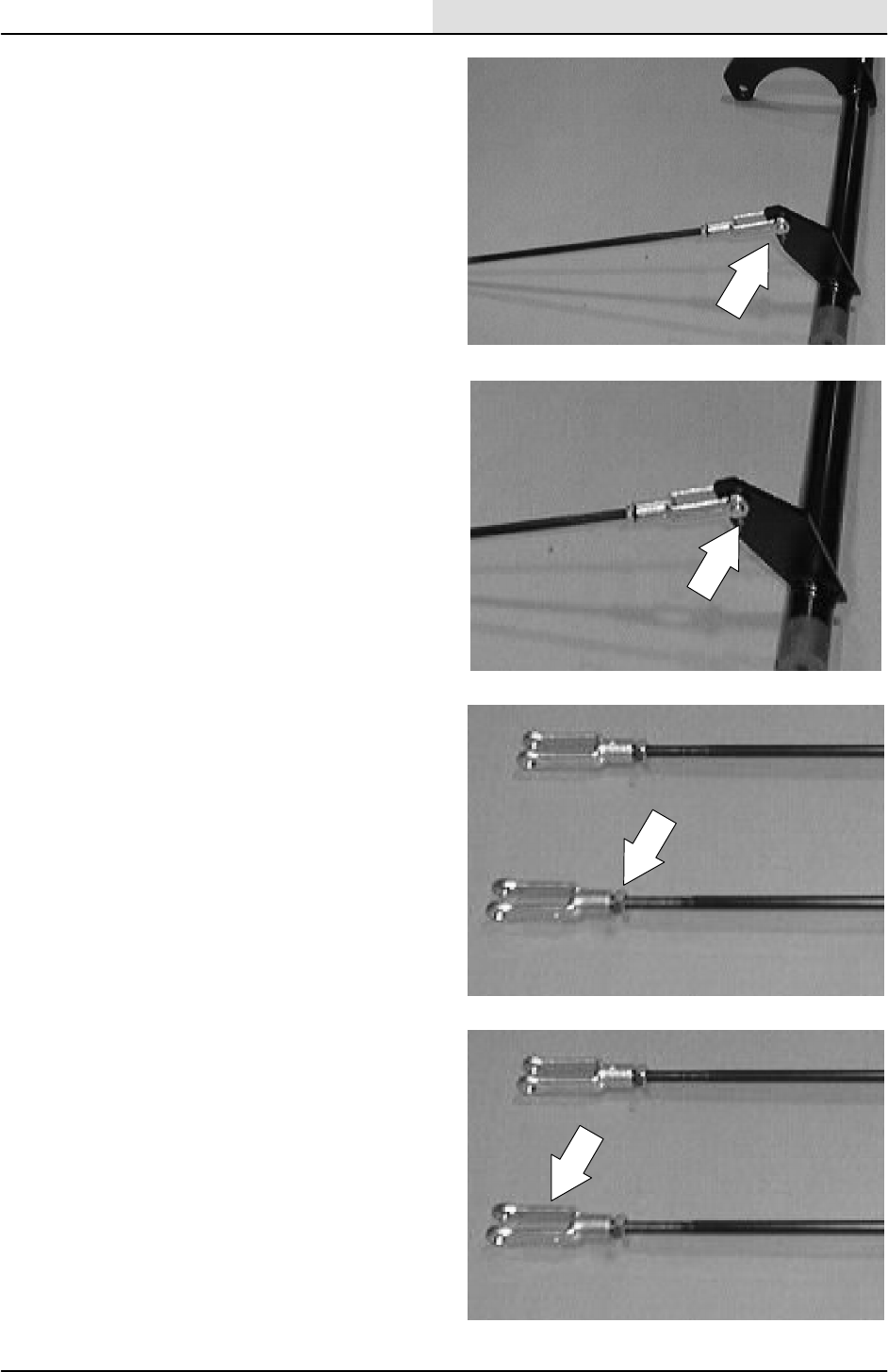
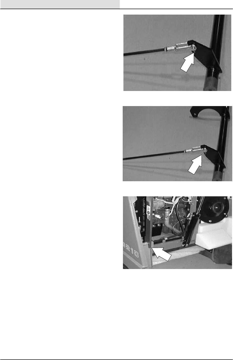
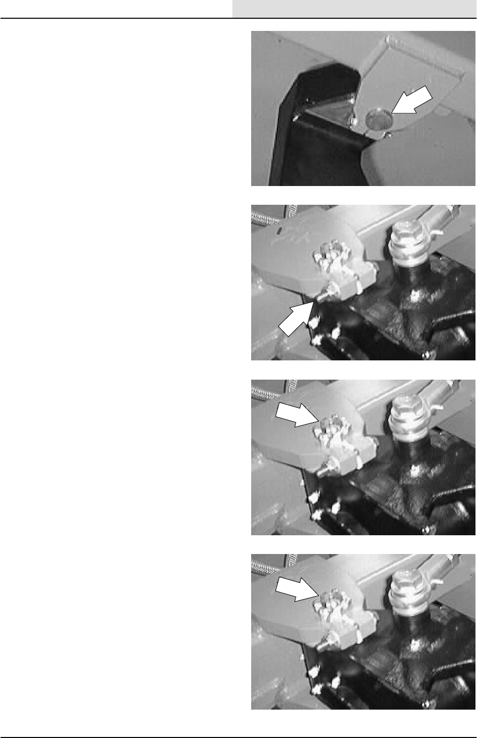
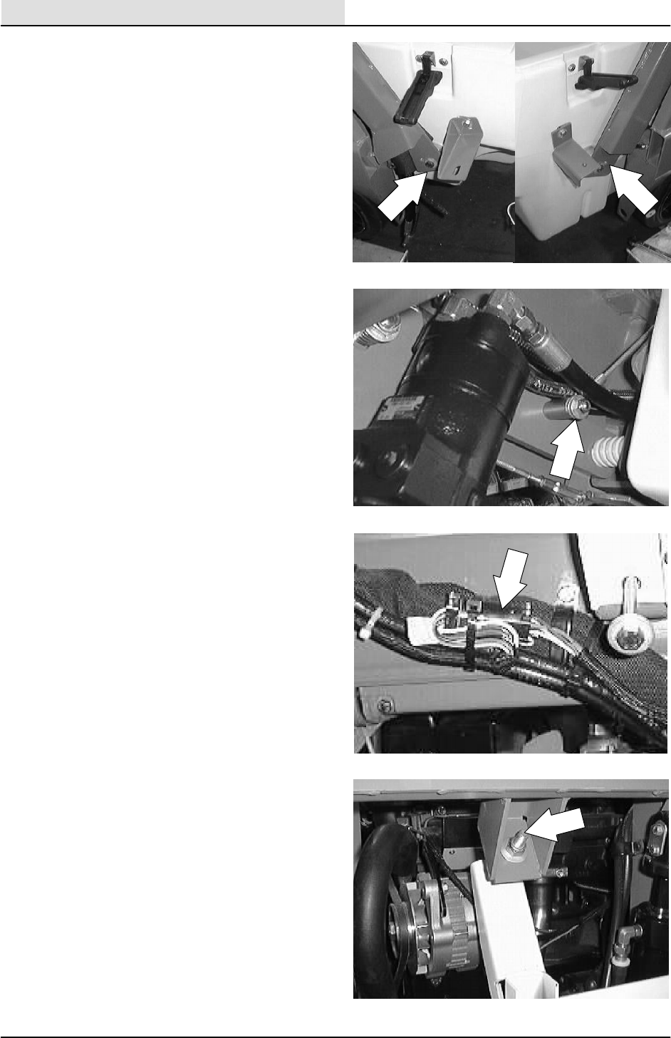
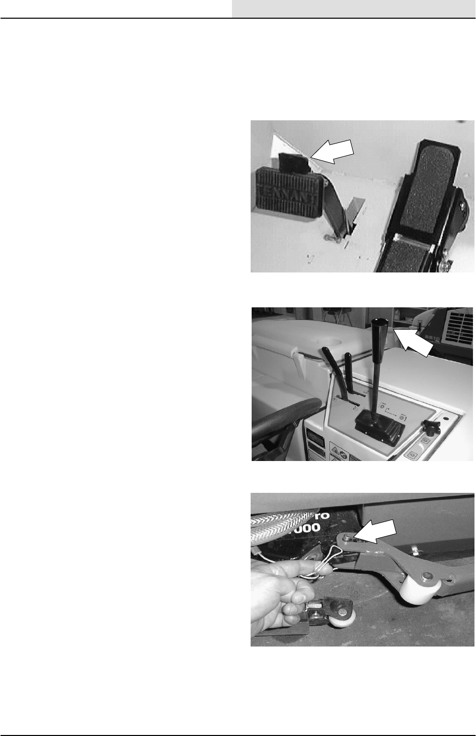
4. Locate the right side brake rod clevis near
the front, lower corner of the engine radiator
and the left side brake rod clevis below the
detergent tank in the engine compartment.
5. Remove the cotter pin and the clevis pin
holding the brake rod clevis to the brake
assembly lever.
6. Loosen the jam nut on the brake rod.
7. Turn the clevis in or out to achieve proper
adjustment and pedal travel. The pedal
should move approximately 1” before
engaging the brakes.
CHASSIS
2-10 8200/8210 330065 (3--01)
8. Reinstall the cotter pin and the clevis pin in
the brake rod clevis and the brake assembly
lever.
9. Repeat the procedure on both sides.
10. Close the engine side door. Disengage the
support bar and lower the hopper.
11. Drive the machine and operate the brakes.
Check for equal engagement of the brakes
on both wheels.
CHASSIS
2-11
8200/8210 330065 (3--01)
FRONT TIRES AND WHEELS
The machine front tires are solid. Inspect the front
wheel bearings for seal damage.
TO REPLACE FRONT WHEEL BEARINGS
FOR SAFETY: Before Leaving Or
Servicing Machine; Stop On Level
Surface, Set Parking Brake, Turn Off
Machine And Remove Key.
1. Disengage the parking brake if activated.
2. Jack up one front corner of the machine.
Place jack stands under machine frame.
FOR SAFETY: Block machine tires
before jacking machine up. Jack
machine up at designated locations
only. Block machine up with jack
stands.
CHASSIS
2-12 8200/8210 330065 (3--01)
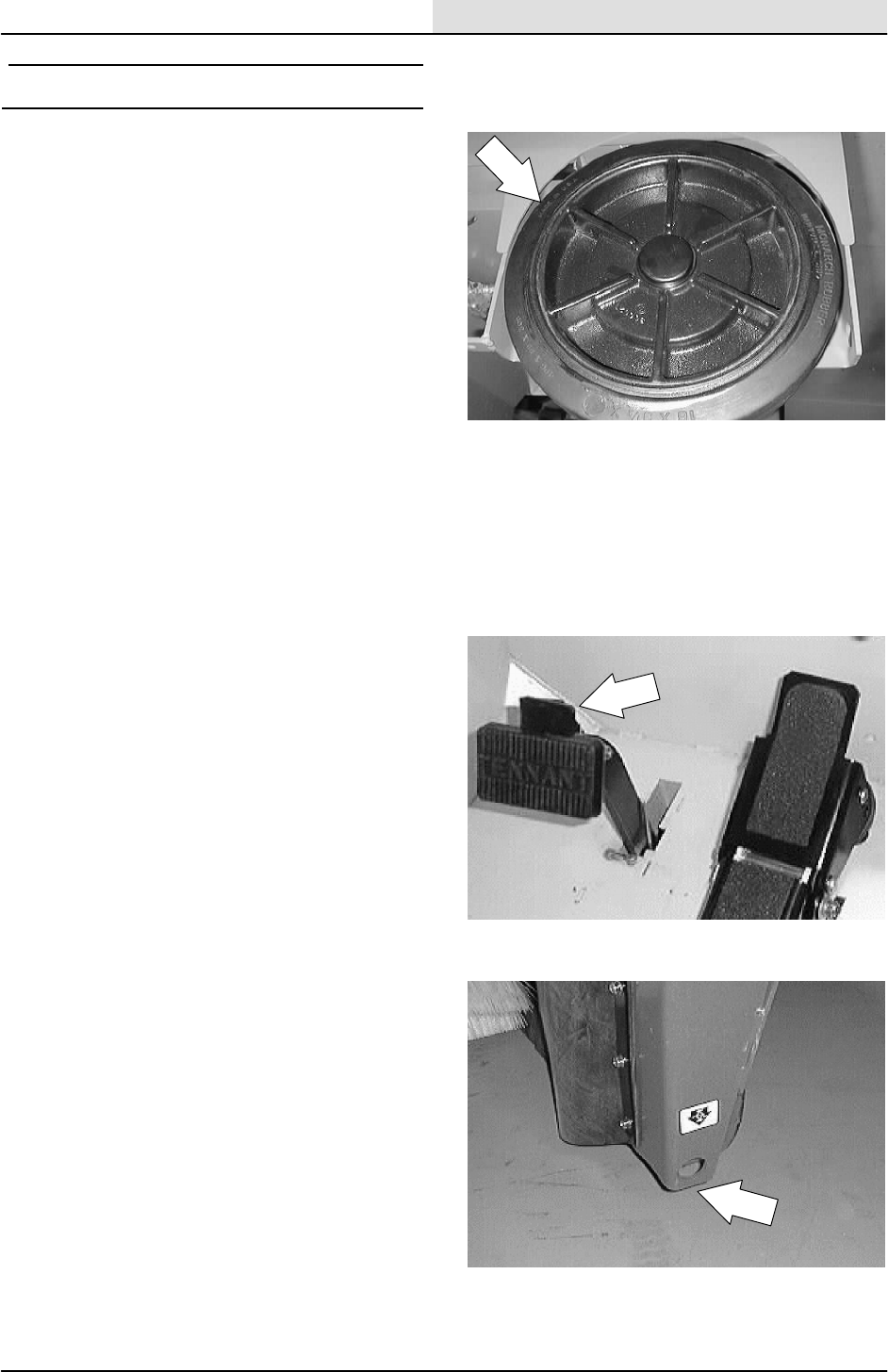
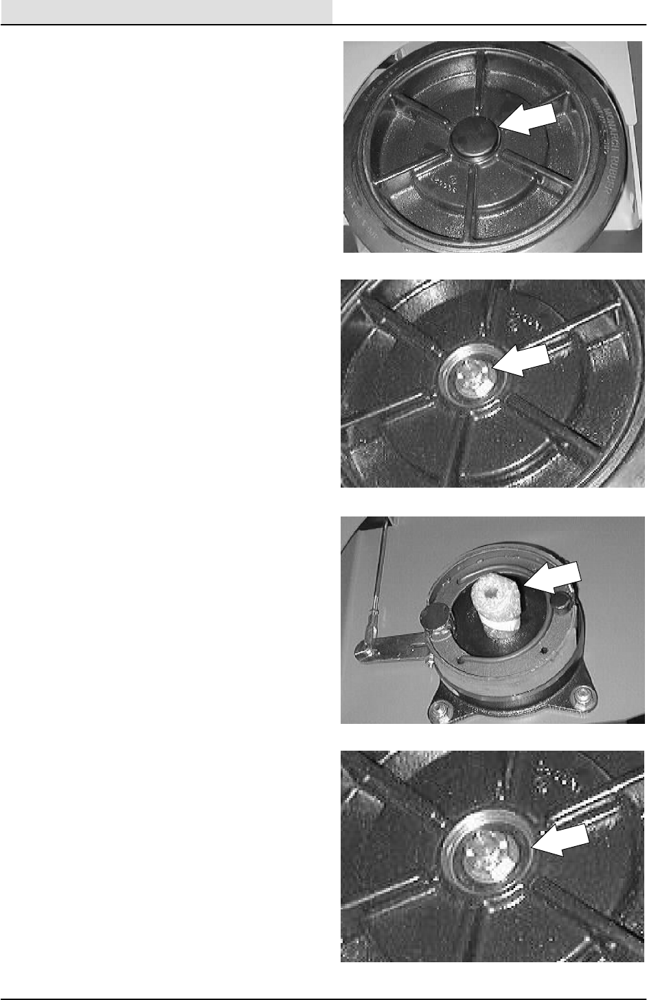
3. Remove the hub cap in the center of front
wheel.
4. Remove the cotter pin, slotted nut, and flat
washer.
5. Slide the wheel off the axle.
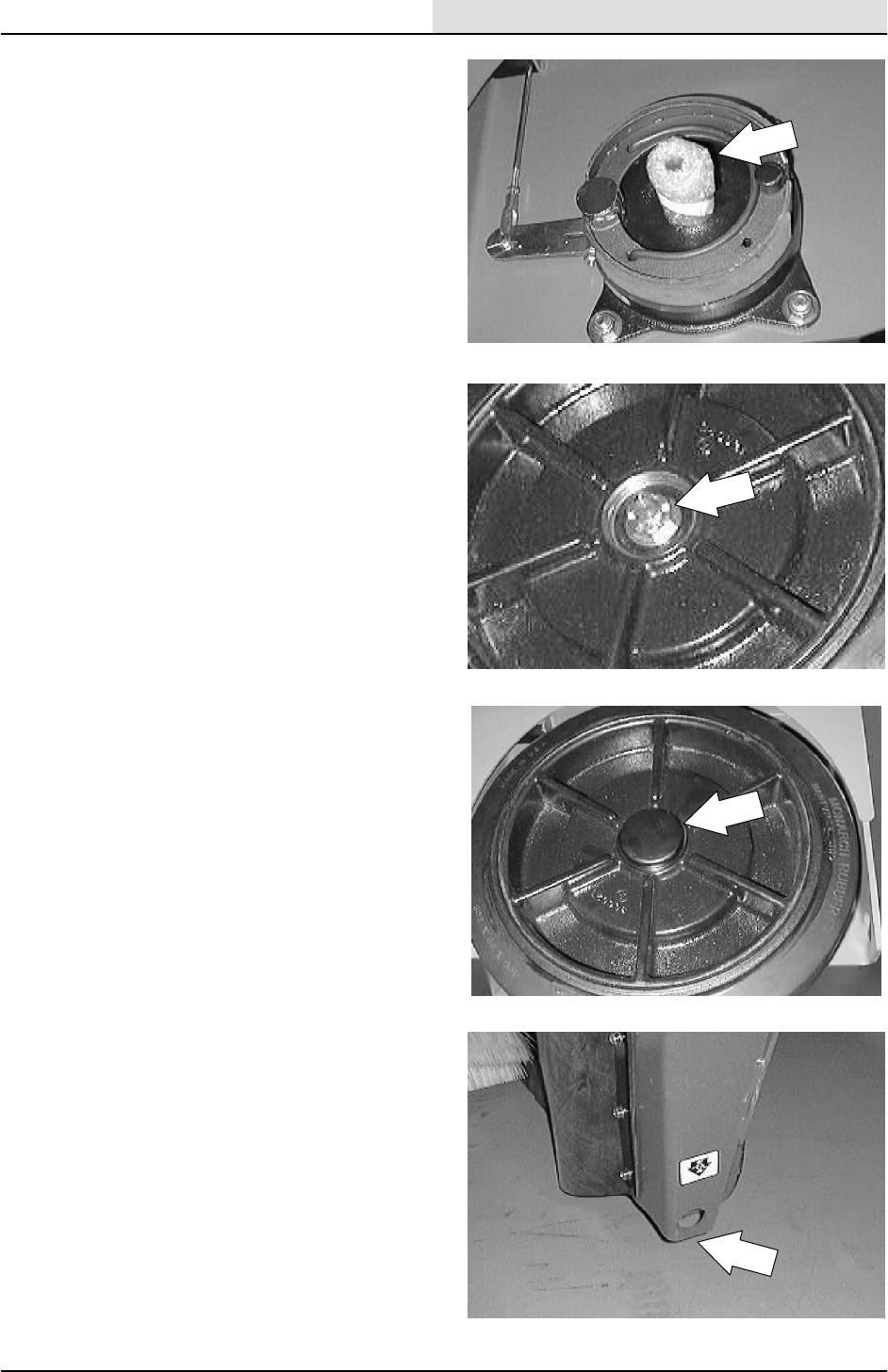
6. Press the old bearings out. Press the new
bearings in the wheel in the same
orientation.
CHASSIS
2-13
8200/8210 330065 (3--01)
7. Slide the wheel back on the axle.
8. Slide the flat washer and nut on the shaft.
9. Tighten the nut with a hand wrench until the
wheel binds, then back the nut off to nearest
cotter pin hole.
10. Insert a new cotter pin through nut and hole.
11. After making sure the wheel spins freely,
carefully reinstall the hub cap.
12. Remove the jackstands and lower the
machine.
13. Repeat the procedure on the other wheel.
CHASSIS
2-14 8200/8210 330065 (3--02)
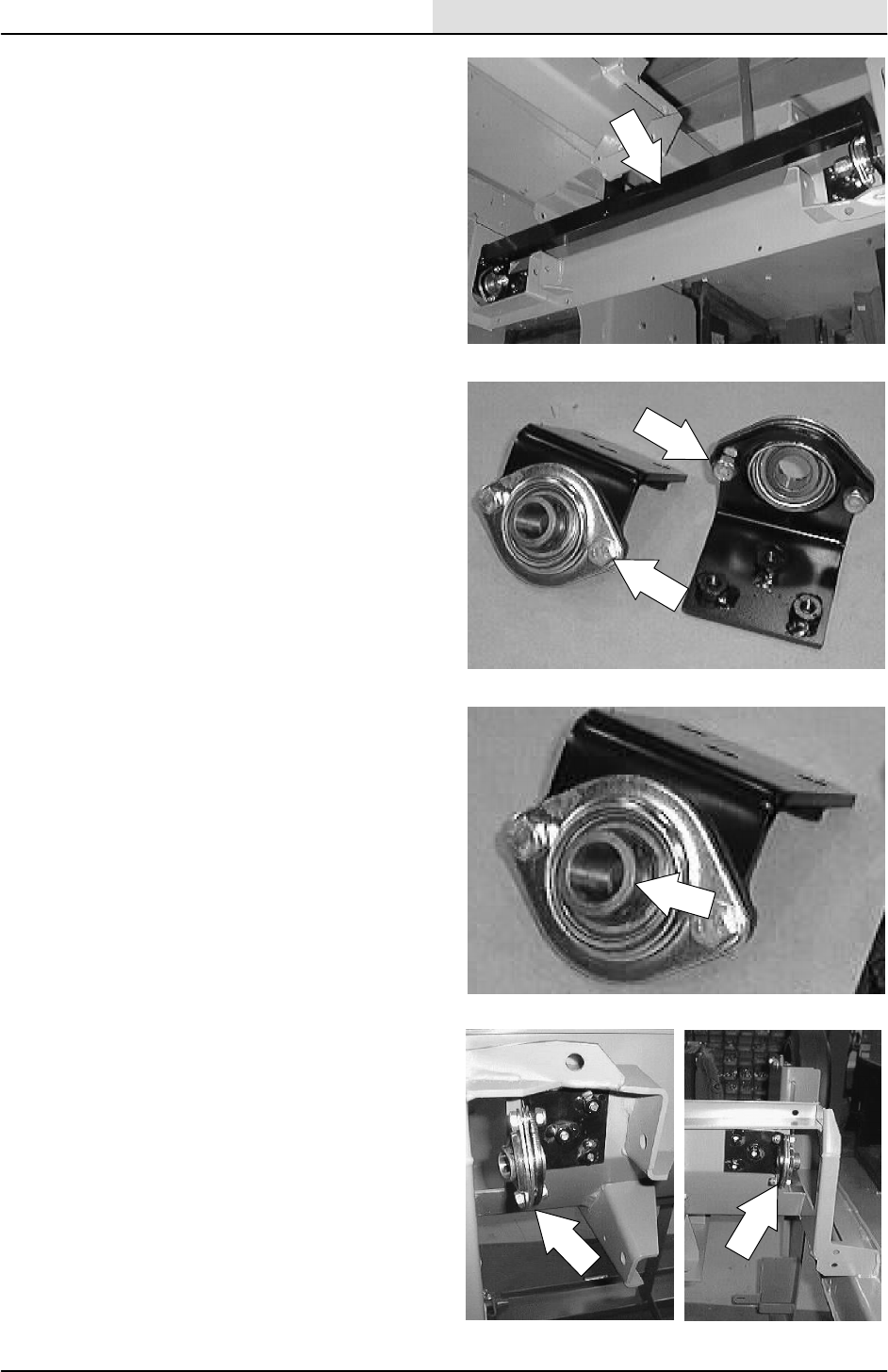
REAR TIRE AND WHEEL, AND WHEEL
SUPPORT
The standard rear machine tire is solid. The rear
wheel support pivots the rear drive wheel. It
consists of the rear tire and drive motor. The
support has two grease fittings for the bearings.
The rear wheel support bearings must be
lubricated every 200 hours of operation. Use
Lubriplate EMB grease (TENNANT part no.
01433--1).
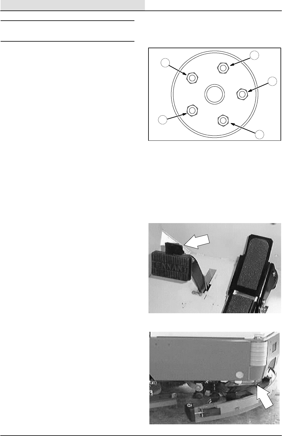
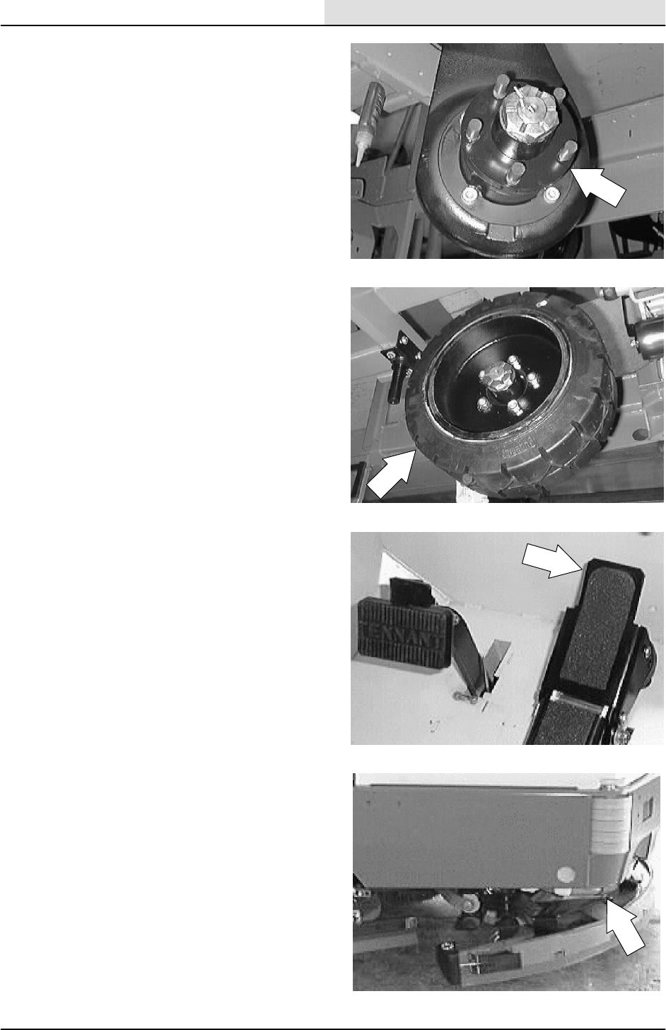
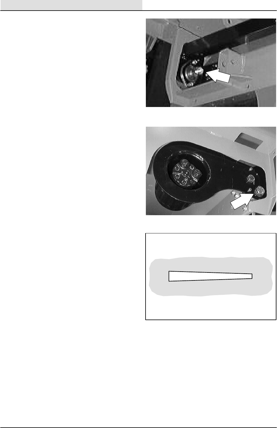
Torque the rear wheel nuts twice in the pattern
shown to 122 to 150 Nm (90 to 110 ft lb) after the
first 50-hours of operation, and every 800 hours
there after.
TO REPLACE REAR WHEEL HOUSING PIVOT
BEARINGS
FOR SAFETY: Before Leaving Or
Servicing Machine; Stop On Level
Surface, Set Parking Brake, Turn Off
Machine And Remove Key.
1. Engage parking brake, block front tires.
2. Jack up rear of machine. Use jack stands to
support machine.
FOR SAFETY: Block machine tires
before jacking machine up. Jack
machine up at designated locations
only. Block machine up with jack
stands.
2
3
4
1
5
CHASSIS
2-15
8200/8210 330065 (3--01)
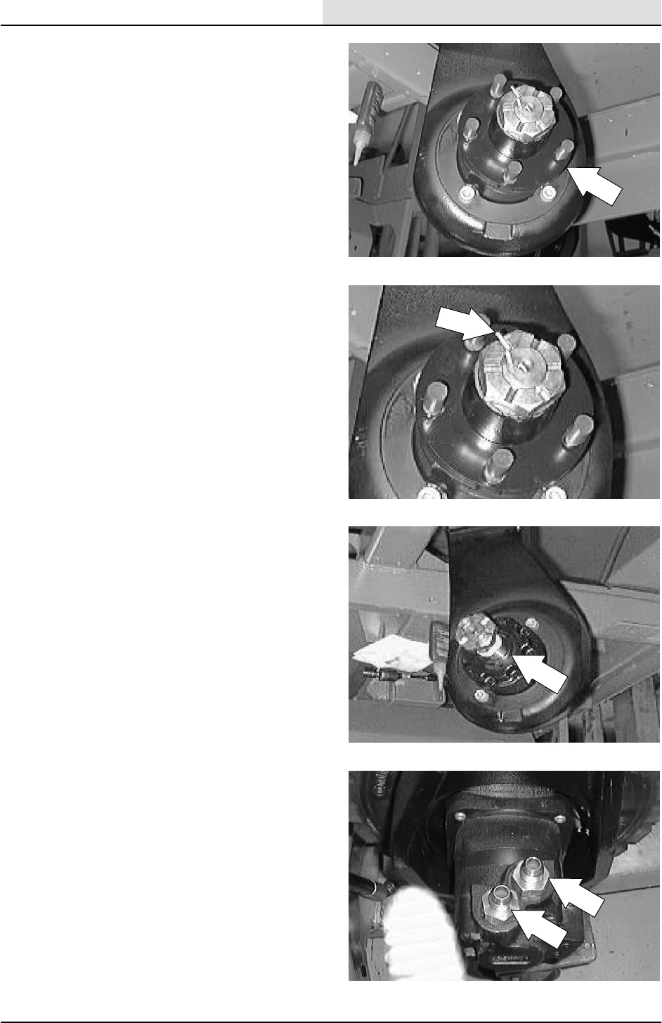
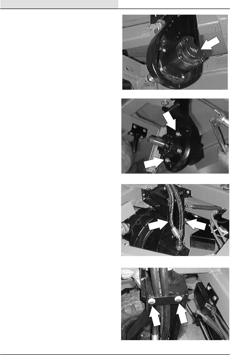
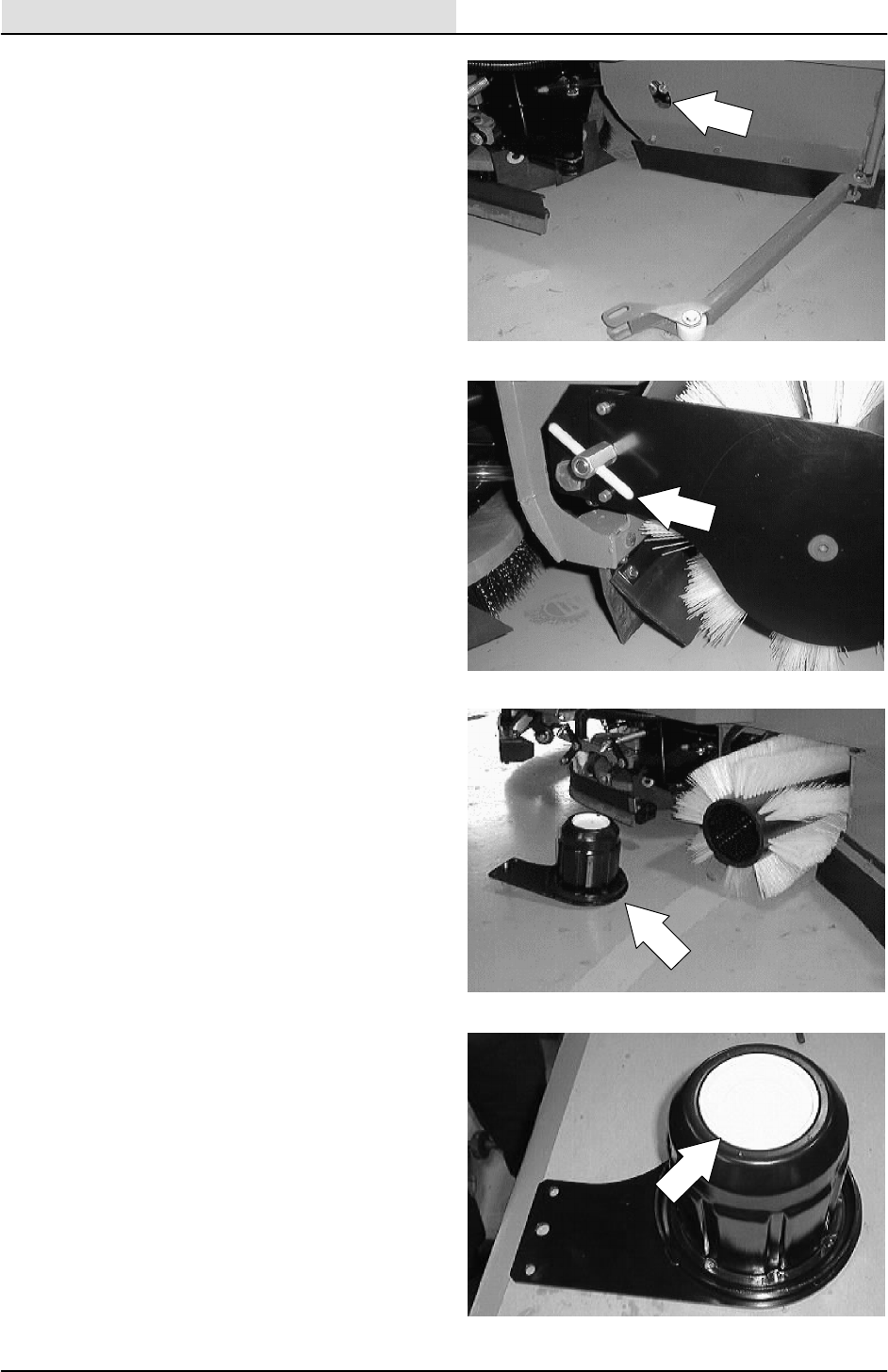
3. Remove the rear tire and wheel assembly
from the drive motor hub.
4. Remove the cotter pin and slotted nut from
drive motor shaft and hub.
5. Use a puller to remove the drive hub from
the tapered motor shaft.
6. Mark, disconnect, and plug the hydraulic
hoses leading to the the drive motor.
NOTE: Observe hydraulic cleanliness
requirements when opening hydraulic lines.
CHASSIS
2-16 8200/8210 330065 (3--01)
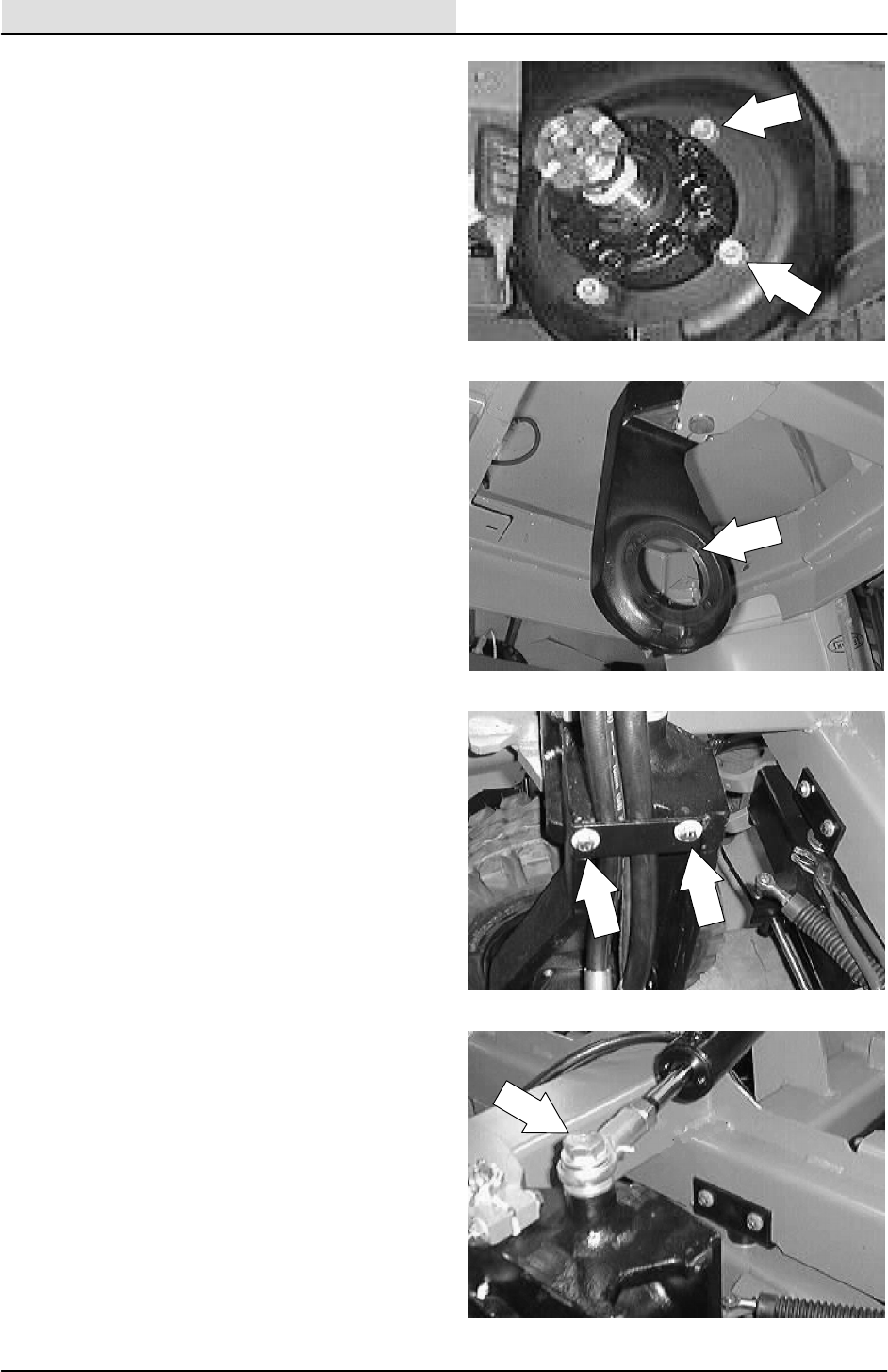
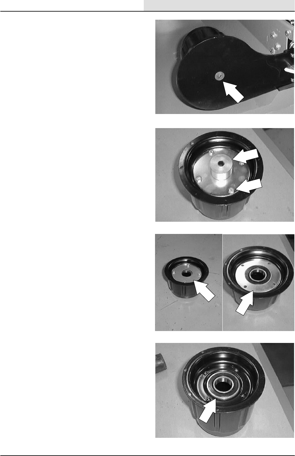
7. Remove the rear drive motor mounting bolts.
8. Slide the rear drive motor out of the wheel
housing.
9. Remove the hydraulic hose clamp from the
wheel housing.
10. Remove the hex screw and nyloc nut
attaching the rod end of steering cylinder to
rear wheel housing.
CHASSIS
2-17
8200/8210 330065 (3--01)
11. Loosen the two hex screws holding the drive
casting pivot pin in the frame.
12. Remove the cotter pin from the large slotted
nut on top of the rear casting pivot pin.
Remove the slotted nut.
13. Drop the pivot pin down and out of the
machine.
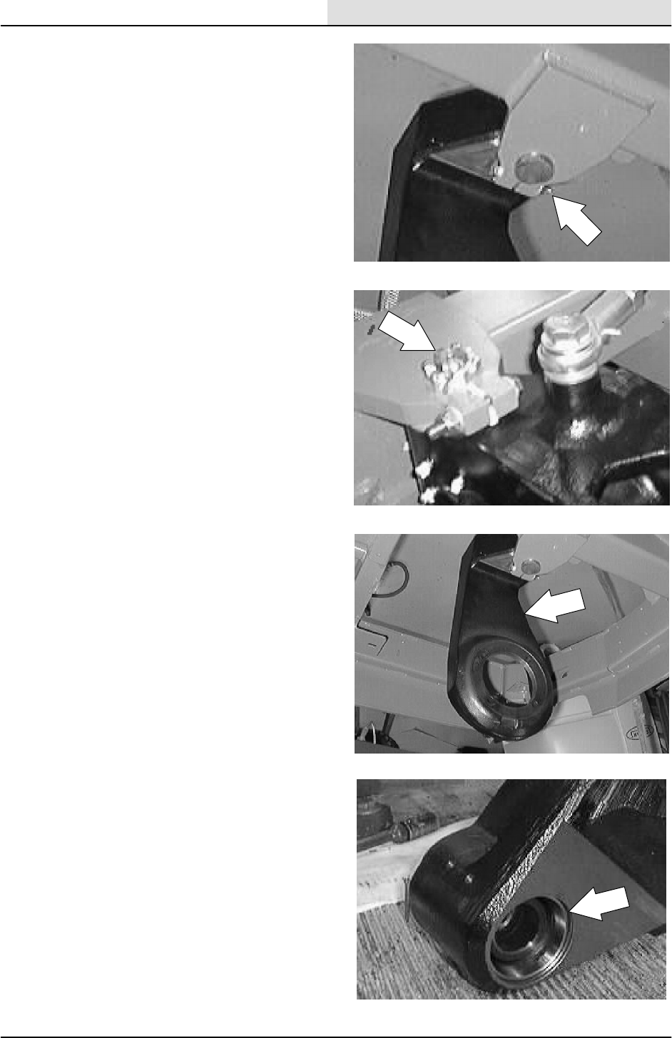
14. Slide the wheel housing out of the main
frame.
NOTE: Make sure to retain the thrust washer and
felt washer from between the top of the drive
casting and machine frame.
15. Remove the two bearing cones from the
drive casting.
CHASSIS
2-18 8200/8210 330065 (3--01)
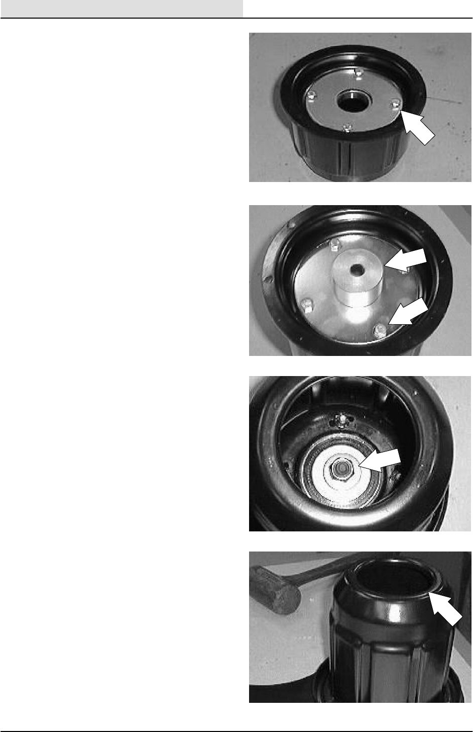
16. Remove and replace the pressed in bearing
cups in the drive casting.
17. Pack the new bearing cones with Lubriplate
EMB grease. Coat the bearing cups with
grease.
18. Position the new bearings in the housing.
NOTE: Make sure the bearing grease tube is
installed in the casting before installing the
bearings.
19. Position the thrust washer and felt washer
on top of the drive casting.
20. Slide the wheel housing in position in main
frame.
CHASSIS
2-19
8200/8210 330065 (3--01)
21. Slide the pivot pin up through the frame
hole. Thread castle nut on the pin. Tighten to
34 -- 40 Nm (25 -- 30 ft lb). Check for any
play. If the pin is not seated, tap with rubber
mallet and re--torque castle nut.
22. Torque the two hex screws to 37 -- 48 Nm
(26 -- 34 ft lb).
23. Tighten the castle nut to next slot and insert
the cotter pin. Torque not to exceed 100 Nm
(75 ft lb).
24. Re--connect the rod end of the steering
cylinder to the wheel housing using the
.750x3.25 hex screw, nyloc nut, and flat
washers. Tighten to 270 -- 300 Nm
(200 -- 220 ft lb).
CHASSIS
2-20 8200/8210 330065 (3--01)
25. Slide the drive motor in the wheel housing.
Note the motor orientation.
26. Thread the four hex screws through the
wheel housing and into the motor. Tighten to
88--115 Nm (65--85 ft lb).
27. Reconnect the hydraulic hoses. See
schematic in the HYDRAULICS section.
28. Reinstall the hose clamp to the wheel
housing. Tighten the hex screws to
18.5 -- 24Nm (15 -- 20 ft lb).
CHASSIS
2-21
8200/8210 330065 (3--01)
29. Mount the hub to the tapered motor shaft.
Tighten the slotted nut to (275 ft lb). Torque
to the next slot in nut. DO NOT back nut off
to install cotter pin. Install the cotter pin.
NOTE: Make sure the key is installed on the
tapered shaft of the drive motor and a small
amount of grease is placed on the shaft.
30. Install the rear tire and wheel assembly.
Torque the rear wheel nuts to 100 -- 120 Nm
(85 -- 95 ft lb).
31. Start the engine. Run the propelling in both
directions. Check for any leaks.
32. Remove the jack stands and lower the
machine to the ground.

CHASSIS
2-22 8200/8210 330065 (3--01)

SWEEPING
3-1
8200/8210 330065 (3--01)
CONTENTS
Page
INTRODUCTION 3--3......................
DEBRIS HOPPER 3--4.....................
TO REMOVE HOPPER 3--4.............
TO INSTALL HOPPER 3--7..............
TO ADJUST HOPPER LIP HEIGHT 3--10.
TO ADJUST HOPPER BUMPER 3--11....
HOPPER LIFT ARM 3--12..................
TO REMOVE HOPPER LIFT ARM 3--12..
TO INSTALL HOPPER LIFT ARM 3--14...
HOPPER LIFT ARM ADJUSTMENT
BOLTS 3--15........................
HOPPER DUMP DOOR 3--16...............
TO REMOVE HOPPER DUMP DOOR 3--16
TO INSTALL HOPPER DUMP DOOR 3--18
HOPPER DUST FILTER 3--19..............
TO REPLACE HOPPER DUST
FILTER 3--20........................
TO REMOVE FILTER SHAKER
ASSEMBLY 3--21....................
TO INSTALL FILTER SHAKER
ASSEMBLY 3--22....................
MAIN BRUSH 3--23.......................
TO REPLACE MAIN BRUSH 3--23.......
TO CHECK AND ADJUST MAIN
BRUSH PATTERN 3--27..............
TO REPLACE MAIN BRUSH IDLER
PLUG BEARING 3--29...............
TO REPLACE MAIN BRUSH SHAFT
BEARINGS 3--34....................
SIDE BRUSH 3--37........................
TO REPLACE SIDE BRUSH 3--37........
TO ADJUST SIDE BRUSH PATTERN 3--40
TO ADJUST SIDE BRUSH LATERAL
TILT PATTERN 3--41.................
TO ADJUST SIDE BRUSH FORE/AFT
TILT PATTERN 3--43.................
SIDE BRUSH GUARD 3--45.............
TO ROTATE OR REPLACE SIDE
BRUSH GUARD 3--45................
Page
SKIRTS AND SEALS 3--46.................
HOPPER LIP SKIRT 3--46..................
TO REPLACE HOPPER LIP SKIRT 3--46..
BRUSH DOOR SKIRTS 3--49...............
TO REPLACE AND ADJUST RIGHT
HAND BRUSH DOOR SKIRT 3--49....
TO REPLACE AND ADJUST LEFT
HAND BRUSH DOOR SKIRT 3--53....
REAR SKIRT AND DEFLECTOR BLADE 3--56
TO REPLACE AND ADJUST THE
REAR SKIRT AND DEFLECTOR
BLADE 3--56.....................
HOPPER SEALS 3--60.....................
TO REPLACE HOPPER SEALS 3--60.....
HOPPER DUST SEAL 3--62................
HOPPER VACUUM FAN SEAL 3--62........
HOPPER DUMP DOOR SEALS 3--62........
TO REPLACE HOPPER DUMP
DOOR SEALS 3--63.................
SWEEPING VACUUM FAN 3--65............
TO REMOVE SWEEPING VACUUM
FAN ASSEMBLY 3--65...............
TO INSTALL SWEEPING VACUUM
FAN ASSEMBLY 3--68...............
MACHINE TROUBLESHOOTING 3--71......

SWEEPING
3-2 8200/8210 330065 (3--01)

SWEEPING
3-3
8200/8210 330065 (3--01)
INTRODUCTION
The side brush sweeps debris into the path of the
main brush. The main brush sweeps debris from
the floor into the hopper. The vacuum system
pulls dust and air through the hopper and the
hopper dust filter.
SWEEPING
3-4 8200/8210 330065 (3--01)
DEBRIS HOPPER
The debris hopper collects the debris swept up by
the machine. The hopper includes the following
main components: hopper dust filter, Thermo
Sentry, hopper dump door, and dust skirts. All
adjustments have been made at the factory and
require no regular maintenance. If hopper
components are repaired or replaced, some
components may need to be readjusted for best
performance. The hopper may need to be
removed from the machine for some repair or
service work.
TO REMOVE HOPPER
FOR SAFETY: Before Leaving Or
Servicing Machine; Stop On Level
Surface, Set Parking Brake.
1. Start the machine and raise the hopper and
open the dump door. Engage the support
bar.
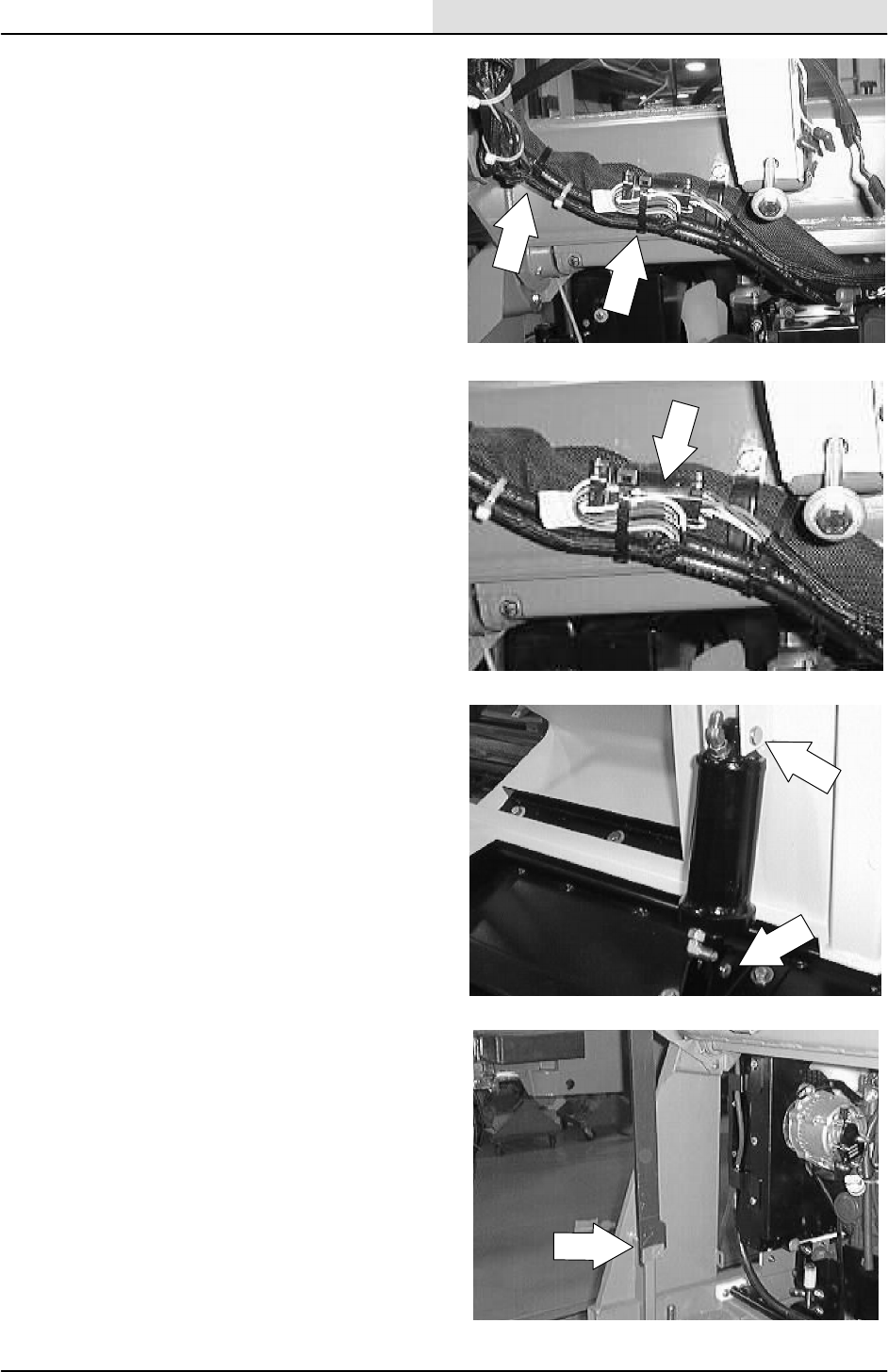
2. Remove the hopper level adjustment bolt,
nut, and washers.
SWEEPING
3-5
8200/8210 330065 (3--01)
3. Cut the plastic ties holding the hopper
harness to the main harness.
4. Unplug the hopper harness connectors from
the main harness.
5. Remove the two clevis pins holding the
dump door cylinder to the back of the
hopper. Let the cylinder drop out of the way.
6. Disengage the hopper support bar and lower
the hopper. Place blocks under the hopper.
FOR SAFETY: Before Leaving Or
Servicing Machine; Stop On Level
Surface, Set Parking Brake, Turn Off
Machine And Remove Key.
SWEEPING
3-6 8200/8210 330065 (3--01)
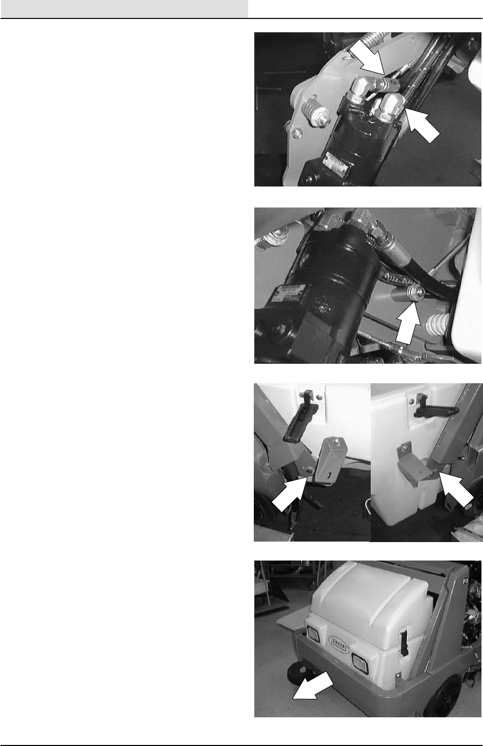
7. Disconnect and plug the hydraulic hoses
leading to the side brush motor.
NOTE:Observe hydraulic cleanliness
requirements when opening hydraulic lines.
8. Disconnect the side brush lift cable at the
hydraulic motor.
9. Remove the two hex screws holding the
pivot pins to each side of the hopper lift arm.
10. The hopper can now be removed from the
machine. Remove and retain the hopper
pivot pins from the molded pockets in the
sides of the hopper.
SWEEPING
3-7
8200/8210 330065 (3--01)
TO INSTALL HOPPER
FOR SAFETY: Before Leaving Or
Servicing Machine; Stop On Level
Surface, Set Parking Brake, Turn Off
Machine And Remove Key.
1. Position the hopper in front of machine.
Make sure the hopper is sitting on two wood
blocks.
NOTE: Be careful not to pinch hydraulic hoses or
electrical wires during this procedure.
2. Reconnect the hydraulic hoses to the side
brush motor. See the schematic in the
HYDRAULICS section.
NOTE:Observe hydraulic cleanliness
requirements when opening hydraulic lines.
3. Position the two hopper pivot pins into the
molded pockets in the sides of the hopper.
SWEEPING
3-8 8200/8210 330065 (3--01)
4. Line up the holes in the hopper pivot pins
with the slots in the hopper lift arms. Install
the two hex screws. Leave loose for now.
5. Reconnect the side brush lift cable at the
side brush assembly.
6. Reconnect the hopper harness to the main
harness. See the schematic in the
ELECTRICAL section.
7. Reinstall the lip height adjustment bolt on
the back of the hopper.
SWEEPING
3-9
8200/8210 330065 (3--01)
8. Push the hopper back and line up the
hopper bumper with the machine frame
bumper. Tighten the two hopper pivot pin
hex screws to 64 -- 83 Nm (47 -- 61 ft lb).
9. Position the dump door lift cylinder onto the
back of the hopper and dump door. Reinstall
the two clevis pins and cotter pins.
10. Start engine and check for proper operation
of dump door, side brush rotation and side
brush up and down.
SWEEPING
3-10 8200/8210 330065 (3--01)
TO ADJUST HOPPER LIP HEIGHT
FOR SAFETY: Before Leaving Or
Servicing Machine; Stop On Level
Surface, Set Parking Brake, Turn Off
Machine And Remove Key.
1. The hopper lip height adjustment should be
2.5 inches from the floor to the hopper
bottom.
2. To achieve this measurement, adjust the
length of the adjustment bolt on the back of
the hopper.
SWEEPING
3-11
8200/8210 330065 (3--01)
TO ADJUST HOPPER BUMPER
FOR SAFETY: Before Leaving Or
Servicing Machine; Stop On Level
Surface, Set Parking Brake, Turn Off
Machine And Remove Key.
1. Loosen the four hex screws and nyloc nuts
holding the hopper bumper to the sides of
the hopper.
2. Loosen the three hex screws holding the
hopper bumper to the front of the hopper.
3. Adjust the hopper bumper so it is level with
the machine frame.
4. Firmly tighten all of the hardware.
SWEEPING
3-12 8200/8210 330065 (3--01)
HOPPER LIFT ARM
The hopper lift arm assembly and hopper lift
cylinder raises and lowers the debris hopper. The
lift arm is held in place by two pivot pins.
TO REMOVE HOPPER LIFT ARM
FOR SAFETY: Before Leaving Or
Servicing Machine; Stop On Level
Surface, Set Parking Brake, Turn Off
Machine And Remove Key.
1. Remove the debris hopper. See TO
REMOVE HOPPER FROM MACHINE
instructions.
2. Remove the upper, hopper lift cylinder pin.
SWEEPING
3-13
8200/8210 330065 (3--01)
3. Raise up slightly on the lift arm to take
pressure off the cylinder pin. Remove the
pin.
4. Remove the socket screws holding the
hopper pivot pins to the frame towers.
5. Raise up slightly on the lift arm to take
pressure off the pins. Remove the pins and
washers and remove the lift arm from the
machine.
6. If the large self aligning bearing needs to be
changed, remove retaining rings and press
the old bearing out of the lift arm.
SWEEPING
3-14 8200/8210 330065 (3--01)
TO INSTALL HOPPER LIFT ARM
FOR SAFETY: Before Leaving Or
Servicing Machine; Stop On Level
Surface, Set Parking Brake, Turn Off
Machine And Remove Key.
1. Position lift arm in the machine, aligning the
upper bearings in the lift arm with the holes
in the towers of the machine.
NOTE: Make sure the side brush lift cable is
looped over the plastic pulley on the right hand lift
arm pin.
2. Install the lift arm pins in the bearings from
the inside of the machine. Make sure to
reinstall the spacer washers that were
removed when the pins were removed.
3. Align the hole in lift arm pin with the hole in
the pin boss on the tower. Install the socket
screws and tighten to 18 -- 24 Nm
(13 -- 18 ft lb).
SWEEPING
3-15
8200/8210 330065 (3--01)
4. Align the small fiberglide bearing in the lift
arm cylinder lug with the hole in the clevis on
the hopper lift cylinder. Reinstall the cylinder
pin and cotter pins.
5. Reinstall the hopper assembly. See TO
INSTALL HOPPER instructions.
HOPPER LIFT ARM ADJUSTMENT BOLTS
FOR SAFETY: Before Leaving Or
Servicing Machine; Stop On Level
Surface, Set Parking Brake, Turn Off
Machine And Remove Key.
1. The lift arm adjustment bolts are used to
position the lift arms correctly. The left side
bolt should be 2.25 inch from the top of the
bolt head to the frame. The right side bolt
should be 1.21 inch from the top of the bolt
head to the frame
SWEEPING
3-16 8200/8210 330065 (3--01)
HOPPER DUMP DOOR
The hopper dump door is used to control debris
when dumping. It also seals the hopper to the
main brush compartment. The dump door is open
and closed with a hydraulic cylinder.
TO REMOVE HOPPER DUMP DOOR
1. Make sure the hopper is emptied of all
debris. Engage the parking brake.
2. Raise the hopper and engage the prop rod.
WARNING: Raised Hopper May Fall.
Engage Hopper Support Bar.
SWEEPING
3-17
8200/8210 330065 (3--01)
3. Open the dump door. Shut off the engine.
FOR SAFETY: Before Leaving Or
Servicing Machine; Stop On Level
Surface, Set Parking Brake, Turn Off
Machine And Remove Key.
4. Disconnect the rod end of dump door
cylinder from the bracket on the center of
the dump door.
5. Remove the hex screws holding the seal on
the front of the dump door to the back of the
hopper.
6. Use a razer knife to remove the RTV from
the two dump door pivot bolts on each side
of the hopper. Remove the two hex screws.
7. Drop the dump door down and out of the
hopper.
F
E
351659
SWEEPING
3-18 8200/8210 330065 (3--01)
TO INSTALL HOPPER DUMP DOOR
1. Position the dump door in the hopper. Line
up the pivot holes in the dump door with the
mount holes in each side of the hopper.
FOR SAFETY: Before Leaving Or
Servicing Machine; Stop On Level
Surface, Set Parking Brake, Turn Off
Machine And Remove Key.
2. Install the two hex screws and nuts. Hand
tighten tight.
3. Put a small amount of RTV around the two
hex screws.
4. Reinstall the seal on the front of the dump
door. Hand tighten the hex screws tight.
5. Reconnect the rod end of dump door
cylinder to the mount bracket on the center
of the dump door.
6. Start the machine and open and close
hopper door a few times. Check for proper
operation.
NOTE: Make sure the seals on the dump door are
adjusted so they contact the inside wall of the
hopper.
SWEEPING
3-19
8200/8210 330065 (3--02)
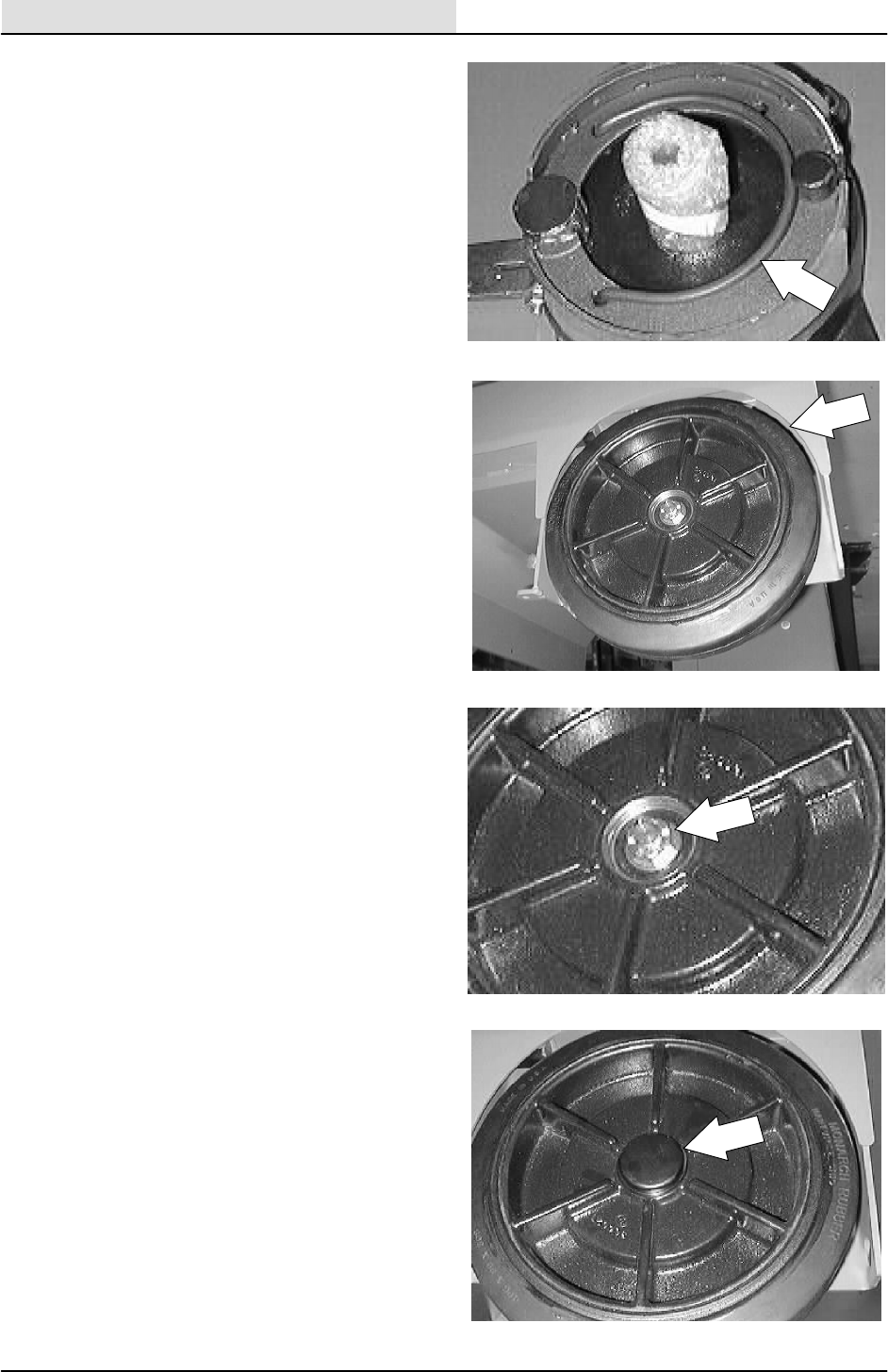
HOPPER DUST FILTER
The dust filter filters the air pulled up from the
hopper. The dust filter is equipped with a shaker
to remove the accumulated dust particles. The
dust filter shaker is operated by the filter shaker
switch.
The standard dust filter works well for normal
sweeping applications. The synthetic filter works
well for humid or wet applications.
Shake the dust filter before dumping the hopper,
at the end of every work shift, or when the
optional filter clogged light is on. Check and clean
or replace the dust filter every 100 hours of
operation.
To clean the dust filter, use one of the following
methods:
DSHAKING -- Activate the shaker button.
DTAPPING -- Tap the filter gently on a flat
surface with the dirty side down. Do not
damage the edges of the filter element or
the filter will not seat properly in the filter
frame.
DAIR -- Always wear eye protection whn using
compressed air. Blow air through the dust
filter opposite the direction of the arrows.
Never use more than 690 kPa (100 psi) of
air pressure and never closer than 50 mm
(2 in) away from the filter. This may be done
with the dust filter in the machine.
FOR SAFETY: When Servicing Machine,
Wear Eye And Ear Protection When
Using Pressurized Air Or Water.
DWATER -- Rinse the synthetic filter with a
low pressure garden hose through the dust
filter opposite the direction of the arrows.
The standard dust filter can also be rinsed,
but the filter will degrade with each rinsing
and should be replaced after rinsing five
times.
NOTE: Be sure the dust filter is dry before
reinstalling it in the machine.
SWEEPING
3-20 8200/8210 330065 (3--01)
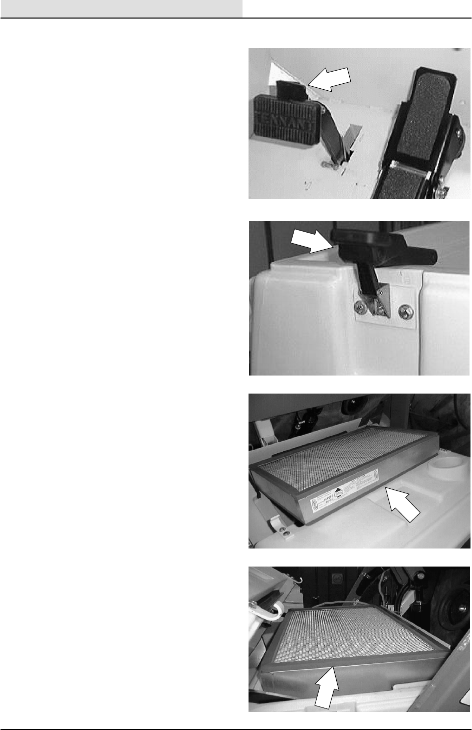
TO REPLACE HOPPER DUST FILTER
1. Stop the engine and set the machine parking
brake.
FOR SAFETY: Before Leaving Or
Servicing Machine; Stop On Level
Surface, Set Parking Brake, Turn Off
Machine And Remove Key.
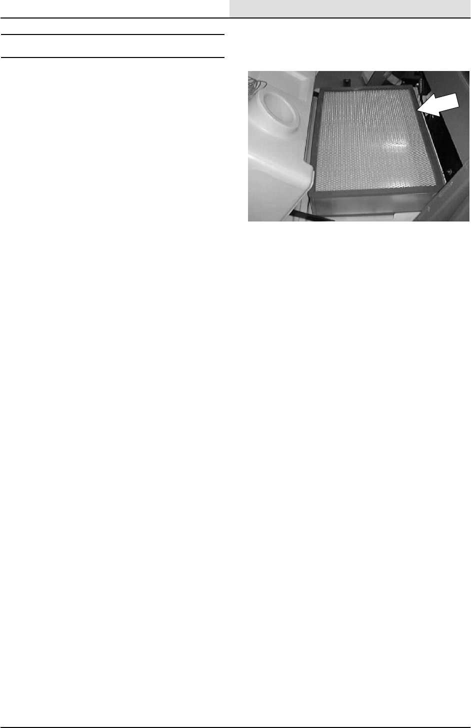
2. Open the hopper cover.
3. Pull the filter up and out of the hopper.
Discard the old filter.
4. Position the new filter in the hopper.
NOTE: Make sure the seals on the new filter are
not damaged.
5. Close the hopper cover.
SWEEPING
3-21
8200/8210 330065 (3--01)
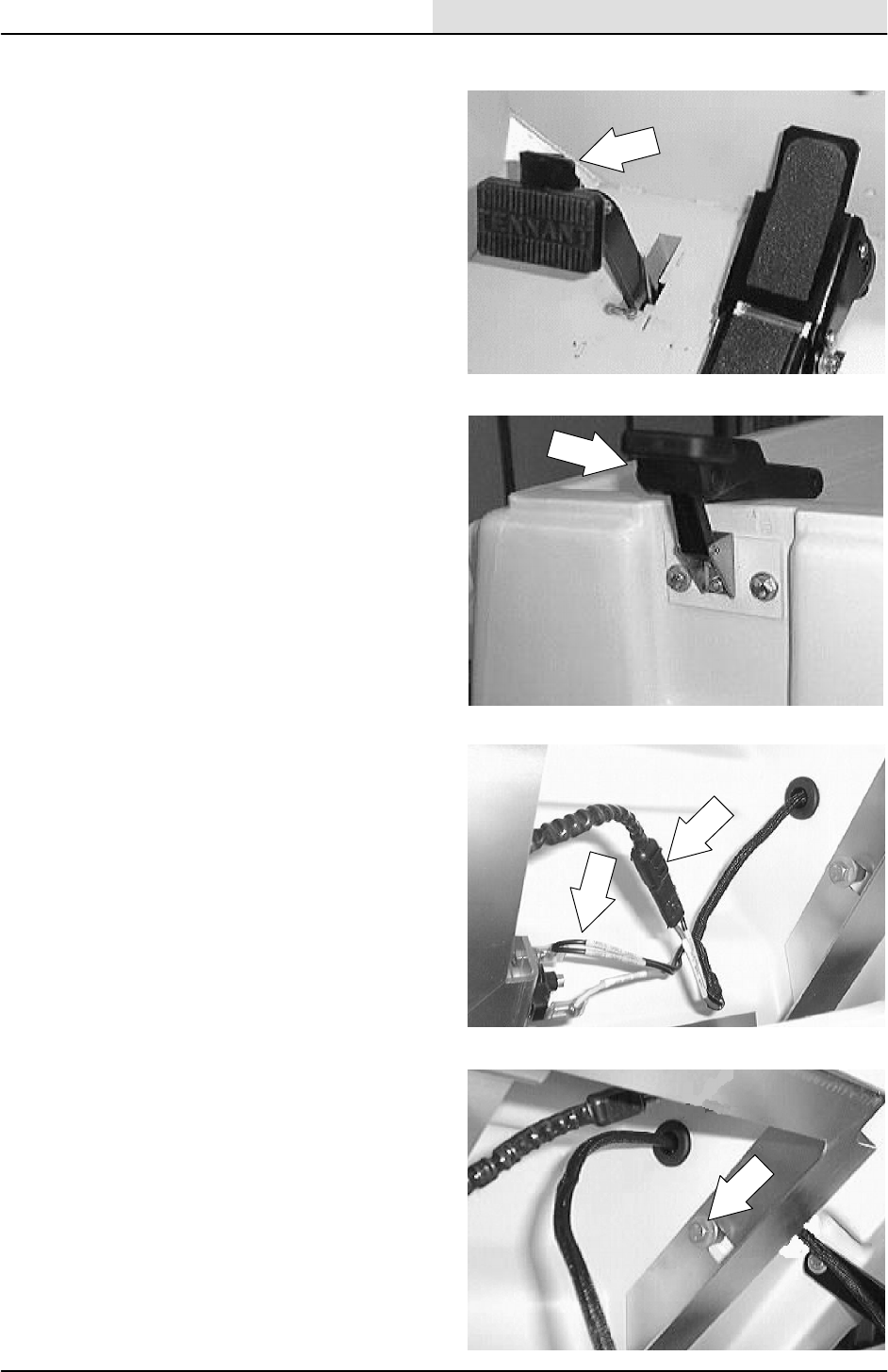
TO REMOVE FILTER SHAKER ASSEMBLY
1. Stop the engine and set the machine parking
brake.
FOR SAFETY: Before Leaving Or
Servicing Machine; Stop On Level
Surface, Set Parking Brake, Turn Off
Machine And Remove Key.
2. Open the hopper cover.
3. Disconnect the shaker motor and thermo
sentry from the hopper harness.
4. Remove the two hex screws holding the
shaker assembly into the hopper cover.
5. Remove the shaker assembly from the
machine.
SWEEPING
3-22 8200/8210 330065 (3--01)
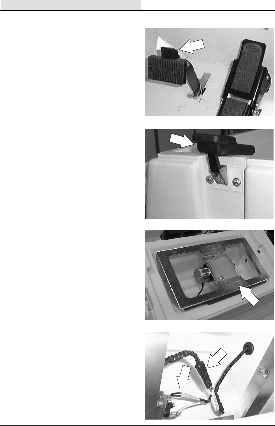
TO INSTALL FILTER SHAKER ASSEMBLY
1. Stop the engine and set the machine parking
brake.
FOR SAFETY: Before Leaving Or
Servicing Machine; Stop On Level
Surface, Set Parking Brake, Turn Off
Machine And Remove Key.
2. Open the hopper cover.
3. Position the shaker assembly into the
hopper cover. Install the two hex screws and
tighten to 18 -- 24 Nm (15 -- 20 ft lb).
4. Connect the shaker motor and Thermo
Sentry to the hopper harness.
5. Close the hopper cover and engage the
latches. Operate the shaker system. Check
for proper operation.
SWEEPING
3-23
8200/8210 330065 (3--01)
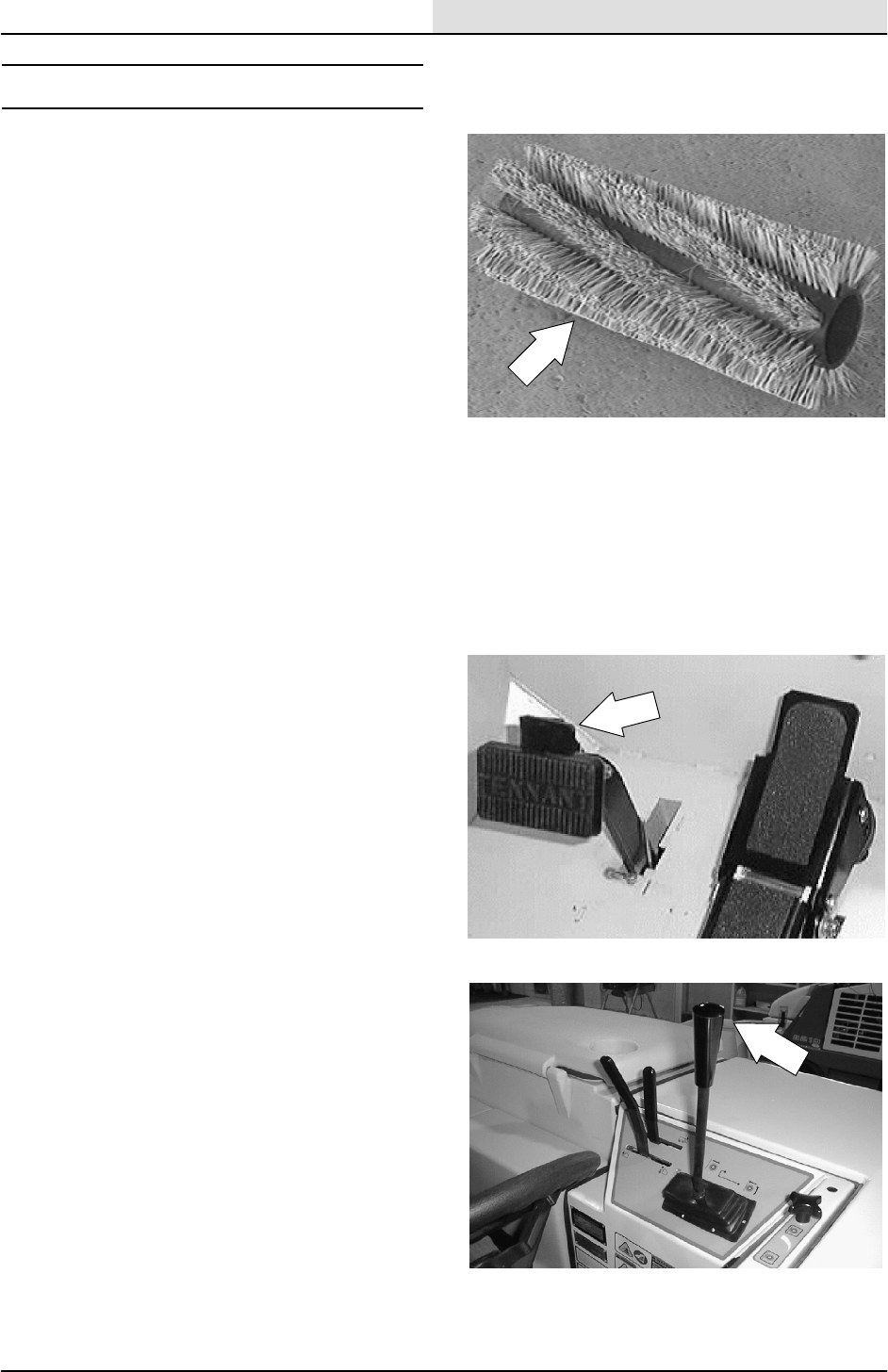
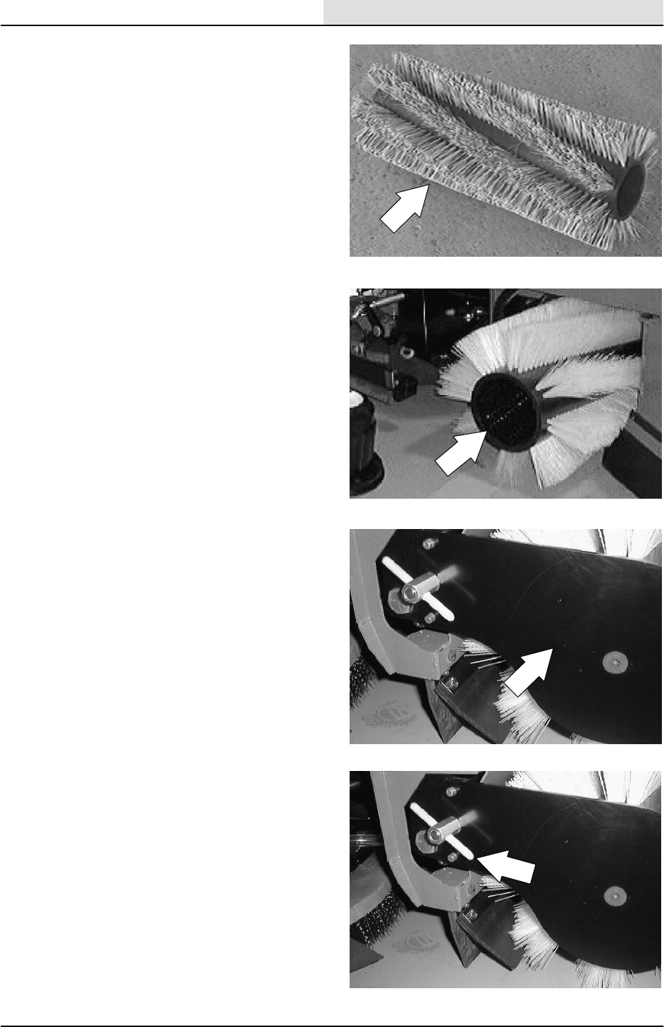
MAIN BRUSH
The main brush is cylindrical and spans the width
of the machine. This brush is used to sweep
debris into the hopper.
Check the brush daily for wear or damage.
Remove any string or wire tangled on the main
brush, main brush drive hub, or main brush idler
hub.
Check the main brush pattern daily. The pattern
should be 65 to 75 mm (2.5 to 3.5 in) wide with
themainbrushintheDown position. Adjust the
main brush pattern by turning the adjustment
knob for more or less pattern.
Rotate the main brush end-for-end every 50 hours
of operation for maximum brush life and best
sweeping performance. Replace the main brush
when the remaining bristles measure 30 mm
(1--1/4 in) in length.
TO REPLACE MAIN BRUSH
1. Stop the engine and set the machine parking
brake.
FOR SAFETY: Before Leaving Or
Servicing Machine; Stop On Level
Surface, Set Parking Brake, Turn Off
Machine And Remove Key.
2. Raise the main brush.

SWEEPING
3-24 8200/8210 330065 (3--01)
3. Remove the clevis pin from the end of the
scrub head guide arm where it is attached to
the scrub head. Pivot the scrub head guide
arm out, away from the right side brush
door.
4. Open the right side main brush access door.
5. Unscrew the” T” nut and remove the brush
idler plate.
6. Grasp the main brush; pull it off the brush
drive plug and out of the main brush
compartment.
SWEEPING
3-25
8200/8210 330065 (3--01)
7. Put the new or rotated end-for-end main
brush on the floor next to the access door.
8. Slide the main brush onto the drive plug.
Rotate the brush until it engages the drive
plug, and push it all the way onto the plug.
9. Slide the main brush idler plate plug in the
main brush.
10. Reinstall the “T “nut and hand tighten. The
stop on the inside of the door will prevent
the handle from loosening.
SWEEPING
3-26 8200/8210 330065 (3--01)
11. Close the right side main brush access door.
12. Pivot the scrub head guide arm back into
place on the scrub head. Reinstall the clevis
pin.
13. Operate the machine. Check the main brush
pattern. See TO CHECK AND ADJUST
MAIN BRUSH PATTERN instructions.
SWEEPING
3-27
8200/8210 330065 (3--01)
TO CHECK AND ADJUST MAIN BRUSH
PATTERN
1. Apply chalk, or some other material that will
not blow away easily, to a smooth, level
floor.
2. Raise the side brush and main brush and
position the main brush over the chalked
area.
3. Start the main brush.
4. Lower the main brush for 15 to 20 seconds
while keeping a foot on the brakes to keep
the machine from moving.
NOTE: If chalk or other material is not available,
allow the brushes to spin on the floor for two
minutes. A polish mark will remain on the floor.
5. Raise the main brush. The main brush will
stop automatically.
6. Drive the machine off the test area.
7. Observe the width of the brush pattern. The
proper brush pattern width is 65 to 75 mm
(2.5 to 3.5 in).
NOTE: Heavier brush pattern may be required for
rough or uneven floors.
8. To increase the width of the main brush
pattern, rotate the main brush pattern
adjustment knob counter--clockwise.
SWEEPING
3-28 8200/8210 330065 (3--01)
To decrease the width of the main brush
pattern, rotate the main brush pattern
adjustment knob clockwise.
If the main brush pattern is tapered, more
than 15 mm (0.5 in) on one end than the
other, adjust taper.
A. Loosen the brush shaft bearing bracket
mounting bolts.
B. Move the brush shaft bearing bracket
up or down in the slots.
C. Re--check the main brush pattern and
readjust as necessary. Then adjust the
width of the main brush pattern.
SWEEPING
3-29
8200/8210 330065 (3--01)
TO REPLACE MAIN BRUSH IDLER PLUG
BEARING
FOR SAFETY: Before Leaving Or
Servicing Machine; Stop On Level
Surface, Set Parking Brake, Turn Off
Machine And Remove Key.
1. Stop the engine and set the machine parking
brake.
FOR SAFETY: Before Leaving Or
Servicing Machine; Stop On Level
Surface, Set Parking Brake, Turn Off
Machine And Remove Key.
2. Raise the main brush.
3. Remove the clevis pin from the end of the
scrub head guide arm where it is attached to
the scrub head. Pivot the scrub head guide
arm out, away from the right side brush
door.
SWEEPING
3-30 8200/8210 330065 (3--01)
4. Open the right side main brush access door.
5. Unscrew the” T” nut.
6. Remove the brush idler plate.
7. Remove the plastic cap from the idler plug.
8. Clean the area around where the cap was
mounted in the idler plug.
SWEEPING
3-31
8200/8210 330065 (3--01)
9. Remove the M12 flat screw, nyloc hex nut,
and washer holding the idler plug to the idler
arm.
10. Remove the four M6 hex screws holding the
idler shaft in the idler plug. Remove the shaft
and cover.
11. Remove the bearing seal plate, retainer and
bearing.
12. Place a new bearing, the old seal plate, and
the retainer on the idler.
SWEEPING
3-32 8200/8210 330065 (3--01)
13. Reinstall the four hex screws that hold the
bearing seal plate and retainer in place.
NOTE: Leave screws loose for now.
14. Install the idler shaft in the new bearing.
Tighten the four hex screws to 8--10 Nm
(6--8 ft lb).
15. Position the idler plug on the idler arm shaft.
Reinstall the long flat head screw. Tighten to
68--81 Nm (50--60 ft lb).
16. Put a small amount of RTV on the lip of the
plastic cap and install in the end of the idler
plug.

SWEEPING
3-33
8200/8210 330065 (3--01)
17. Reinstall the idler arm on the machine.
18. Operate the machine and check for proper
operation.
SWEEPING
3-34 8200/8210 330065 (3--01)
TO REPLACE MAIN BRUSH SHAFT
BEARINGS
FOR SAFETY: Before Leaving Or
Servicing Machine; Stop On Level
Surface, Set Parking Brake, Turn Off
Machine And Remove Key.
1. Remove the main brush idler arm from the
machine.
2. Remove the main brush motor arm
assembly from the machine.
3. Remove the large hex screw and nyloc nut
holding the brush arm to the pivot bearings.
SWEEPING
3-35
8200/8210 330065 (3--01)
4. Let the brush arm drop down and out of the
way.
5. Remove the two bolts holding each of the
two brush shaft bearings and retainers to the
bearing brackets.
6. Remove the old brush shaft bearings.
7. Position the new brush shaft bearings on the
mount brackets. Make sure to have the lock
collars pointing to the outside of the
machine.
SWEEPING
3-36 8200/8210 330065 (3--01)
8. Reinstall the two bolts holding each of the
two brush shaft bearings and retainers to the
bearing brackets. Tighten to 18 -- 24 Nm
(15 -- 20 ft lb).
9. Reinstall the main brush motor plate and
idler plate.
10. Check main brush pattern for taper and
width. Adjust as necessary. See TO CHECK
AND ADJUST MAIN BRUSH PATTERN.
SWEEPING
3-37
8200/8210 330065 (3--01)
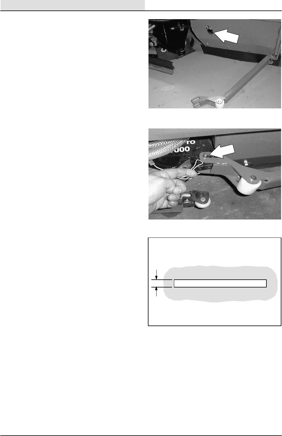
SIDE BRUSH
The side brush sweeps debris along edges into
the path of the main brush.
Check the brush daily for wear or damage.
Remove any string or wire found tangled on the
side brush or side brush drive hub.
Check the side brush pattern daily. One-half of the
side brush bristles should contact the floor in a
11:00 to 3:00 pattern (4_forward and 4_right)
when the brush is in motion. Adjust the side brush
pattern with the side brush down pressure lever.
Turn the lever counter-clockwise to increase the
brush contact with the sweeping surface, and
clockwise to decrease the brush contact with the
sweeping surface.
The side brush should be replaced when it no
longer sweeps effectively for your application. A
guideline length is when the remaining bristles
measure 50 mm (2 in) in length. You may change
the side brush sooner if you are sweeping light
litter, or wear the bristles shorter if you are
sweeping heavy debris.
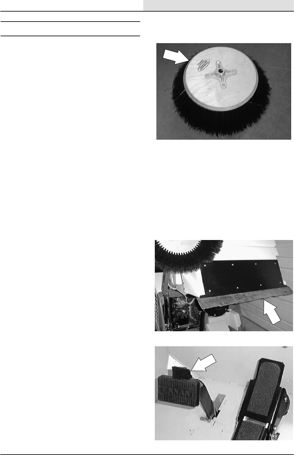
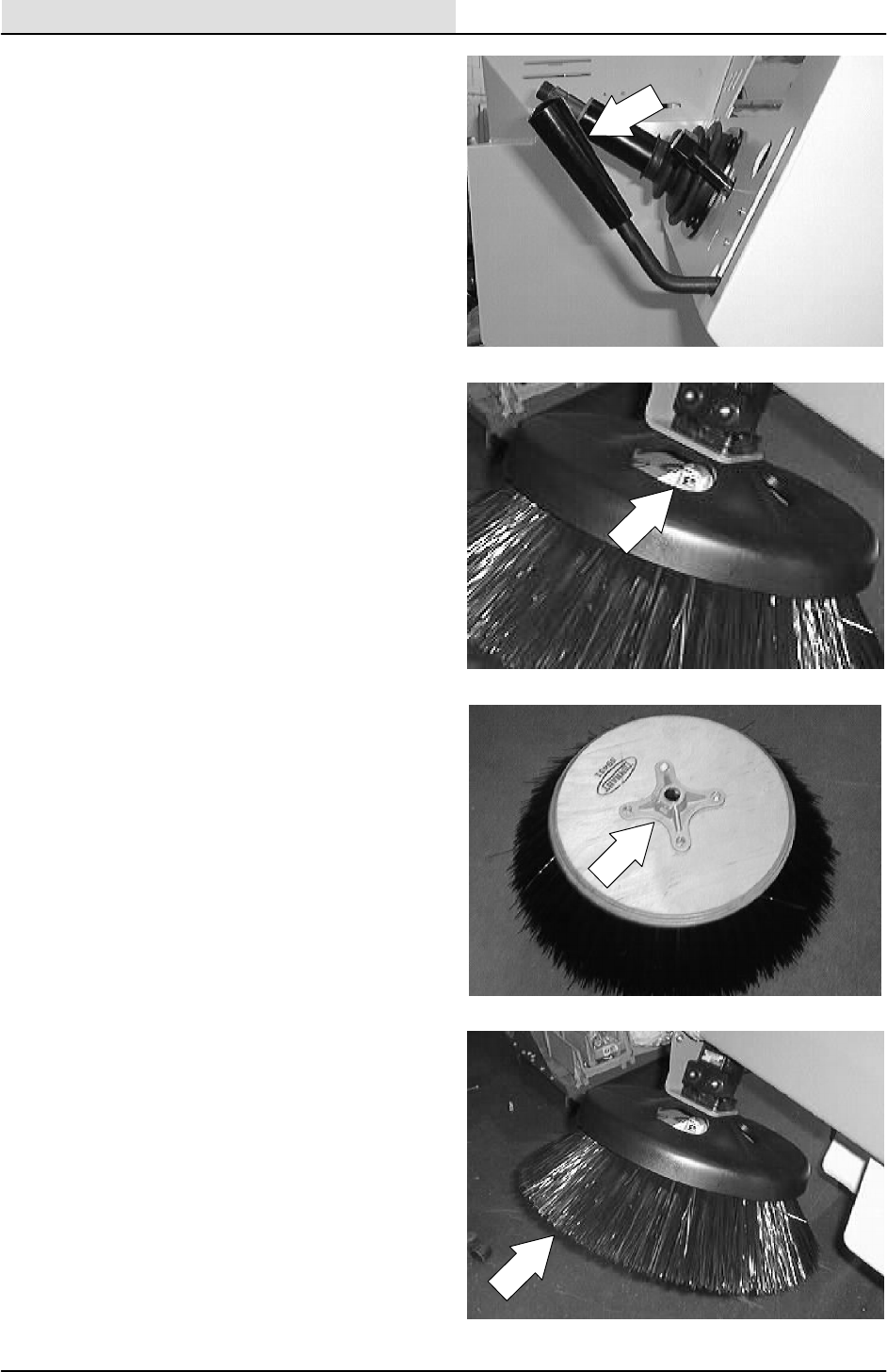
TO REPLACE SIDE BRUSH
1. Empty the debris hopper.
2. Set the machine parking brake.
FOR SAFETY: Before Leaving Or
Servicing Machine; Stop On Level
Surface, Set Parking Brake, Turn Off
Machine And Remove Key.
SWEEPING
3-38 8200/8210 330065 (3--01)
3. Raise the side brush.
4. Remove the side brush retaining pin from
the side brush drive shaft by pulling the pin
keeper off and over the end of the pin.
Remove the pin.
5. Slide the side brush off the side brush motor
shaft.
NOTE: Remove the drive hub and put it on the
new brush if one is not installed.
6. Slide the new side brush on the side brush
motor shaft.
SWEEPING
3-39
8200/8210 330065 (3--01)
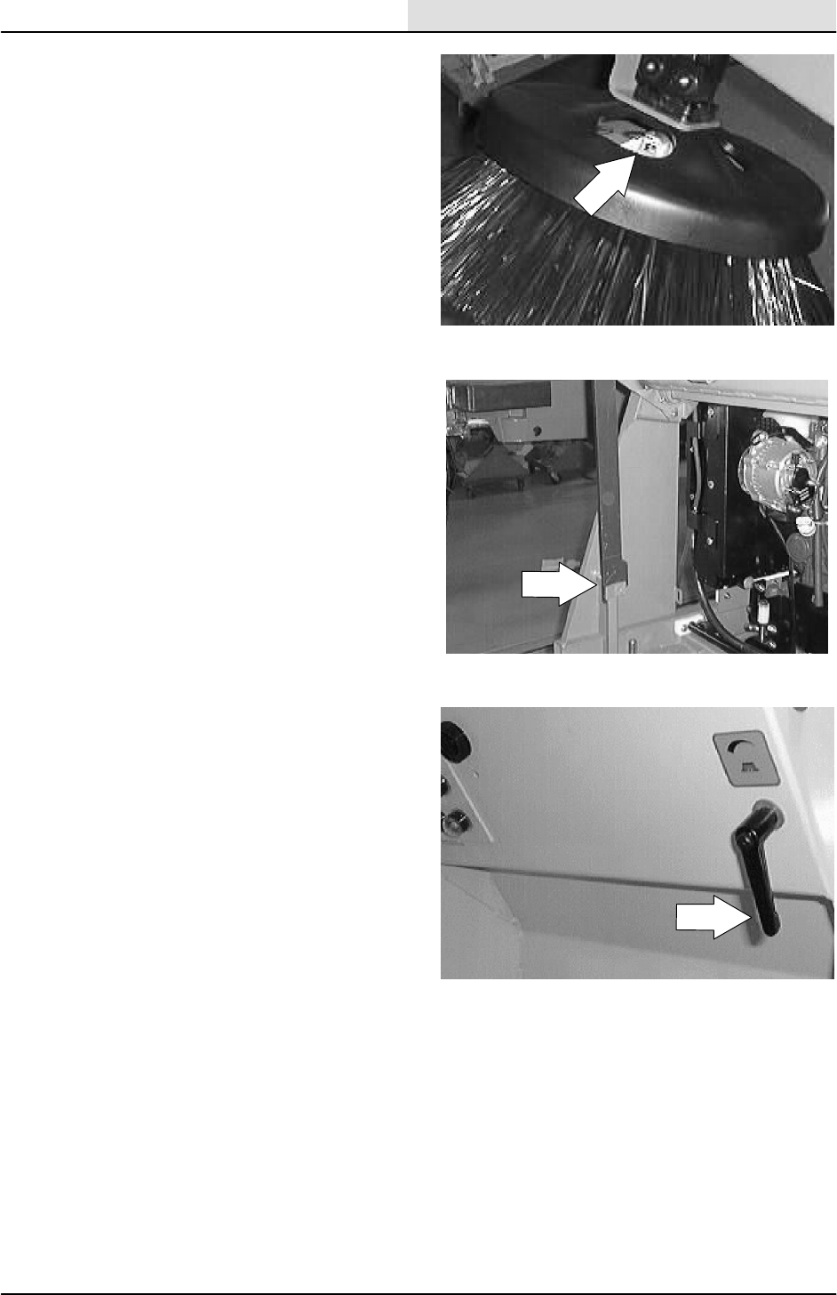
7. Reinstall the side brush retaining pin through
the side brush hub and shaft.
8. Secure the pin by clipping the pin keeper
over the end of the pin.
9. Disengage the hopper support bar and lower
the hopper.
10. Adjust the side brush pattern with the side
brush down pressure lever.
SWEEPING
3-40 8200/8210 330065 (3--01)
TO ADJUST SIDE BRUSH PATTERN
FOR SAFETY: Before Leaving Or
Servicing Machine; Stop On Level
Surface, Set Parking Brake, Turn Off
Machine And Remove Key.
1. Lower the side brush.
2. Turn the side brush lever clockwise to
decrease side brush pattern. Turn the side
brush lever counter--clockwise to increase
side brush pattern.
NOTE: One-half of the bristles should normally
contact the floor.
3. Raise the side brush.
SWEEPING
3-41
8200/8210 330065 (3--01)
TO ADJUST SIDE BRUSH LATERAL TILT
PATTERN
FOR SAFETY: Before Leaving Or
Servicing Machine; Stop On Level
Surface, Set Parking Brake, Turn Off
Machine And Remove Key.
1. Lower the side brush.
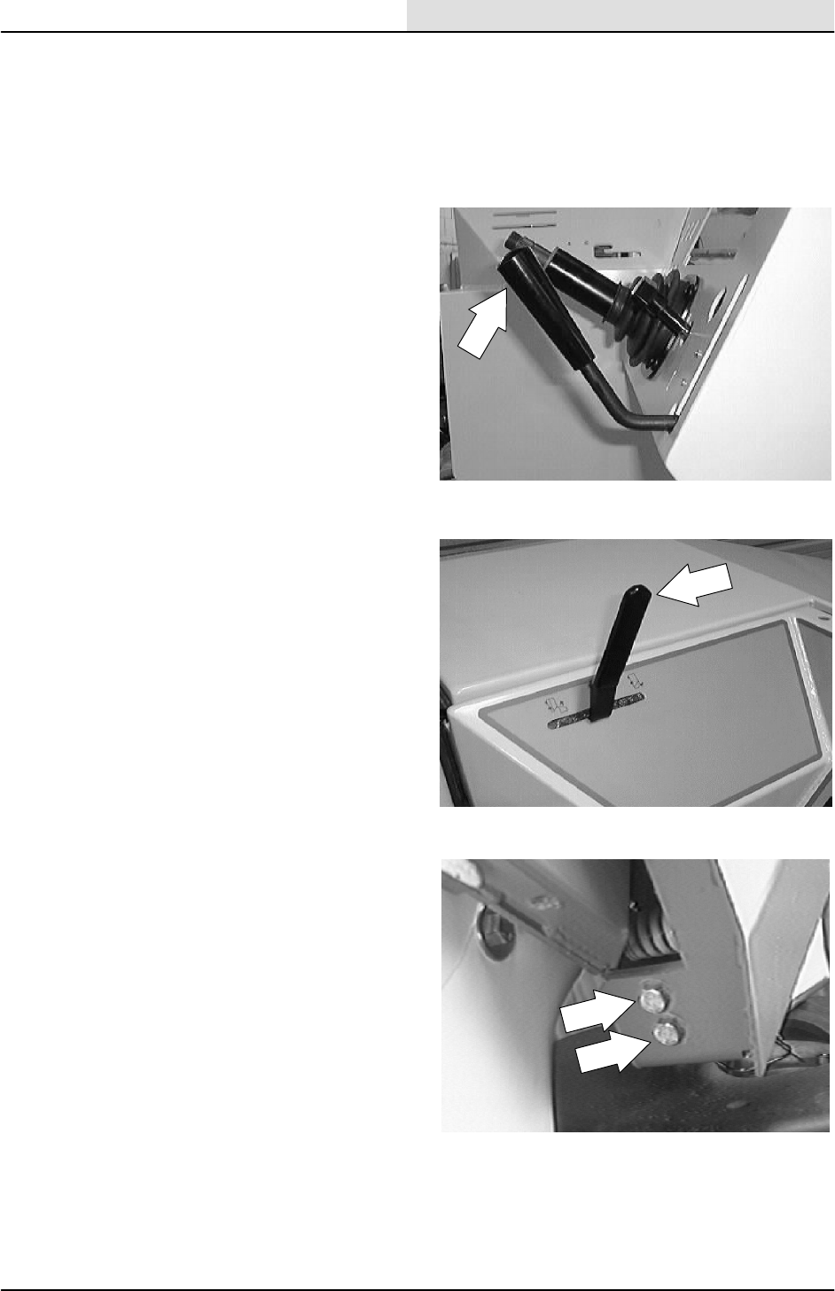
2. Raise the hopper slightly and shut off the
engine.
3. Loosen the two hex screws on the back of
the hopper bumper near the side brush
assembly.
SWEEPING
3-42 8200/8210 330065 (3--01)
4. Tilt the side brush in either direction.
NOTE: For the best performance in most
applications----make a 4
_
forward and 4
_
right
adjustment .
5. Tighten the hardware firmly.
6. Lower the hopper.
7. Start the engine and operate the side brush.
Check the side brush pattern.
NOTE: The side brush bristles should contact the
floor in a 10 o’clock to 3 o’clock pattern when the
brush is in motion.
SWEEPING
3-43
8200/8210 330065 (3--01)
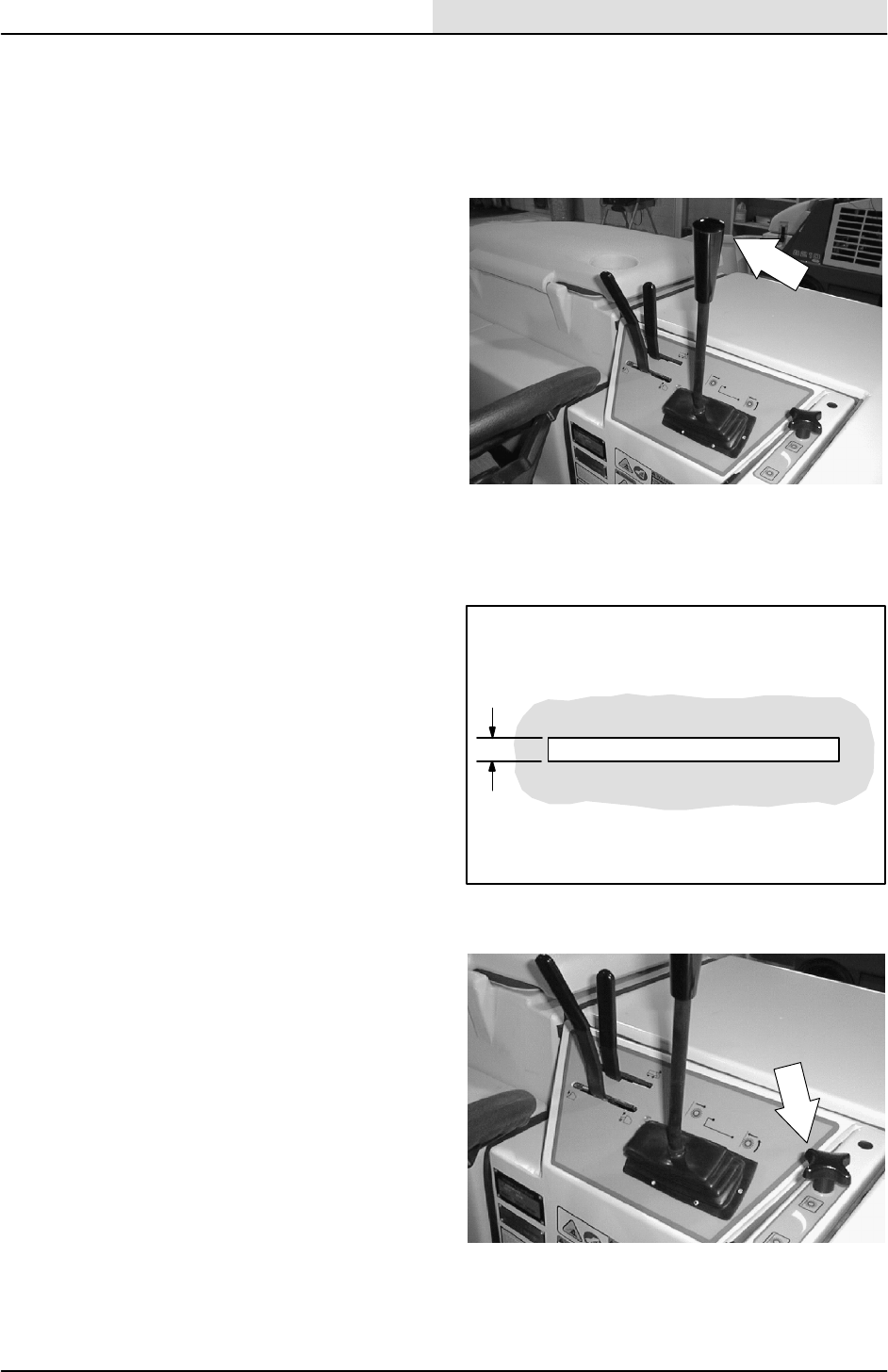
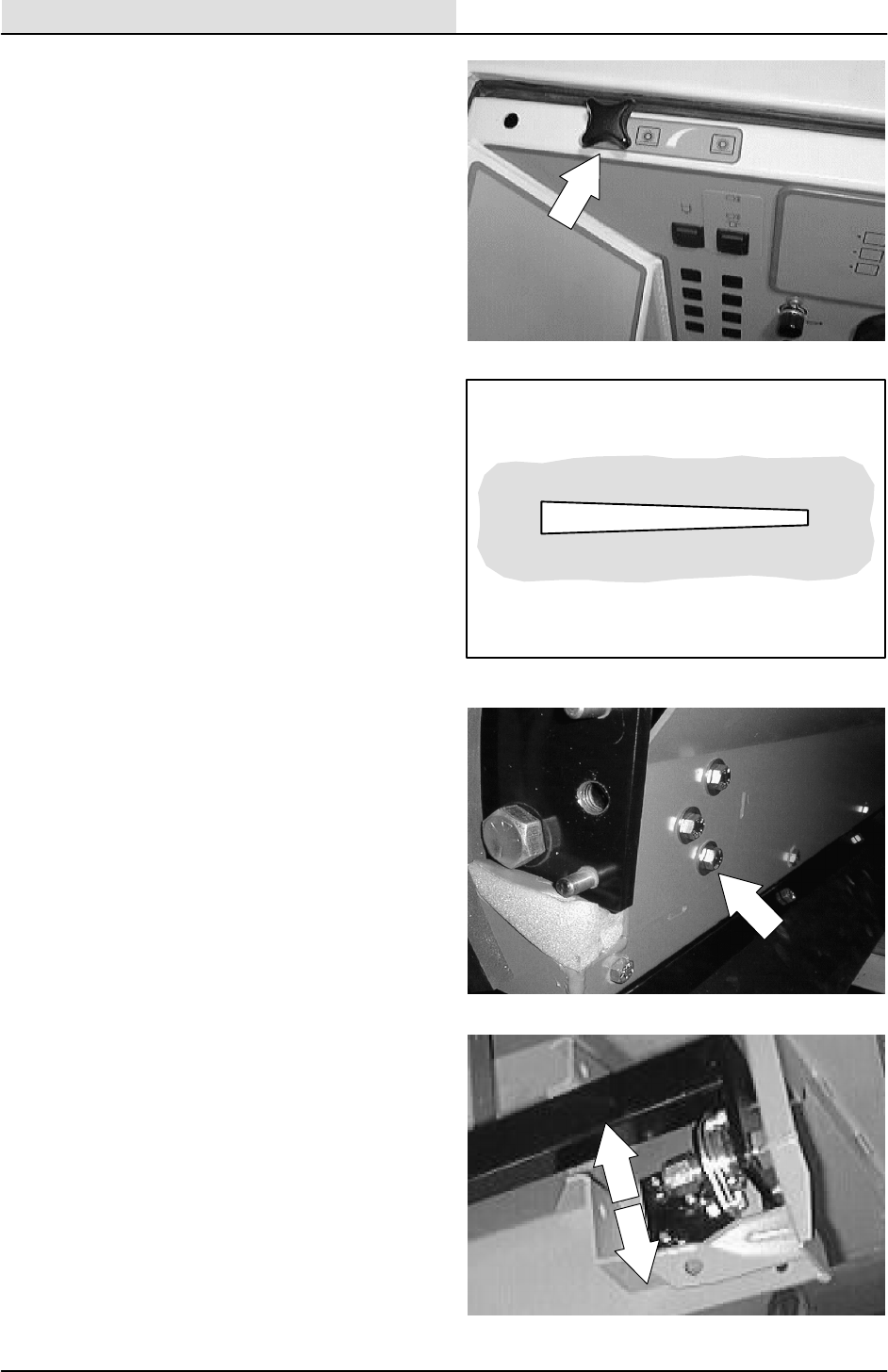
TO ADJUST SIDE BRUSH FORE/AFT TILT
PATTERN
FOR SAFETY: Before Leaving Or
Servicing Machine; Stop On Level
Surface, Set Parking Brake, Turn Off
Machine And Remove Key.
1. Lower the side brush.
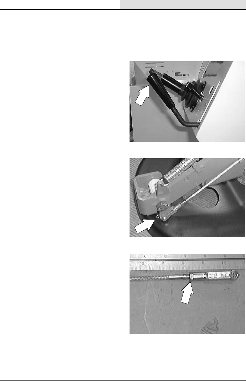
2. Remove the hair pin from the clevis pin on
the fore/aft tilt cable.
3. Loosen the jam nut near the clevis.
SWEEPING
3-44 8200/8210 330065 (3--01)
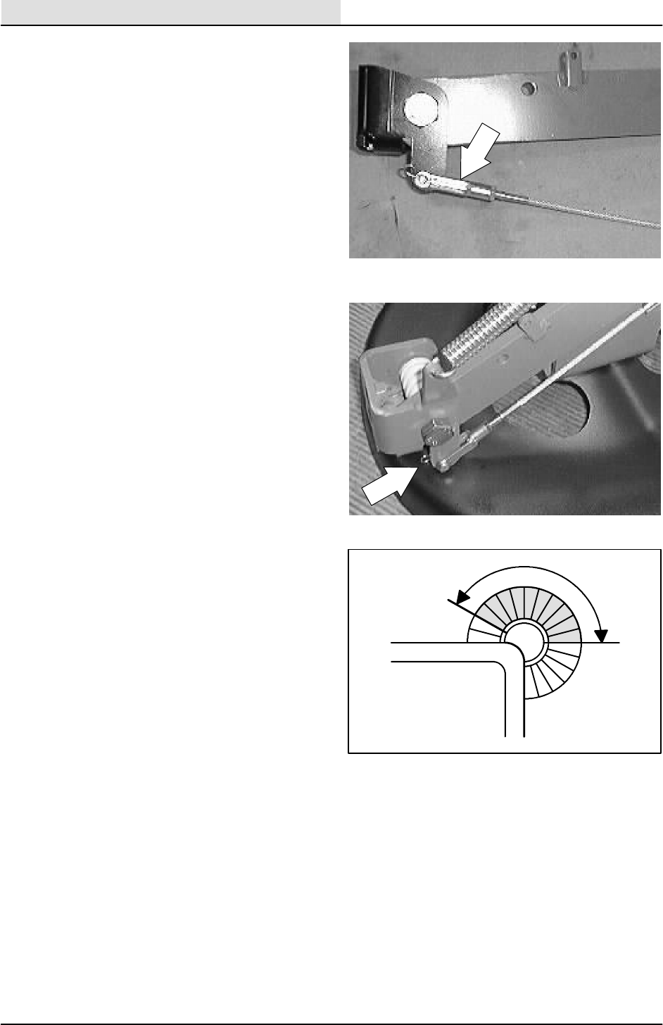
4. Remove the clevis pin and turn the clevis in
or out to achieve proper fore/aft side brush
adjustment.
NOTE: The starting length of the cable should be
10.25 inch from the center of the clevis hole to the
center of the cable ring.
NOTE: For a 4_forward angle----adjust the cable
length to 10.25 inches from the center of the
clevis pin to the center of the eyelet on the cable.
5. Reinstall the clevis pin and tighten the jam
nut.
6. Start the engine and operate the side brush.
Check the side brush pattern.
NOTE: The side brush bristles should contact the
floor in a 10 o’clock to 3 o’clock pattern when the
brush is in motion.
SWEEPING
3-45
8200/8210 330065 (3--01)
SIDE BRUSH GUARD
The side brush guard protects the side brush from
objects along path of the machine. It deflects the
side brush out of harms way.
Rotate the side brush guard 90_every 200 hours
of operation or as required. Replace the brush
guard after all four sides have been used.
TO ROTATE OR REPLACE SIDE BRUSH
GUARD
FOR SAFETY: Before Leaving Or
Servicing Machine; Stop On Level
Surface, Set Parking Brake, Turn Off
Machine And Remove Key.
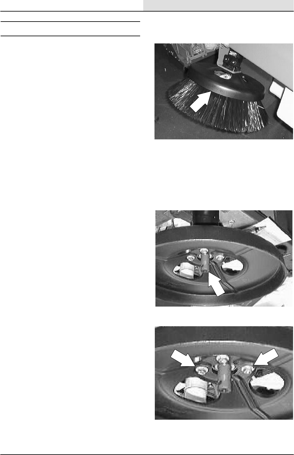
1. Remove the side brush.
2. Remove the four hex screws holding the
side brush guard to the side brush motor.
3. Rotate or replace the side brush guard.
4. Reinstall the four bolts in the side brush
motor and tighten to 22--27 Nm (16--20 ft lb).
SWEEPING
3-46 8200/8210 330065 (3--01)
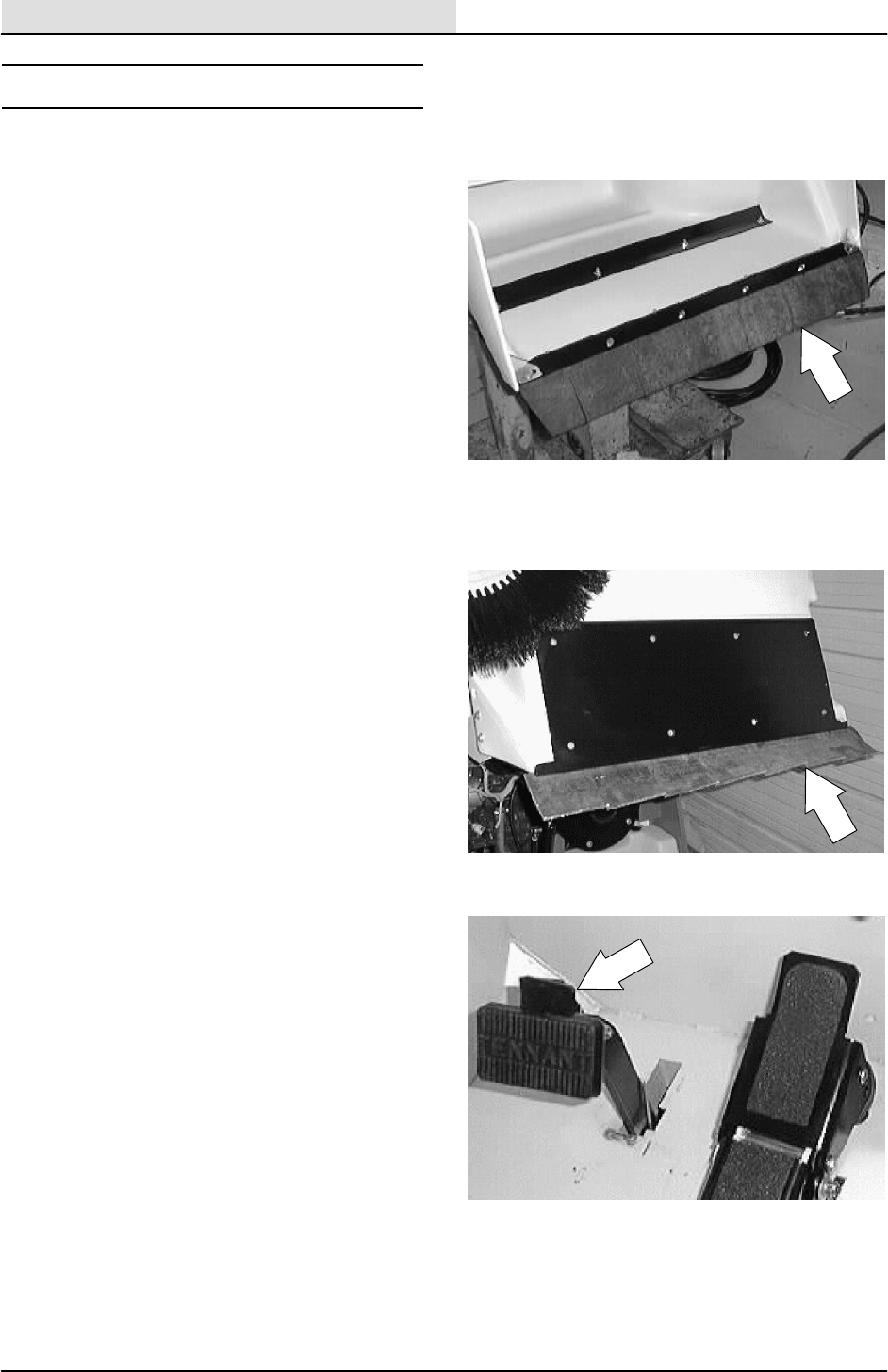
SKIRTS AND SEALS
HOPPER LIP SKIRT
The hopper lip skirt is located on the bottom rear
of the hopper. The skirt floats over debris and
helps deflect that debris into the hopper.
Check the hopper lip skirt for wear or damage
daily. Replace the hopper lip skirt when it no
longer touches the floor.
TO REPLACE HOPPER LIP SKIRT
1. Dump the machine debris hopper.
2. Set the machine parking brake.
SWEEPING
3-47
8200/8210 330065 (3--01)
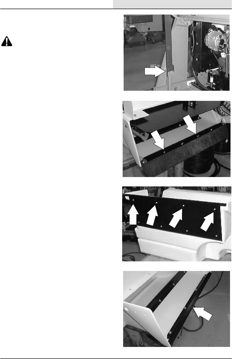
3. Raise the hopper, engage the hopper
support bar. Shut off the engine.
WARNING: Raised Hopper May Fall.
Engage Hopper Support Bar.
FOR SAFETY: Before Leaving Or
Servicing Machine; Stop On Level
Surface, Set Parking Brake, Turn Off
Machine And Remove Key.
4. Remove the six hopper lip retainer strip
mounting screws.
NOTE: Retain the left and right debris deflectors.
5. Loosen the four flat head screws holding the
skirt retainer strip to the hopper.
6. Remove the hopper lip skirt from the hopper.
SWEEPING
3-48 8200/8210 330065 (3--01)
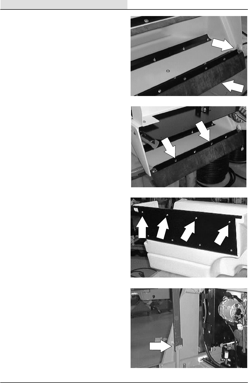
7. Install the new hopper lip skirt under the
retainer strip. Line up the six mounting
holes.
NOTE: Reinstall the left and right debris
deflectors.
8. Reinstall the six thread rolling screws and
hand tighten tight.
9. Tighten the four flat head screws to
8--14 Nm (6--10 ft lb).
10. Start the engine and lower the hopper.
SWEEPING
3-49
8200/8210 330065 (3--01)
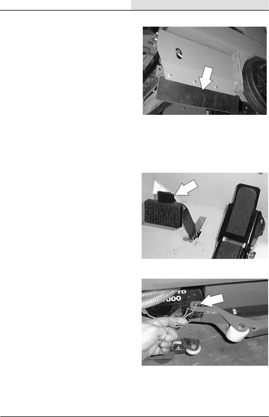
BRUSH DOOR SKIRTS
The right hand brush door skirt is located on the
bottom of the main brush door. The left hand skirt
is located on a skirt mount plate bolted to the
machine frame. Both skirts should clear the floor
up to 5 mm (0.25 in) in dusty conditions, and
touch the floor otherwise.
Check the skirts for wear or damage and
adjustment daily.
NOTE: The brush door skirts have slotted holes to
allow for a ground clearance adjustment. The door
must be closed for proper adjustment.
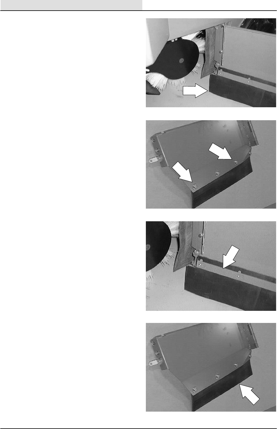
TO REPLACE AND ADJUST RIGHT HAND
BRUSH DOOR SKIRT
1. Stop the engine and set the machine parking
brake.
FOR SAFETY: Before Leaving Or
Servicing Machine; Stop On Level
Surface, Set Parking Brake, Turn Off
Machine And Remove Key.
2. Remove the clevis pin from the end of the
scrub head guide arm where it is attached to
the scrub head. Pivot the scrub head arm
out, away from the right side brush door.
SWEEPING
3-50 8200/8210 330065 (3--01)
3. Open the right hand brush door.
4. Remove the brush door skirt retaining bolts.
5. Remove the skirt retaining strip and door
skirt.
6. Position the new brush door skirt on the
brush door with the cup of the skirt facing
inward.
SWEEPING
3-51
8200/8210 330065 (3--01)
7. Position the retainer over the new skirt.
8. Thread the skirt retaining bolts through the
brush door, the door skirt, and in the skirt
retaining strip.
NOTE: The brush door skirt has slotted holes to
allow for a ground clearance adjustment. The door
must be closed for proper adjustment.
9. Slide the brush door skirt up or down so it
will clear the floor by 3--5 mm
(0.12to0.25in).
NOTE: Hand tighten the hex screws firmly.
10. Close the right hand brush door.
SWEEPING
3-52 8200/8210 330065 (3--01)
11. Pivot the scrub head guide arm back into
place on the scrub head. Reinstall the clevis
pin.
12. Operate the machine and check the new
skirts for proper operation.
SWEEPING
3-53
8200/8210 330065 (3--01)
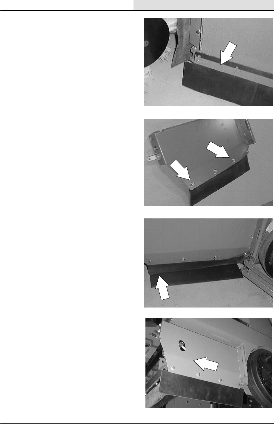
TO REPLACE AND ADJUST LEFT HAND
BRUSH DOOR SKIRT
1. Stop the engine and set the machine parking
brake.
FOR SAFETY: Before Leaving Or
Servicing Machine; Stop On Level
Surface, Set Parking Brake, Turn Off
Machine And Remove Key.
2. Remove the four hex screws holding the
skirt mount plate door to the machine.
3. Remove the brush skirt retaining bolts and
two retainers.

SWEEPING
3-54 8200/8210 330065 (3--01)
4. Remove the skirt from the door.
5. Position the new brush skirt on the mount
plate.
6. Position the two retainers over the new skirt.
7. Thread the skirt retaining bolts through the
mount plate, the door skirt, and into the two
skirt retainers.
NOTE: The brush skirts have slotted holes to
allow for a ground clearance adjustment. The skirt
plate must be mounted on the machine for proper
adjustment.
8. Reinstall the skirt mount plate on the
machine. Tighten the hex screws to
18 -- 24 Nm (15 -- 20 ft lb).
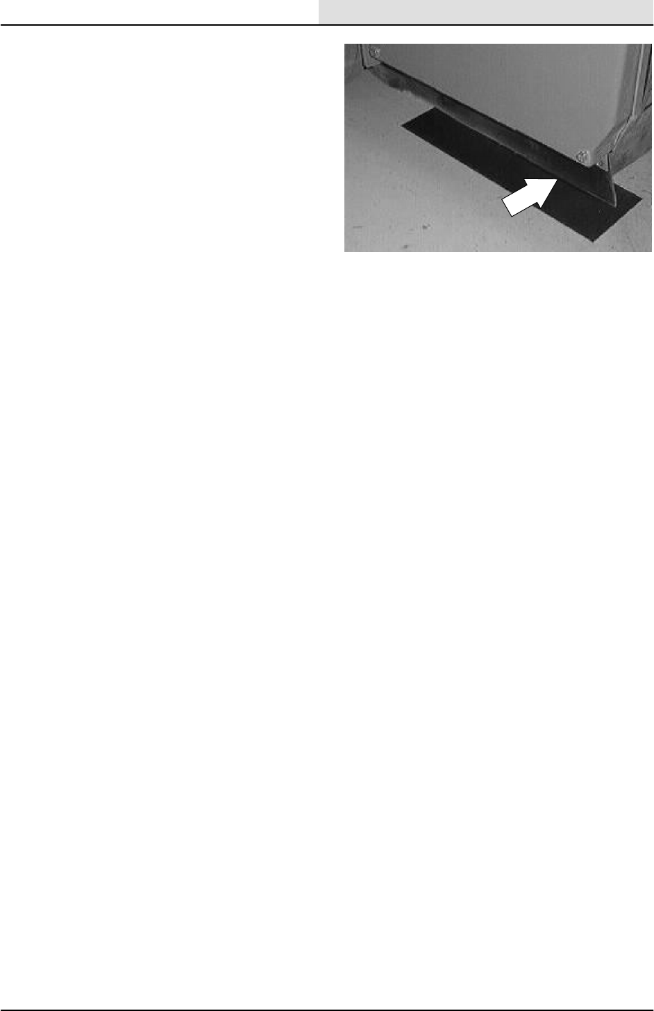
SWEEPING
3-55
8200/8210 330065 (3--01)
9. Slide the brush door skirt up or down so it
will clear the floor by 3--5 mm
(0.12 to 0.25 in). Hand tighten the hex
screws firmly.
10. Operate the machine and check the new
skirts for proper operation.
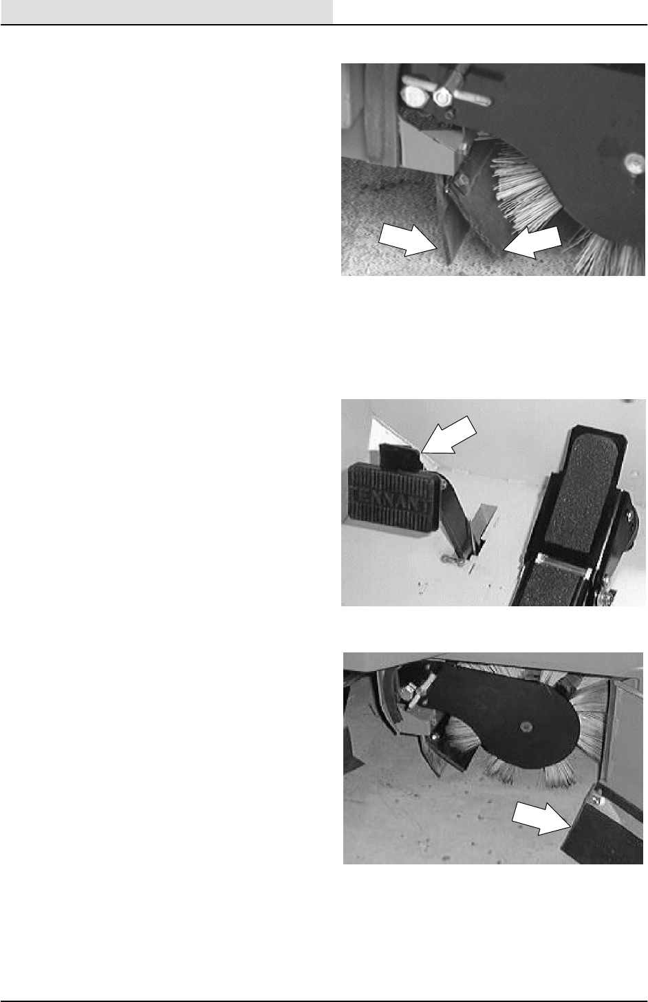
SWEEPING
3-56 8200/8210 330065 (3--01)
REAR SKIRT AND DEFLECTOR BLADE
The rear skirt and the deflector blade are located
on the bottom rear of the main brush
compartment. The rear skirt should clear the floor
up to 5 mm (0.25 in) in dusty conditions, and
touch the floor otherwise.
Check the skirt and blade for wear or damage and
adjustment daily.
TO REPLACE AND ADJUST THE REAR SKIRT
AND DEFLECTOR BLADE
1. Stop the engine and set the machine parking
brake.
FOR SAFETY: Before Leaving Or
Servicing Machine; Stop On Level
Surface, Set Parking Brake, Turn Off
Machine And Remove Key.
2. Open the right brush door.
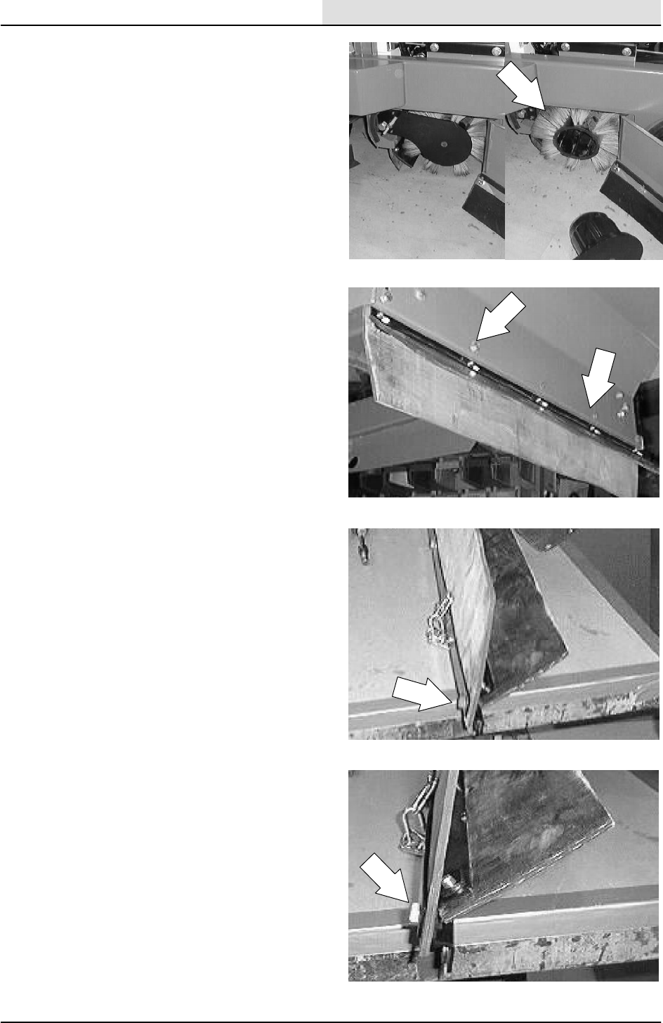
SWEEPING
3-57
8200/8210 330065 (3--01)
3. Remove the main brush.
4. Remove the four hex screws holding the
skirt assembly to the machine frame.
Remove the skirt assembly from the
machine.
5. Remove the hex screws holding rear skirt
and retainer to the assembly. Remove and
discard the rear skirt.
6. Install the new rear skirt. Reinstall the
hardware loosely for now.
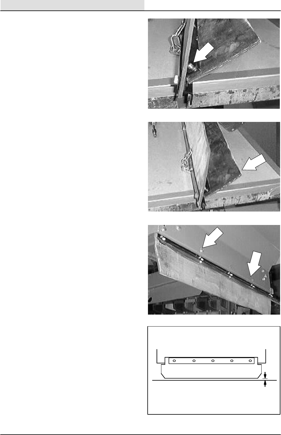
SWEEPING
3-58 8200/8210 330065 (3--01)
7. Remove the hex screws holding the
deflector blade retaining strip and the
deflector blade to the assembly.
NOTE: Remove and discard the deflector blade.
8. Install the new deflector blade and existing
retainer onto the skirt assembly bracket.
Center the slots of the new skirt. Tighten the
skirt mounting bolts to 8--14 Nm (6--10 ft lb).
9. Position the skirt assembly onto the
machine. Reinstall the skirt assembly
mounting hardware. Tighten to 8--14 Nm
(6--10 ft lb).
10. Slide the rear floor skirt up or down so that
the skirt clears the floor up to a maximum of
5 mm (0.25 in). Tighten the rear skirt
mounting bolts to 8--14 Nm (6--10 ft lb).
up to 5 mm
(up to 0.25 in)
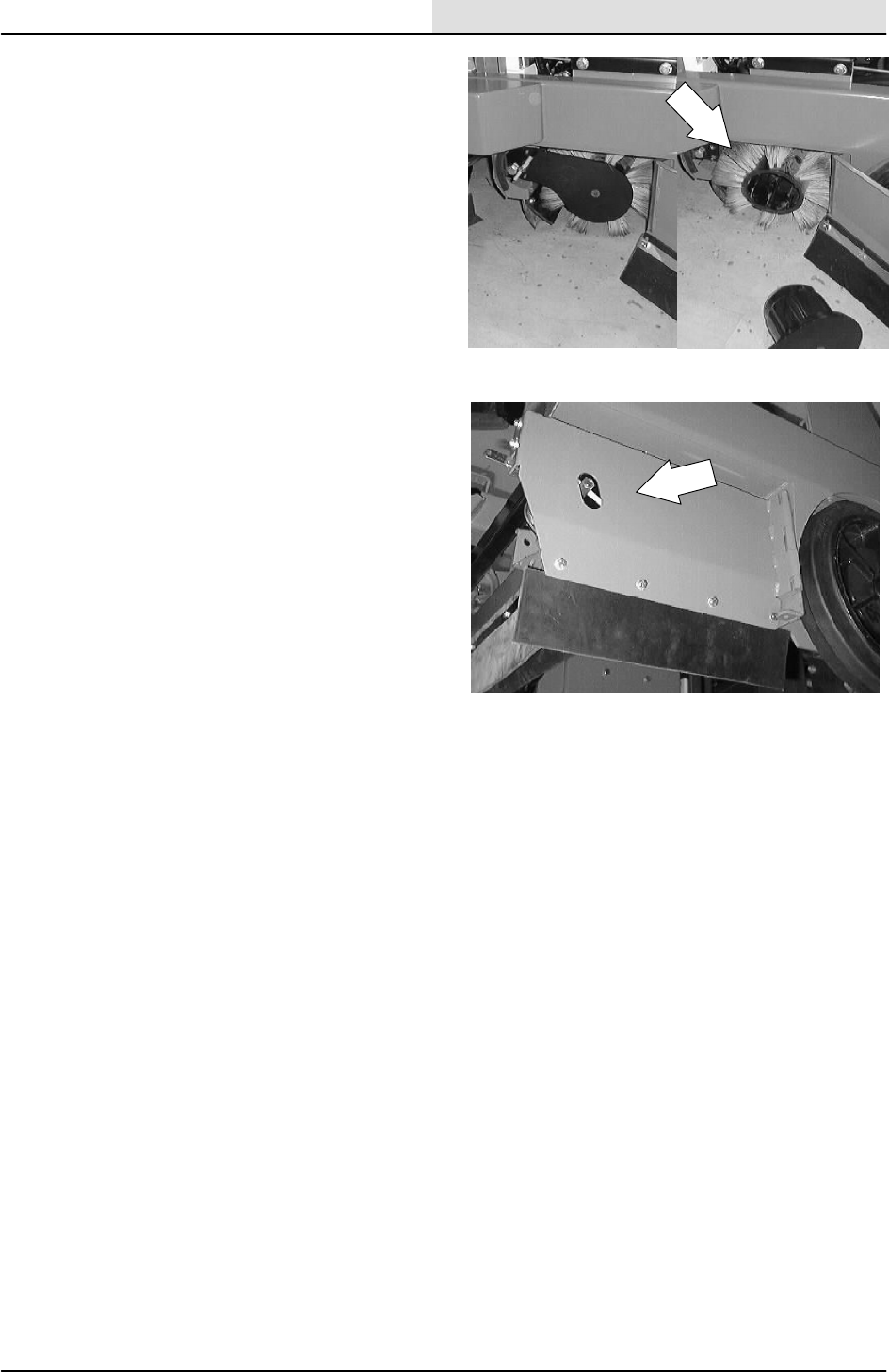
SWEEPING
3-59
8200/8210 330065 (3--01)
11. Reinstall the main brush.
12. Close the right brush door.
13. Operate the machine and check the new
rear skirt and front deflector blade for proper
operation.
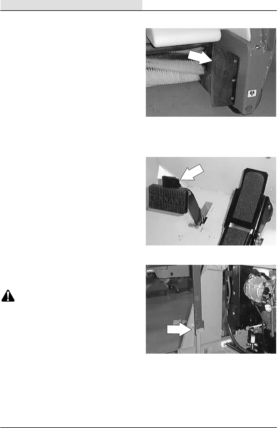
SWEEPING
3-60 8200/8210 330065 (3--01)
HOPPER SEALS
The hopper seals are located on the top and side
portions of the machine frame that contact the
hopper. They seal the main brush compartment.
tighten the seal hardware to 4--5 Nm (3--4 ft lb).
Inspect the seals for wear or damage every
100 hours of operation.
TO REPLACE HOPPER SEALS
1. Stop the engine and set the machine parking
brake.
2. Raise hopper and engage hopper support
bar.
WARNING: Raised Hopper May Fall.
Engage Hopper Support Bar.
FOR SAFETY: Before Leaving Or
Servicing Machine; Stop On Level
Surface, Set Parking Brake, Turn Off
Machine And Remove Key.
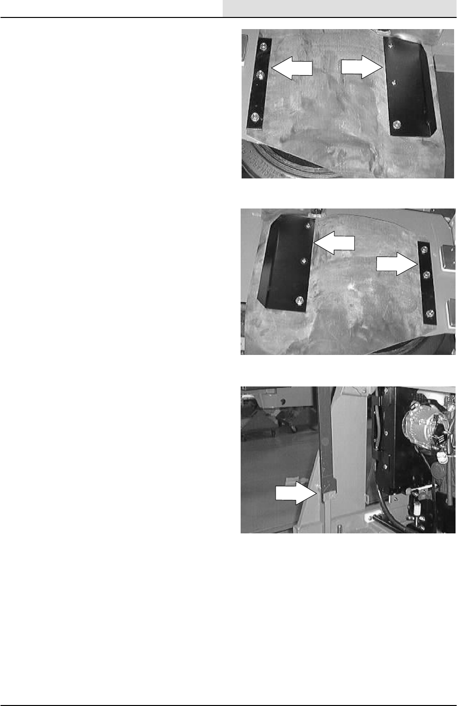
SWEEPING
3-61
8200/8210 330065 (3--01)
3. Remove the skirt retainers and skirts from
each side of the machine.
4. Position the new skirts and existing retainers
on the insides of the machine frame. Secure
with the existing hardware.
5. Start the engine and lower the hopper.
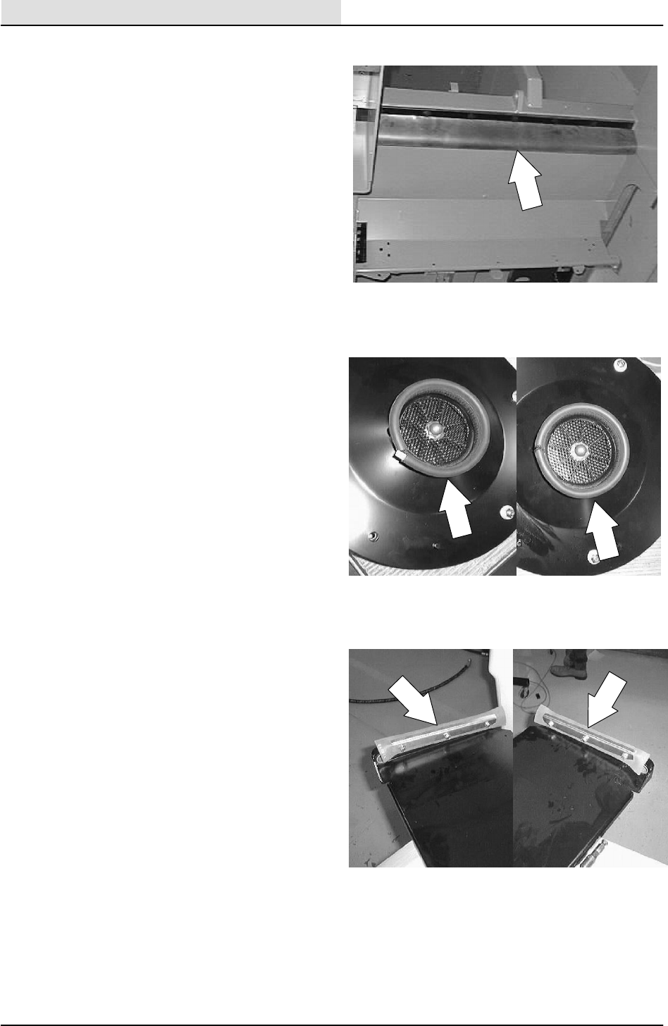
SWEEPING
3-62 8200/8210 330065 (3--02)
HOPPER DUST SEAL
The hopper dust seal is located under the front of
the machine frame in the area of the machine that
is contacted when the hopper is in the down
position.
Check the seal for wear or damage every
100 hours of operation. You can reach the seal by
lifting the hopper and engaging the prop arm.
HOPPER VACUUM FAN SEAL
The hopper vacuum fan seal is mounted on the
front the vacuum fan inlet assembly.
Check the seal for wear or damage every
100 hours of operation. You can reach the seal by
raising the hopper and engaging the prop arm.
NOTE: The seal must contact the back of the
hopper cover when the hopper cover is in the
closed position.
HOPPER DUMP DOOR SEALS
The hopper door seals are located on each end of
the hopper door. They seal the hopper when the
hopper door is closed.
Check the seals for wear or damage every
100 hours of operation.
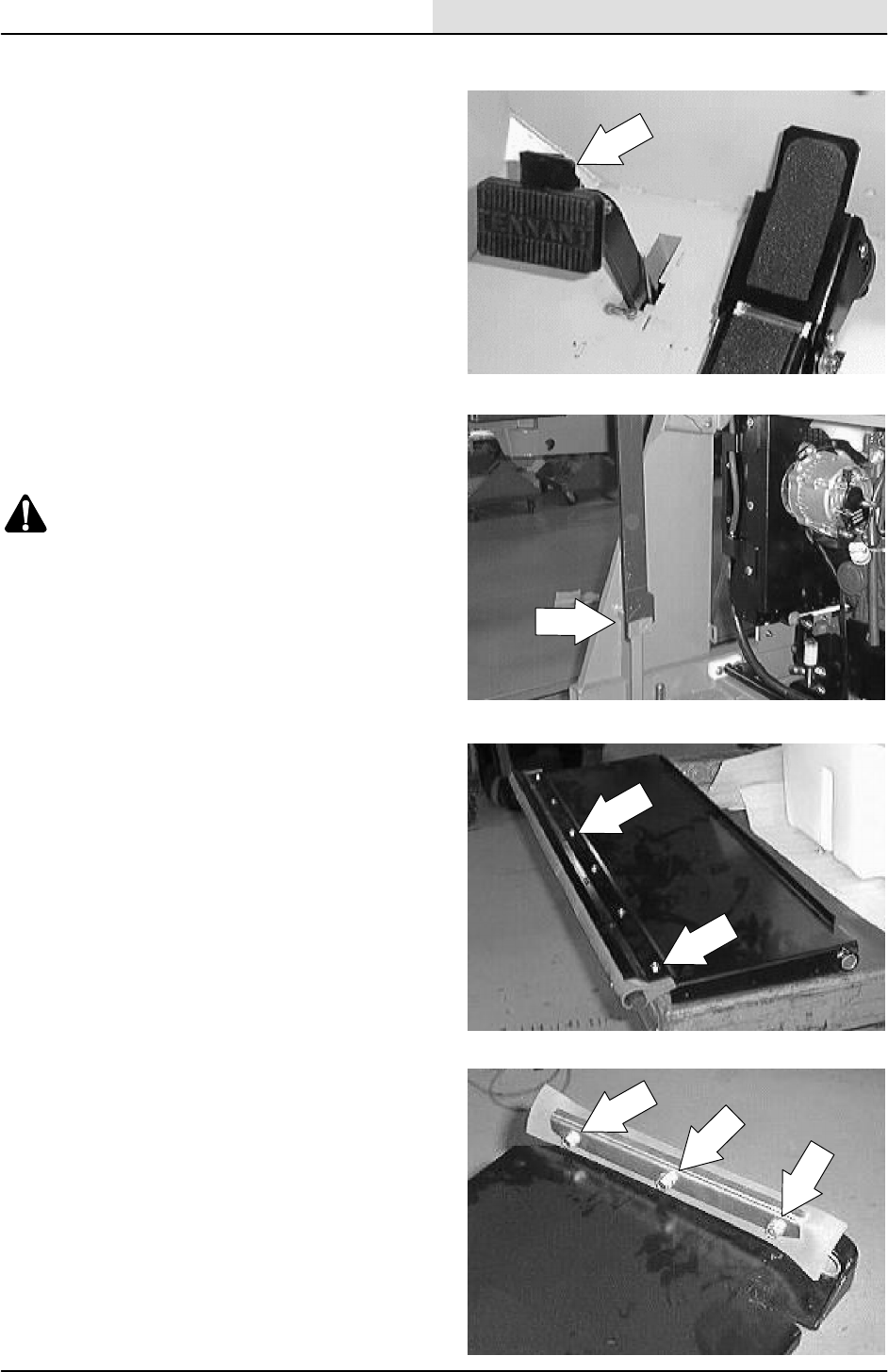
SWEEPING
3-63
8200/8210 330065 (3--02)
TO REPLACE HOPPER DUMP DOOR SEALS
1. Stop the engine and set the machine parking
brake.
2. Raise hopper and engage hopper support
bar.
WARNING: Raised Hopper May Fall.
Engage Hopper Support Bar.
FOR SAFETY: Before Leaving Or
Servicing Machine; Stop On Level
Surface, Set Parking Brake, Turn Off
Machine And Remove Key.
3. Remove the six hex screws holding the
dump door seal, retainer, and sponge cord
to dump door. Discard the old seal.
4. Remove the three hex screws holding each
side seal to the dump door. Discard the old
seals.
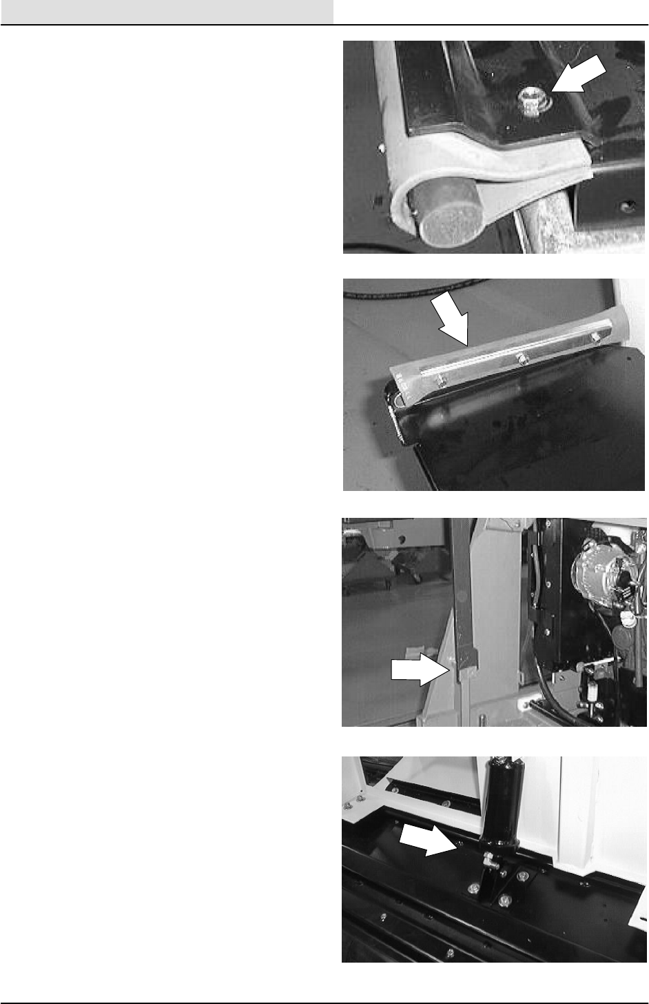
SWEEPING
3-64 8200/8210 330065 (3--01)
5. Align the holes in the new seal with holes on
the rear of the dump door and retainer.
Reinstall the six hex screws. Tighten to
3.3--4.4Nm(30--39Inlb).
6. Align the holes in the new side seal with
holes on the edge of the dump door and
retainer. Reinstall the three hex screws.
Tighten to 3.3 -- 4.4 Nm (30 -- 39 In lb).
Make sure the seals are lined up with edge
of hopper when tightening.
7. Start machine and lower hopper.
8. Operate the machine and check the dump
door for proper operation.
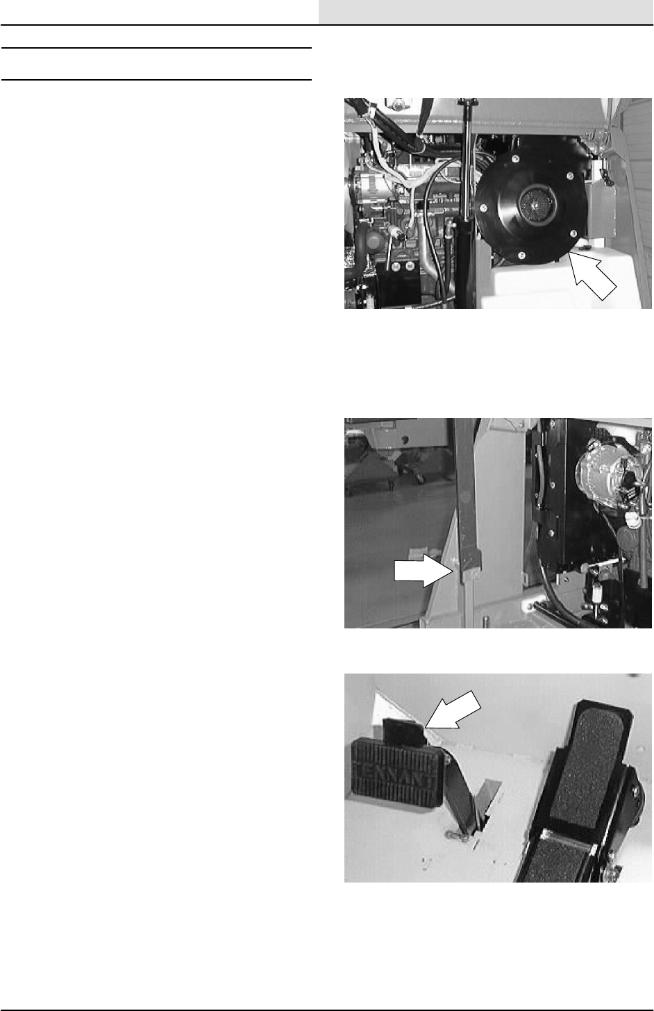
SWEEPING
3-65
8200/8210 330065 (3--01)
SWEEPING VACUUM FAN
The sweeping vacuum fan is located in front of
the engine. The vacuum fan is used during
sweeping to control dusting by pulling air from the
main brush area through the hopper and dust
filter.
TO REMOVE SWEEPING VACUUM FAN
ASSEMBLY
1. Start the machine and raise the hopper.
Engage the prop arm.
2. Stop the engine and set the machine parking
brake. Open the engine cover.
FOR SAFETY: Before Leaving Or
Servicing Machine; Stop On Level
Surface, Set Parking Brake, Turn Off
Machine And Remove Key.
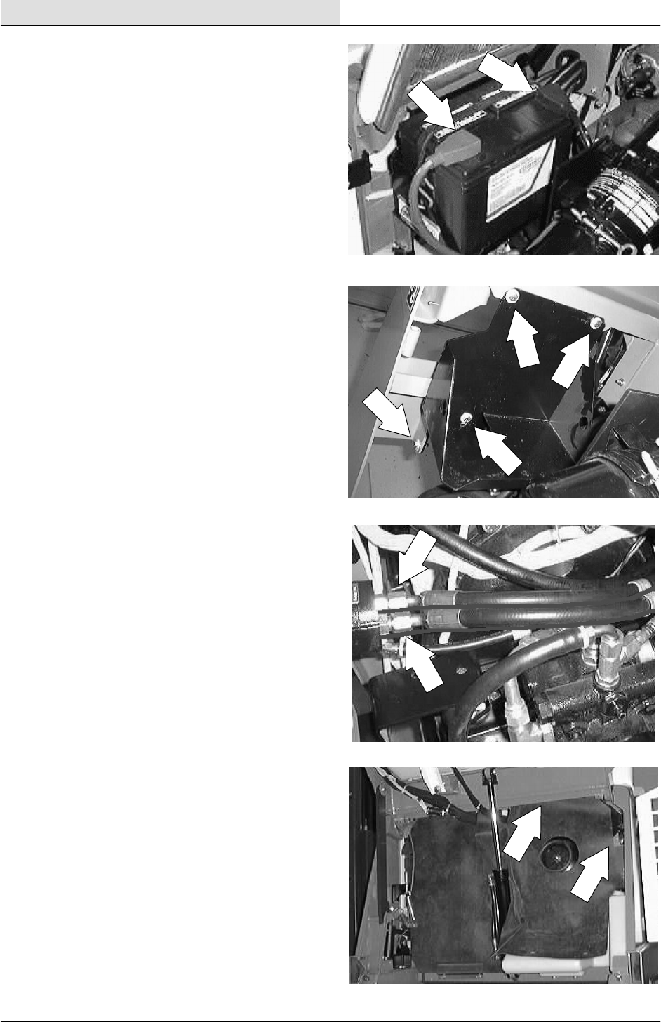
SWEEPING
3-66 8200/8210 330065 (3--01)
3. Disconnect the battery cables and remove
the battery from the machine.
4. Remove the battery tray from the machine
frame.
5. Mark, disconnect, and plug the three
hydraulic hoses leading to the vacuum fan
motor.
NOTE:Observe hydraulic cleanliness
requirements when opening hydraulic lines.
6. Remove the plastic rivets holding the rubber
dust shield to the left side of the machine,
over the sweeping vacuum fan. Pull the
rubber dust shield back to allow access to
the vacuum fan mounting hardware.
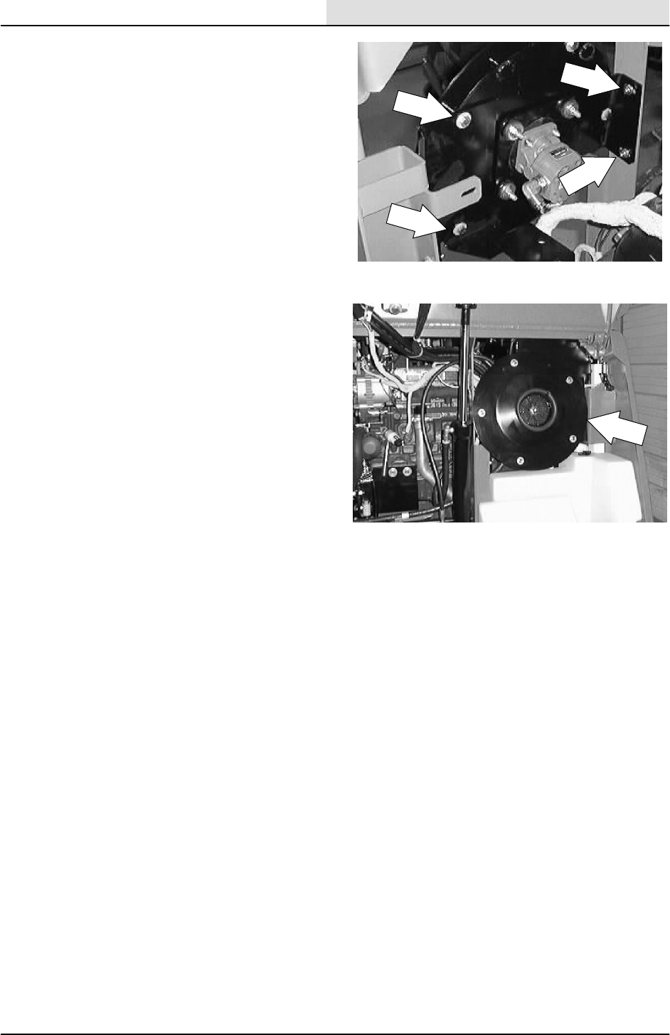
SWEEPING
3-67
8200/8210 330065 (3--01)
7. Remove the four hex screws holding the
front of the sweeping vacuum fan to the two
mount brackets.
8. Remove the sweeping vacuum fan assembly
out the front of the machine.
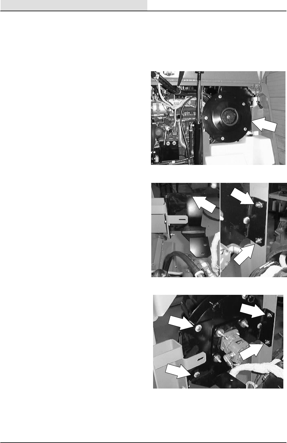
SWEEPING
3-68 8200/8210 330065 (3--01)
TO INSTALL SWEEPING VACUUM FAN
ASSEMBLY
FOR SAFETY: Before Leaving Or
Servicing Machine; Stop On Level
Surface, Set Parking Brake, Turn Off
Machine And Remove Key.
1. Position the sweeping vacuum fan assembly
into the machine from the front.
2. Line up the three fan mount holes with the
mount brackets on the machine frame.
3. Reinstall the hex screws and nuts. Tighten
to 18 -- 24 Nm (15 -- 20 ft lb).
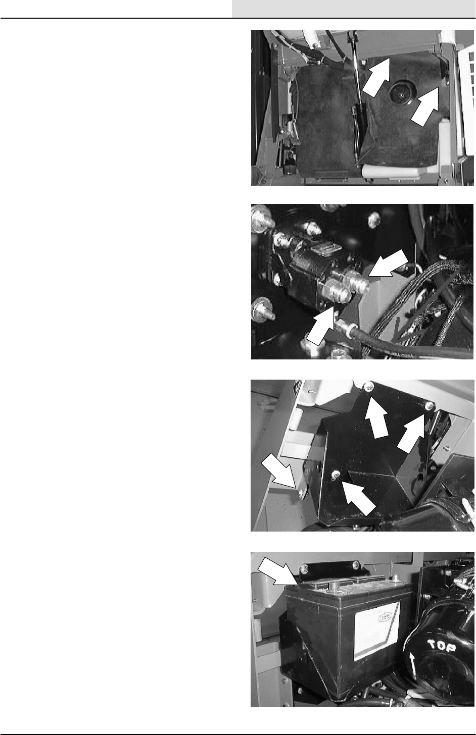
SWEEPING
3-69
8200/8210 330065 (3--01)
4. Position the rubber dust shield over the
vacuum fan assembly. Reinstall the plastic
rivets.
5. Reconnect the three hydraulic hoses. See
the schematic in the HYDRAULICS section.
NOTE:Observe hydraulic cleanliness
requirements when opening hydraulic lines.
6. Reinstall the battery tray in the machine.
Tighten the hardware to 18 -- 24 Nm
(15 -- 20 ft lb).
7. Reinstall the battery and reconnect the
battery cables.
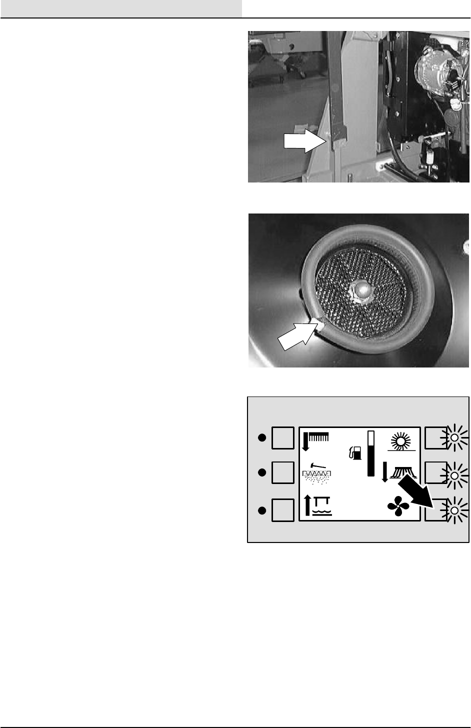
SWEEPING
3-70 8200/8210 330065 (3--01)
8. Close the engine cover and lower the
hopper.
NOTE: The rubber seal on the front of the
sweeping vacuum fan must come in contact with
the back of the hopper cover when the cover is in
the closed position. Adjust the vacuum fan
assembly forward if needed.
9. Start the machine and operate the sweeping
vacuum fan. Check for any leaks and proper
operation.
F
E
351648

SWEEPING
3-71
8200/8210 330065 (3--01)
MACHINE TROUBLESHOOTING
Problem Cause Remedy
Excessive dusting Brush skirts and dust seals worn,
damaged, out of adjustment
Replace or adjust brush skirts or
dust seals
Hopper dust filter clogged Shake and/or clean or replace
dust filter
Vacuum hose damaged Replace vacuum hose
Vacuum fan failure Contact TENNANT service
personnel
Hopper door partially or
completely closed
Open the hopper door
Thermo Sentryttripped Reset Thermo Sentryt
Poor sweeping performance Brush bristles worn Replace brushes
Main and side brushes not
adjusted properly
Adjust main and side brushes
Debris caught in main brush drive
mechanism
Free drive mechanism of debris
Main brush drive failure Contact TENNANT service
personnel
Side brush drive failure Contact TENNANT service
personnel
Hopper full Empty hopper
Hopper lip skirts worn or damaged Replace lip skirts
Hopper door partially or
completely closed
Open the hopper door
Wrong sweeping brush Contact TENNANT representative
for recommendations

SWEEPING
3-72 8200/8210 330065 (3--01)

SCRUBBING
4-1
8200/8210 330065 (3--01)
CONTENTS
Page
INTRODUCTION 4--3......................
SOLUTION TANK 4--4.....................
ES SOLUTION TANK 4--4..................
TO DRAIN AND CLEAN ES
SOLUTION TANK 4--5...............
TO REMOVE SOLUTION TANK 4--7......
TO INSTALL SOLUTION TANK 4--10.....
RECOVERY TANK 4--13...................
TO DRAIN AND CLEAN RECOVERY
TANK 4--13.........................
TO REMOVE RECOVERY TANK 4--16....
TO INSTALL RECOVERY TANK 4--19....
SCRUB HEAD 4--22.......................
SCRUB HEAD LINKS
(Max pro 1000 and Max pro 1200 only) 4--22..
TO REPLACE SCRUB HEAD LINKS 4--23.
TO REMOVE 2 MOTOR SCRUB
HEAD (stationary) 4--25..............
TO INSTALL 2 MOTOR SCRUB
HEAD (stationary) 4--28..............
TO REMOVE 2 MOTOR SCRUB
HEAD (with side--shift option) 4--31....
TO INSTALL 2 MOTOR SCRUB
HEAD (with edge scrub option) 4--35...
TO REMOVE 3 MOTOR SCRUB
HEAD (Max pro 1200) 4--39...........
TO INSTALL 3 MOTOR SCRUB
HEAD (Max pro 1200) (retractable) 4--43
SCRUB HEAD SKIRTS 4--47...............
TO REPLACE SCRUB HEAD
SKIRTS 4--47.......................
SCRUB BRUSHES 4--48...................
TO REPLACE SCRUB BRUSHES 4--48...
SOLUTION VALVE 4--49...................
Page
SQUEEGEES 4--50.......................
SIDE SQUEEGEES 4--50..................
TO REPLACE SIDE SQUEEGEE
BLADES 4--50......................
TO REPLACE SIDE SQUEEGEE
PIVOT CABLE 4--53.................
REAR SQUEEGEE 4--57...................
TO REPLACE OR ROTATE REAR
SQUEEGEE BLADES 4--57...........
TO ADJUST REAR SQUEEGEE
R O L L -- O U T 4 -- 5 9....................
TO LEVEL REAR SQUEEGEE 4--61......
FINE TUNING REAR SQUEEGEE
LEVELNESS 4--64...................
TO REPLACE REAR SQUEEGEE
LIFT CABLE 4--65...................
TO REMOVE REAR SQUEEGEE
FRAME 4--67.......................
TO INSTALL REAR SQUEEGEE
FRAME 4--69.......................
SCRUBBER VACUUM FAN 4--72...........
TO REMOVE SCRUBBER VACUUM
FAN ASSEMBLY 4--72...............
TO INSTALL SCRUBBER VACUUM
FAN ASSEMBLY 4--75...............
MACHINE SCRUBBING
TROUBLESHOOTING 4--78.............

SCRUBBING
4-2 8200/8210 330065 (3--01)

SCRUBBING
4-3
8200/8210 330065 (3--01)
INTRODUCTION
When scrubbing, the water flows from the solution
tank, through the solution valve, and down to the
scrub brushes. The brushes scrub the floor. As
the machine moves forward the rear squeegee
wipes the dirty solution off the floor, which is then
picked up and drawn into the recovery tank by the
vacuum fan.
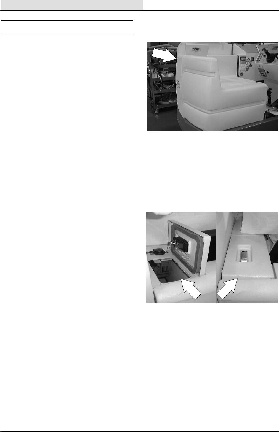
SCRUBBING
4-4 8200/8210 330065 (3--01)
SOLUTION TANK
The solution tank supplies the scrub brushes with
a water and detergent solution. The solution tank
is located on the right hand side of machine,
beside the recovery tank.
Access to the solution tank is through the opening
at the top of the tank, reached by lifting up the
cover.
The solution tank requires no regular
maintenance. If detergent cakes on the bottom of
the tank, remove the deposits with a strong blast
of warm water. Do not use water hotter than 130_
F(54_C) or use steam to clean the tank because
damage may occur. A tank drain cap has been
provided to allow the tank to be drained for
cleaning.
EStSOLUTION TANK
The EStmachine solution tanks supply the scrub
brushes with a water and cleaning solution
mixture.Thetanksalsostorewaterpickedupby
the machine squeegees and the vacuum fan.
Access to the EStsolution tanks is through the
opening at the top of the tanks, reached by lifting
up the tank cover.
The EStsolution tank should be drained and
cleaned after every work shift.
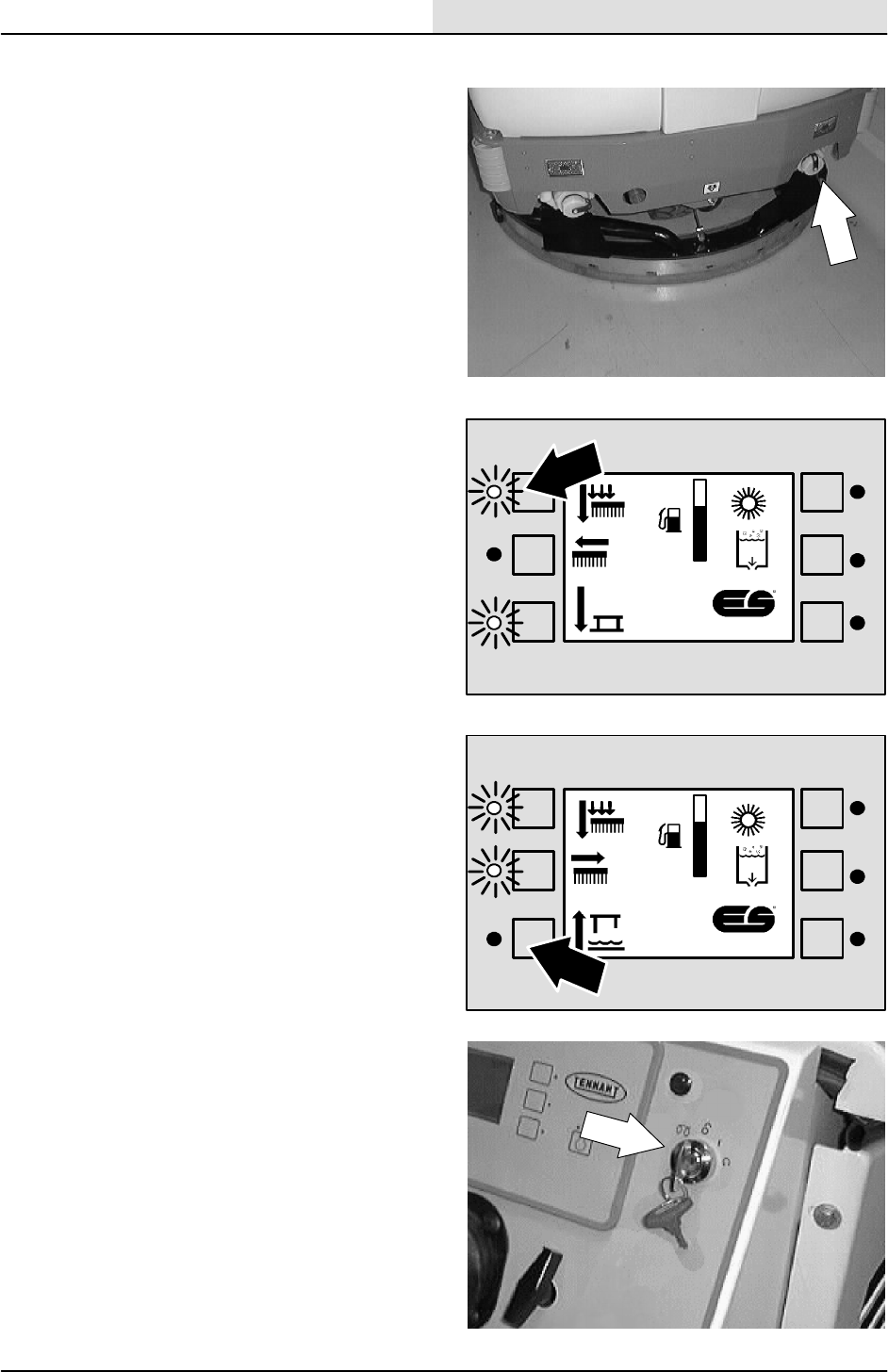
SCRUBBING
4-5
8200/8210 330065 (3--01)
TO DRAIN AND CLEAN ES SOLUTION TANK
1. Make sure the solution tank is empty.
2. Press the scrub brush switch to raise the
scrub head and stop the brushes.
3. Press the squeegee and vacuum fan switch
to raise the rear squeegee and stop the
vacuum fan.
4. Stop the machine next to a floor drain.
5. Turn off the machine and set the machine
parking brake.
FOR SAFETY: Before Leaving Or
Servicing Machine; Stop On Level
Surface, Set Parking Brake, Turn Off
Machine And Remove Key.
F
E
F
E
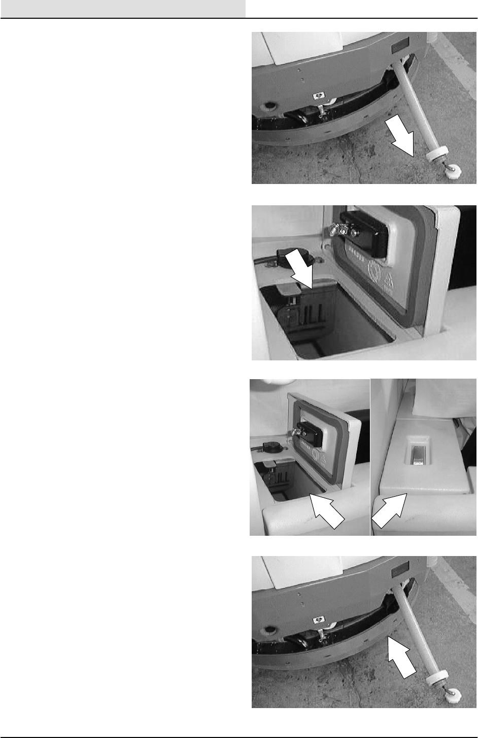
SCRUBBING
4-6 8200/8210 330065 (3--01)
6. Unscrew the drain cap from the solution tank
drain. Drain the solution.
7. Open the tank cover.
8. Spray the inside of the solution tank with
clean water. Do not use water hotter than
130_F(54_C) or use steam to clean the
tank because damage may occur.
9. Lower the tank cover.
10. Replace the drain cap.
11. For machines with the positive drain cap
option, close the drain valve. Remove the
drain hose and attach the dust cap.
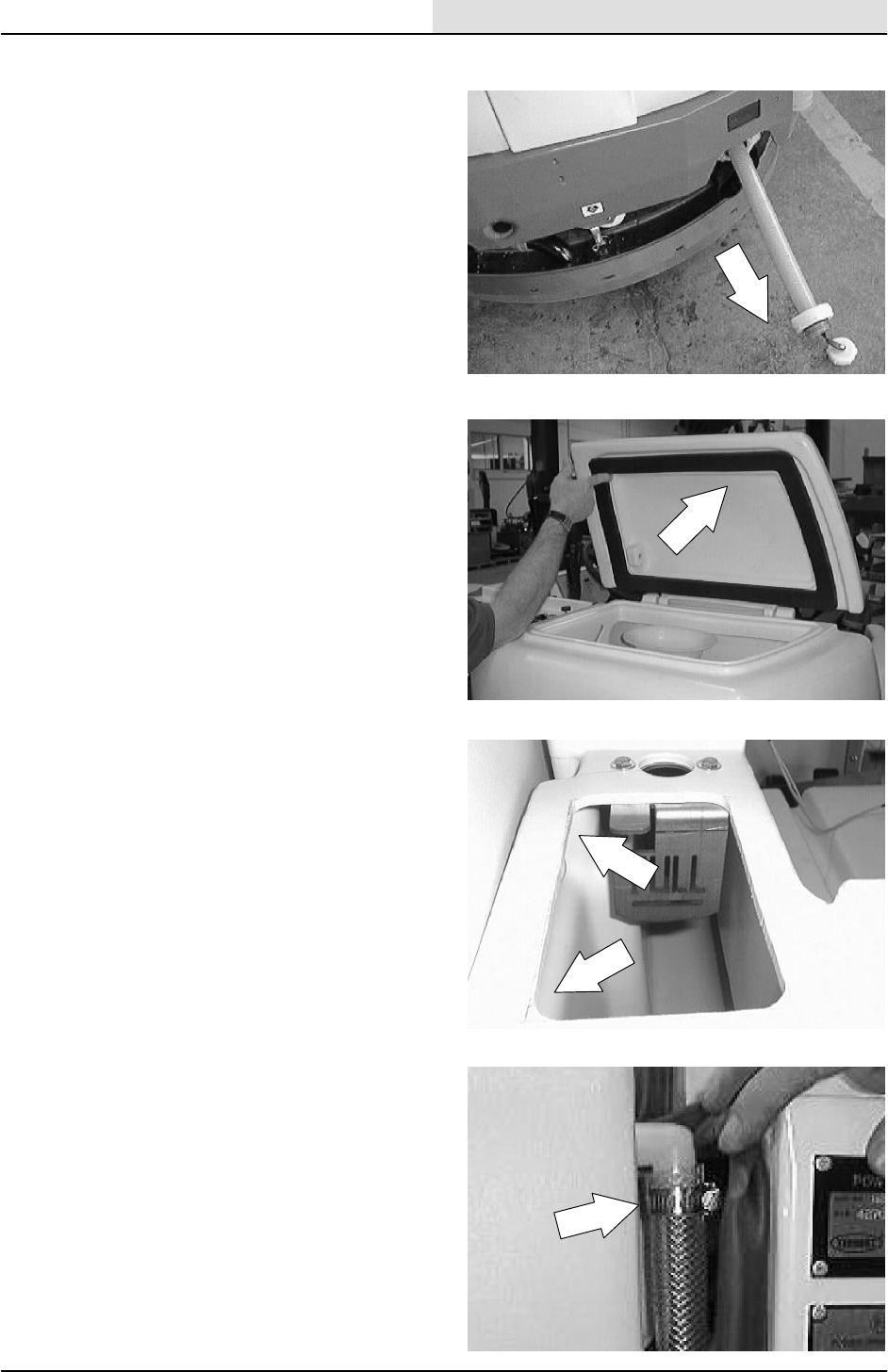
SCRUBBING
4-7
8200/8210 330065 (3--01)
TO REMOVE SOLUTION TANK
1. Make sure the solution tank is empty.
FOR SAFETY: Before Leaving Or
Servicing Machine; Stop On Level
Surface, Set Parking Brake.
2. Open the recovery tank cover.
NOTE: If the machine is equipped with the heavy
duty bumper option, the rear tank bumper must be
removed before the tanks can be removed.
3. Remove the two nuts and the metal plate
from the inside wall of the recovery tank.
4. EStMACHINE: Open the engine cover and
locate the water inlet line on the front corner
of the solution tank. Loosen the clamp and
pull the line off the fitting.
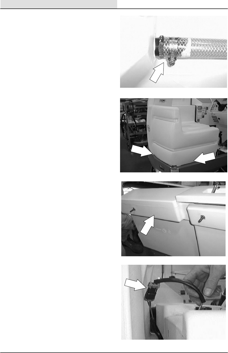
SCRUBBING
4-8 8200/8210 330065 (3--01)
5. Go under the machine at the back, right
corner. Locate the water drain line on the
right side of the solution tank. Loosen the
clamp and pull the line off the fitting.
6. Remove the two hex screws and flat
washers holding the bottom of the solution
tank to the machine frame.
7. Pull the solution tank away from the
recovery tank.
8. EStMACHINE: Disconnect the water level
sensor from the main harness in the area of
the solution tank fill cover.
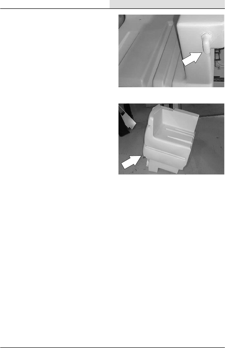
SCRUBBING
4-9
8200/8210 330065 (3--01)
9. Disconnect the water line at the top, front
corner of the tank.
10. Pull the solution tank out of the machine.
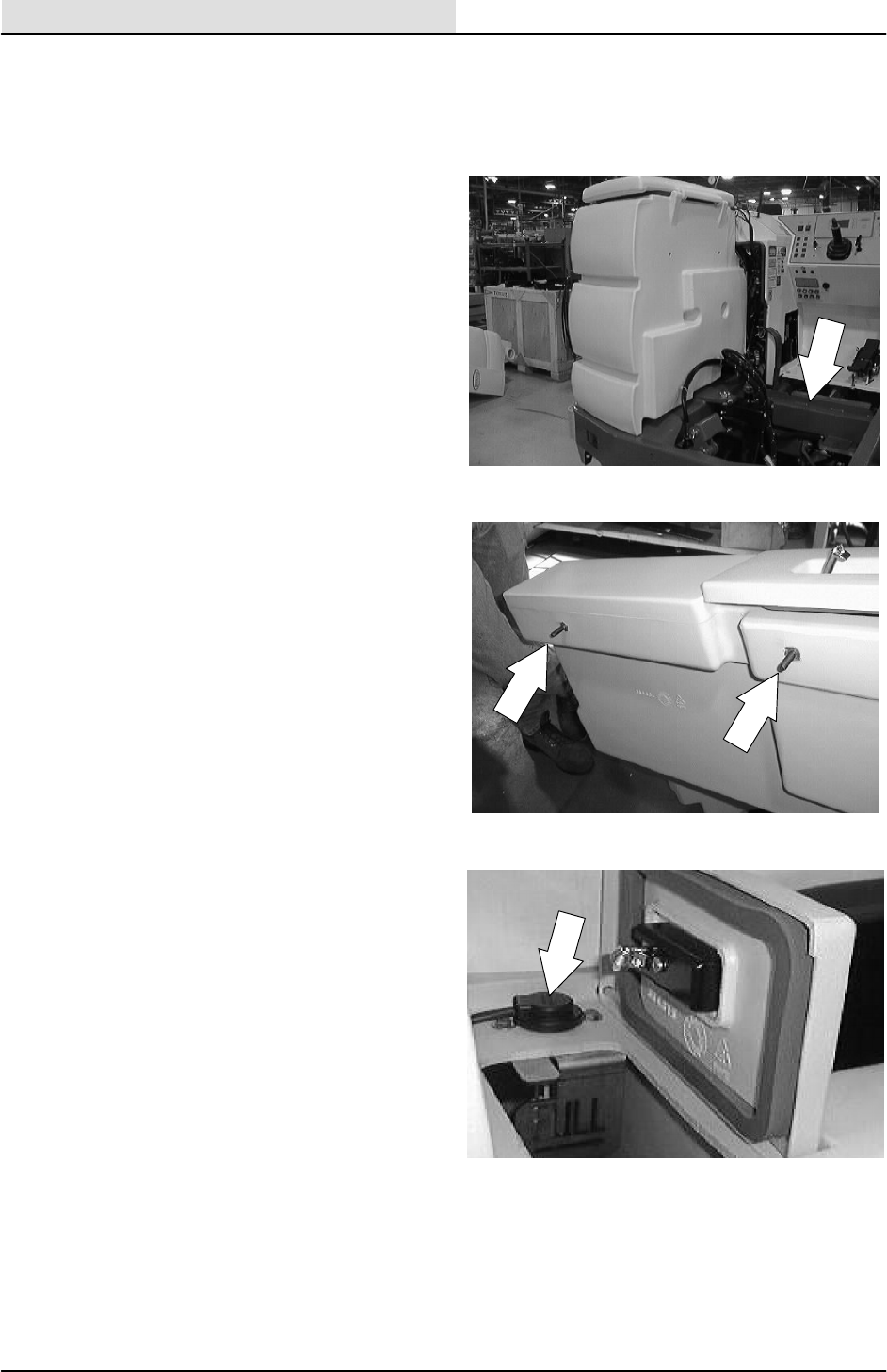
SCRUBBING
4-10 8200/8210 330065 (3--01)
TO INSTALL SOLUTION TANK
FOR SAFETY: Before Leaving Or
Servicing Machine; Stop On Level
Surface, Set Parking Brake.
1. Position the solution tank in the machine,
next to the recovery tank.
NOTE: Make sure the two studs are installed into
the inserts on the side of the solution tank that
comes in contact with the recovery tank.
2. EStMACHINE:Connect the water level
sensor to the main electrical harness in the
area of the solution tank fill cover.
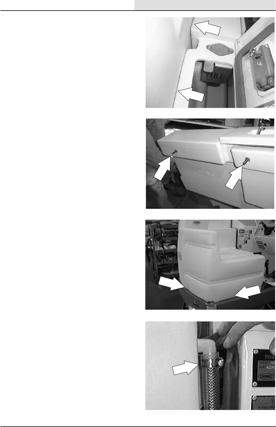
SCRUBBING
4-11
8200/8210 330065 (3--01)
3. Push the solution tank up against the
recovery tank.
4. Line up the two holes in the recovery tank
with the two studs on the side of the solution
tank. Push the studs through the holes.
5. Install the metal plate, washers and nuts
onto the tank studs. Leave loose for now.
6. Go under the machine at the back, right
corner. Locate the water drain line and
install it on the plastic fitting on the lower,
right side of the solution tank. Hand tighten
the clamp.
7. Align the threaded inserts on the bottom of
the tank with the two mount holes in the
machine frame. Install the hardware and
tighten to 18 -- 24 Nm (15 -- 20 ft lb).
8. Go back inside the top of the recovery tank
and tighten the two nuts to 18 -- 24 Nm
(15 -- 20 ft lb).
9. EStMACHINE: Open the engine cover and
locate the water inlet fitting on the front
corner of the solution tank.
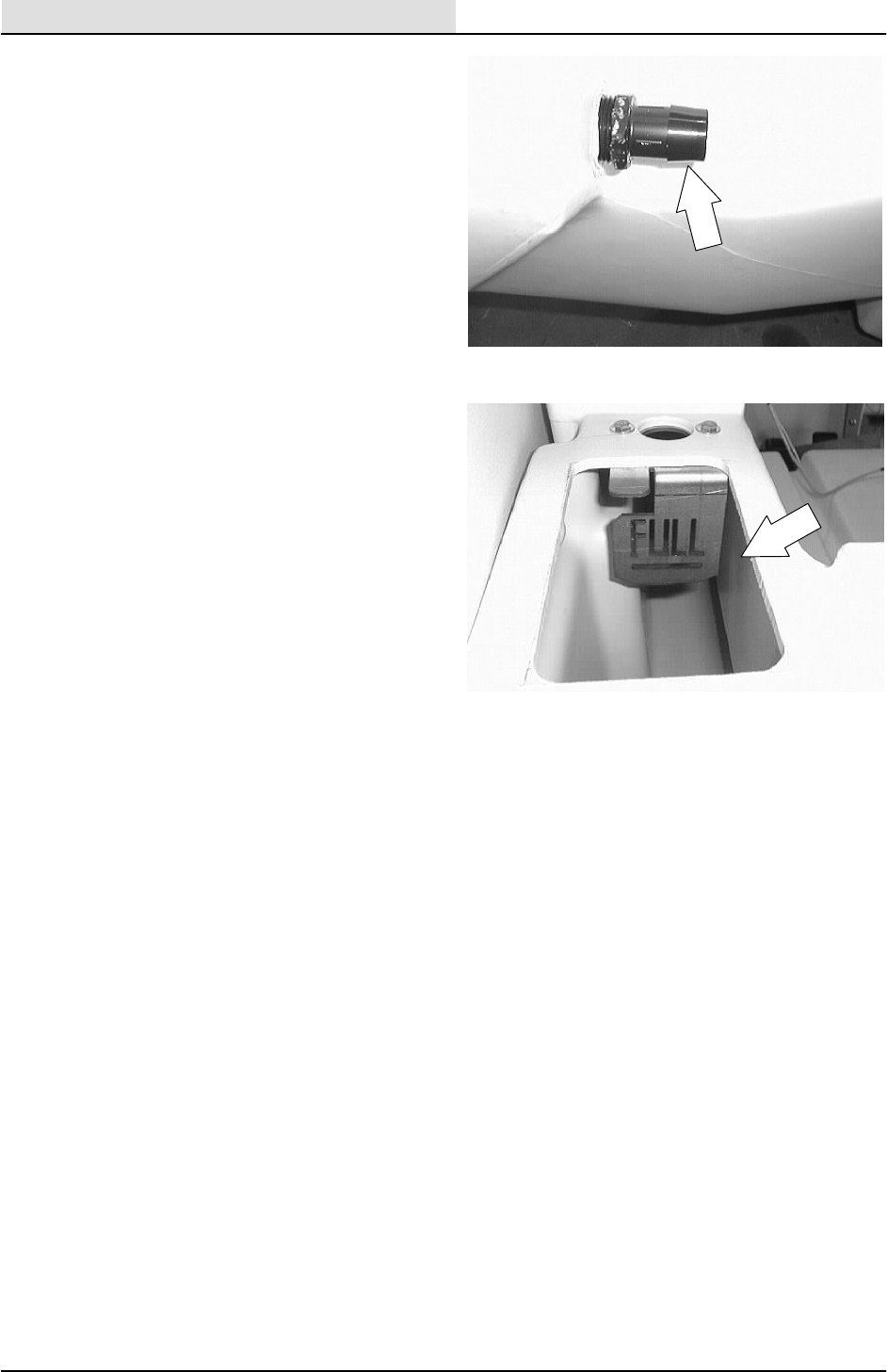
SCRUBBING
4-12 8200/8210 330065 (3--01)
10. EStMACHINE: Locate the EStpump
solution line and install on the fitting. Hand
tighten the clamp. Close the engine cover.
11. Fill the solution tank and check for any
leaks.
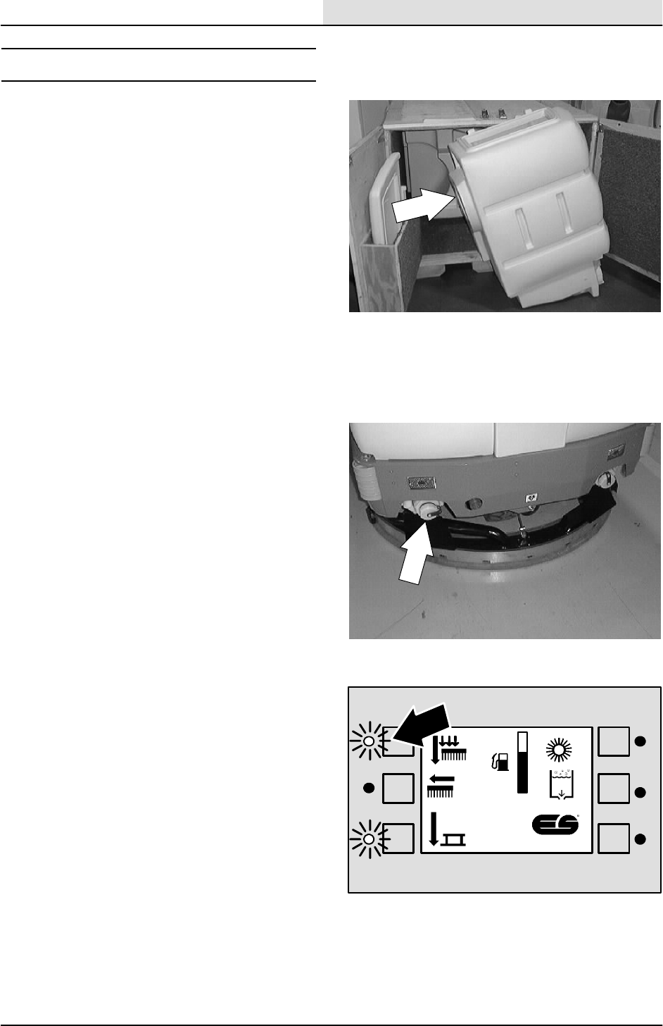
SCRUBBING
4-13
8200/8210 330065 (3--01)
RECOVERY TANK
The recovery tank stores water solution picked up
by the machine squeegees and the vacuum fan.
The recovery tank is located on the left side of the
machine, beside the solution tank.
The recovery tank should be drained and cleaned
after the solution tank is empty and whenever the
float stops the vacuum fan or the recovery tank
full lamp lights.
TO DRAIN AND CLEAN RECOVERY TANK
1. Make sure the recovery tank is empty.
2. Press the scrub brush switch to raise the
scrub head and stop the brushes.
F
E

SCRUBBING
4-14 8200/8210 330065 (3--01)
3. Press the squeegee and vacuum fan switch
to raise the rear squeegee and stop the
vacuum fan.
4. Stop the machine next to a floor drain.
5. Turn off the machine and set the machine
parking brake.
FOR SAFETY: Before Leaving Or
Servicing Machine; Stop On Level
Surface, Set Parking Brake, Turn Off
Machine And Remove Key.
6. To drain the recovery tank, unscrew the
drain hose cap from the access cap of the
recovery tank drain.
7. Pull out and place the drain hoses next to
the floor drain. Remove the drain cap from
the hose. Stand back, the solution rushes
out of the drain hose.
8. For machines with the positive drain cap
option, remove the dust cap. Connect the
drain hose and open the drain valve.
9. Open the tank cover.
10. Spray the inside of the recovery tank with
clean water. Do not use water hotter than
130_F(54_C) or use steam to clean the
tank because damage may occur.
F
E
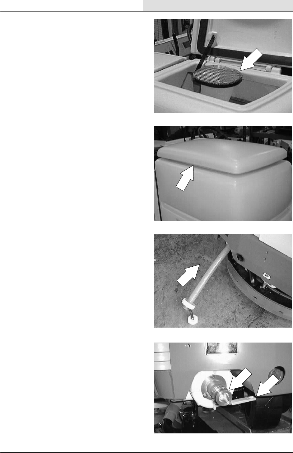
SCRUBBING
4-15
8200/8210 330065 (3--01)
11. Remove the vacuum outlet screen from the
tank horn. Clean the vacuum outlet screen
and place it back on the horn.
12. Lower the tank cover.
13. Replace the drain hoses and drain cap.
14. For machines with the positive drain cap
option, close the drain valve. Remove the
drain hose and attach the dust cap.
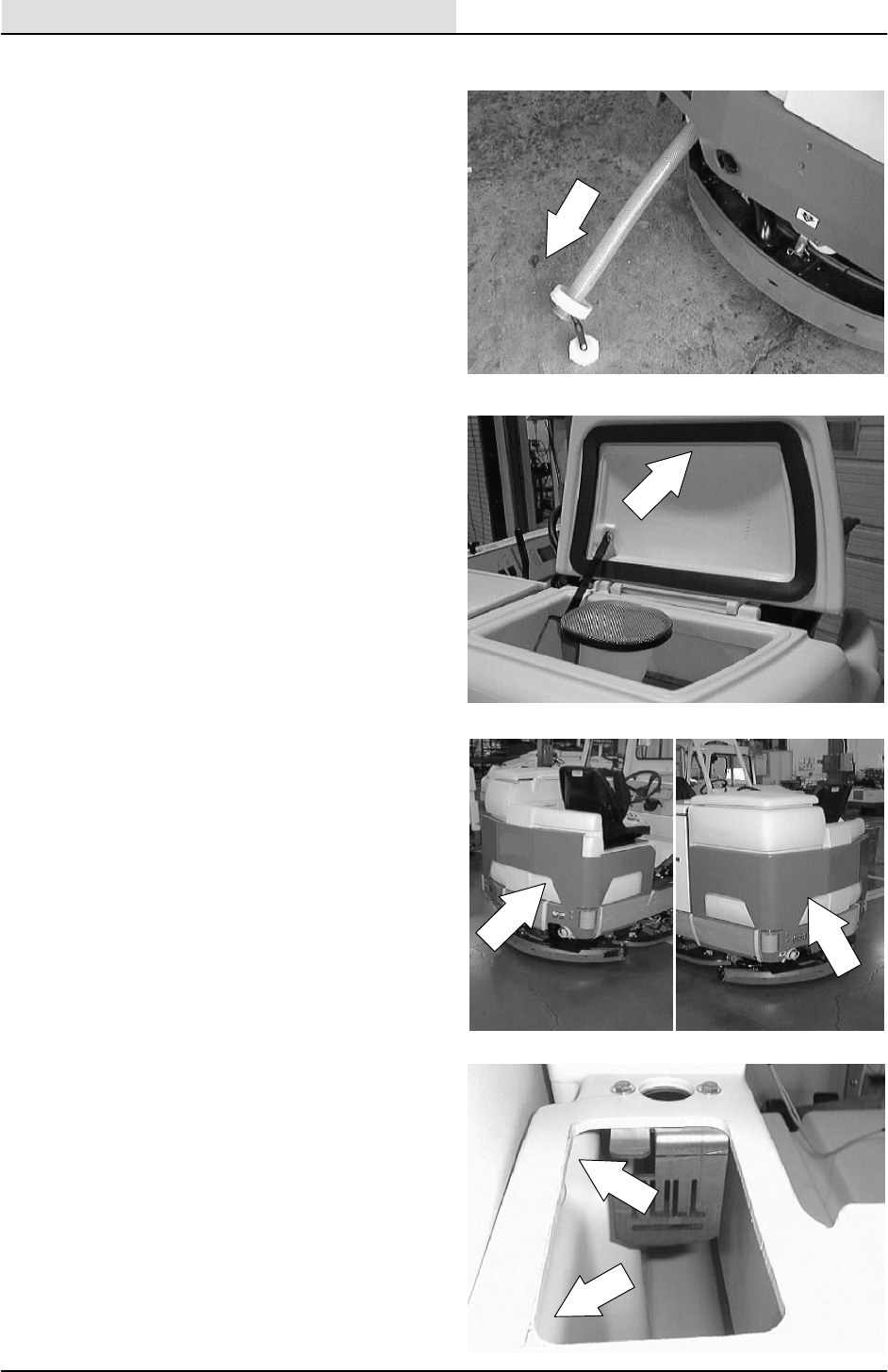
SCRUBBING
4-16 8200/8210 330065 (3--01)
TO REMOVE RECOVERY TANK
1. Make sure the recovery tank is empty.
FOR SAFETY: Before Leaving Or
Servicing Machine; Stop On Level
Surface, Set Parking Brake.
2. Open the recovery tank cover.
NOTE: If the machine is equipped with the heavy
duty bumper option, the rear tank bumper must be
removed before the tanks can be removed.
3. Remove the two nuts and the metal plate
from the inside wall of the recovery tank.
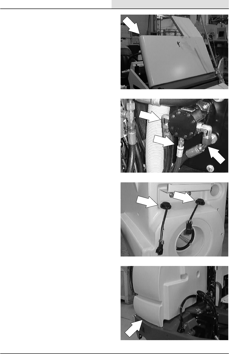
SCRUBBING
4-17
8200/8210 330065 (3--01)
4. Open the engine cover.
5. Mark, disconnect, and plug the hydraulic
hoses leading to the scrubbing vacuum fan
motor.
6. Disconnect the float switch located at the
front of the recovery tank. There are two
switches on a machine equipped with ESt.
7. Go under the machine at the left, rear
corner. Locate the two hex screws and flat
washers holding the bottom of the solution
tank to the machine frame. Remove the
screws.
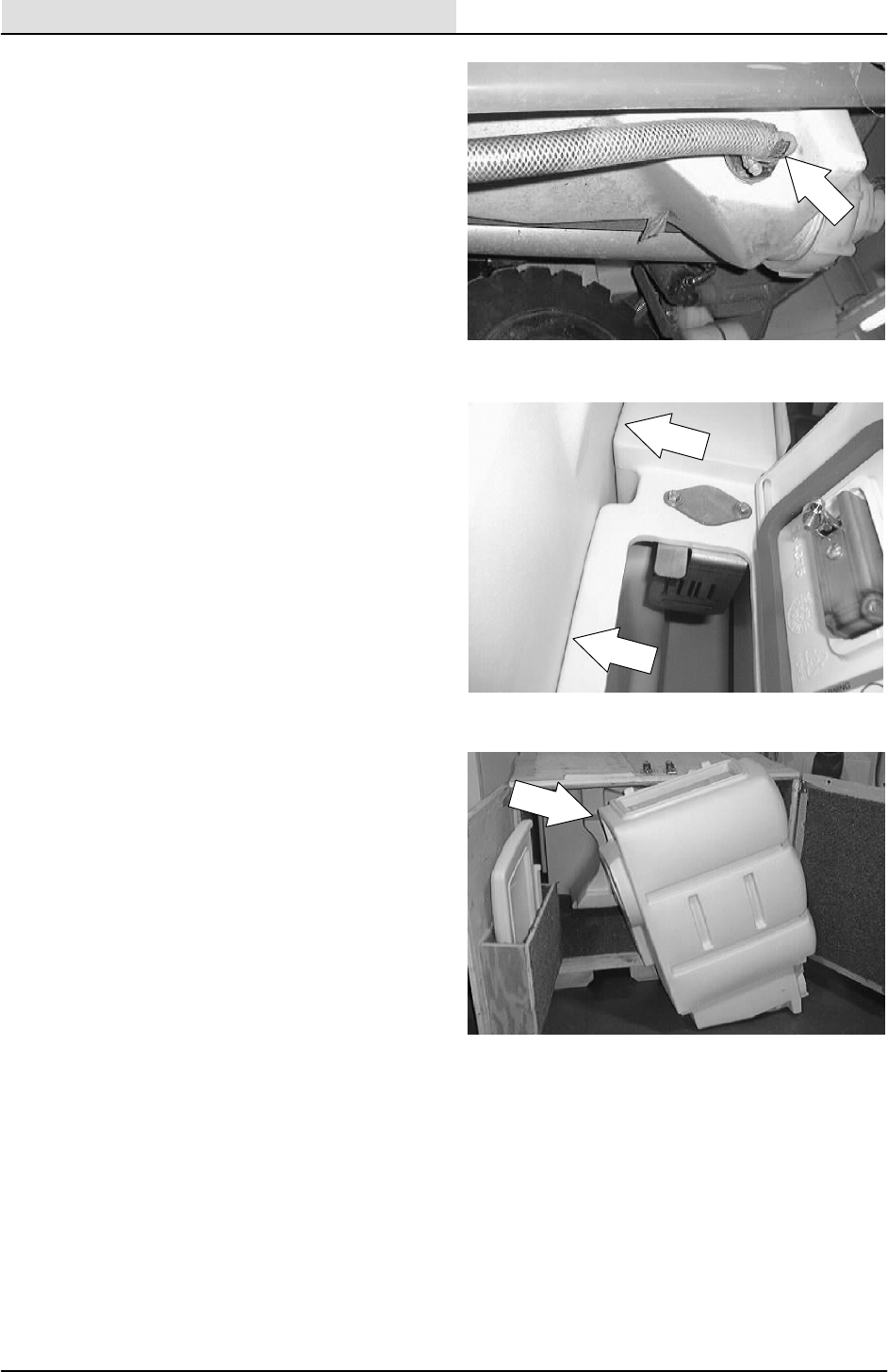
SCRUBBING
4-18 8200/8210 330065 (3--01)
8. EStMACHINE: locate the solution line and
bulkhead fitting on the lower side of the
recovery tank. Loosen the clamp and
remove the solution hose.
9. Pull the recovery tank away from the
solution tank.
10. Pull the recovery tank out of the machine.
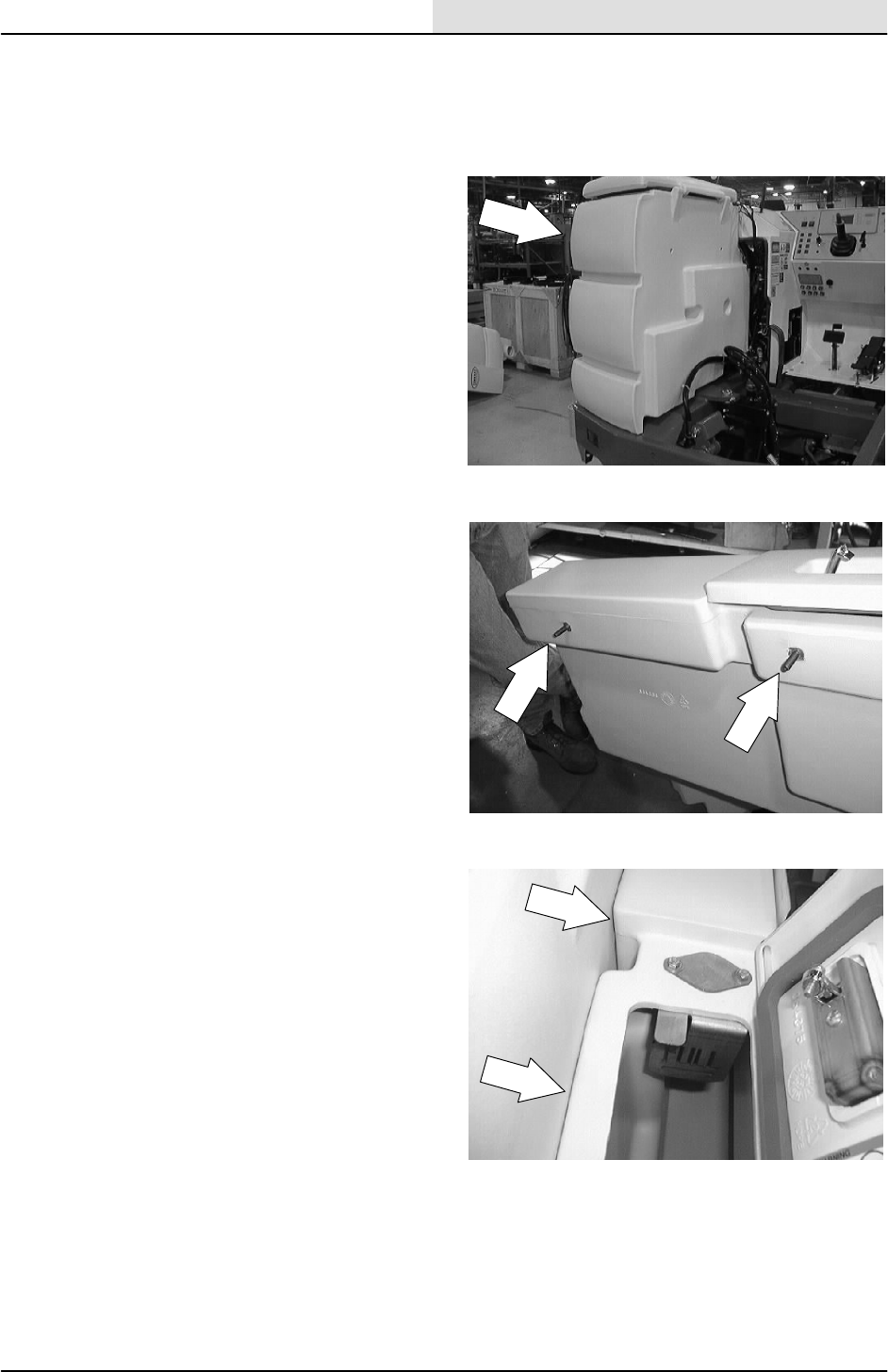
SCRUBBING
4-19
8200/8210 330065 (3--01)
TO INSTALL RECOVERY TANK
FOR SAFETY: Before Leaving Or
Servicing Machine; Stop On Level
Surface, Set Parking Brake.
1. Position the recovery tank in the machine,
next to the solution tank.
NOTE: Make sure the two studs are installed into
the inserts on the side of the solution tank that
comes in contact with the recovery tank.
2. Push the recovery tank up against the
solution tank.
3. Line up the two holes in the recovery tank
with the two studs on the side of the solution
tank. Push the studs through the holes.
4. Install the metal plate, washers and nuts on
the tank studs. Leave loose for now.
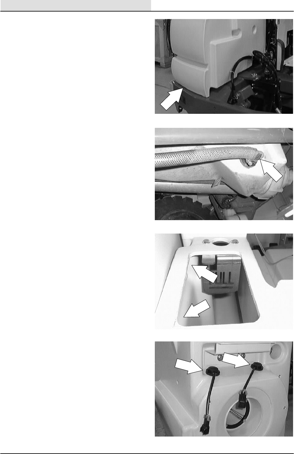
SCRUBBING
4-20 8200/8210 330065 (3--01)
5. Go under the machine at the back, left
corner.
6. Align the threaded inserts on the bottom of
the tank with the two mount holes in the
machine frame. Install the hardware and
tighten to 18 -- 24 Nm (15 -- 20 ft lb).
7. EStMACHINE: Place the EStsolution
line onto the bulkhead fitting on the lower
side of the recovery tank. Tighten the clamp.
8. Go back inside the top of the recovery tank
and tighten the two nuts to 18 -- 24 Nm
(15 -- 20 ft lb).
9. Reconnect the float switch at the front of the
recovery tank. There are two switches on
the EStmachines.
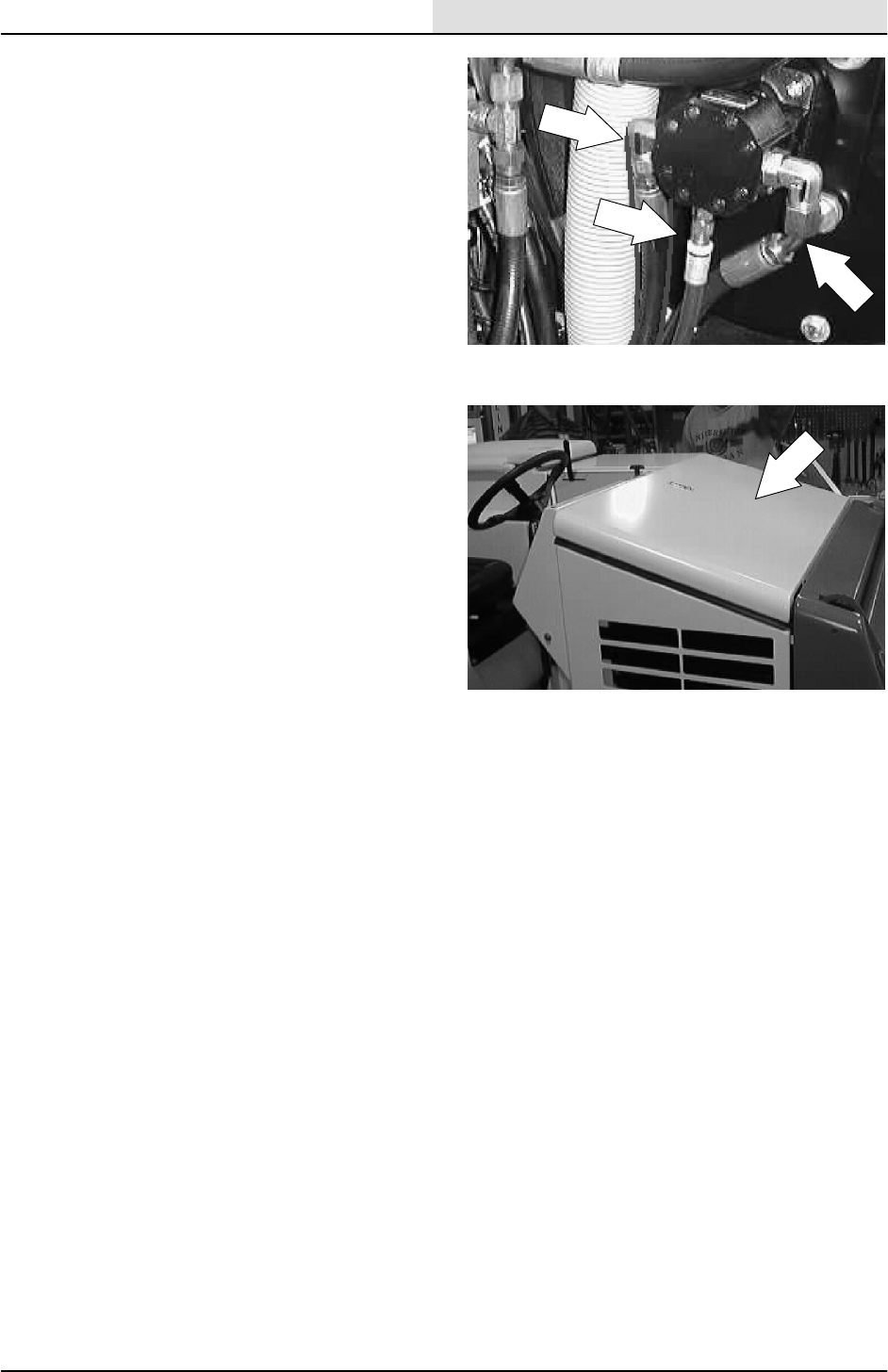
SCRUBBING
4-21
8200/8210 330065 (3--01)
10. Reconnect the hydraulic hoses to the
scrubbing vacuum fan. See schematic in the
HYDRAULIC section.
11. Close the engine cover and tank cover.
12. Operate the machine and check for any
leaks and proper operation of the float
switches.
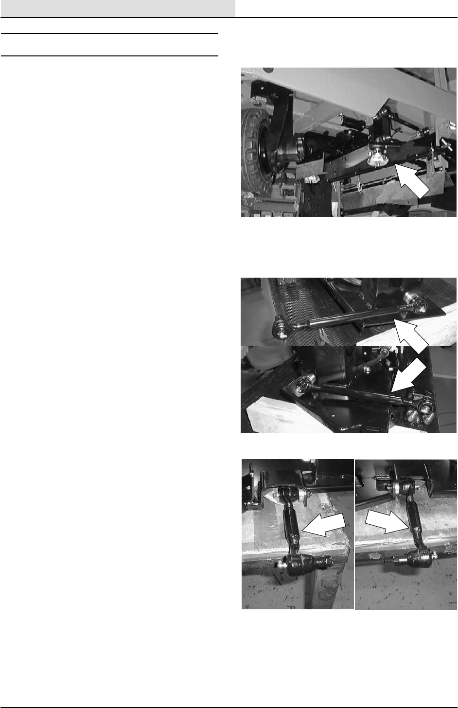
SCRUBBING
4-22 8200/8210 330065 (3--01)
SCRUB HEAD
The scrub head houses disc type scrub brushes
and their drive mechanisms. The scrub head is
factory adjusted and the measurement should not
be changed unless scrub head parts are damaged
or are replaced.
The machine can be equipped with either a two or
a three brush motor scrub head and a side shift
option. The scrub head floor skirts control water
spray from the brushes.
SCRUB HEAD LINKS
(Max pro 1000 and Max pro 1200 only)
The scrub head links attach the scrub head frame
to the machine frame. The two motor scrub head
has four links.
The three motor scrub head has two links. The
links allow the scrub head to follow the contour of
the floor. The scrub head links have (two or four)
pivot points on each side of the machine.
Lubricate the pivot points with a grease gun
containing Lubriplate EMB grease
(TENNANT Part No. 01433--1) after every 200
hours of operation.
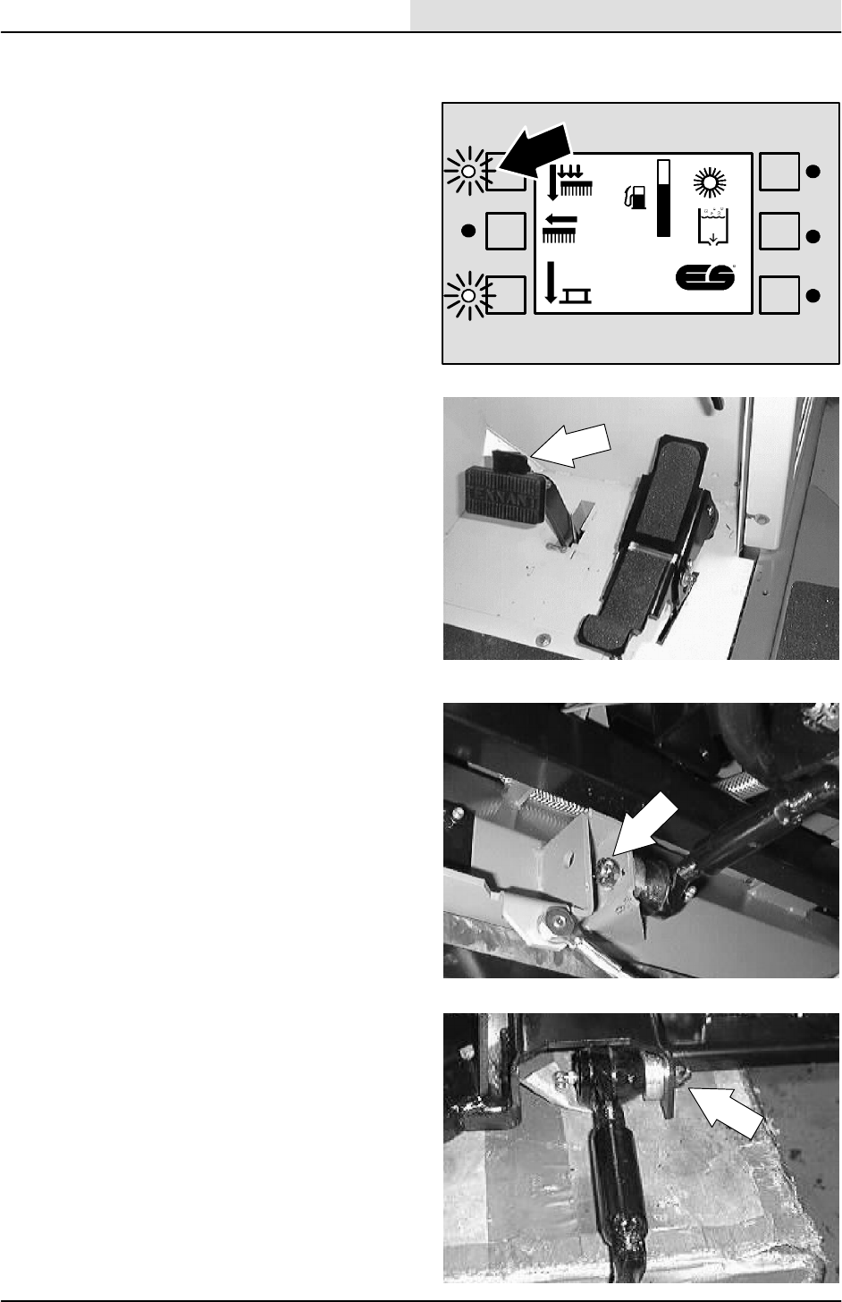
SCRUBBING
4-23
8200/8210 330065 (3--01)
TO REPLACE SCRUB HEAD LINKS
(Max pro 1000 and Max pro 1200 only)
1. Stop the machine and lower the scrub head.
2. Turn off the machine and set the machine
parking brake.
FOR SAFETY: Before Leaving Or
Servicing Machine; Stop On Level
Surface, Set Parking Brake, Turn Off
Machine And Remove Key.
3. Remove the cotter pins from the castle nuts
holding the scrub head link to the front of the
scrub head and the machine frame.
4. Remove the castle nuts from each end of
the link. Remove the spacers from the
tapered shaft of the link.
F
E
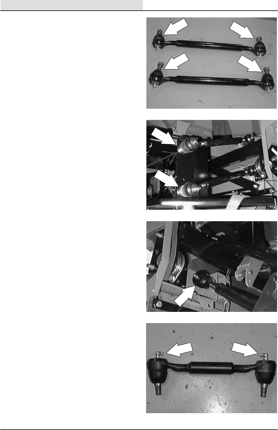
SCRUBBING
4-24 8200/8210 330065 (3--01)
5. Reinstall the spacers on the tapered shaft
on both ends of the new scrub head link.
6. Install the new link and spacer in the hole in
the front of the scrub head. Reinstall the
castle nut and tighten to 90 -- 117 Nm
(65 -- 85 ft lb). Turn the castle nut far enough
to line up with the cotter pin hole.
7. Install the other end of the scrub head link in
the hole in the machine frame. Reinstall the
castle nut and tighten to 90 -- 117 Nm
(65 -- 85 ft lb). Turn the castle nut far enough
to line up with the cotter pin hole. Reinstall
both cotter pins.
8. Lubricate the pivot points with a grease gun
containing Lubriplate EMB grease after
installation and after every 200 hours of
operation.

SCRUBBING
4-25
8200/8210 330065 (3--01)
TO REMOVE 2 MOTOR SCRUB HEAD
(stationary)
FOR SAFETY: Before Leaving Or
Servicing Machine; Stop On Level
Surface, Set Parking Brake, Turn Off
Machine And Remove Key.
1. Start the machine and lower the scrub head
and rear squeegee. Shut off the machine.
2. Raise the engine cover and disconnect the
battery.
3. Raise the back of the machine and install
jack stands under the frame.
FOR SAFETY: Block machine tires
before jacking machine up. Jack
machine up at designated locations
only. Block machine up with jack
stands.
F
E
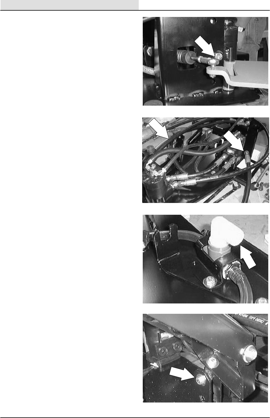
SCRUBBING
4-26 8200/8210 330065 (3--01)
4. Remove the side squeegee shift cable from
the left side squeegee at the ball joint.
5. Mark, disconnect, and plug the hydraulic
hoses leading from the machine to the scrub
brush motors (do not disconnect the
hydraulic hoses leading from one scrub
brush motor to the other).
NOTE: Observe hydraulic cleanliness
requirements when opening hydraulic lines.
6. Disconnect the solution hose from the fitting
in the center of the scrub head.
7. Remove the screw holding the center lift rod
end to the mount frame.
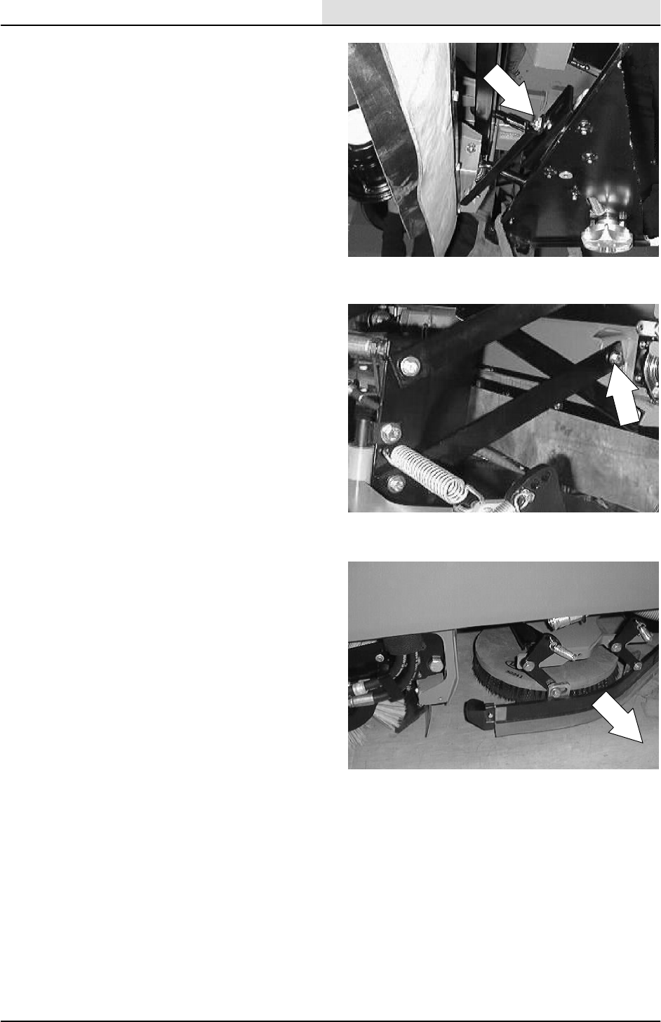
SCRUBBING
4-27
8200/8210 330065 (3--01)
8. Remove the screw holding the front of the
scrub head frame to the side movement
limiter bracket.
9. Remove the screws and nuts from the four
scrub head links where they attach to the
scrub head frame. Place the links out of the
way for scrub head removal.
10. The scrub head can now be removed from
the machine by bringing it out from under
the frame on the left hand side.
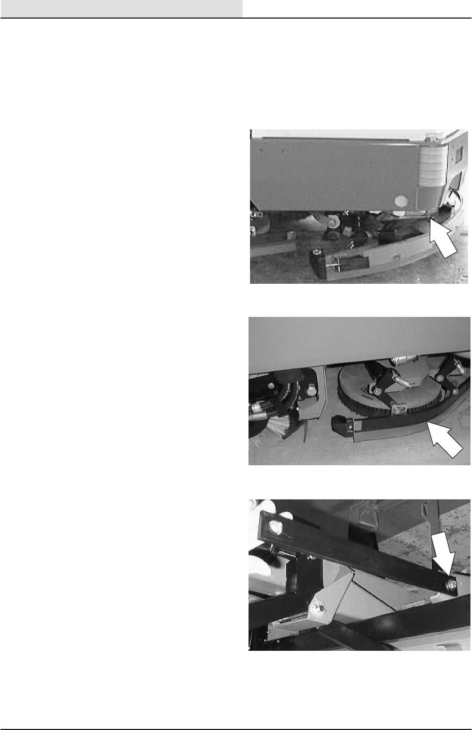
SCRUBBING
4-28 8200/8210 330065 (3--01)
TO INSTALL 2 MOTOR SCRUB HEAD
(stationary)
FOR SAFETY: Block machine tires
before jacking machine up. Jack
machine up at designated locations
only. Block machine up with jack
stands.
1. Raise the rear of the machine and install
jack stands under the frame.
2. Position scrub head under machine frame
from the left hand side.
3. Reinstall the scrub head links in the holes in
the scrub head frame. Tighten the hardware
to 18 -- 24 Nm (15 -- 20 ft lb).
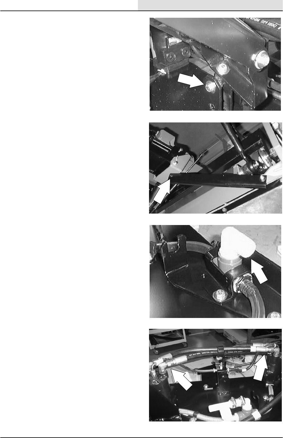
SCRUBBING
4-29
8200/8210 330065 (3--01)
4. Reinstall the head lift pivot rod end onto the
lift bracket. Tighten hardware to 18 -- 24 Nm
(15 -- 20 ft lb).
5. Reinstall the front of the scrub head frame to
the side link. Tighten hardware to
18 -- 24 Nm (15 -- 20 ft lb).
6. Reconnect the main solution feed line to the
fitting in the center of the scrub head.
7. Reconnect the hydraulic hoses to the two
brush motors. See schematic in the
HYDRAULICS section.
NOTE: Observe hydraulic cleanliness
requirements when opening hydraulic lines.

SCRUBBING
4-30 8200/8210 330065 (3--01)
8. Reinstall the side squeegee shift cable into
the mount slot and tighten the two jam nuts.
NOTE: Install the push--pull cable so there is
2--3/16 inch from the center of the bracket to the
end of the cable steel area.
9. Reinstall the side squeegee shift cable to the
left side squeegee at the ball joint.
NOTE: Make sure the balljoint is threaded all the
way onto the cable. The distance between the
middle of the balljoint and the middle of the
bracket on the scrub head should be 10.64
inches.
NOTE: Make sure to reinstall any clamps or
plastic ties that were removed during disassembly.
10. Reconnect the battery and close the engine
cover.
11. Remove the jack stands and lower the
machine. Check for proper operation of the
scrub brushes and head lift.
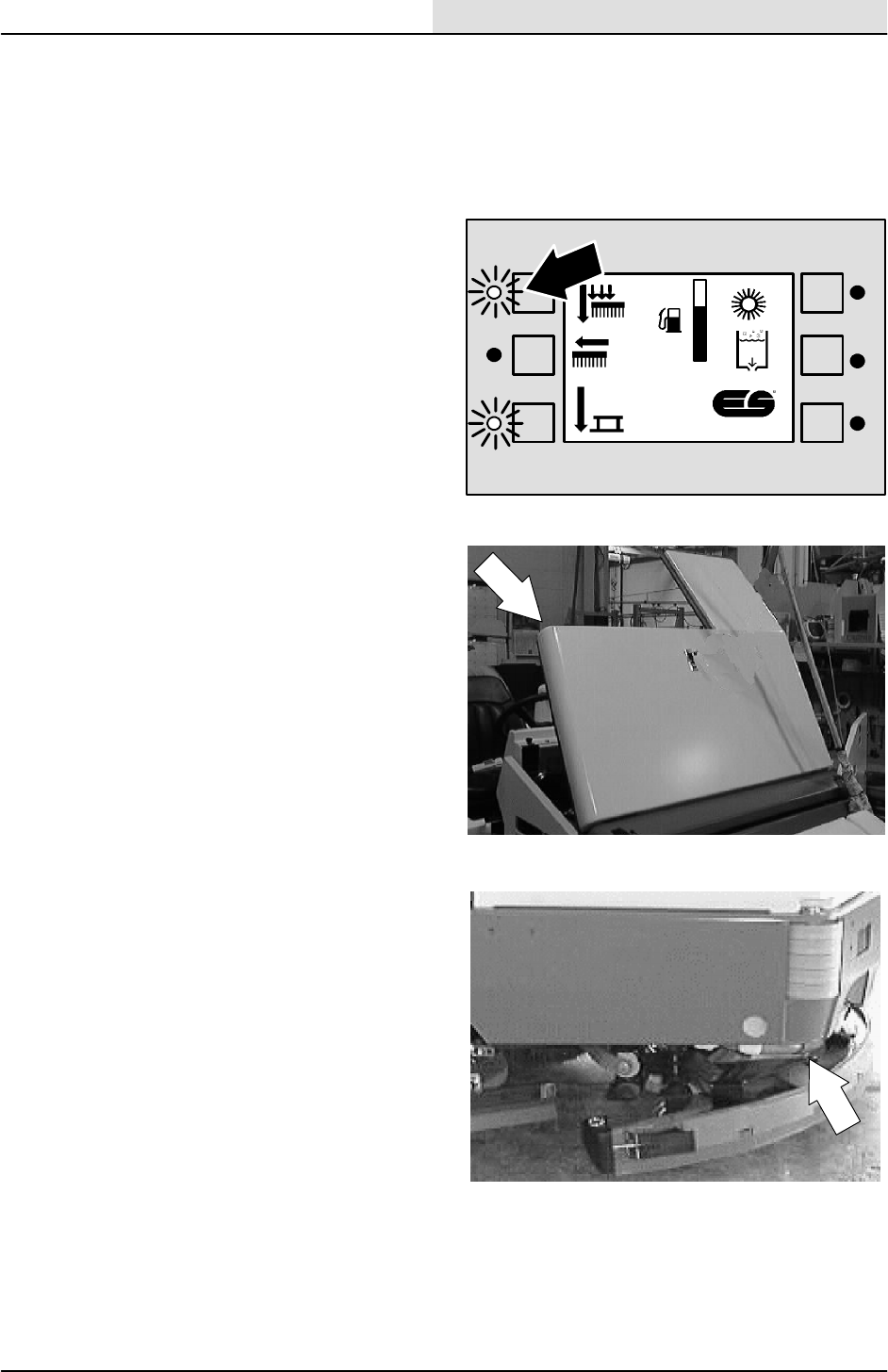
SCRUBBING
4-31
8200/8210 330065 (3--02)
TO REMOVE 2 MOTOR SCRUB HEAD
(with side--shift option)
FOR SAFETY: Before Leaving Or
Servicing Machine; Stop On Level
Surface, Set Parking Brake, Turn Off
Machine And Remove Key.
1. Start the machine and lower the scrub head.
NOTE: Make sure the scrub head is shifted all the
way in, under the machine.
2. Shut off the machine.
3. Raise the engine cover and disconnect the
battery.
4. Raise the back of the machine and install
jack stands under the frame.
FOR SAFETY: Block machine tires
before jacking machine up. Jack
machine up at designated locations
only. Block machine up with jack
stands.
F
E
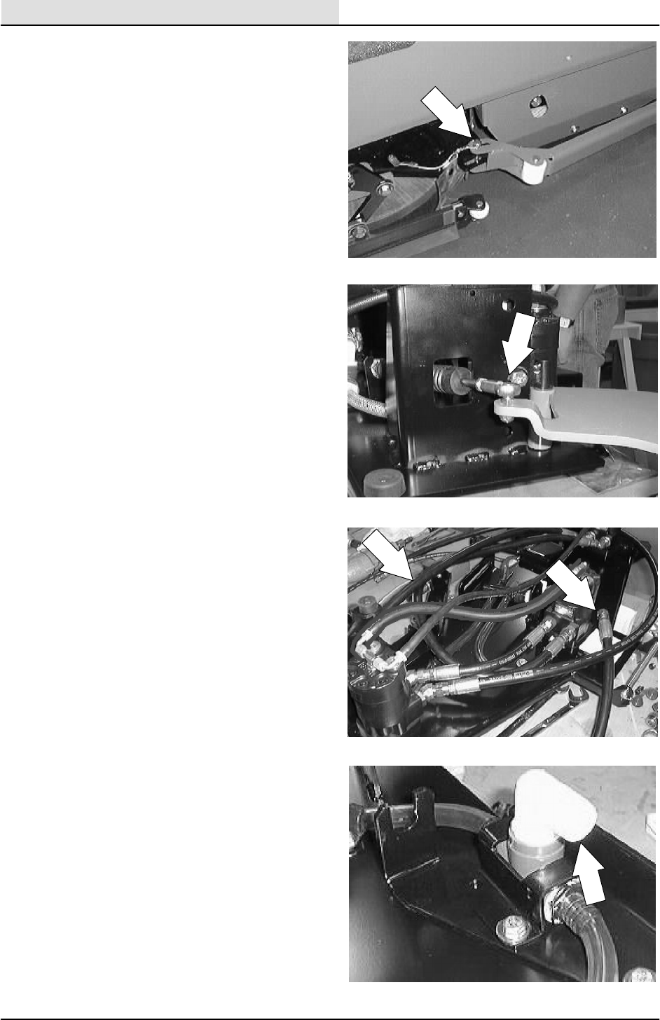
SCRUBBING
4-32 8200/8210 330065 (3--02)
5. Remove the hitch pin holding the scrub head
deflector arm to the right side of the scrub
head.
6. Remove the side squeegee shift cable from
the left side squeegee at the ball joint.
Loosen the two jam nuts on the cable and
remove from the mount slot.
7. Mark, disconnect, and plug the hydraulic
hoses leading to the two scrub brush
motors.
NOTE: Observe hydraulic cleanliness
requirements when opening hydraulic lines.
8. Disconnect the solution hose from the fitting
in the center of the scrub head.
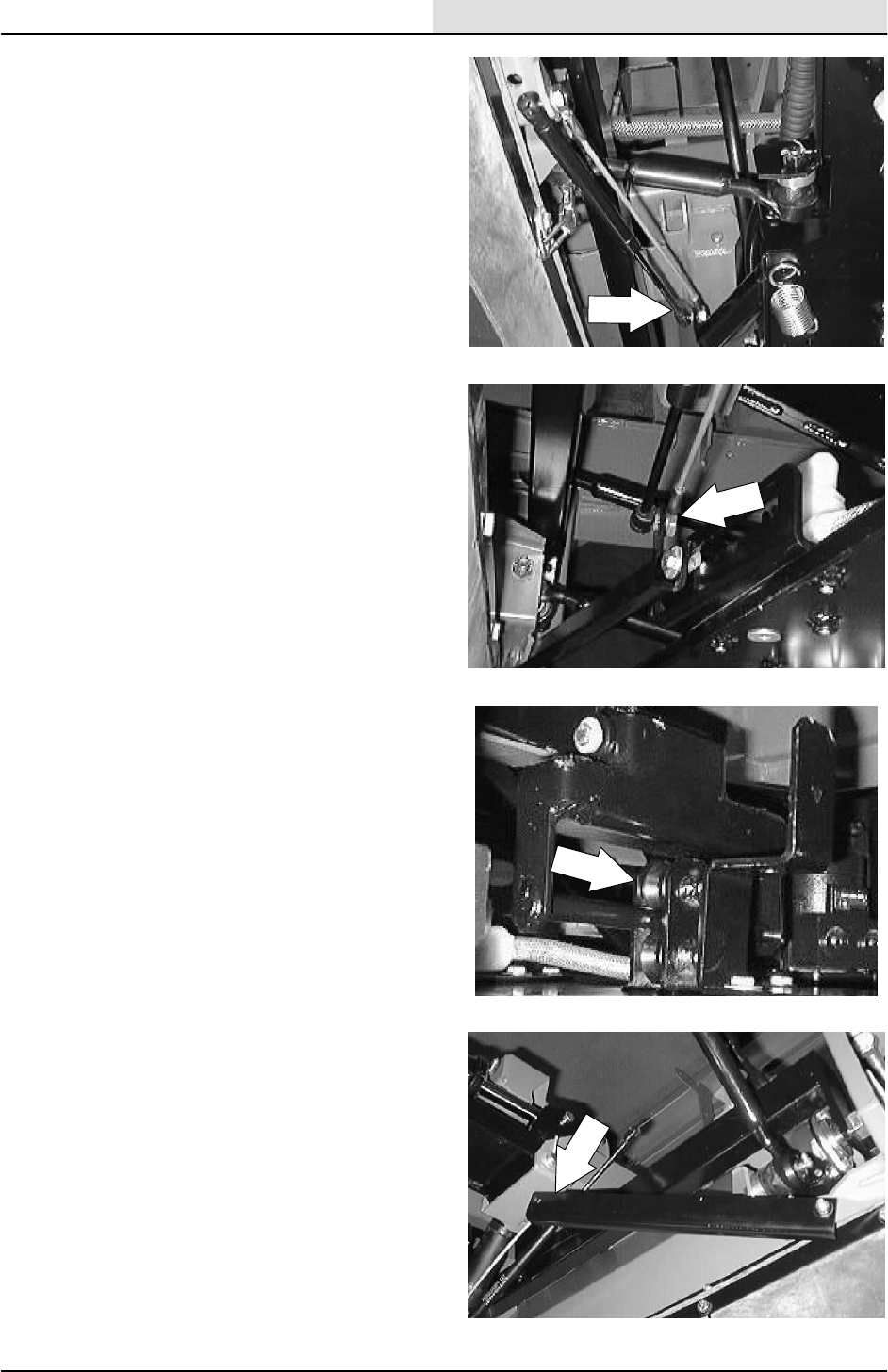
SCRUBBING
4-33
8200/8210 330065 (3--02)
9. Pull the clip up on the end of the side shift
gas spring and remove it from the ball on the
LH side of the scrub head.
10. Remove the ball end and nut holding the
side shift pull cable to the scrub head.
11. Remove the screw holding the center lift
bracket roller to the mount frame. Remove
the roller.
12. Remove the screw and nut holding the scrub
head side shift limiter bracket to the front of
the scrub head frame.
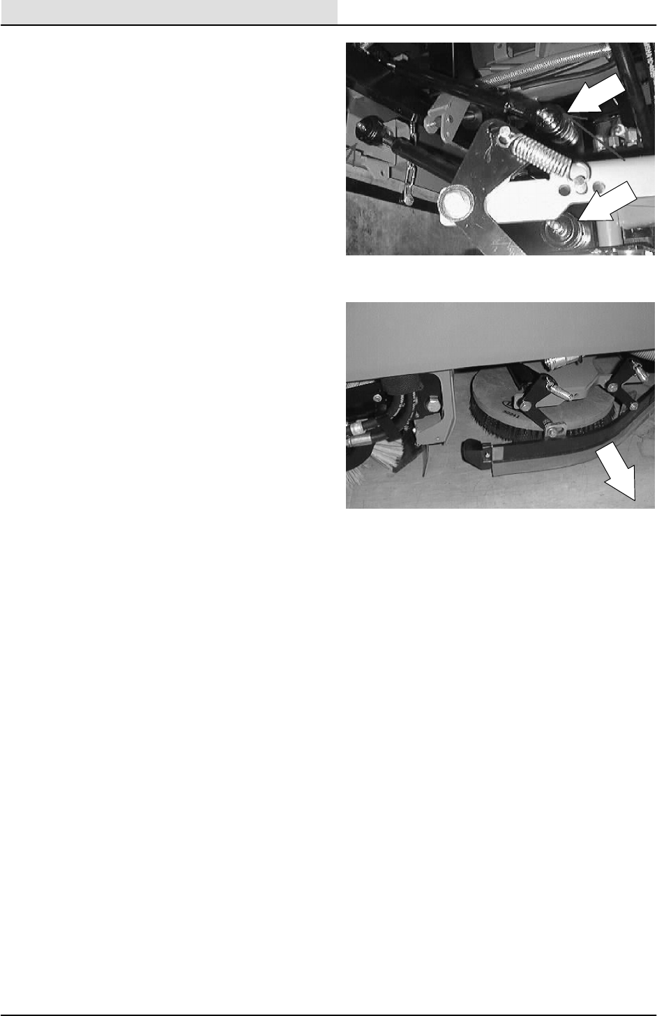
SCRUBBING
4-34 8200/8210 330065 (3--02)
13. Remove the cotter pins and castle nuts from
the four scrub head links where they attach
to the scrub head frame. Place the links up
and out of the way for scrub head removal.
14. The scrub head can now be removed from
the machine by bringing it out from under
the frame on the left hand side.
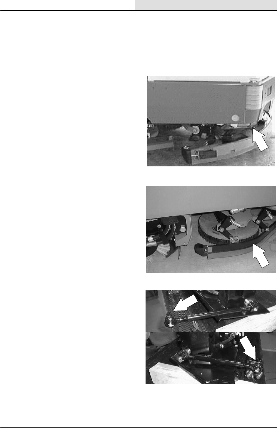
SCRUBBING
4-35
8200/8210 330065 (3--01)
TO INSTALL 2 MOTOR SCRUB HEAD
(with edge scrub option)
FOR SAFETY: Block machine tires
before jacking machine up. Jack
machine up at designated locations
only. Block machine up with jack
stands.
1. Raise the rear of the machine and install
jack stands under the frame.
2. Position scrub head under machine frame
from the left hand side.
3. Reinstall the four scrub head links in the
mount holes on the scrub head frame.
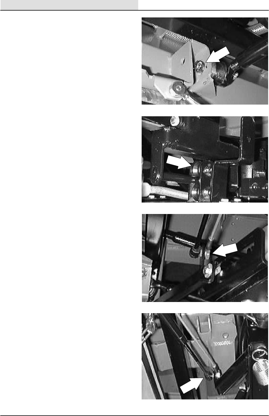
SCRUBBING
4-36 8200/8210 330065 (3--01)
4. Reinstall the castle nuts on the scrub head
links and tighten to 90 -- 117 Nm
(65 -- 85 ft lb). Turn the castle nut far enough
to line up with the cotter pin hole. Reinstall
the cotter pin.
5. Reinstall the head lift pivot roller on the lift
bracket. Tighten hardware to 18 -- 24 Nm
(15 -- 20 ft lb).
6. Reconnect side shift return cable and nut
on the rear of the scrub head. Tighten the
nut to the point were the cable is able to
rotate.
7. Install gas spring onto the ball on the front
side of the scrub head. Make sure the
locking clip re--seats itself.
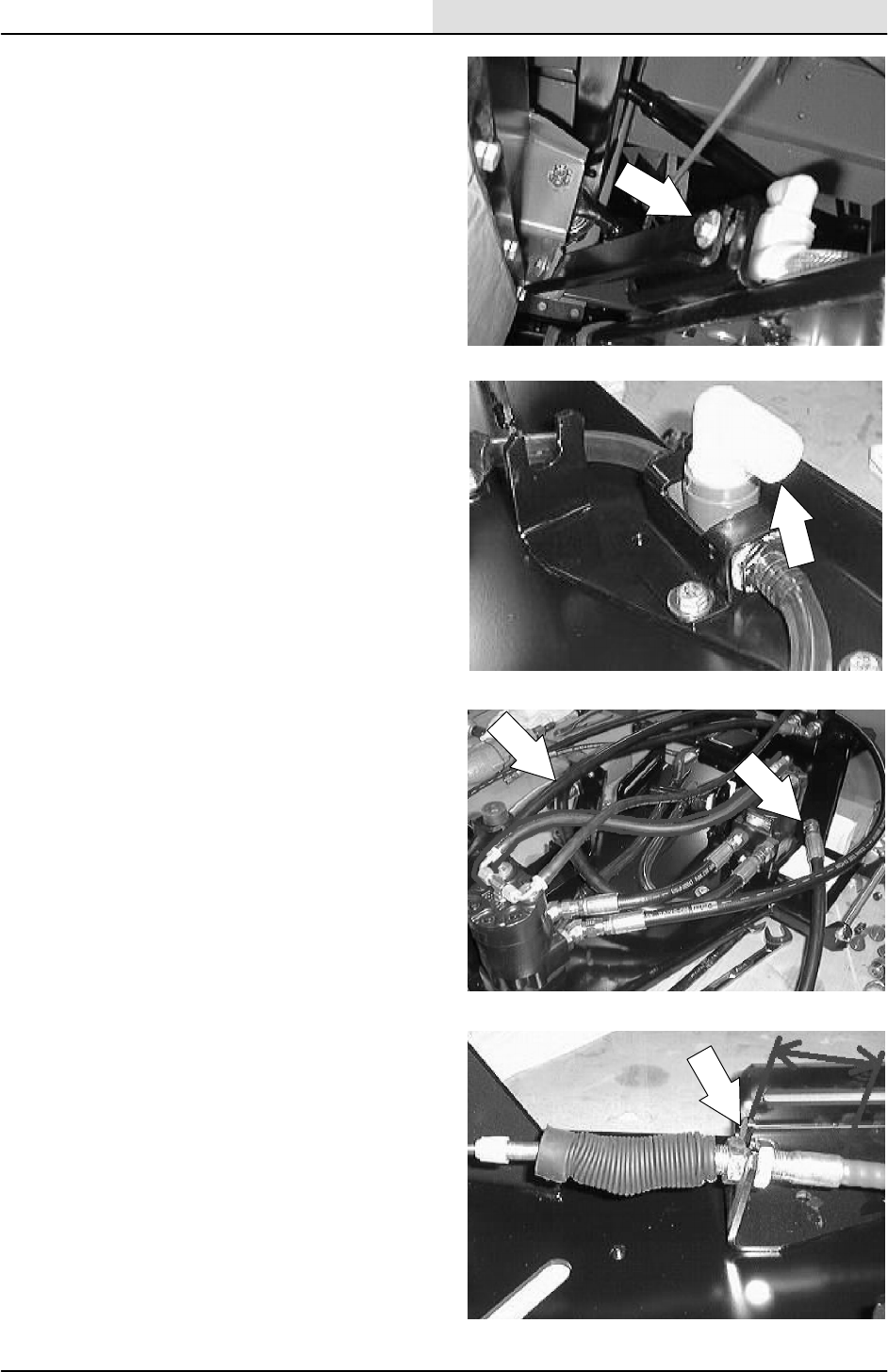
SCRUBBING
4-37
8200/8210 330065 (3--01)
8. Reinstall the scrub head side shift limiter
bracket on the front of the scrub head frame.
Tighten hardware to 18 -- 24 Nm
(15 -- 20 ft lb).
9. Reconnect the main solution feed line to the
fitting in the center of the scrub head.
10. Reconnect the hydraulic hoses to the two
brush motors. See schematic in the
HYDRAULICS section.
NOTE: Observe hydraulic cleanliness
requirements when opening hydraulic lines.
11. Reinstall the side squeegee shift cable into
the mount slot and tighten the two jam nuts.
NOTE: Install the push--pull cable so there is
2--3/16 inch from the center of the bracket to the
end of the cable steel area.
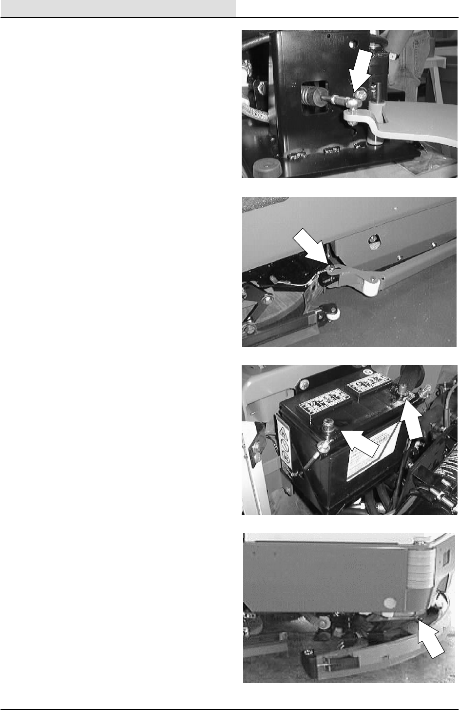
SCRUBBING
4-38 8200/8210 330065 (3--01)
12. Reinstall the side squeegee shift cable to the
left side squeegee at the ball joint.
NOTE: Make sure the balljoint is threaded all the
way onto the cable. The distance between the
middle of the balljoint and the middle of the
bracket on the scrub head should be 10.64
inches.
NOTE: Make sure to reinstall any clamps or
plastic ties that were removed during disassembly.
13. Reinstall the scrub head deflector arm onto
the right hand side of the scrub head.
Reinstall the hitch pin.
14. Reconnect the battery and close the engine
cover.
15. Remove the jack stands and lower the
machine. Check for proper operation of the
scrub brushes and side shift.

SCRUBBING
4-39
8200/8210 330065 (3--02)
TO REMOVE 3 MOTOR SCRUB HEAD
(Max pro 1200)
FOR SAFETY: Before Leaving Or
Servicing Machine; Stop On Level
Surface, Set Parking Brake, Turn Off
Machine And Remove Key.
1. Start the machine and lower the scrub head.
NOTE: Make sure the scrub head is shifted all the
way in, under the machine.
2. Shut off the machine.
3. Raise the engine cover and disconnect the
battery.
4. Raise the back of the machine and install
jack stands under the frame.
FOR SAFETY: Block machine tires
before jacking machine up. Jack
machine up at designated locations
only. Block machine up with jack
stands.
F
E
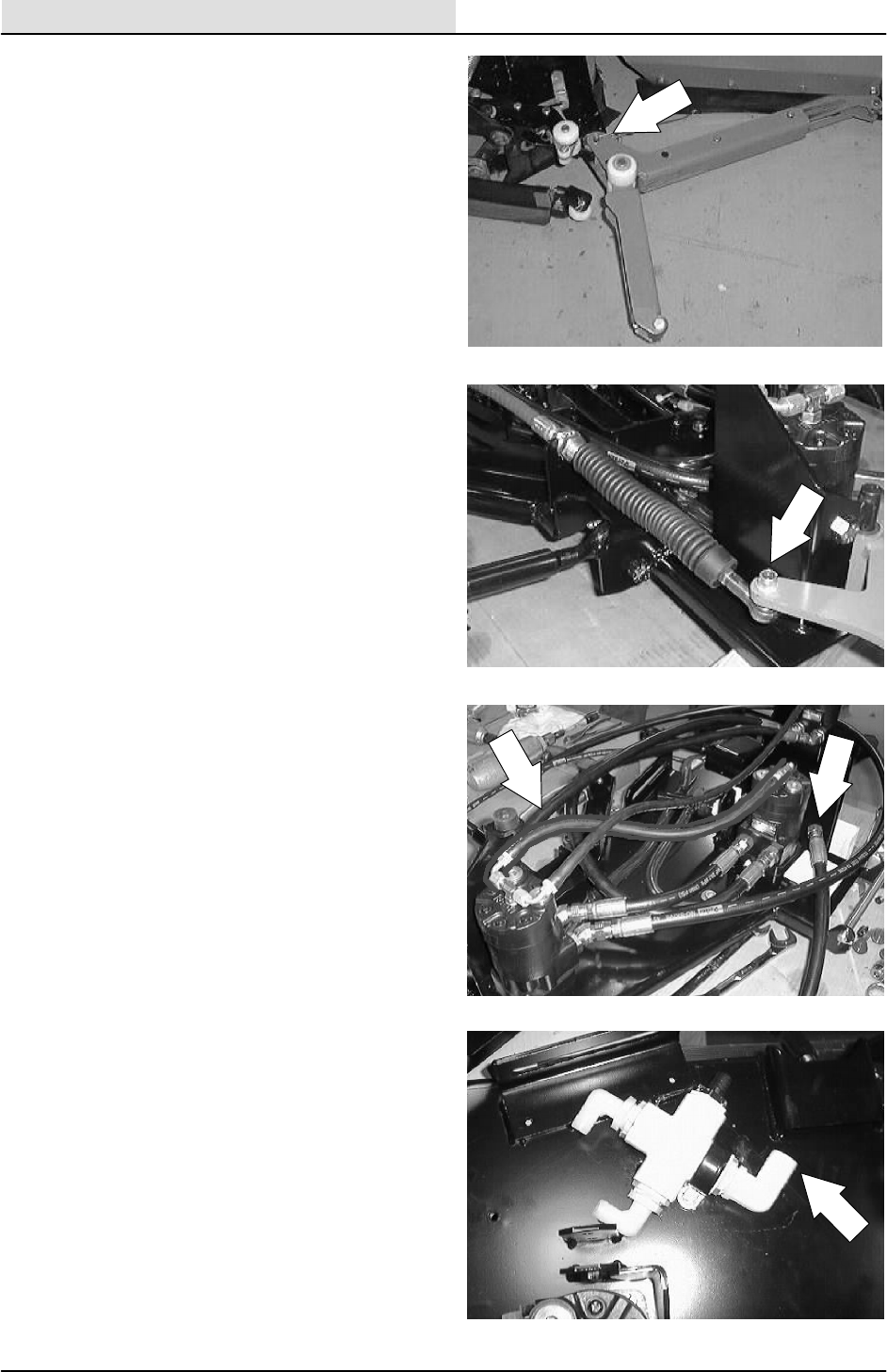
SCRUBBING
4-40 8200/8210 330065 (3--02)
5. Remove the hitch pin holding the scrub head
deflector arm to the right side of the scrub
head.
6. Remove the side squeegee shift cable from
the left side squeegee at the ball joint.
Loosen the two jam nuts on the cable and
remove from the mount slot.
7. Mark, disconnect, and plug the hydraulic
hoses leading to the three scrub brush
motors.
NOTE: Observe hydraulic cleanliness
requirements when opening hydraulic lines.
8. Disconnect the solution hose from the fitting
in the center of the scrub head.
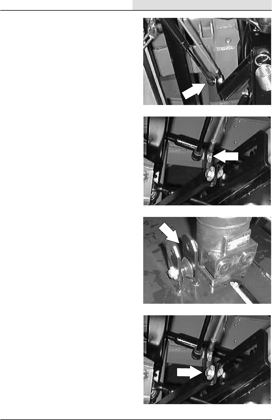
SCRUBBING
4-41
8200/8210 330065 (3--02)
9. Pry the clip up on the end of the side shift
gas spring. Remove the ball on the LH side
of the scrub head.
10. Remove the ball end and nut holding the
scrub head side shift pull cable to the scrub
head.
11. Remove the screw holding the center lift
bracket roller to the mount frame. Remove
the roller.
12. Remove the screw and nut holding the scrub
head side shift limiter bracket to the front of
the scrub head frame.
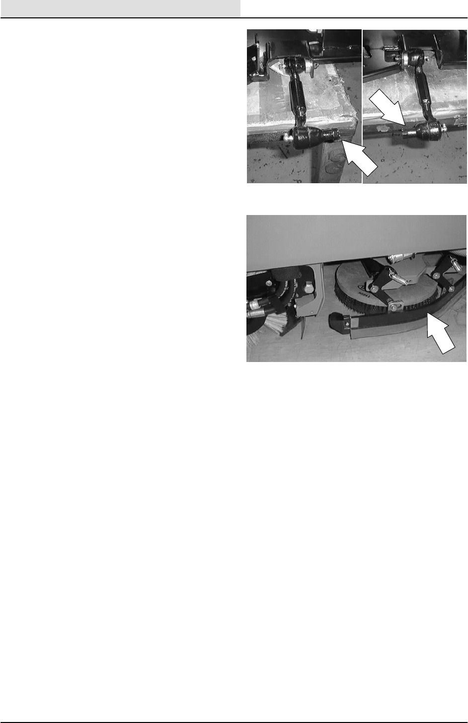
SCRUBBING
4-42 8200/8210 330065 (3--02)
13. Remove the cotter pins and castle nuts from
the two scrub head links where they attach
to the scrub head frame. Place the links out
of the way for scrub head removal.
14. The scrub head can now be removed from
the machine by bringing it out from under
the frame on the left hand side.
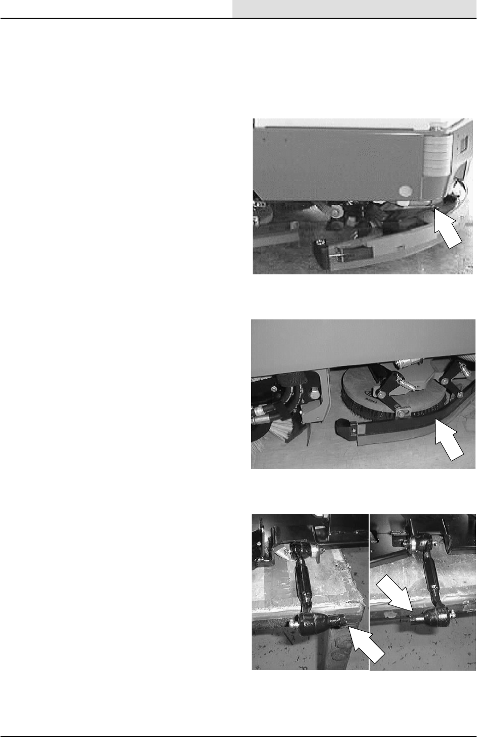
SCRUBBING
4-43
8200/8210 330065 (3--01)
TO INSTALL 3 MOTOR SCRUB HEAD
(Max pro 1200) (retractable)
FOR SAFETY: Before Leaving Or
Servicing Machine; Stop On Level
Surface, Set Parking Brake, Turn Off
Machine And Remove Key.
1. Raise the rear of the machine and install
jack stands under the frame.
2. Position scrub head under machine frame
from the left hand side.
3. Reinstall the two scrub head links in the
mount holes in the scrub head frame.
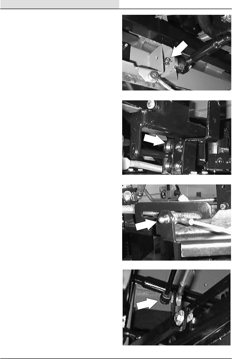
SCRUBBING
4-44 8200/8210 330065 (3--01)
4. Reinstall the castle nuts on the scrub head
links and tighten to 90 -- 117 Nm
(65 -- 85 ft lb). Turn the castle nut far enough
to line up with the cotter pin hole. Reinstall
the cotter pin.
5. Reinstall the head lift pivot roller on the lift
bracket. Tighten hardware to 18 -- 24 Nm
(15 -- 20 ft lb).
6. Reconnect side shift return cable and ball
nut end on the rear side of the scrub head.
Tighten the nut to the point were the cable
can still rotate.
7. Install gas spring onto the ball on the front
side of the scrub head. Make sure the
locking clip re--seats itself.
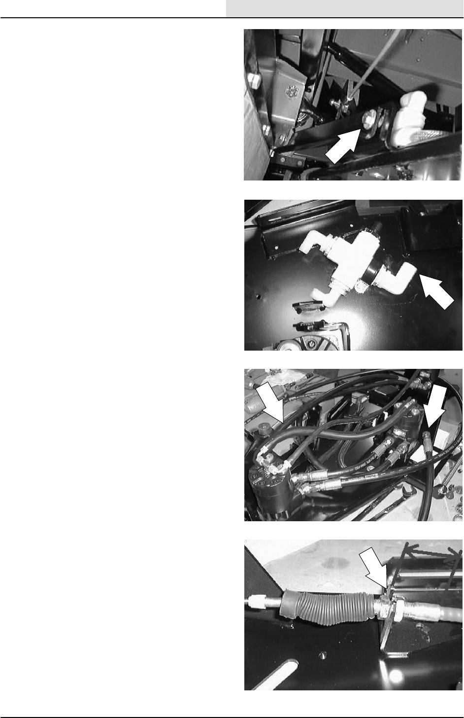
SCRUBBING
4-45
8200/8210 330065 (3--01)
8. Reinstall the scrub head side shift limiter
bracket on the front of the scrub head frame.
Tighten hardware to 18 -- 24 Nm
(15 -- 20 ft lb).
9. Reconnect the main solution feed line to the
fitting in the center of the scrub head.
10. Reconnect the hydraulic hoses to the three
brush motors. See schematic in the
HYDRAULICS section.
NOTE: Observe hydraulic cleanliness
requirements when opening hydraulic lines.
11. Reinstall the side squeegee shift cable into
the mount slot and tighten the two jam nuts.
NOTE: Install the push--pull cable so there is
2--3/16 inch from the center of the bracket to the
end of the cable steel area.
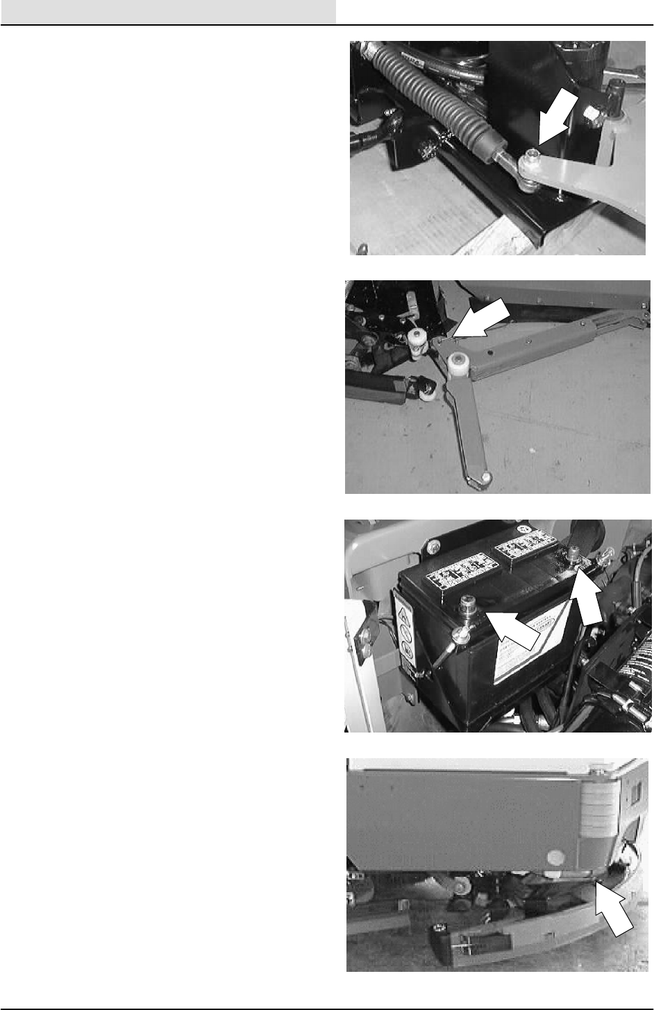
SCRUBBING
4-46 8200/8210 330065 (3--01)
12. Reinstall the side squeegee shift cable to the
left side squeegee at the ball joint.
NOTE: Make sure the balljoint is threaded all the
way onto the cable. The distance between the
middle of the balljoint and the middle of the
bracket on the scrub head should be 10.64
inches.
NOTE: Make sure to reinstall any clamps or
plastic ties that were removed during disassembly.
13. Reinstall the scrub head deflector arm onto
the right hand side of the scrub head.
Reinstall the hitch pin.
14. Reconnect the battery and close the engine
cover.
15. Remove the jack stands and lower the
machine. Check for proper operation of the
scrub brushes and side shift.
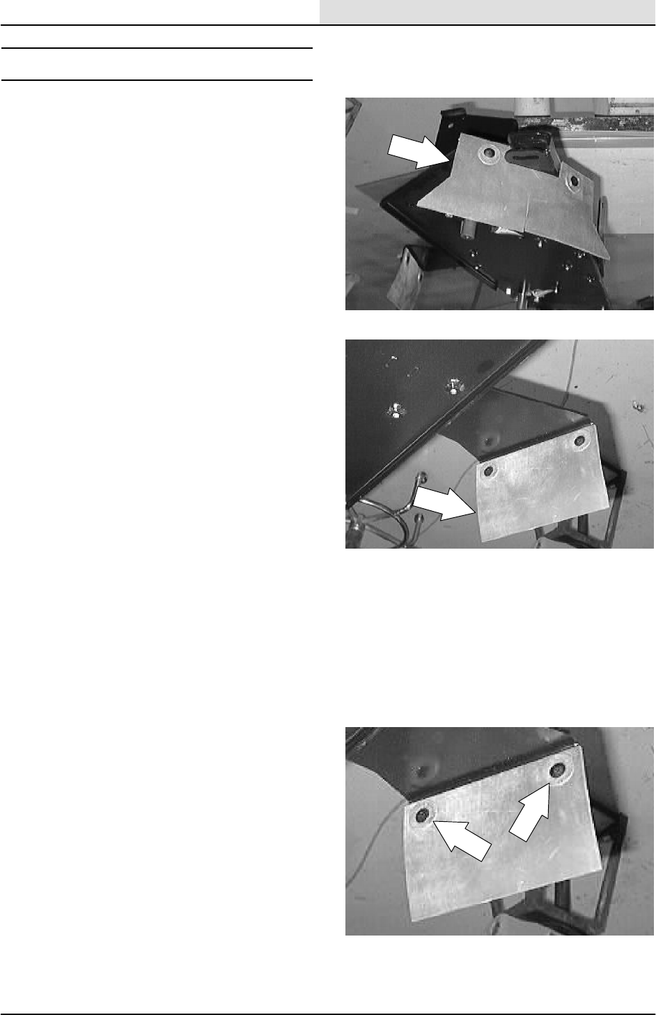
SCRUBBING
4-47
8200/8210 330065 (3--01)
SCRUB HEAD SKIRTS
The scrub head floor skirts control water spray
from the brushes. The skirts are located at the
front right corner of the scrub head on all models
and at the rear edge of the scrub head on the two
brush head. Check these skirts for wear and
damage after every 50 hours of operation.
The skirts should clear the floor by 0 to 0.25 in
(0 to 6 mm) when the scrub head is down. Check
the floor skirt adjustment after every 50 hours of
operation.
TO REPLACE SCRUB HEAD SKIRTS
1. Raise the scrub head and turn off the
machine.
FOR SAFETY: Before Leaving Or
Servicing Machine; Stop On Level
Surface, Set Parking Brake.
2. Remove the two plastic rivets holding the
skirts to the scrub head. Remove and
discard the skirt.
3. Position the new skirts on the mount
brackets. Reinstall the plastic rivets.
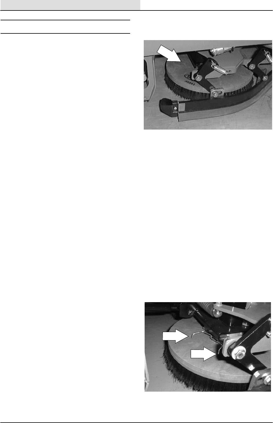
SCRUBBING
4-48 8200/8210 330065 (3--01)
SCRUB BRUSHES
Disc-type scrub brushes scrub the floor. Each
scrub brush is driven by its own hydraulic motor
and drive hub. A spring lock clip holds the scrub
brush onto the drive hub.
There are many variations of brushes and
cleaning pads to choose from. There is a brush or
cleaning pad available for almost any application.
Scrub brushes are ready for use when they are
equipped with a brush drive plate and a spring
clip.
The scrub brushes should be checked daily for
tangled wire or string wear damage. The scrub
brushes should be replaced if large portions of the
brush bristles are missing or if the remaining
brush bristle measure 0.50 in (12 mm) or less in
length.
NOTE: Be sure to replace the scrub brushes in
sets. Otherwise one scrub brush will be more
aggressive than the other.
TO REPLACE SCRUB BRUSHES
1. With the scrub head raised, turn off the
machine and set the machine parking brake.
FOR SAFETY: Before Leaving Or
Servicing Machine; Stop On Level
Surface, Set Parking Brake, Turn Off
Machine And Remove Key.
2. Rotate the scrub brush by hand until the
spring clip is visible at the edge of the scrub
head.
3. Press the brush spring clip ends together
with your thumb and index finger to remove
the scrub brush.
4. Slide the new scrub brush under the scrub
brush drive assembly.
5. Line up the scrub brush drive socket with the
drive plug.
6. Press the brush spring clip together and lift
the scrub brush onto the drive plug. Release
the spring clip when the brush is in place.
7. Repeat this procedure for the other brushes.
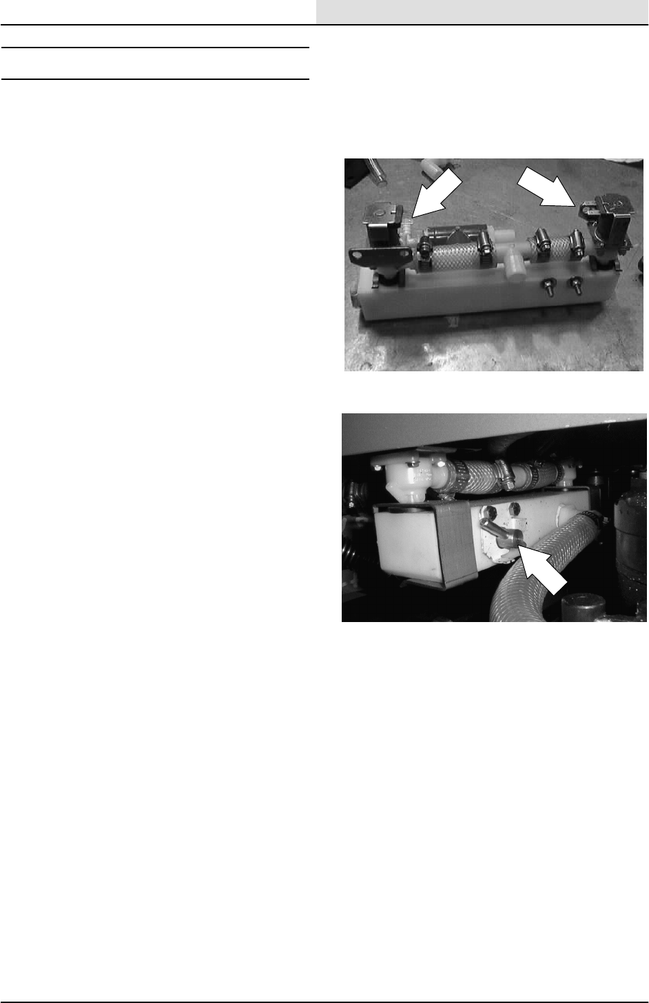
SCRUBBING
4-49
8200/8210 330065 (3--01)
SOLUTION VALVE
The flow of solution to the scrub brushes is
controlled by two electrical solenoids and a
adjustable mechanical valve.
The solenoid solution valves control the flow of
solution to the scrub brushes. The solenoid
solution valve is a non--mechanical electrical
solenoid. The dash mounted switch has a high
and low setting.
The adjustable mechanical valve is used to
custom tailer the amount of solution the scrubber
needs in your particular situation. Once the
mechanical valve is set to your scrubbing
needs----it can be left alone. Solution flow then can
be controlled with the dash mounted high and low
settings.
--Set the valve to a lower water flow rate
(pin straight up) when scrubbing smooth, sealed
floors.
--Set the valve to a higher water flow rate
(pin 90 degree over to left) on coarse floors or
when double scrubbing.
NOTE: If water trails around the ends of the rear
squeegee in turns----set the adjustable valve to a
lower water flow rate.
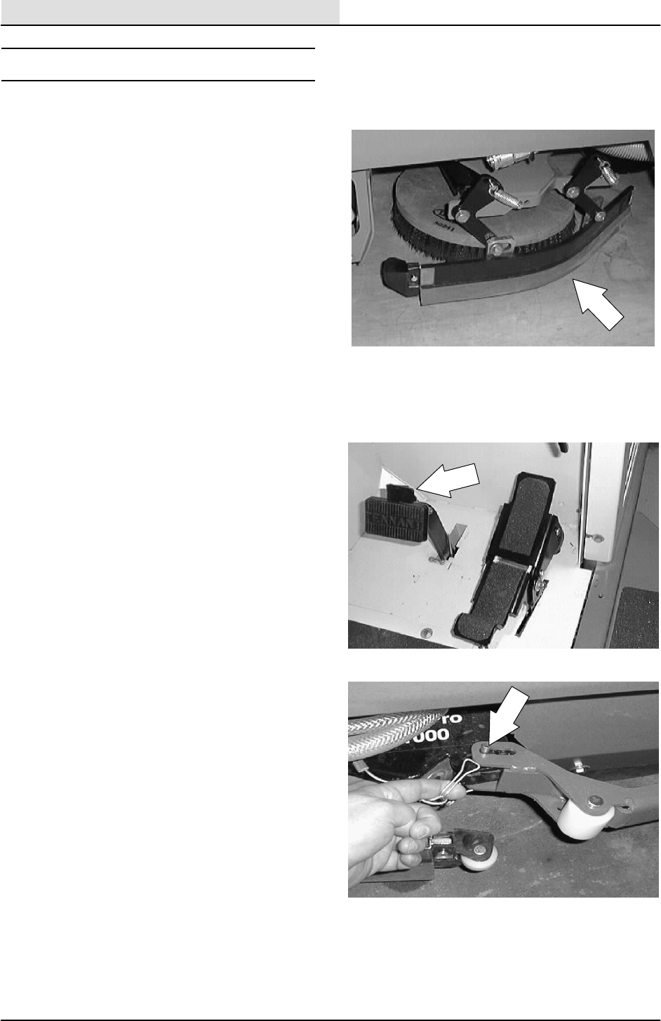
SCRUBBING
4-50 8200/8210 330065 (3--01)
SQUEEGEES
SIDE SQUEEGEES
The side squeegees control water spray and
channel water into the path of the rear squeegee.
Check the side squeegees for damage and wear
daily. Replace the side squeegee blades
whenever they become damaged or lose their
shape or resiliency. Replace the squeegee
deflectors whenever they become worn.
TO REPLACE SIDE SQUEEGEE BLADES
1. With the scrub head raised, turn off the
machine and set the machine parking brake.
FOR SAFETY: Before Leaving Or
Servicing Machine; Stop On Level
Surface, Set Parking Brake, Turn Off
Machine And Remove Key.
2. Remove the hitch pin holding the scrub head
deflector arm to the front edge of the
squeegee.
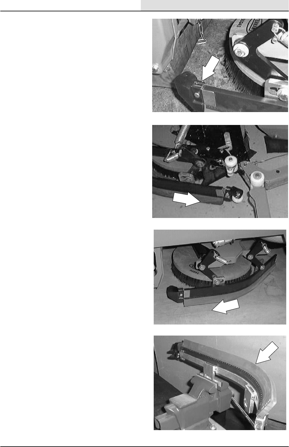
SCRUBBING
4-51
8200/8210 330065 (3--01)
3. Remove the clevis pin and bumper from the
front end of the side squeegee.
4. RH SIDE SQUEEGEE: Pull the squeegee
blade off the mount frame. Discard the
squeegee blade.
5. LH SIDE SQUEEGEE: Pull the squeegee
blade off the mount frame. Discard the
squeegee blade.
6. Slip the new squeegee blade onto the side
squeegee frame.
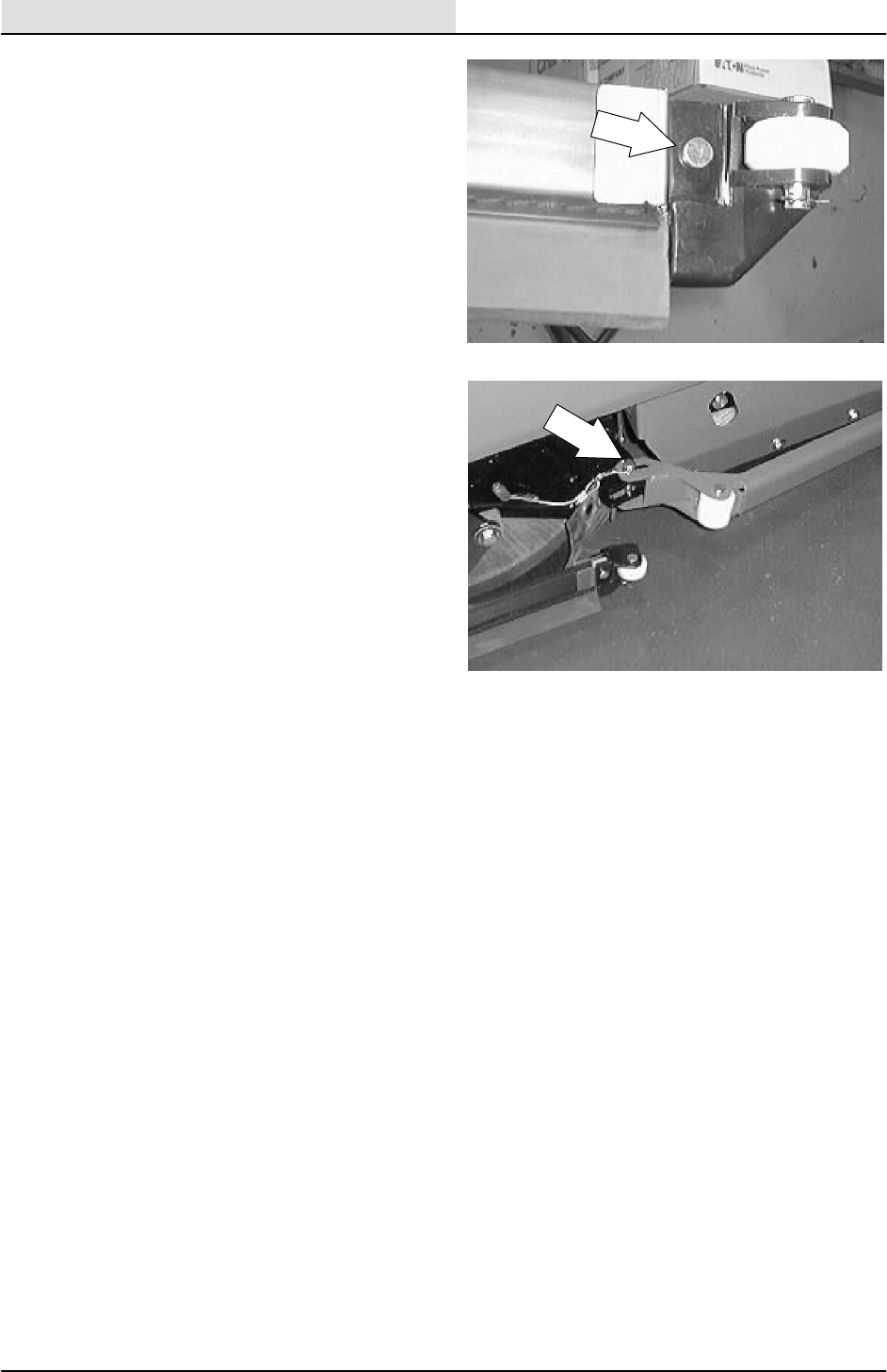
SCRUBBING
4-52 8200/8210 330065 (3--01)
7. Reinstall the squeegee bumper and clevis
pin on the front end of the side squeegee.
8. Reinstall the deflector arm and hitch pin.
9. Operate the machine and check the side
squeegees for proper operation.

SCRUBBING
4-53
8200/8210 330065 (3--01)
TO REPLACE SIDE SQUEEGEE PIVOT CABLE
1. Start the machine and lower the rear
squeegee and scrub head. Shut off the
machine.
FOR SAFETY: Before Leaving Or
Servicing Machine; Stop On Level
Surface, Set Parking Brake, Turn Off
Machine And Remove Key.
2. Locate the solution valve mount assembly
under the operator compartment. Remove
the screws holding the mount plate to the
frame. Let the valve assembly drop down.
3. Loosen the two large jam nuts on the
squeegee pivot cable where it attaches to
the solution valve mount bracket. Pull the
cable out of the slot.
4. Remove the nut holding the cable balljoint to
the squeegee pivot bracket.
F
E
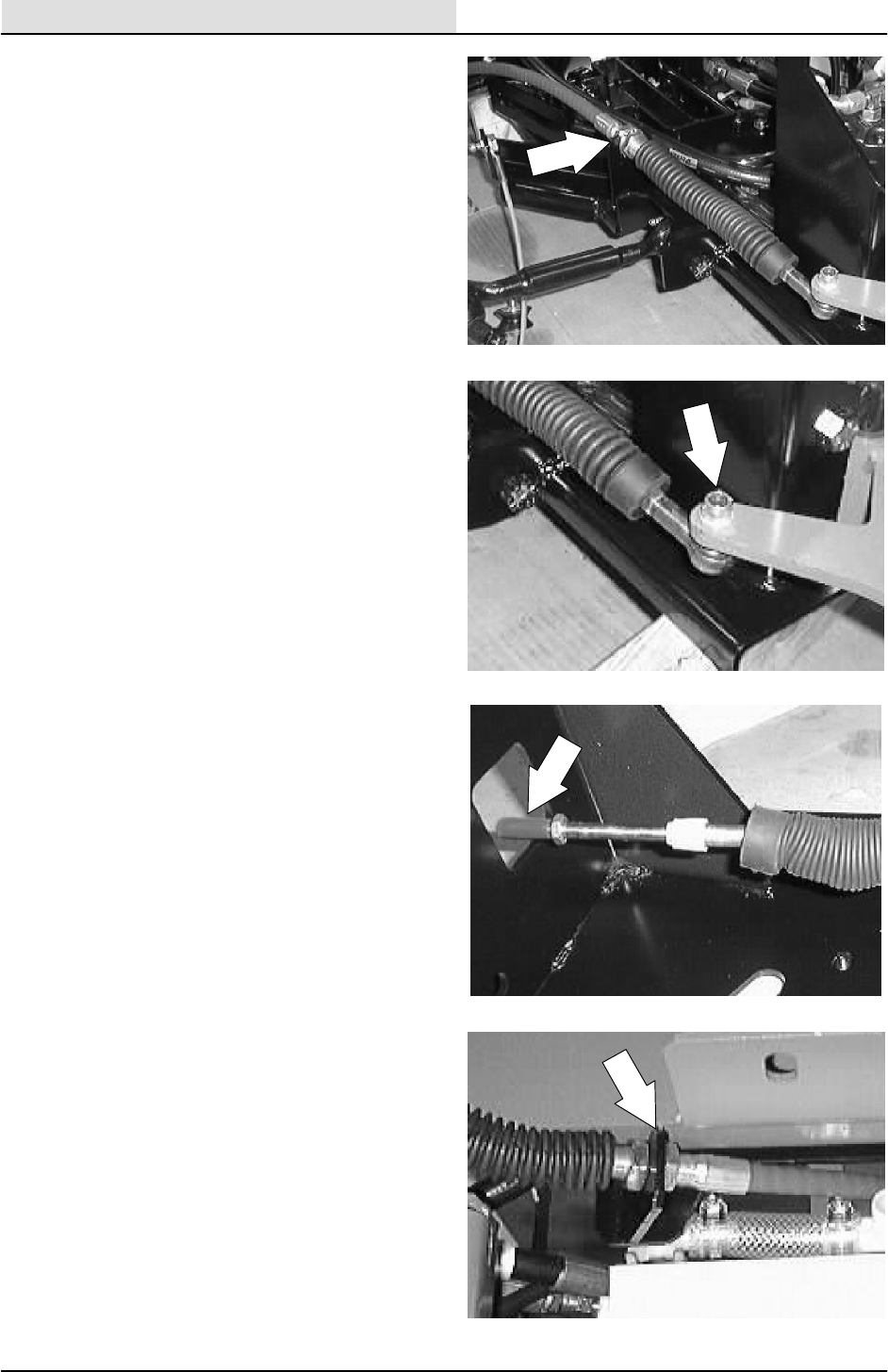
SCRUBBING
4-54 8200/8210 330065 (3--01)
5. Loosen the two large jam nuts on the
squeegee pivot cable where it attaches to
the bracket on the left side of the scrub
head.
6. Remove the nut holding the cable balljoint to
the side squeegee pivot bracket. Pull the
pivot cable out of the slot. Remove the cable
from the machine.
7. Remove the two balljoints and jam nuts from
the old cable and install on the new cable.
Turn the balljoints all the way on. Tighten the
jam nuts.
8. Install one end of the cable in the slot of the
solution valve mount bracket.
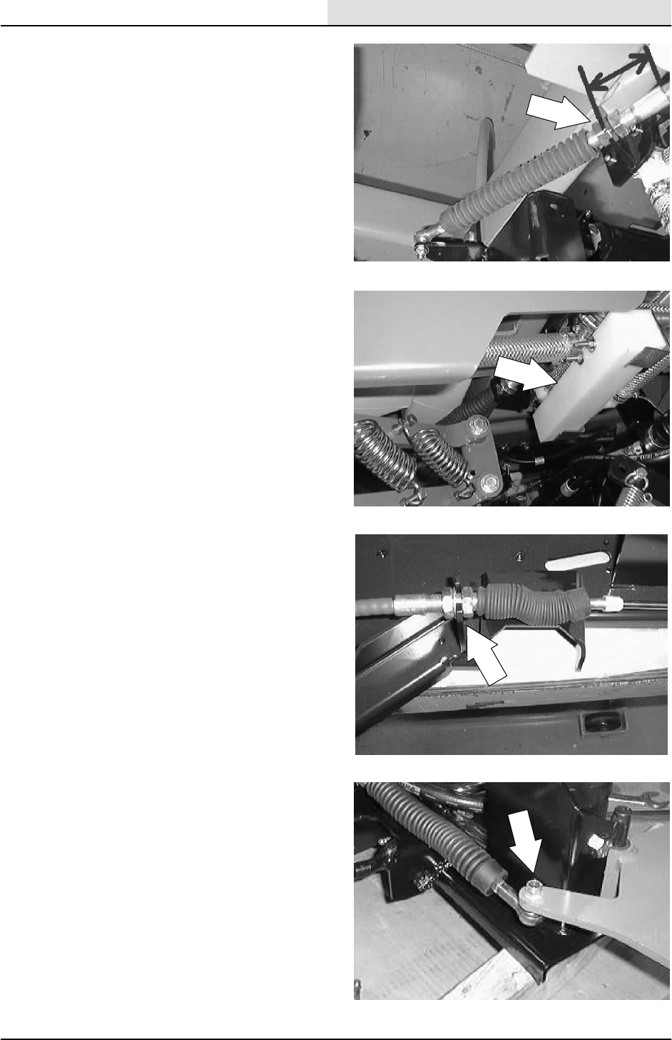
SCRUBBING
4-55
8200/8210 330065 (3--01)
9. With the squeegee raised and the balljoint
installed in the pivot bracket, the distance
between the center of the ball joint and the
center of the slotted tab on the solution
valve mount bracket should be 10.16 inches.
NOTE: Install the push--pull cable so there is
2--3/16 inch from the center of the bracket to the
end of the cable steel area.
10. Reinstall the solution valve mount bracket
onto the machine frame. Tighten the screws
to 18 -- 24 Nm (15 -- 20 ft lb).
NOTE: Make sure the rear squeegee is centered
and both side squeegees are pointed slightly out
(2_).
11. Install the other end of the shift cable into
the slot on the mount bracket on the left side
of the scrub head. Leave the cable jam nuts
loose for now.
12. Install the cable balljoint and nut in the
mount hole of the left side squeegee pivot
bracket.
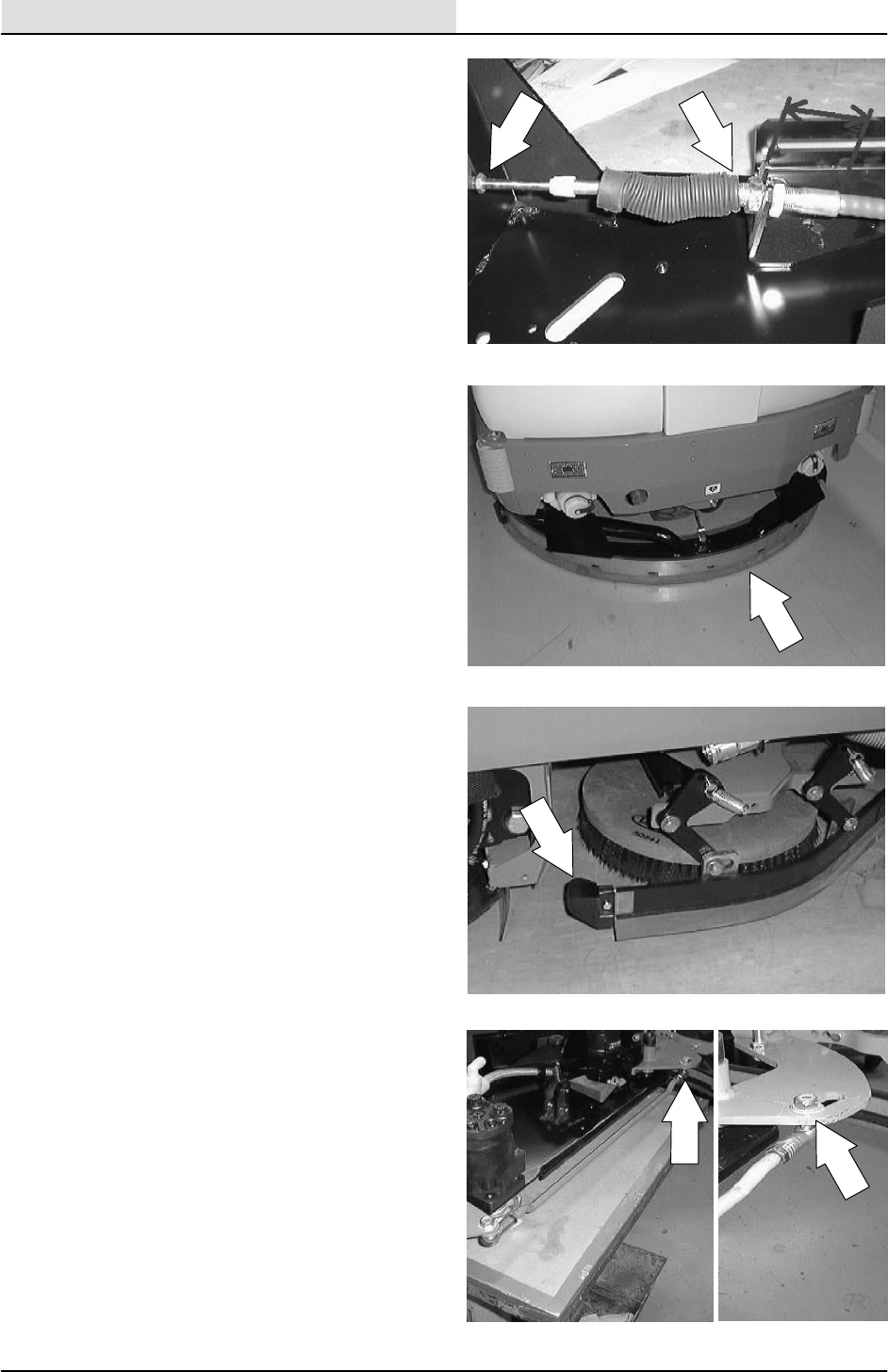
SCRUBBING
4-56 8200/8210 330065 (3--01)
13. The distance between the center of the
balljoint and the center of the bracket on the
scrub head should be 10.64 inches. Tighten
the jam nuts.
NOTE: Install the push--pull cable so there is
2--3/16 inch from the center of the bracket to the
end of the cable steel area.
14. Lower the rear squeegee and scrub head.
Drive forward to center the the rear
squeegee on the scrub path (rear squeegee
is offset in the raised position).
15. The left side squeegee tip should be pointed
out approx. 2_. If is not----adjust the cable at
the scrub head----NOT at the balljoint.
16. Make sure the balljoint on the cross rod to
the right side squeegee is at the bottom of
the slot.
17. Operate the machine. Check the side
squeegees for proper tracking of the rear
squeegee----adjust if necessary.
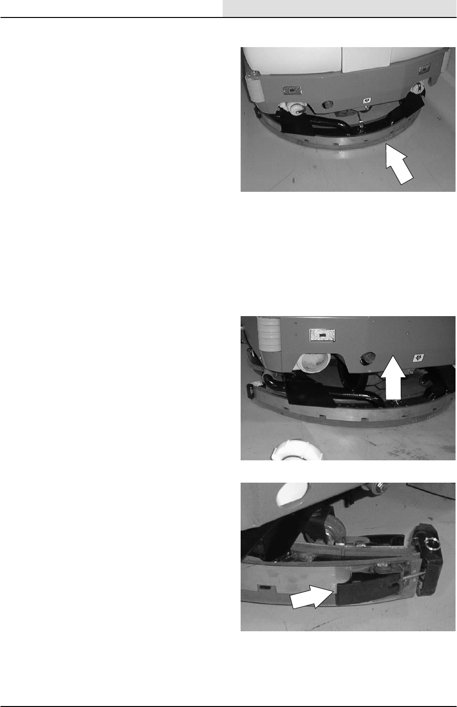
SCRUBBING
4-57
8200/8210 330065 (3--01)
REAR SQUEEGEE
The rear squeegee assembly channels water into
the vacuum fan suction. The front squeegee blade
channels the water, and rear blade wipes the
floor. Check the rear squeegee assembly for
damage, wear, and adjustment daily.
Rotate or replace either squeegee blade if its
leading edge is torn or worn half-way through the
thickness of the blade.
Each blade has four wiping edges. To use them
all, start with one wiping edge. To use the next
wiping edge, rotate the squeegee end-for-end. To
use the next wiping edge, rotate the top edges
down, bottom edges up. To use the last edge,
rotate the squeegee end-for-end.
TO REPLACE OR ROTATE REAR SQUEEGEE
BLADES
1. Make sure the rear squeegee is in the raised
position.
FOR SAFETY: Before Leaving Or
Servicing Machine; Stop On Level
Surface, Set Parking Brake.
2. Pull back on the end of the squeegee blade
lock latch.
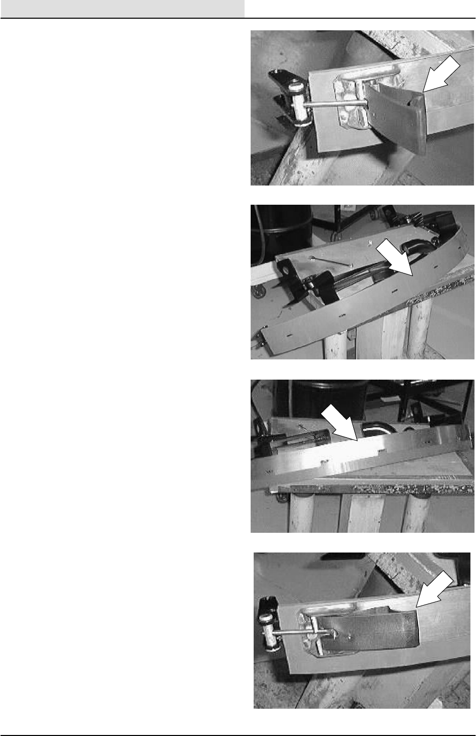
SCRUBBING
4-58 8200/8210 330065 (3--01)
3. Remove the retainer strap from the back
squeegee blade.
4. Remove the squeegee blade from the
squeegee frame.
5. Rotate the squeegee blade to a new edge.
6. Reinstall the squeegee blade on the
squeegee frame.
7. Reinstall the retainer strap.
8. Push down on the end of the squeegee
blade lock latch to lock the retainer and
blade in place.
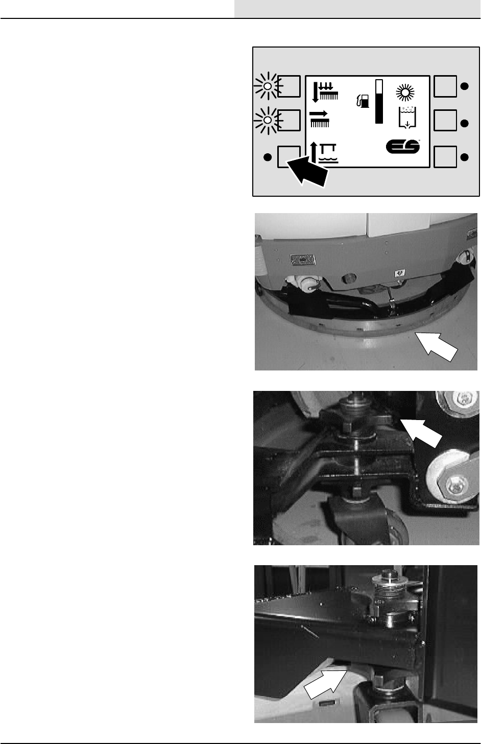
SCRUBBING
4-59
8200/8210 330065 (3--01)
TO ADJUST REAR SQUEEGEE ROLL--OUT
1. Start the machine and lower the rear
squeegee. Pull forward slightly and engage
the parking brake. Shut off the machine.
FOR SAFETY: Before Leaving Or
Servicing Machine; Stop On Level
Surface, Set Parking Brake.
2. Go to the back of the machine and check
the rear squeegee for even blade deflection
across the entire blade.
3. If the squeegee blade roll--out is uneven or if
the blade is too vertical or flattened out too
much----go to the next step.
4. Loosen the large plastic jam nuts on the
squeegee casters. Turn the casters down so
they contact the floor evenly.
5. The bottom caster knob has four “tangs”.
Adjust each caster OFF the floor FIVE
“tangs”.
F
E
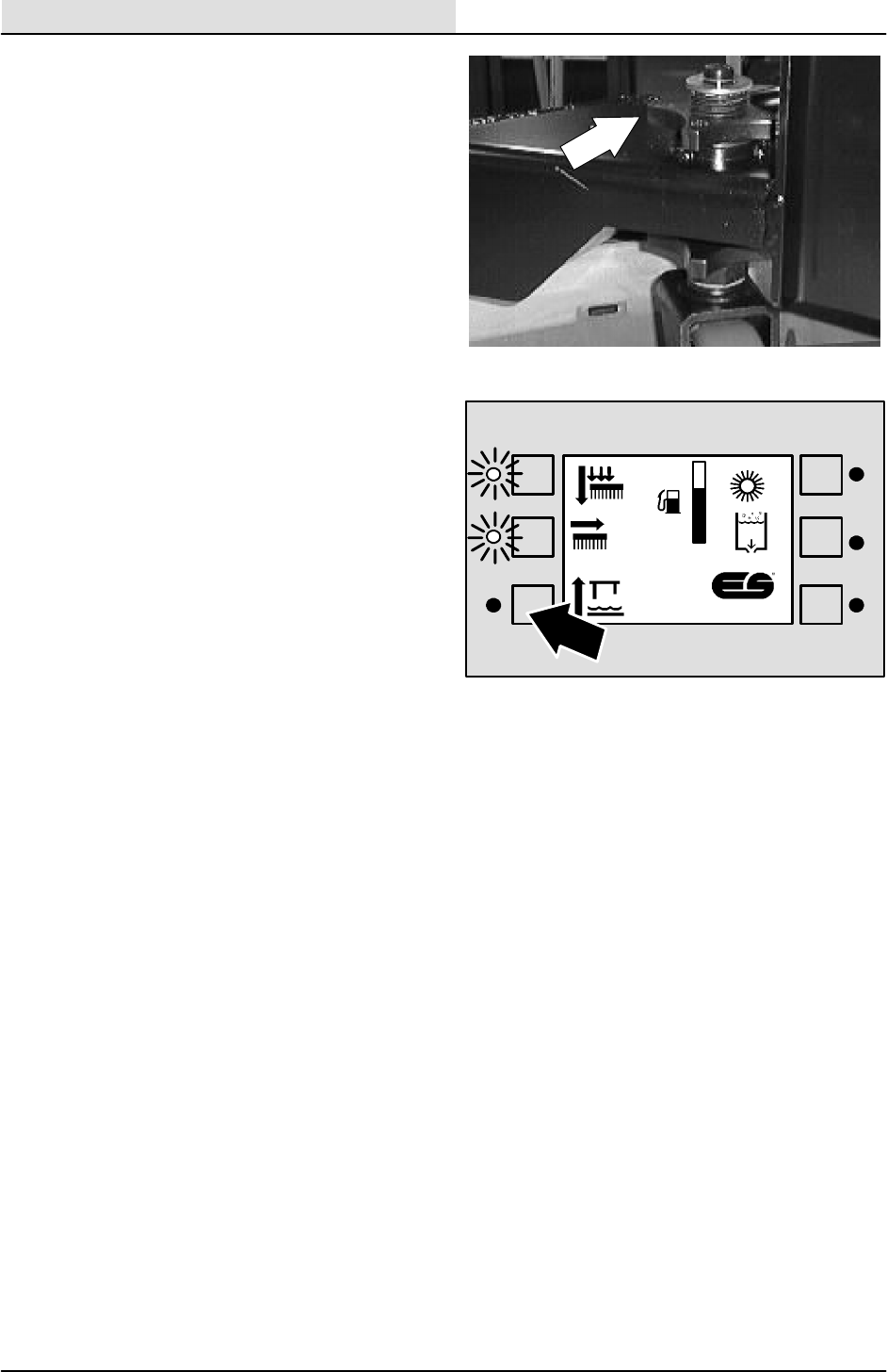
SCRUBBING
4-60 8200/8210 330065 (3--01)
6. Go back and tighten the locking (top) knob.
NOTE: Make sure you hold the bottom knob from
turning.
7. Start the machine and raise the rear
squeegee.
8. Lower the rear squeegee and propel
forward, checking for proper squeegee blade
roll--out. If needed, adjust the casters evenly
in 1/2 “tang” increments. (this is touchy and
may have to be done more than once)
9. Re--adjust the rear casters anytime the rear
squeegee levelness is adjusted.
F
E
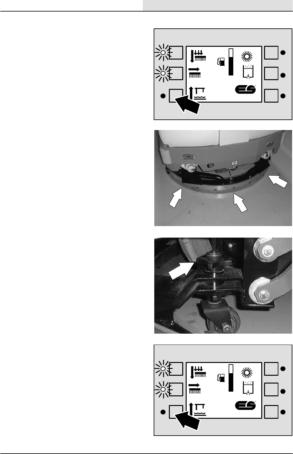
SCRUBBING
4-61
8200/8210 330065 (3--01)
TO LEVEL REAR SQUEEGEE
1. Start the machine and lower the rear
squeegee.
FOR SAFETY: Before Leaving Or
Servicing Machine; Stop On Level
Surface, Set Parking Brake.
2. Go to the back of the machine and check
the rear squeegee for even deflection across
the entire blade.
3. If either side of the squeegee has more
blade deflection than the other----an
adjustment should be made. Go to the next
step.
4. Raise the rear squeegee. Loosen the large
plastic jam nuts on the squeegee casters.
Turn the casters up at least 2 or 3
turns----until the casters no longer come in
contact with the floor.
5. Start the machine and lower the rear
squeegee.
F
E
F
E
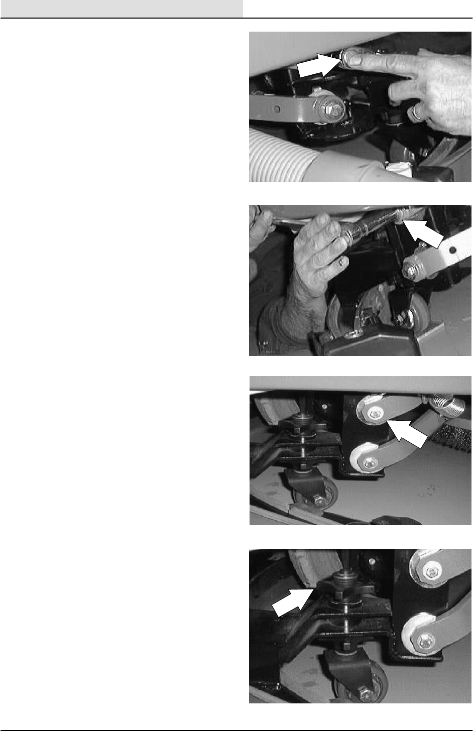
SCRUBBING
4-62 8200/8210 330065 (3--01)
6. Loosen the adjustment cam hex screw on
the outside of the upper squeegee link----at
the squeegee frame.
NOTE: DO NOT over loosen----just enough to
allow cam adjustment.
7. On the top of the adjusting cam, there is a
machined groove. Using a 13mm socket,
adjust the cam until it is rotated slightly
towards the back of the machine
(11:30 o’clock).
8. Hold the adjusting cam with the 13mm
wrench as you tighten the 17mm bolt head.
Repeat this procedure on both sides.
9. Once the squeegee has been properly
leveled, tighten the adjustment cam hex
screw.
10. Turn the casters back down until they just
touch the floor.
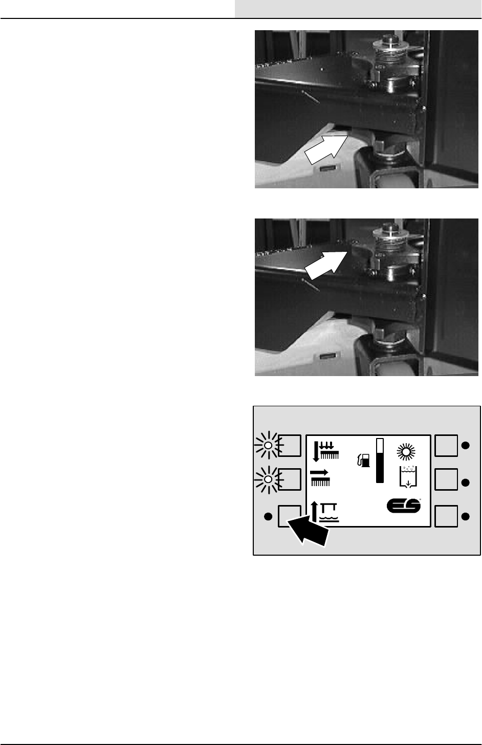
SCRUBBING
4-63
8200/8210 330065 (3--01)
11. The bottom caster knob has four “tangs”.
Adjust each caster OFF the floor FIVE
“tangs”
12. Go back and tighten the locking (top) knob.
NOTE: Make sure you hold the bottom knob from
turning.
13. Start the machine and raise the rear
squeegee.
14. lower the rear squeegee and propel forward,
checking for proper squeegee blade roll--out
and levelness.
F
E
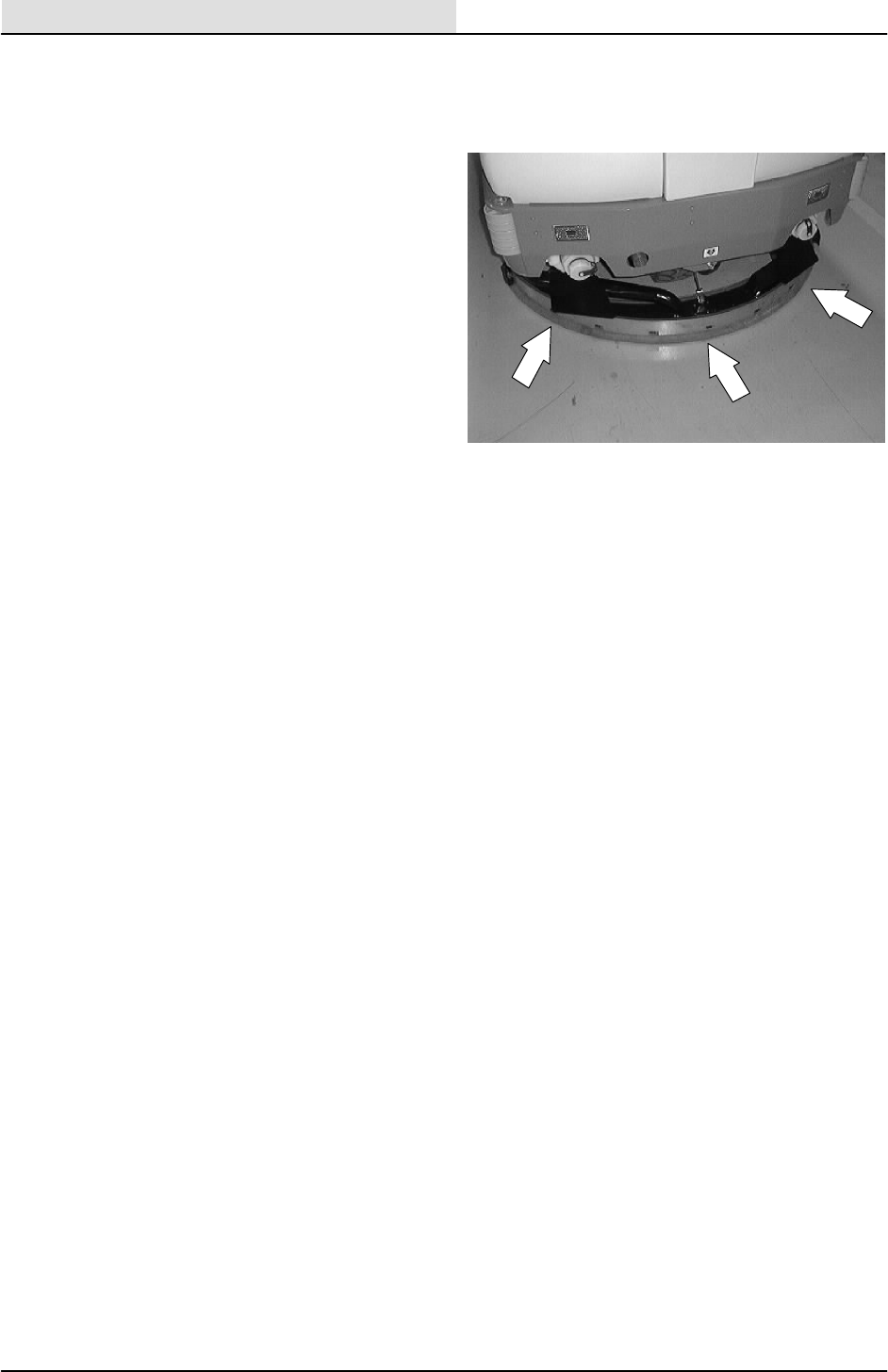
SCRUBBING
4-64 8200/8210 330065 (3--01)
FINE TUNING REAR SQUEEGEE LEVELNESS
Lift and lower the squeegee assembly be
grabbing onto the squeegee near the drain caps.
Verify that the rear blade has even pressure
across its entire length by pushing the blade
toward the front of the machine at various places
along its length with your finger.
The blade should “pucker” and hold its distortion
equally at each point. If it does not, you will have
to fine tune the squeegee adjustment.
What you will want to keep an eye on is the
relationship of the rear blade to the floor at both
the tip and the middle of the blade.
Putting down pressure (rotating the cam toward
the rear of machine) with the 13mm socket, loads
the middle of the squeegee blade (this is normally
what is required)
Putting down pressure (rotating the cam toward
the front of machine) with the 13mm socket,
loads the tips of the rear squeegee.
Again, make sure to hold the cam in position
(with pressure) while tightening the bolt. Repeat
on both sides and verify the pressure of the blade
to the floor.
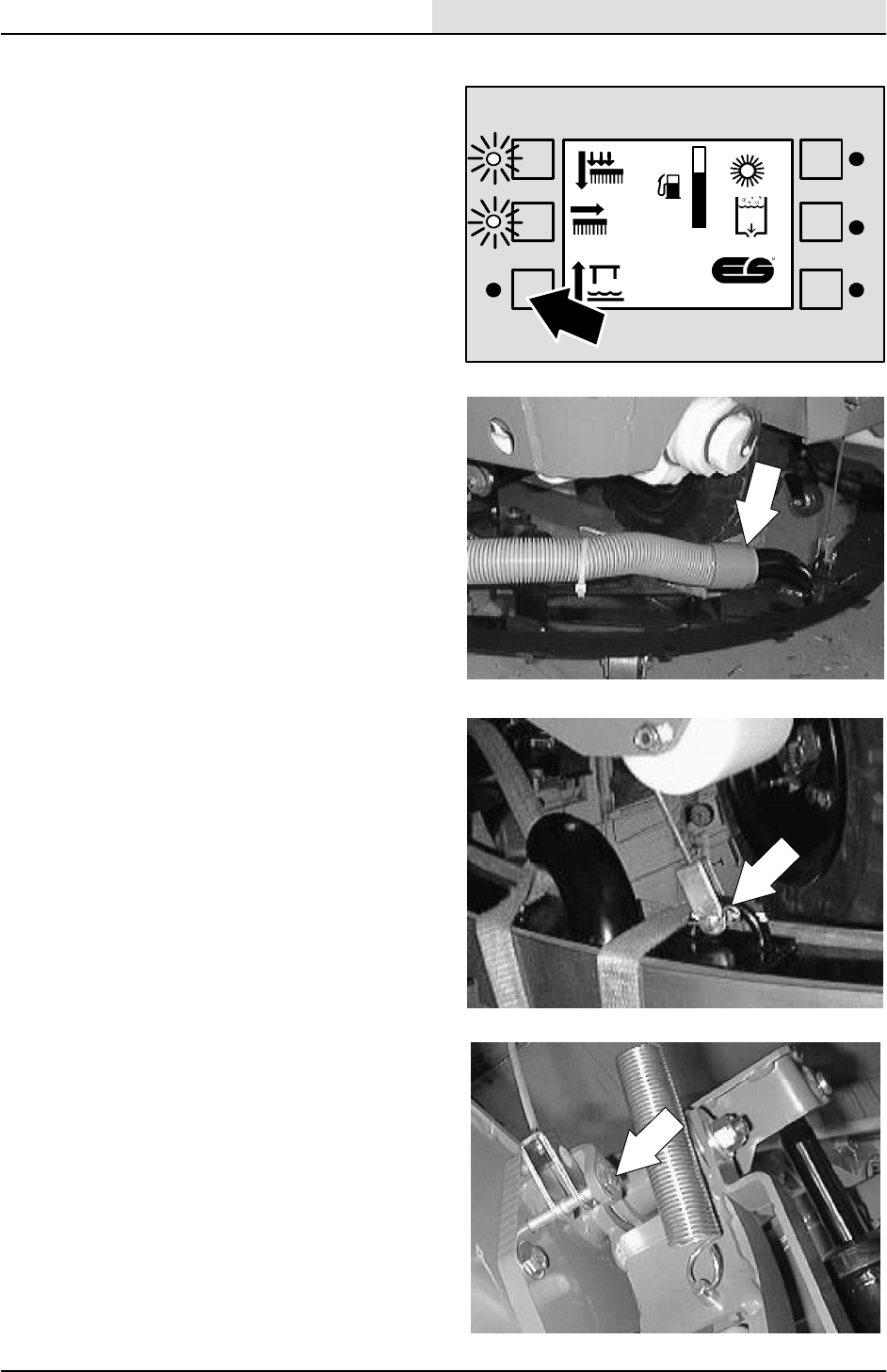
SCRUBBING
4-65
8200/8210 330065 (3--01)
TO REPLACE REAR SQUEEGEE LIFT CABLE
1. Start the machine and lower the rear
squeegee. Shut off the machine.
FOR SAFETY: Before Leaving Or
Servicing Machine; Stop On Level
Surface, Set Parking Brake.
2. Pull the vacuum hose off the tube on the
squeegee frame.
3. Remove the hair pin and clevis pin holding
the lower clevis on the squeegee lift cable to
the squeegee frame.
4. Remove the long hex screw holding the
upper clevis on the squeegee lift cable to the
machine frame. Note the routing of the old
lift cable and remove it from the machine.
F
E
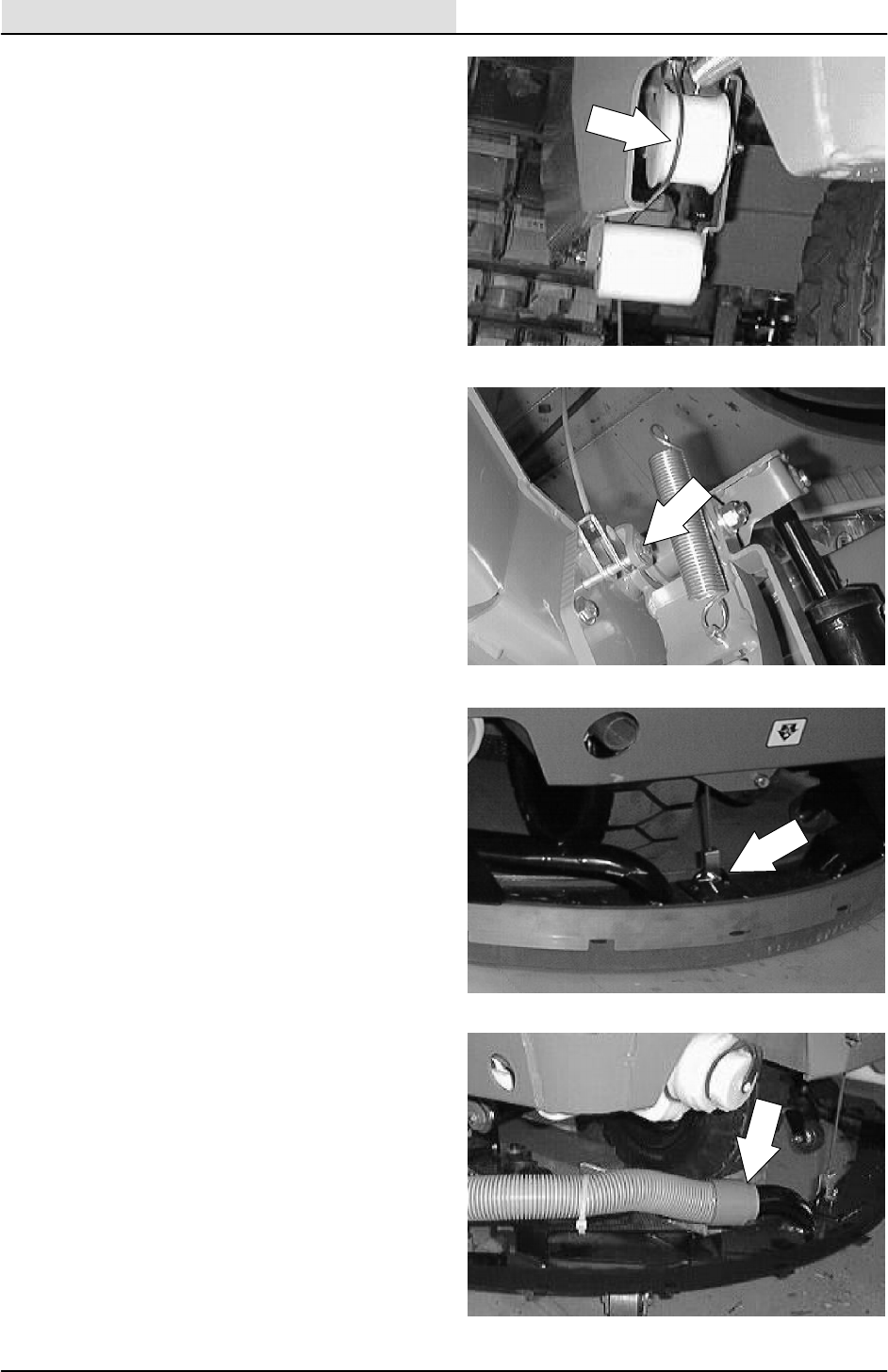
SCRUBBING
4-66 8200/8210 330065 (3--01)
5. Install the new squeegee lift cable in the
machine. Make sure to route the new cable
the same way the old one was routed.
6. Install the long hex screw in the upper clevis
of the new lift cable. Tighten to 18 -- 24 Nm
(15 -- 20 ft lb).
7. Install the clevis pin and hair pin the lower
clevis of the new cable and squeegee frame.
8. Plug the vacuum hose onto the tube on the
squeegee frame.
9. Start the machine and operate the rear
squeegee. Check for proper operation of the
new cable.
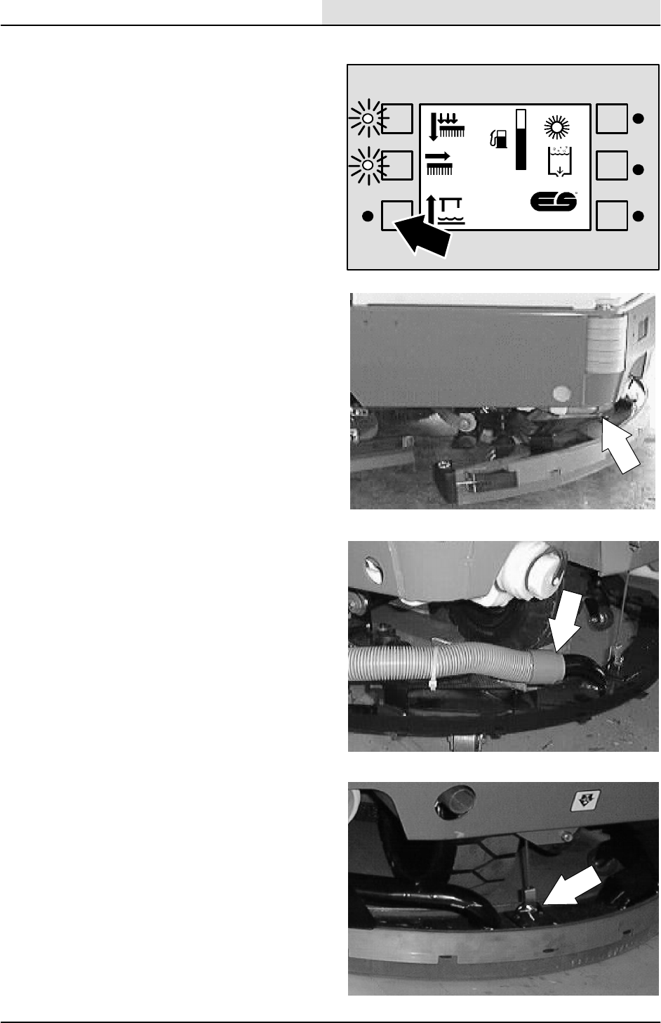
SCRUBBING
4-67
8200/8210 330065 (3--01)
TO REMOVE REAR SQUEEGEE FRAME
1. Start the machine and lower the rear
squeegee. Shut off the machine.
FOR SAFETY: Before Leaving Or
Servicing Machine; Stop On Level
Surface, Set Parking Brake.
2. Raise the rear of the machine and install
jack stands under the machine frame.
FOR SAFETY: Block machine tires
before jacking machine up. Jack
machine up at designated locations
only. Block machine up with jack
stands.
3. Pull the vacuum hose off the tube on the
squeegee frame.
4. Remove the hair pin and clevis pin holding
the lower clevis on the squeegee lift cable to
the squeegee frame.
F
E
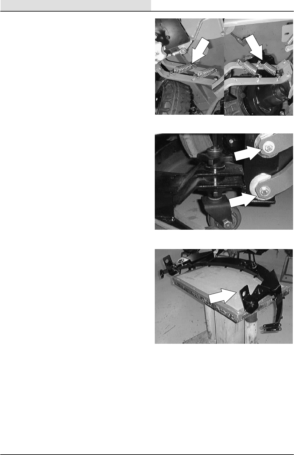
SCRUBBING
4-68 8200/8210 330065 (3--01)
5. Use a vise grip or channel lock to remove
the four down pressure tension springs from
the squeegee links.
6. Remove the hex screws and nuts holding
the squeegee links to the squeegee frame.
NOTE: Make sure to pay close attention to the
order of hardware assembly. The proper
re--assembly of the adjustment cams on the upper
squeegee links is very important.
7. Remove the squeegee frame from the
machine.
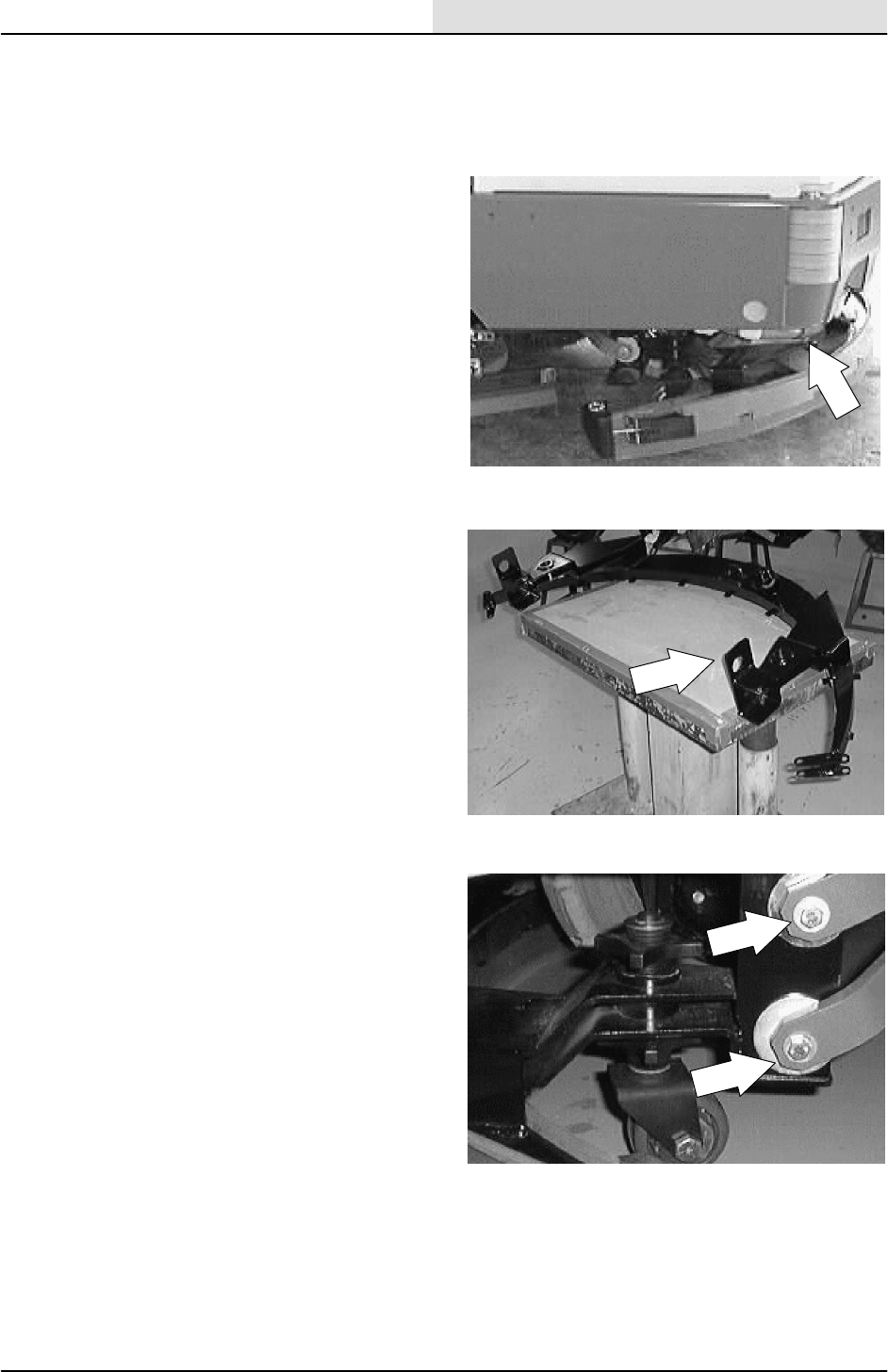
SCRUBBING
4-69
8200/8210 330065 (3--01)
TO INSTALL REAR SQUEEGEE FRAME
FOR SAFETY: Before Leaving Or
Servicing Machine; Stop On Level
Surface, Set Parking Brake.
1. Raise the rear of the machine and install
jack stands under the machine frame.
FOR SAFETY: Block machine tires
before jacking machine up. Jack
machine up at designated locations
only. Block machine up with jack
stands.
2. Position the squeegee frame under the rear
of the machine.
3. Line up the mount holes in the squeegee
frame with the mount holes in the end of the
four squeegee connecting links on the
machine.
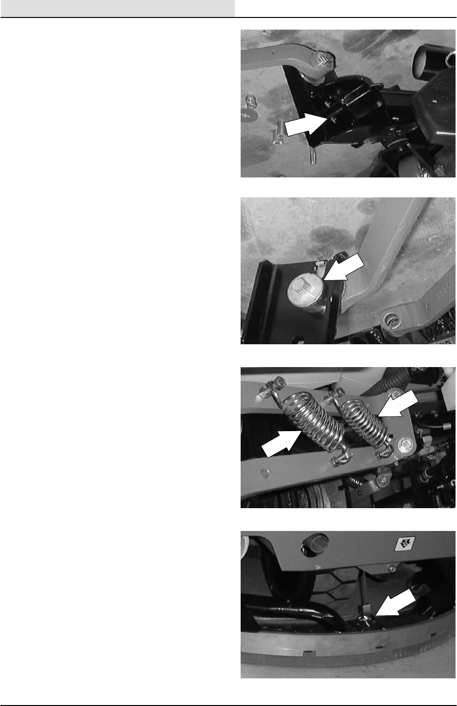
SCRUBBING
4-70 8200/8210 330065 (3--01)
4. Install the hardware and sleeves in the two
lower squeegee links. Leave the hardware
loose for now.
NOTE: Make sure to pay close attention to the
order of hardware assembly. The proper
re--assembly of the adjustment cams on the upper
squeegee links is very important.
5. Install the squeegee level adjustment cams
and washers in the two upper squeegee
links. Tighten all of the hardware to
37 -- 48 Nm (26 -- 34 ft lb).
6. Reinstall the four down pressure tension
springs onto the squeegee links.
7. Reconnect the squeegee lift cable to the
squeegee frame. Reinstall the clevis and
hair pin.

SCRUBBING
4-71
8200/8210 330065 (3--01)
8. Plug the vacuum hose into the tube on the
squeegee frame.
9. Operate the machine and check the rear
squeegee for proper operation. See
TO LEVEL REAR SQUEEGEE instructions
if needed.
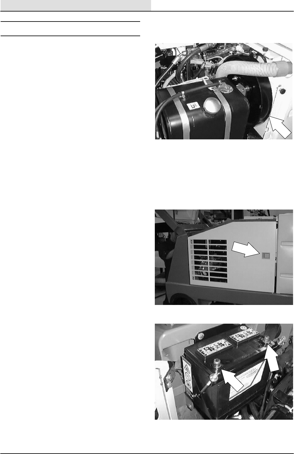
SCRUBBING
4-72 8200/8210 330065 (3--01)
SCRUBBER VACUUM FAN
The scrubbing vacuum fan, when activated,
creates a vacuum in the recovery tank. The
recovery tank is sealed to the tank cover when it
is the down position. Water is pulled from the rear
squeegee to the recovery tank through a vacuum
hose.
TO REMOVE SCRUBBER VACUUM FAN
ASSEMBLY
FOR SAFETY: Before Leaving Or
Servicing Machine; Stop On Level
Surface, Set Parking Brake.
1. Open the engine cover and side door.
2. Disconnect the battery.
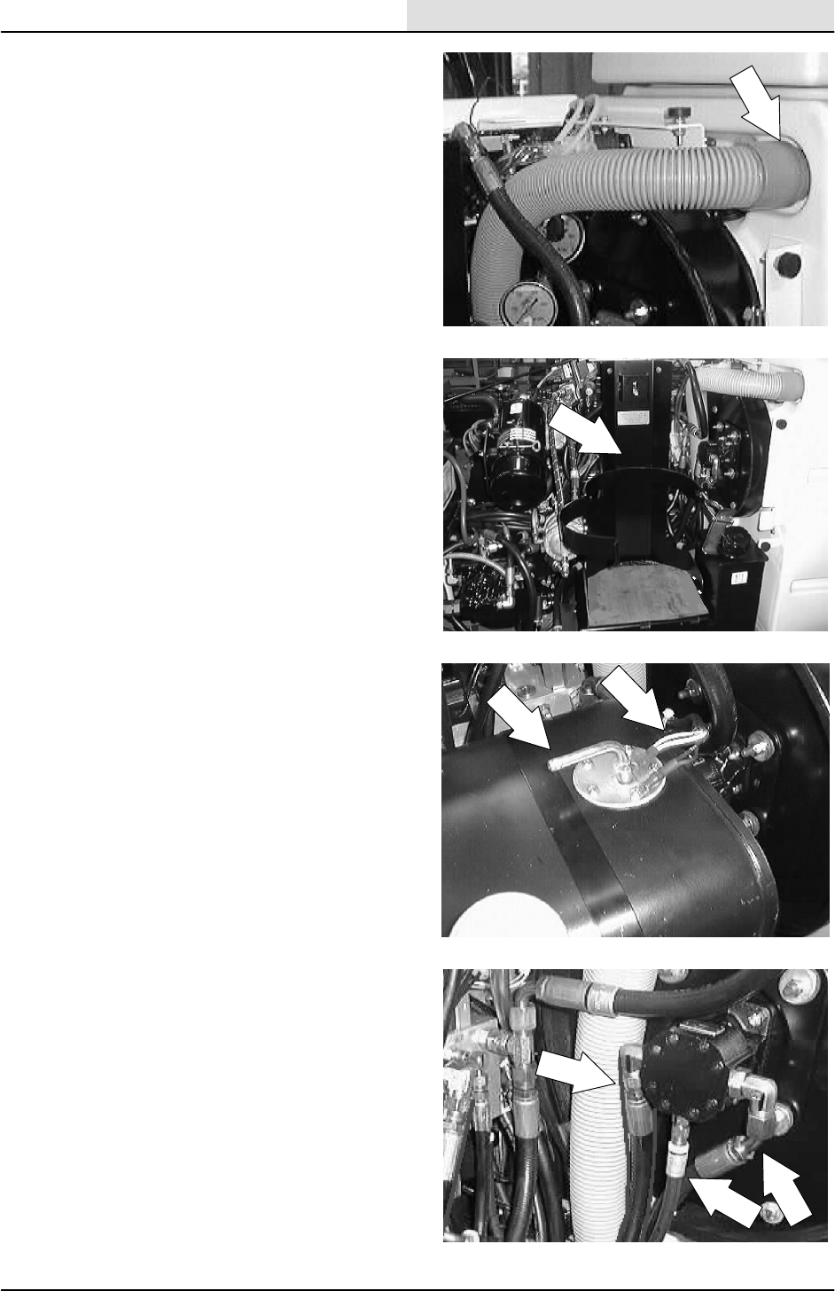
SCRUBBING
4-73
8200/8210 330065 (3--01)
3. Pull the vacuum hose out of the recovery
tank.
4. LP MACHINE: Disconnect the LP tank and
remove it from the machine.
5. GAS/DIESEL MACHINE: Remove the two
wires and two rubber hoses from the top of
the fuel tank. Remove the nut from the out
side end of both tank straps. Remove the
fuel tank.
6. Mark, disconnect, and plug the three
hydraulic hoses leading to the scrubbing
vacuum fan.
NOTE: Make sure to note the orientation of the
vacuum fan on the recovery tank for proper
re--assembly.
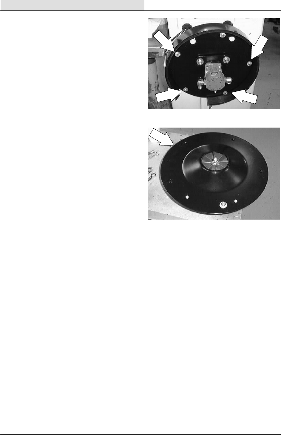
SCRUBBING
4-74 8200/8210 330065 (3--01)
7. Remove the four hex screws holding the
scrubbing vacuum fan to the recovery tank.
8. Remove the vacuum fan from the machine.
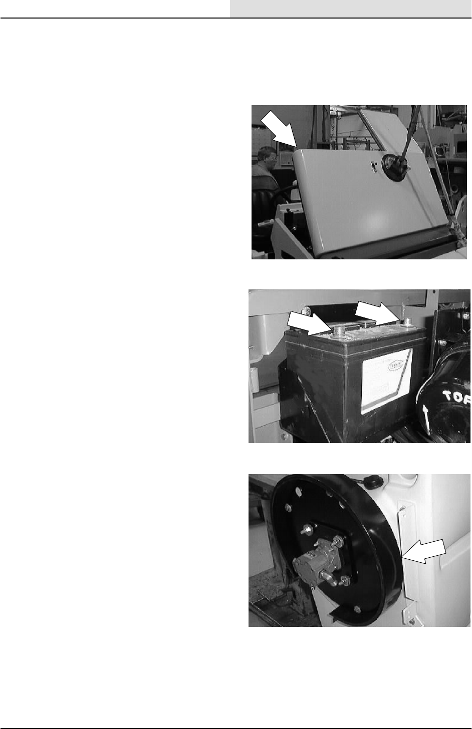
SCRUBBING
4-75
8200/8210 330065 (3--01)
TO INSTALL SCRUBBER VACUUM FAN
ASSEMBLY
FOR SAFETY: Before Leaving Or
Servicing Machine; Stop On Level
Surface, Set Parking Brake.
1. Open the engine cover and side door.
2. Disconnect the battery.
3. Position the scrubber vacuum fan on the
front of the recovery tank.
NOTE: Make sure the vacuum fan assembly is
installed on the recovery tank with the fittings on
the hydraulic motor orientated in the proper
direction.
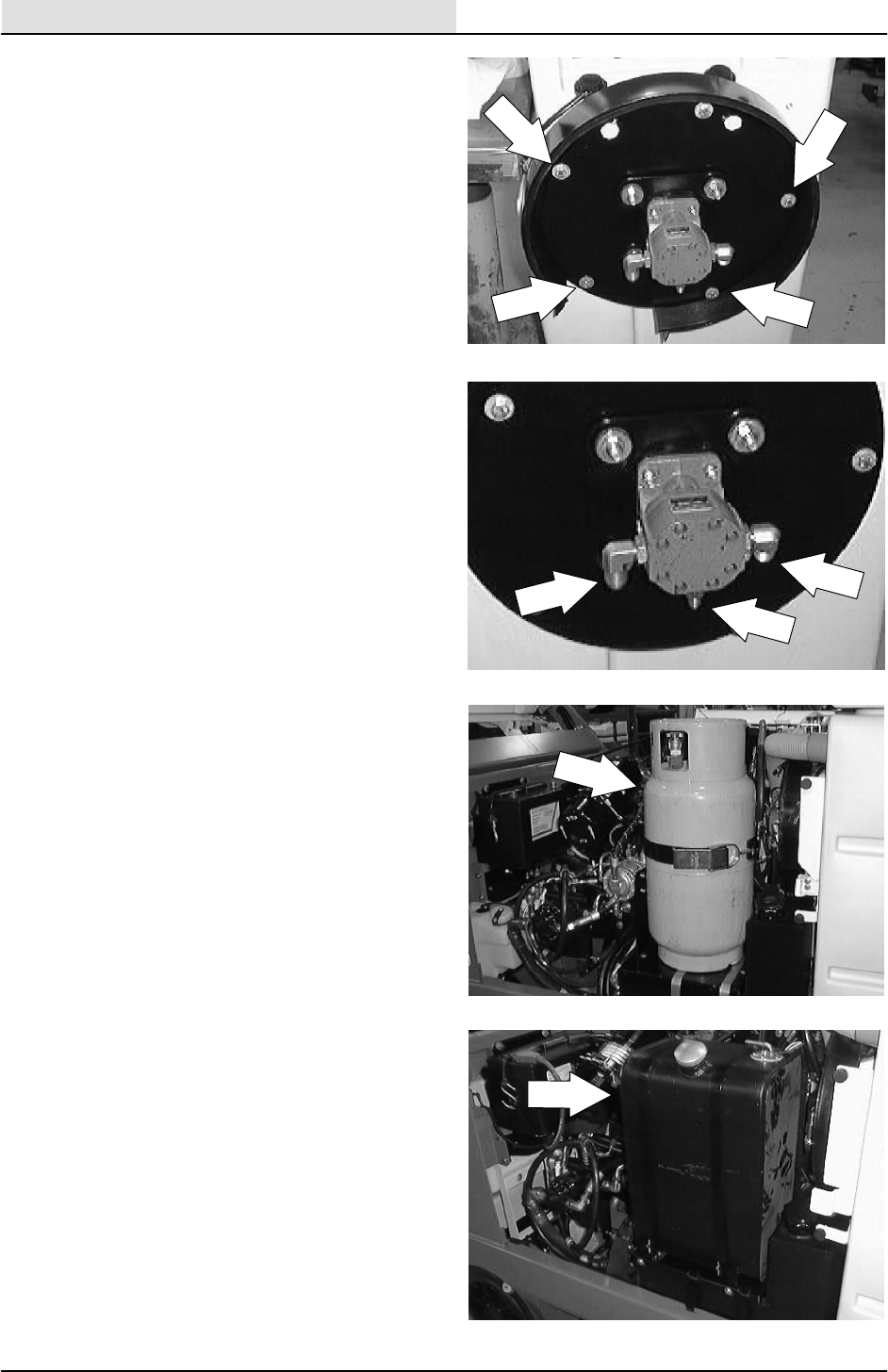
SCRUBBING
4-76 8200/8210 330065 (3--01)
4. Install the four vacuum fan mount screws
and tighten to 18 -- 24 Nm (15 -- 20 ft lb).
5. Reconnect the three hydraulic hoses to the
vacuum fan motor. See schematic in the
HYDRAULICS section.
6. LP MACHINE: Reinstall the LP tank and
connect the LP hose.
7. GAS/DIESEL MACHINE: Reinstall the fuel
tank in the machine. Reinstall the nut on the
out side end of both tank straps. Hand
tighten tight. Reinstall the two wires and two
rubber hoses to the top of the fuel tank.
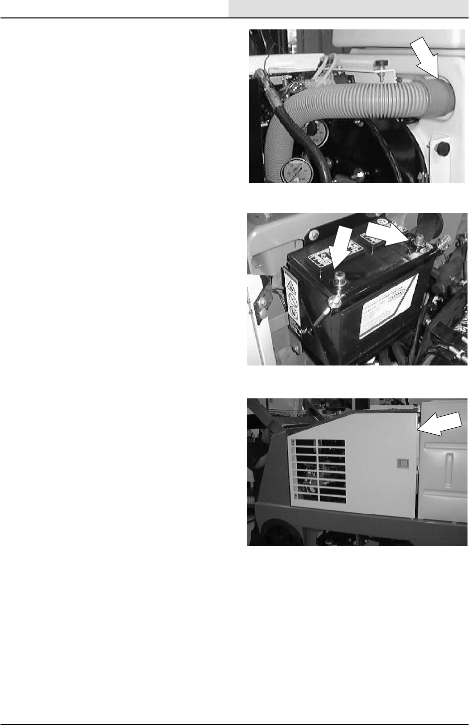
SCRUBBING
4-77
8200/8210 330065 (3--01)
8. Reinstall the vacuum hose into the front of
the recovery tank.
9. Reconnect the battery.
10. Close the engine cover and side door.
11. Start the machine and operate the scrubbing
system. Check the scrubbing vacuum fan for
proper operation.

SCRUBBING
4-78 8200/8210 330065 (3--01)
MACHINE SCRUBBING TROUBLESHOOTING
NOTE: Also see trouble shooting charts in the
ELECTRICAL section.
Problem Cause Remedy
Trailing water -- poor or no
water pickup
Worn rear squeegee blades. Rotate or replace squeegee
blades.
p
p
Rear squeegee out of adjustment. Adjust rear squeegee.
Side squeegees raised. Lower side squeegees.
Worn side squeegee blades. Replace side squeegee blades.
Hopper not adjusted properly. Adjust hopper floor clearance.
Side squeegees out of
adjustment.
Adjust side squeegees.
Too much solution flow to floor. Reduce solution flow to floor.
Vacuum hose clogged. Flush vacuum hoses.
Recovery tank full. Drain recovery tank.
Float stuck shutting off vacuum. Clean float.
Debris caught on rear squeegee. Remove debris.
Foam filling recovery tank. Empty recovery tank; use less or
change detergent.
Vacuum hose to rear squeegee
disconnected or damaged.
Reconnect or replace vacuum
hose.
Only one vacuum fan operating Check and reset circuit breaker
Trailing water -- poor or no
water pickup
Vacuum fan to recovery tank hose
damaged.
Replace hose.
Littleornosolutionflowtothe
f
l
Solution tank empty. Fill solution tank.
f
loor Solution control linkage broken or
out of adjustment.
Replace and/or adjust cable.
Solution supply lines plugged. Flush solution supply lines.
EStswitch off. Turn EStswitch on.
Poor scrubbing performance Debris caught on scrub brushes. Remove debris.
Improper detergent or brushes
used.
Check with TENNANT
representative for advice.
Worn scrub brushes. Replace scrub brushes.
EStsystem does not fill
l
t
i
t
k
Clogged solution pump or lines. Flush EStsystem.
solution tank EStfloat switches stuck. Clean switch floats of debris.
Clogged EStoutlet filter. Clean filter.
Water levels too low in tanks. Add water.

ELECTRICAL
5-1
8200/8210 330065 (3--02)
CONTENTS
Page
INTRODUCTION 5-3.........................
BATTERY 5-4...............................
TO REPLACE BATTERY 5-6...............
INSTRUMENT PANEL 5-8....................
TO REPLACE INDICATOR LIGHT 5-8.......
TO REPLACE TOUCH PANEL 5-11.........
TO REPLACE ELECTRICAL RELAY 5-14....
CIRCUIT BREAKERS 5-17.................
FUSE (DIESEL ONLY) 5-17...............
TO REPLACE CIRCUIT BREAKER 5-18.....
TO REPLACE GLOW PLUG FUSE 5-21.....
TO REPLACE GLOW PLUG TIMER 5-23....
TO REPLACE FILTER SHAKER MOTOR 5-25
THERMO SENTRYt5-28....................
TO REPLACE THERMO SENTRYt5-28....
TO REPLACE EStPUMP 5-30............
TO REPLACE DETERGENT PUMP 5-33....
ELECTRICAL SCHEMATIC 5-36...............
HOPPER WIRE HARNESS DIAGRAM 5-40.....
MAIN WIRE HARNESS DIAGRAM 5-41........
GAS/LP ENGINE WIRE HARNESS
DIAGRAM (000000 -- 006451) 5-49..........
GAS/LP ENGINE WIRE HARNESS
DIAGRAM (006452 -- ) 5-50............
DIAGNOSTICS--8200 5-51....................
OPERATING MODES 5-52...................
INTERLOCKS 5-53.......................
SCRUB BRUSH OPERATION
ENABLED 5-53.....................
SCRUB BRUSH OPERATION
INHIBITED 5-53.....................
SQUEEGEE AND VACUUM FAN
OPERATION ENABLED 5-53.........
SQUEEGEE AND VACUUM FAN
OPERATION INHIBITED 5-53........
EStPUMP OPERATION ENABLED 5-53
EStPUMP OPERATION INHIBITED 5-54
SWEEP BRUSH OPERATION
ENABLED 5-54.....................
SWEEP BRUSH OPERATION
INHIBITED 5-54.....................
SWEEP FAN OPERATION
ENABLED 5-54.....................
SWEEP FAN OPERATION
INHIBITED 5-54.....................
SIDE BRUSH OPERATION
ENABLED 5-54.....................
SIDE BRUSH OPERATION
INHIBITED 5-54.....................
EStAIR FLUSH OPERATION
ENABLED 5-55.....................
EStAIR FLUSH OPERATION
INHIBITED 5-55..................
RECOVERY TANK AUTOFILL
VALVE ENABLED 5-55..............
Page
RECOVERY TANK AUTOFILL
VALVE DISABLED 5-55..............
SOLUTION TANK AUTOFILL
VALVE ENABLED 5-55..............
SOLUTION TANK AUTOFILL
VALVE DISABLED 5-55..............
NORMAL MODE (front panel) 5-56..........
EDGE SCRUB BUTTON 5-56...........
SQUEEGEE 5-56......................
ENGINE SPEED 5-56..................
SCRUB 5-57..........................
DETERGENT 5-58.....................
ESt5-58.............................
OVER--FLOW 5-59.....................
NORMAL MODE (side panel) 5-59..........
MAIN SWEEP BRUSH 5-59.............
SIDE SWEEP BRUSH 5-59.............
FILTER SHAKER 5-59..................
VACUUM FAN 5-60....................
MAINTENANCE MODES 5-60..............
MANUAL MODE 5-61.....................
INPUT DISPLAY MODE 5-63...............
ERROR DISPLAY MODE 5-64..............
PRESSURE ADJUST MODE 5-65..........
RESET SCRUB PRESSURE 5-66..........
DIAGNOSTICS--8210 5-67....................
OPERATING MODES 5-68...................
FRONT PANEL OPERATING MODES 5-69..
FRONT PANEL MAINTENANCE
MODES 5-70..........................
FRONT PANEL MAINTENANCE
MODES 5-71..........................
INTERLOCKS 5-73.......................
SCRUB BRUSH OPERATION
ENABLED 5-73.....................
SCRUB BRUSH OPERATION
INHIBITED 5-73.....................
SQUEEGEE AND VACUUM FAN
OPERATION ENABLED 5-73.........
SQUEEGEE AND VACUUM FAN
OPERATION INHIBITED 5-73........
EStPUMP OPERATION ENABLED 5-74
EStPUMP OPERATION INHIBITED 5-74
SWEEP BRUSH OPERATION
ENABLED 5-74.....................
SWEEP BRUSH OPERATION
INHIBITED 5-74.....................
SWEEP FAN OPERATION ENABLED 5-74
SWEEP FAN OPERATION INHIBITED5-74
SIDE BRUSH OPERATION ENABLED 5-75
SIDE BRUSH OPERATION
INHIBITED 5-75.....................
EStAIR FLUSH OPERATION
ENABLED 5-75.....................

ELECTRICAL
5-2 8200/8210 330065 (3--02)
Page
EStAIR FLUSH OPERATION
INHIBITED 5-75.....................
SOLUTION TANK AUTOFILL
VALVE ENABLED 5-75..............
SOLUTION TANK AUTOFILL
VALVE DISABLED 5-76..............
RECOVERY TANK AUTOFILL
VALVE ENABLED 5-76..............
RECOVERY TANK AUTOFILL
VALVE DISABLED 5-76..............
HOPPER DOOR BLOCKING
VALVE ENABLED 5-76..............
HOPPER DOOR BLOCKING
VALVE DISABLED 5-76..............
DETERGENT PUMP ENABLED 5-77.....
DETERGENT PUMP DISABLED 5-77....
BASIC 8210 OPERATION 5-77.............
EDGE SCRUB (SCRUB, SWEEP/
SCRUB MODE) 5-77................
SQUEEGEE (SCRUB, SWEEP/
SCRUB, SWEEP MODE) 5-77........
ENGINE SPEED (ALL MODELS) 5-78....
DETERGENT (SCRUB MODE) 5-79......
ESt(SCRUB MODE) 5-79.............
OVERFLOW (SCRUB MODE,
SWEEP/SCRUB MODE) 5-79........
MAIN SWEEP BRUSH
(SWEEP MODE,
SWEEP/SCRUB MODE) 5-80......
SIDE SWEEP BRUSH
(SWEEP MODE,
SWEEP/SCRUB MODE) 5-80......
FILTER SHAKER 5-80..................
VACUUM FAN 5-81....................
MAINTENANCE MODES 5-82..............
MANUAL MODE 5-83.....................
INPUT DISPLAY MODE 5-85...............
SELF TEST MODE 5-86...................
PRESSURE ADJUST MODE 5-87..........
SCRUB BUTTON 5-88..................
SQUEEGEE BUTTON 5-88.............
UP ARROW 5-88......................
DOWN ARROW 5-88...................
EXIT 5-88.............................
RESET SCRUB PRESSURE 5-89..........
SET CLOCK 5-90.........................
CHECK MAINTENANCE MODE 5-91........
TROUBLESHOOTING--8200/8210 5-92........
ENGINE WILL NOT CRANK (all engines)
(8200/8210) 5-93.........................
ENGINE WILL NOT RUN (lpg) (8200/8210) 5-94.
ENGINE WILL NOT RUN (gas) (8200/8210) 5-95
ENGINE WILL NOT RUN (diesel)
(8200/8210) 5-96.........................
NO SPEED CHANGE FROM ENGINE
GOVERNOR (8200/8210) 5-97.............
Page
INCORRECT ENGINE GOVERNED
SPEED OR RESPONSE
(8200/8210) 5-98.......................
MAIN SWEEPING BRUSH WILL NOT
RUN (8200) 5-99.......................
SIDE BRUSH WILL NOT RUN (8200) 5-100..
SWEEPING VACUUM FAN WILL
NOT RUN (8200) 5-101.................
FILTER SHAKER WILL NOT RUN
(8200) 5-102...........................
SCRUB BRUSHES WILL NOT RAISE
OR LOWER (8200) 5-103...............
SCRUB BRUSHES WILL NOT
TURN ON (8200) 5-104.................
SCRUB HEAD DOWN FORCE
(SV--8) (8200) 5-105....................
SCRUB HEAD DOWN FORCE
(SV--8) (8200)--continued 5-106..........
SCRUB HEAD EDGE SCRUB WILL
NOT SHIFT (8200) 5-107...............
SQUEEGEE WILL NOT LOWER
(8200) 5-108...........................
SCRUB VACUUM FAN WILL NOT
RUN (8200) 5-109......................
SOLUTION CONTROL WILL NOT
OPERATE (8200) 5-110.................
DETERGENT PUMP WILL NOT
OPERATE (8200) 5-111.................
EStWILL NOT OPERATE (8200) 5-112....
MAIN SWEEPING BRUSH WILL
NOT RUN (8210) 5-113.................
SIDE BRUSH WILL NOT RUN (8210) 5-114..
SWEEPING VACUUM FAN WILL
NOT RUN (8210) 5-115.................
FILTER SHAKER WILL NOT RUN
(8210) 5-116...........................
SCRUB BRUSHES WILL NOT
RAISE/LOWER (8210) 5-117............
SCRUB BRUSHES WILL NOT
TURN ON (8210) 5-118.................
SCRUB HEAD DOWN FORCE
(SV--8) (8210) 5-119....................
SCRUB HEAD DOWN FORCE
(SV--8) (8210)--continued 5-120..........
SCRUB HEAD EDGE SCRUB WILL
NOT SHIFT (8210) 5-121...............
SQUEEGEE WILL NOT LOWER
(8210) 5-122...........................
SCRUB VACUUM FAN WILL NOT
RUN (8210) 5-123......................
SOLUTION CONTROL WILL NOT
OPERATE (8210) 5-124.................
DETERGENT PUMP WILL NOT
OPERATE (8210) 5-125.................
EStWILL NOT OPERATE (8210) 5-126....

ELECTRICAL
5-3
8200/8210 330065 (3--01)
INTRODUCTION
The 8200/8210 electrical system consists of the
battery, instrument panel, touch panel, switches,
relays, and circuit breakers. This section includes
information on these components and their
troubleshooting.
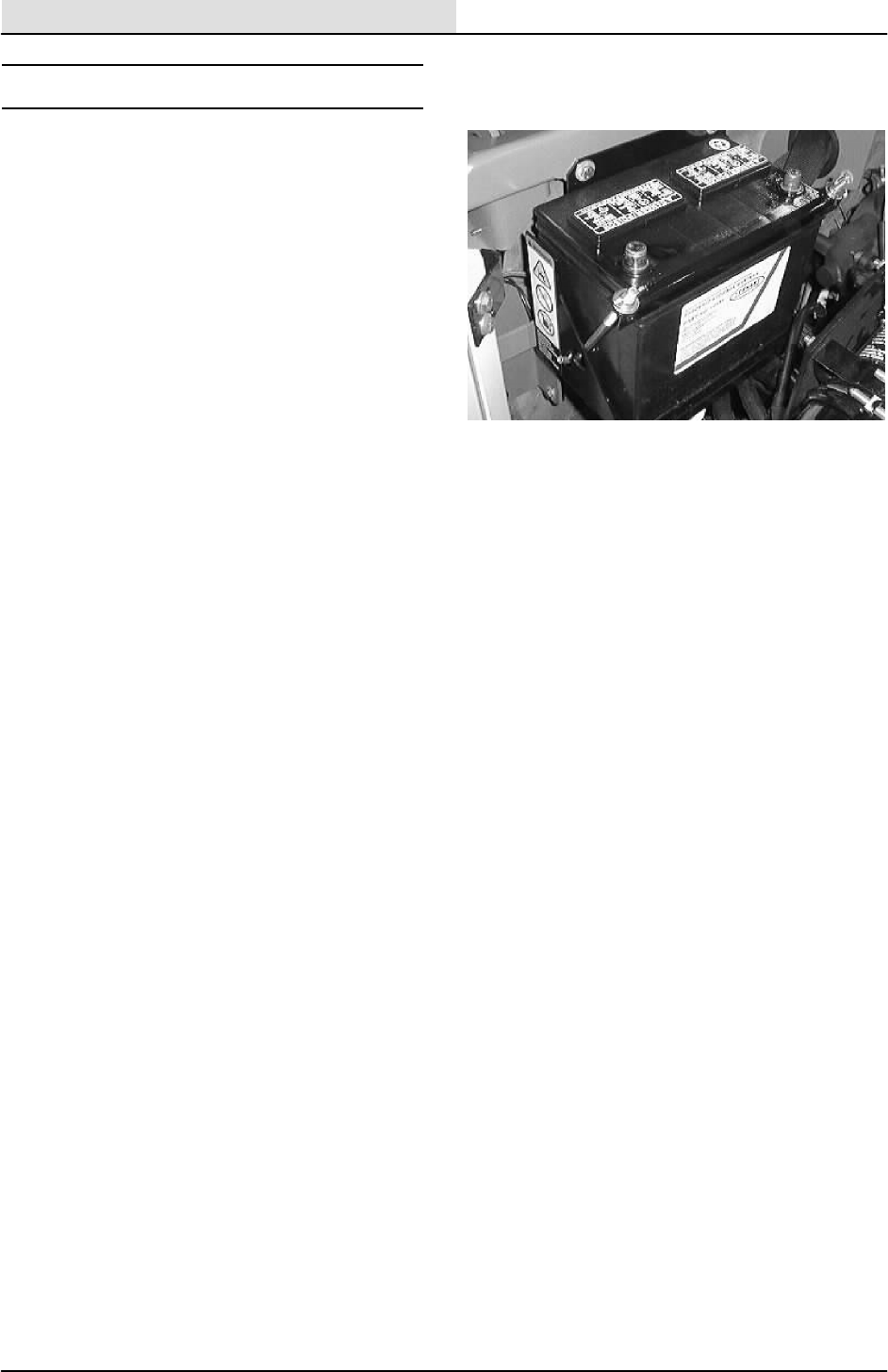
ELECTRICAL
5-4 8200/8210 330065 (3--01)
BATTERY
The battery used in the machine is a low
maintenance battery. It has been constructed with
special materials and has extra electrolyte to
reduce or eliminate maintenance. Its design
reduces electrolyte loss and contamination. Do
not add water, remove the battery vent plugs, or
check the battery specific gravity. For specific
instructions, see the battery label.
Do not allow the battery to remain in discharged
condition for any time. Do not operate the
machine if the battery is in poor condition or
discharged beyond 80%, specific gravity below
1.120.
After the first 50 hours of operation, and every
800 hours after that, clean and tighten the battery
connections.
Periodically clean the top surface of the batteries
and the terminals, and check for loose
connections. Use a strong solution of baking soda
and water. Brush the solution sparingly over the
battery tops, terminals, and cable clamps. Do not
allow any baking soda solution to enter the
batteries. Use a wire brush to clean the terminal
posts and the cable connectors. After cleaning,
apply a coating of clear battery post protectant to
the terminals and the cable connectors. Keep the
tops of the batteries clean and dry.
Keep all metallic objects off the top of the
batteries, which may cause a short circuit.
Replace any worn or damaged wires.
The electrolyte level in regular non--sealed
batteries can be checked. The level must always
be above the battery plates. Never add acid to the
batteries, only distilled water. Keep the battery
caps on the batteries always except when adding
water or taking hydrometer readings.
FOR SAFETY: When Servicing Machine,
Avoid Contact With Battery Acid.
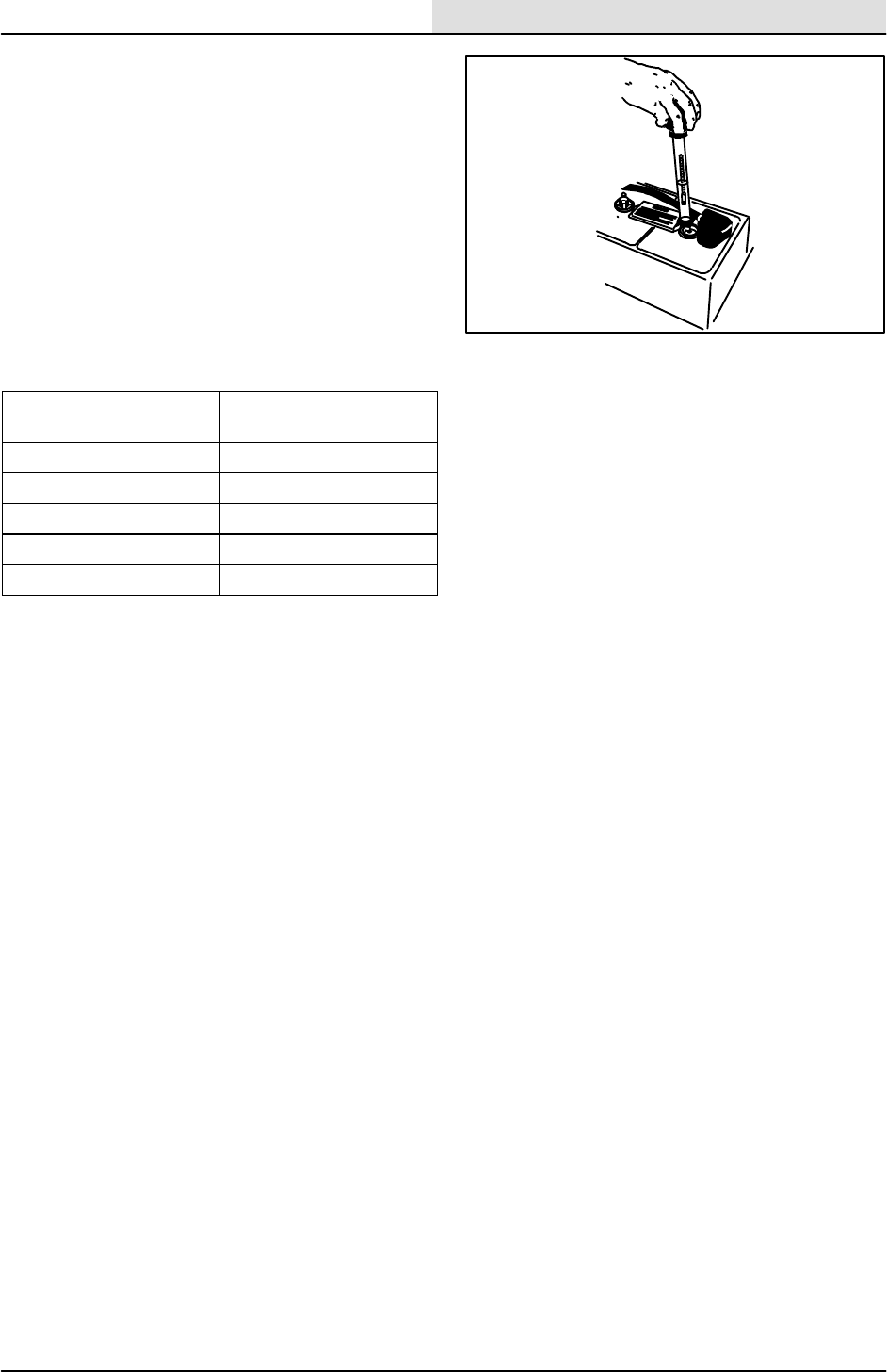
ELECTRICAL
5-5
8200/8210 330065 (3--01)
Using a hydrometer to measure the specific
gravity is a way to determine the charge level and
condition of the batteries. If one or more of the
battery cells test lower than the other battery cells
(0.050 or more), the cell is damaged, shorted, or
is about to fail.
NOTE: Do not take readings immediately after
adding distilled water. If the water and acid are not
thoroughly mixed, the readings may not be
accurate. Check the hydrometer readings against
the following chart to determine the remaining
battery charge level:
SPECIFIC GRAVITY at
27_C(80_F)
BATTERY
CHARGE
1.290 100% Charged
1.252 75% Charged
1.200 50% Charged
1.177 25% Charged
1.140 Discharged
NOTE: If the readings are taken when the battery
electrolyte is any temperature other than 27_C
(80_F), the reading must be temperature
corrected. Add or subtract to the specific gravity
reading 0.004, 4 points, for each 6_C(10_F)
above or below 27_C(80_F).
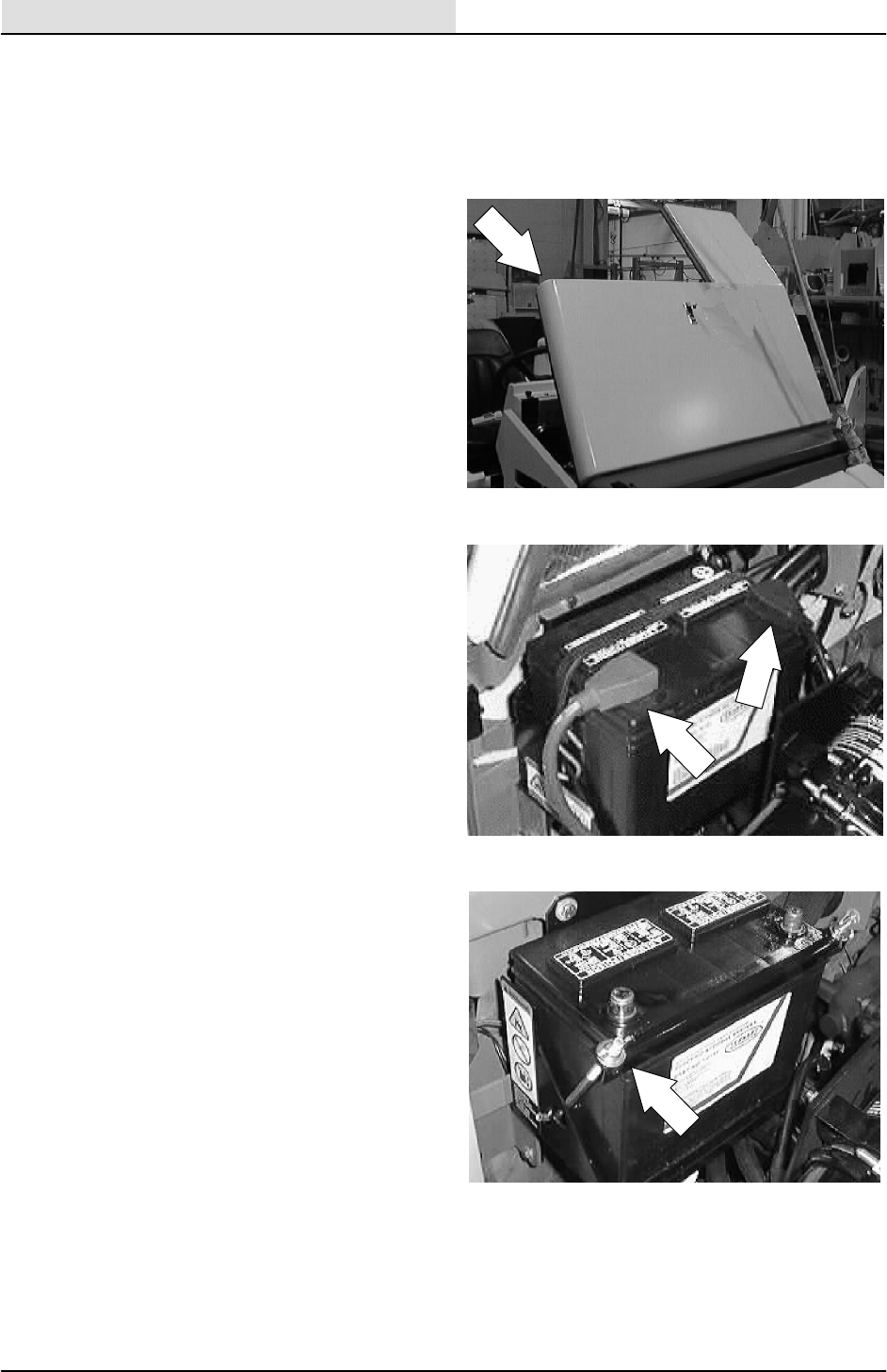
ELECTRICAL
5-6 8200/8210 330065 (3--01)
TO REPLACE BATTERY
FOR SAFETY: Before Leaving Or
Servicing Machine; Stop On Level
Surface, Set Parking Brake, Turn Off
Machine And Remove Key.
1. Open the engine cover and side door.
2. Disconnect the battery cables.
3. Remove the battery hold down strap.
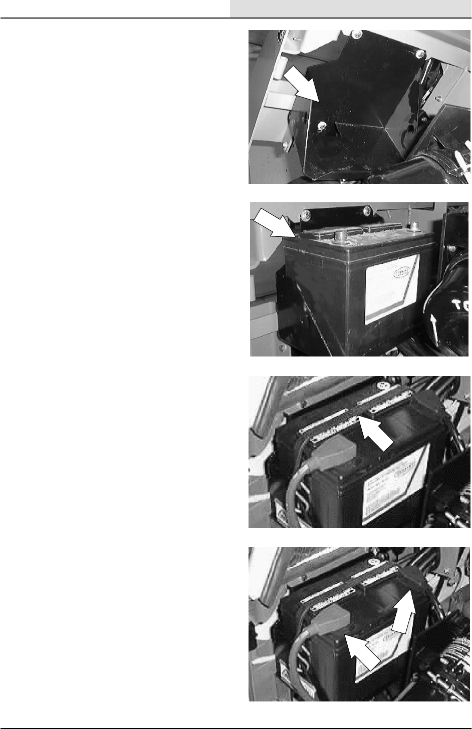
ELECTRICAL
5-7
8200/8210 330065 (3--01)
4. Lift the battery out of the machine using a
battery lifting device.
5. Make sure that both posts are clean on the
new battery. Position the new battery in the
machine.
6. Reinstall the battery hold down strap.
7. Reconnect the positive, then the negative
battery cables.
8. Close the engine cover and side door.
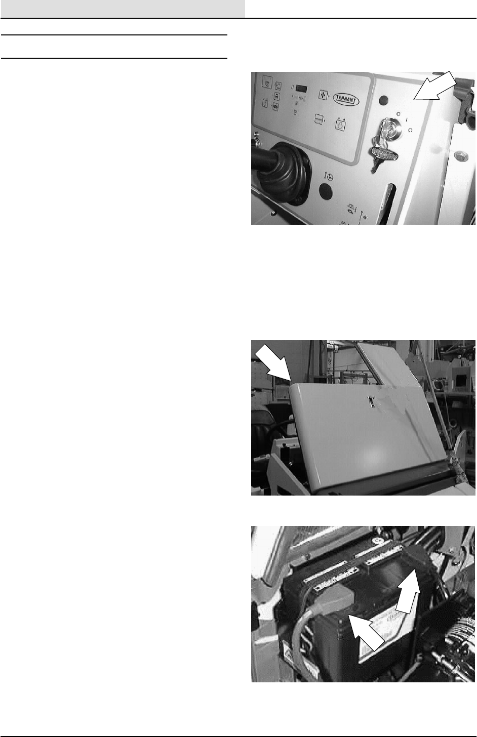
ELECTRICAL
5-8 8200/8210 330065 (3--01)
INSTRUMENT PANEL
The instrument panel consists of a key switch,
light switch, hour meter, fuel gauge, horn button,
and indicator light panel.
TO REPLACE INDICATOR LIGHT
FOR SAFETY: Before Leaving Or
Servicing Machine; Stop On Level
Surface, Set Parking Brake, Turn Off
Machine And Remove Key.
1. Open the engine cover and side door.
2. Disconnect the battery cables.
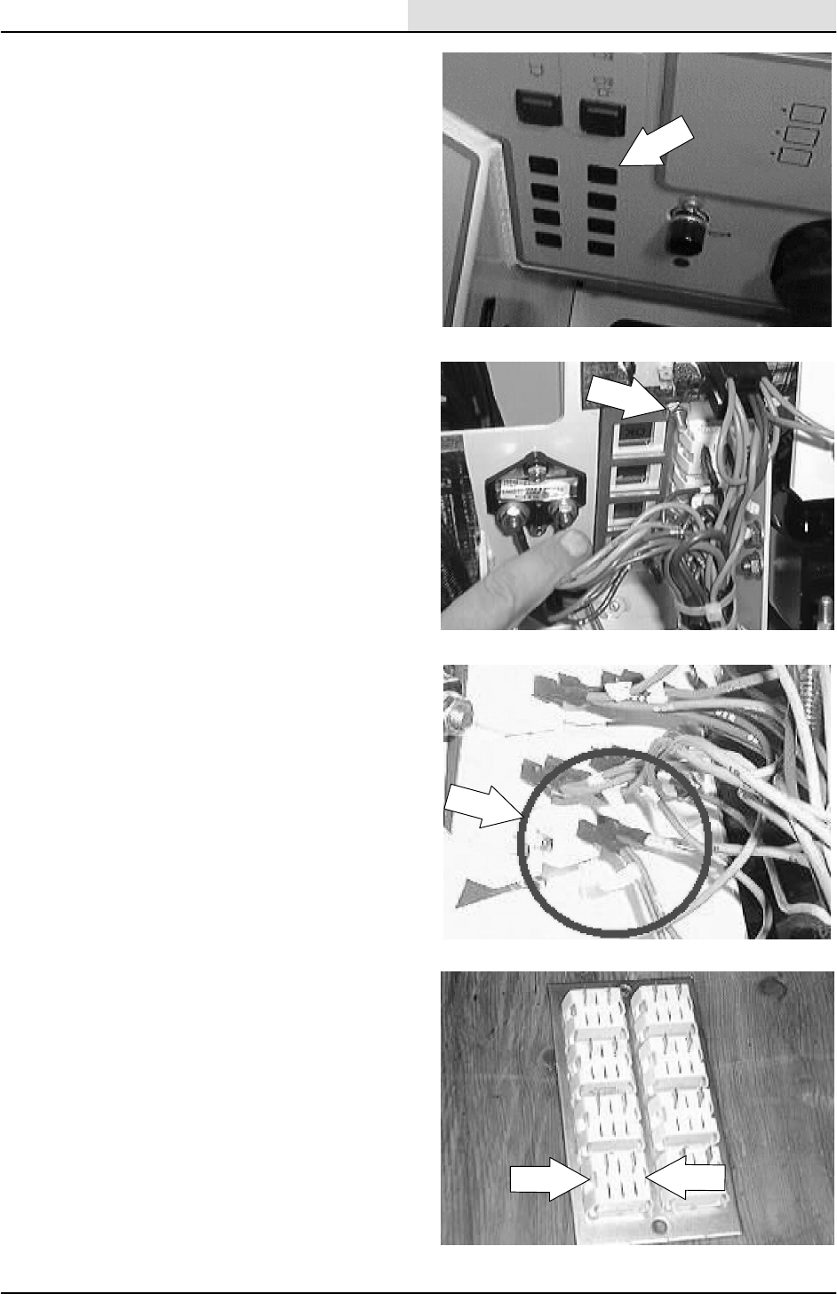
ELECTRICAL
5-9
8200/8210 330065 (3--01)
3. Locate the indicator light panel mount plate
next to the power steering hoses.
4. Remove the two nyloc nuts holding the
mount plate to the instrument panel. Pull the
mount plate back away from the instrument
panel.
5. Unplug the two wires leading to the light that
needs to be changed.
6. Squeeze the sides of the light and push the
light out of the mount plate.
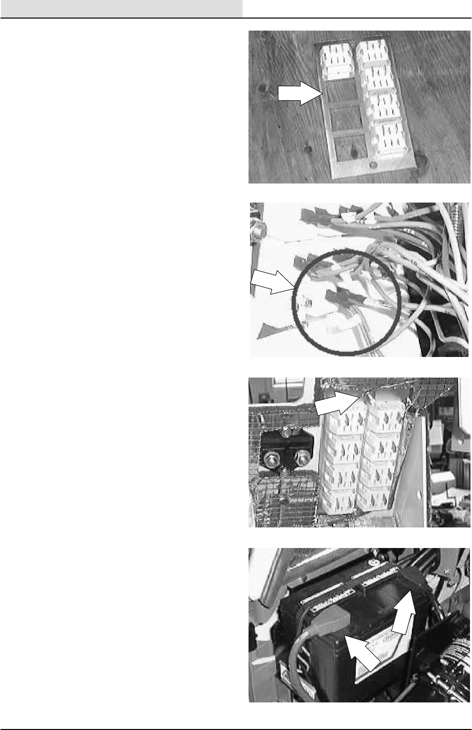
ELECTRICAL
5-10 8200/8210 330065 (3--01)
7. Install the new light in the mount plate. Snap
in place.
8. Reconnect the wires to the new light. See
schematic in this section.
9. Position the mount plate back on the
instrument panel. Reinstall the two nyloc
nuts and tighten.
10. Reconnect the battery cables.
11. Close the engine cover and side door.
Operate the machine and check the
indicator lights for proper operation.
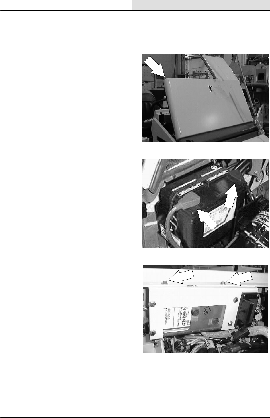
ELECTRICAL
5-11
8200/8210 330065 (3--01)
TO REPLACE TOUCH PANEL
FOR SAFETY: Before Leaving Or
Servicing Machine; Stop On Level
Surface, Set Parking Brake.
1. Open the engine cover and side door.
2. Disconnect the battery cables.
3. Locate the two hex screws holding the
engine governor box mount bracket to the
front of the dash panel. Remove the two
screws.
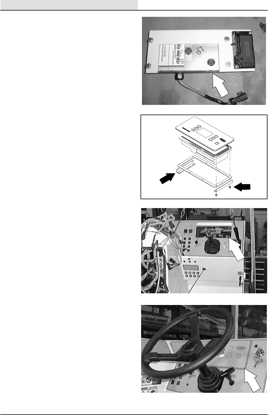
ELECTRICAL
5-12 8200/8210 330065 (3--01)
4. Position the governor and bracket out of the
way to allow access to the back side of the
touch panel.
5. Un--plug the touch panel from the main
electrical harness.
6. Remove the four hex screws holding the two
angle brackets to the back of the touch
panel. Remove the angle brackets.
7. Pull the touch panel out of the mounting hole
in the dash panel.
8. Position the new touch panel into the
mounting hole in the dash panel.
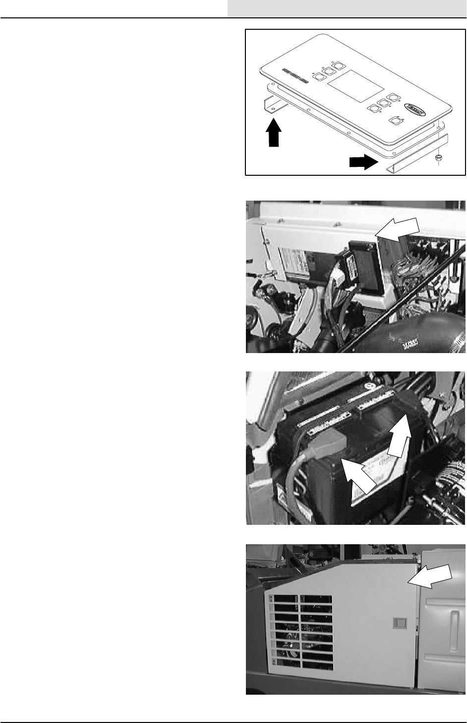
ELECTRICAL
5-13
8200/8210 330065 (3--01)
9. Install the two touch panel mounting angle
brackets.
10. Install the four hex screws holding the two
angle brackets to the back of the touch
panel. Tighten these hex screws lightly.
11. Plug the touch panel into the main electrical
harness.
12. Position the governor and bracket back in
place at the front of the dash panel.
13. Reinstall the two screws into the governor
mount bracket and tighten to 7.6 -- 9.9 Nm
(5.6 -- 7.3 ft lb).
14. Reconnect the battery cables.
15. Close the engine cover and side door.
16. Start the machine and check the touch panel
for proper operation.
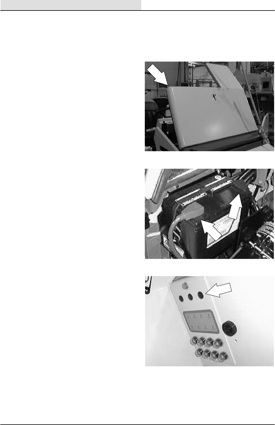
ELECTRICAL
5-14 8200/8210 330065 (3--01)
TO REPLACE ELECTRICAL RELAY
FOR SAFETY: Before Leaving Or
Servicing Machine; Stop On Level
Surface, Set Parking Brake, Turn Off
Machine And Remove Key.
1. Open the engine cover and side door.
2. Disconnect the battery cables.
3. Locate the circuit breaker/relay mount plate
below the indicator lights on the dash panel.
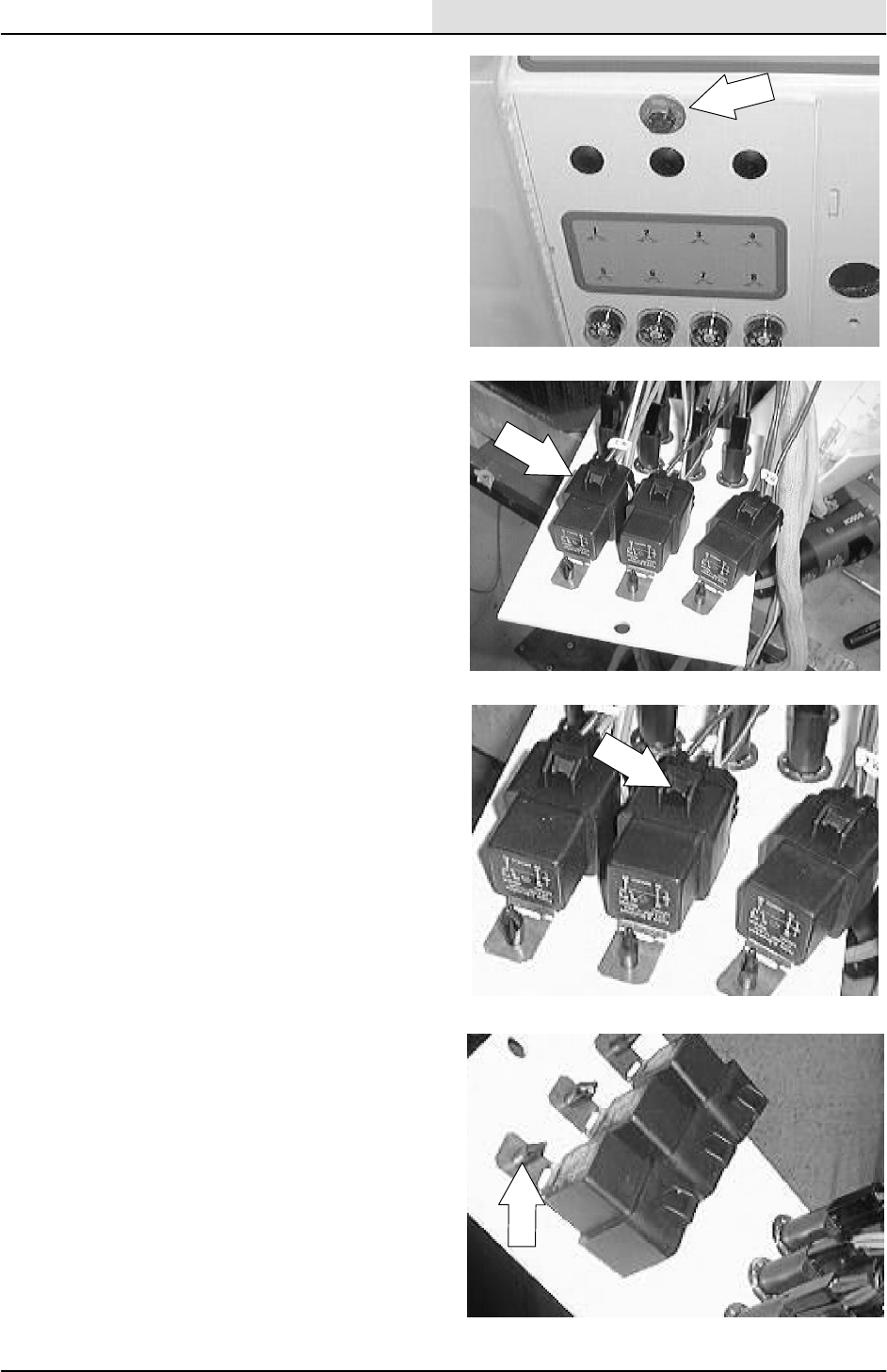
ELECTRICAL
5-15
8200/8210 330065 (3--01)
4. Remove the hex screw holding the circuit
breaker/relay mount plate to the dash panel.
NOTE: Pull the mount plate back for access to the
relays.
5. Use the electrical schematic to locate the
relay that needs to be replaced.
6. Push the two tabs on the electrical plug of
the main harness and remove it from the
faulty relay.
7. Remove the plastic rivet holding the relay to
the panel. Remove and discard the relay.
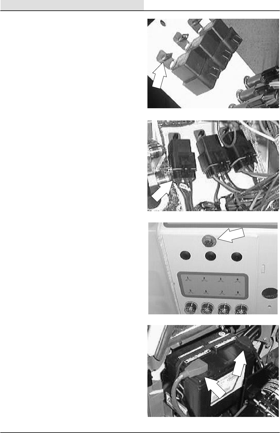
ELECTRICAL
5-16 8200/8210 330065 (3--01)
8. Position the new relay on the mount panel.
Reinstall the plastic rivet.
9. Plug the main harness in the new relay. See
the schematic in this section.
NOTE: The harness plug will only fit in the new
relay in one direction.
10. Position the mount panel back on the dash
panel. Reinstall the hex screw and tighten.
11. Reconnect the battery cables.
12. Start the engine and close the engine cover
and side door. Check the new relay for
proper operation.
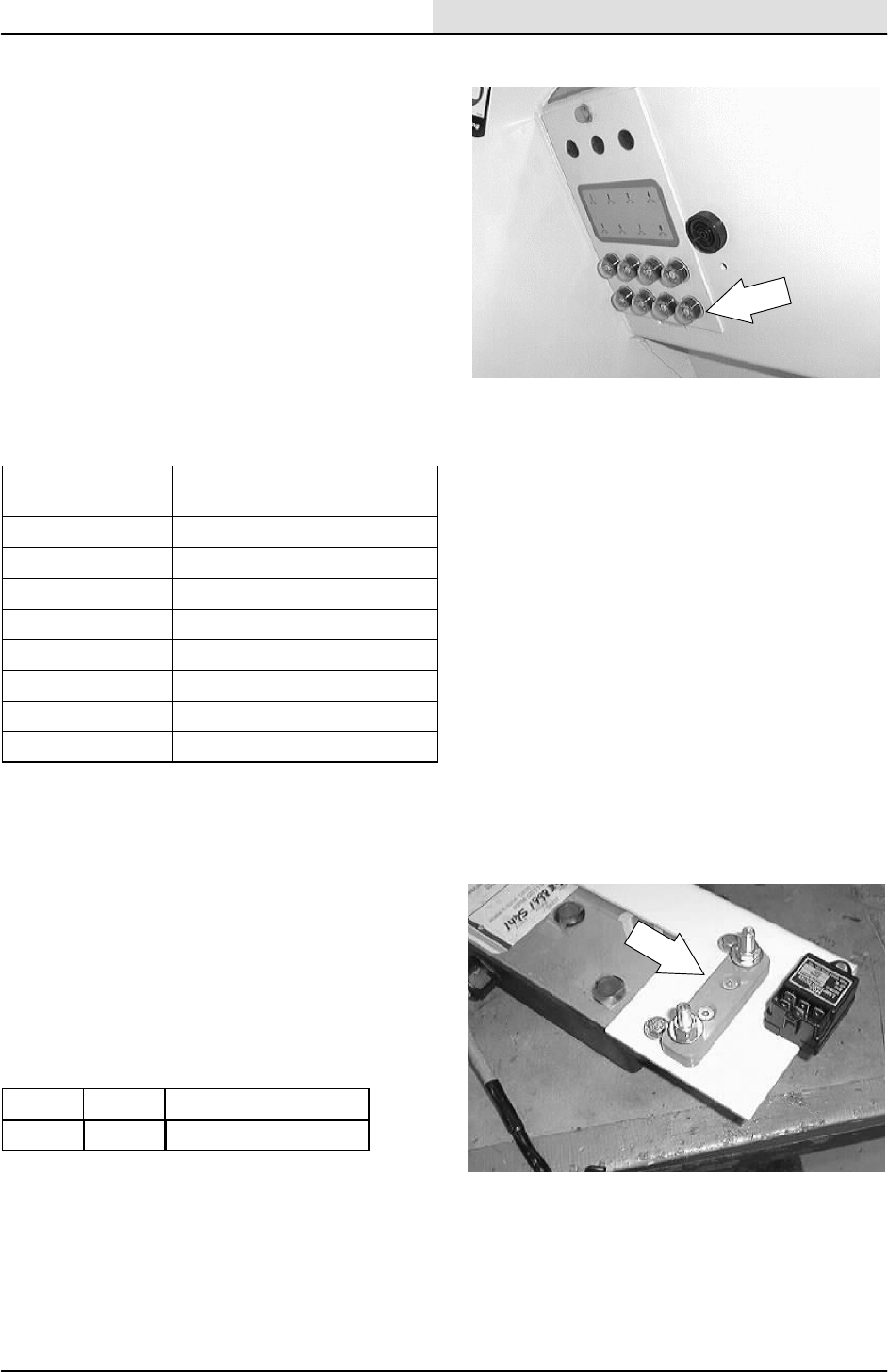
ELECTRICAL
5-17
8200/8210 330065 (3--01)
CIRCUIT BREAKERS
The circuit breakers are resetable electrical circuit
protection devices. Their design stops the flow of
current in the event of a circuit overload. Once a
circuit breaker is tripped, it must be reset
manually. Press the reset button after the breaker
has cooled down.
If the overload that caused the circuit breaker to
trip is still there, the circuit breaker will continue to
stop current flow until the problem is corrected.
The circuit breakers are located in the operator
compartment.
This chart lists the circuit breakers and the
electrical components they protect.
Circuit
Breaker Rating Circuit Protected
CB-1 15 A Horn
CB-2 15 A Ignition
CB-3 15 A Headlights / Taillights
CB-4 5A Logic Power
CB-5 15 A Sweeping
CB-6 15 A Scrubbing
CB-7 15 A Scrubbing
CB-8 15 A Filter Shaker Motor
FUSE (DIESEL ONLY)
The fuse is a one--time protection device designed
to stop the flow of current in the event of a circuit
overload. Never substitute higher value fuses than
specified.
The fuse is located in the operator compartment.
Remove the circuit breaker panel to gain access
to the fuse.
Fuse Rating Circuit Protected
FU-1 40 A Glow plugs
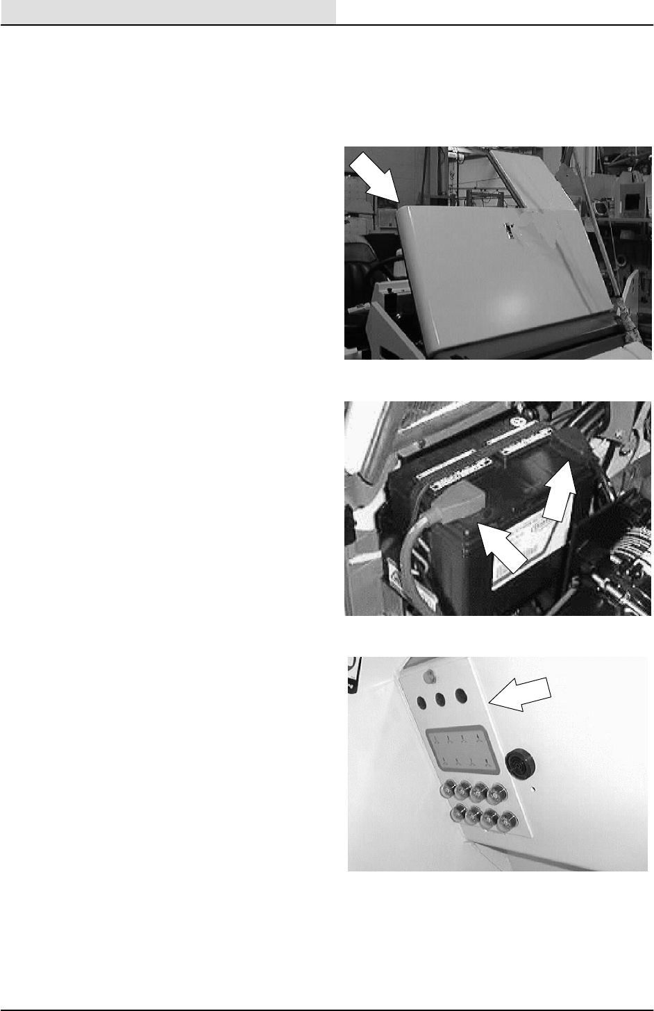
ELECTRICAL
5-18 8200/8210 330065 (3--01)
TO REPLACE CIRCUIT BREAKER
FOR SAFETY: Before Leaving Or
Servicing Machine; Stop On Level
Surface, Set Parking Brake, Turn Off
Machine And Remove Key.
1. Open the engine cover and side door.
2. Disconnect the battery cables.
3. Locate the circuit breaker/relay mount plate
below the indicator lights on the dash panel.
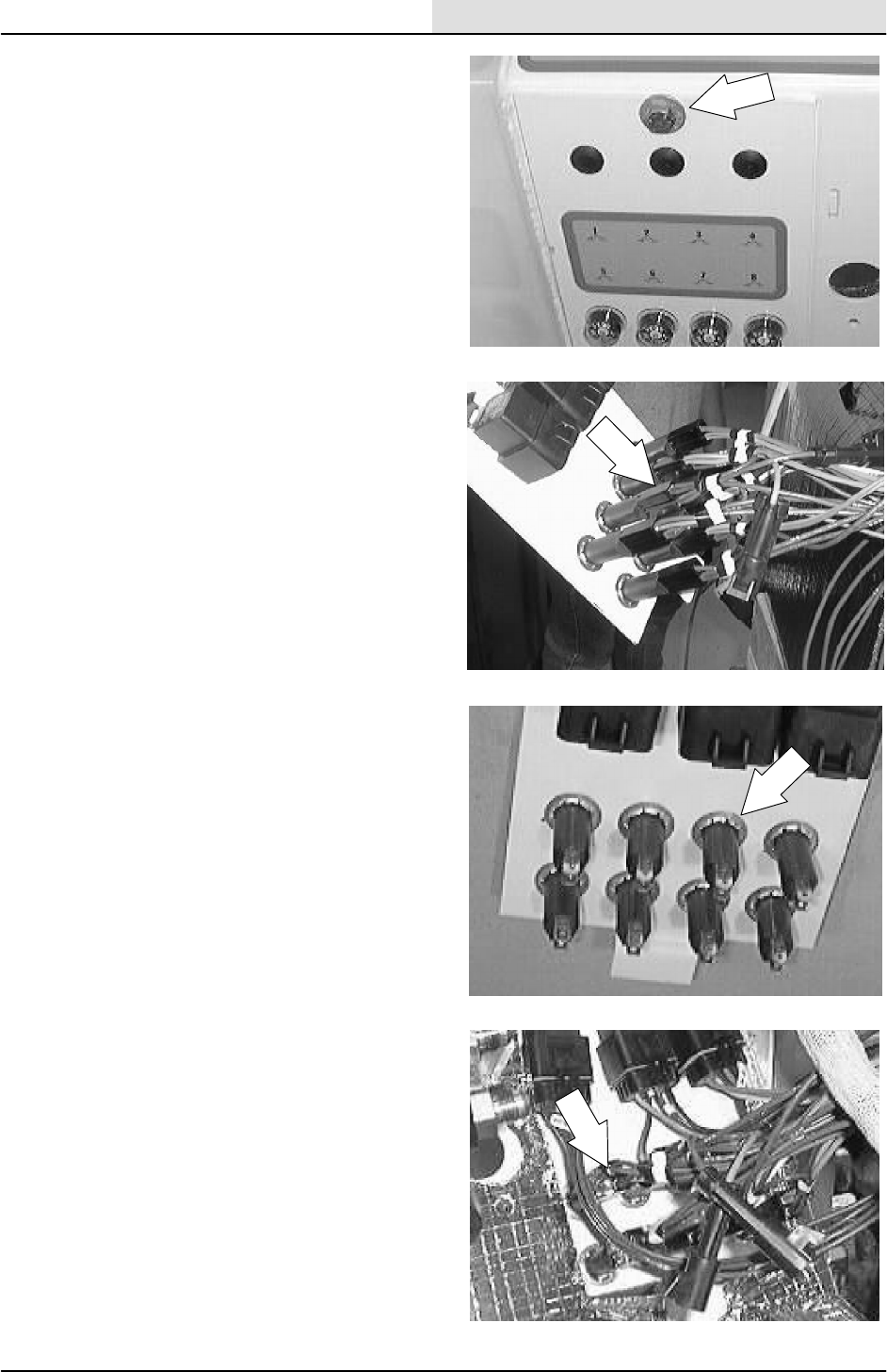
ELECTRICAL
5-19
8200/8210 330065 (3--01)
4. Remove the hex screw holding the circuit
breaker/relay mount plate to the dash panel.
NOTE: Pull the mount plate back for access to the
circuit breakers.
5. Use the electrical schematic to locate the
circuit breaker that needs to be replaced.
6. Disconnect the wires leading to the faulty
circuit breaker.
7. The metal ring must be removed in order to
remove the old circuit breaker. It may need
to be cut off.
8. Remove the old circuit breaker and discard.
9. Position the new circuit breaker in the hole in
the panel. Install the metal lock ring.
NOTE: The circuit breaker will only fit in the hole
in one direction.
10. Plug the main harness wires into the new
circuit breaker. See the schematic in this
section.
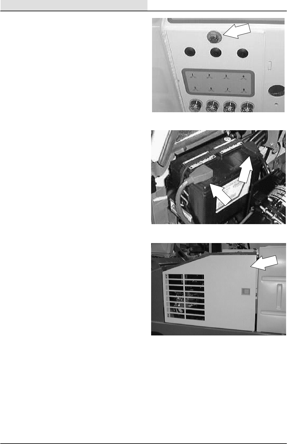
ELECTRICAL
5-20 8200/8210 330065 (3--01)
11. Position the mount panel back on the dash
panel. Reinstall the hex screw and tighten.
12. Reconnect the battery cables.
13. Start the engine and close the engine cover
and side door. Check the new circuit breaker
for proper operation.
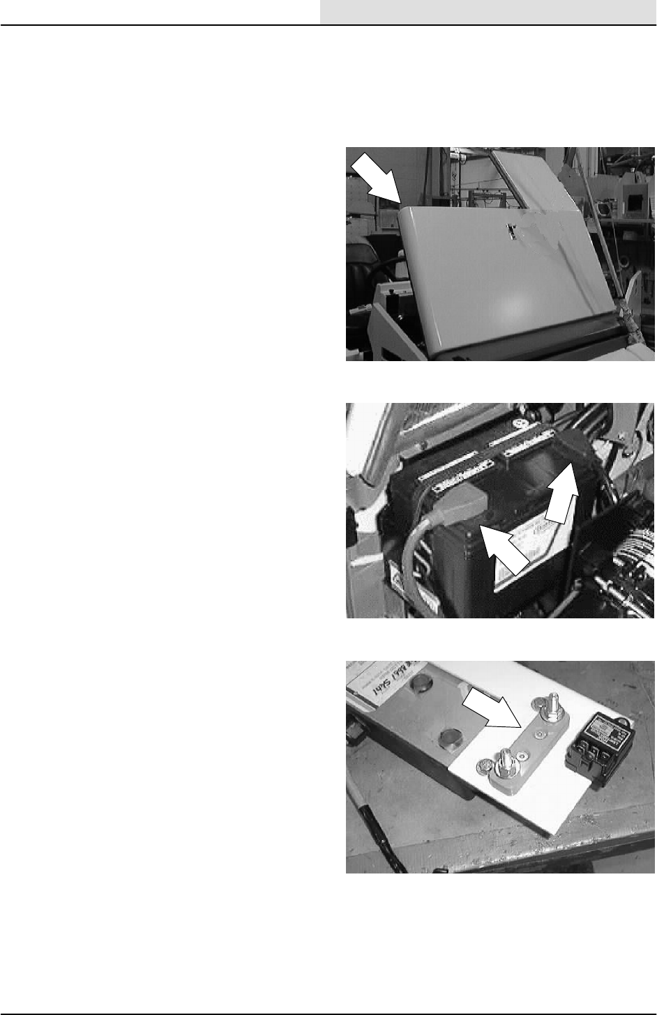
ELECTRICAL
5-21
8200/8210 330065 (3--01)
TO REPLACE GLOW PLUG FUSE
FOR SAFETY: Before Leaving Or
Servicing Machine; Stop On Level
Surface, Set Parking Brake, Turn Off
Machine And Remove Key.
1. Open the engine cover and side door.
2. Disconnect the battery cables.
3. Locate the glow plug fuse on the governor
control box mount plate.
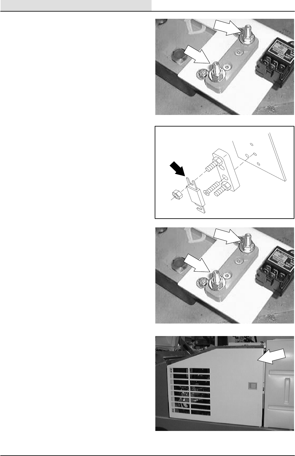
ELECTRICAL
5-22 8200/8210 330065 (3--01)
4. Loosen the two hex nuts holding the wires
and fuse into the fuse holder.
NOTE: Do not remove the hex nuts.
5. Slip the glow plug fuse out of the holder.
6. Position the new glow plug fuse into the
holder, under the glow plug wires.
7. Hand tighten the two hex nuts. Do not over
tighten.
8. Reconnect the battery cables and close the
engine cover.
9. Check the glow plug cycle for proper
operation.
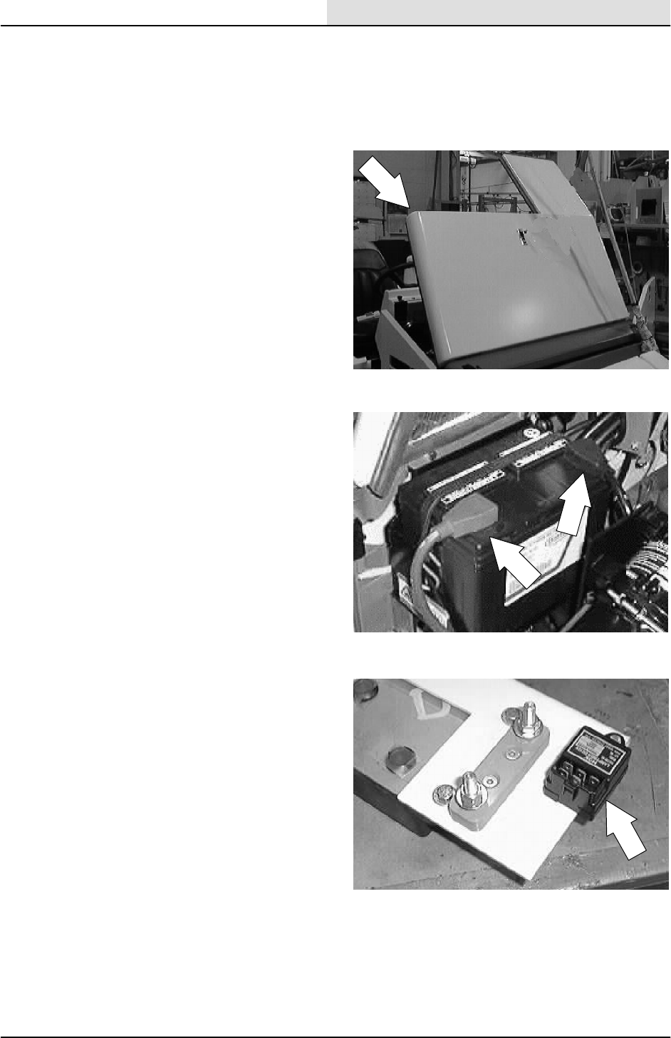
ELECTRICAL
5-23
8200/8210 330065 (3--01)
TO REPLACE GLOW PLUG TIMER
FOR SAFETY: Before Leaving Or
Servicing Machine; Stop On Level
Surface, Set Parking Brake, Turn Off
Machine And Remove Key.
1. Open the engine cover and side door.
2. Disconnect the battery cables.
3. Locate the glow plug timer on the governor
control box mount plate.
4. Disconnect the wires leading to the glow
plug timer.
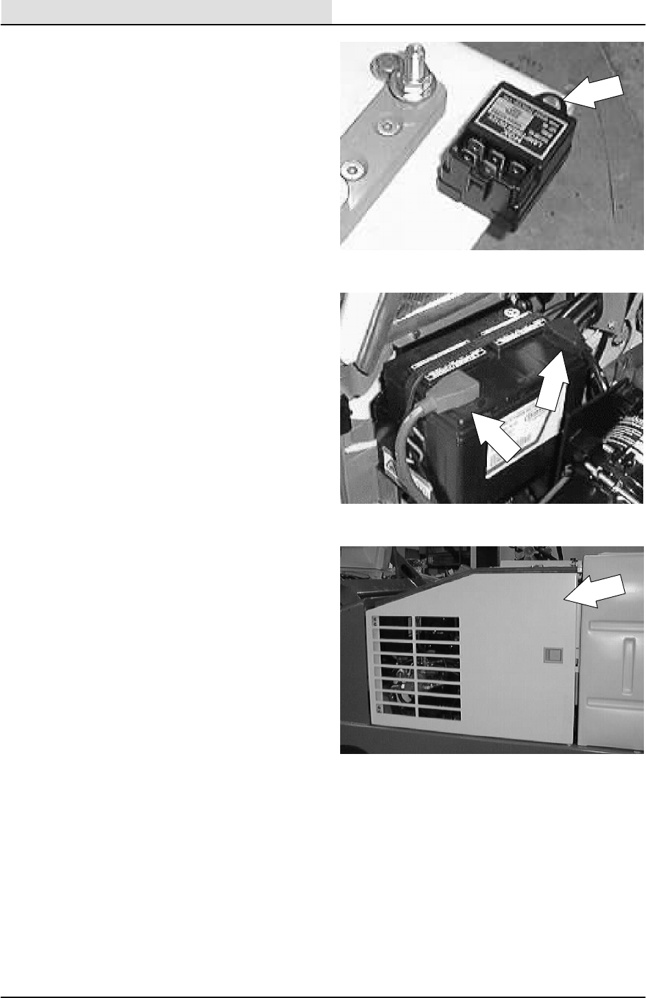
ELECTRICAL
5-24 8200/8210 330065 (3--01)
5. Remove the hex screw holding the glow plug
timer to the mount plate.
6. Remove the glow plug timer.
7. Position the new glow plug timer onto the
mount plate. Reinstall the hex screw and
hand tighten.
8. Reconnect the wires to the glow plug timer.
See the schematic in this section.
9. Reconnect the battery cables.
10. Close the engine cover and side door.
11. Check the glow plug cycle for proper
operation.
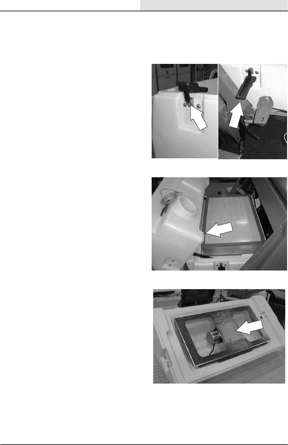
ELECTRICAL
5-25
8200/8210 330065 (3--01)
TO REPLACE FILTER SHAKER MOTOR
FOR SAFETY: Before Leaving Or
Servicing Machine; Stop On Level
Surface, Set Parking Brake, Turn Off
Machine And Remove Key.
1. Un--latch the two rubber hopper cover locks.
2. Open the hopper cover.
3. Locate the filter shaker motor on the top side
of the filter shaker assembly, located in the
hopper cover.
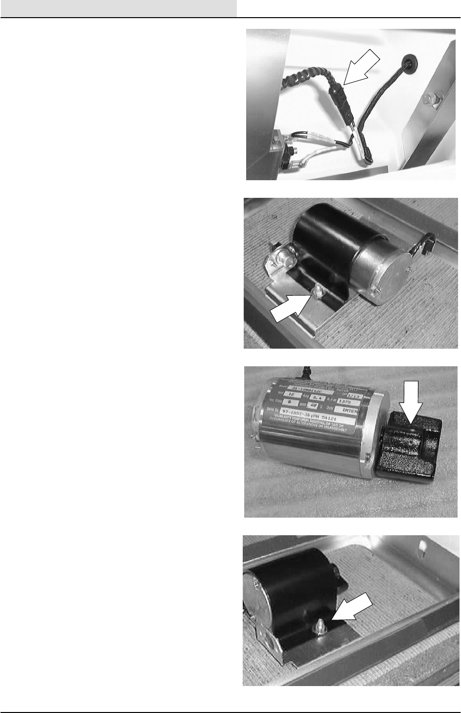
ELECTRICAL
5-26 8200/8210 330065 (3--01)
4. Unplug the filter shaker motor from the
hopper harness.
5. Remove the two hex screws holding the
shaker motor bracket to the motor assembly.
Remove the motor from the assembly.
6. Loosen the two set screws on the eccentric
weight. Pull the weight off the motor shaft.
7. Install the eccentric weight on the new
shaker motor. Position the weight flush with
the guard plate.
8. Install the new shaker motor on the
assembly mount plate. Tighten the two hex
screws to 18 -- 24 Nm (15 -- 20 ft lb).
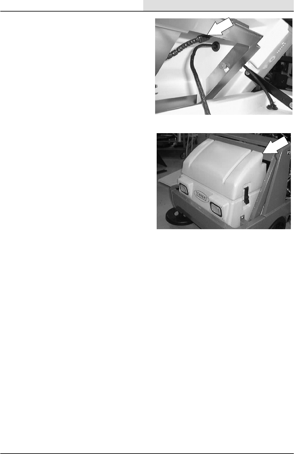
ELECTRICAL
5-27
8200/8210 330065 (3--01)
9. Plug the shaker motor into the hopper
harness.
10. Close the hopper cover and latch the two
rubber locks.
11. Start the machine. Test the shaker motor for
proper operation.
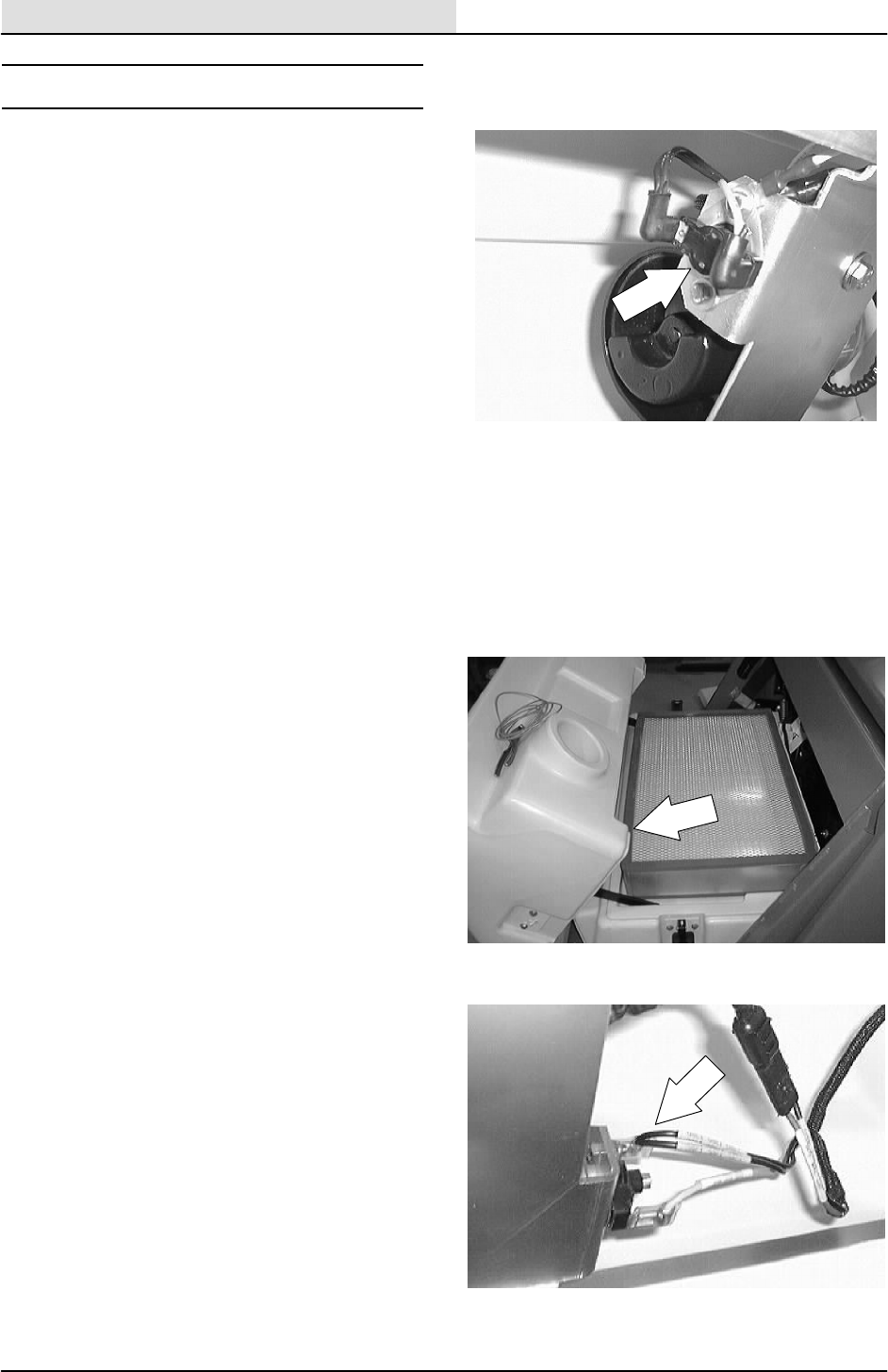
ELECTRICAL
5-28 8200/8210 330065 (3--01)
THERMO SENTRYt
The Thermo Sentrytsenses the temperature of
the air pulled up from the hopper. If there is a fire
in the hopper, the Thermo Sentrytstops the
vacuum fan and cuts off the air flow.
TO REPLACE THERMO SENTRYt
FOR SAFETY: Before Leaving Or
Servicing Machine; Stop On Level
Surface, Set Parking Brake, Turn Off
Machine And Remove Key.
1. Open the hopper cover.
2. Locate the Thermo Sentrytonthesideof
the filter shaker motor bracket. Unplug the
two wires leading to the Thermo Sentryt.
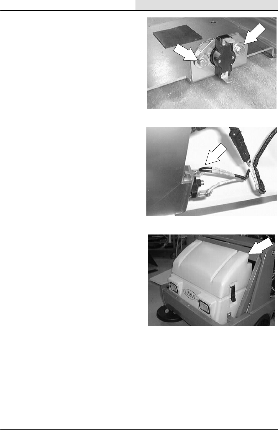
ELECTRICAL
5-29
8200/8210 330065 (3--01)
3. Remove the hex screws holding the
Thermo Sentrytto the bracket. Remove
from the hopper cover.
4. Install the new Thermo Sentryton the
bracket. Reinstall the hardware and tighten,
5. Reconnect the wires to the new Thermo
Sentryt
6. Close the hopper cover.
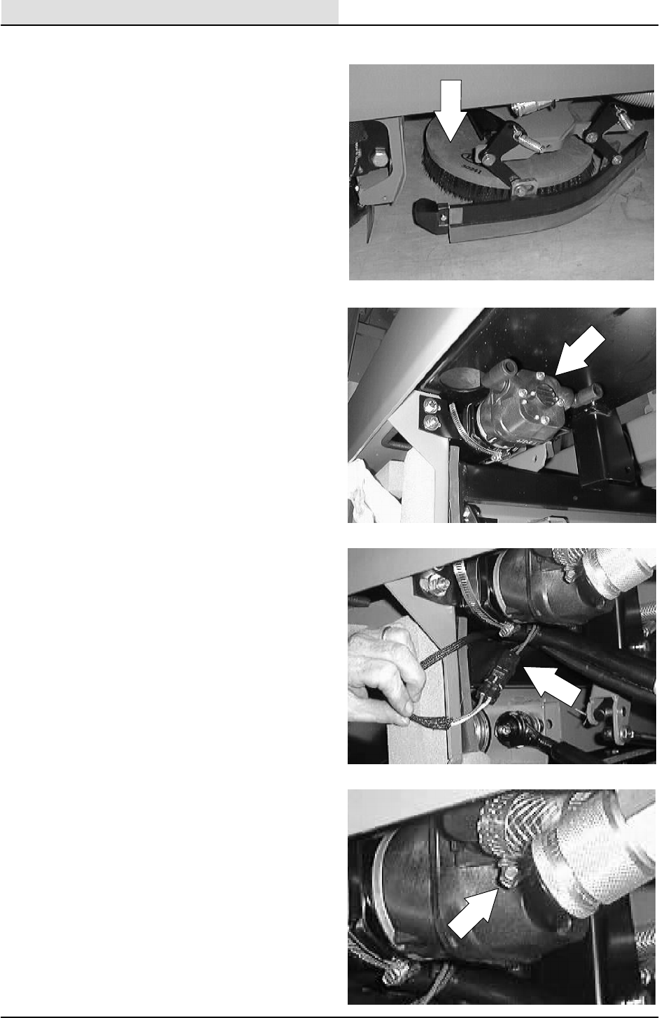
ELECTRICAL
5-30 8200/8210 330065 (3--01)
TO REPLACE EStPUMP
1. Start the machine and lower the scrub head.
Shut off the machine.
FOR SAFETY: Before Leaving Or
Servicing Machine; Stop On Level
Surface, Set Parking Brake.
2. Locate the EStpump on the left hand side
of the machine, under the machine frame,
behind the left side main brush door.
3. Disconnect the EStpump from the main
electrical harness.
4. Loosen the worm drive clamps holding the
two solution hoses leading to the ESt
pump. Remove the hoses from the pump.
NOTE: Make sure to note which hose goes to
what fitting.
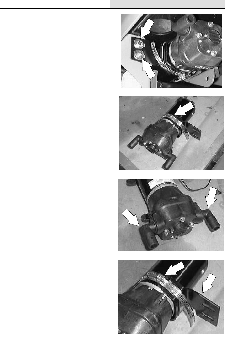
ELECTRICAL
5-31
8200/8210 330065 (3--02)
5. Remove the two hex screws holding the
EStpump and mount bracket to the
machine frame. Remove the pump from the
machine.
6. Remove the worm drive clamp holding the
mount bracket to the EStpump.
NOTE: Remove and retain the mount bracket.
NOTE: Make sure the new pump has the correct
fittings in the same orientation.
7. Install the mount bracket on the new ESt
pump in the same orientation as it was
removed. Tighten the worm drive clamp.
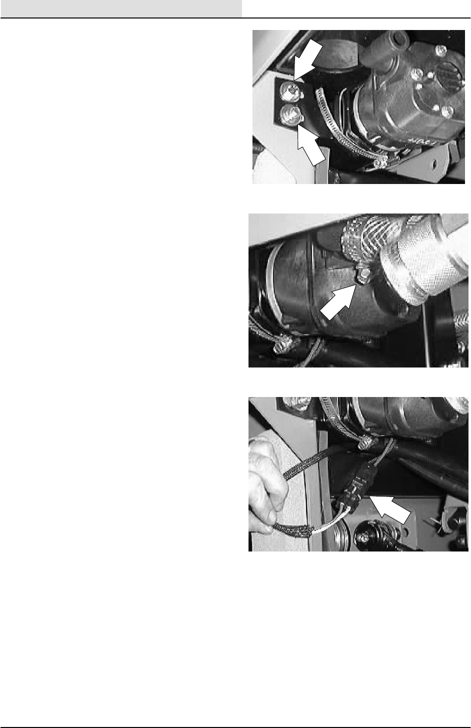
ELECTRICAL
5-32 8200/8210 330065 (3--01)
8. Install the new pump and mount bracket
assembly in the machine. Reinstall the two
hex screws and tighten to 18 -- 24 Nm
(15 -- 20 ft lb).
9. Reconnect the two solution hoses to the
new EStpump. Tighten the worm drive
clamps.
NOTE: Make sure the hoses are installed on the
correct fitting.
10. Connect the new EStpump to the main
harness.
11. Start the machine and operate the ESt
pump. Check for proper operation.
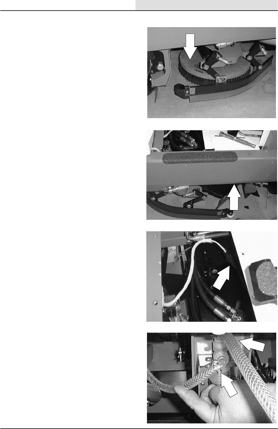
ELECTRICAL
5-33
8200/8210 330065 (3--01)
TO REPLACE DETERGENT PUMP
1. Start the machine and lower the scrub head.
Shut off the machine.
FOR SAFETY: Before Leaving Or
Servicing Machine; Stop On Level
Surface, Set Parking Brake.
2. Locate the detergent pump on the right hand
side of the machine, under the operator
compartment, behind the right side main
brush door.
3. Disconnect the detergent pump from the
main electrical harness.
4. Loosen the worm drive clamps holding the
two hoses leading to the detergent pump.
Remove the hoses from the pump.
NOTE: Make sure to note which hose goes to
what port.
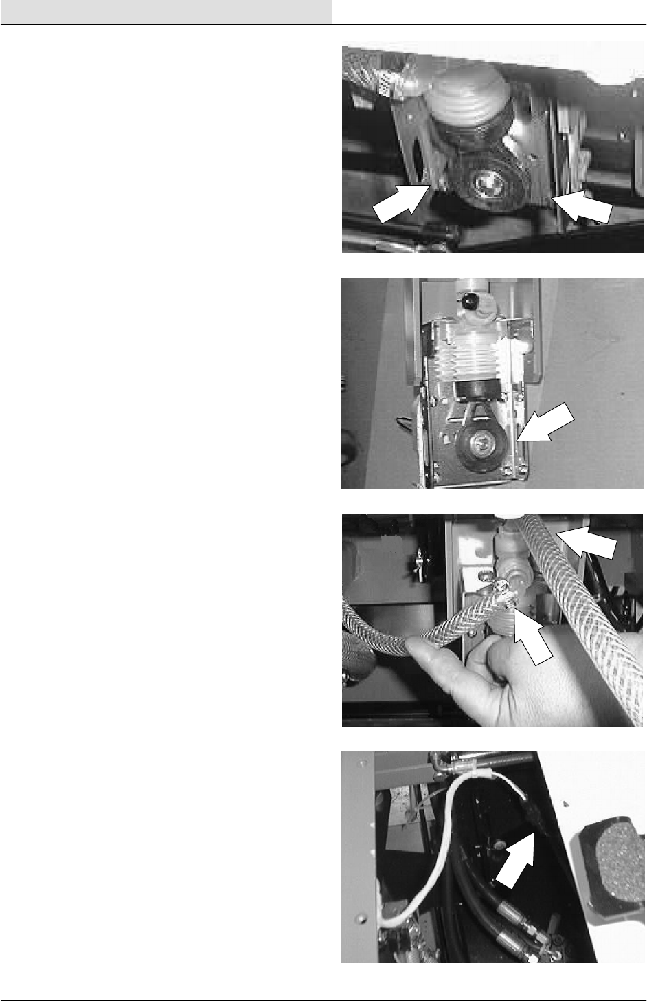
ELECTRICAL
5-34 8200/8210 330065 (3--01)
5. Remove the two hex screws holding the
detergent pump assembly to the mount
bracket. Remove the pump assembly from
the machine.
6. Install the new pump assembly on the mount
bracket. Reinstall the two hex screws and
nuts. Hand tighten.
7. Reconnect the two hoses to the new
detergent pump. Tighten the worm drive
clamps.
NOTE: Make sure the hoses are installed on the
correct ports.
8. Connect the new detergent pump to the
main harness.
9. Start the machine and operate the detergent
pump. Check for proper operation.

ELECTRICAL
5-35
8200/8210 330065 (3--02)
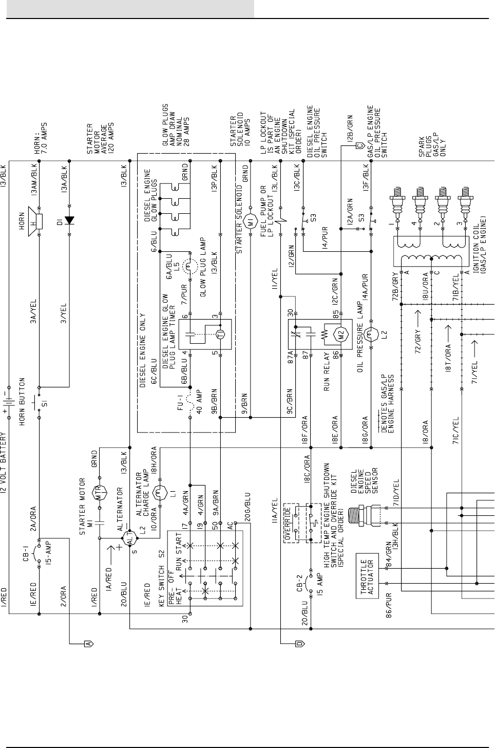
ELECTRICAL
5-36 8200/8210 330065 (3--02)
ELECTRICAL SCHEMATIC
351556 -- ALL
1
2
3
4
5
6
7
8
9
10
11
12
13
14
15
16
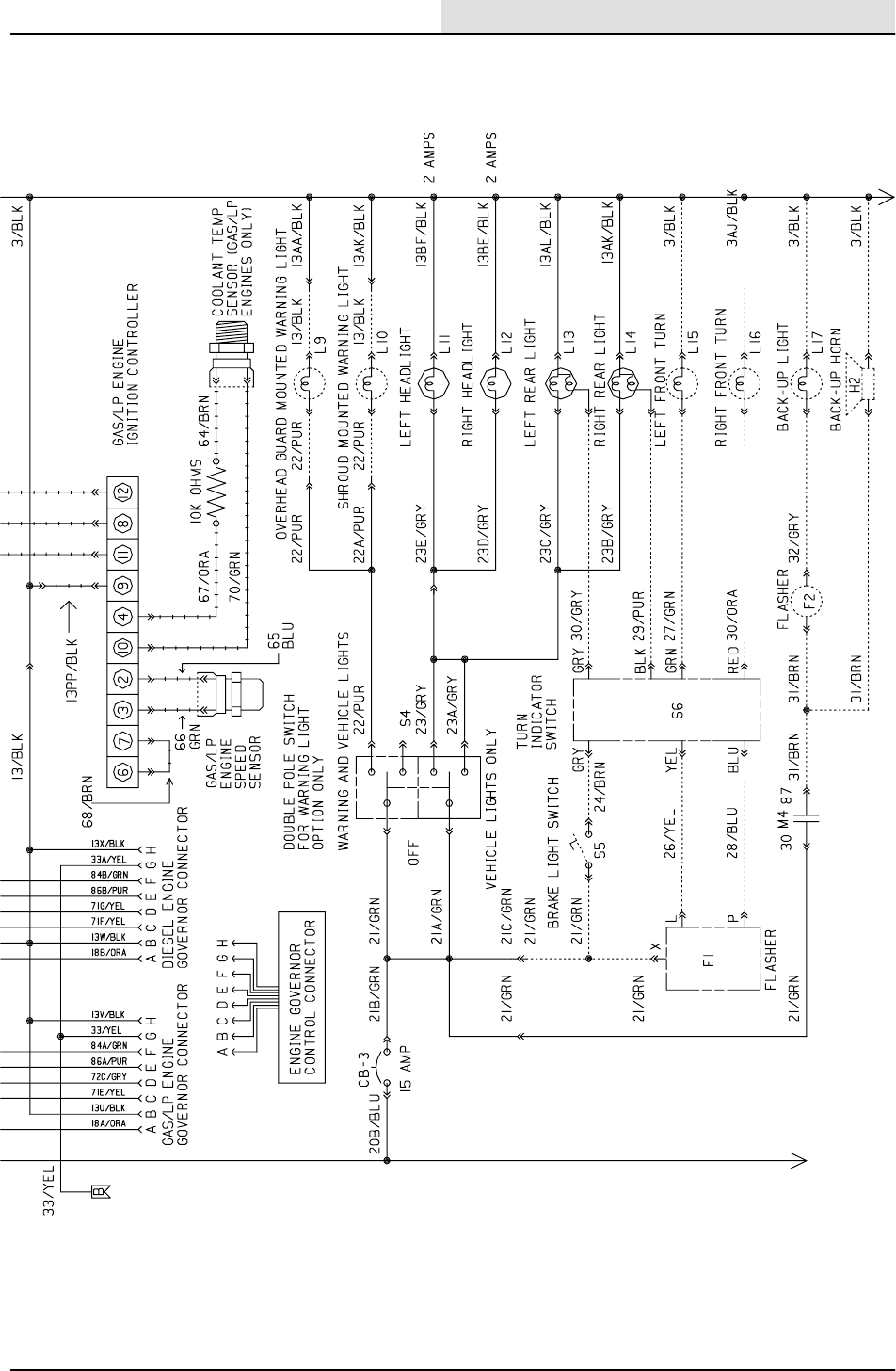
ELECTRICAL
5-37
8200/8210 330065 (3--02)
ELECTRICAL SCHEMATIC
351556 -- ALL
1
2
3
4
5
6
8
9
10
11
12
13
14
15
16
7
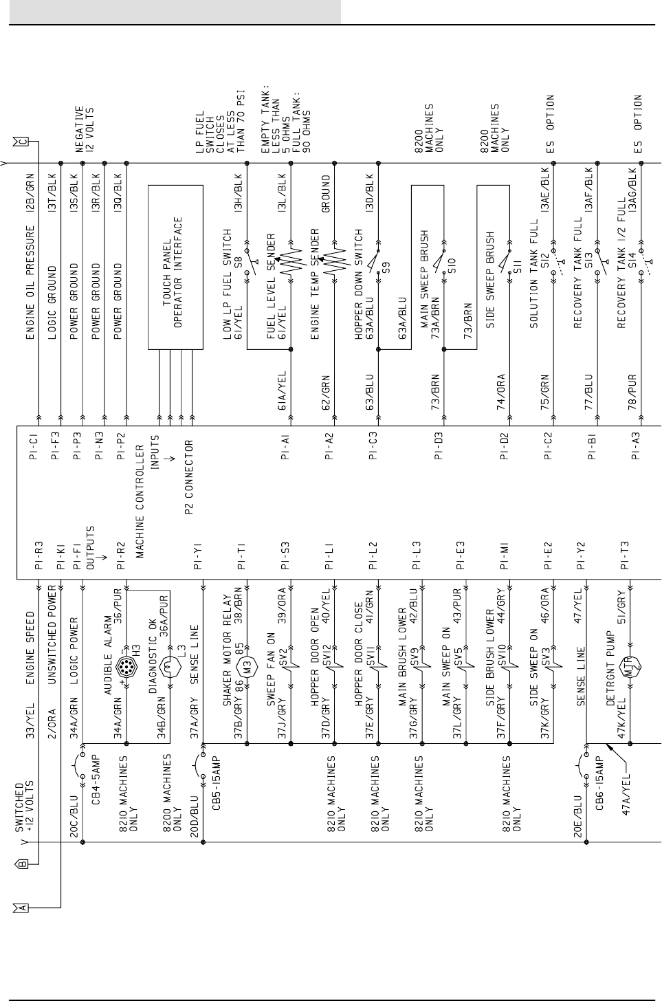
ELECTRICAL
5-38 8200/8210 330065 (3--02)
ELECTRICAL SCHEMATIC
351556 -- ALL
1
2
3
4
5
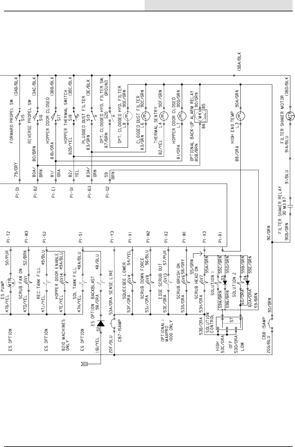
ELECTRICAL
5-39
8200/8210 330065 (3--02)
ELECTRICAL SCHEMATIC
351556 -- ALL
1
2
3
4
5
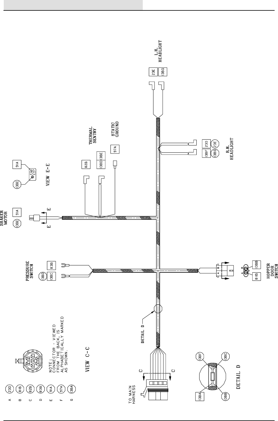
ELECTRICAL
5-40 8200/8210 330065 (3--02)
HOPPER WIRE HARNESS DIAGRAM
351644 -- ALL
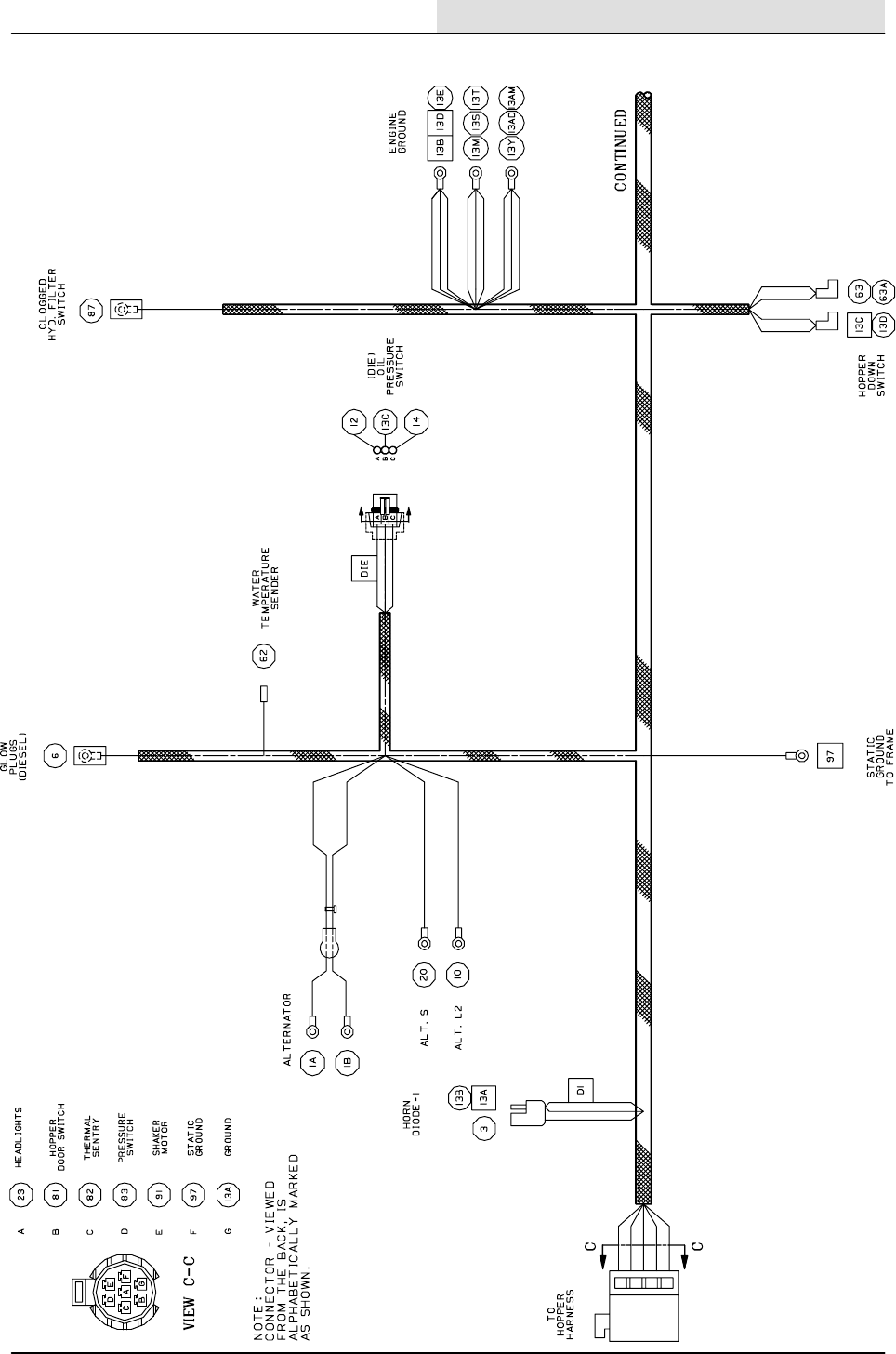
ELECTRICAL
5-41
8200/8210 330065 (3--02)
MAIN WIRE HARNESS DIAGRAM
351645 -- ALL
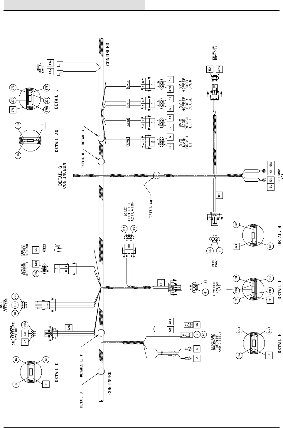
ELECTRICAL
5-42 8200/8210 330065 (3--02)
MAIN WIRE HARNESS DIAGRAM
351645 -- ALL
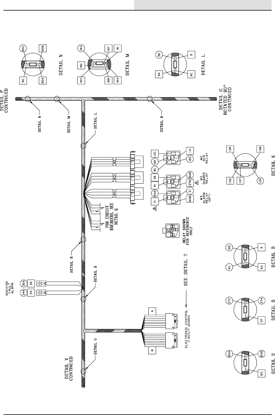
ELECTRICAL
5-43
8200/8210 330065 (3--02)
MAIN WIRE HARNESS DIAGRAM
351645 -- ALL
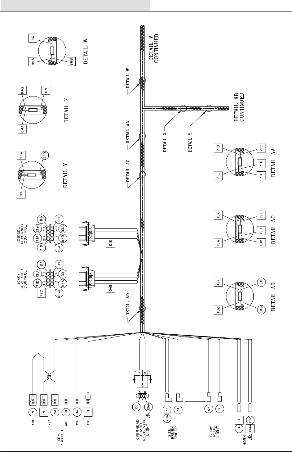
ELECTRICAL
5-44 8200/8210 330065 (3--02)
MAIN WIRE HARNESS DIAGRAM
351645 -- ALL
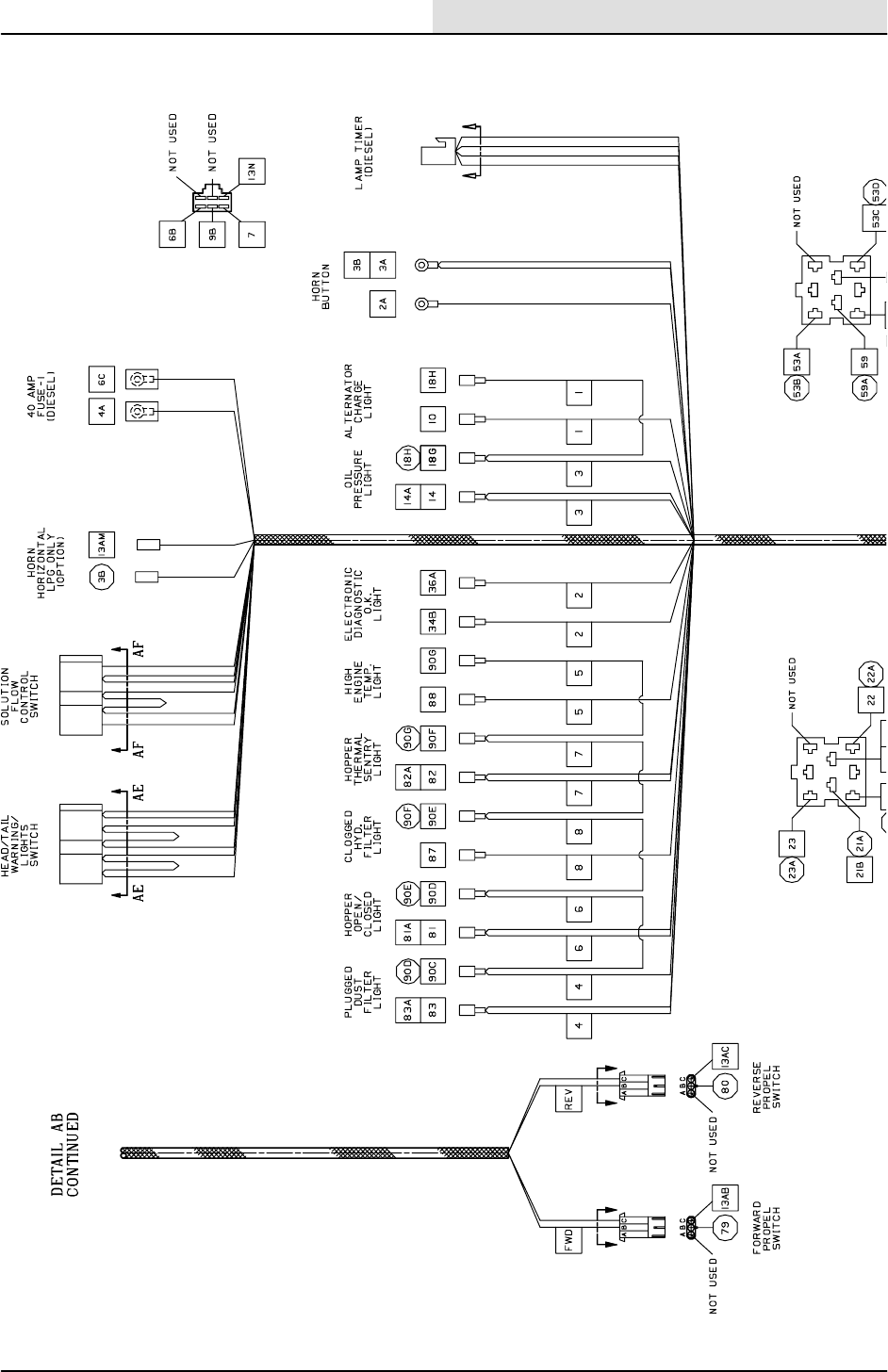
ELECTRICAL
5-45
8200/8210 330065 (3--02)
MAIN WIRE HARNESS DIAGRAM
351645 -- ALL
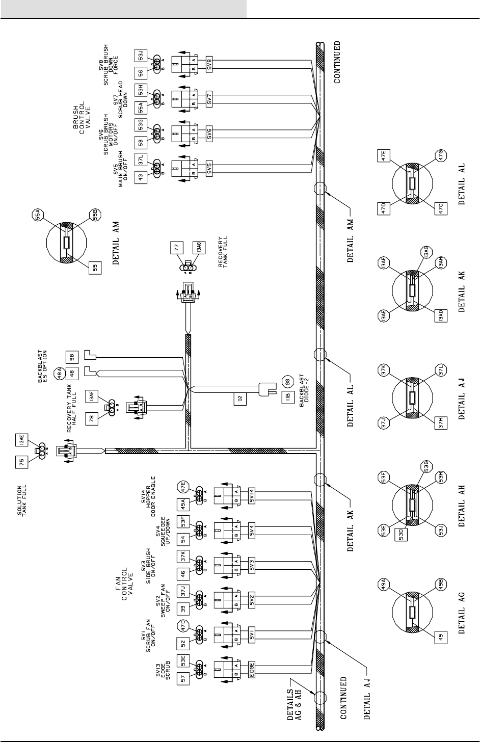
ELECTRICAL
5-46 8200/8210 330065 (3--02)
MAIN WIRE HARNESS DIAGRAM
351645 -- ALL

ELECTRICAL
5-47
8200/8210 330065 (3--02)
MAIN WIRE HARNESS DIAGRAM
351645 -- ALL
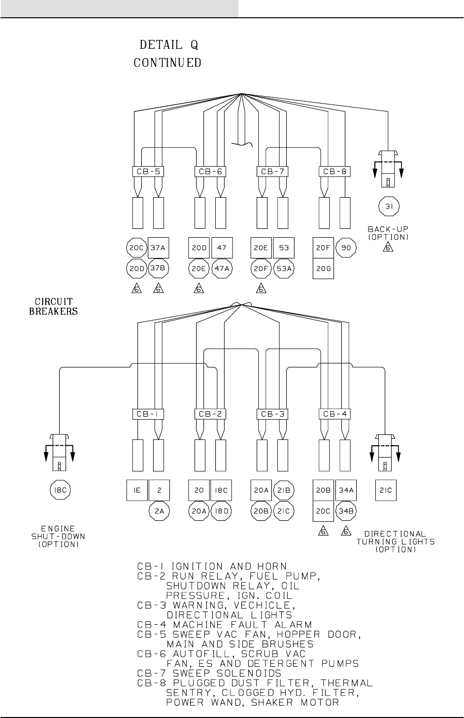
ELECTRICAL
5-48 8200/8210 330065 (3--02)
MAIN WIRE HARNESS DIAGRAM
351645 -- ALL
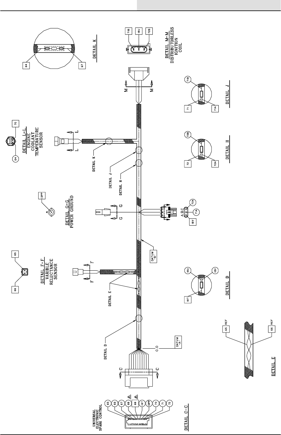
ELECTRICAL
5-49
8200/8210 330065 (3--02)
GAS/LP ENGINE WIRE HARNESS DIAGRAM (000000 -- 006451)
351681 -- G,LP
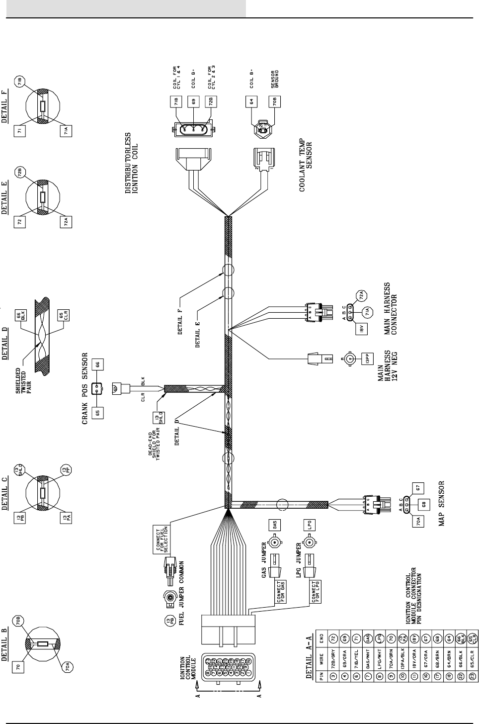
ELECTRICAL
5-50 8200/8210 330065 (3--02)
GAS/LP ENGINE WIRE HARNESS DIAGRAM (006452 -- )
353647 -- G,LP

ELECTRICAL
5-51
8200/8210 330065 (3--01)
DIAGNOSTICS--8200
The Model 8200 has an on--board diagnostic
system.
The first part of the diagnostics section describes
the different operating modes that can be
activated by using an entry sequence on the dash
panel. There is also a chart describing the normal
mode messages that may appear on the dash
panel.

ELECTRICAL
5-52 8200/8210 330065 (3--01)
OPERATING MODES
When the operator turns on the ignition key on the
8200, the control panel will perform a self test. If
the self test passes, the ”OK” light will turn on.
The 8200 front panel has 6 operating modes. The
user can access each mode by depressing
various control buttons, holding them, and turning
on the key. The common operating modes are as
follows:
Operating Modes Entry Sequence
(how to activate)
Indicator
Normal Mode;
Normal operation.
More info pages 5--52 thru 5--56
Default (when key is turned on)
To exit----turn off key
DNone
Manual Mode; Manually operate
discrete functions without inter-
locks.
More info pages 5--57 and 5--58
1. Push and hold the EStbutton
2. Turn on the key
3. Hold the button for 15 seconds
4. Release the EStbutton
5. To exit----turn off key
DGas gauge 2 LED (second
from left of gas gauge) blinking.
Input Display Mode; Display the
state of floats, limit switches, and
sensors.
More info page 5--59
1. Push and hold the Scrub
button
2. Turn on the key
3. Hold the Scrub button for 15
seconds
4. Release the Scrub button
5. To exit----turn off key
DGas gauge 3 LED (third from
left of gas gauge) blinking.
Error Display Mode; Display the
cause of a self test failure.
More info page 5--60
1. Push and hold the Detergent
button
2. Turn on the key
3. Hold the Detergent button for
15 seconds
4. Release the Detergent button
5. To exit----turn off key
DGas gauge 1 LED (far left gas
gauge LED) blinking.
Pressure Adjust Mode; Adjust
pressure levels for the three
down pressure settings.
More info page 5--61
1. Push and hold the Edge Scrub
button
2. Turn on the key
3. Hold the Edge Scrub button
for 15 seconds
4. Release the Edge Scrub
button
5. To exit----turn off key
DEdge scrub LED’s blinking.
Reset Scrub Pressures; Return
the down pressure settings to the
factory defaults.
More info page 5--62
1. Push and hold the Fan button
2. Turn on the key
3. Hold the Fan button for
15 seconds (down press lights
will start to blink)
4. While holding the Fan button,
press the Edge Scrub button
(down pressure lights will stop
blinking)
5. Release the Fan and Edge
Scrub buttons (down pressure
lights may begin blinking again)
6. Turn off key
7. Restart the machine
DNone

ELECTRICAL
5-53
8200/8210 330065 (3--01)
INTERLOCKS
The operator can start and stop the various
functions of the 8200 using a variety of switch
closures and interlocks. What follows are two
tables for each of the basic functions. One table
lists the action that are required for the basic
function to be running. The other table lists the
actions that would prevent the operation from
running. If the operator satisfies all of the
requirements from the first table, and none of the
situations of the second table exist, the operator
could expect the function to operate.
SCRUB BRUSH OPERATION ENABLED
Scrub brush operation enabled by: Indicator
DScrub button DOne or more scrub pressure
LED’s are on
DForward propel DForward limit switch engaged
SCRUB BRUSH OPERATION INHIBITED
Scrub brush operation inhibited by: Indicator
DScrub button DAll scrub pressure LED’s are off
DNeutral or Reverse DForward limit switch disengaged
DFull recovery tank DRecovery tank full LED on
SQUEEGEE AND VACUUM FAN
OPERATION ENABLED
Squeegee operation enabled by: Indicator
DScrub button or Squeegee button DSqueegee LED is on
DForward or Neutral DReverse limit switch disengaged
SQUEEGEE AND VACUUM FAN
OPERATION INHIBITED
Squeegee operation inhibited by: Indicator
DScrub button or Squeegee button DSqueegee LED is off
DReverse DReverse limit switch engaged
DFull recovery tank DRecovery tank full LED blinking
EStPUMP OPERATION ENABLED
EStpump operation enabled by: Indicator
DEStbutton DEStLED is on
DEStfloat covered, or ESt
30 second timer running. The
ESt30 second timer starts when
the EStpump brings the solution
level below the EStfloat.
DNone

ELECTRICAL
5-54 8200/8210 330065 (3--01)
EStPUMP OPERATION INHIBITED
EStpump operation inhibited by: Indicator
DEStbutton DEStLED is off
DMore than 30 seconds has passed
since the EStfloat has become
uncovered
DNone
DSolution Tank Full float covered for
more than 5 seconds
DNone
SWEEP BRUSH OPERATION ENABLED
Sweep brush operation enabled by: Indicator
DSweep limit switch DSweep lever in down position
SWEEP BRUSH OPERATION INHIBITED
Sweep brush operation inhibited by: Indicator
DSweep limit switch DSweep lever in up position
DHopper down switch DHopper up
SWEEP FAN OPERATION ENABLED
Sweep fan operation enabled by: Indicator
DSweep limit switch DSweep lever in down position,
Fan LED will turn on
SWEEP FAN OPERATION INHIBITED
Sweep fan operation inhibited by: Indicator
DSweep limit switch DSweep lever in up position
DPressing the Fan button DFan LED off
DHopper down switch DHopper up
DHopper Thermal Sentryt D Hopper temperature light
DShaker operation DShaker LED on
SIDE BRUSH OPERATION ENABLED
Side brush operation enabled by: Indicator
DSweep limit switch,
Side brush limit switch
DSweep and Side brush levers
must be in down position
SIDE BRUSH OPERATION INHIBITED
Side brush operation inhibited by: Indicator
DSweep limit switch DSweep lever in up position
DSide brush limit switch DSide brush lever in up position
DHopper down switch DHopper up
DHopper Thermal Sentry DHopper temperature light

ELECTRICAL
5-55
8200/8210 330065 (3--01)
EStAIR FLUSH OPERATION ENABLED
EStAir flush valve enabled by: Indicator
DEStbutton, Squeegee button,
and oil pressure
DEStand squeegee LED’s on
DEStAir flush valve will open for a
5 second period, at a 45 second
interval if both EStand squeegee
are enabled
DNone
DEngine on and oil pressure DOil pressure light on
EStAIR FLUSH OPERATION INHIBITED
EStAir flush valve inhibited by: Indicator
DEStbutton, squeegee button DEStor squeegee LED is off
DEngine off and no oil pressure DOil pressure light off
RECOVERY TANK AUTOFILL VALVE ENABLED
Recovery tank autofill valve enabled by: Indicator
DEStfloat in down position DNone
DMachine in neutral DNone
DEngine off DOil pressure light on
RECOVERY TANK AUTOFILL VALVE DISABLED
Recovery tank autofill valve disabled by: Indicator
DEStfloat in up position DNone
DMachine in forward or reverse DForward or reverse switches
engaged
DEngine on DOil pressure light off
SOLUTION TANK AUTOFILL VALVE ENABLED
Solution tank autofill valve enabled by: Indicator
DSolution tank full float in down
position
DNone
DMachine in neutral DNone
DEngine off DOil pressure light on
SOLUTION TANK AUTOFILL VALVE DISABLED
Solution tank autofill valve disabled by: Indicator
DSolution tank full float in up
position
DNone
DMachine in forward or reverse DForward or reverse switches
engaged
DEngine on DOil pressure light off

ELECTRICAL
5-56 8200/8210 330065 (3--01)
Operating Mode Entry Sequence
(how to activate)
Indicator
Normal Mode;
Normal operation.
Default (when key is turned on)
To exit----turn off key
DNone
NORMAL MODE (front panel)
The purpose of the normal mode is for the general
operation of the machine. The machine will
normally start in this mode. What follows is a brief
description of each of the operations in the normal
mode.
EDGE SCRUB BUTTON
Pressing the Edge Scrub button will toggle the
Edge Scrub LED.
If the machine is propelling forward in the scrub
mode and the Edge Scrub LED is on, the scrub
head will shift into the edge scrub position. If the
Edge scrub LED is off, the scrub head will return
to the retracted position.
SQUEEGEE
If the squeegee LED is off and the machine is not
in reverse, pressing the squeegee button will drop
the squeegee and turn on the vacuum fan.
If the squeegee LED is on, pressing the squeegee
button will raise the squeegee, initiate a delay,
and turn off the vacuum fan. Squeegee operation
is inhibited in reverse.
ENGINE SPEED
If the engine is at idle speed, pressing this button
will bring it to operating speed. If the scrub mode
is active, pressing the engine button will cancel all
scrubbing activities.
If the squeegee is down, pressing the engine
button will raise the squeegee and turn off the
scrub vacuum fan.

ELECTRICAL
5-57
8200/8210 330065 (3--01)
SCRUB
If the scrub function is currently inactive, pressing
the scrub button will initiate the following actions:
1. The engine speed is set high.
2. If the machine is propelling forward, the
main brushes will turn on and go down. The
down pressure setting will be the same used
during the last scrub cycle. The solution will
flow at the high or low rate according to the
water position switch.
3. If the machine is in reverse, the brushes will
stay up and off.
4. If the machine goes into neutral, the brushes
will stay on for a short delay, then shut off
and retract.
5. If the Edge Scrub LED is on and the
machine is propelling forward, the scrub
head will go into the edge scrub position.
6. The scrub vacuum fan will turn on.
7. If the machine is not in reverse, the
squeegee will go down.
8. If the machine is in reverse, the squeegee
will stay up until reverse is no longer sensed.
9. If any of the detergent LED’s are active, and
the machine is propelling forward, the
detergent pump will run. The detergent
pump will run at its slow rate if one LED is
on. The detergent pump will run at its fast
rate if two LED’s are on.

ELECTRICAL
5-58 8200/8210 330065 (3--01)
SCRUB (cont...)
If the operator pushes and holds the scrub button,
the pressure settings will begin to scroll. The
pressure setting displayed after releasing the
scrub button will become the new default down
pressure setting.
If the scrub function was active and the operator
pushes, then releases the scrub button, the
following actions will take place:
1. The main brushes will turn off and rise.
2. The edge scrub will retract.
3. The solution flow will turn off.
4. The detergent pump will turn off.
5. A seven second delay will pass, then the
squeegee will rise.
6. A four second delay will pass and the
vacuum fan will turn off.
DETERGENT
Pressing the detergent button will toggle the
function on and off. Holding the detergent button
will cause the display to scroll through its two
speeds. The detergent pump will run only if the
main scrub brushes are active and the solution
switch is on.
1. Off (all LED’s off)------detergent pump off.
2. Low (left LED on)--------detergent pump low.
3. High (both LED’s on)----detergent pump high
ESt
Pressing the EStbutton will enable or disable
the EStfunction. In order for the EStfloat to
become active, it must be consistently in the up
position for at least 10 seconds. If the ESt
function is enabled and the EStfloat becomes
active, the following action will occur:
1. The EStpump will begin to run.
2. The EStpump will continue to run for
30 seconds after the EStfloat becomes
uncovered, or until the solution tank
becomes covered.

ELECTRICAL
5-59
8200/8210 330065 (3--01)
OVER--FLOW
In order for the recovery tank float to become
active, it must be consistently in the up position
for at least 10 seconds. If the scrub or vacuum fan
are active and the tank full float becomes active,
the overflow light will come on and the scrub and
squeegee functions will be canceled. The overflow
light will not turn off by simply emptying the
recovery tank. The scrub or squeegee buttons
must be pressed, or the key switch must be
cycled.
NORMAL MODE (side panel)
The purpose of the normal mode is for the general
operation of the machine. The machine will
normally start in this mode. What follows is a brief
description of each of the operations in the normal
mode.
MAIN SWEEP BRUSH
The main brush is engaged by a limit switch that
senses the position of the brush handle. Engaging
the main sweep brush also engages the sweep
vacuum fan. The operator can cancel the vacuum
fan using the panel switch.
SIDE SWEEP BRUSH
The side brush is engaged by two limit switches
that sense the positions of the side and main
brush handles. When both of these handles are
engaged, the side brush will turn on.
FILTER SHAKER
The Filter Shaker button controls the operation of
the filter shaker and timer system.
DIf the filter shaker LED is off, pressing the
shaker button will initiate a shake sequence. A
shake sequence is defined as follows:
1. The Shaker LED will turn on.
2. The filter shaker will start.
3. The filter shaker and LED will remain on for
approximately 30 seconds.
4. The filter shaker and LED will turn off.
5. If the sweep fan is active, the fan will shut
off during the shake cycle.
DIf the Filter shaker LED is on, pressing the
shaker button will turn off the Shaker motor and
LED.

ELECTRICAL
5-60 8200/8210 330065 (3--01)
VACUUM FAN
Pressing the sweep vacuum fan button will enable
or disable the fan operation while sweeping.
DThe fan is inhibited if the shaker is active.
DEach time the sweep function is engaged, the
fan will be enabled.
DEach time the sweep function is turned off, the
fan will be canceled.
MAINTENANCE MODES
Each time the operator turns on the machine, the
front panel will run an automatic self check. If the
front panel passes its self test, the OK light will
turn on.
The 8200 front panel has a total of six operating
modes. When the operator starts the machine,
the panel will run its self test, then return to the
normal operating mode. The operator can access
five maintenance modes by turning the machine
off, pressing and holding the appropriate button,
turning the machine on, and holding the button for
about 15 seconds.
The following pages include brief descriptions of
how to enter each of the maintenance modes, and
how the machine will function in that mode.

ELECTRICAL
5-61
8200/8210 330065 (3--01)
Operating Mode Entry Sequence
(how to activate)
Indicator
Manual Mode; Manually operate
discrete functions without
interlocks.
1. Push and hold the EStbutton
2. Turn on the key
3. Hold the button for 15 seconds
4. Release the EStbutton
5. To exit----turn off key
DGas gauge 2 LED (second
from left of gas gauge) blinking.
MANUAL MODE
In this mode, the operator can turn on and off
accessories individually and manually. In the
manual mode, the operator can turn on
accessories without regard to inputs or interlocks.
If, for instance, the operator enables the ESt
pump in the manual mode, it will run regardless of
whether or not the EStfloat is in the water.
DTO INITIATE:
1. Turn off the machine.
2. Press and hold the EStbutton.
3. Turn on the machine.
4. Hold the EStbutton for 15 seconds.
5. Release the EStbutton.
GOPERATION:
hESt:Pressing the EStbuttoninthe
manual mode turns on and off
the EStpump. The air flush valve will turn
on and off at 5 second intervals if the oil
pressure light is off.
hEDGE SCRUB BUTTON: Pressing the
Edge Scrub button will extend or retract the
scrub head.
hSQUEEGEE BUTTON: Pressing the
Squeegee button will turn on the vacuum fan
and lower the squeegee. Reverse is ignored.
hENGINE BUTTON: Pressing the Engine
button will toggle the engine between high
and low speed.
Continued on next page.....

ELECTRICAL
5-62 8200/8210 330065 (3--01)
Continued from previous page....
GOPERATION:
hSCRUB BUTTON: Pressing the Scrub
button will turn on and lower the main scrub
head. Holding the Scrub button while scrub
is active will cause the down pressures to
scroll.
hDETERGENT BUTTON: Pressing the
Detergent button will cause the detergent
LED’s to scroll. If no LED’s are on, the
detergent pump will be off. If one LED is
illuminated, the detergent pump will run in
low speed If both LED’s are on, the
detergent pump will run in high speed.
hFAN BUTTON: Pressing the Fan button
will turn on the sweep fan regardless of the
hopper down or the hopper fire switches.
hSHAKE BUTTON: Pressing the Shake
button will turn on the shaker.

ELECTRICAL
5-63
8200/8210 330065 (3--01)
Operating Mode Entry Sequence
(how to activate)
Indicator
Input Display Mode; Display the
state of floats, limit switches, and
sensors.
1. Push and hold the Scrub
button
2. Turn on the key
3. Hold the Scrub button for 15
seconds
4. Release the Scrub button
5. To exit----turn off key
DGas gauge 3 LED (third from
left of gas gauge) blinking.
INPUT DISPLAY MODE
In this mode, the operator can observe whether or
not inputs to the panel are operating as intended.
In the Input display mode, the LED’s on the
instrument panel display the state of each input. If
an input is open, the controller turns off the LED
associated with that input. If an input is shorted to
ground, the controller turns on the LED
associated with that input.
DTO INITIATE:
1. Turn off the machine.
2. Press and hold the Scrub button.
3. Turn on the machine.
4. Hold the Squeegee button until the gas
gauge light #3 (3rd from left) begins to blink.
5. Release the Scrub button.
PANEL LED INPUT SIGNAL
EStLED EStFLOAT
OVERFLOW LED FULL RECOVERY TANK
LEFT BRUSH PRESSURE LED REVERSE
RIGHT BRUSH PRESSURE LED FORWARD
SHAKER LED PLUGGED DUST FILTER
FAR LEFT GAS GAUGE LED SIDE BRUSH LIMIT SWITCH
SECOND GAS GAUGE LED FROM LEFT MAIN SWEEP LIMIT SWITCH
FAR LEFT DETERGENT LED SOLUTION FULL FLOAT
FAR RIGHT DETERGENT LED SOLUTION FLOW SWITCH
FAR RIGHT GAS LED HOPPER DOWN SWITCH
SWEEP FAN LED HOPPER THERMAL SENTRYt

ELECTRICAL
5-64 8200/8210 330065 (3--01)
Operating Mode Entry Sequence
(how to activate)
Indicator
Error Display Mode; Display the
cause of a self test failure.
1. Push and hold the Detergent
button
2. Turn on the key
3. Hold the Detergent button for
15 seconds
4. Release the Detergent button
5. To exit----turn off key
DGas gauge 1 LED (far left gas
gauge LED) blinking.
ERROR DISPLAY MODE
Each time the operator starts the machine, the
panel will run a self test on each output. If the
panel passes the diagnostic, the OK indicator is
illuminated. If the panel fails, a code is stored. In
the Error Display Mode, the operator can obtain
the error code stored after the last startup
diagnostic failure. When the machine is in this
mode, the LED’s on the operator’s panel will
indicate which system experienced the failure.
The operator should then unplug the offending
device, and cycle the key switch on the machine.
If the OK light now comes on, it is likely that the
device that was unplugged was shorted.
DTO INITIATE:
1. Turn off the machine.
2. Press and hold the Detergent button.
3. Turn on the machine.
4. Hold the Detergent button for 15 seconds.
5. Release the Detergent button.
DIAGNOSTIC FAILURE PANEL LED
SOLUTION FILL/BACK FLUSH VALVES LEFT DETERGENT LED
RECOVERY TANK FILL/HOPPER
DOOR ENABLE VALVES
OVERFLOW LED
SWEEP FAN VALVE SWEEP FAN LED
SHAKER MOTOR RELAY SHAKER LED
EStPUMP DRIVE EStLED
DETERGENT PUMP DRIVE RIGHT DETERGENT LED
SCRUB BRUSH VALVE LEFT SCRUB PRESSURE LED
SCRUB BRUSH PRESSURE VALVE CENTER SCRUB PRESSURE LED
SCRUB FAN VALVE LEFT ENGINE SPEED LED
SQUEEGEE VALVE SQUEEGEE LED
EDGE SCRUB VALVE EDGE LED
SCRUB BRUSH DOWN VALVE RIGHT SCRUB PRESSURE LED

ELECTRICAL
5-65
8200/8210 330065 (3--01)
Operating Mode Entry Sequence
(how to activate)
Indicator
Pressure Adjust Mode; Adjust
pressure levels for the three
down pressure settings.
1. Push and hold the Edge Scrub
button
2. Turn on the key
3. Hold the Edge Scrub button
for 15 seconds
4. Release the Edge Scrub
button
5. To exit----turn off key
DEdge scrub LED’s blinking.
PRESSURE ADJUST MODE
When the machine is in this mode, the operator
can adjust the down pressures for the main brush.
The operator may make independent adjustments
to pressures 1, 2, and 3. The operator can change
the pressure settings by pressing and holding the
scrub button. After each adjustment, the new
pressure setting is stored in non--volatile (retained
even after power down) memory.
DTO INITIATE:
1. Turn off the machine.
2. Press and hold the Edge Scrub button.
3. Turn on the machine.
4. Hold the Edge Scrub button for 15 seconds,
until the maintenance light comes on.
5. Release the Side brush button. The Edge
LED will start to blink.
GSCRUB BUTTON:
Pressing the Scrub button will start the
normal scrub sequence. When scrub is
active, the following controls and displays
take on alternate functions:
hGAS GAUGE: For the pressure adjust
mode, the gas gauge displays the current to
the down pressure valve. Gas gauge LED’s
1, 2, and 3 correspond to factory settings for
normal down pressures.
hSQUEEGEE BUTTON: Holding the
squeegee button will decrease the down
pressure.
hDETERGENT BUTTON: Holding the
detergent button will increase the
down pressure.

ELECTRICAL
5-66 8200/8210 330065 (3--01)
Operating Mode Entry Sequence
(how to activate)
Indicator
Reset Scrub Pressures; Return
the down pressure settings to the
factory defaults.
1. Push and hold the Fan button
2. Turn on the key
3. Hold the Fan button for 15
seconds (down press lights will
start to blink)
4. While holding the Fan button,
press the Edge Scrub button
(down pressure lights will stop
blinking)
5. Release the Fan and Edge
Scrub buttons
6. Turn off key
7. Restart the machine
DNone
RESET SCRUB PRESSURE
When the machine goes into this mode, the
controller replaces the current brush down
pressure settings with factory defaults.
DTO INITIATE:
1. Turn off the machine.
2. Press and hold the Sweep Fan button.
3. Turn on the machine.
4. Hold the Sweep Fan button for 15 seconds.
5. Release the Fan and Edge scrub buttons.

ELECTRICAL
5-67
8200/8210 330065 (3--01)
DIAGNOSTICS--8210
The Model 8210 has an on--board diagnostic
system.
The first part of the diagnostics section describes
the different operating modes that can be
activated by using an entry sequence on the dash
panel. There is also a chart describing the normal
mode messages that may appear on the dash
panel.

ELECTRICAL
5-68 8200/8210 330065 (3--01)
OPERATING MODES
The sweep and scrub functions of the 8210 are
controlled using a touch panel with two dedicated
buttons, and 6 multi--function buttons. The
multi--function buttons surround a graphics display
panel. Images on the display panel identify the
current function of the six buttons.
The intent of the system is to offer one button
sweeping and scrubbing, while reducing the
number of controls confronting the operator. This
is accomplished by using multi--function buttons.
This system is designed to offer the operator
control of the functions which are appropriate for
the current task. An example would be the
operation of the hopper door. If the operator is
sweeping, the hopper door will automatically
open. It would be inappropriate for the operator to
close the door while sweeping, so none of the
multi--function switches are assigned to the
hopper door. If the operator lifts the hopper
(presumably to dump), the operator needs to have
control of the hopper door. The door icon will
appear on the screen, and one of the six
multi--function switches will be assigned the
function of opening or closing the door.
The 8210 has 5 operating, and 7 maintenance
modes. The operating modes are engaged using
the 6 multi--function buttons. The button which is
inside the Tennant logo (logo button) will scroll the
machine through the various operating modes
without engaging any functions. The maintenance
modes are enabled buy pressing the logo button,
turning on the machine, waiting 15 seconds, and
releasing the logo button. Maintenance modes
can then be chosen using the multi--function
buttons.

ELECTRICAL
5-69
8200/8210 330065 (3--01)
FRONT PANEL OPERATING MODES
OPERATING MODE ENTRY SEQUENCE FUNCTIONS
AVAILABLE
DESCRIPTION
DIDLE MODE 1. This is the mode in
which the panel will
normally power up.
1. Scrub
2. No function
3. Squeegee
4. Sweep
5. No function
6. No function
This mode gives the
operator the basic,
sweep, scrub, and water
pickup modes.
DSCRUB MODE 1. Pressing the scrub
button from the idle
mode.
2. Pressing the logo
button from the idle
mode.
1. Scrub
2. Edge scrub
3. Squeegee
4. Sweep
5. Detergent metering
6. EStfunction
This mode gives the
operator control of all
scrub functions.
DSWEEP MODE 1. Pressing the sweep
button from the idle
mode.
2. Pressing the logo
button from the scrub
mode.
1. Scrub
2. Filter shaker
3. Squeegee
4. Sweep
5. Side brush
6. Sweep fan
This mode gives the
operator control of all
sweep functions.
DHOPPER UP MODE 1. Lifting the hopper
(releasing the hopper
down switch).
2. Pressing the logo
button from the
sweep mode.
1. Scrub
2. Filter shaker
3. Squeegee
4. No function
5. No function
6. Hopper door
This mode gives the
operator control of the
hopper door.
DSWEEP/SCRUB
MODE
1. Pressing the scrub
button while in the
sweep mode.
2. Pressing the sweep
button while in the
scrub mode.
1. Scrub
2. Edge scrub
3. Squeegee
4. Sweep
5. Side brush
6. Sweep fan
This mode gives the
operator control of the
primary sweep controls,
and the three primary
scrub controls.

ELECTRICAL
5-70 8200/8210 330065 (3--01)
FRONT PANEL MAINTENANCE MODES
MAINTENANCE MODE ENTRY SEQUENCE FUNCTIONS
AVAILABLE
DESCRIPTION
DMAINTENANCE 1
MODE
1. Hold logo key
2. Turn machine on
3. Hold logo key for 15
seconds
4. Release logo key
1. Down pressure reset
2. Down pressure adjust
3. Manual mode
4. No function
5. No function
6. No function
This mode allows the
operator to choose
from the first three
maintenance modes.
DMAINTENANCE 2
MODE
1. Hold logo key
2. Turn machine on
3. Hold logo key for 15
seconds
4. Release logo key
5. Press and release
logo key.
1. Input display mode
2. Enable Edge Scrub
mode
3. Time adjust mode
4. No function
5. No function
6. No function
This mode allows the
operator to choose
from the second three
maintenance modes.
DMAINTENANCE 3
MODE
1. Hold logo key
2. Turn machine on
3. Hold logo key for 15
seconds
4. Release logo key
5. Press and release
logo key 2 times.
1. Self Test mode
2. Check maint. mode
3. Enable maint. mode
4. No function
5. No function
6. No function
This mode allows the
operator to choose
from the last two
maintenance modes,
or exiting to the idle
mode.
DMAINTENANCE 4
MODE
1. Hold logo key
2. Turn machine on
3. Hold logo key for 15
seconds
4. Release logo key
5. Press and release
logo key 3 times.
1. Language select
2. No function
3. No function
4. No function
5. No function
6. Exit to normal mode
Pressing button 1 will
cause the machine to
scroll through the
different language
options. The software
rev level is displayed
near switch 2.
DMANUAL MODE
”MAN” INDICATED
ON GRAPHIC
DISPLAY
Select Manual Mode
from Maintenance 1
screen
Operator can use the
logo button to scroll
through the various
operating modes and
select individual
functions.
Manually operate
discrete functions
without interlocks.

ELECTRICAL
5-71
8200/8210 330065 (3--01)
FRONT PANEL MAINTENANCE MODES
MAINTENANCE MODE ENTRY SEQUENCE FUNCTIONS
AVAILABLE
DESCRIPTION
DINPUT DISPLAY
MODE
Select the Input Display
mode from the
Maintenance 2 screen
Display the state of
floats, limit switches,
and sensors. This mode
enables a special
display that indicates
the various float and
input switch levels. The
operator can operate
the machine in input
display mode by
scrolling to the operating
modes, engaging the
desired functions, and
scrolling back to the
input display mode.
DSELF TEST MODE Select the Self Test
mode from the
maintenance 3 screen
This function tests the
output portion of the
controller board.
DPRESSURE ADJUST
MODE
Select the Pressure
Adjust mode from the
maintenance 1 screen
1. Scrub function
2. No function
3. Squeegee function
4. Increase brush
pressure
5. No function
6. Decrease brush
pressure
Adjust pressure levels
for the three down
pressure settings. The
level of current flowing
to the valve is
represented by a bar
graph on the display.
The neutral head lift
feature is disabled in the
Pressure adjust mode.
DRESET SCRUB
PRESSURES
Select the Reset
function from the
maintenance 1 screen
1. No function
2. Reset down
pressures
3. Do not reset down
pressures, exit
4. No function
5. No function
6. No function
Return the down
pressure settings to the
factory defaults.
Continued on next page...

ELECTRICAL
5-72 8200/8210 330065 (3--01)
FRONT PANEL MAINTENANCE MODES
(continued from previous page)
MAINTENANCE MODE ENTRY SEQUENCE FUNCTIONS
AVAILABLE
DESCRIPTION
DADJUST TIME MODE Select Adjust Time from
the maintenance 2
screen
1. Increment segment
2. Decrement segment
3. Select 24/12 hour
clock
4. Move cursor right
5. Move cursor left
6. No function
Set the on board clock
and calendar.
DCHECK
MAINTENANCE
MODE
Select Check
maintenance from the
maintenance 2 screen
1. No function
2. No function
3. No function
4. Clear maint. timer
5. No function
6. No function
LOGO -- select next
maint. item
Check various
maintenance timers.

ELECTRICAL
5-73
8200/8210 330065 (3--01)
INTERLOCKS:
The operator can start and stop the various
functions of the 8210 using a variety of switch
closures and interlocks. What follows are two
tables for each of the basic functions. One table
lists the action that are required for the basic
function to be running. The other table lists the
actions that would prevent the operation from
running.
NOTE: If the operator satisfies all of the
requirements from the first table, and none of the
situations of the second table exist, the operator
could expect the function to operate.
SCRUB BRUSH OPERATION ENABLED
Scrub brush operation enabled by: Indicator
DScrub button DScrub icon visible with LED illuminated
DForward propel DForward limit switch engaged
SCRUB BRUSH OPERATION INHIBITED
Scrub brush operation inhibited by: Indicator
DScrub button DScrub icon visible with LED extinguished
DNeutral or Reverse DForward limit switch disengaged
DFull recovery tank DRecovery tank full icon visible
SQUEEGEE AND VACUUM FAN OPERATION
ENABLED
Squeegee operation enabled by: Indicator
DScrub button or Squeegee button DSqueegee icon visible with LED illuminated
DForward or Neutral DReverse limit switch disengaged
SQUEEGEE AND VACUUM FAN OPERATION
INHIBITED
Squeegee operation inhibited by: Indicator
DScrub button or Squeegee button DSqueegee icon visible with LED
extinguished
DReverse DReverse limit switch engaged
DFull recovery tank DRecovery Tank full icon visible

ELECTRICAL
5-74 8200/8210 330065 (3--01)
EStPUMP OPERATION ENABLED
EStpump operation enabled by: Indicator
DEStbutton DESticon visible with LED illuminated
DEStfloat covered, or ESt30 second
timer running. The ESt30 second timer
starts when the EStpump brings the
solution level below the EStfloat
DNone
EStPUMP OPERATION INHIBITED
EStpump operation inhibited by: Indicator
DEStbutton DESticon visible with LED extinguished
DMore than 30 seconds has passed since
the EStfloat has become uncovered
DNone
DSolution Tank Full float covered for more
than 5 seconds
DNone
SWEEP BRUSH OPERATION ENABLED
Sweep brush operation enabled by: Indicator
DSweep button DSweep icon visible and LED illuminated
SWEEP BRUSH OPERATION INHIBITED
Sweep brush operation inhibited by: Indicator
DSweep button DSweep icon visible and LED extinguished
DHopper down switch DHopper up, hopper up icon visible
SWEEP FAN OPERATION ENABLED
Sweep fan operation enabled by: Indicator
DSweep button DSweep icon visible and LED illuminated
DFan button DFan icon visible and LED illuminated
SWEEP FAN OPERATION INHIBITED
Sweep fan operation inhibited by: Indicator
DFan button DFan icon visible and LED extinguished
DHopper down switch DHopper up, hopper up icon visible
DHopper Thermal Switch DHopper temperature light
DShaker operation DShaker icon with LED light

ELECTRICAL
5-75
8200/8210 330065 (3--01)
SIDE BRUSH OPERATION ENABLED
Side brush operation enabled by: Indicator
DSide Brush button DSide brush icon visible and LED
illuminated
DSweep button DSweep icon visible and LED illuminated
SIDE BRUSH OPERATION INHIBITED
Side brush operation inhibited by: Indicator
DSweep button DSweep icon visible and LED extinguished
DSide brush button DSide brush icon visible and LED
extinguished
DHopper down switch DHopper up, Hopper up icon visible
DHopper Thermal Sentryt D Hopper temperature light
EStAIR FLUSH OPERATION ENABLED
The EStAirflush valve output has dual functions.
This output runs both the EStAirflush valve, and
the Solution tank autofill. This output will be active
if the Airflush conditions are true and the engine is
running, or if the autofill conditions are true, and
the engine is off.
EStAir flush valve enabled by: Indicator
DEStbutton and Squeegee button DEStand squeegee icons visible and
LED’s illuminated
DEStAir flush valve will open for a 5
second period, at a 45 second interval if
both EStand squeegee are enabled
DNone
DEngine is running DOil pressure light is off
EStAIR FLUSH OPERATION INHIBITED
EStAir flush valve inhibited by: Indicator
DEStbutton, squeegee button DEStor squeegee LED is off
DEngine is off DOil pressure light is on
SOLUTION TANK AUTOFILL VALVE ENABLED
Solution tank autofill valve enabled by: Indicator
DSolution tank full float in down position DNone
DMachine in neutral DNone
DEngine is off DEngine oil pressure light is on

ELECTRICAL
5-76 8200/8210 330065 (3--01)
SOLUTION TANK AUTOFILL VALVE DISABLED
Solution tank autofill valve disabled by: Indicator
DSolution tank full float in up position DNone
DMachine in forward or reverse DForward or reverse switches engaged
DEngine on and hopper door timer
(about 3 sec) expired
DEngine oil pressure light is off
RECOVERY TANK AUTOFILL VALVE ENABLED
The Recovery tank autofill valve output provides
dual functions. This output controls both the
Recovery tank autofill valve (engine not running)
and the hopper door blocking valve (engine
running). To aid starting, this output will be off for
30 seconds after the key is turned on.
Recovery tank autofill valve enabled by: Indicator
DSolution tank full float in down position DNone
DMachine in neutral DNone
DEngine off for more than 30 seconds DOil pressure light on for more than
30 seconds
DEngine on DOil pressure light off
RECOVERY TANK AUTOFILL VALVE DISABLED
Recovery tank autofill valve disabled by: Indicator
DSolution tank full float in up position DNone
DMachine in forward or reverse DForward or reverse switches engaged
DEngine on DOil pressure light off
DEngine off for less than 30 seconds DOil pressure light on for less than
30 seconds
HOPPER DOOR BLOCKING VALVE ENABLED
Hopper door blocking valve enabled by: Indicator
DHopper door active (from the time the
hopper door begins moving, until about
3 sec. after movement has started)
DHopper door icon visible
HOPPER DOOR BLOCKING VALVE DISABLED
Hopper door blocking valve disabled by: Indicator
DMore than 3 seconds passing since the
last hopper door move
DNone
DSweep or scrub fan running DSweep fan or squeegee LED on

ELECTRICAL
5-77
8200/8210 330065 (3--01)
DETERGENT PUMP ENABLED
Detergent pump enabled by: Indicator
DScrub button DScrubiconactiveonscreen
DDetergent button D1 or 2 arrows present on detergent icon
DForward propel DForward limit switch closed
DHigh or Low water flow DVoltage sensed on solution flow input
DETERGENT PUMP DISABLED
Detergent pump disabled by: Indicator
DScrub button DScrub icon inactive on screen
DDetergent button DX present below detergent icon
DNeutral DForward and reverse limit switches open
DWater flow off DNo voltage sensed on solution flow input
BASIC 8210 OPERATION
dEach time the panel is turned on, and the
engine oil pressure is sensed, the following
actions will occur:
1. The main brushes will rotate momentarily,
and raise.
2. The hopper door will close.
3. The scrub vacuum fan will run momentarily,
and the squeegee will raise.
DEDGE SCRUB (SCRUB, SWEEP/SCRUB
MODE):
dPressing the Edge scrub button will toggle
the Edge scrub LED.
If the machine is propelling forward in the scrub
mode and the Edge scrub LED is on, the scrub
head will shift into the edge scrub position. If the
Edge scrub LED is off, the scrub head will return
to the retracted position.
DSQUEEGEE (SCRUB, SWEEP/SCRUB,
SWEEP MODE):
dIf the squeegee LED is off, pressing the
squeegee button will drop the squeegee and turn
on the vacuum fan. If the squeegee LED is on,
pressing the squeegee button will raise the
squeegee, initiate a delay, and turn off the
vacuum fan. Squeegee operation is inhibited in
reverse.

ELECTRICAL
5-78 8200/8210 330065 (3--01)
DENGINE SPEED (ALL MODELS):
dIf the machine is currently in the idle or
sweep modes, pressing the scrub button will
initiate the following action:
1. The engine speed is set high.
2. If the machine is propelling forward, the
main brushes will turn on and go down. The
down pressure setting will be the same used
during the last scrub cycle. The solution will
flow at the high, low, or zero rate according
to the water position switch.
3. If the machine is in reverse, the brushes will
stay up and off.
4. If the machine goes into neutral, the brushes
will stay on for a short delay, then shut off
and retract.
5. If the Edge scrub LED is on and the
machine is propelling forward, the scrub
head will go into the edge scrub position.
6. The scrub vacuum fan will turn on.
7. If the machine is not in reverse, the
squeegee will go down.
8. If the machine is in reverse, the squeegee
will stay up until reverse is no longer sensed.
9. If the detergent LED is illuminated, the
machine is in forward, and the solution flow
valve is turned on, the detergent pump will
run. The detergent pump will run at its slow
rate if one arrow is present on the Detergent
icon. The detergent pump will run at its fast
rate if two arrows are present on the
Detergent icon.
dIf the operator pushes and holds the scrub
button, the pressure settings will begin to scroll.
The pressure setting displayed after releasing the
scrub button will become the new default down
pressure setting.
If the scrub function was active and the operator
pushes, then releases the scrub button, the
following actions will take place:
1. The main brushes will turn off and rise.
2. The edge scrub will turn off and retract.
Continued on next page...

ELECTRICAL
5-79
8200/8210 330065 (3--01)
Continued from previous page...
3. The solution flow will turn off.
4. The detergent pump will turn off.
5. A seven second delay will pass, and then
the squeegee will rise.
6. A four second delay will pass and the
vacuum fan will turn off.
DDETERGENT (SCRUB MODE):
dPressing the detergent button will toggle
the function on and off. Holding the detergent
button will cause the display to scroll through its
two speeds. The detergent pump will run only if
the main scrub brushes are active, the machine is
propelling forward, and the solution switch is on.
1. OFF (No arrows present on detergent icon)
.Detergent pump off
2. LOW (One arrow present on detergent icon)
.Detergent pump low
3. HIGH (Two arrows present on detergent
icon)
.Detergent pump high
DESt(SCRUB MODE):
dPressing the EStbutton will enable or
disable the EStfunction. In order for the ESt
float to become active, it must be consistently in
the up position for at least 10 seconds. If the ESt
function is enabled and the EStfloat becomes
active, the following actions will occur.
1. The EStpump will begin to run.
2. The EStpump will continue to run for 40
seconds after the EStfloat becomes
uncovered, or until the solution tank full float
becomes covered.
DOVERFLOW (SCRUB MODE,
SWEEP/SCRUB MODE):
dIn order for the recovery tank float to
become active, it must be consistently in the up
position for at least 10 seconds. If the scrub or
vacuum fan are active and the tank full float
becomes active the overflow icon will appear, the
audible alarm will sound for 10 seconds, and the
scrub and squeegee functions will be canceled.
The overflow icon will not turn off by simply
emptying the recovery tank. The scrub or
squeegee buttons must be pressed, or the key
switch must be cycled.

ELECTRICAL
5-80 8200/8210 330065 (3--01)
DMAIN SWEEP BRUSH (SWEEP MODE,
SWEEP/SCRUB MODE):
dIf the operator presses the sweep button
while in the idle or scrub modes, the following
actions will take place:
1. The hopper door will open and engine speed
will be set to high.
2. The scrub brush will turn on and lower.
3. The sweep fan will start,
4. The side brush will turn on and lower.
dIf the operator presses the sweep button
while in the Sweep or Sweep/Scrub modes, the
following actions will take place:
1. The hopper door will close.
2. The scrub brush will turn off and rise.
3. The sweep fan will stop.
4. The side brush will turn off and rise.
DSIDE SWEEP BRUSH (SWEEP MODE,
SWEEP/SCRUB MODE):
dThe side brush is automatically engaged
each time the sweep system is turned on. The
side brush can be disengaged by pressing the
side brush button after pressing the sweep button.
DFILTER SHAKER:
dThe Filter Shaker button controls the
operation of the filter shaker timer system.
.If the Filter Shaker LED is off, pressing the
shaker button will initiate a shake sequence. A
shake sequence is defined as follows:
1. The Shaker LED will turn on.
2. The sweep fan will turn off.
3. The filter shaker will start.
4. The filter shaker and LED will remain on for
approximately 30 seconds.
5. The filter shaker and LED will turn off.
6. If the sweep fan was engaged before the
shake cycle, it will turn on.
Continued on next page...

ELECTRICAL
5-81
8200/8210 330065 (3--01)
Continued from previous page...
.If the Filter Shaker LED is on, pressing the
shaker button will turn off the Shaker motor
and LED.
.A 30 second shake sequence will also be
initiated each time the sweep fan is turned
off.
.A shake sequence will be cancelled if active
while the sweep or sweep vacuum fan is
turned on.
.A shake sequence will be cancelled if active,
and the engine speed is dropped to idle.
DVACUUM FAN:
dPressing the sweep vacuum fan button will
enable or disable the fan operation while
sweeping.
.The sweep fan will only operate if the sweep
function is engaged.
.Each time the sweep function is engaged,
the fan will be enabled.
.Each time the sweep function is turned off,
the fan will be cancelled.
.The sweep fan will not operate if the hopper
is up.

ELECTRICAL
5-82 8200/8210 330065 (3--01)
MAINTENANCE MODES
The 8210 front panel has a total of eight
maintenance modes. The operator can access the
maintenance modes by turning the machine off,
pressing and holding the button inside the
Tennant logo, turning the machine on, holding the
button for about 15 seconds, and releasing it. At
that point, the panel will display the maintenance
modes (three at a time). The operator can scroll
through the maintenance modes using the logo
button.
Operating Modes Entry Sequence
(how to activate)
Manual Mode; Manually operate discrete func-
tions without interlocks.
More info pages 5--79 thru 5--81
1. Turn off the machine
2. Press and hold the logo button
3. Turn on the machine
4. Hold the logo button for 15 seconds
5. Release the logo button
6. Select Manual mode
Input Display Mode; Display the state of floats,
limit switches, and sensors.
More info page 5--82
1. Turn off the machine
2. Press and hold the logo button
3. Turn on the machine
4. Hold the logo button for 15 seconds
5. Release the logo button
6. Press and release the logo button
7. Select Input mode
Self Test Mode;
Normal operation.
More info page 5--83
1. Turn off the machine
2. Press and hold the logo button
3. Turn on the machine
4. Hold the logo button for 15 seconds
5. Release the logo button
6. Press and release the logo button twice
7. Select Self Test mode
Pressure Adjust Mode; Adjust pressure levels for
the scrub brush down pressure settings.
More info pages 5--84 and 5--85
1. Turn off the machine
2. Press and hold the logo button
3. Turn on the machine
4. Hold the logo button for 15 seconds
5. Release the logo button
6. Select Pressure Adjust button
Reset Scrub Pressures; Return the down
pressure settings to the factory defaults.
More info page 5--86
1. Turn off the machine
2. Press and hold the logo button
3. Turn on the machine
4. Hold the logo button for 15 seconds
5. Release the logo button
6. Select the Reset button
7. Select the Yes option
Set Clock Mode; This mode is used to set the
internal clock.
More info page 5--87
1. Turn off the machine
2. Press and hold the logo button
3. Turn on the machine
4. Hold the logo button for 15 seconds
5. Release the logo button
6. Press and release the logo button
7. Press the Set Clock button

ELECTRICAL
5-83
8200/8210 330065 (3--01)
Operating Mode Entry Sequence
(how to activate)
Manual Mode; Manually operate discrete
functions without interlocks.
1. Turn off the machine
2. Press and hold the logo button
3. Turn on the machine
4. Hold the logo button for 15 seconds
5. Release the logo button
6. Select Manual mode
MANUAL MODE
In this mode, the operator can turn on and off
accessories individually and manually. In the
manual mode, the operator can turn on
accessories without regard to inputs or interlocks.
If, for instance, the operator enables the ESt
pump in the manual mode, it will run regardless of
whether or not the EStfloat is in the water.
DTO INITIATE:
1. Turn off the machine.
2. Press and hold the logo button.
3. Turn on the machine.
4. Hold the logo button for 15 seconds.
5. Release the logo button.
6. Select Manual mode.
GOPERATION:
.All of the following operations are accessed
by scrolling to the appropriate screen using
the logo button.
hESt(scrub mode): Pressing the ESt
button in the manual mode turns on and
off the EStpump. The air flush valve
will turn on and off at 5 second intervals
if the oil pressure light is off and the
squeegee is on.
hEDGE SCRUB BUTTON (scrub mode):
Pressing the Edge Scrub button will
extend or retract the scrub head.
Continued on next page.....

ELECTRICAL
5-84 8200/8210 330065 (3--01)
Continued from previous page....
GOPERATION:
hENGINE BUTTON: Pressing the Engine
button will toggle the engine between
high and low speed.
hSQUEEGEE BUTTON (scrub mode,
sweep mode): Pressing the Squeegee
button will turn on the vacuum fan and
lower the squeegee. Reverse is
ignored.
hSCRUB BUTTON (idle, scrub, and sweep
mode): Pressing the Scrub button will
turn on and lower the main scrub head.
Holding the Scrub button while scrub is
active will cause the down pressures to
scroll. The neutral head lift feature is
de--activated in the Manual mode.
hDETERGENT BUTTON (scrub mode):
Pressing the Detergent button will
cause the detergent LED’s to scroll. If
no LED’s are on, the detergent pump
will be off. If one LED is illuminated, the
detergent pump will run in low speed If
both LED’s are on, the detergent pump
will run in high speed.
hSWEEP BUTTON (sweep mode):
Pressing the Sweep button will turn on
and lower the sweep brush. The hopper
down switch will have no effect on the
sweep brush operation.
hSIDE BRUSH BUTTON (sweep mode):
Pressing the Side brush button will turn
on and lower the side brush.
hVACUUM FAN BUTTON (sweep mode):
Pressing the Vacuum fan button will
turn on or off the sweep vacuum fan.
The hopper down switch no longer
influences the operation of this device.
hSHAKER BUTTON (sweep mode):
Pressing the Shaker button will turn on
or off the filter shaker.

ELECTRICAL
5-85
8200/8210 330065 (3--01)
Operating Mode Entry Sequence
(how to activate)
Input Display Mode; Display the state of floats,
limit switches, and sensors.
1. Turn off the machine
2. Press and hold the logo button
3. Turn on the machine
4. Hold the logo button for 15 seconds
5. Release the logo button
6. Press and release the logo button
7. Select Input mode
INPUT DISPLAY MODE
In this mode, the operator can observe whether or
not inputs to the panel are operating as intended.
In the Input display mode, the LED’s on the
instrument panel, and and the graphics screen,
display the state if each input to the controller
board.
DTO INITIATE:
1. Turn off the machine.
2. Press and hold the logo button.
3. Turn on the machine.
4. Hold the logo button for 15 seconds.
5. Release the logo button.
6. Press and release the logo button.
7. Select Input mode.
PANEL LED INPUT SIGNAL
EStICON AND LED EStFLOAT
OVERFLOW ICON AND LED FULL RECOVERY TANK
LEFT ARROW REVERSE LIMIT SWITCH
RIGHT ARROW FORWARD LIMIT SWITCH
SHAKER LED PLUGGED DUST FILTER SENSOR
SOLUTION FULL ICON AND LED SOLUTION FULL FLOAT
HOPPER UP/DOWN ICON HOPPER DOWN SWITCH
ARROW INSIDE SOLUTION TANK ICON SOLUTION FLOW INPUT
HOPPER TEMP ICON AND LED HOPPER THERMAL SENSOR

ELECTRICAL
5-86 8200/8210 330065 (3--01)
Operating Mode Entry Sequence
(how to activate)
Self Test Mode;
Normal operation.
1. Turn off the machine
2. Press and hold the logo button
3. Turn on the machine
4. Hold the logo button for 15 seconds
5. Release the logo button
6. Press and release the logo button twice
7. Select Self Test mode
SELF TEST MODE
The purpose of the Self test mode is to verify the
operation of each output from the circuit board.
When the Self test is running, each output will turn
on for a short time and the controller will verify
that the corresponding output pin was pulled to
battery negative. The controller will also turn off
the output, and verify that the pin rises back up to
battery positive. If the controller senses that an
output does not pull to battery negative when
turned on, or stays at battery negative when
turned off, the Self test will fail. If the Self test
fails, the pin number that corresponds to each
output that failed will be printed on the controller
display. If all of the outputs pass Self test, the
”OK” message will be printed on the display
screen.
DTO INITIATE:
1. Turn off the machine.
2. Press and hold the logo button.
3. Turn on the machine.
4. Hold the logo button for 15 seconds.
5. Release the logo button.
6. Press and release the logo button twice.
7. Select Self Test mode.

ELECTRICAL
5-87
8200/8210 330065 (3--01)
Operating Modes Entry Sequence
(how to activate)
Pressure Adjust Mode; Adjust pressure levels for
the scrub brush down pressure settings.
1. Turn off the machine
2. Press and hold the logo button
3. Turn on the machine
4. Hold the logo button for 15 seconds
5. Release the logo button
6. Select Pressure Adjust button
PRESSURE ADJUST MODE
When the machine is in this mode, the operator
can adjust the down pressures for the main brush.
The operator may make independent adjustments
to pressures 1, 2, 3, and 4. The operator can
change the pressure settings by pressing and
holding the scrub button. After each adjustment,
the new pressure setting is stored in non--volatile
(retained even after power down) memory.
In the pressure adjust mode, the panel will
display a vertical bar graph. The length of this bar
graph is a measure of the electrical current being
supplied to the scrub brush down pressure valve.
The horizontal ticks on this graph correspond
roughly to the factory currents for pressures 1
through 4. The neutral headlift feature is disabled
in the pressure adjust mode.
DTO INITIATE:
1. Turn off the machine.
2. Press and hold the logo button.
3. Turn on the machine.
4. Hold the logo button for 15 seconds.
5. Release the logo button.
6. Select the pressure adjust button.
Continued on next page.....

ELECTRICAL
5-88 8200/8210 330065 (3--01)
Continued from previous page....
GSCRUB BUTTON:
Pressing the Scrub button will start the
normal scrub sequence. Pressing and
holding the scrub button will increment the
pressure setting. The neutral headlift feature
is disabled in the pressure adjust mode.
GSQUEEGEE BUTTON:
Pressing the Squeegee button will enable
and disable the squeegee operation.
GUP ARROW:
Pressing the Up--arrow button will increase
the down pressure if the scrub system is
active.
GDOWN ARROW:
Pressing the down arrow button will
decrease the down pressure if the scrub
system is active.
GEXIT:
Pressing the exit button will bring the
controller back to the idle mode.
NOTE: The vertical bar graph represents the
current that is flowing to the down pressure valve.
If, while running the scrub system (especially in
pressures 2 -- 4) the bar graph fails tp become
active, it is likely that a short or open has occurred
on the control valve circuit.

ELECTRICAL
5-89
8200/8210 330065 (3--01)
Operating Mode Entry Sequence
(how to activate)
Reset Scrub Pressures; Return the down
pressure settings to the factory defaults.
1. Turn off the machine
2. Press and hold the logo button
3. Turn on the machine
4. Hold the logo button for 15 seconds
5. Release the logo button
6. Select the Reset button
7. Select the Yes option
RESET SCRUB PRESSURE
This mode allows the operator to restore the
original factory default down pressure settings.
DTO INITIATE:
1. Turn off the machine.
2. Press and hold the logo button.
3. Turn on the machine.
4. Hold the logo button for 15 seconds.
5. Release the logo button.
6. Select the Reset button.
7. Select the yes option.

ELECTRICAL
5-90 8200/8210 330065 (3--01)
Operating Mode Entry Sequence
(how to activate)
Set Clock Mode; This mode is used to set the
internal clock.
1. Turn off the machine
2. Press and hold the logo button
3. Turn on the machine
4. Hold the logo button for 15 seconds
5. Release the logo button
6. Press and release the logo button
7. Press the Set Clock button
SET CLOCK
This mode is used to set the internal clock.
DTO INITIATE:
1. Turn off the machine.
2. Press and hold the logo button.
3. Turn on the machine.
4. Hold the logo button for 15 seconds.
5. Release the logo button.
6. Press and release the logo button.
7. Press the set clock button.
dIn the Set clock mode, the touch panel
functions as follows:
+BUTTON INCREMENT UNDERLINED SEGMENT
-- B U T T O N DECREMENT UNDERLINED SEGMENT
RIGHT ARROW SHIFT UNDERLINE TO NEXT SEGMENT
ON RIGHT
LEFT ARROW SHIFT UNDERLINE TO NEXT SEGMENT
ON LEFT
12/24 SELECT 12 OR 24 HOUR CLOCK

ELECTRICAL
5-91
8200/8210 330065 (3--01)
CHECK MAINTENANCE MODE:
The check maintenance mode allows the
operator to store and monitor the elapsed time
between 6 different required maintenance items.
Each maintenance items is represented by an
icon with the recommended elapsed time interval
(in hours) printed below it. The lower left corner of
the screen displays the number of hours that have
elapsed since this maintenance timer was last
reset. The button at the upper right corner of the
screen will reset the hour counter for this
maintenance item. The operator can scroll
through the various maintenance items by
pressing the logo button.
If the operator presses the reset button each time
one of these maintenance items is performed, this
feature will act as an accurate maintenance log,
and the reminder for the machine.
DIf the Enable maintenance button from
maintenance screen 3 is activated:
The operator will get a 10 second alert each time
the machine is started, if one or more of the
maintenance hour counters goes beyond the
recommended interval.

ELECTRICAL
5-92 8200/8210 330065 (3--01)
TROUBLESHOOTING--8200/8210
The following pages contain electrical flow charts
to help troubleshoot the model 8200/8210
electrical systems.
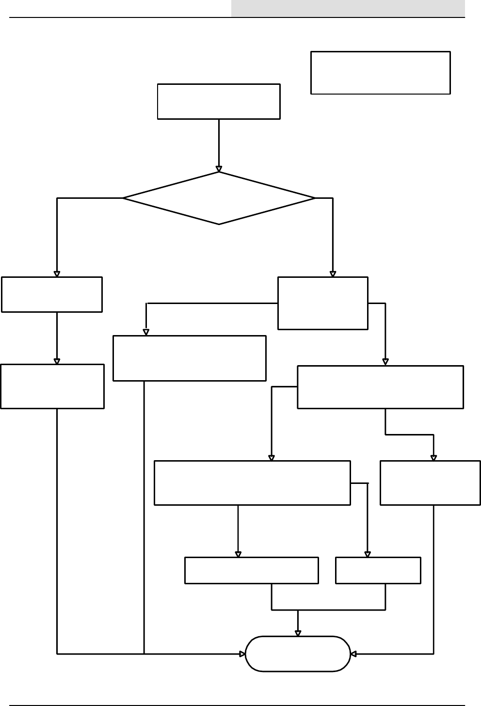
First check to make sure that:
1. Battery is charged.
2. Fuel in the fuel tank.
3. Unrestricted air filter.
Is there battery
voltage at the battery cable terminal
of the starter motor
Check battery cables
and connections
Check for battery
voltage at terminal
30 of the key
switch.
Repair connections or
replace battery cables
Whileturningthekeyswitchtothe
start position, check for battery
voltage at Terminal 50 of the key
switch
yes
Check wire 1/RED from the starter
motor, to the alternator, to the key
switch and repair or replace.
Starter motor won’t turn
no
Again, while turning the key to the start
position, check for battery voltage at wire 9/
BRN at the starter motor solenoid.
Replace the ignition
switch
yes
no
Repair or replace
wire 9/BRN
Replace starter solenoid or
starter motor assembly
yes
no
yesno
Starter motor turns
ELECTRICAL
5-93
8200/8210 330065 (3--01)
ENGINE WILL NOT CRANK
(all engines) (8200/8210)
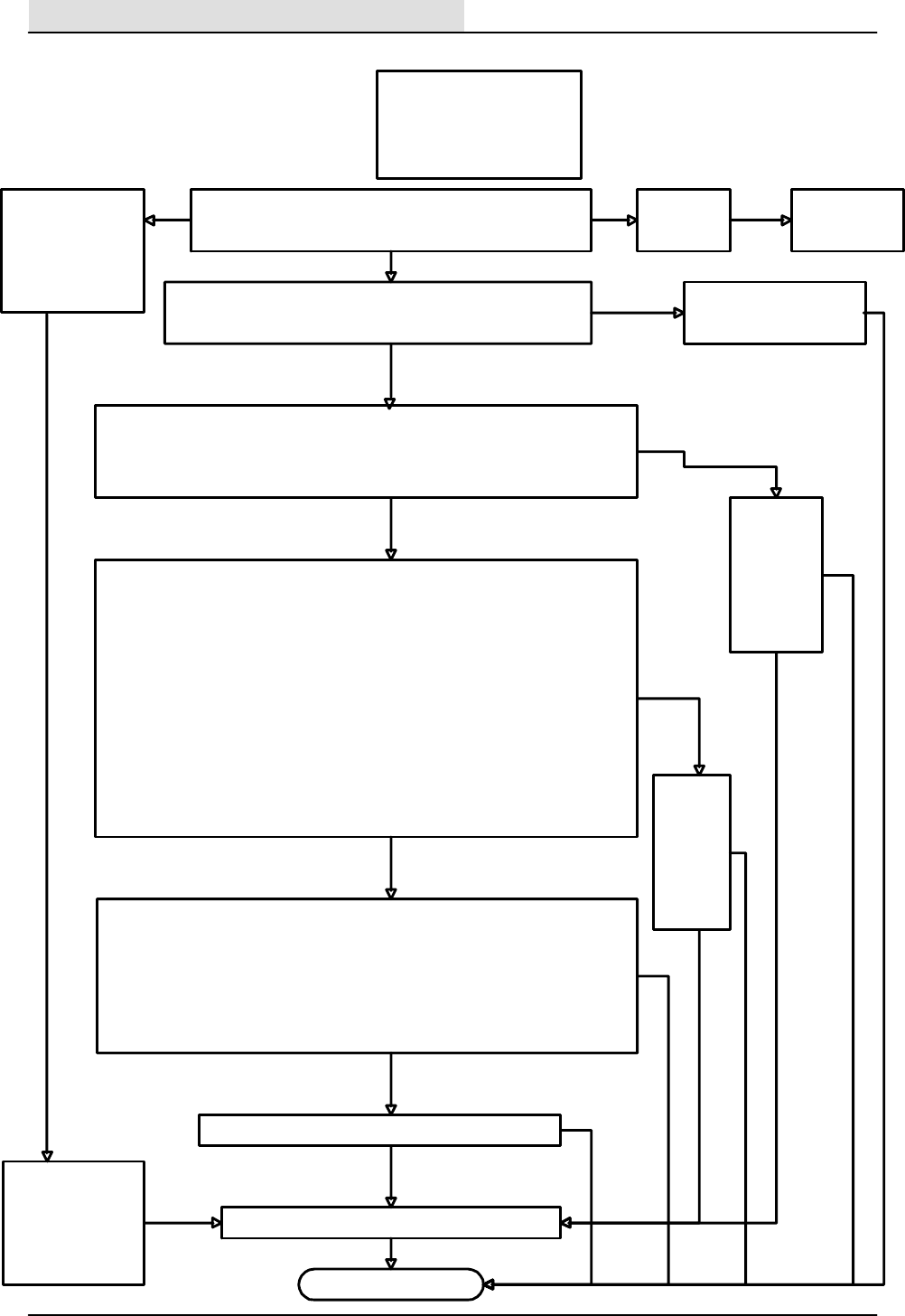
First check to make sure that:
1. Battery is charged.
2. Fuel in the fuel tank.
3. Unrestricted air filter.
4. Engine oil at full level.
Starter motor
will not crank
Engine runs
See page 5--72
no
Engine starts, but
won’t continue to
run after releasing
the key switch from
the start position to
the run position
Engine will not start or run
Engine fails to start. With a voltmeter, check for battery voltage
at circuit breaker CB--2 between the 18C/ORA wire and any 13/
BLK wire while the key switch is in the on position.
battery voltage
Check wiring and repair or,
Reset or replace defective
circuit breaker CB--2.
no
battery
voltage
Check for high voltage spark from the coil module by removing spark plugs 1 & 2
out of the intake manifold.
Next, reconnect the plugs to the plug wires and position them so that the base of
the plug is in contact with the metal of the engine.
Turn the key switch to the start position and look for a spark to jump from each
plug base to the engine.
NOTE ! make sure no fuel is present before attempting this procedure.
NOTE ! never allow the ignition coil to operate open circuit--damage to the
coil may result.
To check for the pulsed signal of the ignition controller, disconnect the harness
connector from the electronic governor controller (8 pin connector). Test by using
either of the two following methods:
1. With a digital voltmeter set for DC volts , connect the positive lead to terminal
”A” of the harness connector (18A/ORA), and the negative lead to terminal ”C”
(71D/YEL) or terminal ”D” (72E/GRY). While cranking the engine, the meter should
read 1--4 volts less than battery voltage if the ignition controller is operating
correctly.
2.Usinga1watt,12volttestlamp,connect one lead to terminal ”A” of the
harness connector (18A/ORA), and the other lead to terminal ”C” (71D/YEL) or
terminal ”D” (72E/GRY). The lamp should flash dimly for a good ignition controller
while cranking the engine.
Note: In either case, make sure that the test is performed by checking each of
the terminals ”C” and ”D” with respect to terminal ”A” of the connector.
Check
controller
wiring, if
ok, then
replace
the
ignition
controller
module.
Check the crank position sensor by disconnecting the 12 pin harness connector to
the ignition controller. Connect a digital voltmeter set to AC volts to terminals ”2”
(65/NLU) and ”3” (66/GRN) of the harness connector. While cranking the engine,
the meter should reada signal of about 2 volts . Adjust the meter scale to measure
for the 2 volt range.
Check fuel and air induction systems for a problem.
signal present Check wiring
to crank
position
sensor, if ok,
then replace
the crank
position
sensor
no
signal
ok
Signal present
no
signal
ok
Check coil module wiring, if ok, replace the coil module.
not
ok
not
ok
not
ok
not ok
no spark
good
spark
ok
ok
Check the LP fuel
tank to see that
the shutoff valve is
open and that the
supply hose fitting
is screwed in tight.
ELECTRICAL
5-94 8200/8210 330065 (3--01)
ENGINE WILL NOT RUN
(lpg) (8200/8210)
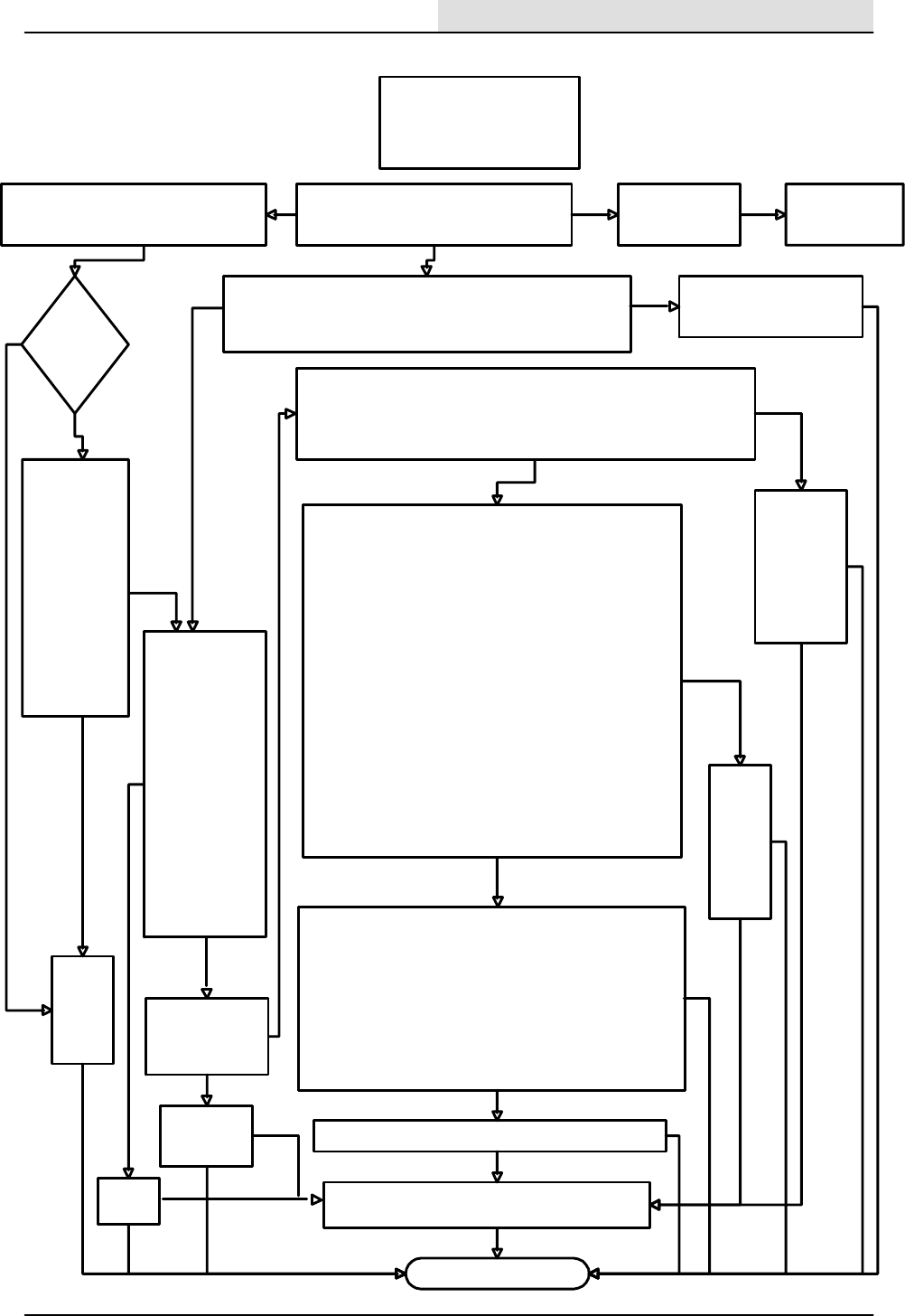
connector. While cranking the engine, the meter should read a signal of
connector to the ignition controller. Connect a digital voltmeter set to
voltage at circuit breaker CB--2 between the 18C/ORA wire and
First check to make sure that:
1. Battery is charged.
2. Fuel in the fuel tank.
3. Unrestricted air filter.
4. Engine oil at full level.
Starter motor will
not crank
Replace
the oil
pressure
switch
Engine runs
no
Engine starts, but won’t continue to run
after releasing the key switch from the
start position to the run position
Engine will not start or run
Does the
oil pressure
light
go out?
no
Disconnect
the RUN relay
M2. Measure
with a
voltmeter for
battery voltage
at the M2
(RUN) relay
connector
between wire
18E/ORA and
12C/GRN,
while trying to
start the
engine.
yes
No battery
voltage
With M2 installed,
disconnect the
electric fuel pump.
Using a voltmeter,
look for battery
voltage at the main
harness connector
to the fuel pump
wires 11/YEL and
13M/BLK while
trying to start the
engine. Battery
voltage should be
present when the
oil pressure lamp is
on, and after it
goes out while the
engine is cranking.
Battery
voltage
present
Replace
relay M2
ok
Check to see if the
fuel pump and filter
are functioning
properly.
yes
Replace the
fuel pump if it
is defective.
no
ok
Engine fails to start. With a voltmeter, check for battery
any 13/BLK wire while the key switch is in the on position.
battery
voltage Check wiring and repair or,
Reset or replace defective
circuit breaker CB--2.
no battery
voltage
no
Check for high voltage spark from the coil module by
removing spark plugs 1 & 2 out of the intake manifold.
Next, reconnect the plugs to the plug wires and position
them so that the base of the plug is in contact with the
metal of the engine.
Turn the key switch to the start position and look for a
spark to jump from each plug base to the engine.
NOTE ! make sure no fuel is present before
attempting this procedure.
NOTE ! never allow the ignition coil to operate
open circuit--damage to the coil may result.
To check for the pulsed signal of the ignition controller,
disconnect the harness connector from the electronic
governor controller (8 pin connector). Test by using
either of the two following methods:
1. With a digital voltmeter set for DC volts , connect
the positive lead to terminal ”A” of the harness connector
(18A/ORA), and the negative lead to terminal ”C” (71D/
YEL) or terminal ”D” (72E/GRY). While cranking the
engine, the meter should read 1--4 volts less than battery
voltage if the ignition controller is operating correctly.
2.Usinga1watt,12volttestlamp,connect one lead
to terminal ”A” of the harness connector (18A/ORA), and
the other lead to terminal ”C” (71D/YEL) or terminal ”D”
(72E/GRY). The lamp should flash dimly for a good
ignition controller while cranking the engine.
Note: In either case, make sure that the test is
performed by checking each of the terminals ”C” and ”D”
with respect to terminal ”A” of the connector.
Check
controller
wiring, if
ok, then
replace
the
ignition
controller
module.
Check the crank position sensor by disconnecting the 12 pin harness
AC
volts to terminals ”2” (65/NLU) and ”3” (66/GRN) of the harness
about 2 volts . Adjust the meter scale to measure for the 2 volt range.
Check fuel and air induction systems for problem.
signal present
yes
Check wiring
to crank
position
sensor, if ok,
then replace
the crank
position
sensor
no
signal
ok
Signal present
no signal
ok
Check coil module wiring, if ok, replace the coil module.
not
ok
not ok
not
ok
not
ok
not ok
no spark
good spark
ok
ok
See page 5--72
ELECTRICAL
5-95
8200/8210 330065 (3--01)
ENGINE WILL NOT RUN
(gas) (8200/8210)
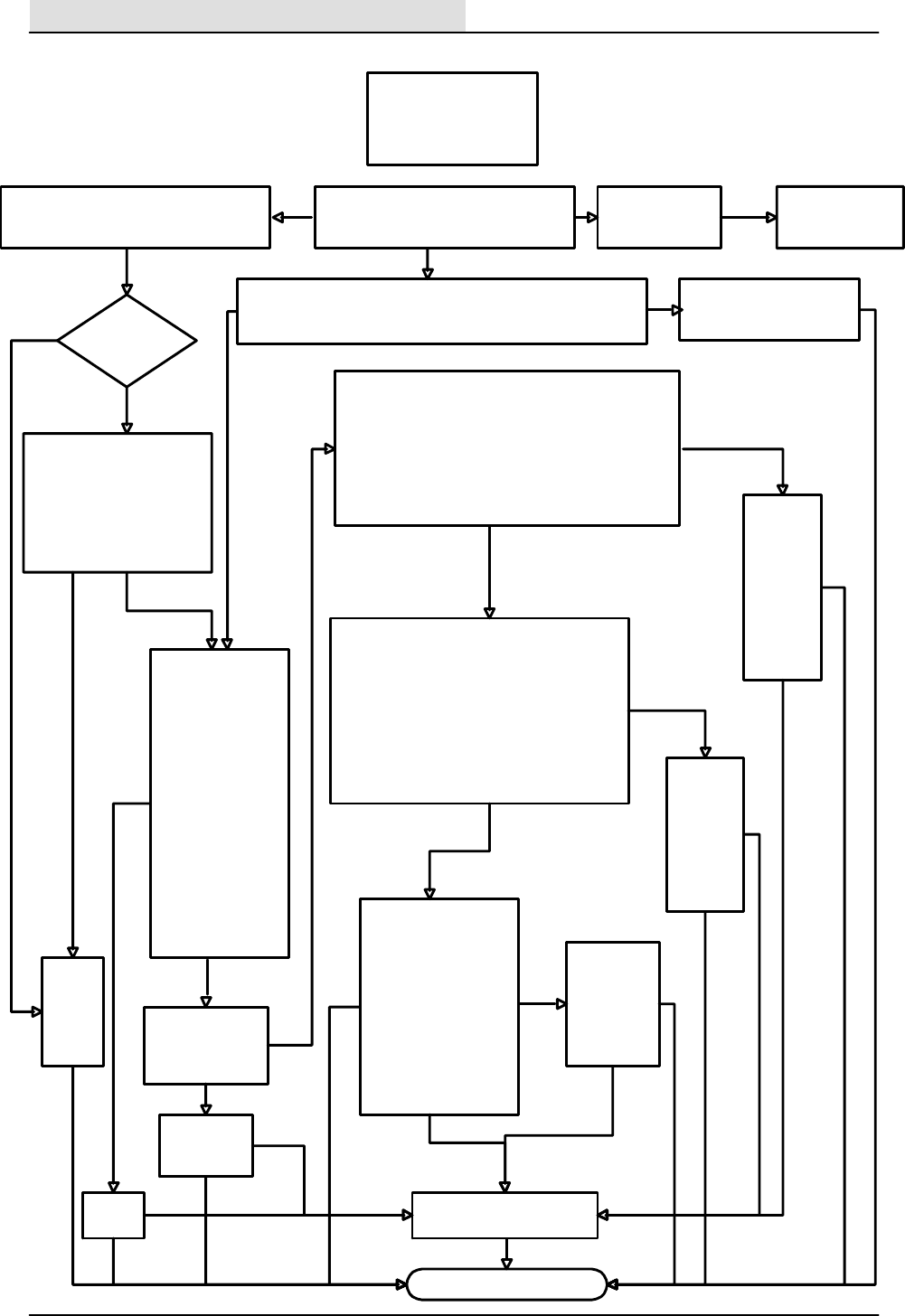
First check to make sure :
1. Battery is charged.
2. Fuel in the fuel tank.
3. Unrestricted air filter.
4. Engine oil at full level.
Starter motor will
not crank
Replace
the oil
pressure
switch
Engine runs
no
Engine starts, but won’t continue to
run after releasing the key switch from
the start position to the run position
Engine will not start or run
Does the
oil pressure light
go out?
no
Disconnect the RUN relay
M2. Measure with a
voltmeter for battery voltage
at the M2 (RUN) relay
connector between wire
18E/ORA and 12C/GRN,
while trying to start the
engine.
yes
No battery
voltage With M2 installed,
disconnect the
electric fuel pump.
Using a voltmeter,
look for battery
voltage at the main
harness connector
to the fuel pump
wires 11/YEL and
13M/BLK while
trying to start the
engine. Battery
voltage should be
present when the
oil pressure lamp is
on, and after it
goes out while the
engine is cranking.
Battery
voltage
Replace
relay M2
ok
Check to see if the
fuel pump and filter
are functioning
properly.
yes
Replace the
fuel pump if it
is defective.
no
ok
Engine fails to start. With a voltmeter, check for battery voltage
at circuit breaker CB--2 between the 18C/ORA wire and any 13/
BLK wire while the key switch is in the on position.
battery
voltage Check wiring and repair or,
Reset or replace defective
circuit breaker CB--2.
no battery
voltage
no
Check the flywheel speed sensor by disconnecting
the 8--pin main harness connector (for the diesel
engine) to the electronic governor controller.
Connect a digital voltmeter set to AC volts to
terminals ”B” (13W/BLK) and ”C” (71E/YEL) of the
harness connector. While cranking the engine, the
meter should read a signal between 1 and 2 volts.
Adjust the meter scale to measure for the 2 volt AC
range.
Check fuel and air induction
systems for problem.
yes
Check the
wiring to
the
Flywheel
speed
sensor, if
ok, then
replace the
speed
position
sensor
no
signal
ok
not
ok
not
ok
not
ok
ok
correct voltage
no
voltage
Remove the governor
actuator and turn the
key to the on position.
Note that the pin
should retract and
then come back out
quickly. With the key
in the off position,
check to make sure
that the pin doesn’t
stick or have any drag
through its range of
motion.
ok not
ok
Check the
wiring to the
governor
actuator, if ok,
then replace
the governor
actuator.
ok
not ok
Check the
wiring to
the
governor
actuator, if
ok, then
replace the
governor
actuator.
not
ok
not ok
Using a digital voltmeter, measure the voltage
to the electronic engine governor actuator .
Connect the positive meter lead to wire 86B/
PUR (terminal ”A”) and the negative lead to
84/GRN (terminal ”B”) of the actuator
connector. Set the voltmeter to read DC volts.
Turn the key to the on position (Caution--do
not start the engine!) and look for battery
voltagegoing to the governor actuator. Be
careful not to short the two leads together!
ok
good signal
See page 5--72
ELECTRICAL
5-96 8200/8210 330065 (3--01)
ENGINE WILL NOT RUN
(diesel) (8200/8210)
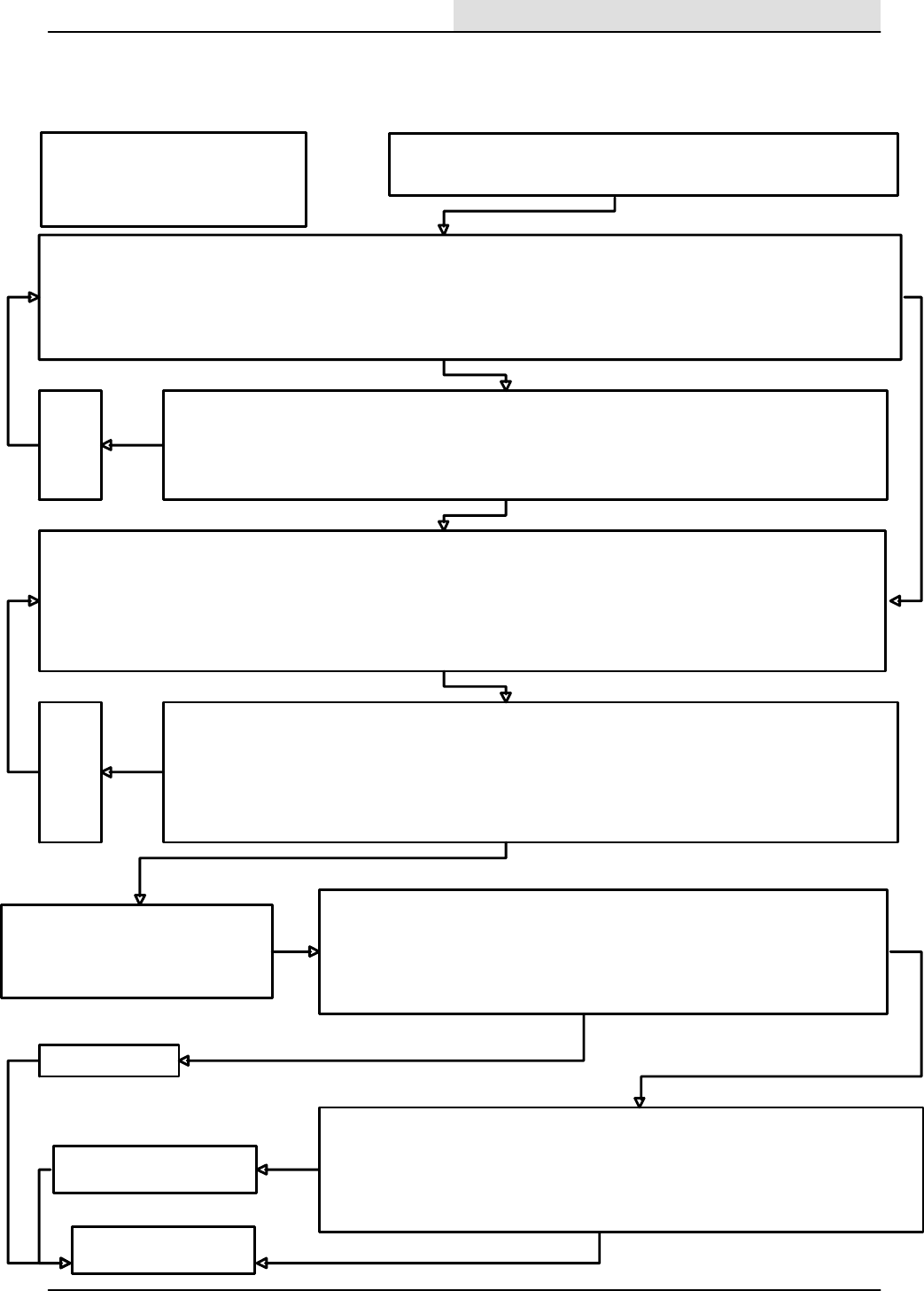
First check to make sure that :
1. Battery is fully charged.
2. Electronic engine governor actuator
mechanical linkage operates correctly.
3. Electronic Instrument Panel is installed
After the engine is started, it only runs at idle speed and will not run at the correct engine
governed speeds when the engine speed select button is selected on the Electronic
Instrument Panel. No response from the electronic engine governor actuator .
Engine governor
controls speed
Checking for battery voltage at the electronic engine governor control.
1. Find and disconnect the 8--pin harness connector to the electronic governor Controller.
2. Connect the positive meter lead of a digital DC voltmeter to the 18/ORN wire (connector terminal ”A” ) and the negative lead to the 13/
BLK wire (connector terminal ”B” ). Be careful not to short the two leads together!
3. Turn the key to the on position, (Caution--do not start the engine!) and look for battery voltage going to the governor controller.
4. Turn the key switch off. Does the meter indicate battery voltage to the electronic engine governor controller?
Checking the battery voltage supply wiring to the electronic engine governor controller :
1. With an ohmmeter, check the wiring from battery (--) to the 13/BLK wire (connector terminal ”B” ) at the wire
harness connector to the electronic engine governor controller.
2. With an ohmmeter, check the wiring from 18C/ORN at CB--2 to the 18/ORN wire (connector terminal ”A” ) at the
wire harness connector to the electronic engine governor controller.
Do the wires check out good?
Checking for the speed select signal from the electronic instrumrnt panel to the electronic engine governor control.
1. Find and disconnect the 8--pin harness connector to the electronic governor Controller.
2. Connect the positive meter lead of a digital DC voltmeter to the 33/YEL wire (connector terminal ”G” ) and the negative lead to the
13/BLK wire. Be careful not to short the two leads together!
3. Turn the key to the on position, (Caution--do not start the engine!) and look for about 10.5 volts going to the governor controller.
4. Press the engine speed select button on the electronic instrument panel and look for the voltage to drop to near zero volts.
5. Turn the key switch off.
Does the meter indicate the correct voltage to the electronic engine governor controller?
no
Repair or
replace
the
defective
wiring
no
yes
ok
yes
Checking the engine speed select signal wiring from the electronic instrument panel to the electronic engine
governor controller :
1. With an ohmmeter, check the wiring from battery (--) to the 13/BLK wire (connector terminal ”B” ) at the wire
harness connector to the electronic engine governor controller.
2. With an ohmmeter, check the 33/YEL wire between the harness connector for the electronic instrument panel
(connector terminal ”R3” ) and the wire harness connector to the electronic engine governor controller (connector
terminal ”G” ).
Do the wires check out good?
no
Checking the engine speed input pulses to
the electronic engine governor control .
See page 5--73 for gas
See page 5--74 for LPG
See page 5--75 for diesel
Repair or
replace
the
defective
wiring
no
yes
ok
ok
Checking the wiring from the electronic instrument panel to the electronic engine governor
actuator with the key in the off position:
1. With an ohmmeter, check the 86/PUR wire from the electronic engine governor controller
(terminal ”E”) to the actuator connector (terminal ”A”) mounted on the engine.
2. With an ohmmeter, check the 84/GRN wire from the electronic engine governor controller
(terminal ”F”) to the actuator connector (terminal ”B”) mounted on the engine.
Do the wires check out good?
Using a digital voltmeter, measure the voltage to the electronic engine governor actuator .
Connect the positive meter lead to wire 86/PUR (connector terminal ”A” ) and the
negative lead to 84/GRN (connector terminal ”B” ) to the governor actuator connectorr.
Set the voltmeter to read DC volts. Turn the key to the on position (Caution--do not
start the engine!) and look for battery voltage going to the governor actuator. Be careful
not to short the two leads together!
Is a voltage being measured to the governor actuator?
Replace the actuator
yes
no
yes
Repair or replace the wiring to
the actuator
no
ok
ok
ELECTRICAL
5-97
8200/8210 330065 (3--01)
NO SPEED CHANGE FROM
ENGINE GOVERNOR (8200/8210)
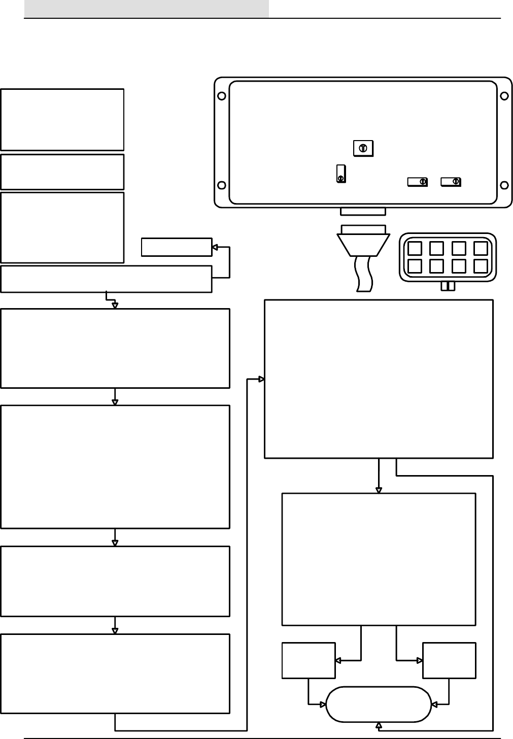
First check to make sure :
1. Battery is charged.
2. Engine runs good.
This troubleshooting guide
deals primarily with tuning the
governor controller . If the
governor actuator is not
responding at all, consult page 5--76
Initial Adjustment Settings: CW=Clockwise CCW=Counter
clockwise
Adjustments made with the key switch in the off position.
1. Turn P1 20 turns CCW, then 10 turns CW (middle of the
adjustment range)
2. Turn P2 full CCW, then 1/4 turn CW.
3. Turn P3 full CCW, then 1/3 turn CW.
4. P4 is not used with this application.
P4
P2
P3 P1
Electronic Engine
Governor Controller
(cover removed)
1. For gasoline and LP fueled
engines, connect a digital
tachometer that measures RPM
for distributorless ignition
systems.
2. For diesel engines, use an
optical tachometer.
Description of Adjustment Pots: Type:
1. P1--high engine speed adjustment. 20 turn pot
2. P2--engine response orgain adjustment. single turn pot
3. P3--low engine speed adjustment. single turn pot
4. P4--medium engine speed adjustment single turn pot
(Note:P4 is not used on the 8200/8210 product)
Theory of operation:
The electronic engine governor for the 8200/8210 application
requires a positive voltage (10--12 volts) from the electronic
instrument panel to the electronic engine governor connector
(terminal ”G”) in order to enable the low speed of 1350 RPM. If
no signal is present at terminal ”G”, then the governor will cause
the engine to operate at the high speed of 2400 RPM.
Voltage status at governor connector terminal ”G” :
1. No voltage at terminal ”G” indicates a selected high engine
speed condition.
2. 9--12volts at ”G” indicates a low engine speed condition.
Final Adgustments:
1. Start the engine.
2. P1--using the tachometer, select high speed on the electronic
instrument panel and adjust P1 for an engine speed of 2400
RPM.
3. P3--using the tachometer, select low speed on the electronic
instrument panel and adjust P3 for an engine speed of 1350
RPM.
4. Check both speeds again and adjust if necessary (Always adjust
the high speed first, then the low speed).
5. P2--Adjust for best engine response (make small changes)--
Check by pressing the engine speed button form low to high
repeatedly. When adjusting P2, sometimes it helps to turn on the
machine sweeping function intermittently to test the response of
the electronic engine gonernor
Does the engine governor respond properly?
Does the electronic engine governor respond to speed
selections from the electronic instrument panel ?
See page 5--76 no
yes
Does the electronic engine governor respond to load and speed
selections from the electronic instrument panel in the followin
manner:
1. The engine speed ”hunts” when the engine speed is changed or
a load is encountered.
2. The engine responds slowly or slugglishly to speed changes.
3. Inaccurate engine speeds.
If so, proceed further
low
speed
high
speed
medium speed
(not used)
Check the actuator for smooth motion with the following:
1. Disconnect the governor actuator from the main wire
harness. (For diesel applications, remove the
actuator.)
2. Using a variable DC voltage power supply, connect
the supply leads to the govenor actuator.
3. Increase the voltage gradually to the actuator until
approximately 12 volts is reached.
4. Watch the movement of the armature as the voltage is
increased and decreased.
Does the armature of the actuator move smoothly
without any sticking motion ?
Correct engine
response
yesno
Replace the
governor
actuator
no
ok
Replace the
governor
controller
yes
ok
D ABC
H EFG
8 Pin Connector
ELECTRICAL
5-98 8200/8210 330065 (3--01)
INCORRECT ENGINE
GOVERNED SPEED OR
RESPONSE (8200/8210)
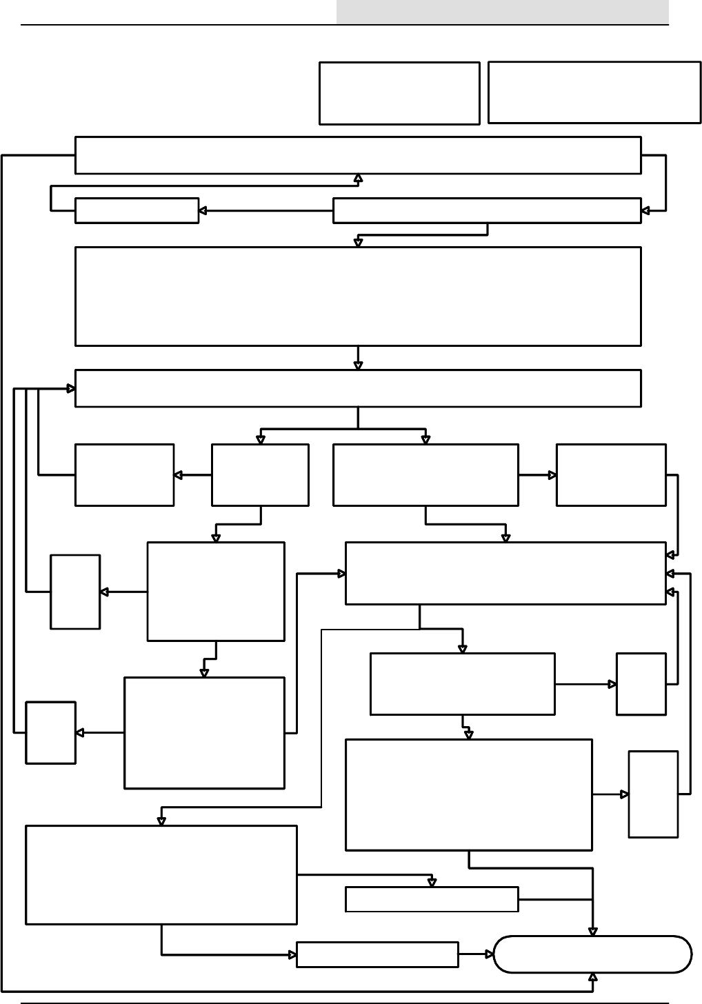
Main Sweeping brush works
With the engine running, does the main sweeping brush turn on when the main sweep brush
lever is placed in the on position ?
Check the 15 amp circuit breaker CB--5 to see if it has tripped.
DIAGNOSTIC INPUT DISPLAY MODE-- checks the hopper down limit switch and the main sweep limit switch
1. Start the engine and raise the hopper to the full up position.
2. Turn off the engine.
3. Install the safety bar to prevent the hopper from dropping.
4. While pressing the scrub button, turn the key switch to the on position and hold the scrub button until the 3rd fuel
gauge LED from the left starts to flash. (Caution--Do not start the engine!) You are now in the diagnostic input
display mode.
Checking the hopper down limit switch input: Using the LED’s of the fuel gauge, watch the far right LED turn on while
manually activating the hopper down limit switch. Does the LED illuminate when the limit switch is activated?
ok
Checking the hopper down
limit switch: With an
ohmmeter, check the
hopper door closed limit
switch contacts to make
sure the switch is not
defective.
Check the main sweep micro switch input: Using the LED’s of the
fuel gauge, watch the second from the left fuel gauge LED turn on
while manually activating the operator’s main sweeping brush lever.
Does the LED illuminate when the lever is activated?
Checking the wiring:
1. Check the wiring from battery
(--) to the 13D//BLK wire at the
switch.
2. Check the 63/BLU wire
between the switch and the
machine controller connector
at terminal C3
switch is ok
Replace
the
defective
switch
switch
is
bad
Repair or
replace
defective
wiring
bad
wiring
wiring
is ok
Reset the circuit breaker
Main sweep micro switch mounting:
Is the main sweep switch mounted so
that it operates correctly with the main
sweep lever?
Switch mounting:
Is the switch
mounted so that it
operates correctly?
yes
Adjust the switch
so that it operates
when activated by
the hopper lift arm.
Adjust the switch so
that it operates when
activated by the main
brush on lever.
Checking the main sweep limit switch:
With an ohmmeter, check the main
sweep limit switch contacts to make
sure the switch is not defective.
no
Checking the wiring:
1. Check the wiring from battery (--) to the 13D/BLK
wire at the switch.
2. Check the 63/BLU wire between the hopper
down switch and the machine controller
connector at terminal C3.
3. Check the 73/BRN wire between the switch and
the machine controller connector at terminal D3.
Replace
the
defective
switch
switch
is
bad
Repair or
replace
the
defective
wiring
bad
wiring
ok
ok
ok
Checking the main sweep brush hydraulic solenoid
valve:
1. Turn the key on, (engine off).
2. Activate the main brush lever,
3. Disconnect valve SV5.
4. Measure with a digital voltmeter for battery voltage
across 43/PUR and 37L/GRY at the connector.
Repair or replace defective wiring
Replace the defective solenoid.
yes
no
battery
voltage
ok
ok
Note: Operation of the main sweep brush is
dependent upon the hopper down limit switch,
and the main sweep brush limit switch!
With the engine running, does the main sweeping brush turn on when the main sweep brush
lever is placed in the on position ?
no
Check the 15 amp circuit breaker CB--5 to see if it has tripped.
First check for the following:
1. Correct hydraulic oil level
2. Engine is runs properly
3. Hopper is fully lowered.
DIAGNOSTIC INPUT DISPLAY MODE-- checks the hopper down limit switch and the main sweep limit switch.
1. Start the engine and raise the hopper to the full up position.
2. Turn off the engine.
3. Install the safety bar to prevent the hopper from dropping.
4. While pressing the scrub button, turn the key switch to the on position and hold the scrub button until the 3rd fuel
gauge LED from the left starts to flash. (Caution--Do not start the engine!) You are now in the diagnostic input
display mode.
no
Checking the hopper down limit switch input: Using the LED’s of the fuel gauge, watch the far right LED turn on while
manually activating the hopper down limit switch. Does the LED illuminate when the limit switch is activated?
Checking the hopper down
limit switch: With an
ohmmeter, check the
hopper door closed limit
switch contacts to make
sure the switch is not
defective.
Check the main sweep micro switch input: Using the LED’s of the
fuel gauge, watch the second from the left fuel gauge LED turn on
while manually activating the operator’s main sweeping brush lever.
Does the LED illuminate when the lever is activated?
yes
Checking the wiring:
1. Check the wiring from battery
(--) to the 13D//BLK wire at the
switch.
2. Check the 63/BLU wire
between the switch and the
machine controller connector
at terminal C3
Replace
the
defective
switch
Repair or
replace
defective
wiring
Reset the circuit breaker yes
ok
Main sweep micro switch mounting:
Is the main sweep switch mounted so
that it operates correctly with the main
sweep lever?
Switch mounting:
Is the switch
mounted so that it
operates correctly?
no
Adjust the switch
so that it operates
when activated by
the hopper lift arm.
no no
Adjust the switch so
that it operates when
activated by the main
brush on lever.
Checking the main sweep limit switch:
With an ohmmeter, check the main
sweep limit switch contacts to make
sure the switch is not defective.
ok
yes
Checking the wiring:
1. Check the wiring from battery (--) to the 13D/BLK
wire at the switch.
2. Check the 63/BLU wire between the hopper
down switch and the machine controller
connector at terminal C3.
3. Check the 73/BRN wire between the switch and
the machine controller connector at terminal D3.
ok
Replace
the
defective
switch
Repair or
replace
the
defective
wiring
Checking the main sweep brush hydraulic solenoid
valve:
1. Turn the key on, (engine off).
2. Activate the main brush lever,
3. Disconnect valve SV5.
4. Measure with a digital voltmeter for battery voltage
across 43/PUR and 37L/GRY at the connector.
Repair or replace defective wiring
Replace the defective solenoid.
battery voltage
yes
Note: Operation of the main sweep brush is
dependent upon the hopper down limit switch,
and the main sweep brush limit switch!
ELECTRICAL
5-99
8200/8210 330065 (3--01)
MAIN SWEEPING BRUSH
WILL NOT RUN (8200)
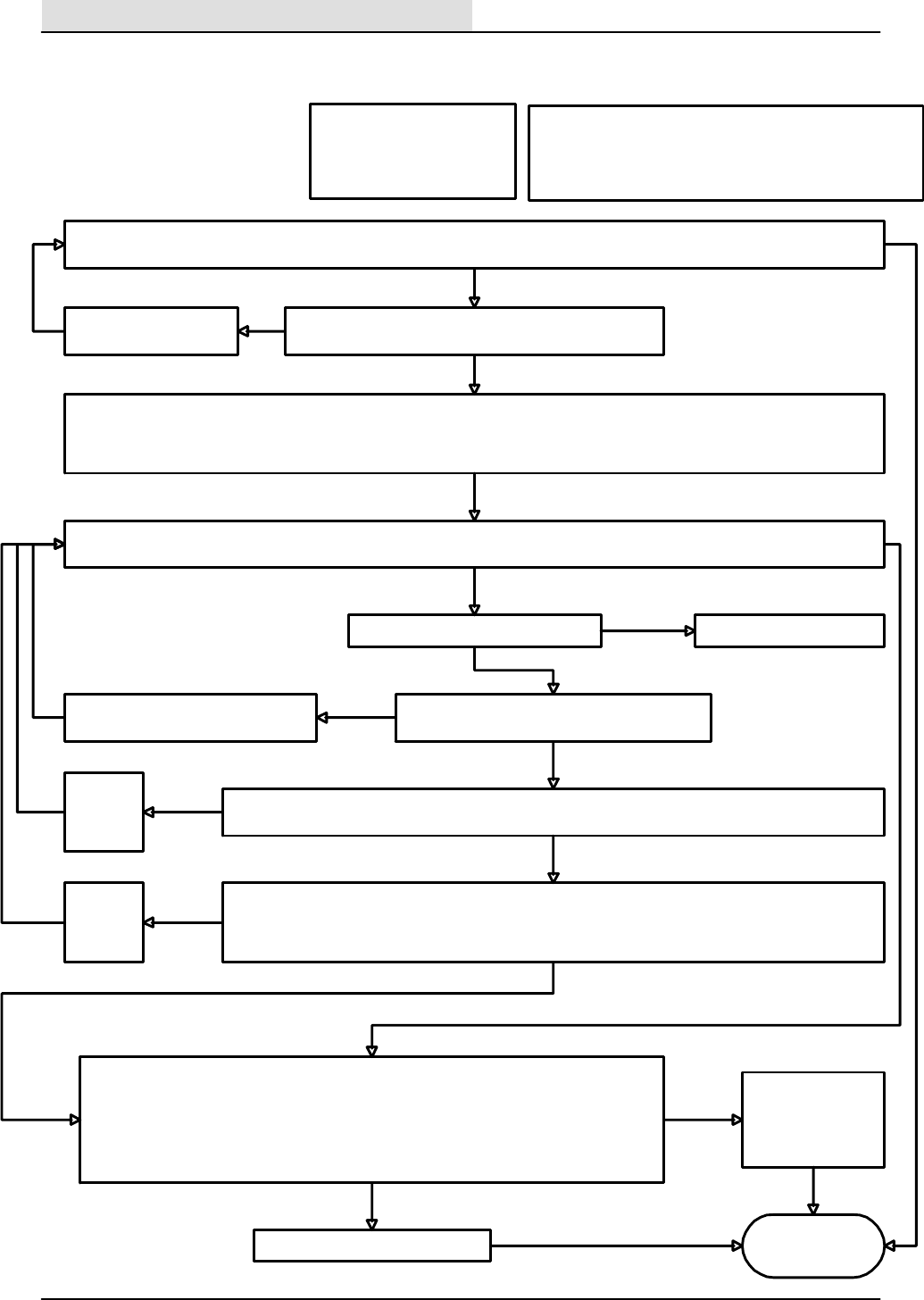
Side Sweeping
brush works
With the engine running, does the side sweep brush turn on when the main sweep brush lever and the side sweep levers are placed in
the on position and the hopper is fully lowered?
no
Check the 15 amp circuit breaker CB--5 to see if it has tripped.
First check for the following:
1. Correct hydraulic oil level
2. Engine is runs properly
3. Hopper is fully lowered
4. Main brush page 5--78
DIAGNOSTIC INPUT DISPLAY MODE--checks the side sweep limit switch .
1. Turn the key switch to the off position .
2. While pressing the scrub button, turn the key switch to the on position and hold the scrub button until the 3rd fuel gauge LED from the
left starts to flash. Do not start the engine. You are now in the diagnostic input display mode.
no
Checking the side brush limit switch input: Using the LED’s of the fuel gauge, watch the far left LED turn on while manually activating
the side brush limit switch with the operator’s side brush lever. Does the LED illuminate when the limit switch is activated?
ok
Checking the side brush limit switch: With an ohmmeter, check the side brush limit switch contacts to make
sure the switch is not defective.
Replace the
defective
switch
switch
is
bad
ok
Repair or
replace
defective
wiring
ok
bad
wiring
Reset circuit breaker CB--5 yes
ok
Switch mounting: is the switch mounted so that it
operates correctly?
yes
yes
Adjust the switch so that it operates
when activated by the side brush lever. no
ok
Checking the wiring:
1. With an ohmmeter, check the 73/BRN wire from the main sweep brush limit switch to the side sweep limit
switch.
2. Check the 74/ORN wire between the switch and the machine controller connector at terminal D2.
Checking the side brush hydraulic solenoid valve:
1. Turn the key to the on position, (engine off).
2. Activate the main brush lever and the side brush lever, with the hopper in the lowered position.
3. Disconnect the side brush solenoid valve SV10.
4. Measure with a digital voltmeter for battery voltage across 46/ORA and 37C/GRY at the
connector.
Repair or replace
defective wiring
between the controller
and the solenoid valve
Replace the defective solenoid.
no
battery
voltage
ok
ok
yes
Note: Operation of the side sweep brush is
dependent upon the hopper down switch,
main sweep brush, and the side sweep brush
switch.
switch is ok
wiring is ok
Battery voltage present
Does the main sweeping brush work?
yes
Refer to page 5--78
no
no
ELECTRICAL
5-100 8200/8210 330065 (3--01)
SIDE BRUSH WILL
NOT RUN (8200)
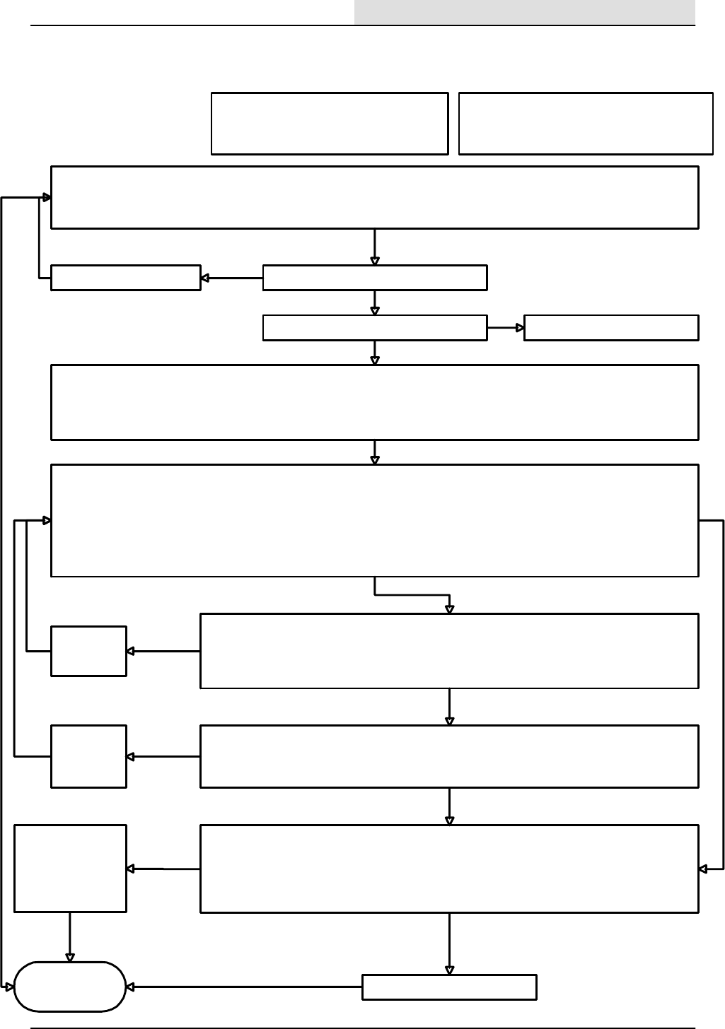
Vacuum Fan
works
With the engine running, does the vacuum fan turn on by pressing the fan button when the following conditions exist?
1. The main sweep brush lever is placed in the operating position.
2. The hopper is fully lowered.
3. The hopper high temperature light is off.
no
Is the 15 amp circuit breaker CB--5 tripped?
First check for the following:
1. Hydraulic system is functioning properly
2. Engine is runs properly
3. Hopper is fully lowered
DIAGNOSTIC INPUT DISPLAY MODE-- checks the side sweep limit switch .
1. Turn the key switch to the off position .
2. While pressing the scrub button on the instrument panel, turn the key switch to the on position and hold the scrub button until the 3rd
fuel gauge LED from the left starts to flash. Caution-- --Do not start the engin e! You are now in the diagnostic input display mode.
yes
Checking the hopper thermal sentry switch input:
1. Open the hopper filter cover to gain access to the underside of the hopper filter cover area.
2. Disconnect the two individual wires to the thermal switch mounted next to the filter shaker motor
3. Jumper the two wires while observing that the cluster indicator light for the sweep fan (proving that the switch is ok) and the sweep
fan LED on the electronic instrument panel illuminates in the diagnostic display mode (proving that that the input is received by the
machine controller).
4. Reconnect the wires to the switch and secure the cover to the hopper.
Does the cluster light and the sweep fan LED illuminate while the thermal switch wires are jumpered?
ok
Checking the hopper thermal sentry switch:
1. Remove the switch from its mounting.
2. With an ohmmeter, check the thermal sentry switch by holding a small flame to the switch head .
3. The meter should indicate a closed contact when activated by heat.
Does the switch respond to heat properly?
Replace the
defective
switch
switch
is
bad
ok
Repair or
replace
defective
wiring
ok
bad
wiring
Reset circuit breaker CB--5
yes
ok
no
Checking the wiring:
1. With an ohmmeter, check the 13BC/BLK wire from the hopper thermal switch to Battery (--).
2. With an ohmmeter, check the 82/YEL wire between the hopper thermal switch and the electronic
instrument panel connector at terminal G1.
Checking the sweep vacuum fan hydraulic solenoid valve:
1. Disconnect the side brush solenoid valve SV10.
2. Measure with a digital voltmeter for battery voltage across 37J/GRY and 39/ORN at the connector.
3. Turn the key to the on position, (engine off).
4. Activate the vacuum fan button on the electronic instrument panel and look for battery voltage.
5. Reconnect the side brush solenoid.
Repair or replace
defective wiring
between the electronic
instrument panel and
the solenoid valve
Replace the defective solenoid
no
battery
voltage
ok
ok
yes
Note: Operation of the sweeping vacuum fan is
dependent upon the hopper down switch and the
hopper thermal sentry switch.
switch is ok
wiring is ok
Battery voltage present
Does the main sweeping brush work? Refer to page 5--78
no
no
yes
ELECTRICAL
5-101
8200/8210 330065 (3--01)
SWEEPING VACUUM
FAN WILL NOT
RUN (8200)
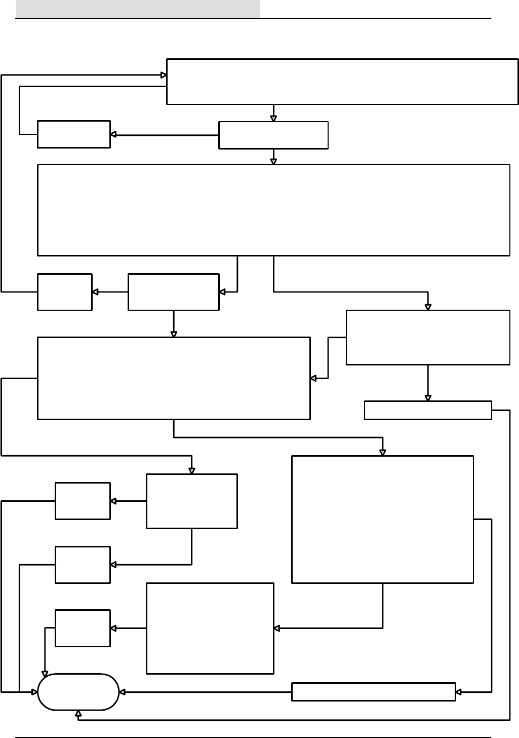
Filter Shaker
Motor works
Does the filter shaker turn on by pressing the filter shaker button when the following conditions exist?
1. The key switch is in on position, (Caution----Do not start the engine!)
2. The main sweeping lever is in the off position.
3. The sweeping vacuum fan is turned off.
no
Is the 15 amp circuit breaker
CB--5 tripped?
Check the output from the electronic instrument panel to the filter shaker motor relay.
1. Turn the key switch to the off position .
2. Disconnect M3 relay from the harness connector.
3. Using a digital voltmeter, connect the positive meter lead to the terminal of the 37B/GRY wire, and the negative meter lead to the
terminal of the 38/BRN wire at the M3 relay harness connector.
4. Turn the key switch to the on position, (Caution----Do not start the engine!)
5. Press the filter shaker button on the electronic instrument panel.
Does the voltmeter display battery voltage for a 30 second time period ?
no
Reset circuit
breaker CB--5
yes
ok
Replace the defective filter shaker motor.
no
With key in the off position, use an ohmmeter
to check the 37/GRY wire from CB5 to the M3
relay, and 38/BRN from the electronic
instrument panel terminal T1, to the M3 relay.
Is the 15 amp circuit
breaker CB--8 tripped?
Reset circuit
breaker CB--8
yes
yesok
Check the output from the M3 filter shaker motor relay.
1. Using a digital voltmeter, connect the positive meter lead to the terminal of
the 91/BLU wire, and the negative meter lead to any 13/BLK wire.
2. Turn the key switch to the on position, (Caution----Do not start the
engine!)
3. Press the filter shaker button on the electronic instrument panel.
Does the voltmeter display battery voltage for a 30 second time period ?
no
Check the output from the M3 filter shaker motor
relay at the shaker motor.
1. Using a digital voltmeter, connect the positive
meter lead to the terminal of the 91A/BLU wire,
and the negative meter lead to the 13BD/BLK
wire.
2. With the key switch in the on position,
(Caution----Do not start the engine!)
3. Press the filter shaker button on the electronic
instrument panel.
Does the voltmeter display battery voltage for a
30 second time period ?
With the key in the off
position, use an
ohmmeter to check the
90/GRN wire between
CB--8 and M3 relay
no
yes
Replace relay
M3
ok
Repair or
replace the
wiring
not ok
ok
With the key in the off position:
1. Use an ohmmeter to check the
91/BLU and 91A/BLU wires
between M3 relay and the shaker
motor connector.
2. Also with the ohmmeter, check
from 13BD/BLK at the shaker
motor connector to battery(--)
Repair or
replace the
wiring
yes
ok
no
not ok
ok
ok
Repair or replace the wiring
not ok
ELECTRICAL
5-102 8200/8210 330065 (3--01)
FILTER SHAKER WILL
NOT RUN (8200)
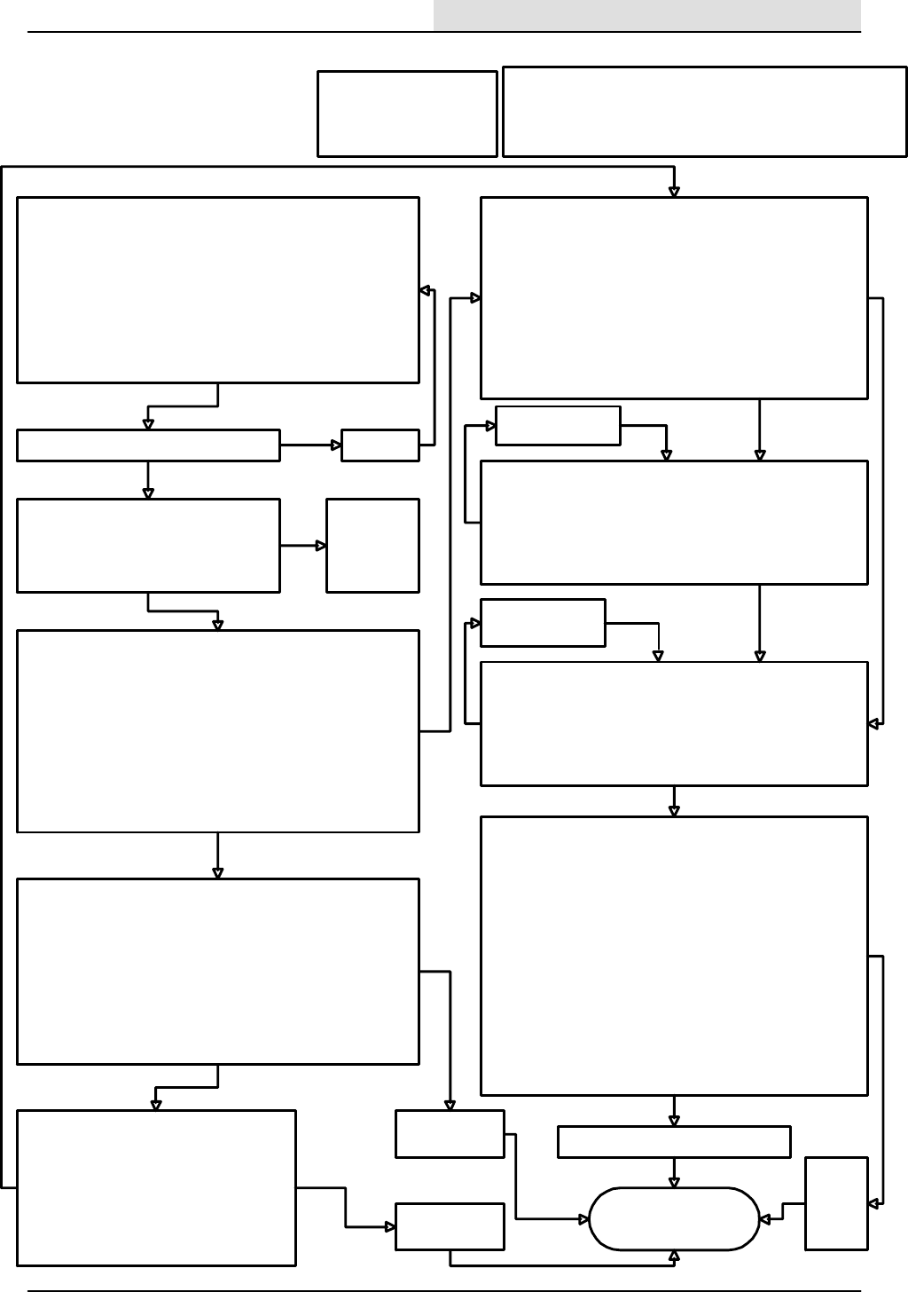
Scrub head goes
up and down
To check the scrub brush down operation.
1. Start the engine.
2. Press the scrub button and notice that the engine changes to
high speed.
3. Press the propel pedal forward and causing the scrub brushes to
go down and on.
4. Press the scrub button again and notice that the brush head
goes up.
5. Turn off the engine by turning the key switch to the off position.
With the above procedure, does the scrub brush head go down?
no
Is circuit breaker CB--7 tripped?
First check for the following:
1. Correct hydraulic oil level
2. Propel pedal is enabled
3. Recovery tank is not full
DIAGNOSTIC INPUT DISPLAY MODE-- checks the forward
propel limit switch input.
1. Turn the key switch to the off position.
2. While pressing the scrub button on the electronic instrument
panel, turn the key switch to the on position and hold the scrub
button until the 3rd fuel gauge LED from the left starts to flash.
(Caution----do not start the engin e!) You are now in the
diagnostic input display mode.
3. Push the propel pedal forward while watching the LED’s on the
electronic instrument panel.
Does the right LED above the scrub button turn on when the
pedal is moved forward?
Checking the forward propel limit switch:
1. Disconnect the hitch pin on the scrub brush head and swing
open the right side guide arm .
2. Open the right hand side main sweeping brush access door.
3. Disconnect the front mounted switch connector from the main
harness.
4. With an ohmmeter, connect the meter leads to terminals ”B” and
”C” at the connector of the switch.
5. Move the propel pedal through its range while checking the
meter.
Does the meter show a change while operating the pedal?
Replace the
defective switch
no
Repair or replace
defective wiring
bad
wiring
Reset CB--7
yes ok
Checking the wiring for the forward propel
switch:
1. With an ohmmeter, check the 13AC/BLK
wire from the forward propel switch harness
connector to Battery (--).
2. With an ohmmeter, check the 79/GRY wire
between the forward propel switch harness
connector and the electronic instrument
panel harness connector at terminal D1.
Replace
the
defective
solenoid.
ok
Note: Normal operation of the scrub brush lift is dependent upon
pressing the scrub brush switch, activating the forward propel
pedal limit switch, the recovery tank is not full, and the engine in the
high speed mode.
switch is ok
no
With the key switch in the on position,
(Caution-- do not start the engin e) do any
of the scrub button LED’s (on the electronic
instrument panel) illuminate when the scrub
button is pressed?
Check CB--4
for power to
the circuit
board .
no
yes
no
yes
ok
DIAGNOSTIC INPUT DISPLAY MODE-- checks the recovery
tank full level switch.
1. Turn the key switch to the off position.
2. While pressing the scrub button on the electronic instrument
panel, turn the key switch to the on position and hold the
scrub button until the 3rd fuel gauge LED from the left starts
to flash. Caution-- --Do not start the engin e! You are now in
the diagnostic input display mode.
3. lift the float while watching the recovery tank full LED on the
electronic instrument panel.
Does the recovery tank full LED turn on when the float is
lifted?
Checking the wiring:
1. With an ohmmeter, check the 13AF/BLK wire from the
forward propel switch harness connector to Battery (--).
2. With an ohmmeter, check the 77/BLU wire between the
forward propel switch harness connector and the electronic
instrument panel harness connector at terminal B1.
Do the wires check out good?
yes
Checking the recovery tank full level switch:
1. Disconnect the front mounted switch connector from the main
harness.
2. With an ohmmeter, connect the meter leads to terminals
”A” and ”b” at the connector of the switch.
3. Move the float up and down while checking the meter.
Does the meter show a change while operating the float?
no
yes
Replace the
defective switch
no
MANUAL MODE-- Checking the scrub head down hydraulic
solenoid valve:
1. While holding the ES button, turn the key switch to the on
position (Caution -- do not start the engine ) and continue to
hold for 15 seconds until the left fuel gauge LED is
illuminated.
2. Disconnect the scrub head down solenoid valve SV--7
connector.
3. Measure with a digital voltmeter for battery voltage across
55A/GRN and 53H/ORN at the harness connector.
4. Press the scrub brush button on the electronic instrument
panel.
5. Notice that the meter shows battery voltage when the button is
turned on.
6. Reconnect the scrub head down solenoid SV--7.
Is there battery voltage when SV--7 is turned on?
yes
Repair or Replace
the defective wiring.
no
yes
Repair or replace the defective wiring.
no
ok
ok
ok
ok
ok
ELECTRICAL
5-103
8200/8210 330065 (3--01)
SCRUB BRUSHES WILL
NOT RAISE OR
LOWER (8200)
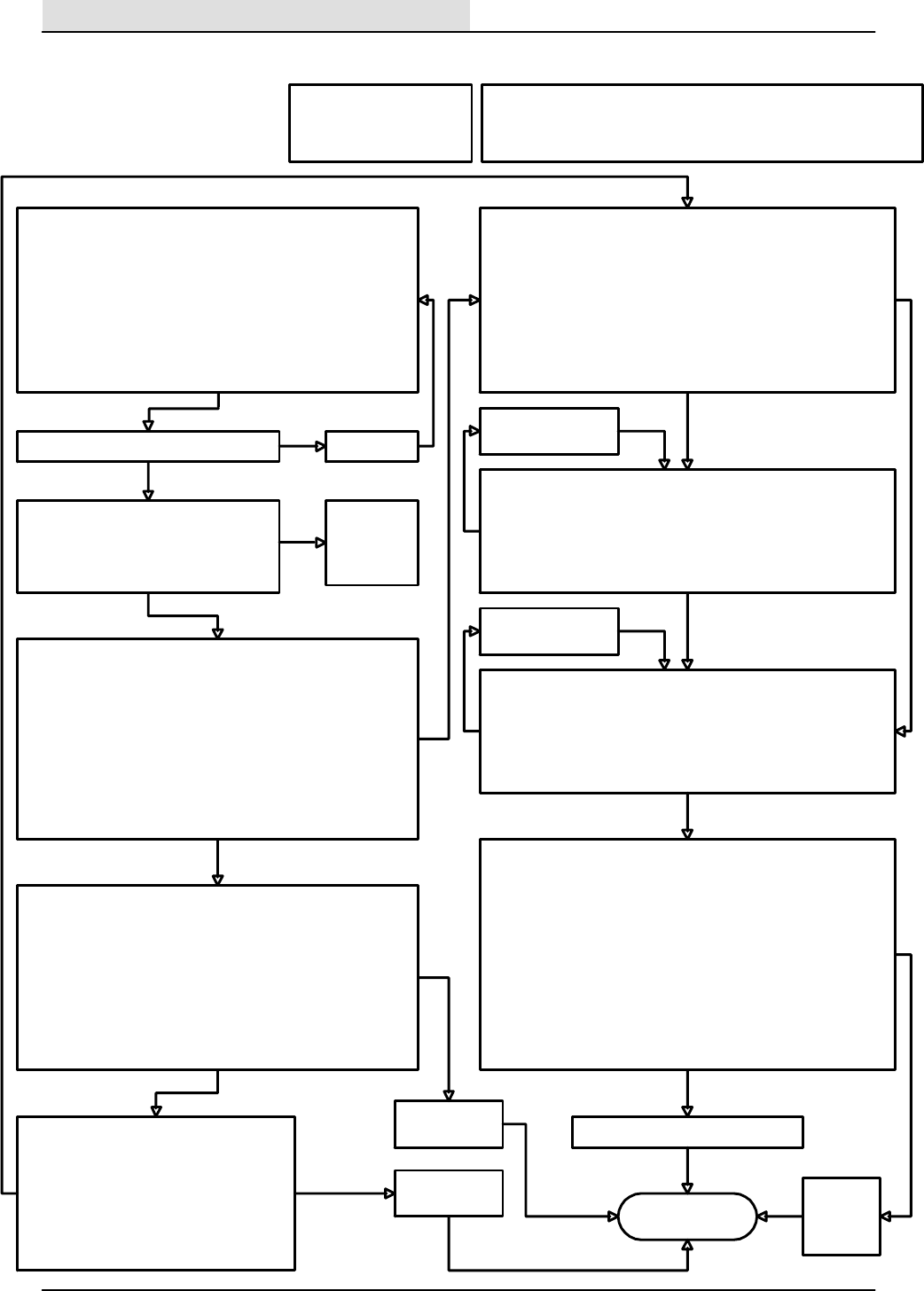
Scrub brushes
turn on
To check the scrub brush on operation.
1. Start the engine.
2. Press the scrub button and notice that the engine changes to
high speed.
3. Press the propel pedal forward and causing the scrub brushes to
go down and on.
4. Press the scrub button again and notice that the brush head
goes up.
5. Turn off the engine by turning the key switch to the off position.
With the above procedure, do the scrub brushes go on?
no
Is circuit breaker CB--7 tripped?
First check for the following:
1. Correct hydraulic oil level
2. Propel pedal is enabled
3. Recovery tank is not full
DIAGNOSTIC INPUT DISPLAY MODE-- checks the forward
propel limit switch input.
1. Turn the key switch to the off position.
2. While pressing the scrub button on the electronic instrument
panel, turn the key switch to the on position and hold the scrub
button until the 3rd fuel gauge LED from the left starts to flash.
Caution----Do not start the engin e! You are now in the
diagnostic input display mode.
3. Push the propel pedal forward while watching the LED’s on the
electronic instrument panel.
Does the right LED above the scrub button turn on when the
pedal is moved forward?
Checking the forward propel limit switch:
1. Disconnect the hitch pin on the scrub brush head and swing
open the right side guide arm .
2. Open the right hand side main sweeping brush access door.
3. Disconnect the front mounted switch connector from the main
harness.
4. With an ohmmeter, connect the meter leads to terminals ”B” and
”C” at the connector of the switch.
5. Move the propel pedal through its range while checking the
meter.
Does the meter show a change while operating the pedal?
Replace the
defective switch
no
Repair or replace
defective wiring
bad
wiring
Reset CB--7
yes
ok
Checking the wiring for the forward propel
switch:
1. With an ohmmeter, check the 13AC/BLK
wire from the forward propel switch harness
connector to Battery (--).
2. With an ohmmeter, check the 79/GRY wire
between the forward propel switch and the
electronic instrument panel harness
connector at terminal D1.
Replace the
defective
solenoid.
ok
Note: Normal operation of the scrub brushes are dependent upon pressing
the scrub brush switch, activating the forward propel pedal limit switch, the
recovery tank is not full, and the engine in the high speed mode.
switch is ok
no
With the key switch in the on position,
(engine not started ) do any of the scrub
button LED’s (on the electronic instrument
panel) illuminate when the scrub button is
pressed?
Check CB--4
for power to
the circuit
board .
no
yes
no
yes
ok
DIAGNOSTIC INPUT DISPLAY MODE-- checks the recovery tank
full level switch.
1. Turn the key switch to the off position.
2. While pressing the scrub button on the electronic instrument panel,
turn the key switch to the on position and hold the scrub button until
the 3rd fuel gauge LED from the left starts to flash. Caution----Do
not start the engin e! You are now in the diagnostic input display
mode.
3. lift the float while watching the recovery tank full LED on the
electronic instrument panel.
Does the recovery tank full LED turn on when the float is lifted?
Checking the recovery tank full level switch wiring:
1. With an ohmmeter, check the 13AF/BLK wire from the recovery
tank full float switch harness connector to Battery (--).
2. With an ohmmeter, check the 77/BLU wire between the recovery
tank full float switch harness connector and the electronic
instrument panel harness connector at terminal B1.
Do the wires check out good?
yes
Checking the recovery tank full level switch:
1. Disconnect the front mounted switch connector from the main
harness.
2. With an ohmmeter, connect the meter leads to terminals ”A”
and ”b” at the switch connector.
5. Move the float up and down while checking the meter.
Does the meter show a change while operating the float?
no
yes
Replace the defective
switch
no
MANUAL MODE-- Checking the scrub head down hydraulic solenoid
valve:
1. While holding the ES button, turn the key switch to the on position
(do not start the engine ) and continue to hold for 15 seconds until
the left fuel gauge LED is illuminated.
2. Disconnect the side brush solenoid valve SV10 connector.
3. Measure with a digital voltmeter for battery voltage across 55A/
GRN and 53H/ORN at the harness connector.
4. Press the scrub brush button on the electronic instrument panel.
5. Notice that the meter shows battery voltage when the button is
turned on.
6. Reconnect the scrub head down solenoid SV--7.
Is there battery voltage when SV--7 is turned on?
yes
Repair or replace the
defective wiring.
no
yes
Repair or replace the defective wiring.
no
ok
ok
ok
ok
ok
ELECTRICAL
5-104 8200/8210 330065 (3--01)
SCRUB BRUSHES
WILL NOT TURN
ON (8200)
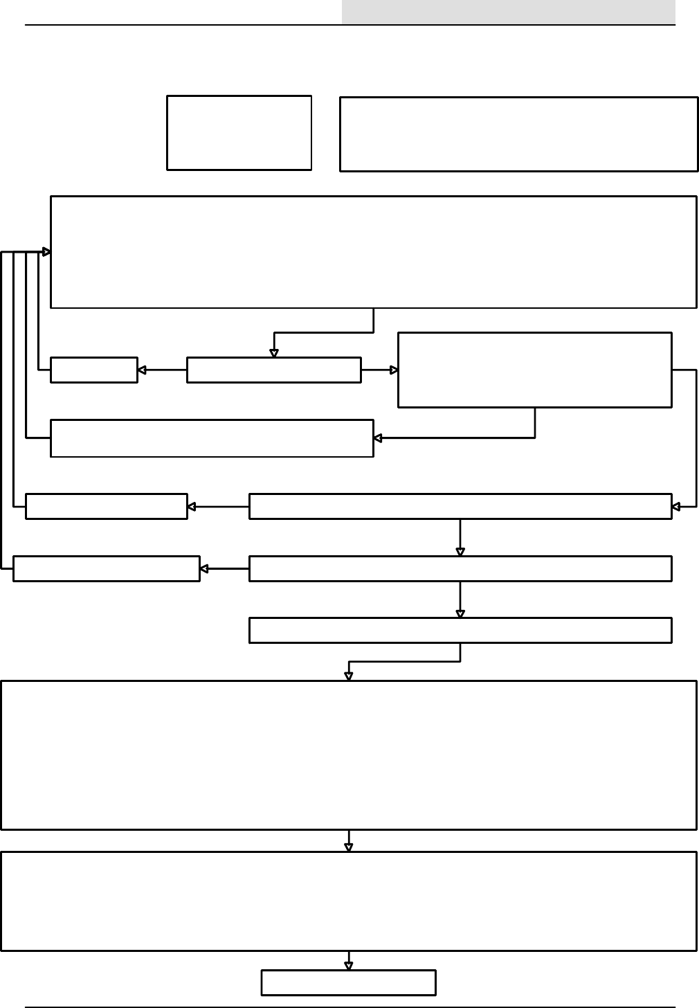
First check for the following:
1. Correct hydraulic oil level
2. Propel pedel is enabled
3. Recovery tank is not full
Note: Normal operation to lower the scrub brushes are dependent upon
pressing the scrub brush switch, the scrub head down valve SV--7operation
(see sheet 4.A), activating the forward propel pedal limit switch, the
recovery tank is not full, and the engine in the high speed mode.
B. SCRUB PRESSURE SELECTION --allows the adjustment of down force to the scrub brush head .
The scrub brush system is designed to provide a selection of three increments of down force for a variety of cleaning applications. These three
selections are represented by displaying one, two, or three LED’s above the scrub button. One LED illuminated represents the lowest scrub brush
down force applied to the floor, all three LED’s illuminated would indicate the heaviest scrub brush down force to the floor. Once the selection is
made, it will remain stored until another change is made later. The operator can choose the appropriate selection based on the cleaning
requirements.
To change the selection:
1. Turn the key switch to the on position (starting the engine is not necessary).
2. Press the scrub button on the electronic instrument panel to momentarily turn the scrub function on and off.
3. Press and hold the scrub button, to scroll the selection of three available setpoints for brush down force.
C. FACTORY DEFAULT SETPOINTS
1. The machine is built with three setpoints that should work well for most applications. These setpoints correspond to the amount of DC current
supplied to the down force hydraulic solenoid valve (SV--8) during a scrubbing operation.
2. Approximate default scrubbing selection setpoint values in milliamperes (ma).:
Ist Scrubbing selection (1 LED) -- 20 ma.
2nd Scrubbing selection (2 LED’s) -- 350 ma.
3rd Scrubbing selection (3 LED’s) -- 645 ma.
A. SCRUB BRUSH HEAD DOWN FORCE ELECTRICAL CHECK
Two visual checks are provided to help determine if the scrub brush down force solenoid SV--8 is working correctly.
1. With the key switch in on position (Caution----Do not start the engine!) , the OK light on the indicator light cluster should be on. If the
OK light is not on, the electronic instrument panel may be detecting a shorted output.
2. With the key switch in on position (Caution----Do not start the engine!) , press the scrub button on the electronic instrument panel. If
none of the LED’s for down force selection are illuminated, an open circuit with SV--8 has been detected.
Check for the following conditions:
Has circuit breaker CB--7 tripped?
yes
Reset CB--7
yes
ok With the key switch in the on position (Caution, do not
start the engine), use a digital voltmeter to check for
battery voltage on the 53J/ORN wire at the connector of
SV--8. Does the meter indicate battery voltage?
no
Check the wiring for the 53/ORA circuit between circuit breaker
CB--7 and SV--8. Repair or replace the defective wiring.
With a digital ohmmeter, check to see that the resistance of SV--8 is about 7.5 ohms.
no
yes
ok
Replace the solenoid coil.
no
ok
Check wire 56/BLU between SV--8 and the electronic instrument panel connector
terminal W2
Repair or replace the defective wiring.
yes
ok bad
wiring
ok
Use the following information to see if the down pressure selection setpoints are correct
Proceed to the next page
ELECTRICAL
5-105
8200/8210 330065 (3--01)
SCRUB HEAD DOWN FORCE
(SV--8) (8200)

E. SCRUB PRESSURE SETPOINT CALIBRATION (USING A DIGITAL MULTIMETER)-- Checking the down force output from the electronic
instrument pan el to SV--8, and allows a precise adjustment of individual setpoints for each of the three down pressure selections.
1. Instead of using the fuel guage LED’s for DC current reference to SV--8, this value can be measured by connecting a digital multimeter in series
with one of the wires to the coil of SV--8. Use caution when connecting the meter, and select a range to measure 0--1000 milliamperes.
2. Disconnect the scrub down force solenoid SV--8.
3. Install a jumper between the SV--8 connector and the harness connector for SV--8, that will enable a series connection for measuring the DC
current through one of the wires to the SV--8 solenoid coil with a digital multimeter.
4. Enter the scrub force adjustment mode using the procedure outlined above, (steps 1 and 2).
5. Choose the the desired down force selection, (as in step 3 above).
6. While observing the meter, adjust the setpoints to the desired values using the defualt information in B.2 above as a reference point:
a. Press and hold the detergent selection button to increase the brush down force selection setpoint. This will increase the DC current to
SV--8 for that selection as indicated on the meter.
b. Press and hold the squeegee button to decrease the brush down force selection setpoint. This will decrease the DC current to
SV--8 for that selection as indicated on the meter.
c. After adjusting each selection for its desired setpoint, press the scrub button to the off state, (scrub force selection LED’s turn off)
in order to store the new setpoint in to memory. Then press and hold the scrub button to scroll to the next selection.
d. When each of the selections have the desired setpoint, turn the key switch off, to leave the scrub force adjustment mode.
D. SCRUB PRESSURE SETPOINT CALIBRATION (USING THE FUEL GUAGE LED’S). --Allows the adjustment of individual setpoints for each
of the three down pressure selections.
In special situations, a customized calibration other than the factory default settings, may be used to provide a unique performance characteristic.
To change the setpoint:
1. Turn the key switch to the off position.
2. While pressing the edge scrub button on the instrument panel, turn the key switch to the on position and hold the edge scrub button for 15
seconds until the the edge scrub LED starts to flash (Caution----Do not start the engine!) . You are now in the scrub force adjustment mode.
3. Press and hold the scrub button until the appropriate selection is displayed by the scrolling LED’s above the scrub button.
4. To assist with the adjustment, the 4 fuel guage LED’s display specific values within the adjustment range (only in the scrub force adjust mode).
1st fuel guage LED turns on at 11ma. of current supplied to SV--8.
2nd fuel guage LED turns on at 350ma. of current supplied to SV--8.
3rd fuel guage LED turns on at 642ma. of current supplied to SV--8.
4th fuel guage LED turns on at 745ma. of current supplied to SV--8.
5. Adjust the setpoint for each selection using the following procedure:
a. Enter the scrub brush down force adjust mode using the above procedure.
b. Press and hold the scrub button until the appropriate selection is displayed by the scrolling LED’s above the scrub button.
c. Press and hold the detergent selection button to increase the brush down force selection setpoint . This will increase the DC current
to SV--8 for that selection causing more LED’s to light if the detergent button is continued to be held.
d. Press and hold the squeegee button to decrease the brush down force selection setpoint . This will decrease the DC current to
SV--8 for that selection causing less LED’s to light if the squeegee button is continued to be held.
e. After adjusting each selection for its desired setpoint, press the scrub button to the off state, (scrub force selection LED’s turn off)
in order to store the new setpoint in to memory. Then press and hold the scrub button to scroll to the next selection.
f. When each of the selections have the desired setpoint, turn the key switch off, to leave the scrub force adjustment mode.
Note: Be patient when using the LED’s as a reference for down force adjustment, sometimes it takes a long period of time to hold either the
detergent button or the squeegee button to affect a change with the fuel guage LED’s.
or
ELECTRICAL
5-106 8200/8210 330065 (3--01)
SCRUB HEAD DOWN FORCE
(SV--8) (8200)--continued

Edge Scrub
Shifts OK
To check the scrub brush head edge scrub operation.
1. Start the engine.
2. Press the scrub button on the electronic instrument panel and notice that the engine changes to high speed.
3. Press the propel pedal forward (slightly) (Caution-- the machine may move forward) causing the scrub brush head to move down
and shift outward.
4. Press the edge scrub button again and notice that the brush head moves in.
5. Press the scrub button again and notice that the brush head raises and the brushes turn off.
6. Turn off the engine by turning the key switch to the off position.
With the above procedure, does the scrub brush head move out and in?
no
Is circuit breaker CB--7 tripped?
First check for the following:
1. Correct hydraulic oil level
2. Propel pedal is enabled
3. Recovery tank is not full
Checking the solenoid coil:
With the key in the off position:
1. Disconnect the Edge Scrub solenoid SV--13
connector from the wire harness.
2. Connect an ohmmeter to the two terminals on the
connector from the edge shift solenoid SV--13.
3.Check to see that the resistance of SV--13 is
about 7.5 ohms.
Is the resistance value about 7.5 ohms?
bad
wiring
Reset CB--7
yes
ok
Replace the defective solenoid.
ok
Note: Normal operation of the scrub brush lift is dependent upon
pressing the scrub brush switch, activating the forward propel
pedal limit switch, the recovery tank is not full, and the engine in the
high speed mode.
yes
no
no
Checkingthewiringwiththekeyswitchintheoff
position:
1. With an ohmmeter, check the 53E/ORN wiring
between circuit breaker CB--7 and the wire
harness connector at SV--!3.
2. With an ohmmeter, check the 57/PUR wire
between the wire harness connector at SV--!3
and the connector for the electronic instrument
panel at terminal X2 .
Do the wires check out good?
MANUAL MODE-- Checking the output from the electronic instrument panel to the edge scrub hydraulic solenoid valve:
1. While holding the ES button, turn the key switch to the on position ( do not start the engine ) and continue to hold for 15 seconds
until the left fuel gauge LED is illuminated.
2. Disconnect the edge scrub shift solenoid valve SV13 connector.
3. Measure with a digital voltmeter for battery voltage across 57/PUR and 53E/ORN at the harness connector.
4. Press the Edge Scrub button on the electronic instrument panel.
5. Notice that the meter shows battery voltage when the edge scrub function is enabled.
6. Reconnect the Edge Scrub solenoid SV--13 to the wiring harness.
Is there battery voltage when SV--13 is turned on?
Repair or replace the defective wiring.
ok
no
Check the
hydraulic
system.
yes yes
ok
ELECTRICAL
5-107
8200/8210 330065 (3--01)
SCRUB HEAD EDGE
SCRUB WILL NOT
SHIFT (8200)
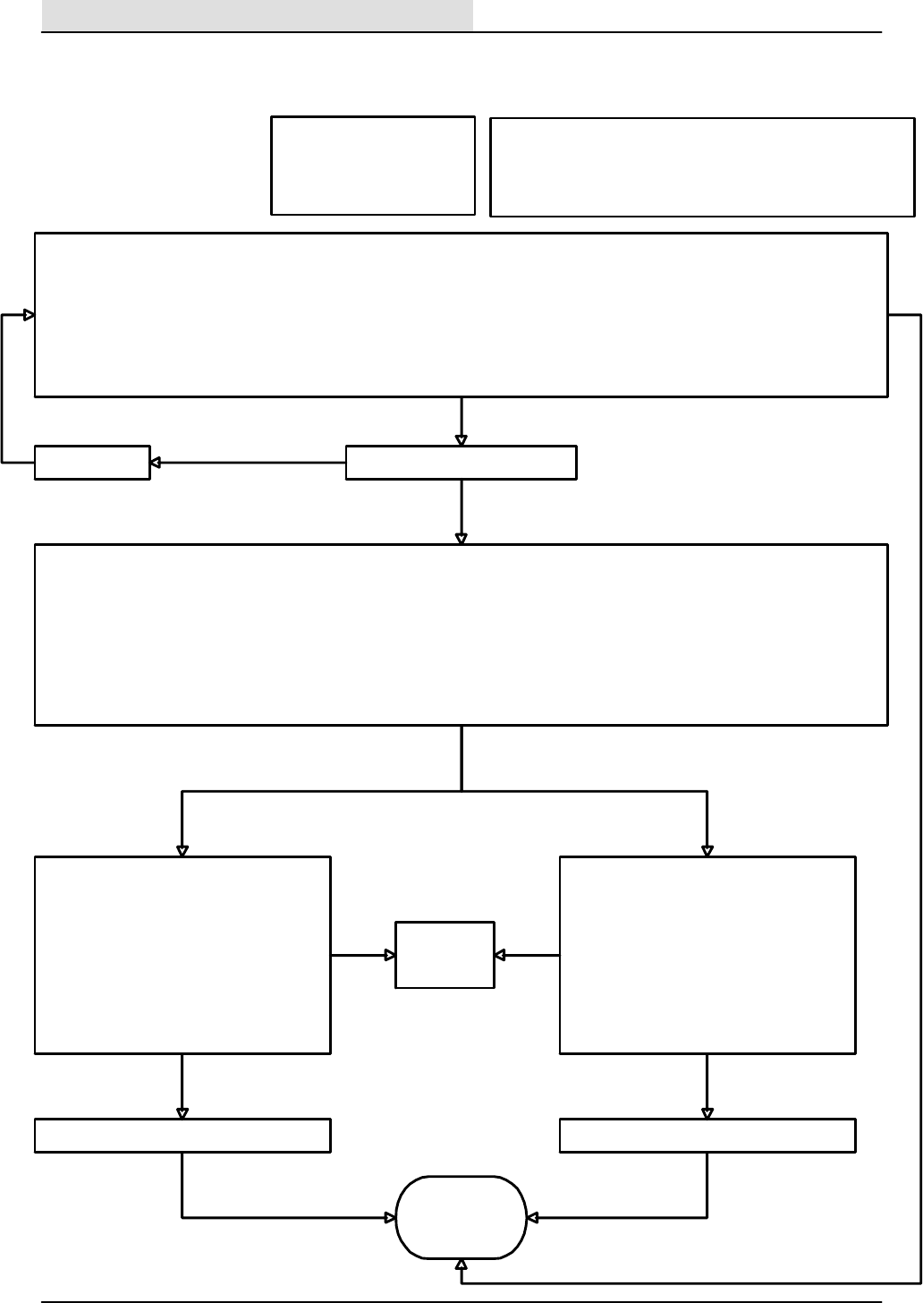
Squeegee
works OK
To check the squeegee lower operation.
1. Start the engine.
2. Press the squeegee button on the electronic instrument panel and notice that the engine changes to high speed.
3. The vacuum fan will turn on and the squeegee will move down.
4. Move the propel pedal slightly to reverse (Caution-- the machine may move!) and notice that the squeegee moves up.
5. Turn off the engine by turning the key switch to the off position.
With the above procedure, does the scrub brush head move out and in?
no
Is circuit breaker CB--7 tripped?
First check for the following:
1. Correct hydraulic oil level
2. Propel pedal is not in reverse
3. Recovery tank is not full
Checking the solenoid coil:
With the key in the off position:
1. Disconnect the squeegee lower solenoid
SV--4 connector from the wire harness.
2. Connect an ohmmeter to the two terminals
on the connector from the squeegee lower
solenoid SV--4.
3.Check to see that the resistance of SV--4 is
about 7.5 ohms.
Is the resistance value about 7.5 ohms?
no
Reset CB--7
yes
ok
Replace the defective solenoid.
ok
Note: Normal operation of the squeegee lower function is
dependent upon pressing the scrub or squeegee button, activating
the forward or reverse propel pedal limit switch, the recovery tank is
not full, and the engine in the high speed mode.
yes
no
no
Checkingthewiringwiththekeyswitchinthe
off position:
1. With an ohmmeter, check the 53F/ORN
wiring between circuit breaker CB--7 and the
wire harness connector at SV--4.
2. With an ohmmeter, check the 54/YEL wire
between the wire harness connector at SV--
4 and the connector for the electronic
instrument panel at terminal X1 .
Do the wires check out good?
MANUAL MODE-- Checking the output from the electronic instrument panel to the squeegee lower hydraulic solenoid valve:
1. While holding the ES button, turn the key switch to the on position ( do not start the engine ) and continue to hold for 15 seconds
until the left fuel gauge LED is illuminated.
2. Disconnect the squeegee lower solenoid valve SV--4 connector.
3. Measure with a digital voltmeter for battery voltage across 54/YEL and 53F/ORN at the harness connector.
4. Press the squeegee button on the electronic instrument panel.
5. Notice that the meter shows battery voltage when the squeegee button is pressed.
6. Reconnect the Squeegee lower solenoid SV--4 to the wiring harness.
Is there battery voltage when SV--4 is turned on?
Repair or replace the defective wiring.
ok
no
Check the
hydraulic
system.
yes yes
ok
ELECTRICAL
5-108 8200/8210 330065 (3--01)
SQUEEGEE WILL NOT
LOWER (8200)

Scrub
vacuum fan
works OK
To check the scrub vacuum fan operation.
1. Start the engine.
2. Press the squeegee button on the electronic instrument panel and notice that the engine changes to high speed.
3. The vacuum fan will turn on and the squeegee will move down.
4. Move the propel pedal slightly to reverse (Caution-- the machine may move!) and notice that the squeegee moves up.
5. Move the pedal back to neutral and press the squeegee button to raise the squeegee and turn off the vacuum fan after 6 seconds.
6. Turn off the engine by turning the key switch to the off position.
With the above procedure, does the scrub brush head move out and in?
no
Is circuit breaker CB--6 tripped?
First check for the following:
1. Correct hydraulic oil level
2. Recovery tank is not full
3. Vacuum lines are not restricted
Checking the solenoid coil:
With the key in the off position:
1. Disconnect the scrub vacuum fan solenoid
SV--1 connector from the wire harness.
2. Connect an ohmmeter to the two terminals
on the connector from the scrub vac fan
solenoid SV1.
3.Check to see that the resistance of SV--1 is
about 7.5 ohms.
Is the resistance value about 7.5 ohms?
no
Reset CB--6
yesok
Replace the defective solenoid.
ok
Note: Normal operation of the scrub vacuum fan function is
dependent upon pressing the scrub or squeegee button, activating
the forward or reverse propel pedal limit switches, the recovery tank
is not full, and the engine in the high speed mode.
yes
no
no
Checkingthewiringwiththekeyswitchinthe
off position:
1. With an ohmmeter, check the 47D/YEL
wiring between circuit breaker CB--6 and the
wire harness connector at SV--1.
2. With an ohmmeter, check the 52/BRN wire
between the wire harness connector at SV--
1 and the connector for the electronic
instrument panel at terminal W3 .
Do the wires check out good?
MANUAL MODE-- Checking the output from the electronic instrument panel to the vacuum fan hydraulic solenoid valve:
1. Turn the key switch to the on position (Caution-- do not start the engine ).
2. Disconnect the scrub vacuum fan solenoid valve SV--1 connector.
3. Measure with a digital voltmeter for battery voltage across wires 52/BRN and 47D/YEL at the harness connector for the scrub vacuum
fan .
4. Press the squeegee button on the electronic instrument panel.
5. Notice that the meter shows battery voltage when the squeegee button pressed.
6. Reconnect the scrub vacuum fan solenoid SV--1 to the wiring harness.
Is there battery voltage when SV--1 is turned on?
Repair or replace the defective wiring.
ok
no
Check the
hydraulic
system.
yes yes
ok
ELECTRICAL
5-109
8200/8210 330065 (3--01)
SCRUB VACUUM FAN WILL
NOT RUN (8200)
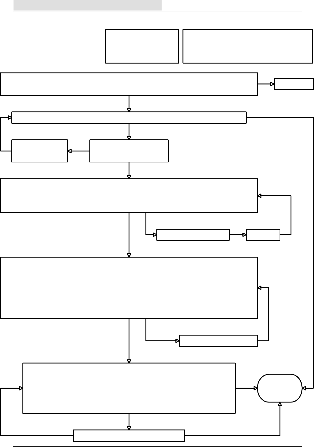
Note: Normal operation of the scrub solution control is
dependent upon pressing the scrub button, activating the
forward or reverse propel pedal limit switches, the recovery
tank is not full, and the engine in the high speed mode.
During a scrubbing operation, is a scrubbing solution applied to the floor near the scrub brushes?
First check for the following:
1. Correct solution tank level
2. Recovery tank is not full
3. Solution lines are not restricted
After starting the engine, pressing the scrub button on the electronic instrument panel, and moving the propel pedal
slightly forward (Caution-- the machine may move!), the scrub brush head should lower and the brushes will turn on.
yes
See page 5--82
no
Is the solution control rocker switch
selected for the desired flow?
Select either the high or
low solution flow rate.
CHECKING THE SOLUTION CONTROL ROCKER SWITCH:
1. Using a digital voltmeter, Connect the positive lead to any 53/ORN wire at the solution control rocker switch.
2. Connect the negative meter lead to any 13/BLK wire.
3. Turn the key switch to the on position, (Caution-- do not start the engine)
Does the meter display battery voltage?
Solution
control works
OK
yes
no
ok no
yes
Checking the solenoid coils:
With the key in the off position:
1. Disconnect each of the solution control solenoid connectors from the wire harness.
2. Connect an ohmmeter to the two terminals on the connector from each of the solution control
solenoids.
3. Check to see that the resistance of each coil measures about 13.5 ohms.
Is the resistance value about 13.5 ohms?
Replace the defective solution control solenoid.
Repair or replace the bad wires.
Checking the wiring with the key switch in the off position:
1. With an ohmmeter, check the 53/ORN wiring between circuit breaker CB--7 and the wire harness connector at the
solution control rocker switch.
2. With an ohmmeter, check the 59A/BRN wire between the wire harness connector at the solution control rocker
switch, and the connector for the #1 solution control valve .
3. With an ohmmeter, check the 60/ORA wire between the wire harness connector at the solution control rocker switch,
and the connector for the #2 solution control valve .
4. With an ohmmeter, check the 55B/GRY and 55C/GRY wires between the wire harness connector at the solution
control solenoid valves and the X3 terminal for the connector at the electronic instrument panel .
Do the wires check out good?
yes
no
ok
yes
yes
no
ok
Is circuit breaker CB--7 tripped? Reset CB--7
no
yes ok
ELECTRICAL
5-110 8200/8210 330065 (3--01)
SOLUTION CONTROL
WILL NOT OPERATE
(8200)
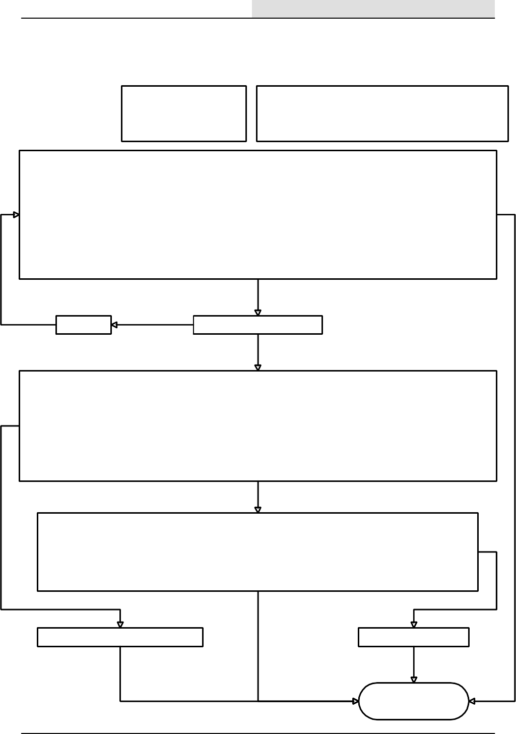
First check for the following:
1. Correct detergent tank level
2. Recovery tank is not full
3. Solution switch is on high or low
Note: Normal operation of the detergent metering pump requires that
one of the detergent flow rates is selected on the electronic instrument
panel, the solution control rocker switch must be set to high or low, and
operating in the scrub mode with the machine propelling forward.
Repair or replace the wires
To check the detergent metering pump operation :
1. Disconnect the hitch pin on the scrub brush head and swing open the right side guide arm .
2. Open the right side main sweeping brush access door.
3. Find the detergent metering pump located under the floor, just below the foot pedals
3. Turn the key switch to the on position (Caution--do not start the engine).
4. Press the scrub button on the electronic instrument panel.
5. Select the solution control rocker switch to either high or low flow .
6. Press the detergent metering button on the electronic instrument panel to either high or low flow.
7. Move the propel pedal slightly to the forward direction.
8. Notice if the pump motor is running.
9. Turn off the key switch to the off position.
With the above procedure, does the detergent metering pump operate?
no
yes
Solution control
works OK
Is circuit breaker CB--6 tripped?Reset CB--6
yesok
MANUAL MODE-- Checking the output from the electronic instrument panel to the edge scrub hydraulic solenoid valve:
1. While holding the ES button, turn the key switch to the on position (Caution, do not start the engine ) and continue to hold for 15
seconds until the left fuel gauge LED is illuminated.
2. Disconnect the detergent metering pump motor connector from the wire harness.
3. Measure with a digital voltmeter for DC voltage across 47K/YEL and 51/GRY at the harness connector to the detergent pump.
4. Press the detergent button on the electronic instrument panel.
5. The meter should indicated almost battery voltage when the high detergent flow rate is selected, and less than half of battery voltage
when the low flow rate is selected.
6. Reconnect the detergent metering pump motor connector to the wire harness.
Is there a DC voltage when the detergent pump is turned on?
no
no
Checking the wiring with the key switch in the off position:
1. With an ohmmeter, check the 47K/YEL wiring between circuit breaker CB--6 and the wire harness connector at the
detergent metering pump motor connector.
2. With an ohmmeter, check the 51/GRY wire between the wire harness connector at the detergent metering pump
motor, T3 terminal at the connector for the electronic instrument panel .
Do the wires check out good?
yes
Replace the detergent metering pump motor.
ok ok
yes
no
ELECTRICAL
5-111
8200/8210 330065 (3--01)
DETERGENT PUMP WILL
NOT OPERATE (8200)

First check for the following:
1. Solution tank not full.
2. Recovery tank level is
above the lower level
switch point.
3. Solution control rocker
switch is on selected to
thehighorlow.
Note: The Extended Scrub (ES) system uses the ES pump to recycle scrub
water from the recovery tank to the solution tank. The ES function is
enabled by the key switch in the on position, and pressing the ES button
on the electronic instrument panel. The solution tank level must be less
than full, and the recovery tank level above its lower level switch. The ES
pump will continue to run for 40 seconds after the level in the recovery tank
has dropped below its lower switch, or after the solution tank level has
approached its level switch (solution tank full).
To check the ES system operation :
1. Turn the key switch to the on position, (Caution--do not start the engine).
2. Open the access covers on both recovery and solution tanks.
3. Raise the lower level float in the recovery tank for 5 seconds to run the ES pump for a 40 second time interval.
4. Notice that the pump motor starts to run after the lower recovery tank level switch is activated for at least 5 seconds.
5. Try step 3 again, but now activate the solution tank level switch momentarily to stop the ES pump.
6. Turn the key switch to the off position.
With the above procedure, does the detergent metering pump operate?
no
yes
Extended Scrub (ES) system works OK
Is circuit breaker
CB--6 tripped?
Reset
CB--6
yes
ok
MANUAL MODE-- Checking the output from the electronic
instrument panel to the ES pump :
1. While holding the ES button, turn the key switch to the on
position (Caution-- do not start the engine! ) and continue
to hold for 15 seconds until the 2nd from the left fuel gauge
LED flashes.
2. Toggle the ES button again to start and stop the ES pump.
(The backblast valve will cycle along with the ES pump)
3. Turn the key switch to the off position.
Does the ES pump run?
no
Checking the ES pump wiring --key switch in the off position:
1. With an ohmmeter, check the 47B/YEL wiring between
circuit breaker CB--6 and the wire harness connector at the
ES pump motor connector.
2. With an ohmmeter, check the 50/PUR wire between the
wire harness connector at the ES pump motor and the T2
connector terminal for the electronic instrument panel.
Do the wires check out good?
DIAGNOSTIC INPUT DISPLAY MODE-- checks the lower
recovery tank level switch circuit .
1. Turn the key switch to the off position .
2. Press and hold the scrub button on the electronic
instrument panel, and turn the key switch to the on position
(Caution----Do not start the engine!) until the 3rd fuel
gauge LED from the left starts to flash. You are now in the
diagnostic input display mode.
3. lift the lower float in the recovery tank while watching the
ES LED on the electronic instrument panel.
Does the ES LED illuminate when the float is lifted?
ok
Checking the lower recovery tank level switch:
1. Disconnect the front mounted switch connector from the
main harness.
2. With an ohmmeter, connect the meter leads to terminals
”A” and ”b” at the switch connector.
5. Move the float up and down while checking the meter.
Does the meter show a change while operating the float?
Replace the defective switch
Repair or
replace
the
defective
wiring.
yes
DIAGNOSTIC INPUT DISPLAY MODE-- checks the solution
tank level switch.
1. Turn the key switch to the off position.
2. Press and hold the scrub button on the electronic
instrument panel, and turn the key switch to the on position
(Caution----Do not start the engine!) until the 3rd fuel
gauge LED from the left starts to flash. You are now in the
diagnostic input display mode.
3. lift the lower float in the recovery tank while watching the ES
LED on the electronic instrument panel.
Does the ES LED illuminate when the float is lifted?
Checking the lower recovery tank level switch wiring:
1. With an ohmmeter, check the 13AG/BLK wire from the
lower recovery tank level switch harness connector to
Battery (--).
2. With an ohmmeter, check the 78/PUR wire between the
lower recovery tank level switch harness connector and the
electronic instrument panel harness connector at terminal
A3.
Do the wires check out good?
no
no
ok
no
yes
Replace the defective ES pump motor
no
yes
yes
yes
no
ok
ELECTRICAL
5-112 8200/8210 330065 (3--01)
EStWILL NOT
OPERATE (8200)
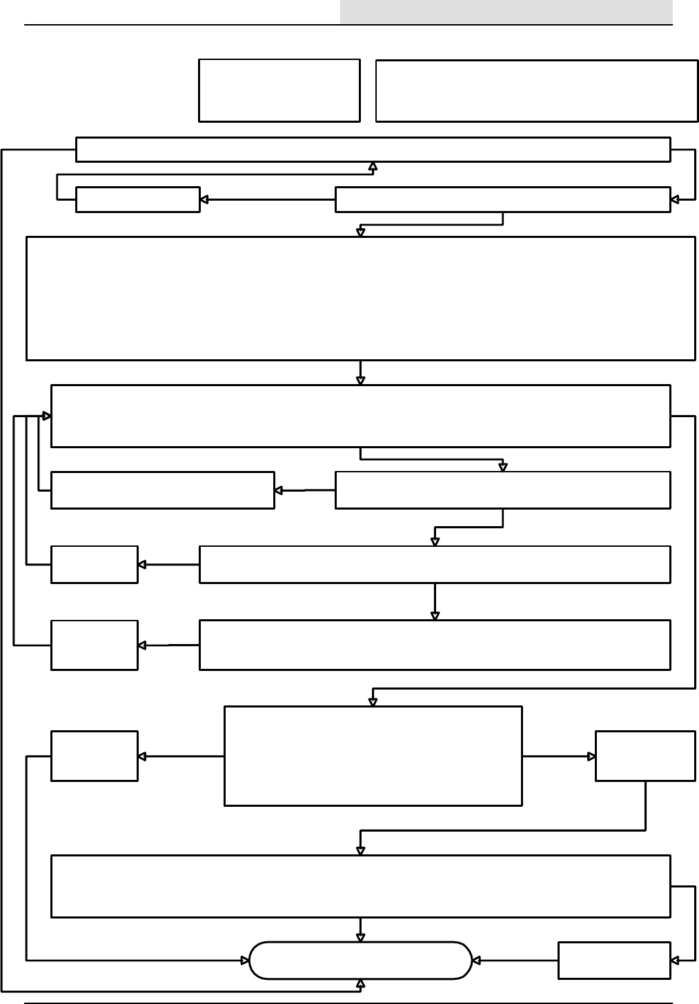
Main Sweeping brush works
With the engine running, does the main sweeping brush turn on when the main sweep soft key is pressed ?
no
Check the 15 amp circuit breaker CB--5 to see if it has tripped.
First check for the following:
1. Correct hydraulic oil level
2. Engine is runs properly
3. Hopper is fully lowered.
DIAGNOSTIC INPUT DISPLAY MODE-- checks the hopper down limit switch .
1. Start the engine and raise the hopper to the full up position.
2. Turn off the engine.
3. (Caution--install the safety bar to prevent the hopper from dropping).
4. While pressing the Tennant logo button, turn the key switch to the on position (Caution--do not start the engine), and hold the logo
button for 15 seconds.
5.Press the Tennant logo button once more to enter maiuntenance mode 2.
6. Press the button associated with the input display message on the display.
7. Note the graphic symbols of various functions on the display.
no
Checking the hopper down limit switch input:
Using the graphic symbol of a model 8010 machine on the display, watch the hopper in the graphic raise and lower while manually
activating the hopper down limit switch.
Does the hopper on the graphic display change when the limit switch is activated?
ok
Checking the hopper down limit switch:
With the key switch off, use an ohmmeter to check the hopper door closed limit switch contacts .
Checking the wiring:
1. Check the wiring from battery (--) to the 13D//BLK wire at the switch.
2. Check the 63/BLU wire between the switch and the machine controller connector at terminal C3
switch is ok
Replace the
defective switch
switch
is
bad
ok
Repair or replace
the defective
wiring
ok
bad
wiring
Reset the circuit breaker yes
ok
Switch mounting:
Is the switch mounted so that it operates correctly?
no
yes
Adjust the switch so that it operates when
activated by the hopper lift arm. nook
Check the main sweep brush hydraulic solenoid valve:
1. Turn the key on, (engine off).
2. Activate the sweep mode
3. Disconnect valve SV5.
4. Measure with a digital voltmeter for battery voltage across
43/PUR and 37L/GRY at the connector.
5. Turn the key switch off.
Repair or replace
the defective wiring
Replace the
defective
solenoid.
battery
voltage
no
battery
voltage
yes
ok
yes
Note: Operation of the main sweep brush is
dependent upon the hopper down limit switch,
and the sweep function enabled.
yes
With the key switch in the off position,check the wiring with an ohmeter:
1. Check the wiring from 37/Gry at CB--5 to the 37L/GRY wire at the solenoid.
2. Check wire 43/PUR from the electronic instrument panel connector (terminal E3) to the SV5 solenoid.
Do the wires check out good ?
ok
Repair or replace the
defective wiring
no
ok
ELECTRICAL
5-113
8200/8210 330065 (3--01)
MAIN SWEEPING
BRUSH WILL NOT
RUN (8210)
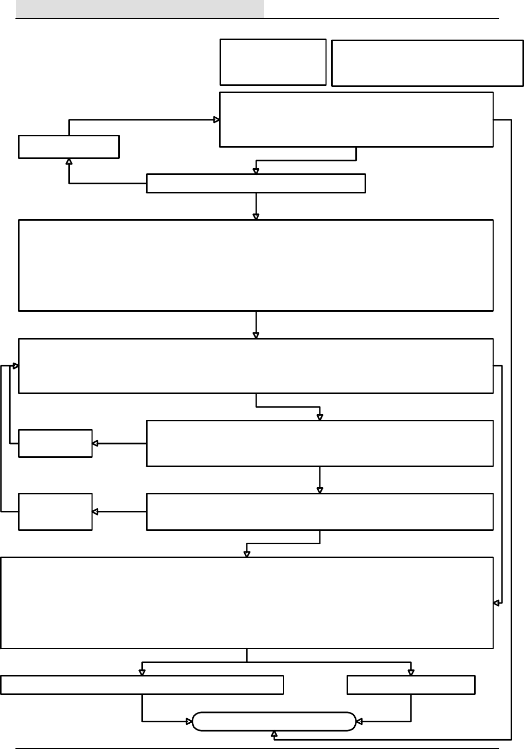
Side Sweeping brush works
With the engine running, does the side sweep brush turn on when:
1. The sweeping hopper is fully lowered.
2. The main sweep function is enabled on the electronic instrument panel.
3. The side sweep function is not disabled on the electronic instrument panel.
no
Check the 15 amp circuit breaker CB--5 to see if it has tripped.
First check for the following:
1. Correct hydraulic oil level
2. Engine is runs properly
3. Hopper is fully lowered
DIAGNOSTIC INPUT DISPLAY MODE-- checks the hopper down limit switch.
1. Start the engine and raise the hopper to the full up position.
2. Turn off the engine.
3. (Caution--install the safety bar to prevent the hopper from dropping).
4. While pressing the Tennant logo button, turn the key switch to the on position (Caution--do not start the engine) , hold the logo
button for 15 seconds.
5.Press the Tennant logo button once more to enter maiuntenance mode 2.
6. Press the button associated with the input display message on the display.
7. Note the graphic symbol representations of various machine functions on the display.
no
Checking the hopper down limit switch input:
Using the graphic symbol of a model 8010 machine on the display, watch the hopper in the graphic on the electronic instrument panel
raise and lower while manually activating the hopper down limit switch (hopper still in the raised position with the safety bar in
place ).
Does the hopper on the graphic display move up and down when the limit switch is activated?
ok
Repair or replace
the defective wiring
ok
bad
wiring
Reset circuit breaker CB--5
yes
ok
Checking the wiring:
1. Turn the key switch to the off position and use an ohmmeter to check the 63/BLU wire from the
hopper down limit switch to the C3 terminal of the connector to the electronic instrument panel.
2. Check the 13D/BLK wire between the switch and the battery negative(--).
Repair or replace defective wiring between the controller and the solenoid valve Replace the defective solenoid.
no battery voltage
ok ok
yes
Note: Operation of the side sweep brush is dependent
upon the hopper down limit switch, the sweep function
enabled, and the side sweep function not disabled.
wiring is ok
Battery voltage
Checking the limit switch:
1. With an ohmmeter, check the contacts of the hopper down limit switch.
Does the limit switch contacts check out ok?
yes
Replace the limit
switch no
no
ok
switch is ok
MANUAL MODE-- checks the output of the hydraulic side brush solenoid. (Caution--do not start the engine)
1. Disconnect the side sweep solenoid (SV--3) and connect a voltmeter to the harness terminals of the 37C/GRY and 46/ORA wires.
1. While pressing the Tennant logo button, turn the key switch to the on position and continue to hold the Tennant logo button for 15 seconds.
2. Press the button associated with the manual mode message (lower left).
3. Press the button associated with the sweeping function graphic (upper right) .
4. Repeatedly press the button associated with the side sweep brush function graphic (middle right).
6. Check the voltmeter for battery voltage when the side sweep brush function is toggled.
7. When the function is active, it is indicated by the graphic of the side sweep brush with a down arrow for on and an up arrow for off.
Does the meter indicate battery voltage the side sweep brush function when it is turned on ?
ELECTRICAL
5-114 8200/8210 330065 (3--01)
SIDE BRUSH WILL
NOT RUN (8210)
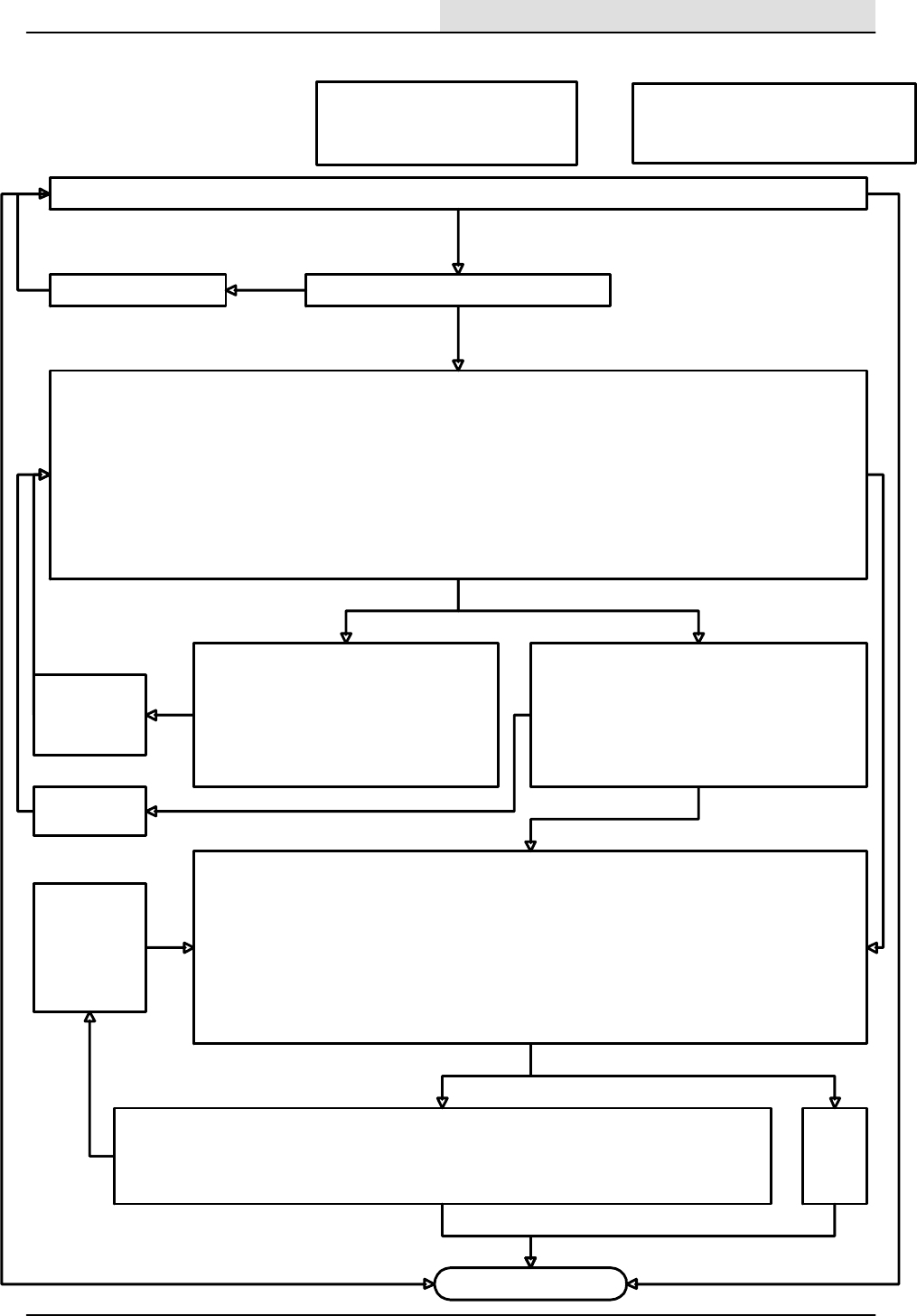
Vacuum Fan works
With the engine running, does the sweep vacuum fan turn on by pressing the sweep function button when the hopper is down ?
no
Is the 15 amp circuit breaker CB--5 tripped?
First check for the following:
1. Hydraulic system is functioning properly
2. Engine is runs properly
3. Hopper is fully lowered
Checking the hopper Thermal Sentry switch:
1. Remove the switch from its mounting.
2. With an ohmmeter, check the Thermal Sentry
switch by holding a small flame to the switch head .
3. The meter should indicate a closed contact when
activated by heat.
Does the switch respond to heat properly?
Replace the
defective switch
no
ok
Repair or replace
the defective
wiring
ok
no
Reset circuit breaker CB--5
yes
ok
no
Checking the wiring:
1. With an ohmmeter, check the 13BC/BLK wire
from the hopper thermal switch to Battery (--).
2. With an ohmmeter, check the 82/YEL wire
between the Thermal Sentry switch and the
instrument panel connector at terminal G1.
Do the wires check out good ?
Checking the sweep vacuum fan hydraulic solenoid :
1. Disconnect the sweep vacuum fan solenoid SV2.
2. Connect a digital voltmeter and measure for battery voltage across 37J/GRY and 39/ORN at the connector.
3. Turn the key switch to the on position, (Caution--do not start the engine) .
4. Select the button associated with the sweep function to turn on the fan output (the LED should be on next
to the fan icon).
5. Observe that the voltmeter indicates battery voltage when the fan is on.
6. Turn the key switch to the off position.
5. Reconnect the sweeping vacuum fan solenoid.
Does the meter indicate a voltage when the sweep vacuum fan is active ?
Repair or replace
the defective
wiring between
the electronic
instrument panel
and the valve
solenoid.
Replace
the
defective
solenoid
no
no
ok
yes
Note: Operation of the sweeping vacuum fan
is dependent upon the hopper down switch
and the hopper thermal sentry switch.
yes
ok
yes
no
yes
yes
DIAGNOSTIC INPUT DISPLAY MODE-- checks the Thermal Sentry switch input.
1. Open the hopper filter cover to gain access to the underside of the hopper filter cover area.
2. Disconnect the two individual wires to the Thermal Sentry switch mounted next to the filter shaker motor.
3. While pressing the Tennant logo button, turn the key switch to the on position (Caution--do not start the engine) , and hold the
logo button for 15 seconds.
4. Press the Tennant logo button once more to enter maintenance mode 2.
5. Press the button associated with the input display message on the display.
6. Jumper the two wires and observe that both the LED associated with the icon of the hopper, and the cluster indicator light for the
Thermal Sentry illuminate.
7. Reconnect the wires to the switch and secure the cover to the hopper.
Do the LED and Thermal Sentry light come on when the wires are jumpered ?
yes
Checking the wiring:
1. With an ohmmeter, check the 37/GRY circuit between CB--5 and the sweep vacuum fan solenoid SV--2 .
2. With an ohmmeter, check the 39/ORA wire between the sweep vacuum fan solenoid SV--2 and the
instrument panel connector at terminal S3.
Do the wires check out good ?
ok
ELECTRICAL
5-115
8200/8210 330065 (3--01)
SWEEPING VACUUM
FAN WILL NOT
RUN (8210)
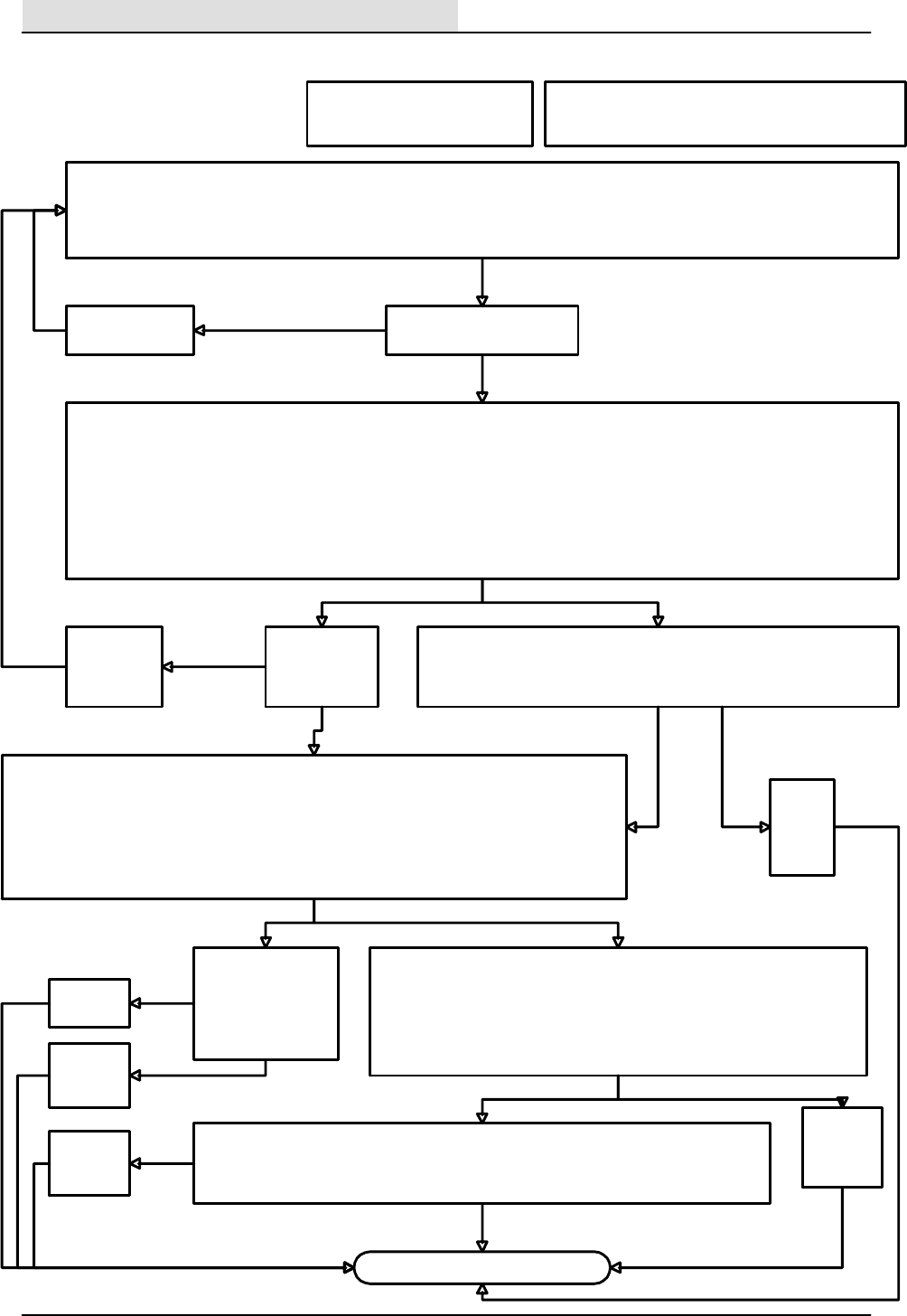
Filter Shaker Motor works
Does the filter shaker turn on by when the following conditions exist?
1. The key switch is in on position.
2. The main sweeping mode is selected.
3. The main sweeping mode is then deselected or the button associated with the filter shaker is pressed.
(the filter shaker runs for 30 seconds after the sweeping vacuum fan is switched off)
no
Is the 15 amp circuit breaker
CB--5 tripped?
Check the output from the electronic instrument panel to the filter shaker motor relay.
1. Turn the key switch to the off position .
2. Disconnect M3 relay from the harness connector.
3. Using a digital voltmeter, connect the positive meter lead to the terminal of the 37B/GRY wire, and the negative meter lead to the
terminal of the 38/BRN wire at the M3 relay harness connector.
4. Turn the key switch to the on position, (Caution----Do not start the engine!)
5. Press the Tennant logo button twice (allow the graphic display time to change between screens).
6. Press the button associated with the filter shaker function on the electronic instrument panel.
Does the voltmeter display battery voltage for a 30 second time period ?
no
Reset circuit
breaker CB--5
yes
ok
Replace the
defective
filter shaker
motor.
no
CheckingthewiringtoM3relay:
With key in the off position, use an ohmmeter to check the 37/GRY wire from
CB5 to the M3 relay, and the 38/BRN wire from terminal T1 of the electronic
instrument panel to the M3 relay (terminal 85).
Is the 15 amp
circuit breaker
CB--8 tripped?
Reset circuit
breaker CB--8
yes
yes
ok
Check the output from the M3 filter shaker motor relay.
1. Using a digital voltmeter, connect the positive meter lead to the terminal of the 91/BLU wire,
and the negative meter lead to any 13/BLK wire.
2. Turn the key switch to the on position, (Caution-- --Do not start the engine!)
3. Press the Tennant logo button twice (allow the graphic display time to change between screens).
4. Press the button associated with the filter shaker function on the electronic instrument panel.
Does the voltmeter display battery voltage for a 30 second time period ?
no
Check the output from the M3 filter shaker motor relay at the shaker motor.
1. Using a digital voltmeter, connect the positive meter lead to the terminal of
the 91A/BLU wire, and the negative meter lead to the 13BD/BLK wire.
2. With the key switch in the on position, (Caution----Do not start the engine!)
3. Press the filter shaker button on the electronic instrument panel.
Does the voltmeter display battery voltage for a 30 second time period ?
With the key in the off
position, use an
ohmmeter to check
the 90/GRN wire
between CB--8 and M3
relay
no yes
Replace
relay M3
ok
Repair or
replace the
wiring
not ok
ok
ok
Checking the wiring to the shaker motor.
1. With the key in the off position, use an ohmmeter to check the 91/BLU and 91A/BLU wires
between M3 relay and the shaker motor connector.
2. Also with the ohmmeter, check from 13BD/BLK at the shaker motor connector to battery(--)
Repair or
replace the
wiring
yes
ok
no
not
ok
ok
ok
Repair or
replace
the
wiring
not
ok
ok
First check for the following:
1. The battery is fully charged.
2. The Thermal Sentry is functioning .
Note: The filter shaker motor normally cycles for 30 seconds
each time the sweeping vacuum fan has been shut off.
ELECTRICAL
5-116 8200/8210 330065 (3--01)
FILTER SHAKER WILL
NOT RUN (8210)
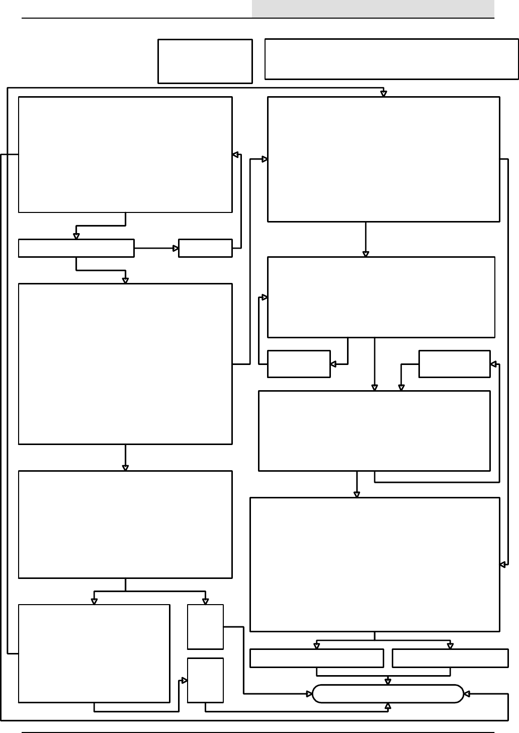
Scrub head goes up and down
To check the scrub brush down operation.
1. Start the engine.
2. Press the button associated with the scrub mode and
notice that the engine changes to high speed.
3. Press the propel pedal forward (slightly) causing the scrub
brushes to go down and on.
4. Press the scrub button again and notice that the brush
head goes up.
5. Turn off the key switch to the off position.
With the above procedure, does the scrub brush head go
down?
no
Is circuit breaker CB--7 tripped?
First check for the following:
1. Correct hydraulic oil level
2. Propel pedal is enabled
3. Recovery tank is not full
DIAGNOSTIC INPUT DISPLAY MODE-- checks the forward
propel limit switch input :
1. While pressing the Tennant logo button on the electronic
instrument panel, turn the key switch to the on position and
hold the scrub button for 15 seconds (Caution----do not
start the engin e!) .
2. Momentarily, press the Tennant logo to view the screen
with the INPUT DISPLAY message.
3. Press the button associated with the INPUT DISPLAY
message.
4. Push the propel pedal forward while watching the graphic
display on the electronic instrument panel.
Does an arrow icon representing the forward direction (with
respect to the icon of the 8210 machine above) become
visible when the propel pedal is moved forward?
Checking the forward propel limit switch:
1. Disconnect the hitch pin on the scrub brush head and
swing open the right side guide arm .
2. Open the right side main sweeping brush access door.
3. Disconnect the forward propel switch connector from the
main harness.
4. With an ohmmeter, connect the meter leads to terminals
”B” and ”C” at the connector of the switch.
5. Move the propel pedal forward while checking the meter.
Does the meter show a change while operating the pedal?
Replace
the
defective
switch
no
Repair or
replace
defective
wiring
bad wiring
Reset CB--7
yes
ok
Checking the wiring for the forward propel
switch:
1. With an ohmmeter, check the 13AC/
BLK wire from the forward propel
switch harness connector to Battery (--).
2. With an ohmmeter, check the 79/GRY
wire between the forward propel switch
harness connector and the electronic
instrument panel harness connector at
terminal D1.
Replace the defective solenoid.
ok
Note: Normal operation of the scrub brush lift is dependent upon pressing
the scrub brush button, activating the forward propel pedal limit switch, the
recovery tank is not full, and the engine in the high speed mode.
yes
no
no
yes
ok
DIAGNOSTIC INPUT DISPLAY MODE-- checks the recovery tank
full level switch input:
1. While pressing the Tennant logo button on the electronic
instrument panel, turn the key switch to the on position
(Caution----do not start the engine!) and hold the Tennant logo
button for 15 seconds .
2. Momentarily, press the Tennant logo button to view the screen
with the INPUT DISPLAY message.
3. Press the button associated with the INPUT DISPLAY message.
4. Lift the recovery tank full float while watching the LED next to the
graphic for recovery tank full, on the electronic instrument panel.
Does the recovery tank full LED change when the float is lifted?
Checking the wiring for the recovery tank full switch:
1. With an ohmmeter, check the 13AF/BLK wire from the recovery
tank full switch harness connector to Battery (--).
2. With an ohmmeter, check the 77/BLU wire between the recovery
tank full switch harness connector and the electronic instrument
panel harness connector at terminal B1.
Do the wires check out good?
yes
Checking the recovery tank full level switch:
1. Disconnect the recovery tank full switch from the connector
on the main harness (the upper level switch).
2. With an ohmmeter, connect the meter leads to terminals ”A”
and ”b” at the connector of the switch.
3. Move the float up and down while checking the ohmmeter.
Does the meter show a change while operating the float?
no
yes
Replace the
defective switch
no
Checking the scrub head down hydraulic solenoid:
1. Disconnect the scrub head down solenoid valve SV--7 connector.
2. Connect a digital voltmeter and measure for battery voltage across
wires 55A/GRN and 53H/ORN at the harness connector.
3. Turn the key switch to the on position (Caution--do not start the
engine!).
4. Press the button associated with the scrub function on the electronic
instrument panel.
5. Move the propel pedal forward slightly.
6. Notice the meter shows battery voltage when the button is turned on.
7. Turn the key switch to the off position.
8. Reconnect the scrub head down solenoid SV--7.
Is there battery voltage when SV--7 is turned on ?
yes
Repair or Replace
the defective wiring.
no
yes
Repair or replace the defective wiring.
no
ok
ok
ok
ok
ok
yes
ELECTRICAL
5-117
8200/8210 330065 (3--01)
SCRUB BRUSHES
WILL NOT RAISE/
LOWER (8210)
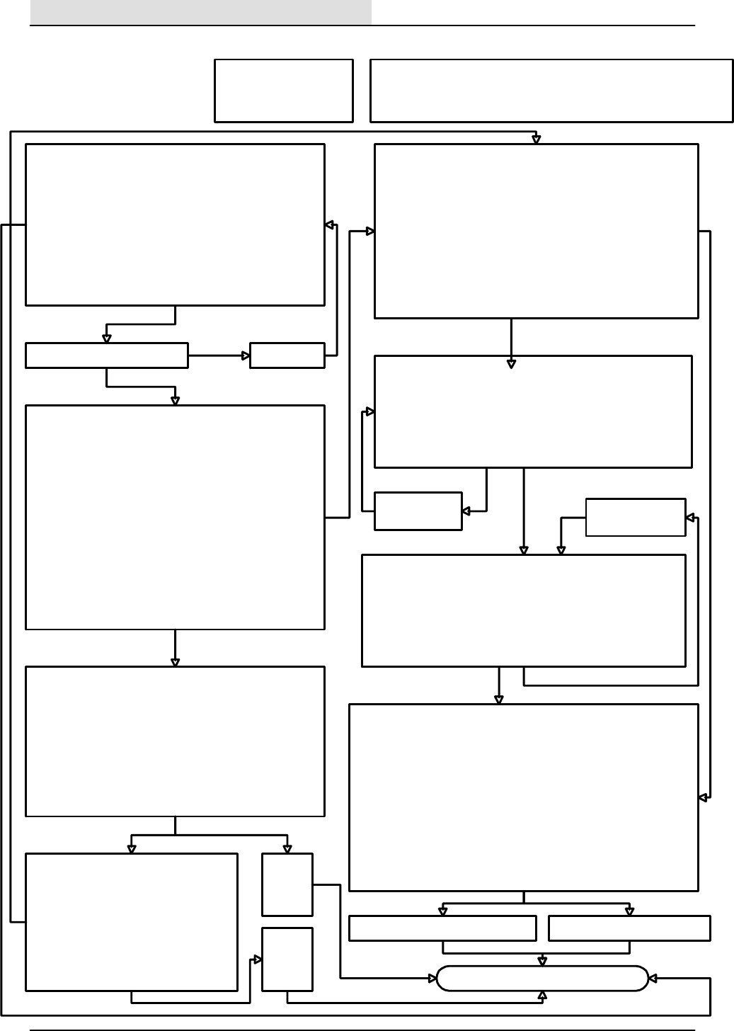
First check for the following:
1. Correct hydraulic oil level
2. Propel pedal is enabled
3. Recovery tank is not full
Note: Normal operation of the scrub brushes are dependent upon pressing
the scrub brush switch, activating the forward propel pedal limit switch, the
recovery tank is not full, and the engine in the high speed mode.
Scrub head goes up and down
To check the scrub brush down operation.
1. Start the engine.
2. Press the button associated with the scrub mode and
notice that the engine changes to high speed.
3. Press the propel pedal forward (slightly) causing the scrub
brushes to go down and on.
4. Press the scrub button again and notice that the brush
head goes up.
5. Turn off the key switch to the off position.
With the above procedure, does the scrub brush head go
down?
no
Is circuit breaker CB--7 tripped?
DIAGNOSTIC INPUT DISPLAY MODE-- checks the forward
propel limit switch input:
1. While pressing the Tennant logo button on the electronic
instrument panel, turn the key switch to the on position and
hold the scrub button for 15 seconds (Caution----do not
start the engin e!).
2. Momentarily, press the Tennant logo to view the screen
with the INPUT DISPLAY message.
3. Press the button associated with the INPUT DISPLAY
message.
4. Push the propel pedal forward while watching the graphic
display on the electronic instrument panel.
Does an arrow icon representing the forward direction (with
respect to the icon of the 8210 machine above) become
visible when the propel pedal is moved forward?
Checking the forward propel limit switch:
1. Disconnect the hitch pin on the scrub brush head and
swing open the right side guide arm .
2. Open the right side main sweeping brush access door.
3. Disconnect the forward propel switch connector from the
main harness.
4. With an ohmmeter, connect the meter leads to terminals
”B” and ”C” at the connector of the switch.
5. Move the propel pedal forward while checking the meter.
Does the meter show a change while operating the pedal?
Replace
the
defective
switch
no
Repair or
replace
defective
wiring
bad wiring
Reset CB--7
yes
ok
Checking the wiring for the forward propel
switch:
1. With an ohmmeter, check the 13AC/
BLK wire from the forward propel
switch harness connector to Battery (--).
2. With an ohmmeter, check the 79/GRY
wire between the forward propel switch
harness connector and the electronic
instrument panel harness connector at
terminal D1.
Replace the defective solenoid.
ok
yes
no
no
yes
ok
DIAGNOSTIC INPUT DISPLAY MODE-- checks the recovery tank
full level switch input:
1. While pressing the Tennant logo button on the electronic
instrument panel, turn the key switch to the on position
(Caution----do not start the engine!) and hold the Tennant logo
button for 15 seconds .
2. Momentarily, press the Tennant logo button to view the screen
with the INPUT DISPLAY message.
3. Press the button associated with the INPUT DISPLAY message.
4. Lift the recovery tank full float while watching the LED next to the
graphic for recovery tank full, on the electronic instrument panel.
Does the recovery tank full LED change when the float is lifted?
Checking the wiring for the recovery tank full switch:
1. With an ohmmeter, check the 13AF/BLK wire from the recovery
tank full switch harness connector to Battery (--).
2. With an ohmmeter, check the 77/BLU wire between the recovery
tank full switch harness connector and the electronic instrument
panel harness connector at terminal B1.
Do the wires check out good?
yes
Checking the recovery tank full level switch:
1. Disconnect the recovery tank full switch from the connector
on the main harness (the upper level switch).
2. With an ohmmeter, connect the meter leads to terminals ”A”
and ”b” at the connector of the switch.
3. Move the float up and down while checking the ohmmeter.
Does the meter show a change while operating the float?
no
yes
Replace the
defective switch
no
Checking the scrub brushes on hydraulic solenoid:
1. Disconnect the scrub head down solenoid valve SV--6 connector.
2. Connect a digital voltmeter and measure for battery voltage across
wires 58A/GRY and 53G/ORN at the harness connector.
3. Turn the key switch to the on position (Caution--do not start the
engine!).
4. Press the button associated with the scrub function on the electronic
instrument panel.
5. Move the propel pedal forward slightly.
6. Notice the meter shows battery voltage when the button is turned on.
7. Turn the key switch to the off position.
8. Reconnect the scrub head down solenoid SV--6.
Is there battery voltage when SV--6 is turned on ?
yes
Repair or Replace
the defective wiring.
no
yes
Repair or replace the defective wiring.
no
ok
ok
ok
ok
ok
yes
ELECTRICAL
5-118 8200/8210 330065 (3--01)
SCRUB BRUSHES
WILL NOT TURN
ON (8210)

First check for the following:
1. Correct hydraulic oil level
2. Propel pedal is enabled
3. Recovery tank is not full
Note: Normal operation to lower the scrub brushes are dependent upon
pressing the scrub brush switch, the scrub head down valve SV--7 (see
sheet 4.A), the scrub down force solenoid SV--8, activating the forward
propel pedal limit switch, the recovery tank is not full, and the engine in the
high speed mode.
B. SCRUB PRESSURE SELECTION-- allows the adjustment of down force to the scrub brush head .
The scrub brush system is designed to provide a selection of four increments of down force for a variety of cleaning applications. These four
selections are represented by displaying one, two, three, or four arrows above the scrub brush icon on the display. One arrow represents the
lowest scrub brush down force applied to the floor, all four arrows displayed would indicate the heaviest scrub brush down force to the floor. Once
the selection is made, it will remain stored until another change is made later. The operator can choose the appropriate selection based on the
cleaning requirements.
To change the selection:
1. Turn the key switch to the on position (is not necessary to start the engine ).
2. Press and hold the button associated with the scrub function on the electronic instrument panel to scroll through down pressure settings.
3.Release the button when the desired setting is viewed.
A. SCRUB BRUSH HEAD DOWN FORCE ELECTRICAL CHECK
Two visual checks are provided to help determine if the scrub brush down force solenoid SV--8 is working correctly.
1. With the key switch in on position (Caution--Do not start the engine!) , the OK message will be visible on the graphic display. If the OK
message is not displayed, the electronic instrument panel may be detecting a shorted output and will display the associated output
terminal number on the connector for the electronic instrument panel.
For example: a message of ”W2” would indicate that the scrub down force solenoid (SV--8) connected to output ”W2” of the
connector from the electronic instrument panel is short circuited. The fault may be with the solenoid coil or the wiring to the coil.
2.
A.While pressing the Tennant logo button turn the key switch in on position (Caution--Do not start the engine!) , and hold the Tennant
logo button for 15 seconds.
B. Press the button associated with the PRESSURE ADJUSTMENT message on the display.
C. Located in the center of the display, a normal condition would be represented by an icon that appears like a vertical fuel gauge.
D. When an open circuit is detected, the vertical gauge will be gone, and four small horizontal lines will be displayed where the default
down pressure setpoints were previously located.
Check for the following conditions:
Has circuit breaker CB--7 tripped?
yes
Reset CB--7
yes
ok
Checking the output to the scrub down pressure valve solenoid:
1. Disconnect the SV--8 solenoid from the harness.
2. Connect a digital voltmeter to the SV--8 harness connector wires 53J/ORA and 56/BLU.
3. Turn the key switch to the on position (Caution, do not start the engine), press the button associated with the scrub function,
and move the propel pedal to the forward position.
Does the meter indicate battery voltage?
no
Checking the wiring to the scrub down pressure solenoid.
Using an ohmmeter, check the wiring for the 53/ORA circuit between circuit breaker CB--7 and SV--8. Also check
the 56/BLU wire between SV--8 and the electronic instrument panel at the connector terminal W2.
Does the ohmmeter indicate an open circuit ?
With a digital ohmmeter, check to see that the resistance of SV--8 is about 7.5 ohms.
no
yes
ok
Replace the solenoid coil. no
ok
ok
Use the following information to see if the down pressure selection setpoints are correct
Repair or
replace the
defective
wiring.
yes
Continued on the next page:
ELECTRICAL
5-119
8200/8210 330065 (3--01)
SCRUB HEAD
DOWN FORCE
(SV--8) (8210)
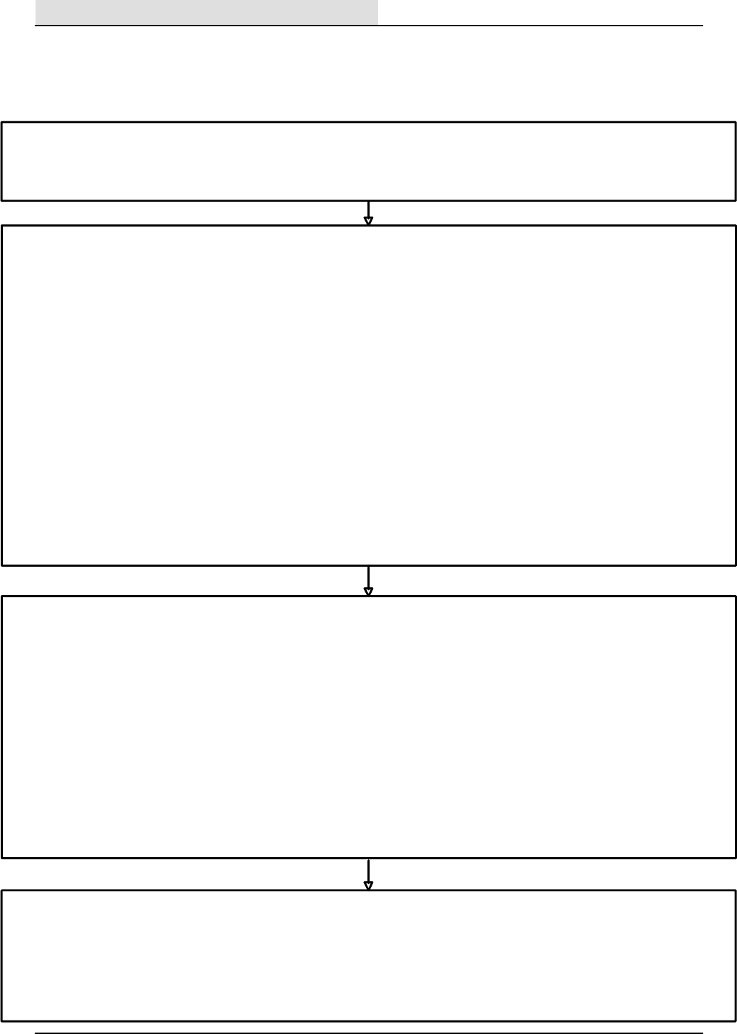
E. SCRUB PRESSURE SETPOINT CALIBRATION (USING A DIGITAL MULTIMETER)-- Checking the down force output from the electronic
instrument pan el to SV--8, and allows a precise adjustment of individual setpoints for each of the four down pressure selections.
1. Instead of using the fuel gauge LED’s for DC current reference to SV--8, this value can be measured by connecting a digital multimeter in series
with one of the wires to the coil of SV--8. Use caution when connecting the meter, and select a range to measure 0--1000 milliamperes.
2. Disconnect the scrub down force solenoid SV--8.
3. Install a jumper between the SV--8 connector and the harness connector for SV--8, that will enable a series connection for measuring the DC
current through one of the wires to the SV--8 solenoid coil with a digital multimeter.
4. Enter the scrub force adjustment mode using the procedure outlined above.
5. Choose the the desired down force selection.
6. While observing the meter, adjust the setpoints to the desired values using the default information in D.7 above for reference.:
a. Press and hold the button associated with the up arrow to increase the scrub brush down force selection setpoint. This will increase
the DC current to SV--8 for that selection as indicated on the meter and the vertical bar graph.
b. Press and hold the button associated with the down arrow to decrease the scrub brush down force selection setpoint. This will
decrease the DC current to SV--8 for that selection as indicated on the meter and the vertical bar graph.
c. After adjusting each selection for its desired setpoint, press the button associated with the scrub button to scroll to the next selection
as indicated by the arrows above the scrub brush icon on the display.
d. When each of the selections have the desired setpoint, Press the button associated with the EXIT message on the display.
D. SCRUB BRUSH PRESSURE STEEPING CALIBRATION (USING THE BAR GRAPH ON THE DISPLAY). --Allows the adjustment of
individual setpoints for each of the four down pressure selections.
In special situations, a customized calibration other than the factory default settings, may be used to provide unique performance characteristics.
To change the down pressure setpoints of the:
1. Turn the key switch to the off position.
2. While pressing the Tenant logo button on the instrument panel, turn the key switch to the on position and hold the Tenant logo button for 15
seconds until the display indicates ADJUST PRESSURE (Caution----Do not start the engine!) .
3. Press the button associated with the ADJUST PRESSURE message.
4. Notice that the display now has a vertical bar graph with four horizontal divisions. Each division line corresponds to a default steeping value for a
down pressure selection. (You are now in the scrub brush down pressure adjustment mode .)
5. To change a default steeping for a down force selection, hold the button associated with the scrub brush to scroll until the desired down force
selection is displayed with 1--4 arrows pointing down.
6. Use the two buttons associated with the up and down arrows viewed on the right side of the display to increase or decrease the value of down
pressure for that particular down pressure selection as viewed on the bar graph. As either button is held, notice that the bar on the bar graph will
change accordingly. (Note: be patient, this adjustment is very slow.)
7. For reference, the measured electrical current values for the factory default setpoints for the four scrub brush down pressure selections are
listed below. For exact measurement, these values can be measured with a digital ammeter connected in series with one of the solenoid wires to
SV--8.
1st division on the bar graph= 12ma. of current supplied to SV--8.
2nd division on the bar graph= 350ma. of current supplied to SV--8.
3rd division on the bar graph= 647ma. of current supplied to SV--8.
4th division on the bar graph= 751ma. of current supplied to SV--8.
C. FACTORY DEFAULT SETPOINTS
The machine has been designed with four standard (default) setpoints that should work well for the majority of applications. These setpoints
correspond to the amount of DC current supplied to the down force hydraulic solenoid valve (SV--8) during a scrubbing operation. For most
applications, these setpoints should be valid for the life of the machine . Setpoint # 4 is only available when not in the sweeping mode
F. RESTORE THE ELECTRONIC INSTRUMENT PANEL TO THE FACTORY DEFAULT SETPOINTS
1. Turn the key switch to the off position.
2. While pressing the Tennant logo button on the instrument panel, turn the key switch to the on position and hold the Tennant logo button for 15
seconds until the display indicates RESET SCRUB PRESSURE (Caution----Do not start the engine!).
3. Press the button associated with the RESET SCRUB PRESSURE message.
4. Press the button associated with the YES message.
5. The control will exit this mode automatically and return to the operating mode.
ELECTRICAL
5-120 8200/8210 330065 (3--01)
SCRUB HEAD DOWN FORCE
(SV--8) (8210)--continued

Edge Scrub Shifts OK
To check the edge scrub operation.
1. Start the engine.
2. Press the scrub button on the electronic instrument panel and notice that the engine changes to high speed.
3. Press the button associated with edge scrub function.
4. Press the propel pedal slightly forward (Caution--the machine may move forward!) causing the scrub brush head to move down
and shift outward.
5. Press the edge scrub button again and notice that the brush head moves in.
6. Press the scrub button again and notice that the brush head raises and the brushes turn off.
7. Turn the key switch to the off position.
With the above procedure, does the scrub brush head move out and in?
no
Is circuit breaker CB--7 tripped?
First check for the following:
1. Machine is equipped with a MAXPRO 1000 scrub
head.
2. The edge scrub feature is enabled
3. Correct hydraulic oil level
4. Recovery tank is not full
Checking the solenoid coil:
With the key in the off position:
1. Disconnect the Edge Scrub solenoid SV--13 connector
from the wire harness.
2. Connect an ohmmeter to the two terminals on the
connector from the edge shift solenoid SV--13.
3.Check for resistance of SV--13 at about 7.5 ohms.
Is the resistance value about 7.5 ohms?
no
Reset CB--7
yes
ok
Replace the defective solenoid.
ok
Note: Normal operation of the scrub brush shift is
dependent upon being in the scrub mode, activating
the forward propel pedal limit switch, the recovery tank
is not full, and the engine in the high speed mode.
yes
no
no
Check the wiring with the key switch in the off position:
1. With an ohmmeter, check the 53E/ORN circuit
between circuit breaker CB--7 and the wire harness
connector at SV--!3.
2. With an ohmmeter, check wire 57/PUR between the
wire harness connector at SV--!3 and the electronic
instrument panel connector at terminal X2 .
Do the wires check out good ?
MANUAL MODE-- Checking the output from the electronic instrument panel to the edge scrub hydraulic solenoid valve:
1. Disconnect the edge scrub shift solenoid valve SV13 connector.
2. Connect a digital voltmeter to measure battery voltage across 57/PUR and 53E/ORN at the harness connector.
3. While holding Tennant logo bottom, turn the key switch to the on position ( do not start the engine ) and continue to hold the Tennant logo
button for 15 seconds.
4. Press the button associated with the MANUAL message.
5. Press the button associated with the scrub function.
6. Press the edge scrub button on the electronic instrument panel.
7. Notice that the meter shows battery voltage when the edge scrub function is active.
8. Turn the key switch to the off position.
8. Reconnect the Edge Scrub solenoid SV--13 to the wiring harness.
Is there battery voltage when SV--13 is turned on?
Repair or replace the defective wiring.
ok
no
Check
the
hydraulic
system.
yes yes
ok
Edge scrub feature:
The edge scrub feature is available on the 8210 when equipped with a scrub head using only two scrub brushes. By activating the edge scrub
function, the scrub head moves laterally allowing the machine to scrub closer to walls on the right hand side. If the electronic instrument panel has
been replaced, it may be necessary to reset this feature to match the configuration of the machine. Machines that have this feature enabled, are
recognizable with an icon located in the mid left area of the graphic display during the scrub mode. The icon resembles a brush with a horizontal
arrow pointing in the direction of the present position of the scrub brush head.
To configure the electronic instrument panel for the edge scrub function:
1.While pressing the Tennant logo button turn the key switch to on position (Caution--Do not start the engine!) , and hold the Tennant logo
button for 15 seconds.
2. Press the Tennant logo button again to display the EDGE SCRUB message.
3. Press the button associated with the EDGE SCRUB message.
4. Observe that the display provides a choice of YES or NO to enable the edge scrub function.
5. Press the associated button for the desired configuration choice.
ELECTRICAL
5-121
8200/8210 330065 (3--01)
SCRUB HEAD
EDGE SCRUB
WILL NOT
SHIFT (8210)
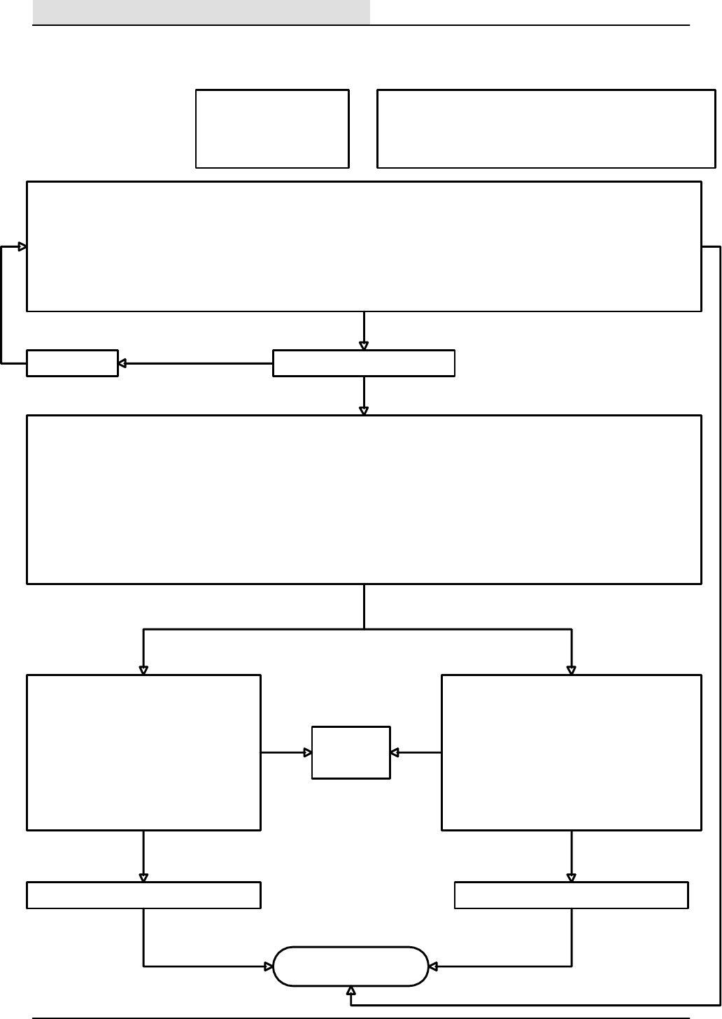
Squeegee works OK
To check the squeegee lower operation.
1. Start the engine.
2. Press the squeegee button on the electronic instrument panel and notice that the engine changes to high speed.
3. The vacuum fan will turn on and the squeegee will move down.
4. Move the propel pedal slightly to reverse (Caution-- the machine may move!) and notice that the squeegee moves up.
5. Turn the key switch to the off position.
With the above procedure, does the scrub brush head move out and in?
no
Is circuit breaker CB--7 tripped?
First check for the following:
1. Correct hydraulic oil level
2. Propel pedal is not in reverse
3. Recovery tank is not full
Checking the solenoid coil:
With the key in the off position:
1. Disconnect the squeegee lower solenoid
SV--4 connector from the wire harness.
2. Connect an ohmmeter to the two terminals
on the connector from the squeegee lower
solenoid SV--4.
3.Check to see that the resistance of SV--4 is
about 7.5 ohms.
Is the resistance value about 7.5 ohms ?
no
Reset CB--7
yes
ok
Replace the defective solenoid.
ok
Note: Normal operation of the squeegee lower function is
dependent upon pressing the scrub or squeegee button, activating
the forward or reverse propel pedal limit switch, the recovery tank is
not full, and the engine in the high speed mode.
yes
no
no
Checkingthewiringwiththekeyswitchintheoff
position:
1. With an ohmmeter, check the 53F/ORN wiring
between circuit breaker CB--7 and the wire
harness connector at SV--4.
2. With an ohmmeter, check the 54/YEL wire
between the wire harness connector at SV--4 and
the connector for the electronic instrument panel
at terminal X1 .
Do the wires check out good ?
MANUAL MODE-- Checking the output from the electronic instrument panel to the squeegee lower hydraulic solenoid valve:
1. Disconnect the squeegee lower solenoid valve SV--4 connector.
2. Connect a digital voltmeter to measure battery voltage across 54/YEL and 53F/ORN at the harness connector.
3. While holding the Tennant logo button, turn the key switch to the on position (do not start the engine) and continue to hold the
Tennant logo button for 15 seconds.
4. Press the squeegee button on the electronic instrument panel.
5. Observe that the meter shows battery voltage when the squeegee function is selected.
6. Turn the key switch to the off position.
7. Reconnect the squeegee lower solenoid SV--4 to the wiring harness.
Is there battery voltage when SV--4 is turned on?
Repair or replace the defective wiring.
ok
no
Check the
hydraulic
system.
yes yes
ok
ELECTRICAL
5-122 8200/8210 330065 (3--01)
SQUEEGEE WILL NOT
LOWER (8210)
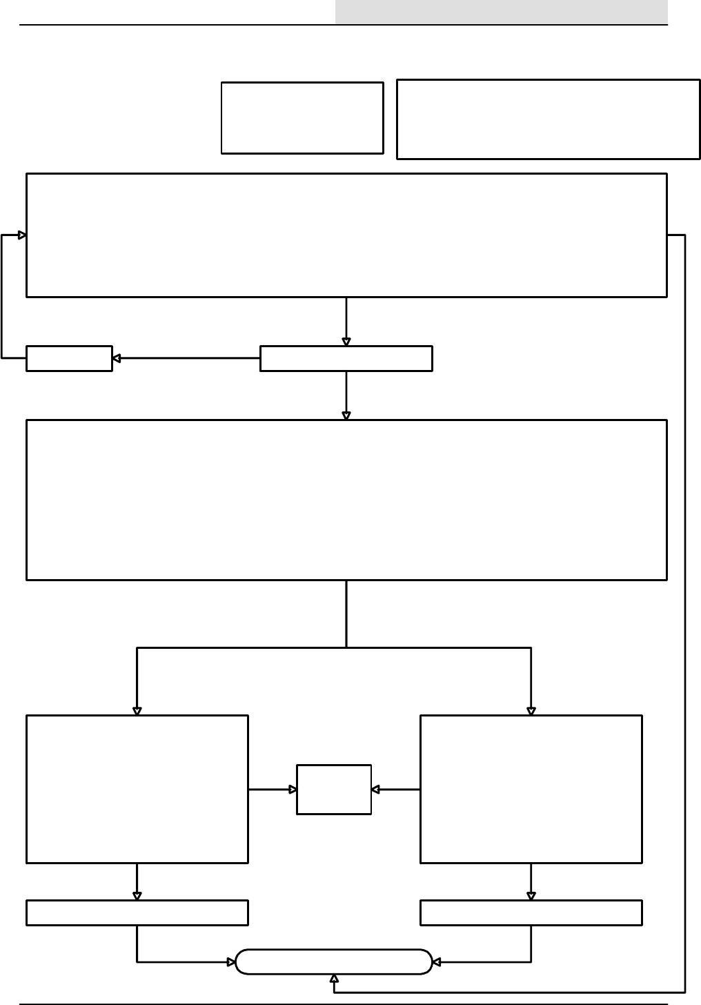
Scrub vacuum fan works OK
To check the squeegee lower operation.
1. Start the engine.
2. Press the scrub button on the electronic instrument panel and notice that the engine changes to high speed.
3. The vacuum fan will turn on and the squeegee will move down.
4. Move the propel pedal slightly to reverse (Caution--the machine may move!) and notice that the squeegee moves up.
5. Turn the key switch to the off position.
With the above procedure, does the scrub vacuum fan turn on ?
no
Is circuit breaker CB--6 tripped?
First check for the following:
1. Correct hydraulic oil level
2. Recovery tank is not full
3. Vacuum lines are not restricted
Checking the solenoid coil:
With the key in the off position:
1. Disconnect the scrub vacuum fan solenoid
SV--1 connector from the wire harness.
2. Connect an ohmmeter to the two terminals
on the connector from the scrub vacuum
fan solenoid SV1.
3.Check to see that the resistance of SV--1 is
about 7.5 ohms.
Is the resistance value about 7.5 ohms?
no
Reset CB--6
yes
ok
Replace the defective solenoid.
ok
Note: Normal operation of the scrub vacuum fan function is
dependent upon having the scrub or squeegee mode active,
activating the forward or reverse propel pedal limit switches, the
recovery tank is not full, and the engine in the high speed mode.
yes
no
no
Checkingthewiringwiththekeyswitchinthe
off position:
1. With an ohmmeter, check the 47D/YEL
wiring between circuit breaker CB--6 and the
wire harness connector at SV--1.
2. With an ohmmeter, check the 52/BRN wire
between the wire harness connector at SV--
1 and the connector for the electronic
instrument panel at terminal W3 .
Do the wires check out good?
MANUAL MODE-- Checking the output from the electronic instrument panel to the vacuum fan hydraulic solenoid :
1. Disconnect the scrub vacuum fan solenoid SV--1 connector.
2. Measure with a digital voltmeter for battery voltage across wires 52/BRN and 47D/YEL at the harness connector for the scrub
vacuum fan .
3. While holding the Tennant logo button, turn the key switch to the on position (Caution--do not start the engine!) and continue to
hold the Tennant logo button for 15 seconds.
4. Press the button associated with MANUAL mode message on the display.
5. Press the button associated with the squeegee function.
6. Notice that the meter should indicate battery voltage for the scrub vacuum fan when the squeegee button is pressed.
7. Turn the key switch to the off position.
Is there battery voltage when SV--1 is turned on?
Repair or replace the defective wiring.
ok
no
Check the
hydraulic
system.
yes yes
ok
ELECTRICAL
5-123
8200/8210 330065 (3--01)
SCRUB VACUUM
FAN WILL NOT
RUN (8210)
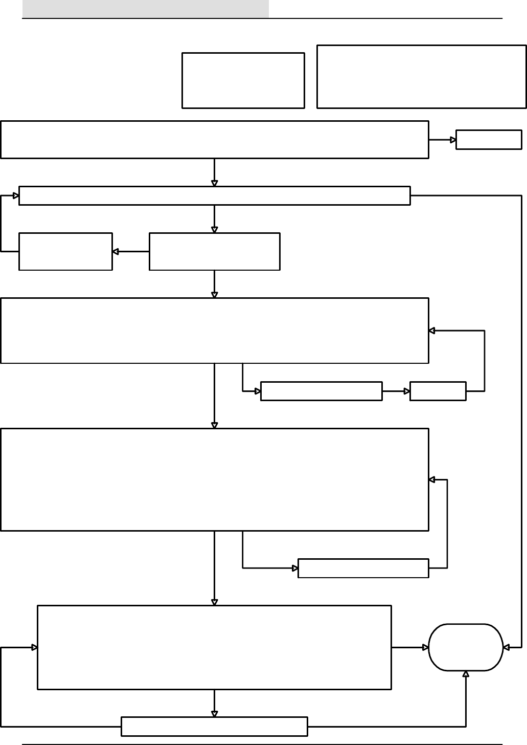
Note: Normal operation for the scrub solution control is
dependent upon pressing the scrub button, activating the
forward or reverse propel pedal limit switches, the recovery
tank is not full, and the engine in the high speed mode.
During a scrubbing operation, is a scrubbing solution applied to the floor near the scrub brushes?
First check for the following:
1. Correct solution tank level
2. Recovery tank is not full
3. Solution lines are not restricted
The scrubbing solution should turn on after starting the engine, pressing the scrub button on the electronic instrument
panel, and moving the propel pedal slightly forward (Caution-- the machine may move!) .
yes
See page 5--96
no
Is the solution control rocker switch
selected for the desired flow?
Select either the high or
low solution flow rate.
Checking the solution control rocker switch:
1. Using a digital voltmeter, Connect the positive lead to any 53/ORN wire at the solution control rocker switch.
2. Connect the negative meter lead to any 13/BLK wire.
3. Turn the key switch to the on position, (Caution-- do not start the engine!)
Does the meter display battery voltage?
Solution
control works
OK
yes
no
ok
no
yes
Checking the solenoid coils:
With the key in the off position:
1. Disconnect each of the solution control solenoid connectors from the wire harness.
2. Connect an ohmmeter to the two terminals on the connector from each of the solution control
wires.
3. Check to see that the resistance of each coil measures about 13.5 ohms.
Is the resistance value about 13.5 ohms ?
Replace the defective solution control solenoid.
Repair or replace the bad wires.
Checking the wiring with the key switch in the off position:
1. With an ohmmeter, check the 53/ORN wiring between circuit breaker CB--7 and the wire harness connector at the
solution control rocker switch.
2. With an ohmmeter, check the 59A/BRN wire between the wire harness connector at the solution control rocker
switch, and the connector for the #1 solution control valve .
3. With an ohmmeter, check the 60/ORA wire between the wire harness connector at the solution control rocker switch,
and the connector for the #2 solution control valve .
4. With an ohmmeter, check the 55B/GRY and 55C/GRY wires between the wire harness connector at the solution
control solenoid valves and the X3 terminal for the connector at the electronic instrument panel .
Do the wires check out good?
yes
no
ok
yes
yes
no
ok
Is circuit breaker CB--7 tripped? Reset CB--7
no
yes
ok
ELECTRICAL
5-124 8200/8210 330065 (3--01)
SOLUTION CONTROL
WILL NOT OPERATE
(8210)
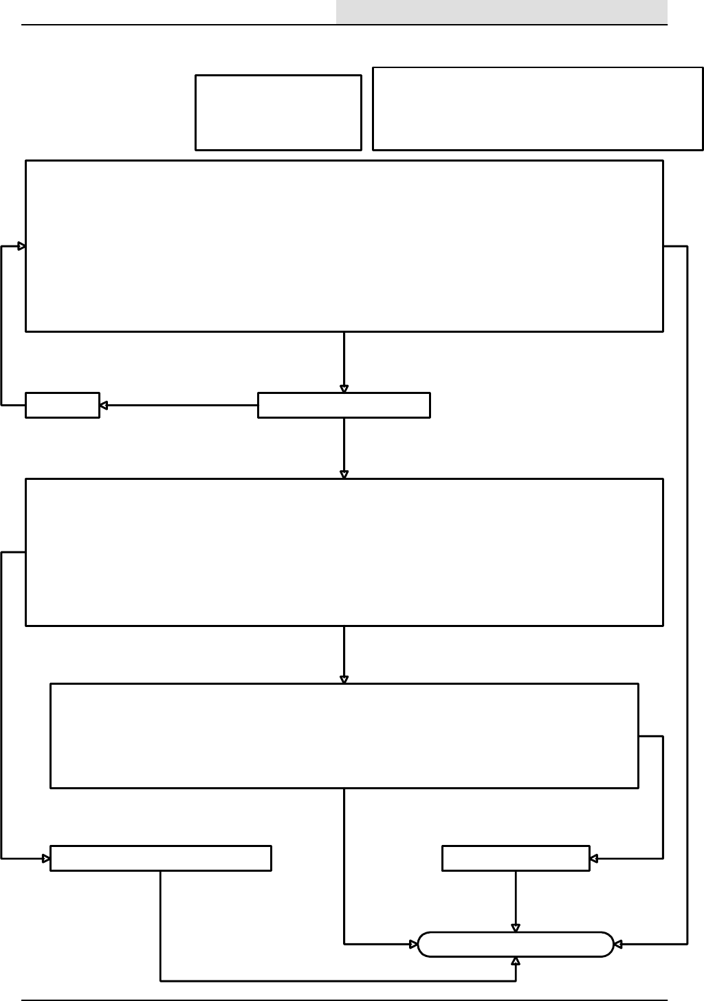
First check for the following:
1. Correct detergent tank level
2. Recovery tank is not full
3. Solution switch is on high or low
Note: Normal operation of the detergent metering pump requires that
one of the detergent flow rates is selected on the electronic instrument
panel, the solution control rocker switch must be set to high or low, and
operating in the scrub mode with the machine propelling forward.
Repair or replace the wires
To check the detergent metering pump operation :
1. Disconnect the hitch pin on the scrub brush head and swing open the right side guide arm .
2. Open the right side main sweeping brush access door.
3. Find the detergent metering pump located under the floor, just below the foot pedals
3. Turn the key switch to the on position (Caution--do not start the engine!).
4. Press the button associated with the scrub function on the electronic instrument panel.
5. Select the solution control rocker switch to either high or low flow .
6. Press the button associated with the detergent metering function on the electronic instrument panel to either high or low flow.
7. Move the propel pedal slightly to the forward direction.
8. Notice if the pump motor is running.
9. Turn off the key switch to the off position.
With the above procedure, does the detergent metering pump operate ?
no
yes
Solution control works OK
Is circuit breaker CB--6 tripped?Reset CB--6
yes
ok
MANUAL MODE-- Checking the output from the electronic instrument panel to the edge scrub hydraulic solenoid valve:
1. Disconnect the detergent metering pump motor connector from the wire harness.
2. Measure with a digital voltmeter for DC voltage across 47K/YEL and 51/GRY at the harness connector to the detergent pump.
3. Press the detergent button on the electronic instrument panel.
4. While holding the Tennant logo button, turn the key switch to the on position (Caution--do not start the engine!) and continue to
hold the Tennant logo button for 15 seconds.
5. The meter should indicated almost battery voltage when the high detergent flow rate is selected, and less than half of battery voltage
when the low flow rate is selected.
Is there a DC voltage when the detergent pump is turned on ?
no
no
Checking the wiring with the key switch in the off position:
1. With an ohmmeter, check the 47K/YEL wiring between circuit breaker CB--6 and the wire harness connector at the
detergent metering pump motor connector.
2. With an ohmmeter, check the 51/GRY wire between the wire harness connector at the detergent metering pump
motor, and the T3 terminal at the connector for the electronic instrument panel .
Do the wires check out good ?
yes
Replace the detergent metering pump motor.
ok ok
yes
no
ELECTRICAL
5-125
8200/8210 330065 (3--01)
DETERGENT PUMP
WILL NOT
OPERATE (8210)
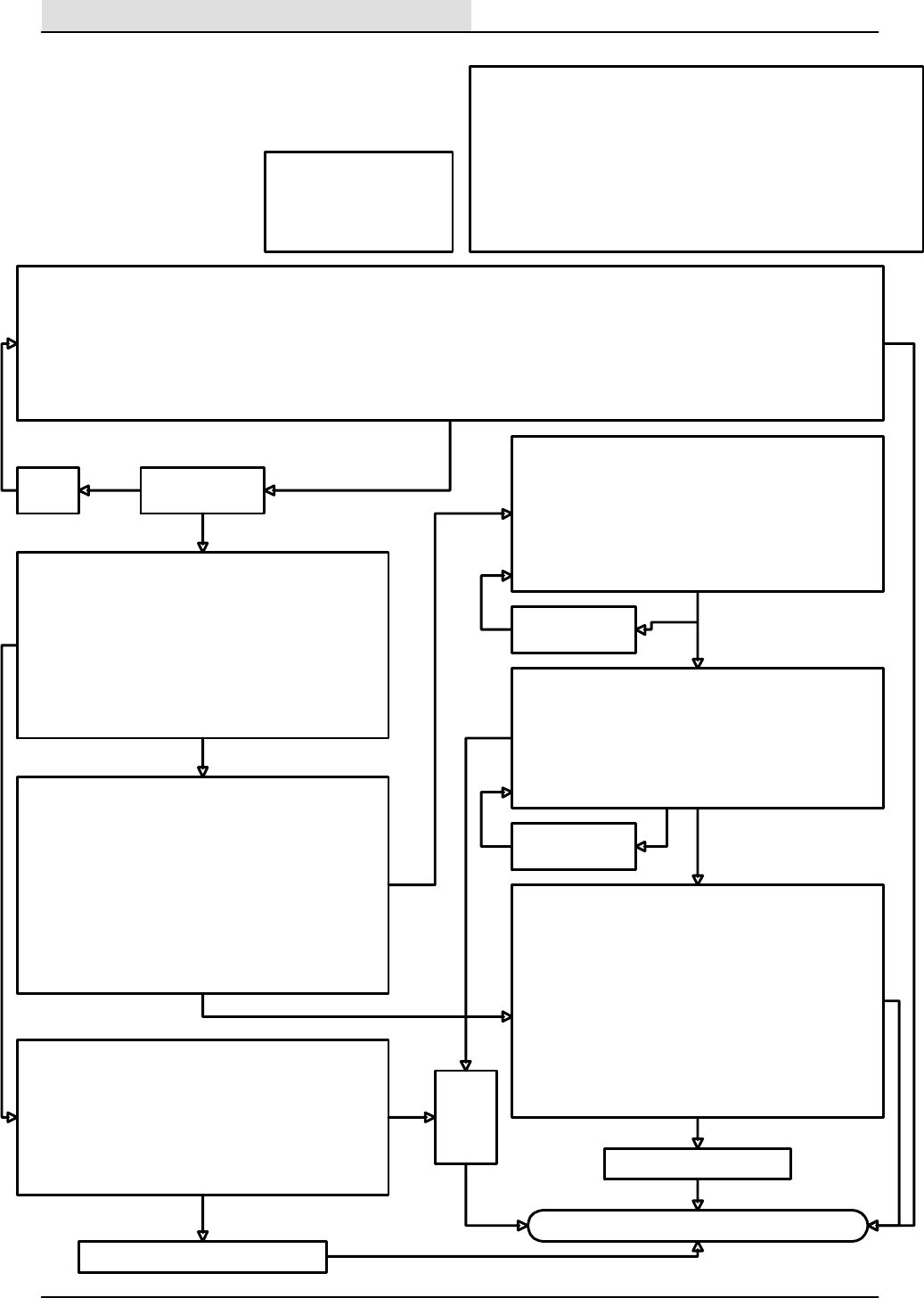
First check for the following:
1. Solution tank is not full.
2. Recovery tank level is
above the lower level
switch point.
Note: The Extended Scrub (ES) system uses the ES pump to recycle scrub
water from the recovery tank back to the solution tank. The ES function is
enabled by the key switch in the on position, and pressing the ES button
on the electronic instrument panel. The solution tank level must be less
than full, and the recovery tank level above its lower level switch. The ES
pump will continue to run for 40 seconds after the level in the recovery tank
has dropped below its lower switch, or after the solution tank level has
approached its level switch (solution tank full).
To check the ES system operation :
1. Turn the key switch to the on position, (Caution--do not start the engine!) .
2. Press the button associated with the ES function.
3. Open the access covers on both recovery and solution tanks.
4. Raise the lower level float in the recovery tank for 5 seconds to run the ES pump for a 40 second time interval.
5. Notice that the pump motor starts to run after the lower recovery tank level switch is activated for at least 5 seconds.
6. Try step 4 again, but now activate the solution tank level switch momentarily to stop the ES pump.
7. Turn the key switch to the off position.
With the above procedure, does the detergent metering pump operate ?
no
yes
Extended Scrub (ES) system works OK
Is circuit breaker
CB--6 tripped?
Reset
CB--6
yes
ok
MANUAL MODE-- Checking the output from the electronic
instrument panel to the ES pump :
1. While holding the Tennant logo button, turn the key switch
to the on position (Caution--do not start the engine!) and
continue to hold the Tennant logo button for 15 seconds.
2. Toggle the button associated with the ES function to start
and stop the ES pump.
(The backblast valve will cycle along with the ES pump)
3. Turn the key switch to the off position.
Does the ES pump run ?
no
Checking the ES pump wiring --key switch in the off position:
1. With an ohmmeter, check the 47B/YEL wiring between
circuit breaker CB--6 and the wire harness connector at the
ES pump motor connector.
2. With an ohmmeter, check the 50/PUR wire between the
wire harness connector at the ES pump motor and the T2
connector terminal for the electronic instrument panel.
Do the wires check out good ?
DIAGNOSTIC INPUT DISPLAY MODE-- checks the lower
recovery tank level switch circuit.
1. While holding the Tennant logo button, turn the key switch
to the on position (Caution--do not start the engine!) and
continue to hold the Tennant logo button for 15 seconds.
2. Press the Tennant logo button again.
3. Press the button associated with the INPUT DISPLAY
message on the display.
4. Lift the lower float in the recovery tank while watching the
LED associated with the ES function on the electronic
instrument panel.
Does the ES LED illuminate when the float is lifted ?
ok
Checking the lower recovery tank level switch:
1. Disconnect the lower recovery tank level switch connector
from the main harness.
2. With an ohmmeter, connect the meter leads to terminals
”A” and ”b” at the switch connector.
3. Move the float up and down while checking the meter.
Does the meter show a change while operating the float?
Replace the defective switch
Repair or
replace
the
defective
wiring.
yes
DIAGNOSTIC INPUT DISPLAY MODE-- checks the solution
tank level switch.
1. While holding the Tennant logo button, turn the key switch
to the on position(Caution--do not start the engine!) and
continue to hold the Tennant logo button for 15 seconds.
2. Press the Tennant logo button again.
3. Press the button associated with the INPUT DISPLAY
message on the display.
4. Lift the float in the solution tank while watching the LED
associated with the ES function on the electronic
instrument panel.
Does the ES LED illuminate when the float is lifted ?
Checking the lower recovery tank level switch wiring:
1. With an ohmmeter, check the 13AG/BLK wire from the
lower recovery tank level switch harness connector to
Battery (--).
2. With an ohmmeter, check the 78/PUR wire between the
lower recovery tank level switch harness connector and the
electronic instrument panel harness connector at terminal
A3.
Do the wires check out good ?
no
no
ok
no
yes
Replace the defective ES pump motor
no
yes
yes
yes
no
ok
Repair or replace
the defective wiring. no
ok
Replace the
defective switch no
ok
yes
ELECTRICAL
5-126 8200/8210 330065 (3--01)
EStWILL NOT
OPERATE (8210)

HYDRAULICS
6-1
8200/8210 330065 (6--01)
CONTENTS
Page
INTRODUCTION 6--3........................
HYDRAULIC FLUID RESERVOIR 6--4.........
HYDRAULIC HOSES 6--4....................
HYDRAULIC FLUID 6--5.....................
TO DRAIN HYDRAULIC FLUID RESERVOIR
AND REPLACE FILTER ELEMENT 6--6..
TO FILL HYDRAULIC FLUID
RESERVOIR 6--8......................
HYDRAULIC PUMPS 6--9....................
TO REPLACE PROPEL PUMP 6--9.........
TO REPLACE PRIMARY ACCESSARY
PUMP 6--14...........................
TO REPLACE BELT DRIVEN
ACCESSARY PUMP 6--17..............
TO REPLACE BELT DRIVEN
ACCESSARY PUMP V--BELT 6--27......
DIRECTIONAL PEDAL 6--31.................
TO REPLACE PROPEL DIRECTIONAL
SPRING 6--31.........................
TO REPLACE PROPEL DIRECTIONAL
CABLE 6--35..........................
TO ADJUST NEUTRAL CENTERING 6--41..
TO REPLACE HOPPER LIFT
CYLINDER 6--43......................
TO REPLACE HOPPER DUMP
DOOR CYLINDER 6--47................
TO REPLACE MAIN BRUSH LIFT
CYLINDER (8210 only) 6--49............
TO REPLACE SIDE BRUSH LIFT
CYLINDER (8210 only) 6--52............
TO REPLACE SCRUB HEAD SIDE SHIFT
CYLINDER (optional on 8200,
std on 8210) 6--55..................
TO REPLACE SCRUB HEAD
LIFT CYLINDER 6--58..................
TO REPLACE REAR SQUEEGEE LIFT
CYLINDER 6--61......................
TO REPLACE STEERING CYLINDER 6--65.
TO REPLACE STEERING VALVE 6--70.....
HOPPER LIFT VALVE 6--73..................
TO REPLACE HOPPER LIFT VALVE 6--73..
HYDRAULIC SOLENOID VALVES 6--77........
TO REPLACE BRUSH AND VACUUM
FAN SOLENOID VALVES 6--77.........
TO REPLACE OPTIONAL SCRUB HEAD
SIDE SHIFT SOLENOID
VALVE (8210) 6--82.................
TO REPLACE SIDE BRUSH/MAIN BRUSH
LIFT, HOPPER DOOR OPEN/CLOSE
SOLENOID VALVE (8210) 6--86......
TO REPLACE MAIN SWEEPING BRUSH
MOTOR 6--90.........................
TO REPLACE SIDE BRUSH MOTOR 6--94..
TO REPLACE SCRUB BRUSH
MOTOR 6--97.........................
Page
TO REPLACE SWEEPING VACUUM FAN
MOTOR 6--100........................
TO REPLACE SCRUBBING VACUUM FAN
MOTOR 6--103........................
TO REPLACE REAR DRIVE MOTOR 6--106....
HYDRAULIC SCHEMATIC 6--112.............
HYDRAULIC HOSE DIAGRAM (8200) 6--114...
HYDRAULIC HOSE DIAGRAM (8210) 6--116...
TROUBLESHOOTING 6--119.................
POWER STEERING IS NOT NORMAL 6--120
SCRUB HEAD WILL NOT RAISE 6--121....
SCRUB HEAD WILL NOT LOWER 6--122...
SCRUB HEAD WILL NOT STAY UP 6--123..
MAIN BROOM WILL NOT TURN ON 6--124.
MAIN BROOM WILL NOT TURN OFF 6--125
SCRUB BRUSHES WILL NOT
TURN ON 6--126......................
SCRUB BRUSHES WILL NOT
TURN OFF 6--127.....................
SQUEEGEE WILL NOT RAISE 6--128......
SQUEEGEE WILL NOT LOWER 6--129.....
SQUEEGEE WILL NOT STAY UP 6--130....
SCRUB FAN WILL NOT TURN ON 6--131...
SCRUB FAN WILL NOT TURN OFF 6--132..
SWEEP FAN WILL NOT TURN ON 6--133...
SWEEP FAN WILL NOT TURN OFF 6--134..
SIDE BRUSH WILL NOT TURN ON 6--135..
SIDE BRUSH WILL NOT TURN OFF 6--136.
HOPPER DOOR WILL NOT CLOSE 6--137..
HOPPER DOOR WILL NOT STAY
CLOSED 6--138.......................
HOPPER WILL NOT RAISE 6--139.........
HOPPER WILL NOT HOLD UP
POSITION 6--140......................
HOPPER WILL NOT LOWER 6--141........
SCRUB HEAD WILL NOT GO OUT
(edge scrub option) 6--142..............
SCRUB HEAD WILL NOT GO IN
(edge scrub option) 6--143..............
MAIN BRUSH WILL NOT GO DOWN
(8210 only) 6--144.....................
MAIN BRUSH WILL NOT GO UP
(8210 only) 6--145.....................
SIDE BRUSH WILL NOT GO DOWN
(8210 only) 6--146.....................
SIDE BRUSH WILL NOT GO UP
(8210 only) 6--147.....................
HOPPER DOOR WILL NOT CLOSE
(8210 only) 6--148.....................
HOPPER DOOR WILL NOT STAY
CLOSED (8210 only) 6--149.............
HOPPER DOOR WILL NOT OPEN
(8210 only) 6--150.....................
PROPEL MOTOR WILL NOT
PROPEL 6--151.......................

HYDRAULICS
6-2 8200/8210 330065 (6--01)

HYDRAULICS
6-3
8200/8210 330065 (3--01)
INTRODUCTION
The 8200/8210 hydraulic system consists of the
lift cylinders, hydraulic motors, hydraulic pumps,
and hydraulic valves. This section includes
information on these components and their
troubleshooting.
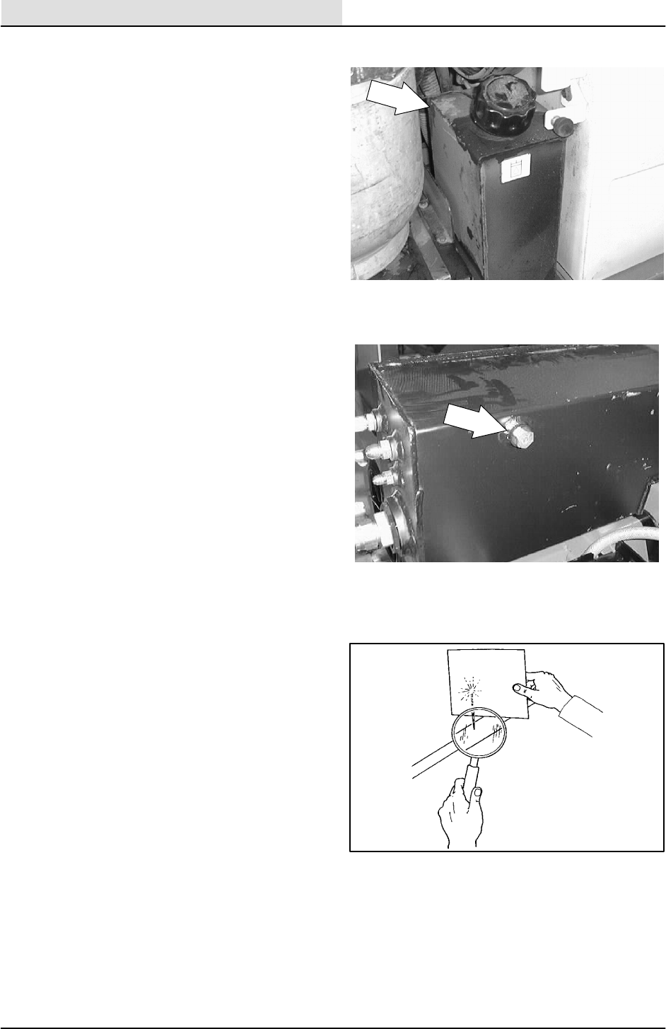
HYDRAULICS
6-4 8200/8210 330065 (3--01)
HYDRAULIC FLUID RESERVOIR
Check the hydraulic fluid level at operating
temperature every 100 hours of operation. Make
sure the hopper is down when checking hydraulic
fluid level. The end of the dipstick is marked with
FULL and ADD levels to indicate the level of
hydraulic fluid in the reservoir.
Lubricate the filler cap gasket with a film of
hydraulic fluid before putting the cap back on the
reservoir.
ATTENTION! Do not overfill the
hydraulic fluid reservoir or operate the
machine with a low level of hydraulic
fluid in the reservoir. Damage to the
machine hydraulic system may result.
Drain and refill the hydraulic fluid reservoir with
new hydraulic fluid every 800 hours of operation.
The hydraulic fluid filter is located at the bottom of
the engine compartment. Replace the filter
element every 800 hours of operation.
The reservoir has a built-in strainer outlet that
filters hydraulic fluid before it enters the system.
Replace the strainer every 800 hours of operation.
HYDRAULIC HOSES
Check the hydraulic hoses every 800 hours of
operation for wear or damage.
Fluid escaping at high pressure from a very small
hole can be almost invisible, and can cause
serious injuries.
See a doctor at once if injury results from
escaping hydraulic fluid. Serious infection or
reaction can develop if proper medical treatment
is not given immediately.
FOR SAFETY: When servicing machine,
use cardboard to locate leaking
hydraulic fluid under pressure.
If you discover a fluid leak, contact your
mechanic/supervisor.
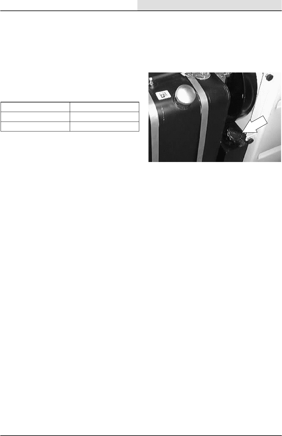
HYDRAULICS
6-5
8200/8210 330065 (3--01)
HYDRAULIC FLUID
The quality and condition of the hydraulic fluid
play a very important role in how well the machine
operates. TENNANT’s hydraulic fluid is specially
selected to meet the needs of TENNANT
machines.
TENNANT’s hydraulic fluids provide a longer life
for the hydraulic components. There are two fluids
available for different temperature ranges:
Tennant part no. Ambient Temperature
65869 above 7_C(45_F)
65870 below 7_C(45_F)
The higher temperature fluid has a higher
viscosity and should not be used at the lower
temperatures. Damage to the hydraulic pumps
may occur because of improper lubrication.
The lower temperature fluid is a thinner fluid for
colder temperatures.
If a locally-available hydraulic fluid is used, make
sure the specifications match TENNANT hydraulic
fluid specifications. Using substitute fluids can
cause premature failure of hydraulic components.
European manufactured machines are filled with
locally available hydraulic fluids. Check the label
on the hydraulic fluid reservoir.
ATTENTION! Hydraulic components
depend on system hydraulic fluid for
internal lubrication. Malfunctions,
accelerated wear, and damage will result
if dirt or other contaminants enter the
hydraulic system.
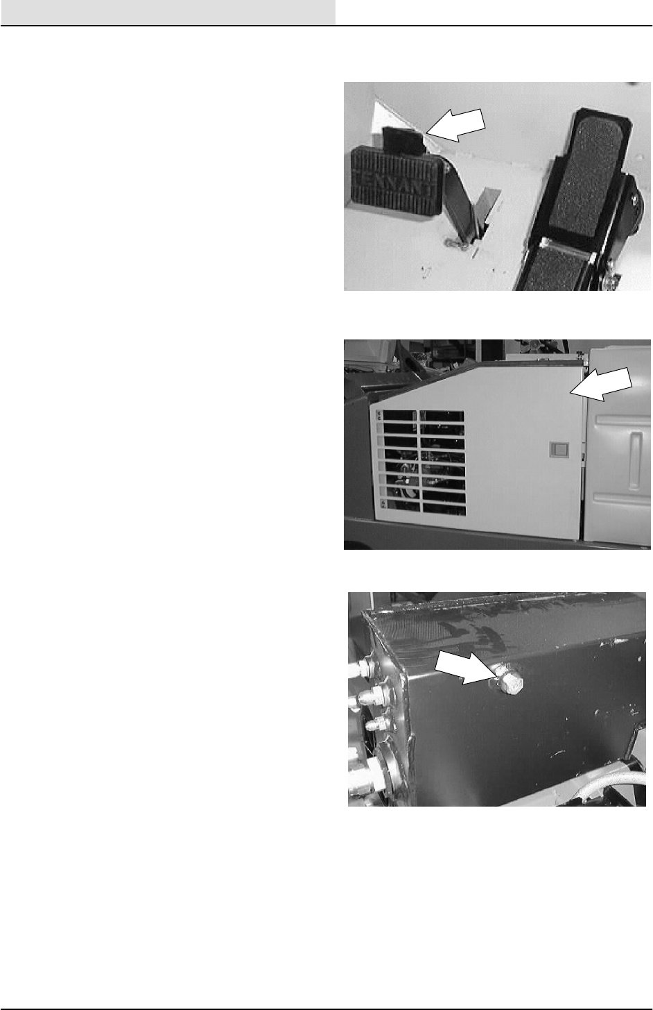
HYDRAULICS
6-6 8200/8210 330065 (3--01)
TO DRAIN HYDRAULIC FLUID RESERVOIR
AND REPLACE FILTER ELEMENT
1. Stop the engine and set the machine parking
brake.
FOR SAFETY: Before Leaving Or
Servicing Machine; Stop On Level
Surface, Set Parking Brake, Turn Off
Machine And Remove Key.
2. Open the engine cover and side door.
3. Wait for the hydraulic fluid to cool down.
4. Remove the drain plug from the bottom of
the hydraulic tank (above LH side squeegee)
on the left hand side of the machine. Drain
the fluid into a pan. Properly discard the old
fluid.
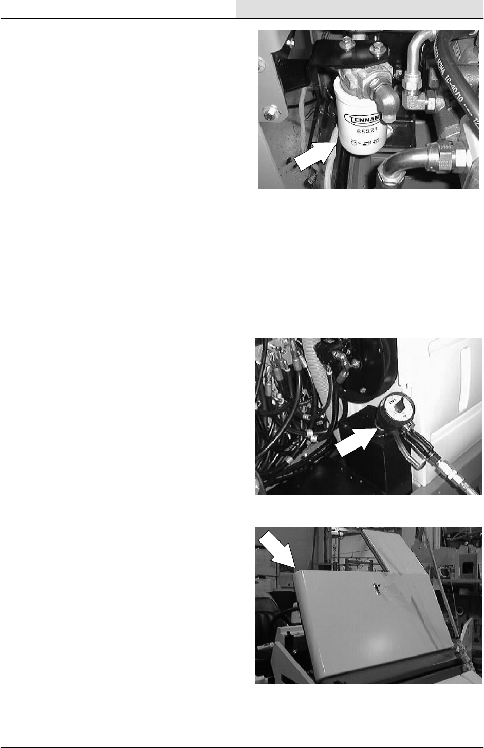
HYDRAULICS
6-7
8200/8210 330065 (3--02)
5. Locate the hydraulic oil filter at the front side
of the main hydraulic pump, behind the
solution tank.
6. Unthread and discard the hydraulic fluid filter
element.
NOTE: Hydraulic fluid will drain through the filter
head.
7. Discard the used hydraulic fluid. Loosen the
breather-filler cap.
NOTE: Be aware the hydraulic filter is lower than
the reservoir. All fluid will drain from the reservoir.
Discard all hydraulic fluid drained from the
system. The fluid may contain foreign material
harmful to the hydraulic system.
8. Apply a thin coat of hydraulic fluid to the seal
of the new hydraulic fluid filter element.
9. Thread and hand tighten the new hydraulic
fluid filter element on the filter head.
10. Refill the hydraulic reservoir.
11. Close the engine side door and engine
cover. Operate the machine and its
functions. Re--check the hydraulic fluid level,
add fluid if necessary.
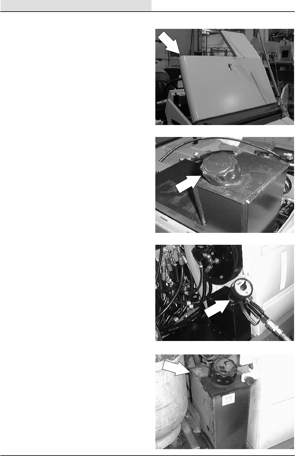
HYDRAULICS
6-8 8200/8210 330065 (3--01)
TO FILL HYDRAULIC FLUID RESERVOIR
1. Open the engine cover and side door.
2. Remove the reservoir breather-filler cap.
NOTE: Make sure the hydraulic reservoir drain
plug is installed in the bottom of the tank before
refilling.
3. Pour new, approved hydraulic fluid through a
200 mesh screened funnel and into the
reservoir.
ATTENTION! Use only new, approved
hydraulic fluid to fill the hydraulic fluid
reservoir. Do not overfill.
4. Check the hydraulic fluid level in the
reservoir with the fluid level dipstick.
5. Add hydraulic fluid until the level in the
reservoir is between the ADD and the FULL
range. Do not overfill.
NOTE: Do not overfill the hydraulic fluid reservoir.
Hydraulic fluid expands as it reaches its normal
operating temperature. Always allow for
expansion when filling the reservoir.
6. Put the reservoir breather-filler cap on the
reservoir.
7. Start engine and operate all the hydraulic
components. Re--check the hydraulic fluid
level, add fluid if necessary.
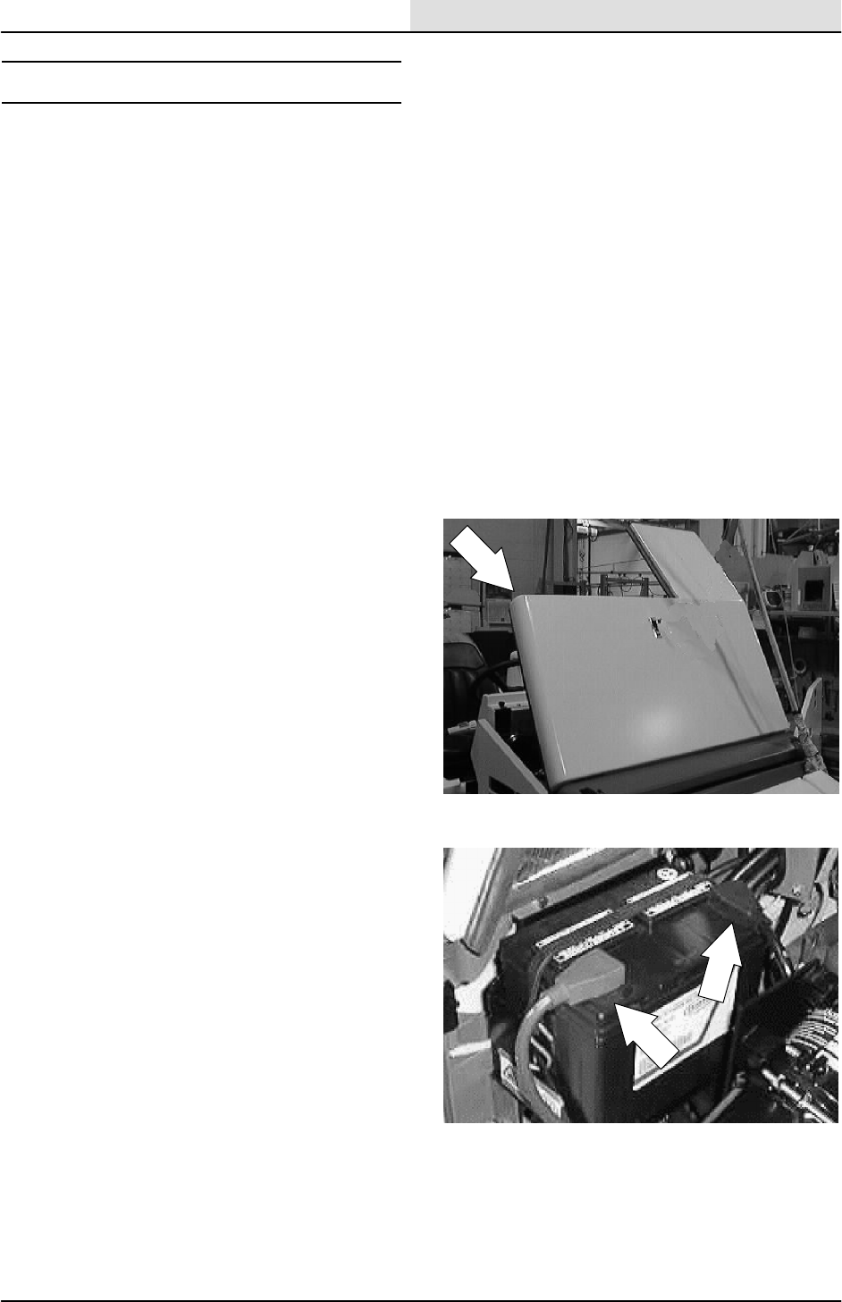
HYDRAULICS
6-9
8200/8210 330065 (3--01)
HYDRAULIC PUMPS
The machine propelling pump is a variable
displacement hydraulic piston pump. The machine
accessory pumps are a hydraulic gear type pump.
After repairing or replacing a hydraulic pump, or
when system contamination is likely, change the
hydraulic fluid in the reservoir and the hydraulic
fluid filter.
TO REPLACE PROPEL PUMP
FOR SAFETY: Before Leaving Or
Servicing Machine; Stop On Level
Surface, Set Parking Brake, Turn Off
Machine And Remove Key.
1. Open the engine cover and side door.
2. Disconnect the battery cables.
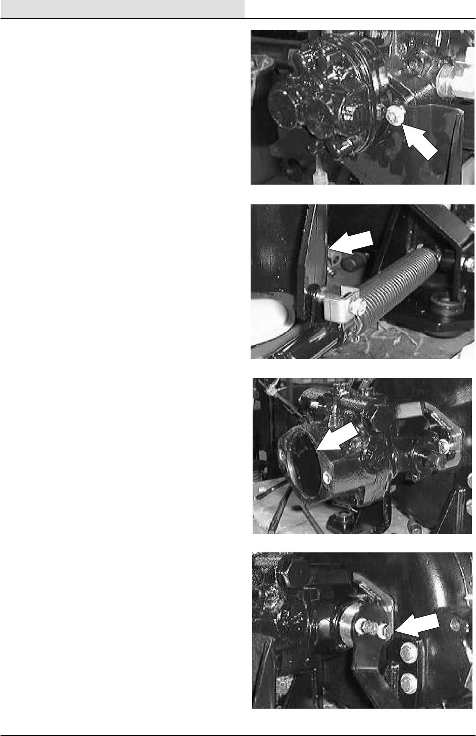
HYDRAULICS
6-10 8200/8210 330065 (3--02)
3. Remove the two hex screws holding the
accessory pump and shock absorber
bracket to the back of the accessory pump.
4. Drop the shock absorber bracket down.
5. Pull the accessory pump out of the propel
pump.
NOTE: Make sure to retain the rubber O--ring and
steel spline from between the accessory pump
and propel pump.
NOTE:Do not disconnect the hydraulic hoses
leading to the accessory pump.
6. Remove the three hex screws holding the
directional arm to the propel pump.
NOTE: Let the arm drop out of the way.

HYDRAULICS
6-11
8200/8210 330065 (3--01)
7. Mark, disconnect, and plug the hydraulic
hoses leading to the propel pump.
NOTE:Observe hydraulic cleanliness
requirements when opening hydraulic lines.
8. Remove the two hex screws holding the
propel pump to the bellhousing. Pull the
propel pump out of the bellhousing and
remove it from the machine.
9. Remove the hydraulic fittings from the old
propel pump and install in the new pump in
the same orientation.
10. Remove the directional arm hub from the old
pump and install on the new pump in the
same orientation.
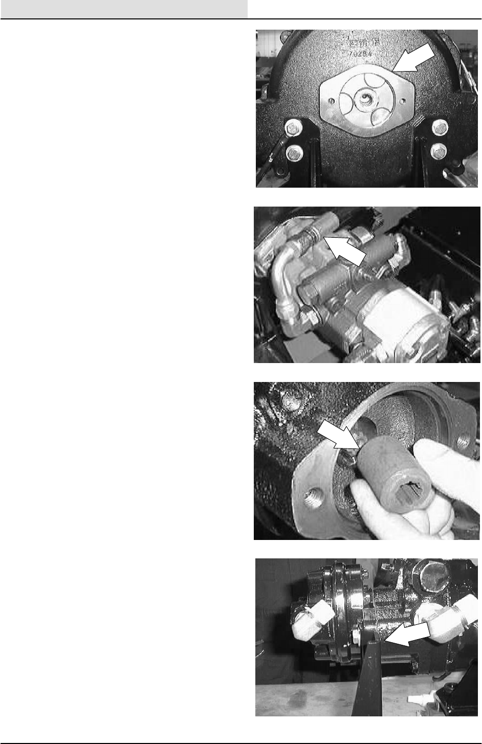
HYDRAULICS
6-12 8200/8210 330065 (3--02)
11. Position the new propel pump in the
bellhousing. Reinstall the two hex screws
and tighten to 36 -- 40 Nm (27 -- 30 ft lb).
Use loctite 242 blue on the threads.
12. Reconnect the hydraulic hoses to the new
propel pump. See the hose pictorial in this
section.
NOTE:Observe hydraulic cleanliness
requirements when opening hydraulic lines.
13. Position the accessory pump into the back
of the new propel pump.
NOTE: Make sure the O--ring and steel spline are
in place on the accessory pump.
14. Position the shock absorber mount bracket
over the mounting flange on the accessory
pump. Reinstall the two hex screws and
tighten to 36 -- 40 Nm (27 -- 30 ft lb). Use
loctite 242 blue on the threads.
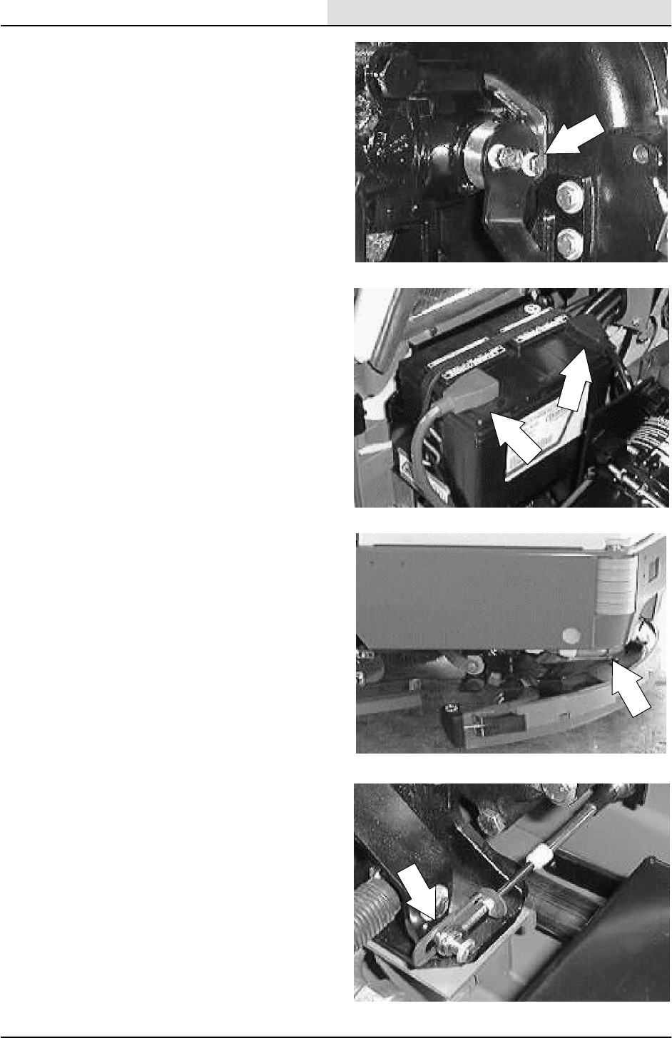
HYDRAULICS
6-13
8200/8210 330065 (3--01)
15. Reinstall the directional arm to the propel
pump. Leave the three screws loose for
now.
16. Reconnect the battery cables.
17. Jack up rear of machine. Use jack stands to
support machine.
FOR SAFETY: Block machine tires
before jacking machine up. Jack
machine up at designated locations
only. Block machine up with jack
stands.
18. Adjust the neutral centering of the new
propel pump. See TO ADJUST
DIRECTIONAL SPRING instructions.
19. Start the machine and check for proper
propel operation.
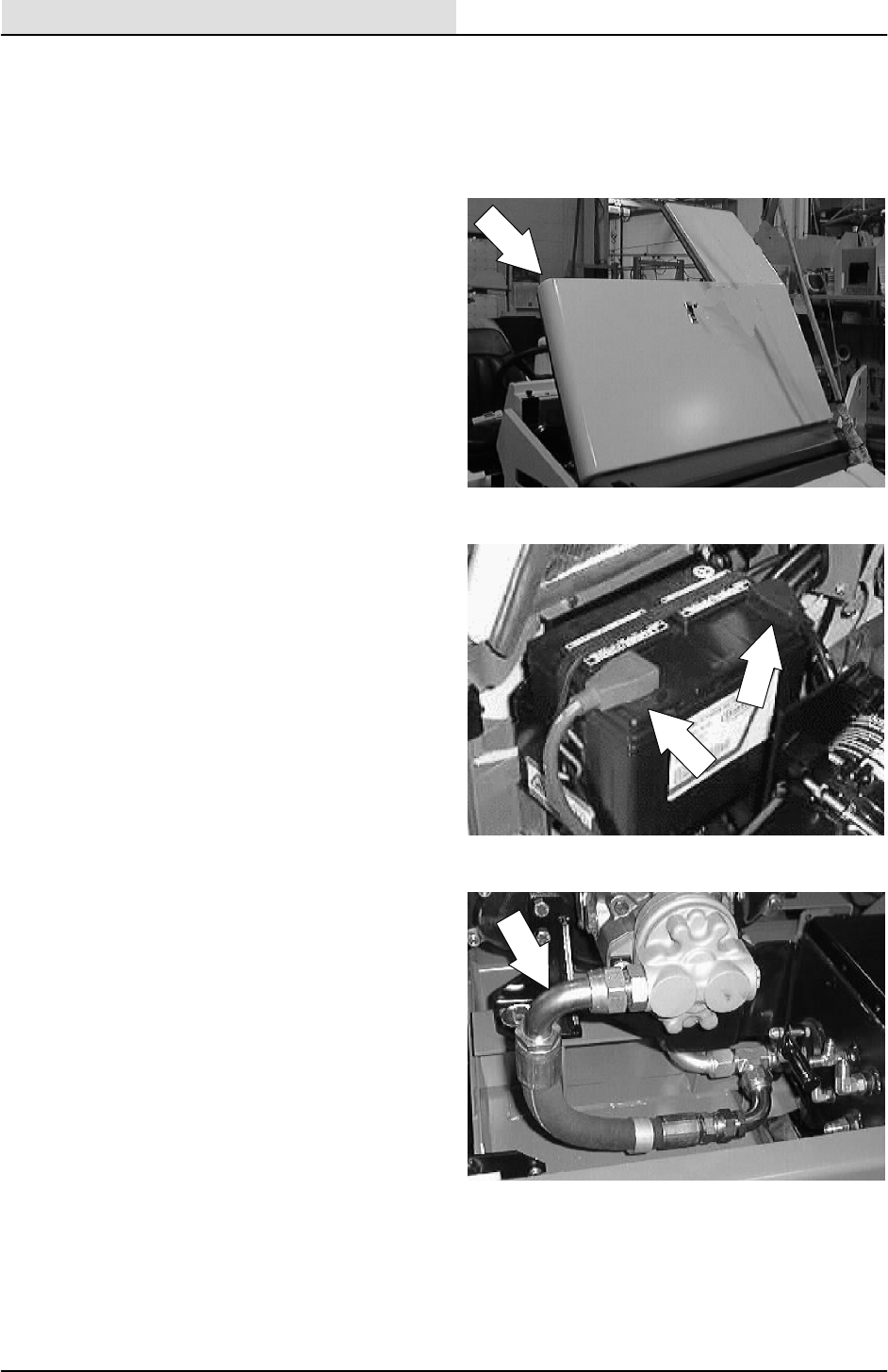
HYDRAULICS
6-14 8200/8210 330065 (3--01)
TO REPLACE PRIMARY ACCESSARY PUMP
FOR SAFETY: Before Leaving Or
Servicing Machine; Stop On Level
Surface, Set Parking Brake, Turn Off
Machine And Remove Key.
1. Open the engine cover and side door.
2. Disconnect the battery cables.
3. Mark, disconnect, and plug the hydraulic
hoses leading to the accessory pump.
NOTE:Observe hydraulic cleanliness
requirements when opening hydraulic lines.
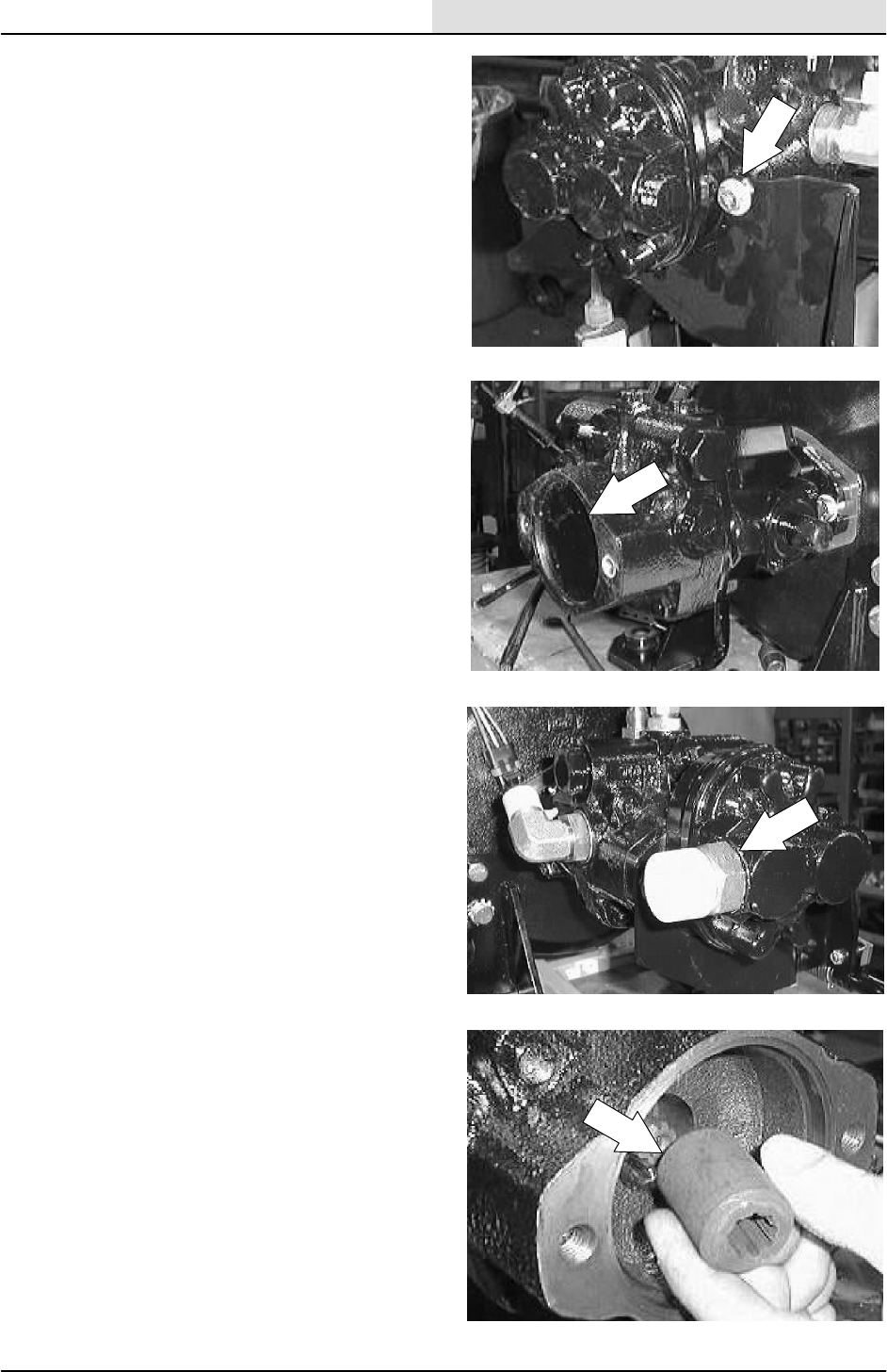
HYDRAULICS
6-15
8200/8210 330065 (3--02)
4. Remove the two hex screws holding the
accessory pump and shock absorber
bracket to the back of the accessory pump.
5. Drop the shock absorber bracket down and
pull the accessory pump out of the propel
pump.
NOTE: Make sure to retain the rubber O--ring and
steel spline from between the accessory pump
and propel pump.
6. Remove the hydraulic fittings from the old
accessory pump and install in the new pump
in the same orientation.
7. Position the new accessory pump in the
back of the propel pump.
NOTE: Make sure the O--ring and steel spline are
in place on the accessory pump.
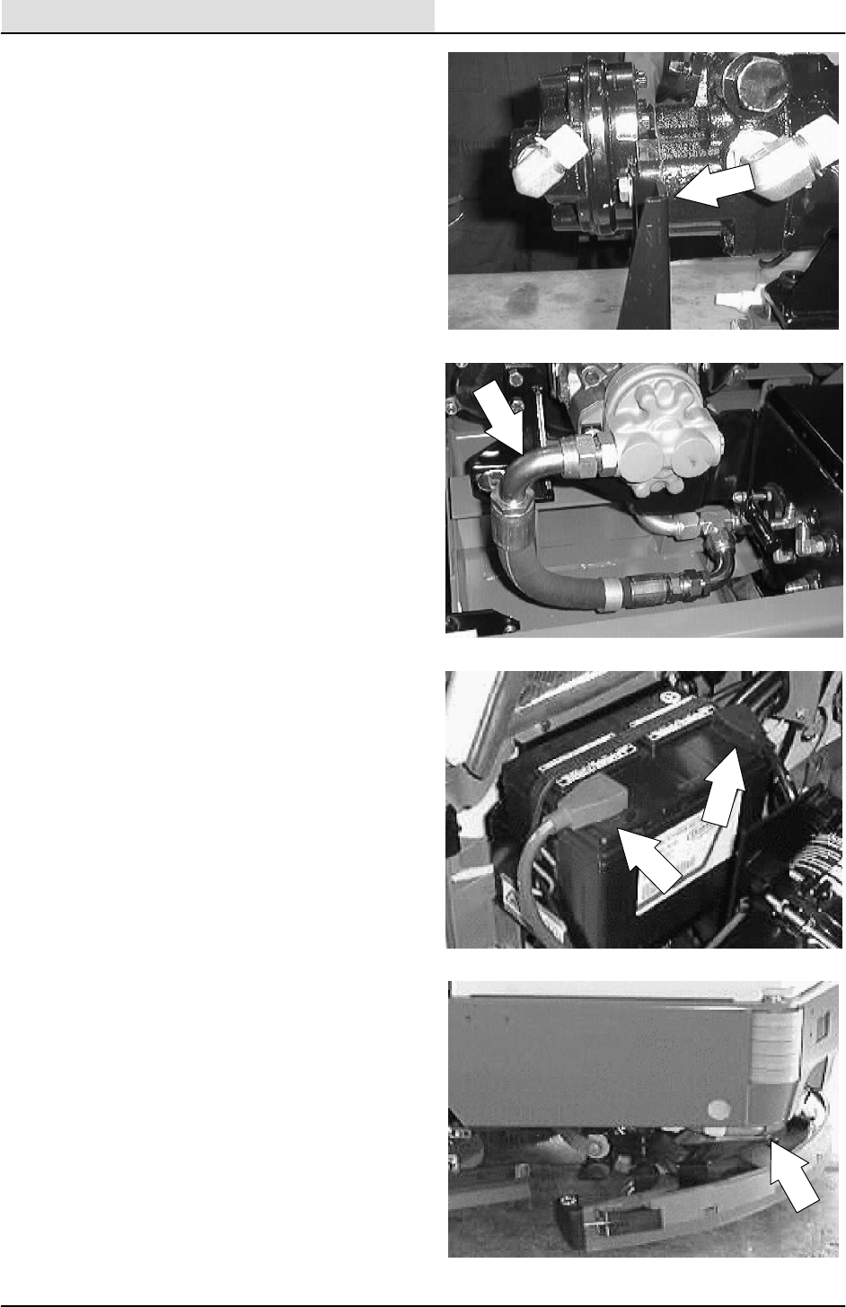
HYDRAULICS
6-16 8200/8210 330065 (3--01)
8. Position the shock absorber mount bracket
over the mounting flange on the accessory
pump. Reinstall the two hex screws and
tighten to 36 -- 40 Nm (27 -- 30 ft lb). Use
loctite 242 blue on the threads.
9. Reconnect the hydraulic hoses to the new
accessory pump.
NOTE:Observe hydraulic cleanliness
requirements when opening hydraulic lines.
10. Reconnect the battery cables.
11. Raise the rear of the machine. Place jack
stands under the frame.
FOR SAFETY: Block machine tires
before jacking machine up. Jack
machine up at designated locations
only. Block machine up with jack
stands.
12. Start the machine and check for proper
operation. See TO ADJUST DIRECTIONAL
SPRING instructions if needed.
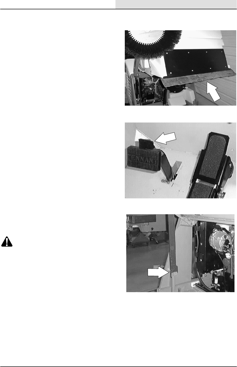
HYDRAULICS
6-17
8200/8210 330065 (3--01)
TO REPLACE BELT DRIVEN ACCESSARY
PUMP
1. Empty the debris hopper.
2. Set the machine parking brake.
3. Raise the hopper and engage the prop arm.
Shut off the engine.
WARNING: Raised Hopper May Fall.
Engage Hopper Support Bar.
FOR SAFETY: Before Leaving Or
Servicing Machine; Stop On Level
Surface, Set Parking Brake, Turn Off
Machine And Remove Key.
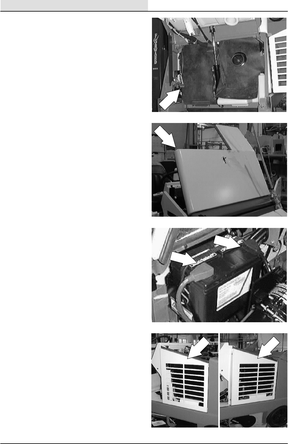
HYDRAULICS
6-18 8200/8210 330065 (3--01)
4. Pull the rubber dust shield out of the metal
bracket. Pull the dust shield back for access
to the accessory pump.
5. Open the engine cover and side door.
6. Disconnect the battery cables.
7. Remove the two screws holding the radiator
guard to the machine. Remove the guard.
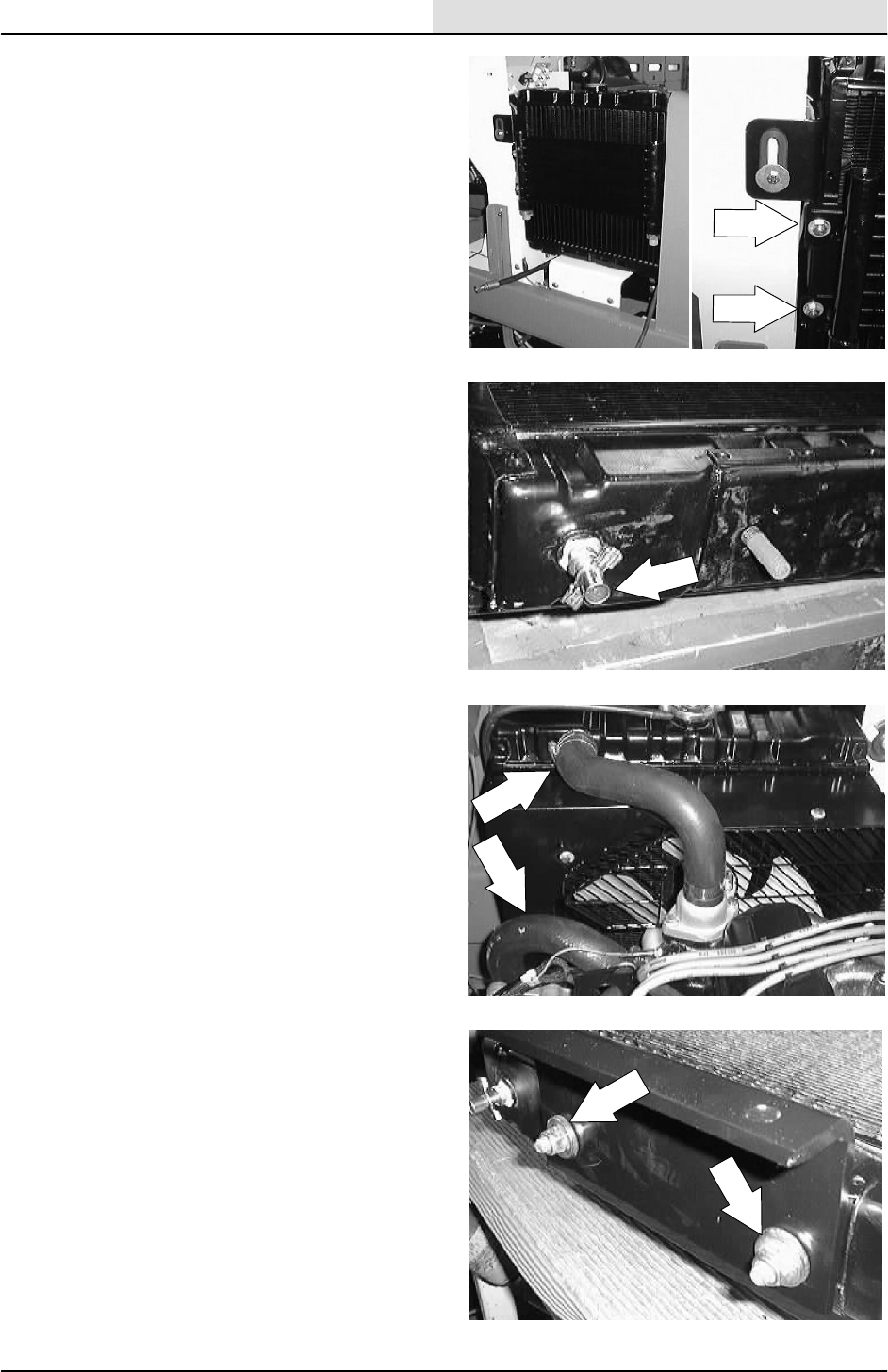
HYDRAULICS
6-19
8200/8210 330065 (3--01)
8. Remove the four screws holding the
hydraulic oil cooler to the radiator. Pull the
cooler away from the radiator.
9. Drain the engine coolant.
10. Disconnect the upper and lower radiator
hoses.
11. Remove the tow hex nuts holding the bottom
of the radiator to the mount bracket.
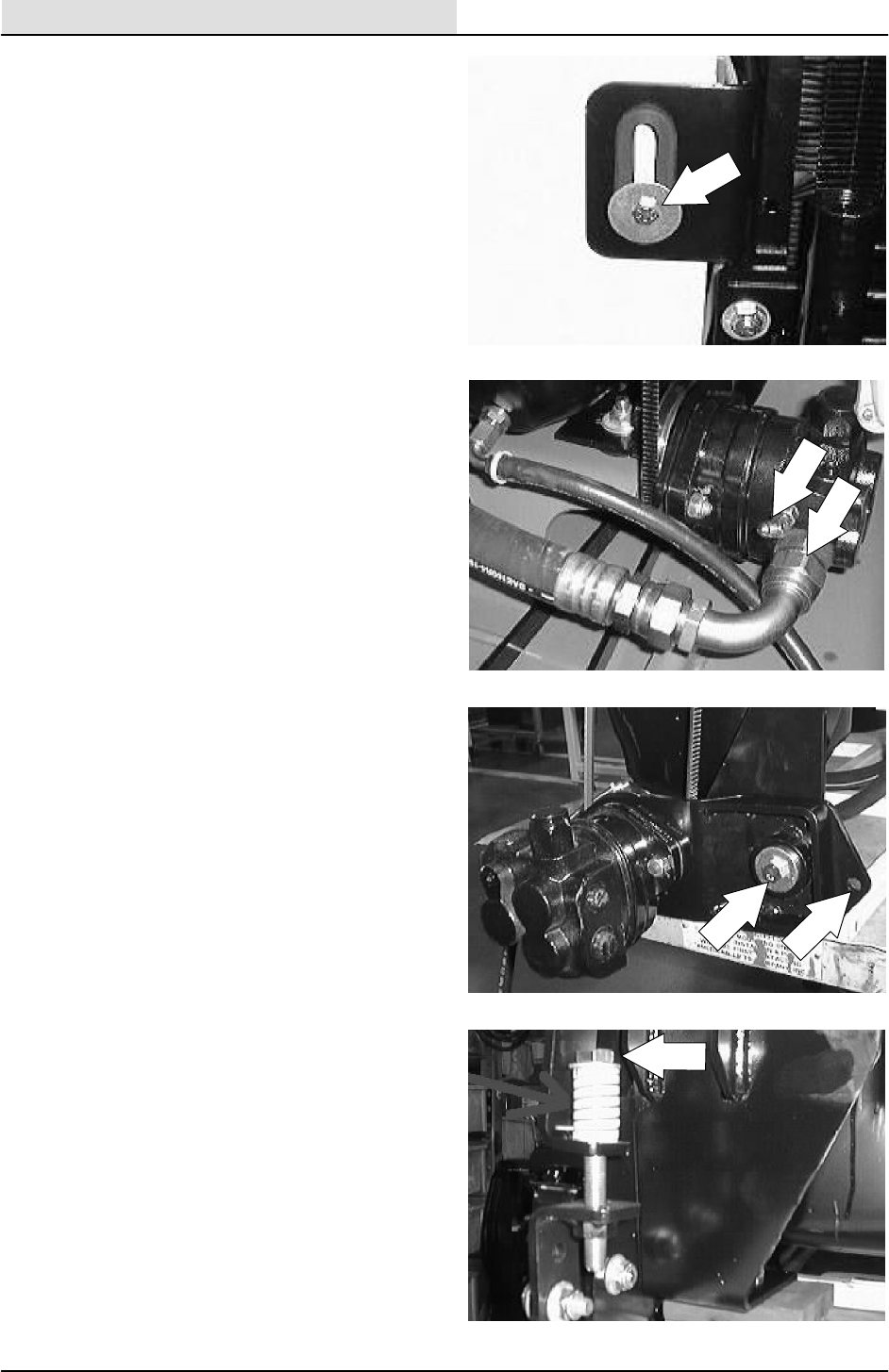
HYDRAULICS
6-20 8200/8210 330065 (3--01)
12. Remove the hex screw holding the top of the
radiator to the operator compartment.
Remove the radiator from the machine.
13. Mark, disconnect, and plug the hydraulic
hoses leading to the accessory pump.
NOTE:Observe hydraulic cleanliness
requirements when opening hydraulic lines.
14. Go to the front the machine and locate the
two hex screws and nuts holding the
accessory pump pivot plate to the mount
plate. Loosen these two screws.
15. Locate the hex bolt and compression spring
at the front of the accessory pump mount
bracket. Remove the hex bolt and
compression spring. Push the pump up to
remove the V--belt from the pump sheave.
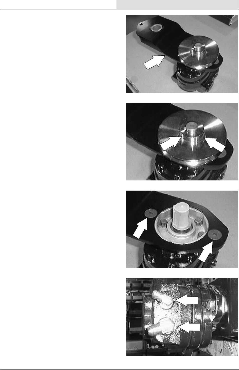
HYDRAULICS
6-21
8200/8210 330065 (3--01)
16. Remove the two hex screws and nuts
holding the accessory pump pivot plate to
the mount plate. Remove the pump and
pivot plate from the machine.
17. Loosen the set screws holding the sheave to
the pump shaft. Remove the sheave from
the pump.
18. Remove the two flat screws and nyloc nuts
holding the pump to the pivot plate. Remove
the pump from the plate.
19. Remove the hydraulic fittings from the old
accessory pump and install in the new pump
in the same orientation.
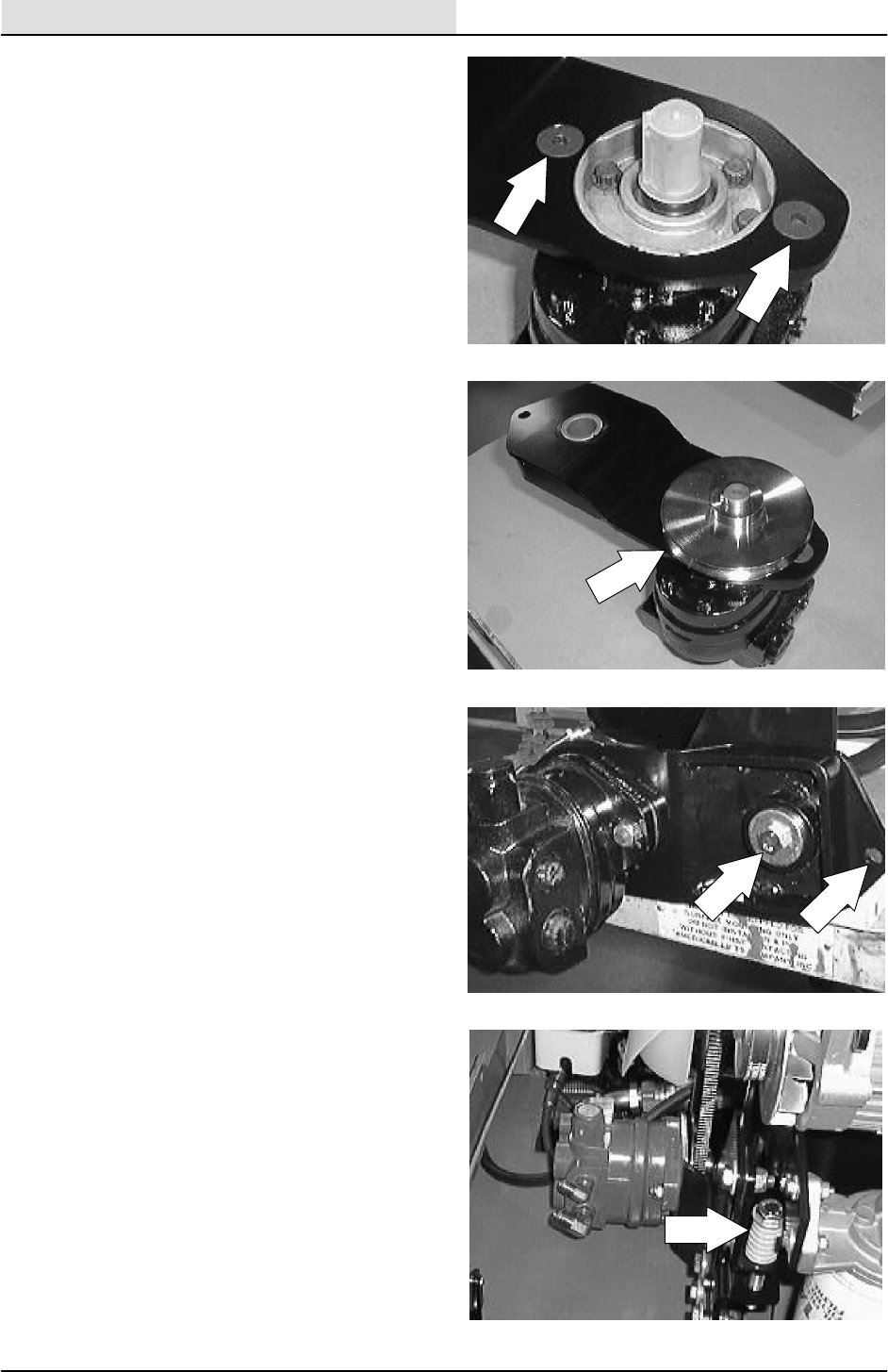
HYDRAULICS
6-22 8200/8210 330065 (3--01)
20. Install the new pump and fittings on the pivot
bracket. Tighten the nyloc nuts to
37 -- 48 Nm (26 -- 34 ft lb).
21. Install the V--belt sheave on the shaft of the
new pump. Leave the set screws loose for
now.
22. Install the pump and pivot bracket assembly
onto the mount bracket. Install the two
screws and nuts. Leave loose for now.
23. Install the compression spring and long hex
screw in the front adjustment hole in the
mount bracket and pivot bracket.
NOTE: Be sure to put blue loctite on the threads
of the hex screw.
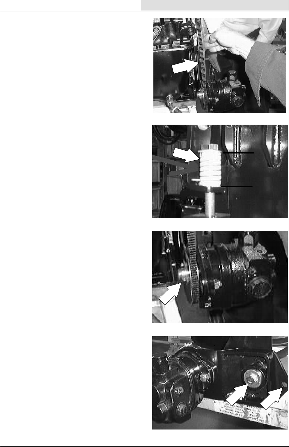
HYDRAULICS
6-23
8200/8210 330065 (3--01)
24. Install the V--belt around the accessory
pump sheave.
NOTE: Use a straight edge to align the pump
sheave and engine sheave within .020 inch runout
for proper belt tracking.
25. The accessory pump belt adjustment is
made by turning the bolt on top of the
tension spring. The tension spring is located
at the front of the engine compartment, near
the accessory pump belt sheave. The
accessory pump belt is at the proper tension
when the tension spring is compressed to
3.81 cm 0.0076 mm (1.5 in 0.030 in).
NOTE: When adjusting the accessory pump belt
tension, measure only the spring and not the
washers at either end.
26. Put blue loctite on the threads of the two
pump sheave set screws. Install and tighten
securely.
27. Go back and tighten the two pivot plate
mount screws to 37 -- 48 Nm (26 -- 34 ft lb).
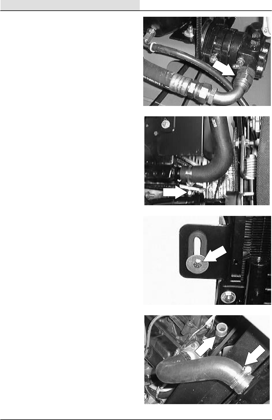
HYDRAULICS
6-24 8200/8210 330065 (3--01)
28. Reconnect the hydraulic hoses to the new
accessory pump. See hose diagram in this
section.
29. Position the radiator into the machine.
Reinstall the two nuts under the radiator
mount bracket.
30. Reinstall the hex screw and washer into the
top of the radiator.
31. Reconnect the top and bottom radiator
hoses.
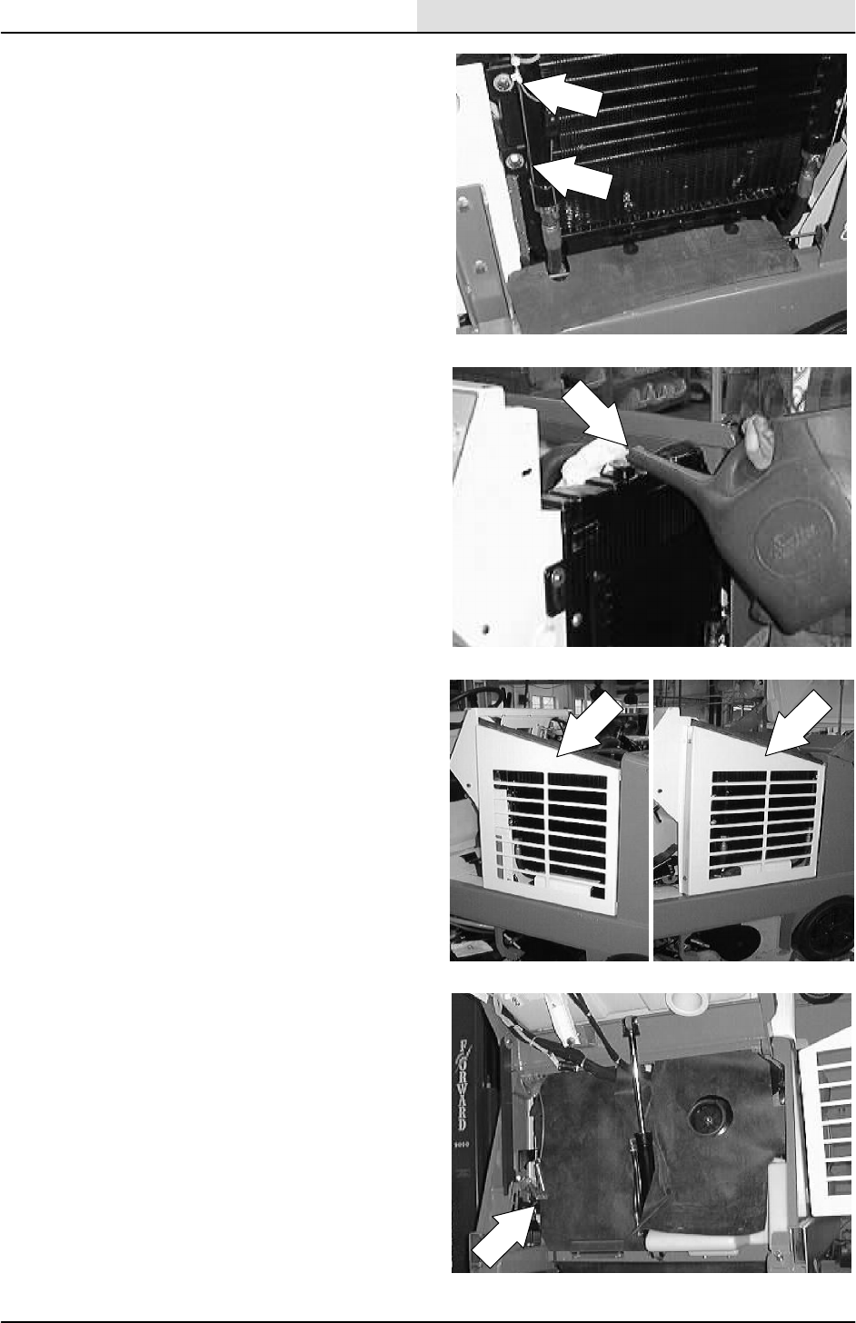
HYDRAULICS
6-25
8200/8210 330065 (3--01)
32. Position the hydraulic cooler onto the front of
the radiator. Reinstall the four screws and
tighten to 18 -- 24 Nm(15 -- 20 ft lb).
33. Refill the radiator with coolant.
34. Reinstall the radiator grill and two mounting
screws. Tighten to 18 -- 24 Nm(15 -- 20 ft lb).
35. Position the rubber dust shield back into the
metal bracket.
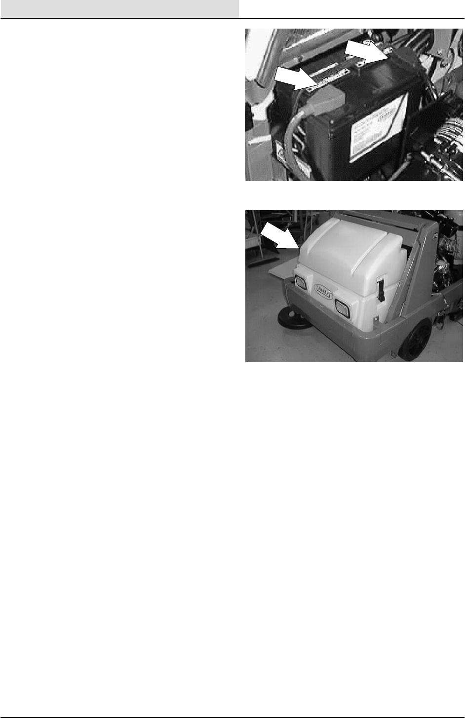
HYDRAULICS
6-26 8200/8210 330065 (3--01)
36. Reconnect the battery and start the
machine.
37. Disengage the prop arm and lower the
hopper.
38. Check the machine for proper operation.
Check for hydraulic leaks at the accessory
pump.

HYDRAULICS
6-27
8200/8210 330065 (3--01)
TO REPLACE BELT DRIVEN ACCESSARY
PUMP V--BELT
1. Empty the debris hopper.
2. Set the machine parking brake.
3. Raise the hopper and engage the prop arm.
Shut off the engine.
WARNING: Raised Hopper May Fall.
Engage Hopper Support Bar.
FOR SAFETY: Before Leaving Or
Servicing Machine; Stop On Level
Surface, Set Parking Brake, Turn Off
Machine And Remove Key.
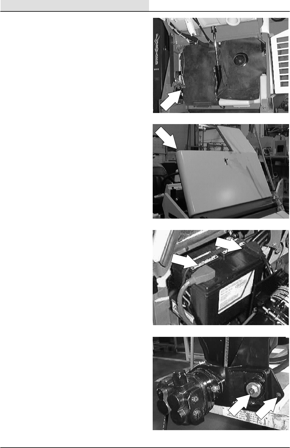
HYDRAULICS
6-28 8200/8210 330065 (3--01)
4. Pull the rubber dust shield out of the metal
bracket. Pull the dust shield back for access
to the accessory pump.
5. Open the engine cover and side door.
6. Disconnect the battery cables.
7. Go to the front the machine and locate the
two hex screws and nuts holding the
accessory pump pivot plate to the mount
plate. Loosen these two screws.
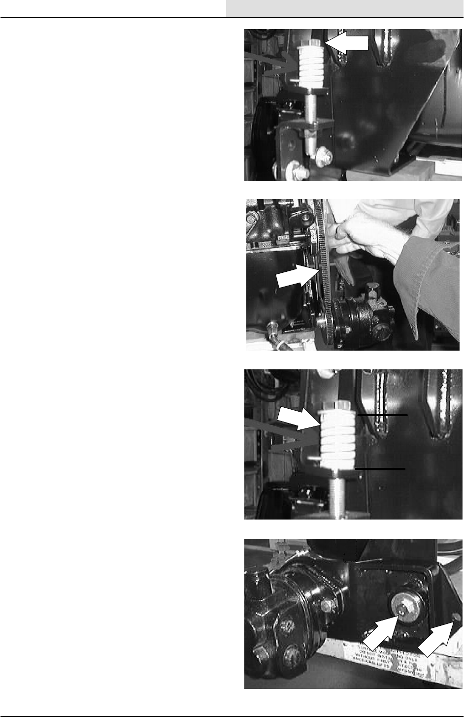
HYDRAULICS
6-29
8200/8210 330065 (3--01)
8. Locate the hex bolt and compression spring
at the front of the accessory pump mount
bracket. Remove the hex bolt and
compression spring. Push the pump up to
remove the V--belt from the pump sheave.
9. Install the V--belt around the accessory
pump sheave.
NOTE: Use a straight edge to align the pump
sheave and engine sheave within .020 inch runout
for proper belt tracking.
10. The accessory pump belt adjustment is
made by turning the bolt on top of the
tension spring. The tension spring is located
at the front of the engine compartment, near
the accessory pump belt sheave. The
accessory pump belt is at the proper tension
when the tension spring is compressed to
3.81 cm 0.0076 mm (1.5 in 0.030 in).
NOTE: When adjusting the accessory pump belt
tension, measure only the spring and not the
washers at either end.
11. Go back and tighten the two pivot plate
mount screws to 37 -- 48 Nm (26 -- 34 ft lb).
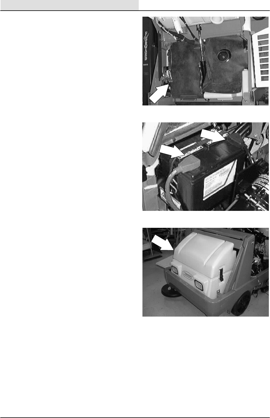
HYDRAULICS
6-30 8200/8210 330065 (3--01)
12. Position the rubber dust shield back into the
metal bracket.
13. Reconnect the battery and start the
machine.
14. Disengage the prop arm and lower the
hopper.
15. Check the machine for proper operation.
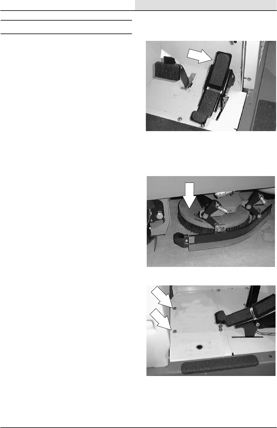
HYDRAULICS
6-31
8200/8210 330065 (3--01)
DIRECTIONAL PEDAL
The directional pedal controls the flow of hydraulic
fluid to the hydraulic propelling motor.
The pedal neutral position is the position in which
the propelling pump sends no hydraulic fluid to the
propelling motor. The machine should not move
when the pedal neutral position is adjusted
correctly. The pedal linkages should also be
adjusted whenever the reverse is faster or slower
than machine specification.
TO REPLACE PROPEL DIRECTIONAL SPRING
1. Start the machine and lower the scrub head.
Turn off the machine.
FOR SAFETY: Before Leaving Or
Servicing Machine; Stop On Level
Surface, Set Parking Brake, Turn Off
Machine And Remove Key.
2. Remove the floor mat from the operators
compartment. Remove the three screws
holding the floor plate in the operator
compartment. Remove the floor plate.
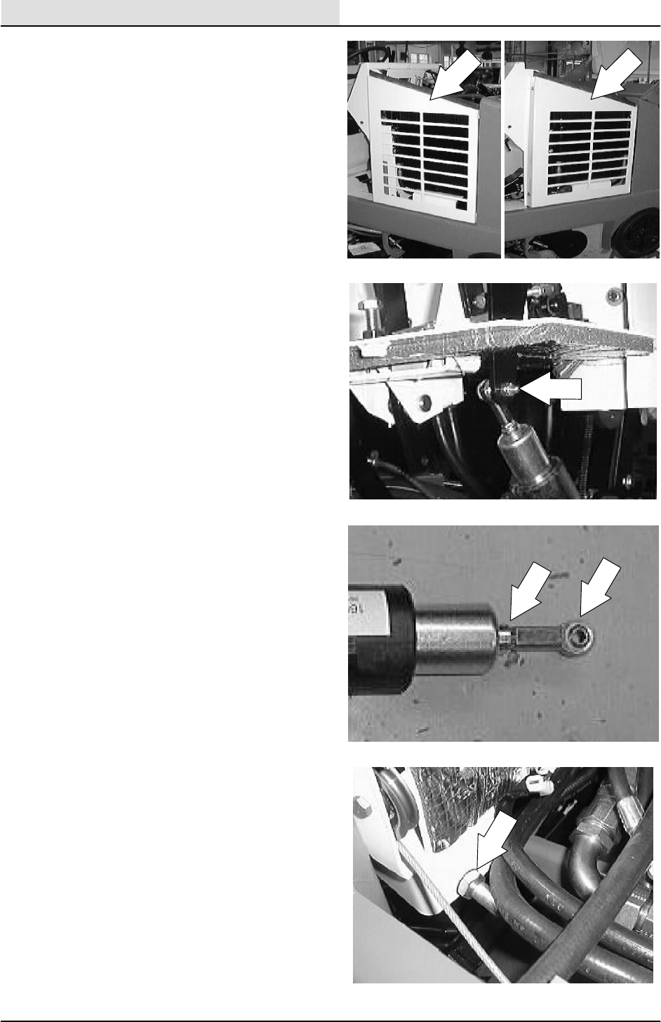
HYDRAULICS
6-32 8200/8210 330065 (3--01)
3. Remove the two screws holding the radiator
grill guard to the machine. Pull the grill out of
the rubber grommets and remove it from the
machine.
4. Go in under the operator compartment,
above the scrub head. Locate the directional
spring ball joint end on the direction pedal.
Remove the nut from the ball joint end. Pull
the ball end out of the pedal.
5. Loosen the jam nut on the directional cable.
Remove the ball joint and jam nut from the
cable.
6. Loosen the two large jam nuts holding the
directional spring assembly to the frame.
Drop the spring down out of the mount slot.
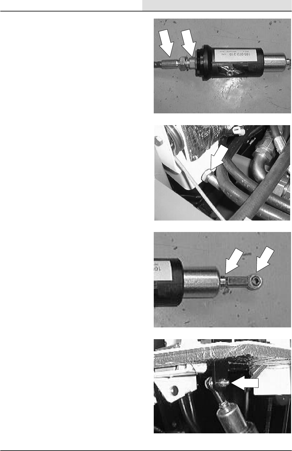
HYDRAULICS
6-33
8200/8210 330065 (3--01)
7. Un--screw the directional spring assembly
from the directional cable. Remove the
spring assembly from the machine.
NOTE: Mark the directional cable before removing
the directional spring to make sure the new spring
is install in the same location.
8. Install the new directional spring on the old
directional cable. Position the new spring in
the same location on the cable as the old
one.
9. Place the new directional spring in the
mount slot. Tighten the large jam nut firmly.
10. Reinstall the jam nut and ball joint onto the
directional cable in the same location as it
was removed. Tighten the jam nut against
the ball joint.
11. Reinstall the ball joint into the mount hole in
the directional pedal. Tighten the nyloc nut
tight.
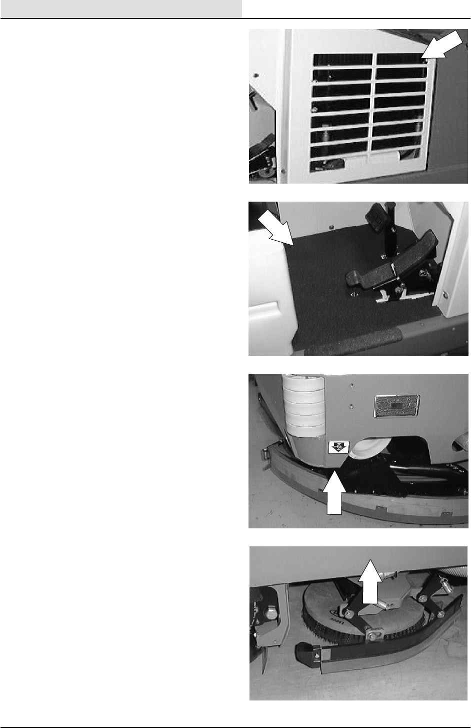
HYDRAULICS
6-34 8200/8210 330065 (3--01)
12. Reinstall the radiator grill guard and two
mounting screws. Tighten to 18 -- 24 Nm
(15 -- 20 ft lb).
13. Reinstall the floor plate and three mounting
screws. Tighten to 18 -- 24 Nm
(15 -- 20 ft lb). Reinstall the floor mat.
14. Raise the rear of the machine and install
jack stands under the frame.
15. Start the machine and raise the scrub head.
Check the rear drive wheel for any rotation.
Adjust if necessary. See TO ADJUST
NEUTRAL CENTERING instructions.
16. Remove the jack stands and lower the
machine.
17. Operate the machine and check the propel
centering for proper operation.
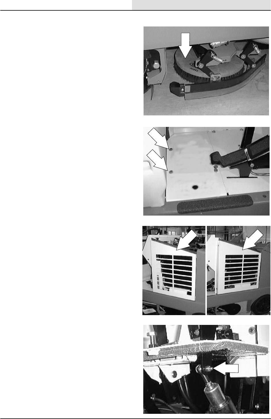
HYDRAULICS
6-35
8200/8210 330065 (3--01)
TO REPLACE PROPEL DIRECTIONAL CABLE
1. Start the machine and lower the scrub head.
Turn off the machine.
FOR SAFETY: Before Leaving Or
Servicing Machine; Stop On Level
Surface, Set Parking Brake, Turn Off
Machine And Remove Key.
2. Remove the floor mat from the operators
compartment. Remove the three screws
holding the floor plate in the operator
compartment. Remove the floor plate.
3. Remove the two screws holding the radiator
grill guard to the machine. Pull the grill out of
the rubber grommets and remove it from the
machine.
4. Go in under the operator compartment,
above the scrub head. Locate the directional
spring ball joint end on the direction pedal.
Remove the nut from the ball joint end. Pull
the ball end out of the pedal.
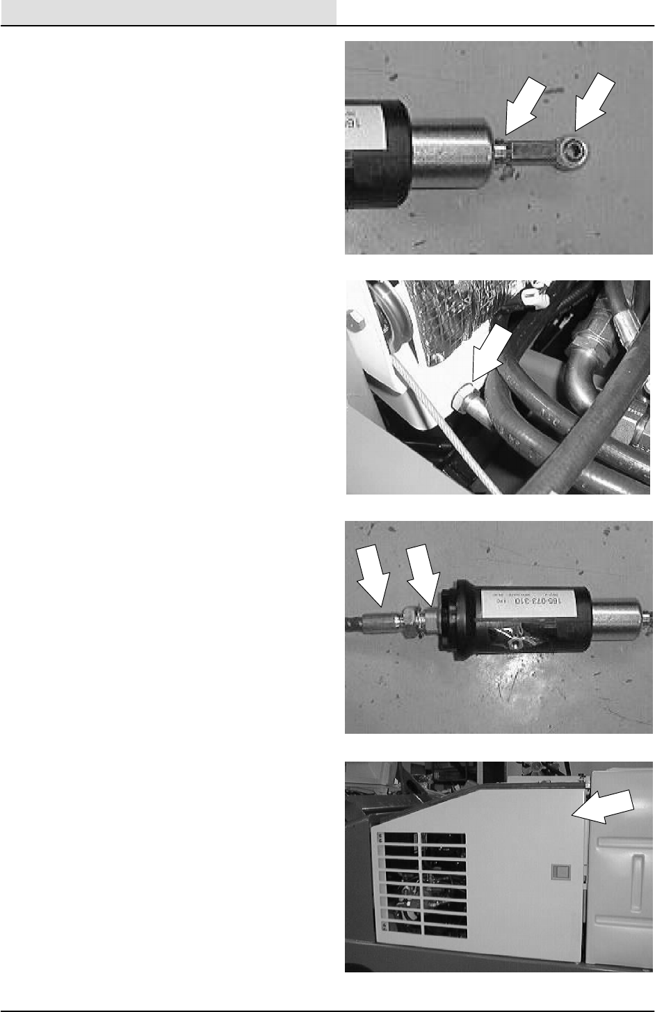
HYDRAULICS
6-36 8200/8210 330065 (3--01)
5. Loosen the jam nut on the directional cable.
Remove the ball joint and jam nut from the
cable.
6. Loosen the two large jam nuts holding the
directional spring assembly to the frame.
Drop the spring down out of the mount slot.
7. Un--screw the directional spring assembly
from the directional cable. Remove the
spring assembly from the machine.
NOTE: Mark the directional cable before removing
the directional spring to make sure the new spring
is install in the same location.
8. Open the engine side door.
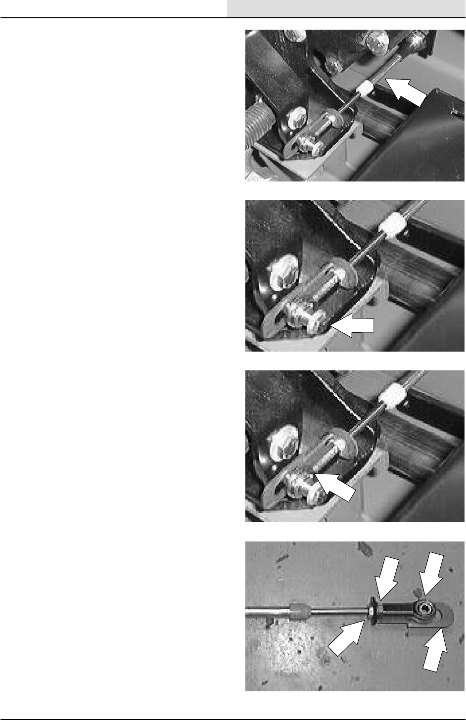
HYDRAULICS
6-37
8200/8210 330065 (3--01)
9. Locate the other end of the directional cable
at the propel pump.
10. Remove the hex screw, spacer, and nyloc
nut holding the directional spring ball end to
the propel pump arm.
11. Cut the plastic tie from around the propel
cable bracket.
12. Remove the ball end, 1st jam nut, washer,
propel cable bracket, and 2nd jam nut from
the end of the directional cable.
NOTE: Make note of the location of the 2nd jam
nut for proper re--assembly.
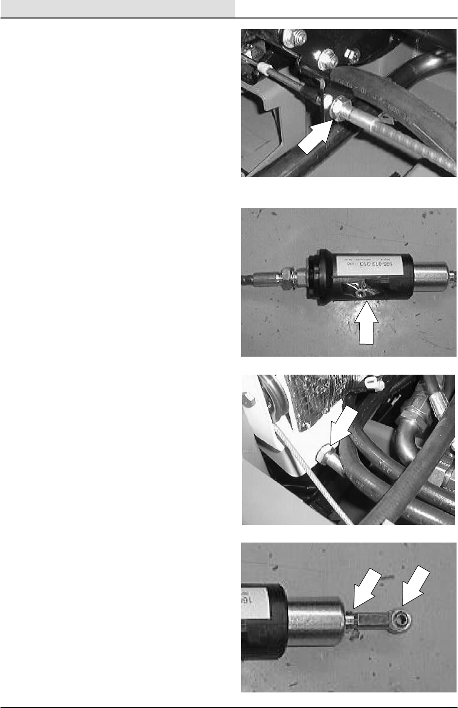
HYDRAULICS
6-38 8200/8210 330065 (3--01)
13. Loosen the two large jam nuts holding the
directional spring assembly to the lower
mount bracket. Drop the cable down and out
of the mount slot.
14. Remove the old directional cable from the
machine. Carefully route the new directional
cable in the machine. Follow the same path
as the old cable.
NOTE: One end of the new cable has 1 inch of
thread and the other end has 1--1/2 inch of thread.
The end with 1--1/2 inch of thread goes toward the
directional pedal and the end with 1 inch of
thread goes toward the propel pump.
15. Install the directional spring on the new
directional cable. Position the spring in the
same location on the new cable as the old
one.
16. Place the directional spring in the mount
slot on the front of the operators
compartment. Tighten the large jam nut
firmly.
17. Reinstall the jam nut and ball joint onto the
directional cable and spring in the same
location as it was removed. Tighten the jam
nut against the ball joint.
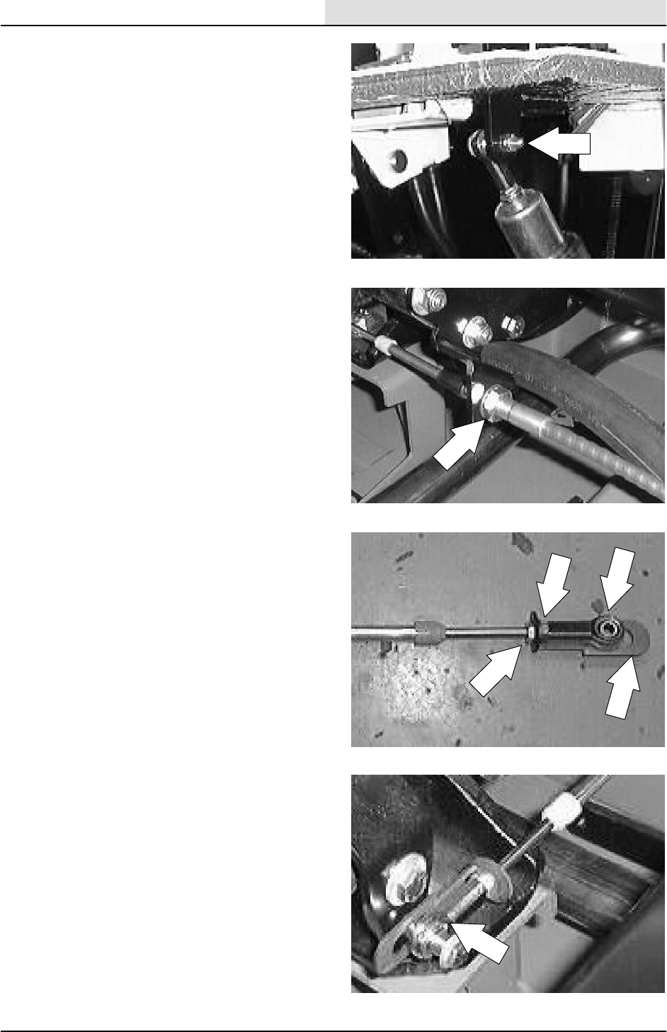
HYDRAULICS
6-39
8200/8210 330065 (3--01)
18. Reinstall the ball joint into the mount hole in
the directional pedal. Tighten the nyloc nut
tight.
19. Go to the area near the engine and propel
pump. Position the new cable in the slot on
the mount bracket near the propel pump.
Tighten the large jam nut tight.
20. Reinstall the 1st jam nut, cable bracket,
rubber washer, 2nd jam nut, and ball end.
Tighten the jam nuts in the same location as
they were removed.
NOTE: Make note of the location of the 2nd jam
nut for proper re--assembly.
21. Install a new plastic wire tie around the cable
bracket. Reinstall the front rubber firewall.
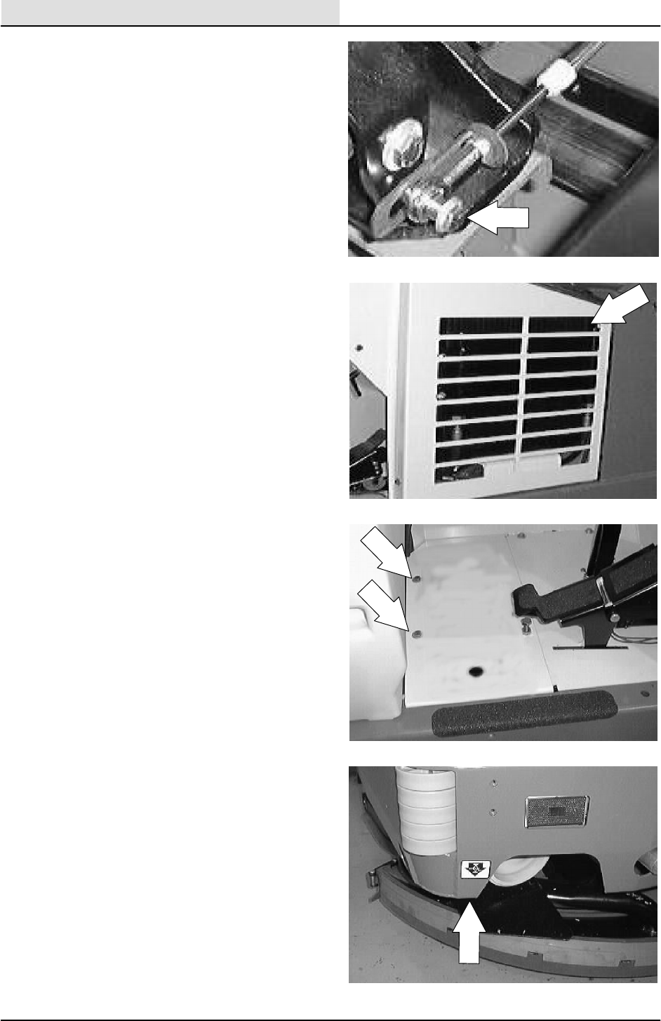
HYDRAULICS
6-40 8200/8210 330065 (3--01)
22. Reconnect the cable ball end to the propel
pump arm. Tighten the hex screw to
11 -- 1 4 N m ( 7 -- 1 0 f t l b ) .
NOTE: Make sure the spacers are in place under
the ball end.
23. Reinstall the radiator grill guard and two
mounting screws. Tighten to 18 -- 24 Nm
(15 -- 20 ft lb).
24. Reinstall the floor plate and three mounting
screws. Tighten to 18 -- 24 Nm
(15 -- 20 ft lb).
25. Raise the rear of the machine and install
jack stands under the frame.
26. Start the machine and raise the scrub head.
Check the rear drive wheel for any rotation.
Adjust if necessary. See TO ADJUST
NEUTRAL CENTERING instructions.
27. Remove the jack stands and lower the
machine.
28. Operate the machine and check for proper
operation.
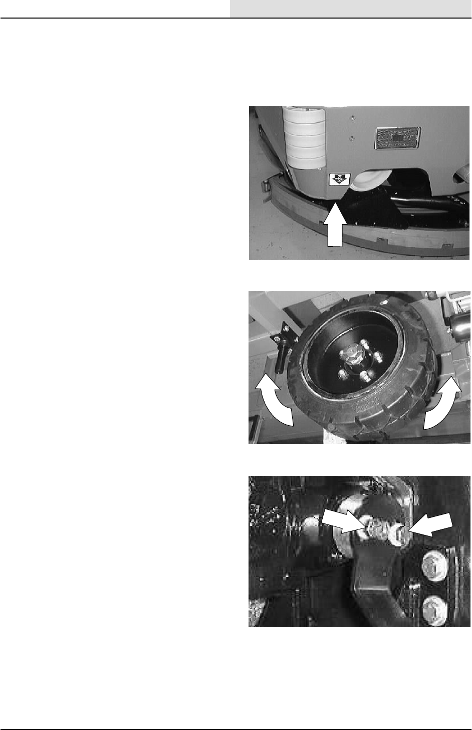
HYDRAULICS
6-41
8200/8210 330065 (3--01)
TO ADJUST NEUTRAL CENTERING
FOR SAFETY: Before Leaving Or
Servicing Machine; Stop On Level
Surface, Set Parking Brake, Turn Off
Machine And Remove Key.
1. Raise the rear of the machine and install
jack stands under the machine frame.
2. Start the machine and check the rear tire for
any rotation. If the tire is rotating in either
direction the neutral centering needs to be
adjusted.
3. Loosen the two outside hex screws on the
directional arm where it attaches to the
pump hub. Leave the center screw tight.
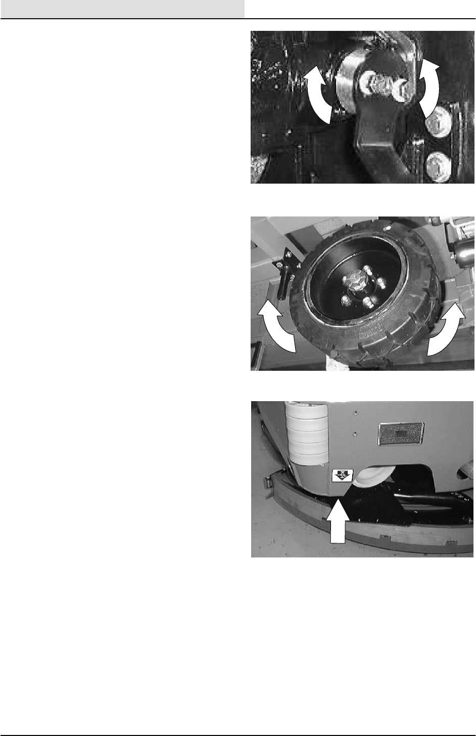
HYDRAULICS
6-42 8200/8210 330065 (3--01)
4. Rotate the pump hub, under the directional
arm, either clockwise or counter clockwise to
achieve neutral centering.
5. Check to make sure the rear tire is not
turning with the engine running. If the tire is
not turning----tighten the two hex screws to
18 -- 24 Nm (15 -- 20 ft lb).
6. Remove the jack stands and lower the
machine. Check to make sure the machine
does not creep in neutral.

HYDRAULICS
6-43
8200/8210 330065 (3--01)
TO REPLACE HOPPER LIFT CYLINDER
1. Empty the debris hopper.
2. Set the machine parking brake.
3. Raise the hopper and engage the prop arm.
Shut off the engine. Move the hopper lift
handle back and forth a few times.
NOTE: Make sure the hopper is resting down onto
the hopper support bar.
WARNING: Raised Hopper May Fall.
Engage Hopper Support Bar.
FOR SAFETY: Before Leaving Or
Servicing Machine; Stop On Level
Surface, Set Parking Brake, Turn Off
Machine And Remove Key.
4. Place a drain pan under the hopper lift
cylinder. Loosen the hose fitting on the
bottom of the cylinder. After the hydraulic oil
stop flowing, disconnect and plug the bottom
hose.
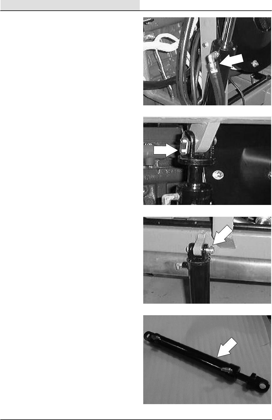
HYDRAULICS
6-44 8200/8210 330065 (3--01)
5. Mark, disconnect, and cap the two hydraulic
hose leading to the top of the lift cylinder.
NOTE: Always observe hydraulic cleanliness
requirements when opening hydraulic lines.
6. Remove the screw holding the upper
cylinder pin to the cylinder clevis. Push the
pin out of the clevis.
7. Remove the ”C” clip from the clevis pin on
the lower end of the hopper lift cylinder.
Remove the clevis pin.
8. Remove the hopper lift cylinder from the
machine.
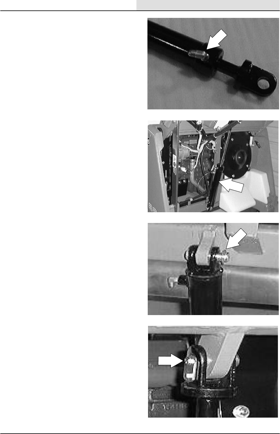
HYDRAULICS
6-45
8200/8210 330065 (3--01)
9. Remove the fittings from the old cylinder and
install in the new cylinder in the same
orientation.
10. Position the new cylinder in the machine
with the rod end pointing up.
11. Align the bottom of the lift cylinder with the
hole in the frame mount lug. Reinstall the
clevis pin and ”C” clip.
12. Align the top cylinder clevis with the hole in
the lift arm cylinder mounting lug. Reinstall
the clevis pin and hex screw. Install the pin
so the hex screw is on the operators side of
the machine.
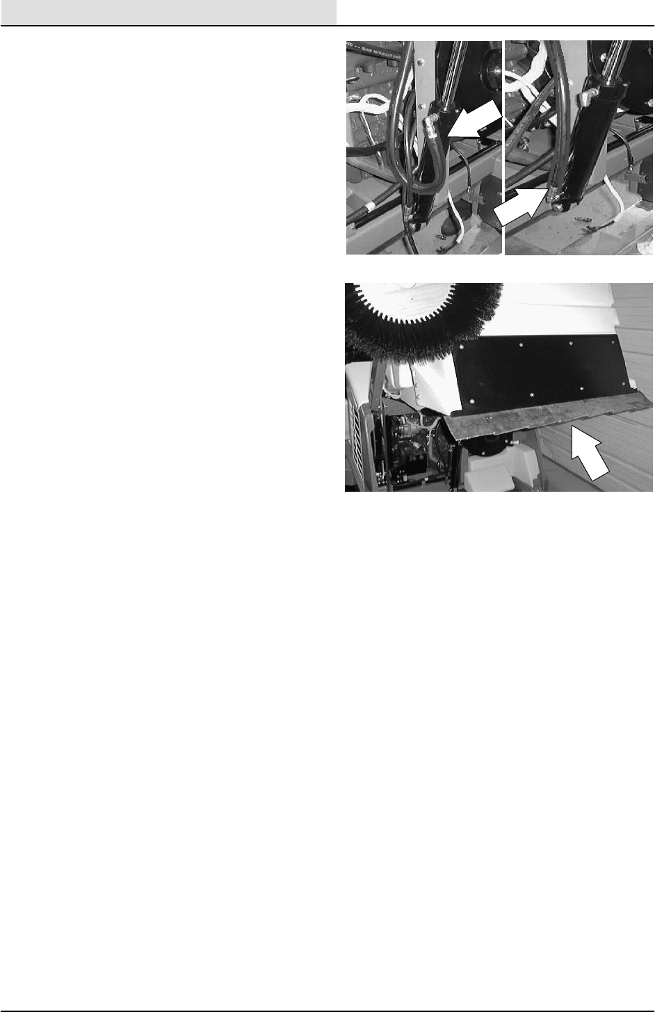
HYDRAULICS
6-46 8200/8210 330065 (3--01)
13. Reconnect the hydraulic hoses to the new
cylinder. See schematic in this section.
14. Start the machine and lower the hopper.
Check for any leaks and proper operation.
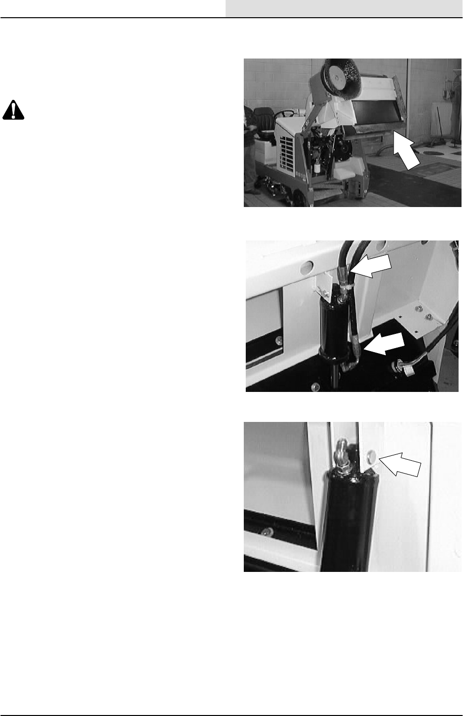
HYDRAULICS
6-47
8200/8210 330065 (3--01)
TO REPLACE HOPPER DUMP DOOR
CYLINDER
1. Dump the debris hopper. Engage the
support bar.
WARNING: Raised Hopper May Fall.
Engage Hopper Support Bar.
FOR SAFETY: Before Leaving Or
Servicing Machine; Stop On Level
Surface, Set Parking Brake, Turn Off
Machine And Remove Key.
2. Mark, disconnect, and plug the two hoses
leading to the hopper dump door cylinder.
3. Remove the cotter pin and clevis pin from
the top of the dump door cylinder where it
attaches to the center/rear of the debris
hopper.
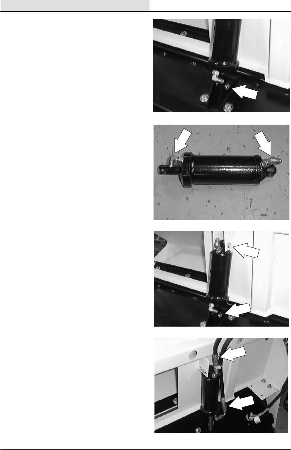
HYDRAULICS
6-48 8200/8210 330065 (3--01)
4. Remove the cotter pin and clevis pin from
the bottom of the dump door cylinder were it
attaches to the center of the dump door.
5. Remove the old cylinder from the back of
the hopper. Remove the fittings from the old
cylinder and install in the new cylinder in the
same orientation.
6. Position the new cylinder in the machine
with the rod end pointing to the center of the
dump door.
7. Reinstall the clevis pin and cotter pin in the
lower end of the dump door cylinder.
8. Reinstall the clevis pin and cotter pin in the
upper end of the dump door cylinder.
9. Reconnect the hydraulic hoses to the dump
door cylinder. See the hose diagram in this
section.
10. Start the machine and open and close the
hopper dump door. Check for any leaks and
proper operation.
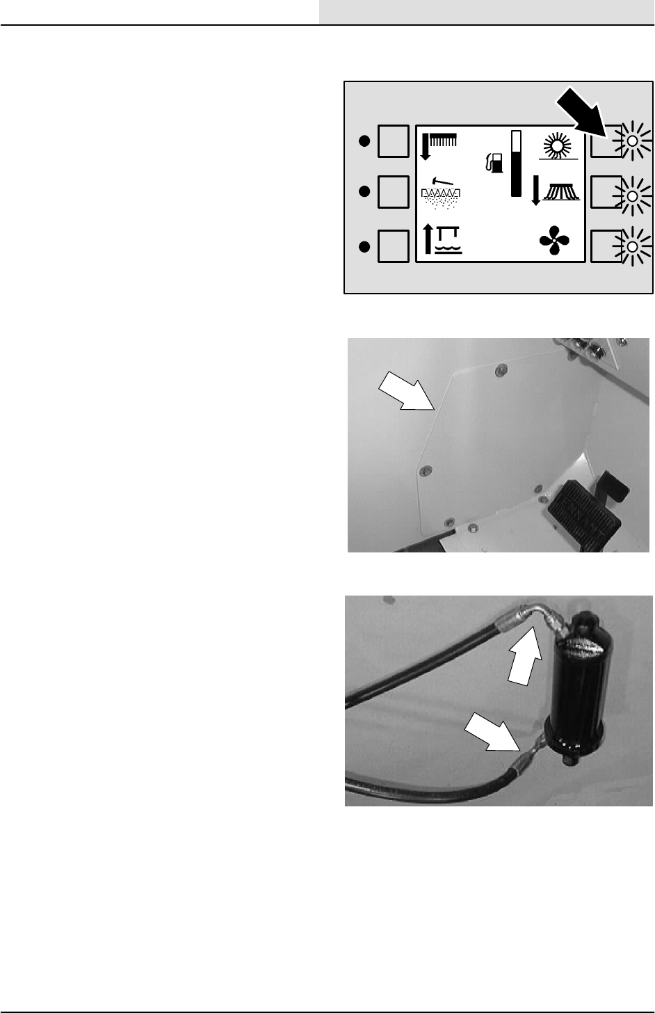
HYDRAULICS
6-49
8200/8210 330065 (3--01)
TO REPLACE MAIN BRUSH LIFT CYLINDER
(8210 only)
1. Start the machine and lower the main brush.
Turn off the machine.
FOR SAFETY: Before Leaving Or
Servicing Machine; Stop On Level
Surface, Set Parking Brake.
2. Locate the main brush lift cylinder access
panel on the inside wall of the operator
compartment. Remove the five screws
holding the access panel to the operator
compartment. Remove the panel.
3. Mark, disconnect, and plug the two hoses
leading to the main brush lift cylinder.
F
E

HYDRAULICS
6-50 8200/8210 330065 (3--01)
4. Remove the cotter pin and clevis pin from
the top of the main brush lift cylinder where
it attaches to the main brush lift arm.
5. Remove the cotter pin and clevis pin from
the bottom of the main brush lift cylinder
were it attaches to the machine frame.
6. Remove the main brush lift cylinder through
the access panel opening.
7. Remove the fittings from the old main brush
lift cylinder and install in the new cylinder in
the same orientation.
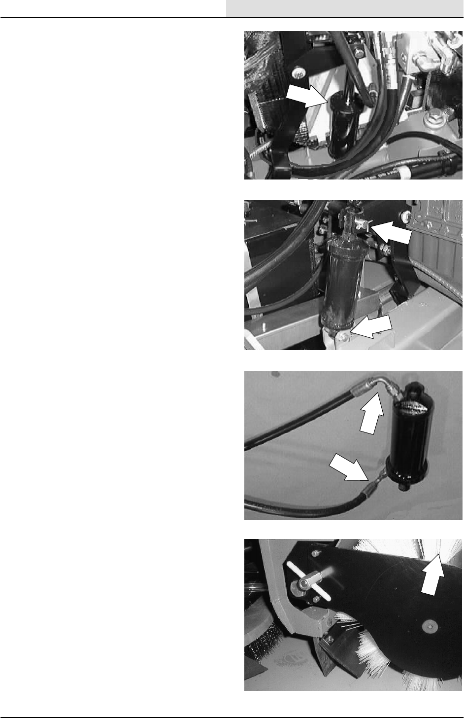
HYDRAULICS
6-51
8200/8210 330065 (3--01)
8. Position the new cylinder in the machine
with the rod end pointing up.
9. Reinstall the clevis pins and cotter pins in
the upper and lower ends of the new main
brush lift cylinder.
10. Reconnect the hydraulic hoses to the main
brush lift cylinder. See the hose diagram in
this section.
11. Start the machine and raise and lower the
main brush. Check for any leaks and proper
operation.
12. Reinstall the main brush lift cylinder access
panel on the inside wall of the operator
compartment.
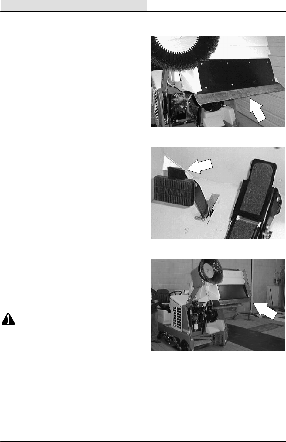
HYDRAULICS
6-52 8200/8210 330065 (3--01)
TO REPLACE SIDE BRUSH LIFT CYLINDER
(8210 only)
1. Empty the debris hopper.
2. Set the machine parking brake.
3. Raise the hopper and engage the prop arm.
Shut off the engine. Move the hopper lift
handle back and forth a few times.
NOTE: Make sure the hopper is resting down onto
the hopper support bar.
WARNING: Raised Hopper May Fall.
Engage Hopper Support Bar.
FOR SAFETY: Before Leaving Or
Servicing Machine; Stop On Level
Surface, Set Parking Brake, Turn Off
Machine And Remove Key.
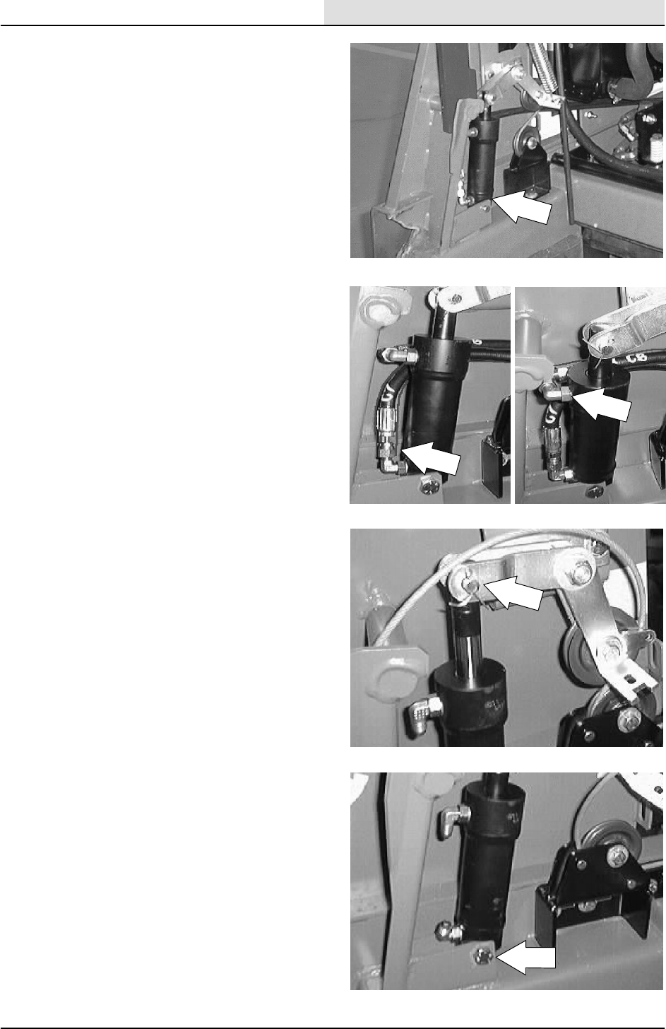
HYDRAULICS
6-53
8200/8210 330065 (3--01)
4. Place a drain pan under the side brush lift
cylinder. Loosen the hose fitting on the
bottom of the cylinder.
5. Mark, disconnect, and cap the two hydraulic
hoses leading to the side brush lift cylinder.
NOTE: Always observe hydraulic cleanliness
requirements when opening hydraulic lines.
6. Remove the cotter pin and clevis pin holding
the top of the side brush lift cylinder to the
machine pivot bracket.
7. Remove the M10 hex screw and nut holding
the bottom of the lift cylinder to the machine
frame. Remove the lift cylinder from the
machine.
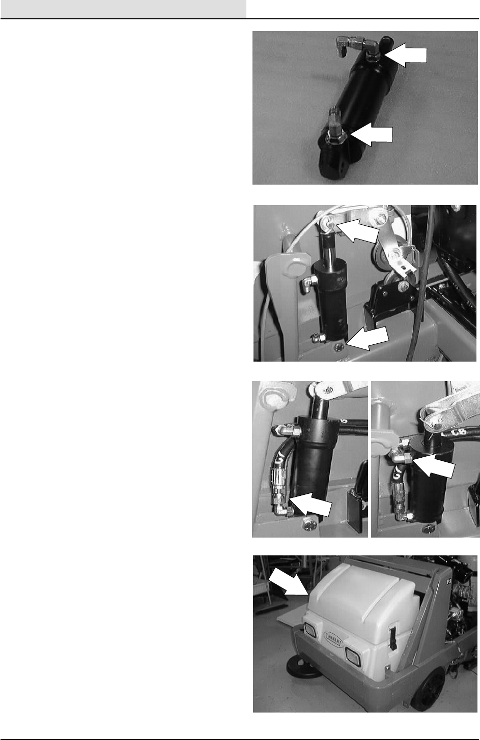
HYDRAULICS
6-54 8200/8210 330065 (3--01)
8. Remove the fittings from the old cylinder and
install in the new cylinder in the same
orientation.
9. Position the new cylinder in the machine
with the rod end pointing up.
10. Reinstall the clevis pin and cotter pin in the
rod end of the dump door cylinder where it
attaches to the pivot bracket.
11. Reinstall the M10 hex screw and nut in the
lower end of the side brush lift cylinder
where it attaches to the frame. Tighten to
37 -- 48 Nm (26 -- 34 ft lb).
12. Reconnect the hydraulic hoses to the side
brush lift cylinder. See the hose diagram in
this section.
NOTE: Always observe hydraulic cleanliness
requirements when opening hydraulic lines.
13. Start the machine and disengage the prop
arm. Lower the hopper.
14. Operate the machine and raise and lower
the side brush. Check for any leaks and
proper operation.
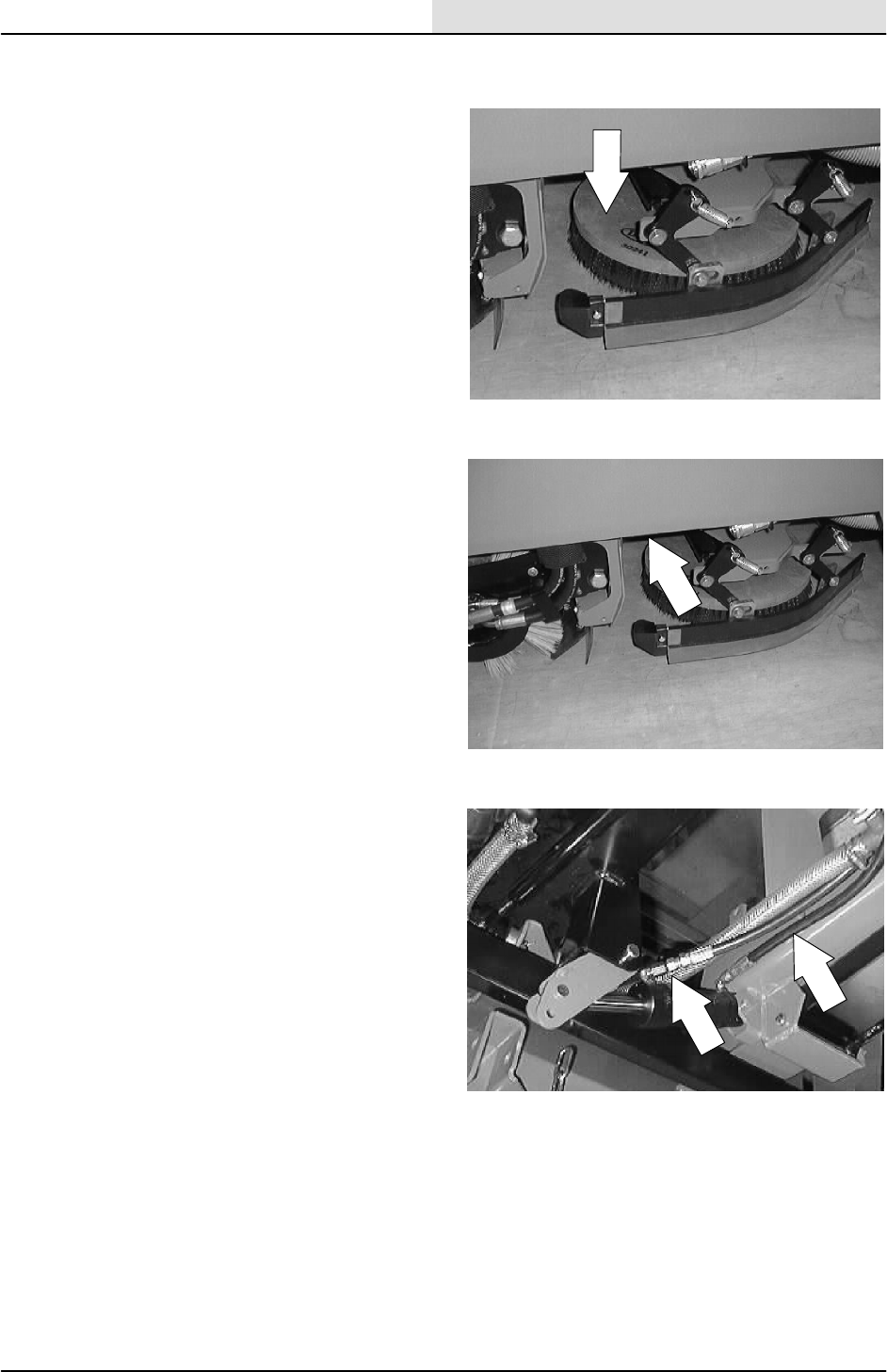
HYDRAULICS
6-55
8200/8210 330065 (3--01)
TO REPLACE SCRUB HEAD SIDE SHIFT
CYLINDER (optional on 8200, std on 8210)
1. Start the machine and lower the scrub head.
Turn off the machine.
FOR SAFETY: Before Leaving Or
Servicing Machine; Stop On Level
Surface, Set Parking Brake, Turn Off
Machine And Remove Key.
2. Go under the machine frame on the left
hand side. Locate the side shift hydraulic
cylinder above the scrub head.
3. Mark, disconnect, and cap the two hydraulic
hoses leading to the scrub head side shift
cylinder.
NOTE: Always observe hydraulic cleanliness
requirements when opening hydraulic lines.
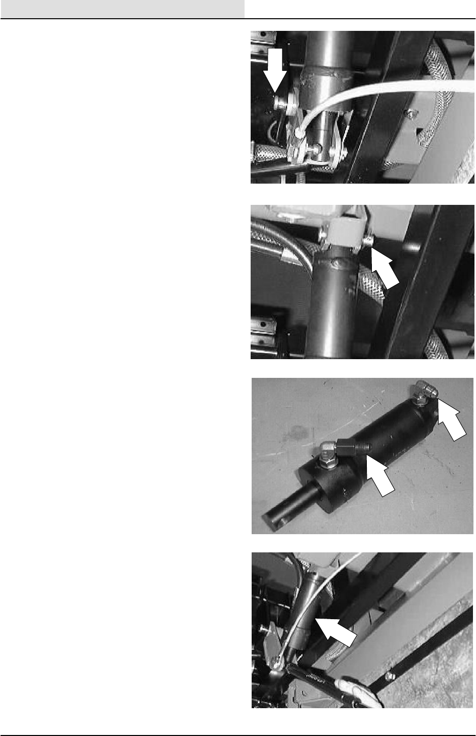
HYDRAULICS
6-56 8200/8210 330065 (3--01)
4. Remove the cotter pin and clevis pin from
the rod end of the side shift cylinder.
5. Remove the clevis pin and cotter pin from
the top of the side shift cylinder. Remove the
cylinder from the machine.
6. Remove the fittings from old cylinder. Install
the fittings in the new cylinder in the same
orientation.
7. Position the new cylinder in the machine
with the rod end pointing toward the right
side of the machine. Install both clevis pins
and cotter pins.
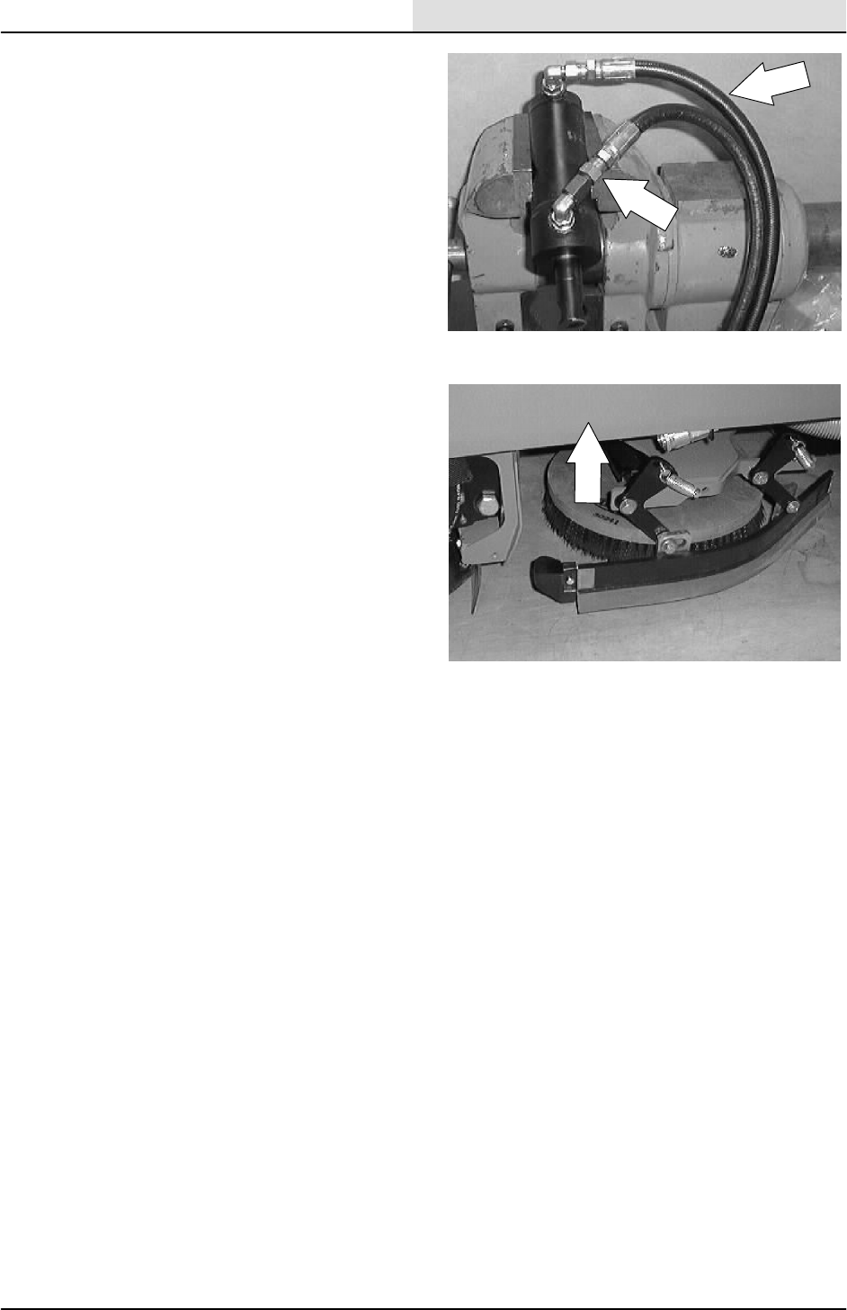
HYDRAULICS
6-57
8200/8210 330065 (NIL)
8. Connect the hydraulic hoses to the new side
shift cylinder. See the hose diagram in this
section.
9. Start the machine and raise the scrub head.
10. Start the machine and operate the scrub
head side shift button. Check for proper
operation.
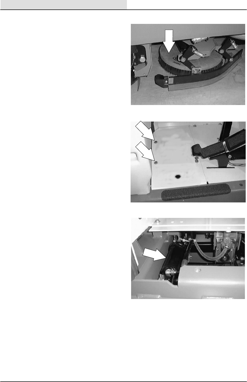
HYDRAULICS
6-58 8200/8210 330065 (3--01)
TO REPLACE SCRUB HEAD LIFT CYLINDER
1. Start the machine and lower the scrub head.
Turn off the machine.
FOR SAFETY: Before Leaving Or
Servicing Machine; Stop On Level
Surface, Set Parking Brake, Turn Off
Machine And Remove Key.
2. Remove the three screws holding the floor
plate in the operators compartment. Remove
the floor plate.
3. Go under the machine frame on the right
hand side, above the scrub head. Locate the
scrub head lift cylinder.
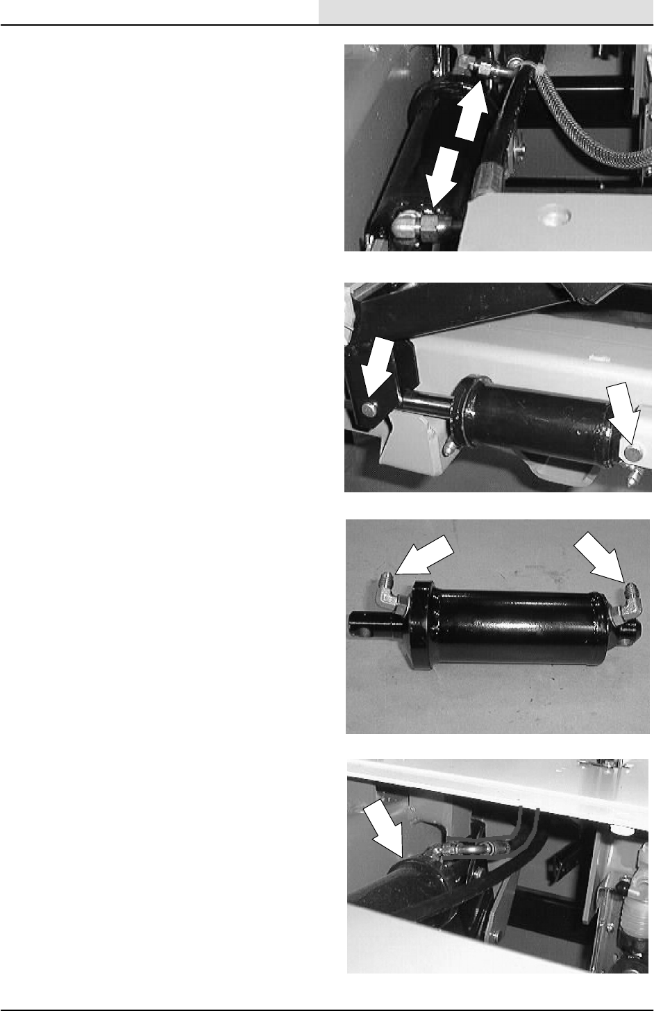
HYDRAULICS
6-59
8200/8210 330065 (3--01)
4. Mark, disconnect, and cap the two hydraulic
hoses leading to the scrub head lift cylinder.
NOTE: Always observe hydraulic cleanliness
requirements when opening hydraulic lines.
5. Remove the cotter pins and clevis pins from
both ends of the scrub head lift cylinder.
Remove the lift cylinder from the machine.
6. Remove the fittings from old cylinder. Install
the fittings in the new cylinder in the same
orientation.
7. Position the new cylinder in the machine
with the rod end pointing toward the front of
the machine.
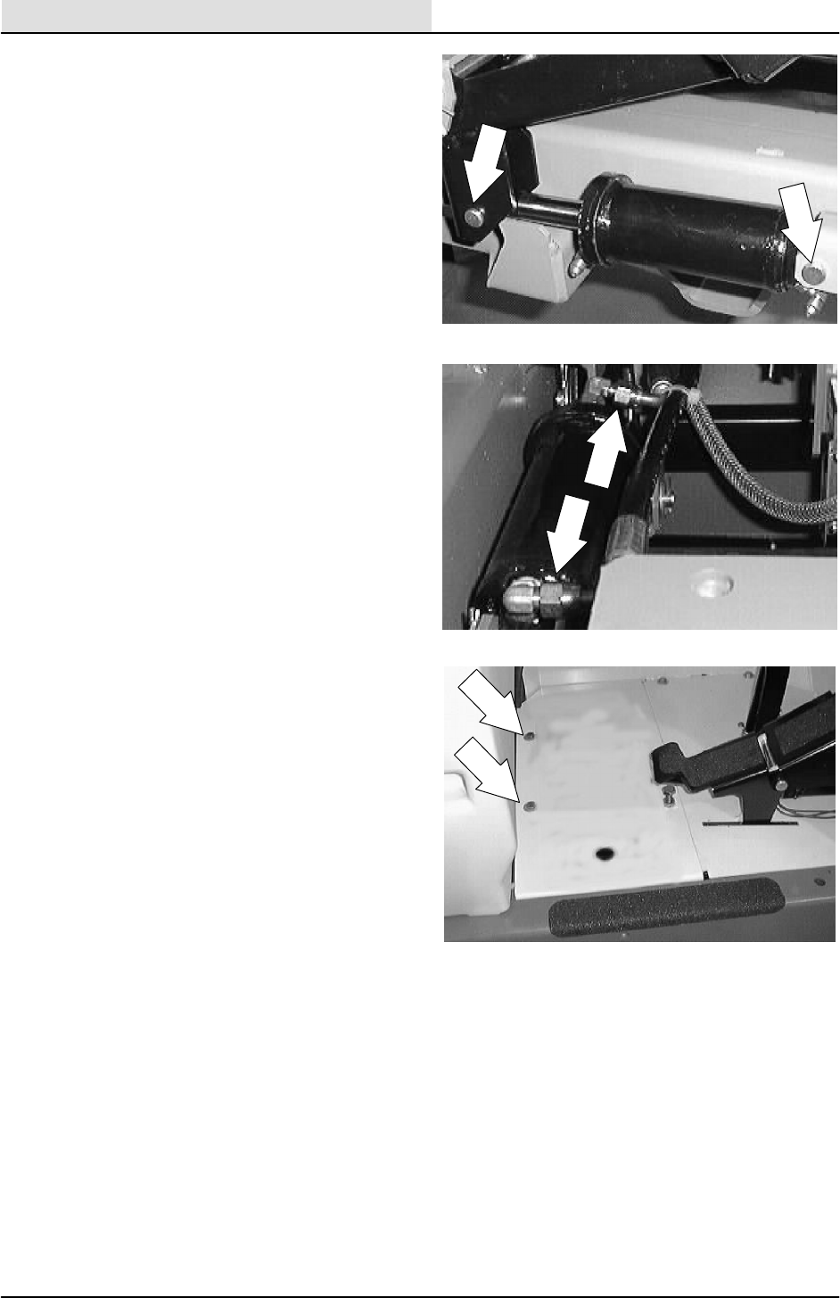
HYDRAULICS
6-60 8200/8210 330065 (3--01)
8. Install both clevis pins and cotter pins.
9. Connect the hydraulic hoses to the new
scrub head lift cylinder. See the hose
diagram in this section.
NOTE: Always observe hydraulic cleanliness
requirements when opening hydraulic lines.
15. Reinstall the floor plate and three mounting
screws. Tighten to 18 -- 24 Nm
(15 -- 20 ft lb).
10. Start the machine and operate the scrub
head lift button. Check for proper operation.

HYDRAULICS
6-61
8200/8210 330065 (3--01)
TO REPLACE REAR SQUEEGEE LIFT
CYLINDER
1. Start the machine and lower the rear
squeegee. Turn off the machine.
FOR SAFETY: Before Leaving Or
Servicing Machine; Stop On Level
Surface, Set Parking Brake, Turn Off
Machine And Remove Key.
2. Remove the solution tank. See TO
REMOVE SOLUTION TANK instructions in
the SCRUBBING section.
3. Go under the machine frame at the rear of
the machine. Locate the squeegee lift
cylinder.
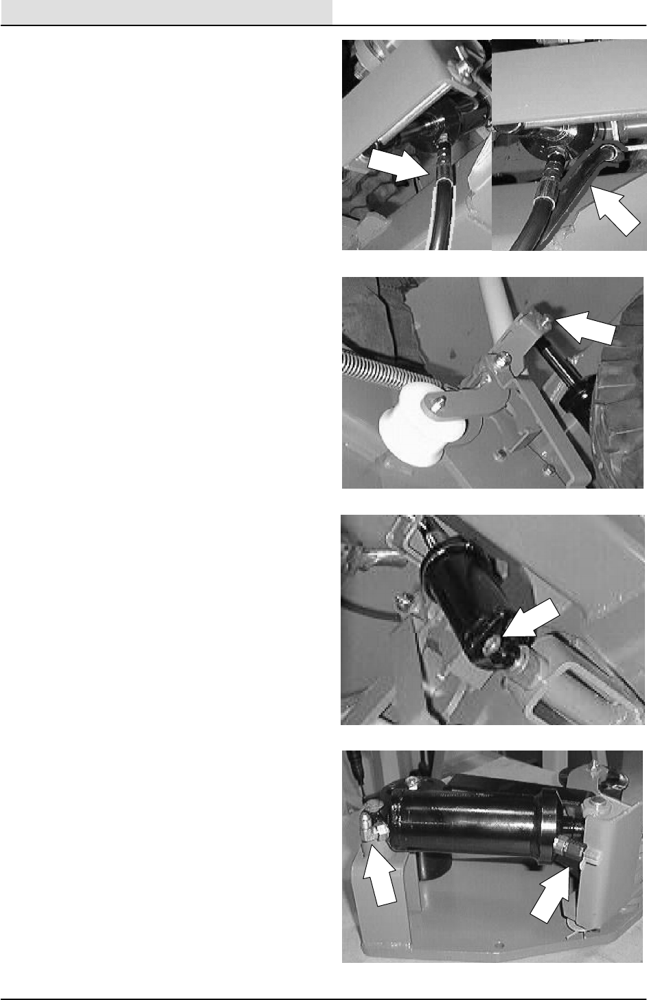
HYDRAULICS
6-62 8200/8210 330065 (3--01)
4. Mark, disconnect, and cap the two hydraulic
hoses leading to the squeegee lift cylinder.
NOTE: Always observe hydraulic cleanliness
requirements when opening hydraulic lines.
5. Remove the cotter pin and clevis pin from
the rod end of the squeegee lift cylinder.
6. Remove the ”C” clip from the lower mount
pin on the squeegee lift cylinder. Remove
the cylinder from the machine.
7. Remove the fittings from old cylinder. Install
the fittings in the new cylinder in the same
orientation.
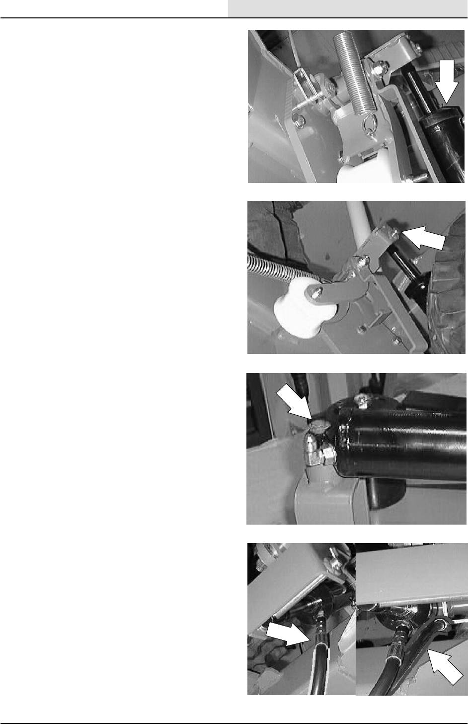
HYDRAULICS
6-63
8200/8210 330065 (3--01)
8. Position the new cylinder in the machine
with the rod end pointing upward.
9. Install the clevis pin and cotter pin in the rod
end of the cylinder.
10. Install the ”C” clip on the lower mount pin.
11. Connect the hydraulic hoses to the new
squeegee lift cylinder. See the hose diagram
in this section.
NOTE: Always observe hydraulic cleanliness
requirements when opening hydraulic lines.
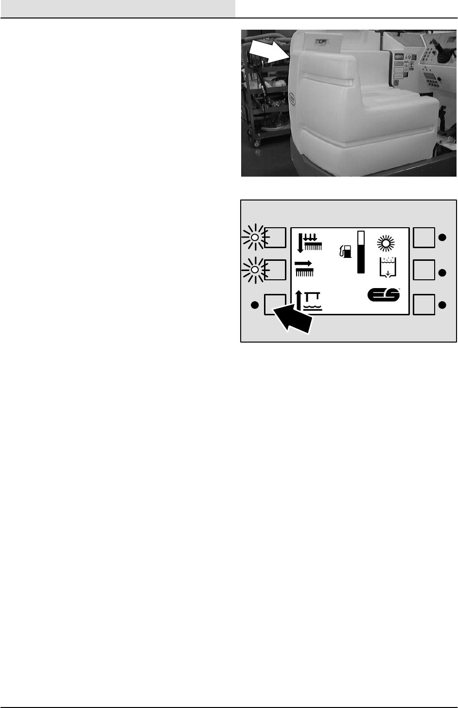
HYDRAULICS
6-64 8200/8210 330065 (3--01)
12. Reinstall the solution tank. See TO INSTALL
SOLUTION TANK instructions in the
SCRUBBING section.
13. Start the machine and operate the squeegee
lift button. Check for proper operation.
F
E
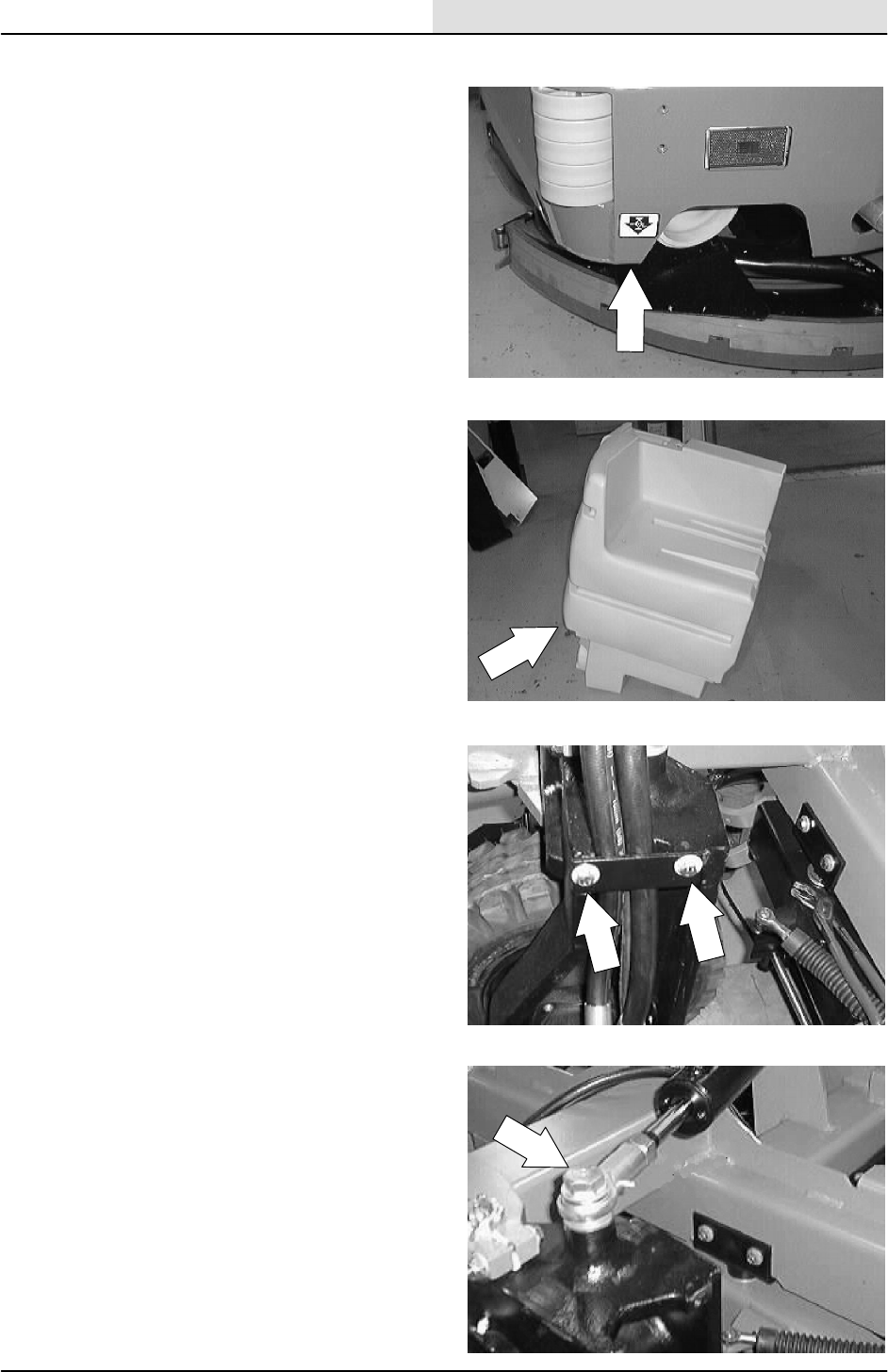
HYDRAULICS
6-65
8200/8210 330065 (3--01)
TO REPLACE STEERING CYLINDER
1. Raise the rear of the machine. Put jack
stands under the rear frame.
FOR SAFETY: Before Leaving Or
Servicing Machine; Stop On Level
Surface, Set Parking Brake., Turn Off
Machine And Remove Key.
2. Remove the solution tank. See TO
REMOVE SOLUTION TANK instructions in
the SCRUBBING section.
3. Remove the clamp holding the drive motor
hydraulic hoses to rear casting. Move the
hoses to gain access to the steering cylinder
hardware.
4. Remove the hex screw and nut holding the
steering cylinder rod end balljoint to the rear
drive casting.
NOTE: Retain and reuse the flat washers under
the balljoint or hex screw.
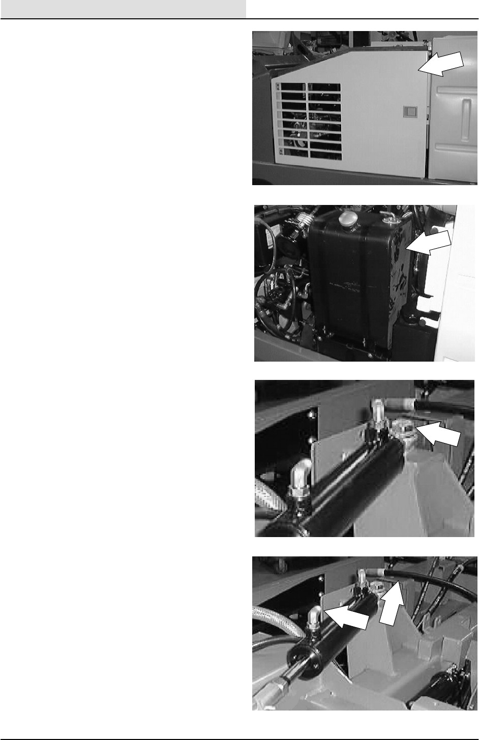
HYDRAULICS
6-66 8200/8210 330065 (3--01)
5. Open the engine cover and side door.
6. Remove the fuel tank or LP tank mount
assembly from the machine.
7. Remove the hex screw and nyloc nut
holding the piston end of the steering
cylinder rod end to the machine frame.
8. Mark, disconnect, and cap the two hydraulic
hoses leading to the steering cylinder.
NOTE: Always observe hydraulic cleanliness
requirements when opening hydraulic lines.
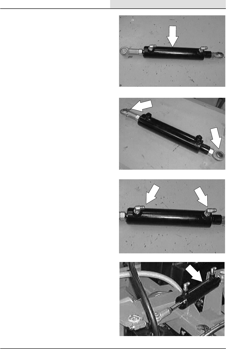
HYDRAULICS
6-67
8200/8210 330065 (3--02)
9. Remove the steering cylinder from the
machine.
10. Remove the ball joint ends from the old
cylinder and install on the new cylinder.
NOTE: Make sure that the balljoints are pointed
down and they are turned all the way in until they
are bottomed out.
11. Tighten the jam nuts against the balljoints.
12. Remove the fittings from old cylinder. Install
the fittings in the new cylinder in the same
orientation.
13. Position the new steering cylinder and
balljoint assembly in the machine with the
rod part of the cylinder toward the rear of the
machine.

HYDRAULICS
6-68 8200/8210 330065 (3--01)
14. Reinstall the hex screws and nuts on the
steering cylinder rod ends. Reinstall any flat
washers that were removed earlier.
Tighten to 339 Nm (250 ft lb).
15. Reconnect the hydraulic hoses to the
steering cylinder. See schematic in this
section.
NOTE: Always observe hydraulic cleanliness
requirements when opening hydraulic lines.
16. Reinstall the clamp holding the drive motor
hydraulic hoses to rear casting.
17. Reinstall the solution tank. See TO INSTALL
SOLUTION TANK instructions in the
SCRUBBING section.
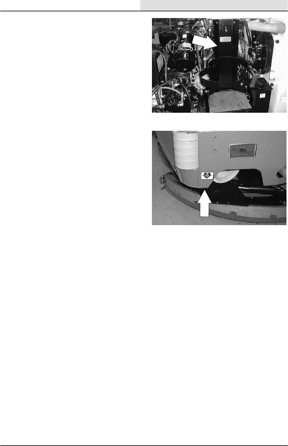
HYDRAULICS
6-69
8200/8210 330065 (3--01)
18. Reinstall the fuel tank or LP tank mount
assembly.
19. Remove the jack stands from machine and
lower.
20. Start machine and turn steering wheel in
both directions. Observe the steering
cylinder for any leaks.
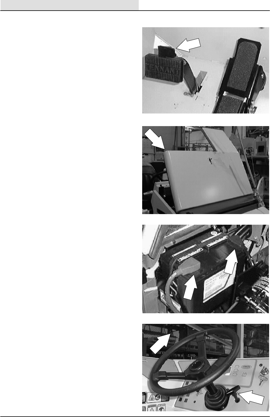
HYDRAULICS
6-70 8200/8210 330065 (3--01)
TO REPLACE STEERING VALVE
1. Turn off the engine and engage the parking
brake.
FOR SAFETY: Before Leaving Or
Servicing Machine; Stop On Level
Surface, Set Parking Brake, Turn Off
Machine And Remove Key.
2. Open the engine cover.
3. Remove battery cables from battery.
4. Tilt the steering wheel to the highest
position.
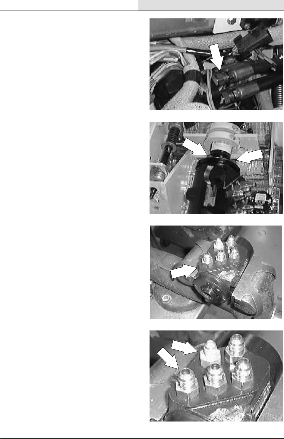
HYDRAULICS
6-71
8200/8210 330065 (3--01)
5. Mark, remove, and plug the five hydraulic
hoses leading to the steering control valve.
NOTE: Observe hydraulic cleanliness
requirements when opening hydraulic lines.
6. Remove the hex screws holding the
hydraulic steering valve to the steering
column.
7. The hydraulic steering valve can now be
removed from machine.
8. Remove the five hydraulic fittings from the
old steering valve. Install the fittings in the
new valve in the same orientation.

HYDRAULICS
6-72 8200/8210 330065 (3--01)
9. Install the new hydraulic steering valve in the
machine. Position the ports in the same
orientation as the old valve. Reinstall the
hex screws and tighten to 31 -- 40 Nm
(27 -- 35 ft lb).
10. Reconnect the hydraulic hoses to hydraulic
steering valve. See the schematic in this
section.
11. Reconnect the battery cables and start
engine. Turn the steering wheel and check
for any leaks.
12. Close the engine side door and engine
cover. Operate the machine and check for
proper operation.
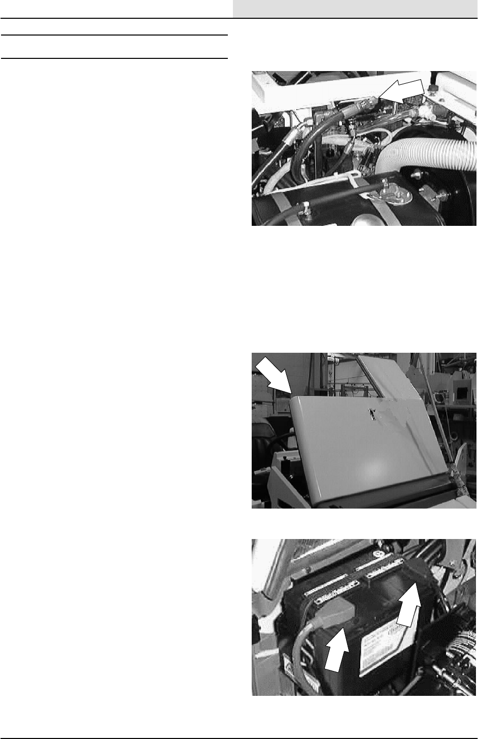
HYDRAULICS
6-73
8200/8210 330065 (3--01)
HOPPER LIFT VALVE
The hopper lift valve is used to raise and lower
the hopper and open and close the dump door on
the standard machine. The hopper dump door is
controlled with a solenoid valve on the 8210. The
main and side brushes will only turn on when the
hopper is in the down position.
TO REPLACE HOPPER LIFT VALVE
FOR SAFETY: Before Leaving Or
Servicing Machine; Stop On Level
Surface, Set Parking Brake, Turn Off
Machine And Remove Key.
1. Open the engine cover and side door.
2. Disconnect the battery cables.
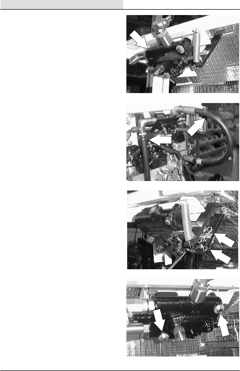
HYDRAULICS
6-74 8200/8210 330065 (3--01)
3. Locate the hopper lift valve on the top,
inside of the operators compartment.
4. Mark, disconnect, and plug the hydraulic
hoses leading to the hopper lift valve.
NOTE: Observe hydraulic cleanliness
requirements when opening hydraulic lines.
5. Remove the hair pins and clevis pins holding
the handles to the lift valve. Remove the
tension spring from the shorter handle.
6. Remove the two M6 hex screws and nyloc
nuts holding the lift valve to the lintel.
Remove the valve from the machine.
NOTE: Make sure to retain the two rubber
washers located between the valve and lintel.
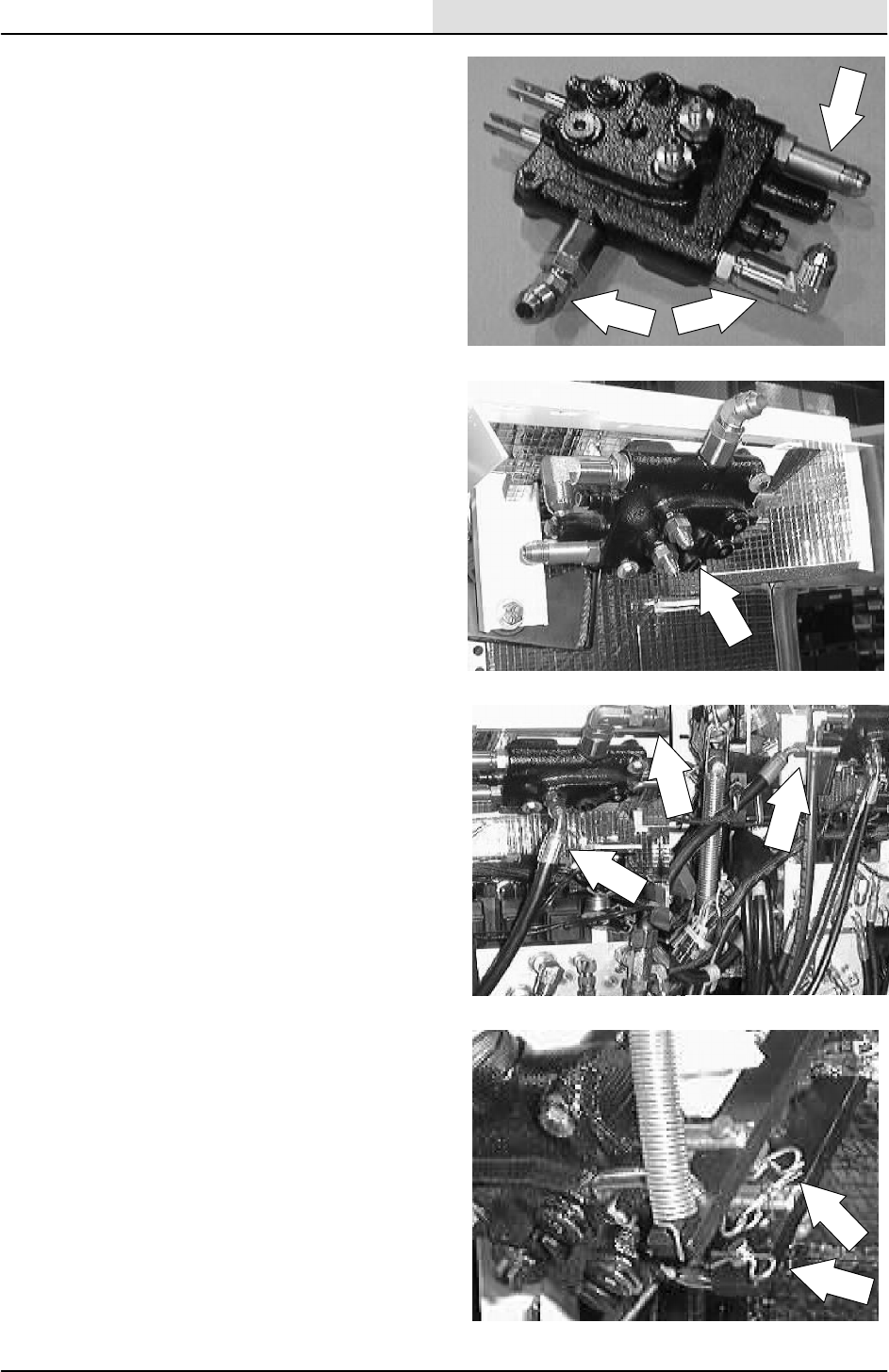
HYDRAULICS
6-75
8200/8210 330065 (3--01)
7. Remove the fittings from the old valve and
install in the new valve in the same
orientation.
8. Install the new valve back onto the inside
wall of the lintel. Reinstall the two M6 hex
screws, two rubber washers, and nyloc nuts.
Tighten to 115 -- 225 Ncm (10 -- 20 in lb).
9. Reconnect the hydraulic hoses. See hose
diagram in this section.
NOTE: Observe hydraulic cleanliness
requirements when opening hydraulic lines.
10. Reinstall the two valve handles, clevis pins,
and hair pins on the new valves. The link
goes into the second hole on the handle.
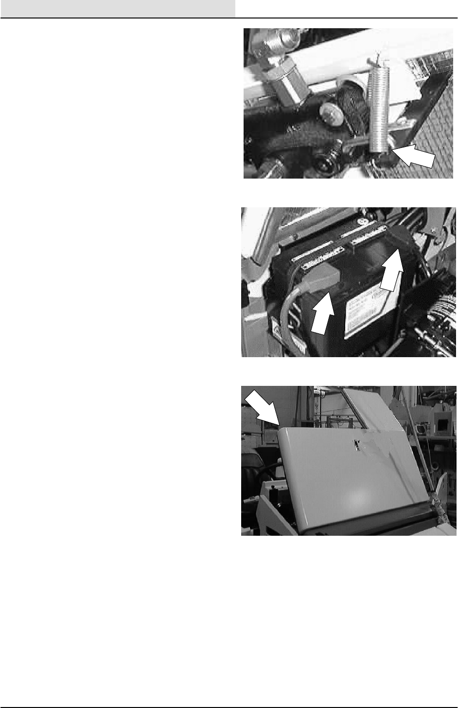
HYDRAULICS
6-76 8200/8210 330065 (3--01)
11. Reconnect the tension spring to the shorter
handle.
12. Reconnect the battery cables.
13. Start the machine and check the lift valve
any leaks.
14. Close the engine side door and engine
cover. Operate the machine and check for
proper operation.
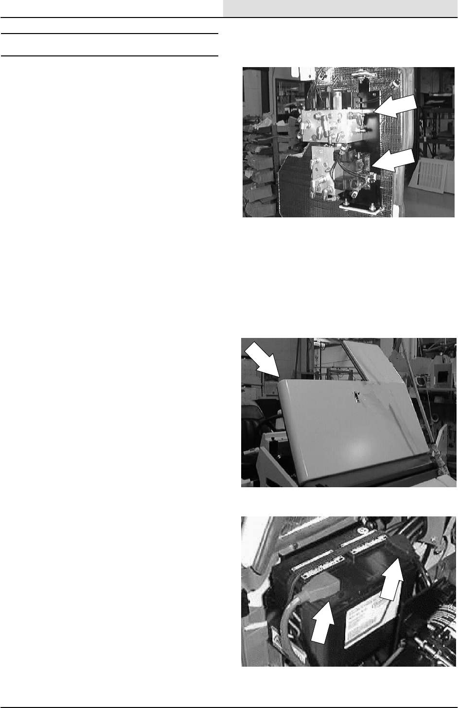
HYDRAULICS
6-77
8200/8210 330065 (3--01)
HYDRAULIC SOLENOID VALVES
The hydraulic solenoid valves control the
operation of the main and side brushes, vacuum
fans, side shift option, and the side brush/main
brush lift on the model 8210. The solenoid valve
coils are electrically activated when the switches
are activated on the touch panel. The solenoid
valves also contain relief valves to protect the
hydraulic system from damage.
TO REPLACE BRUSH AND VACUUM FAN
SOLENOID VALVES
FOR SAFETY: Before Leaving Or
Servicing Machine; Stop On Level
Surface, Set Parking Brake, Turn Off
Machine And Remove Key.
1. Open the engine cover and side door.
2. Disconnect the battery cables.
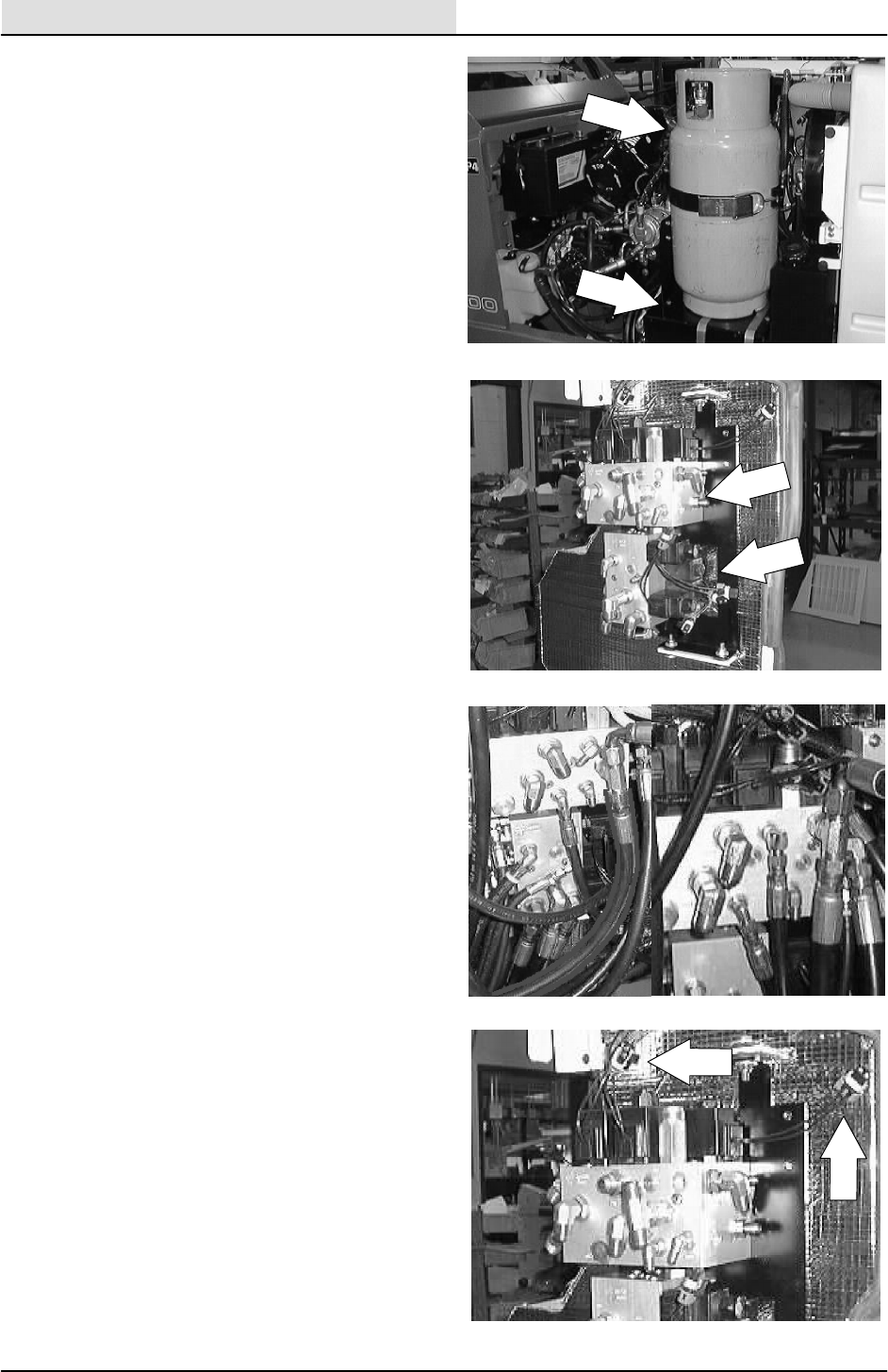
HYDRAULICS
6-78 8200/8210 330065 (3--01)
3. Remove the fuel tank or LP tank mount
plate.
NOTE: This will allow access to the solenoid valve
assembly.
4. Locate the brush/vacuum fan solenoid
valves on the lower/middle section of the
operator compartment.
5. Mark, disconnect, and plug the hydraulic
hoses leading to the brush/vacuum fan
solenoid valve.
6. Un--plug the electrical coils from the main
machine harness.
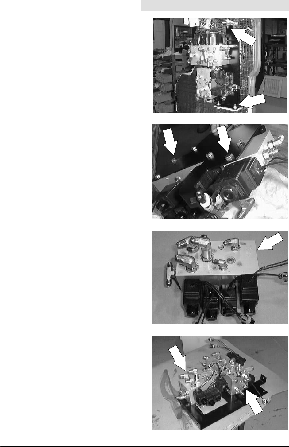
HYDRAULICS
6-79
8200/8210 330065 (3--01)
7. Remove the three hex screws and nyloc
nuts holding the valve mount plate to the
operator compartment. Remove the valve
and mount plate assembly from the
machine.
8. Remove the seven hex screws holding the
valves to the mount plate. Remove the valve
from the plate.
9. Remove the fittings from the old solenoid
valves and install in the new valves in the
same orientation.
10. Install the new valve onto the mount plate.
Reinstall the seven hex screws and tighten
to 18 -- 24 Nm (15 -- 20 ft lb).
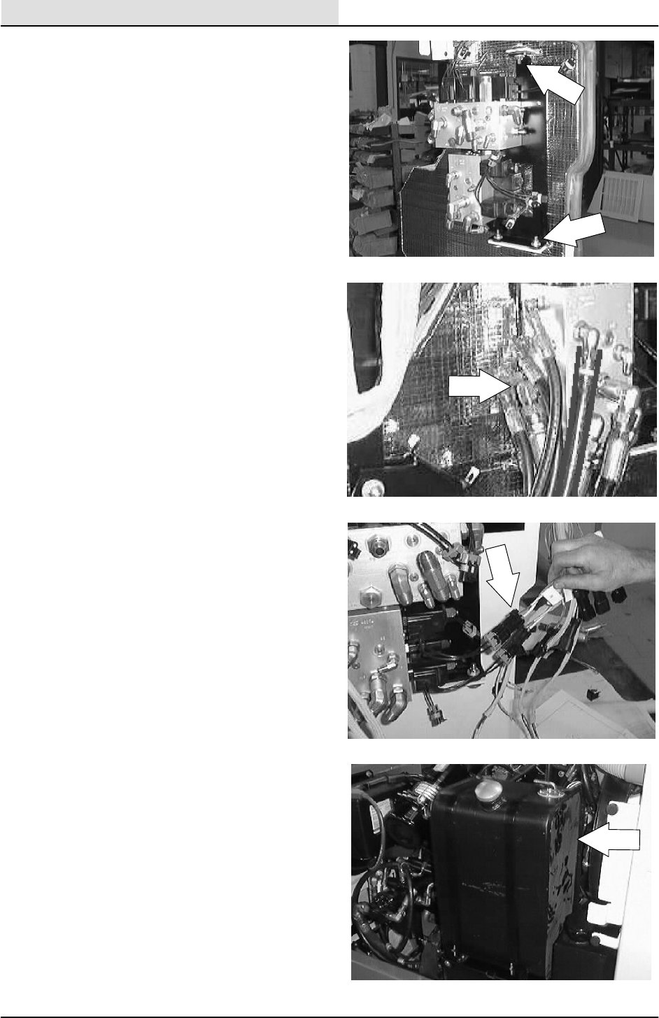
HYDRAULICS
6-80 8200/8210 330065 (3--01)
11. Install the new valves and mount plate on
the inside wall of the operator compartment.
12. Reinstall the three hex screws and nyloc
nuts and tighten to 18 -- 24 Nm
(15 -- 20 ft lb).
13. Reconnect the hydraulic hoses. See hose
diagram in this section.
14. Reconnect the electrical coils to the main
machine harness.
15. Reinstall the fuel tank or LP tank.
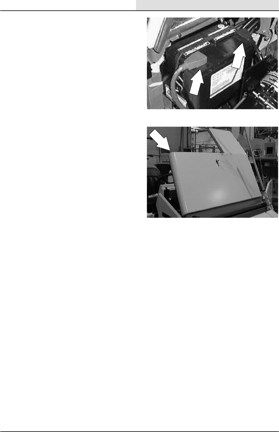
HYDRAULICS
6-81
8200/8210 330065 (3--01)
16. Reconnect the battery cables.
17. Start the machine and check the lift valve
any leaks.
18. Close the engine side door and engine
cover. Operate the machine and check for
proper operation.
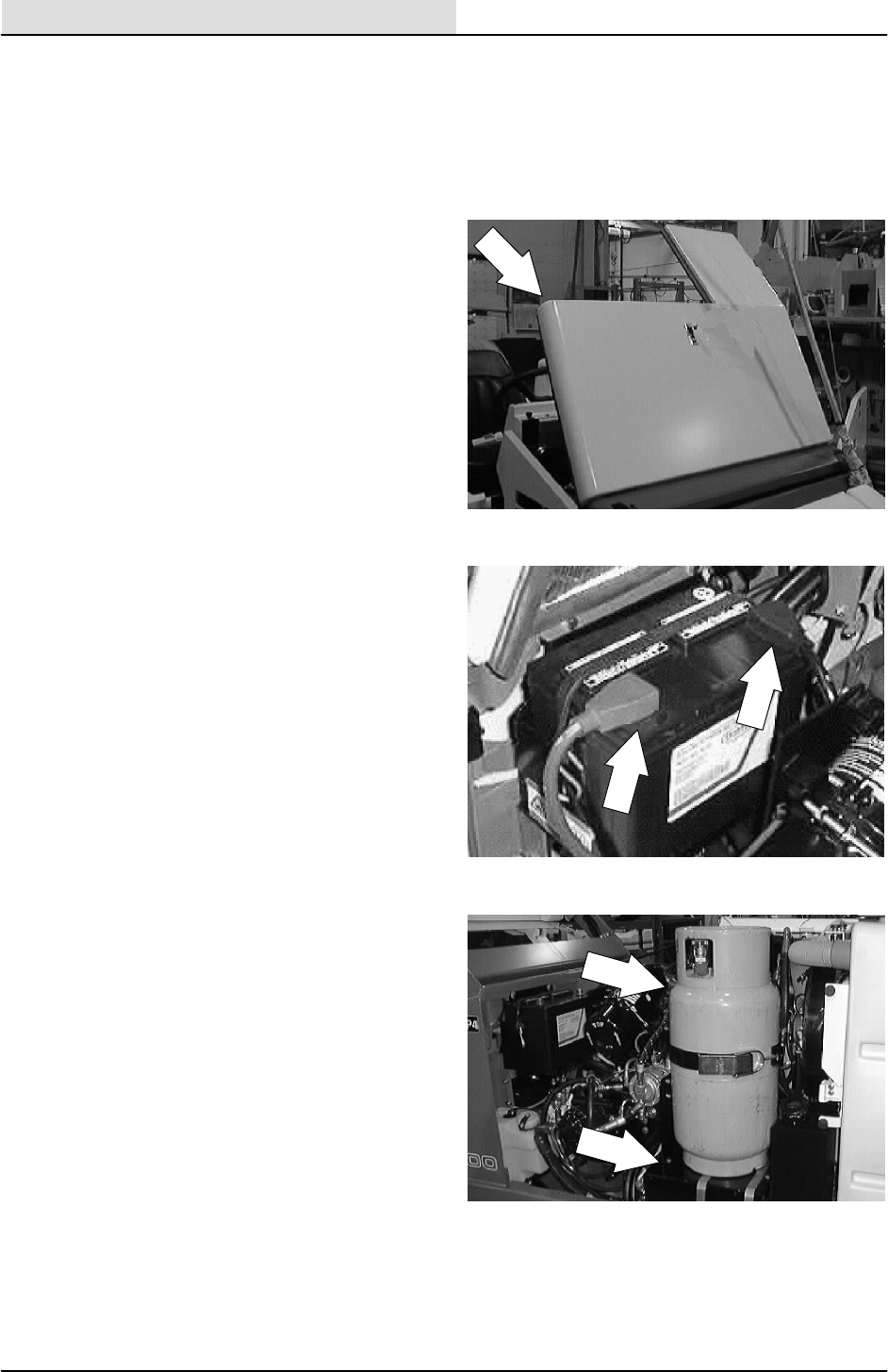
HYDRAULICS
6-82 8200/8210 330065 (3--01)
TO REPLACE OPTIONAL SCRUB HEAD SIDE
SHIFT SOLENOID VALVE (8210)
FOR SAFETY: Before Leaving Or
Servicing Machine; Stop On Level
Surface, Set Parking Brake, Turn Off
Machine And Remove Key.
1. Open the engine cover and side door.
2. Disconnect the battery cables.
3. Remove the fuel tank or LP tank mount
plate.
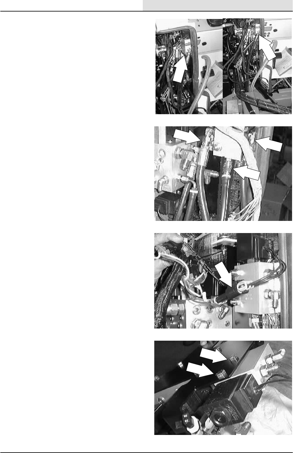
HYDRAULICS
6-83
8200/8210 330065 (3--01)
4. Locate the scrub head side shift solenoid
valve on the lower/middle section of the
operator compartment.
5. Mark, disconnect, and plug the hydraulic
hoses leading to the side shift solenoid
valve.
6. Un--plug the electrical coils from the main
machine harness.
7. Remove the two hex screws and nyloc nuts
holding the valve to the mount plate.
Remove the valve from the plate.
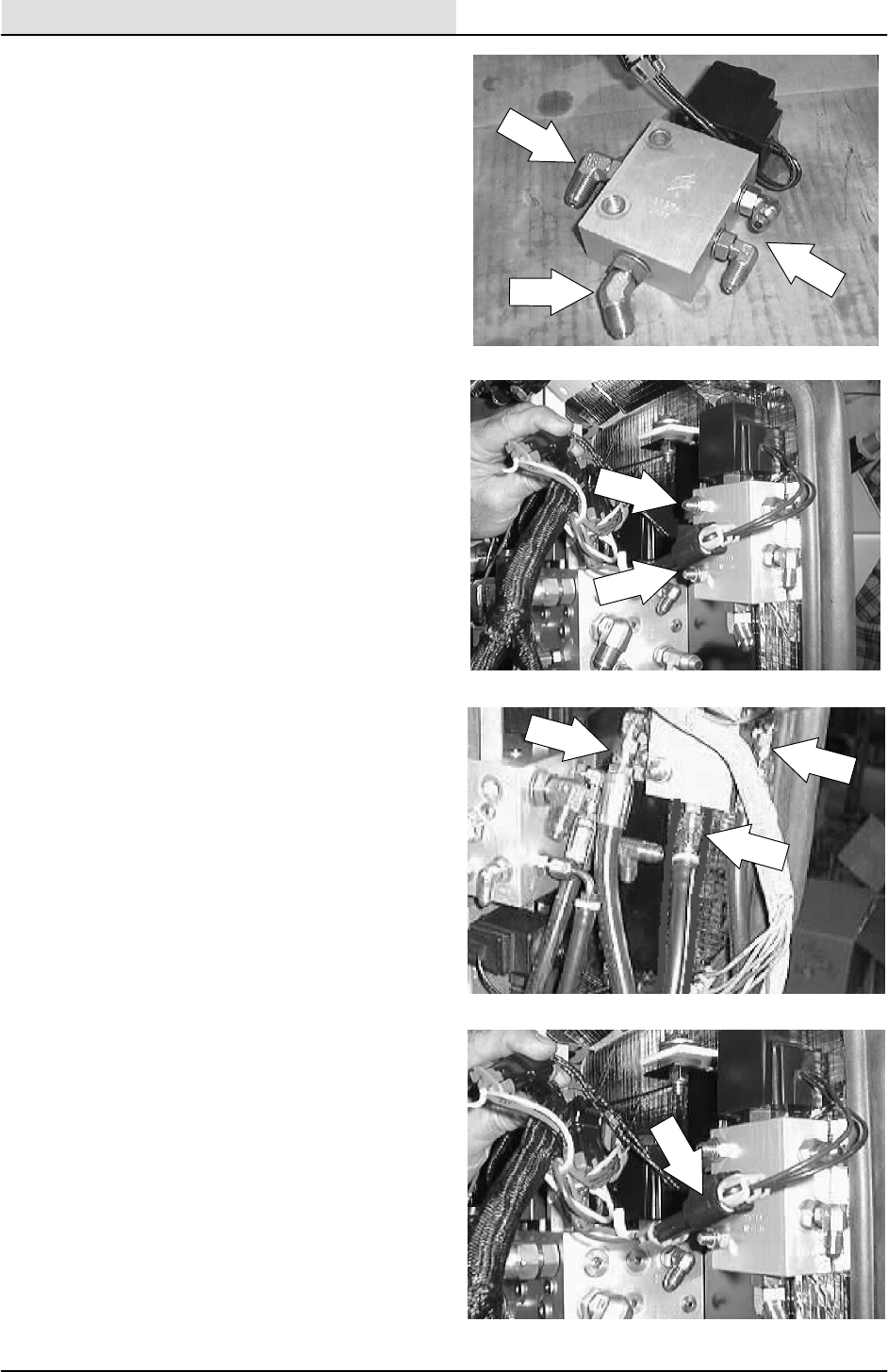
HYDRAULICS
6-84 8200/8210 330065 (3--01)
8. Remove the fittings from the old solenoid
valves and install in the new valve in the
same orientation.
9. Install the new valve onto the mount plate.
Reinstall the two hex screws and nuts.
Tighten to 18 -- 24 Nm (15 -- 20 ft lb).
10. Reconnect the hydraulic hoses. See hose
diagram in this section.
11. Reconnect the electrical coils to the main
machine harness.
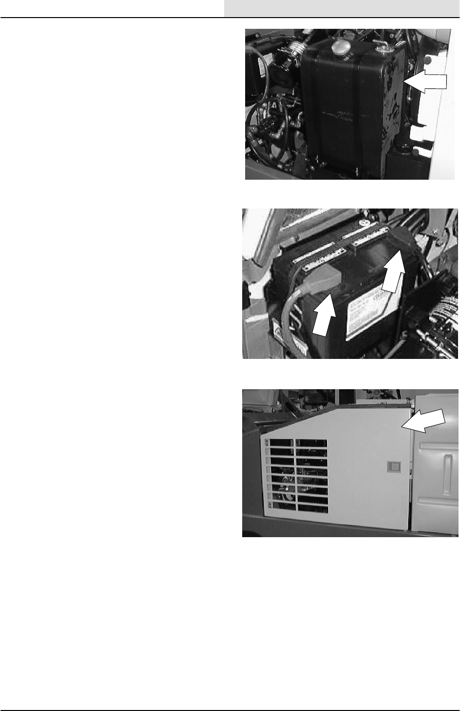
HYDRAULICS
6-85
8200/8210 330065 (3--01)
12. Reinstall the fuel tank or LP tank. Reconnect
the battery cables.
13. Reconnect the battery cables.
14. Start the machine and check the side shift
valve any leaks.
15. Close the engine side door and engine
cover. Operate the machine and check for
proper operation.

HYDRAULICS
6-86 8200/8210 330065 (3--01)
TO REPLACE SIDE BRUSH/MAIN BRUSH LIFT,
HOPPER DOOR OPEN/CLOSE SOLENOID
VALVE (8210)
FOR SAFETY: Before Leaving Or
Servicing Machine; Stop On Level
Surface, Set Parking Brake, Turn Off
Machine And Remove Key.
1. Open the engine cover and side door.
2. Disconnect the battery cables.
3. Locate the solenoid valve at the upper/front
outside corner of the operator compartment.
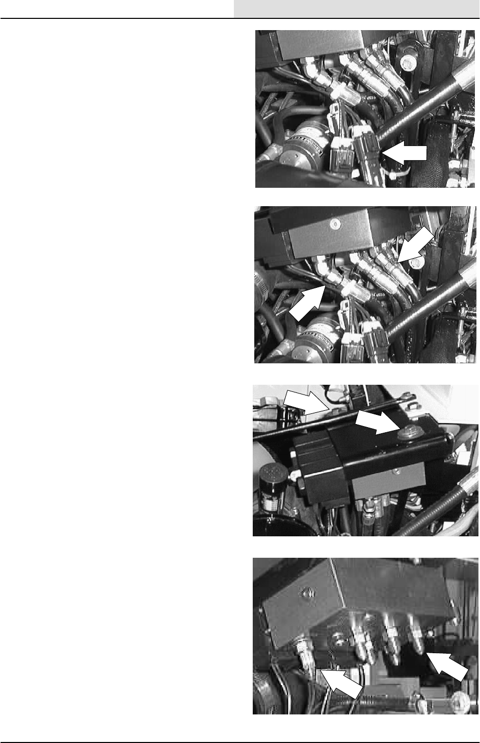
HYDRAULICS
6-87
8200/8210 330065 (3--01)
4. Un--plug the electrical coils from the main
machine harness.
5. Mark, disconnect, and plug the hydraulic
hoses leading to the solenoid valve.
6. Remove the two hex screws and nyloc nuts
holding the valve to the mount bracket.
7. Remove the fittings from the old solenoid
valve and install in the new valve in the
same orientation.
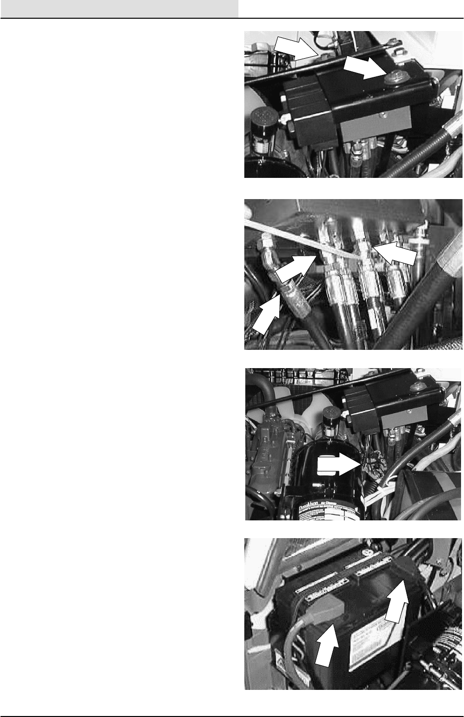
HYDRAULICS
6-88 8200/8210 330065 (3--01)
8. Install the new valve onto the mount plate.
Reinstall the two hex screws and tighten to
18 -- 24 Nm (15 -- 20 ft lb).
9. Reconnect the hydraulic hoses. See hose
diagram in this section.
10. Reconnect the electrical coils to the main
machine harness.
11. Reconnect the battery cables.
12. Start the machine and check the brush lift
valve for any leaks.
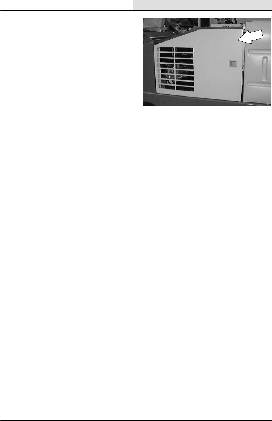
HYDRAULICS
6-89
8200/8210 330065 (3--01)
13. Close the engine side door and engine
cover. Operate the machine and check for
proper operation.
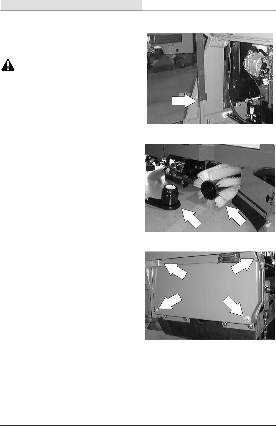
HYDRAULICS
6-90 8200/8210 330065 (3--01)
TO REPLACE MAIN SWEEPING BRUSH
MOTOR
1. Raise the hopper and engage the support
bar.
WARNING: Raised Hopper May Fall.
Engage Hopper Support Bar.
FOR SAFETY: Before Leaving Or
Servicing Machine; Stop On Level
Surface, Set Parking Brake, Turn Off
Machine And Remove Key.
2. Remove the main brush from the machine.
3. Remove the hex screws holding the left
side main brush door to the machine.
Remove the door from the machine.
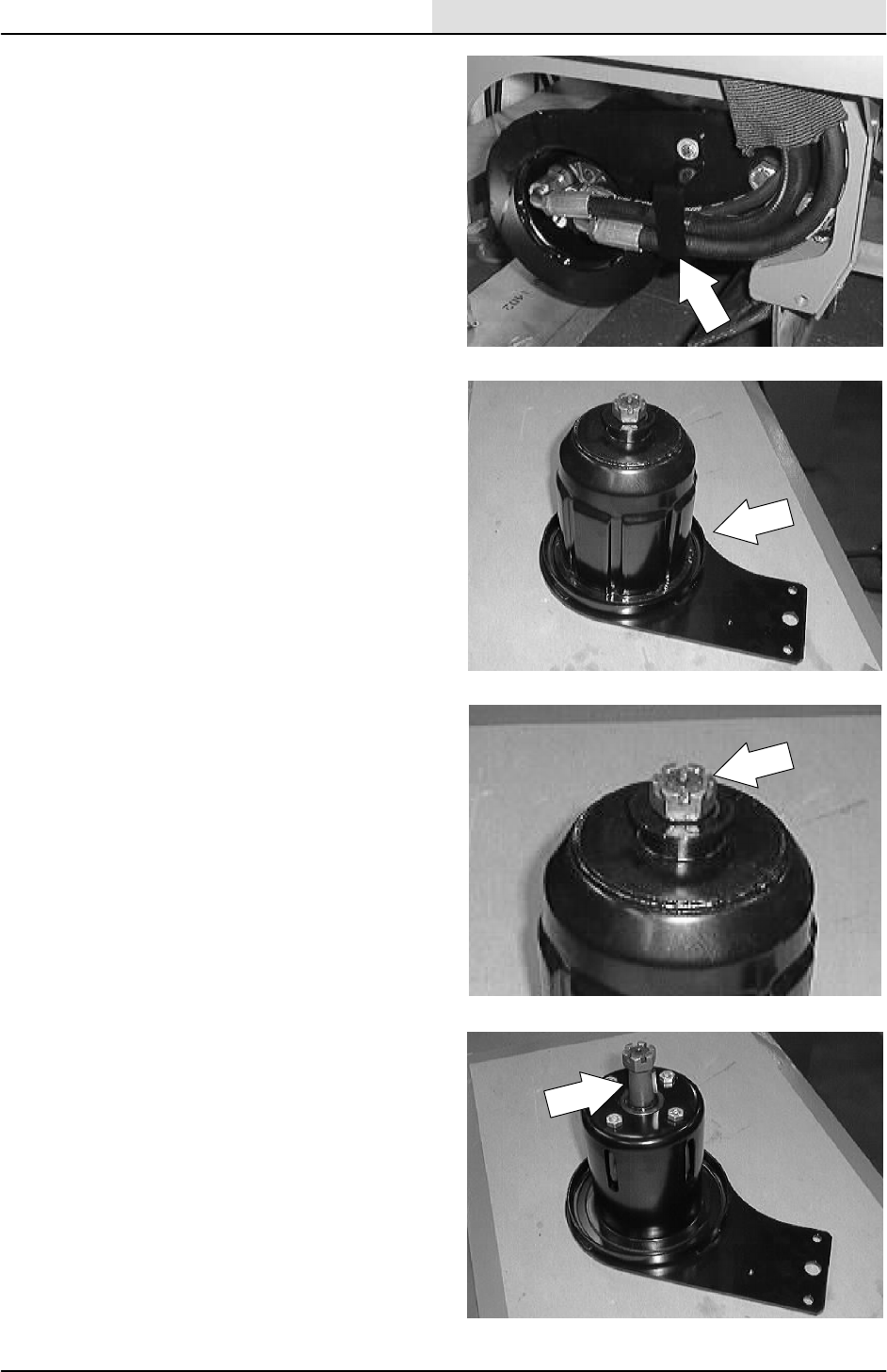
HYDRAULICS
6-91
8200/8210 330065 (3--01)
4. Mark, remove, and plug the hydraulic hoses
leading to the main brush motor. Remove
the hose clamp from the brush arm.
NOTE:Observe hydraulic cleanliness
requirements when opening hydraulic lines.
5. Remove the hex screw holding the brush
arm and motor to the machine. Remove the
brush arm and motor.
6. Remove the cotter pin from castle nut at the
end of main brush drive motor plug.
7. Hold the brush drive plug from turning and
remove the castle nut.
8. A puller must be used to remove the brush
drive plug from tapered shaft on the main
brush motor.
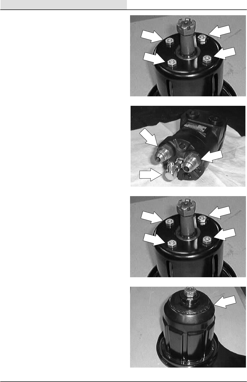
HYDRAULICS
6-92 8200/8210 330065 (3--01)
9. Remove the four hex screws holding the
main brush motor to the brush arm. Remove
the motor from the machine.
10. Remove the hydraulic fittings from old motor
and install in the new motor in the same
orientation.
11. Install the new main brush motor in the
brush arm. Tighten the hex screws to
(27 -- 53 ft lb).
12. Reinstall the brush drive plug back on the
tapered shaft of the new motor. Make sure
the key is in place.
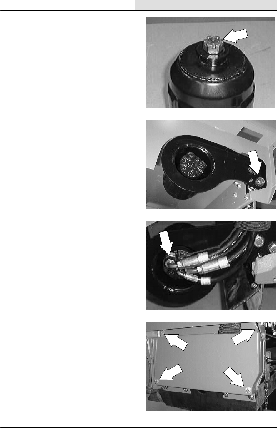
HYDRAULICS
6-93
8200/8210 330065 (3--01)
13. Reinstall the castle nut and tighten to
40 -- 54 Nm (30 -- 40 ft lb). Continue to
tighten castle nut until it lines up with hole in
brush motor shaft. Install a new cotter pin.
14. Reinstall the brush arm and motor onto the
brush shaft. Tighten the hex screw to
163 -- 190 Nm (120 -- 140 ft lb).
15. Reconnect the hydraulic hoses to the new
motor. Reinstall the hose clamp.
See schematic in this section.
16. Reinstall the left hand door and skirt. Tighten
the hex screws to 18 -- 24 Nm (15 -- 20 ft lb).
17. Reinstall the main brush. Operate the
machine and check for proper operation.
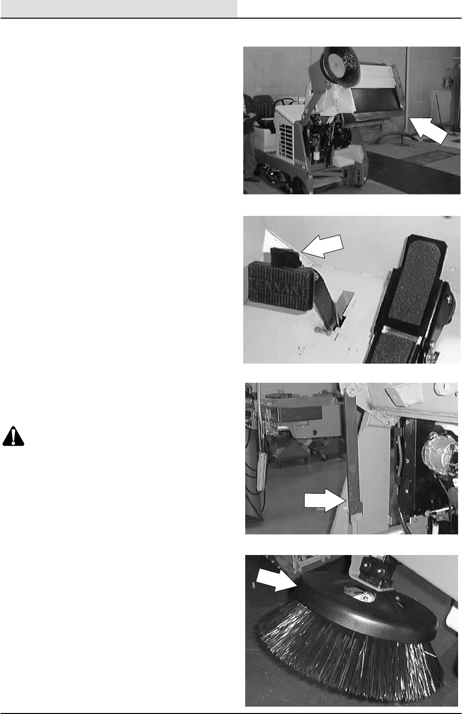
HYDRAULICS
6-94 8200/8210 330065 (3--01)
TO REPLACE SIDE BRUSH MOTOR
1. Empty the debris hopper.
2. Set the machine parking brake.
3. Raise the hopper and engage the support
bar.
WARNING: Raised Hopper May Fall.
Engage Hopper Support Bar.
FOR SAFETY: Before Leaving Or
Servicing Machine; Stop On Level
Surface, Set Parking Brake, Turn Off
Machine And Remove Key.
4. Remove the side brush retaining pin from
the side brush drive shaft by pulling the pin
keeper over the end of the pin. Remove the
side brush from the side brush motor.
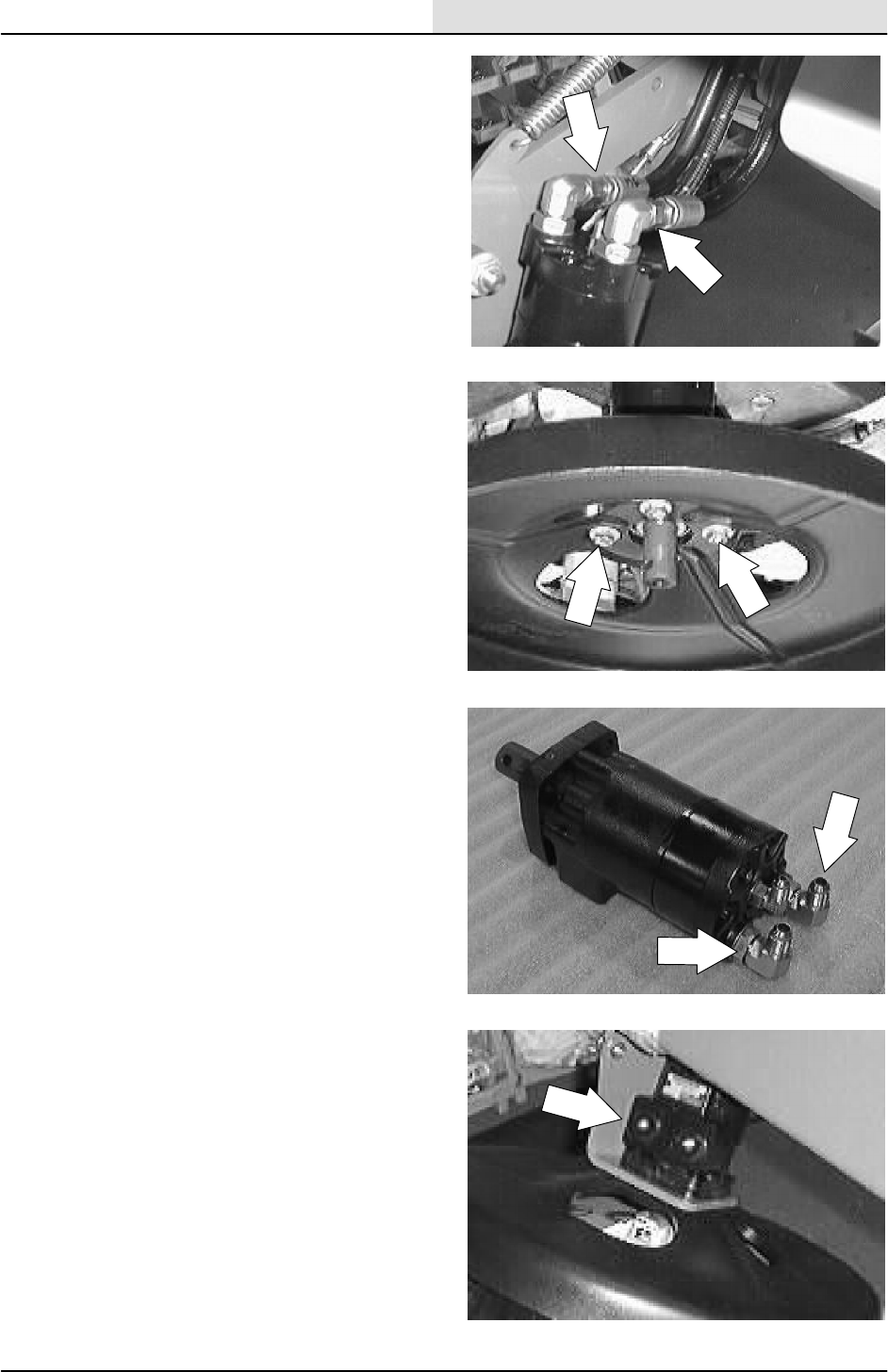
HYDRAULICS
6-95
8200/8210 330065 (3--01)
5. Mark, remove, and plug the hydraulic hoses
leading to the side brush motor.
NOTE: Observe hydraulic cleanliness
requirements when opening hydraulic lines.
6. Remove the four hex screws holding the
side brush motor to the mount bracket.
Remove the side brush guard and side
brush motor from machine.
7. Remove the hydraulic fittings from the old
motor and install in the new motor in the
same orientation.
8. Install the new side brush motor and the
side brush guard on the mount bracket.
Tighten the four hex screws to
(27 -- 35 ft lb).
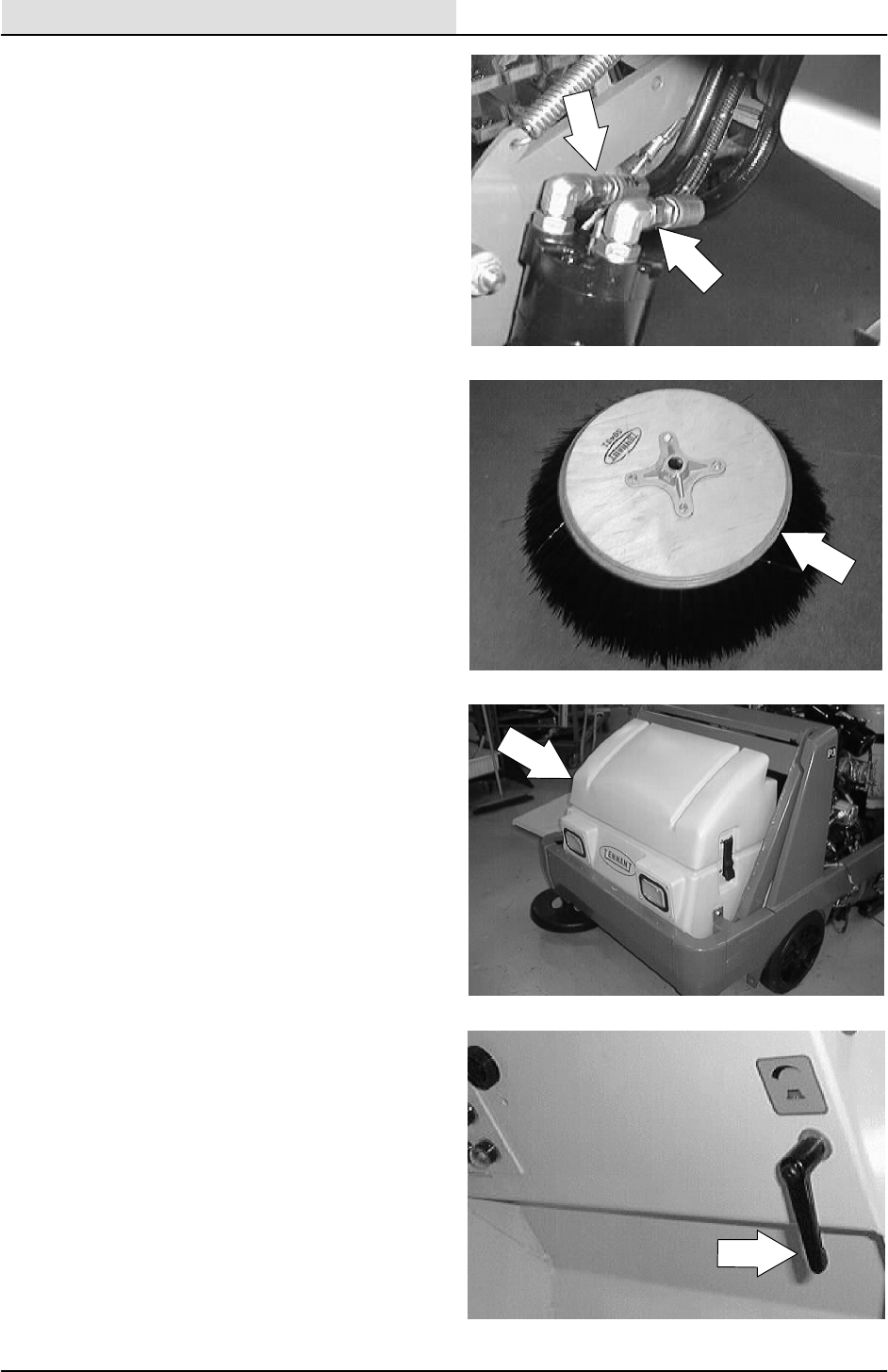
HYDRAULICS
6-96 8200/8210 330065 (3--01)
9. Reconnect the hydraulic hoses to the side
brush motor. See hose diagram in this
section.
NOTE: Check the orientation of the hydraulic
fittings in the motor so that the hoses do not rub
on the lift arms when the side brush is raised and
lowered.
10. Reinstall the side brush on the side brush
motor.
11. Reinstall the side brush retaining pin through
the side brush hub and shaft.
12. Secure the pin by clipping the pin keeper
over the end of the pin.
13. Disengage the hopper support bar and lower
the hopper.
14. Adjust the side brush pattern with the side
brush down pressure lever.
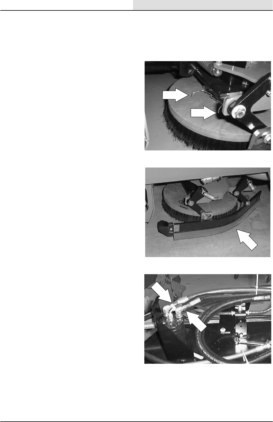
HYDRAULICS
6-97
8200/8210 330065 (3--01)
TO REPLACE SCRUB BRUSH MOTOR
FOR SAFETY: Before Leaving Or
Servicing Machine; Stop On Level
Surface, Set Parking Brake, Turn Off
Machine And Remove Key.
1. Remove the scrub brush from the motor that
needs changing.
2. Remove the side squeegee from the side of
the scrub head nearest the motor that needs
changing.
3. Mark, remove, and plug the hydraulic hoses
leading to the scrub brush motor.
NOTE: Observe hydraulic cleanliness
requirements when opening hydraulic lines.
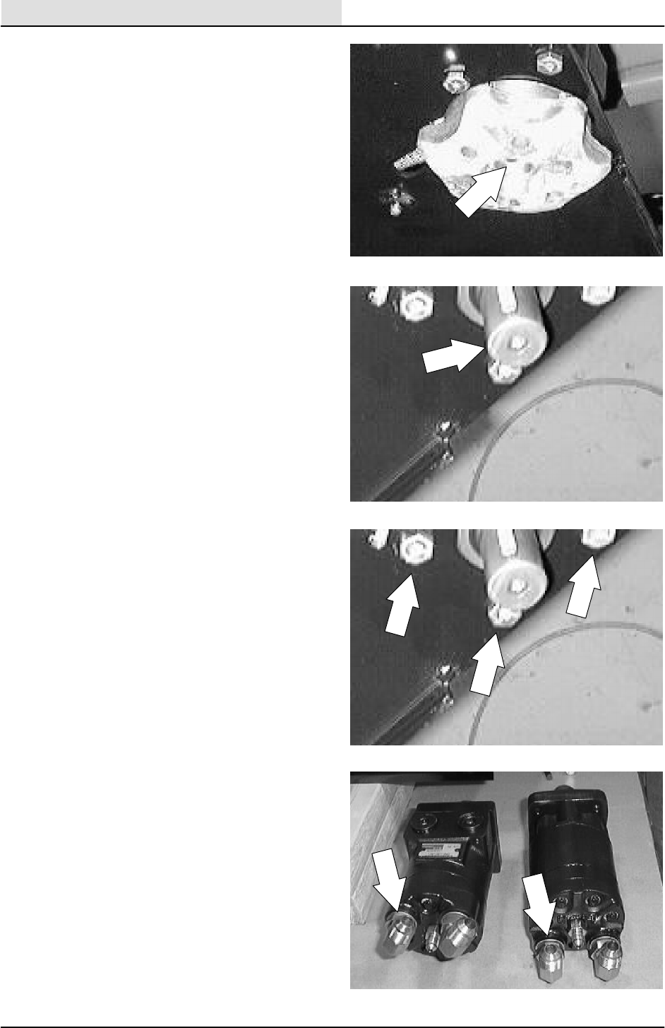
HYDRAULICS
6-98 8200/8210 330065 (3--01)
4. Remove the hex screw and two spacers
holding the scrub brush drive plug to the
scrub brush motor.
5. Pull the drive plug down and off the scrub
brush motor.
NOTE: The drive plug may need to be pried off
with a crow bar or large screw driver.
6. Remove the four hex screws holding the
scrub brush motor to the scrub head.
Remove the motor from the head. Note the
orientation of the motor fittings.
7. Remove the hydraulic fittings from the old
motor and install in the new motor in the
same orientation.
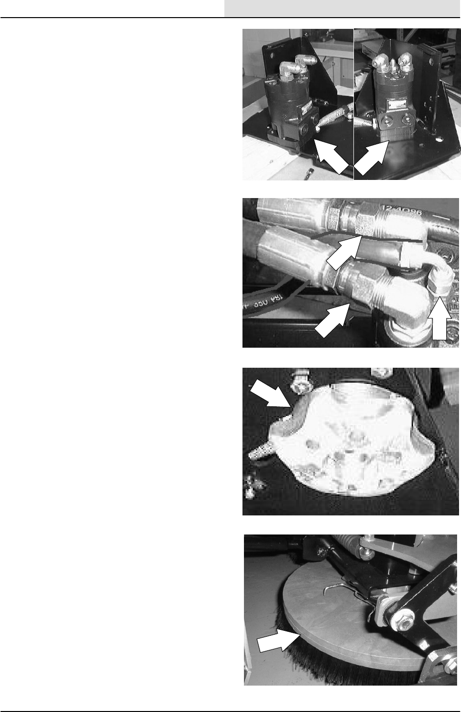
HYDRAULICS
6-99
8200/8210 330065 (3--01)
8. Install the new scrub brush motor onto the
scrub head. Tighten the four hex screws to
(27 -- 35 ft lb).
NOTE: Note the orientation of the motor fittings.
9. Reconnect the hydraulic hoses to the side
brush motor. See hose diagram in this
section.
NOTE: Reinstall any plastic clamps or ties.
10. Reinstall the drive plug, two washers, and
hex screw. Tighten to 11 -- 14 Nm
(7 -- 10 ft lb). Make sure the square key is in
place on the motor shaft.
11. Reinstall the scrub brush and side squeegee
assembly.
12. Operate the machine and check the scrub
head for proper operation.

HYDRAULICS
6-100 8200/8210 330065 (3--01)
TO REPLACE SWEEPING VACUUM FAN
MOTOR
FOR SAFETY: Before Leaving Or
Servicing Machine; Stop On Level
Surface, Set Parking Brake, Turn Off
Machine And Remove Key.
1. Remove the sweeping vacuum fan assembly
from the machine. See TO REMOVE
SWEEPING VACUUM FAN ASSEMBLY
instructions in the SWEEPING section.
2. Remove the three hex screws, washers, and
nyloc nuts holding the inlet plate to the
vacuum fan assembly. Lift the inlet plate off
the backing plate.
3. Remove the flex lock nut from the center of
the fan impeller. Pull the fan impeller straight
up and off the vacuum fan hydraulic motor.
Make sure to retain the square key.
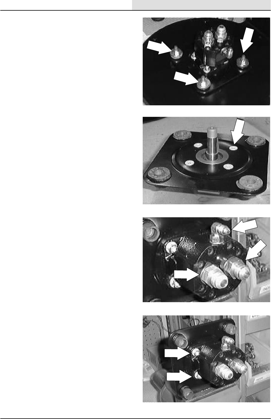
HYDRAULICS
6-101
8200/8210 330065 (3--02)
4. Remove the four flat screws, washers, and
nyloc nuts holding the fan motor mount plate
to the vacuum plate.
NOTE: Note the orientation of the hydraulic motor
fittings to the pins on the vacuum plate.
5. Remove the motor and mount plate
assembly.
6. Remove the four flat screws, washers, and
nyloc nuts holding the fan motor to the
mount plate. Remove the motor.
7. Remove the hydraulic fittings from the old
motor and install in the new motor in the
same orientation.
8. Install the new fan motor onto the mount
plate. Install the four flat screws, washers,
and nyloc nuts. Tighten to 11 -- 14 Nm
(7 -- 10 ft lbs).
NOTE: The motor can be installed on the mount
plate in any orientation.
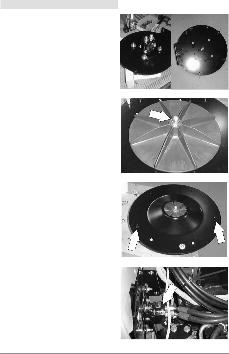
HYDRAULICS
6-102 8200/8210 330065 (3--02)
9. Install the fan and mount plate assembly
onto the vacuum plate.
NOTE: Note the orientation of the hydraulic motor
fittings to the pins on the vacuum plate.
10. Install the four flat screws, washers, and
nyloc nuts. Tighten to 18 -- 24 Nm
(15 -- 20 ft lbs).
11. Install the impeller onto the vacuum fan
hydraulic motor shaft.
NOTE: Make sure the square key is in place on
the motor shaft.
Install the flex lock nut. Use a small amount
of blue loctite 242 on the threads. Tighten to
37 -- 48 Nm (26 -- 34 ft lbs).
12. Install the inlet plate onto the vacuum plate
assembly.
NOTE: The inlet plate can only be installed one
way.
13. Install the three hex screws, washers, and
nyloc nuts. Tighten to
18 -- 24 Nm (15 -- 20 ft lbs).
14. Reinstall the sweeping vacuum fan
assembly into the machine. See TO
INSTALL SWEEPING VACUUM FAN
ASSEMBLY instructions in the SWEEPING
section.
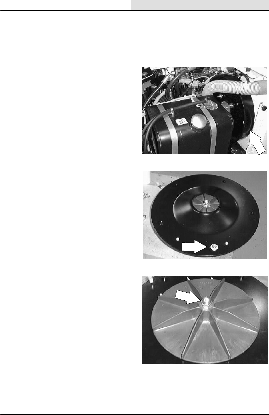
HYDRAULICS
6-103
8200/8210 330065 (3--01)
TO REPLACE SCRUBBING VACUUM FAN
MOTOR
FOR SAFETY: Before Leaving Or
Servicing Machine; Stop On Level
Surface, Set Parking Brake, Turn Off
Machine And Remove Key.
1. Remove the scrubbing vacuum fan
assembly from the machine. See TO
REMOVE SCRUBBING VACUUM FAN
ASSEMBLY instructions in the SCRUBBING
section.
2. Remove the one hex screw, washer, and
nyloc nut holding the inlet plate to the
vacuum fan assembly. lift the inlet plate off
the backing plate.
3. Remove the flex lock nut from the center of
the fan impeller. Pull the fan impeller straight
up and off the vacuum fan hydraulic motor.
Make sure to retain the square key.

HYDRAULICS
6-104 8200/8210 330065 (3--02)
4. Remove the four flat screws, washers, and
nyloc nuts holding the fan motor mount plate
to the vacuum plate.
NOTE: Note the orientation of the hydraulic motor
fittings to the pins on the vacuum plate.
5. Remove the motor and mount plate
assembly.
6. Remove the four flat screws, washers, and
nyloc nuts holding the fan motor to the
mount plate. Remove the motor.
7. Remove the hydraulic fittings from the old
motor and install in the new motor in the
same orientation.
8. Install the new fan motor onto the mount
plate. Install the four flat screws, washers,
and nyloc nuts. Tighten to 11 -- 14 Nm
(7 -- 10 ft lbs). The motor can be installed on
the mount plate in any orientation.
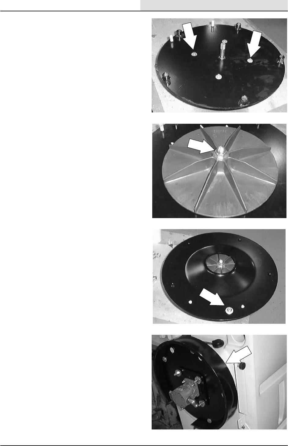
HYDRAULICS
6-105
8200/8210 330065 (3--02)
9. Install the fan and mount plate assembly
onto the vacuum plate.
NOTE: Note the orientation of the hydraulic motor
fittings to the pins on the vacuum plate.
10. Install the four flat screws, washers, and
nyloc nuts. Tighten to 18 -- 24 Nm
(15 -- 20 ft lbs).
11. Install the impeller onto the vacuum fan
hydraulic motor shaft. Make sure the square
key is in place on the motor shaft. Install the
flex lock nut. Use a small amount of blue
loctite 242 on the threads. Tighten to 37 -- 48
Nm (26 -- 34 ft lbs).
12. Install the inlet plate onto the vacuum plate
assembly. The inlet plate can only be
installed one way. Install the one hex screw,
washer, and nyloc nut. Tighten to
18 -- 24 Nm (15 -- 20 ft lbs).
13. Reinstall the scrubbing vacuum fan
assembly into the machine. See TO
INSTALL SCRUBBING VACUUM FAN
ASSEMBLY instructions in the SCRUBBING
section.
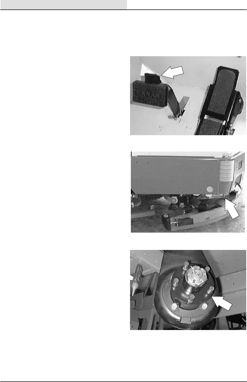
HYDRAULICS
6-106 8200/8210 330065 (3--01)
TO REPLACE REAR DRIVE MOTOR
FOR SAFETY: Before Leaving Or
Servicing Machine; Stop On Level
Surface, Set Parking Brake, Turn Off
Machine And Remove Key.
1. Engage parking brake, block front tires.
2. Jack up rear of machine. Use jack stands to
support machine.
FOR SAFETY: Block machine tires
before jacking machine up. Jack
machine up at designated locations
only. Block machine up with jack
stands.
3. Remove the rear tire and wheel assembly
from the drive motor hub.
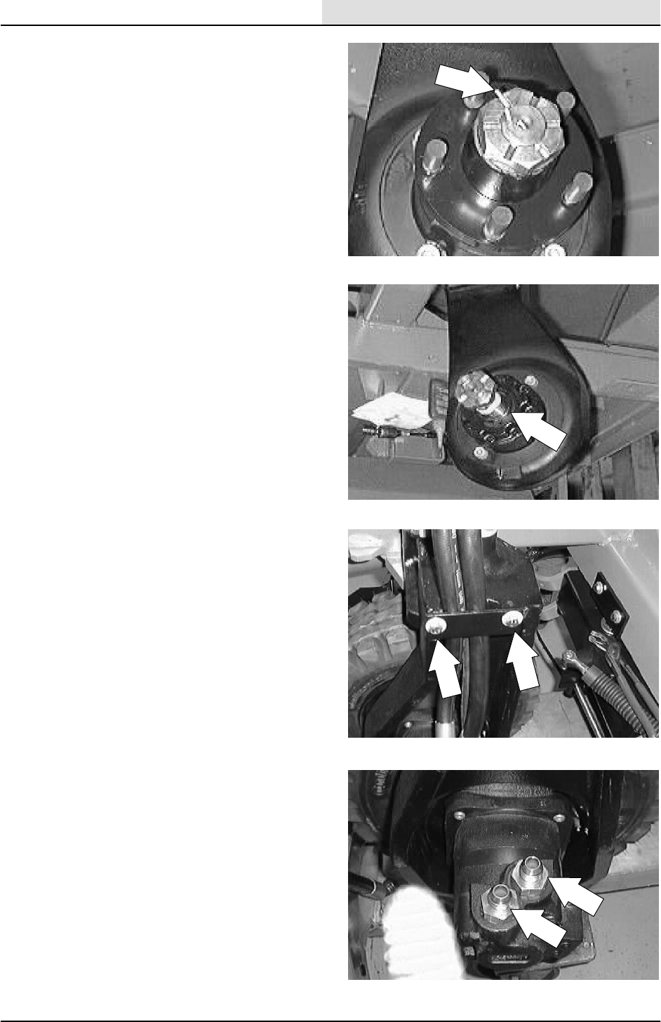
HYDRAULICS
6-107
8200/8210 330065 (3--01)
4. Remove the cotter pin and slotted nut from
drive motor shaft and hub.
5. Use a puller to remove the drive hub from
the tapered motor shaft.
6. Reinstall the hose clamp to the wheel
housing. Tighten the hex screws to
18.5 -- 24Nm (15 -- 20 ft lb).
7. Mark, disconnect, and plug the hydraulic
hoses leading to the the drive motor.
NOTE: Observe hydraulic cleanliness
requirements when opening hydraulic lines.
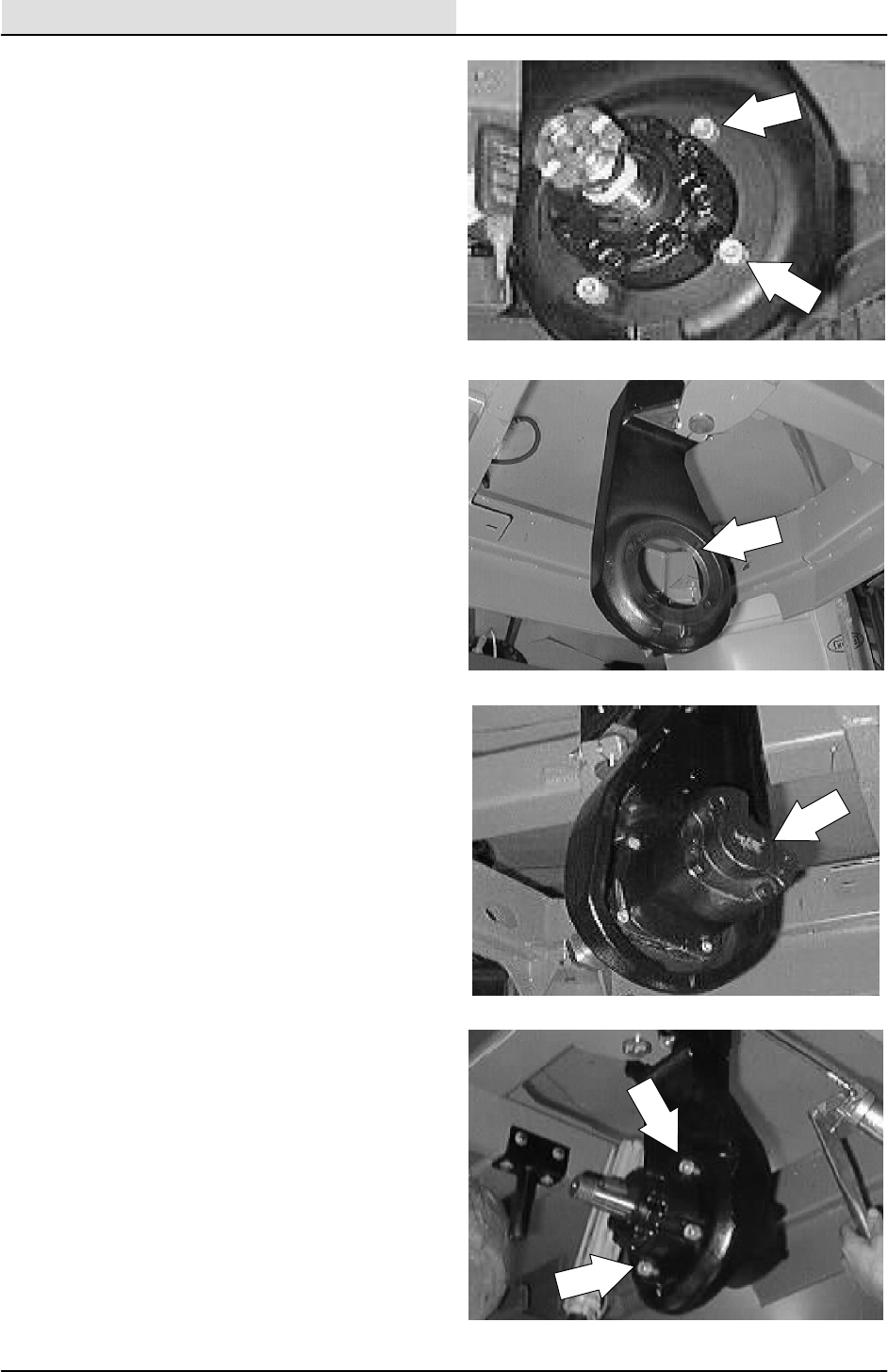
HYDRAULICS
6-108 8200/8210 330065 (3--01)
8. Remove the rear drive motor mounting bolts.
9. Slide the rear drive motor out of the wheel
housing.
10. Slide the drive motor in the wheel housing.
Note the motor orientation.
11. Thread the four hex screws through the
wheel housing and into the motor. Tighten to
88--115 Nm (65--85 ft lb).
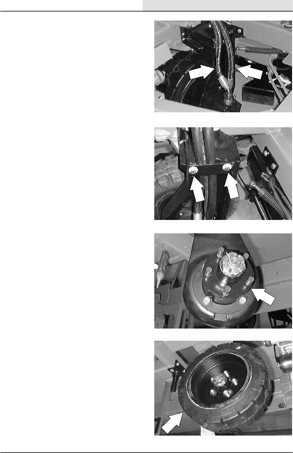
HYDRAULICS
6-109
8200/8210 330065 (3--01)
12. Reconnect the hydraulic hoses. See
schematic in the HYDRAULICS section.
13. Reinstall the hose clamp to the wheel
housing. Tighten the hex screws to
18.5 -- 24Nm (15 -- 20 ft lb).
14. Mount the hub to the tapered motor shaft.
Tighten the slotted nut to (275 ft lb). Torque
to the next slot in nut. DO NOT back nut off
to install cotter pin. Install the cotter pin.
NOTE: Make sure the key is installed on the
tapered shaft of the drive motor and a small
amount of grease is placed on the shaft.
15. Install the rear tire and wheel assembly.
Torque the rear wheel nuts to 100 -- 120 Nm
(85 -- 95 ft lb).
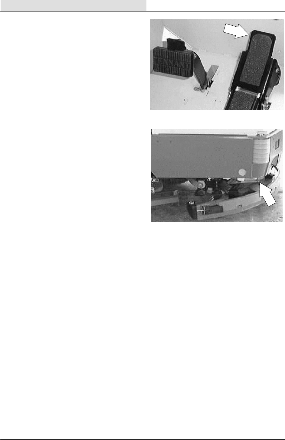
HYDRAULICS
6-110 8200/8210 330065 (3--01)
16. Start the engine. Run the propelling in both
directions. Check for any leaks.
17. Remove the jack stands and lower the
machine to the ground.
18. Operate the machine and check for proper
operation of the drive motor.

HYDRAULICS
6-111
8200/8210 330065 (3--01)
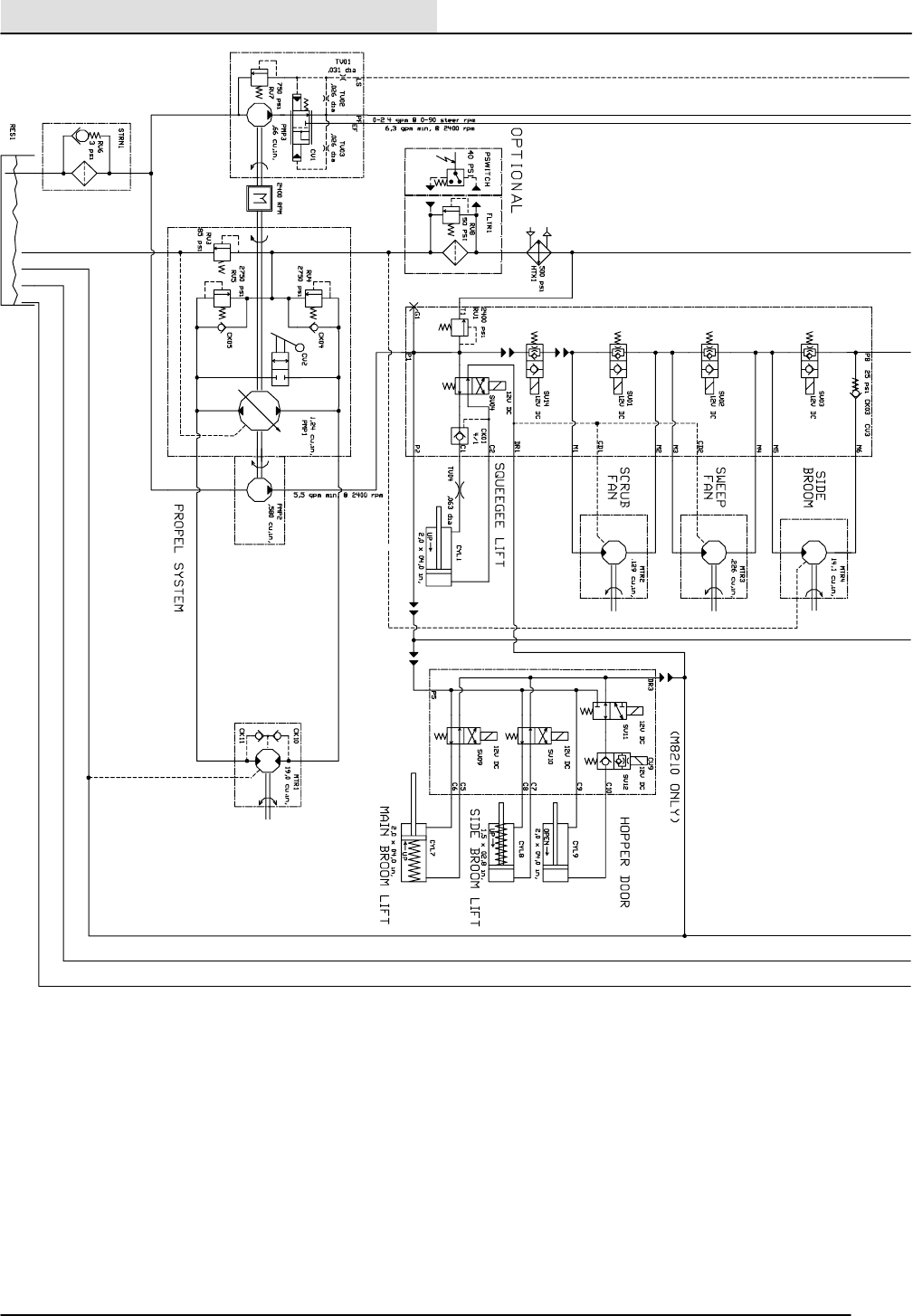
HYDRAULICS
6-112 8200/8210 330065 (3--01)
1
2
3
4
5
6
7
8
9
351672 -- ALL
HYDRAULIC SCHEMATIC
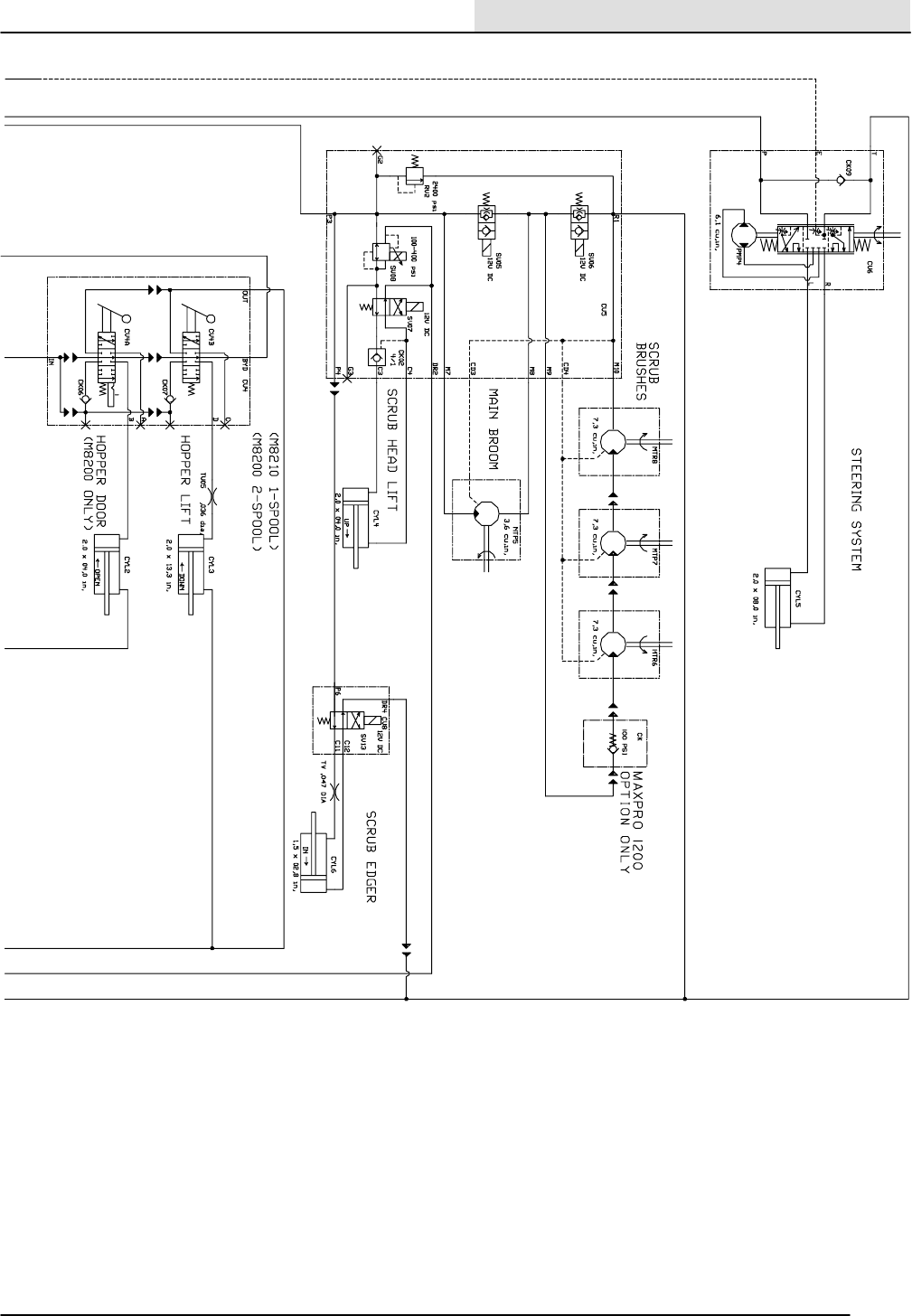
HYDRAULICS
6-113
8200/8210 330065 (3--01)
1
2
3
4
5
6
7
8
9
351672 -- ALL
HYDRAULIC SCHEMATIC
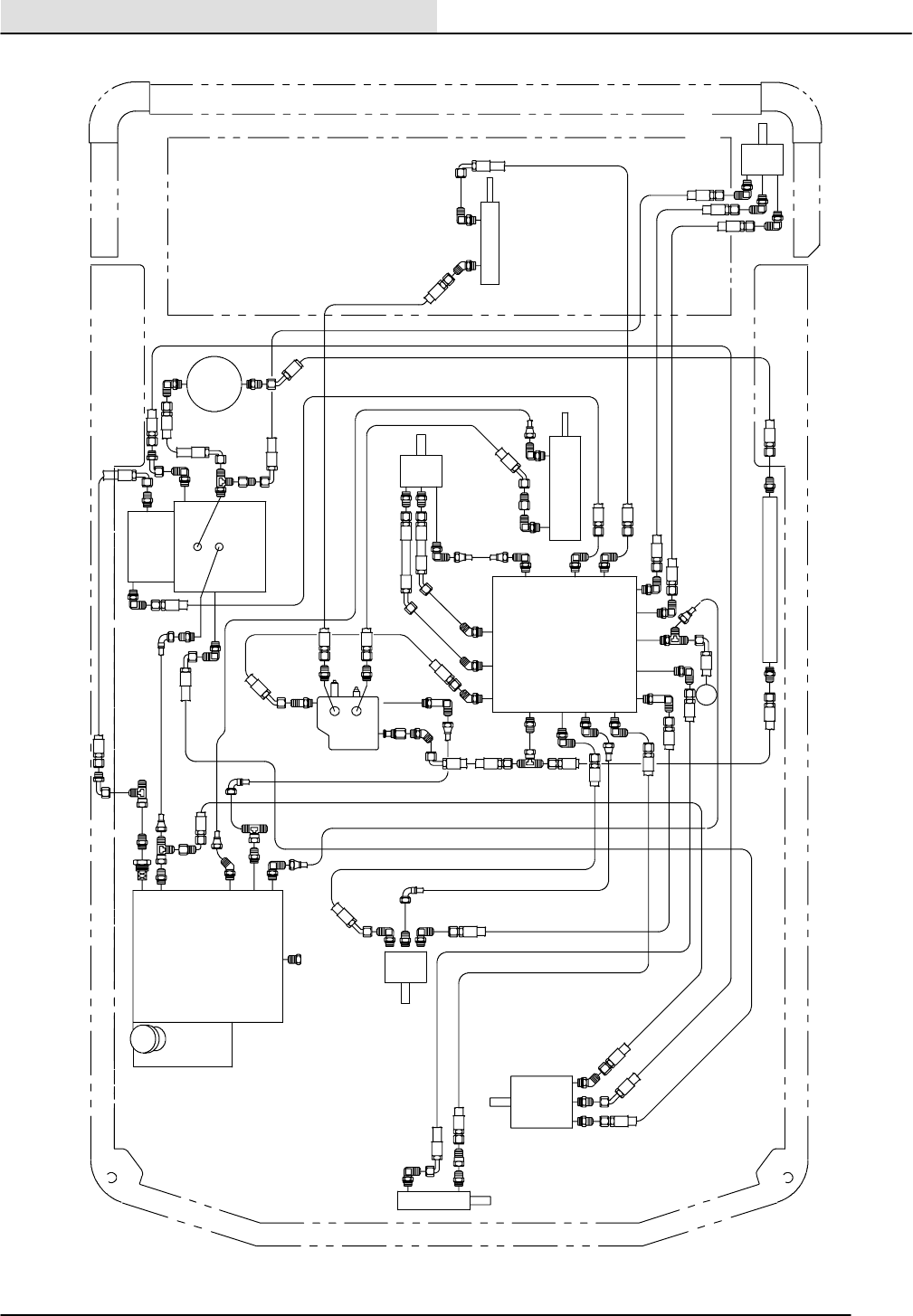
HYDRAULICS
6-114 8200/8210 330065 (3--01)
CD
P2
DRIVE
MOTOR
CD
A
M3M4
M6
RESERVOIR
MANUAL
VALVE
PROPEL
PUMP
AUX
PUMP
VAC FAN
MOTOR
SCRUB
VAC FAN
MOTOR
SWEEP
OUT
IN
BYD
D
B
IN
OUT
CP
CD
OUT
SOL VALVE
PB
M1
T1
M2
CD1
C1
M5DR1
CD2
C2
P1
IN
OUT
CD
CD
SQUEEGEE
LIFT CYL
SIDE BRUSH
MOTOR
OIL
FILTER
HOPPER DOOR
CYL
HOPPER LIFT CYL
OIL COOLER
HYDRAULIC HOSE DIAGRAM (8200)
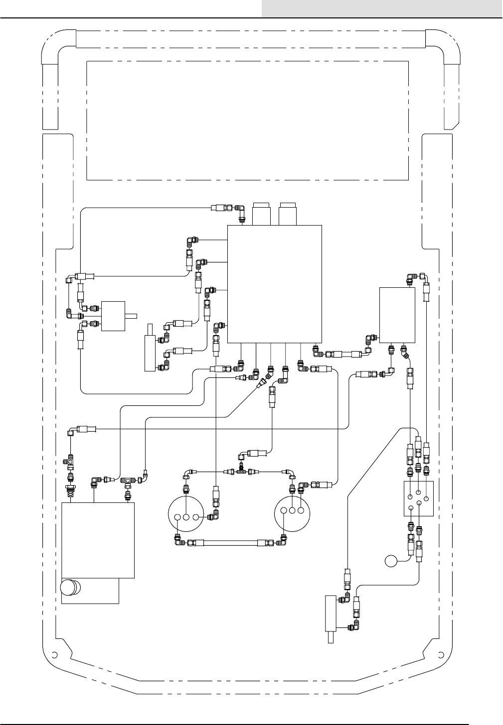
HYDRAULICS
6-115
8200/8210 330065 (3--01)
STEERING
CONTROL
SCRUB HEAD
LH MOTOR
SCRUB HEAD
RH MOTOR
CD
SCRUB HEAD
LIFT
MAIN BRUSH
MOTOR
IN
OUT
OUT
IN
CD
CD
A
PF
RESERVOIR
STEERING
CYL
LS
BELT DRIVE
PUMP
EF
S
TR
E
P
L
SOL VALVE
BRUSH CONTROL
CD4
M10
M9
CD3
P3
DR2
P4
R1
C3
M7
C4
M8
HYDRAULIC HOSE DIAGRAM (8200)
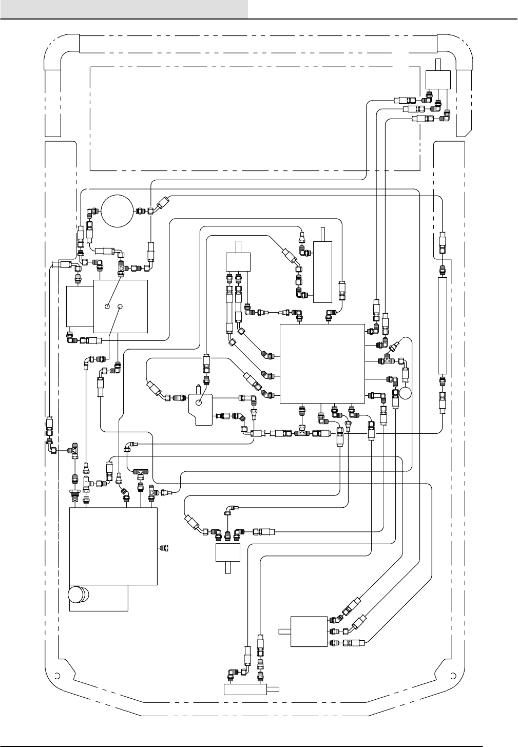
HYDRAULICS
6-116 8200/8210 330065 (3--01)
RESERVOIR
BYD
B
IN
OUT
CD
P2
DRIVE
MOTOR
CD
A
M3M4
M6
MANUAL
VALVE
PROPEL
PUMP
AUX
PUMP
VAC FAN
MOTOR
SCRUB
VAC FAN
MOTOR
SWEEP
OUT
IN
CP
CD
OUT
SOL VALVE
PB
M1
T1
M2
CD1
C1
M5DR1
CD2
C2
P1
IN
OUT
CD
CD
SQUEEGEE
LIFT CYL
SIDE BRUS
H
MOTOR
OIL
FILTER
HOPPER LIFT CYL
OIL COOLER
HYDRAULIC HOSE DIAGRAM (8210)
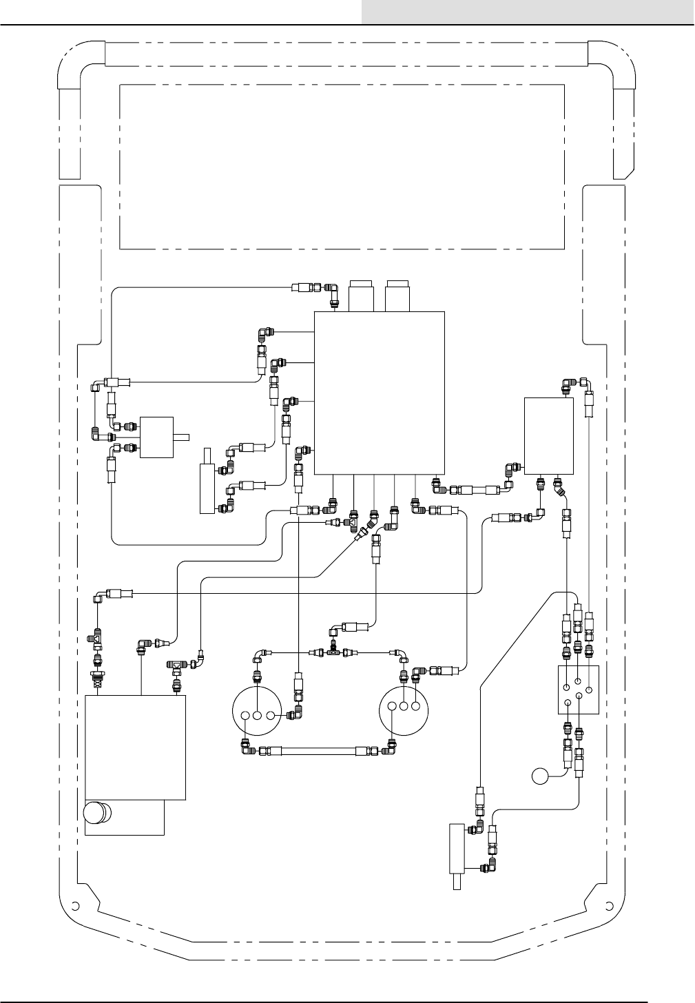
HYDRAULICS
6-117
8200/8210 330065 (3--01)
STEERING
CONTROL
SCRUB HEAD
LH MOTOR
SCRUB HEAD
RH MOTOR
CD
SCRUB HEAD
LIFT
MAIN BRUSH
MOTOR
IN
OUT
OUT
IN
CD
CD
A
PF
RESERVOIR
STEERING
CYL
LS
BELT DRIVE
PUMP
EF
S
TR
E
P
L
SOL VALVE
BRUSH CONTROL
CD4
M10
M9
CD3
P3
DR2
P4
R1
C3
M7
C4
M8
HYDRAULIC HOSE DIAGRAM (8210)
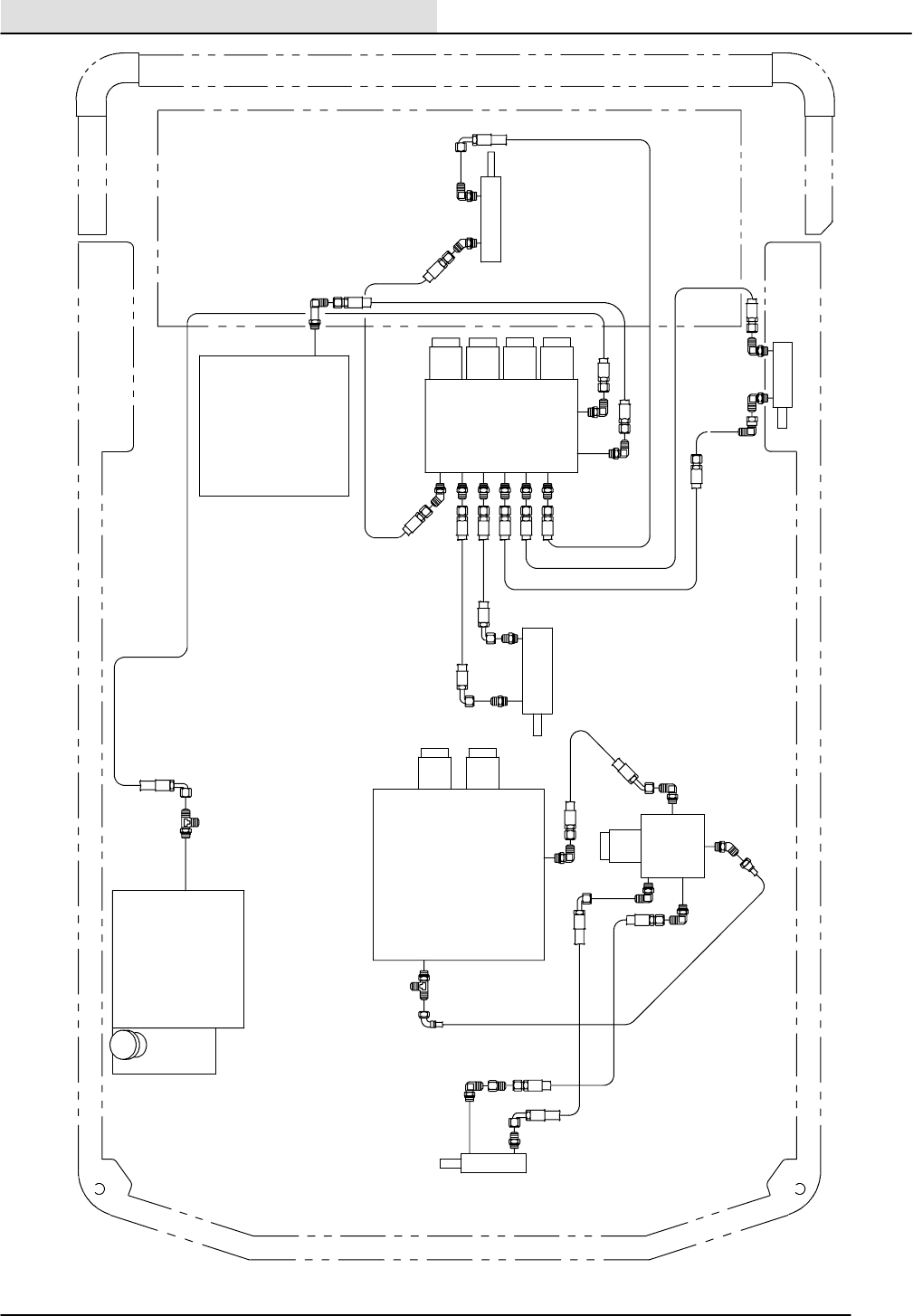
HYDRAULICS
6-118 8200/8210 330065 (3--01)
EDGE SCRUB
VALVE
SV14
P2
M3M4
M6
SOL VALVE
PB
M1
T1
M2
CD1
C1
M5DR1
CD2
C2
P1
SOL VALVE
BRUSH CONTROL
CD4
M10
M9
CD3
P3
DR2
P4
R1
C3
M7
C4
M8
P6
HOPPER DOOR
CYL
RESERVOIR
SIDE BRUSH
LIFT CYL
C11
C12
DR4
MAIN BRUSH
LIFT CYL
EDGE SCRUB
CYL
C5
C10
DR3
P5
C8
C6
C7
C9
SOL VALVE
XP CONTROL
HYDRAULIC HOSE DIAGRAM (8210)

HYDRAULICS
6-119
8200/8210 330065 (3--01)
TROUBLESHOOTING
The troubleshooting charts that follow are
organized so they lead you through the circuits.
They include flow charts and instructions for you
as to where to insert your test instruments.
Yes
Yes
Yes
No
Yes
No
No
No
POWER STEERING IS NOT NORMAL
PLUMBING OK? REPAIR / REPLACE
PLUMBING
REPAIR / REPLACE
PUMP
STEER CYLINDER
ROD ENDS & SEALS
OK?
REPAIR/REPLACE
STEER CYLINDER
OR ROD ENDS
CIRCUIT FLOW &
PRESSURE OK?
STEERING INLET
PRESSURE OK?
REPAIR/REPLACE
STEERING CONTROL
STEERING
COLUMN OK?
HYDRAULICS
6-120 8200/8210 330065 (3--01)
LIFT CYLINDER
LINKAGE & SEALS
OK?
Yes
REPAIR / REPLACE
LINKAGE OR
CYLINDER
CK2 CHECK VALVE
SHIFTING OK?
REPAIR / REPLACE
CK2 CHECK VALVE
CARTRIDGE
REPAIR / REPLACE
SV7 COIL, VALVE
CARTRIDGE OR
ELECTRICAL SYS.
SV8 STEM
MAGNETIZED &
PRESSURE OK AT
12VOLTS?
Yes
SV7 STEM
MAGNETIZED &
VALVE SHIFTING
OK AT 12VOLTS?
REPAIR / REPLACE
SV8 COIL, VALVE
CARTRIDGE OR
ELECTRICAL SYS.
Yes
CIRCUIT FLOW &
PRESSURE OK?
REPAIR / REPLACE
PUMP OR RELIEF
No
Yes
PLUMBING OK?
REPAIR / REPLACE
PLUMBING OR
REMOVE
RESTRICTION
Yes
No
No
No
No
No
SCRUB HEAD WILL NOT RAISE
HYDRAULICS
6-121
8200/8210 330065 (3--01)

Yes
Yes
Yes
No
Yes
No
No
No
No
CHECK VALVE
SHIFTING OK?
REPAIR / REPLACE
CHECK VALVE
CARTRIDGE
CIRCUIT FLOW &
PRESSURE OK? REPAIR / REPLACE
PUMP OR RELIEF
REPAIR / REPLACE
SV7 COIL, VALVE
CARTRIDGE OR
ELECTRICAL SYS.
SV8 STEM COIL
MAGNETIZED &
PRESSURE OK AT
12VOLTS?
SV7 STEM COIL
MAGNETIZED &
VALVE SHIFTING
OK AT 12 VOLTS?
REPAIR / REPLACE
SV8 COIL, VALVE
CARTRIDGE OR
ELECTRICAL SYS.
PLUMBING OK?
REPAIR / REPLACE
PLUMBING OR
REMOVE
RESTRICTION
HYDRAULICS
6-122 8200/8210 330065 (3--01)
SCRUB HEAD WILL NOT LOWER
Yes
No
Yes
No
No
CHECK VALVE
OK?
REPAIR / REPLACE
CHECK VALVE
CARTRIDGE
REPLACE LIFT
CYLINDER
PLUMBING OK? REPAIR / REPLACE
PLUMBING
LIFT CYLINDER
SEALS OK?
HYDRAULICS
6-123
8200/8210 330065 (3--01)
SCRUB HEAD WILL NOT STAY
UP
Yes
Yes
Yes
No
Yes
Yes
No
No
No
No
No
SV5 STEM
MAGNETIZED?
REPAIR
ELECTRICAL
SYSTEM
SV5 VALVE
CARTRIDGE
SHIFTING OK?
REPAIR / REPLACE
SV5 VALVE
CARTRIDGE
REPAIR / REPLACE
MOTOR
MOTOR INLET
FLOW OK?
REPAIR / REPLACE
PLUMBING
PLUMBING OK?
RV2 RELIEF
CARTRIDGE OK?
REPAIR / REPLACE
RV2 CARTRIDGE
REPAIR / REPLACE
PUMP
CIRCUIT FLOW &
PRESSURE OK?
HYDRAULICS
6-124 8200/8210 330065 (3--01)
MAIN BROOM WILL NOT TURN
ON
Yes
No
Yes
No
No
SV5 STEM
MAGNETIZED?
REPAIR
ELECTRICAL
SYSTEM
SV5 VALVE
CARTRIDGE
SHIFTING OK?
REPAIR / REPLACE
SV5 VALVE
CARTRIDGE
BROOM TURNS
SLOWLY
LESS THAN 20RPM SYSTEM OK
HYDRAULICS
6-125
8200/8210 330065 (3--01)
MAIN BROOM WILL NOT TURN
OFF
Yes
Yes
Yes
No
Yes
Yes
No
No
No
No
No
SV6 STEM
MAGNETIZED?
REPAIR
ELECTRICAL
SYSTEM
SV6 VALVE
CARTRIDGE
SHIFTING OK?
REPAIR / REPLACE
SV6 VALVE
CARTRIDGE
REPAIR / REPLACE
MOTOR/S
MOTOR/S INLET
FLOW OK?
REPAIR / REPLACE
PLUMBING
PLUMBING OK?
RV2 RELIEF
CARTRIDGE OK? REPAIR / REPLACE
RV2 CARTRIDGE
REPAIR / REPLACE
PUMP
CIRCUIT FLOW &
PRESSURE OK?
HYDRAULICS
6-126 8200/8210 330065 (3--01)
SCRUB BRUSHES WILL NOT
TURN ON
Yes
No
Yes
No
No
SV6 STEM
MAGNETIZED?
REPAIR
ELECTRICAL
SYSTEM
SV6 VALVE
CARTRIDGE
SHIFTING OK?
REPAIR / REPLACE
SV6 VALVE
CARTRIDGE
BRUSH TURNS
SLOWLY
LESS THAN 10RPM SYSTEM OK
HYDRAULICS
6-127
8200/8210 330065 (3--01)
SCRUB BRUSHES WILL NOT
TURN OFF
Yes
Yes
Yes
No
Yes
Yes
No
No
No
No
No
LIFT CYLINDER
LINKAGE & SEALS
OK?
REPAIR / REPLACE
LIFT CYLINDER OR
LINKAGE
CHECK VALVE
SHIFTING OK?
REPAIR / REPLACE
CHECK VALVE
CARTRIDGE
REPAIR / REPLACE
SV4 COIL, VALVE
CARTRIDGE OR
ELECTRICAL SYS.
SV4 COIL
MAGNETIZED &
VALVE SHIFTING
OK AT 12VOLTS?
INLINE ORIFICE
PLUGGED?
REPAIR / REPLACE
ORIFICE
CIRCUIT FLOW &
PRESSURE OK? REPAIR / REPLACE
PUMP OR RELIEF
PLUMBING OK? REPAIR / REPLACE
PLUMBING
HYDRAULICS
6-128 8200/8210 330065 (3--01)
SQUEEGEE WILL NOT RAISE
Yes
Yes
Yes
No
Yes
No
No
No
No
CHECK VALVE
SHIFTING OK?
REPAIR / REPLACE
CHECK VALVE
CARTRIDGE
REPAIR / REPLACE
SV4 COIL, VALVE
CARTRIDGE OR
ELECTRICAL SYS.
PLUMBING OK? REPAIR / REPLACE
PLUMBING
SV4 STEM
MAGNETIZED &
VALVE CARTRIDGE
SHIFTING OK?
CIRCUIT FLOW &
PRESSURE OK? REPAIR / REPLACE
PUMP OR RELIEF
INLINE ORIFICE
PLUGGED? REPAIR / REPLACE
ORIFICE
HYDRAULICS
6-129
8200/8210 330065 (3--01)
SQUEEGEE WILL NOT LOWER
Yes
No
Yes
No
No
CHECK VALVE
OK?
REPAIR / REPLACE
CHECK VALVE
CARTRIDGE
REPLACE LIFT
CYLINDER
PLUMBING OK? REPAIR / REPLACE
PLUMBING
LIFT CYLINDER
SEALS OK?
HYDRAULICS
6-130 8200/8210 330065 (3--01)
SQUEEGEE WILL NOT STAY UP
Yes
Yes
Yes
No
Yes
Yes
No
No
No
No
No
SV1 STEM
MAGNETIZED?
REPAIR
ELECTRICAL
SYSTEM
SV1 VALVE
CARTRIDGE
SHIFTING OK?
REPAIR / REPLACE
SV1 VALVE
CARTRIDGE
REPAIR / REPLACE
MOTOR
MOTOR INLET
FLOW OK?
REPAIR / REPLACE
PLUMBING
PLUMBING OK?
RV1 RELIEF
CARTRIDGE OK? REPAIR / REPLACE
RV1 CARTRIDGE
REPAIR / REPLACE
PUMP
CIRCUIT FLOW &
PRESSURE OK?
HYDRAULICS
6-131
8200/8210 330065 (3--01)
SCRUB FAN WILL NOT TURN ON
Yes
No
Yes
No
No
SV1 STEM
MAGNETIZED?
REPAIR
ELECTRICAL
SYSTEM
SV1 STEM
CARTRIDGE
SHIFTING OK?
REPAIR / REPLACE
SV1 STEM
CARTRIDGE
FAN TURNS
SLOWLY SYSTEM OK
HYDRAULICS
6-132 8200/8210 330065 (3--01)
SCRUB FAN WILL NOT TURN
OFF
Yes
Yes
Yes
No
Yes
Yes
No
No
No
No
No
SV2 STEM
MAGNETIZED?
REPAIR
ELECTRICAL
SYSTEM
SV2 VALVE
CARTRIDGE
SHIFTING OK?
REPAIR / REPLACE
SV2 VALVE
CARTRIDGE
REPAIR / REPLACE
MOTOR
MOTOR INLET
FLOW OK?
REPAIR / REPLACE
PLUMBING
PLUMBING OK?
RV1 RELIEF
CARTRIDGE OK?
REPAIR / REPLACE
RV1 CARTRIDGE
REPAIR / REPLACE
PUMP
CIRCUIT FLOW &
PRESSURE OK?
HYDRAULICS
6-133
8200/8210 330065 (3--01)
SWEEP FAN WILL NOT TURN ON
Yes
No
Yes
No
No
SV2 STEM
MAGNETIZED?
REPAIR
ELECTRICAL
SYSTEM
SV2 VALVE
CARTRIDGE
SHIFTING OK?
REPAIR / REPLACE
SV2 VALVE
CARTRIDGE
FAN TURNS
SLOWLY SYSTEM OK
HYDRAULICS
6-134 8200/8210 330065 (3--01)
SWEEP FAN WILL NOT TURN
OFF
Yes
Yes
Yes
No
Yes
Yes
No
No
No
No
No
SV3 STEM
MAGNETIZED?
REPAIR
ELECTRICAL
SYSTEM
SV3 VALVE
CARTRIDGE
SHIFTING OK?
REPAIR / REPLACE
SV3 VALVE
CARTRIDGE
REPAIR / REPLACE
MOTOR
MOTOR INLET
FLOW OK?
REPAIR / REPLACE
PLUMBING
PLUMBING OK?
RV1 RELIEF
CARTRIDGE OK? REPAIR / REPLACE
RV1 CARTRIDGE
REPAIR / REPLACE
PUMP
CIRCUIT FLOW &
PRESSURE OK?
HYDRAULICS
6-135
8200/8210 330065 (3--01)
SIDE BRUSH WILL NOT TURN
ON
Yes
No
Yes
No
No
REPAIR
ELECTRICAL
SYSTEM
SV3 VALVE
CARTRIDGE
SHIFTING OK?
REPAIR / REPLACE
SV3 VALVE
CARTRIDGE
SIDE BROOM
TURNS SLOWLY
REPAIR / REPLACE
CHECK VALVE
CARTRIDGE
SV3 STEM
MAGNETIZED?
HYDRAULICS
6-136 8200/8210 330065 (3--01)
SIDE BRUSH WILL NOT TURN
OFF
Yes
Yes
Yes
No
Yes
No
No
No
No
DOOR CYLINDER
LINKAGE & SEALS
OK?
REPAIR / REPLACE
DOOR LINKAGE OR
CYLINDER
MANUAL CONTROL
VALVE SPOOL
SHIFTING OK?
REPAIR / REPLACE
MANUAL CONTROL
VALVE
REPAIR / REPLACE
PLUMBING
PLUMBING OK?
RV1 RELIEF
CARTRIDGE OK? REPAIR / REPLACE
RV1 CARTRIDGE
REPAIR / REPLACE
PUMP
CIRCUIT FLOW &
PRESSURE OK?
HYDRAULICS
6-137
8200/8210 330065 (3--01)
HOPPER DOOR WILL NOT
CLOSE
Yes
Yes
Yes
No
Yes
No
No
No
No
DOOR CYLINDER
LINKAGE & SEALS
OK?
REPAIR / REPLACE
DOOR LINKAGE OR
CYLINDER
MANUAL CONTROL
VALVE SPOOL
SHIFTING OK?
REPAIR / REPLACE
MANUAL CONTROL
VALVE
REPAIR / REPLACE
PLUMBING
PLUMBING OK?
MANUAL CONTROL
VALVE SPOOL
LEAKAGE OK?
REPAIR / REPLACE
MANUAL CONTROL
VALVE
DOOR HOLDS LOAD
FOR 5 MINUTES SYSTEM OK
HYDRAULICS
6-138 8200/8210 330065 (3--01)
HOPPER DOOR WILL NOT STAY
CLOSED
Yes
Yes
Yes
No
Yes
No
No
No
No
LIFT CYLINDER
LINKAGE & SEALS
OK?
REPAIR / REPLACE
LIFT LINKAGE OR
CYLINDER
MANUAL CONTROL
VALVE SPOOL
SHIFTING OK?
REPAIR / REPLACE
MANUAL CONTROL
VALVE
REPAIR / REPLACE
CYL. ORIFICE OR
PLUMBING
CYL. ORIFICE &
PLUMBING OK?
RV1 RELIEF
CARTRIDGE OK? REPAIR / REPLACE
RV1 CARTRIDGE
REPAIR / REPLACE
PUMP
CIRCUIT FLOW &
PRESSURE OK?
HYDRAULICS
6-139
8200/8210 330065 (3--01)
HOPPER WILL NOT RAISE
Yes
No
Yes
No
CAN SAFETY LEG BE
PUT IN PLACE? SYSTEM OK
LIFT CYLINDER
SEALS OK? REPAIR / REPLACE
LIFT CYLINDER
REPAIR / REPLACE
MANUAL CONTROL
VALVE
HYDRAULICS
6-140 8200/8210 330065 (3--01)
HOPPER WILL NOT HOLD UP
POSITION
Yes
No
Yes
No
No
LIFT CYLINDER OK? REPAIR / REPLACE
LIFT CYLINDER
MANUAL CONTROL
VALVE SPOOL
SHIFTING OK?
REPAIR / REPLACE
MANUAL CONTROL
VALVE
REPAIR / REPLACE
CYL. ORIFICE OR
PLUMBING
CYL. ORIFICE &
PLUMBING OK?
HYDRAULICS
6-141
8200/8210 330065 (3--01)
HOPPER WILL NOT LOWER
Yes
Yes
Yes
No
Yes
No
No
No
No
EDGER CYLINDER
LINKAGE & SEALS
OK?
REPAIR / REPLACE
LINKAGE OR
CYLINDER
REPAIR / REPLACE
SV13 VALVE
CARTRIDGE
SV13 VALVE
CARTRIDGE
SHIFTING OK?
CIRCUIT FLOW &
PRESSURE OK?
REPAIR / REPLACE
PUMP OR RELIEF
PLUMBING OK? REPAIR / REPLACE
PLUMBING
SV13 STEM
MAGNETIZED?
REPAIR
ELECTRICAL
SYSTEM
HYDRAULICS
6-142 8200/8210 330065 (3--01)
SCRUB HEAD WILL NOT GO OUT
(edge scrub option)
Yes
Yes
Yes
No
Yes
No
No
No
No
EDGER CYLINDER
LINKAGE & SEALS
OK?
REPAIR / REPLACE
LINKAGE OR
CYLINDER
REPAIR / REPLACE
SV13 VALVE
CARTRIDGE
SV13 VALVE
CARTRIDGE
SHIFTING OK?
CIRCUIT FLOW &
PRESSURE OK?
REPAIR / REPLACE
PUMP OR RELIEF
PLUMBING OK? REPAIR / REPLACE
PLUMBING
SV13 STEM
MAGNETIZED?
REPAIR
ELECTRICAL
SYSTEM
HYDRAULICS
6-143
8200/8210 330065 (3--01)
SCRUB HEAD WILL NOT GO IN
(edge scrub option)
Yes
Yes
Yes
No
Yes
No
No
No
No
LIFT CYLINDER
LINKAGE & SEALS
OK?
REPAIR / REPLACE
LINKAGE OR
CYLINDER
REPAIR / REPLACE
SV9 VALVE
CARTRIDGE
SV9 VALVE
CARTRIDGE
SHIFTING OK?
CIRCUIT FLOW &
PRESSURE OK? REPAIR / REPLACE
PUMP OR RELIEF
PLUMBING OK? REPAIR / REPLACE
PLUMBING
SV9 STEM
MAGNETIZED?
REPAIR
ELECTRICAL
SYSTEM
HYDRAULICS
6-144 8200/8210 330065 (3--01)
MAIN BRUSH WILL NOT GO
DOWN (8210 only)
Yes
Yes
Yes
No
Yes
No
No
No
No
LIFT CYLINDER
LINKAGE & SEALS
OK?
REPAIR / REPLACE
LINKAGE OR
CYLINDER
REPAIR / REPLACE
SV9 VALVE
CARTRIDGE
SV9 VALVE
CARTRIDGE
SHIFTING OK?
CIRCUIT FLOW &
PRESSURE OK? REPAIR / REPLACE
PUMP OR RELIEF
PLUMBING OK? REPAIR / REPLACE
PLUMBING
SV9 STEM
MAGNETIZED?
REPAIR
ELECTRICAL
SYSTEM
HYDRAULICS
6-145
8200/8210 330065 (3--01)
MAIN BRUSH WILL NOT GO UP
(8210 only)
Yes
Yes
Yes
No
Yes
No
No
No
No
LIFT CYLINDER
LINKAGE & SEALS
OK?
REPAIR / REPLACE
LINKAGE OR
CYLINDER
CIRCUIT FLOW &
PRESSURE OK? REPAIR / REPLACE
PUMP OR RELIEF
REPAIR / REPLACE
SV10 VALVE
CARTRIDGE
SV10 VALVE
CARTRIDGE
SHIFTING OK?
PLUMBING OK? REPAIR / REPLACE
PLUMBING
SV10 STEM
MAGNETIZED?
REPAIR
ELECTRICAL
SYSTEM
HYDRAULICS
6-146 8200/8210 330065 (3--01)
SIDE BRUSH WILL NOT GO
DOWN (8210 only)

Yes
Yes
Yes
No
Yes
No
No
No
No
LIFT CYLINDER
LINKAGE & SEALS
OK?
REPAIR / REPLACE
LINKAGE OR
CYLINDER
CIRCUIT FLOW &
PRESSURE OK? REPAIR / REPLACE
PUMP OR RELIEF
REPAIR / REPLACE
SV10 VALVE
CARTRIDGE
SV10 VALVE
CARTRIDGE
SHIFTING OK?
PLUMBING OK? REPAIR / REPLACE
PLUMBING
SV10 STEM
MAGNETIZED?
REPAIR
ELECTRICAL
SYSTEM
HYDRAULICS
6-147
8200/8210 330065 (3--01)
SIDE BRUSH WILL NOT GO UP
(8210 only)
Yes
Yes
Yes
No
Yes
No
No
No
No
DOOR CYLINDER
LINKAGE & SEALS
OK?
REPAIR / REPLACE
LINKAGE OR
CYLINDER
CIRCUIT FLOW &
PRESSURE OK? REPAIR / REPLACE
PUMP OR RELIEF
REPAIR / REPLACE
SV11 VALVE
CARTRIDGE
SV11 VALVE
CARTRIDGE
SHIFTING OK?
PLUMBING OK? REPAIR / REPLACE
PLUMBING
SV11 STEM
MAGNETIZED?
REPAIR
ELECTRICAL
SYSTEM
HYDRAULICS
6-148 8200/8210 330065 (3--01)
HOPPER DOOR WILL NOT
CLOSE (8210 only)
Yes
Yes
Yes
No
Yes
No
No
No
No
DOOR CYLINDER
LINKAGE & SEALS
OK?
REPAIR / REPLACE
LINKAGE OR
CYLINDER
REPAIR / REPLACE
SV12 VALVE
CARTRIDGE
SV12 VALVE
CARTRIDGE
SHIFTING &
LEAKAGE OK?
CIRCUIT FLOW &
PRESSURE OK? REPAIR / REPLACE
PUMP OR RELIEF
PLUMBING OK? REPAIR / REPLACE
PLUMBING
DOOR HOLDS
LOAD FOR 15
MINUTES
SYSTEM OK
HYDRAULICS
6-149
8200/8210 330065 (3--01)
HOPPER DOOR WILL NOT STAY
CLOSED (8210 only)
Yes
Yes
Yes
No
Yes
Yes
No
No
No
No
No
DOOR CYLINDER
LINKAGE & SEALS
OK?
REPAIR / REPLACE
LINKAGE OR
CYLINDER
CIRCUIT FLOW &
PRESSURE OK?
REPAIR / REPLACE
PUMP OR RELIEF
REPAIR
ELECTRICAL
SYSTEM
SV11 STEM
MAGNETIZED
PLUMBING OK? REPAIR / REPLACE
PLUMBING
SV12 STEM
MAGNETIZED &
VALVE SHIFTING OK
AT 12 VOLTS?
REPAIR / REPLACE
SV12 COIL, VALVE
CARTRIDGE OR
ELECTRICAL SYS.
REPAIR / REPLACE
SV11 VALVE
CARTRIDGE
SV11 VALVE
SHIFTING OK?
HYDRAULICS
6-150 8200/8210 330065 (3--01)
HOPPER DOOR WILL NOT OPEN
(8210 only)

Yes
Yes
No
Yes
No
No
No
REPAIR / REPLACE
PROPEL MOTOR
MOTOR INLET
FLOW OK?
REPAIR / REPLACE
PLUMBING
PLUMBING OK?
RELIEF PRESSURE
OK?
REPAIR / REPLACE
RELIEF
CARTRIDGE
ADJUST DUMP
VALVE OR
REPAIR / REPLACE
PROPEL PUMP
CIRCUIT FLOW
OK?
HYDRAULICS
6-151
8200/8210 330065 (3--01)
PROPEL MOTOR WILL NOT
PROPEL

HYDRAULICS
6-152 8200/8210 330065 (3--01)
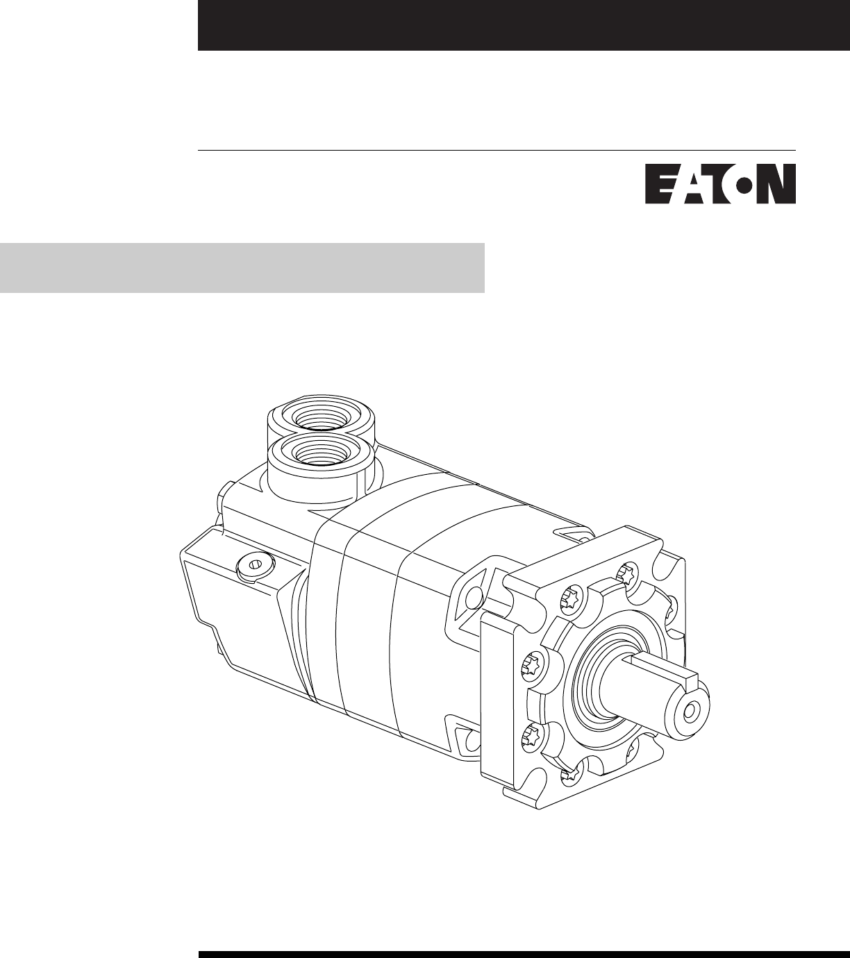
No. 7-118
May, 1999
Char-Lynn®
Disc Valve Motor
4000 Series
Geroler® Motors Std., Whl. and Brgl.-004 Std. and Whl.-006
Repair Information
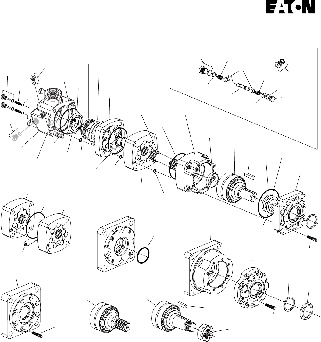
2
4000 Series Char-Lynn Motors
Retainer,
Front
(Flange)
Retainer, Front
(C Flange)
Housing, Bearing
Screw,
Cap
Screw, Cap Screw, Cap
Valve Housing Inner
Face
Seal
Outer
Face
Seal
Spring
Piston Shuttle
Seal
Balance
Ring
Valve
Valve
Plate
Valve
Drive
Geroler
Drive
Seal
Seal
Seal
Seal
Seal
Seal
Seal
Seal
Seal
Geroler
Geroler
Geroler
Shaft
Face
Seal
Bearingless Motor
Mounting Flange
Bearing Housing
Wheel Motor Back-up
Washer
(if supplied)
O-ring
Poppet
Spring
Spring
Sleeve, Dash Pot
Sleeve, Dash Pot
Shaft
Seal
Shuttle (Two Way)
Shuttle Valve
Location when
Applicable Dust
Seal
Dust
Seal Seal
Guard
Shaft and
Bearing Kit
(1-1/4 inch Straight)
Shaft and
Bearing Kit
(1-5/8 inch Tapered)
Shaft and Bearing Kit
(1-1/4 inch
14 Tooth Splined)
Plug
Assembly
Plug
Assembly
Plug Assembly
Plug Assembly
Check
Valve
Plug
Assembly
Ball Plug
Key
Nut
Key
Retainer
Spring
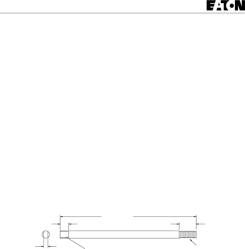
3
4000 Series Char-Lynn Motors
Tools required for disassembly and reassembly
— Torque wrench (68 Nm [600 lb-in] capacity)
— 300 to 400 mm [12 to 16 inch] breaker bar
— 3/4 inch and 1/2 inch sockets
— Small screwdriver (150 to 200 mm [6 to 8 inch] long,
6 mm [.25 inch] blade)
— 3/16 inch Hex Key
— Hydraulic press — 1335 N [300 lbf]
— Shaft face seal (-004) installation tool 600468
— Shaft face seal (-006) installation tool 600421-2
*— Bullet (600463) for 1-1/4 inch diameter shafts
— Shaft seal installation tool (2 -1/4 inch socket)
— Torq wrench required for eight mounting flange
screws (replacement screws or -006 design)
No. E10
The following tools are not necessary for disassembly
and reassembly but are extremely helpfull
— Alignment studs (2), see dimensions below
*Available by special order, contact Eaton Corp.,
Hydraulics Division Service Dept.
200 mm [8 inch]
Approx. 13 [.5]
6,3 [.25] Grind Flat Spots on Each Side
11 mm [7/16 inch] Dia. Steel Rod
25 mm
[1 inch]
7/16-20 UNF
Wheel motor and bearingless motor repair information on page 9 and 10.
Shuttle valve and seal guard repair information on page 10.
Seal guard reference on page 10.
Tools
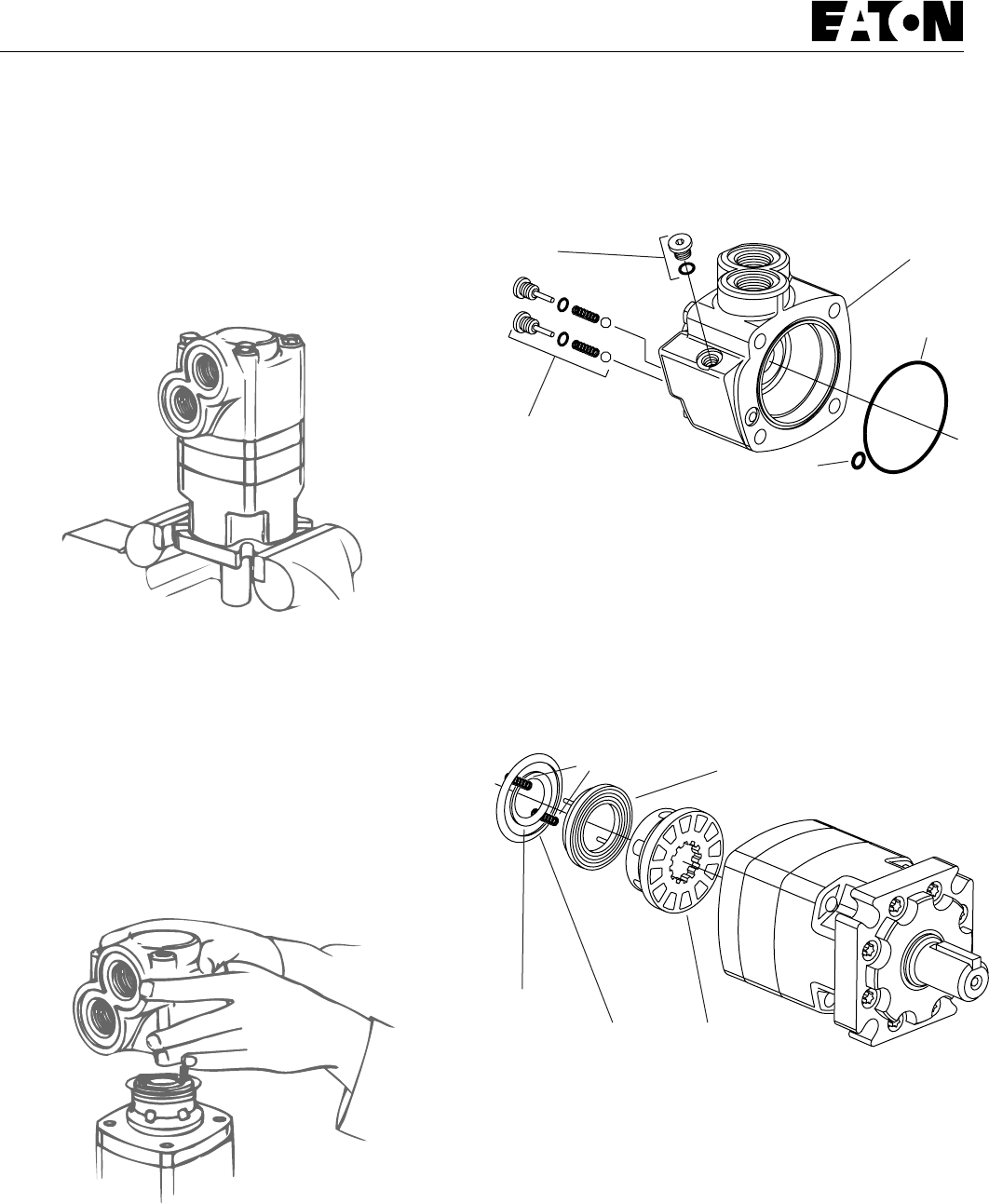
4
4000 Series Char-Lynn Motors
Disassembly
Cleanliness is extremely important when repairing a hydraulic motor.
Work in a clean area. Before disconnecting the lines, clean port area of
motor thoroughly. Use a wire brush to remove foreign material and
debris from exterior joints of motor. Check shaft and keyway. Use
600 grit paper/cloth to remove all nicks, burrs, and sharp edges that
might damage the shaft seals when installing retainer on shaft and
bearing assembly. Before starting disassembly procedures, drain oil
from inside of motor.
1 Place motor in a vise with output shaft down. Clamp across edge
of mounting flange, not on housing (see Figure 1). Excessive
clamping pressure will cause distortion. When clamping, use some
protective device on vise, such as special soft jaws, pieces of hard
rubber or board.
Although not all drawings show the motor in a vise, it is recom-
mended that you keep the motor in the vise during disassembly.
Follow the clamping procedures explained throughout the manual.
2 Remove 4 bolts from the valve housing.
3 Lift valve housing straight up. If done carefully, the springs and
balance ring subassembly will remain on valve for easy removal.
4 Carefully remove the following from the valve housing:
1 seal, 82,3 mm [3.24 inch] I.D.
1 seal, 8,9 mm [.35 inch] I.D.
2 check valve plug assemblies (plug, seal, spring, ball) 1 plug (case
drain) with seal.
5 Remove 2 balance ring springs.
6 Remove balance ring subassembly.
7 Remove inner and outer face seals from the balance ring.
8 Lift off valve.
Figure 1
Figure 2
Plug
Assembly Valve
Housing
Check
Plug
Assembly Seal
Seal
Figure 3
Spring Balance Ring
Valve
Figure 4
Inner
Face
Seal Outer Face Seal
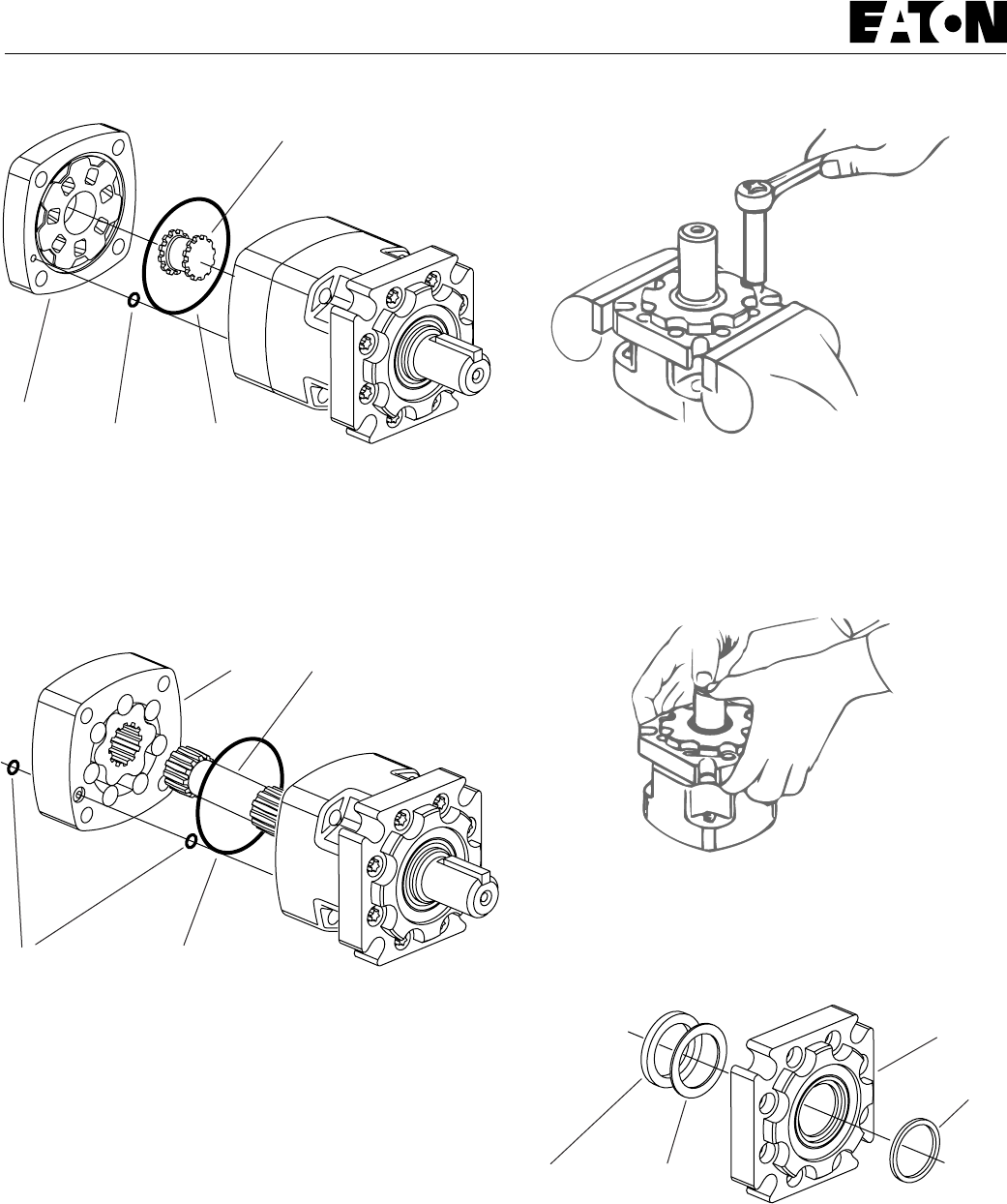
5
4000 Series Char-Lynn Motors
Disassembly
9 Remove valve plate.
10 Remove 88,6 mm [3.49 inch] I.D. seal from valve plate (see
Figure 5).
11 Remove valve drive (see Figure 5).
12 Remove Geroler. Retain rollers in outer Geroler ring if they are
loose.
13 Remove 2 seals from Geroler, 1 seal on each side of Geroler.
14 Remove drive.
15 Remove 88,6 mm [3.49 inch] I.D. seal from bearing housing.
17 Remove shaft seal, back-up ring (if used) and dust seal from flange.
Use a small screwdiver to remove dust seal. Do not damage bore of
flange.
16 Use a stud remover or vise grips to remove studs (earlier models
only). Clamp bearing housing in vise as shown in Figure 7. Loosen 8
screws. Remove screws, washers (discard washers, as they are not
required for reassembly), and mounting flange (see Figure 8).
Valve
Plate Seal Seal
Valve Drive
Figure 5
Figure 6
Seal Seal
Geroler Drive
Figure 7
Figure 8
Shaft
Seal Back-up
Ring
Mounting
Flange
Dust
Seal
Figure 9
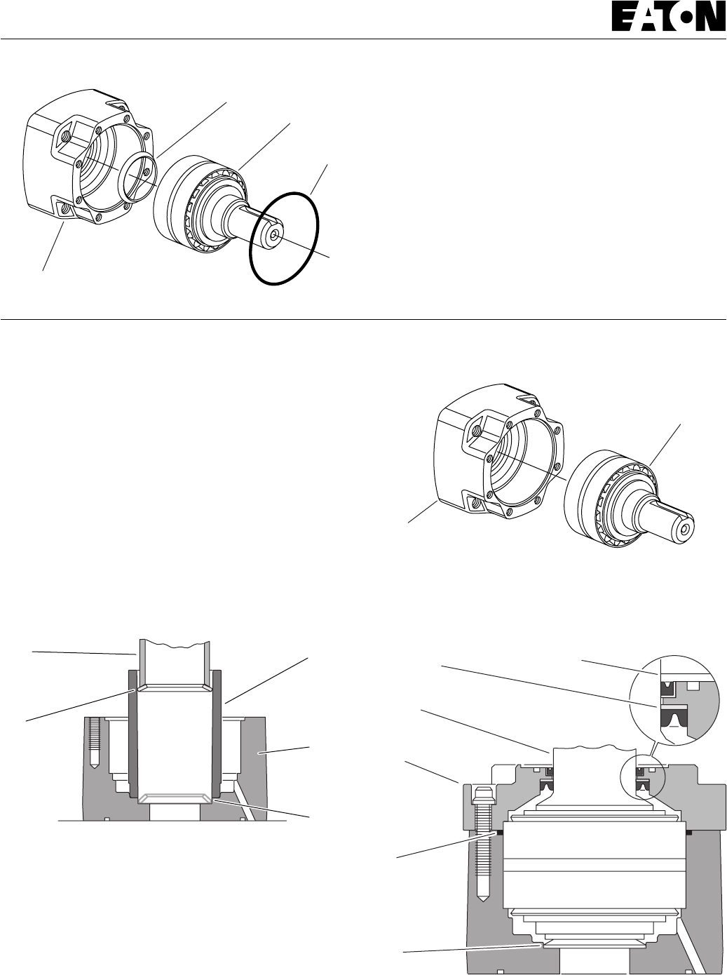
6
4000 Series Char-Lynn Motors
Reassembly
Check all mating surfaces. Replace any parts that have scratches or
burrs that couId cause leakage. Clean all metal parts in clean solvent.
Blow dry with air. Do not wipe with cloth or paper towel because lint
or other matter could get into the hydraulic system and cause damage.
Do not use a coarse grit papers/cloth or try to file or grind motor parts.
Check around the keyway and chamfered area of the shaft for burrs,
nicks, or sharp edges that can damage the seals when reassembling
the retainer.
Note: Lubricate all seals (prior to installation) with petroleum jelly
such as Vaseline®. Use new seals when reassembling the motor.
21 Place bearing housing on smooth flat surface with largest open end
of housing up. Apply petroleum jelly to shaft face seal. Install seal in
seal seat. Seat seal properly in groove (see Figure 11). A damaged or
improperly installed shaft face seal could cause internal lubrication
loss and subsequent parts wear.
22 Install shaft and bearing assembly in bearing housing (see Figure
12). Do not damage seal in bore of housing. You may need a press to
install shaft and bearing assembly.
18 Remove shaft and bearing assembly. You may need a press to
remove shaft and bearing assembly (see Figure 10).
19 Remove shaft face seal from bore of bearing housing (see Figure
10). Do not damage bore of bearing housing.
Note: Individual parts of the shaft and bearing assembly are not sold
separately and must be replaced as a unit.
Disassembly
Bearing Housing
Shaft and
Bearing
Assembly
Seal
Shaft Face Seal
Figure 10
Figure 11
Seal
Driver Seal
Tube
Seal
Seat
Bearing
Housing
Seal
Face
Seal
Note: Shaft face seal installation tool is available by special order.
Contact Eaton Corporation, Hydraulics Division (Service Department).
600468 (-004) 600421-2 (-006).
Figure 13
Shaft
Face
Seal
Seal
Flange
Shaft and
Bearing
Assembly
Back-up Ring Dust Seal Lip
Shaft Seal
Figure 12
Bearing
Housing
Shaft and
Bearing
Assembly
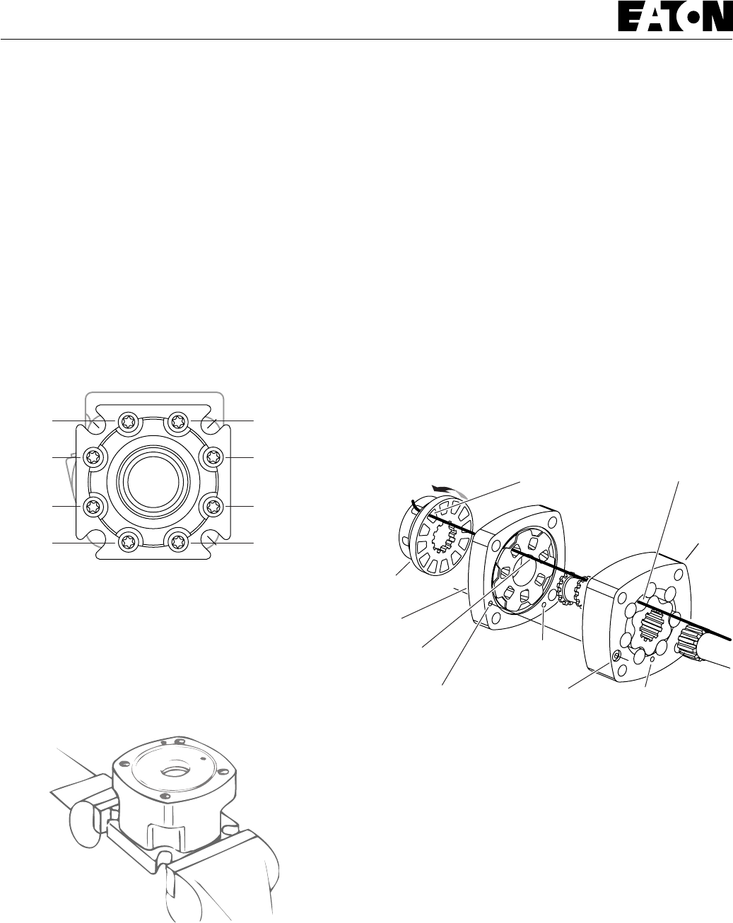
7
4000 Series Char-Lynn Motors
27 Lubricate threads of 8 screws with a film of light oil. Install and
finger tighten screws. Clamp bearing housing in vise. Torque screws
to 6 Nm [50 lb-in] in sequence (see Figure 14). Then final torque to 34
Nm [300 lb-in], in sequence. Install key (when used) in keyway of
shaft.
Note: Full torque 34 Nm [300 lb-in] on one bolt at a time can
damage bolt or retainer.
29 Pour a small amount of light oil inside the output shaft.
30 Apply a light film of petroleum jelly on 88,6 mm [3.49 inch] I.D.
seal. Install seal in bearing housing.
31 Install drive in output shaft (insert longer splined end of drive first),
(see parts drawing on page 2).
32 To help in the reassembly procedure, it is recommended using two
alignment studs (see special tools page 3) diagonally opposed in the
four bolt holes of the bearing housing.
33 Apply petroleum jelly on 2 seals, 9,3 mm [.25 inch] I.D. Install seals
(1 on each side of Geroler) in case drain grooves of Geroler.
Note: Installation at this point involves 3 steps in timing the motor.
Timing determines the direction of rotation of the output shaft.
Timing parts include:
1. Geroler
2. Valve drive
3. Valve Plate
4. Valve
23 Apply petroleum jelly to 88,6 [3.49] ID seal. Install seal in seal
groove of bearing housing (see Figure 13).
24 Use a small press, if available, to install dust seal in retainer. Metal
side of dust seal must face toward flange, as shown in Figure 13. If a
press is not available, use a plastic or rubber hammer to tap dust seal
in place.
25 Install 92,1 [3.62] ID seal, back-up ring and shaft seal in retainer.
Flat or smooth side of shaft seal must face toward retainer as shown in
Figure 13. Apply petroleum jelly to inside diameter of shaft seal (after
installing seal).
26 Before installing retainer, place a protective sleeve of bullet (see
note below) over shaft. Grease inside diameter of dust and shaft seals.
To prevent damage to seals, install retainer over shaft with a twisting
motion. Do not cut or distort shaft seal. Damage to shaft seal will
cause external leakage.
Note: Bullet 600463 for 1-1/4 inch diameter shafts available by
special order through Eaton Hydraulics Division service department.
Figure 14
1
2
3
4
5
67
8
Figure 15
28 Reposition motor in vise with output shaft down. Clamp across
edges of retainer as shown in Fig. 15.
Rotate Valve Clockwise
1/2 Tooth to Engage Spline
Valve
Valve
Plate
Alignment
Ref. Only
Note: Case Drain Holes (2)
Proper Alignment Shown Case Drain
Hole
Do Not Use
as a drain
hole Pressure
Relief Hole
Anyone of 6 Ports
Open to Outside
of Valve
Largest Open
Pocket
Geroler
Figure 16 Timing Alignment
Timing Step No. 1 — Locate largest open pocket in Geroler. Then
mark location of pocket on outside edge of Geroler (see Figure 16).
34 Align case drain hole and pressure relief hole in Geroler with case
drain hole and pressure relief hole in bearing housing. Install Geroler
on bearing housing (see Figure 16). Retain rollers in outer Geroler ring
if they are loose.
35 Install valve drive in Geroler.
Reassembly
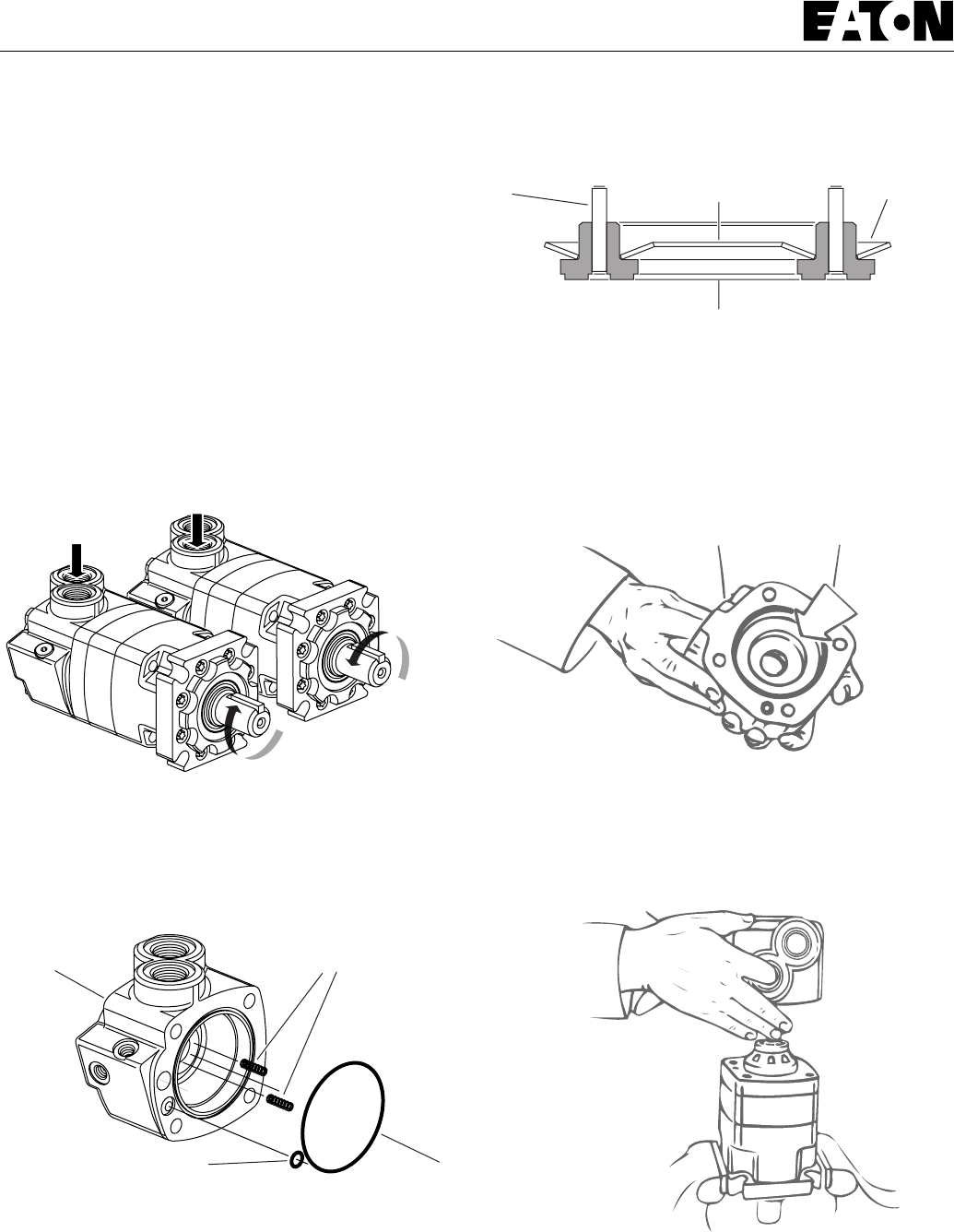
8
4000 Series Char-Lynn Motors
Reassembly
36 Apply a light film of petroleum jelly on 88,6 mm [3.49 inch] I.D.
seal. Install seal in valve plate.
37 Align case drain hole in valve plate with case drain hole in Geroler.
Install valve plate (seal side toward Geroler) on Geroler as shown in
Figure 16.
Timing Step No. 2 — Locate slot opening in valve plate which is in
line with largest open pocket of Geroler (see Figure 16).
38 Use the following procedure for installing the valve on the valve
plate.
Timing Step No. 3 — Locate any one of the side openings of the
valve that goes through to the face of the valve. Line up this side
opening in the valve with open slot of valve plate that is in line with
largest open pocket of Geroler. Rotate valve clockwise (1/2 spIine
tooth) to engage valve with the valve drive spline, alignment reference
shown in Figure 17 (above). This procedure provides standard timing
when pressurized as shown in Figure 17.
39 Apply clean grease on balance ring assembly springs. Install
springs in 2 holes located inside bore face of valve housing (see
Figure 18).
41 Apply a light film of petroleum jelly on 82,3 mm [3.24 inch] I.D.
seal. Install seal in outside seal groove of valve housing.
42 Apply petroleum jelly on inner and outer face seals. Install seals on
balance ring as shown in Figure 19.
Important: Install face seals in the positions shown in Figure 19 or
the motor will not operate properly. Do not force or bend these face
seals. Any damage to these seals will affect the operation of the
motor.
43 Align 2 pins of balance ring with 2 spring holes in valve housing as
shown in Figure 20 . Install balance ring in valve housing.
40 Apply a light film of petroleum jelly on 8,9 mm [.35 inch] I.D. seal.
Install seal in case drain groove of valve housing.
Figure 19
Balance Ring
Pin Inner Seal Outer Seal
Valve
Housing
Seal
Figure 18
Seal
Balance Ring
Spring
Clockwise
Rotation
Counter
Clockwise
Rotation
Figure 17
Figure 20
Figure 21
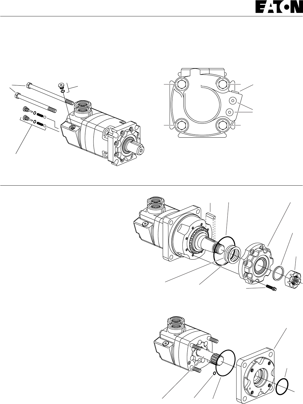
9
4000 Series Char-Lynn Motors
Wheel Motors
Reassembly 45 Install and finger tighten 2 bolts (or studs for earlier models)
opposite alignment studs. Remove alignment studs and install
remaining bolts (or studs and 4 nuts for earlier models). Torque bolts
(or nuts) to 85 Nm[750 lb-in], in sequence (see Figure 23).
46 Install 2 check plug assemblies (ball, spring, plug with seal). Also
install case drain plug with seal, parts shown in Figure 22 (plug torque
shown in Figure 24).
A different bearing housing is used on wheel
motors (see Figure 24). Other than this, the
parts are the same as the standard motor and
the same disassembly and reassembly
procedures apply.
Bearingless Motors
This motor is the same as the standard without the shaft/bearing
assembly, bearing housing and retainer. The mounting flange replaces
the bearing housing (see Figure 25). Follow same disassembly and
reassembly procedures as rear section of standard motor.
Important: Loctite® information for bearingless motor on page 10.
44 Insert your finger through port of housing. Apply pressure to side
of balance ring assembly. Hold ring in position until valve housing is
in place (see Figure 21). Align case drain hole in housing with case
drain hole in valve plate. Install valve housing against valve plate (see
Figure 22).
Note: After installing valve housing on valve plate, check between
body parts of motor for unseated seals.
Figure 22
Check Plug
Assembly
Bolt Plug Assembly
Key Seal
Shaft
Seal
Retainer
Dust
Seal
Nut
Cap ScrewBackup Ring
Figure 24
Figure 25
Drive Seal Seal
O-ring
Seal
Mounting
Flange
Figure 23
1
3
4
2
7/16-20 Drain
Plug Torque to
17 Nm [150 lb-in]
(lubricated threads)
Check Plug
Torque to
7-14 Nm
[60-120 lb-in]
(lubricated threads)
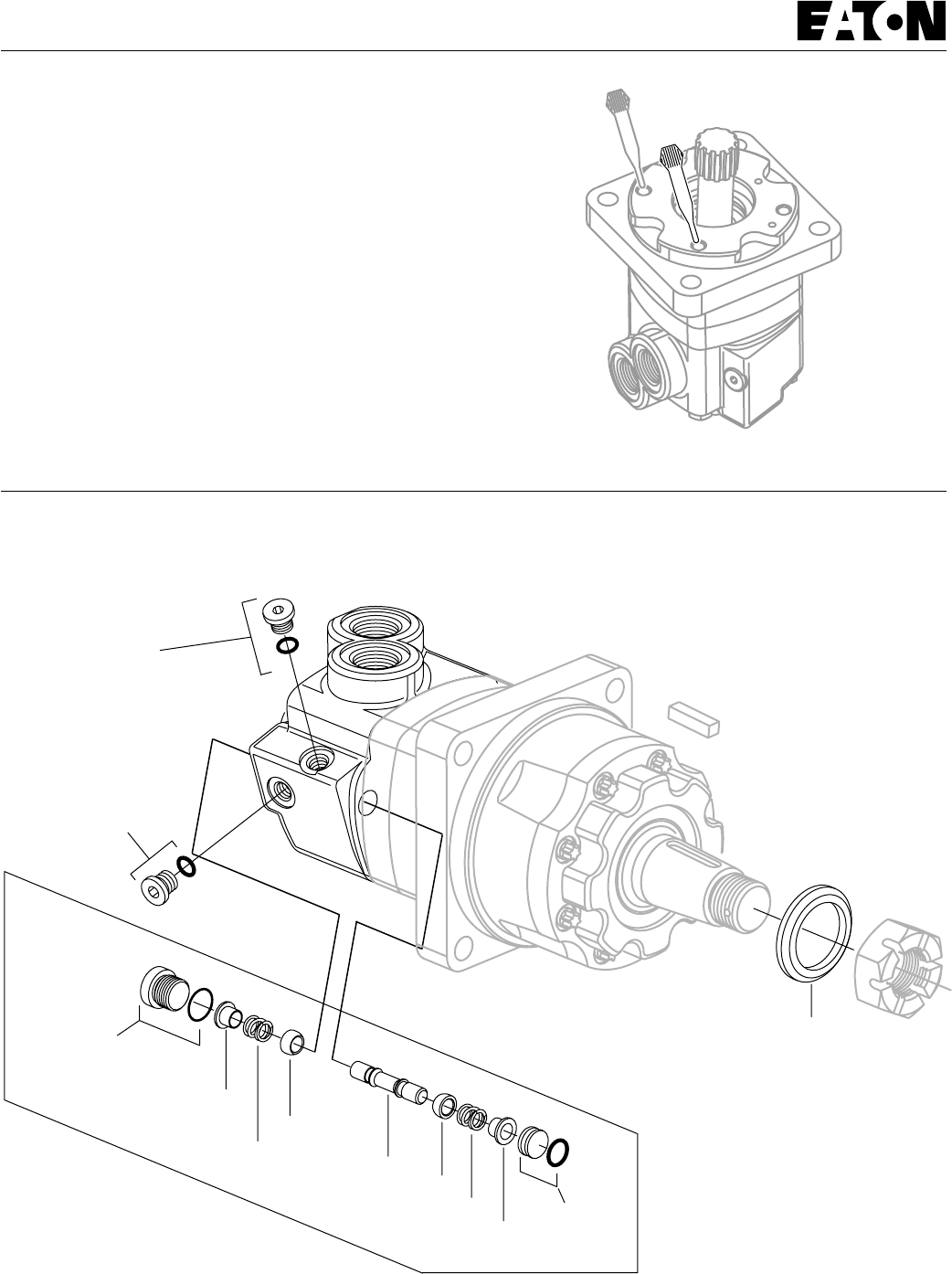
10
4000 Series Char-Lynn Motors
Important: This motor requires Loctite in threaded holes of
mounting flange.
Follow these procedures:
Adequate Loctite penetration and sealing depend highly on cleanliness
and dryness of threads. Use a non-petroleum base solvent to clean
excess oil from threads of flange after disassembly. You may need to
use a tap to clean threads of excess old Loctite. After you have fully
reassembled the motor, apply 2 to 3 drops of Loctite no. 290 at top of
threaded holes (see Figure 26).
Note: Allow Loctite 5 minutes for thread penetration before installing
motor on gear case.
Reassembly
Figure 26
Attention:
Do not use
more than
3 drops of
Loctite on
threaded
portion.
Motors with Shuttle
and, or Seal Guard
Piston
Poppet
Dash
Pot
Plug/O-ring
S/A (9/16-18)
Torque to
41 Nm [360 lb-in]
(Lubricated Thread)
Enlarged
Parts
Drawing
Plug/O-ring*
S/A (9/16-18)
Torque to
23 Nm [200 lb-in]
(Lubricated
Thread)
Plug/O-ring
S/A (3/8-24)
Torque to
5 Nm [50 lb-in]
(Lubricated
Thread)
*Plug/O-ring S/A must be removed and
drain line added for shuttle valve operation.
Plug/
O-ring
S/A
Optioal
Seal Guard
Dash
Pot
Spring
Spring
Poppet
11
4000 Series Char-Lynn Motors
Char-Lynn
®
Product number
Eaton Corp. Hydraulics Div.
Eden Prairie, MN 55344
Product Number
109 0000 000
110 0000 000
111 0000 000
Product Line
Identification
Number
Product
Identification
Number
Engineering
Change
Code
Week of
Year 01
Thru 52
Last
Number
of Year
Date Code
00 0
For more detailed information contact Eaton Corp. Hydraulics
Division 15151 Highway 5 Eden Prairie, MN 55344.
Specifications and performance data, Catalog No. 11-878.
Replacement part numbers and kit information — Parts
Information No. 6-126.
Each Order Must Include the Following:
How to Order Replacement Parts
1. Product Number
2. Date Code
3. Part Name
4. Part Number
5. Quantity of Parts
Product Numbers—4000 Series Motors
Use digit prefix —109-, 110-, or 111- plus four digit number from charts
for complete product number—Example 111-1057.
Orders will not be accepted without three digit prefix.
109-1100 -1101 -1102 -1103 -1104 -1105 -1106 -1212
1-1/4 inch Straight
Standard
SAE
B-Mount
Standard
SAE
C-Mount
Displ. cm
3
/r [ in
3
/r] Product Number
ShaftMounting 130
[ 7.9] 160
[ 9.9] 205
[12.5] 245
[15.0] 310
[19.0] 395
[24.0] 495
[30.0]
110
[ 6.7] 625
[38.0]
109-1114 -1115 -1116 -1117 -1118 -1119 -1120 —
Ports
1-5/8 Inch
Tapered 110-1081 -1082 -1083 -1084 -1085 -1086 -1087 1116
111-1033 -1034 -1035 -1036 -1037 -1038 -1039 -1062
1-1/16 O-ring
Bearingless
Wheel
Motor
1-1/4 Inch
14 T Splined
111-1057
1-1/16 O-ring
1-1/16 O-ring
1-1/16 O-ring -1215
—
-1117
-1063
109-1184 -1185 -1227 -1224 -1225 -1189 -1190 —40 mm Straight G 3/4 (BSP) —
111-1052 -1053 -1054 -1055 -1056 -1057 -1058 —
G 3/4 (BSP) —
110-1074 -1075 -1076 -1077 -1078 -1079 -1080 —
1-1/4 inch Straight 1-1/16 O-ring -1122
110-1088 -1089 -1090 -1091 -1092 -1093 -1094 —
1-1/4 Inch
14 T Splined 1-1/16 O-ring —
109-1001 -1054 -1002 -1003 -1055 -1056 -1057 —
3/4 inch Split Flange —
109-1011 -1062 -1012 -1013 -1063 -1064 -1065 —
3/4 inch Split Flange —
110-1001 -1040 -1002 -1003 -1041 -1042 -1043 —
3/4 inch Split Flange —
110-1006 -1044 -1007 -1008 -1045 -1046 -1047 —
3/4 inch Split Flange —
110-1011 -1048 -1012 -1013 -1049 -1050 -1051 —
3/4 inch Split Flange —
111-1044 -1015 -1045 -1046 -1016 -1017 -1018 —
3/4 inch Split Flange —
1-5/8 Inch
Tapered
109-1107 -1108 -1109 -1110 -1111 -1112 -1113 —
1-1/16 O-ring —
109-1006 -1058 -1007 -1008 -1059 -1060 -1061 —
3/4 inch Split Flange —
109-1191 -1192 -1193 -1194 -1195 -1196 -1197 —
1-1/2 Inch
17 T Splined G 3/4 (BSP) —
110-1108 -1109 -1110 -1111 -1112 -1113 -1125 —
40 mm Straight G 3/4 (BSP) —

Copyright Eaton Corporation 1981, 1992, 1995, 1997 and 1999
All Rights Reserved
Printed in USA
Form No. 7-118
Disc Valve Motors
4000 Series Motors
Sumitomo Eaton
Hydraulic Company Ltd.
Ooi-Cho Kameoka-Shi
621-0017 Kyoto
Japan
Telephone: [+81] 771-22-9601
Fax: [+81] 771-29-2020
Eaton Corporation
Hydraulics Division
15151 Hwy. 5
Eden Prairie, MN 55344
Telephone: 612/937-7254
Fax: 612/937-7130
Eaton Ltd.
7th Floor, Woo Duk Building
832-2 Yeoksam-Dong, Kangnam-Ku
Soeul 135-750
Korea
Telephone: [+82] 2-557-0595
Fax: [+82] 2-557-1634
Eaton Ltd.
Hydraulics Division
Glenrothes, Fife
Scotland, KY7 4NW
Telephone: [+44] (0)1592-771-771
Fax: [+44] (0)1592-773-184
Eaton Hydraulics (Shanghai) Co. Ltd.
388 Aidu Road, Waigaogiao FTZ
Pudong New Area
Shanghai 200137
Peoples Republic of China
Telephone: [+86] 21-5046 0758
Fax: [+86] 21-5046 0767
Eaton B.V.
Boeing Avenue 11
1119 PC Schiphol-Rijk
The Netherlands
Telephone: [+31] (0)20-655 6776
Fax: [+31] (0)20-655 6800
Jining Eaton Hydraulic Co. Ltd.
6 Ji Da Road
Jining City
Shandong Province 272131
Peoples Republic of China
Telephone: [+86] 537-2221288
Fax: [+86] 537-2221557
Sumitomo Eaton Hydraulic Co.
8 Temasek Blvd.
42-01 Suntec Tower Three
Singapore 03988
Telephone: [+65] 832-7727
Fax: [+65] 832-7733
www.eatonhydraulics.com
ISO-9001 CERTIFICATED FIRM
DET NORSKE VERITAS INDUSTRY BV, THE NETHERLANDS
ACCREDITED BY
THE DUTCH COUNCIL
FOR CERTIFICATION
Reg. No. 24
Qualitiy System Certified
Products in this catalog are manufactured
in an ISO-9001-certified site.
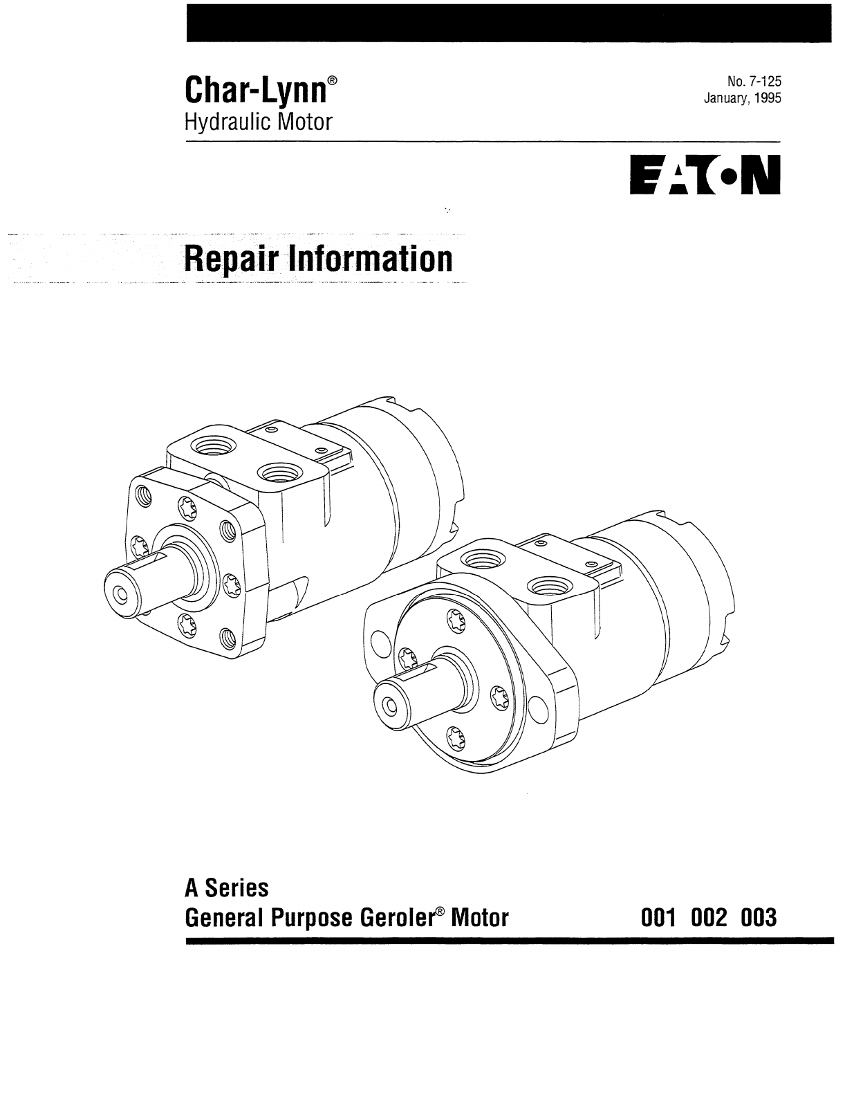
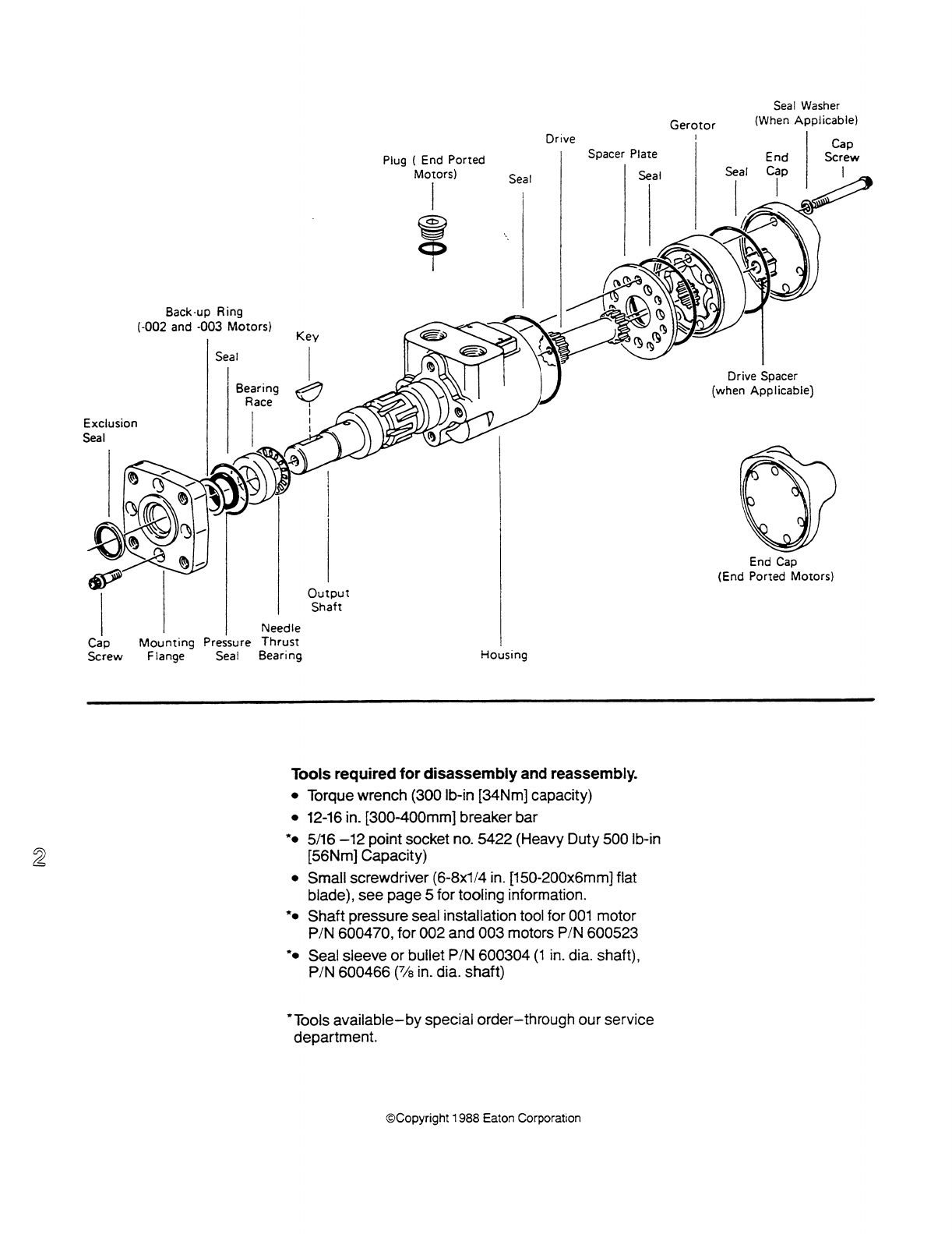
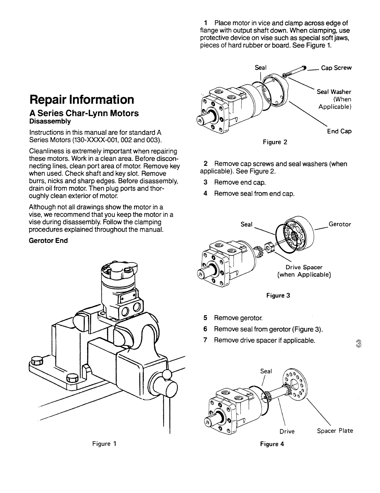
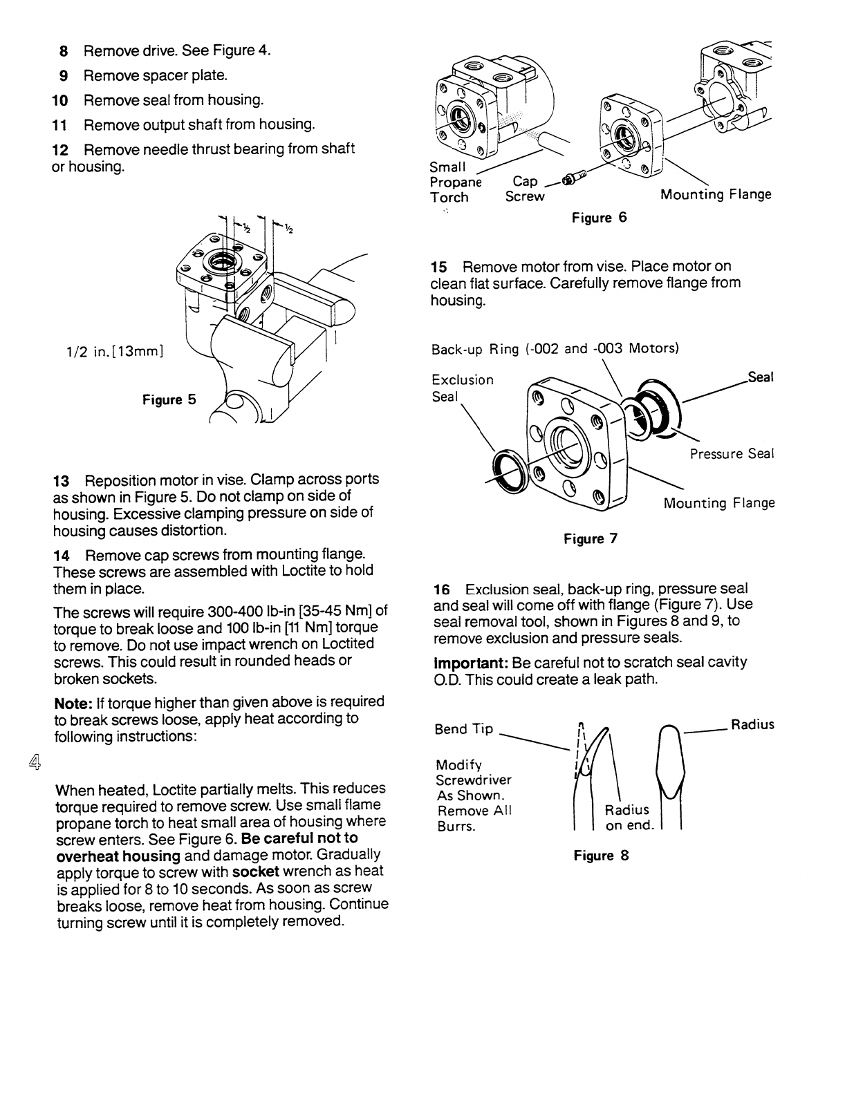
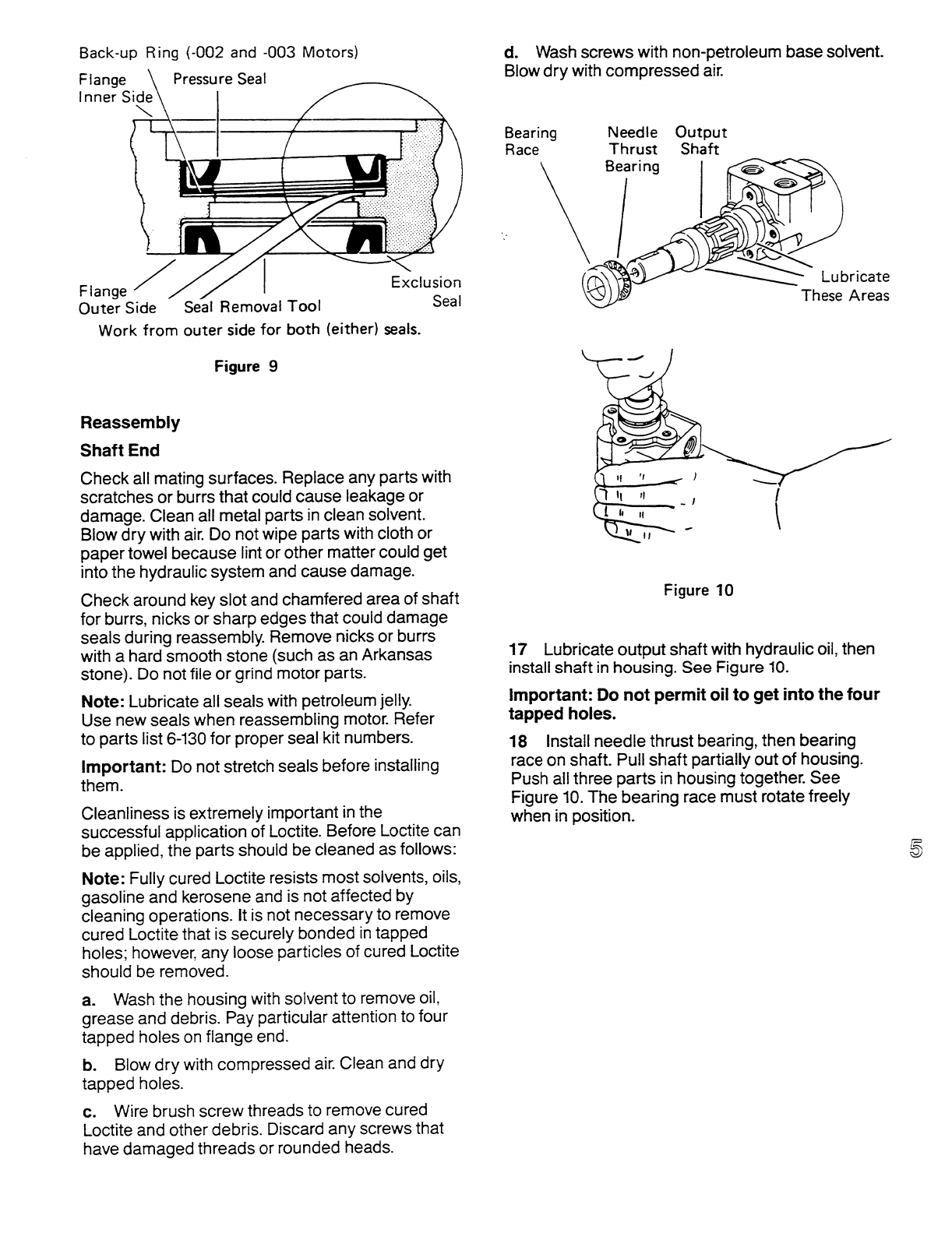
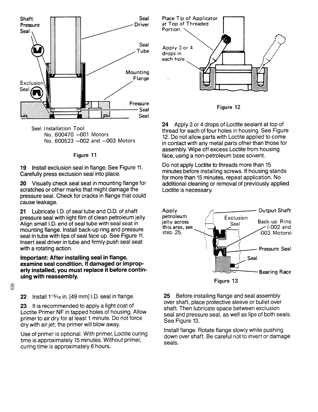
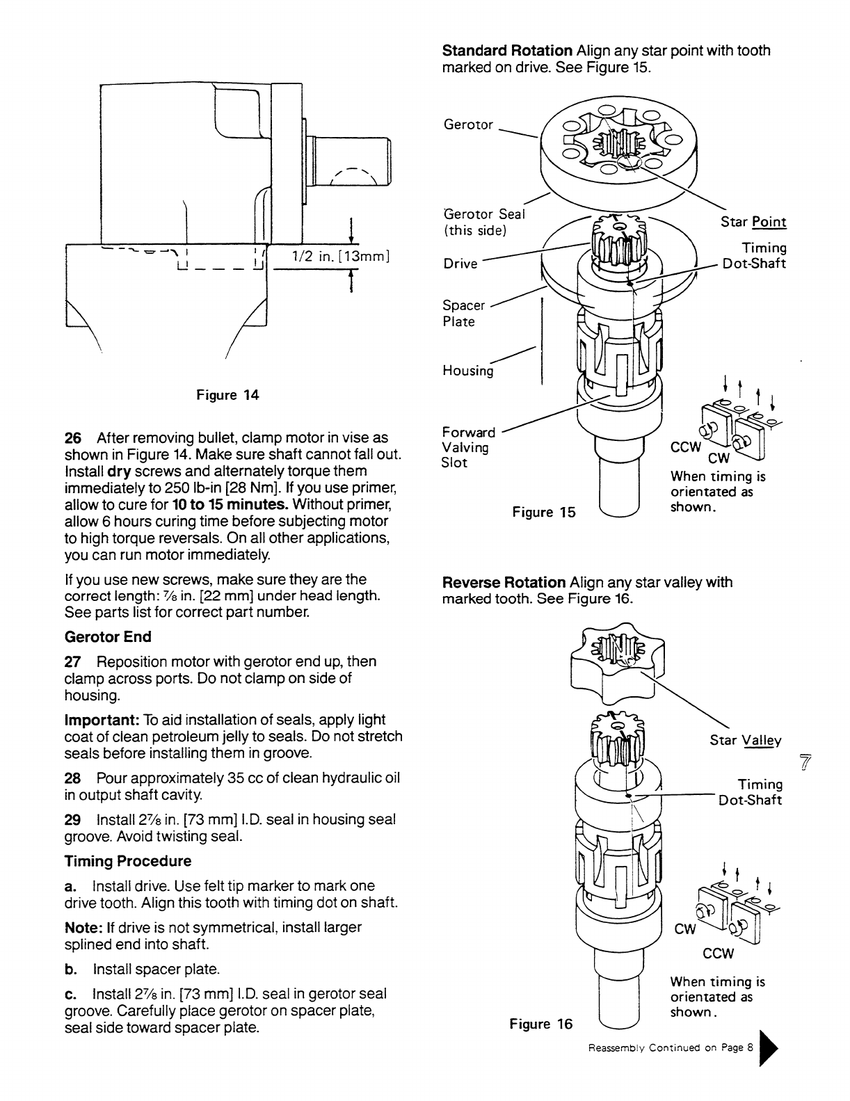
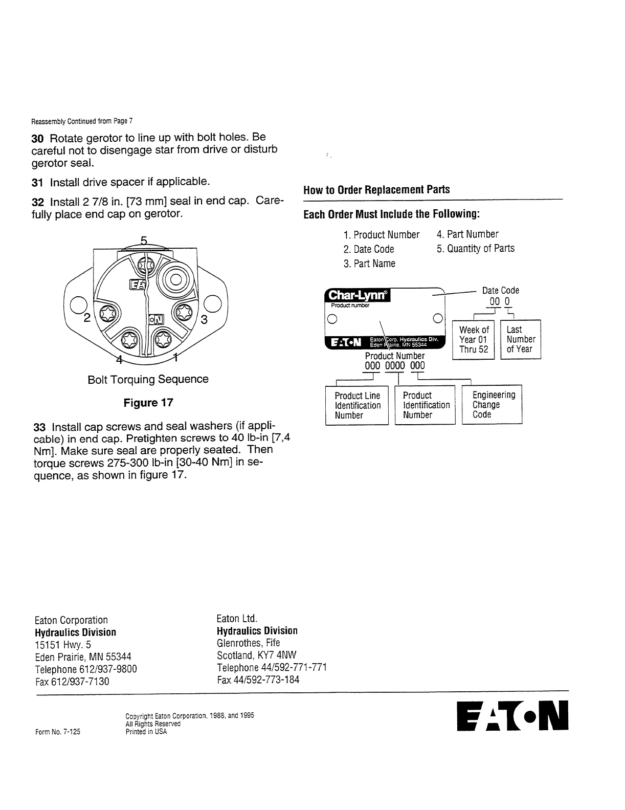
No. 7-310
January, 1995
Char-Lynn®
Power Steering
2 Series
Steering Control Unit 001
Repair Information
TE
LR
P
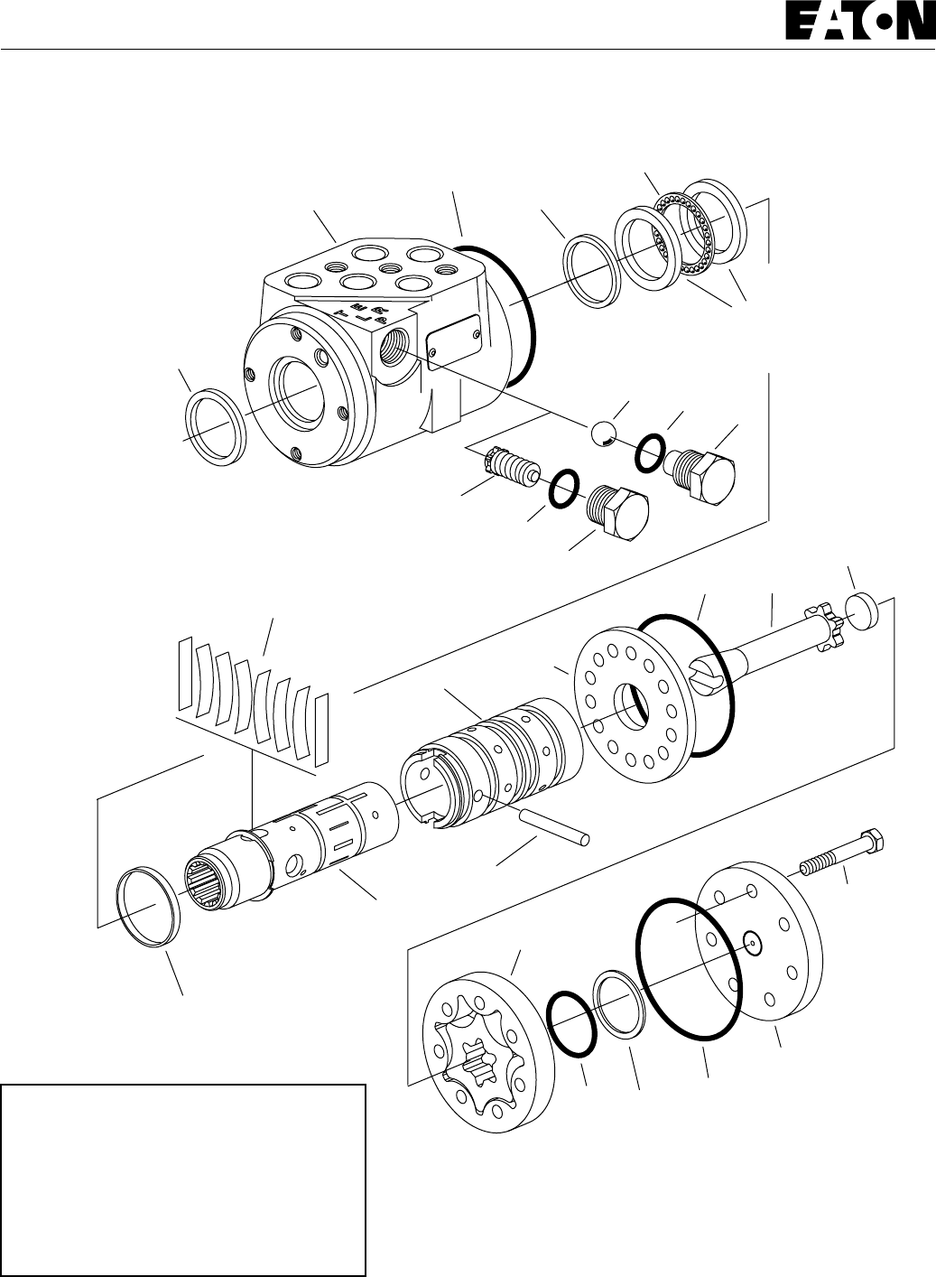
2
Dust
Seal
Housing Quad
Seal
Thrust
Bearing
Sleeve
Spool
Pin
Centerin
Springs
Bearing Race (2)
O-ring
Seal
O-ring
Seal
Wear
Plate
Drive
Gerotor
Spacer
Manual Steering
Relief Valve
O-ring
O-ring
O-ring
O-ring Seal
Ring
End
Cap
Cap
Screw
(7)
Plug
Plug
Check
Ball
Spring
Retaining
Ring
Power Steering
2 Series
Steering Control Units
Tools Required
• 10 mm Socket
• 7/8 in. Socket
• Torque Wrench (18 Nm [160 lb-in] Capacity)
• Small Blade Screwdriver

3
Power Steering
2 Series
Steering Control Units
Disassembly
Cleanliness is extremely important when repairing hydraulic
Steering Control Units (SCU). Work in a clean area. Before
disconnecting the hydraulic lines, clean the port area of the
SCU. Before disassembly, drain the oil, then plug the ports and
thoroughly clean the exterior of the SCU. During repairs,
always protect machined surfaces.
1 Remove the seven cap screws and disassemble the SCU as
shown in Figure 1.
2 Remove the plug and manual steering check as shown in
Figure 1.
Note: The manual steering check may be a check ball or a
check/relief valve.
3 Slide the spool and sleeve from the housing (see Figure 2).
4 Remove the thrust bearing and bearing races.
5 Remove the quad seal.
6 Using a small blade screwdriver, carefully pry the dust seal
from the housing.
Important: Do not damage the dust seal seat.
O-ring
Seal
O-ring
Seal
Wear
Plate Drive
Gerotor
Seal
Ring
Spacer
Manual Steering
Check/Relief Valve
O-ring
O-ring O-ring
End
Cap
Cap
Screw
(7)
Figure 1
Plug
Dust
Seal
Housing Quad
Seal
Thrust
Bearing
Bearing Race (2)
Spool and Sleeve
Figure 2

4
Power Steering
2 Series
Steering Control Units
7 Remove the pin that holds the spool and sleeve together
(see Figure 3).
8 Carefully slide the spool out of the sleeve. The springs
and retaining ring will stay with the spool as it's removed.
Reassembly
Check all mating surfaces. Replace any parts with
scratches or burrs that could cause leakage. Wash all
metal parts in clean solvent. Blow them dry with pressur-
ized air. Do not wipe parts dry with paper towels or cloth
as lint in a hydraulic system will cause damage.
Note: Always use new seals when reassembling
hydraulic steering control units. Refer to parts list 6-323
for seal kit part numbers, replacement parts, and
ordering information.
Important: During reassembly lubricate the new seals
with a petroleum jelly such as Vaseline®. Also lubricate
machined surfaces and bearings with clean hydraulic
fluid.
9 Remove the retaining ring and springs.
Caution: The centering springs are under tension. Remove
the retaining ring carefully.
10 Install the quad seal:
• Put one of the bearing races and sleeve into
the housing.
• Together, the housing and bearing race create
a groove into which the quad seal will be
installed.
• Hold the bearing race tightly against the input
end of the housing by pushing on the gerotor
end of the sleeve.
• Fit the quad seal into its seat through the input
end of the housing. Be sure the seal is not
twisted.
• Remove the sleeve and bearing race.
Centering
Springs and
Spacers
Sleeve
Pin
Spool
Figure 3
Spring
Retaining
Ring
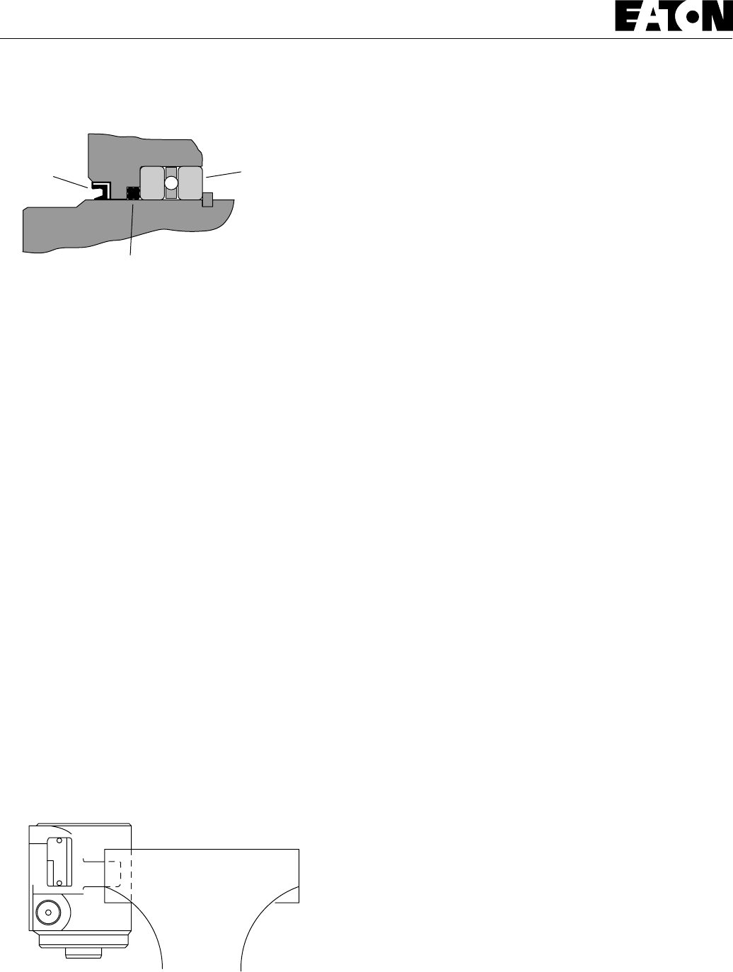
5
Power Steering
2 Series
Steering Control Units
20 Lubricate and install a new o-ring seal in the groove in
the housing.
21 Install the wear plate and align the holes in the wear
plate with threaded holes in the housing.
Note: The holes in the wear plate are symmetrical.
22 Install the drive, be sure the slot in the drive engages
the pin.
23 Lubricate and install a new o-ring seal in the groove in
the wear plate.
24 Install the gerotor and align the screw holes.
25 Lubricate and install a new o-ring seal in the groove in
the gerotor ring.
26 Lubricate and install a new o-ring and seal ring in the
groove in the gerotor star.
27 Install the spacer.
28 Install end cap and seven cap screws. Tighten cap screws,
in a crisscross pattern, to 16 -18 Nm [140 -160 lb-in].
29 Remove the SCU from the vise.
30 Install the relief valve/check or check ball and plug. Use
a new o-ring and tighten the plug to 17 Nm [150 lb-in].
Quad Seal
Figure 4
Dust Seal Thrust Bearing
and Race (2)
Figure 5
11 Lubricate and install the dust seal (see Figure 4 for
correct seal orientation).
12 Install the centering springs in the spool. It is best to
install the two flat pieces first. Next, install the curved
pieces, three at a time.
13 Fit the retaining ring over the centering springs.
14 Apply a light coating of clean hydraulic fluid to the
spool and slide it into the sleeve. Be sure the centering
springs fit into the notches in the sleeve.
15 Install the pin (see Figure 3).
16 Apply a light coating of petroleum jelly to the inner
edge of the dust and quad seals.
17 Put the thrust bearing and races into the housing. The
thrust bearing goes between the two races (see Figure 2).
18 Apply a light coating of clean hydraulic fluid to the
spool and sleeve assembly and slide it into the housing.
Important: Do not damage the dust or quad seals.
19 Clamp the housing in a vise as shown in Figure 5. Use
just enough clamping force to hold the housing securely.

6
System
Product Numbers 2 Series (Standard — 69 Bar [1000 PSI])
Product Numbers 2 Series (High Pressure — 103 Bar [1500 PSI])
Ports Relief Valve
Setting
Bar [PSI] 31 [1.9] 39 [2.4] 63 [3.8] 74 [4.5] 100 [6.1]51 [3.1]
Displacement cm
3
/r [in
3
/r] and Product Number
291-1001-001None 291-1002-001 291-1003-001 291-1004-001 291-1005-001 291-1006-001
291-1001-04140 [ 580] 291-1002-041 291-1003-041 291-1004-041 291-1005-041 291-1006-041
291-1001-05150 [ 725] 291-1002-051 291-1003-051 291-1004-051 291-1005-051 291-1006-051
291-1001-06163 [ 914] 291-1002-061 291-1003-061 291-1004-061 291-1005-061 291-1006-061
291-1001-07170 [1015] 291-1002-071 291-1003-071 291-1004-071 291-1005-071 291-1006-071
293-4001-001None 293-4002-001 293-4003-001 293-4004-001 293-4005-001 293-4006-001
293-4007-001None 293-4008-001 293-4009-001 293-4010-001 293-4011-001 293-4012-001
Open
Center
Non-
Load
Reaction
Power
Beyond
Non-
Load
Reaction
Dynamic
Signal
Load
Sensing
9/16 Inch
Plug-O (4)
9/16 Inch
Plug-O (5)
9/16 Inch
Plug-O (5)
9/16 -18
Inch
SAE (4)
9/16 -18
Inch
SAE (5)
9/16 -18
Inch
SAE (5)
None
40 [ 580]
50 [ 725]
63 [ 914]
70 [1015]
None
40 [ 580]
50 [ 725]
63 [ 914]
70 [1015]
None
40 [ 580]
50 [ 725]
63 [ 914]
70 [1015]
291-1007-001 291-1008-001 291-1009-001 291-1010-001 291-1011-001 291-1012-001
291-1007-041 291-1008-041 291-1009-041 291-1010-041 291-1011-041 291-1012-041
291-1007-051 291-1008-051 291-1009-051 291-1010-051 291-1011-051 291-1012-051
291-1007-061 291-1008-061 291-1009-061 291-1010-061 291-1011-061 291-1012-061
291-1007-071 291-1008-071 291-1009-071 291-1010-071 291-1011-071 291-1012-071
291-5001-001 291-5002-001 291-5003-001 291-5004-001 291-5005-001 291-5006-001
291-5001-041 291-5002-041 291-5003-041 291-5004-041 291-5005-041 291-5006-041
291-5001-051 291-5002-051 291-5003-051 291-5004-051 291-5005-051 291-5006-051
291-5001-061 291-5002-061 291-5003-061 291-5004-061 291-5005-061 291-5006-061
291-5001-071 291-5002-071 291-5003-071 291-5004-071 291-5005-071 291-5006-071
291-5007-001 291-5008-001 291-5009-001 291-5010-001 291-5011-001 291-5012-001
291-5007-041 291-5008-041 291-5009-041 291-5010-041 291-5011-041 291-5012-041
291-5007-051 291-5008-051 291-5009-051 291-5010-051 291-5011-051 291-5012-051
291-5007-061 291-5008-061 291-5009-061 291-5010-061 291-5011-061 291-5012-061
291-5007-071 291-5008-071 291-5009-071 291-5010-071 291-5011-071 291-5012-071
291-1001-121None 291-1002-121 291-1003-121 291-1004-121 291-1005-121 291-1006-121
291-1001-081 80 [1160] 291-1002-081 291-1003-081 291-1004-081 291-1005-081 291-1006-081
291-1001-091 90 [1305] 291-1002-091 291-1003-091 291-1004-091 291-1005-091 291-1006-091
291-1001-101100 [1450] 291-1002-101 291-1003-101 291-1004-101 291-1005-101 291-1006-101
293-4001-121None 293-4002-121 293-4003-121 293-4004-121 293-4005-121 293-4006-121
293-4007-121None 293-4008-121 293-4009-121 293-4010-121 293-4011-121 293-4012-121
Open
Center
Non-
Load
Reaction
Power
Beyond
Non-
Load
Reaction
Dynamic
Signal
Load
Sensing
9/16 Inch
Plug-O
(4)
9/16 Inch
Plug-O
(5)
9/16 Inch
Plug-O (5)
9/16 -18
Inch
SAE
(4)
9/16 -18
Inch
SAE
(5)
9/16 -18
Inch
SAE (5)
None
80 [1160]
90 [1305]
100 [1450]
None
80 [1160]
90 [1305]
100 [1450]
None
80 [1160]
90 [1305]
100 [1450]
291-1007-121 291-1008-121 291-1009-121 291-1010-121 291-1011-121 291-1012-121
291-1007-081 291-1008-081 291-1009-081 291-1010-081 291-1011-081 291-1012-081
291-1007-091 291-1008-091 291-1009-091 291-1010-091 291-1011-091 291-1012-091
291-1007-101 291-1008-101 291-1009-101 291-1010-101 291-1011-101 291-1012-101
291-5001-121 291-5002-121 291-5003-121 291-5004-121 291-5005-121 291-5006-121
291-5001-081 291-5002-081 291-5003-081 291-5004-081 291-5005-081 291-5006-081
291-5001-091 291-5002-091 291-5003-091 291-5004-091 291-5005-091 291-5006-091
291-5001-101 291-5002-101 291-5003-101 291-5004-101 291-5005-101 291-5006-101
291-5007-121 291-5008-121 291-5009-121 291-5010-121 291-5011-121 291-5012-121
291-5007-081 291-5008-081 291-5009-081 291-5010-081 291-5011-081 291-5012-081
291-5007-091 291-5008-091 291-5009-091 291-5010-091 291-5011-091 291-5012-091
291-5007-101 291-5008-101 291-5009-101 291-5010-101 291-5011-101 291-5012-101
Power Steering
2 Series Steering Control Units

7
Power Steering
2 Series
Steering Control Units

Copyright Eaton Corporation, 1991, and 1995
All Rights Reserved
Printed in USA
Form No. 7-310
Char-Lynn
®
Eaton Corp. Hydraulics Div.Hydraulics Div.
Eden Prairie, MN 55344
Product number
000 0000 000
000
Product Number
000 0000 000
Product Line
Identification
Number
Product
Identification
Number
Engineering
Change
Code
Week of
Year
01 Thru 52
Last Number(s)
of Year
Date Code
00 00
Relief Valve Pressure Code
00 = None
04 = 40 Bar [ 580 PSI]
05 = 50 Bar [ 725 PSI]
06 = 63 Bar [ 914 PSI]
07 = 70 Bar [1015 PSI]
08 = 80 Bar [1160 PSI]
09 = 90 Bar [1305 PSI]
10 = 100 Bar [1450 PSI]
Each Order Must Include the Following:
How to Order Replacement Parts
1. Product Number
2. Date Code
3. Part Name
4. Part Number
5. Quantity of Parts
For More Detailed Information Contact Eaton Corp. Hydraulics
Division 15151 Highway 5 Eden Prairie, MN 55344.
Specifications and performance data, Catalog No. 11-872
Replacement part numbers and kit information — Parts
Information No. 7-310.
Power Steering
2 Series
Steering Control Units
Eaton Corporation
Hydraulics Division
15151 Hwy. 5
Eden Prairie, MN 55344
Telephone 612/937-9800
Fax 612/937-7130
Eaton Ltd.
Hydraulics Division
Glenrothes, Fife
Scotland, KY7 4NW
Telephone 01-592-771-771
Fax 01-592-773-184
Eaton GmbH
Hydraulics Products
Am Schimmersfeld 7
40880 Ratingen, Germany
Telephone 02102-406-830
Fax 02102-406-800
ISO-9001 CERTIFICATED FIRM
DET NORSKE VERITAS INDUSTRY BV, THE NETHERLANDS
ACCREDITED BY
THE DUTCH COUNCIL
FOR CERTIFICATION
Reg. No. 24
Quality System Certified
Products in this catalog are manufactured
in an ISO-9001-certified site.

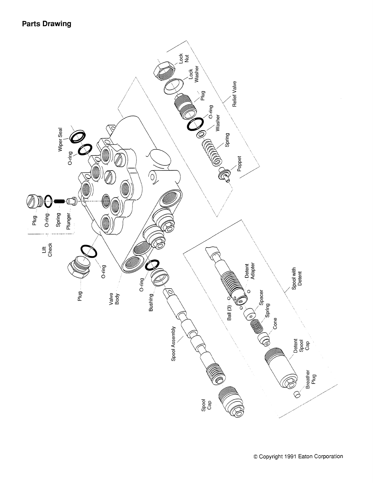
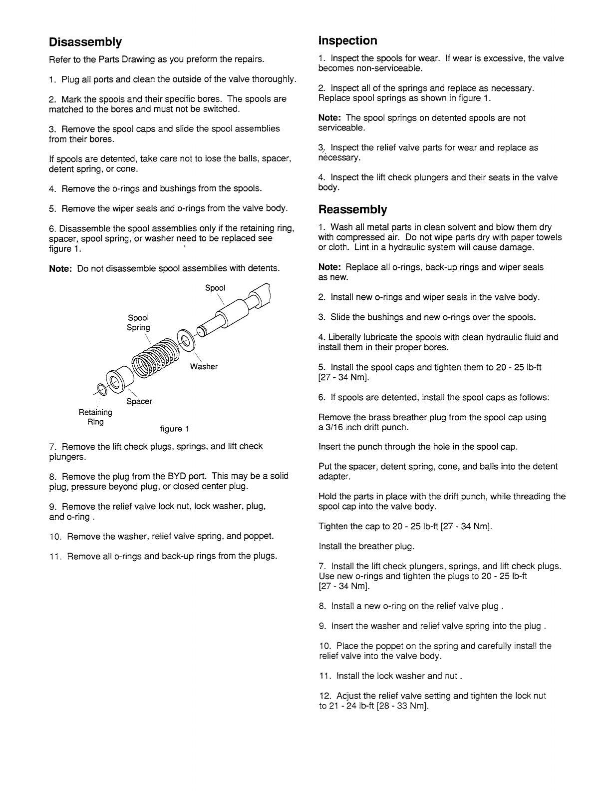

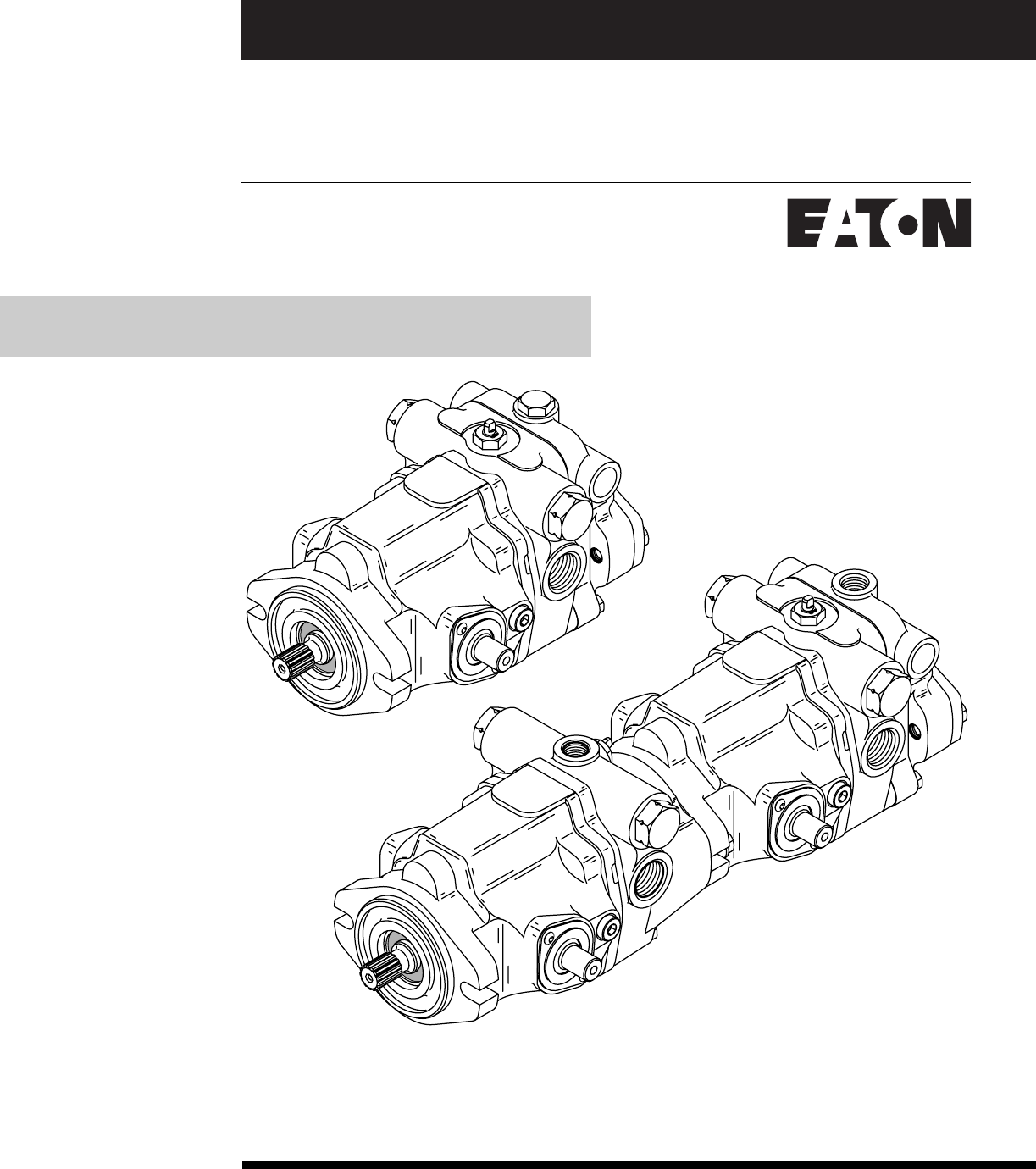
No. 7-623
July,1995
Eaton®
Medium Duty Piston Pump
Repair Information
Model 70142 / 70144, 20.3 cm3/r [1.24 in3/r] Displacement
and 70145, 23.6 cm3/r [1.44 in3/r] Displacement
Variable Displacement Piston Pump design code 01 02
with Valve Plate

22
Model 70142 / 70144 and 70145
Introduction
Table of Contents
Introduction....................................................................................................... 2
Identification...................................................................................................... 3
Required Tools .................................................................................................. 3
Exploded View Drawing ..................................................................................... 4 & 5
Parts List ........................................................................................................... 6 & 7
Disassembly and Inspection.............................................................................. 8
Reassembly ....................................................................................................... 9
Appendix A: ....................................................................................................... 10
Appendix B: ....................................................................................................... 11
Fault-Logic Trouble Shooting ............................................................................ 12 - 16
Start-up Procedure ............................................................................................ 17
Introduction
This manual provides service information for the Eaton Models 70142 / 70144 and 70145 Variable
Displacement Piston Pumps. Step by step instructions for the complete disassembly, inspection, and
reassembly of the pump are given. The following recommendations should be followed to insure successful
repairs.
Remove the pump from the application.
Cleanliness is extremely important.
Clean the port areas thoroughly before disconnecting the hydraulic lines.
Plug the pump ports and cover the open hydraulic lines immediately after they're disconnected.
Drain the oil and clean the exterior of the pump before making repairs.
Wash all metal parts in clean solvent.
Use compressed air to dry the parts. Do not wipe them dry with paper towels or cloth.
The compressed air should be filtered and moisture free.
Always use new seals when reassembling hydraulic pumps.
For replacement parts and ordering information refer to parts list 6-632.
Lubricate the new rubber seals with a petroleum jelly (vaseline) before installation.
Torque all bolts over gasketed joints, then repeat the torquing sequence to make-up for gasket
compression.
Verifying the accuracy of pump repairs on an authorized test stand is essential.

33
Model 70142 / 70144 and 70145
Identification and
Tools Required
Identification Numbers
Stamped on each unit.
A- Product Number Discription
70142 = Piston Pump (20.3 cm3/r [1.24 in3/r]) with Gerotor
70144 = Piston Pump (20.3 cm3/r [1.24 in3/r]) without Gerotor
70145 = Piston Pump (23.6 cm3/r [1.44 in3/r]) with or without Gerotor
78113 = Tandem Piston Pumps (20.3 cm3/r [1.24 in3/r]) no Gear Pump
78114 = Tandem Piston Pumps (20.3 cm3/r [1.24 in3/r]) with Gear Pump
78115 = Tandem Piston Pumps (23.6 cm3/r [1.44 in3/r]) no Gear Pump
78116 = Tandem Piston Pumps (23.6 cm3/r [1.44 in3/r]) with Gear Pump
ABC D
Single Pump - Product Number
7 0 1 4 2 - R A A - 0 1
Required Tools
7/16 in. Hex Key (Allen)
9/16 in. End Wrench
1 in. End Wrench
9/16 in. Socket
1/2 in. Socket
Internal Retaining Ring Pliers (straight .090 tip)
External Retaining Ring Pliers (straight .070 tip)
O-ring Pick
Torque Wrench (135.6 N.m [100 lbf.ft] capacity)
Hammer (soft face)
Light Petroleum Jelly
Seal Driver
Arbor Press
Testers Initials
Day of Month
(two digits)
Month (two digits)
Serial Number Code:
B 93 01 31 JB
Revision level
of parts list.
Last two digits
of year built.
( 93 for 1993 etc.)
Tandem Pumps - Product Number
7 8 1 1 3 - R A B - 0 1
ABCD
B- Rotation,
R = Righthand,
L = Lefthand
C- Sequential Letters
D- Design Code Number
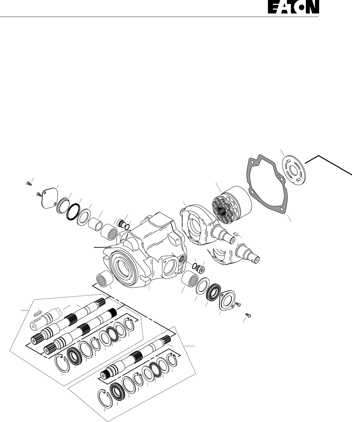
44
3-1 3
6
Date Code and
Assembly Number Location
5
4
1
Shaft assembly for
rear pump of tandem.
Shaft assembly for
single pump
or front pump
of tandem.
50
50-1
51
51-1
1
7
7
8
8
8
8
910
10
910
10
11
11
13
13
14 15
15 16
17
17
22
23
24 25
30
29
48
12
6
Model 70142 / 70144 and 70145
Parts
Drawing - Figure 1-1
Right Side
Left Side
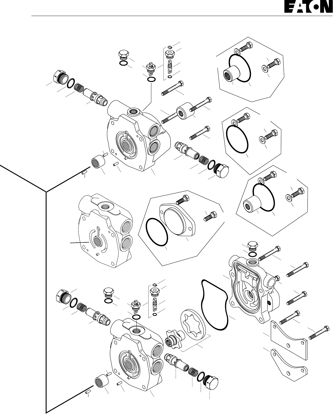
55
Model 70142 / 70144 and 70145
2
2-1 2-2
26
26
21
20
18
1919-1
19
19-1
18
27
27
28
28
37
37
(K4-4)
2-1 2-2
26
26
21
20
18
19
19-1
19
19-1
18
2
27A
27B
28A
49-1
49
49-2
49-3
49-4
49-5
37
35
36
49-1
49
49-2
49-3
49-4
49-5
34
34-1
32
(K2-1)
K2-2
K2-3
32
(K3-1)
31
(K3-2)
33
(K3-3)
K3
K2
32
(K4-1)
K4-2
K4-3
K4
K1-1
32
(K2-2)
K2-3
K2-4
K1
46
46
No
Groove
design code
02
design code
01
design code
02

66
Model 70142 / 70144 and 70145
Parts List
Item Qty. Description
1 1 Drive Shaft
2 1 Backplate Assembly
3 1 Housing Assembly
4 1 Rotating Kit Assembly
5 1 Camplate
6 1 Washer
+ 7 1 Retaining Ring
+ 8 2 Retaining Ring
9 1 Thrust Bearing
10 2 Bearing Race
+ 11 1 Shaft Seal, Drive
+ 12 1 Housing Gasket
13 2 Needle Bearing
+ 14 1 O-ring, 3.175 mm Dia. x 31.75 mm ID. [.125 in. Dia. x 1.25 in. ID.]
15 2 Washer
+ 16 1 Shaft Seal, Trunnion
17 4 Screw, Pan Head
18 2 Spring
19 2 Plug Assembly
+ 19-1 2 O-ring, 2.38 mm Dia. x 22.23 mm ID. [.0937 in. Dia. x .875 in. ID.]
20 1 Relief Valve for Port “C”
21 1 Relief Valve for Port “D”
22 1 Inner Race
23 1 Seal Cover
24 1 Trunnion Cover
25 1 Cover, O-ring
26 2 Dowel Pin
27 2 Cap Screws, 5/16-18, 50.8 mm [2 in.] Long
28 2 Cap Screws, 5/16-18, 63.5 mm [2.5 in.] Long
29 1 Key, Drive Shaft
30 1 Key, Camplate Trunnion
31 1 Cover Plate (In K3 kit)
+ 32 1 O-ring (In K1, K2, K3 & K4 kit)
33 2 Cap Screws, Cover Plate (In K3 kit)
34 1 Plug Assembly
+ 34-1 1 O-ring, 2.21 mm Dia. x 16.36 mm ID. [.087 in. Dia. x .644 in. ID.]
+ 35 1 Molded O-ring
36 1 Charge Pump Adaptor
37 1 Gerotor set and coupler sub-assembly
6.9 cm3/r [.42 in3/r] displacement, 6.35 mm [.25 in ] width
13.8 cm3/r [.84 in3/r] displacement, 12.7 mm [.5 in] width
37 1 9 tooth coupler (In K4 kit)
46 1 Mounting Bracket, Square shaped
46 1 Mounting Bracket, “V” shaped
48 1 Valve Plate

77
Model 70142 / 70144 and 70145
Parts List
Item Qty. Description
49 1 Dump Valve sub-assembly
+ 49-1 1 Retaining Ring
49-2 1 Separator Plug
49-3 1 Separator
+ 49-4 1 O-ring, 1.59 mm Dia. x 9.53 mm I.D. [.0625 in. Dia. x .375 in. I.D.]
+ 49-5 1 O-ring, 2.46 mm Dia. x 19.18 mm I.D. [.097 in. Dia. x .755 in. I.D.]
49 1 Plug Assembly
49-5 1 O-ring, 2.46 mm Dia. x 19.18 mm I.D. [.097 in. Dia. x .755 in. I.D.]
50 1 Plug Assembly
+ 50-1 1 O-ring, 1.98 mm Dia. x 11.89 mm ID. [.078 in. Dia. x .468 in. ID.]
51 1 Plug Assembly
+ 51-1 1 O-ring, 1.98 mm Dia. x 11.89 mm ID. [.078 in. Dia. x .468 in. ID.]
Mounting Kits
K1 1 Tandem Piston Pump Mounting Kit
K1-1 1 35T Coupler, 36.8 mm [1.45 in.] long
K1-2 1 O-ring, 1.59 mm Dia. x 101.6 mm ID. [.0625 in. Dia. x 4 in. ID.]
K1-3 2 Cap Screws
K1-4 2 Washer
K2 1 Gear Pump Mounting Kit
K2-1 1 O-ring, 1.59 mm Dia. x 82.55 mm ID. [.0625 in. Dia. x 3.25 in. ID.]
K2-2 2 Washer
K2-3 2 Cap Screws
K3 1 Cover Plate Kit
K3-1 1 O-ring, 1.59 mm Dia. x 82.55 mm ID. [.0625 in. Dia. x 3.25 in. ID.]
K3-2 1 Cover Plate
K3-3 2 Cap Screws
K4 1 Gear Pump Mounting Kit with Coupler
K4-1 1 9T Coupler
K4-2 1 O-ring, 1.59 mm Dia. x 101.6 mm ID. [.0625 in. Dia. x 4 in. ID.]
K4-3 2 Cap Screws
K4-4 2 Washer
Seal Repair Kit
70142-938 Seal Repair Kit for 70142, 70144 and 70145 piston pump.
Legend + Included in seal repair kit.
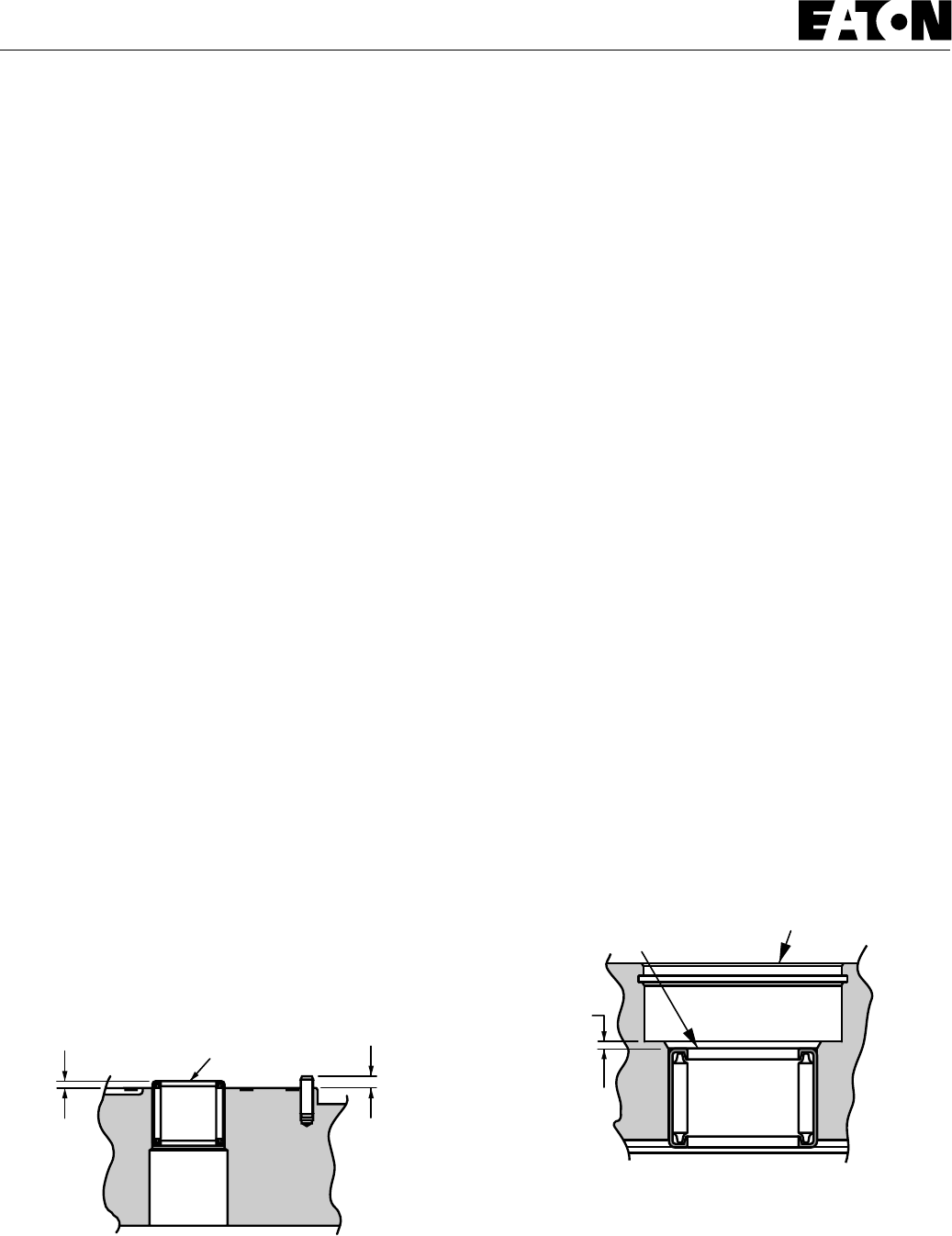
88
Model 70142 / 70144 and 70145
Disassembly
8Remove housing gasket from housing or backplate.
9To remove rotating kit assembly from housing, first
remove pump from vise holding the rotating kit assembly in
position. Lower pump so that the shaft end (flange end) is up.
Set the rear of housing onto table with housing flat and rotating
kit assembly at rest on table. Hole in table for protruding shaft
is required. Remove by lifting the housing and shaft from
rotating kit assembly.
Refer to Appendix B for disassembly and Inspection of rotating
kit.
10 Remove retaining ring from the front of housing. Press the
shaft, shaft seal or spacer, and washer from housing. Remove
retaining ring, thrust washer, thrust bearing, second thrust
washer, and second retaining ring from shaft.
11 To remove camplate from housing, remove the two screws
from both sides of housing (four total) retaining seal cover and
trunnion cover. Remove seal cover, shaft seal, washer, and
bearing from housing. Remove trunnion cover, o-ring cover, o-
ring, washer, inner race, and bearing from housing. Slide the
camplate over to one side and remove thru the back side of
housing.
Camplate Inspection:
• The finish on the piston shoe surfaces of the camplate
should show no signs of scoring.
Housing Inspection:
• Check the bearing (press fit) in front of housing. If
needles remain in cage, move freely, and setting at the
dimension shown in figure 1-4, removal not required.
1.78 mm
[.07 in.]
Numbered End Flange End of Housing
Figure 1-4
12 Discard the shaft seal, gaskets, and o-rings from all
assemblies. Replace with new seals upon reassembly.
Disassembly
The following instructions apply to a variable displacement
piston pump with or without a gerotor charge pump. A tandem
pump assembly should be separated into individual pumps
before disassembly.
1Position the pump into a protected jaw vise, clamping onto
the outer portion of the flange, with the input drive shaft down.
Remove the four cap screws retaining charge pump adapter or
backplate.
No gerotor charge pump skip to step 6.
2Lift the charge pump adapter assembly straight up off
backplate, shaft, and gerotor. Gerotor may stay in adapter or on
backplate.
3Remove o-ring from charge pump adapter.
4Remove outer gerotor ring from either the charge pump
adapter or the inner gerotor ring.
Refer to Appendix A for disassembly and inspection of charge
pump adapter assembly.
5Remove the inner gerotor ring and coupler assembly from
shaft.
6Lift backplate straight up off of shaft and housing. Remove
valve plate from backplate or from rotating kit assembly, still in
housing.
7From backplate remove dump valve assembly or plug
assembly, and relief valve assemblies. Note: Mark the relief
valve in relationship to the cavity it was removed, for
reassembly purposes.
Backplate Inspection:
• Check the bearing (press fit) in backplate. If needles
remain in cage, move freely, and setting is at the dimension
shown in figure 1-3, removal not required.
• Check roll pin in backplate. If tight and set to the
dimension shown in figure 1-3, removal not required.
2.79 mm
[.110 in.]
1.91 mm
[.075 in.]
Numbered End
Figure 1-3

99
Model 70142 / 70144 and 70145
Reassembly
Reassembly
1All parts should be cleaned and critical moving parts
lubricated before reassembly.
2If necessary, press new bearing in housing to dimension
shown in figure 1-4 with the numbered end of bearing outward.
3Starting with the camplate, insert camplate into the housing
with the long trunnion side down and to the appropriate side of
linkage on the machine.
4 On the short trunnion side of camplate install bearing
(bearing with numbered side to the inside of pump), bearing
race (race with chamfer toward inside of pump), washer, o-ring,
o-ring cover, trunnion cover, and retain with two screws.
Torque screws 4.1 to 5.4 N.m [36 to 48 lbf.in].
5 On the long trunnion side of camplate install bearing
(bearing with numbered side to the inside of pump), washer,
trunnion shaft seal, seal cover, and retain with two screws.
Torque screws 4.1 to 5.4 N.m [36 to 48 lbf.in].
6To install shaft, place exterior retaining ring, thrust race,
thrust bearing, second thrust race, and second retaining ring
onto shaft. Position washer and shaft seal or spacer onto shaft.
7Install shaft assembly into front of housing: For units with
spacer, retain with interior retaining ring and go on to step 8.
For units with shaft seal, seat seal into position with seal driver
and retain with interior retaining ring.
Refer to Appendix B for reassembly of rotating kit assembly.
8With flange end of housing up, position rotating kit
assembly onto shaft and into housing. Align the spline within
the piston block with shaft internal spline. Make sure piston
block is engaged fully to put piston shoes in contact with
camplate. Check all parts for proper position before proceeding.
9Clamp pump assembly in a protected jaw vise with the
open end of the housing up. Install gasket and two dowel pins
onto housing.
10 If necessary, press new bearing and roll pin in backplate to
dimension shown in figure 1-3. Bearing installed with the
numbered end outward. Roll pin installed with split oriented
away from bearing.
11 Install new o-ring on relief valves. Install relief valve in its
original cavity in backplate that it was removed. Torque 128 to
142 N.m [95 to 105 lbf.ft.]
12 Install new o-ring on dump valve or plug. Install dump
valve or plug into backplate. Torque dump valve or plug to 36.6
to 40.7 N.m [ 27 to 30 lbf.ft]
13 Apply a small amount of petroleum jelly to the steel side of
valve plate to hold in place for installation. Aligning the index
pin, place the valve plate in position onto the backplate, with
steel side against backplate.
14 Install backplate assembly onto housing assembly. Making
sure valve plate and gasket stay in place.
No gerotor charge pump, skip to step 17.
15 Install inner gerotor and coupler assembly. The coupler has
a "V" groove on one end and this end of coupler should enter
backplate first. Lubricate inner gerotor.
Refer to Appendix A for reassembly of Charge relief valve in
adapter plate.
16 Install o-ring and outer gerotor ring onto adapter plate.
Lubricate both o-ring and outer gerotor ring to hold in position
during assembly of adapter plate. Install adapter plate onto
backplate. Make sure o-ring and gerotor ring stay in place.
17 Retain backplate and adapter plate (when used) with four
cap screws, Torque 23 to 27 N.m [17 to 20 lbf.ft].
18 Install new o-rings on all plugs. Install plugs into housing.
Torque 9/16 in. - 18 plug 28 to 32 N.m [21 to 24 lbf.ft].
19 Refer to start-up procedures on page 17.
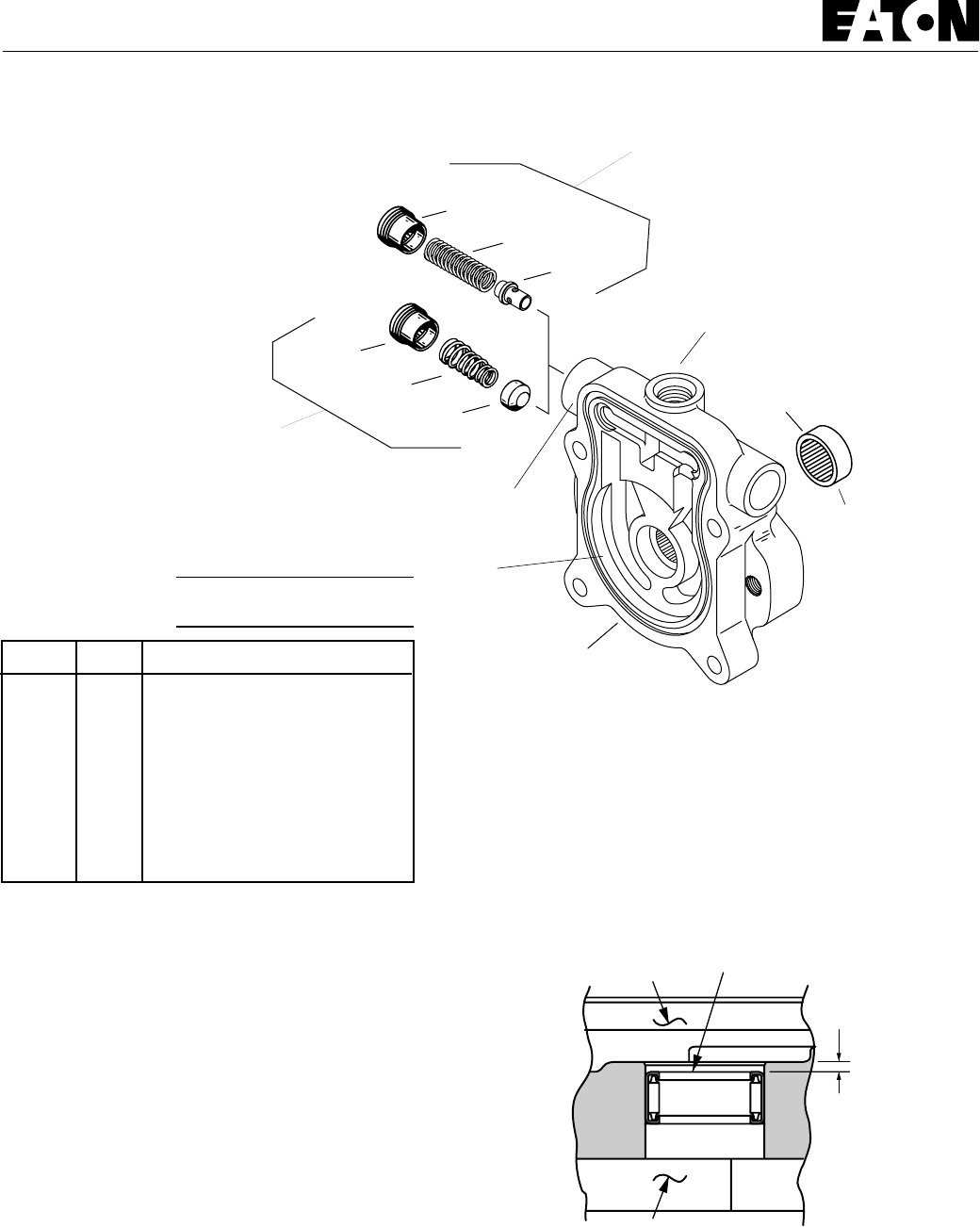
1010
Model 70142 and 70145
Appendix A - Charge Pump Adapter Assembly
36-4
36-3 36-1
36-2
Gerotor Ring
Pocket
(See chart for
depth)
Bearing
36-4a
36-3a or 3b
36-2a
Configuration for
6.9 to 1.3 bar
[100 to 150 lbf/in
2
]
Charge Relief Valve
36
Charge Pump
Suction Port
Pressure Check Port or
Remote Charge Port
Configuration for
13.8 to 17.2 bar [200 to 250 lbf/in
2
] or
17.2 to 20.7 bar [250 to 300 lbf/in
2
]
Charge Relief Valve
Reassembly - Charge Pump Adapter Assembly
1If necessary, press new bearing in adapter assembly. The
bearing to dimension shown in figure 1-2 with the numbered
end of bearing outward and closest to mounting flange.
2Install cup poppet or pin poppet, spring, and spring
retainer into charge pump adapter. Torque retainer 6.8 to 9.5
N.m [5 to 7 lbf.ft.]
Numbered End
Gerotor Pocket
2.41 mm
[.095 in.]
Flange
Figure 1-2
Disassembly - Charge Pump Adapter Assembly
1Remove spring retainer, spring, and poppet from adapter
assembly.
Inspection:
• Inspect the charge pump relief valve seat inside the
charge pump adapter. Check to insure that seat is smooth and
free of burrs or other defects.
• Inspect the charge pump relief valve spring.
• Inspect the bearing inside the charge pump adapter.
The bearing needles must remain in the bearing cage and
bearing at dimension shown in figure 1-2.
• Inspect the gerotor pocket inside the charge pump
adapter assembly. It should not be scored excessively.
Item Qty. Description
36 1 Charge Pump Adapter Assy.
36-11 Bearing (press fit)
36-21 Poppet, Cup
36-2a 1 Poppet, Pin
36-31 Spring, Tappered
36-3a 1 Spring, "Light Green" *
36-3b 1 Spring, "Pink" **
36-41 Spring Retainer
36-4a 1 Spring Retainer
*200 to 250 lbf/in2
**250 to 300 lbf/in2
Gerotor Pocket Depth
Displacement Depth of Pocket
cm3/r [in3/r] mm [in.]
6.9 [.42] 6.35 [.25]
13.8 [.84] 12.7 [.50]
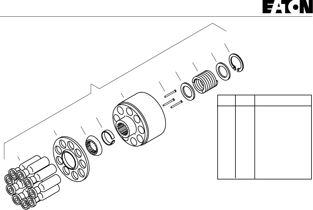
1111
Model 70142 / 70144 and 70145
Appendix B -
Rotating Kit Assembly
4-1
4-2 4-3
4-5
4-4
4-6 4-7 4-8
4-9
4-7
4
Item Qty. Description
4-19 Piston assemblies
4-21 Spider
4-31 Spider Pivot
4-41 Retainer
4-51 Piston Block
4-63 Pins
4-72 Washer
4-81 Spring
4-91 Retaining Ring
Disassembly - Rotating Kit Assembly
Disassembly of rotating assembly is required for inspection
only.
1Remove the nine piston assemblies, spider, and spider
pivot from piston block.
Inspection:
• Examine the O.D. of the pistons for finish condition.
They should not show wear or deep scratches. Inspect the
shoes for a snug fit on the ball end of the pistons and a flat
smooth surface that comes in contact with the camplate. Do not
lap piston shoes.
• Examine the spider for wear in the pivot area.
• Examine the pivot to insure smoothness and no signs
of wear.
• Inspect the piston block surface that makes contact
with valve plate. This surface should be smooth and free of
deep scratches. Do not lap piston block.
• The pistons should move freely in the piston block
bore. If not free moving, examine the bore for scoring or
contamination.
2To inspect pins and spring Caution should be taken in
removing spring. The spring is highly compressed and the
retaining ring should not be removed without compressing the
spring safely.
The following parts are required to disassemble the piston
block:2 ea. 5/16 in. I.D. x 15/16 in. O.D. flat washers
1 ea. 5/16 in. x 2-7/8 in. N.C. cap screw, and
1 ea. 5/16 in. N.C. nut
To remove spring, place one of the flat washers over the 5/16
in. x 2-7/8 in. cap screw. Put cap screw through the center of
the piston block and apply the second washer. Let washer rest
on the three pins and retain with nut. Turning nut and
compressing spring inside the block. Use a pair of retaining ring
pliers and remove the internal retaining ring. Remove nut, bolt,
and the two washers from block. Removing the washer, spring,
second washer, three pins, and pin keeper at the same time.
Reassembly - Rotating Kit Assembly
1To reassemble the rotating kit assembly complete the
following: Compress the pin keeper and install in the spline of
the piston block. Install the three pins with head end to the
inside of the block and position in the special grooves of the
piston block spline.
2Install the washer, spring, and second washer into the
piston block. Use the two 5/16 in. I.D. washers, nut, and 5/16
in. x 2-7/8 in. cap screw to compress the spring and retain with
retaining ring. Remove the nut, cap screw, and the two
washers.
3Install the pivot onto the three pins, spider on the pivot,
and piston assemblies thru the spider and into piston block,
resting on spider.
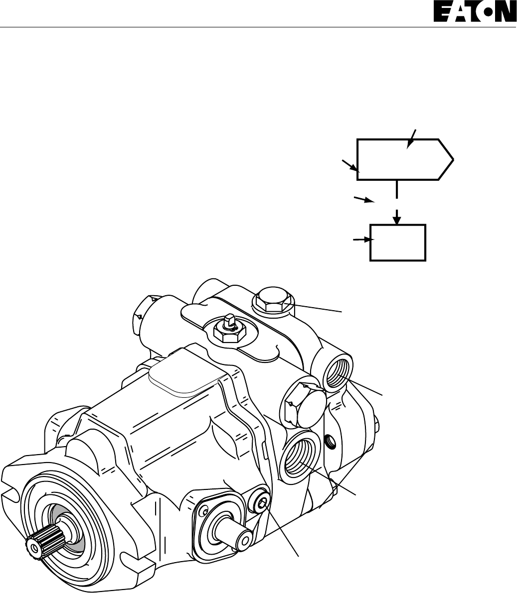
1212
1
Inspect
?
Repair
or
Replace
Defective
Action
Step
Comment
Number
Decision
Solution
Symptom:
Gauges Recommended
Inlet vacuum gauge: 207 bar to 0 bar [30 lbf/in2 to 30 inHg]
System pressure gauge: 700 bar [10,000 lbf/in2]
Charge pressure gauge: 0 to 50 bar [0 to 600 lbf/in2]
Case pressure gauge: 0 to 25 bar [0 to 300 lbf/in2]
Explanatory
Diagram
Model 70142 / 70144 and 70145
Fault - Logic
Trouble Shooting
This fault - logic trouble shooting guide is a diagnostic aid in
locating transmission problems.
Match the transmission symptoms with the problem statements
and follow the action steps shown in the box diagrams. This will
give expedient aid in correcting minor problems eliminating
unnecessary machine down time.
Following the fault - logic diagrams are diagram action
comments of the action steps shown in the diagrams. Where
applicable, the comment number of the statement appears in
the action block of the diagrams.
Recommended Gauge Locations
Figure 3-1
Pressure Ports
Tee in line to check System
Pressure
Charge Pump Suction Port
Tee in line to check Inlet Vacuum
Drain Port
Tee in line to check Case
Pressure
Auxiliary Port
Check Charge Pressure
1313
Model 70142 / 70144 and 70145
Fault - Logic
Trouble Shooting
Inspect
Servo Control
(If used)
OK
12
Inspect
External Control
Linkage
Defective
Repair
or
Replace
Defective
Repair
or
Replace
Symptom: Neutral Difficult or Impossible to Find
Inspect
Heat
Exchanger OKOK OK
456
Check
Oil Level in
Reservoir
Fill to
Proper
Level
DefectiveBelow Level
Repair
or
Replace
Check
System
Pressure
Reduce
System
Load
High
OK 9
Inspect
Charge Relief
Valve
OK 11
Inspect
Charge
Pump 13
Inspect
Motor 12
Inspect
Inlet Screen
or Filter
Replace
Clogged
OK 8
Check
Charge
Pressure
10
Low OK
OK
Replace
Pump &
Motor
Inspect
Dump Valve
(If used)
OK 7
Inspect Heat
Exchanger
By-Pass Valve
(If used)
OK
Defective
Repair
or
Replace
Defective
Repair
or
Replace
Defective
Repair
or
Replace
Defective
Repair
or
Replace
Defective
Repair
or
Replace
Symptom: System Operating Hot
1414
Model 70142 / 70144 and 70145
Fault - Logic
Trouble Shooting
Inspect
Servo Control
(If used)
OK OK
123
Inspect
External Control
Linkage
Defective
Repair
or
Replace
Inspect
System Relief
Valves
Defective
Repair
or
Replace
Defective
Repair
or
Replace
Symptom: Operates in One Diection Only
Inspect
Servo Control
(If used) OKOK OK
27
Defective
Repair
or
Replace
Inspect
Motor
12
Replace
Clogged
Check
Charge
Pressure
10
Low OK
Inspect
Dump Valve
(If used)
Replace
Pump &
Motor
Defective
Repair
or
Replace
Inspect
Inlet Screen
or Filter OK
OK OK
813
Defective
Repair
or
Replace
Inspect
Charge Relief
Valve
11
Inspect
Charge
Pump
Defective
Repair
or
Replace
Defective
Repair
or
Replace
Symptom: System Response Sluggish
1515
Model 70142 / 70144 and 70145
Fault - Logic
Trouble Shooting
Check External
Control
Linkage OKOK OK
417
Check
Oil Level in
Reservoir
Fill to
Proper
Level
DefectiveBelow Level
Repair
or
Replace
Check
System
Pressure
OK 9
Inspect
Charge Relief
Valve
OK 11
Inspect
Charge
Pump 13
Inspect
Motor 12
Inspect
Inlet Screen
or Filter
Replace
Clogged
OK 8
Check
Charge
Pressure
10
Low OK
OK
Replace
Pump &
Motor
Inspect
Servo Control
(If used)
OK 2
Inspect
Dump Valve
(If used)
OK
Defective
Repair
or
Replace
Defective
Repair
or
Replace
Defective
Repair
or
Replace
Defective
Repair
or
Replace
Defective
Repair
or
Replace
High
Reduce
System
Load
Symptom: System Will Not Operate In Either Direction

1616
11 Inspect Charge Relief Valve for:
a. improper charge relief pressure setting *
b. damaged or broken spring
c. poppet valve held off seat
12 Inspect Motor for:
a. disconnected coupling
13 Inspect Charge Pump for:
a. broken or missing drive key
b. damaged or missing o-ring
c. excessive gerotor clearance
d. galled or broken gerotor set
* System/Charge Relief Valve
Pressure Settings for
Eaton’s Variable Displacement
Controlled Piston Pumps
Inlet Vacuum 6 inHg max.
Case Pressure 25 lbf/in2 maximum
Charge Pressure 100 to 150 lbf/in2 Standard
200 to 250 lbf/in2 Optional
250 to 300 lbf/in2 Optional
System Pressure 5000 lbf/in2 maximum
3000 lbf/in2 continuous
The high pressure relief valves are all factory preset and cannot
be readjusted.
The pressure setting and assembly number is stamped on each
high pressure relief valve cartridge.
Valve Identification Example:
32060-IA 5000
Relief Valve Setting
Relief Valve Assembly Number
Model 70142 / 70144 and 70145
Fault - Logic
Trouble Shooting
Diagram Action Step Comments
1Inspect External Control Linkage for:
a. misadjusted or disconnected
b. binding, bent, or broken
c. misadjusted, damaged or broken neutral return spring
2Inspect Servo Control Valve for: (if used)
a. proper inlet pressure
b. misadjusted, damaged or broken neutral return spring
c. galled or stuck control spool
d. galled or stuck servo piston
3Inspect System Relief Valves * for:
a. improper pressure relief setting
b. damaged or broken spring
c. valve held off seat
d. damaged valve seat
4Check Oil Level in Reservoir:
a. consult owner/operators manual for the proper type
fluid and level
5Inspect Heat Exchanger for:
a. obstructed air flow (air cooled)
b. obstructed water flow (water cooled)
c. improper plumbing (inlet to outlet)
d. obstructed fluid flow
6Inspect Heat Exchanger By-Pass Valve for: (if used)
a. improper pressure adjustment
b. stuck or broken valve
7Inspect Dump Valve for: (if used)
a. held in a partial or full open position
8Inspect Inlet Screen or Filter for:
a. plugged or clogged screen or filter element
b. obstructed inlet or outlet
c. open inlet to charge pump
9Check System Pressure:
a. See figure 3-1 for location of pressure gauge
installation.
b. consult owner/operators manual for maximum system
relief valve settings
10 Check Charge Pressure:
a. See figure 3-1 for location of pressure gauge
installation.
b. consult owner/operators manual for maximum charge
relief valve settings

1717
Model 70142 / 70144 and 70145
Start-up Procedure
When initially starting a new or a rebuilt transmission system, it
is extremely important that the start-up procedure be followed.
It prevents the chance of damaging the unit which might occur
if the system was not properly purged of air before start-up.
1After the transmission components have been properly
installed, fill the pump housing at least half full with filtered
system oil. Connect all hydraulic lines and check to be sure they
are tight.
2Install and adjust all control linkage.
3Fill the reservoir with an approved oil that has been filtered
through a 10 micron filter. Refer to Eaton Hydraulics Technical
Data sheet number 3-401 titled Hydraulic Fluid
Recommendations.
4Gasoline or L.P. engines: remove the coil wire and turn the
engine over for 15 seconds. Diesel engines: shut off the fuel
flow to the injectors and turn the engine over for 15 seconds.
5Replace the coil wire or return the fuel flow to the injectors.
Place the transmission unit in the neutral position, start the
engine and run it at a low idle. The charge pump should
immediately pick up oil and fill the system. If there is no
indication of fill in 30 seconds, stop engine and determine the
cause.
6After the system starts to show signs of fill, slowly move
pump camplate to a slight cam angle. Continue to operate
system slowly with no load on motors until system responds
fully.
7Check fluid level in the reservoir and refill if necessary to
the proper level with an approved filtered oil.
8Check all line connections for leaks and tighten if
necessary.
9The machine is now ready to be put into operation.
10 Frequent filter changes are recommended for the first two
changes after placing the machine back into operation. Change
the first filter in 3-5 hours and the second at approximately 50
hours approx. hours. Routinely scheduled filter changes are
recommended for maximum life of the hydraulic system.

1818
Model 70142 / 70144 and 70145
Notes

1919
Model 70142 / 70144 and 70145
Notes

Form No. 7-623
November, 1993
Copyright Eaton Corporation, 1993
All Rights Reserved
Printed in USA
Eaton Corporation
15151 Hwy. 5
Eden Prairie, MN 55344
Telephone 612/937-9800
Fax 612/937-7130
Hydraulics Division Eaton Ltd.
Glenrothes, Fife
Scotland, KY7 4NW
Telephone 44/592-771-771
Fax 44/592-773-184
Hydraulics Division
Order parts from number 6-632 Parts Information booklet.
Each order must include the following information.
1. Product and/or Part Number
2. Serial Code Number
3. Part Name
4. Quantity

ENGINE--GAS/LP
7-1
8200/8210 330065 (3--02)
CONTENTS
Page
INTRODUCTION 7-3......................
LUBRICATION 7-4.....................
ENGINE OIL 7-4....................
COOLING SYSTEM 7-4................
ENGINE FAN BELT 7-5..............
TO REPLACE ENGINE
FAN/ALTERNATOR BELT 7-5.....
AIR INTAKE SYSTEM 7-10.............
AIR FILTER 7-10....................
AIR FILTER INDICATOR (optional) 7-10
TO REPLACE AIR FILTER
ELEMENT 7-11..................
FUEL SYSTEM -- GASOLINE 7-13.......
FUEL FILTER 7-13..................
CARBURETOR 7-13................
FUEL PUMP 7-13...................
FUEL SYSTEM -- LPG 7-14.............
LP FUEL TANKS 7-16...............
LPG FUEL TANK STORAGE 7-18.....
TO CHANGE AN LPG FUEL
TANK 7-19
FUEL FILTER LOCK 7-21............
VAPORIZER-REGULATOR 7-21......
CARBURETOR 7-21................
OIL PRESSURE SWITCH 7-21.......
LPG FUEL TROUBLESHOOTING 7-22
CYLINDER HEAD 7-22.................
VALVE TAPPET CLEARANCE 7-22...
CRANKCASE VENTILATION
SYSTEM 7-22...................
GOVERNOR 7-23.....................
TO ADJUST GOVERNOR
CONTROL BOX 7-23.............
DIGITAL CONTROLLER SET--UP 7-25
GOVERNOR
TROUBLESHOOTING 7-26.......
IGNITION SYSTEM 7-34...............
SPARK PLUGS 7-34................
TO REPLACE SPARK PLUGS 7-34...
FORD DISTRIBUTORLESS IGNITION
SYSTEM 7-35
RUN MODE 7-36...................
SERVICING AND TESTING 7-36.....
“FAILURE MODE OF DIS” IGNITION
HARNESS 7-37..................
FORD DIS IGNITION 7-38...........
TO REPLACE ALTERNATOR 7-40....
TO REPLACE STARTER 7-44.......
TO REMOVE ENGINE 7-48..........
TO INSTALL ENGINE 7-55...........
GAS/LP ENGINE SERVICE MANUAL
FORD VSG--411/413
TENNANT Part Number 38978

ENGINE--GAS/LP
7-2 8200/8210 330065 (3--01)

ENGINE--GAS/LP
7-3
8200/8210 330065 (3--01)
INTRODUCTION
This section includes repair information on the
engine and related systems, such as fuel,
electrical, and drive belts.
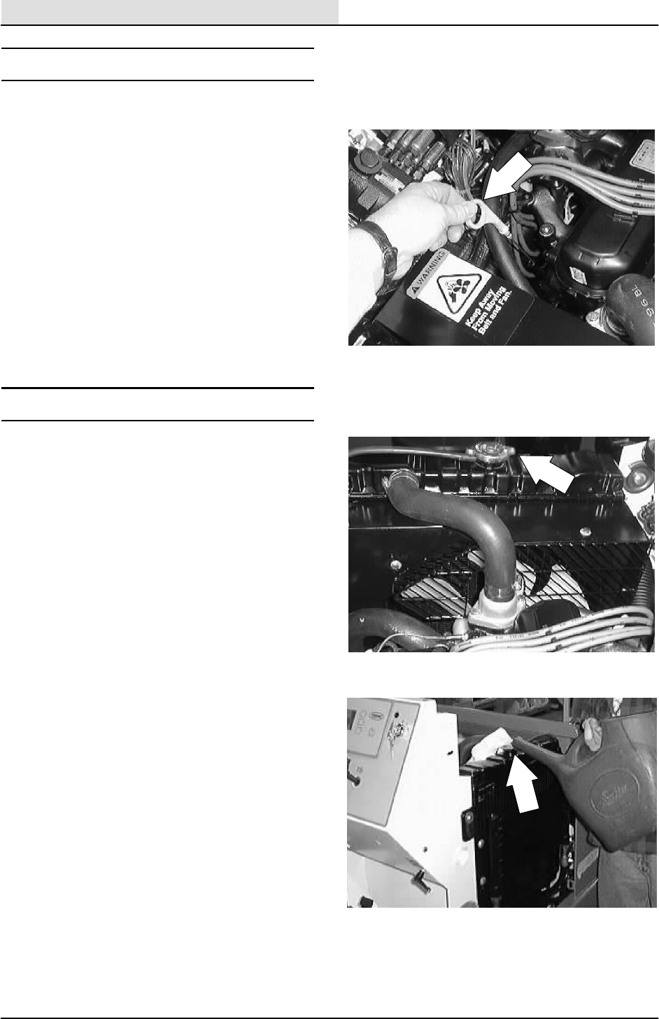
ENGINE--GAS/LP
7-4 8200/8210 330065 (3--01)
LUBRICATION
ENGINE OIL
Check the engine oil level daily. Change the
engine oil and oil filter every 50 hours of machine
operation. Use 10W30 SAE--SG/SH rated engine
oil.
Fill the engine with oil to the level indicated on the
oil dipstick. The engine oil capacity is 4.7 L
(5 qt) including the oil filter.
COOLING SYSTEM
Check the radiator coolant level every 100 hours
of operation. Use clean water mixed with a
permanent-type, ethylene glycol antifreeze to a
-- 3 4 _C(--30_F) rating.
FOR SAFETY: When Servicing Machine,
Avoid Contact With Hot Engine Coolant.
Check the radiator hoses and clamps every 200
hours of operation. Tighten the clamps if they are
loose. Replace the hoses and clamps if the hoses
are cracked, harden, or swollen.
Check the radiator core exterior and hydraulic
cooler fins for debris every 100 hours of
operation. Blow or rinse all dust, which may have
collected on the radiator, in through the engine fan
and out the radiator fins, opposite the direction of
normal air flow. Be careful not to bend the cooling
fins when cleaning. Clean thoroughly to prevent
the fins becoming encrusted with dust. Clean the
radiator and cooler only after the radiator has
cooled to avoid cracking.
FOR SAFETY: When Servicing Machine,
Wear Eye And Ear Protection When
Using Pressurized Air Or Water.
Flush the radiator and the cooling system every
400 hours of operation, using a dependable
cleaning compound.
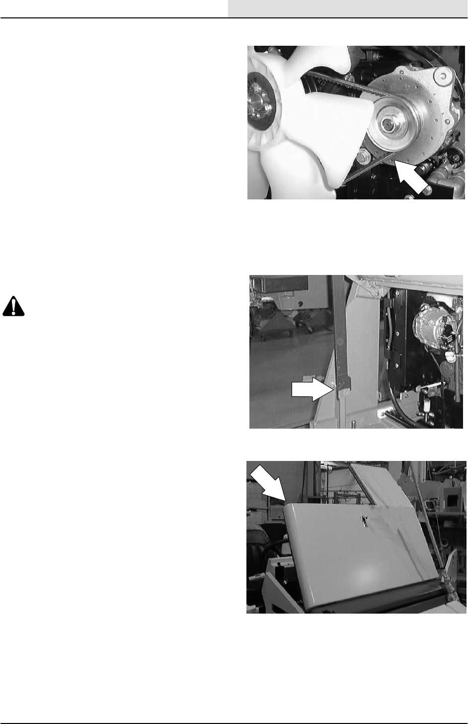
ENGINE--GAS/LP
7-5
8200/8210 330065 (3--01)
ENGINE FAN BELT
The engine fan belt is driven by the engine
crankshaft pulley and drives the alternator pulley.
Proper belt tension is 9 to 10 mm (0.35 to 0.39 in)
for a new belt and 10 to 11 mm (0.39 to 0.43 in)
for a used belt with a force of 10 kg (22 lb).
Check and adjust the belt tension every 100 hours
of operation.
TO REPLACE ENGINE FAN/ALTERNATOR
BELT
1. Raise the hopper and engage the prop bar.
WARNING: Raised Hopper May Fall.
Engage Hopper Support Bar.
FOR SAFETY: Before Leaving Or
Servicing Machine; Stop On Level
Surface, Set Parking Brake, Turn Off
Machine And Remove Key.
2. Open the engine cover and side door.
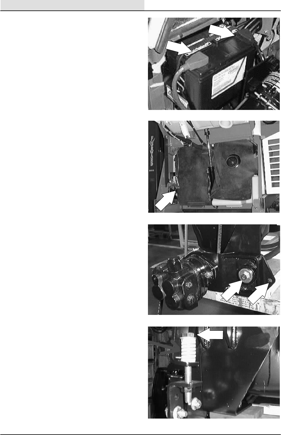
ENGINE--GAS/LP
7-6 8200/8210 330065 (3--01)
3. Disconnect the battery cables from the
battery.
4. Pull the rubber dust shield away from the
front of the engine in the area of the
alternator.
5. Go to the area of the machine in front of the
engine. Locate the two hex screws and nuts
holding the accessory pump pivot plate to
the mount plate. Loosen these two screws.
6. Locate the hex bolt and compression spring
at the front of the accessory pump mount
bracket. Loosen the hex bolt and
compression spring. Remove the accessory
pump V--belt from the pump sheave.
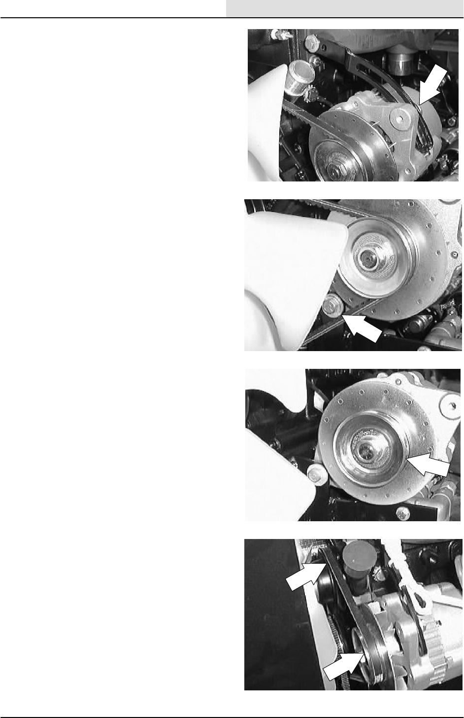
ENGINE--GAS/LP
7-7
8200/8210 330065 (3--01)
7. Loosen the hex screw holding the top of the
alternator to the mount bracket.
8. Loosen the hex screw and nyloc nut holding
the bottom of the alternator to the lower
mount bracket.
9. Push the alternator in toward the engine.
Remove the V--belt from the alternator and
engine pulleys.
10. Position the new fan belt on the alternator
pulley and engine pulleys.
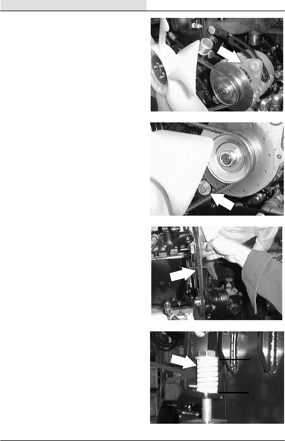
ENGINE--GAS/LP
7-8 8200/8210 330065 (3--01)
11. Pull the alternator away from the engine to
tighten the belt. See adjustment in ENGINE
FAN BELT description. Tighten the hex
screw to 18 -- 24 Nm (13 -- 18 ft lb).
12. Tighten the bottom hex screw to
18 -- 24 Nm (15 -- 20 ft lb).
13. Install the hydraulic pump V--belt around the
accessory pump sheave.
14. The accessory pump belt adjustment is
made by turning the bolt on top of the
tension spring. The tension spring is located
at the front of the engine compartment, near
the accessory pump belt sheave. The
accessory pump belt is at the proper tension
when the tension spring is compressed to
3.81 cm 0.0076 mm (1.5 in 0.030 in).
NOTE: When adjusting the accessory pump belt
tension, measure only the spring and not the
washers at either end.
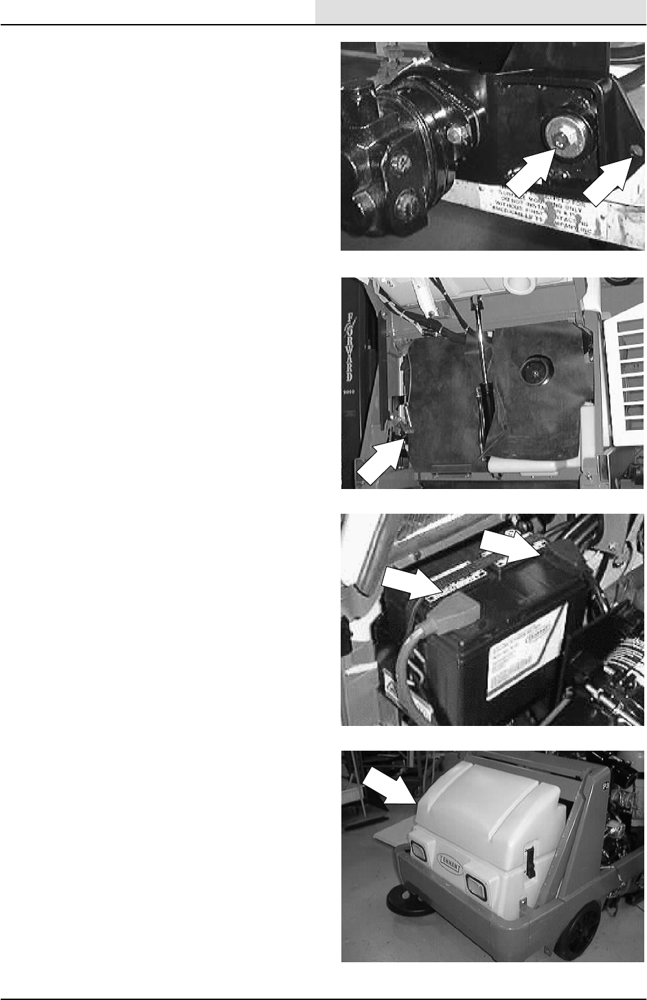
ENGINE--GAS/LP
7-9
8200/8210 330065 (3--01)
15. Go back and tighten the two pivot plate
mount screws to 37 -- 48 Nm (26 -- 34 ft lb).
16. Position the rubber dust shield back into the
metal bracket.
17. Reconnect the battery and start the
machine.
18. Disengage the prop arm and lower the
hopper.
19. Check the alternator for proper operation.

ENGINE--GAS/LP
7-10 8200/8210 330065 (3--01)
AIR INTAKE SYSTEM
AIR FILTER
The engine air filter housing has a dust cap and a
dry cartridge-type air filter element. Empty the
dust cap daily. The air filter must be replaced
whenever the filter element is damaged or has
been cleaned three times.
Service the air filter element only when the air
filter indicator shows restriction in the air intake
system. Do not remove the air filter element from
the housing unless it is restricting air flow.
AIR FILTER INDICATOR (optional)
The air filter indicator shows when to clean or
replace the air filter element. Check the indicator
daily. The indicator’s red line will move as the air
filter element fills with dirt. Do not clean or replace
the air filter element until the red line reaches 5
kPa (20 in H2O) and the ”SERVICE WHEN RED”
window is filled with red. The indicator’s red line
may return to a lower reading on the scale when
the engine shuts off. The red line will return to a
correct reading after the engine runs for a while.
Reset the air filter indicator by pushing the reset
button on the end of the indicator after cleaning or
replacing the air filter element.

ENGINE--GAS/LP
7-11
8200/8210 330065 (3--01)
TO REPLACE AIR FILTER ELEMENT
FOR SAFETY: Before Leaving Or
Servicing Machine: Stop On Level
Surface, Set The Parking Brake, Turn Off
Machine And Remove Key.
1. Open the engine cover and side door.
2. Unscrew the clamp ring on the filter.
3. Remove the dust cap.
4. Empty the dust cap.
5. Remove the filter wing nut.

ENGINE--GAS/LP
7-12 8200/8210 330065 (3--01)
6. Pull the filter element out of the filter
housing.
7. Clean the interior of the air cleaner housing
with a camp cloth. Clean the element
housing sealing surfaces.
8. Using an air hose, direct dry, clean air
maximum 205 kPa (30 psi) up and down
pleats on the inside of the filter. Do not rap,
tap, or pound dust out of the element.
FOR SAFETY: When Servicing Machine,
Wear Eye And Ear Protection When
Using Pressurized Air Or Water.
9. After cleaning the air filter element, inspect it
for damage by placing a bright light inside.
The slightest rupture requires replacement
of the filter. Clean and inspect the seals on
the ends of the element. They should be
unbroken and flexible. Remember to replace
the element after cleaning it three times.
10. Install the new or cleaned filter element so
the fins on the element are at the intake end
of the air cleaner. Be careful not to damage
the fins. Make sure the element is seating
evenly. Tighten the element wing nut.
11. Install the dust cap with the arrows pointing
up. Tighten the clamp ring to hold it in place.
Check all intake hose connections for leaks
or abrasions.
12. Reset the air filter restriction indicator.
13. Close the engine cover and side door.
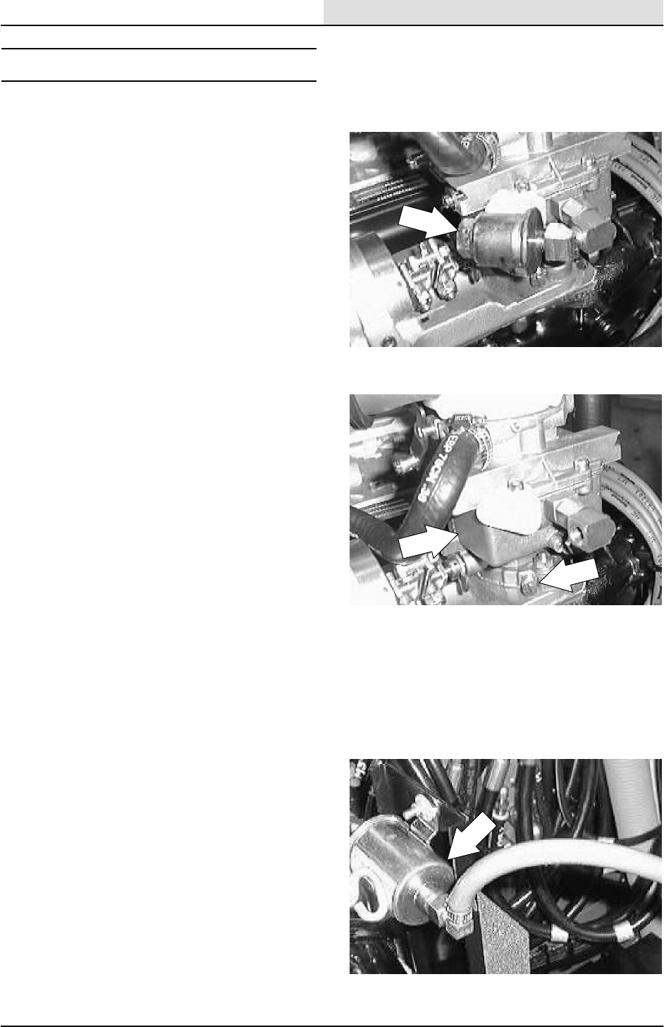
ENGINE--GAS/LP
7-13
8200/8210 330065 (3--01)
FUEL SYSTEM -- GASOLINE
FUEL FILTER
The fuel filter traps fuel contaminants. The filter is
located on the fuel line going into the carburetor.
Replace the filter elements every 400 hours of
operation.
CARBURETOR
The carburetor has two basic adjustments. Those
adjustments are idle fuel mixture and idle speed.
Check and adjust idle fuel mixture and idle speed
periodically.
The carburetor is designed to deliver the correct
fuel-to-air mixture to the engine under all
operating conditions. The high idle is set at the
factory and cannot be adjusted. The low idle fuel
adjusting needle is also set at the factory and
normally does not need adjustment.
If the engine is hard-starting or runs roughly or
stalls at low idle speed, it may be necessary to
adjust or service the carburetor.
FOR SAFETY: When servicing machine,
allow engine to cool. Keep flames and
sparks away from fuel system service
area. Keep area well ventilated.
FUEL PUMP
The in--line fuel pump is located on the mount
plate at the end of the fuel tank. The fuel pump is
electrically operated with 12 volts from the battery.
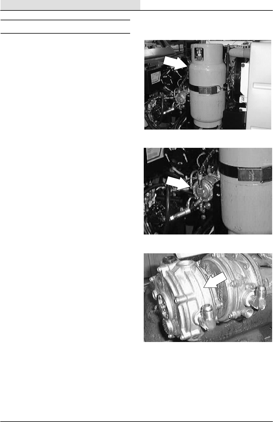
ENGINE--GAS/LP
7-14 8200/8210 330065 (3--01)
FUEL SYSTEM -- LPG
The liquid withdrawal LPG fuel system has up of
five components: the LPG fuel tank, pressure
relief valve, fuel filter lock, vaporizer-regulator,
and the carburetor.
Liquid LPG fuel flows from the LPG tank under its
own pressure, to the pressure relief valve. Usually
this valve is closed, preventing LPG fuel from
escaping into the atmosphere. The valve opens to
relieve pressure if the fuel pressure exceeds
system limits. From the pressure relief valve, the
liquid LPG fuel flows to the fuel filter lock.
The fuel filter lock filters unwanted tank scale and
deposits out of the LPG fuel. The fuel filter lock
also stops the flow of LPG fuel when the engine is
not operating. The LPG is operated with engine
vacuum.
The vaporizer section of the vaporizer-regulator
converts the liquid LPG fuel into a gaseous LPG
fuel. From the vaporizer section, the gaseous
LPG fuel is sent to the primary regulator section
of the vaporizer-regulator. The primary regulator
section reduces the pressure of the LPG fuel. The
secondary regulator section reduces the LPG fuel
pressure to the level required by the carburetor.
From the vaporizer-regulator, the LPG fuel is sent
to the carburetor where it is finally metered into
the air flow sent to the engine combustion
chamber.
Never operate an LPG powered machine if the
LPG fuel system is leaking, or if any component in
the fuel system is malfunctioning. Operating the
machine under either of these conditions may
cause a fire or explosion.
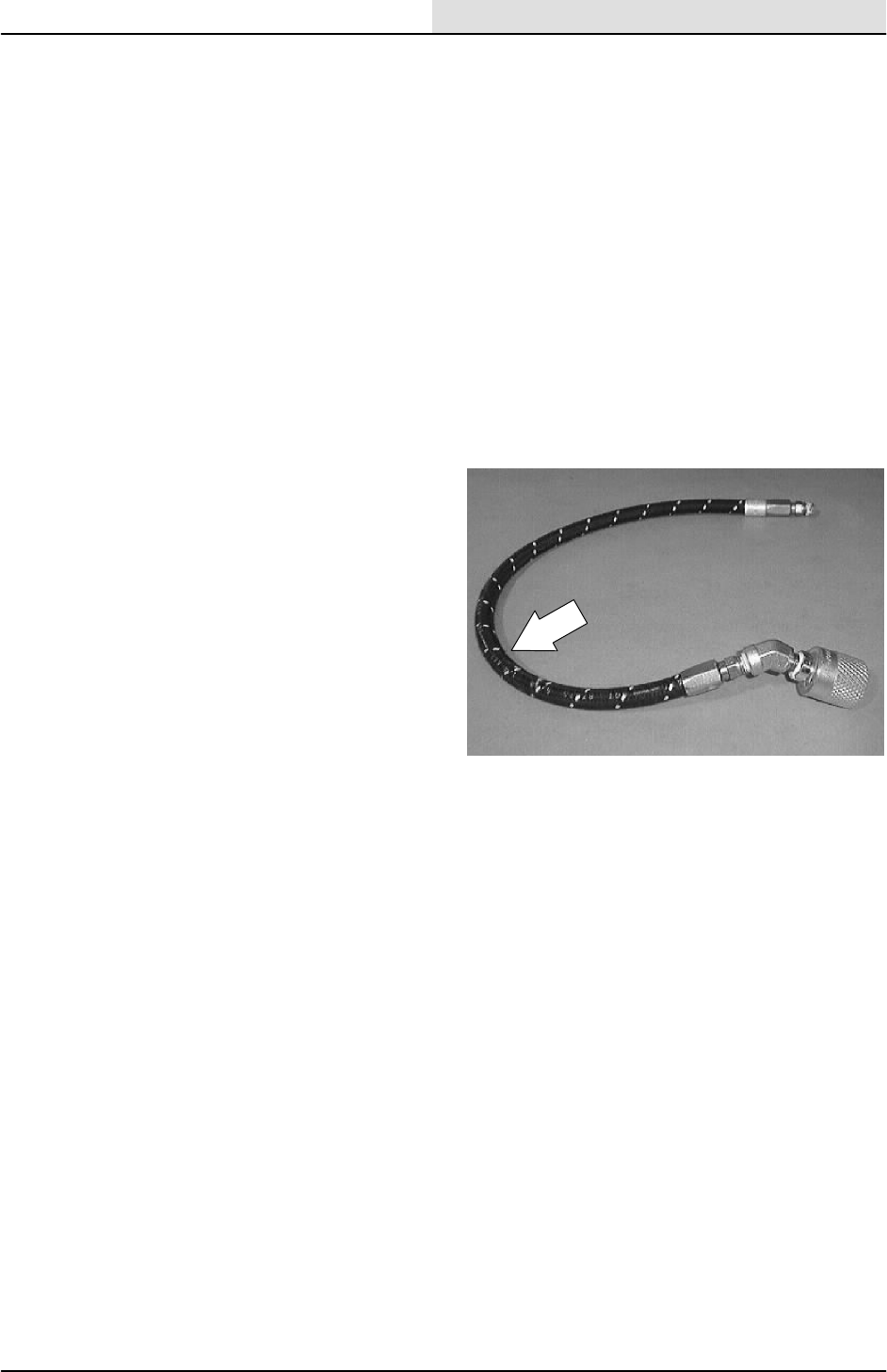
ENGINE--GAS/LP
7-15
8200/8210 330065 (3--01)
Check for frosting. If frosting occurs on or near
any LPG component, there is a possible LPG fuel
leak or malfunctioning component.
To locate the leak, apply a soapy water solution to
the suspected area. Watch for bubbles forming in
this suspected area. This area may have an LPG
fuel leak. Repair or replace the part. Use Loctite
brand Stainless Steel PST thread sealant when
reassembling. Aging or high humidity does not
affect this epoxy-type sealant. Be sure to follow
application directions and apply proper torque
when reconnecting fittings. Never bypass safety
components except to test. If they are defective,
replace them before operating the machine.
Frosting does not occur before the engine
reaches operating temperature. Check after
engine reaches operating temperature.
Check routings of all LPG hoses. Keep them
away from sharp edges, exhaust manifolds, or
other hot surfaces. Check for signs of abrasion or
deterioration. Replace worn or damaged hoses.
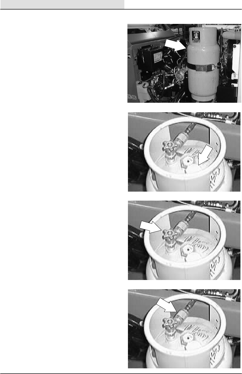
ENGINE--GAS/LP
7-16 8200/8210 330065 (3--01)
LP FUEL TANKS
The LPG fuel tanks should be inspected for sharp
dents, gouges, leaks, and broken protecting rings
whenever the tanks are refilled. All tank valves
must be inspected for leaks using a soap solution.
Valves must also be checked for dirt, paint, or
other debris in the valve openings. The following
specific checks must also be made:
Filler Valve -- Check the valve for proper
functioning and the presence of the handwheel.
Valve must be closed except during filling.
Liquid Service Valves -- Check the valve for
proper functioning and presence of the
handwheel. The valve must be closed except
when in service.
Tank Service Valve Coupling -- Check for proper
functioning, thread condition, and damaged or
missing washers or o-rings.
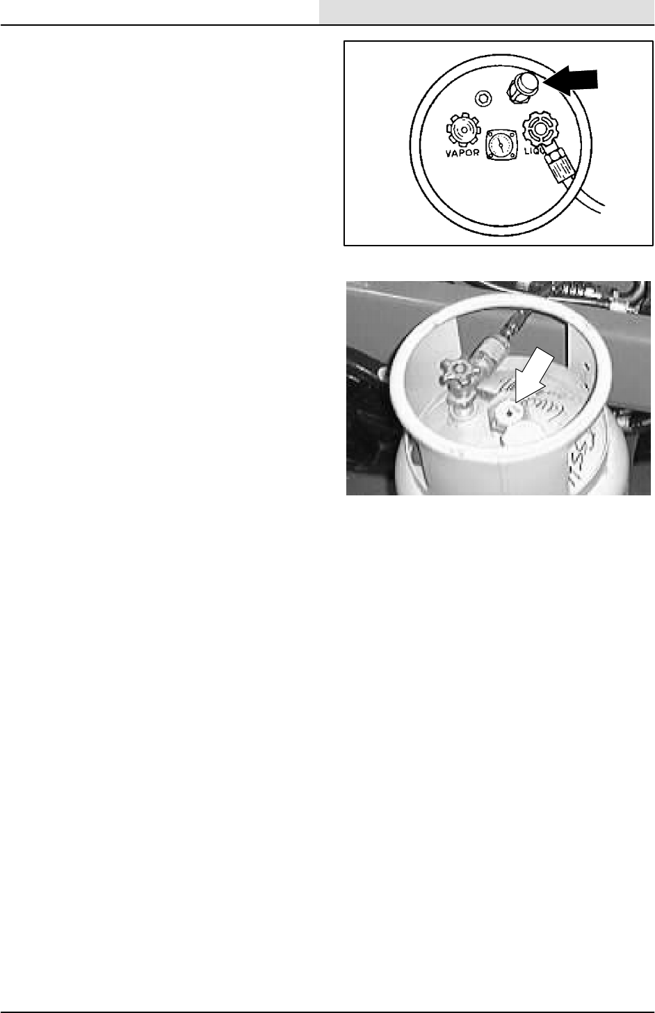
ENGINE--GAS/LP
7-17
8200/8210 330065 (3--01)
Safety Relief Valve -- Check for damage. Check
for the presence of the relief valve elbow and the
proper direction of the elbow. If the rain cap is
missing, check for foreign matter and replace the
rain cap. Do not tamper with the relief valve
setting.
Magnetic Liquid Level Gauge -- Check the
operation against the maximum filling point as
determined by weight.

ENGINE--GAS/LP
7-18 8200/8210 330065 (3--01)
LPG FUEL TANK STORAGE
An LPG fuel tank with any of the stated defects
must be removed from service and be repaired or
destroyed accordingly.
If an LPG fuel tank is damaged or leaking, it
should be removed to a designated safe area. Do
not attempt to make repairs to the tank,
regardless of condition. Qualified personnel must
make repairs or disposal.
The care an LPG fuel tank receives has a direct
bearing on how long that tank can be used safely.
LPG fuel tanks must not be dropped or dragged
across any surface. To move LPG fuel tanks, use
a hand truck or roll the tank on its foot ring while it
is being held in a position slightly off the vertical.
Whether the storage is inside or outside, fuel
tanks should not be stored near combustible
materials or high temperature sources such as
ovens and furnaces, since the heat may raise the
pressure of the fuel to a point where the safety
relief valves would function. Store the tanks in a
way that if the safety relief valves do function,
they will relieve vapor and not liquid.
Valves on empty tanks must be closed during
storage and transportation.
Similar precautions should be taken in storing
machines fitted with LPG fuel tanks. The
machines may be stored or serviced inside
buildings, provided there are no leaks in the fuel
system and the tanks are not overfilled. While
machines are being repaired inside a building, the
shut-off valve on the tank must be closed, except
when the engine has to be operated.
Changing the tank is a chance for the machine
operator to carefully check over the tank, fittings,
and the fuel lines and fittings. If abnormal wear is
detected, report the findings to the appropriate
personnel.
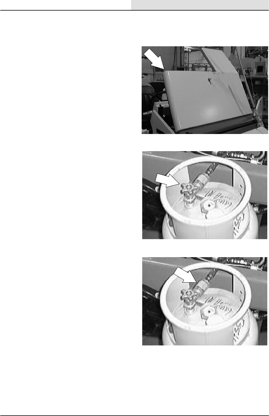
ENGINE--GAS/LP
7-19
8200/8210 330065 (3--01)
TO CHANGE AN LPG FUEL TANK
1. Park the machine in a designated well
ventilated area.
2. Open the engine cover and side door.
3. Close the tank service valve.
4. Operate the engine until it stops from lack of
fuel. Set the machine parking brake.
FOR SAFETY: Before Leaving Or
Servicing Machine: Stop On Level
Surface, Set The Parking Brake, Turn Off
Machine And Remove Key.
5. Put on gloves and remove the
quick-disconnect tank coupling.
6. Inspect the LPG fuel lines for wear or
damage.
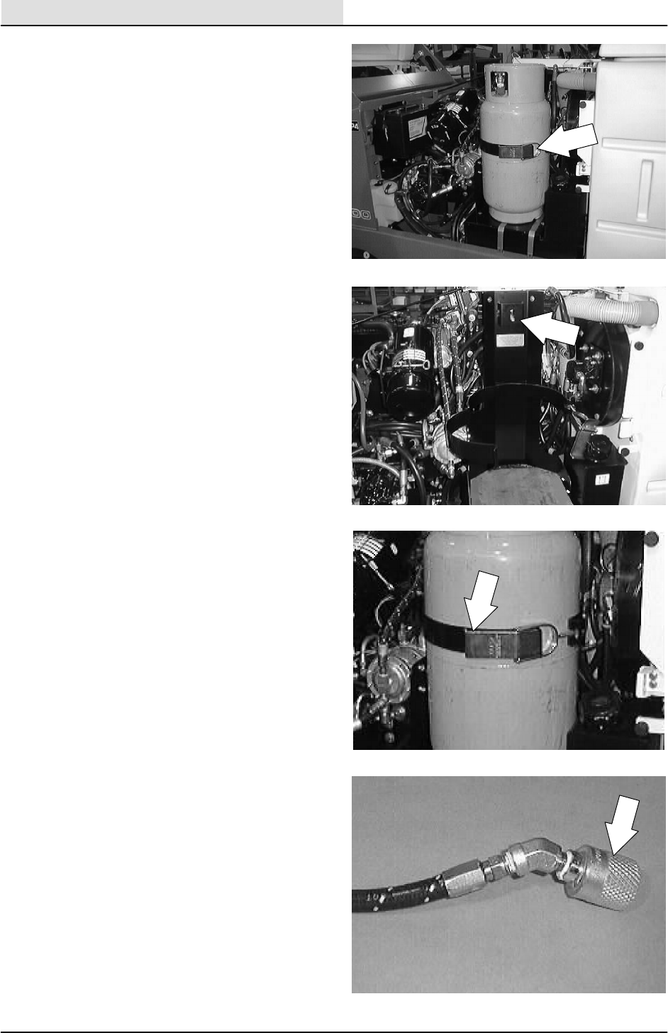
ENGINE--GAS/LP
7-20 8200/8210 330065 (3--01)
7. Remove the empty LPG fuel tank from the
machine.
8. Check the tank for damage or wear.
9. Store the tank in a designated, safe area.
10. Select a filled LPG fuel tank and inspect it
for damage or leaks.
NOTE: Make sure the LPG fuel tank matches the
fuel system (liquid tank with liquid system).
11. Carefully put the LPG tank in the machine
so that the tank centering pin enters the
aligning hole in the tank collar.
NOTE: If you cannot line up the centering pin,
make sure you have the correct LPG fuel tank
and then adjust the pin locator in or out.
12. Fasten the tank hold-down clamp to lock the
tank in position.
13. Connect the LPG fuel line to the tank service
coupling. Make sure the service coupling is
clean and free of damage. Also make sure it
matches the machine service coupling.
14. Open the tank service valve slowly and
check for leaks. Close the service valve
immediately if an LPG leak is found, and tell
the appropriate personnel.
15. If no leaks are found, the engine is ready to
start.
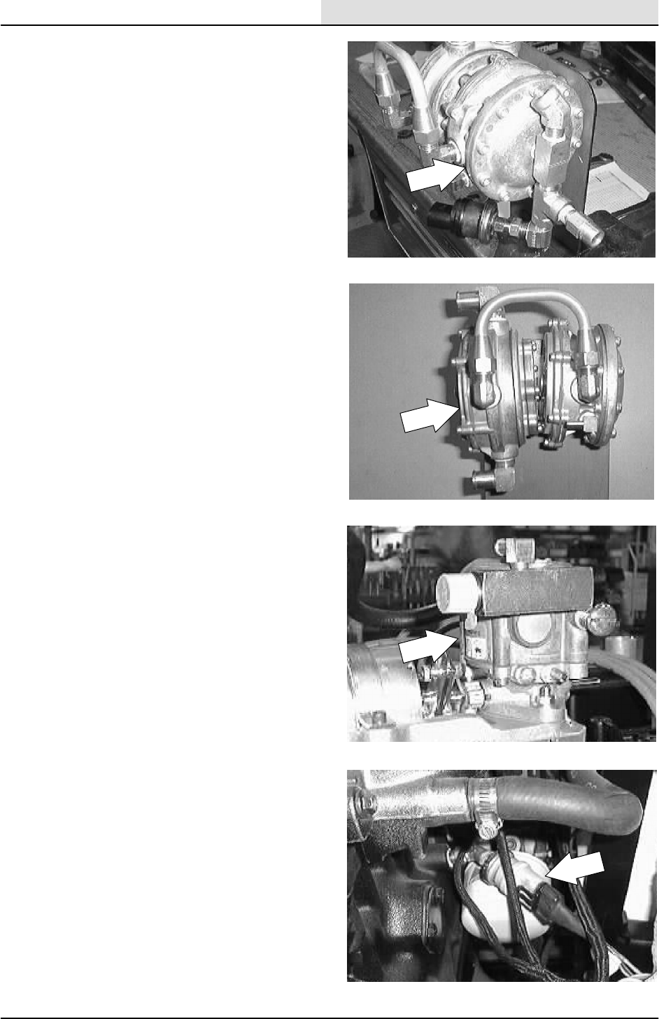
ENGINE--GAS/LP
7-21
8200/8210 330065 (3--01)
FUEL FILTER LOCK
The fuel filter lock filters the LPG fuel. It also
stops the flow of LPG fuel to the engine when the
engine is not operating.
VAPORIZER-REGULATOR
If any malfunction is found, completely
disassemble the vaporizer-regulator. Clean all the
parts in alcohol.
Inspect all the parts and replace where needed.
Carefully reassemble the vaporizer-regulator with
the seal repair kit. Check for proper operation.
CARBURETOR
If any malfunction is found, completely
disassemble the carburetor. Clean all the parts in
alcohol.
Inspect all the parts and replace where needed.
Carefully reassemble the carburetor with the seal
repair kit.
OIL PRESSURE SWITCH
The engine oil pressure switch requires no regular
maintenance. Never bypass the oil pressure
switch. The oil pressure switch turns on the LP
lock--off when the engine reaches proper
operating oil pressure.

ENGINE--GAS/LP
7-22 8200/8210 330065 (3--01)
LPG FUEL TROUBLESHOOTING
Problem Cause Remedy
Engine will not start Outoffuel Replace fuel tank with full one
Service valve opened too quickly
-- check valve stopped fuel flow
Close service valve and reopen
slowly
Plugged fuel filter Replace filter
Kinked or restricted fuel line Straighten or replace fuel line
Engine out of tune Tune-up engine
Oil pressure switch failure Replace oil pressure switch
Fuel lock valve failure Repair or replace fuel filter lock
Vaporizer-regulator failure Repair or replace
vaporizer-regulator
Engine runs unevenly or lacks
power
Wrong type of fuel tank -- vapor
withdrawal tank
Replace vapor withdrawal tank
with liquid withdrawal tank
Plugged fuel filter Replace filter
Kinked or restricted fuel line Straighten or replace fuel line
Engine out of tune Tune-up engine
Restricted air filter Clean or replace air filter element
Vaporizer-regulator out of
adjustment
Adjust vaporizer-regulator
CYLINDER HEAD
A three-stage torque procedure should be used
when reassembling the cylinder head. Tighten the
cylinder head bolts seasonally. See Ford VSG
411/413 Engine Service Manual.
VALVE TAPPET CLEARANCE
Check and adjust the intake valve clearance to
0.22 mm (0.009 in), and the exhaust valve
clearance to 0.32 mm (0.013 in) while the engine
is cold the first 50 hours of operation and every
400 hours there after. See Ford VSG 411/413
Engine Service Manual.
CRANKCASE VENTILATION SYSTEM
Clean the crankcase ventilation hoses, tubes, and
fittings and replace the PCV valve every
400 hours of operation.
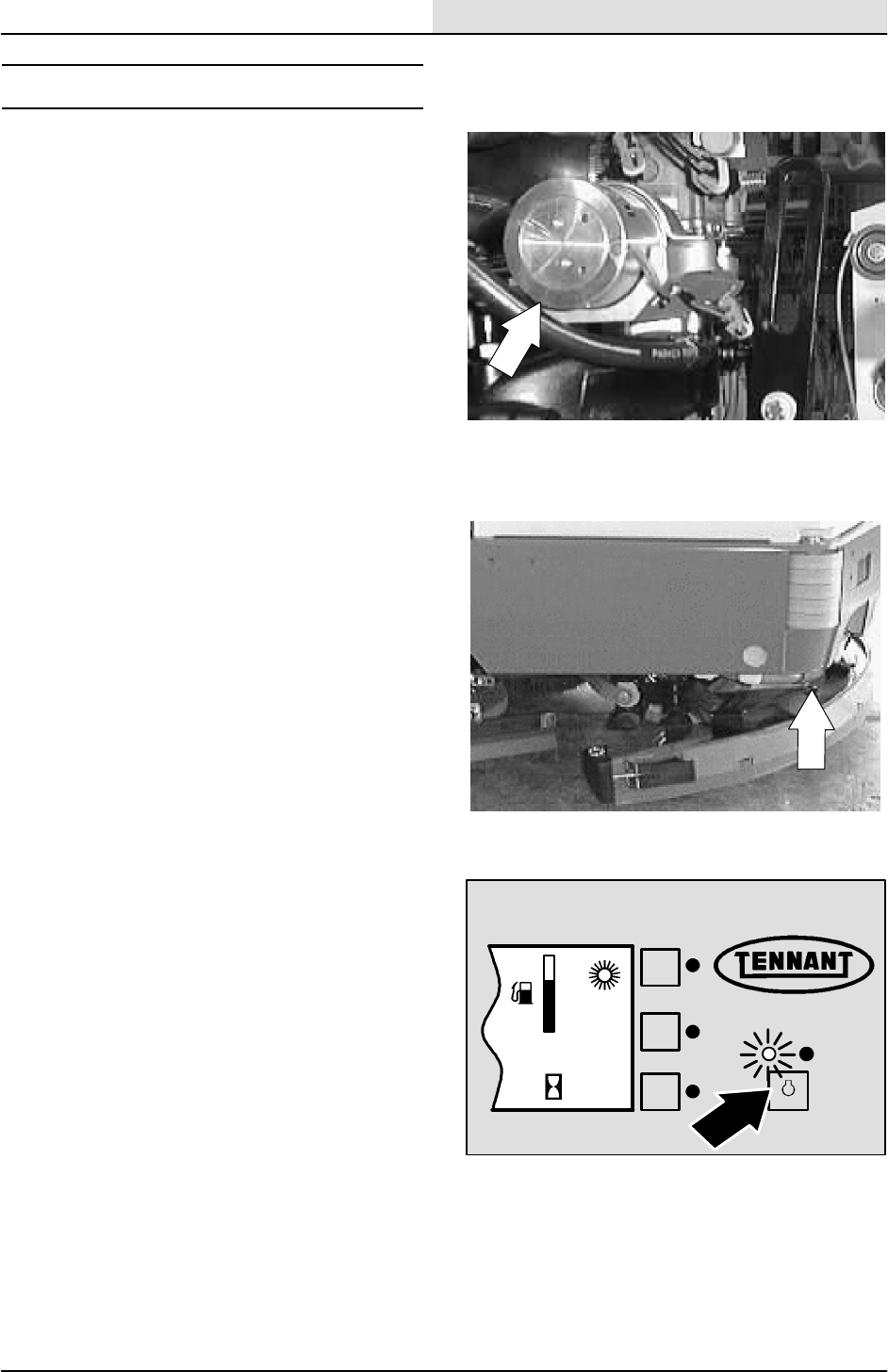
ENGINE--GAS/LP
7-23
8200/8210 330065 (3--01)
GOVERNOR
The electronic governor controls engine speed.
The governor consists of an ignition control
assembly, a control box, and an actuator mounted
on the carburetor. The ignition control assembly
and control box regulate the actuator, which in
turn controls the throttle.
The carb mounted, electronic governor is factory
set and is not user serviceable.
TO ADJUST GOVERNOR CONTROL BOX
1. Raise the rear of the machine and place jack
stands under the frame.
FOR SAFETY: Block machine tires
before jacking machine up. Jack
machine up at designated locations
only. Block machine up with jack
stands.
2. Start the engine and warm to operating
temperature.
3. Move the speed switch to idle, all
accessories off.
4. Move the speed switch to the fast position. F
E
12 : 16 PM
0021
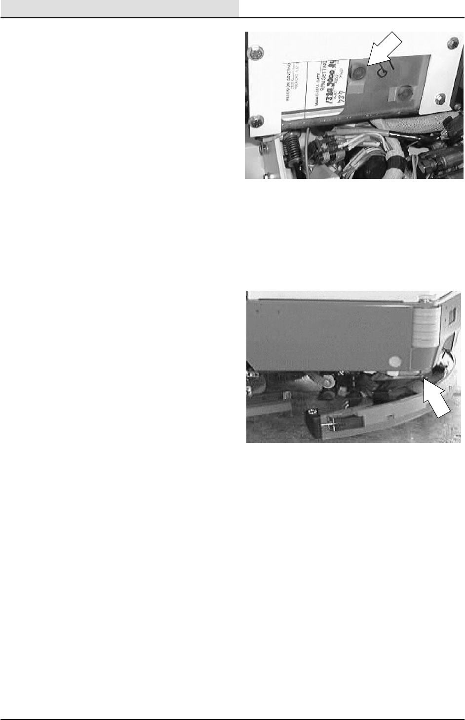
ENGINE--GAS/LP
7-24 8200/8210 330065 (3--02)
5. FOR ANALOG CONTROLLER: If engine
speed surges occur, turn the surge
adjustment screw (located on back of
governor control box under hole plug)
counterclockwise one-eighth of a turn.
Repeat until surges do not occur.
Replace hole plug if removed for adjustment.
6. FOR DIGITAL CONTROLLER: Follow the
instructions on the DIGITAL CONTROLLER
SET--UP diagram.
7. Remove the jack stands and lower the
machine.
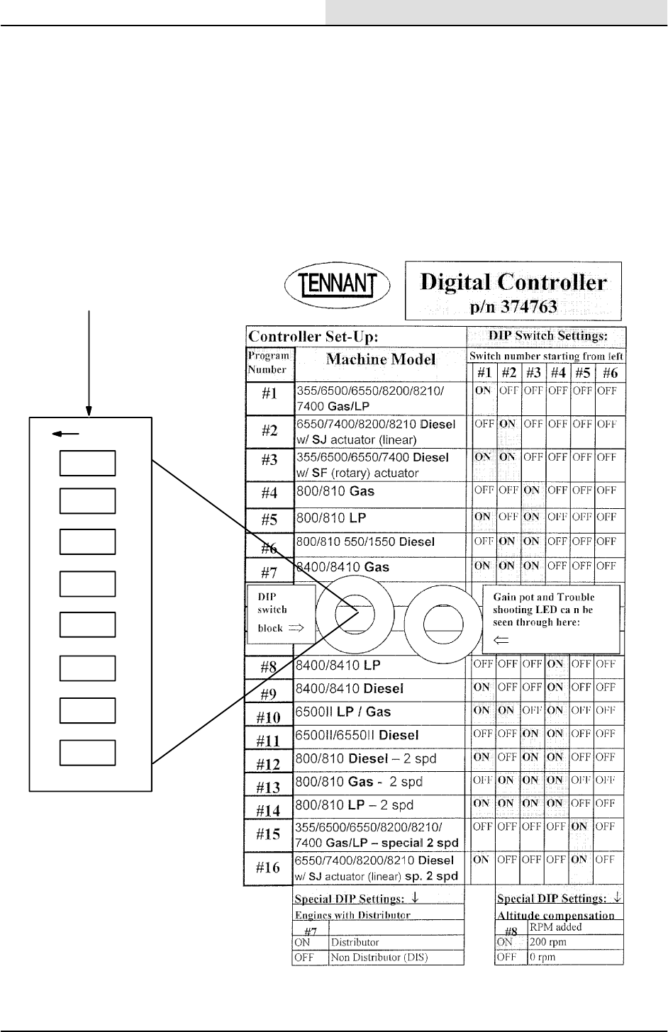
ENGINE--GAS/LP
7-25
8200/8210 330065 (3--02)
rocker down
O
F
F
Set DIP switches according to
controller label, before installing
controller.
123 45 6 78
DIGITAL CONTROLLER SET-- UP
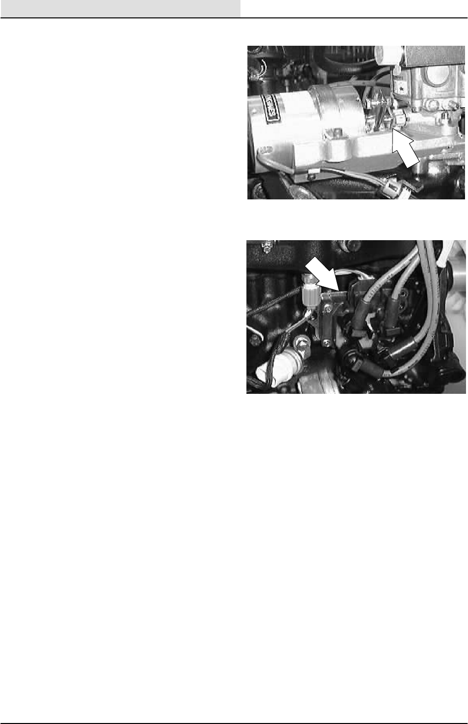
ENGINE--GAS/LP
7-26 8200/8210 330065 (3--01)
GOVERNOR TROUBLESHOOTING
1. The first step in this troubleshooting is to
disconnect the throttle linkage at the
carburetor and work the throttle at the
carburetor by hand.
If you can run the engine by hand and it
works with no problems, go to step four.
If the problem continues, it is not with the
governor, it is with the ignition signal fuel
systems or the engine itself.
2. Ignition Signal
The DIS engine has no distributor, but the
timing signals that drive the governor
originate from the Ignition Control input
leads. They are the Yellow Wire #71 and the
Yellow Wire #72. To test this, use the
governor test harness (TENNANT Part No.
66137). Once the harness is in place, use a
tach/dwell meter to test for the proper RPM’s
and a flat ignition signal. Test at the text plug
at either Pin C, or Pin D.
NOTE: An inductive RPM pickup won’t work for
this test.
NOTE: When checking the RPM’s at Pin C, and
Pin D, the ignition signal will be half of the total
RPM’s the engine is running at because of the
DIS system.
Your readings should be:
TOTAL READING--GAS
a. Start/Idle -- 800 RPM
b. I -- 1350¦50 RPM
c. II -- 2400¦50 RPM
TOTAL READING--LPG
a. Start/Idle -- 900 RPM
b. I -- 1350¦50 RPM
c. II -- 2400¦50 RPM

ENGINE--GAS/LP
7-27
8200/8210 330065 (3--01)
3. Fuel System
A common problem that has been
encountered on LPG machines is a
restricted fuel hose (a clogged fuel filter can
have the same effect).
If the governor opens the carburetor wide
open and the engine loses speed, the
problem is not in the governor. The fuel
system is at fault. The purpose of the
governor is to open the carburetor and to
bring the engine to set RPM’s depending on
where you have the speed control switch set
at.
After you have verified that the ignition
system and the fuel system are not at fault,
go to the next step.
4. System Grounds
The wire harness grounds on the machines
with a DIS engine are routed to the stud on
the alternator, and from there, a separate
cable is routed to the bolt on the bell housing
where the battery cable is attached.
If a bad ground is present, the engine will
tend to run over speed.
The machine must have good grounds
throughout from the battery cable to the
control box.
The battery cable must be clean and tight.
There must not be a greater voltage drop
than .2 volts between Pin B, on the test
harness, the engine, the alternator, and the
battery positive terminal and the battery
negative terminal.
To do this, take your voltmeter and set it on
the DC volts scale. Then with your positive
probe, clamp it to battery positive. Then with
the negative probe, move it to the
above-stated places on the machine.
The actuator is internally isolated and does
not require that the cable be grounded.
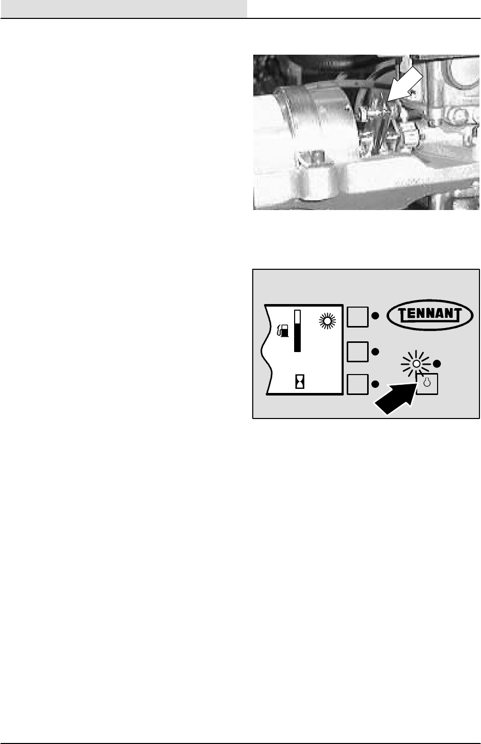
ENGINE--GAS/LP
7-28 8200/8210 330065 (3--01)
5. Start-Up Check
With the throttle switch in the engine start
position, turn the ignition switch to the on
position. The actuator should cycle the
carburetor lever once.
NOTE: A cycle is to move from the off or idle
position to the open position and then return to
the off or idle position.
If this does not happen, the power wiring to
the control box is probably at fault or the
control box is faulty. IT IS RARE TO HAVE
A FAULTY CONTROL BOX, so proceed
with the following voltage checks BEFORE
REPLACING IT.
6. Throttle Control Switch Check
If the engine doesn’t respond to the throttle
switch control:
a. With the engine running, disconnect
Wire 86, purple wire, at the actuator.
b. Connect a jumper wire from the battery
terminal on the starter to the terminal
where you removed Wire 86, purple
wire, from the actuator.
The engine should come up to operating
speed. If the engine comes up to speed,
replace the throttle control switch. If the
engine doesn’t respond, go to the next step.
7. Operating Voltage
The following voltage checks are done with
the machine not running and using a Fluke
or Beckman digital multimeter and the
governor test harness.
F
E
12 : 16 PM
0021

ENGINE--GAS/LP
7-29
8200/8210 330065 (3--01)
Throttle control switch in start/idle position:
Pin A -- Battery Voltage ¦.2
Pin B -- 0 -- this is a ground
Pin C -- Battery Voltage ¦.2
Pin D -- Battery Voltage ¦.2
Pin E -- Battery Voltage ¦.2
Pin F -- Battery Voltage ¦.2
Pin G -- Battery Voltage ¦.2
PinH--3to3.5VDC
Throttle control switch in the normal sweep
position:
Pin G -- <1VDC
PinH--7to9VDC
Throttle control switch in the Litter sweep position:
Pin G -- <1VDC
Pin H -- <1VDC
The following voltage and RPM readings are at
the electric control box using the test harness with
the machine running.
NOTE: when you are testing if you should be in
the DC or AC scale on your multimeter. You will
also need your tach/dwell for the RPM checks.
The readings are taken with either a Fluke or
Beckman digital multimeter:
Throttle control switch in the start/idle position:
Pin C -- 675 ¦100 RPM
Pin D -- 675 ¦100 RPM
Pin E -- Battery Voltage ¦.2
PinF--6to6.5VAC

ENGINE--GAS/LP
7-30 8200/8210 330065 (3--01)
Throttle control switch in the normal sweep
position:
Pin C -- 1100 ¦25 RPM
Pin D -- 1100 ¦25 RPM
Pin E -- Battery Voltage ¦.2
PinF--6.5to7VAC
Throttle control switch in the litter sweep position:
Pin C -- 1200 ¦25 RPM
Pin D -- 1200 ¦25 RPM
Pin E -- Battery Voltage ¦.2
PinF--7to7.5VAC
If you do not get these values:
Pin A -- Check battery, wiring/connections,
and also the charging system.
Pin B -- Check all grounds.
Pin C -- Check ignition system and fuel
systems.
Pin D -- Check ignition system and fuel
systems.
Pin E -- Possible control board.
Pin F -- Possible control board.
Pin G -- Possible switch.
Pin F -- Possible switch.
The volt readings at the actuator with the machine
running and using a Fluke or Beckman digital
multimeter:
At the terminal where Wire 84, green wire, is
hooked to:
Start/Idle -- 6 to 6.5 VAC ¦.2
Normal -- 6.5 to 7 VAC ¦.2
Litter -- 7 to 7.5 VAC ¦.2
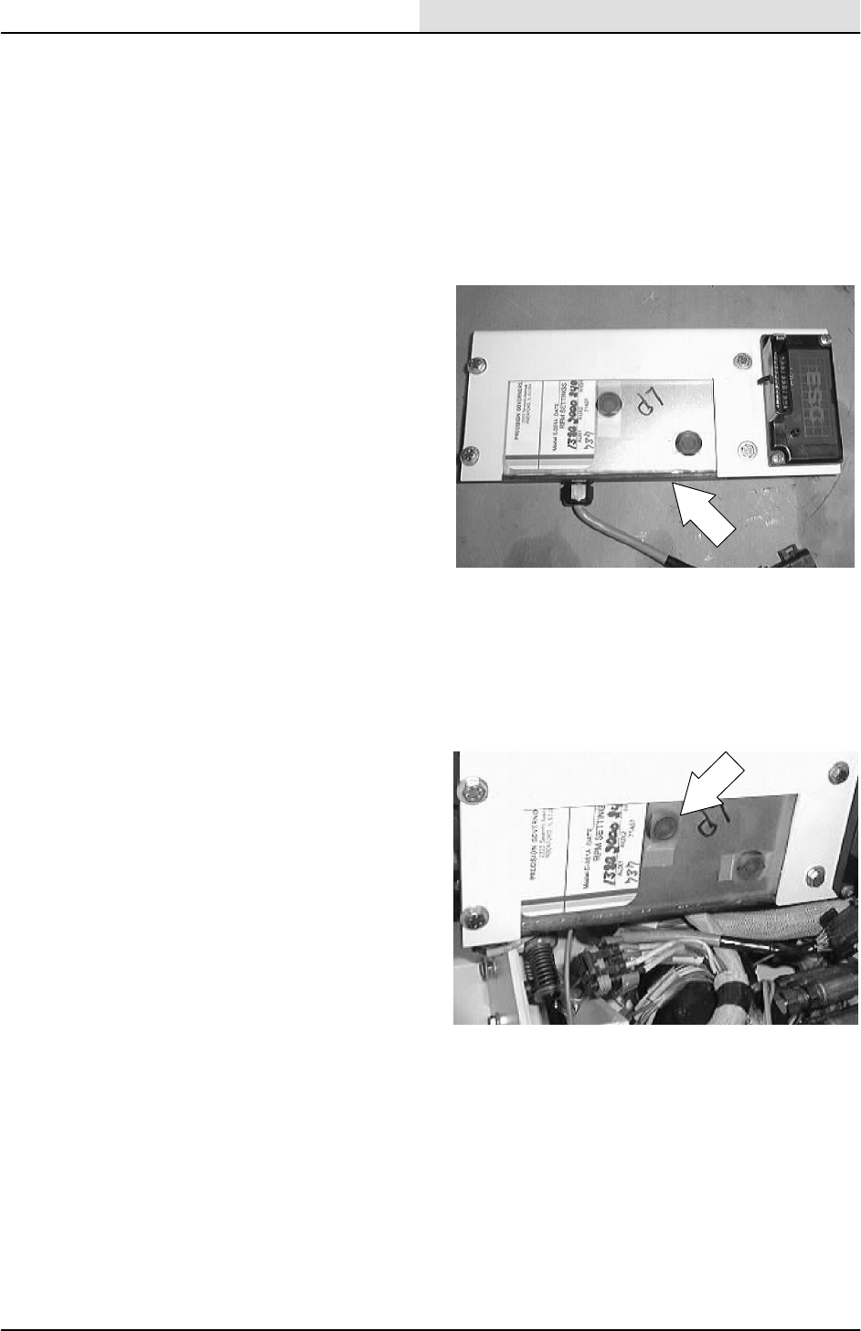
ENGINE--GAS/LP
7-31
8200/8210 330065 (3--02)
At the terminal where Wire 86, purple wire, is
hooked to:
Start/Idle -- 12 to 14.5 VDC ¦.2
Normal--12to14.5VDC¦.2
Litter -- 12 to 14.5 VDC ¦.2
8. Control Box Adjustment
If all the above aspects, in particular the
linkage, have been verified and the warmed
up engine either:
a. Hunts at running speed with the
accessories off.
b. Responds very sluggishly to switch
changes, an adjustment change in the
control box may be necessary.
FOR ANALOG CONTROLLER:
Remove the plastic seal plug from the back
of the box.
A slight adjustment of the surge screw may
be necessary to correct the conditions
mentioned above. Turn the screw
approximately 2_at a time and wait for 30
seconds to verify the change. Be careful.
Only a slight change is necessary, and the
“pot” can be broken if too much force is
used.
After the control throttle response is
achieved, verify that the operating speeds
are correct and adjust, if necessary. After
the speeds are reset, the surge screw may
have to be readjusted.
In general, if a new box is being installed, a
gasoline-equipped machine may require that
the sensitivity be reduced slightly.
When the sensitivity is adjusted, the run
speed should not be affected. If the
adjustment is too great, the start speed will
be affected. Verify that the start speed is
correct.
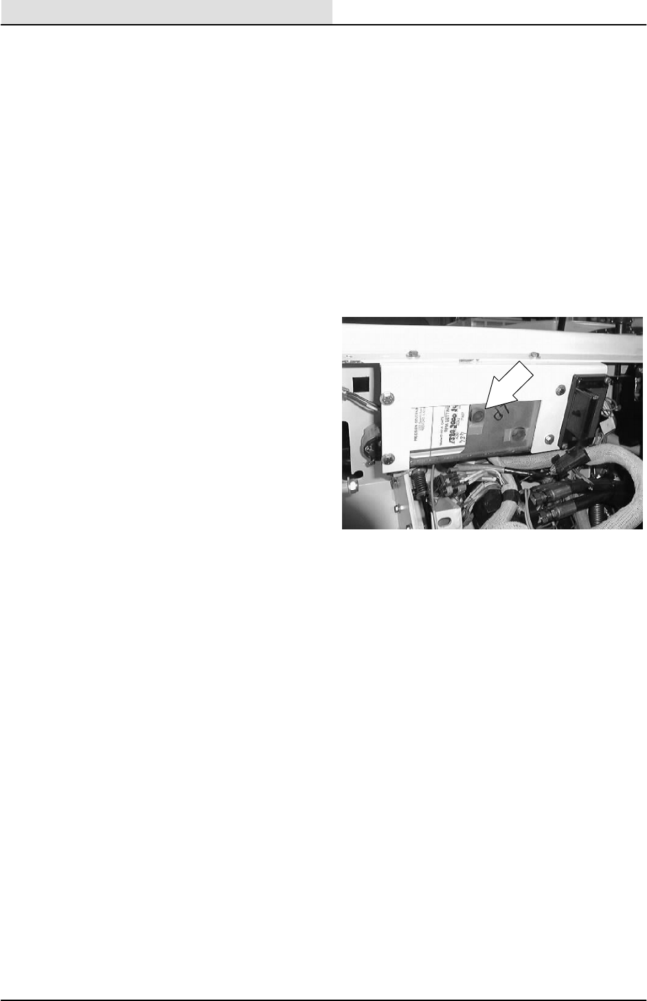
ENGINE--GAS/LP
7-32 8200/8210 330065 (3--02)
If too much sensitivity is adjusted in, the
engine will either hunt in a no load condition
or over speed severely when the speed
switch is actuated.
If too little sensitivity is adjusted in, the
engine will seem sluggish. The engine speed
will drop off when the load is increased and
not recover promptly.
The engine speed should not drop off, but
you can have the three hunts of the engine.
If, for some reason, the sensitivity
adjustment became grossly maladjusted, a
good starting point can be obtained by
rotating the pot fully counterclockwise and
then back clockwise 45_.
After the adjustments are made and verified,
reinstall the plastic plug into the back of the
governor box.
FOR DIGITAL CONTROLLER:
See TO ADJUST GOVERNOR CONTROL
BOX section of this manual.
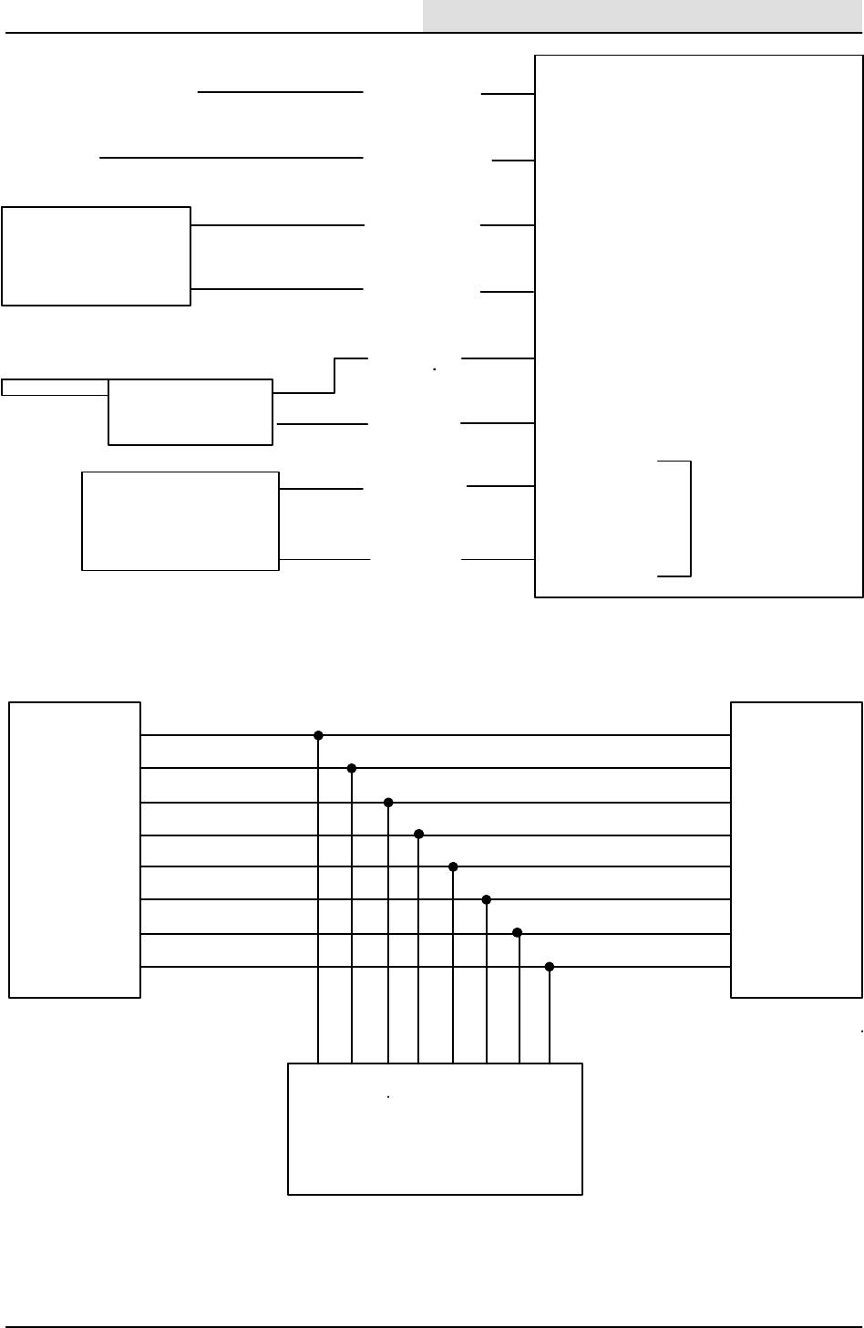
ENGINE--GAS/LP
7-33
8200/8210 330065 (3--01)
(A) +
(B) --
(C) Signal
(D) Signal
(E) Actuator +
(F) Actuator --
(G) Speed
(H) Speed
High=+9VDC
Low = 0VDC
+12VDC Switched (18D/ORA)
Ground (13E/BLK)
D.I.S.
Ignition
Module (72C/YEL)
(71C/YEL)
(84/GRN)
(83/BRN)
ELECTRONIC GOVERNOR WIRING PICTORIAL
Throttle actuator
(+)
(--)
(86/PUP)
(85/BLU)
Electronic
Instrument
Panel
A
B
C
D
E
F
G
H
A
B
C
D
E
F
G
H
A BCDEF G
H
TO: HARNESS TO: GOVERNOR
TEST PLUG
NOTE: The wire colors of the test harness do not necessarily match the machine harness.
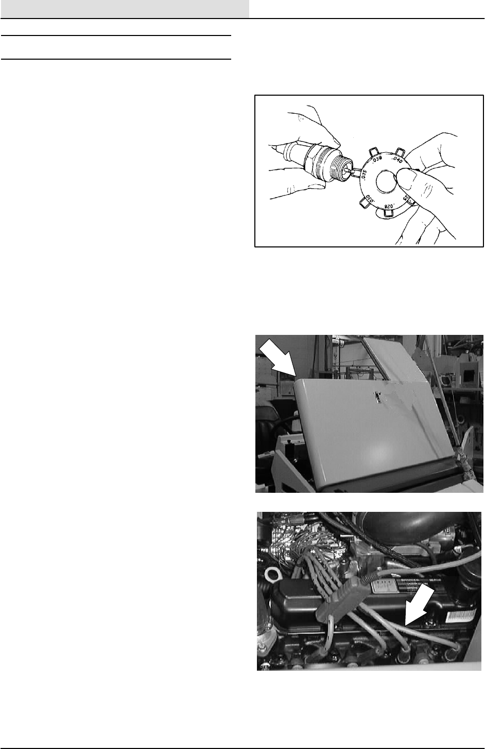
ENGINE--GAS/LP
7-34 8200/8210 330065 (3--01)
IGNITION SYSTEM
SPARK PLUGS
Clean or replace, and set the gap of the spark
plugs every 400 hours of operation. A wire gauge
is best for checking the spark plug gap. A flat
gauge should not be used unless the electrode
surfaces have been dressed with a small file to
get parallel surfaces between the center and side
electrode. Set the spark plug gap by bending the
side electrode. All spark plugs, new or used,
should have the gaps checked and reset if
necessary.
The proper spark plug gap is 1 mm (0.040 in).
TO REPLACE SPARK PLUGS
FOR SAFETY: Before Leaving Or
Servicing Machine: Stop On Level
Surface, Set The Parking Brake, Turn Off
Machine And Remove Key.
1. Open the engine cover and side door.
2. Remove the spark plug wires from the spark
plugs.
NOTE: Clean any dirt from the spark plug seat
area before removing the spark plugs.
3. Remove the spark plugs from the engine.
4. Clean the spark plug seat in the cylinder
head. Use a new seat gasket and screw the
new spark plug in by hand.
5. Tighten the spark plugs with a socket
wrench of the correct size. Reinstall the
spark plug wires.
6. Close the engine cover and side door. Start
the engine. Check for proper operation.

ENGINE--GAS/LP
7-35
8200/8210 330065 (3--02)
FORD DISTRIBUTORLESS IGNITION SYSTEM
SYNOPSIS:
This is a troubleshooting guide for the Ford
Distributorless Ignition System.
Unlike a conventional system, the Ford
Distributorless Ignition System (DIS) uses two
coils that each fire one pair of spark plugs. The
spark plugs are also fired on both the power and
exhaust stroke.
The DIS system also uses a Universal Electronic
Spark Control (UESC) module which adjusts the
timing of the engine. The degree of timing change
needed is determined by electrical and vacuum
input to the UESC, these are:
The engine wire harness has a separate wire for
the gas and another for the LPG machines. Make
sure you connect the correct wire for the type of
fuel being used.
Engine Load -- From Pressure Reducer
Located in the intake manifold
Minimum 21 KPA (6.22” Hg)
Maximum 101 KPA (29.91” Hg)
Engine Temperature
The Engine Coolant Temperature Sensor (ECTS)
located in the intake manifold water jacket sends
engine temperature information to UESC.
Minimum --39_C38_F
Maximum 112_C 232_F
When the engine is starting, at 250 RPM or less,
the timing is set at 10_before top dead center
(BTDC).
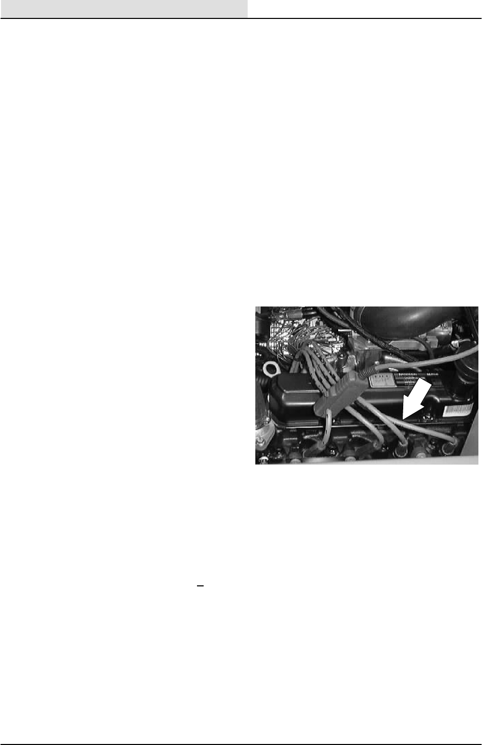
ENGINE--GAS/LP
7-36 8200/8210 330065 (3--01)
RUN MODE
In this mode the RPM is above 250 and the spark
advance is calculated in three sections which are
added together to maintain optimum running
condition.
The Base Spark Advance (BSA) is calculated by
the UESC module looking at speed and load
inputs.
The Spark Advance Offset Temperature (SAOT)
will change ignition timing. This is determined by
the Engine Coolant Temperature (ECT). This
allows the spark advance to be altered during cold
engine conditions.
SERVICING AND TESTING
Servicing
1. Every 400 hours, remove the spark plugs
and clean and adjust the electrode.
2. Clean and visually check spark plug high
tension leads and test for resistance. The
Ohm meter should read between 9,000 and
16,000 Ohms.
Testing
Secondary Coil Testing
Remove the four (4) spark plug wires and
measure the secondary coil resistance by
placing the meter into plug wire terminal.
1 -- 4 at the coil
2 -- 3 at the coil
On each test you should read 14,000 + 50
Ohms.
Universal Spark Control Module Diaphragm
Testing
Using a vacuum pump, apply 15” Hg to the
UESC and vacuum inlet. The diaphragm
should hold the pressure. If it fails, replace
UESC unit.
To test the sensors and wiring harness,
follow the direction on the next three pages.

ENGINE--GAS/LP
7-37
8200/8210 330065 (3--01)
“FAILURE MODE OF DIS” IGNITION HARNESS
The Ford DIS Universal Spark Control was
checked for “poor connection”.
The results of open leads were:
Term 11 or 12 Ignition Coil Signal Leads --
The governor received 1/2 of its intended
signal and caused the actuator to hold the
carb arm wide open. At the same time, the
engine missed due to incorrect firing of
plugs, but the speed still climbed to about
3,000--4,000 rpm. When either of these
leads were opened at the start speed, the
engine missed slightly and rose to double
the start speed or about 3,000 rpm.
Term 9 Ground -- Any failure here killed the
engine instantly or caused the engine to
slow down if it were cycled.
Term 6 & 7 Octane Selector -- Opening
these terminals retards the spark in varying
degrees. Under light to moderate load
conditions, no adverse effect will take place.
However, run-on or pre-ignition may take
place.
Term 4 & 10 Coolant Sensor -- Contrary to
previous thoughts, opening the lead doesn’t
noticeably affect the engine. The timing only
changes a few degrees.
Term 2 & 3 Crank Position Sensor --
Opening either of these leads kills the
engine quickly and it will not start.
Term 8 Power Lead -- Opening this lead kills
the engine and it will not start.
In summary, no alarming effect happens except if
the coil signal leads are interrupted. These are the
end leads on the module and if the harness has
too much tension on it, the signal will become
intermittent and cause the engine to overspeed.
The only obvious damage will probably occur to
the propelling pump, as the fan is rated for
operation to 10,000 rpm. If the acc. are on when
the lead becomes intermittent, the engine will not
develop enough power to overspeed excessively.
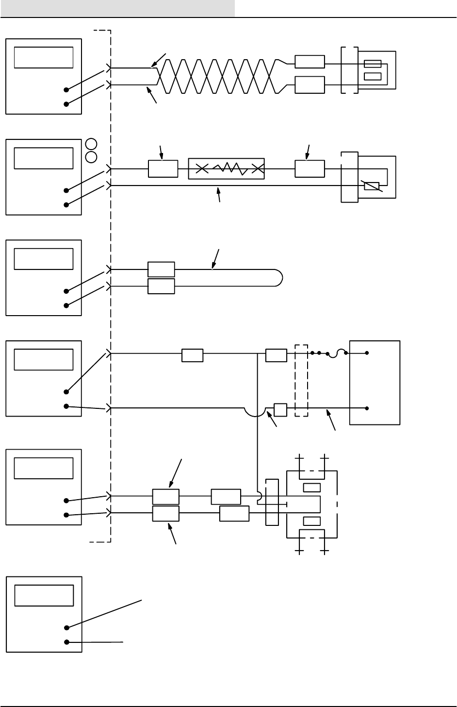
ENGINE--GAS/LP
7-38 8200/8210 330065 (3--01)
200---600
Ohms
2
3
VRS +
V R S ---
65 Blue
66 Green
Variable reluctance
sensor (crank position
sensor)
Ohms
Ohms
105,000
0
4
10
ECT1
ECT2
67 Orange
10K Ohm
70 Green
64 Brown
Engine coolant
temperature sensor in
ice water bath
See Engine Coolant
Sensor chart
1
2
6
7
OCT2
OCT1
6
6
68 Brown
Cut and ground to set octane (retard
spark advance)
18T Orange
12.6
Volts +
D . C . ---
8
9
VBatt
Power Ground
16M 16I
57
13PP Black
Ignition
switch on
13QQ Black
+
Batt
12.6 V
DC
---
11
12
0.5 --- 1.0
Ohms
CDO
(Phase
A)
CDO
(Phase
B)
852
71 Yellow
72 Gray
850A
852A
HT HT
14
HT HT
23
Distributorless
Ignition Coil
12.6
Volts +
D . C . ---
Remove the coil connector and probe
the center female terminal
To Pi n #9
FORD DIS IGNITION

ENGINE--GAS/LP
7-39
8200/8210 330065 (10--93)
Engine Cooler Sensor
Temperature
_C_F
Sensor (Ohms)
+.02_
Sensor & Harness
(Ohms) + .03_
-- 3 0 --- 2 2 481,000 491,000
-- 2 0 4271,000 281,000
-- 1 0 14 158,000 168,000
032 95,000 105,000
10 50 58,750 68,750
20 68 37,300 47,300
30 86 24,270 34,270
40 104 16,150 26,150
50 122 10,970 20,970
60 140 7,600 17,600
70 158 5,360 15,360
80 176 3,840 13,840
90 194 2,800 12,800
100 212 2,070 12,070
110 230 1,550 11,550
120 248 1,180 11,180
130 266 930 10,930
140 284 701 10,701
150 302 550 10,550
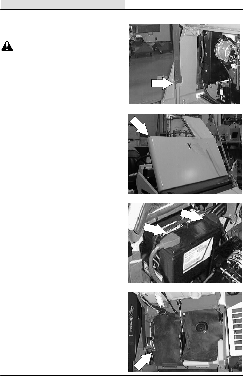
ENGINE--GAS/LP
7-40 8200/8210 330065 (3--01)
TO REPLACE ALTERNATOR
1. Raise the hopper and engage the prop bar.
WARNING: Raised Hopper May Fall.
Engage Hopper Support Bar.
FOR SAFETY: Before Leaving Or
Servicing Machine; Stop On Level
Surface, Set Parking Brake, Turn Off
Machine And Remove Key.
2. Open the engine cover and side door.
3. Disconnect the battery cables from the
battery.
4. Pull the rubber dust shield away from the
front of the engine in the area of the
alternator.
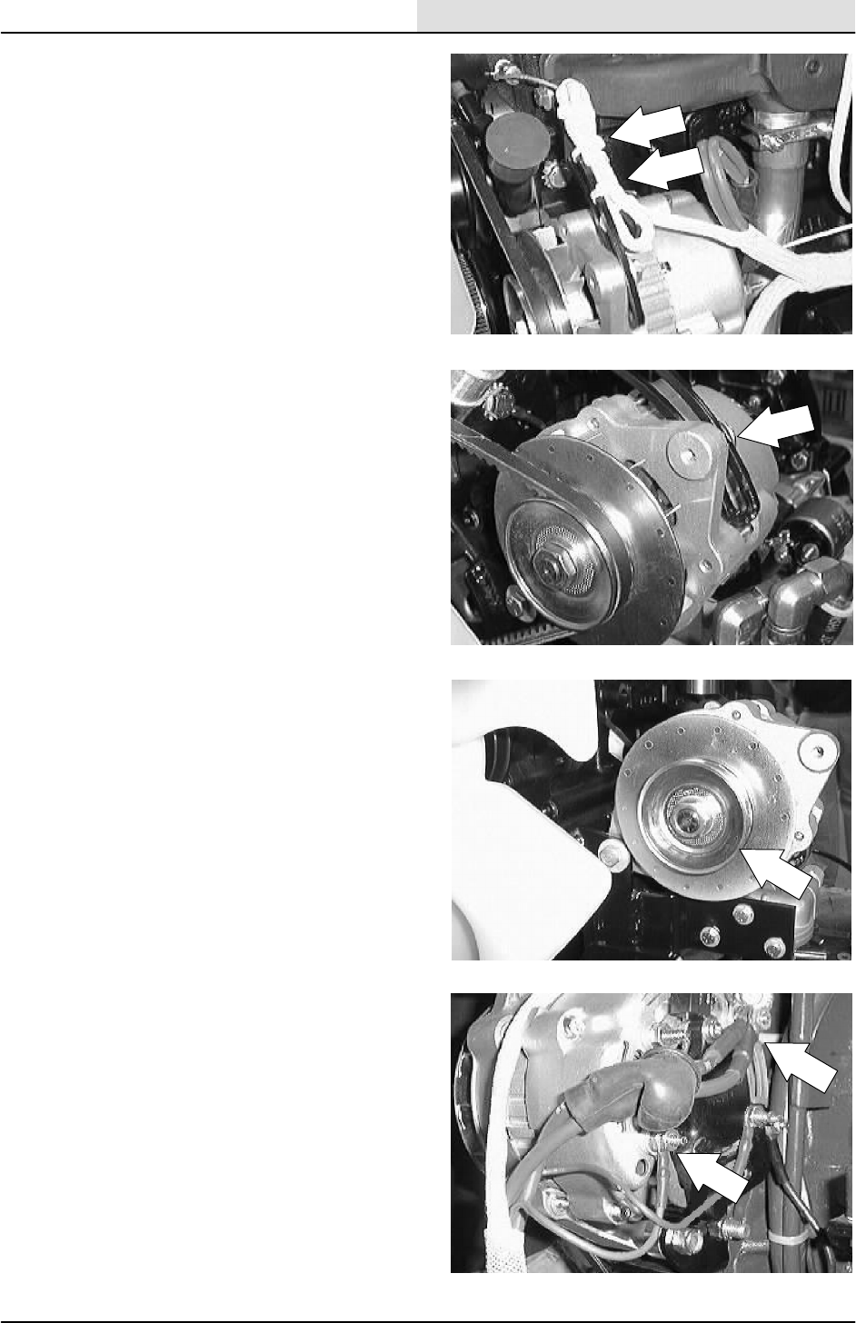
ENGINE--GAS/LP
7-41
8200/8210 330065 (3--01)
5. Cut any plastic wire ties holding the wire
harness to the alternator bracket.
6. Remove the hex screw holding the top of the
alternator to the mount bracket. Remove
and retain the heat shield.
7. Push the alternator in toward the engine and
remove the V--belt.
8. Disconnect the wires leading to the back of
the alternator.

ENGINE--GAS/LP
7-42 8200/8210 330065 (3--01)
9. Remove the hex screw and nyloc nut
holding the bottom of the alternator to the
lower mount bracket.
10. The alternator can now be removed out the
front of the machine.
11. If the new or rebuilt alternator needs a drive
pulley, remove the pulley from the old
alternator. Hold the pulley from turning and
use an impact wrench to remove the hex
nut.
12. Install the pulley, washer, and hex nut on the
new alternator. Firmly tighten the nut with
the impact.
13. Install the new alternator back in the
machine. Align the bottom hole in the
alternator with hole in lower mount bracket.
Reinstall the hex bolt, ground cable, and
nyloc nut. Leave it loose for now.
14. Reconnect the wires to the back of
alternator. See the schematic in the
ELECTRICAL section.
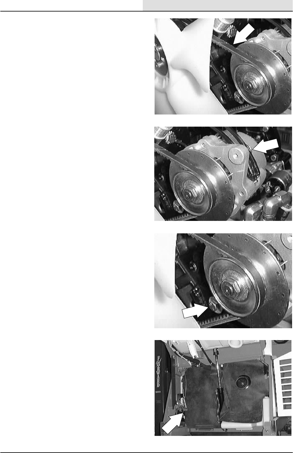
ENGINE--GAS/LP
7-43
8200/8210 330065 (3--01)
15. Place the V--belt back on the alternator
pulley.
16. Reinstall the hex screw in the top hole of the
alternator through upper slotted mounting
bracket. Pull the alternator away from the
engine to tighten the belt. See adjustment in
ENGINE FAN BELT description. Tighten the
hex screw to 18 -- 24 Nm (13 -- 18 ft lb).
17. Tighten the bottom hex screw to
18 -- 24 Nm (15 -- 20 ft lb).
18. Place the rubber dust shield back in position.
19. Reconnect the battery cables and start the
engine. Check the new alternator for proper
operation.
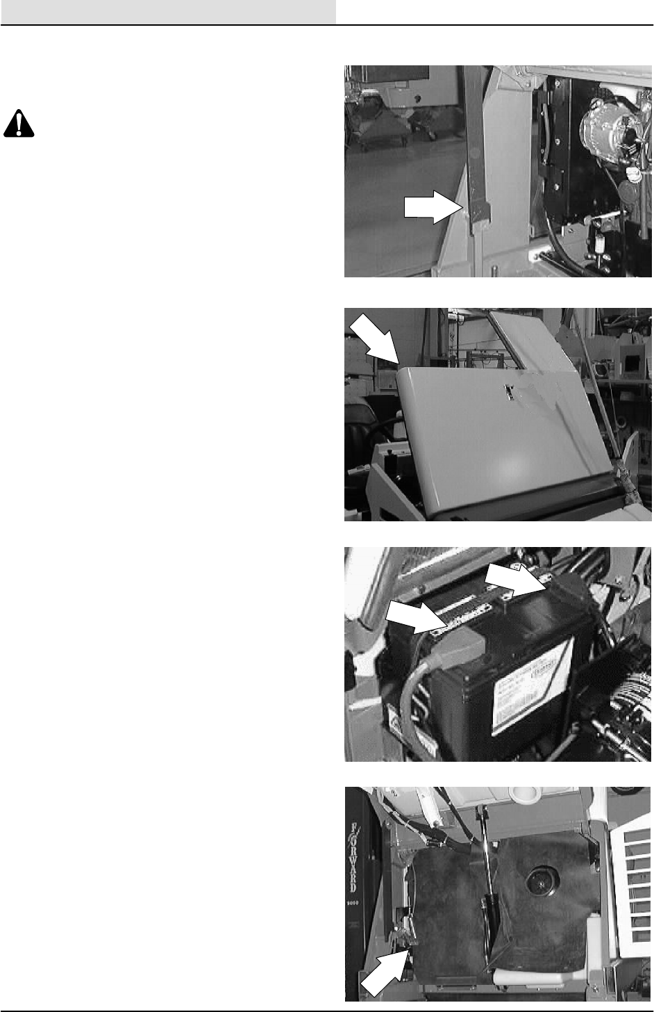
ENGINE--GAS/LP
7-44 8200/8210 330065 (3--01)
TO REPLACE STARTER
1. Raise the hopper and engage the prop bar.
WARNING: Raised Hopper May Fall.
Engage Hopper Support Bar.
NOTE: If the engine will not start because of a
bad starter-- --use an overhead crane to lift the
hopper and engage the prop arm.
FOR SAFETY: Before Leaving Or
Servicing Machine; Stop On Level
Surface, Set Parking Brake, Turn Off
Machine And Remove Key.
2. Open the engine cover and side door.
3. Disconnect the battery cables from the
battery.
4. Pull the rubber dust shield away from the
front of the engine in the area of the starter.
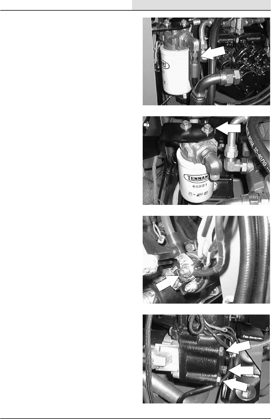
ENGINE--GAS/LP
7-45
8200/8210 330065 (3--01)
5. Mark, disconnect, and cap the two hydraulic
hoses leading to the hydraulic filter head.
NOTE: Always observe hydraulic cleanliness
requirements when opening hydraulic lines.
6. Remove the hydraulic fluid filter assembly
from the machine.
NOTE: This will allow access to the engine starter
hardware.
7. Disconnect the wires leading to the starter.
8. Remove the three hex screws holding the
starter to the engine bellhousing.
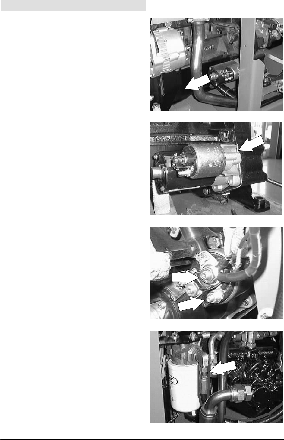
ENGINE--GAS/LP
7-46 8200/8210 330065 (3--01)
9. Pull the starter straight out of the bellhousing
and remove it from the machine.
10. Install the new starter in the machine. Align
the three holes in the starter with the holes
in the bellhousing. Reinstall the three hex
screws. Tighten to 18 -- 24 Nm
(15 -- 20 ft lb).
11. Reconnect the wires to the starter. See the
schematic in the ELECTRICAL section.
12. Reinstall the hydraulic oil filter assembly.
Reconnect the two hydraulic hoses. See
hose diagram in HYDRAULIC section.
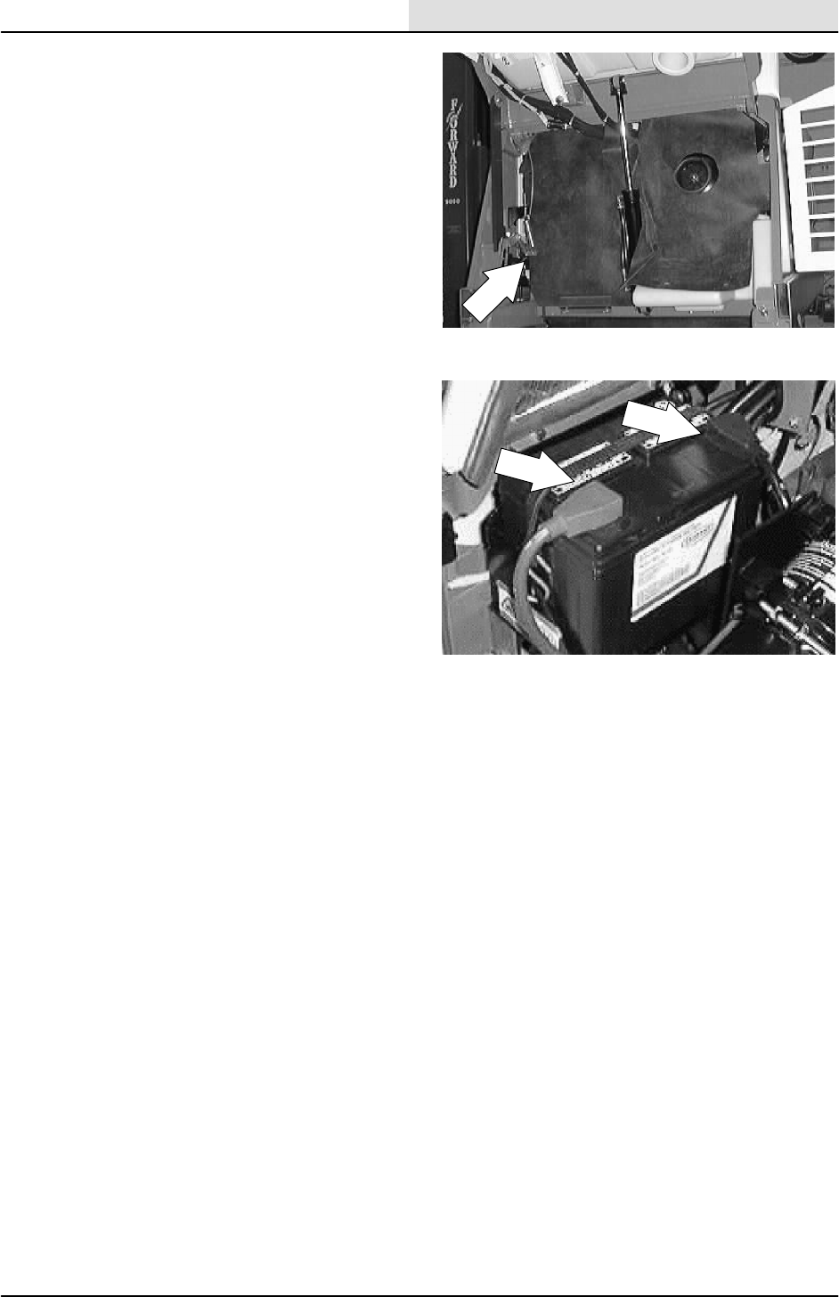
ENGINE--GAS/LP
7-47
8200/8210 330065 (3--01)
13. Place the rubber dust shield back in position.
14. Reconnect the battery cables. Close the
engine cover and side door.
15. Check the starter for proper operation.
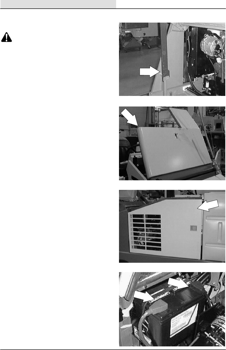
ENGINE--GAS/LP
7-48 8200/8210 330065 (3--01)
TO REMOVE ENGINE
1. Raise the hopper and engage the prop bar.
WARNING: Raised Hopper May Fall.
Engage Hopper Support Bar.
NOTE: If the engine will not start because of a
bad starter-- --use an overhead crane to lift the
hopper and engage the prop arm.
FOR SAFETY: Before Leaving Or
Servicing Machine; Stop On Level
Surface, Set Parking Brake., Turn Off
Machine And Remove Key.
2. Open the engine cover and side door.
3. Remove the engine cover and side door
from the machine.
4. Disconnect the battery cables from the
battery. Remove the battery and battery tray
from the machine.
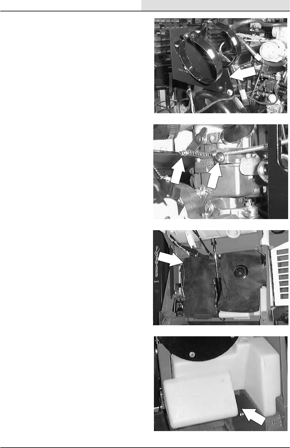
ENGINE--GAS/LP
7-49
8200/8210 330065 (3--01)
5. Remove the air cleaner and mount bracket
from the engine.
6. Disconnect the choke cable from the engine.
7. Pull the rubber dust shield up and out of the
way for access to the front of the engine.
8. If the machine is equipped with a detergent
tank----remove for better access.
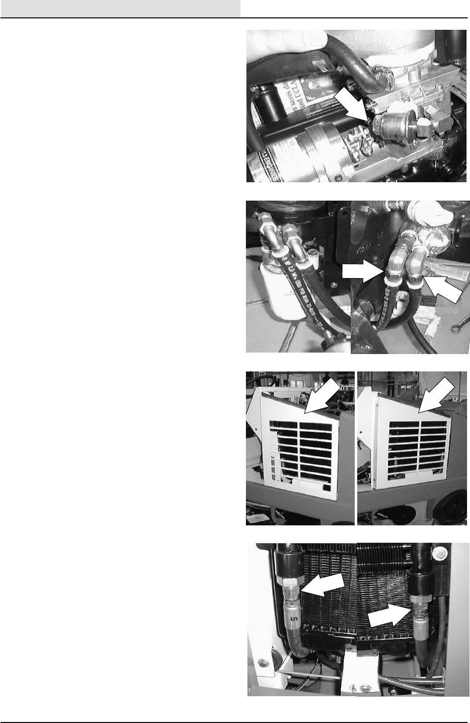
ENGINE--GAS/LP
7-50 8200/8210 330065 (3--01)
9. Disconnect the fuel line at the connection
between the hose and steel line on a gas
machine. On an LPG machine, disconnect
the line leading from the tank to the fuel
lockoff / vaporizer.
10. Mark,disconnect, and plug the two engine
oil lines running to the remote oil filter.
11. Remove the two hex screw holding the
radiator grill guard to the frame. Remove the
grill from the machine.
12. Mark, disconnect, and plug the two hydraulic
hoses leading to the hydraulic oil cooler on
the front of the radiator.
NOTE: Always observe hydraulic cleanliness
requirements when opening hydraulic lines.
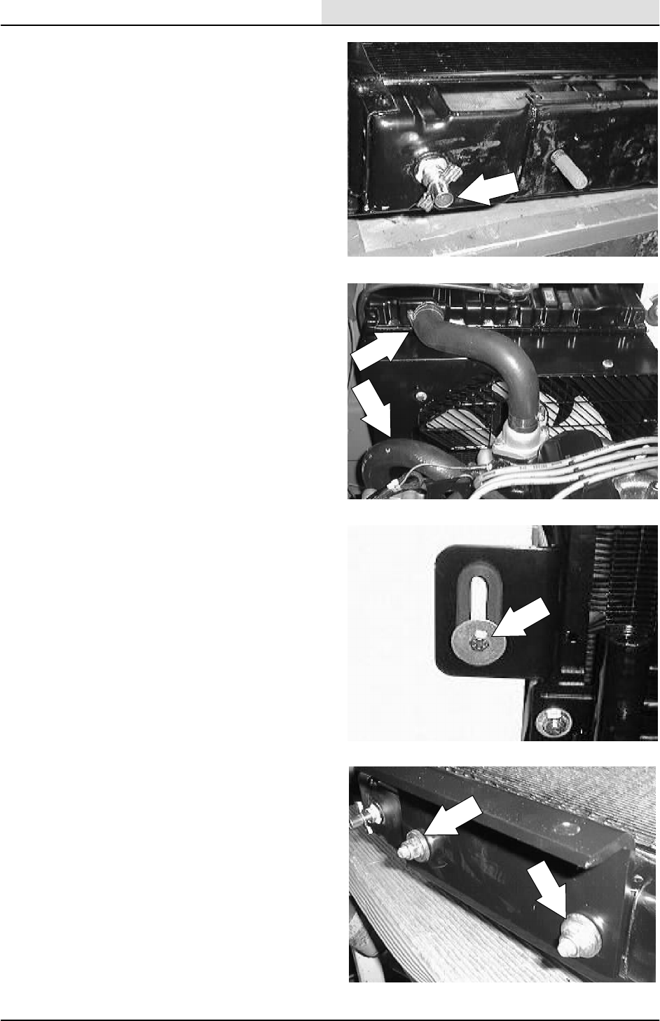
ENGINE--GAS/LP
7-51
8200/8210 330065 (3--01)
13. Drain the coolant from the radiator.
14. Disconnect the upper and lower radiator
hoses.
15. Remove the hex screw, spacer, and fender
washer holding the top left side of the
radiator to the radiator support.
16. Remove the two hex screws and nyloc nuts
holding the bottom of the radiator to the
mount bracket.
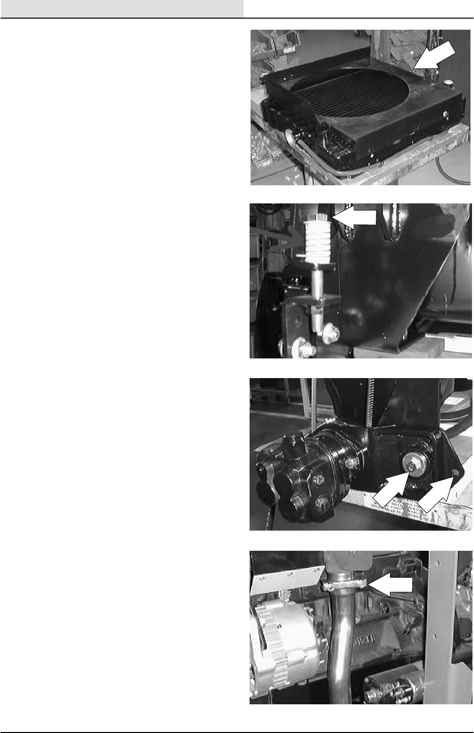
ENGINE--GAS/LP
7-52 8200/8210 330065 (3--01)
17. Pull the radiator back so it clears the engine
fan. Remove the radiator, fan shroud, and
hydraulic oil cooler from the machine.
18. Remove the hex screw and compression
spring from the front of the accessory pump
pivot bracket. Remove the V--belt from the
engine sheave.
19. Remove the hex screw, nut, and sleeve
holding the hydraulic accessory pump pivot
bracket to the front motor mount. Drop the
hydraulic pump down onto the frame. DO
NOT disconnect the hydraulic hoses leading
to the accessory pump.
20. Loosen the muffler clamp holding the
exhaust pipe to the engine manifold. Pull
the exhaust pipe off the manifold and let it
drop down, out of the way.
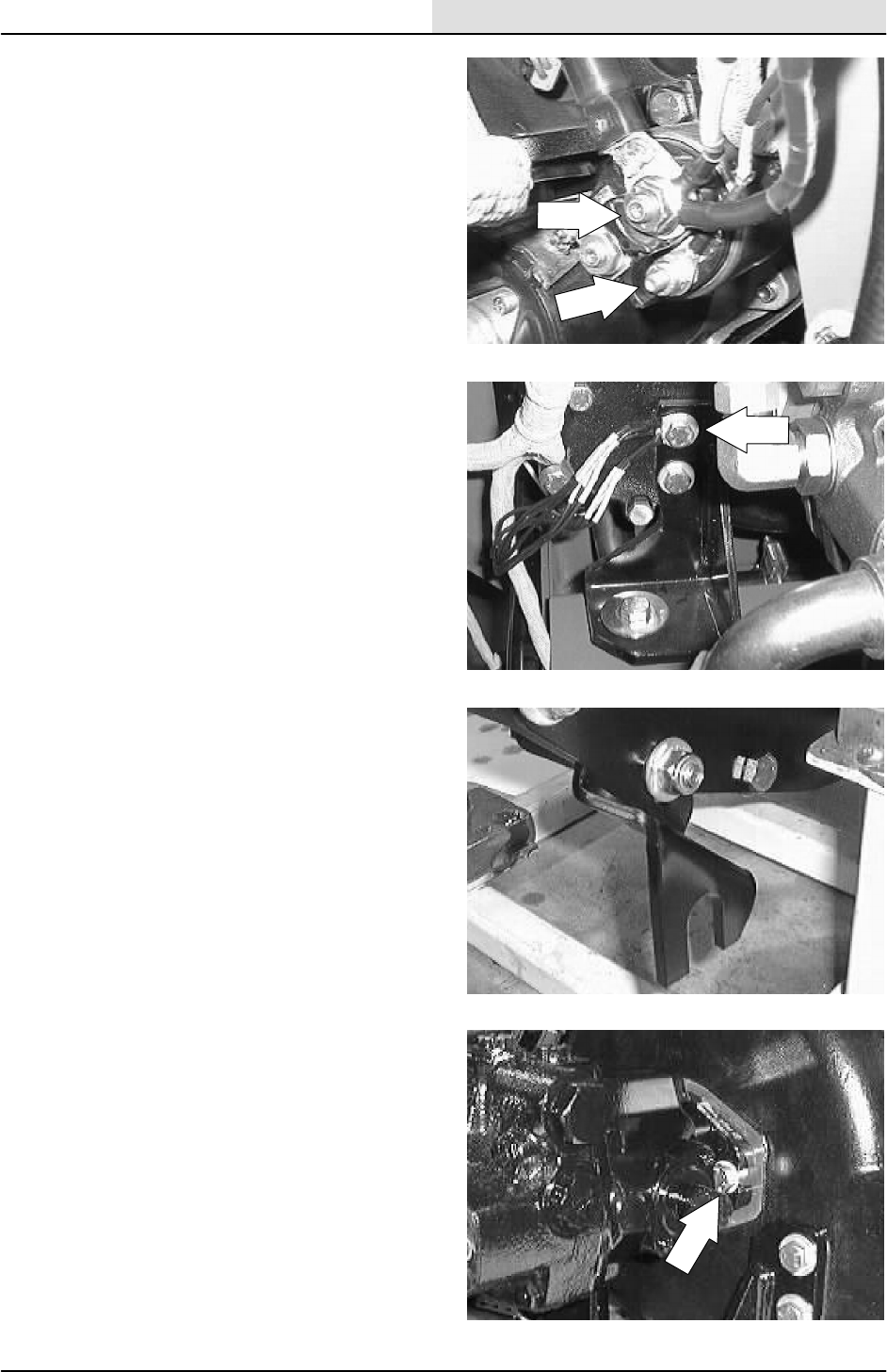
ENGINE--GAS/LP
7-53
8200/8210 330065 (3--01)
21. Disconnect the wire harness from the
alternator, starter, oil sender, temp. sender,
ect.
NOTE: Move the wires out of the way for engine
removal.
22. Disconnect the ground wires and ground
cable from the rear motor mount hex screw.
23. Loosen the jam nuts on the propel cable
where it attaches to the mount bracket on
the bellhousing. Pull the propel cable out of
the mount bracket slot.
24. Remove the two hex screws holding the
propel pump into the flywheel housing.
NOTE: Leave the hydraulic hoses connected to
the propel pump.
NOTE: Place a block of wood under the hydraulic
pump assembly for support when removing the
engine.
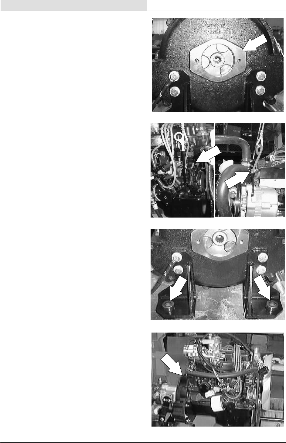
ENGINE--GAS/LP
7-54 8200/8210 330065 (3--01)
25. Pull the propel and accessory pump
assembly back, out of the bellhousing.
NOTE: Leave the hydraulic hoses connected to
the propel pump.
NOTE: Pull the engine toward the right side of the
machine until the hydraulic pump assembly is free
of the bellhousing.
26. Using an overhead hoist, hook a chain
through the two pick--up points on the top of
the engine. Put a slight amount of tension on
the chain.
27. Remove the three hex screws and nyloc
nuts holding the three motor mounts to the
rubber isolators on the frame brackets.
28. The engine can now be carefully lifted out.
NOTE: Make sure the engine is clear of any wires
or hoses before you lift it out of the frame.
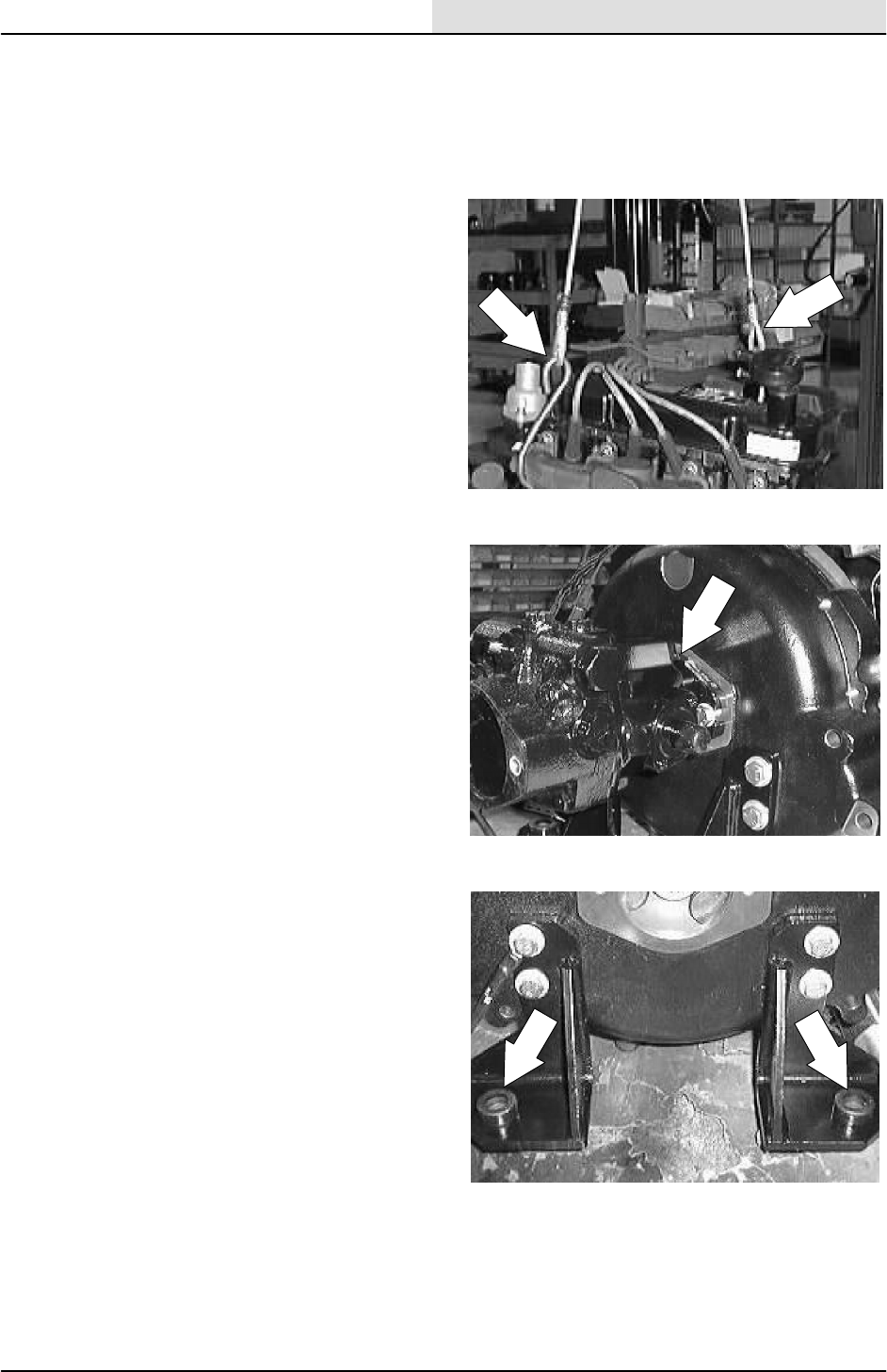
ENGINE--GAS/LP
7-55
8200/8210 330065 (3--01)
TO INSTALL ENGINE
FOR SAFETY: Before Leaving Or
Servicing Machine; Stop On Level
Surface, Set Parking Brake., Turn Off
Machine And Remove Key.
1. Using an overhead hoist, hook a chain
through the two pick--up points on top of the
engine. Carefully position the engine back in
the engine compartment.
NOTE: Make sure the hoses, wire harness,
exhaust pipe and propel pump are pulled back out
of the way when lowering engine assembly into
place.
2. Slide the engine toward the left side of the
machine until the propel pump is positioned
into the back of the bellhousing. Install the
two hex screws. Use a small amount of blue
loctite 242 on the threads. Tighten the
hardware to 37 -- 48 Nm (26 -- 34 ft lb).
NOTE: Make sure the splines on pump line up
with splines in coupler when installing pump.
3. Move the engine around until the three
motor mounts on the engine line up with the
mount holes in the machine frame.

ENGINE--GAS/LP
7-56 8200/8210 330065 (3--01)
4. Reinstall the hex screws, washers, and
nylocs in the three motor mounts. Lower the
engine all the way. Remove the hoist from
the engine. Tighten the hex screws to
64 -- 83 Nm (47 -- 61 ft lbs).
5. Position the propel cable into the slot on the
bellhousing mount bracket.
6. Reconnect the ground cable and ground
wires to the rear motor mount hardware.
7. Reinstall the exhaust pipe back on the
engine manifold. Tighten the muffler clamp
tight.
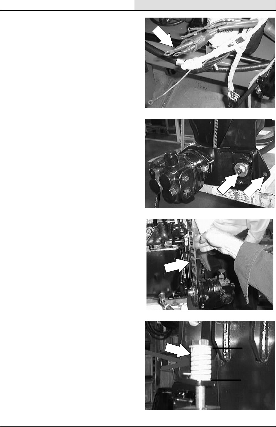
ENGINE--GAS/LP
7-57
8200/8210 330065 (3--01)
8. Reconnect the wire harness to the engine
components; alternator, starter, oil switch,
temperature sender, ect. See schematic in
the ELECTRICAL section.
9. Reinstall the accessory pump and pivot
bracket onto the motor mount. Tighten the
hex screw to 37 -- 48 Nm (26 -- 34 ft lb).
Make sure the sleeve is in place.
10. Position the accessory pump V--belt onto the
engine sheave.
11. The accessory pump belt adjustment is
made by turning the bolt on top of the
tension spring. The tension spring is located
at the front of the engine compartment, near
the accessory pump belt sheave. The
accessory pump belt is at the proper tension
when the tension spring is compressed to
3.81 cm 0.0076 mm (1.5 in 0.030 in).
NOTE: When adjusting the accessory pump belt
tension, measure only the spring and not the
washers at either end.
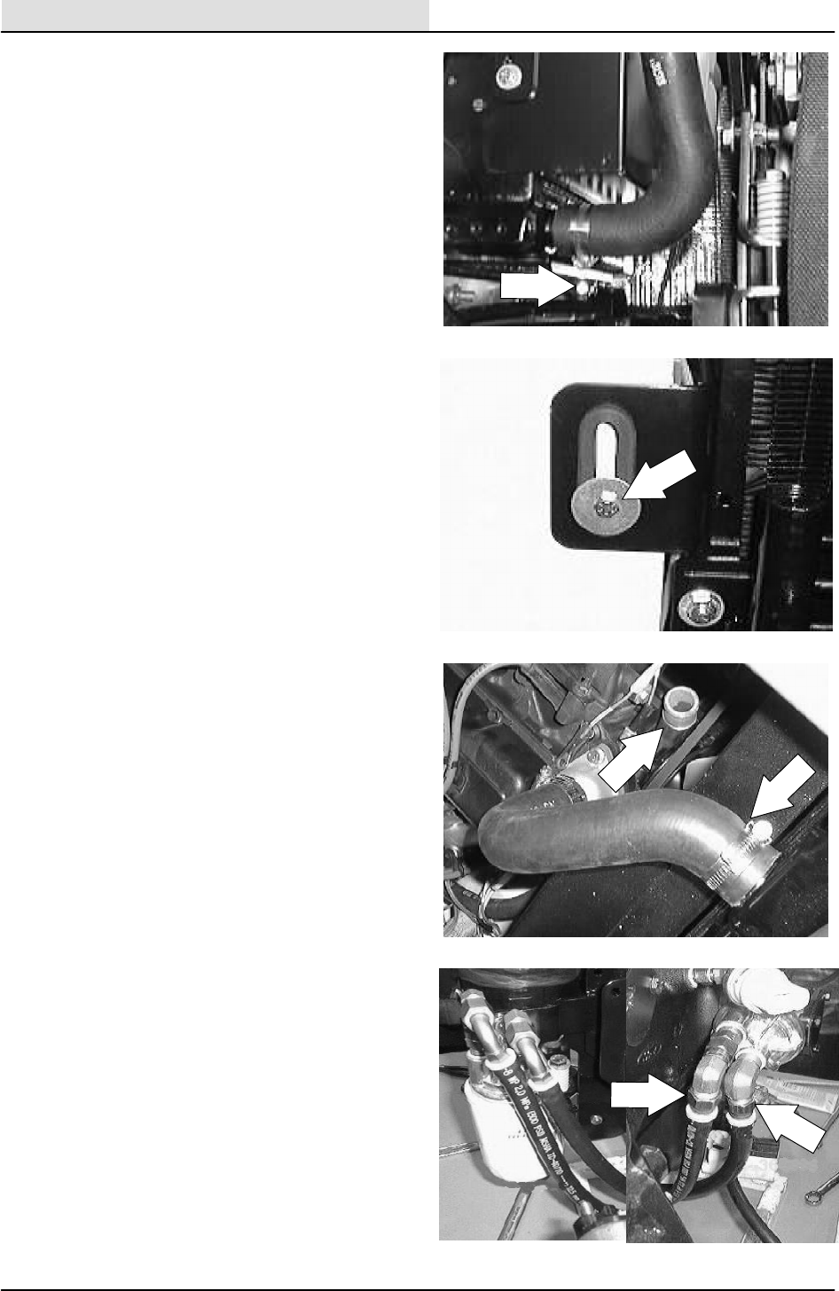
ENGINE--GAS/LP
7-58 8200/8210 330065 (3--01)
12. Position the radiator back in the machine.
Align the two holes in the bottom of the
radiator mount bracket with the holes in the
frame. Reinstall the two hex screws and
nuts. Leave loose for now.
13. Reinstall the hex screw and fender washer
holding the top of the radiator to the radiator
support. Tighten to 6 -- 9 Nm (7 -- 10 ft lb).
Go back and tighten the two hex screws on
the bottom of the mount bracket. Tighten to
37 -- 48 Nm (26 -- 34 ft lb).
14. Reinstall the radiator hoses to engine and fill
the radiator with coolant.
15. Reconnect the two engine oil lines running
to the remote oil filter.
NOTE: MAKE SURE THE ENGINE OIL LINES
ARE RECONNECTED TO THE PROPER PORT !
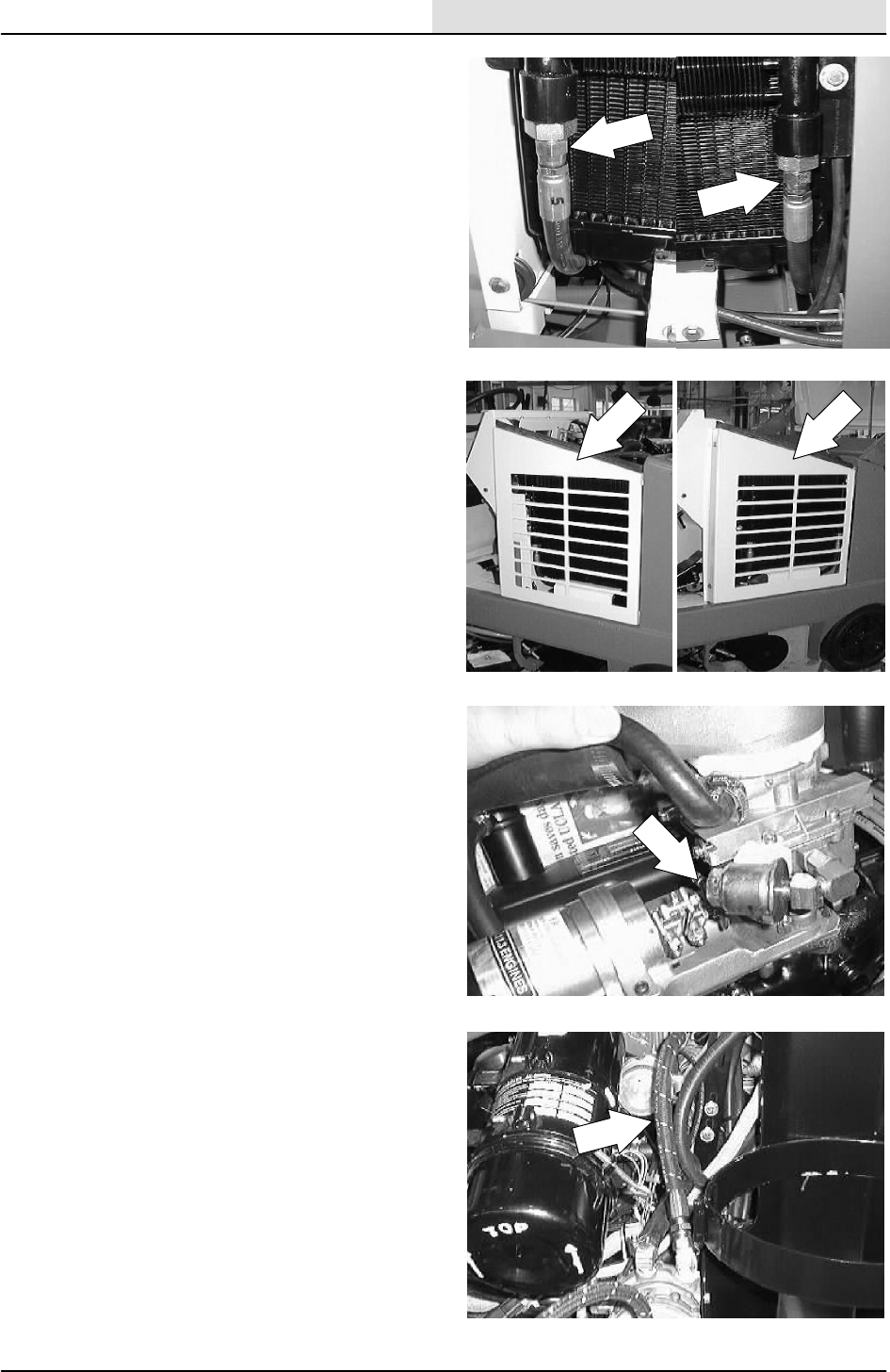
ENGINE--GAS/LP
7-59
8200/8210 330065 (3--01)
16. Reconnect the two hydraulic hoses to the
hydraulic oil cooler on the front of the
radiator.
17. Reinstall the radiator grill guard.
18. Reconnect fuel line on the Gas machine.
19. On the LPG machine, reinstall the LPG hose
to the lockoff/vaporizer.
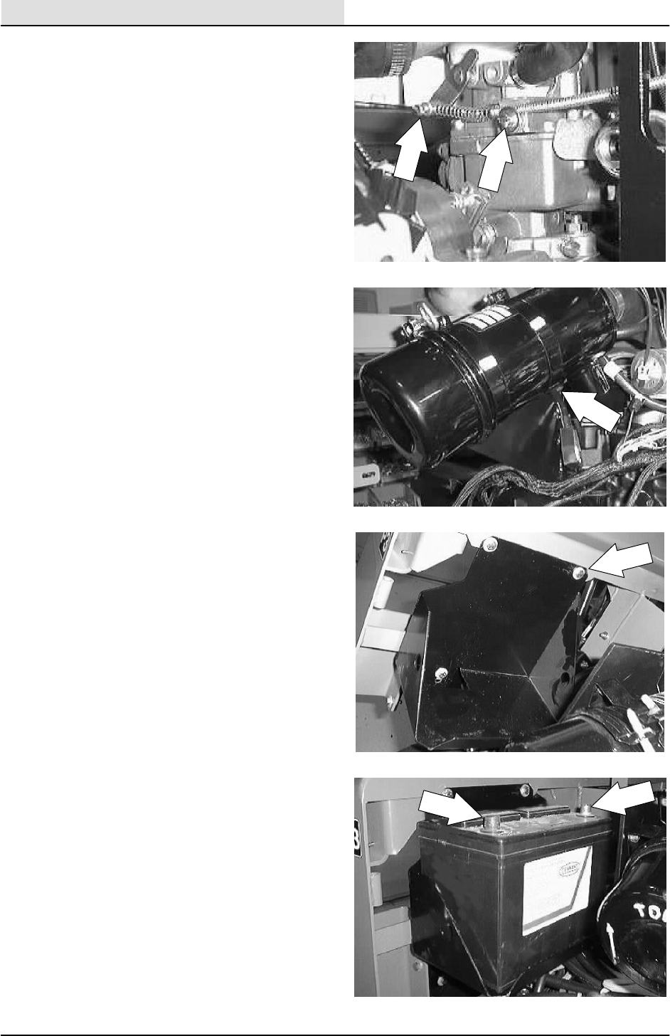
ENGINE--GAS/LP
7-60 8200/8210 330065 (3--01)
20. Reconnect the choke cable on the gas
engine.
21. Reinstall the air cleaner mount bracket and
air cleaner assembly to the engine
bellhousing. Tighten to 18 -- 24 Nm
(15 -- 20 ft lb).
22. Reinstall the battery tray and battery.
23. Reconnect the battery cables to the battery.
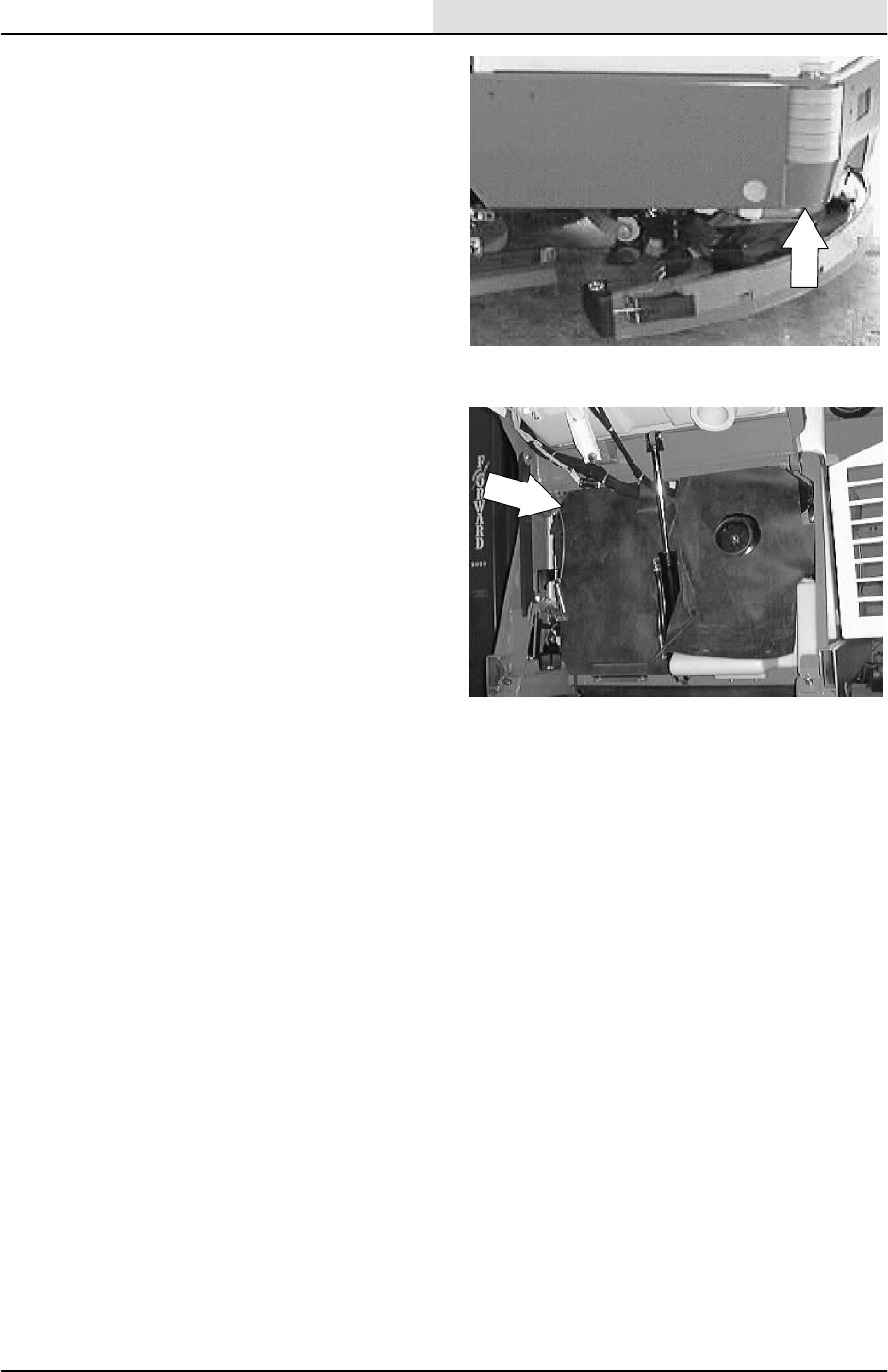
ENGINE--GAS/LP
7-61
8200/8210 330065 (3--01)
24. Jack up the rear of the machine.
FOR SAFETY: Block machine tires
before jacking machine up. Jack
machine up at designated locations
only. Block machine up with jack
stands.
25. Start the engine and check for any leaks and
proper operation.
26. Reinstall the front rubber firewall, engine
cover, and side door.

ENGINE--GAS/LP
7-62 8200/8210 330065 (3--01)

ENG--DIESEL
8-1
8200/8210 330065 (3--02)
CONTENTS
Page
INTRODUCTION 8-3......................
LUBRICATION 8-4.....................
ENGINE OIL 8-4....................
COOLING SYSTEM 8-4................
ENGINE FAN BELT 8-5..............
TO REPLACE ENGINE
FAN/ALTERNATOR BELT 8-5.....
AIR INTAKE SYSTEM 8-10.............
AIR FILTER 8-10....................
AIR FILTER INDICATOR (optional) 8-10
TO REPLACE AIR FILTER
ELEMENT 8-11..................
FUEL SYSTEM -- DIESEL 8-13..........
FUEL FILTER 8-14..................
TO REPLACE THE FUEL FILTER
CARTRIDGE 8-14................
FUEL LINES 8-15...................
ELECTRIC FUEL PUMP 8-15........
PRIMING FUEL SYSTEM 8-16.......
TO PRIME FUEL SYSTEM 8-16......
GOVERNOR 8-17.....................
TO ADJUST GOVERNOR
CONTROL BOX 8-17.............
DIGITAL CONTROLLER SET--UP 8-19
TO ADJUST TRANSDUCER
(MAGNETIC PICKUP) 8-20........
CYLINDER HEAD 8-20.................
VALVE TAPPET CLEARANCE 8-20...
CRANKCASE VENTILATION
SYSTEM 8-20...................
TO REPLACE ALTERNATOR 8-21....
TO REPLACE STARTER 8-26........
TO REMOVE ENGINE 8-29..........
TO INSTALL ENGINE 8-35...........
DIESEL ENGINE SERVICE MANUAL
KUBOTA V1505 B (E)
TENNANT Part Number 84660

ENG--DIESEL
8-2 8200/8210 330065 (3--01)

ENG--DIESEL
8-3
8200/8210 330065 (3--01)
INTRODUCTION
This section includes repair information on the
engine and related systems, such as fuel,
electrical, and drive belts.
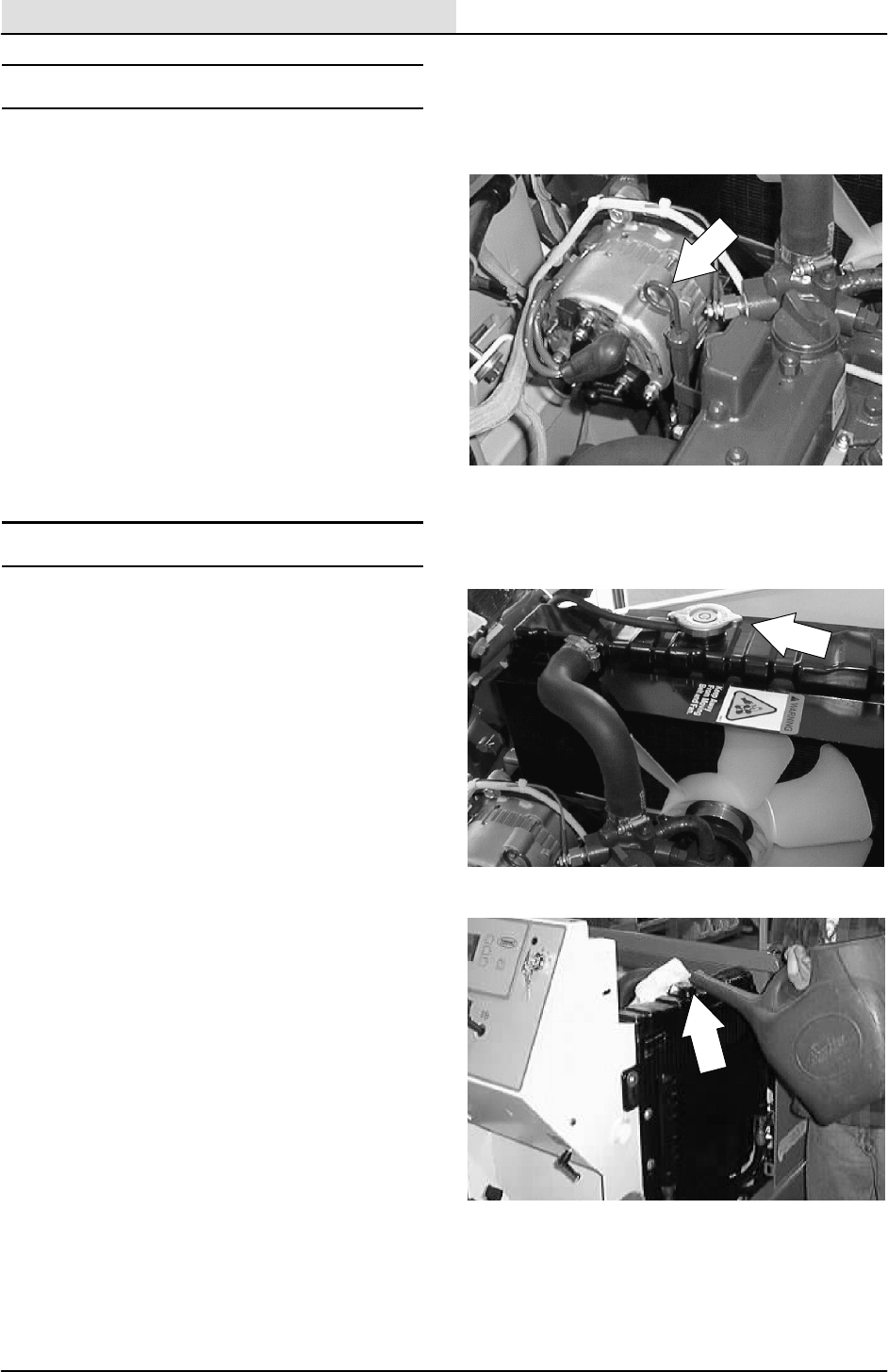
ENG--DIESEL
8-4 8200/8210 330065 (3--01)
LUBRICATION
ENGINE OIL
Check the engine oil level daily. Change the
engine oil and oil filter every 100 hours of machine
operation. Use 10W30 SAE--CC/CD rated engine
oil.
Fill the engine with oil to the level indicated on the
oil dipstick. The engine oil capacity is 6.15 L
(6.5 qt) without the oil filter.
COOLING SYSTEM
Check the radiator coolant level every 100 hours
of operation. Use clean water mixed with a
permanent-type, ethylene glycol antifreeze to a
-- 3 4 _C(--30_F) rating.
FOR SAFETY: When Servicing Machine,
Avoid Contact With Hot Engine Coolant.
Check the radiator hoses and clamps every 200
hours of operation. Tighten the clamps if they are
loose. Replace the hoses and clamps if the hoses
are cracked, harden, or swollen.
Check the radiator core exterior and hydraulic
cooler fins for debris every 100 hours of
operation. Blow or rinse all dust, which may have
collected on the radiator, in through the engine fan
and through radiator fins, opposite the direction of
normal air flow. Be careful not to bend the cooling
fins when cleaning. Clean thoroughly to prevent
the fins becoming encrusted with dust. Clean the
radiator and cooler only after the radiator has
cooled to avoid cracking.
FOR SAFETY: When Servicing Machine,
Wear Eye And Ear Protection When
Using Pressurized Air Or Water.
Flush the radiator and the cooling system every
400 hours of operation, using a dependable
cleaning compound.
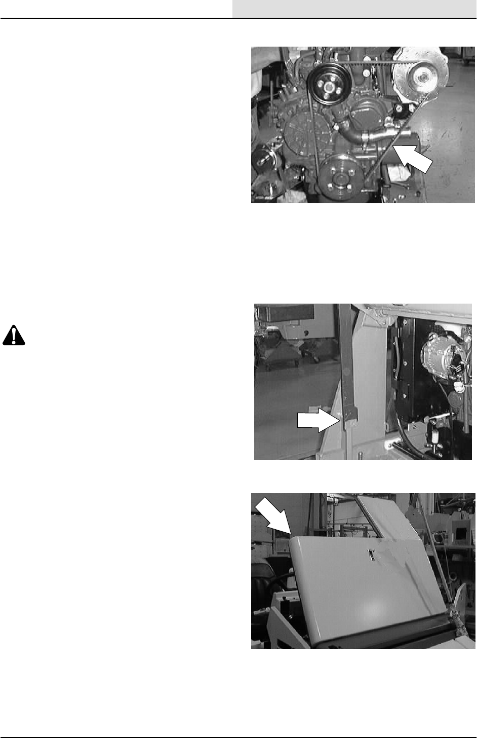
ENG--DIESEL
8-5
8200/8210 330065 (3--01)
ENGINE FAN BELT
The engine fan belt is driven by the engine
crankshaft pulley and drives the alternator pulley.
Proper belt tension is 13 mm (0.50 in) from a
forceof4to5kg(8to10lb)appliedatthe
mid-point of the longest span.
Check and adjust the belt tension every 100 hours
of operation.
TO REPLACE ENGINE FAN/ALTERNATOR
BELT
1. Raise the hopper and engage the prop bar.
WARNING: Raised Hopper May Fall.
Engage Hopper Support Bar.
FOR SAFETY: Before Leaving Or
Servicing Machine; Stop On Level
Surface, Set Parking Brake, Turn Off
Machine And Remove Key.
2. Open the engine cover and side door.

ENG--DIESEL
8-6 8200/8210 330065 (3--01)
3. Disconnect the battery cables from the
battery.
4. Pull the rubber dust shield away from the
front of the engine in the area of the
alternator.
5. Go to the area of the machine in front of the
engine. Locate the two hex screws and nuts
holding the accessory pump pivot plate to
the mount plate. Loosen these two screws.
6. Locate the hex bolt and compression spring
at the front of the accessory pump mount
bracket. Loosen the hex bolt and
compression spring.
NOTE: Remove the accessory pump V--belt from
the pump sheave.
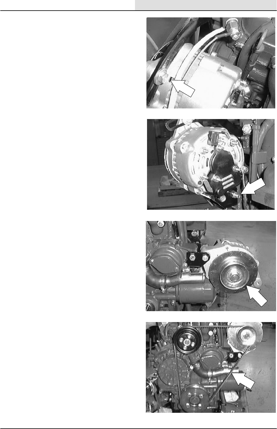
ENG--DIESEL
8-7
8200/8210 330065 (3--01)
7. Loosen the hex screw holding the top of the
alternator to the mount bracket.
8. Loosen the hex screw and nyloc nut holding
the bottom of the alternator to the lower
mount bracket.
9. Push the alternator in toward the engine.
Remove the V--belt from the alternator and
engine pulleys.
10. Position the new fan belt on the alternator
pulley and engine pulleys.
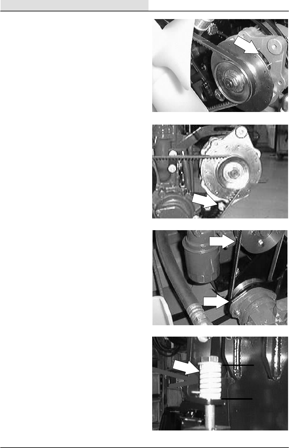
ENG--DIESEL
8-8 8200/8210 330065 (3--01)
11. Pull the alternator away from the engine to
tighten the belt. See adjustment in ENGINE
FAN BELT description. Tighten the hex
screw to 18 -- 24 Nm (13 -- 18 ft lb).
12. Tighten the bottom hex screw to
18 -- 24 Nm (15 -- 20 ft lb).
13. Install the hydraulic pump V--belt around the
accessory pump sheave.
14. The accessory pump belt adjustment is
made by turning the bolt on top of the
tension spring. The tension spring is located
at the front of the engine compartment, near
the accessory pump belt sheave. The
accessory pump belt is at the proper tension
when the tension spring is compressed to
3.81 cm 0.0076 mm (1.5 in 0.030 in).
NOTE: When adjusting the accessory pump belt
tension, measure only the spring and not the
washers at either end.

ENG--DIESEL
8-9
8200/8210 330065 (3--01)
15. Go back and tighten the two pivot plate
mount screws to 37 -- 48 Nm (26 -- 34 ft lb).
16. Position the rubber dust shield back into the
metal bracket.
17. Reconnect the battery and start the
machine.
18. Disengage the prop arm and lower the
hopper.
19. Check the alternator for proper operation.
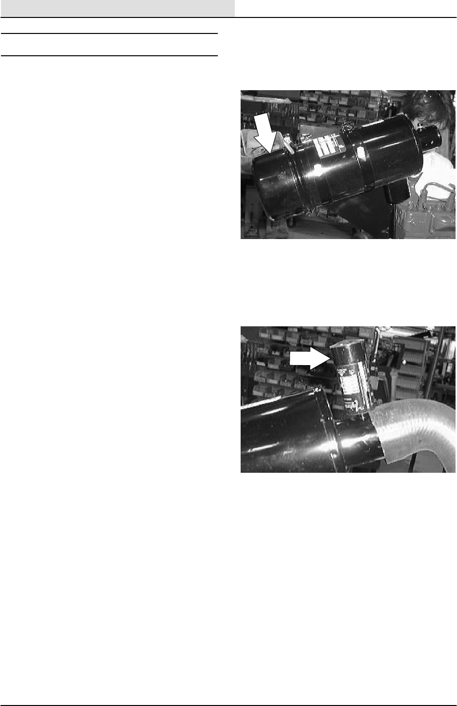
ENG--DIESEL
8-10 8200/8210 330065 (3--01)
AIR INTAKE SYSTEM
AIR FILTER
The engine air filter housing has a dust cap and a
dry cartridge-type air filter element. Empty the
dust cap daily. The air filter must be replaced
whenever the filter element is damaged or has
been cleaned three times.
Machines with the heavy duty air filter option have
a safety element. It is inside the standard
element. Replace, do not clean this element after
the regular element has been damaged or
cleaned three times.
Service the air filter element only when the air
filter indicator shows restriction in the air intake
system. Do not remove the air filter element
unless it is restricting air flow.
AIR FILTER INDICATOR (optional)
The air filter indicator shows when to clean or
replace the air filter element. Check the indicator
daily. The indicator’s red line will move as the air
filter element fills with dirt. Do not clean or replace
the air filter element until the red line reaches 5
kPa (20 in H2O) and the ”SERVICE WHEN RED”
window is filled with red. The indicator’s red line
may return to a lower reading on the scale when
the engine shuts off. The red line will return to a
correct reading after the engine runs for a while.
Reset the air filter indicator by pushing the reset
button on the end of the indicator after cleaning or
replacing the air filter element.
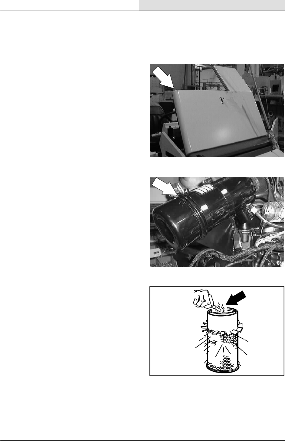
ENG--DIESEL
8-11
8200/8210 330065 (3--01)
TO REPLACE AIR FILTER ELEMENT
FOR SAFETY: Before Leaving Or
Servicing Machine: Stop On Level
Surface, Set The Parking Brake, Turn Off
Machine And Remove Key.
1. Open the engine cover and side door.
2. Unscrew the clamp ring on the filter.
3. Remove the dust cap.
4. Empty the dust cap.
5. Remove the filter wing nut.
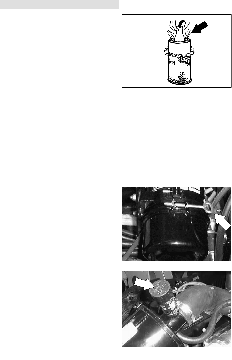
ENG--DIESEL
8-12 8200/8210 330065 (3--01)
6. Pull the filter element out of the filter
housing.
7. Clean the interior of the air cleaner housing
with a camp cloth. Clean the element
housing sealing surfaces.
8. Using an air hose, direct dry, clean air
maximum 205 kPa (30 psi) up and down
pleats on the inside of the filter. Do not rap,
tap, or pound dust out of the element.
FOR SAFETY: When Servicing Machine,
Wear Eye And Ear Protection When
Using Pressurized Air Or Water.
9. After cleaning the air filter element, inspect it
for damage by placing a bright light inside.
The slightest rupture requires replacement
of the filter. Clean and inspect the seals on
the ends of the element. They should be
unbroken and flexible. Remember to replace
the element after cleaning it three times.
10. Install the new or cleaned filter element so
the fins on the element are at the intake end
of the air cleaner. Be careful not to damage
the fins. Make sure the element is seating
evenly. Tighten the element wing nut.
11. Install the dust cap with the arrows pointing
up. Tighten the clamp ring to hold it in place.
Check all intake hose connections for leaks
or abrasions.
12. Reset the air filter restriction indicator.
13. Close the engine cover and side door.
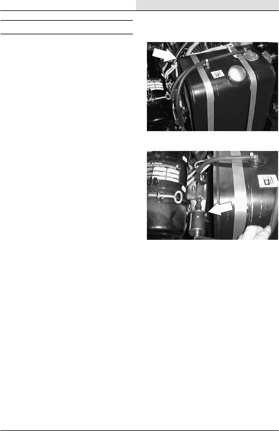
ENG--DIESEL
8-13
8200/8210 330065 (3--01)
FUEL SYSTEM -- DIESEL
The diesel fuel system is made up of five basic
components which are: fuel tank, electric fuel
pump, fuel filter/water trap, injection pump, and
injectors.
Fuel flows from the fuel tank through the electric
fuel pump and is pumped to the fuel filter/ water
trap. The water trap-filter separates water and
impurities from the fuel. From the fuel water
trap-filter, fuel continues on to the injection pump.
The injection pump pressurizes and sends fuel to
the injectors. The injectors atomize and inject
proper amounts of fuel into the combustion
chamber at the proper times. Excess fuel is
returned to the fuel tank through an overflow pipe.
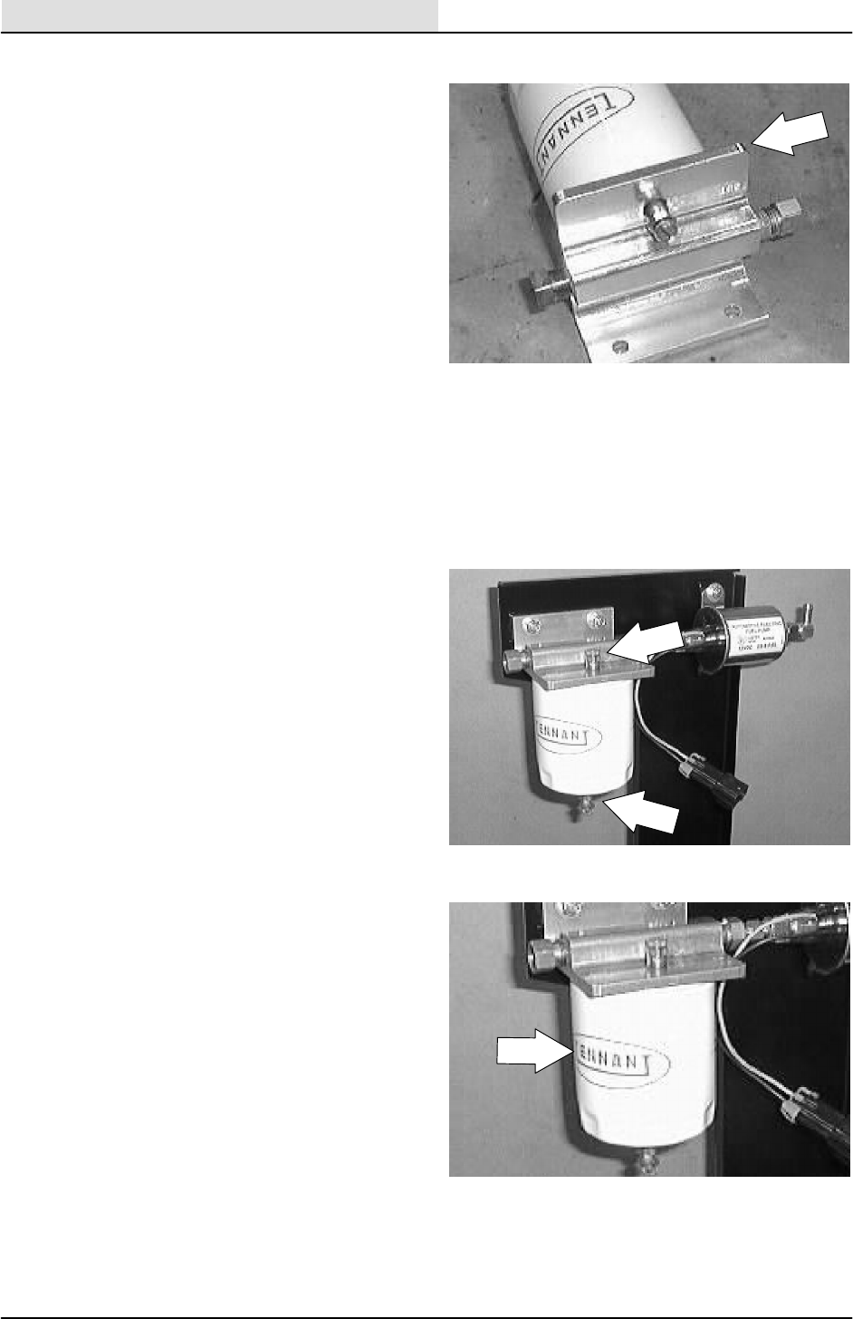
ENG--DIESEL
8-14 8200/8210 330065 (3--01)
FUEL FILTER
The large fuel filter cartridge filters impurities from
the fuel. Water is also removed from the fuel with
this filter/water separator.
TO REPLACE THE FUEL FILTER CARTRIDGE
FOR SAFETY: Before Leaving Or
Servicing Machine; Stop On Level
Surface, Set Parking Brake, And Turn
Off Machine.
1. Loosen the unit vent plug and open the
water trap drain to drain diesel fuel.
2. Remove the filter cartridge from the filter
head.
3. Lubricate the o-ring of the new filter
cartridge and spin it onto the filter head.
4. Bleed the fuel lines of air as described in TO
PRIME FUEL SYSTEM instructions.
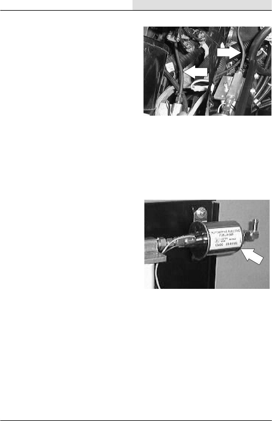
ENG--DIESEL
8-15
8200/8210 330065 (3--01)
FUEL LINES
Check the fuel lines every 50 hours of operation.
If the clamp band is loose, apply oil to the screw
of the band, and securely tighten the band.
Made of rubber, the fuel lines become worn out
whether the engine has been used much or not.
Replace the fuel lines and clamp bands every two
years.
If the fuel lines and clamp bands are found worn
or damaged before two years’ time, replace or
repair them at once. Bleed the fuel system after
replacement of any of the fuel lines, see TO
PRIME THE FUEL SYSTEM. When the fuel lines
are not installed, plug both ends with clean cloth
or paper to prevent dirt from entering the lines.
Dirt in the lines can cause fuel injection pump
malfunction.
ELECTRIC FUEL PUMP
The fuel pump is operated with 12 volts from the
battery. Fuel is drawn from the fuel tank to the
electric fuel pump. The fuel then flows through the
fuel/water separator and on to the injector pump.
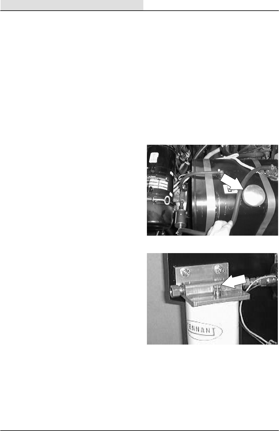
ENG--DIESEL
8-16 8200/8210 330065 (3--01)
PRIMING FUEL SYSTEM
Priming the fuel system removes pockets of air in
the fuel lines and fuel components. Air in the fuel
system will prevent smooth engine operation.
Prime the fuel system after running out of fuel,
changing fuel filter element or repairing a fuel
system component.
TO PRIME FUEL SYSTEM
FOR SAFETY: Before Leaving Or
Servicing Machine; Stop On Level
Surface, Set Parking Brake, And Turn
Off Machine.
1. Make sure the fuel tank is full.
2. Open the air vent on top of the fuel filter.
3. Start the engine and allow it to run until a
steady stream of fuel flows from the vent.
4. Close the air vent and shut off the engine.
5. Clean up any fuel that was spilled during the
bleeding process.

ENG--DIESEL
8-17
8200/8210 330065 (3--01)
GOVERNOR
The electronic governor controls engine speed.
The governor consists of a mag pick--up
assembly, a control box, and an throttle actuator
mounted on the back of the injector pump. The
control box regulates the actuator, which in turn
controls the throttle.
The electronic governor is factory set and is not
user serviceable.
TO ADJUST GOVERNOR CONTROL BOX
1. Raise the rear of the machine and place jack
stands under the frame.
FOR SAFETY: Block machine tires
before jacking machine up. Jack
machine up at designated locations
only. Block machine up with jack
stands.
2. Start the engine and warm to operating
temperature.
3. Move the speed switch to idle, all
accessories off.
4. Move the speed switch to the fast position. F
E
12 : 16 PM
0021
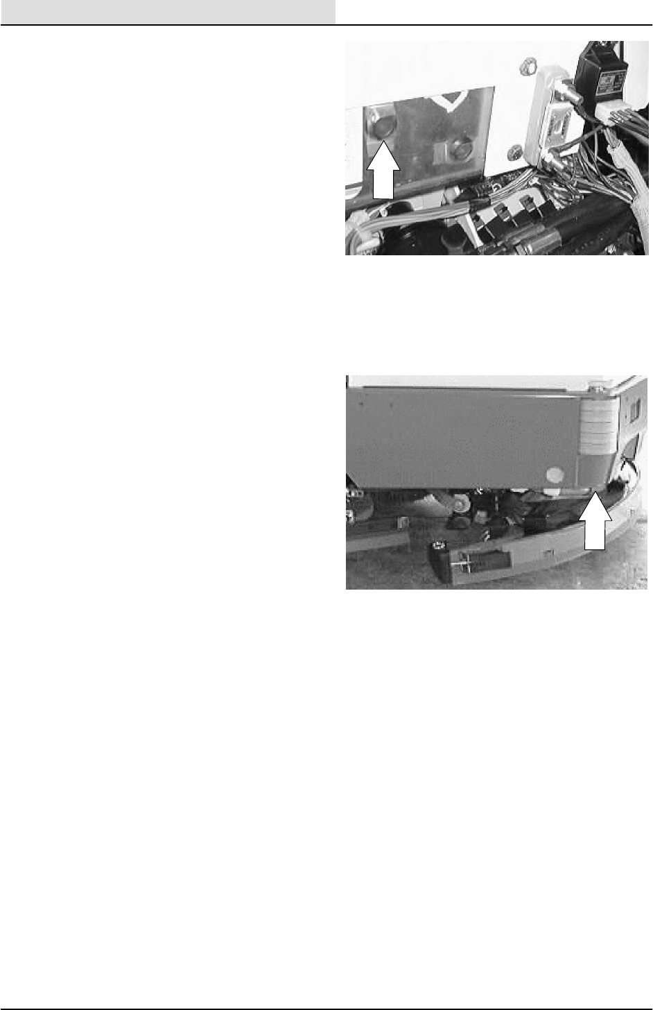
ENG--DIESEL
8-18 8200/8210 330065 (3--02)
5. FOR ANANLOG CONTROLLER: If engine
speed surges occur, turn the surge
adjustment screw (located on back of
governor control box under hole plug)
counterclockwise one-eighth of a turn.
Repeat until surges do not occur.
Replace hole plug if removed for adjustment.
6. FOR DIGITAL CONTROLLER: Follow the
instructions on the DIGITAL CONTROLLER
SET--UP diagram.
7. Remove the jack stands and lower the
machine.

ENG--DIESEL
8-19
8200/8210 330065 (3--02)
rocker down
O
F
F
Set DIP switches according to
controller label, before installing
controller.
123 45 6 78
DIGITAL CONTROLLER SET-- UP
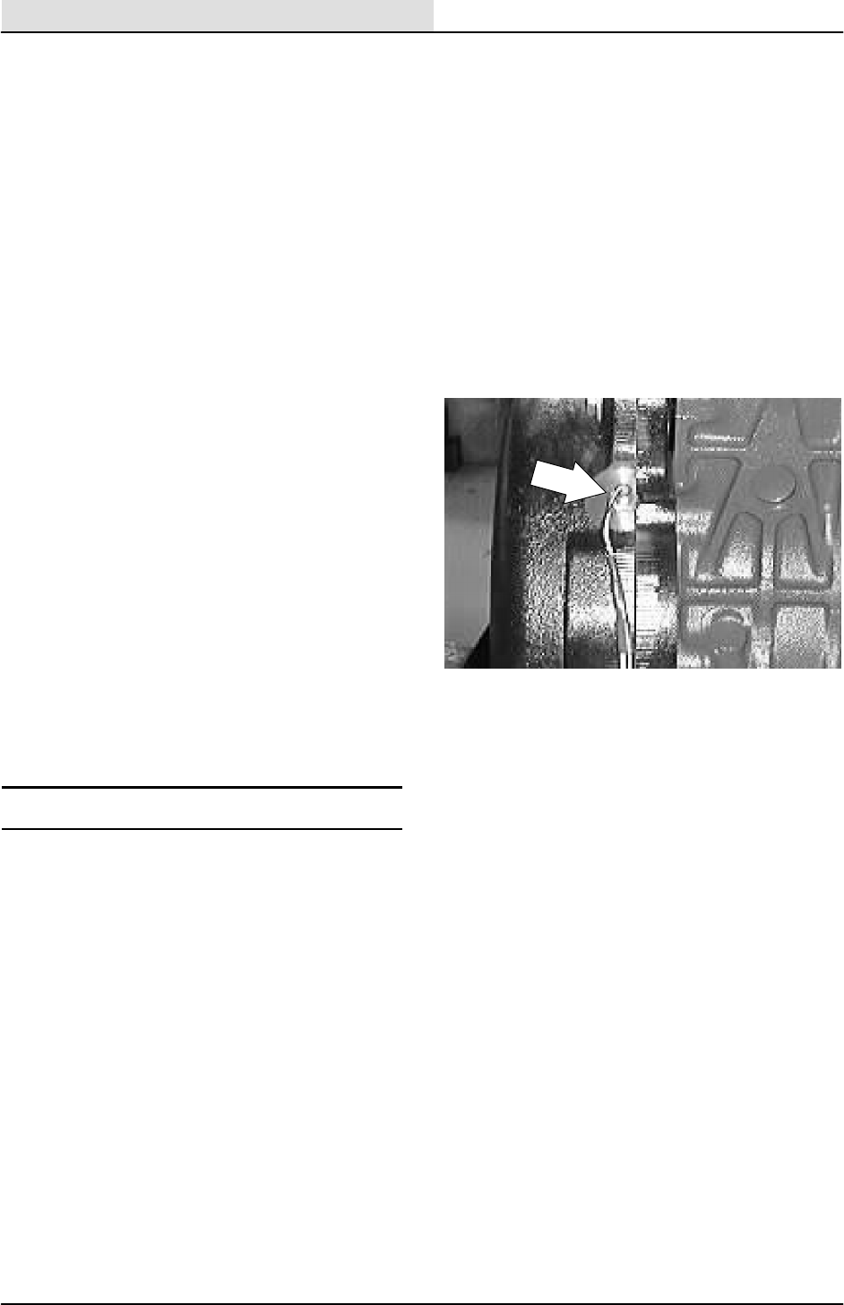
ENG--DIESEL
8-20 8200/8210 330065 (3--01)
TO ADJUST TRANSDUCER
(MAGNETIC PICKUP)
FOR SAFETY: Before Leaving Or
Servicing Machine: Stop On Level
Surface, Set The Parking Brake, Turn Off
Machine And Remove Key.
1. Turn the flywheel until you see a starter ring
gear tooth centered in the mag pickup hole.
NOTE: On existing engines in the field, there is
one tooth marked white for ease of visibility. On
new engines, you may want to mark a tooth white
in the vicinity of the mag pickup and then turn the
flywheel until it is centered.
2. Screw the new transducer (mag pickup) in
until it lightly hits the tooth.
3. Back the transducer (mag pickup) out 1/4
turn to 1/2 turn (.015 + or -- .005 in. gap).
Tighten the jam nut.
4. Slowly turn the engine over to make sure the
flywheel does not hit the transducer
(mag pickup).
5. If it hits, turn the transducer (mag pickup)
out 1/4 more and repeat step 4.
CYLINDER HEAD
VALVE TAPPET CLEARANCE
The valve tappet clearance must be checked and
adjusted if necessary every 400 hours of
operation. See Kubota Diesel Engine Workshop
Manual.
CRANKCASE VENTILATION SYSTEM
See Kubota Diesel Engine Workshop Manual.
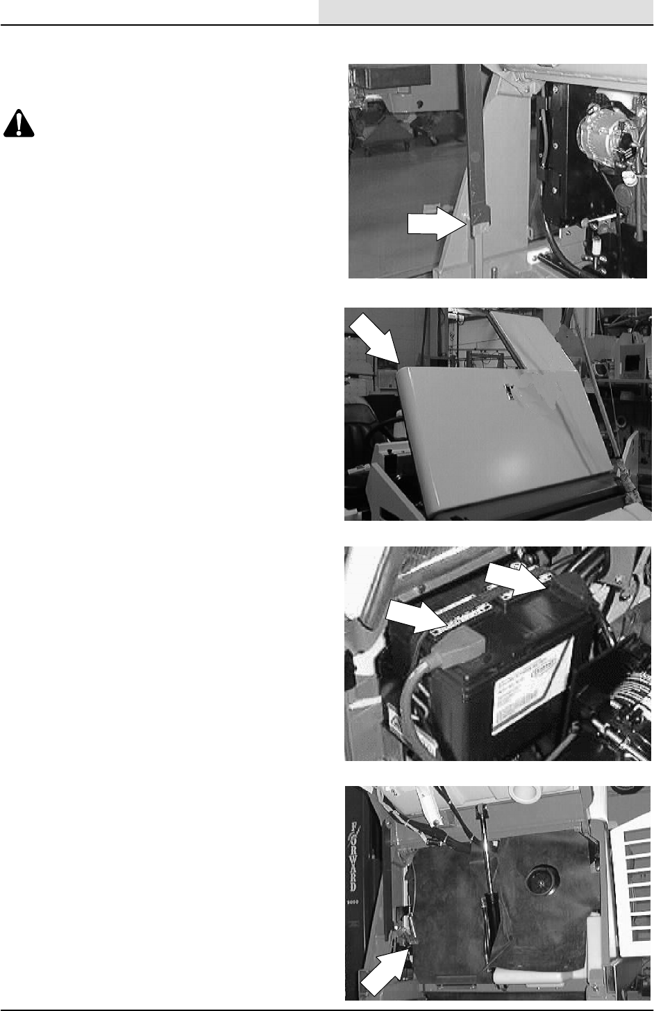
ENG--DIESEL
8-21
8200/8210 330065 (3--01)
TO REPLACE ALTERNATOR
1. Raise the hopper and engage the prop bar.
WARNING: Raised Hopper May Fall.
Engage Hopper Support Bar.
FOR SAFETY: Before Leaving Or
Servicing Machine; Stop On Level
Surface, Set Parking Brake, Turn Off
Machine And Remove Key.
2. Open the engine cover and side door.
3. Disconnect the battery cables from the
battery.
4. Pull the rubber dust shield away from the
front of the engine in the area of the
alternator.
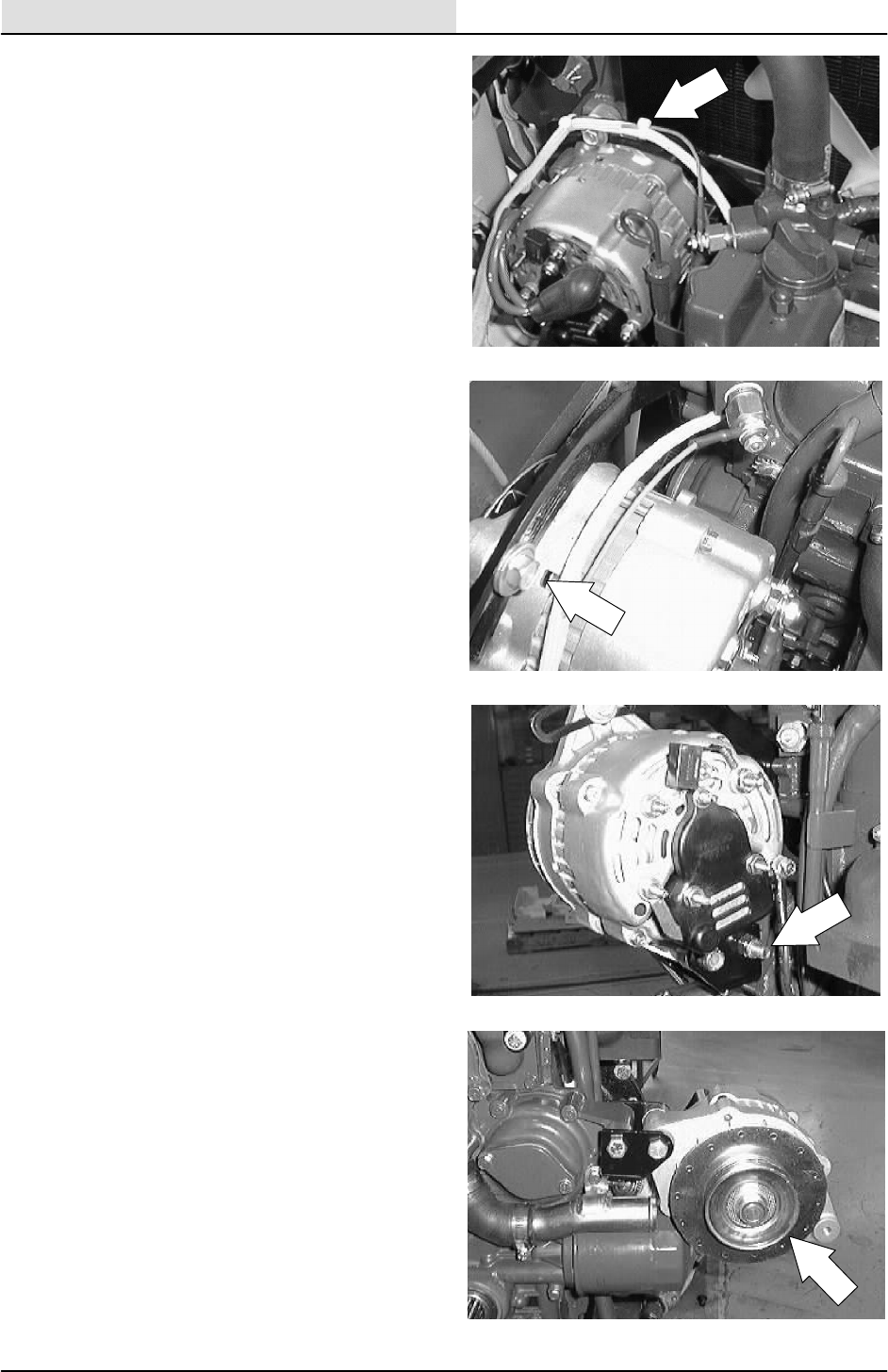
ENG--DIESEL
8-22 8200/8210 330065 (3--01)
5. Cut any plastic wire ties holding the wire
harness to the alternator bracket.
6. Loosen the hex screw holding the top of the
alternator to the mount bracket.
7. Loosen the hex screw and nyloc nut holding
the bottom of the alternator to the lower
mount bracket.
8. Push the alternator in toward the engine.
Remove the V--belt from the alternator and
engine pulleys.
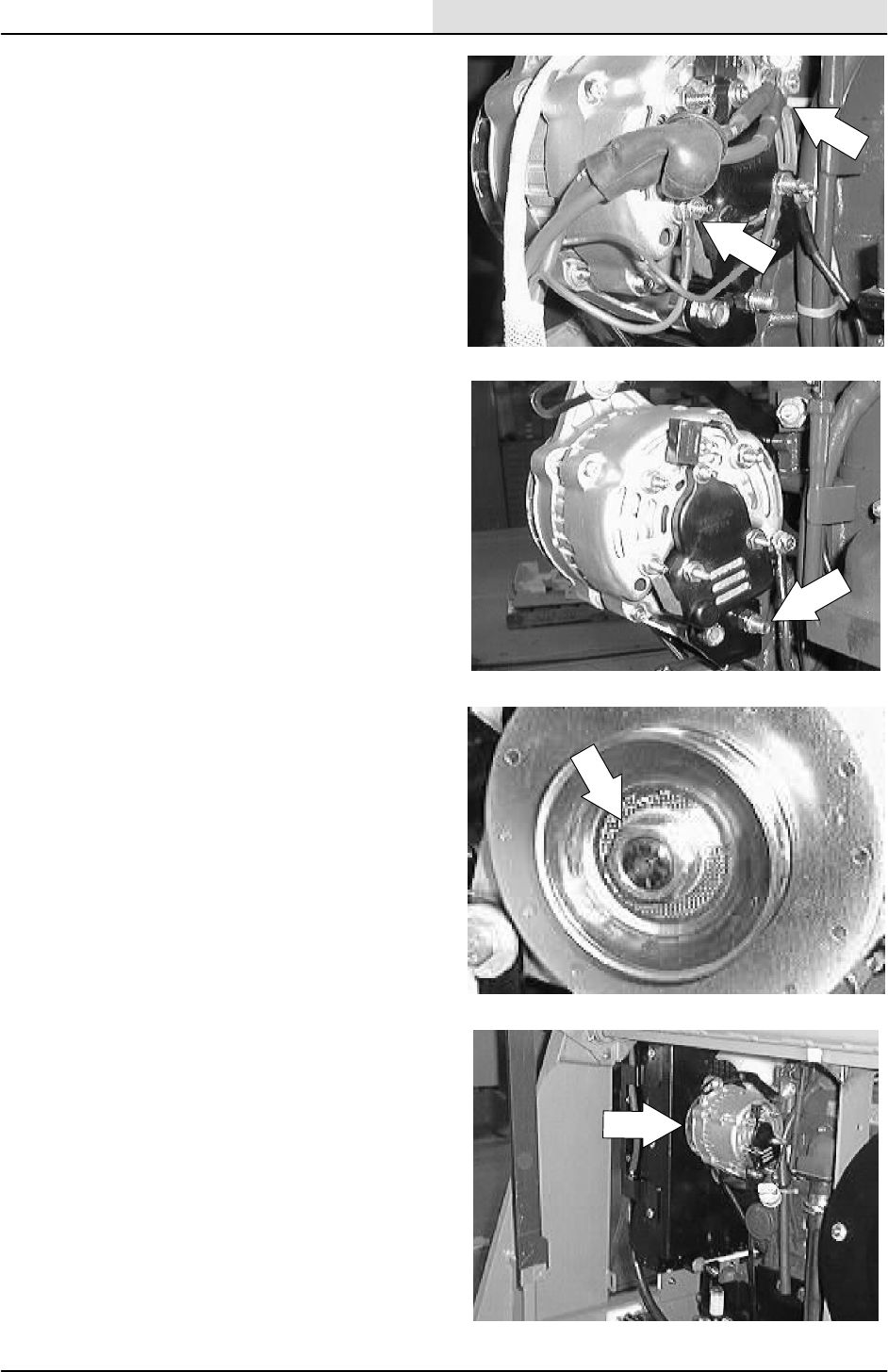
ENG--DIESEL
8-23
8200/8210 330065 (3--01)
9. Disconnect the wires leading to the back of
the alternator.
10. Remove the hex screw and nyloc nut
holding the bottom of the alternator to the
lower mount bracket.
11. The alternator can now be removed out the
front of the machine.
12. If the new or rebuilt alternator needs a drive
pulley, remove the pulley from the old
alternator. Hold the pulley from turning and
use an impact wrench to remove the hex
nut.
13. Install the pulley, washer, and hex nut on the
new alternator. Firmly tighten the nut with
the impact.
14. Install the new alternator back in the
machine. Align the bottom hole in the
alternator with hole in lower mount bracket.
Reinstall the hex bolt, ground cable, and
nyloc nut. Leave it loose for now.
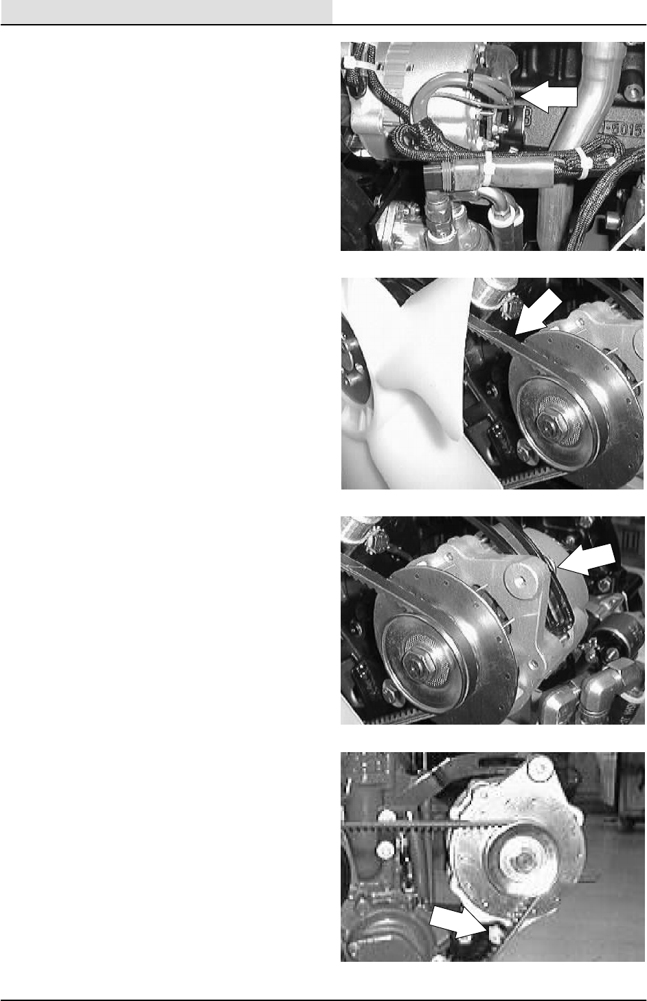
ENG--DIESEL
8-24 8200/8210 330065 (3--01)
15. Reconnect the wires to the back of
alternator. See the schematic in the
ELECTRICAL section.
16. Place the V--belt back on the alternator
pulley.
17. Reinstall the hex screw in the top hole of the
alternator through upper slotted mounting
bracket. Pull the alternator away from the
engine to tighten the belt. See adjustment in
ENGINE FAN BELT description. Tighten the
hex screw to 18 -- 24 Nm (13 -- 18 ft lb).
18. Tighten the bottom hex screw to
18 -- 24 Nm (15 -- 20 ft lb).

ENG--DIESEL
8-25
8200/8210 330065 (3--01)
19. Place the rubber dust shield back in position.
20. Reconnect the battery cables and start the
engine. Check the new alternator for proper
operation.

ENG--DIESEL
8-26 8200/8210 330065 (3--01)
TO REPLACE STARTER
FOR SAFETY: Before Leaving Or
Servicing Machine; Stop On Level
Surface, Set Parking Brake, Turn Off
Machine And Remove Key.
1. Open the engine cover and side door.
2. Disconnect the battery cables from the
battery.
3. Disconnect the wires leading to the engine
starter.

ENG--DIESEL
8-27
8200/8210 330065 (3--01)
4. Remove the two M8 hex screws holding the
starter to the engine bellhousing.
5. Pull the starter straight out of the bellhousing
and remove it from the machine.
6. Install the new starter in the machine. Align
the two holes in the starter with the holes in
the bellhousing. Reinstall the two M8 hex
screws. Tighten to 18 -- 24 Nm
(15 -- 20 ft lb).
7. Reconnect the wires to the back of the
starter. See the schematic in the
ELECTRICAL section.

ENG--DIESEL
8-28 8200/8210 330065 (3--01)
8. Reconnect the battery cables.
9. Close the engine cover and side door.
Check the starter for proper operation.
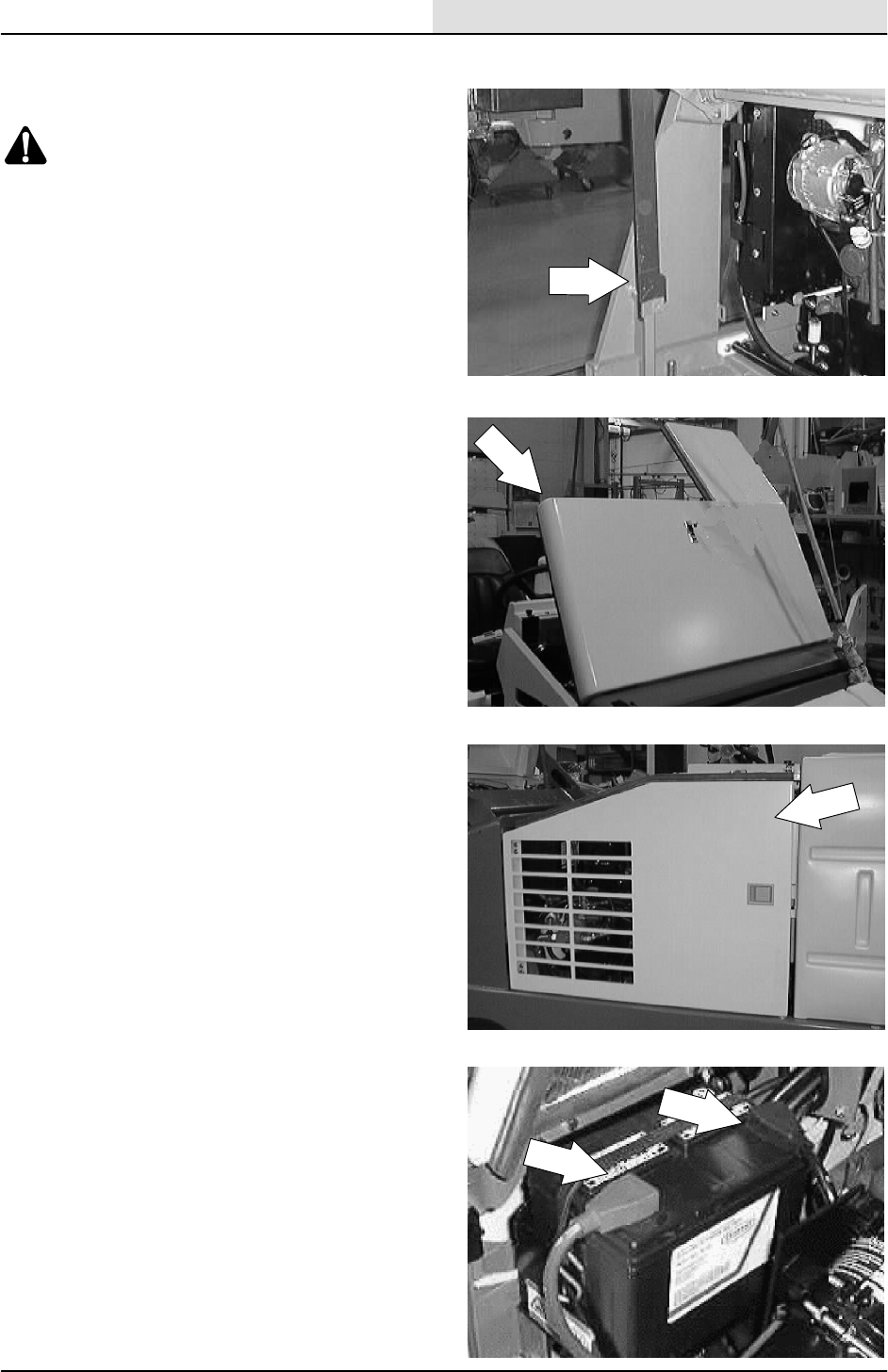
ENG--DIESEL
8-29
8200/8210 330065 (3--01)
TO REMOVE ENGINE
1. Raise the hopper and engage the prop bar.
WARNING: Raised Hopper May Fall.
Engage Hopper Support Bar.
NOTE: If the engine will not start because of a
bad starter-- --use an overhead crane to lift the
hopper and engage the prop arm.
FOR SAFETY: Before Leaving Or
Servicing Machine; Stop On Level
Surface, Set Parking Brake., Turn Off
Machine And Remove Key.
2. Open the engine cover and side door.
3. Remove the engine cover and side door
from the machine.
4. Disconnect the battery cables from the
battery. Remove the battery and battery tray
from the machine.
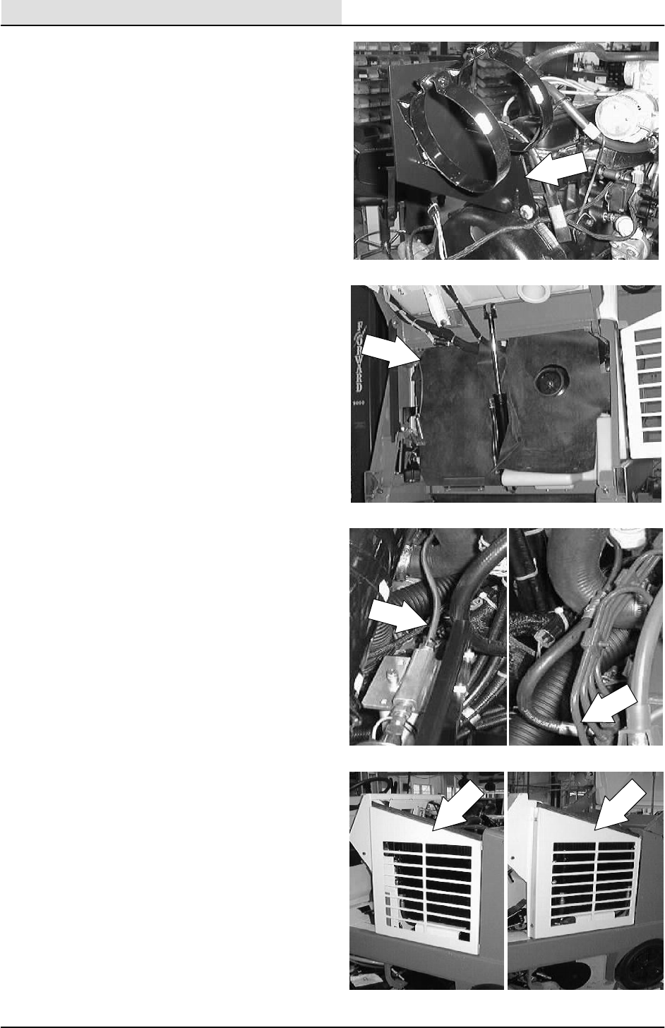
ENG--DIESEL
8-30 8200/8210 330065 (3--01)
5. Remove the air cleaner and mount bracket
from the engine.
6. Pull the rubber dust shield up and out of the
way for access to the front of the engine.
7. Disconnect the fuel tank lines at the injector
pump and injector return line.
8. Remove the two hex screw holding the
radiator grill guard to the frame. Remove the
grill from the machine.
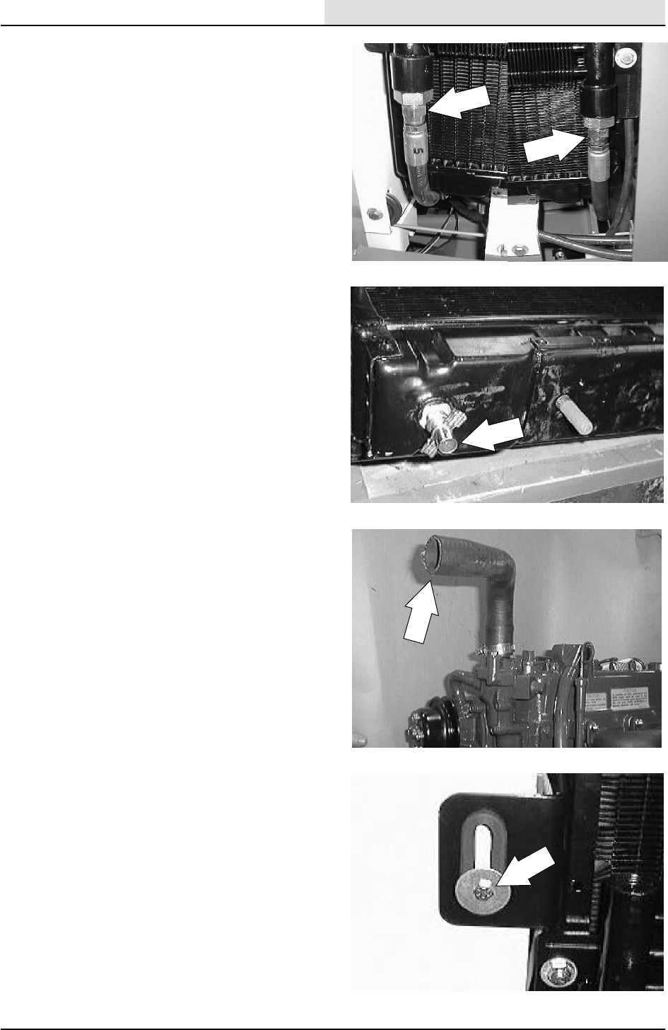
ENG--DIESEL
8-31
8200/8210 330065 (3--01)
9. Mark, disconnect, and plug the two hydraulic
hoses leading to the hydraulic oil cooler on
the front of the radiator.
NOTE: Always observe hydraulic cleanliness
requirements when opening hydraulic lines.
10. Drain the coolant from the radiator.
11. Remove the two radiator hoses from the
engine.
12. Remove the hex screw, spacer, and fender
washer holding the top left side of the
radiator to the radiator support.
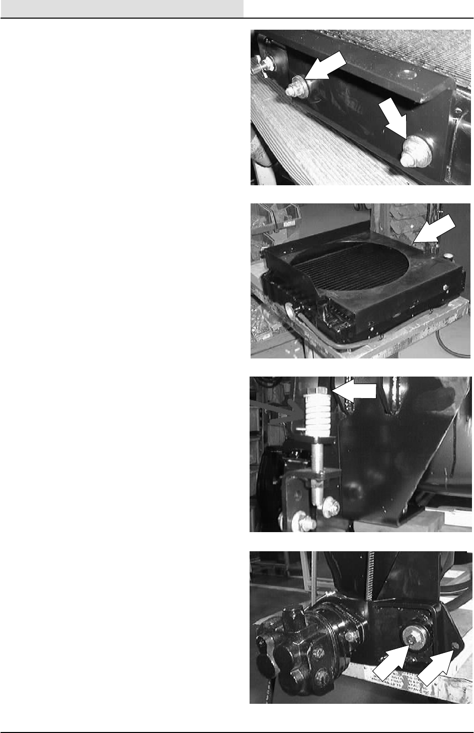
ENG--DIESEL
8-32 8200/8210 330065 (3--01)
13. Remove the two hex screws and nyloc nuts
holding the bottom of the radiator to the
mount bracket.
14. Pull the radiator back so it clears the engine
fan. Remove the radiator, fan shroud, and
hydraulic oil cooler from the machine.
15. Remove the hex screw and compression
spring from the front of the accessory pump
pivot bracket. Remove the V--belt from the
engine sheave.
16. Remove the hex screw, nut, and sleeve
holding the hydraulic accessory pump pivot
bracket to the front motor mount. Drop the
hydraulic pump down onto the frame. DO
NOT disconnect the hydraulic hoses leading
to the accessory pump.
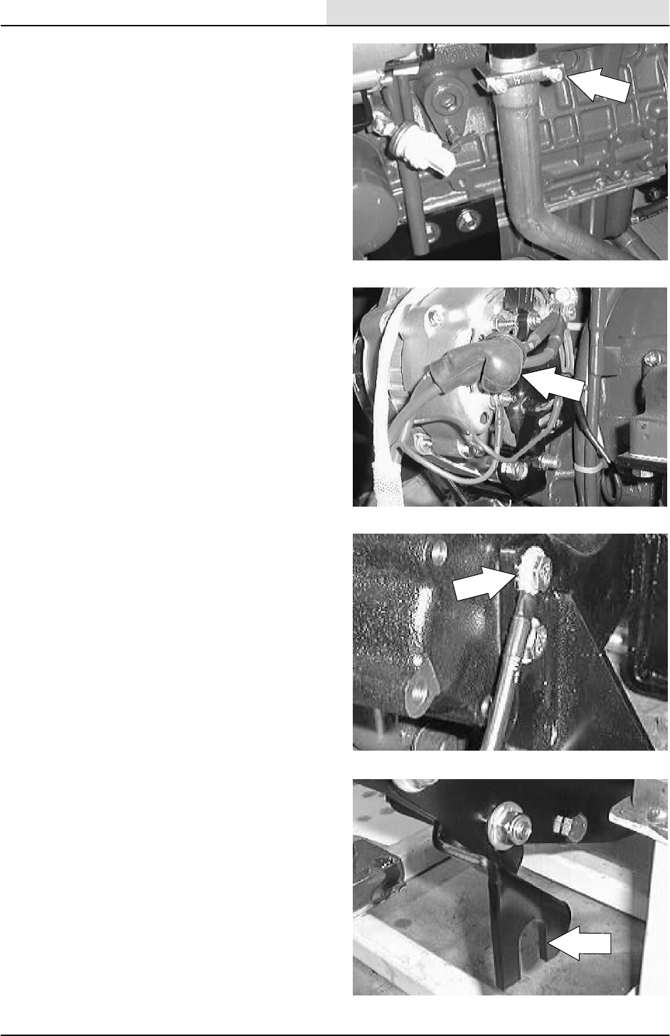
ENG--DIESEL
8-33
8200/8210 330065 (3--01)
17. Remove the muffler clamp holding the
exhaust pipe to the engine manifold. Slip the
pipe off the manifold.
18. Disconnect the wire harness from the
alternator, starter, oil sender, temp. sender,
governor, glow plugs, mag. pick--up, ect.
Move the wires out of the way for engine
removal.
19. Disconnect the ground wires and ground
cable from the rear motor mount hex screw.
20. Loosen the jam nuts on the propel cable
where it attaches to the mount bracket on
the bellhousing. Pull the propel cable out of
the mount bracket slot.
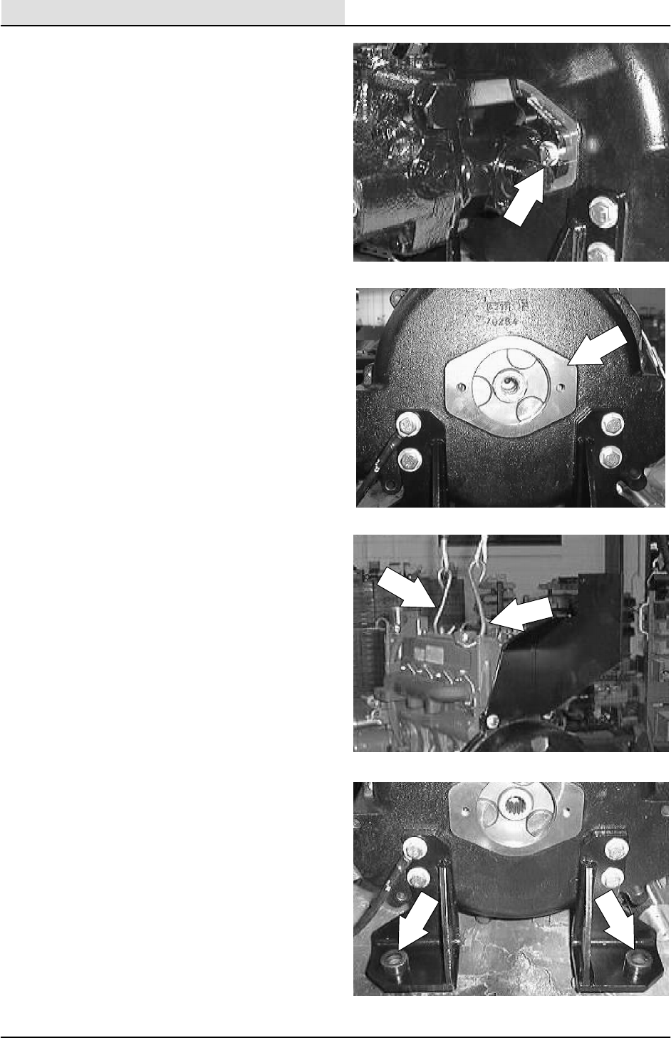
ENG--DIESEL
8-34 8200/8210 330065 (3--01)
21. Remove the two hex screws holding the
propel pump into the flywheel housing.
NOTE: Leave the hydraulic hoses connected to
the propel pump.
NOTE: Place a block of wood under the hydraulic
pump assembly for support when removing the
engine.
22. Pull the propel and accessory pump
assembly back, out of the bellhousing.
NOTE: Leave the hydraulic hoses connected to
the propel pump.
NOTE: Pull the engine toward the right side of the
machine until the hydraulic pump assembly is free
of the bellhousing.
23. Using an overhead hoist, hook a chain
through the two pick--up points on the top of
the engine. Put a slight amount of tension on
the chain.
24. Remove the three hex screws and nyloc
nuts holding the three motor mounts to the
rubber isolators on the frame brackets.
25. The engine can now be carefully lifted out.
NOTE: Make sure the engine is clear of any wires
or hoses before you lift it out of the frame.
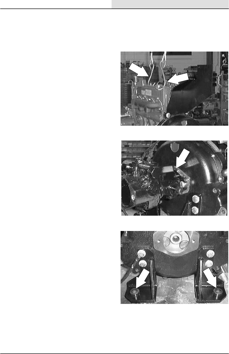
ENG--DIESEL
8-35
8200/8210 330065 (3--01)
TO INSTALL ENGINE
FOR SAFETY: Before Leaving Or
Servicing Machine; Stop On Level
Surface, Set Parking Brake., Turn Off
Machine And Remove Key.
1. Using an overhead hoist, hook a chain
through the two pick--up points on top of the
engine. Carefully position the engine back in
the engine compartment.
NOTE: Make sure the hoses, wire harness,
exhaust pipe and propel pump are pulled back out
of the way when lowering engine assembly into
place.
2. Slide the engine toward the left side of the
machine until the propel pump is positioned
into the back of the bellhousing. Install the
two hex screws. Use a small amount of blue
loctite 242 on the threads. Tighten the
hardware to 37 -- 48 Nm (26 -- 34 ft lb).
3. Carefully align the mount holes in the motor
mounts with the mount holes in the machine
frame.
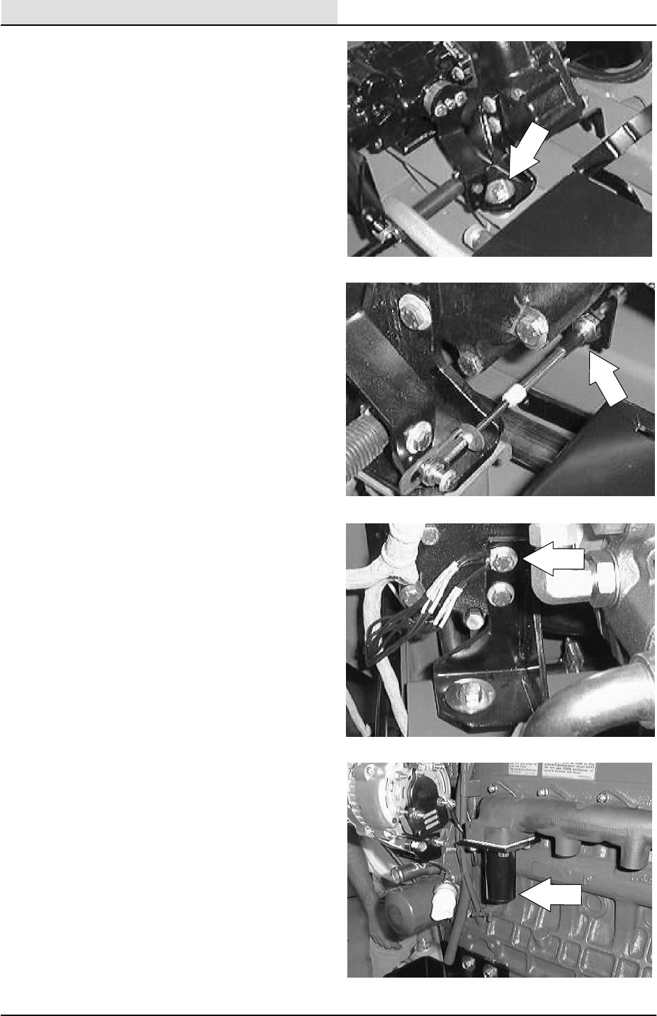
ENG--DIESEL
8-36 8200/8210 330065 (3--01)
4. Reinstall the hex screws, washers, and
nylocs in the three motor mounts. Lower the
engine all the way. Remove the hoist from
the engine. Tighten the hex screws to
64 -- 83 Nm (47 -- 61 ft lbs).
5. Position the propel cable into the slot on the
bellhousing mount bracket.
6. Reconnect the ground cable and ground
wires to the rear motor mount hardware.
7. Reinstall the exhaust pipe back on the
engine manifold. Tighten the muffler clamp
tight.
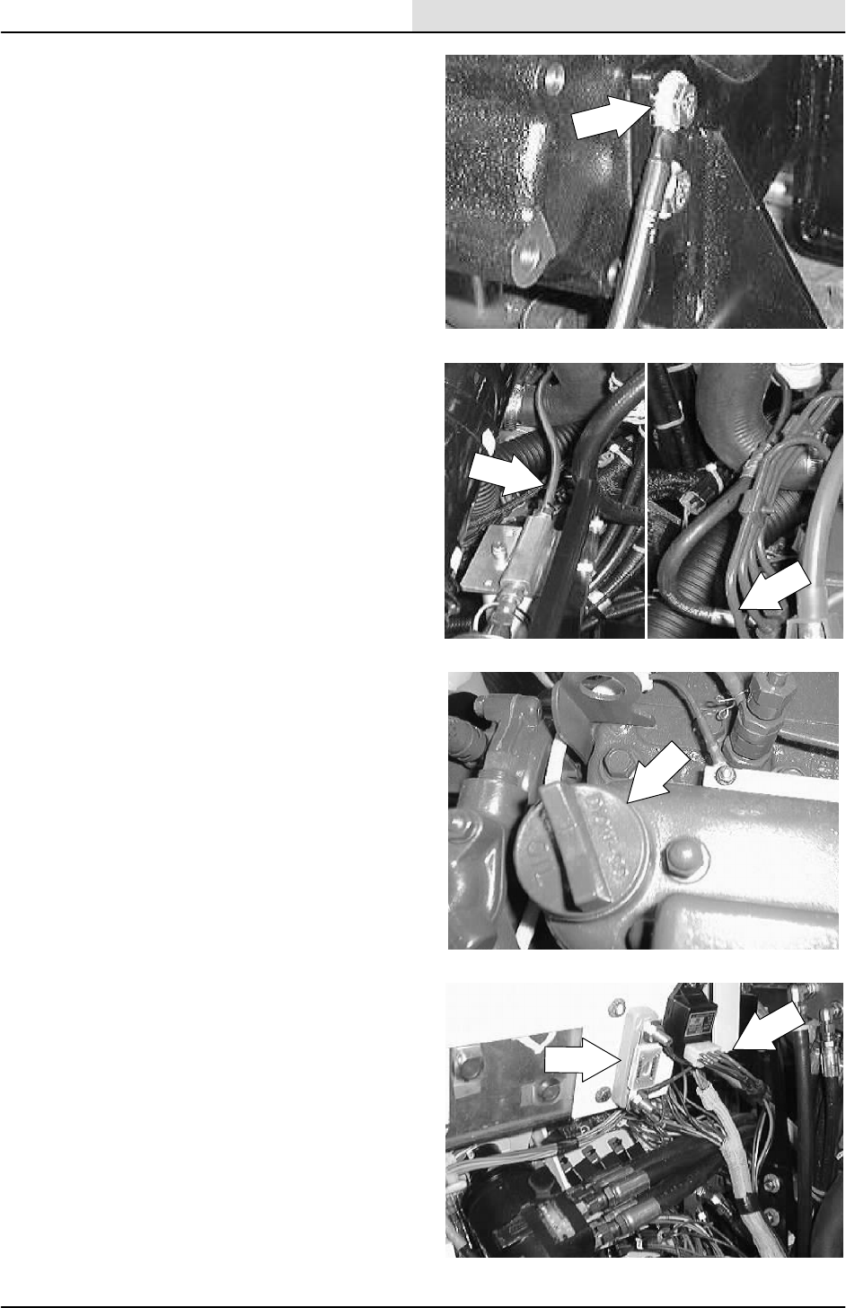
ENG--DIESEL
8-37
8200/8210 330065 (3--01)
8. Reconnect the ground cable from the
bellhousing to the machine frame.
9. Reconnect fuel lines on the injector pump
and return line.
10. Fill the engine with the proper grade of oil.
Use 6L (6.35 qt) of 10W30 SAE--CC/CD
rated engine oil with a new filter.
11. Reconnect the wire harness to the engine
components; alternator, starter, governor
actuator, oil switch, temperature sender,
and glow plugs. Use the schematic in the
ELECTRICAL section of this manual if
needed.
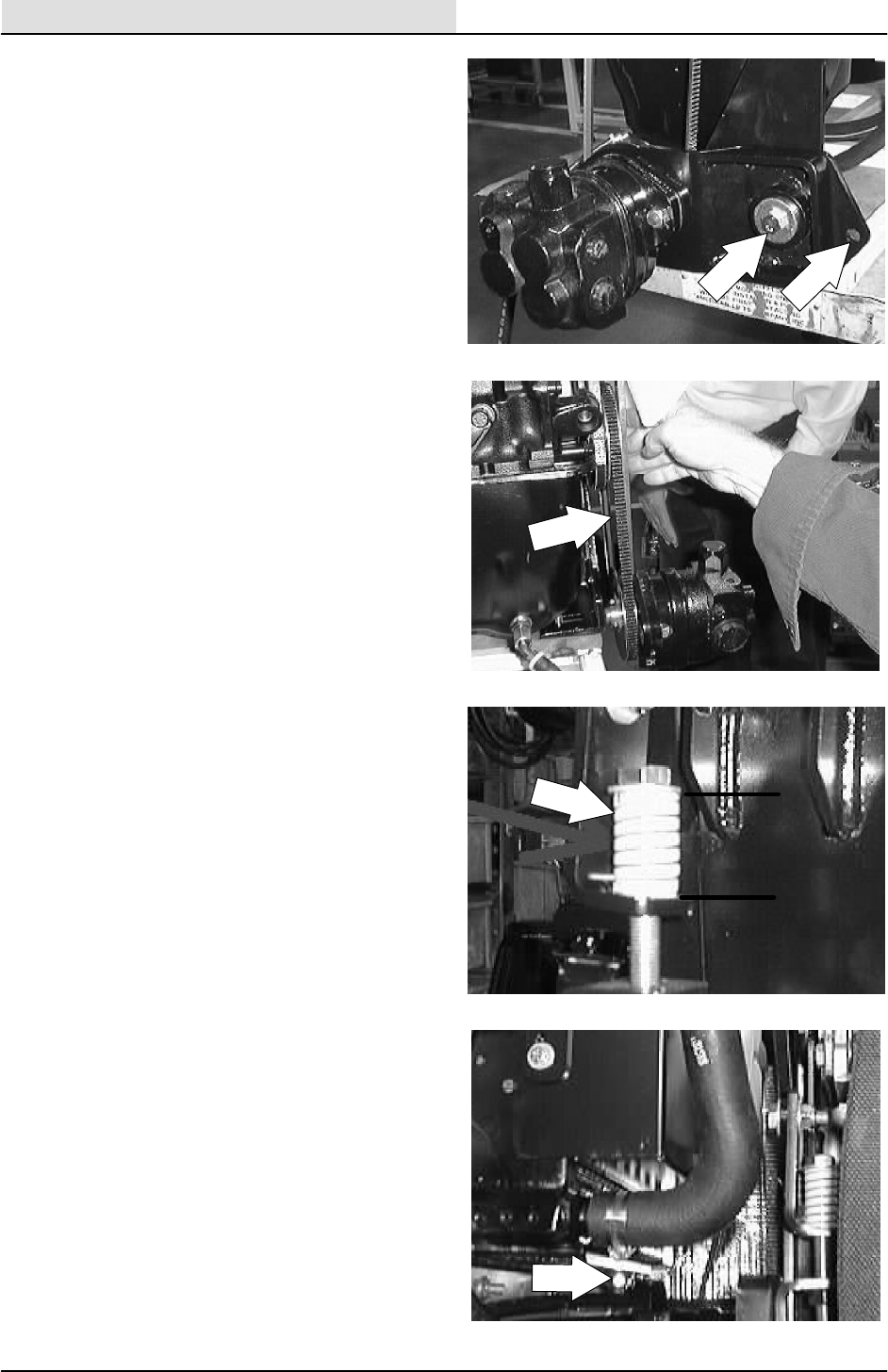
ENG--DIESEL
8-38 8200/8210 330065 (3--01)
12. Reinstall the accessory pump and pivot
bracket onto the motor mount. Tighten the
hex screw to 37 -- 48 Nm (26 -- 34 ft lb).
NOTE: Make sure the sleeve is in place.
13. Position the accessory pump V--belt onto the
engine sheave.
14. The accessory pump belt adjustment is
made by turning the bolt on top of the
tension spring. The tension spring is located
at the front of the engine compartment, near
the accessory pump belt sheave. The
accessory pump belt is at the proper tension
when the tension spring is compressed to
3.81 cm 0.0076 mm (1.5 in 0.030 in).
NOTE: When adjusting the accessory pump belt
tension, measure only the spring and not the
washers at either end.
15. Position the radiator back in the machine.
Align the two bottom studs on the radiator
assembly with the isolators in the mount
bracket. Reinstall the two 0.375 nyloc nuts
and washers. Lightly hand tighten.
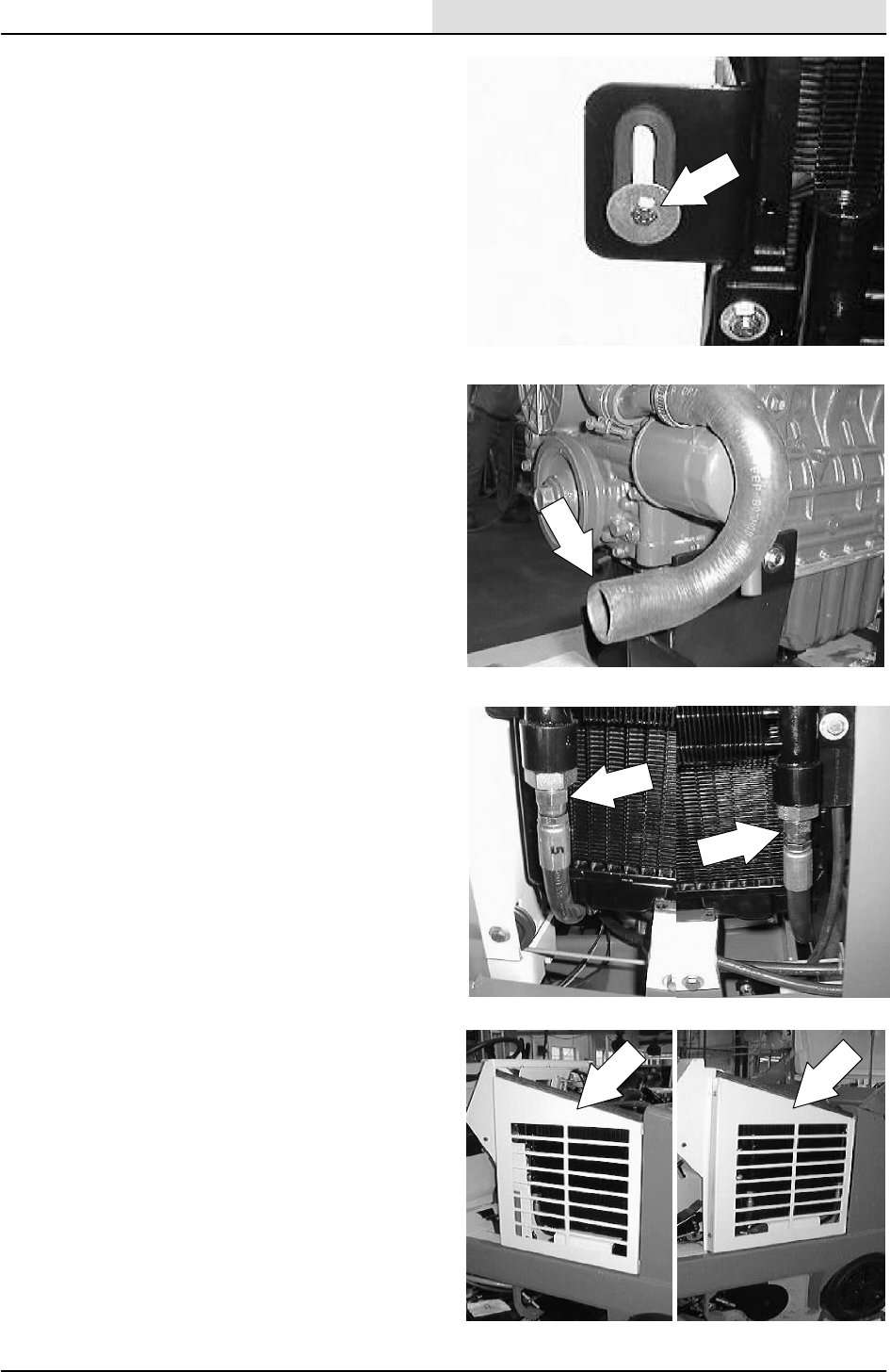
ENG--DIESEL
8-39
8200/8210 330065 (3--01)
16. Reinstall the hex screw and fender washer
holding the top of the radiator to the radiator
support. Tighten to 6 -- 9 Nm (7 -- 10 ft lb).
Go back and tighten the two hex screws on
the bottom of the mount bracket. Tighten to
37 -- 48 Nm (26 -- 34 ft lb).
17. Reinstall the radiator hoses to engine and fill
the radiator with coolant.
18. Reconnect the two hydraulic hoses to the
hydraulic oil cooler on the front of the
radiator.
19. Reinstall the radiator grill guard.
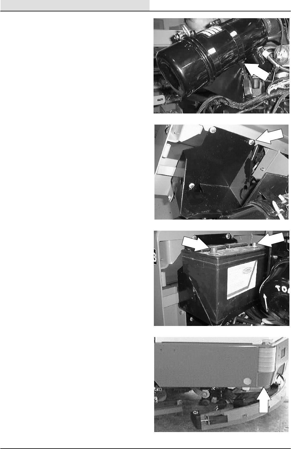
ENG--DIESEL
8-40 8200/8210 330065 (3--01)
20. Reinstall the air cleaner mount bracket and
air cleaner assembly on the rear of the
bellhousing. Use the two M10 hex screws.
Tighten to 37 -- 48 Nm (26 -- 34 ft lb).
21. Reinstall the battery tray and battery.
22. Reconnect the battery cables to the battery.
23. Jack up the rear of the machine.
FOR SAFETY: Block machine tires
before jacking machine up. Jack
machine up at designated locations
only. Block machine up with jack
stands.
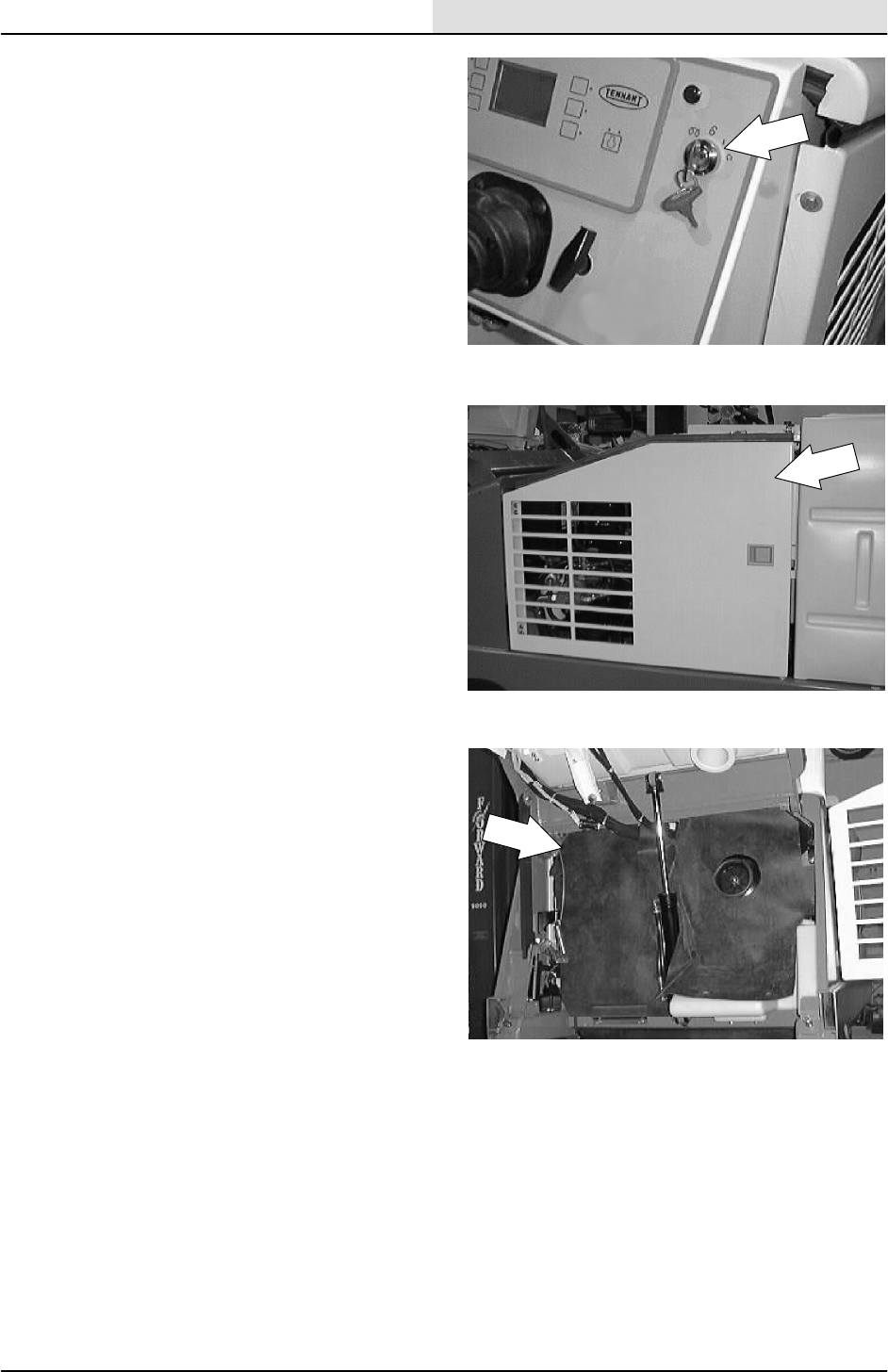
ENG--DIESEL
8-41
8200/8210 330065 (3--01)
24. Start the engine and check for any leaks and
proper operation.
25. Reinstall the engine cover and side door.
26. Reinstall the front rubber firewall.

ENG--DIESEL
8-42 8200/8210 330065 (3--02)

We Need Your Help...
As part of Tennant’s Zero Defects Program, we want to know about errors you have
found or suggestions you may have regarding our machine manuals. If you find an
error or have a suggestion, please complete this postage-paid form and mail it to us.
Thank you for helping us make zero defects a way of life at Tennant.
Manual No. Rev. No. Publish Date Page
Machine -Report Error -Suggestion
Name Date
Customer Number
Company
Address
City/State/Zip Code
Tape hereFold along dotted lines
NO POSTAGE
NECESSARY
IF MAILED
IN THE
UNITED SATES
BUSINESS REPLY MAIL
FIRST CLASS MAIL PERMIT NO. 94 MINNEAPOLIS, MN
POSTAGE WILL BE PAID BY ADDRESSEE
Technical Publications #15
701 North Lilac Drive
P.O. Box 1452
Minneapolis, MN 55440--9947
TENNANT COMPANY

We Need Your Help...
As part of Tennant’s Zero Defects Program, we want to know about errors you have
found or suggestions you may have regarding our machine manuals. If you find an
error or have a suggestion, please complete this postage-paid form and mail it to us.
Thank you for helping us make zero defects a way of life at Tennant.
Manual No. Rev. No. Publish Date Page
Machine -Report Error -Suggestion
Name Date
Customer Number
Company
Address
City/State/Zip Code

Tape hereFold along dotted lines
NO POSTAGE
NECESSARY
IF MAILED
IN THE
UNITED SATES
BUSINESS REPLY MAIL
FIRST CLASS MAIL PERMIT NO. 94 MINNEAPOLIS, MN
POSTAGE WILL BE PAID BY ADDRESSEE
Technical Publications #15
701 North Lilac Drive
P.O. Box 1452
Minneapolis, MN 55440--9947
TENNANT COMPANY
