8410 Service Manual Tennant Rider Floor Sweeper Scrubber
2018-06-13
: Sweepscrub Tennant-8410-Rider-Floor-Sweeper-Scrubber-Service-Manual tennant-8410-rider-floor-sweeper-scrubber-service-manual 2757 file product_file
Open the PDF directly: View PDF ![]() .
.
Page Count: 418 [warning: Documents this large are best viewed by clicking the View PDF Link!]
8410
Service Manual
MM392
Rev. 03 (5--02)
*mm392*

This service manual is intended to be an aid for the disassembly and reassembly of your TENNANT
Model 8410.
The set is organized into eight major groups: General Information, Chassis, Sweeping, Scrubbing,
Electrical, Hydraulics, Engine--G/LPG and Engine--D.
General Information: Machine transport, machine jacking, machine storage, machine specifications, and
machine maintenance chart.
Chassis: Tire/wheel replacement, brake adjustment and replacement, chassis lubrication, steering
adjustment and replacement, and cover/door adjustment.
Sweeping: Hopper repair/replacement, brush repair/replacement. skirt/seal repair/replacement, and
sweeping troubling shooting.
Scrubbing: Scrubber head repair/replacement, brush repair/replacement. squeegee repair/replacement,
and scrubber troubling shooting.
Electrical: Battery maintenance and replacement, instrument panel replacement, and electrical
troubleshooting.
Hydraulics: Valve replacement/repair, motor replacement/repair, cylinder replacement/repair, pump
replacement/repair, filter replacement, and hydraulics troubleshooting.
Engine -- G/LPG: Air filter replacement, oil changing, cooling system maintenance/repair, fuel system
maintenance/repair, governor adjustment/repair, engine repair, engine troubleshooting, and engine
repairs.
Engine -- D: Air filter replacement, oil changing, cooling system maintenance/repair, fuel system
maintenance/repair, governor adjustment/repair, engine repair, engine troubleshooting, and engine
repairs.
Manual Number -- MM392
Revision: 03
Published: 5--02
CALIFORNIA PROPOSITION 65 WARNING:
Engine exhaust from this product contains chemicals known to the State of
California to cause cancer, birth defects, or other reproductive harm.
Copyright E1998, 2001, 2002 TENNANT, Printed in U.S.A.

GENERAL INFORMATION
1-1
8410 MM392 (8--01)
CONTENTS
Page
SAFETY PRECAUTIONS 1--3..............
PUSHING OR TOWING MACHINE 1--7......
TIEING DOWN MACHINE 1--7..............
MACHINE JACKING 1--8...................
STORING MACHINE 1--8..................
SPECIFICATIONS 1--9....................
GENERAL MACHINE PERFORMANCE 1--9..
POWER TYPE 1--10.......................
STEERING 1--11..........................
HYDRAULIC SYSTEM 1--11................
MAINTENANCE 1--12.....................
MAINTENANCE CHART/GLP 1--12.......
MAINTENANCE CHART/D 1--14.........
HARDWARE INFORMATION 1--16..........
STANDARD BOLT TORQUE CHART 1--16
METRIC BOLT TORQUE CHART 1--16...
BOLT IDENTIFICATION 1--16............
THREAD SEALANT AND LOCKING
COMPOUNDS 1--16.................
HYDRAULIC FITTING INFORMATION 1--17..
HYDRAULIC TAPERED PIPE
FITTING (NPT) TORQUE CHART 1--17
HYDRAULIC TAPERED SEAT
FITTING (JIC) TORQUE CHART 1--17.
HYDRAULIC O--RING FITTING
TORQUE CHART 1--17....................

GENERAL INFORMATION
1-2 8410 MM392 (8--01)

GENERAL INFORMATION
1-3
8410 MM392 (5--02)
SAFETY PRECAUTIONS
The following precautions are used throughout
this manual as indicated in their description:
WARNING: To warn of hazards or
unsafe practices that could result in
severe personal injury or death.
FOR SAFETY: To identify actions that
must be followed for safe operation of
equipment.
The machine is suited to sweep disposable
debris. Do not use the machine other than
described in this Operator Manual. The machine
is not designed for use on public roads.
WARNING: Engine emits toxic gases.
Severe respiratory damage or
asphyxiation can result. Provide
adequate ventilation. Consult with your
regulatory authorities for exposure
limits. Keep engine properly tuned.
WARNING: Raised hopper may fall.
Engage hopper support bar.
WARNING: Lift arm pinch point. Stay
clear of hopper lift arms.
WARNING: Moving belt and fan. Keep
away.
WARNING: Flammable materials can
cause an explosion or fire. Do not use
flammable materials in tank(s).
WARNING: Flammable materials or
reactive metals can cause explosion or
fire. Do not pick up.
WARNING: Strong vacuum. Keep away
from fan inlet when fan is running.
WARNING: Hot bumper. Keep away.
The following information signals potentially
dangerous conditions to the operator or
equipment:
FOR SAFETY:
1. Do not operate machine:
-- Unless trained and authorized.
-- Unless operator manual is read and
understood.
-- If it is not in proper operating
condition.
-- In flammable or explosive areas unless
designed for use in those areas.
-- In areas with possible falling objects
unless equipped with overhead guard.
2. Before starting machine:
-- Check for fuel, oil, and liquid leaks.
-- Keep sparks and open flame away
from refueling area.
-- Make sure all safety devices are in
place and operate properly.
-- Check brakes and steering for proper
operation.
3. When starting machine:
-- Keep foot on brake and directional
pedal in neutral.
4. When using machine:
-- Use brakes to stop machine.
-- Go slow on inclines and slippery
surfaces.
-- Use care when reversing machine.
-- Move machine with care when hopper
is raised.
-- Make sure adequate clearance is
available before raising hopper.
-- Do not carry passengers on machine.
-- Always follow safety and traffic rules.
-- Report machine damage or faulty
operation immediately.
-- Follow mixing and handling
instructions on chemical containers.
5. Before leaving or servicing machine:
-- Stop on level surface.
-- Set parking brake.
-- Turn off machine and remove key.

GENERAL INFORMATION
1-4 8410 MM392 (5--02)
6. When servicing machine:
-- Avoid moving parts. Do not wear loose
jackets, shirts, or sleeves.
-- Block machine tires before jacking
machine up.
-- Jack machine up at designated
locations only. Block machine up with
jack stands.
-- Use hoist or jack that will support the
wieght of the machine.
-- Wear eye and ear protection when
using pressurized air or water.
-- Disconnect battery connections before
working on machine.
-- Avoid contact with battery acid.
-- Avoid contact with hot engine coolant.
-- Allow engine to cool.
-- Keep flames and sparks away from
fuel system service area. Keep area
well ventilated.
-- Use cardboard to locate leaking
hydraulic fluid under pressure.
-- Use Tennant supplied or approved
replacement parts.
7. When loading/unloading machine
onto/off truck or trailer:
-- Turn off machine.
-- Use truck or trailer that will support
the weight of the machine.
-- Use winch. Do not drive the machine
onto/off the truck or trailer unless the
load height is 380 mm (15 in) or less
from the ground.
-- Set parking brake after machine is
loaded.
-- Block machine tires.
-- Tie machine down to truck or trailer.
GENERAL INFORMATION
1-5
8410 MM392 (8--01)
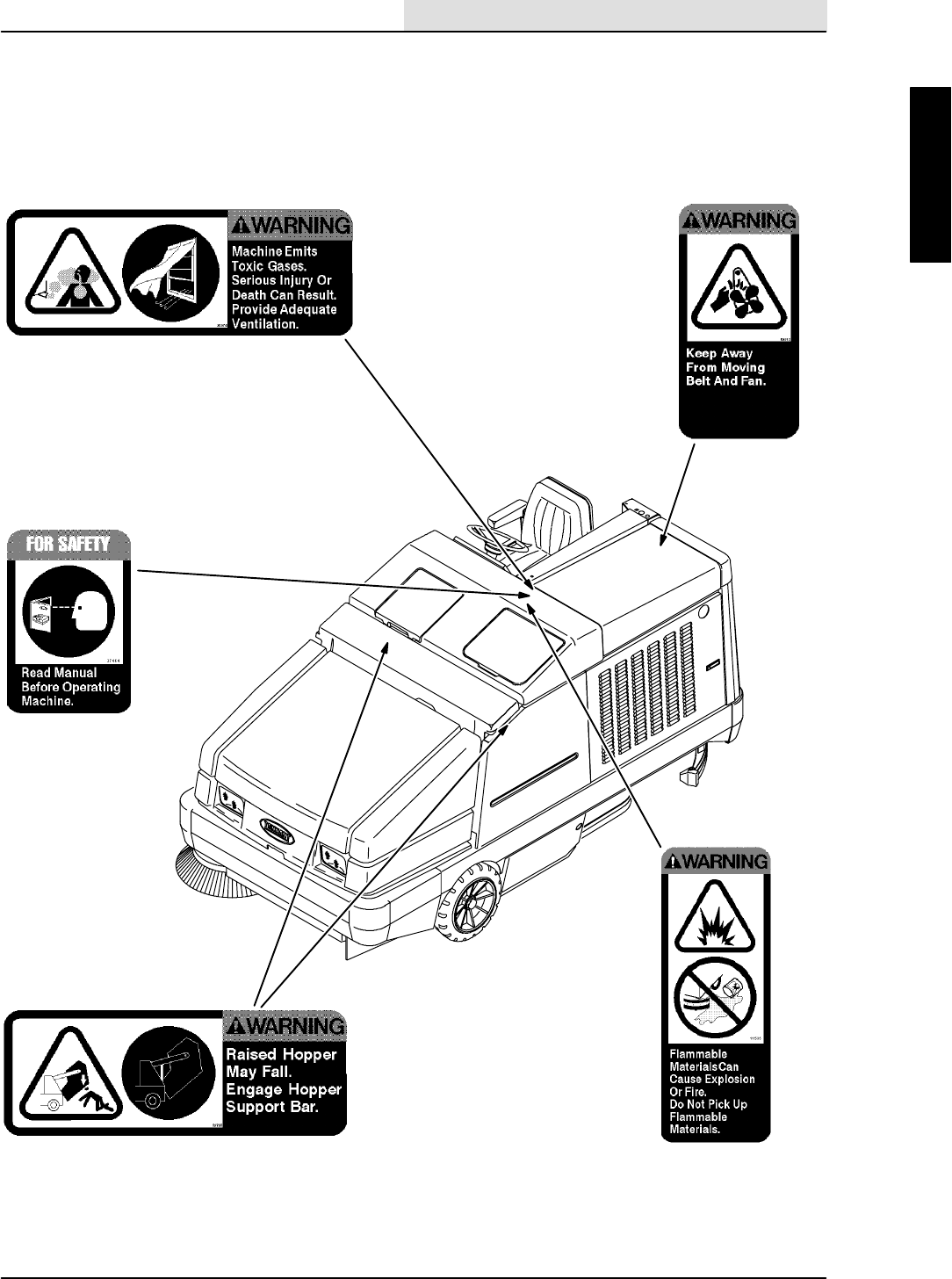
The following safety labels are mounted on the
machine in the locations indicated. If these or any
label becomes damaged or illegible, install a new
label in its place.
HOPPER SUPPORT BAR LABEL -- LOCATED
ON THE HOPPER SUPPORT BAR AND ON
BOTH HOPPER LIFT ARMS.
ENGINE FAN AND BELT LABEL -- LOCATED
ON THE RADIATOR SHROUD.
EMISSIONS LABEL -- LOCATED ON THE SIDE
PANEL OF THE OPERATOR COMPARTMENT.
11047
FOR SAFETY LABEL -- LOCATED ON THE
SIDE PANEL OF THE OPERATOR
COMPARTMENT.
FLAMMABLE SPILLS LABEL -- LOCATED ON
THE SIDE PANEL OF THE OPERATOR
COMPARTMENT.
GENERAL INFORMATION
1-6 8410 MM392 (8--01)
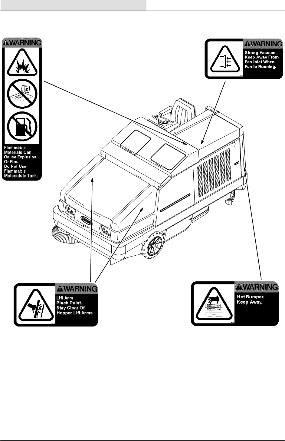
STRONG VACUUM LABEL -- LOCATED ON
THE VACUUM FAN HOUSING.
HOPPER LIFT ARMS LABEL -- LOCATED ON
BOTH HOPPER LIFT ARMS.
09078
FLAMMABLE MATERIALS LABEL -- LOCATED
ON THE SOLUTION TANK COVER.
HOT BUMPER LABEL -- LOCATED ON THE
REAR LEFT PANEL.
GENERAL INFORMATION
1-7
8410 MM392 (8--01)
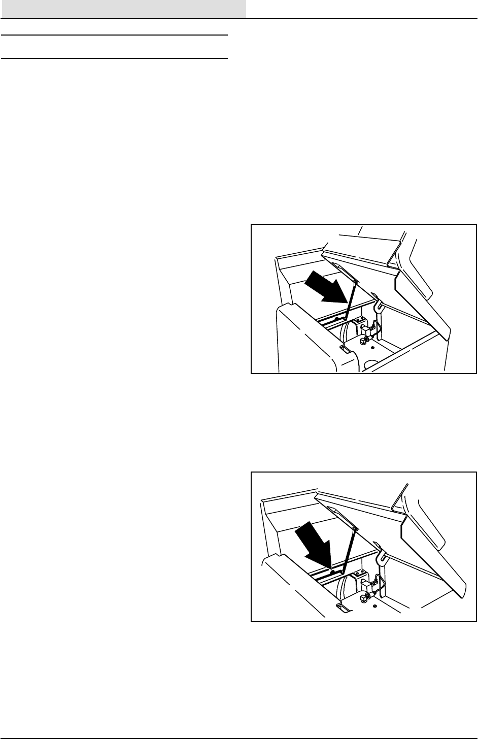
PUSHING, TOWING, AND TRANSPORTING
THE MACHINE
PUSHING OR TOWING THE MACHINE
If the machine becomes disabled, it can be
pushed from the front or rear, but towed only from
the rear.
The propelling pump has a bypass valve to
prevent damage to the hydraulic system when the
machine is being pushed or towed. This valve
allows a disabled machine to be moved for a very
short distance and at a speed to not exceed 1.6
kp/h (1 mph). The machine is NOT intended to be
pushed or towed a long distance or at a high
speed.
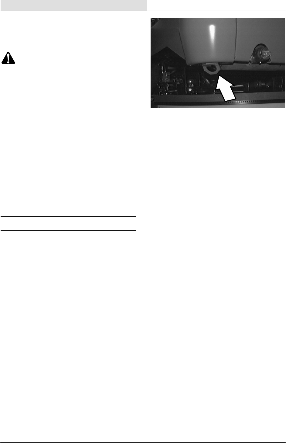
ATTENTION! Do not push or tow
machine for a long distance and without
using the bypass valve, or the machine
hydraulic system may be damaged.
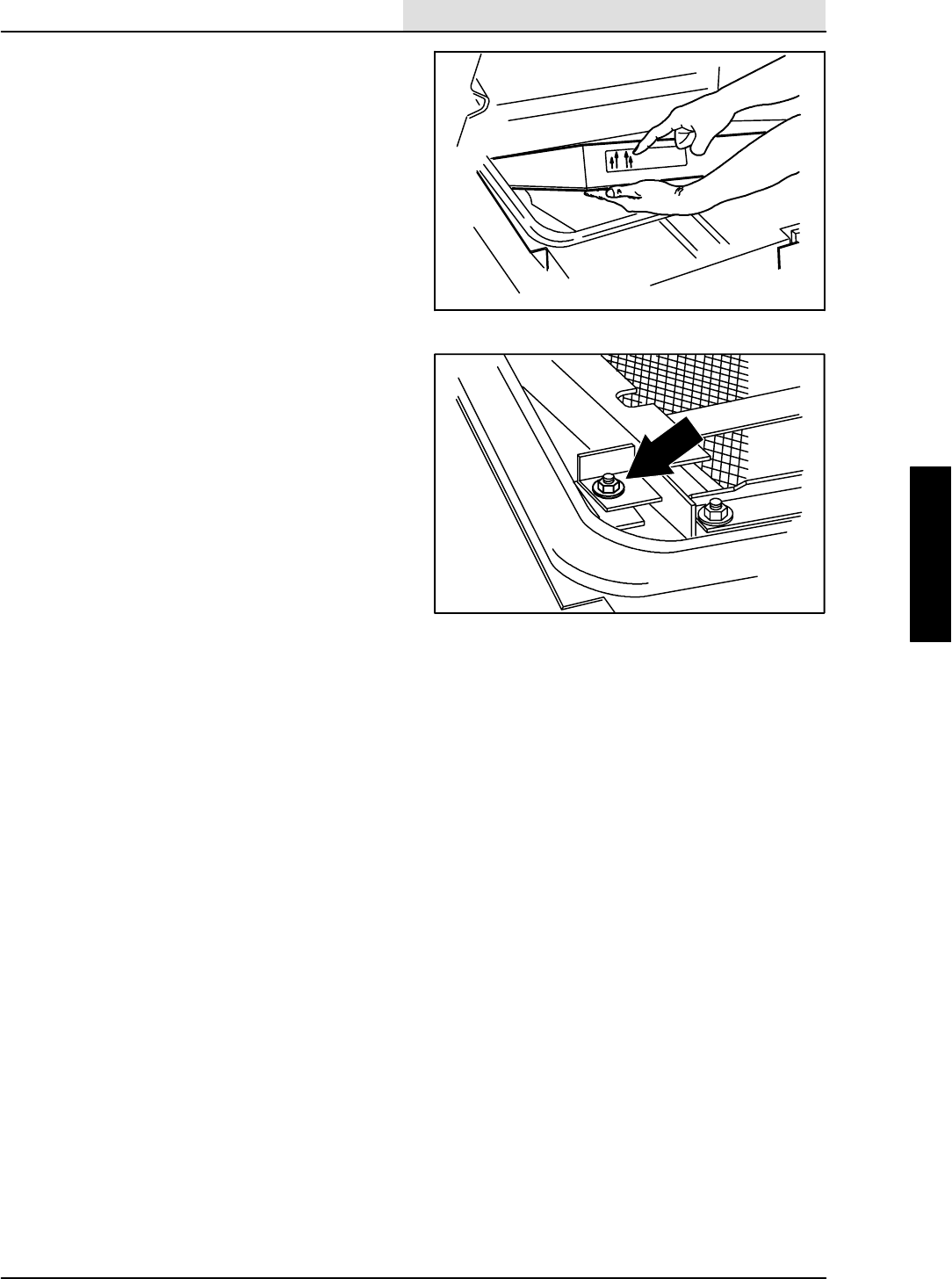
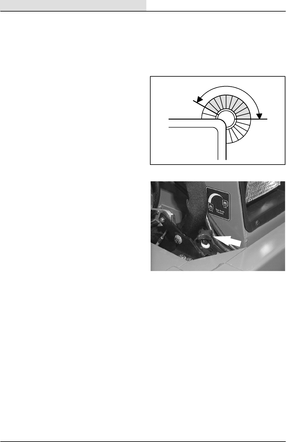
Turn the bypass valve 90_from the normal
position before pushing or towing the machine.
The illustration shows the bypass valve in the
pushing or towing position.
GENERAL INFORMATION
1-8 8410 MM392 (8--01)
TRANSPORTING THE MACHINE
1. Position the rear of the machine at the
loading edge of the truck or trailer.
FOR SAFETY: Use truck or trailer that
will support the weight of the machine.
NOTE: Empty the hopper, recovery tank, and
solution tank before transporting the machine.
2. If the loading surface is not horizontal or is
higher than 380 mm (15 in) from the ground,
use a winch to load machine.
If the loading surface is horizontal AND is
380 mm (15 in) or less from the ground, the
machine may be driven onto the truck or
trailer.
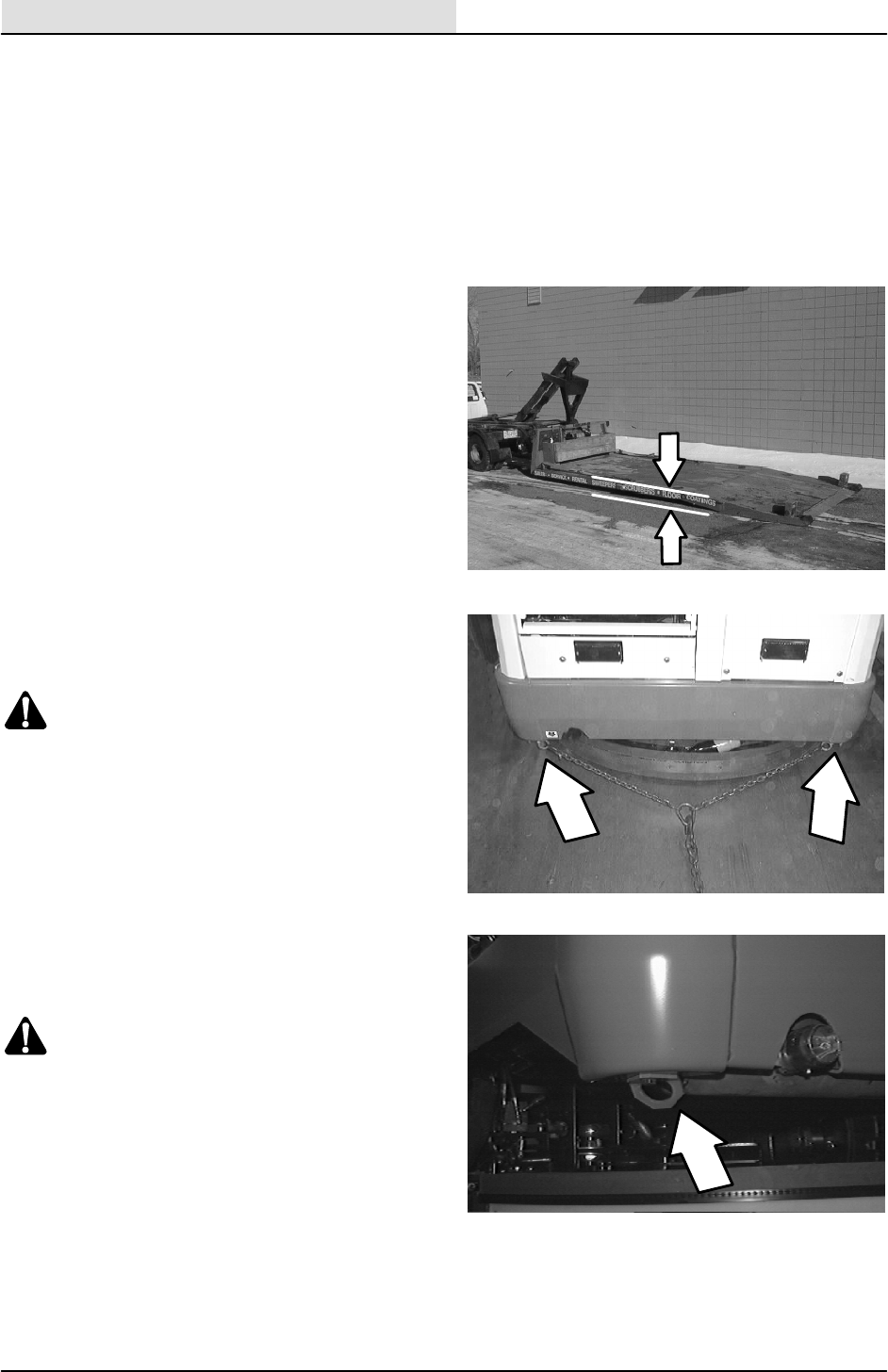
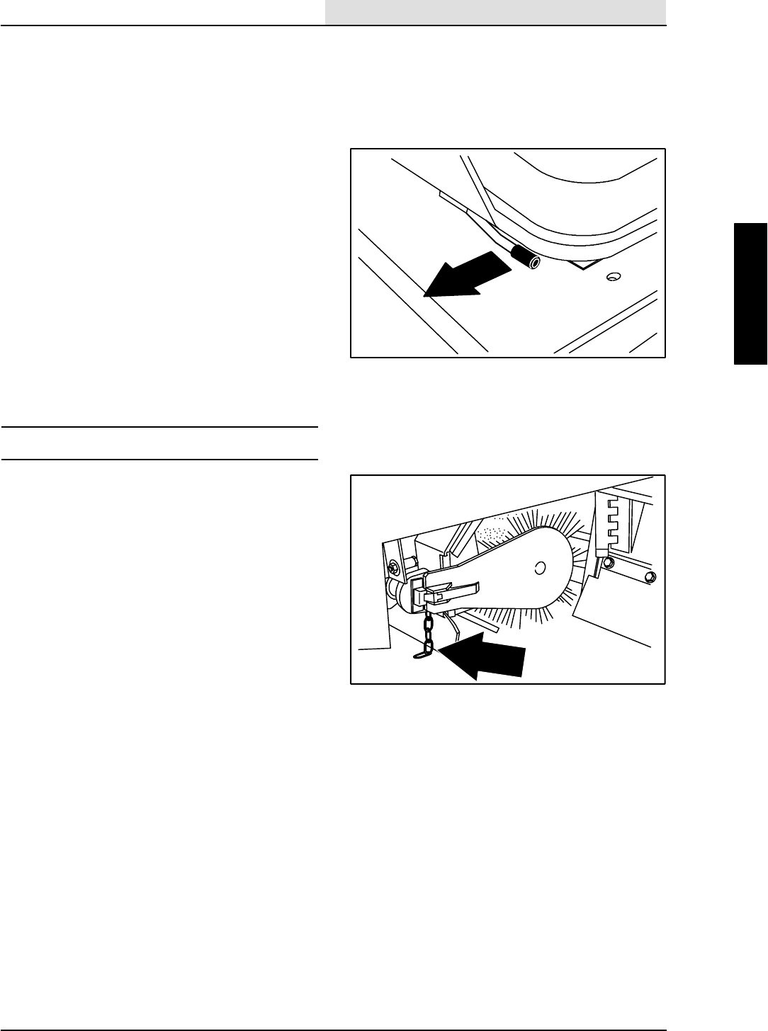
3. To winch the machine onto the truck or
trailer, attach the winching chains in the
holes at the bottom of the rear bumper.
WARNING: Hot bumper. Keep away.
If the machine has the optional rear tie down
brackets, attach the winching chains to
them.
WARNING: Hot bumper. Keep away.
GENERAL INFORMATION
1-9
8410 MM392 (8--01)
4. Turn the bypass valve 90_from the normal
position before winching the machine onto
the truck or trailer. See PUSHING OR
TOWING THE MACHINE section of this
manual. Make sure the machine is centered.
FOR SAFETY: When loading machine
onto truck or trailer, use winch. Do not
drive the machine onto the truck or
trailer unless the loading surface is
horizontal AND is 380 mm (15 in) or less
from the ground.
5. Position the machine onto the truck or trailer
as far as possible. If the machine starts to
veer off the centerline of the truck or trailer,
stop and turn the steering wheel to center
the machine.
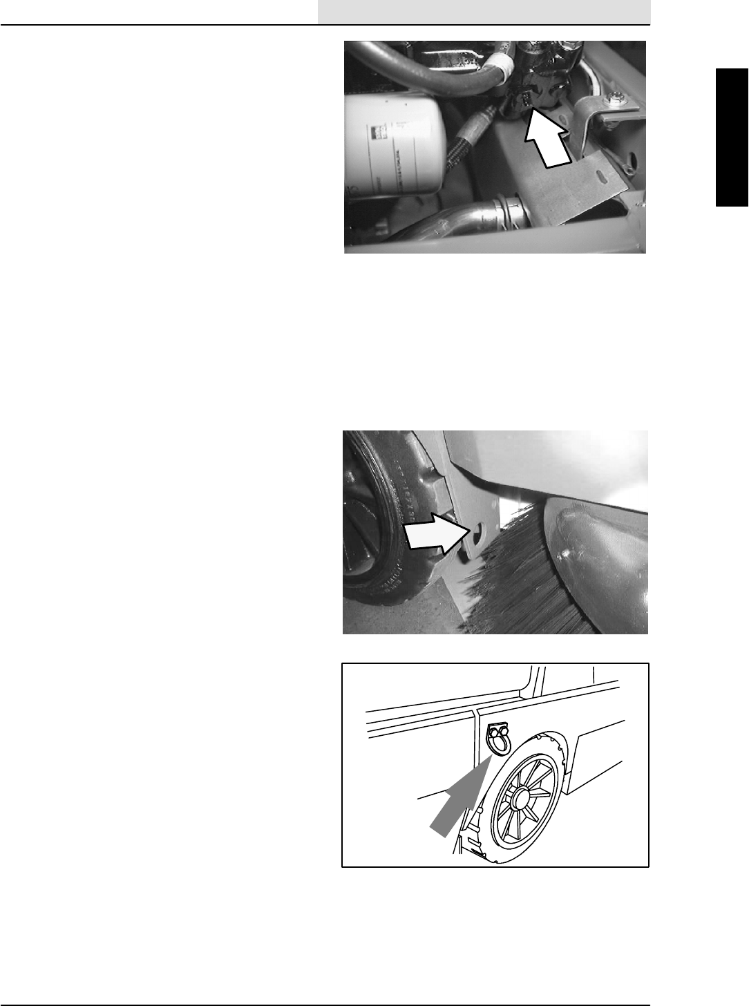
6. Set the parking brake, lower the scrub head
and block the machine tires. Tie down the
machine to the truck or trailer before
transporting.
The front tie-down locations are the holes in
the wheel pockets at the front of the
machine frame.
If the machine has the optional front tie
down brackets above the front tires, attach
the winching chains to them.
08152
GENERAL INFORMATION
1-10 8410 MM392 (8--01)
The rear tie down locations are in the holes
at the bottom of the rear bumper. If the
machine has the optional rear tie down
brackets, use them to tie down the machine.
WARNING: Hot bumper. Keep away.
7. If the loading surface is not horizontal or is
higher than 380 mm (15 in) from the ground,
use a winch to unload machine.
If the loading surface is horizontal AND is
380 mm (15 in) or less from the ground, the
machine may be driven off the truck or
trailer.
FOR SAFETY: When unloading machine
off truck or trailer, use winch. Do not
drive the machine off the truck or trailer
unless the loading surface is horizontal
AND 380 mm (15 in) or less from the
ground.
STORING MACHINE
Before storing the machine for an extended period
of time, the machine needs to be prepped to
lessen the chance of rust, sludge, and other
undesirable deposits from forming. Contact
TENNANT service personnel.

GENERAL INFORMATION
1-11
8410 MM392 (8--01)
SPECIFICATIONS
GENERAL MACHINE DIMENSIONS/CAPACITIES
Item Dimension/capacity
Length, Gasoline 2970 mm (117 in)
Length, LPG 15 kg (33 lb) tank 3070 mm (121 in)
Length, LPG 19.5 kg (43 lb) tank 3175 mm (125 in)
Length, Diesel 2970 mm (117 in)
Width with side brush 1610 mm (63.5 in)
Height 1625 mm (64 in)
Height with overhead guard 2125 mm (83.7 in)
Track 1330 mm (52.38 in)
Wheelbase 1625 mm (63.88 in)
Main sweeping brush diameter 355 mm (14 in)
Main sweeping brush length 1145 mm (45 in)
Scrub brush diameter 405 mm (16 in)
Side brush diameter 585 mm (23 in)
Sweeping path width 1145 mm (45 in)
Sweeping path width with side brush 1525 mm (60 in)
Squeegee width 1490 mm (58.7 in)
Scrubbing path width 1220 mm (48 in)
Main sweeping brush pattern width 50 to 65 mm (2 to 2.5 in)
Hopper weight capacity 545 kg (1200 lb)
Hopper volume capacity 400 L (14 ft3)
Dust filter area 6.9 m2(74 ft2)
Solution tank 227 L (60 gal)
Recovery tank 227 L (60 gal)
Detergent tank (option) 18.9 L (5 gal)
Total capacity with ESt(option) 379 L (100 gal)
GVWR 3133 kg (6900 lb)
Ceiling height minimum dumping clearance 2490 mm (98 in)
GENERAL MACHINE PERFORMANCE
Item Measure
Maximum forward speed 12.9km/h(8mph)
Maximum reverse speed 4.8km/h(3mph)
Minimum aisle turn width, left 3530 mm (139 in)
Minimum turning radius, right 3235 mm (128 in)
Minimum turning radius, left 2270 mm (90 in)
Maximum rated incline for transport of machine 8_/14.1%
Maximum rated incline for scrubbing/sweeping 6_/10.5%
GENERAL INFORMATION
1-12 8410 MM392 (8--01)
POWER TYPE
Engine Type Ignition Cycle Aspiration Cylinders Bore Stroke
Kubota V2203--B Piston Diesel 4Natural 487 mm
(3.34 in)
92.4 mm
(3.64 in)
Displacement Net power, governed Net power, maximum
2200 cc (134.08 cu in) 32.8 kw (44 hp) @ 2400 rpm 36.6 kw (49 hp) @
2800 rpm
Fuel Cooling system Electrical system
Diesel
Fuel tank: 37.9 L (10 gal)
Water/ethylene glycol
antifreeze
12 V nominal
(
g
)
Total: 17 L (4.5 gal) 50 A alternator
Radiator: 6 L (1.6 gal)
Idle speed, no load (Fast) governed speed, under
load
Engine lubricating oil
without filter
1500 +25 rpm 2400 +25 rpm 6.15 L (6.5 qt)
SAE--CC/CD rated
engine oil
Engine Displacement Net power, governed Net power, maximum
Ford LRG 2.3 2300 cc (140 cu in) 37.3 kw (50 hp) @ 2400 rpm 47 kw (63 hp) @
2800 rpm
Ford LRG 2.5 2500 cc (152 cu in) 40.3 kw (54 hp) @ 2400 rpm 59 kw (79 hp) @
3000 rpm
Ford LRG 2.3
and LRG 2.5
Type Ignition Cycle Aspirat-
ion
Cyl Bore LRG 2.3
Stroke
LRG 2.5
Stroke
Piston Distributerless-
type spark
4Natural 496 mm
(3.78 in)
80 mm
(3.126 in)
96 mm
(3.78 in)
Fuel Cooling system Electrical system
Gasoline, 87 octane
minimum, unleaded. Fuel
tank: 45.5 L (12 gal)
Water/ethylene glycol
antifreeze
12 V nominal
LPG,
F
u
e
l
t
a
n
k
:
1
5
k
g
(
3
3
l
b
)
Total: 16.7 L (4.4 gal) 50 A alternator
F
ue
l
t
an
k
:
1
5
k
g
(
3
3
l
b
)
Fuel tank: 19.5 kg (43 lb) Radiator: 6.2 L (1.6 gal)
(Start) governed speed (Low) governed speed (High) governed speed
1475 + 50 rpm 2000 + 50 rpm 2400 + 50 rpm
Spark plug gap Firing order
1to1.1mm
(0.042 to 0.046 in)
1--3--4--2
Engine lubricating oil with filter (10W30 SAE--SG/SH)
Ford LRG 2.5 -- 4.26 L (4.5 qt) FordLRG2.3--4.7L(5qt)

GENERAL INFORMATION
1-13
8410 MM392 (8--01)
STEERING
Type Power source Emergency steering
Rear wheel, hydraulic cylinder
and rotary valve controlled
Hydraulic accessory pump Manual
HYDRAULIC SYSTEM
System Capacity Fluid Type
Hydraulic reservoir 37.8 L (10 gal) TENNANT part no. 65869 -- above 7_C(45_F)
Hydraulic total 53 L (14 gal)
p
(
)
TENNANT part no. 65870 -- below 7_C(45_F)
BRAKING SYSTEM
Type Operation
Service brakes Mechanical drum brakes (2), one per front wheel,
cable actuated
Parking brake Utilize service brakes, cable actuated
TIRES
Location Type Size Pressure
Front (2) Solid 5x18in --
Rear (1) Solid 6x18in --
GENERAL INFORMATION
1-14 8410 MM392 (8--01)
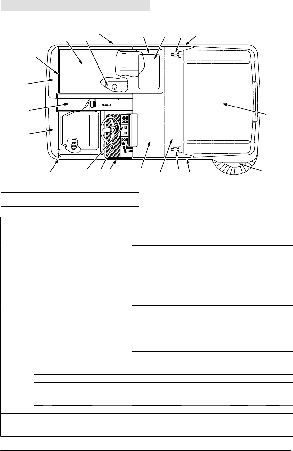
MAINTENANCE
1
23
4567
810
11
12
13
14
15
16
8
9
47
17
17
MAINTENANCE CHART G/LP
Interval Key Description Procedure
Lubricant/
Fluid
No. of
Service
Points
Daily 2Engine air filter Check indicator -- 1
D
a
i
l
y
2
E
n
g
i
n
e
a
i
r
f
i
l
t
e
r
Empty dust cap -- 1
2Engine crankcase Check oil level EO 1
11 Brush compartment skirts Check for damage, wear and ad-
justment
-- 5
9Hopper lip skirts Check for damage, wear and ad-
justment
-- 3
11 Main sweep brush Check for damage, wear, and ad-
justment
-- 1
Check brush pattern -- 1
10 Side brush Check for damage, wear, and ad-
justment
-- 1
Check brush pattern -- 1
9Hopper dust filter Shake -- 2
15 Rear Squeegee Check for damage and wear -- 1
1
5
R
e
a
r
S
q
u
e
e
g
e
e
Check deflection -- 1
4Side Squeegees Check for damage and wear -- 2
4Scrub brushes Check for damage and wear -- 1
5Recovery tank Clean -- 1
12 Recovery tank, EStmode Clean EStfilter -- 1
6Solution tank, EStmode Clean -- 1
50 Hours 11 Main sweep brush Rotate end-for-end -- 1
5
0
H
o
u
r
s
17 Rear squeegee casters Lubricate SPL 2
100 Hours 1Radiator Clean core exterior -- 1
1
0
0
H
o
u
r
s
1
R
a
d
i
a
t
o
r
Check coolant level WG 1
2Engine crankcase Change oil and filter element EO 1

GENERAL INFORMATION
1-15
8410 MM392 (8--01)
Interval Key Description Procedure
Lubricant/
Fluid
No. of
Service
Points
100 Hours 2Engine Check belt tension -- 1
1
0
0
H
o
u
r
s
2
E
n
g
i
n
e
Check and adjust idle speed -- 1
Check and adjust idle mixture -- 1
9Hopper dust filter Check for damage, clean or re-
place
-- 1
3Hydraulic fluid reservoir Check fluid level HYDO 1
8Tires Check for damage -- 3
11 Main sweep brush and
hopper seals
Check for damage or wear -- 8
15 Rear squeegee Check leveling -- 1
200 Hours 1Radiator hoses and clamps Check for tightness and wear -- 2
2
0
0
H
o
u
r
s
14 Parking brake Check adjustment -- 1
14 Brake pedal Check and adjust travel -- 1
16 Rear wheel support bear-
ings
Lubricate SPL 2
10 Side brush guard Rotate 90_-- 1
7Lift arm pivots Lubricate SPL 4
9Hopper door pivots Lubricate SPL 2
400 Hours 8Front wheel bearings Check, lubricate, and adjust SPL 2
4
0
0
H
o
u
r
s
1 Cooling system Flush WG 1
2Engine Clean or replace and adjust
spark plugs
-- 4
Replace PCV valve -- 1
Fuel filter, gasoline -- 2
Replace suction strainer -- 1
Change hydraulic fluid HYDO 1
3Hydraulic fluid filter Change filter element -- 1
-- Hydraulic hoses Check for wear and damage -- All
16 Propelling motor HTorque shaft nut -- 1
16 Rear wheel HTorque wheel nuts -- 1
13 Battery HClean and tighten battery cable
connections
-- 1
Check electrolyte DW 1
2Engine Clean PCV hoses, tubes, and fit-
tings
-- 1
Torque intake manifold bolts -- 8
Check timing belt -- 1
1600
Hours
2Engine Replace timing belt -- 1
LUBRICANT/FLUID
EO Engine oil, SAE--SG/SH rated....
HYDO Tennant or approved hydraulic fluid.
WG Water and permanent-type ethylene glycol anti-freeze, --34_C(--30_F)...
SPL Special lubricant, Lubriplate EMB grease (Tennant part number 01433--1)...
DW Distilled water....
NOTE: Also check procedures indicted (H) after
the first 50-hours of operation.
NOTE: More frequent intervals may be required
in extremely dusty conditions.
GENERAL INFORMATION
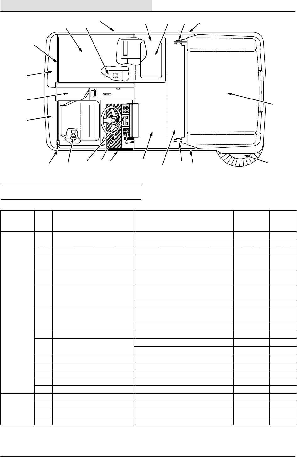
1-16 8410 MM392 (8--01)
1
23
4567
810
11
12
13
14
1516
8
9
47
17
18
18
MAINTENANCE CHART Diesel
Interval Key Description Procedure
Lubricant/
Fluid
No. of
Service
Points
Daily 2Engine air filter Check indicator -- 1
D
a
i
l
y
2
E
n
g
i
n
e
a
i
r
f
i
l
t
e
r
Empty dust cap -- 1
2Engine crankcase Check oil level EO 1
11 Brush compartment skirts Check for damage, wear and ad-
justment
-- 5
9Hopper lip skirts Check for damage, wear and ad-
justment
-- 3
11 Main sweep brush Check for damage, wear, and ad-
justment
-- 1
Check brush pattern -- 1
10 Side brush Check for damage, wear, and ad-
justment
-- 1
Check brush pattern -- 1
9Hopper dust filter Shake -- 2
16 Rear Squeegee Check for damage and wear -- 1
1
6
R
e
a
r
S
q
u
e
e
g
e
e
Check deflection -- 1
4Side Squeegees Check for damage and wear -- 2
4Scrub brushes Check for damage and wear -- 1
5Recovery tank Clean -- 1
12 Recovery tank, EStmode Clean EStfilter -- 1
6Solution tank, EStmode Clean -- 1
50 Hours 11 Main sweep brush Rotate end-for-end -- 1
5
0
H
o
u
r
s
2Fuel pipes and clamps Check for tightness and wear -- 1
2Engine crankcase Change oil and filter EO 1
18 Rear squeegee casters Lubricate SPL 2

GENERAL INFORMATION
1-17
8410 MM392 (8--01)
Interval Key Description Procedure
Lubricant/
Fluid
No. of
Service
Points
100 Hours 1Radiator Clean core exterior -- 1
Check coolant level WG 1
2Engine belt Check tension -- 1
9Hopper dust filter Check for damage, clean or re-
place
-- 1
3Hydraulic fluid reservoir Check fluid level HYDO 1
8Tires Check for damage -- 3
11 Main sweep brush and
hopper seals
Check for damage or wear -- 8
16 Rear squeegee Check leveling -- 1
200 Hours 1Radiator hoses and clamps Check for tightness and wear -- 2
14 Parking brake Check adjustment -- 1
14 Brake pedal Check and adjust travel -- 1
17 Rear wheel support bear-
ings
Lubricate SPL 2
10 Side brush guard Rotate 90_-- 1
7Lift arm pivots Lubricate SPL 4
9Hopper door pivots Lubricate SPL 2
400 Hours 8Front wheel bearings Check, lubricate, and adjust SPL 2
2Fuel filter Replace cartridge -- 1
15 Fuel tank Remove sediment -- 1
1 Cooling system Flush WG 1
800 Hours 3Hydraulic reservoir Replace filler cap -- 1
y
Replace suction strainer -- 1
Change hydraulic fluid HYDO 1
3Hydraulic fluid filter Change filter element -- 1
-- Hydraulic hoses Check for wear and damage -- All
17 Propelling motor HTorque shaft nut -- 1
17 Rear wheel HTorque wheel nuts -- 1
13 Battery HClean and tighten battery cable
connections
-- 1
Check electrolyte DW 1
LUBRICANT/FLUID
EO Engine oil, SAE--CC/CD rated....
HYDO Tennant Company or approved hydraulic fluid.
WG Water and permanent-type ethylene glycol anti-freeze, --34_C(--30_F)...
SPL Special lubricant, Lubriplate EMB grease (Tennant part number 01433--1)...
DW Distilled water....
NOTE: Also check procedures indicted (H) after
the first 50-hours of operation.
NOTE: More frequent intervals may be required
in extremely dusty conditions.
GENERAL INFORMATION
1-18 8410 MM392 (8--01)
HARDWARE INFORMATION
The following charts state standard plated
hardware tightening ranges for normal assembly
applications. Decrease the specified torque by
20% when using a thread lubricant. Do not
substitute lower grade hardware for higher grade
hardware. If higher grade hardware than specified
is substituted, tighten only to the specified
hardware torque value to avoid damaging the
threads of the part being threaded into, as when
threading into speed nuts or weldments.
STANDARD BOLT TORQUE CHART
Thread
Size
SAE Grade 5
Torque ft lb
(Nm)
SAE Grade 8
Torque ft lb
(Nm)
0.25 in 7--10 (9--14) 10--13 (14--38)
0.31 in 15--20 (20--27) 20--26 (27--35)
0.38 in 27--35 (37--47) 36--47 (49--64)
0.44 in 43--56 (58--76) 53--76 (72--103)
0.50 in 65--85 (88--115) 89--116
(121--157)
0.62 in 130--170
(176--231)
117--265
(159--359)
0.75 in 215--280
(291--380)
313--407
(424--552)
1.00 in 500--650
(678--881)
757--984
(1026--1334)
NOTE: Decrease torque by 20% when using a
thread lubricant.
METRIC BOLT TORQUE CHART
Thread
Size
Class 8.8
Torque ft lb
_Nm)
Class 10.9
Torque ft lb
(Nm)
M4 2(3) 3(4)
M5 4(5) 6(8)
M6 7(9) 10 (14)
M8 18 (24) 25 (34)
M10 32 (43) 47 (64)
M12 58 (79) 83 (112)
M14 94 (127) 133 (180)
M16 144 (195) 196 (265)
M20 260 (352) 336 (455)
M24 470 (637) 664 (900)
NOTE: Decrease torque by 20% when using a
thread lubricant.
Exceptions to the above chart:
Check the machine for exceptions!
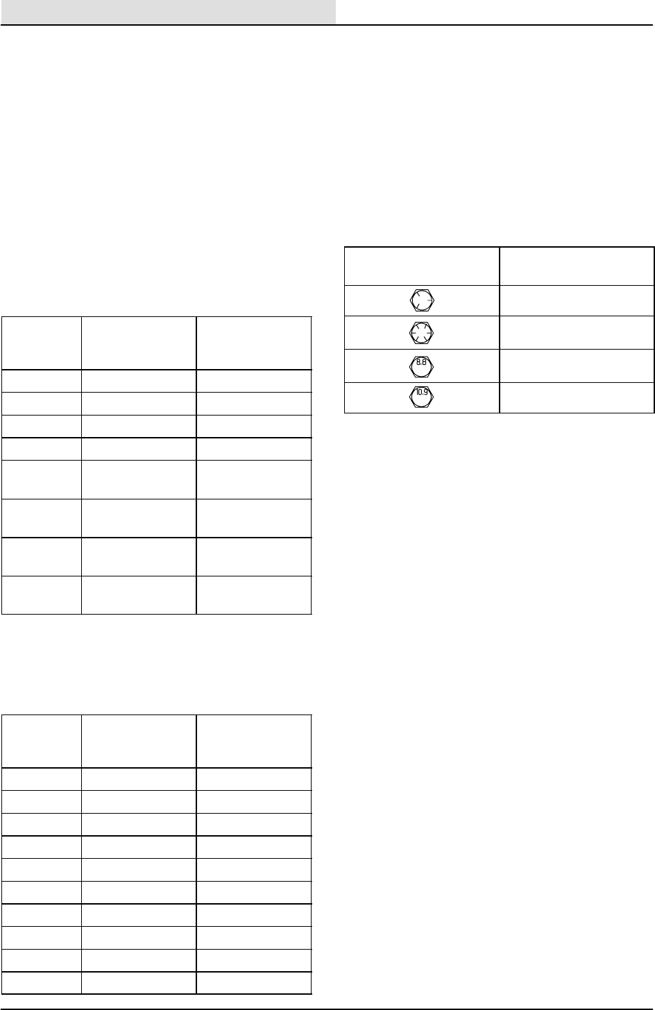
BOLT IDENTIFICATION
Identification
Grade Marking
Specification and
Grade
SAE--Grade 5
SAE--Grade 8
ISO--Grade 8.8
ISO--Grade 10.9
01395
THREAD SEALANT AND LOCKING
COMPOUNDS
Thread sealants and locking compounds may be
used on this machine. They include the following:
Locktite 515 sealant -- gasket forming
material. TENNANT Part No. 75567,15 oz
(440 ml) cartridge.
Locktite 242 blue -- medium strength thread
locking compound. TENNANT Part No.
32676, 0.5 ml tube.
Locktite 271 red -- high strength thread
locking compound. TENNANT Part No.
19857, 0.5 ml tube.
GENERAL INFORMATION
1-19
8410 MM392 (8--01)
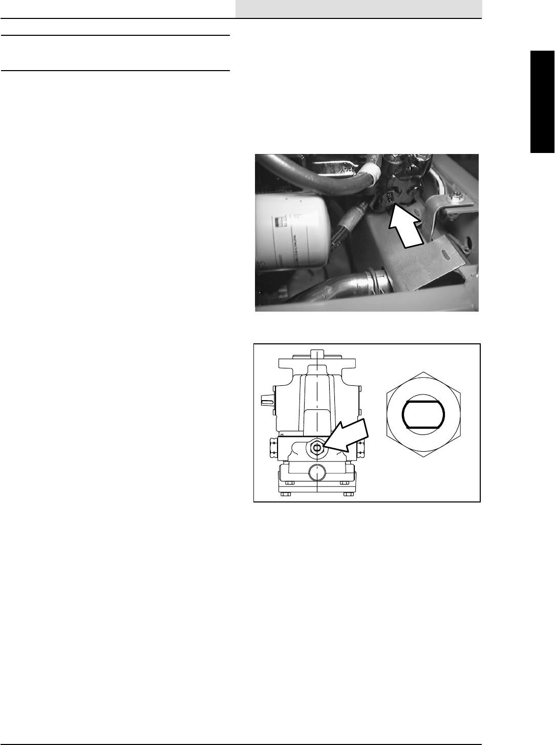
HYDRAULIC FITTING INFORMATION
HYDRAULIC TAPERED PIPE FITTING (NPT)
TORQUE CHART
NOTE: Ratings listed are when using teflon
thread seal.
Size Minimum
Torque
Maximum
Torque
1/4 NPT 10 ft lb (14 Nm) 30 ft lb (41 Nm)
1/2 NPT 25 ft lb (34 Nm) 50 ft lb (68 Nm)
3/4 NPT 50 ft lb (68 Nm) 100 ft lb (136
Nm)
HYDRAULIC TAPERED SEAT FITTING (JIC)
TORQUE CHART
Tube O.D.
(in)
Thread Size Maximum
Torque
0.25 0.44--20 9ftlb(12Nm)
0.38 0.56--18 20 ft lb (27 Nm)
0.50 0.75--16 30 ft lb (41 Nm)
0.62 0.88--14 40 ft lb (54 Nm)
0.75 1.12--12 70 ft lb (95 Nm)
1.0 1.31--12 90 ft lb (122 Nm)
HYDRAULIC O--RING FITTING TORQUE
CHART
Tube
O.D.
(in)
Thread
Size
Minimum
Torque
Maximum
Torque
0.25 0.44--20 6ftlb(8Nm) 9ftlb
(12 Nm)
0.38 0.56--18 13 ft lb
(18 Nm)
20 ft lb
(27 Nm)
*10 ft lb
(14 Nm)
12 ft lb
(16 Nm)
0.50 0.75--16 20 ft lb
(27 Nm)
30 ft lb
(41 Nm)
*21 ft lb
(28 Nm)
24 ft lb
(33 Nm)
0.62 0.88--14 25 ft lb
(34 Nm)
40 ft lb
(54 Nm)
0.75 1.12--12 45 ft lb
(61 Nm)
70 ft lb
(95 Nm)
1.0 1.31--12 60 ft lb
(81 Nm)
90 ft lb
(122 Nm)
NOTE: Do not use sealant on o--ring threads.
*Aluminum bodied components

GENERAL INFORMATION
1-20 8410 MM392 (8--01)

CHASSIS
2-1
8410 MM392 (5--02)
CONTENTS
Page
INTRODUCTION 2-3......................
SEAT 2-4.............................
TO REMOVE SEAT ASSEMBLY 2-4..
TO REPLACE SEAT ASSEMBLY 2-4..
TO ADJUST SEAT POSITION 2-5....
STATIC DRAG CHAIN 2-5..............
BRAKES AND TIRES 2-6...............
SERVICE BRAKES 2-6..............
TO REPLACE BRAKE SHOES 2-6....
PARKING BRAKE LEVER 2-8........
FRONT TIRES AND WHEELS 2-9.......
TO REPACK FRONT WHEEL
BEARINGS 2-9..................
REAR WHEEL AND WHEEL
SUPPORT 2-11.....................
TO REPLACE REAR WHEEL
HOUSING PIVOT BEARINGS 2-12.

CHASSIS
2-2 8410 MM392 (8--01)

CHASSIS
2-3
8410 MM392 (8--01)
INTRODUCTION
This section includes information on the main
chassis related components for example the seat,
steering, brakes and tires.
CHASSIS
2-4 8410 MM392 (8--01)
SEAT
The seat assembly is removable and adjustable
on the 8400.
The operator seat is a fixed back style with a
forward-backward adjustment.
TO REMOVE SEAT ASSEMBLY
FOR SAFETY: Before Leaving Or
Servicing Machine; Stop On Level
Surface, Set Parking Brake, Turn Off
Machine And Remove Key.
1. Tilt the seat assembly forward.
2. Slide the seat prop rod up and out of the rod
slot.
3. Pull the hair cotter pin out of the pivot shaft.
4. Lift and slide the seat sideways off the
machine.
TO REPLACE SEAT ASSEMBLY
FOR SAFETY: Before Leaving Or
Servicing Machine; Stop On Level
Surface, Set Parking Brake, Turn Off
Machine And Remove Key.
1. Slide the seat assembly pins in the pivot
holes on the seat support.
2. Slide the hair cotter pin in the hole on the
pivot shaft to secure the seat.
3. Slide the seat rod through the large hole in
the slot.
4. Lower the seat.
CHASSIS
2-5
8410 MM392 (8--01)
TO ADJUST SEAT POSITION
FOR SAFETY: Before Leaving Or
Servicing Machine; Stop On Level
Surface, Set Parking Brake, Turn Off
Machine And Remove Key.
1. Pull the lever out, slide the seat backward or
forward to the desired position and release
the lever.
STATIC DRAG CHAIN
A static drag chain prevents the buildup of static
electricity in the machine. The chain is attached to
the machine by a rear main brush skirt retaining
bolt.
Make sure the chain is touching the floor at all
times.
CHASSIS
2-6 8410 MM392 (5--02)
BRAKES AND TIRES
SERVICE BRAKES
The mechanical service brakes are located on the
front wheels. The brakes are operated by the foot
brake pedal and connecting cables.
Check the brake adjustment every 200 hours of
operation.
TO REPLACE BRAKE SHOES
FOR SAFETY: Before Leaving Or
Servicing Machine; Stop On Level
Surface, Set Parking Brake, Turn Off
Machine And Remove Key.
1. Empty the debris hopper.
2. Turn the parking brake knurled knob
counterclockwise until it stops.
(early version machines only)
3. Disconnect the battery cables and remove
the battery to access the floor plate
hardware.
4. Remove floor plate from the machine.
5. Thread the brake cable clevis yoke toward
the threaded rod to reduce brake cable
tension.
CHASSIS
2-7
8410 MM392 (8--01)
6. Jack up one front corner of the machine.
Place jack stands under machine.
7. Remove the hub cap.
8. Remove the cotter pin, slotted nut, flat
washer, and bearing cone.
9. Remove the front tire and wheel assembly
from the machine.
10. Remove the two springs holding the brake
shoes together. Remove the old brake
shoes from the machine.
11. Position the new brake shoes on the
machine.
NOTE: Always replace brake shoes in sets.
12. Reattach brake springs to the new brake
shoes.
13. Pack the wheel bearings with Lubriplate
EMB grease.
14. Slide the wheel on the axle.
15. Slide the outer bearing, flat washer and nut
on the shaft.
16. Tighten nut with hand wrench until wheel
binds, then back the nut off to nearest hole.
17. Insert a new cotter pin through nut and hole.
18. After making sure the wheel spins freely,
carefully install the hub cap.
19. Remove the jack stand and lower the
machine. Repeat this procedure on the
opposite side.
NOTE: Always replace brake shoes in sets.
20. Thread the brake cable clevis yoke away
from the threaded rod until the brake pedal
travels 25--50 mm (1--2 in) before engaging
brakes.
CHASSIS
2-8 8410 MM392 (8--01)
21. Tighten the brake clevis jam nuts.
22. Reinstall the floor plate.
23. Install the battery and battery cables.
24. Lower the seat support.
25. Adjust the parking brake by turning the
knurled knob clockwise until the parking
brake properly holds the machine in place.
(early version machines only).
26. Drive the machine and check the brakes for
proper operation.
PARKING BRAKE LEVER
The parking brake lever sets and releases the
front wheel brakes.
Set: Move the brake lever from the short to the
long slot with your foot. Step on the brake pedal to
lock the pedal in place.
Release: Step on the brake pedal to release it,
and move the brake lever to the left with your foot
at the same time. Lock the lever in place in the
short slot.
CHASSIS
2-9
8410 MM392 (8--01)
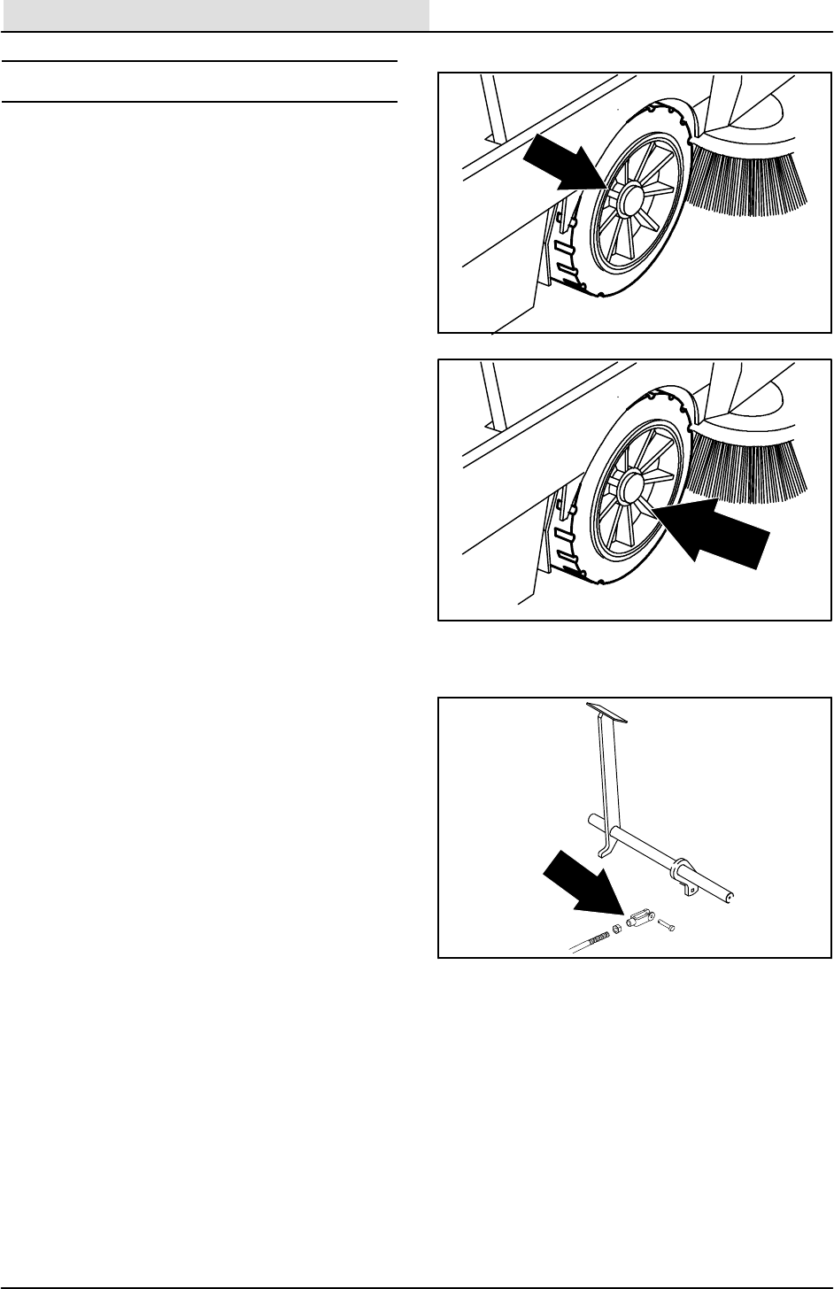
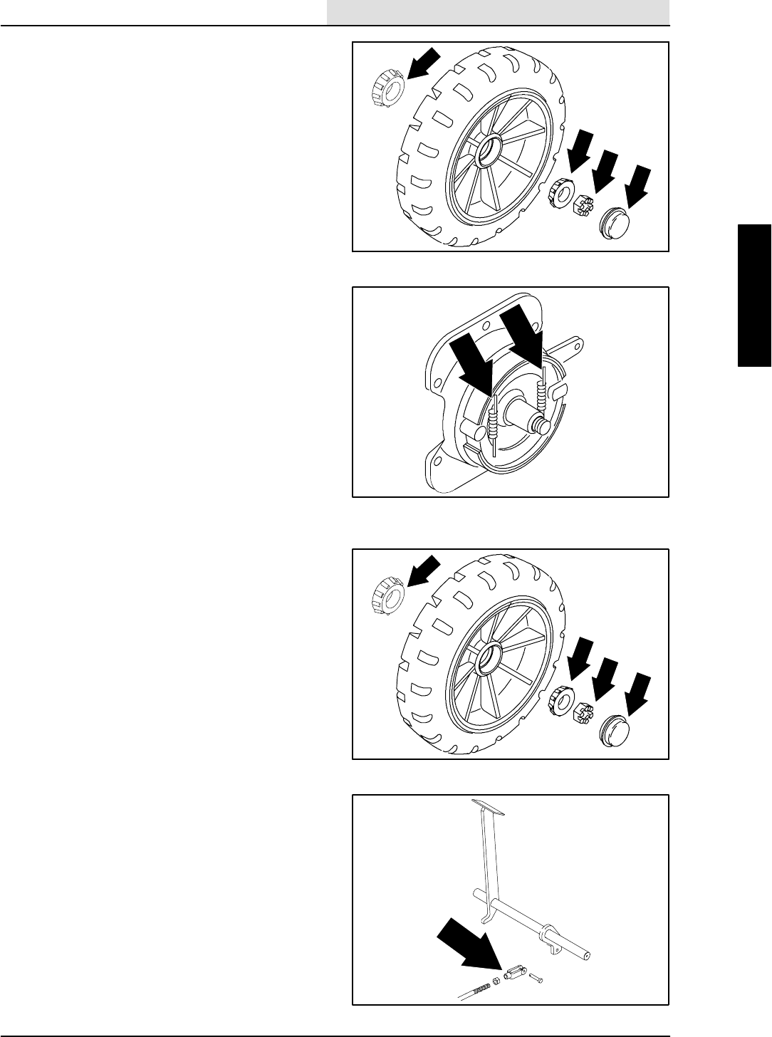
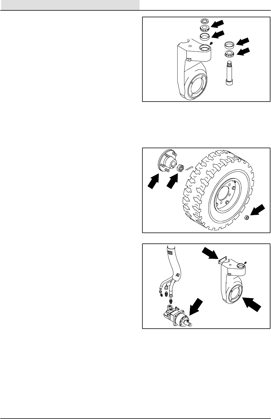
FRONT TIRES AND WHEELS
The machines front tires are semi--pneumatic.
Inspect the front wheel bearings for seal damage,
and repack and adjust every 1600 hours of
operation. Use Lubriplate EMB grease
(TENNANT part no. 01433--1).
TO REPACK FRONT WHEEL BEARINGS
FOR SAFETY: Before Leaving Or
Servicing Machine; Stop On Level
Surface, Set Parking Brake, Turn Off
Machine And Remove Key.
1. Empty the debris hopper.
2. Turn the parking brake knurled knob
counterclockwise until it stops. (early version
machines only)
3. Disconnect the battery cables and remove
the battery to access the floor plate
hardware.
4. Remove floor plate from the machine.
5. Thread the brake cable clevis yoke toward
the threaded rod to reduce brake cable
tension.
6. Jack up one front corner of the machine.
Place jack stands under machine.
7. Remove the hub cap.
8. Remove the cotter pin, slotted nut, flat
washer, and bearing cone.
9. Remove the front tire and wheel assembly
from the machine.
10. Pack the wheel bearings with Lubriplate
EMB grease.
11. Slide the wheel assembly back on the axle.
12. Slide the outer bearing, flat washer and nut
onto the shaft.
13. Tighten the nut with hand wrench until the
wheel binds, then back the nut off to the
nearest hole.
CHASSIS
2-10 8410 MM392 (8--01)
14. Insert a new cotter pin through nut and hole.
15. After making sure the wheel spins freely,
carefully install the hub cap. Repeat this
procedure on the opposite side of the
machine.
16. Remove the jack stand and lower the
machine.
17. Thread the brake cable clevis yoke away
from the threaded rod until the brake pedal
travels 25--50 mm (1--2 in) before engaging
brakes.
18. Tighten the brake clevis jam nuts.
19. Reinstall the floor plate.
20. Install the battery and battery cables.
21. Lower the seat support.
22. Adjust the parking brake by turning the
knurled knob clockwise until the parking
brake properly holds the machine in place.
(early version machines only)
23. Drive the machine and check for proper
operation.
CHASSIS
2-11
8410 MM392 (5--02)
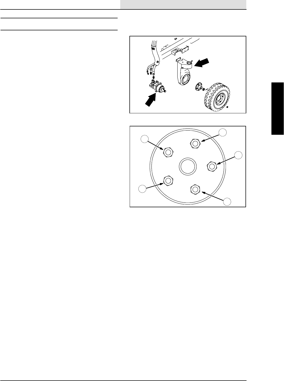
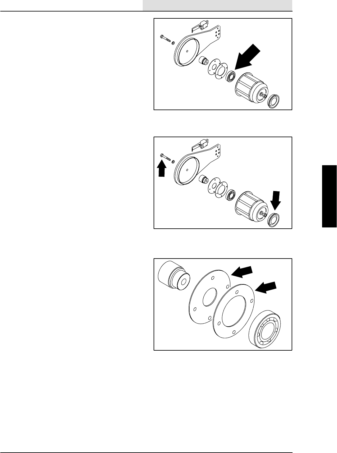
REAR WHEEL AND WHEEL SUPPORT
The rear wheel support pivots the rear wheel. The
support has one grease fitting for the bearings.
The rear wheel support bearings must be
lubricated every 200 hours of operation. Use
Lubriplate EMB grease (TENNANT part no.
01433--1).
Torque the rear wheel nuts twice in the pattern
shown to 142 -- 156 Nm (105 -- 115 ft lb) after the
first 50-hours of operation, and every 800 hours
thereafter. Torque the rear wheel hub nut to
(375 ft lb).
2
3
4
1
5
CHASSIS
2-12 8410 MM392 (8--01)
TO REPLACE REAR WHEEL HOUSING
PIVOT BEARINGS
FOR SAFETY: Before Leaving Or
Servicing Machine; Stop On Level
Surface, Set Parking Brake, Turn Off
Machine And Remove Key.
1. Engage the parking brake and block the
front tires.
2. Jack up the rear of the machine. Use jack
stands to support machine.
FOR SAFETY: Block machine tires
before jacking machine up. Jack
machine up at designated locations
only. Block machine up with jack
stands.
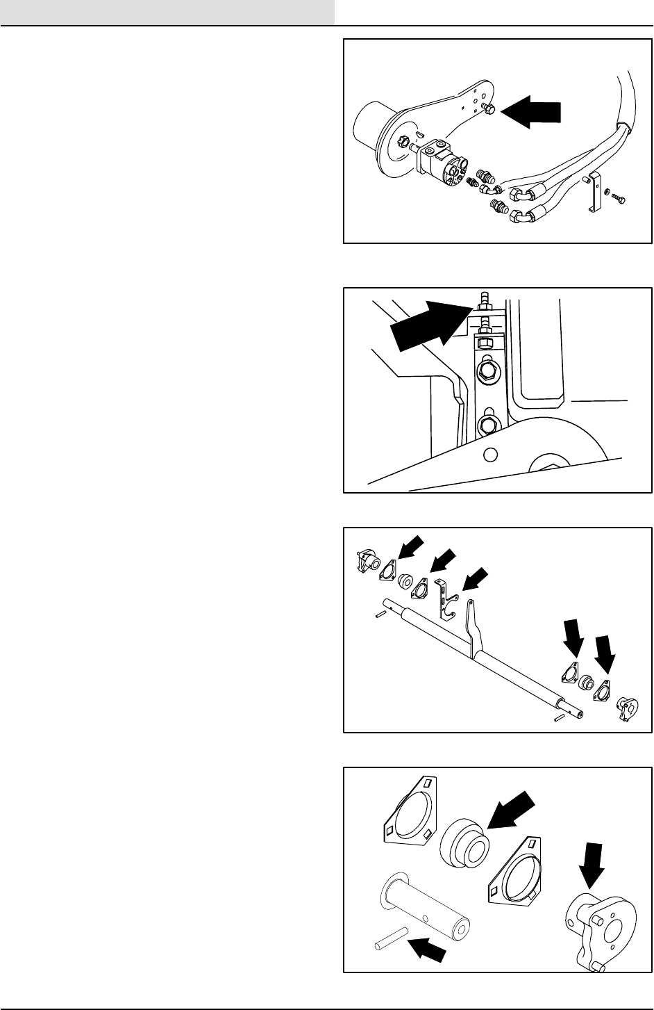
3. Remove the rear tire and wheel assembly.
4. Remove the slotted nut from drive wheel
motor hub shaft.
5. Use a large puller to remove the drive hub
from the motor shaft.
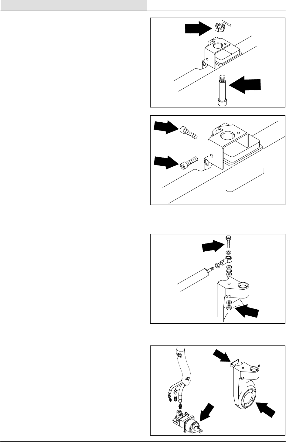
6. Remove the hose support plate from the
rear wheel housing.
NOTE: The hydraulic hoses can remain
connected to the drive motor
7. Remove the four drive motor mounting bolts.
NOTE: The orientation of the motor in the rear
wheel housing.
8. Slide the motor out of the rear wheel
housing.
9. The hydraulic motor can moved out of the
way to ease rear wheel housing removal.
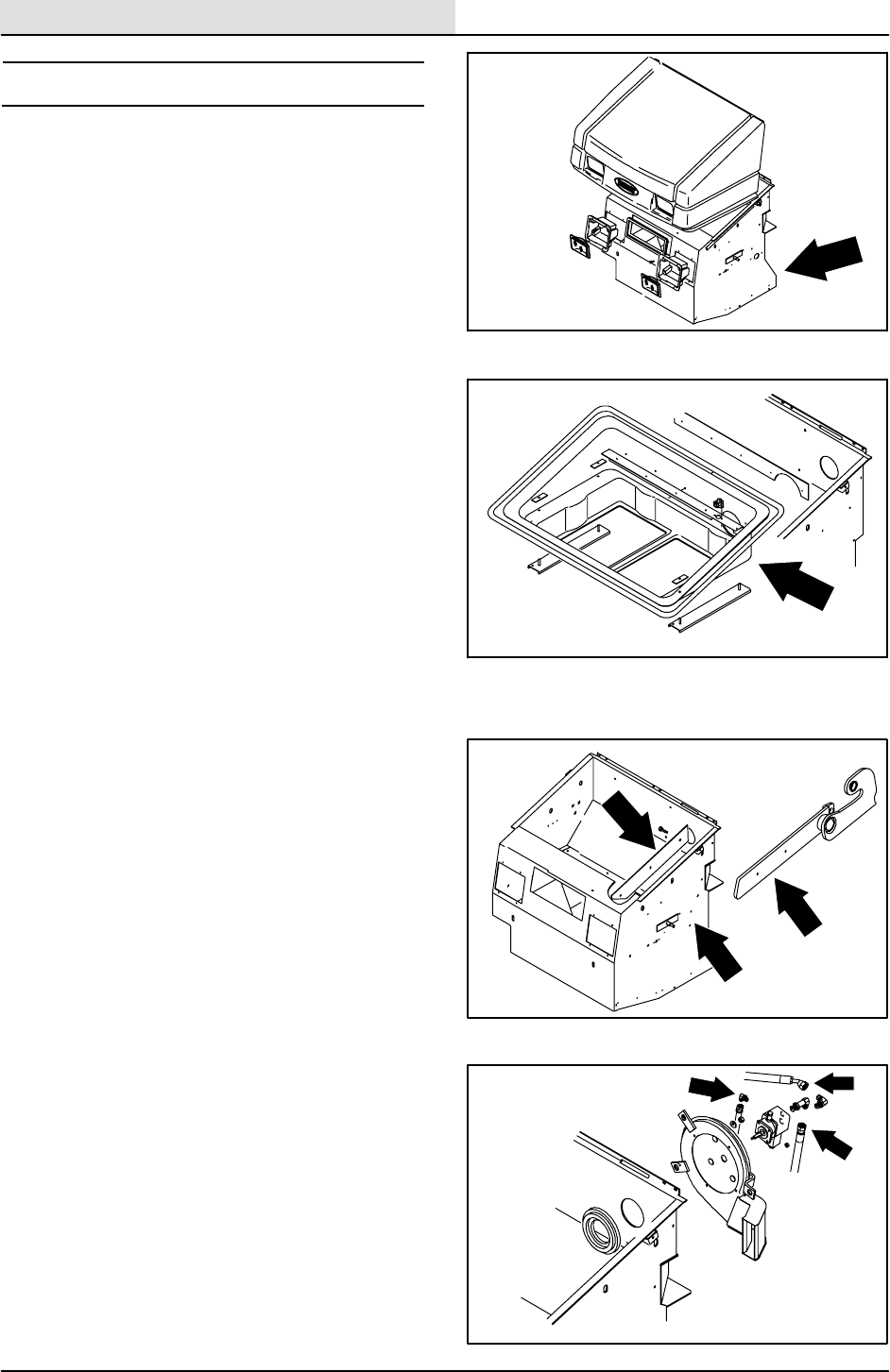
CHASSIS
2-13
8410 MM392 (8--01)
10. Remove .750 inch hex screw attaching rod
end of steering cylinder to rear wheel
housing.
11. Remove the cotter pin and large slotted nut
from the top of the pivot pin.
12. Loosen the two M10 socket head bolts that
are pinching the pivot pin in the frame.
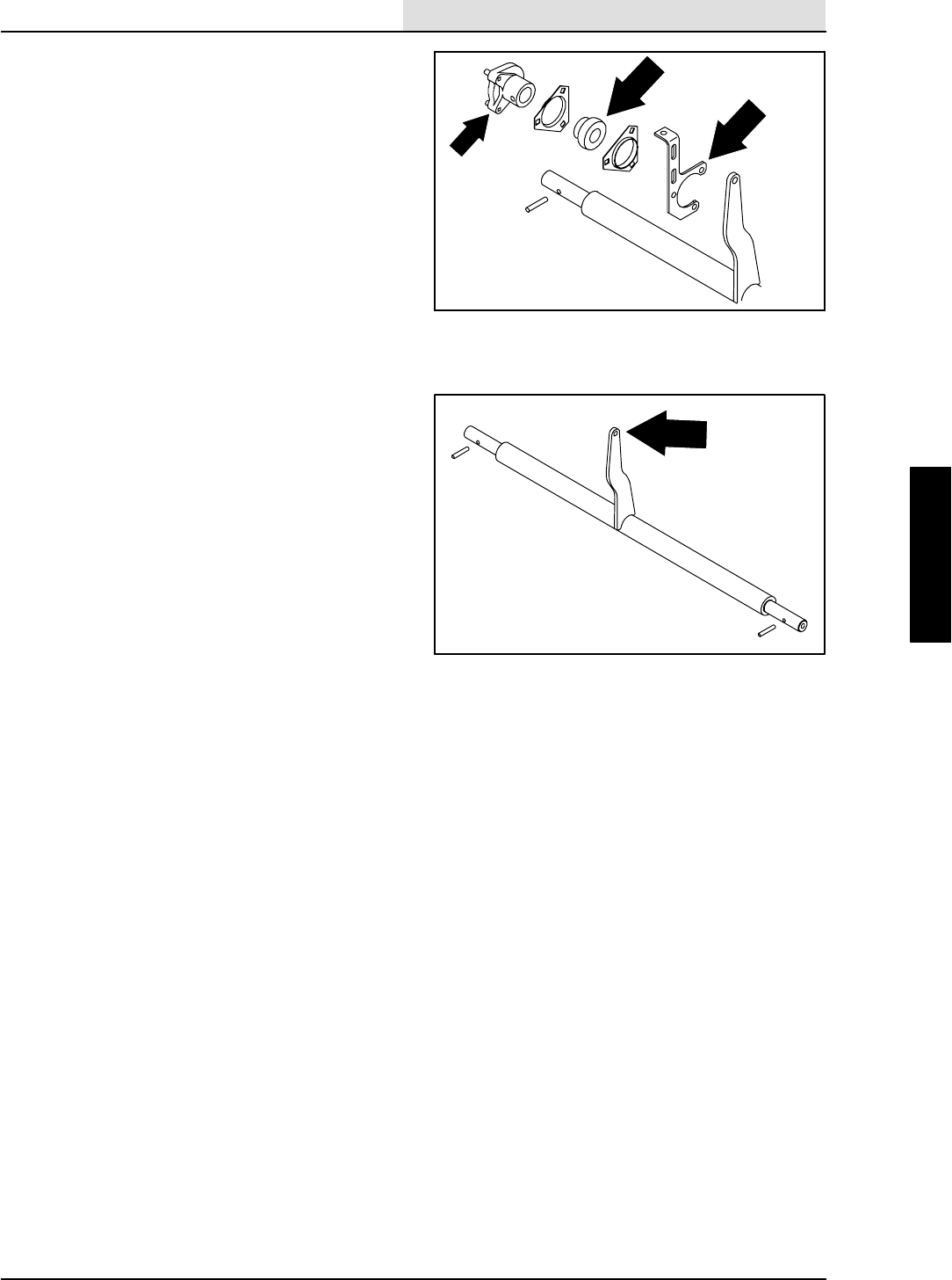
13. Remove the pivot pin from the machine.
NOTE: The rear drive housing is heavy and will
drop out of the machine frame when the pivot pin
is removed.
14. Slide the wheel housing out of the main
frame. Retain the thrust washer that is in
place on top of the upper bearing cone.
15. Remove and discard both bearing cones.
16. Remove and discard the pressed in bearing
cups by tapping them out with a hammer
and drift punch.
17. Press the new bearing cups in by using a
hydraulic press.
18. Pack the new bearing cones with Lubriplate
EMB grease. Coat the new bearing cups
with grease also.
19. Position the new bearings in the wheel
housing.
20. Position the thrust washer on top of top
bearing cone.
21. Position the wheel housing back in the
machine frame.
22. Slide the pivot pin up through the hole in the
frame and through the two bearings. Thread
the castle nut on the pin. Tighten to
34 -- 40 Nm (25 -- 30 ft lb). Check for play. If
pin is not seated, tap with rubber mallet and
re--torque castle nut.
23. Torque the top socket screw with hand
torque wrench to 100 -- 115 Nm
(73--85 ft lb).
CHASSIS
2-14 8410 MM392 (8--01)
24. Tighten the castle nut to the next slot and
insert the cotter pin. Torque not to exceed
100 Nm (75 ft lb).
25. Check the casting to see if it rocks or binds.
If it does, loosen the top socket screw, move
the casting to seat bearing, and re--tighten
the socket screw to 100 -- 115 Nm
(73--85 ft lb).
26. Tighten the lower socket screw to
100 -- 115 Nm (73--85 ft lb).
27. Reconnect the rod end of the steering
cylinder to wheel casting using the
.750x3.25 hex screw, nyloc nut, and four
washers. Tighten to 270 -- 300 Nm
(200 -- 220 ft lb).
28. Slide the rear drive motor in the wheel
housing.
NOTE: The orientation of the motor in the rear
wheel housing.
29. Install the four socket screws. Torque to
90 -- 117 Nm (70 -- 85 ft lb).
30. Reinstall the hose clamp to the drive
housing. Tighten M8 hex screws to
18.5 -- 24Nm (15 -- 20 ft lb).
31. Install the drive hub to the tapered motor
shaft. Tighten slotted nut to 500 Nm
(375 ft lb). Install the cotter pin.
NOTE: Make sure the square key is in place on
the tapered shaft before installing the drive hub.
32. Install rear tire and wheel assembly. Torque
the rear wheel nuts to 142 -- 156 Nm
(105 -- 115 ft lb).
33. Re--connect battery cables, start engine, run
propelling in both directions, check for leaks.
34. Remove the jack stands and lower the
machine.
35. Drive the machine and check for proper
operation.

SWEEPING
3-1
8410 MM392 (5--02)
CONTENTS
Page
INTRODUCTION 3-3......................
DEBRIS HOPPER 3-4..................
TO REMOVE HOPPER 3-4..........
TO INSTALL HOPPER 3-5...........
TO ADJUST HOPPER 3-6...........
TO ADJUST HOPPER BUMPER 3-7..
HOPPER DUMP DOOR 3-8.............
TO REMOVE HOPPER DUMP
DOOR 3-8......................
TO INSTALL HOPPER DUMP
DOOR 3-9......................
TO ADJUST HOPPER DUMP
DOOR 3-10.....................
HOPPER DUST FILTER 3-11...........
TO REMOVE OR REPLACE HOPPER
DUST FILTER 3-12...............
THERMO SENTRYt3-14..............
TO REPLACE THERMO SENTRYt3-14
BRUSHES 3-15.
MAIN SWEEP BRUSH 3-15..........
REPLACING MAIN SWEEP
BRUSH 3-16..................
CHECKING AND ADJUSTING
MAIN SWEEP BRUSH
PATTERN 3-17.............
TO REPLACE MAIN BRUSH
IDLER PLUG BEARING 3-19...
TO REPLACE BRUSH SHAFT
BEARINGS 3-20..............
SIDE BRUSH 3-22..................
REPLACING SIDE BRUSH 3-23...
SIDE BRUSH GUARD 3-24.............
TO ROTATE OR REPLACE SIDE
BRUSH GUARD 3-24.............
SKIRTS AND SEALS 3-25..............
HOPPER LIP SKIRTS 3-25...........
TO REPLACE HOPPER LIP
SKIRTS 3-25.................
BRUSH DOOR SKIRTS 3-26.........
TO REPLACE AND ADJUST
BRUSH DOOR SKIRTS 3-26...
REAR SKIRT AND DEFLECTOR
BLADE 3-27.....................
TO REPLACE AND ADJUST
THE REAR SKIRT AND
DEFLECTOR BLADE 3-28...
BRUSH DOOR SEALS 3-29..........
HOPPER SEALS 3-29...............
TO REPLACE HOPPER
SEALS 3-29..................
HOPPER INSPECTION DOOR
SEAL 3-31......................
Page
HOPPER DOOR SEALS 3-31........
TO REPLACE HOPPER DOOR
SEALS 3-32..................
HOPPER COVER SEAL 3-33.........
TO REPLACE HOPPER
COVER SEAL 3-33............
HOPPER DUST SEAL 3-34..........
TO REPLACE HOPPER
DUST SEAL 3-34.............
HOPPER VACUUM FAN SEAL 3-35...
TO REPLACE HOPPER VACUUM
FAN SEAL 3-35...............
HOPPER LIFT ARMS 3-36..............
TO REMOVE HOPPER LIFT
ARMS 3-36......................
TO INSTALL HOPPER LIFT
ARMS 3-37......................
SWEEPING VACUUM FAN 3-38.........
TO REMOVE SWEEPING
VACUUM FAN 3-38..............
TO INSTALL SWEEPING
VACUUM FAN 3-39..............
TO REPLACE SWEEPING
VACUUM FAN IMPELLER 3-40....
MACHINE TROUBLESHOOTING 3-41...

SWEEPING
3-2 8410 MM392 (8--01)

SWEEPING
3-3
8410 MM392 (8--01)
INTRODUCTION
The side brush sweeps debris into the path of the
main brush. The main brush sweeps debris from
the floor into the hopper. The vacuum system
pulls dust and air through the hopper and the
hopper dust filter.
SWEEPING
3-4 8410 MM392 (8--01)
DEBRIS HOPPER
The debris hopper collects the debris swept up by
the machine. The hopper includes the following
main components: hopper dust filters, hopper
dump door, and dust skirts. All adjustment have
been made at the factory and require no regular
maintenance. If the hopper components are
repaired or replaced, some components may
need to be readjusted for best performance. The
hopper may need to be removed from the
machine some repair or service work.
TO REMOVE HOPPER
FOR SAFETY: Before Leaving Or
Servicing Machine; Stop On Level
Surface, Set Parking Brake, Turn Off
Machine And Remove Key.
1. Engage the parking brake.
2. Start the engine and raise the hopper high
enough to position two 4” tall blocks on the
floor under the hopper. Lower the hopper
down on these blocks. Shut off the engine.
3. Open the hopper cover, unplug the wires
from the filter shaker and Thermo Sentryt.
4. Remove the filter carrier tray from the
machine.
5. Remove the six M12 hex screws and nyloc
nuts holding the lift arms to hopper sides.
6. Start the machine and carefully back it away
from the hopper a few feet. Watch the right
hand lift arm when backing up, it needs to
clear the hopper solenoid valve on the way
out.
7. After the machine is clear of the hopper,
shut off engine and disconnect and plug
hydraulic hoses leading from hopper to the
machine.
NOTE:Observe hydraulic cleanliness
requirements when opening hydraulic lines.
8. Disconnect the hopper wire harness from
the main harness. Unplug the vacuum fan
solenoid from the main harness.
9. The hopper can now be removed from the
machine.
NOTE: Do not start engine with hydraulic hoses
disconnected.
SWEEPING
3-5
8410 MM392 (8--01)
TO INSTALL HOPPER
FOR SAFETY: Before Leaving Or
Servicing Machine; Stop On Level
Surface, Set Parking Brake, Turn Off
Machine And Remove Key.
1. Position the hopper in front of the machine.
Move the hopper in close enough to
reconnect the hydraulic hoses and the wire
harness.
NOTE: Make sure the hopper cover is in the
raised position.
2. See the schematic in the HYDRAULICS
section of this manual for proper hose
connections.
3. See the schematic in the ELECTRICAL
section of this manual for proper harness
connections.
4. The machine can now be started and
carefully inched forward. The right hand lift
arm must clear the hopper solenoid valve
when positioning hopper back in the
machine.
NOTE: Be careful not to pinch hydraulic hoses or
electrical wires during this procedure.
5. The hopper must go in until the rubber pads
on the bumper hit the machine frame.
6. Remove the filter tray from the hopper.
7. Align the holes in lift arms with the holes in
hopper sides. It may be necessary to use a
pry bar for the final alignment.
NOTE: Hopper must be on 4”tall blocks for proper
adjustment before installing hardware.
8. Install six M12 hex screws, nyloc nuts and
Belleville washers along with the two hopper
plates. Tighten to 90 -- 117 Nm
(65 -- 85 ft lb).
9. Install the hydraulic hose clamps to the
hopper lift arm.
10. Reinstall the filter tray back in the hopper
and reconnect the wires to the filter shaker
and Thermo Sentryt.
11. Start the engine and check for proper
operation of the hopper vacuum fan, dump
door, side brush rotation and side brush up
and down.
SWEEPING
3-6 8410 MM392 (8--01)
TO ADJUST HOPPER
FOR SAFETY: Before Leaving Or
Servicing Machine; Stop On Level
Surface, Set Parking Brake, Turn Off
Machine And Remove Key.
1. Engage the parking brake.
2. Start the engine and raise the hopper high
enough to position two 4” tall blocks on the
floor under the hopper. Lower the hopper
down on these blocks. Shut off the engine.
3. Open the hopper cover, unplug the wires
from the filter shaker and Thermo Sentryt.
4. Remove the filter carrier tray from the
machine.
5. Loosen the six M12 hex screws and nyloc
nuts holding lift arms to hopper. Make sure
hopper arms drop down to the lowest
position, and the hopper is all the way back
against the main frame.
6. Tighten the six M12 hex screws and nyloc
nuts to Tighten to 90 -- 117 Nm
(65 -- 85 ft lb).
7. Reinstall the filter tray back in the hopper
and reconnect the wires to the filter shaker
and Thermo Sentryt.
8. Start the engine, raise the hopper high
enough to remove the two 4” tall blocks.
Lower the hopper and check for proper
hopper to floor clearance.
SWEEPING
3-7
8410 MM392 (8--01)
TO ADJUST HOPPER BUMPER
FOR SAFETY: Before Leaving Or
Servicing Machine; Stop On Level
Surface, Set Parking Brake, Turn Off
Machine And Remove Key.
1. Using a long straight edge, check the
levelness of the hopper bumper to the
machine frame. If there is more than an
1/8 in. difference; the bumper needs to be
adjusted.
2. Use a hoist or a floor jack to hold up the
bumper while loosening the six M10 hex
screws holding it to the hopper.
3. Using the straight edge and hoist, re--align
the bumper to the frame. Tighten the M10
hex screws to 52 -- 67 Nm (39 -- 51 ft lb).
4. Remove the hoist, shut the hopper cover,
check the hood and bumper for proper
alignment.
SWEEPING
3-8 8410 MM392 (8--01)
HOPPER DUMP DOOR
The hopper dump door is used to control the
debris when dumping.
TO REMOVE HOPPER DUMP DOOR
FOR SAFETY: Before Leaving Or
Servicing Machine; Stop On Level
Surface, Set Parking Brake, Turn Off
Machine And Remove Key.
1. Make sure the hopper is emptied of all
debris. Engage the parking brake.
2. Open the dump door and hopper cover.
3. Remove the clevis pin holding the rod end of
dump door cylinder and dust door pivot link
to the dump door pivot yoke.
4. Using a hammer and punch; drive the roll
pins out of the pivot yokes. Remove the
pivot yokes from the machine.
5. Remove the four M8 hex screws and flange
nuts holding the bearing pivot hubs to the
hopper. Remove both hubs.
6. Close the hopper cover.
7. Raise the hopper and engage the safety
arm.
WARNING: Raised Hopper May Fall.
Engage Hopper Support Bar.
8. Completely loosen the two adjustment bolts
on the dump door pivot rod.
9. Using a vice grip and a pry bar, remove the
three springs from the dump door.
10. Slide the dump door all the way in either
direction, drop one side down, remove the
dump door from the machine.
SWEEPING
3-9
8410 MM392 (8--01)
TO INSTALL HOPPER DUMP DOOR
FOR SAFETY: Before Leaving Or
Servicing Machine; Stop On Level
Surface, Set Parking Brake, Turn Off
Machine And Remove Key.
1. Make sure the hopper is emptied of all
debris. Engage the parking brake.
2. Raise the hopper and engage safety arm.
3. Slide the pivot rod weldment in the holes on
hopper dump door.
NOTE: Both of the bearing pivot blocks must be
removed before the next step can be completed.
4. Place one end of dump door assembly in
one of the holes in rear of hopper. Slide it all
the way to one side, bring up the other end
and place it in the other hole. Center the
door in machine.
5. Reconnect the three tension springs from
eye bolts in hopper to holes in brackets on
dump door. Use a vice grips and a pry bar to
hook the springs in the holes.
6. Set the adjustment bolts on the dump door
to 3/4 in. from the head of the bolt to edge of
the bracket.
7. Disengage the safety arm, lower the hopper
and open hopper cover.
8. Reinstall both bearing pivot blocks using four
M8 hex head screws and flange nuts.
Tighten to 18 -- 24 Nm (13 -- 18 ft lb).
9. Install pivot yokes on the dump door rod with
the smooth side towards the hopper.
10. Align the holes in the rod with holes in the
pivot yoke. Use a hammer to drive the roll
pins in flush.
11. Reconnect the rod end of dump door
cylinder and the dust door pivot link to dump
door pivot yoke using the clevis pins and
hair pins.
12. Start the machine and open and close the
hopper door a few times checking for proper
operation.
SWEEPING
3-10 8410 MM392 (8--01)
TO ADJUST HOPPER DUMP DOOR
FOR SAFETY: Before Leaving Or
Servicing Machine; Stop On Level
Surface, Set Parking Brake, Turn Off
Machine And Remove Key.
1. Make sure the hopper is emptied of all
debris. Engage the parking brake.
2. Open the dump door.
3. Raise the hopper and engage the safety
arm.
4. Measure the opening between the inside of
the dump door to the inside lower corner of
the hopper. This dimension should be 10.5”.
5. Use the two adjustment screws on the dump
door to achieve this dimension.
SWEEPING
3-11
8410 MM392 (5--02)
HOPPER DUST FILTER
The dust filters filter the air pulled up from the
hopper. The dust filters are equipped with a
shaker to remove the accumulated dust particles.
The dust filters shaker is operated by the filter
shaker switch.
Shake the dust filters before dumping the hopper
and at the end of every work shift. Check and
clean the dust filters every 50 hours of operation.
Extremely dusty conditions may require more
frequent cleaning of dust filters.
To clean the dust filters, use one of the following
methods:
DSHAKING -- Press the filter shaker switch.
DTAPPING -- Tap the filter gently on a flat
surface with the dirty side down. Do not
damage the edges of the filter element or
the filter will not seat properly in the filter
frame.
DAIR -- Always wear eye protection when
using compressed air. Blow air through the
dust filter opposite the direction of the
arrows. Never use more than 690 kPa
(100 psi) of air pressure and never closer
than 50 mm (2 in) away from the filter.
FOR SAFETY: When Servicing Machine,
Wear Eye And Ear Protection When
Using Pressurized Air Or Water.
DWATER -- The dust filter can be rinsed with
water, but the filter will degrade with each
rinsing. Replaced the filter after rinsing five
times. Rinse with a low pressure garden
hose through the dust filter opposite the
direction of the arrows.
NOTE: Be sure the dust filter is dry before
reinstalling it in the machine.
SWEEPING
3-12 8410 MM392 (8--01)
TO REMOVE OR REPLACE HOPPER
DUST FILTER
1. Stop the engine and set the machine parking
brake.
FOR SAFETY: Before Leaving Or
Servicing Machine; Stop On Level
Surface, Set Parking Brake, Turn Off
Machine And Remove Key.
2. Open the hopper cover.
3. Disconnect the shaker motor wire
connectors.
4. Remove the four retaining screws from the
filter shaker frame.
5. Pull the filter shaker frame out of the hopper.
6. Lift the dust filter element out of the hopper
insert.
SWEEPING
3-13
8410 MM392 (8--01)
7. Clean or discard the dust filter as required.
8. Put the cleaned or new dust filter in the
hopper insert with the arrows pointing up.
9. Install the four retaining screws and tighten.
10. Connect the shaker motor wire connectors.
SWEEPING
3-14 8410 MM392 (8--01)
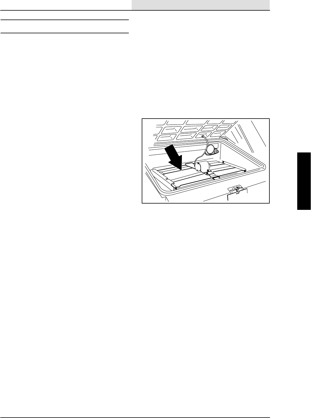
THERMO SENTRYt
The Thermo Sentrytsenses the temperature of
the air pulled up from the hopper. If there is a fire
in the hopper, the Thermo Sentrytstops the
vacuum fan and cuts off the air flow.
Reset the Thermo Sentrytby pushing in its reset
button.
TO REPLACE THERMO SENTRYt
1. Open the hopper cover.
2. Disconnect the Thermo Sentrytfrom the
hopper harness.
3. Remove the two screws holding the
Thermo Sentrytto the stiffener plate.
Remove the Thermo Sentryt.
4. Mount the new Thermo Sentrytto the
stiffener plate with existing hardware.
5. Connect the new Thermo Sentrytto the
hopper wire harness.
6. Close the hopper cover.

SWEEPING
3-15
8410 MM392 (5--02)
BRUSHES
MAIN SWEEP BRUSH
The main sweep brush is cylindrical and spans
the width of the machine, sweeping debris into the
hopper.
Check the brush daily for wear or damage.
Remove any string or wire tangled on the main
brush, main brush drive hub, or main brush idler
hub.
Check the main sweep brush pattern daily. The
pattern should be 50 to 65 mm (2.0 to 2.5 in) wide
with the main sweep brush in the lowered
position. Adjust the main sweep brush pattern by
turning the main brush pressure knob located next
to the brush position lever.
Rotate the main brush end-for-end every 50 hours
of operation for maximum brush life and best
sweeping performance.
Replace the main sweep brush when the
remaining bristles measure 25 mm (1 in) in length.
SWEEPING
3-16 8410 MM392 (5--02)
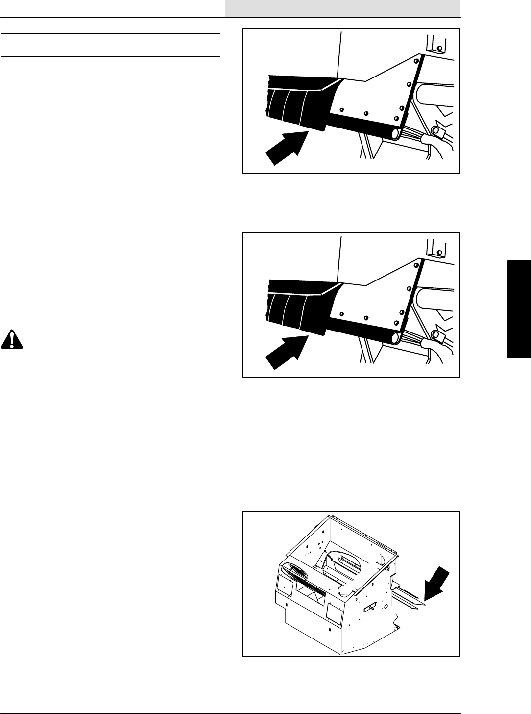
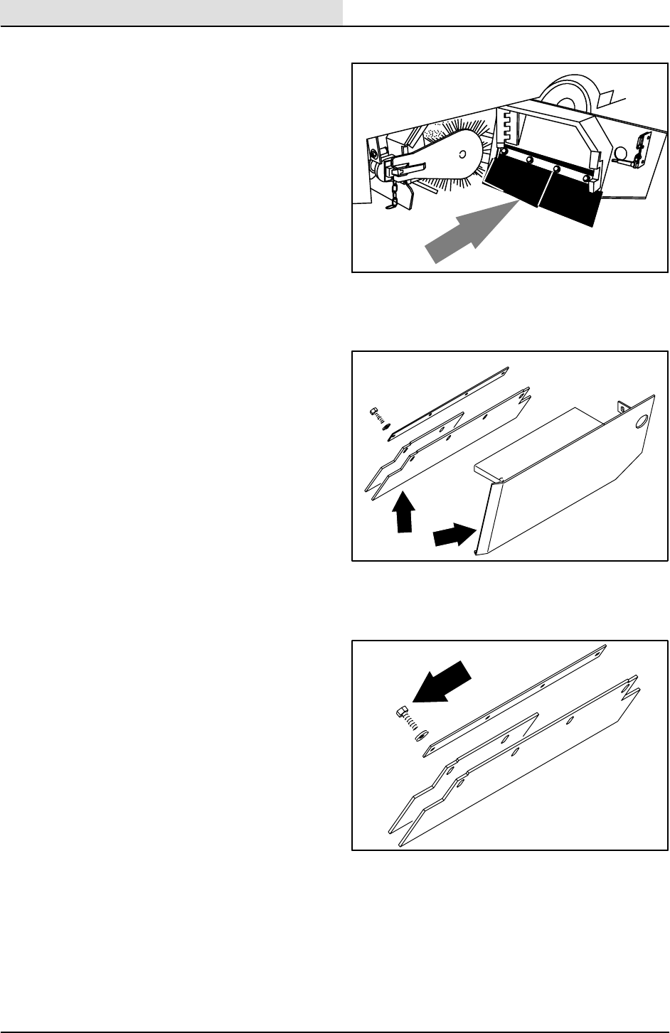
REPLACING MAIN SWEEP BRUSH
1. Stop the engine and set the machine parking
brake.
FOR SAFETY: Before leaving or
servicing machine; stop on level
surface, set parking brake, turn off
machine and remove key.
2. Raise the main sweep brush.
3. Open the right side brush access door.
4. Unlatch and remove the brush idler plate.
5. Grasp the main sweep brush; pull it off the
brush drive plug and out of the main brush
compartment.
6. Put the new or rotated end-for-end main
sweep brush on the floor next to the access
door.
7. Slide the main sweep brush onto the drive
plug. Rotate the brush until it engages the
drive plug, and push it all the way onto the
plug.
8. Slide the brush idler plate plug onto the main
sweep brush.
9. Latch the idler plate onto the machine frame.
10. Close the right side brush access door.
08016
08017
08018
SWEEPING
3-17
8410 MM392 (5--02)
CHECKING AND ADJUSTING MAIN SWEEP
BRUSH PATTERN
1. Apply chalk, or some other material that will
not blow away easily, to a smooth, level
floor.
2. Raise the side brush and main sweep brush
and position the main sweep brush over the
chalked area.
3. Start the main sweep brush.
4. Lower the main sweep brush for 15 to 20
seconds while keeping a foot on the brakes
to keep the machine from moving. This will
lower the rotating main sweep brush.
NOTE: If chalk or other material is not available,
allow the sweep brush to spin on the floor for two
minutes. A polish mark will remain on the floor.
5. Raise the main sweep brush.
6. Stop the main sweep brush.
7. Drive the machine off the test area.
8. Observe the width of the brush pattern. The
proper brush pattern width is 50 to 65 mm
(2.0 to 2.5 in).
9. To increase the width of the main sweep
brush pattern, turn the main sweep brush
down pressure knob counter-clockwise.
To decrease the width of the main sweep
brush pattern, turn the main sweep brush
down pressure knob clockwise.
00582
SWEEPING
3-18 8410 MM392 (5--02)
If the main sweep brush pattern is tapered,
more than 15 mm (0.5 in) on one end than
the other, adjust the taper with the taper
adjustment bracket at the idler end of the
brush.
A. Loosen the bracket mounting bolts.
B. Turn the taper adjustment nut
counter-clockwise to increase the
pattern width at the brush idler end, and
clockwise to decrease the pattern width
at the brush idler end. Tighten the
mounting bolts.
C. Check the main sweep brush pattern
and readjust as necessary. Then adjust
the width of the main brush pattern.
00601
09183
09184
SWEEPING
3-19
8410 MM392 (8--01)
TO REPLACE MAIN BRUSH IDLER PLUG
BEARING
FOR SAFETY: Before Leaving Or
Servicing Machine; Stop On Level
Surface, Set Parking Brake, Turn Off
Machine And Remove Key.
1. Open the right side brush door and remove
the main brush idler arm from machine.
2. Remove the plastic cap from the idler plug.
3. Remove the M12 hex screw, nyloc hex nut,
and washer holding the idler plug to the
brush idler arm. Save the hardware.
4. Remove the four M6 hex screws holding the
idler shaft in the idler plug. Remove the
shaft. Save the hardware.
5. Remove the bearing seal plate, retainer and
bearing.
6. Clean the inside of the idler plug.
7. Place a new bearing, the seal plate and the
retainer in the idler.
8. Reinstall the four screws and flat washers.
9. Install the idler shaft and tighten the four M6
hex screws to 8--10 Nm (6--8 ft lb).
10. Position the idler plug and shaft on the brush
idler arm. Reinstall the hardware removed
earlier. Tighten to 68--81 Nm (50--60 ft lb).
11. Apply RTV to the area where plastic cap will
fit in the end of idler plug. Snap plastic cap
into place.
NOTE: If you replace idler arm latch, use blue
locktite on hardware to hold in place.
SWEEPING
3-20 8410 MM392 (8--01)
TO REPLACE BRUSH SHAFT BEARINGS
FOR SAFETY: Before Leaving Or
Servicing Machine; Stop On Level
Surface, Set Parking Brake, Turn Off
Machine And Remove Key.
1. Remove the main brush and idler.
2. Remove the main brush motor mount plate
from the brush shaft.
NOTE: The hydraulic hoses can be left hooked up
to the motor when removing the mount plate.
3. Remove the brush lift cable clevis from the
brush shaft arm.
4. Loosen the main brush taper adjustment
screw.
5. Remove the hardware holding each of the
two brush shaft flange bearings.
6. Pull the brush shaft out of the machine.
7. Use a punch and a hammer to drive the
brush hub roll pins out of the brush hubs.
8. Slide the brush hubs off the end of the shaft.
9. Remove the remaining hardware holding the
bearing collars in place.
10. Loosen the bearing set screws and slide the
bearings off the shaft.
11. Slide the new bearings on the shaft with the
collar facing the ends of the shaft. Be sure
to have a bearing flange on each side of the
bearings.
12. Slide the brush hubs on each end of the
brush shaft.
13. Align the hole in the hub with the hole in the
shaft.
SWEEPING
3-21
8410 MM392 (8--01)
14. Use a hammer to pound the roll pin in flush.
15. Mount the main brush shaft plate to the right
side bearing flange. Tighten the hardware to
22--27 Nm (16--20 ft lb).
NOTE: If you are replacing the idler arm latch
bracket, use blue locktite to hold the bolts in
place. Tighten the bolts to 8--10 Nm(6--8 ft lb).
16. Center the brush shaft in the machine.
Tighten the bearing collar set screws.
17. Connect the main brush lift cable to the
brush shaft arm with the clevis pin removed
earlier.
18. Reinstall the main brush hydraulic motor
mount plate. Tighten the hex screw to
64 -- 83 Nm (47 -- 61 ft lb).
19. Reinstall the main brush and idler.
20. Check the main brush pattern for taper and
width.
SWEEPING
3-22 8410 MM392 (5--02)
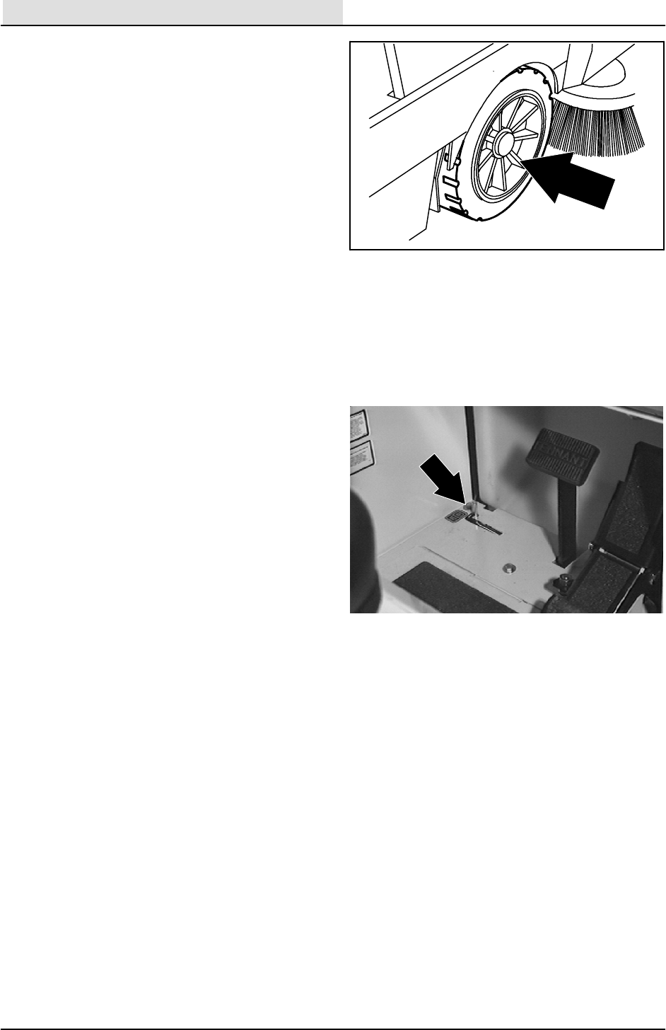
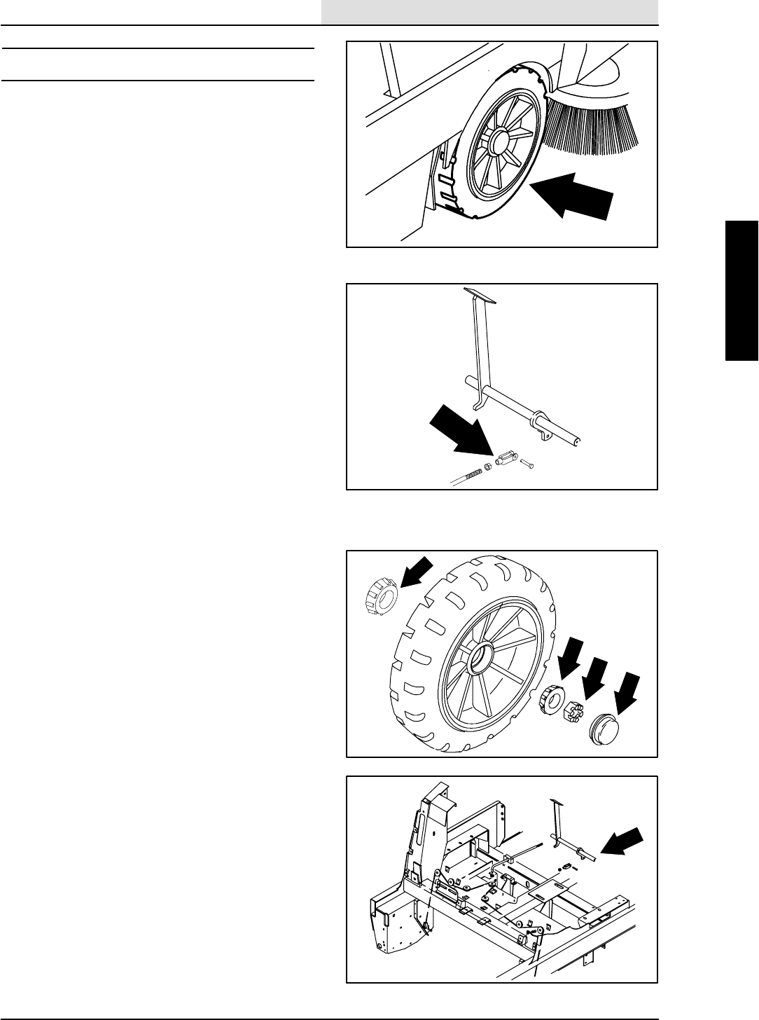
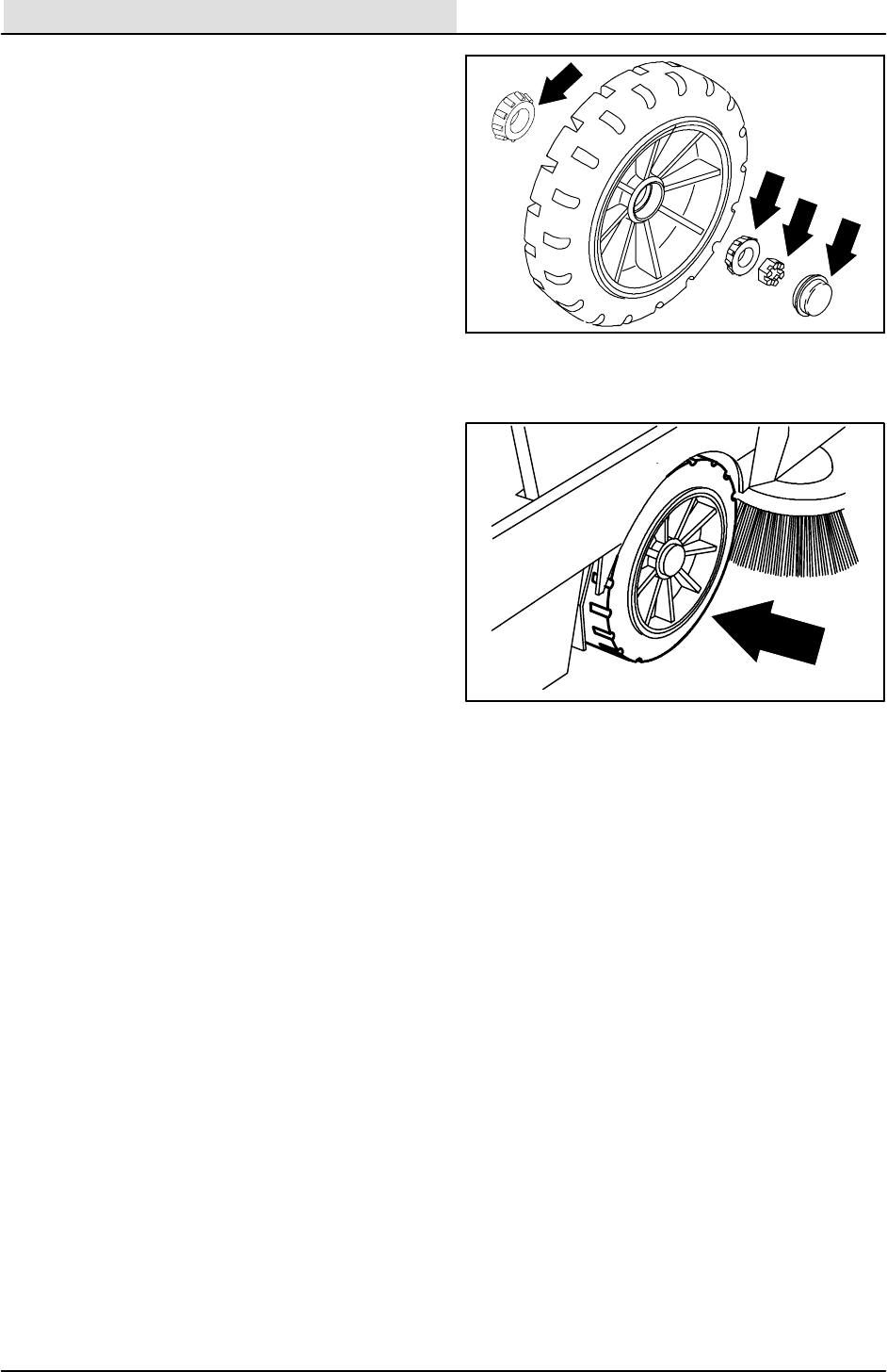
SIDE BRUSH
The side brush sweeps debris along edges into
the path of the main brush.
Check the brush daily for wear or damage.
Remove any string or wire found tangled on the
side brush or side brush drive hub.
Check the side brush pattern daily. The side brush
bristles should contact the floor in a 10 o’clock to
3 o’clock pattern when the brush is in motion.
Adjustthesidebrushpatternbythesidebrush
down pressure knob. Turn the knob
counter-clockwise to increase the brush contact
with the sweeping surface, and clockwise to
decrease the brush contact with the sweeping
surface.
The side brush should be replaced when it no
longer sweeps effectively for your application. A
guideline length is when the remaining bristles
measure 50 mm (2 in) in length. You may change
the side brush sooner if you are sweeping light
litter, or wear the bristles shorter if you are
sweeping heavy debris.
350327
SWEEPING
3-23
8410 MM392 (5--02)
REPLACING SIDE BRUSH
1. Empty the debris hopper.
2. Set the machine parking brake.
3. Stop the engine.
FOR SAFETY: Before leaving or
servicing machine; stop on level
surface, set parking brake, turn off
machine and remove key.
4. Remove the side brush retaining pin from
the side brush drive shaft by pulling the pin
keeper off over the end of the pin.
5. Slide the side brush off the side brush drive
shaft.
NOTE: Remove the drive hub and put it on the
new brush if one is not installed.
6. Slide the new side brush onto the side brush
drive shaft.
7. Insert the side brush retaining pin through
the side brush hub and shaft.
8. Secure the pin by clipping the pin keeper
over the end of the pin.
9. Disengage the hopper support bar and lower
the hopper.
10. Adjust the side brush pattern with the side
brush down pressure knob.
08019
SWEEPING
3-24 8410 MM392 (8--01)
SIDE BRUSH GUARD
The side brush guard protects the side brush from
objects along path of the machine. It deflects the
side brush out of harms way.
Rotate the side brush guard 90_every 200 hours
of operation. Replace the brush guard after all
four sides have been used.
TO ROTATE OR REPLACE SIDE BRUSH
GUARD
FOR SAFETY: Before Leaving Or
Servicing Machine; Stop On Level
Surface, Set Parking Brake, Turn Off
Machine And Remove Key.
1. Remove the side brush.
2. Remove the four bolts holding the side brush
guard to the side brush motor. Use care not
to disturb the motor position.
3. Rotate or replace the side brush guard.
4. Reinstall the four .375 in. hex screws in the
side brush motor. Tighten to 22--27 Nm
(16--20 ft lb).
5. Install the side brush.
SWEEPING
3-25
8410 MM392 (8--01)
SKIRTS AND SEALS
HOPPER LIP SKIRTS
The hopper lip skirts are located on the bottom
rear of the hopper. The skirts float over debris and
help deflect that debris into the hopper. The
hopper lip skirts consist of five bottom lip
segments and two additional side lip segments.
Check the hopper lip skirts for wear or damage
daily.
Replace the hopper lip skirts when they no longer
touch the floor.
TO REPLACE HOPPER LIP SKIRTS
1. Dump the machine debris hopper.
2. Set the machine parking brake.
3. Raise the hopper and engage the hopper
support bar.
WARNING: Raised Hopper May Fall.
Engage Hopper Support Bar.
4. Shut off the engine.
FOR SAFETY: Before Leaving Or
Servicing Machine; Stop On Level
Surface, Set Parking Brake, Turn Off
Machine And Remove Key.
5. Remove the hopper lip skirt retaining strip
mounting hardware.
6. Remove the hopper lip retaining strip, the
hopper lip, and the back-up strip.
7. Thread the retaining strip mounting bolts
through the retaining strip, the new hopper
lip skirt, the back-up strip, and in the hopper.
8. Tighten the mounting bolts to 8--14 Nm
(6--10 ft lb).
9. Start the engine.
10. Disengage the hopper support bar and lower
the hopper.
11. Check the skirt for proper adjustment. The
skirt should be evenly touching the floor.
SWEEPING
3-26 8410 MM392 (5--02)
BRUSH DOOR SKIRTS
The brush door skirts are located on the bottom of
each of the two main brush doors. The long skirt
should clear the floor by 3 to 6 mm
(0.12 to 0.25 in). The inner skirt should be angled
so that the rear corner touches the floor, and the
front corner is 6 mm (0.25 in) above the corner of
the long skirt.
Check the skirts for wear or damage and
adjustment daily.
NOTE: The brush door skirts have slotted holes
to allow for a ground clearance adjustment. The
door must be closed for proper adjustment.
TO REPLACE AND ADJUST BRUSH DOOR
SKIRTS
1. Park the machine on a smooth, level
surface.
2. Stop the engine and set the machine parking
brake.
FOR SAFETY: Before Leaving Or
Servicing Machine; Stop On Level
Surface, Set Parking Brake, Turn Off
Machine And Remove Key.
3. Open the main brush doors.
4. Remove the brush door skirt retaining bolts.
5. Remove the skirt retaining strip and the door
skirt.
6. Position the new door skirt and skirt
retaining strip on the brush door with the flat
edge forward and angled toward the back of
the machine.
7. Place the new half-length skirt over the front
half of the long skirt. Place the retainer over
the skirts.
8. Thread the skirt retaining bolts through the
brush door, the door skirts, and into the skirt
retaining strip.
NOTE: The brush door skirts have slotted holes to
allow for a ground clearance adjustment. The door
must be closed for proper adjustment.
08001
SWEEPING
3-27
8410 MM392 (8--01)
9. Slide the long brush door skirt up or down so
it will clear the floor by 3--5 mm
(0.12 to 0.25 in). Secure the two bolts
holding only one skirt.
10. Adjust the inner half--length skirt so the front
edge of it is 5 mm (0.25 in) above the long
skirt and the back half just touches the floor.
tighten all four bolts to 6--8 ft lb (8--10 Nm).
11. Repeat for the other brush door.
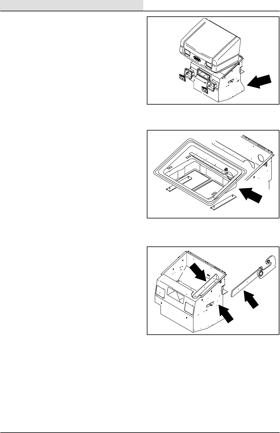
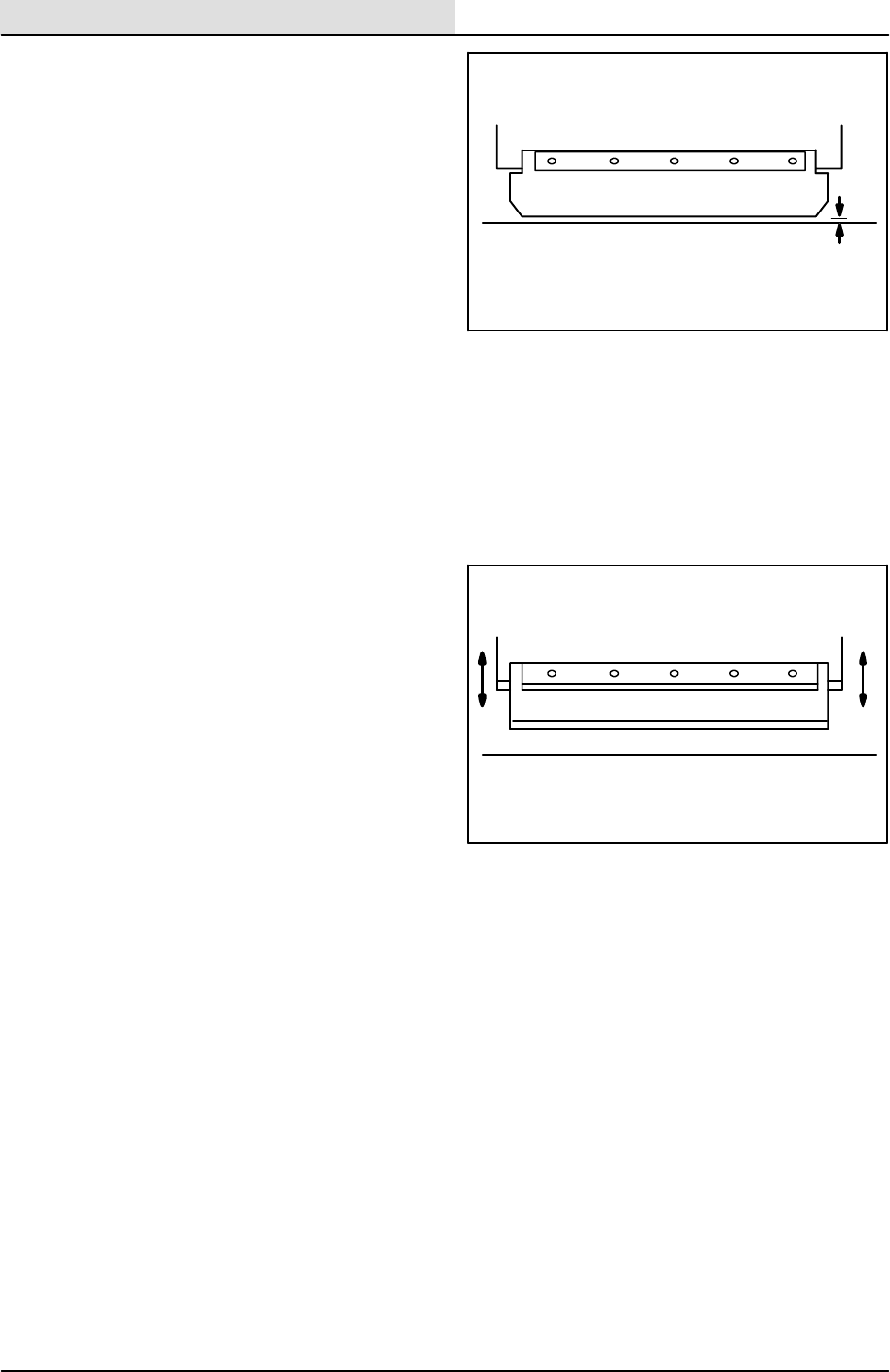
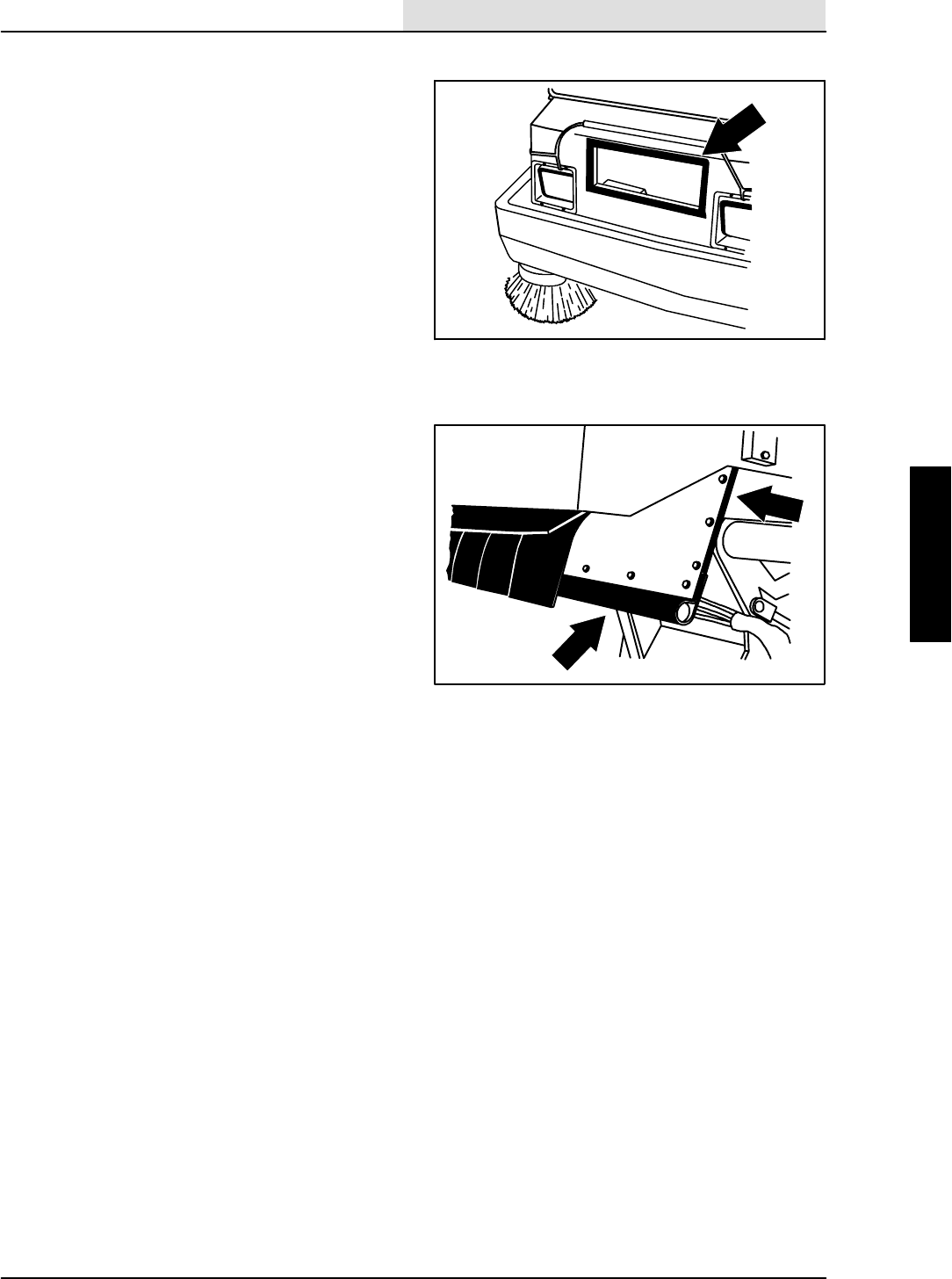
REAR SKIRT AND DEFLECTOR BLADE
The rear skirt and the deflector blade are located
on the bottom rear of the main brush
compartment. The rear skirt should clear the floor
up to 5 mm (0.25 in) in dusty conditions, and
touch the floor otherwise. The deflector blade is
spring loaded.
Check the skirt and blade for wear or damage and
adjustment daily.
NOTE: Rear tire pressure will affect skirt
clearances.
5 mm (0.25 in) 3mmto5mm
(0.12 to 0.25 in)
SWEEPING
3-28 8410 MM392 (8--01)
TO REPLACE AND ADJUST THE REAR
SKIRT AND DEFLECTOR BLADE
1. Park the machine on a smooth, level
surface.
2. Stop the engine and set the machine parking
brake.
FOR SAFETY: Before Leaving Or
Servicing Machine; Stop On Level
Surface, Set Parking Brake, Turn Off
Machine And Remove Key.
3. Open the main brush doors.
4. Remove the main brush.
5. Remove the retaining strip and floor skirt.
6. Thread the mounting bolts through the
machine frame, the rear floor skirt, and the
retaining strip toward the rear wheel.
7. Slide the rear floor skirt up or down so it
clears the floor up to a maximum of
5 mm (0.25 in).
8. Tighten the rear floor skirt mounting bolts to
8--14 Nm (6--10 ft lb).
9. Remove the brush contact blade retaining
strip and the brush contact blade.
10. Thread the mounting bolts through the
mounting bracket, the brush contact blade,
and the retaining strip.
11. Tighten the brush contact blade mounting
bolts to 8--14 Nm (6--10 ft lb).
12. Make sure the deflector spring moves the
blade into position freely.
13. Reinstall the main brush.
14. Close the main brush doors.
up to 5 mm
(up to 0.25 in)
SWEEPING
3-29
8410 MM392 (5--02)
BRUSH DOOR SEALS
The brush door seals are located on both main
brush doors and on corresponding portions of the
main frame.
Check the seals for wear or damage every
100 hours of operation.
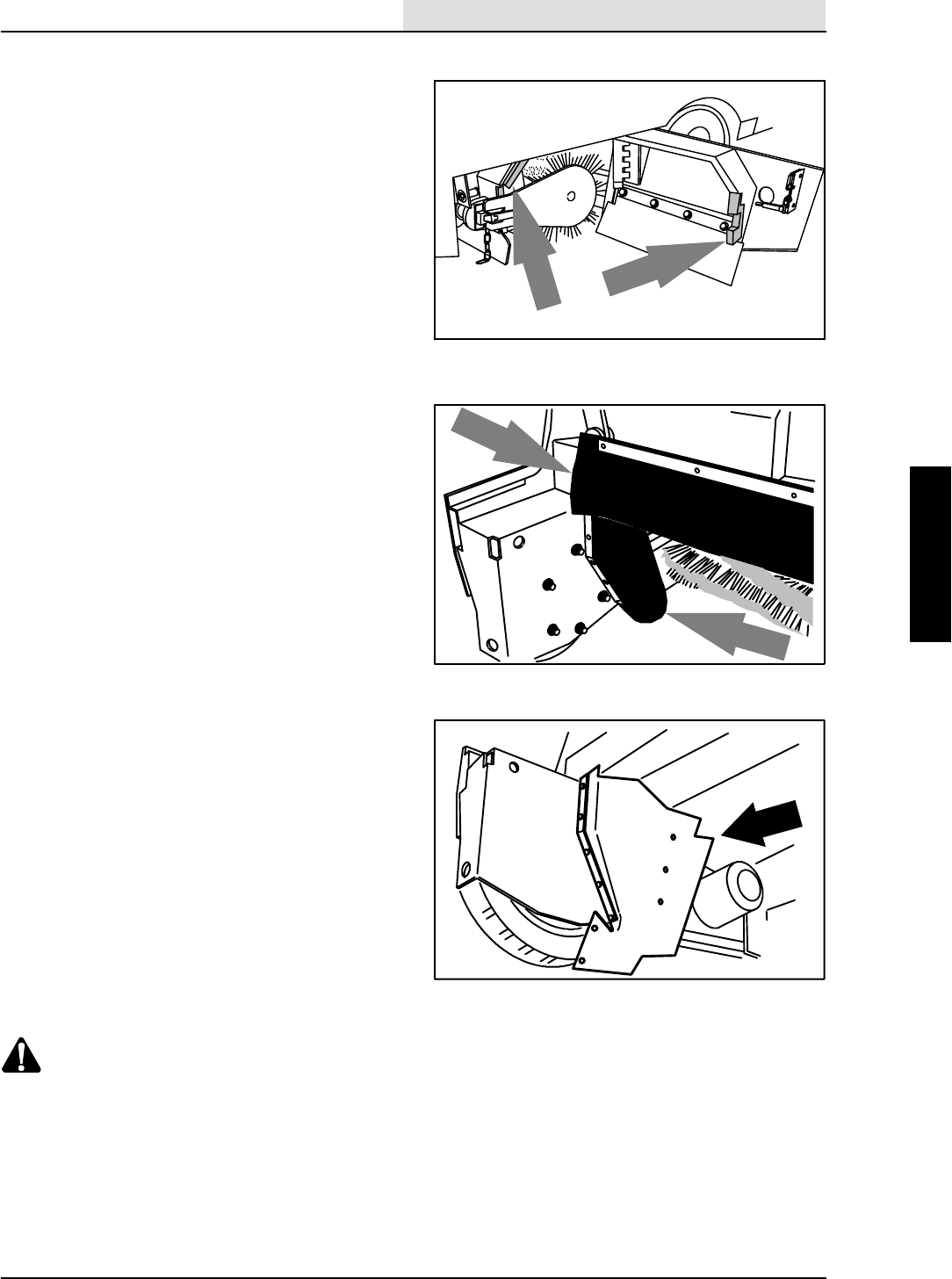
HOPPER SEALS
The hopper seals are located on the top and side
portions of the machine frame that contact the
hopper. They seal the main brush compartment.
Tighten the seal hardware to 4--5 Nm (3--4 ft lb).
Check the seals for wear or damage every
100 hours of operation.
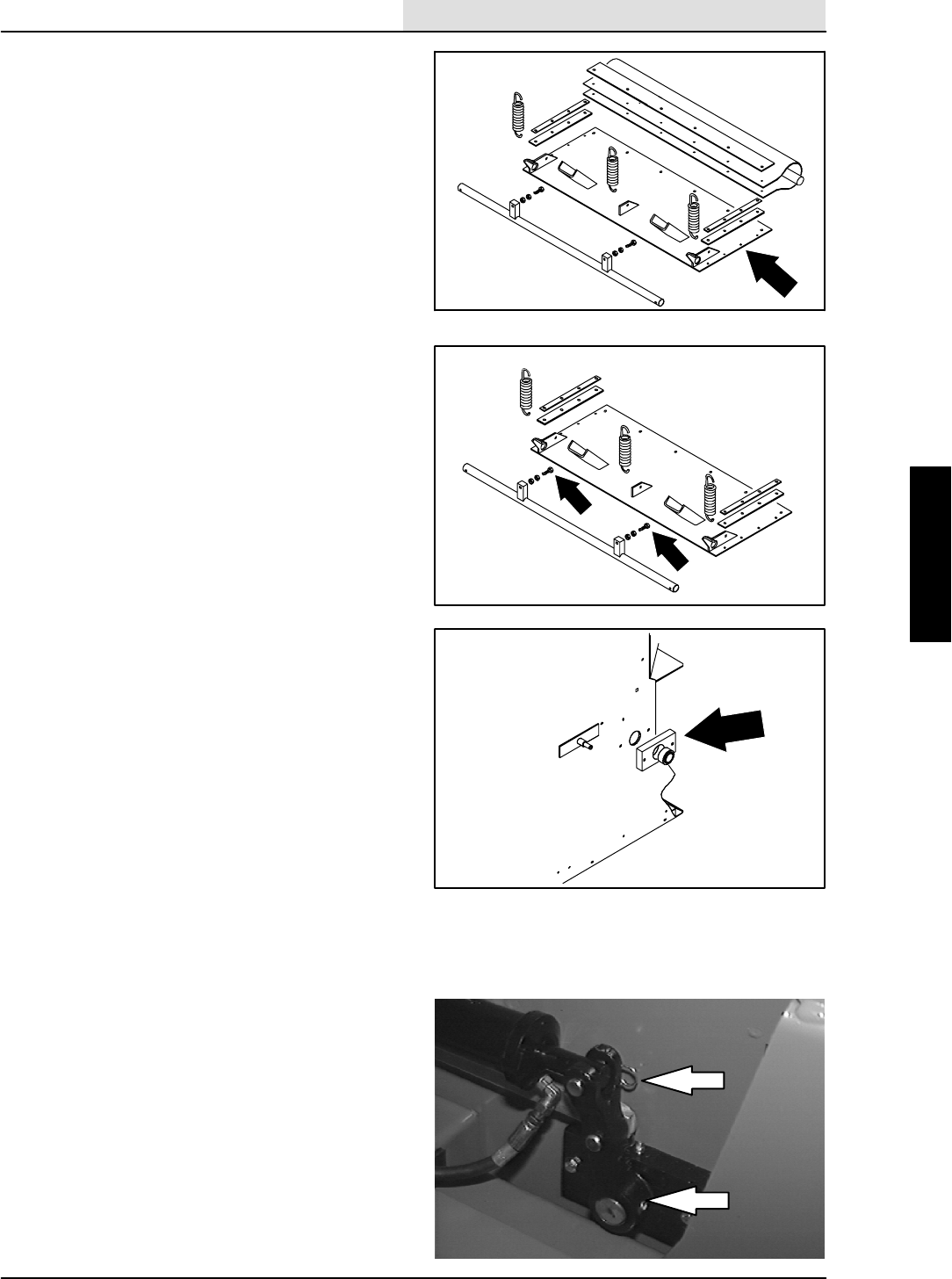
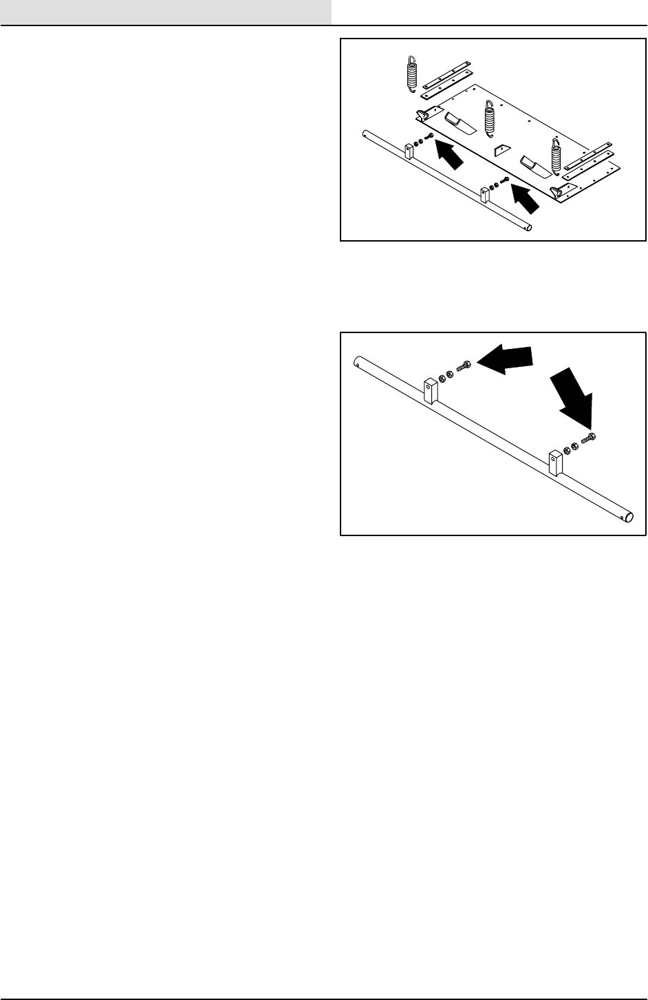
TO REPLACE HOPPER SEALS
1. Park the machine on a smooth, level
surface.
2. Stop the engine and set the machine parking
brake.
FOR SAFETY: Before Leaving Or
Servicing Machine; Stop On Level
Surface, Set Parking Brake, Turn Off
Machine And Remove Key.
3. Raise hopper and engage hopper support
bar.
WARNING: Raised Hopper May Fall.
Engage Hopper Support Bar.
4. Open the main brush doors.
5. Remove the main brush.
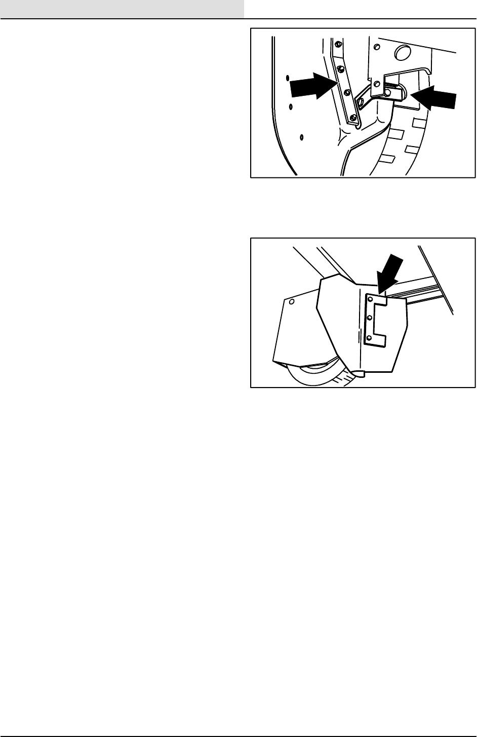
08022
08023
SWEEPING
3-30 8410 MM392 (8--01)
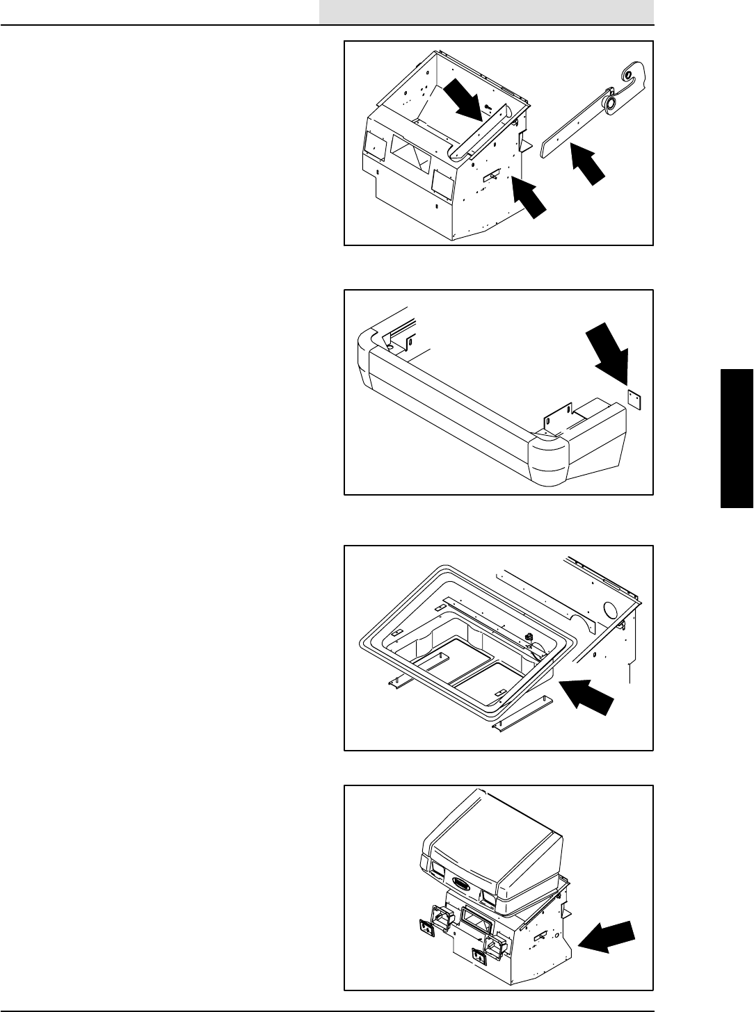
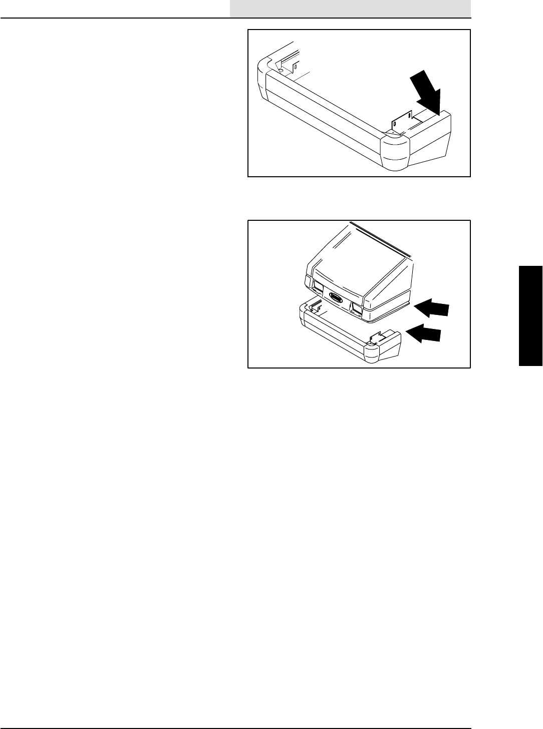
6. Remove the skirt retainer and skirt on each
side of the machine. Remove the plastic
rivets by prying under the head.
7. Position new skirt and existing retainer on
front of machine frame. Secure with plastic
push--in rivets.
8. Pull skirt around inside of frame. Push skirt
all of the way in its slots. Secure with
existing angle retainer and two M6 bolts, flat
washers, and Nyloc nuts. tighten bolts to
4--5 Nm (3--4 ft lb).
9. Pull skirt toward the brush door. Secure it in
place with the C-shaped retainer and bolts.
Tighten the bolts to 8--10 Nm (6--8 ft lb).
10. Repeat for the other side of the main frame.
SWEEPING
3-31
8410 MM392 (8--01)
HOPPER INSPECTION DOOR SEAL
The hopper inspection door seal is located on the
hopper and seals the front of the debris hopper.
Check the seal for wear or damage every
100 hours of operation.
HOPPER DOOR SEALS
The hopper door seals are located on the hopper
door. They seal the hopper when the hopper door
is closed. Use RTV between the sponge cord and
door seal. Make sure the seals are straight.
Tighten hardware to 3--4 Nm (2.5--3.5 ft lb).
Hardware should be oriented with the nyloc nuts
on the top side of the door.
Check the seals for wear or damage every
100 hours of operation.
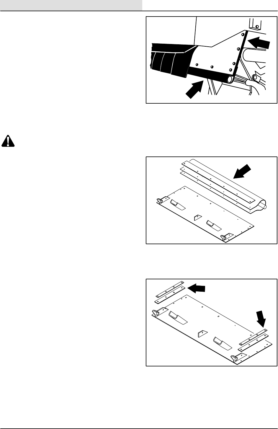
SWEEPING
3-32 8410 MM392 (8--01)
TO REPLACE HOPPER DOOR SEALS
1. Park the machine on a smooth, level
surface.
2. Open the hopper dump door.
3. Stop the engine and set the machine parking
brake.
FOR SAFETY: Before Leaving Or
Servicing Machine; Stop On Level
Surface, Set Parking Brake, Turn Off
Machine And Remove Key.
4. Raise the hopper and engage the hopper
support bar.
WARNING: Raised Hopper May Fall.
Engage Hopper Support Bar.
5. Remove the six M6 hex screws and nyloc
nuts holding dump door seal, retainer, and
sponge cord to dump door. Discard the seal.
6. Use black RTV to hold the sponge cord to
the new dump door seal.
7. Align the holes in the new seal with holes on
dump door and retainer. Reinstall the six M6
hex screws and nyloc nuts. Tighten to
3.3--4.4Nm(30--39Inlb).
8. Remove the four M6 hex screws and nyloc
nuts holding the dump door side seals and
retainers to each side of the dump door.
Note the direction of the hardware.
Discard the seals.
9. Align the holes in the seal with the holes on
the dump door and retainer. Reinstall the
four M6 hex screws and nyloc nuts. Tighten
to 3.3 -- 4.4 Nm (30 -- 39 In lb).
NOTE: Make sure the seals are lined up with the
inside edge of the hopper when tightening.
10. Start the machine and lower the hopper.
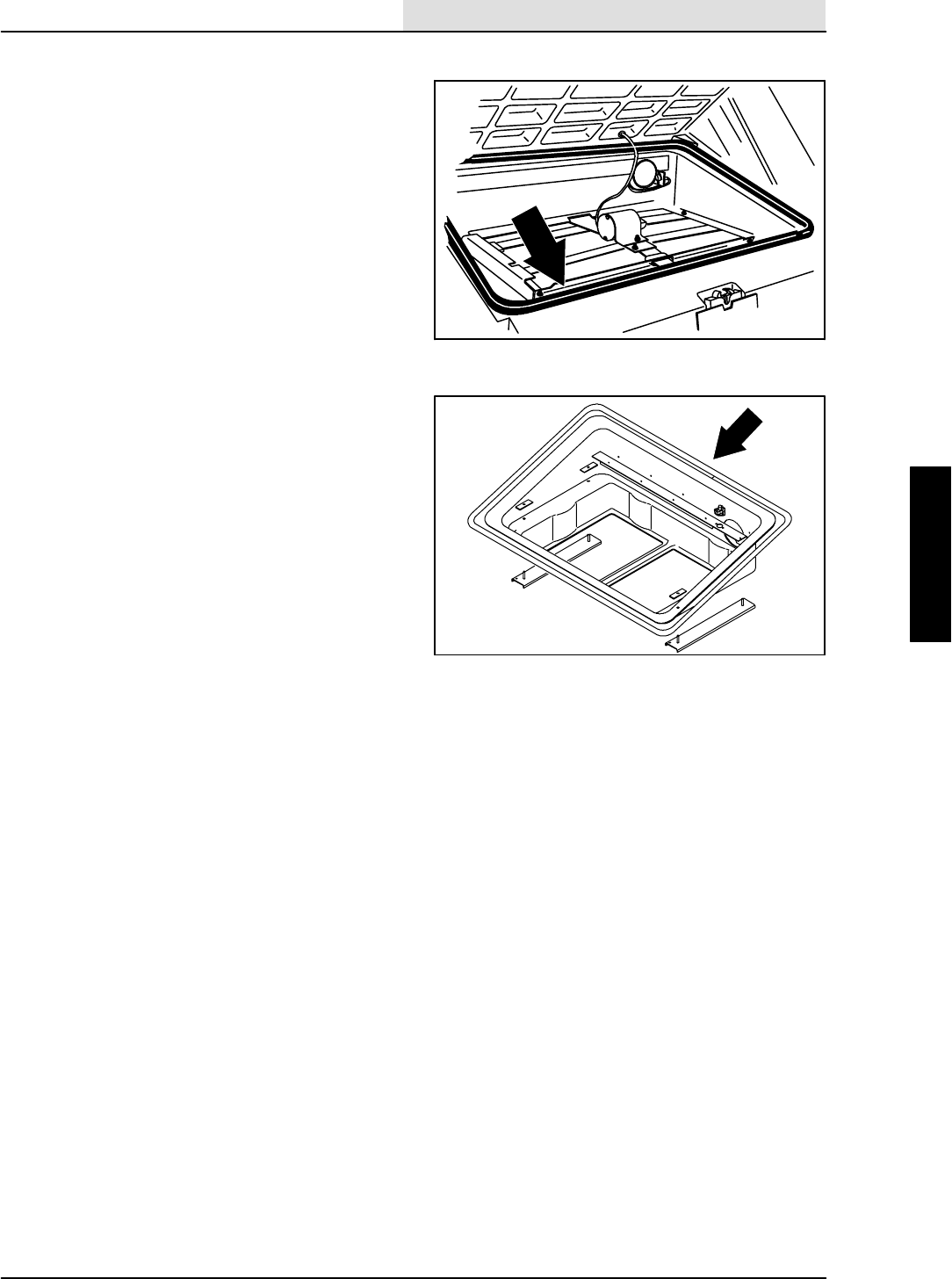
SWEEPING
3-33
8410 MM392 (8--01)
HOPPER COVER SEAL
The hopper cover seal is located on the top edges
of the hopper insert. It seals the hopper filter
compartment when the hopper cover is in the
down position.
Check the seal for wear or damage every
100 hours of operation.
TO REPLACE HOPPER COVER SEAL
1. Park the machine on a smooth, level
surface.
2. Stop the engine and set the machine parking
brake.
FOR SAFETY: Before Leaving Or
Servicing Machine; Stop On Level
Surface, Set Parking Brake, Turn Off
Machine And Remove Key.
3. Raise the hopper cover, unplug the wires
from filter shaker and thermo--sentry,
remove the filter carrier tray from the hopper
and set it on the floor.
4. Remove the old rubber bubble seal from the
filter carrier tray. The seal is glued to the tray
so a putty knife or a razor blade knife is
needed for removal.
5. Make sure the new seal is cut to the same
length as the old seal.
6. Use super glue in the groove of the new seal
and install it, bubble side up, on the filter
tray.
7. Reinstall the filter carrier tray back in the
hopper. Reconnect the shaker motor and
thermo--sentry to the hopper harness.
8. Close the hopper cover and operate the
machine. Check the new seal for any air
leaks.
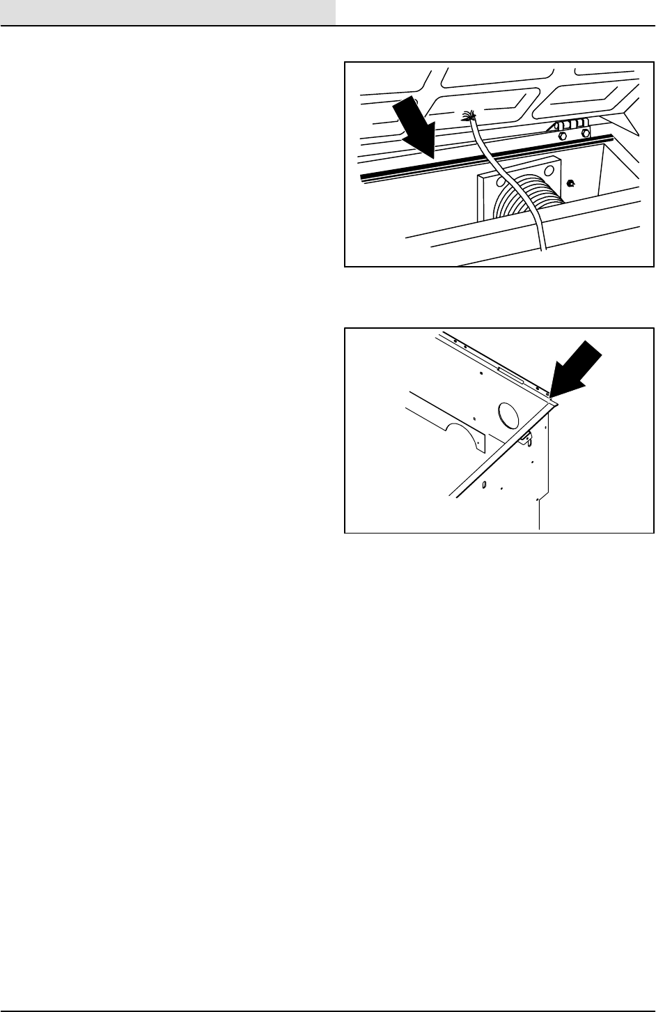
SWEEPING
3-34 8410 MM392 (8--01)
HOPPER DUST SEAL
The hopper dust seal is located under the hopper
insert along the top of the hopper.
Check the seal for wear or damage every
100 hours of operation. You can reach the seal by
removing the hopper insert.
TO REPLACE HOPPER DUST SEAL
1. Park the machine on a smooth, level
surface.
2. Stop the engine and set the machine parking
brake.
FOR SAFETY: Before Leaving Or
Servicing Machine; Stop On Level
Surface, Set Parking Brake, Turn Off
Machine And Remove Key.
3. Raise the hopper cover, unplug the wires
from filter shaker and thermo--sentry,
remove the filter carrier tray from the hopper
and set it on the floor.
4. Using a scraper or a putty knife, remove the
old seal from the back of the hopper.
Discard the old seal.
5. Make sure that all of the old seal is removed
before attempting to glue the new one on.
6. Cut the new seal to length and use an
industrial strength contact cement to attach
it to the back of the hopper.
7. Reinstall the filter carrier tray back in the
hopper. Reconnect the shaker motor and
thermo--sentry to the hopper harness.
8. Close the hopper cover and operate the
machine. Check the new seal for any air
leaks.
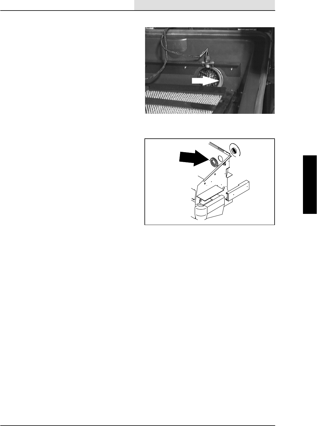
SWEEPING
3-35
8410 MM392 (5--02)
HOPPER VACUUM FAN SEAL
The hopper vacuum fan seal is mounted on the
inside of the hopper around the vacuum fan inlet.
Check the seal for wear or damage every
100 hours of operation. You can reach the seal by
removing the hopper insert.
TO REPLACE HOPPER VACUUM FAN SEAL
1. Park the machine on a smooth, level
surface.
2. Stop the engine and set the machine parking
brake.
FOR SAFETY: Before Leaving Or
Servicing Machine; Stop On Level
Surface, Set Parking Brake, Turn Off
Machine And Remove Key.
3. Raise the hopper cover, unplug the wires
from filter shaker and thermo--sentry,
remove the filter carrier tray from the hopper
and set it on the floor.
4. Using a scraper or a putty knife, remove the
old seal from the back of the hopper.
Discard the old seal.
5. Make sure that all of the old seal is removed
before attempting to glue the new one on.
6. Cut the new seal to length and use an
industrial strength contact cement to attach
it to the back of the hopper.
7. Reinstall the filter carrier tray back in the
hopper. Reconnect the shaker motor and
thermo--sentry to the hopper harness.
8. Close the hopper cover and operate the
machine. Check the new seal for any air
leaks.
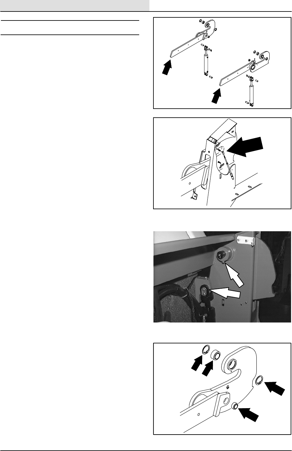
SWEEPING
3-36 8410 MM392 (8--01)
HOPPER LIFT ARMS
The hopper lift arms lift and lower the hopper
assembly. They are held in place by two pins and
self-aligning bearings with retaining rings.
TO REMOVE HOPPER LIFT ARMS
1. Park the machine on a smooth, level
surface.
2. Stop the engine and set the machine parking
brake.
FOR SAFETY: Before Leaving Or
Servicing Machine; Stop On Level
Surface, Set Parking Brake, Turn Off
Machine And Remove Key.
3. Remove the hopper. See TO REMOVE
HOPPER instructions in this section.
4. Remove the RH and LH tank panels.
5. Disconnect the speed limiter cable from RH
side lift arm. The cable can be removed from
the ball by pushing down on the sleeve
around the ball joint end and prying it off.
6. Remove the M6 hex screw holding the
cylinder pin plate to the cylinder clevis.
7. Raise up slightly on lift arm to take the
pressure off the lift cylinder pin. Remove pin.
8. Remove the M8 socket screw from the
upper lift arm pivot pin.
9. Raise up slightly on the lift arm to take
pressure off the pivot pin. Remove the pivot
pin and lift arm from the machine.
10. If the large self aligning bearing needs to be
changed, remove the retaining rings and
press the bearing out of the lift arm.
11. If the small self aligning bearing needs to be
changed, press the bearing out of the lift
arm.
12. Repeat this procedure on the LH side lift
arm if needed.
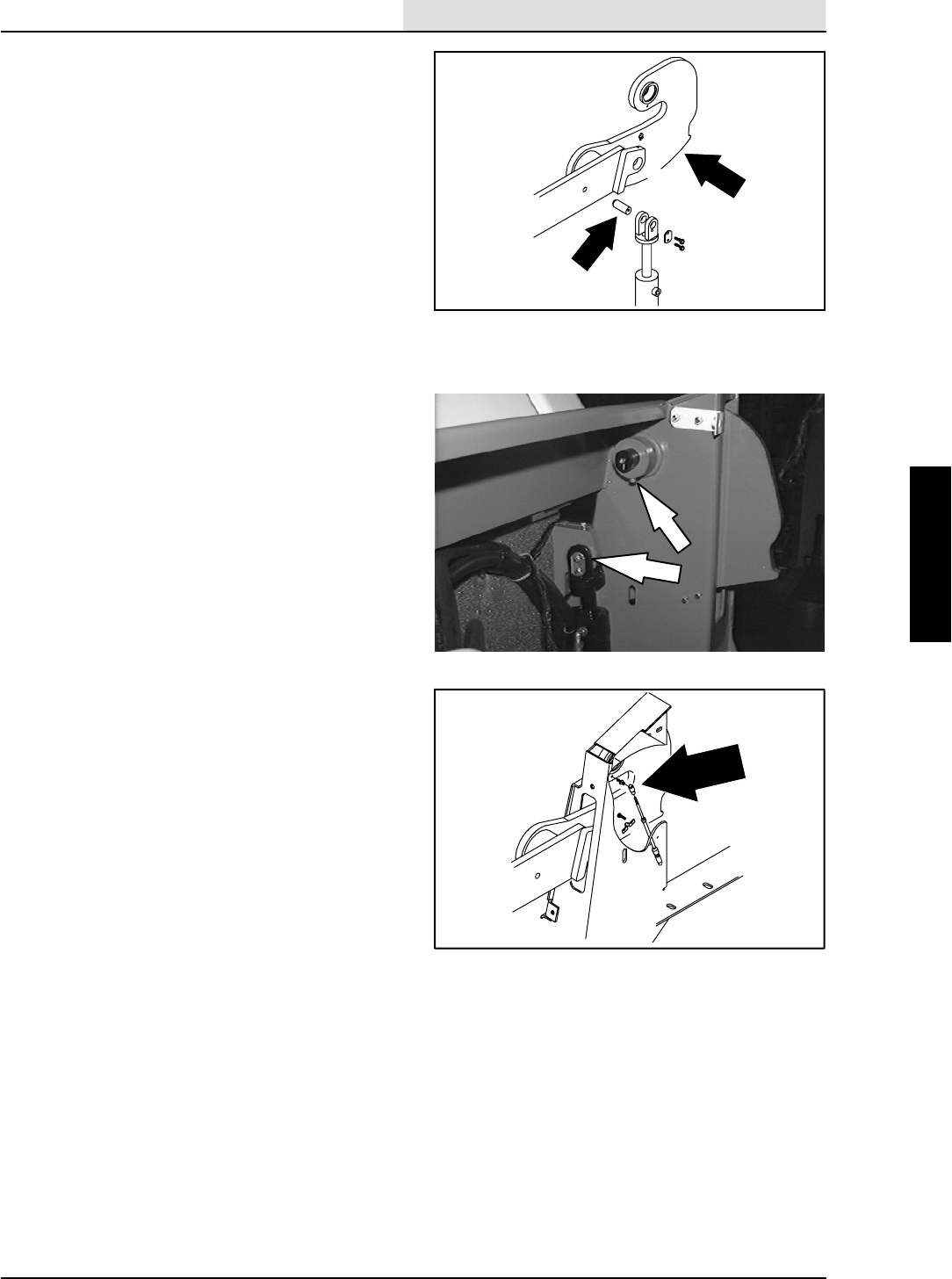
SWEEPING
3-37
8410 MM392 (8--01)
TO INSTALL HOPPER LIFT ARMS
1. Park the machine on a smooth, level
surface.
2. Stop the engine and set the machine parking
brake.
FOR SAFETY: Before Leaving Or
Servicing Machine; Stop On Level
Surface, Set Parking Brake, Turn Off
Machine And Remove Key.
3. Position the lift arm in the machine. Align the
large bearing with the upper hole in the
machine frame tower.
4. Install the lift arm pivot pin through the large
bearing from the outside of machine.
5. Align the hole in lift arm pivot pin with the
hole in the pin boss on the machine frame
tower. Install the M8 socket head screw and
tighten to 18 -- 24 Nm (13 -- 18 ft lb).
6. Align the small bearing in the lift arm with
the hole in the lift cylinder clevis.
7. Install the lift cylinder pin plate through the
bearing. Reinstall the M6 hex screw and
tighten to 8 -- 10 Nm (6 -- 8 ft lb).
8. On the RH lift arm, reconnect the speed
limiter cable to the ball end.
9. Repeat steps 3 -- 7 on the opposite side.
10. Reinstall hopper. See TO INSTALL
HOPPER instructions in this section.
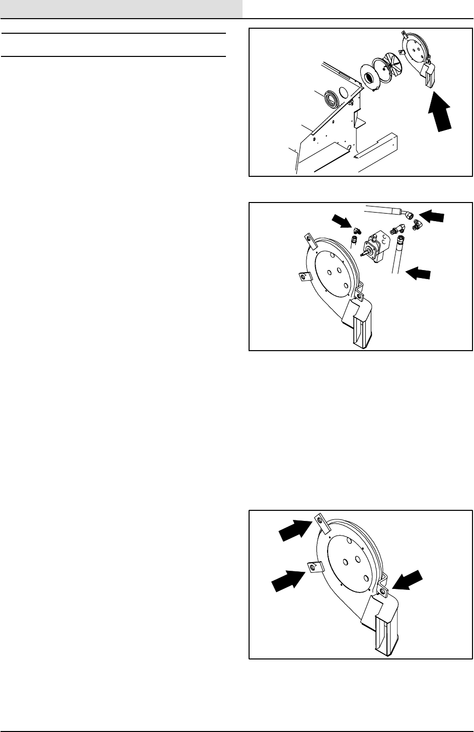
SWEEPING
3-38 8410 MM392 (8--01)
SWEEPING VACUUM FAN
The sweeping vacuum fan is located on the back
of the debris hopper. It is used during sweeping to
control dusting by pulling air through the filters.
TO REMOVE SWEEPING VACUUM FAN
1. Park the machine on a smooth, level
surface.
2. Stop the engine and set the machine parking
brake.
FOR SAFETY: Before Leaving Or
Servicing Machine; Stop On Level
Surface, Set Parking Brake, Turn Off
Machine And Remove Key.
3. Raise the hopper cover, unplug the wires
from filter shaker and thermo--sentry,
remove the filter carrier tray from the hopper
and set it on the floor.
4. Leave the hopper cover open and raise the
hopper 1/3 of the way up or far enough to
access the three M10 hex screws holding
the vacuum fan to the back of the hopper.
NOTE: Hopper must be held in this position with a
hoist, jack stands or a prop rod between hopper
bumper and machine frame.
5. Disconnect and plug the three hydraulic
hoses on the vacuum fan motor.
NOTE:Observe hydraulic cleanliness
requirements when opening hydraulic lines.
6. Disconnect the wire harness from the fan
motor solenoid.
7. Remove the three M10 hex screws holding
vacuum fan to rear of hopper. Reach in from
the left side of the hopper, under the hopper
cover, to access the hex screws.
8. Remove the vacuum fan assembly from the
machine and make the necessary repairs.
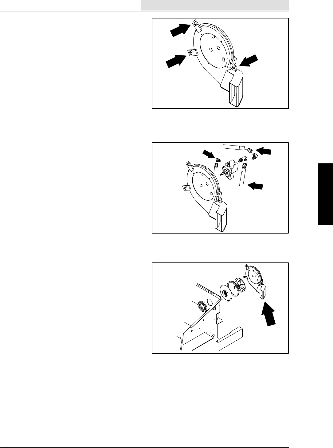
SWEEPING
3-39
8410 MM392 (8--01)
TO INSTALL SWEEPING VACUUM FAN
1. Park the machine on a smooth, level
surface.
2. Stop the engine and set the machine parking
brake.
FOR SAFETY: Before Leaving Or
Servicing Machine; Stop On Level
Surface, Set Parking Brake, Turn Off
Machine And Remove Key.
3. Raise the hopper cover, unplug the wires
from filter shaker and thermo--sentry,
remove the filter carrier tray from the hopper
and set it on the floor.
4. Leave the hopper cover open and raise the
hopper 1/3 of the way up or far enough to
access the three M10 hex screws holding
the vacuum fan to the back of the hopper.
NOTE: Hopper must be held in this position with a
hoist, jack stands or a prop rod between hopper
bumper and machine frame.
5. Align the holes in fan isolators with the holes
in the back of the hopper.
6. Reinstall the three M10 hex screws,
washers and nyloc nuts with the nuts on the
outside of the hopper. Tighten to 18 -- 24 Nm
(13 -- 18 ft lb).
7. Reconnect hydraulic hoses. See schematic
in HYDRAULICS section.
8. Reconnect the wire harness to the vacuum
fan solenoid.
9. Make sure the wires and hoses are tied and
clamped up properly.
10. Remove the hoist, jack stands or prop rod
and lower the hopper.
11. Reinstall the filter carrier tray back in the
hopper. Reconnect the shaker motor and
thermo--sentry to the hopper harness.
12. Close the hopper cover and operate the
machine. Check the sweeping vacuum fan
for proper operation.
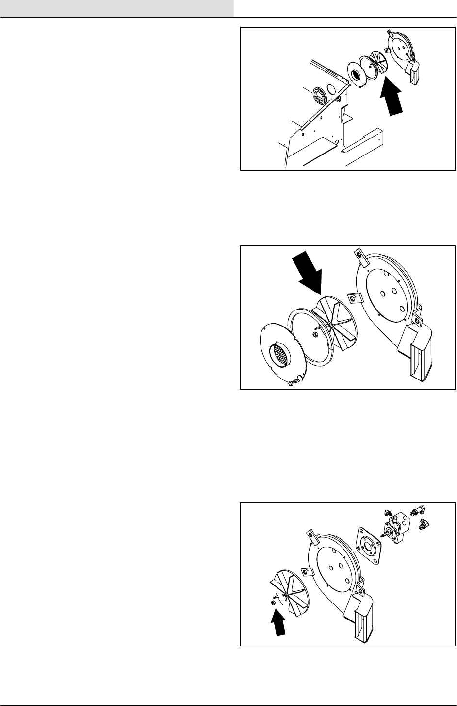
SWEEPING
3-40 8410 MM392 (8--01)
TO REPLACE SWEEPING VACUUM FAN
IMPELLER
1. Park the machine on a smooth, level
surface.
2. Stop the engine and set the machine parking
brake.
FOR SAFETY: Before Leaving Or
Servicing Machine; Stop On Level
Surface, Set Parking Brake, Turn Off
Machine And Remove Key.
3. Remove the vacuum fan from the machine.
See TO REMOVE SWEEPING VACUUM
FAN instructions in this section.
4. Place the vacuum fan assembly in a vice.
5. Remove the four 0.25 in. hex screws and
fender washers holding the inlet plate to the
vacuum fan housing. Remove the plate.
6. Hold the impeller from turning and remove
the 0.31 in. hex nut from the vacuum fan
motor shaft.
7. Pull the impeller straight off the shaft. The
impeller may have to be lightly pried off. Be
careful not to loose the square key.
8. Put a small amount of grease on the motor
shaft before installing the new impeller.
Make sure the square key is in place.
9. Slide the impeller all the way on the shaft
and spin it slowly. If the impeller rubs on
housing pull it back off and place a 0.38 in.
flat washer on shaft under impeller and
re--assemble. Repeat this procedure until
the impeller spins freely.
10. Hold the new impeller from turning and firmly
tighten the 0.31 in. flex lock nut.
11. Reinstall the inlet plate using the four 0.25
in. hex screws and fender washers. Tighten
t o 11 -- 1 4 N m ( 7 -- 1 0 f t l b ) .
12. Reinstall vacuum fan assembly to the rear of
the hopper. See TO INSTALL SWEEPING
VACUUM FAN instructions in this section.

SWEEPING
3-41
8410 MM392 (8--01)
MACHINE TROUBLESHOOTING
Problem Cause Remedy
Excessive dusting Brush skirts and dust seals worn,
damaged, out of adjustment
Replace or adjust brush skirts or
dust seals
Hopper dust filter clogged Shake and/or clean or replace
dust filter
Vacuum hose damaged Replace vacuum hose
Vacuum fan failure Contact TENNANT service
personnel
Thermo Sentryttripped Reset Thermo Sentryt
Poor sweeping performance Brush bristles worn Replace brushes
Main and side brushes not
adjusted properly
Adjust main and side brushes
Debris caught in main brush drive
mechanism
Free drive mechanism of debris
Main brush drive failure Contact TENNANT service
personnel
Side brush drive failure Contact TENNANT service
personnel
Hopper full Empty hopper
Hopper lip skirts worn or damaged Replace lip skirts
Wrong sweeping brush Contact TENNANT representative
for recommendations

SWEEPING
3-42 8410 MM392 (8--01)

SCRUBBING
4-1
8410 MM392 (5--02)
CONTENTS
Page
INTRODUCTION 4-3......................
SOLUTION SYSTEM 4-4...............
RECOVERY TANK 4-4..............
TO REMOVE RECOVERY
TANK 4-4....................
TO INSTALL RECOVERY
TANK 4-7....................
SOLUTION TANK 4-8...............
TO REMOVE SOLUTION
TANK 4-9....................
TO INSTALL SOLUTION TANK 4-10
SCRUB HEAD 4-11....................
TO REMOVE SCRUB HEAD 4-11.....
TO INSTALL SCRUB HEAD 4-14.....
TO REPLACE SIDE SHIFT CABLE 4-16
SQUEEGEES 4-17.....................
TO REPLACE SQUEEGEE
PUSH--PULL CABLE 4-17.........
TO REPLACE SQUEEGEE LIFT
CABLE 4-19.....................
TO REMOVE REAR SQUEEGEE
FRAME 4-20....................
TO INSTALL REAR SQUEEGEE
FRAME 4-21....................
LEVELING THE REAR
SQUEEGEE 4-23................
ADJUSTING REAR SQUEEGEE
BLADE DEFLECTION 4-24........
SQUEEGEE BLADES 4-25.............
REAR SQUEEGEE 4-25.............
REPLACING OR ROTATING
REAR SQUEEGEE BLADES 4-25
SIDE SQUEEGEES 4-26............
REPLACING SIDE SQUEEGEE
BLADES 4-26.................
SCRUB VACUUM FAN 4-27.............
TO REMOVE SCRUB VACUUM
FAN 4-27........................
TO INSTALL SCRUB VACUUM
FAN 4-28........................
MACHINE TROUBLESHOOTING 4-29...

SCRUBBING
4-2 8410 MM392 (8--01)

SCRUBBING
4-3
8410 MM392 (8--01)
INTRODUCTION
When the scrubbing mode is used, water flows
from the solution tank through the solution valve
to the three disc scrub brushes. The brushes
scrub the floor. As the machine is moved forward
the squeegee wipes the dirty solution off the floor,
which is then picked up and drawn into the
recovery tank by the vacuum fan.
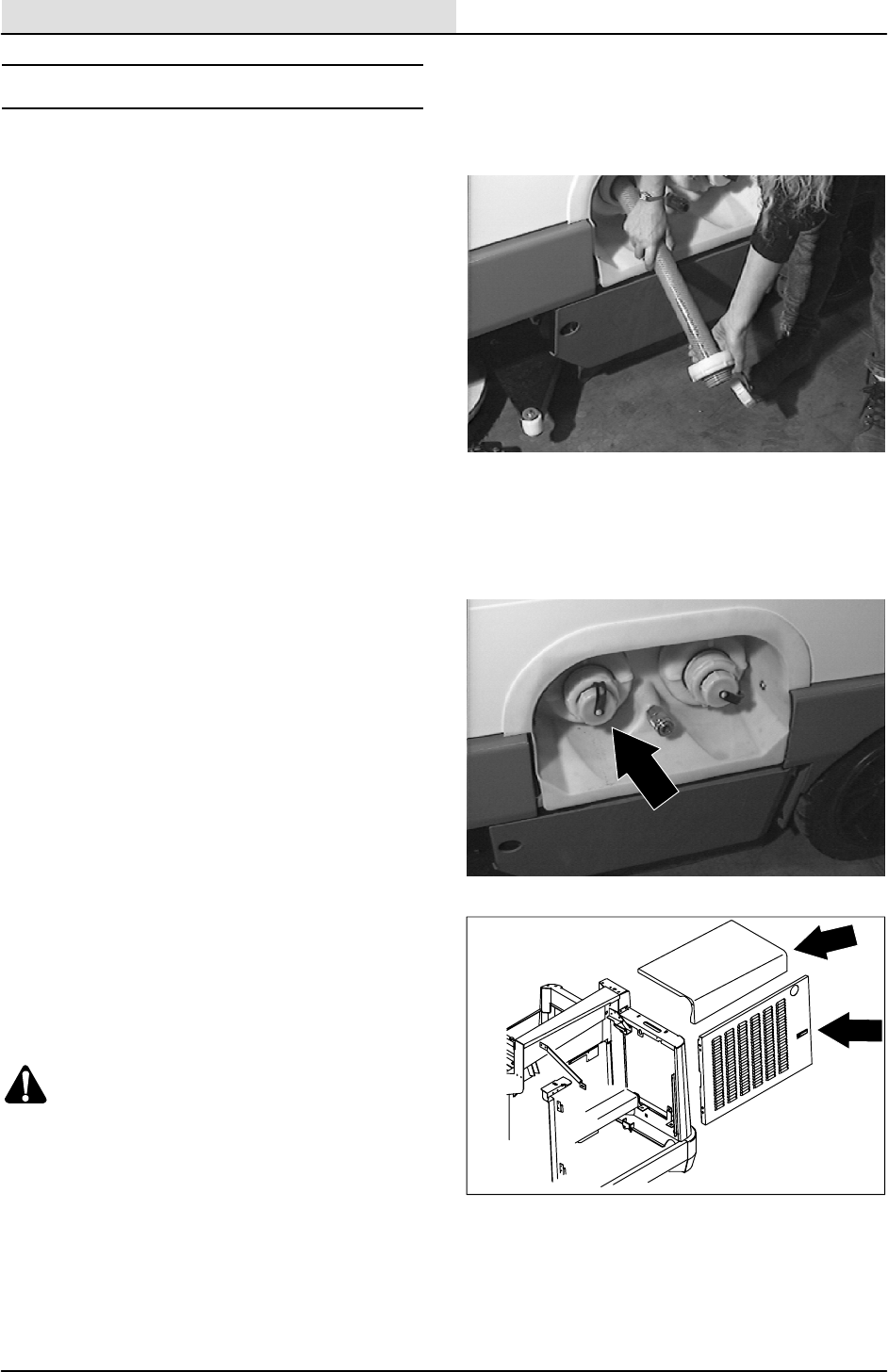
SCRUBBING
4-4 8410 MM392 (5--02)
SOLUTION SYSTEM
RECOVERY TANK
The recovery tank stores recovered solution. The
recovery tank should be drained and cleaned
daily, or when the recovery tank full light comes
on.
EStoption: The EStfilter should be cleaned
daily. The EStfilter can be rinsed while in the
recovery tank through the right tank fill opening, or
by removing the EStpump from the recovery
tank.
TO REMOVE RECOVERY TANK
FOR SAFETY: Before Leaving Or
Servicing Machine; Stop On Level
Surface, Set Parking Brake, Turn Off
Machine And Remove Key.
1. Drain the recovery tank.
2. Open the engine cover and side door.
3. Loosen the four M8 hex screws holding the
lintel cover to the machine. Remove the
cover.
4. Start the engine, raise the hopper, and
engage the safety leg.
WARNING: Raised Hopper May Fall.
Engage Hopper Support Bar.
5. Disconnect the vacuum hose and squeegee
hose from the back of the recovery tank.
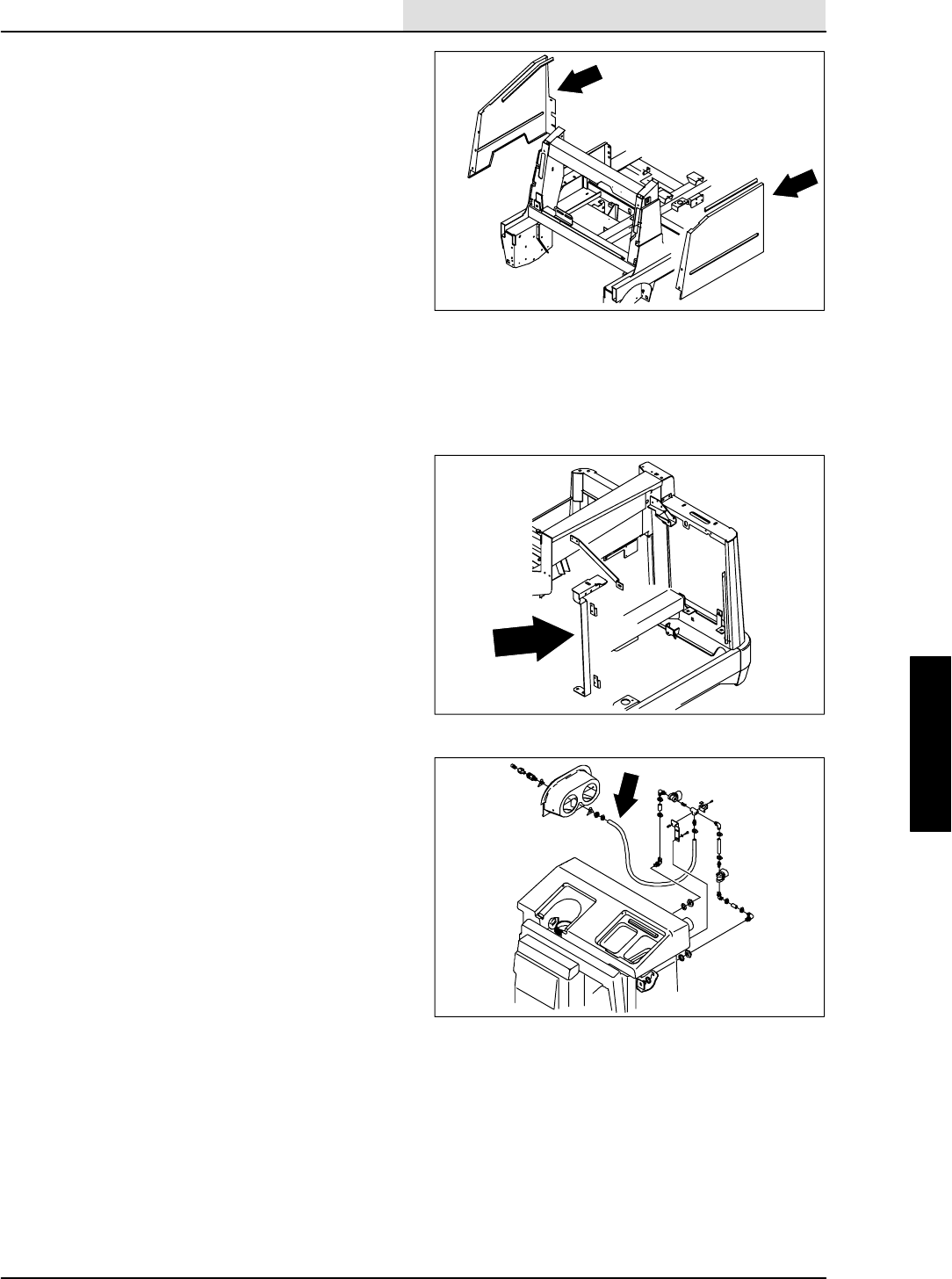
SCRUBBING
4-5
8410 MM392 (8--01)
6. Remove the six M6 hex screws holding the
LH side panel to the machine. Remove the
panel.
7. Remove the three M6 hex screws holding
the plastic clean out cover to the machine.
Remove the drain hoses, caps and clean out
cover. If the machine is equipped with the
EStoption, remove the solution hose from
the brass fitting.
8. Remove the three M6 hex screws and one
M8 hex screw holding the RH side panel to
the machine. Remove the panel.
9. Remove the M8 hex screws holding the
recovery tank to the machine. This hardware
is located near tank drain opening and the
center of the machine.
10. Remove the four M8 hex screws holding the
engine side door mount bracket to the back
of the recovery tank. Remove the mount
bracket.
11. If the machine is equipped with the EStor
auto--fill option, remove the hoses connected
to the recovery tank.
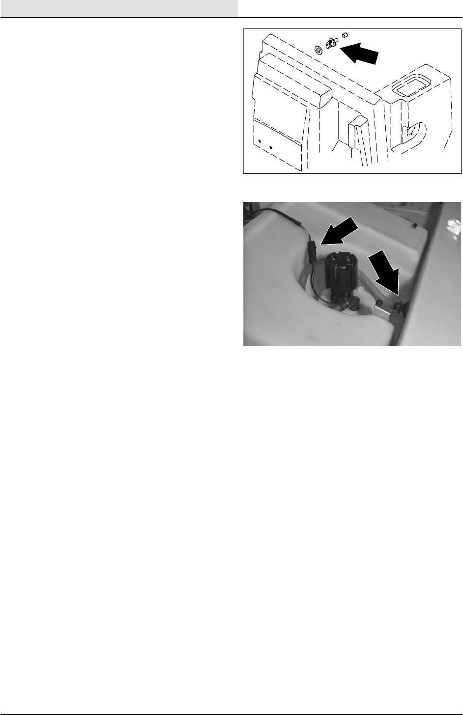
SCRUBBING
4-6 8410 MM392 (8--01)
12. Remove black plastic check valve from the
top of the solution tank.
13. If the machine is equipped with the ESt
option, remove the wires connected to the
float switch on the recovery tank.
14. The recovery tank can now be removed.
Some careful maneuvering of the tank will
be needed to get it to come out easily
because of the tight fit. Lift the tank straight
up and out of machine. Leave the outer ring
of the tank cap on the threads to protect it
from damage during removal.
NOTE: The hardware can be loosened on the
solution tank to ease removal of recovery tank.
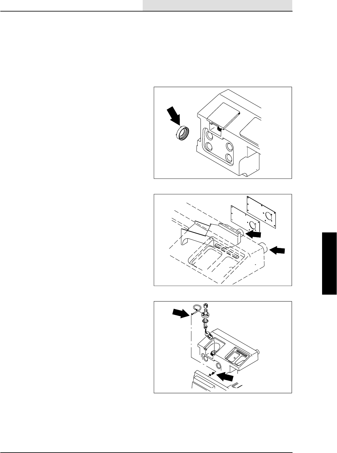
SCRUBBING
4-7
8410 MM392 (8--01)
TO INSTALL RECOVERY TANK
FOR SAFETY: Before Leaving Or
Servicing Machine; Stop On Level
Surface, Set Parking Brake, Turn Off
Machine And Remove Key.
NOTE: Be careful not to pinch hydraulic hoses or
electrical wires during this procedure.
1. Position the recovery tank in the machine.
This is a tight fit. With careful maneuvering
the tank will slip in. Leave the outer ring of
the tank cap on the threads to protect it from
damage during installation.
NOTE: The hardware can be loosened on the
solution tank to ease installation of recovery tank.
2. Align the three holes in the right hand side of
machine, near the tank drain hole area, with
the three threaded inserts in the recovery
tank. Install the three M8 SS hex screws
and washers, leave loose for now.
3. Reinstall the vacuum hose and squeegee
hose to the back of the recovery tank.
4. Reinstall the black plastic check valve in the
top of the solution tank.
5. Reinstall the left hand side panel.
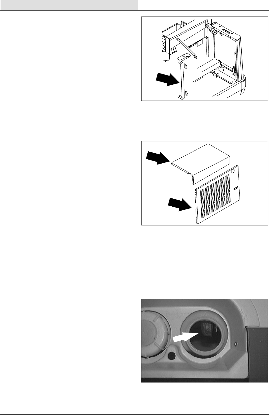
SCRUBBING
4-8 8410 MM392 (5--02)
6. Reinstall the door mount bracket to the back
of the recovery tank and frame using the
M8 hex screws and washers. Tighten to
18 -- 24 Nm (13 -- 15 ft lb).
7. Go back and tighten the three M8 hex
screws on recovery tank near the tank drain
area. Tighten to 18 -- 24 Nm (13 -- 15 ft lb).
8. If the machine is equipped with the ESt
option, Reinstall the hoses to the fittings on
the back of the solution tank.
9. If the machine is equipped with the ESt
option, reconnect the wires to the float
switch on the right side of the tank. See
schematic in the ELECTRICAL section.
10. Reinstall the right hand side panel on the
machine using the six M6 hex screws and
washers. Tighten to 8 -- 10 Nm (5 -- 7 ft lb).
11. Reinstall the plastic clean out cover using
the three M6 hex screws and washers.
Tighten to 8 -- 10 Nm (5 -- 7 ft lb). Reinstall
tank caps and hoses.
12. Start the engine, disengage the safety arm,
and lower the hopper.
13. Reinstall the lintel cover and lightly hand
tighten the four M8 hex screws.
14. Lower the engine cover and side door.
SOLUTION TANK
The solution tank contains the cleaning solution.
The solution tank does not require regular
maintenance. If deposits form on the bottom of
the tank, rinse the tank with a strong blast of
warm water. The right tank can be flushed through
the drain opening. Drain the tank with the solution
tank drain hose.
The solution tank on machines with the ESt
option should be drained and cleaned daily. Rinse
the solution outlet filters at the bottom of the tank
through the drain access.
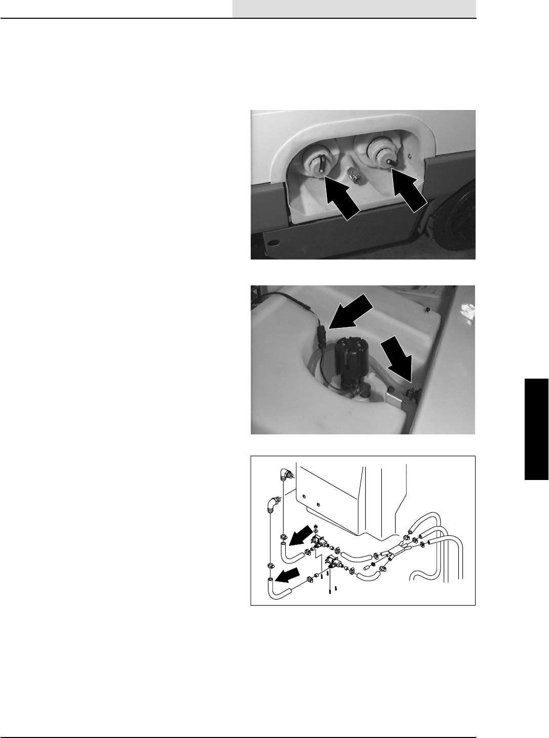
SCRUBBING
4-9
8410 MM392 (8--01)
TO REMOVE SOLUTION TANK
FOR SAFETY: Before Leaving Or
Servicing Machine; Stop On Level
Surface, Set Parking Brake, Turn Off
Machine And Remove Key.
1. Drain the solution and recovery tanks. The
recovery tank must be removed before
the solution tank can be removed.
See TO REMOVE RECOVERY TANK
instructions.
2. Remove the four M8 hex screws holding the
solution tank to the machine frame. Make
sure to retain the two plated clamps from the
front of the tank.
3. Lift the solution tank slightly and remove the
solution lines from the electric water
solenoids.
4. Remove the M8 nyloc nut and clamp holding
the hydraulic hoses to the front of the
solution tank.
5. The solution tank can now be removed.
Some careful maneuvering of the tank will
be needed to get it to come out easily
because of the tight fit. Lift the tank straight
up and out of machine. Leave the outer ring
of the tank cap on the threads to protect it
from damage during removal.
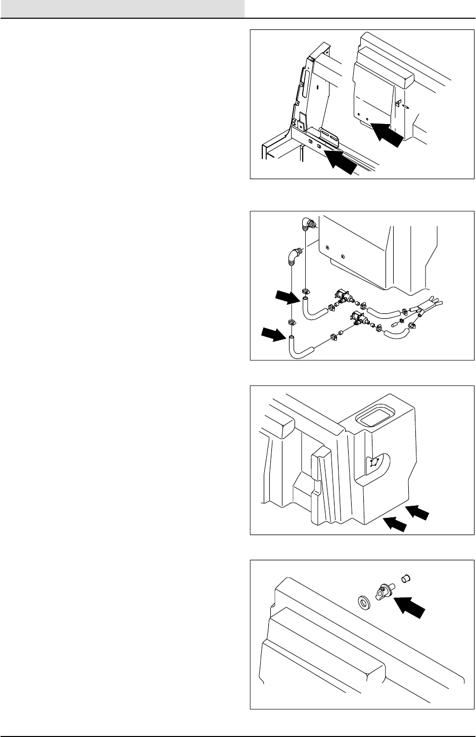
SCRUBBING
4-10 8410 MM392 (8--01)
TO INSTALL SOLUTION TANK
FOR SAFETY: Before Leaving Or
Servicing Machine; Stop On Level
Surface, Set Parking Brake, Turn Off
Machine And Remove Key.
1. Position solution tank in the machine. Be
careful not to damage the face of the drain
outlet hole when placing tank in the
machine. Do not install any hardware at this
time.
NOTE: Be careful not to pinch any hydraulic
hoses or electrical wires during this procedure.
2. Make sure the solution hoses are on the
fittings on the right side of the tank.
3. Align the holes in the left hand side of
machine, near the main valve area, with the
threaded inserts in the solution tank. Install
the M8 SS hex screws and washers, leave
loose for now.
4. Align the two holes in the front of the
solution tank with the holes in the machine
frame. Install the two M8 hex screws,
washers and two plated clamps.
Tighten to 18 -- 24 Nm (13 -- 15 ft lb).
5. Go back and tighten the M8 hex screws on
solution tank near the main valve area.
Tighten to 18 -- 24 Nm (13 -- 15 ft lb).
6. Reinstall hydraulic hoses, clamp and M8
nyloc nut to the front of the solution tank.
Tighten to 18 -- 24 Nm (13 -- 15 ft lb).
NOTE: Do not install the EStfitting in the top of
the solution tank until the recovery tank has been
installed.
7. The recovery tank can now be installed. See
TO INSTALL RECOVERY TANK
instructions.
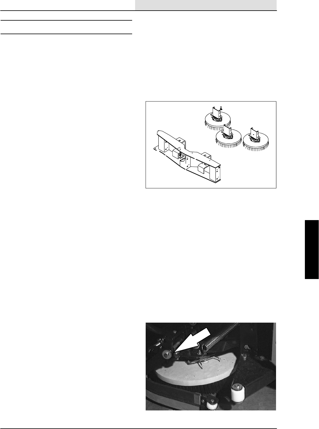
SCRUBBING
4-11
8410 MM392 (5--02)
SCRUB HEAD
The scrub head encloses the scrub brushes and a
solution dispensing system. The scrub head is
located directly behind the sweeping brush
compartment.
The scrub head is factory adjusted and the
measurement should not be changed unless
scrub head parts are damaged or are replaced.
The scrub head contains three disc brushes,
hydraulic motors, lift cylinders and side
squeegees. Each brush has its own hydraulic
motor and lift cylinder. There is also a hydraulic
cylinder that can shift the scrub head over to the
right for superior edge cleaning. Water from the
solution tank flows to the center of each brush.
TO REMOVE SCRUB HEAD
1. Start the engine, lower and side shift the
scrub head, shut off the engine.
FOR SAFETY: Before Leaving Or
Servicing Machine; Stop On Level
Surface, Set Parking Brake, Turn Off
Machine And Remove Key.
2. Raise the rear of machine using a hoist or
floor jack.
FOR SAFETY: Block machine tires
before jacking machine up. Jack
machine up at designated locations
only. Block machine up with jack
stands.
3. Remove the cotter pin from the long
horizontal clevis pin holding each side
squeegee to the scrub head frame. Remove
the clevis pins and squeegee assemblies
from both sides.
4. Remove all three scrub brushes.
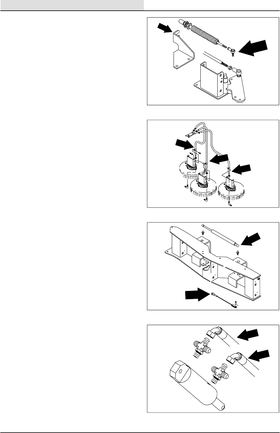
SCRUBBING
4-12 8410 MM392 (8--01)
5. Remove the hex nut holding the balljoint and
push--pull cable to the LH side squeegee
bracket.
6. Loosen the large hex nut holding the cable
to the cable bracket. Remove the cable from
the bracket and place it out of the way for
scrub head removal.
7. Locate the water flow manifold on the
machine frame. Remove the three solution
feed lines from the manifold. Some of the
plastic ties will have to be removed from the
water flow lines to do this.
8. Locate the side shift gas spring and return
cable on the top, front, center of the scrub
head frame. Remove the small clip holding
the gas spring ball end to the scrub head.
Pop the gas spring off the ball end.
9. Remove the cotter pin and clevis from the
return cable at the cylinder bracket.
NOTE: Mark the hoses for proper re--assembly.
10. Disconnect and plug the two #4 hydraulic
hoses leading from the control valve to the
center scrub brush lift cylinder.
NOTE:Observe hydraulic cleanliness
requirements when opening hydraulic lines.
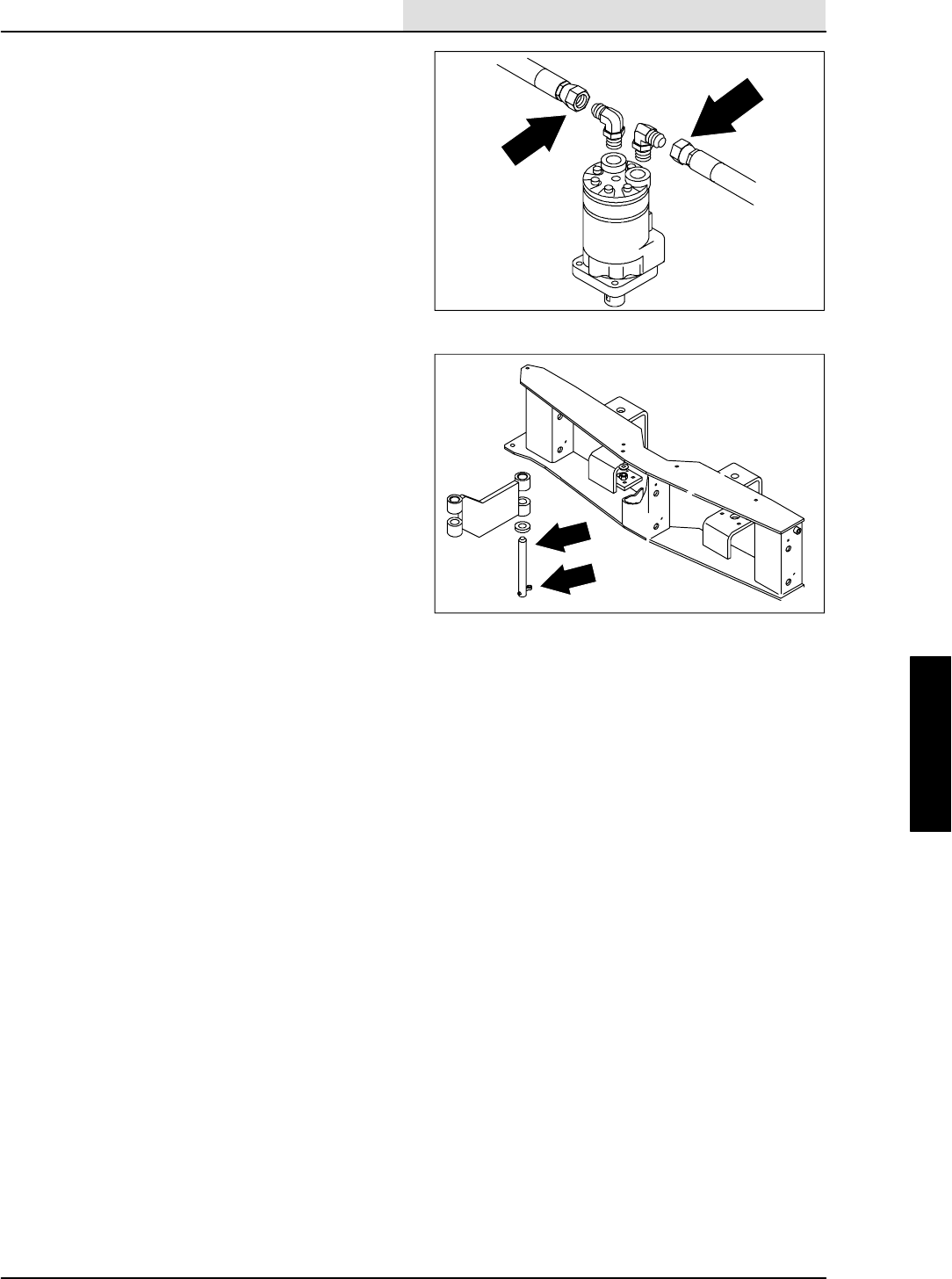
SCRUBBING
4-13
8410 MM392 (8--01)
11. Disconnect and plug the two #8 hydraulic
hoses leading from the control valve to the
RH and LH scrub brush motors.
NOTE:Place a floor jack under the scrubber head
to help hold it up when pins are removed.
12. Remove the M6 hex screw and washer
holding the cotter pin into the scrub head pin
on the scrub head frame. Remove both pins.
13. The scrub head can now be removed from
the machine.
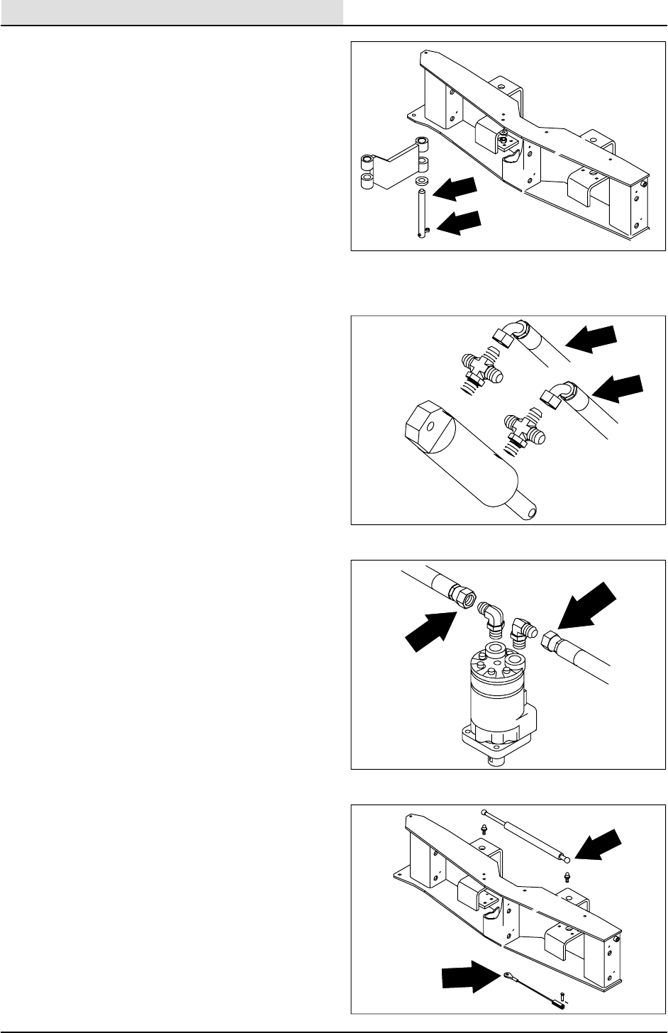
SCRUBBING
4-14 8410 MM392 (8--01)
TO INSTALL SCRUB HEAD
FOR SAFETY: Before Leaving Or
Servicing Machine; Stop On Level
Surface, Set Parking Brake, Turn Off
Machine And Remove Key.
1. Raise the rear of machine using a hoist or
floor jack.
FOR SAFETY: Block machine tires
before jacking machine up. Jack
machine up at designated locations
only. Block machine up with jack
stands.
2. Position the scrub head under the machine
using a floor jack.
3. Raise the head up and align the holes in the
scrub head frame with holes in edge scrub
link. Install the scrub head pins in from the
bottom.
4. Align the hole in the pin with the cotter pin
and hole in scrub head frame. Reinstall the
M6 hex screw and washer through the hole
in cotter pin. Tighten to 8 -- 10 Nm
(5 -- 7 ft lb).
5. Reconnect the two #4 hydraulic hoses to the
center lift cylinder and the two #8 hoses to
the outside brush motors. See schematic in
HYDRAULICS section.
NOTE: Make sure the scrub head is pulled over
all the way to the right for the next operation.
6. Reconnect the side shift cable to the
cylinder pivot bracket.
7. Install the gas spring ball end back on the
ball on the scrub head. Make sure to
reinstall the locking clip.
8. Reconnect the main solution feed line to the
plastic, water manifold.
NOTE: Make sure to reinstall any clamps or
plastic ties that were removed during disassembly.
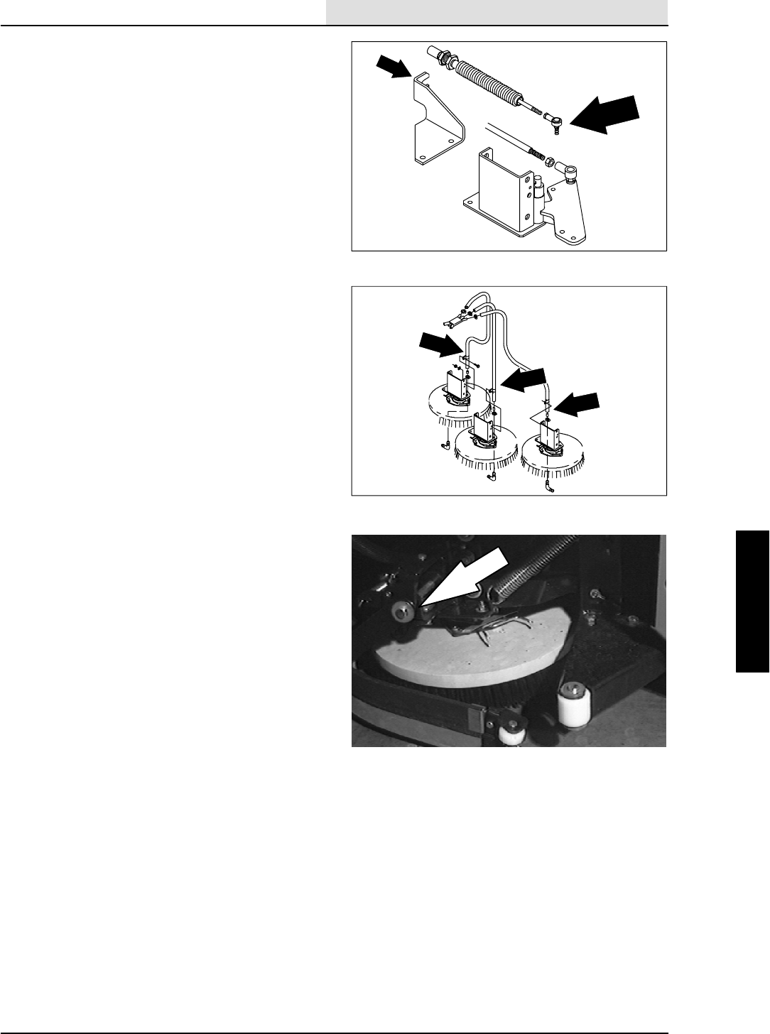
SCRUBBING
4-15
8410 MM392 (8--01)
9. Position push--pull cable back in the
mounting bracket and hand tighten large nut.
Do not change the adjustment.
10. Reinstall the ball joint end of the push--pull
cable back in the hole on side squeegee
bracket. Tighten 0.31 in. hex nut to
18 -- 24 Nm (13 -- 18 ft lb).
11. Reinstall the three disc brushes.
12. Reinstall the LH and RH side squeegees
with the long clevis pins and cotter pins.
13. Lower the machine. Start the engine and
check for any leaks and for proper operation
of the scrub brushes and side shift.
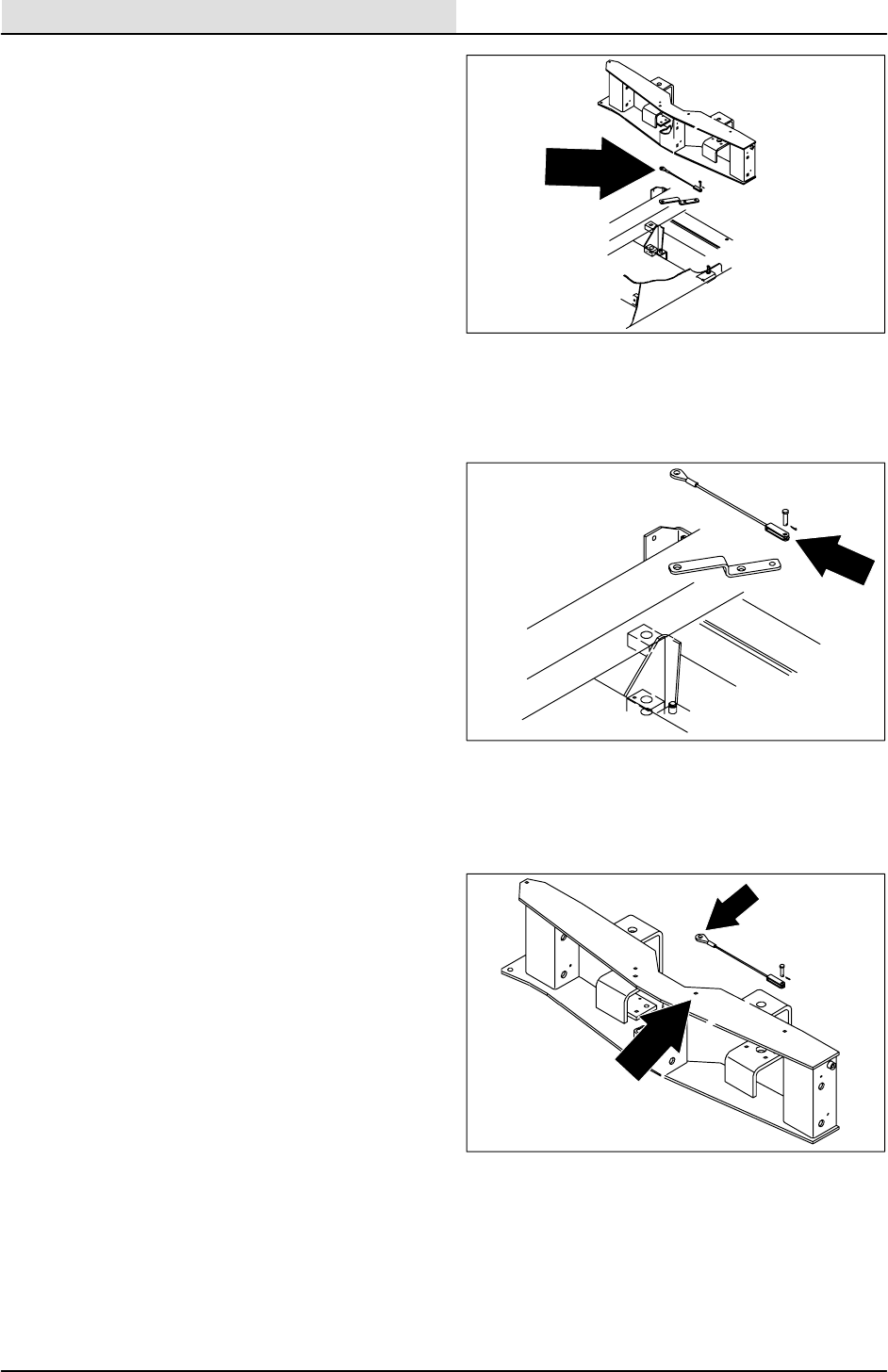
SCRUBBING
4-16 8410 MM392 (8--01)
TO REPLACE SIDE SHIFT CABLE
1. Start the engine, lower and side shift the
scrub head, shut off the engine.
FOR SAFETY: Before Leaving Or
Servicing Machine; Stop On Level
Surface, Set Parking Brake, Turn Off
Machine And Remove Key.
2. Raise the rear of machine using a hoist or
floor jack.
FOR SAFETY: Block machine tires
before jacking machine up. Jack
machine up at designated locations
only. Block machine up with jack
stands.
3. Go under the machine on the left side. Look
up above the left hand scrub brush motor
and to the right of the control valve. Locate
the clevis pin holding the side shift cable to
the pivot bracket. Remove the cotter and
clevis pin.
4. Go under the machine on the right side and
locate the M8 hex screw holding the other
end of the side shift cable to the scrub head
frame. Remove the M8 hex screw, nyloc nut,
and cable from the machine.
5. Position the new cable back in the machine.
Align the hole in the ring end of cable with
the hole in scrub head frame. Reinstall the
M8 hex screw and lightly tighten. The cable
must be able to swivel after tightening.
6. Go under the machine on the left side and
align the clevis end of the cable with the hole
in the pivot bracket. Reinstall the clevis and
cotter pin.
7. Lower the machine. Start the engine and
check for proper side shift function.
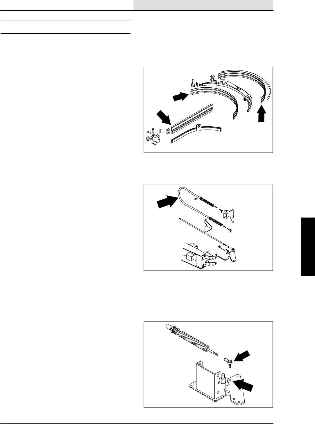
SCRUBBING
4-17
8410 MM392 (8--01)
SQUEEGEES
The squeegee channels water into the vacuum
fan suction. The front blade channels the water,
and the rear blade wipes the floor.
There are two types of squeegee blades
available; one for smooth surfaces is standard on
the machine, and one for rough surfaces is an
option.
Check the squeegee blades for damage and wear
daily. Rotate or replace either of the squeegee
blades if the leading edge is torn or worn half-way
through the thickness of the blade.
The squeegee can be adjusted for leveling and
deflection. The deflection of the squeegee blades
should be checked daily, or when scrubbing a
different type of floor. The leveling of the
squeegee should be checked every 100 hours of
machine operation.
TO REPLACE SQUEEGEE PUSH--PULL
CABLE
1. Start the engine, lower and side shift the
scrub head, shut off the engine.
FOR SAFETY: Before Leaving Or
Servicing Machine; Stop On Level
Surface, Set Parking Brake, Turn Off
Machine And Remove Key.
2. Raise the rear of machine using a hoist or
floor jack.
FOR SAFETY: Block machine tires
before jacking machine up. Jack
machine up at designated locations
only. Block machine up with jack
stands.
3. Remove the 0.31 in. nyloc nut holding the
balljoint and push--pull cable to the LH side
squeegee bracket.
4. Loosen the large hex nuts holding the cable
to the cable bracket. Remove the cable from
the bracket.
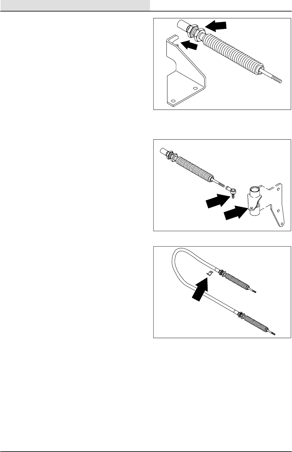
SCRUBBING
4-18 8410 MM392 (8--01)
5. Remove the 0.31 in. nyloc nut holding the
balljoint on the other end of the push--pull
cable to the left hand rear squeegee pivot
bracket.
6. Remove the M6 thread roller hex screw
holding the clamp to the machine frame.
7. Remove the balljoints and jam nuts from the
old cable and install on the new one. Run
the jam nut and balljoint all the way on the
threads.
8. Install the new cable in the machine. Make
sure the cable is routed between the tie rod
and scrub head frame.
9. Adjust the rear squeegee end of the cable at
8.25 inches from the center line of the
balljoint to the edge of bracket with the cable
in the retracted position.
10. Adjust the side squeegee end of cable at
8.25 inches from the center line of the
balljoint to the edge of bracket with the cable
in the retracted position. Firmly tighten all
four large hex nuts.
11. Reinstall the cable clamp and M6 thread
rolling hex screw to the bottom of the
machine frame.
12. Reinstall the balljoints in the holes in both
rear and side squeegee brackets. Tighten
the 0.31 in. hex screw to 18 -- 24 Nm
(13 -- 18 ft lb).
13. Lower machine and check for proper scrub
head side shift operation.
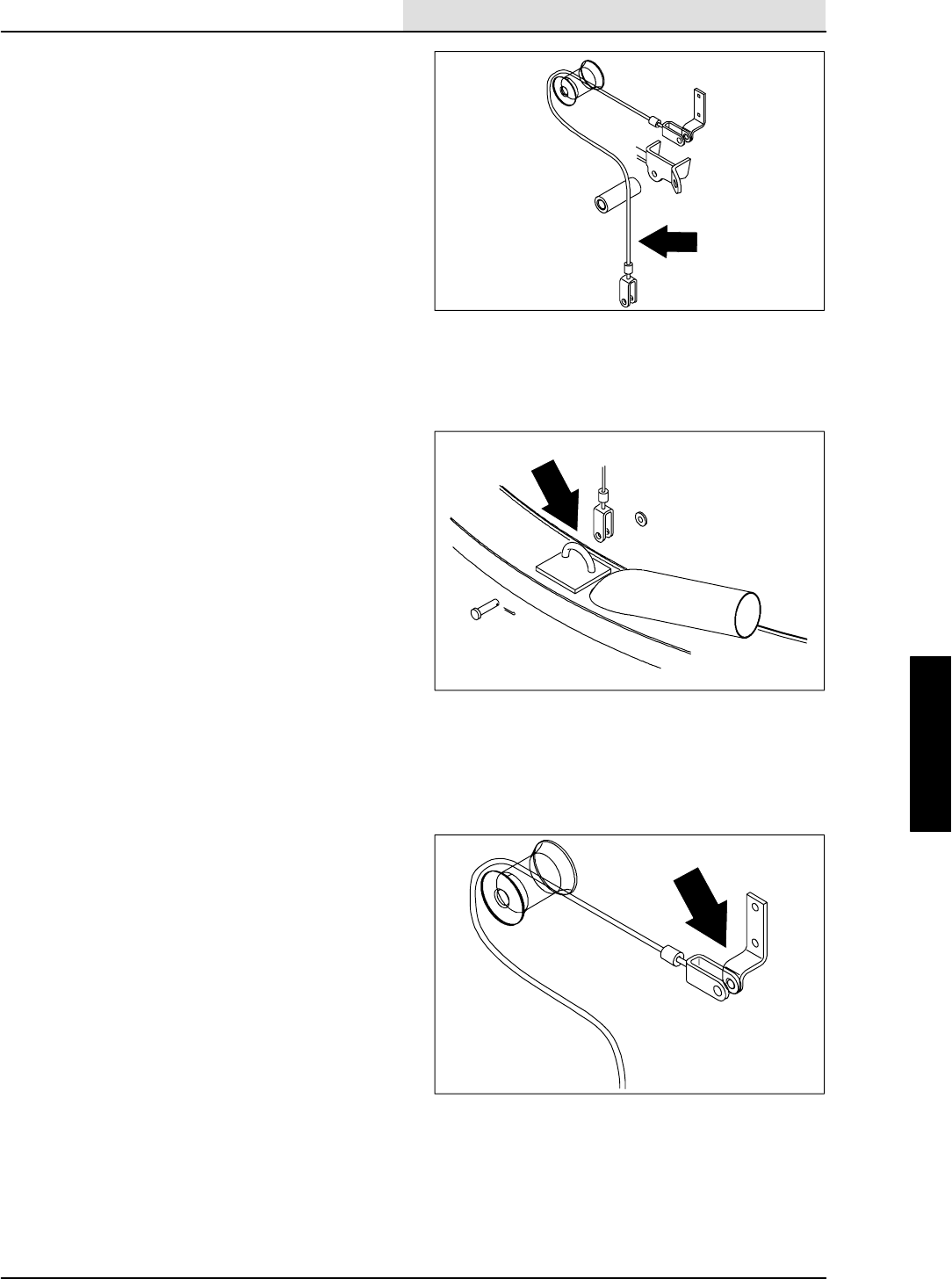
SCRUBBING
4-19
8410 MM392 (8--01)
TO REPLACE SQUEEGEE LIFT CABLE
1. Start the engine, lower the rear squeegee,
shut off the engine.
FOR SAFETY: Before Leaving Or
Servicing Machine; Stop On Level
Surface, Set Parking Brake, Turn Off
Machine And Remove Key.
2. Raise the rear of machine using a hoist or
floor jack.
FOR SAFETY: Block machine tires
before jacking machine up. Jack
machine up at designated locations
only. Block machine up with jack
stands.
3. Remove the M8 hex screw, nyloc nut, and
spacer tube from the rear squeegee lift
cable where it attaches at the center of the
rear squeegee frame.
NOTE: The squeegee frame will drop down when
the hex screw is removed.
4. Remove the clevis pin holding the lift cable
to the upper cable bracket.
NOTE: When installing the new cable, make sure
to route it around the plastic rollers in the same
manner as it was removed.
5. Align the hole in the upper end of the new
cable with the hole in the upper cable
bracket. Reinstall the clevis pin and cotter
pin.
6. Lift the squeegee assembly up until the hole
in the lower end of the lift cable lines up with
the hole in the squeegee frame. Reinstall the
clevis pin and cotter pin.
7. Lower machine and check for proper rear
squeegee lift cable operation.
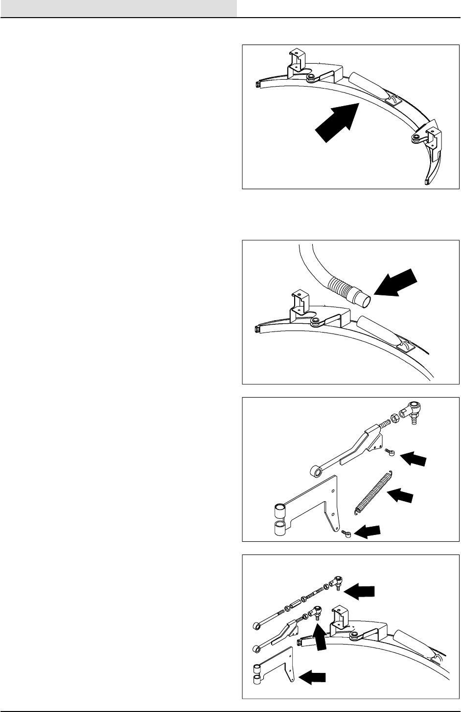
SCRUBBING
4-20 8410 MM392 (8--01)
TO REMOVE REAR SQUEEGEE FRAME
1. Start the engine, lower the rear squeegee,
shut off the engine.
FOR SAFETY: Before Leaving Or
Servicing Machine; Stop On Level
Surface, Set Parking Brake, Turn Off
Machine And Remove Key.
2. Raise the rear of machine using a hoist or
floor jack.
FOR SAFETY: Block machine tires
before jacking machine up. Jack
machine up at designated locations
only. Block machine up with jack
stands.
3. Remove the M8 hex screw, nyloc nut, and
spacer tube from the rear squeegee lift
cable where it attaches at the center of the
rear squeegee frame.
NOTE: The squeegee frame will drop down when
the hex screw is removed.
4. Remove the vacuum hose from the
squeegee frame.
5. Remove the two tension springs connecting
the squeegee upper link rods to the
squeegee pivot brackets.
6. Remove the M10 hex screw, washers
sleeve, thrust washers, and nyloc nut
holding each of the four link rods to the
squeegee pivot brackets.
7. The squeegee assembly can now be
removed from the machine.
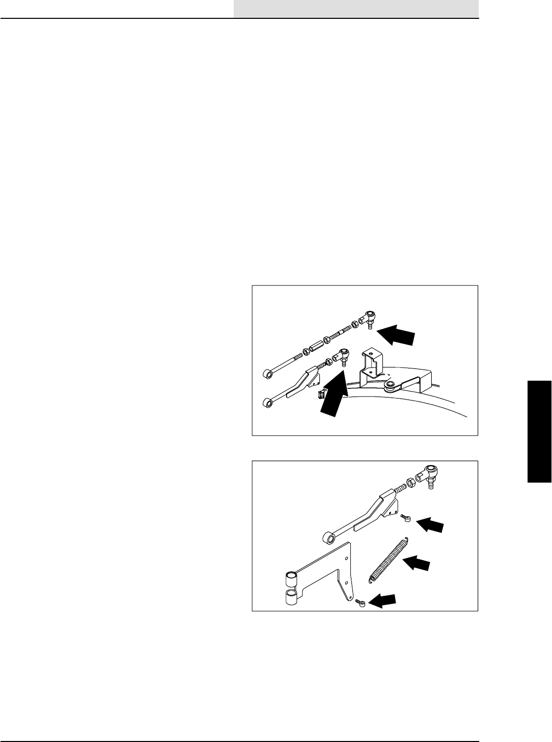
SCRUBBING
4-21
8410 MM392 (8--01)
TO INSTALL REAR SQUEEGEE FRAME
1. Start the engine, lower the rear squeegee,
shut off the engine.
FOR SAFETY: Before Leaving Or
Servicing Machine; Stop On Level
Surface, Set Parking Brake, Turn Off
Machine And Remove Key.
2. Raise the rear of machine using a hoist or
floor jack.
FOR SAFETY: Block machine tires
before jacking machine up. Jack
machine up at designated locations
only. Block machine up with jack
stands.
3. Position the squeegee assembly under the
rear of the machine.
4. Align the holes in the end of squeegee link
rods to the holes in the squeegee pivot
brackets. Install the M10 hex screws,
washers, sleeves, thrust washers, and nyloc
nuts. Tighten to 37 -- 48 Nm (25 -- 53 ft lb).
5. Reconnect the tension springs from the
lower link rod to the squeegee pivot bracket.
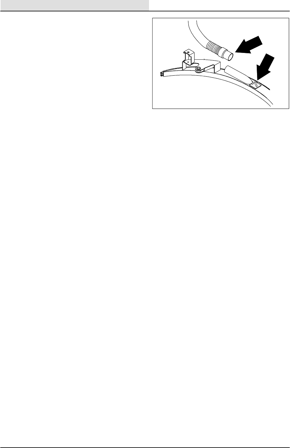
SCRUBBING
4-22 8410 MM392 (8--01)
6. Lift the squeegee assembly up until the hole
in the lower end of the lift cable lines up with
the hole in the squeegee frame. Reinstall the
M8 hex screw, nyloc nut, and spacer tube.
Tighten to 18 -- 24 Nm (13 -- 18 ft lb).
7. Lower machine and check for proper rear
squeegee operation.
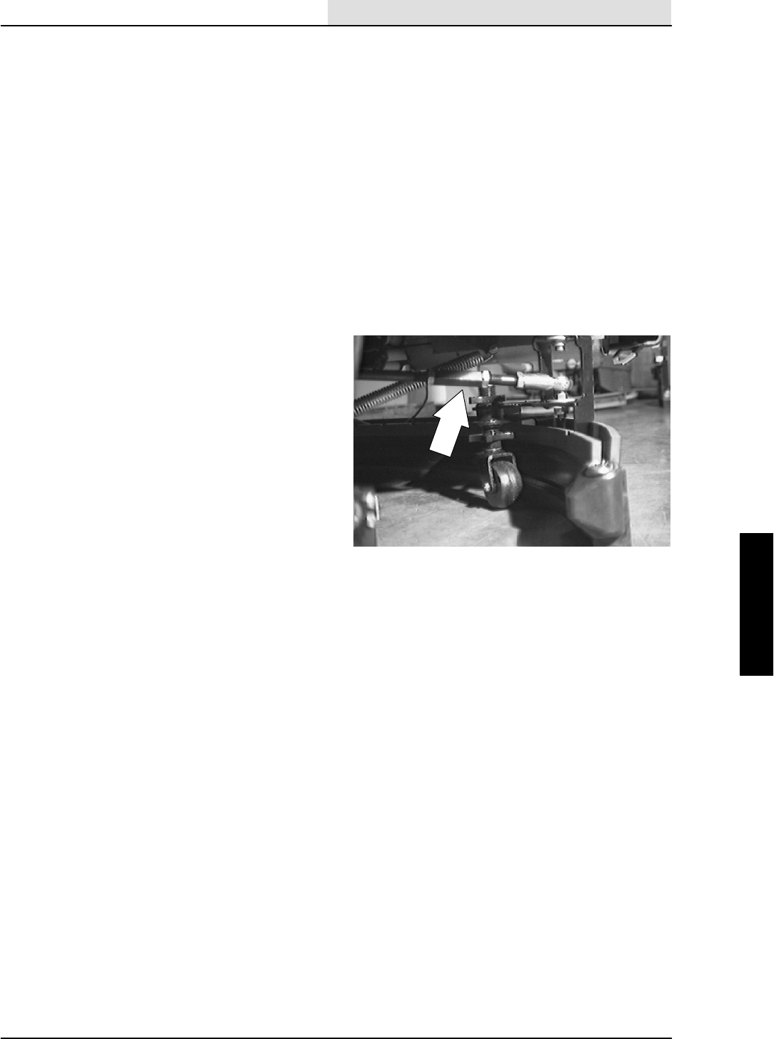
SCRUBBING
4-23
8410 MM392 (5--02)
LEVELING THE REAR SQUEEGEE
Leveling of the squeegee assures even contact
the length of the squeegee blade with the surface
being scrubbed. Make sure this adjustment is
done on an even, level floor.
1. Lower the squeegee and drive the machine
forward.
2. Shut off the engine and set the machine
parking brake.
FOR SAFETY: Before Leaving Or
Servicing Machine; Stop On Level
Surface, Set Parking Brake, Turn Off
Machine And Remove Key.
3. Look at the deflection of the squeegee blade
over the full length of the squeegee blade.
4. If the deflection is not the same over the full
length of the blade, loosen the turnbuckle
jam nuts.
5. Turn the turnbuckle clockwise, from the rear
of the machine, to increase the deflection at
the ends of the squeegee. Turn the
turnbuckle counter-clockwise, from the rear
of the machine, to decrease the deflection at
the ends of the squeegee blade. Be sure to
turn both turnbuckles the same number of
turns.
6. Tighten the jam nuts.
NOTE: When tightening the turnbuckle jam nuts,
make sure the rod ends are square with the
squeegee frame, not tilted up.
7. Start the engine and drive the machine
forward again to check the squeegee blade
deflection.
8. Readjust the squeegee blade deflection if
necessary.
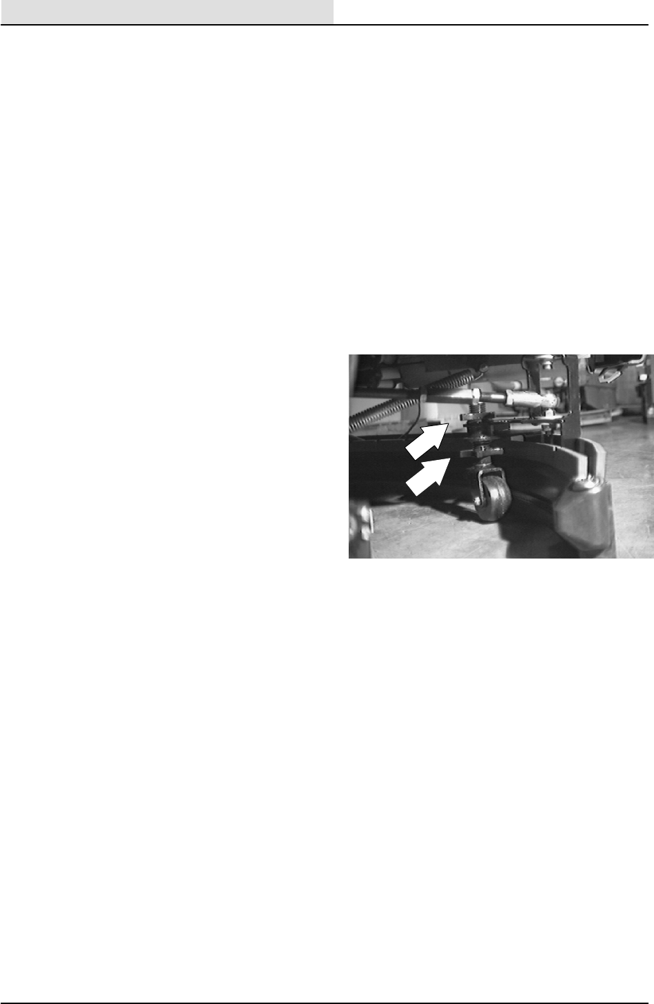
SCRUBBING
4-24 8410 MM392 (5--02)
ADJUSTING REAR SQUEEGEE BLADE
DEFLECTION
Deflection is the amount of curl the squeegee
blade has when the machine moves forward with
the squeegee lowered to the floor. The best
deflection is when the squeegee wipes the floor
just dry with a minimum amount of deflection.
1. Lower the squeegee and drive the machine
forward.
2. Shut off the engine and set the machine
parking brake.
FOR SAFETY: Before Leaving Or
Servicing Machine; Stop On Level
Surface, Set Parking Brake, Turn Off
Machine And Remove Key.
3. Look at the deflection of the squeegee blade
over the full length of the squeegee blade.
The correct amount of deflection is 7 mm
(0.25 in).
4. To adjust the amount of deflection, loosen
the top knob on the two casters.
5. Turn the bottom knob clockwise to decrease
the blade deflection. Turn the bottom knob
counter-clockwise to increase the blade
deflection. Be sure to turn both knobs the
same number of turns. Tighten the top
knobs on the casters.
6. Start the engine and drive the machine
forward again to check the squeegee blade
deflection. Readjust the squeegee blade
deflection if necessary.
7. Raise the squeegee when finished.
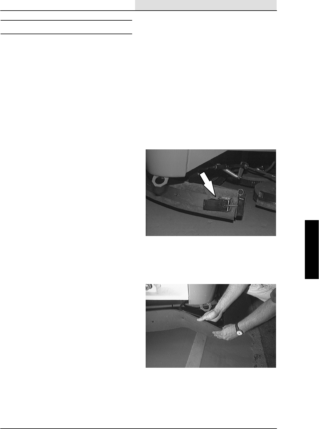
SCRUBBING
4-25
8410 MM392 (5--02)
SQUEEGEE BLADES
REAR SQUEEGEE
The rear squeegee has two squeegee blades.
Each blade has four wiping edges. To use them
all, start with one wiping edge. To use the next
wiping edge, rotate the blade end-for-end. To use
the next wiping edge, rotate the top edges down,
bottom edges up. To use the last edge, rotate the
blade end-for-end.
Replace any worn or damaged squeegee blades.
REPLACING OR ROTATING REAR SQUEEGEE
BLADES
1. Make sure the squeegee is raised off the
floor.
2. Shut the engine off and set the parking
brake.
FOR SAFETY: Before Leaving Or
Servicing Machine; Stop On Level
Surface, Set Parking Brake, Turn Off
Machine And Remove Key.
3. Open the retaining band clamp and remove
the squeegee blade.
4. Replace or rotate the squeegee blade to
allow a new edge to face the front of the
machine.
5. Place the squeegee blade over the pins of
the squeegee frame.
6. Position the retaining band over the
squeegee blade. Latch the retaining band
clamp.
7. Adjust the squeegee blade leveling and
deflection as stated in LEVELING THE
REAR SQUEEGEE and ADJUSTING REAR
SQUEEGEE BLADE DEFLECTION.
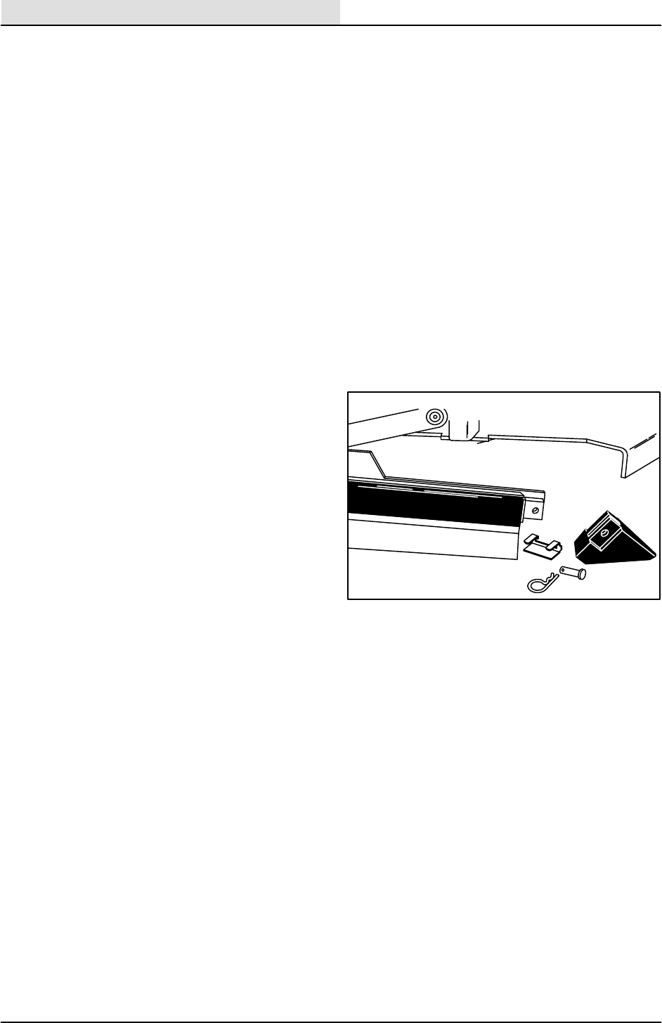
SCRUBBING
4-26 8410 MM392 (8--01)
SIDE SQUEEGEES
The side squeegees control water spray and
channel water into the path of the rear squeegee.
Check the side squeegees for damage and wear
daily. Replace the side squeegee blades
whenever they become damaged or lose their
shape or resilience. Replace the squeegee
deflectors whenever they become worn.
REPLACING SIDE SQUEEGEE BLADES
1. Raise the scrub head.
2. Turn off the machine and set the machine
parking brake.
FOR SAFETY: Before Leaving Or
Servicing Machine; Stop On Level
Surface, Set Parking Brake, Turn Off
Machine And Remove Key.
3. Remove the cotter pin, clevis pin, deflector,
and the retainer bracket from the front of the
side squeegee.
4. Pull the squeegee blade off the front of the
squeegee frame.
5. Slide the new squeegee blade onto the
frame.
NOTE: Lubricating the squeegee frame where
the squeegee makes contact will make for easier
squeegee installation.
6. Replace the retainer bracket, deflector,
clevis pin, and cotter pin.
7. Repeat for the side squeegee on the other
side of the scrub head.
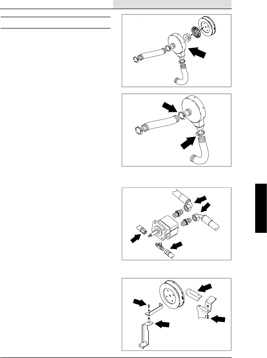
SCRUBBING
4-27
8410 MM392 (8--01)
SCRUB VACUUM FAN
The scrub vacuum fan, when activated, creates a
vacuum in the recovery tank. The recovery tank is
sealed to the demister tank/engine cover when it
is the down position. Water is pulled from the rear
squeegee to the demister tank through a vacuum
hose.
TO REMOVE SCRUB VACUUM FAN
FOR SAFETY: Before Leaving Or
Servicing Machine; Stop On Level
Surface, Set Parking Brake, Turn Off
Machine And Remove Key.
1. Raise the engine cover.
2. Open the engine side door.
3. Loosen the hose clamp and remove the
vacuum hose leading from recovery tank to
the inlet tube of the scrub vacuum fan.
4. Loosen the hose clamp and remove the
vacuum hose from the exhaust outlet of
scrub vacuum fan.
NOTE: Mark the hoses for proper re--assembly.
5. Remove and plug the hydraulic hoses
connected to the scrub vacuum fan motor.
Access to these hoses is between air
cleaner and vacuum fan housing.
NOTE:Observe hydraulic cleanliness
requirements when opening hydraulic lines.
6. Remove the three M10 hex screws,
washers, and nyloc nuts holding the vacuum
fan to mounting brackets.
7. Remove the vacuum fan assembly from the
machine.
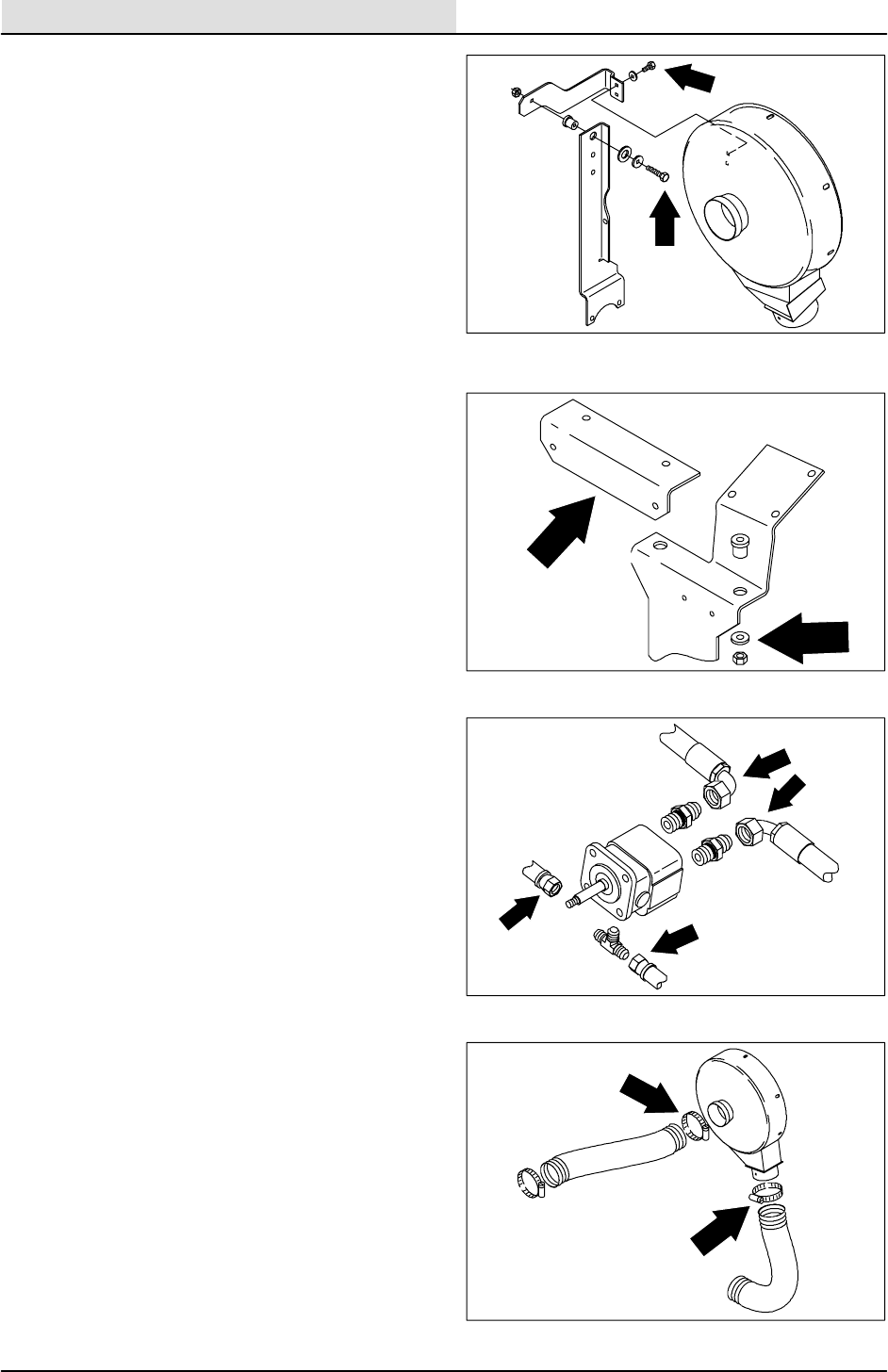
SCRUBBING
4-28 8410 MM392 (8--01)
TO INSTALL SCRUB VACUUM FAN
FOR SAFETY: Before Leaving Or
Servicing Machine; Stop On Level
Surface, Set Parking Brake, Turn Off
Machine And Remove Key.
1. Raise the engine cover.
2. Open the engine side door.
3. Position the vacuum fan assembly in the
machine.
4. Align the three mounting holes in the
vacuum fan housing with the three rubber
isolators in the mounting brackets. Reinstall
the three M10 hex screws, washers, and
nyloc nuts. Tighten to 18 -- 24 Nm
(13 -- 18 ft lb).
5. Reconnect the hydraulic hoses to the
vacuum fan motor. See the hydraulic
schematic in the HYDRAULIC section.
Access to these hoses is between air
cleaner and vacuum fan housing.
6. Reinstall the vacuum hose on the exhaust
outlet of vacuum fan housing. Firmly tighten
the hose clamp.
7. Reinstall the vacuum hose from recovery
tank to the inlet tube on the vacuum fan
housing. Firmly tighten the hose clamps.
8. Start engine and turn on the vacuum fan.
Check for leaks and proper operation.

SCRUBBING
4-29
8410 MM392 (5--02)
MACHINE TROUBLESHOOTING
Problem Cause Remedy
Trailing water -- poor or no
water pickup.
Worn rear squeegee blades. Rotate or replace squeegee
blades.
Rear squeegee out of adjustment. Adjust rear squeegee.
Side squeegees raised. Lower side squeegees.
Worn side squeegee blades. Replace side squeegee blades.
Side squeegees out of
adjustment.
Adjust side squeegees.
Tank cover not seated. Reseat tank cover.
Tank cover seals worn. Replace seals.
Too much solution flow to floor. Reduce solution flow to floor.
Vacuum hose clogged. Flush vacuum hoses.
Recovery tank full. Drain recovery tank.
Check EStpump and filter
Float stuck shutting off vacuum. Clean float.
Debris caught on rear squeegee. Remove debris.
Foam filling recovery tank. Empty recovery tank; use less or
change detergent.
Vacuum hose to rear squeegee
disconnected or damaged.
Reconnect or replace vacuum
hose.
Vacuum fan to recovery tank hose
damaged.
Replace hose.
Littleornosolutionflowtothe
f
l
Solution tank empty. Fill solution tank.
floor. Solution flow switch turned off. Turn solution flow switch on.
Solution supply lines plugged. Flush solution supply lines.
EStswitch off. Turn EStswitch on.
Poor scrubbing performance. Debris caught on scrub brushes. Remove debris.
Improper detergent or brushes
used.
Check with TENNANT
representative for advice.
Worn scrub brushes. Replace scrub brushes.
EStsystem does not fill
l
t
i
t
k
Clogged solution pump or lines. Flush EStsystem.
solution tank. EStfloat stuck. Clean floats of debris.
Clogged EStpump filter. Clean filter.
Water levels too low in tanks. Add water.

SCRUBBING
4-30 8410 MM392 (5--02)

ELECTRICAL
5-1
8410 MM392 (8--01)
CONTENTS
Page
INTRODUCTION 5--4......................
BATTERY 5--4.........................
TO REPLACE BATTERY 5--5............
INSTRUMENT PANEL 5--6.................
TO REPLACE MAIN INSTRUMENT
PANEL 5--6......................
TO REPLACE AUXILIARY INSTRUMENT
PANEL 5--7.........................
TO DISASSEMBLE MAIN INSTRUMENT
PANEL 5--8.........................
TO REASSEMBLE MAIN INSTRUMENT
PANEL 5--9.........................
TO DISASSEMBLE AUXILIARY
INSTRUMENT PANEL 5--10..........
TO REASSEMBLE AUXILIARY
INSTRUMENT PANEL 5--11..........
TO REPLACE MACHINE RELAY 5--12.......
CIRCUIT BREAKERS 5--13................
TO REPLACE MACHINE CIRCUIT
BREAKER 5--14.....................
TO REPLACE GOVERNOR
CONTROL BOX 5--15................
GAS/LP ELECTRICAL SCHEMATIC 5-17....
GAS/LP WIRE HARNESS GROUP 5-20.....
DIESEL ELECTRICAL SCHEMATIC 5-30....
DIESEL WIRE HARNESS GROUP 5-34.....
DIAGNOSTICS 5--44......................
FRONT PANEL OPERATING
MODES 5--45.......................
NORMAL MODE 5--46............
EDGE SCRUB: 5--46..............
SQUEEGEE: 5--46................
ENGINE SPEED: 5--46............
SCRUB: 5--47....................
DETERGENT: 5--48...............
ES: 5--48........................
OVER FLOW: 5--48...............
MANUAL MODE: 5--49............
ES: 5--49........................
EDGE SCRUB BUTTON: 5--49.....
SQUEEGEE BUTTON: 5--49.......
ENGINE BUTTON: 5--49..........
SCRUB BUTTON: 5--49...........
DETERGENT BUTTON: 5--49......
INPUT DISPLAY MODE: 5--50.....
ERROR DISPLAY MODE 5--51.....
ES LED 5--51....................
EDGE SCRUB LED 5--52..........
SQUEEGEE LED 5--52............
SCRUB LED 5--53................
DETERGENT LED 5--53...........
PRESSURE ADJUST MODE 5--54..
SCRUB BUTTON 5--54............
RESET SCRUB PRESSURES 5--55
Page
SIDE PANEL OPERATING MODES 5--56.
NORMAL MODE 5--57...............
HAZARD LIGHTS: 5--57..............
HEAD LIGHTS: 5--57................
FILTER SHAKER: 5--57..............
HOPPER LIFT: 5--57.................
HOPPER LOWER: 5--58.............
HOPPER DOOR: 5--58...............
SIDE BRUSH: 5--58..................
VACUUM FAN: 5--58.................
SWEEP 1 (NORMAL SWEEP): 5--59...
SWEEP 2 (LITTER SWEEP): 5--60....
MANUAL MODE 5--61...............
HAZARD LIGHT: 5--61...............
HEAD LIGHT: 5--61..................
FILTER SHAKER: 5--61..............
HOPPER UP: 5--61..................
HOPPER DOWN: 5--61..............
HOPPER DOOR: 5--61...............
SIDE BRUSH: 5--62..................
SWEEP FAN: 5--62..................
SWEEP 1: 5--62.....................
SWEEP 2: 5--62.....................
INPUT DISPLAY MODE: 5--63........
BLINKING HAZARD LED: 5--63.......
BLINKING SHAKER LED: 5--63.......
BLINKING HOPPER DOOR LED: 5--63
BLINKING SIDE BRUSH LED: 5--63...
BLINKING HEAD LIGHT LED: 5--63...
ERROR DISPLAY MODE 5--64........
BLINKING SHAKER LED: 5--64.......
BLINKING HAZARD LED: 5--64.......
BLINKING HEADLIGHT LED: 5--64....
BLINKING SIDE BRUSH LED: 5--64...
BLINKING HOPPER DOOR LED: 5--64
BLINKING HOPPER UP LED: 5--64....
BLINKING HOPPER DOWN LED: 5--64
BLINKING SWEEP FAN LED: 5--64....
BLINKING SWEEP 1 LED: 5--64......
BLINKING SWEEP 2 LED: 5--64......
TROUBLESHOOTING 5--66................
INSTRUMENT PANEL DOES NOT
POWER UP (SCHEMATIC) 5--67......
INSTRUMENT PANEL DOES NOT
POWER UP(FLOW CHART) 5--68.....
SCRUB BRUSH WILL NOT TURN ON
AND/OR DOWN (SCHEMATIC) 5--69..
SCRUB BRUSH WILL NOT TURN ON
AND/OR DOWN (FLOW CHART) 5--70.
SCRUB HEAD WILL NOT EXTEND
(SCHEMATIC) 5--73.................
SCRUB HEAD WILL NOT EXTEND
(FLOW CHART) 5--74................

ELECTRICAL
5-2 8410 MM392 (8--01)
Page
SQUEEGEE AND VACUUM FAN NOT
TURNING ON AND GOING DOWN
(SCHEMATIC) 5--75..............
SQUEEGEE AND VACUUM FAN NOT
TURNING ON AND GOING DOWN
(FLOW CHART) 5--76.............
WATER VALVES NOT OPERATING
(SCHEMATIC) 5--79.................
WATER VALVES NOT OPERATING
(FLOW CHART) 5--80................
RECOVERY TANK FULL LIGHT
WILL NOT TURN ON OR
OFF (SCHEMATIC) 5--81..........
RECOVERY TANK FULL LIGHT WILL NOT
TURN OFF(FLOW CHART) 5--82......
RECOVERY TANK FULL LIGHTWILL NOT
TURN ON (FLOW CHART) 5--82......
DETERGENT METERING PUMP IS NOT
OPERATING (SCHEMATIC) 5--83.....
DETERGENT METERING PUMP IS NOT
OPERATING (FLOW CHART) 5--84....
ES PUMP NOT WORKING
(SCHEMATIC) 5--85.................
ES PUMP NOT WORKING
(FLOW CHART) 5--86................
SWEEP BRUSH WILL NOT TURN ON
AND LOWER WITH SWEEP 1
SELECTED (SCHEMATIC) 5--87...
SWEEP BRUSH WILL NOT TURN ON
AND LOWER WITH SWEEP 1
SELECTED (FLOW CHART) 5--88..
SWEEP BRUSH WILL NOT TURN ON AND
LOWER WITH SWEEP 2 SELECTED
SWEEP 1 WORKS
(SCHEMATIC) 5--89............
SWEEP BRUSH WILL NOT TURN ON
AND LOWER WITH SWEEP 2
SELECTED (FLOW CHART) 5--90..
SWEEP SIDE BRUSH WILL NOT TURN
ON AND LOWER (SCHEMATIC) 5--91.
SWEEP SIDE BRUSH WILL NOT TURN
ON AND LOWER (FLOW CHART) 5--92
SWEEP VACUUM FAN WILL NOT
TURN ON (SCHEMATIC) 5--93........
SWEEP VACUUM FAN WILL NOT TURN
ON (FLOW CHART) 5--94............
SHAKER SYSTEM WILL NOT TURN
ON (SCHEMATIC) 5--95..............
SHAKER SYSTEM WILL NOT TURN
ON (FLOW CHART) 5--96............
HOPPER DIFFERENTIAL PRESSURE
LIGHT ALWAYS ON
(SCHEMATIC) 5--97..............
HOPPER DIFFERENTIAL PRESSURE
SWITCH ALWAYS ON
(FLOW CHART) 5--98.............
HOPPER DIFFERENTIAL PRESSURE
SWITCH ALWAYS OFF
(SCHEMATIC) 5--99..............
Page
HOPPER DIFFERENTIAL PRESSURE
LIGHT ALWAYS OFF
(FLOW CHART) 5--100............
HOPPER THERMAL SENTRY LIGHT
ALWAYS ON (SCHEMATIC) 5--101....
HOPPER THERMAL SENTRY LIGHT
ALWAYS ON (FLOW CHART) 5--102..
HOPPER THERMAL SENTRY LIGHT
ALWAYS OFF (SCHEMATIC) 5--103...
HOPPER THERMAL SENTRY LIGHT
ALWAYS OFF
(FLOW CHART) 5--104............
HOPPER WILL NOT LIFT
(SCHEMATIC) 5--105................
HOPPER WILL NOT LIFT
(FLOW CHART) 5--106...............
HOPPER WILL NOT LOWER
(SCHEMATIC) 5--107................
HOPPER WILL NOT LOWER
(FLOW CHART) 5--108...............
HOPPER DOOR WILL NOT CLOSE
(SCHEMATIC) 5--109................
HOPPER DOOR WILL NOT CLOSE
(FLOW CHART) 5--110...............
HOPPER DOOR WILL NOT OPEN
(SCHEMATIC) 5--111................
HOPPER DOOR WILL NOT OPEN
(FLOW CHART) 5--112...............
ENGINE COOLING FAN NOT
OPERATING (SCHEMATIC) 5--113....
ENGINE COOLING FAN NOT
OPERATING (FLOW CHART) 5--114...
ENGINE OIL PRESSURE WARNING
LIGHT WILL NOT TURN ON OR
OFF (SCHEMATIC) 5--115.........
ENGINE OIL PRESSURE WARNING
LIGHT WILL NOT TURN OFF
(FLOW CHART) 5--116............
ENGINE OIL PRESSURE WARNING
LIGHT WILL NOT TURN ON
(FLOW CHART) 5--116............
ENGINE TEMPERATURE LIGHT
WILL NOT TURN ON OR OFF
(SCHEMATIC) 5--117.............
ENGINE TEMPERATURE LIGHT
WILL NOT TURN ON
(FLOW CHART) 5--118............
ENGINE TEMPERATURE LIGHT
WILL NOT TURN OFF
(FLOW CHART) 5--118............
ALTERNATOR / BATTERY WARNING
LIGHT WILL NOT TURN ON
(SCHEMATIC) 5--119.............
ALTERNATOR / BATTERY WARNING
LIGHT WILL NOT TURN ON
(FLOW CHART) 5--120............
ALTERNATOR / BATTERY WARNING
LIGHT STAYS ON WHEN ENGINE IS
RUNNING (SCHEMATIC) 5--121...

ELECTRICAL
5-3
8410 MM392 (8--01)
Page
ALTERNATOR / BATTERY WARNING
LIGHT STAYS ON WHEN ENGINE IS
RUNNING (FLOW CHART) 5--122.
FUEL GAUGE NOT OPERATING
(GAS AND DIESEL)
(SCHEMATIC) 5--123.............
FUEL GAUGE NOT OPERATING
(GAS AND DIESEL)
(FLOW CHART) 5--124............
FUEL GAUGE (LPG) (SCHEMATIC) 5--125
FUEL GAUGE (LPG) (FLOW CHART)5--126
HEAD LIGHTS WILL NOT
TURN ON (SCHEMATIC) 5--127.......
HEAD LIGHTS WILL NOT TURN ON
(FLOW CHART) 5--128...............
HAZARD LIGHT WILL NOT TURN
ON (SCHEMATIC) 5--129.............
HAZARD LIGHT WILL NOT TURN
ON (FLOW CHART) 5--130...........
REVERSE LIGHT OR ALARMDO NOT
TURN ON (SCHEMATIC) 5--131.......
REVERSE LIGHT OR ALARM
DO NOT TURN ON
(FLOW CHART) 5--132............
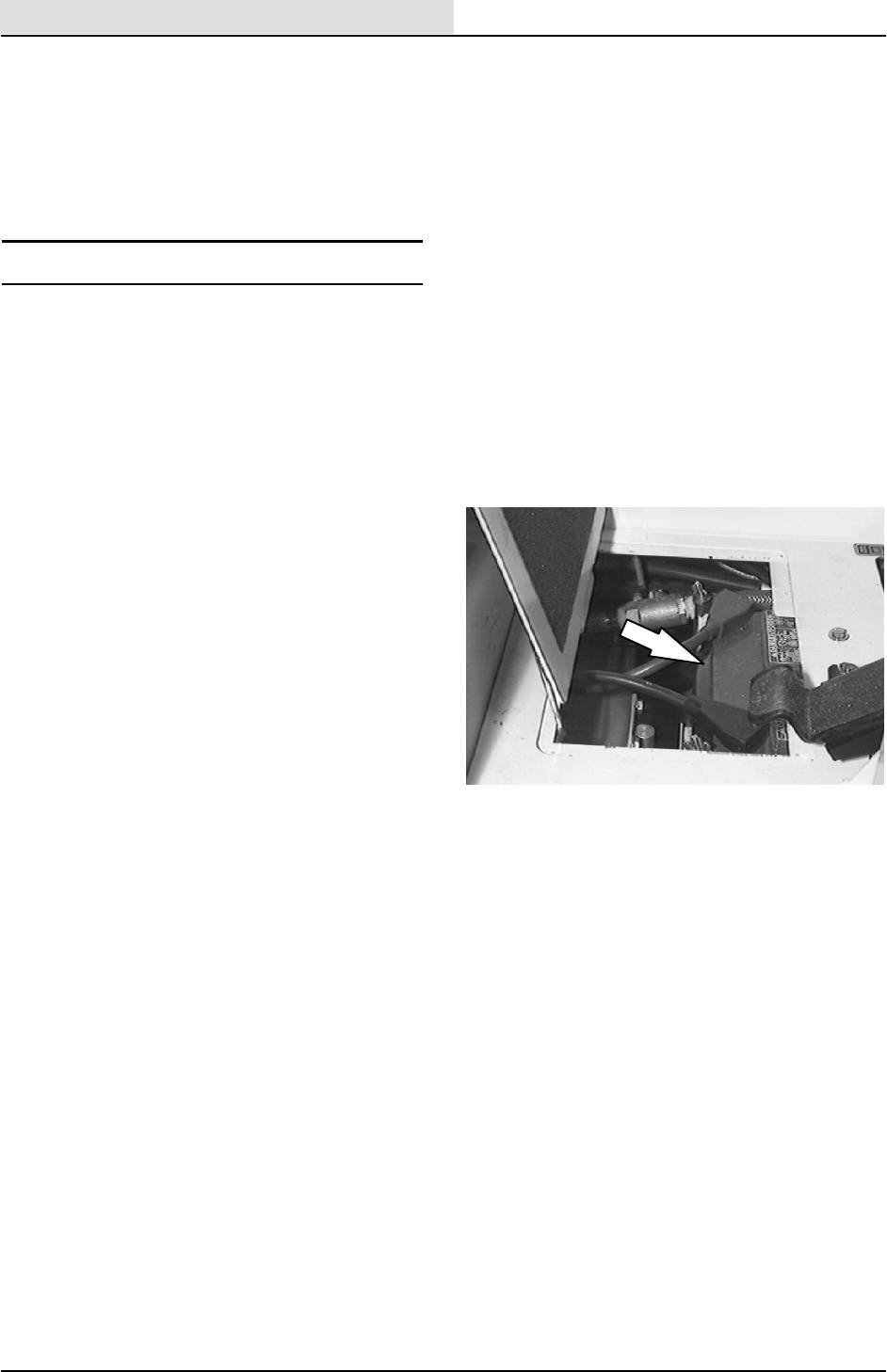
ELECTRICAL
5-4 8410 MM392 (8--01)
INTRODUCTION
The machines electrical system consists of the
batteries, instrument panel, relays, and circuit
breakers.
BATTERY
The battery used in the machine is a low
maintenance battery. It has been constructed with
special materials and has extra electrolyte to
reduce or eliminate maintenance. Its design
reduces electrolyte loss and contamination. Do
not add water, remove the battery vent plugs, or
check the battery specific gravity. For specific
instructions, see the battery label.
Do not allow the battery to remain in discharged
condition for any time. Do not operate the
machine if the battery is in poor condition or
discharged beyond 80%, specific gravity below
1.120.
Periodically clean the top surface of the batteries
and the terminals, and check for loose
connections. Use a strong solution of baking soda
and water. Brush the solution sparingly over the
battery tops, terminals, and cable clamps. Do not
allow any baking soda solution to enter the
batteries. Use a wire brush to clean the terminal
posts and the cable connectors. After cleaning,
apply a coating of clear battery post protectant to
the terminals and the cable connectors. Keep the
tops of the batteries clean and dry.
Keep all metallic objects off the top of the
batteries, which may cause a short circuit.
Replace any worn or damaged wires.
The electrolyte level in regular non--sealed
batteries can be checked. The level must always
be above the battery plates. Never add acid to the
batteries, only distilled water. Keep the battery
caps on the batteries always except when adding
water or taking hydrometer readings.
FOR SAFETY: When Servicing Machine,
Avoid Contact With Battery Acid.
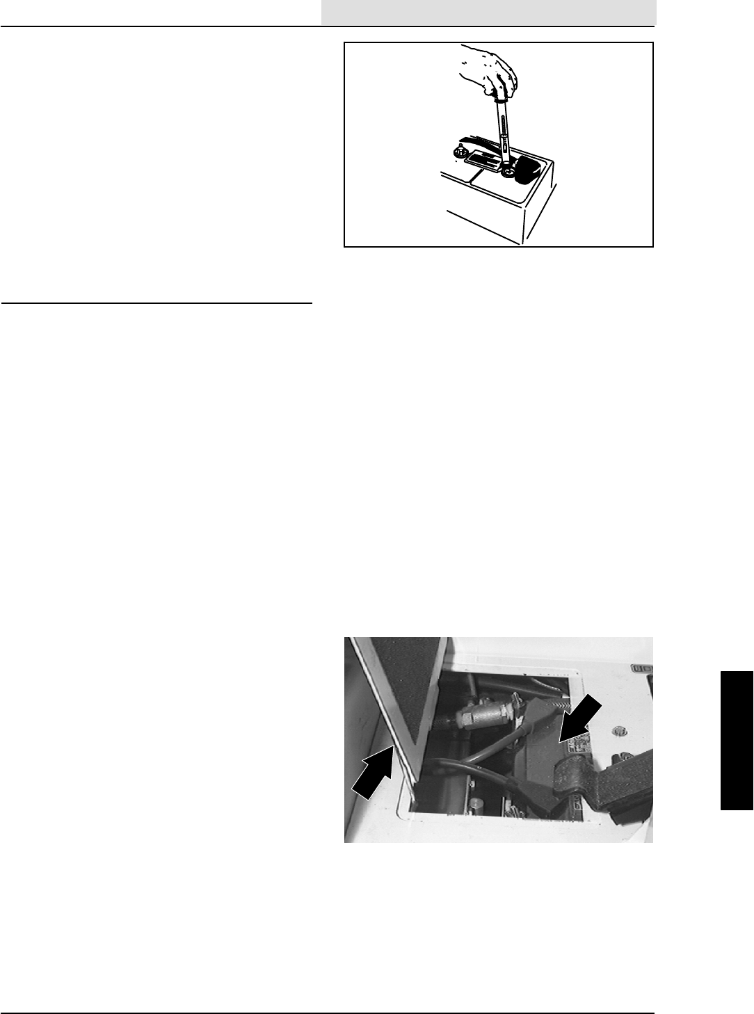
ELECTRICAL
5-5
8410 MM392 (8--01)
Using a hydrometer to measure the specific
gravity is a way to determine the charge level and
condition of the batteries. If one or more of the
battery cells test lower than the other battery cells
(0.050 or more), the cell is damaged, shorted, or
is about to fail.
NOTE: Do not take readings immediately after
adding distilled water. If the water and acid are not
thoroughly mixed, the readings may not be
accurate. Check the hydrometer readings against
the following chart to determine the remaining
battery charge level:
SPECIFIC GRAVITY BATTERY
at 27_C(80_F) CHARGE
1.260 -- 1.280 100% Charged
1.230 -- 1.250 75% Charged
1.200 -- 1.220 50% Charged
1.170 -- 1.190 25% Charged
1.110 -- 1.160 Discharged
NOTE: If the readings are taken when the battery
electrolyte is any temperature other than 27_C
(80_F), the reading must be temperature
corrected. Add or subtract to the specific gravity
reading 0.004, 4 points, for each 6_C(10_F)
above or below 27_C(80_F).
TO REPLACE BATTERY
FOR SAFETY: Before Leaving Or
Servicing Machine; Stop On Level
Surface, Set Parking Brake, Turn Off
Machine And Remove Key.
1. Open the battery cover on the floor of the
operators compartment.
2. Disconnect the negative cable first and then
the positive battery cable.
3. Remove the battery hold down bracket from
the machine.
4. Tilt the battery back and lift it out of the
machine.
5. Clean the old cables and the posts on the
new battery and install it in the machines
battery tray.
6. Reinstall the battery hold down bracket.
7. Reconnect the positive cable and then the
negative battery cable. Close the battery
cover.
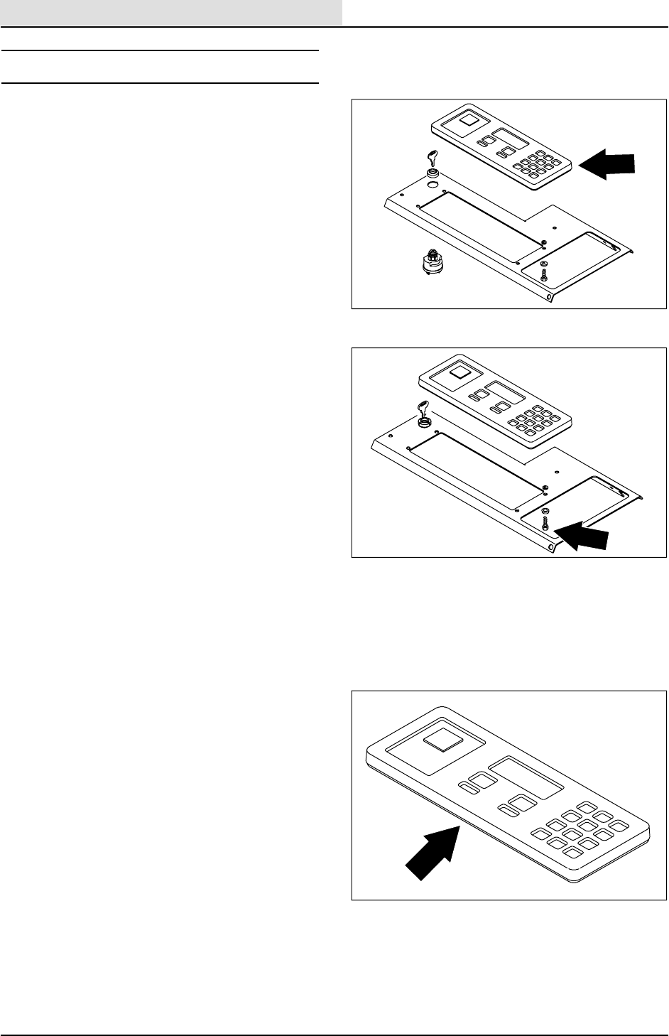
ELECTRICAL
5-6 8410 MM392 (8--01)
INSTRUMENT PANEL
The instrument panel consists of a circuit board, a
touch panel, and a water/dust resistant plastic
enclosure. The touch panel controls various
machine functions, while its indicator lights keep
the operator informed on machine performance.
TO REPLACE MAIN INSTRUMENT PANEL
FOR SAFETY: Before Leaving Or
Servicing Machine; Stop On Level
Surface, Set Parking Brake, Turn Off
Machine And Remove Key.
1. Disconnect the battery cables from the
machine.
2. Put the steering wheel in the lowest position.
3. Remove the four M8 hex head screws
holding the dash panel to the machine.
4. Pull the dash panel back away from the
machine.
5. Remove the four M5 pan head screws
holding the instrument panel to the dash
panel.
6. Loosen the allen head screw in center of
wire harness plug. Unplug the harness.
7. Remove the instrument panel from the
machine.
8. Install the new instrument panel back on the
dash panel using the four M5 pan head
screws and washers. Lightly hand tighten.
9. Push the harness plug back in the
instrument panel plug.
NOTE: The slot in the panel plug must line up
with the notch on the harness plug. Firmly hand
tighten the allen head screw.
10. Position the dash panel back on the
machine using the four M8 hex screws and
washers. Tighten to 18 -- 24 Nm
(13 -- 18 ft lb).
11. Reconnect the battery cables.
12. Start the machine and check for proper
instrument panel operation.
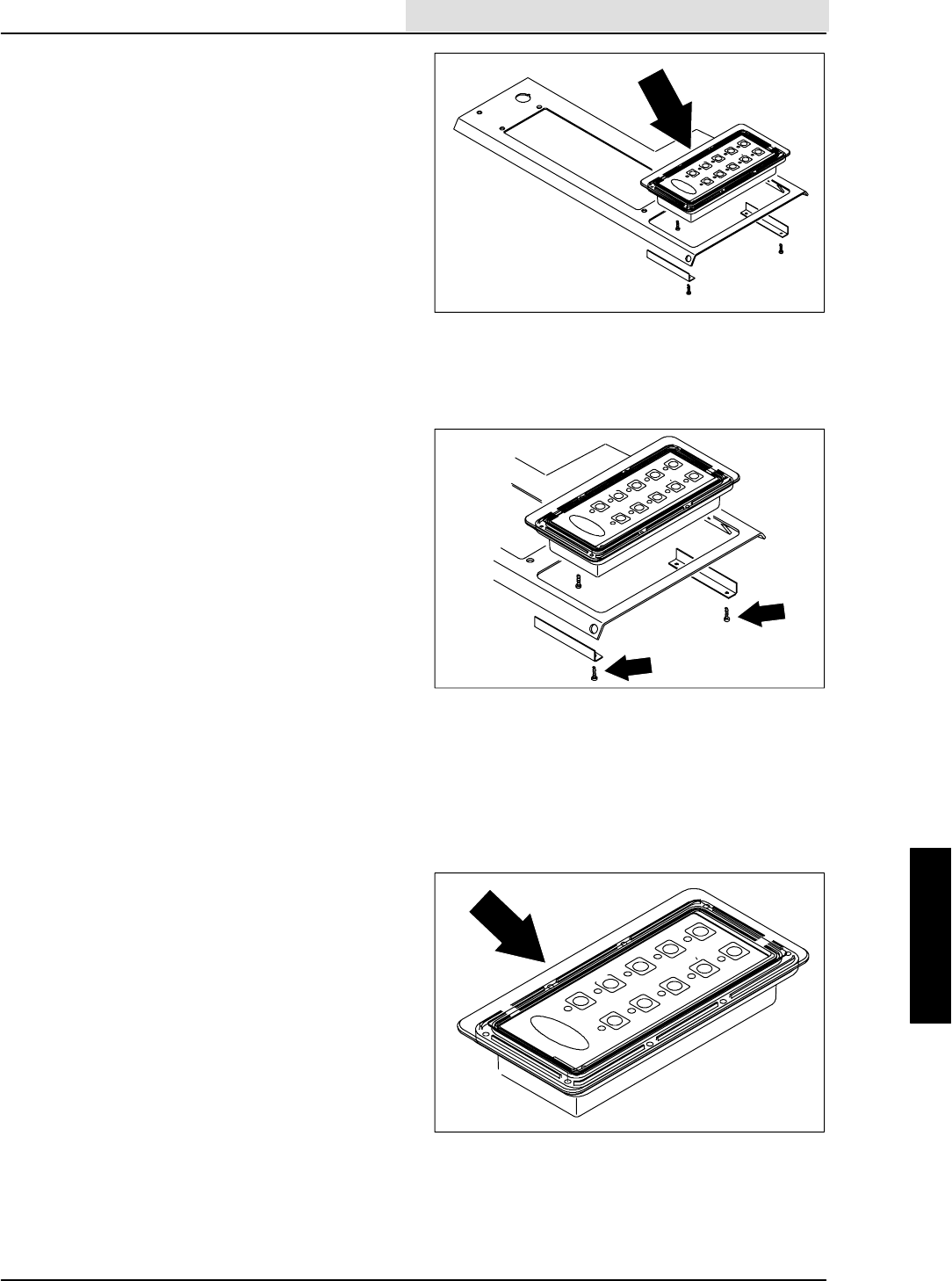
ELECTRICAL
5-7
8410 MM392 (8--01)
TO REPLACE AUXILIARY INSTRUMENT
PANEL
FOR SAFETY: Before Leaving Or
Servicing Machine; Stop On Level
Surface, Set Parking Brake, Turn Off
Machine And Remove Key.
1. Disconnect the battery cables from the
machine.
2. Put the steering wheel in the lowest position.
3. Remove the four M8 hex head screws
holding the dash panel to the machine.
4. Pull the dash panel back away from the
machine.
5. Remove the two M4 pan head screws and
bracket holding the top of the auxiliary
instrument panel to the dash panel. Loosen
the screws on the bottom of the panel.
6. Install the new auxiliary instrument panel
back on the dash panel using the four M5
pan head screws and washers. Lightly hand
tighten.
7. Push the harness plug back in the auxiliary
instrument panel plug.
NOTE: The slot in the panel plug must line up
with the notch on the harness plug. Firmly hand
tighten the allen head screw.
8. Position the dash panel back on the
machine using the four M8 hex screws and
washers. Tighten to 18 -- 24 Nm
(13 -- 18 ft lb).
9. Reconnect the battery cables.
10. Start the machine and check for proper
auxiliary instrument panel operation.
ELECTRICAL
5-8 8410 MM392 (8--01)
TO DISASSEMBLE MAIN INSTRUMENT
PANEL
FOR SAFETY: Before Leaving Or
Servicing Machine; Stop On Level
Surface, Set Parking Brake, Turn Off
Machine And Remove Key.
1. Remove the main instrument panel from the
machine. See TO REPLACE MAIN
INSTRUMENT PANEL instructions.
2. Place the main instrument panel face down
and remove the twelve larger pan head
screws holding it together.
3. The main instrument panel cases can now
be separated.
4. Remove the four smaller pan head screws
to completely disassemble touch panel case.
5. Remove the case box from the circuit board
and touch panel assembly.
6. The o--ring and connector gaskets can now
be replaced in the case box if necessary.
7. Remove the eight pan head screws and
unplug the flat connector and ground strap
to remove the touch panel from the circuit
board.
8. Any burned-out lamps can now be changed
by turning them 1/4 turn counterclockwise
and lifting them out.
9. To replace the hour meter, unplug the two
wires and remove the two pan head screws.
ELECTRICAL
5-9
8410 MM392 (8--01)
TO REASSEMBLE MAIN INSTRUMENT
PANEL
FOR SAFETY: Before Leaving Or
Servicing Machine; Stop On Level
Surface, Set Parking Brake, Turn Off
Machine And Remove Key.
1. Position the circuit board over the touch
panel. Feed the flat connector from the
panel through the slot in the board. Plug the
flat connector in and reconnect the ground
strap.
2. Reinstall the eight pan head screws and
lightly hand tighten.
3. Turn the circuit board assembly over and
place it back in the case box.
4. Reinstall the four smaller pan head screws
in the center of the case box.
5. Reinstall the touch panel case to the outer
case.
6. Reinstall the twelve pan head screws and
lightly hand tighten.
7. The instrument panel is now ready to
reinstall on the machine. See TO REPLACE
MAIN INSTRUMENT PANEL instructions.
ELECTRICAL
5-10 8410 MM392 (8--01)
TO DISASSEMBLE AUXILIARY INSTRUMENT
PANEL
FOR SAFETY: Before Leaving Or
Servicing Machine; Stop On Level
Surface, Set Parking Brake, Turn Off
Machine And Remove Key.
1. Remove the auxiliary instrument panel from
the machine. See TO REPLACE
AUXILIARY INSTRUMENT PANEL
instructions.
2. Place the auxiliary instrument panel face
down and remove the eight pan head
screws holding it together.
3. The auxiliary instrument panel cases can
now be separated.
4. Remove the four smaller pan head screws
to completely disassemble touch panel case.
5. Remove the case box from the circuit board
and touch panel assembly.
6. The o--ring and connector gaskets can now
be replaced in the case box if necessary.
7. Remove the four pan head screws and
unplug the flat connector and ground strap
to remove the touch panel from the circuit
board.
8. Any burned-out lamps can now be changed
by turning them 1/4 turn counterclockwise
and lifting them out.
9. To replace the hour meter, unplug the two
wires and remove the two pan head screws.
ELECTRICAL
5-11
8410 MM392 (8--01)
TO REASSEMBLE AUXILIARY INSTRUMENT
PANEL
FOR SAFETY: Before Leaving Or
Servicing Machine; Stop On Level
Surface, Set Parking Brake, Turn Off
Machine And Remove Key.
1. Position the circuit board over the touch
panel. Feed the flat connector from the
panel through the slot in the board. Plug the
flat connector in and reconnect the ground
strap.
2. Reinstall the four pan head screws and
lightly hand tighten.
3. Turn the circuit board assembly over and
place it back in the case box.
4. Reinstall the four smaller pan head screws
in the center of the case box.
5. Reinstall the touch panel case to the outer
case.
6. Reinstall the eight pan head screws and
lightly hand tighten.
7. The instrument panel is now ready to
reinstall on the machine. See TO REPLACE
AUXILIARY INSTRUMENT PANEL
instructions.

ELECTRICAL
5-12 8410 MM392 (8--01)
TO REPLACE MACHINE RELAY
FOR SAFETY: Before Leaving Or
Servicing Machine; Stop On Level
Surface, Set Parking Brake, Turn Off
Machine And Remove Key.
1. Disconnect the battery cables from the
machine.
2. Open the engine cover and side door.
3. Locate the problem relay on the back side of
the operators compartment.
4. Remove the M6 nyloc nut from the top of the
problem relay. Pull the relay off the stud.
5. Disconnect the relay from the main electrical
harness. Discard the relay.
6. Plug the new relay in the electrical harness.
7. Position the new relay on the stud. Reinstall
the M6 nyloc nut and firmly hand tighten.
8. Plug the new relay into the main harness.
See schematic in the ELECTRICAL section.
9. Reconnect the battery cables and operate
the machine. Check for proper operation.
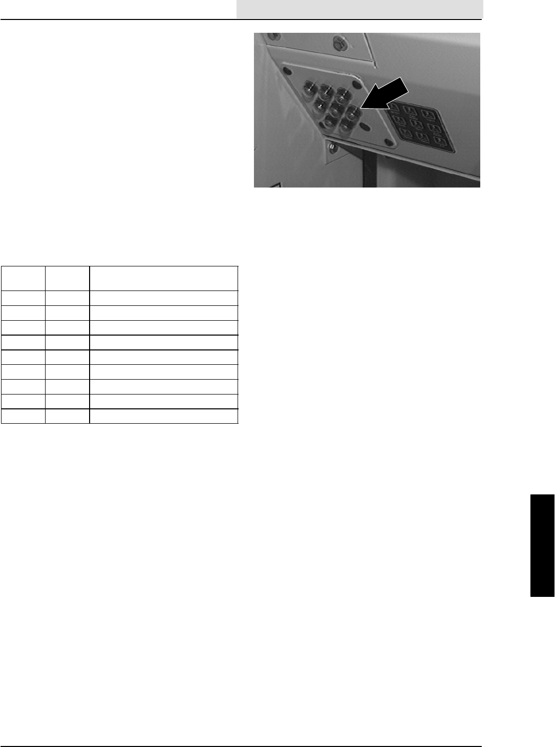
ELECTRICAL
5-13
8410 MM392 (8--01)
CIRCUIT BREAKERS
The circuit breakers are resettable electrical
circuit protection devices. Their design stops the
flow of current in the event of a circuit overload.
Once a circuit breaker is tripped, it must be reset
manually. Press the reset button after the breaker
has cooled down.
If the overload that caused the circuit breaker to
trip is still there, the circuit breaker will continue to
stop current flow until the problem is corrected.
The circuit breakers are located in the operator
compartment.
The chart lists the circuit breakers and the
electrical components they protect.
Circuit
Breaker Rating Circuit Protected
CB-1 15 A Horn
CB-2 15 A Ignition
CB-3 10 A Instrument panel
CB-4 15 A Scrubbing
CB-5 15 A Filter shaker, vacuum fan
CB-6 15 A Operating lights
CB-7 15 A ESt
CB-8 15 A Sweeping
CB-9 15 A Solenoid valve
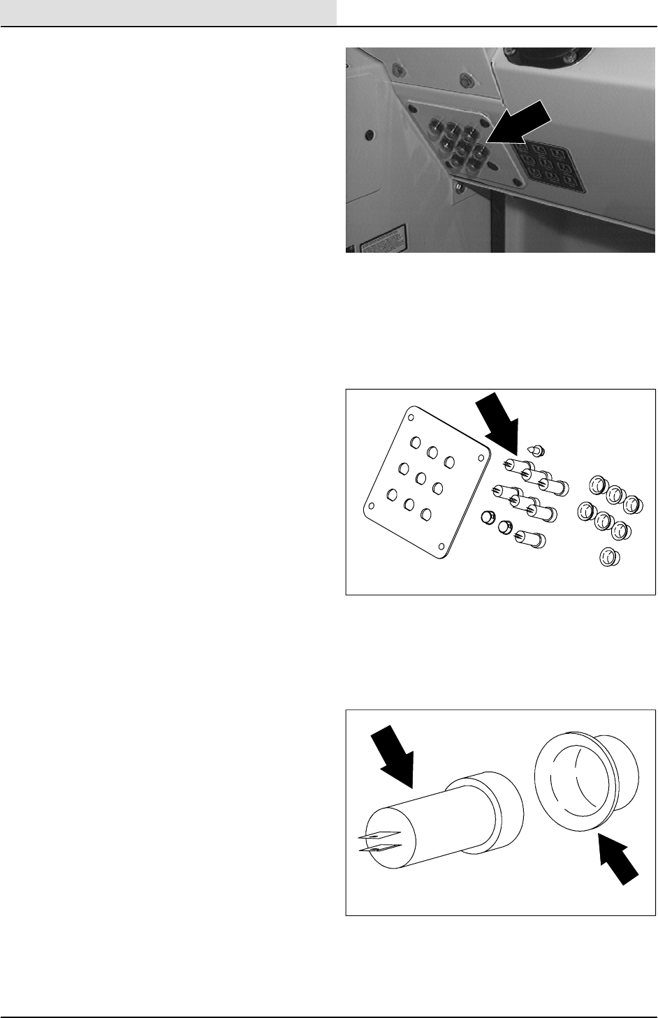
ELECTRICAL
5-14 8410 MM392 (8--01)
TO REPLACE MACHINE CIRCUIT BREAKER
FOR SAFETY: Before Leaving Or
Servicing Machine; Stop On Level
Surface, Set Parking Brake, Turn Off
Machine And Remove Key.
1. Disconnect the battery cables from the
machine.
2. Go in the operators compartment and
remove the four black plastic rivets holding
the circuit breaker mount bracket to the dash
panel. Retain the rivets.
3. Pull the circuit breaker mount bracket back
to expose the circuit breakers.
4. Locate the problem circuit breaker and
disconnect it from the main electrical
harness.
5. Remove and retain the rubber boot from the
front of the circuit breaker.
6. Remove and discard the metal retaining ring
from the back of the circuit breaker.
7. Push the old circuit breaker out of the mount
panel. Discard the circuit breaker.
8. Position the new circuit breaker in the mount
panel.
NOTE: The hole in the mount panel is ”D” shaped.
Make sure to install the new circuit breaker in the
correct orientation.
9. Install the new retaining ring on the new
circuit breaker. Push the retaining ring all the
way down the circuit breaker.
10. Reconnect the circuit breaker to the main
electrical harness. See schematic in the
ELECTRICAL section.
11. Reinstall the rubber boot on the front of the
new circuit breaker.
12. Position the circuit breaker mount panel to
the dash panel. Reinstall the four plastic
rivets.
13. Reconnect the battery cables and operate
the machine. Check for proper operation.
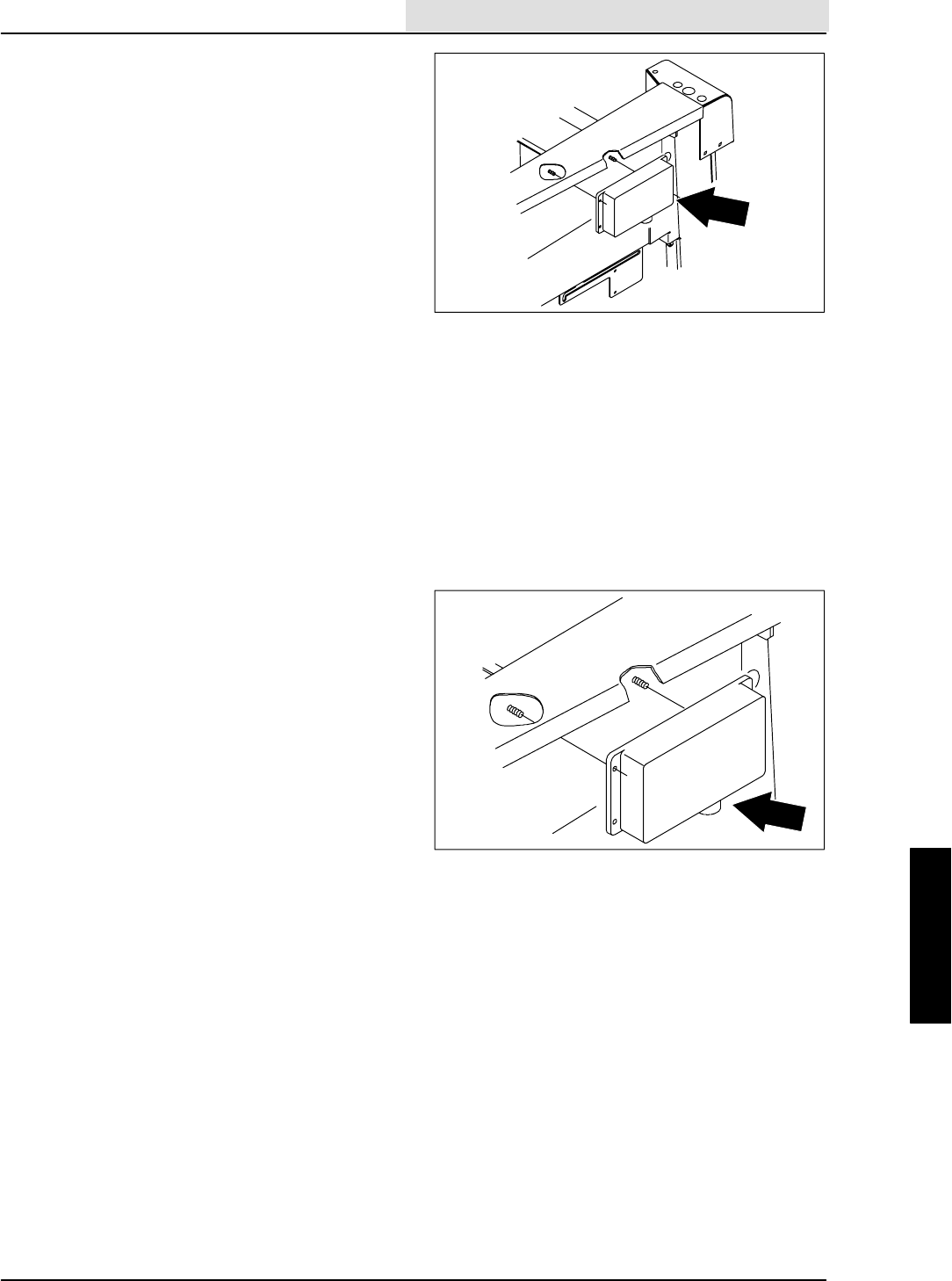
ELECTRICAL
5-15
8410 MM392 (8--01)
TO REPLACE GOVERNOR CONTROL BOX
FOR SAFETY: Before Leaving Or
Servicing Machine; Stop On Level
Surface, Set Parking Brake, Turn Off
Machine And Remove Key.
1. Disconnect the battery cables from the
machine.
2. Open the engine cover and side door.
3. Locate the governor control box on the back
side of the operators compartment.
4. Remove the two nuts holding the control box
to the control panel.
5. Pull the control box off the studs and
disconnect it from the main electrical
harness. Remove the control box from the
machine.
NOTE: You may have to cut a few plastic ties
holding the control box harness to the main
harness.
6. Position the new control box in the engine
compartment.
7. Connect the new control box to the main
electrical harness. See schematic in the
ELECTRICAL section.
8. Position the control box on the studs and
reinstall the two nuts. Lightly hand tighten.
NOTE: Reinstall any plastic ties that were
removed earlier.
9. Reconnect the battery cables and operate
the machine. Check for proper operation.

ELECTRICAL
5-16 8410 MM392 (8--01)
ELECTRICAL
5-17
8410 MM392 (5--02)
GAS/LP ELECTRICAL SCHEMATIC
16E/GRN
LP
CLOSES BELOW
70 PSI
1H/RED
CLOSED = RUN
S--5 CLOSED =
S--3&4 CLOSED=
96 OHM = FULL
OPEN AT 155F
REVERSE
CLOSES IN
13CD/BLK
13AY/BLK
13AQ/BLK
13BH/BLK
13AM/BLK
13AL/BLK
13AM/BLK
13AX/BLK
13BA/BLK
13BJ/BLK
13CF/BLK
16E/GRN
16F/
GRN 19C/BLU
19B/BLU
19A/BLU
83/BRN
83B/BRN
36B/GRN
36A/GRN
P
16H/
GRN
24B/PUR
50/ORA
1F/RED 21/ORA
21A/ORA
1G/RED
73/WHT
72/ORA
C
A
A
5A/BLU
8685
3087
87A
50A/ORA
50B/ORA
COOLANT SENSOR
CRANK
POSITION
SENSOR
SV--14
24A/PUR
D
BLU
GRY
GRY/RED
GRY/RED
YEL/BLK
BLK
TAN/ORA
TAN/ORA
BLK
TAN/WHT
TAN/WHT
16C/
GRN
16D/
GRN
16/GRN
16G/GRN
RED/GRN
RED/GRN
H
15A
CB--7
MTR
23A/GRY
K
M4
30 87
L
9
8
12
4
5
1
BLK
IGN. COIL
15B/BLU
15A/BLU S--2 OIL SWITCH
16A/GRN
16B/GRN
3/ORA
CB--1
1A/RED
1D/RED
1B/RED
1A/RED
1C/RED
20A/BLU
20/BLU
CB--2
IGNITION SWITCH
S--15
( X INDICATES A
CLOSED CONTACT )
D--1
10A 22/
YEL
CB--3
19/BLU
23/GRY
S--5
S--4 N.C.H.O.
S--3 N.O.H.C.
SWITCH
HOPPER THERMAL
S--8
S--7
24/PUR
36/GRN REVERSE
J
M5 86
85
B
START
STARTRUN
OFF
PREHEAT
X
XXX
XX
X
IGN.
19
30
BATT.
50
17
N/U
RUN/
ACC
1/RED
5 SEC. DELAY
ES PUMP RUNS
30 SEC.
5 SEC. DELAY
1MIN.TOVAC
FAN SHUT--OFF
42A/YEL
42B/YEL42/YEL
56/ORA
3
5
13
10
8
18
17
14
15
4
1
9
27/PUR
26/BRN
FRONT
RECOVERY
TANK
SOLUTION
TANK
ELEC.
SPARK
CONT. PLUGS
11
7
6
2
FLOW SWITCH
10/GRY
15A
15A15A
14/GRN
N.C.H.O.
N.C.H.O.
GAS--DIESEL
C
FUEL PUMP
M2
STARTER RELAY
M1
S--6
8730
15/
BLU
M4 8685
28/YEL
C
57/GRN
ES PUMP
MTR
DETERGENT
METERING
RECOVERY TANK
S--1
M3
8685 M3
A
2/
ORA
C
43/BLU
55A MAX.
CHARGE
2/ORA
A
L2
5/BLU
12V
540 C.C.A.
4/YEL
84/GRN
86/PUR
HG
FEDC
B
A
CLOSES AT
225°F
ELECTRONIC
INSTRUMENT
PANEL
COOLANT TEMP
SENDER
FUEL SENDER
SE--1
SE--2
HORN BUTTON
15A
HORN
SENSE
GOV
CONTROL THROTTLE
ACTUATOR
13A/BLK
STARTER MOTOR
13/BLK
BATTERY
ALTERNATOR
GND
OUT
STARTER RELAY
M1 MTR
11077--8410 G, LP
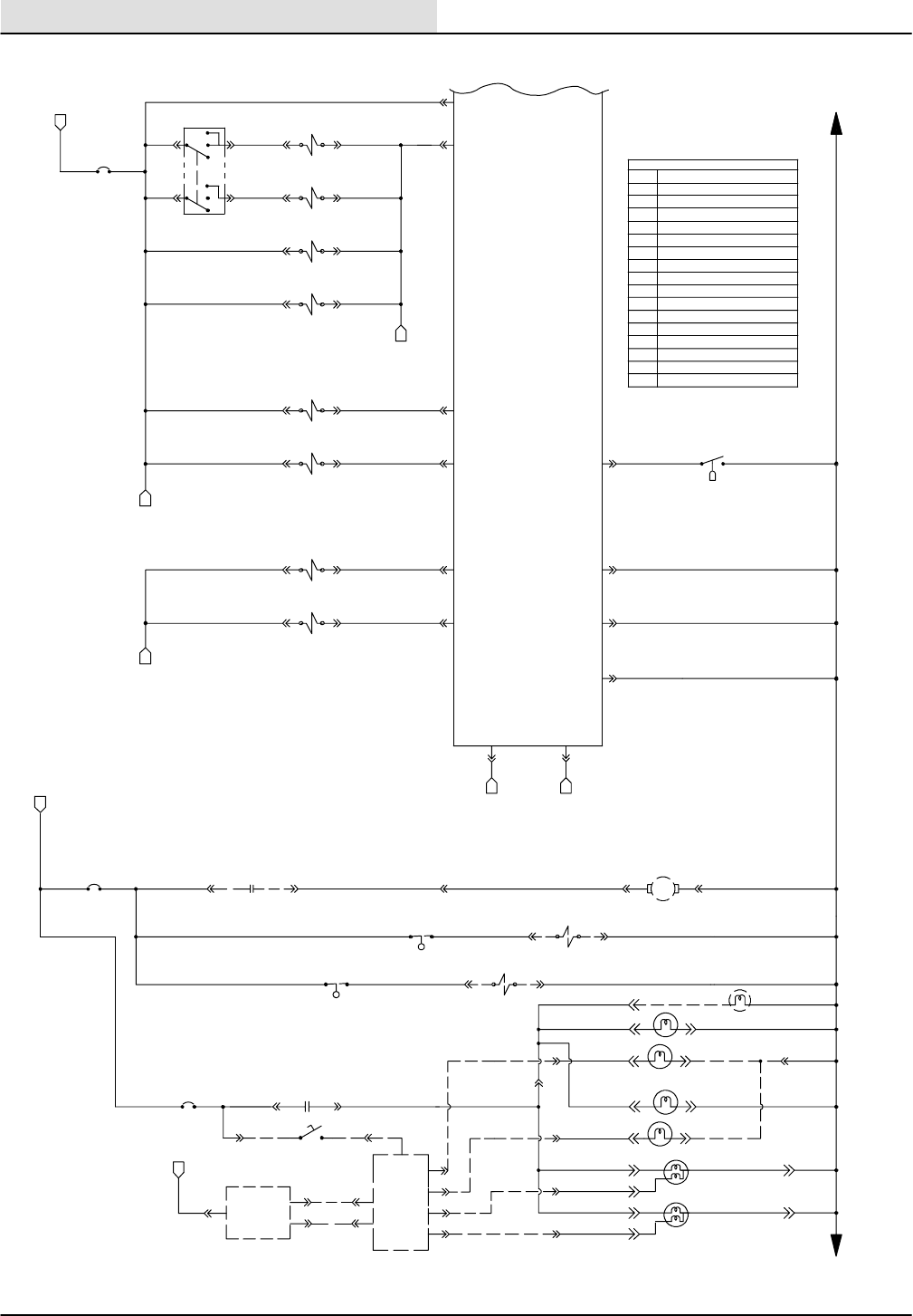
ELECTRICAL
8410 MM392 (5--02)
5-18
GAS/LP ELECTRICAL SCHEMATIC
ON
OFF
C N.O.
62H/YEL
62B/YEL
R.H.
RUNNING
LIGHT
L.H.
RUNNING
LIGHT
R.H.
HEADLIGHT
13BF/BLK
13BG/BLK
62C/YEL 62F/YEL
62G/YEL
62E/YEL
4A/YEL
SV--19 SCRUB BR. DN. FORCE
PROP. VALVE
H2OCLOSED =
>20 INCHES
25J
25B
/GRY
/GRY
WATER CONTROL
S--9
ON
ON
OFF
OFF
65/ORA
65A/ORA
65B/ORA
13CB/BLK
13CG/BLK
13CA/BLK
13AS/BLK
13AR/BLK
13CE/BLK
13EE/BLK
13FF/BLK
13GG/BLK
13AD/BLK
13AC/BLK
13AB/BLK
13AU/BLK
17/ORA7/BLU
31H/GRY
31L/GRY
25D/GRY
25H/GRY
25G/GRY
25F/GRY
46C/BRN
46B/BRN
46E/BRN
46/BRN
46D/BRN
25A
/GRY
25/GRY
21/
ORA
89A/BRN
90A/GRY
88A/GRN
87A/PUR
S--4
S--3
62D/YEL
77/GRY
45/GRN
48/BLU
SV--1 VAC FAN
SCRUB VALVE
LIGHTS ON
SWEEP SENSE
SV--4 SCRUB BR.
DOWN VALVE
SV--3 SCRUB BR.
ON VALVE
SV--22 HIGH
WATER VALVE
SV--21 LOW
WATER VALVE
96/YEL
21
16
M
E
K
GROUND
LINE
6/YEL
HOPPER DIFFERENTIAL PRESSURE
N
SV--10
EDJE SCRUB
SV--12
SQEEGEE DOWN
51/PUR
47/ORA 11
20
7
GF
12
59B/
BRN
FRONT
6
SIDE BRUSH LIGHT
HEADLIGHT L.H.
87/PUR
88/GRN
89/BRN
90/GRY
80/BLU
79/YEL
RED
GRN
BLK
GRY
GRY
BLU
YEL
P
L
X
FLASHER
DIRECTIONAL
SWITCH
BRAKE
SWITCH
S--12
B
M7
MTR--3
SHAKER MOTOR
11 /GRN
30A/GRY30/GRY
M6
H
20A/
BLU
CB--5
59A/BRN
59/
BRN
95/BLU
20B/
BLU
24
23
22
19
2
ELECTRONIC
INSTRUMENT
PANEL
87
30
CB--6
62/YEL
15 AMP
TAIL LHT L.H.
TAIL LHT R.H.
AUTO FILL
RECOVERY TANK
SOLUTION TANK
N.O.H.C.
N.O.H.C.
8730
15 AMP
MTR
FUSE
FU
LEGEND
NORMALLY CLOSED
NORMALLY OPEN
COMMON
GROUND CHASSIS
ACCESSORY
SWITCH
SOLENOID VALVE
HOURMETER
N.C.
N.O.
C
GND
ACC
S
SV
HM
VOLTMETER
PUSHBUTTON
PLUG--MALE PIN
JACK--FEM. SOCKET
PERMANENT MAGNET
CIRCUIT BREAKER
MOTOR
POWER RELAY
VM
PB
P
J
PM
CB
M
MTR
GROUND
LINE
15 AMP
CB--4
9/BLU
SV--23
SV--24
11077--8410 G, LP
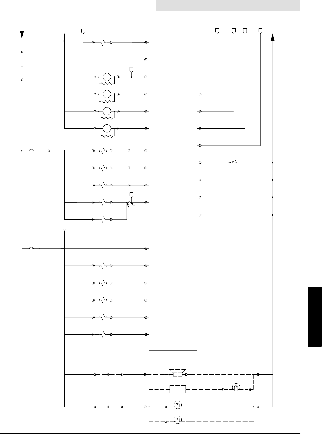
ELECTRICAL
5-19
8410 MM392 (5--02)
GAS/LP ELECTRICAL SCHEMATIC
53/BRN
WARNING LIGHT L.R.C.
WARNING LIGHT O.H.G.
BACKUPLIGHT
BACK UP ALARM
FLASHER
76/GRN
94/YEL
93/ORA
8730
8730 M9
M8
2
50F/ORA
50E/ORA
50C/ORA
50D/ORA
50A/ORA
17B/ORA
17A/ORA
13
19
18/GRN
12/YEL
M--9
M--8
REVERSE RELAY
WARNING LIGHT RELAY
AUXILIARY
86
85
86
85
HOPPER
THERMAL
SENSE
ENG. SPEED SENSE
SCRUB SENSE
10
8
HOPPER LOCATION
7
15
3
EJ
D
SV--15 SIDE BR.
DOWN VALVE
SV--13 SIDE BR.
ON VALVE
11
G
44/YEL
SV--18 VAC FAN
SWEEP VALVE
20
41/PUR
SV--16 HOPPER
CLOSE VALVE
12
40/BRN
SV--17 HOPPER
OPEN VALVE
14
39/ORA
9
38/GRN
37/YEL
SV--9 HOPPER
DOWN VALVE
18
SV--8 HOPPER UP
VALVE
6
35/PUR
21
34/BRN
4
5
F
M--6
HEADLIGHT RELAY
86
85 M--7
SHAKER RELAY
86
85
1
SV--2 ENG. FAN
VALVE 49/GRN 17
N
LM
UNSWITCHED POWER
15 AMP
16
CB--8
15 AMP
24
23
22
ELECTRONIC
INSTRUMENT
PANEL
GROUND
LINE
7C/BLU
7B/BLU
LOW = SCRUB
LOW = REVERSE
LOW = SW.FAN ENABLE
LOW = SWEEP ENABLE
HOPPER DN
N.O.H.C.
SV--5 MAIN SWEEP BRUSH
NORMAL SPEED VALVE
SV--6 MAIN SWEEP BRUSH
LITTER SPEED VALVE
SV--11 MAIN SWEEP BRUSH
DN. VALVE
13LL/BLK
13VV/BLK
13QQ/BLK
13NN/BLK
CLOSED =
13BE/BLK
13BD/BLK
13AH/BLK
13AG/BLK
13AF/BLK
13AT/BLK
46A/BRN
31D/GRY
31C/GRY
31M/GRY
31G/GRY
31F/GRY
31N/GRY
31K/GRY
31A/GRY
33D/ORA
33C/ORA
33E/ORA
33F/ORA
33/ORA
33A/ORA
25E/GRY
CB--9
P
97/BLU
76/GRN
76/GRN
93/ORA
93/ORA
44A/BRN
41A/PUR
40A/BRN
31/GRY
7A/BLU
7D/BLU
7E/BLU
33B/ORA
32/BLU
32A/BLU
8730
1G/RED
M5
36A/GRN
REVERSE SENSE
83A/BRN
24A/PUR
11077--8410 G, LP
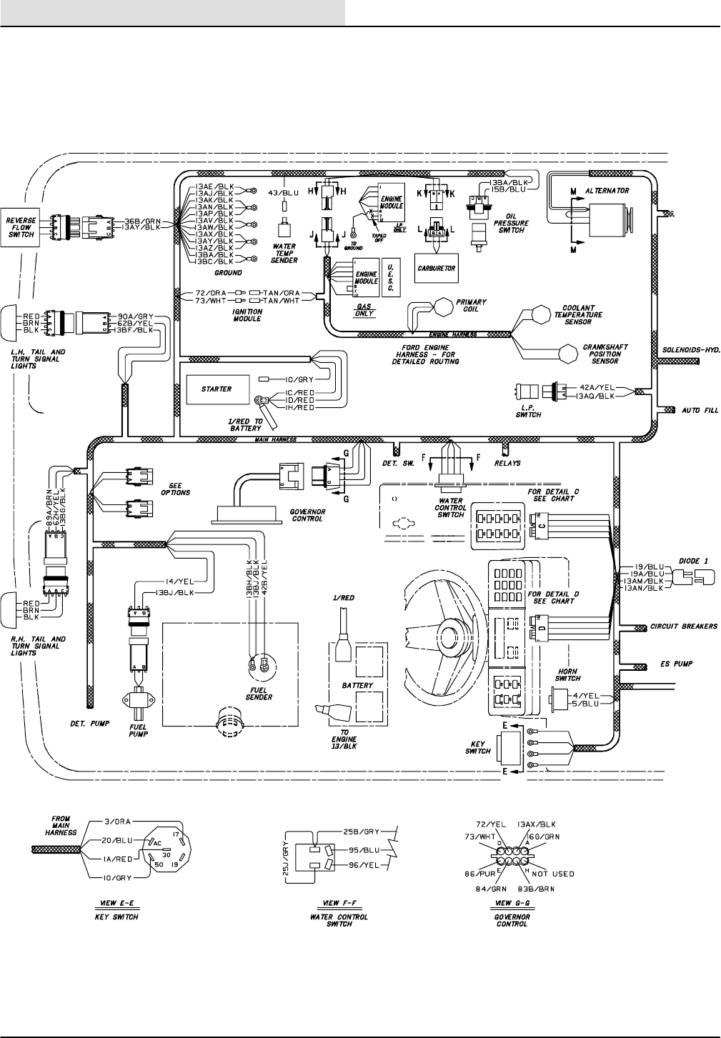
ELECTRICAL
8410 MM392 (5--02)
5-20
GAS/LP WIRE HARNESS GROUP
11077--8410 G, LP
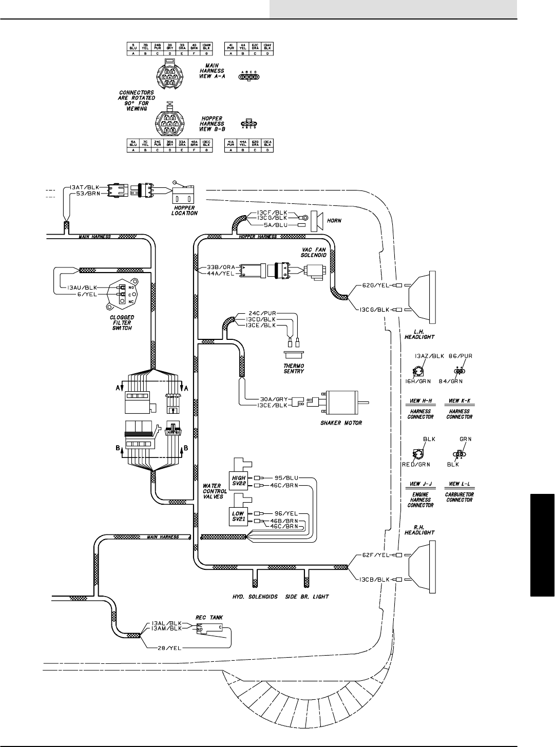
ELECTRICAL
5-21
8410 MM392 (5--02)
GAS/LP WIRE HARNESS GROUP
11077--8410 G, LP
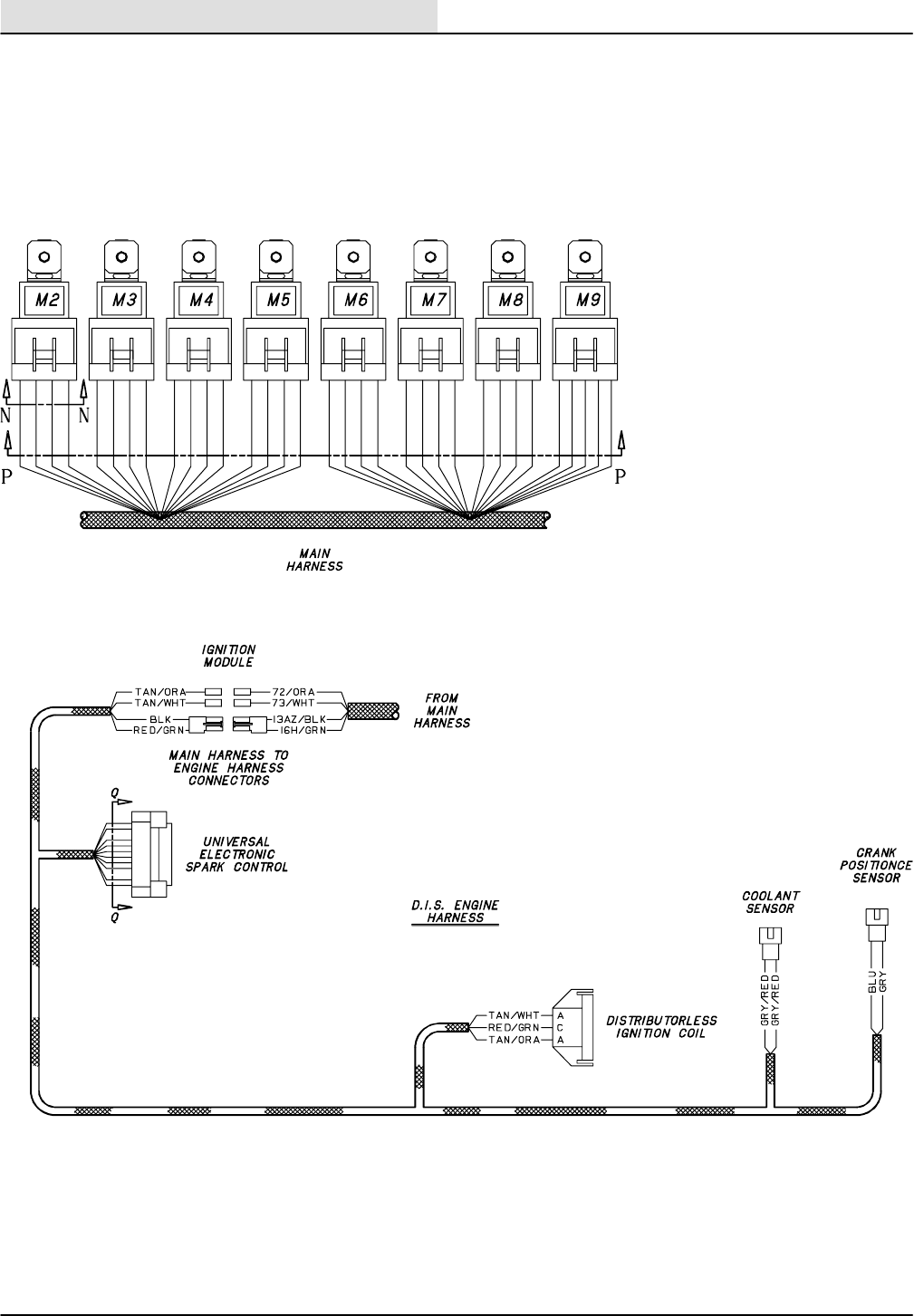
ELECTRICAL
8410 MM392 (5--02)
5-22
GAS/LP WIRE HARNESS GROUP
11077--8410 G, LP
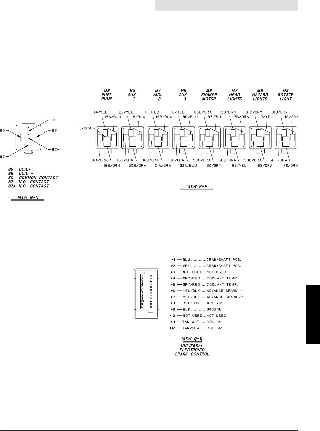
ELECTRICAL
5-23
8410 MM392 (5--02)
GAS/LP WIRE HARNESS GROUP
11077--8410 G, LP
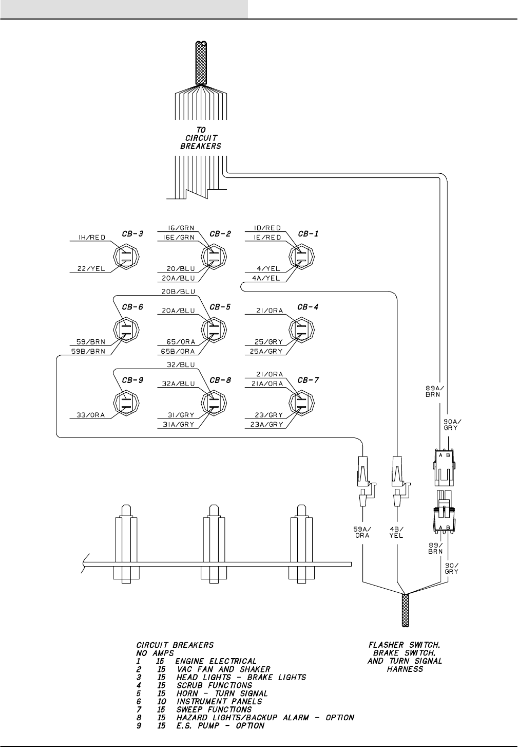
ELECTRICAL
8410 MM392 (5--02)
5-24
GAS/LP WIRE HARNESS GROUP
11077--8410 G, LP
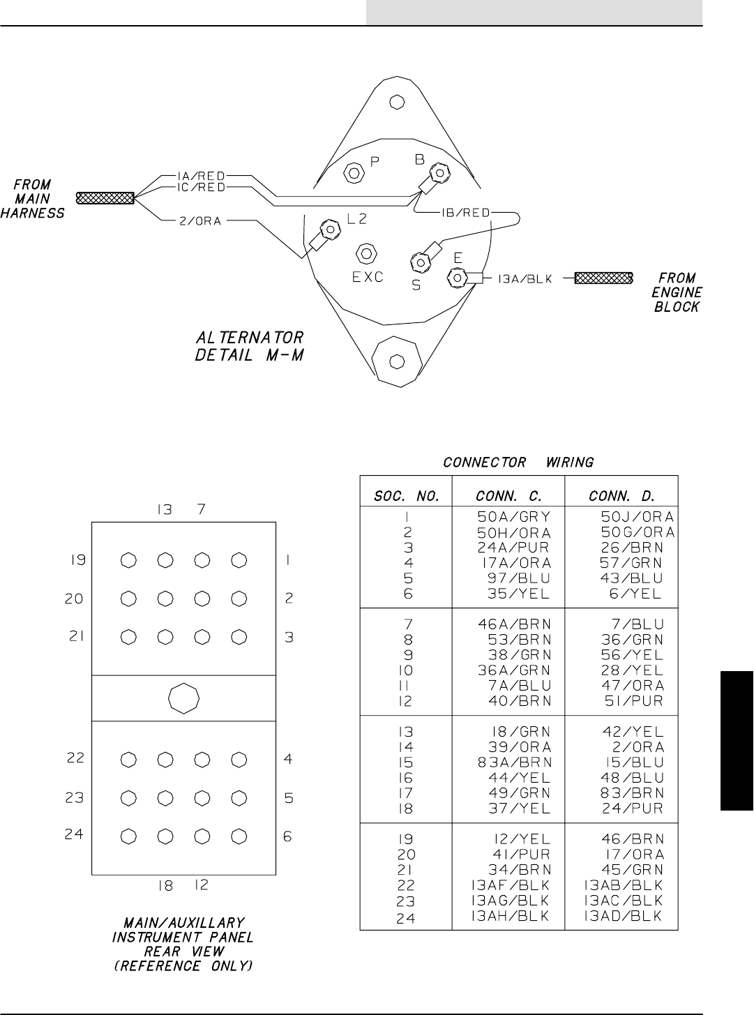
ELECTRICAL
5-25
8410 MM392 (5--02)
GAS/LP WIRE HARNESS GROUP
11077--8410 G, LP
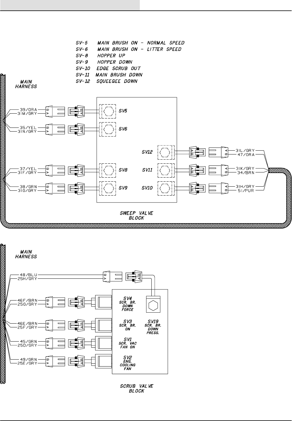
ELECTRICAL
8410 MM392 (5--02)
5-26
GAS/LP WIRE HARNESS GROUP
11077--8410 G, LP
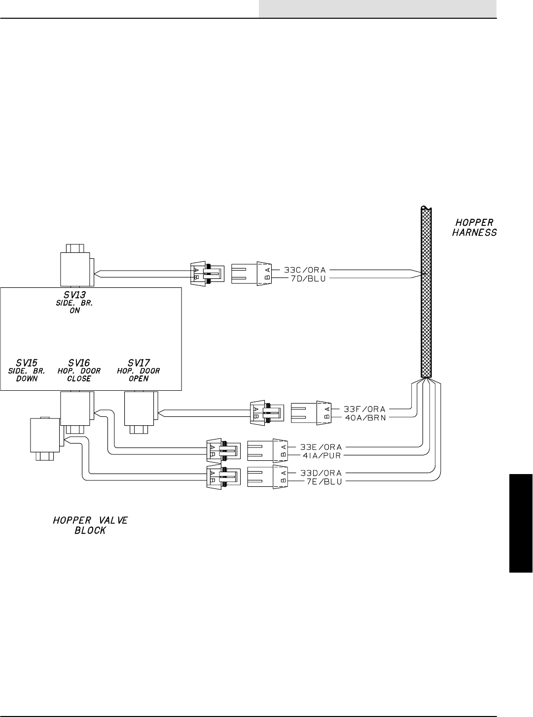
ELECTRICAL
5-27
8410 MM392 (5--02)
GAS/LP WIRE HARNESS GROUP
11077--8410 G, LP
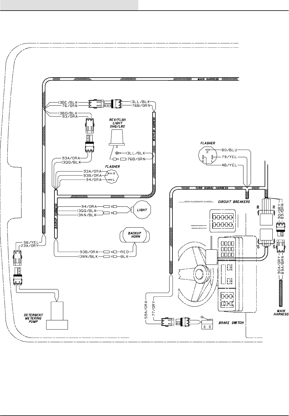
ELECTRICAL
8410 MM392 (5--02)
5-28
GAS/LP WIRE HARNESS GROUP
OPTIONS
11077--8410 G, LP
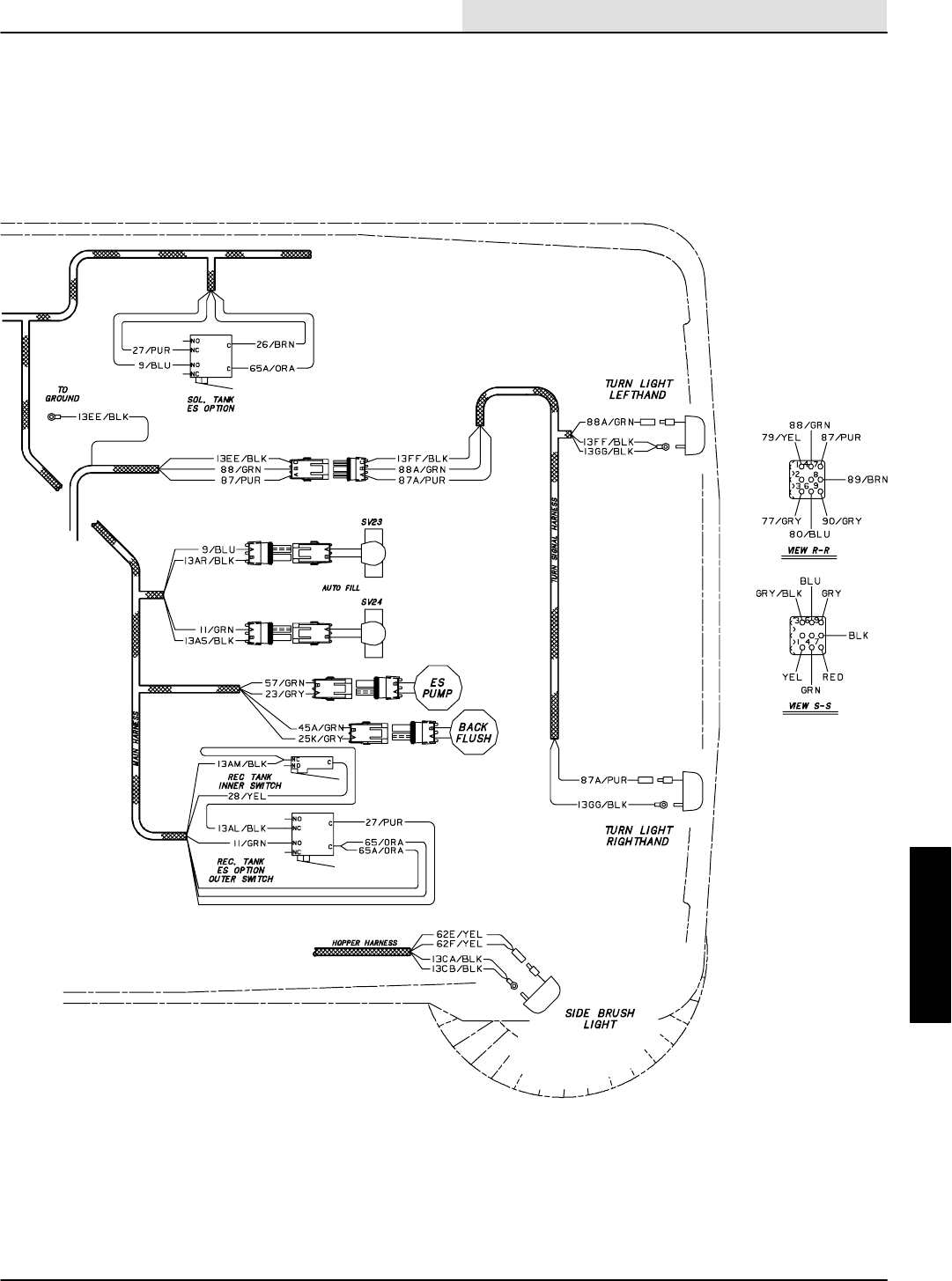
ELECTRICAL
5-29
8410 MM392 (5--02)
GAS/LP WIRE HARNESS GROUP
OPTIONS
11077--8410 G, LP
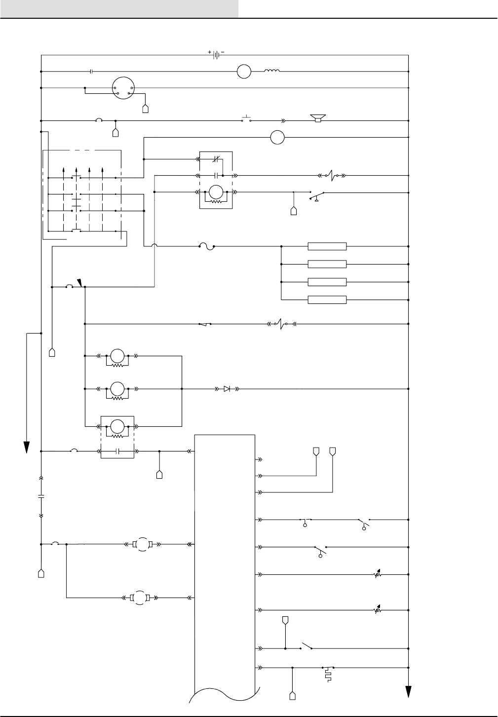
ELECTRICAL
8410 MM392 (5--02)
5-30
DIESEL ELECTRICAL SCHEMATIC
16E/GRN
13BF/BLK
13AX/BLK
13AY/BLK
13BG/BLK
13AQ/BLK
1H/RED
3A/PUR
3/PUR
SHOWN
LOW SPEED
16G/GRN 49/PUR
ENG.FAN VALVE
SV--2
THROTTLE SWITCH
S--6
S--5 CLOSED =
S--3&4 CLOSED=
CLOSED=RUN
8/GRN
GLOW PLUGS
FU--1
40A
10A/GRY
96 OHM = FULL
OPEN AT 155F
REVERSE
CLOSES IN
13CD/BLK
13AM/BLK
13AL/BLK
13AM/BLK
13CF/BLK
16F/
GRN 19C/BLU
19B/BLU 19A/BLU
36B/GRN
36A/GRN
P
24B/PUR
50/ORA
1F/RED 21/ORA
21A/ORA
1G/RED
5A/BLU
8685
3087
87A
50A/ORA
50B/ORA
SV--14
24A/PUR
D
16C/
GRN
16D/
GRN
16/GRN
H
15A
CB--7
MTR
23A/GRY
K
M4
30 87
L
15B/BLU
15A/BLU S--2 OIL SWITCH
16A/GRN
16B/GRN
CB--1
1A/RED
1D/RED
1B/RED
1A/RED
1C/RED
20A/BLU
20/BLU
CB--2
IGNITION SWITCH
S--15
( X INDICATES A
CLOSED CONTACT )
D--1
10A
22/
YEL
CB--3
19/BLU
23/GRY
S--5
S--4 N.C.H.O.
S--3 N.O.H.C.
SWITCH
HOPPER THERMAL
S--8
S--7
24/PUR
36/GRN
REVERSE
M5 86
85
B
START
STARTRUN
OFF
PREHEAT
X
XXX
XX
X
IGN.
19
30
BATT.
50
17
N/U
RUN/
ACC
1/RED
5SEC.DELAY
ES PUMP RUNS
30 SEC.
5SEC.DELAY
1MIN.TOVAC
FAN SHUT--OFF
42/YEL
56/ORA
3
5
13
10
8
18
17
14
15
4
1
9
27/PUR
26/BRN
FRONT
RECOVERY
TANK
SOLUTION
TANK
FLOW SWITCH
10/GRY
15A
15A
14/GRN
N.C.H.O.
GAS--DIESEL
C
FUEL PUMP
M2
STARTER RELAY
M1
8730
15/
BLU
M4 8685
28/YEL
57/GRN
ES PUMP
MTR
DETERGENT
METERING
RECOVERY TANK
S--1
M3
8685 M3
A
2/
ORA
C
43/BLU
55A MAX.
CHARGE
2/ORA
A
L2
5/BLU
12V
540 C.C.A.
4/YEL
CLOSES AT
225°F
ELECTRONIC
INSTRUMENT
PANEL
COOLANT TEMP
SENDER
FUEL SENDER
SE--1
SE--2
HORN BUTTON
HORN
SENSE
13A/BLK
STARTER MOTOR
13/BLK
BATTERY
ALTERNATOR
GND
OUT
STARTER RELAY
M1 MTR
11093--8410 D

ELECTRICAL
5-31
8410 MM392 (5--02)
DIESEL ELECTRICAL SCHEMATIC
ELECTRONIC
INSTRUMENT
PANEL
8730
CB--6 62/YEL
15 AMP
TAIL LHT L.H.
TAIL LHT R.H.
AUTO FILL
AUTO FILL
RECOVERY TANK
SOLUTION TANK
N.O.H.C.
N.O.H.C.
8730
15 AMP
MTR
GROUND
LINE
FUSE
FU
LEGEND
NORMALLY CLOSED
NORMALLY OPEN
COMMON
GROUND CHASSIS
ACCESSORY
SWITCH
SOLENOID VALVE
HOURMETER
N.C.
N.O.
C
GND
ACC
S
SV
HM
VOLTMETER
PUSHBUTTON
PLUG--MALE PIN
JACK--FEM. SOCKET
PERMANENT MAGNET
CIRCUIT BREAKER
MOTOR
POWER RELAY
VM
PB
P
J
PM
CB
M
MTR
C N.O.
R.H.
RUNNING
LIGHT
L.H.
RUNNING
LIGHT
R.H.
HEADLIGHT
62C/YEL
13GG/BLK
62D/YEL
62F/YEL
62G/YEL
62E/YEL
13BE/BLK
13BD/BLK
4A/YEL
25H
25E/GRY
25F/GRY
25G/GRY
SV--24
SV--23
SV--19 SCRUB BR. DN. FORCE
PROP. VALVE
H2OCLOSED =>20 INCHES
25B
/GRY
/GRY
WATER CONTROL
S--9
ON
ON
ON
OFF
OFF
OFF
65/ORA
65A/ORA
65B/ORA
13CB/BLK
13CG/BLK
13CA/BLK
13AS/BLK
13AR/BLK
13CE/BLK
13EE/BLK
13FF/BLK
13AD/BLK
13AC/BLK
13AB/BLK
13AU/BLK
17/ORA7/BLU
31H/GRY
31L/GRY
25D/GRY
46F/BRN
46E/BRN
46C/BRN
46/BRN46B/BRN
25A
/GRY
25/GRY
21/
ORA
89A/BRN
90A/GRY
88A/GRN
87A/PUR
S--4
S--3
77/GRY
45/GRN
48/BLU
SV--1 VAC FAN
SCRUB VALVE
LIGHTS ON
SWEEP SENSE
SV--4 SCRUB BR.
DOWN VALVE
SV--3 SCRUB BR.
ON VALVE
SV--22 HIGH
WATER VALVE
SV--21 LOW
WATER VALVE
96/YEL
CB--4
21
16
E
K
GROUND
LINE
6/YEL
HOPPER DIFFERENTIAL PRESSURE
N
SV--10
EDJE SCRUB
SV--12
SQEEGEE DOWN
51/PUR
47/ORA 11
20
7
GF
12
59B/
BRN
FRONT
6
62B/YEL
62H/YEL
SIDE BRUSH LIGHT
HEADLIGHT L.H.
87/PUR
88/GRN
89/BRN
90/GRY
80/BLU
79/YEL
RED
GRN
BLK
GRY
GRY
BLU
YEL
P
L
XFLASHER
DIRECTIONAL
SWITCH
BRAKE
SWITCH
S--12
B
M7
MTR--3
SHAKER MOTOR
11 /GRN
9/BLU
30A/GRY30/GRY
M6
H
20A/
BLU CB--5
59A/BRN
59/
BRN
95/BLU
20B/
BLU
24
23
22
19
2
15 AMP
11093--8410 D
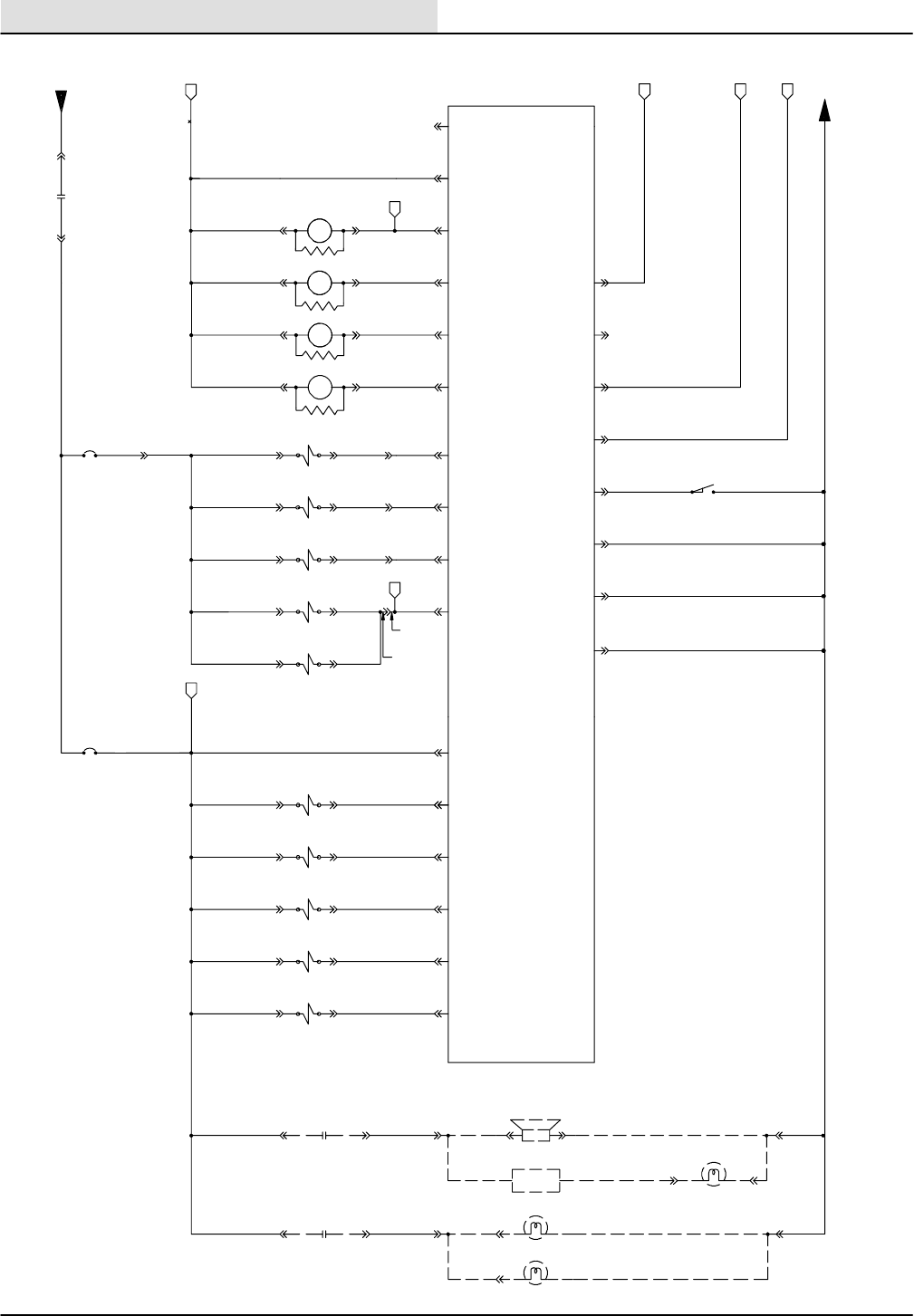
ELECTRICAL
8410 MM392 (5--02)
5-32
DIESEL ELECTRICAL SCHEMATIC
7C/BLU
7B/BLU
LOW = REVERSE
LOW = SCRUB
LOW = SW.FAN ENABLE
LOW = SWEEP ENABLE
13BA/BLK
13BC/BLK
N.C.H.O.
13LL/BLK
13VV/BLK
13QQ/BLK
13NN/BLK
HOPPER DN
CLOSED =
13AH/BLK
13AG/BLK
13AF/BLK
13AT/BLK
46A/BRN
31D/GRY
31C/GRY
31M/GRY
31G/GRY
31F/GRY
31N/GRY
31K/GRY
31A/GRY
33D/ORA
33C/ORA
33E/ORA
33F/ORA
33/ORA 33A/ORA
CB--9
P
97/BLU
76/GRN
76/GRN
93/ORA
93/ORA
44A/BRN
41A/PUR
40A/BRN
31/GRY
7A/BLU
7D/BLU
7E/BLU
33B/ORA
32A/BLU
8730
1G/RED
M5
36A/GRN
REVERSE SENSE
24A/PUR
53/BRN
WARNING LIGHT L.R.C.
WARNING LIGHT O.H.G.
BACKUPLIGHT
BACK UP ALARM
FLASHER
76/GRN
94/YEL
93/ORA
8730
8730 M9
M8
2
50F/ORA
50E/ORA
50C/ORA
50D/ORA
50A/ORA
17B/ORA17A/ORA
13
19
18/GRN
12/YEL
M--9
M--8
REVERSE RELAY
WARNING LIGHT RELAY
AUXILIARY
86
85
86
85
HOPPER
THERMAL
SENSE
SCRUB SENSE
10
8
HOPPER LOCATION
7
15
3
ED
SV--15 SIDE BR.
DOWN VALVE
SV--13 SIDE BR.
ON VALVE
11
G
44/YEL
SV--18 VAC FAN
SWEEP VALVE
20
41/PUR
SV--16 HOPPER
CLOSE VALVE
12
40/BRN
SV--17 HOPPER
OPEN VALVE
14
39/ORA
SV--5 MAIN BRUSH
NORMAL SPEED VALVE
9
38/GRN
37/YEL
SV--9 HOPPER
DOWN VALVE
18
SV--8 HOPPER UP
VALVE
6
35/PUR
SV--6 MAIN BRUSH
LITTER SPEED VALVE
SV--11 MAIN BRUSH
DN. VALVE
21
34/BRN
4
5
F
M--6
HEADLIGHT RELAY
86
85 M--7
SHAKER RELAY
86
85
1
17
N
L
UNSWITCHED POWER
15 AMP
16
CB--8
15 AMP
24
23
22
ELECTRONIC
INSTRUMENT
PANEL
GROUND
LINE
32/BLU
11093--8410 D

ELECTRICAL
5-33
8410 MM392 (8--01)
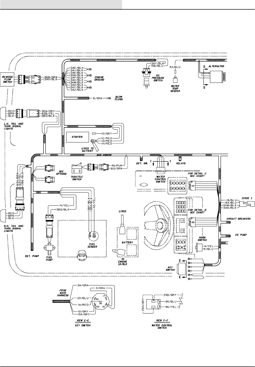
ELECTRICAL
8410 MM392 (5--02)
5-34
DIESEL WIRE HARNESS GROUP
11093--8410 D
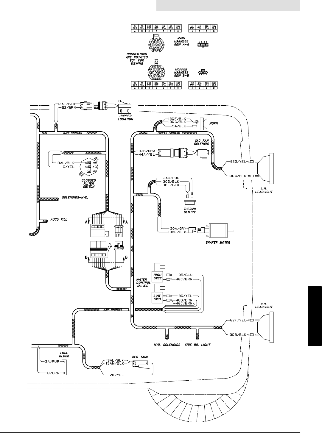
ELECTRICAL
5-35
8410 MM392 (5--02)
DIESEL WIRE HARNESS GROUP
11093--8410 D
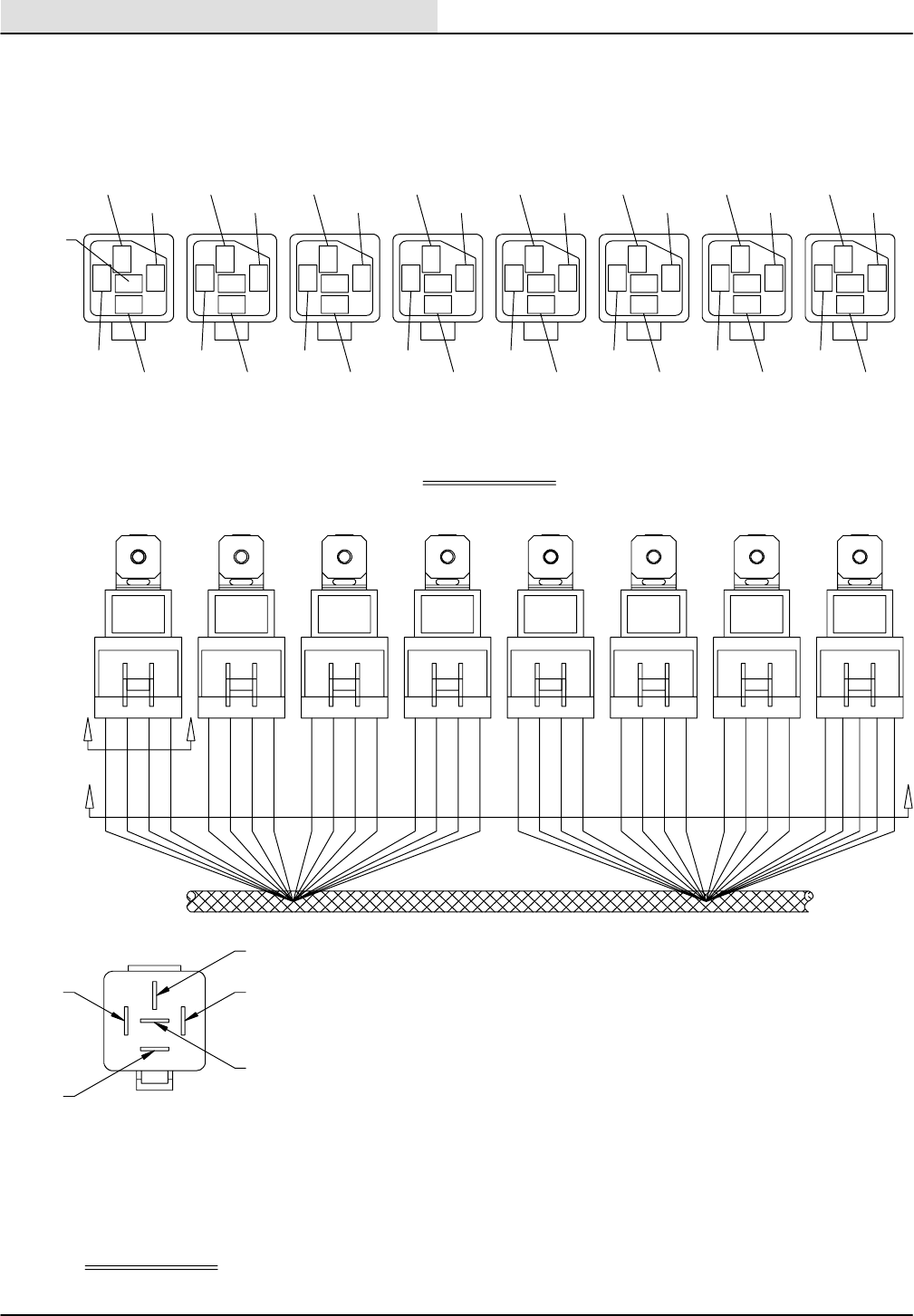
ELECTRICAL
8410 MM392 (5--02)
5-36
DIESEL WIRE HARNESS GROUP
87A
87
85
30
86
VIEW J--J
VIEW H--H
JJ
HH
MAIN
HARNESS
85 COIL+
86 COIL --
30 COMMON CONTACT
87 N.O. CONTACT
87A N.C. CONTACT
M2
FUEL
PUMP
M3
AUX.
1
M4
AUX.
2
M5
AUX.
3
M6
SHAKER
MOTOR
M7
HEAD
LIGHTS
M8
HAZARD
LIGHTS
M9
ROTATE
LIGHT
M2 M3 M4 M5 M6 M7 M8 M9
10A/GRY
12/YEL17B/ORA97/BLU
31C/GRY59/BRN65B/ORA
93/ORA62/YEL30/GRY32A/BLU21A/ORA
14/YEL
19C/BLU
19B/BLU
1G/RED
16B/GRN
16F/GRN16D/GRN
16C/GRN16A/GRN 50E/ORA50D/ORA50C/ORA
50B/ORA 76/GRN
50F/ORA
18/GRN
31D/GRY
15A/BLU
22/YEL
19/BLU
1F/RED
11093--8410 D
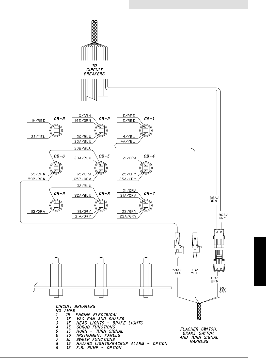
ELECTRICAL
5-37
8410 MM392 (5--02)
DIESEL WIRE HARNESS GROUP
11093--8410 D
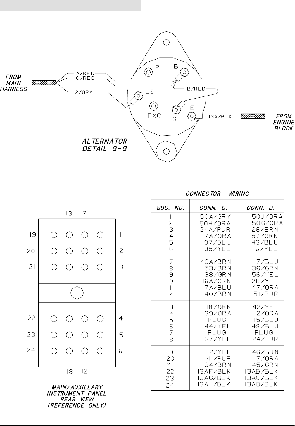
ELECTRICAL
8410 MM392 (5--02)
5-38
DIESEL WIRE HARNESS GROUP
11093--8410 D
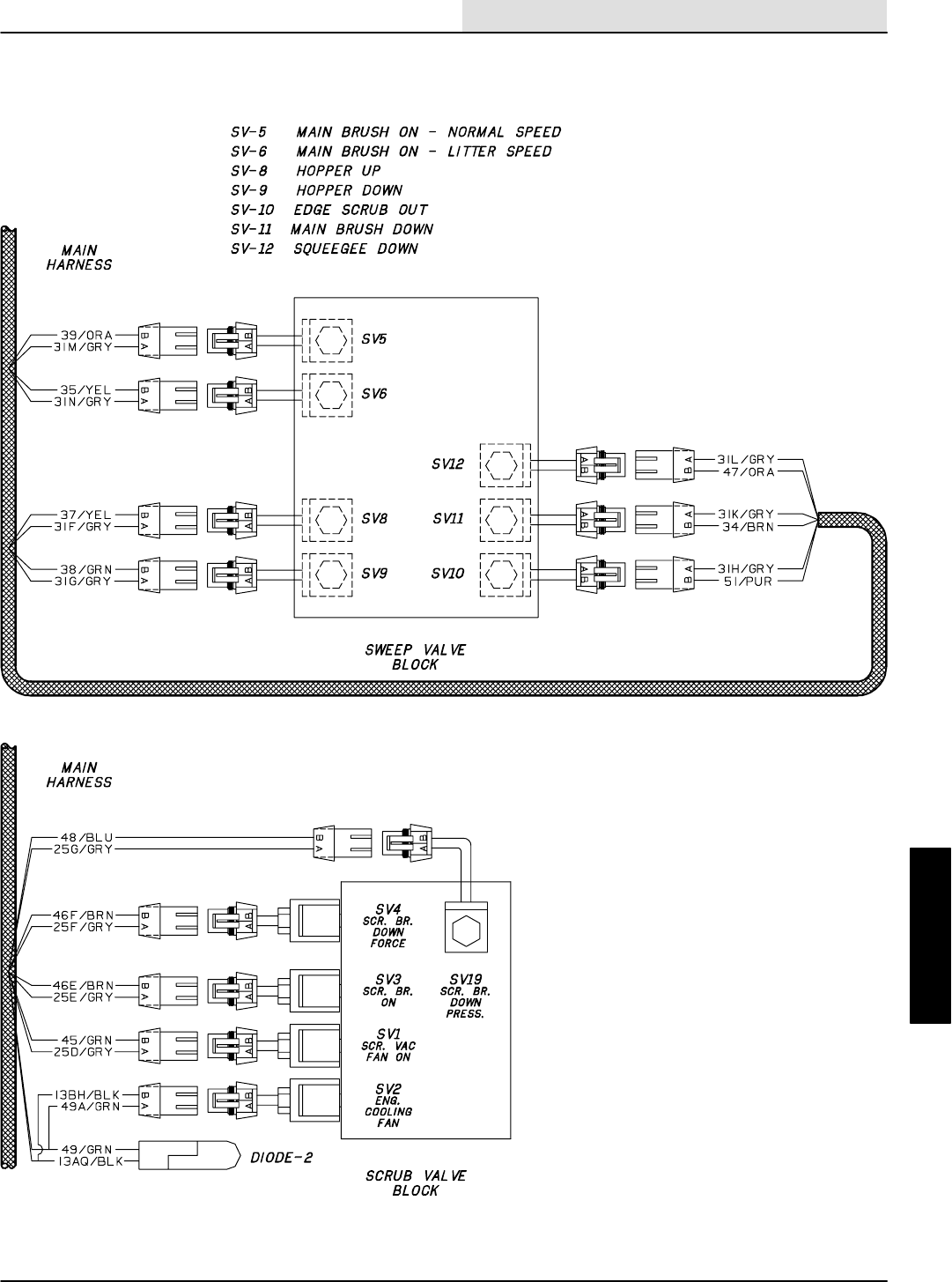
ELECTRICAL
5-39
8410 MM392 (5--02)
DIESEL WIRE HARNESS GROUP
11093--8410 D
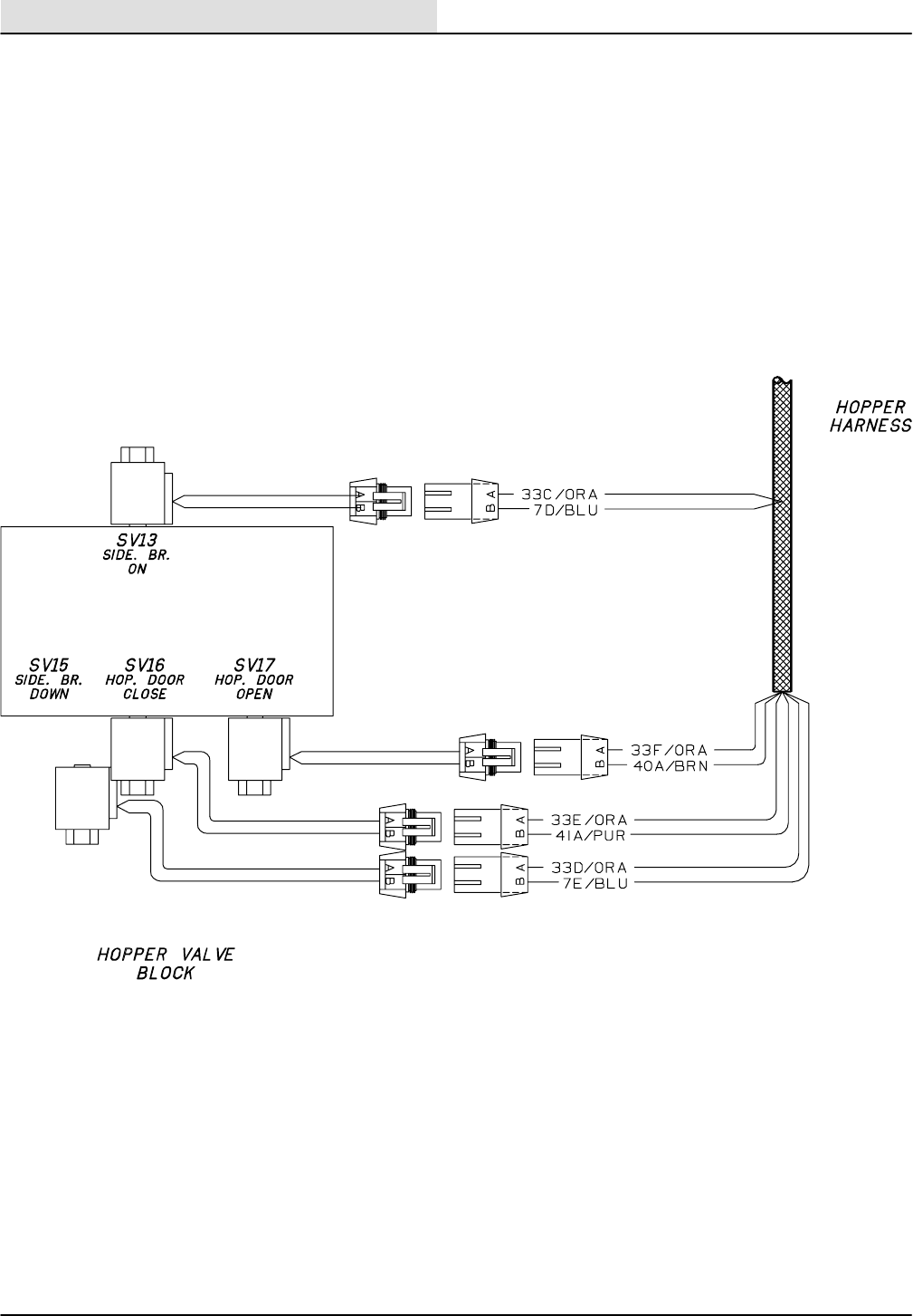
ELECTRICAL
8410 MM392 (5--02)
5-40
DIESEL WIRE HARNESS GROUP
11093--8410 D

ELECTRICAL
5-41
8410 MM392 (8--01)
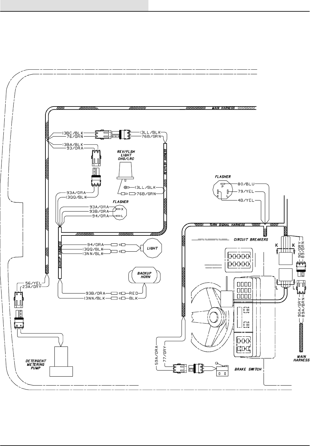
ELECTRICAL
8410 MM392 (5--02)
5-42
DIESEL WIRE HARNESS GROUP
OPTIONS
11093--8410 D
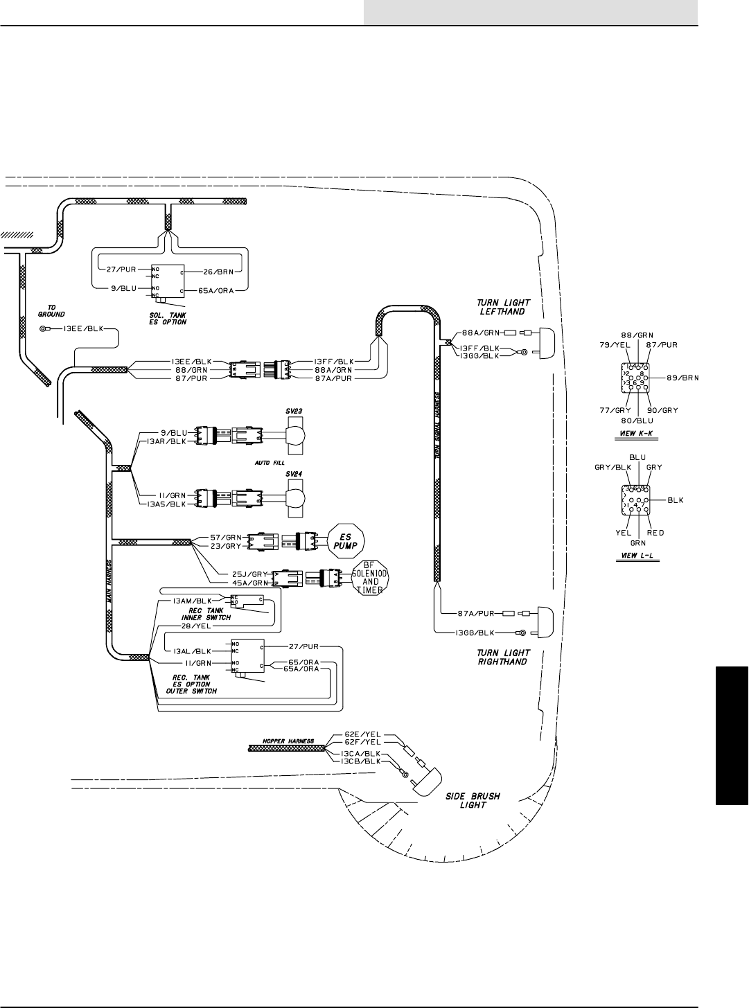
ELECTRICAL
5-43
8410 MM392 (5--02)
DIESEL WIRE HARNESS GROUP
OPTIONS
11093--8410 D

ELECTRICAL
5-44 8410 MM392 (8--01)
DIAGNOSTICS
The Model 8410 sweeper scrubber has a
on--board diagnostic system.
When the operator turns on the ignition key on the
8410, the front and side panels will each perform
an independent self test. If the self test for the
front panel passes, the OK light will begin to blink.
If the side panel passes its self test, it will blink
the headlight. When the main panel sees the
headlights blink, it assumes the side panel has
passed its self test. When both boards have
passed the self test, the OK light will go to a
steady on condition.
The 8410 front panel has 6 operating modes. The
side panel has 4 operating modes. The user can
access each mode by depressing various control
buttons, holding them, and turning on the key. The
common operating modes are as follows:
The first part of the diagnostics section describes
the different operating modes that can be
activated by using an entry sequence on the front
and side panels. There is also a chart describing
the normal mode messages that may appear on
the dash panel.
The second part of the diagnostics section
includes a chart that details the error messages
that may appear on the dash panel during the self
test mode and the cause/corrective action
description.
The third part of the diagnostics is a trouble
shooting section that includes a flow chart
detailing the flow of the electrical circuits.

ELECTRICAL
5-45
8410 MM392 (8--01)
FRONT PANEL OPERATING MODES
The 8410 front panel has a total of six operating
modes. When the operator starts the machine,
the panel will run its self test, then return to the
normal operating mode. The operator can access
five maintenance modes by turning the machine
off, pressing and holding the appropriate button,
turning the machine on, and holding the button
until the maintenance light comes on.
The following chart will detail each mode and the
entry sequence.
Operating Modes Entry Sequence
(how to activate)
Normal Mode;Normal operation.
More info pages 5--35 thru 5--37
Default (when key is turned on)
Manual Mode; Manually operate discrete
functions without interlocks.
More info page 5--38
1. Push and hold the EStbutton
2. Turn on the key
3. Hold the EStbutton until the maintenance light
comes on.
4. Release the EStbutton
5. To exit----turn off key
Input Display Mode; Display the state of floats,
limit switches, and sensors.
More info page 5--39
1. Push and hold the Squeegee button
2. Turn on the key
3. Hold the Squeegee button until the maintenance
light comes on
4. Release the Squeegee button
5. To exit----turn off key
Error Display Mode; Display the cause of a
self test failure.
More info pages 5--40 thru 5--42
1. Push and hold the Detergent button
2. Turn on the key
3. Hold the Detergent button until the maintenance
light comes on.
4. Release the Detergent button
5. To exit----turn off key
Pressure Adjust Mode; Adjust pressure levels for
the three down pressure settings.
More info page 5--43
1. Push and hold the Edge Scrub button
2. Turn on the key
3. Hold the Edge Scrub button until the
maintenance light comes on.
4. Release the Edge Scrub button
5. To exit----turn off key
Reset Scrub Pressures; Return the down
pressure settings to the factory defaults.
More info page 5--44
1. Push and hold the Scrub button
2. Turn on the key
3. Continue to hold the Scrub button
4. Wait for the maintenance light.
5. While holding the Scrub button, press and hold
the Edge Scrub button.
6. Wait for the maintenance light to go out.
7. Release the Scrub and Edge scrub buttons.
8. Turn the key off.
9. Restart the machine.

ELECTRICAL
5-46 8410 MM392 (8--01)
Operating Mode Entry Sequence
(how to activate)
Normal Mode;Normal operation. Default (when key is turned on)
NORMAL MODE
The purpose of the normal mode is for the general
operation of the machine. The machine will
normally start in this mode. What follows is a brief
description of each buttons operation in the
normal mode.
EDGE SCRUB:
1. Pressing the Edge scrub button will toggle the
Edge scrub LED.
2. If the machine is in the scrub mode, the Edge
scrub LED is on, no reverse condition is
being sensed, and the machine is running at
high engine speed, the scrub head will shift
into the edge scrub position.
3. If the machine is in the scrub mode and the
Edge scrub LED is off, the scrub head will
be in the retracted position.
SQUEEGEE:
1. If the squeegee LED is off, pressing the
squeegee button will drop the squeegee,
turn on the vacuum fan, and select high
engine speed.
2. If the squeegee LED is on, pressing the
squeegee button will raise the squeegee,
initiate a delay, and turn off the vacuum fan.
3. The squeegee operation is inhibited in
reverse.
4. Squeegee LED will turn off automatically if
scrub system is turned off, low engine speed
is selected or recovery tank full condition is
sensed.
ENGINE SPEED:
1. If the engine is at idle speed, pressing this
button will bring it to operating speed.
2. If the scrub mode is active, pressing the
engine button will cancel all scrubbing
activities.
3. High speed is selected automatically if Scrub,
Squeegee, or Sweep 1 or 2 are turned on.

ELECTRICAL
5-47
8410 MM392 (8--01)
SCRUB:
DIf the scrub function is currently inactive,
pressing the scrub button will initiate the following
actions:
1. The engine speed is set to high.
2. The main brushes will turn on and go down.
The down pressure setting will be the same
used during the last scrub cycle. The
squeegee will lower and the scrub vacuum
will turn on. The solution will flow at the high
or low rate according to the water position
switch. The EStsystem, detergent
metering system, and the edge scrub will
operate if selected by the operator.
3. If the machine is in reverse, the brushes will
retract, lift , and turn off.
4. The squeegee will lift and the scrub vacuum
fan will turn off.
5. If the low engine speed is selected or an
overflow condition is sensed the scrub
system is turned off automatically.
DIf the operator pushes and holds the scrub
button, the pressure settings will begin to scroll.
The pressure setting displayed after releasing the
scrub button will become the new default down
pressure setting.
DIf the scrub function was active and the
operator pushes, then releases the scrub button,
the following actions will take place:
1. The main brushes will retract, raise and turn
off.
2. The solution flow will turn off.
3. The detergent pump will turn off.
4. A seven second delay will pass, and then
the rear squeegee will rise.
5. A four second delay will pass and the
vacuum fan will turn off.

ELECTRICAL
5-48 8410 MM392 (8--01)
DETERGENT:
DPressing the detergent button will cause the
detergent display to scroll through its three
modes. The detergent pump will run if the main
scrub brushes are active, the solution switch is
on, and the machine is not in reverse.
1. OFF (all LED’s off)----Detergent pump
OFF
2. LOW (left LED’s on)----Detergent pump
LOW.
3. HIGH (both LED’s on)----Detergent pump
HIGH.
ESt:
DPressing the EStbutton will enable or
disable the EStfunction. In order for the ESt
float to become active, it must be consistently in
the up position for ar least 10 seconds. If the ESt
function is enabled and the EStfloat becomes
active, the following actions will occur:
1. The EStpump will begin to run.
2. The EStpump will continue to run for 40
seconds after the EStfloat becomes
uncovered.
OVER FLOW:
DIn order for the recovery tank float to become
active, it must be consistently in the up position
for least 10 seconds. If the scrub or vacuum fan
are active and the tank full float becomes active,
the following actions will occur:
1. The overflow light will begin to blink.
2. A 50 second delay will pass.
3. The overflow light will stop blinking and stay
on.
4. The scrub and squeegee functions will be
cancelled.

ELECTRICAL
5-49
8410 MM392 (8--01)
Operating Mode Entry Sequence
(how to activate)
Manual Mode; Manually operate discrete
functions without interlocks.
1. Push and hold the EStbutton
2. Turn on the key
3. Hold the EStbutton until the maintenance light
comes on.
4. Release the EStbutton
5. To exit----turn off key
MANUAL MODE:
In this mode, the operator can turn on and off
accessories individually and manually. In the
manual mode, the operator can turn on
accessories without regard to inputs or interlocks.
If, for instance, the operator enables the ESt
pump in the manual mode, it will run regardless of
whether or not the EStfloat is in the water. What
follows is a brief description of each buttons
operation in the manual mode.
ESt:
DPressing the EStbutton in the manual mode
turns on and off the EStpump.
EDGE SCRUB BUTTON:
DPressing the Edge scrub button will extend or
retract the scrub head.
SQUEEGEE BUTTON:
DPressing the Squeegee button will turn on the
vacuum fan and lower the squeegee. Reverse is
ignored.
ENGINE BUTTON:
DPressing the Engine button will toggle the
engine between high and low speed.
SCRUB BUTTON:
DPressing the Scrub button will turn on and
lower the main scrub head. Holding the Scrub
button while scrub is active will cause the down
pressures to scroll.
DETERGENT BUTTON:
DPressing and holding the Detergent button will
cause the detergent LED’s to scroll. If no LED’s
are on, the detergent pump will be off. If one LED
is illuminated, the detergent pump will run in low
speed. If both LED’s are on, the detergent pump
will run at high speed.

ELECTRICAL
5-50 8410 MM392 (8--01)
Operating Mode Entry Sequence
(how to activate)
Input Display Mode; Display the state of floats,
limit switches, and sensors.
1. Push and hold the Squeegee button
2. Turn on the key
3. Hold the Squeegee button until the maintenance
light comes on
4. Release the Squeegee button
5. To exit----turn off key
INPUT DISPLAY MODE:
In this mode, the operator can observe whether or
not inputs to the panel are operating as intended.
In the Input Display Mode, the segments of the
gas gauge display the state of each input. If an
input is open, the controller turns off the segment
associated with that input. If an input is shorted to
ground, the controller turns on the segment
associated with that input.
The operation of the Input Display Mode is as
follows:
DSEGMENT 0 -- Rightmost segment of the
gas gauge. This segment displays the state
of the ES float. This segment will illuminate
when this input is shorted to ground.
DSEGMENT 1 -- Second segment from the
right of the gas gauge. This segment
displays the state of the recovery tank float.
This segment will be illuminated when this
input is shorted to ground.
DSEGMENT 2 -- Third segment from the
right of the gas gauge. This segment
displays the state of the reverse input. This
segment will be illuminated when this input
is shorted to ground.
DSEGMENT 3 -- Forth segment from the
right of the gas gauge. This segment
displays the state of the sweep sense input.
This segment will be illuminated when this
input is shorted to ground.
DENGINE TEMPERATURE LIGHT -- In the
Input Display Mode, the engine temperature
light will blink until the engine reaches
operating temperature.

ELECTRICAL
5-51
8410 MM392 (8--01)
Operating Mode Entry Sequence
(how to activate)
Error Display Mode; Display the cause of a
self--test failure.
1. Push and hold the Detergent button
2. Turn on the key
3. Hold the Detergent button until the maintenance
light comes on.
4. Release the Detergent button
ERROR DISPLAY MODE
Each time the operator starts the machine, the
panel will run a self test on each output. If the
panel passes the diagnostic, the “OK” indicator is
illuminated. If the panel fails, a code is stored in a
non volatile (preserved even after power down)
memory. If the machine passes the diagnostic on
the next startup cycle, the panel preserves the
last failed code. In the Error Display Mode, the
operator can obtain the error code stored after the
last startup diagnostic failure. When the machine
is in this mode, the LED’s on the operators panel
will indicate which system experienced the failure.
If the operator pushes the button associated with
an illuminated LED, segments on the gas gauge
will indicate which output failed and what type of
failure occurred.
The operation of the Error Display Mode is as
follows:
EStLED
Problem with the EStoutput. If the operator
pushes the headlight button in this mode, the
panel will display one of the following codes:
DSEGMENT 0 -- Rightmost segment of the
gas gauge. This segment would indicate that
the EStoutput was shorted to ground when
the controller was expecting it to be open.
DSEGMENT 0, 1 -- First and second
segments from the right of the gas gauge.
These segments would indicate that the
EStoutput was open when the controller
was trying to short it to ground.

ELECTRICAL
5-52 8410 MM392 (8--01)
EDGE SCRUB LED
Problem with the edge scrub outputs. If the
operator pushes the edge scrub button in this
mode the panel would display one of the following
codes:
DSEGMENT 0 -- Rightmost segment of the
gas gauge. This segment would indicate that
the edge scrub output was shorted to
ground when the controller was expecting it
to be open.
DSEGMENT 0, 1 -- First and second
segments from the right of the gas gauge.
These segments would indicate that the
edge scrub output was open when the
controller was trying to short it to ground.
SQUEEGEE LED
Problem with the squeegee actuator or vacuum
fan motor outputs. If the operator pushes the
squeegee button in this mode, the panel would
display one of the following codes:
DSEGMENT 0 -- Rightmost segment of the
gas gauge. This segment would indicate that
the squeegee actuator output was shorted to
ground when the controller was expecting it
to be open.
DSEGMENT 0, 1 -- First and second
segments from the right of the gas gauge.
These segments would indicate that the
squeegee actuator output was open when
the controller was trying to short it to ground.
DSEGMENT 2 -- Third segment from the right
of the gas gauge. This segment would
indicate that the vacuum fan motor output
was shorted to ground when the controller
was expecting it to be open.
DSEGMENT 2, 3 -- Third and forth segments
from the right of the gas gauge. These
segments would indicate that the vacuum
fan motor output was open when the
controller was trying to short it to ground.

ELECTRICAL
5-53
8410 MM392 (8--01)
SCRUB LED
Problem with the main brush actuator or motor
outputs. If the operator pushes the scrub button in
this mode, the panel would display one of the
following codes:
DSEGMENT 0 -- Rightmost segment of the
gas gauge. This segment would indicate that
the main brush actuator output was shorted
to ground when the controller was expecting
it to be open.
DSEGMENT 0, 1 -- First and second
segments from the right of the gas gauge.
These segments would indicate that the
main brush actuator output was open when
the controller was trying to short it to ground.
DSEGMENT 2 -- Third segment from the right
of the gas gauge. This segment would
indicate that the main brush motor output
was shorted to ground when the controller
was expecting it to be open.
DSEGMENT 2, 3 -- Third and forth segments
from the right of the gas gauge. These
segments would indicate that the main brush
motor output was open when the controller
was trying to short it to ground.
DETERGENT LED
Problem with the headlight or detergent pump
outputs. If the operator pushes the detergent
button in this mode, the panel would display one
of the following codes:
DSEGMENT 0 -- Rightmost segment of the
gas gauge. This segment would indicate that
the detergent pump output was shorted to
ground when the controller was expecting it
to be open.
DSEGMENT 0, 1 -- First and second
segments from the right of the gas gauge.
These segments would indicate that the
detergent pump output was open when the
controller was trying to short it to ground.

ELECTRICAL
5-54 8410 MM392 (8--01)
Operating Mode Entry Sequence
(how to activate)
Pressure Adjust Mode; Adjust the pressure
levels for the three down pressure settings.
1. Push and hold the Edge Scrub button
2. Turn on the key
3. Hold the Edge Scrub button until the
maintenance light comes on.
4. Release the Edge Scrub button
PRESSURE ADJUST MODE
When the machine is in this mode, the operator
can adjust the down pressures for the main and
side brushes. When the operator adjusts down
pressure number 3, pressures 1 and 2 are
automatically calculated and stored. The operator
may make independent adjustments to pressures
1 and 2 after storing number 3. These
adjustments will influence only the currently
displayed setting.
The operator can change the pressure settings by
pressing and holding the scrub button. When the
side brush is inactive and the main brush is
active, the operator can adjust the down pressure
for the main brush. When the side brush and main
brush are active, the operator can adjust the
down pressure for the side brush.
After each adjustment, the new pressure setting is
stored in a non--volatile (retained even after power
down) memory.
The operation of the Pressure Adjust Mode is as
follows:
SCRUB BUTTON
Pressing the Scrub button will start the normal
scrub sequence. When scrub is active the
following controls and displays take on alternate
functions.
DGAS GAUGE -- The gas gauge in the
pressure adjust mode displays the relative
down pressure of the main (when the side
brush is inactive) or the side brush (when
thesidebrushisactive).
DSQUEEGEE BUTTON -- Holding the
squeegee button will decrease the down
pressure.
DDETERGENT BUTTON -- Holding the
detergent button will increase the down
pressure.

ELECTRICAL
5-55
8410 MM392 (8--01)
Operating Mode Entry Sequence
(how to activate)
Reset Scrub Pressures; Return the down
pressure settings to the factory defaults.
1. Push and hold the Scrub button
2. Turn on the key
3. Hold the Scrub button
4. Wait for the maintenance light
5. While holding the Scrub button, press and hold
the Edge Scrub button
6. Wait for the maintenance light to go out
7. Release the Scrub and Edge Scrub buttons
8. Turn the key off
9. Restart the machine
RESET SCRUB PRESSURES
When the machine goes into this mode, the
controller replaces the current brush down
pressure settings with factory defaults. To initiate,
follow the entry sequence (how to activate). The
pressures will automatically reset.

ELECTRICAL
5-56 8410 MM392 (8--01)
SIDE PANEL OPERATING MODES
The 8410 side panel has a total of four operating
modes. When the operator starts the machine the
panel will run its self test. If the self test fails, an
LED which is associated with the failing system
will blink (error display mode). If the operator
engages any sweeping functions, the error display
mode will cancel and the side panel will run in the
normal mode. If the test passes, the side panel
will blink the headlights. The main panel will
detect the headlight flash, and display a
non--blinking OK signal.
Note; The hopper lift LED will blink if Sweep 1 or
2 is selected and the hopper is up.
The following chart will detail each mode and the
entry sequence.
Operating Modes Entry Sequence
(how to activate)
Normal Mode;Normal operation.
More info pages 5--46 thru 5--49
Default (when key is turned on)
Manual Mode; Manually operate discrete
functions without interlocks.
More info pages 5--50 and 5--51
1. Push and hold the Hazard light button.
2. Turn on the key
3. Hold the Hazard light button for 10 seconds.
comes on.
4. Release the Hazard light button. The Hazard
light should begin to blink.
5. To exit----turn off key
Input Display Mode; Display the state of floats,
limit switches, and sensors.
More info page 5--52
1. Push and hold the Headlight button.
2. Turn on the key
3. Hold the Headlight button for 10 seconds.
4. Release the Headlight button. The sweep
1 and sweep 2 lights will be on.
5. To exit----turn off key
Error Display Mode; Display the cause of a
self test failure.
More info page 5--53
If an error is detected, the side panel will
automatically go into the error display mode.
When a function from the side panel is selected,
the panel will go into the normal mode.

ELECTRICAL
5-57
8410 MM392 (8--01)
Operating Mode Entry Sequence
(how to activate)
Normal Mode;Normal operation. Default (when key is turned on)
NORMAL MODE
The purpose of the normal mode is for the general
operation of the machine. The machine will
normally start in this mode. What follows is a brief
description of each buttons operation in the
normal mode.
HAZARD LIGHTS:
DPressing the Hazard light button will toggle on
and off the Hazard lights.
HEAD LIGHTS:
DPressing the Head light button will toggle on
and off the Head lights.
FILTER SHAKER:
DThe Filter shaker button controls the
operation of the filter shaker and timer system.
DIf the Filter shaker LED is OFF, pressing the
shaker button will initiate a shake sequence.
A shake sequence is defined as follows:
1. The Shaker LED will turn on.
2. The filter shaker will start.
3. The filter shaker and LED will remain on for
approximately 40 seconds.
4. The filter shaker and LED will turn off.
DIf the Filter shaker LED is ON, pressing the
shaker button will turn off the shaker motor
and LED.
DA 15 second shake sequence will also be
initiated each time the sweep system is
turned off.
DA shake sequence will be cancelled if active
while the sweep, or sweep vacuum fan is
turned on.
HOPPER LIFT:
DPressing and holding the Hopper lift button
will engage the hopper lift mechanism. The
Hopper will continue to lift as long as the operator
holds his finger on the Hopper lift button.
Note; The hopper lift LED will blink if Sweep 1 or
2 are selected and the hopper is up.

ELECTRICAL
5-58 8410 MM392 (8--01)
HOPPER LOWER:
DPressing and holding the Hopper lower button
will engage the hopper lower mechanism. The
Hopper will continue to drop as long as the
operator holds his finger on the Hopper lower
button.
HOPPER DOOR:
DPressing the Hopper door button will toggle
the hopper door open or closed.
DIf the Hopper door LED is lit, the hopper
door is closed. Pressing the Hopper door
button will turn off the LED and open the
door for 3 seconds.
DIf the Hopper door LED is not lit,the
hopper door is open. Pressing the Hopper
door button will turn on the LED and close
the door for 3 seconds.
DThe Hopper door will automatically open
each time the sweep function is engaged.
DThe Hopper door will automatically close
each time the machine is started, or the
sweep function is turned off.
SIDE BRUSH:
DPressing the Side Brush button will enable or
disable the side brush operation while sweeping.
DThe Side brush will only operate if the
Sweep function is engaged.
DEach time the Sweep function is engaged,
the side brush will be enabled.
DEach time the Sweep function is turned off,
the Side brush will be canceled.
VACUUM FAN:
DPressing the Sweep Vacuum Fan button will
enable or disable the fan operation while
sweeping.
DThe Sweep fan will only operate if the
Sweep function is engaged.
DEach time the Sweep function is engaged,
the fan will be enabled.
DEach time the Sweep function is turned off,
the fan will be canceled.

ELECTRICAL
5-59
8410 MM392 (8--01)
SWEEP 1 (NORMAL SWEEP):
DThe Sweep 1 button is used to engage and
disengage the normal sweep functions. Sweep 1
can only be engaged if the hopper is in the down
position. If the hopper is not in the down position
and the Sweep 1 button is pushed, the Sweep
system will not be engaged, and the hopper up
light will begin to blink.
DIftheSweep1and2LED’sarenotlit
(Sweep not currently active), pressing the
Sweep 1 button will engage the following
sweep sequence:
1. The controller will check the hopper down
switch. If the hopper down switch is not
engaged, the sweep function will be
canceled. If the hopper down switch is
engaged, the following sequence will
continue:
2. The hopper door will begin to open.
3. After the hopper door opens, the sweep fan
will turn on.
4. The side brush will turn on.
5. The engine will be set to its high operating
speed.
6. The main broom will turn on in normal
speed.
DIf the Sweep 1 LED is lit (Sweep currently
active), pressing the Sweep 1 button will
disengage the sweep system with the
following sequence:
1. The main broom, side brush, and sweep fan
will turn off.
2. The hopper door will close.
3. A filter shake sequence will begin.

ELECTRICAL
5-60 8410 MM392 (8--01)
SWEEP 2 (LITTER SWEEP):
DThe Sweep 2 button is used to engage and
disengage the litter sweep functions. The litter
sweep function can only be engaged if the scrub
system is turned off. Pressing the Sweep 2 button
while the scrub function is enabled will engage the
Sweep 1 system. Sweep 1 can only be engaged
if the hopper is in the down position. If the hopper
is not in the down position and the Sweep 1
button is pushed, the Sweep system will not be
engaged, and the hopper up light will begin to
blink.
DIftheSweep1and2LED’sarenotlit
(Sweep not currently active), pressing the
Sweep 2 button will engage the following
sweep sequence:
1. The controller will check the hopper down
switch. If the hopper down switch is not
engaged, the sweep function will be
canceled. If the hopper down switch is
engaged, the following sequence will
continue:
2. The hopper door will begin to open.
3. After the hopper door opens, the sweep fan
will turn on.
4. The side brush will turn on.
5. The engine will be set to its high operating
speed.
6. The main broom will turn on in litter speed.
DIf the Sweep 2 LED is lit (Sweep currently
active), pressing the Sweep 2 button will
disengage the sweep system with the
following sequence:
1. The main broom, side brush, and sweep fan
will turn off.
2. The hopper door will close.
3. A filter shake sequence will begin.

ELECTRICAL
5-61
8410 MM392 (8--01)
Operating Mode Entry Sequence
(how to activate)
Manual Mode; Manually operate discrete
functions without interlocks.
1. Push and hold the Hazard light button.
2. Turn on the key
3. Hold the Hazard light button for 10 seconds.
comes on.
4. Release the Hazard light button. The Hazard
light should begin to blink.
5. To exit----turn off key
MANUAL MODE
In this mode, the operator can turn on and off
accessories individually and manually. In the
manual mode, the operator can turn on
accessories without regard to inputs or interlocks.
If, for instance, the operator enables the sweep
vacuum fan in the manual mode, it will run
regardless of whether or not the sweep function is
engaged or the hopper down switch is closed.
What follows is a brief description of each buttons
operation in the manual mode.
HAZARD LIGHT:
DSame as normal operation.
HEAD LIGHT:
DSame as normal operation.
FILTER SHAKER:
DToggles on and off the filter shaker motor.
Timer is disabled.
HOPPER UP:
DSame as normal operation.
HOPPER DOWN:
DSame as normal operation.
HOPPER DOOR:
DSame as normal operation.

ELECTRICAL
5-62 8410 MM392 (8--01)
SIDE BRUSH:
DToggles on and off the side brush. Side brush
will run regardless of whether or not sweeping is
engaged.
SWEEP FAN:
DToggles on or off the sweep fan. Fan will run
regardless of the state of sweep or hopper down
switch. Sweep 1 or Sweep 2 must be engaged.
SWEEP 1:
DToggles on or off main broom in normal
speed. Broom will run regardless of the state of
the hopper down switch.
SWEEP 2:
DToggles on or off main broom in litter speed.
Broom will run regardless of the state of the
hopper down switch.

ELECTRICAL
5-63
8410 MM392 (8--01)
Operating Mode Entry Sequence
(how to activate)
Input Display Mode; Display the state of floats,
limit switches, and sensors.
1. Push and hold the Headlight button.
2. Turn on the key
3. Hold the Headlight button for 10 seconds.
4. Release the Headlight button. The sweep
1 and sweep 2 lights will be on simultaneously.
5. To exit----turn off key
INPUT DISPLAY MODE:
In this mode, the side panel will display the state
of the external switches (i.e. hopper down switch)
or functions which are used as interlocks. In this
mode, the function of the switch LED‘s changes
from indicating the state of an operation (like the
hopper door is closed), to indicating the state of a
sensor (like the hopper down switch). The
technician can use this mode to check the state of
various sensors on the machine.
The operation of the Input Display Mode is as
follows:
BLINKING HAZARD LED:
DHopper thermal switch is open.
BLINKING SHAKER LED:
DReverse switch is closed.
BLINKING HOPPER DOOR LED:
DHopper down switch is open.
BLINKING SIDE BRUSH LED:
DScrub signal is low (active).
BLINKING HEAD LIGHT LED:
DEngine is in high speed.

ELECTRICAL
5-64 8410 MM392 (8--01)
Operating Mode Entry Sequence
(how to activate)
Error Display Mode; Display the cause of a
self test failure.
If an error is detected, the side panel will
automatically go into the error display mode.
When a function from the side panel is selected,
the panel will go into the normal mode.
ERROR DISPLAY MODE
If the 8410 side panel fails its initial self test, this
mode is designed to give the service person a
clue as to the cause of the failure. The 8410 side
panel will automatically go into this mode when a
failure is detected. To cancel the error display
mode, the operator can press any button on the
side panel. Once a button has been pushed,
normal operation will resume.
The operator can identify errors detected during
self test using blinking LED’s on the side panel.
The assignments between LED’s and failures are
as follows:
BLINKING SHAKER LED:
DFailure on shaker output.
BLINKING HAZARD LED:
DFailure on hazard light or reverse output.
BLINKING HEADLIGHT LED:
DFailure on headlight output.
BLINKING SIDE BRUSH LED:
DFailure on side brush output.
BLINKING HOPPER DOOR LED:
DFailure on hopper door open or close output.
BLINKING HOPPER UP LED:
DFailure on hopper raise output.
BLINKING HOPPER DOWN LED:
DFailure on hopper lower output.
BLINKING SWEEP FAN LED:
DFailure on sweep fan or engine fan output.
BLINKING SWEEP 1 LED:
DFailure on Sweep 1 or brush down output.
BLINKING SWEEP 2 LED:
DFailure on Sweep 2 or output.

ELECTRICAL
5-65
8410 MM392 (8--01)

ELECTRICAL
5-66 8410 MM392 (8--01)
TROUBLESHOOTING
The following troubleshooting section is organized
with the section of the electrical schematic that
pertains to that particular problem first, followed
by the flow chart.
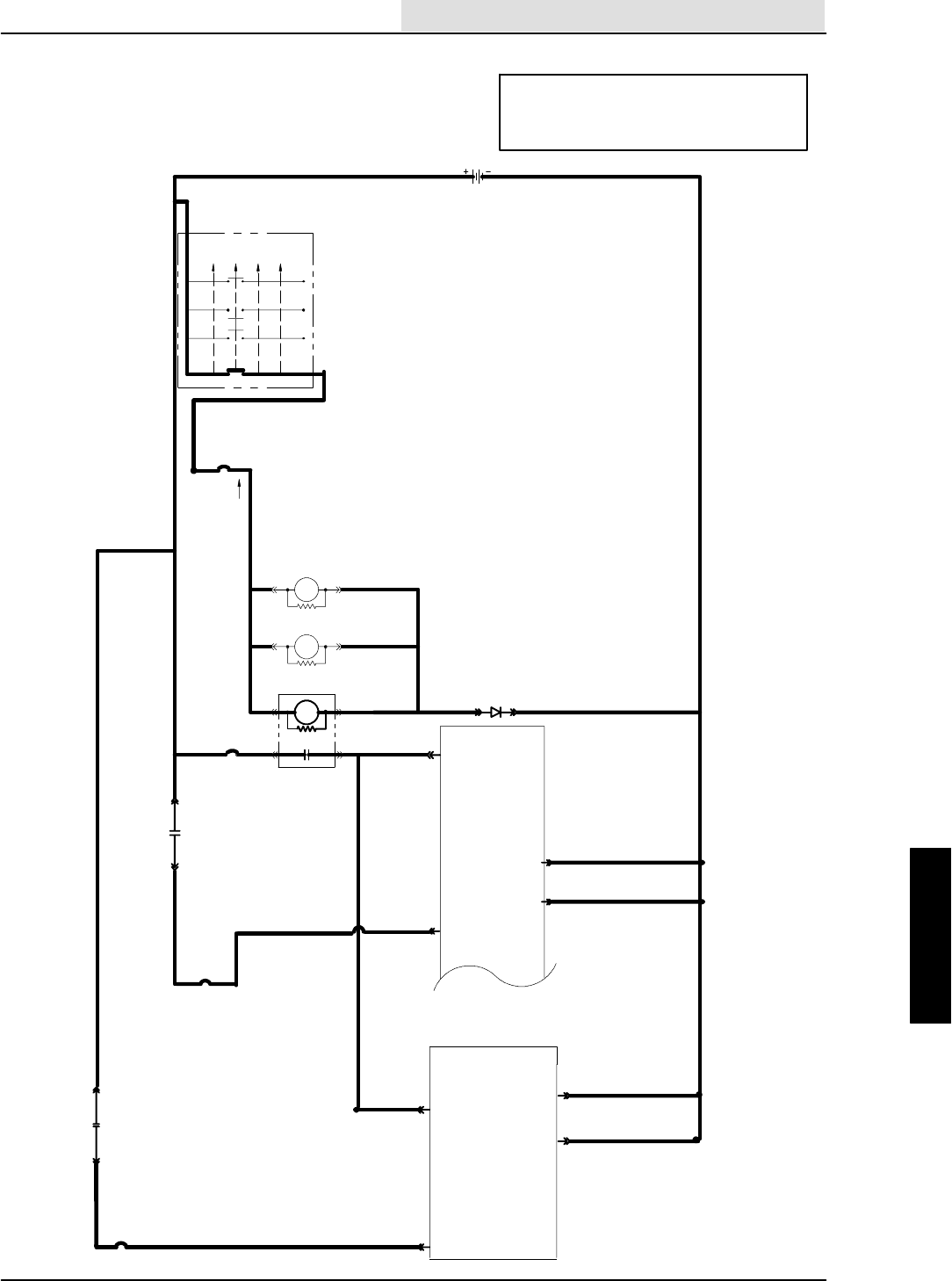
ELECTRICAL
5-67
8410 MM392 (8--01)
16E/GRN
1H/RED 13AM/BLK
16E/GRN
16F/
GRN
19C/BLU
19B/BLU
19A/BLU
1F/RED 21A/ORA
1G/RED
50A/ORA
50B/ORA
16C/
GRN
16D/
GRN
30 87
1A/RED
20/BLU
CB--2
IGNITION SWITCH
S--15
( X INDICATES A
CLOSED CONTACT )
D--1
10A
22/YEL
CB--3
19/BLU
M5 86
85
START
START
RUN
OFF
PREHEAT
X
XXX
XX
X
IGN.
19
30
BATT.
50
17
N/U
RUN/
ACC
1/RED
1
FRONT
15A
8730
M4 8685
M3
8685 M3
ELECTRONIC
INSTRUMENT
PANEL
13/BLK
BATTERY
M4
13AC/BLK
13AB/BLK
25A/GRY
25/GRY
21/
ORA
23
22
2
GROUND
LINE
15 AMP
CB--4
2
50A/ORA
AUXILIARY
1
CB--8
15 AMP
23
22
ELECTRONIC
INSTRUMENT
PANEL
13AG/BLK
13AF/BLK
31A/GRY 31/GRY
32A/BLU
87
30
1G/RED M5
INSTRUMENT PANEL
DOES NOT POWER UP
(SCHEMATIC)
OPERATION:
--KEY SWITCH ACTIVATES M3, M4, AND M5
--M3, M4, AND M5 CONTACTS SUPPLY B+
TO INSTRUMENT PANEL (PIN 1 AND 2)
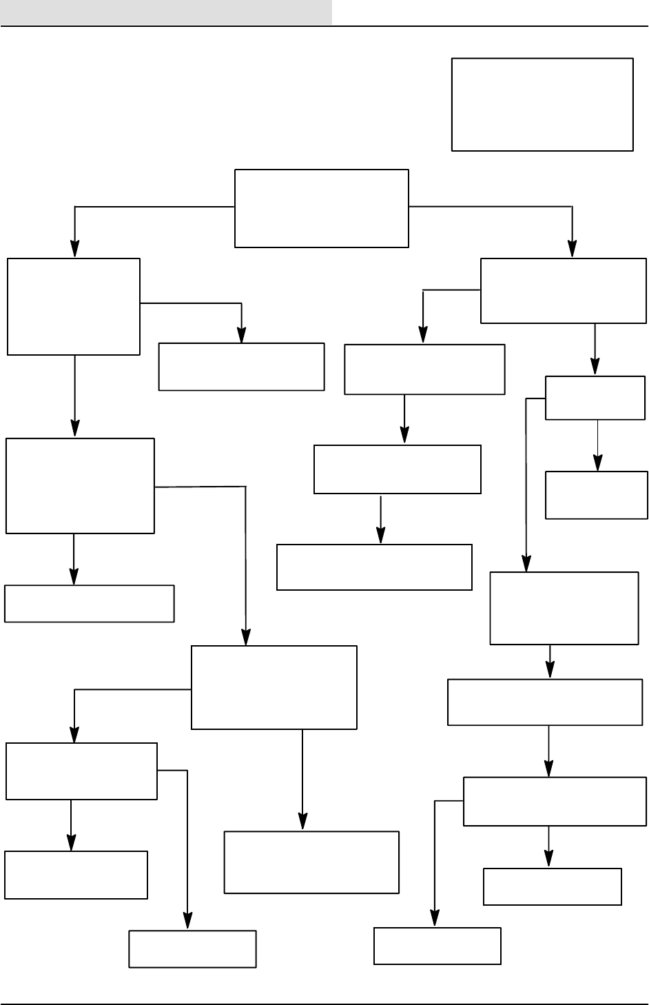
ELECTRICAL
5-68 8410 MM392 (8--01)
CHECK FOR VOLTAGE
AT PINS 22 AND 23 OF
EACH PANEL TO BATTERY
POSITIVE
KEY ON AND RELAYS
BACK IN
PANELS REMOVED
CHECK VOLTAGE AT PIN 1
AND PIN 2 OF BOTH PANELS
TO GROUND
REMOVE M3, M4, AND
M5 RELAYS
TURN KEY ON AND
CHECK VOLTAGE
FROM 16/GRN, PIN 85
TO 19/BLU, PIN 86 ON
EACH RELAY
KEY ON AND M3, M4,
AND M5 STILL REMOVED
CHECK VOLTAGE AT
--22/YEL, PIN 30, M3
--1F/RED, PIN 30, M4
--1G/RED, PIN 30, M5
TO MACHINE GROUND
SWEEP PANEL IS FAILING
SELF--TEST
POWER UP SYSTEM OK
FAILED OUTPUT LED,
SHOULD BE BLINKING
POWER UP AND
SELF--TEST ARE
SUCCESSFUL
DO FAULT LIGHTS ON
SCRUB PANEL TURN ON
FOR 4 SECONDS ? AND CAN
ANY OF THE SWEEP PANEL
LED’SBEACTIVATED?
INSTRUMENT PANEL
DOES NOT POWER UP
(FLOW CHART)
TURN KEY ON
ENGINE NEED NOT BE RUNNING
OPERATION:
--KEY SWITCH ACTIVATES M3,
M4, AND M5
--M3, M4, AND M5 CONTACTS
SUPPLY B+ TO INSTRUMENT
PANEL (PIN 1 AND 2)
YES TO BOTH CONDITIONS
NO TO EITHER CONDITION
TURN KEY OFF/ON
DOES SCRUB PANEL OK
LIGHT COME ON AFTER THE
4 SECOND POWER UP ?
ALL = B+
0 VOLTAGE
NO
YES
IS THE LIGHT
BLINKING ?
SCRUB PANEL IS FAILING
SELF--TEST
POWER UP SYSTEM IS OK
YES
NO
GO TO THE TROUBLESHOOTING
FLOW CHART OF THE MACHINE
FUNCTION INDICATING A FAILURE
IF MACHINE FUNCTION
PASSES TROUBLESHOOTING
TEST THE HEADLIGHT SYSTEM
FAILURE
REPAIR HEADLIGHT
SYSTEM AND RE--TEST
PASS
SYSTEM IS WORKING
RUN ERROR DISPLAY
SOFTWARE TO DETERMINE
WHICH FUNCTION IS FAILING
GO TO THE TROUBLESHOOTING
FLOW CHART OF THE MACHINE
FUNCTION INDICATING A FAILURE
KEY SWITCH, CB--2, 16/GRN
19/BLU, D--1, 13AM/BLK, OR
1A/RED ARE OPEN
1G/RED, 1F/RED, 1H/RED
CB--3, OR 22/YEL ARE OPEN
B+
ANY 0 VOLTAGE
0VOLTAGE
M3, M4, OR M5
ARE BAD OR 50/ORA, 21/ORA,
CB--4, 25/GRY, 32/BLU, CB--8,
OR 31/GRY ARE OPEN
B+
0 VOLTAGE
B+
REPLACE PANEL
NOT POWERING UP
13/BLK WIRES ON PINS
22 AND 23 ARE OPEN
TO MACHINE GROUND
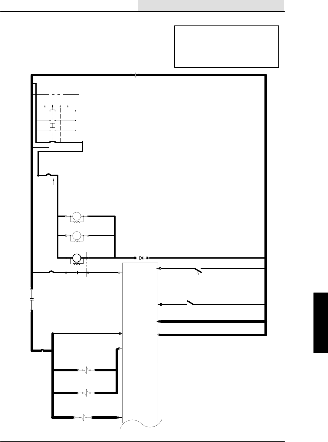
ELECTRICAL
5-69
8410 MM392 (8--01)
OPERATION:
--SCRUB IS SELECTED ON TOUCH PANEL
--MACHINE IS NOT IN REVERSE
--RECOVERY TANK IS NOT FULL
--ENGINE SPEED IS SELECTED TO HIGH
--SCRUB SOLENOIDS WILL TURN ON,
HEAD WILL LOWER, BRUSHES WILL SPIN
SCRUB BRUSH WILL NOT
TURN ON AND/OR DOWN
(SCHEMATIC)
16E/GRN
1H/RED
13AM/BLK
16E/GRN
16F/
GRN
19C/BLU
19B/BLU
19A/BLU
1F/RED 21A/ORA
50A/ORA
50B/ORA
16C/
GRN
16D/
GRN
30 87
1A/RED
20/BLU
CB--2
IGNITION SWITCH
S--15
( X INDICATES A
CLOSED CONTACT )
D--1
10A
22/YEL
CB--3
19/BLU
M58685
START
START
RUN
OFF
PREHEAT
X
XXX
XX
X
IGN.
19
30
BATT.
50
17
N/U
RUN/
ACC
1/RED
1
FRONT
15A
8730
M48685
M3
8685 M3
ELECTRONIC
INSTRUMENT
PANEL
13/BLK
BATTERY
M4
13AC/BLK
13AB/BLK
25A/GRY
25/GRY
21/
ORA
23
22
2
GROUND
LINE
15 AMP
CB--4
13AM/BLK
S--5
10
N.C.H.O.
28/YEL RECOVERY TANK
REVERSE
CLOSES IN
13AY/BLK
36B/GRN
S--7
36/GRN
REVERSE
8
FLOW SWITCH
SV--19 SCRUB BR. DN. FORCE
PROP. VALVE
25H/GRY
25G/GRY
25F/GRY
46C/BRN
46B/BRN
46/BRN
48/BLU
SV--4 SCRUB BR.
DOWN VALVE
SV--3 SCRUB BR.
ON VALVE
16
19
CLOSED =
REC TANK
FULL
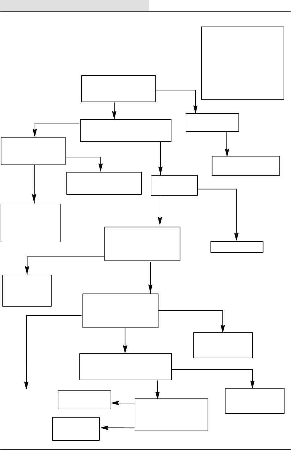
ELECTRICAL
5-70 8410 MM392 (8--01)
S--7 IS NOT WORKING
(REVERSE SWITCH)
OR 36/GRN OR 13AY/
BLK IS OPEN OR ANY
36/GRN IS SHORTED
TO GROUND
IS THE REC TANK
FULL LIGHT ON ?
STILL NOT TURNING
ON/OFF
OPERATION:
--SCRUB IS SELECTED ON
TOUCH PANEL
--MACHINE IS NOT IN REVERSE
--RECOVERY TANK IS NOT
FULL
--ENGINE SPEED IS SELECTED
TO HIGH
--SCRUB SOLENOIDS WILL
TURN ON
--HEAD WILL LOWER
-- BRUSHES WILL SPIN
46/BRN IS OPEN
FROM PANEL PIN TO
SOLENOID WITHOUT
VOLTAGE
SCRUB BRUSH WILL NOT
TURN ON AND/OR DOWN
(FLOW CHART)
BOTH PANELS ARE
POWERED UP
KEY IS ON
ENGINE IS OFF
CAN THE SCRUB BUTTON
BE TURNED ON AND OFF ? NO
REPLACE TOUCH
PANEL FACE
REPLACE INSTRUMENT
PANEL
YES
ENGINE IS ON
ACTIVATE SQ. / VAC BUTTON
DOES THE SQUEEGEE GO DOWN
AND VAC FAN TURN ON ?
YES
NO
YES
DRAIN THE TANK
NO
ENGINE IS OFF
KEY IS ON
SCRUB SELECTED
DISCONNECT SOLENOIDS
CHECK VOLTAGE AT SV--3,
SV--4, AND SV--19
FROM 25/GRY TO GROUND
VOLTAGE
NO
WIRE 25/GRY
FROM CB--4 TO
SOLENOIDS SV--3,
SV--4, OR SV--19 IS
OPEN
VOLTAGE
ENGINE IS OFF
KEY IS ON
SCRUB SELECTED
DISCONNECT SOLENOIDS
CHECK VOLTAGE AT SV--3,
AND SV--4 FROM 25/GRY TO
46/BRN
VOLTAGE ON ONLY
ONE SOLENOID
NO VOLTAGE
AT EITHER
SOLENOID
SOLENOID STILL DISCONNECTED
TURN KEY SW. OFF THEN ON
DOES THE ” OK” LIGHT COME ON ?
YES
WIRE 46/BRN IS OPEN
FROM PANEL (PIN 19)
TO SV--3 AND SV--4
NO
DISCONNECT INST. PANEL
CHECK CONTINUITY OF
WIRE 46/BRN FROM INST.
PANEL HARNESS (PIN 19)
TO GROUND
OPEN
REPLACE INST.
PANEL
CONTINUED ON
NEXT PAGE
CONTINUITY
WIRE 46/BRN IS
SHORTED TO
GROUND
RUN INPUT DISPLAY
SOFTWARE MODE
DETERMINE IF REVERSE
SWITCH IS WORKING
SWITCH SIGNAL OK
NO
VOLTAGE ACROSS
BOTH SOLENOIDS
GO TO SQUEEGEE/VAC FAN
TROUBLESHOOTING FLOW
CHART
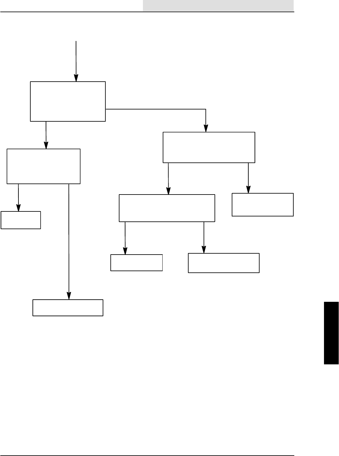
ELECTRICAL
5-71
8410 MM392 (8--01)
CONTINUED FROM
PREVIOUS PAGE
KEY ON
ENGINE OFF
SCRUB SELECTED
SV--19 DISCONNECTED
CHECK VOLTAGE AT SV--19
FROM 25H/GRY TO 48/BLU
NO VOLTAGE
SOLENOID STILL
DISCONNECTED
TURN KEY OFF, THEN ON
DOES THE ”OK” LIGHT COME ON ?
NO YES
WIRE 48/BLU IS OPEN
FROM SV--19 TO INST.
PANEL (PIN 16)
KEY IS OFF
DISCONNECT INSTRUMENT PANEL
CHECK CONTINUITY FROM 48/BLU
TO GROUND
OPEN CONTINUITY
REPLACE PANEL WIRE 48/BLU IS
SHORTED TO GROUND
VOLTAGE
CHECK TO SEE IF ALL
THREE SOLENOIDS ARE
O N -- -- U S E M A G N E T I S M
TEST ON SV--3, SV--4,
AND SV--19
ALL ON ONE OR
MORE NOT
ACTIVATED
REPLACE BAD SOLENOID
AND RETEST
HYDRAULIC
PROBLEM
>2VOLTS

ELECTRICAL
5-72 8410 MM392 (8--01)
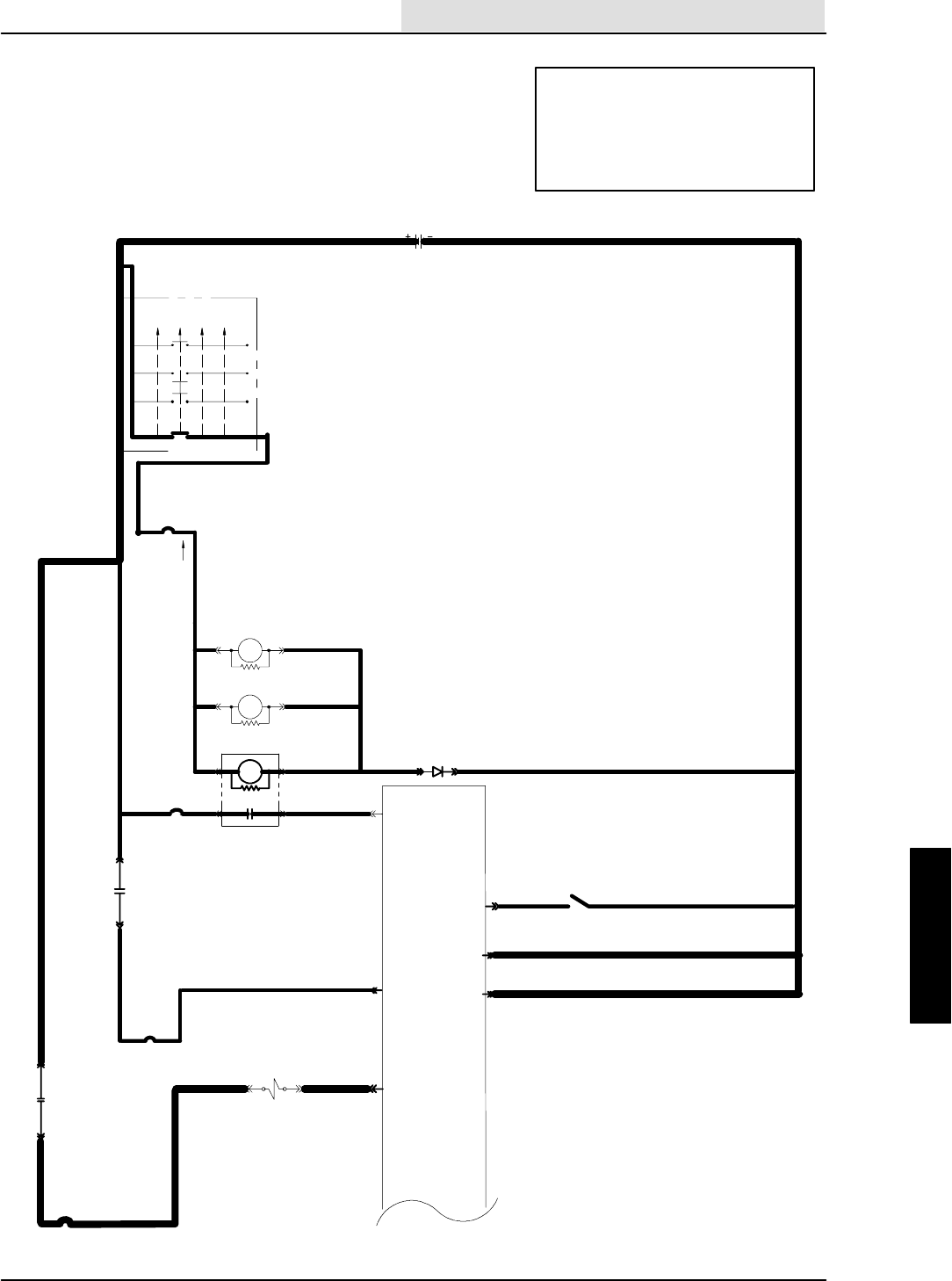
ELECTRICAL
5-73
8410 MM392 (8--01)
SCRUB HEAD WILL NOT EXTEND
(SCHEMATIC)
OPERATION:
--MACHINE MUST BE IN SCRUB MODE
--EDGE SCRUB BUTTON IS ACTIVATED
--MACHINE NOT IN REVERSE
--ENGINE SPEED ON HIGH
--SV--10 IS TURNED ON
--THE SCRUB HEAD WILL EXTEND
16E/GRN
1H/RED
13AM/BLK
16E/GRN
16F/
GRN 19C/BLU
19B/BLU
19A/BLU
1F/RED 21A/ORA
50A/ORA
50B/ORA
16C/
GRN
16D/
GRN
30 87
1A/RED
20/BLU
CB--2
IGNITION SWITCH
S--15
( X INDICATES A
CLOSED CONTACT )
D--1
10A
22/YEL
CB--3
19/BLU
M586
85
START
START
RUN
OFF
PREHEAT
X
XXX
XX
X
IGN.
19
30
BATT.
50
17
N/U
RUN/
ACC
1/RED
1
FRONT
15A
8730
M48685
M3
8685 M3
ELECTRONIC
INSTRUMENT
PANEL
13/BLK
BATTERY
M4
13AC/BLK
13AB/BLK
25A/GRY
25/GRY
21/
ORA
23
22
2
GROUND
LINE
15 AMP
CB--4
REVERSE
CLOSES IN
13AY/BLK
36B/GRN
S--7
36/GRN
REVERSE
8
FLOW SWITCH
1G/RED
CB--8
15 AMP
32A/BLU
87
30
1G/RED M5
31H/GRY
SV--10
EDJE SCRUB
51/PUR 12
31A/GRY
31/GRY
UNSWITCHED
POWER
ELECTRICAL
5-74 8410 MM392 (8--01)
--ENGINE OFF
--KEY ON
--SCRUB SELECTED
--EDGE SCRUB SELECTED
--SOLENOID DISCONNECTED,
CHECK VOLTAGE ACROSS
SOLENOID FROM 31H/GRY TO
51 PUR
--SOLENOIDS STILL DISCONNECTED
--TURN KEY OFF, THEN ON
DOES THE ”OK” LIGHT COME ON ?
31H/GRY, 31A/GRY, CB--8
32/BLU, OR M5 CONTACTS
ARE OPEN
REPLACE TOUCH
PANEL FACE
CAN THE EDGE SCRUB BUTTON
BE TURNED ON AND OFF?
SCRUB HEAD WILL NOT EXTEND
(FLOW CHART)
PANEL IS POWERED UP
KEY IS ON
ENGINE IS RUNNING
SCRUB SYSTEM ON
NO
STILL DOES
NOT WORK
REPLACE INST.
PANEL
YES
--ENGINE OFF
--KEY ON
--SCRUB SELECTED
--EDGE SCRUB SELECTED
CHECK VOLTAGE AT SV--10 FROM
31H/GRY TO GROUND
VOLTAGE
NO VOLTAGE
VOLTAGE ACROSS
SOLENOID SV--10
NO VOLTAGE
YES
NO 51/PUR IS OPEN
FROM PANEL TO
SOLENOID SV--10
--DISCONNECT
INSTRUMENT PANEL
CHECK CONTINUITY
OF 51/PUR TO
GROUND
OPEN
CONTINUITY
REPLACE INST.
PANEL
WIRE 51/PUR IS
SHORTED TO
GROUND
OPERATION:
--MACHINE MUST BE IN SCRUB MODE
--EDGE SCRUB BUTTON IS ACTIVATED
--MACHINE NOT IN REVERSE
--ENGINE SPEED ON HIGH
--SV--10 IS TURNED ON
--THE SCRUB HEAD WILL EXTEND
CHECK TO SEE IF S--10 IS
TURNING ON
USE THE MAGNETIC TEST
OFF
ON
REPLACE BAD
SOLENOID
HYDRAULIC PROBLEM
SEE TROUBLESHOOTING
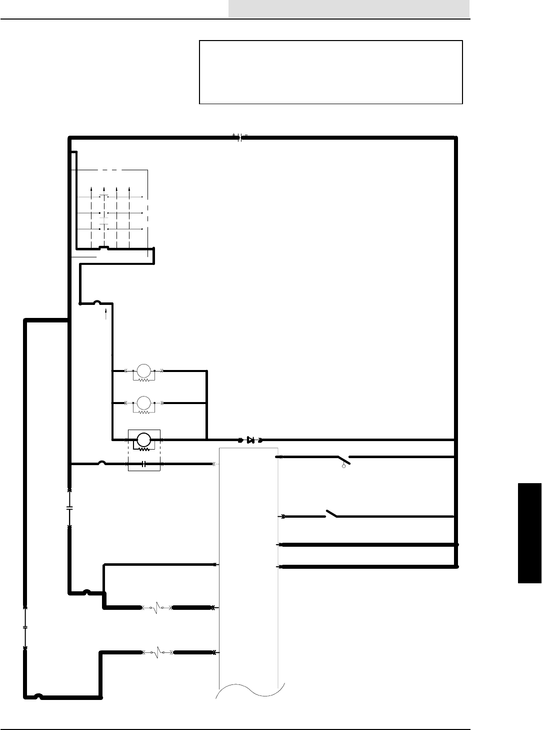
ELECTRICAL
5-75
8410 MM392 (8--01)
SQUEEGEE AND VACUUM FAN NOT
TURNING ON AND GOING DOWN
(SCHEMATIC)
OPERATION:
--SQ/VAC IS SELECTED ON TOUCH PANEL
--MACHINE NOT IN REVERSE
--ENGINE SPEED HIGH
--NO OVERFLOW CONDITION SENSED
--THE SQUEEGEE LOWERS AND SCRUB VACUUM FAN TURNS ON
16E/GRN
1H/RED
13AM/BLK
16E/GRN
16F/
GRN 19C/BLU
19B/BLU
19A/BLU
1F/RED 21A/ORA
50A/ORA
50B/ORA
16C/
GRN
16D/
GRN
30 87
1A/RED
20/BLU
CB--2
IGNITION SWITCH
S--15
( X INDICATES A
CLOSED CONTACT )
D--1
10A
22/YEL
CB--3
19/BLU
M58685
START
START
RUN
OFF
PREHEAT
X
XXX
XX
X
IGN.
19
30
BATT.
50
17
N/U
RUN/
ACC
1/RED
1
FRONT
15A
8730
M48685
M3
8685 M3
ELECTRONIC
INSTRUMENT
PANEL
13/BLK
BATTERY
M4
13AC/BLK
13AB/BLK
25A/GRY
25/GRY
21/
ORA
23
22
2
GROUND
LINE
15 AMP
CB--4
13AM/BLK
S--5
10
N.C.H.O.
28/YEL RECOVERY TANK
REVERSE
CLOSES IN
13AY/BLK
36B/GRN
S--7
36/GRN
REVERSE
8
FLOW SWITCH
1G/RED
CB--8
15 AMP
32A/BLU87
30
1G/RED M5
31A/GRY 31/GRY
UNSWITCHED
POWER
31L/GRY
SV--12
SQEEGEE DOWN
47/ORA 11
25D/GRY 45/GRN
SV--1 VAC FAN
SCRUB VALVE
21
ELECTRICAL
5-76 8410 MM392 (8--01)
START THE ENGINE
DOES THE THIRD FUEL
GAUGE SEGMENT
FROM RIGHT LIGHT UP
IN REVERSE AND TURN
OFF IN NEUTRAL?
NO
VOLTAGE
YES
25/GRY, 21/ORA,
CB--4, M--4, 31/GRY,
CB--8, 32/BLU, OR
M5 CONTACTS
ARE OPEN
DISCONNECT SV--1 AND SV--12
CHECK VOLTAGE AT SV--1
FROM 25D/GRY TO GND. AND
SV--12 FROM 31L/GRY TO GND.
ELECTRONICS OK
SEE HYDRAULIC
TROUBLESHOOTING
DOES THE SQ. AND/OR
VAC TURN ON/OFF WITH THE
SQ/VAC BUTTON NOW ?
CAN THE SQ/VAC TOUCH
PANEL BUTTON
BE TURNED ON AND OFF?
SQUEEGEE AND VACUUM FAN NOT
TURNING ON AND GOING DOWN
(FLOW CHART)
PANEL IS POWERED UP
KEY IS ON
ENGINE IS RUNNING
NO
YES
REPLACE TOUCH
PANEL FACE
STILL DOES
NOT WORK
REPLACE INST.
PANEL
GO INTO ”MANUAL MODE”
THE OUTPUTS WILL TURN
ON REGARDLESS OF THE
INPUTS
--TURN KEY OFF
--PUSH AND HOLD ”ES”
BUTTON
--TURN KEY ON
--KEEP HOLDING ”ES” BUT-
TON UNTIL THE MAINTE-
NANCE LIGHT COMES ON
--RELEASE ”ES” BUTTON
NO
VOLTAGE
--MANUAL MODE
-- E N G I N E O F F
--KEY ON
--SQ/VAC SELECTED
”ON”
ARE SV--1 AND SV--12
TURNED ON ? (USE
MAGNETIZED TEST)
NO
YES
DISCONNECT HYD.
COILS AGAIN
CHECK VOLTAGE
ACROSS BOTH COILS,
SV--1 FROM 25D/GRY TO
45/GRN AND SV--12 FROM
31L/GRY TO 47/ORA
VOLTAGE
NO
VOLTAGE
CONTINUED ON
NEXT PAGE
REPLACE HYD. COIL
THAT WILL NOT TURN
ON-- --RE--TEST SYSTEM
YES
IS THE REC TANK
FULL LIGHT ON ?
DRAIN TANK AND
RE--TEST
IF LIGHT IS STILL
ON--GO TO RE-
COVERY TANK
FULL LIGHT WILL
NOT TURN OFF
FLOW CHART
NO
OPERATION:
--SQ/VAC IS SELECTED ON
TOUCH PANEL
--MACHINE NOT IN REVERSE
--ENGINE SPEED HIGH
--NO OVERFLOW CONDITION
SENSED
--THE SQUEEGEE LOWERS
AND SCRUB VACUUM FAN
TURNS ON
RECONNECT
SV--1 AND
SV--12
GO INTO ”INPUT DISPLAY MODE”
THE INPUT CONDITIONS WILL BE
DISPLAYED ON FUEL GAUGE
--TURN OFF THE KEY
--PUSH AND HOLD SQ/VAC BUTTON
HOLD UNTIL MAINTENANCE LIGHT
COMES ON
YES
NO
PANEL TESTS
GOOD
LIGHT ALWAYS ON
LIGHT ALWAYS OFF
CHECK CONTINUITY OF
36/GRN AT PIN 8 TO GROUND
--ENGINE ON AND IN NEUTRAL
REPLACE INST.
PANEL
OPEN 36/GRN IS SHORTED
TO GROUND OR S--7
IS ALWAYS CLOSED
CONTINUITY
CHECK CONTINUITY
OF 36/GRN, 36B/GRN
AND S--7 (S--7 IS
CLOSED IN REVERSE
CONTINUITY
REPLACE INST.
PANEL
OPEN
REPAIR 36/GRN,
36B/GRN, OR
REPLACE S--7
TURN KEY OFF,
THEN ON
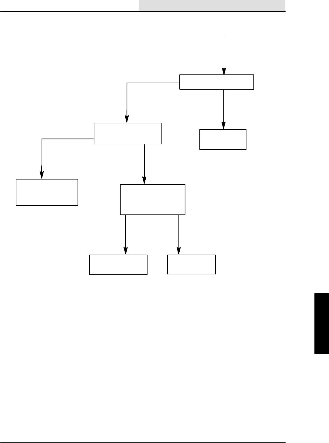
ELECTRICAL
5-77
8410 MM392 (8--01)
REMOVE THE SHORT
TO GROUND ON
47/ORA AND/OR
45/GRN
COILS STILL
DISCONNECTED
CONTINUED FROM
PREVIOUS PAGE
--TURN KEY OFF THEN ON
IS THE ”OK” LIGHT ON ?
NO
YES
WIRE 47/ORA
OR WIRE 45/GRN
ARE OPEN
KEY OFF
PANEL
DISCONNECTED
CHECK CONTINUITY OF
47/ORA AND 45/GRN TO
GROUND
OPEN
CONTINUITY
--RECONNECT PANEL
--KEY OFF THEN ON
DOES THE ”OK” PANEL
LIGHT COME ON ?
YESNO
RE--TEST
SYSTEM
REPLACE
INSTRUMENT PANEL

ELECTRICAL
5-78 8410 MM392 (8--01)
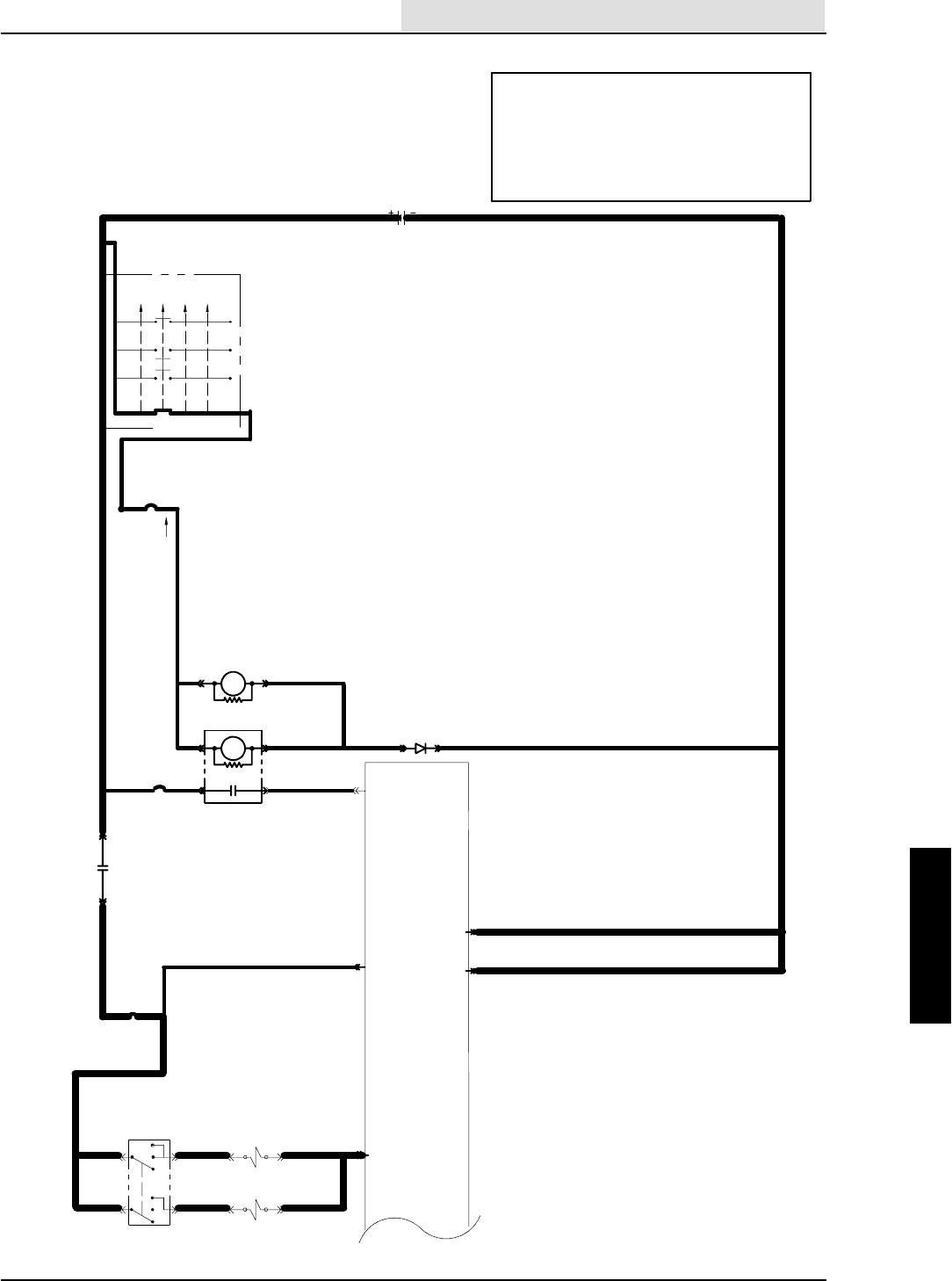
ELECTRICAL
5-79
8410 MM392 (8--01)
WATER VALVES NOT OPERATING
(SCHEMATIC) OPERATION:
--SCRUB FUNCTIONS MUST
BE ON
--WATER SWITCH IN POSITION #1 TURNS ON
SV--21 LOW WATER VALVE
--WATER SWITCH IN POSITION #2 TURNS ON
SV--21 AND SV--22 (HIGH WATER VALVE)
16E/GRN
1H/RED
13AM/BLK
16E/GRN
19B/BLU
19A/BLU
1F/RED 21A/ORA
50A/ORA
50B/ORA
16C/
GRN
16D/
GRN
30 87
1A/RED
20/BLU
CB--2
IGNITION SWITCH
S--15
( X INDICATES A
CLOSED CONTACT )
D--1
10A
22/YEL
CB--3
19/BLU
START
START
RUN
OFF
PREHEAT
X
XXX
XX
X
IGN.
19
30
BATT.
50
17
N/U
RUN/
ACC
1/RED
1
FRONT
15A
8730
M4 8685
M3
8685 M3
ELECTRONIC
INSTRUMENT
PANEL
13/BLK
BATTERY
M4
13AC/BLK
13AB/BLK
25A/GRY
25/GRY
21/
ORA
23
22
2
GROUND
LINE
15 AMP
CB--4
19
ON
OFF
25J
/GRY
WATER CONTROL
S--9
ON
ON
OFF
OFF
46E/BRN
46D/BRN
SV--22 HIGH
WATER VALVE
SV--21 LOW
WATER VALVE
96/YEL
95/BLU
25B
/GRY
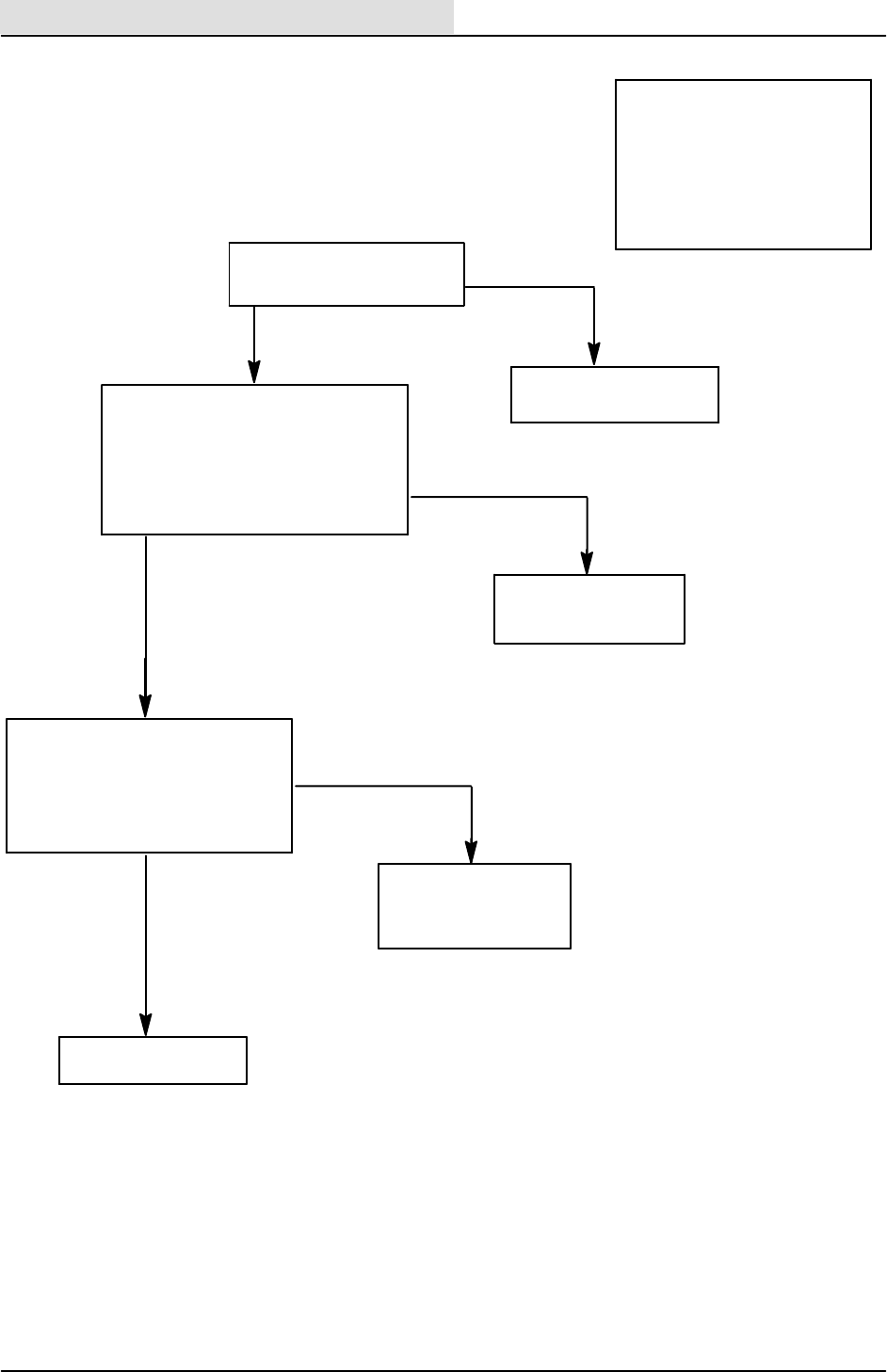
ELECTRICAL
5-80 8410 MM392 (8--01)
TROUBLESHOOT THE
SCRUB FUNCTION FIRST
ACTIVATE THE SCRUB
DOES THE SCRUB BRUSH
TURN ON AND COME DOWN ?
WATER VALVES NOT OPERATING
(FLOW CHART)
PANEL IS POWERED UP
KEY IS ON
ENGINE IS RUNNING
YES
NO
--ENGINE RUNNING
--SCRUB SYSTEM ON
--WATERSWITCHONPOSITION#2
--SV--21, AND SV--22 DISCONNECTED
CHECK FOR VOLTAGE AT SV--21 FROM
96/YEL TO GROUND
CHECK FOR VOLTAGE AT SV--22 FROM
95/BLU TO GROUND
NO VOLTAGE ON ANY
VOLTAGE ON
BOTH SOLENOIDS
--KEY ON, ENGINE OFF
--SOLENOIDS STILL DISCONNECTED
--SCRUB ON
CHECK VOLTAGE AT SV--21 FROM
96/YEL TO 46D/BRN
CHECK VOLTAGE AT SV--22 FROM
95/BLU TO 46E/BRN
NO VOLTAGE ACROSS
EITHER VALVE
VOLTAGE ON
SOLENOIDS
REPLACE ANY VALVE
NOT OPERATING
OPERATION:
--SCRUB FUNCTIONS MUST
BE ON
--WATERSWITCHINPOSITION#1
TURNS ON SV--21 LOW WATER
VALVE
--WATERSWITCHINPOSITION#2
TURNS ON SV--21 AND SV--22
(HIGH WATER VALVE)
96/YEL, 95/BLU, S--9,
25B/GRY, OR 25H/
GRY ARE OPEN
46D/BRN, 46E/BRN, OR
46/BRN IS OPEN
FROM SV--21 AND
SV--22 TO PIN 19
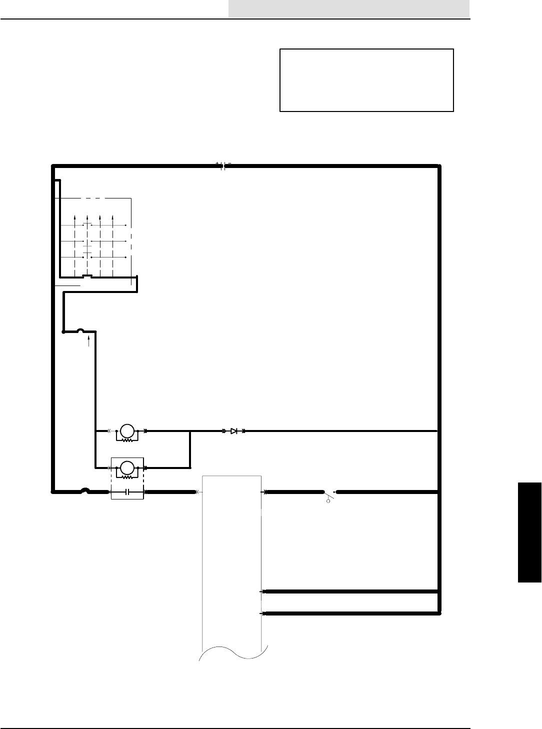
ELECTRICAL
5-81
8410 MM392 (8--01)
RECOVERY TANK FULL LIGHT
WILL NOT TURN ON OR OFF
(SCHEMATIC)
OPERATION:
--IF S--5 CLOSES, THE RECOVERY TANK
IS FULL
--THE RECOVERY TANK LIGHT COMES ON
--SCRUB , SQUEEGEE, AND VACUUM FAN
TURNS OFF
16E/GRN
1H/RED
13AM/BLK
16E/GRN
19B/BLU
19A/BLU
50A/ORA
50B/ORA
16C/
GRN
16D/
GRN
1A/RED
20/BLU
CB--2
IGNITION SWITCH
S--15
( X INDICATES A
CLOSED CONTACT )
D--1
10A
22/YEL
CB--3
19/BLU
START
START
RUN
OFF
PREHEAT
X
XXX
XX
X
IGN.
19
30
BATT.
50
17
N/U
RUN/
ACC
1/RED
1
FRONT
15A
8730
M4 8685
M3
8685 M3
ELECTRONIC
INSTRUMENT
PANEL
13/BLK
BATTERY
13AC/BLK
13AB/BLK
23
22
GROUND
LINE
S--5 CLOSED =
13AM/BLK
S--5
5 SEC. DELAY
1 MIN. TO VAC FAN SHUT--OFF
10
N.C.H.O.
28/YEL
RECOVERY TANK
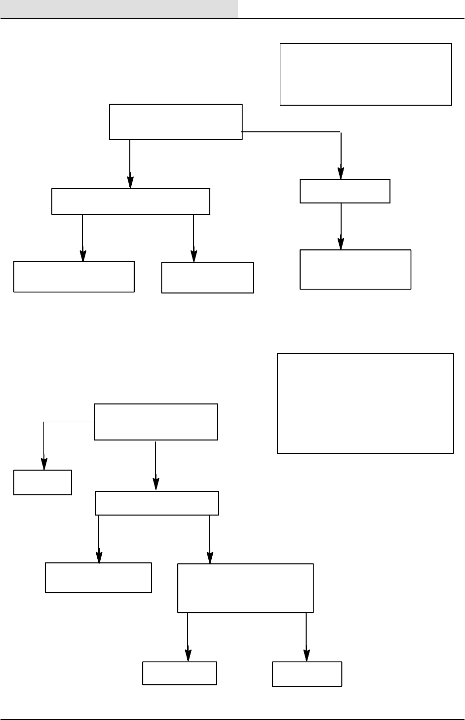
ELECTRICAL
5-82 8410 MM392 (8--01)
REPLACE INSTR.
PANEL
--DRAIN REC TANK
--TURN ON SCRUB
DOES THE LIGHT TURN OFF ?
DOES THE REC TANK FULL
LIGHT TURN ON
MOMENTARILY AT POWER UP ?
RECOVERY TANK FULL LIGHT
WILL NOT TURN OFF
(FLOW CHART)
RECOVERY TANK FULL LIGHT
WILL NOT TURN ON
(FLOW CHART)
-- P O W E R O F F
--DISCONNECT INSTR. PANEL
DISCONNECT S--5
CHECK CONTINUITY FROM WIRE
28/YEL TO GROUND
IF THE LIGHT IS STILL
NOT TURNING ON MO-
MENTARILY AT POWER
UP----REPLACE THE PANEL
OPERATION:
--IF S--5 CLOSES, THE RECOVERY TANK
IS FULL
--THE RECOVERY TANK LIGHT COMES ON
--SCRUB , SQUEEGEE, AND VACUUM FAN
TURN OFF
YES
NO
REPLACE LAMP L3
INSIDE THE PANEL
DISCONNECT S--5 AND GROUND WIRE
28/YEL DOES THE LIGHT TURN ON ?
YES NO
WIRE 28/YEL IS OPEN
FROM S--5 TO PANEL
(PIN 10)
WHEN RECOVERY TANK
IS FULL, S--5 IS NOT CLOSING
OR 13J/BLK IS OPEN
OPERATION:
--IF S--5 CLOSES, THE RECOVERY TANK
IS FULL
--THE RECOVERY TANK LIGHT COMES ON
--SCRUB , SQUEEGEE, AND VACUUM FAN
TURNS OFF
--SELECTING SQUEEGEE/VAC FAN OR
TURNING KEY OFF, THEN ON WILL TURN
LIGHT OFF IF REC TANK IS NO LONGER
FULL
DISCONNECT S--5
DOES THE LIGHT TURN OFF ?
YES NO
RECOVERYTANKISFULL
SYSTEM OK, OR
S--5 IS SHORTED
OPEN CONTINUITY
WIRE 28/YEL IS
GROUNDED
YES
SYSTEM IS
WORKING
NO

ELECTRICAL
5-83
8410 MM392 (8--01)
DETERGENT METERING
PUMP IS NOT OPERATING
(SCHEMATIC)
OPERATION:
--PANEL DETERGENT BUTTON IS
ACTIVE IN LOW OR HIGH POSITION
--MACHINE IS IN SCRUB MODE
--MACHINE IS NOT IN REVERSE
--DETERGENT PUMP WILL BE TURNED ON
WITH A PULSE WIDTH MODULATED SIGNAL
16E/GRN
1H/RED
13AM/BLK
16E/GRN
19B/BLU
19A/BLU
1F/RED 21A/ORA
50A/ORA
50B/ORA
16C/
GRN
16D/
GRN
30 87
1A/RED
20/BLU
CB--2
IGNITION SWITCH
S--15
( X INDICATES A
CLOSED CONTACT )
D--1
10A
22/YEL
CB--3
19/BLU
START
START
RUN
OFF
PREHEAT
X
XXX
XX
X
IGN.
19
30
BATT.
50
17
N/U
RUN/
ACC
1/RED
1
FRONT
15A
8730
M48685
M3
8685 M3
ELECTRONIC
INSTRUMENT
PANEL
13/BLK
BATTERY
M4
13AC/BLK
13AB/BLK
25A/GRY
25/GRY
21/
ORA
23
22
2
GROUND
LINE
15 AMP
CB--4
REVERSE
CLOSES IN
13AY/BLK
36B/GRN
S--7
36/GRN
REVERSE
8
FLOW SWITCH
15A
CB--7 23A/GRY 56/ORA 9
MTR
DETERGENT
METERING
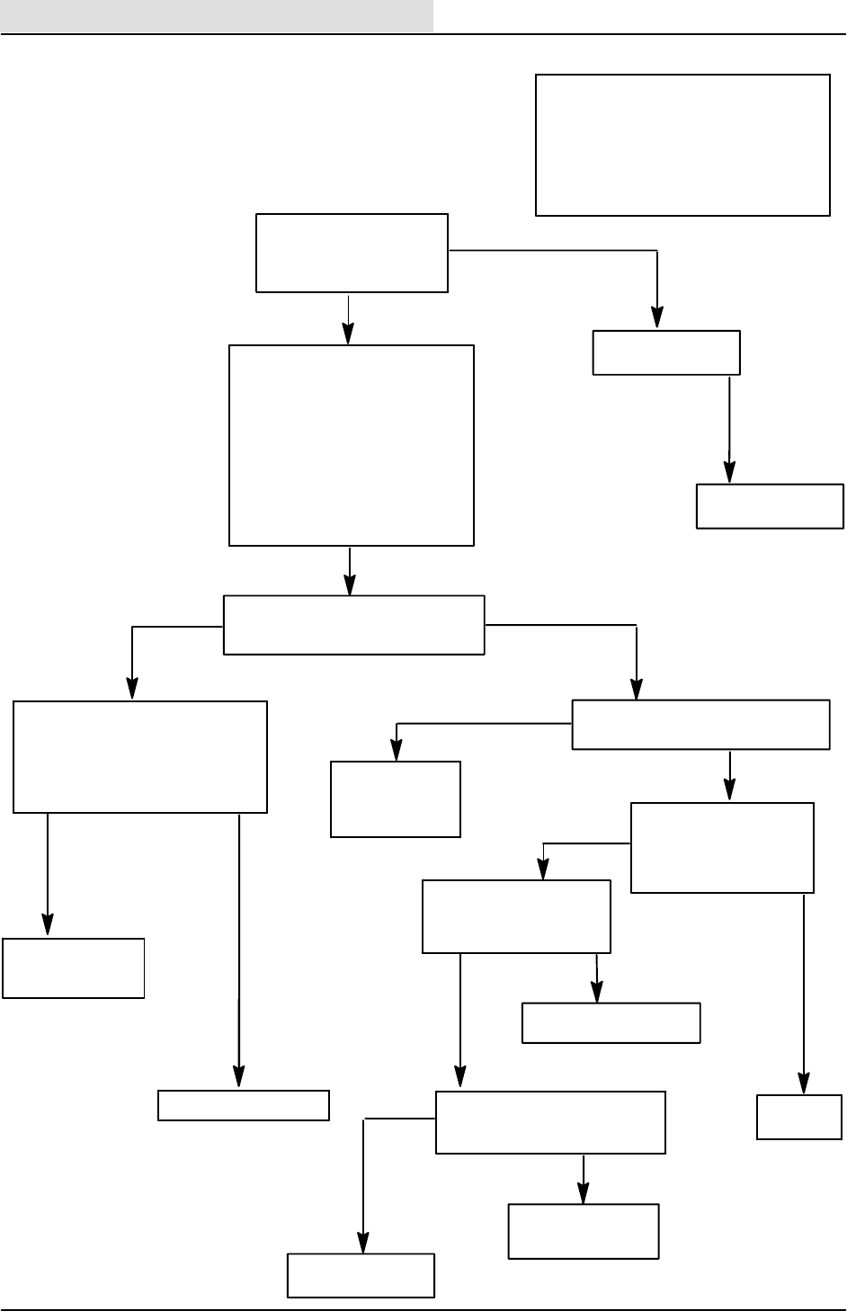
ELECTRICAL
5-84 8410 MM392 (8--01)
--TURN KEY OFF, THEN ON
--START THE ENGINE
VERIFY THAT THE SCRUBBING
SYSTEM IS FUNCTIONING
SELECT SCRUB--DOES THE HEAD
LOWER AND BRUSHES TURN ON ?
DISCONNECT DETERGENT
PUMP
--IN MANUAL MODE
--KEY ON, ENGINE OFF
CHECK VOLTAGE AT
PUMP FROM WIRE 23A/
GRY TO 56/ORA
GO INTO ”MANUAL MODE”
THE OUTPUTS WILL TURN ON
REGARDLESS OF THE INPUTS
--TURN KEY OFF
--PUSH AND HOLD ”ES” BUTTON
--TURN KEY ON
--KEEP HOLDING ”ES” BUTTON
UNTIL THE MAINTENANCE LIGHT
COMES ON
--RELEASE ”ES” BUTTON
ENGINE DOES NOT HAVE TO BE
RUNNING
DETERGENT METERING
PUMP IS NOT OPERATING
(FLOW CHART)
PANEL IS POWERED UP
KEY IS ON
REPLACE TOUCH
PANEL FACE
STILL DOES
NOT WORK
REPLACE INST.
PANEL
NO
CAN THE DETERGENT
METERING AND TOUCH
PANEL SWITCHES BE
TURNED ON AND OFF ?
YES
DOES THE DETERGENT METERING
PUMP TURN ON AND OFF WITH
THE TOUCH PANEL SWITCH ?
NO
YES
TEST
SCRUB
INPUTS
CHECK VOLTAGE AT DETERGENT
PUMP FROM 23A/GRY TO GROUND
VOLTAGE
NO VOLTAGE
YESNO
TROUBLESHOOT
SCRUB BRUSH
SYSTEM FIRST
NO VOLTAGE
VOLTAGE
(LESS THAN 5 VOLTS)
REPLACE
PUMP
-- P O W E R O F F
--PANEL DISCONNECTED
CHECK CONTINUITY OF 56/ORA
REPLACE INST.
PANEL
OPERATION:
--PANEL DETERGENT BUTTON IS
ACTIVE IN LOW OR HIGH POSITION
--MACHINE IS IN SCRUB MODE
--MACHINE IS NOT IN REVERSE
--DETERGENT PUMP WILL BE TURNED
ON WITH A PULSE WIDTH MODULATED
SIGNAL
23A/GRY, CB--7,
21A/ORA, OR
M4 CONTACTS
ARE OPEN
SYSTEM TESTS GOOD
OPEN TO
GROUND
56/ORA SHORTED
TO GROUND
CONTINUITY
--COILS DISCONNECTED
--TURN KEY OFF, THEN
ON
IS ”OK” LIGHT ON ?
YES
WIRE56/ORAISOPEN
NO
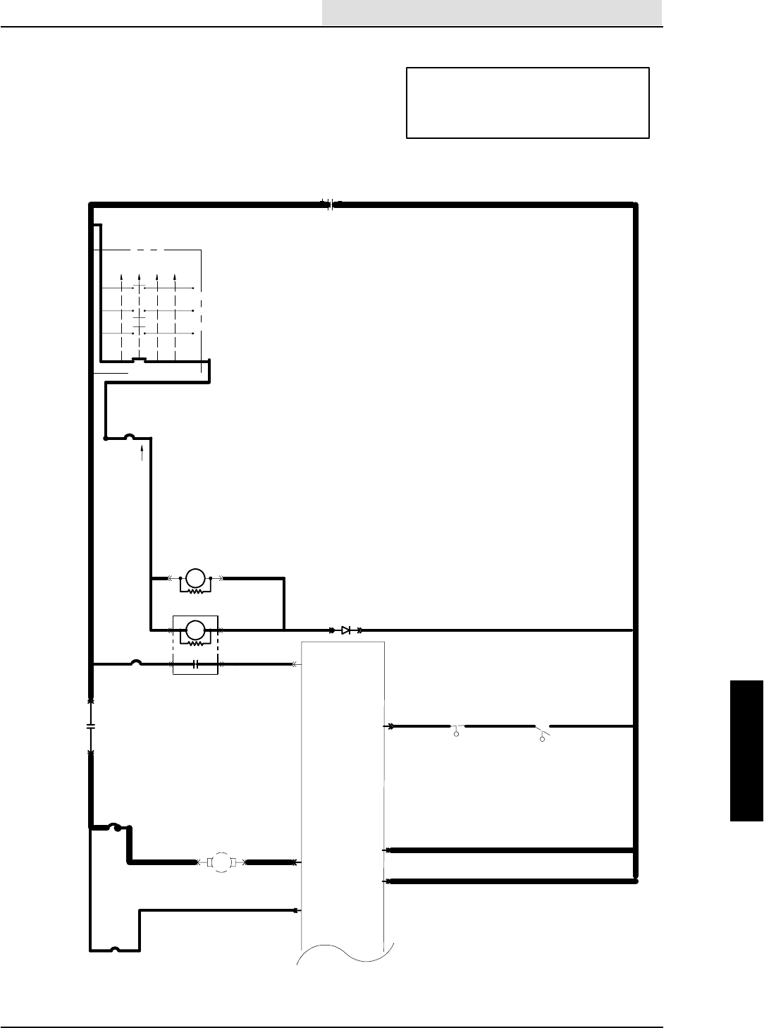
ELECTRICAL
5-85
8410 MM392 (8--01)
EStPUMP NOT WORKING
(SCHEMATIC) OPERATION:
--IF ES IS SELECTED ON PANEL AND
--S--3 AND S--4 CLOSE FOR 10 SECONDS
--THE ES PUMP WILL RUN UNTIL S--3 OR
S--4 OPENS PLUS 40 SECONDS
16E/GRN
1H/RED
13AM/BLK
16E/GRN
19B/BLU
19A/BLU
1F/RED 21A/ORA
50A/ORA
50B/ORA
16C/
GRN
16D/
GRN
30 87
1A/RED
20/BLU
CB--2
IGNITION SWITCH
S--15
( X INDICATES A
CLOSED CONTACT )
D--1
10A
22/YEL
CB--3
19/BLU
START
START
RUN
OFF
PREHEAT
X
XXX
XX
X
IGN.
19
30
BATT.
50
17
N/U
RUN/
ACC
1/RED
1
FRONT
15A
8730
M4 8685
M3
8685 M3
ELECTRONIC
INSTRUMENT
PANEL
13/BLK
BATTERY
M4
13AC/BLK
13AB/BLK
25A/GRY
25/GRY
21/
ORA
23
22
2
GROUND
LINE
15 AMP
CB--4
S--3&4 CLOSED=
13AL/BLK
S--4 N.C.H.O.
S--3 N.O.H.C.
5 SEC. DELAY
ES PUMP RUNS30 SEC.
327/PUR
26/BRN
RECOVERY
TANK
SOLUTION
TANK
15A
CB--7
MTR
23/GRY 4
57/GRN
ES PUMP
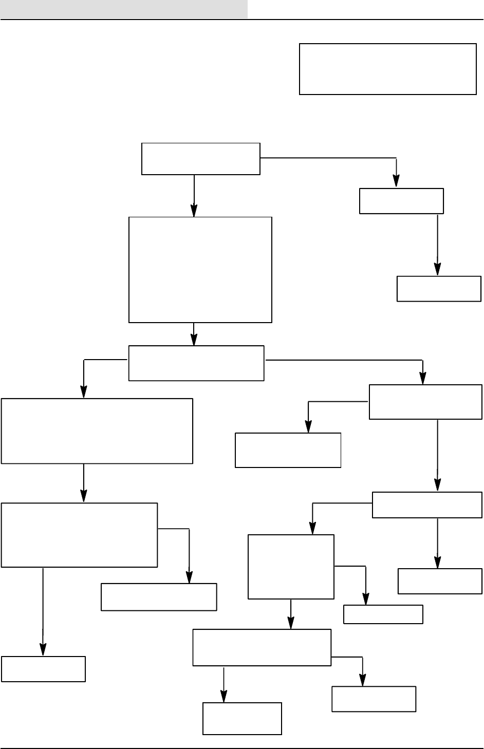
ELECTRICAL
5-86 8410 MM392 (8--01)
26/BRN, 27/PUR, 13AL/BLK,
S--3, OR S--4 ARE OPEN
GO INTO ”INPUT DISPLAY MODE”
THE INPUT CONDITIONS WILL BE DISPLAYED
ON FUEL GAUGE
--TURN OFF THE KEY
--PUSH AND HOLD SQ/VAC BUTTON----HOLD
UNTIL MAINTENANCE LIGHT COMES ON
DISCONNECT INSTRUMENT
PANEL AND CHECK CONTINUITY
OF 57/GRN TO GROUND
23/GRY, CB--7, 21A/ORA,
M4 CONTACT, OR
1F/RED ARE OPEN
GO INTO ”MANUAL MODE”
THE OUTPUTS WILL TURN ON
REGARDLESS OF THE INPUTS
--TURN KEY OFF
--PUSH AND HOLD ”ES” BUTTON
--TURN KEY ON, ENGINE NOT
RUNNING
--KEEP HOLDING ”ES” BUTTON
UNTIL THE MAINTENANCE LIGHT
COMES ON
--RELEASE ”ES” BUTTON
CAN THE ES PUMP TOUCH
PANEL BUTTON BE
TURNED ON/OFF
EStPUMP NOT WORKING
(FLOW CHART)
PANEL IS POWERED UP
KEY IS ON
ENGINE NOT RUNNING
NO
YES REPLACE TOUCH
PANEL FACE
STILL DOES
NOT WORK
REPLACE INST.
PANEL
NO
YES DOES THE ES PUMP TURN
ON AND OFF WITH THE ES
BUTTON IN MANUAL MODE ?
TEST INPUT
TEST OUTPUT
DISCONNECT ES PUMP
CHECK VOLTAGE FROM
23/GRY TO GROUND
NO VOLTAGE
VOLTAGE
OPERATION:
--IF ES IS SELECTED ON PANEL AND
--S--3 AND S--4 CLOSE FOR 10 SECONDS
--THE ES PUMP WILL RUN UNTIL S--3 OR
S--4 OPENS PLUS 40 SECONDS
WITH ES ON AND
MACHINE IN
MANUAL MODE
ES PUMP
DISCONNECTED
CHECK VOLTAGE FROM
23/GRY TO 57/GRN
VOLTAGE
REPLACE MOTOR
NO VOLTAGE
--ES PUMP STILL
DISCONNECTED
--TURN KEY OFF,
THEN ON
-- D O E S T H E ” O K
LIGHT” COME ON ?
YES
57/GRN IS OPEN
NO
REPLACE INST.
PANEL
OPEN
CONTINUITY
WIRE 57/GRN IS
SHORTED TO
GROUND
WITH SOLUTION TANK LOW
(S--3=CLOSED)
AND RECOVERY TANK >1/2 FULL
(S--4 =CLOSED)
DOES THE FAR RIGHT SEGMENT OF
FUEL GAUGE LIGHT ?
NO
YES
SYSTEM TESTS
GOOD
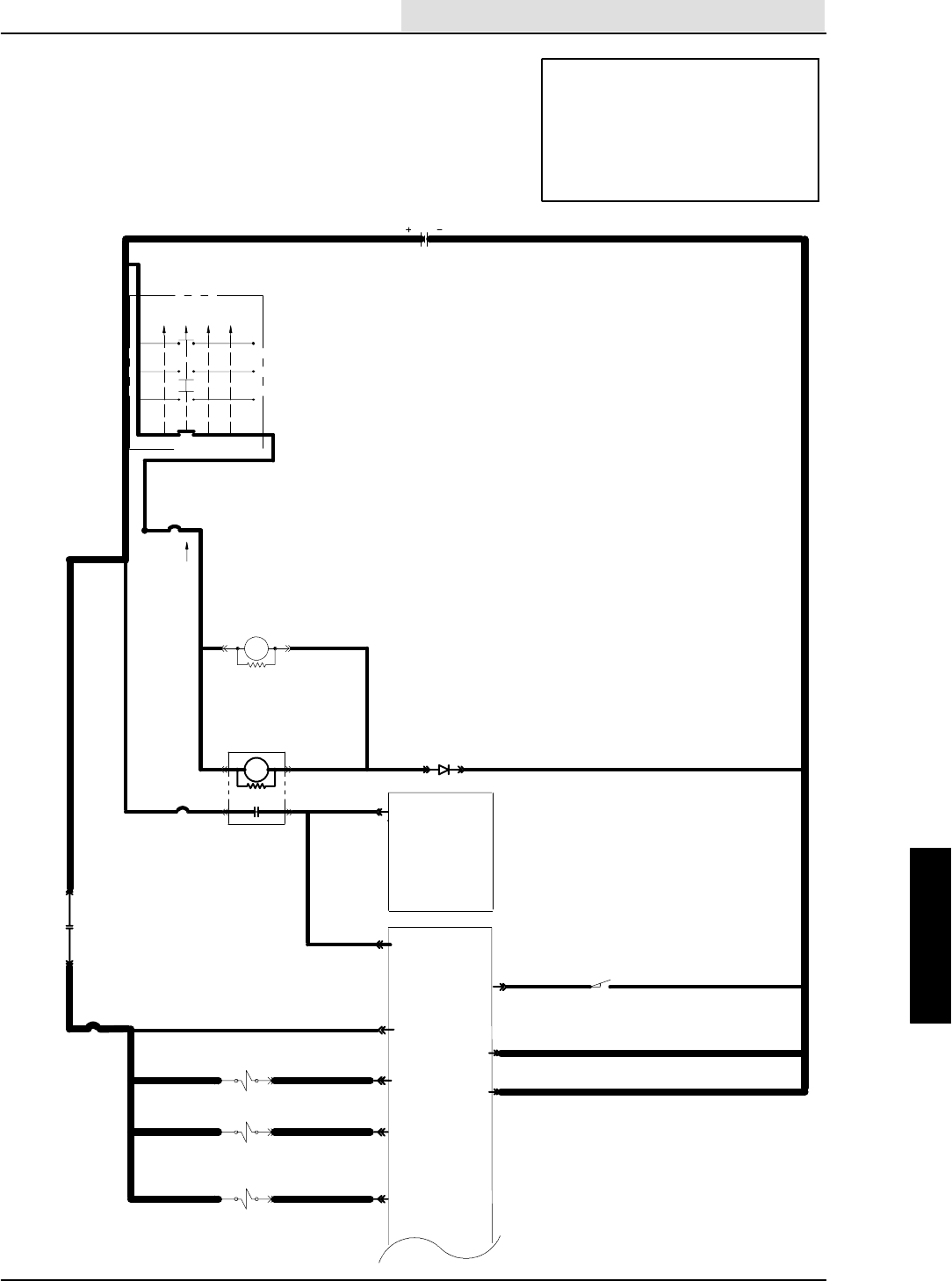
ELECTRICAL
5-87
8410 MM392 (8--01)
OPERATION:
--SWEEP 1 SELECTED ON PANEL
--HOPPER IN DOWN POSITION
--ENGINE SPEED SET ON HIGH
--SV--11 AND SV--5 ARE TURNED ON,
BRUSHES TURN ON AND LOWER
--HOPPER DOOR OPEN WILL SELECT
AUTOMATICALLY
UNSWITCHED
POWER
SWEEP BRUSH WILL NOT TURN ON AND
LOWER WITH SWEEP 1 SELECTED
(SCHEMATIC)
16E/GRN
1H/RED
13AM/BLK
16E/GRN
16F/
GRN 19C/BLU
19A/BLU
50A/ORA
50B/ORA
16C/GRN
1A/RED
20/BLU
CB--2
IGNITION SWITCH
S--15
( X INDICATES A
CLOSED CONTACT )
D--1
10A
CB--3
19/BLU
M58685
START
START
RUN
OFF
PREHEAT
X
XXX
XX
X
IGN.
19
30
BATT.
50
17
N/U RUN/ACC
1/RED
1
FRONT
15A
8730M3
8685 M3
ELECTRONIC
INSTRUMENT
PANEL
13/BLK
BATTERY
13AC/BLK
13AB/BLK
23
22
GROUND
LINE
1G/RED
CB--8
15 AMP
32A/BLU
87
30
1G/RED M5
31A/GRY
50A/ORA AUXILIARY
1
ELECTRONIC
INSTR.
PANEL
53/BRN
8
HOPPER LOCATION
LOW = SWEEP ENABLE
HOPPER DN
N.O.H.C.
CLOSED =
13AT/BLK
2
14
39/ORA
6
35/PUR
21
34/BRN
SV--5 MAIN SWEEP BRUSH
NORMAL SPEED VALVE
SV--6 MAIN SWEEP BRUSH
LITTER SPEED VALVE
SV--11 MAIN SWEEP BRUSH
DN. VALVE
31M/GRY
31N/GRY
31K/GRY
31/GRY
22/YEL
ELECTRICAL
5-88 8410 MM392 (8--01)
SWEEP BRUSH WILL NOT
TURN ON AND LOWER
WITH SWEEP 1 SELECTED
(FLOW CHART)
WIRE 34/BRN OR
39/ORAISSHORTED
TO GROUND
GO TO HYDRAULIC
TROUBLESHOOTING
FLOW CHART
OPERATION:
--SWEEP 1 SELECTED ON PANEL
--HOPPER IN DOWN POSITION
--ENGINE SPEED SET ON HIGH
--SV--11 AND SV--5 ARE TURNED ON,
BRUSHES TURN ON AND LOWER
--HOPPER DOOR SELECTED AUTOMATICALLY
--KEY OFF
--DISCONNECT PANEL
CHECK CONTINUITY OF 34/BRN
AND 39/ORA TO GROUND
--TURN KEY OFF, THEN ON
DOES OK LIGHT COME
ONANDSTAYON?
REPLACE SV--11 IF HEAD
NOT LOWERING
REPLACE SV--5 IF BRUSHES NOT
SPINNING
-- S V -- 5 A N D S V -- 1 1 S T I L L
DISCONNECTED
CHECK VOLTAGE ACROSS
SV--11 WIRES 31K/GRY AND
34/BRN
CHECK VOLTAGE ACROSS
SV--5 WIRES 31M/GRY AND
39/ORA
--DISCONNECT SV--11 AND
SV--5
CHECK VOLTAGE AT SV--11 WIRE
31K/GRY AND SV--5 WIRE 31M/GRY
53/BRN, HOPPER
LOCATION SWITCH, OR
13AT/BLK ARE OPEN
LOWER HOPPER
RE--TEST
IS HOPPER LIFT LED
BLINKING ON
SWEEP PANEL ?
NO
YES
--PANELS PASS POWER--UP
TESTING
--KEY ON AND ENGINE OFF
CAN SWEEP 1 BE
SELECTED ?
NO
YES
REPLACE PANEL
STILL BLINKING ?
B+
0 VOLTAGE
31K/GRY, 31M/GRY,
31A/GRY, CB--8,
32/BLU, 32A/BLU,
M5 CONTACTS, OR
1G/RED ARE OPEN
B+ ON
BOTH
0 VOLTAGE ONE OR BOTH
YES
NO
WIRE 34/BRN OR
39/ORAISOPEN OPENCONTINUITY
REPLACE PANEL
STILL
DISCONNECTED
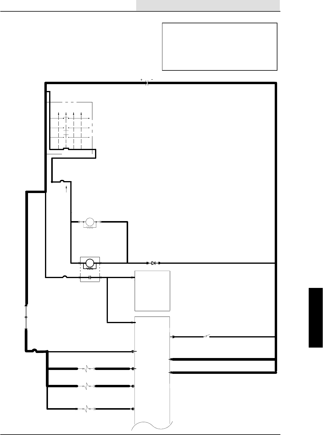
ELECTRICAL
5-89
8410 MM392 (8--01)
SWEEP BRUSH WILL NOT
TURN ON AND LOWER
WITH SWEEP 2 SELECTED
SWEEP 1 WORKS
(SCHEMATIC)
OPERATION:
--SCRUB FUNCTION OFF
--SWEEP 2 SELECTED ON PANEL
--HOPPER IN DOWN POSITION
--ENGINE SPEED SET ON HIGH
--SV--11 AND SV--5 ARE TURNED ON, BRUSHES
TURN ON AND LOWER
--HOPPER DOOR SELECTED AUTOMATICALLY
UNSWITCHED
POWER
16E/GRN
1H/RED
13AM/BLK
16E/GRN
16F/
GRN 19C/BLU
19A/BLU
50A/ORA
50B/ORA
16C/GRN
1A/RED
20/BLU
CB--2
IGNITION SWITCH
S--15
( X INDICATES A
CLOSED CONTACT )
D--1
10A
CB--3
19/BLU
M58685
START
START
RUN
OFF
PREHEAT
X
XXX
XX
X
IGN.
19
30
BATT.
50
17
N/U RUN/ACC
1/RED
1
FRONT
15A
8730M3
8685 M3
ELECTRONIC
INSTRUMENT
PANEL
13/BLK
BATTERY
13AC/BLK
13AB/BLK
23
22
GROUND
LINE
1G/RED
CB--8
15 AMP
32A/BLU
87
30
1G/RED M5
31A/GRY
50A/ORA AUXILIARY
1
ELECTRONIC
INSTR.
PANEL
53/BRN
8
HOPPER LOCATION
LOW = SWEEP ENABLE
HOPPER DN
N.O.H.C.
CLOSED =
13AT/BLK
2
14
39/ORA
6
35/PUR
21
34/BRN
SV--5 MAIN SWEEP BRUSH
NORMAL SPEED VALVE
SV--6 MAIN SWEEP BRUSH
LITTER SPEED VALVE
SV--11 MAIN SWEEP BRUSH
DN. VALVE
31M/GRY
31N/GRY
31K/GRY
31/GRY
22/YEL
ELECTRICAL
5-90 8410 MM392 (8--01)
SWEEP BRUSH WILL NOT
TURN ON AND LOWER
WITH SWEEP 2 SELECTED
(FLOW CHART)
--KEY OFF
--DISCONNECT PANEL
CHECK CONTINUITY OF 34/BRN
AND 35/PUR TO GROUND
--TURN KEY OFF, THEN ON
DOES OK LIGHT COME
ONANDSTAYON?
REPLACE SV--11 IF HEAD
NOT LOWERING
REPLACE SV--6 IF BRUSHES NOT
SPINNING
-- S V -- 6 A N D S V -- 1 1 S T I L L
DISCONNECTED
CHECK VOLTAGE ACROSS
SV--11 WIRES 31K/GRY AND
34/BRN
CHECK VOLTAGE ACROSS
SV--6 WIRES 31N/GRY AND
35/PUR
--DISCONNECT SV--11 AND
SV--6
CHECK VOLTAGE AT SV--11 WIRE
31K/GRY AND SV--6 WIRE 31N/GRY
53/BRN, HOPPER
LOCATION SWITCH, OR
13AT/BLK ARE OPEN
LOWER HOPPER
RE--TEST
IS HOPPER LIFT LED
BLINKING ON
SWEEP PANEL ?
NO
YES
--PANELS PASS POWER--UP
TESTING
--KEY ON AND ENGINE OFF
--SCRUB OFF
CAN SWEEP 2
BE SELECTED ?
NO
YES
REPLACE PANEL
STILL BLINKING ?
B+
0 VOLTAGE
31K/GRY, 31N/GRY,
31A/GRY, CB--8,
32/BLU, 32A/BLU,
M5 CONTACTS, OR
1G/RED ARE OPEN
B+ ON
BOTH
0 VOLTAGE ONE OR BOTH
YES
NO
WIRE 34/BRN OR
35/PUR IS OPEN OPENCONTINUITY
REPLACE PANEL
WIRE 34/BRN OR
35/PUR IS SHORTED
OPERATION:
--SCRUB FUNCTION OFF
--SWEEP 2 SELECTED ON PANEL
--HOPPER IN DOWN POSITION
--ENGINE SPEED SET ON HIGH
--SV--11 AND SV--5 ARE TURNED ON, BRUSHES
TURN ON AND LOWER
--HOPPER DOOR SELECTED AUTOMATICALLY
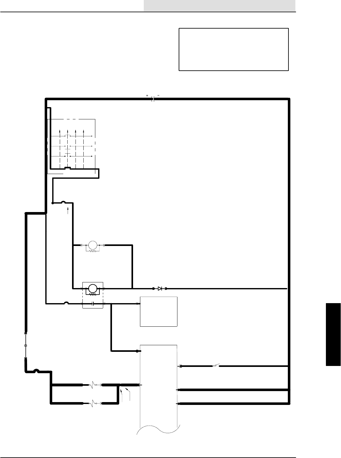
ELECTRICAL
5-91
8410 MM392 (8--01)
SWEEP SIDE BRUSH WILL
NOT TURN ON AND LOWER
(SCHEMATIC)
OPERATION:
--SIDE BRUSH IS SELECTED ON PANEL
--SWEEP 1 OR 2 ARE ON AND WORKING
--PIN 11 OF SWEEP PANEL = GROUND
-- S V -- 1 3 A N D S V -- 1 5 T U R N O N
--SIDE BRUSH TURNS ON AND LOWERS
UNSWITCHED
POWER
16E/GRN
1H/RED
13AM/BLK
16E/GRN
16F/
GRN 19C/BLU
19A/BLU
50A/ORA
50B/ORA
16C/GRN
1A/RED
20/BLU
CB--2
IGNITION SWITCH
S--15
( X INDICATES A
CLOSED CONTACT )
D--1
10A
CB--3
19/BLU
M5 86
85
START
START
RUN
OFF
PREHEAT
X
XXX
XX
X
IGN.
19
30
BATT.
50
17
N/U RUN/ACC
1/RED
1FRONT
15A
8730M3
8685 M3
ELECTRONIC
INSTRUMENT
PANEL
13/BLK
BATTERY
13AC/BLK
13AB/BLK
23
22
GROUND
LINE
1G/RED
32A/BLU
87
30
1G/RED M5
50A/ORA AUXILIARY
1
ELECTRONIC
INSTR.
PANEL
53/BRN
8
HOPPER LOCATION
LOW = SWEEP ENABLE
HOPPER DN
N.O.H.C.
CLOSED =
13AT/BLK
SV--15 SIDE BR.
DOWN VALVE
SV--13 SIDE BR.
ON VALVE
11
15 AMP
7C/BLU
7B/BLU
33D/ORA
33C/ORA
33/ORA
33A/ORA
CB--9
7D/BLU
7E/BLU
22/YEL
ELECTRICAL
5-92 8410 MM392 (8--01)
CHECK VOLTAGE ACROSS
SV--13 WIRE 33C/ORA
TO 7D/BLU
CHECK VOLTAGE ACROSS
SV--15 WIRE 33D/ORA TO 7E/BLU
REPLACE TOUCH
PANEL FACE--DISCONNECT SV--13 AND
SV--15
CHECK VOLTAGE AT SV--13 WIRE
33C/ORA AND SV--15 WIRE 33D/ORA
TO GROUND
SWEEP SIDE BRUSH WILL
NOT TURN ON AND LOWER
(FLOW CHART)
NO
YES
OPERATION:
--SIDE BRUSH IS SELECTED ON PANEL
--SWEEP 1 OR 2 ARE ON AND WORKING
--PIN 11 OF SWEEP PANEL = GROUND
-- S V -- 1 3 A N D S V -- 1 5 T U R N O N
--SIDE BRUSH TURNS ON AND LOWERS
--BOTH PANELS PASS POWER--UP
TESTING
--SWEEP SYSTEM IS WORKING
--KEY ON AND ENGINE OFF
--SWEEP 1 OR 2 SELECTED ON
CAN SIDE BRUSH
BE SELECTED ON
PANEL?
B+
0 VOLTAGE
33C/ORA, 33D/ORA, 33A/
ORA, 33/ORA, CB--9, 32A/
BLU, M--5 CONTACTS, OR
1G/RED ARE OPEN
B+
0VOLTAGE
REPLACE VALVE SV--13
IF BRUSH NOT TURNING
REPLACE SV--15 IF NOT
LOWERING
STILL NOT WORKING
GO TO HYDRAULIC
TROUBLESHOOTING
FLOW--CHARTS
--TURN KEY OFF, THEN ON
DOES SIDE SWEEP BRUSH
PANEL LED BLINK ?
NO
WIRE 7A/BLU OR
7D/BLU IS OPEN
YES
--KEY OFF
--DISCONNECT PANEL
CHECK CONTINUITY OF 7A/BLU
AND 7D/BLU TO GROUND
REPLACE PANEL
OPEN
CONTINUITY
WIRE 7A/BLU OR 7D/BLU ARE
SHORTED TO GROUND
STILL NOT
WORKING
REPLACE PANEL

ELECTRICAL
5-93
8410 MM392 (8--01)
OPERATION:
--SWEEP 1 OR 2 SELECTED
--SWEEP VACUUM FAN SELECTED
(TURNS ON AUTOMATICALLY WHEN
SWEEP 1 OR 2 SELECTED AND NO
HOPPER THERMAL CONDITION)
--SV--18 IS TURNED ON
SWEEP VACUUM FAN WILL
NOT TURN ON
(SCHEMATIC)
UNSWITCHED
POWER
16E/GRN
1H/RED
13AM/BLK
16E/GRN
16F/
GRN 19C/BLU
19A/BLU
50A/ORA
50B/ORA
16C/GRN
1A/RED
20/BLU
CB--2
IGNITION SWITCH
S--15
( X INDICATES A
CLOSED CONTACT )
D--1
10A
CB--3
19/BLU
M58685
START
START
RUN
OFF
PREHEAT
X
XXX
XX
X
IGN.
19
30
BATT.
50
17
N/U RUN/ACC
1/RED
1FRONT
15A
8730M3
8685 M3
ELECTRONIC
INSTRUMENT
PANEL
13/BLK
BATTERY
13AC/BLK
13AB/BLK
23
22
GROUND
LINE
1G/RED
CB--8
15 AMP
32A/BLU
87
30
1G/RED M5
31A/GRY
50A/ORA
AUXILIARY
1
ELECTRONIC
INSTR.
PANEL
2
31/GRY
44/YEL
15 AMP
16
33/ORA
33A/ORA
CB--9
44A/BRN
33B/ORA
SV--18 VAC FAN
SWEEP VALVE
22/YEL
OPEN AT 155F
13CD/BLK
24B/PUR
24A/PUR
SWITCH
HOPPER THERMAL
S--8
24/PUR
18
3
ELECTRICAL
5-94 8410 MM392 (8--01)
--DISCONNECT S--8
--SHORT WIRE 24A/PUR
AT S--8 TO GROUND
DOES HAZARD LIGHT
STOP BLINKING ?
OPERATION:
--SWEEP 1 OR 2 SELECTED
--SWEEP VACUUM FAN SELECTED
(TURNS ON AUTOMATICALLY WHEN
SWEEP 1 OR 2 SELECTED AND NO
HOPPER THERMAL CONDITION)
--SV--18 IS TURNED ON
--KEY OFF
--DISCONNECT PANEL
CHECK CONTINUITY OF 44A/
BRN AND 44/YEL TO GROUND
STILL NOT WORKING
GO TO HYDRAULIC
TROUBLESHOOTING
FLOW--CHARTS
--SELECT SWEEP 1
DOES SWEEP VACUUM FAN
TOUCH PANEL LED LIGHT UP ?
--DISCONNECT SV--18
CHECK VOLTAGE AT SV--18 WIRE
33B/ORA TO GROUND
SWEEP VACUUM FAN WILL
NOT TURN ON
(FLOW CHART)
NO
YES
--SWEEP 1 WORKS (BRUSHES SPIN
AND HEAD LOWERS)
--KEY ON AND ENGINE OFF
B+
0 VOLTAGE
33B/ORA, 33A/ORA,
32A/BLU, CB--9, M5
CONTACTS, OR
1G/RED ARE OPEN
CHECK VOLTAGE AT
SV--18 WIRE 33B/ORA
TO WIRE 44A/BRN
0VOLTAGE
B+
REPLACE SV--18
--SV--18 STILL DISCONNECTED
--TURN KEY OFF, THEN ON
IS THE SWEEP VACUUM LED
BLINKING ?
YES
NO
44A/BRN OR 44/YEL
IS OPEN
REPLACE PANEL
OPEN
CONTINUITY
WIRE 44A/BRN OR
44/YEL IS SHORTED TO GROUND
--PUT SWEEP PANEL IN
”INPUT DISPLAY MODE”
--KEY OFF, HOLD HEADLIGHT
SWITCH, KEY ON
--HOLD HEADLIGHT SWITCH FOR
10 SEC, THEN RELEASE
--SWEEP 1 AND 2 LED’S SHOULD
TURN ON
IS HAZARD LED
BLINKING ?
YES
NO
REPLACE PANEL
YES
S--8 IS OPEN
NO
CHECK CONTINUITY
OF 24/PUR FROM
SWEEP PANEL PIN 3
TO S--8
OPEN
REPAIR 24/PUR
REPLACE PANEL
CONT.
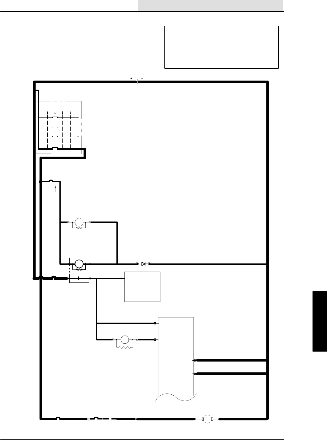
ELECTRICAL
5-95
8410 MM392 (8--01)
SHAKER SYSTEM WILL
NOT TURN ON
(SCHEMATIC)
OPERATION:
--SWEEP AND SWEEP FAN MUST BE OFF
--SHAKE SYSTEM SELECTED ON PANEL
--ONCE ACTIVATED M6 IS TURNED ON FOR 40
SECONDS
--RUNS FOR 15 SECONDS EVERY TIME SWEEP
SYSTEM IS TURNED OFF
16E/GRN
1H/RED
13AM/BLK
16E/GRN
16F/
GRN 19C/BLU
19A/BLU
50A/ORA
50B/ORA
16C/GRN
1A/RED
20/BLU
CB--2
IGNITION SWITCH
S--15
( X INDICATES A
CLOSED CONTACT )
D--1
10A
CB--3
19/BLU
M5 86
85
START
START
RUN
OFF
PREHEAT
X
XXX
XX
X
IGN.
19
30
BATT.
50
17
N/U RUN/ACC
1/RED
1FRONT
15A
8730M3
8685 M3
ELECTRONIC
INSTRUMENT
PANEL
13/BLK
BATTERY
13AC/BLK
13AB/BLK
23
22
GROUND
LINE
50A/ORA
AUXILIARY
1
ELECTRONIC
INSTR.
PANEL
22/YEL
20A/BLU
50C/ORA
5
M--6
SHAKER RELAY
8685
97/BLU
65B/ORA 13CE/BLK
MTR--3
SHAKER MOTOR
30A/GRY
30/GRY
M6
20A/ BLU
CB--5 87
30
15 AMP
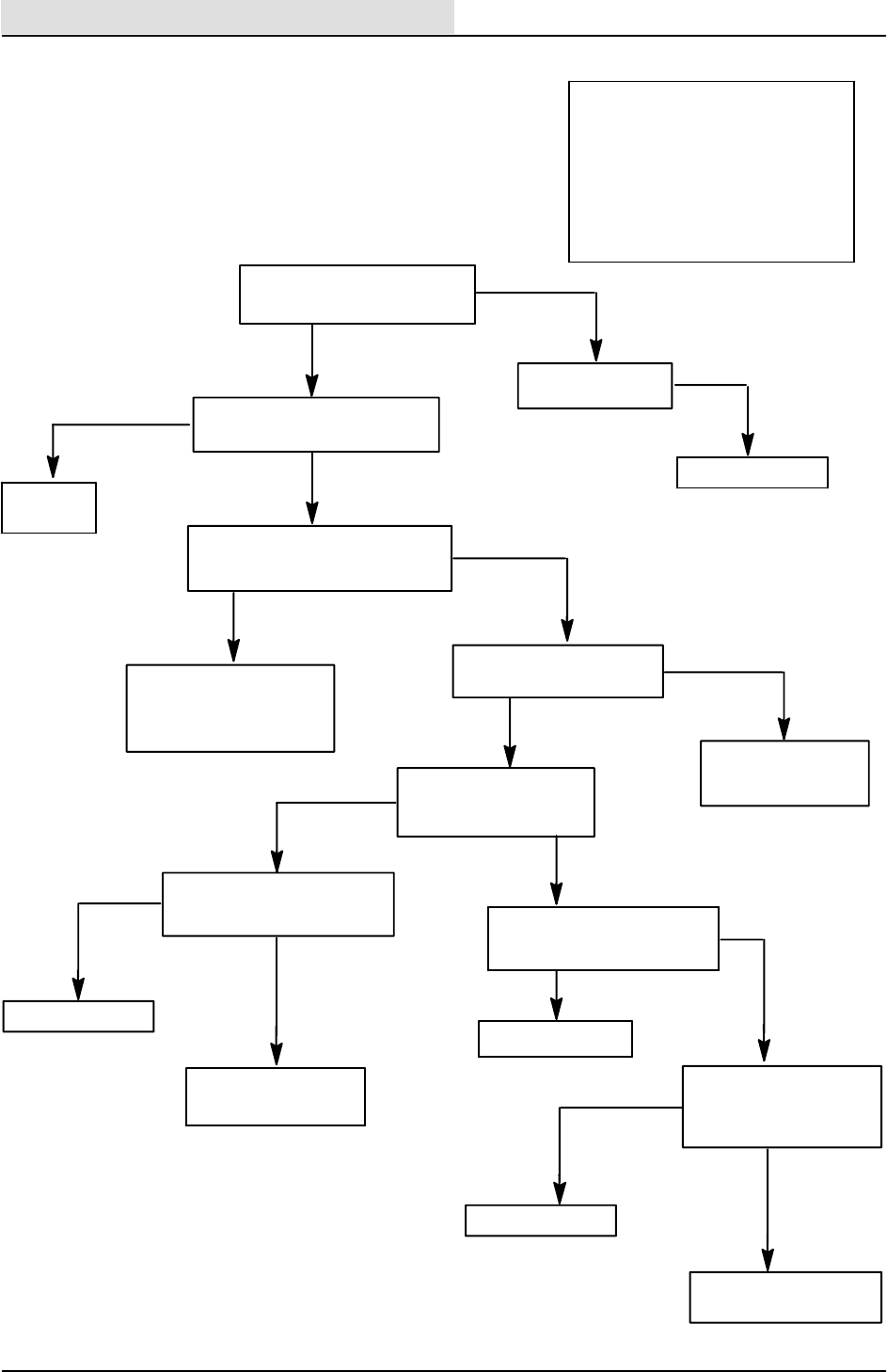
ELECTRICAL
5-96 8410 MM392 (8--01)
REPLACE TOUCH
PANEL FACE
97/BLU IS
SHORTED TO GROUND
--DISCONNECT PANEL
--KEY OFF
CHECK CONTINUITY OF
97/BLU TO GROUND
SHAKER SYSTEM WILL
NOT TURN ON
(FLOW CHART)
OPERATION:
--SWEEP AND SWEEP FAN MUST BE
OFF
--SHAKE SYSTEM SELECTED ON
PANEL
--ONCE ACTIVATED M6 IS TURNED
ON FOR 40 SECONDS
--RUNS FOR 15 SECONDS EVERY
TIME SWEEP SYSTEM IS TURNED
OFF
--DISCONNECT M--6
CHECK VOLTAGE AT M6 AT PIN 85
WIRE 50C/ORA TO GROUND
NO
YES
--KEY ON AND ENGINE OFF
-- P A N E L S P O W E R U P
--SWEEP AND SWEEP FAN OFF
B+
0 VOLTAGE
CAN SHAKER SYSTEM
BE SELECTED ON PANEL ?
B+
0 VOLTAGE
REPLACE M6 WITH A KNOWN
GOOD RELAY
WORKS
PROBLEM
SOLVED
NOT
WORKING
WIRES 50C/ORA, 50A/ORA,
50B/ORA, M3 CONTACTOR,
22/YEL,CB--3,OR1H/RED
ARE OPEN
CHECK VOLTAGE AT M6
PIN 30 WIRE 65B/ORA
65B/ORA, CB--5,
20A/BLU, OR 20/BLU
ARE OPEN
--RECONNECT M6
CHECK VOLTAGE AT M6
PIN 87 TO GROUND
B+
0 VOLTAGE
CHECK VOLTAGE ACROSS
SHAKER MOTOR
REPLACE MOTOR
B+
0 VOLTAGE
30/GRY, 30A/GRY, OR
13CE/BLK IS OPEN
--DISCONNECT M6
--TURN KEY OFF THEN ON
DOES SHAKER LIGHT BLINK ?
NO
97/BLU IS OPEN
YES
REPLACE PANEL
OPEN
CONTINUITY
STILL NOT
WORKING
REPLACE PANEL
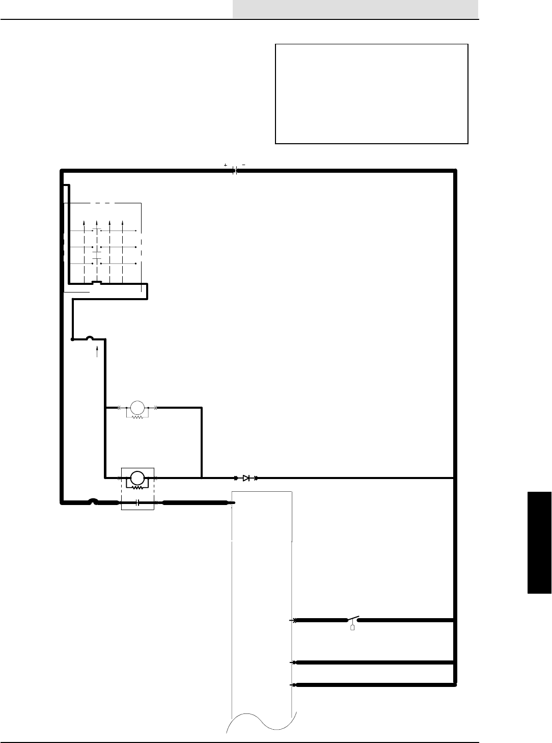
ELECTRICAL
5-97
8410 MM392 (8--01)
HOPPER DIFFERENTIAL
PRESSURE LIGHT ALWAYS ON
(SCHEMATIC)
OPERATION;
--IF THE DIFFERENCE IN AIR PRESSURE ON
BOTH SIDES OF THE SWEEP FILTER EXCEED
20 INCHES OF H20 THE PRESSURE SWITCH
CLOSES
--THE PRESSURE SWITCH CLOSING WILL
SUPPLY A GROUND AT PIN 6 TURNING ON
THE LIGHT
--THIS LIGHT TELLS THE OPERATOR TO RUN
THE SHAKER SYSTEM
16E/GRN
1H/RED
13AM/BLK
16E/GRN
16F/
GRN 19C/BLU
19A/BLU
50A/ORA
50B/ORA
16C/GRN
1A/RED
20/BLU
CB--2
IGNITION SWITCH
S--15
( X INDICATES A
CLOSED CONTACT )
D--1
10A
CB--3
19/BLU
M5 8685
START
START
RUN
OFF
PREHEAT
X
XXX
XX
X
IGN.
19
30
BATT.
50
17
N/U RUN/ACC
1/RED
1FRONT
15A
8730M3
8685 M3
ELECTRONIC
INSTRUMENT
PANEL
13/BLK
BATTERY
13AC/BLK
13AB/BLK
23
22
GROUND
LINE
22/YEL
CN.O.
H2OCLOSED = >20 INCHES
13AU/BLK
6/YEL
HOPPER DIFFERENTIAL PRESSURE
6
ELECTRICAL
5-98 8410 MM392 (8--01)
RUN THE SHAKER SYSTEM
TWICE
IS THE LIGHT ALWAYS ON ?
HOPPER DIFFERENTIAL
PRESSURE SWITCH ALWAYS ON
(FLOW CHART)
YES
NO
OPERATION;
--IF THE DIFFERENCE IN AIR PRESSURE ON
BOTH SIDES OF THE SWEEP FILTER EXCEED
20 INCHES OF H20 THE PRESSURE SWITCH
CLOSES
--THE PRESSURE SWITCH CLOSING WILL
SUPPLY A GROUND AT PIN 6 TURNING ON
THE LIGHT
--THIS LIGHT TELLS THE OPERATOR TO RUN
THE SHAKER SYSTEM
--KEY ON
--ENGINE OFF
FILTER MAY NEED TO
BE REPLACED SOON
DISCONNECT DIFFERENTIAL
PRESSURE SWITCH
IS THE LIGHT STILL ON ?
YES
NO
MACHINE OFF
TAKE AN OHM READING
AT PRESSURE SWITCH
IS IT OPEN ?
YES
NO
REPLACE DIFFERENTIAL
PRESSURE SWITCH
REPLACE THE FILTER
IS THE LIGHT STILL
ALWAYS ON ?
YESNO
REPLACE DIFFERENTIAL
PRESSURE SWITCH
FILTER WAS CLOGGED
--KEY OFF
--PANEL DISCONNECTED
CHECK CONTINUITY OF
6/YEL TO GROUND
OPEN
REPLACE THE PANEL
CONTINUITY
6/YEL IS SHORTED
TO GROUND

ELECTRICAL
5-99
8410 MM392 (8--01)
HOPPER DIFFERENTIAL
PRESSURE SWITCH ALWAYS OFF
(SCHEMATIC)
OPERATION;
--IF THE DIFFERENCE IN AIR PRESSURE ON
BOTH SIDES OF THE SWEEP FILTER EXCEED
20 INCHES OF H20 THE PRESSURE SWITCH
CLOSES
--THE PRESSURE SWITCH CLOSING WILL
SUPPLY A GROUND AT PIN 6 TURNING ON
THE LIGHT
--THIS LIGHT TELLS THE OPERATOR TO RUN
THE SHAKER SYSTEM
16E/GRN
1H/RED
13AM/BLK
16E/GRN
16F/
GRN 19C/BLU
19A/BLU
50A/ORA
50B/ORA
16C/GRN
1A/RED
20/BLU
CB--2
IGNITION SWITCH
S--15
( X INDICATES A
CLOSED CONTACT )
D--1
10A
CB--3
19/BLU
M58685
START
START
RUN
OFF
PREHEAT
X
XXX
XX
X
IGN.
19
30
BATT.
50
17
N/U RUN/ACC
1/RED
1FRONT
15A
8730M3
8685 M3
ELECTRONIC
INSTRUMENT
PANEL
13/BLK
BATTERY
13AC/BLK
13AB/BLK
23
22
GROUND
LINE
22/YEL
CN.O.
H2OCLOSED = >20 INCHES
13AU/BLK
6/YEL
HOPPER DIFFERENTIAL PRESSURE
6
ELECTRICAL
5-100 8410 MM392 (8--01)
REPLACE DIFF. PRESSURE
SWITCH IF AIR PRESSURE
DIFFERENCE EXCEEDS 20
INCH. 0F H2O
HOPPER DIFFERENTIAL
PRESSURE LIGHT ALWAYS OFF
(FLOW CHART)
YES
NO
OPERATION;
--IF THE DIFFERENCE IN AIR PRESSURE ON
BOTH SIDES OF THE SWEEP FILTER EXCEED
20 INCHES OF H20 THE PRESSURE SWITCH
CLOSES
--THE PRESSURE SWITCH CLOSING WILL
SUPPLY A GROUND AT PIN 6 TURNING ON
THE LIGHT
--THIS LIGHT TELLS THE OPERATOR TO RUN
THE SHAKER SYSTEM
--KEY ON
--ENGINE OFF
DISCONNECT DIFFERENTIAL
PRESSURE SWITCH AND
GROUND WIRE 6/YEL
DOES THE LIGHT TURN ON ?
NO
NO
REPLACE THE PANEL
DOES THE LIGHT COME ON
MOMENTARILY AT POWER UP ?
WIRE 6/YEL
IS OPEN
REPLACE LAMP L5
INSIDE THE PANEL
THEN RE--TEST
DOES THE LIGHT
TURN ON MOMENTARILY
AT POWER UP ?
LIGHT STILL OFF
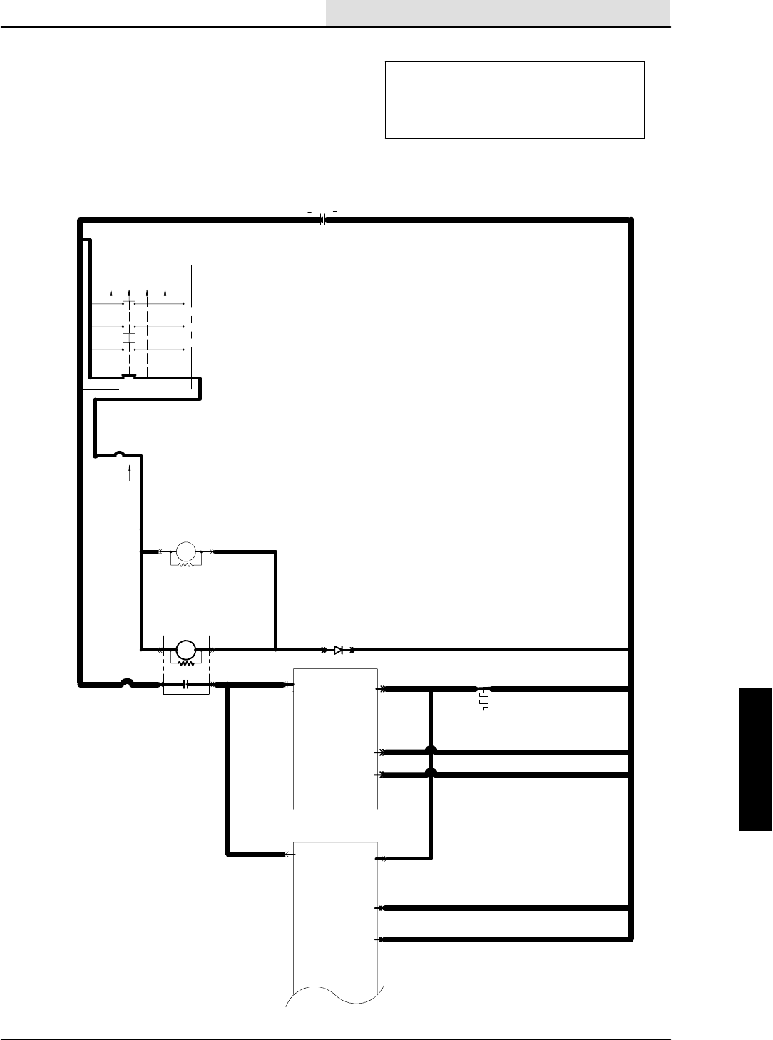
ELECTRICAL
5-101
8410 MM392 (8--01)
HOPPER THERMAL SENTRY
LIGHT ALWAYS ON
(SCHEMATIC)
OPERATION:
--HOPPER TEMPERATURE EXCEEDS 155_F
--S--8 OPENS
--HOPPER THERMAL SENTRY LIGHT TURNS
ON
16E/GRN
1H/RED
13AM/BLK
16E/GRN
16F/
GRN 19C/BLU
19A/BLU
50A/ORA
50B/ORA
16C/GRN
1A/RED
20/BLU
CB--2
IGNITION SWITCH
S--15
( X INDICATES A
CLOSED CONTACT )
D--1
10A
CB--3
19/BLU
M58685
START
START
RUN
OFF
PREHEAT
X
XXX
XX
X
IGN.
19
30
BATT.
50
17
N/U RUN/ACC
1/RED
1FRONT
15A
8730M3
8685 M3
ELECTRONIC
INSTRUMENT
PANEL
13/BLK
BATTERY
13AC/BLK
13AB/BLK
23
22
GROUND
LINE
50A/ORA
AUXILIARY
1
ELECTRONIC
INSTR.
PANEL
22/YEL
OPEN AT 155F 13CD/BLK
24B/PUR
24A/PUR SWITCH
HOPPER THERMAL
S--8
24/PUR
18
13AC/BLK
13AB/BLK
23
22
HOPPER
THERMAL
SENSE
3LOW = SW.FAN ENABLE
24A/PUR
ELECTRICAL
5-102 8410 MM392 (8--01)
REPAIR 24/PUR
AND 24B/PUR
RE--TEST
--KEY OFF
--DISCONNECT PANEL
CHECK CONTINUITY OF
24/PUR AND 24B/PUR
HOPPER THERMAL SENTRY
LIGHT ALWAYS ON
(FLOW CHART)
YES
NO
--KEY ON
--ENGINE OFF
OPERATION:
--HOPPER TEMPERATURE EXCEEDS 155_F
--S--8 OPENS
--HOPPER THERMAL SENTRY LIGHT TURNS
ON
--DISCONNECT S--8
--GROUND 24B/PUR
DOES LIGHT TURN OFF ?
CHECK CONTINUITY
OF S--8
OPEN
CONTINUITY
REPLACE S--8
WIRE 13CD/BLK IS
OPEN TO MACHINE
GROUND
OPEN
CONTINUITY
REPLACE THE PANEL
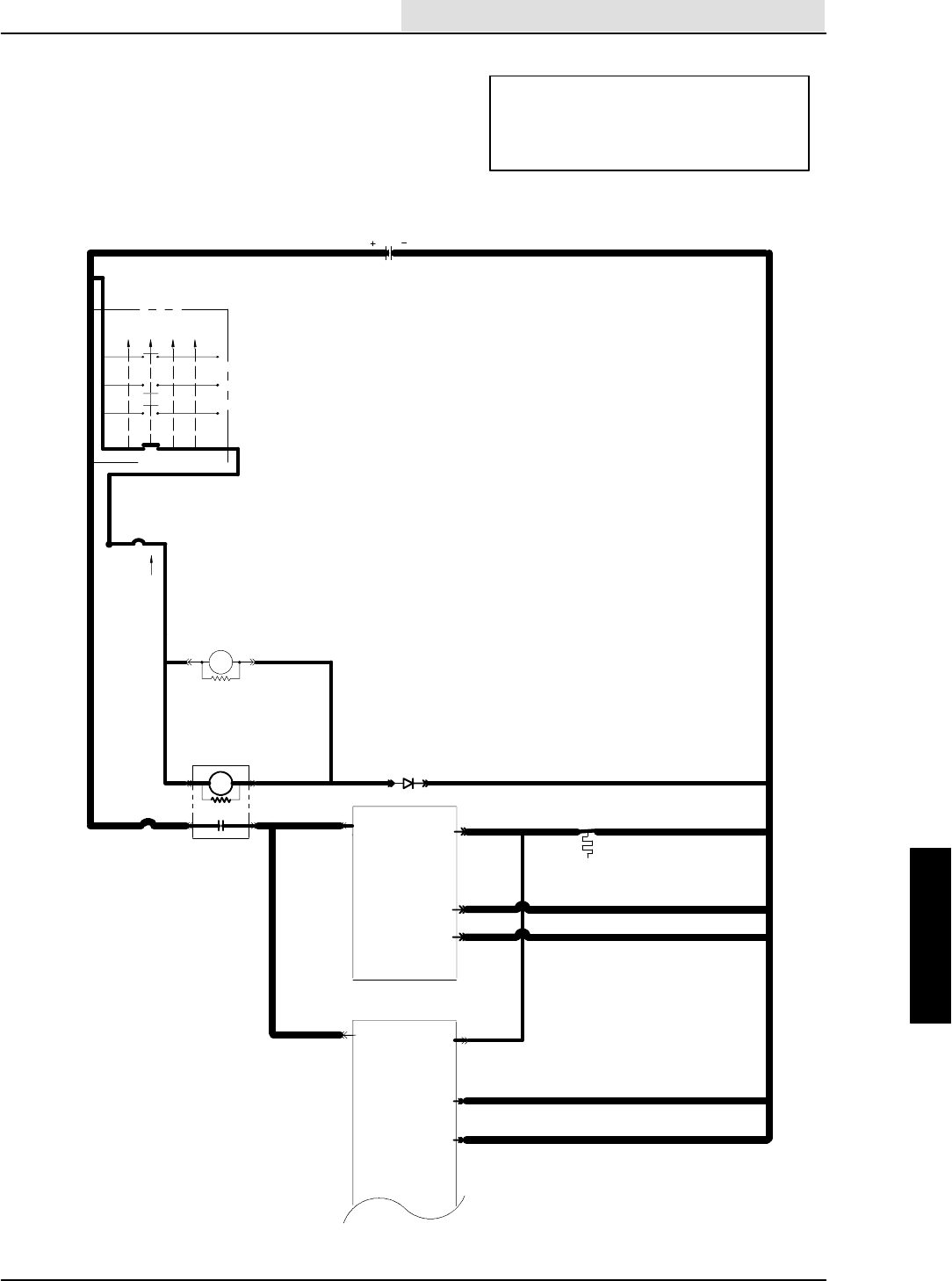
ELECTRICAL
5-103
8410 MM392 (8--01)
HOPPER THERMAL SENTRY
LIGHT ALWAYS OFF
(SCHEMATIC)
OPERATION:
--HOPPER TEMPERATURE EXCEEDS 155_F
--S--8 OPENS
--HOPPER THERMAL SENTRY LIGHT TURNS
ON
16E/GRN
1H/RED
13AM/BLK
16E/GRN
16F/
GRN 19C/BLU
19A/BLU
50A/ORA
50B/ORA
16C/ GRN
1A/RED
20/BLU
CB--2
IGNITION SWITCH
S--15
( X INDICATES A
CLOSED CONTACT )
D--1
10A
CB--3
19/BLU
M5 8685
START
START
RUN
OFF
PREHEAT
X
XXX
XX
X
IGN.
19
30
BATT.
50
17
N/U RUN/ACC
1/RED
1FRONT
15A
8730M3
8685 M3
ELECTRONIC
INSTRUMENT
PANEL
13/BLK
BATTERY
13AC/BLK
13AB/BLK
23
22
GROUND
LINE
50A/ORA
AUXILIARY
1
ELECTRONIC
INSTR.
PANEL
22/YEL
OPEN AT 155F 13CD/BLK
24B/PUR
24A/PUR SWITCH
HOPPER THERMAL
S--8
24/PUR
18
13AC/BLK
13AB/BLK
23
22
HOPPER
THERMAL
SENSE
3LOW = SW.FAN ENABLE
24A/PUR
ELECTRICAL
5-104 8410 MM392 (8--01)
CHECK CONTINUITY OF
24/PUR AND 24A/PUR
TO GROUND
HOPPER THERMAL SENTRY
LIGHT ALWAYS OFF
(FLOW CHART)
OPERATION:
--HOPPER TEMPERATURE EXCEEDS 155_F
--S--8 OPENS
--HOPPER THERMAL SENTRY LIGHT TURNS
ON
YES
NO
--KEY ON
--ENGINE OFF
DISCONNECT S--8
DOES THE PANEL LIGHT
TURN ON ?
YES
NO
NO
REPLACE THE PANEL
DOES THE LIGHT COME ON
MOMENTARILY AT POWER UP ?
REPLACE LAMP L4
INSIDE THE PANEL
THEN RE--TEST
DOES THE LIGHT
TURN ON MOMENTARILY
AT POWER UP ?
REPLACE SWITCH
S--8
CONTINUITY
OPEN
REPLACE THE PANEL
24/PUR AND 24A/PUR
ARE SHORTED TO
GROUND
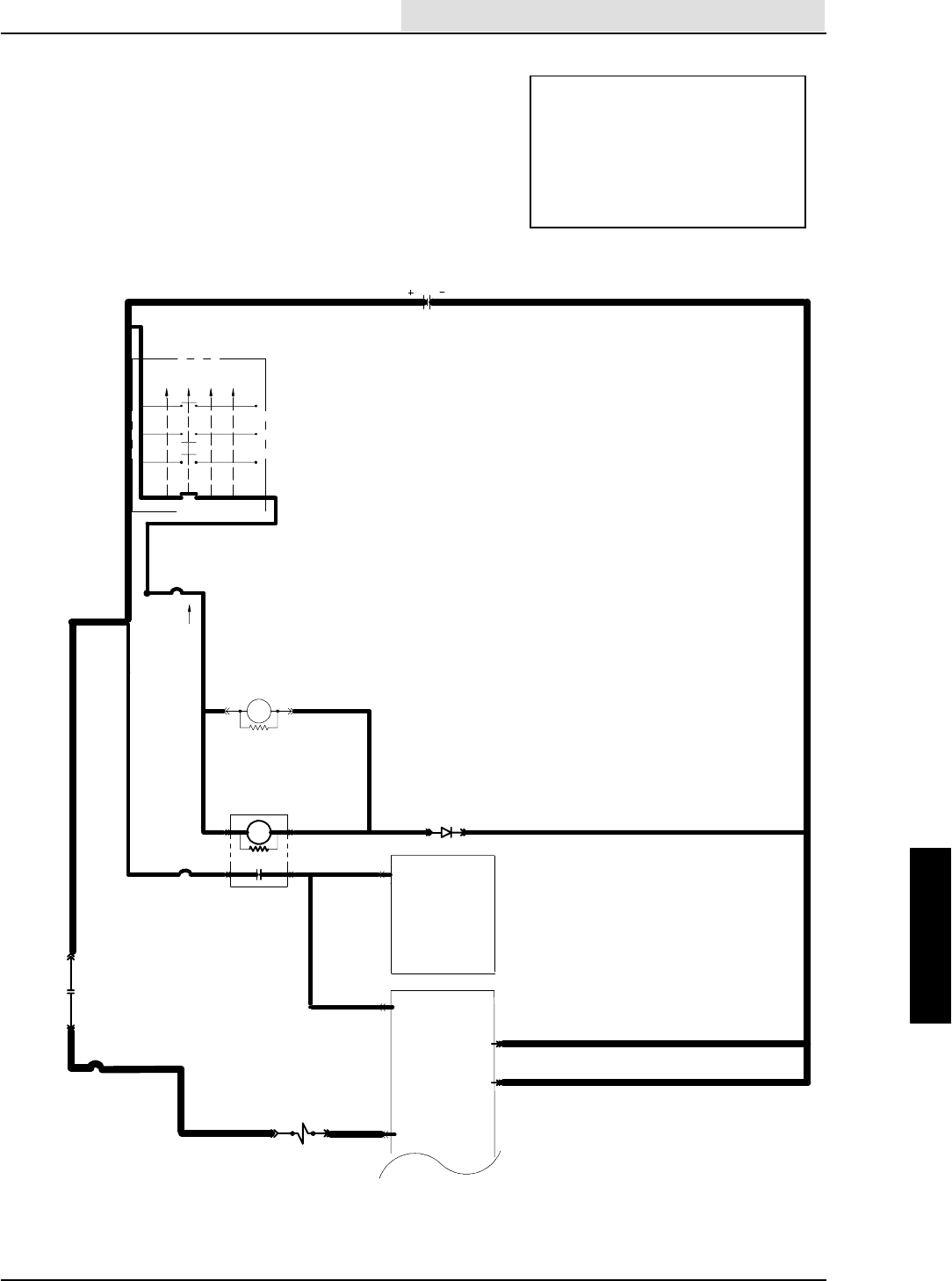
ELECTRICAL
5-105
8410 MM392 (8--01)
HOPPER WILL NOT LIFT
(SCHEMATIC)
OPERATION:
--HOLDING MOMENTARY HOPPER
LIFT SWITCH ON TOUCH PANEL
WILL:
-- T U R N O N S V -- 8
NOTE: IF SWEEP IS SELECTED
WHEN HOPPER IS UP, THE LIFT
LIGHT WILL BLINK AND SWEEP WILL
BE TURNED OFF AUTOMATICALLY
UNSWITCHED
POWER
16E/GRN
1H/RED
13AM/BLK
16E/GRN
16F/
GRN 19C/BLU
19A/BLU
50A/ORA
50B/ORA
16C/GRN
1A/RED
20/BLU
CB--2
IGNITION SWITCH
S--15
( X INDICATES A
CLOSED CONTACT )
D--1
10A
CB--3
19/BLU
M5 86
85
START
START
RUN
OFF
PREHEAT
X
XXX
XX
X
IGN.
19
30
BATT.
50
17
N/U RUN/ACC
1/RED
1
FRONT
15A
8730M3
8685 M3
ELECTRONIC
INSTRUMENT
PANEL
13/BLK
BATTERY
13AC/BLK
13AB/BLK
23
22
GROUND
LINE
1G/RED
CB--8
15 AMP
32A/BLU
87
30
1G/RED M5
31A/GRY
50A/ORA AUXILIARY
1
ELECTRONIC
INSTR.
PANEL
22/YEL
37/YEL 18
SV--8 HOPPER UP
VALVE
31F/GRY
ELECTRICAL
5-106 8410 MM392 (8--01)
--DISCONNECT PANEL
CHECK CONTINUITY OF
37/YEL TO GROUND
HOPPER WILL NOT LIFT
(FLOW CHART)
OPERATION:
--HOLDING MOMENTARY HOPPER
LIFT SWITCH ON TOUCH PANEL
WILL:
-- T U R N O N S V -- 8
NOTE: IF SWEEP IS SELECTED
WHEN HOPPER IS UP, THE LIFT
LIGHT WILL BLINK AND SWEEP WILL
BE TURNED OFF AUTOMATICALLY
NO
YES
--KEY ON AND ENGINE OFF
-- P A N E L S P O W E R U P
B+
0 VOLTAGE
REPLACE PANEL
CAN THE HOPPER LIFT
LEDONTHEPANELBE
TURNED ON ?
--DISCONNECT SV--8
CHECK VOLTAGE ON 31F/
GRY AT SV--8 TO GROUND
31F/GRY, 31A/GRY, CB--8,
32/BLU, M5 CONTACT,
OR 1G/RED ARE OPEN
WITH SV--8 DISCONNECTED
CHECK VOLTAGE ON 31F/GRY
TO 37/YEL WHILE HOLDING
HOPPER LIFT BUTTON
0 VOLTAGE
--TURN KEY OFF, THEN ON
IS HOPPER LIFT LIGHT
BLINKING ?
37/YEL IS OPEN
NO
YES
OPEN
CONTINUITY
REPLACE PANEL
WIRE 37/YEL IS
SHORTED TO
GROUND
B+
REPLACE SV--8
STILL NOT WORKING
SEE HYDRAULIC
TROUBLESHOOTING
FLOW CHART
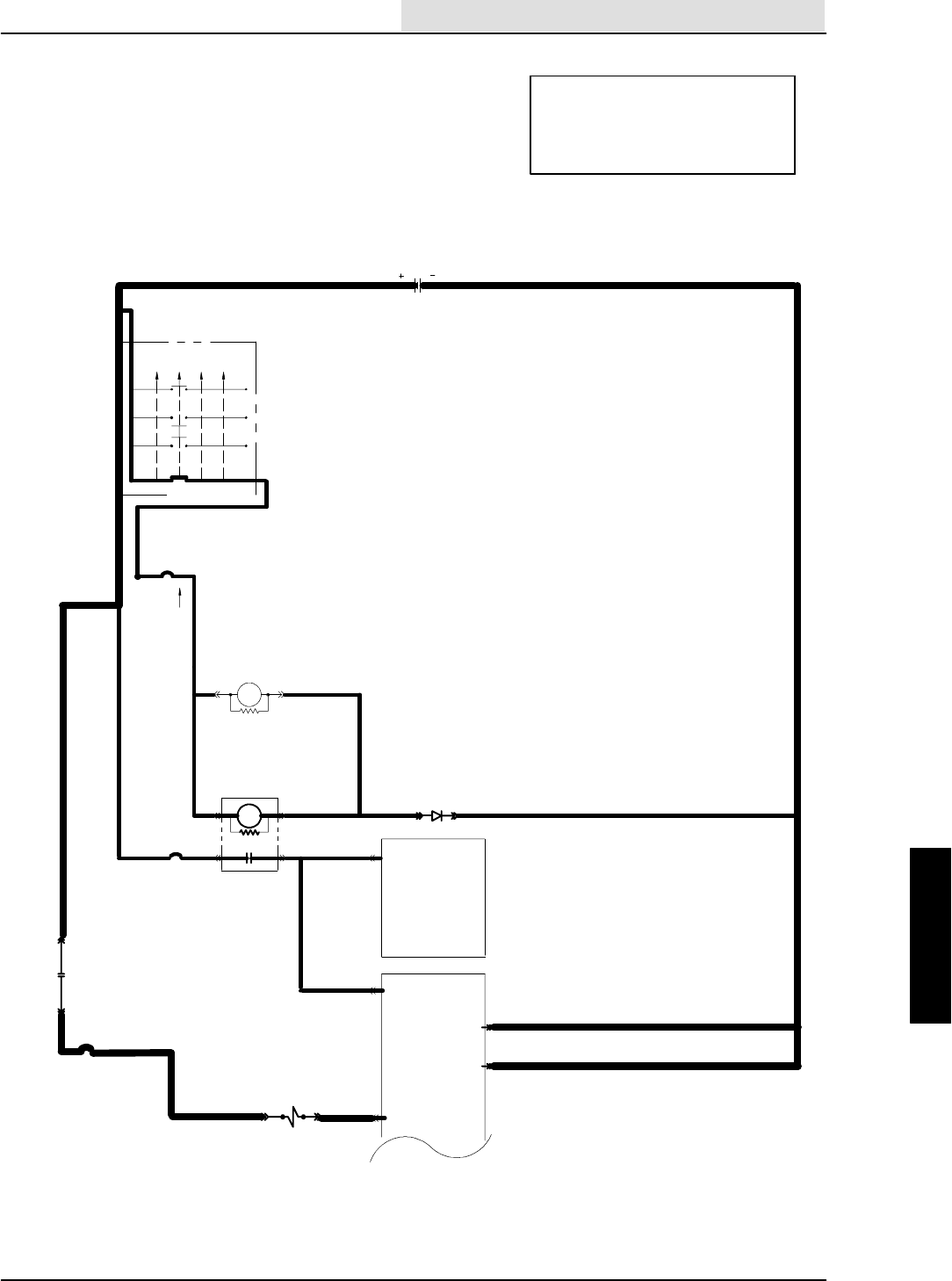
ELECTRICAL
5-107
8410 MM392 (8--01)
HOPPER WILL NOT LOWER
(SCHEMATIC)
OPERATION:
--HOLDING MOMENTARY HOPPER
LOWERSWITCHONTOUCHPANEL
WILL:
-- T U R N O N S V -- 9
UNSWITCHED
POWER
16E/GRN
1H/RED
13AM/BLK
16E/GRN
16F/
GRN 19C/BLU
19A/BLU
50A/ORA
50B/ORA
16C/GRN
1A/RED
20/BLU
CB--2
IGNITION SWITCH
S--15
( X INDICATES A
CLOSED CONTACT )
D--1
10A
CB--3
19/BLU
M58685
START
START
RUN
OFF
PREHEAT
X
XXX
XX
X
IGN.
19
30
BATT.
50
17
N/U RUN/ACC
1/RED
1
FRONT
15A
8730M3
8685 M3
ELECTRONIC
INSTRUMENT
PANEL
13/BLK
BATTERY
13AC/BLK
13AB/BLK
23
22
GROUND
LINE
1G/RED
CB--8
15 AMP
32A/BLU
87
30
1G/RED M5
31A/GRY
50A/ORA AUXILIARY
1
ELECTRONIC
INSTR.
PANEL
22/YEL
SV--9 HOPPER
31G/GRY 38/GRN
DOWN VALVE
9
ELECTRICAL
5-108 8410 MM392 (8--01)
--DISCONNECT PANEL
CHECK CONTINUITY OF
38/GRN TO GROUND
HOPPER WILL NOT LOWER
(FLOW CHART)
OPERATION:
--HOLDING MOMENTARY HOPPER
LOWERSWITCHONTOUCHPANEL
WILL:
-- T U R N O N S V -- 9
NO
YES
--KEY ON AND ENGINE OFF
-- P A N E L S P O W E R U P
B+
0 VOLTAGE
REPLACE PANEL
CAN THE HOPPER LOWER
LEDONTHEPANELBE
TURNED ON ?
--DISCONNECT SV--9
CHECK VOLTAGE ON 31G/
GRY AT SV--9 TO GROUND
31G/GRY, 31A/GRY, CB--8,
32/BLU, M5 CONTACT, OR
1G/RED ARE OPEN
WITH SV--9 DISCONNECTED
CHECK VOLTAGE ON 31G/GRY
TO 38/GRN WHILE HOLDING
HOPPER LOWER BUTTON
0 VOLTAGE
--TURN KEY OFF, THEN ON
IS HOPPER LOWER LIGHT
BLINKING ?
38/GRN IS OPEN
NO
YES
OPEN
CONTINUITY
REPLACE PANEL
WIRE 38/GRN IS
SHORTED TO
GROUND
B+
REPLACE SV--9
STILL NOT WORKING
SEE HYDRAULIC
TROUBLESHOOTING
FLOW CHART

ELECTRICAL
5-109
8410 MM392 (8--01)
HOPPER DOOR WILL NOT
CLOSE
(SCHEMATIC)
OPERATION:
--HOPPER DOOR CLOSE IS SELECTED ON PANEL
--SV--16 IS TURNED ON MOMENTARILY
--HOPPER DOOR IS CLOSED
NOTE: HOPPER DOOR CLOSED IS SELECTED AUTOMATI-
CALLY AT POWER UP AND WHEN SWEEP IS TURNED OFF
--DOOR CLOSES FOR 8 SECONDS IN LOW ENGINE SPEED
--DOOR CLOSES FOR 3 SECONDS IN HIGH ENGINE SPEED
UNSWITCHED
POWER
16E/GRN
1H/RED
13AM/BLK
16E/GRN
16F/
GRN 19C/BLU
19A/BLU
50A/ORA
50B/ORA
16C/GRN
1A/RED
20/BLU
CB--2
IGNITION SWITCH
S--15
( X INDICATES A
CLOSED CONTACT )
D--1
10A
CB--3
19/BLU
M586
85
START
START
RUN
OFF
PREHEAT
X
XXX
XX
X
IGN.
19
30
BATT.
50
17
N/U RUN/ACC
1/RED
1
FRONT
15A
8730M3
8685 M3
ELECTRONIC
INSTRUMENT
PANEL
13/BLK
BATTERY
13AC/BLK
13AB/BLK
23
22
GROUND
LINE
1G/RED
32A/BLU
87
30
1G/RED M5
50A/ORA AUXILIARY
1
ELECTRONIC
INSTR.
PANEL
15 AMP 33/ORA
33A/ORA
CB--9
22/YEL
20
41/PUR
33E/ORA 41A/PUR
SV--16 HOPPER
CLOSE VALVE
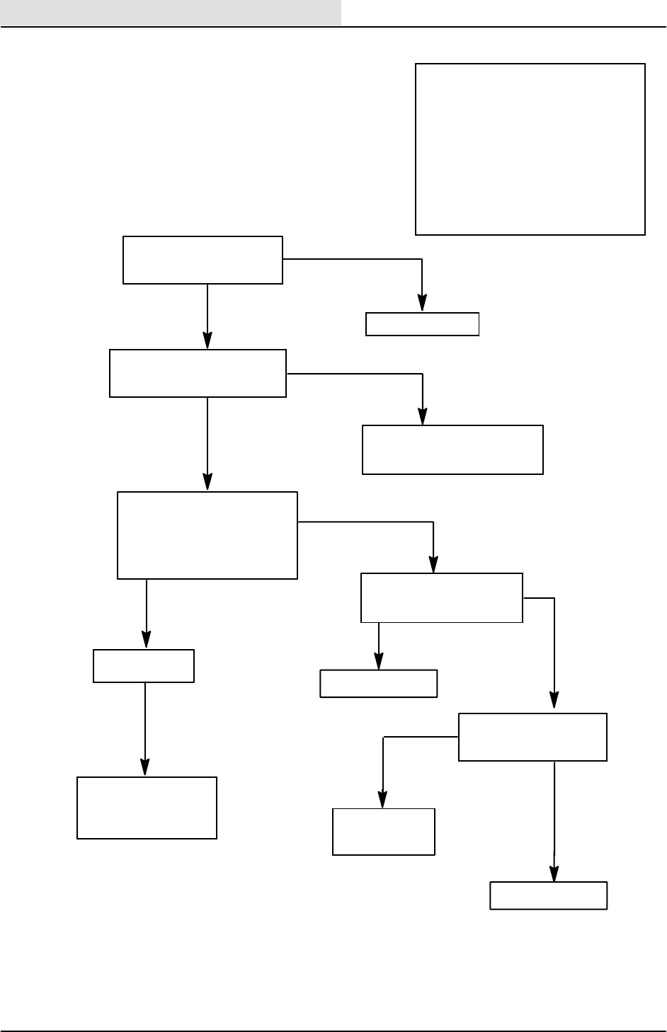
ELECTRICAL
5-110 8410 MM392 (8--01)
WITH SV--16 DISCONNECTED
CHECK VOLTAGE ACROSS
SV--16 CONNECTOR WIRES
33E/ORA TO 41A/PUR
--TURN HOPPER DOOR CLOSE
OFF, THEN ON
33E/ORA, 33A/ORA, 33/ORA
CB--9, 32A/BLU, M5 CONTACTS,
OR 1G/RED IS OPEN
STILL NOT WORKING
SEE HYDRAULIC
TROUBLESHOOTING
FLOW CHART
--DISCONNECT PANEL
CHECK CONTINUITY OF
41/PUR TO GROUND
HOPPER DOOR WILL NOT
CLOSE
(FLOW CHART)
OPERATION:
--HOPPER DOOR CLOSE IS SELECTED
ON PANEL
--SV--16 IS TURNED ON MOMENTARILY
--HOPPER DOOR IS CLOSED
NOTE: HOPPER DOOR CLOSED IS SE-
LECTED AUTOMATICALLY AT POWER
UP AND WHEN SWEEP IS TURNED
OFF
--DOOR CLOSES FOR 8 SECONDS IN
LOW ENGINE SPEED
--DOOR CLOSES FOR 3 SECONDS IN
HIGH ENGINE SPEED
NO
YES
--KEY ON AND ENGINE OFF
-- P A N E L S P O W E R U P
B+
0 VOLTAGE
REPLACE PANEL
CAN THE HOPPER DOOR
CLOSED BE SELECTED
ON THE PANEL ?
--DISCONNECT SV--16
CHECK VOLTAGE ON 33E/ORA
AT SV--16 TO GROUND
0 VOLTAGE
--TURN KEY OFF, THEN ON
IS HOPPER DOOR CLOSE
LIGHT BLINKING ?
41/PUR IS OPEN
NO
YES
OPEN
CONTINUITY
REPLACE PANEL
WIRE 41/PUR IS
SHORTED TO
GROUND
B+
REPLACE SV--16

ELECTRICAL
5-111
8410 MM392 (8--01)
HOPPER DOOR WILL NOT
OPEN
(SCHEMATIC)
OPERATION:
--HOPPER DOOR CLOSE IS TURNED OFF ON PANEL
--SV--17 IS TURNED ON MOMENTARILY
--HOPPER DOOR IS OPENED
NOTE: HOPPER DOOR OPEN IS SELECTED AUTOMATI-
CALLY WHEN SWEEP IS TURNED ON
--DOOR OPENS FOR 8 SECONDS IN LOW ENGINE SPEED
--DOOR OPENS FOR 3 SECONDS IN HIGH ENGINE SPEED
UNSWITCHED
POWER
16E/GRN
1H/RED
13AM/BLK
16E/GRN
16F/
GRN 19C/BLU
19A/BLU
50A/ORA
50B/ORA
16C/GRN
1A/RED
20/BLU
CB--2
IGNITION SWITCH
S--15
( X INDICATES A
CLOSED CONTACT )
D--1
10A
CB--3
19/BLU
M586
85
START
START
RUN
OFF
PREHEAT
X
XXX
XX
X
IGN.
19
30
BATT.
50
17
N/U RUN/ACC
1/RED
1
FRONT
15A
8730M3
8685 M3
ELECTRONIC
INSTRUMENT
PANEL
13/BLK
BATTERY
13AC/BLK
13AB/BLK
23
22
GROUND
LINE
1G/RED
32A/BLU
87
30
1G/RED M5
50A/ORA AUXILIARY
1
ELECTRONIC
INSTR.
PANEL
15 AMP 33/ORA
33A/ORA
CB--9
22/YEL
12
40/BRN
SV--17 HOPPER
OPEN VALVE
33F/ORA 40A/BRN
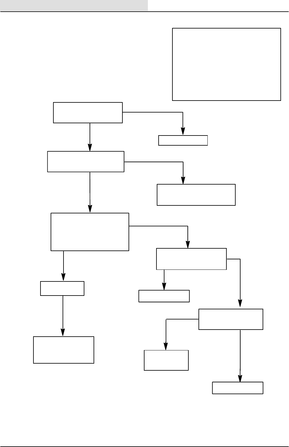
ELECTRICAL
5-112 8410 MM392 (8--01)
WITH SV--17 DISCONNECTED
CHECK VOLTAGE ACROSS
SV--17 CONNECTOR WIRES
33F/ORA TO 40A/BRN
--TURN HOPPER DOOR CLOSE
ON, THEN OFF
33F/ORA, 33A/ORA, 33/ORA
CB--9, 32A/BLU, M5 CONTACTS,
OR 1G/RED IS OPEN
STILL NOT WORKING
SEE HYDRAULIC
TROUBLESHOOTING
FLOW CHART
--DISCONNECT PANEL
CHECK CONTINUITY OF
40/BRN TO GROUND
HOPPER DOOR WILL NOT
OPEN
(FLOW CHART)
OPERATION:
--HOPPER DOOR CLOSE IS TURNED OFF
ON PANEL
--SV--17 IS TURNED ON MOMENTARILY
--HOPPER DOOR IS OPENED
NOTE: HOPPER DOOR OPEN IS SELECTED
AUTOMATICALLY WHEN SWEEP IS
TURNED ON
--DOOR OPENS FOR 8 SECONDS IN LOW
ENGINE SPEED
--DOOR OPENS FOR 3 SECONDS IN HIGH
ENGINE SPEED
NO
YES
--KEY ON AND ENGINE OFF
-- P A N E L S P O W E R U P
B+
0 VOLTAGE
REPLACE PANEL
CAN THE HOPPER DOOR
CLOSED BE TURNED OFF
ON THE TOUCH PANEL ?
--DISCONNECT SV--17
CHECK VOLTAGE ON 33F/ORA
AT SV--17 TO GROUND
0 VOLTAGE
--TURN KEY OFF, THEN ON
IS HOPPER DOOR CLOSE
LIGHT BLINKING ?
40/BRN IS OPEN
NO
YES
OPEN
CONTINUITY
REPLACE PANEL
WIRE 40/BRN IS
SHORTED TO
GROUND
B+
REPLACE SV--17
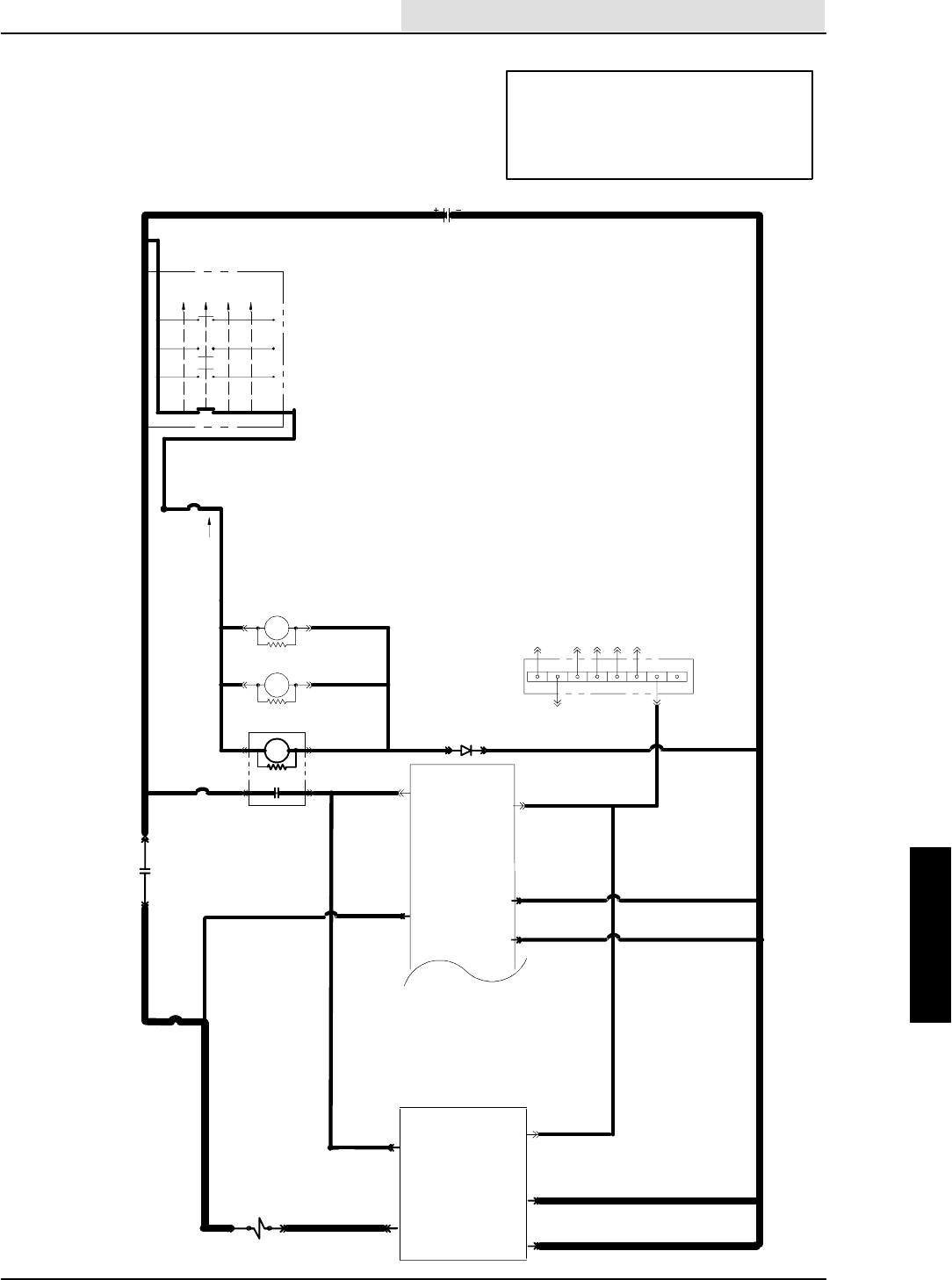
ELECTRICAL
5-113
8410 MM392 (8--01)
OPERATION:
--HIGH ENGINE SPEED SELECTED
--ENGINE SPEED IS SENSED ON SWEEP
PANEL WHEN PIN 15 IS LESS THEN 1 VDC
--PIN17ISPULLEDLOW
--SV--2 TURNS ON
ENGINE COOLING FAN NOT
OPERATING
(SCHEMATIC)
16E/GRN
1H/RED 13AM/BLK
16E/GRN
16F/
GRN
19C/BLU
19B/BLU
19A/BLU
1F/RED 21A/ORA
50A/ORA
50B/ORA
16C/
GRN
16D/
GRN
30 87
1A/RED
20/BLU
CB--2
IGNITION SWITCH
S--15
( X INDICATES A
CLOSED CONTACT )
D--1
10A
22/YEL
CB--3
19/BLU
M5 86
85
START
START
RUN
OFF
PREHEAT
X
XXX
XX
X
IGN.
19
30
BATT.
50
17
N/U
RUN/
ACC
1/RED
1
FRONT
15A
8730
M4 8685
M3
8685 M3
ELECTRONIC
INSTRUMENT
PANEL
13/BLK
BATTERY
M4
13AC/BLK
13AB/BLK
25A/GRY
25/GRY
21/ ORA
23
22
2
GROUND
LINE
15 AMP
CB--4
50A/ORA
AUXILIARY
1
23
22
ELECTRONIC
INSTRUMENT
PANEL
13AG/BLK
13AF/BLK
SV--2 ENG. FAN
VALVE 49/GRN 17
25E/GRY
83B/BRN
17
HG
FEDC
B
A
GOVERNOR CONTROL
ENG. SPEED SENSE
15 83A/BRN
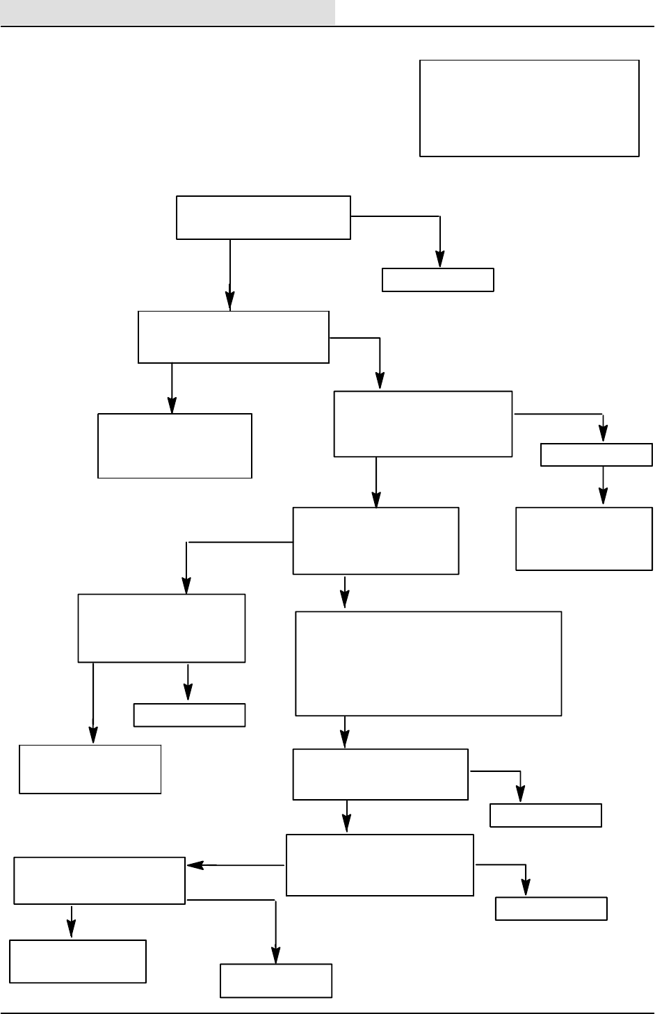
ELECTRICAL
5-114 8410 MM392 (8--01)
REPLACE SWEEP
PANEL
--KEY OFF
--PANEL DISCONNECTED
CHECK CONTINUITY FROM
49/GRN TO GROUND
--TURN KEY OFF, THEN ON
DOES THE SWEEP VAC
FAN LIGHT BLINK ?
(NOT BLINKING)
STILL NO FAN ?
GO TO HYDRAULIC
TROUBLESHOOTING
FLOW--CHARTS
--SELECT ”HIGH” ENGINE
SPEED
CHECK VOLTAGE ACROSS
SV--2 WIRES 25E/GRY AND
49/GRN
OPERATION:
--HIGH ENGINE SPEED SELECTED
--ENGINE SPEED IS SENSED ON
SWEEP PANEL WHEN PIN 15 IS LESS
THEN 1 VDC
--PIN17ISPULLEDLOW
--SV--2 TURNS ON
--DISCONNECT SV--2
CHECK VOLTAGE AT SV--2 WIRE
25E/GRY TO GROUND
ENGINE COOLING FAN NOT
OPERATING
(FLOW CHART)
NO
YES
--KEY ON AND ENGINE OFF
-- P A N E L S P O W E R U P
REPLACE PANEL
B+
0 VOLTAGE
CAN ENGINE SPEED ”HIGH”
BE SELECTED ON PANEL ?
25E/GRY, 25A/GRY, CB--4,
21/ORA, 21A/ORA, M4
CONTACTS, OR IF/RED
ARE OPEN
B+
0VOLTAGE
REPLACE SV--2
NO
YES
OPEN
CONTINUITY
WIRE 49/GRN IS
SHORTED TO GROUND
REPLACE PANEL
SV--2 STILL
DISCONNECTED
PUT SWEEP PANEL INTO
”INPUT DISPLAY MODE”
--TURN KEY OFF, HOLD HEADLIGHT BUTTON,
TURN KEY ON
--HOLD HEADLIGHT BUTTON FOR 10 SECONDS
THEN RELEASE
--SWEEP 1 AND 2 LED’S WILL BE ON
IS HEADLIGHT LED BLINKING
WHEN HIGH ENGINE SPEED
IS SELECTED
YES
49/GRN IS OPEN
NO
--DISCONNECT PANELS
CHECK CONTINUITY OF 83/BRN
FROM SCRUB PANEL PIN 17 TO
SWEEP PANEL PIN 15
OPEN
REPAIR 83/BRN
CONTINUITY
IS ENGINE SPEED CHANGING
WHEN SELECTED ON SCRUB
PANEL ?
NO
GO TO GOVERNOR
TROUBLESHOOTING
YES
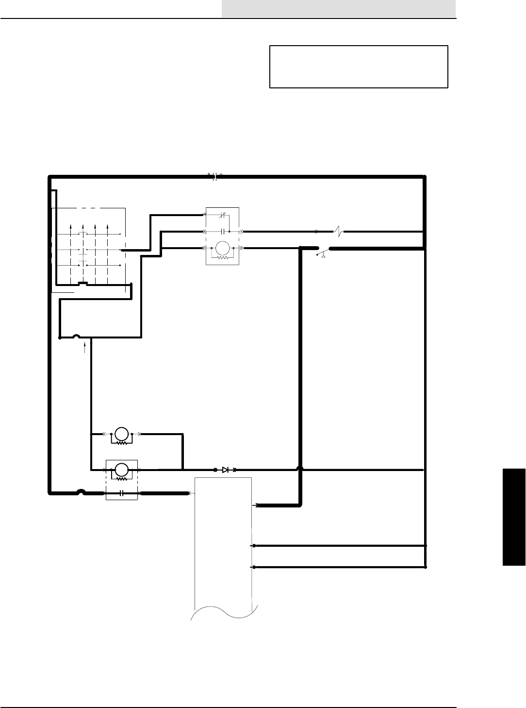
ELECTRICAL
5-115
8410 MM392 (8--01)
ENGINE OIL PRESSURE WARNING
LIGHT WILL NOT TURN ON OR OFF
(SCHEMATIC)
OPERATION:
--(PIN 15) IS PULLED TO GROUND THROUGH
S--2 WHEN OIL PRESSURE IS HIGH ENOUGH
--OIL LIGHT TURNS OFF
16E/GRN
1H/RED
13AM/BLK
19B/BLU
19A/BLU
50A/ORA
50B/ORA
16C/
GRN
16D/
GRN
1A/RED
20/BLU
CB--2
IGNITION SWITCH
S--15
( X INDICATES A
CLOSED CONTACT )
D--1
10A
22/YEL
CB--3
19/BLU
START
START
RUN
OFF
PREHEAT
X
XXX
XX
X
IGN.
19
30
BATT.
50
17
N/U
RUN/
ACC
1/RED
1
FRONT
15A
8730
M48685
M3
8685 M3
ELECTRONIC
INSTRUMENT
PANEL
13/BLK
BATTERY
13AC/BLK
13AB/BLK
23
22
GROUND
LINE
CLOSED = RUN
13BA/BLK
13BJ/BLK
8685
30
87
87A
SV--14
16/GRN
15B/BLU
15A/BLU S--2 OIL SWITCH
16A/GRN
16B/GRN
3/ORA
14/GRN
FUEL PUMP
M2
15 15/ BLU
ELECTRICAL
5-116 8410 MM392 (8--01)
ENGINE OIL PRESSURE WARNING
LIGHT WILL NOT TURN OFF
(FLOW CHART)
ENGINE OIL PRESSURE WARNING
LIGHT WILL NOT TURN ON
(FLOW CHART)
(PIN 15) IS GROUNDED
CHECK OIL PRESSURE
SWITCH OPERATION
DOES OIL LIGHT TURN
ON MOMENTARILY AT
POWER UP ?
YES
NO
REPLACE LAMP L1
INSIDE PANEL
STILL NOT TURNING
ON AT POWER UP
REPLACE INSTR. PANEL
DISCONNECT OIL PRESSURE
SWITCH S--4
GROUND WIRE 15/BLU
DOES LIGHT SHUT OFF ?
YES
NO
KEY ON
ENGINE OFF
REPLACE OIL PRESSURE LIGHT
WIRE 15/BLU IS OPEN
FROM OIL PRES-
SURE SWITCH TO
(PIN 15)
OPERATION:
--(PIN 15) IS PULLED TO GROUND THROUGH
S--2 WHEN OIL PRESSURE IS HIGH ENOUGH
--OIL LIGHT TURNS OFF
OPERATION:
--(PIN 15) IS PULLED TO GROUND THROUGH
S--2 WHEN OIL PRESSURE IS HIGH ENOUGH
--OIL LIGHT TURNS OFF
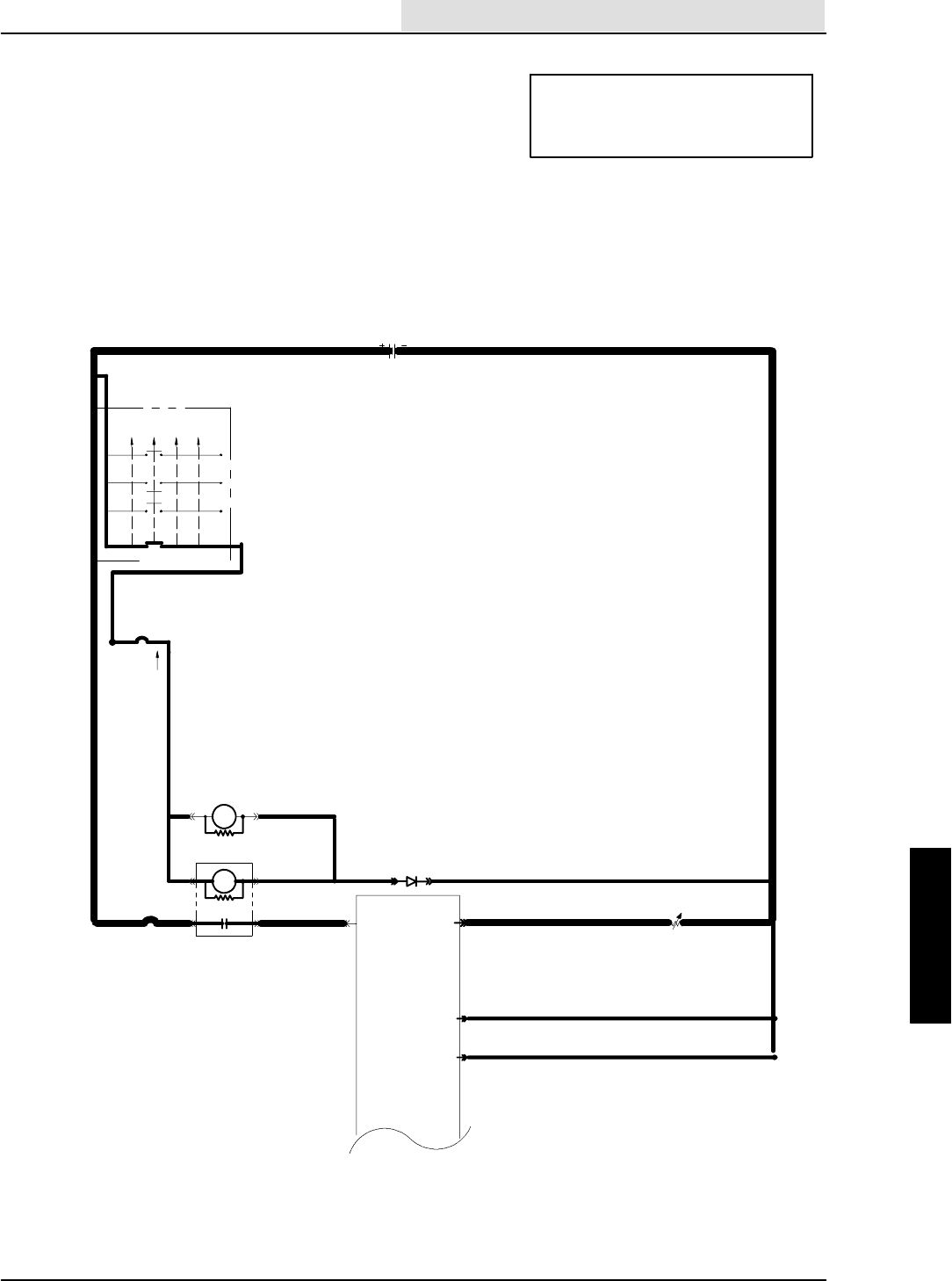
ELECTRICAL
5-117
8410 MM392 (8--01)
ENGINE TEMPERATURE LIGHT
WILL NOT TURN ON OR OFF
(SCHEMATIC)
OPERATION:
--WHEN ENGINE COOLANT EXCEEDS
225 DEGREE F. SE--2 =<80 OHMS
--COOLANT LIGHT TURNS ON
16E/GRN
1H/RED
13AM/BLK
19B/BLU
19A/BLU
50A/ORA
50B/ORA
16C/
GRN
16D/
GRN
1A/RED
20/BLU
CB--2
IGNITION SWITCH
S--15
( X INDICATES A
CLOSED CONTACT )
D--1
10A
22/YEL
CB--3
19/BLU
START
START
RUN
OFF
PREHEAT
X
XXX
XX
X
IGN.
19
30
BATT.
50
17
N/U
RUN/
ACC
1/RED
1
FRONT
15A
8730
M4 8685
M3
8685 M3
ELECTRONIC
INSTRUMENT
PANEL
13/BLK
BATTERY
13AC/BLK
13AB/BLK
23
22
GROUND
LINE
5N.C.H.O.
43/BLU
CLOSES AT225°F
COOLANT TEMP
SENDER
SE--2
ELECTRICAL
5-118 8410 MM392 (8--01)
ENGINE TEMPERATURE LIGHT
WILL NOT TURN ON
(FLOW CHART)
OPERATION:
--WHEN ENGINE COOLANT EXCEEDS
225 DEGREE F. SE--2 =<80 OHMS
--COOLANT LIGHT TURNS ON
DOES THE LIGHT TURN
ON MOMENTARILY AT POWER UP ?
YES
NO
REPLACE LAMP L2
INSIDE PANEL
RETEST
REPLACE INSTR. PANEL
STILL NOT
TURNING ON AT
POWER UP
DISCONNECT SE--2 AND GROUND
WIRE 43/BLU
DOES LIGHT TURN ON ?
YES
NO
WIRE 43/BLU IS
OPEN FROM (PIN 5) TO SE--2
IF ENGINE TEMP IS GREATER
THAN 225 DEGREES
REPLACE SE--2
SYSTEM IS OK
ENGINE TEMPERATURE LIGHT
WILL NOT TURN OFF
(FLOW CHART)
KEY ON
ENGINE OFF
DISCONNECT SE--2
LIGHT STILL ON
LIGHT TURNS OFF
POWER OFF
DISCONNECT PANEL
DISCONNECT SE--2
CHECK CONTINUITY
43/BLU TO GROUND
OPEN
CONTINUITY
REPLACE INSTR. PANEL
WIRE 43/BLU IS
GROUNDED
IF ENGINE TEMP IS LESS
THAN 225 DEGREES
REPLACE SE--2
SYSTEM IS OK
OPERATION:
--WHEN ENGINE COOLANT EXCEEDS
225 DEGREE F. SE--2 =<80 OHMS
--COOLANT LIGHT TURNS ON
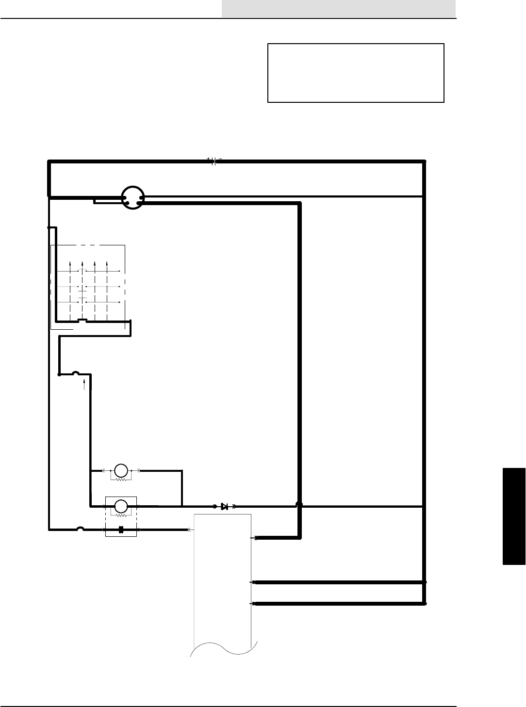
ELECTRICAL
5-119
8410 MM392 (8--01)
M3
ALTERNATOR / BATTERY WARNING
LIGHT WILL NOT TURN ON
(SCHEMATIC)
OPERATION:
--CONNECTION L2 ON ALTERNATOR
GOES TO BATTERY POSITIVE WHEN ALTER-
NATOR IS TURNED ON
--BATTERY POSITIVE AT (PIN 14) TURNS OFF
THE ALTERNATOR / BATTERY INDICATOR
16E/GRN
1H/RED
13AM/BLK
19B/BLU
19A/BLU
50A/ORA
50B/ORA
16C/
GRN
16D/
GRN
1A/RED
20/BLU
CB--2
IGNITION SWITCH
S--15
( X INDICATES A
CLOSED CONTACT )
D--1
10A
22/
YEL
CB--3
19/BLU
START
START
RUN
OFF
PREHEAT
X
XXX
XX
X
IGN.
19
30
BATT.
50
17
N/U
RUN/
ACC
1/RED
1
FRONT
15A
8730
M4 8685
M3
8685
ELECTRONIC
INSTRUMENT
PANEL
13/BLK
BATTERY
13AC/BLK
13AB/BLK
23
22
GROUND
LINE
14
2/ ORA
1B/RED
1A/RED
55A MAX.
CHARGE
2/ORA
L2
SENSE
13A/BLK
ALTERNATOR
GNDOUT
ELECTRICAL
5-120 8410 MM392 (8--01)
ALTERNATOR IS SHORTED
L2 TO BATTERY POSITIVE
OR WIRE 2/ORA IS SHORTED
TO BATTERY POSITIVE
ALTERNATOR / BATTERY WARNING
LIGHT WILL NOT TURN ON
(FLOW CHART)
OPERATION:
--CONNECTION L2 ON ALTERNATOR
GOES TO BATTERY POSITIVE WHEN ALTER-
NATOR IS TURNED ON
--BATTERY POSITIVE AT (PIN 14) TURNS OFF
THE ALTERNATOR / BATTERY INDICATOR
KEY ON
ENGINE OFF
REMOVE 2/ORA FROM
ALTERNATOR (PIN L2)
GROUND WIRE 2/ORA
DOES THE LIGHT
TURN ON ?
NO
YES
OPEN
REPAIR AND REPLACE
2/ORA
CONTINUITY
REPLACE LAMP L8
INSIDE THE PANEL
CHECK CONTINUITY 2/ORA
FROM ALTERNATOR TO
(PIN 14)
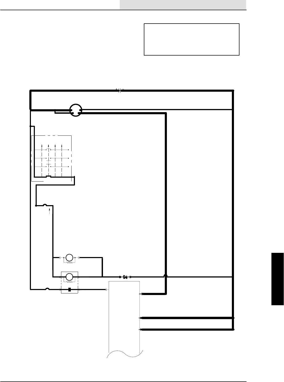
ELECTRICAL
5-121
8410 MM392 (8--01)
ALTERNATOR / BATTERY WARNING LIGHT
STAYS ON WHEN ENGINE IS RUNNING
(SCHEMATIC)
OPERATION:
--CONNECTION L2 ON ALTERNATOR
GOES TO BATTERY POSITIVE WHEN ALTER-
NATOR IS TURNED ON
--BATTERY POSITIVE AT (PIN 14) TURNS OFF
THE ALTERNATOR / BATTERY INDICATOR
M3
16E/GRN
1H/RED
13AM/BLK
19B/BLU
19A/BLU
50A/ORA
50B/ORA
16C/
GRN
16D/
GRN
1A/RED
20/BLU
CB--2
IGNITION SWITCH
S--15
( X INDICATES A
CLOSED CONTACT )
D--1
10A
22/
YEL
CB--3
19/BLU
START
START
RUN
OFF
PREHEAT
X
XXX
XX
X
IGN.
19
30
BATT.
50
17
N/U
RUN/
ACC
1/RED
1
FRONT
15A
8730
M4 8685
M3
86
85
ELECTRONIC
INSTRUMENT
PANEL
13/BLK
BATTERY
13AC/BLK
13AB/BLK
23
22
GROUND
LINE
14
2/ ORA
1B/RED
1A/RED
55A MAX.
CHARGE
2/ORA
L2
SENSE
13A/BLK
ALTERNATOR
GNDOUT
ELECTRICAL
5-122 8410 MM392 (8--01)
DISCONNECT INSTR.
PANEL, THEN RECONNECT
IF LIGHT STILL ON----REPLACE
INSTR. PANEL
WIRE 2/ORA IS
SHORTED TO BATTERY
POSITIVE
--ENGINE RUNNING
--PANEL DISCONNECTED
CHECK VOLTAGE OF WIRE
2/ORA AT (PIN 14) OF INSTR.
PANEL
DISCONNECT WIRE 2/ORA
AT THE ALTERNATOR
TOUCH WIRE 2/ORA TO WIRE 1B/RED
AT THE ALTERNATOR
DOES THE ALTERNATOR LIGHT TURN
OFF ?
ALTERNATOR / BATTERY WARNING LIGHT
STAYS ON WHEN ENGINE IS RUNNING
(FLOW CHART)
OPERATION:
--CONNECTION L2 ON ALTERNATOR
GOES TO BATTERY POSITIVE WHEN ALTER-
NATOR IS TURNED ON
--BATTERY POSITIVE AT (PIN 14) TURNS OFF
THE ALTERNATOR / BATTERY INDICATOR
ENGINE RUNNING
CHECK VOLTAGE FROM L2
AT ALTERNATOR TO GROUND VOLTAGE
NO VOLTAGE
KEY ON
ENGINE OFF
YES
NO
TIGHTEN ALTERNATOR BELT
IF NECESSARY
REPLACE ALTERNATOR
DOES LIGHT TURN OFF ?
NO
VOLTAGE
NO VOLTAGE
WIRE2/ORAISOPEN
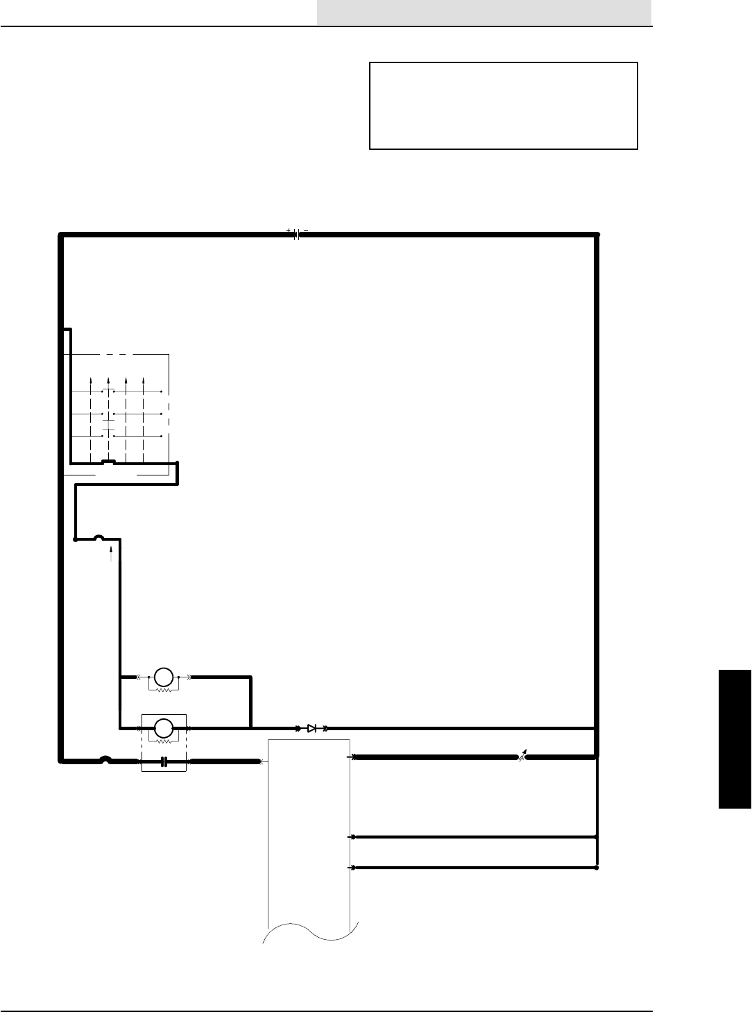
ELECTRICAL
5-123
8410 MM392 (8--01)
FUEL GAUGE NOT OPERATING
(GAS AND DIESEL)
(SCHEMATIC)
OPERATION:
--SE--1 GREATER THE 90 OHMS=FULL TANK
--SE--1 LESS THAN 10 OHMS=EMPTY TANK
-- N O T E ; I F S E -- 1 >500OHMS OR <10 OHMS AT
POWERUPTHEPANELGOESTOLPMODE
(NO LIGHTS FOR FULL, 2 LIGHTS FOR EMPTY)
16E/GRN
1H/RED
13AM/BLK
19B/BLU
19A/BLU
50A/ORA
50B/ORA
16C/
GRN
16D/
GRN
1A/RED
20/BLU
CB--2
IGNITION SWITCH
S--15
( X INDICATES A
CLOSED CONTACT )
D--1
10A
22/YEL
CB--3
19/BLU
START
START
RUN
OFF
PREHEAT
X
XXX
XX
X
IGN.
19
30
BATT.
50
17
N/U
RUN/
ACC
1/RED
1
FRONT
15A
8730
M4 8685
M3
86
85M3
ELECTRONIC
INSTRUMENT
PANEL
13/BLK
BATTERY
13AC/BLK
13AB/BLK
23
22
GROUND
LINE
1A/RED
96 OHM = FULL
13BH/BLK
42B/YEL42/YEL
13
GAS--DIESEL
FUEL SENDER
SE--1
ELECTRICAL
5-124 8410 MM392 (8--01)
--SE--1 STILL DISCONNECTED
--DISCONNECT THE PANEL
--TURN KEY OFF
CHECK THE CONTINUITY OF
42/YEL TO GROUND AND B+
--KEY OFF
--DISCONNECT 42B/YEL AT SE--1
--CHECK OHMS AT SE--1,
90 OHMS = TANK FULL
50 OHMS = 1/2 FULL
10 OHMS = EMPTY
FUEL GAUGE NOT OPERATING
(GAS AND DIESEL)
(FLOW CHART)
OPERATION:
--SE--1 GREATER THE 90 OHMS=FULL TANK
--SE--1 LESS THAN 10 OHMS=EMPTY TANK
-- N O T E ; I F S E -- 1 >500OHMS OR <10 OHMS AT
POWERUPTHEPANELGOESTOLPMODE
(NO LIGHTS FOR FULL, 2 LIGHTS FOR EMPTY)
YES
NO
KEY ON
ENGINE OFF
FUEL TANK >
1/2 FULL
DO ANY OF THE FUEL
LIGHTS TURN ON ?
ARE THE LEFT 2
SEGMENTS FLASHING ?
MORE THAN
2LIGHTS
YES
IF THE GAUGE IS WORKING
BUT INACCURATE
--REPLACE THE FLOAT
--NOTE; 90 OHMS = FULL
10 OHMS = EMPTY
STILL
INACCURATE
REPLACE PANEL
BAD OHM
READINGS
REPLACE FUEL
TANK FLOAT
GOOD OHM
READINGS
OPEN
REPLACE PANEL
CONTINUITY
42/YEL IS SHORTED
TO GROUND
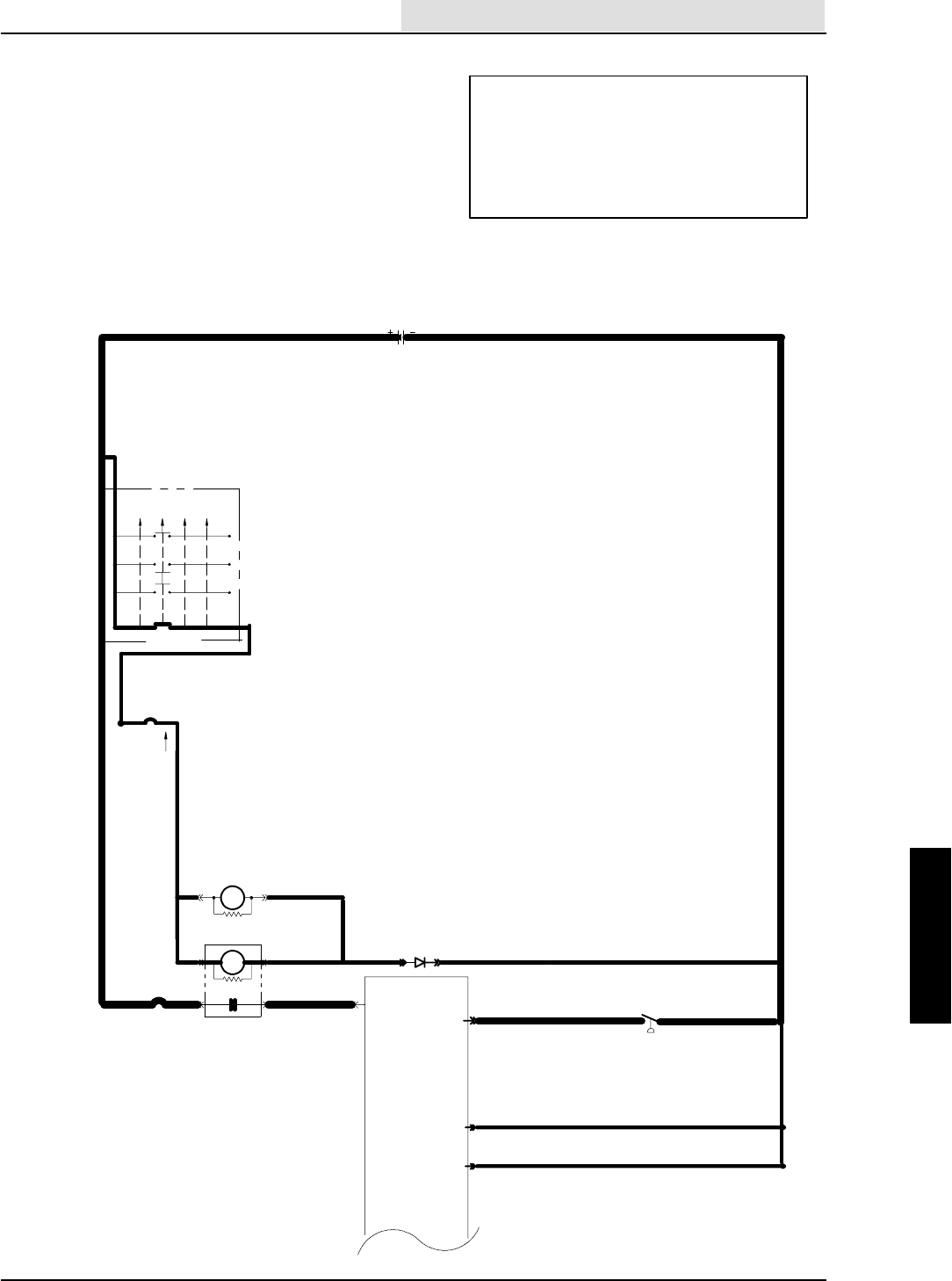
ELECTRICAL
5-125
8410 MM392 (8--01)
OPERATION:
--S--6ISOPEN=GAUGEISOFF
--S--6 IS CLOSED = LEFT 2 SEGMENTS OF
GAUGE FLASH
--SE--1 IS NOT ON MACHINE
-- N O T E ; I F S E -- 1 >500OHMS OR <10 OHMS AT
POWERUPTHEPANELGOESTOLPMODE
(NO LIGHTS FOR FULL, 2 LIGHTS FOR EMPTY)
FUEL GAUGE (LPG)
(SCHEMATIC)
16E/GRN
1H/RED
13AM/BLK
19B/BLU
19A/BLU
50A/ORA
50B/ORA
16C/
GRN
16D/
GRN
1A/RED
20/BLU
CB--2
IGNITION SWITCHS--15
( X INDICATES A
CLOSED CONTACT )
D--1
10A
22/YEL
CB--3
19/BLU
START
START
RUN
OFF
PREHEAT
X
XXX
XX
X
IGN.
19
30
BATT.
50
17
N/U
RUN/
ACC
1/RED
1
FRONT
15A
8730
M4 8685
M3
86
85 M3
ELECTRONIC
INSTRUMENT
PANEL
13/BLK
BATTERY
13AC/BLK
13AB/BLK
23
22
GROUND
LINE
1A/RED
LP
CLOSES BELOW
70 PSI
13AQ/BLK
42A/YEL
42/YEL
13
N.C.H.O.
S--6 C
ELECTRICAL
5-126 8410 MM392 (8--01)
REPAIR 42 /YEL
AND 42A/YEL
FUEL GAUGE (LPG)
(FLOW CHART)
42/YEL AND 42A/YEL
ARE SHORTED
TO GROUND
-- P O W E R O F F
--DISCONNECT PANEL
--DISCONNECT S--6
CHECK CONTINUITY OF 42/YEL
AND 42A/YEL TO GROUND
-- P O W E R O F F
CHECK CONTINUITY OF 42/YEL
AND 42A/YEL FROM S--6 TO PANEL
(PIN 13)
IF SYSTEM IS NOT
WORKING PROPERLY----
REPLACE S--6
GROUND 42A/YEL AT S--6
IS GAUGE FLASHING ?
YES
KEY ON
ENGINE OFF
DISCONNECT S--6
IS GAUGE OFF ?
NO
YES
OPEN CONTINUITY
REPLACE INSTR.
PANEL
CONTINUITY
OPEN
REPLACE INSTR.
PANEL
OPERATION:
--S--6ISOPEN=GAUGEISOFF
--S--6 IS CLOSED = LEFT 2 SEGMENTS OF
GAUGE FLASH
--SE--1 IS NOT ON MACHINE
-- N O T E ; I F S E -- 1 >500OHMS OR <10 OHMS AT
POWERUPTHEPANELGOESTOLPMODE
(NO LIGHTS FOR FULL, 2 LIGHTS FOR EMPTY)
2 SEGMENTS ON
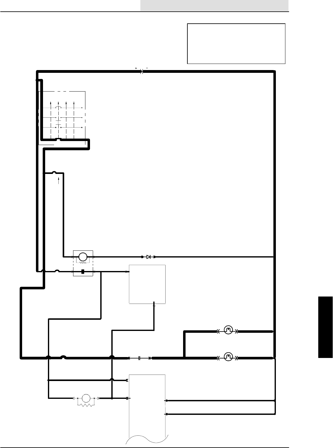
ELECTRICAL
5-127
8410 MM392 (8--01)
OPERATION:
--HEADLIGHT SWITCH IS SELECTED
ON PANEL
--M7 IS TURNED ON
--CONTACT OF M7 SUPPLIES VOLTAGE
TO HEADLIGHTS
HEAD LIGHTS WILL NOT TURN ON
(SCHEMATIC)
16E/GRN
1H/RED 13AM/BLK
50A/ORA
50B/ORA
16C/GRN
1A/RED
20/BLU
CB--2
IGNITION SWITCH
S--15
( X INDICATES A
CLOSED CONTACT )
D--1
10A
CB--3
19/BLU
START
START
RUN
OFF
PREHEAT
X
XXX
XX
X
IGN.
19
30
BATT.
50
17
N/U RUN/ACC
1/RED
1
FRONT
15A
8730
8685M3
ELECTRONIC
INSTRUMENT
PANEL
13/BLK
BATTERY
13AC/BLK
13AB/BLK
23
22
GROUND
LINE
AUXILIARY
1
ELECTRONIC
INSTR.
PANEL
22/YEL
17/ORA
LIGHTS ON
20
20A/BLU
50D/ORA
50A/ORA
17B/ORA
4
HEADLIGHT RELAY
86
85 M--7
R.H.HEADLIGHT
62C/YEL 62F/YEL
62G/YEL
13CB/BLK
13CG/BLK
62D/YEL
HEADLIGHT L.H.
87/PUR
M7
59/BRN
20B/BLU
8730 62/YEL
CB--6
15 AMP
17A
ORA
ELECTRICAL
5-128 8410 MM392 (8--01)
--DISCONNECT INSTRUMENT
PANEL
CHECK CONTINUITY OF
17/ORA TO GROUND
--REMOVE M7
--SELECT HEADLIGHTS
--TURN KEY OFF THEN ON
IS THE HEADLIGHT LED
FLASHING ?
--REPLACE M7
--KEY ON
--ENGINE OFF
--HEADLIGHTS SELECTED
CHECK VOLTAGE ON PIN 87 OF
M7, WIRE 62/YEL TO GROUND
-- R E M O V E M -- 7
--KEY ON
--ENGINE OFF
--HEADLIGHTS SELECTED
CHECK FOR VOLTAGE ON PIN 85 OF
M--7 (WIRE 50D/ORA) TO GROUND
REPLACE M--7 WITH A
GOOD RELAY
DO THE HEADLIGHTS COME ON ?
HEAD LIGHTS WILL NOT TURN ON
(FLOW CHART)
BOTH PANELS ARE
POWERED UP
KEY IS ON
VOLTAGE
NO VOLTAGE
OPERATION:
--HEADLIGHT SWITCH IS SELECTED
ON PANEL
--M7 IS TURNED ON
--CONTACT OF M7 SUPPLIES VOLTAGE
TO HEADLIGHTS
YES
PROBLEM SOLVED
50D/ORA, 50A/ORA, OR
50B/ORA ARE OPEN
--M--7 STILL REMOVED
CHECK THE VOLTAGE AT
PIN 30 OF M--7, WIRE
59/BRN TO GROUND
NO VOLTAGE
B+
59/BRN, CB--6, 20B/BLU,
OR 20/BLU ARE OPEN
B+
NO VOLTAGE
CHECK VOLTAGE
ACROSS LIGHTS
B+
REPLACE LIGHT
NO VOLTAGE
ALL 62/YEL WIRES OR
13/BLK WIRES GOING
TO THE HEADLIGHTS
ARE OPEN
YES
17A/ORA OR 17B/ORA
WIRES ARE OPEN
NO
CONTINUITY
WIRE 17/ORA IS
SHORTED TO GROUND
REPLACE PANEL
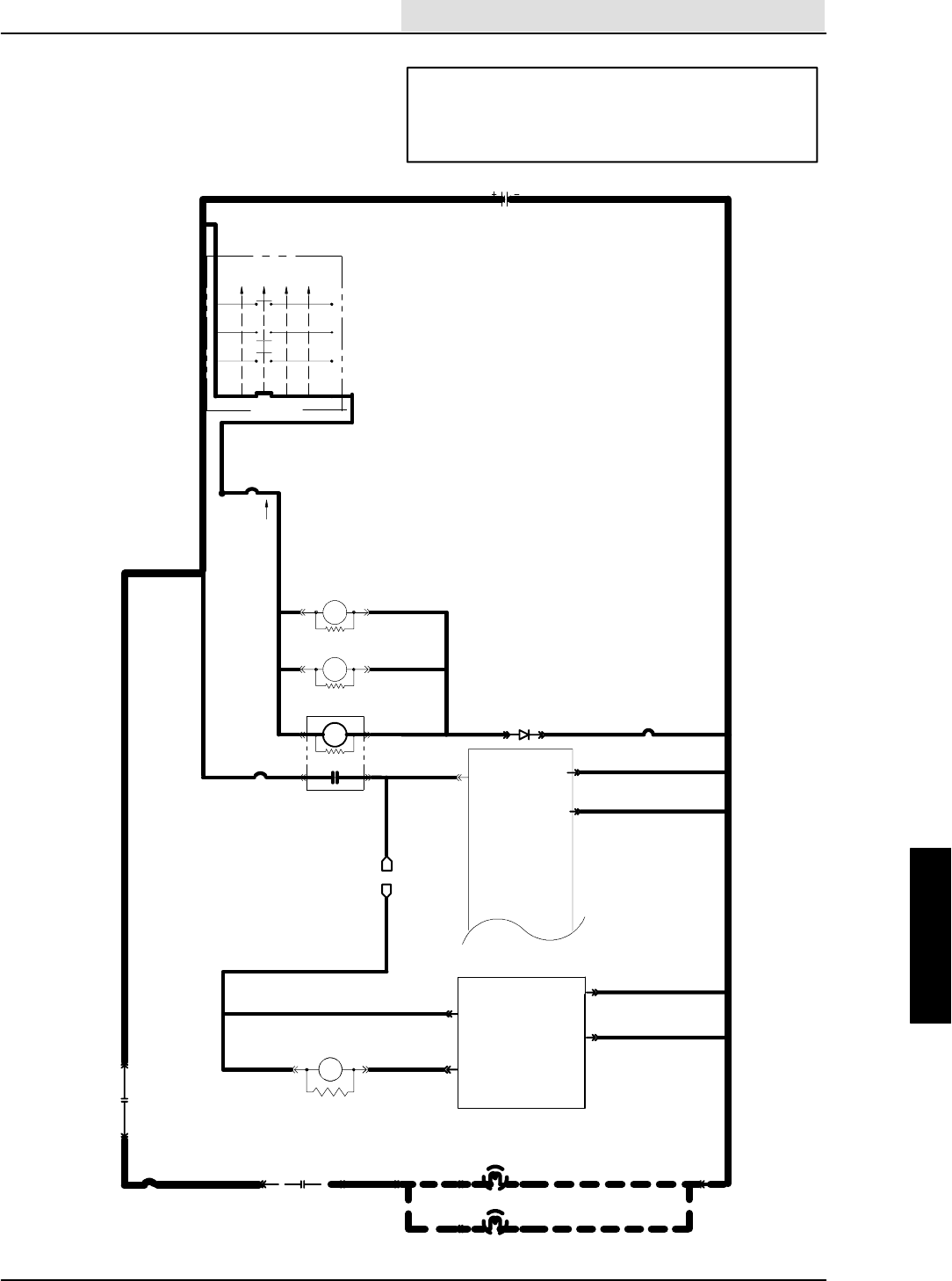
ELECTRICAL
5-129
8410 MM392 (8--01)
HAZARD LIGHT WILL NOT TURN ON
(SCHEMATIC)
OPERATION:
--HAZARD LIGHT SWITCH IS SELECTED
ON PANEL
--M9 IS TURNED ON
--CONTACT OF M9 SUPPLIES VOLTAGE TO HAZARD LIGHT
16E/GRN
1H/RED
13AM/BLK
16E/GRN
16F/
GRN 19C/BLU
19B/BLU
19A/BLU
1G/RED
50A/ORA
50B/ORA
16C/
GRN
16D/
GRN
L
1A/RED
20/BLU
CB--2
IGNITION SWITCH
S--15
( X INDICATES A
CLOSED CONTACT )
D--1
10A
22/YEL
CB--3
19/BLU
M5 8685
START
START
RUN
OFF
PREHEAT
X
XXX
XX
X
IGN.
19
30
BATT.
50
17
N/U
RUN/
ACC
1/RED
1
FRONT
15A
8730
M4 8685
86
85 M3
ELECTRONIC
INSTRUMENT
PANEL
13/BLK
BATTERY
13AC/BLK
13AB/BLK
23
22
GROUND
LINE
50A/ORA
AUXILIARY
1
L
CB--8
15 AMP
23
22
ELECTRONIC
INSTRUMENT
PANEL
13AG/BLK
13AF/BLK
31A/GRY
32A/BLU
87
30
1G/RED M5
50F/ORA 13
18/GRN
M--9
WARNING LIGHT RELAY
86
85
WARNING LIGHT L.R.C.
WARNING LIGHT O.H.G.
76/GRN
8730 M9
13LL/BLK
13VV/BLK 13BE/BLK
31D/GRY
76/GRN
76/GRN
ELECTRICAL
5-130 8410 MM392 (8--01)
31C/GRY, 31A/GRY, CB--8,
32/BLU, 32A/BLU, M5 CONTACTS,
OR 1G/RED ARE OPEN
--DISCONNECT INSTRUMENT
PANEL
CHECK CONTINUITY OF
18/GRN TO GROUND
--REMOVE M9
--TURN KEY OFF THEN ON
IS THE HAZARD LED
FLASHING ?
--REPLACE M9
--KEY ON
--ENGINE OFF
--HAZARD LIGHT SELECTED
CHECK VOLTAGE ON PIN 87 OF
M7, WIRE 76/GRN TO GROUND
-- R E M O V E M -- 9
--KEY ON
--ENGINE OFF
--HAZARD LIGHT SELECTED
CHECK FOR VOLTAGE ON PIN 85 OF
M--9 (WIRE 50F/ORA) TO GROUND
REPLACE M--9 WITH A
GOOD RELAY
DOES THE HAZARD LIGHT COME ON ?
HAZARD LIGHT WILL NOT TURN ON
(FLOW CHART)
BOTH PANELS ARE
POWERED UP
KEY IS ON
VOLTAGE
NO VOLTAGE
YES
PROBLEM SOLVED
50F/ORA, 50A/ORA, OR
50B/ORA ARE OPEN
--M--9 STILL REMOVED
CHECK THE VOLTAGE AT
PIN 30 OF M--9, WIRE
31C/GRY TO GROUND
NO VOLTAGE
B+
B+
NO VOLTAGE
CHECK VOLTAGE
ACROSS HAZARD
LIGHT
B+
REPLACE LIGHT
NO VOLTAGE
ALL 76/GRN WIRES OR
13/BLK WIRES GOING
TO THE HEADLIGHTS
ARE OPEN
YES
18/GRN IS OPEN
NO
CONTINUITY
WIRE 18/GRN IS
SHORTED TO GROUND
REPLACE PANEL
OPERATION:
--HAZARD LIGHT SWITCH IS SELECTED
ON PANEL
--M9 IS TURNED ON
--CONTACT OF M9 SUPPLIES VOLTAGE
TO HAZARD LIGHT
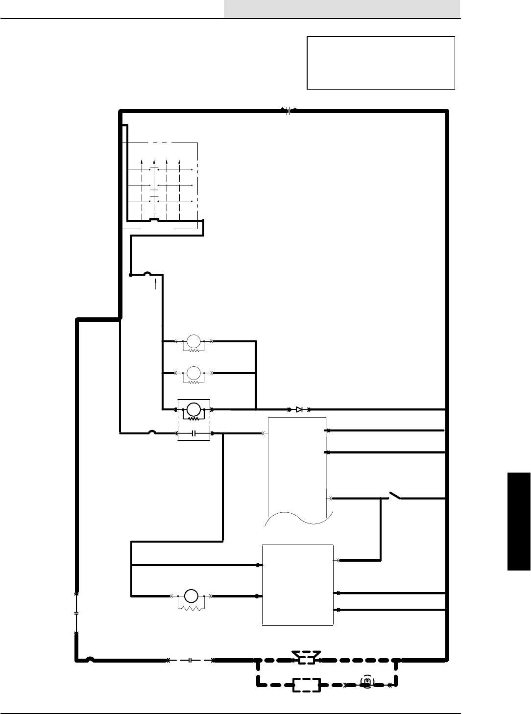
ELECTRICAL
5-131
8410 MM392 (8--01)
REVERSE LIGHT OR ALARM
DO NOT TURN ON
(SCHEMATIC)
OPERATION:
--S--7 CLOSES IN REVERSE
--M--8 WILL TURN ON
--M--8 CONTACTS SUPPLY VOLTAGE
TO ALARM AND LIGHT
16E/GRN
1H/RED 13AM/BLK
16E/GRN
16F/
GRN 19C/BLU
19B/BLU
19A/BLU
1G/RED
50A/ORA
50B/ORA
16C/
GRN
16D/
GRN
1A/RED
20/BLU
CB--2
IGNITION SWITCH
S--15
( X INDICATES A
CLOSED CONTACT )
D--1
10A
22/YEL
CB--3
19/BLU
M5 8685
START
START
RUN
OFF
PREHEAT
X
XXX
XX
X
IGN.
19
30
BATT.
50
17
N/U
RUN/
ACC
1/RED
1
FRONT
15A
8730
M4 8685
86
85M3
ELECTRONIC
INSTRUMENT
PANEL
13/BLK
BATTERY
13AC/BLK
13AB/BLK
23
22
50A/ORA
AUXILIARY
1
CB--8
15 AMP
23
22
ELECTRONIC
INSTRUMENT
PANEL
13AG/BLK
13AF/BLK
31A/GRY
32A/BLU
87
30
1G/RED
M5
86
85
50E/ORA 19
12/YEL
M--8
REVERSE RELAY
BACK UP LIGHT
BACK UP ALARM
FLASHER 94/YEL
93/ORA
8730 M8
13QQ/BLK
13NN/BLK 13BD/BLK
31C/GRY 93/ORA
93/ORA
10
LOW = REVERSE
36A/GRN
REVERSE SENSE
REVERSE
CLOSES IN
13AY/BLK
36B/GRN
S--7
36/GRN
REVERSE
8
FLOW SWITCH
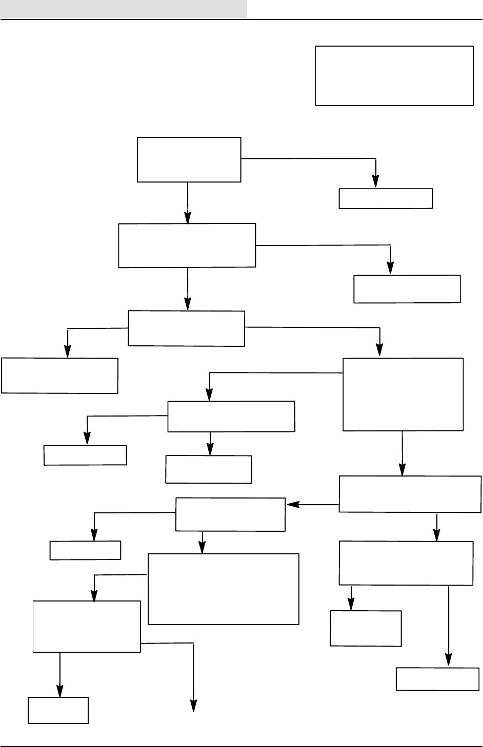
ELECTRICAL
5-132 8410 MM392 (8--01)
--DISCONNECT INSTRUMENT
PANEL
CHECK CONTINUITY OF 12/YEL
TO GROUND
GO INTO ”INPUT DISPLAY MODE”
THE INPUT CONDITIONS WILL BE
DISPLAYED ON FUEL GAUGE
--TURN OFF THE KEY
--PUSH AND HOLD HEADLIGHT BUT-
TON, HOLD FOR 10 SEC. SWEEP 1
AND 2 LED’S SHOULD TURN ON
START THE ENGINE
DOES THE SHAKER LED
BLINK IN REVERSE AND
TURN OFF IN NEUTRAL
OR FWD?
YES
PANEL TEST
GOOD
CHECK CONTINUITY OF
12/YEL FROM M8 PIN 86
TO PIN 19 OF PANEL
-- R E M O V E M -- 8
--TURN KEY OFF, THEN ON
DOES THE HAZARD LIGHT BLINK ?
50E/ORA, 50A/ORA,
OR 50B/ORA ARE OPEN
-- R E M O V E M -- 8
--KEY ON, ENGINE OFF
CHECK VOLTAGE ON PIN 85 OF
M8 WIRE 50E/ORA TO GROUND
REVERSE LIGHT OR ALARM
DO NOT TURN ON
(FLOW CHART)
OPERATION:
--S--7 CLOSES IN REVERSE
--M--8 WILL TURN ON
--M--8 CONTACTS SUPPLY VOLTAGE
TO ALARM AND LIGHT
BOTH PANELS POWERED UP
REPLACE M--8
CHECK OPERATION OF
REVERSE LIGHT AND
ALARM
WORKS
PROBLEM SOLVED
STILL DOES
NOT WORK
0VOLTS
B+
CHECK VOLTAGE ON PIN
30 OF M8 WIRE 31C/GRY
TO GROUND
0VOLTS
31C/GRY, 31A/GRY, CB--8,
32/BLU, OR M5 CONTACT
OR 16/RED IS OPEN
B+
-- R E -- I N S T A L L M -- 8
--KEY AND ENGINE ON
--MACHINE SLIGHTLY IN
REVERSE
CHECK VOLTAGE ON PIN
87 OF M8 WIRE 93/ORA TO
GROUND
B+
CHECK VOLTAGE ACROSS
HAZARD LIGHT IN REVERSE
0VOLTS
B+
REPLACE LIGHT
93/ORA OR 13/BLK
IS OPEN
YES
OPEN
REPAIR 12/YEL
NO
CONTINUITY
CONTINUED ON
NEXT PAGE
CONTINUITY OPEN
REPLACE PANEL
WIRE 12/YEL
IS SHORTED
TO GROUND
NO
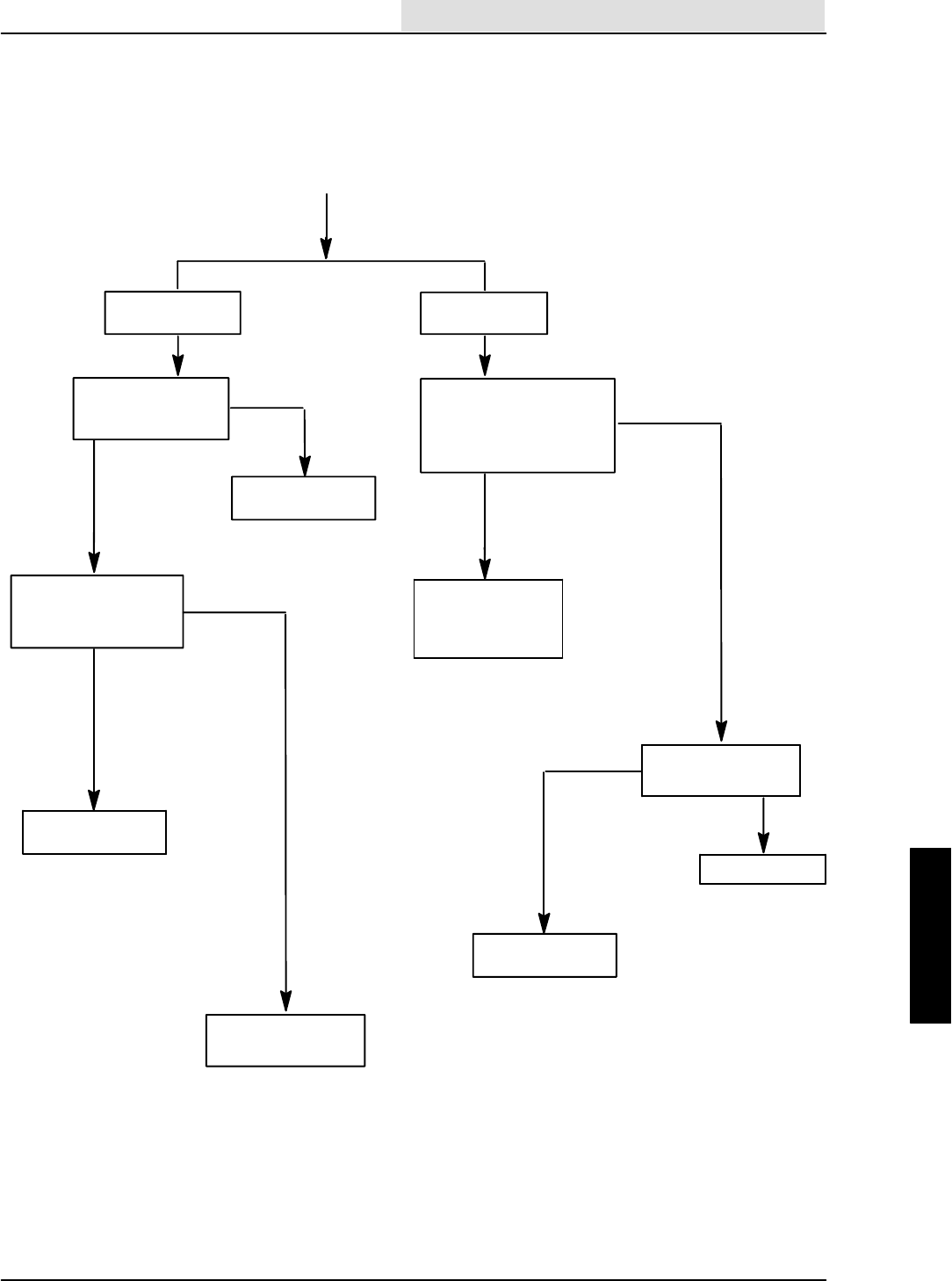
ELECTRICAL
5-133
8410 MM392 (8--01)
S--7 NOT CLOSING
IN REVERSE
REPLACE S--7
AND RETEST
--DISCONNECT S--7
--GROUND WIRE 36/GRN
AT S -- 7
DOES THE SHAKER LED
BLINK ?
CONTINUED FROM
PREVIOUS PAGE
CHECK CONTINUITY
OF 36/GRN
CONTINUITY
REPAIR 36/GRN
REPLACE SWEEP
PANEL
OPEN
SHAKER LED
ALWAYS BLINKS
SHAKER LED
NEVER BLINKS
NO
YES
--DISCONNECT S--7
DOES SHAKER
LED TURN OFF ?
NO
YES
S--7 IS SHORTED
REPLACE S--7
--DISCONNECT PANEL
CHECK CONTINUITY
OF 36/GRN TO
GROUND
REPLACE SWEEP
PANEL
OPEN
CONTINUITY
36/GRN IS SHORTED
TO GROUND

ELECTRICAL
5-134 8410 MM392 (8--01)

HYDRAULICS
6-1
8410 MM392 (5--02)
CONTENTS
Page
INTRODUCTION 6-3.........................
HYDRAULIC FLUID RESERVOIR 6-4.......
HYDRAULIC FLUID 6-5................
HYDRAULIC HOSES 6-5...............
TO REPLACE DIRECTIONAL PEDAL
CENTERING SPRING 6-6...........
TO REPLACE DIRECTIONAL
CONTROL CABLE 6-8...............
TO ADJUST DIRECTIONAL
CONTROL 6-11....................
TO REPLACE PROPEL PUMP 6-12.....
TO REPLACE LOAD SENSING
PUMP 6-15........................
TO REPLACE HYDRAULIC
STEERING VALVE 6-18............
TO REPLACE MAIN HYDRAULIC
VALVE 6-19.......................
TO REPLACE SCRUB VALVE 6-21.....
TO REPLACE SOLENOID VALVE
CARTRIDGE 6-23..................
TO REPLACE REAR DRIVE MOTOR 6-24
TO REPLACE SWEEPING VACUUM
FAN HYDRAULIC MOTOR 6-26.....
TO REPLACE ENGINE COOLING
FAN HYDRAULIC MOTOR 6-28.....
TO REPLACE SCRUB VACUUM
FAN HYDRAULIC MOTOR 6-30.....
TO REPLACE SCRUB BRUSH
HYDRAULIC MOTOR 6-32..........
TO REPLACE MAIN BRUSH
HYDRAULIC MOTOR 6-34..........
TO REPLACE SIDE BRUSH MOTOR 6-36
TO REPLACE STEERING
CYLINDER 6-38...................
TO REPLACE HOPPER LIFT
CYLINDER 6-41...................
TO REPLACE HOPPER DUMP
DOOR CYLINDER 6-42.............
TO REPLACE MAIN BRUSH LIFT
CYLINDER 6-43...................
TO REPLACE SIDE BRUSH LIFT
CYLINDER 6-45...................
TO REPLACE SQUEEGEE LIFT
CYLINDER 6-46...................
TO REPLACE SCRUB BRUSH LIFT
CYLINDER 6-48...................
TO REPLACE SCRUB HEAD SIDE
SHIFT HYDRAULIC CYLINDER 6-50.
HYDRAULIC SCHEMATIC 6-52.........
HYDRAULIC HOSE GROUP 6-56.......
CLAMP LOCATION AND HOSE
ORIENTATION 6-58................
Page
TROUBLESHOOTING 6-61...............
8410 HYDRAULIC PUMP
OPERATION 6-62..................
8410 HYDRAULIC PUMP LOW
PRESSURE FLOW 6-63............
8410 HYDRAULIC PUMP INCREASE
FLOW DEMAND 6-64..............
8410 HYDRAULIC PUMP HIGH
PRESSURE 6-65..................
ENGINE FAN CIRCUIT
(HIGH SPEED) 6-66................
ENGINE FAN CIRCUIT
(IDLE SPEED) 6-67................
ENGINE FAN DOES NOT RUN 6-68....
ENGINE FAN ALWAYS RUNS FAST 6-69
ENGINE FAN ALWAYS RUNS SLOW 6-70
SCRUB FAN CIRCUIT 6-72............
SCRUB FAN DOES NOT TURN OFF 6-73
SCRUB FAN DOES NOT TURN ON 6-74
HOPPER DOOR CLOSE CIRCUIT 6-76.
HOPPER DOOR DOES NOT OPEN 6-77
HOPPER DOOR DOES NOT CLOSE 6-78
HOPPER DOOR DOES NOT
STAY CLOSED 6-79................
HOPPER LIFT CIRCUIT 6-80..........
HOPPER DOES NOT RAISE 6-81......
HOPPER DRIFTS DOWN
TOO QUICKLY 6-82................
HOPPER LOWER CIRCUIT 6-84.......
HOPPER DOES NOT LOWER 6-85.....
MAIN BRUSH CIRCUIT -- SPD 1
(MAIN BRUSH DOWN AND ON,
VAC FAN ON) 6-86..............
MAIN BRUSH CIRCUIT -- SPD 2
(MAIN BRUSH DOWN AND ON,
VAC FAN ON) 6-87..............
MAIN BRUSH DOES NOT RAISE 6-88..
MAIN BRUSH DOES NOT LOWER 6-89.
MAIN BRUSH DOES NOT
TURN OFF 6-90...................
MAIN BRUSH DOES NOT TURN ON 6-91
SWEEPER FAN DOES NOT
TURN OFF 6-92...................
SWEEPER FAN DOES NOT
TURN ON 6-93....................
SIDE BRUSH CIRCUIT -- SPD 1
(MAIN BRUSH ON, VAC FAN ON,
SIDE BRUSH DOWN AND
ON) 6-94....................
SIDE BRUSH CIRCUIT -- SPD 2
(MAIN BRUSH ON, VAC FAN ON,
SIDE BRUSH DOWN AND
ON) 6-95....................

HYDRAULICS
6-2 8410 MM392 (5--02)
Page
SIDE BRUSH DOES NOT RAISE 6-96..
SIDE BRUSH DOES NOT LOWER 6-97.
SIDE BRUSH DOES NOT
TURN OFF 6-98...................
SIDE BRUSH DOES NOT TURN ON 6-99
EDGE SCRUB CIRCUIT 6-100.........
SCRUB HEAD DOES NOT GO IN 6-101.
SCRUB HEAD DOES NOT GO OUT 6-102
SCRUB HEAD LOWER CIRCUIT 6-104..
SCRUB BRUSHES DO NOT
LOWER 6-105.....................
SCRUB HEAD RAISE CIRCUIT 6-106...
SCRUB BRUSHES DO NOT RAISE 6-107
SCRUB BRUSH CIRCUIT 6-108........
SCRUB BRUSHES DO NOT
TURN OFF 6-109..................
SCRUB BRUSHES DO NOT
TURN ON 6-110...................
SQUEEGEE LIFT CIRCUIT 6-112.......
SQUEEGEE DOES NOT RAISE 6-113..
SQUEEGEE DRIFTS DOWN TOO
QUICKLY 6-114....................
SQUEEGEE LOWER CIRCUIT 6-116...
SQUEEGEE DOES NOT LOWER 6-117.
LEFT TURN CIRCUIT 6-118............
RIGHT TURN CIRCUIT 6-119..........

HYDRAULICS
6-3
8410 MM392 (8--01)
INTRODUCTION
The hydraulic system consists of the propel pump,
accessory pump, control valve, drive motors,
steering cylinder, and vacuum fan motor.
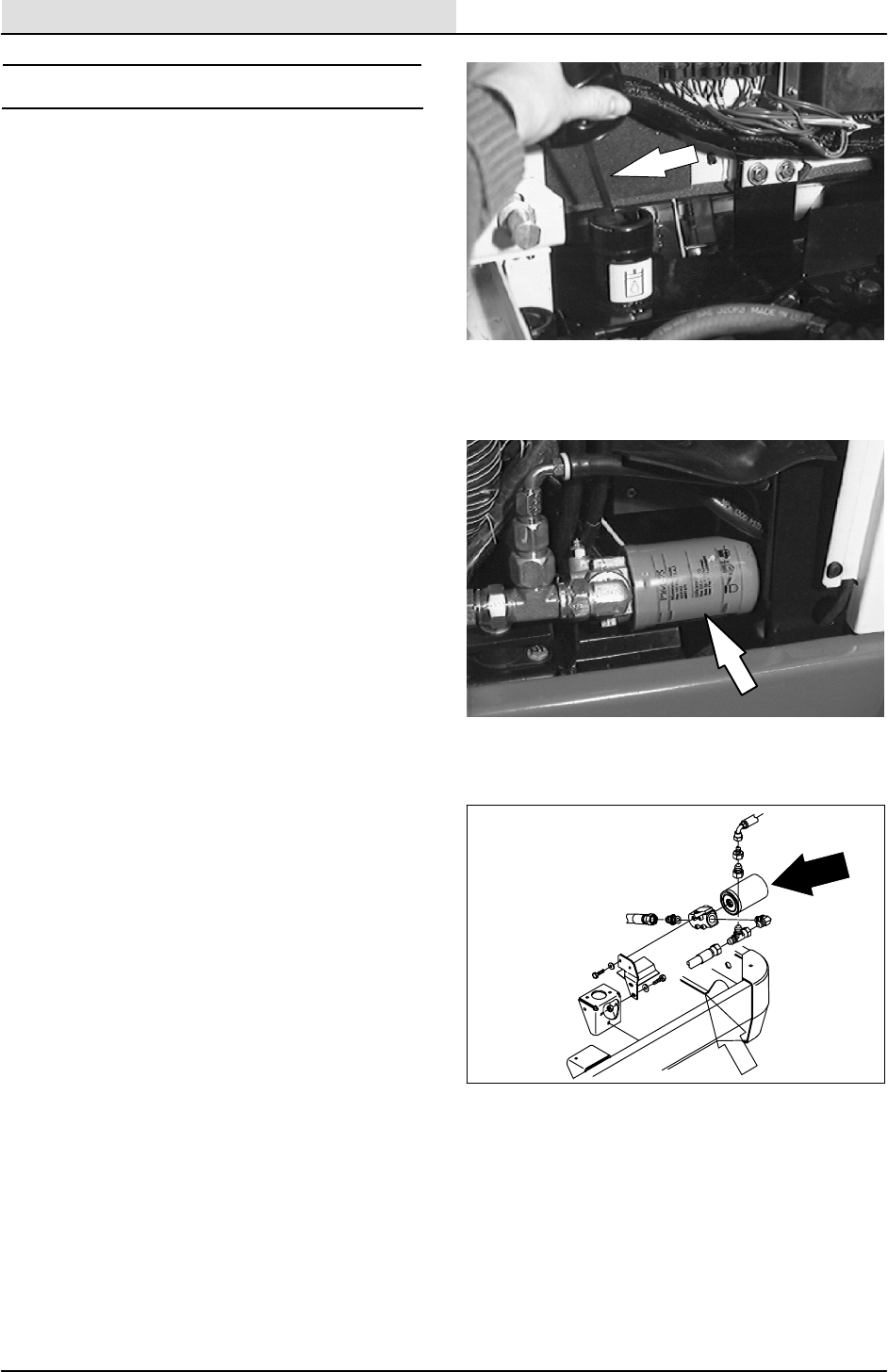
HYDRAULICS
6-4 8410 MM392 (8--01)
HYDRAULIC FLUID RESERVOIR
The reservoir is located in the engine
compartment next to the radiator.
Mounted on top of the reservoir is a filler cap with
a built-in breather and fluid level dipstick. Replace
the cap every 800 hours of operation.
Check the hydraulic fluid level at operating
temperature every 100 hours of operation. Make
sure the hopper is down when checking hydraulic
fluid level. The end of the dipstick is marked with
FULL and ADD levels to indicate the level of
hydraulic fluid in the reservoir.
Lubricate the filler cap gasket with a film of
hydraulic fluid before putting the cap back on the
reservoir.
ATTENTION! Do not overfill the
hydraulic fluid reservoir or operate the
machine with a low level of hydraulic
fluid in the reservoir. Damage to the
machine hydraulic system may result.
Drain and refill the hydraulic fluid reservoir with
new hydraulic fluid every 800 hours of operation.
The hydraulic fluid filter is located at the bottom of
the engine compartment. Replace the filter
element every 800 hours of operation.
The reservoir has a built-in strainer outlet that
filters hydraulic fluid before it enters the system.
Replace the strainer every 800 hours of operation.
HYDRAULICS
6-5
8410 MM392 (8--01)
HYDRAULIC FLUID
The quality and condition of the hydraulic fluid
play a very important role in how well the machine
operates. Tennant’s hydraulic fluid is specially
selected to meet the needs of Tennant machines.
Tennant’s hydraulic fluids provide a longer life for
the hydraulic components. There are two fluids
available for different temperature ranges:
Tennant part no. Ambient Temperature
65869 above 7_C(45_F)
65870 below 7_C(45_F)
The higher temperature fluid has a higher
viscosity and should not be used at the lower
temperatures. Damage to the hydraulic pumps
may occur because of improper lubrication.
The lower temperature fluid is a thinner fluid for
colder temperatures.
If a locally-available hydraulic fluid is used, make
sure the specifications match Tennant hydraulic
fluid specifications. Using substitute fluids can
cause premature failure of hydraulic components.
European manufactured machines are filled with
locally available hydraulic fluids. Check the label
on the hydraulic fluid reservoir.
ATTENTION! Hydraulic components
depend on system hydraulic fluid for
internal lubrication. Malfunctions,
accelerated wear, and damage will result
if dirt or other contaminants enter the
hydraulic system.
HYDRAULIC HOSES
Check the hydraulic hoses every 800 hours of
operation for wear or damage.
Fluid escaping at high pressure from a very small
hole can be almost invisible, and can cause
serious injuries.
See a doctor at once if injury results from
escaping hydraulic fluid. Serious infection or
reaction can develop if proper medical treatment
is not given immediately.
FOR SAFETY: When servicing machine,
use cardboard to locate leaking
hydraulic fluid under pressure.
HYDRAULICS
6-6 8410 MM392 (8--01)
TO REPLACE DIRECTIONAL PEDAL
CENTERING SPRING
1. Shut off the engine and engage the parking
brake.
FOR SAFETY: Before Leaving Or
Servicing Machine; Stop On Level
Surface, Set Parking Brake, Turn Off
Machine And Remove Key.
2. Remove the two M8 hex screws holding the
rear radiator grill to the machine. Disconnect
the taillight and remove the grill from the
machine.
3. Remove the nyloc nut holding the centering
spring balljoint to the directional control arm.
4. Loosen the large jam nut holding the
directional cable to the propel bracket.
5. Remove the spring assembly from the
propel bracket and place it outside the back
of the machine.
6. Remove the ball joint and jam nuts.
7. Unscrew the directional spring assembly
from the directional control cable.
NOTE: The directional cable will have to be held
to keep it from turning.
8. Thread a new directional spring assembly all
the way on the directional control cable.
Leave 0.25 in of threads showing on the
0.62 in diameter threads.
9. Install two 0.25 in. jam nuts on the end of
the directional cable. Tighten one to the
housing and the other one to the balljoint,
leaving 0.06 in. between them.
10. Use the large jam nut to lock directional
spring assembly in place.
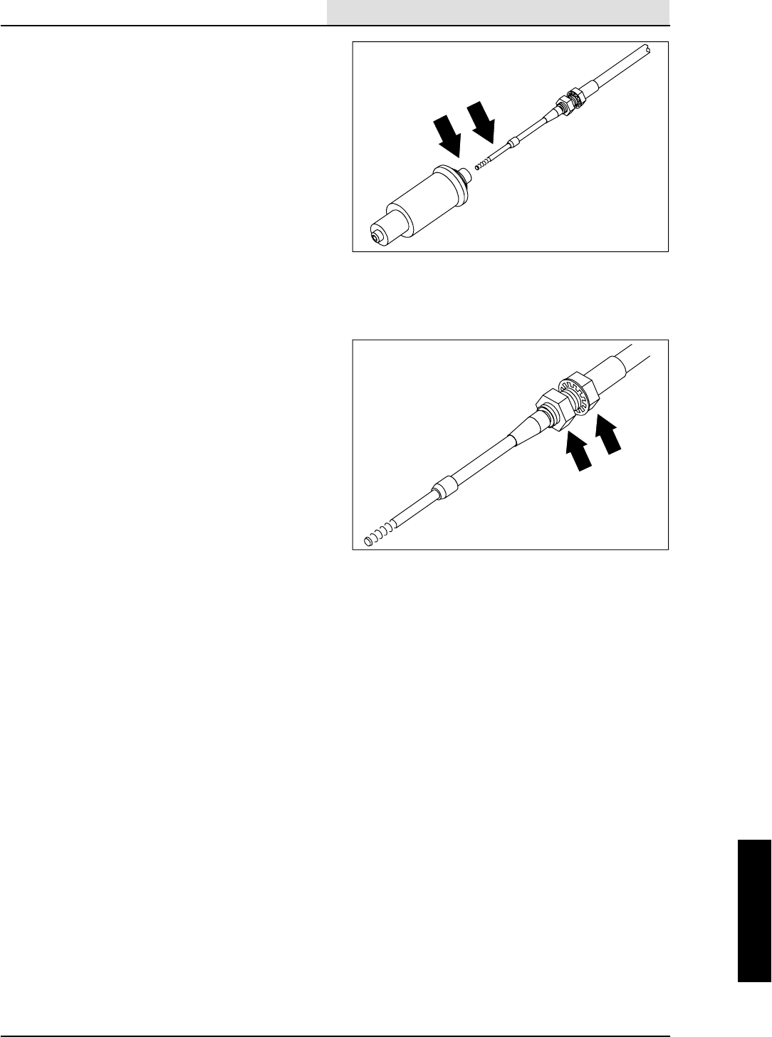
HYDRAULICS
6-7
8410 MM392 (8--01)
11. Reinstall the balljoint to the directional
control arm. Tighten the 0.25 in. nyloc nut to
11 -- 14 Nm (7 -- 10 ft lb).
12. Jack up the rear of the machine.
FOR SAFETY: Block machine tires
before jacking machine up. Jack
machine up at designated locations
only. Block machine up with jack
stands.
13. Check the neutral centering of the propel
pump by starting the machine and observing
the rear tire for any rotation. If tire is rotating;
See TO ADJUST DIRECTIONAL
CONTROL instructions.
14. Once the neutral centering has been set;
reinstall the rear grill panel. Tighten the four
M8 hex screws to 18 -- 24 Nm (15 -- 20 ft lb).
Lower the machine and test drive.
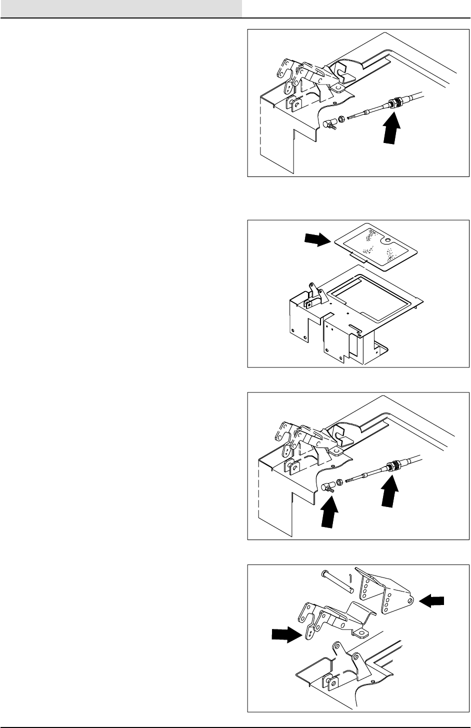
HYDRAULICS
6-8 8410 MM392 (8--01)
TO REPLACE DIRECTIONAL
CONTROL CABLE
1. Shut off the engine and engage the parking
brake.
FOR SAFETY: Before Leaving Or
Servicing Machine; Stop On Level
Surface, Set Parking Brake, Turn Off
Machine And Remove Key.
2. Lift the battery cover and disconnect the
battery cables.
3. Remove the battery hold down bracket and
remove the battery.
4. Remove the 0.25 nyloc nut holding the
control cable balljoint to the directional pedal
assembly.
5. Remove the cotter pin and clevis pin from
the directional control pedal. Remove the
pedal from the machine.
6. Loosen the two large hex nuts holding the
control cable to the mount bracket on the
floor plate.
7. Go under machine on operators side and
locate the two M5 hex screws holding the
clamp on the speed limiter cable. Remove
screws and clamp.
8. Go under machine and remove any clamps
or plastic ties holding control cable to the
machine frame.
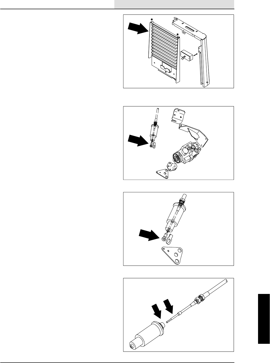
HYDRAULICS
6-9
8410 MM392 (8--01)
9. Remove the two hex screws holding the rear
radiator grill to the machine. Unplug the
taillight and remove the grill from the
machine.
10. Remove the 0.25 in. nyloc nut holding the
centering spring balljoint to the directional
control arm on the propel pump.
11. Loosen the large jam nuts holding the
directional cable to mount bracket on the
propel pump.
12. Remove the cable from the bracket and
position it outside the back of the machine.
13. Unscrew the directional spring assembly
from the directional control cable.
NOTE: Control cable will have to be held to keep
it from turning.
14. The old control cable can now be removed
from the machine and a new one installed.
Remove one of the jam nuts and thread the
other one all the way on.
NOTE: The end of the cable with 1.5 in of thread
goes to the directional spring.
15. Make sure to route the cable between the
square tube of the frame and the scrub
head.
16. Thread the directional spring assembly all
the way back on the directional control
cable. Leave 0.25 in of threads showing on
the 0.62 in diameter threads.
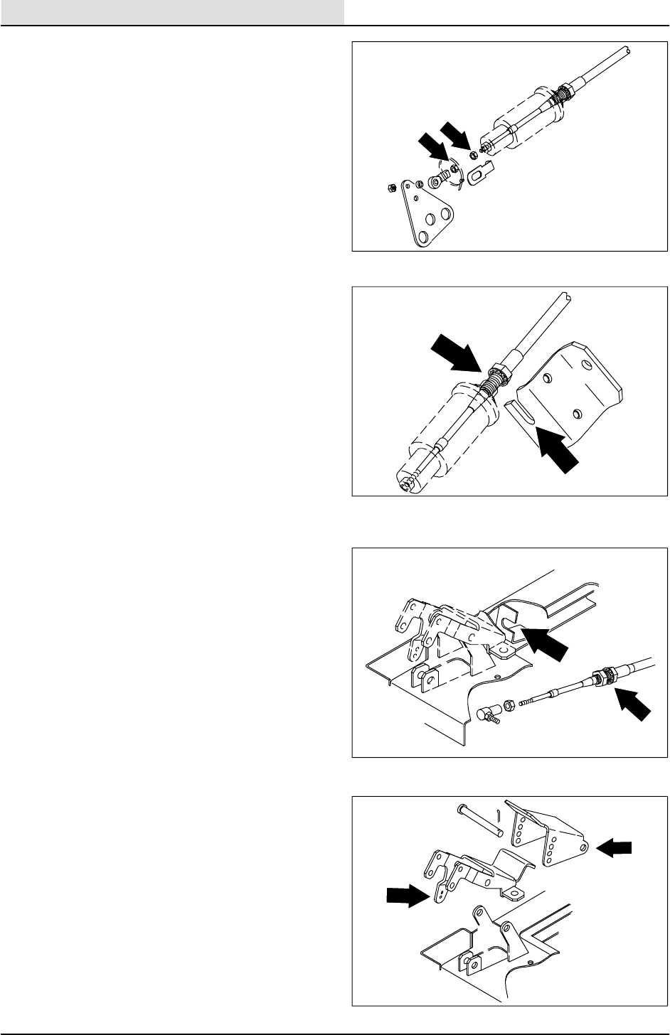
HYDRAULICS
6-10 8410 MM392 (8--01)
17. Install two 0.25 in jam nuts on the end of the
cable. Tighten one to the housing and the
other one to the balljoint, leaving 0.06
(1/16 in.) between them.
18. Reconnect the balljoint to the propel pump
control arm using the 0.25 nyloc nut. Tighten
t o 11 -- 1 4 N m ( 7 -- 1 0 f t l b ) .
19. Position the control cable back in the cable
mount bracket on the propel pump. Firmly
hand tighten large jam nut.
20. Install the control cable back in the mount
bracket on the bottom of the floor plate.
Firmly hand tighten large jam nuts so there
is an equal amount of threads showing on
both sides of bracket.
21. Reinstall the foot pedal with the clevis pin
and cotter pin.
22. Reinstall the 0.25 in. jam nut and balljoint on
the pedal end of control cable. Adjust it so
there is 1.5 in. of movement between jam
nut and rubber seal.
23. Reconnect the directional control cable
balljoint to foot pedal with 0.25 nyloc nut.
Tighten to 11 -- 14 Nm (7 -- 10 ft lb).
24. Jack up the rear of the machine.
FOR SAFETY: Block machine tires
before jacking machine up. Jack
machine up at designated locations
only. Block machine up with jack
stands.
25. Check the neutral centering of the propel
pump by starting the machine and observing
the rear tire for any sign of rotation. If the tire
is rotating See TO ADJUST DIRECTIONAL
CONTROL instructions.
26. Once the neutral centering has been set,
reinstall the rear grill panel. Tighten the four
M8 hex screws to 18 -- 24 Nm (15 -- 20 ft lb).
Lower the machine.
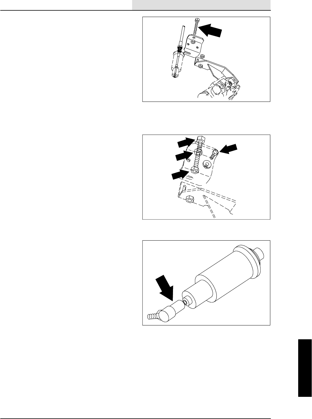
HYDRAULICS
6-11
8410 MM392 (8--01)
TO ADJUST DIRECTIONAL CONTROL
1. Set the emergency brake and start the
engine.
FOR SAFETY: Before Leaving Or
Servicing Machine; Stop On Level
Surface, Set Parking Brake, Turn Off
Machine And Remove Key.
2. Jack up the rear of machine.
FOR SAFETY: Block machine tires
before jacking machine up. Jack
machine up at designated locations
only. Block machine up with jack
stands.
3. Check the neutral centering of the pump by
observing the rear tire for any rotation.
4. If the rear tire is rotating, shut off the engine
and go under the machine by the engine
muffler.
5. Look up at the propel pump and locate the
long threaded adjustment bolt on the
movable cable bracket. Loosen the jam
nuts.
6. Loosen the two hex screws holding the
movable cable bracket to the fixed pump
bracket.
7. Start the machine and observe the rear tire
for any rotation. If the tire is rotating in either
direction, turn the long threaded adjustment
bolt until the rotation stops. Tighten the jam
nuts and hex screws.
8. For fine adjustments the balljoint on the end
of the propel cable can be rotated in or out a
few turns.
9. Lower the machine to the ground and
operate. Check to see if the machine creeps
in either direction.
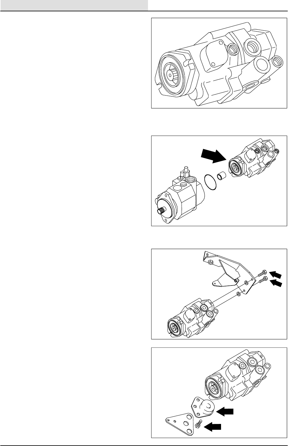
HYDRAULICS
6-12 8410 MM392 (8--01)
TO REPLACE PROPEL PUMP
1. Start the engine and lower the squeegee.
FOR SAFETY: Before Leaving Or
Servicing Machine; Stop On Level
Surface, Set Parking Brake, Turn Off
Machine And Remove Key.
2. Disconnect the battery cables from the
battery.
3. Jack up the rear of the machine.
FOR SAFETY: Block machine tires
before jacking machine up. Jack
machine up at designated locations
only. Block machine up with jack
stands.
4. Remove two M8 hex screws holding the rear
radiator grill to the machine. Unplug the
taillight and remove the grill from the
machine.
5. Open the engine cover and side door.
6. Remove the muffler and exhaust pipe.
7. Remove hex screws holding directional
control cable mount bracket to the back of
propel pump.
8. Remove the hex screw holding the propel
pump arm to the pump hub.
9. Unplug the pump switch from main harness.
10. Move the pump arm, cable mount bracket,
and control cable back out of the way.
11. Remove and plug the four hydraulic hoses
leading to the propel pump.
NOTE: Observe hydraulic cleanliness
requirements when opening hydraulic lines.
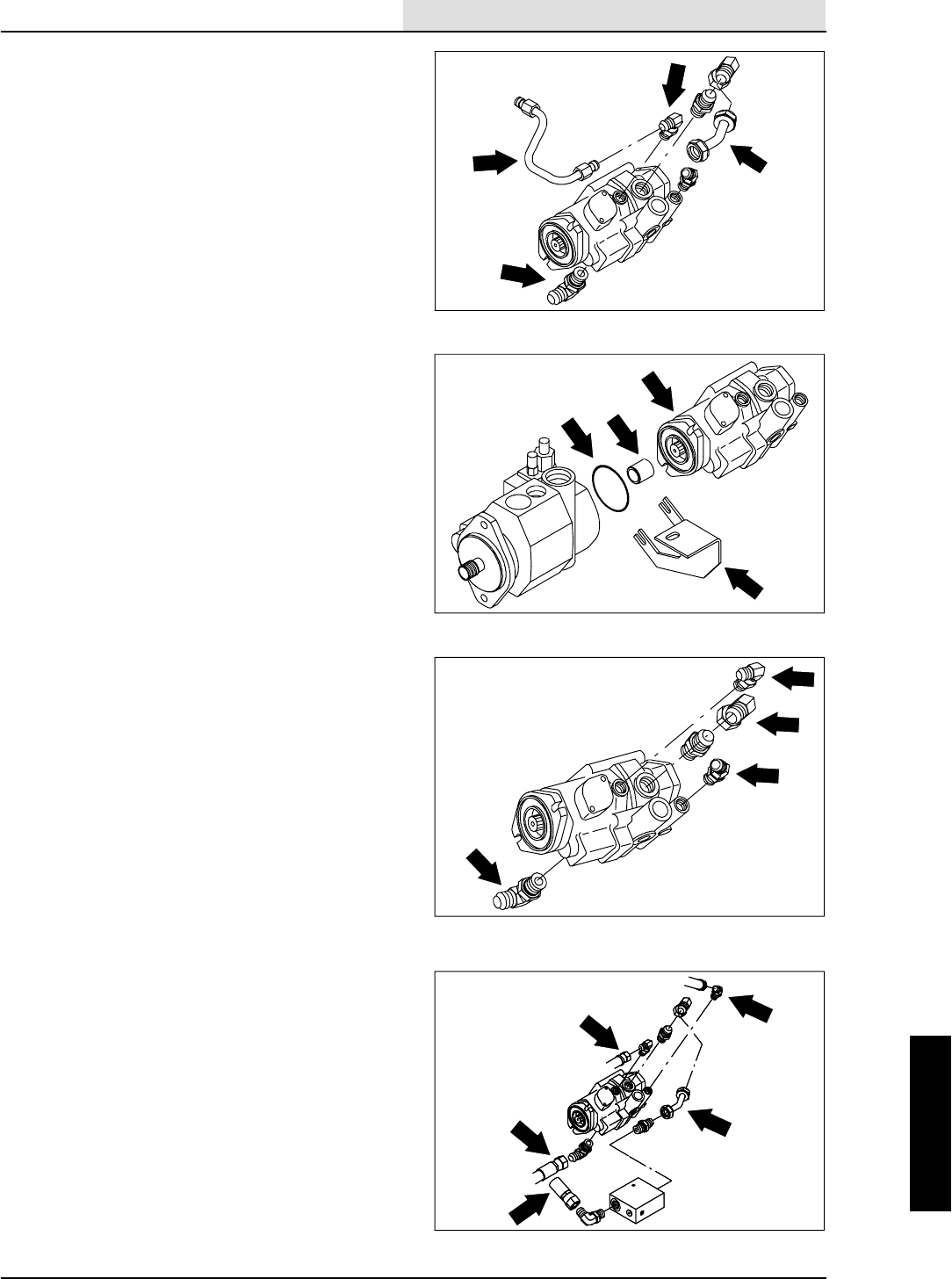
HYDRAULICS
6-13
8410 MM392 (8--01)
12. Remove the two 0.38 in. hex screws holding
the propel pump to the load sensing pump.
13. Move the flow switch and mounting bracket
out of the way.
14. The propel pump can now be pulled back
and out of the load sensing pump.
NOTE: Be careful not to loose or damage the
o--ring or the pump coupler.
15. Remove the propel pump from the machine.
16. Remove the hydraulic fittings from the old
pump and install them in the new one. Make
sure the fittings are installed in the same
orientation as they were removed.
17. Remove hub from the pump shaft on the old
propel pump. A puller may needed to break
the hub loose.
18. Install the hub on the new pump shaft. Use
the new key already on the pump shaft.
Lightly tap the hub on the taper shaft with a
hammer so it will stay in place until the
hardware is installed.
19. Position pump back in the machine. Make
sure the o--ring and coupler are in place.
Reinstall the 0.38 in. hex screws with blue
loctite 242. Place the flow switch bracket
under the bolt heads. Tighten to 31 -- 40 Nm
(27 -- 35 ft lb).
NOTE: Be careful not to loose or damage the
o--ring or the pump coupler.
20. Reconnect the hydraulic hoses. See the
schematic in this section.
NOTE: Observe hydraulic cleanliness
requirements when opening hydraulic lines.
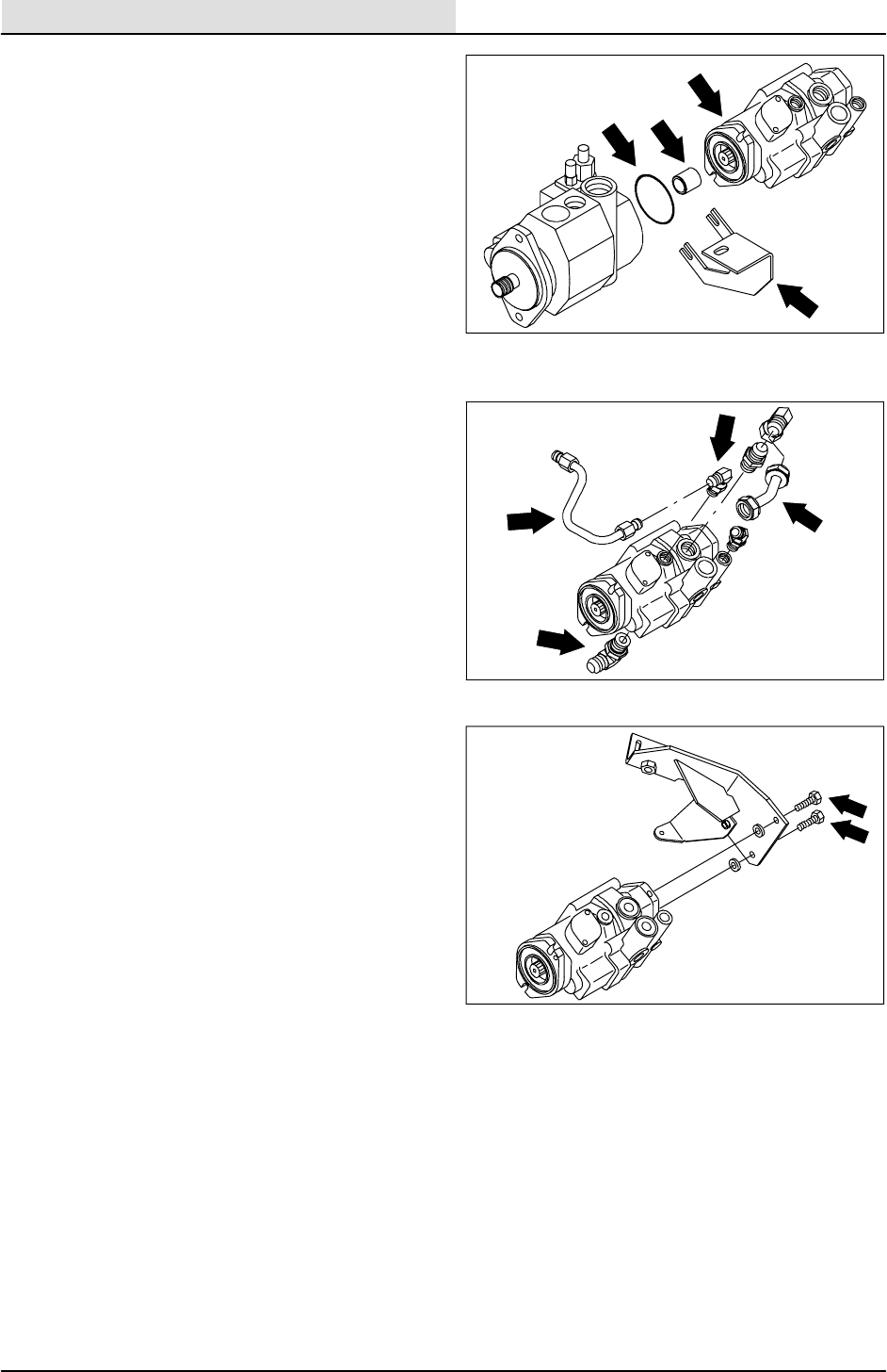
HYDRAULICS
6-14 8410 MM392 (8--01)
21. Place the control cable, cable mount plate,
and the pump arm back in position.
22. Align the mount holes in the cable plate with
the holes in the back of the propel pump.
Reinstall the 0.38 in. hex screws and
washers. Make sure to put one washer
between the plate and pump under each hex
screw. Use blue loctite 242 and tighten to
31 -- 40 Nm (27 -- 35 ft lb).
23. Reinstall the pump arm to the pump hub
using the two M8 hex screws on the outside
and one 0.31 in. hex screw in the center.
Tighten to 18 -- 24 Nm (15 -- 20 ft lb).
24. Reconnect the pump switch to the main
electrical harness.
25. Reinstall the muffler and exhaust pipe.
26. Reconnect the battery cables.
27. Check the neutral centering of the new
propel pump by starting the machine and
observing the rear tire for any rotation. If tire
is rotating See TO ADJUST DIRECTIONAL
CONTROL instructions in this section.
28. Once the neutral centering has been set,
reinstall rear grill panel. Tighten four M8 hex
screws to 18 -- 24 Nm (15 -- 20 ft lb). Lower
the machine.
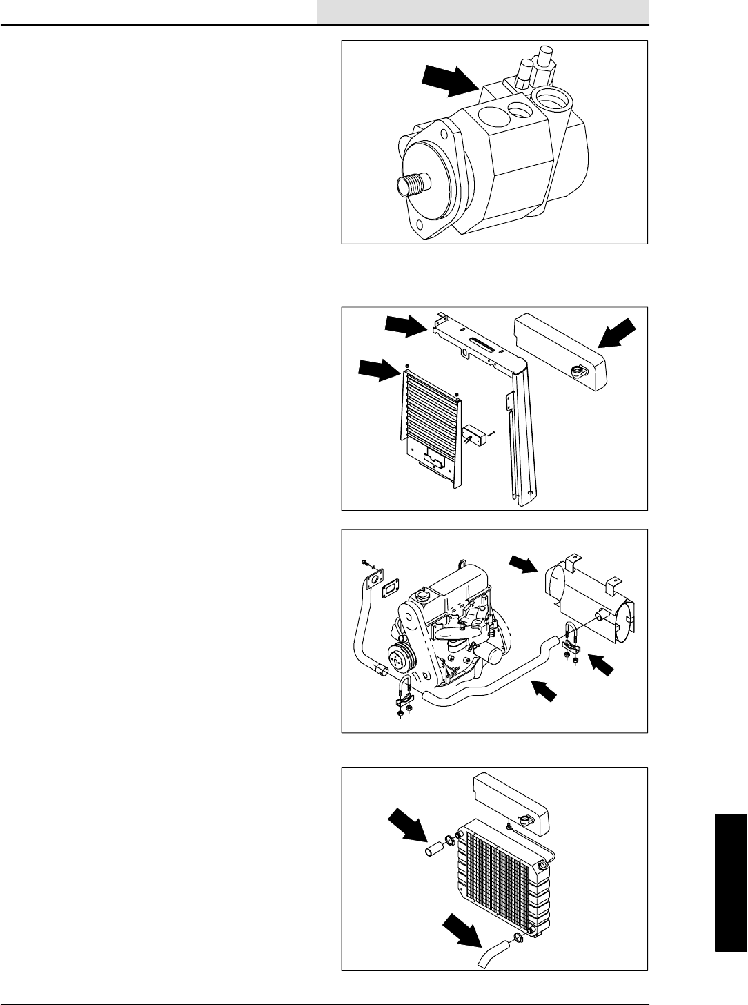
HYDRAULICS
6-15
8410 MM392 (8--01)
TO REPLACE LOAD SENSING PUMP
1. Start the engine and lower the squeegee.
FOR SAFETY: Before Leaving Or
Servicing Machine; Stop On Level
Surface, Set Parking Brake., Turn Off
Machine And Remove Key.
2. Jack up the rear of the machine.
FOR SAFETY: Block machine tires
before jacking machine up. Jack
machine up at designated locations
only. Block machine up with jack
stands.
3. Open the engine cover and side door.
4. Lift the engine side door off the hinges and
put it aside.
5. Remove two M8 hex screws holding the rear
radiator grill to the machine. Unplug the
taillight and remove the grill from the
machine.
6. Remove the muffler and exhaust pipe.
7. Drain the hydraulic tank.
8. Remove the radiator overflow tank.
9. Remove the left hand corner channel.
10. Drain the radiator and disconnect the
radiator hoses from the radiator.
11. Remove and plug hydraulic hoses going to
the hydraulic oil cooler that sits behind
engine radiator.
12. Remove and plug the hydraulic hoses going
to the engine cooling fan hydraulic motor.
NOTE: Observe hydraulic cleanliness
requirements when opening hydraulic lines.
13. Remove the two nyloc nuts holding the
bottom of the radiator to the mounting
channel.
14. The radiator assembly can now be carefully
lifted out and set aside.
15. Remove the six M8 hex screws holding the
mounting channel to the frame. Remove the
channel.
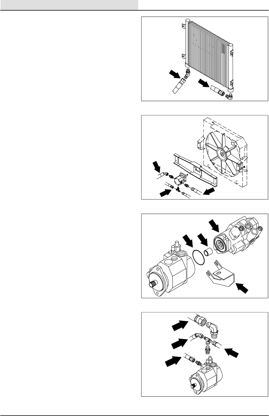
HYDRAULICS
6-16 8410 MM392 (8--01)
16. Remove the hex screws holding the propel
pump to the load sensing pump.
17. Move the flow switch and mounting bracket
out of the way.
18. The propel pump can now be pulled back
out of the load sensing pump.
NOTE: Be careful not to loose or damage the
o--ring or the pump coupler.
19. Remove and plug the hydraulic hoses going
to the load sensing pump.
NOTE: Observe hydraulic cleanliness
requirements when opening hydraulic lines.
20. Remove the two M12 hex screws holding
the load sensing pump to the bellhousing.
21. The load sensing pump can now be pulled
back out of the flywheel coupler and
removed from the machine.
22. Remove the fittings from the old pump and
install in the new pump in the same
orientation they were removed.
23. Place a small amount of grease on the
splines of the new pump and install it back in
the machine.
24. Align the holes in pump flange with holes in
bellhousing. Install the two M12 hex screws
with blue loctite 242 and tighten to 31 -- 40
Nm (27 -- 35 ft lb).
25. Reconnect the hydraulic hoses to the load
sensing pump. See the schematic in this
section.
26. Position the propel pump back in the load
sensing pump. Make sure o--ring and
coupler are in place. Reinstall the 0.38 in.
hex screws with blue loctite 242. Place the
flow switch bracket back under the bolt
heads. Tighten to 31 -- 40 Nm (27 -- 35 ft lb).
27. Reinstall the radiator mounting channel
using six M8 hex screws. Tighten to
18 -- 24 Nm (15 -- 20 ft lb).
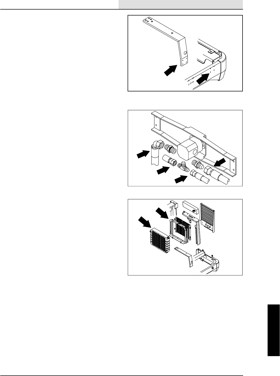
HYDRAULICS
6-17
8410 MM392 (8--01)
28. Place the radiator assembly back on the
mount channel. Reinstall the two M10 nyloc
nuts and washers and tighten to
18 -- 24 Nm (15 -- 20 ft lb).
29. Reconnect the hydraulic hoses to the engine
cooling fan motor. See the schematic in this
section.
30. Reconnect the hydraulic hoses to the
hydraulic oil cooler. See the schematic in
this section.
31. Reconnect the radiator hoses to the
radiator.
32. Position the LH tower back on the machine.
33. Tighten the M8 hex screws to 18 -- 24 Nm
(15 -- 20 ft lb). Tighten the M10 hex screw
to 52 -- 67 Nm (39 -- 51 ft lb).
34. Reinstall the muffler and exhaust pipe.
35. Refill the engine radiator with coolant.
36. Refill the hydraulic fluid reservoir with the
proper grade of hydraulic fluid.
37. Reinstall the engine side door.
38. Start the engine and check for proper
operation and leaks.
39. Once the neutral centering has been set,
reinstall rear grill panel. Tighten four M8 hex
screws to 18 -- 24 Nm (15 -- 20 ft lb). Lower
the machine.
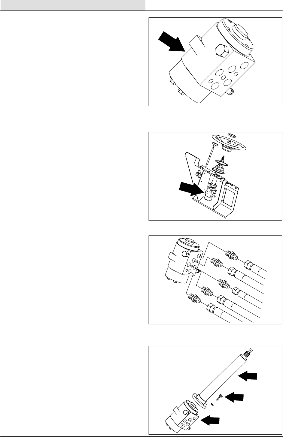
HYDRAULICS
6-18 8410 MM392 (8--01)
TO REPLACE HYDRAULIC STEERING
VALVE
1. Turn off the engine and engage the parking
brake.
FOR SAFETY: Before Leaving Or
Servicing Machine; Stop On Level
Surface, Set Parking Brake, Turn Off
Machine And Remove Key.
2. Remove the battery cables from the battery.
3. Remove the recovery tank. See TO
REMOVE RECOVERY TANK instructions in
the SCRUBBING section.
4. Remove and plug the five hydraulic hoses
leading to the steering control motor.
NOTE: Observe hydraulic cleanliness
requirements when opening hydraulic lines.
5. Remove the four M6 hex screws holding the
hydraulic steering valve to the steering
column.
6. The hydraulic steering valve can now be
removed from machine.
7. Remove the hydraulic fittings from the old
control motor. Install in the new or rebuilt
control motor in the same orientation as they
were removed.
NOTE: Remember to orientate the fittings as
close as possible to the way they came out.
8. Install the new hydraulic steering valve
assembly back in the machine. Position the
ports in the same orientation as it was
removed. Reinstall the four M6 hex screws
and tighten to 8 -- 10 Nm (5 -- 7 ft lb).
9. Reconnect the five hydraulic hoses to the
hydraulic steering valve. See the schematic
in this section.
10. Reconnect battery cables. Start engine and
move the steering wheel back and forth,
checking for leaks and proper operation.
11. Reinstall the recovery tank. See TO
INSTALL RECOVERY TANK instructions in
the SCRUBBING section.
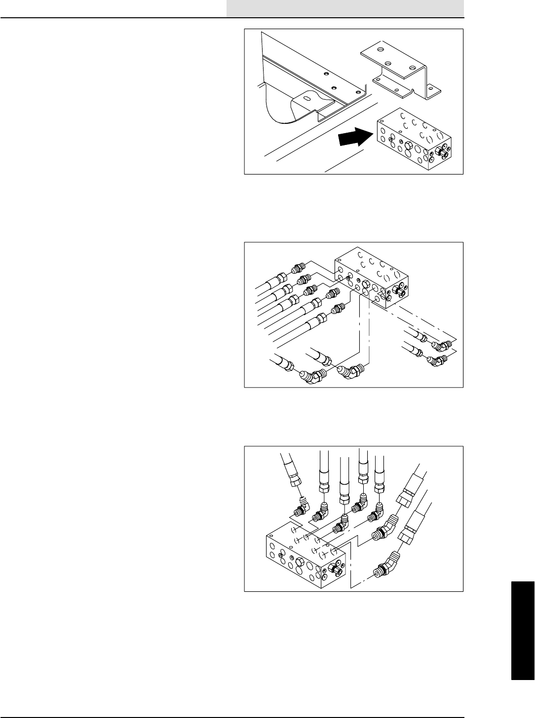
HYDRAULICS
6-19
8410 MM392 (8--01)
TO REPLACE MAIN HYDRAULIC VALVE
NOTE: Do Not replace complete valve unless the
manifold block has cracked, otherwise replace
individual component cartridge.
FOR SAFETY: Before Leaving Or
Servicing Machine; Stop On Level
Surface, Set Parking Brake., Turn Off
Machine And Remove Key.
1. Jack up the rear of the machine.
FOR SAFETY: Block machine tires
before jacking machine up. Jack
machine up at designated locations
only. Block machine up with jack
stands.
2. Remove the battery cables from the battery.
3. Go under the machine on left side and
locate the main hydraulic valve. Disconnect
the electrical solenoids from the main
harness.
4. Remove and cap the hydraulic hoses on the
main hydraulic valve. Start with the hoses
nearest the outside of the machine and work
toward the center.
NOTE: Observe hydraulic cleanliness
requirements when opening hydraulic lines.
5. Remove the three M8 hex screws holding
the main valve to the mount bracket.
6. The main valve can now be dropped down
and out of the machine.
7. Carefully place the valve in a vice. Note the
orientation of fittings.
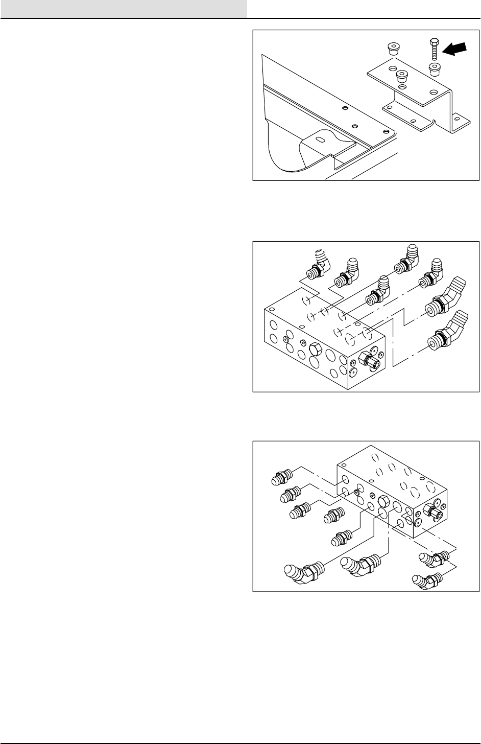
HYDRAULICS
6-20 8410 MM392 (8--01)
8. Remove the hydraulic fittings from old valve
and install in the new valve in the same
orientation.
NOTE: Install the fittings in the new valve in the
same orientation as they were removed.
9. Position the new valve back under machine.
Reinstall the three M8 hex screws and
washers. Tighten to 18 -- 24 Nm
(15 -- 20 ft lb).
10. Reconnect the hydraulic hoses to the new
valve. See the hydraulic schematic in this
section. Start from the side of the valve
nearest the center of the machine and work
toward the outside.
11. Reconnect the electric solenoids to the main
harness. See the schematic in the
ELECTRICAL section of this manual.
12. Reinstall the brush guard using the two M12
hex screws. Tighten to 64 -- 83 Nm
(50 -- 60 ft lb).
13. Remove the jack stands and lower the
machine.
14. Reconnect the battery cables to the battery.
15. Start the machine and check the hydraulic
components for proper operation.
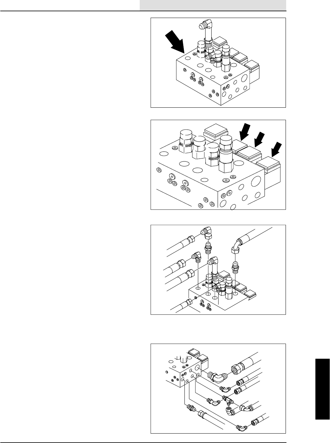
HYDRAULICS
6-21
8410 MM392 (8--01)
TO REPLACE SCRUB VALVE
NOTE: Do Not replace complete valve unless the
manifold block has cracked, otherwise replace
individual component cartridge.
FOR SAFETY: Before Leaving Or
Servicing Machine; Stop On Level
Surface, Set Parking Brake., Turn Off
Machine And Remove Key.
1. The solution and recovery tanks must be
removed in order to service the scrubber
valve. See TO REMOVE SOLUTION TANK
instructions in the SCRUBBING section of
this manual.
2. Remove the battery cables from the battery.
3. Remove the main brush from the machine.
4. Locate the scrub valve on top of the
machine frame near the front left tower.
5. Disconnect the electrical solenoids from
main harness.
6. Remove and cap the hydraulic hoses on the
scrub valve.
NOTE: Observe hydraulic cleanliness
requirements when opening hydraulic lines.
7. Open the the brush door on the left side of
the machine.
8. Remove the three M10 hex screws,
washers, and nyloc nuts holding the
scrubber valve assembly to the machine
frame.
9. Remove the scrubber valve from machine
and place it in a vice upside down.
10. Remove the three M8 hex screws holding
the two mounting plates to the valve.
11. Turn the valve over in the vice and remove
the hydraulic fittings.
12. Install fittings in the new valve in the same
orientation.
NOTE: Install the fittings in the new valve in the
same orientation as they were removed.
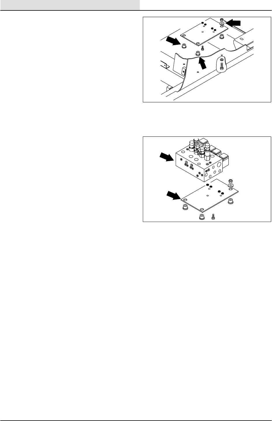
HYDRAULICS
6-22 8410 MM392 (8--01)
13. Reinstall the two mounting plates to the new
scrubber valve. Reinstall the three M8 hex
screws and tighten to 18 -- 24 Nm
(15 -- 20 ft lb).
14. Position the new scrubber valve assembly
back in the machine. Reinstall the three M10
hex screws, washers, and nyloc nuts.
Tighten to 37 -- 48 Nm (26 -- 34 ft lb).
NOTE: Remember to put hex screws in from
under the machine so the nyloc nuts are on valve
side.
15. Reconnect the hydraulic hoses to scrubber
valve. See the hydraulic schematic in this
section.
16. Reconnect the electric solenoids to the main
harness. See the schematic in the
ELECTRICAL section of this manual.
17. Reconnect the battery cables to the battery.
18. Start the machine and operate the hydraulic
scrubbing functions. Check the scrubber
valve for any leaks and for proper operation.
19. Reinstall solution and recovery tanks. See
TO INSTALL SOLUTION TANK instructions
in the SCRUBBING section of this manual.
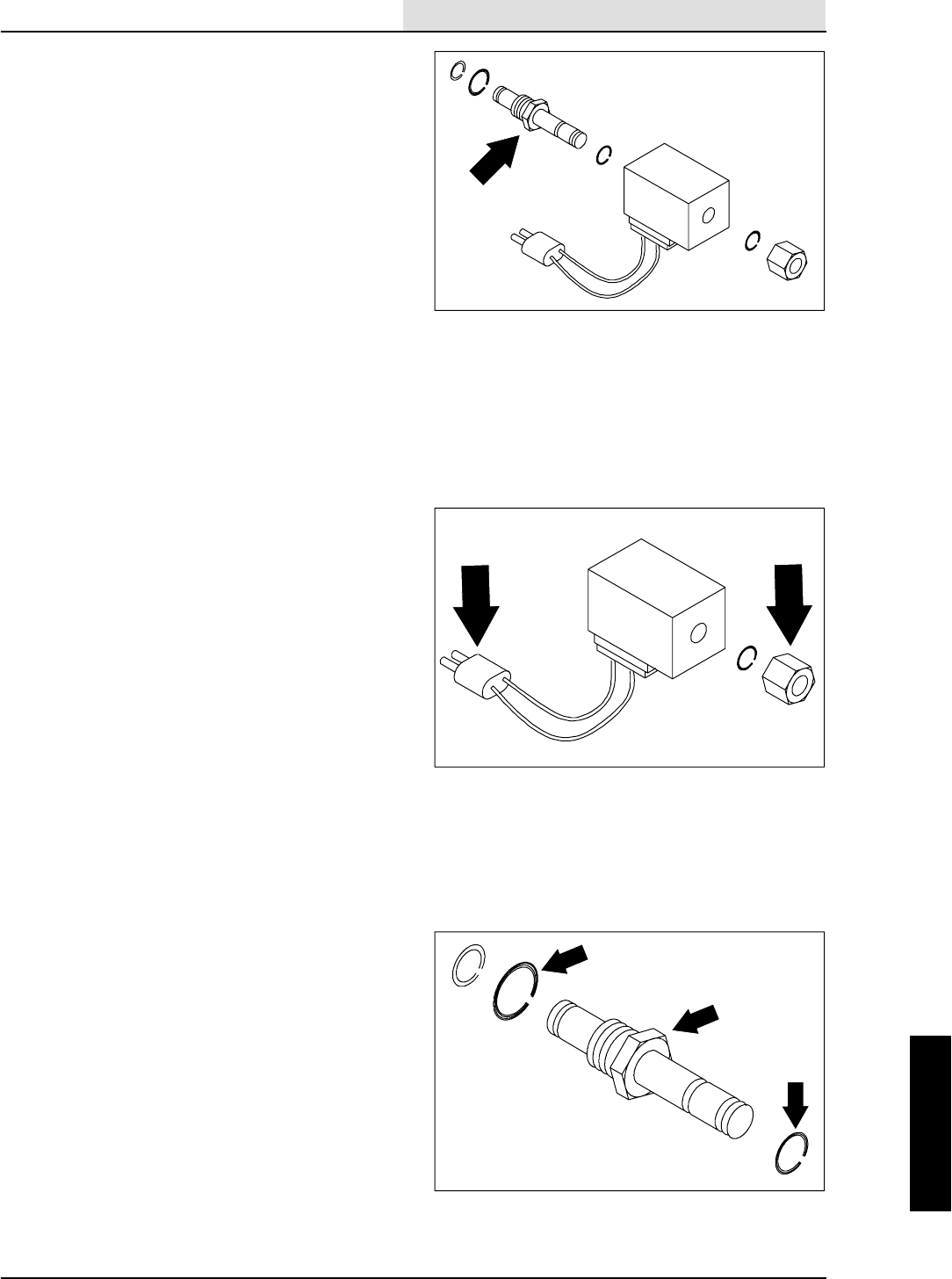
HYDRAULICS
6-23
8410 MM392 (8--01)
TO REPLACE SOLENOID VALVE
CARTRIDGE
1. Shut off the engine and engage the parking
brake.
FOR SAFETY: Before Leaving Or
Servicing Machine; Stop On Level
Surface, Set Parking Brake, Turn Off
Machine And Remove Key.
2. Remove the battery cables from the battery.
3. Locate and identify the cartridge to be
replaced. Unplug the solenoid from the main
harness.
4. Remove the hex nut and rubber o--ring from
the cartridge stem.
5. Slide electrical coil and rubber o--ring off the
valve stem.
NOTE: Oil will run out of the valve when the
cartridge is removed.
6. Remove the cartridge stem from the valve
body.
NOTE: Observe hydraulic cleanliness
requirements when opening hydraulic lines.
7. Install a new cartridge stem back in the
valve port. Firmly hand tighten.
NOTE: Make sure the new cartridge had an
o--ring installed and oiled.
8. Slip the o--ring and coil back over the new
stem.
9. Install the o--ring and hex nut on the new
stem. Lightly hand tighten.
NOTE: Do not over tighten----snug only.
10. Plug the solenoid coil back in the main
harness. See schematic in ELECTRICAL
section.
11. Reconnect the battery cables to the battery.
12. Start the machine and check the new
cartridge for leaks.
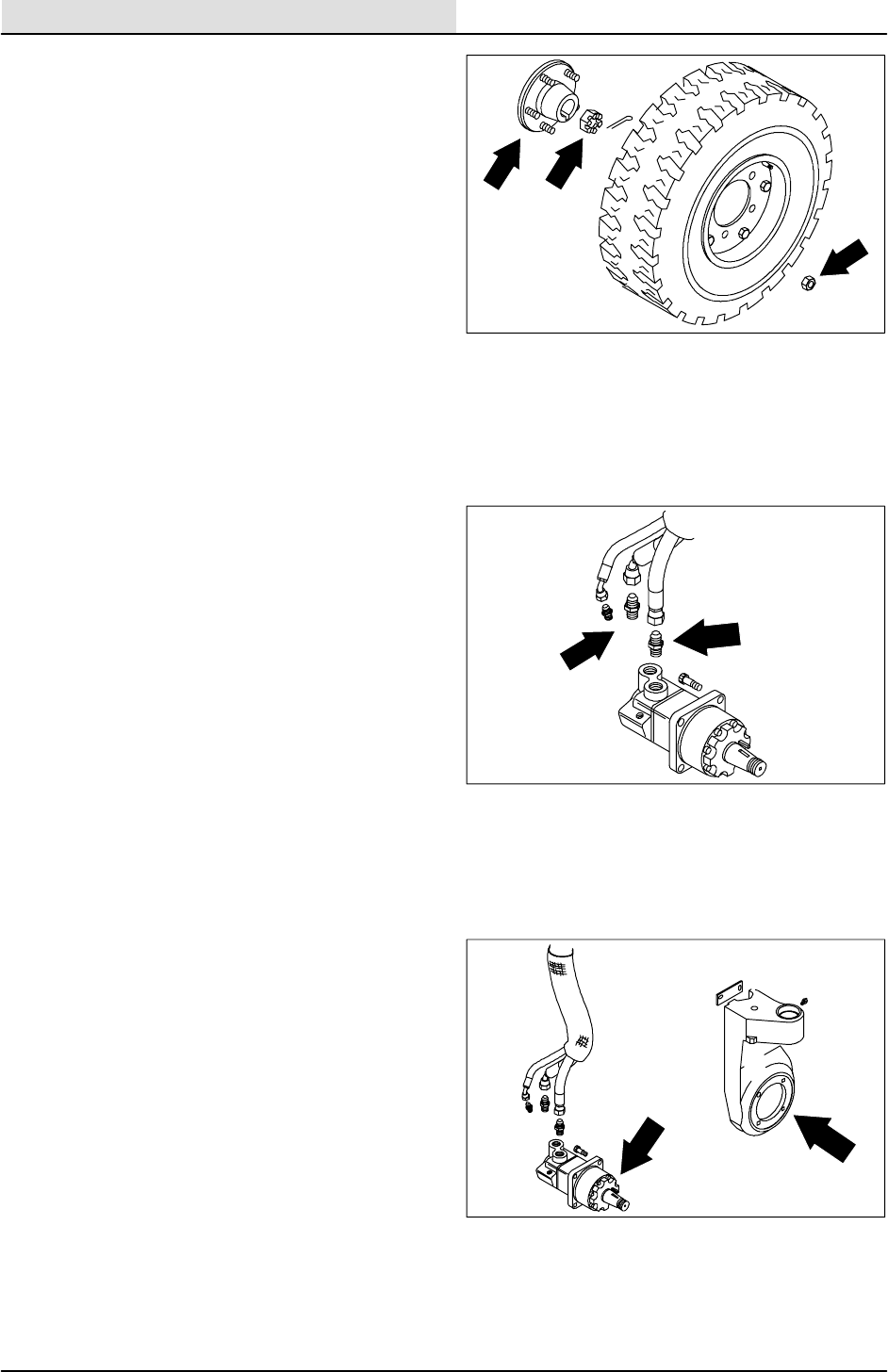
HYDRAULICS
6-24 8410 MM392 (8--01)
TO REPLACE REAR DRIVE MOTOR
FOR SAFETY: Before Leaving Or
Servicing Machine; Stop On Level
Surface, Set Parking Brake, Turn Off
Machine And Remove Key.
1. Engage the parking brake and block the
front tires.
2. Jack up the rear of the machine. Use jack
stands to support machine.
FOR SAFETY: Block machine tires
before jacking machine up. Jack
machine up at designated locations
only. Block machine up with jack
stands.
3. Remove the rear tire and wheel assembly.
4. Remove the slotted nut from drive wheel
motor hub shaft.
5. Use a large puller to remove the drive hub
from the motor shaft.
NOTE: Mark the hoses to make sure they are
returned to the correct fitting when reassembled.
6. Remove and plug the hydraulic hoses
leading to the drive motor.
NOTE: Observe hydraulic cleanliness
requirements when opening hydraulic lines.
7. Remove the four drive motor mounting bolts.
8. Slide the motor out of the rear wheel
housing.
NOTE: The orientation of the motor in the rear
wheel housing.
9. Rebuild or replace drive motor. If you
replace the drive motor, install the fittings on
the new motor oriented the same as they
were removed.
10. Slide the rebuilt or new motor in the rear
wheel housing.
NOTE: The orientation of the motor in the rear
wheel housing.
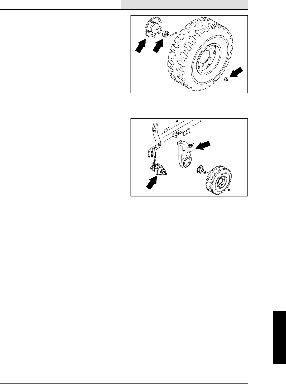
HYDRAULICS
6-25
8410 MM392 (8--01)
11. Install the four socket screws. Torque to
90 -- 117 Nm (70 -- 85 ft lb).
12. Reconnect the hydraulic hoses to the drive
motor.
NOTE: Make sure the hoses are returned to the
correct fitting when reassembled. See schematic
in the HYDRAULICS section.
13. Install the drive hub to the tapered motor
shaft. Tighten slotted nut to 500 Nm
(375 ft lb). Install the cotter pin.
NOTE: Make sure the square key is in place on
the tapered shaft before installing the drive hub.
14. Install rear tire and wheel assembly. Torque
the rear wheel nuts to 142 -- 156 Nm
(105 -- 115 ft lb).
15. Remove the jack stands and the lower
machine.
16. Drive the machine and check for proper
operation.
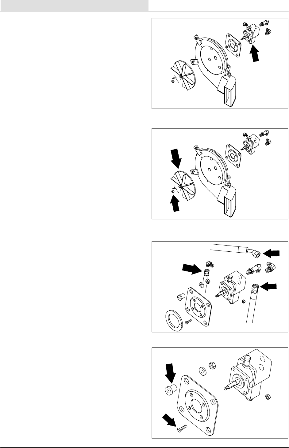
HYDRAULICS
6-26 8410 MM392 (8--01)
TO REPLACE SWEEPING VACUUM FAN
HYDRAULIC MOTOR
1. Park the machine on a smooth, level
surface.
2. Stop the engine and set the machine parking
brake.
FOR SAFETY: Before Leaving Or
Servicing Machine; Stop On Level
Surface, Set Parking Brake, Turn Off
Machine And Remove Key.
3. Remove the vacuum fan from the machine.
See TO REMOVE SWEEPING VACUUM
FAN instructions in this section.
4. Place the vacuum fan assembly in a vice.
5. Remove the four 0.25 in. hex screws and
fender washers holding the inlet plate to the
vacuum fan housing. Remove the plate.
6. Hold the impeller from turning and remove
the 0.31 in. hex nut from the vacuum fan
motor shaft.
7. Pull the impeller straight off the shaft. The
impeller may have to be lightly pried off. Be
careful not to loose the square key.
8. Remove the four M10 nyloc nuts holding the
hydraulic motor plate to vacuum fan
housing.
9. Remove the hydraulic motor and plate
assembly from the vacuum fan housing.
10. Remove the four M8 flat head screws and
nyloc nuts holding hydraulic fan motor to the
motor plate.
11. Remove the hydraulic fittings and install in
the new or rebuilt fan motor. Keep the same
orientation.
12. Install the new motor on the motor plate
using the four M8 flat head screws and nyloc
nuts. Tighten to 18 -- 24 Nm (13 -- 18 ft lb).
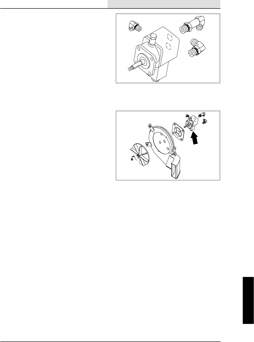
HYDRAULICS
6-27
8410 MM392 (8--01)
13. Reinstall the hydraulic motor and plate
assembly back on the fan housing using four
M10 nyloc nuts and flat washers. Tighten to
18 -- 24 Nm (13 -- 18 ft lb).The motor should
be oriented with case drain fitting pointing
toward the fan exhaust outlet.
14. Put a small amount of grease on the motor
shaft before installing the new impeller.
Make sure the square key is in place.
15. Slide the impeller all the way on the shaft
and spin it slowly. If the impeller rubs on
housing, remove and place a 0.38 in. flat
washer on shaft under impeller and
re--assemble. Repeat this procedure until
the impeller spins freely.
16. Hold the new impeller from turning and firmly
tighten the 0.31 in. flex lock nut.
17. Reinstall the inlet plate using the four 0.25
in. hex screws and fender washers. Tighten
t o 11 -- 1 4 N m ( 7 -- 1 0 f t l b ) .
18. Reinstall vacuum fan assembly to the rear of
the hopper. See TO INSTALL SWEEPING
VACUUM FAN instructions in this section.
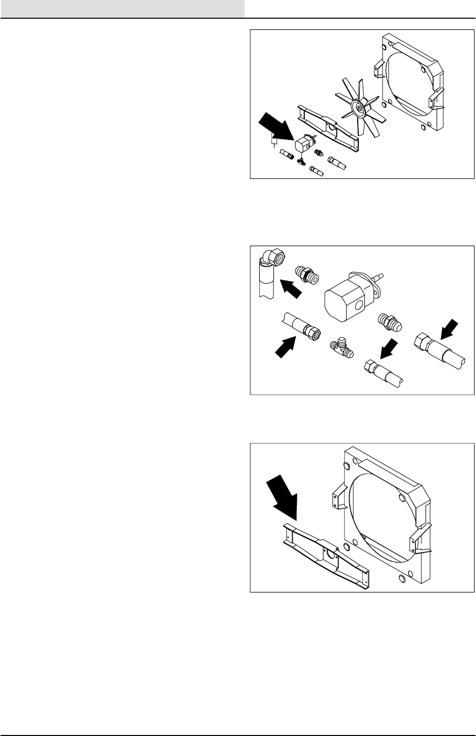
HYDRAULICS
6-28 8410 MM392 (8--01)
TO REPLACE ENGINE COOLING FAN
HYDRAULIC MOTOR
1. Shut off the engine and engage the parking
brake.
FOR SAFETY: Before Leaving Or
Servicing Machine; Stop On Level
Surface, Set Parking Brake, Turn Off
Machine And Remove Key.
2. Open the engine cover and side door.
3. Remove and plug the hoses connected to
thecoolingfanmotor.
NOTE: Observe hydraulic cleanliness
requirements when opening hydraulic lines.
4. Remove the four M6 hex screws and nyloc
nuts holding the fan motor mount channel to
the fan housing. Remove the cooling fan
assembly from the machine.
5. Remove the hex nut from the fan motor
shaft in center of fan blade.
6. Remove the fan blade from the motor shaft.
NOTE: A puller must be used to remove fan blade
from tapered motor shaft.
7. Remove the four M8 hex screws holding the
fan motor to mount channel. Remove the
motor.
8. Remove the fittings from the old fan motor
and install in the new motor in the same
orientation.
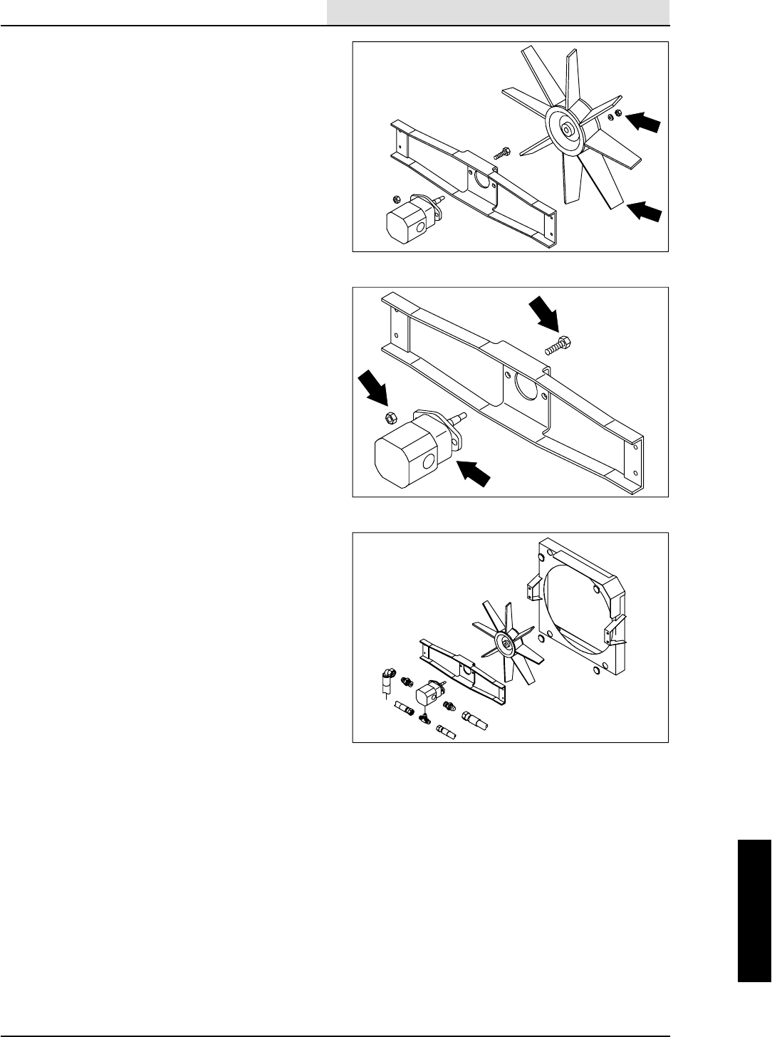
HYDRAULICS
6-29
8410 MM392 (8--01)
9. Install a new cooling fan motor on the mount
channel. Reinstall the four M8 hex screws.
Tighten to 18.5 -- 24 Nm (16 -- 21 ft lb).
10. Reinstall the fan blade on the new fan motor
shaft.
NOTE: Make sure key is in place on motor shaft.
11. Reinstall the hex nut and tighten to
18.5 -- 24 Nm (16 -- 21 ft lb).
12. Reinstall the fan motor assembly on the fan
housing. Reinstall the four M6 hex screws
and nyloc nuts. Tighten to 7.6 -- 9.9 Nm
(5 -- 7 ft lb).
13. Reconnect the hydraulic hoses to the new
cooling fan motor. See the hydraulic
schematic in this section.
14. Start the machine and check the new
cooling fan motor for leaks.
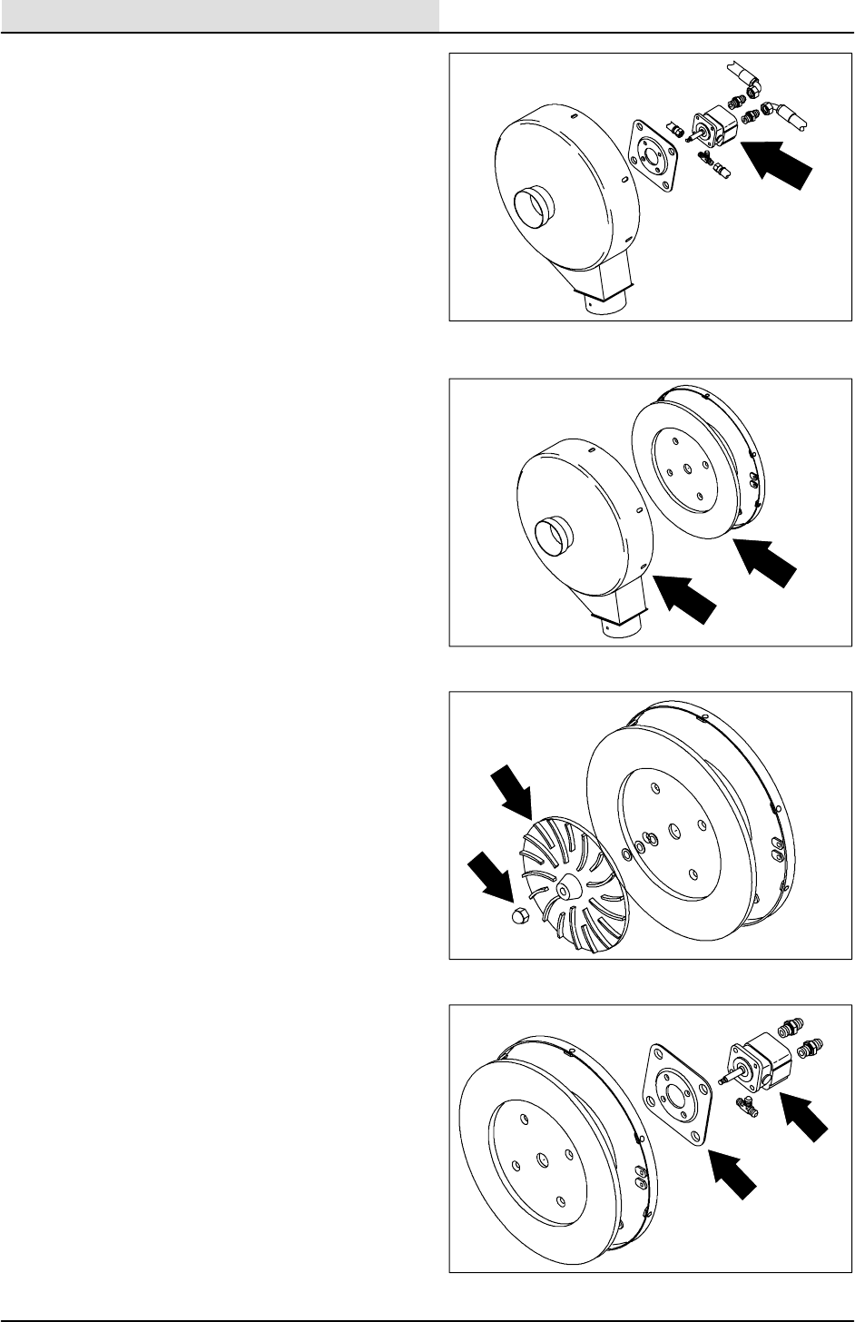
HYDRAULICS
6-30 8410 MM392 (8--01)
TO REPLACE SCRUB VACUUM FAN
HYDRAULIC MOTOR
FOR SAFETY: Before Leaving Or
Servicing Machine; Stop On Level
Surface, Set Parking Brake, Turn Off
Machine And Remove Key.
1. Remove the scrub vacuum fan from the
machine. See TO REMOVE SCRUB
VACUUM FAN instructions in this section.
2. Place the vacuum fan assembly in a vice or
other holding device.
3. Remove the six hex screws holding the front
housing to the rear housing. Remove the
front housing.
NOTE: The orientation of front housing to rear
housing is very important. Mark both the front and
rear housing for proper reassembly.
4. Remove the crown nut on the impeller shaft.
Slide the impeller off the shaft.
NOTE: Remove and save the square key and any
shims on the shaft under the impeller.
5. Turn the bottom housing over and remove
the four nyloc nuts and washers from the
motor mount plate. Remove the plate from
the housing.
NOTE: Mark the orientation of hydraulic motor
and fittings.
6. Remove the four flat head screws and nyloc
nuts holding the hydraulic fan motor to the
mounting plate.
7. Install a new motor on the mounting plate.
Tighten the four flat head screws to
9--13Nm(7--10ftlb).
8. Remove the hydraulic fittings from the old
motor. Install these fittings in the new motor
in the same orientation as they were
removed.
9. Reinstall the new motor and mounting plate
on the rear housing. Tighten the four nyloc
nuts to 16 -- 22 Nm (12 -- 16 ft lb).
NOTE: Make sure the motor is installed on the
rear housing with the hydraulic motor in the
correct orientation.
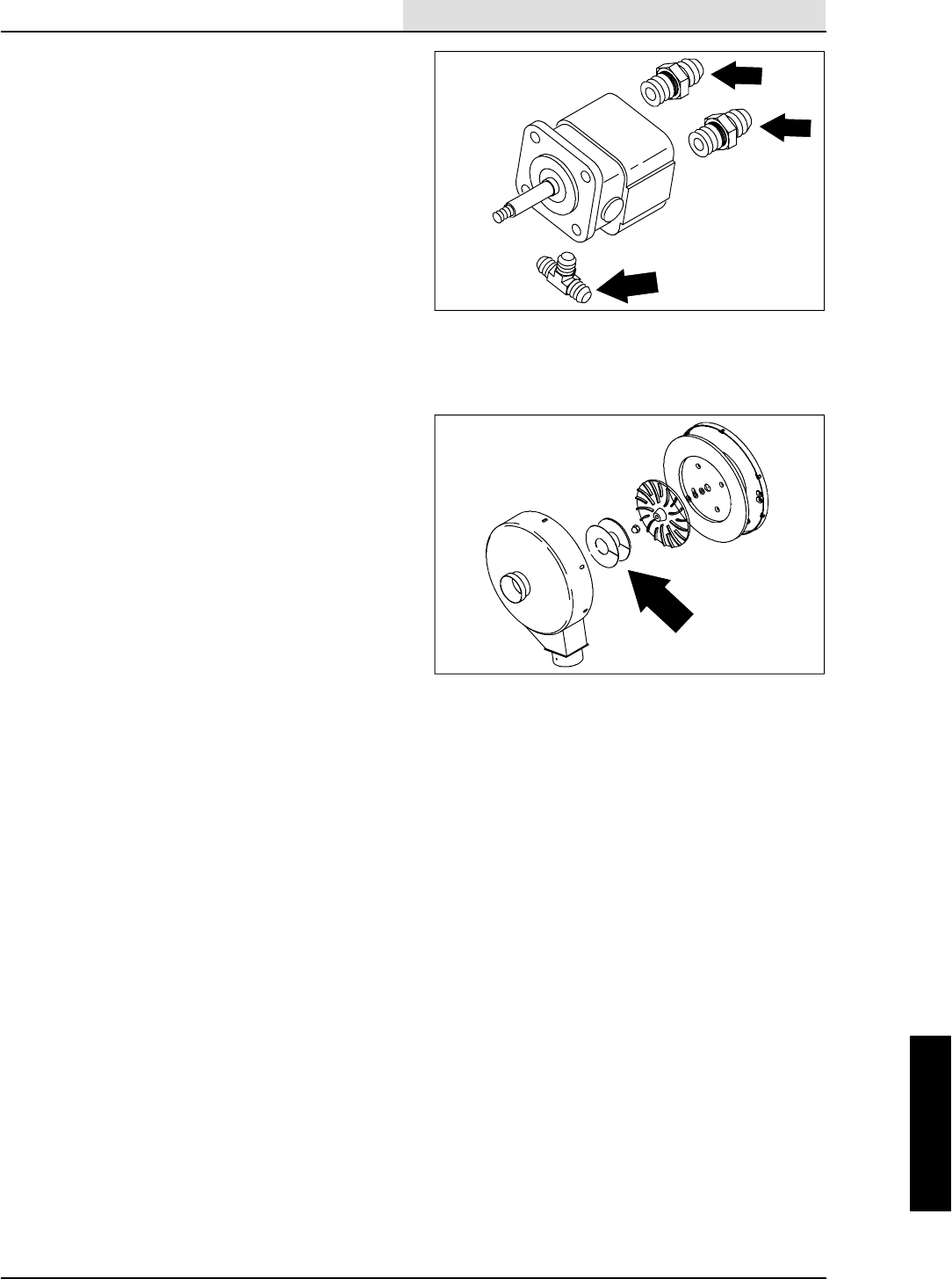
HYDRAULICS
6-31
8410 MM392 (8--01)
10. Turn the rear housing over and reinstall the
shims, key, fan impeller, and crown nut.
Tighten nut to 34 -- 47 Nm (25 -- 35 ft lb).
NOTE: Be sure the key is on the shaft. Super
gluing the key helps keep it in place.
NOTE: Use blue loctite 242 on shaft threads.
11. Reinstall the front housing to the rear
housing. Reinstall the six hex screws and
tighten to 22 -- 27 Nm (16 -- 20 ft lb).
NOTE: Tennant part no. 57543 plastic shims must
be used for proper fan to housing clearance.
Remove these shims after housing has been
tightened.
12. Reinstall the vacuum fan assembly back in
the machine. See TO INSTALL SCRUB
VACUUM FAN instructions in this section.
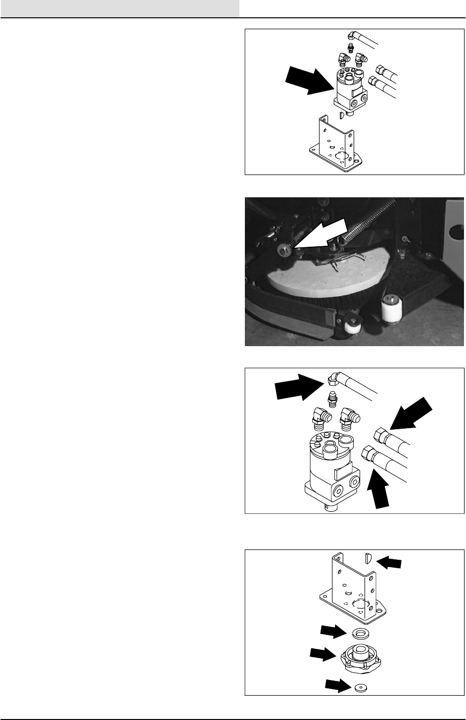
HYDRAULICS
6-32 8410 MM392 (8--01)
TO REPLACE SCRUB BRUSH HYDRAULIC
MOTOR
1. Start the engine, lower and side shift the
scrub head, shut off the engine.
FOR SAFETY: Before Leaving Or
Servicing Machine; Stop On Level
Surface, Set Parking Brake, Turn Off
Machine And Remove Key.
2. Raise the rear of machine using a hoist or
floor jack.
FOR SAFETY: Block machine tires
before jacking machine up. Jack
machine up at designated locations
only. Block machine up with jack
stands.
3. Remove the cotter pin from the long
horizontal clevis pin holding each side
squeegee to the scrub head frame. Remove
the clevis pins and squeegee assemblies
from both sides.
4. Remove all three scrub brushes.
NOTE: Mark the hoses for proper re--assembly.
5. Remove and plug the hydraulic hoses
connected to brush motor.
NOTE:Observe hydraulic cleanliness
requirements when opening hydraulic lines.
6. Remove the 0.25 in. hex screw and spacer
washer holding the brush drive hub to the
brush hydraulic motor. Remove hub, spacer,
and key.
7. Remove the four 0.38 in. hex screws holding
the brush motor to the bracket. Note the
orientation of the motor in the bracket and
remove.
8. Remove the hydraulic fittings from the old
motor and install in the same orientation in
the new or rebuilt motor.
9. Install the new motor in the bracket in the
same orientation it came out. Reinstall the
four 0.38 in. hex screws and tighten to
31 -- 40 Nm (27 -- 35 ft lb).
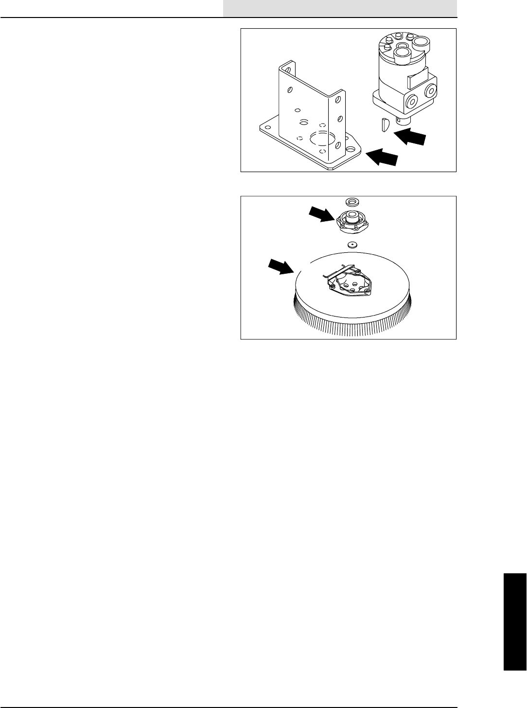
HYDRAULICS
6-33
8410 MM392 (8--01)
10. Reinstall the spacer, key, hub, washer, and
0.25 in. hex screw in the new brush motor
shaft. Use blue loctite 242 in threads of the
hex screw. Tighten to 11 -- 14 Nm
(7 -- 10 ft lb).
11. Reconnect hydraulic hoses to brush motor.
See schematic in HYDRAULICS section.
12. Reinstall the three disc brushes.
13. Reinstall the LH and RH side squeegees
with the long clevis pins and cotter pins.
14. Lower the machine. Start the engine and
check for any leaks and for proper operation
of the scrub brushes.
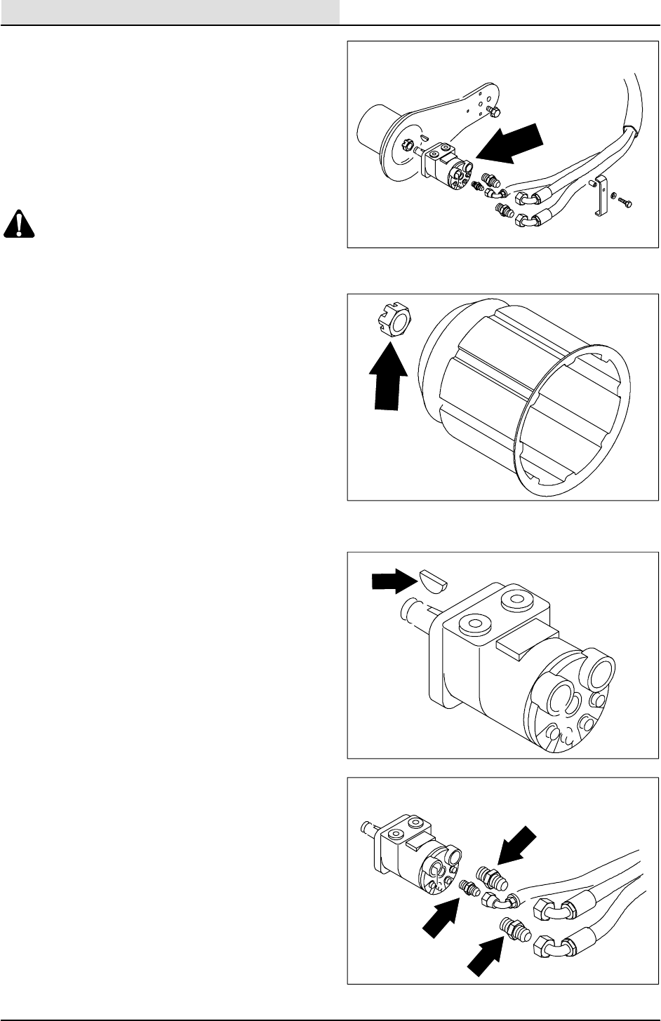
HYDRAULICS
6-34 8410 MM392 (8--01)
TO REPLACE MAIN BRUSH HYDRAULIC
MOTOR
FOR SAFETY: Before Leaving Or
Servicing Machine; Stop On Level
Surface, Set Parking Brake, Turn Off
Machine And Remove Key.
1. Raise the hopper and engage the hopper
support bar.
WARNING: Raised Hopper May Fall.
Engage Hopper Support Bar.
2. Remove the main brush.
3. Remove and plug the hydraulic hoses
leading to the main brush motor.
NOTE:Observe hydraulic cleanliness
requirements when opening hydraulic lines.
4. Remove the cotter pin from castle nut at the
end of brush drive plug.
5. Hold the brush drive plug from turning and
remove the castle nut.
6. A puller must be used to remove brush drive
plug from the tapered shaft on the brush
motor.
7. Remove the four .375 in. hex screws holding
the main brush motor to the main brush
motor arm. The brush motor can now be
removed from the machine.
NOTE: Mark the orientation of the brush motor
before removal for proper reassembly.
8. Remove the hydraulic fittings from the old
motor.
9. Install a new or rebuilt main brush motor in
the main brush arm. Reinstall the four .375
in. hex screws and tighten to (27 -- 53 ft lb).
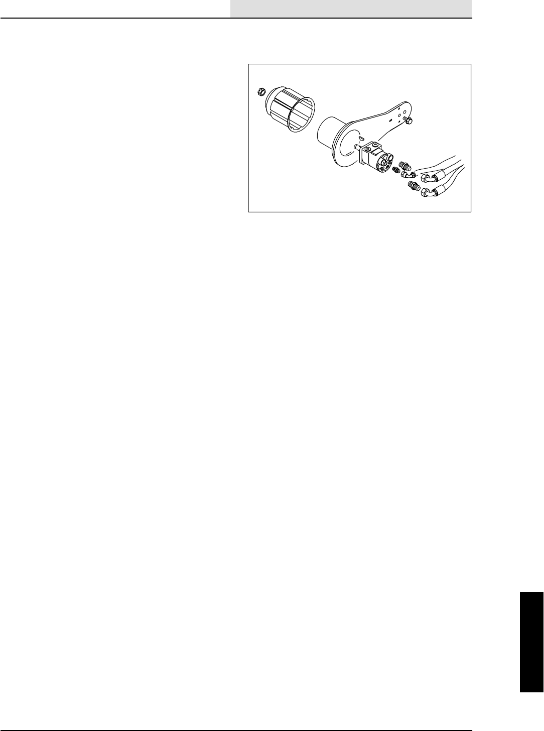
HYDRAULICS
6-35
8410 MM392 (8--01)
NOTE: Make sure the corners of brush motor line
up with the slots in brush arm.
10. Reinstall the hydraulic fittings in the new
motor.
NOTE: Make sure to orientate the fittings they
way they were removed.
11. Reconnect the hydraulic hoses to the motor.
See schematic in HYDRAULIC section.
12. Reinstall the brush drive plug on the tapered
motor shaft. Make sure the square key is in
place.
13. Reinstall the castle nut and tighten to
40 -- 54 Nm (30 -- 40 ft lb). Continue to
tighten the castle nut until it lines up with the
hole in brush motor shaft. Install a new
cotter pin.
14. Reinstall the main brush.
15. Start the machine and run the main brush.
Check for proper operation and leaks.
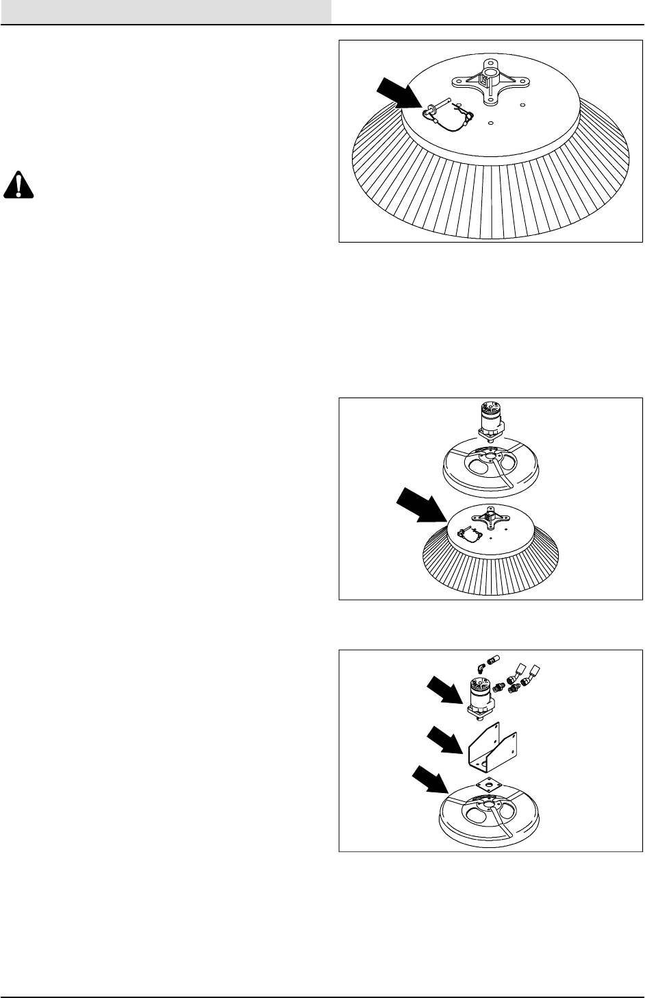
HYDRAULICS
6-36 8410 MM392 (8--01)
TO REPLACE SIDE BRUSH MOTOR
1. Empty the debris hopper.
2. Set the machine parking brake.
3. Raise the hopper and engage the hopper
support bar.
WARNING: Raised Hopper May Fall.
Engage Hopper Support Bar.
4. Stop the engine.
FOR SAFETY: Before Leaving Or
Servicing Machine; Stop On Level
Surface, Set Parking Brake, Turn Off
Machine And Remove Key.
5. Remove the side brush retaining pin from
the side brush drive shaft by pulling the pin
keeper off and over the end of the pin.
6. Slide the side brush off the side brush drive
shaft.
7. Remove and plug hydraulic hoses from side
brush motor.
NOTE:Observe hydraulic cleanliness
requirements when opening hydraulic lines.
8. Remove the four .375 in. hex screws from
bottom of side brush motor. Remove the
side brush guard and side brush motor from
machine.
9. Remove hydraulic fittings from the old motor.
10. Install a new or rebuilt side brush motor and
side brush guard with the four .375 in. hex
screws. Tighten to 31 -- 40 Nm
(27 -- 35 ft lb).
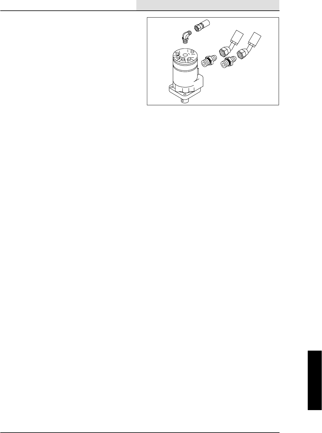
HYDRAULICS
6-37
8410 MM392 (8--01)
11. Reinstall the hydraulic fittings in the new
motor.
NOTE: Make sure to orientate the fittings they
way they were removed.
12. Reconnect the hydraulic hoses to the motor.
See schematic in HYDRAULIC section.
13. Slide the side brush on the side brush drive
shaft.
14. Insert the side brush retaining pin through
the side brush hub and shaft.
15. Disengage the hopper support bar and lower
the hopper.
16. Start the machine and run the side brush
motor. Check for proper operation and leaks.
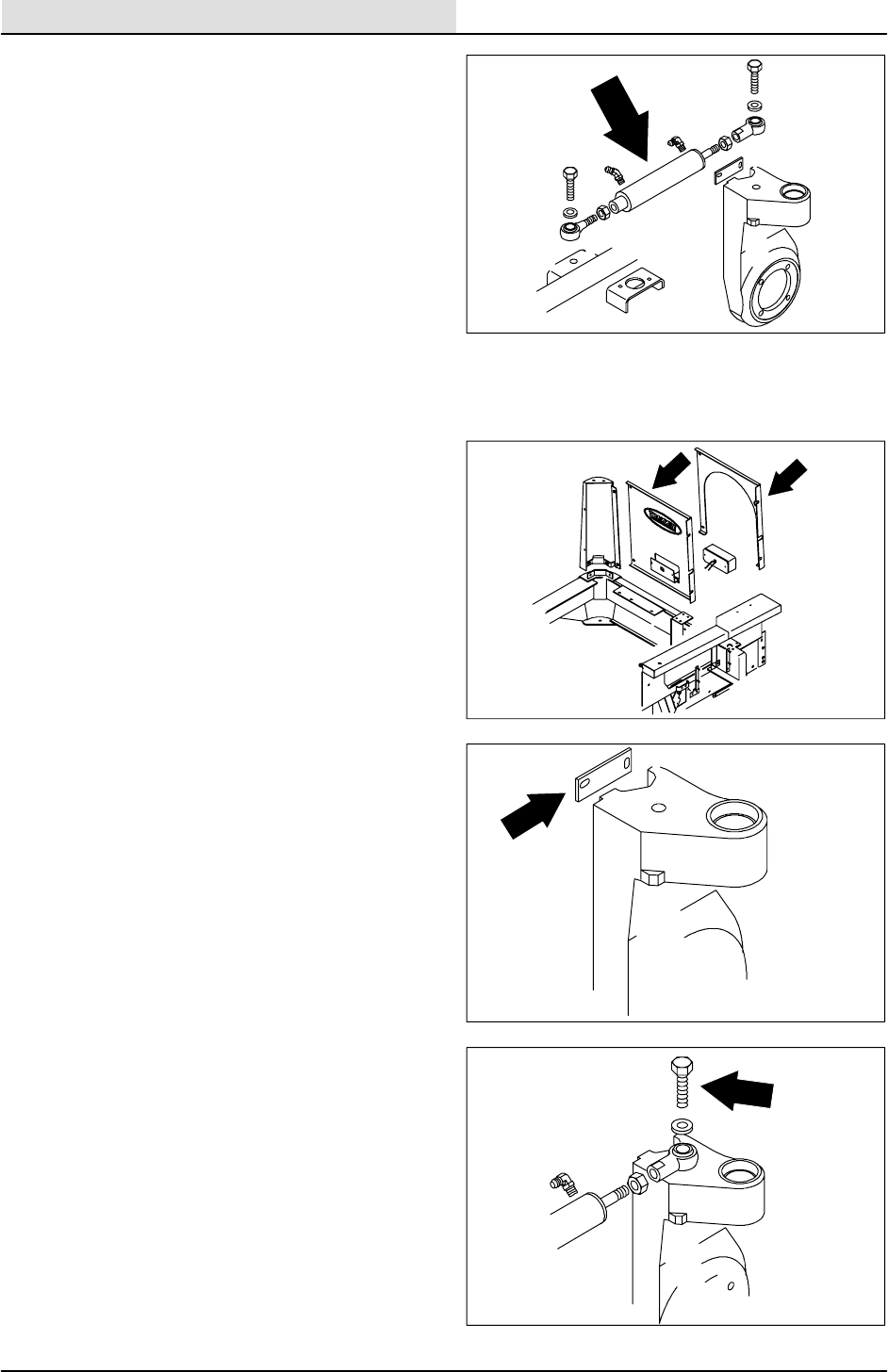
HYDRAULICS
6-38 8410 MM392 (8--01)
TO REPLACE STEERING CYLINDER
1. Start the engine and lower the scrub head.
Shut off the engine.
FOR SAFETY: Before Leaving Or
Servicing Machine; Stop On Level
Surface, Set Parking Brake, Turn Off
Machine And Remove Key.
2. Jack up the rear of the machine.
FOR SAFETY: Block machine tires
before jacking machine up. Jack
machine up at designated locations
only. Block machine up with jack
stands.
3. Disconnect the battery cables and remove
the battery from machine.
4. LPG machines; Disconnect the LP tank and
remove from the machine.
5. Gas and Diesel machines; Remove the
four hex screws holding the right rear panel.
Unplug the tail light and remove the panel.
Disconnect the fuel lines at the tank.
Remove the two tank straps and the fuel
tank.
6. Turn the steering wheel half way to the left
so the rear drive casting can be accessed
from the fuel tank area of the machine.
7. Remove the clamp holding the drive motor
hoses to rear casting. Move the hoses for
access to steering cylinder attachment bolt.
8. Using a torque multiplier wrench; remove the
.750IΧ3.25Ihex screw and nyloc nut
holding the rod end of steering cylinder to
the drive casting. Discard the hardware.
9. Using the access through the battery tray
area; remove and plug the hydraulic hose
near the rod end of the steering cylinder.
NOTE: Always observe hydraulic cleanliness
requirements when opening hydraulic lines.
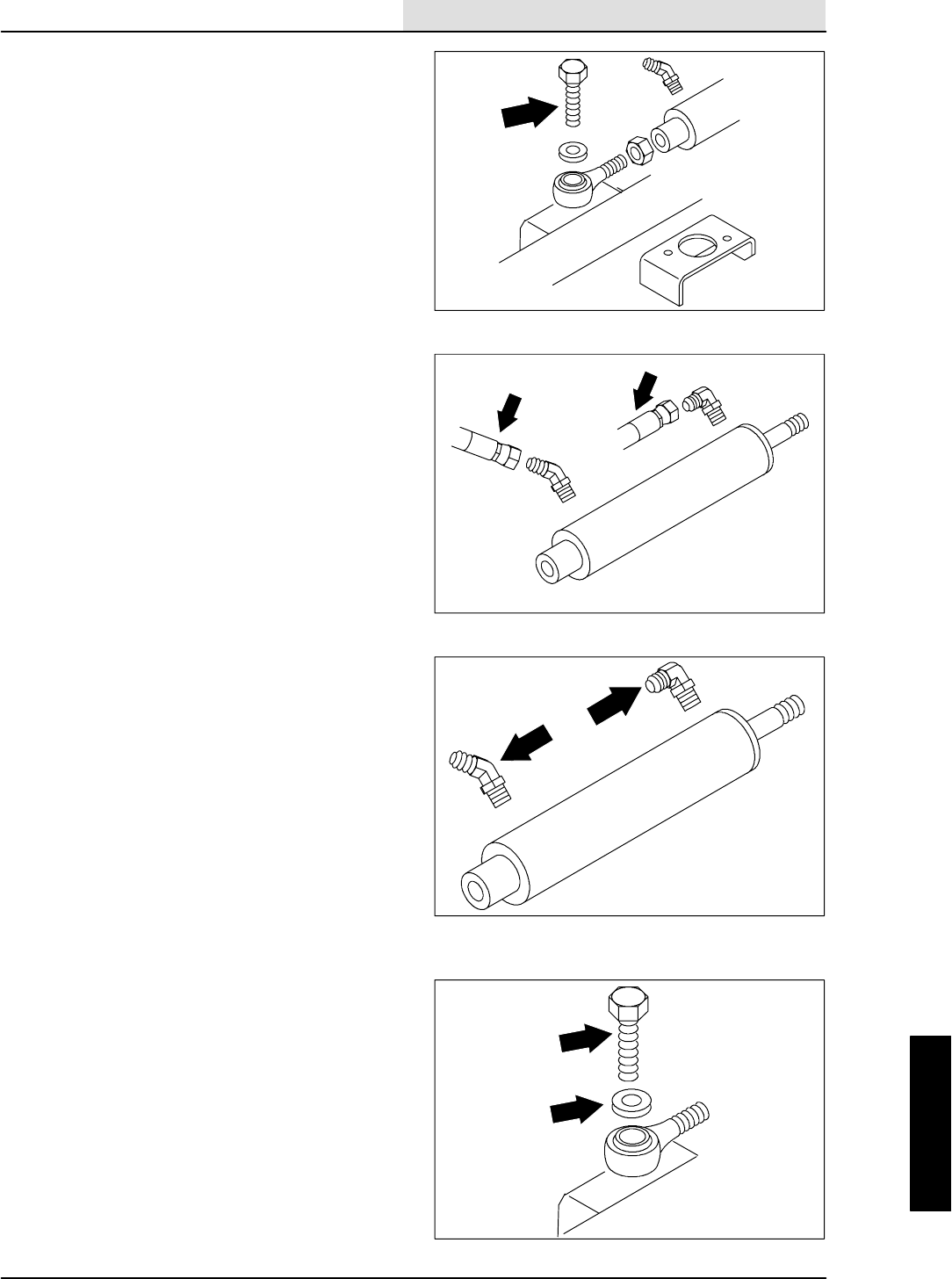
HYDRAULICS
6-39
8410 MM392 (8--01)
10. Go under the machine from the operators
compartment side. Remove and plug the
hydraulic hose near the piston end of the
steering cylinder.
NOTE: Always observe hydraulic cleanliness
requirements when opening hydraulic lines.
11. Go under the machine from the engine side
and locate the .750“ X 3.25” hex screw and
nyloc nut holding the piston end of the
steering cylinder to machine frame.
12. Using the torque multiplier wrench, a
16Iextension, and a long breaker bar,
loosen and remove the .750” X 3.25“ hex
screw. Access to the nyloc nut is through the
battery tray area. Discard the hardware.
NOTE: An extension should be added to the
handle of the torque multiplier so it can be rested
against the rear tire for leverage.
13. Remove the steering cylinder from the
machine.
14. Remove the fittings from the old cylinder and
install in the new cylinder. Install in the same
orientation.
15. Position the new cylinder and balljoint
assembly in the machine with the rod end
toward the rear drive casting.
16. Install one new .750” X 3.25” hex screw
and nyloc nut along with three washers
between the balljoint and frame and one
washer between the balljoint and nyloc nut
in the piston end of the new steering
cylinder.
NOTE: Washers must be installed for proper
cylinder to frame clearance
17. Using the torque multiplier wrench, a
16Iextension, and a long ft lb torque
wrench; tighten the .750“ X 3.25” hex
screw to 200--220 ft lb. Access to the nyloc
nut is through the battery tray area.
NOTE: An extension should be added to the
handle of the torque multiplier so it can be rested
against the rear tire for leverage.
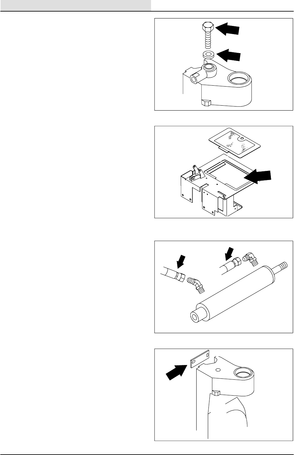
HYDRAULICS
6-40 8410 MM392 (8--01)
18. Go to the rear of the machine and install a
new .750” X 3.25” hex screw and nyloc nut
along with three washer between balljoint
and casting and one washer between
balljoint and hex screw in the rod end of the
new steering cylinder.
NOTE: Washers must be installed for proper
cylinder to frame clearance
19. Using the torque multiplier and a long ft lb
torque wrench; tighten the .750” X 3.25”
hex screw to 200--220 ft lb.
20. Use the access in the battery tray area and
reconnect the hydraulic hose near the rod
end of steering cylinder.
NOTE: Always observe hydraulic cleanliness
requirements when opening hydraulic lines.
21. Go under the machine from the operators
compartment side and reconnect the
hydraulic hose near the piston end of
steering cylinder.
22. Reinstall the clamp holding the drive motor
hoses to the rear casting.
23. LPG machines; Reinstall the LP tank.
24. Gas and Diesel machines; Reinstall the
fuel tank and straps. Reconnect the fuel
lines. Reinstall the rear panel and hardware.
Reconnect the tail light wires.
25. Reinstall the battery and reconnect the
cables.
26. Remove the jack stands and lower the
machine.
27. With the seat in the raised position, start the
machine and turn steering wheel in both
directions. Observe steering cylinder for any
leaks.
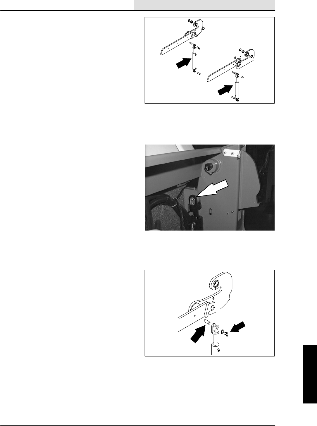
HYDRAULICS
6-41
8410 MM392 (8--01)
TO REPLACE HOPPER LIFT CYLINDER
1. Set the machine parking brake.
2. Raise the hopper and engage the prop arm.
Drop the hopper down on the prop rod to
relieve pressure on the cylinders.
FOR SAFETY: Before Leaving Or
Servicing Machine; Stop On Level
Surface, Set Parking Brake, Turn Off
Machine And Remove Key.
3. Disconnect and cap the two hydraulic hoses
leading to the hopper lift cylinder.
NOTE: Always observe hydraulic cleanliness
requirements when opening hydraulic lines.
4. Remove the M6 hex screw holding the
cylinder pin plate to the cylinder clevis.
5. Remove and retain one of the ”C” clips from
the grooved pin in the upper clevis of the lift
cylinder. Remove the grooved pin.
6. Remove and retain one of the ”C” clips from
the grooved pin in the lower clevis of the lift
cylinder. Remove the grooved pin. Remove
the old lift cylinder from the machine.
7. Remove the fittings from the old cylinder and
install in the new cylinder in the same
orientation.
8. Position the new cylinder in the machine
with the rod end pointing up.
9. Align the bottom of the lift cylinder with the
hole in the frame mount lug. Reinstall the
grooved pin and ”C” clip.
10. Align the small bearing in the lift arm with
the hole in the lift cylinder clevis.
11. Reconnect the hydraulic hoses to the new
lift cylinder. See schematic in this section.
12. Start the machine and raise the hopper.
Check for any leaks and proper operation.
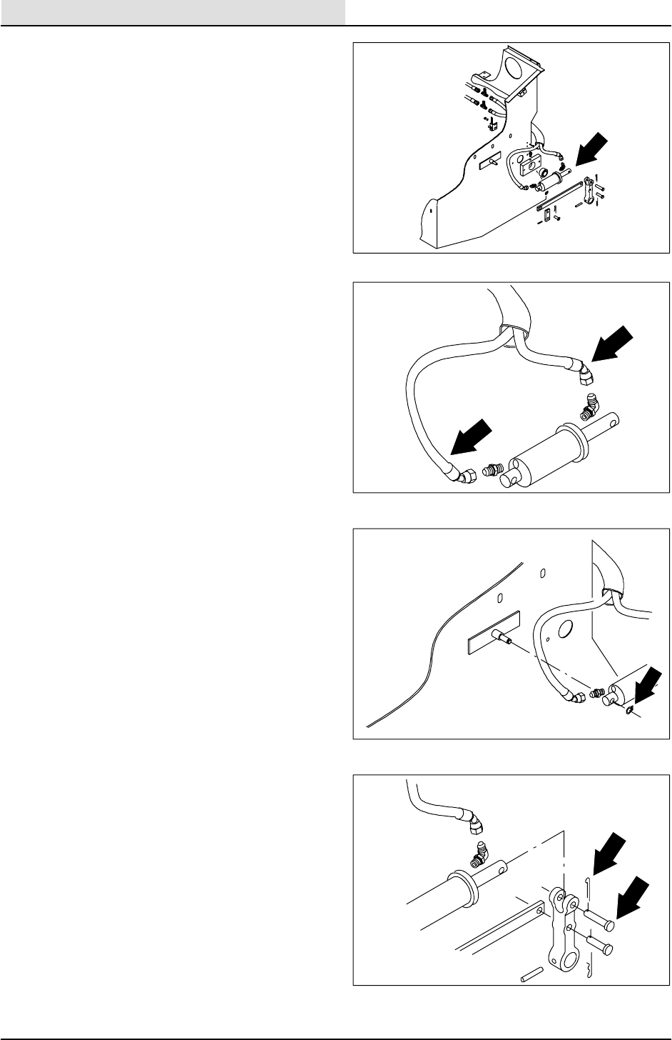
HYDRAULICS
6-42 8410 MM392 (8--01)
TO REPLACE HOPPER DUMP DOOR
CYLINDER
1. Set the machine parking brake.
FOR SAFETY: Before Leaving Or
Servicing Machine; Stop On Level
Surface, Set Parking Brake, Turn Off
Machine And Remove Key.
2. Open the hopper cover.
3. Disconnect and plug the two hoses leading
to the hopper dump door cylinder.
4. Remove the retaining ring from the front
cylinder mount pin.
5. Remove the cotter pin and clevis pin from
the rear of the dump door cylinder were it
attaches to the pivot yoke.
6. Remove the old cylinder from the hopper.
7. Remove the fittings from the old cylinder and
install in the new cylinder in the same
orientation.
8. Position the new cylinder in the machine
with the rod end pointing to the rear of the
machine hopper.
9. Slip the piston end of the new cylinder over
the pin on the hopper. Reinstall the retaining
ring.
10. Reinstall the clevis pin and cotter pin in the
rod end of the dump door cylinder and the
door pivot yoke.
11. Reconnect the hydraulic hoses to the dump
door cylinder. See the schematic in this
section.
12. Start the machine and open and close the
hopper dump door. Check for any leaks and
proper operation.

HYDRAULICS
6-43
8410 MM392 (8--01)
TO REPLACE MAIN BRUSH LIFT CYLINDER
1. Start the engine and lower the main brush.
Shut off the engine.
FOR SAFETY: Before Leaving Or
Servicing Machine; Stop On Level
Surface, Set Parking Brake, Turn Off
Machine And Remove Key.
2. Remove the solution and recovery tanks.
See TO REMOVE SOLUTION TANK
instructions in the SCRUBBING section.
3. Locate the clevis pin holding the main brush
lift cable to the main brush lift arm. Remove
the cotter pin and clevis pin.
4. Start the engine and raise the main brush.
Shut off the engine.
5. Locate the two M10 hex nuts holding the two
plastic tubes to the rod end of the main
brush lift cylinder.
NOTE: Make sure cylinder is all the way
retracted before removing springs.
6. Remove the hex nuts, tension springs,
plastic tubes, main brush lift cable and
threaded rod.
7. Disconnect and plug the two hydraulic hoses
leading to the main brush lift cylinder.
NOTE: Observe hydraulic cleanliness
requirements when opening hydraulic lines.
8. Remove the cotter pin and clevis pin holding
the piston end of the main brush lift cylinder
to the machine frame.
9. Remove the lift cylinder from the machine.
NOTE: Remember to orientate the fittings as
close as possible to the way they came out.
10. Remove the hydraulic fittings from old main
brush lift cylinder and install in the new
cylinder in the same orientation.
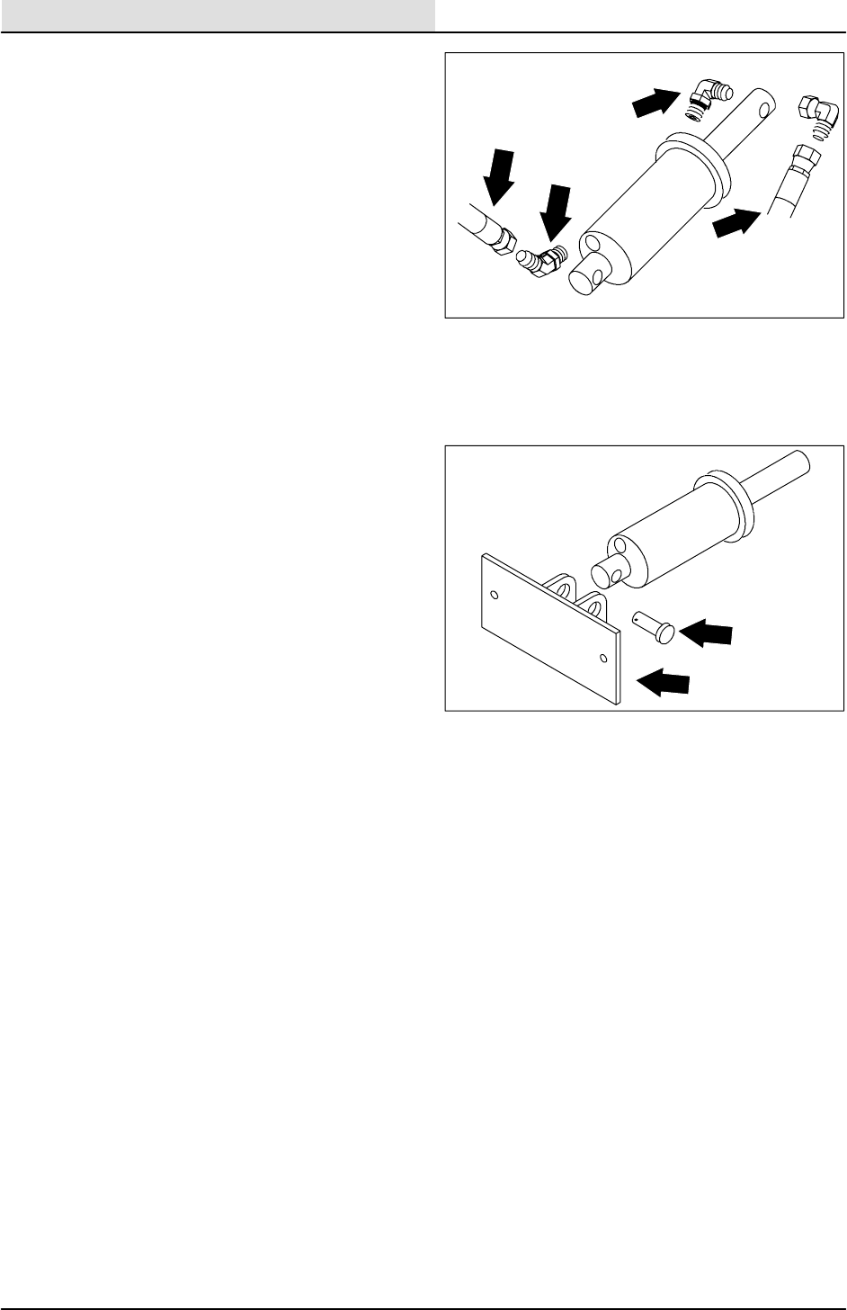
HYDRAULICS
6-44 8410 MM392 (8--01)
11. Position the new main brush lift cylinder in
the machine. Align the mount hole in piston
end of the lift cylinder with hole in the mount
bracket on the machine frame.
12. Reinstall the clevis pin and cotter pin.
NOTE: Make sure cylinder is all the way retracted
before installing springs.
13. Reinstall the threaded rod, plastic tubes,
main brush lift cable, M10 hex nuts, and
tension springs to the rod end of the lift
cylinder. Hand tighten hex nuts.
14. Reconnect the hydraulic hoses to the main
brush lift cylinder. See the schematic in this
section.
15. Start engine and lower the main brush. Shut
off the engine.
16. Reconnect the main brush lift cable to the
main brush lift arm using the clevis pin and
cotter pin.
17. Start the engine and run the main brush up
and down. Check for leaks and proper
operation.
18. Reinstall solution and recovery tanks. See
TO INSTALL RECOVERY TANK instructions
in the SCRUBBING section.
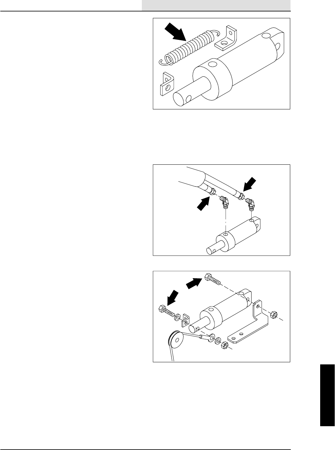
HYDRAULICS
6-45
8410 MM392 (8--01)
TO REPLACE SIDE BRUSH LIFT CYLINDER
1. Start the engine and raise the side brush.
Shut off the engine.
FOR SAFETY: Before Leaving Or
Servicing Machine; Stop On Level
Surface, Set Parking Brake, Turn Off
Machine And Remove Key.
2. Open the hopper cover.
3. Disconnect the tension spring from the
bracket on the side brush lift cylinder and
cable.
4. Start the machine and lower the side brush.
5. Disconnect and plug the two hydraulic hoses
leading to the side brush lift cylinder.
NOTE: Observe hydraulic cleanliness
requirements when opening hydraulic lines.
6. Remove the two hex screws holding the lift
cylinder to the hopper bumper and side
brush lift cable. Remove the lift cylinder from
the machine.
7. Remove the hydraulic fittings from the old
cylinder and install in the new cylinder in the
same orientation.
8. Position the new cylinder on the machine
and reinstall the two hex screws and nyloc
nuts. Make sure the side brush lift cable is
attached to the rod end of the lift cylinder.
9. Reconnect the two hydraulic hoses. See
schematic in the HYDRAULICS section.
10. Start the machine and raise the side brush.
11. Reconnect the tension spring to the
brackets. Close the hopper cover.
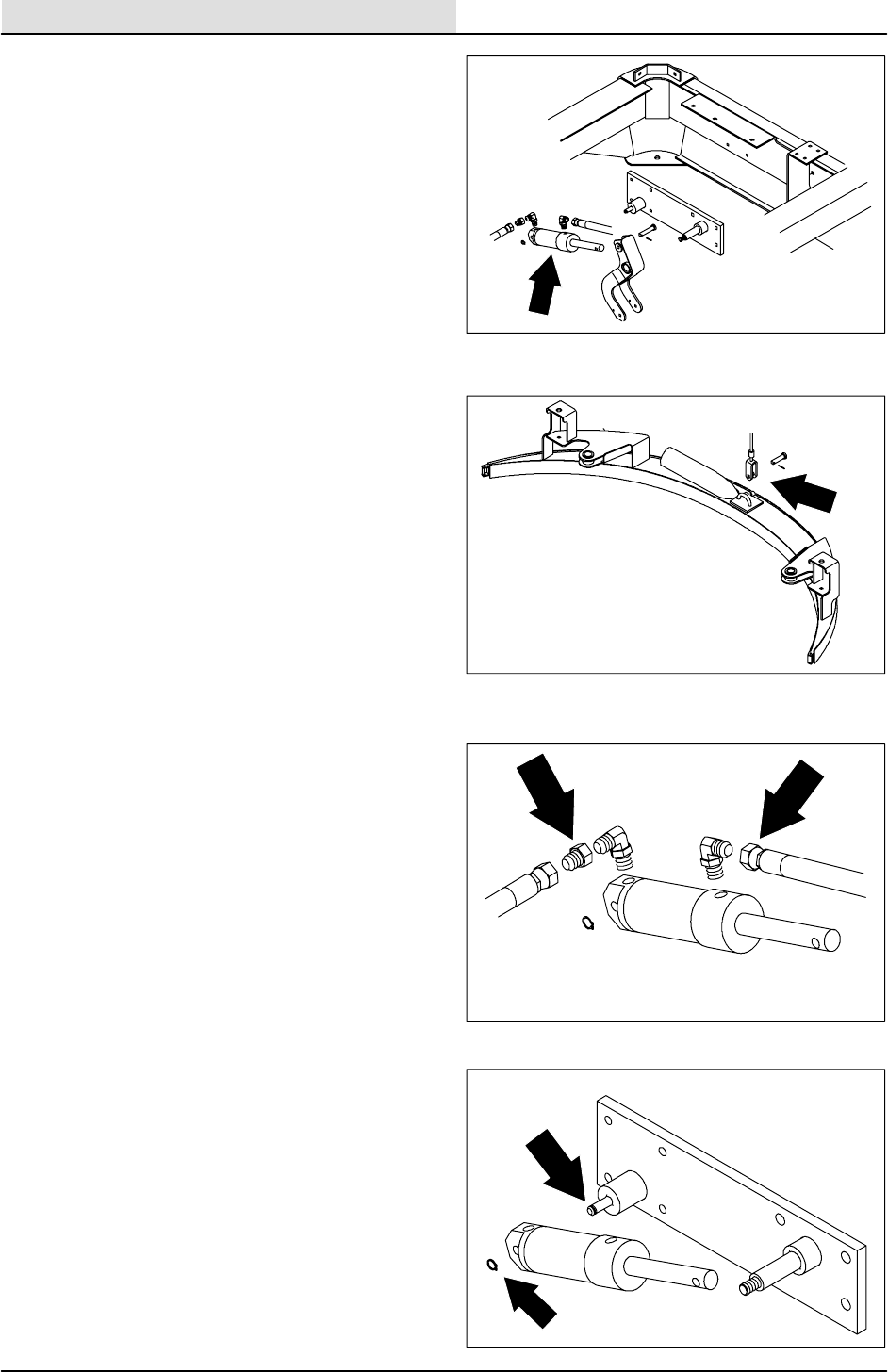
HYDRAULICS
6-46 8410 MM392 (8--01)
TO REPLACE SQUEEGEE LIFT CYLINDER
1. Start the engine, lower the rear squeegee,
shut off the engine.
FOR SAFETY: Before Leaving Or
Servicing Machine; Stop On Level
Surface, Set Parking Brake, Turn Off
Machine And Remove Key.
2. Raise the rear of machine using a hoist or
floor jack.
FOR SAFETY: Block machine tires
before jacking machine up. Jack
machine up at designated locations
only. Block machine up with jack
stands.
3. Remove the M8 hex screw, nyloc nut, and
spacer tube from the rear squeegee lift
cable where it attaches at the center of the
rear squeegee frame.
NOTE: The squeegee frame will drop down when
the hex screw is removed.
NOTE: Mark the hoses for proper re--assembly.
4. Remove and plug the hydraulic hoses
connected to the rear squeegee lift cylinder.
NOTE:Observe hydraulic cleanliness
requirements when opening hydraulic lines.
5. Remove the snap retaining ring from the
grooved pin on the pivot plate on the piston
end of the squeegee lift cylinder.
6. Remove the cotter pin and clevis pin from
the rod end of the lift cylinder and squeegee
lift bellcrank.
7. The squeegee lift cylinder can now be pulled
off the mount pin and removed from the
machine.
8. Remove the hydraulic fittings and install in
the new cylinder in the same orientation.
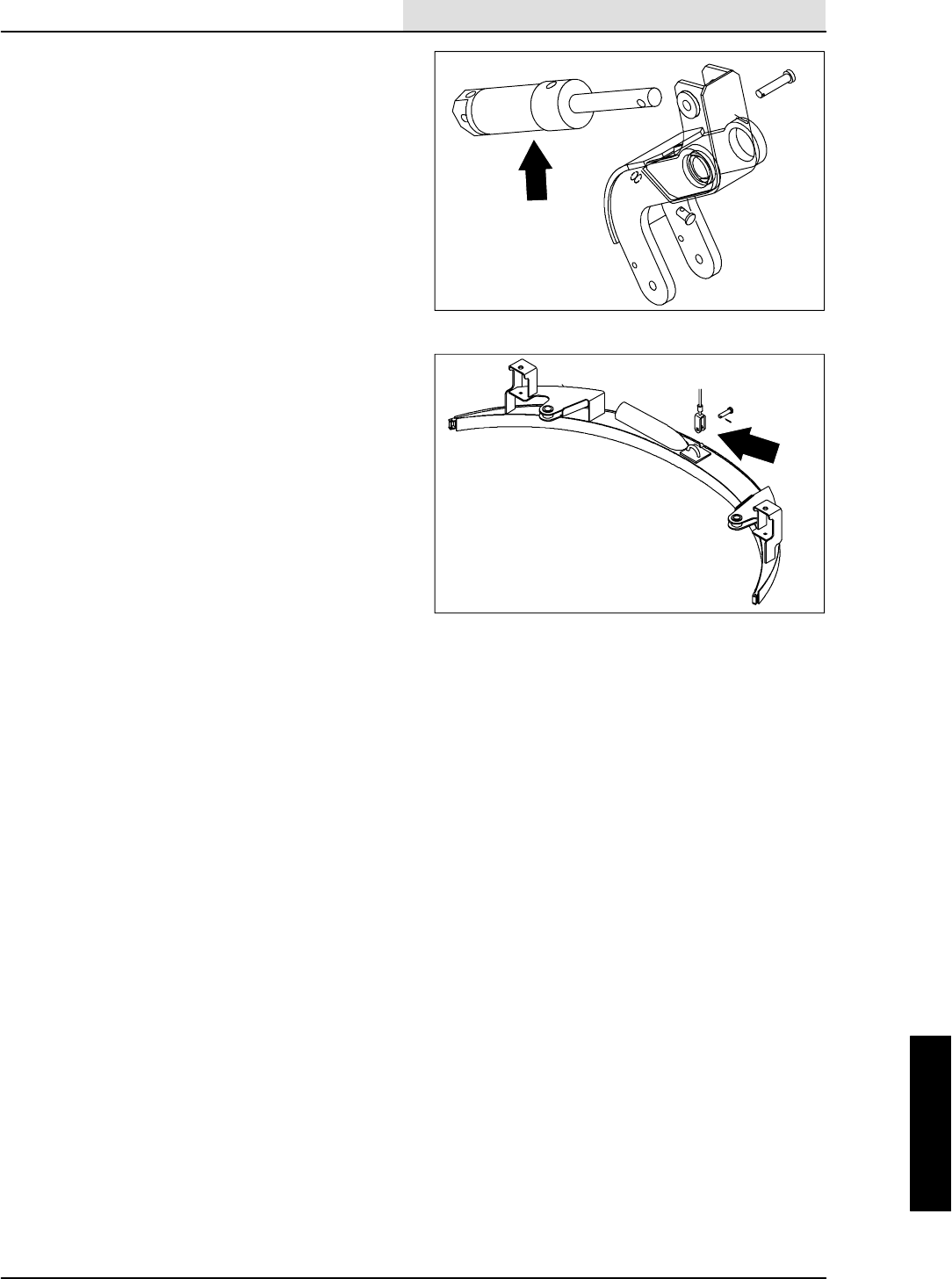
HYDRAULICS
6-47
8410 MM392 (8--01)
9. Position the new cylinder back in the
machine. Place the hole in the piston end of
the squeegee lift cylinder on the grooved
mount pin on frame. Reinstall the snap ring
retainer.
10. Align the hole in the rod end of the new
squeegee lift cylinder with hole in the
squeegee lift bellcrank. Reinstall the clevis
and cotter pin.
11. Reconnect the hydraulic hoses to squeegee
lift cylinder. See the schematic in the
HYDRAULICS section.
12. Lift the squeegee assembly up until the hole
in the lower end of the lift cable lines up with
the hole in the squeegee frame. Reinstall the
M8 hex screw, nyloc nut, and spacer tube.
Tighten to 18 -- 24 Nm (13 -- 18 ft lb).
13. Lower machine and check for proper rear
squeegee lift cylinder operation.
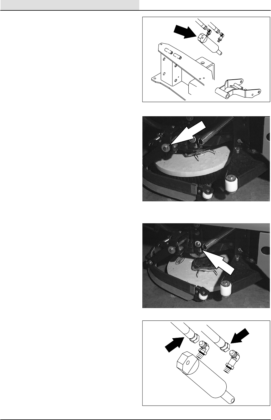
HYDRAULICS
6-48 8410 MM392 (8--01)
TO REPLACE SCRUB BRUSH LIFT CYLINDER
1. Start the engine, lower and side shift the
scrub head, shut off the engine.
FOR SAFETY: Before Leaving Or
Servicing Machine; Stop On Level
Surface, Set Parking Brake, Turn Off
Machine And Remove Key.
2. Raise the rear of machine using a hoist or
floor jack.
FOR SAFETY: Block machine tires
before jacking machine up. Jack
machine up at designated locations
only. Block machine up with jack
stands.
3. Remove the cotter pin from the long
horizontal clevis pin holding each side
squeegee to the scrub head frame. Remove
the clevis pins and squeegee assemblies
from both sides.
4. Remove all three scrub brushes.
5. Remove the 0.25 in. eye bolt holding the
tension spring to the scrub brush motor
bracket.
NOTE: Mark the hoses for proper re--assembly.
6. Remove and plug the hydraulic hoses
connected to the scrub brush lift cylinder.
NOTE:Observe hydraulic cleanliness
requirements when opening hydraulic lines.
7. Remove the cotter pin from the clevis pin
holding the rod end of cylinder to the lower
link. Remove the clevis pin.
8. Remove the 0.38 in. nyloc nut, washer, and
hex screw holding the piston end of the lift
cylinder to the top of the squeegee frame.
The lift cylinder can now be removed from
the scrub frame.
9. Remove the hydraulic fittings from the old
cylinder and install in the same orientation in
the new or rebuilt lift cylinder.
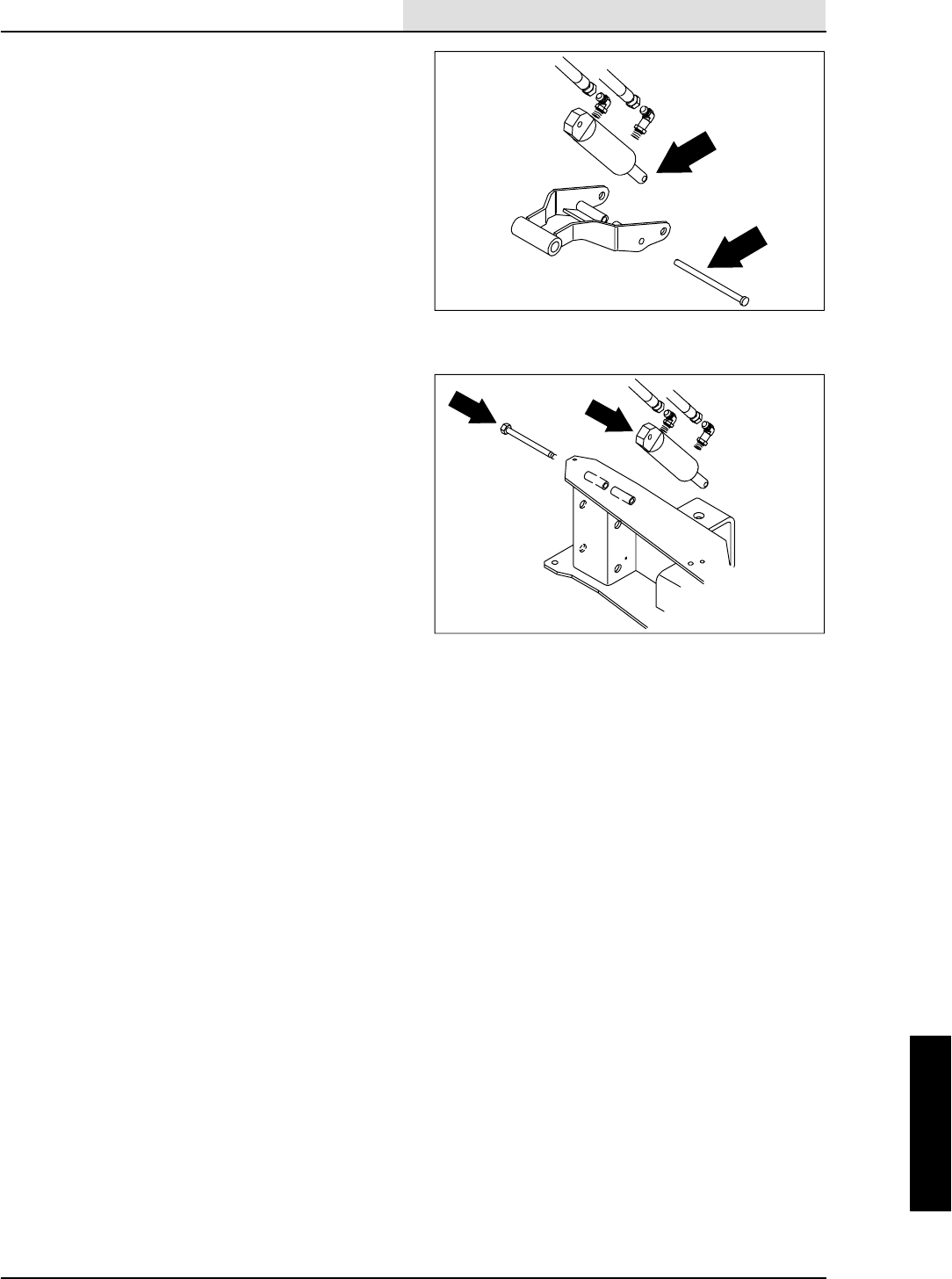
HYDRAULICS
6-49
8410 MM392 (8--01)
10. Position the new lift cylinder back in the
scrub head frame. Align the hole in the
piston end of the cylinder with the hole in the
top of the frame. Reinstall the 0.38 in. hex
screw, washers, and nyloc nut. Firmly
tighten the hardware.
11. Raise the lower link up until the hole in the
rod end of the lift cylinder lines up with the
hole in the bracket. Reinstall the clevis pin
and cotter pin.
12. Reconnect the hydraulic hoses to the lift
cylinder. See the schematic in HYDRAULIC
section.
13. Reinstall the eye bolt and tension spring.
Firmly tighten the nyloc nut.
14. Reinstall the three disc brushes.
15. Reinstall the LH and RH side squeegees
with the long clevis pins and cotter pins.
16. Lower the machine. Start the engine and
check for any leaks and for proper operation
of the scrub brush lift cylinder.
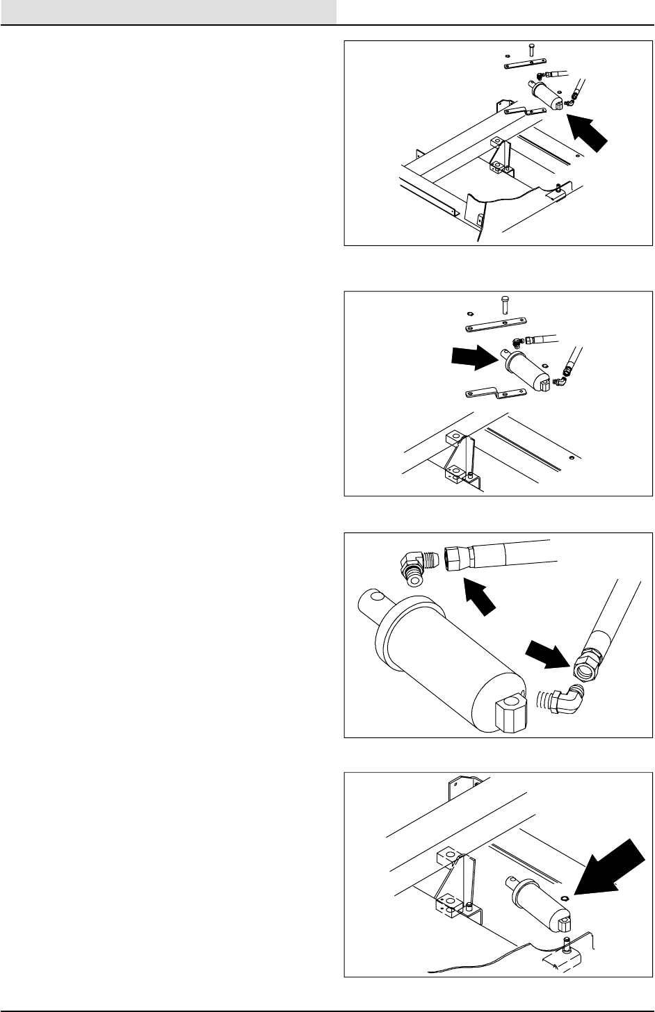
HYDRAULICS
6-50 8410 MM392 (8--01)
TO REPLACE SCRUB HEAD SIDE SHIFT
HYDRAULIC CYLINDER
1. Start the engine, lower and side shift the
scrub head, shut off the engine.
FOR SAFETY: Before Leaving Or
Servicing Machine; Stop On Level
Surface, Set Parking Brake, Turn Off
Machine And Remove Key.
2. Raise the rear of machine using a hoist or
floor jack.
FOR SAFETY: Block machine tires
before jacking machine up. Jack
machine up at designated locations
only. Block machine up with jack
stands.
3. Remove the solution and recovery tanks
from the machine. See TO REMOVE
SOLUTION TANK FROM MACHINE
instructions in this section.
4. Once the tanks are removed, locate the side
shift cylinder on the left side of machine,
behind the hydraulic control valve.
NOTE: Mark the hoses for proper re--assembly.
5. Remove and plug the hydraulic hoses
connected to side shift cylinder.
NOTE:Observe hydraulic cleanliness
requirements when opening hydraulic lines.
6. Remove the retaining ring that is holding the
piston end of side shift cylinder to the mount
pinonthemachineframe.
7. Remove the cotter pin and clevis pin holding
the rod end of side shift cylinder to edge
scrub pivot lever.
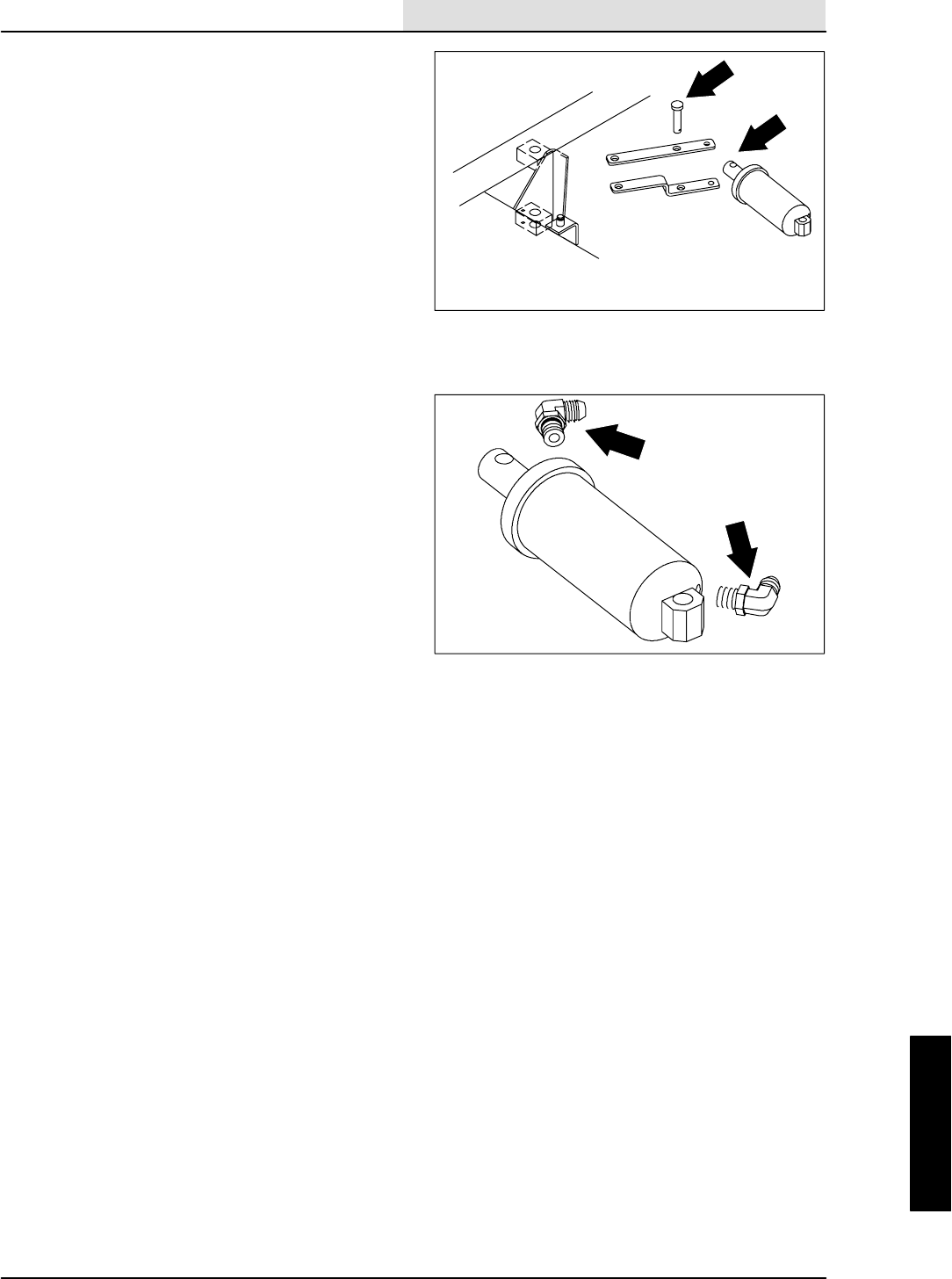
HYDRAULICS
6-51
8410 MM392 (8--01)
8. The side shift cylinder can now be pulled up
and off the mount pin and removed from the
machine.
9. Remove the hydraulic fittings and install in
the new cylinder in the same orientation.
10. Position the new cylinder back in the
machine. Place the hole in the piston end of
the side shift cylinder on the mount pin on
the machine frame. Reinstall the snap ring
retainer.
11. Align the hole in the rod end of the side shift
cylinder with hole in edge scrub pivot lever.
Reinstall the clevis and cotter pin.
12. Reconnect the hydraulic hoses to the side
shift cylinder. See the schematic in the
HYDRAULICS section.
13. Reinstall the solution and recovery tanks.
See TO INSTALL SOLUTION TANK
instructions in this section.
14. Lower the machine. Start the engine and
check for any leaks and for proper operation
of the side shift function.
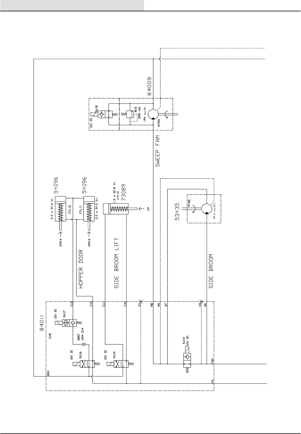
HYDRAULICS
8410 MM392 (8--01)
6-52
HYDRAULIC SCHEMATIC
11176 -- 8410, ALL
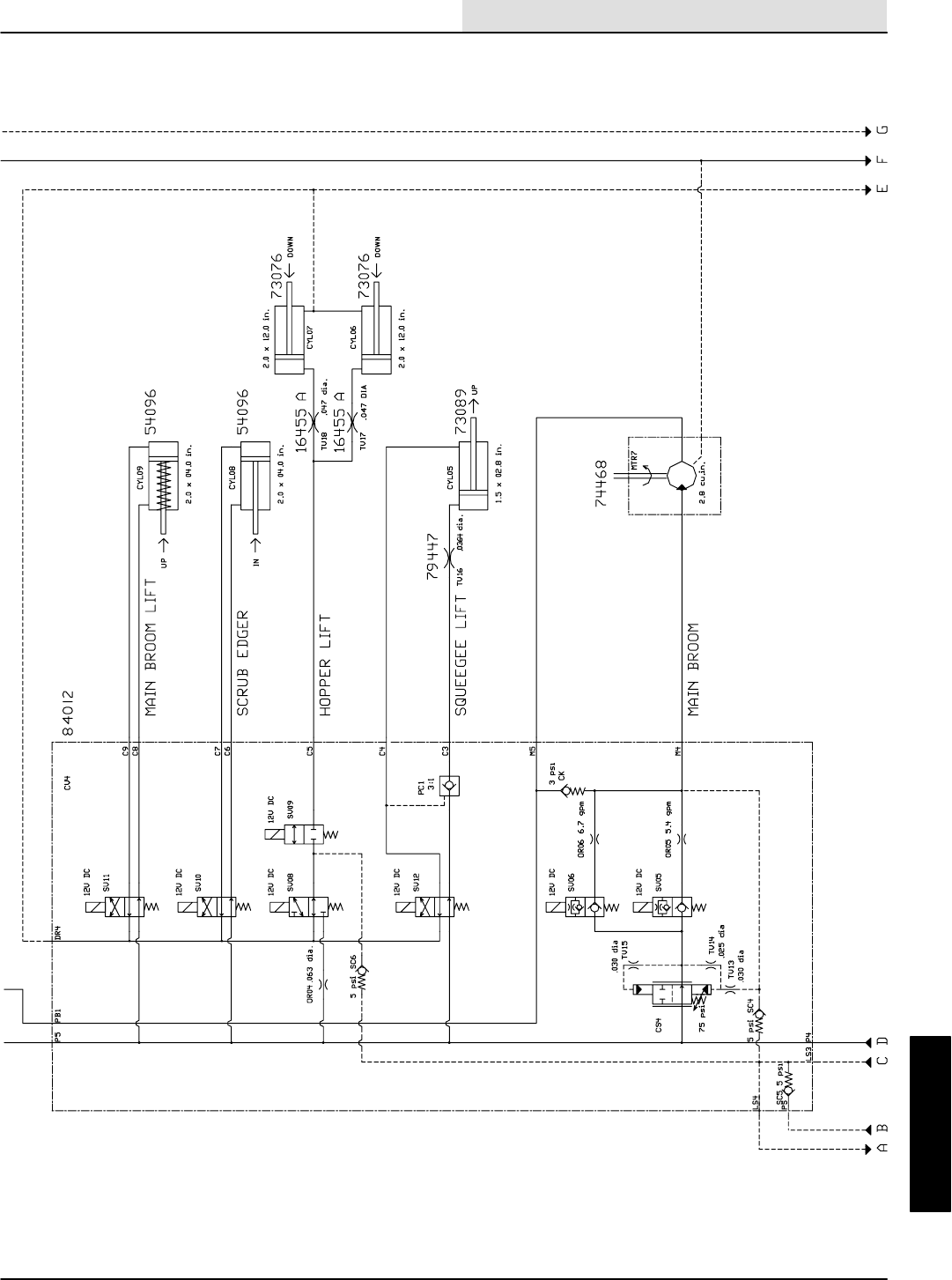
HYDRAULICS
6-53
8410 MM392 (8--01)
HYDRAULIC SCHEMATIC
11176 -- 8410, ALL
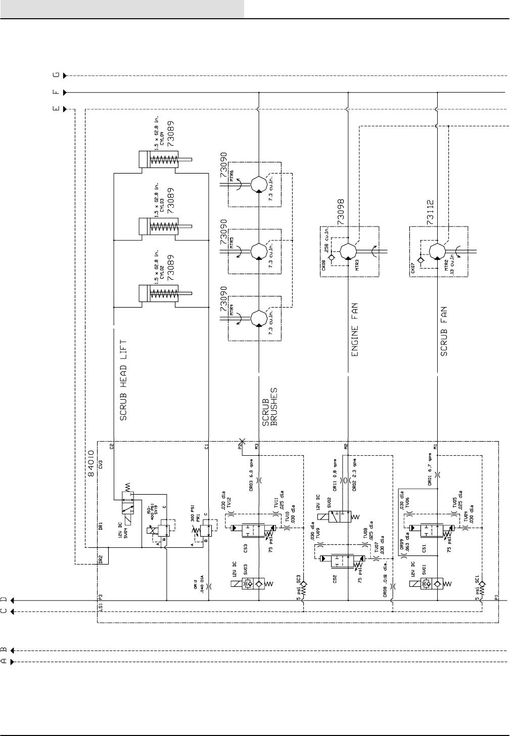
HYDRAULICS
8410 MM392 (8--01)
6-54
HYDRAULIC SCHEMATIC
11177 -- 8410, ALL
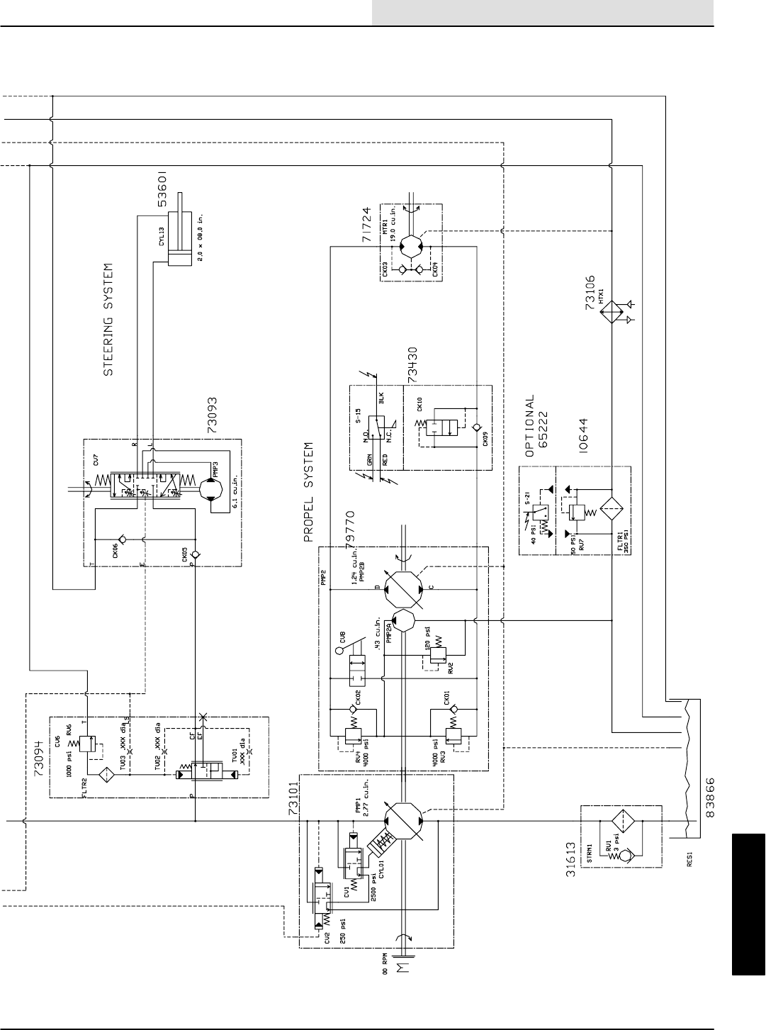
HYDRAULICS
6-55
8410 MM392 (8--01)
HYDRAULIC SCHEMATIC
11177 -- 8410, ALL
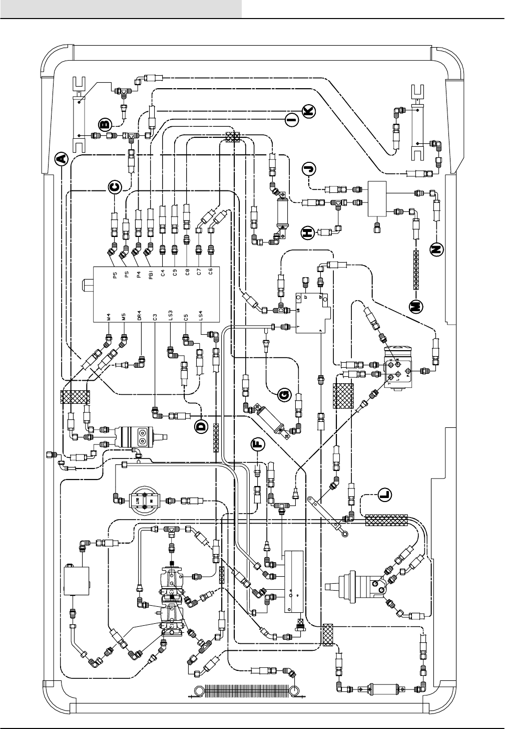
HYDRAULICS
8410 MM392 (8--01)
6-56
HYDRAULIC HOSE GROUP
Brush
Lift Cylinder LH
Control Valve
Lift Cylinder RH
Manifold
Steering
Control
Steering
Valve
Reservoir
Propelling
Motor
Squeegee
Lift Cylinder
Steering
Cylinder
Cooler
Propel
Pump
Auxilary Pump
Flow Sensor Switch
Filter Main
Motor
Edge In/Out
Cylinder Main Brush
Cylinder
11089
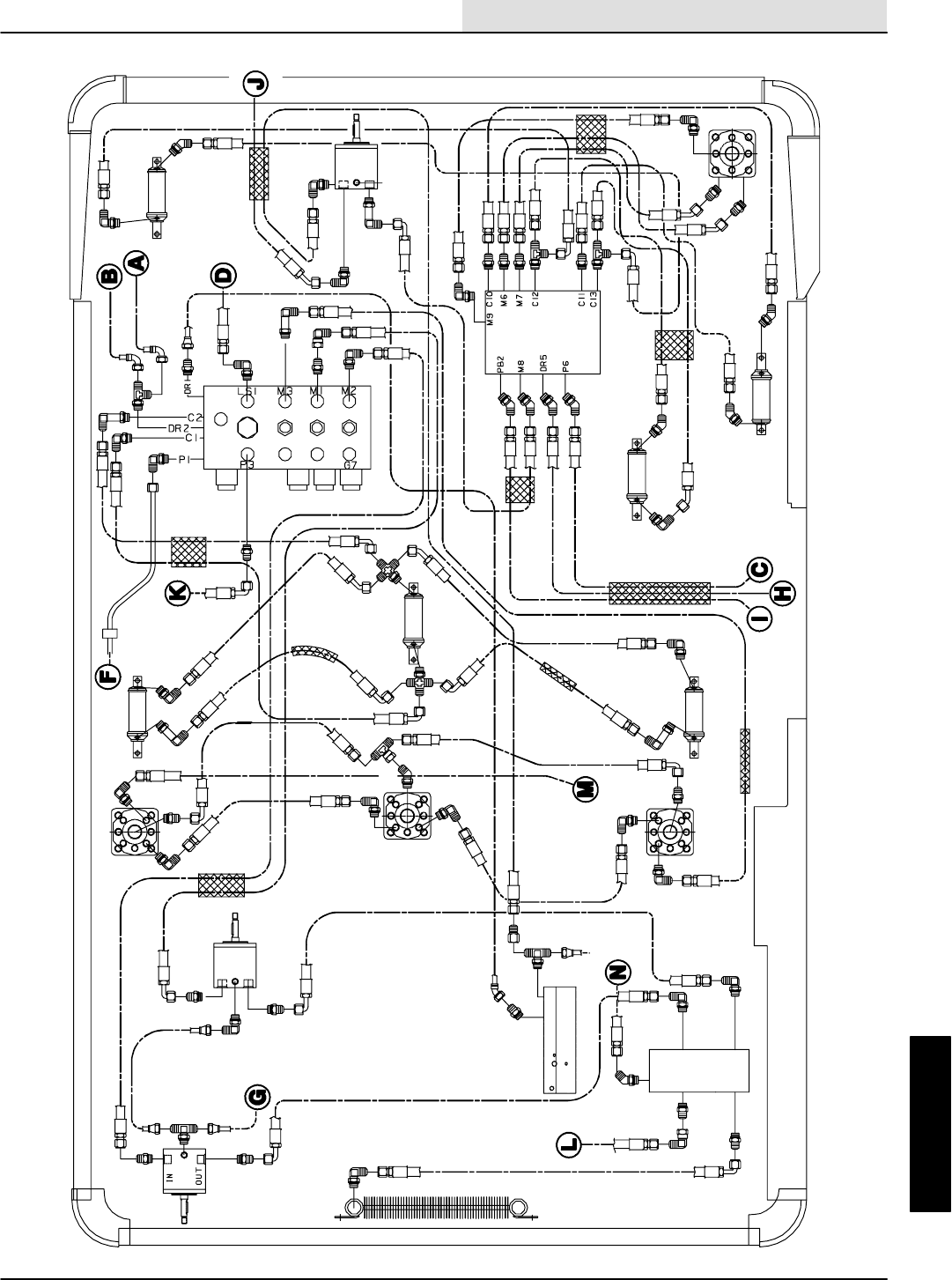
HYDRAULICS
6-57
8410 MM392 (8--01)
HYDRAULIC HOSE GROUP
Scrub Fan
Motor
Manifold
Hopper Control
Valve
Hopper Door
Cylinder
Engine
Motor
Left Scrub Brush Motor Left Scrub Head
Right Scrub Head
Right Scrub
Scrub
Head
Motor
Scrub Head
Lift Cylinder
Side Brush
Lift Cylinder
Hopper Door
Cylinder
Scrub Head
Motor Side Brush
Lift Cylinder
Brush Motor
Center Control Valve
Center
Lift Cylinder
Sweeping
Fan Motor
Fan
11091
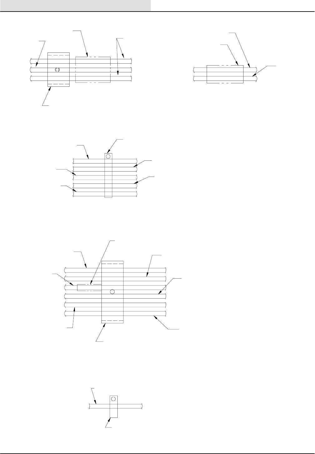
HYDRAULICS
8410 MM392 (8--01)
6-58
CLAMP LOCATION AND HOSE ORIENTATION
78820 REF
57160 REF
50121 SLEEVE
87677 SLEEVE
77307 REF
82832 SLEEVE
82815 REF
82815 REF
77308 REF
31602 REF 53466 CLAMP
78776 REF
58366 CLAMP
78810 REF
77337 REF
31568 REF
77338 REF
82815 REF
82815 REF
77297 BRKT W/77298 INSOLATOR
82817 REF 34355 REF
63516 BRKT W/09900--1 SLEEVE
HOSE MOUNTING TO
HOPPER RH CORNER
MAIN BRUSH HOSE MOUNTING
TO BRUSH ARM
HOSE MOUNTING TO MAIN VALVE
BRACKET ON THE FRAME
HOSE MOUNTING TO SEAT SUPPORT
HOSE MOUNTING TO UNDERSIDE OF FRAME
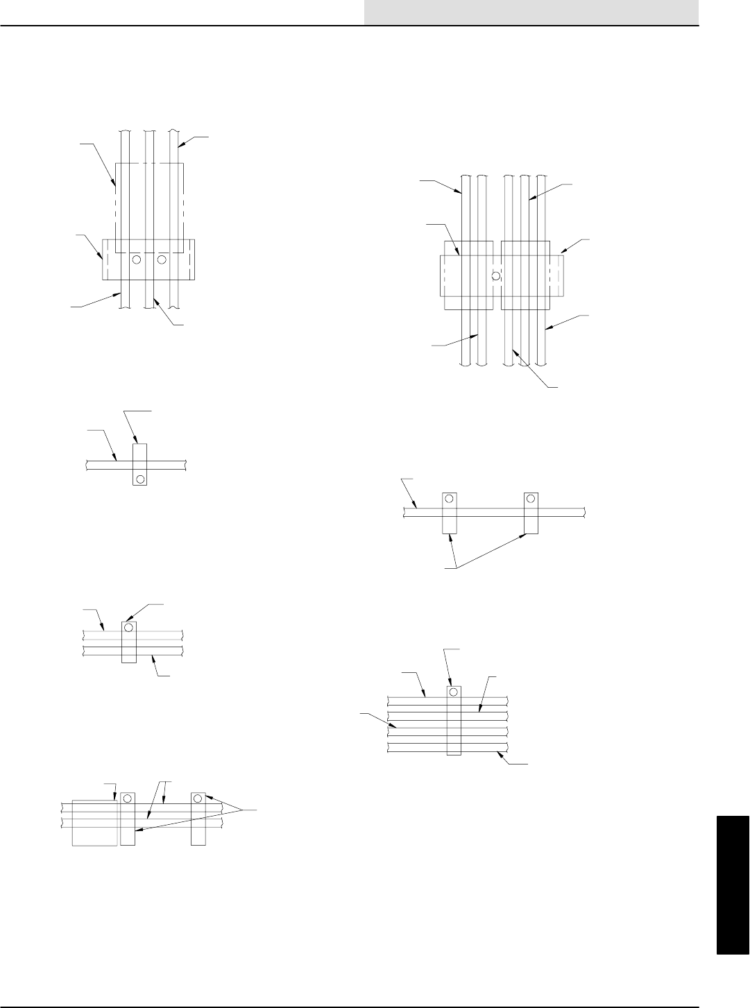
HYDRAULICS
6-59
8410 MM392 (8--01)
CLAMP LOCATION AND HOSE ORIENTATION
50121 SLEEVE (2)
57966 REF
78821 REF
01988 REF
87652 REF
53466 CLAMP
57966 REF
78821 REF
31646 SLEEVE
53468 CLAMP
78887 BRKT W/78886
THREADED ROD
57193 REF
57160 REF
53466 CLAMP
01988 REF
87652 REF
78820 REF
57160 REF
53466 CLAMP
77316 REF
53466 CLAMP
57219 REF
77315 REF
19644 REF
77314 REF
82832 SLEEVE
58842 BRKT
SIDE BRUSH HOSE MOUNTING
(1) CLAMP TO HOPPER LIFT ARM
(1) CLAMP TO HOPPER SIDE
HOSE MOUNTING BY VAC FAN
ON HOPPER BACKSIDE
HOSE MOUNTING FROM SCRUB
VALVE TO MAIN PUMP
HOSE MOUNTING TO
SOLUTION TANK
HOSE MOUNTING ON
HOPPER BACKSIDE
HOSE MOUNTING TO FRAME
BETWEEN FILTER AND HYD TANK
HOSE MOUNTING TO FRAME
FROM MAIN DRIVE MOTOR

HYDRAULICS
8410 MM392 (8--01)
6-60

HYDRAULICS
6-61
8410 MM392 (8--01)
TROUBLESHOOTING
The troubleshooting charts that follow are
organized so they lead you through the circuits.
They include flow charts and instructions for you
as to where to insert your test instruments.
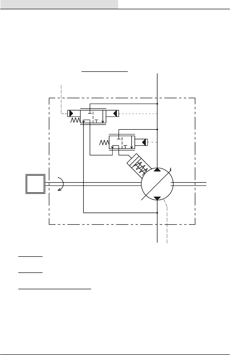
HYDRAULICS
6-62 8410 MM392 (8--01)
M
2400
RPM
8410 HYDRAULIC PUMP
OPERATION
FLOW
COMPENSATOR
HIGH PRESSURE
COMPENSATOR
SENSE
LINE
PRESSURE
LINE
2500 PSI
250 PSI
PRESSURE LINE
SENSE LINE
--
= 250 PSI
PURPOSE: 1. Reduce the total number of gear pumps.
2. Reduce the amount of horsepower required.
GENERAL: The pump will deliver only the amount of oil which is demanded by
the system.
OPERATION OF PISTON PUMP:
The piston pump contains nine piston assemblies which will move in and out of
the piston block bores depending on the position of the cam plate. With the cam
plate in the neutral position, there is no displacement of oil from the input to the
output of the pump.
When the cam plate moves, the pistons will move in and out of the bores. Now the
pump will pump oil. The pistons which are pulled, suck oil into the pump and then
pushes the oil out the pressure port.

HYDRAULICS
6-63
8410 MM392 (8--01)
M
2400
RPM
8410 HYDRAULIC PUMP
LOW PRESSURE FLOW
FLOW
COMPENSATOR
HIGH PRESSURE
COMPENSATOR
SENSE
LINE
PRESSURE
LINE
No demand for oil, so also no pressure fed back to the pump compensator
through the sensor line. The pump will go into the low--pressure standby
position. On the other ends of the flow compensator spool and high--
pressure compensator spool, there will be a pressure of about 250 PSI
(internal working of the pump). The flow spool will move and the oil will
flow into the control piston. The pressure will move the cam plate back to
neutral position causing the pump to destroke. Pump will only pump
enough oil to make up for internal oil leakage and maintain 250 PSI in the
pressure line.
PRESSURE--FLOW LOW--PRESSURE STANDBY:

HYDRAULICS
6-64 8410 MM392 (8--01)
M
2400
RPM
8410 HYDRAULIC PUMP
INCREASE FLOW DEMAND
FLOW
COMPENSATOR
HIGH PRESSURE
COMPENSATOR
SENSE
LINE
PRESSURE
LINE
PRESSURE--FLOW INCREASED FLOW DEMAND:
Demand for increased oil flow. The flow spool moves because of the pressure
on the sensor line. Now the oil will flow from the control piston via the spool
to the drain suction port. The cam plate will move to a greater angle and the
pump will provide more oil until the demand of oil is met.
PRESSURE--FLOW LOAD SENSING WORKING PRESSURE:
When there is a demand of oil, this is controlled by the difference in pressure
applied to the ends of the flow compensating spool. When the pressure in
the sensor line increases or decreases, the spool will move up and down.
This means that the control piston for the cam plate will be filled with oil or
decharged. This will move the cam plate to another position. When moving
the cam plate, the nine piston assemblies will move in and out of the bores
and provide more or less oil to the output port.
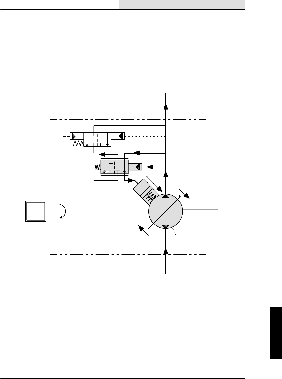
HYDRAULICS
6-65
8410 MM392 (8--01)
M
2400
RPM
8410 HYDRAULIC PUMP
HIGH PRESSURE
FLOW
COMPENSATOR
HIGH PRESSURE
COMPENSATOR
SENSE
LINE
PRESSURE
LINE
HIGH--PRESSURE STANDBY:
When the hydraulic system is overloaded, the pump will go into the high--
pressure standby position. The pressure on both ends of the flow spool
will be equal and does not function in this case. Now the high--pressure
spool is working. The pressure from the pump will move the spool and
will enter oil inside the control piston which will move the cam plate in
the position compared to the normal working condition. This means the
amount of oil is reduced.
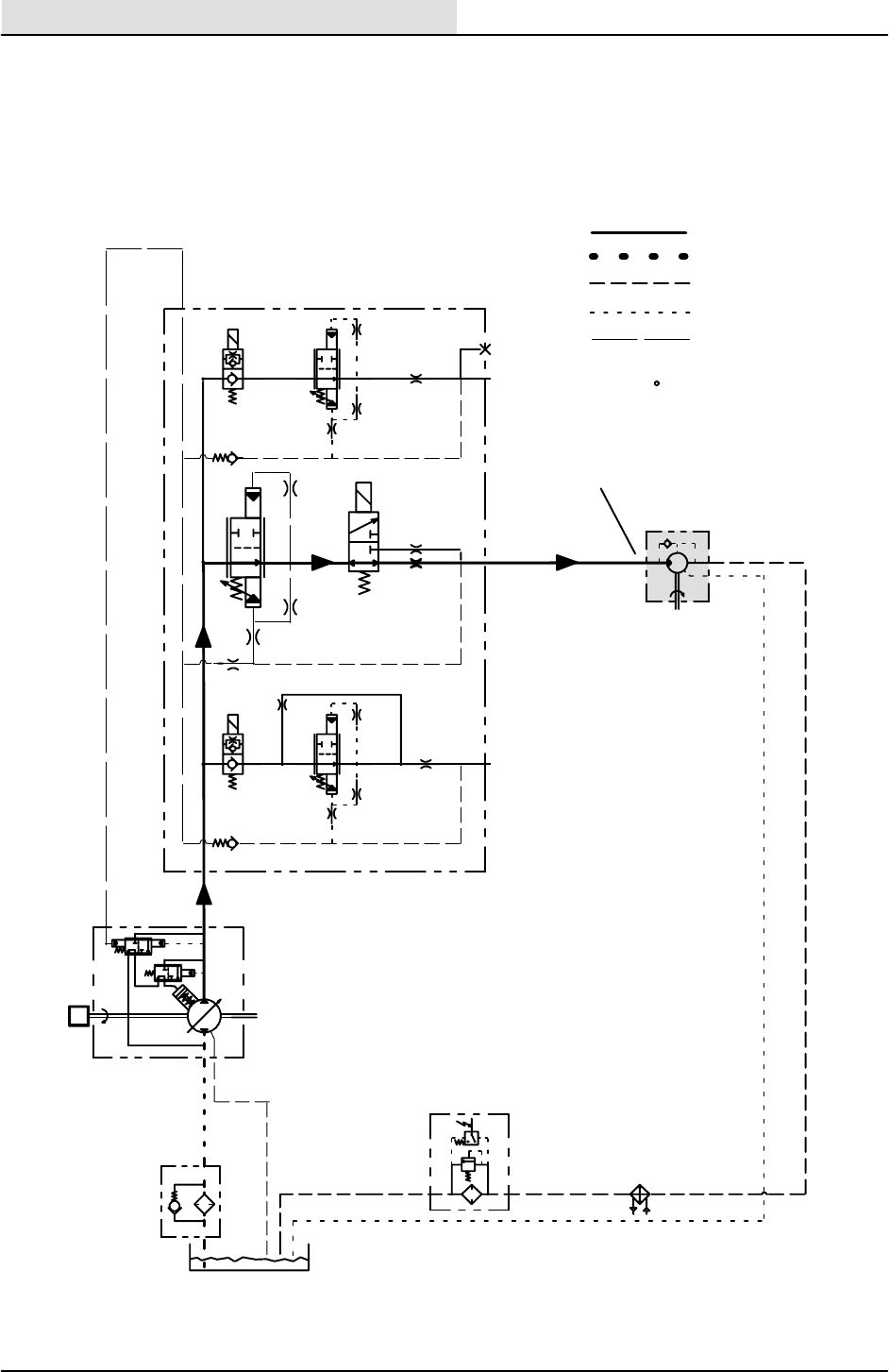
HYDRAULICS
6-66 8410 MM392 (8--01)
ENGINE
FAN
S--21
RV7
50
PSI
40
PSI
FILTER
STRAINER
RESERVOIR
RV1
3 PSI
M
2400
M2
SV02
P1
LS1
RPM
ENGINE FAN CIRCUIT (HIGH SPEED)
PRESSURE
RETURN
SUCTION
CASE DRAIN
SENSE LINE
1100 PSI
2.3 GPM (HIGH SPEED)
PRESSURE READINGS BASED
ON 150 F
x
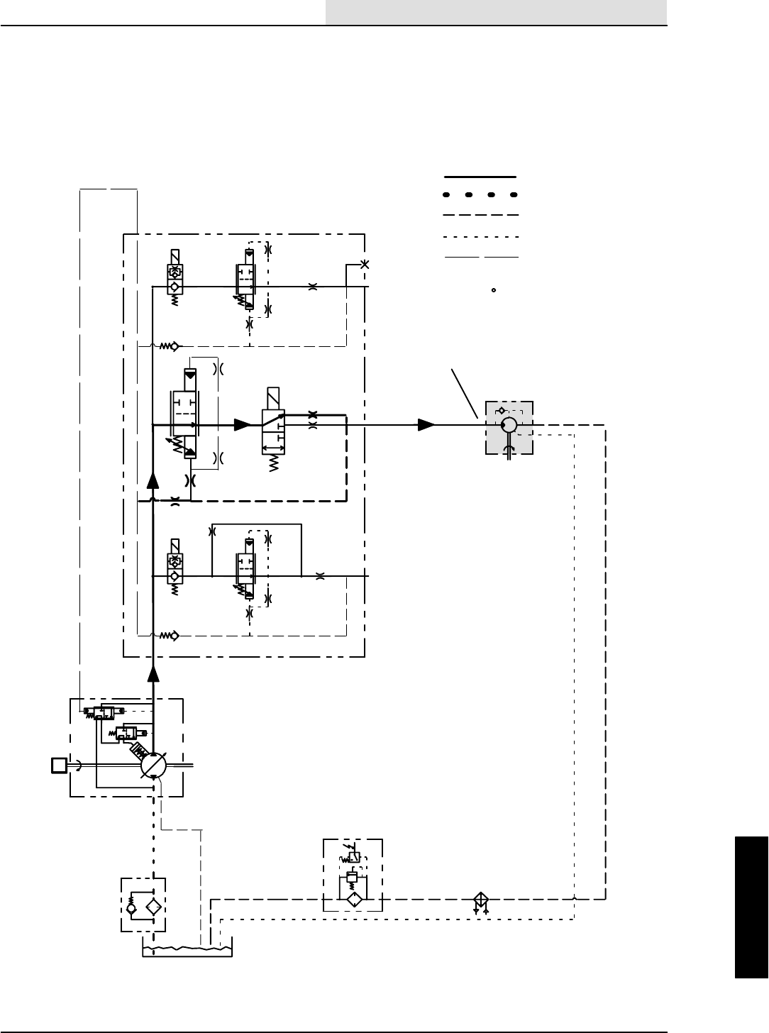
HYDRAULICS
6-67
8410 MM392 (8--01)
ENGINE
FAN
S--21
RV7
50
PSI
40
PSI
FILTER
STRAINER
RESERVOIR
RV1
3 PSI
M
2400
M2
SV02
P1
LS1
RPM
ENGINE FAN CIRCUIT (IDLE SPEED)
PRESSURE
RETURN
SUCTION
CASE DRAIN
SENSE LINE
.8 GPM (IDLE SPEED)
PRESSURE READINGS BASED
ON 150 F
x
HYDRAULICS
6-68 8410 MM392 (8--01)
ENGINE FAN DOES NOT RUN
NO YES
FLOW COMPENSATOR
CS2 STUCK?
CLEAN OR REPLACE
CS2
ORIFICE PLUGGED? NO
CHECK FAN
MOTOR

HYDRAULICS
6-69
8410 MM392 (8--01)
ENGINE FAN ALWAYS RUNS FAST
YESNO
NO YES
IS SV--2 CARTRIDGE
STEM STUCK?
FLOW COMPENSATOR
CS2 STUCK?
CLEAN OR REPLACE
CS2
ORIFICE PLUGGED?
CLEAN OR REPLACE
SV--2
HYDRAULICS
6-70 8410 MM392 (8--01)
ENGINE FAN ALWAYS RUNS SLOW
YESNO
NO YES
IS SV--2 CARTRIDGE
STEM STUCK?
FLOW COMPENSATOR
CS2 STUCK?
CLEAN OR REPLACE
CS2
ORIFICE PLUGGED?
CLEAN OR REPLACE
SV--2
CHECK FAN
MOTOR
NO

HYDRAULICS
6-71
8410 MM392 (8--01)
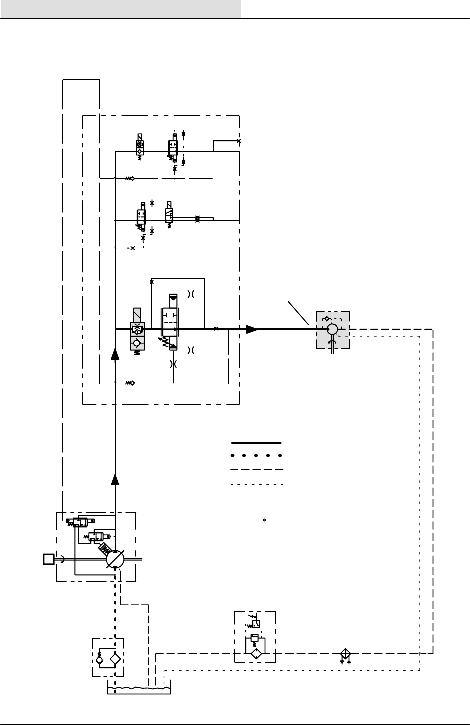
HYDRAULICS
6-72 8410 MM392 (8--01)
S--21
RV7
50
PSI
40
PSI
FILTER
STRAINER
RESERVOIR
RV1
3 PSI
M
2400
M1
M2
M3
P2
SV01
SV02
5 PSI
P1
5 PSI
LS1
RPM
SCRUB FAN CIRCUIT
PRESSURE
RETURN
SUCTION
CASE DRAIN
SENSE LINE
SCRUB
FAN
1250 PSI
6.5 GPM
PRESSURE READINGS BASED
ON 150 F - SMOOTH FLOORS
SQUEEGEE DOWN - CLEAN
MODE
x
HYDRAULICS
6-73
8410 MM392 (8--01)
SCRUB FAN DOES NOT TURN OFF
YESNO
NO YES
REPAIR OR REPLACE
SV--1
IS SC1 SENSE YES
DOES SV--1 COIL HAVE
MAGNETISM AFTER
TURNING THE
SCRUBBER FAN OFF?
CHECK
ELECTRICAL
SYSTEM
IS SV--1 CARTRIDGE
STEM STUCK OPEN?
REPAIR OR REPLACE
SC1
CHECK STUCK OPEN?
HYDRAULICS
6-74 8410 MM392 (8--01)
SCRUB FAN DOES NOT TURN ON
YES NO
NO YES
REPAIR OR REPLACE
SV--1
IS COMPENSATOR
YES
DOES SV--1 COIL HAVE
MAGNETISM AFTER
TURNING THE
SCRUBBER ON?
CHECK
ELECTRICAL
SYSTEM
IS SV--1 CARTRIDGE
STEM STUCK CLOSED?
REPAIR OR REPLACE
CS1
CS1 STUCK CLOSED?
NO
IS ORIFICE OR1
PLUGGED?
REPAIR OR REPLACE
OR1
YES

HYDRAULICS
6-75
8410 MM392 (8--01)
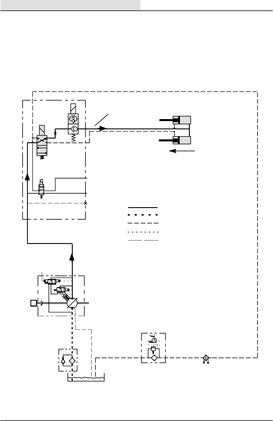
HYDRAULICS
6-76 8410 MM392 (8--01)
S--21
RV7
50
PSI
40
PSI
FILTER
STRAINER
RESERVOIR
RV1
3 PSI
M
2400
RPM
G1
C10
C11
C12
C13
P6
DR5
SV16
SV15
SV17
HOPPER DOOR CLOSE CIRCUIT
PRESSURE
RETURN
SUCTION
CASE DRAIN
SENSE LINE
LINE
PRESSURE
x
HYDRAULICS
6-77
8410 MM392 (8--01)
HOPPER DOOR DOES NOT OPEN
YES NO
NO YES
DOES SV--17 COIL HAVE
MAGNETISM FOR TIMED
CHECK
ELECTRICAL
SYSTEM
REPLACE SV--17
CARTRIDGE STEM
PERIOD AFTER
TOUCHING THE DOOR
OPEN/CLOSE BUTTON?
ARE THE DOOR
CYLINDERS
RETRACTING?
CHECK DOOR
SEALS FOR BINDING
HYDRAULICS
6-78 8410 MM392 (8--01)
HOPPER DOOR DOES NOT CLOSE
YES NO
DOES SV--16 COIL HAVE
MAGNETISM FOR TIMED
CHECK
ELECTRICAL
SYSTEM
REPLACE SV--16
CARTRIDGE STEM
PERIOD AFTER
TOUCHING THE DOOR
OPEN/CLOSE BUTTON?

HYDRAULICS
6-79
8410 MM392 (8--01)
HOPPER DOOR DOES NOT
STAY CLOSED
YESNO
DOES SV--17 COIL
HAVE MAGNETISM
CHECK
ELECTRICAL
SYSTEM
ALL THE TIME?
DOOR CYLINDER
PISTON SEAL
LEAKING?
YES NO
REPLACE LEAKY
DOOR CYLINDER
REPLACE SV--17
CARTRIDGE STEM
SEALS
DOES DOOR
STAY CLOSED?
NO
REPLACE SV--17
CARTRIDGE STEM
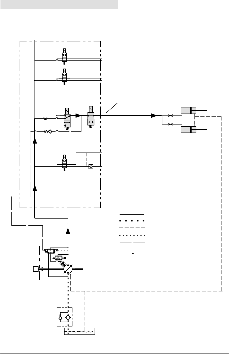
HYDRAULICS
6-80 8410 MM392 (8--01)
C3
C4
C5
C6
C7
C8
C9
SV10
SV08 SV09
SV12
OR4
5 PSI
SV11
DR4
P5
LS4
P4 PRESSURE
RETURN
SUCTION
CASE DRAIN
SENSE LINE
STRAINER
RESERVOIR
RV1
3 PSI
M
2400
RPM
HOPPER LIFT CIRCUIT
1300 PSI -- EMPTY
2400 PSI -- FULL
PRESSURE READINGS BASED
ON 150 F - SMOOTH FLOORS
x

HYDRAULICS
6-81
8410 MM392 (8--01)
HOPPER DOES NOT RAISE
YES NO
DOES SV--8 & SV--9 HAVE
MAGNETISM AFTER
CHECK
ELECTRICAL
SYSTEM
TOUCHING THE HOPPER
LIFT CYLINDER
PISTON SEAL
LEAKING?
YES NO
REPLACE LEAKY
LIFT CYLINDER
DOES HOPPER
NO
REPLACE SV--8
CARTRIDGE STEM &
RAISE BUTTON?
PUT #10 O--RING
PLUG IN PLACE OF
SV--9 CARTRIDGE
STEM
RAISE AND NOT
STAY UP?
YES
PUT SV--9 CARTRIDGE
BACK IN PLACE
REPLACE SV--9
CARTRIDGE STEM
WITH NEW STEM
HYDRAULICS
6-82 8410 MM392 (8--01)
HOPPER DRIFTS DOWN TOO QUICKLY
YESNO
DOES SV--9 COIL HAVE
MAGNETISM AFTER
CHECK
ELECTRICAL
SYSTEM
RAISING HOPPER?
LIFT CYLINDER
PISTON SEAL
LEAKING?
YES NO
REPLACE LEAKY
LIFT CYLINDER
REPLACE SV--9
CARTRIDGE STEM
SEALS
DOES HOPPER
STAY IN UP
NO
REPLACE SV--9
CARTRIDGE STEM
POSITION?

HYDRAULICS
6-83
8410 MM392 (8--01)
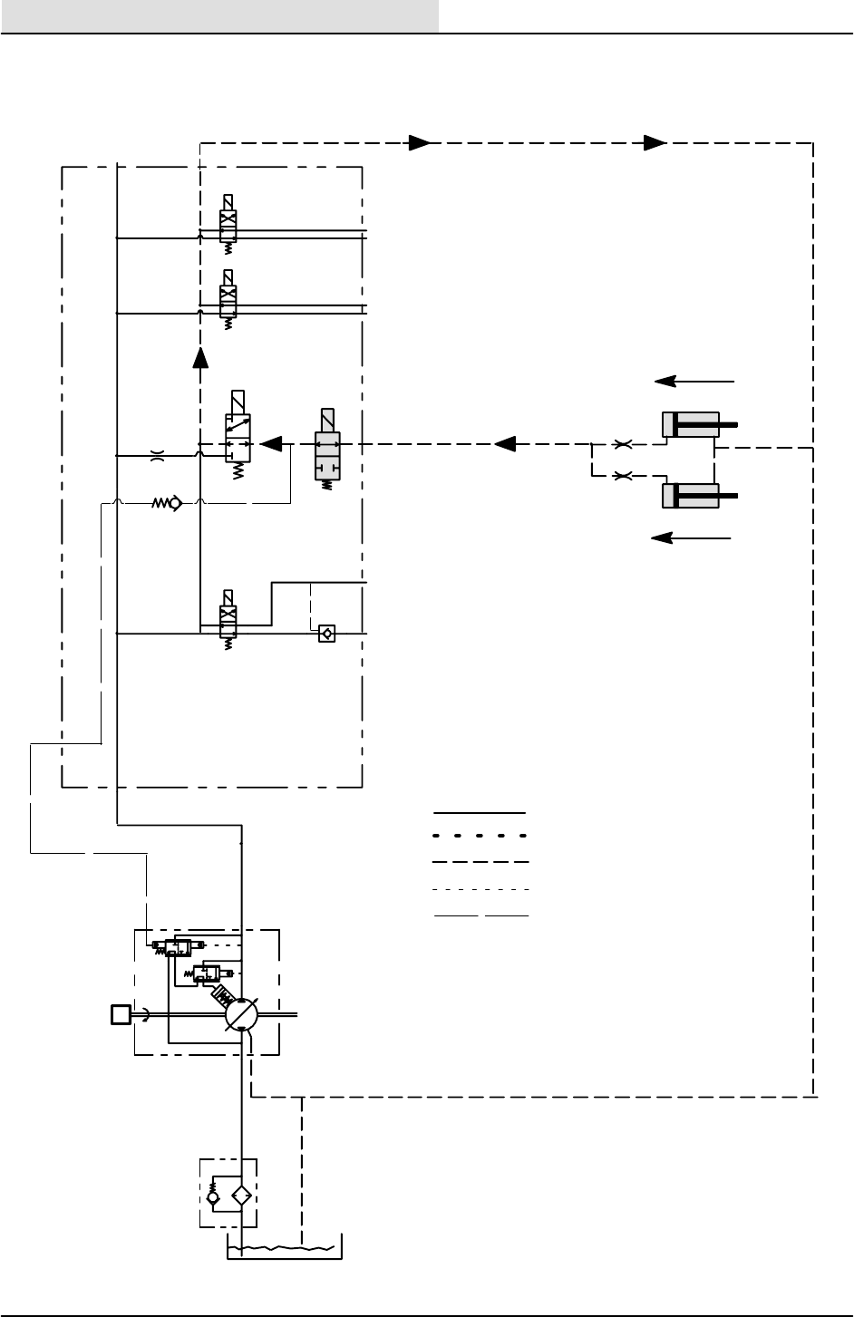
HYDRAULICS
6-84 8410 MM392 (8--01)
C3
C4
C5
C6
C7
C8
C9
SV10
SV08
SV09
SV12
OR4
5 PSI
SV11
DR4
P5
LS4
P4 PRESSURE
RETURN
SUCTION
CASE DRAIN
SENSE LINE
STRAINER
RESERVOIR
RV1
3 PSI
M
2400
RPM
HOPPER LOWER CIRCUIT
HYDRAULICS
6-85
8410 MM392 (8--01)
HOPPER DOES NOT LOWER
YES NO
DOES SV--9 COIL HAVE
MAGNETISM AFTER
CHECK
ELECTRICAL
SYSTEM
REPLACE SV--9
CARTRIDGE STEM
TOUCHING THE HOPPER
LOWER BUTTON?
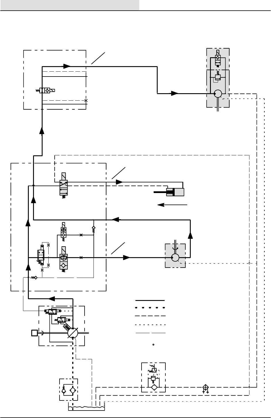
HYDRAULICS
6-86 8410 MM392 (8--01)
SWEEP FAN
MAIN BROOM
LIFT
M5
C8
C9
SV06 3
OR6
SV05
5 PSI
CS4
OR5
SV11
DR4PB1
M6
G5
M7
M9
M8
PB2
SV13
SV18
RV5
1800
MAIN BROOM
PSI
PSI
5.4 GPM
6.7 GPM
M4
LS3 P4
DOWN
PRESSURE
RETURN
SUCTION
CASE DRAIN
SENSE LINE
S--21
RV7
50
PSI
40
PSI
FILTER
STRAINER
RESERVOIR
RV1
3 PSI
M
2400
RPM
MAIN BRUSH CIRCUIT -- SPD 1
(MAIN BRUSH DOWN AND ON, VAC FAN ON)
1100 PSI
1100 PSI
750 PSI
PRESSURE READINGS BASED
ON 150 F - SMOOTH FLOORS
x
x
x
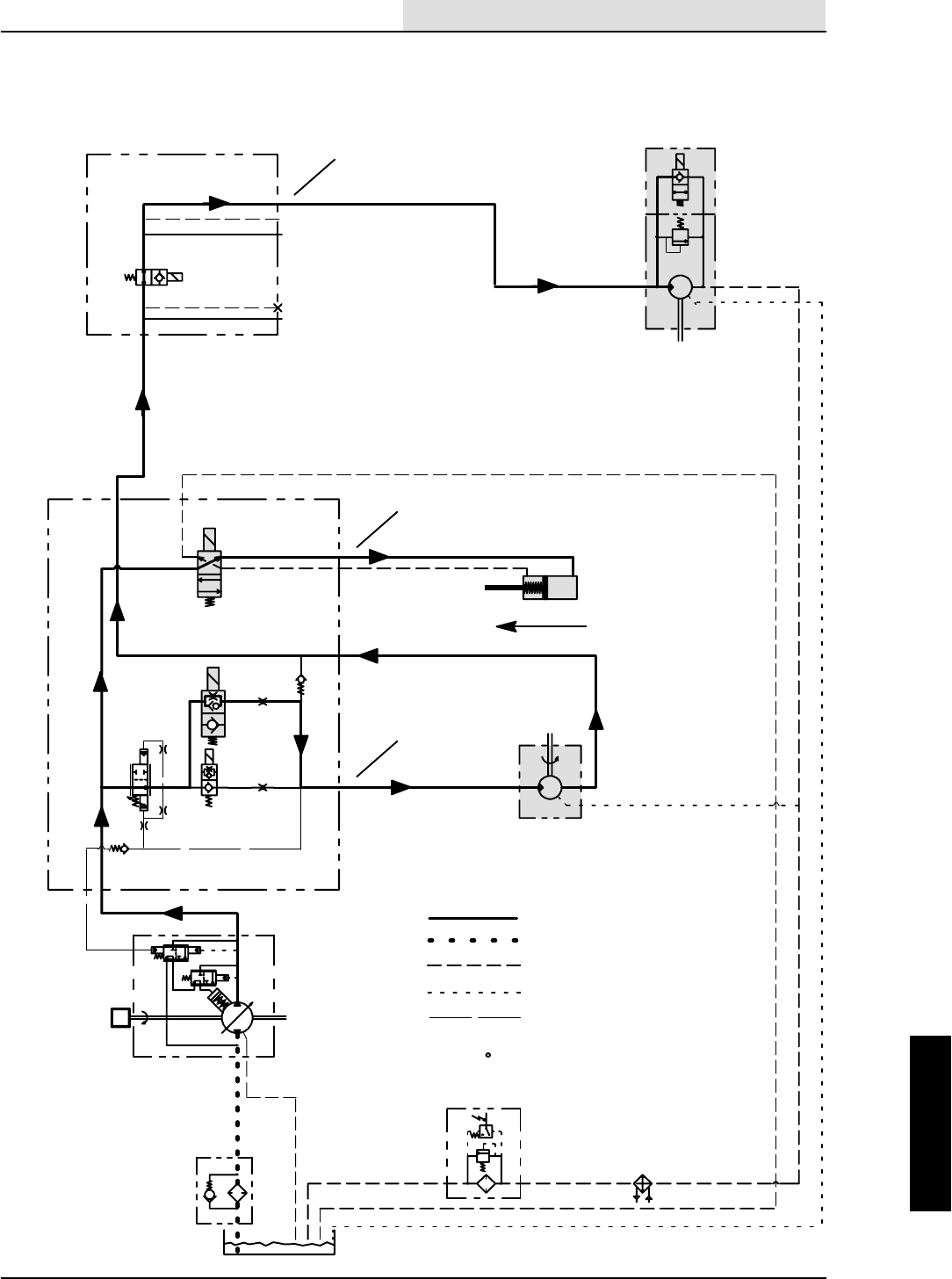
HYDRAULICS
6-87
8410 MM392 (8--01)
SWEEP FAN
MAIN BROOM
LIFT
M5
C8
C9
SV06
3
OR6
SV05
5 PSI
CS4
OR5
SV11
DR4PB1
M6
G5
M7
M9
M8
PB2
SV13
SV18
RV5
1800
MAIN BROOM
PSI
PSI
5.4 GPM
6.7 GPM
M4
LS3 P4
DOWN
PRESSURE
RETURN
SUCTION
CASE DRAIN
SENSE LINE
S--21
RV7
50
PSI
40
PSI
FILTER
STRAINER
RESERVOIR
RV1
3 PSI
M
2400
RPM
MAIN BRUSH CIRCUIT -- SPD 2
(MAIN BRUSH DOWN AND ON, VAC FAN ON)
1400 PSI
1400 PSI
1050 PSI
PRESSURE READINGS BASED
ON 150 F - SMOOTH FLOORS
x
x
x

HYDRAULICS
6-88 8410 MM392 (8--01)
MAIN BRUSH DOES NOT RAISE
YESNO
DOES SV--11 COIL
HAVE MAGNETISM
CHECK
ELECTRICAL
SYSTEM
YES NO
REPLACE SV--11
AFTER TURNING THE
MAIN BRUSH OFF?
IS THE LIFT
CYLINDER
RETRACTING?
CHECK
MECHANICAL
LINKAGE STEM

HYDRAULICS
6-89
8410 MM392 (8--01)
MAIN BRUSH DOES NOT LOWER
YES NO
DOES SV--11 COIL
HAVE MAGNETISM
CHECK
ELECTRICAL
SYSTEM
YES NO
REPLACE SV--11
AFTER TURNING THE
MAIN BRUSH ON?
IS THE LIFT
CYLINDER
EXTENDING?
CHECK
MECHANICAL
LINKAGE STEM
HYDRAULICS
6-90 8410 MM392 (8--01)
MAIN BRUSH DOES NOT
TURN OFF
YES
NO
CHECK
ELECTRICAL
SYSTEM
YES NO
IS MAIN BRUSH
STUCK IN SPEED 1?
CHECK VOLTAGE
AT SV--5 & SV--6
AFTER TURNING OFF
REPLACE STEM
CARTRIDGE FOR
SV--5
REPLACE STEM
CARTRIDGE FOR
SV--6

HYDRAULICS
6-91
8410 MM392 (8--01)
MAIN BRUSH DOES NOT
TURN ON
YES NO
CHECK
ELECTRICAL
SYSTEM
YES
NO
CHECK VOLTAGE
AT SV--5 IN LOW SPEED
REPLACE STEM
CARTRIDGE FOR
SV--5 OR SV--6
(SV--6 IN HIGH SPEED)
CHECK STEM
(IS IT SHIFTING?)
CHECK FLOW
COMPENSATOR
CS4 FOR STICKING
YESNO
REPLACE FLOW
COMPENSATOR
CS4
CHECK LOAD
SENSE CHECKS
FOR LEAKING
NO
YES
RESEAT CHECK
VALVE OR REPLACE
VALVEBLOCK
OVER--RUNNING
CHECK VALVE AT
3 PSI STUCK OPEN?
NO YES
REPLACE
CHECK VALVE
CHECK LOAD--
SENSE PUMP FOR
FLOW
CHECK MAIN
BRUSH MOTOR
CHECK
PLUMBING
HYDRAULICS
6-92 8410 MM392 (8--01)
SWEEPER FAN DOES NOT TURN OFF
YES NO
DOES SV--18 COIL ON
MAGNETISM AFTER
TURNING FAN OFF?
FAN MOTOR HAVE
REPLACE SV--18
STEM
CHECK
ELECTRICAL
SYSTEM
HYDRAULICS
6-93
8410 MM392 (8--01)
SWEEPER FAN DOES NOT TURN ON
YES NO
NO YES
DOES SV--18 COIL ON
MAGNETISM AFTER
TURNING FAN ON?
CHECK
ELECTRICAL
SYSTEM
FAN MOTOR HAVE
IS THE MAIN
BRUSH MOTOR AT
SWEEP SPEED?
CHECK MAIN
BRUSH MOTOR
FUNCTIONS
REPLACE SV--18
STEM AT FAN MOTOR
DOES FAN MOTOR
TURN ON?
NO
REPLACE THE
FAN MOTOR
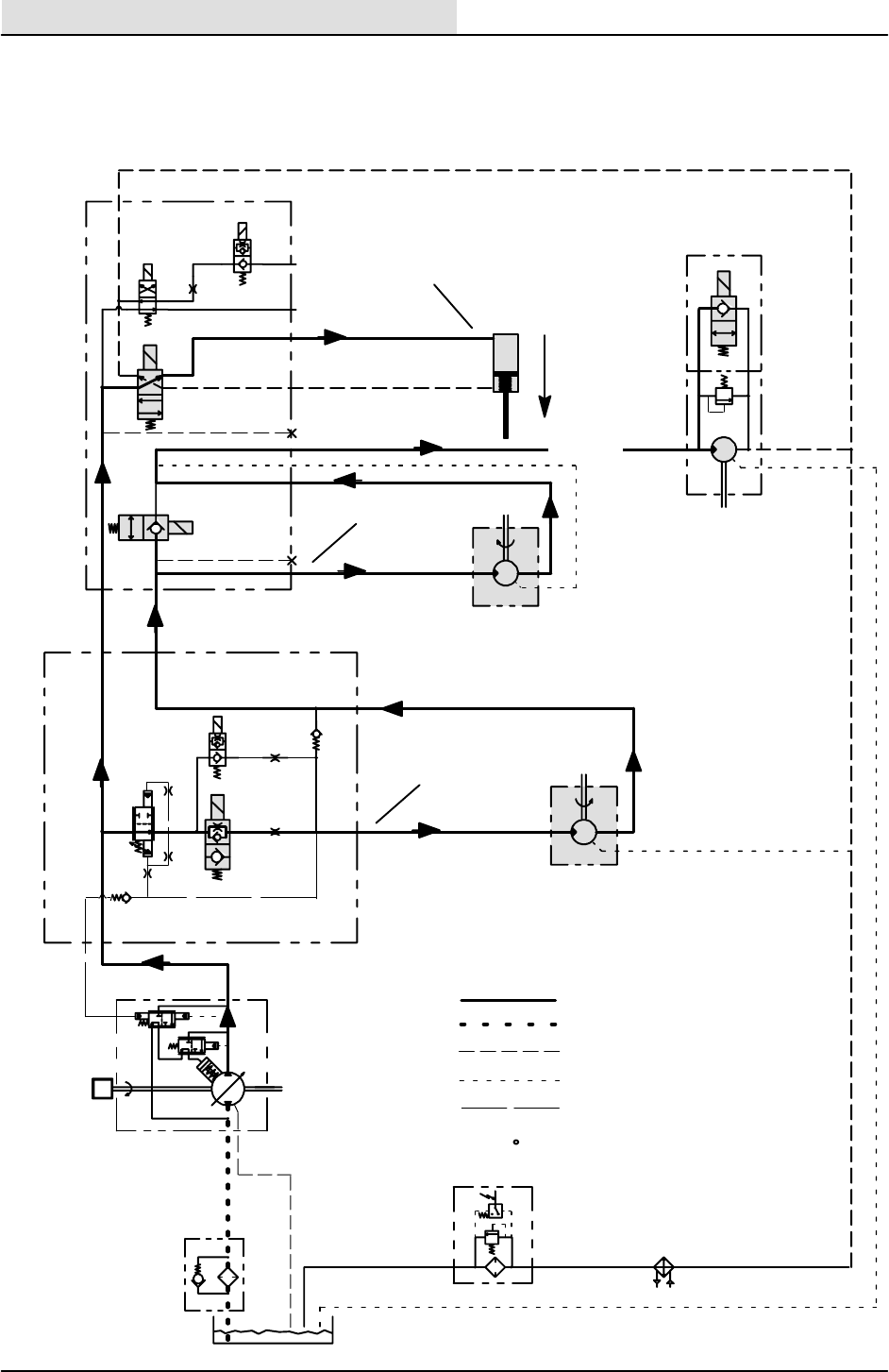
HYDRAULICS
6-94 8410 MM392 (8--01)
SIDE BROOM
SWEEP FAN
SIDE BROOM
LIFT
M5
SV06 3
OR6
SV05
5 PSI
CS4
OR5
PB1
P5
M6
G5
M7
M9
M8
G1
C10
C11
C12
C13
PB2
P6
DR5
SV16
SV15
SV13
SV17
SV18
RV5
1800
MAIN BROOM
PSI
PSI
5.4 GPM
6.7 GPM
M4
LS3 P4
S--21
RV7
50
PSI
40
PSI
FILTER
STRAINER
RESERVOIR
RV1
3 PSI
M
2400
RPM
SIDE BRUSH CIRCUIT -- SPD 1
(MAIN BRUSH ON, VAC FAN ON, SIDE BRUSH DOWN AND ON)
PRESSURE
RETURN
SUCTION
CASE DRAIN
SENSE LINE
750 PSI
850 PSI
1200 PSI
1200 PSI
PRESSURE READINGS BASED
ON 150 F - SMOOTH FLOORS
x
x
x
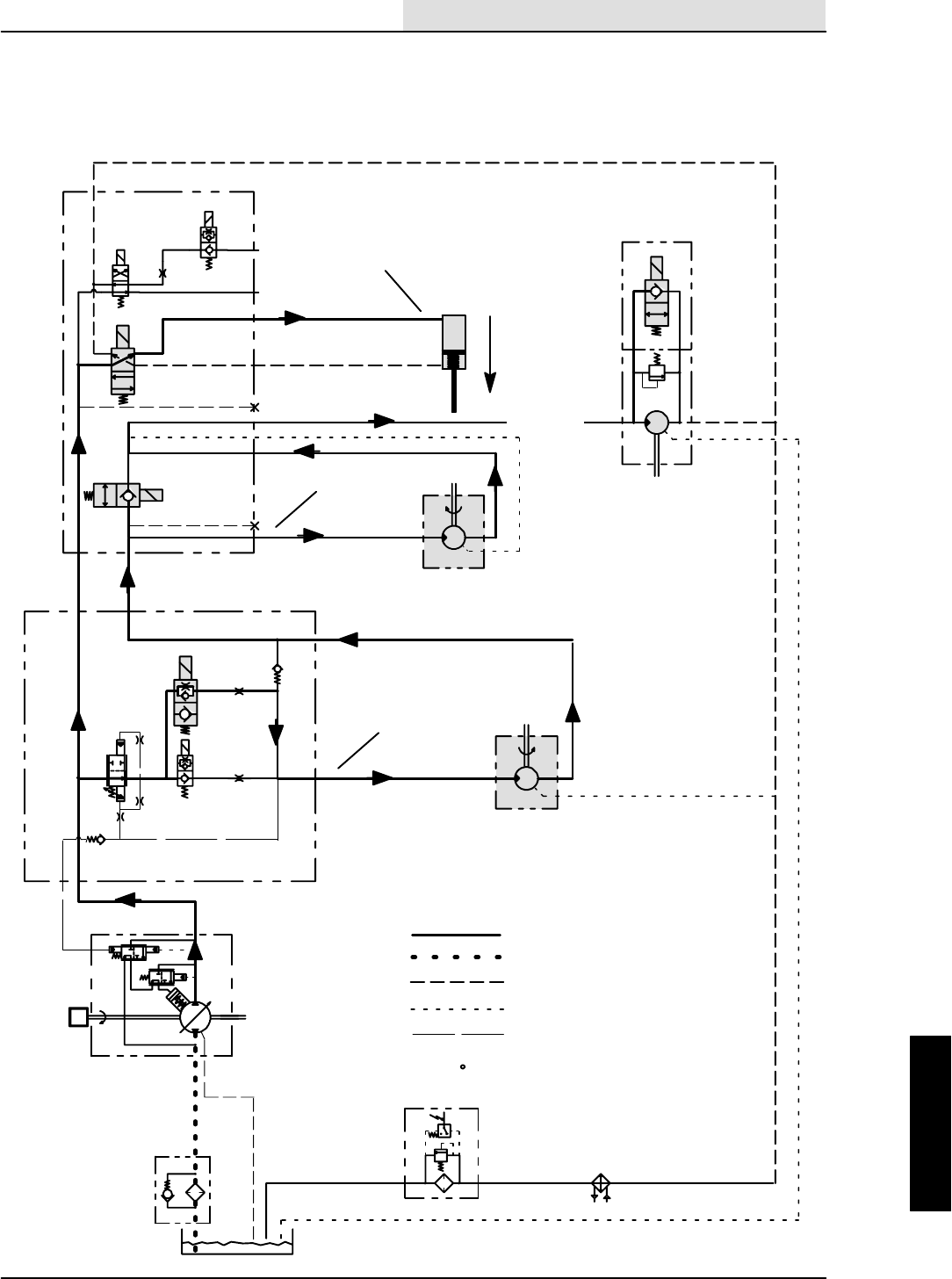
HYDRAULICS
6-95
8410 MM392 (8--01)
SIDE BROOM
SWEEP FAN
SIDE BROOM
LIFT
M5
SV06 3
OR6
SV05
5 PSI
CS4
OR5
PB1
P5
M6
G5
M7
M9
M8
G1
C10
C11
C12
C13
PB2
P6
DR5
SV16
SV15
SV13
SV17
SV18
RV5
1800
MAIN BROOM
PSI
PSI
5.4 GPM
6.7 GPM
M4
LS3 P4
S--21
RV7
50
PSI
40
PSI
FILTER
STRAINER
RESERVOIR
RV1
3 PSI
M
2400
RPM
SIDE BRUSH CIRCUIT -- SPD 2
PRESSURE
RETURN
SUCTION
CASE DRAIN
SENSE LINE
(MAIN BRUSH ON, VAC FAN ON, SIDE BRUSH DOWN AND ON)
1600 PSI
1150 PSI
1050 PSI
1600 PSI
PRESSURE READINGS BASED
ON 150 F - SMOOTH FLOORS
x
x
x

HYDRAULICS
6-96 8410 MM392 (8--01)
SIDE BRUSH DOES NOT RAISE
YESNO
DOES SV--15 COIL
HAVE MAGNETISM
CHECK
ELECTRICAL
SYSTEM
YES NO
REPLACE SV--15
AFTER TURNING THE
SIDE BRUSH OFF?
IS THE LIFT
CYLINDER
RETRACTING?
CHECK
MECHANICAL
LINKAGE STEM

HYDRAULICS
6-97
8410 MM392 (8--01)
SIDE BRUSH DOES NOT LOWER
YES NO
DOES SV--15 COIL
HAVE MAGNETISM
CHECK
ELECTRICAL
SYSTEM
YES NO
REPLACE SV--15
AFTER TURNING THE
SIDE BRUSH ON?
IS THE LIFT
CYLINDER
EXTENDING?
CHECK
MECHANICAL
LINKAGE STEM
HYDRAULICS
6-98 8410 MM392 (8--01)
SIDE BRUSH DOES NOT
TURN OFF
YES
NO
DOES SV--13 COIL
HAVE MAGNETISM
CHECK
ELECTRICAL
SYSTEM
REPLACE SV--13
AFTER TURNING THE
SIDE BRUSH OFF?
STEM
HYDRAULICS
6-99
8410 MM392 (8--01)
SIDE BRUSH DOES NOT
TURN ON
YES NO
DOES SV--13 COIL
HAVE MAGNETISM
CHECK
ELECTRICAL
SYSTEM
REPLACE SV--13
AFTER TURNING THE
SIDE BRUSH ON?
STEM
NO YES
IS THE MAIN
BRUSH MOTOR AT
SWEEP SPEED?
CHECK MAIN
BRUSH MOTOR
FUNCTIONS
DOES SIDE BRUSH
MOTOR TURN ON?
NO
REPLACE THE
SIDE BRUSH
MOTOR
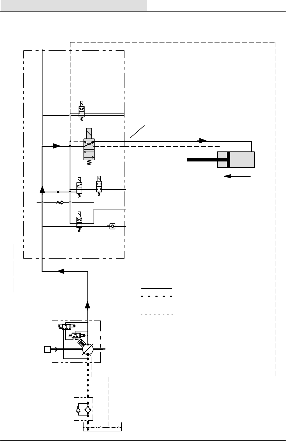
HYDRAULICS
6-100 8410 MM392 (8--01)
C3
C4
C5
C6
C7
C8
C9
SV10
SV08 SV09
SV12
OR4
5 PSI
SV11
DR4PB1
P5
LS4
P4
STRAINER
RESERVOIR
RV1
3 PSI
M
2400
RPM
PRESSURE
RETURN
SUCTION
CASE DRAIN
SENSE LINE
EDGE SCRUB CIRCUIT
OUT
LINE
PRESSURE
x

HYDRAULICS
6-101
8410 MM392 (8--01)
SCRUB HEAD DOES NOT GO IN
YES
NO
DOES SV--10 COIL
HAVE MAGNETISM
CHECK
ELECTRICAL
SYSTEM
REPLACE SV--10
AFTER TURNING THE
EDGER OFF?
STEM
NOYES IS THE EDGER
CYLINDER
RETRACTING?
CHECK
MECHANICAL
LINKAGE

HYDRAULICS
6-102 8410 MM392 (8--01)
SCRUB HEAD DOES NOT GO OUT
YES NO
DOES SV--10 COIL
HAVE MAGNETISM
CHECK
ELECTRICAL
SYSTEM
REPLACE SV--10
AFTER TURNING THE
EDGER ON?
STEM
NOYES IS THE EDGER
CYLINDER
EXTENDING?
CHECK
MECHANICAL
LINKAGE

HYDRAULICS
6-103
8410 MM392 (8--01)
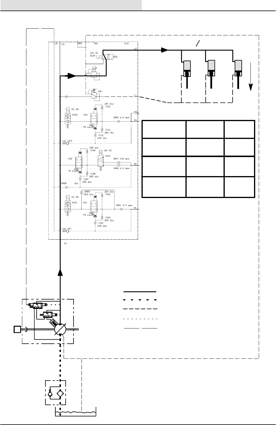
HYDRAULICS
6-104 8410 MM392 (8--01)
A150--400 PSI
SV19
300 PSI
84010
.018
B
C
A
BC
.040 DIA
OR12
SCRUB HEAD LOWER CIRCUIT
STRAINER
RESERVOIR
RV1
3 PSI
M
2400
RPM
PRESSURE
RETURN
SUCTION
CASE DRAIN
SENSE LINE
DOWN
PRESSURE
x
DOWN FORCE PRESSURE
PSI
LEVEL #
150 LBS
300 LBS
450 LBS
260
330
380
1
2
3
HYDRAULICS
6-105
8410 MM392 (8--01)
SV4 AND SV19 STEMS
MAGNETIZED?
CHECK
ELECTRICAL SYSTEM
REPAIR OR REPLACE
PR1 STEM
CARTRIDGE
C2 PORT
PRESSURE OK?
(>400 PSI)
YES
NO
SCRUB BRUSHES DO NOT LOWER
YES NO
C1 PORT
PRESSURE OK?
250--300 PSI
NO
REPAIR OR REPLACE
SV4 STEM
CARTRIDGE
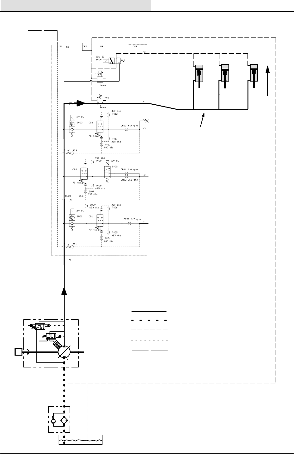
HYDRAULICS
6-106 8410 MM392 (8--01)
A150--400 PSI
SV19
300 PSI
84010
.018
B
C
A
BC
.040 DIA
OR12
SCRUB HEAD RAISE CIRCUIT
STRAINER
RESERVOIR
RV1
3 PSI
M
2400
RPM
PRESSURE
RETURN
SUCTION
CASE DRAIN
SENSE LINE
PRESSURE
290 -- 310 PSI
x
UP
HYDRAULICS
6-107
8410 MM392 (8--01)
C1 PORT PRESSURE
OK ? (300 PSI)
C2 PORT PRESSURE
OK ? (<25 PSI)
REPAIR OR REPLACE
PR1 CARTRIDGE
YES NO
SCRUB BRUSHES DO NOT RAISE
DR1 PORT PRESSURE
OK ? (<25 PSI)
YES
SV4 STEM
MAGNETIZED ?
NO
REPAIR OR REPLACE
PLUMBING
NO
REPAIR OR REPLACE
LINKAGE OR CYLINDER
YES
SV4 STEM CARTRIDGE
SHIFTING OK ?
REPAIR OR REPLACE
SV4 STEM CARTRIDGE
NO
YES
NO
CHECK
ELECTRICAL SYSTEM
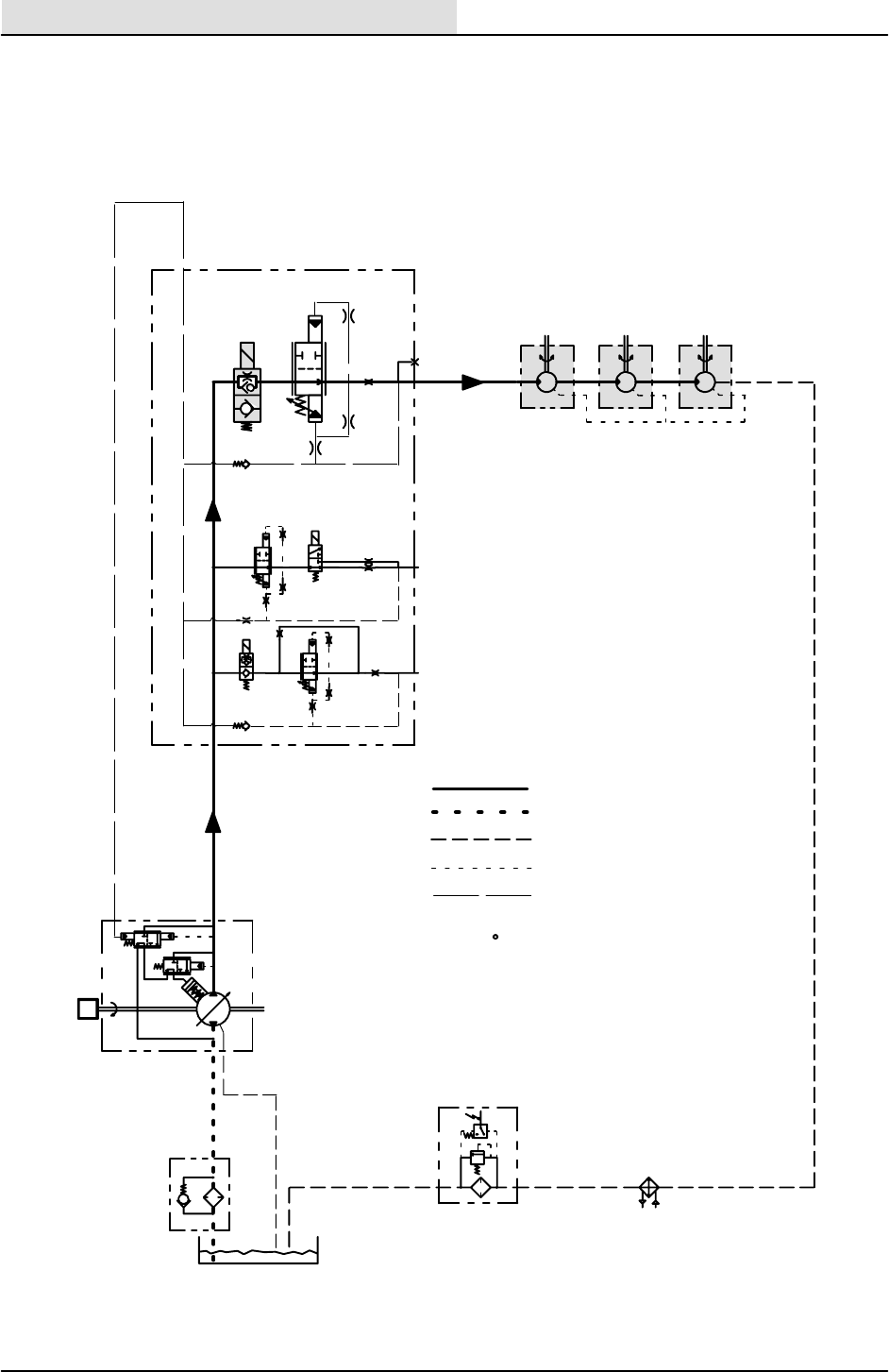
HYDRAULICS
6-108 8410 MM392 (8--01)
SCRUB
BRUSHES
S--21
RV7
50
PSI
40
PSI
FILTER
STRAINER
RESERVOIR
RV1
3 PSI
M
2400
M1
M2
M3
P2
SV01
SV02
SV03
5 PSI
P1
5 PSI
LS1
RPM
SCRUB BRUSH CIRCUIT
PRESSURE
RETURN
SUCTION
CASE DRAIN
SENSE LINE
PRESSURE READINGS BASED
ON 150 F - SMOOTH FLOORS
x

HYDRAULICS
6-109
8410 MM392 (8--01)
SCRUB BRUSHES DO NOT
TURN OFF
YESNO
DOES SV--3 COIL
HAVE MAGNETISM
CHECK
ELECTRICAL
SYSTEM
AFTER TURNING THE
SCRUBBER OFF?
NO
YES
YES
REPAIR OR REPLACE
IS SV--3 CARTRIDGE
STEM STUCK OPEN?
SV--3
IS SC3 STUCK
OPEN?
REPAIR OR REPLACE
SC3
HYDRAULICS
6-110 8410 MM392 (8--01)
SCRUB BRUSHES DO NOT TURN ON
YES NO
DOES SV--3 COIL
HAVE MAGNETISM
CHECK
ELECTRICAL
SYSTEM
AFTER TURNING THE
SCRUBBER ON?
NO
YES
YES
REPAIR OR REPLACE
IS SV--3 CARTRIDGE
STEM STUCK CLOSED?
SV--3
IS COMPENSATOR
CS3 STUCK
CLOSED?
NO
REPAIR OR REPLACE
CS3
IS ORIFICE OR3
PLUGGED?
YES
REPAIR OR REPLACE
OR3

HYDRAULICS
6-111
8410 MM392 (8--01)
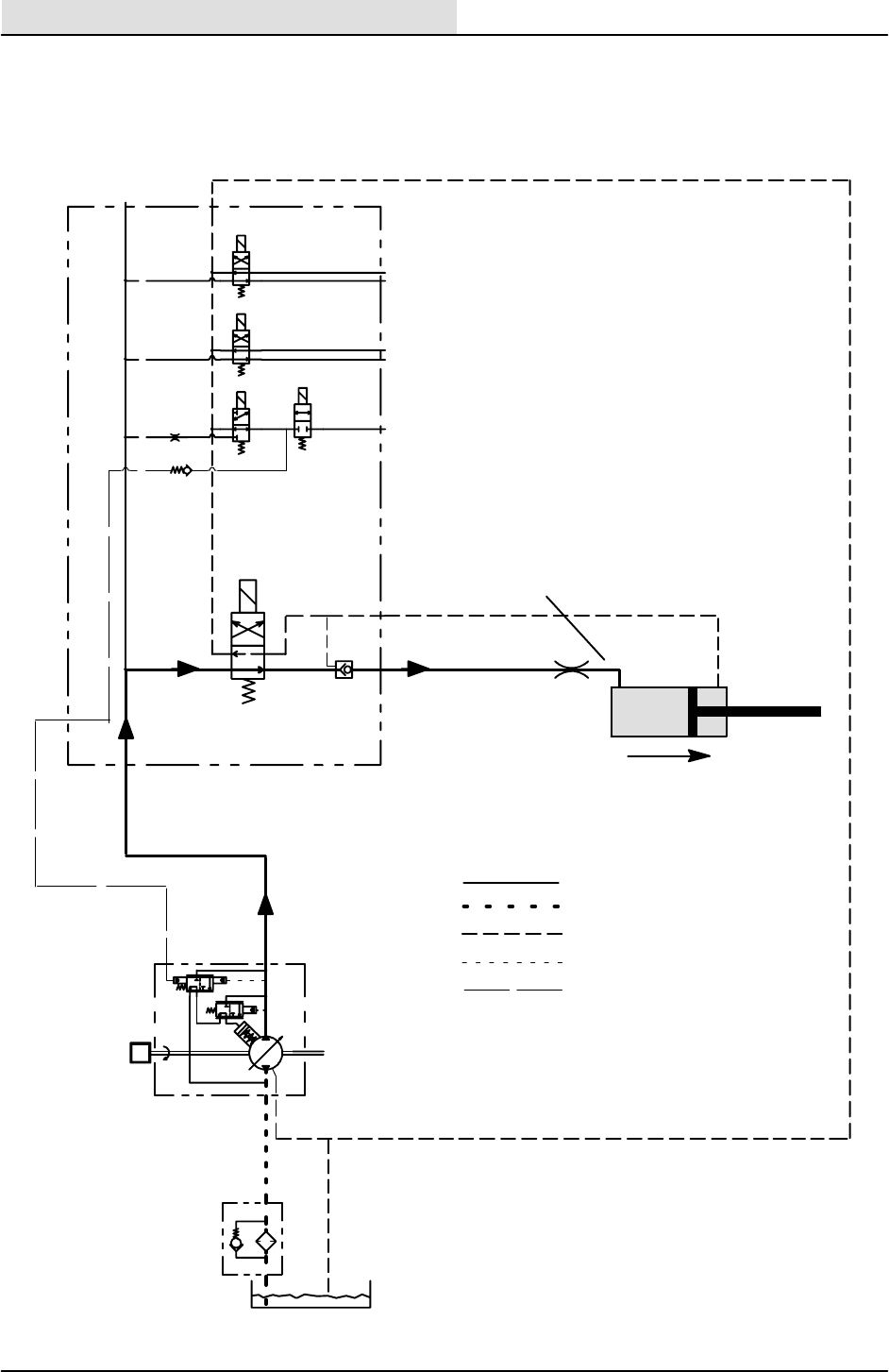
HYDRAULICS
6-112 8410 MM392 (8--01)
C3
C4
C5
C6
C7
C8
C9
SV10
SV08 SV09
SV12
OR4
SV11
DR4PB1
P5
LS4
P4
SQUEEGEE LIFT CIRCUIT
STRAINER
RESERVOIR
RV1
3 PSI
M
2400
RPM
PRESSURE
RETURN
SUCTION
CASE DRAIN
SENSE LINE
LINE
PRESSURE
x
HYDRAULICS
6-113
8410 MM392 (5--02)
SQUEEGEE DOES NOT RAISE
YES NO
CHECK
ELECTRICAL
SYSTEM
NO YES
YES
NO
IS ORIFICE TV16
PLUGGED?
YES
CLEAN OR REPLACE
ORIFICE
CHECK VOLTAGE
AT SV -- 12
CHECK STEM
(IS IT SHIFTING?)
REPLACE STEM
CARTRIDGE FOR
SV--12
PILOT CHECK
VALVE PC1 STUCK?
REPLACE CHECK
VALVE PC1
NO
CHECK SQUEEGEE
LIFT CYLINDER
HYDRAULICS
6-114 8410 MM392 (8--01)
SQUEEGEE DRIFTS DOWN TOO QUICKLY
YESNO
NO YES REPLACE CHECK
VALVE PC1
PILOT CHECK VALVE
PC1 LEAKING?
SQUEEGEE LIFT
CYLINDER
LEAKING?
CHECK PLUMBING
FOR LEAKS
REPLACE
CYLINDER

HYDRAULICS
6-115
8410 MM392 (8--01)
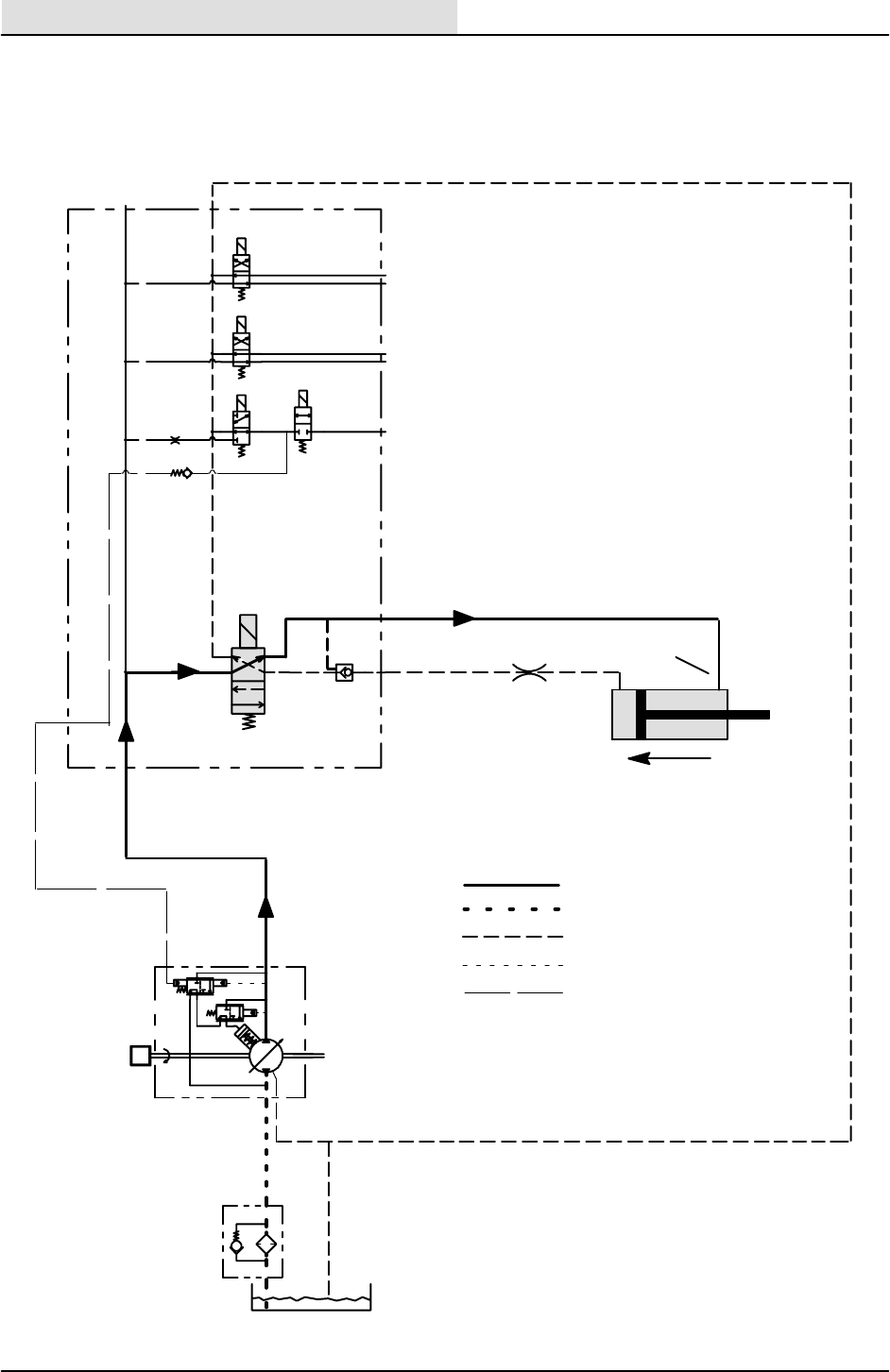
HYDRAULICS
6-116 8410 MM392 (8--01)
C3
C4
C5
C6
C7
C8
C9
SV10
SV08 SV09
SV12
OR4
SV11
DR4PB1
P5
LS4
P4
SQUEEGEE LOWER CIRCUIT
STRAINER
RESERVOIR
RV1
3 PSI
M
2400
RPM
PRESSURE
RETURN
SUCTION
CASE DRAIN
SENSE LINE
LINE
PRESSURE
x

HYDRAULICS
6-117
8410 MM392 (8--01)
SQUEEGEE DOES NOT LOWER
YES NO
CHECK
ELECTRICAL
SYSTEM
NO YES
YES
NO
IS ORIFICE TV16
PLUGGED?
YES
CLEAN OR REPLACE
ORIFICE
CHECK VOLTAGE
AT SV -- 12
CHECK STEM
(IS IT SHIFTING?)
REPLACE STEM
CARTRIDGE FOR
SV--12
PILOT CHECK
VALVE PC1 STUCK?
REPLACE CHECK
VALVE PC1
NO
CHECK SQUEEGEE
LIFT CYLINDER
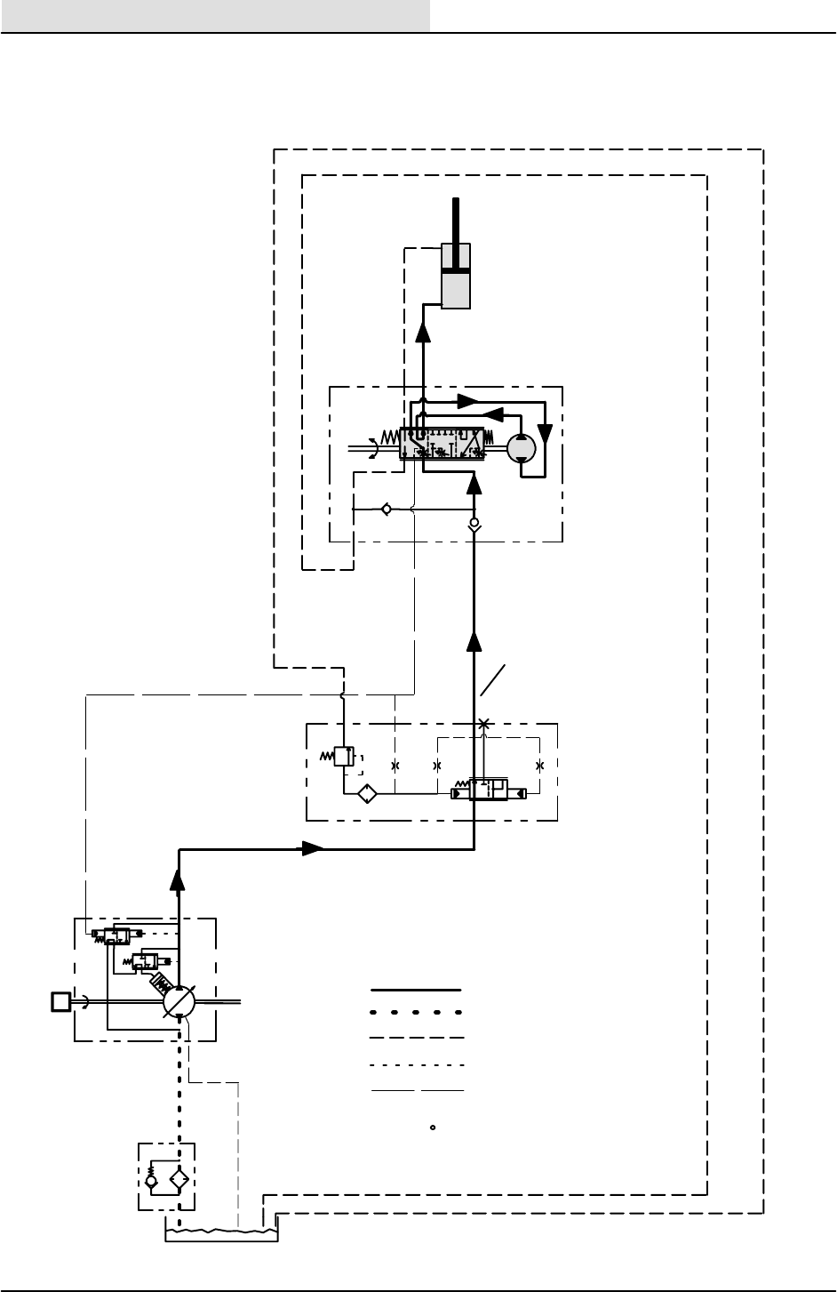
HYDRAULICS
6-118 8410 MM392 (8--01)
RL
STRAINER
RESERVOIR
RV1
3 PSI
M
2400
P
EF
CF
LS
RV6
1000 PSI
T
TEP
RPM
LEFT TURN CIRCUIT
PRESSURE
RETURN
SUCTION
CASE DRAIN
SENSE LINE
400 PSI
PRESSURE READINGS BASED
ON 150 F - SMOOTH FLOORS
x
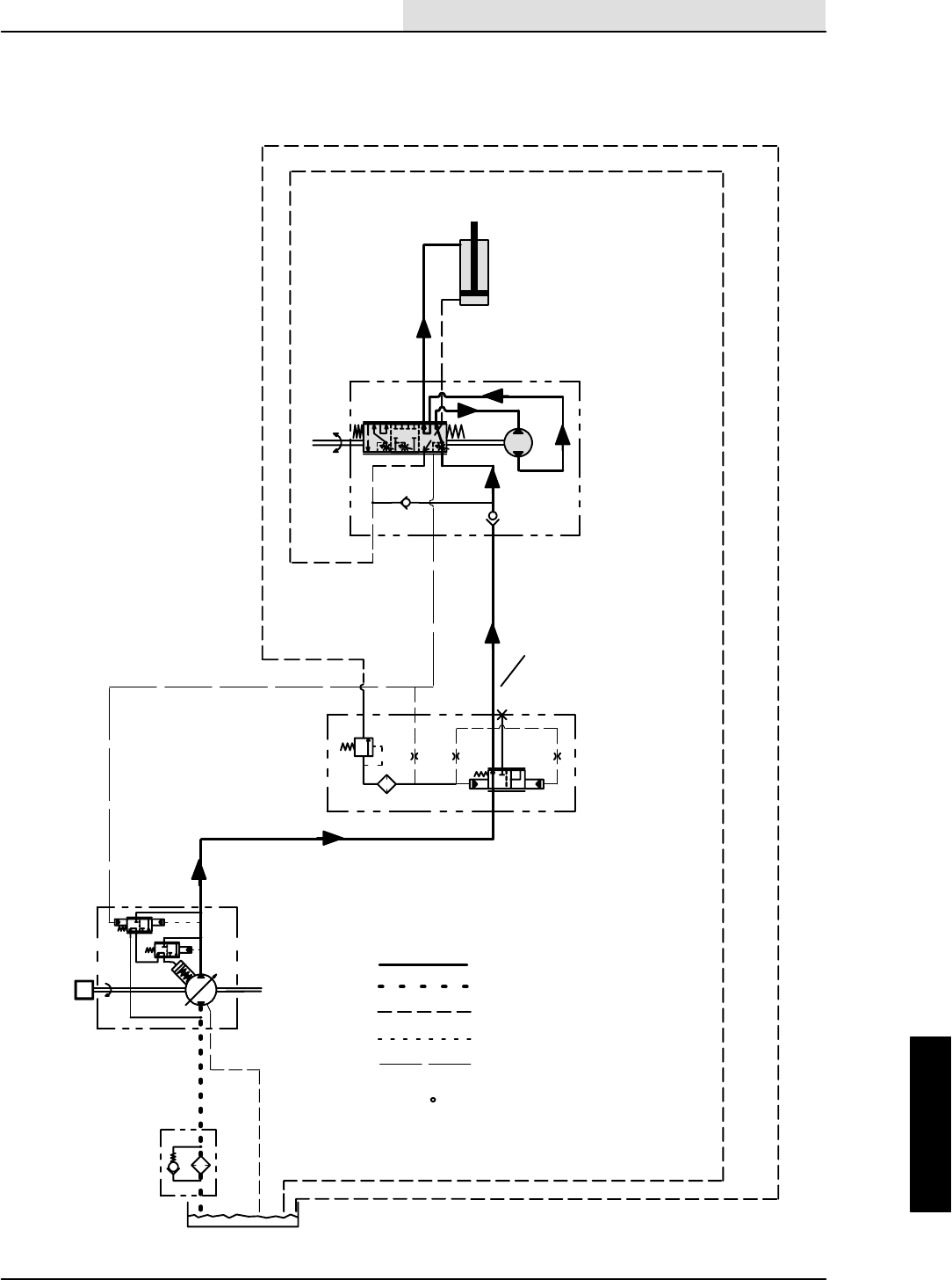
HYDRAULICS
6-119
8410 MM392 (8--01)
RL
STRAINER
RESERVOIR
RV1
3 PSI
M
2400
P
EF
CF
LS
RV6
1000 PSI
T
TEP
RPM
RIGHT TURN CIRCUIT
PRESSURE
RETURN
SUCTION
CASE DRAIN
SENSE LINE
400 PSI
PRESSURE READINGS BASED
ON 150 F - SMOOTH FLOORS
x

HYDRAULICS
6-120 8410 MM392 (8--01)

ENGINE--GAS/LP
7-1
8410 MM392 (5--02)
CONTENTS
Page
INTRODUCTION 7-3......................
LUBRICATION 7-4.....................
ENGINE OIL 7-4....................
COOLING SYSTEM 7-5................
RADIATOR 7-5.....................
ENGINE FAN BELT 7-5..............
AIR INTAKE SYSTEM 7-6..............
AIR FILTER INDICATOR 7-6.........
AIR FILTER 7-7.....................
TO REPLACE AIR FILTER
ELEMENT 7-7................
FUEL SYSTEM -- GASOLINE 7-9........
FUEL FILTERS 7-9..................
CARBURETOR 7-9.................
FUEL SYSTEM -- LPG 7-10.............
FUEL TANKS 7-12..................
TO CHANGE LPG FUEL TANK 7-14..
FUEL FILTER LOCK 7-15............
VAPORIZER-REGULATOR 7-15......
CARBURETOR 7-15................
OIL PRESSURE SWITCH 7-15.......
LPG FUEL TROUBLESHOOTING 7-16...
GOVERNOR 7-17.....................
TO ADJUST GOVERNOR
CONTROL BOX 7-17.............
DIGITAL CONTROLLER SET--UP 7-18
GOVERNOR
TROUBLESHOOTING 7-19.......
IGNITION SYSTEM 7-22...............
SPARK PLUGS 7-22................
TO REPLACE SPARK PLUGS 7-22...
ENGINE IGNITION TIMING 7-22.....
TIMING BELT 7-22..................
CYLINDER HEAD 7-23..............
VALVE TAPPET CLEARANCE 7-23...
CRANKCASE VENTILATION
SYSTEM 7-23...................
INTAKE MANIFOLD 7-23............
TO CHANGE ENGINE TIMING BELT 7-24
TO REPLACE ALTERNATOR 7-26....
TO REPLACE STARTER 7-28........
TO REMOVE ENGINE 7-30..........
TO INSTALL ENGINE 7-32...........
GAS ENGINE SERVICE MANUALS
FORD LRG--423 (2.3 Litre)
TENNANT Part Number 21791
FORD LRG--425 (2.5 Litre)
TENNANT Part Number 385439

ENGINE--GAS/LP
7-2 8410 MM392 (8--01)

ENGINE--GAS/LP
7-3
8410 MM392 (8--01)
INTRODUCTION
This section includes repair information on the
engine and related systems, such as fuel,
electrical, and drive belts.
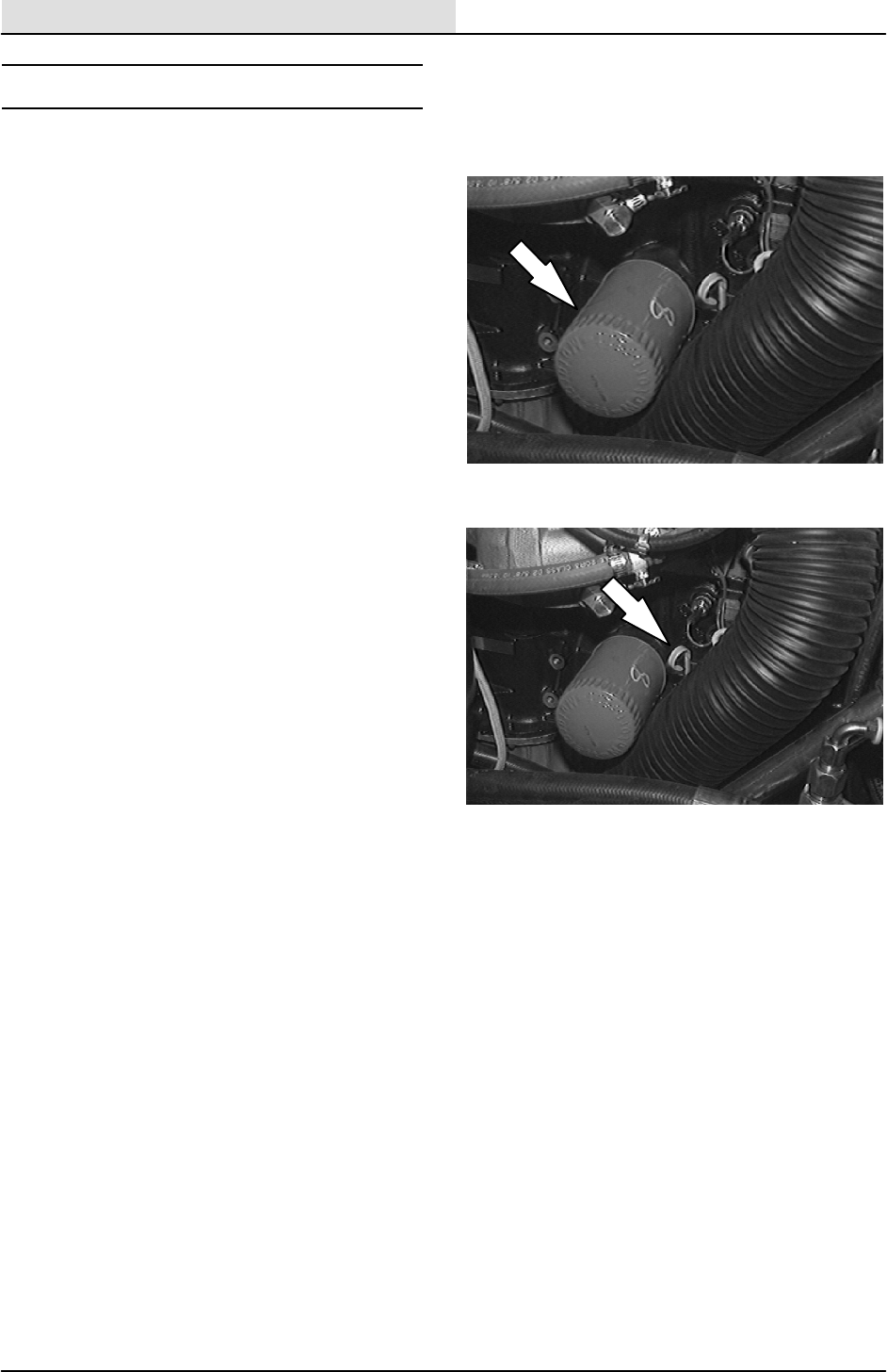
ENGINE--GAS/LP
7-4 8410 MM392 (8--01)
LUBRICATION
ENGINE OIL
Check the engine oil level daily. Change the
engine oil and oil filter every 100 hours of machine
operation. Use 10W30 SAE--SG/SH rated engine
oil.
Fill the engine with oil to the level indicated on the
oil dipstick. The engine oil capacity is 4.7 L
(5 qt) including the oil filter.
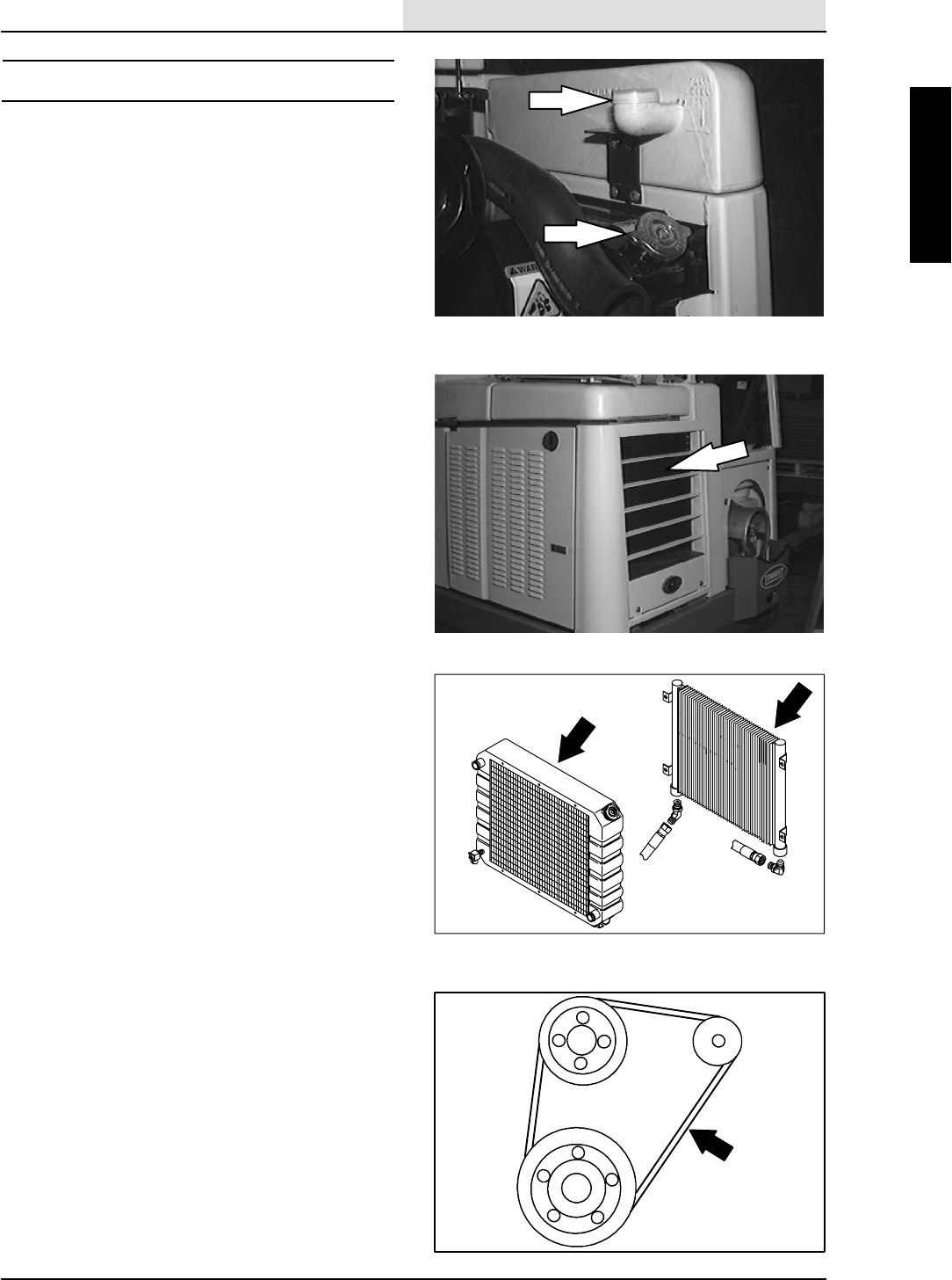
ENGINE--GAS/LP
7-5
8410 MM392 (8--01)
COOLING SYSTEM
RADIATOR
Check the radiator coolant every 100 hours of
operation. Use clean water mixed with a
permanent-type, ethylene glycol antifreeze to a
-- 3 4 _C(--30_F) rating.
FOR SAFETY: When Servicing Machine,
Avoid Contact With Hot Engine Coolant.
ATTENTION! Never pour cold water or
cold antifreeze into the radiator of an
overheated engine. Allow the engine to
cool down to avoid cracking the
cylinder head or block. Keep the engine
running while adding water.
Check the radiator hoses and clamps every
200 hours of operation. Tighten the clamps if they
are loose. Replace the hoses and clamps if the
hoses are cracked, harden, or swollen.
Check the radiator core exterior and hydraulic
cooler fins for debris every 100 hours of
operation. Blow or rinse all dust, which may have
collected on the radiator, in through the grille and
radiator fins, opposite the direction of normal air
flow. The grille and hydraulic cooler open for
easier cleaning. Be careful not to bend the
cooling fins when cleaning. Clean thoroughly to
prevent the fins becoming encrusted with dust.
Clean the radiator and cooler only after the
radiator has cooled to avoid cracking.
FOR SAFETY: When Servicing Machine,
Wear Eye And Ear Protection When
Using Pressurized Air Or Water.
Flush the radiator and the cooling system every
400 hours of operation, using a dependable
cleaning compound.
ENGINE FAN BELT
The engine fan belt is driven by the engine
crankshaft pulley and drives the alternator pulley.
Proper belt tension is 9 to 10 mm (0.35 to 0.39
in) for a new belt and 10 to 11 mm (0.3 to 0.43 in)
for a used belt with a force of 10 kg (22 lb).
Check and adjust the belt tension every 100 hours
of operation.
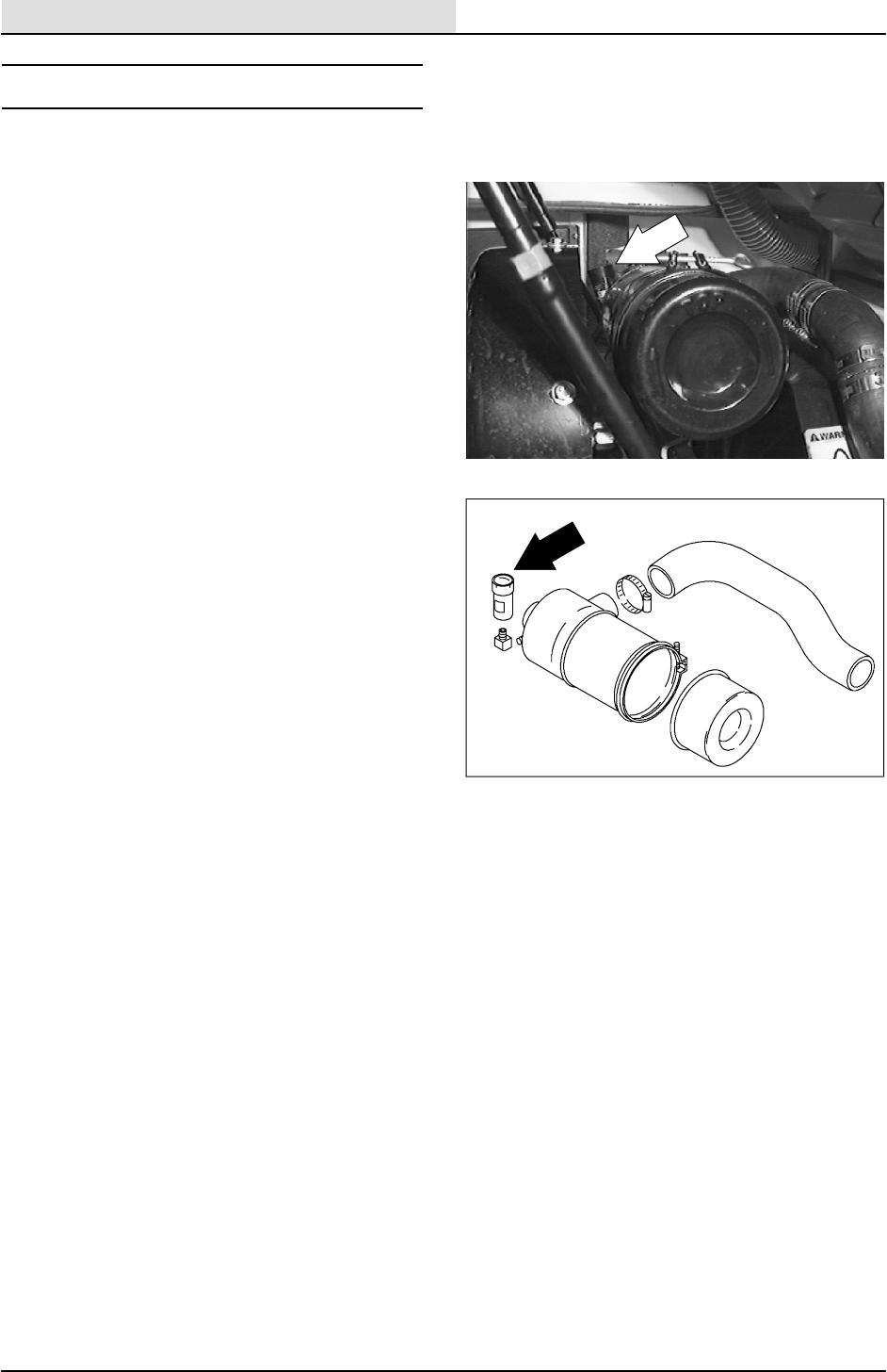
ENGINE--GAS/LP
7-6 8410 MM392 (5--02)
AIR INTAKE SYSTEM
AIR FILTER INDICATOR
The air filter indicator shows when to clean or
replace the air filter element. Check the indicator
daily. The indicator’s red line will move as the air
filter element fills with dirt. Do not clean or replace
the air filter element until the red line reaches 5
kPa (20 in H2O) and the ”SERVICE WHEN RED”
window is filled with red. The indicator’s red line
may return to a lower reading on the scale when
the engine shuts off. The red line will return to a
correct reading after the engine runs for a while.
Reset the air filter indicator by pushing the reset
button on the end of the indicator after cleaning or
replacing the air filter element.
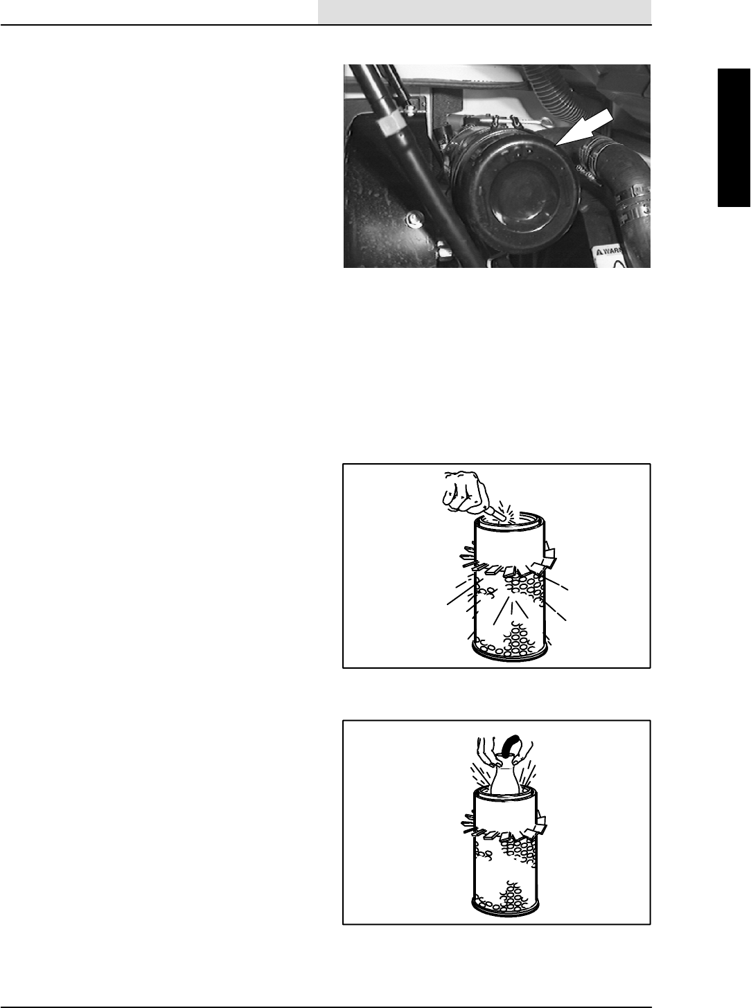
ENGINE--GAS/LP
7-7
8410 MM392 (5--02)
AIR FILTER
The engine air filter housing has a dust cap and a
dry cartridge-type air filter element. Empty the
dust cap daily. The air filter must be replaced
whenever the filter element is damaged or when
the air filter indicator shows a restriction. The air
filters cannot be cleaned.
Machines with the heavy duty air filter option have
a safety element. It is inside the standard
element. Replace, do not clean this element after
the regular element has been damaged or
cleaned three times.
Replace the air filter element only when the air
filter indicator shows restriction in the air intake
system. Do not remove the air filter element from
the housing unless it is restricting air flow.
TO REPLACE AIR FILTER ELEMENT
1. Stop the engine and set the machine parking
brake.
FOR SAFETY: Before Leaving Or
Servicing Machine; Stop On Level
Surface, Set Parking Brake, Turn Off
Machine And Remove Key.
2. Open the left side and top engine access
doors.
3. Unscrew the clamp ring on the filter
assembly.
4. Remove the dust cap.
5. Empty the dust cap.
6. Remove the filter wing nut.
7. Gently pull the filter element out of the filter
housing.
8. Clean the interior of the air cleaner housing
with a damp cloth. Clean the element
housing sealing surfaces.
9. Using an air hose, direct dry, clean air
maximum 205 kPa (30 psi) up and down
pleats on the inside of the filter. Do not rap,
tap, or pound dust out of the element.
FOR SAFETY: When Servicing Machine,
Wear Eye And Ear Protection When
Using Pressurized Air Or Water.
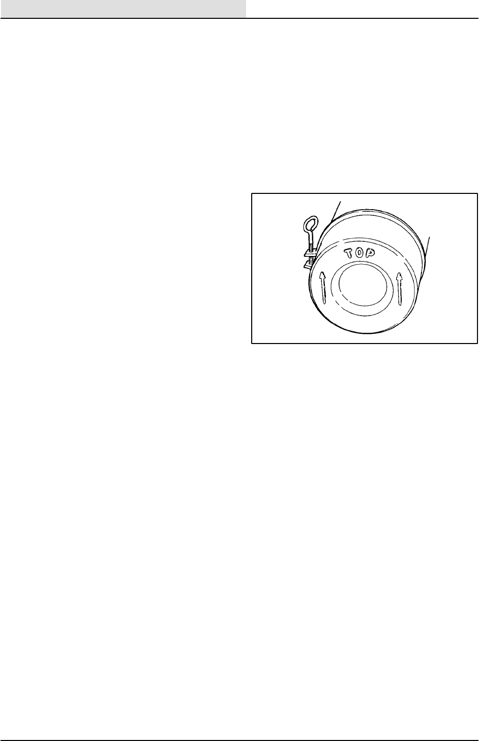
ENGINE--GAS/LP
7-8 8410 MM392 (5--02)
10. After cleaning the air filter element, inspect it
for damage by placing a bright light inside.
The slightest rupture requires replacement
of the filter. Clean and inspect the seals on
the ends of the element. They should be
unbroken and flexible. Remember to replace
the element after cleaning it three times.
11. Install the new or cleaned filter element so
the fins on the element are at the intake end
of the air cleaner. Be careful not to damage
the fins. Make sure the element is seating
evenly. Tighten the element wing nut.
12. Install the dust cap on the air filter housing
with the arrows pointing up. Tighten the
clampringtoholditinplace.Checkall
intake hose connections for leaks or
abrasions.
13. Reset the air filter restriction indicator.
14. Close the access doors.
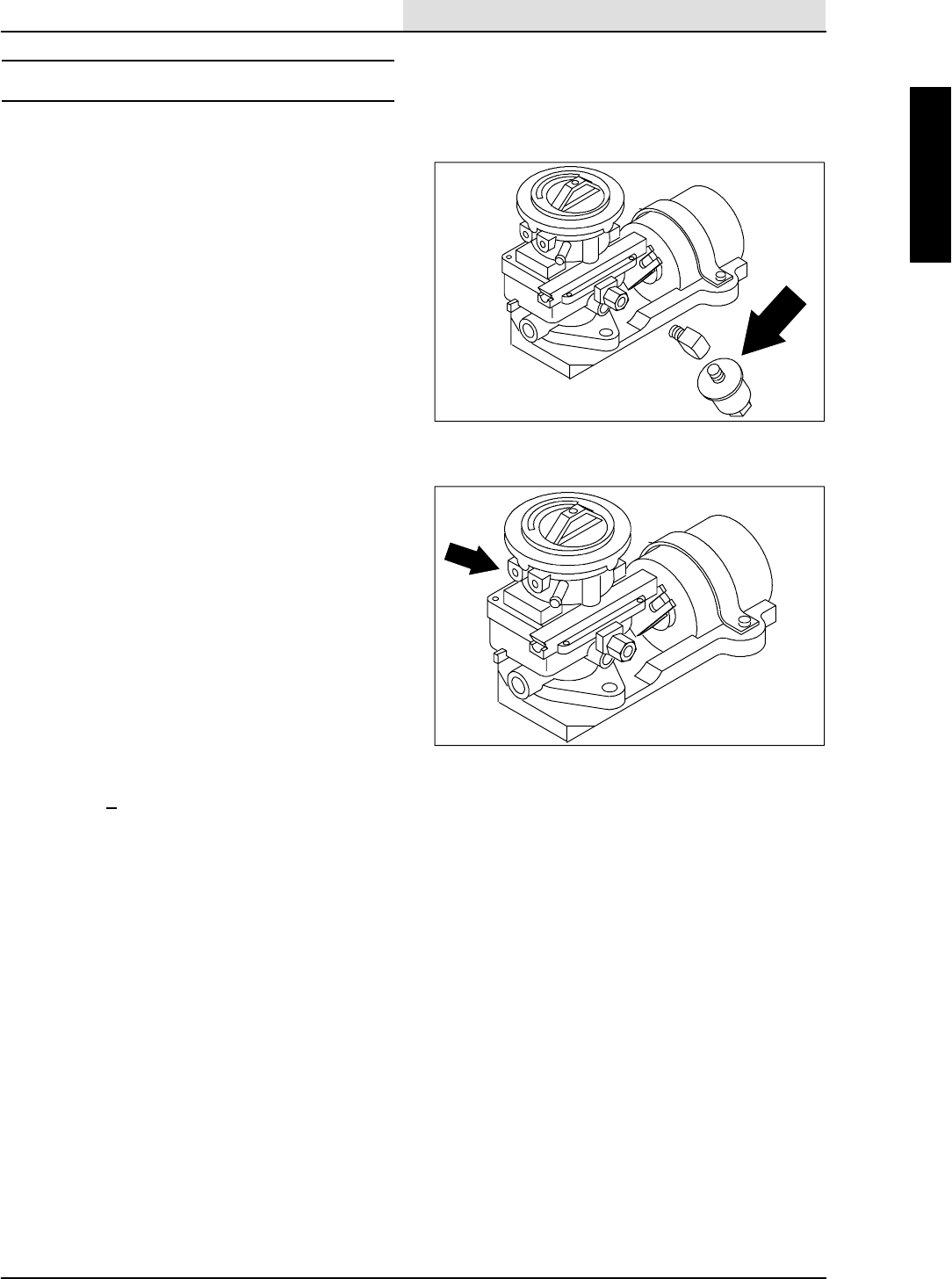
ENGINE--GAS/LP
7-9
8410 MM392 (8--01)
FUEL SYSTEM -- GASOLINE
FUEL FILTERS
The fuel filter trap fuel contaminants. The filter is
located on the fuel line going into the carburetor.
Replace the filter elements every 400 hours of
operation.
CARBURETOR
The carburetor has two basic adjustments. Those
adjustments are idle fuel mixture and idle speed.
Check and adjust idle fuel mixture and idle speed
every 100 hours of operation.
FOR SAFETY: When Servicing Machine,
Keep Flames And Sparks Away From
Fuel System Service Area. Keep Area
Well Ventilated.
The idle speed is controlled by a screw located on
the side of the carburetor next to the throttle
linkage. Increase the engine speed by turning the
screw clockwise. Decrease the engine speed by
turning the screw counter--clockwise. Proper idle
speed is 950 + 50 rpm with all accessories off.
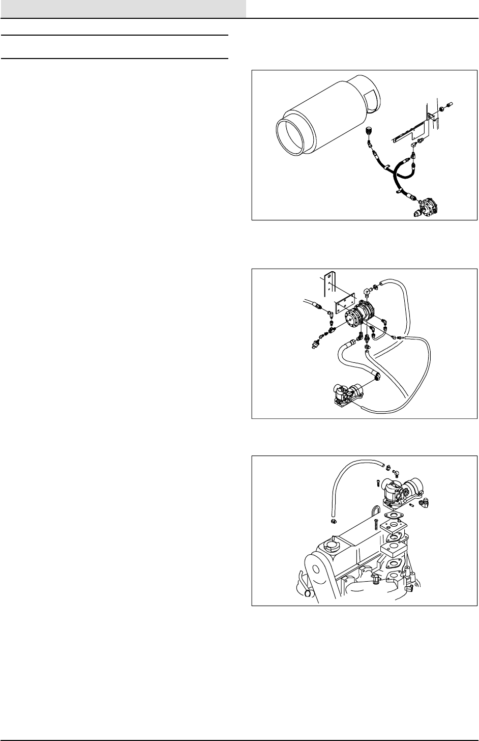
ENGINE--GAS/LP
7-10 8410 MM392 (8--01)
FUEL SYSTEM -- LPG
The liquid withdrawal LPG fuel system has up of
five components: the LPG fuel tank, pressure
relief valve, fuel filter lock, vaporizer-regulator,
and the carburetor.
Liquid LPG fuel flows from the LPG tank under its
own pressure, to the pressure relief valve. Usually
this valve is closed, preventing LPG fuel from
escaping into the atmosphere. The valve opens to
relieve pressure if the fuel pressure exceeds
system limits. From the pressure relief valve, the
liquid LPG fuel flows to the fuel filter lock.
The fuel filter lock filters unwanted tank scale and
deposits out of the LPG fuel. The fuel filter lock
also stops the flow of LPG fuel when the engine is
not operating. The oil pressure switch controls the
fuel filter lock. When the engine oil pressure is 35
kPa (5 psi) or greater, the oil pressure switch
permits an electrical current to open the fuel filter
lock which allows LPG fuel to flow on to the
vaporizer-regulator. The oil pressure switch is
bypassed when the engine is being started,
allowing LPG fuel to flow.
The vaporizer section of the vaporizer-regulator
converts the liquid LPG fuel into a gaseous LPG
fuel. From the vaporizer section, the gaseous
LPG fuel is sent to the primary regulator section
of the vaporizer-regulator. The primary regulator
section reduces the pressure of the LPG fuel. The
secondary regulator section reduces the LPG fuel
pressure to the level required by the carburetor.
From the vaporizer-regulator, the LPG fuel is sent
to the carburetor where it is finally metered into
the air flow sent to the engine combustion
chamber.

ENGINE--GAS/LP
7-11
8410 MM392 (8--01)
Never operate an LPG powered machine if the
LPG fuel system is leaking, or if any component in
the fuel system is malfunctioning. Operating the
machine under either of these conditions may
cause a fire or explosion.
Check for frosting. If frosting occurs on or near
any LPG component, there is a possible LPG fuel
leak or malfunctioning component.
To locate the leak, apply a soapy water solution to
the suspected area. Watch for bubbles forming in
this suspected area. This area may have an LPG
fuel leak. Repair or replace the part. Use Loctite
brand Stainless Steel PST thread sealant when
reassembling. Aging or high humidity does not
affect this epoxy-type sealant. Be sure to follow
application directions and apply proper torque
when reconnecting fittings. Never bypass safety
components except to test. If they are defective,
replace them before operating the machine.
Frosting does not occur before the engine
reaches operating temperature. Check after
engine reaches operating temperature.
Check routings of all LPG hoses. Keep them
away from sharp edges, exhaust manifolds, or
other hot surfaces. Check for signs of abrasion or
deterioration. Replace worn or damaged hoses.
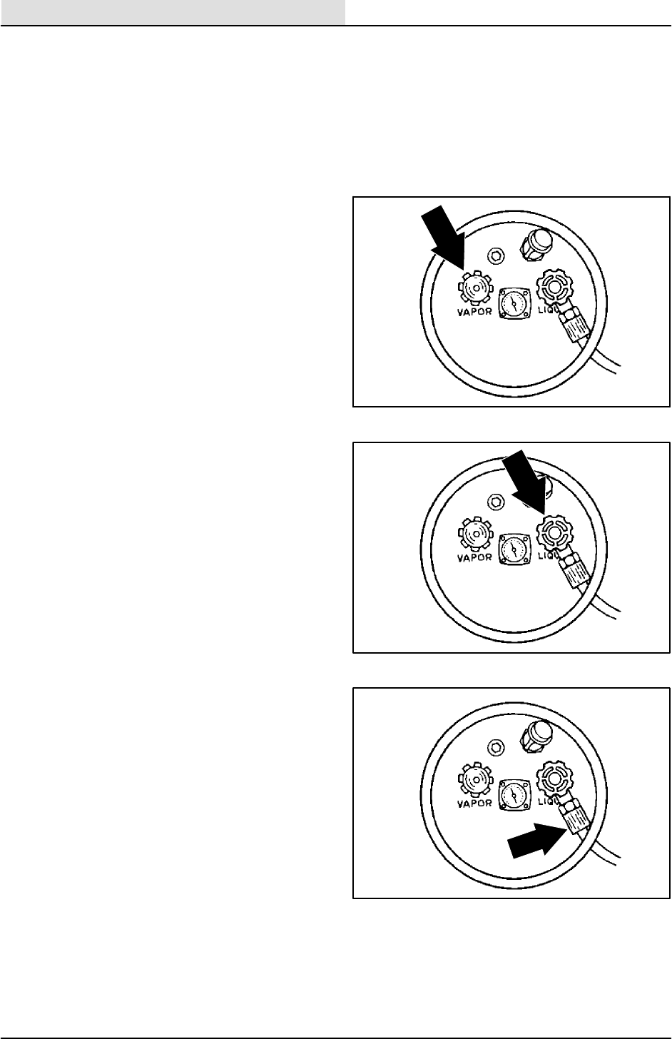
ENGINE--GAS/LP
7-12 8410 MM392 (8--01)
FUEL TANKS
The LPG fuel tanks should be inspected for sharp
dents, gouges, leaks, and broken protecting rings
whenever the tanks are refilled. All tank valves
must be inspected for leaks using a soap solution.
Valves must also be checked for dirt, paint, or
other debris in the valve openings. The following
specific checks must also be made:
Filler Valve -- Check the valve for proper
functioning and the presence of the
handwheel. Valve must be closed except
during filling.
Liquid Service Valves -- Check the valve
for proper functioning and presence of the
handwheel. The valve must be closed
except when in service.
Tank Service Valve Coupling -- Check for
proper functioning, thread condition, and
damaged or missing washers or o-rings.
03485
03485
03485
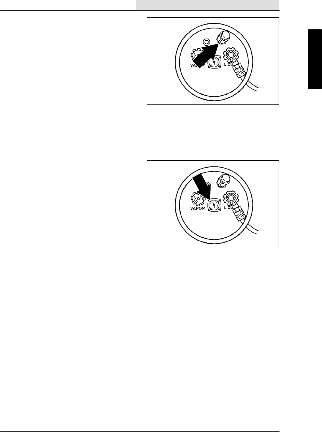
ENGINE--GAS/LP
7-13
8410 MM392 (8--01)
Safety Relief Valve -- Check for damage.
Check for the presence of the relief valve
elbow and the proper direction of the elbow.
If the rain cap is missing, check for foreign
matter and replace the rain cap. Do not
tamper with the relief valve setting.
Magnetic Liquid Level Gauge -- Check the
operation against the maximum filling point
as determined by weight.
An LPG fuel tank with any of the stated defects
must be removed from service and be repaired or
destroyed accordingly.
If an LPG fuel tank is damaged or leaking, it
should be removed to a designated safe area. Do
not attempt to make repairs to the tank,
regardless of condition. Qualified personnel must
make repairs or disposal.
The care an LPG fuel tank receives has a direct
bearing on how long that tank can be used safely.
LPG fuel tanks must not be dropped or dragged
across any surface. To move LPG fuel tanks, use
a hand truck or roll the tank on its foot ring while it
is being held in a position slightly off the vertical.
Whether the storage is inside or outside, fuel
tanks should not be stored near combustible
materials or high temperature sources such as
ovens and furnaces, since the heat may raise the
pressure of the fuel to a point where the safety
relief valves would function. Store the tanks in a
way that if the safety relief valves do function,
they will relieve vapor and not liquid.
Valves on empty tanks must be closed during
storage and transportation.
Similar precautions should be taken in storing
machines fitted with LPG fuel tanks. The
machines may be stored or serviced inside
buildings, provided there are no leaks in the fuel
system and the tanks are not overfilled. While
machines are being repaired inside a building, the
shut-off valve on the tank must be closed, except
when the engine has to be operated.
Changing the tank is a chance for the machine
operator to carefully check over the tank, fittings,
and the fuel lines and fittings. If abnormal wear is
detected, report the findings to the appropriate
personnel.
03485
03485
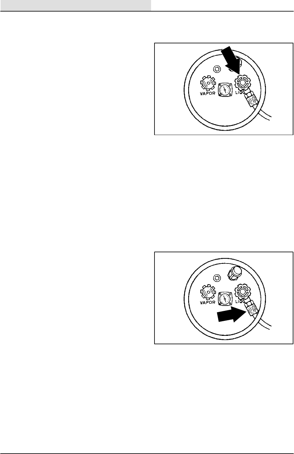
ENGINE--GAS/LP
7-14 8410 MM392 (8--01)
TO CHANGE LPG FUEL TANK
1. Park the machine in a designated safe area.
2. Close the tank service valve.
3. Operate the engine until it stops from lack of
fuel, then set the machine parking brake.
FOR SAFETY: Before Leaving Or
Servicing Machine: Stop On Level
Surface, Set The Parking Brake, Turn Off
Machine And Remove Key.
4. Put on gloves and remove the
quick-disconnect tank coupling.
5. Inspect the LPG fuel lines for wear or
damage.
6. Remove the empty LPG fuel tank from the
machine.
7. Check the tank for damage or wear.
8. Store the tank in a designated, safe area.
9. Select a filled LPG fuel tank and inspect it
for damage or leaks.
NOTE: Make sure the LPG fuel tank matches the
fuel system (liquid tank with liquid system).
10. Carefully put the LPG tank in the machine
so that the tank centering pin enters the
aligning hole in the tank collar.
NOTE: If you cannot line up the centering pin,
make sure you have the correct LPG fuel tank
and then adjust the pin locator in or out.
11. Fasten the tank hold-down clamp to lock the
tank in position.
12. Connect the LPG fuel line to the tank service
coupling. Make sure the service coupling is
clean and free of damage. Also make sure it
matches the machine service coupling.
13. Open the tank service valve slowly and
check for leaks. Close the service valve
immediately if an LPG leak is found, and tell
the appropriate personnel.
14. If no leaks are found, the engine is ready to
start.
03485
03485
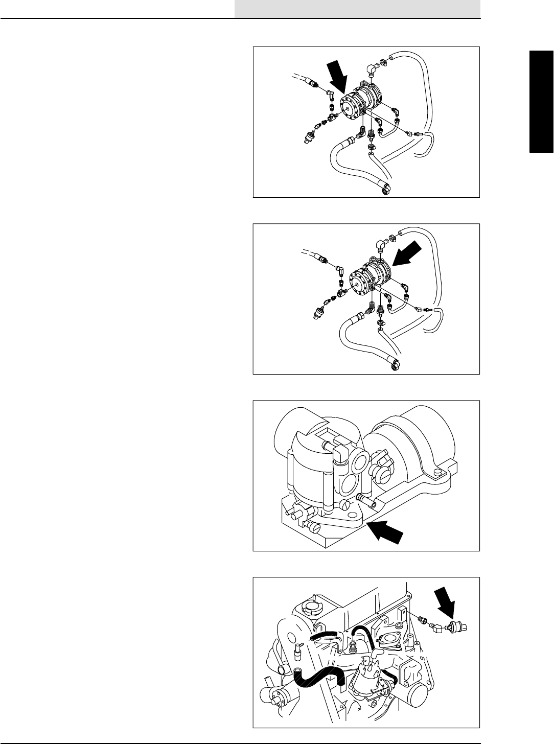
ENGINE--GAS/LP
7-15
8410 MM392 (8--01)
FUEL FILTER LOCK
The fuel filter lock filters the LPG fuel. It also
stops the flow of LPG fuel to the engine when the
engine is not operating or when the engine oil
pressure is less than 35 kPa (5 psi).
VAPORIZER-REGULATOR
The vaporizer-regulator. If any malfunction is
found, completely disassemble the
vaporizer-regulator. Clean all the parts in alcohol.
Inspect all the parts and replace where needed.
Carefully reassemble the vaporizer-regulator with
the seal repair kit. Check for proper operation.
CARBURETOR
The carburetor. If any malfunction is found,
completely disassemble the carburetor. Clean all
the parts in alcohol.
Inspect all the parts and replace where needed.
Carefully reassemble the carburetor with the seal
repair kit.
OIL PRESSURE SWITCH
The engine oil pressure switch requires no regular
maintenance. Never bypass the oil pressure
switch. The switch is a safety feature that
prevents LPG fuel from flowing when the engine
is not operating properly.

ENGINE--GAS/LP
7-16 8410 MM392 (8--01)
LPG FUEL TROUBLESHOOTING
Problem Cause Remedy
Engine will not start Outoffuel Replace fuel tank with full one
Service valve opened too quickly
-- check valve stopped fuel flow
Close service valve and reopen
slowly
Plugged fuel filter Replace filter
Kinked or restricted fuel line Straighten or replace fuel line
Engine out of tune Tune-up engine
Oil pressure switch failure Replace oil pressure switch
Fuel lock valve failure Repair or replace fuel filter lock
Vaporizer-regulator failure Repair or replace
vaporizer-regulator
Engine runs unevenly or lacks
power
Wrong type of fuel tank -- vapor
withdrawal tank
Replace vapor withdrawal tank
with liquid withdrawal tank
Plugged fuel filter Replace filter
Kinked or restricted fuel line Straighten or replace fuel line
Engine out of tune Tune-up engine
Restricted air filter Clean or replace air filter element
Vaporizer-regulator out of
adjustment
Adjust vaporizer-regulator
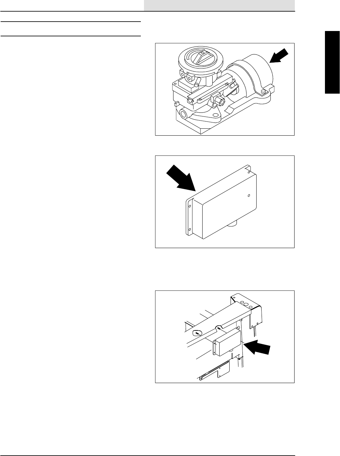
ENGINE--GAS/LP
7-17
8410 MM392 (5--02)
GOVERNOR
The electronic governor controls the engine
speed. The governor consists of an ignition
control assembly, a control box, and an actuator
mounted to the carburetor. The ignition control
assembly and control box regulate the actuator,
which in turn controls the throttle.
The electronic governor is factory set and is not
user serviceable.
TO ADJUST GOVERNOR CONTROL BOX
FOR SAFETY: Before Leaving Or
Servicing Machine: Stop On Level
Surface, Set The Parking Brake.
1. Raise the rear of the machine until the drive
wheel is off the floor.
FOR SAFETY: Block machine tires
before jacking machine up. Jack
machine up at designated locations
only. Block machine up with jack
stands.
2. Start the engine and warm to operating
temperature.
3. Move the speed switch to idle, all
accessories off.
4. Move speed switch to fast position.
5. FOR ANALOG CONTROLLER:
If engine speed surges occur, turn the surge
adjustment screw (located on back of
governor control box under hole plug)
counterclockwise one-eighth of a turn.
Repeat until engine surges do not occur.
Replace the hole plug if removed for
adjustment.
6. FOR DIGITAL CONTROLLER:
Follow the instructions on the Digital
Controller SetUp diagram.
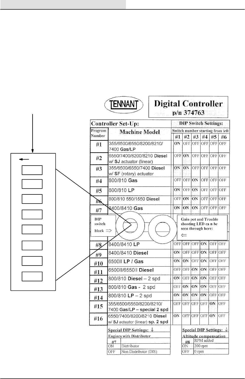
ENGINE--GAS/LP
7-18 8410 MM392 (5--02)
rocker down
O
F
F
Set DIP switches according to
controller label, before installing
controller.
123 45 6 78
DIGITAL CONTROLLER SET -- UP

ENGINE--GAS/LP
7-19
8410 MM392 (8--01)
GOVERNOR TROUBLESHOOTING
1. The first step in this troubleshooting is to
disconnect the throttle linkage at the
carburetor and work the throttle at the
carburetor by hand.
If you can run the engine by hand and it
works with no problems, go to step two.
If the problem continues, it is not with the
governor, it is with the ignition signal, fuel
systems or the engine itself.
2. The idle speed is the governor position. This
is 1100 -- 1500 RPM and is controlled by the
governor, NOT THE IDLE STOP SCREW
ON THE CARBURETOR! In order to adjust
the idle mixture and (SHUTOFF SPEED) on
the carburetor,either of the wires on the
actuator box must be disconnected. After
warming up the engine, adjust the shutoff
speed to 850 ¦25 RPM and adjust the idle
mixture for optimum idle quality. After doing
this, shut off the engine and reattach the
wires to the actuator. It is important that the
shutoff speed not be set any higher than 900
RPM or the engine will (diesel) when it is
shut off. Again, the idle speed screw on the
carburetor does not control the start/idle
speed of a correctly setup engine.
3. Fuel System
A common problem that has been
encountered on LPG machines is a
restricted fuel hose (a clogged fuel filter can
have the same effect).
If the governor opens the carburetor wide
open and the engine loses speed, the
problem is not in the governor. The fuel
system is at fault. The purpose of the
governor is to open the carburetor and to
bring the engine to set RPM’s depending on
where you have the speed control switch set
at.

ENGINE--GAS/LP
7-20 8410 MM392 (8--01)
4. System Grounds
The wire harness grounds are routed to the
stud on the alternator, and from there, a
separate cable is routed to the bolt on the
bell housing where the battery cable is
attached.
If a bad ground is present, the engine will
tend to run over speed.
The machine must have good grounds
throughout from the battery cable to the
control box.
The battery cable must be clean and tight.
The actuator is internally isolated and does
not require that the cable be grounded.
5. Start-Up Check
With the throttle switch in the engine start
position, turn the ignition switch to the on
position. The actuator should cycle the
carburetor lever once.
NOTE: A cycle is to move from the off or idle
position to the open position and then return to
the off or idle position.
If this does not happen, the power wiring to
the control box is probably at fault or the
control box is faulty. IT IS RARE TO HAVE
A FAULTY CONTROL BOX, so proceed
with the following voltage checks BEFORE
REPLACING IT.
6. Throttle Control Switch Check
If the engine doesn’t respond to the throttle
switch control:
a. With the engine running, disconnect
Wire 86, purple wire, at the actuator.
b. Connect a jumper wire from the battery
terminal on the starter to the terminal
where you removed Wire 86, purple
wire, from the actuator.
The engine should come up to operating
speed. If the engine comes up to speed,
replace the throttle control switch.
a. Hunts at running speed with the
accessories off.

ENGINE--GAS/LP
7-21
8410 MM392 (5--02)
b. Responds very sluggishly to switch
changes, an adjustment change in the
control box may be necessary.
FOR ANALOG CONTROLLER:
Cut and remove the RTV seal on the back of
the box.
A slight adjustment of the surge screw may
be necessary to correct the conditions
mentioned above. Turn the screw
approximately 2_at a time and wait for 30
seconds to verify the change. Be careful.
Only a slight change is necessary, and the
“pot” can be broken if too much force is
used.
After the control throttle response is
achieved, verify that the operating speeds
are correct and adjust, if necessary. After
the speeds are reset, the surge screw may
have to be readjusted.
In general, if a new box is being installed, a
gasoline-equipped machine may require that
the sensitivity be reduced slightly.
When the sensitivity is adjusted, the run
speed should not be affected. If the
adjustment is too great, the start speed will
be affected. Verify that the start speed is
correct.
If too much sensitivity is adjusted in, the
engine will either hunt in a no load condition
or over speed severely when the speed
switch is actuated.
The engine speed should not drop off, but
you can have the three hunts of the engine.
If, for some reason, the sensitivity
adjustment became grossly maladjusted, a
good starting point can be obtained by
rotating the pot fully counterclockwise and
then back clockwise 45_.
After the adjustments are made and verified,
reassemble the back plate and reseat the plate
with a bead of RTV to keep dust and moisture out
of the box.
FOR DIGITAL CONTROLLER:
See To Adjust Governor Control Box section
of this manual.

ENGINE--GAS/LP
7-22 8410 MM392 (8--01)
IGNITION SYSTEM
SPARK PLUGS
Clean or replace, and set the gap of the spark
plugs every 400 hours of operation. A wire gauge
is best for checking the spark plug gap. A flat
gauge should not be used unless the electrode
surfaces have been dressed with a small file to
get parallel surfaces between the center and side
electrode. Set the spark plug gap by bending the
side electrode. All spark plugs, new or used,
should have the gaps checked and reset if
necessary.
The proper spark plug gap is 1 mm (0.040 in).
TO REPLACE SPARK PLUGS
FOR SAFETY: Before Leaving Or
Servicing Machine: Stop On Level
Surface, Set The Parking Brake.
1. Open the engine cover and side door.
2. Pull the plug wires off the spark plugs.
NOTE: Before spark plugs are removed; clean
any dirt or grease that has accumulated around
the base of the spark plug.
3. Remove the spark plugs from the engine
cylinder head.
4. Clean the spark plug seat in the cylinder
head.
5. Use a new seat gasket and screw the plug
in by hand.
6. Tighten the spark plugs with a socket
wrench of the correct size.
ENGINE IGNITION TIMING
The engine timing should be set at 10_BTDC with
the throttle set in the idle position.
TIMING BELT
Check the engine timing belt every 800 hours of
operation, and replace the engine timing belt
every 1600 hours of operation.
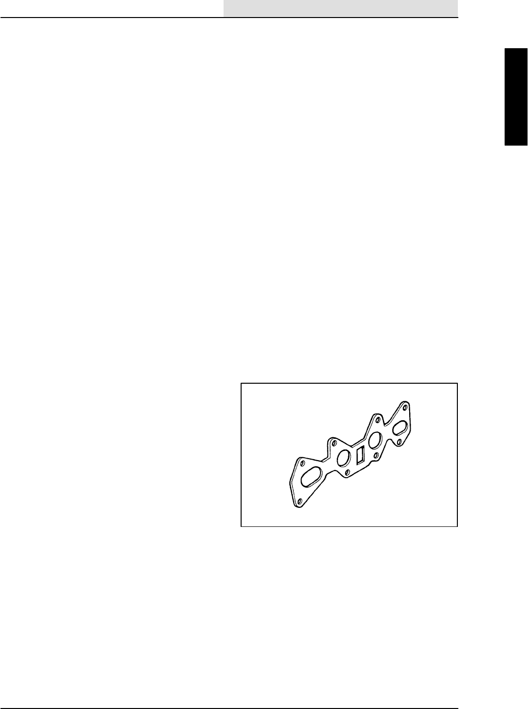
ENGINE--GAS/LP
7-23
8410 MM392 (8--01)
CYLINDER HEAD
A three-stage torque procedure should be used
when reassembling the cylinder head. Tighten the
cylinder head bolts seasonally. See Ford LRG 2.5
Engine Service Manual at the end of this section.
VALVE TAPPET CLEARANCE
The valve tappet clearance must be checked and
adjusted if necessary every 400 hours of
operation. See Ford LRG 2.5 Engine Service
Manual.
Clean the crankcase ventilation hoses, tubes, and
fittings and replace the PCV valve every
400 hours of operation.
CRANKCASE VENTILATION SYSTEM
Replace the PCV valve every 400 hours of
operation. Clean the crankcase ventilation hoses,
tubes, and fittings every 800 hours of operation.
INTAKE MANIFOLD
Tighten the intake manifold bolts or nuts every
800 hours of operation. They are tighten in a two
step sequence. Torque the M8 bolts or nuts to
7to9.5Nm(5to7ftlb)inthefirststep,and
19 to 28.5 Nm (14 to 21 ft lb) in the second step
of torquing.
1
2
3
4
5
6
78
ENGINE--GAS/LP
7-24 8410 MM392 (8--01)
TO CHANGE ENGINE TIMING BELT
FOR SAFETY: Before Leaving Or
Servicing Machine; Stop On Level
Surface, Set Parking Brake, Turn Off
Machine And Remove Key.
1. Disconnect the battery cables from machine.
2. Open the engine cover and side door.
3. Remove the engine spark plugs.
NOTE: Make sure the timing pointer on the timing
belt cover is lined up with the ”O” mark on the
crank shaft damper before removing the timing
belt.
4. Loosen the engine alternator and remove
the V--belt.
NOTE: If the engine is equipped with a smaller
top timing belt cover; it needs to be removed
before the larger timing belt cover can be
removed.
5. Remove the three M6 hex screws and nyloc
nuts holding the smaller top cover to the
engine. Remove and retain the smaller
cover.
6. Remove the crankshaft damper pulley.
7. Pull the belt guide off the end of the
crankshaft where the damper was removed.
8. Remove the five hex screws holding the
large timing belt cover to the engine.
Remove and retain the large cover.
NOTE: The tension on the timing belt needs to be
released before the belt can be removed.
9. Loosen the belt tensioner adjustment screw
and release the tension on the timing belt.
Once the tension is released, re--tighten the
tensioner adjustment screw.
NOTE: A special tension release tool is available
from FORD. The part number is T74P--6254--A. A
small pry bar may be used in place of this tool.
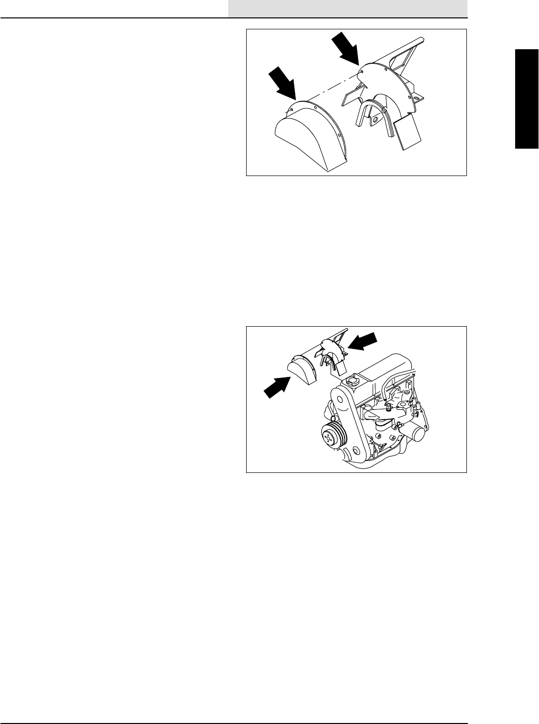
ENGINE--GAS/LP
7-25
8410 MM392 (8--01)
10. Remove the old timing belt from the engine.
11. Before installing a new timing belt, make
sure the camshaft sprocket timing mark lines
up with the timing pointer on the engine.
12. Remove the distributor cap and set the
distributor rotor to number 1 firing position
by turning the auxiliary shaft sprocket.
Reinstall the distributor cap.
13. Install the new timing belt over the
crankshaft sprocket and then
counterclockwise over the the auxiliary and
camshaft sprockets. Align the belt fore and
aft on each sprocket.
14. Loosen the tensioner adjustment bolt to
allow the tensioner to move against the belt.
15. Rotate the crankshaft two complete turns in
normal rotation to remove the slack from the
belt.
16. Re--check the alignment of the timing marks.
17. Reinstall the belt guide and damper to the
crankshaft.
18. Reinstall the timing belt cover and the five
hex screws.
19. Reinstall the small, top cover on the timing
belt cover. Hand tighten the three M6 hex
screws and nyloc nuts.
20. Reinstall the spark plugs.
21. Reinstall the alternator V--belt, pull the
alternator to tension the belt, tighten the
alternator mount bolts.
22. Reconnect the battery cables. Start the
engine and check the timing. The timing
should be set at 10 degrees BTDC with the
engine at idle speed.
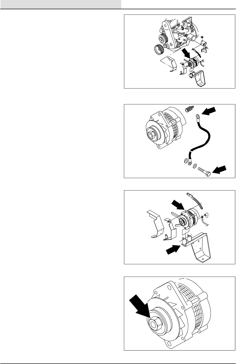
ENGINE--GAS/LP
7-26 8410 MM392 (8--01)
TO REPLACE ALTERNATOR
FOR SAFETY: Before Leaving Or
Servicing Machine; Stop On Level
Surface, Set Parking Brake, Turn Off
Machine And Remove Key.
1. The solution and recovery tanks must be
removed from machine to replace the
alternator. See TO REMOVE SOLUTION
TANK FROM MACHINE instructions in the
SCRUBBING section of this manual.
2. Disconnect the battery cables from the
battery.
3. Open the engine cover and side door.
4. Disconnect the wires on the back of the
alternator.
5. Remove the 0.31 in. hex screw holding the
top of the alternator to the upper mount
bracket. Push the alternator toward the
engine and remove the v--belt.
6. Remove the 0.38 in. hex screw and nyloc
nut holding the bottom of the alternator to
the lower mount bracket.
7. The alternator can now be removed. Bring
the alternator forward and out through the
area of the solution tanks.
8. If the new or rebuilt alternator needs a drive
pulley; remove the pulley from the old
alternator by holding pulley from turning and
using an impact wrench to remove hex nut.
9. Install pulley, washer, and hex nut on the
new alternator. Hand tighten the nut with an
impact wrench.
10. Install the new alternator back in the
machine. Align the bottom hole in the
alternator with hole in the lower mount
bracket. Reinstall the 0.38 in. hex bolt,
washer, and sleeve. Leave loose for now.
11. Place the v--belt back on the alternator
pulley.

ENGINE--GAS/LP
7-27
8410 MM392 (8--01)
12. Reinstall the 0.31 in. hex screw in the top
hole of the alternator through the upper
mounting bracket. Pull alternator toward the
outside of machine to tighten belt. Tighten
the hex screw to 18 -- 24 Nm (13 -- 18 ft lb).
13. The engine fan belt is driven by the engine
crankshaft pulley and drives the alternator
pulley. Proper belt tension is 9 to 10 mm
(0.35 to 0.39 in) for a new belt and
10 to 11 mm (0.39 to 0.43 in) for a used
belt with a force of 10 kg (22 lb).
14. Tighten the bottom 0.38 in. hex screw to
31 -- 40 Nm (27 -- 35 ft lb).
15. Reconnect the wires to the back of
alternator. See the schematic in the
ELECTRICAL section.
16. Reconnect the battery, start the engine, and
check for proper operation of the alternator.
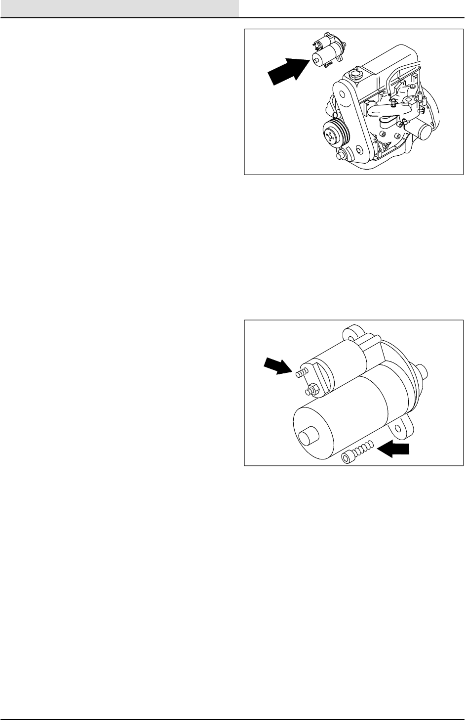
ENGINE--GAS/LP
7-28 8410 MM392 (8--01)
TO REPLACE STARTER
FOR SAFETY: Before Leaving Or
Servicing Machine; Stop On Level
Surface, Set Parking Brake, Turn Off
Machine And Remove Key.
1. Remove all three scrub brushes.
2. If the machine will start, activate the scrub
mode to lower the scrub head. Shut off the
engine. If the machine will not start, place a
drain pan under the middle and left hand
scrub brush motors. Loosen the hydraulic
hoses at the cylinder rod end fittings. Push
the two scrub heads all the way down and
block them in this position using a piece of
wood. Re--tighten the two hydraulic hoses.
3. Disconnect the battery cables from the
battery.
4. Remove the side brush so it will not get
damaged when the rear of the machine is
raised.
5. Raise the rear of machine using a hoist or
floor jack.
FOR SAFETY: Block machine tires
before jacking machine up. Jack
machine up at designated locations
only. Block machine up with jack
stands.
6. The starter must be accessed from under
the machine. Go under from the engine side.
7. The hardware holding the positive battery
cable and starter wires to the starter is
difficult to reach when its bolted in the
engine. Remove the three M10 hex screws
holding the starter to the engine. Use a 17
MM thin wall socket and swivel on the top
screw. Tip the starter down and remove the
hardware holding the cable and wires to
starter.

ENGINE--GAS/LP
7-29
8410 MM392 (8--01)
8. Swing the rear squeegee all the way to the
left and slide the starter out through the
space between the oil pan and the
squeegee link plate.
9. Bring the new starter under machine and
reconnect positive battery cable and starter
wires to it. See the schematic in the
ELECTRICAL section. Hand tighten the
hardware.
10. Position the new starter, with wires
connected, back in the bellhousing. Align the
holes and reinstall the three M10 hex
screws. Tighten to 37 -- 40 Nm
(26--34ftlb).Usea17MMthinwallsocket
and swivel on the top screw.
11. Remove the wood blocks from the middle
and left hand scrub heads. Remove the jack
stands, lower the machine, and reinstall the
side brush.
12. Reconnect battery cables to battery, start
the engine, raise the scrub head and
reinstall the three scrub brushes.
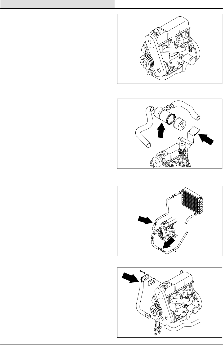
ENGINE--GAS/LP
7-30 8410 MM392 (8--01)
TO REMOVE ENGINE
FOR SAFETY: Before Leaving Or
Servicing Machine; Stop On Level
Surface, Set Parking Brake, Turn Off
Machine And Remove Key.
1. Remove the battery cables from the battery.
2. Remove the engine cover and side door.
3. Drain the radiator.
4. Drain the engine oil.
5. Remove the vacuum fan hose, squeegee
hose, and the air cleaner tube.
6. Remove the air cleaner assembly from the
mounting bracket.
7. Disconnect and plug the hydraulic hoses on
the scrubber vacuum fan motor.
NOTE: Observe hydraulic cleanliness
requirements when opening hydraulic lines.
8. Remove the scrubber vacuum fan assembly.
9. Remove the vacuum fan/air cleaner mount
bracket from the engine.
10. Remove the radiator hoses from the engine.
11. Disconnect the exhaust pipe at the engine
manifold.
12. Disconnect the main electrical wire harness
from all engine components and remove the
clamps holding it to the engine. Place the
harness out of the way.
13. Disconnect the engine ground strap from the
right rear of the bellhousing.
14. On a GAS machine; disconnect the fuel line
at the fuel pump. On an LPG machine;
disconnect line from the lpg tank at the fuel
lockoff / vaporizer assembly.
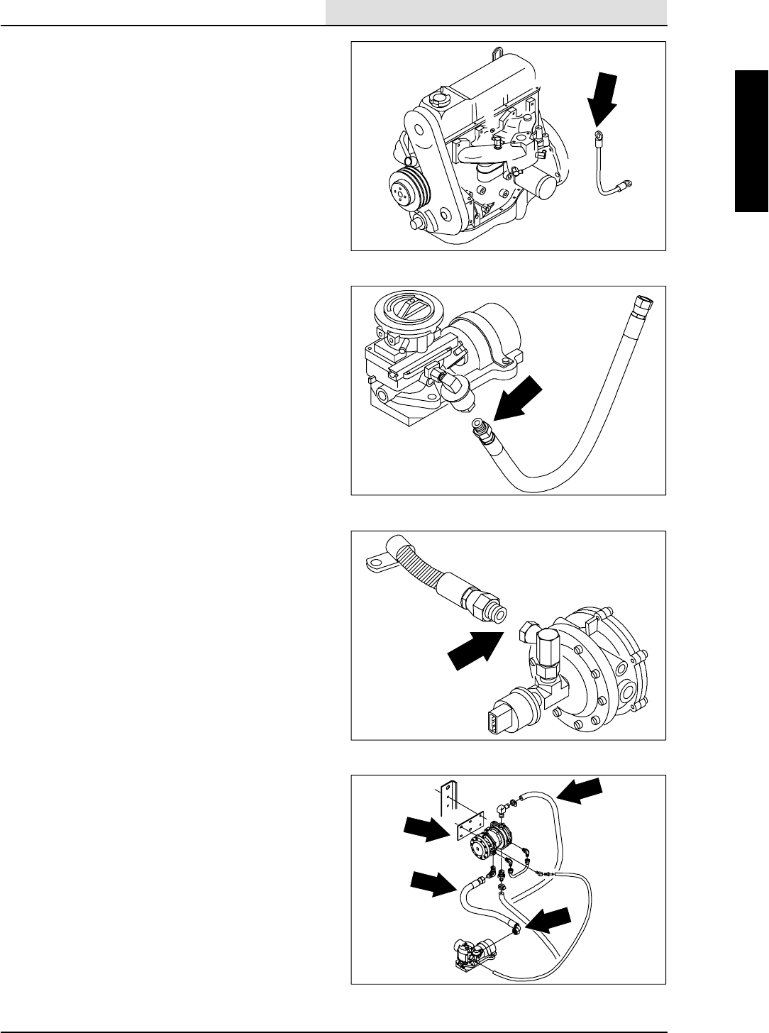
ENGINE--GAS/LP
7-31
8410 MM392 (8--01)
15. On an LPG machine; remove the two
coolant and two fuel lines connected to the
lockoff / vaporizer assembly.
16. Remove the lockoff/vaporizer assembly from
the machine.
17. Remove the left rear grill panel for access to
the hydraulic pump assemblies.
18. Remove the two M12 hex screws holding
the load sensing / propel pump assembly to
the flywheel housing.
19. Pull the load sensing / propel pump
assembly back and out of flywheel housing.
20. Using an overhead hoist; hook a chain
through the two pick--up points on engine.
Put a slight amount of tension on the chain.
21. Remove the four M12 hex screws holding
the motor mounts to the rubber isolators.
22. The engine can now be carefully lifted out.
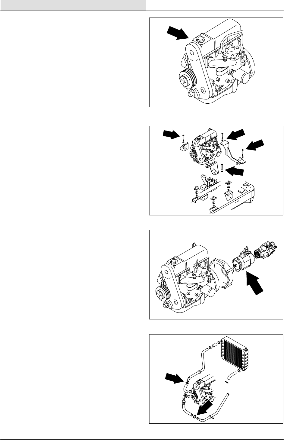
ENGINE--GAS/LP
7-32 8410 MM392 (8--01)
TO INSTALL ENGINE
FOR SAFETY: Before Leaving Or
Servicing Machine; Stop On Level
Surface, Set Parking Brake, Turn Off
Machine And Remove Key.
1. Hook a chain through the two pick--up points
on the engine. Use an over head hoist to lift
the engine in the engine compartment.
2. Carefully lower the engine assembly down
on the motor mounts.
NOTE: Make sure the hoses, wire harness,
exhaust pipe, and load sensing pump are pulled
back out of the way when lowering the engine
assembly in place.
3. Reinstall the M12 hex screws in the four
engine motor mounts. Tighten to 64 -- 83 Nm
(50 -- 60 ft lb).
4. Reconnect the ground cable from the
bellhousing to the machine frame.
5. Reinstall load sensing pump back in the
bellhousing. Reinstall the M12 hex screws.
Tighten to 64 -- 83 Nm (50 -- 60 ft lb).
NOTE: Make sure the splines on pump line up
with splines in coupler when installing pump.
6. Reinstall exhaust pipe back on the engine
manifold. Reinstall the four M10 hex screws.
Tighten to 52 -- 67Nm (39 -- 51 ft lb).
NOTE: Make sure the steel gasket is in place
when installing exhaust pipe.
7. Reconnect the fuel lines.
8. On an LPG machine; reinstall the
lockoff/vaporizer assembly on the machine.
9. On an LPG machine; reconnect the two
coolant and two fuel lines to the
lockoff/vaporizer assembly.
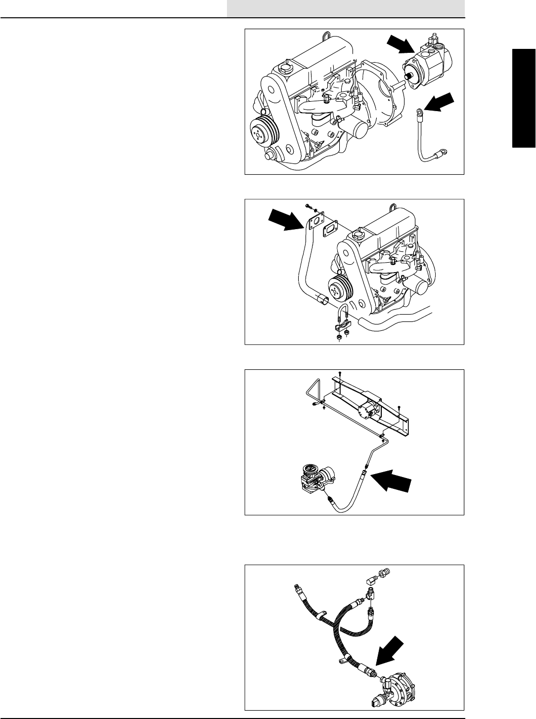
ENGINE--GAS/LP
7-33
8410 MM392 (8--01)
10. Fill the engine with proper grade of motor oil.
11. Reconnect wire harness to the engine
components: alternator, starter, governor
actuator, oil switch, temperature sender,
distributor, and ignition module.
12. Reinstall the radiator hoses to engine and fill
the radiator with coolant.
13. Reinstall the vacuum fan/air cleaner mount
bracket to bellhousing. Reinstall the two M10
hex screws and tighten to 37 -- 48 Nm
(26 -- 34 ft lb).
14. Reinstall the vacuum fan assembly to the
mount bracket. Reinstall the three M10 hex
screws, six washers, and three nyloc nuts.
Tighten to 34 -- 44 Nm (24 -- 28 ft lb).
15. Reconnect the hydraulic hoses to the
scrubbing vacuum fan motor. See the
schematic in the HYDRAULICS section.
16. Reinstall the air cleaner assembly.
17. Reinstall the air cleaner tube, squeegee
vacuum hose, and scrubber vacuum fan
hose.
18. Reinstall the left rear grill panel to the
machine. Reinstall the two M8 hex screws
and washers. Tighten to 18 -- 24 Nm
(15 -- 20 ft lb).
19. Reinstall the engine cover and side door.
20. Reconnect the battery cables to the battery.
21. Jack up the rear of the machine.
FOR SAFETY: Block machine tires
before jacking machine up. Jack
machine up at designated locations
only. Block machine up with jack
stands.
22. Start the engine and check for any leaks.

ENGINE--GAS/LP
7-34 8410 MM392 (8--01)

ENGINE--DIESEL
8-1
8410 MM392 (5--02)
CONTENTS
Page
INTRODUCTION 8-3......................
LUBRICATION 8-4.....................
ENGINE OIL 8-4....................
COOLING SYSTEM 8-4................
RADIATOR 8-4.....................
ENGINE FAN BELT 8-5..............
AIR INTAKE SYSTEM 8-6..............
AIR FILTER INDICATOR 8-6.........
AIR FILTER 8-7.....................
TO REPLACE AIR FILTER
ELEMENT 8-7................
FUEL SYSTEM -- DIESEL 8-9...........
DIESEL FUEL SYSTEM 8-9..........
FUEL FILTER 8-9...................
TO REPLACE THE FUEL FILTER
CARTRIDGE 8-9.................
FUEL LINES 8-10...................
PRIMING THE FUEL SYSTEM 8-10...
TO REPLACE ALTERNATOR 8-12....
TO REPLACE STARTER 8-14........
TO REMOVE ENGINE 8-15..........
TO INSTALL ENGINE 8-17...........
DIESEL ENGINE SERVICE MANUAL
Kubota V2203--B
TENNANT Part Number 73032.

ENGINE--DIESEL
8-2 8410 MM392 (8--01)

ENGINE--DIESEL
8-3
8410 MM392 (8--01)
INTRODUCTION
This section includes repair information on the
engine and related systems, such as fuel,
electrical, and drive belts.
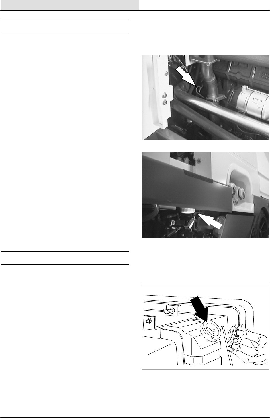
ENGINE--DIESEL
8-4 8410 MM392 (5--02)
LUBRICATION
ENGINE OIL
Check the engine oil level daily. Change the
engine oil and oil filter every 50 hours of machine
operation. Use 10W30 SAE--CC/CD/CE rated
engine oil.
Fill the engine with oil to the level indicated on the
oil dipstick. Low oil level is indicated by the mark
closest to the end of the dipstick. Full level is
indicated by the mark closest to the top of the
dipstick. The engine oil capacity is 6.15 L (6.5 qt)
without the oil filter.
The engine oil filter is mounted on the right side of
the machine frame above the scrub brushes.
COOLING SYSTEM
RADIATOR
Check the radiator coolant level every 100 hours
of operation. Use clean water mixed with a
permanent-type, ethylene glycol antifreeze to a
-- 3 4 _C(--30_F) rating.
FOR SAFETY: When Servicing Machine,
Avoid Contact With Hot Engine Coolant.
ATTENTION! Never pour cold water or
cold antifreeze into the radiator of an
overheated engine. Allow the engine to
cool down to avoid cracking the
cylinder head or block. Keep the engine
running while adding water.
Check the radiator hoses and clamps every 200
hours of operation. Tighten the clamps if they are
loose. Replace the hoses and clamps if the hoses
are cracked, harden, or swollen.
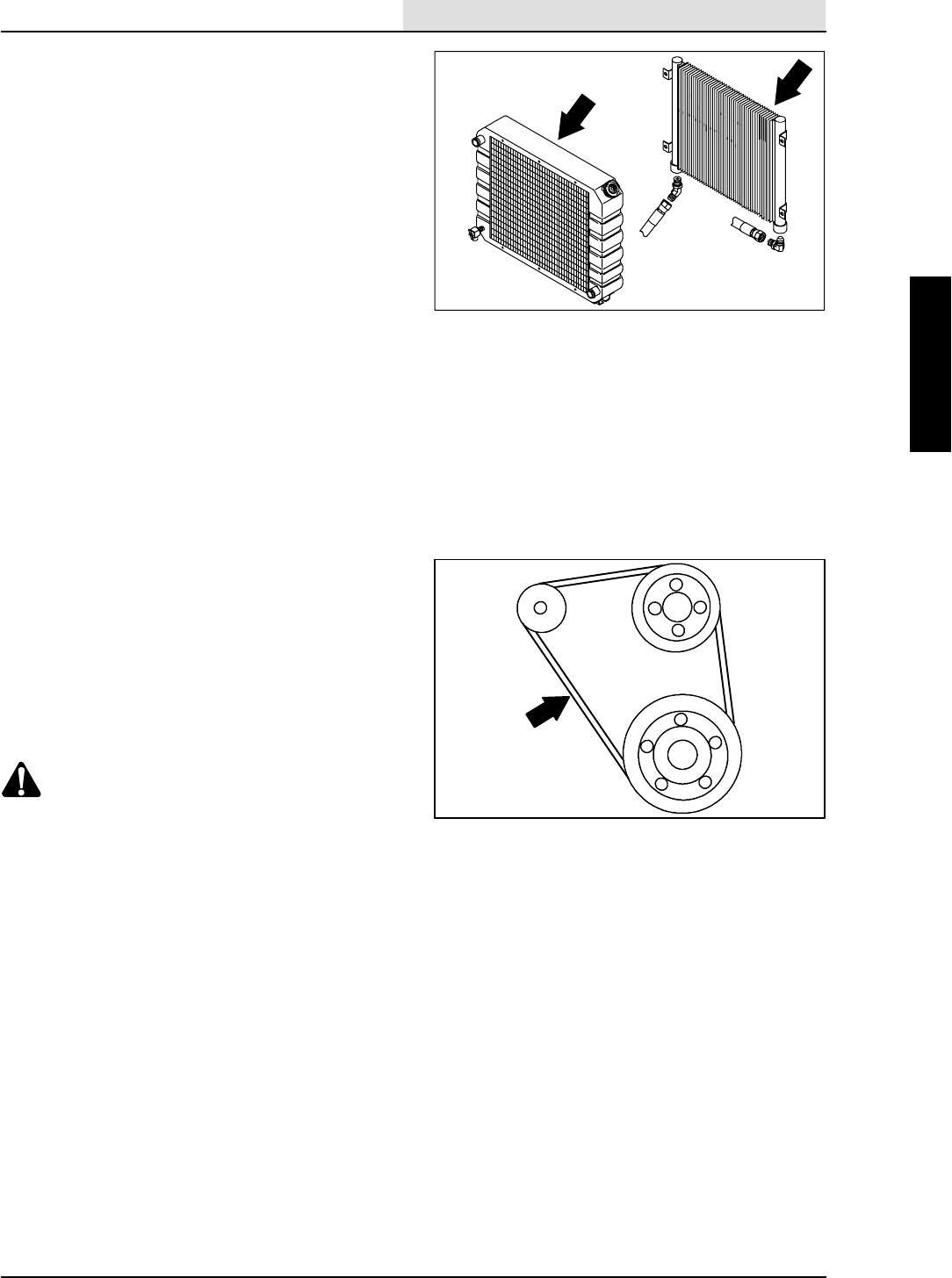
ENGINE--DIESEL
8-5
8410 MM392 (5--02)
Check the radiator core exterior and hydraulic
cooler fins for debris every 100 hours of
operation. Blow or rinse all dust, which may have
collected on the radiator, in through the grille and
radiator fins, opposite the direction of normal air
flow. The grille and hydraulic cooler open for
easier cleaning. Be careful not to bend the cooling
fins when cleaning. Clean thoroughly to prevent
the fins becoming encrusted with dust. Clean the
radiator and cooler only after the radiator has
cooled to avoid cracking.
FOR SAFETY: When Servicing Machine,
Wear Eye And Ear Protection When
Using Pressurized Air Or Water.
Flush the radiator and the cooling system every
400 hours of operation, using a dependable
cleaning compound.
ENGINE FAN BELT
The engine fan belt is driven by the engine
crankshaft pulley and drives the engine water
pump and alternator pulleys. Proper belt tension is
obtained when the belt deflects 7 to 9 mm (0.28 to
0.35 in) from a force of 10 kg (22 lb) applied at the
mid-point of the longest span.
Check and adjust the belt tension every 100 hours
of operation.
WARNING: Moving belt and fan. Keep
away.
08935
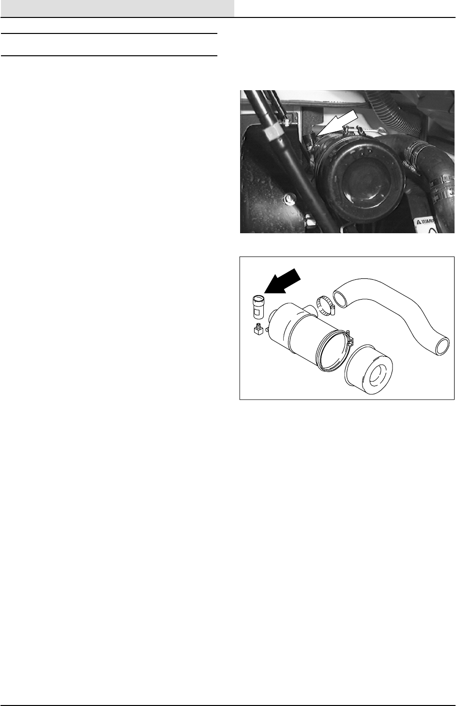
ENGINE--DIESEL
8-6 8410 MM392 (5--02)
AIR INTAKE SYSTEM
AIR FILTER INDICATOR
The air filter indicator shows when to clean or
replace the air filter element. Check the indicator
daily. The indicator’s red line will move as the air
filter element fills with dirt. Do not clean or replace
the air filter element until the red line reaches 5
kPa (20 in H2O) and the ”SERVICE WHEN RED”
window is filled with red. The indicator’s red line
may return to a lower reading on the scale when
the engine shuts off. The red line will return to a
correct reading after the engine runs for a while.
Reset the air filter indicator by pushing the reset
button on the end of the indicator after cleaning or
replacing the air filter element.
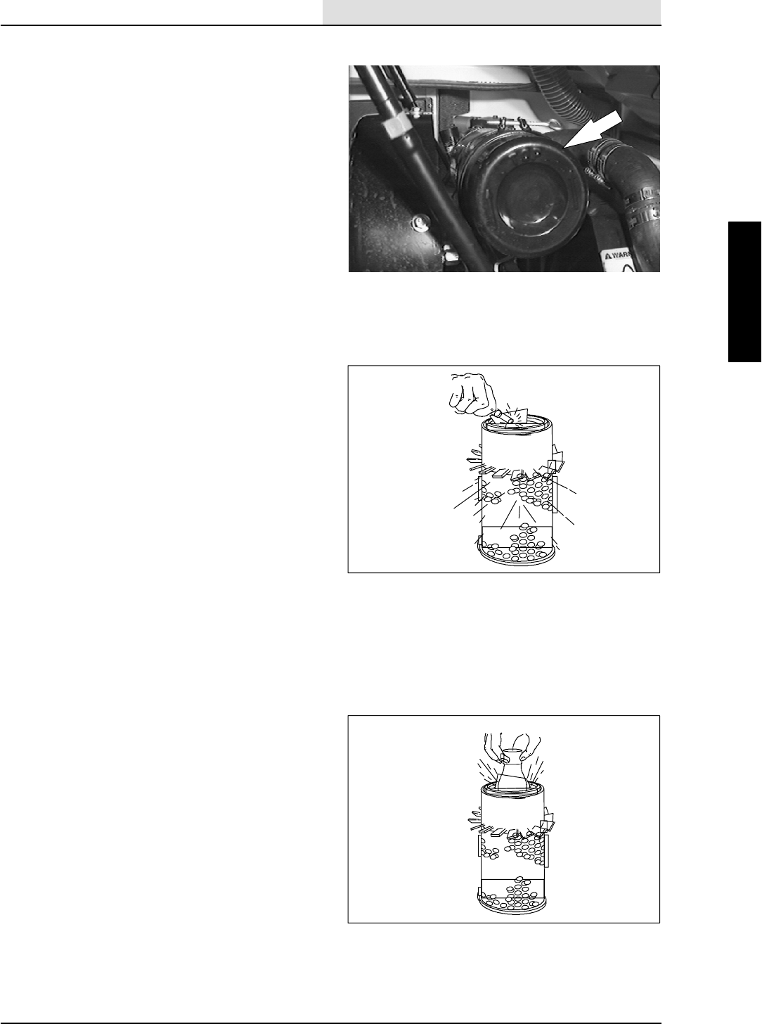
ENGINE--DIESEL
8-7
8410 MM392 (5--02)
AIR FILTER
The engine air filter housing has a dust cap and a
dry cartridge-type air filter element. Empty the
dust cap daily. The air filter must be replaced
whenever the filter element is damaged or when
the air filter indicator shows a restriction. The air
filters cannot be cleaned.
Machines with the heavy duty air filter option have
a safety element. It is inside the standard
element. Replace, do not clean this element after
the regular element has been damaged or
cleaned three times.
Replace the air filter element only when the air
filter indicator shows restriction in the air intake
system. Do not remove the air filter element from
the housing unless it is restricting air flow.
TO REPLACE AIR FILTER ELEMENT
1. Stop the engine and set the machine parking
brake.
FOR SAFETY: Before Leaving Or
Servicing Machine; Stop On Level
Surface, Set Parking Brake, Turn Off
Machine And Remove Key.
2. Open the left side and top engine access
doors.
3. Unscrew the clamp ring on the filter
assembly.
4. Remove the dust cap.
5. Empty the dust cap.
6. Remove the filter wing nut.
7. Gently pull the filter element out of the filter
housing.
8. Clean the interior of the air cleaner housing
with a damp cloth. Clean the element
housing sealing surfaces.
9. Using an air hose, direct dry, clean air
maximum 205 kPa (30 psi) up and down
pleats on the inside of the filter. Do not rap,
tap, or pound dust out of the element.
FOR SAFETY: When Servicing Machine,
Wear Eye And Ear Protection When
Using Pressurized Air Or Water.
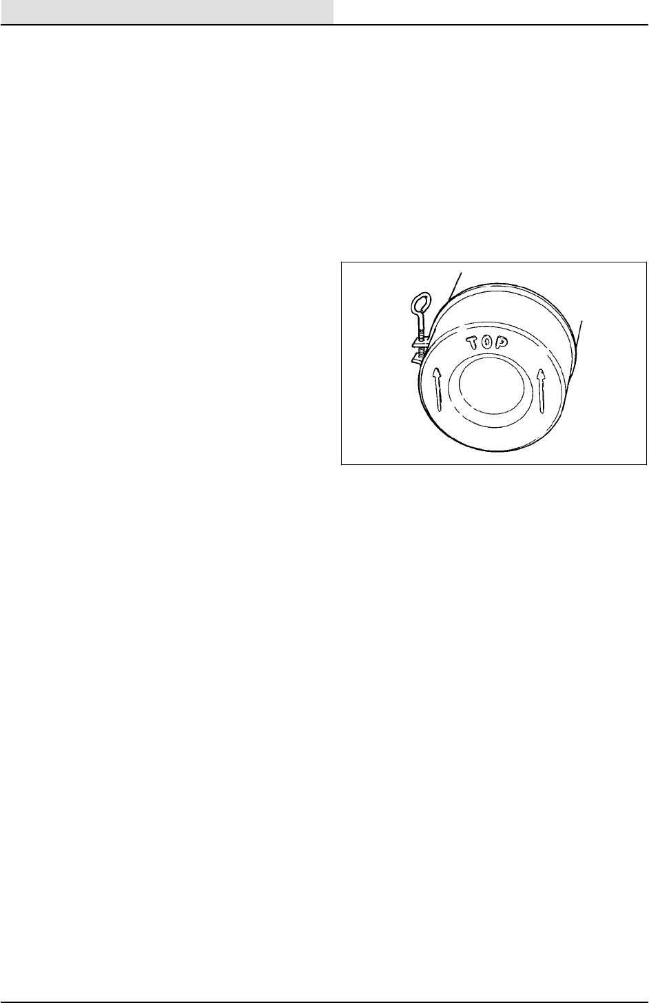
ENGINE--DIESEL
8-8 8410 MM392 (5--02)
10. After cleaning the air filter element, inspect it
for damage by placing a bright light inside.
The slightest rupture requires replacement
of the filter. Clean and inspect the seals on
the ends of the element. They should be
unbroken and flexible. Remember to replace
the element after cleaning it three times.
11. Install the new or cleaned filter element so
the fins on the element are at the intake end
of the air cleaner. Be careful not to damage
the fins. Make sure the element is seating
evenly. Tighten the element wing nut.
12. Install the dust cap on the air filter housing
with the arrows pointing up. Tighten the
clampringtoholditinplace.Checkall
intake hose connections for leaks or
abrasion.
13. Reset the air filter restriction indicator.
14. Close the access doors.
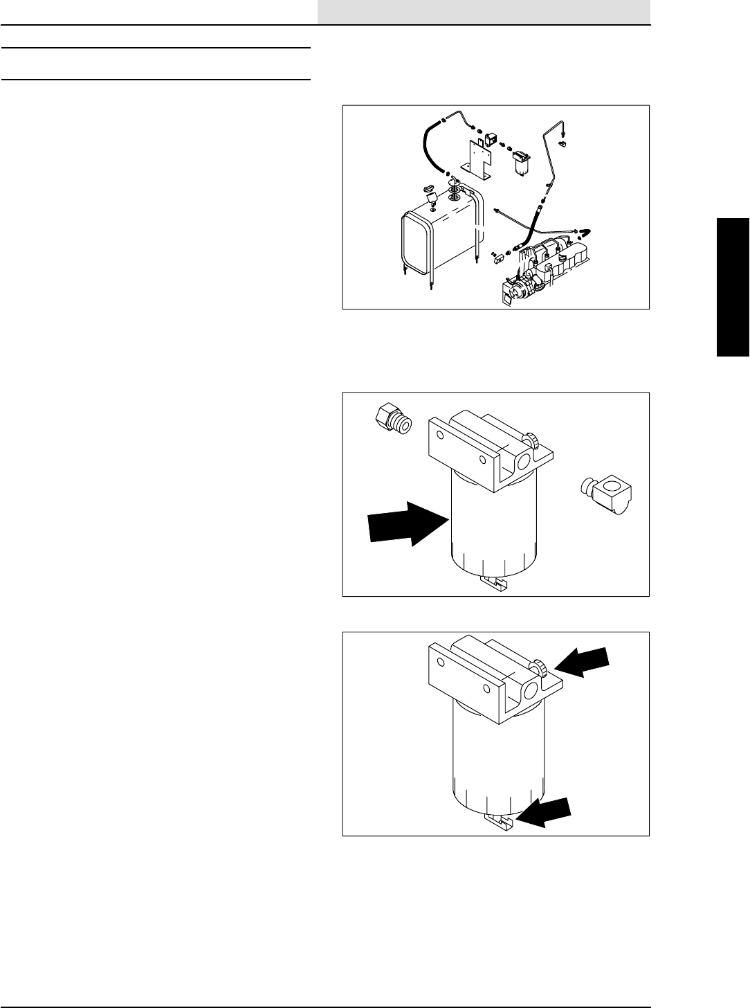
ENGINE--DIESEL
8-9
8410 MM392 (5--02)
FUEL SYSTEM -- DIESEL
DIESEL FUEL SYSTEM
The diesel fuel system is made up of five basic
components which are: fuel tank, fuel filter, fuel
water trap filter, fuel pump, injection pump, and
injectors.
Fuel flows from the fuel tank through the fuel
water trap-filter. The water trap-filter separates
water and impurities from the fuel. From the fuel
water trap-filter, fuel is drawn through the electric
fuel pump and pumped to the injection pump. The
injection pump pressurizes and sends fuel to the
injectors. The injectors atomize and inject proper
amounts of fuel into the combustion chamber at
the proper times. Excess fuel is returned to the
fuel tank through an overflow pipe.
FUEL FILTER
The fuel filter cartridge filters impurities from the
fuel. The filter is located by the fuel tank.
Replace the fuel filter element every 400 hours of
operation.
TO REPLACE THE FUEL FILTER
CARTRIDGE
1. Stop the engine and set the machine parking
brake.
FOR SAFETY: Before Leaving Or
Servicing Machine; Stop On Level
Surface, Set Parking Brake, And Turn
Off Machine.
2. Loosen the unit vent plug and open the
water trap drain to drain diesel fuel.
3. Remove the filter cartridge from the filter
head.
4. Lubricate the o-ring of the new filter
cartridge and spin it onto the filter head.
5. Bleed the fuel lines of air as described in TO
PRIME FUEL SYSTEM instructions.

ENGINE--DIESEL
8-10 8410 MM392 (5--02)
FUEL LINES
Check the fuel lines every 50 hours of operation.
If the clamp band is loose, apply oil to the screw
of the band, and securely tighten the band.
Made of rubber, the fuel lines become worn out
whether the engine has been used much or not.
Replace the fuel lines and clamp bands every two
years.
If the fuel lines and clamp bands are found worn
or damaged before two years’ time, replace or
repair them at once. Bleed the fuel system after
replacement of any of the fuel lines, see
PRIMING THE FUEL SYSTEM instructions.
When the fuel lines are not installed, plug both
ends with clean cloth or paper to prevent dirt from
entering the lines. Dirt in the lines can cause fuel
injection pump malfunction.
PRIMING THE FUEL SYSTEM
Priming the fuel system removes pockets of air in
the fuel lines and fuel components. Air in the fuel
system will prevent smooth engine operation.
Prime the fuel system after running out of fuel,
changing fuel filter elements or repairing a fuel
system component.
1. Stop the engine and set the machine parking
brake.
FOR SAFETY: Before Leaving Or
Servicing Machine; Stop On Level
Surface, Set Parking Brake, And Turn
Off Machine.
2. Make sure the fuel tank is full.
3. Raise the seat up.
4. Unplug the RH tail light from the main
harness.
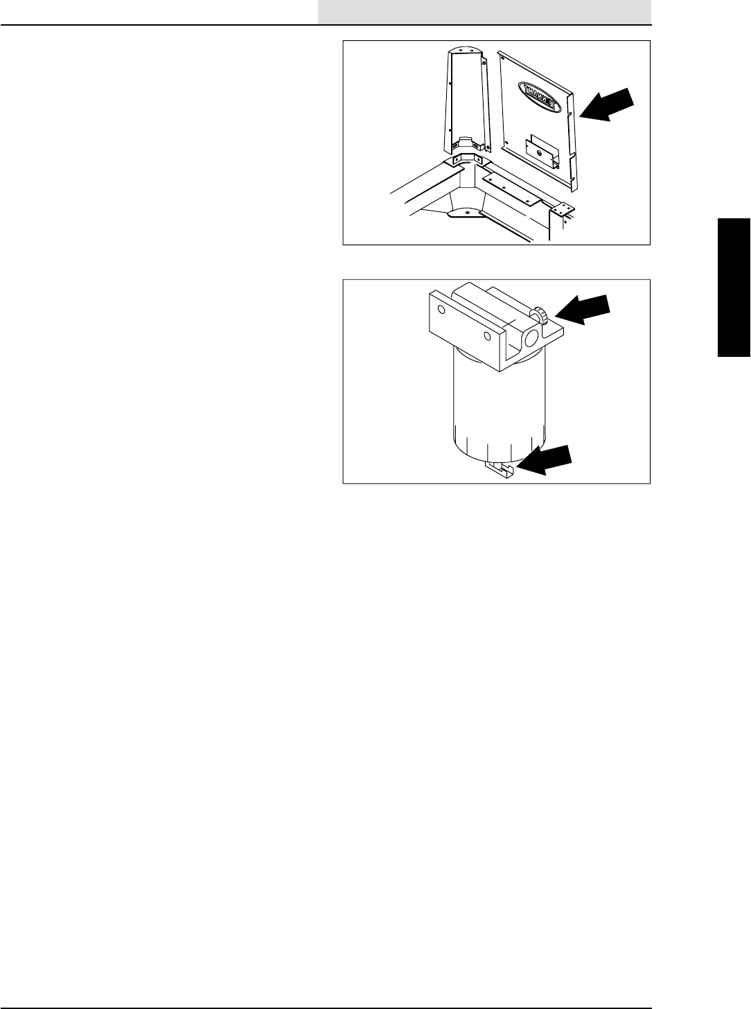
ENGINE--DIESEL
8-11
8410 MM392 (8--01)
5. Loosen the two M8 hex screws holding the
RH rear panel to the center tower.
6. Go to the back of the machine and remove
the two M8 hex screws holding the rear
panel to the RH corner tower.
7. Remove the rear panel for access to the fuel
filter.
8. Open the air vent on top of the fuel filter.
9. Start the engine, operate it for one minute,
then stop it; or operate the starter motor in
ten-second intervals until a steady stream of
fuel flows from the vent.
10. Close the air vent and shut off the engine.
11. Position the RH rear access panel back on
the machine, Reinstall the two M8 hex
screws and tighten to 18 -- 24 Nm
(15 -- 20 ft lb).
12. Go under the seat and tighten the two M8
hex screws to 18 -- 24 Nm (15 -- 20 ft lb).
13. Reconnect the tail light to the main harness.
14. Lower the seat.
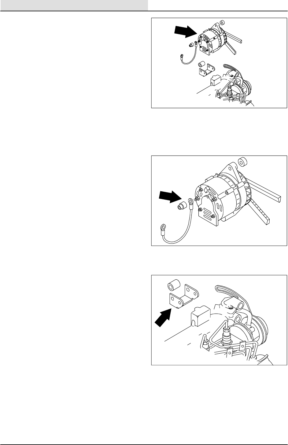
ENGINE--DIESEL
8-12 8410 MM392 (8--01)
TO REPLACE ALTERNATOR
FOR SAFETY: Before Leaving Or
Servicing Machine; Stop On Level
Surface, Set Parking Brake, Turn Off
Machine And Remove Key.
1. Disconnect the battery cables from the
battery.
2. Open the engine cover and side door.
3. Disconnect the wires on the back of the
alternator.
4. Remove the hex screw holding the top of the
alternator to the upper mount bracket. Push
the alternator toward the engine and remove
the v--belt.
5. Remove the hex screw and nyloc nut
holding the bottom of the alternator to the
lower mount bracket.
6. The alternator can now be removed. Bring
the alternator up and out of the machine.
7. If the new or rebuilt alternator needs a drive
pulley; remove the pulley from the old
alternator by holding pulley from turning and
using an impact wrench to remove hex nut.
8. Install pulley, washer, and hex nut on the
new alternator. Hand tighten the nut with an
impact wrench.
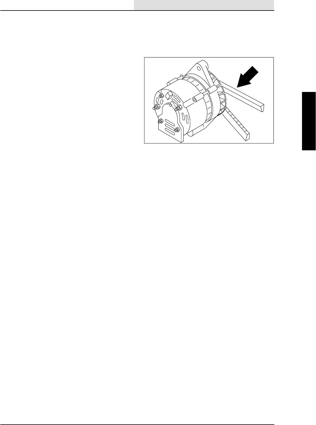
ENGINE--DIESEL
8-13
8410 MM392 (8--01)
9. Install the new alternator back in the
machine. Align the bottom hole in the
alternator with hole in the lower mount
bracket. Reinstall the hex bolt, washer, and
sleeve. Leave loose for now.
10. Place the v--belt back on the alternator
pulley.
11. Reinstall the hex screw in the top hole of the
alternator through the upper mounting
bracket. Pull alternator toward the outside of
machine to tighten belt. Tighten the hex
screw to 18 -- 24 Nm (13 -- 18 ft lb).
12. Tighten the bottom hex screw to
31 -- 40 Nm (27 -- 35 ft lb).
13. Reconnect the wires to the back of
alternator. See the schematic in the
ELECTRICAL section.
14. Reconnect the battery, start the engine, and
check for proper operation of the new
alternator.
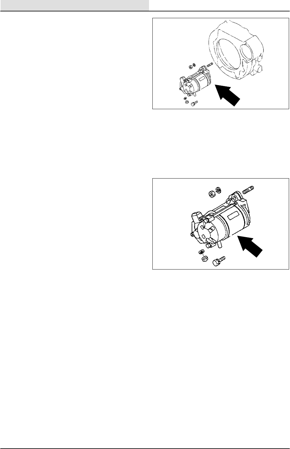
ENGINE--DIESEL
8-14 8410 MM392 (8--01)
TO REPLACE STARTER
FOR SAFETY: Before Leaving Or
Servicing Machine; Stop On Level
Surface, Set Parking Brake, Turn Off
Machine And Remove Key.
1. Disconnect the battery cables from the
battery.
2. Open the engine cover and side door.
3. Remove the vacuum hose from the exhaust
side of scrubbing vacuum fan.
4. Remove the M8 hex nut holding positive
battery cable to the starter. Remove the
cable and unplug the starter wires.
5. Remove one hex nut and one hex screw
holding the starter to the bellhousing.
Remove the starter from machine.
6. Position the new starter back in the
machine. Align the top hole in the starter
with the stud on bellhousing.
7. Reinstall one hex nut and one hex screw.
Firmly hand tighten.
8. Reconnect the battery cable and starter
wires to starter. See the schematic in the
ELECTRICAL section.
9. Reinstall the vacuum hose to the exhaust
side of scrubbing vacuum fan.
10. Reconnect the battery cables to the battery.
Start the engine to check the new starter for
proper operation.
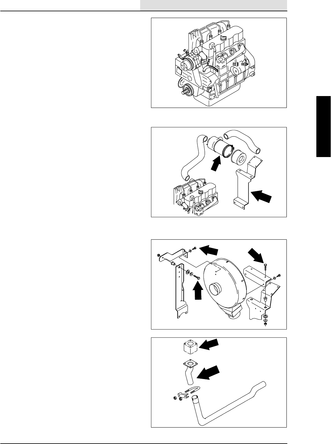
ENGINE--DIESEL
8-15
8410 MM392 (8--01)
TO REMOVE ENGINE
FOR SAFETY: Before Leaving Or
Servicing Machine; Stop On Level
Surface, Set Parking Brake., Turn Off
Machine And Remove Key.
1. Remove the engine cover and side door.
2. Remove the battery cables from the battery.
3. Drain the radiator.
4. Drain the engine oil.
5. Remove the air cleaner assembly from the
mounting bracket.
6. Disconnect and plug the hydraulic hoses on
the scrubber vacuum fan motor.
NOTE: Observe hydraulic cleanliness
requirements when opening hydraulic lines.
7. Remove the scrubber vacuum fan assembly
and vacuum hose.
8. Remove the vacuum fan/air cleaner mount
bracket from the engine.
9. Remove the radiator hoses from the engine.
10. Disconnect the exhaust pipe at the engine
manifold.
11. Disconnect the main electrical wire harness
from all engine components and place it out
of the way.
12. Disconnect the engine ground strap from the
machine frame.
13. Disconnect both the fuel line and the return
line leading from the fuel tank to the engine.
14. Disconnect the throttle cable from the
engine.
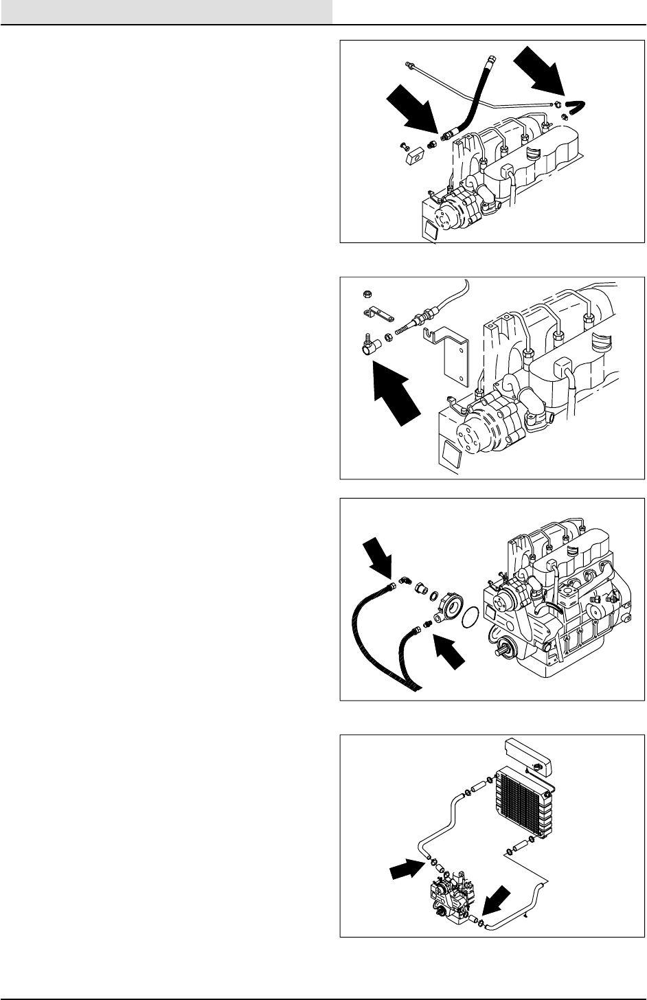
ENGINE--DIESEL
8-16 8410 MM392 (8--01)
15. Disconnect and plug the two engine oil lines,
coming from the remote oil filter, at the
engine oil filter adaptor.
NOTE: Observe engine oil cleanliness
requirements when opening remote filter lines.
16. Remove the LH side panel.
17. Remove the side door mounting bracket
from the machine.
18. Remove the left rear grill panel for access to
the hydraulic pump assemblies.
19. Remove the two M12 hex screws holding
the load sensing / propel pump assembly to
the flywheel housing.
20. Pull the load sensing / propel pump
assembly back and out of flywheel housing.
21. Using an overhead hoist; hook a chain
through the two pick--up points on engine.
Put a slight amount of tension on the chain.
22. Remove the four M12 hex screws holding
the motor mounts to the rubber isolators.
23. The engine can now be carefully lifted out.
NOTE: Be sure to disconnect engine oil drain
hose from oil pan before lifting engine completely
out of the machine.

ENGINE--DIESEL
8-17
8410 MM392 (8--01)
TO INSTALL ENGINE
FOR SAFETY: Before Leaving Or
Servicing Machine; Stop On Level
Surface, Set Parking Brake., Turn Off
Machine And Remove Key.
1. Hook a chain through the two pick--up points
on the engine. Use an over head hoist to lift
the engine in the engine compartment.
2. Carefully lower the engine assembly down
on the motor mounts.
NOTE: Make sure the hoses, wire harness,
exhaust pipe, and load sensing pump are pulled
back out of the way when lowering the engine
assembly in place.
3. Reinstall the M12 hex screws in the four
engine motor mounts. Tighten to 64 -- 83 Nm
(50 -- 60 ft lb).
4. Reconnect the ground cable from the
bellhousing to the machine frame.
5. Reinstall load sensing pump back in the
bellhousing. Reinstall the M12 hex screws.
Tighten to 64 -- 83 Nm (50 -- 60 ft lb).
NOTE: Make sure the splines on pump line up
with splines in coupler when installing pump.
6. Reinstall exhaust pipe back on the engine
manifold. Reinstall the four M10 hex screws.
Tighten to 52 -- 67Nm (39 -- 51 ft lb).
NOTE: Make sure the steel gasket is in place
when installing exhaust pipe.
7. Reconnect the fuel lines.
8. Reconnect the two engine oil lines to the
remote oil filter adaptor on the engine.
NOTE: Observe engine oil cleanliness
requirements when opening remote filter lines.
9. Reconnect the throttle cable to the engine.
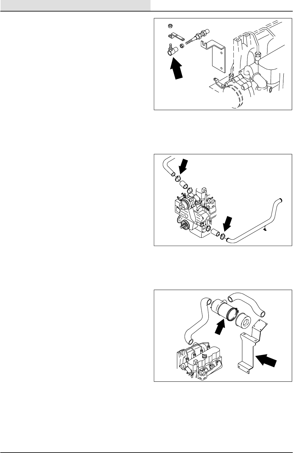
ENGINE--DIESEL
8-18 8410 MM392 (8--01)
10. Fill the engine with proper grade of motor oil.
11. Reconnect wire harness to the engine
components: alternator, starter, oil switch,
temperature sender.
12. Reinstall the radiator hoses to engine and fill
the radiator with coolant.
13. Reinstall the vacuum fan/air cleaner mount
bracket to bellhousing. Reinstall the two M10
hex screws and tighten to 37 -- 48 Nm
(26 -- 34 ft lb).
14. Reinstall the vacuum fan assembly to the
mount bracket. Reinstall the three M10 hex
screws, six washers, and three nyloc nuts.
Tighten to 34 -- 44 Nm (24 -- 28 ft lb).
15. Reconnect the hydraulic hoses to the
scrubbing vacuum fan motor. See the
schematic in the HYDRAULICS section of
this manual.
16. Reinstall the air cleaner assembly.
17. Reinstall the LH side panel using the three
M6 hex screws and washers and two M8
hex screws and washers. Tighten the M6
hex screws to 11 -- 14 Nm (7 -- 10 ft lb).
Tighten the M8 hex screws to 18 -- 24 Nm
(15 -- 20 ft lb).
18. Reinstall the left rear grill panel to the
machine. Reinstall the two M8 hex screws
and washers. Tighten to 18 -- 24 Nm
(15 -- 20 ft lb).
19. Reinstall the engine cover and side door.
20. Reconnect the battery cables to the battery.
21. Jack up the rear of the machine.
FOR SAFETY: Block machine tires
before jacking machine up. Jack
machine up at designated locations
only. Block machine up with jack stands
22. Start the engine and check for any leaks.

We Need Your Help...
As part of Tennant’s Zero Defects Program, we want to know about errors you have
found or suggestions you may have regarding our machine manuals. If you find an
error or have a suggestion, please complete this postage-paid form and mail it to us.
Thank you for helping us make zero defects a way of life at Tennant.
Manual No. Rev. No. Publish Date Page
Machine -Report Error -Suggestion
Name Date
Customer Number
Company
Address
City/State/Zip Code
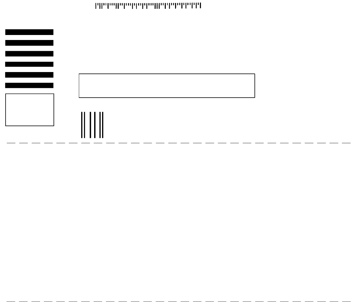
Tape hereFold along dotted lines
NO POSTAGE
NECESSARY
IF MAILED
IN THE
UNITED SATES
BUSINESS REPLY MAIL
FIRST CLASS MAIL PERMIT NO. 94 MINNEAPOLIS, MN
POSTAGE WILL BE PAID BY ADDRESSEE
Technical Publications #15
701 North Lilac Drive
P.O. Box 1452
Minneapolis, MN 55440--9947
TENNANT COMPANY
