ATLV 4300 Service Manual Tennant Rider Floor Sweeper
2018-06-19
: Sweepscrub Tennant-Atlv-4300-Rider-Floor-Sweeper-Service-Manual tennant-atlv-4300-rider-floor-sweeper-service-manual 2765 file product_file
Open the PDF directly: View PDF ![]() .
.
Page Count: 206 [warning: Documents this large are best viewed by clicking the View PDF Link!]
330495
Rev. 03 (5--02)
Service Manual
ATLVt
tt
t4300
*330495*

This service manual is intended to be used as an aid in the detailed service, repair, and troubleshooting of
your TENNANT Model ATLV--4300.
The set is organized into six major groups: General Information, Chassis, Vacuuming, Electrical,
Hydraulics, and Engine--D.
General Information: Safety precautions, machine specifications, machine maintenance chart, machine
tieing, machine jacking, machine storing, machine pushing or towing, and hardware information.
Chassis: Tire/wheel replacement, brake adjustment and replacement, steering adjustment and
replacement.
Vacuuming: Hopper repair/replacement, vacuum head repair/replacement, skirt/seal repair/replacement,
and vacuuming troubleshooting.
Electrical: Battery maintenance and replacement, electrical schematics, and electrical troubleshooting.
Hydraulics: Valve replacement, motor replacement/repair, cylinder replacement/repair, pump
replacement/repair, filter replacement, hydraulic schematic, and hydraulic troubleshooting.
Engine -- D: Air filter replacement, oil changing, cooling system maintenance/repair,
engine troubleshooting, engine removal, and engine repairs.
Manual Number -- 330495
Revision: 03
Published: 5--02
Copyright E1998, 2001, 2002 TENNANT, Printed in U.S.A.

GENERAL INFORMATION
1-1
ATLV 4300 330495 (12--01)
CONTENTS
Page
SAFETY PRECAUTIONS 1-3..............
SPECIFICATIONS 1-6....................
GENERAL MACHINE
DIMENSIONS/CAPACITIES 1-6......
GENERAL MACHINE PERFORMANCE 1-6
POWER TYPE 1-7.....................
STEERING 1-7
HYDRAULIC SYSTEM 1-7..............
BRAKING SYSTEM 1-7................
TIRES 1-7............................
MACHINE DIMENSIONS 1-8............
MAINTENANCE 1-10.....................
MAINTENANCE CHART 1-10...........
PUSHING, TOWING, AND
TRANSPORTING THE MACHINE 1-12
PUSHING OR TOWING THE
MACHINE 1-12..................
TRANSPORTING THE MACHINE 1-13
MACHINE JACKING 1-15...............
STORING MACHINE 1-15..............
HARDWARE INFORMATION 1-16..........
STANDARD BOLT TORQUE CHART 1-16
METRIC BOLT TORQUE CHART 1-16...
BOLT IDENTIFICATION 1-16............
THREAD SEALANT AND LOCKING
COMPOUNDS 1-16.................
HYDRAULIC FITTING INFORMATION 1-17..
HYDRAULIC TAPERED PIPE FITTING
(NPT) TORQUE CHART 1-17........
HYDRAULIC TAPERED SEAT FITTING
(JIC) TORQUE CHART 1-17.........
HYDRAULIC O--RING FITTING TORQUE
CHART 1-17.......................

GENERAL INFORMATION
1-2 ATLV 4300 330495 (8--94)

GENERAL INFORMATION
1-3
ATLV 4300 330495 (5--02)
SAFETY PRECAUTIONS
The following symbols are used throughout this
manual as indicated in their description:
WARNING: To warn of hazards or
unsafe practices that could result in
severe personal injury or death.
FOR SAFETY: To identify actions that
must be followed for safe operation of
equipment.
The machine is suited to vacuum disposable
debris. Do not use the machine other than
described in this Operator Manual.
WARNING: Machine Can Emit Excessive
Noise. Consult With Your Regulatory
Agency For Exposure Limits. Hearing
Loss Can Result. Wear Hearing
Protection.
WARNING: Moving fan blades. Keep
away.
WARNING: Sharp objects in debris
canister. Wear gloves.
WARNING: Spinning fan. Stop engine
before opening debris canister.
WARNING: Engine Emits Toxic Gases.
Severe Respiratory Damage Or
Asphyxiation Can Result. Provide
Adequate Ventilation. Consult With Your
Regulatory Agency For Exposure
Limits. Keep Engine Properly Tuned.
The following information signals potentially
dangerous conditions to the operator or
equipment:
FOR SAFETY:
1. Do not operate machine:
-- Unless trained and authorized.
-- Unless operation manual is read and
understood.
-- In flammable or explosive areas unless
designed for use in those areas.
-- In areas with possible falling objects
unless equipped with overhead guard.
2. Before starting machine:
-- Make sure all safety devices are in
place and operate properly.
-- Check brakes and steering for proper
operation.
3. When starting machine:
-- Keep foot on brake and directional
pedal in neutral.
4. When using machine:
-- Use brakes to stop machine.
-- Go slowly on inclines and slippery
surfaces.
-- Use care when reversing machine.
-- Do not carry riders on machine.
-- Always follow safety and traffic rules.
-- Report machine damage or faulty
operation immediately.
5. Before leaving or servicing machine:
-- Stop on level surface.
-- Set parking brakes.
-- Turn off machine and remove key.
6. Before Opening Or Emptying Hopper:
-- Stop on level surface.
-- Set parking brakes.
-- Turn off vacuum.
-- Turn off machine and remove key.
7. When servicing machine:
-- Avoid moving parts. Do not wear loose
jackets, shirts, or sleeves.
-- Block machine tires before jacking
machine up.
-- Jack machine up at designated
locations only. Block machine up with
jack stands.
-- Use hoist or jack that will support the
weight of the machine.
-- Wear eye and ear protection when
using pressurized air or water.
-- Disconnect battery connections before
working on machine.
-- Avoid contact with battery acid.
-- Avoid contact with hot engine coolant.
-- Allow engine to cool.
-- Keep flames and sparks away from
fuel system service area. Keep area
well ventilated.
-- Use cardboard to locate leaking
hydraulic fluid under pressure.
-- Use TENNANT supplied or approved
replacement parts.

GENERAL INFORMATION
1-4 ATLV 4300 330495 (5--02)
8. When loading/unloding machine onto/off
truck or trailer:
-- Use truck or trailer that will support
the weight of the machine.
-- Use Winch. Do not drive the machine
onto/off the truck or trailer unless the
load height is 380 mm (15 in) or less
from the ground.
-- Set parking brake after machine is
loaded.
-- Block machine tires.
-- Tie machine down to truck or trailer.

GENERAL INFORMATION
1-5
ATLV 4300 330495 (6--01)
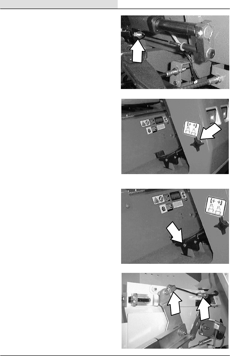
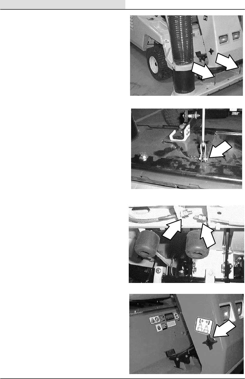
The following safety labels are mounted on the
machine in the locations indicated. If these or any
label becomes damaged or illegible, install a new
label in its place.
SHARP OBJECTS HAZARD LABEL -- Located
On The Air Deflector.
EMISSIONS LABEL -- Located
Below The Operator’s Seat.
FOR SAFETY LABEL --
Located Below The Operator Seat.
FAN WARNING LABEL --
Located In The Engine
Compartment.
NOISE WARNING LABEL -- Located
Below The Operator’s Seat.
MOVING FAN HAZARD LABEL-- Located
On The Debris Canister.

GENERAL INFORMATION
1-6 ATLV 4300 330495 (12--01)
SPECIFICATIONS
GENERAL MACHINE DIMENSIONS/CAPACITIES
Item Dimension/capacity
Length 2590 mm (102 in)
Width 168 mm (46 in)
Height 2113 mm (83 in)
Track 965 mm (38 in)
Wheelbase 1320 mm (52 in)
Hopper weight capacity 68 kg (150 lb)
Hopper volume capacity 416 L (110 gal )
Water dust control tank capacity (option) 30L(8gal)
GVWR 910 kg (2600 lb)
Axle rating (front and rear) 680 kg (1500 lb)
GENERAL MACHINE PERFORMANCE
Item Measure
Maximum forward speed 26 kmh (16 mph)
Maximum reverse speed 8 kmh (5 mph)
Minimum isle turn 4064 mm (160 in)
Minimum turning radius 457 mm (18 in)
Maximum rated climb and descent angle 12_/ 21% Empty or Full hopper

GENERAL INFORMATION
1-7
ATLV 4300 330495 (6--01)
POWER TYPE
Engine Type Ignition Cycle Aspiration Cylinders Bore Stroke
Kubota Piston Diesel 4Natural 378 mm
(3.07 in)
78.5mm
(3.09 in)
Displacement Net power, governed Net power, maximum
1.1L(60.9cuin) 20.9 kw (28 hp) @ 3000 rpm
Turbo engine--28.0 kw
(38 hp)@ 3000
20.9 kw (28 hp) @
3000 rpm
Turbo engine--28.0 kw
(38 hp)@ 3000
Fuel Cooling system Electrical system
Diesel Fuel tank: 31.42 L
(8.3 gal)
Water/ethylene glycol
antifreeze
12 V nominal
Total:4L(1gal) 30 A alternator
12V Battery -- 730 cca
Idle speed, no load Governed speed, under load
1200 rpm 3000 rpm maximum
Engine lubricating oil with filter
5.2 L (5.5 qt) 10W30 SAE--CD/SE rated engine oil
STEERING
Type Power source Emergency steering
Front wheels, hydraulic cylinder,
steering rod
Hydraulic accessory pump Manual
HYDRAULIC SYSTEM
System Capacity Fluid Type
Hydraulic reservoir 19L(5gal) TENNANT part no. 65869 -- above 7_C(45_F)
Hydraulic total 21 L (5.5 gal) TENNANT part no. 65870 -- below 7_C(45_F)
BRAKING SYSTEM
Type Operation
Service brakes Cable actuated disc brakes, one per each rear
wheel
Parking brake Utilize service brakes on rear wheels, cable
actuated
TIRES
Location Type Size Ply Rating Pressure
Front (2) Pneumatic 216 mm (8.5 in) x
457 mm (18 in)
4Ply 152 kPa (22 psi)
Rear (2) Pneumatic 216 mm (8.5 in) x
584 mm (23 in)
4Ply 124 kPa (18 psi)
Rear (2) (Optional) Pneumatic Traction 216 mm (8.5 in) x
584 mm (23 in)
4Ply 48 kPa (7 psi)

GENERAL INFORMATION
1-8 ATLV 4300 330495 (6--01)
ATLV 4300
2113 mm
(83 in)
168 mm
(46 in)
2590 mm
(102 in)
1320 mm
(52 in)
965 mm
(38 in)
MACHINE DIMENSIONS

GENERAL INFORMATION
1-9
ATLV 4300 330495 (12--01)

GENERAL INFORMATION
1-10 ATLV 4300 330495 (12--01)
MAINTENANCE
1
2
3
7
8
4
5
6
9
11
13
12
14
10
15
MAINTENANCE CHART
Interval Key Description Procedure
Lubricant/
Fluid
No. of
Service
Points
Daily 1Engine air filter Check indicator -- 1
y
Engine dust cap Empty -- 1
Engine crankcase Check oil level EO 1
2Radiator Check and clean inlet screen -- 1
Check coolant level in overflow
reservoir
WG 1
10 Vacuum hose support arm Check for damage and wear -- 3
p
p
Check gas cylinders for wear -- 2
7Vacuum head skirts (option) Check for damage and wear -- 1
8Vacuum head (option) Check for damage, wear, and
adjustment
-- 1
Check for blockage -- 1
9Vacuum hose Check for damage and blockage -- 1
4Vacuum fan screen Check for debris and clean -- 1
Vacuum bag Check for debris and clean -- 1
Dust filter bag (option) Check for debris and clean -- 1
Dust panel filter (option) Check for debris and clean -- 1
Water dust control (option)
spray nozzle
Check for debris and
adjustment
-- 1

GENERAL INFORMATION
1-11
ATLV 4300 330495 (12--01)
Interval Key Description Procedure
Lubricant/
Fluid
No. of
Service
Points
50 Hours 5Fuel lines and clamps Check for tightness and wear 4
2Radiator core Check and clean -- 2
3Hydraulic cooler core Check and clean -- 1
6Tires Check pressure -- 4
100 Hours 1Engine crankcase HChange oil and filter element EO 1
Engine fan belt Check tension -- 1
Engine air filter Replace -- 1
Hydraulic reservoir Check fluid level -- 6
4Vacuum bag Check for wear and damage -- 1
Dust panel filter (option) Check for wear and damage -- 1
200 Hours 2Radiator hoses and clamps Check for tightness and wear -- 2
11 Steering cylinder Lubricate steering cylinder SPL 2
13 Brakes Check brake adjustment -- 2
12 Wheel pivot points Lubricate pivots SPL 2
5Fuel filter Replace -- 1
5Fuel screen Clean -- 1
6Tires Check wear and rotate -- 4
3Hydraulic hoses Check for wear and damage -- All
1Battery HClean and tighten battery cable
connections
-- 1
Check electrolyte level DW 1
14 Directional pedal Check for wear, lubricate -- 2
1Engine door seals Check for wear -- 4
4Water dust control (option)
waterlines and clamps
Check for tension and wear -- 6
-- Windshield wiper blades
(option)
Check for wear -- 2
800 Hours 3Hydraulic reservoir Replace filler cap and suction
strainer
-- 1
Change hydraulic fluid HYDO 1
Hydraulic fluid filter Change filter element -- 1
-- Hydraulic drive motors Check for wear and damage -- 1
2 Cooling system Flush WG 1
6Wheels HCheck wheel nut torque -- 4
LUBRICANT/FLUID
EO Engine oil, 10W--30--CD/SE rated....
HYDO TENNANT or approved hydraulic fluid.
SPL Special lubricant, Lubriplate EMB grease (TENNANT part no. 01433--1)...
WG Water and permanent-type ethylene glycol anti-freeze, --34_C(--30_F)...
DW Distilled water....
Note: Also check procedures indicted (H)afterthe
first 50-hours of operation.
Note: More frequent intervals may be required in
extremely dusty conditions.

GENERAL INFORMATION
1-12 ATLV 4300 330495 (6--01)
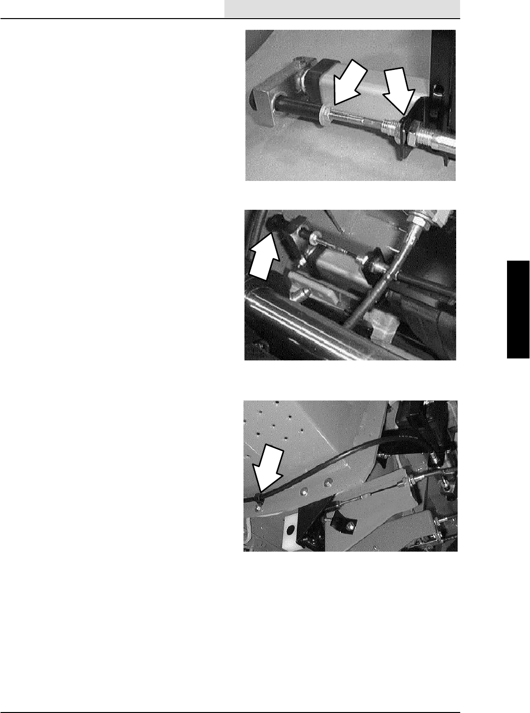
PUSHING, TOWING, AND TRANSPORTING
THE MACHINE
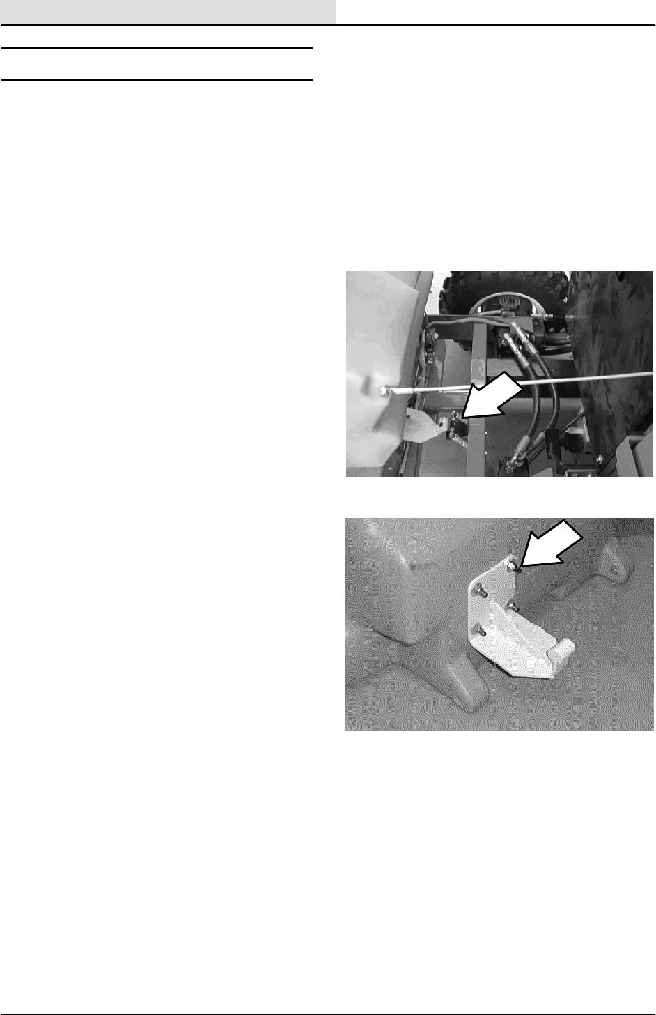
PUSHING OR TOWING THE MACHINE
If the machine becomes disabled, it can be
pushed from the front or rear, but towed only from
the front.
The propelling pump has a bypass valve to
prevent damage to the hydraulic system when the
machine is being pushed or towed. This valve
allows a disabled machine to be moved for a very
short distance and at a speed to not exceed 1.6
kp/h (1 mph). The machine is NOT intended to be
pushed or towed a long distance or at a high
speed.
ATTENTION! Do not push or tow
machine for a long distance and without
using the bypass valve, or the machine
hydraulic system may be damaged.
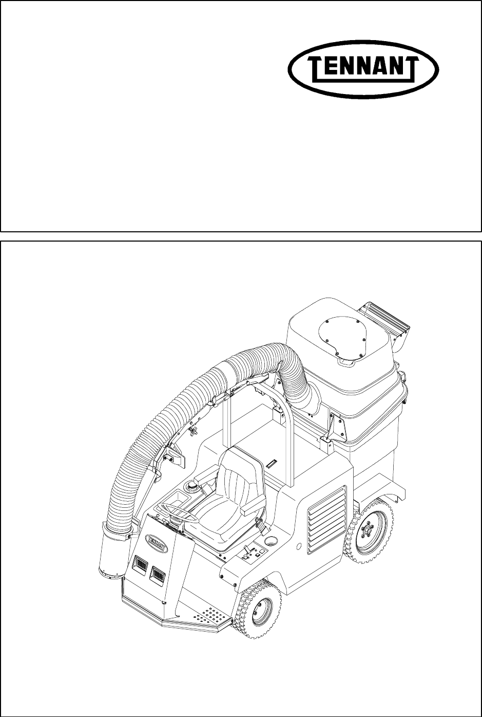
Turn the bypass valve 90_from the normal
position before pushing or towing the machine.
The illustration shows the bypass valve in the
pushing or towing position.
GENERAL INFORMATION
1-13
ATLV 4300 330495 (6--01)
TRANSPORTING THE MACHINE
1. Position the rear of the machine at the
loading edge of the truck or trailer.
FOR SAFETY: Use truck or trailer that
will support the weight of the machine.
NOTE: Empty the hopper before transporting the
machine.
2. If the loading surface is not horizontal or is
higher than 380 mm (15 in) from the ground,
use a winch to load machine.
If the loading surface is horizontal AND is
380 mm (15 in) or less from the ground, the
machine may be driven onto the truck or
trailer.
3. To winch the machine onto the truck or
trailer, attach the winching chains to the rear
tie down locations. The rear tie-down
locations are through the rear holes of the
frame.
4. Turn the bypass valve 90_from the normal
position before winching the machine onto
the truck or trailer. See PUSHING OR
TOWING THE MACHINE section of this
manual. Make sure the machine is centered.
FOR SAFETY: When loading machine
onto truck or trailer, use winch. Do not
drive the machine onto the truck or
trailer unless the loading surface is
horizontal AND is 380 mm (15 in) or less
from the ground.
5. Position the machine onto the truck or trailer
as far as possible. If the machine starts to
veer off the centerline of the truck or trailer,
stop and turn the steering wheel to center
the machine.

GENERAL INFORMATION
1-14 ATLV 4300 330495 (6--01)
6. Set the parking brake, lower the vacuum
head and block the machine tires. Tie down
the machine to the truck or trailer before
transporting.
If the machine does not have the optional tie
down bracket, tie the front end down with a
tie strap over the floor of the machine.
If the machine does have an optional tie
down bracket, tie down the machine to the
truck or trailer with it.
The rear tie-down locations are through the
rear holes of the frame.
7. If the loading surface is not horizontal or is
higher than 380 mm (15 in) from the ground,
use a winch to unload machine.
If the loading surface is horizontal AND is
380 mm (15 in) or less from the ground, the
machine may be driven off the truck or
trailer.
FOR SAFETY: When unloading machine
off truck or trailer, use winch. Do not
drive the machine off the truck or trailer
unless the loading surface is horizontal
AND 380 mm (15 in) or less from the
ground.
GENERAL INFORMATION
1-15
ATLV 4300 330495 (6--01)
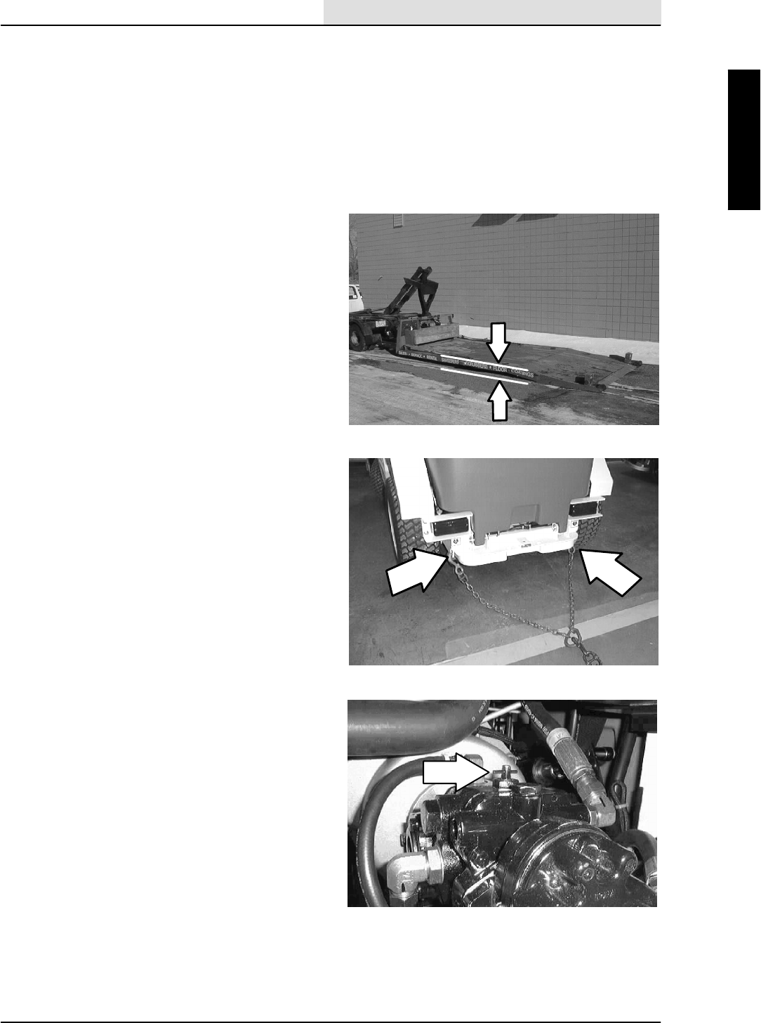
MACHINE JACKING
Empty the hopper before jacking the machine.
You can jack up the machine for service at the
designated locations. Use a hoist or jack that will
support the weight of the machine.
Always stop the machine on a flat, level surface
and block the tires before jacking up the machine.
The front jacking locations are on the frame near
the front tires.
FOR SAFETY: When Servicing Machine,
Block Machine Tires Before Jacking
Machine Up.
FOR SAFETY: When Servicing Machine,
Jack Machine Up At Designated
Locations Only. Block Machine Up With
Jack Stands.
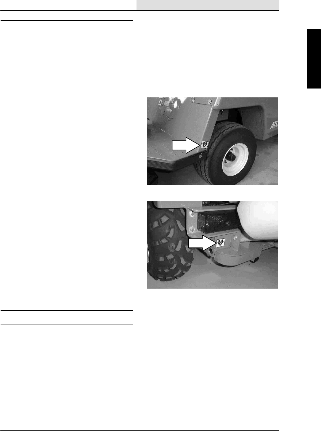
The rear jacking locations are below the rear
bumper.
FOR SAFETY: When Servicing Machine,
Block Machine Tires Before Jacking
Machine Up.
FOR SAFETY: When Servicing Machine,
Jack Machine Up At Designated
Locations Only. Block Machine Up With
Jack Stands.
STORING MACHINE
Before storing the machine for an extended period
of time, the machine needs to be prepped to
lessen the chance of rust, sludge, and other
undesirable deposits from forming. Contact
TENNANT service personnel.

GENERAL INFORMATION
1-16 ATLV 4300 330495 (10--98)
HARDWARE INFORMATION
The following charts state standard plated
hardware tightening ranges for normal assembly
applications. Decrease the specified torque by
20% when using a thread lubricant. Do not
substitute lower grade hardware for higher grade
hardware. If higher grade hardware than specified
is substituted, tighten only to the specified
hardware torque value to avoid damaging the
threads of the part being threaded into, as when
threading into speed nuts or weldments.
STANDARD BOLT TORQUE CHART
Thread
Size
SAE Grade 5
Torque ft lb
(Nm)
SAE Grade 8
Torque ft lb
(Nm)
0.25 in 7--10 (9--14) 10--13 (14--38)
0.31 in 15--20 (20--27) 20--26 (27--35)
0.38 in 27--35 (37--47) 36--47 (49--64)
0.44 in 43--56 (58--76) 53--76 (72--103)
0.50 in 65--85 (88--115) 89--116
(121--157)
0.62 in 130--170
(176--231)
117--265
(159--359)
0.75 in 215--280
(291--380)
313--407
(424--552)
1.00 in 500--650
(678--881)
757--984
(1026--1334)
NOTE: Decrease torque by 20% when using a
thread lubricant.
METRIC BOLT TORQUE CHART
Thread
Size
Class 8.8
Torque ft lb
_Nm)
Class 10.9
Torque ft lb
(Nm)
M4 2(3) 3(4)
M5 4(5) 6(8)
M6 7(9) 10 (14)
M8 18 (24) 25 (34)
M10 32 (43) 47 (64)
M12 58 (79) 83 (112)
M14 94 (127) 133 (180)
M16 144 (195) 196 (265)
M20 260 (352) 336 (455)
M24 470 (637) 664 (900)
NOTE: Decrease torque by 20% when using a
thread lubricant.
Exceptions to the above chart:
Check the machine for exceptions!
BOLT IDENTIFICATION
Identification
Grade Marking
Specification and
Grade
SAE--Grade 5
SAE--Grade 8
ISO--Grade 8.8
ISO--Grade 10.9
01395
THREAD SEALANT AND LOCKING
COMPOUNDS
Thread sealants and locking compounds may be
used on this machine. They include the following:
Locktite 515 sealant -- gasket forming
material. TENNANT Part No. 75567,15 oz
(440 ml) cartridge.
Locktite 242 blue -- medium strength thread
locking compound. TENNANT Part No.
32676, 0.5 ml tube.
Locktite 271 red -- high strength thread
locking compound. TENNANT Part No.
19857, 0.5 ml tube.

GENERAL INFORMATION
1-17
ATLV 4300 330495 (6--01)
HYDRAULIC FITTING INFORMATION
HYDRAULIC TAPERED PIPE FITTING (NPT)
TORQUE CHART
NOTE: Ratings listed are when using teflon
thread seal.
Size Minimum
Torque
Maximum
Torque
1/4 NPT 10 ft lb (14 Nm) 30 ft lb (41 Nm)
1/2 NPT 25 ft lb (34 Nm) 50 ft lb (68 Nm)
3/4 NPT 50 ft lb (68 Nm) 100 ft lb (136
Nm)
HYDRAULIC TAPERED SEAT FITTING (JIC)
TORQUE CHART
Tibe O.D.
(in)
Thread Size Maximum
Torque
0.25 0.44--20 9ftlb(12Nm)
0.38 0.56--18 20 ft lb (27 Nm)
0.50 0.75--16 30 ft lb (41 Nm)
0.62 0.88--14 40 ft lb (54 Nm)
0.75 1.12--12 70 ft lb (95 Nm)
1.0 1.31--12 90 ft lb (122 Nm)
HYDRAULIC O--RING FITTING TORQUE
CHART
Tube
O.D.
(in)
Thread
Size
Minimum
Torque
Maximum
Torque
0.25 0.44--20 6ftlb(8Nm) 9ftlb
(12 Nm)
0.38 0.56--18 13 ft lb
(18 Nm)
20 ft lb
(27 Nm)
*10 ft lb
(14 Nm)
12 ft lb
(16 Nm)
0.50 0.75--16 20 ft lb
(27 Nm)
30 ft lb
(41 Nm)
*21 ft lb
(28 Nm)
24 ft lb
(33 Nm)
0.62 0.88--14 25 ft lb
(34 Nm)
40 ft lb
(54 Nm)
0.75 1.12--12 45 ft lb
(61 Nm)
70 ft lb
(95 Nm)
1.0 1.31--12 60 ft lb
(81 Nm)
90 ft lb
(122 Nm)
NOTE: Do not use sealant on o--ring threads.
*Aluminum bodied components

GENERAL INFORMATION
1-18 ATLV 4300 330495 (12--01)

CHASSIS
2-1
ATLV 4300 330495 (12--01)
CONTENTS
Page
INTRODUCTION 2-3......................
SEAT 2-4.............................
OPERATOR SEAT 2-4...............
TO REMOVE SEAT ASSEMBLY 2-4..
TO INSTALL SEAT ASSEMBLY 2-5...
BRAKES AND TIRES 2-6...............
SERVICE BRAKES 2-6..............
TO REPLACE SERVICE BRAKE
PADS 2-6
TO REPLACE SERVICE BRAKE
CABLE 2-8......................
TO ADJUST SERVICE/PARKING
BRAKE 2-9......................
PARKING BRAKE 2-10..............
TIRES AND WHEELS 2-10...........
TO REPLACE FRONT TIRE
AND WHEEL 2-10................
TO REPLACE REAR TIRE AND
WHEEL 2-11....................
TO ALIGN FRONT TIRES 2-12.......
STEERING 2-13.......................
TO SET TURNING RADIUS
STOPS 2-13.....................
FRONT AXLE 2-14.....................
TO REMOVE FRONT AXLE
ASSEMBLY 2-14.................
TO INSTALL FRONT AXLE
ASSEMBLY 2-16.................
TO REPLACE FRONT AXLE LEAF
SPRING 2-18....................
TO REPLACE FRONT AXLE
ROD END 2-19..................
PROPEL CABLE 2-20..................
TO REPLACE PROPEL CABLE 2-20..
TO REPLACE PROPEL
HYDROBACK 2-24...............
TO SET TRAVEL SPEEDS 2-26......
TO ADJUST PROPEL NEUTRAL 2-27.

CHASSIS
2-2 ATLV 4300 330495 (10--98)

CHASSIS
2-3
ATLV 4300 330495 (10--98)
INTRODUCTION
This section includes information on the main
chassis related components for example the seat,
steering, brakes and tires.

CHASSIS
2-4 ATLV 4300 330495 (10--98)
SEAT
OPERATOR SEAT
The standard operators seat on the ATLVt4300
is a fixed back style with no adjustment for
operator weight. The optional operators seat has
an adjustable back and several settings for
operator weight.
TO REMOVE SEAT ASSEMBLY
FOR SAFETY: Before Leaving Or
Servicing Machine; Stop On Level
Surface, Set Parking Brake, turn off
machine, and remove key.
1. Raise the seat assembly and engage the
prop rod.
2. Hold the seat up with an overhead hoist or a
piece of wood.
3. Remove the four screws holding the seat
support to the machine frame.
4. Disengage the prop rod and drop the seat
assembly down slightly.
5. Remove the end of the prop rod through the
access hole.
6. Remove the seat assembly from the
machine.

CHASSIS
2-5
ATLV 4300 330495 (10--98)
TO INSTALL SEAT ASSEMBLY
FOR SAFETY: Before Leaving Or
Servicing Machine; Stop On Level
Surface, Set Parking Brake, turn off
machine, and remove key.
1. Position the seat assembly onto the
machine.
2. Hold the seat up with an overhead hoist or a
piece of wood.
3. Install the four hex screws and nuts. Tighten
to 8 -- 10 Nm (6 -- 8 ft. lb).
4. Drop the seat down enough to place the end
of the prop rod into the access hole.
5. Drop the seat assembly down and remove
the hoist.
CHASSIS
2-6 ATLV 4300 330495 (10--98)
BRAKES AND TIRES
SERVICE BRAKES
The service brakes on the model ATLVt4300 are
located on the rear wheels only. The service
brakes are mechanically actuated with two pedals
and two cables. The service brakes are
independent left to right.
There is a left and right brake pedal in the
operators compartment. These pedals can be
actuated together or just the right or just the left
pedal can be pressed.
TO REPLACE SERVICE BRAKE PADS
FOR SAFETY: Before Leaving Or
Servicing Machine; Stop On Level
Surface, Set Parking Brake, turn off
machine, and remove key.
1. Place blocks in front and back of the front
tires.
2. Jack up the rear of the machine at the
indicated jack points. Install jack stands
under the machine frame.
3. Make sure the parking brake is engaged.
Remove the five wheel nuts. Remove the
tire and wheel assembly from the machine.
4. Lift the hopper cover and tilt the hopper
back.
5. Disengage the parking brake.
CHASSIS
2-7
ATLV 4300 330495 (10--98)
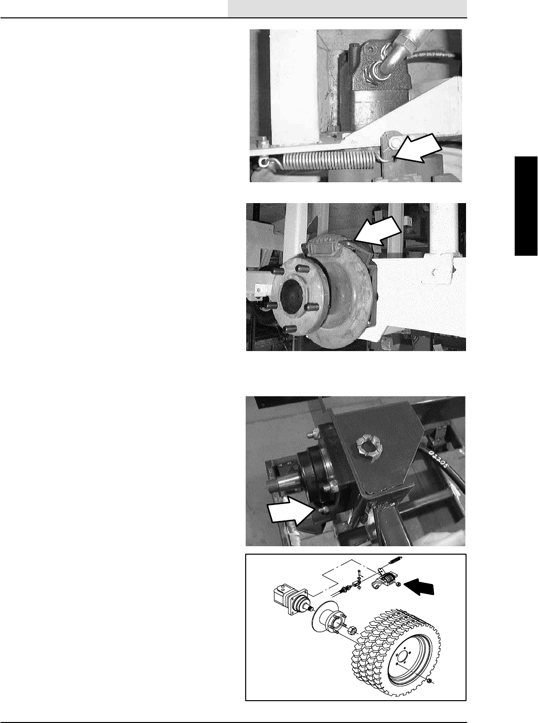
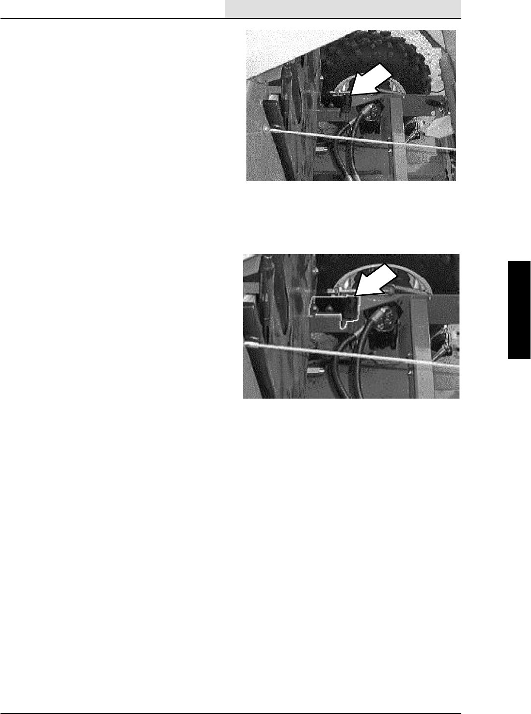
6. Remove the tension spring and clevis pin
from the brake cable clevis and arm on the
brake assembly.
7. Remove the two M12 hex screws and nyloc
nuts holding the brake assembly to the top
side of the wheel motor.
8. Pull the brake assembly straight up and off
the brake hub.
9. Remove the brake pads from the brake
assembly. Note the orientation of the pads.
10. Install the new brake pads in the same
orientation as the used ones.
11. Spread the new brake pads and slide the
brake assembly onto the brake hub.
12. Align the holes in the brake assembly with
the mount holes in the wheel motor.
13. Reinstall the hardware. Tighten to
64 -- 83 Nm (47 -- 61 ft. lb.)
14. Reinstall the clevis pin in the end of the
brake cable at the brake arm.
15. Reinstall the tension spring on the brake
arm.
16. Go to the operators compartment and press
the brake pedal on the side where the brake
pads were just replaced. Adjust the brake
cable if necessary. See TO ADJUST BRAKE
CABLE instructions in this section.
17. Engage the parking brake.
18. Reinstall the rear tire and wheel assembly.
19. Reinstall the five wheel nuts and tighten to
122 -- 162 Nm (90 -- 120 ft. lb).
20. Repeat this procedure on both sides of the
machine.
21. Tilt the hopper forward and lower the hopper
cover.
22. Remove the jack stands and lower the
machine.
23. Remove the blocks from the front tires and
disengage the parking brake.
24. Operate the machine and check the service
brakes for proper operation.
CHASSIS
2-8 ATLV 4300 330495 (10--98)
TO REPLACE SERVICE BRAKE CABLE
1. Lower the vacuum head.
FOR SAFETY: Before Leaving Or
Servicing Machine; Stop On Level
Surface, turn off machine, and remove
key.
2. Place blocks in front and back of the front
tires.
3. Lift the hopper cover and tilt the hopper
back.
NOTE:MakesuretheparkingbrakeISNOT
engaged.
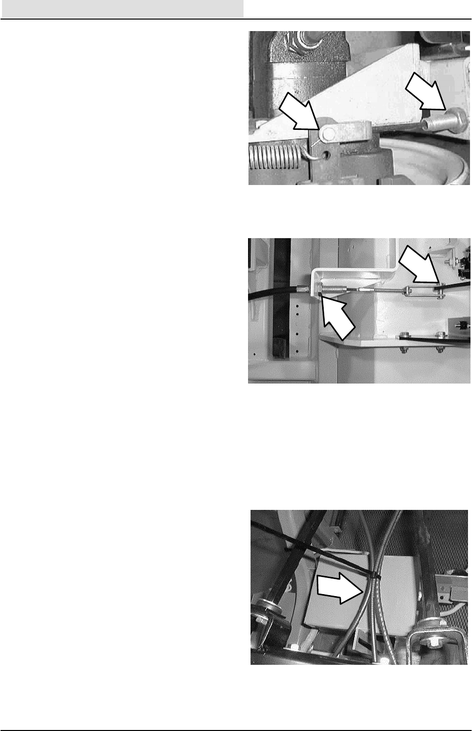
4. Remove the tension spring and clevis pin
from the brake cable clevis and arm on the
rear wheel brake assembly.
5. Loosen the large jam nut on the brake cable
where it attaches to the frame bracket.
6. Go under the front of the machine and
locate the lower part of the brake pedal
assembly.
7. Remove the cotter pin and clevis pin from
the end of the brake cable.
8. Loosen the large jam nut on the brake cable.
9. Note the routing of the brake cable and
remove it from the machine.
10. Note the location of the clevis on the old
cable and remove. Install on the new cable
in the same location. Leave the small jam
nuts loose for now.
11. Install the new cable in the machine. Make
sure to route the new cable in the same
manner that the old was routed.
12. Position the new cable into the mount hole
at the front of the machine. Lightly finger
tighten the large jam nut.
13. Reinstall the clevis pin and cotter pin into the
clevis on the front of the new brake cable.
14. Go to the back of the machine and position
the brake cable into the mount hole. Tighten
the large jam nut.
CHASSIS
2-9
ATLV 4300 330495 (10--98)
15. Reinstall the clevis pin and cotter pin into the
clevis on the rear of the new brake cable.
16. Reinstall the the tension spring onto the rear
brake assembly lever.
17. Check the foot pedal in the operators
compartment for proper adjustment. The
pedal should have less than 1” of free play.
Adjust the right pedal so it does not
contact the frame. Set the left pedal so
its surface is flush with the right pedal.
If the pedal needs to be adjusted----do so at
the front clevis. Tighten the large and small
jam nuts.
18. Reinstall any plastic ties that were removed.
19. Operate the machine and check the brakes
for proper operation.
TO ADJUST SERVICE/PARKING BRAKE
1. Open the hopper cover and tilt the hopper
back.
FOR SAFETY: Before Leaving Or
Servicing Machine; Stop On Level
Surface, Set Parking Brake, turn off
machine, and remove key.
2. Check the foot pedal in the operators
compartment for proper adjustment.
3. The pedal should have less than 1” of free
play.
NOTE: Adjust the right pedal so it does not
contact the frame. Set the left pedal so its surface
is flush with the right pedal.
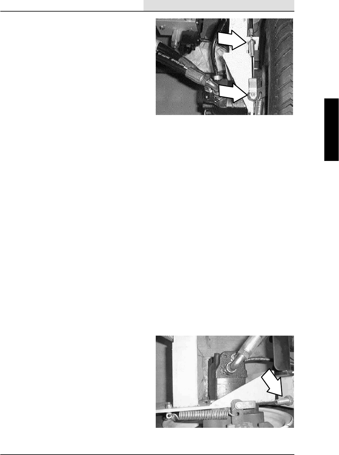
4. If the pedal needs to be adjusted----do so at
the rear cable mount.
5. Loosen the jam nuts on the cable and adjust
until there is a slight pull on the cable.
Tighten the jam nuts. Repeat on both sides.
6. Close the hopper and cover.
7. Operate the machine and check the brakes
for proper operation.

CHASSIS
2-10 ATLV 4300 330495 (10--98)
PARKING BRAKE
The parking brake is activated by a pedal located
above the service brake pedal. Pushing on the
parking brake will lock the service brake pedal in
position. To release the parking brake----press on
the service brake pedal.
TIRES AND WHEELS
The front and rear tires on the ATLVt4300 are
pneumatic. The rims are one piece steel tubeless
style.
NOTE: Inflate the front tires to 22 psi and the rear
tires to (7 psi. standard, 18 psi. optional all terrain
tires).
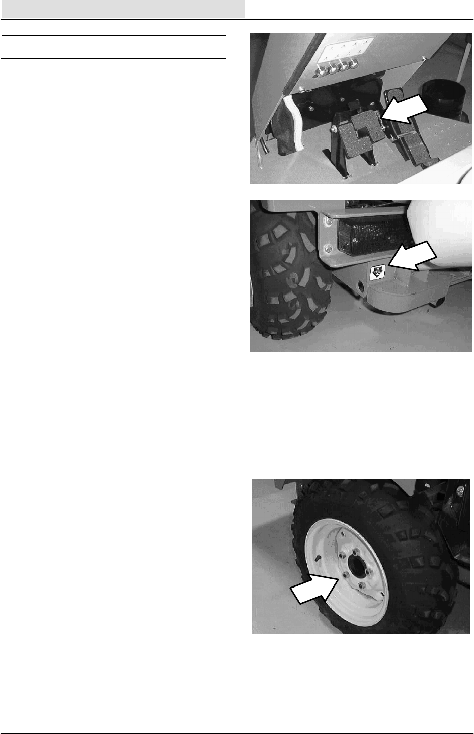
TO REPLACE FRONT TIRE AND WHEEL
FOR SAFETY: Before Leaving Or
Servicing Machine; Stop On Level
Surface, Set Parking Brake, turn off
machine, and remove key.
1. Loosen the four wheel nuts before raising
the front end of the machine. DO NOT
remove the wheel nuts at this point.
2. Jack up the front of the machine at the
indicated jack points. Install jack stands
under the machine frame.
3. Finish removing the four wheel nuts.
Remove the tire and wheel assembly from
the machine.
4. Position the new tire and wheel assembly
onto the front axle hub.
5. Reinstall the four wheel nuts and tighten
finger tight.
6. Remove the jack stands and lower the
machine to the floor.

CHASSIS
2-11
ATLV 4300 330495 (10--98)
7. Go back and finish tightening the four wheel
nuts to 122 -- 162 Nm (90 -- 120 ft. lb).
8. Check the new tires for wear and rotate
every 200 hours of operation.
9. Check the tire pressure every 50 hours of
operation.
TO REPLACE REAR TIRE AND WHEEL
FOR SAFETY: Before Leaving Or
Servicing Machine; Stop On Level
Surface, Set Parking Brake, turn off
machine, and remove key.
1. Place blocks in front and back of the front
tires.
2. Jack up the rear of the machine at the
indicated jack points. Install jack stands
under the machine frame.
3. Make sure the parking brake is engaged.
Remove the five wheel nuts. Remove the
tire and wheel assembly from the machine.
4. Position the new tire and wheel assembly
onto the front axle hub.
5. Reinstall the five wheel nuts and tighten to
122 -- 162 Nm (90 -- 120 ft. lb).
6. Remove the jack stands and lower the
machine to the floor.
7. Remove the blocks from the front tires.
8. Check the new tires for wear and rotate
every 200 hours of operation.
9. Check the tire pressure every 50 hours of
operation.
CHASSIS
2-12 ATLV 4300 330495 (10--98)
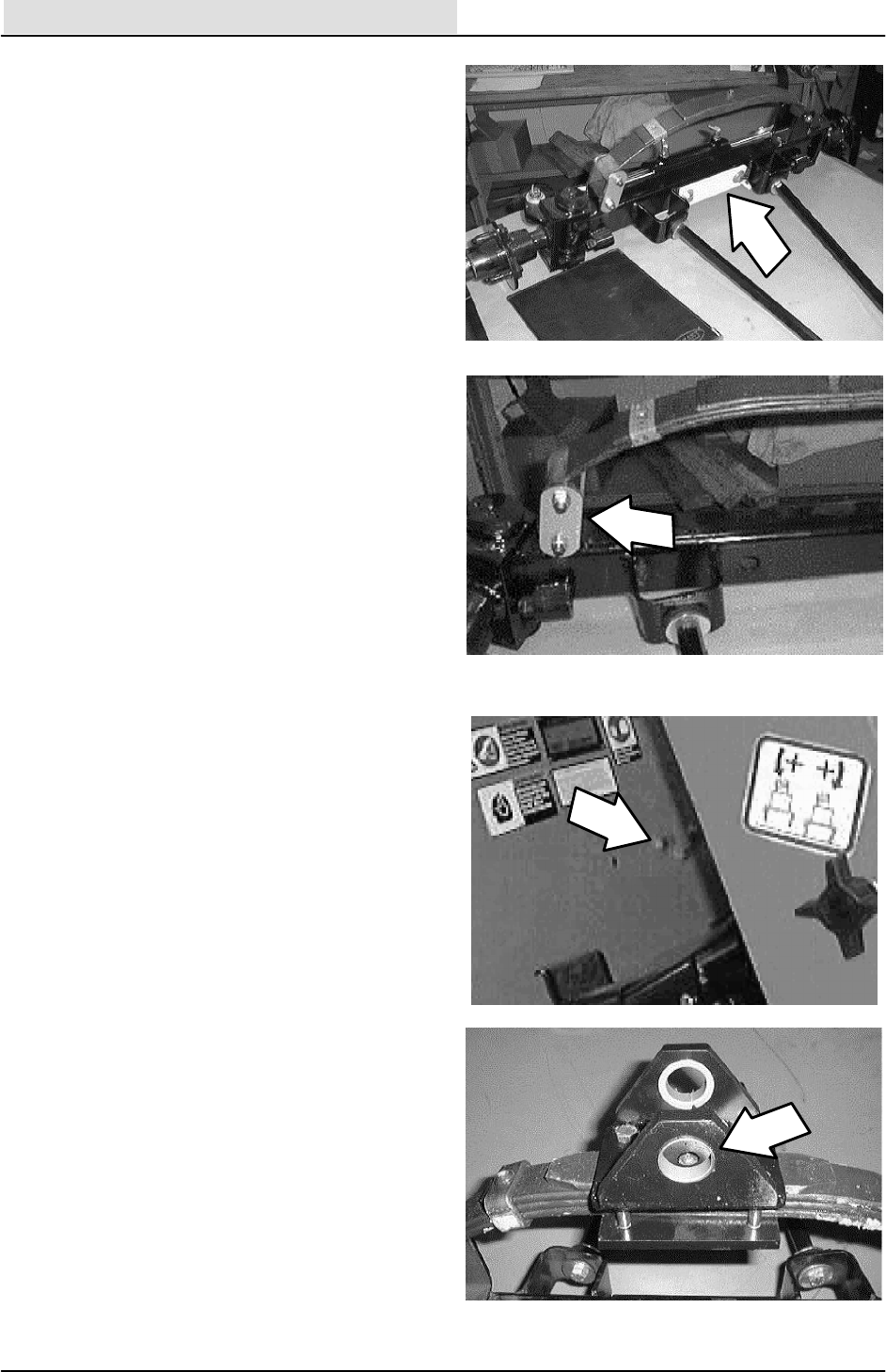
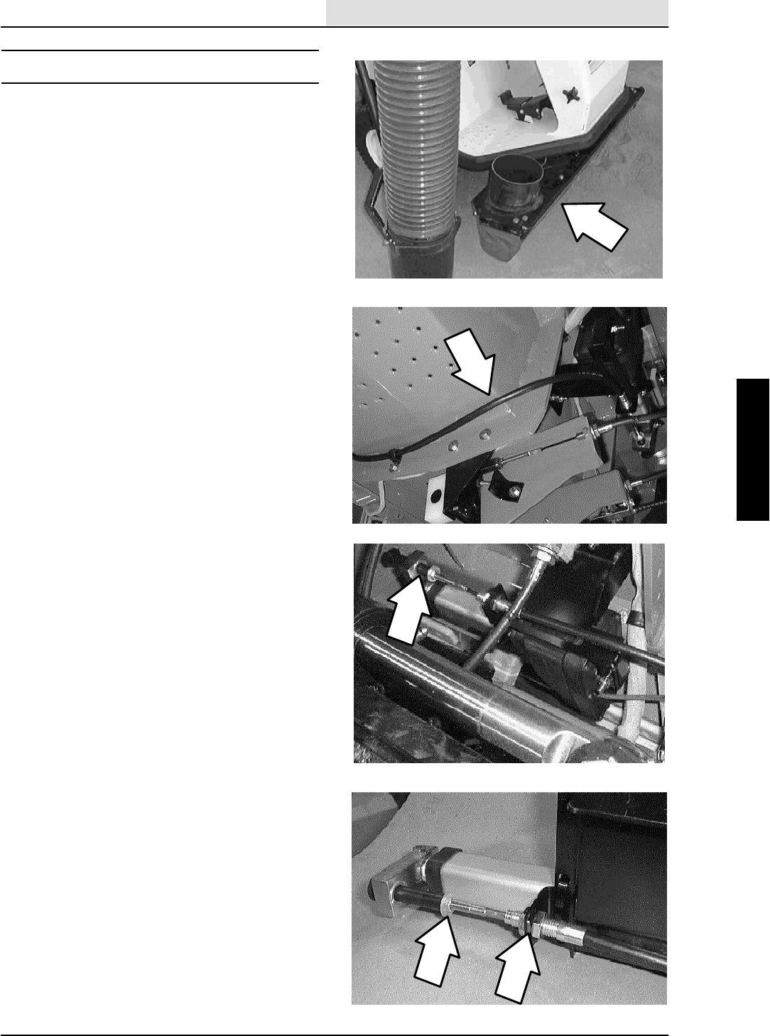
TO ALIGN FRONT TIRES
1. Drive the machine forward with the steering
wheel pointed straight ahead.
FOR SAFETY: Before Leaving Or
Servicing Machine; Stop On Level
Surface, Set Parking Brake, turn off
machine, and remove key.
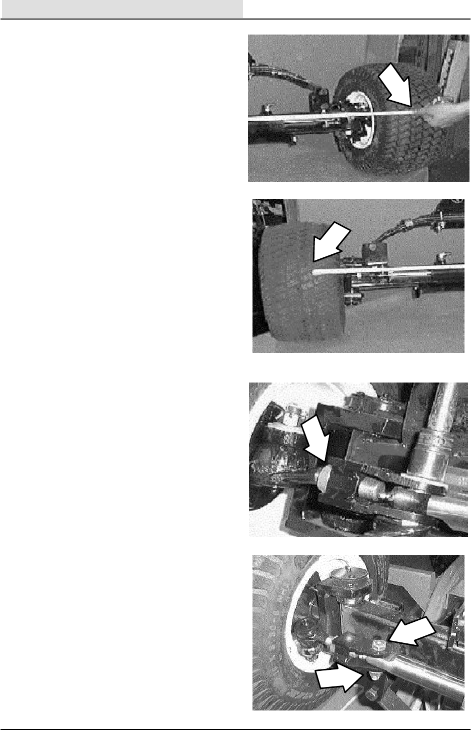
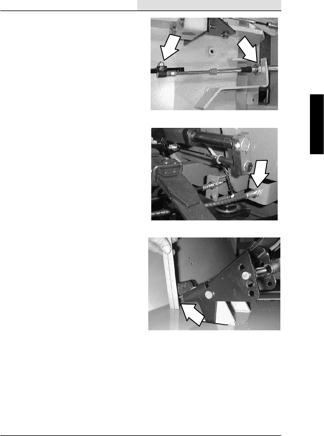
2. Use a tape measure to check the alignment
of the front tires. The rear of the front tires
should be 1/16” to 3/16” farther apart than
the front of the front tires (” toe--in”
condition).
3. If an adjustment is needed----go under the
machine on either side and locate the clevis
at each end of the steering cylinder.
4. Loosen the jam nut where the ball end is
attached to the cylinder clevis.
5. Remove the .50” hex screw and nyloc nut
from the clevis and cylinder end. Pull the
clevis off the cylinder.
NOTE: Make sure to retain the steel spacers
(2 per end) in the end of the cylinder.
6. Three full turns of the clevis on the rod end
equals 1/2” travel. Make adjustments to both
sides equally (this will keep piston travel of
the steering cylinder centered on the axle).
NOTE: There should be approximately 3/8” of
thread sticking through the block on the clevis.
7. Reinstall the clevis onto the end of the
cylinder. Reinstall the hardware and tighten
to 90 -- 117 Nm (65 -- 85 ft. lb).
8. Tighten the jam nut where the ball joint is
attached to the clevis.
9. Drive the machine forward with the steering
wheel pointed straight ahead.
10. Re--check the tire alignment. Re--adjust if
necessary.

CHASSIS
2-13
ATLV 4300 330495 (10--98)
STEERING
The steering system on the ATLVt4300 consists
of a hydraulic steering wheel motor and a dual
action hydraulic cylinder on the front axle. Service
instructions for these components can be found in
the HYDRAULIC section of this manual.
TO SET TURNING RADIUS STOPS
FOR SAFETY: Before Leaving Or
Servicing Machine; Stop On Level
Surface, Set Parking Brake, turn off
machine, and remove key.
1. Jack up the front of the machine at the
indicated jack points. Install jack stands
under the machine frame.
2. Turn the steering wheel all the way in one
direction.
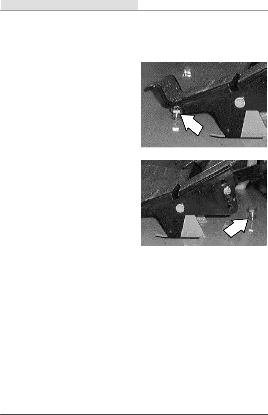
3. Go under the machine and locate the
steering stop bolts on each end of the axle
assembly on the back side.
4. The wheel axle casting should NOT BE
touching the stop bolt. There should be
.030” clearance between the head of the
stop bolt and the edge of the wheel axle
casting.
5. If an adjustment needs to be made, loosen
the jam nut on the stop bolt and turn in or
out. Hold the bolt from turning and
re--tighten the jam nut.
6. Turn the steering wheel all the way the other
direction and repeat steps 4 and 5.
7. Remove the jack stands and lower the
machine.

CHASSIS
2-14 ATLV 4300 330495 (10--98)
FRONT AXLE
The front axle on the ATLVt4300 is a pivoting,
spring mounted design. The pivoting design
allows the machine to be driven over uneven
terrain and still have all four tires contact the
ground. The leaf spring provides a comfortable
ride.
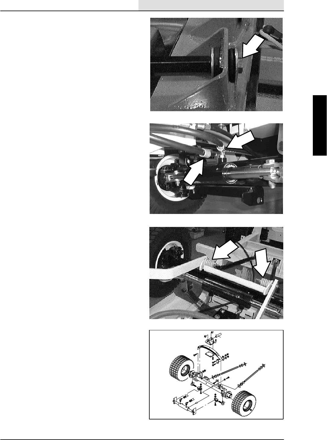
TO REMOVE FRONT AXLE ASSEMBLY
1. Lower the vacuum head. Disconnect the
vacuum head from the axle assembly
FOR SAFETY: Before Leaving Or
Servicing Machine; Stop On Level
Surface, Set Parking Brake, turn off
machine, and remove key.
2. Removal of the front axle is easier with the
front tires removed.
3. Loosen the eight wheel nuts before lifting the
front end of the machine. DO NOT remove
the wheel nuts at this point.
4. Jack up the front of the machine at the
indicated jack points. Install jack stands
under the machine frame.
5. Finish removing the eight wheel nuts.
Remove the tire and wheel assemblies from
the machine.
6. Remove the three hex screws holding the
head lift actuator assembly to the left side of
the operator compartment. Let the actuator
assembly drop down and out of the way so
the pivot pin can be removed.
7. Mark, remove, and cap the two hydraulic
hoses leading to the steering cylinder on the
front of the axle assembly.
NOTE: Observe hydraulic cleanliness
requirements when opening hydraulic lines.
8. The front axle assembly must be supported
before any hardware is removed. Use jack
stands or a floor jack.

CHASSIS
2-15
ATLV 4300 330495 (10--98)
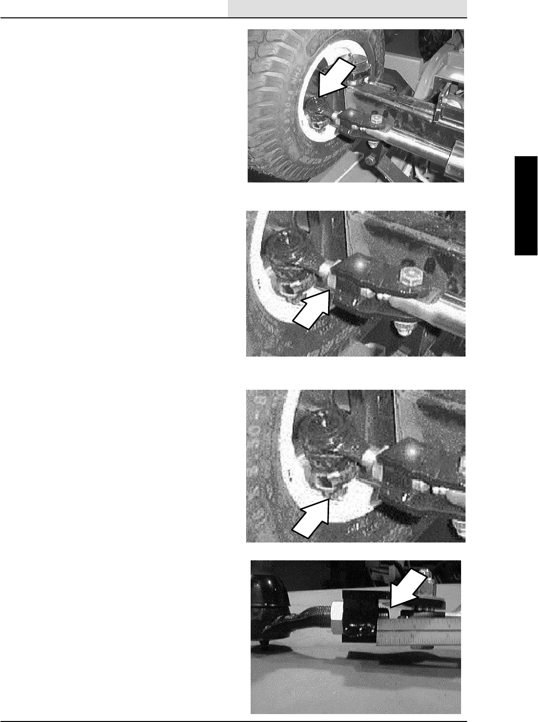
9. Remove the M12 hex screw and washer
holding each stabilizer bar to the machine
frame.
10. Remove the M8 hex screw and nyloc nut
holding the leaf spring pivot pin into the
frame. Carefully push the pivot pin toward
the front of the machine.
NOTE: Make sure the front axle is supported in
some manner.
11. Remove the two nyloc nuts holding the rear
facing shackle plate to the left side of the
leaf spring. Pull the shackle plate off the two
hex screws. Pull the front shackle plate and
two screws out the front of the spring and
axle.
12. Lift the end of the leaf spring that is
disconnected from the axle. Move the axle
assembly down and over slowly so the two
brake cables and propel cable can be
slipped off the end of the axle.
13. Carefully drop the front axle assembly down
and out of the machine.
CHASSIS
2-16 ATLV 4300 330495 (12--01)
TO INSTALL FRONT AXLE ASSEMBLY
1. Jack up the front of the machine at the
indicated jack points. Install jack stands
under the machine frame.
2. Installation of the front axle is easier with the
front tires removed.
3. Position the front axle assembly under the
machine with the steering cylinder facing the
front of the machine and the stabilizer bars
pointing to the back of the machine.
4. Use a floor jack to carefully lift the axle into
position.
NOTE: Make sure the left side of the leaf spring is
disconnected from the axle.
5. Slowly move the axle assembly into position.
While doing so, place the two brake cables
and propel cable over the top of the axle and
below the leaf spring.
6. Reinstall the two shackle plates, two
shoulder screws, and two nyloc nuts into the
left end of the leaf spring. Tighten the two
hex screws with an impact then hit with a
hammer to seat knurls.
7. Line up the mount holes in the leaf spring
pivot bracket with the mount hole in the
machine frame. Install the pivot pin. Install
the M8 hex screw and washer and tighten to
18 -- 24 Nm (15 -- 20 ft.. lb).
8. Position the head lift actuator assembly onto
the left side of the operator compartment.
Reinstall the hardware and tighten to
18 -- 24 Nm (15 -- 20 ft. lb).
9. Line up the mount holes in the ends of the
two stabilizer bars with the mount hole in the
rubber dampners. Install the M12 hex
screws and washers. Hand tighten tight.
CHASSIS
2-17
ATLV 4300 330495 (12--01)
10. Reconnect the two hydraulic hoses to the
steering cylinder.
NOTE: Observe hydraulic cleanliness
requirements when opening hydraulic lines.
11. Position the front tire and wheel assemblies
onto the front axle.
12. Reinstall the eight wheel nuts and tighten
finger tight.
13. Remove the jack stands and lower the
machine to the floor.
14. Go back and finish tightening the wheel nuts
to 122 -- 162 Nm (90 -- 120 ft. lb).
15. Reconnect the vacuum head to the front
axle.
16. Operate the machine and check for proper
operation.

CHASSIS
2-18 ATLV 4300 330495 (10--98)
TO REPLACE FRONT AXLE LEAF SPRING
FOR SAFETY: Before Leaving Or
Servicing Machine; Stop On Level
Surface, Set Parking Brake, turn off
machine, and remove key.
1. Remove the front axle assembly. See TO
REMOVE FRONT AXLE ASSEMBLY
instructions in this section.
2. Remove four hex screws and nyloc nuts
holding the pivot assembly to the top of the
leaf spring. Remove the pivot assembly.
3. Remove the hex screws (1 bolt on right side,
2 on left side) and nyloc nuts holding the
ends of the leaf spring to the front axle
assembly. The hex screws may need to be
hammered out of the mount holes because
of a knurl on the bolt shoulder.
4. Remove the shackle plates from the left side
of the leaf spring.
5. Remove the leaf spring from the axle
assembly.
6. Position the new leaf spring onto the axle
assembly in the same orientation as the old
leaf spring.
7. Install the two shackle plates, two hex
screws, and two nylocs to the left side of the
new leaf spring. Place the nylocs on the
back side.
8. Install the hex screw and nyloc to the right
side of the new leaf spring. Place the nyloc
on the back side.
9. Tighten all the hardware with an impact then
hit the bolt with a hammer to seat the knurl.
10. Reinstall the axle assembly. See TO
INSTALL FRONT AXLE ASSEMBLY
instructions in this section.
CHASSIS
2-19
ATLV 4300 330495 (10--98)
TO REPLACE FRONT AXLE ROD END
FOR SAFETY: Before Leaving Or
Servicing Machine; Stop On Level
Surface, Set Parking Brake, turn off
machine, and remove key.
1. Loosen the four wheel nuts before raising
the front end of the machine. DO NOT
remove the wheel nuts at this point.
2. Jack up the front of the machine at the
indicated jack points. Install jack stands
under the machine frame.
3. Finish removing the four wheel nuts.
Remove the tire and wheel assembly from
the machine.
4. Go under the machine on either side and
locate the clevis at each end of the steering
cylinder.
5. Loosen the jam nut where the rod end is
attached to the cylinder clevis.
6. Remove the cotter pin from the castle nut on
top of the rod end. Remove the castle nut.
7. Use a pickle fork to pop the rod end out of
thesteeringarmontheaxleassembly.
8. Unscrew the rod end from the steering
cylinder clevis. Note orientation of rod end to
clevis.
9. Install the new rod in the same orientation
as the old one. Leave 3/8” of the rod end
threads sticking through the clevis
block. Leave the jam nut loose for now.
10. Position the rod end into the bottom of the
axle steering arm. Install the castle nut and
tighten tight, then tighten to the next cotter
pin cross hole. Install the cotter pin.
11. Tighten the jam nut on the new rod end.
12. Reinstall the four wheel nuts and tighten
finger tight.
13. Remove the jack stands and lower the
machine to the floor.
14. Go back and finish tightening the four wheel
nuts to 122 -- 162 Nm (90 -- 120 ft. lb).
15. Check the front wheel alignment. See TO
ALIGN FRONT TIRES instructions in this
section.

CHASSIS
2-20 ATLV 4300 330495 (10--98)
PROPEL CABLE
The model ATLVt4300 is hydrostatically driven.
The foot pedal in the operators compartment is
connected to a push/pull cable that in turn is
connected to the propel pump arm.
TO REPLACE PROPEL CABLE
FOR SAFETY: Before Leaving Or
Servicing Machine; Stop On Level
Surface, Set Parking Brake, turn off
machine, and remove key.
1. Go under the machine at the front right
corner. Locate the propel cable ball joint on
the bottom of the propel pedal.
2. Remove the nyloc nut holding the ball joint
to the pedal. Pull the ball joint out of the
mount hole.
3. Loosen the large jam nuts on the propel
cable where it is attached to the machine
frame. Pull the cable out of the slot.
4. Follow the propel cable back and remove
any plastic ties that are holding the cable to
the frame or other cables.
5. Open the hopper cover and tilt the hopper
back.
6. Open the top engine cover.
7. Remove the five pan screws holding the rear
engine cover to the machine. Remove the
cover.

CHASSIS
2-21
ATLV 4300 330495 (10--98)
8. Locate the propel cable and hydroback on
the back side of the propel pump and
engine.
9. Cut the plastic tie. Remove the M6 hex
screw and nyloc nut from the ball joint where
it attaches to the propel pump arm. Retain
the two spacers.
10. Loosen the one large jam nut holding the
propel cable/hydroback to the mount
bracket. Pull the assembly out of the mount
slot. Remove the propel cable/hydroback
assembly from the machine.
NOTE: Note the how the cable is routed in the
machine.
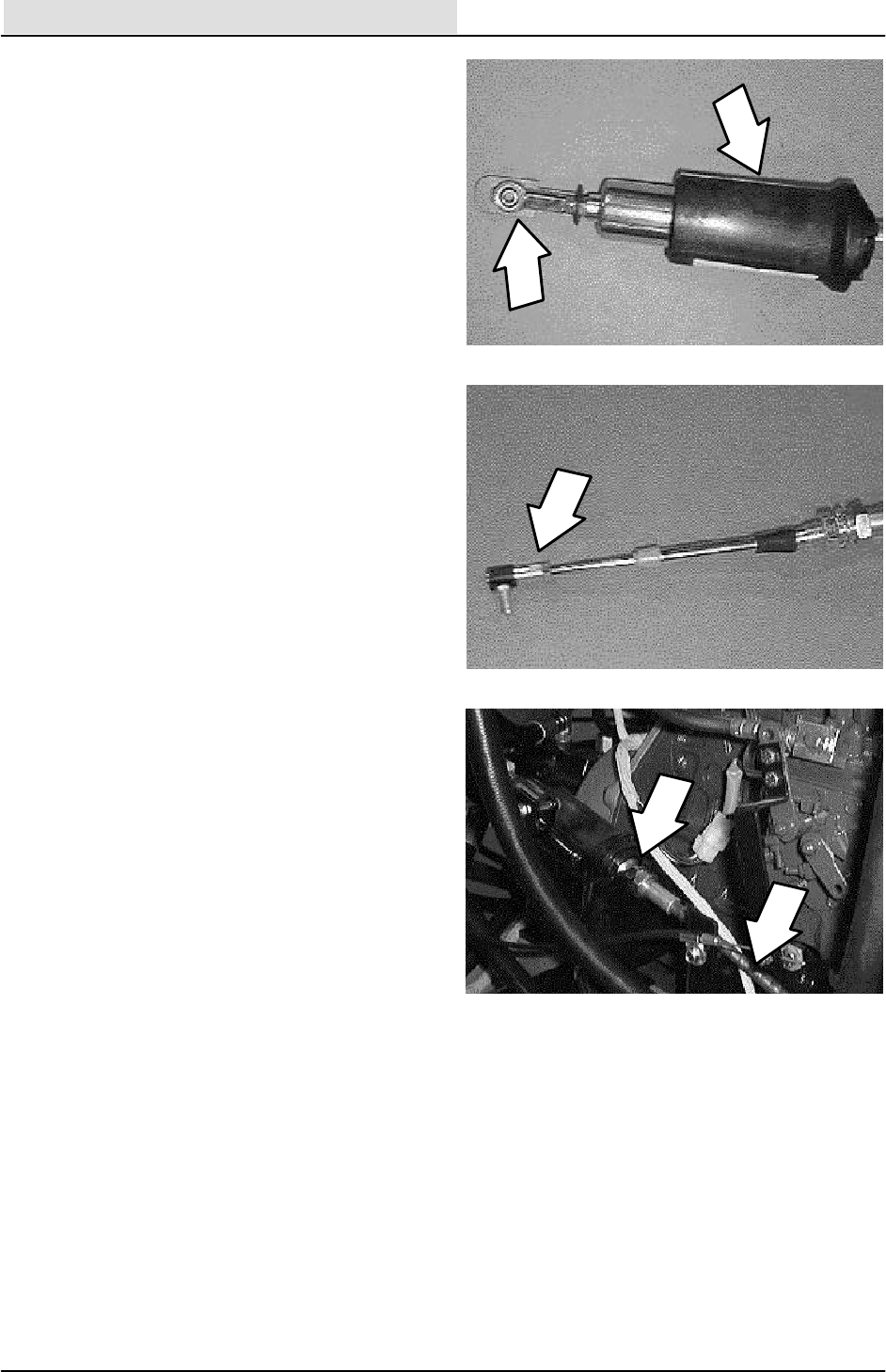
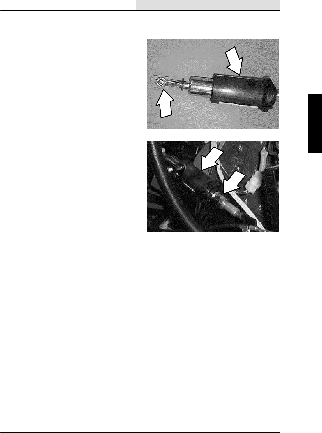
11. Remove and retain the clevis and safety clip
from the hydroback end of the propel cable.
12. Loosen the jam nut at the back of the
hydroback. Screw the hydroback off the
propel cable. Retain the hydroback.
13. Remove and retain the ball joint from the
other end of the propel cable. Discard the
old propel cable.
14. Locate the end of the new propel cable with
1.5 inches of .25--28 thread. Remove the
small cable nut and one large jam nut from
this end of the cable. Position the hydroback
onto this end of the cable (large end first).
15. Spin the large jam nut down until it bottoms
out on the cable housing. Spin the
hydroback down until there is .50 inch of
threads between the large jam nut and the
end of the hydroback.
16. Install the one small cable nut on the other
side of the hydroback and lock it down.
Install the safety clip, rubber washer, and
the second cable nut. Lock the second nut
against the safety clip and the first cable nut.
Spin the clevis down against the second
cable nut. Lock the clevis to the nut.
CHASSIS
2-22 ATLV 4300 330495 (10--98)
17. Go to the other end of the new propel cable
(1 inch of thread) and install the small cable
nut.
18. Turn the small nut down until there is .25
inch of threads left on the cable. Place a
small amount of blue loctite (242) onto the
threads of the cable.
19. Install the ball joint and spin down against
the small cable nut. Lock the nut against the
ball joint.
20. Position the new cable assembly into the
machine. Route the cable in the machine in
the same orientation as the old one.
NOTE: It is very important that the new cable
follows the same routing as the old one.
21. Position the hydroback into the mount
bracket. on the back side of the propel
pump. Tighten the jam nut. Make sure the
internal lock washer is on the hydroback
side of the mount bracket.
22. Install the hex screw and two spacers in the
clevis end of the cable and into the propel
pump arm. Tighten to 8 -- 10 Nm
(6 -- 8 ft. lb). Reinstall a plastic tie.
23. Go under the front of the machine and
position the propel cable into the mount slot
on the machine frame. Leave the jam nuts
loose for now.
24. Place the ball joint into the hole in the
bottom of the propel pedal. Tighten the nyloc
nut to 8 -- 10 Nm (6 -- 8 ft. lb).
CHASSIS
2-23
ATLV 4300 330495 (10--98)
25. Set the heel of the foot pedal to 1--1/8 inch.
from the floor plate. Tighten the jam nuts on
the propel cable.
26. The neutral centering will have to be set at
this point. See TO ADJUST PROPEL
NEUTRAL instructions in this section.
CHASSIS
2-24 ATLV 4300 330495 (10--98)
TO REPLACE PROPEL HYDROBACK
FOR SAFETY: Before Leaving Or
Servicing Machine; Stop On Level
Surface, Set Parking Brake, turn off
machine, and remove key.
1. Open the hopper cover and tilt the hopper
back.
2. Open the top engine cover.
3. Remove the five pan screws holding the rear
engine cover to the machine. Remove the
cover.
4. Locate the propel cable and hydroback on
the back side of the propel pump and
engine.
5. Cut the plastic tie. Remove the M6 hex
screw and nyloc nut from the ball joint where
it attaches to the propel pump arm. Retain
the two spacers.
6. Loosen the one large jam nut holding the
propel cable/hydroback to the mount
bracket. Pull the assembly out of the mount
slot. Remove the propel cable/hydroback
assembly from the machine.
NOTE: Note how the cable is routed in the
machine.
7. Remove and retain the clevis and safety clip
from the hydroback end of the propel cable.
8. Loosen the jam nut at the back of the
hydroback. Screw the hydroback off the
propel cable. Discard the hydroback.
9. Position the new hydroback onto the end of
the cable (large end first).
CHASSIS
2-25
ATLV 4300 330495 (10--98)
10. Spin the large jam nut down until it bottoms
out on the cable housing. Spin the new
hydroback down until there is .50 inch of
threads between the large jam nut and the
end of the hydroback.
11. Install the one small cable nut on the other
side of the hydroback and lock it down.
Install the safety clip, rubber washer, and
the second cable nut. Lock the second nut
against the safety clip and the first cable nut.
Spin the clevis down against the second
cable nut. Lock the clevis to the nut.
12. Position the new hydroback into the mount
bracket. on the back side of the propel
pump. Tighten the jam nut. Make sure the
internal lock washer is on the hydroback
side of the mount bracket.
13. Install the hex screw and two spacers in the
clevis end of the cable and into the propel
pump arm. Tighten to 8 -- 10 Nm
(6 -- 8 ft. lb). Reinstall a plastic tie.
14. The neutral centering will have to be set at
this point. See TO ADJUST PROPEL
NEUTRAL instructions in this section.
CHASSIS
2-26 ATLV 4300 330495 (10--98)
TO SET TRAVEL SPEEDS
FOR SAFETY: Before Leaving Or
Servicing Machine; Stop On Level
Surface, Set Parking Brake, turn off
machine, and remove key.
1. Go to the operators compartment and locate
the two hex screws and jam nuts at the front
and rear of the propel pedal.
2. Start with the bolt under the rear (heel)
portion of the propel pedal set at I--1/8 inch
from the top of the bolt head to the floor of
the operators compartment. This should give
about 4 mph.
3. Use the bolt under the front (toe) portion of
the propel pedal to set the maximum forward
speed to 16 mph.
4. Loosen the jam nut and screw the bolt up or
down to make any adjustments. Retighten
the jam nut after the speed adjustment has
been made.

CHASSIS
2-27
ATLV 4300 330495 (10--98)
TO ADJUST PROPEL NEUTRAL
FOR SAFETY: Before Leaving Or
Servicing Machine; Stop On Level
Surface, Set Parking Brake, turn off
machine, and remove key.
1. Open the hopper cover and tilt the hopper
back.
2. Open the top engine cover.
3. Remove the five pan screws holding the rear
engine cover to the machine. Remove the
cover.
NOTE: The rear wheels must be off the ground
when adjusting the neutral centering.
4. Place blocks in front and back of the front
tires.
5. Jack up the rear of the machine at the
indicated jack points. Install jack stands
under the machine frame.
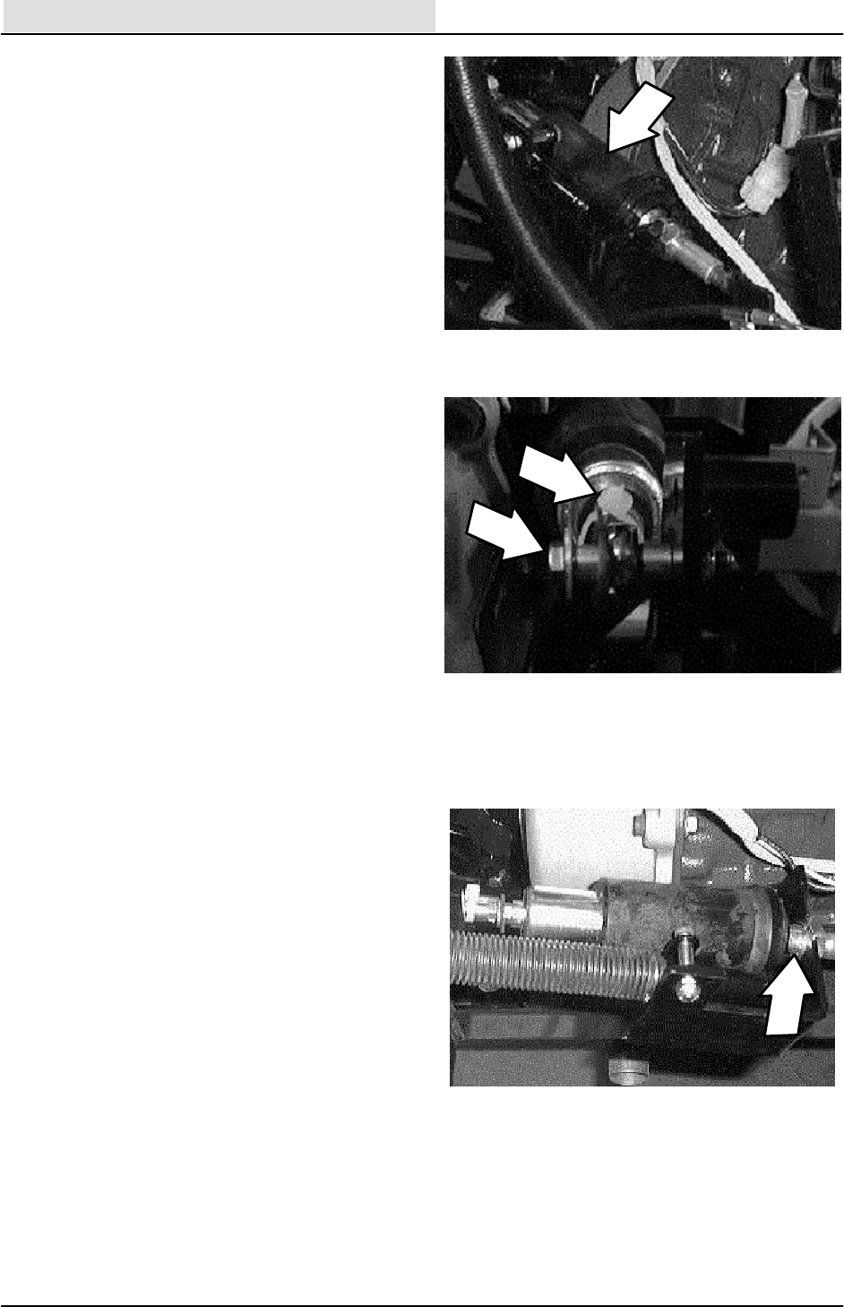
6. Locate the propel pump directional arm hub
on the back side of the pump.
7. Loosen the two outside hex screws on the
hub. DO NOT loosen the cap screw in the
center of the hub. Place an allen wrench in
the cap screw (this will be used to rotate the
hub).
8. Start the machine and observe the rear tires.
If they are not turning----no adjustment is
needed and the hardware can be tightened.
If the tires are rotating----an adjustment is
needed. Go to the next step.
9. Rotate the allen wrench until the tires are
stationary. Hold the allen wrench so the hub
does not move. Tighten the two outside hex
screws. Re--observe the rear tires for
rotation. Repeat step if necessary.
10. Lower the machine and reinstall the rear
engine cover.
11. Operate the machine and check the propel
for proper operation.

CHASSIS
2-28 ATLV 4300 330495 (12--01)

VACUUMING
3-1
ATLV 4300 330495 (10--98)
CONTENTS
Page
INTRODUCTION 3--3......................
DEBRIS HOPPER 3--4.....................
TO ADJUST HOPPER STOP
BRACKET 3--4......................
TO ADJUST HOPPER LEVEL
BRACKETS 3--5.....................
TO ADJUST HOPPER COVER
PIVOT BRACKETS 3--6..............
SKIRTS 3--7..............................
TO REPLACE VACUUM HEAD
REAR SKIRT 3--7...................
TO REPLACE VACUUM HEAD
FRONT SKIRT 3--8..................
VACUUM HEAD 3--9......................
TO REPLACE VACUUM HEAD
ACTUATOR LIFT CABLE 3--9.........
TO REPLACE VACUUM HEAD
SECONDARY LIFT CABLES 3--12.....
TO ADJUST VACUUM HEAD
ACTUATOR LIFT CABLE 3--14........
VACUUM FAN 3--15.......................
TO REPLACE VACUUM FAN
IMPELLER 3--15....................
TO REPLACE VACUUM FAN
IMPELLER SCREEN 3--18............
MACHINE TROUBLESHOOTING 3--19......

VACUUMING
3-2 ATLV 4300 330495 (10--98)

VACUUMING
3-3
ATLV 4300 330495 (10--98)
INTRODUCTION
This section includes information on the
vacuuming operation. The vacuum head collects
debris which in turn is deposited in the hopper
using the suction created by the vacuum fan. The
vacuum fan pulls air from the vacuum head,
through the hopper, and out the back of the
hopper.
VACUUMING
3-4 ATLV 4300 330495 (10--98)
DEBRIS HOPPER
The hopper is plastic and is located behind the
operators compartment. Debris is deposited into
the hopper from the vacuum chamber above. With
the hopper cover raised, the hopper body can be
tilted back to assist in dumping and for access to
the components under the hopper.
TO ADJUST HOPPER STOP BRACKET
FOR SAFETY: Before Leaving Or
Servicing Machine; Stop On Level
Surface, Set Parking Brake, turn off
machine, and remove key.
1. Raise the hopper cover and tilt the hopper
back.
2. Locate the hopper stop bracket on the
bottom right side of the hopper.
3. The hopper stop bracket should contact and
then trip the spring pivot.
4. If the hopper stop bracket does not contact
then trip the spring pivot, the stop bracket
needs to be adjusted.
5. Loosen the hardware holding the stop
bracket to the bottom of the hopper.
6. Movethestopbracketupordownsoit
contacts and trips the spring pivot. Tighten
the hardware to 18 -- 24 Nm (15 -- 20 ft. lb).
7. Pivot the hopper forward and backward,
make sure the bracket is contacting the pivot
spring before the hopper is tilted all the way
back.
VACUUMING
3-5
ATLV 4300 330495 (10--98)
TO ADJUST HOPPER LEVEL BRACKETS
FOR SAFETY: Before Leaving Or
Servicing Machine; Stop On Level
Surface, Set Parking Brake, turn off
machine, and remove key.
1. Raise the hopper cover and tilt the hopper
back.
2. Locate the hopper level brackets on each
side of the frame, just in front of the drive
motors.
3. The hopper level brackets should contact
the bottom of the hopper when the hopper is
in a level position. The lip seal of the hopper
must contact the lip of the hopper cover for
proper operation of the vacuum system.
4. If the hopper is not level with the hopper
cover, the level brackets must be adjusted.
5. Loosen the two hex screws holding the level
bracket to each side of the frame.
6. Move the level brackets up or down until the
hopper and hopper cover seal evenly with
each other. Re--tighten the hardware to
18 -- 24 Nm (15 -- 20 ft. lb).
7. Open and close the hopper cover. Check for
proper sealing of the cover to hopper seal.

VACUUMING
3-6 ATLV 4300 330495 (10--98)
TO ADJUST HOPPER COVER PIVOT
BRACKETS
FOR SAFETY: Before Leaving Or
Servicing Machine; Stop On Level
Surface, Set Parking Brake, turn off
machine, and remove key.
1. The lip seal of the hopper must contact the
lip of the hopper cover for proper operation
of the vacuum system.
2. If the hopper cover is not level with the
hopper, the pivot brackets must be
adjusted.
3. Raise the hopper cover and tilt the hopper
back.
4. Loosen the hex screws holding the pivot
brackets to each front side of the hopper
cover.
5. Move the front of the hopper cover up or
down until the hopper and hopper cover seal
evenly with each other. Re--tighten the
hardware to 18 -- 24 Nm (15 -- 20 ft. lb).
6. Open and close the hopper cover. Check for
proper sealing of the cover to hopper seal.
VACUUMING
3-7
ATLV 4300 330495 (10--98)
SKIRTS
The vacuum head on the model ATLVt4300 is
equipped with front and rear rubber skirts. These
skirts allow debris to enter the vacuum head
chamber, move through the vacuum hose, and be
deposited into the hopper. The vacuum head
skirts need to be in place and in good condition for
optimal vacuuming performance.
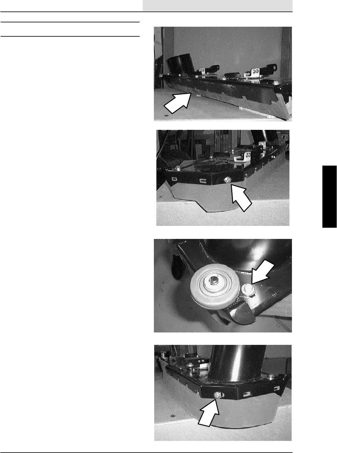
TO REPLACE VACUUM HEAD REAR SKIRT
FOR SAFETY: Before Leaving Or
Servicing Machine; Stop On Level
Surface, Set Parking Brake.
1. The vacuum head should be in the raised
position to replace skirts.
2. Remove the three hex screws holding the
left hand skirt retainer to the left side of the
vacuum head.
3. Remove the cotter pin and washer holding
the edge roller wheel to the mount pin. Pull
the wheel off the pin.
4. Remove the two hex screws holding the
right hand skirt retainer to the vacuum head
frame.
5. Pull the rear skirt off the vacuum head.
Discard the rubber skirt.
6. Position the new rear vacuum head skirt on
the back of the vacuum head. NOTE: The
notched end of the blade is positioned
opposite the tube end of the head (left side).
7. Reinstall the right hand side retainer first.
Reinstall the two hex screws. Leave loose
for now.
8. Reinstall the left hand side retainer second.
Reinstall the three hex screws. Make sure
the skirt is positioned over all of the tabs.
9. Tighten the corner bolts first, then the front
bolts, then the center bolt.
10. Reinstall the edge roller wheel onto the
mount pin. Reinstall the cotter pin and
washer.
11. Operate the machine and check the vacuum
head for proper operation.

VACUUMING
3-8 ATLV 4300 330495 (10--98)
TO REPLACE VACUUM HEAD FRONT SKIRT
FOR SAFETY: Before Leaving Or
Servicing Machine; Stop On Level
Surface, Set Parking Brake.
1. The vacuum head rear skirt retainers must
be removed before the front skirt can be
changed. See TO REPLACE VACUUM
HEAD REAR SKIRT instructions in this
section.
2. Remove the five hex screws holding the skirt
retainer to the front of the vacuum head.
3. Remove the cotter pin and washer holding
the edge roller wheel to the mount pin. Pull
the wheel off the pin.
4. Remove the retainer from the vacuum head.
Pull the skirt off the retainer tabs. Discard
the rubber skirt.
5. Position the new front skirt onto the front
retainer tabs.
6. Position the skirt and retainer assembly onto
the front of the vacuum head. Reinstall the
five hex screws and washers. Tighten to
18 -- 24 Nm (15 -- 20 ft. lb).
7. Reinstall the rear skirt and retainers. See TO
REPLACE VACUUM HEAD REAR SKIRT
instructions in this section.
8. Reinstall the edge roller wheel onto the
mount pin. Reinstall the cotter pin and
washer.
9. Operate the machine and check the vacuum
head for proper operation.
VACUUMING
3-9
ATLV 4300 330495 (10--98)
VACUUM HEAD
The vacuum head is positioned at the front of the
machine. Airflow from the vacuum fan is routed to
the vacuum head through the large, clear debris
tube. The vacuum head is raised and lowered with
a lift actuator and cable. The knob on the front,
right side of the machine is used to control how
far down the head is allowed to travel.
TO REPLACE VACUUM HEAD ACTUATOR
LIFT CABLE
FOR SAFETY: Before Leaving Or
Servicing Machine; Stop On Level
Surface, Set Parking Brake.
1. Position a block of wood under the front of
the vacuum head.
2. Lower the vacuum head down onto the block
of wood, lower the head enough so there is
some slack in the lift cable.
3. Go under the machine at the front right side
of the machine.
4. Locate the vacuum head lift actuator and the
long, black cable nut at the end of the lift
cable.
5. Hold the cable from turning with a pliers or a
vice grip.
6. Loosen the jam nut against the long, black
cable nut.
7. Un--screw the long, black cable nut from the
end of the lift cable.
8. Remove the small jam nut and washer from
the lift cable.
9. Loosen the two larger jam nuts holding the
head lift cable to the actuator mount bracket.
10. Remove the outer most jam nut. Pull the lift
cable out of the mount bracket.
11. Remove the hex screw and nut holding the
lift cable clamp to the machine frame.
Removethecableclamp.
VACUUMING
3-10 ATLV 4300 330495 (10--98)
12. Go to the operators compartment and locate
the vacuum head adjustment knob. Remove
the adjustment knob.
13. Remove the clevis pin holding the propel
pedal to the pivot bracket. Position the
propel pedal back out of the way of the
vacuum head cable assembly mount plate.
14. Remove the three hex screws holding the
slide assembly to the cable assembly mount
plate. Remove the slide assembly from the
machine.
15. Remove the three hex screws holding the
vacuum head cable assembly mount plate to
the machine (one on top, two from under
front of frame).
16. Pull the vacuum head cable assembly mount
plate back away from the machine frame.
17. Remove the cotter pin and clevis pin from
the end of the vacuum head lift cable.
18. Loosen the two larger lift cable jam nuts on
the cable.
19. Pull the cable out of the mount slot. Remove
the lift cable from the machine.
NOTE: Note how the cable was routed in the
machine.
20. Position the new cable into the machine.
The end of the cable with the clevis goes to
the front of the machine. Make sure the new
cable is routed the same manner as the old
one.
21. Install the upper end of the lift cable into the
mount slot on the cable assembly mount
plate. Center the jam nuts on the threads
and tighten tight. Install the clevis and cotter
pin.
22. Position the cable assembly mount plate
back against the front of the machine frame.
Reinstall the three hex screws and tighten to
18 -- 24 Nm (15 -- 20 ft. lb).
23. Reinstall the slide assembly and tighten the
three hex screws to 18 -- 24 Nm
(15 -- 20 ft. lb).
24. Reinstall the propel pedal, clevis pin, and
cotter pin.
VACUUMING
3-11
ATLV 4300 330495 (10--98)
25. Reinstall the vacuum head adjustment knob.
26. Go under the machine and remove one
large jam nut from the lower end of the new
lift cable.
27. Position the new lift cable through the mount
hole in the actuator mount bracket. Reinstall
the large jam nut. Leave loose for now.
28. Install one small cable nut and washer on
the lower end of the cable.
29. Position the long, black cable lift nut through
the hole in the actuator lift block.
30. Thread the long, black lift nut onto the new
cable. Leave loose for now.
31. Install the cable clamp on the new cable and
into the machine frame. Reinstall the hex
screw and nut. Tighten to 18 -- 24 Nm
(15 -- 20 ft. lb).
32. See TO ADJUST VACUUM HEAD
ACTUATOR LIFT CABLE instructions in this
section.
33. Go back and tighten all jam nuts.
34. Raise the vacuum head and remove the
wood block.
35. Operate the machine and check the vacuum
head lift actuator for proper operation.
VACUUMING
3-12 ATLV 4300 330495 (10--98)
TO REPLACE VACUUM HEAD SECONDARY
LIFT CABLES
FOR SAFETY: Before Leaving Or
Servicing Machine; Stop On Level
Surface, Set Parking Brake.
1. Position a block of wood under the front of
the vacuum head
2. Lower the vacuum head down onto the block
of wood, lower the head enough so there is
some slack in the main actuator lift cable
3. Locate the two secondary vacuum head lift
cables where they attach to the vacuum
head.
4. Pull down on the cable that needs to be
changed. Remove the cotter pin and clevis
pin from the end of the secondary lift cable
where it attaches to the vacuum head.
5. Locate the adjustment end of the secondary
vacuum head lift cables at the front, bottom
of the machine frame. Hold the cable from
turning and remove the adjustment nut.
6. Remove the nut and jam nut from the end of
the cable attached to the front of the
machine frame.
7. Go to the operators compartment and locate
the vacuum head adjustment knob. Remove
the adjustment knob.
8. Remove the clevis pin holding the propel
pedal to the pivot bracket. Position the
propel pedal back out of the way of the
vacuum head cable assembly mount plate.
9. Remove the three hex screws holding the
slide assembly to the cable assembly mount
plate. Remove the slide assembly from the
machine.
10. Remove the three hex screws holding the
vacuum head cable assembly mount plate to
the machine (one on top, two from under
front of frame).
11. Pull the vacuum head cable assembly mount
plate back away from the machine frame.
12. Remove the tension spring holding the two
cable pulley pivot brackets together.

VACUUMING
3-13
ATLV 4300 330495 (10--98)
13. Remove the hex screw and nut holding the
pulley and pulley cover to the pivot bracket.
Pull the pulley cover up far enough to
remove the lift cable from the pulley groove.
Remove and discard the cable.
14. Position the new cable over the pulley. Push
the pulley cover down and tighten the
hardware to 18 -- 24 Nm (15 -- 20 ft. lb). The
threaded end of the cable should be looped
toward the center of the pivot brackets.
15. Position the cable assembly mount plate
back against the front of the machine frame.
Reinstall the three hex screws and tighten to
18 -- 24 Nm (15 -- 20 ft. lb).
NOTE: Make sure the new cable is routed through
the holes in the front of the frame.
16. Reinstall the slide assembly and tighten the
three hex screws to 18 -- 24 Nm
(15 -- 20 ft. lb).
17. Reinstall the propel pedal, clevis pin, and
cotter pin.
18. Reinstall the vacuum head adjustment knob.
19. Route the threaded end of the new cable
down and around the curved frame bracket
and into the adjustment hole. Reinstall the
adjustment nut. Leave loose for now.
20. Connect the clevis end of the new cable to
the lift bracket on the vacuum head.
Reinstall the clevis and cotter pin.
21. Go the the other end of the new cable and
hold it from turning. Turn the adjustment nut
all the way down to the end of the threads.
22. Raise the vacuum head and remove the
wood block.
23. Operate the vacuum head lift. Check for
proper operation.

VACUUMING
3-14 ATLV 4300 330495 (10--98)
TO ADJUST VACUUM HEAD ACTUATOR LIFT
CABLE
FOR SAFETY: Before Leaving Or
Servicing Machine; Stop On Level
Surface, Set Parking Brake.
1. Make sure the two shorter vacuum head lift
cables have the jam nuts screwed on as far
as possible.
2. Extend (raise) the vacuum head lift actuator
as far as possible. Go under the front of the
machine and check the two black rubber
bumpers. The vacuum head should
compress the bumpers no more than 1/8
inch. If needed, adjust the vacuum head lift
height (see next step).
3. Loosen the jam nut at the end of the long,
black lift cable sleeve. Turn the black cable
sleeve until the head compresses the rubber
bumpers 1/8 inch. Tighten the washer and
jam nut against the black cable sleeve. Use
blue loctite (242) on the threads of the cable.
4. Go to the head stop adjustment knob and
turn all the way clockwise (lowest head
position). Lower the actuator until it stops.
5. Go back under the machine and check the
black cable sleeve. There should be
approximately 1/2 inch of clearance between
the head of the black sleeve and the top of
the thrust bushing.
6. This procedure will leave the rubber skirts
approximately flush with the floor when the
head stop is adjusted to the highest position
(counter--clockwise).

VACUUMING
3-15
ATLV 4300 330495 (10--98)
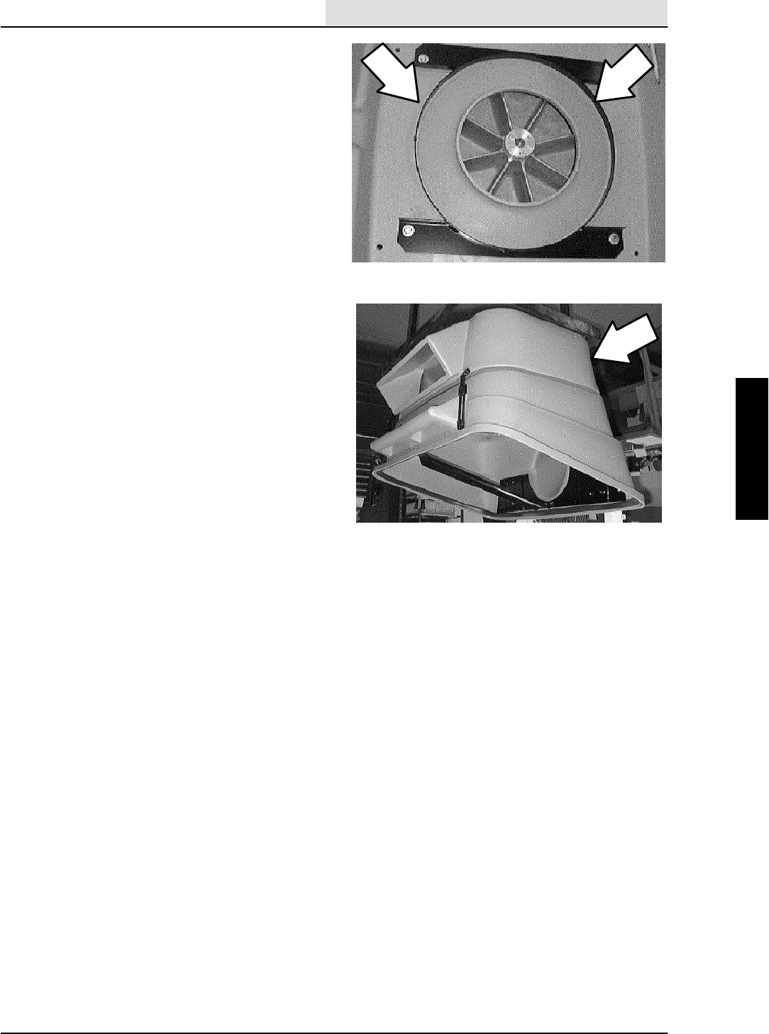
VACUUM FAN
The vacuum fan is mounted to the top of the
hopper assembly. A hydraulic motor is used to
spin the impeller which creates airflow. This
airflow creates vacuum through the vacuum tube
and down to the vacuum head. Debris is brought
up through the vacuum tube and deposited in the
hopper. A screen on the vacuum fan impeller
keeps debris from contacting the impeller.
TO REPLACE VACUUM FAN IMPELLER
FOR SAFETY: Before Leaving Or
Servicing Machine; Stop On Level
Surface, Set Parking Brake.
NOTE: Anytime hopper or vacuum system parts
are serviced the seals should be inspected and
replaced if necessary.
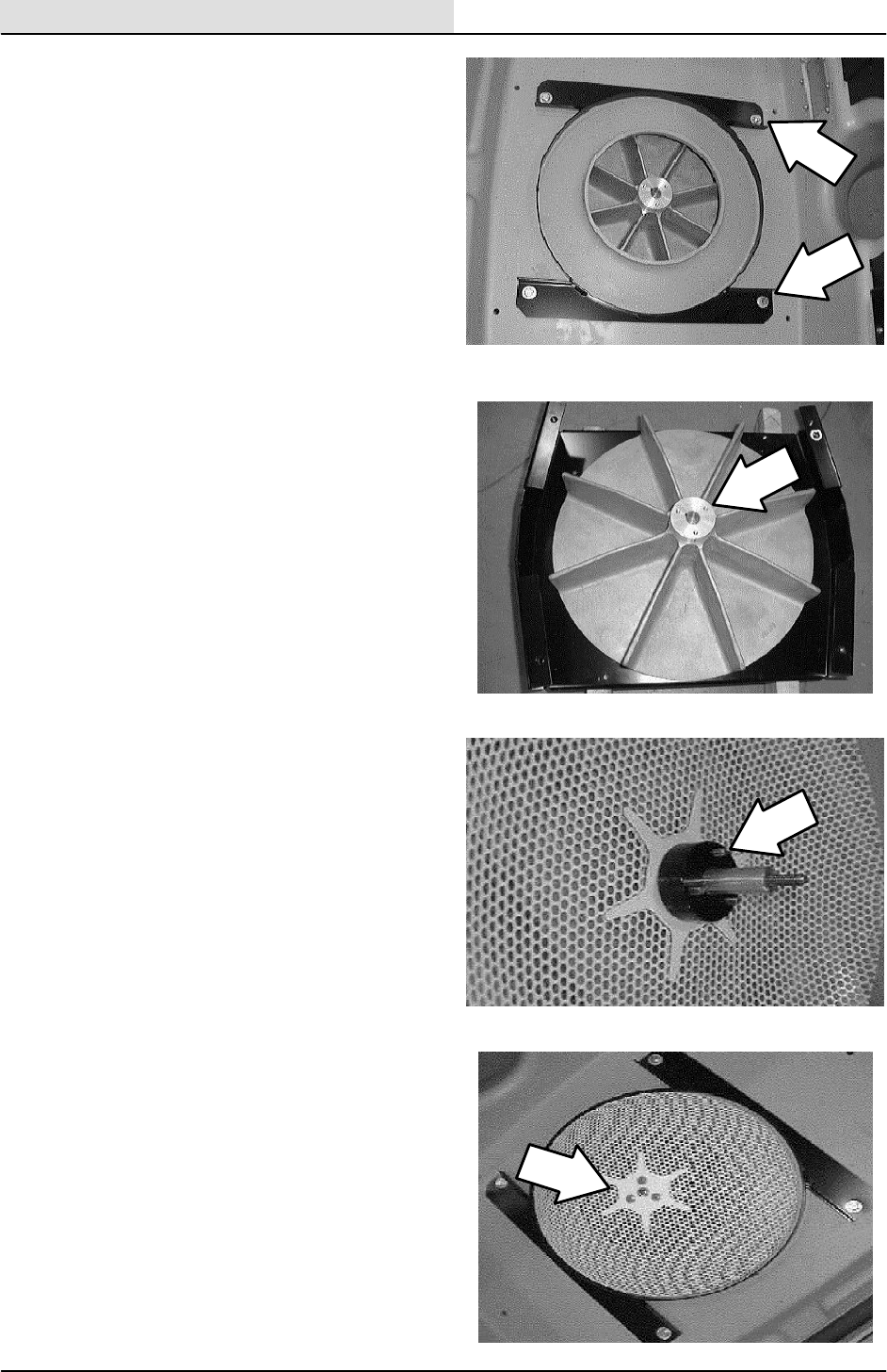
1. Remove the six screws holding the vacuum
fan motor cover plate to the top of the
plenum assembly on top of the hopper
cover. Remove the plate.
NOTE: Observe hydraulic cleanliness
requirements when opening hydraulic lines.
2. Mark, disconnect, and plug the hydraulic
lines leading to the vacuum fan motor.
3. Open the hopper cover and tilt the hopper
back.
4. Go under the hopper cover and remove the
six hex screws holding the cover assembly
to the hopper plenum. Remove the cover
assembly.
5. Go back under the hopper plenum and
locate the vacuum fan impeller screen.
Remove the three flat head screws and the
one hex screw holding the screen to the
impeller.
6. Pull the impeller screen, spacer, and sleeve
off the vacuum fan motor shaft.
7. Remove the four hex screws holding the
vacuum fan assembly retainer plate to the
bottom of the hopper plenum.
VACUUMING
3-16 ATLV 4300 330495 (10--98)
8. Go to the top of the hopper plenum and
remove the vacuum fan assembly from the
machine. Set the assembly up side down on
a flat surface.
9. Pull the vacuum fan impeller off the fan
motor shaft. Retain the key from the motor
shaft.
10. Install the new vacuum fan impeller onto the
motor shaft.
NOTE: Make sure to use the key that was
removed with the old impeller.
11. Turn the assembly over and place it back on
top of the hopper plenum. Hold the impeller
in place while turning over. Line up the holes
in the motor bracket with the holes in the
cover.
12. Go under the hopper cover and install the
four hex screws into vacuum fan assembly
retainer plate. Leave the hardware loose for
now.
13. Reinstall the impeller screen, spacer, and
sleeve onto the vacuum fan motor shaft.
14. Use blue loctite (242) on the threads of the
impeller screen hardware. Reinstall the one
M8 hex screw and three M6 flat screws.
15. Tighten the M8 hex screw to 18 -- 24 Nm
(15 -- 20 ft.. lb) and the M6 flat screws to
8 -- 10 Nm (6 -- 8 ft.. lb).
16. After the screen has been tighten down,
center the string guard (on the retainer
plate) around the outside of the screen.
Tighten the four screws to 18 -- 24 Nm
(15 -- 20 ft. lb).Use blue loctite (242) on the
threads of this hardware.
17. Reinstall cover assembly onto the hopper
plenum.
VACUUMING
3-17
ATLV 4300 330495 (10--98)
18. Reinstall six hex screws holding the cover
assembly to the hopper plenum. Tighten the
screws to 18 -- 24 Nm (15 -- 20 ft. lb).
NOTE: Observe hydraulic cleanliness
requirements when opening hydraulic lines.
19. Reconnect the hydraulic lines leading to the
vacuum fan motor. See hydraulic schematic
in the HYDRAULIC section.
20. Reinstall the six screws holding the vacuum
fan motor cover plate to the top of the
plenum assembly on top of the hopper
cover. Tighten the screws to 18 -- 24 Nm
(15 -- 20 ft. lb).
21. Tilt the hopper forward and close the cover.
22. Operate the machine and check the vacuum
fan for proper operation.
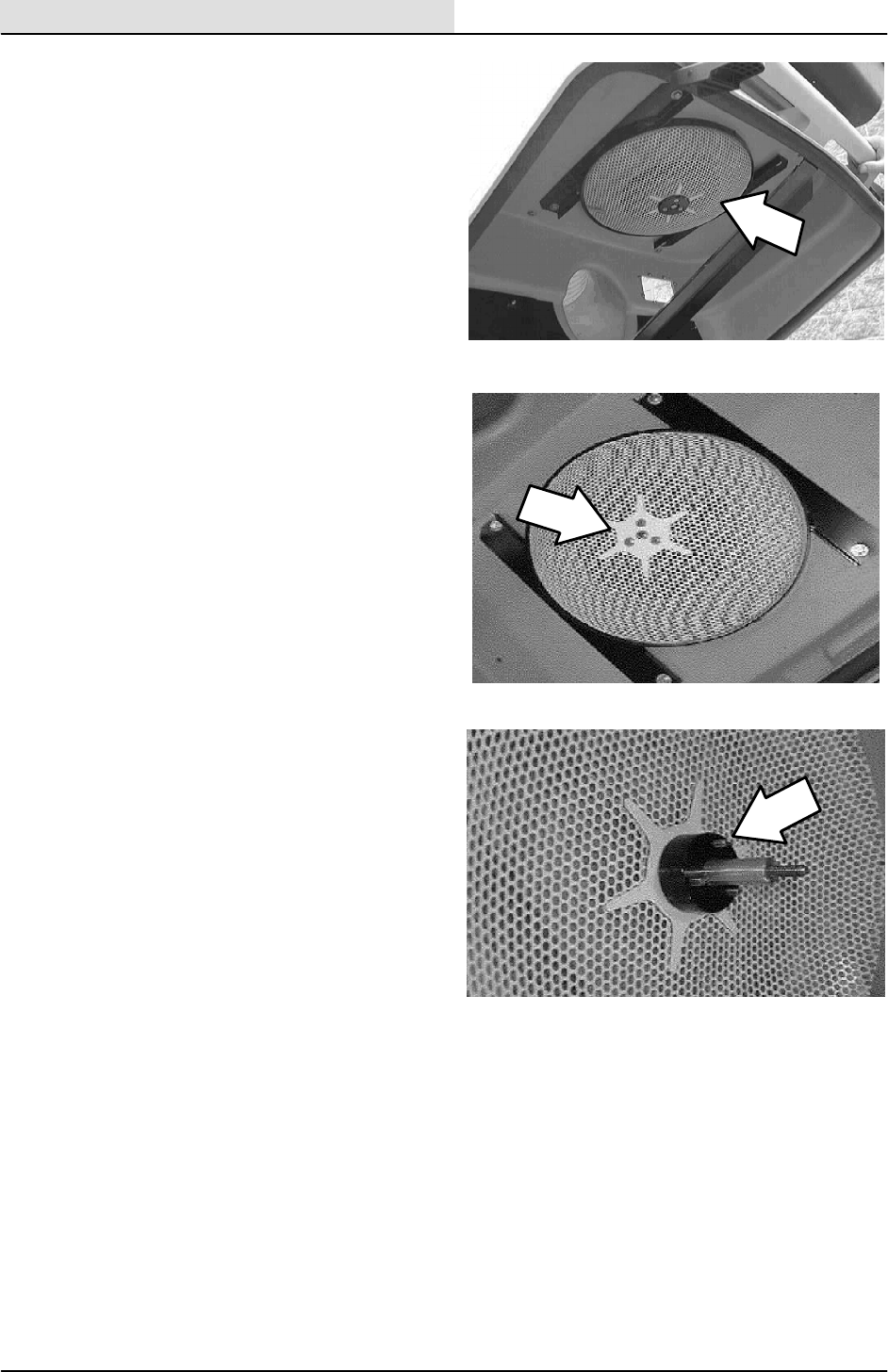
VACUUMING
3-18 ATLV 4300 330495 (10--98)
TO REPLACE VACUUM FAN IMPELLER
SCREEN
FOR SAFETY: Before Leaving Or
Servicing Machine; Stop On Level
Surface, Set Parking Brake.
NOTE: Anytime hopper or vacuum system parts
are serviced the seals should be inspected and
replaced if necessary.
1. Open the hopper cover.
2. Go under the hopper cover and locate the
vacuum fan impeller screen. Remove the
three flat head screws and the one hex
screw holding the screen to the impeller.
3. Pull the impeller screen off the vacuum fan
motor shaft. Make note of the orientation of
the spacers.
4. Install the new impeller screen, spacers, and
sleeve onto the vacuum fan motor shaft.
5. Use blue loctite (242) on the threads of the
impeller screen hardware. Reinstall the one
M8 hex screw and three M6 flat screws.
6. Close the hopper cover.
7. Operate the machine and check the vacuum
fan for proper operation.

VACUUMING
3-19
ATLV 4300 330495 (5--02)
MACHINE TROUBLESHOOTING
Problem Cause Remedy
Machine does not start Glow plug not warmed up properly Turnkeytowarmupglowplug
Fuel filter plugged Replace fuel filter
Fuel pump damaged Replace fuel pump
Machine propels slowly Cables not adjusted Readjust stops or cables
Machine does not propel Machine not on Start machine
Parking brake on Release parking brake
Towing valve on Turn towing valve 90°
Poor vacuum performance Vacuum head or hose clogged Remove vacuum head or hose
blockage
Hopper vacuum fan clogged Clean off fan vacuum screen
Vacuum head not lowered
completely
Lower vacuum head completely
Vacuum head seals damaged Replace or repair worn vacuum
head seals
Machine propelling too fast Slow machine speed
Vacuum not close enough to
debris
Move vacuum closer to debris
Debris hopper full Empty debris hopper
Engine throttle too low Increase engine throttle
Vacuum bag (option) clogged Empty Vacuum bag (option)
Dust filter bag (option) clogged Empty dust filter bag (option)
Panel filter (option) clogged Clean panel filter (option)
No vacuum power Hopper Thermo Sentryton Check for fire in hopper
Solenoid valve not operating Contact TENNANT service
personnel
Vacuum fan not on Turn vacuum fan on
Vacuum fan failure Contact TENNANT service
personnel
Main vacuum hose gate valve
closed
Open main vacuum hose gate
valve
Vacuum hose unsupported or
too low
Gas cylinders damaged Contact TENNANT service
personnel
Excessive Dusting Vacuum bag (option) open Close Vacuum bag
Panel filter (option) door open Close panel filter door
Water dust control (option) not on Turn on water dust control
Water dust control (option) water
tank empty
Fill water dust control tank
Water dust control (option) spray
nozzle clogged
Clean water dust control spray
nozzle

VACUUMING
3-20 ATLV 4300 330495 (10--98)

ELECTRICAL
4-1
ATLV 4300 330495 (10--98)
CONTENTS
Page
INTRODUCTION 4--3......................
ELECTRICAL SYSTEM 4--4................
BATTERY 4--4............................
TO CHARGE BATTERY 4--4.............
TO REPLACE BATTERY 4--5............
INSTRUMENT PANEL 4--6.................
TO REMOVE INSTRUMENT PANEL 4--6..
TO INSTALL INSTRUMENT PANEL 4--7..
FUSES 4--8..............................
CIRCUIT BREAKERS 4--8.................
TO REPLACE CIRCUIT BREAKER 4--9...
TO REPLACE RELAY 4--11..............
ACTUATOR 4--12.........................
TO REPLACE VACUUM HEAD
LIFT ACTUATOR 4--12...............
TO REPLACE ENGINE ALTERNATOR 4--14.
TO REPLACE ENGINE STARTER 4--16.....
ELECTRICAL SCHEMATIC 4--17............
WIRE HARNESS 4--19....................
TROUBLESHOOTING 4--25................

ELECTRICAL
4-2 ATLV 4300 330495 (10--98)

ELECTRICAL
4-3
ATLV 4300 330495 (10--98)
INTRODUCTION
The machines electrical system consists of the
batteries, instrument panel, actuators, switches,
relays, and circuit breakers.
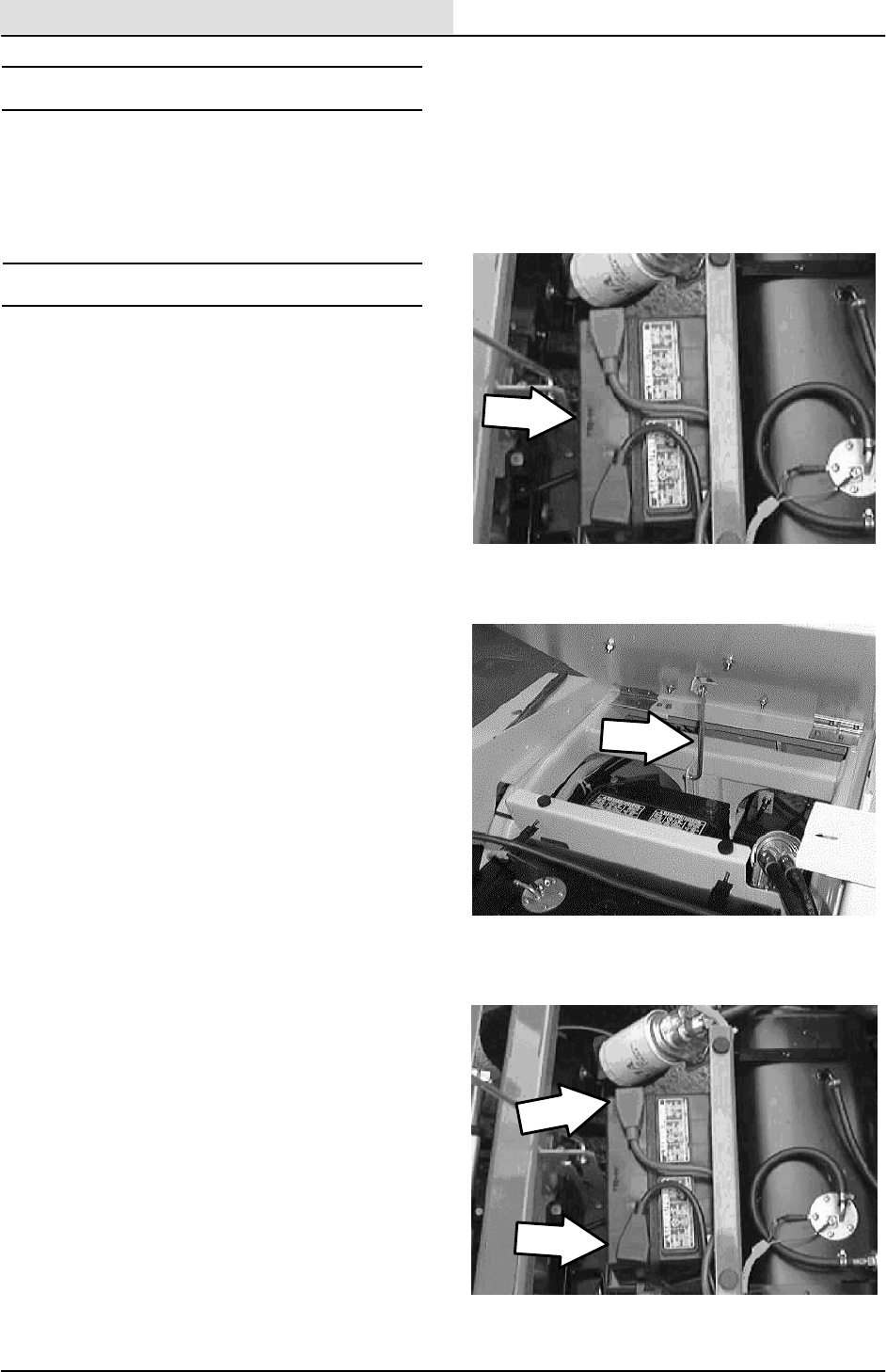
ELECTRICAL
4-4 ATLV 4300 330495 (10--98)
ELECTRICAL SYSTEM
The electrical system on the model ATLV 4300 is
a 12 volt system consisting of a battery, alternator,
circuit breakers, relays, and switches.
BATTERY
The battery is located under the operator’s seat
and can be accessed by lifting the seat up.
After the first 50 hours of operation, and every
200 hours after that, clean and tighten the battery
connections.
Check the electrolyte level every 200 hours of
operation. Only add distilled water.
FOR SAFETY: When Servicing Machine,
Avoid Contact With Battery Acid.
TO CHARGE BATTERY
FOR SAFETY: Before Leaving Or
Servicing Machine; Stop On Level
Surface, Set Parking Brake, turn off
machine, and remove key.
1. Open the seat support and engage the prop
rod.
2. Locate the battery at the center of the
machine, on top and ahead of the front axle.
3. Remove the battery negative cable.
4. Connect the battery charger to the battery.
Make sure to hook the red clamp on the
positive post and the black clamp to the
negative post.
5. Start the charger. Check the voltage meter
on the charger for proper charge voltage.
6. Remove the charger after the voltage meter
reads a full charge.
7. Reinstall the negative battery cable and start
the machine. Check the battery for proper
operation.
8. Disengage the prop rod and lower the seat
support.
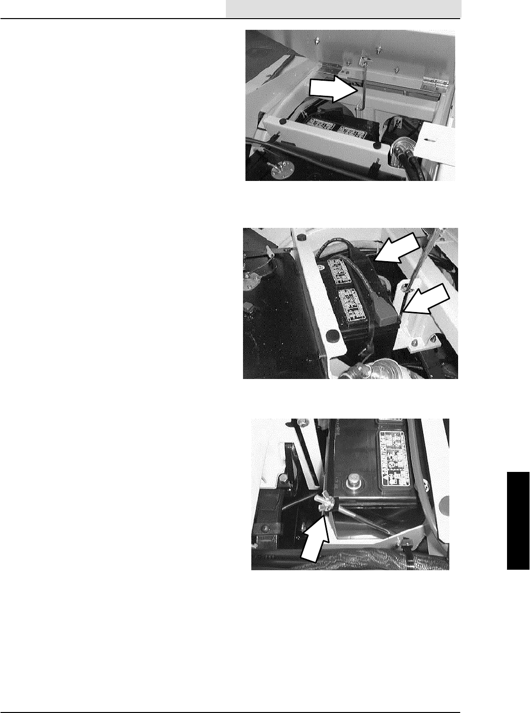
ELECTRICAL
4-5
ATLV 4300 330495 (10--98)
TO REPLACE BATTERY
FOR SAFETY: Before Leaving Or
Servicing Machine; Stop On Level
Surface, Set Parking Brake, turn off
machine, and remove key.
1. Open the seat support and engage the prop
rod.
2. Locate the battery at the center of the
machine, on top and ahead of the front axle.
3. Unhook and remove the rubber battery hold
down strap or remove the threaded hold
down bracket.
4. Remove the battery negative and positive
cables.
5. Lift the battery out of the machine.
6. Install the new battery in the machine in the
same orientation as the old one.
7. Reconnect the battery cables to the battery
(red cable to positive post, black cable to
negative post)
8. Reinstall the rubber battery hold down strap
or reinstall the threaded hold down bracket.
9. Disengage the prop rod and lower the seat
support.
10. Check the new battery for proper operation.
If battery needs charging, see TO CHARGE
BATTERY instructions in this section.

ELECTRICAL
4-6 ATLV 4300 330495 (10--98)
INSTRUMENT PANEL
The instrument panel on the model ATLVt4300
is used to hold most of the electrical switches,
indicator lights, circuit breakers, and meters.
TO REMOVE INSTRUMENT PANEL
FOR SAFETY: Before Leaving Or
Servicing Machine; Stop On Level
Surface, Set Parking Brake, turn off
machine, and remove key.
1. Open the seat support and engage the prop
rod.
2. Locate the battery at the center of the
machine, on top and ahead of the front axle.
3. Remove the battery negative cable.
4. Disengage the prop rod and lower the seat
support.
5. Remove the cap from the center of the
steering wheel (snap out).
6. Remove the M20 hex nut from the center of
the steering wheel.
7. Use a puller to remove the steering wheel
from the steering column.
8. Remove the knob from the tilt steering wheel
pull lever.
9. If the machine is equipped with turn signals,
remove the turn signal unit from the steering
column.
10. Remove the two smaller pan screws from
the top side of the instrument panel.
11. Remove the two larger pan screws from the
back side of the instrument panel.
12. Carefully pull the instrument panel up until
the rubber boot clears the steering column.
13. Place the instrument panel back, against the
kick panel of the operators compartment.
14. The components located on the instrument
panel can now be serviced.
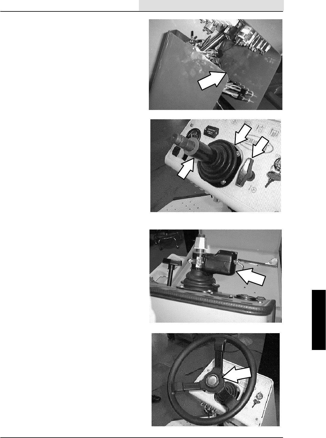
ELECTRICAL
4-7
ATLV 4300 330495 (10--98)
TO INSTALL INSTRUMENT PANEL
FOR SAFETY: Before Leaving Or
Servicing Machine; Stop On Level
Surface, Set Parking Brake, turn off
machine, and remove key.
1. Position the instrument panel and rubber
boot over the top of the steering column. Be
careful not to tear the boot.
2. Push the panel down until the four mount
holes line up with the weldnuts.
3. Reinstall the two small pan screws on top of
the panel and the two larger pan screws on
the back side of the panel. Hand tighten
tight.
4. Reinstall the tilt steering rod knob. Spin
down tight.
5. Reinstall the steering wheel and M20 nut.
Tighten tight.
6. Reinstall the cap in the center of the steering
wheel (snap in).
7. Reinstall the turn signal assembly if the
machine is equipped with road light option.
8. Open the seat support and engage the prop
rod.
9. Reconnect the battery cable to the battery
(red cable to positive post, black cable to
negative post).
10. Disengage the prop rod and lower the seat
support.
11. Start the machine and check for proper
operation.
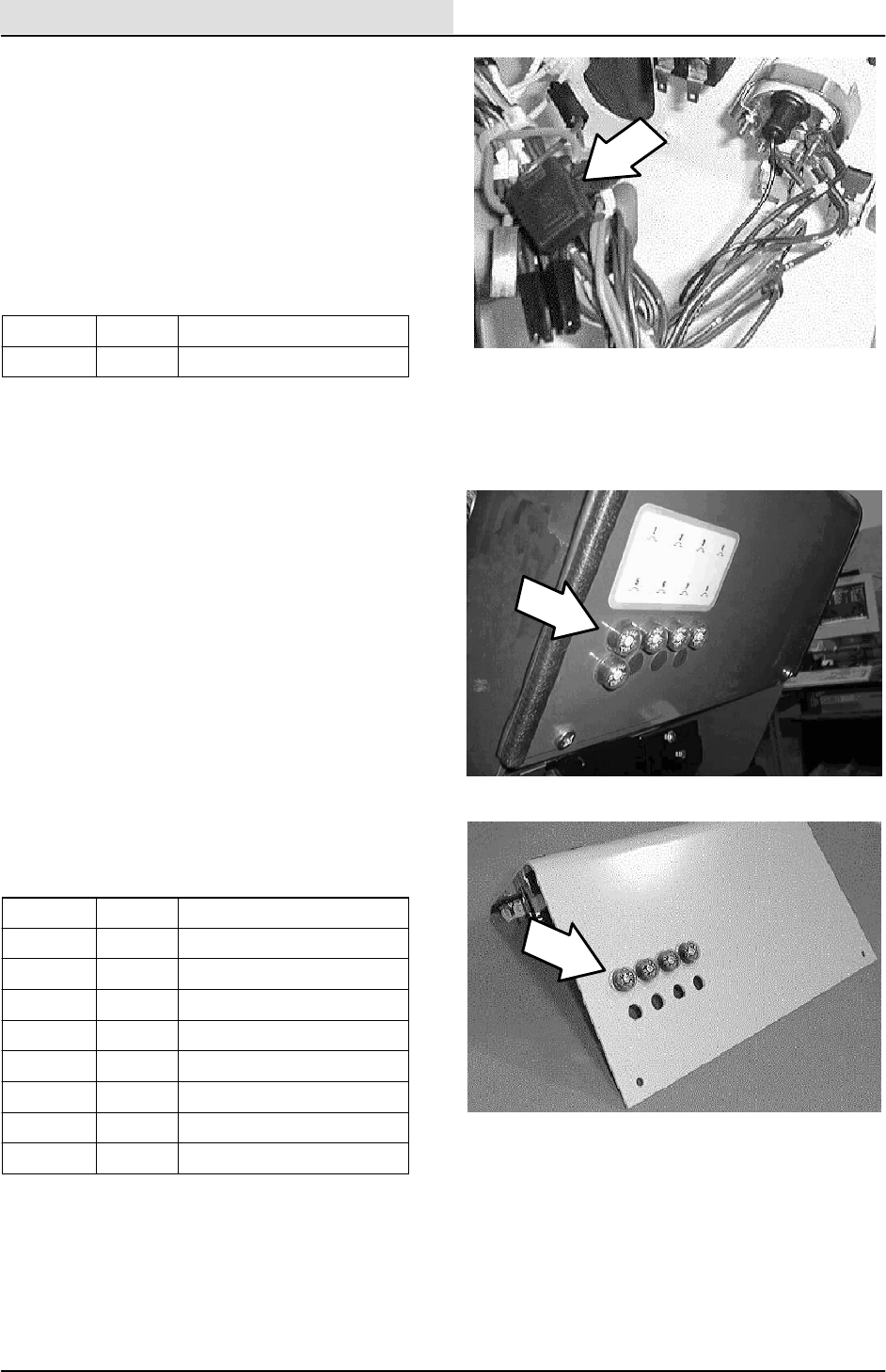
ELECTRICAL
4-8 ATLV 4300 330495 (10--98)
FUSE
The fuse is a one-time protection device designed
to stop the flow of current in the event of a circuit
overload.
NOTE: Never substitute higher value fuses than
specified.
Thefuseisanin--linetypeandislocatedinthe
main harness, behind the circuit breaker panel.
Fuse Rating Circuit Protected
FU-1 30 A Glow plug
CIRCUIT BREAKERS
The circuit breakers are resettable electrical
circuit protection devices. Their design stops the
flow of current in the event of a circuit overload.
Once a circuit breaker is tripped, it must be reset
manually. Press the reset button after the breaker
has cooled down.
If the overload that caused the circuit breaker to
trip is still there, the circuit breaker will continue to
stop current flow until the problem is corrected.
The circuit breaker panel is located above the foot
pedals
The chart lists the circuit breakers and the
electrical components they protect.
Breaker Rating Circuit Protected
CB-1 15 A Accessory/ Vac/ Hyd
CB-2 15 A Horn
CB--3 15 A Work Lights (Opt)
CB-4 15 A Operating Lights
CB-5 15 A Brake/ Turn signals (Opt)
CB-6 15 A Options
CB-7 15 A Options
CB-8 15 A Options
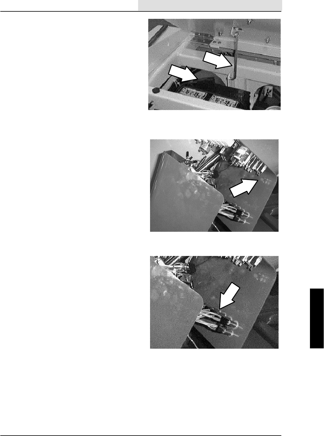
ELECTRICAL
4-9
ATLV 4300 330495 (10--98)
TO REPLACE CIRCUIT BREAKER
FOR SAFETY: Before Leaving Or
Servicing Machine; Stop On Level
Surface, Set Parking Brake, turn off
machine, and remove key.
1. Open the seat support and engage the prop
rod.
2. Locate the battery at the center of the
machine, on top and ahead of the front axle.
3. Remove the battery negative cable.
4. Disengage the prop rod and lower the seat
support.
5. Remove the instrument panel. See TO
REMOVE INSTRUMENT PANEL
instructions in this section.
6. Locate the circuit breaker that needs to be
changed.
7. Mark and disconnect the wires leading to the
back of the circuit breaker.
8. Remove the metal retainer ring from the
back of the circuit breaker.
9. Push the circuit breaker out of the hole.
Retain the clear, rubber boot and discard the
circuit breaker.
10. Position the new circuit breaker into the
mount hole.
NOTE: The mount hole has a “D” shape to match
the shape of the circuit breaker.
11. Install the metal retainer ring onto the back
of the new circuit breaker. Push the retainer
all the way down the circuit breaker.
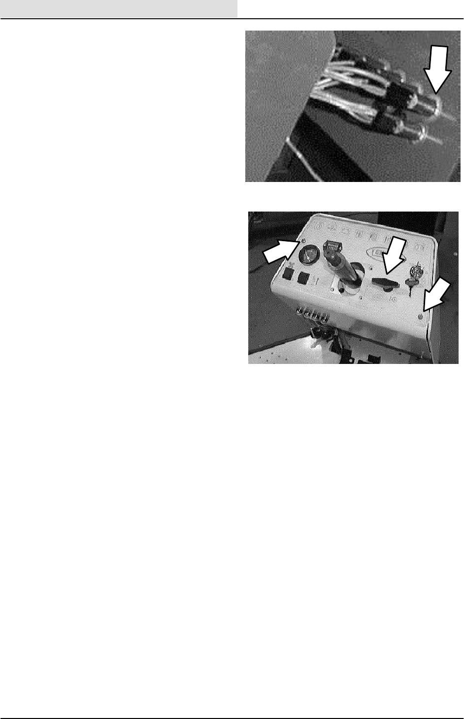
ELECTRICAL
4-10 ATLV 4300 330495 (10--98)
12. Install the rubber boot onto the out side of
the new circuit breaker.
13. Reconnect the electrical wires to the new
circuit breaker. See schematic in the
ELECTRICAL section.
14. Reinstall the instrument panel. See TO
INSTALL INSTRUMENT PANEL instructions
in this section.
15. Open the seat support and engage the prop
rod.
16. Reconnect the battery cable to the battery
(red cable to positive post, black cable to
negative post)
17. Disengage the prop rod and lower the seat
support.
18. Start the machine and check for proper
operation.
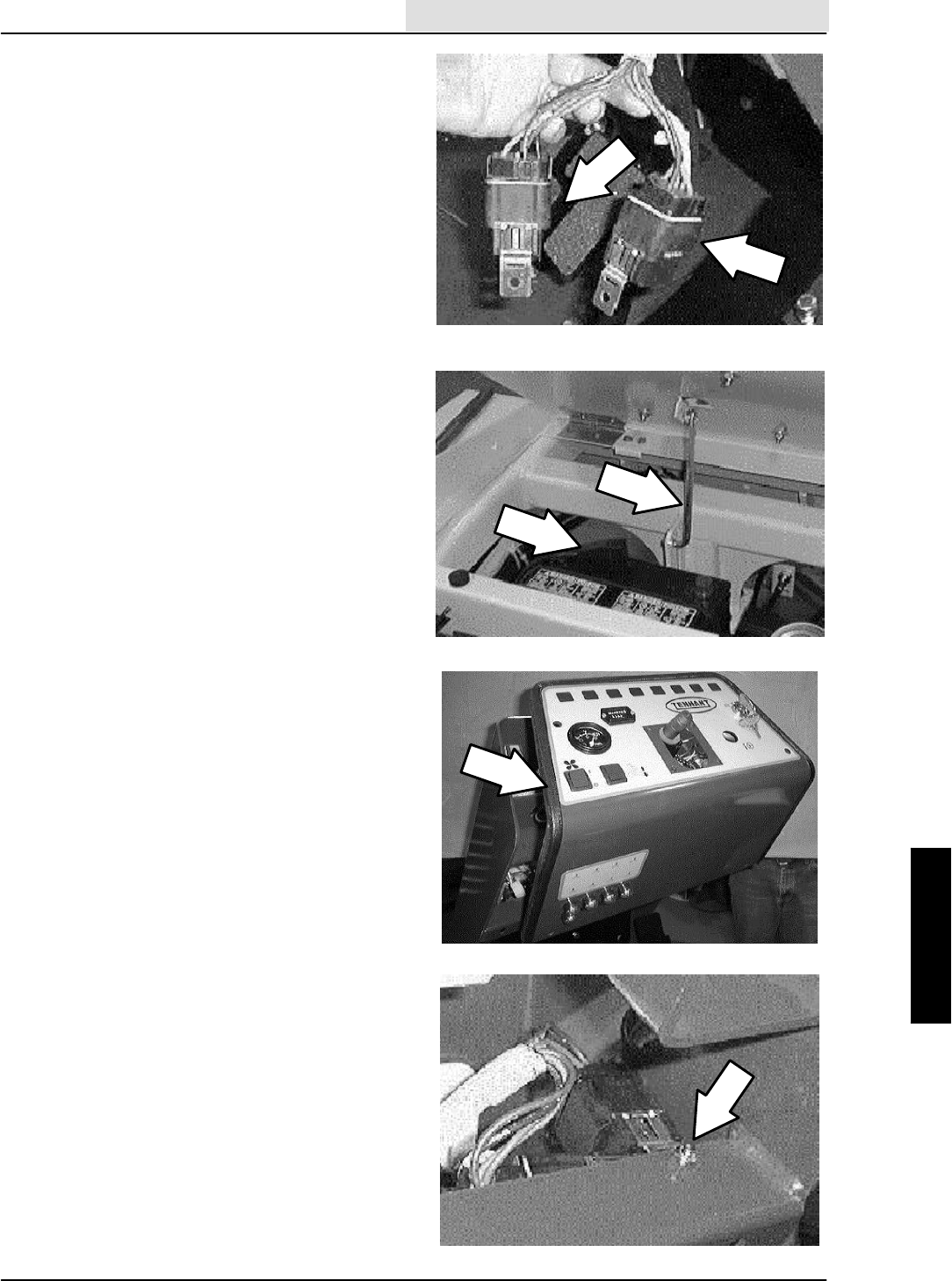
ELECTRICAL
4-11
ATLV 4300 330495 (10--98)
TO REPLACE RELAY
FOR SAFETY: Before Leaving Or
Servicing Machine; Stop On Level
Surface, Set Parking Brake, turn off
machine, and remove key.
1. Open the seat support and engage the prop
rod.
2. Locate the battery at the center of the
machine, on top and ahead of the front axle.
3. Remove the battery negative cable.
4. Disengage the prop rod and lower the seat
support.
5. Remove the instrument panel. See TO
REMOVE INSTRUMENT PANEL
instructions in this section.
6. Locate the relay that needs to be changed.
7. Disconnect the wire connector leading to the
back of the relay.
8. Remove the hex screw and nut holding the
relay to the machine frame. Remove and
discard the relay.
9. Position the new relay in the machine and
reinstall the hex screw and nut. Hand
tighten.
10. Reconnect the electrical connector to the
new relay. See schematic in the
ELECTRICAL section.
11. Reinstall the instrument panel. See TO
INSTALL INSTRUMENT PANEL instructions
in this section.
12. Open the seat support and engage the prop
rod.
13. Reconnect the battery cable to the battery
(red cable to positive post, black cable to
negative post)
14. Disengage the prop rod and lower the seat
support.
15. Start the machine and check for proper
operation.

ELECTRICAL
4-12 ATLV 4300 330495 (10--98)
ACTUATOR
The actuator on the model ATLVt4300 is used
to raise and lower the vacuum head on the front
of the machine. The actuator is connected to a lift
cable that pulls on a pulley assembly to raise the
vacuum head.
TO REPLACE VACUUM HEAD LIFT
ACTUATOR
FOR SAFETY: Before Leaving Or
Servicing Machine; Stop On Level
Surface, Set Parking Brake, turn off
machine, and remove key.
1. Position a block of wood under the front of
the vacuum head.
2. Lower the vacuum head down onto the block
of wood, lower the head enough so there is
some slack in the lift cable.
3. Go under the machine at the front right side
of the machine.
4. Locate the vacuum head lift actuator and the
long, black cable nut at the end of the lift
cable.
5. Hold the cable from turning with a pliers or a
vice grip.
6. Loosen the jam nut against the long, black
cable nut.
7. Un--screw the long, black cable nut from the
end of the lift cable.
8. Disconnect the actuator from the main
electrical harness.
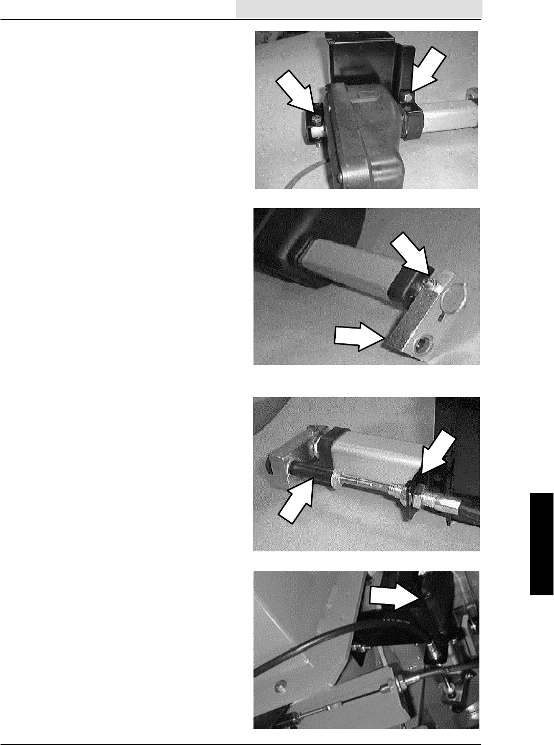
ELECTRICAL
4-13
ATLV 4300 330495 (10--98)
9. Go to the operators compartment and
remove the three actuator mount screws
from the back kick panel.
10. Drop the vacuum head lift actuator assembly
out of the machine.
11. Remove the three hex screws and two
mount brackets holding the actuator to the
main mount bracket. Remove the actuator.
NOTE: Make sure to retain the gasket.
12. Remove the long M8 hex screw holding the
cable block to the shaft of the actuator.
Remove the cable block and position it onto
the new actuator in the same orientation.
13. Reinstall the long M8 hex screw. Tighten to
18 -- 24 Nm (15 -- 20 ft. lb).
14. Position the new actuator onto the main
mount bracket. Reinstall the two brackets
and three hex screws. Tighten to
18 -- 24 Nm (15 -- 20 ft. lb).
NOTE: Make sure to reinstall the gasket to protect
the aluminum housing on the actuator.
15. Position the actuator assembly back into the
machine. Reinstall the three hex screws.
Tighten to 18 -- 24 Nm (15 -- 20 ft. lb).
16. Reconnect the actuator to the main electrical
harness.
17. Position the long, black cable lift sleeve
through the hole in the actuator lift block.
18. Thread the long, black lift sleeve onto the
end of the vacuum head lift cable. Leave
loose for now.
19. See TO ADJUST vacuum HEAD
ACTUATOR LIFT CABLE instructions in the
vacuum section.
20. Operate the machine and check the vacuum
head lift actuator for proper operation.
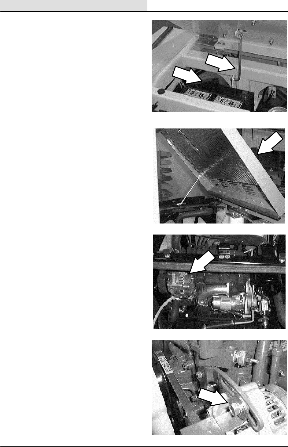
ELECTRICAL
4-14 ATLV 4300 330495 (10--98)
TO REPLACE ENGINE ALTERNATOR
FOR SAFETY: Before Leaving Or
Servicing Machine; Stop On Level
Surface, Set Parking Brake, Turn Off
Machine And Remove Key.
1. Tilt the seat assembly forward and engage
the prop rod. Disconnect the battery cables
from the battery.
2. Open the top engine cover.
3. Locate the alternator at the front right area
of the engine.
4. Disconnect the wires from the back of the
alternator.
5. Loosen the hex screw holding the top of the
alternator to the pivot bracket.
6. Loosen the hex screw on the bottom of the
alternator.
7. Pivot the alternator in toward the engine and
remove the fan belt from the sheave.
8. Remove both hex screws. Remove the old
alternator out past the exhaust pipe.
9. Position the new alternator in place. Go in
front the exhaust pipe.
10. Reinstall the longer lower hex bolt and nut.
Leave loose for now.
11. Reinstall the shorter hex bolt in the top of
the alternator. Leave loose for now.
12. Reinstall the fan/alternator belt.
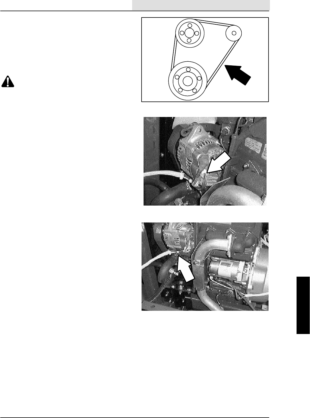
ELECTRICAL
4-15
ATLV 4300 330495 (10--98)
13. Using a pry bar, pull the alternator away
from the engine until the belts are tight.
Proper belt tension is 10 mm (0.40 in) from
aforceof4to5kg(8to10lb)appliedatthe
mid-point of the longest span. Check and
adjust the belt tension every 100 hours of
operation. Hand tighten the top hex bolt
tight.
WARNING: Moving Belt And Fan Blades.
Keep Away.
14. Firmly tighten the lower hex bolt.
15. Reconnect the electrical wires to the back of
the alternator. See schematic in this section.
16. Reconnect the battery cables to the battery.
17. Close the engine cover and lower the seat
assembly.
18. Start the engine and check the alternator for
proper operation.
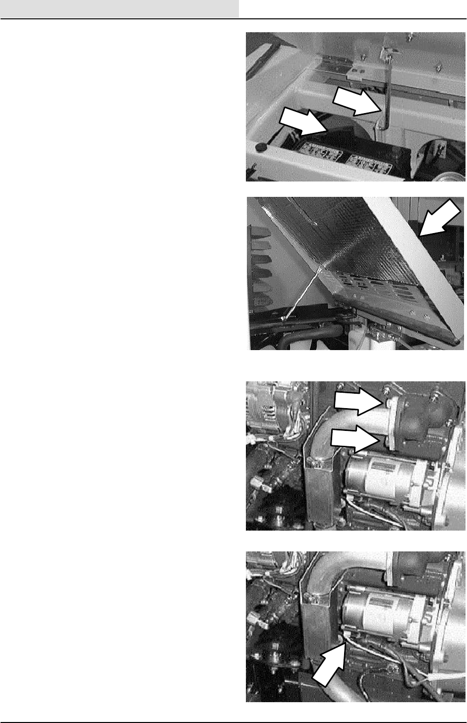
ELECTRICAL
4-16 ATLV 4300 330495 (10--98)
TO REPLACE ENGINE STARTER
FOR SAFETY: Before Leaving Or
Servicing Machine; Stop On Level
Surface, Set Parking Brake, Turn Off
Machine And Remove Key.
1. Tilt the seat assembly forward and engage
the prop rod. Disconnect the battery cables
from the battery.
2. Open the top engine cover.
3. Disconnect the wires from the starter motor.
4. Remove the two hex screws holding the
exhaust pipe to the exhaust manifold. Pull
the pipe out of the way for clearance to
remove the starter.
5. Remove the two hex nuts holding the starter
to the engine. Remove the starter from the
flywheel housing and out of the machine.
6. Position the new starter back in the flywheel
housing. Re--use the two hex nuts and
tighten to 18 -- 24 Nm (15 -- 20 ft lb).
7. Reconnect the electrical wires to the starter.
See schematic in this section.
8. Reinstall the exhaust pipe to the exhaust
manifold. Reinstall the two hex screws and
tighten to 18 -- 24 Nm (15 -- 20 ft lb).
9. Reconnect the battery cables to the battery
and check the starter for proper operation.
10. Close the engine cover and pivot the seat
assembly down.
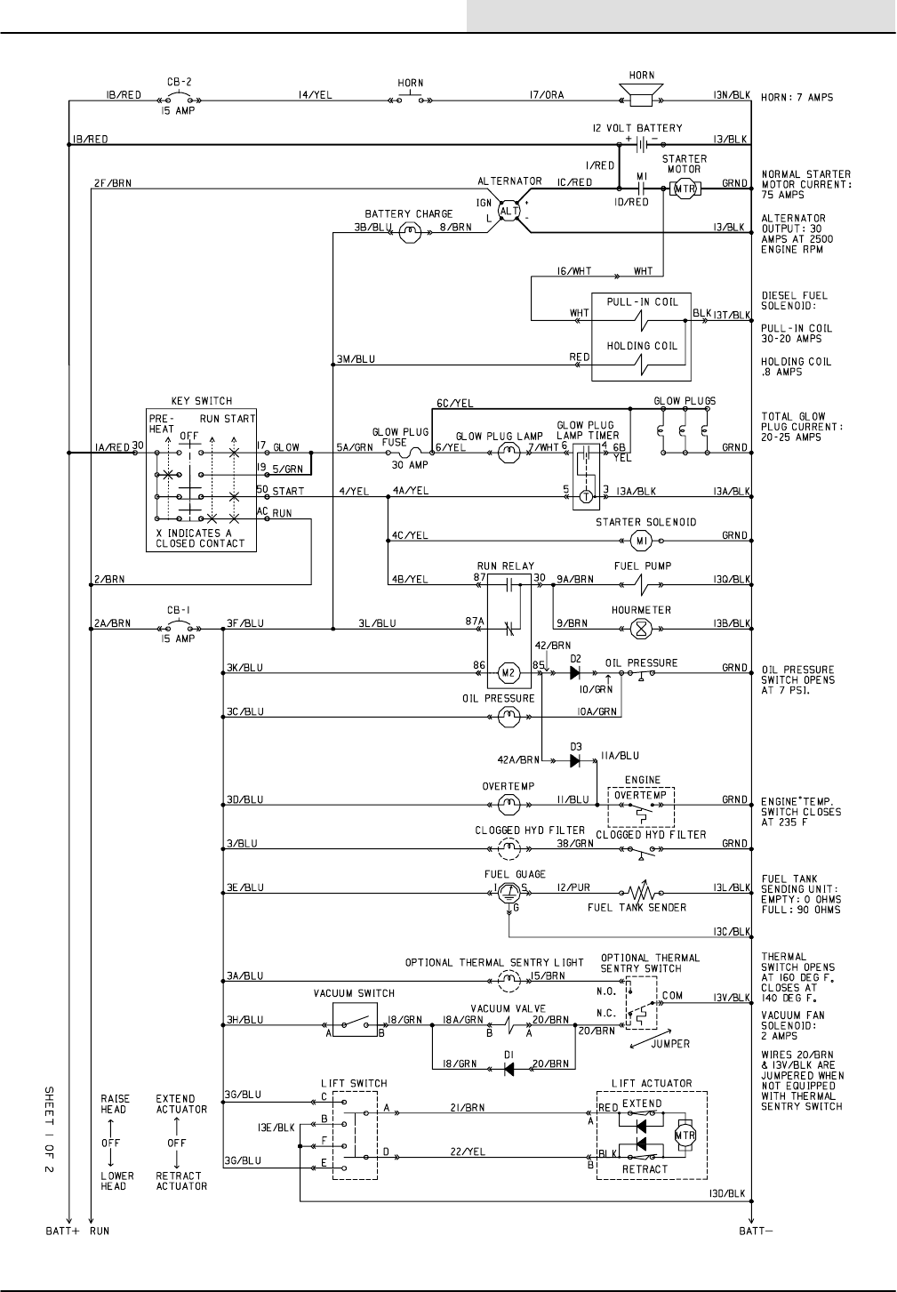
ELECTRICAL
4-17
ATLV 4300 330495 (6--01)
ELECTRICAL SCHEMATIC
352281
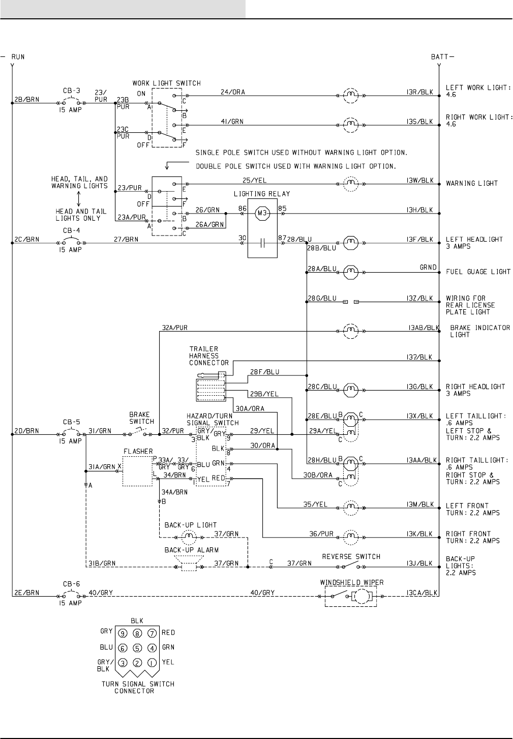
ELECTRICAL
ATLV 4300 330495 (6--01)
4-18
ELECTRICAL SCHEMATIC
352281
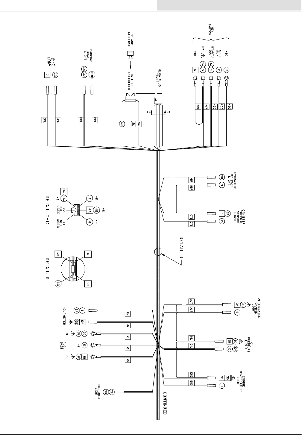
ELECTRICAL
4-19
ATLV 4300 330495 (6--01)
WIRE HARNESS
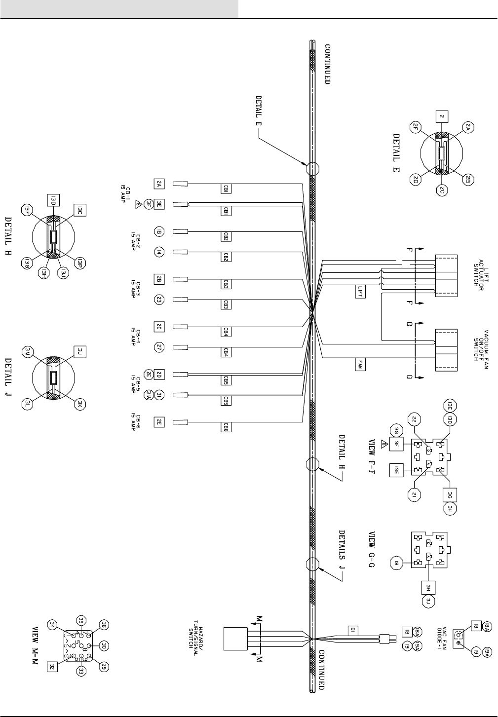
ELECTRICAL
ATLV 4300 330495 (6--01)
4-20
WIRE HARNESS
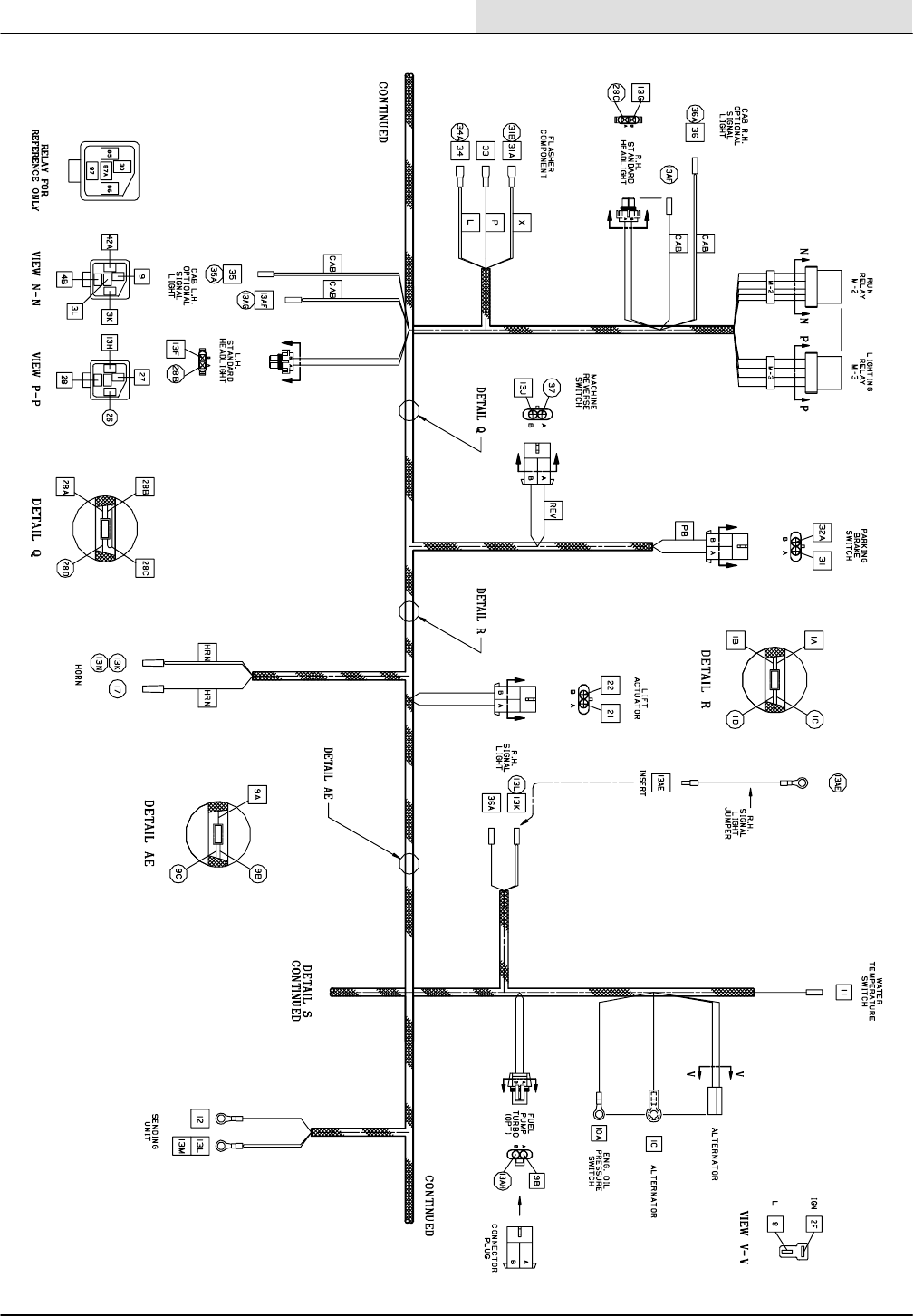
ELECTRICAL
4-21
ATLV 4300 330495 (6--01)
WIRE HARNESS

ELECTRICAL
ATLV 4300 330495 (6--01)
4-22
WIRE HARNESS

ELECTRICAL
4-23
ATLV 4300 330495 (6--01)
WIRE HARNESS
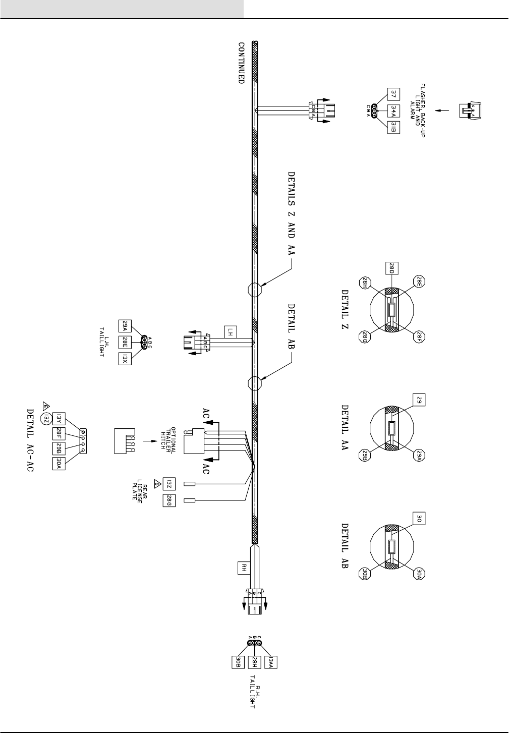
ELECTRICAL
ATLV 4300 330495 (6--01)
4-24
WIRE HARNESS

ELECTRICAL
4-25
ATLV 4300 330495 (10--98)
TROUBLESHOOTING
The troubleshooting charts that follow are
organized so they lead you through the circuits.
They include flow charts and instructions for you
as to where to insert your test instruments.

ELECTRICAL
4-26 ATLV 4300 330495 (10--98)
First check to make sure that:
1. Battery is charged.
2. Fuel in the fuel tank.
3. Unrestricted air filter.
Is there battery
voltage at the battery cable terminal
of the starter motor
Check battery,
battery cables, and
connections.
Check for battery
voltage at terminal
30 of the key
switch.
Repair
connections or
replace battery
cables
While turning the key
switch to the start
position, check for
battery voltage at
Terminal 50 of the key
switch with respect to
battery negative (--).
yes
Check wire 1/RED from the
starter motor, to the alternator, to
the key switch and repair or
replace as necessary.
no
Again, while turning the
key to the start position,
check for battery
voltage at wire 4C/YEL
at the starter motor
solenoid M1.
Replace the ignition
switch
yes
no
Repair or
replace wire
4C/YEL
yes
no
yesno
Starter motor turns
Starter motor won’t turn
Replace the starter motor
solenoid or starter motor
assembly
ENGINE WILL NOT CRANK

ELECTRICAL
4-27
ATLV 4300 330495 (10--98)
ENGINE WILL NOT RUN First check to make sure :
1. Battery is charged.
2. Fuel in the fuel tank.
3. Unrestricted air filter.
4. Engine oil at full level.
5. CB--1 is not tripped
Starter motor
will not crank
Check the oil pressure
switch:
Disconnect wire 10A/
GRN and check the oil
pressure switch with an
ohmmeter connected to
the pressure switch
terminal and engine
ground. Crank the
engine for a few
seconds to see if the
contacts change from a
closed to an open
condition Caution,
keep clear of rotating
fan and belt drive!
Engine runs
See previous pagenoEngine turns over, but won’t start. Engine will not run
no
ok
Checking M2 Relay:
With M2 installed, disconnect the electric fuel pump. Using a voltmeter, look for battery voltage
at the main harness connector to the fuel pump wires 9A/BRN and 13Q/BLK while trying to
start the engine.Caution, keep clear of rotating fan and belt drive! Battery voltage should
be present while the engine is cranking and after the oil pressure lamp goes out.
Replace
relay M2
ok
ok
Does the oil pressure light turn on with the key switch in the run position, and then go out after
cranking the engine for a while? Caution, keep clear of rotating fan and belt drive!
ok
Check the key switch: With a voltmeter, check for battery voltage at the key switch terminal AC (wire 2/BRN) with any
13/BLK wire while the key switch is in the on position.
no
Check wiring and repair or, reset
or replace circuit breaker CB--1.
ok
no
Check for fuel delivery from the fuel pump to the engine while
cranking the engine.
Caution, keep clear of rotating fan and belt drive!
ok
ok
yes
Replace the oil
pressure switch or
check for low oil
pressure problem.
no
yes
no
Disconnect the diesel fuel solenoid mounted to the side of the engine.
Check for battery voltage at each of the 4/YEL and 3/BLU wires with
respect to ground, while cranking the engine and after the oil
pressure light has gone out.
Caution, keep clear of rotating fan and belt drive!
Replace the key switch
Checking the fuel solenoid:
Remove the diesel solenoid from the engine and reconnect to the
main harness. Disconnect the 4/YEL wire from the starter solenoid to
prevent the starter motor from turning. Turn the key switch to the start
positionand notice if the plunger on the solenoid moves.
no
Check engine circuit breaker:With a voltmeter, check for battery voltage at CB--1, wire 3/BLU with
any 13/BLK wire while the key switch is in the on position.
ok
no
Replace
fuel
pump
Replace fuel
solenoid
ok

ELECTRICAL
4-28 ATLV 4300 330495 (10--98)
VACUUM FAN WILL NOT RUN
With the engine off ,First check to make sure that:
1.The vacuum fan rotates free.
2. The hydraulic oil level is correct.
3. The hopper is not full.
Vacuum fan runs
Checking for battery voltage to the vacuum fan switch:
With the key switch in the on position and the engine NOT running , check for
battery voltage between the 3//BLU wire at the vacuum fan switch and any 13/
BLK wire.
Checking the vacuum switch:
With the key switch in the on position and the engine NOT running , turn on the vacuum
switch and check for battery voltage between wire 18/GRN at the vacuum switch and any
13/BLK wire..
battery
voltage
present
Reset or replace if
defective, CB--1
circuit breaker.
no
battery
voltage
present
no battery
voltage
no battery
voltage
battery
voltage
present
no battery
voltage
ok
ok
Replace if the defective
Vacuum fan switch.
Is the optional thermal
sentry light on?
Make sure the key switch is off with
the engine NOT running, check for
possible fire or high temperatures in
the hopper cover area !!!
yes
Checking the thermal sentry switch:
With the key switch in the on position and the engine NOT
running , turn on the vacuum switch and check for battery
voltage between wire 18/GRN at the vacuum switch and 20/BRN
at the thermal sentry switch.
Replace if the defective thermal sentry
switch.
Replace if the defective vacuum fan
solenoid valve coil.
ok

ELECTRICAL
4-29
ATLV 4300 330495 (10--98)
HEAD LIFT WILL NOT OPERATE
With the key switch in the on position, check for battery
voltage between the 3/BLU wire at the CB--1 circuit breaker
and any 13/BLK wire.
This troubleshooting guide deals primarily
with the optional head lift motorized linear
actuator
With the engine NOT running and the key switch in the
on position, check for battery voltage between both 3/BLU
wires, and any 13/BLK wire.
Replace CB--1
circuit breaker
Head lift operates correctly
ok
ok
Check to see that the head lift mechanism has not been damaged or prevented from traveling its normal range of movement.
Vacuum head lift does not operate
no yes
Does the engine
run ?
yes
First check to make sure :
1. Battery is charged.
2. Engine runs good.
Check wiring of 3/BLU wires
between CB--1 and the head
lift switch and repair
no
battery
voltage battery
voltage
With the key switch in the on position and the engine NOT
running , hold the head lift switch in the raise position while
measuring for battery voltage between both 21/Brn and 22/
YEL wires to any 13/BLK wire.
battery
voltage
no
battery
voltage
battery
voltage
no
battery
voltage
With the key switch in the on position
and the engine NOT running , hold
the head lift switch in the lower position
while measuring for battery voltage
between both 21/Brn and 22/YEL wires
to any 13/BLK wire.
battery
voltage
Replace the head
lift switch
ok
no
battery
voltage
Replace the head lift actuator.ok

ELECTRICAL
4-30 ATLV 4300 330495 (10--98)

HYDRAULICS
5-1
ATLV 4300 330495 (10--98)
CONTENTS
Page
INTRODUCTION 5--3.......................
HYDRAULIC FLUID RESERVOIR 5--4........
HYDRAULIC FLUID 5--5....................
HYDRAULIC HOSES 5--5...................
HYDRAULIC FLUID COOLER 5--6...........
HYDRAULIC FLUID FILTER 5--6.............
TO REPLACE HYDRAULIC FLUID
FILTER 5--6...........................
HYDRAULIC PUMPS 5--7...................
TO REPLACE PROPEL PUMP 5--7........
TO REPLACE ACCESSORY PUMP 5--10...
HYDRAULIC MOTORS 5--12.................
TO REPLACE VACUUM FAN
MOTOR 5--12.........................
TO REPLACE STEERING WHEEL
MOTOR 5--15.........................
TO REPLACE DRIVE WHEEL
MOTOR 5--17........................
STEERING CYLINDER 5--19.................
TO REPLACE STEERING CYLINDER 5--19.
STEERING CYLINDER BREAKDOWN 5--21.
CONTROL VALVE 5--22......................
TO REPLACE SOLENOID CONTROL
VALVE 5-- 22..........................
HYDRAULIC SCHEMATIC 5--25..............
HYDRAULIC HOSE GROUP 5--26............
TROUBLESHOOTING 5--27..................
EATON HYDRAULIC REPAIR MANUAL 5--33...

HYDRAULICS
5-2 ATLV 4300 330495 (10--98)

HYDRAULICS
5-3
ATLV 4300 330495 (10--98)
INTRODUCTION
The hydraulic system consists of the propel pump,
accessory pump, control valve, drive motors,
steering cylinder, and vacuum fan motor.
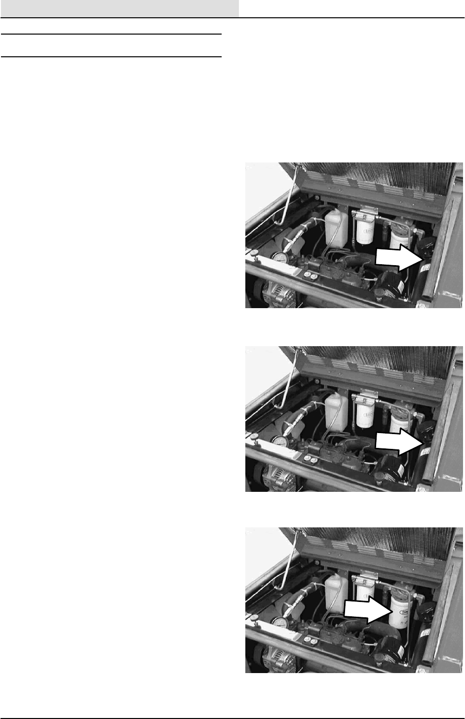
HYDRAULICS
5-4 ATLV 4300 330495 (10--98)
HYDRAULIC FLUID RESERVOIR
The reservoir is located on the left side of the
machine next to the engine.
A filler cap is mounted on top of the reservoir. It
has a built in breather and fluid level dipstick.
Replace the cap after every 800 hours of
operation.
Check the hydraulic fluid level at operating
temperature daily. The dipstick is marked with full
and add markings to indicate the level of hydraulic
fluid in the reservoir. Cold fluid level is mid-point of
add and full lines.
Lubricate the filler cap gasket with a film of
hydraulic fluid before putting the cap back on the
reservoir.
ATTENTION! Do not overfill the
hydraulic fluid reservoir or operate the
machine with a low level of hydraulic
fluid in the reservoir. Damage to the
machine hydraulic system may result.
Drain and refill the hydraulic fluid reservoir with
new hydraulic fluid every 800 hours of operation.
NOTE: When the hydraulic filter bypass light
(optional) comes on, replace the filter, and change
the hydraulic fluid as soon as possible.
The hydraulic fluid filter is located in front of the
hydraulic reservoir near the rear of the engine
compartment. Replace the filter element every
800 hours of operation.

HYDRAULICS
5-5
ATLV 4300 330495 (10--98)
HYDRAULIC FLUID
The quality and condition of the hydraulic fluid
plays a very important role in how well the
machine operates. TENNANT’s hydraulic fluid is
specially selected to meet the needs of TENNANT
machines.
TENNANT’s hydraulic fluids provide a longer life
for the hydraulic components. There are two
TENNANT fluids available for different
temperature ranges:
TENNANT part no. Ambient
Temperature
65869 above 7_C(45_F)
65870 below 7_C(45_F)
The higher temperature fluid has a higher
viscosity and should not be used at the lower
temperatures. Damage to the hydraulic pumps
may occur because of improper lubrication.
The lower temperature fluid is a thinner fluid for
colder temperatures.
If a locally-available hydraulic fluid is used, make
sure the specifications match TENNANT hydraulic
fluid specifications. Using substitute fluids can
cause premature failure of hydraulic components.
ATTENTION! Hydraulic components
depend on system hydraulic fluid for
internal lubrication. Malfunctions,
accelerated wear, and damage will result
if dirt or other contaminants enter the
hydraulic system.
HYDRAULIC HOSES
Check the hydraulic hoses every 200 hours of
operation for wear or damage.
Fluid escaping at high pressure from a very small
hole can be almost invisible, and can cause
serious injuries.
See a doctor at once if injury results from
escaping hydraulic fluid. Serious infection or
reaction can develop if proper medical treatment
is not given immediately.
FOR SAFETY: When Servicing Machine,
Use Cardboard To Locate Leaking
Hydraulic Fluid Under Pressure.
If you discover a fluid leak, contact your
mechanic/supervisor.
00002

HYDRAULICS
5-6 ATLV 4300 330495 (10--98)
HYDRAULIC FLUID COOLER
The hydraulic fluid cooler is located on the outside
of the engine radiator. Hydraulic fluid flows
through the cooler when the machine is running.
Airflow from the engine fan cools the fluid.
HYDRAULIC FLUID FILTER
The hydraulic fluid filter is located on the left side
of the machine frame, behind the engine. The
filter is used to keep the fluid free from
contaminates. The filter should be changed every
800 hours.
TO REPLACE HYDRAULIC FLUID FILTER
FOR SAFETY: Before Leaving Or
Servicing Machine; Stop On Level
Surface, Set Parking Brake, turn off
machine, and remove key.
1. Open the hopper cover and tilt the hopper
back.
2. Open the top engine cover.
3. Remove the five pan screws holding the rear
engine cover to the machine. Remove the
cover.
4. Locate the hydraulic fluid filter on the left
side of the upper machine frame. Place a
drain pan under the filter, on top of the
muffler guard.
5. Un--screw the filter from the filter head.
Properly discard the old filter.
6. Place a small amount of hydraulic oil on the
rubber O--ring on the new filter.
7. Screw the new filter onto the filter head.
Tighten until snug then 1/4 turn.
8. Reinstall the rear engine cover.
9. Remove the drain pan. Tilt the hopper
forward and close the hopper cover.
10. Start the machine and check the new
hydraulic fluid filter for any leaks.
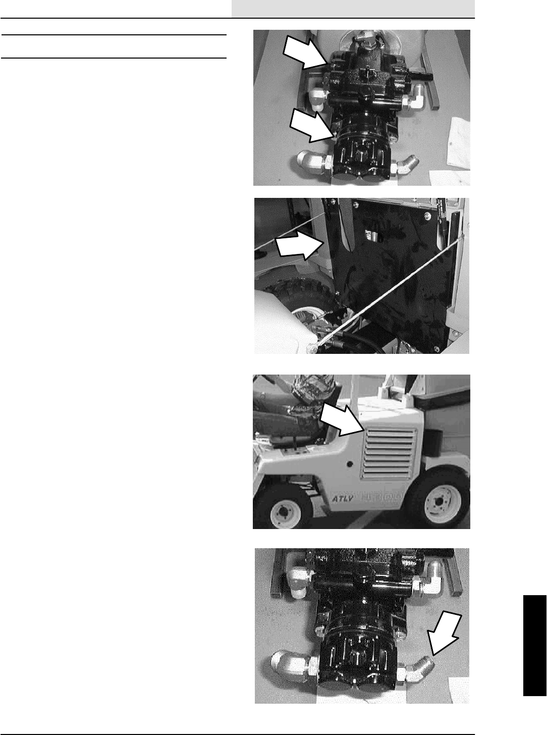
HYDRAULICS
5-7
ATLV 4300 330495 (10--98)
HYDRAULIC PUMPS
The propel pump is used to provide hydraulic flow
to the drive motors. The accessory pump is used
to provide flow to the vacuum fan and steering
circuit.
TO REPLACE PROPEL PUMP
FOR SAFETY: Before Leaving Or
Servicing Machine; Stop On Level
Surface, Set Parking Brake, turn off
machine, and remove key.
1. Open the hopper cover and tilt the hopper
back.
2. Open the top engine cover.
3. Remove the five pan screws holding the rear
engine cover to the machine. Remove the
cover.
4. Remove the grill from the left side fender
panel.
5. Disconnect the air intake tube from the collar
on the left side machine fender.
6. Remove the seven pan screws holding the
left fender to the machine. Pull the fender
out slightly and disconnect the turn signal.
Remove the fender from the machine.
NOTE: Observe hydraulic cleanliness
requirements when opening hydraulic lines.
7. Disconnect and plug the small hydraulic
hose leading to the back side of the
accessory pump. Leave the larger suction
line connected.
8. Remove the two cap screws holding the
accessory pump to the propel pump. Pull the
accessory pump straight back out of the
propel pump. Let the accessory pump drop
down out of the way for access to the propel
pump.
NOTE: Make sure to retain the O--ring.
9. Locate the propel pump directional arm on
the back side of the propel pump. Remove
the two hex screws holding the pump arm to
the pump hub.

HYDRAULICS
5-8 ATLV 4300 330495 (10--98)
10. Mark, disconnect, and plug the four
hydraulic hoses leading to the propel pump.
11. Remove the two hex screws holding the
propel pump to the bellhousing.
NOTE: The bottom hex screw can be accessed
easier with the motor mount removed.
12. Pull the propel pump out of the bellhousing
and remove it from the machine.
13. Remove the directional hub from the side of
the propel pump and install on the new
pump in the same orientation. Use blue
loctite (242) on the threads of the cap screw.
Tighten to 18 -- 24 Nm (15 -- 20 ft. lb).
14. Remove the hydraulic fittings from the old
propel pump and install into the new pump in
the same orientation.
15. Position the new pump assembly into the
engine bellhousing. Line up splines on the
pump input shaft with the teeth in the
flywheel coupling. Push the pump in until it is
against the bellhousing plate.
16. Reinstall the two hex screws into the pump
mount holes. Tighten to 31 -- 40 Nm
(27 -- 35 ft. lb).
NOTE: The pump directional hub faces the rear of
the machine.
17. Reconnect the four hydraulic hoses to the
propel pump. See hose diagram in this
section.
NOTE: Observe hydraulic cleanliness
requirements when opening hydraulic lines.
18. Reinstall the accessory pump into the propel
pump. Make sure the O--ring is installed on
the face of the pump. Reinstall the hardware
and tighten to 31 -- 40 Nm (27 -- 35 ft. lb).
19. Reconnect the one small hydraulic hose to
the accessory pump. See hose diagram in
this section.
NOTE: Observe hydraulic cleanliness
requirements when opening hydraulic lines.
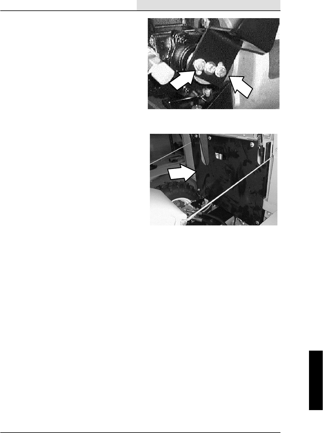
HYDRAULICS
5-9
ATLV 4300 330495 (10--98)
20. Reinstall the directional pump arm onto the
pump hub. Reinstall the two hex screws.
Leave the screws loose for now.
21. The neutral centering will have to be set at
this point. See TO ADJUST PROPEL
NEUTRAL instructions in the CHASSIS
section.
22. Reinstall the left hand side panel and left
hand grill.
23. Reinstall the rear engine cover.
24. Tilt the hopper forward, close the hopper
cover, and close the top engine cover.
25. Start the machine and operate the propel
circuit. Check for proper operation.
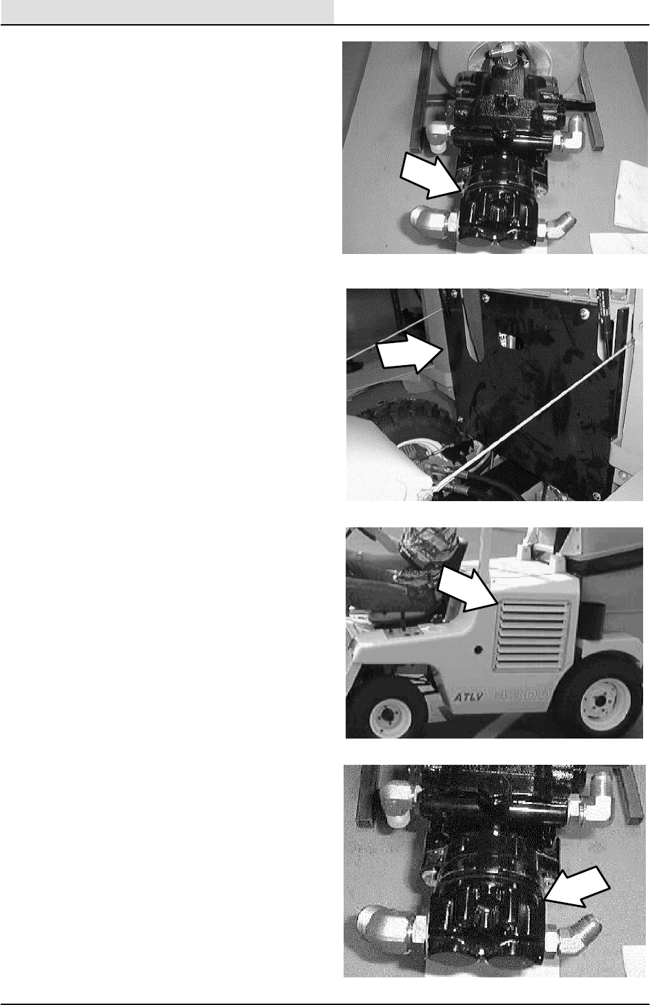
HYDRAULICS
5-10 ATLV 4300 330495 (10--98)
TO REPLACE ACCESSORY PUMP
FOR SAFETY: Before Leaving Or
Servicing Machine; Stop On Level
Surface, Set Parking Brake, turn off
machine, and remove key.
1. Open the hopper cover and tilt the hopper
back.
2. Open the top engine cover.
3. Remove the five pan screws holding the rear
engine cover to the machine. Remove the
cover.
4. Remove the grill from the left side fender
panel.
5. Disconnect the air intake tube from the collar
on the left side machine fender.
6. Remove the seven pan screws holding the
left fender to the machine. Pull the fender
out slightly and disconnect the turn signal.
Remove the fender from the machine.
NOTE: Observe hydraulic cleanliness
requirements when opening hydraulic lines.
7. Disconnect and plug the two hydraulic hoses
leading to the accessory pump.
NOTE: The hydraulic fluid reservoir must be
drained or a suction device used to minimize fluid
lose.
8. Remove the two cap screws holding the
accessory pump to the propel pump. Pull the
accessory pump straight back out of the
propel pump.
NOTE: Make sure to retain the O--ring.
9. Remove the hydraulic fittings from the old
accessory pump and install into the new
pump in the same orientation.
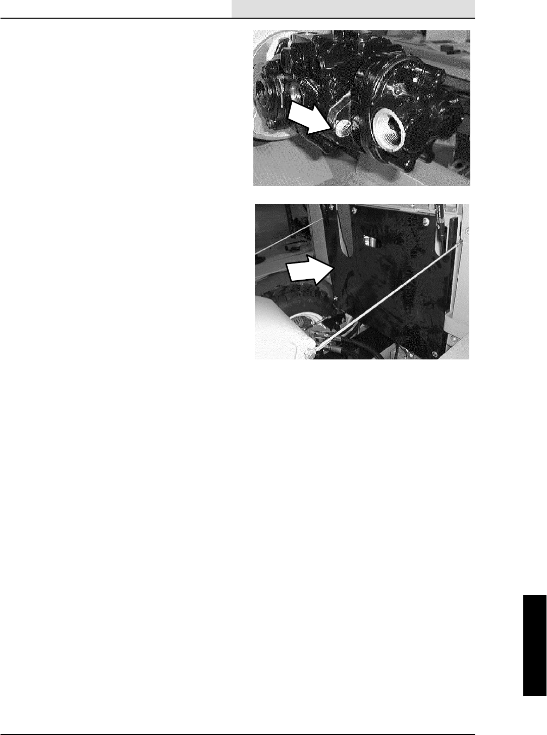
HYDRAULICS
5-11
ATLV 4300 330495 (10--98)
10. Reinstall the accessory pump into the propel
pump. Make sure the O--ring is installed on
the face of the pump. Reinstall the hardware
and tighten to 31 -- 40 Nm (27 -- 35 ft. lb).
11. Reconnect the two hydraulic hose to the
accessory pump. See hose diagram in this
section.
NOTE: Observe hydraulic cleanliness
requirements when opening hydraulic lines.
12. Reinstall the left hand side panel and left
hand grill.
13. Tilt the hopper forward, close the hopper
cover, and close the top engine cover.
14. Start the machine and operate the hydraulic
circuit. Check for proper operation.
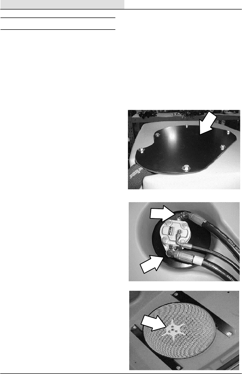
HYDRAULICS
5-12 ATLV 4300 330495 (10--98)
HYDRAULIC MOTORS
The vacuum fan impeller is driven by a hydraulic
motor located on top of the hopper cover. The
vacuum fan motor is controlled by a solenoid
valve located on the machine frame.
The steering wheel motor is used to provide
hydraulic flow to the steering cylinder.
The drive wheel motors propel the machine
forward and reverse. The propel pump provides
hydraulic flow to the drive motors.
TO REPLACE VACUUM FAN MOTOR
FOR SAFETY: Before Leaving Or
Servicing Machine; Stop On Level
Surface, Set Parking Brake, turn off
machine, and remove key.
NOTE: Anytime hopper or vacuum system parts
are serviced the seals should be inspected and
replaced if necessary.
1. Remove the six screws holding the vacuum
fan motor cover plate to the top of the
plenum assembly on top of the hopper
cover. Remove the plate.
NOTE: Observe hydraulic cleanliness
requirements when opening hydraulic lines.
2. Mark, disconnect, and plug the hydraulic
lines leading to the vacuum fan motor.
3. Open the hopper cover and tilt the hopper
back.
4. Go under the hopper cover and remove the
six hex screws holding the cover assembly
to the hopper cover. Remove the cover
assembly.
5. Locate the vacuum fan impeller screen.
Remove the three flat head screws and one
hex screw holding the screen to the impeller.
6. Pull the impeller screen, spacer, and sleeve
off the vacuum fan motor shaft.
7. Remove the four hex screws holding the
vacuum fan assembly retainer plate to the
bottom of the hopper cover.
8. Go to the top of the hopper cover and
remove the vacuum fan assembly from the
machine. Set the assembly up side down on
a flat surface.
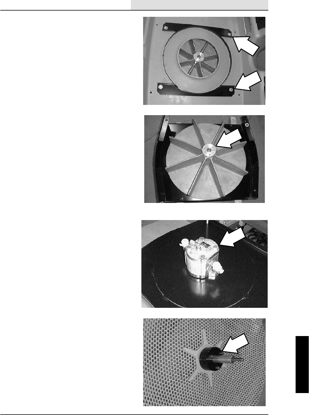
HYDRAULICS
5-13
ATLV 4300 330495 (10--98)
9. Pull the vacuum fan impeller off the fan
motor shaft. Retain the key form the motor
shaft.
10. Remove the two hex screws and nyloc nuts
holding the vacuum fan motor to the mount
plate. Remove the motor.
NOTE: The orientation of the motor ports and the
reference hole in the mount plate.
11. Remove the hydraulic fittings from the old
motor and install in the new motor in the
same orientation.
12. Position the new motor assembly on the
mount plate in the same orientation as the
old one. Reinstall the hardware and tighten
to 37 -- 48 Nm (26 -- 34 ft. lb).
NOTE: The orientation of the motor ports and the
reference hole in the mount plate.
13. Install the vacuum fan impeller onto the
motor shaft.
NOTE: Make sure to use the key that was
removed with the old impeller.
14. Turn the assembly over and place it back on
top of the hopper cover. Hold the impeller in
place while turning over. Line up the holes in
the motor bracket with the holes in the
cover.
15. Go under the hopper cover and install the
four hex screws into vacuum fan assembly
retainer plate. Leave the hardware loose for
now. Use blue loctite (242) on the threads of
this hardware.
16. Reinstall the impeller screen, spacer, and
sleeve onto the vacuum fan motor shaft.
17. Use blue loctite (242) on the threads of the
impeller screen hardware. Reinstall the one
M8 hex screw and three M6 flat screws.
18. Tighten the M8 hex screw to 18 -- 24 Nm
(15 -- 20 ft.. lb) and the M6 flat screws to
8--10Nm(6--8ft.lb).
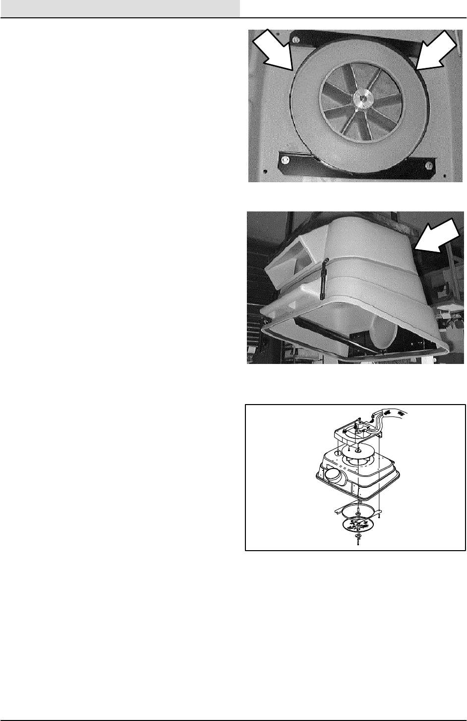
HYDRAULICS
5-14 ATLV 4300 330495 (10--98)
19. After the screen has been tighten down,
center the string guard (on the retainer
plate) around the outside of the screen.
Tighten the four screws to 18 -- 24 Nm
(15 -- 20 ft. lb).
20. Reinstall cover assembly onto the hopper
plenum.
21. Reinstall six hex screws holding the cover
assembly to the hopper plenum. Tighten the
screws to 18 -- 24 Nm (15 -- 20 ft. lb). Use
blue loctite (242) on the threads of this
hardware.
NOTE: Observe hydraulic cleanliness
requirements when opening hydraulic lines.
22. Reconnect the hydraulic lines leading to the
vacuum fan motor. See hydraulic schematic
in this section.
23. Reinstall the six screws holding the vacuum
fan motor cover plate to the top of the
plenum assembly on top of the hopper
cover. Tighten the screws to 18 -- 24 Nm
(15 -- 20 ft. lb).
24. Tilt the hopper forward and close the cover.
25. Operate the machine and check the vacuum
fan for proper operation.

HYDRAULICS
5-15
ATLV 4300 330495 (10--98)
TO REPLACE STEERING WHEEL MOTOR
FOR SAFETY: Before Leaving Or
Servicing Machine; Stop On Level
Surface, Set Parking Brake, turn off
machine, and remove key.
1. Open the seat support and engage the prop
rod.
2. Locate the battery at the center of the
machine, on top and ahead of the front axle.
3. Remove the battery negative cable.
4. Disengage the prop rod and lower the seat
support.
5. Remove the cap from the center of the
steering wheel (snap out).
6. Remove the M20 hex nut from the center of
the steering wheel.
7. Use a puller to remove the steering wheel
from the steering column.
8. Remove the knob from the tilt steering wheel
pull lever.
9. If the machine is equipped with turn signals,
remove the turn signal unit from the steering
column.
10. Remove the two smaller pan screws from
the top side of the instrument panel.
11. Remove the two larger pan screws from the
back side of the instrument panel.
12. Carefully pull the instrument panel up until
the rubber boot clears the steering column.
13. Place the instrument panel back, against the
kick panel of the operators compartment.
NOTE: Observe hydraulic cleanliness
requirements when opening hydraulic lines.
14. Mark, disconnect, and plug the five hydraulic
hoses leading to the steering wheel motor.
15. Loosen the hardware holding the lock collars
to the tilt bracket. Pull the steering wheel
motor and column down until the four hex
screws are accessible.
16. Remove the four M6 hex screws holding the
steering column to the motor. Remove the
motor from the machine. Note the
orientation of the motor and fittings.
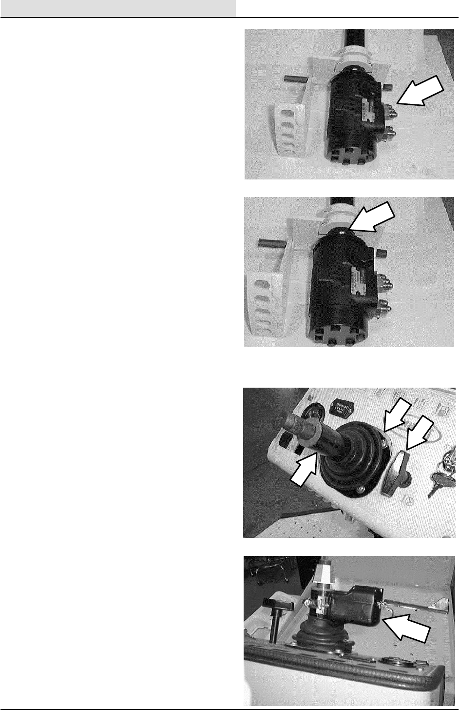
HYDRAULICS
5-16 ATLV 4300 330495 (10--98)
17. Remove the five hydraulic fittings from the
motor and install in the new steering wheel
motor.
18. Install the new steering wheel motor
assembly in the machine in the same
orientation as the old one.
19. Reinstall the four M6 hex screws and tighten
to 8 -- 10 Nm (6 -- 8 ft. lb).
20. Push the motor and column back up in
position. Tighten the locking collars to
8--10Nm(6--8ft.lb).
21. Connect the five hydraulic hoses to the new
steering wheel motor. See hose diagram in
this section.
22. Position the instrument panel and rubber
boot over the top of the steering column.
NOTE: Be careful not to tear the boot.
23. Push the panel down until the four mount
holes line up with the weldnuts.
24. Reinstall the two small pan screws on top of
the panel and the two larger pan screws on
the back side of the panel. Hand tighten
tight.
25. Reinstall the tilt steering rod knob. Turn the
knob down tight.
26. Reinstall the steering wheel and M20 nut.
Tighten tight.
27. Reinstall the cap in the center of the steering
wheel (snap in).
28. Reinstall the turn signal assembly if the
machine is equipped with road light option.
29. Open the seat support and engage the prop
rod.
30. Reconnect the battery cable to the battery
(red cable to positive post, black cable to
negative post).
31. Disengage the prop rod and lower the seat
support.
32. Start the machine and check for proper
operation.
NOTE: Observe hydraulic cleanliness
requirements when opening hydraulic lines.
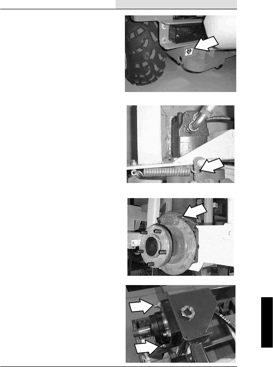
HYDRAULICS
5-17
ATLV 4300 330495 (10--98)
TO REPLACE DRIVE WHEEL MOTOR
FOR SAFETY: Before Leaving Or
Servicing Machine; Stop On Level
Surface, Set Parking Brake, turn off
machine, and remove key.
1. Place blocks in front and back of the front
tires.
2. Jack up the rear of the machine at the
indicated jack points. Install jack stands
under the machine frame.
NOTE: Make sure the parking brake is engaged.
3. Remove the five wheel nuts. Remove the
tire and wheel assembly from the machine.
4. Remove the castle nut from the center of the
wheel hub.
5. Disengage the parking brake.
6. Remove the tension spring and clevis pin
from the brake cable clevis and arm on the
brake assembly.
7. Remove the two M12 hex screws and nyloc
nuts holding the brake assembly to the top
side of the wheel motor.
8. Pull the brake assembly straight up and off
the brake hub.
9. A large wheel puller must be used to remove
the wheel hub from the hydraulic drive
motor. Remove the hub.
NOTE: Observe hydraulic cleanliness
requirements when opening hydraulic lines.
10. Mark, disconnect, and plug the hydraulic
hoses leading to the drive motor.
11. Remove the remaining two M12 hex screws
and nyloc nuts holding the drive motor to the
machine frame. Remove the drive motor
from the machine.
NOTE: Note that the two longer bolts go in the
upper mount holes.
12. Remove the hydraulic fittings from the old
drive motor and install in the new motor in
the same orientation.
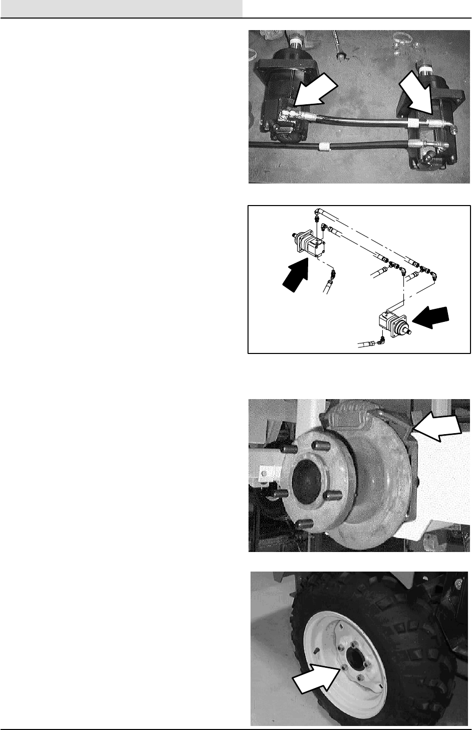
HYDRAULICS
5-18 ATLV 4300 330495 (10--98)
13. Install the new motor in the machine (fittings
face up). Line up the mount holes and
reinstall the lower hex screws (short ones)
and nuts. Leave loose for now.
14. Apply a small amount of white grease on the
shaft of the new drive motor before installing
the wheel hub.
15. Use a small amount of blue loctite (242)
on the threads of the motor shaft
Install the wheel hub and castle nut. Tighten
to at least 170 Nm (125 ft. lb).
16. Spread the brake pads and slide the brake
assembly onto the wheel hub.
17. Align the holes in the brake assembly with
the mount holes in the wheel motor.
18. Reinstall the two longer hex screws. Tighten
all four hex screws to 64 -- 83 Nm
(47 -- 61 ft. lb.).
NOTE: Make sure to install the two longer bolts
into the upper holes.
19. Reconnect the hydraulic hoses to the new
drive motor. See hose diagram in this
section.
20. Reinstall the clevis pin in the end of the
brake cable at the brake arm.
21. Reinstall the tension spring on the brake
arm.
22. Engage the parking brake.
23. Reinstall the rear tire and wheel assembly.
24. Reinstall the five wheel nuts and tighten to
122 -- 162 Nm (90 -- 120 ft. lb).
25. Tilt the hopper forward and lower the hopper
cover.
26. Remove the jack stands and lower the
machine.
27. Remove the blocks from the front tires and
disengage the parking brake. Operate the
machine and check for proper operation.
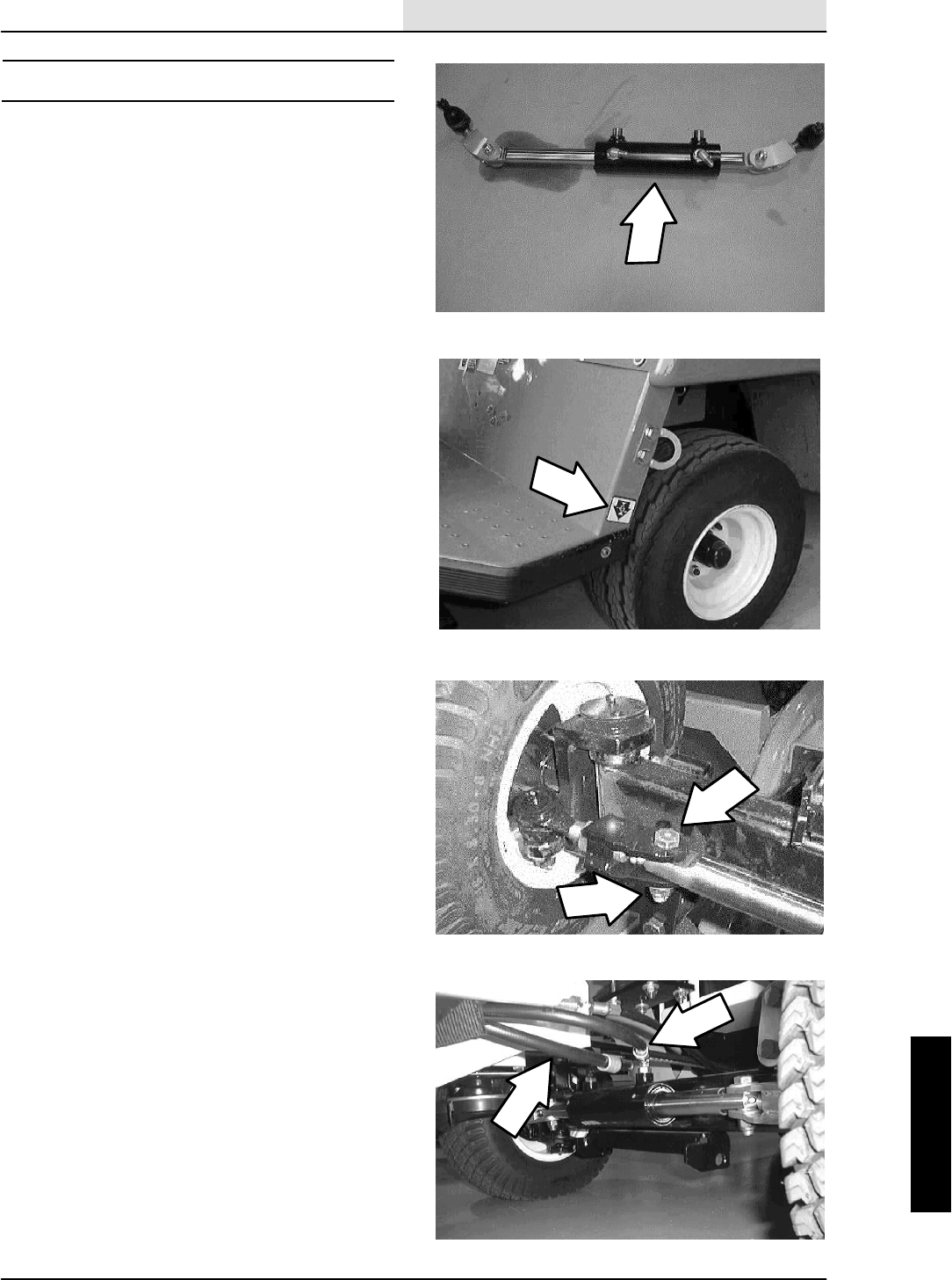
HYDRAULICS
5-19
ATLV 4300 330495 (10--98)
STEERING CYLINDER
The steering cylinder on the model ATLVt4300
is located at the front of the front axle assembly,
between the front wheels. The steering cylinder is
controlled by the steering wheel motor and
hydraulic flow from the accessory pump.
TO REPLACE STEERING CYLINDER
FOR SAFETY: Before Leaving Or
Servicing Machine; Stop On Level
Surface, Set Parking Brake, turn off
machine, and remove key.
1. Jack up the front of the machine at the
indicated jack points. Install jack stands
under the machine frame.
2. Remove the .50” hex screws and nyloc nuts
from the clevises and cylinder ends. Pull the
clevis off the cylinder.
NOTE: Make sure to retain the steel spacers
(2 per end) in the end of the cylinder.
3. Mark, disconnect, and plug the two hydraulic
hoses leading to the steering cylinder.
NOTE: Observe hydraulic cleanliness
requirements when opening hydraulic lines.
4. Remove the two M12 hex screws holding
the steering cylinder to the front axle. Make
sure to retain the two tube spacers and
vacuum head mount plate (if equipped).
5. Remove the fittings from the old steering
cylinder and install in the new cylinder in the
same orientation.
6. Position the new steering cylinder onto the
front of the front axle. Reinstall the two tube
spacers, vacuum head mount plate
(if equipped), and two hex screws. Tighten
to 64 -- 83 Nm (47 -- 61 ft. lb.)
7. Grab the front tires and move inward until
the ball end clevis mount hole lines up with
the end of the new steering cylinder. Make
sure the steel spacers are in place at the
end of the cylinder.
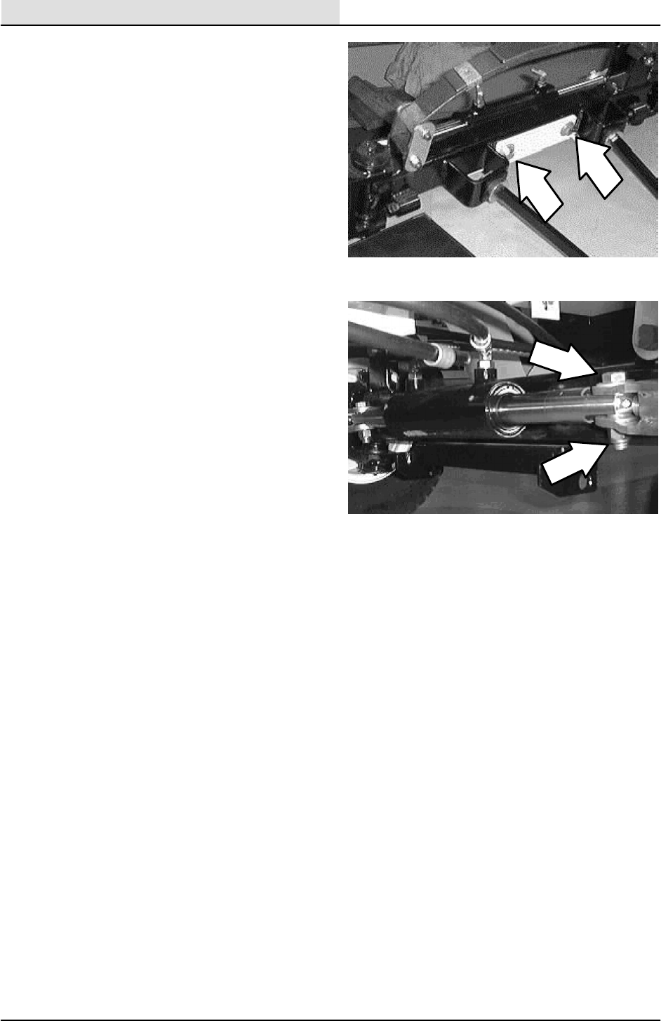
HYDRAULICS
5-20 ATLV 4300 330495 (10--98)
8. Reinstall the hex screws and nuts into the
clevises. Tighten to 64 -- 83 Nm
(47 -- 61 ft. lb.)
9. Reconnect the hydraulic hoses to the new
steering cylinder. See hose diagram in this
section.
10. Check the front wheel alignment. See TO
ALIGN FRONT TIRES instructions in this
section.
11. Remove the jack stands and lower the
machine to the floor.
12. Operate the machine and check the new
steering cylinder for proper operation.

HYDRAULICS
5-21
ATLV 4300 330495 (10--98)
STEERING CYLINDER BREAKDOWN

HYDRAULICS
5-22 ATLV 4300 330495 (10--98)
CONTROL VALVE
The solenoid control valve is located on the lower
frame behind the engine, just below the bottom of
the hopper. The solenoid control valve receive
hydraulic flow from the accessory pump and
distributes this flow to the steering and vacuum
fan circuit. The vacuum fan function is controlled
by a dash mounted switch.
TO REPLACE SOLENOID CONTROL VALVE
FOR SAFETY: Before Leaving Or
Servicing Machine; Stop On Level
Surface, Set Parking Brake, turn off
machine, and remove key.
1. Open the hopper cover and tilt the hopper
back.
2. Remove the five pan screws holding the rear
engine cover to the machine. Remove the
cover.
3. Locate the solenoid control valve behind the
engine, just below the rear frame member.
4. Disconnect the main harness from the
electrical solenoid on the back side of the
valve.
5. Mark, disconnect, and plug the hydraulic
hoses leading to the control valve.
NOTE: Observe hydraulic cleanliness
requirements when opening hydraulic lines.
6. Remove the two M6 hex screws and nyloc
nuts holding the control valve to the mount
bracket. Remove the control valve from the
machine.
7. Remove the hydraulic fittings from the old
control valve and install into the new valve in
the same orientation.
8. Position the new valve assembly on the
mount bracket. Reinstall the hardware and
tighten to 8 -- 10 Nm (6 -- 8 ft. lb).

HYDRAULICS
5-23
ATLV 4300 330495 (10--98)
9. Reconnect the hydraulic hoses to the new
valve. See hose diagram in this section.
10. Reconnect the solenoid valve to the main
electrical harness.
11. Reinstall the rear engine cover.
12. Tilt the hopper forward and lower the hopper
cover.
13. Operate the machine and check the new
steering cylinder for proper operation.

HYDRAULICS
5-24 ATLV 4300 330495 (10--98)

HYDRAULICS
5-25
ATLV 4300 330495 (6--01)
HYDRAULIC SCHEMATIC

HYDRAULICS
ATLV 4300 330495 (6--01)
5-26
HYDRAULIC HOSE GROUP

HYDRAULICS
5-27
ATLV 4300 330495 (10--98)
TROUBLESHOOTING
The troubleshooting charts that follow are
organized to lead you through the circuits.
HYDRAULICS
5-28 ATLV 4300 330495 (10--98)
POWER STEERING IS NOT NORMAL
STEER CYLINDER
ROD ENDS & SEALS
OK?
No
Yes
REPAIR / REPLACE
STEER CYLINDER
OR ROD ENDS
PLUMBING OK? REPAIR / REPLACE
PLUMBING
Yes
Yes
No
STEERING INLET
PRESSURE OK? No
REPAIR / REPLACE
STEERING
CONTROL
REPAIR / REPLACE
RV1 RELIEF
CARTRIDGE
RV1 RELIEF
CARTRIDGE
PRESSURE OK?
No
STEERING
COLUMN OK?
Yes
REPAIR / REPLACE
CS
COMPENSATOR
CARTRIDGE
CS
COMPENSATOR
CARTRIDGE FLOW
OK?
No
Yes
REPAIR / REPLACE
STEERING
COLUMN
No
VACUUM FAN
WORKS OK?
REPAIR / REPLACE
PUMP
No
Yes
HYDRAULICS
5-29
ATLV 4300 330495 (10--98)
VACUUM FAN WILL NOT TURN ON
SV1 STEM
MAGNETIZED? No
Yes
REPAIR
ELECTRICAL
SYSTEM
SV1 VALVE
CARTRIDGE
SHIFTING OK?
REPAIR / REPLACE
SV1 VALVE
CARTRIDGE
Yes
No
REPAIR / REPLACE
MOTOR
MOTOR INLET
FLOW
OK?
Yes
REPAIR / REPLACE
PLUMBING
PLUMBING OK? No
No
Yes
RV2 RELIEF
CARTRIDGE OK? No
REPAIR / REPLACE
RV2 CARTRIDGE
REPAIR / REPLACE
PUMP
CIRCUIT
FLOW OK? No
Yes
REPAIR / REPLACE
PC1 CHECK VALVE
CARTRIDGE
PC1 CHECK VALVE
SHIFTING
OK?
No
Yes

HYDRAULICS
5-30 ATLV 4300 330495 (10--98)
VACUUM FAN WILL NOT TURN OFF
SV1 STEM
MAGNETIZED? Yes
No
REPAIR
ELECTRICAL
SYSTEM
SV1 STEM
CARTRIDGE
SHIFTING OK?
REPAIR / REPLACE
SV1 STEM
CARTRIDGE
No
No
FAN TURNS
SLOWLY Yes
REPAIR / REPLACE
PC1 PILOT CHECK
CARTRIDGE

HYDRAULICS
5-31
ATLV 4300 330495 (10--98)
PROPEL MOTOR WILL NOT PROPEL
REPAIR / REPLACE
PROPEL MOTOR
MOTOR INLET
FLOW OK? Yes
REPAIR / REPLACE
PLUMBING
PLUMBING OK? No
No
Yes
RELIEF PRESSURE
OK?
No
REPAIR / REPLACE
RELIEF
CARTRIDGE
REPAIR / REPLACE
PROPEL PUMP
CIRCUIT FLOW
OK?
No
Yes
ADJUST TOW
DUMP VALVE
CIRCUIT FLOW
OK? No
Yes

HYDRAULICS
5-32 ATLV 4300 330495 (10--98)
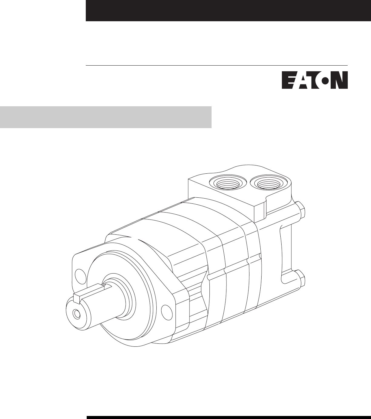
No. 7-124
July, 1999
Char-Lynn®
Hydraulic Motor
2000 Series
Disc Valve Geroler Motor 006
Repair Information
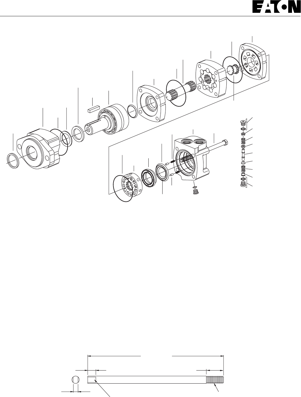
2
2000 Series Disc Valve Motors
Exclusion
Seal
Bearing
Housing
Seal
Back-up
Washer
Shaft
Seal
Bearing and
Shaft
Assembly
Key
Shaft
Face Seal Wear
Plate
Seal
Seal
Valve
Plate
Splined
Drive
Geroler
Valve
Drive
Pin
Spring
Valve
Housing Tie
Bolt
Inner
Face Seal
O-ring/
Plug S/A
O-ring/
Plug S/A
O-ring/
Plug S/A
Shuttle Vave Option
Piston
Spring
Poppet
Poppet
Spring
Dash Pot
Dash Pot
Balance
Ring
Outer
Face Seal
Valve
Seal
8,0 [.312]
Grind flat spots on each side
Approx. 13,0 [.50]
200,0 [8.00]
Alignment studs (2)
25,0 [1.00]
3/8-24 UNF thread
9,5 [.375] Dia. Steel Rod
Tools required for disassembly and reassembly.
Torque wrench 57Nm [500 lb-in] capacity
300-450 [12-16]* breaker bar
9/16 socket
Small screwdriver 150-200 x 6,5 [6-8 x 1/4] blade
3/16 Allen wrench
Press
* Unless indicated otherwise, measurements
are given in mm [inches]
** Shaft seal installation tool (600496)
** Bullet (600465) for 1 diameter shafts
The following tools are not necessary for disassembly and reassem-
bly, but are extremely helpful.
Alignment studs (2)
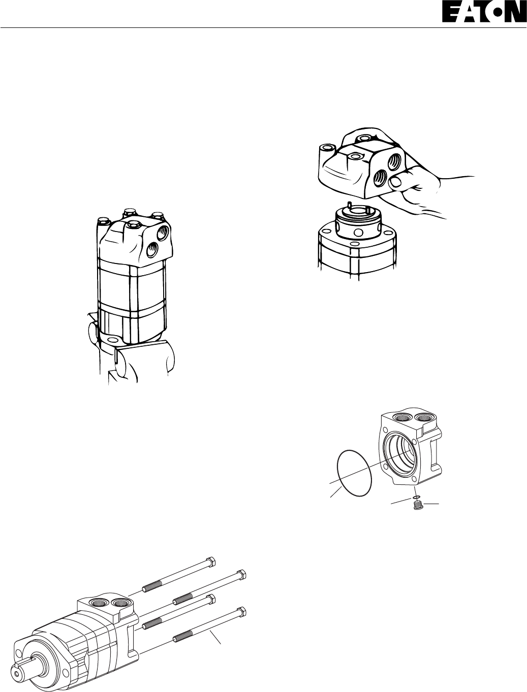
3
2000 Series Disc Valve Motors
Tie Bolts
Seal Seal Case Drain Plug
Cleanliness is extremely important when repairing a hydraulic motor.
Work in a clean area. Before disconnecting the lines, clean the port
area of the motor thoroughly. Use a wire brush to remove foreign
material and debris from around the exterior joints of the motor.
Check the shaft and key slot, remove all nicks, burrs or sharp edges
that might damage the bearing housing seals when installing the shaft
and bearing assembly. Before starting the disassembly procedures,
drain the oil from inside the motor.
1 Place the motor in a vise with the output shaft down. Clamp
across the mounting flange of the motor not the housing. Excessive
clamping pressure will cause distortion. When clamping, use some
protective device on the vise, such as special soft jaws, pieces of hard
rubber or board.
Although not all drawings show the motor in a vise, we recommend
that you keep the motor in the vise during disassembly and reas-
sembly. Follow the clamping procedures explained throughout the
manual.
2 Remove 4 bolts from motor.
3 Lift valve housing straight up. If done carefully the pins, springs,
balance ring assembly, and valve will remain on the valve plate.
4 Carefully remove 76,0 [3.00] diameter seal from valve housing.
5 Remove case drain plug—with seal, from valve housing.
6 Remove 2 pins and 2 springs from balance ring assembly, see
Figure 5.
Figure 1
Figure 2
Figure 4
Figure 3
Disassembly
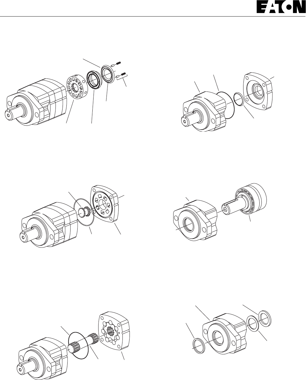
4
2000 Series Disc Valve Motors
Outer Face Seal
Inner
Face Seal
Pin (2) and
Spring (2)
Valve Balance Ring
Seal
Valve Drive
Valve Plate
Seal
Seal Geroler
Bearing
Housing Seal
Shaft Face Seal
Wear
Plate
Bearing Housing Shaft Seal
Back-up Washer
Exclusion
Seal
7 Remove balance ring assembly.
8 Remove inner and outer face seals from balance ring.
9 Remove the valve.
10 Remove the valve plate.
11 Remove the 76,0 [3.00] diameter seal from valve plate.
12 Remove the valve drive.
13 Remove the Geroler. Be sure to retain the rollers in the outer ring
if they are loose.
14 Remove the drive.
15 Remove the 76,0 [3.00] diameter seal from wear plate,
see Figure 7.
16 Remove the wear plate.
17 Remove the shaft face seal from the wear plate.
18 Remove the 76,0 [3.00] diameter seal from bearing housing.
19 You may need a press to remove shaft and bearing assembly from
bearing housing. (Key must be removed before removing shaft.)
20 Use a small screwdriver to remove shaft seal, back-up washer and
exclusion seal from bearing housing, see Figure 10. Do not damage
bore of housing.
Note: Individual parts of shaft and bearing assembly are not sold
separately. Replace as a unit.
Figure 5
Figure 6
Figure 7
Figure 10
Figure 9
Figure 8
Disassembly
Bearing
Housing
Shaft and
Bearing
Assembly

5
2000 Series Disc Valve Motors
Shaft Seal
Back-up
Washer
Exclusion
Seal
Shaft Face
Shaft Face
Seal
Wear Plate
Seal
Shaft and
Bearing
Assembly
Geroler Valve Plate Valve
Drive Valve
Drive
Largest
Open Pocket Alignment
Ref. Only
Anyone of
6 Ports Open
to Ouside of Vave
Rotate
Valve
Clockwise
1/2 tooth max.
to Engage Spline
Check all mating surfaces. Replace any parts that have scratches or
burrs that could cause leakage. Clean all metal parts in clean solvent.
Blow dry with air. Do not wipe dry with cloth or paper towel because
lint or other matter can get in the hydraulic system and cause damage.
Do not use a coarse grit or try to file or grind these parts. Check
around the keyway and chamfered area of the shaft for burrs, nicks or
sharp edges that can damage the seals when reassembling the bearing
housing.
Note: Lubricate all seals (prior to installation) with petroleum jelly such
as Vaseline. Use new seals when reassembling this motor. Refer to
parts list (6-129) for proper seal kit number.
21 Use a press to install exclusion seal in outer bore of bearing
housing. Lip of seal must face outward. See Figure 11. If a press is
not available use a plastic or rubber hammer, being careful not to
damage or cock seal in the bore.
22 Place back-up washer into seal bore. Place shaft seal onto
installation tool (600496) and press seal into seal bore of the
housing.
23 Clamp housing in vise, see Figure 1.
24 Place protective bullet (see note below) over shaft. Apply
petroleum jelly to inside diameter of dust and shaft seal. You may
need a press to install shaft and bearing assembly. Do not distort
shaft seal. Damage to this seal will cause leakage.
Note: Bullet (600465), for 1inch dia. shafts, available— by special
order. Use tape over other shafts to prevent cutting the seals.
25 Apply petroleum jelly to the 76,0 [3.00] diameter seal. Install
seal into the bearing housing.
26 Alignment studs can be very helpful in reassembly of the motor.
See special tool listing page 2. If you use studs, install 2 studs
diagonally opposed in the bearing housing.
27 Install the shaft face seal in the wear plate as shown in Figure 11.
Do not distort seal.
28 Install the wear plate, see Figure 11.
29 Apply a light film of petroleum jelly to the 76,0 [3.00] diameter seal
and install seal in the wear plate.
30 Install the drive into the output shaft.
31 Align the notch on the outside of the Geroler with the notch on the
wear plate. Install the Geroler against the wear plate. Be sure to retain
the rollers in the outer ring if they are loose.
32 Install the valve drive in the Geroler.
Note: Installation at this time involves 3 steps in the timing of the
motor. Timing determines the direction of rotation of the output shaft.
Timing parts include:
1. Geroler
2. Valve Drive
3. Valve Plate
4. Valve
Timing Step # 1 — Locate the largest open pocket in the Geroler and
mark it on the outside edge of the Geroler.
33 Apply a light film of petroleum jelly to the 76,0 [3.00] diameter
seal. Install seal in groove of valve plate.
Figure 11
Figure 12 Timing Alignment
Reassembly

6
2000 Series Disc Valve Motors
Spring and Pin
Seal Valve
Housing
Balance Ring
Inner Seal Pin NotchOuter Seal
Alignment
Studs
Balance
Ring
Valve
Housing
Valve
Plate
34 Align the notch on the outside of the valve plate with the notch on
the Geroler as shown in Figure 12.
Timing Step # 2 — Locate the slot opening in the valve plate which is
in line with the largest open pocket of the Geroler.
Timing Step # 3 — Locate any one of the side openings of the valve
and align this opening with the open slot of the valve plate that is in
line with the largest open pocket of the Geroler. Install the valve by
rotating it clockwise until the spine teeth engage (1/2 spine tooth
max.). This will provide the proper rotation when pressurized as
shown in Figure 13.
35 Install 2 springs and 2 pins in the holes located in the bore of the
valve housing, as shown in Figure 14.
36 Apply a light film of petroleum jelly to the 76,0 [3.00] diameter
seal. Install seal in the valve housing.
37 Apply petroleum jelly to inner and outer face seals. Install seals
on balance ring as shown in Figure 15.
Important: Install face seals in the positions shown in Figure 15, or the
motor will not operate properly. Do not force or bend the face seals.
Any damage to these seals will affect the operation of the motor.
38 Align pin notches in balance ring with pins in bore of valve housing.
Install balance ring assembly in valve housing.
39 Insert your finger through port of valve housing. Apply pressure
to side of balance ring as shown in Figure 16. Hold ring in position
until valve housing is in place against valve plate (see Figure 17).
Note: After installing the valve housing on the valve plate check for
proper placement. Push down on the valve housing. You should
get a slight spring action.
Figure 13
Figure 14
Figure 17
Figure 16
Figure 15
Reassembly
Clockwise
Rotation
Counter
Clockwise
Rotation
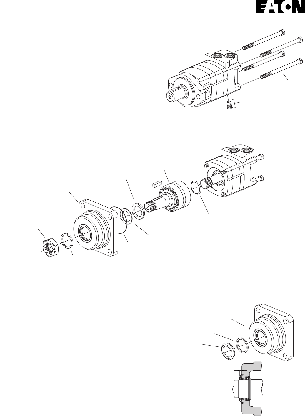
7
2000 Series Disc Valve Motors
Case Drain Plug with Seal
Tie Bolts
Exclusion Seal
Housing with Seal Guard Groove
Seal Guard
4,40[.177]
40 Install tie bolts. If you use alignment Studs, install 2 bolts opposite
the studs. Finger tighten the bolts. Remove the alignment studs and
replace with the two remaining bolts. Torque all four bolts alternately
to 50 Nm [450 lb-in].
41 Install seal on case drain plug then install in valve housing. Torque
to 6 Nm [50 lb-in.]
On wheel motors, a different bearing housing is used, see Figure 19.
Other than this the parts are the same as the standard motor and the
same disassembly and reassembly procedures apply.
Figure 18
Figure 19
Reassembly
Wheel Motor
Wheel Motor
with Seal Guard
Installation of Seal Guard:
After completing assembly of the shaft and bearing assembly into the
bearing housing, press the seal guard onto the shaft with a tool that
will provide an even push over the seal. This tool must bottom out
against the bearing housing and provide a 4,5 mm [.177 inch] stop for
the seal guard.
Exclusion Seal
Castle Nut
Bearing Housing
Seal
Shaft Seal
Shaft and Bearing
Assembly
Shaft Face Seal
Back-up Washer

8
2000 Series Disc Valve Motors
This motor is the same as the standard motor without the shaft/
bearing assembly, and bearing housing. The mounting flange replaces
the bearing housing, see Figure 20. Follow same disassembly and
reassembly procedures as rear section of standard motor.
Seal
Seal
Flange
Figure 20
Figure 21
Bearingless Motor
Disassembly Reassembly
Shuttle Valve Option
Disassembly of shuttle valve option, this valve is
located in the valve housing. Clean and inspect
shuttle valve parts and reassemble with new
seals, torque plugs to 8-11 Nm [75-100 lb-in].
Shuttle Location
when Applicable
O-ring/Plug S/A
Torque to 8-11 Nm [75-100 lb-in]
O-ring/Plug S/A
Torque to 8-11 Nm [75-100 lb-in]
Shuttle Vave Option
Piston
Spring
Poppet
Poppet
Spring
Dash Pot
Dash Pot

9
2000 Series Disc Valve Motors
90°
Alignment Notch
Alignment Notch
Alignment Notch
Speed Sensor Body
Speed Sensor Installation
Figure 22 Figure 23
Figure 24 Figure 25
Alignment Notchs
Perpendicular to
Centerline of Motor
Alignment Nut
9/16 inch
Hex Head
Lock Nut
11/16 inch
Hex Head
Parallel with
Centerline of Motor Shaft
Alignment Nut
Speed Sensor Port
Lock Nut
Housing
Back out
Gear/Target
Tooth
Washer
O-ring
1 Rotate the motor shaft until a (gear/target)
tooth is centered in the speed sensor port. If
this is not done, the sensor may be damaged
during the operation of the motor.
2 Make sure the lock nut and its threads are
clean and dry for the proper torque. Position
the lock nut against the alignment nut as
shown in Figure 22.
3 Move the washer and the o-ring up against
the speed sensor body threads as shown in
Figure 22.
4 By hand, lightly thread the speed sensor
body into the housing until the sensor
touches against the motor (gear/target) tooth.
Do not force the sensor against the (gear/
target) tooth, damage may occur. Make sure
the o-ring or the washer do not touch the
housing — see Figure 23.
5 Turn the speed sensor body out one quarter
turn (CCW) plus the additional amount (CCW)
needed to make the alignment notches
perpendicular to the motor shaft centerline
(90° +/-5 degrees from the motor shaft
centerline — Figure 24 and 25).
6 Maintain the speed sensor body alignment
(Figure 25), and tighten the lock nut to 8,5-14
Nm [75-125 lb-in.] (torque values are for
clean dry threads).
7 Check the speed sensor body for correct
alignment (Figure 25), reinstall the sensor if it
is not correct.
Reassembly —
Speed Sensor
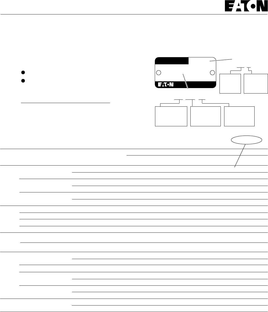
10
2000 Series Disc Valve Motors
104-1007
104-1001 -1002 -1003 -1004 -1005 -1006 -1007 -1143
1 inch Straight
2 Bolt
SAE A
Flange
Displacement cm
3
/r [ in
3
/r ] and Product Number
ShaftMounting 100
[ 6.2] 130
[ 8.0] 160
[ 9.6] 195
[11.9] 245
[14.9] 305
[18.7] 395
[24.0]
80
[ 4.9] 490
[29.8]
104-1037 -1038 -1039 -1040 -1041 -1042 -1043 -1044
7/8-14 O-ring Staggered
Ports
1-1/16—12 O-ring 180° Apart
104-1022 -1023 -1024 -1025 -1026 -1027 -1028 -1228 -1420
1-1/4 Inch Straight 104-1061 -1062 -1063 -1064 -1065 -1066 -1067 -1068 -1421
7/8-14 O-ring Staggered
1-1/16—12 O-ring 180° Apart
104-1029 -1030 -1031 -1032 -1033 -1034 -1035 -1229 -1422
1-1/4 Inch
14 T Splined 104-1087 -1088 -1089 -1090 -1091 -1092 -1093 -1094 -1423
7/8-14 O-ring Staggered
1-1/16—12 O-ring 180° Apart
32 mm Straight 104-1384 -1385 -1386 -1387 -1388 -1389 -1390 -1391G 1/2 (BSP)
105-1001 -1002 -1003 -1004 -1005 -1006 -1007 -1060
104-1376 -1377 -1378 -1379 -1380 -1381 -1382 -1383G 1/2 (BSP)
1-1/4 Inch
14 T Splined
105-1071 -1072 -1073 -1074 -1075 -1076 -1077 -1078
Standard
with 4 Bolt
Square
Flange
105-1029 -1030 -1031 -1032 -1033 -1034 -1035 -1096
105-1079 -1080 -1081 -1082 -1083 -1084 -1085 -1086
7/8-14 O-ring Staggered
1-1/16—12 O-ring 180° Apart
7/8-14 O-ring Staggered
1-1/16—12 O-ring 180° Apart
Wheel
Motor
105-1134 -1135 -1136 -1137 -1138 -1139 -1140 -1141G 1/2 (BSP)
32 mm Straight
1-1/4 Inch
14 T Splined
1-1/4 Inch
Tapered
106-1008 -1009 -1010 -1011 -1012 -1013 -1014 -1015 -1047
106-1038 -1039 -1040 -1041 -1042 -1043 -1044 -1045G 1/2 (BSP)
7/8-14 O-ring Staggered
Bearingless
2 Bolt
SAE B
Flange
104-1200 -1201 -1202 -1203 -1204 -1205 -1206 -1207
1-1/4 Inch Straight
104-1208 -1209 -1210 -1211 -1212 -1213 -1214 -1215
7/8-14 O-ring Staggered
104-1193 -1194 -1195 -1196 -1197 -1198 -1199
104-1216 -1217 -1218 -1219 -1220
7/8-14 O-ring Staggered
7/8-14 O-ring Staggered
7/8-14 O-ring Staggered
1-1/4 In. Involute SAE C Splined
1 Inch SAE 6B Splined
7/8 Inch SAE B Splined
7/8-14 O-ring Staggered
1-1/16—12 O-ring 180° Apart
1-1/4 Inch Straight — — — — — — —
— — — — — — —
-1148
-1149
-1152
—
—
—
—
—
—
—
—
—
—
—
—
— — —
—
—
105-
105-
—
—
Use digit prefix —104-, 105-, or 106- plus four digit number from charts
for complete product number—Example 106-1039.
Product Numbers—2000 Series
Each Order Must Include the Following:
How to Order Replacement Parts
1. Product Number
2. Date Code
3. Part Name
4. Part Number
5. Quantity of Parts
For Additional Literature Contact Eaton Corp. Hydraulics
Division 15151 Highway 5 Eden Prairie, MN 55344.
Specifications and performance data, Catalog No. 11-878
Replacement part numbers and kit information — Parts
Information No. 6-129
Char-Lynn
®
Product number
Eaton Corp. Hydraulics Div.
Eden Prairie, MN 55344
Product Number
000 0000 000
Product Line
Identification
Number
Product
Identification
Number
Engineering
Change
Code
Week of
Year 01
Thru 52
Last
Number(s)
of Year
Date Code
00 00
Product Identification

11
2000 Series Disc Valve Motors
Notes:

Copyright Eaton Corporation, 1985, 1988, 1994, 1996, 1997 and 1999
All Rights Reserved
Printed in USA
Form No. 7-124
Sumitomo Eaton
Hydraulic Company Ltd.
Ooi-Cho Kameoka-Shi
621-0017 Kyoto
Japan
Telephone: [+81] 771-22-9601
Fax: [+81] 771-29-2020
Eaton Corporation
Hydraulics Division
15151 Hwy. 5
Eden Prairie, MN 55344
Telephone: 612/937-7254
Fax: 612/937-7130
Eaton Ltd.
7th Floor, Woo Duk Building
832-2 Yeoksam-Dong, Kangnam-Ku
Soeul 135-750
Korea
Telephone: [+82] 2-557-0595
Fax: [+82] 2-557-1634
Eaton Ltd.
Hydraulics Division
Glenrothes, Fife
Scotland, KY7 4NW
Telephone: [+44] (0)1592-771-771
Fax: [+44] (0)1592-773-184
Eaton Hydraulics (Shanghai) Co. Ltd.
388 Aidu Road, Waigaogiao FTZ
Pudong New Area
Shanghai 200137
Peoples Republic of China
Telephone: [+86] 21-5046 0758
Fax: [+86] 21-5046 0767
Eaton B.V.
Boeing Avenue 11
1119 PC Schiphol-Rijk
The Netherlands
Telephone: [+31] (0)20-655 6776
Fax: [+31] (0)20-655 6800
Jining Eaton Hydraulic Co. Ltd.
6 Ji Da Road
Jining City
Shandong Province 272131
Peoples Republic of China
Telephone: [+86] 537-2221288
Fax: [+86] 537-2221557
Sumitomo Eaton Hydraulic Co.
8 Temasek Blvd.
42-01 Suntec Tower Three
Singapore 03988
Telephone: [+65] 832-7727
Fax: [+65] 832-7733
www.eatonhydraulics.com
ISO-9001 CERTIFICATED FIRM
DET NORSKE VERITAS INDUSTRY BV, THE NETHERLANDS
ACCREDITED BY
THE DUTCH COUNCIL
FOR CERTIFICATION
Reg. No. 24
Qualitiy System Certified
Products in this catalog are manufactured
in an ISO-9001-certified site.
2000 Series Disc Valve Motors
Eaton®
Medium Duty Piston Pump
Repair Information
07-06-630
EN-0401
Model 70160 Variable Displacement Piston Pump
20,3 cm3/r [1.24 in3/r] or 23,6 cm3/r [1.44 in3/r] Displacements
Manual Controlled - 03

2
Model 70160
Table of Contents
Introduction .........................................................................................................2
Identification ........................................................................................................ 3
Tools Required .................................................................................................... 3
Parts Drawing ......................................................................................................4 - 5
Parts List ............................................................................................................. 6 - 7
Repair information
Disassembly ..................................................................................................8 - 10
Reassembly ...................................................................................................11 - 12
Fault - Logic Troubleshooting ..............................................................................13 - 17
Start-up Procedure .............................................................................................. 18
Introduction
This manual provides service information for Eaton Models 70160 variable displacement piston pumps. Step
by step instructions for the complete disassembly, inspection, and reassembly of the pump are given. The
following recommendations should be followed to insure successful repairs.
Remove the pump from the application.
Cleanliness is extremely important.
Clean the port areas thoroughly before disconnecting the hydraulic lines.
Plug the pump ports and cover the open hydraulic lines immediately after they're disconnected.
Drain the oil and clean the exterior of the pump before making repairs.
Wash all metal parts in clean solvent.
Use compressed air to dry the parts. Do not wipe them dry with paper towels or cloth.
Compressed air should be filtered and moisture free.
Always use new seals when reassembling hydraulic pumps.
Lubricate the new rubber seals with a petroleum jelly (Vaseline®) before installation.
Torque all bolts over gasketed joints, then repeat the torquing sequence to makeup for gasket
compression.
Verifying the accuracy of pump repairs on an authorized test stand is essential.
Introduction
3
Model 70160
Single Pump - Product Number:
7 0 1 6 0 - R A A - 03
Tandem Pumps - Product Number:
7 8 1 6 3 - R A B - 03
Serial Number Code:
A 99 01 31 JB
Tester's Initials
Day of Month (two digits)
Month (two digits)
Revision level of parts list.
Last two digits of year built.
( 98 for 1998 etc.)
Identification Numbers - Manually Variable Displacement Piston Pump
Stamped on each unit's mounting flange.
A - Product Number Description
70160 = Single Piston Pump
78162 = Single Piston Pump with Gear Pump
78161 = Tandem Piston Pumps
78163 = Tandem Piston Pumps with Gear Pump
B - Sequential Numbering
C - Engineering Design Code
A
A
B
B
Tools Required
1/2, 9/16, 7/8 & 1-1/8 in. sockets and/or end
wrenches
Torque wrench (136 N.m [100 lbf.ft] capacity)
Ratchet wrench
5/16 in. and 7/16 Allen wrenches or bit sockets
Internal and external retaining ring pliers
Small screwdrivers (2)
Hammer (soft face)
Light Petroleum Jelly
Seal driver or similar tool
Each order must include the following information.
1. Product and/or Part Number
2. Serial Number Code
3. Part Name
4. Quantity
C
C

4
Model 70160
Parts
Drawing
Pump drawn below is typical of a righthand rotation pump.
30
3-1
Press Fit
6
5
4
1
Shaft assembly for
rear pump of tandem.
Shaft assembly for
single pump
or front pump
of tandem.
1
7
7
8
8
8
8
910
10
910
10
11
11
29
48
12
24
41
16
Press Fit
23
17
17
14
3
50
50-1
51
22
22 Press Fit
51-1
13
14
40
39
41
Port
(D2)
Port
(D1)
39
Press Fit into
Cover plate

5
Model 70160
Parts
Drawing
2
2-1 2-2
26
26
27
27
28
28
37
37
(K4-4)
2-1 2-2
26
26
19
2
27A
27B
28A
55-1
49 55-2
55-3
55-4
49-1
55
55-5
37
35
36
55-1
55
55-2
55-4
55-5
49
49-1
34
34-1
32
(K2-1)
K2-2
K2-3
32
(K3-1)
31
(K3-2)
33
(K3-3)
K3
K2
32
(K4-1)
K4-2
K4-3
K4
K1-1 32
(K2-2)
K2-3
K2-4
K1
46
46
20
21
21-1
20-1
20
21
21-1
20-1
55-3

6
Model 70160
Item Qty. Description
1 1 Drive Shaft
2 1 Backplate Assembly
3 1 Housing Assembly
4 1 Rotating Kit Assembly
5 1 Camplate
6 1 Washer
+ 7 1 Retaining Ring
+ 8 2 Retaining Ring
9 1 Thrust Bearing
10 2 Bearing Race
+ 11 1 Shaft Seal, Drive
11 1 Viton Shaft Seal, Drive
11 1 Spacer
+ 12 1 Housing Gasket
13 1 Camplate Insert
14 6 Washer
+ 16 1 Shaft Seal, Trunnion
17 6 Screw, Cap
20 1 for Port "C" Relief Valve S/A
+ 20-1 1 O-ring, 2.95 mm Dia. x 23,46 mm ID. [.116 in. Dia. x .924 in. ID.]
21 1 for Port "D" Relief Valve S/A
+ 21-1 1 O-ring, 2.95 mm Dia. x 23,46 mm ID. [.116 in. Dia. x .924 in. ID.]
22 2 Cone Bearing
23 1 Coverplate Sub Assembly
24 1 Coverplate Sub Assembly
26 2 Dowel Pin
27 2 Cap Screws, 5/16-18, 50.8 mm [2 in.] Long
27A 2 Cap Screws, 5/16-18, 82.6 mm [3.25 in.] Long
27B 2 Cap Screws, 5/16-18, 88.9 mm [3.5 in.] Long
28 2 Cap Screws, 5/16-18, 63.5 mm [2.5 in.] Long
28A 2 Cap Screws, 5/16-18, 95.3 mm [3.75 in.] Long
28B 2 Cap Screws, 5/16-18, 101.6 mm [4.00 in.] Long
29 1 Key, Drive Shaft
30 1 Key, Tapered Arm
31 1 Cover Plate (In K3 kit)
+ 32 1 O-ring (In K1, K2, K3, & K4 kit)
33 2 Cap Screws, Cover Plate (In K3 kit)
34 1 Plug Assembly
+ 34-1 1 O-ring, 2.21 mm Dia. x 16.36 mm ID. [.087 in. Dia. x .644 in. ID.]
+ 35 1 Molded O-ring
36 1 Charge Pump Adaptor
37 1 Gerotor set and coupler sub-assembly
37 1 9 tooth coupler (In Kit 4)
37 1 11 tooth coupler (In Kit 5)
39 2 Cup, Bearing
40 1 Ring, Crush
41 2 O-ring, 2.38 mm Dia. x 66.68 mm I.D. [.0937 in. Dia. x 2.625 in. I.D.]
42 4 Washer
46 1 Mounting Bracket, Square shaped
46 1 Mounting Bracket, "V" shaped
48 1 Valve Plate
Parts List

7
Model 70160
Parts List
Righthand (CW) Rotation
Lefthand (CCW) Rotation
49 1 Plug Assembly
49-1 1 Plug Assembly
+ 50-1 1 O-ring, 1.98 mm Dia. x 11.89 mm ID. [.078 in. Dia. x .468 in. ID.]
51 1 Plug Assembly
+ 51-1 1 O-ring, 1.98 mm Dia. x 11.89 mm ID. [.078 in. Dia. x .468 in. ID.]
55 1 Bypass Valve sub-assembly
+ 55-1 1 Retaining Ring
55-2 1 Separator Plug
55-3 1 Separator
+ 55-4 1 O-ring, 1.59 mm Dia. x 9.53 mm I.D. [.0625 in. Dia. x .375 in. I.D.]
+ 55-5 1 O-ring, 2.46 mm Dia. x 19.18 mm I.D. [.097 in. Dia. x .755 in. I.D.]
Mounting Kits
K1 1 Tandem Piston Pump Mounting Kit
K1-1 1 35T Coupler, 36.8 mm [1.45 in.] long
K1-2 1 O-ring, 1.59 mm Dia. x 101.6 mm ID. [.0625 in. Dia. x 4 in. ID.]
K1-3 2 Cap Screws
K1-4 2 Washer
K2 1 Gear Pump Mounting Kit
K2-1 1 O-ring, 1.59 mm Dia. x 82.55 mm ID. [.0625 in. Dia. x 3.25 in. ID.]
K2-2 2 Washer
K2-3 2 Cap Screws
K3 1 Cover Plate Kit
K3-1 1 O-ring, 1.59 mm Dia. x 82.55 mm ID. [.0625 in. Dia. x 3.25 in. ID.]
K3-2 1 Cover Plate
K3-3 2 Cap Screws
K4 1 Gear Pump Mounting Kit with Coupler
K4-1 1 O-ring, 1.59 mm Dia. x 101.6 mm ID. [.0625 in. Dia. x 4 in. ID.]
K4-2 2 Washer
K4-3 2 Cap Screws
K4-4 1 9T Coupler
Seal Repair Kit
•1 Seal Repair Kit (see Parts Manual for part numbers)
Legend + Included in seal repair kit.
Item Qty. Description

8
Model 70160
Disassembly
The following disassembly procedure applies to a single pump
with or without gear pump The
repair procedure for tandem
pumps, once they are separated, is
basically the same. The basic
configuration differences between
a single and tandem pumps are the
backplates, pump shafts and
housing assemblies. In most
cases, only the rear pump of
tandem units contain a charge pump, which is common to
both the front and rear pump. The rear tandem pump does not
incorporate a shaft seal.
Thoroughly clean the Eaton Model 70160 or 78162 variable
displacement pump before any
repairs are attempted. When
working on tandem pumps,
separate the front and rear pumps
first.
1Support the pump with the
input shaft down. Use a 1/2 in.
socket or end wrench to remove
the pump adapter cover plate or
gear pump (see Figure 2).
2Use a pick or similar tool to
remove the adapter cover plate or
gear pump o-ring. (See Figure 3)
3Use a 7/16 in. Allen wrench or
bit socket remover to remove the
charge pressure relief valve spring
retainer from the pump adaptor
assembly (see Figure 4).
4Use a pencil magnet or similar
tool to carefully remove the charge
pressure spring and poppet from
the pump adaptor assembly. (See
Figure 5) Use caution not to drop
the charge pump poppet into the
pump adaptor assembly.
5The charge pressure relief
valve and poppet may be of the
standard or high pressure type. The
(6.9 to 10.3 bar [100 to 150 PSI])
standard spring and poppet are
shown on the bottom and the
optional high pressure (13.7 to
20.7 bar [200 to 300 PSI]) spring
and poppet is shown on the top.
The same charge pressure relief valve spring retainer is used
with either the standard or high
pressure (see Figure 6).
6Use a 7/8 in. socket or end
wrench to remove the optional
bypass valve assembly from the
backplate (see Figure 7).
7The internal seal may be
replaced by first removing the
small retaining ring on the end of
the bypass valve. Remove and
replace the o-rings (see Figure 8).
8Use a 9/16 in. hex key to
remove the two high pressure relief
valves from the pumps backplate
assembly (see Figure 9). Remove
relief valve as shown from each
side (see Figure 10). Each system
relief valve S/A is identified by both
its part number and relief valve
setting as shown in Parts Information manual.
9Firmly support the pump assembly. Use a 1/2 in. socket or
end wrench to remove the four cap screws retaining the charge
pump adapter assembly.
10 With the cap screws removed,
remove the charge pump adaptor
assembly from the backplate (see
Figure 11).
Note: The front pump assemblies
do not have charge pump adapter
assemblies.
11 Turn the adapter assembly
over. Use an o-ring pick or similar
tool remove the o-ring seal (see
Figure 12).
12 Inspect the gerotor pocket and
needle bearing located in the
charge pump adapter. The needles in the needle bearing must
remain intact in the bearing cage.
Repair Information - Disassembly
Figure 1
Figure 2
Figure 3
Figure 5
Figure 4
Figure 6
Figure 7
Figure 8
Figure 9
Figure 10
Figure 11
Figure 12
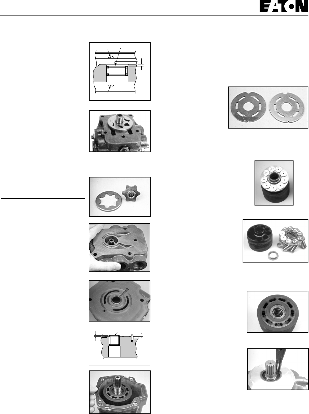
9
Model 70160
13 When the needle bearing
assembly is replaced, the
numbered end of the bearing must
face toward the flange side of the
adapter to the dimension as shown
(see Figure 13).
14 With the charge pump adapter
removed, remove the charge pump
outerring and inner gerotor ring
assembly (see Figure 14 and 15).
15 Charge pumps are available in
two different displacements Charge
pump displacements are based on
the thickness of the gerotor
assembly and the depth of the
pocket located in the charge pump adapter. To determine the
displacement, refer to the table below.
Gerotor Pocket Depth
Displacement Depth of Pocket
cm3/r [in3/r] mm [in.]
6.9 [.42] 6.35 [.25]
13.8 [.84] 12.7 [.50]
16 To separate the backplate
assembly from the dowel pins in
the pump housing assembly, insert
two screwdrivers between
backplate and housing assembly
and pry upward (see Figure 16).
17 After separation, remove the
backplate from the housing
assembly.
18 Turn the backplate assembly
over and inspect the needle
bearing. The needles in the needle
bearing must remain intact in the
bearing cage (see Figure 17).
19 When the needle bearing
assembly is replaced, the
numbered end of the bearing must
face the valve plate side of the
backplate to the dimension as
shown (see Figure 18).
20 With the backplate removed,
remove the gasket from the pump
housing assembly and discard (see
Figure 19).
21 Remove the valve plate from the piston block assembly.
Note: This valve plate may have stuck to the backplate
assembly that was previously removed.
22 Valveplate directional rotation (CW or CCW) is identified
by the location of the metering slots located on the face of the
valve plates. Pump input
rotation should always turn
into the metering slots (see
Figure 20). A clockwise
valve plate is shown on the
left and a counter clockwise
valveplate is on the right.
Note: Whenever pump
input rotation is changed, the valve plate must be replaced
along with the desired rotation charge pump adapter.
23 Remove the rotating kit assembly
by carefully retaining it in the housing
assembly (see Figure 21). Lift the
housing and rotating kit assembly and
turn over assemblies allowing the
rotating kit assembly to slide down the
input shaft and out of the pump
housing.
24 With the rotating kit
assembly removed, remove the
piston assemblies, spider and
spider pivot from the piston
barrel.(see Figure 22).
25 Inspect the piston
assemblies, spider, spider pivot
and piston block. The piston block assembly usually requires
no further disassembly unless the pins or block spring are
damaged.
26 When any excessive wear or
scratches are noted on the face of
the piston block, the block
assembly must be replaced (see
Figure 23).
DO NOT LAP THE FACE OF PISTON
BLOCK ASSEMBLY.
27 To remove the input shaft
assembly, use a pair of internal
snap ring pliers and remove the
shaft seal retaining ring from the
housing assembly (see Figure 24).
Numbered End
Gerotor Pocket
2.41 mm
[.095 in.]
Flange
Figure 13
Figure 17
2.79 mm
[.110 in.]
1.91 mm
[.075 in.]
Numbered End
Figure 18
Figure 20
Figure 22
Figure 23
Figure 24
Figure 15
Figure 16
Figure 14
Figure 19
Figure 21
Repair Information - Disassembly

10
Model 70160
28 With the retaining ring
removed, use a small press to
press the shaft seal and input shaft
assembly from the housing
assembly.
29 With the input shaft assembly
removed, disassemble the
assembly for inspection by
removing the shaft seal, washer,
retaining ring thrust washers and
bearing (see Figure 26).
Note: The rear pump on tandem
units uses a spacer in place of
shaft seals.
30 To remove the camplate from
the housing assembly, use a 9/16
in. socket or end wrench and
remove the three cap screws and
washers retaining the control arm cover plate assembly. Start
at the cover plate with control arm (see Figure 27).
31 With the retaining cap screws removed, insert two small
screwdrivers in the notches located
in the cover plate assembly and pry
upward. Make sure bearing cup
comes off with the cover plate (see
Figure 28).
Note: The crush ring in the control
arm trunnion cover does not need
to be removed (see Figure 29). The
only time the crush ring needs to
be removed is when either the
trunnion cover, the camplate
assembly or the housing assembly
is replaced. A shim kit is then
required in the crush ring’s place.
32 Reposition the pump assembly
to remove opposite cover plate.
The bearing cup in this cover plate
is press fit and not removable.
Repeat steps 30 through 31.
32b Remove the slip fit bearing on
the non-control arm side of the
camplate.
33 With housing in the upright
position, slide the camplate toward the control side and lift it
from the pump housing (see Figure 30).
Note: The camplate control shaft will fit out either side of the
pump housing. Be sure to note on which side of the housing
the control shaft protrudes before removing camplate from
housing for correct reassembly orientation.
34 Use an o-ring pick or similar tool to remove the o-ring
seals from the two counter-bores in the housing or the cover
plates (see Figure 31).
35 To remove the control side cover plate lip seal, use a small
press and press the lip seal inward
(see Figure 32).
36 Remove the thrust plate from
the camplate. The thrust plate is
reversible and either side may face
the camplate (see Figure 33).
37 Inspect the housing
assembly's front needle bearing. If
the needles remain in their cage
and move freely, replacement
usually is not required (see Figure
34).
38 When the needle bearing is
replaced, the numbered end of the
needle bearing must face away
from the housing and pressed to
the dimension as shown (see
Figure 35).
Figure 26
Figure 27
Repair Information - Disassembly
Figure 32
Figure 34
1.78 mm
[.07 in.]
Numbered End Flange End of Housing
Figure 35
Figure 25
Figure 28
Figure 29
Figure 30
Figure 33
Figure 31

11
Model 70160
Reassembly
1Before reassembling the pump, replace all worn and
damaged parts, assemblies, seals and o-rings. Lubricate the
seals and o-rings with petroleum jelly to help retain them
during reassembly and to provide lubrication to the input and
control shaft seals. Lubricate all finished part surfaces freely
with clean hydraulic fluid to help provide start up lubrication
between all rotating parts.
2To reassemble the camplate
assembly into the pump housing,
tilt the camplate slightly and install
the control side of the camplate
through the previously noted or
marked side of the housing
assembly (see Figure 36).
3Lubricate the tapered bearing
and reassemble it on the non-
control arm side of the camplate
(see Figure 37).
4Lubricate and install the o-ring
seal into counter-bore of housing
(see Figure 37).
5Install the trunnion cover over
bearing and onto pump housing.
Install the three cap screws and
washers, torque screws to 39,3 Nm
[29 ft-lb] (see Figure 38).
6Lubricate and install the
control arm shaft seal into the
control arm cover plate. Install with the lip of the seal facing
upward or to the inside of the pump (see Figure 39).
7If the housing, trunnion covers or camplate assembly have
not been replaced, the existing crush ring may be re-used. If
you have replaced anyone of the above a shim kit must replace
the crush ring. See Parts Information manual for number.
8Place the bearing cup into trunnion cover over the crush
ring or shims (see Figure 40).
9Lubricate and install the o-ring
seal into counter-bore of housing
(see Figure 41).
10 Install the trunnion cover over
the control shaft and into the pump
housing. Install the three retaining
cap screws and washers, torque
screws to 39,3 Nm [29 ft-lb] (see
Figure 42).
11 Using your fingers, tilt the
camplate back and forth to check
the trunnion bearing preload.
Proper preload is achieved when
the camplate has a very slight
tilting resistance. The camplate
must not have any or very little side
clearance.
12 Reassemble the input shaft
assembly by installing the thrust
washer, thrust bearing, second
thrust washer, retaining ring,
washer and shaft seal (see Figure
43).
Note: The lip of the shaft seal must
point toward the center of the input
shaft.
13 Install the input shaft
assembly into the housing
assembly. Push the shaft seal in
just far enough so you can start the
shaft seal retaining ring.
14 Use a pair of snap ring pliers
to install retaining snap ring into
the housing assembly (see Figure
44).
15 Use a seal driver or similar
tool to press or drive the snap ring and seal into the housing
assembly (see Figure 45).
CAUTION! Press or drive inward
until the snap ring snaps into the
snap ring groove located in the
pump housing assembly.
16 The thrust plate is reversible.
Either side will fit into the camplate.
In most cases if any irregularities
are noted it is best to replace the thrust plate (see Figure 46).
Figure 38
Figure 42
Figure 43
Figure 44
Figure 45
Repair Information - Reassembly
Figure 36
Figure 37
Figure 39 Figure 40
Figure 41
Figure 46

12
Model 70160
18 Lubricate and install the
thrustplate over the input shaft
assembly and into the camplate.
The thrustplate must rest firmly in
its pocket located in the camplate.
19 Reassemble the rotating kit
assembly by first aligning the
splines in the pivot with the splines
in the block. Install the pivot on the
block assembly pins (see Figure 47).
20 Use a small socket or similar
tool to help retain the pivot in the
centered position. Lubricate and
install the spider and piston
assemblies onto the pivot and
pistons into the piston block
assembly (see Figure 48).
21 Hold the housing assembly in
the vertical position then carefully
install the rotating kit by first
aligning with the splines on the
input shaft. With splines aligned,
install the rotating kit into the
pump housing (see Figure 50). Use
caution to ensure all parts are kept
in their proper position.
22 With the rotating kit installed,
reposition the housing assembly in
the input shaft down position and
install a new housing gasket (see
Figure 50).
23 Lightly coat the backplate side
of the valve plate with petroleum
jelly for retention during assembly.
Install the valve plate over the
needle bearing, aligning the small
slot on the outside of the valve
plate with the dowel pin in the
backplate (see Figure 51).
24 Carefully install the backplate
assembly by aligning it with the
dowel pins located in the pump
housing. Use caution not to
dislodge the valve plate (see Figure 54).
25 Align the spline of the
gerotor’s inner ring, then lubricate
and install the inner ring and outer
ring over the input shaft and onto
the backplate assembly (see Figure
53).
Note: Before installing the charge pump adaptor plate, offset
the outer ring of the geroter as
shown.
26 With the gerotor assembly
installed, install new o-ring into
charge pump adapter plate and
place adapter onto backplate over
gerotor. Retain with cap screws.
Torque cap screws to 25 N•m [18.5
lbf•ft] (see Figure 54).
27 Install the two high pressure
relief valves. Torque valves 128,8
to 142,4 Nm [95 to105 lb-ft] (see
Figure 55).
29 Lubricate and reassemble the
bypass valve assembly. Install the
bypass valve into the backplate.
Torque valve to 30,5±2 Nm
[22.5±1.5 lb-ft] (see Figure 56).
30 Coat the charge pressure
poppet with petroleum jelly and
place poppet onto spring and install
into the adapter plate (see Figure
57).
31 Install the hollow charge
pressure relief valve retainer into
the adapter plate. Torque retainer
to 6,8 to 9,5 Nm [5 to 7 lb-ft].
32 Lubricate and install the o-ring
on the cover plate or gear pump.
Install the cover plate or gear pump
and two cap screws. Torque cap screws to 36,6 to 40 Nm [27
to 31 lb-ft].
The Model 70160 or 78162 variable displacement pump is now
ready for test and reinstallation.
Figure 48
Figure 49
Figure 51
Figure 54
Figure 55
Figure 56
Figure 57
Repair Information - Reassembly
Figure 47
Figure 50
Figure 52
Figure 53
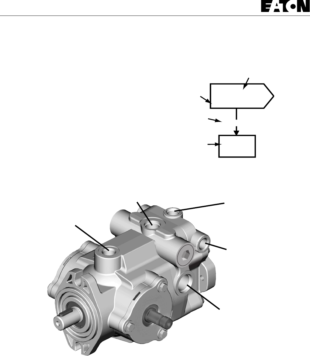
13
Model 70160
1
Inspect
?
Repair
or
Replace
Defective
Action
Step
Comment
Number
Decision
Solution
Symptom:
Gauges Recommended
Inlet vacuum gauge: 2 bar to 1 bar [30 PSI to 30 inHg]
System pressure gauge: 700 bar [10,000 PSI]
Charge pressure gauge: 0 to 50 bar [0 to 600 PSI]
Case pressure gauge: 0 to 25 bar [0 to 300 PSI]
Explanatory
Diagram
This fault - logic troubleshooting guide is a
diagnostic aid in locating transmission problems.
Match the transmission symptoms with the problem
statements and follow the action steps shown in the
box diagrams. This will provide help in correcting
minor problems eliminating unnecessary machine
down time.
Following the fault - logic diagrams are diagram
action comments of the action steps shown in the
diagrams. Where applicable, the comment number of
the statement appears in the action block of the
diagrams.
Recommended Gauge Locations
Figure 58
Pressure Ports
Tee In Line to Check
System Pressure
Charge Pump Suction Port
Tee In Line to Check Inlet
Vacuum
Drain Port
Tee In Line to Check
Case Pressure
Auxiliary Port
Check Charge Pressure
Fault - Logic Troubleshooting
Bypass Valve
Location

14
Model 70160
Fault - Logic Troubleshooting
Inspect
Servo Control
(If used)
OK
12
Inspect
External Control
Linkage
Defective
Repair
or
Replace
Defective
Repair
or
Replace
Symptom: Neutral Difficult or Impossible to Find
Inspect
Heat
Exchanger
OKOK OK
456
Check
Oil Level in
Reservoir
Fill to
Proper
Level
DefectiveBelow Level
Repair
or
Replace
Check
System
Pressure
Reduce
System
Load
High
OK
9
Inspect
Charge Relief
Valve
OK
11
Inspect
Charge
Pump 13
Inspect
Motor 12
Inspect
Inlet Screen
or Filter
Replace
Clogged
OK
8
Check
Charge
Pressure
10
Low OK
OK
Replace
Pump &
Motor
Inspect Pump
Bypass Valve
(If used)
OK
7
Inspect Heat
Exchanger
Bypass Valve
(If used)
OK
Defective
Repair
or
Replace
Defective
Repair
or
Replace
Defective
Repair
or
Replace
Defective
Repair
or
Replace
Defective
Repair
or
Replace
Symptom: System Operating Hot
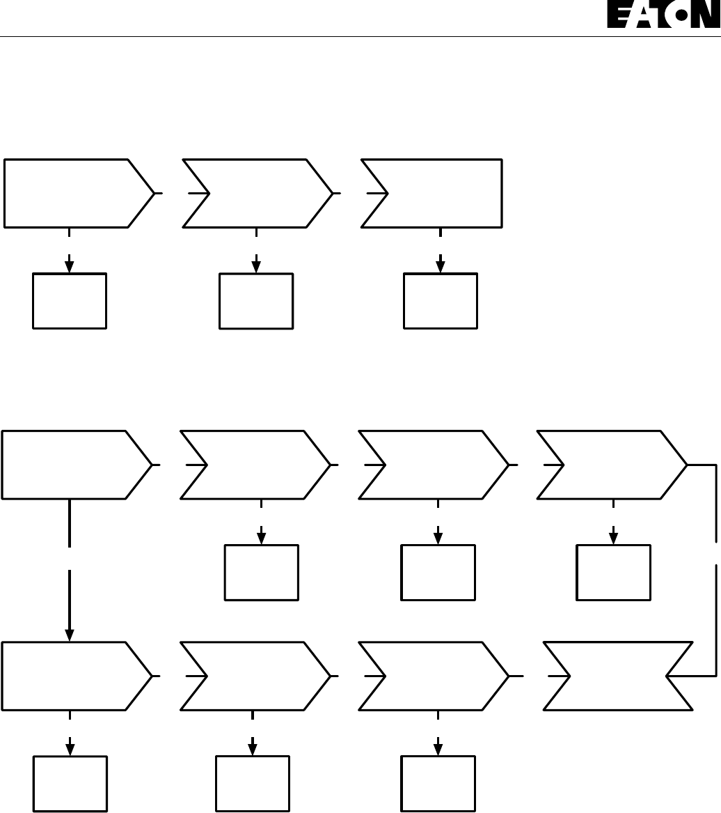
15
Model 70160
Inspect
Servo Control
(If used)
OK OK
123
Inspect
External Control
Linkage
Defective
Repair
or
Replace
Inspect
System Relief
Valves
Defective
Repair
or
Replace
Defective
Repair
or
Replace
Symptom: Operates in One Direction Only
Inspect
Servo Control
(If used)
OKOK OK
27
Defective
Repair
or
Replace
Inspect
Motor
12
Replace
Clogged
Check
Charge
Pressure
10
Low OK
Inspect Pump
Bypass Valve
(If used)
Replace
Pump &
Motor
Defective
Repair
or
Replace
Inspect
Inlet Screen
or Filter
OK
OK OK
813
Defective
Repair
or
Replace
Inspect
Charge Relief
Valve
11
Inspect
Charge
Pump
Defective
Repair
or
Replace
Defective
Repair
or
Replace
Symptom: System Response Sluggish
Fault - Logic Troubleshooting

16
Model 70160
Check External
Control
Linkage
OKOK OK
417
Check
Oil Level in
Reservoir
Fill to
Proper
Level
DefectiveBelow Level
Repair
or
Replace
Check
System
Pressure
OK
9
Inspect
Charge Relief
Valve
OK
11
Inspect
Charge
Pump 13
Inspect
Motor 12
Inspect
Inlet Screen
or Filter
Replace
Clogged
OK
8
Check
Charge
Pressure
10
Low OK
OK
Replace
Pump &
Motor
Inspect
Servo Control
(If used)
OK
2
Inspect Pump
Bypass Valve
(If used)
OK
Defective
Repair
or
Replace
Defective
Repair
or
Replace
Defective
Repair
or
Replace
Defective
Repair
or
Replace
Defective
Repair
or
Replace
High
Reduce
System
Load
Symptom: System Will Not Operate In Either Direction
Fault - Logic Troubleshooting

17
Model 70160
Diagram Action Step Comments
1 Inspect External Control Linkage for:
a. misadjustment or disconnection
b. binding, bending or breakage
c. misadjusted, damaged or broken neutral return spring
2 Inspect Servo Control Valve for: (if used)
a. proper inlet pressure
b. misadjusted, damaged or broken neutral return spring
c. galled or stuck control spool
d. galled or stuck servo piston
3 Inspect System Relief Valves* for:
a. improper pressure relief setting
b. damaged or broken spring
c. valve held off seat
d. damaged valve seat
4 Check Oil Level in Reservoir:
a. consult owner/operators manual for the proper type
fluid and level
5 Inspect Heat Exchanger for:
a. obstructed air flow (air cooled)
b. obstructed water flow (water cooled)
c. improper plumbing (inlet to outlet)
d. obstructed fluid flow
6 Inspect Heat Exchanger Bypass Valve for: (if used)
a. improper pressure adjustment
b. stuck or broken valve
7 Inspect Pump Bypass Valve for: (if used)
a. held in a partial or full open position
8 Inspect Inlet Screen or Filter for:
a. plugged or clogged screen or filter element
b. obstructed inlet or outlet
c. open inlet to charge pump
9 Check System Pressure:
a. See figure 60 for location of pressure gauge installation.
b. consult owner/operators manual for maximum system
relief valve settings
10 Check Charge Pressure:
a. See figure 60 for location of pressure gauge installation.
b. consult owner/operators manual for maximum charge
relief valve settings
11 Inspect Charge Relief Valve for:
a. improper charge relief pressure setting *
b. damaged or broken spring
c. poppet valve held off seat
12 Inspect Motor for:
a. disconnected coupling
13 Inspect Charge Pump for:
a. broken or missing drive key
b. damaged or missing o-ring
c. excessive gerotor clearance
d. galled or broken gerotor set
* System/Charge Relief Valve Pressure Settings for Eaton’s
Variable Displacement Controlled Piston Pumps
Inlet Vacuum 6 inHg max.
Case Pressure 25 PSI maximum
Charge Pressure 100 to 150 PSI Standard
200 to 250 PSI Optional
250 to 300 PSI Optional
System Pressure 5000 PSI maximum
3000 PSI continuous
The high pressure relief valves are all factory preset and
cannot be readjusted.
The pressure setting and assembly number is stamped on
each high pressure relief valve cartridge.
Valve Identification Example:
110603-500 5000
Relief Valve Setting
Relief Valve Assembly Number
Fault - Logic Troubleshooting

18
Model 70160
When starting a new or rebuilt transmission system, it is
extremely important to follow the start-up procedure. It
prevents the chance of damaging the unit which might occur if
the system was not properly purged of air before start-up.
1After the transmission components have been properly
installed, fill the pump housing at least half full with filtered
system oil. Connect all hydraulic lines and check to be sure
they are tight.
2Install and adjust all control linkage.
3Fill the reservoir with an approved oil that has been filtered
through a 10 micron filter. Refer to Eaton Hydraulics
Technical Data Sheet number 3-401 titled Hydraulic Fluid
Recommendations.
4For Gasoline engines or L.P. engines remove the coil wire
and turn the engine over for 15 seconds. For Diesel engines
shut off the fuel flow to the injectors and turn the engine
over for 15 seconds.
5Replace the coil wire or return the fuel flow to the injectors.
Place the transmission unit in the neutral position, start the
engine and run it at a low idle. The charge pump should
immediately pick up oil and fill the system. If there is no
indication of fill in 30 seconds, stop the engine and
determine the cause.
6After the system starts to show signs of fill, slowly move
pump camplate to a slight cam angle. Continue to operate
system slowly with no load on motors until system
responds fully.
7Check fluid level in the reservoir and refill if necessary to
the proper level with an approved filtered oil.
8Check all line connections for leaks and tighten if
necessary.
The machine is now ready to be put into operation.
Frequent filter changes are recommended for the first two
changes after placing the machine back into operation. Change
the first filter in 3-5 hours and the second in approximately 50
hours. Routinely scheduled filter changes are recommended
for maximum life of the hydraulic system.
Start-up Procedure

19
Model 70160
Notes:

Model 70160
Form No. 07-06-630 Copyright Eaton Corporation, 2001
EN-0401 All rights reserved.
Printed in U.S.A
Eaton Hydraulics
14615 Lone Oak Road
Eden Prairie, MN 55344
Telephone: 652 937-7254
Fax: 652 937-7130
www.eatonhydraulics.com
46 New Lane, Havant
Hampshire PO9 2NB
England
Telephone: (44) 23 92 486 451
Fax: (44) 23 92 487 110
ISO-9001 CERTIFICATED FIRM
DET NORSKE VERITAS INDUSTRY BV, THE NETHERLANDS
ACCREDITED BY
THE DUTCH COUNCIL
FOR CERTIFICATION
Reg. No. 24
Quality System Certified
Products in this catalog are
manufactured in an
ISO-9001-certified site.
Information contained in this catalog is accurate as of the publication date and is subject to
change without notice. Performance values are typical values. Customers are responsible for
selecting products for their applications using normal engineering methods.
No. 7-310
January, 1995
Char-Lynn®
Power Steering
2 Series
Steering Control Unit 001
Repair Information
TE
LR
P

2
Dust
Seal
Housing Quad
Seal
Thrust
Bearing
Sleeve
Spool
Pin
Centerin
Springs
Bearing Race (2)
O-ring
Seal
O-ring
Seal
Wear
Plate
Drive
Gerotor
Spacer
Manual Steering
Relief Valve
O-ring
O-ring
O-ring
O-ring Seal
Ring
End
Cap
Cap
Screw
(7)
Plug
Plug
Check
Ball
Spring
Retaining
Ring
Power Steering
2 Series
Steering Control Units
Tools Required
• 10 mm Socket
• 7/8 in. Socket
• Torque Wrench (18 Nm [160 lb-in] Capacity)
• Small Blade Screwdriver
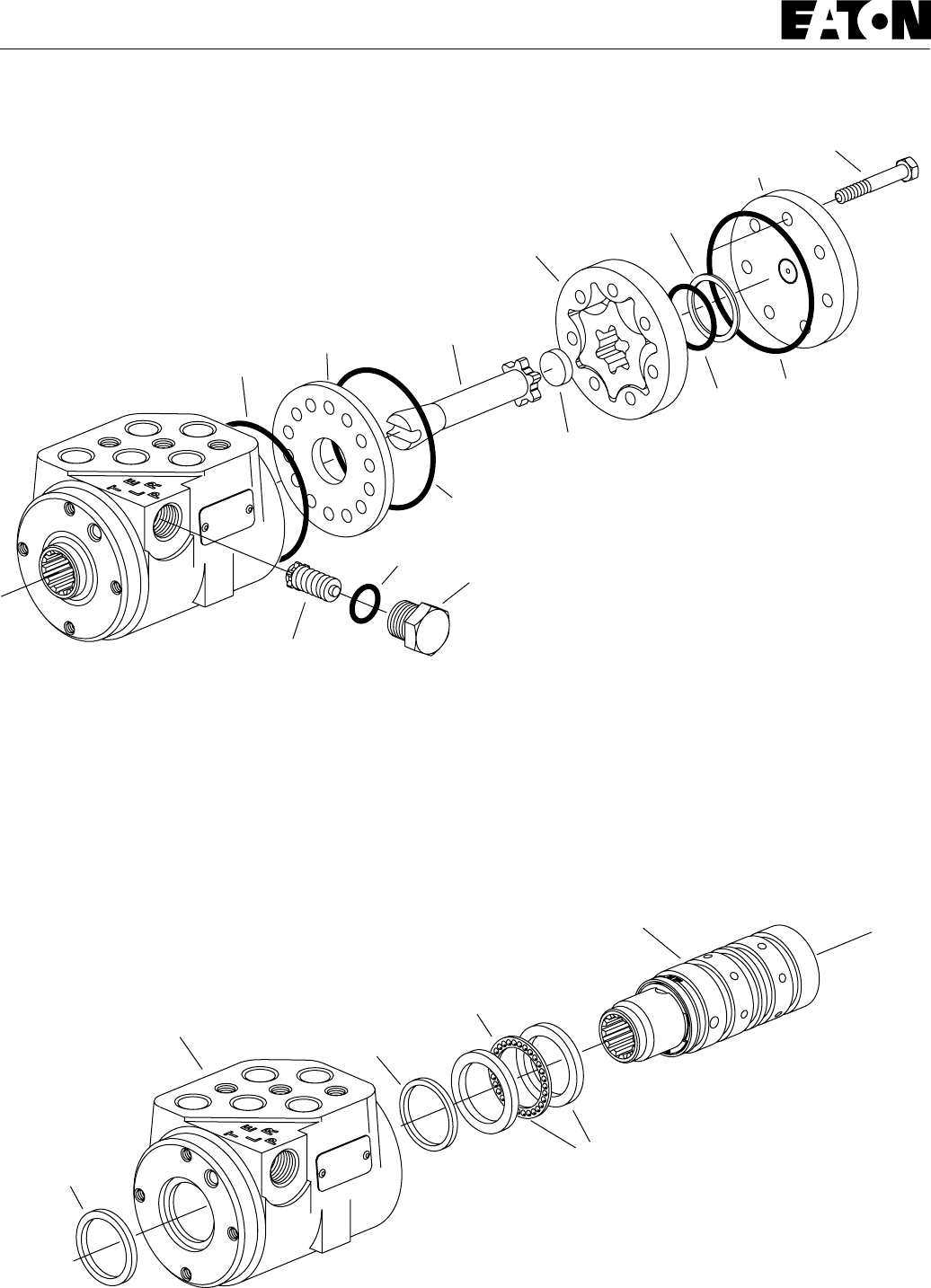
3
Power Steering
2 Series
Steering Control Units
Disassembly
Cleanliness is extremely important when repairing hydraulic
Steering Control Units (SCU). Work in a clean area. Before
disconnecting the hydraulic lines, clean the port area of the
SCU. Before disassembly, drain the oil, then plug the ports and
thoroughly clean the exterior of the SCU. During repairs,
always protect machined surfaces.
1 Remove the seven cap screws and disassemble the SCU as
shown in Figure 1.
2 Remove the plug and manual steering check as shown in
Figure 1.
Note: The manual steering check may be a check ball or a
check/relief valve.
3 Slide the spool and sleeve from the housing (see Figure 2).
4 Remove the thrust bearing and bearing races.
5 Remove the quad seal.
6 Using a small blade screwdriver, carefully pry the dust seal
from the housing.
Important: Do not damage the dust seal seat.
O-ring
Seal
O-ring
Seal
Wear
Plate Drive
Gerotor
Seal
Ring
Spacer
Manual Steering
Check/Relief Valve
O-ring
O-ring O-ring
End
Cap
Cap
Screw
(7)
Figure 1
Plug
Dust
Seal
Housing Quad
Seal
Thrust
Bearing
Bearing Race (2)
Spool and Sleeve
Figure 2

4
Power Steering
2 Series
Steering Control Units
7 Remove the pin that holds the spool and sleeve together
(see Figure 3).
8 Carefully slide the spool out of the sleeve. The springs
and retaining ring will stay with the spool as it's removed.
Reassembly
Check all mating surfaces. Replace any parts with
scratches or burrs that could cause leakage. Wash all
metal parts in clean solvent. Blow them dry with pressur-
ized air. Do not wipe parts dry with paper towels or cloth
as lint in a hydraulic system will cause damage.
Note: Always use new seals when reassembling
hydraulic steering control units. Refer to parts list 6-323
for seal kit part numbers, replacement parts, and
ordering information.
Important: During reassembly lubricate the new seals
with a petroleum jelly such as Vaseline®. Also lubricate
machined surfaces and bearings with clean hydraulic
fluid.
9 Remove the retaining ring and springs.
Caution: The centering springs are under tension. Remove
the retaining ring carefully.
10 Install the quad seal:
• Put one of the bearing races and sleeve into
the housing.
• Together, the housing and bearing race create
a groove into which the quad seal will be
installed.
• Hold the bearing race tightly against the input
end of the housing by pushing on the gerotor
end of the sleeve.
• Fit the quad seal into its seat through the input
end of the housing. Be sure the seal is not
twisted.
• Remove the sleeve and bearing race.
Centering
Springs and
Spacers
Sleeve
Pin
Spool
Figure 3
Spring
Retaining
Ring
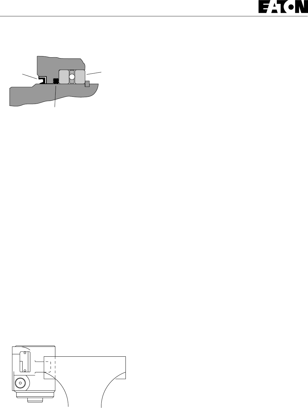
5
Power Steering
2 Series
Steering Control Units
20 Lubricate and install a new o-ring seal in the groove in
the housing.
21 Install the wear plate and align the holes in the wear
plate with threaded holes in the housing.
Note: The holes in the wear plate are symmetrical.
22 Install the drive, be sure the slot in the drive engages
the pin.
23 Lubricate and install a new o-ring seal in the groove in
the wear plate.
24 Install the gerotor and align the screw holes.
25 Lubricate and install a new o-ring seal in the groove in
the gerotor ring.
26 Lubricate and install a new o-ring and seal ring in the
groove in the gerotor star.
27 Install the spacer.
28 Install end cap and seven cap screws. Tighten cap screws,
in a crisscross pattern, to 16 -18 Nm [140 -160 lb-in].
29 Remove the SCU from the vise.
30 Install the relief valve/check or check ball and plug. Use
a new o-ring and tighten the plug to 17 Nm [150 lb-in].
Quad Seal
Figure 4
Dust Seal Thrust Bearing
and Race (2)
Figure 5
11 Lubricate and install the dust seal (see Figure 4 for
correct seal orientation).
12 Install the centering springs in the spool. It is best to
install the two flat pieces first. Next, install the curved
pieces, three at a time.
13 Fit the retaining ring over the centering springs.
14 Apply a light coating of clean hydraulic fluid to the
spool and slide it into the sleeve. Be sure the centering
springs fit into the notches in the sleeve.
15 Install the pin (see Figure 3).
16 Apply a light coating of petroleum jelly to the inner
edge of the dust and quad seals.
17 Put the thrust bearing and races into the housing. The
thrust bearing goes between the two races (see Figure 2).
18 Apply a light coating of clean hydraulic fluid to the
spool and sleeve assembly and slide it into the housing.
Important: Do not damage the dust or quad seals.
19 Clamp the housing in a vise as shown in Figure 5. Use
just enough clamping force to hold the housing securely.

6
System
Product Numbers 2 Series (Standard — 69 Bar [1000 PSI])
Product Numbers 2 Series (High Pressure — 103 Bar [1500 PSI])
Ports Relief Valve
Setting
Bar [PSI] 31 [1.9] 39 [2.4] 63 [3.8] 74 [4.5] 100 [6.1]51 [3.1]
Displacement cm
3
/r [in
3
/r] and Product Number
291-1001-001None 291-1002-001 291-1003-001 291-1004-001 291-1005-001 291-1006-001
291-1001-04140 [ 580] 291-1002-041 291-1003-041 291-1004-041 291-1005-041 291-1006-041
291-1001-05150 [ 725] 291-1002-051 291-1003-051 291-1004-051 291-1005-051 291-1006-051
291-1001-06163 [ 914] 291-1002-061 291-1003-061 291-1004-061 291-1005-061 291-1006-061
291-1001-07170 [1015] 291-1002-071 291-1003-071 291-1004-071 291-1005-071 291-1006-071
293-4001-001None 293-4002-001 293-4003-001 293-4004-001 293-4005-001 293-4006-001
293-4007-001None 293-4008-001 293-4009-001 293-4010-001 293-4011-001 293-4012-001
Open
Center
Non-
Load
Reaction
Power
Beyond
Non-
Load
Reaction
Dynamic
Signal
Load
Sensing
9/16 Inch
Plug-O (4)
9/16 Inch
Plug-O (5)
9/16 Inch
Plug-O (5)
9/16 -18
Inch
SAE (4)
9/16 -18
Inch
SAE (5)
9/16 -18
Inch
SAE (5)
None
40 [ 580]
50 [ 725]
63 [ 914]
70 [1015]
None
40 [ 580]
50 [ 725]
63 [ 914]
70 [1015]
None
40 [ 580]
50 [ 725]
63 [ 914]
70 [1015]
291-1007-001 291-1008-001 291-1009-001 291-1010-001 291-1011-001 291-1012-001
291-1007-041 291-1008-041 291-1009-041 291-1010-041 291-1011-041 291-1012-041
291-1007-051 291-1008-051 291-1009-051 291-1010-051 291-1011-051 291-1012-051
291-1007-061 291-1008-061 291-1009-061 291-1010-061 291-1011-061 291-1012-061
291-1007-071 291-1008-071 291-1009-071 291-1010-071 291-1011-071 291-1012-071
291-5001-001 291-5002-001 291-5003-001 291-5004-001 291-5005-001 291-5006-001
291-5001-041 291-5002-041 291-5003-041 291-5004-041 291-5005-041 291-5006-041
291-5001-051 291-5002-051 291-5003-051 291-5004-051 291-5005-051 291-5006-051
291-5001-061 291-5002-061 291-5003-061 291-5004-061 291-5005-061 291-5006-061
291-5001-071 291-5002-071 291-5003-071 291-5004-071 291-5005-071 291-5006-071
291-5007-001 291-5008-001 291-5009-001 291-5010-001 291-5011-001 291-5012-001
291-5007-041 291-5008-041 291-5009-041 291-5010-041 291-5011-041 291-5012-041
291-5007-051 291-5008-051 291-5009-051 291-5010-051 291-5011-051 291-5012-051
291-5007-061 291-5008-061 291-5009-061 291-5010-061 291-5011-061 291-5012-061
291-5007-071 291-5008-071 291-5009-071 291-5010-071 291-5011-071 291-5012-071
291-1001-121None 291-1002-121 291-1003-121 291-1004-121 291-1005-121 291-1006-121
291-1001-081 80 [1160] 291-1002-081 291-1003-081 291-1004-081 291-1005-081 291-1006-081
291-1001-091 90 [1305] 291-1002-091 291-1003-091 291-1004-091 291-1005-091 291-1006-091
291-1001-101100 [1450] 291-1002-101 291-1003-101 291-1004-101 291-1005-101 291-1006-101
293-4001-121None 293-4002-121 293-4003-121 293-4004-121 293-4005-121 293-4006-121
293-4007-121None 293-4008-121 293-4009-121 293-4010-121 293-4011-121 293-4012-121
Open
Center
Non-
Load
Reaction
Power
Beyond
Non-
Load
Reaction
Dynamic
Signal
Load
Sensing
9/16 Inch
Plug-O
(4)
9/16 Inch
Plug-O
(5)
9/16 Inch
Plug-O (5)
9/16 -18
Inch
SAE
(4)
9/16 -18
Inch
SAE
(5)
9/16 -18
Inch
SAE (5)
None
80 [1160]
90 [1305]
100 [1450]
None
80 [1160]
90 [1305]
100 [1450]
None
80 [1160]
90 [1305]
100 [1450]
291-1007-121 291-1008-121 291-1009-121 291-1010-121 291-1011-121 291-1012-121
291-1007-081 291-1008-081 291-1009-081 291-1010-081 291-1011-081 291-1012-081
291-1007-091 291-1008-091 291-1009-091 291-1010-091 291-1011-091 291-1012-091
291-1007-101 291-1008-101 291-1009-101 291-1010-101 291-1011-101 291-1012-101
291-5001-121 291-5002-121 291-5003-121 291-5004-121 291-5005-121 291-5006-121
291-5001-081 291-5002-081 291-5003-081 291-5004-081 291-5005-081 291-5006-081
291-5001-091 291-5002-091 291-5003-091 291-5004-091 291-5005-091 291-5006-091
291-5001-101 291-5002-101 291-5003-101 291-5004-101 291-5005-101 291-5006-101
291-5007-121 291-5008-121 291-5009-121 291-5010-121 291-5011-121 291-5012-121
291-5007-081 291-5008-081 291-5009-081 291-5010-081 291-5011-081 291-5012-081
291-5007-091 291-5008-091 291-5009-091 291-5010-091 291-5011-091 291-5012-091
291-5007-101 291-5008-101 291-5009-101 291-5010-101 291-5011-101 291-5012-101
Power Steering
2 Series Steering Control Units

7
Power Steering
2 Series
Steering Control Units

Copyright Eaton Corporation, 1991, and 1995
All Rights Reserved
Printed in USA
Form No. 7-310
Char-Lynn
®
Eaton Corp. Hydraulics Div.Hydraulics Div.
Eden Prairie, MN 55344
Product number
000 0000 000
000
Product Number
000 0000 000
Product Line
Identification
Number
Product
Identification
Number
Engineering
Change
Code
Week of
Year
01 Thru 52
Last Number(s)
of Year
Date Code
00 00
Relief Valve Pressure Code
00 = None
04 = 40 Bar [ 580 PSI]
05 = 50 Bar [ 725 PSI]
06 = 63 Bar [ 914 PSI]
07 = 70 Bar [1015 PSI]
08 = 80 Bar [1160 PSI]
09 = 90 Bar [1305 PSI]
10 = 100 Bar [1450 PSI]
Each Order Must Include the Following:
How to Order Replacement Parts
1. Product Number
2. Date Code
3. Part Name
4. Part Number
5. Quantity of Parts
For More Detailed Information Contact Eaton Corp. Hydraulics
Division 15151 Highway 5 Eden Prairie, MN 55344.
Specifications and performance data, Catalog No. 11-872
Replacement part numbers and kit information — Parts
Information No. 7-310.
Power Steering
2 Series
Steering Control Units
Eaton Corporation
Hydraulics Division
15151 Hwy. 5
Eden Prairie, MN 55344
Telephone 612/937-9800
Fax 612/937-7130
Eaton Ltd.
Hydraulics Division
Glenrothes, Fife
Scotland, KY7 4NW
Telephone 01-592-771-771
Fax 01-592-773-184
Eaton GmbH
Hydraulics Products
Am Schimmersfeld 7
40880 Ratingen, Germany
Telephone 02102-406-830
Fax 02102-406-800
ISO-9001 CERTIFICATED FIRM
DET NORSKE VERITAS INDUSTRY BV, THE NETHERLANDS
ACCREDITED BY
THE DUTCH COUNCIL
FOR CERTIFICATION
Reg. No. 24
Quality System Certified
Products in this catalog are manufactured
in an ISO-9001-certified site.
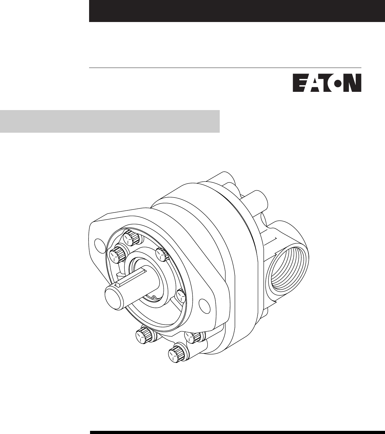
No. 7-624
October,1995
Eaton®
Gear Pumps
Repair Information
Series 26
Model 26000 Single Gear Pumps

2
Series 26 - Model 26000 Single Gear Pumps
Introduction
Table of Contents
Introduction ................................................................................................................................ 2
Identification............................................................................................................................... 3
Tools Required ........................................................................................................................... 3
Exploded View Drawing .............................................................................................................. 4
Parts List .................................................................................................................................... 5
Disassembly ............................................................................................................................... 5 & 6
Reversibility ................................................................................................................................ 7
Inspection................................................................................................................................... 8
Reassembly ................................................................................................................................9 & 10
Specific Backplate Parts List.......................................................................................................11 &12
Placing Pump Back into Operation ............................................................................................. 13
Trouble Shooting ........................................................................................................................ 14
Ordering Information .................................................................................................................. 16
Introduction
This manual provides service information for the Eaton model 26000 single gear pumps. Step by step
instructions for the complete disassembly, inspection, and reassembly of the pumps are included.
The following recommendations should be followed to insure successful repairs.
Remove the pump from the application.
Cleanliness is extremely important.
Clean the port areas thoroughly before disconnecting the hydraulic lines.
Plug the pump ports and cover the open hydraulic lines immediately after they're disconnected.
Drain the oil and clean the exterior of the pump before making repairs.
Wash all metal parts in clean solvent.
Use compressed air to dry the parts. Do not wipe them dry with paper towels or cloth.
The compressed air should be filtered and moisture free.
Always use new seals when reassembling hydraulic pumps.
For replacement parts and ordering information refer to parts list 6-634.
Lubricate the new rubber seals with a petroleum jelly (vaseline) before installation.
Torque all bolts over gasket joints, then repeat the torquing sequence to makeup for gasket
compression.
Verifying the accuracy of pump repairs on an authorized test stand is essential.

3
Series 26 - Model 26000 Single Gear Pumps
Identification and Tools
Required
B 95 01 31 JB Serial Number Code:
Series
26 = Gear Pump
( SAE "A" Mount )
Features
0 = Standard Single Pump
1 = Standard Single W/ Relief
2 = Flow Divider Backplate
3 = Flow Divider W/ Load Sense
4 = Tandem Backplate
5 = Multiple Pumps
Displacement cm3/r [ in3 /r]
01 = 6.6 [.40] 08 = 22.5 [1.37]
02 = 8.2 [.50] 09 = 24.3 [1.48]
03 = 9.5 [.58] 10 = 25.2 [1.54]
04 = 10.8 [.66] 11 = 27.7 [1.69]
05 = 13.8 [.84] 12 = 29.0 [1.77]
06 = 16.7 [1.02] 13 = 30.6 [1.87]
07 = 19.7 [1.20]
Input Rotation
R = Right-hand (clockwise)
L = Left-hand (Counterclockwise)
Catalog / Non-Catalog
Z = Cataloged Pump
A-Y = Non-Cataloged Pump
Shafts , Porting Size and Location
Side Ports
A = 3/4 in. 11 Tooth, 1 5/16-12 UN-2B Suction, 7/8-14 UNF-2B Pressure
C = 3/4 in. Str. Keyed, 1 5/16-12 UN-2B Suction, 7/8-14 UNF-2B Pressure
E = 3/4 in. 9 Tooth, 1 5/16-12 UN-2B Suction, 7/8-14 UNF-2B Pressure
G = 5/8 in. Str. Keyed, 1 1/16-12 UN-2B Suction, 7/8-14 UNF-2B Pressure
J = 5/8 in. 9 Tooth, 1 1/16-12 UN-2B Suction, 7/8-14 UNF-2B Pressure
L = 5/8 in. Str. Keyed, 1 5/16-12 UN-2B Suction, 7/8-14 UNF-2B Pressure
N = 3/4 in. 11 Tooth, 1 1/16-12 UN-2B Suction, 7/8-14 UNF-2B Pressure
R = 3/4 in. Str. Keyed, 1 1/16-12 UN-2B Suction, 7/8-14 UNF-2B Pressure
Rear Ports
B = 3/4 in. 11 Tooth, 1 5/16-12 UN-2B Suction, 7/8-14 UNF-2B Pressure
D = 3/4 in. Str. Keyed, 1 5/16-12 UN-2B Suction, 7/8-14 UNF-2B Pressure
F = 3/4 in. 9 Tooth, 1 5/16-12 UN-2B Suction, 7/8-14 UNF-2B Pressure
H = 5/8 in. Str. Keyed, 1 1/16-12 UN-2B Suction, 7/8-14 UNF-2B Pressure
K = 5/8 in. 9 Tooth, 1 1/16-12 UN-2B Suction, 7/8-14 UNF-2B Pressure
M = 5/8 in. Str. Keyed, 1 5/16-12 UN-2B Suction, 7/8-14 UNF-2B Pressure
P = 3/4 in. 11 Tooth, 1 1/16-12 UN-2B Suction, 7/8-14 UNF-2B Pressure
S = 3/4 in. Str. Keyed, 1 1/16-12 UN-2B Suction, 7/8-14 UNF-2B Pressure
Product Number: 26 0 01 - R Z A
Tools Required
3/8 in. socket and ratchet wrench
Internal Retaining Ring Pliers
(straight .090 tip)
O-ring Pick
Thread 3/8 dia. UNC bolt/screw
Torque Wrench
(135.6 N.m [100 lbf.ft] capacity)
Hammer (soft face)
Light Petroleum Jelly
Seal Driver
Arbor Press
Testers Initials
Day of Month (two digits)
Month (two digits)
Last two digits of year built.
( 95 for 1995 etc.)
Revision level of parts list.
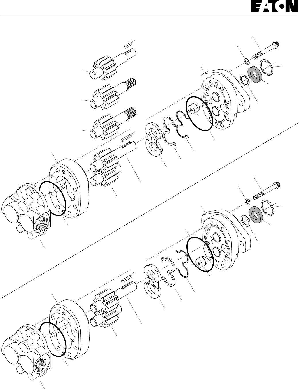
4
Series 26 - Model 26000 Single Gear Pumps
Parts
Drawing
Righthand (CW)
Rotation Pump
Lefthand (CCW)
Rotation Pump
3
Body
1
Front Plate
11
Cap Screws
17
Washer
8
O- ring
8
O-ring
40
Plug
12
Backup Gasket
13
Seal
7
Wear Plate
4C
Drive Gear
Assembly
5
Idler Gear
Assembly
10
Washer
L
R
9
Shaft seal
25
Optional
Retaining
Ring
4A
Drive Gear
Assembly
4D
Drive Gear
Assembly
4B
Drive Gear
Assembly
14a
Key
14b
Key
2
Backplate
3
Body
1
Front Plate
11
Cap Screws
17
Washer
8
O- ring
8
O-ring
40
Plug
12
Backup Gasket
13
Seal
7
Wear Plate
4C
Drive Gear
Assembly
5
Idler Gear
Assembly
10
Washer
L
R
9
Shaft seal
25
Optional
Retaining
Ring
14a
Key
2
Backplate
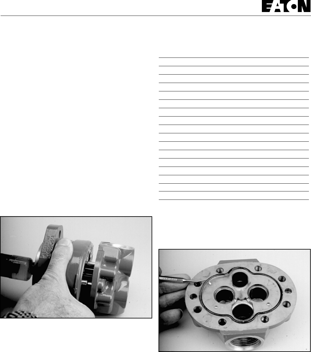
5
Series 26 - Model 26000 Single Gear Pumps
Disassembly Parts List
Item
No. Description Qty.
1 Front plate Assembly 1
2 Backplate 1
3 Body Assembly 1
4 Drive Gear Assembly 1
5 Idler Gear Assembly 1
~ 7 Wear Plate 1
~ 8 O-ring 2
~ 9 Shaft Seal 1
~ 10 Washer 1
11 Cap Screw 8
~ 12 Backup Gasket 1
~ 13 Seal 1
14 Key for Straight Shaft 1
~ 17 Washer 4
25 Retaining Ring (optional) 1
40 Plug 1
~ Seal Kit 26000-901 for Single Pumps
6 Remove
o-ring
seal from backplate.
7 To disassemble the
relief valve backplate, flow divider
backplate, and tandem flow divider backplate
see page 11 &
12.
Repair Information - Model 26000
Work in a clean area; cleanliness is extremely important when
repairing hydraulic pumps. Before disconnecting the lines,
clean port area of pump. Disconnect hydraulic lines, removing
pump assembly from vehicle and plugging ports. Thoroughly
clean the outside of pump. After cleaning, remove port plugs
and drain oil.
Disassembly
1 Remove
key
from drive shaft if keyed drive gear assembly
is used.
2 Put a
location mark
across front plate, body and backplate
to assure proper reassembly.
3 Clamp pump in vise, shaft end up.
4 Remove
cap screws
(eight each) and washer (four each).
5 Remove pump from vise, hold pump in hands and tap
shaft with plastic hammer or rawhide mallet to separate front
plate from backplate. Body will remain with either front plate or
backplate.
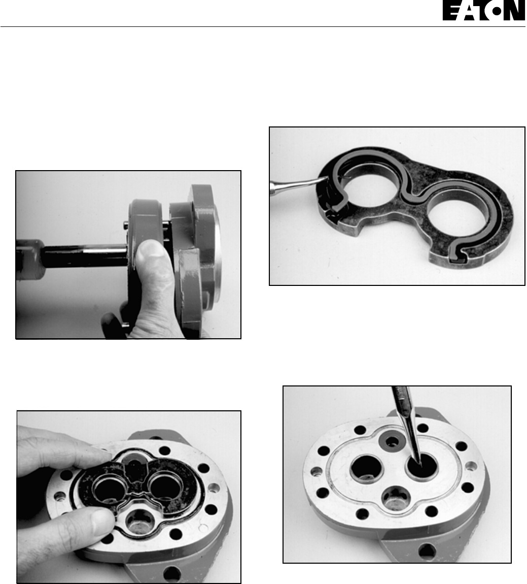
6
Series 26 - Model 26000 Single Gear Pumps
Disassembly
8 Remove
idler gear assembly
from body.
9 To separate
body
from the plate it remained with, place
drive gear assembly
in gear pocket and tap protruding end with
plastic hammer or rawhide mallet. Remove drive gear
assembly.
10 Remove wear plate and o-ring seal, noting position of
open side of wear plate.
11 Remove
back-up gasket and seal
from wear plate by
extracting with a o-ring tool.
12 Remove snap ring (if applicable) from the front of the front
plate shaft seal area.
13 Remove
shaft seal
and
washer
from front plate with a
blunt punch from the back side.
14 Removing the
plug
in front plate is not necessary, unless
you intend to change rotation. See Reversibility - Changing
Input Rotation of Pump.

7
Series 26 - Model 26000 Single Gear Pumps
Reversibility
Changing Input Rotation of Pump
1 Place pump in a protected jaw vise with shaft end up.
Remove the eight cap screws.
2 Remove front plate, noting orientation of drive shaft
through bearing in reference to the backplate.
3 Notice the location of the open side of wear plate and
remove wear plate.
4 Switch
drive gear and idler gear
within gear pockets. Do
not flip idler gear end for end.
Note: Gear housing body and backplate do not need altering.
5 Re-install wear plate into gear pockets over the gears with
seal and backup gasket up. (Same orientation as removed)
6 Front plate disassembly and assembly:
- Thread 3/8 UNC threaded bolt into
plug
cavity. Start
with fingers, then place bolt head in vise and turn front
plate to engage threads 2-3 turns.
- Holding bolt in vise, tap front plate with rubber
hammer to disengage
plug
.
- Remove
plug
from bolt.
- Install plug in the other casting cavity and tap flush
with rubber hammer. Note L or R at bottom of cavity.
40
Plug
40
Plug
Open for
righthand
rotation
Open for
lefthand
rotation
R
L
R
L
- Ensure that bearing drain holes are free of debris.
- Note proper placement of o-ring in groove of front
plate.
7 Hold o-ring in groove of front plate with petroleum jelly.
Reassemble front plate over drive shaft end, being careful not
to damage shaft seal.
8 Torque 8 cap screws 34 to 38 N•m [25 to 28 lbf•ft].
9 Lubricate gears and mating surfaces with hydraulic oil
through ports.
10 Rotate shaft (manually) to ensure proper assembly of
components.

8
Series 26 - Model 26000 Single Gear Pumps
Inspection
Model Number 26001 26002 26003 26004 26005 26006 26007 26008 26009 26010 26011 26012 26013
Pump Disp. 6,6 8,2 9,5 10,8 13,8 16,7 19,7 22,5 24,3 25,2 27,7 29,0 30,6
cm3/r [in3/r] [.40] [.50] [.58] [.66] [.84] [1.02] [1.20] [1.37] [1.48] [1.54] [1.69] [1.77] [1.87]
Gear Width 7,85 9,75 11,20 12,95 16,15 19,35 22,56 25,76 28,12 28,96 32,16 33,78 35,36
mm [in] [.309] [.384] [.441] [.510] [.636] [.762] [.888] [1.014] [1.107] [1.140] [1.266] [1.330] [1.392]
Front plate and Backplate Inspection
1Oil groove in bushings in front plate should be in line with
dowel pin holes and 180° apart. The oil grooves in the
backplate bushings should be at approximately 37° to the
pressure side.
2Replace the backplate or front plate if I.D. of bushings
exceed 19,2 mm [.755 in] (Bushings are not available as
separate items).
3Bushings in front plate should be at 3,20 mm [.126 in]
above surface of front plate.
4Check for scoring on face of backplate. Replace if wear
exceeds ,038 mm [.0015 in.].
Body Inspection
1Check body inside gear pockets for excessive scoring or
wear.
2 Replace body if I.D. of gear pockets exceeds 43,7 mm
[1.719 in].
Inspect Parts for Wear
General
1 Clean and dry all parts.
2 Remove all nicks and burrs from all parts with emery
cloth.
Gear Assembly Inspection
1 Check spline drive shaft for twisted or broken teeth or
check keyed drive shaft for broken or chipped keyway.
2Inspect both the drive gear and idler gear shafts at
bushing points and seal area for rough surfaces and excessive
wear.
3Replace gear assembly if shaft measures less than 19 mm
[ .748 in] in bushing area. (One gear assembly may be replaced
separately; shafts and gears are available as assemblies only.)
4Inspect gear for scoring and excessive wear.
5Replace gear assembly if gear width is below the following
dimensions. Refer to chart on this page.
6Assure that snap rings are in grooves on either side of
drive and idler gears.
7If edge of gear teeth are sharp, break edge with emery
cloth.

9
Series 26 - Model 26000 Single Gear Pumps
4 Install new
seal
and new
backup gasket
into wear plate.
Note in the middle of the backup gasket a flat section or
support. This area must face away from the wear plate inside
the seal.
5 Place new
wear plate, seal,
and
backup gasket
into gear
pocket with seal and backup gasket next to front plate. The side
of the wear plate with the mid section cut-away must be on the
suction side of pump.
6 Dip
gear assemblies
into oil and slip into front plate
bushings and gears into pockets of body.
Reassembly
General Information
It is important that the relationship of the backplate, body, wear
plate and front plate is correct. You will note two half moon
cavities in the body. Note: The smaller half moon port cavity
must be on the pressure side of the pump. The side of wear
plate with midsection cut out must be on suction side of pump.
Suction side of backplate is always side with larger port boss.
Reassembly
1 During the reassembly replace the
wear plate, seal, back-up
gasket, shaft seal and o-rings
as new parts.
2 Install
o-ring
in groove of front plate.
3 Apply a thin coat of petroleum jelly or hydraulic oil to both
milled gear pockets of body. Slip body onto front plate with half
moon port cavities in body facing away from front plate.
Note: The small half moon port cavity must be on the pressure
side (the plugged side of the front plate) of pump.

10
Series 26 - Model 26000 Single Gear Pumps
Reassembly
7 Install new
o-ring
in groove of backplate.
8 Make sure port orientation is correct and then slide
backplate
over gear shafts until dowel pins are engaged.
9 Secure with
cap screws
and new
washers
. Tighten cap
screws evenly in a crisscross pattern 34 to 38 N•m [25 to 28
lbf•ft] torque.
10 Place washer over drive shaft into housing. Liberally oil
shaft seal and install over drive shaft, carefully so that rubber
sealing lips are not cut.
11 Place 1-5/16 in. O.D. sleeve over shaft and press in shaft
seal until flush with front surface of front plate.
13 Install key on keyed shaft.
Note: Refer to Start-up Procedure and Trouble Shooting
Procedure.

11
Series 26 - Model 26000 Single Gear Pumps
Specific Backplate Parts List
Item
No. Description Qty.
2 Relief Valve Backplate 1
18 O-ring 3
19A Relief Valve Assembly 1
19A1 Relief Valve 1
~ 19A2 O-ring 1
~ 19A3 Backup Ring 1
~ 19A4 O-ring 1
19B Plug Assembly 1
19B1 Plug 1
Item
No. Description Qty.
2C Flow Divider Backplate 1
19A Relief Valve Assembly 1
19A1 Relief Valve 1
~ 19A2 O-ring 1
~ 19A3 Backup Ring 1
~ 19A4 O-ring 1
19B Plug Assembly 1
19B1 Plug 1
20 Flow Divider Spool 1
21 Plug/O-ring Assembly 1
21A Plug 1
~ 21B O-ring 2
22 Plug/O-ring Assembly 1
22A Plug 1
23 Spring 1
24 Shim (.0239 inch thick) A/R
A/R – As Required
3 Remove flow divider
plugs, shims, spring, and spool
from
backplate. (Notice orientation of spool with cavity in backplate)
4 Install new plug
seals
on plugs. Install
spool, spring,
shims, and plug assemblies
into backplate. Torque plugs 29 to
33 N•m [21 to 24 lbf•ft]
21B
22A
22
2C
20
23
24
19A4
21A
21
19A319A2
19B1
19B
21B
19A4
19A2
19A3
19A1
19A
Flow Divider Backplate
Disasembly and Reassembly
1 After removing
relief valve or plug
, remove and replace o-
ring and backup ring with new parts.
2 Install
relief valve or plug
and torque 41 to 46 N•m [30 to
34 lbf•ft]
19A4
19A2
19A3
19A1
19A
2B
Relief Valve Backplate
Disasembly and Reassembly
1 After removing
relief valve
, remove and replace o-rings
and backup ring with new parts.
2 Install
relief valve
and torque 41 to 46 N•m [30 to 34 lbf•ft]

12
Series 26 - Model 26000 Single Gear Pumps
Specific Backplate Parts List
29A
29B
35
30
34
2D
29
27 26
33
32
18
20A
23A
24
28B28A
28
Tandem Flow Divider Backplate
Item
No. Description Qty.
2D Tandem Flow Divider Backplate 1
2E Tandem Backplate 1
18 O-ring 3
20A Spool for Tandem Flow Divider Backplate
23A Spring for Tandem Flow Divider Backplate 1
24 Shim (.0239 inch thick) A/R
~ 26 O-ring 1
27 Plug 1
28 Plug/O-ring Assembly 1
28A Plug 1
~ 28B O-ring 2
29 Plug/O-ring Assembly 1
29A Plug 1
~ 29B O-ring 1
30 Relief Valve Spring 1
32 Sleeve 1
33 Spring 1
34 Poppet 1
35 Shim Washer (.010 inch thick) A/R
36 Tandem Cover Plate 1
37 O-ring 1
38 Cap Screw 2
A/R – As Required
Tandem Backplate
2E
37
36
38
Disasembly and Reassembly
1 Remove
relief valve plug, shim, spring, and poppet
from
backplate. Do not remove internal relief valve seat. Seat is
loctited to a predetermined depth. Remove o-ring from plug
and replace with new o-ring.
2 Install
poppet, spring, shim, and relief valve plug
and
torque 14 to 16 N•m [10 to 12 lbf•ft]
3 Remove flow divider
plugs, shims, springs, spool, and
sleeve
from backplate. (Notice orientation of spool with cavity
in backplate) Remove
o-rings
from sleeve and replace with new
o-rings
.
4 Install
sleeve, spool, springs, shims, and plug assemblies
into backplate. Torque plug #27 48 to 54 N•m [35 to 40 lbf•ft]
and plug #28 29 to 33 N•m [21 to 24 lbf•ft]
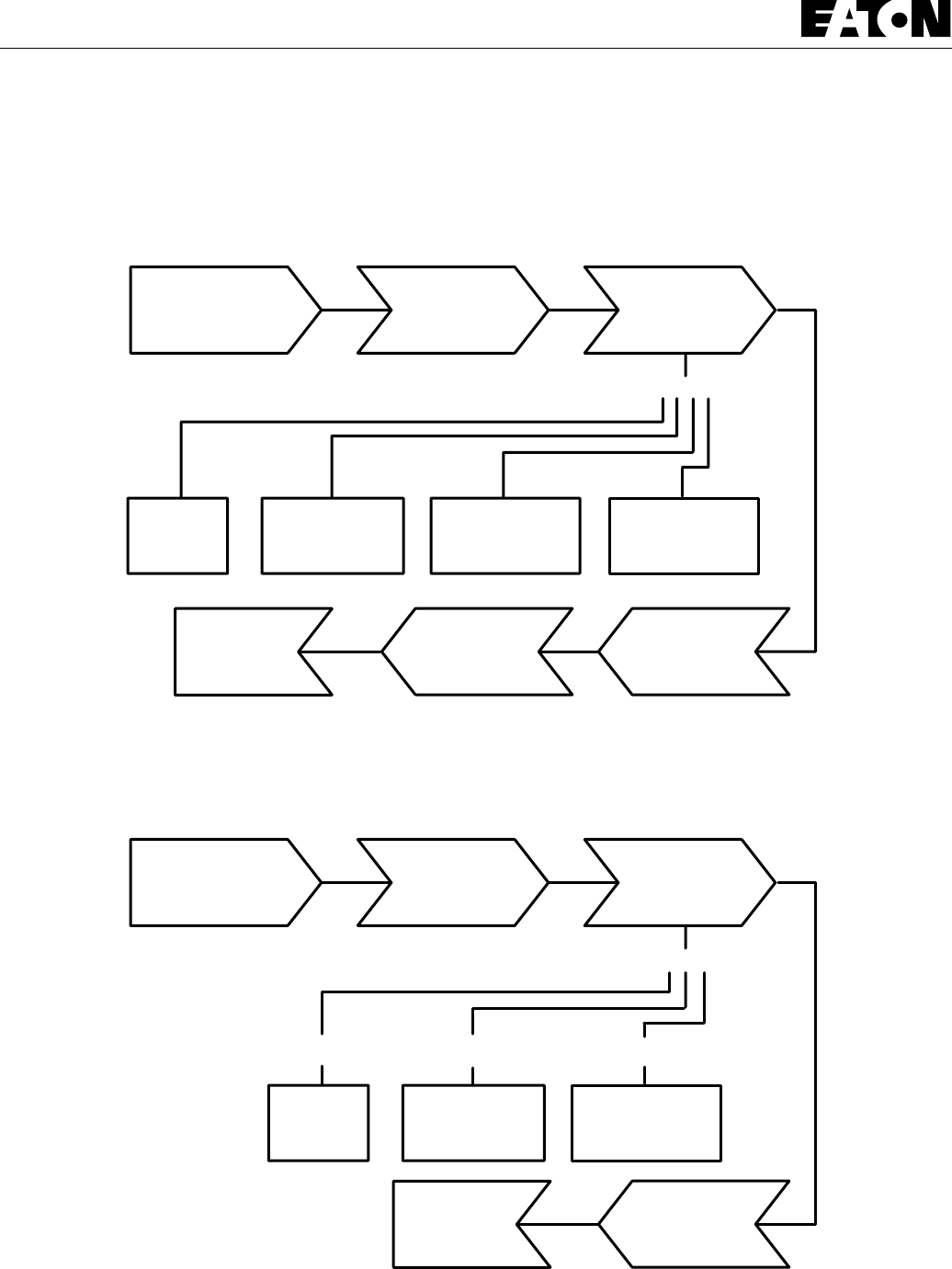
13
Series 26 - Model 26000 Single Gear Pumps
Placing Series 26 Gear Pump
Back into Operation
Connect
to
Fluid Supply
Mount Pump
on
Machine
Check
for
Leaks
Pump
Ready for
Service
Start Pump
and
Run For
3 Minutes
Each
At 1/2 Speed At 1/2 Speed At Full Speed
At
Zero
Pressure
Load
Intermittently
to 1000 lbf/in
2
Load
Intermittently
to 500 lbf/in
2
When test stand is
not available
.
When test stand is
available
.
Connect
to
Fluid Supply
Mount Pump
on
Test Stand
Check
for
Leaks
Pump
Ready for
Service
Start Pump
and
Run For
3 Minutes
Each
At
Zero
Pressure
Load
Intermittently
to 1000 lbf/in
2
Load
Intermittently
to 500 lbf/in
2
Remove
from
Test Stand
Load
Intermittently
to 2000 lbf/in
2

14
Series 26 - Model 26000 Single Gear Pumps
Trouble Shooting
Problem Possible Cause Correction
Cavitation a. Oil too heavy. a. Change to proper viscosity
b. Oil filter plugged. b. Clean filter.
c. Suction line plugged or too small. c. Clean line and check size of line.
Oil heating a. Oil supply low. a. Fill reservoir.
b. Contaminated oil. b. Drain reservoir and refill with clean oil.
c. Setting of relief valve too high or
too low. c. Set to correct pressure.
d. Oil in system too light. d. Drain reservoir and refill with proper
viscosity oil.
Shaft seal leakage a. Worn shaft seal. a. Replace shaft seal.
b. Worn shaft in seal area. b. Replace drive assembly.
c. Debris in shaft seal suction side
drain holes. c. Disassemble pump and inspect.
Foaming oil a. Low oil level a. Fill reservoir.
b. Air leaking into suction line b. Tighten fittings.
c. Wrong kind of oil. c. Drain and fill reservoir with
non-foaming oil.
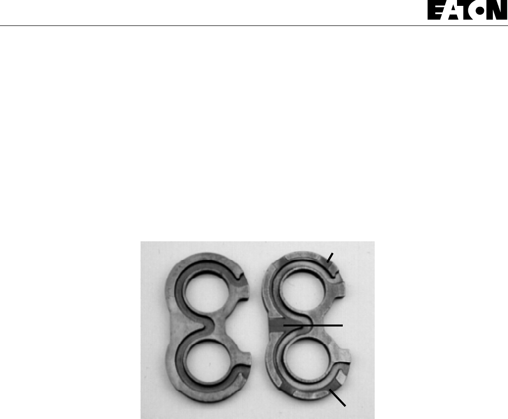
15
Series 26 - Model 26000 Single Gear Pumps
Note
Wear Plate Identification
A product improvement has been made to the Model 26000 gear pump with a new designed wear plate. To identify the new wear
plate, look for grooves placed in the seal side of the wear plate as shown below.
This new wear plate enables better pressure clamping with aerated oil in pumps 1.37 cubic inch or smaller. Aerated oil
may occur during a cold start-up in applications with long suction lines or when the mouth of the inlet line is temporarily
exposed to air.
New Groove
New Groove
New Groove
OLD
Wear Plate
NEW
Wear Plate

Eaton Corporation
Hydraulics Division
15151 Hwy. 5
Eden Prairie, MN 55344
Telephone 612/937-9800
Fax 612/937-7130
Eaton Ltd.
Hydraulics Division
Glenrothes, Fife
Scotland, KY7 4NW
Telephone 01-592-771-771
Fax 01-592-773-184
Eaton GmbH
Hydraulics Products
Am Schimmersfeld 7
40880 Ratingen, Germany
Telephone 02102-406-830
Fax 02102-406-800
ISO-9001 CERTIFICATED FIRM
DET NORSKE VERITAS INDUSTRY BV, THE NETHERLANDS
ACCREDITED BY
THE DUTCH COUNCIL
FOR CERTIFICATION
Reg. No. 24
Quality System Certified
Products in this catalog are manufactured
in an ISO-9001-certified site.
Form No. 7-624 Copyright Eaton Corporation, 1995
All Rights Reserved
Printed in USA
Order parts from 6-634 Parts Information booklet.
Each order must include the following information.
1. Product and/or Part Number
2. Serial Number Code
3. Part Name
4. Quantity

ENGINE--DIESEL
6-1
ATLV 4300 330495 (12--01)
CONTENTS
Page
INTRODUCTION 6-3......................
COOLING SYSTEM 6-4.............
ENGINE OIL 6-5....................
ENGINE OIL FILTER 6-5............
BELTS 6-5............................
ENGINE BELT 6-5..................
AIR FILTER 6-6.....................
AIR FILTER INDICATOR 6-6.........
FUEL FILTER/WATER SEPARATOR 6-7
TO REPLACE FUEL FILTER/WATER
SEPARATOR 6-7................
FUEL LINES 6-9....................
FUEL PUMP 6-9....................
PRIMING FUEL SYSTEM 6-10.......
TO PRIME FUEL SYSTEM 6-10......
TO REMOVE ENGINE 6-11..........
TO INSTALL ENGINE 6-14...........
ENGINE SPEEDS 6-16..............
DIESEL ENGINE SERVICE MANUAL
KUBOTA D1105 B (E)
TENNANT Part Number 84660

ENGINE--DIESEL
6-2 ATLV 4300 330495 (10--98)

ENGINE--DIESEL
6-3
ATLV 4300 330495 (10--98)
INTRODUCTION
This section includes repair information on the
engine and related systems, such as fuel,
electrical, and drive belts. Also, engine removal
and installation.
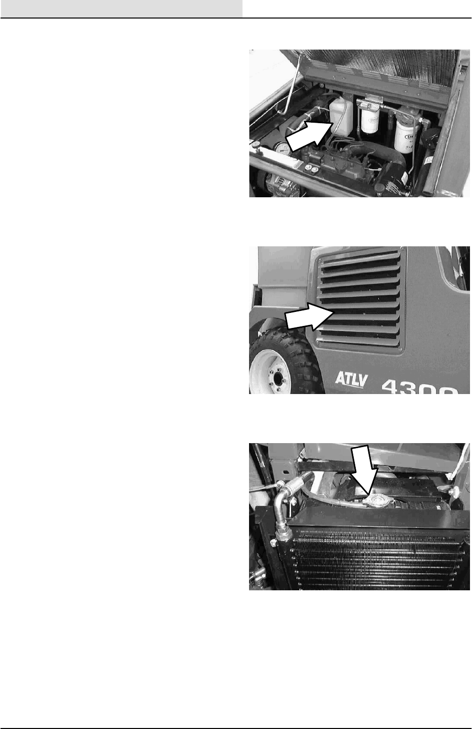
ENGINE--DIESEL
6-4 ATLV 4300 330495 (10--98)
COOLING SYSTEM
Check the radiator coolant level daily in the
overflow reservoir. Use clean water mixed with a
permanent-type, ethylene glycol antifreeze to a
-- 3 4 _C(--30_F) rating. Add coolant to the
overflow reservoir.
FOR SAFETY: When Servicing Machine,
Avoid Contact With Hot Engine Coolant.
Check the radiator hoses and clamps every
200 hours of operation. Tighten the clamps if they
are loose. Replace the hoses and clamps if the
hoses are cracked, harden, or swollen.
Check the radiator core exterior and hydraulic
cooler fins for debris daily. Blow or rinse all dust,
which may have collected on the radiator, in
through the radiator fins, and out the grill,
opposite the direction of normal air flow. Be
careful not to bend the cooling fins when cleaning.
Clean thoroughly to prevent the fins becoming
encrusted with dust. Clean the radiator and cooler
only after the radiator has cooled to avoid
cracking.
FOR SAFETY: When Servicing Machine,
Wear Eye And Ear Protection When
Using Pressurized Air Or Water.
Flush the radiator and the cooling system every
1600 hours of operation, using a dependable
cleaning compound.
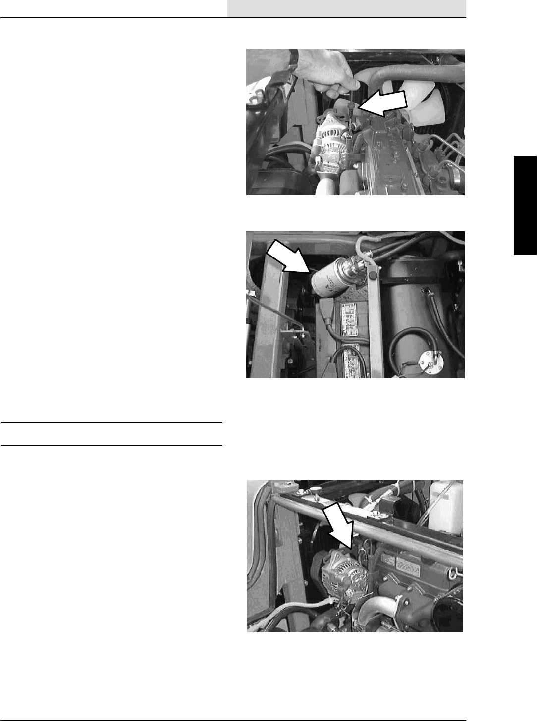
ENGINE--DIESEL
6-5
ATLV 4300 330495 (10--98)
ENGINE OIL
Check the engine oil level daily. The engine oil
dipstick can be accessed by lifting up the engine
cover. Change the engine oil and oil filter after
every 100 hours of machine operation. Use
10W30 SAE--CD/SE rated engine oil.
ENGINE OIL FILTER
Open the seat support assembly. Locate the
engine oil filter to the right of the machine battery.
Change the engine oil and oil filter after every 100
hours of machine operation. Use 10W30
SAE--CD/SE rated engine oil.
BELTS
ENGINE BELT
The engine fan belt is driven by the engine
crankshaft pulley and drives the alternator pulley.
Proper belt tension is 10 mm (0.40 in) from a
forceof4to5kg(8to10lb)appliedatthe
mid-point of the longest span.
Check and adjust the belt tension every 100 hours
of operation.
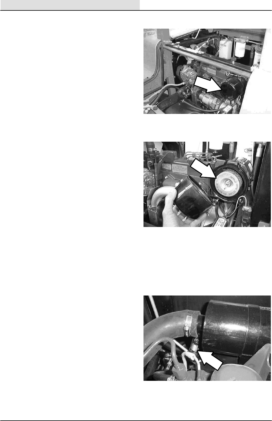
ENGINE--DIESEL
6-6 ATLV 4300 330495 (10--98)
AIR FILTER
The engine air filter housing has a dust cap and a
dry cartridge-type air filter element. Empty the
dust cap daily. Check the dust cap every 100
hours of operation to make sure it is expelling
dust. Replace the dust cap if the rubber is worn.
The air filter element must be replaced whenever
it is damaged or has been cleaned three times.
Service the air filter element only when the air
filter indicator shows restriction in the air intake
system. Do not remove the air filter element from
the housing unless it is restricting air flow.
To clean the filter element, remove it from the filter
housing. Carefully clean the end cap and the
interior of the housing with a damp cloth. Clean
the housing sealing surfaces.
Using an air hose, direct clean, dry air, maximum
205 kPa (30 psi), up and down the pleats on the
inside of the element. Do not rap, tap or pound
dust out of the element.
FOR SAFETY: When Servicing Machine,
Wear Eye And Ear Protection When
Using Pressurized Air Or Water.
After cleaning the air filter element, inspect it for
damage by placing a bright light inside. The
slightest rupture requires replacement of the
element. Inspect the seals on the ends of the
element, they should be flexible and undamaged.
Install the dust cap on the air filter housing with
the arrows pointing up.
AIR FILTER INDICATOR
The air filter indicator shows when to clean or
replace the air filter element. Check the indicator
daily. The indicator’s red line will move as the air
filter element fills with dirt. Do not clean or replace
the air filter element until the red line reaches
5kPa(20inH
2O) and the “SERVICE WHEN
RED” window is filled with red. The indicator’s red
line may return to a lower reading on the scale
when the engine shuts off. The red line will return
to a correct reading after the engine runs for a
while.
Reset the air filter indicator by pushing the reset
button on the end of the indicator after cleaning or
replacing the air filter element.
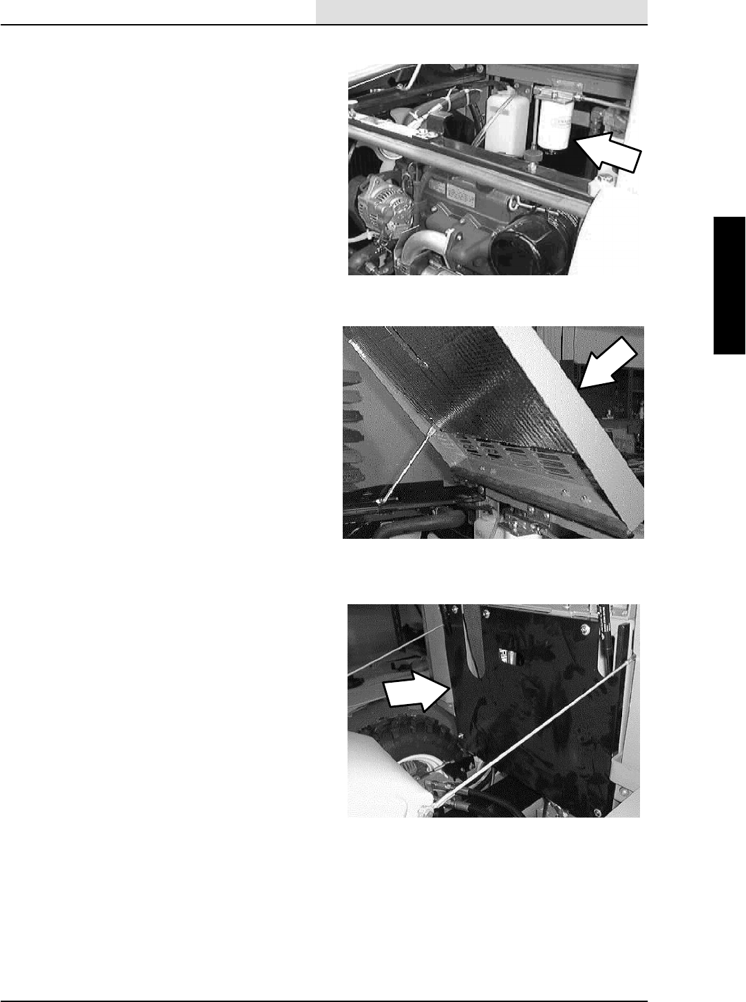
ENGINE--DIESEL
6-7
ATLV 4300 330495 (10--98)
FUEL FILTER/WATER SEPARATOR
The fuel filter/water separator cartridge filters
impurities from the diesel fuel. It is located on the
back side of the engine, to the right of the larger
hydraulic fluid filter.
Replace the fuel filter element every 200 hours of
operation.
NOTE: Check the fuel filter water trap daily for
water. Drain any water that has collected in the
cartridge.
TO REPLACE FUEL FILTER/WATER
SEPARATOR
FOR SAFETY: Before Leaving Or
Servicing Machine; Stop On Level
Surface, Set Parking Brake, And Turn
Off Machine.
1. Open the hopper cover and tilt the hopper
back.
2. Open the top engine cover.
3. Remove the five pan screws holding the rear
engine cover to the machine. Remove the
cover.
4. Locate the fuel filter/water separator in the
center of the upper machine frame. Remove
the air cleaner hose from the engine and air
cleaner. Place a drain pan under the filter.
5. Open the pet--cock on the bottom of the filter
cartridge. Let any water drain from the filter.
6. Un--screw the filter from the filter head.
Properly discard the old filter.
7. Place a small amount of oil on the rubber
O--ring on the new filter.
8. Screw the new filter onto the filter head.
Tighten until snug then 1/4 turn.

ENGINE--DIESEL
6-8 ATLV 4300 330495 (10--98)
9. Open the air breather on top of the filter
head and turn the engine over. Close the air
breather when the diesel fuel coming out of
the breather is free of air bubbles. The
engine may start at any time during this
procedure. Clean up any spilled diesel fuel.
10. Remove the drain pan. Reinstall the rear
engine cover.
11. Tilt the hopper forward and close the hopper
cover.
12. Start the machine and check the new filter
for any leaks.
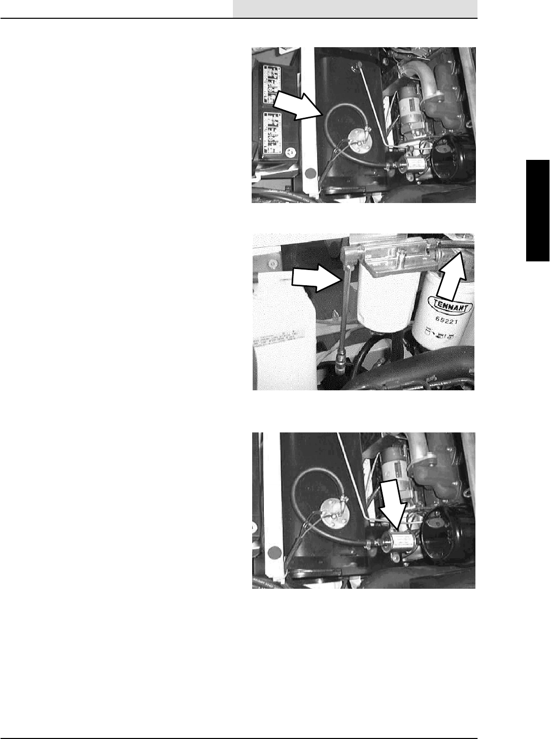
ENGINE--DIESEL
6-9
ATLV 4300 330495 (10--98)
FUEL LINES
Check the fuel lines every 50 hours of operation.
If the clamp band is loose, apply oil to the screw
of the band, and securely tighten the band.
Parts of the fuel line are made of rubber. The fuel
lines may become worn out whether the engine
has been used much or not. Replace the rubber
fuel lines and clamp bands every two years.
If the fuel lines and clamp bands are found worn
or damaged before two years’ time, replace or
repair them at once. Bleed the fuel system after
replacement of any of the fuel lines, see TO
PRIME THE FUEL SYSTEM. When the fuel lines
are not installed, plug both ends with clean cloth
or paper to prevent dirt from entering the lines.
Dirt in the lines can cause fuel injection pump
malfunction.
FUEL PUMP
Check the fuel pump every 100 hours of
operation.
Check the clamps and fuel lines that connect to
the fuel pump every 50 hours of operation.
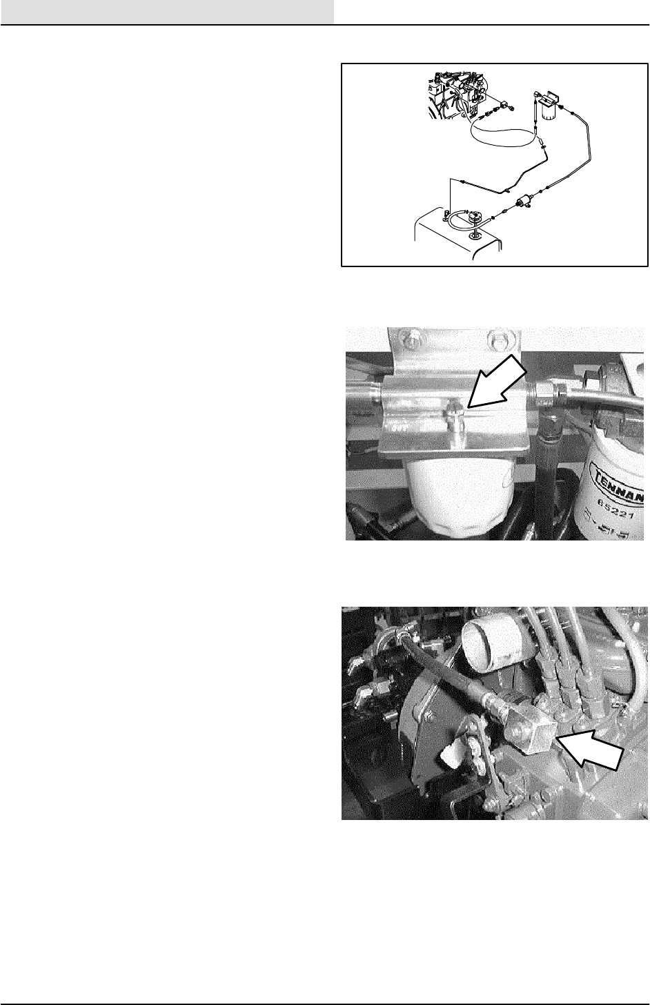
ENGINE--DIESEL
6-10 ATLV 4300 330495 (10--98)
PRIMING FUEL SYSTEM
Priming the fuel system removes pockets of air in
the fuel lines and fuel components. Air in the fuel
system will prevent smooth engine operation.
Prime the fuel system after running out of fuel,
changing the fuel filter, disconnecting the low
pressure fuel lines, or any part of the low pressure
fuel system leaks during engine operation.
TO PRIME FUEL SYSTEM
FOR SAFETY: Before Leaving Or
Servicing Machine; Stop On Level
Surface, Set Parking Brake, And Turn
Off Machine.
1. Open the seat support and engage the prop
rod. Make sure the fuel tank is full.
2. Open the breather vent on top of the fuel
filter/water separator.
3. Turn the key to the start position until fuel,
free from air, appears at the filter vent point.
Close the breather vent.
4. Loosen the bleed screw at the banjo fitting
on the injector pump.
5. Turn the key to the start position until fuel,
free from air, appears at the banjo fitting on
the injector pump. Tighten the connection.
6. Clean up any spilled fuel. Operate the
machine and check for proper operation.
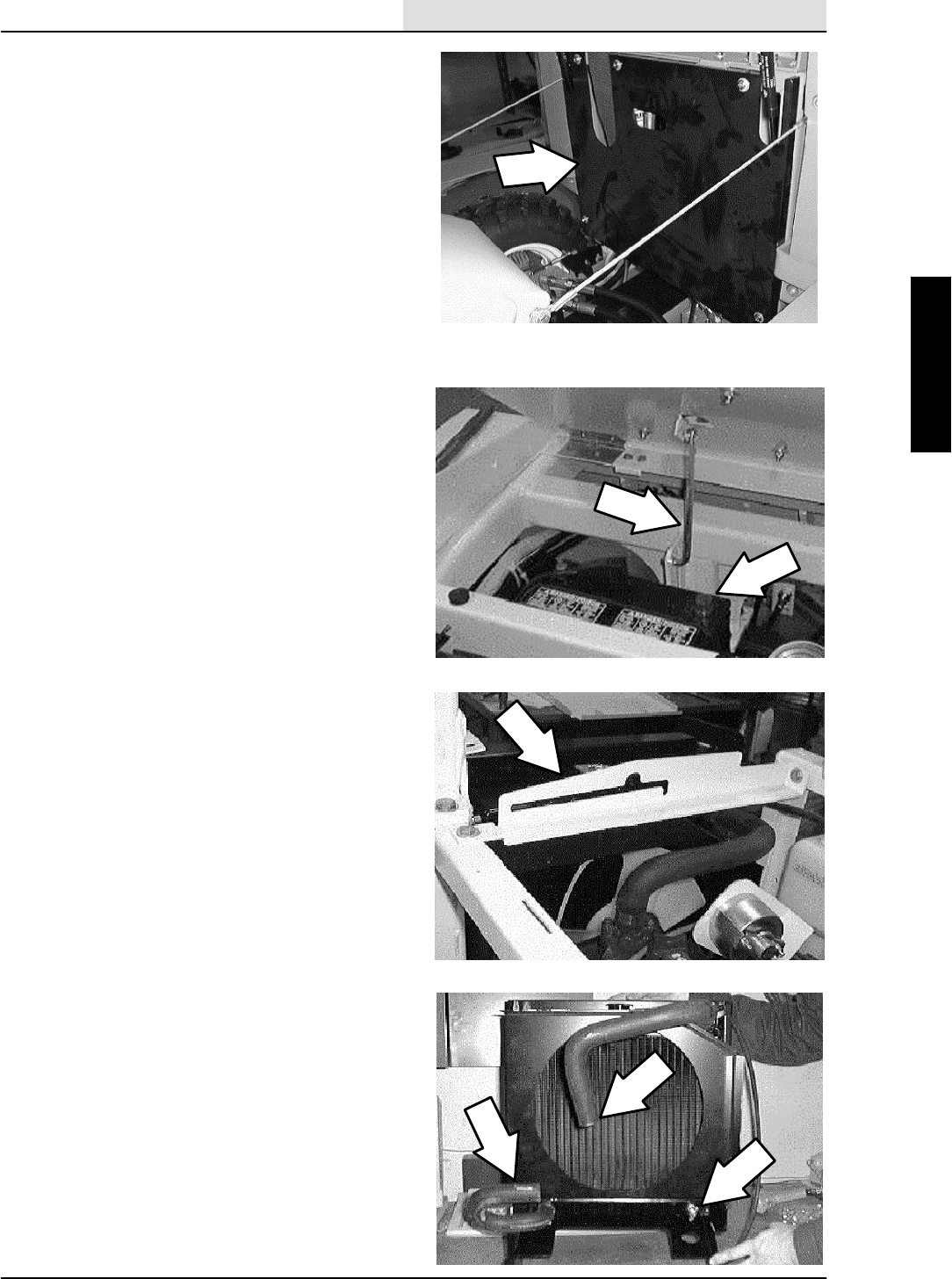
ENGINE--DIESEL
6-11
ATLV 4300 330495 (10--98)
TO REMOVE ENGINE
FOR SAFETY: Before Leaving Or
Servicing Machine; Stop On Level
Surface, Set Parking Brake, And Turn
Off Machine.
1. Open the hopper cover and tilt the hopper
back. Close the hopper cover.
2. Open the top engine cover.
3. Remove the five pan screws holding the rear
engine cover to the machine. Remove the
cover.
4. Pivot the seat assembly forward and engage
theproprod.
5. Disconnect the battery cables.
6. Remove both side fenders.
7. Remove the top engine cover and prop rod
at the hinges.
8. Remove the engine cover prop rod cross
brace.
9. Remove the black cross brace running
between the legs of the roll bar.
10. Remove the clamps holding the two air
hoses of the air cleaner assembly to the
engine and intake tube. Remove the two air
cleaner hoses.
11. Remove the two M10 hex screws holding
the air cleaner mounting bracket to the
bellhousing. Remove the air cleaner
assembly from the machine.
12. Drain the anti--freeze from the cooling
system. Remove the radiator hoses from the
engine. Disconnect the hose leading to the
overflow tank.
13. Remove the four M10 hex screws holding
the bottom of the radiator/cooler/shroud
assembly to the machine frame.

ENGINE--DIESEL
6-12 ATLV 4300 330495 (10--98)
14. Remove the two M8 hex screws holding the
top of the radiator to the two “L” brackets.
Move the radiator/cooler/shroud assembly
away from the front of the engine. Leave the
hydraulic hoses connected to the cooler and
engine oil cooler lines connected to the
lower cooler.
15. Remove the four M6 hex screws holding the
fan blade to the engine. Remove the fan
from the engine.
16. Disconnect the exhaust pipe at the exhaust
manifold.
17. Remove all of the fuel lines (rubber and
steel).
18. Remove the fuel filter/water separator from
the machine frame.
19. Remove the hardware holding the hydraulic
fluid filter to the machine frame. Move the
filter and filter head out of the way.
NOTE: Leave the hoses connected to the filter.
20. Pull the radiator overflow tank off the mount
bracket.
21. Disconnect the battery cables from the
engine starter and the ground cables from
the frame
22. Disconnect the main electrical harness from
the back of the alternator, starter, oil sender,
temp sender,glow plugs, ect. Pull the main
harness away from the engine.
23. Disconnect the engine throttle cable at the
engine lever. Loosen the throttle cable clamp
mount screw. Remove the throttle cable
from the mount clamp.
24. Drain the engine oil.

ENGINE--DIESEL
6-13
ATLV 4300 330495 (10--98)
25. Mark, disconnect, and plug the two remote
engine oil lines at the oil filter adaptor plate
on the engine.
NOTE: Make sure to mark the hoses for proper
re--assembly ! If the hoses are connected
incorrectly-- --engine damage may result !
26. Remove the hardware holding the directional
hydroback mount bracket to the side of the
engine.
27. Remove the two hex screws holding the
directional pump arm to the propel pump
hub. Pull the directional hydroback assembly
away from the engine.
28. Remove the propel pump and accessory
pump assembly from the back of the engine.
See TO REPLACE PROPEL PUMP
instructions in the HYDRAULIC section of
this manual. DO NOT DISCONNECT THE
HYDRAULIC HOSES. Pull the pump back
and out of the way for engine removal.
29. Remove the three M12 hex screws, nyloc
nuts, and washers holding the engine motor
mounts to the engine frame.
30. Using a overhead hoist, hook a chain in the
engine lift brackets and slowly lift the engine
out of the engine frame. Be careful not to
catch the engine on any hydraulic hoses or
electrical wires on the way out of the engine
compartment.
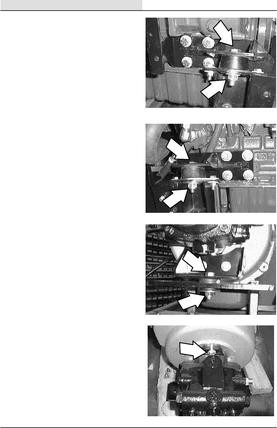
ENGINE--DIESEL
6-14 ATLV 4300 330495 (10--98)
TO INSTALL ENGINE
FOR SAFETY: Before Leaving Or
Servicing Machine; Stop On Level
Surface, Set Parking Brake, And Turn
Off Machine.
1. Using a overhead hoist, hook a chain in the
engine lift brackets and slowly lift the engine
into the machine frame. Be careful not to
catch the engine on any hydraulic hoses or
electrical wires on the way into the engine
compartment.
2. Line up the three engine isolators in the
engine motor mounts with the holes in the
frame mounts. Make sure the four special
washers are in place between the frame and
isolator.
3. Install the three M12 hex screws, washers,
and nyloc nuts into the engine mounts.
Tighten to 64 -- 83 Nm (50 -- 60 ft lb).
4. Position the propel/accessory pump
assembly back in the bellhousing and drive
coupling. See TO REPLACE PROPEL
PUMP instructions in the HYDRAULIC
section of this manual. Make sure the
splines on the pump drive hub line up with
the splines in the flywheel drive flange.
Install the two hex screws and washers
holding the pump assembly to the
bellhousing. Tighten to 45 -- 58 Nm
(36 -- 47 ft lb).
5. Reinstall the propel pump arm onto the hub
on the side of the propel pump. Reinstall the
two hex screws. Leave loose for now.
6. Reinstall the propel hydroback mount
bracket onto the side of the engine. Reinstall
the two hex screws and tighten to
37 -- 48 Nm (26 -- 34 ft lb).
7. Reconnect the throttle cable to the engine
throttle lever. Tighten the cable clamp.
8. Reconnect the electrical harness to the
engine and related component (alternator,
starter, oil sender, temp sender,glow plugs,
ect.). See harness diagram or electrical
schematic in the ELECTRICAL section of
this manual.
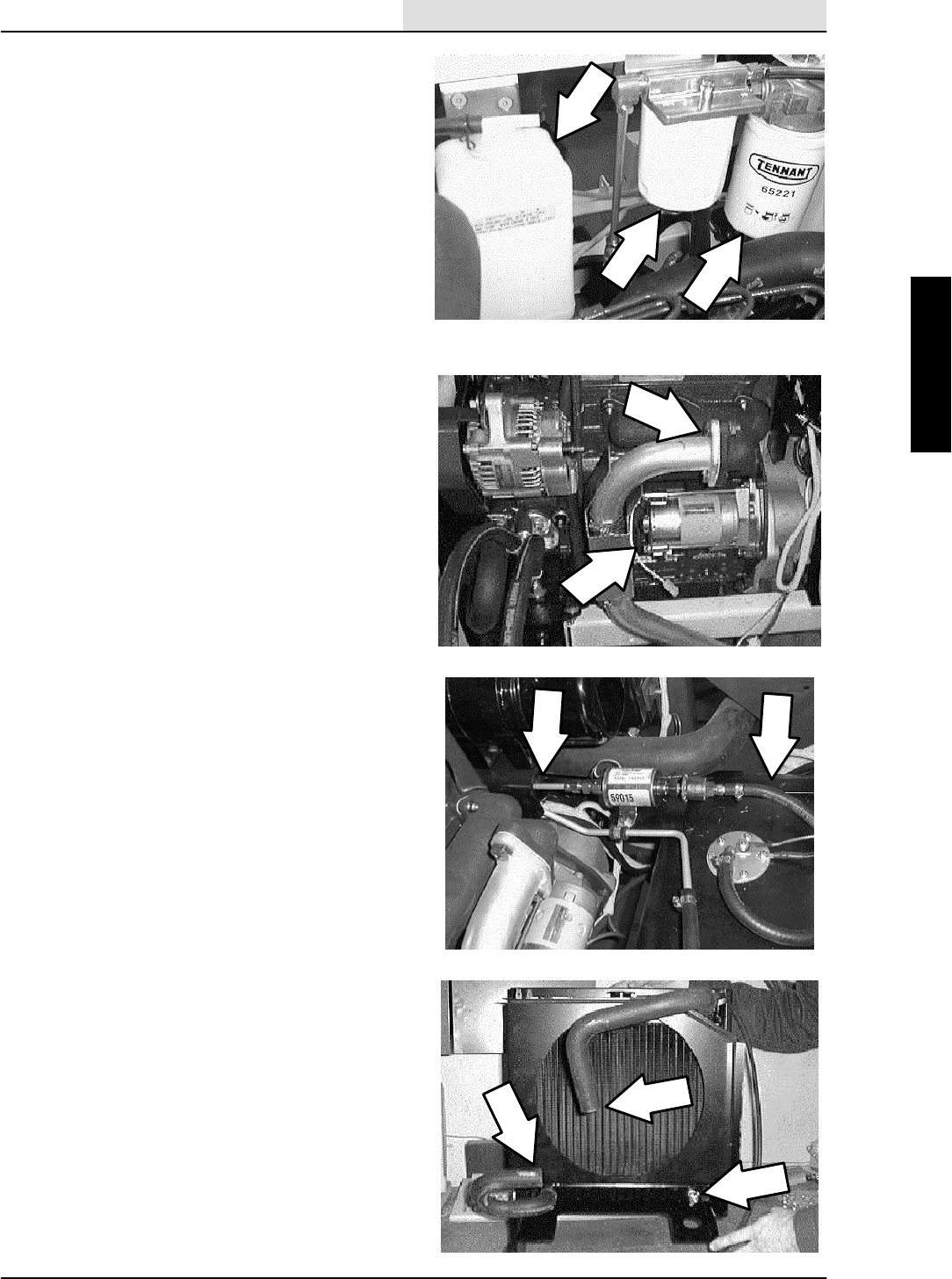
ENGINE--DIESEL
6-15
ATLV 4300 330495 (10--98)
9. Reconnect the battery cables to the starter
and the ground cables to the machine
frame.
10. Reinstall the radiator over flow tank into the
mount bracket.
11. Reinstall the hydraulic fluid filter and head
assembly onto the machine frame. Reinstall
the two hex screws and tighten to
18 -- 24 Nm (15 -- 20 ft lb).
12. Reinstall the fuel filter/water separator onto
the machine frame. Reinstall the two hex
screws and tighten to 8 -- 10 Nm (6 -- 8 ft lb)
13. Reconnect the fuel lines (rubber and steel)
14. Reconnect the exhaust pipe to the exhaust
manifold. Tighten the two hex screws to
37 -- 48 Nm (26 -- 34 ft lb).
15. Position the engine fan back on the upper
engine sheave. Install the four M6 hex
screws and tighten to 11 -- 14 Nm
(7 -- 10 ft lb).
16. Pivot the radiator back in position and install
the two upper hex screws into the “L”
brackets. Tighten to 8 -- 10 Nm (6 -- 8 ft lb)
17. Reinstall the four hex screws into the lower
radiator mount brackets. Tighten the screws
to 37 -- 48 Nm (26 -- 34 ft lb).
18. Reinstall the radiator hoses to the engine
and fill the cooling system with 4 L
(1 gal) of antifreeze.
19. Reconnect the over flow hose from the top
of the radiator to the over flow tank.
20. Reconnect the two engine oil lines leading
from the remote oil filter to the adaptor on
the front, right side of the engine.
NOTE: Make sure to mark the hoses for proper
re--assembly! If the hoses are connected
incorrectly-- --engine damage may result!

ENGINE--DIESEL
6-16 ATLV 4300 330495 (10--98)
21. Fill the engine with 5.2 L (5.5 qt) 10W30
SAE--CD/SE rated engine oil with a new
filter.
22. Reinstall the air cleaner mounting bracket to
the rear of the bellhousing. Tighten the two
M10 hex screws to 52 -- 67 Nm
(39 -- 51 ft lb).
23. Reinstall the two air cleaner tubes onto the
air cleaner and engine intake.
24. Reinstall the black cross brace running
between the legs of the roll bar.
25. Reinstall the engine cover prop rod brace.
26. Reinstall the engine cover and prop rod at
the hinges.
27. Reinstall both side fenders.
28. Reconnect the battery cables.
29. See TO ADJUST PROPEL NEUTRAL
instructions in the CHASSIS section of this
manual before attempting to start the
machine.
30. Start the machine. The engine speed and
travel speeds must be checked and set at
this point.. See below for engine speed
setting. See TO SET TRAVEL SPEEDS
instructions in the CHASSIS section.
31. After the engine and travel speeds have
been set, close the seat assembly and
reinstall the rear engine cover. Tilt the
hopper in place and operate the machine.
Check all systems carefully for proper
operation
ENGINE SPEEDS
The idle speed of the model ATLV 4300 is set at
the factory at 1200±50 rpm. The top engine speed
should not exceed 3050±50 rpm. To set the
engine speed, use the position of the end of the
throttle cable in the cable clamp on the engine
bracket to set the upper engine speed. Use the
stop bolt on the engine injector pump to set the
engine idle speed.

We Need Your Help...
As part of Tennant’s Zero Defects Program, we want to know about errors you have
found or suggestions you may have regarding our machine manuals. If you find an
error or have a suggestion, please complete this postage-paid form and mail it to us.
Thank you for helping us make zero defects a way of life at Tennant.
Manual No. Rev. No. Publish Date Page
Machine -Report Error -Suggestion
Name Date
Customer Number
Company
Address
City/State/Zip Code

Tape hereFold along dotted lines
NO POSTAGE
NECESSARY
IF MAILED
IN THE
UNITED SATES
BUSINESS REPLY MAIL
FIRST CLASS MAIL PERMIT NO. 94 MINNEAPOLIS, MN
POSTAGE WILL BE PAID BY ADDRESSEE
Technical Publications #15
701 North Lilac Drive
P.O. Box 1452
Minneapolis, MN 55440--9947
TENNANT COMPANY

We Need Your Help...
As part of Tennant’s Zero Defects Program, we want to know about errors you have
found or suggestions you may have regarding our machine manuals. If you find an
error or have a suggestion, please complete this postage-paid form and mail it to us.
Thank you for helping us make zero defects a way of life at Tennant.
Manual No. Rev. No. Publish Date Page
Machine -Report Error -Suggestion
Name Date
Customer Number
Company
Address
City/State/Zip Code
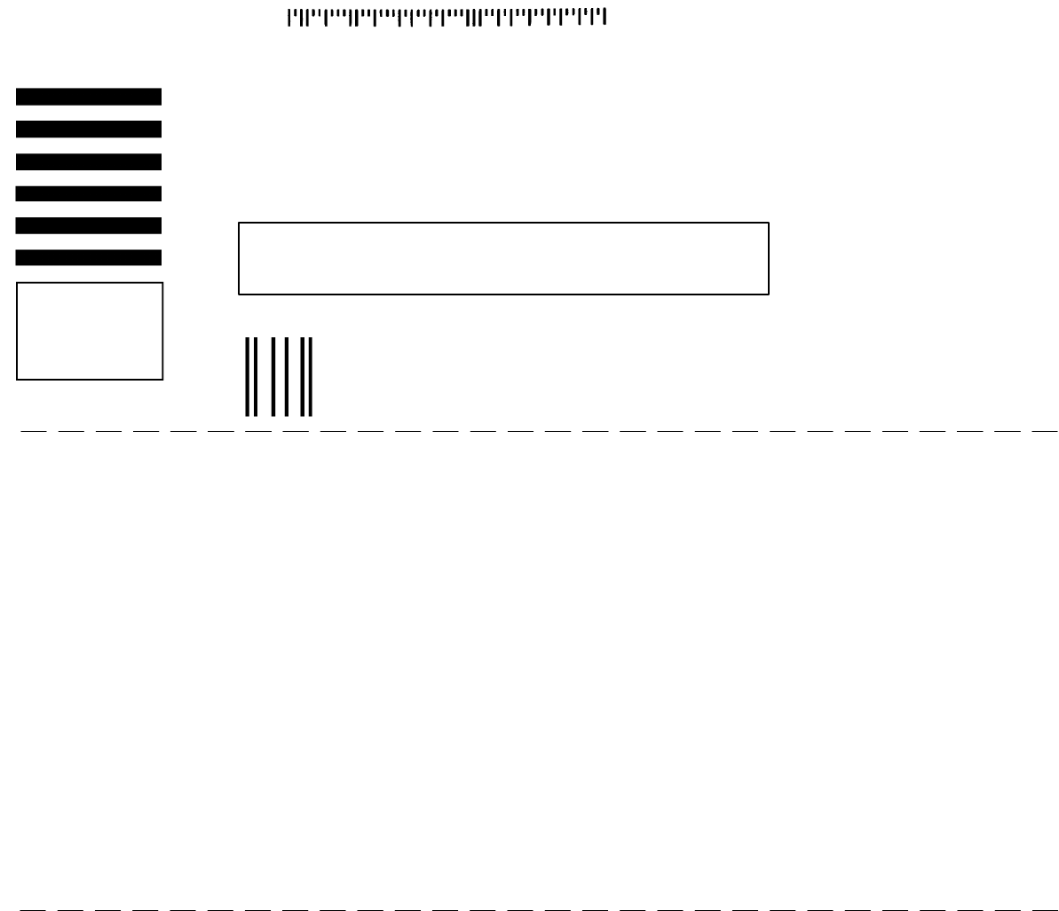
Tape hereFold along dotted lines
NO POSTAGE
NECESSARY
IF MAILED
IN THE
UNITED SATES
BUSINESS REPLY MAIL
FIRST CLASS MAIL PERMIT NO. 94 MINNEAPOLIS, MN
POSTAGE WILL BE PAID BY ADDRESSEE
Technical Publications #15
701 North Lilac Drive
P.O. Box 1452
Minneapolis, MN 55440--9947
TENNANT COMPANY
