M20 Service Manual (S/N 000000 007999) Tennant Rider Floor Sweeper Scrubber Sn 0 007999
2018-06-12
: Sweepscrub Tennant-M20-Rider-Floor-Sweeper-Scrubber-Service-Manual-Sn-0-007999 tennant-m20-rider-floor-sweeper-scrubber-service-manual-sn-0-007999 2752 file product_file
Open the PDF directly: View PDF ![]() .
.
Page Count: 180 [warning: Documents this large are best viewed by clicking the View PDF Link!]
- M20 Service Information Manual
- Safety Precautions
- GENERAL MACHINE INFORMATION
- MAINTENANCE
- Maintenance Check Points
- Maintenance Chart
- Lubrication
- Hydraulics
- Engine
- Battery
- Fuses & Relays
- Cleaning the Hopper Dust Filter
- Main Brushes
- Side Brush
- FaST System
- Squeegee Blades
- Skirts & Seals
- Brakes & Tires
- Propelling Motor
- Pushing,Towing, & Transporting Machine
- Machine Jacking
- Storage Information
- Pinch Valve Adjustments
- ELECTRICAL
- Electrical Schematic
- Wiring Harness Detail
- Electrical Symbols & Terms
- Touch Panel Detail
- Touch Panel LED’s Detail
- Option Components
- Key Switch
- Key OFF Power Distribution
- Key ON Power Distribution
- Main Brushes ON
- Scrub Vacuum Fan ON & Squeegees DOWN
- Hopper LIFT
- Hopper LOWER
- Side Brush ON
- Sweep Vacuum Fan ON
- Shaker Motor ON
- Float Switches
- Auto Fill Solenoids
- Conventional Detergent Pump & ES Pump
- Hopper Door OPEN
- Hopper Door CLOSE
- Horn
- Forward Propel
- Reverse Propel
- Gas/LPG Shutdown Relay (Normal Operation)
- Diesel Shutdown Relay (Normal Operation)
- Gas/LPG Shutdown Relay (Shutdown Mode)
- Diesel Shutdown Relay (Shutdown Mode)
- Gas/LPG Starting System ON
- Diesel Starting System ON
- Diesel Glow Plugs ON
- Conventional Main & Side Brush Solution Valves
- FaST System ON
- Fuel Level Sensors
- Impact, Hydraulic Temperature, & Hydraulic Filter Sensors
- Gas/LPG Engine Oil Pressure, Temperature, & MIL Systems
- Diesel Engine Oil Pressure & Temperature Systems
- Gas/LPG Fuel Pump & Engine Speed Control
- Diesel Fuel Pump
- Diesel Engine Speed Control
- Enable/Disable Chart
- Control Board Connectors
- Fault Indicators
- Condition & Warning Indicators
- Configuration Modes
- Diagnostic Modes
- HYDRAULIC
- Hydraulic Schematic
- Hydraulic Hose, Pump & Valve Drawings
- Solenoid Valve Details
- General Information
- Operating Matrix
- Option Components
- Scrub/Sweep Head Lower
- Scrub/Sweep Head Lift
- Squeegees Lower
- Squeegees Lift
- Main Brushes ON
- Side Brush ON
- Scrub Vacuum Fan ON
- Scrub Vacuum Fan & Side Brush ON
- Sweep Vacuum Fan ON
- Sweep Vacuum Fan & Side Brush ON
- Hopper Lift
- Hopper Lower
- Hopper Door Open
- Hopper Door Close
- Side Brush Lower
- Side Brush Lift
- Side Brush Extend
- Side Brush Retract
M20
*331385*
www.tennantco.com
Service Information Manual
331385
Rev.01 (02-2007)
Hygenic Fully Cleanable Tanks
FloorSmart
t
Integrated Cleaning System
ES Extended Scrub System
R
R
The Safe Scrubbing AlternativeR
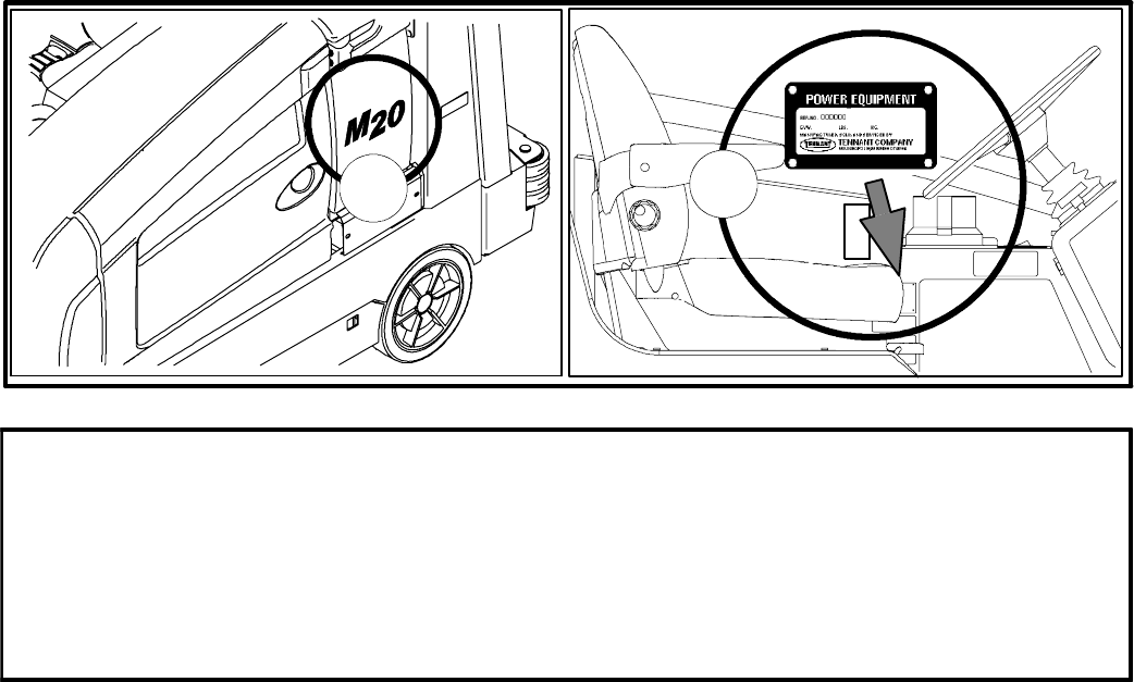
B
A
FOR REPLACEMENT PARTS
Identify machine model and serial number.
1. (A) Identify the machine model.
2. (B) Identify the machine serial number from the data plate.
Refer to the TENNANT Parts Manual.
NOTE: Only use TENNANT Company supplied or equivalent parts. Parts and supplies may be ordered
online, by phone, by fax or by mail.
Tennant Company
PO Box 1452
Minneapolis, MN 55440
Phone: (800) 553--8033 or (763) 513--2850
www.tennantco.com
Specifications and parts are subject to change without notice.
Copyright E2007TENNANT Company, Printed in U.S.A.
M20 331385 (02-2007)
ii
M20 Service Information Manual
Table of Contents
(Page 1 of 2)
page
SAFETY PRECAUTIONS…………………………………………………
.
v to vi
GENERAL MACHINE INFORMATION
Electrical Component Locator………………………………..…
…
2 to 9
Hydraulic Component Locator………………………………..…
…
10 to 16
Scrub Manifold Details………………………………..……
…
14
Sweep Manifold Details………………………………..…
…
15
Side Brush Manifold Details……………………………….. 16
Specifications………………………………..……………………
…
17 to 19
Machine Dimensions………………………………..……………
…
19
Basic Troubleshooting………………………………..…………… 20 to 21
MAINTENANCE
Maintenance Check Points………………………………..……… 24
Maintenance Chart………………………………..………………
…
25 to 26
Lubrication………………………………..………………………… 27
Hydraulics………………………………..…………………………. 29
Engine………………………………..…………………………..…
…
30
Battery………………………………..…………………………..…
…
33
Fuses & Relays………………………………..…………………
…
33 to 34
Cleaning the Hopper Dust Filter………………………………..
…
35
Main Brushes………………………………..……………………
…
35
Side Brush………………………………..………………………… 39
FaST System………………………………..……………………
…
40
Squeegee Blades………………………………..………………… 42
Skirts & Seals………………………………..……………………
…
48
Brakes & Tires………………………………..……………………
…
49
Propelling Motor………………………………..…………………
…
49
Pushing,Towing,& Transporting Machine………………………
…
50
Machine Jacking………………………………..…………………
…
52
Storage Information………………………………..……………… 52
Pinch Valve Adjustment………………………………..…………
…
53
ELECTRICAL
Electrical Schematic………………………………..……………
…
56 to 62
Wiring Harness Detail………………………………..……………
…
63 to 77
Main Wire Harness………………………………..………
…
63 to 69
Headlight Wire Harness………………………………..…
…
70
Hopper Wire Harness………………………………..……
…
71
Hopper Cover Wire Harness………………………………. 72
Gas/LPG Engine Wiring………………………………..…
…
73 to 76
FaST Wire Harness………………………………..………
…
77
Electrical Symbols & Terms………………………………..……
…
78
Touch Panel Detail………………………………..………………
…
79
Touch Panel LED’s………………………………..………………
…
80
Option Components………………………………..……………… 81
Key Switch………………………………..………………………… 82
Key OFF Power Distribution………………………………..……
…
83
Key ON Power Distribution………………………………..……… 84
Main Brushes ON………………………………..………………… 85
Scrub Vacuum Fan ON & Squeegees DOWN…………………
…
86
Hopper LIFT………………………………..………………………
…
87
Hopper LOWER………………………………..…………………
…
88
Side Brush ON………………………………..……………………
…
89
Sweep Vacuum Fan ON………………………………..………… 90
Shaker Motor ON………………………………..………………… 91
Tank Level Switches………………………………..……………
…
92
A
uto Fill Solenoids………………………………..………………
…
93
Detergent Pump & ES Pump………………………………..……
…
94
Hopper Door OPEN………………………………..……………… 95
Hopper Door CLOSE………………………………..……………
…
96
Horn………………………………..…………………………..……
…
97
Forward Propel………………………………..…………………… 98
Reverse Propel………………………………..…………………… 99
M20 331385 (02-2007)
iii
M20 Service Information Manual
Table of Contents
(Page 2 of 2)
page
ELECTRICAL (continued)
Gas/LPG Shutdown Relay (Normal Machine Operation)……
…
100
Diesel Shutdown Relay (Normal Machine Operation)…………
…
101
Gas/LPG Shutdown Relay (Shutdown Mode)…………………
…
102
Diesel Shutdown Relay (Shutdown Mode)……………………… 103
Gas/LPG Starting System ON………………………………..…
…
104
Diesel Starting System ON………………………………..……… 105
Diesel Glow Plugs ON………………………………..…………… 106
Conventional Solution Valves………………………………..…
…
107
FaST System ON………………………………..………………… 108
Fuel Level Sensors………………………………..………………
…
109
Impact, Hydraulic Temperature, & Hydraulic Filter Sensors…
…
110
Gas/LPG Engine Oil Pressure, Temperature, & MIL Systems
…
111
Diesel Engine Oil Pressure & Temperature Systems…………
…
112
Gas/LPG Fuel Pump & Engine Speed Control…………………
…
113
Diesel Fuel Pump………………………………..………………… 114
Diesel Engine Speed Control………………………………..…… 115
Enable/Disable Chart………………………………..……………
…
116 to 117
Control Board Connectors………………………………..………
…
118
Fault Indicators………………………………..…………………… 119
Condition & Warning Indicators………………………………..… 120
Configuration Modes………………………………..……………
…
121 to 124
Diagnostic Modes………………………………..………………… 125 to 126
HYDRAULICS
Hydraulic Schematic………………………………..……………
…
128
Hydraulic Hose, Pump & Valve Drawings………………………
…
129 to 147
Steering and Propel………………………………..………
…
129
Pumps and Vacuum Fan………………………………..…
…
130
Brush and Hopper………………………………..…………
…
132
Squeegee Lift………………………………..……………… 134
Pumps Group………………………………..……………… 136
Cooler and Tubes Group………………………………..…
…
138
Reservoir Group………………………………..…………… 140
Scrub/Sweep Manifold Valves Group……………………
…
142
Side Brush Manifold Valves Group………………………
…
144
Side Brush Hose Group………………………………..…
…
146
Hydraulic Solenoid Valve Details………………………………..
…
148
General Information………………………………..……………… 149 to 150
Hydraulic Symbols………………………………..………… 149
Pump Flow Rates………………………………..…………
…
150
A
bbreviations………………………………..………………
…
150
Port Markings………………………………..……………… 150
Operating Matrix………………………………..…………………
…
151
Option Components………………………………..……………… 152
Scrub/Sweep Head Lower………………………………..………
…
153
Scrub/Sweep Head Lift………………………………..…………
…
154
Squeegees Lower………………………………..………………
…
155
Squeegees Lift………………………………..……………………
…
156
Main Brushes ON………………………………..………………… 157
Side Brush ON………………………………..……………………
…
158
Scrub Vacuum Fan ON………………………………..…………
…
159
Scrub Vacuum Fan & Side Brush ON…………………………… 160
Sweep Vacuum Fan ON………………………………..………… 161
Sweep Vacuum Fan & Side Brush ON…………………………
…
162
Hopper Lift………………………………..………………………… 163
Hopper Lower………………………………..……………………
…
164
Hopper Door Open………………………………..………………
…
165
Hopper Door Close………………………………..………………
…
166
Side Brush Lower………………………………..………………… 167
Side Brush Lift………………………………..……………………
…
168
Side Brush Extend………………………………..………………
…
169
Side Brush Retract………………………………..………………
…
170
M20 331385 (02-2007)
iv

The following precautions are used throughout
this manual as indicated in their description:
WARNING: To warn of hazards or
unsafe practices that could result in
severe personal injury or death.
CAUTION: To warn of unsafe practices
that could result in minor or moderate
personal injury.
FOR SAFETY: To identify actions that must be
followed for safe operation of equipment.
Do not use the machine other than described in
this Operator Manual. The machine is not
designed for use on public roads.
The following information signals potentially
dangerous conditions to the operator or
equipment:
WARNING: Flammable materials can
cause an explosion or fire. Do not use
flammable materials in tank.
WARNING: Flammable materials or
reactive metals can cause an explosion
or fire. Do not pickup.
WARNING: Moving belt and fan. Keep
away.
WARNING: Engine emits toxic gases.
Serious injury or death can result.
Provide adequate ventilation.
WARNING: Raised hopper may fall.
Engage hopper support pin.
WARNING: Lift arm pinch point. Stay
clear of hopper lift arms.
WARNING: Burn hazard. Hot surface. Do
NOT touch.
CAUTION: LPG engine will run for a
few seconds after key is turned off.
Apply parking brake before leaving
machine.
CALIFORNIA PROPOSITION 65
WARNING: Engine exhaust from this
product contains chemicals known to
the State of California to cause cancer,
birth defects, or other reproductive
harm.
FOR SAFETY:
1. Do not operate machine:
-- Unless trained and authorized.
-- Unless operator manual is read and
understood.
-- If it is not in proper operating
condition.
-- In flammable or explosive areas.
-- In areas with possible falling objects
unless equipped with overhead guard.
2. Before starting machine:
-- Check for fuel, oil, and liquid leaks.
-- Keep sparks and open flame away
from refueling area.
-- Make sure all safety devices are in
place and operate properly.
-- Check brakes and steering for proper
operation.
3. When starting machine:
-- Keep foot on brake and directional
pedal in neutral.
4. When using machine:
-- Use brakes to stop machine.
-- Go slow on inclines and slippery
surfaces.
-- Use care when reversing machine.
-- Move machine with care when hopper
is raised.
-- Make sure adequate clearance is
available before raising hopper.
-- Do not carry passengers on machine.
-- Always follow safety and traffic rules.
-- Report machine damage or faulty
operation immediately.
-- Follow mixing and handling
instructions on chemical containers.
M20 Safety Precautions
(Page 1 of 2)
M20 331385 (02-2007)
v
5. Before leaving or servicing machine:
-- Stop on level surface.
-- Set parking brake.
-- Turn off machine and remove key.
6. When servicing machine:
-- Avoid moving parts. Do not wear loose
jackets, shirts, or sleeves.
-- Block machine tires before jacking
machine up.
-- Jack machine up at designated
locations only. Support machine with
jack stands.
-- Use hoist or jack that will support the
weight of the machine.
-- Wear eye and ear protection when
using pressurized air or water.
-- Disconnect battery connections before
working on machine.
-- Avoid contact with battery acid.
-- Avoid contact with hot engine coolant.
-- Do not remove cap from radiator when
engine is hot.
-- Allow engine to cool.
-- Keep flames and sparks away from
fuel system service area. Keep area
well ventilated.
-- Use cardboard to locate leaking
hydraulic fluid under pressure.
-- Use Tennant supplied or approved
replacement parts.
7. When loading/unloading machine
onto/off truck or trailer:
-- Turn off machine.
-- Use truck or trailer that will support
the weight of the machine.
-- Use winch. Do not drive the machine
onto/off the truck or trailer unless the
load height is 380 mm (15 in) or less
from the ground.
-- Set parking brake after machine is
loaded.
-- Block machine tires.
-- Tie machine down to truck or trailer.
M20 Safety Precautions
(Page 2 of 2)
M20 331385 (02-2007)
vi

M20
GENERAL
MACHINE
INFORMATION
M20 331385 (02-2007)
1
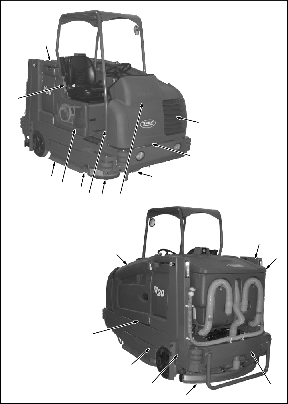
G
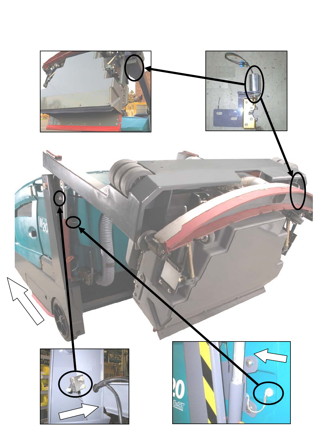
M20 Electrical Component Locator
(Page 1 of 8)
RECOVERY TANK FULL SWITCH S-15HOPPER DOWN SENSE SWITCH S-6
HOPPER LATCH
SOLENOID SOL-9
FRONT
FRONT
FRONT
M20 331385 (02-2007)
2
G
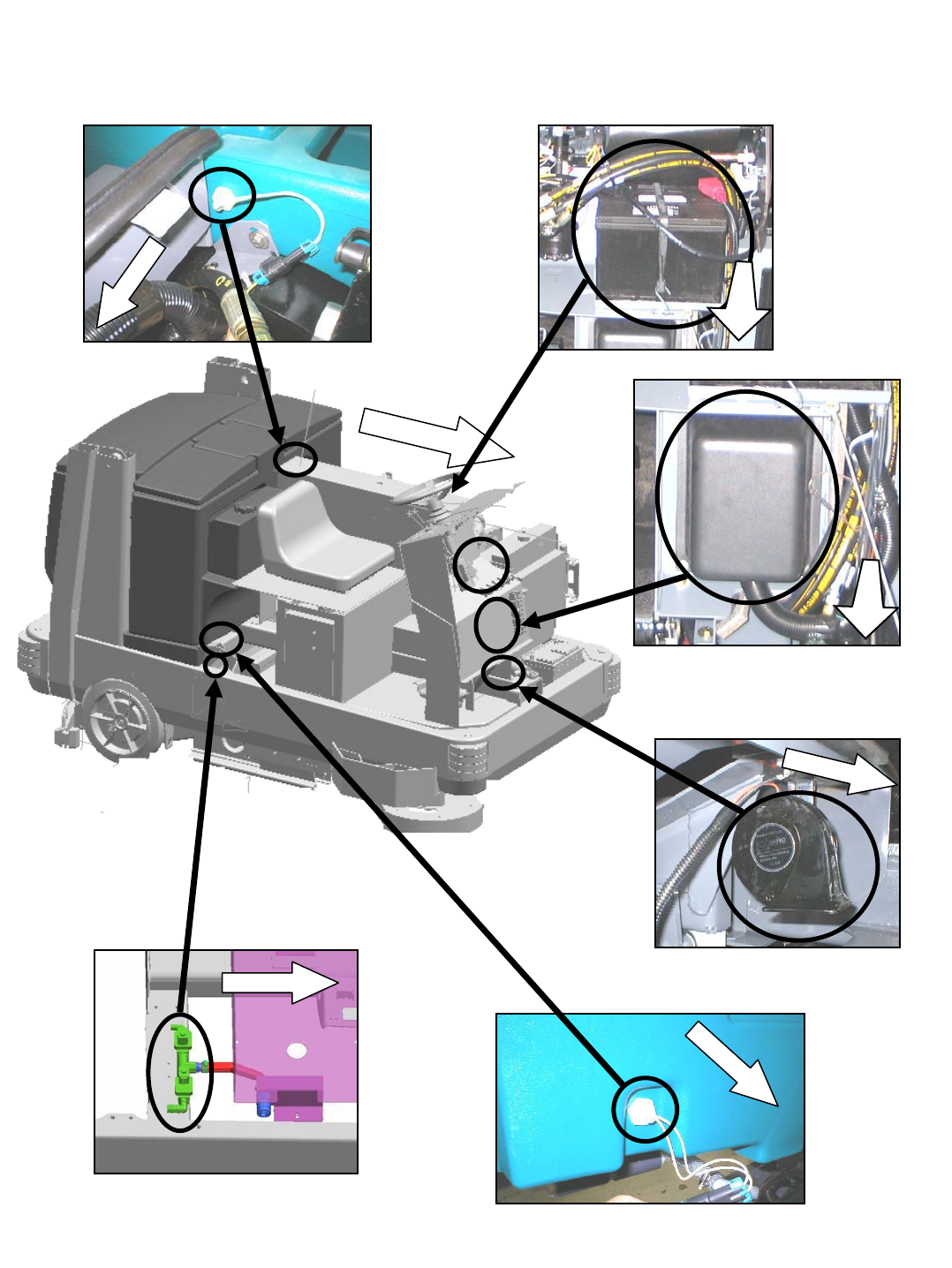
HORN
SOLUTION TANK EMPTY SWITCH S-19
SOLUTION TANK FULL SWITCH S-14
FRONT
AUTO FILL SOLENOID VALVES
SOL-1, SOL-2
FRONT
FRONT
FRONT
FRONT
BATTERY
FUSE/RELAY PANEL
FR
O
NT
FR
O
NT
M20 Electrical Component Locator
(Page 2 of 8)
M20 331385 (02-2007)
3
G
HORN SWITCH S-22
ES PUMP
IGNITION SWITCH
FRONT
RECOVERY TANK HALF FULL SWITCH S-16
FRONT
M20 Electrical Component Locator
(Page 3 of 8)
M20 331385 (02-2007)
4
G
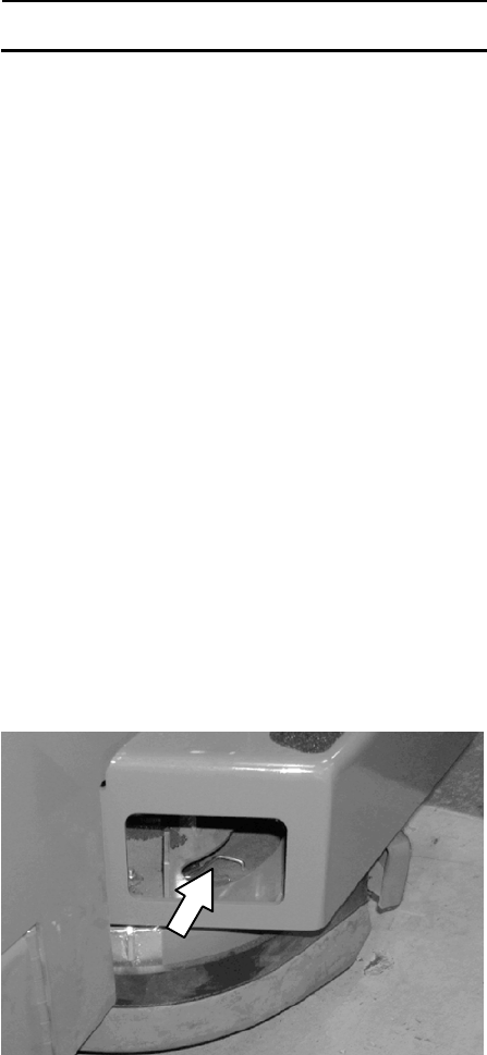
SWEEP FILTER CLOGGED SWITCH S-18
(VIEWED BEHIND BUMPER)
SHAKER MOTOR HOPPER THERMAL SENTRY SWITCH S-9
FRONT
FRONT
M20 Electrical Component Locator
(Page 4 of 8)
M20 331385 (02-2007)
5
G
FRONT
SWEEP FAN VALVE SV9
(BESIDE ENGINE FUSE PANEL)
SCRUB VALVE
SV1, SV2, SV3, SV4,SV6, SV7
SWEEP VALVE
SV13, SV14, SV15
PROPEL PEDAL POSITION SENSORSIDE BRUSH VALVE
SV8, SV10, SV11, SV12
DETERGENT PUMP
SPRAY NOZZLE PUMP
FRONT
FRONT
FRONT
FRONT
FRONT
M20 Electrical Component Locator
(Page 5 of 8)
M20 331385 (02-2007)
6
G
FRONT
FaST COMPONENTS HYDRAULIC FILTER CLOGGED SWITCH S-17
LPG LOW FUEL PRESSURE SWITCH S-8
HYDRAULIC OIL TEMPERATURE SENSOR S-20
(BACK SIDE)
M20 Electrical Component Locator
(Page 6 of 8)
M20 331385 (02-2007)
7
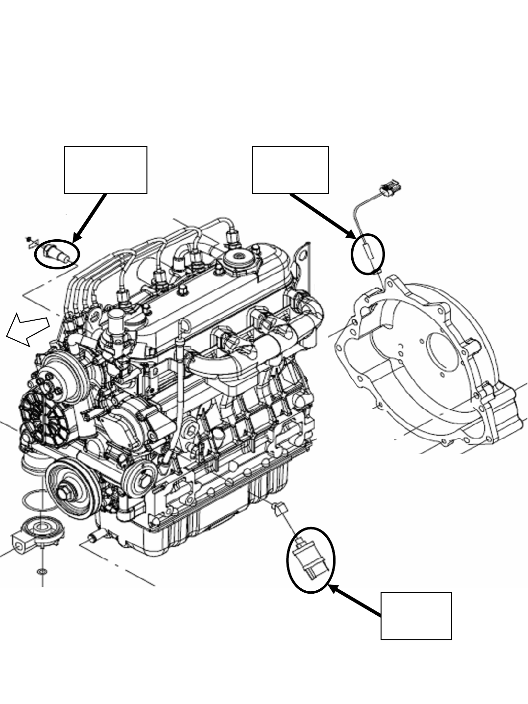
G
Coolant
Temperature
Switch
Crankshaft
Position
Sensor
Coolant
Temperature
Sensor
Oil
Pressure
Switch
Gas / LPG Engine
FR
O
N
T
M20 Electrical Component Locator
(Page 7 of 8)
M20 331385 (02-2007)
8
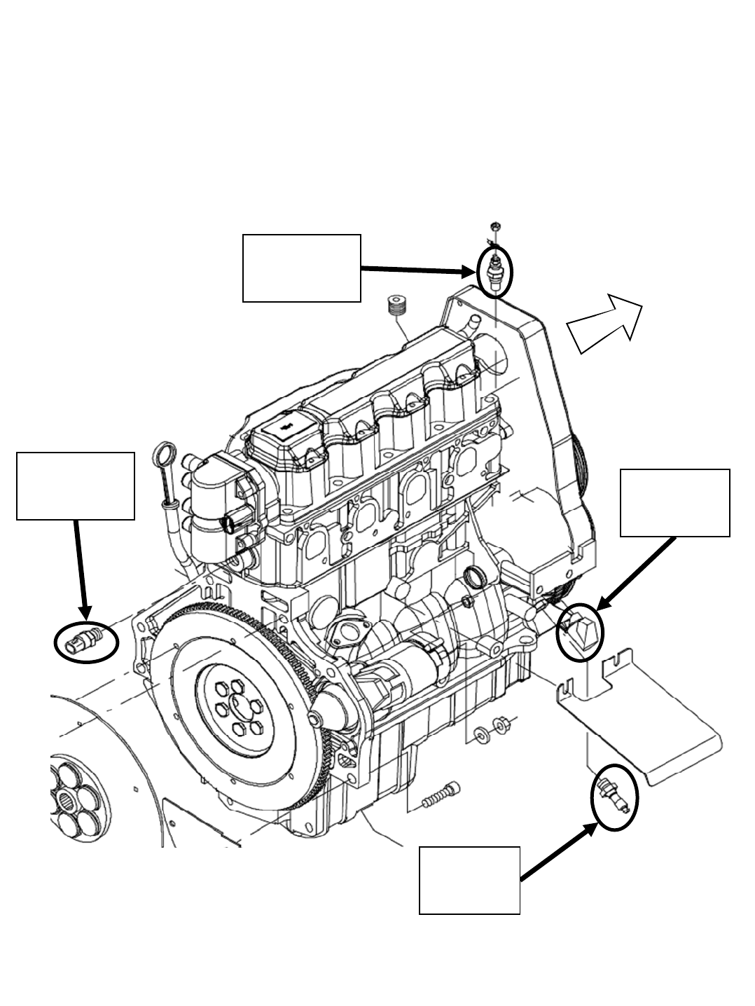
G
Crankshaft
Position
Sensor
Coolant
Temperature
Sensor
Oil
Pressure
Switch
Diesel Engine
F
R
O
N
T
M20 Electrical Component Locator
(Page 8 of 8)
M20 331385 (02-2007)
9
G
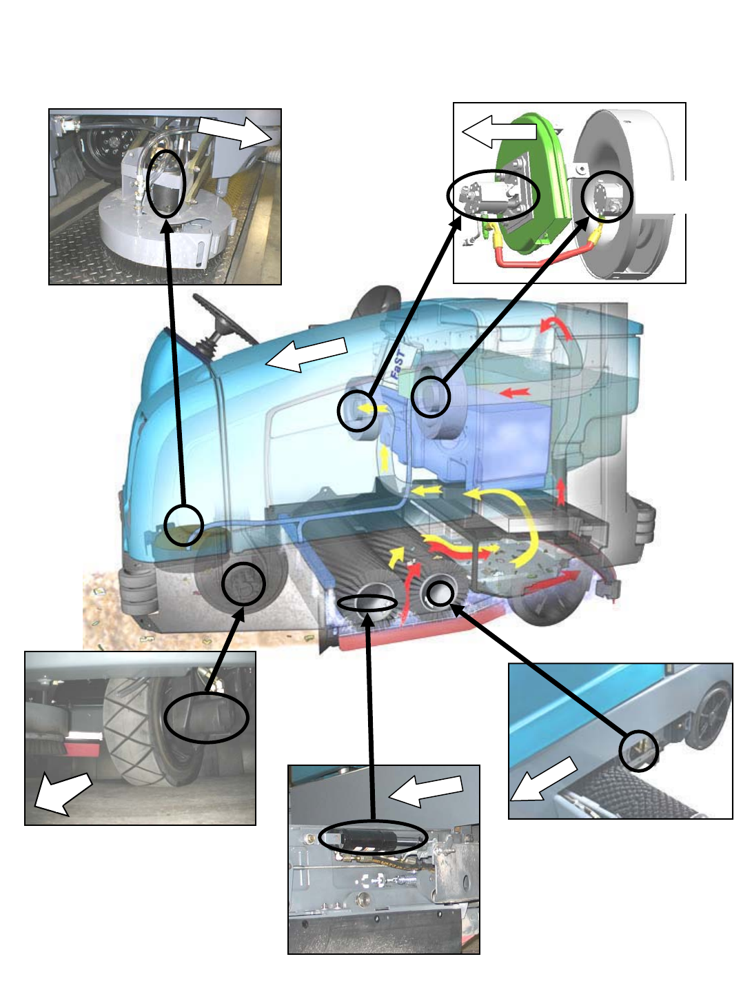
SWEEP FAN
MOTOR
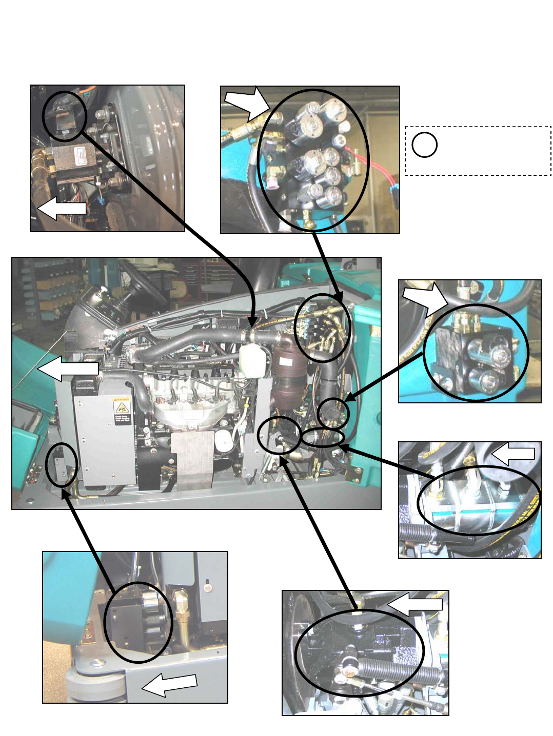
M20 Hydraulic Component Locator
(Page 1 of 7)
PROPEL MOTOR
SCRUB FAN
MOTOR
SIDE BRUSH MOTOR
MAIN BRUSH MOTOR (REAR)
FRONT
FRONT
FRONT
FRONT
F
RON
T
LEFT SIDE SQUEEGEE LIFT CYLINDER
FRONT
M20 331385 (02-2007)
10
G
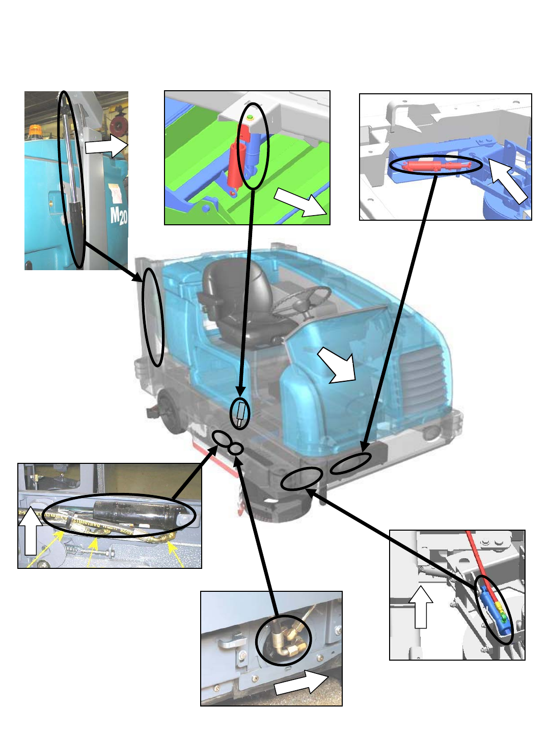
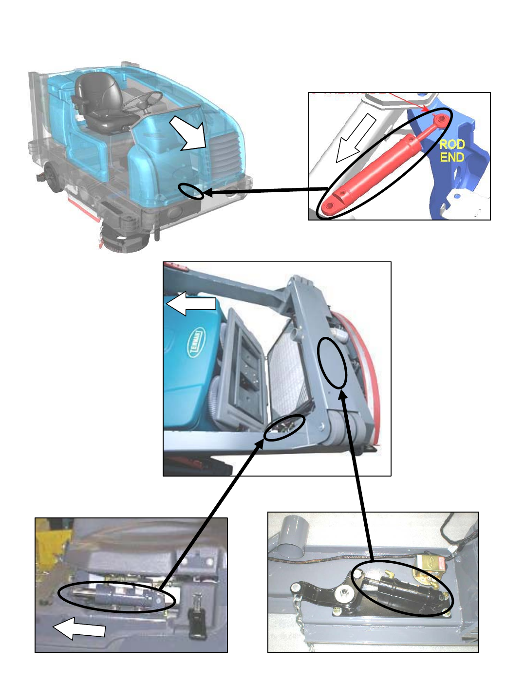
FRONT BUMPER
(INNER VIEW)
FRONT
MAIN BRUSH MOTOR (FRONT)
SCRUB HEAD LIFT CYLINDER
SIDE BRUSH LIFT CYLINDER
SIDE BRUSH EXTEND CYLINDER
RIGHT SIDE SQUEEGEE LIFT CYLINDER
HOPPER LIFT CYLINDER
FRONT
FRONT
FRONT
FRONT
FRONT
F
R
ON
T
M20 Hydraulic Component Locator
(Page 2 of 7)
M20 331385 (02-2007)
11
G
FRONT
SWEEP FAN VALVE SV9
(BESIDE ENGINE FUSE PANEL)
SCRUB MANIFOLD
SV1, SV2, SV3, SV4,SV6, SV7
RV1, RV2, CV1, PC1, PC2
SWEEP MANIFOLD
SV13, SV14, SV15,
RV3, PC5, PC6
SIDE BRUSH MANIFOLD
SV8, SV10, SV11, SV12, PR1, PC8
FRONT
FRONT
See pages 14, 15 and 16
for more information on
the Scrub, Sweep, and
Side Brush manifolds
i
FR
O
N
T
FR
O
N
T
FRONT
PROPEL PUMP
ACCESSORY PUMPS
FRONT
M20 Hydraulic Component Locator
(Page 3 of 7)
M20 331385 (02-2007)
12
G
REAR SQUEEGEE LIFT CYLINDER
(VIEWED BEHIND BUMPER)
HOPPER DOOR CYLINDER
FRONT
STEERING CYLINDER
FRONT
F
R
ON
T
FRONT
M20 Hydraulic Component Locator
(Page 4 of 7)
M20 331385 (02-2007)
13
G
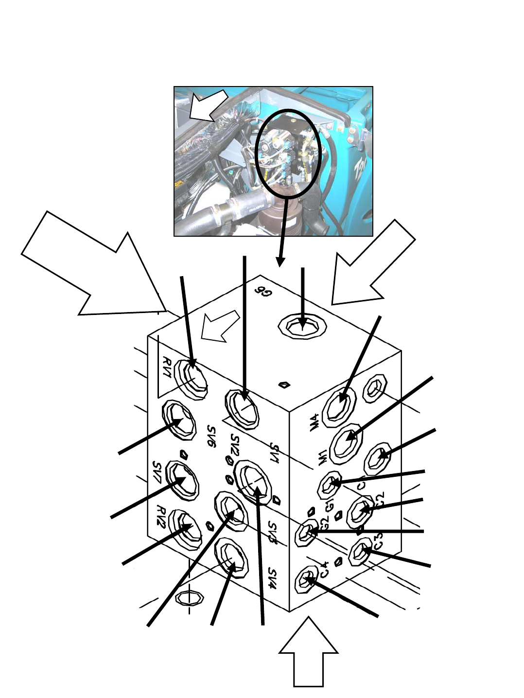
SCRUB MANIFOLD DETAILS
G6
M4
M1
C1
SV7
G1
SV3
SV6
C2
RV2
RV1
SV1
SV4 SV2
C4
C3
G2
Rightside:
CV1,G5,P1,P2,P7,
0.046in(1.17m
m)orifice
0.055in(1.40m
m)orifice
Backside:
G6,P
C1,PC2
Bottom:
T1, T2
F
R
O
N
T
F
R
O
N
T
M20 Hydraulic Component Locator
(Page 5 of 7)
M20 331385 (02-2007)
14
G
SWEEP MANIFOLD DETAILS
T5
G11
C10
SV15
SV13, SV14
C9
PC6
RV3
P5
Backside:
PC5
F
R
O
N
T
FR
O
N
T
P6
C12 &
OR1 0.030 in
(0.76 mm) orifice
C11 &
OR2 0.040 in
(1.02 mm) orifice
M20 Hydraulic Component Locator
(Page 6 of 7)
M20 331385 (02-2007)
15
G
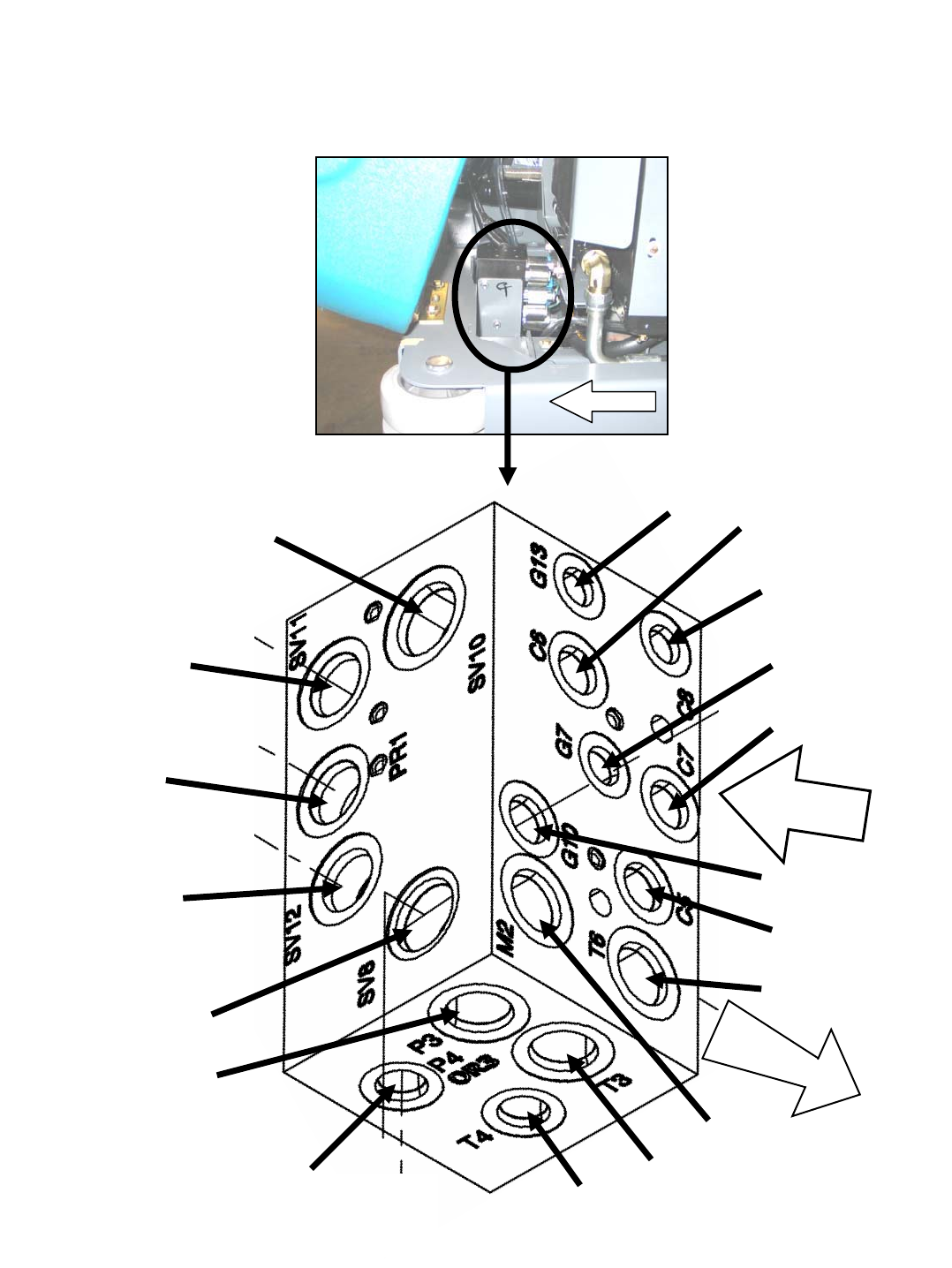
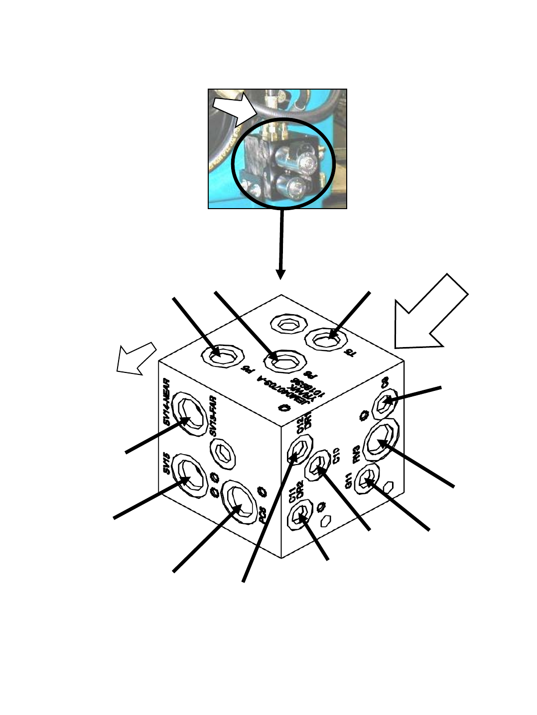
SIDE BRUSH MANIFOLD DETAILS
FRONT
F
RO
NT
M2
C7
C5
G7
G13
C8
C6
SV12
SV8
P4 &
OR3 0.040 in
(1.02 mm) orifice
T4
G10
T6
T3
P3
PR1
SV11
SV10
Frontside:
PC8
M20 Hydraulic Component Locator
(Page 7 of 7)
M20 331385 (02-2007)
16
G
GENERAL MACHINE DIMENSIONS/CAPACITIES
Item Dimension/capacity
Length 2410 mm (95 in)
Height 1470 mm (58 in)
Height (with overhead guard) 2120 mm (83.5 in)
Width/frame (roller to roller) 1270 mm (50 in)
Width (rear squeegee) 1300 mm (51 in)
Width(withsidebrush) 1470 mm (58 in)
Cleaning path width (Main brush length) 1020 mm (40 in)
Cleaning path width (with scrubbing side brush) 1370 mm (54 in)
Cleaning path width (with sweeping side brush) 1420 mm (56 in)
Main brush diameter (2) 300 mm (12 in)
Side brush diameter (scrubbing) 410 mm (16 in)
Side brush diameter (sweeping) 530 mm (21 in)
Solution tank capacity 212 L (56 gallons)
Recovery tank capacity 276 L (73 gallons)
Debris hopper volume capacity 110L(3.9ft
3)
Debris hopper weight capacity 177 kg (390 lbs)
Dump height (variable to) 1520 mm (60 in)
Minimum ceiling dump height 2500 mm (98 in)
Weight -- empty 1497 Kg (3300 lbs)
GVWR 2359 Kg (5200 lbs)
Transport ground clearance 80 mm (3 in)
Operating Sound Level At Operator Ear 81 r1.5 dBA
Vibration level at steering wheel does not exceed 0.2 m/s@
GENERAL MACHINE PERFORMANCE
Item Measure
Minimum aisle turn 2790 mm (110 in)
Travel speed forward (maximum) 12.9Km/h(8mph)
Travel speed reverse (maximum) 4.8Km/h(3mph)
Maximum rated climb and descent at GVWR 10_/18%
Maximum rated climb and descent angle when scrubbing 8_/14%
HYDRAULIC SYSTEM
System Capacity Fluid Type
Hydraulic reservoir 38 L (10 gal) TENNANT part no. 65869 -- above 7_C(45_F)
Hydraulic total 45 L (12 gal) TENNANT part no. 65870 -- below 7_C(45_F)
STEERING
Type Power source Emergency steering
Front wheel, hydraulic cylinder
and rotary valve controlled
Hydraulic accessory pump Manual hydraulic
M20 Specifications
(Page 1 of 3)
M20 331385 (02-2007)
17
G
POWER TYPE
Engine Type Ignition Cycle Aspiration Cylinders Bore Stroke
Kubota V1505--B Piston Diesel 4Natural 478 mm
(3.07 in)
78.4 mm
(3.08 in)
Displacement Net power, governed Net power, maximum
1500 cc (91.4 cu in) 24.6 kw (34 hp) @ 2400 rpm 27.2 kw (37.5 hp) @
3000 rpm
Fuel Cooling system Electrical system
Diesel
Fuel tank: 42 L (11.2 gal)
Water/ethylene glycol
antifreeze
12 V nominal
Total: 7.5 L (2 gal) 37 A alternator
Radiator: 3.8 L (1 gal)
Idle speed, no load (Fast) governed speed, under
load
Engine lubricating oil
without filter
950 +50 rpm 2400 +50 rpm 6 L (6.35 qt)
Diesel rated engine oil
above CD grade only
BRAKING SYSTEM
Type Operation
Service brakes Mechanical drum brakes (2), one per rear wheel,
cable actuated
Parking brake Utilize service brakes, cable actuated
Engine Type Ignition Cycle Aspiration Cylinders Bore Stroke
GM 1.6 Piston Distributorless-
type spark
4Natural 479 mm
(3.11 in)
81.5 mm
(3.21 in)
Displacement Net power, governed Net power, maximum
1600 cc (98 cu in) 23.2 kw (32 hp) @ 2400 rpm 39.5 kw (53 hp) @
4000 rpm
Fuel Cooling system Electrical system
Gasoline, 87 octane
minimum, unleaded
Fuel tank: 42 L (11.2 gal)
Water/ethylene glycol
antifreeze
12 V nominal
LPG,
F
l
t
k
1
5
k
(
3
3
l
b
)
Total: 7.5 L (2 gal) 75 A alternator
,
Fuel tank: 15 kg (33 lb) Radiator: 3.8 L (1 gal)
Idle speed, no load (Fast) governed speed, under
load
Firing order
950 + 50 rpm 2400 + 50 rpm 1--3--4--2
Spark plug gap Valve clearance, cold Engine lubricating oil
with filter
1 mm (0.04 in) No Adjustment
OHC Engine
3.5 L (3.7 qt) 5W30
SAE--SG/SH
M20 Specifications
(Page 2 of 3)
M20 331385 (02-2007)
18
G
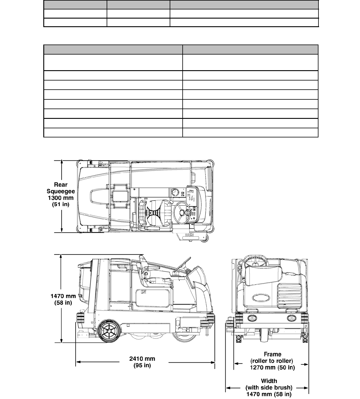
MACHINE DIMENSIONS
TIRES
Location Type Size
Front (1) Solid 140 mm x 460 mm (5.5 in x 18 in)
Rear (2) Solid 90 mm x 410 mm (3.5 in x 16 in)
FaST SYSTEM
Item Measure
Solution pump 12 Volt DC, 11A, 11.6 LPM (3.0 GPM) open flow,
45 psi bypass setting
Low solution flow rate 2.7 LPM (0.7 GPM)
High solution flow rate 5.4 LPM (1.4 GPM)
Detergent pump 12 Volt DC
Low concentrate flow rate 2.6 CC/Minute (0.085 Liquid Ounces/Minute)
High concentrate flow rate 5.2 CC/Minute (0.17 Liquid Ounces/Minute)
Air pump 12 Volt DC, 0.6 Maximum Amp draw
Air pump flow rate 8.7 LPM (0.3 CFM) open flow
M20 Specifications
(Page 3 of 3)
M20 331385 (02-2007)
19
G

MACHINE TROUBLESHOOTING
Problem Cause Remedy
Trailing water--poor or no
t
i
k
Scrub vacuum fan turned off Turn on vacuum fan
g
p
water pickup Worn squeegee blades Rotate or replace squeegee blades
Squeegee out of adjustment Adjust squeegee
No detergent in solution tank
causing squeegee to chatter
Add detergent to solution tank
Vacuum hose clogged Flush vacuum hoses
Vacuum screen dirty Clean vacuum screen
Scrub vacuum fan cover seals
worn
Replace seals
Debris caught in squeegee Remove debris
Vacuum hose to squeegee or
recovery tank disconnected or
damaged
Reconnect or replace vacuum hose
Recovery tank cover not
completely closed
Check for obstructions and make
sure cover is closed properly
Scrub vacuum fan will not
turn on
Vacuum fan / squeegee button
turned off
Turn on Vacuum fan / squeegee
button
Recovery tank full Drain recovery tank
Foam filling recovery tank Empty recovery tank
g
y
Use less detergent/or use
defoamer
Recovery tank sensor dirty or stuck Clean or replace sensor
Little or no solution flow to
t
h
f
l
(
C
t
i
l
Solution tank empty Fill solution tank
the floor (Conventional
S
c
r
u
b
b
i
n
g
M
o
d
e
)
Solution flow turned off Turn on solution flow
S
cru
b
b
i
ng
M
o
d
e
)
Solution supply lines plugged Flush solution supply lines
Excessive dusting Brush skirts and dust seals worn,
damaged, or out of adjustment
Replace or adjust brush skirts and/
or brush seals
Hopper dust filter clogged Shake and/or replace dust filter
Sweep vacuum fan seal damaged Replace vacuum fan seal
Sweep vacuum fan failure Call Tennant service representative
Thermo--Sentry tripped Allow Therm--Sentry to cool
Poor sweeping performance Worn brush bristles Replace brushes
p
g
p
Brush pressure set too light Increase brush pressure
Main brushes not properly adjusted Adjust brushes
Debris caught in main brush drive
mechanism
Remove debris from main brush
drive mechanism
Main and/or side brush drive failure Call Tennant service representative
Hopper is full Empty hopper
Hopper lip skirts worn or damaged Replace lip skirts
Improper main brushes Call Tennant service representative
T20 Basic Troubleshooting
(Page 1 of 2)
M20 331385 (02-2007)
20
G

Problem Cause Remedy
Poor scrubbing performance 1--STEP Scrub button not on Turn on 1--STEP Scrub button
gp
Improper detergent or brushes Call Tennant service representative
Solution tank empty Fill solution tank
Debris caught on main brushes Remove debris
Worn main brushes Replace brushes
Brush pressure set too light Increase brush pressure
FaST System does not
t
FaST button is turned off Turn on the FaST button
operate Clogged FaST--PAK supply hose
and/or connector
Soak connector and hose in warm
water and clean
FaST--PAK carton is empty or not
connected
Replace FaST--PAK carton and/or
connect supply hose
FaST system is not primed To prime, operate the FaST
solution system for a few minutes
Clogged filter screen Drain solution tank, remove and
clean filter screen
Blown fuse Call Tennant service representative
Faulty solution pump Call Tennant service representative
ES System does not operate ES button is turned off Turn on ES button
ES sensor in tank dirty Clean sensor
Clogged ES pump filter Clean ES filter
Water level in recovery tank too
low
Fill recovery tank about half full
Water level in solution tank too low Fill solution tank
Sweeping or Scrubbing
fti d tt
Hopper is up Completely lower hopper
functions do not turn on Fire in the hopper Shut off machine. Extinguish fire.
If necessary, call emergency
personnel.
Recovery tank full Press the Scrub vacuum
fan/squeegee button for one
minute of extended water pickup.
Empty recovery tank.
ES models: activate the ES system
to prevent this.
T20 Basic Troubleshooting
(Page 2 of 2)
M20 331385 (02-2007)
21
G
M20 331385 (02-2007)
22
G

MAINTENANCE
Information
NOTE: Troubleshooting charts may be shown with optional equipment.
The optional equipment may not be specified in these charts. Some machines
may not be equipped with all components shown.
BEFORE CONDUCTING TESTS:
DURING TESTS:
* Read and Follow ALL Safety Warnings and Precautions as
mentioned at the beginning of this manual
* Always use an ESD (Electrostatic Discharge) strap when working
near the Control Board
* Be cautious when working near Control Board – Battery voltage is
always present, even with Key OFF
* Always unhook Battery when removing or replacing components
* Call Technical Services if Diagnostic Time Exceeds One Hour With
Unknown Cause or Course of Action
M20
M20 331385 (02-2007)
23
M
1
2
3
4
5
6
7
8
9
19
10
12
14
13
15
16
11
17
18
MAINTENANCE
M20 Maintenance Information
(Page 1 of 30)
M20 331385 (02-2007)
24
M

Interval Key Description Procedure
Lubricant/
Fluid
No. of
Service
Points
Daily 1Engine Check oil level EO 1
y
g
Check coolant level in reservoir WG 1
Check belt tension -- 1
10 Hydraulic fluid reservoir Check fluid level HYDO 1
8, 9 Tank cover seals Check for damage or wear -- 3
3Main brushes Check for damage and wear -- 2
Check brush pattern -- 2
4Side brush (option) Check for damage and wear -- 1
(
p
)
Check squeegee blade for
damage and wear
-- 1
5Hopper dust filter Shake to clean -- 1
6Rear Squeegee Blade Check for damage and wear -- 1
q
g
Check deflection -- 1
7Side Squeegee Blades Check for damage and wear -- 2
8Recovery tank Clean -- 1
8Recovery tank, ES mode
(option)
Clean ES filter -- 1
9Solution tank, ES mode
(option)
Clean -- 1
5Hopper Clean hopper, debris screen,
and hose
-- 1
20 Hours 5Hopper dust filter Check for damage, clean,
replace if necessary
-- 1
50 Hours 16 FaST filter screen Clean -- 1
3Main brushes Rotate front to rear -- 2
13 Front wheel Torque wheel nuts (after initial
50 hours only)
-- 1
15 Battery Clean and tighten battery cable
connections (after initial 50
hours only)
-- 1
100 Hours 19 Radiator Clean core exterior -- 1
Check coolant level WG 1
19 Hydraulic cooler Clean core exterior -- 1
1Engine Change oil and filter EO 1
-- Tires Check for damage -- 3
6Rear squeegee casters Lubricate SPL 2
6Rear squeegee Check leveling -- 1
2Scrub head skirt Check for damage or wear -- 1
MAINTENANCE
M20 Maintenance Information
(Page 2 of 30)
M20 331385 (02-2007)
25
M

Interval Key Description Procedure
Lubricant/
Fluid
No. of
Service
Points
200 Hours 12 Front wheel support
bearings
Lubricate SPL 2
1, 17 Torque tube Lubricate SPL 4
12 Steering cylinder Lubricate SPL 1
1, 19 Radiator hoses and clamps Check for tightness and wear -- 2
11 Parking brake Check adjustment -- 1
11 Brake pedal Check adjustment -- 1
14 Hopper lift arm pivots Lubricate SPL 2
5Hopper door pivots Lubricate SPL 2
18 Hopper lift arm latch Clean and lubricate SPL 1
16 FaST air filter Clean -- 1
400 Hours 1Engine Clean and re--gap or replace
spark plugs (Gas/LPG)
-- 4
Replace air filter -- 1
Replace fuel filter -- 1
800 Hours 10 Hydraulic reservoir Change hydraulic fluid HYDO 1
y
Replace strainer outlet 1
Replace filler cap 1
Replace fluid filter -- 1
1Engine Check timing belt -- 1
g
Replace fuel filter (Gasoline) -- 1
-- Hydraulic hoses Check for wear and damage -- All
1, 19 Cooling system Flush WG 2
13 Propelling motor Torque shaft nut -- 1
13 Front wheel Torque wheel nuts -- 1
15 Battery Clean and tighten battery cable
connections
-- 1
1600
Hours
1Engine Replace timing belt -- 1
LUBRICANT/FLUID
EO . . . . . Engine oil, Gas/LPG: 10W30 SAE--SG/SH only; Diesel: Rating above CD grade only
HYDO Tennant or approved hydraulic fluid.
WG Water and ethylene glycol anti-freeze, --34_C(--30_F)...
SPL Special lubricant, Lubriplate EMB grease (Tennant part number 01433--1)...
NOTE: More frequent maintenance intervals may be required in extremely dusty conditions.
MAINTENANCE
M20 Maintenance Information
(Page 3 of 30)
(LPG/Diesel)
(Gas,LPG)
(Gas,LPG)
M20 331385 (02-2007)
26
M
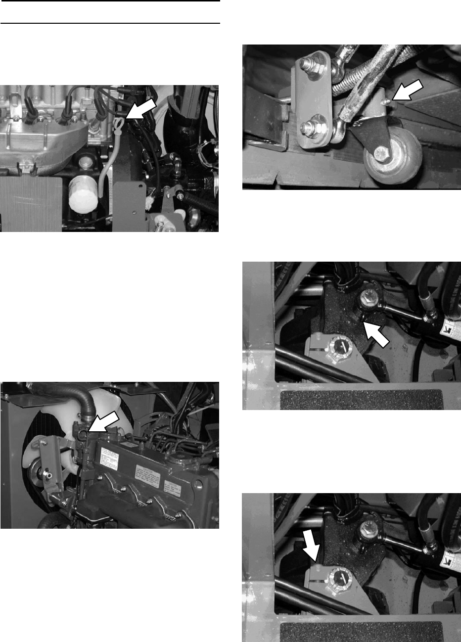
LUBRICATION
DIESEL ENGINE OIL
Check the engine oil level daily. Change the oil
and oil filter after every 100 hours of operation.
Use engine oil with a diesel rating above CD
grade only.
FRONT WHEEL SUPPORT BEARING
Lubricate the front wheel support bearings after
every 200 hours of operation. Both front wheel
support grease fittings are located underneath the
frame support plate.
STEERING CYLINDER BEARING
Lubricate the steering cylinder after every 200
hours of operation. The steering cylinder bearing
is located next to the front wheel support.
SQUEEGEE CASTER BEARINGS
Lubricate the squeegee caster bearings after
every 100 hours of operation.
GAS/LPG ENGINE OIL
Check the engine oil level daily. Change the oil
and oil filter after every 100 hours of operation.
Fill the engine with oil until the oil is between the
indicator marks on the dipstick. DO NOT fill past
the top indicator mark. The engine oil capacity is
3.5 L (3.7 qt) with oil filter.
Fill the engine with oil until the oil is between the
indicator marks on the dipstick. DO NOT fill past
the top indicator mark. The engine oil capacity is
6 L (6.35 qt) with oil filter.
M20 Maintenance Information
(Page 4 of 30)
M20 331385 (02-2007)
27
M
HOPPER LIFT ARM PIVOTS
Lubricate the hopper lift arm pivots after every
200 hours of operation.
HOPPER DOOR PIVOTS
Lubricate the hopper door pivots after every 200
hours of operation.
LIFT ARM LATCH
Clean and lubricate the lift arm latch and latch
stop after every 200 hours of operation.
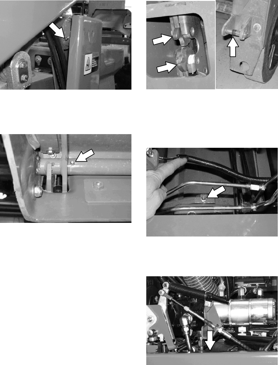
TORQUE TUBES
Lubricate the torque tubes after every 200 hours
of operation. The torque tube grease fittings on
the operator side of the machine are located
beneath the fuel tank.
On the other side of the machine the torque tube
grease fittings are located beneath the propel
pump.
M20 Maintenance Information
(Page 5 of 30)
M20 331385 (02-2007)
28
M
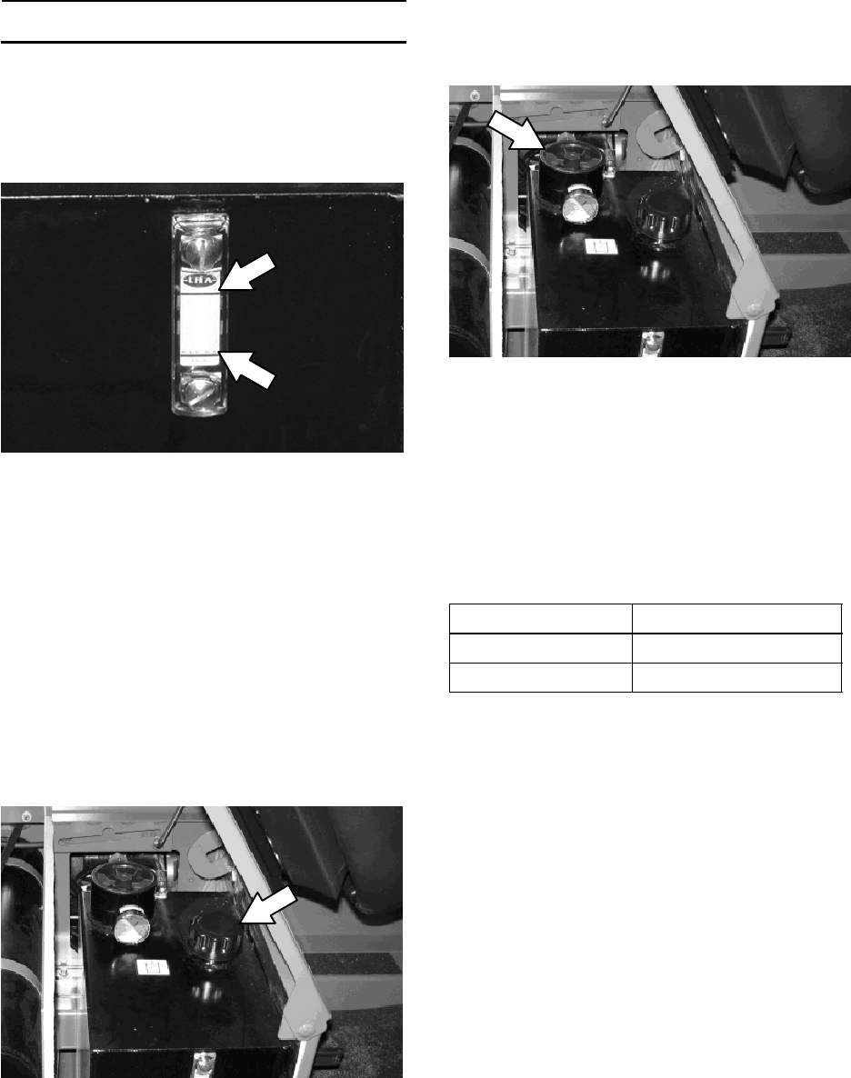
HYDRAULICS
Check the hydraulic fluid level at operating
temperature daily. The hydraulic fluid level should
be between the two lines on the hydraulic gauge.
The hopper must be down when checking
hydraulic fluid level.
ATTENTION! Do not overfill the hydraulic fluid
reservoir or operate the machine with a low
level of hydraulic fluid in the reservoir.
Damage to the machine hydraulic system may
result.
Drain and refill the hydraulic fluid reservoir with
new hydraulic fluid after every 800 hours of
operation.
Replace the filler cap after every 800 hours of
operation. Apply a light film of hydraulic fluid onto
the filler cap gasket before installing the cap onto
the reservoir.
Replace the hydraulic fluid filter after every 800
hours of operation or if the hydraulic reservoir
gauge is in the yellow/red zone when the reservoir
hydraulic fluid is approximately 32_C(90_F).
Replace the hydraulic strainer outlet after every
800 hours of operation.
HYDRAULIC FLUID
Tennant hydraulic fluid is specially selected to
meet the needs of Tennant machines. There are
two fluids available for different temperature
ranges:
Tennant part no. Ambient Temperature
65869 above 7_C(45_F)
65870 below 7_C(45_F)
High temperature fluids have a higher viscosity
(thicker) and should only be used in high
temperature environments. Low temperature
fluids have a lower viscosity (thinner) and should
only be used in cold temperature environments.
Select the appropriate hydraulic fluid for the
environment where the machine is operated.
Using improper hydraulic fluids can cause
premature failure of hydraulic components.
If using a locally-available hydraulic fluid, be sure
the specifications match Tennant hydraulic fluid
specifications. Substitute fluids can cause
premature failure of hydraulic components.
ATTENTION! Hydraulic components depend
on system hydraulic fluid for internal
lubrication. Malfunctions, accelerated wear,
and damage will result if dirt or other
contaminants enter the hydraulic system.
M20 Maintenance Information
(Page 6 of 30)
M20 331385 (02-2007)
29
M
HYDRAULIC HOSES
Check the hydraulic hoses after every 800 hours
of operation for wear or damage.
FOR SAFETY: When servicing machine, use
cardboard to locate leaking hydraulic fluid
under pressure.
High pressure fluid escaping from a very small
hole can almost be invisible, and can cause
serious injuries.
Consult a physician immediately if injury results
from escaping hydraulic fluid. Serious infection or
reaction can occur if proper medical treatment is
not given immediately.
Contact a mechanic or supervisor if a leak is
discovered.
ENGINE
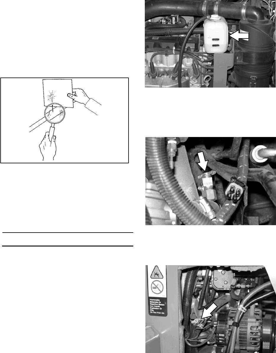
COOLING SYSTEM
FOR SAFETY: When servicing machine, avoid
contact with hot engine coolant.
Check the coolant level in the reservoir daily. The
coolant level must be between the two indicator
marks when the engine is cold.
FOR SAFETY: When servicing machine, do
not remove cap from radiator when engine is
hot. Allow engine to cool.
Check the coolant level in the radiator after every
100 hours of operation. Refer to the label on the
coolant container for water/coolant mixing
instructions.
The cooling system must be completely filled with
coolant to keep the engine from overheating.
When filling the cooling system, open the drain
cocks to bleed the air from the system.
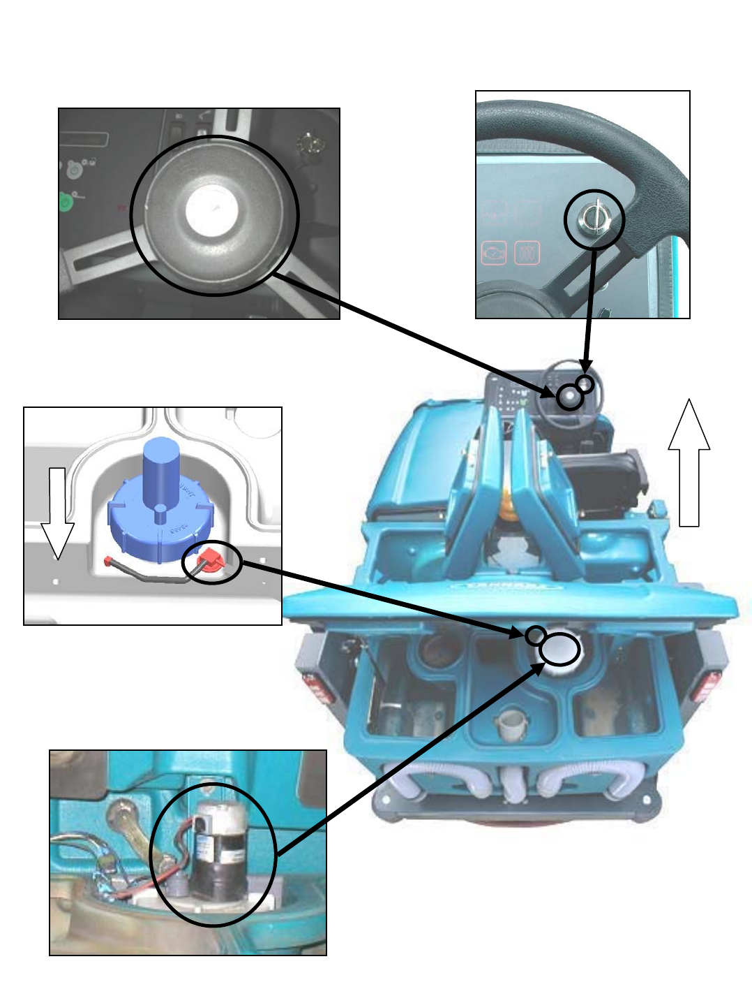
Location of drain cock on LPG machines.
Location of drain cock on gasoline machines.
Remove the panel from operators compartment to
access the drain cock.
00002
M20 Maintenance Information
(Page 7 of 30)
Flush the radiator and the cooling system after
every 800 hours of operation.
M20 331385 (02-2007)
30
M
Check the radiator hoses and clamps after every
200 hours of operation. Tighten loose clamps.
Replace damaged hoses and clamps.
Check the radiator core exterior and hydraulic
cooler fins for debris after every 100 hours of
operation. Blow or rinse all dust through the grille
and radiator fins, in the opposite direction of
normal air flow. Be careful to not bend the cooling
fins when cleaning. Clean thoroughly to prevent
the fins from becoming encrusted with dust. To
avoid cracking the radiator, allow the radiator and
cooler fins to cool before cleaning.
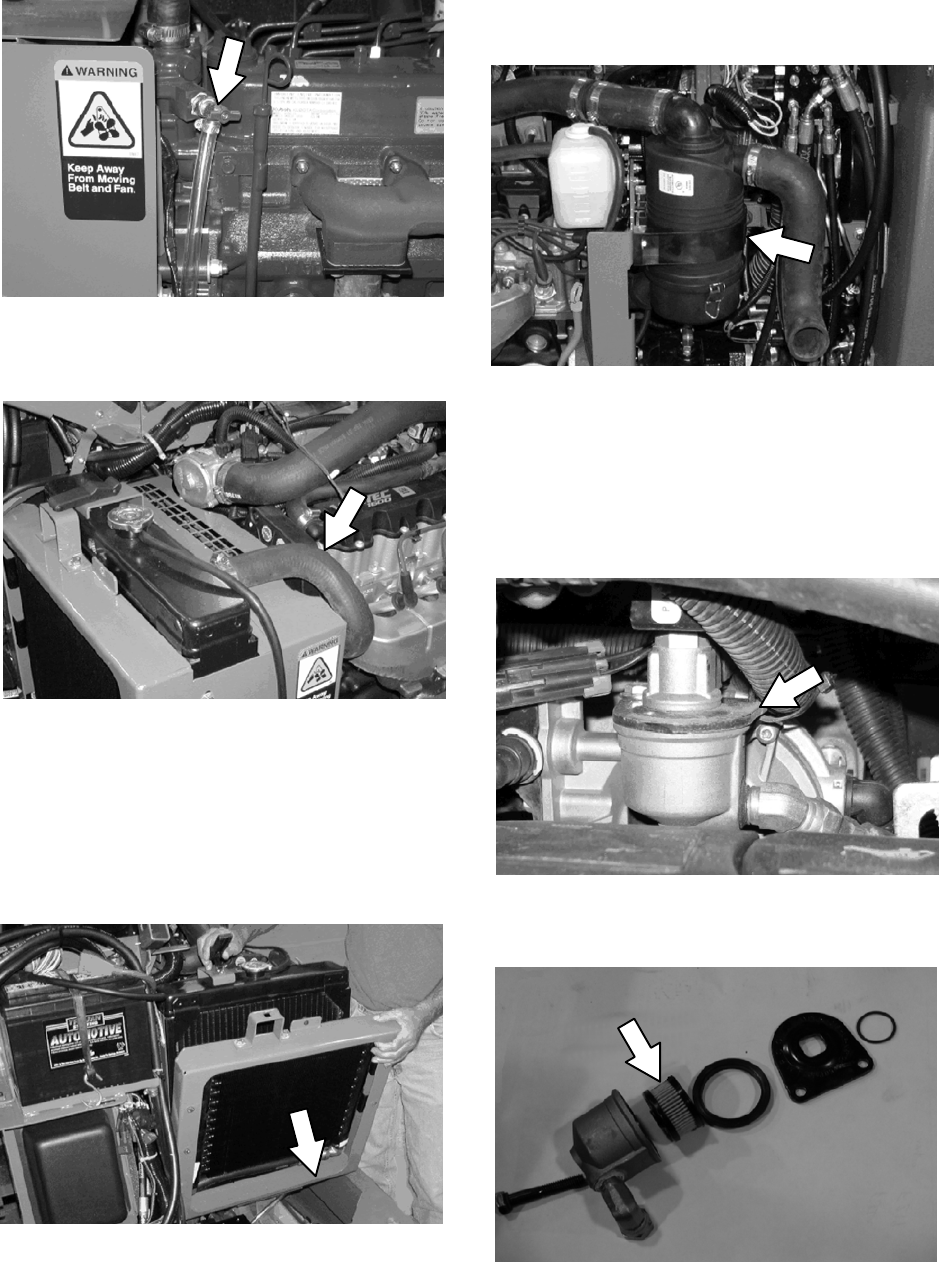
Location of drain cock on diesel machines..AIR FILTER
Replace the air filter after every 400 hours of
operation.
FOR SAFETY: When servicing machine, wear
eye and ear protection when using
pressurized air or water.
FUEL FILTER (LPG)
Replace the LPG fuel filter after every 400 hours
of operation.
FOR SAFETY: When servicing machine, keep
flames and sparks away from fuel system
service area. Keep area well ventilated.
Disassemble the fuel lock off valve to access the
LPG fuel filter.
M20 Maintenance Information
(Page 8 of 30)
M20 331385 (02-2007)
31
M
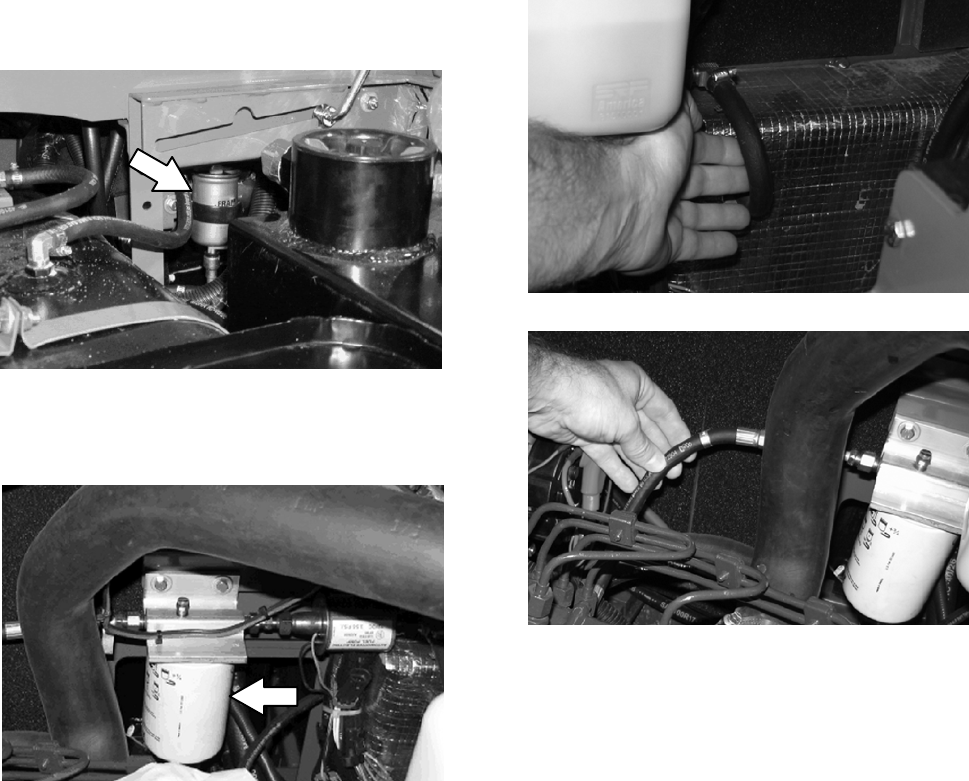
FUEL FILTER (DIESEL)
Replace the diesel fuel filter after every 400
hours of operation.
FOR SAFETY: When servicing machine, keep
flames and sparks away from fuel system
service area. Keep area well ventilated.
FUEL FILTER (Gasoline)
Replace the gasoline fuel filter after every 800
hours of operation.
FOR SAFETY: When servicing machine, keep
flames and sparks away from fuel system
service area. Keep area well ventilated.
M20 Maintenance Information
(Page 9 of 30)
FUEL LINES (DIESEL)
Check the fuel lines every 50 hours of operation.
If the clamp band is loose, apply oil to the screw
of the band and securely tighten the band.
The diesel rubber fuel lines can become worn--out
whether the engine has been used much or not.
Replace the fuel lines and clamp bands every two
years.
FOR SAFETY: When servicing machine, keep
flames and sparks away from fuel system
service area. Keep area well ventilated.
If the fuel lines and clamp bands are found worn
or damaged before two years’ time; replace or
repair them at once. Bleed the fuel system after
replacement of any fuel lines, see PRIMING THE
FUEL SYSTEM. When the fuel lines are not
installed, plug both ends with clean cloth or paper
to prevent dirt from entering the lines. Dirt in the
lines can cause fuel injection pump malfunction.
M20 331385 (02-2007)
32
M

BATTERY
Clean and tighten the battery connections after
the first 50 hours of operation and after every 800
hours after that. Do not remove the vent plugs
from the battery or add water to the battery.
FOR SAFETY: When servicing machine, avoid
contact with battery acid.
FUSES AND RELAYS
RELAY PANEL FUSES AND RELAYS
Fuses are one-time protection devices designed
to protect the wire harness by stopping the flow of
current in the event of a circuit overload. Relays
switch the electrical power going to the machine
electrical systems on/off. Remove the relay panel
cover to access fuses and relays.
WARNING: Moving belt and fan. Keep
away.
ENGINE BELT
Check the belt tension daily. Adjust tension as
necessary. Proper belt tension is 13 mm (0.50 in)
fromaforceof4to5kg(8to10lb)appliedatthe
mid-point of the longest span.
PRIMING THE DIESEL FUEL SYSTEM
Typical diesel fuel systems require priming to
remove pockets of air from the fuel lines and fuel
components. This is usually required after running
out of fuel, changing fuel filter elements or
repairing a fuel system component. Air in the fuel
prevents smooth engine operation.
This fuel system however is self-priming. The
return line comes from the top of the injector that
allows the air to escape through the return line.
SPARK PLUGS
Clean or replace, and set the gap of the spark
plugs after every 400 hours of operation. The
proper spark plug gap is 1 mm (0.042 in).
TIMING BELT
Check the timing belt after every 800 hours of
operation.
Replace the timing belt after every 2000 hours of
operation.
M20 Maintenance Information
(Page 10 of 30)
M20 331385 (02-2007)
33
M
Refer to the table below for the fuses and circuits
protected.
Fuse Rating Circuit Protected
FU1 15 A Auxiliary Relays/Engine Controls
FU2 15 A Shaker
FU3 15 A Horn
FU4 15 A Not Used
FU5 15 A Scrub Vacuum/Main Brush/
Squeegee Down/Hopper Up
FU6 15 A Enable/Side Brush/Sweep Vacuum
FU7 15 A Solution/Hopper Latch and Door/
Auto Fill/Reverse/Shaker
FU8 15 A ES/FaST/Detergent/
Hopper Down/Spray Wand
FU9 15 A Lights
FU10 15 A Unswitched B+ for controller board
FU11 15 A Not Used: Options
FU12 15 A Spray Nozzle Pump
FU13 15 A Not Used
FU14 15 A Not Used
Refer to the table below for the relays and circuits
controlled.
Relay Rating Circuit Controlled
M1 12 VDC, 40 A Auxiliary 1
M2 12 VDC, 40 A Auxiliary 2
M3 12 VDC, 40 A Shaker
M4 12 VDC, 40 A Reverse
M5 12 VDC, 40 A Horn
M6 12 VDC, 40 A Shutdown
M7 12 VDC, 40 A Starter
M8 12 VDC, 40 A Not Used
M9 12 VDC, 40 A Not Used
M10 12 VDC. 40 A Spray Wand (Separate Relay)
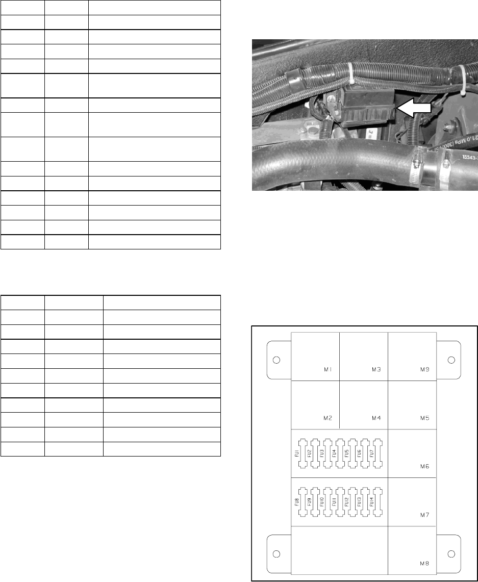
ENGINE HARNESS FUSES AND RELAYS
The engine harness fuses and relays are located
in the fuse box on the side panel inside the engine
compartment. Refer to the fuse box cover for
locations of engine harness fuses and relays.
N
.
M20 Maintenance Information
(Page 11 of 30)
OTE: Always replace a fuse with a fuse of the
same amperage. Extra 15 Amp fuses are
provided inside the relay panel drawer on the
relay panel.
Refer to the diagram below for locations of the
fuses and relays on the relay panel. The M10
relay for the optional spray nozzle is located
behind the battery.
M20 331385 (02-2007)
34
M
CLEANING THE HOPPER DUST FILTER
Shake the dust filter before emptying the hopper
and at the end of every shift. Inspect and clean
the filter after every 20 hours of operation.
Replace damaged dust filters.
NOTE: The dust filter may need to be cleaned at
more frequent intervals if the machine is used in
extremely dusty conditions.
Use one of the following methods to clean the
dust filter:
SHAKING--Press the filter shaker button.
TAPPING--Tap the filter, with the dirty side down,
gently on a flat surface. Do not damage the
edges of the filter. The filter will not seal properly
in the filter frame if the edges of the filter are
damaged.
AIR--Always wear eye protection when using
compressed air. Blow air through the dust filter
opposite the direction of the arrows. Never use
more than 690 kPa (100 psi) of air pressure and
never hold the nozzle closer than 50 mm (2 in) to
the filter. This may be done with the dust filter in
the machine.
FOR SAFETY: When servicing machine, wear
eye and ear protection when using
pressurized air or water.
WATER--Rinse the dust filter with a low pressure
garden hose through the dust filter opposite the
direction of the arrows.
NOTE: If water is used to clean the dust filter, be
sure the filter is completely dry before reinstalling
it into the hopper. Do Not reinstall a wet dust
filter.
THERMO--SENTRY
The Thermo--Sentry, located inside the
hopper, senses the temperature of the air pulled
up from the hopper. If there is a fire in the hopper,
the Thermo--Sentry stops the vacuum fan and
cuts off the air flow. The Thermo--Sentry
automatically resets after cooling down.
MAIN BRUSHES
Check the main brushes daily for tangled wire or
string, wear, damage, and adjustment.
Replace the brushes if large portions of the
bristles are missing or if the remaining bristles are
19 mm (0.75 in) or less in length.
For optimal cleaning performance, rotate the
brushes front to rear after every 50 hours of
operation.
NOTE: Replace brushes in sets of two. Otherwise
one scrub brush may scrub more aggressively
than the other.
REPLACING OR ROTATING THE MAIN
BRUSHES
The front brush can be accessed on the left side
of the machine and rear brush can be accessed
on the right side of the machine.
1. Raise the scrub head.
FOR SAFETY: Before leaving or servicing
machine, stop on level surface, set parking
brake, and turn off machine.
2. Open the outer brush doors.
M20 Maintenance Information
(Page 12 of 30)
M20 331385 (02-2007)
35
M
3. Open the inner brush doors.
4. Remove the brush idler plates.
5. Pull the brushes out from the scrub head.
6. Install the new or rotated brushes by pushing
down on the ends while sliding them onto the
drive motor hubs.
7. If rotating the existing brushes, only rotate
front to rear. Do NOT rotate end--for--end.
Before After
A
D
B
CA
D B
C
8. Reinstall the brush idler plates.
9. Close the inner and outer brush doors.
10. Check and adjust the brush pattern if needed.
Refer to CHECKING AND ADJUSTING THE
MAIN BRUSH PATTERN.
M20 Maintenance Information
(Page 13 of 30)
M20 331385 (02-2007)
36
M
CHECKING THE MAIN BRUSH PATTERN
1. Apply chalk, or a similar marking material, to
a smooth and level section of the floor.
NOTE: If chalk or other material is not available,
allow the brush to spin on the floor for two
minutes. A polish mark will remain on the floor.
2. Raise the scrub head, then position the
brushes over the chalked area.
3. Set the parking brake.
4. Press the 1--STEP Sweep button to lower the
scrub head. Set the brush pressure to the
lowest setting and allow the brushes to
operate for 15 to 20 seconds. Keep the scrub
head in one spot in the chalked area.
5. Raise the scrub head, release the parking
brake, and drive the machine away from the
chalked area.
FOR SAFETY: Before leaving or servicing
machine, stop on level surface, set parking
brake, and turn off machine.
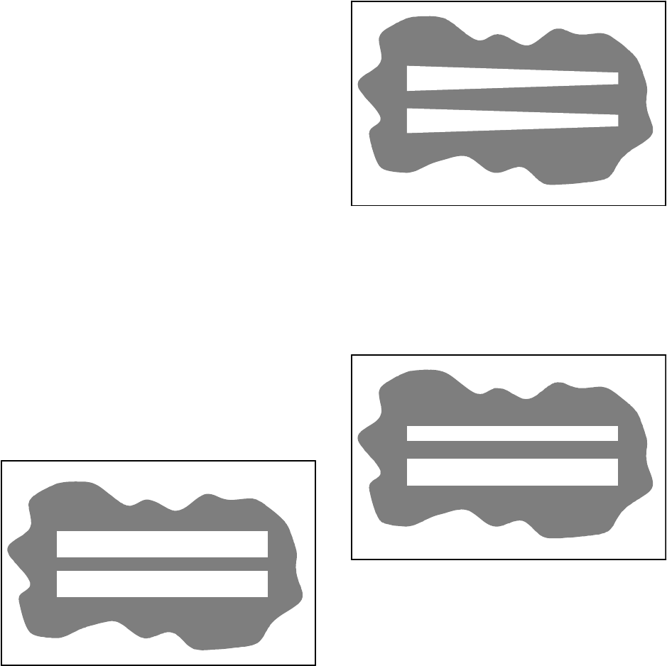
6. Observe the brush patterns. If the brush
pattern is the same width across the entire
length of each brush and both brushes are the
same width, no adjustment is necessary.
10355
7. If the brush patterns are tapered, see
ADJUSTING THE MAIN BRUSH TAPER
section of this manual.
10652
8. The brush patterns should be 75 to 130 mm
(3 to 5 in) wide with the brushes in the
lowered position and both patterns should be
the same width. If the width of the brushes is
not the same, see ADJUSTING THE MAIN
BRUSH WIDTH section of this manual.
10653
M20 Maintenance Information
(Page 14 of 30)
M20 331385 (02-2007)
37
M
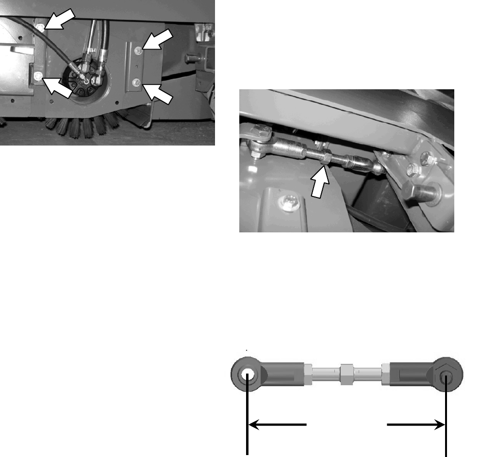
ADJUSTING THE MAIN BRUSH TAPER
1. Loosen the four mounting bolts on the brush
drive housing.
2. Move the brush drive housing up to decrease
the pattern width on that side of the scrub
head or down to increase the pattern width on
that side of the scrub head.
3. Tighten the mounting bolts.
4. Recheck the pattern. Readjust if necessary.
ADJUSTING THE MAIN BRUSH WIDTH
1. Adjust the length of the drag links on both
sides of the scrub head. Lengthen the drag
links to increase the rear brush pattern width.
Shorten the drag links to increase the front
brush pattern. Always adjust the nut on each
drag link an equal number of turns.
NOTE: Two full turns of the drag link adjustment
bolt will change the brush pattern approximately
25 mm (1 in).
2. Recheck the pattern. Readjust if necessary.
M20 Maintenance Information
(Page 15 of 30)
NOTE: If replacing Drag Link, refer to
diagram below to set adjustment to factory
specifications, then adjust as necessary to
obtain equal front and rear brush pattern
widths.
7- 9/16 in.
(19.2 cm)
M20 331385 (02-2007)
38
M
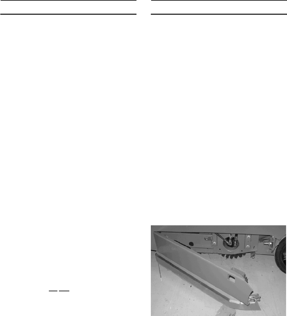
SIDE BRUSH (OPTION)
Check the side brush daily for wear or damage.
Remove any tangled string or wire from the side
brush or side brush drive hub.
REPLACING THE SIDE BRUSH
Replace the side brush when it no longer cleans
effectively or when the remaining bristles are
19 mm (0.75 in) or less in length for the scrub
brush or 64 mm (2.5 in) or less in length for the
sweep brush. The side brush may be changed
sooner if sweeping light litter. The bristles may be
worn shorter if sweeping heavy debris.
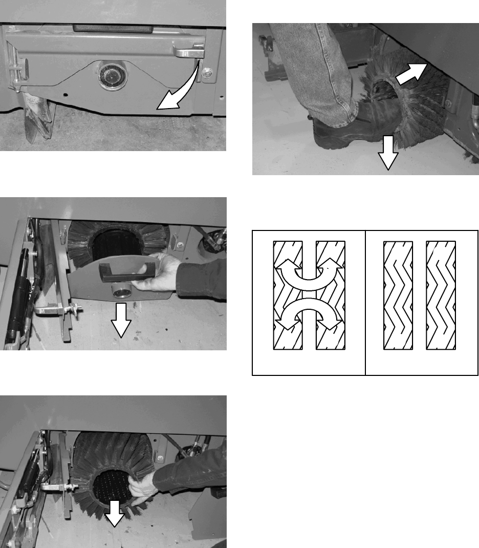
1. If necessary, raise the side brush.
FOR SAFETY: Before leaving or servicing
machine, stop on level surface, set parking
brake, and turn off machine.
2. Turn the brush until the spring handles are
visible through the access hole in the side
brush assembly.
3. Squeeze the spring handles and let the side
brush drop to the floor.
4. Remove the side brush from underneath the
side brush assembly.
5. Place the new side brush underneath the side
brush assembly and lift the side brush up onto
the side brush hub until the brush locks onto
the hub.
M20 Maintenance Information
(Page 16 of 30)
M20 331385 (02-2007)
39
M
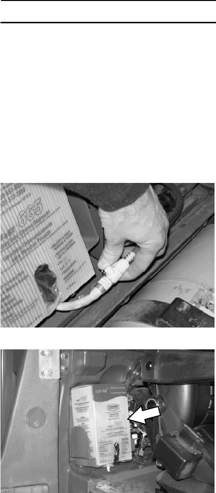
FaST SYSTEM
REPLACING THE FaST--PAK CARTON
FOR SAFETY: Before leaving or servicing
machine, stop on level surface, set parking
brake, and turn off machine.
1. Open the side access door.
2. Slide the seat completely forward.
3. Squeeze the button on the FaST supply hose
connector, then pull the empty FaST--PAK
carton out from the compartment and discard.
4. Remove the perforated knock outs from the
new FaST--PAK carton. Do Not remove the
bag from the carton. Pull out the hose
connector located on the bottom of the bag
and remove the hose cap from the connector.
NOTE: The FaST--PAK Floor Cleaning
Concentrate is specially designed for use with the
FaST system scrubbing application. NEVER use
a substitute. Other cleaning solutions may cause
FaST system failure.
5. Slide the FaST--PAK carton into the
FaST--PAK bracket.
6. Connect the FaST supply hose to the
FaST--PAK hose connector.
7. Scrub with the FaST system for a few
minutes to allow the detergent to reach
maximum foaming.
M20 Maintenance Information
(Page 17 of 30)
M20 331385 (02-2007)
40
M
CLEANING THE FaST SUPPLY HOSE
CONNECTOR
Soak the connector in warm water if detergent
buildup is visible. When a FaST--PAK carton is not
installed, store the supply hose connector on the
storing plug to prevent the hose from clogging.
CLEANING THE FaST SYSTEM FILTER
SCREEN
The FaST system filter screen filters water from
the solution tank as the water flows into the FaST
system.
Remove the filter screen bowl and clean the filter
screen after every 50 hours of operation. Empty
the solution tank before removing the filter.
CLEANING THE FaST SYSTEM AIR PUMP
FILTER
Remove and clean the air filter with compressed
air after every 200 hours of FaST scrubbing.
FOR SAFETY: When servicing machine, wear
eye protection when using pressurized air or
water.
M20 Maintenance Information
(Page 18 of 30)
M20 331385 (02-2007)
41
M
SQUEEGEE BLADES
Check the squeegee blades for damage and wear
daily. When the blades become worn, rotate the
blades end--for--end or top--to--bottom to a new
wiping edge. Replace blades when all edges are
worn.
Check the deflection of the squeegee blades daily
or when scrubbing a different type of surface.
Check the leveling of the rear squeegee every
100 hours of operation.
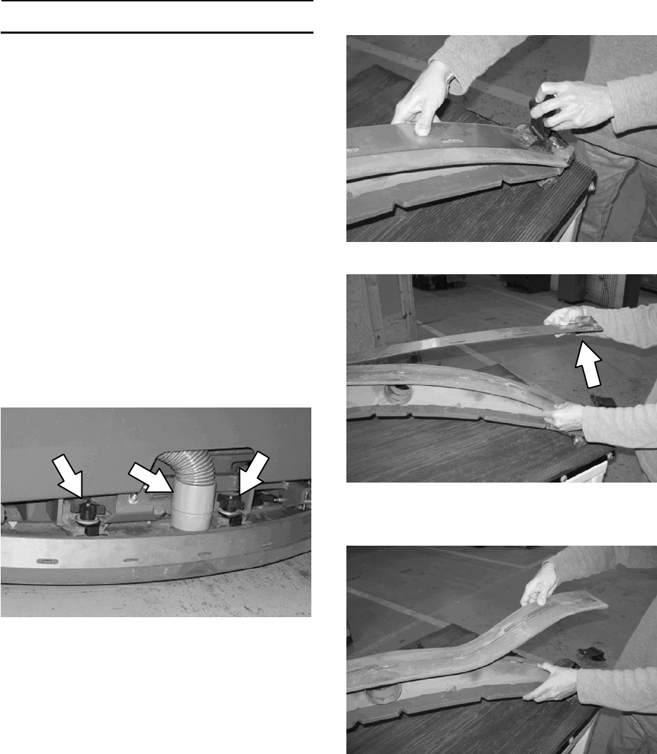
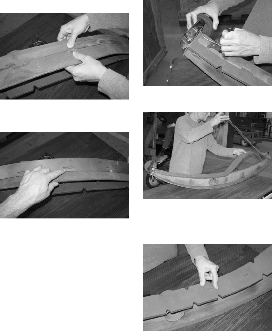
REPLACING (OR ROTATING) THE REAR
SQUEEGEE BLADES
1. Lower the scrub head.
FOR SAFETY: Before leaving or servicing
machine, stop on level surface, set parking
brake, and turn off machine.
2. Disconnect the vacuum hose from the rear
squeegee assembly.
3. Remove both mounting knobs from the rear
squeegee assembly.
4. Turn on the machine, raise the scrub head,
and turn off the machine.
5. Remove the rear squeegee assembly from
the machine.
6. Loosen the rear retaining band tension latch
and open the retaining band.
7. Remove the rear squeegee.
M20 Maintenance Information
(Page 19 of 30)
M20 331385 (02-2007)
42
M
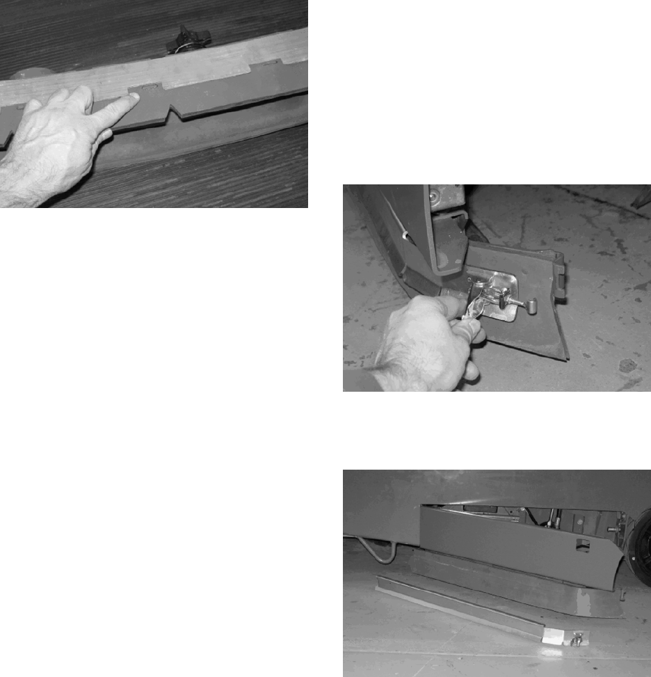
8. Install the new rear squeegee blade or rotate
the existing blade to the new edge. Be sure all
the holes in the squeegee blade are hooked
onto the tabs.
9. Reinstall the rear retaining band aligning the
tabs with the holes.
10. Tighten the rear retaining band tension latch.
11. Loosen the front retaining band tension latch
and open the retaining band.
12. Remove the front squeegee.
13. Install the new front squeegee blade or rotate
the existing blade to the new edge. Be sure
the holes in the squeegee blade are hooked
onto the tabs.
M20 Maintenance Information
(Page 20 of 30)
M20 331385 (02-2007)
43
M
14. Reinstall the front retaining band aligning the
tabs with the notches.
15. Tighten the front retaining band tension latch.
16. Reinstall the rear squeegee assembly onto
the machine.
17. Check and adjust the rear squeegee if
necessary. Refer to ADJUSTING THE REAR
SQUEEGEE BLADE DEFLECTION and
LEVELING THE REAR SQUEEGEE sections
of this manual.
REPLACING OR ROTATING THE SIDE
SQUEEGEE BLADES
1. If necessary, raise the scrub head.
FOR SAFETY: Before leaving or servicing
machine, stop on level surface, set parking
brake, and turn off machine.
2. Open the outer brush doors.
3. Unhook the latch on the side squeegee
retaining band from the side squeegee
assembly.
4. Remove the retaining band from the side
squeegee assembly.
M20 Maintenance Information
(Page 21 of 30)
M20 331385 (02-2007)
44
M
5. Remove the side squeegee blade. If the outer
edge of the squeegee blade is not worn,
rotate the squeegee blade with the blade from
the other side of the machine. Discard the
squeegee blade if both edges are worn.
6. Install the new or rotated squeegee blades.
7. Reattach the side squeegee retaining band to
the side squeegee assembly.
8. Hook the latch on the side squeegee retaining
band.
9. Close the outer brush door.
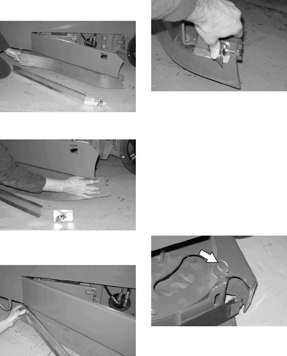
REPLACING THE SIDE BRUSH SQUEEGEE
BLADE (OPTION)
Check the side brush squeegee blade for damage
and wear daily. Replace the blade if the leading
edge is torn or worn half-way through the
thickness of the blade.
1. If necessary, raise the scrub head.
FOR SAFETY: Before leaving or servicing
machine, stop on level surface, set parking
brake, and turn off machine.
2. Pull the pin from the squeegee bumper and
open the squeegee bumper.
M20 Maintenance Information
(Page 22 of 30)
M20 331385 (02-2007)
45
M
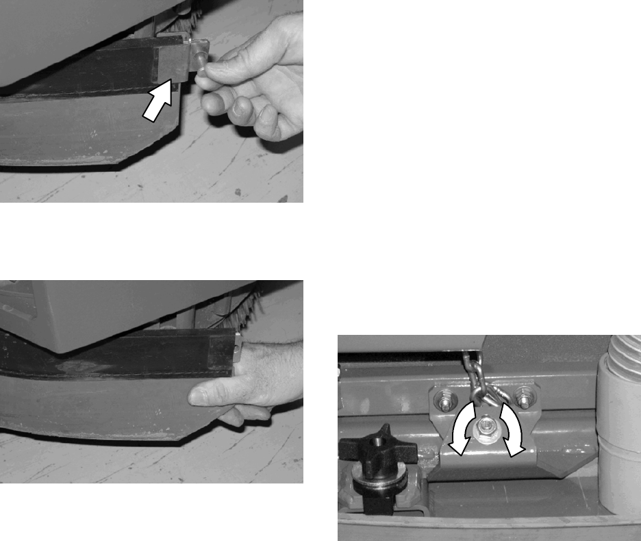
3. Remove the clevis pin and squeegee retainer.
4. Pull the squeegee out from the side brush
assembly.
5. Slide the new squeegee into the side brush
assembly.
6. Reinstall the squeegee retainer and clevis pin.
7. Close the squeegee bumper and reinsert the
pin.
LEVELING THE REAR SQUEEGEE
Leveling the squeegee assures the entire length
of the squeegee blade is in even contact with the
surface being scrubbed. Perform this adjustment
on an even and level floor.
1. Lower the squeegee and drive the machine
forward a few meters (feet).
FOR SAFETY: Before leaving or servicing
machine, stop on level surface, set parking
brake, and turn off machine.
2. Look at the deflection of the squeegee over
the full length of the squeegee blade.
3. If the deflection is not the same over the full
length of the blade, turn the squeegee
levelling nut to make adjustments.
DO NOT disconnect the suction hose from
the squeegee frame when leveling squeegee.
4. Turn the squeegee leveling nut
counter-clockwise to decrease the deflection
at the ends of the squeegee blade.
Turn the squeegee leveling nut clockwise to
increase the deflection at the ends of the
squeegee blade.
5. Drive the machine forward with the squeegee
down to recheck the squeegee blade
deflection if adjustments were made.
6. Readjust the squeegee blade deflection if
necessary.
M20 Maintenance Information
(Page 23 of 30)
M20 331385 (02-2007)
46
M
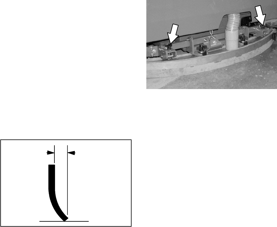
ADJUSTING THE REAR SQUEEGEE BLADE
DEFLECTION
Deflection is the amount of curl the overall
squeegee blade has when the machine moves
forward. The best deflection is when the
squeegee wipes the floor dry with a minimal
amount of deflection.
NOTE: Make sure the squeegee is level before
adjusting the deflection. See LEVELING THE
REAR SQUEEGEE.
1. Lower the squeegee and drive the machine
forward a few meters (feet).
FOR SAFETY: Before leaving or servicing
machine, stop on level surface, set parking
brake, and turn off machine.
2. Look at the amount of deflection or “curl” of
the squeegee blade. The correct amount of
deflection is 12 mm (0.50 in) for scrubbing
smooth floors and 15 mm (0.62 in) for rough
floors.
12 mm
(0.50 in)
3. To adjust the overall squeegee blade
deflection, turn the adjustment knobs
counterclockwise to increase deflection or
clockwise to decrease deflection.
4. Drive the machine forward again to recheck
the squeegee blade deflection after
adjustments are made.
5. Readjust the squeegee blade deflection if
necessary.
M20 Maintenance Information
(Page 24 of 30)
M20 331385 (02-2007)
47
M
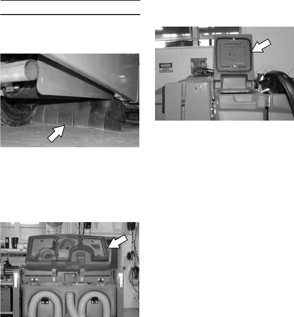
SKIRTS AND SEALS
SCRUB HEAD SKIRT
Check the skirt for damage and wear after every
100 hours of operation.
The skirts should be between 0 to 6 mm
(0 to 0.25 in) from the floor when the scrub head
is down.
RECOVERY TANK SEAL
Check the recovery tank cover seal for damage
and wear daily.
SOLUTION TANK SEALS
Check each solution tank cover seal for damage
and wear daily.
M20 Maintenance Information
(Page 25 of 30)
M20 331385 (02-2007)
48
M

BRAKES AND TIRES
BRAKES
The mechanical brakes are located on the rear
wheels. The brakes are operated by the foot
brake pedal and connecting cables.
Check the brake adjustment after every 200 hours
of operation.
PARKING BRAKE
The parking brake is set with the parking brake
pedal that activates the brakes.
Check the parking brake adjustment after every
200 hours of operation.
TIRES
Check tires for damage and wear after every 100
hours of operation.
FRONT WHEEL
Torque the front wheel nuts twice in the pattern
shown to 122 to 149 Nm (90 to 110 ft lb) after the
first 50 hours of operation, and after every 800
hours there after.
2
3
4
1
5
PROPELLING MOTOR
Torque the shaft nut to 508 Nm (375 ft lb)
lubricated, 644 Nm (475 ft lb) dry, after every 800
hours of operation.
M20 Maintenance Information
(Page 26 of 30)
M20 331385 (02-2007)
49
M
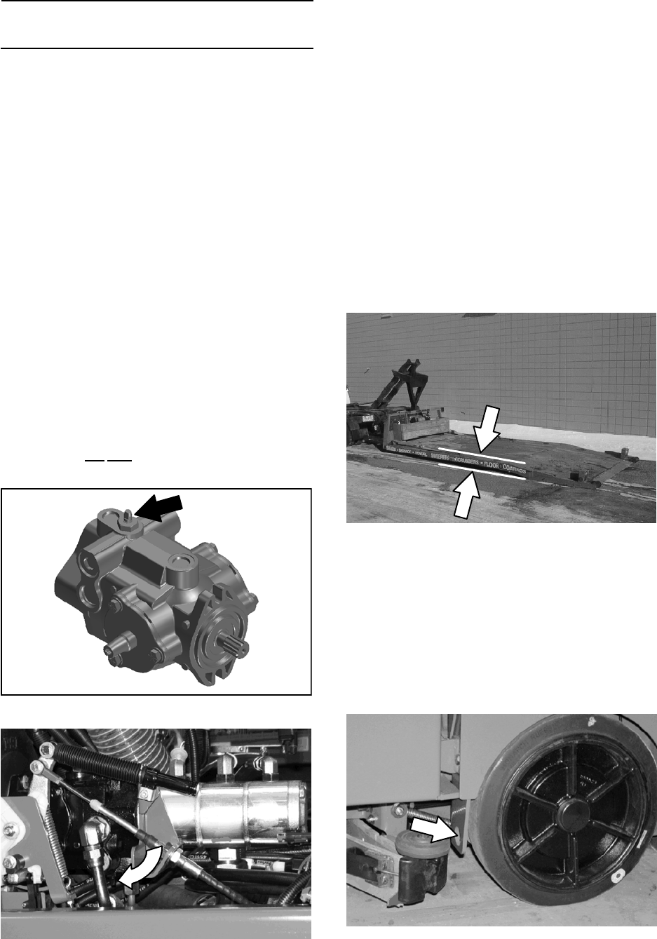
PUSHING, TOWING, AND TRANSPORTING
THE MACHINE
PUSHING OR TOWING THE MACHINE
If the machine becomes disabled, it can be
pushed from the front or rear, but only towed from
the front.
The propelling pump has a bypass valve to
prevent damage to the hydraulic system when the
machine is being pushed or towed. This valve
allows a disabled machine to be moved for a very
short distance and at a speed to not exceed 1.6
kp/h (1 mph). The machine is NOT intended to be
pushed or towed a long distance or at a high
speed.
ATTENTION! Do not push or tow machine for
a long distance or damage may occur to the
propelling system.
Turn the bypass valve located on the bottom of
the propelling pump 90_(either direction) from the
normal position before pushing or towing the
machine. Return the bypass valve back to the
normal position when through pushing or towing
the machine. Do Not use the bypass valve during
normal machine operation.
TRANSPORTING THE MACHINE
1. Raise the squeegee, scrub head, and
brushes. If necessary, raise the hopper for
additional ramp clearance.
NOTE: Empty the hopper, the recovery tank, and
the solution tank before transporting.
2. Position the rear of the machine at the loading
edge of the truck or trailer.
3. If the loading surface is not horizontal or is
higher than 380 mm (15 in) from the ground,
use a winch to load machine.
If the loading surface is horizontal and 380
mm (15 in) or less from the ground, the
machine may be driven onto the truck or
trailer.
FOR SAFETY: When loading machine onto
truck or trailer, use winch. Do not drive the
machine onto the truck or trailer unless the
loading surface is horizontal AND is 380 mm
(15 in) or less from the ground.
4. To winch the machine onto the truck or trailer,
attach the winching chains to the holes in the
rear jacking brackets behind the rear tires.
M20 Maintenance Information
(Page 27 of 30)
M20 331385 (02-2007)
50
M
5. Position the machine as close to the front of
the trailer or truck as possible.
6. Set the parking brake and place a block
behind each wheel to prevent the machine
from rolling.
7. Lower the scrub head.
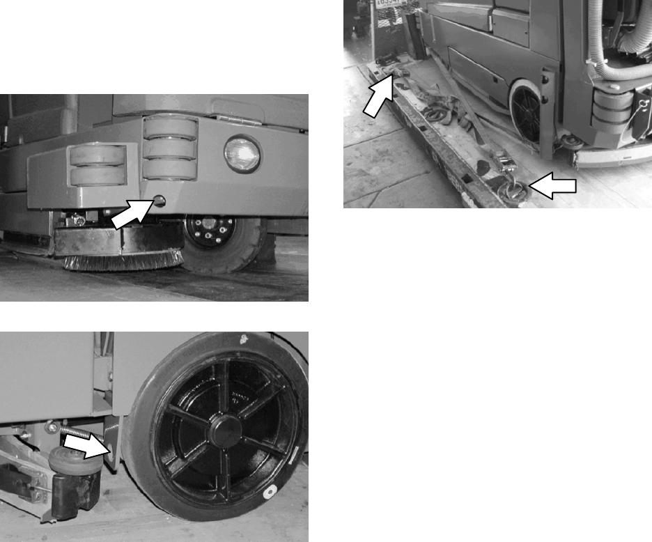
8. Connect the tie--down straps to the holes in
the right and left lower corners in front of the
machine and the holes in the rear jacking
brackets behind the rear tires.
9. Route the tie--downs to the opposite ends of
the machine and hook them to the brackets
on the floor of the trailer or truck. Tighten the
tie--down straps.
NOTE: It may be necessary to install tie-down
brackets to the floor of the trailer or truck.
10. If the loading surface is not horizontal or is
higher than 380 mm (15 in) from the ground,
use a winch to unload machine.
If the loading surface is horizontal AND is 380
mm (15 in) or less from the ground, the
machine may be driven off the truck or trailer.
FOR SAFETY: When unloading machine off
truck or trailer, use winch. Do not drive the
machine off the truck or trailer unless the
loading surface is horizontal AND 380 mm
(15 in) or less from the ground.
M20 Maintenance Information
(Page 28 of 30)
M20 331385 (02-2007)
51
M
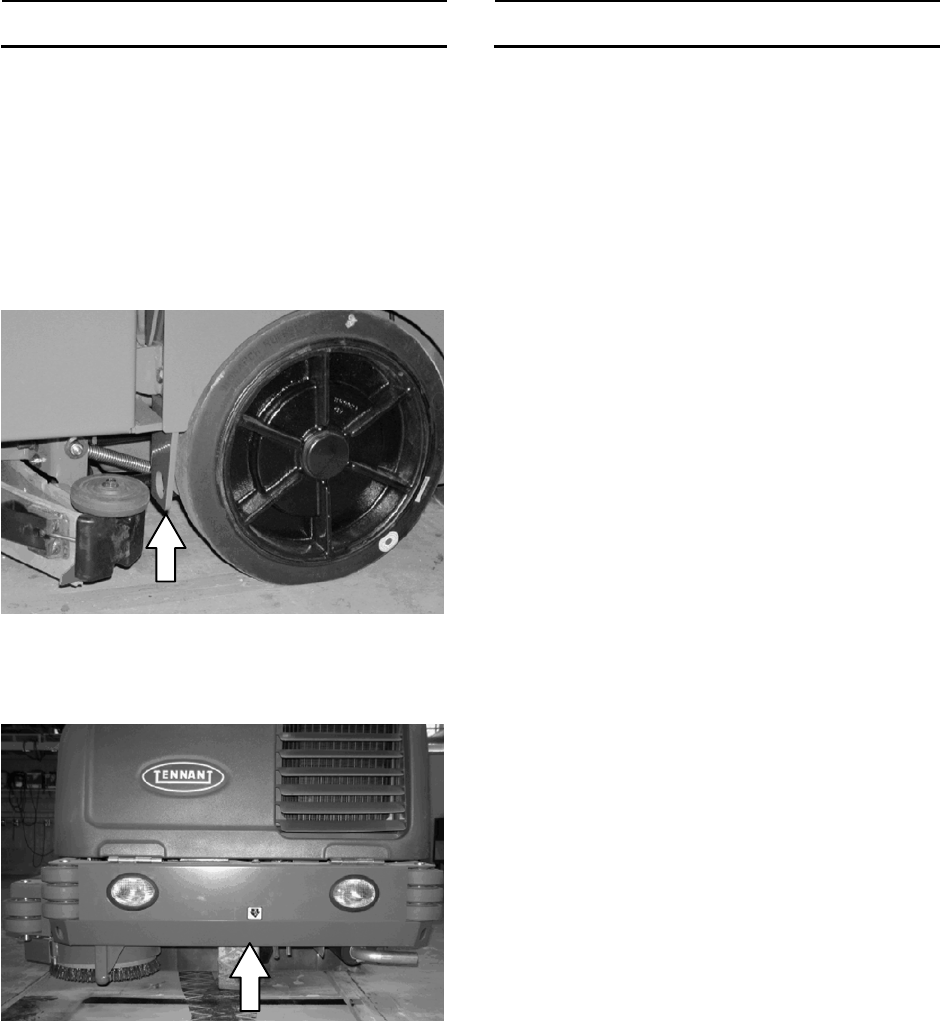
MACHINE JACKING
Empty the hopper, recovery tank, and solution
tank before jacking up the machine.Jack up the
machine at the designated locations. Use a hoist
or jack capable of supporting the weight of the
machine. Use jackstands to support the machine.
Always stop the machine on a flat, level surface
and block the tires before jacking up the machine.
Rear jacking locations are located directly behind
the rear tires on each side of the machine.
Front jacking locations are located on the frame
directly in front of the front tire.
FOR SAFETY: Before leaving or servicing
machine, stop on level surface.
FOR SAFETY: When servicing machine, block
machine tires before jacking machine up. Use
a hoist or jack that will support the weight of
the machine. Jack machine up at designated
locations only. Support machine with jack
stands.
STORAGE INFORMATION
The following steps should be taken prior to
storing the machine for extended periods.
1. Drain and clean the solution and recovery
tanks. Open the recovery tank and solution
tank covers to allow the air to circulate.
2. Park the machine in a cool, dry area. Do not
expose the machine to rain. Store indoors.
3. Remove the battery, or charge battery every
three months.
FREEZE PROTECTION
FOR SAFETY: Before leaving or servicing
machine, stop on level surface, set parking
brake, and turn off machine.
1. Be sure the solution tank and recovery tank
are empty.
2. Pour 3.8 L (1 gal) of premixed automotive
windshield washer solution into the solution
tank.
3. Turn the key to the on position (without
starting the machine).
4. Press the 1--STEP Scrub button.
5. Repeatedly press the Solution increase button
(+) until the solution flow is at the highest
setting.
6. Press the directional pedal to circulate the
windshield washer solution completely
through the system.
7. Press the 1--STEP Scrub button again to turn
off the system and turn the key to the off
position.
8. The remaining washer solution does not need
to be drained from the solution tank.
NOTE: Storing or transporting machines equipped
with the ES or the FaST system in freezing
temperatures requires special procedures.
Consult a TENNANT representative for more
information.
M20 Maintenance Information
(Page 29 of 30)
M20 331385 (02-2007)
52
M
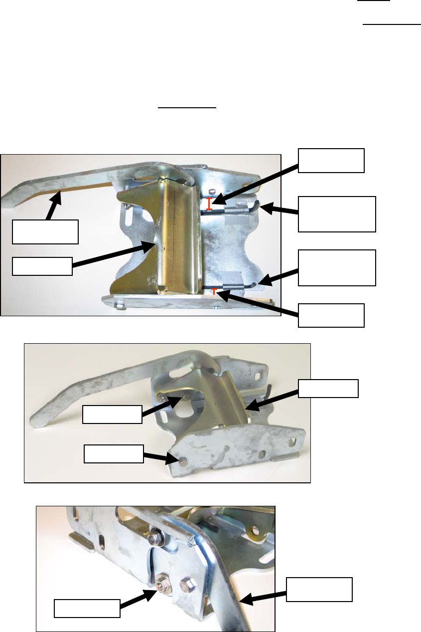
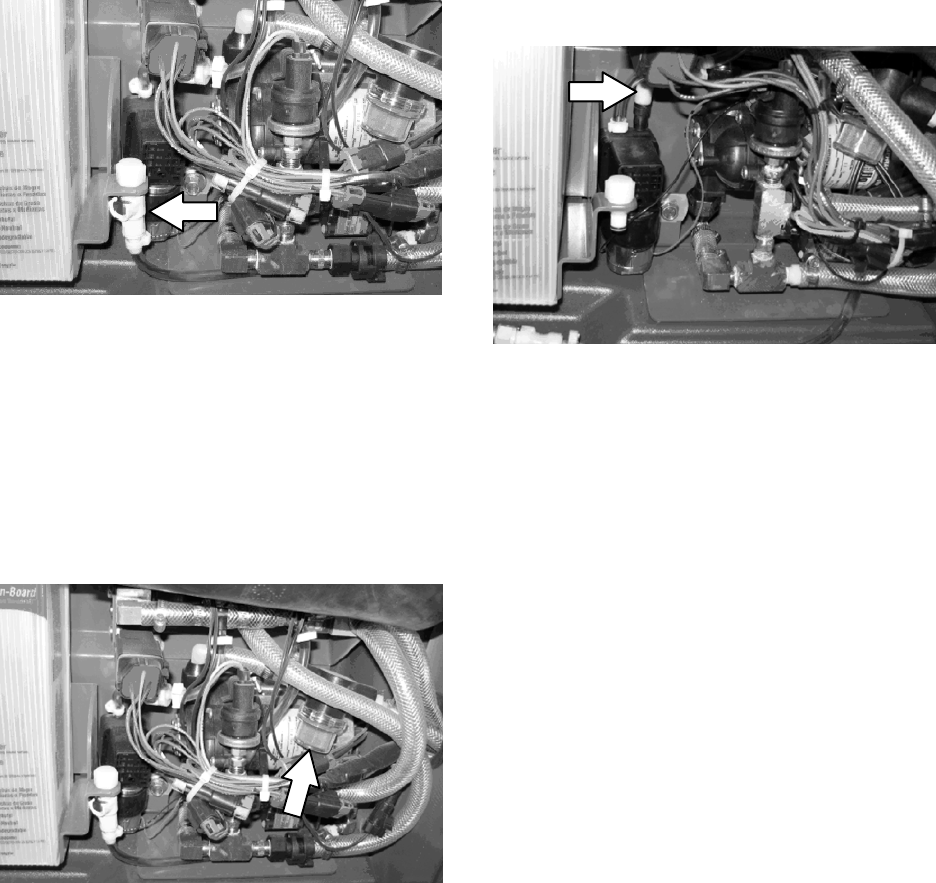
Solution & Recovery Tanks Pinch Valve Adjustments
Procedure to adjust Solution & Recovery Tank pinch valves:
1) Place a 1/4” or 6 mm hex key wrench or drill bit approximately 1” (25 mm) from the LEVER side of
the pinch valve bracket. Secure with tape.
2) Place a 5/32” or 4 mm hex key wrench or drill bit approximately 1” (25 mm) from the NON-LEVER
side of the pinch valve bracket. Secure with tape.
3) Loosen bolts “A” and “B”.
4) Apply downward pressure to Pinch Arm.
5) Turn cam “C” on Pinch Valve Lever until contact is made with the 1/4” or 6 mm hex key wrench or
drill bit.
6) While keeping downward pressure on the Pinch Arm, ensure that contact is made with the 5/32” or 4
mm hex key wrench or drill bit on the NON-LEVER side.
7) Tighten bolts “A” & “B”.
8) Verify proper clearances have been attained. Repeat procedure if needed.
1/4” or 6 mm
hex key wrench
or drill bit
5/32” or 4 mm
hex key wrench
or drill bit
1” (25 mm)
from side
1” (25 mm)
from side
Bolt “A”
Bolt “B”
Cam “C”
Pinch Valve
Lever
Pinch Arm
Pinch Arm
Pinch Valve
Lever
M20 Maintenance Information
(Page 30 of 30)
M20 331385 (02-2007)
53
M
M20 331385 (02-2007)
54
M

ELECTRICAL
NOTE: Troubleshooting charts may be shown with optional equipment.
The optional equipment may not be specified in these charts. Some machines
may not be equipped with all components shown.
BEFORE CONDUCTING TESTS:
DURING TESTS:
* Read and Follow ALL Safety Warnings and Precautions as
mentioned at the beginning of this manual
* Always use an ESD (Electrostatic Discharge) strap when working
near the Control Board
* Be cautious when working near Control Board – Battery voltage is
always present, even with Key OFF
* Always unhook Battery when removing or replacing components
* Call Technical Services if Diagnostic Time Exceeds One Hour With
Unknown Cause or Course of Action
Troubleshooting Information
M20
M20 331385 (02-2007)
55
E
1
2
3
1018547
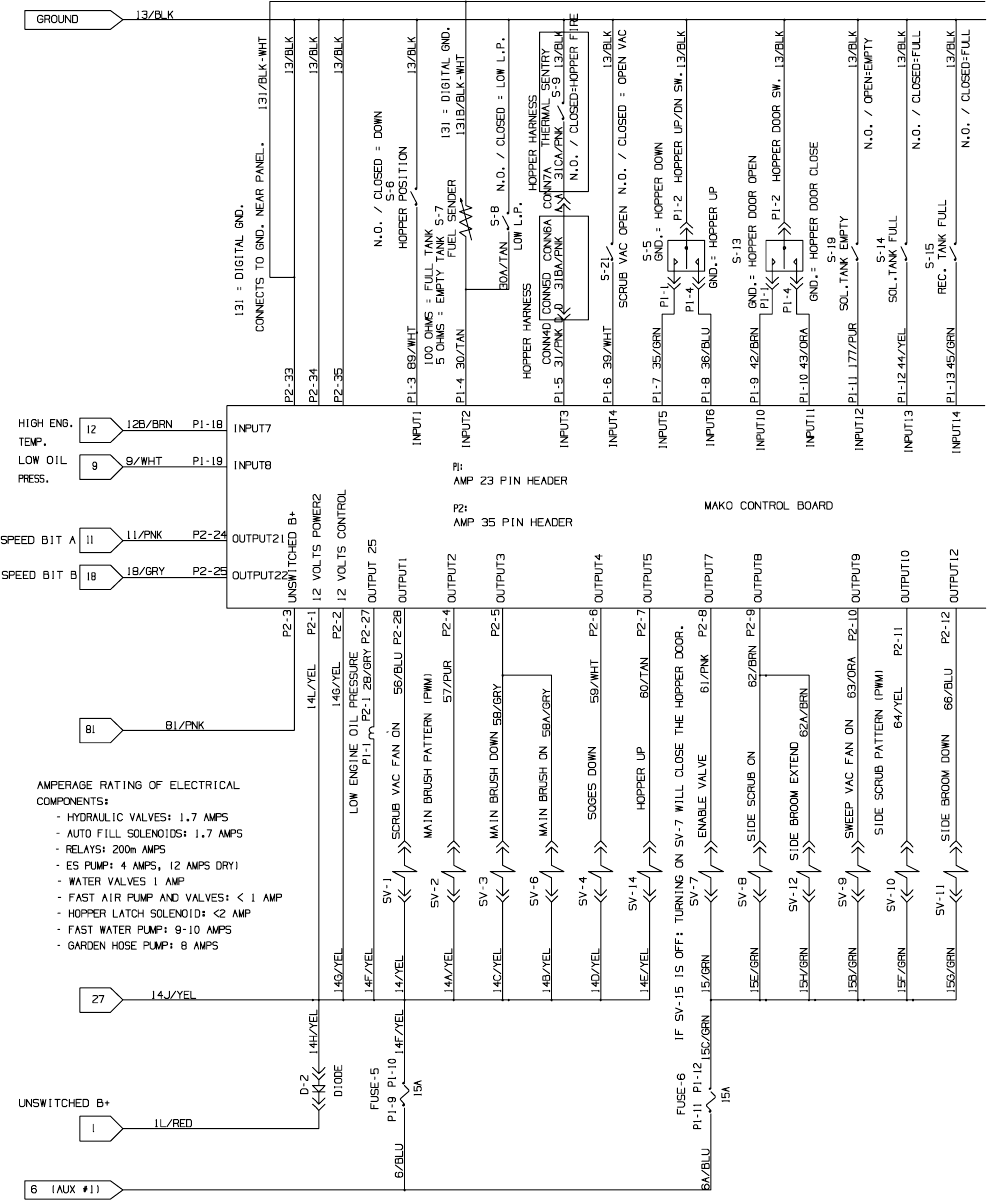
M20 Electrical Schematic
(Page 1 of 7)
M20 331385 (02-2007)
56
E
NOTE: Refer to the current Operators or Parts Manual for the most up-to-date information
1
2
3
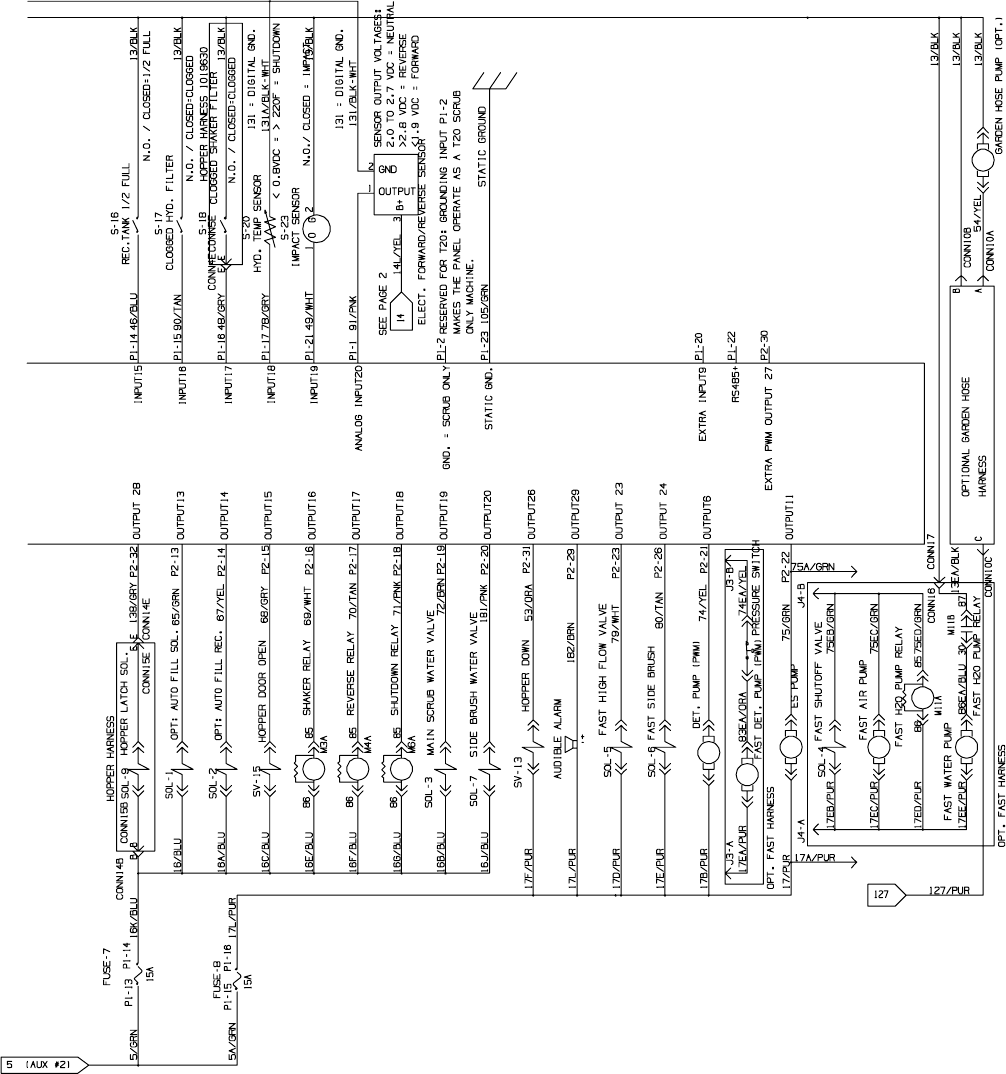
1018547
M20 Electrical Schematic
(Page 2 of 7)
M20 331385 (02-2007)
57
E
NOTE: Refer to the current Operators or Parts Manual for the most up-to-date information
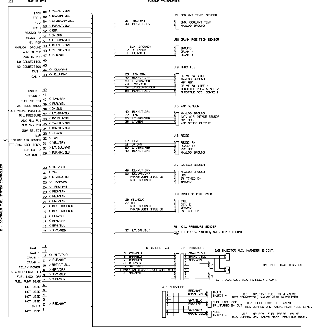
4
5
6
7
1018547
M20 Electrical Schematic
(Page 3 of 7)
M20 331385 (02-2007)
58
E
NOTE: Refer to the current Operators or Parts Manual for the most up-to-date information
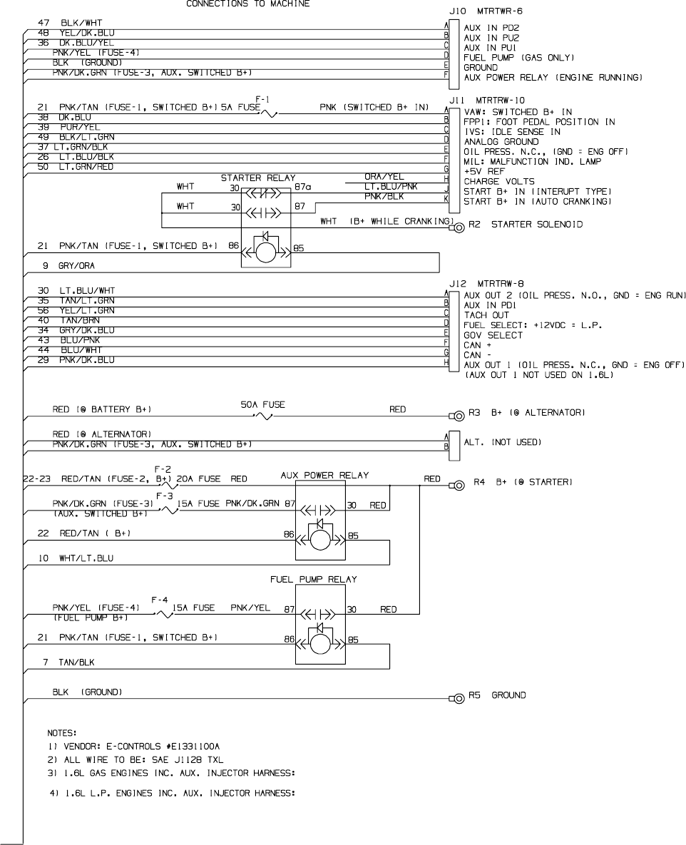
4
5
6
7
1018547
M20 Electrical Schematic
(Page 4 of 7)
M20 331385 (02-2007)
59
E
NOTE: Refer to the current Operators or Parts Manual for the most up-to-date information
8
1018547
M20 Electrical Schematic (Gas/LPG only)
(Page 5 of 7)
M20 331385 (02-2007)
60
E
NOTE: Refer to the current Operators or Parts Manual for the most up-to-date information
8
1018547
M20 Electrical Schematic (Gas/LPG only)
(Page 6 of 7)
M20 331385 (02-2007)
61
E
NOTE: Refer to the current Operators or Parts Manual for the most up-to-date information
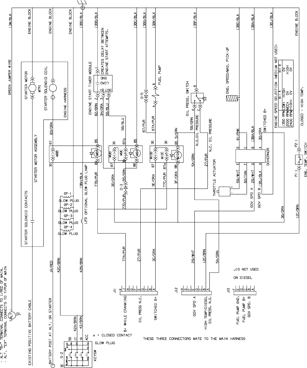
1018547
M20 Electrical Schematic (Diesel only)
(Page 7 of 7)
M20 331385 (02-2007)
62
E
NOTE: Refer to the current Operators or Parts Manual for the most up-to-date information
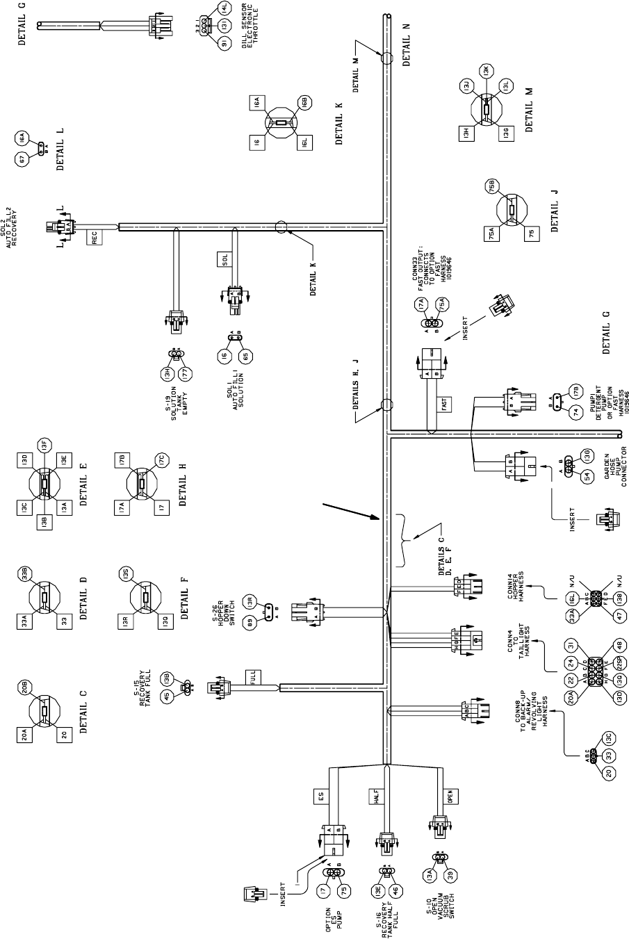
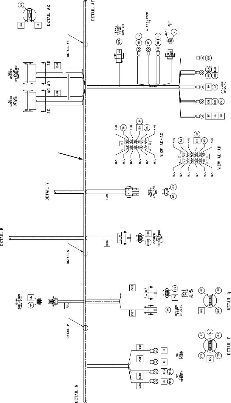
Main Wire Harness
1
M20 Electrical Wiring Harness Detail
(Page 1 of 14)
M20 331385 (02-2007)
63
E
NOTE: Refer to the current Operators or Parts Manual for the most up-to-date information
Main Wire Harness
1
M20 Electrical Wiring Harness Detail
(Page 2 of 14)
M20 331385 (02-2007)
64
E
NOTE: Refer to the current Operators or Parts Manual for the most up-to-date information
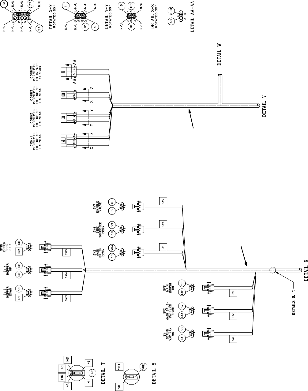
Main Wire Harness
1
1
M20 Electrical Wiring Harness Detail
(Page 3 of 14)
M20 331385 (02-2007)
65
E
NOTE: Refer to the current Operators or Parts Manual for the most up-to-date information
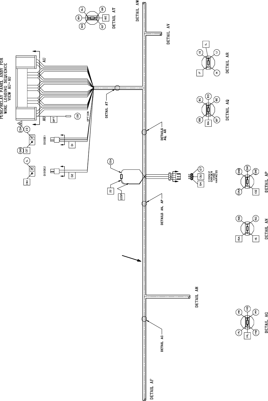
Main Wire Harness
1
M20 Electrical Wiring Harness Detail
(Page 4 of 14)
M20 331385 (02-2007)
66
E
NOTE: Refer to the current Operators or Parts Manual for the most up-to-date information
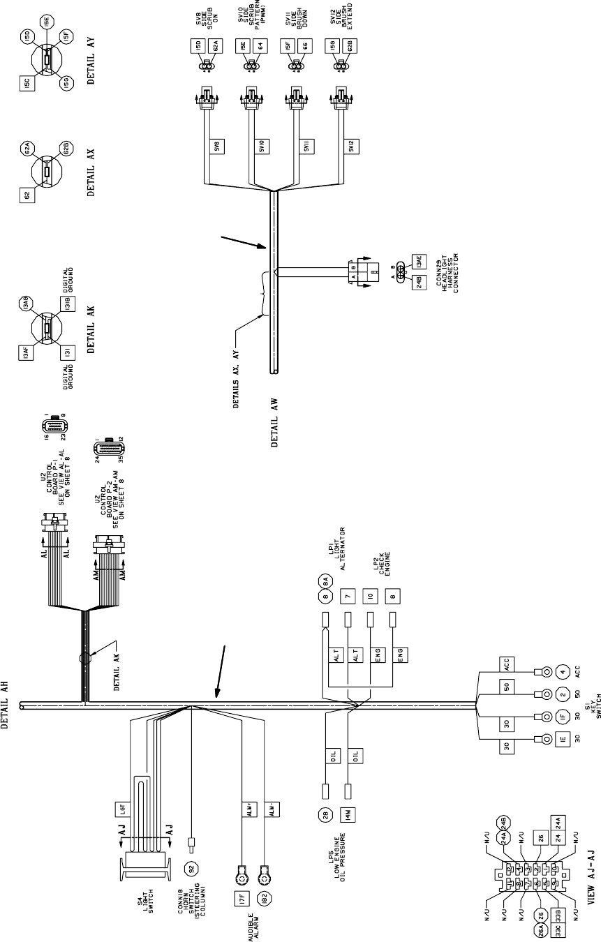
Main Wire Harness
1
1
M20 Electrical Wiring Harness Detail
(Page 5 of 14)
M20 331385 (02-2007)
67
E
NOTE: Refer to the current Operators or Parts Manual for the most up-to-date information
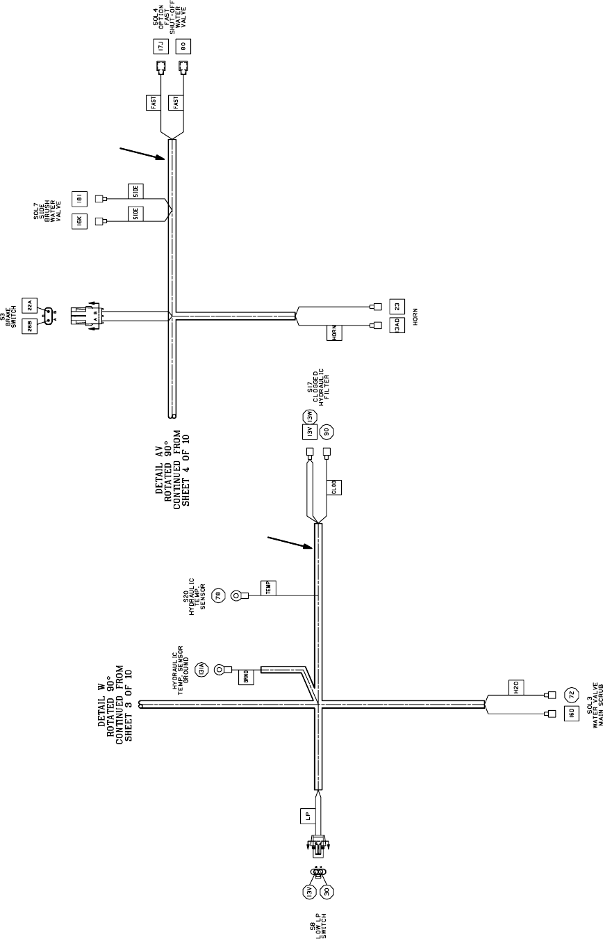
Main Wire Harness
1
1
M20 Electrical Wiring Harness Detail
(Page 6 of 14)
M20 331385 (02-2007)
68
E
NOTE: Refer to the current Operators or Parts Manual for the most up-to-date information
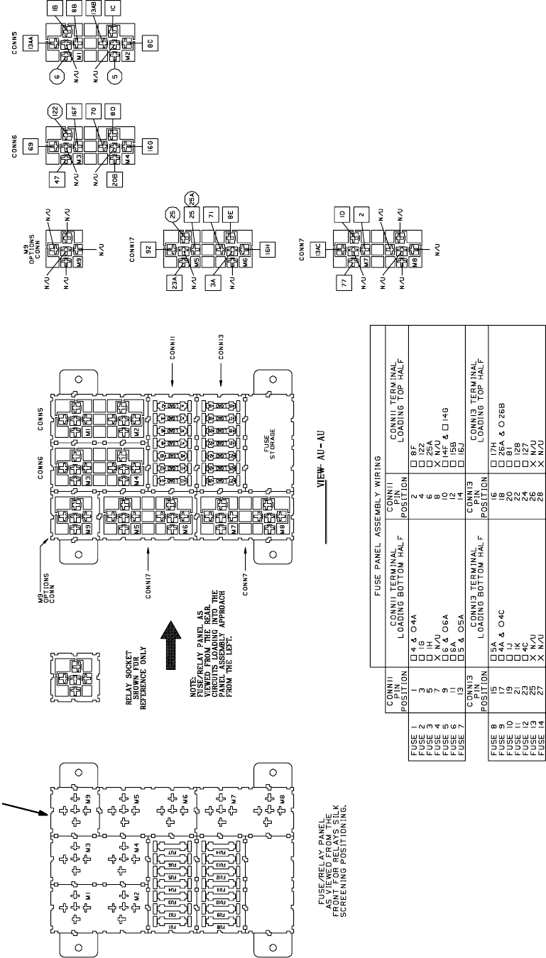
Main Wire Harness
1
M20 Electrical Wiring Harness Detail
(Page 7 of 14)
M20 331385 (02-2007)
69
E
NOTE: Refer to the current Operators or Parts Manual for the most up-to-date information
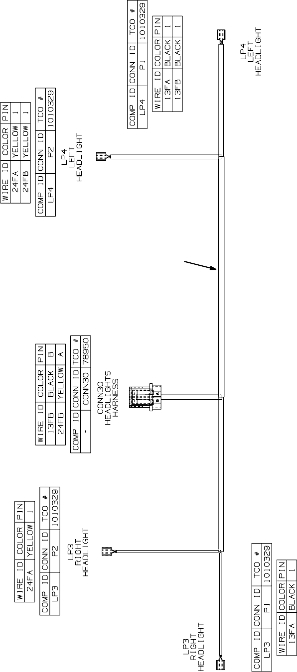
Headlight Wire Harness
2
M20 Electrical Wiring Harness Detail
(Page 8 of 14)
M20 331385 (02-2007)
70
E
NOTE: Refer to the current Operators or Parts Manual for the most up-to-date information
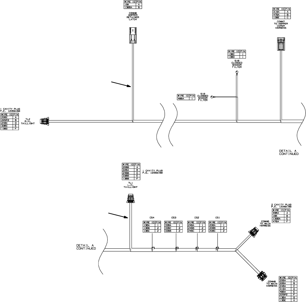
Hopper Wire Harness
M20 Electrical Wiring Harness Detail
(Page 9 of 14)
M20 331385 (02-2007)
71
E
NOTE: Refer to the current Operators or Parts Manual for the most up-to-date information
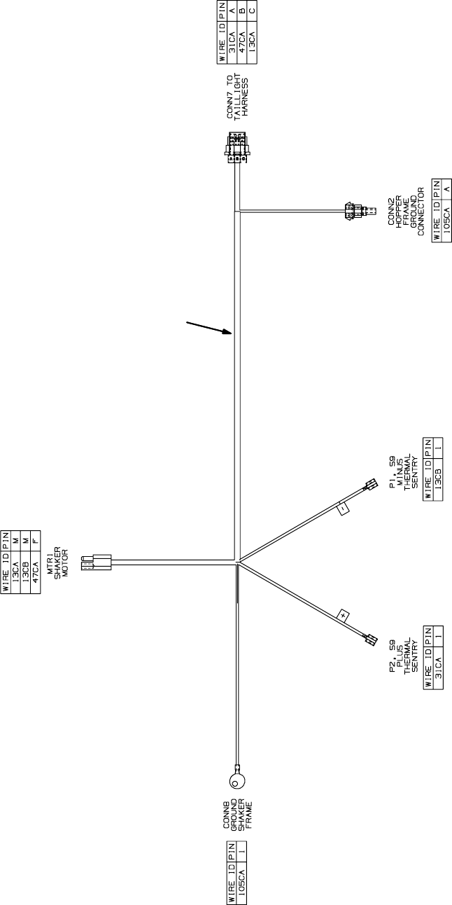
Hopper Cover Wire Harness
4
M20 Electrical Wiring Harness Detail
(Page 10 of 14)
M20 331385 (02-2007)
72
E
NOTE: Refer to the current Operators or Parts Manual for the most up-to-date information
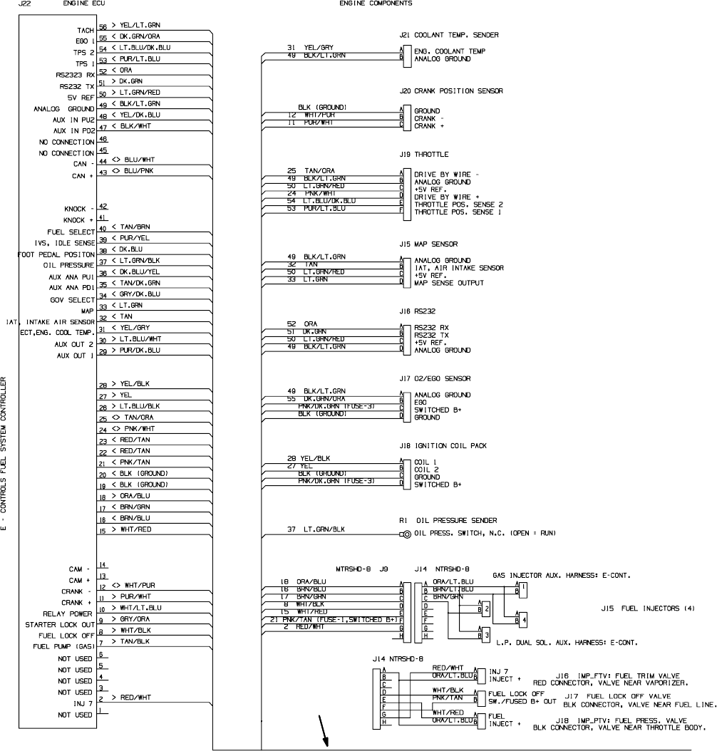
8
1018547
5
M20 Electrical Wiring Harness Detail
(Page 11 of 14)
M20 331385 (02-2007)
73
E
NOTE: Refer to the current Operators or Parts Manual for the most up-to-date information
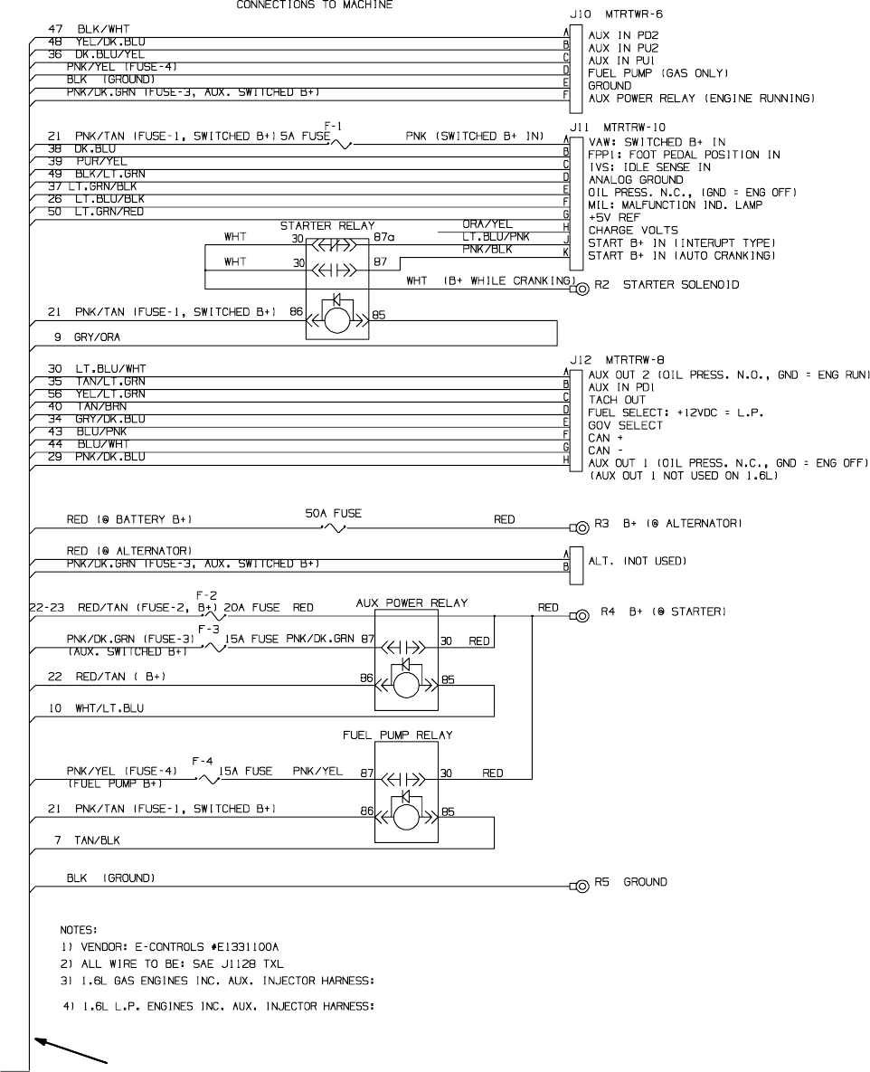
8
1018547
5
M20 Electrical Wiring Harness Detail
(Page 12 of 14)
M20 331385 (02-2007)
74
E
NOTE: Refer to the current Operators or Parts Manual for the most up-to-date information
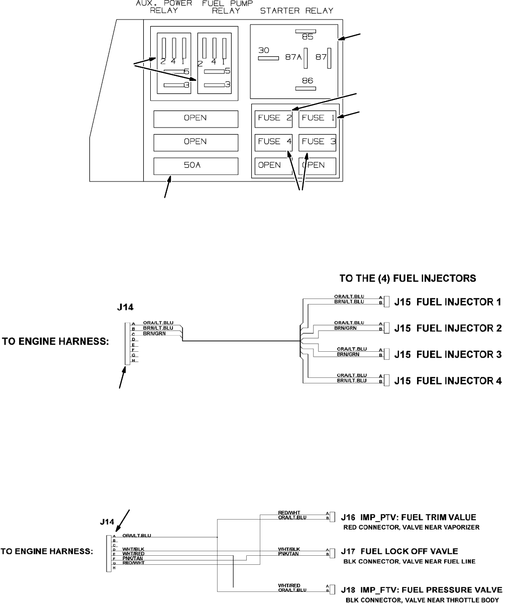
GAS INJECTOR AUX. HARNESS
L.P. DUAL SOL. AUX. HAENESS
8
11
7
10
12
13
6
9
M20 Electrical Wiring Harness Detail
(Page 13 of 14)
M20 331385 (02-2007)
75
E
NOTE: Refer to the current Operators or Parts Manual for the most up-to-date information

354389
Ref. Serial Number Description Qty.
1(000000-- )Harness, Main [M20] 1
2 (000000-- ) Harness, Headlight [M20 And T20] 1
3 (000000-- ) Harness, Hppr [M20] 1
4 (000000-- ) Harness, Hppr, Cover [M20] 1
o5 (000000-- ) Harness, Eng [1.6l, Gm, E--cntrl] 1
Y6(000000-- )Relay, 12vdc, 20a, Spdt 1
Y7 (000000-- ) Relay, 12vdc, 40a, Spdt 2
Y8 (000000-- ) Fuse, 5 Amp, [Min--5] 1
Y9 (000000-- ) Fuse,20Amp,[Min--20] 1
Y10 (000000-- ) Fuse,15Amp,[Min--15] 2
Y11 (000000-- )Fuse, 50amp 1
12 (000000-- ) Harness, Injector, Gas [1.6l,Gm,E--cntrl] 1
13 (000000-- ) Harness, Injector, Lpg [1.6l,Gm,E--cntrl] 1
M20 Electrical Wiring Harness Detail
(Page 14 of 14)
M20 331385 (02-2007)
76
E
NOTE: Refer to the current Operators or Parts Manual for the most up-to-date information
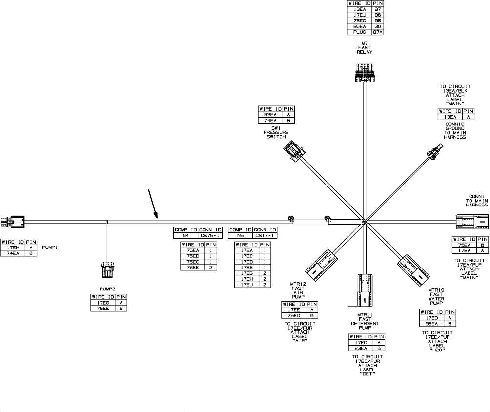
Fast Wire Harness Group
1
1019646
Ref. Serial Number Description Qty.
1(000000-- )Harness [Fast, M20 And T20] 1
M20 Wiring Harness Detail
(Page 15 of 15)
M20 331385 (02-2007)
77
E
NOTE: Refer to the current Operators or Parts Manual for the most up-to-date information
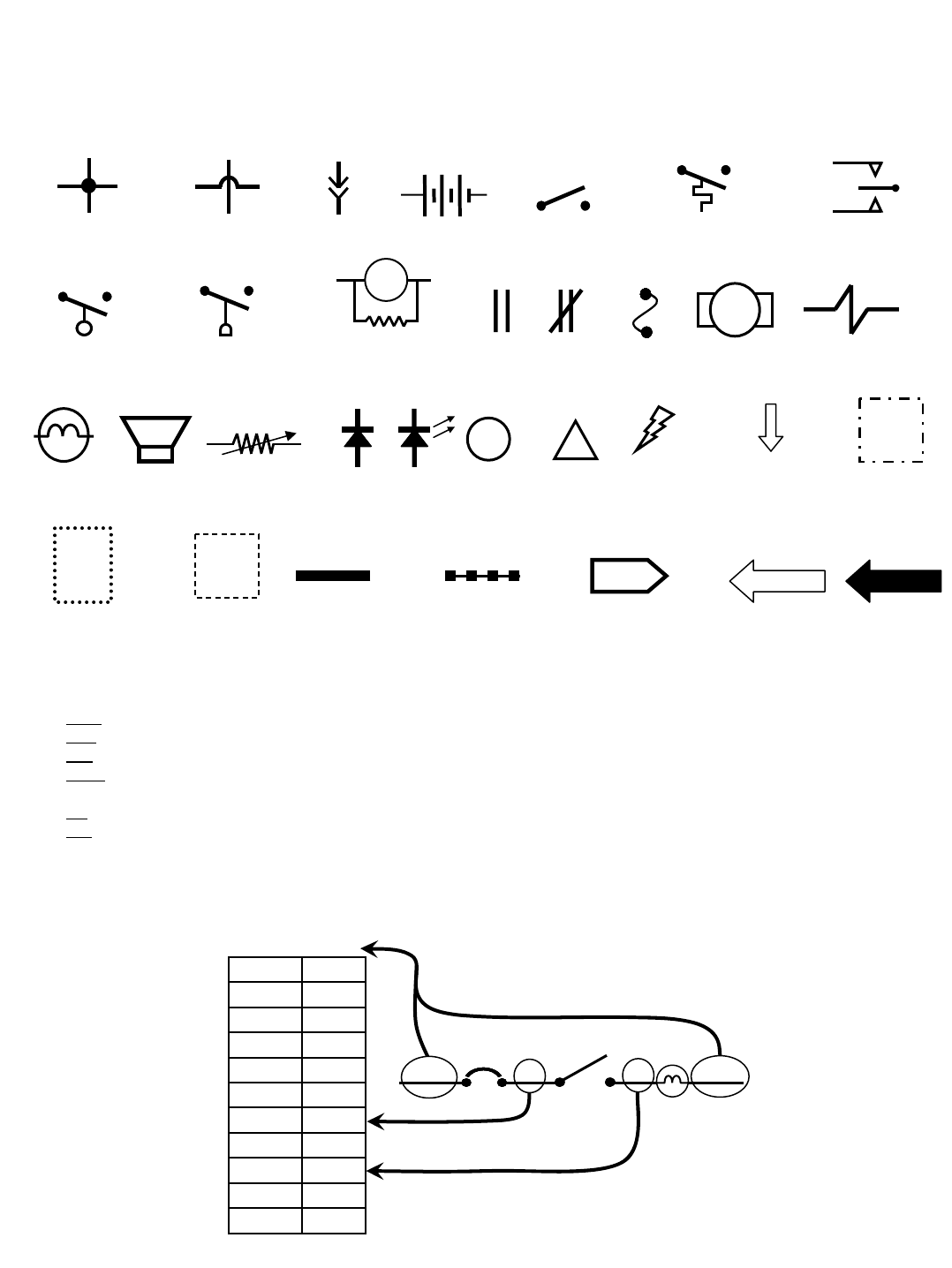
Commonly Used Electrical Symbols & Terms
Example of Wiring Numbers & Colors:
NOTE: The term “NORMALLY” refers to the component’s “at rest” or “de-energized” position
Terms & Abbreviations
ECM – Engine Control Module
LED – Light Emitting Diode
MIL – Malfunction Indicator Lamp
PWM – Pulse Width Modulation (A method of using controlled on/off times to regulate the voltage and current
supplied to an electrical device)
SV – Solenoid Valve
SW –Switch
Wiring Color Codes
(Unless otherwise marked)
0
1
2
3
4
5
6
7
8
9
Tan
Pink
Brown
Orange
Yellow
Green
Blue
Purple
Gray
White
Right Most Digit
of Wire Number Color of Wire
1 RED 25 7 13 BLK
+-
Battery
Fuse
Normally Open
Switch
Motor Solenoid
Valve
Horn or
Alarm
Wires Connected
Together
Component
is Energized
Plug-in
Connection
Diode
Wires Not
Connected
Together
Movement from
Normal Position
Component in Position
Other than Normal
Battery Positive
or Positive Output
Battery Negative
or Logic Ground
LED
Relay Contacts
Open Closed
Information
!
Warning!
Information
Box
Assembly
Normally Open
Liquid Level Switch
Lamp
(Light Bulb)
M2A
Relay Coil with spike
suppression resistor
Normally Open
Temperature Switch
Normally Open
Pressure Switch
Sensor
(Variable Resistor)
Connection TO or
FROM Another Point
Normally Open
Momentary Switch
PIN P2-11 PIN P2-35
Control
Board Input
Control
Board Output
OFF
i
M20 331385 (02-2007)
78
E
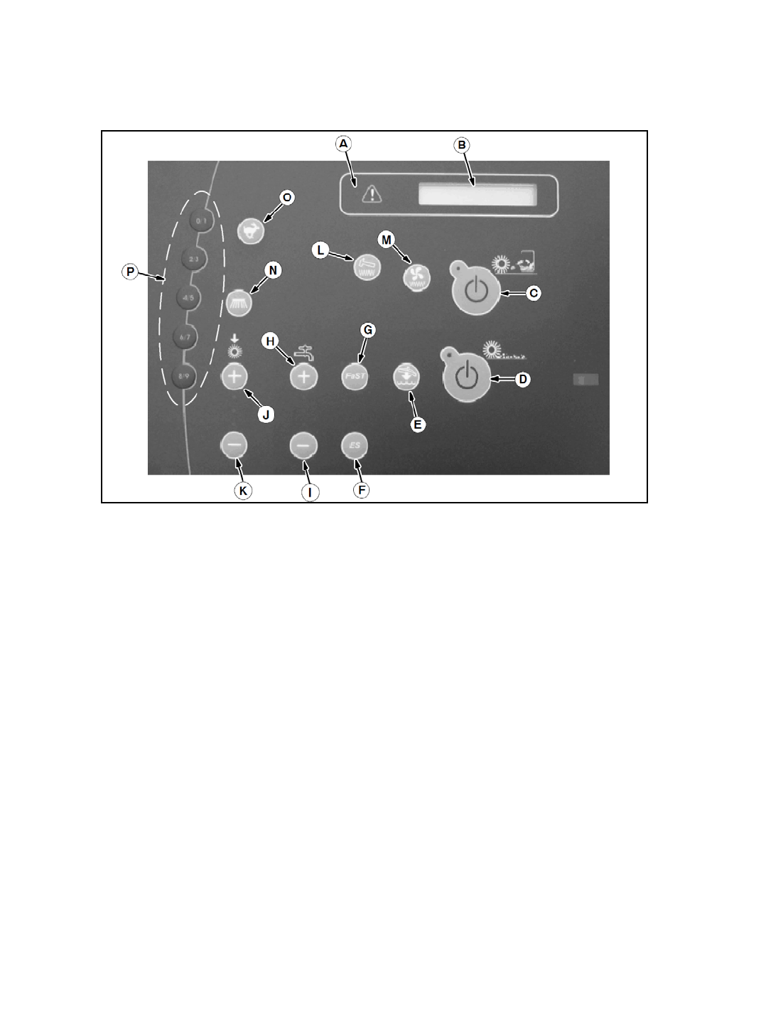
M20 Touch Panel Detail
A. Fault indicator light
B. Hour meter / fuel indicator / fault code indicator
C. 1-STEP sweep button
D. 1-STEP scrub button
E. Scrub vacuum fan / squeegee button
F. ES (Extended Scrub) button (option)
G. FaST button (option)
H. Solution & detergent increase button (+)
I. Solution & detergent decrease button (-)
J. Brush pressure increase button (+)
K. Brush pressure decrease button (-)
L. Filter shaker button
M. Sweep vacuum fan button
N. Side brush button
O. Engine speed button
P. Supervisor control buttons
M20 331385 (02-2007)
79
E
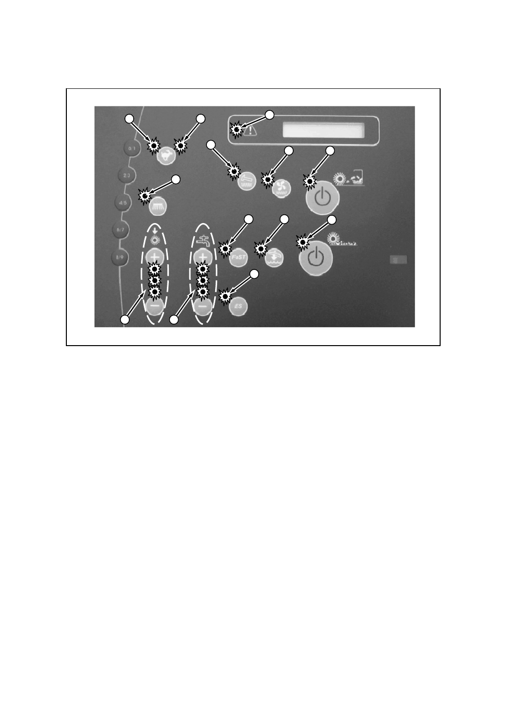
M20 Touch Panel LED’s Detail
A B
GF
D
H I
M
E
K L
J
C
A. Low Engine Speed Indicator
B. High Engine Speed Indicator
C. Fault/Condition Indicator
D. Side Brush ON Indicator
E. Filter Shaker ON Indicator
F. Sweeping Vacuum Fan ON Indicator
G. 1-STEP Sweep ON Indicator
H. FaST System ON Indicator
I. Scrubbing Vacuum Fan ON & Squeegee System ON Indicator
J. 1-STEP Scrub ON Indicator
K. Brush Pressure Indicators (1 LED=Low, 2 LED’s=Medium, 3 LED’s=High)
L. Solution Volume Indicators (1 LED=Low, 2 LED’s=Medium, 3 LED’s=High)
M. ES (Extended Scrub) System ON Indicator
M20 331385 (02-2007)
80
E
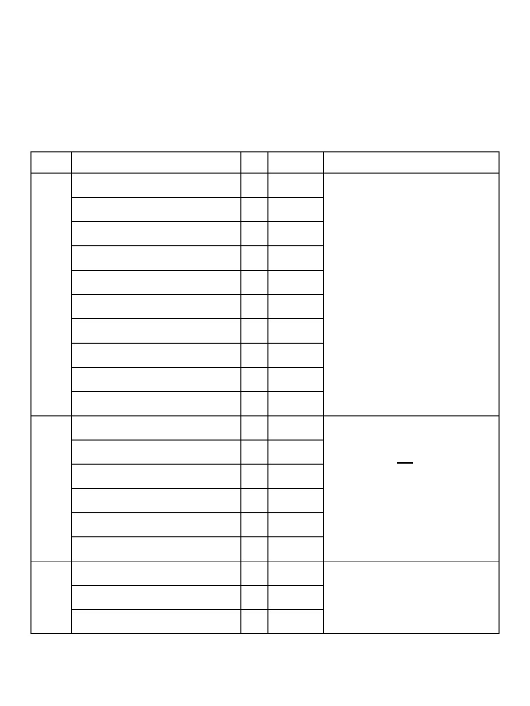
M20 Option Components
E = Electrical Component
H = Hydraulic Component
The following chart lists various options and the electrical and/or hydraulic components
that are associated with the option. Refer to the “notes” section for any components that
are deleted from a standard machine in order to have the installed option.
option added components E or H component # notes
Side Brush ON Solenoid Valve E,H SV-8
Side Brush Pressure Solenoid Valve E,H SV-10
Side Brush Down Solenoid Valve E,H SV-11
Side Brush Extend Solenoid Valve E,H SV-12
FaST Side Brush Valve ESOL-6
Side Brush Water Valve ESOL-7
Side Brush Manifold Hx
Side Brush Lift Cylinder Hx
Side Brush Extend Cylinder Hx
Side Brush Motor Hx
Solution Tank Auto Fill Water Valve ESOL-1
Recovery Tank Auto Fill Water Valve ESOL-2
Solution Tank Full Switch ES-14
Recovery Tank Half Full Switch ES-16
Detergent Pump Ex
ES Pump Ex
Spray Hose Pump Ex
Spray Hose Relay EM12
Spray Hose Switch ES-25
ES
(Extended Scrub)
If machine has ES option, the following
components will not be on the
machine: FaST Water Pump, FaST
Water Pump Relay (M11), FaST
Detergent Pump, FaST Air Pump,
FaST Enable Valve (SOL-4), FaST
High Flow Valve (SOL-5), FaST Side
Brush Valve (SOL-6)
Spray
Hose Side Brush
M20 331385 (02-2007)
81
E
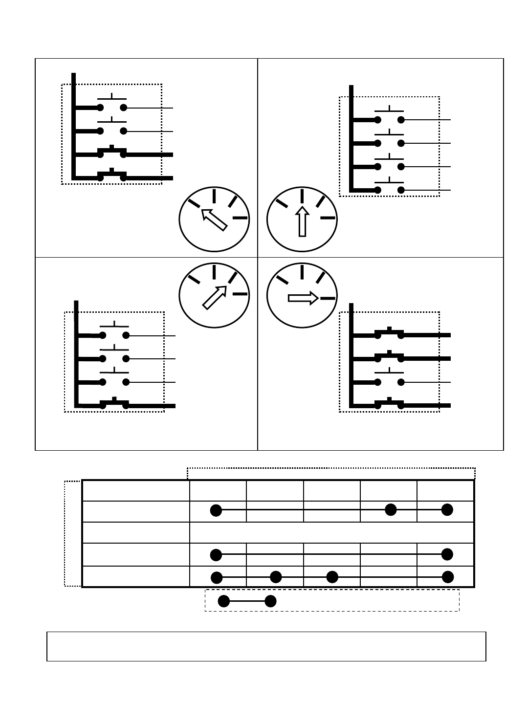
M20 Key Switch
ACC
START
RUN
NO CONNECTIONSOFF
GLOW PLUG
19175030
SWITCH TERMINAL MARKING
KEY SWITCH POSITION
NOTE: Common connections in various switch positions should be less than 1ȍ
“ . “ Indicates a common connection
30
17
19
ACC
50
RUN POSITION
30
17
19
ACC
50
START POSITION
Spring loaded-Returns to “RUN" unless held
Glow
Plug
START
RUN
OFF
KEY SWITCH
Glow
Plug START
RUN
OFF
KEY SWITCH
30
17
19
ACC
50
OFF POSITION
Glow
Plug START
RUN
OFF
KEY SWITCH
30
17
19
ACC
50
GLOW PLUG POSITION
(Diesel Only)
Spring loaded- Returns
to "OFF" unless held
Glow
Plug START
RUN
OFF
KEY SWITCH
M20 331385 (02-2007)
82
E
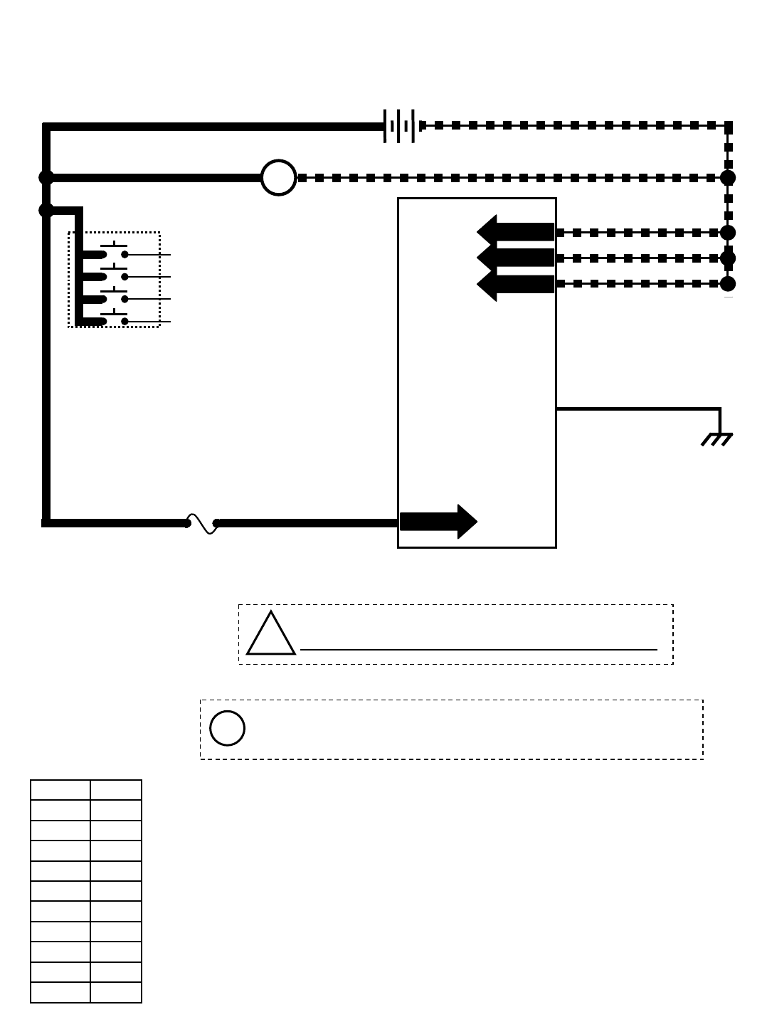
M20 Key OFF Power Distribution
81
1/RED 13/BLK
13/BLK
13/BLK
13/BLK
+-
12 VDC
+ -
ALTERNATOR
Touch Panel / Control Board
FUSE 10
15 AMP
GREEN JUMPER WIRE1/RED
1/RED
1/RED
81
Wiring Color Codes
(Unless otherwise marked)
0
1
2
3
4
5
6
7
8
9
Tan
Pink
Brown
Orange
Yellow
Green
Blue
Purple
Gray
White
Right Most Digit
of Wire Number Color of Wire
!Be cautious when working near Control Board -
Battery voltage is always present, even with Key OFF
PIN P2-33
PIN P2-34
PIN P2-35
PIN P2-3
PIN P1-23
STATIC
GROUND
105
Pin P2-3 supplies power to the on-board clock only.
Disconnecting battery, removing Fuse 10, or removing connector
P2 from Control Board will require the clock to be reset.
KEY SWITCH
OFF
Conditions: Key off
i
M20 331385 (02-2007)
83
E
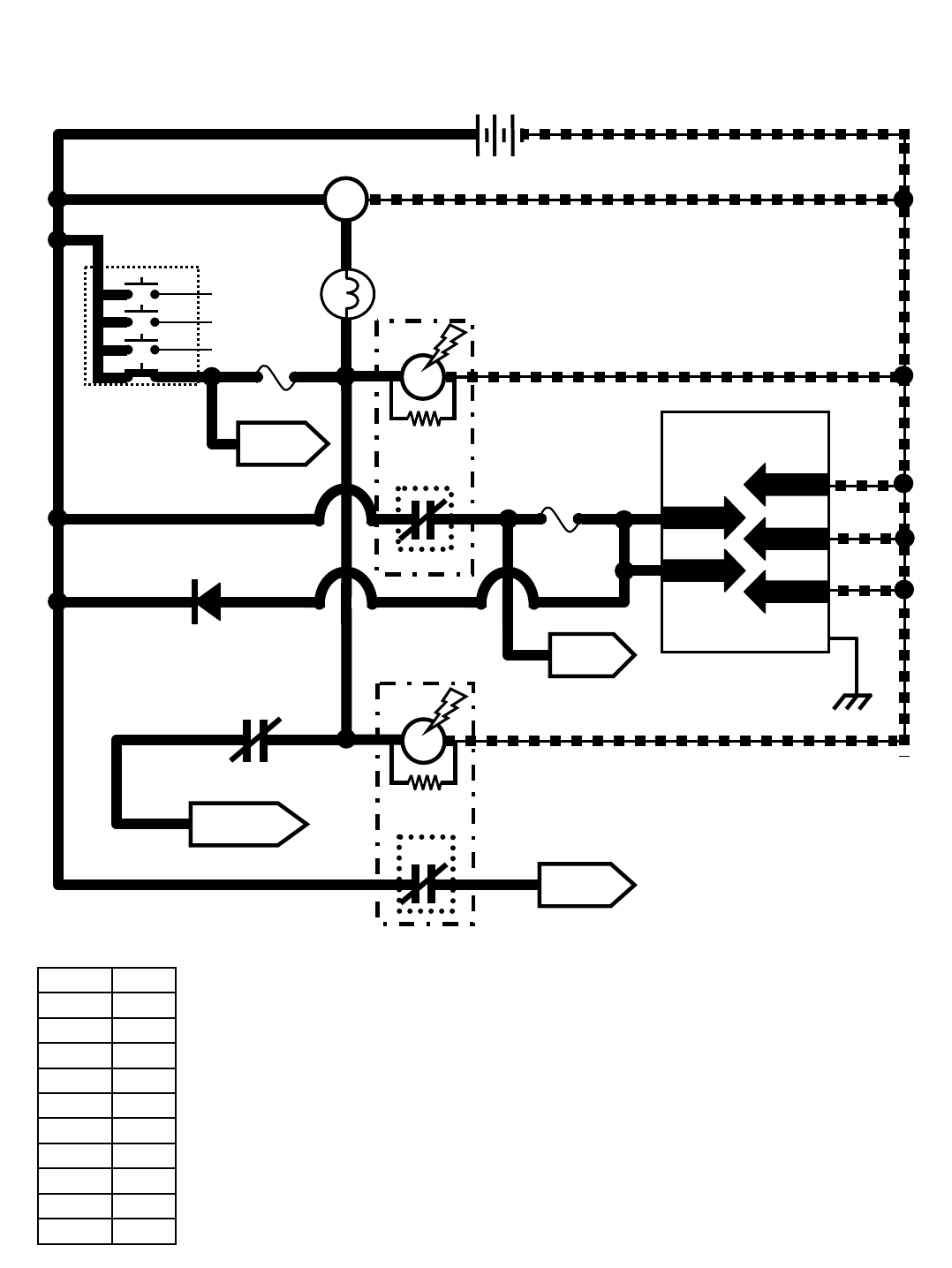
M20 Key ON Power Distribution
1/RED 13/BLK
13/BLK
13/BLK
13/BLK
+-
12 VDC
KEY SWITCH
RUN
+ -
ALTERNATOR
Touch Panel /
Control Board
GREEN JUMPER WIRE1/RED
1/RED
FUSE 5
15 AMP
4
TO ENGINE
HARNESS
1/RED1/RED 6
PIN P2-33
PIN P2-34
PIN P2-35
PIN P1-23
STATIC
GROUND
105
Wiring Color Codes
(Unless otherwise marked)
0
1
2
3
4
5
6
7
8
9
Tan
Pink
Brown
Orange
Yellow
Green
Blue
Purple
Gray
White
Right Most Digit
of Wire Number Color of Wire
TO FUSES
7 & 8
SHUTDOWN RELAY
CONTACTS
(Normally CLOSED)
3
8
8
813/BLK
13/BLK
M6C
TO FUSE
6
1/RED
14
5
1/RED
FUSE 1
15 AMP
PIN P2-1
PIN P2-2
ALTERNATOR
LAMP
M1B
AUX. 1
RELAY
M1A
7
8
3
8
6
14
13/BLK
13/BLK
86 85
30 87
M2B
AUX. 2
RELAY
M2A
86 85
30 87
4
14
D-2
14 14
Conditions: Key on, engine off
TO FUSES
9 &12
1/RED
M20 331385 (02-2007)
84
E
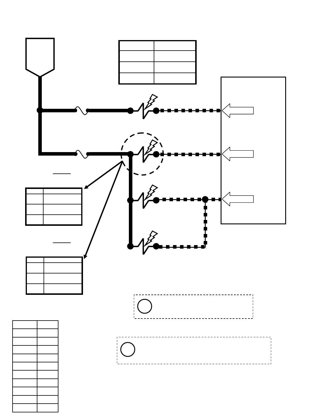
M20 Main Brushes ON
614
Touch Panel / Control Board
61
FUSE 6
15 AMP
FUSE 5
15 AMP
6
14
14
15
57
58
SV-7
SV-2
SV-3
SV-6
ENABLE VALVE
BRUSH HEAD
PRESSURE
MAIN BRUSHES
LOWER
MAIN BRUSHES
ROTATE 58
PWM
SV-2 is controlled by PWM; A higher duty cycle
(more Brush Pressure LED’s lit on Touch
Panel) will result in more brush down pressure
BATTERY
POSITIVE
FROM
AUX 1
RELAY
CONTACTS
PIN P2-8
PIN P2-4
PIN P2-5
Wiring Color Codes
(Unless otherwise marked)
0
1
2
3
4
5
6
7
8
9
Tan
Pink
Brown
Orange
Yellow
Green
Blue
Purple
Gray
White
Right Most Digit
of Wire Number Color of Wire
Max Amp DrawComponent
1.7 ASV-7
1.7 ASV-6
1.7 ASV-3
490 mA
395 mA
285 mA
SV-2 Amp Draw
P3
P2
P1
Setting
Typical Default
Amp Draw Readings (+/- 10%)
(SCRUBBING)
290 mA
255 mA
180 mA
SV-2 Amp Draw
P3
P2
P1
Setting
Typical Default
Amp Draw Readings (+/- 10%)
(SWEEPING)
Pressure settings P1, P2, & P3 are
the Touch Panel LED indicators
for Brush down pressure
Conditions: Key on, engine running, scrubbing or sweeping system on, propel forward or reverse
i
i
M20 331385 (02-2007)
85
E
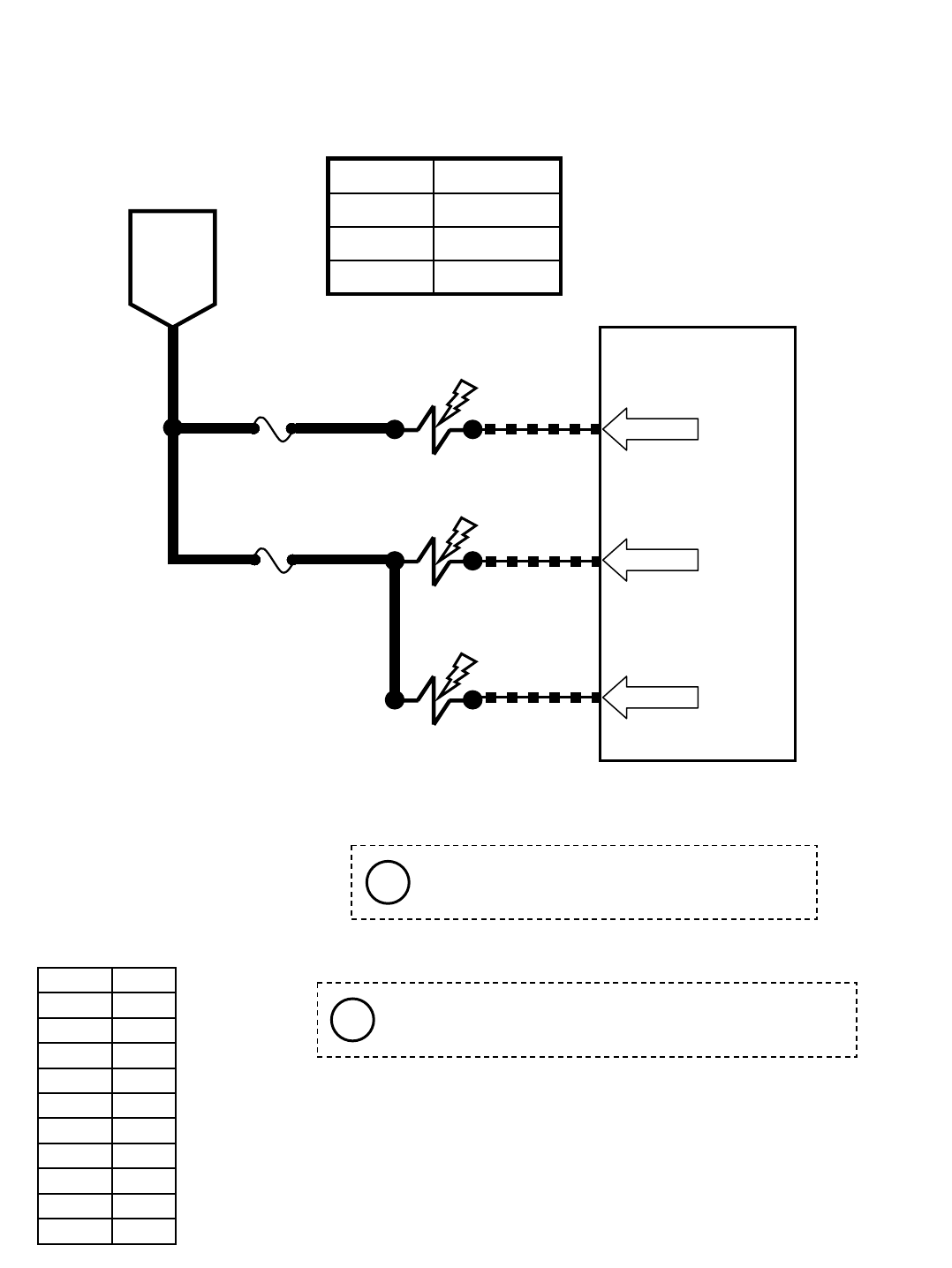
614
Touch Panel / Control Board
61
FUSE 6
15 AMP
FUSE 5
15 AMP
6
14
15
56
59
SV-7
SV-1
SV-4
ENABLE
VALVE
SCRUB
VACUUM
FAN ON
SIDE & REAR
SQUEEGEES
LOWER
M20 Scrub Vacuum Fan ON & Squeegees DOWN
BATTERY
POSITIVE
FROM
AUX 1
RELAY
CONTACTS
PIN P2-8
PIN P2-28
PIN P2-6
Wiring Color Codes
(Unless otherwise marked)
0
1
2
3
4
5
6
7
8
9
Tan
Pink
Brown
Orange
Yellow
Green
Blue
Purple
Gray
White
Right Most Digit
of Wire Number Color of Wire
Reverse propel will turn OFF SV-4 (Pin P2-6)
and raise the side and rear squeegees.
Any condition that cancels the scrub functions will also
turn OFF the scrub vacuum fan and raise squeegees.
Max Amp DrawComponent
1.7 ASV-7
1.7 ASV-4
1.7 ASV-1
Conditions: Key on, engine running, scrubbing system & scrub vacuum on, propel forward
i
i
M20 331385 (02-2007)
86
E
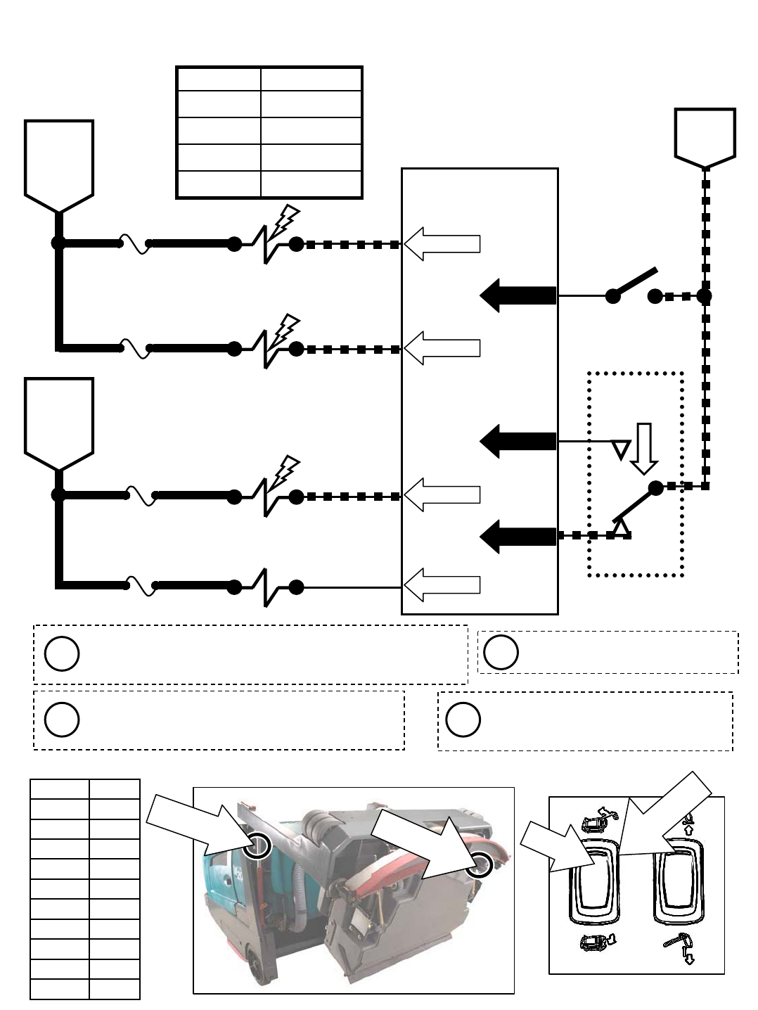
614
Touch Panel / Control Board
61
FUSE 6
15 AMP
FUSE 5
15 AMP
615
SV-7
SV-14
SV-13
ENABLE
VALVE
HOPPER
LIFT
HOPPER
LOWER
M20 Hopper LIFT
5FUSE 8
15 AMP
S-6
HOPPER DOWN
SENSE SWITCH
60
53
17
OPEN = UP
CLOSED = DOWN
S-5
2
1
4
HOPPER
LIFT/LOWER
SWITCH
1&2 CLOSED = LIFT
2&4 CLOSED = LOWER
35
36
13/BLK
13/BLK89
BATTERY
POSITIVE
FROM
AUX 1
RELAY
CONTACTS
BATTERY
NEGATIVE
BATTERY
POSITIVE
FROM
AUX 2
RELAY
CONTACTS
PIN P2-8
PIN P2-7
PIN P2-31
PIN P1-3
PIN P1-7
PIN P1-8
HOPPER
LATCH
5FUSE 7
15 AMP
138
16 PIN P2-32
SOL-9
HOPPERLIFT/
LOWER SWITCH
PUSH
TOLIFT
Wiring Color Codes
(Unless otherwise marked)
0
1
2
3
4
5
6
7
8
9
Tan
Pink
Brown
Orange
Yellow
Green
Blue
Purple
Gray
White
Right Most Digit
of Wire Number Color of Wire
OFF
Activating the Hopper Lift/Lower Switch will
cancel the sweep or scrub systems and
automatically selects HIGH engine speed
Hopper Latch solenoid (SOL-9) turns
ON for 3 to 5 seconds with each
activation of Hopper Lift Switch
If hopper is in the fully DOWN position when activating
Hopper Lift, the Hopper Lower Valve (SV-13) is
momentarily turned ON to help “jog” the hopper latch
HOPPERLATCH
SOLENOID
HOPPERDOWN
SENSESWITCH
Hopper Latch solenoid (SOL-9)
is an electro-mechanical device
Max Amp DrawComponent
1.7 ASV-14
1.7 ASV-13
1.7 ASV-9
1.7 ASV-7
Conditions: Key on, engine running, hopper lift switch activated
i
i
i
i
M20 331385 (02-2007)
87
E
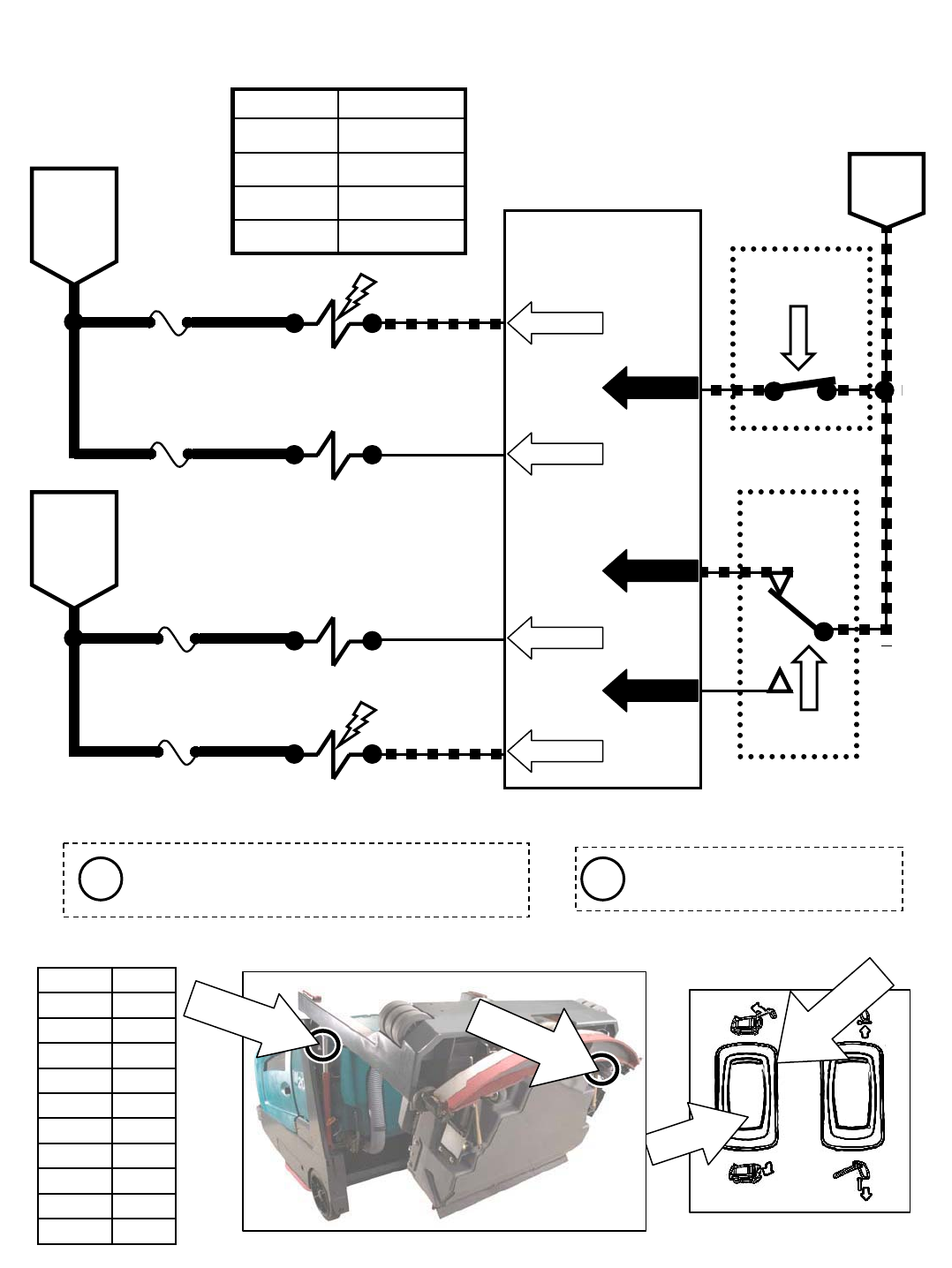
M20 Hopper LOWER
S-6
HOPPER DOWN
SENSE SWITCH
OPEN = UP
CLOSED = DOWN
89 13/BLK
BATTERY
NEGATIVE
Wiring Color Codes
(Unless otherwise marked)
0
1
2
3
4
5
6
7
8
9
Tan
Pink
Brown
Orange
Yellow
Green
Blue
Purple
Gray
White
Right Most Digit
of Wire Number Color of Wire
S-5
2
1
4
HOPPER
LIFT/LOWER
SWITCH
1&2 CLOSED = LIFT
2&4 CLOSED = LOWER
35
36
13/BLK
OFF
Activating the Hopper Lift/Lower Switch will
cancel the sweep or scrub systems and
automatically selects HIGH engine speed
614
Touch Panel / Control Board
61
FUSE 6
15 AMP
FUSE 5
15 AMP
615
SV-7
SV-14
SV-13
ENABLE
VALVE
HOPPER
LIFT
HOPPER
LOWER
5FUSE 8
15 AMP
60
53
17
BATTERY
POSITIVE
FROM
AUX 1
RELAY
CONTACTS
BATTERY
POSITIVE
FROM
AUX 2
RELAY
CONTACTS
PIN P2-8
PIN P2-7
PIN P2-31
PIN P1-3
PIN P1-7
PIN P1-8
HOPPER
LATCH
5FUSE 7
15 AMP
138
16 PIN P2-32
SOL-9
HOPPERLIFT/
LOWER SWITCH
PUSH
TOLOWER
Hopper Latch solenoid (SOL-9)
is an electro-mechanical device
Max Amp DrawComponent
1.7 ASV-14
1.7 ASV-13
1.7 ASV-9
1.7 ASV-7
Conditions: Key on, engine running, hopper lower switch activated
i i
HOPPERLATCH
SOLENOID
HOPPERDOWN
SENSESWITCH
M20 331385 (02-2007)
88
E
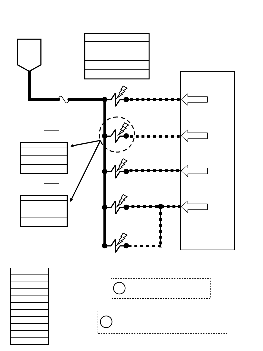
M20 Side Brush ON
Touch Panel / Control Board
61
FUSE 6
15 AMP
6
15
15
15
64
62
SV-7
SV-10
SV-8
SV-12
ENABLE VALVE
SIDE
BRUSH
PRESSURE
SIDE
BRUSH RUN
SIDE
BRUSH EXTEND
62
PWM
BATTERY
POSITIVE
FROM
AUX 1
RELAY
CONTACTS
15
66
SIDE
BRUSH DOWN
SV-11
PIN P2-8
PIN P2-11
PIN P2-9
PIN P2-12
15
SV-10 is controlled by PWM; A higher duty cycle
(more Brush Pressure LED’s lit on Touch
Panel) will result in more brush down pressure
Wiring Color Codes
(Unless otherwise marked)
0
1
2
3
4
5
6
7
8
9
Tan
Pink
Brown
Orange
Yellow
Green
Blue
Purple
Gray
White
Right Most Digit
of Wire Number Color of Wire
Max Amp DrawComponent
1.7 ASV-12
1.7 ASV-11
1.7 ASV-8
1.7 ASV-7
715 mA
625 mA
530 mA
SV-10 Amp Draw
P3
P2
P1
Setting
Typical Default
Amp Draw Readings (+/- 10%)
(SCRUBBING)
615 mA
540 mA
500 mA
SV-10 Amp Draw
P3
P2
P1
Setting
Typical Default
Amp Draw Readings (+/- 10%)
(SWEEPING)
Pressure settings P1, P2, & P3 are
the Touch Panel LED indicators
for Brush down pressure
Conditions: Key on, engine running, scrubbing or sweeping system on, side brush on, propel forward or reverse
i
i
M20 331385 (02-2007)
89
E
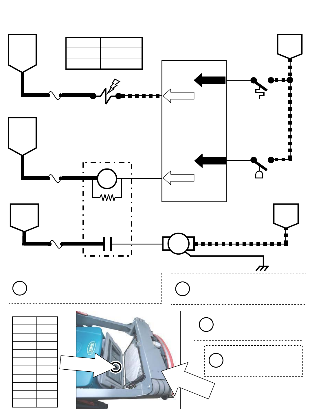
1221/RED FUSE 2
48
Touch Panel / Control Board
M20 Sweep Vacuum Fan ON
BATTERY
POSITIVE
FROM
AUX 1
RELAY
CONTACTS
15 63
SV-9
6FUSE 6
15 AMP
SWEEP
VACUUM
FAN RUN
S-9
HOPPER
THERMAL
SENTRY
SWITCH
OPEN = BELOW 140°F
CLOSED = ABOVE 140°F
31
13/BLK
13/BLK
BATTERY
NEGATIVE
OPEN = FILTER OK
CLOSED = FILTER CLOGGED
S-18
SWEEP FILTER
CLOGGED
SWITCH
UN-
SWITCHED
BATTERY
POSITIVE
16
5FUSE 7
15 AMP
BATTERY
POSITIVE
FROM
AUX 2
RELAY
CONTACTS
BATTERY
NEGATIVE
69
M3B
SHAKER
RELAY SHAKER
MOTOR
47 13/BLK
15 AMP
PIN P2-10
PIN P2-16
PIN P1-16
PIN P1-5
STATIC GROUND
Wiring Color Codes
(Unless otherwise marked)
0
1
2
3
4
5
6
7
8
9
Tan
Pink
Brown
Orange
Yellow
Green
Blue
Purple
Gray
White
Right Most Digit
of Wire Number Color of Wire
If the shaker system is manually selected when
Sweep Vacuum Fan is ON, the fan is turned
OFF during the shaker cycle, and turned back
ON when shaker cycle is complete
If the Hopper Thermal
Sentry Switch closes (above
140°F in hopper), all sweep
functions are cancelled.
A short shaker cycle is
automatically performed
each time the Sweep
Vacuum is turned OFF
If Sweep Filter Clogged Switch closes
(restriction in filter), a fault condition will
be displayed, but vacuum fan will
continue operating normally.
SWEEPFILTER
CLOGGEDSWITCH
(BEHINDBUMPER)
HOPPERTHERMAL
SENTRYSWITCH
M3A
86 85
30 87
Max Amp DrawComponent
1.7 ASV-9
200 mAM3A
Conditions: Key on, engine running, sweeping system and/or sweep vacuum fan on
ii
i
i
M20 331385 (02-2007)
90
E
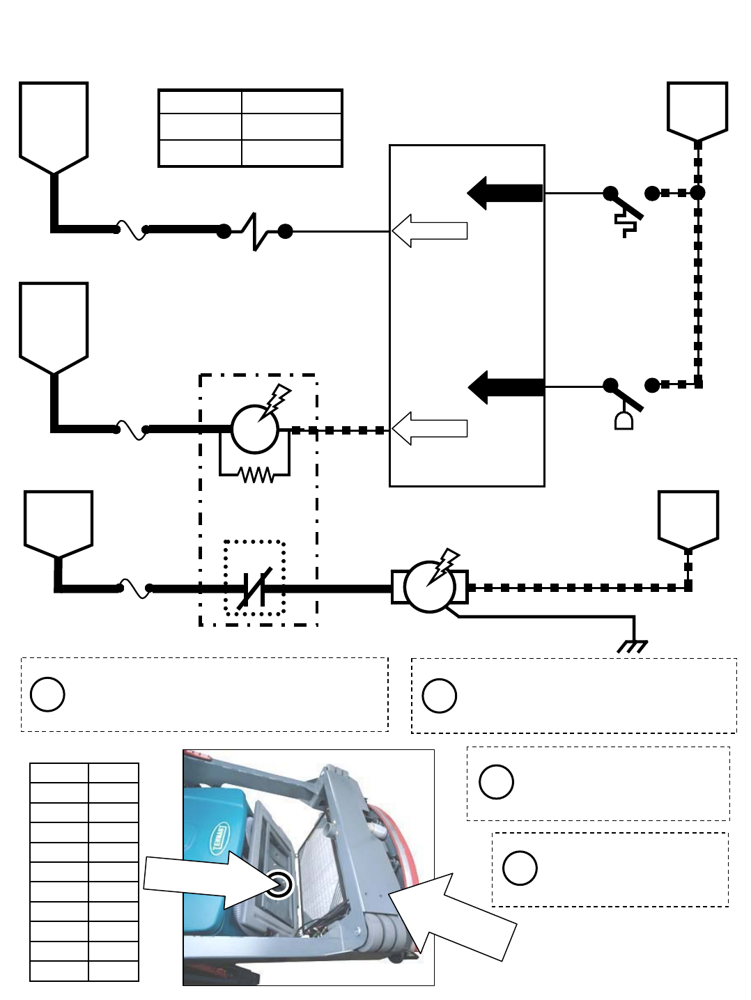
1221/RED FUSE 2
48
Touch Panel / Control Board
BATTERY
POSITIVE
FROM
AUX 1
RELAY
CONTACTS
15 63
SV-9
6FUSE 6
15 AMP
SWEEP
VACUUM
FAN RUN
S-9
HOPPER
THERMAL
SENTRY
SWITCH
OPEN = BELOW 140°F
CLOSED = ABOVE 140°F
31
13/BLK
13/BLK
BATTERY
NEGATIVE
OPEN = FILTER OK
CLOSED = FILTER CLOGGED
S-18
SWEEP FILTER
CLOGGED
SWITCH
UN-
SWITCHED
BATTERY
POSITIVE
16
5FUSE 7
15 AMP
BATTERY
POSITIVE
FROM
AUX 2
RELAY
CONTACTS
BATTERY
NEGATIVE
69
SHAKER
RELAY
SHAKER
MOTOR
47 13/BLK
15 AMP
PIN P2-10
PIN P2-16
PIN P1-16
PIN P1-5
STATIC GROUND
M3B
M20 Shaker Motor ON
Wiring Color Codes
(Unless otherwise marked)
0
1
2
3
4
5
6
7
8
9
Tan
Pink
Brown
Orange
Yellow
Green
Blue
Purple
Gray
White
Right Most Digit
of Wire Number Color of Wire
If the shaker system is manually selected when
Sweep Vacuum Fan is ON, the fan is turned
OFF during the shaker cycle, and turned back
ON when shaker cycle is complete
If the Hopper Thermal
Sentry Switch closes (above
140°F in hopper), all sweep
functions are cancelled.
A short shaker cycle is
automatically performed
each time the Sweep
Vacuum is turned OFF
If Sweep Filter Clogged Switch closes
(restriction in filter), a fault condition will
be displayed, but vacuum fan will
continue operating normally.
M3A
86 85
30 87
Max Amp DrawComponent
1.7 ASV-9
200 mAM3A
Conditions: Key on, One-Step sweeping turned off or shaker system on
ii
i
i
SWEEPFILTER
CLOGGEDSWITCH
(BEHINDBUMPER)
HOPPERTHERMAL
SENTRYSWITCH
M20 331385 (02-2007)
91
E
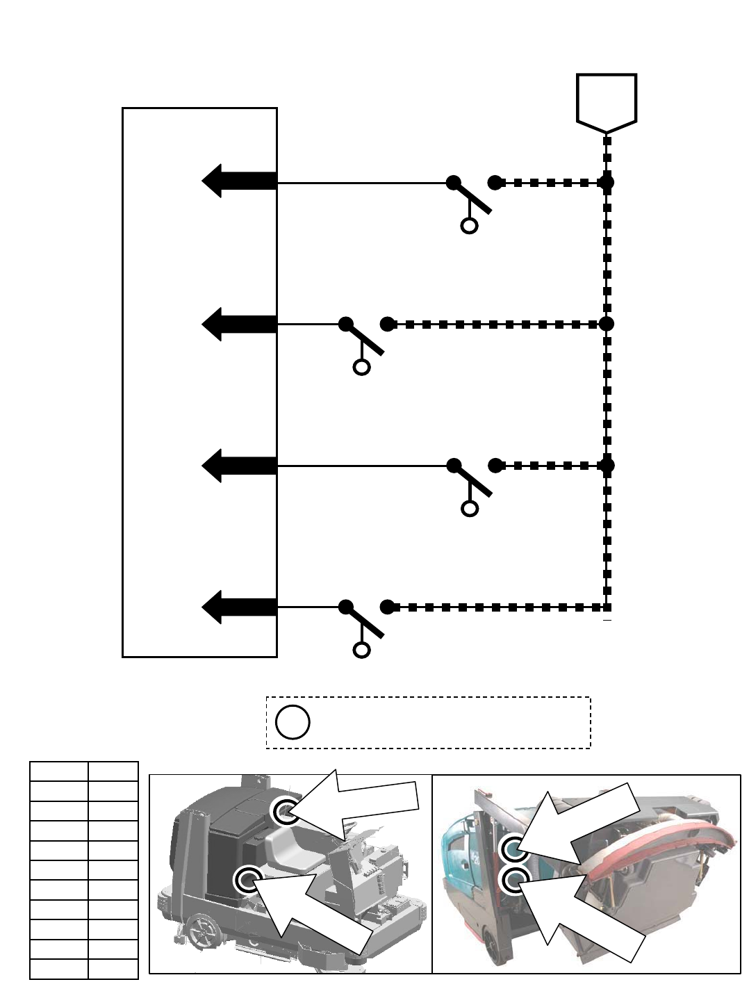
Touch Panel / Control Board
M20 Float Switches
OPEN = EMPTY
CLOSED = NOT EMPTY
46
177 13/BLK
BATTERY
NEGATIVE
PIN P1-11
PIN P1-12
PIN P1-14
45
PIN P1-13
13/BLK
13/BLK
13/BLK
44
OPEN = NOT FULL
CLOSED = FULL
OPEN = LESS THAN HALF FULL
CLOSED = HALF FULL OR MORE
OPEN = NOT FULL
CLOSED = FULL
RECOVERY TANK
HALF FULL SWITCH
S-16
S-15
RECOVERY TANK
FULL SWITCH
S-14
SOLUTION TANK
FULL SWITCH
S-19
SOLUTION TANK
EMPTY SWITCH
Wiring Color Codes
(Unless otherwise marked)
0
1
2
3
4
5
6
7
8
9
Tan
Pink
Brown
Orange
Yellow
Green
Blue
Purple
Gray
White
Right Most Digit
of Wire Number Color of Wire
RECOVERYT
ANK
FULLS
WITCH
RECOVERYTANK
HALF FULLSWITCH
SOLUTIONTANK
EMPTYS
WITCH
SOLUTIONTANK
FULLSWITCH
The Float Switches must be closed for
5 seconds before any output is affected
i
M20 331385 (02-2007)
92
E
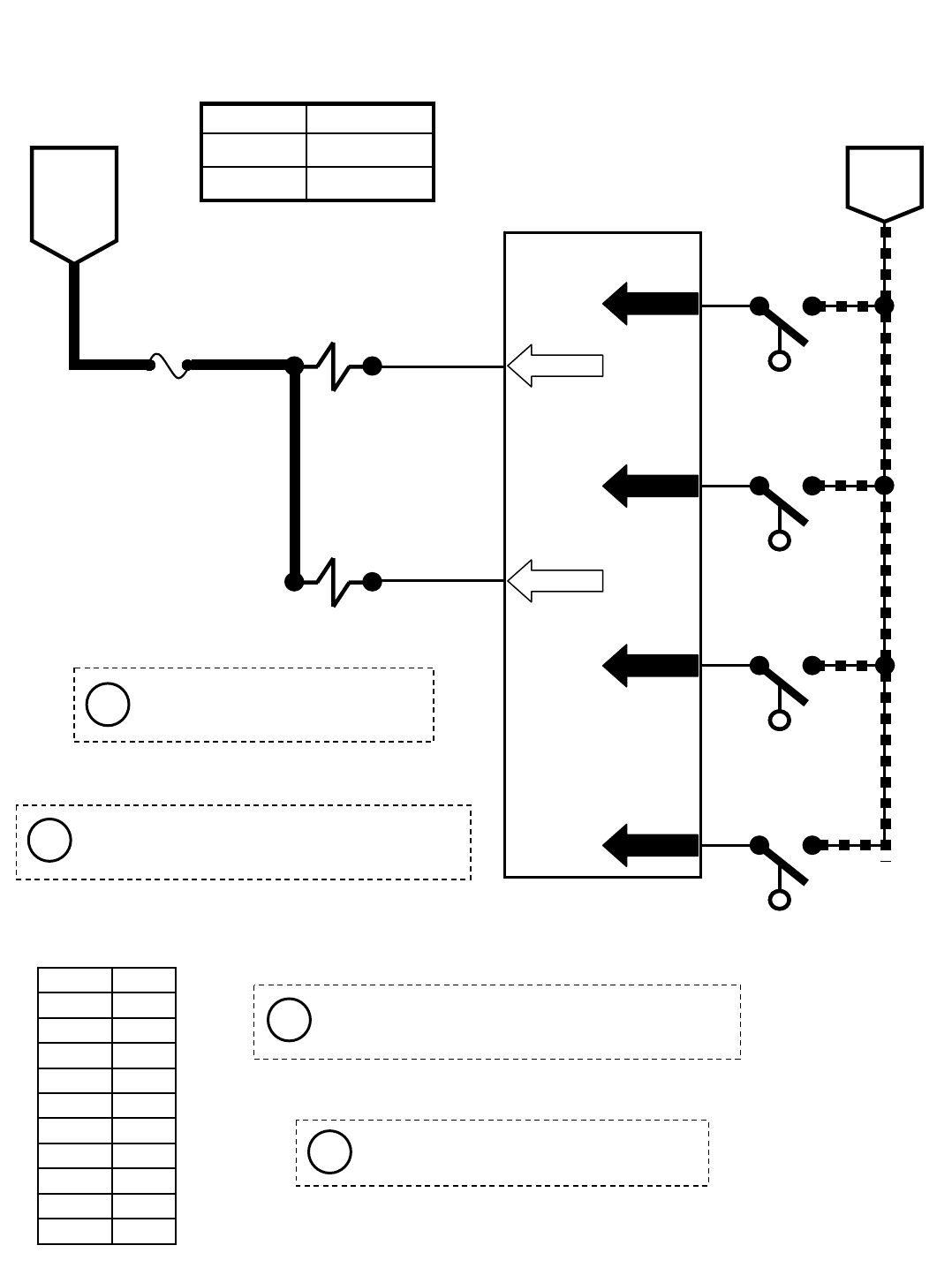
16
Touch Panel / Control Board
65
FUSE 7
15 AMP
516
67
SOL-1
SOL-2
SOLUTION
TANK AUTO
FILL VALVE
M20 Auto Fill Solenoids
OPEN = EMPTY
CLOSED = NOT EMPTY
46
177 13/BLK
BATTERY
POSITIVE
FROM
AUX 2
RELAY
CONTACTS
BATTERY
NEGATIVE
PIN P2-13
PIN P2-14
PIN P1-11
PIN P1-12
PIN P1-14
RECOVERY
TANK AUTO
FILL VALVE
45
PIN P1-13
13/BLK
13/BLK
13/BLK
44
OPEN = NOT FULL
CLOSED = FULL
OPEN = LESS THAN HALF FULL
CLOSED = HALF FULL OR MORE
OPEN = NOT FULL
CLOSED = FULL
RECOVERY TANK
HALF FULL SWITCH
S-16
S-15
RECOVERY TANK
FULL SWITCH
S-14
SOLUTION TANK
FULL SWITCH
S-19
SOLUTION TANK
EMPTY SWITCH
Wiring Color Codes
(Unless otherwise marked)
0
1
2
3
4
5
6
7
8
9
Tan
Pink
Brown
Orange
Yellow
Green
Blue
Purple
Gray
White
Right Most Digit
of Wire Number Color of Wire
Machine must be in neutral and Solution Tank
Full Switch OPEN (tank not full) to activate
Solution Tank Auto Fill Valve (SOL-1)
Machine must be in neutral and Recovery Tank
Half Full Switch OPEN (tank less than half full) to
activate Recovery Tank Auto Fill Valve (SOL-2)
The Float Switches must be closed for
5 seconds before any output is affected
Solution and Recovery Tank Auto
Fill solenoids (SOL-1 & SOL-2) are
electro-mechanical devices
Max Amp DrawComponent
1.7 ASOL-2
1.7 ASOL-1
Conditions: Key on
i
i
i
i
M20 331385 (02-2007)
93
E
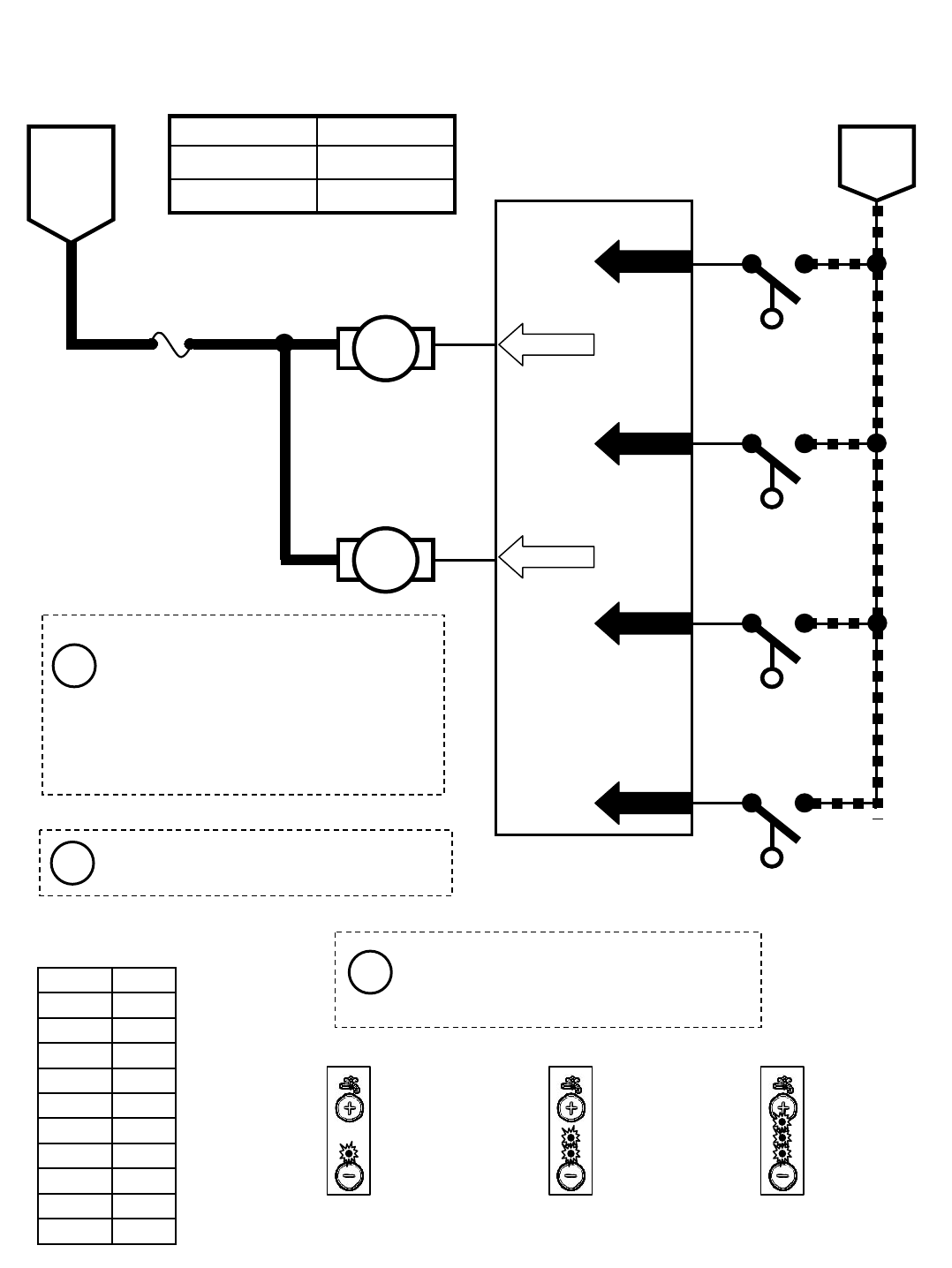
Touch Panel / Control Board
74
FUSE 8
15 AMP
517
75
DETERGENT
PUMP
M20 Conventional Detergent Pump & ES Pump
BATTERY
POSITIVE
FROM
AUX 2
RELAY
CONTACTS
PIN P2-21
PIN P2-22
ES
PUMP
PWM
The Detergent Pump is controlled by
PWM; A higher duty cycle (more Solution
LED’s lit on Touch Panel) will result in
more detergent & solution applied to floor
Low Water and
Detergent Pump OFF
Medium Water and
Detergent Pump LOW
High Water and
Detergent Pump HIGH
17
17 OPEN = EMPTY
CLOSED = NOT EMPTY
46
177 13/BLK
BATTERY
NEGATIVE
PIN P1-11
PIN P1-12
PIN P1-14
45
PIN P1-13
13/BLK
13/BLK
13/BLK
44
OPEN = NOT FULL
CLOSED = FULL
OPEN = LESS THAN HALF FULL
CLOSED = HALF FULL OR MORE
OPEN = NOT FULL
CLOSED = FULL
RECOVERY TANK
HALF FULL SWITCH
S-16
S-15
RECOVERY TANK
FULL SWITCH
S-14
SOLUTION TANK
FULL SWITCH
S-19
SOLUTION TANK
EMPTY SWITCH
Wiring Color Codes
(Unless otherwise marked)
0
1
2
3
4
5
6
7
8
9
Tan
Pink
Brown
Orange
Yellow
Green
Blue
Purple
Gray
White
Right Most Digit
of Wire Number Color of Wire
The Float Switches must be closed for
5 seconds before any output is affected
The Recovery Tank must be at least half
full for ES Pump to turn ON. This will
begin a 30 second run cycle of the ES
Pump. If the Recovery Tank is still at
least half full after the cycle, another 30
second cycle will begin. If a full Solution
Tank is sensed, the ES Pump will turn
OFF before completing 30 second cycle.
Max Amp DrawComponent
n/aES Pump
1.7 A
Detergent Pump
Conditions: Key on, engine running, scrubbing system on, ES system on, two or three solution LED’s lit
i
i
i
M20 331385 (02-2007)
94
E
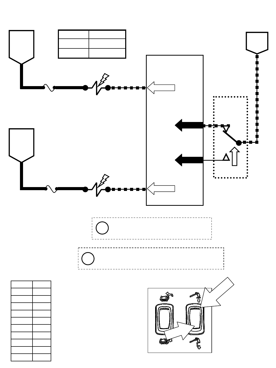
Touch Panel / Control Board
61
FUSE 6
15 AMP
615
SV-7
SV-15
ENABLE
VALVE
HOPPER
DOOR OPEN
5FUSE 7
15 AMP
68
16
BATTERY
POSITIVE
FROM
AUX 1
RELAY
CONTACTS
BATTERY
POSITIVE
FROM
AUX 2
RELAY
CONTACTS
PIN P2-8
PIN P2-15
HOPPER
DOOR
OPEN/CLOSE
SWITCH
BATTERY
NEGATIVE
A&C CLOSED = DOOR OPEN
A&B CLOSED = DOOR CLOSE
M20 Hopper Door OPEN
HOPPER
DOORSWITCH
Wiring Color Codes
(Unless otherwise marked)
0
1
2
3
4
5
6
7
8
9
Tan
Pink
Brown
Orange
Yellow
Green
Blue
Purple
Gray
White
Right Most Digit
of Wire Number Color of Wire
PUSH
TOOPEN
S-13
A
B
C
42
43
13/BLK
OFF
PIN P1-9
PIN P1-10
Activating the Hopper Door Switch to open or close
the door will cancel the sweep or scrub systems
and automatically selects HIGH engine speed
Anytime the Enable Valve (SV-7) is ON
and the Hopper Door Open Valve (SV15)
is OFF, the hopper door will close
Max Amp DrawComponent
1.7 ASV-15
1.7 ASV-7
Conditions: Key on, engine running, hopper door open switch activated
i
i
M20 331385 (02-2007)
95
E
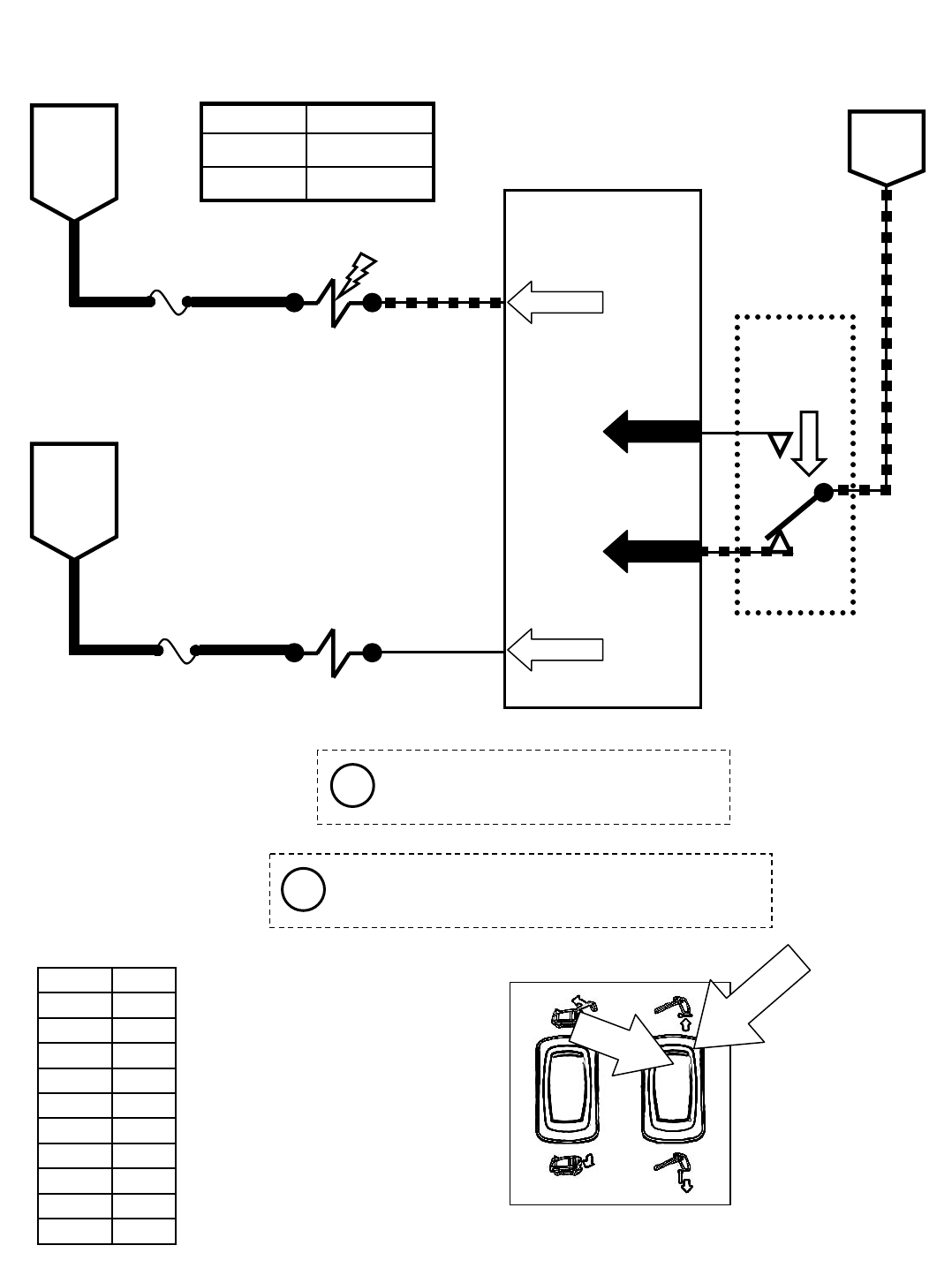
Touch Panel / Control Board
61
FUSE 6
15 AMP
615
SV-7
SV-15
ENABLE
VALVE
HOPPER
DOOR OPEN
5FUSE 7
15 AMP
68
16
BATTERY
POSITIVE
FROM
AUX 1
RELAY
CONTACTS
BATTERY
POSITIVE
FROM
AUX 2
RELAY
CONTACTS
PIN P2-8
PIN P2-15
M20 Hopper Door CLOSE
Wiring Color Codes
(Unless otherwise marked)
0
1
2
3
4
5
6
7
8
9
Tan
Pink
Brown
Orange
Yellow
Green
Blue
Purple
Gray
White
Right Most Digit
of Wire Number Color of Wire
PUSH
TOCLOSE
HOPPER
DOOR
OPEN/CLOSE
SWITCH
BATTERY
NEGATIVE
A&C CLOSED = DOOR OPEN
A&B CLOSED = DOOR CLOSE
S-13
A
B
C
42
43
13/BLK
OFF
PIN P1-9
PIN P1-10
HOPPER
DOORSWITCH
Activating the Hopper Door Switch to open or close
the door will cancel the sweep or scrub systems
and automatically selects HIGH engine speed
Anytime the Enable Valve (SV-7) is ON
and the Hopper Door Open Valve (SV15)
is OFF, the hopper door will close
Max Amp DrawComponent
1.7 ASV-15
1.7 ASV-7
Conditions: Key on, engine running, hopper door close switch activated
i
i
M20 331385 (02-2007)
96
E
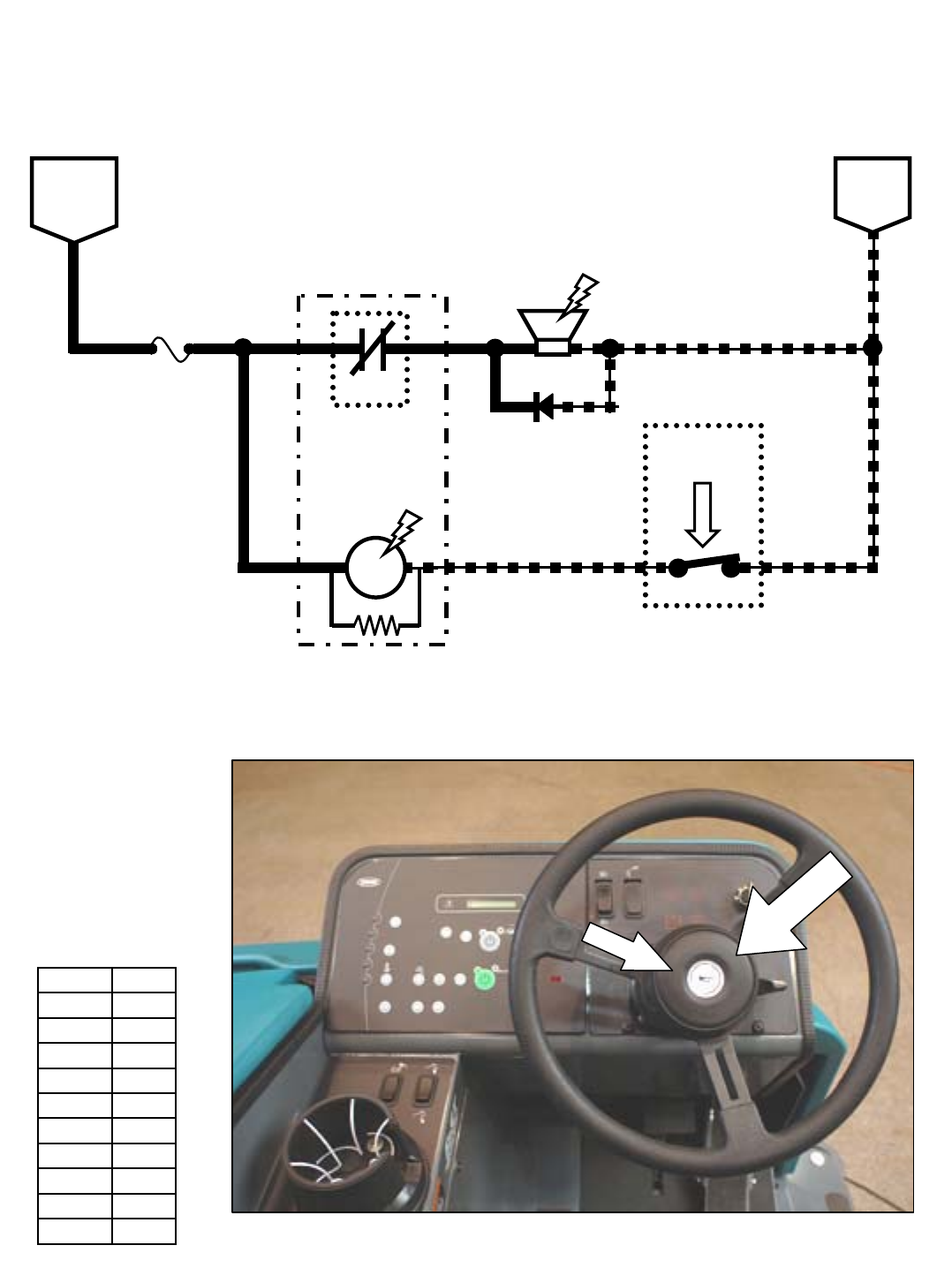
251/RED FUSE 3
M20 Horn
UN-
SWITCHED
BATTERY
POSITIVE
BATTERY
NEGATIVE
M5B
HORN
RELAY
HORN
23 13/BLK
15 AMP
25
S-22
HORN
SWITCH
OPEN = HORN OFF
CLOSED = HORN ON
92 13/BLK
D1
23 13/BLK
HORN
SWITCH
PUSH
Wiring Color Codes
(Unless otherwise marked)
0
1
2
3
4
5
6
7
8
9
Tan
Pink
Brown
Orange
Yellow
Green
Blue
Purple
Gray
White
Right Most Digit
of Wire Number Color of Wire
M5A
86 85
30 87
Conditions: Horn switch activated
M20 331385 (02-2007)
97
E
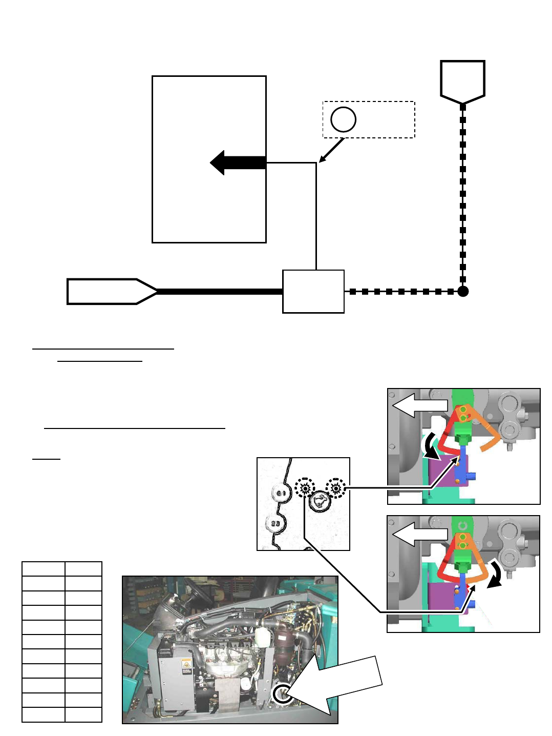
Wiring Color Codes
(Unless otherwise marked)
0
1
2
3
4
5
6
7
8
9
Tan
Pink
Brown
Orange
Yellow
Green
Blue
Purple
Gray
White
Right Most Digit
of Wire Number Color of Wire
91
Touch Panel / Control Board
13/BLK
BATTERY
NEGATIVE
PIN P1-1
BATTERY POSITIVE
FROM FUSE 5
PROPEL
PEDAL
POSITION
SENSOR
14 131/BLK-WHT
DIGITAL
GROUND
1
23
SENSOR
OUTPUT
SENSOR OUTPUT VOLTAGES:
2.0 to 2.7 VDC = NEUTRAL
2.8 VDC OR HIGHER = REVERSE
1.9 VDC OR LOWER = FORWARD
1.9 VDC OR
LOWER IN
FORWARD
M20 Forward Propel
Propel Pedal Position Sensor
Arms Adjustment
1) Enter Input Diagnostics Mode
2) Loosen sensor arms hardware
3) Tighten top bolt to snug
4) Slide arm until the light goes ON
5) Back arm out until the light goes OFF
6) Retighten all hardware
NOTE: Use the High Engine Speed LED
to adjust the arm closest to the front of
machine (forward adjustment), and the
Low Engine Speed LED to adjust the arm
closest to the rear of machine (reverse
adjustment).
Conditions: Key on, propel pedal pushed for forward travel
TOUCH PANEL
FORWARD
ADJUSTMENT
FRONT
FRONT
REVERSE
ADJUSTMENT
i
PROPELPEDAL
POSITION SENSOR
M20 331385 (02-2007)
98
E
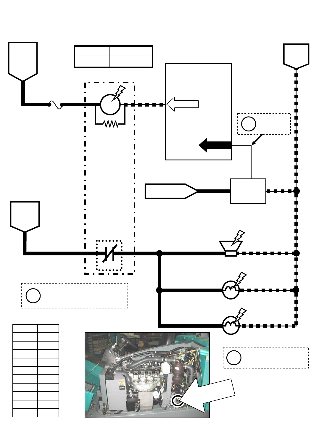
8
91
Touch Panel / Control Board
M20 Reverse Propel
13/BLK
BATTERY
NEGATIVE
BATTERY
POSITIVE
FROM
FUSE 1
16
5FUSE 7
15 AMP
BATTERY
POSITIVE
FROM
AUX 2
RELAY
CONTACTS
70
M4B
REVERSE
RELAY
20 13/BLK
PIN P2-17
PIN P1-1
BATTERY POSITIVE
FROM FUSE 5
PROPEL
PEDAL
POSITION
SENSOR
14
131/BLK-
WHT
DIGITAL
GROUND
1
23
SENSOR
OUTPUT
SENSOR OUTPUT VOLTAGES:
2.0 to 2.7 VDC = NEUTRAL
2.8 VDC OR HIGHER = REVERSE
1.9 VDC OR LOWER = FORWARD
REVERSE ALARM/
WARNING LIGHT
13/BLK
13/BLK
20
20
20
REVERSE
TAIL LIGHT
REVERSE
TAIL LIGHT
2.8 VDC OR
HIGHER IN
REVERSE
Wiring Color Codes
(Unless otherwise marked)
0
1
2
3
4
5
6
7
8
9
Tan
Pink
Brown
Orange
Yellow
Green
Blue
Purple
Gray
White
Right Most Digit
of Wire Number Color of Wire
PROPELPEDAL
POSITION SENSOR
M4A
86 85
30 87
Max Amp DrawComponent
200 mAM4A
Conditions: Key on, propel pedal pushed for reverse travel
See Forward Propel page for
information on adjusting
Propel Pedal Position Sensor
Reverse propel will turn OFF
SV-4 (Pin P2-6) and raise the
side and rear squeegees.
i
i
i
M20 331385 (02-2007)
99
E
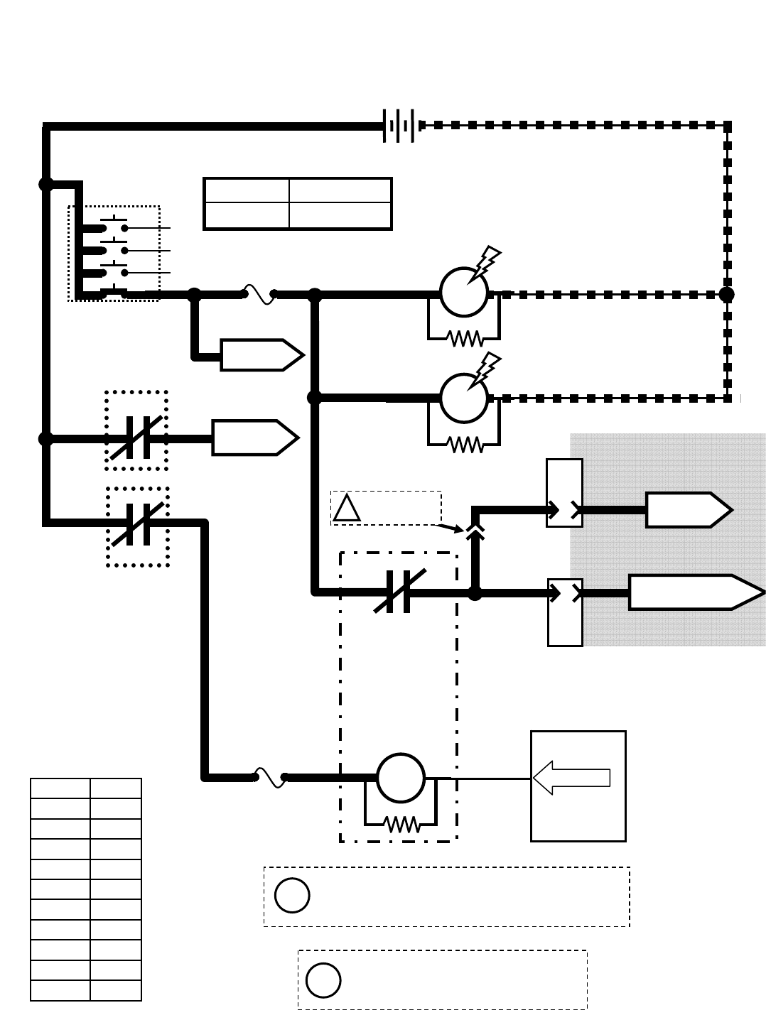
OPEN = MACHINE
SHUTDOWN
CLOSED = NORMAL
OPERATION
Touch Panel /
Control Board
165FUSE 7
15 AMP
71
SHUTDOWN
RELAY
PIN P2-18
M6A
M20 Shutdown Relay (Normal Machine Operation)
1/RED 13/BLK
+-
12 VDC
1/RED
1/RED
1/RED
6
5
M1B
M2B
AUX. 1 RELAY
CONTACTS
AUX. 2 RELAY
CONTACTS
AUXILIARY
RELAY
38
8 13/BLK
13/BLK
M6C
Wiring Color Codes
(Unless otherwise marked)
0
1
2
3
4
5
6
7
8
9
Tan
Pink
Brown
Orange
Yellow
Green
Blue
Purple
Gray
White
Right Most Digit
of Wire Number Color of Wire
AUXILIARY
RELAY
A
D
10
PIN
8
PIN
CONNECT FOR
L.P.G. ONLY
!
3
76
TO FUSES
5 &6
TO ENGINE
ECM
When control board turns ON M6A,
the engine ECM loses power, and
engine shuts OFF
8
8
FUSE 1
15 AMP
M1A
M2A
KEY SWITCH
RUN
86 85
30 87a
4
TO FUSES
9 & 12
4
4
J-12
ENGINE HARNESS
CONNECTORS
J-11
(Gas/LPG)
TAN/BRN
PINK TO FUSE 2 OF
ENGINE HARNESS
Max Amp DrawComponent
200 mAM6A
Refer to the Engine
Controller schematics
i
i
The Shutdown system is used to turn OFF the
engine under certain conditions on machines
with certain optional equipment
M20 331385 (02-2007)
100
E
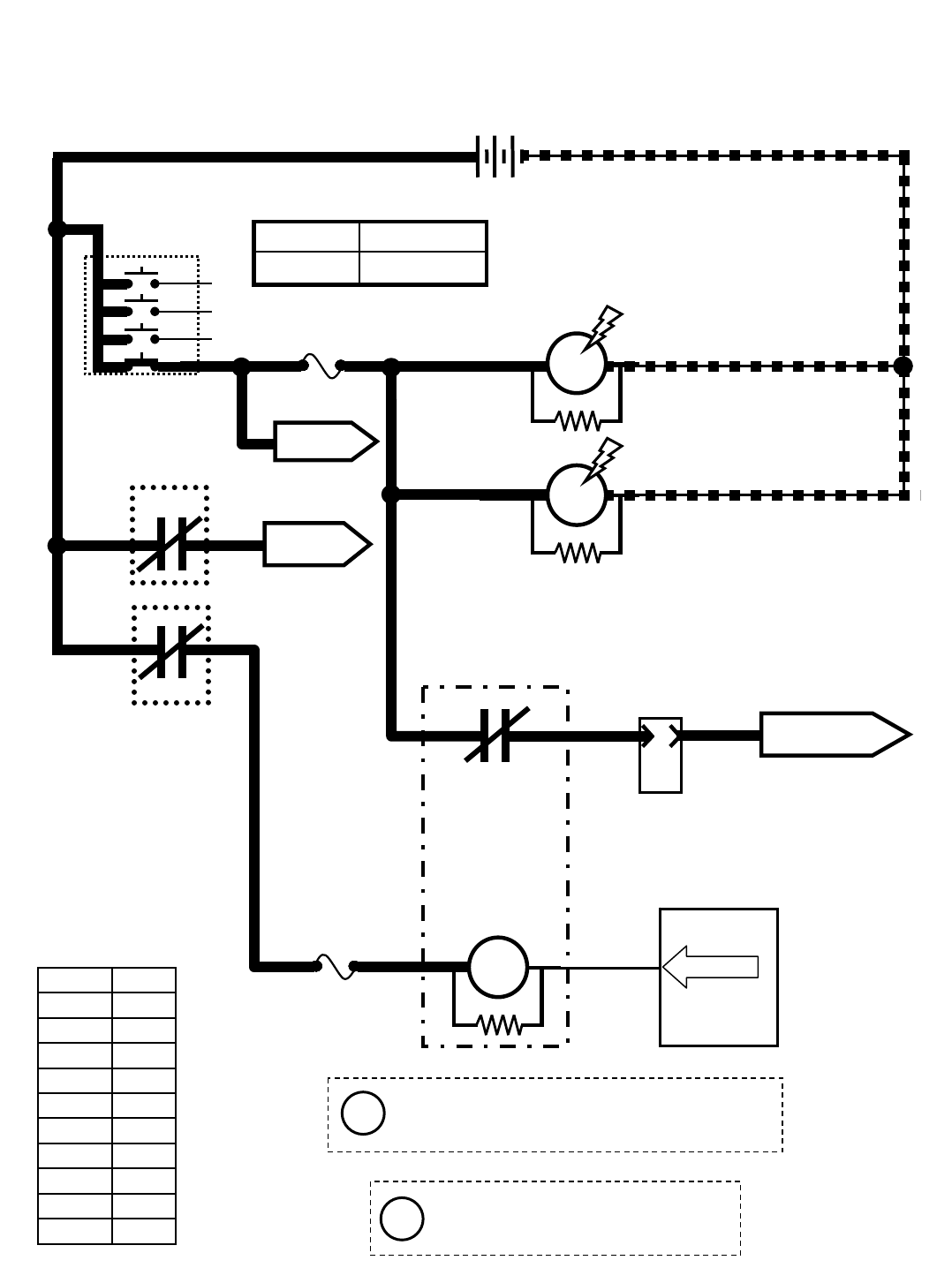
OPEN = MACHINE
SHUTDOWN
CLOSED = NORMAL
OPERATION
Touch Panel /
Control Board
165FUSE 7
15 AMP
71
SHUTDOWN
RELAY
PIN P2-18
M6A
M20 Shutdown Relay (Normal Machine Operation)
1/RED 13/BLK
+-
12 VDC
1/RED
1/RED
1/RED
6
5
M1B
M2B
AUX. 1 RELAY
CONTACTS
AUX. 2 RELAY
CONTACTS
AUXILIARY
RELAY
38
8 13/BLK
13/BLK
M6C
Wiring Color Codes
(Unless otherwise marked)
0
1
2
3
4
5
6
7
8
9
Tan
Pink
Brown
Orange
Yellow
Green
Blue
Purple
Gray
White
Right Most Digit
of Wire Number Color of Wire
AUXILIARY
RELAY
A
10
PIN
TO FUSES
5 &6
TO FUEL PUMP
RELAY M10
When control board turns ON M6A,
the engine ECM loses power, and
engine shuts OFF
8
8
FUSE 1
15 AMP
M1A
M2A
KEY SWITCH
RUN
86 85
30 87a
4
TO FUSES
9 & 12
4
4
3
J-11
ENGINE HARNESS
CONNECTOR
(Diesel)
Max Amp DrawComponent
200 mAM6A
i
i
The Shutdown system is used to turn OFF the
engine under certain conditions on machines
with certain optional equipment
M20 331385 (02-2007)
101
E
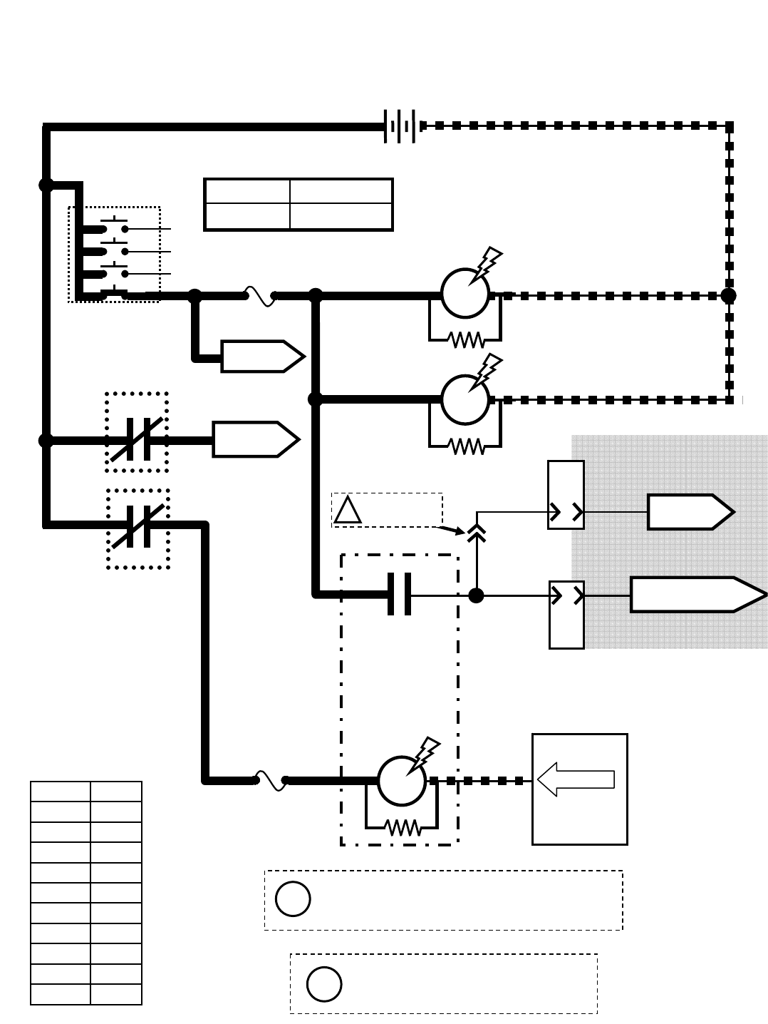
A
10
PIN
M20 Shutdown Relay (Shutdown Mode)
1/RED 13/BLK
+-
12 VDC
1/RED
FUSE 1
15 AMP
4
1/RED
1/RED
6
5
M1B
M2B
AUX. 1 RELAY
CONTACTS
AUX. 2 RELAY
CONTACTS
AUXILIARY
RELAY
8
8
13/BLK
13/BLK
Touch Panel /
Control Board
16
5FUSE 7
15 AMP
Wiring Color Codes
(Unless otherwise marked)
0
1
2
3
4
5
6
7
8
9
Tan
Pink
Brown
Orange
Yellow
Green
Blue
Purple
Gray
White
Right Most Digit
of Wire Number Color of Wire
AUXILIARY
RELAY
CONNECT FOR
L.P.G. ONLY
!
8
8
3
76
TO FUSES
5 &6
PIN P2-18
When control board turns ON M6A,
the engine ECM loses power, and
engine shuts OFF
M1A
M2A
KEY SWITCH
RUN
71
SHUTDOWN
RELAY
M6A
38
M6C
86 85
30 87a
OPEN = MACHINE
SHUTDOWN
CLOSED = NORMAL
OPERATION
TO FUSES
9 & 12
4
4
D
8
PIN
J-12
ENGINE HARNESS
CONNECTORS
J-11
(Gas/LPG)
TO ENGINE
ECM
TAN/BRN
PINK TO FUSE 1 OF
ENGINE HARNESS
Max Amp DrawComponent
200 mAM6A
Refer to the Engine
Controller schematics
i
i
The Shutdown system is used to turn OFF the
engine under certain conditions on machines
with certain optional equipment
M20 331385 (02-2007)
102
E
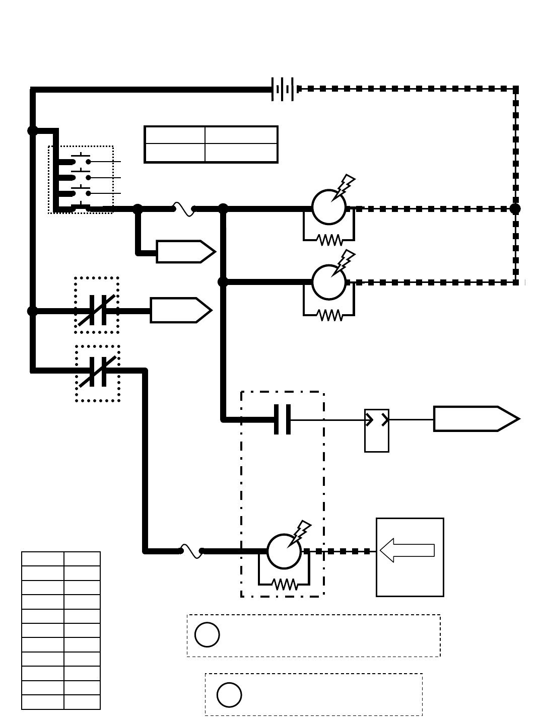
A
10
PIN
M20 Shutdown Relay (Shutdown Mode)
1/RED 13/BLK
+-
12 VDC
1/RED
FUSE 1
15 AMP
4
1/RED
1/RED
6
5
M1B
M2B
AUX. 1 RELAY
CONTACTS
AUX. 2 RELAY
CONTACTS
AUXILIARY
RELAY
8
8
13/BLK
13/BLK
Touch Panel /
Control Board
16
5FUSE 7
15 AMP
Wiring Color Codes
(Unless otherwise marked)
0
1
2
3
4
5
6
7
8
9
Tan
Pink
Brown
Orange
Yellow
Green
Blue
Purple
Gray
White
Right Most Digit
of Wire Number Color of Wire
AUXILIARY
RELAY
8
8
TO FUSES
5 &6
PIN P2-18
When control board turns ON M6A,
the engine ECM loses power, and
engine shuts OFF
M1A
M2A
KEY SWITCH
RUN
71
SHUTDOWN
RELAY
M6A
8
M6C
86 85
30 87a
OPEN = MACHINE
SHUTDOWN
CLOSED = NORMAL
OPERATION
TO FUSES
9 & 12
4
4
3TO FUEL PUMP
RELAY M10
J-11
ENGINE HARNESS
CONNECTOR
3
(Diesel)
Max Amp DrawComponent
200 mAM6A
i
i
The Shutdown system is used to turn OFF the
engine under certain conditions on machines
with certain optional equipment
M20 331385 (02-2007)
103
E
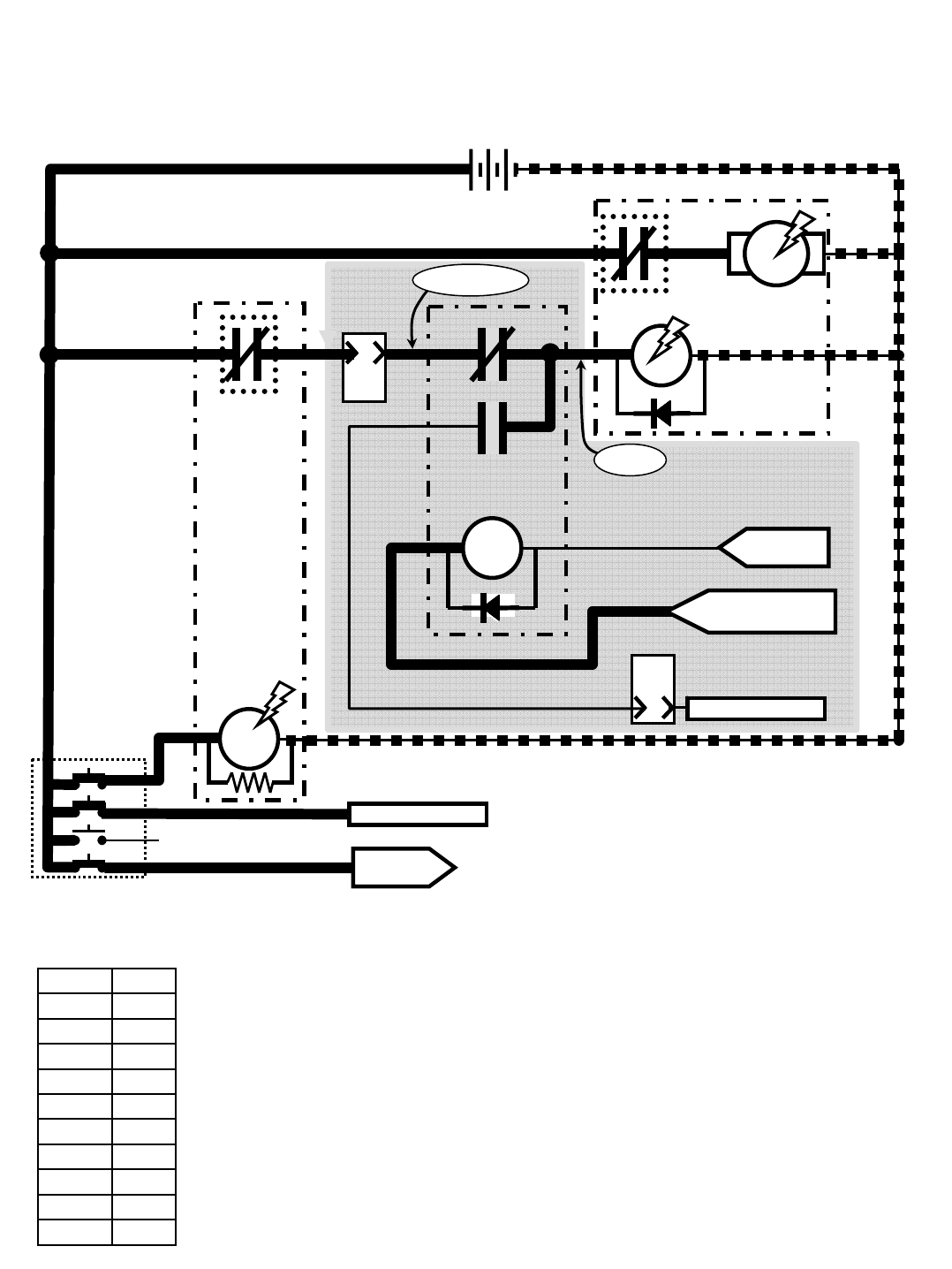
K
10
PIN
M20 Starting System ON
1/RED 13/BLK
+-
12 VDC
1/RED
4
STARTER
RELAY
85
77
TO FUSES
1, 9, & 12
2
Wiring Color Codes
(Unless otherwise marked)
0
1
2
3
4
5
6
7
8
9
Tan
Pink
Brown
Orange
Yellow
Green
Blue
Purple
Gray
White
Right Most Digit
of Wire Number Color of Wire
M7A
KEY SWITCH
START
STARTER MOTOR
ASSEMBLY
J
10
PIN
ENGINE
HARNESS
CONNECTOR
J-11
J-11
FROM ECM
PIN 9
FROM FUSE 1 OF
ENGINE HARNESS
STARTER
LOCKOUT
RELAY
1/RED
ENGINE
BLOCK
13/BLK
M7B
86
30
87a
87
ENGINE
BLOCK
86 85
30 87
ENGINE HARNESS
CONNECTOR
(Gas/LPG)
NO CONNECTION
GRAY/ORANGE
PINK/BLK
PINK/BLK
LT.BLUE/PINK
WHITE
PINK/TAN
NO CONNECTION
Conditions: Key turned to start position
Refer to the Engine
Controller schematics
M20 331385 (02-2007)
104
E
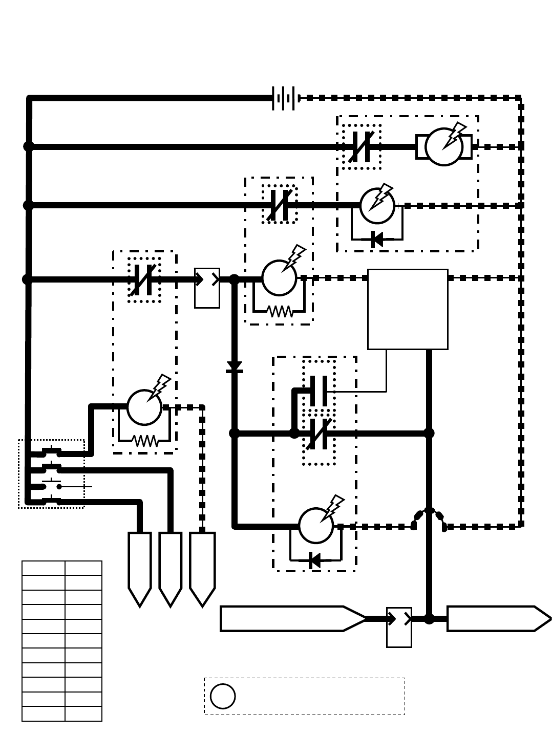
M20 Starting System ON
1/RED 13/BLK
+-
12 VDC
1/RED
4
STARTER
RELAY
77
2
Wiring Color Codes
(Unless otherwise marked)
0
1
2
3
4
5
6
7
8
9
Tan
Pink
Brown
Orange
Yellow
Green
Blue
Purple
Gray
White
Right Most Digit
of Wire Number Color of Wire
M7A
KEY SWITCH
START
STARTER MOTOR
ASSEMBLY
J
10
PIN
ENGINE
HARNESS
CONNECTOR
J-11
TO BATTERY
NEGATIVE
1/RED
ENGINE
BLOCK
13/BLK
M7B
30 87
3
ENGINE
BLOCK
M8B
M8A
85
M9A
STARTER
LOCKOUT
RELAY
86
30 87
TO FUSES
1, 9, & 12
TO
GLOWPLUGS
42
1/RED
1/RED
13/BLK
13/BLK
SWITCHED BATTERY POSITIVE
FROM SHUTDOWN RELAY M6C
STARTER
TIMER
MODULE
A
10
PIN
3
3
87a
3
77
77 82
55
55
D-3
PIN 1
GND
PIN 2
LOAD
PIN 6
INIT
PIN 3
B+
The Starter Timer Module creates
a delay between start attempts
56
56
STARTER
RELAY
85
86
30 83
85
86
87
TO FUEL PUMP RELAY
M10 & GOVERNOR
3
13/BLK
J-11
ENGINE HARNESS
CONNECTOR
(Diesel)
M9B
M9C
Conditions: Key turned to start position
i
M20 331385 (02-2007)
105
E
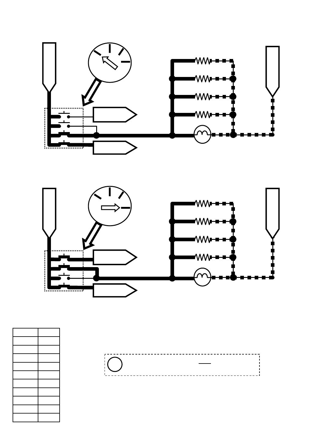
Glow
Plug
START
RUN
OFF
KEY SWITCH
M20 Glow Plugs ON
Wiring Color Codes
(Unless otherwise marked)
0
1
2
3
4
5
6
7
8
9
Tan
Pink
Brown
Orange
Yellow
Green
Blue
Purple
Gray
White
Right Most Digit
of Wire Number Color of Wire
KEY SWITCH
GLOW PLUG
42
1/RED
FROM BATTERY
POSITIVE
TO FUSES
1, 9, & 12
TO START
RELAY M7A
GLOW PLUGS
GP4
GP3
GP2
GP1
CH ASS IS GRO UNDS
FROM BATTERY
NEGATIVE
GLOW PLUG LAMP
13/BLK
KEY SWITCH
START
FROM BATTERY
POSITIVE
TO FUSES
1, 9, & 12
TO START
RELAY M7A
GLOW PLUGS
GP4
GP3
GP2
GP1
CH ASS IS GRO UNDS
FROM BATTERY
NEGATIVE
GLOW PLUG LAMP
13/BLK
42
42
42
42
42
42
42
1/RED
42
42
42
42
42
42
The Glow Plugs are ON only when ignition
switch is in the “Glow Plug” or “Start” position
(Diesel)
Conditions: Key turned to start or glow plug position
Glow
Plug START
RUN
OFF
KEY SWITCH
i
M20 331385 (02-2007)
106
E
Touch Panel / Control Board
72
FUSE 7
15 AMP
516
181
SOL-3
SOL-7
M20 Conventional Main & Side Brush Solution Valves
BATTERY
POSITIVE
FROM
AUX 2
RELAY
CONTACTS
PIN P2-19
PIN P2-20
SIDE BRUSH
SOLUTION VALVE
16
Wiring Color Codes
(Unless otherwise marked)
0
1
2
3
4
5
6
7
8
9
Tan
Pink
Brown
Orange
Yellow
Green
Blue
Purple
Gray
White
Right Most Digit
of Wire Number Color of Wire
The Solution Valves are pulsed slowly to adjust the solution
volume. Less OFF time (more Solution LED’s lit on Touch
Panel) will result in more solution applied to floor
Low Solution Medium Solution High Solution
The Solution Valves will function only while propelling
forward or reverse during scrub operation
Max Amp DrawComponent
1.7 ASOL-7
1.7 ASOL-3
Conditions: Key on, scrubbing system on, side brush on, forward or reverse propel, one or more solution LED’s lit
i
i
MAIN BRUSH
SOLUTION VALVE
M20 331385 (02-2007)
107
E
Wiring Color Codes
(Unless otherwise marked)
0
1
2
3
4
5
6
7
8
9
Tan
Pink
Brown
Orange
Yellow
Green
Blue
Purple
Gray
White
Right Most Digit
of Wire Number Color of Wire
M20 FaST System ON
Touch Panel / Control Board
79
FUSE 8
15 AMP
5
17
17
17
80
75
SOL-5
SOL-6
SOL-4
FaST HIGH
FLOW VALVE
FaST SIDE
BRUSH VALVE
FaST
ENABLE
VALVE
75
BATTERY
POSITIVE
FROM
AUX 2
RELAY
CONTACTS
17
74
PIN P2-23
PIN P2-26
PIN P2-22
PIN P2-21
17
FaST DETERGENT
PUMP
FaST
WATER
PRESSURE
SWITCH
83
FaST AIR
PUMP
BATTERY
NEGATIVE
M11A
FaST WATER
PUMP RELAY
M11B
75
75
75
75
17
17
FaST WATER
PUMP
17
The FaST Detergent Pump
is controlled by PWM;
A higher duty cycle (more
Solution LED’s lit on Touch
Panel) will result in more
FaST foam applied to floor
PWM
FaST Water Pressure Switch :
OPEN = Less than 10PSI
CLOSED = More than 10 PSI
86 13/BLK
FaST High Flow Valve is
ON only when all 3
Solution LED’s are lit
86 85
30 87
200 mAM11A
1.7 ASOL-6
Max Amp DrawComponent
1.7 AFaST Air Pump
1.7 AFaST Det. Pump
1.7 ASOL-5
1.7 ASOL-4
Low FaST Low FaST High FaST
One or two Solution LED’s
lit selects Low FaST output
Conditions: Key on, scrubbing system on, side brush on, forward or reverse propel, one or more solution LED’s lit
i
i
i
i
M20 331385 (02-2007)
108
E
Wiring Color Codes
(Unless otherwise marked)
0
1
2
3
4
5
6
7
8
9
Tan
Pink
Brown
Orange
Yellow
Green
Blue
Purple
Gray
White
Right Most Digit
of Wire Number Color of Wire
30
Touch Panel / Control Board
GAS /
DIESEL 13/BLK
BATTERY
NEGATIVE
100 OHMS = FULL TANK
5 OHMS = EMPTY TANK
S-7
FUEL LEVEL
SENDER
PIN P1-4
M20 Fuel Level Sensors
DIGITAL
GROUND
30
Touch Panel / Control Board
LPG
13/BLK
BATTERY
NEGATIVE
NORMALLY CLOSED, HELD
OPEN BY FUEL PRESSURE
OPEN = MORE THAN 70 PSI
CLOSED = 70 PSI OR LOWER
S-8
FUEL
PRESSURE
SWITCH
PIN P1-4 DIGITAL
GROUND
S-8
131/BLK-
WHT
131/BLK-
WHT
GAS/DIESELFUEL
FUELLEVELSENSOR
LPG FUEL
PRESSURESWITCH
Conditions: Key on
M20 331385 (02-2007)
109
E
Wiring Color Codes
(Unless otherwise marked)
0
1
2
3
4
5
6
7
8
9
Tan
Pink
Brown
Orange
Yellow
Green
Blue
Purple
Gray
White
Right Most Digit
of Wire Number Color of Wire
M20 Impact, Hydraulic Temperature, & Hydraulic Filter Sensors
Touch Panel / Control Board
OPEN = LESS THAN 20 PSI (FILTER OK)
CLOSED = MORE THAN 20 PSI (FILTER
CLOGGED)
49
90 13/BLK
BATTERY
NEGATIVE
PIN P1-15
PIN P1-21
78
PIN P1-17
13/BLK
S-23
S-20
HYDRAULIC OIL
TEMPERATURE SENSOR
S-17
HYDRAULIC FILTER
CLOGGED SWITCH
131/BLK-WHT
DIGITAL
GROUND
IMPACT
SENSOR
0.8 VDC OR LESS = 220°F OR HIGHER
ABOVE 0.8 VDC = UNDER 220°F
HYDRAULICFILTER
CLOGGED SWITCH
HYDRAULICOIL
TEMPERATURESENSOR
(BACKSIDEOFTANK)
OPEN = NO IMPACT DETECTED
CLOSED = IMPACT DETECTED
The Hydraulic Filter Clogged Switch will not be
sensed until after the machine has run for 5
minutes to allow the hydraulic oil to warm up
i i Impact Sensor S-23 is used
only on machines with certain
optional equipment
M20 331385 (02-2007)
110
E
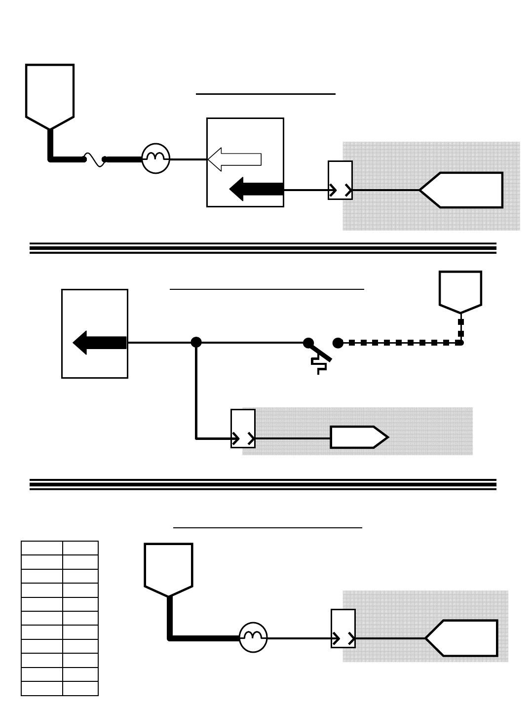
Wiring Color Codes
(Unless otherwise marked)
0
1
2
3
4
5
6
7
8
9
Tan
Pink
Brown
Orange
Yellow
Green
Blue
Purple
Gray
White
Right Most Digit
of Wire Number Color of Wire
M20 Engine Oil Pressure, Temperature, & MIL Systems
12
Touch Panel /
Control Board
PIN P1-18
SW2
OPEN = BELOW 220°F
CLOSED = ABOVE 220°F
B
8
PIN
TO ECM
PIN 35
BATTERY
NEGATIVE
HIGH ENGINE
TEMPERATURE
SWITCH 13/BLK
12
12
J-12
ENGINE HARNESS
CONNECTOR
F
10
PIN
10
SWITCHED
BATTERY
POSITIVE
FROM
FUSE 1
8MIL SIGNAL
FROM ECM
PIN 26
MIL (CHECK
ENGINE LAMP)
J-11
ENGINE HARNESS
CONNECTOR
6FUSE 5
15 AMP
BATTERY
POSITIVE
FROM
AUX 1
RELAY
CONTACTS
Touch Panel /
Control Board
PIN P2-27
14 28
LOW ENGINE OIL
PRESSURE LAMP A
8
PIN
9
PIN P1-19
OIL PRESSURE
SIGNAL FROM
ECM PIN 30
J-12
ENGINE HARNESS
CONNECTOR OPEN = LOW OIL PRESSURE
BATTERY NEG.= OIL PRESSURE OK
(Gas/LPG)
Engine Oil Pressure
Malfunction Indicator Lamp
LT.BLUE/WHITE
TAN/DK.GREEN
LT.BLUE/BLK
Refer to the Engine
Controller schematics
Refer to the Engine
Controller schematics
Refer to the Engine
Controller schematics
Engine Temperature Switch
M20 331385 (02-2007)
111
E
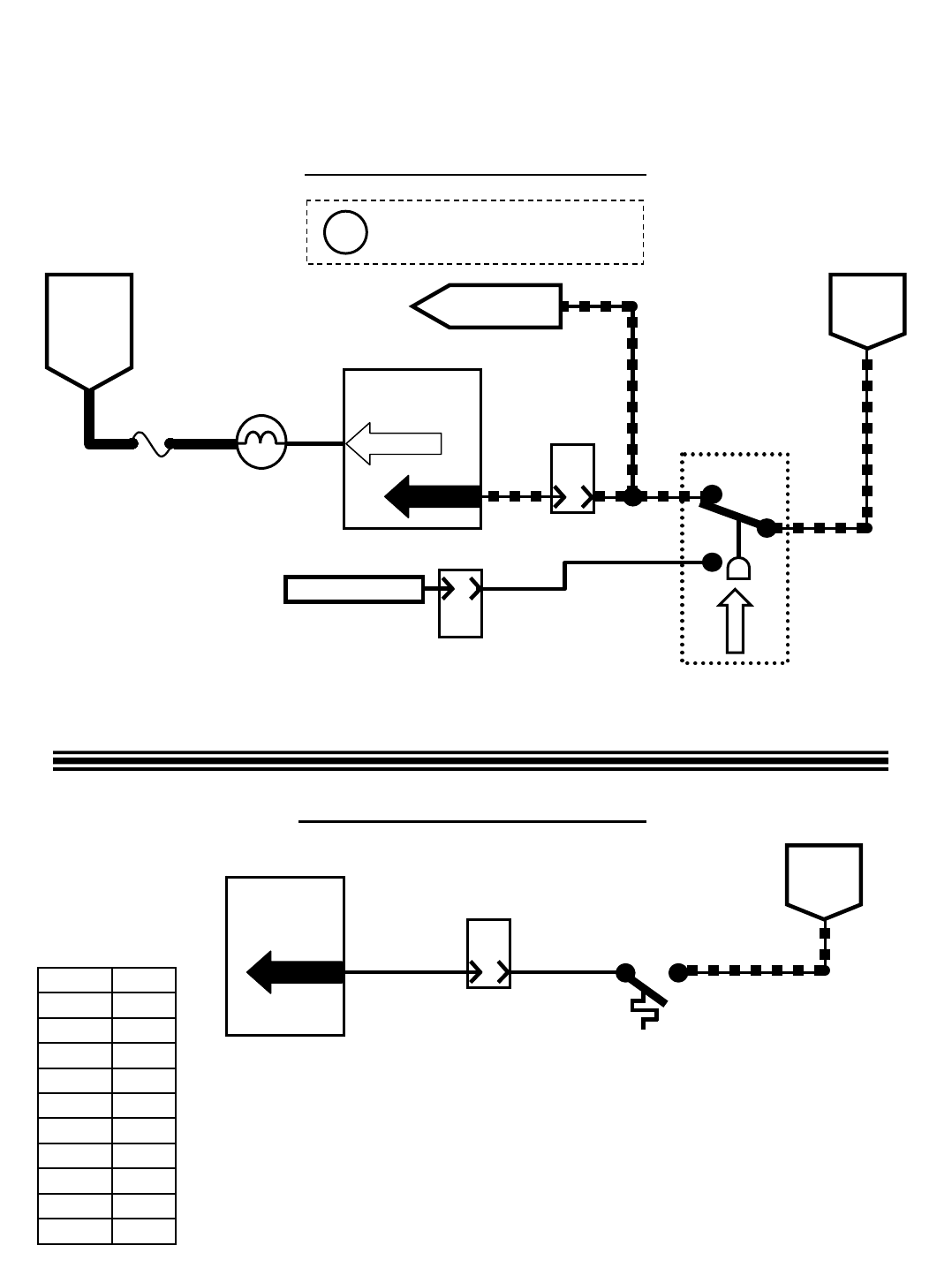
A
B
C
Wiring Color Codes
(Unless otherwise marked)
0
1
2
3
4
5
6
7
8
9
Tan
Pink
Brown
Orange
Yellow
Green
Blue
Purple
Gray
White
Right Most Digit
of Wire Number Color of Wire
12
Touch Panel /
Control Board
PIN P1-18
SW2
OPEN = BELOW 220°F
CLOSED = ABOVE 220°F
BATTERY
NEGATIVE
HIGH ENGINE
TEMPERATURE
SWITCH 13/BLK
M20 Engine Oil Pressure & Temperature Systems
(Diesel)
S-3
OIL PRESSURE
SWITCH
B&C CLOSED = LOW OIL PRESSURE
A&B CLOSED = OIL PRESSURE OK
6FUSE 5
15 AMP
BATTERY
POSITIVE
FROM
AUX 1
RELAY
CONTACTS
Touch Panel /
Control Board
PIN P2-27
14 28
LOW ENGINE OIL
PRESSURE LAMP
13/BLK
BATTERY
NEGATIVE
9
J-12
ENGINE HARNESS
CONNECTOR
TO FUEL PUMP
RELAY M10
E
10
PIN
ENGINE HARNESS
CONNECTOR
J-11
NO CONNECTION
55
5
27
27
B
8
PIN
J-12
ENGINE HARNESS
CONNECTOR
12
A
8
PIN
PIN P1-19
This drawing shown with key
switch ON, and engine running
i
Engine Temperature Switch
Engine Oil Pressure Switch
M20 331385 (02-2007)
112
E
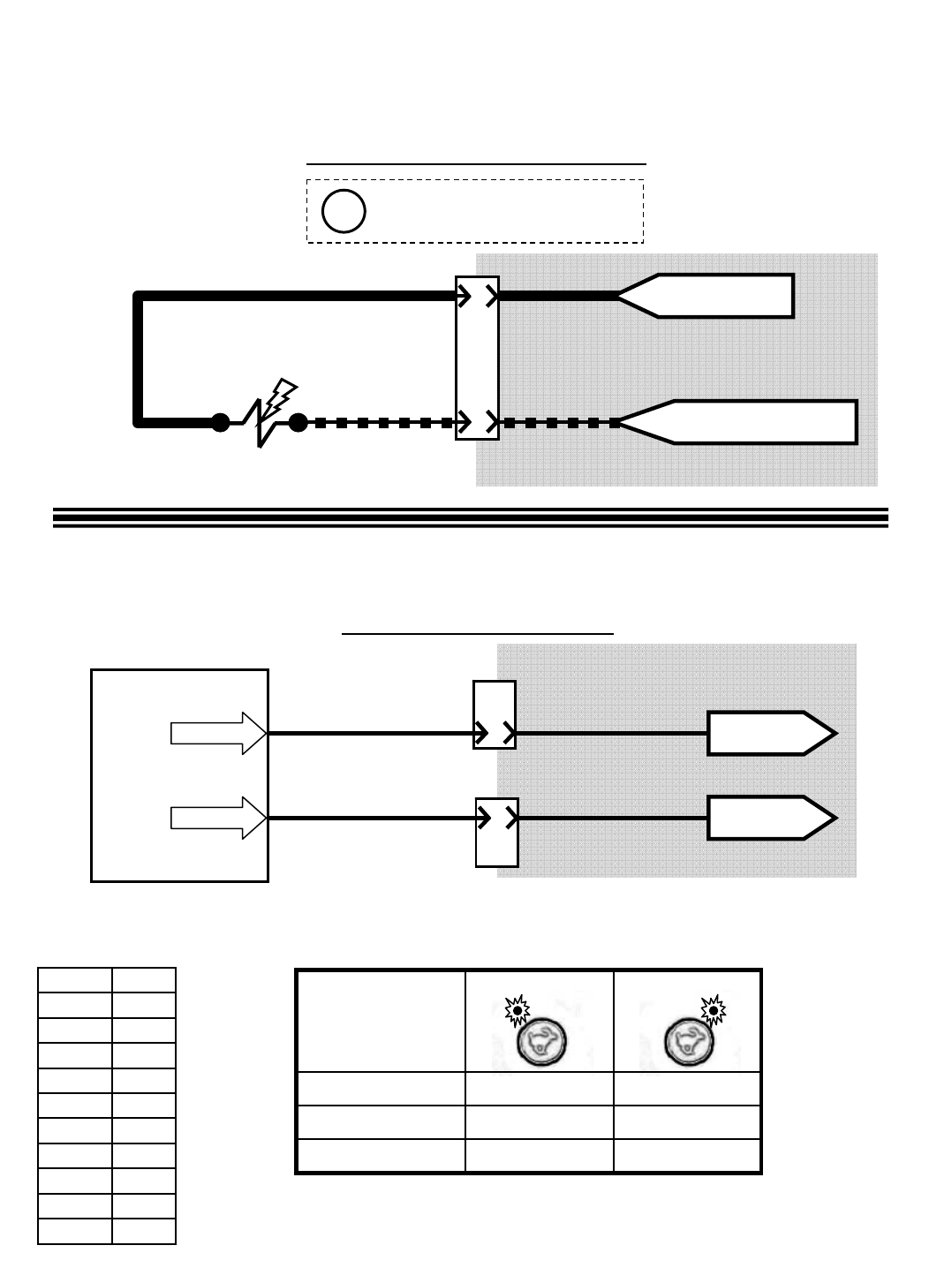
Wiring Color Codes
(Unless otherwise marked)
0
1
2
3
4
5
6
7
8
9
Tan
Pink
Brown
Orange
Yellow
Green
Blue
Purple
Gray
White
Right Most Digit
of Wire Number Color of Wire
M20 Fuel Pump & Engine Speed Control
(Gas/LPG)
D
6
PIN
ENGINE HARNESS
CONNECTOR
J-10
BLACK
E
FROM FUSE 4 OF
ENGINE HARNESS
19
13/BLK
PINK/YEL
19
Fuel Pump (Gasoline Only)
FUEL PUMP
Touch Panel / Control Board
11
18
PIN P2-24
PIN P2-25 B
6
PIN
J-10
E
8
PIN
J-12
ENGINE HARNESS
CONNECTORS
TO PIN 34
OF ECM
TO PIN 48
OF ECM
GRAY/DK.BLUE
YEL/DK.BLUE
Speed Control Output
Governor Speed “A”
Governor Speed “B”
Low Engine Speed High Engine Speed
ENGINE
SPEED
CHART
0 VDC0 VDCVoltage Speed “B”
0 VDC5 VDCVoltage Speed “A”
2400 (+/- 25)950 (+/- 25)Engine RPM
FROM CHASSIS GROUND
OF ENGINE HARNESS
This drawing shown with key
switch ON, and engine running
Refer to the Engine
Controller schematics
Refer to the Engine
Controller schematics
i
M20 331385 (02-2007)
113
E
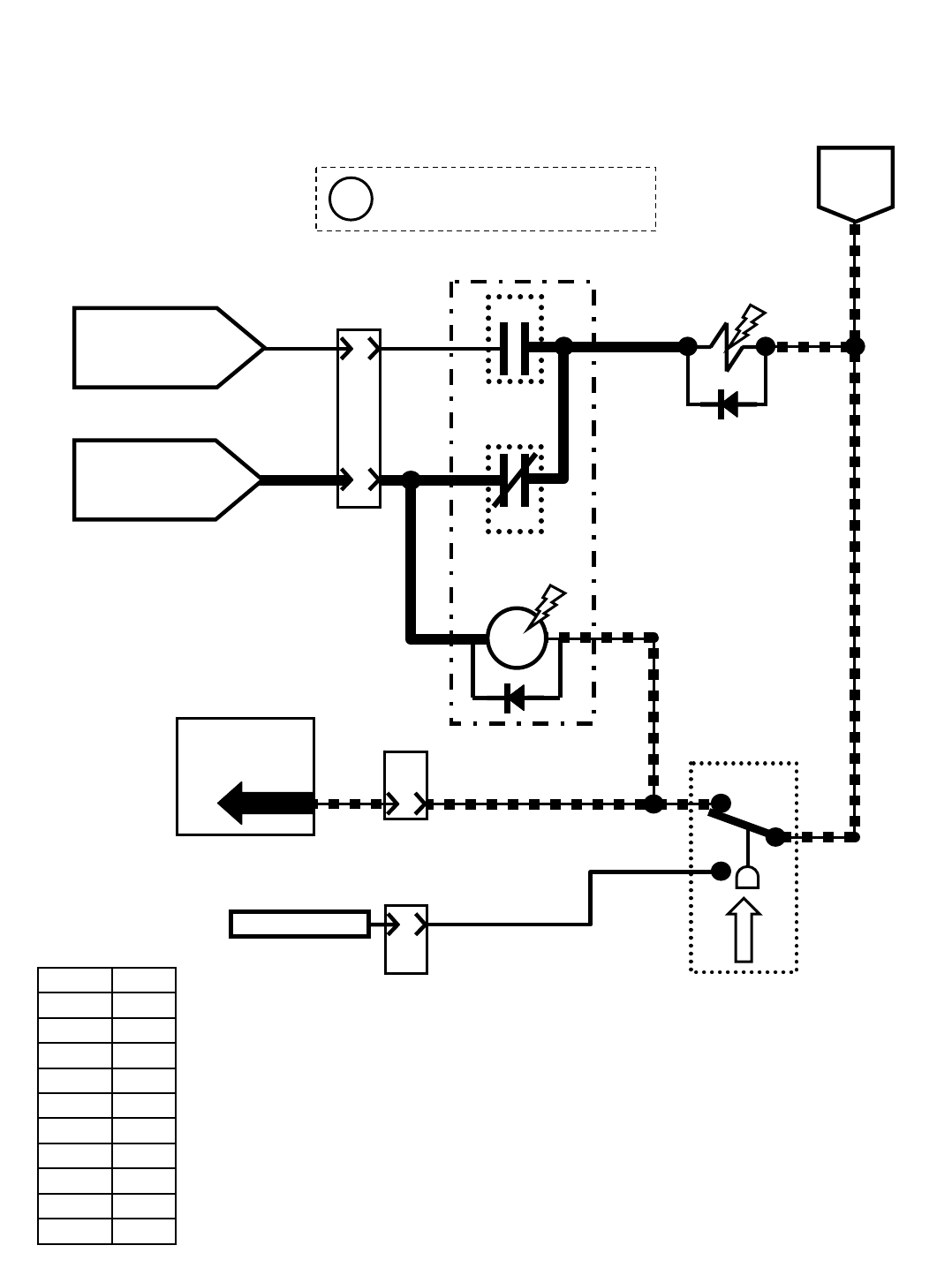
Wiring Color Codes
(Unless otherwise marked)
0
1
2
3
4
5
6
7
8
9
Tan
Pink
Brown
Orange
Yellow
Green
Blue
Purple
Gray
White
Right Most Digit
of Wire Number Color of Wire
M20 Fuel Pump
(Diesel)
J
10
PIN
ENGINE HARNESS
CONNECTOR
J-11
A
D-5
3
FUEL PUMP
85
M10A
FUEL
PUMP
RELAY
86
30
87
87a
M10B
M10C
S-3
OIL PRESSURE
SWITCH
B&C CLOSED = LOW OIL PRESSURE
A&B CLOSED = OIL PRESSURE OK
13/BLK
A
B
C
55
27
BATTERY
POSITIVE WHILE
CRANKING FROM
START RELAY M7B
13/BLK
BATTERY
NEGATIVE
SWITCHED
BATTERY POSITIVE
FROM SHUTDOWN
RELAY M6C
Touch Panel /
Control Board
A
8
PIN
9
PIN P1-19 5
J-12
ENGINE HARNESS
CONNECTORS
E
10
PIN
J-11
NO CONNECTION 27
3
3
77
77
3
67
5
This drawing is shown with key
switch ON, and engine running
i
M20 331385 (02-2007)
114
E
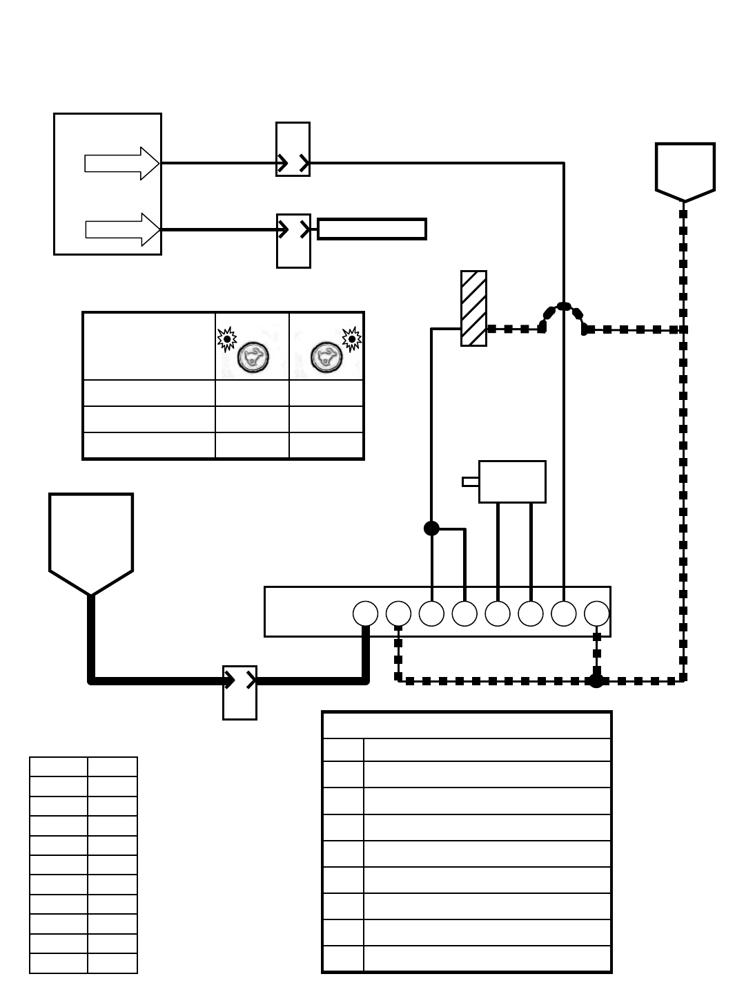
Low Engine
Speed
Wiring Color Codes
(Unless otherwise marked)
0
1
2
3
4
5
6
7
8
9
Tan
Pink
Brown
Orange
Yellow
Green
Blue
Purple
Gray
White
Right Most Digit
of Wire Number Color of Wire
M20 Engine Speed Control
(Diesel)
Touch Panel /
Control Board
11
18
PIN P2-24
B
6
PIN
J-10
E
8
PIN
J-12
ENGINE HARNESS
CONNECTORS
Governor Speed “A”
Governor Speed “B”
High Engine
Speed
ENGINE
SPEED
CHART
0 VDC0 VDCVoltage Speed “B”
0 VDC5 VDCVoltage Speed “A”
24001350Engine RPM
NO CONNECTION
GOVERNOR
CONTROLLER
A
10
PIN
3
J-11
ENGINE HARNESS
CONNECTOR
SWITCHED
BATTERY
POSITIVE
FROM
SHUTDOWN
RELAY M6C
A E F GB H
BATTERY
NEGATIVE
3
3
PIN P2-25
THROTTLE
ACTUATOR
+-
C D
MAGNETIC
PICK-UP
(ENGINE SPEED)
SENSOR
descriptionpin
Governor Controller Pin Chart
INPUT – Engine Speed SensorC
INPUT – Engine Speed SensorD
OUTPUT – Throttle Actuator (PWM)E
OUTPUT – Throttle ActuatorF
INPUT – Engine Speed Selection “B”H
INPUT – Engine Speed Selection “A”G
INPUT – Battery NegativeB
INPUT – Battery PositiveA
13/BLK
13/BLK13/BLK
29
29
13/BLK
6059
61 61
61
29
3
M20 331385 (02-2007)
115
E

M20 Control Board
Inputs and the Outputs
they Control
Lower
Hopper
Switch
Closed
Raise
Hopper
Switch
Closed
Hopper Position
Switch Closed
(Hopper Down)
Hopper
Position
Switch Open
(Hopper Up)
Fuel Level
Sender
(Gas, Diesel)
Fuel Pressure
Switch Closed
(LPG)
Hopper
Thermal Sentry
Switch Closed
Open Hopper
Door Switch
Closed
Close Hoppe
r
Door Switch
Closed
Solution
Tank Full
Switch
Closed
Recovery
Tank Full
Switch
Closed
Recovery
Tank Half
Full Switch
Closed
Clogged
Hydraulic Filter
Switch Closed
Notes
S-5 S-5 S-6 S-6 S-7 S-8 S-9 S-13 S-13 S-14 S-15 S-16 S-17
pin P1-7 P1-8 P1-3 P1-3 P1-4 P1-4 P1-5 P1-9 P1-10 P1-12 P1-13 P1-14 P1-15
Scrub Vacuum Fan Valve
ON SV-1 P2-28 DD E D D D D D
Main Brush Head Down
Pressure Valve ON SV-2 P2-4 DD E D D D D D
scrub only
Propel required to to get full
operational down pressure
(SCRUBBING)
Main Brush Head Lower
Valve ON
SV-3 P2-5 DD E D D D D D Propel required to to get full
operational down pressure
(SWEEPING)
Main Brush Head Lower
Valve ON
SV-3 P2-5 DD E D D D D Propel required to to get full
operational down pressure
Rear and Side Squeegees
Lower
Valve ON
SV-4 P2-6 DD E D D D D D
(SCRUBBING)
Main Brushes Spin
Valve ON
SV-6 P2-5 DD E D D D D D Propel required to to get full
operational down pressure
(SWEEPING)
Main Brushes Spin
Valve ON
SV-6 P2-5 DD E D D D D Propel required to to get full
operational down pressure
Hydraulic Enable
Valve ON SV-7 P2-8 EE E E
Turns OFF automatically if not
required (SV-7 is required for
all hydraulic functions
EXCEPT sweep and scrub
vacuum fans)
Side Brush Spin
Valve ON SV-8 P2-9 DD E D D D D D
scrub only
Sweep Vacuum Fan
Valve ON SV-9 P2-10 DD E D D D D
Side Brush Down Pressure
Valve ON SV-10 P2-11 DD E D D D D D
scrub only
Side Brush Lower
Valve ON SV-11 P2-12 D D E D D D D D
scrub only
Side Brush Extend
Valve ON SV-12 P2-9 DD E D D D D D
scrub only
Hopper Lower
Valve ON SV-13 P2-31 ED
All sweep or scrub functions
are cancelled as long as
switch is closed
Hopper Lift
Valve ON SV-14 P2-7 DE
Mechanical hopper latch must
release for hopper to lift from
full down position; All sweep o
r
scrub functions are cancelled
as long as switch is closed
Hopper Door Open
Valve ON SV-15 P2-15 Refer to Notes Refer to
Notes E
All sweep or scrub functions
are cancelled as long as
switch is open; Hopper door
closes automatically when
hopper down is sensed
Auto-Fill Solution Tank
Valve ON SOL-1 P2-13 D
Auto-Fill Recovery Tank
Valve ON SOL-2 P2-14 D
Main Brushes Solution
Valve ON SOL-3 P2-19 DD E D D D D D
ES Pump ON OR FaST
Enable Valve, Air Pump &
Water Pump Relay ON
SOL-4,
M11 P2-22 DD E D D D D D
ES Pump
only
DE
ES Pump
only
FaST High Flow
Valve ON SOL-5 P2-23 DD E D D D D D
FaST Side Brush
Valve ON SOL-6 P2-26 DD E D D D D D
Side Brush Solution Valve
ON SOL-7 P2-20 DD E D D D D D
Hopper Latch
Solenoid ON SOL-9 P2-32 E
Shaker Motor ON M3A P2-16
Reverse Propel M4A P2-17
Shut Down Relay ON M6A P2-18
Detergent Pump ON OR
FaST Detergent Pump ON n/a P2-21 DD E D D D D D
Audible Alarm n/a P2-29 E
when low
E
when low EE
Low Engine Oil
Pressure Lamp n/a P2-27
If low oil pressure, engine
ECM will shutdown the engine
after a time delay
Governor Speed Bit "A" n/a P2-24
Governor Speed Bit "B" n/a P2-25
E = Input required to ENABLE output
D = Input required to DISABLE output
Output
Input
component #
M20 Enable/Disable Chart
(Page 1 of 2)
M20 331385 (02-2007)
116
E

M20 Control Board
Inputs and the Outputs
they Control
Clogged
Sweep Filter
Switch Closed
Soution
Tank Empty
Switch
Closed
Hydraulic Oil
Temperature
Sensor above
230F
Scrub
Vacuum
Open Switch
Closed
Impact
Sensor
Closed
Propel Pedal
Sensor
FORWARD
Propel Pedal
Sensor
REVERSE
Propel Pedal
Sensor
NEUTRAL
Touch Panel Input Required to
ENABLE
Touch Panel Input Required to
DISABLE Notes
S-18 S-19 S-20 S-21 S-23 n/a n/a n/a
pin P1-16 P1-11 P1-17 P1-6 P1-21 P1-1 P1-1 P1-1
Scrub Vacuum Fan Valve
ON SV-1 P2-28
OneStep Scrub ON;
Squeegee/Scrub Vacuum
ON
OneStep Scrub OFF; OneStep
Sweep ON; Squeegee/Scrub
Vacuum OFF; Low Engine Speed
Selected
Main Brush Head Down
Pressure Valve ON SV-2 P2-4 E
see notes
E
see notes
Refer to
Notes
OneStep Scrub ON;
OneStep Sweep ON
OneStep Scrub OFF; OneStep
Sweep OFF; Low Engine Speed
Selected
Propel required to to get full
operational down pressure
(SCRUBBING)
Main Brush Head Lower
Valve ON
SV-3 P2-5 E
see notes
E
see notes
Refer to
Notes OneStep Scrub ON
OneStep Scrub OFF; OneStep
Sweep ON; Low Engine Speed
Selected
Propel required to to get full
operational down pressure
(SWEEPING)
Main Brush Head Lower
Valve ON
SV-3 P2-5 EE
Refer to
Notes OneStep Sweep ON
OneStep Sweep OFF; OneStep
Scrub ON; Low Engine Speed
Selected; Squeegee/Scrub
Vacuum ON
Propel required to to get full
operational down pressure
Rear and Side Squeegees
Lower
Valve ON
SV-4 P2-6 EDE
OneStep Scrub ON;
Squeegee/Scrub Vacuum
ON
OneStep Scrub OFF; OneStep
Sweep ON; Low Engine Speed
Selected; Squeegee/Scrub
Vacuum OFF
(SCRUBBING)
Main Brushes Spin
Valve ON
SV-6 P2-5 E
see notes
E
see notes
Refer to
Notes OneStep Scrub ON
OneStep Scrub OFF; OneStep
Sweep ON; Low Engine Speed
Selected
Propel required to to get full
operational down pressure
(SWEEPING)
Main Brushes Spin
Valve ON
SV-6 P2-5 EE
Refer to
Notes OneStep Sweep ON
OneStep Sweep OFF; OneStep
Scrub ON; Low Engine Speed
Selected; Scrub Vacuum ON
Propel required to to get full
operational down pressure
Hydraulic Enable
Valve ON SV-7 P2-8
Turning ON Any Touch
Panel Function OR
Selecting High Engine
Speed
Refer to Notes
Turns OFF automatically if not
required (SV-7 is required for
all hydraulic functions
EXCEPT sweep and scrub
vacuum fans)
Side Brush Spin
Valve ON SV-8 P2-9 EE
Side Brush ON (after
OneStep Scrub ON OR
OneStep Sweep ON)
OneStep Scrub OFF; OneStep
Sweep OFF; Low Engine Speed
Selected; Side Brush OFF
Sweep Vacuum Fan
Valve ON SV-9 P2-10
Side Brush Down Pressure
Valve ON SV-10 P2-11 EE
Side Brush ON (after
OneStep Scrub ON OR
OneStep Sweep ON)
OneStep Scrub OFF; OneStep
Sweep OFF; Low Engine Speed
Selected; Side Brush OFF
Side Brush Lower
Valve ON SV-11 P2-12
Side Brush Extend
Valve ON SV-12 P2-9 EE
Side Brush ON (after
OneStep Scrub ON OR
OneStep Sweep ON)
OneStep Scrub OFF; OneStep
Sweep OFF; Low Engine Speed
Selected; Side Brush OFF
Hopper Lower
Valve ON SV-13 P2-31
All sweep or scrub functions
are cancelled as long as
switch is closed
Hopper Lift
Valve ON SV-14 P2-7
Mechanical hopper latch must
release for hopper to lift from
full down position; All sweep o
r
scrub functions are cancelled
as long as switch is closed
Hopper Door Open
Valve ON SV-15 P2-15
All sweep or scrub functions
are cancelled as long as
switch is open; Hopper door
closes automatically when
hopper down is sensed
Auto-Fill Solution Tank
Valve ON SOL-1 P2-13
Auto-Fill Recovery Tank
Valve ON SOL-2 P2-14
Main Brushes Solution
Valve ON SOL-3 P2-19
ES Pump ON OR FaST
Enable Valve, Air Pump &
Water Pump Relay ON
SOL-4,
M11 P2-22
FaST High Flow
Valve ON SOL-5 P2-23
FaST Side Brush
Valve ON SOL-6 P2-26
Side Brush Solution Valve
ON SOL-7 P2-20
Hopper Latch
Solenoid ON SOL-9 P2-32
Shaker Motor ON M3A P2-16
Reverse Propel M4A P2-17
Shut Down Relay ON M6A P2-18
Detergent Pump ON OR
FaST Detergent Pump ON n/a P2-21
Audible Alarm n/a P2-29 EEE E
Low Engine Oil
Pressure Lamp n/a P2-27
If low oil pressure, engine
ECM will shutdown the engine
after a time delay
Governor Speed Bit "A" n/a P2-24
Governor Speed Bit "B" n/a P2-25
E = Input required to ENABLE output
D = Input required to DISABLE output
Input
Output component #
M20 Enable/Disable Chart
(Page 2 of 2)
M20 331385 (02-2007)
117
E
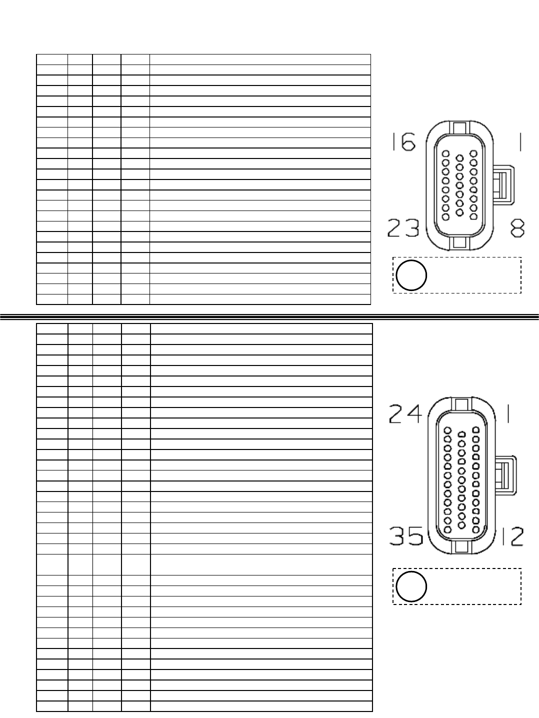
M20 Control Board Connectors
socket # wire # color type goes to
P1-1 91 pink input Forward/Reverse Propel Sensor
P1-2 x x x empty
P1-3 89 white input S-6 Hopper Position Switch
P1-4 30 tan input S-7 or S-8 Fuel Level Sensor or Pressure Switch
P1-5 31 pink input S-9 Thermal Sentry Switch
P1-6 39 white input S-21 Scrub Vacuum Open Switch
P1-7 35 green input S-5 Hopper Up/Down Switch
P1-8 36 blue input S-5 Hopper Up/Down Switch
P1-9 42 brown input S-13 Hopper Door Open/Close Switch
P1-10 43 orange input S-13 Hopper Door Open/Close Switch
P1-11 177 purple input S-19 Solution Tank Empty Switch
P1-12 44 yellow input S-14 Solution Tank Full Switch
P1-13 45 green input S-15 Recovery Tank Full Switch
P1-14 46 blue input S-16 Recovery Tank Half Full Switch
P1-15 90 tan input S-17 Clogged Hydraulic Filter Switch
P1-16 48 gray input S-18 Clogged Shaker Filter Switch
P1-17 78 gray input S-20 Hydraulic Temperature Sensor
P1-18 12 brown input SW2 High Engine Temperature Switch
P1-19 9 white input Engine Oil Pressure Signal
P1-20 x x x empty
P1-21 49 white input S-23 Impact Sensor
P1-22 x x x empty
P1-23 105 green ground Static Ground
Connector
P1
Connector
P2
socket # wire # color type goes to
P2-1 14 yellow power Switched Battery Positive
P2-2 14 yellow power Switched Battery Positive
P2-3 81 pink power Unswitched Battery Positive
P2-4 57 purple output SV-2 Brush Head Pressure Solenoid Valve
P2-5 58 gray output SV-3, SV-6 Brush Head Down & ON Solenoid Valves
P2-6 59 white output SV-4 Squeegees Down Solenoid Valve
P2-7 60 tan output SV-14 Hopper Up Solenoid Valve
P2-8 61 pink output SV-7 Hydraulic Enable Solenoid Valve
P2-9 62 brown output SV-8, SV-12 Side Brush ON & Extend Solenoid Valves
P2-10 63 orange output SV-9 Sweep Vacuum Fan Solenoid Valve
P2-11 64 yellow output SV-10 Side Brush Pressure Solenoid Valve
P2-12 66 blue output SV-11 Side Brush Down Solenoid Valve
P2-13 65 green output SOL-1 Solution Tank Auto Fill Water Valve
P2-14 67 purple output SOL-2 Recovery Tank Auto Fill Water Valve
P2-15 68 gray output SV-15 Hopper Door Open Solenoid Valve
P2-16 69 white output M3A Shaker Relay
P2-17 70 tan output M4A Reverse Relay
P2-18 71 pink output M6A Shutdown Relay
P2-19 72 brown output SOL-3 Main Brush Head Water Valve
P2-20 181 pink output SOL-7 Side Brush Water Valve
P2-21 74 yellow output Detergent Pump or FaST Pressure Switch
P2-22 75 green output SOL-4, M11A ES Pump or FaST Enable Valve, Air Pump,
Water Pump Rela
y
P2-23 79 white output SOL-5 FaST High Flow Valve
P2-24 11 pink output ECM (Governor Speed Bit "A")
P2-25 18 gray output ECM (Governor Speed Bit "B")
P2-26 80 tan output SOL-6 FaST Side Brush Valve
P2-27 28 gray output Low Engine Oil Pressure Lamp
P2-28 56 blue output SV-1 Scrub Vacuum Fan Valve
P2-29 182 brown output Audible Alarm
P2-30 x x x empty
P2-31 53 orange output SV-13 Hopper Down Solenoid Valve
P2-32 138 gray output SOL-9 Hopper Latch Solenoid
P2-33 13 black ground Unswitched Battery Negative
P2-34 13 black ground Unswitched Battery Negative
P2-35 13 black ground Unswitched Battery Negative
Viewed from wire
side of connector
i
Viewed from wire
side of connector
i
M20 331385 (02-2007)
118
E

Indicates squeegee may have broken
free.
F11: OPEN SCB VAC
Squeegee
Disconnected
(Option)
Low fuel indicator (blinking lowest fuel
gauge block).
F10: LOW FUELLow Fuel
Indicates excessive hydraulic
temperature
F9: HIGH HYD TEMP
High Hydraulic
Temperature
Indicates high engine temperature.F8: HIGH ENG TEMP
High Engine
Temperature
Indicates the recovery tank is full and
shuts down the entire Scrub system.
F7: REC. TANK FULLRecovery Tank Full
Indicates the solution tank is empty.F6: SOL. TANK ESolution Tank empty
Indicates that the hopper is too hot due
to fire, etc. Turns off entire sweep
system.
F5: HOPPER FIREHopper Fire
Indicates the Sweep dust filter is
clogged.
F4: SHAKER FILTER
Sweep Filter
Clogged
Indicates the hydraulic filter is clogged.F3: CLOGGED HYD.
Hydraulic Filter
Clogged
Indicates and prevents an attempt to
engage Scrub/Sweep systems without
the hopper down switch engaged.
F1: HOPPER UPHopper Up Error
DescriptionLCD DisplayFault
M20 Fault Indicators
The following table describes fault codes communicated to the operator. A fault code is
indicated by blinking a Fault LED (red), sounding an alarm, and also by displaying the fault
name on the LCD. Faults can be cleared when they are no longer present and one of the
action buttons (i.e. One-Step) is depressed. If there is more than one fault, they are displayed
for about a second, one after the other.
M20 331385 (02-2007)
119
E

M20 Condition & Warning Indicators
The following table describes displayed conditions or warnings. If a condition is sensed,
the condition or warning code will be displayed on the LCD. Conditions are typically
caused by activating buttons that are unavailable. For example: the Sweep vacuum fan
is unavailable when the scrub functions are active.
The M20 machine is NOT
programmed to operate with
only the side brush ON.
C6: NO SIDE BRUSH
Side Brush button is
activated alone without
1-STEP Sweep/Scrub.
Only machines with the ES or
FaST system installed (and
programmed to be ES or Fast
machines) can turn ON the ES
or FaST system.
C5: NO ES/FAST
FaST or ES system is
selected by the operator and
the machine is not
configured with the ES or
FaST option.
Only machines with the ES
system installed (and
programmed to be ES
machines) can turn ON the ES
system.
C4: NO ES MODE
ES system is selected by the
operator and the machine is
not configured with the ES
option.
Only machines with the FaST
system installed (and
programmed to be FaST
machines) can turn ON the
FaST system.
C3: NO FAST MODE
FaST system is selected by
the operator and the
machine is not configured
with the FaST option.
When Scrub system is active,
the Sweep vacuum is
unavailable.
C2: NO SWEEP VAC
Sweep Vacuum button is
activated with Scrub system
active.
When Sweep system is active,
the Scrub vacuum is
unavailable.
C1: NO SQGE/VAC
Squeegee Vacuum button is
activated with Sweep
system active.
DescriptionLCD DISPLAYCondition
M20 331385 (02-2007)
120
E

Configuration modes are designed for use by a technician for setup purposes.
To enter the Configuration modes:
1) Press “4/5” and Side-Brush buttons simultaneously.
2) While holding the “4/5” and Side-Brush buttons, turn the ignition key switch to the “RUN” position.
3) Continue holding the “4/5” and Side-Brush buttons until “CONFIG MODE” is displayed on the screen,
then release the buttons.
While In Configuration Mode:
Each single activation of the “2/3” button will scroll through the various configurations available. Each
configuration is displayed one at a time on the LCD. Once the desired configuration mode is displayed,
push the “0/1” to select the displayed mode.
To enter Pressure Adjust Mode:
1) Enter Configuration Mode.
2) Press “2/3” button until “PRESS. ADJ MODE” is displayed.
3) Press “0/1” button again to select pressure adjust mode. “READY” is displayed on LCD screen.
The following table shows the different configuration modes the machine can be placed in.
M20 Configuration Modes
(Page 1 of 4 )
Resets all the down pressure defaults to the
factory default levels.
1) Enter Configuration Mode, then put the
machine into Pressure Adjust Mode.
2) Press “4/5” button to reset all the down
pressures. “SET TO DEFAULT” is displayed
on LCD screen.
Reset Default
down
pressures
Adjusts main sweep brush down pressures.
Bars on bar graph represent solenoid valve
current when adjusting the down pressure.
Each bar indicates approximately 125mA of
valve current.
1) Enter Configuration Mode, then put the
machine into Pressure Adjust Mode.
2) Press 1-STEP Sweep button to select
Sweep pressure adjust. The 1-STEP Sweep
LED is ON.
3) Use brush pressure “+”or “-” buttons to
select which pressure level to adjust
(Low/Medium/High).
4) Press “0/1” button to increase the down
pressure OR press “8/9” button to decrease
the down pressure.
5) Press 1-STEP Sweep button again or turn
key switch OFF to save new down pressure
settings.
Adjusting the
Main Sweep
brush down
pressure
Adjusts main scrub brush down pressures.
Bars on bar graph represent solenoid valve
current when adjusting the down pressure.
Each bar indicates approximately 125mA of
valve current.
1) Enter Configuration Mode, then put the
machine into Pressure Adjust Mode.
2) Press 1-STEP Scrub button to select
Scrub pressure adjust. The 1-STEP Scrub
LED is ON.
3) Use brush pressure “+”or “-” buttons to
select which pressure level to adjust
(Low/Medium/High).
4) Press “0/1” button to increase the down
pressure OR press “8/9” button to decrease
the down pressure.
5) Press 1-STEP Scrub button again or turn
key switch OFF to save new down pressure
settings.
Adjusting the
Main Scrub
brush down
pressure
Function / NotesEntry Sequence / IndicatorMode
M20 331385 (02-2007)
121
E

M20 Configuration Modes
(Page 2 of 4)
Adjust sweeping side brush down pressure.
Note: Only one of three Side Sweep down
pressure settings can be selected. The Side
Brush pressure does not increase when Main
Brush pressure is increased during SWEEP
FUNCTION ONLY.
1) Enter Configuration Mode, then put the
machine into Pressure Adjust Mode.
2) Press Sweep Vacuum Fan button to
select Side Sweep Brush pressure adjust.
The Sweep Vacuum Fan LED is ON.
3) Use brush pressure “+”or “-” buttons
to select which Side Sweep Brush
pressure level is desired
(Low/Medium/High).
4) Press Sweep Vacuum Fan button
again or turn key switch OFF to save new
down pressure settings.
Adjusting the
Side Sweep
brush down
pressures
Adjusts Side Scrub brush down pressures. Bars
on bar graph represent solenoid valve current
when adjusting the down pressure. Each bar
indicates approximately 125mA of valve current.
1) Enter Configuration Mode, then put the
machine into Pressure Adjust Mode.
2) Press Side Brush button to select Side
Scrub Brush pressure adjust. The Side
Brush LED is ON.
3) Use brush pressure “+”or “-” buttons
to select which pressure level to adjust
(Low/Medium/High).
4) Press “0/1” button to increase the
down pressure OR press “8/9” button to
decrease the down pressure.
5) Press Side Brush button again or turn
key switch OFF to save new down
pressure settings.
Adjusting the
Side Scrub
brush down
pressure
Function / NotesEntry Sequence / IndicatorMode
To enter the Configuration modes:
1) Press “4/5” and Side-Brush buttons simultaneously.
2) While holding the “4/5” and Side-Brush buttons, turn the ignition key switch to the “RUN” position.
3) Continue holding the “4/5” and Side-Brush buttons until “CONFIG MODE” is displayed on the screen,
then release the buttons.
While In Configuration Mode:
Each single activation of the “2/3” button will scroll through the various configurations available. Each
configuration is displayed one at a time on the LCD. Once the desired configuration mode is displayed,
push the “0/1” to select the displayed mode.
To enter Pressure Adjust Mode:
1) Enter Configuration Mode.
2) Press “2/3” button until “PRESS. ADJ MODE” is displayed.
3) Press “0/1” button again to select pressure adjust mode. “READY” is displayed on LCD screen.
M20 331385 (02-2007)
122
E

M20 Configuration Modes
(Page 3 of 4)
This is a set-up mode that enables the ES
system, and disables the FaST system.
1) Enter Configuration Mode.
2) Press “2/3” button until “ES MODE” is
displayed
3) Press “0/1” button to enable the ES
system. “DONE” is displayed on LCD
screen.
Enable the
ES system
(also disables
the FaST
system)
This is a set-up mode that enables the FaST
system, and disables the ES system.
1) Enter Configuration Mode.
2) Press “2/3” button until “FAST MODE”
is displayed.
3) Press “0/1” button to enable the FaST
system. “DONE” is displayed on LCD
screen.
Enable the
FaST system
(also disables
the ES
system)
This allows the setting of the contrast of the LCD
screen display.
1) Enter Configuration Mode.
2) Press “2/3” button until “CONTRAST
ADJUST” is displayed.
3) Press “0/1” button to select mode.
“SET CONTRAST” is displayed on
screen.
4) Press and hold “0/1” button to increase
screen contrast OR press and hold “8/9”
to decrease screen contrast.
LCD Display
Contrast
Adjust mode
This is a set-up mode that disables both ES and
FaST functions.
1) Enter Configuration Mode.
2) Press “2/3” button until “C5: NO
ES/FAST” is displayed.
3) Press “0/1” button to disable ES and
FaST systems. “DONE” is displayed on
LCD screen.
Disable
BOTH the ES
and FaST
systems
Function / NotesEntry Sequence / IndicatorMode
To enter the Configuration modes:
1) Press “4/5” and Side-Brush buttons simultaneously.
2) While holding the “4/5” and Side-Brush buttons, turn the ignition key switch to the “RUN” position.
3) Continue holding the “4/5” and Side-Brush buttons until “CONFIG MODE” is displayed on the screen,
then release the buttons.
While In Configuration Mode:
Each single activation of the “2/3” button will scroll through the various configurations available. Each
configuration is displayed one at a time on the LCD. Once the desired configuration mode is displayed,
push the “0/1” to select the displayed mode.
M20 331385 (02-2007)
123
E

This mode allows the machine to be set-up
as a Side Sweep ONLY machine OR Side
Sweep AND Side Scrub machine.
Note: There will be NO solution delivery to
Side Brush when in Scrub mode if
“SIDE_SWEEP_ONLY” is selected.
1) Enter Configuration Mode.
2) Press “2/3” button until “SIDE_BRUSH
_MODE” is displayed.
3) Press “0/1” button to observe
“SIDE_SWEEP&SCRUB” or
“SIDE_SWEEP_ONLY”
4) Press 1-STEP Scrub button to toggle
between modes.
5) After desired mode is displayed, press
“2/3” button to continue to a different
mode or turn key switch OFF to save new
setting.
Side Brush
Mode
Allows for the adjustment of the Water flow.
There are three selections: HEAVY,
NORMAL, and ECONOMY.
NOTE: “NORMAL” means factory default
water delivery level.
1) Enter Configuration Mode.
2) Press “2/3” button until “SET WATER
LEVEL” is displayed.
3) Press “0/1” button to enter mode.
“READY” is displayed on screen.
4) Press button shown below to select
the desired water delivery level:
“0/1” – HEAVY WATER
“2/3” – NORMAL WATER
“4/5” – ECONOMY WATER
The selected level is displayed on screen.
Water
delivery
level
adjustment
mode
Allows for the adjustment of the Detergent
level flow. There are four selections: HEAVY,
NORMAL, LIGHT, and OFF.
NOTE: “NORMAL” means factory default
detergent delivery level.
1) Enter Configuration Mode.
2) Press “2/3” button until “SET DET
LEVEL” is displayed.
3) Press “0/1” button to enter mode.
“READY” is displayed on screen.
4) Press button shown below to select
the desired detergent delivery level:
“0/1” – HEAVY
“2/3” – NORMAL
“4/5” – LIGHT
“6/7”–OFF
The selected level is displayed on screen.
Detergent
delivery
level
adjustment
mode
Function / NotesEntry Sequence / IndicatorMode
M20 Configuration Modes
(Page 4 of 4)
To enter the Configuration modes:
1) Press “4/5” and Side-Brush buttons simultaneously.
2) While holding the “4/5” and Side-Brush buttons, turn the ignition key switch to the “RUN” position.
3) Continue holding the “4/5” and Side-Brush buttons until “CONFIG MODE” is displayed on the screen,
then release the buttons.
While In Configuration Mode:
Each single activation of the “2/3” button will scroll through the various configurations available. Each
configuration is displayed one at a time on the LCD. Once the desired configuration mode is displayed,
push the “0/1” to select the displayed mode.
M20 331385 (02-2007)
124
E

M20 Diagnostic Modes
(Page 1 of 2)
Allows the technician to turn on machine functions
regardless of the status of the sensed inputs.
EX: The ES pump will turn on when ES is selected,
regardless of the state of the tank float switches.
1) Enter Configuration Mode.
2) Press “2/3” button until
“MANUAL MODE” is displayed.
3) Press “0/1” button to select
Manual Mode. “MANUAL MODE
OPR” is displayed on screen.
Manual
Mode
This diagnostic test determines the status of the
electrical load on each output. All output pins with
open or shorted electrical loads are displayed on the
screen with the control board pin number, and the
condition of that output. If no faults are detected an
“OK” message is displayed.
1) Enter Configuration Mode.
2) Press “2/3” button until “SELF
TEST” is displayed.
3) Press “0/1” button to run the
self test. When Self Test is
finished, “DONE” & the software
revision date is shown (mmddyy).
Self Test
Mode
Self Test Mode Notes:
• The LCD screen will show “DONE” when the Self-Test is complete. It will not show
“PASS” or FAIL”.
• All unused outputs will show “OPEN” if the machine is not equipped with certain options.
Some examples of this may be:
– Solution Tank Auto Fill Valve (P2-13 OPEN)
– Recovery Tank Auto Fill Valve (P2-14 OPEN)
• The Detergent Pump output (P2-21) will show “OPEN” on machines equipped with the
FaST system because of the FaST Water Pressure Switch (open when Water Pump is not
running). To allow the Self-Test to check the FaST Detergent Pump output, place a jumper
wire across the terminals of the FaST Water Pressure Switch harness connector.
Function / NotesEntry Sequence / IndicatorMode
To enter the Configuration modes:
1) Press “4/5” and Side-Brush buttons simultaneously.
2) While holding the “4/5” and Side-Brush buttons, turn the ignition key switch to the “RUN” position.
3) Continue holding the “4/5” and Side-Brush buttons until “CONFIG MODE” is displayed on the screen,
then release the buttons.
While In Configuration Mode:
Each single activation of the “2/3” button will scroll through the various configurations available. Each
configuration is displayed one at a time on the LCD. Once the desired configuration mode is displayed,
push the “0/1” to select the displayed mode.
M20 331385 (02-2007)
125
E
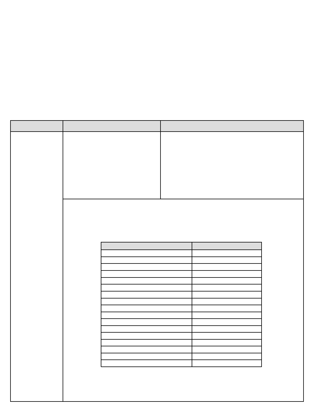
Each LED on the panel represents the state of one
of the control board inputs. If the input is grounded
(0V), the associated LED is turned ON. If the input
NOT grounded (open), the associated LED is turned
off. Each input (bold) has an associated LED as
described below:
1) Enter Configuration Mode
2) Press “2/3” button until “INPUT
MODE” is displayed.
3) Press “0/1” button to select
Input Mode. “READY” is displayed
on screen.
Input Display
Mode
(This mode is
used to test input
sensors and
circuitry)
Function / NotesEntry Sequence / IndicatorMode
Hopper Down SelectSweep Vacuum Fan LED
Hopper Up SelectOne Step Sweep LED
Solution Tank EmptyScrub Pressure Low LED
Solution Tank FullSolution Level High LED
Recovery Tank FullSolution Tank Medium LED
Recovery Tank Half FullSolution Tank Low LED
Open Scrub VacuumRed warning LED
Hopper Door CloseScrub Pressure Medium LED
Hopper Door Open
Impact Sense
Hopper Down Position
Thermal Sentry
Forward
Reverse
High Engine Temp
Clogged Shaker Filter
Clogged Hydraulic Filter
Input
One Step Scrub LED
Shaker LED
Squeegee/Scrub Vacuum Fan LED
Low Engine Speed LED
LED
Scrub Pressure High LED
Side Brush LED
FaST LED
ES LED
High Engine Speed LED
To enter the Configuration modes:
1) Press “4/5” and Side-Brush buttons simultaneously.
2) While holding the “4/5” and Side-Brush buttons, turn the ignition key switch to the “RUN” position.
3) Continue holding the “4/5” and Side-Brush buttons until “CONFIG MODE” is displayed on the screen,
then release the buttons.
While In Configuration Mode:
Each single activation of the “2/3” button will scroll through the various configurations available. Each
configuration is displayed one at a time on the LCD. Once the desired configuration mode is displayed,
push the “0/1” to select the displayed mode.
M20 Diagnostic Modes
(Page 2 of 2)
M20 331385 (02-2007)
126
E

HYDRAULIC
Troubleshooting Information
NOTE: Troubleshooting charts may be shown with optional equipment.
The optional equipment is not specified in these charts. Some machines
may not be equipped with all components shown.
BEFORE CONDUCTING TESTS:
DURING TESTS:
* Read and Follow ALL Safety Warnings and Precautions as
mentioned at the beginning of this manual
* Engine & Hydraulic Oil Must Be At Normal Operating Temperatures
after Running Machine and Hydraulics a Minimum of 5 Minutes
* Examine Machine For Any Linkage Binding or Mechanical
Problems
* Call Technical Services if Diagnostic Time Exceeds One Hour With
Unknown Cause or Course of Action
* Maintain Normal Main Brush Pressure as Listed in Operator's
Manual
M20
M20 331385 (02-2007)
127
H
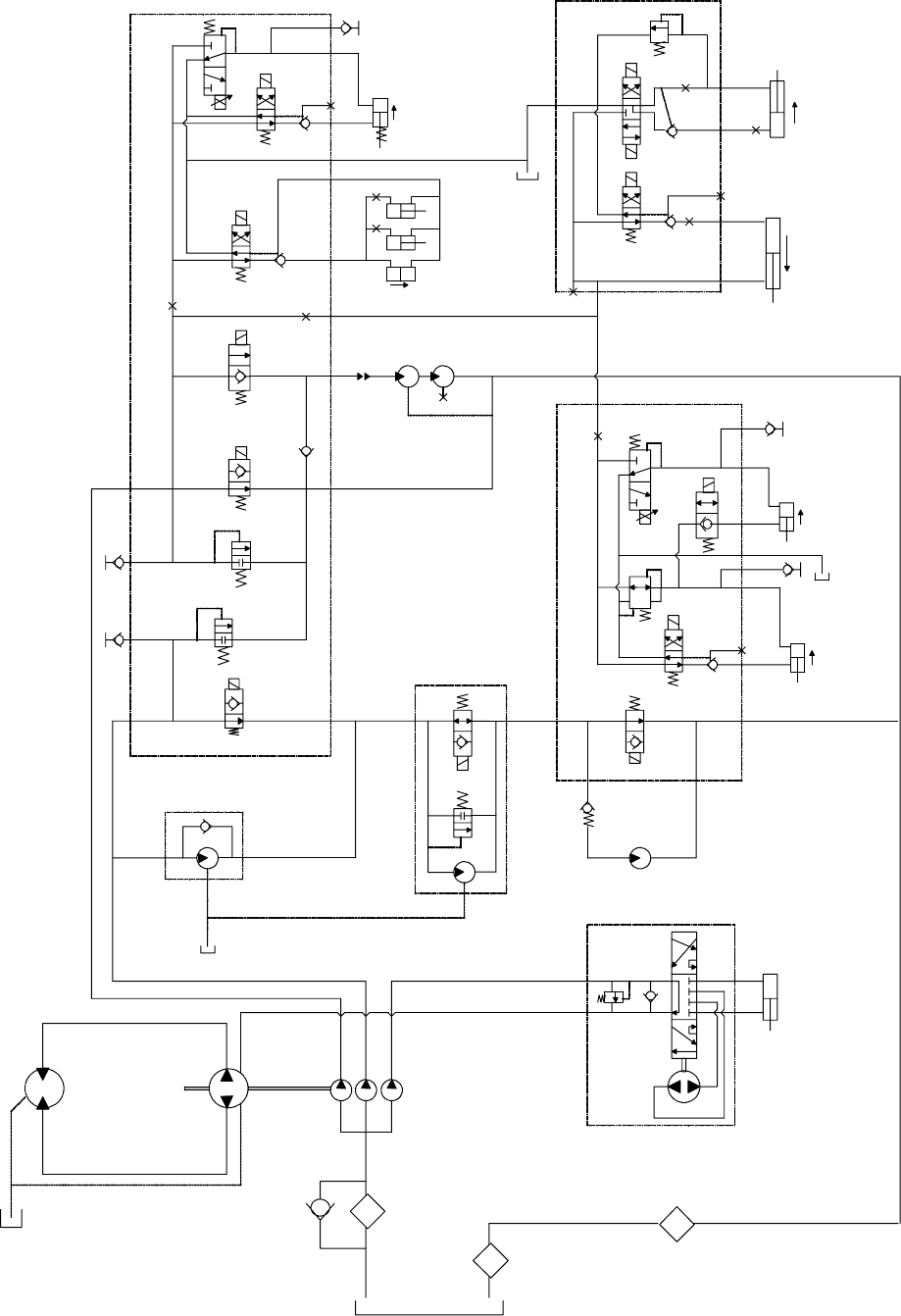
M20 Hydraulic Schematic
0.40
Cooler
Filter
35 psi bypass
Propel Pump
4000 psi Forward
RV, 3000 psi
Reverse RV, 1.24 cir
Propel
19.0 cir
Hot Oil
1160 psi
Steering Unit
6.1 cir
SteeringCyl
Engine,
2400 rpm
Hopper Door
Hopper Lift
SV13
SV14
SV15
Main
4.5 cir, 400 rpm
Main Scrub Lift
0.046
SV1
SV2
SV3
SV4
SV6
SV7
Reservoir
2500 psi
SV3 & SV6 TIED TOGETHER
Gear Pump
Scrub Fan
0.129 cir
Sweep Fan
0.194 cir
SV 9
1800 psi
T5
P5
C12
C9
C10
G11
C11
Scrub Valve
M1
T2
G2
C2
C4
C3
G1
C1
T1
P2
P1
G6
M4
P7
UP
(SPRING
UP)
UP
CLOSE
0.040
Side Scrub
Side Scrub
Lift
SV8
SV11
SV8 & SV11 TIED TOGETHER
0.040
OR3
SV10
C6
C8
G13
G7
G10
T3
P3
P4
G5
Screen
Side Scrub
Extend
SV12
PR1
400 psi C7
C5
T4
Oil
Temp Sender
Coupling
RV2
RV1
CV1
PC1
PC2
0.055
0.028
PC8
P6
PC6
PC5
Sweep Valve
Side Valve
RV3
500 PSI
M2 T6
LIFT
RETRACT
UP
Filter Indicators
Check
25 psi
Tube
Tube
Tube
Tube
Tube
0.031
Tube
Tubes
OR1
OR2
0.031
0.031 LH Side
RH Side
Rear
P
T
L
R
External
Charge
Port
Side & Rear
Squeegee
Valve
0.97 .61
Motor
Shuttle
Valve
2500 psi
M20 331385 (02-2007)
128
H
NOTE: Refer to the current Operators or Parts Manual for the most up-to-date information
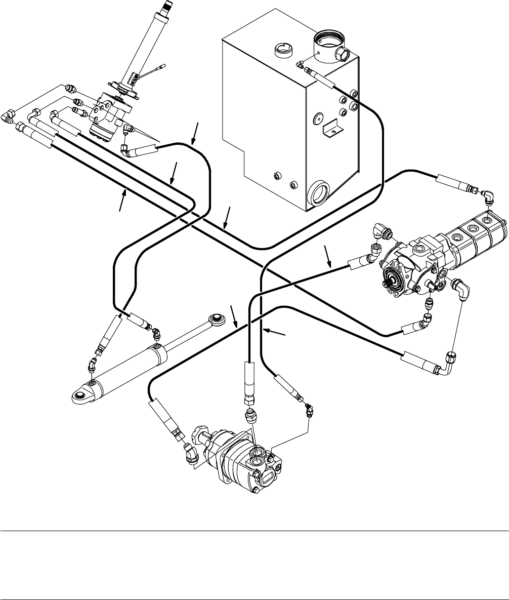
Hydraulic Hose Group, Steering and Propel
M20 Hydraulic Hose, Pump & Valve Drawings
(Page 1 of 19)
2
3
4
5
6
1
Reservoir
Propel Pump
Aux Pump
Wheel Drive
Motor
Steering
Valve
Steer
Cylinder
Out
In
L
R
3
354392
Ref. Part No. Serial Number Description Qty.
1(000000-- )Hose, Hyd, Tc08, Jf08e45/Jf08str, 96.0 1
2 1023608 (000000-- ) Hose, Hyd, Tc06, Jf06e90/Jf06str, 104.0 1
3 396221 (000000-- ) Hose, Hyd, Tc06, Jf06e90/Jf06str, 040.0 2
4 1023489 (000000-- ) Hose, Hyd, Spcl, Jf10e45/Jf10str, 58.0 1
5 1023488 (000000-- ) Hose, Hyd, Spcl, Jf10e90/Jf10str, 63.0 1
6(000000-- )Hose, Hyd,Med04, Jf04str/Jf04str, 066.0 1
M20 331385 (02-2007)
129
H
NOTE: Refer to the current Operators or Parts Manual for the most up-to-date information
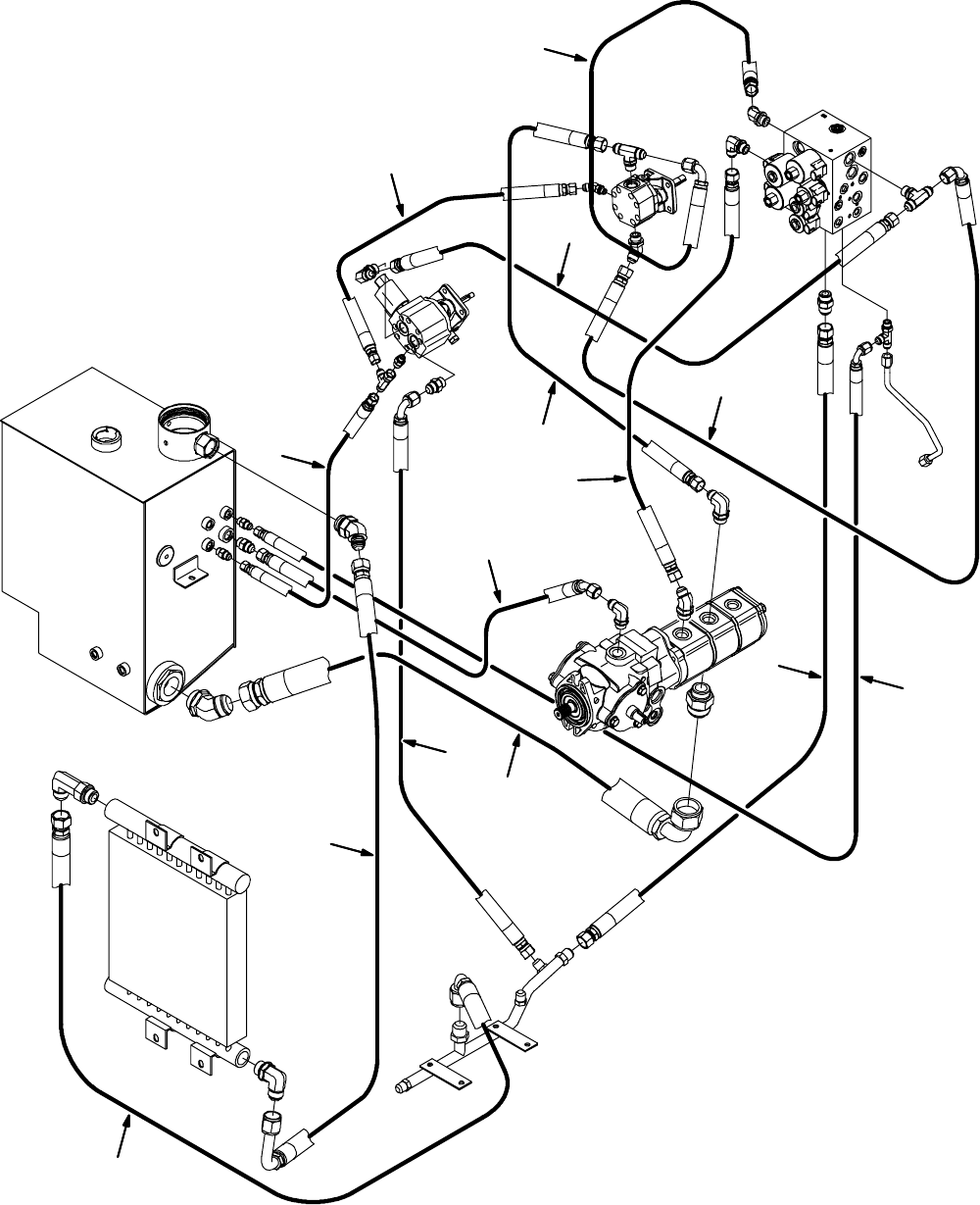
Hydraulic Hose Group, Pump and Vacuum Fans
M20 Hydraulic Hose, Pump & Valve Drawings
(Page 2 of 19)
2
3
4
5
6
7
8
9
10
1
11
12
13
14
Reservoir
Vac Fan
Motor
(Scrub)
Vac Fan
Motor
(Sweep)
Scrub Valve
Cooler
Propel Pump
Aux Pump
M4
P1
P2
T2
T1
M20 331385 (02-2007)
130
H
NOTE: Refer to the current Operators or Parts Manual for the most up-to-date information

Hydraulic Hose Group, Pump and Vacuum Fans
M20 Hydraulic Hose, Pump & Valve Drawings
(Page 3 of 19)
Ref. Part No. Serial Number Description Qty.
1(000000-- )Hose, Hyd, Tc08, Jf08e90/Jf08str, 046.0 1
2 361044 (000000-- ) Hose, Hyd, Med06, Jf06str/Jf06str, 018.0 1
3 381862 (000000-- ) Hose, Hyd, Tc08, Jf08str/Jf08str, 024.0 1
4 396255 (000000-- ) Hose, Hyd, Tc08, Jf08str/Jf08e90, 031.0 1
5 1026645 (000000-- ) Hose, Hyd, Tc08, Jf08e45/Jf08str, 26.0 1
6(000000-- )Hose, Hyd, Med06, Jf06str/Jf06str, 022.0 1
7 1023607 (000000-- ) Hose, Hyd, Med08, Jf08str /Jf08e45, 21.0 1
8 1023611 (000000-- ) Hose, Hyd, Suc20, Jf20str /Jf20e90, 29.0 1
9 396266 (000000-- ) Hose, Hyd, Med08, Jf08e90/Jf08str, 031.0 1
10 71735 (000000-- ) Hose, Hyd, Med06, Jf06e90/Jf06str, 042.0 1
11 (000000-- )Hose, Hyd, Med10, Jf10str/Jf10str, 41.0 1
12 396438 (000000-- ) Hose, Hyd, Tc12, Jf12e90/Jf12str, 044.0 1
13 1023487 (000000-- ) Hose, Hyd, Med12, Jf12e90/Jf12str, 50.0 1
14 1023606 (000000-- ) Hose, Hyd, Tc08, Jf08str/Jf08str, 21.0 1
M20 331385 (02-2007)
131
H
NOTE: Refer to the current Operators or Parts Manual for the most up-to-date information
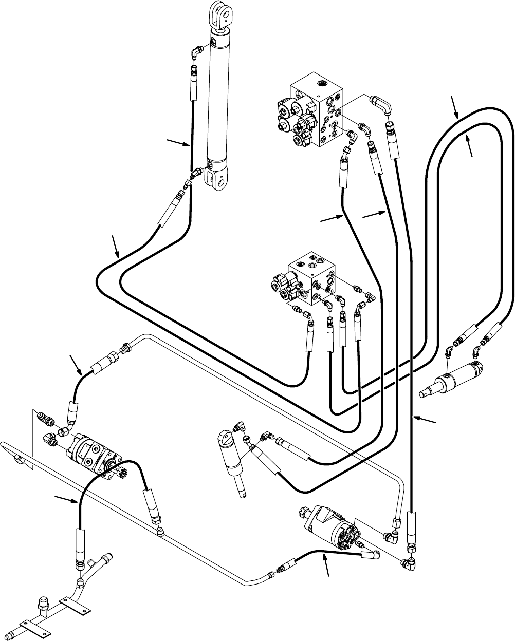
Hydraulic Hose Group, Brush and Hopper
M20 Hydraulic Hose, Pump & Valve Drawings
(Page 4 of 19)
23
4
5
6
7
8
9
10
1
Hopper Lift
Scrub Valve
Main Brush
Sweep Valve
Hopper Dump
Cylinder
Motor
(Front)
Main Brush
Motor
(Rear)
Door Cylinder
Brush LIft
Cylinder
M1
C1
C2
C12 C11
C10
C9
M20 331385 (02-2007)
132
H
NOTE: Refer to the current Operators or Parts Manual for the most up-to-date information

Hydraulic Hose Group, Brush and Hopper
M20 Hydraulic Hose, Pump & Valve Drawings
(Page 5 of 19)
Ref. Part No. Serial Number Description Qty.
1(000000-- )Hose, Hyd, Tc04, Jf04str /Jf04e90, 88.0 1
2 1027321 (000000-- ) Hose, Hyd, Tc04, Jf04str /Jf04e90, 70.0 1
3 1025548 (000000-- ) Hose, Hyd, Tc06, Jf06str /Jf06e45, 54.0 1
4 1026733 (000000-- ) Hose, Hyd, Spcl, Jf04str/Jf04str, 115.0 1
5 1024688 (000000-- ) Hose, Hyd, Spcl, Jf04str/Jf04str, 121.0 1
6(000000-- )Hose, Hyd, Tc08, Jf08str/Jf08str, 48.0 1
7 1023769 (000000-- ) Hose, Hyd, Tc 06, Jf06str /Jf06e45, 56.0 1
8 57946 (000000-- ) Hose, Hyd, Med04, Jf04e90/Jf04str, 016.0 1
9 1025544 (000000-- ) Hose, Hyd, Tc08, Jf08e90/Jf08str, 13.0 1
10 (000000-- )Hose, Hyd, Med08, Jf08str/Jf08str, 022.0 1
M20 331385 (02-2007)
133
H
NOTE: Refer to the current Operators or Parts Manual for the most up-to-date information
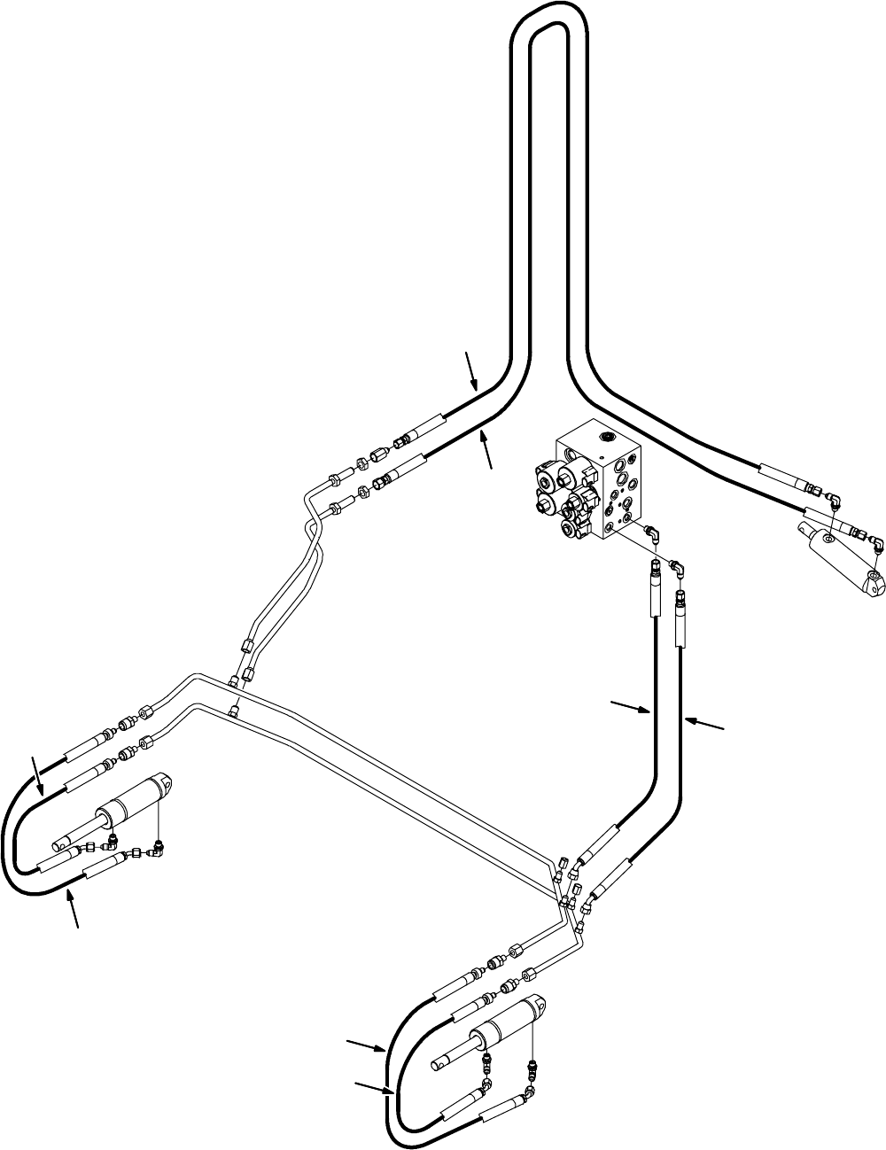
Hydraulic Hose Group, Squeegee Lift
M20 Hydraulic Hose, Pump & Valve Drawings
(Page 6 of 19)
2
3
4
5
1
Scrub Valve
C3
Rear Squeegee
Lift Cylinder
Right Side
Squeegee
Lift Cylinder
Left Side
Squeegee
Lift Cylinder
C4
3
4
5
M20 331385 (02-2007)
134
H
NOTE: Refer to the current Operators or Parts Manual for the most up-to-date information

Hydraulic Hose Group, Squeegee Lift
M20 Hydraulic Hose, Pump & Valve Drawings
(Page 7 of 19)
Ref. Part No. Serial Number Description Qty.
1(000000-- )Hose, Hyd, Spcl, Jf04str/Jf04str, 121.0 1
2 1025551 (000000-- ) Hose, Hyd, Spcl, Jf04str/Jf06str, 125.0 1
3 1030709 (000000-- ) Hose, Hyd,Tc 04, Jf04str /Jf04e45 , 35.0 2
4 1025550 (000000-- ) Hose, Hyd, Tc04, Jf04e45/Qm06, 28.0 2
5(000000-- )Hose, Hyd, Tc04, Jf04e45/Qm06, 26.0 2
M20 331385 (02-2007)
135
H
NOTE: Refer to the current Operators or Parts Manual for the most up-to-date information
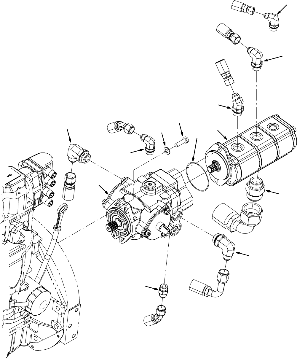
Hydraulic Pumps Group
M20 Hydraulic Hose, Pump & Valve Drawings
(Page 8 of 19)
1
2
3
45
67
8
9
10
11
12
4
M20 331385 (02-2007)
136
H
NOTE: Refer to the current Operators or Parts Manual for the most up-to-date information

Hydraulic Pumps Group
M20 Hydraulic Hose, Pump & Valve Drawings
(Page 9 of 19)
Ref. Part No. Serial Number Description Qty.
1(000000-- )Pump, Hyd, Piston, Var, 1.24 4000, Cw (See Breakdown) 1
2 44868 (000000-- ) Fitting, Hyd, E90, Jm08/Om08 1
3 44869 (000000-- ) Fitting, Hyd, Str, Jm08/Om08 1
4 53076 (000000-- ) Fitting, Hyd, E90, Jm10/Om12 2
5 21198 (000000-- ) Screw, Hex, .38--16 X 1.25, 5 22
6(000000-- )Washer, Flat, 0.38 Sae 2
7 1022666 (000000-- ) Pump, Hyd, Gear, Ext, 3, 00.97 2500, Cw 1
8 65145--1 (000000-- ) Seal, Org, .069 X 3.06id 11
9 47513 (000000-- ) Fitting, Hyd, E45, Jm08/Om10 1
10 56821 (000000-- ) Fitting, Hyd, E90, Jm08/Om10 1
11 (000000-- )Fitting, Hyd, E90, Jm06/Om08 1
12 67811 (000000-- ) Fitting, Hyd, Str, Jm20/Om16 1
M20 331385 (02-2007)
137
H
NOTE: Refer to the current Operators or Parts Manual for the most up-to-date information
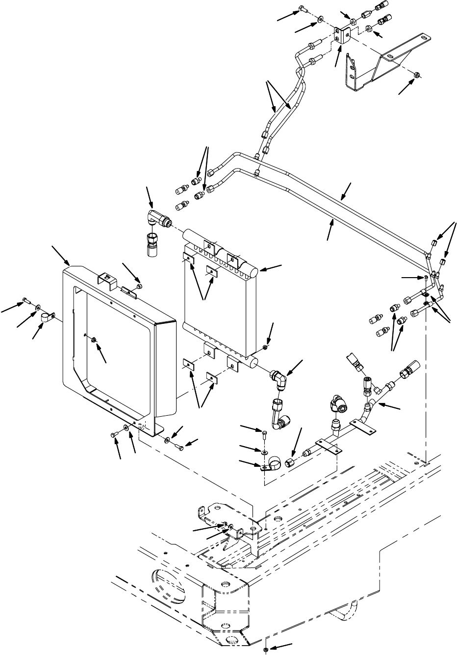
Hydraulic Cooler and Tubes Group
M20 Hydraulic Hose, Pump & Valve Drawings
(Page 10 of 19)
1
2
3
4
5
6
78
9
10
11
12
13
14
15
16
17
18
19
20
21
22
23
5
8
7
7
8
13
9
7
8
8
9
9
19
24
25
M20 331385 (02-2007)
138
H
NOTE: Refer to the current Operators or Parts Manual for the most up-to-date information

Hydraulic Cooler and Tubes Group
M20 Hydraulic Hose, Pump & Valve Drawings
(Page 11 of 19)
Ref. Part No. Serial Number Description Qty.
1(000000-- )Cooler, Hyd, 25gpm 325btu Of12 13x12x2 1
2 46481 (000000-- ) Fitting, Hyd, E90, Jm12/Om12 1
3 62471 (000000-- ) Fitting, Hyd, E90, Jm12/Om12, L 1
4 1026319 (000000-- ) Bracket Wldt, Cooler, Hyd Fluid 1
5 1026126 (000000-- ) Pad, Tank, Hyd 4
6(000000-- )Clamp, Cable, Stl, 1.00d X 0.62w, 1h 1
7 39277 (000000-- ) Screw, Hex, M8 X 1.25 X 25, 8.8 9
8 32491 (000000-- ) Washer, Flat, 0.31 Std 15
9 07791 (000000-- ) Nut, Hex, Flng, M8 X 1.25 9
10 51787 (000000-- ) Bumper, Rbr, 0.6d 0.34t .3d Tip 1
11 (000000-- )Tube, Hyd, Main Return [M20] 1
12 53466 (000000-- ) Clamp, Cable, Stl, 1.50d X 1.00w, 1h 1
13 1027002 (000000-- ) Fitting, Hyd, Str, Spcl 4
14 1028821 (000000-- ) Tube, Hyd, Sqge 1
15 1028822 (000000-- ) Tube, Hyd, Sqge 1
16 (000000-- )Clamp, Cable, Stl, 0.44d X 0.62w, 1h 2
17 74455 (000000-- ) Screw, Hex, M6 X 1.0 X 12, Fmg 1
18 1028823 (000000-- ) Tube, Hyd, Rear Sqge [M20] 2
19 35904 (000000-- ) Nut, Ftg, Hyd, 0.56--18 2
20 1026647 (000000-- ) Angle, Mtg, Stl, .12 1.6 1.6 02.2l 1
21 (000000-- )Screw, Hex, M10 X 1.5 X 25, 8.8 1
22 32492 (000000-- ) Washer, Flat, 0.38 Std 1
23 41430 (000000-- ) Nut, Hex, Lock, M10 X 1.5, Nl 1
24 50161 (000000-- ) Fitting, Hyd, Cap, Jf04 2
25 (000000-- )Fitting, Hyd, Cap, Jf08 1
M20 331385 (02-2007)
139
H
NOTE: Refer to the current Operators or Parts Manual for the most up-to-date information
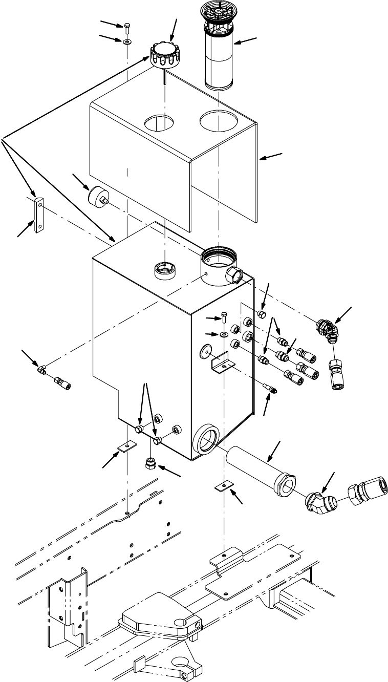
M20 Hydraulic Hose, Pump & Valve Drawings
(Page 12 of 19)
Hydraulic Reservoir Group
1
2
4
5
6
7
8
9
10
11
12
13
14
15
16
17
7
8
9
5
3
18
M20 331385 (02-2007)
140
H
NOTE: Refer to the current Operators or Parts Manual for the most up-to-date information

Hydraulic Reservoir Group
M20 Hydraulic Hose, Pump & Valve Drawings
(Page 13 of 19)
Ref. Part No. Serial Number Description Qty.
o1(000000-- )Reservoir, Hyd, 10.0 Gal 1
Y2 25122 (000000-- ) Cap, Breather, Hyd, 2.4 Ds 1
Y3 65215 (000000-- ) Gauge, Sensing, Level 1
4 56690 (000000-- ) Fitting, Hyd, Str, Jm06/Om06 2
5 46482 (000000-- ) Fitting, Hyd, Plug, Om06 3
6(000000-- )Fitting, Hyd, Str, Jm08/Om08 1
7 1026126 (000000-- ) Pad, Tank, Hyd 2
8 39277 (000000-- ) Screw, Hex, M8 X 1.25 X 25, 8.8 2
9 32491 (000000-- ) Washer, Flat, 0.31 Std 2
10 1023545 (000000-- ) Fitting, Hyd, E45, Jm12/Om16 1
11 (000000-- )Strainer, Hyd, 25gpm 100mesh Psi 1
12 71726 (000000-- ) Fitting, Hyd, E45, Jm20/Om20 1
13 1021579 (000000-- ) Filter Assy [Pt4 936498] 1
14 55455 (000000-- ) Fitting, Hyd, E90, Jm04/Pm02 1
15 58592 (000000-- ) Send--Unit, Water, Temp, 04npt 113oh/195d 1
16 (000000-- )Fitting, Hyd, Plug, Om10 1
17 1025132 (000000-- ) Indicator, Press, 60psi 1
18 1034878 (000000-- ) Insulation, Thermal, Hydraulic Blanket 1
M20 331385 (02-2007)
141
H
NOTE: Refer to the current Operators or Parts Manual for the most up-to-date information
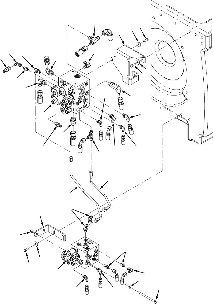
Hydraulic Valves Group
M20 Hydraulic Hose, Pump & Valve Drawings
(Page 14 of 19)
G1
M1
C1
P7
G5
G6
P2
C10
T2
C2
T1
C4
C3
P6
T5
M4
C12
C11
C9
P1
1
2
3
4
5
6
7
8
9
10
11
12
13
14
15
16
17
18
19
20
21
22 23
24
25
26
27
28
29
7
26
7
26
30
16
17
M20 331385 (02-2007)
142
H
NOTE: Refer to the current Operators or Parts Manual for the most up-to-date information

Hydraulic Valves Group
M20 Hydraulic Hose, Pump & Valve Drawings
(Page 15 of 19)
Ref. Part No. Serial Number Description Qty.
1(000000-- )Valve, Cntrl, Hyd [M20] (See Breakdowns) 1
2 49883 (000000-- ) Screw, Hex, M8 X 1.25 X 120, 8.8, Fl 2
3 32491 (000000-- ) Washer, Flat, 0.31, Std 2
4 08709 (000000-- ) Nut, Hex, Lock, M8 X 1.25, Nl 2
5 77097 (000000-- ) Fitting, Hyd, E90, Jm04/Om04 2
6(000000-- )Fitting, Hyd, Str, Jm04/Om04 2
7 77097 (000000-- ) Fitting, Hyd, E90, Jm04/Om04 2
8 39210 (000000-- ) Fitting, Hyd, E90, Jf04/Jm04 1
9 47522 (000000-- ) Fitting, Hyd, E45, Jm06/Om06 2
10 1020708 (000000-- ) Bracket, Mtg, Valve, Hyd, Swp 1
11 (000000-- ) Screw, Hex, M8 X 1.25 X 20, Ss 2
12 1017218 (000000-- ) Washer, Flat, 0.32b 1.00d .12, Ss 2
13 1022482 (000000-- ) Tube, Hyd, Swp 1
14 1022484 (000000-- ) Tube, Hyd, Swp 1
15 1020394 (000000-- ) Valve, Cntrl, Hyd (See Breakdowns) 1
16 (000000-- ) Screw, Hex, M8 X 1.25 X 20, Ss 6
17 1017218 (000000-- ) Washer, Flat, 0.32b 1.00d .12, Ss 6
18 1021991 (000000-- ) Bracket, Mtg, Valve, Hyd, Scb 1
19 39210 (000000-- ) Fitting, Hyd, E90, Jf04/Jm04 1
20 395973 (000000-- ) Fitting, Hyd, Str, Om04/Qm04 1
21 (000000-- )Fitting, Hyd, E90, Om04/Qm04 1
22 396476 (000000-- ) Fitting, Hyd, Str, Jf04/Qm04 1
23 42226 (000000-- ) Fitting, Hyd, E45, Jm08/Om08 1
24 44868 (000000-- ) Fitting, Hyd, E90, Jm08/Om08 1
25 55586 (000000-- ) Fitting, Hyd, Str, Jm04/Om04 1
26 (000000-- )Fitting, Hyd, E90, Jm06/Om06 3
27 46480 (000000-- ) Fitting, Hyd, Str, Jm10/Om10 1
28 49933 (000000-- ) Fitting, Hyd, Tee, Jm08/Jm08/Om08, Br 1
29 69173 (000000-- ) Fitting, Hyd, E90, Jm08/Om08, L 1
30 (000000-- )Fitting, Hyd, Tee, Jm06/Jm06/Om06, Run 1
M20 331385 (02-2007)
143
H
NOTE: Refer to the current Operators or Parts Manual for the most up-to-date information
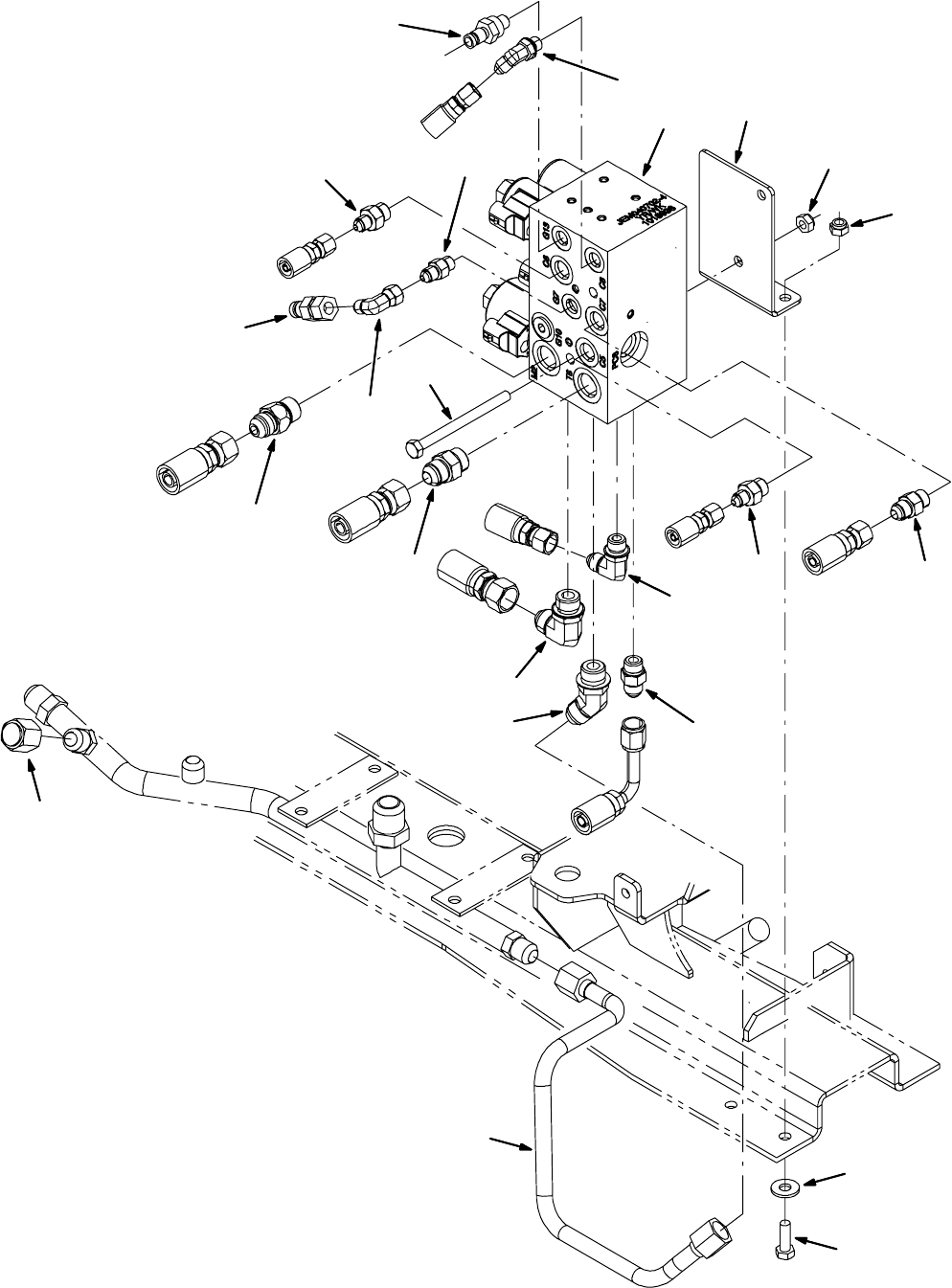
P3
G13
C8
M2
G7
P4
T4
C5 C7
T6
T3
C6
1
2
3
4
5
6
7
8
9
10
11
12
13
14
15
16
17
18
19
20
21
2
3
Side Brush Hydraulic Valve Group
M20 Hydraulic Hose, Pump & Valve Drawings
(Page 16 of 19)
M20 331385 (02-2007)
144
H
NOTE: Refer to the current Operators or Parts Manual for the most up-to-date information

Ref. Part No. Serial Number Description Qty.
1(000000-- )Valve, Cntrl, Hyd [M20 And T20] (See Breakdown) 1
2 56690 (000000-- ) Fitting, Hyd, Str, Jm06/Om06 2
3 55685 (000000-- ) Fitting, Hyd, Str, Jm04/Om06 2
4 34359 (000000-- ) Fitting, Hyd, E45, Jm04/Om04 1
5 44868 (000000-- ) Fitting, Hyd, E90, Jm08/Om08 1
6(000000-- )Fitting, Hyd, Str, Om04/Qm04 1
7 1026119 (000000-- ) Valve, Hyd, Check, Jm08/Om08 5000psi 1
8 55586 (000000-- ) Fitting, Hyd, Str, Jm04/Om04 1
9 39210 (000000-- ) Fitting, Hyd, E90, Jf04/Jm04 1
10 396476 (000000-- ) Fitting, Hyd, Str, Jf04/Qm04 1
11 (000000-- )Fitting, Hyd, Str, Jm08/Om08 1
12 42226 (000000-- ) Fitting, Hyd, E45, Jm08/Om08 1
13 56820 (000000-- ) Fitting, Hyd, E90, Jm06/Om06 1
14 1025405 (000000-- ) Tube, Hyd, 08 Jf08/Jf08 1
15 1025834 (000000-- ) Bracket, Valve, Sba [M20 And T20] 1
16 (000000-- )Screw, Hex, M8 X 1.25 X 100, 8.8 2
17 08709 (000000-- ) Nut, Hex, Lock, M8 X 1.25, Nl 2
18 09010 (000000-- ) Screw, Hex, M8 X 1.25 X 25, Ss 2
19 32491 (000000-- ) Washer, Flat, 0.31, Std 2
20 08713 (000000-- ) Nut, Hex, Lock, M8 X 1.25, Nl, Ss 2
21 (000000-- )Fitting, Hyd, Cap, Jf08 1
M20 Hydraulic Hose, Pump & Valve Drawings
(Page 17 of 19)
Side Brush Hydraulic Valve Group
M20 331385 (02-2007)
145
H
NOTE: Refer to the current Operators or Parts Manual for the most up-to-date information
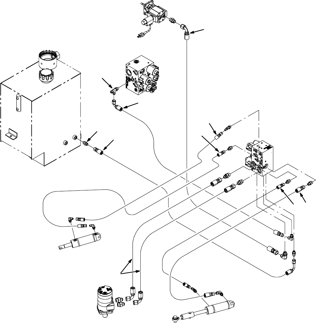
C8
C6
M2
T6
P3
C7
P4
T4
P7
C5
1
2
3
4
5
6
7
8
9
10
M20 Hydraulic Hose, Pump & Valve Drawings
(Page 18 of 19)
Side Brush Hydraulic Hose Group
M20 331385 (02-2007)
146
H
NOTE: Refer to the current Operators or Parts Manual for the most up-to-date information

Ref. Part No. Serial Number Description Qty.
1(000000-- )Hose, Hyd, Med06, Jf06e90l/Jf06str,038.0 1
2 1023485 (000000-- ) Hose, Hyd, Tc06, Jf06str/Jf06str, 033.0 1
3 1025990 (000000-- ) Hose, Hyd, Tc04, Jf04str /Jf04str, 39.0 1
4 1023486 (000000-- ) Hose, Hyd, Tc08, Jf08e90/Jf08str, 034.0 2
5 1025991 (000000-- ) Hose, Hyd, Tc06, Jf06str /Jf06str, 23.0 1
6(000000-- )Hose, Hyd, Tc04, Jf04str /Jf04str, 20.0 1
7 1025445 (000000-- ) Hose, Hyd, Tc06, Jf06str /Jf06e90, 74.0 1
8 365004 (000000-- ) Hose, Hyd, Tc08, Jf08e90/Jf08str, 056.0 1
9 56690 (000000-- ) Fitting, Hyd, Str, Jm06/Om06 1
10 (000000-- )Fitting, Hyd, Tee, Jm06/Jm06/Om06, Run 1
M20 Hydraulic Hose, Pump & Valve Drawings
(Page 19 of 19)
Side Brush Hydraulic Hose Group
M20 331385 (02-2007)
147
H
NOTE: Refer to the current Operators or Parts Manual for the most up-to-date information
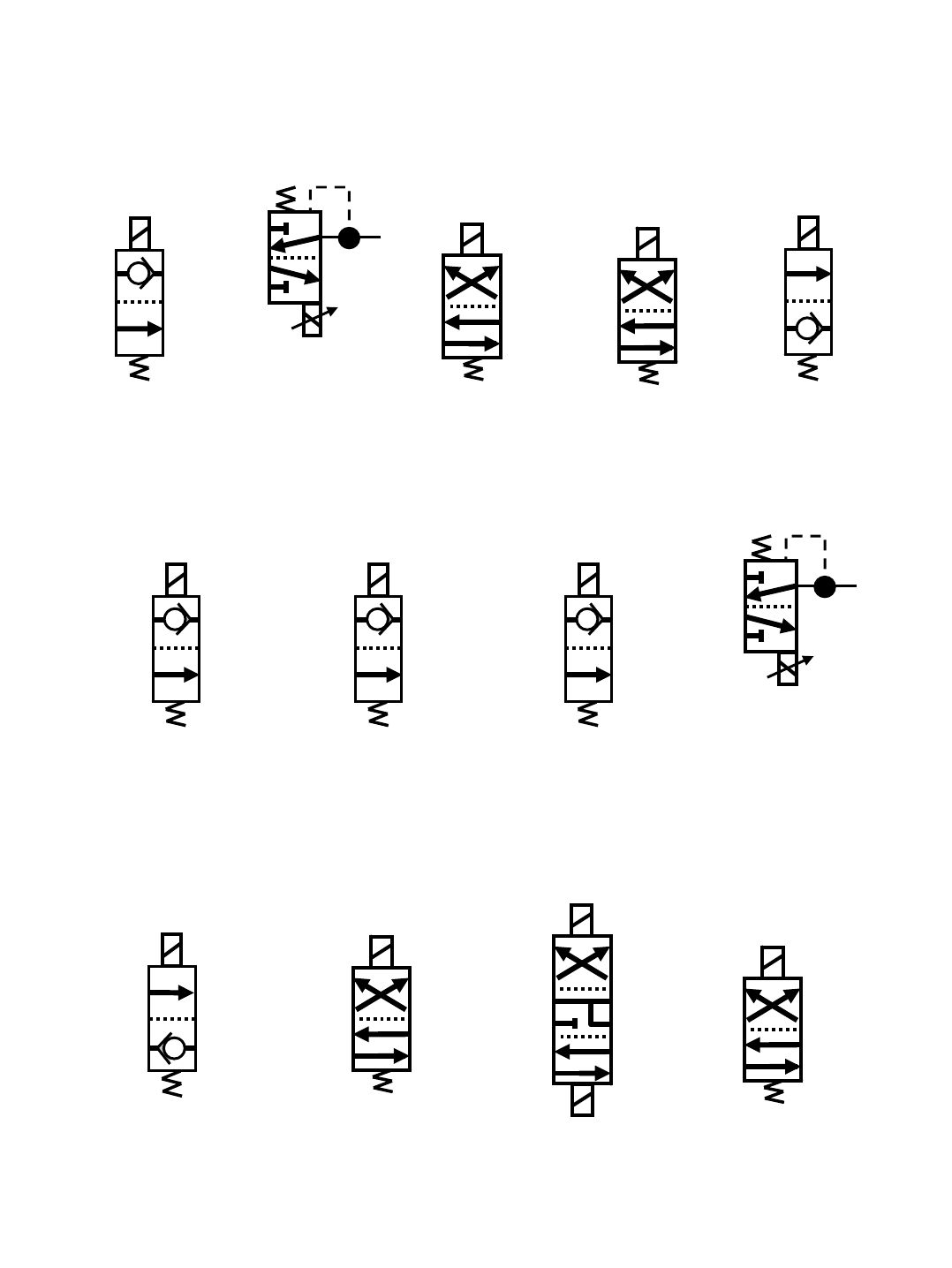
M20 Hydraulic Solenoid Valve Details
SV1
SV2
*PWM*
SV3 SV4 SV6
SV7 SV8 SV9
SV10
*PWM*
SV11 SV12
SV14
SV13
SV15
M20 331385 (02-2007)
148
H
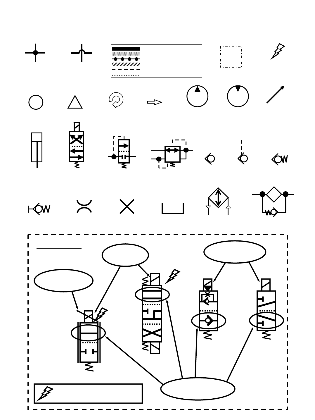
Commonly Used Hydraulic Symbols
Lines Connected
Together
Lines Not
Connected
Together
Component
is Energized
Information
!
Warning!
Assembly
Pressure / Flow Line
Return or Low Pressure Line
Active Pilot Port Line
Inactive Pilot Port Line
Case Drain Line
Suction Line
Component
is Rotating
Hydraulic
Flow
Hydraulic
Pump
Hydraulic
Motor
Relief Valve
Hydraulic
Cylinder
Hydraulic
Solenoid Valve
Pressure
Reducing Valve
Check
Valve
Spring Loaded
Check Valve
No ConnectionQuick Connect
Test Port
Restrictor or
Orifice
Oil Tank or
Reservoir
Oil Cooler or
Heat Exchanger
Oil Filter
With Bypass
Pilot Port
Check Valve
Variable
or PWM
Indicates Energized Solenoid Valve Coil
EXAMPLES
Circled envelope is
valve position for indicated
hydraulic circuit
SV19
A
B
SV25
Arrow indicates a
PWM (Pulse Width
Modulated) valve
SV14 SV7
Energized
Coils
Non-Energized
Coils
M20 General Information
(Page 1 of 2)
i
M20 331385 (02-2007)
149
H
M20 Hydraulic Pump Flow Rates (typical)
ENGINE @
2400 RPM
10 GPM
(37.9 LPM)
4 GPM
(15.1 LPM)
6 GPM
(22.7 LPM)
PROPEL
PUMP
ACCESSORY PUMPS
PUMP
1
PUMP
2
PUMP
3
M20 General Information
(Page 2 of 2)
AUX Auxiliary
CIR Cubic Inch Displacement per Revolution
CK Check Valve
CM Centimeters
CONV Conveyor
CU Cubic
CV Control Valve
CYL Cylinder
DC Disconnect Coupler (Hydraulic)
DC Direct Current (Electrical)
E Engine (Combustion)
FLTR Filter
GPM Gallons Per Minute
HTX Heat Exchanger
IN Inches
LH Left Hand
LPM Liters Per Minute
LS Load Sense
M Motor (Combustion)
MFLD Man ifo ld
MTR Motor (Hydraulic)
OR Orifice
PC Pilot Port Check Valve
PMP Pump
PR Pressure Relief Valve
PSI Pounds Per Square Inch
PTO Power Take Off
PWM Pulse Width Modulation
RES Reservoir
RH Right Hand
RPM Revolutions Per Minute
RV Relief Valve
SC Spring Loaded Check Valve
STRN Strainer
SV Solenoid Valve
SW Switch
TV Throttle Valve
VVolts
C Hydraulic Cylinder Connection
GTest Port
LS Load Sense Port
M Hydraulic Motor Connection
P Pump Connection
R or T Return Port (To Tank)
Commonly Used Abbreviations
Typical Hydraulic Manifold Port Markings
12.5 GPM
(47.3 LPM)
maximum
M20 331385 (02-2007)
150
H

Component /
System Function Test Port Test Port
Location
Enable
Coil Energized Coil(s) Notes Valve Block Valve Block
Number Location Feed Port Exit Port
Pressure
Control in
Circuit
Pressure
Setting (PSI) Notes
Down G1 SV2, SV3 C1 C2 SV2 0 to 800
Up C2 default C2 C1 RV2 2500
Down G5 SV4
Operate Squeegees "Up and Down"
using Manual Mode--Monitor pressure
at G5
C4 C3
Up C3 default C3 C4
Closed P5 default C11 C10
Open G11 SV15 C10 C11
Main Brushes Run G5 Scrub
Valve SV7 SV6
Operate Main Brushes "On" using
Manual Mode--Monitor pressure at G5;
SV3 and SV6 tied together electrically
Scrub
Valve 1020394
Left Side, on
vacuum fan
frame
M1 Direct to
Tank RV2 2500
Operating Flow
from Pump # 1
(inner most pump)
Down SV13 500 PSI RV3 keeps hopper pushed
tight to frame C12 C9 RV3 500
Up SV14 C9 C12 RV2 2500
Scrub Fan Run G6 Scrub
Valve - SV1 Scrub
Valve 1020394
Left Side, on
vacuum fan
frame
Direct
from
Pump
Direct to
Tank RV1 2500
Operating Flow
from Pump # 2
(middle pump)
Sweep Fan Run G6 Scrub
Valve - SV9 On Sweep
Fan Motor 53485 On sweep
fan motor
M4
(on Scrub
Valve)
P3
(on Side
Valve)
On Sweep
Fan Motor 1800
Operating Flow
from Pump # 2
(middle pump)
Side Brush
(Sweep/Scrub) Run G6 Scrub
Valve - SV8
Operate Side Brush "On" using Manual
Mode--Monitor pressure at G6; SV8
and SV11 tied together electrically
Side Valve 1018938 Left front M2 T6 RV1 2500
Operating Flow
from Pump # 2
(middle pump)
Up G7 default C8 C6 PR1 400
Down G13 SV10, SV11 C6 C8 SV10 0 to 800
Retract C5 default C5 C7 RV1 2500
Extend G7 SV12 C7 C5 PR1 400
1020394
Left Side, on
vacuum fan
frame
RV2
Operating Flow
from Pump # 1
(inner most pump)
Left Side, on
vacuum fan
frame
Side Brush
Scrub Head
Squeegees,
Side and Rear
Hopper Door
Scrub
Valve
Operating Flow
from Pump # 1
(inner most pump)
Hopper Lift
SV7
1020394
Scrub
Valve
SV7
Scrub
Valve
SV2 is PWM controlled; Down
pressure varies with current to SV2;
SV3 and SV6 tied together electrically
Left Side, on
vacuum fan
frame
2500
Operating Flow
from Pump # 1
(inner most pump)
Side
Valve SV7 Side Valve 1018938 Left front
Operating Flow
from Pump # 1
(inner most pump)
Scrub
Valve
Lift Hopper, Operate Hopper Door
"Open and Closed" using Manual Mode
-
-Monitor pressure at P5 and/or G11
Operating Flow
from Pump # 1
(inner most pump)
Sweep
Valve SV7 Sweep
Valve 1018936
Left Side, on
vacuum fan
frame
RV2 2500
Sweep
Valve
SV10 is PWM controlled; Operate
Side Brush up and down using Manual
Mode; SV8 and SV11 tied together
electrically; If main brush is ON, there
may not be enough pump pressure to
fully retract against the 400 PSI.
1018936P5 Sweep
Valve SV7
M20 Operating Matrix
M20 331385 (02-2007)
151
H

M20 Option Components
E = Electrical Component
H = Hydraulic Component
The following chart lists various options and the electrical and/or hydraulic components
that are associated with the option. Refer to the “notes” section for any components that
are deleted from a standard machine in order to have the installed option.
option added components E or H component # notes
Side Brush ON Solenoid Valve E,H SV-8
Side Brush Pressure Solenoid Valve E,H SV-10
Side Brush Down Solenoid Valve E,H SV-11
Side Brush Extend Solenoid Valve E,H SV-12
FaST Side Brush Valve ESOL-6
Side Brush Water Valve ESOL-7
Side Brush Manifold Hx
Side Brush Lift Cylinder Hx
Side Brush Extend Cylinder Hx
Side Brush Motor Hx
Solution Tank Auto Fill Water Valve ESOL-1
Recovery Tank Auto Fill Water Valve ESOL-2
Solution Tank Full Switch ES-14
Recovery Tank Half Full Switch ES-16
Detergent Pump Ex
ES Pump Ex
Spray Hose Pump Ex
Spray Hose Relay EM12
Spray Hose Switch ES-25
ES
(Extended Scrub)
If machine has ES option, the following
components will not be on the
machine: FaST Water Pump, FaST
Water Pump Relay (M11), FaST
Detergent Pump, FaST Air Pump,
FaST Enable Valve (SOL-4), FaST
High Flow Valve (SOL-5), FaST Side
Brush Valve (SOL-6)
Spray
Hose Side Brush
M20 331385 (02-2007)
152
H
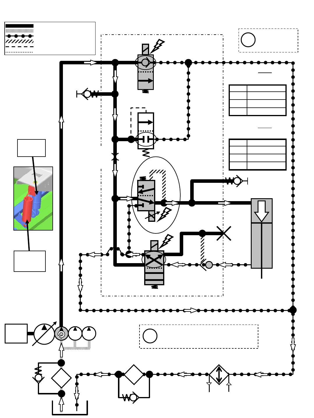
M20 Scrub/Sweep Head Lower
Engine speed: 2400 RPM
SV7
G5
SV2
SV3
LOWER
G2
G1
P2
T1
C2
C1
SCRUB HEAD
ACTUATOR
T2
SCREEN
SCRUB MANIFOLD
ENGINE
OIL
FILTER
OIL
COOLER
PC1
*PWM*
Pressure / Flow Line
Return or Low Pressure Line
Active Pilot Port Line
Inactive Pilot Port Line
Case Drain Line
Suction Line Gray items are
energized
or activated
Typical Default
Pressure Readings (+/- 15%)
(SCRUBBING)
Typical Default
Pressure Readings (+/- 15%)
(SWEEPING)
Pressure settings P1, P2, & P3 are
the Touch Panel LED indicators
for Main Brush down pressure
Scrub
Head
Actuator
NOTE
SPRING
ASSIST
i
i
240psi (16.5 bar)
159psi (11 bar)
44psi (3 bar)
Pressure at G1
P3
P2
P1
Setting
66psi (4.5 bar)
22psi (1.5 bar)
5psi (0.34 bar)
Pressure at G1
P3
P2
P1
Setting
ORIFICE
0.046 in
(1.17 mm)
RV2
2500 PSI
(172.4 BAR)
35 PSI
(2.4 BAR)
M20 331385 (02-2007)
153
H
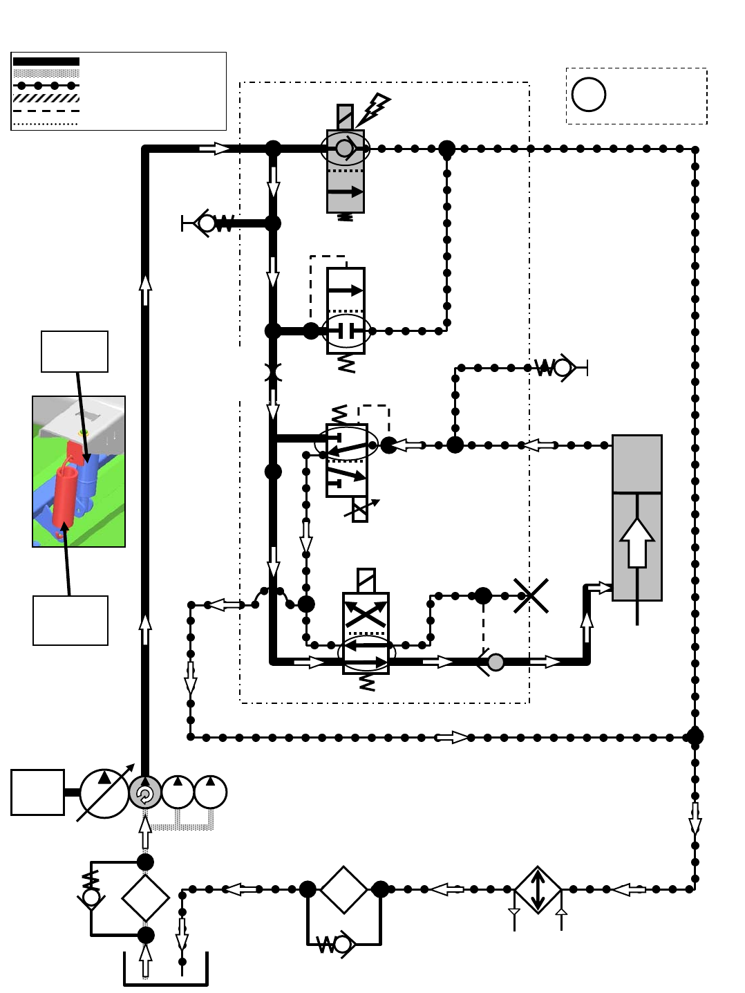
G2
M20 Scrub/Sweep Head Lift
Engine speed: 2400 RPM
SV7
G5
SV3
LIFT
G2
G1
P2
T1
C2
C1
SCRUB HEAD
ACTUATOR
T2
SCREEN
SCRUB MANIFOLD
OIL
FILTER
OIL
COOLER
PC1
SV2
Pressure / Flow Line
Return or Low Pressure Line
Active Pilot Port Line
Inactive Pilot Port Line
Case Drain Line
Suction Line
ENGINE
Scrub
Head
Actuator
NOTE
SPRING
ASSIST
Gray items are
energized
or activated
i
ORIFICE
0.046 in
(1.17 mm)
RV2
2500 PSI
(172.4 BAR)
35 PSI
(2.4 BAR)
M20 331385 (02-2007)
154
H
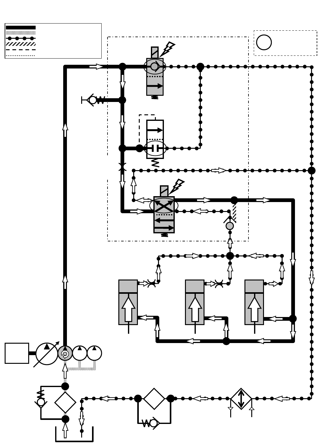
M20 Squeegees Lower
Engine speed: 2400 RPM
SV7
G5
P2
SV4
C4
T1
C2
LOWER
LEFT
SQUEEGEE
ACTUATOR
RIGHT
SQUEEGEE
ACTUATOR
REAR
SQUEEGEE
ACTUATOR
T2
SCREEN
SCRUB MANIFOLD
OIL
FILTER
OIL
COOLER
PC2
LOWER
LOWER
Pressure / Flow Line
Return or Low Pressure Line
Active Pilot Port Line
Inactive Pilot Port Line
Case Drain Line
Suction Line
ENGINE
Gray items are
energized
or activated
i
ORIFICE
0.046 in
(1.17 mm)
RV2
2500 PSI
(172.4 BAR)
35 PSI
(2.4 BAR)
ORIFICE
0.031 in
(0.79 mm)
ORIFICE
0.031 in
(0.79 mm)
M20 331385 (02-2007)
155
H
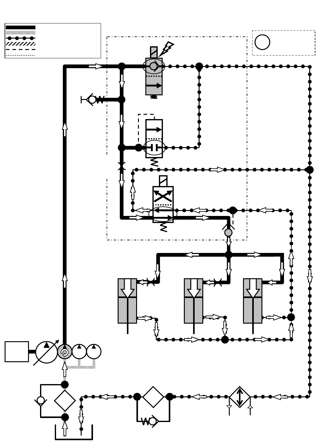
M20 Squeegees Lift
Engine speed: 2400 RPM
SV7
G5
OIL
COOLER
P2
SV4
C4
T1
C2
LIFT
LIFT
LIFT
LEFT
SQUEEGEE
ACTUATOR
RIGHT
SQUEEGEE
ACTUATOR
REAR
SQUEEGEE
ACTUATOR
T2
SCREEN
SCRUB MANIFOLD
OIL
FILTER
PC2
Pressure / Flow Line
Return or Low Pressure Line
Active Pilot Port Line
Inactive Pilot Port Line
Case Drain Line
Suction Line
ENGINE
Gray items are
energized
or activated
i
ORIFICE
0.046 in
(1.17 mm)
RV2
2500 PSI
(172.4 BAR)
35 PSI
(2.4 BAR)
ORIFICE
0.031 in
(0.79 mm)
ORIFICE
0.031 in
(0.79 mm)
M20 331385 (02-2007)
156
H
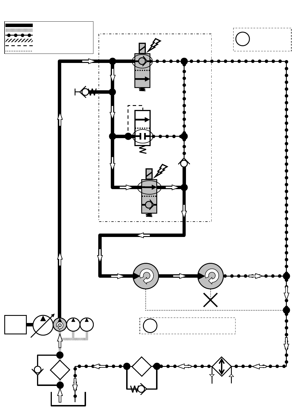
M20 Main Brushes ON
Engine speed: 2400 RPM
SV7
G5
OIL
COOLER
P2
SV6
M1
CV1
T2
SCREEN
SCRUB MANIFOLD
REAR MAIN
BRUSH
MOTOR
FRONT MAIN
BRUSH
MOTOR
OIL
FILTER
Pressure / Flow Line
Return or Low Pressure Line
Active Pilot Port Line
Inactive Pilot Port Line
Case Drain Line
Suction Line
ENGINE Main Brush Motors speed:
420-480 RPM
Gray items are
energized
or activated
i
i
RV2
2500 PSI
(172.4 BAR)
35 PSI
(2.4 BAR)
M20 331385 (02-2007)
157
H
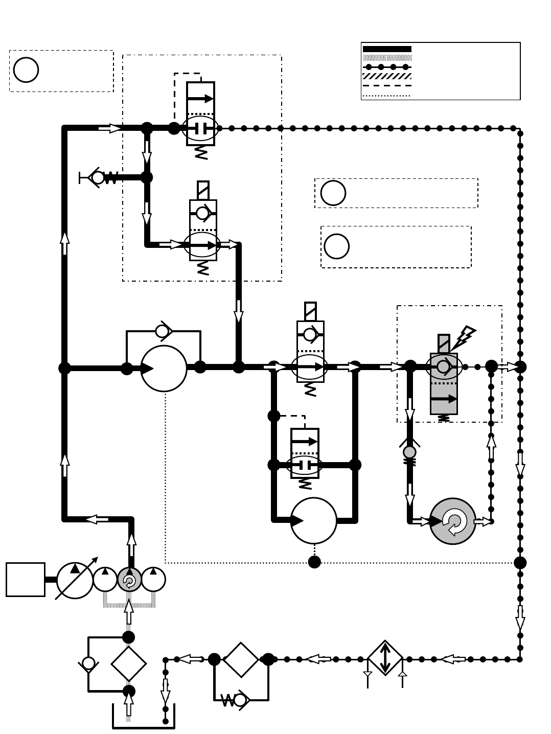
M20 Side Brush ON
Engine speed: 2400 RPM
SV1
G6
OIL
COOLER
P1 T2
SCREEN
SCRUB MANIFOLD
SV9
1800 PSI
(124 BAR)
SCRUB FAN
MOTOR
OIL
FILTER
SWEEP FAN
MOTOR
SIDE BRUSH
MOTOR
SV8
SIDE BRUSH MANIFOLD
Pressure / Flow Line
Return or Low Pressure Line
Active Pilot Port Line
Inactive Pilot Port Line
Case Drain Line
Suction Line
ENGINE
Side Brush Motor speed:
140-160 RPM
Gray items are
energized
or activated
i
i
RV1
2500 PSI
(172.4 BAR)
35 PSI
(2.4 BAR)
25 PSI
(1.7 BAR)
G6
M4
P3 T3
M2 T6
Side Brush can only be
operated when Main
Brushes are ON
i
M20 331385 (02-2007)
158
H
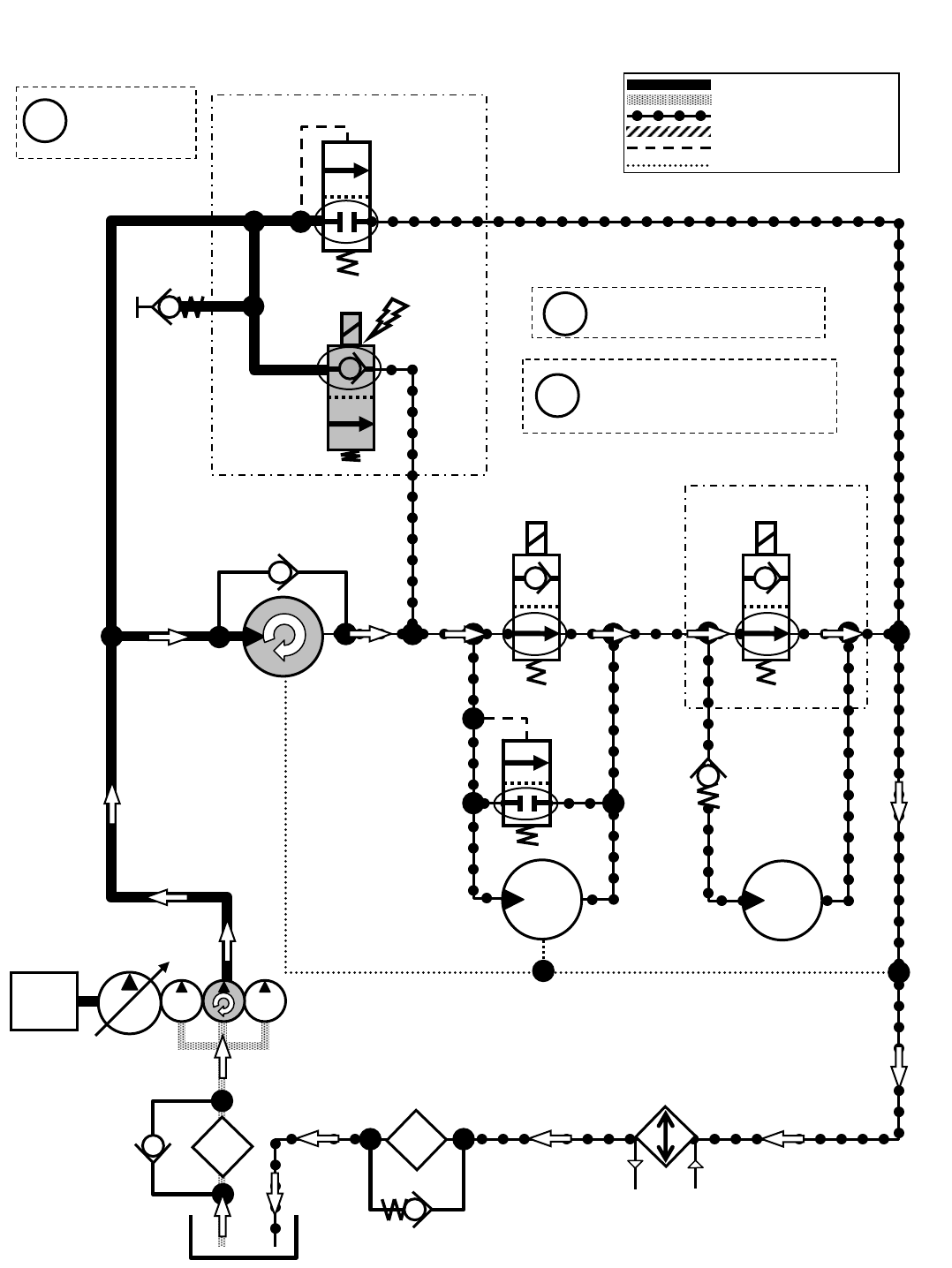
SCREEN
ENGINE
M20 Scrub Vacuum Fan ON
Engine speed: 2400 RPM
SV1
G6
OIL
COOLER
P1 T2
SCRUB MANIFOLD
SV9 SV8
SIDE BRUSH MANIFOLD
SCRUB FAN
MOTOR
M4
P3
M2 T6
OIL
FILTER
SWEEP FAN
MOTOR
SIDE BRUSH
MOTOR
Pressure / Flow Line
Return or Low Pressure Line
Active Pilot Port Line
Inactive Pilot Port Line
Case Drain Line
Suction Line
Scrub Fan Motor speed:
10,500 RPM (+/- 150 RPM)
Gray items are
energized
or activated
i
i
RV1
2500 PSI
(172.4 BAR)
35 PSI
(2.4 BAR)
1800 PSI
(124 BAR)
T3
25 PSI
(1.7 BAR)
Scrub Fan Motor vacuum:
34-39 in/H2O (86-99 cm/H2O)
measured at squeegee
i
M20 331385 (02-2007)
159
H
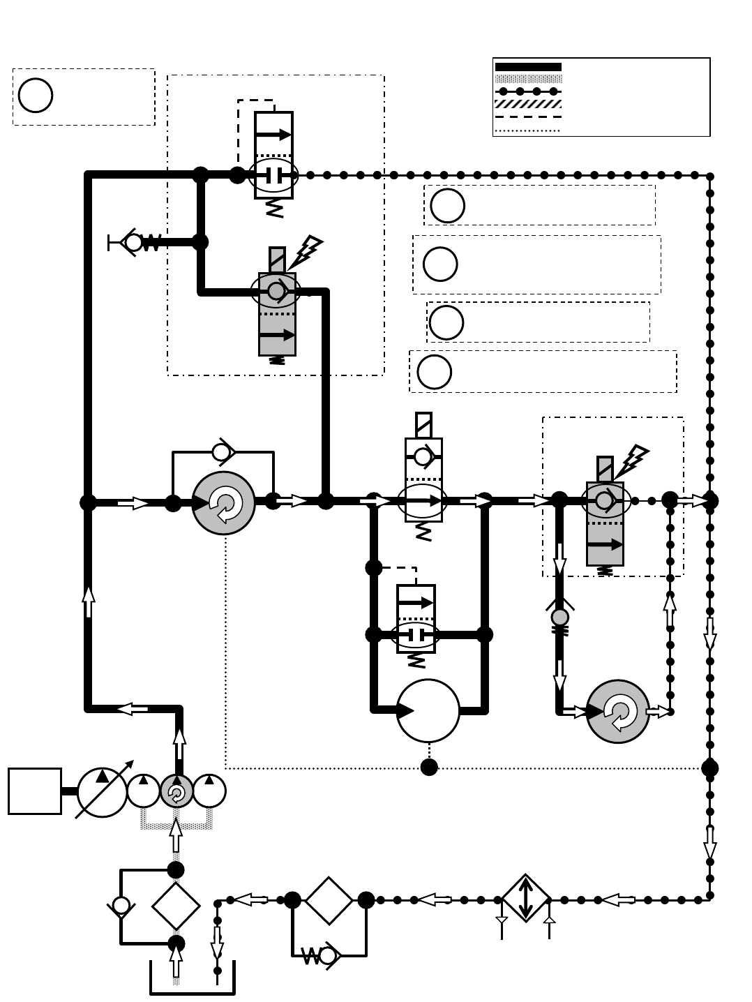
ENGINE
M20 Scrub Vacuum Fan & Side Brush ON
Engine speed: 2400 RPM
SV1
G6
OIL
COOLER
P1 T2
SCREEN
SCRUB MANIFOLD
SCRUB FAN
MOTOR
SV9
SV8
SWEEP FAN
MOTOR
SIDE BRUSH MANIFOLD
SIDE BRUSH
MOTOR
OIL
FILTER
Pressure / Flow Line
Return or Low Pressure Line
Active Pilot Port Line
Inactive Pilot Port Line
Case Drain Line
Suction Line
Side Brush Motor speed:
140-160 RPM
Scrub Fan Motor speed:
10,500 RPM (+/- 150 RPM)
Gray items are
energized
or activated
i
i
i
RV1
2500 PSI
(172.4 BAR)
35 PSI
(2.4 BAR)
1800 PSI
(124 BAR)
P3
M2 T6
T3
M4
25 PSI
(1.7 BAR)
Scrub Fan Motor vacuum:
34-39 in/H2O (86-99 cm/H2O)
measured at squeegee
i
Side Brush can only be operated
when Main Brushes are ON
i
M20 331385 (02-2007)
160
H
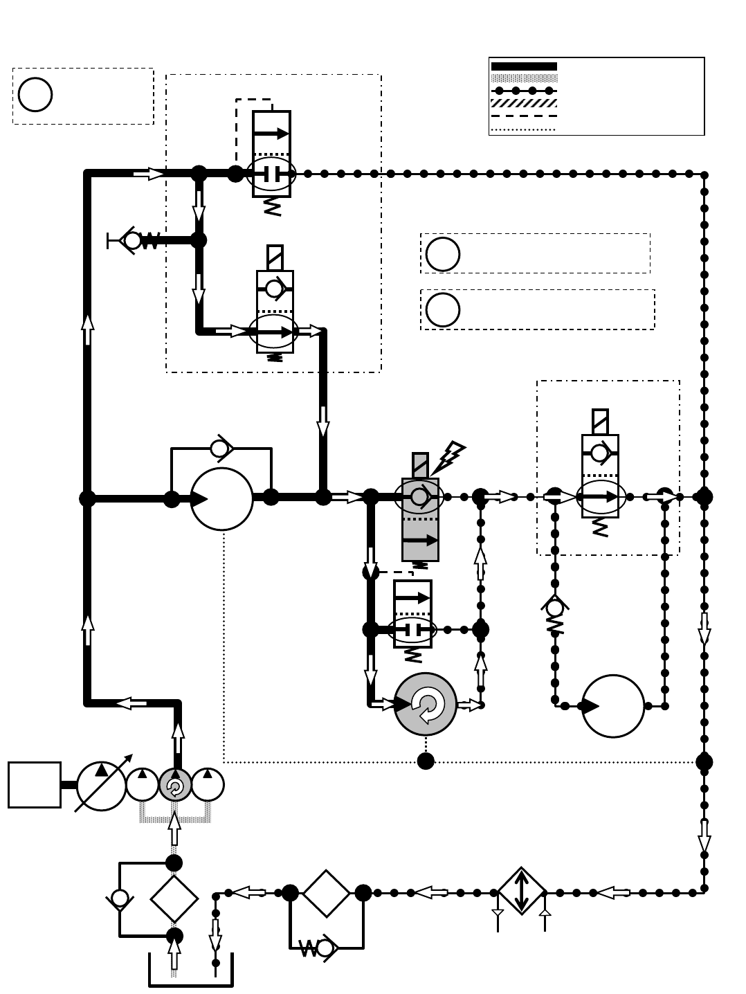
SCREEN
ENGINE
M20 Sweep Vacuum Fan ON
Engine speed: 2400 RPM
SV1
G6
OIL
COOLER
P1 T2
SCRUB MANIFOLD
SV9
SV8
SIDE BRUSH MANIFOLD
SCRUB FAN
MOTOR
OIL
FILTER
SWEEP FAN
MOTOR
SIDE BRUSH
MOTOR
Pressure / Flow Line
Return or Low Pressure Line
Active Pilot Port Line
Inactive Pilot Port Line
Case Drain Line
Suction Line
Sweep Fan Motor speed:
7,000 RPM (+/- 150 RPM)
Sweep Fan Motor vacuum:
20-24 in/H2O (51-61 cm/H2O)
Gray items are
energized
or activated
i
i
i
RV1
2500 PSI
(172.4 BAR)
35 PSI
(2.4 BAR)
1800
PSI
(124
BAR)
P3
M2 T6
T3
M4
25 PSI
(1.7 BAR)
M20 331385 (02-2007)
161
H
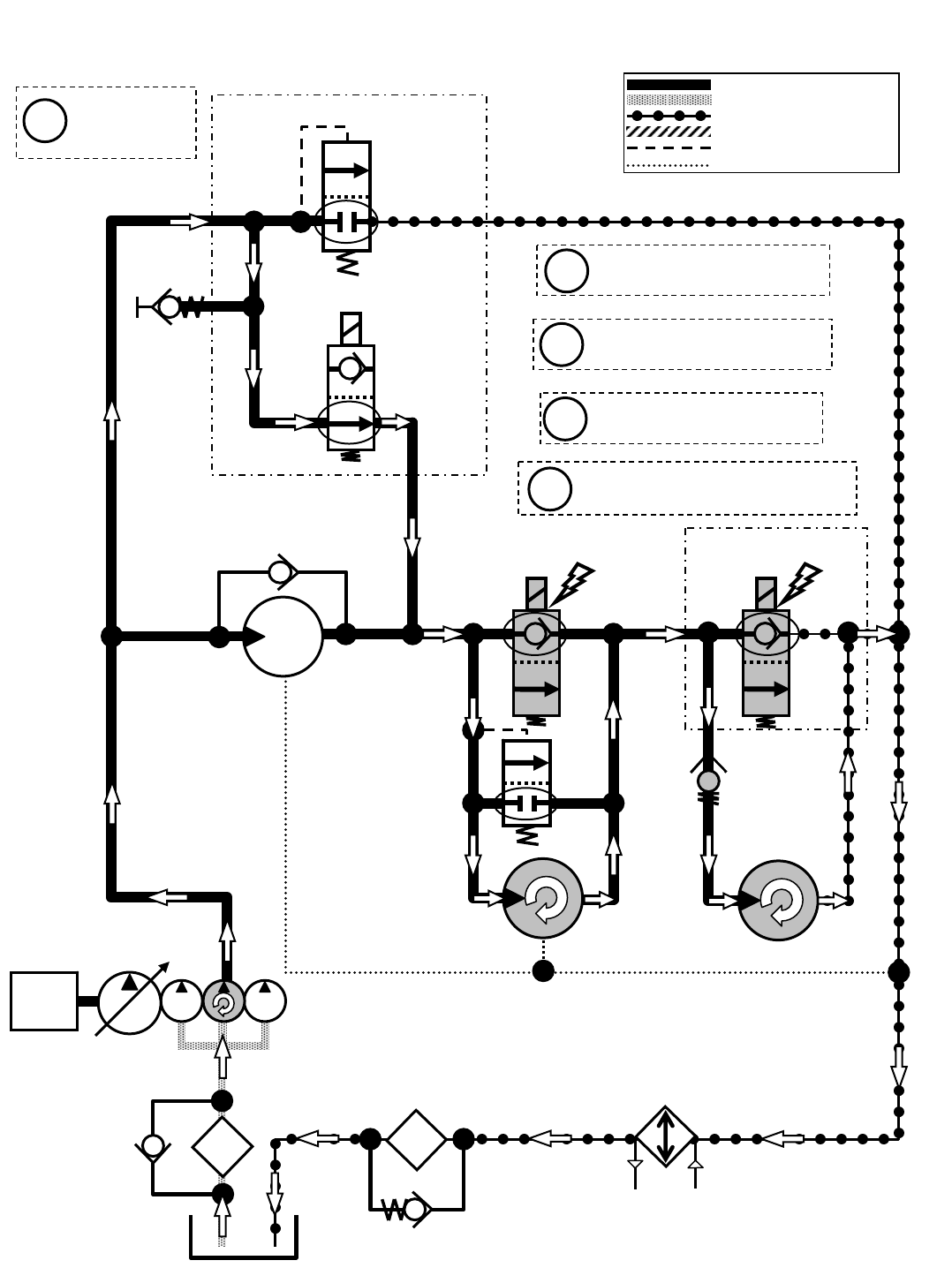
M20 Sweep Vacuum Fan & Side Brush ON
Engine speed: 2400 RPM
SV1
G6
OIL
COOLER
P1 T2
SCRUB MANIFOLD
SV9
SCRUB FAN
MOTOR
OIL
FILTER
SWEEP FAN
MOTOR
SIDE BRUSH
MOTOR
SV8
SIDE BRUSH MANIFOLD
Pressure / Flow Line
Return or Low Pressure Line
Active Pilot Port Line
Inactive Pilot Port Line
Case Drain Line
Suction Line
SCREEN
ENGINE
Sweep Fan Motor speed:
7,000 RPM (+/- 150 RPM)
Side Brush Motor speed:
140-160 RPM
Gray items are
energized
or activated
i
i
i
RV1
2500 PSI
(172.4 BAR)
35 PSI
(2.4 BAR)
1800
PSI
(124
BAR)
P3
M2 T6
T3
M4
25 PSI
(1.7 BAR)
Side Brush can only be operated
when Main Brushes are ON
i
Sweep Fan Motor vacuum:
20-24 in/H2O (51-61 cm/H2O)
i
M20 331385 (02-2007)
162
H
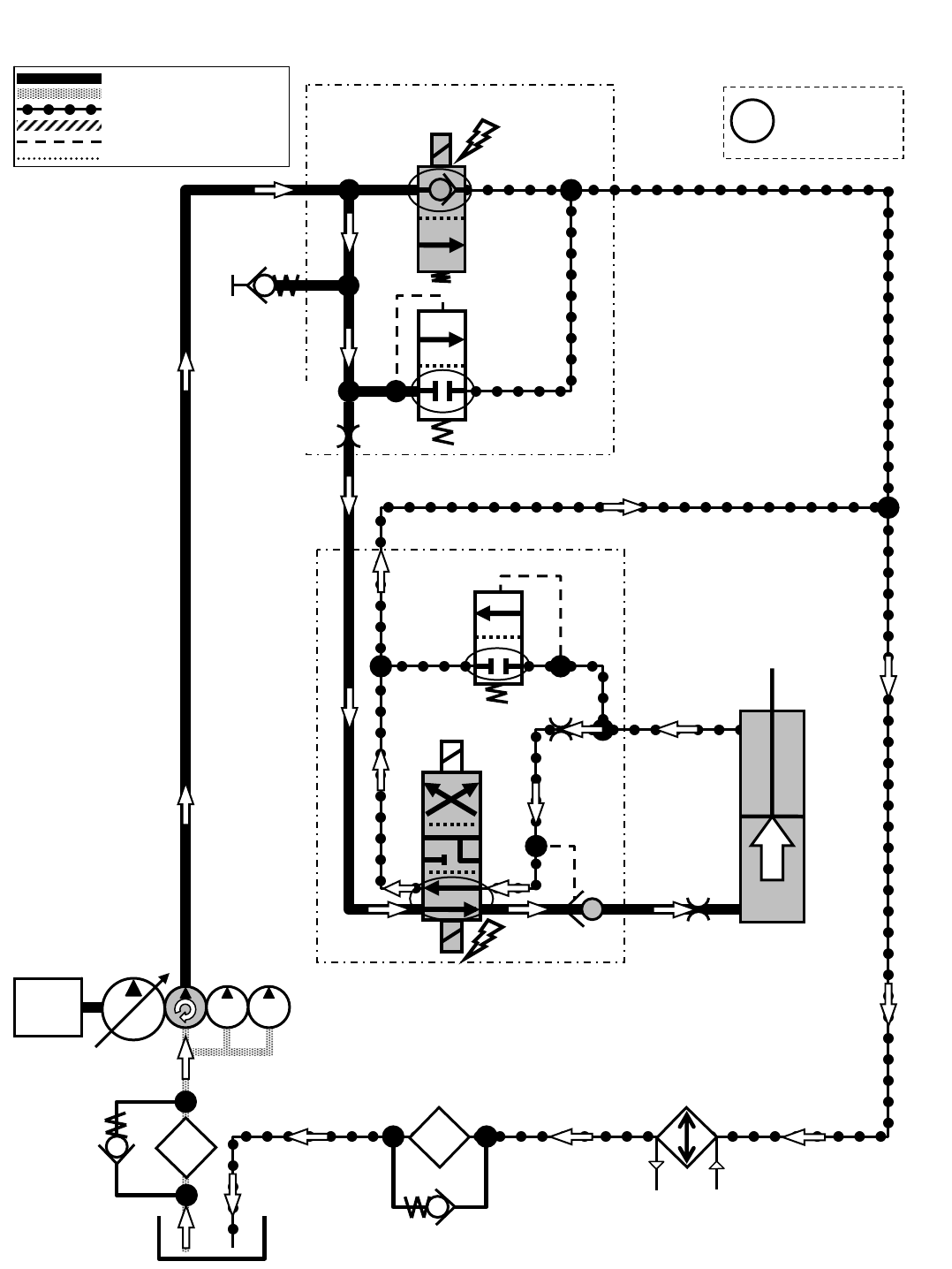
M20 Hopper Lift
Engine speed: 2400 RPM
SV7
G5
LIFT
P2
HOPPER LIFT
ACTUATOR
T2
SCREEN
SCRUB MANIFOLD
OIL
FILTER
OIL
COOLER
P7
P6 T5
C12
C9
SV14
RV3
500 PSI
(34.5 BAR)
OR1
0.030 in
(0.76 mm)
SWEEP MANIFOLD
PC5
SV13
Pressure / Flow Line
Return or Low Pressure Line
Active Pilot Port Line
Inactive Pilot Port Line
Case Drain Line
Suction Line
ENGINE
Gray items are
energized
or activated
i
RV2
2500 PSI
(172.4 BAR)
35 PSI
(2.4 BAR)
ORIFICE
0.055 in
(1.4 mm)
ORIFICE
0.028 in
(0.71 mm)
M20 331385 (02-2007)
163
H
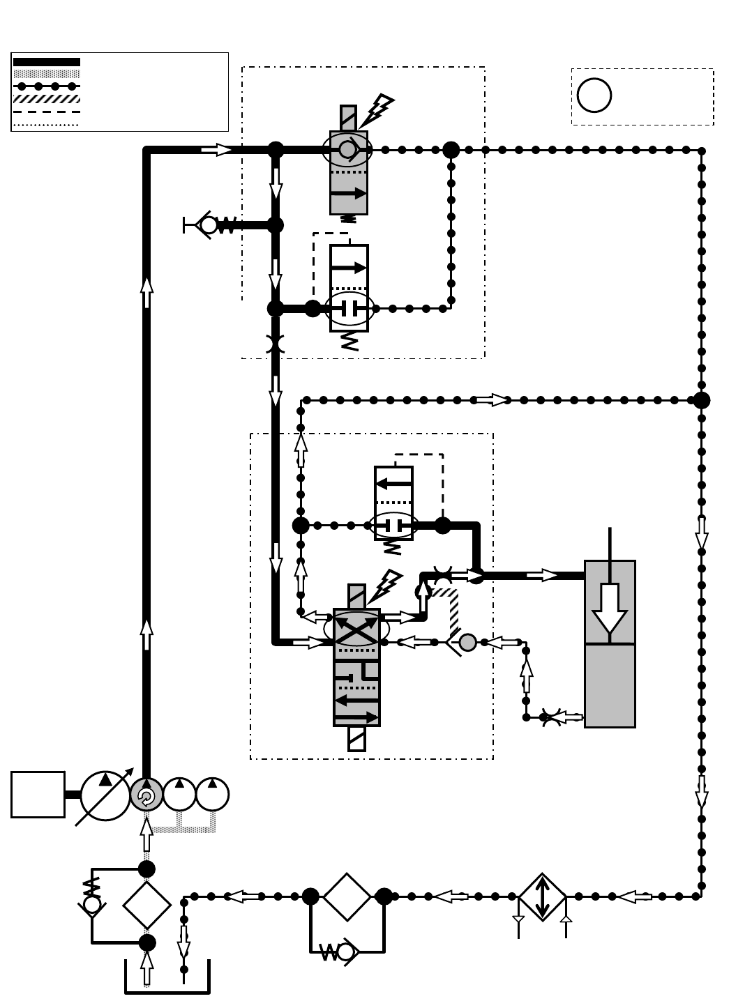
M20 Hopper Lower
Engine speed: 2400 RPM
SV7
G5
P2
HOPPER LIFT
ACTUATOR
T2
SCREEN
SCRUB MANIFOLD
OIL
FILTER
OIL
COOLER
P7
P6 T5
C12
C9
SV13
SV14 ORIFICE
0.028 in
(0.71 mm)
SWEEP MANIFOLD
PC5
LOWER
Pressure / Flow Line
Return or Low Pressure Line
Active Pilot Port Line
Inactive Pilot Port Line
Case Drain Line
Suction Line
ENGINE
Gray items are
energized
or activated
i
RV2
2500 PSI
(172.4 BAR)
35 PSI
(2.4 BAR)
ORIFICE
0.055 in
(1.4 mm)
OR1
0.030 in
(0.76 mm)
RV3
500 PSI
(34.5 BAR)
M20 331385 (02-2007)
164
H
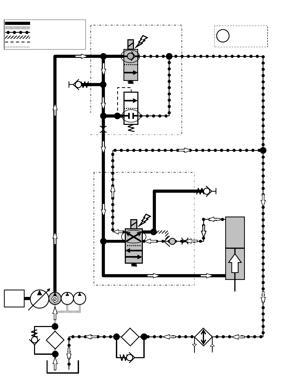
M20 Hopper Door Open
Engine speed: 2400 RPM
SV7
G5
P2
HOPPER DOOR
ACTUATOR
T2
SCREEN
SCRUB MANIFOLD
OIL
FILTER
OIL
COOLER
P7
P6 T5
C11
SV15
OR2
0.040 in
(1.0 mm)
SWEEP MANIFOLD
PC6
OPEN
G11
C10
Pressure / Flow Line
Return or Low Pressure Line
Active Pilot Port Line
Inactive Pilot Port Line
Case Drain Line
Suction Line
ENGINE
Gray items are
energized
or activated
i
RV2
2500 PSI
(172.4 BAR)
35 PSI
(2.4 BAR)
ORIFICE
0.055 in
(1.4 mm)
M20 331385 (02-2007)
165
H
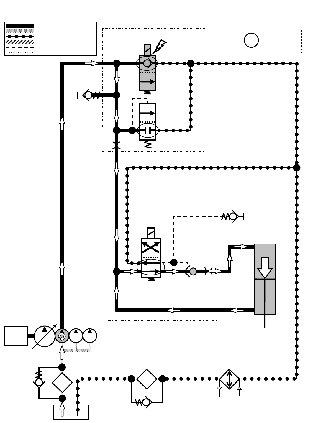
M20 Hopper Door Close
Engine speed: 2400 RPM
SV7
G5
P2
HOPPER DOOR
ACTUATOR
T2
SCREEN
SCRUB MANIFOLD
OIL
FILTER
OIL
COOLER
P7
P6 T5
C11
SV15
SWEEP MANIFOLD
PC6
G11
C10
CLOSE
Pressure / Flow Line
Return or Low Pressure Line
Active Pilot Port Line
Inactive Pilot Port Line
Case Drain Line
Suction Line
ENGINE
Gray items are
energized
or activated
i
RV2
2500 PSI
(172.4 BAR)
35 PSI
(2.4 BAR)
ORIFICE
0.055 in
(1.4 mm)
OR2
0.040 in
(1.0 mm)
M20 331385 (02-2007)
166
H
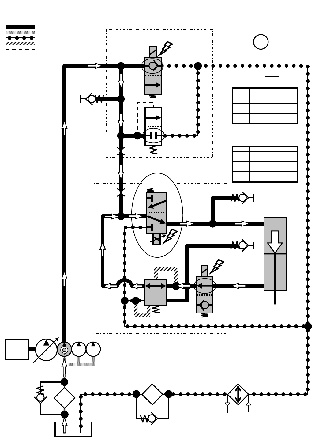
M20 Side Brush Lower
Engine speed: 2400 RPM
SV7
G5
P2
SIDE BRUSH
LIFT ACTUATOR
T2
SCREEN
SCRUB MANIFOLD
OIL
FILTER
OIL
COOLER
P7
P4
G13
LOWER
SV10
SV11
PR1
400 PSI
(27.6 BAR)
G7
C6
C8
T4
*PWM* SIDE BRUSH
MANIFOLD
Pressure / Flow Line
Return or Low Pressure Line
Active Pilot Port Line
Inactive Pilot Port Line
Case Drain Line
Suction Line
ENGINE
Typical Default
Pressure Readings (+/- 15%)
(SCRUBBING)
Typical Default
Pressure Readings (+/- 15%)
(SWEEPING)
Gray items are
energized
or activated
i
RV2
2500 PSI
(172.4 BAR)
35 PSI
(2.4 BAR)
ORIFICE
0.055 in
(1.4 mm)
OR3
0.040 in
(1.0 mm)
500 psi (34.5 bar)
400 psi (27.6 bar)
300 psi (20.7 bar)
Pressure at G13
P3
P2
P1
Setting
430 psi (29.6 bar)
330 psi (22.8 bar)
300 psi (20.7 bar)
Pressure at G13
P3
P2
P1
Setting
M20 331385 (02-2007)
167
H
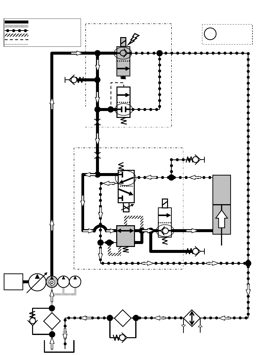
M20 Side Brush Lift
Engine speed: 2400 RPM
SV7
G5
P2
SIDE BRUSH
LIFT ACTUATOR
T2
SCREEN
SCRUB MANIFOLD
OIL
FILTER
OIL
COOLER
P7
P4
T4
SIDE BRUSH MANIFOLD G13
SV11
G7
LIFT
SV10
C6
C8
Pressure / Flow Line
Return or Low Pressure Line
Active Pilot Port Line
Inactive Pilot Port Line
Case Drain Line
Suction Line
ENGINE
Gray items are
energized
or activated
i
RV2
2500 PSI
(172.4 BAR)
35 PSI
(2.4 BAR)
ORIFICE
0.055 in
(1.4 mm)
OR3
0.040 in
(1.0 mm)
PR1
400 PSI
(27.6 BAR)
M20 331385 (02-2007)
168
H
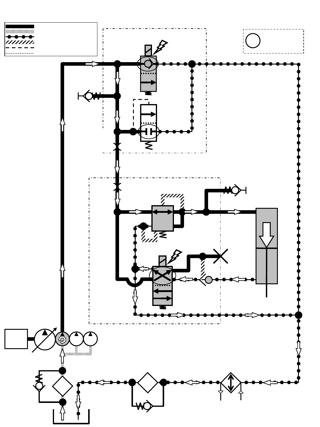
M20 Side Brush Extend
Engine speed: 2400 RPM
SV7
G5
P2
SIDE BRUSH
EXTEND ACTUATOR
T2
SCREEN
SCRUB MANIFOLD
OIL
FILTER
OIL
COOLER
P7
P4
SIDE BRUSH MANIFOLD G7
EXTEND
C7
C5
T4
SV12
PC6
G10
Pressure / Flow Line
Return or Low Pressure Line
Active Pilot Port Line
Inactive Pilot Port Line
Case Drain Line
Suction Line
ENGINE
Gray items are
energized
or activated
i
RV2
2500 PSI
(172.4 BAR)
35 PSI
(2.4 BAR)
ORIFICE
0.055 in
(1.4 mm)
OR3
0.040 in
(1.0 mm)
PR1
400 PSI
(27.6 BAR)
M20 331385 (02-2007)
169
H
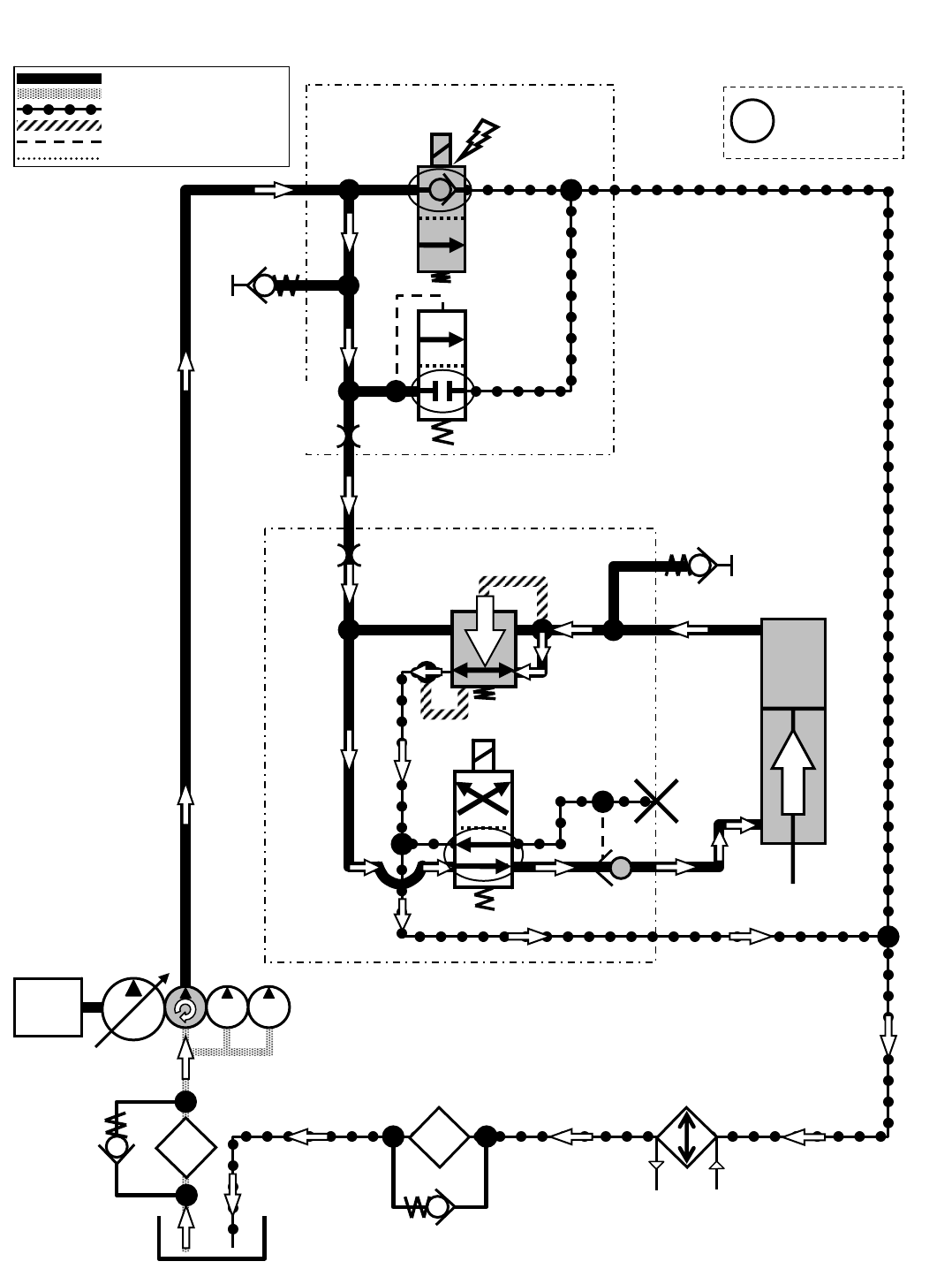
M20 Side Brush Retract
Engine speed: 2400 RPM
SV7
G5
P2
SIDE BRUSH
EXTEND ACTUATOR
T2
SCREEN
SCRUB MANIFOLD
OIL
FILTER
OIL
COOLER
P7
P4
SIDE BRUSH MANIFOLD G7
C7
C5
T4
SV12
PC6
G10
400 PSI
RETRACT
Pressure / Flow Line
Return or Low Pressure Line
Active Pilot Port Line
Inactive Pilot Port Line
Case Drain Line
Suction Line
ENGINE
Gray items are
energized
or activated
i
RV2
2500 PSI
(172.4 BAR)
35 PSI
(2.4 BAR)
ORIFICE
0.055 in
(1.4 mm)
OR3
0.040 in
(1.0 mm)
PR1
400 PSI
(27.6 BAR)
M20 331385 (02-2007)
170
H

We Need Your Help...
As part of Tennant’s Zero Defects Program, we want to know about errors you have
found or suggestions you may have regarding our machine manuals. If you find an
error or have a suggestion, please complete this postage-paid form and mail it to us.
Thank you for helping us make zero defects a way of life at Tennant.
Manual No. Rev. No. Publish Date Page
Machine -Report Error -Suggestion
Name Date
Customer Number
Company
Address
City/State/Zip Code
M20 331385 (02-2007)
171
Tape hereFold along dotted lines
NO POSTAGE
NECESSARY
IF MAILED
IN THE
UNITED SATES
BUSINESS REPLY MAIL
FIRST CLASS MAIL PERMIT NO. 94 MINNEAPOLIS, MN
POSTAGE WILL BE PAID BY ADDRESSEE
Technical Publications #15
701 North Lilac Drive
P.O. Box 1452
Minneapolis, MN 55440--9947
TENNANT COMPANY
M20 331385 (02-2007)
172

We Need Your Help...
As part of Tennant’s Zero Defects Program, we want to know about errors you have
found or suggestions you may have regarding our machine manuals. If you find an
error or have a suggestion, please complete this postage-paid form and mail it to us.
Thank you for helping us make zero defects a way of life at Tennant.
Manual No. Rev. No. Publish Date Page
Machine -Report Error -Suggestion
Name Date
Customer Number
Company
Address
City/State/Zip Code
M20 331385 (02-2007)
173

Tape hereFold along dotted lines
NO POSTAGE
NECESSARY
IF MAILED
IN THE
UNITED SATES
BUSINESS REPLY MAIL
FIRST CLASS MAIL PERMIT NO. 94 MINNEAPOLIS, MN
POSTAGE WILL BE PAID BY ADDRESSEE
Technical Publications #15
701 North Lilac Drive
P.O. Box 1452
Minneapolis, MN 55440--9947
TENNANT COMPANY
M20 331385 (02-2007)
174
