M20 / M30 Service Manual (S/N 008000 ) Tennant Rider Floor Sweeper Scrubber Sn Up
2018-06-12
: Sweepscrub Tennant-M20-Rider-Floor-Sweeper-Scrubber-Service-Manual-Sn-008000-Up tennant-m20-rider-floor-sweeper-scrubber-service-manual-sn-008000-up 2753 file product_file
Open the PDF directly: View PDF ![]() .
.
Page Count: 166 [warning: Documents this large are best viewed by clicking the View PDF Link!]
- M20/M30 Service Manual
- CONTENTS
- SPECIFICATIONS
- ELECTRICAL COMPONENT LOCATOR
- ELECTRICAL
- ELECTRICAL SCHEMATIC SYMBOLS
- ELECTRICAL OPTION COMPONENTS
- Key Power Distribution
- Key Power Distribution
- Key On Power Distribution
- Main Brushes On
- Hopper Lift
- Hopper Lower
- Scrub Vacuum Fan On & Squeegee Down
- Hopper Door Open
- Side Brush On
- Side Brush On
- Shaker Motor On
- Solution & Recovery Float Switches
- Forward Propel
- Auto Fill Solenoids
- Conventional Detergent Pump & ES Pump
- Horn
- Hopper Door Closed
- Reverse Propel
- Shutdown Relay (Normal Machine Operation)
- Shutdown Relay (Normal Machine Operation)
- Shutdown Relay (Shutdown Mode)
- Shutdown Relay (Shutdown Mode)
- Starting System On
- Starting System On
- Glow Plugs On
- Conventional Main & Side Brush Solution Valves
- FaST System On
- Fuel Level Sensor (Gas / LP / Diesel)
- Impact, Hydraulic Temperature & Filter Sensors
- Engine Oil Pressure, Temperature, and MIL System
- Engine Oil Pressure and Temperature Sensor
- Fuel Pump and Speed Control Output
- Fuel Pump
- Engine Speed Control
- M_Series Enable / Disable Chart
- M_Series Control Board Connectors
- M_Series Fault Condition Chart
- M_Series Condition and Warning Indicators
- General Information
- M20_M30 Operational Matrix
- M20_M30 Option Components
- M20_M30 Hydraulic Component Locator Side Brush Motor - Sweep Fan Motor - Scrub Fan Motor Propel Motor - Main Brush Motor - Side Sqeegee Lift Cylinder
- M20_M30 Hydraulic Component Locator Hopper Cylinder - Scrub Head Cylinder - Side Brush Extend CylinderSide Squeegee Cylinder - Main Brush Motor
- M20_M30 Hydraulic Component Locator Sweep Fan Valve - Scrub Manifold - Sweep Manifold
- M20_M30 Hydraulic Component Locator Steering Cylinder - Hopper Door Cylinder -
- Rear Squeegee Lift Cylinder
- M20_M30 Hydraulic Component Locator Hose Group - Steering and Propel
- M20_M30 Hydraulic Component Locator Hose Group - Pump and Vacuum Fan
- M20_M30 Hydraulic Component Locator Hose Group - Brush and Hopper
- M20_M30 Hydraulic Component Locator Hose Group - Squeegee Lift
- M20_M30 Scrub/Sweep Head Lower
- M20_M30 Scrub/Sweep Head Lift
- M20_M30 Squeegee Lower
- M20_M30 Squeegee Lift
- M20_M30 Main Brushes On
- M20_M30 Side Brush On
- M20_M30 Scrub Vacuum Fan On
- M20_M30 Scrub Vacuum Fan & Side Brush On
- M20_M30 Scrub Vacuum Fan On
- M20_M30 Scrub Vacuum Fan & Side Brush On
- M20_M30 Pressure Washer On
- M20_M30 Hopper Lift
- M20_M30 Hopper Lower
- M20_M30 Hopper Door Open
- M20_M30 Hopper Door Close
- M20_M30 Side Brush Lower
- M20_M30 Side Brush Lift
- M20_M30 Side Brush Extend
- M20_M30 Side Brush Retract
- Hydraulic Solenoid Valve Details
- M20_M30 Fault Codes (ProPanel and Standard Panel)
- M Series Maintenance
- HYDRAULICS
- General Information
- M20_M30Operational Matrix
- Option Components
- M20_M30 Hydraulic Component Locator
- M20_M30 Scrub/Sweep Head Lower
- M20_M30 Scrub/Sweep Head Lift
- M20_M30 Squeegee Lower
- M20_M30 Squeegee Lift
- M20_M30 Main Brushes On
- M20_M30 Side Brush On
- M20_M30 Scrub Vacuum Fan On
- M20_M30 Scrub Vacuum Fan & Side Brush On
- M20_M30 Scrub Vacuum Fan On
- M20_M30 Scrub Vacuum Fan & Side Brush On
- M20_M30 Pressure Washer On
- M20_M30 Hopper Lift
- M20_M30 Hopper Lower
- M20_M30 Hopper Door Open
- M20_M30 Hopper Door Close
- M20_M30 Side Brush Lower
- M20_M30 Side Brush Lift
- M20_M30 Side Brush Extend
- M20_M30 Side Brush Retract
- Hydraulic Solenoid Valve Details
- FAULT CODES
- MAINTENANCE
- YELLOW TOUCH POINTS
- LUBRICATION
- HYDRAULICS
- ENGINE
- BATTERY
- FUSES AND RELAYS
- CL EANING THE HOPPER DUST F ILTER
- MAIN BRUSHES
- SIDE BRUSH (OPTION)
- FaST SYSTEM
- CLEANING THE ec-H20 FILTER SCREEN
- SQUEEGEE BLADES
- SKIRTS AND SEALS
- BRAKES AND TIRES
- PUSHING, TOWING, AND TRANSPORTINGTHE MACHINE
- MACHINE JACKING
- STORAGE INFORMATION
- TROUBLESHOOTING
M20/M30
(S/N 008000- )
Sweeper Scrubber
Service Manual
9016006
Rev. 01 (03-2017)
*9016006*
North America / International
For the latest Parts Manuals and other
language Operator Manuals, visit:
www.tennantco.com/manuals
ES® Extended Scrub System
Tennant True® Parts
IRIS® a Tennant Technology
Pro-Panel™ Controls
Insta-Fit™ Adapter
INTRODUCTION
This manual is furnished with each new model. It provides necessary operation and maintenance instructions.
Read this manual completely and understand
the machine before operating or servicing it.
This machine will provide excellent service. However, the best results will be obtained at minimum costs if:
• The machine is operated with reasonable care.
• The machine is maintained regularly - per the machine maintenance instructions provided.
• The machine is maintained with manufacturer supplied or equivalent parts.
PROTECT THE
ENVIRONMENT
Please dispose of packaging
materials, used components such
as batteries and uids in an
environmentally safe way
according to local waste disposal
regulations.
Always remember to recycle.
MACHINE DATA
Please ll out at time of installation for future
reference.
Model No. -
Serial No. -
Installation Date -
INTENDED USE
The M17 is an industrial rider machine designed to wet scrub and sweep both rough and smooth hard surfaces (concrete, tile, stone, synthetic, etc).
Typical applications include schools, hospitals / health care facilities, ofce buildings, and retail centers. Do not use this machine on soil, grass,
articial turf, or carpeted surfaces. This machine is intended for indoor use only. This machine is not intended for use on public roadways. Do not use
this machine other than described in this Operators Manual.
Tennant Company
PO Box 1452
Minneapolis, MN 55440
Phone: (800) 553-8033 or (763) 513-2850
www.tennantco.com
DFS (Dual Force Sweeping), PerformanceView, Pro-ID, Pro-Check, Perma-Filter, ShakeMax, Zone Settings, SmartRelease, QA Controls, 1−Step,
Dura−Track, Touch−N−Go, Duramer, are trademarks of Tennant Company.
Specications and parts are subject to change without notice.
Original Instructions, copyright © 2017 TENNANT Company, Printed in U.S.A.

3
M20/M30 9016006 - 3-2017
CONTENTS
CONTENTS
Contents ............................................................ 3
Specications .................................................... 7
M30 General Machine Dimensions /
Specications .............................................. 7
M20 General Machine Dimensions /
Specications ............................................ 12
Electrical Component Locator ......................... 17
M Series Electrical Component Locator ........ 17
Electrical .......................................................... 32
Electrical Schematic Symbols........................ 32
Electrical Option Components ....................... 33
Key Power Distribution .............................. 34
Key Power Distribution .............................. 35
Key On Power Distribution ......................... 36
Main Brushes On ....................................... 37
Hopper Lift ................................................. 38
Hopper Lower ............................................ 39
Scrub Vacuum Fan On & Squeegee
Down ...................................................... 40
Hopper Door Open .................................... 41
Side Brush On ........................................... 42
Side Brush On ........................................... 43
Shaker Motor On ....................................... 44
Solution & Recovery Float Switches .......... 45
Forward Propel .......................................... 46
Auto Fill Solenoids ..................................... 47
Conventional Detergent Pump &
Es Pump ................................................. 48
Horn ........................................................... 49
Hopper Door Closed .................................. 50
Reverse Propel .......................................... 51
Shutdown Relay (Normal Machine
Operation) .............................................. 52
Shutdown Relay (Normal Machine
Operation) .............................................. 53
Shutdown Relay (Shutdown Mode) ........... 54
Shutdown Relay (Shutdown Mode) ........... 55
Starting System On .................................... 56
Starting System On .................................... 57
Glow Plugs On ........................................... 58
Conventional Main & Side Brush
...........................................Solution Valves ...
59
Fast System On ......................................... 60
Fuel Level Sensor (Gas / Lp / Diesel) ........ 61
Impact, Hydraulic Temperature & Filter
Sensors .................................................. 62
Engine Oil Pressure, Temperature,
And Mil System ...................................... 63
Engine Oil Pressure And
Temperature Sensor ............................... 64
Fuel Pump And Speed Control Output ...... 65
Fuel Pump ................................................. 66
Engine Speed Control ................................ 67
M_series Enable / Disable Chart ............... 68
M_series Control Board Connectors .......... 69
M_series Fault Condition Chart ................. 70
M_series Condition And Warning
Indicators ................................................ 71
General Information ................................... 73
M20_m30 Operational Matrix .................... 75
M20_m30 Option Components .................. 76
M20_m30 Hydraulic Component
Locator Side Brush Motor -
Sweep Fan Motor - Scrub Fan Motor
Propel Motor - Main Brush Motor -
Side Sqeegee Lift Cylinder ..................... 77
M20_m30 Hydraulic Component
Locator Hopper Cylinder - Scrub
Head Cylinder - Side Brush Extend
Cylinderside Squeegee Cylinder -
Main Brush Motor ................................... 78
M20_m30 Hydraulic Component
Locator Sweep Fan Valve - Scrub Manifold -
Sweep Manifold ...................................... 79
M20_m30 Hydraulic Component
Locator Steering Cylinder -
Hopper Door Cylinder - ......................... 80
Rear Squeegee Lift Cylinder ...................... 80
M20_m30 Hydraulic Component
Locator Hose Group - Steering
And Propel ............................................. 81
M20_m30 Hydraulic Component
Locator Hose Group - Pump And
Vacuum Fan ........................................... 82
M20_m30 Hydraulic Component
Locator Hose Group - Brush
And Hopper ............................................ 83
M20_m30 Hydraulic Component
Locator Hose Group - Squeegee Lift ..... 84
M20_m30 Scrub/Sweep Head Lower ........ 85
M20_m30 Scrub/Sweep Head Lift ............. 86
M20_m30 Squeegee Lower ....................... 87
M20_m30 Squeegee Lift ............................ 88
M20_m30 Main Brushes On ...................... 89
M20_m30 Side Brush On .......................... 90
M20_m30 Scrub Vacuum Fan On ............. 91

4M20/M30 9016006 - 3-2017
CONTENTS
M20_m30 Scrub Vacuum Fan &
Side Brush On ........................................ 92
M20_m30 Scrub Vacuum Fan On ............. 93
M20_m30 Scrub Vacuum Fan &
Side Brush On ........................................ 94
M20_m30 Pressure Washer On ................ 95
M20_m30 Hopper Lift ................................ 96
M20_m30 Hopper Lower ........................... 97
M20_m30 Hopper Door Open ................... 98
M20_m30 Hopper Door Close ................... 99
M20_m30 Side Brush Lower ................... 100
M20_m30 Side Brush Lift ........................ 101
M20_m30 Side Brush Extend .................. 102
M20_m30 Side Brush Retract .................. 103
Hydraulic Solenoid Valve Details ............. 104
M20_m30 Fault Codes
(Propanel And Standard Panel) ........... 105
M Series Maintenance ..............................112
Troubleshooting ............................................. 147
M20/M30 Membrane Panel Service Modes 147
Service Mode .......................................... 147
Manual Mode ........................................... 148
Conguration Mode ................................. 149
Additional Water Level Setting
Information: .......................................... 150
Self Test Mode ............................................. 150
Throttle Adjust Mode ................................ 152
Down Pressure Adjust Mode ................... 154
Membrane Test Mode .............................. 155
Service Mode ........................................... 156
M20/M30 Propanel Service Modes .......... 157
Conguration Mode ................................. 158

5
M20/M30 9016006 - 3-2017
CONTENTS

6M20/M30 9016006 - 3-2017
CONTENTS
SPECIFICATIONS
M20/M30 9016006 - 3-2017 7
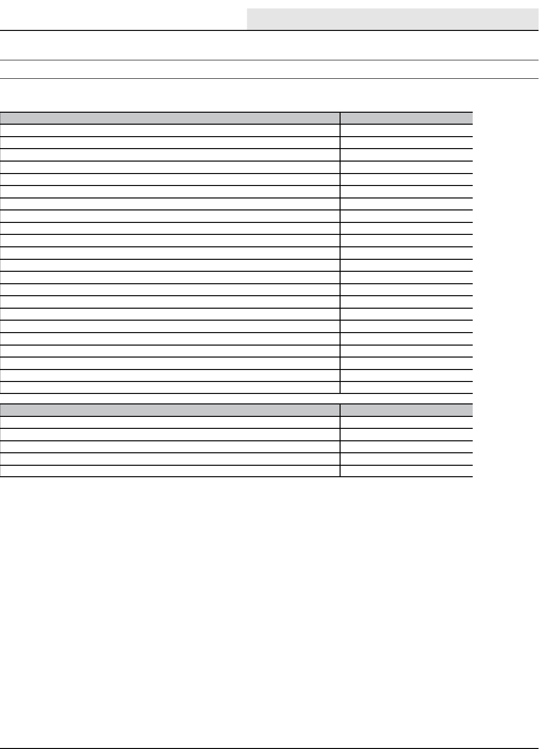
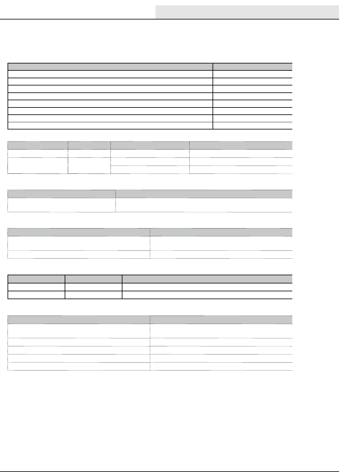
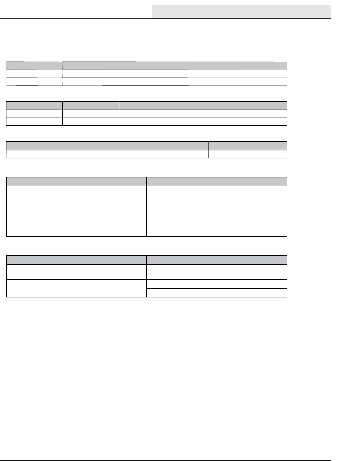
M30 GENERAL MACHINE DIMENSIONS/CAPACITIES
Item Dimension/Capacity
Length 2745 mm (108 in)
Height 1475 mm (58 in)
Height (with overhead guard) 2135 mm (84 in)
Width/frame (roller to roller) 1475 mm (58 in)
Width (rear squeegee) 1500 mm (59 in)
Width (with side brush) 1625 mm (64 in)
Cleaning path width (Main brush length) 1220 mm (48 in)
Cleaning path width (with scrubbing side brush) 1575 mm (62 in)
Cleaning path width (with sweeping side brush) 1625 mm (64 in)
Main brush diameter (2) 305 mm (12 in)
Side brush diameter (scrubbing) 410 mm (16 in)
Side brush diameter (sweeping) 535 mm (21 in)
Solution tank capacity 284 L (75 gallons)
Recovery tank capacity 360 L (95 gallons)
Debris hopper volume capacity 198 L (7.0 ft3)
Debris hopper weight capacity 295 kg (650 lbs)
Dump height (variable to) 1525 mm (60 in)
Minimum ceiling dump height 2620 mm (103 in)
Weight - empty 1815 Kg (4000 lbs)
GVWR 2449 Kg (5400 lbs)
Transport ground clearance 80 mm (3 in)
Protection Grade IPX3
Values determined as per IEC 60335- 2- 72 Measure
Sound pressure level LpA 84 dB(A)
Sound uncertainty KpA 3.0 dB(A)
Sound power level LWA + Uncertainty KWA 106 dB(A)
Vibration - Hand- arm < 2.5 m/s@
Vibration - Whole body < 0.5 m/s@
SPECIFICATIONS
M30 GENERAL MACHINE DIMENSIONS / SPECIFICATIONS
SPECIFICATIONS
M20/M30 9016006 - 3-2017
8
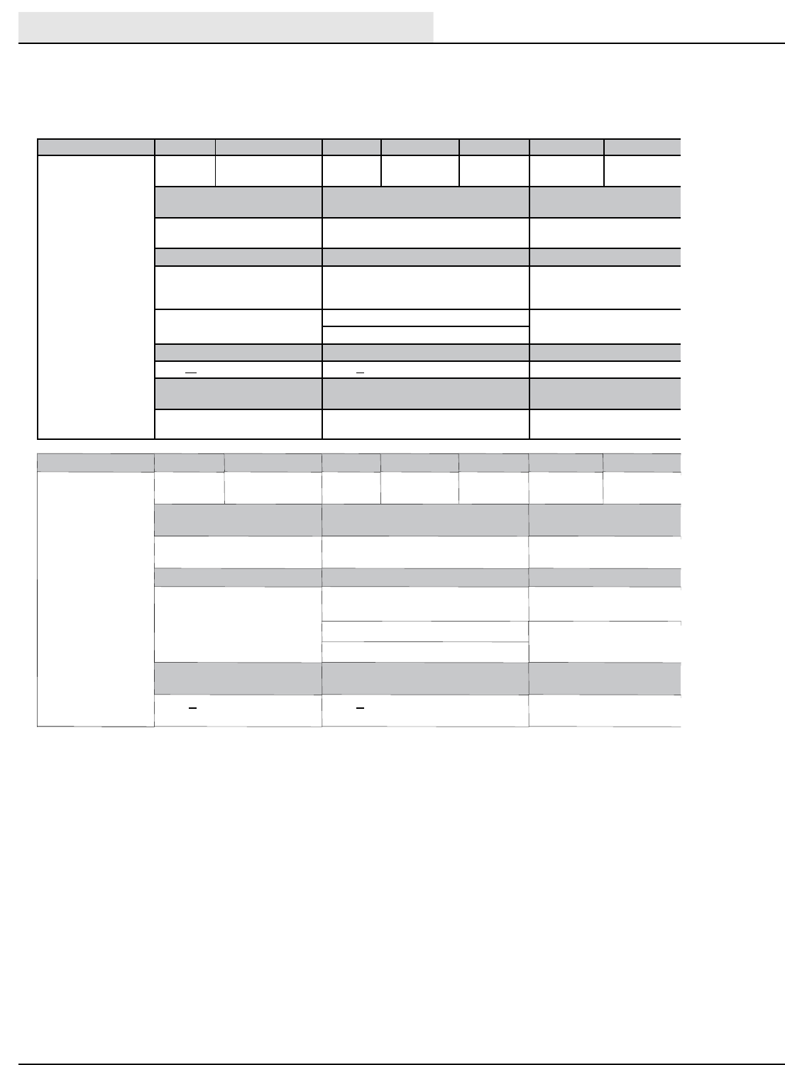
M30 POWER TYPE
Engine Type Ignition Cycle Aspiration Cylinders Bore Stroke
Mitsubishi 2.0 Piston Coil @ Plug 4Natural 485 mm
(3.35 in)
88 mm (3.46
in)
Displacement Tennant machine governed net
power
Engine mfg un- governed
net power
1997 cc (122 cu in) 37.3 kw (50 hp) @ 2300 rpm 44.7 kw (60 hp) @ 30
00 rpm
Fuel Cooling system Electrical system
Gasoline, 87 octane
minimum, unleaded
Fuel tank: 42 L (11.2 gal)
Water/ethylene glycol
antifreeze
12 V nominal
LPG,
Fuel tank: 15 kg (33 lb)
Total: 7.5 L (2 gal) 75 A alternator
Radiator: 3.8 L (1 gal)
Idle speed, no load (Fast) governed speed, under load Firing order
1350 + 50 rpm 2300 + 50 rpm 1- 3- 4- 2
Spark plug gap Valve clearance, cold Engine lubricating oil with
filter
1.1 mm (0.043 in) No Adjustment
OHC Engine
4.7 L (5 qt) 5W30
SAE- SG/SH
Engine Type Ignition Cycle Aspiration Cylinders Bore Stroke
Kubota V1505- TB Piston Diesel 4Charged /
Turbo
478 mm
(3.07 in)
78.4 mm
(3.08 in)
Displacement Tennant machine governed net
power
Engine mfg un- governed
net power
1500 cc (91.4 cu in) 25.4 kw (34 hp) @ 2800 rpm 27.2 kw (44.2 hp) @ 3000
rpm
Fuel Cooling system Electrical system
Diesel
Fuel tank: 42 L (11.2 gal)
low sulfur fuel content less
than 500ppm only
Water/ethylene glycol
antifreeze
12 V nominal
Total: 7.5 L (2 gal) 37 A alternator
Radiator: 3.8 L (1 gal)
Idle speed, no load (Fast) governed speed, under load Engine lubricating oil
without filter
1350 +50 rpm 2800 +50 rpm 6 L (6.35 qt) API diesel
classification CF or better
M30 GENERAL MACHINE DIMENSIONS / SPECIFICATIONS - (CONTINUED)
SPECIFICATIONS
M20/M30 9016006 - 3-2017 9
M30 GENERAL MACHINE PERFORMANCE
Item Measure
Minimum aisle turn 3175 mm (125 in)
Travel speed forward (maximum) 12.9 Km/h (8 mph)
Travel speed reverse (maximum) 4.8 Km/h (3 mph)
Maximum ramp incline for loading - Empty tanks 18%
Maximum ramp incline for scrubbing 10%
Maximum ramp incline for transporting (GVWR) 14%
Maximum ambient temperature for machine operation 43_C (110_F)
Minimum temperature for operating machine scrubbing functions 0_C (32_F)
M30 HYDRAUL
IC SYSTEM
System Capacity ISO Grade Viscosity Index Ambient Air Temperature Ranges
Hydraulic reservoir 38 L (10 gal) ISO 100 VI 126 or higher 19_C (65_F) or higher
Hydraulic total 45 L (12 gal) ISO 68 VI 155 or higher 7to43_C (45 to 110_F)
ISO 32 VI 163 or higher 16_C (60_F) or lower
M30 STEERING
Type Power source
Front wheel, hydraulic cylinder and rotary
valve controlled
Hydraulic accessory pump
M30 BRAKING SYSTEM
Type Operation
Service brakes Mechanical drum brakes (2), one per rear wheel, cable
actuated
Parking brake Utilize service brakes, cable actuated
M30 TIRES
Location Type Size
Front (1) Solid 150 mm x 460 mm (6 in x 18 in)
Rear (2) Solid 127 mm x 460 mm (5 in x 18 in)
M30 FaST SYSTEM
Item Measure
Solution pump 12 Volt DC, 11A, 0.7 GPM & 1.4 GPM flow (2 speed), 75
psi high- pressure shutdown
Low solution flow rate 2.7 LPM (0.7 GPM)
High solution flow rate 5.4 LPM (1.4 GPM)
Low concentrate flow rate 2.6 CC/Minute (0.085 Liquid Ounces/Minute)
High concentrate flow rate 5.2 CC/Minute (0.17 Liquid Ounces/Minute)
M30 GENERAL MACHINE DIMENSIONS / SPECIFICATIONS - (CONTINUED)

SPECIFICATIONS
M20/M30 9016006 - 3-2017
10
M30
ec- H2O SYSTEM
Item Measure
Solution pump 12 Volt DC, 11A, 0.7 GPM & 1.4 GPM flow, (2 speeds), 75 psi
high- pressure shutdown
Solution flow rate 2.65 LPM (0.7 GPM) - Low
5.30 LPM (1.4 GPM) - High
M30 GENERAL MACHINE DIMENSIONS / SPECIFICATIONS - (CONTINUED)
SPECIFICATIONS
M20/M30 9016006 - 3-2017 11
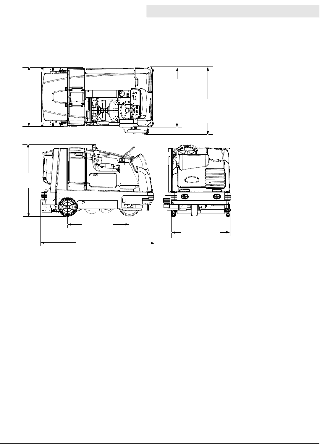
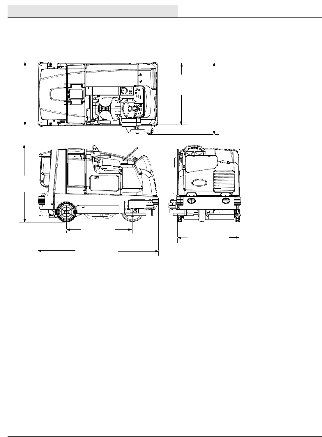
M30 MACHINE DIMENSIONS
Frame
(roller to roller)
1475 mm (58 in)
1475 mm
(58 in)
2745 mm
(108 in)
Rear
Squeegee
1500 mm
(59 in) Width
(with side brush)
1625 mm (64 in)
Track
(at rear wheels)
1473 mm
(58 in)
Wheel base
1422 mm
(56 in)
1014751
M30 GENERAL MACHINE DIMENSIONS / SPECIFICATIONS - (CONTINUED)
SPECIFICATIONS
M20/M30 9016006 - 3-2017
12
M20 SPECIFICATIONS
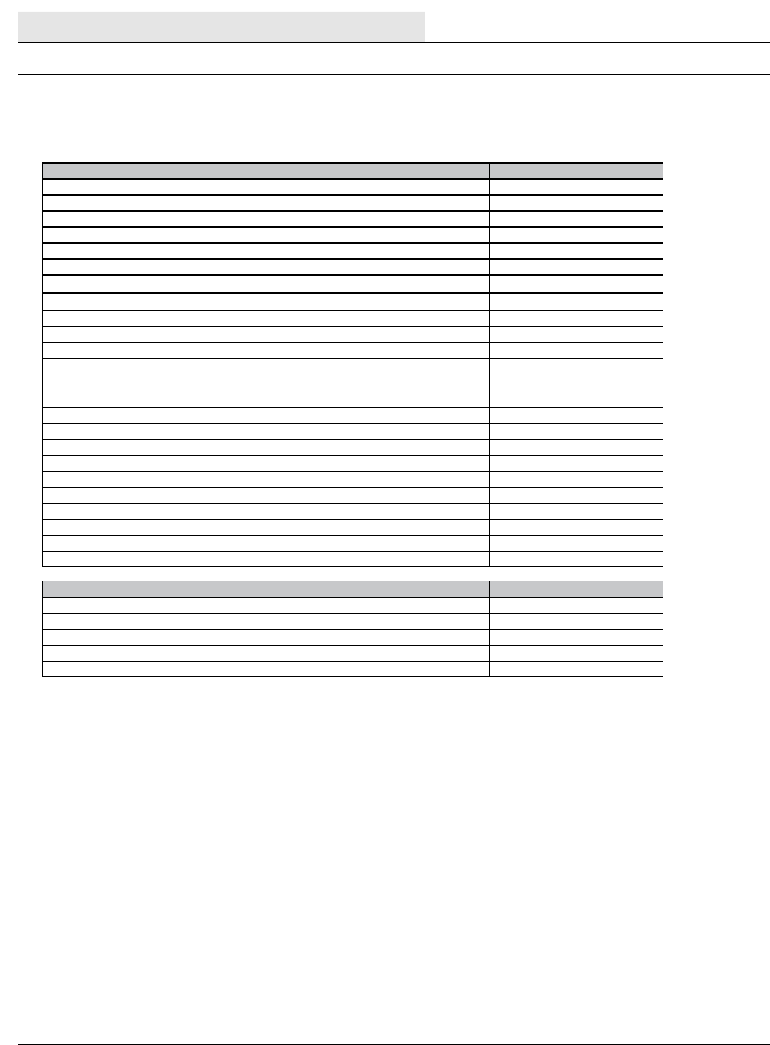
M20 GENERAL MACHINE DIMENSIONS/CAPACITIES
Item Dimension/capacity
Length 2410 mm (95 in)
Height 1470 mm (58 in)
Height (with overhead guard) 2120 mm (83.5 in)
Width/frame (roller to roller) 1270 mm (50 in)
Width (rear squeegee) 1300 mm (51 in)
Width (with side brush) 1470 mm (58 in)
Wheel base 1280 mm (50.38 in)
Track 1270 mm (50 in)
Cleaning path width (Main brush length) 1020 mm (40 in)
Cleaning path width (with scrubbing side brush) 1370 mm (54 in)
Cleaning path width (with sweeping side brush) 1420 mm (56 in)
Main brush diameter (2) 300 mm (12 in)
Side brush diameter (scrubbing) 410 mm (16 in)
Side brush diameter (sweeping) 530 mm (21 in)
Solution tank capacity 212 L (56 gallons)
Recovery tank capacity 276 L (73 gallons)
Debris hopper volume capacity 110L(3.9ft
3)
Debris hopper weight capacity 177 kg (390 lbs)
Dump height (variable to) 1520 mm (60 in)
Minimum ceiling dump height 2500 mm (98 in)
Weight - empty 1497 Kg (3300 lbs)
GVWR 2359 Kg (5200 lbs)
Transport ground clearance 80 mm (3 in)
Protection Grade IPX3
Values determined as per IEC 60335- 2- 72 Measure
Sound pressure level LpA 84 dB(A)
Sound uncertainty KpA 3.0 dB(A)
Sound power level LWA + Uncertainty KWA 106 dB(A)
Vibration - Hand- arm < 2.5 m/s@
Vibration - Whole body < 0.5 m/s@
M20 GENERAL MACHINE DIMENSIONS / SPECIFICATIONS

SPECIFICATIONS
M20/M30 9016006 - 3-2017 13
M20 GENERAL MACHINE PERFORMANCE
Item Measure
Minimum aisle turn 2790 mm (110 in)
Travel speed forward (maximum) 12.9 Km/h (8 mph)
Travel speed reverse (maximum) 4.8 Km/h (3 mph)
Maximum ramp incline for loading - Empty tanks 18%
Maximum ramp incline for scrubbing 14%
Maximum ramp incline for transporting (GVWR) 18%
Maximum ambient temperature for machine operation 43_C (110_F)
Minimum temperature for operating machine scrubbing functions 0_C (32_F)
M20 GENERAL MACHINE DIMENSIONS / SPECIFICATIONS - (CONTINUED)
SPECIFICATIONS
M20/M30 9016006 - 3-2017
14
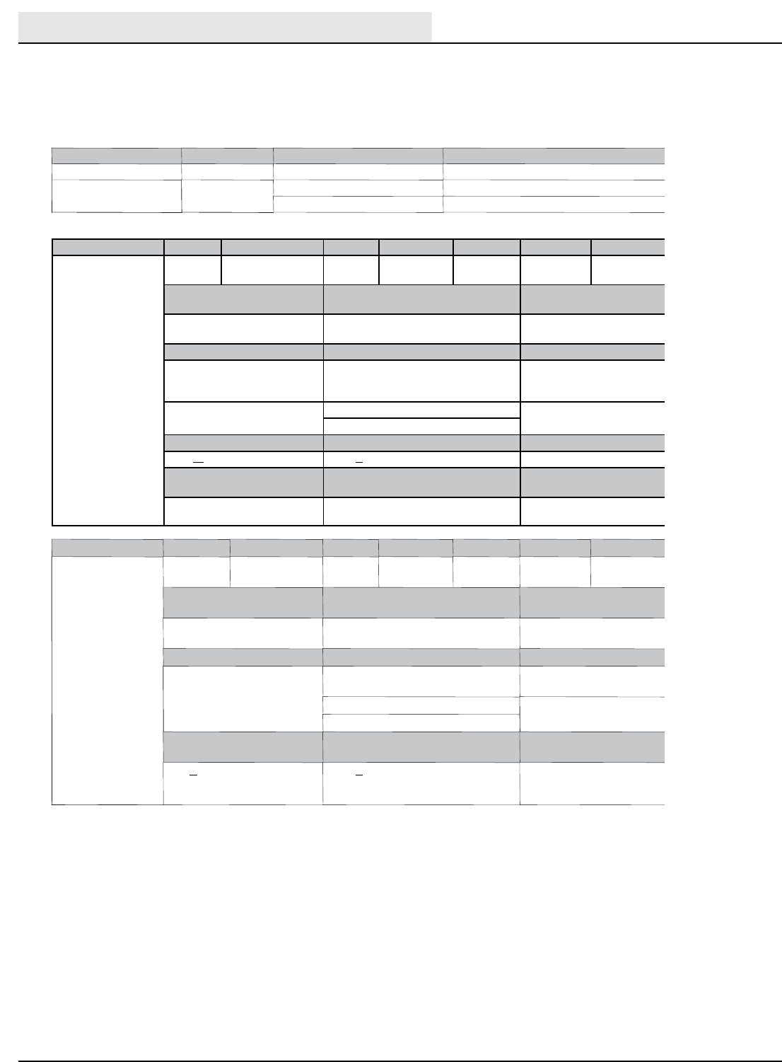
M20 HYDRAUL
IC SYSTEM
System Capacity ISO Grade Viscosity Index Ambient Air Temperature Ranges
Hydraulic reservoir 38 L (10 gal) ISO 100 VI 126 or higher 19_C (65_F) or higher
Hydraulic total 45 L (12 gal) ISO 68 VI 155 or higher 7to43_C (45 to 110_F)
ISO 32 VI 163 or higher 16_C (60_F) or lower
M20 POWER TYPE
Engine Type Ignition Cycle Aspiration Cylinders Bore Stroke
Mitsubishi 2.0 Piston Coil @ Plug 4Natural 485 mm
(3.35 in)
88 mm (3.46
in)
Displacement Tennant governed power Gross intermittent power
per SAE J1995
2.0 L (122 cu in) 37.3 kw (50 hp) @ 2300 rpm 44.7 kw (60 hp) @ 30
00 rpm
Fuel Cooling system Electrical system
Gasoline, 87 octane
minimum, unleaded
Fuel tank: 42 L (11.2 gal)
Water/ethylene glycol
antifreeze
12 V nominal
LPG,
Fuel tank: 15 kg (33 lb)
Total: 7.5 L (2 gal) 75 A alternator
Radiator: 3.8 L (1 gal)
Idle speed, no load (Fast) governed speed, under load Firing order
1350 + 50 rpm 2300 + 50 rpm 1- 3- 4- 2
Spark plug gap Valve clearance, cold Engine lubricating oil with
filter
1.1 mm (0.043 in) No Adjustment
OHC Engine
4.7 L (5 qt) 5W30
SAE- SG/SH
Engine Type Ignition Cycle Aspiration Cylinders Bore Stroke
Kubota V1505- B Piston Diesel 4Natural 478 mm
(3.07 in)
78.4 mm
(3.09 in)
Displacement Tennant governed power Gross intermittent power
per SAE J1995
1500 cc (91.4 cu in) 18.5 kw (24.8 hp) @ 2300 rpm 18.5 kw (24.8 hp) @ 2300
rpm
Fuel Cooling system Electrical system
Diesel
Fuel tank: 42 L (11.2 gal)
low sulfur fuel content less
than 500ppm only
Water/ethylene glycol
antifreeze
12 V nominal
Total: 7.5 L (2 gal) 37 A alternator
Radiator: 3.8 L (1 gal)
Idle speed, no load (Fast) governed speed, under load Engine lubricating oil
without filter
950 +50 rpm 2400 +50 rpm 6 L (6.35 qt)
diesel classification CF or
better
M20 GENERAL MACHINE DIMENSIONS / SPECIFICATIONS - (CONTINUED)
SPECIFICATIONS
M20/M30 9016006 - 3-2017 15
M20 GENERAL MACHINE DIMENSIONS / SPECIFICATIONS - (CONTINUED)
M20 BRAKING SYSTEM
Type Operation
Service brakes Mechanical drum brakes (2), one per rear wheel, cable actuated
Parking brake Utilize service brakes, cable actuated
M20 TIRES
Location Type Size
Front (1) Solid 140 mm x 460 mm (5.5 in x 18 in)
Rear (2) Solid 90 mm x 410 mm (3.5 in x 16 in)
M20 STEERING
Type Power source
Front wheel, hydraulic cylinder, and rotary valve controlled Hydraulic accessory pump
M20 FaST SYSTEM
Item Measure
Solution pump 12 Volt DC, 11A, 0.7 GPM & 1.4 GPM flow,
(2 speeds), 75 psi high- pressure shutdown
Low solution flow rate 2.7 LPM (0.7 GPM)
High solution flow rate 5.4 LPM (1.4 GPM)
Low concentrate flow rate 2.6 CC/Minute (0.085 Liquid Ounces/Minute)
High concentrate flow rate 5.2 CC/Minute (0.17 Liquid Ounces/Minute)
M20
ec- H2O SYSTEM
Item Measure
Solution pump 12 Volt DC, 11A, 0.7 GPM & 1.4 GPM flow,
(2 speeds), 75 psi high- pressure shutdown
Solution flow rate 2.65 LPM (0.7 GPM) - Low
5.30 LPM (1.4 GPM) - High
SPECIFICATIONS
M20/M30 9016006 - 3-2017
16
M20 GENERAL MACHINE DIMENSIONS / SPECIFICATIONS - (CONTINUED)
M20 MACHINE DIMENSIONS
Frame
(roller to roller)
1270 mm (50 in)
1470 mm
(58 in)
2410 mm
(95 in)
Rear
Squeegee
1300 mm
(51 in) Width
(with side brush)
1470 mm (58 in)
Track
(at rear wheels)
1270 mm
(50 in)
Wheel base
1280 mm
(50.38 in)
1014751
ELECTRICAL COMPONENT LOCATOR
M20/M30 9016006 - 3-2017 17
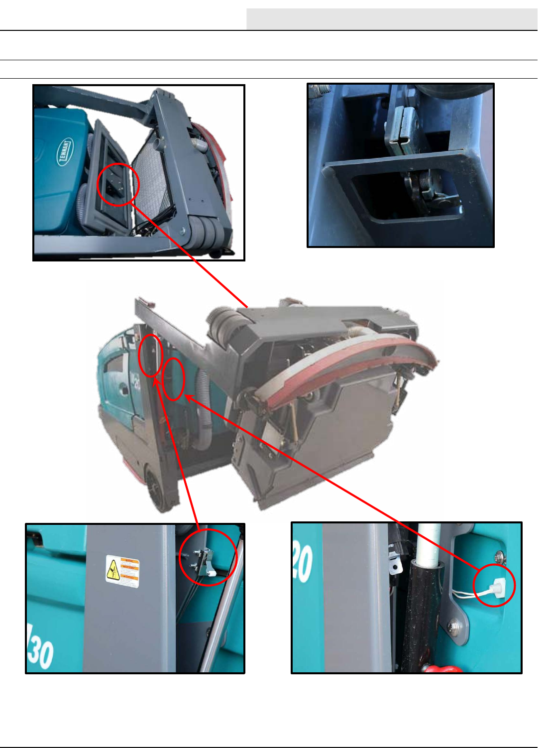
M20/30 -Series ElectricalComponentLocator
Shaker Motor Hopper Latch
Solenoid SOL-9
Hopper Down
Sense Switch
Recovery Tank
Full Switch S-15
ELECTRICAL COMPONENT LOCATOR
M SERIES ELECTRICAL COMPONENT LOCATOR
ELECTRICAL COMPONENT LOCATOR
M20/M30 9016006 - 3-2017
18
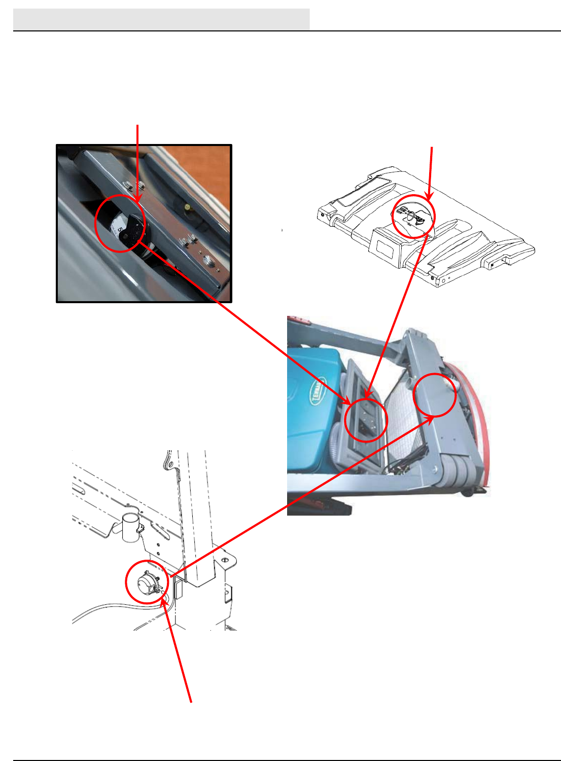
M20/30 Series ElectricalComponentLocator
Solution Tank
Switch S-14
Auto Fill Solenoid
Valves Sol-1 and 2
Solution Tank
Empty Switch (S-15)
M SERIES ELECTRICAL COMPONENT LOCATOR - (CONTINUED)
ELECTRICAL COMPONENT LOCATOR
M20/M30 9016006 - 3-2017 19
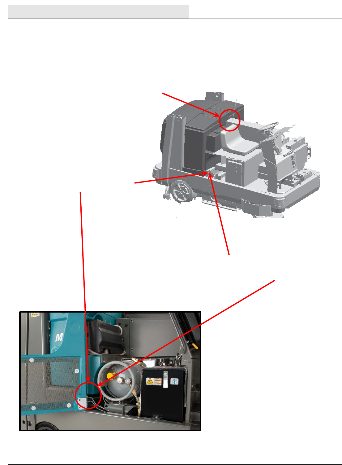
M20/30 Series ElectricalComponentLocator
Battery
Fuse / Relay
Panel
Horn
Recovery Tank Half
Full Switch S-16
ES (Extended Scrub
Pump
ES Equipped Machines
M SERIES ELECTRICAL COMPONENT LOCATOR - (CONTINUED)
ELECTRICAL COMPONENT LOCATOR
M20/M30 9016006 - 3-2017
20
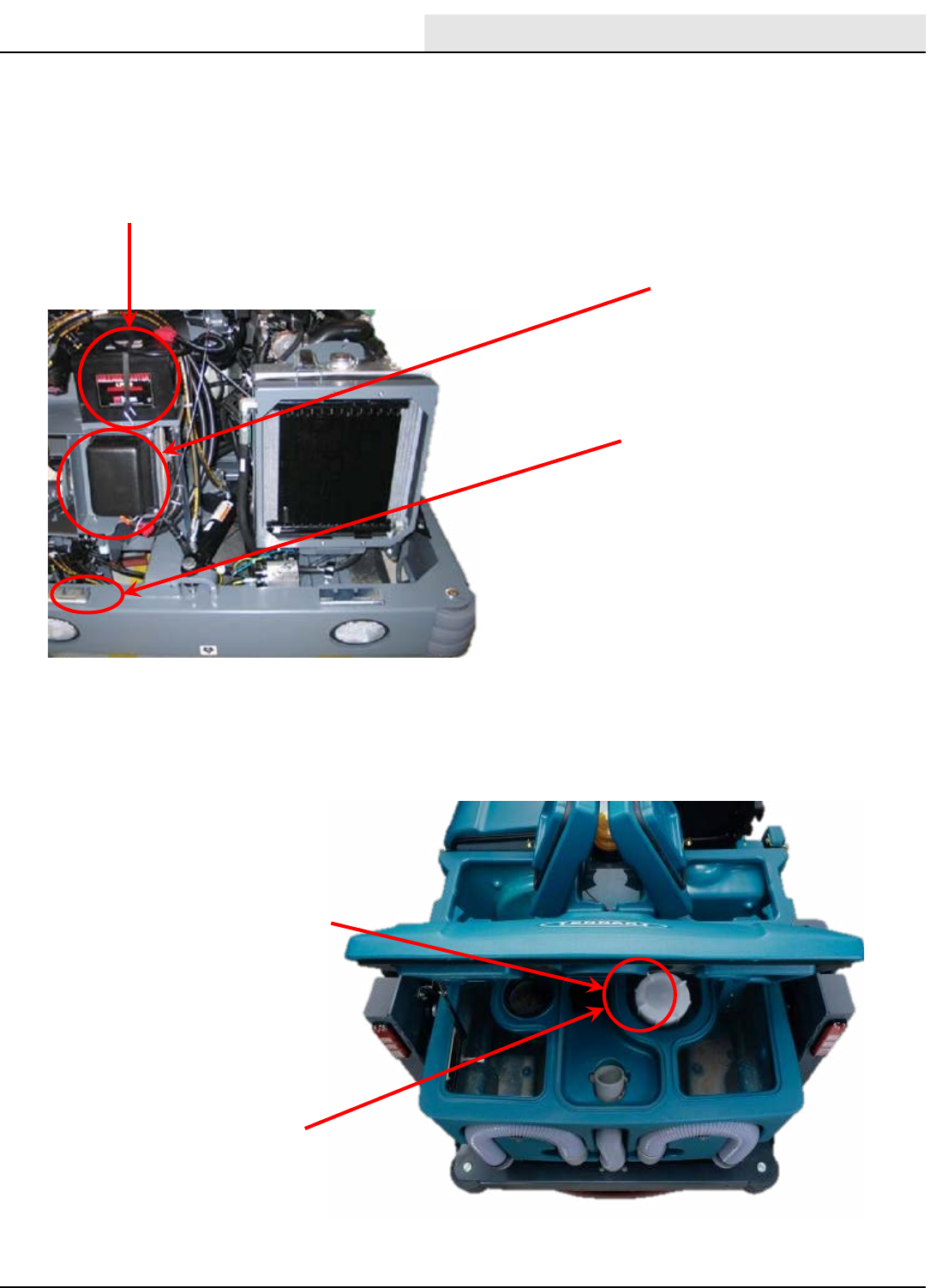
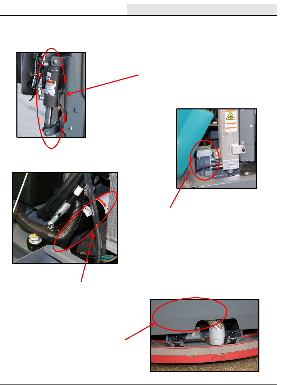
M20/30 Series ElectricalComponentLocator
Shaker Motor Hopper Thermal
Sentry Switch S-9
Sweeper Filter Clogged
Switch S-18
(Viewed Behind Bumper
M SERIES ELECTRICAL COMPONENT LOCATOR - (CONTINUED)
ELECTRICAL COMPONENT LOCATOR
M20/M30 9016006 - 3-2017 21
M20/30 Series ElectricalComponentLocator
M SERIES ELECTRICAL COMPONENT LOCATOR - (CONTINUED)
ELECTRICAL COMPONENT LOCATOR
M20/M30 9016006 - 3-2017
22
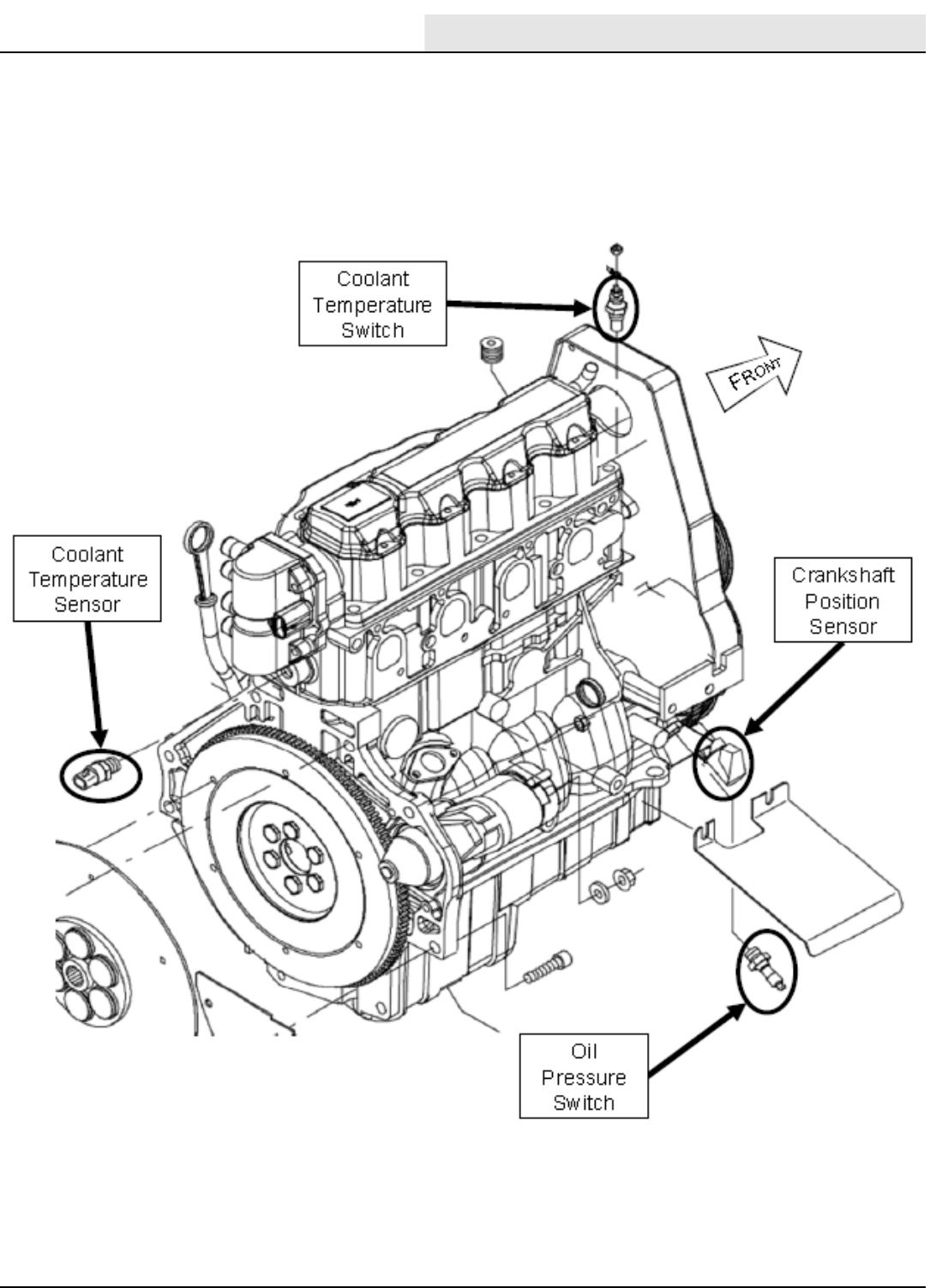
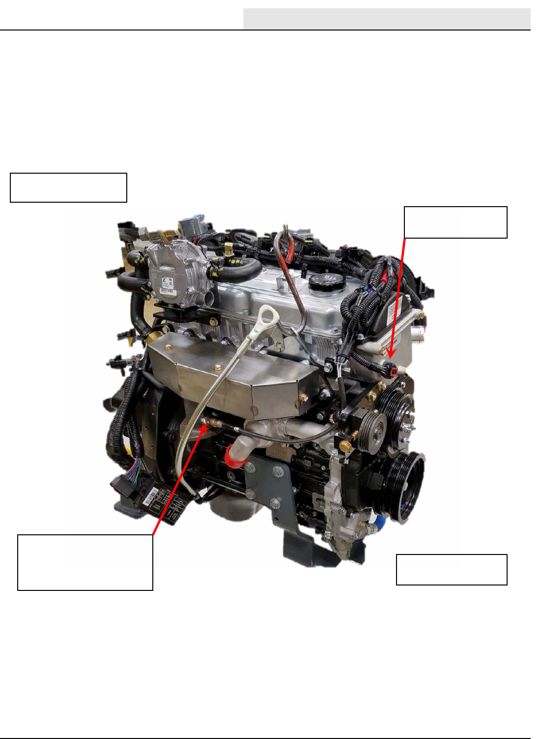
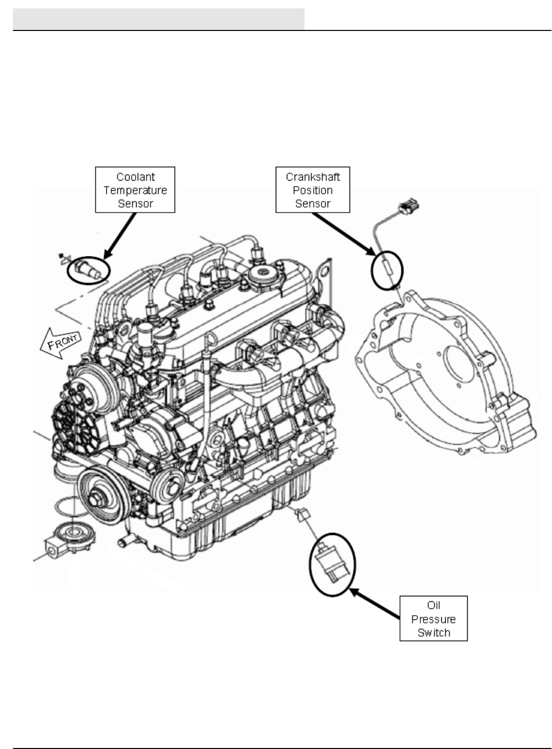
M20/30 Series ElectricalComponentLocator
ECT -Engine Coolant
Temperature Sensor
Cam Sensor
Front of Engine
Back of Engine
Front of Engine
Back of Engine
ECM / ECU
Engine Control Module
or module
CKP
Crank Position Sensor
M SERIES ELECTRICAL COMPONENT LOCATOR - (CONTINUED)
ELECTRICAL COMPONENT LOCATOR
M20/M30 9016006 - 3-2017 23
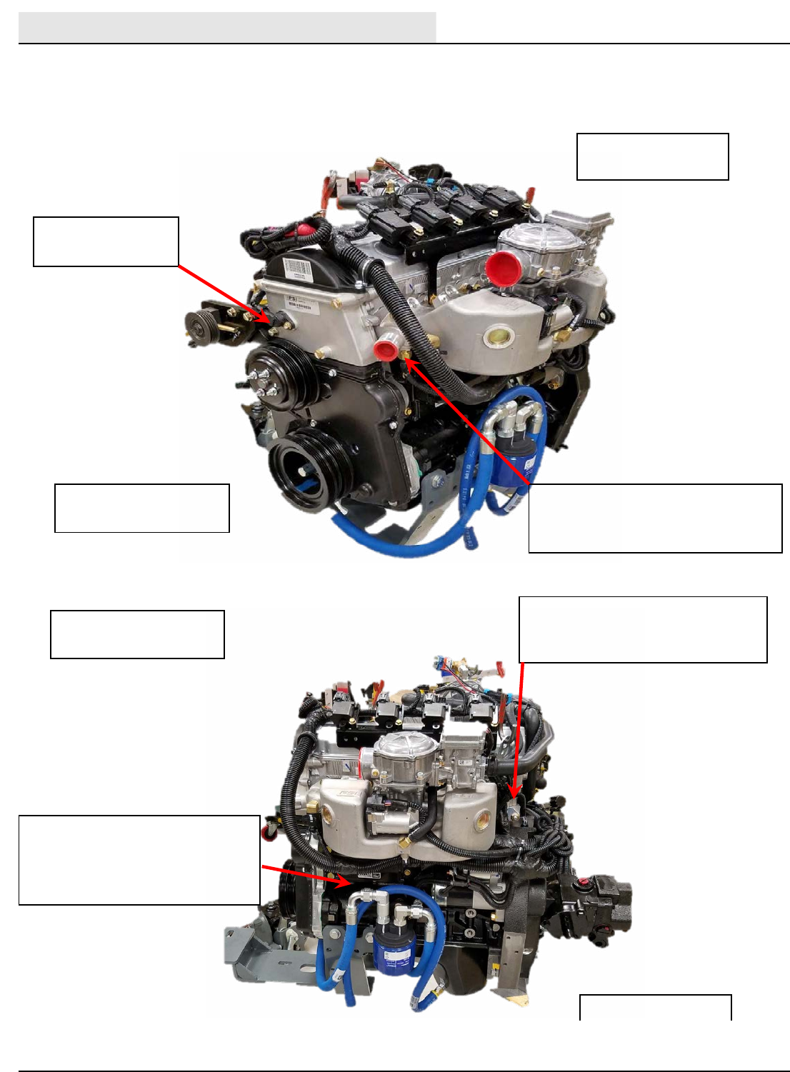
M20/30 Series ElectricalComponentLocator
HEGO 1
Heated Exhaust Gas
Oxygen Sensor
CAM Sensor
Front of Engine
Back of Engine
M SERIES ELECTRICAL COMPONENT LOCATOR - (CONTINUED)
ELECTRICAL COMPONENT LOCATOR
M20/M30 9016006 - 3-2017
24
M20/30 Series ElectricalComponentLocator
M SERIES ELECTRICAL COMPONENT LOCATOR - (CONTINUED)
ELECTRICAL COMPONENT LOCATOR
M20/M30 9016006 - 3-2017 25
M20/30 Series Hydraulic ComponentLocator
Side Brush Motor Sweep Fan Motor
Main Brush
Motor (Rear)
Propel Motor
Left Side Squeegee
Lift Cylinder
M SERIES ELECTRICAL COMPONENT LOCATOR - (CONTINUED)
ELECTRICAL COMPONENT LOCATOR
M20/M30 9016006 - 3-2017
26
M20/30 Series Hydraulic ComponentLocator
Hopper Lift Cylinder Side Brush
Extend Cylinder
Side Brush
Cylinder
Right Side Squeegee
Lift Cylinder
Main Brush
Motor (Front)
Scrub Head
Lift Cylinder
M SERIES ELECTRICAL COMPONENT LOCATOR - (CONTINUED)
ELECTRICAL COMPONENT LOCATOR
M20/M30 9016006 - 3-2017 27
M20/30 Series Hydraulic ComponentLocator
Hopper Door Cylinder
Rear Squeegee Lift Cylinder
(Viewed Behind Bumper)
Steering Cylinder
Side Brush Manifold
SV-8, SV-10, SV-11,
SV-12, PR-1, PR-12, PC-8
M SERIES ELECTRICAL COMPONENT LOCATOR - (CONTINUED)
ELECTRICAL COMPONENT LOCATOR
M20/M30 9016006 - 3-2017
28
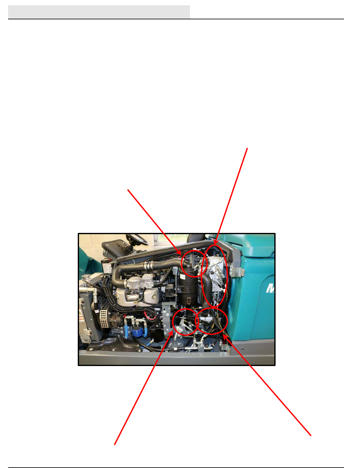
M20/30 Series Hydraulic ComponentLocator
Propel Pump
Sweep Fan Valve SV-9
Hydraulic Valve SV-1, SV-2, SV-3, SV-4, SV-6, SVC-7, SV-13A,
SVC-14B, SV-15 RV-1, RV-2, OR-1, OR-4, CV-1, PC-1, PC-2,
PC-5, PC-6, PCV-7, G-1,. G-2, G-5, G-6, G-11, C-11
Accessory Pumps
M SERIES ELECTRICAL COMPONENT LOCATOR - (CONTINUED)
ELECTRICAL COMPONENT LOCATOR
M20/M30 9016006 - 3-2017 29
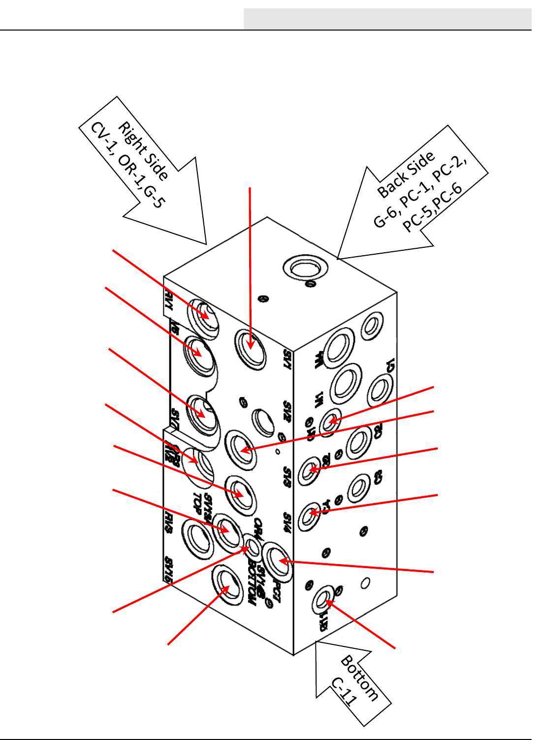
RV-1
SV-1
SV-6
SV-3
RV-2
SV-7
OR-4
SV-13A
SV-13B
SV-15
SV-4
PC-7
G-1
G-2
G-11
C-4
M20/30-Series Hydraulic ComponentLocator
Hydraulic Manifold Details
P/N #1072995
M SERIES ELECTRICAL COMPONENT LOCATOR - (CONTINUED)
ELECTRICAL COMPONENT LOCATOR
M20/M30 9016006 - 3-2017
30
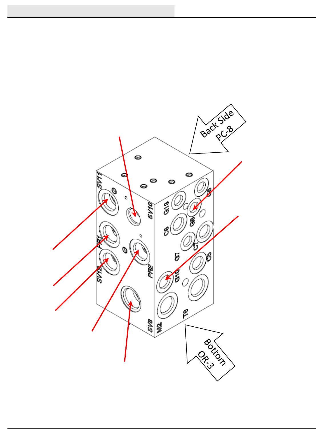
M20/30-Series Hydraulic ComponentLocator
Hydraulic Manifold Details
P/N #1072997
G-8
G-10
PR-2
SV-8
SV-12
PR-1
SV-11
SV-11
M SERIES ELECTRICAL COMPONENT LOCATOR - (CONTINUED)

ELECTRICAL
M20/M30 9016006 - 3-2017 31
M20/30 -Series
ELECTRICAL
TroubleshootingInformation
NOTE:Troubleshootingchartsmaybeshown withoptionalequipment.
Theoptionalequipmentmaynot be specified in thesecharts.Some
machines maynot be equippedwith all componentsshown.
BEFORECONDUCTINGTESTS:
*Read and Follow ALL Safety Warnings and Precautions as
mentioned at the beginning of this manual.
*Always use an ESD(ElectrostaticDischarge)strap when working near the
Control Board.
*Be cautious when workingnearControlBoard – Battery voltage is always
present, even with Key OFF.
*Always dis-connect Battery when removing or replacing components.
*Call Technical Services if Diagnostic Time Exceeds One Hour With
Unknown Cause or Course of Action.
65
E
DURINGTESTS:
E
M-Series Electrical
ELECTRICAL
M20/M30 9016006 - 3-2017
32
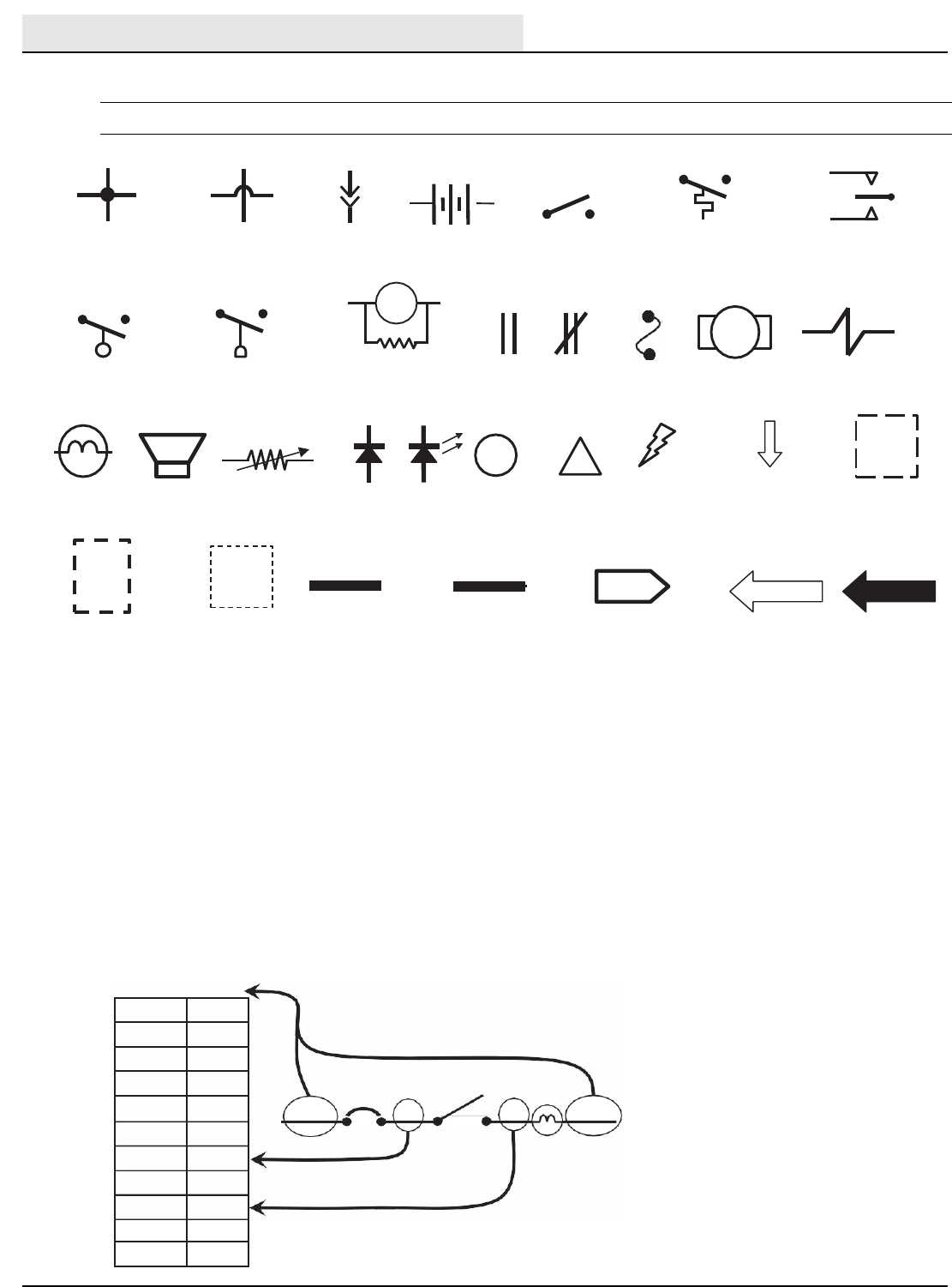
Ter ms &Abbreviations
Example of Wiring Numbers &Colors:
Wiring Color Codes
(Unless otherwise marked)
Right Most Digit
of WireNumber
Color of Wire
0Tan
1Pink
2 Brown
3Orange
4Yellow
5Green
6Blue
7 Purple
8Gray
9White
1RED 25 7 13 BLK
Fuse Motor Solenoid
Valve
Horn or
Alarm
Together
Movement from
Normal Position
Component in Position
Other thanNormal
Battery Positive
or Positive Output
Battery Negative
or Logic Ground
OpenClosed
Relay Contacts
Diode LED Information
!
Warning! Component
is Energized
Information
Box
Assembly
Lamp
(Light Bulb)
M2A
Relay Coil with spike
suppression resistor
Normally Open Normally Open
Liquid Level Switch Pressure Switch
Sensor
(Variable Resistor)
Connection TO or
FROM Another Point
PIN P2-11 PIN P2-35
Control
Board Input
Control
Board Output
+ -
OFF
Wires Connected Wires Not Plug-in
Battery
Normally Open Normally Open Normally Open
Together Connected Connection Switch Temperature Switch Momentary Switch
i
ECM –Engine Control Module
LED –Light Emitting Diode
MIL –Malfunction Indicator Lamp
PWM –Pulse Width Modulation (A method of using controlled on/off
times to regulate the voltage and current supplied to an electrical device)
SV –Solenoid Valve
SW –Switch
ELECTRICAL
ELECTRICAL SCHEMATIC SYMBOLS
ELECTRICAL
M20/M30 9016006 - 3-2017 33
E = ElectricalComponent
H = HydraulicComponent
Thefollowing chartlistsvariousoptionsandthe electricaland/orhydraulic components
thatareassociatedwith theoption.Refer to the“notes”sectionforany componentsthat
aredeletedfrom a standardmachine in order to havethe installedoption.
Hose
90
option added components E or H component # notes
Side Brush
Side Brush ON SolenoidValve E,H SV-8
Side Brush Pressure SolenoidValve E,H SV-10
Side Brush Down SolenoidValve E,H SV-11
Side Brush ExtendSolenoidValve E,H SV-12
FaSTSide Brush Valve ESOL-6
Side Brush WaterValve ESOL-7
Side Brush Manifold Hx
Side Brush Lift Cylinder Hx
Side Brush Extend Cylinder Hx
Side Brush Motor Hx
ES
(Extended Scrub)
Solution TankAuto Fill WaterValve ESOL-1 If machinehas ES option,the following
components willnot be on the
machine:FaST WaterPump, FaST
WaterPump Relay (M11), FaST
DetergentPump, FaSTAirPump,
FaSTEnableValve (SOL-4), FaST
High FlowValve (SOL-5), FaSTSide
Brush Valve (SOL-6)
Recovery TankAuto Fill W aterValve ESOL-2
Solution Tank Full Switch ES-14
Recovery TankHalf Full Switch ES-16
DetergentPump Ex
ES Pump Ex
Spray
Spray Hose Pump Ex
SprayHose Relay EM12
Spray Hose Switch ES-25
ELECTRICAL OPTION COMPONENTS
ELECTRICAL
M20/M30 9016006 - 3-2017
34
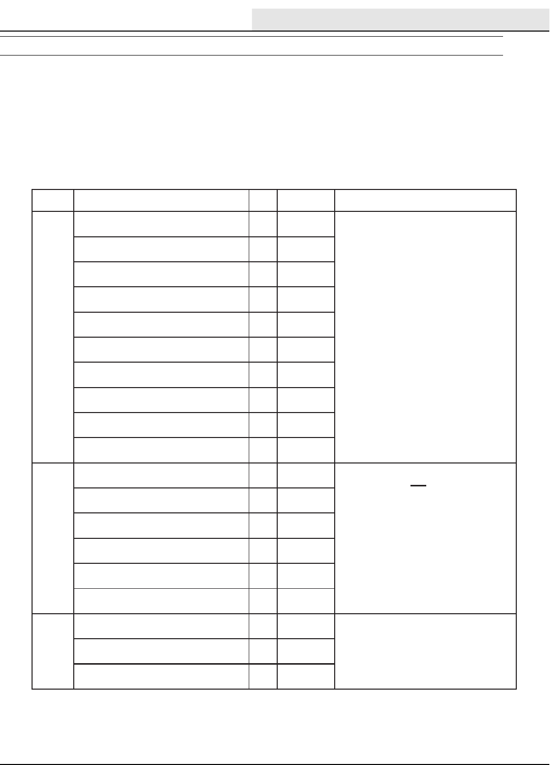
ACC
RUN
START
NO CONNECTIONSOFF
GLOWPLUG
50 17 19
30
KEY SWITCH POSITION
“Indicates a common connection
30
50
17
19
ACC
30
50
17
19
ACC
30
50
17
19
ACC
Run Position Start Position
Spring Loaded-Returns to “RUN” Unless Held
30
50
17
19
ACC
Off Position
Glow Plug Position (Diesel Only)
Spring Loaded –Returns to “Off” Unless Held
Key Switch
Glow
Plug
Off Run
Start
Key Switch
Glow
Plug
Off Run
Start
Key Switch
Glow
Plug
Off Run
Start
Key Switch
Glow
Plug
Off Run
Start
Common connections in various switch positions should
be less than one (1) ohm resistance.
i
i
Switch Terminal Markings
M-Series Key Power Distribution
Conditions: Glow plug, key off, run, start positions
Key Power Distribution
Conditions: Glow Plug, Key Off, Run, Start Positions
ELECTRICAL
M20/M30 9016006 - 3-2017 35
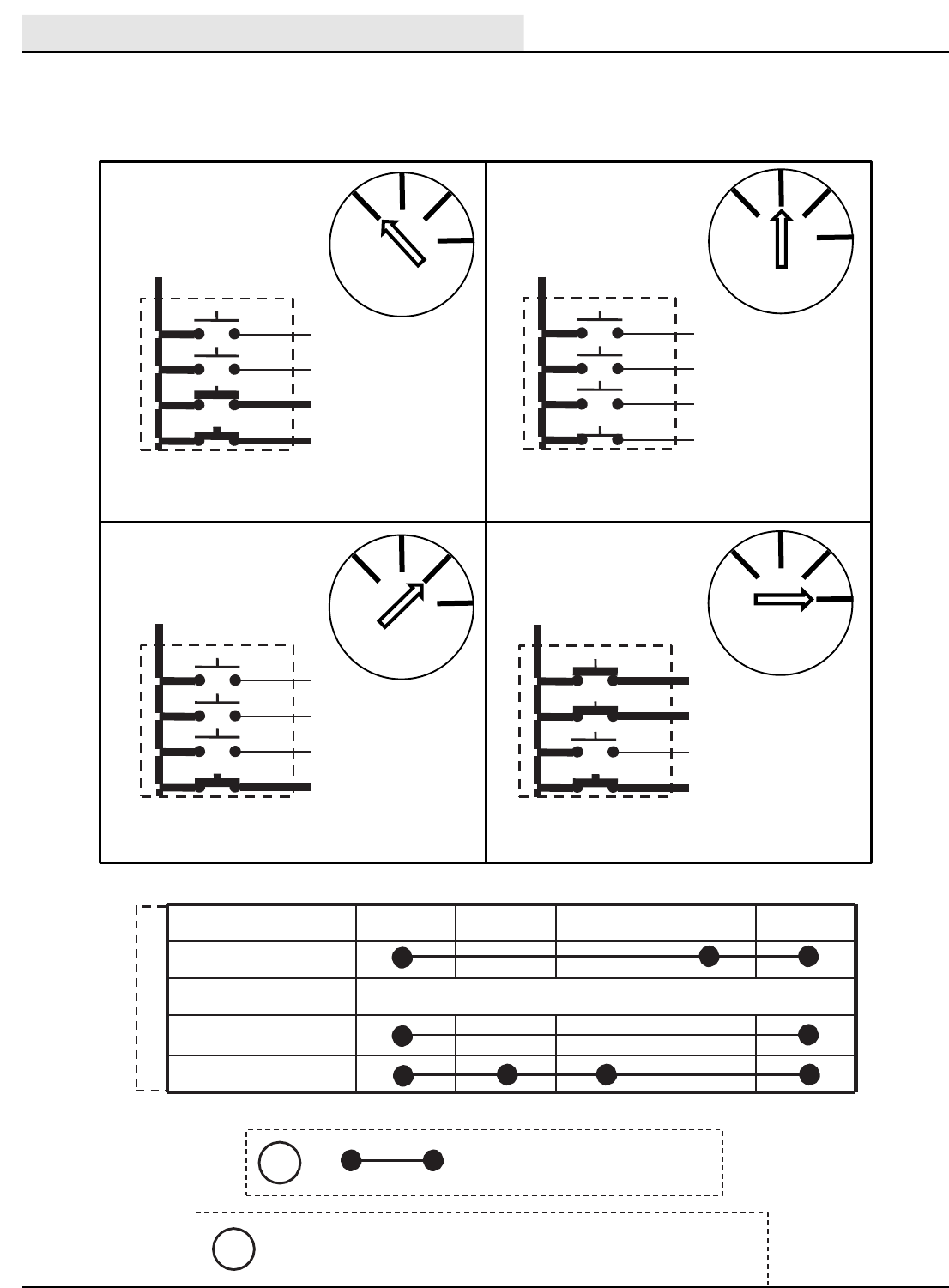
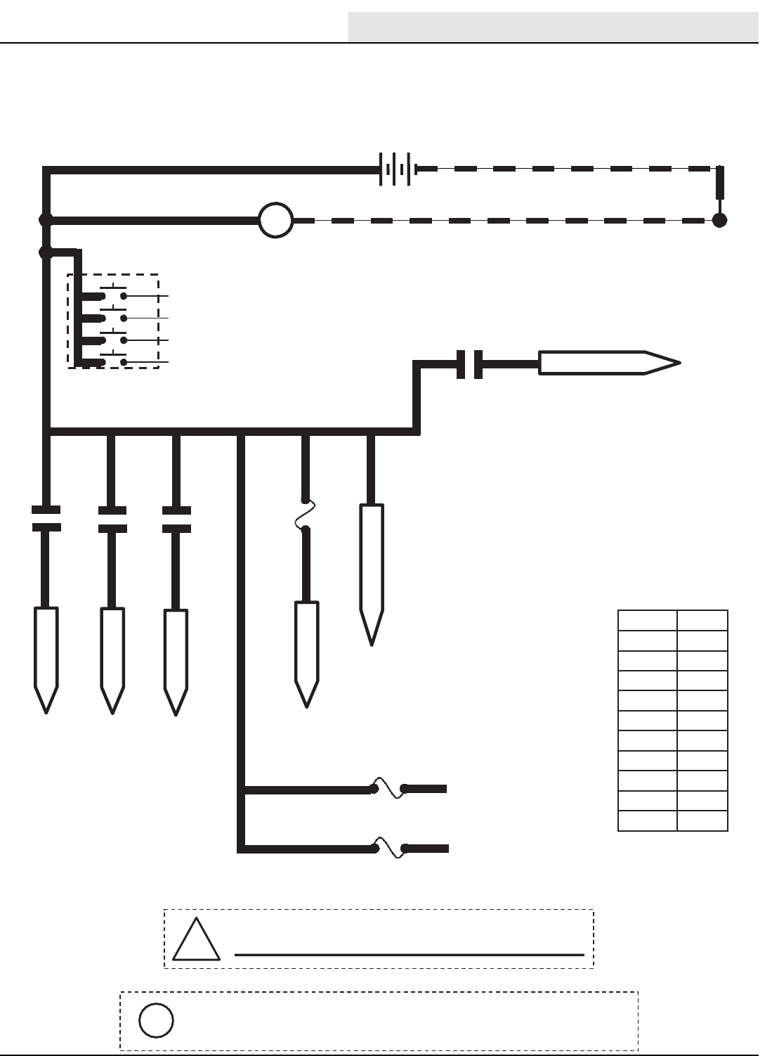
M-Series Key OFF Power Distribution
Conditions: Keyoff
1/RED 13/BLK
+-
12 VDC
ALTERNATOR
+ -
1/RED
GREEN JUMPER WIRE1/RED
1/RED
Wiring Color Codes
(Unless otherwise marked)
!Be cautious when workingnearControlBoard -
Battery voltage is always present, even with Key OFF
KEY SWITCH
OFF
Right Most Digit
of Wire Number
Color of Wire
0 Tan
1Pink
2 Brown
3Orange
4Yellow
5Green
6Blue
7 Purple
8Gray
9White
30
50
17
19
ACC
Pin P2-3 supplies power to the on-board clock only.
Disconnecting battery, removing Fuse 10, or removing connector
P2 from Control Board will require the clock to be reset.
i
1/RED
1/RED
1/RED
1/RED 128/GRY
FUSE-2
15A
Aux. 2 Relay
Aux. 3 Relay
Fuse 11
15A
128 B+
Extra Fused B+
1 (UNSWITCHED B+)
SEE DIODE D-2
27 (AUX #3)
27 / PUR
5(AUX #2)
5/ GRN
6 (AUX #1)
6 / BLU
M/7B
START RELAY
77/PUR
1/RED
1/RED
1/RED
Aux. 1 Relay
FUSE-3
15A
122/BRN
25/GRN
B+ WHILE CRANKING
Key Power Distribution
Conditions: Key Off
ELECTRICAL
M20/M30 9016006 - 3-2017
36
13/BLK
TO ENGINE
HARNESS
PIN P2-35
PIN P1-23
STATIC
GROUND
105
Wiring Color Codes
(Unless otherwise marked)
TO FUSES
7 & 8
SHUTDOWN RELAY
CONTACTS
(Normally CLOSED)
3
8
8
M2A
M6C
TO FUSE
6
1/RED 5
1/RED 30
3
8 86
6
85 13/BLK
M2B
AUX. 2
RELAY
87
14
M-Series Key ON Power Distribution
Conditions: Key on,engineoff
1/RED 13/BLK
13/BLK
13/BLK
+-
12 VDC
KEY SWITCH
RUN
ALTERNATOR
+ -
TouchPanel /
Control Board
GREEN JUMPER WIRE1/RED
1/RED
FUSE 5
15 AMP
4
1/RED1/RED 6
PIN P2-33
PIN P2-34
813/BLK
13/BLK
14
FUSE 1
15 AMP
PIN P2-1
PIN P2-2
ALTERNATOR
LAMP
M1B
AUX. 1
RELAY
M1A
7
8
14
13/BLK
86 85
30 87
4
D-2
14 14
TO FUSES
9&12
1/RED
Right Most Digit
of Wire Number
Color of Wire
0 Tan
1Pink
2 Brown
3Orange
4Yellow
5Green
6Blue
7 Purple
8Gray
9White
30
50
17
19
ACC
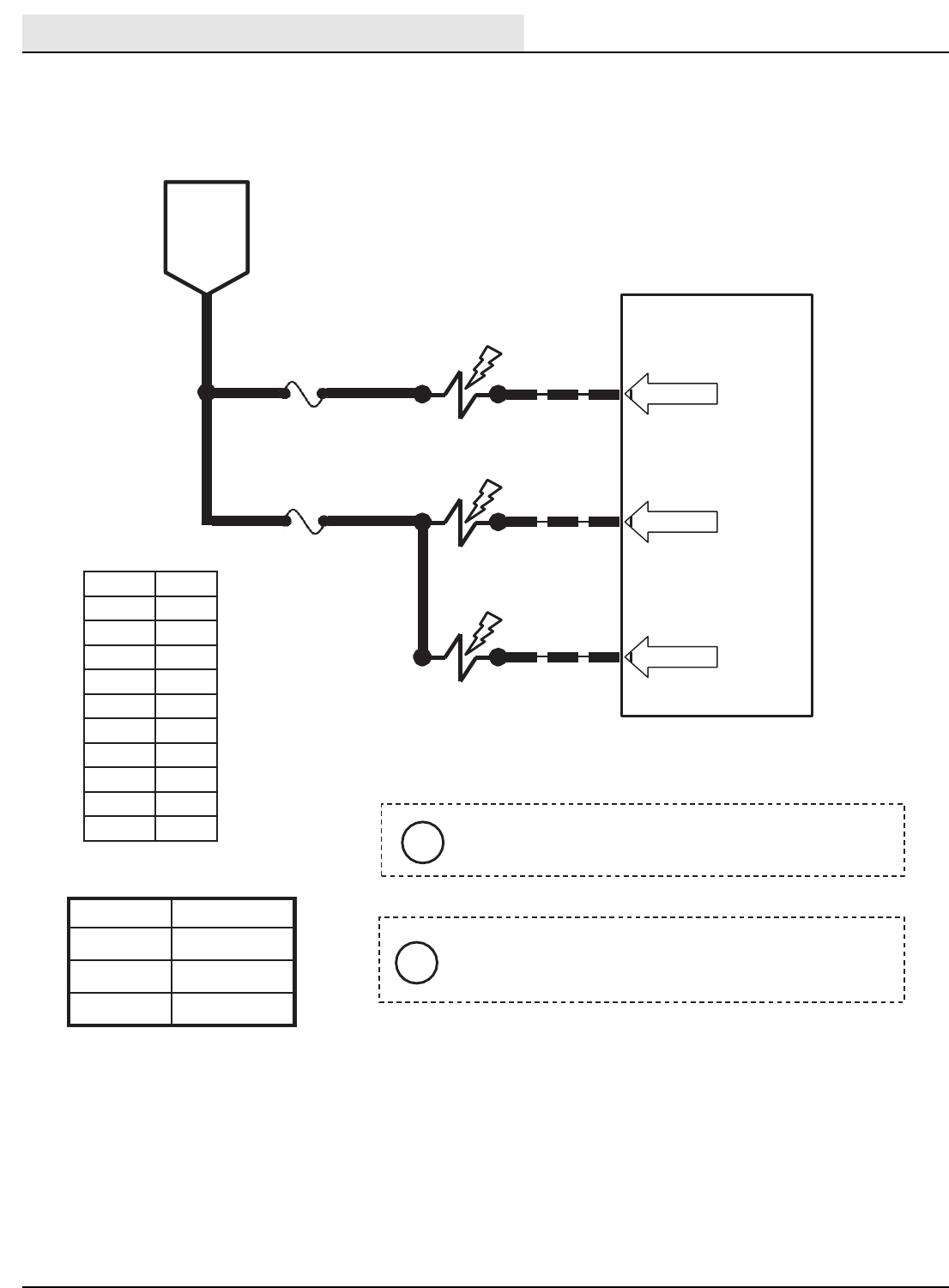
Key On Power Distribution
Conditions: Key On Engine Off
ELECTRICAL
M20/M30 9016006 - 3-2017 37
6 14
FUSE 5
15 AMP
14
14
MAIN BRUSHES
57
58
SV-2
SV-3
MAIN BRUSHES
LOWER
ROTATE 58
PIN P2-4
TouchPanel / Control Board
61
FUSE 6
PIN P2-8
15 AMP
SV-7
615 ENABLEVALVE
BRUSHHEAD
PRESSURE
PWM
BATTERY
POSITIVE
FROM
AUX 1
RELAY
CONTACTS
PIN P2-5
Wiring Color Codes
(Unless otherwise marked)
Maximum Amp. Draw Readings
Right Most Digit
of Wire Number
Color of Wire
0 Tan
1Pink
2 Brown
3Orange
4Yellow
5Green
6Blue
7 Purple
8Gray
9White
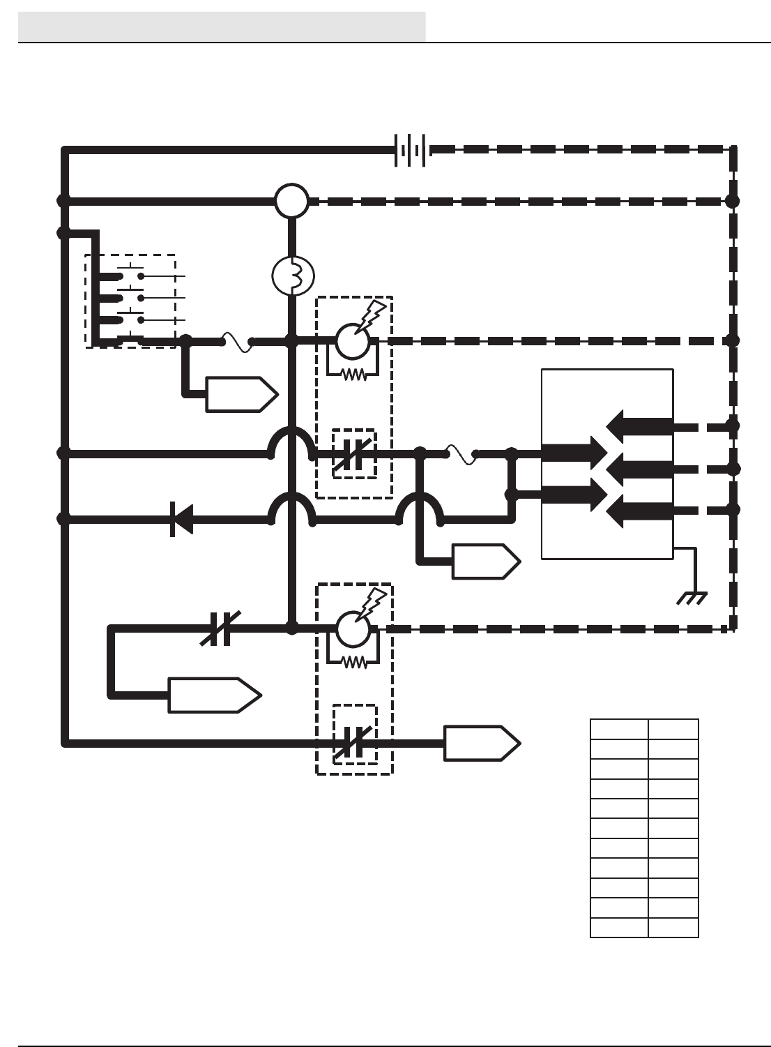
Component Max Amp Draw
SV-3 1.7 A
SV-6 1.7 A
SV-7 1.7 A
SV-6
iPressure settings P1, P2, & P3 are the Touch Panel
LED indicators for Brush down pressure.
i
SV-2 is controlled by PWM; ahigher duty cycle
(more Brush Pressure LED’s lit on Touch
Panel) will result in more brush down pressure.
M-Series Main Brushes ON
Conditions: Key on,enginerunning, scrubbing or sweeping system on, propel forward or reverse
Typical Default
AmpDraw Readings(+/-15%)
(SCRUBBING)
Setting SV-10 Amp Draw
P1 530mA
P2 625mA
P3 715mA
Typical Default
AmpDraw Readings(+/-15%)
(SWEEPING)
Setting SV-10 Amp Draw
P1 500 mA
P2 540 mA
P3 615 mA
Main Brushes On
Conditions: Key On, Engine Running, Scrubbing or Sweeping System On Propelling
ELECTRICAL
M20/M30 9016006 - 3-2017
38
614
Touch Panel /Control Board
61
6 15
SV-7
SV-14
ENABLE
VALVE
HOPPER
LIFT S-6
60
OPEN = UP
CLOSED = DOWN
S-5
2
4
HOPPER
LIFT/LOWER
SWITCH
2 & 4 CLOSED = LIFT
2 & 1 CLOSED = LOWER
35 1
36
13/BLK
HOPPER POSITION
SWITCH
89 13/BLK
FROM
AUX 1
RELAY
CONTACTS
BATTERY
NEGATIVE
BATTERY
POSITIVE
PIN P2-8
PIN P2-7
PIN P1-3
PIN P1-7
PIN P1-8
Wiring Color Codes
(Unless otherwise marked)
Right Most Digit
of WireNumber
Color of Wire
0Tan
1Pink
2 Brown
3Orange
4Yellow
5Green
6Blue
7 Purple
8Gray
9White
OFF
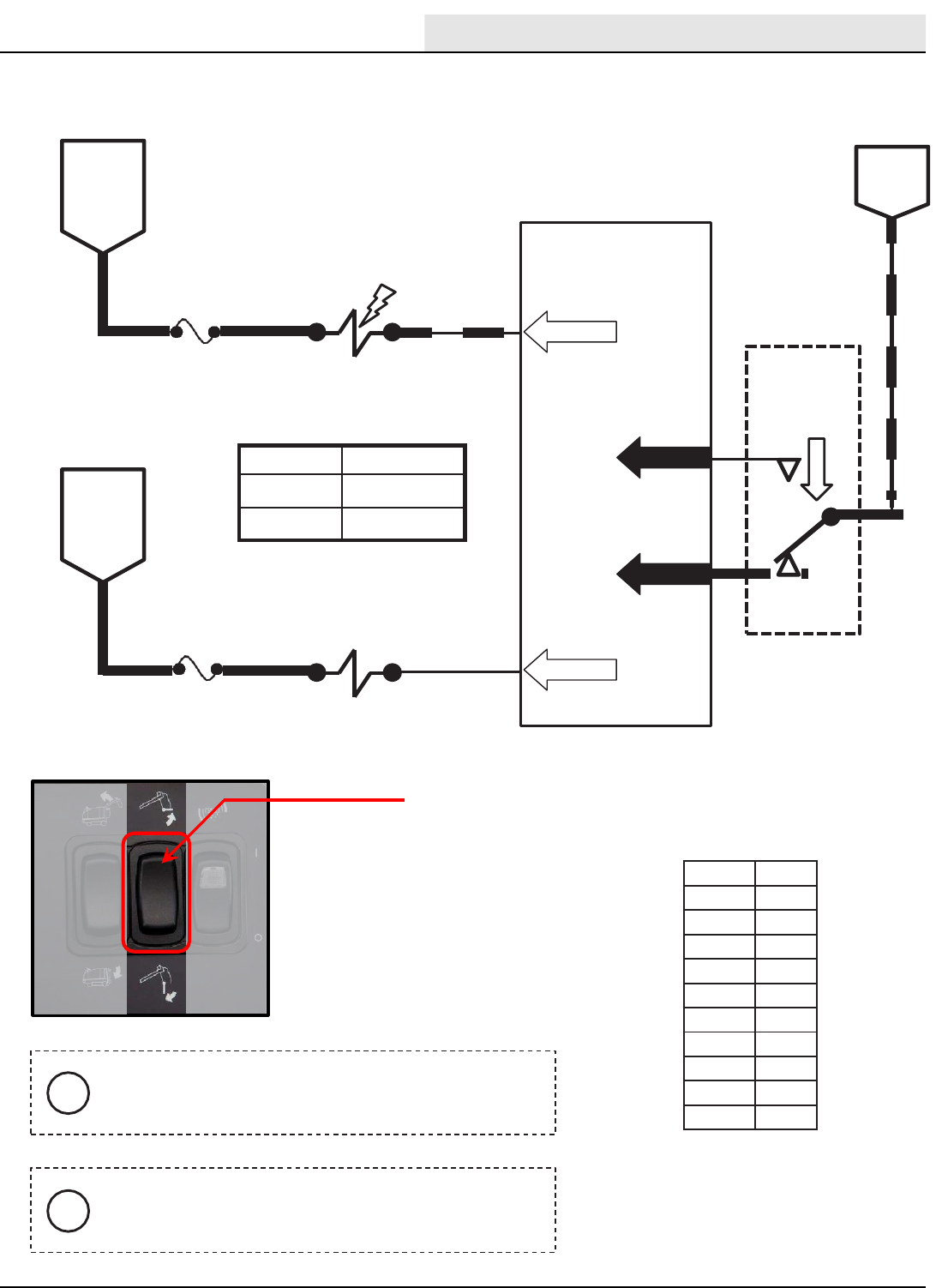
Component Max Amp Draw
SV-7 1.7 A
SV-13 1.7 A
SV-14 1.7 A
FUSE 6
15 AMP
FUSE 5
15 AMP
D-2
TO Unswitched B+
1/RED
HOPPER
LIFT/LOWER
SWITCH
PUSH TO LIFT
HOPPER
i
Activating the Hopper Lift/Lower Switch will cancel
the sweep or scrub systems and automatically
selects HIGH engine speed.
i
If hopper is in the full DOWN position when activating
Hopper Lift, the Hopper Lower Valve (SV-13) is
momentarily turned ON to help “jog” the hopper latch.
iHopper Latch Solenoid (SOL-9) is an electro-
mechanical device.
iHopper Latch Solenoid (SOL-9) turns ON for 3 to 5
seconds with each activation of Hopper Lift Switch.
M-Series Hopper Lift
Conditions: Key on,enginerunning, hopper lift switch activated
SV-13
HOPPER
LOWER
5FUSE 8
15 AMP
53
17
BATTERY
POSITIVE
FROM
AUX2
RELAY
CONTACTS
PIN P2-31
HOPPER
LATCH
5FUSE 7
15 AMP
138
16 PIN P2-32
SOL-9
Hopper Lift
Conditions: Key On Engine Running, Hopper Lift Switch Activated
ELECTRICAL
M20/M30 9016006 - 3-2017 39
Wiring Color Codes
(Unless otherwise marked)
Right Most Digit
of WireNumber
Color of Wire
0Tan
1Pink
2 Brown
3Orange
4Yellow
5Green
6Blue
7Purple
8Gray
9White
HOPPER
LIFT/LOWER
SWITCH
PUSH TO
LOWER HOPPER
M-Series Hopper Lower
Conditions: Key on,enginerunning, hopper lower switch activated
iActivating the Hopper Lift/Lower Switch will cancel the sweep or
scrub systems and automatically selects HIGH engine speed.
iHopper Latch solenoid (SOL-9) is an electro-mechanical device.
S-6
HOPPER DOWN
SENSE SWITCH
OPEN = UP
CLOSED = DOWN
89 13/BLK
BATTERY
NEGATIVE
S-5
2
1
HOPPER
LIFT/LOWER
4SWITCH
1&2 CLOSED = LIFT
2&4 CLOSED = LOWER
35
36
13/BLK
OFF
6 14
Touch Panel /Control Board
61
15 AMP
FUSE 5
15 AMP
6FUSE 615
SV-7
SV-14
SV-13
ENABLE
VALVE
HOPPER
LIFT
HOPPER
LOWER
5FUSE 8
15 AMP
60
53
17
BATTERY
POSITIVE
FROM
AUX 1
RELAY
CONTACTS
BATTERY
POSITIVE
FROM
AUX2
RELAY
CONTACTS
PIN P2-8
PIN P2-7
PIN P2-31
PIN P1-3
PIN P1-7
PIN P1-8
5FUSE 7
15 AMP
HOPPER
LATCH 138
16 PIN P2-32
SOL-9
Hopper Lower
Conditions: Key On, Engine Running, Hopper Lower Switch Activated
ELECTRICAL
M20/M30 9016006 - 3-2017
40
6 14
BATTERY
POSITIVE
FROM
AUX 1
RELAY
CONTACTS
TouchPanel / Control Board
61
FUSE 6
15 AMP
FUSE 5
15 AMP
6
14
15
56
59
SV-7
SV-1
SV-4
ENABLE
VALVE
SCRUB
VACUUM
FAN ON
SIDE & REAR
SQUEEGEES
LOWER
PIN P2-8
PIN P2-28
PIN P2-6
Maximum Amp Draw Readings
Right Most Digit
of Wire Number
Color of Wire
0 Tan
1Pink
2 Brown
3Orange
4Yellow
5Green
6Blue
7 Purple
8Gray
9White
Component Max Amp Draw
SV-1 1.7 A
SV-4 1.7 A
SV-7 1.7 A
i
Any condition that cancels the scrub functions will
also turn OFF the scrub vacuum fan and raise
squeegees.
i
Reverse propel will turn OFF SV-4 (Pin P2-6) and
raise the side and rear squeegees.
M-Series Scrub Vacuum Fan On & Squeegees Down
Conditions: Key on,enginerunning, scrubbing system & scrub vacuum on, propel forward
Scrub Vacuum Fan On & Squeegee Down
Conditions: Key On, Engine Running, Scrubbing System & Scrub Vacuum On, Propelling
ELECTRICAL
M20/M30 9016006 - 3-2017 41
Touch Panel /Control Board
61
615
SV-7
SV-15
ENABLE
VALVE
5
HOPPER
DOOR OPEN 68
16
BATTERY
POSITIVE
FROM
AUX 1
RELAY
CONTACTS
BATTERY
POSITIVE
FROM
AUX 2
RELAY
CONTACTS
PIN P2-8
PIN P2-15
Wiring Color Codes
(Unless otherwise marked)
Right Most Digit
of WireNumber
Color of Wire
0Tan
1Pink
2 Brown
3Orange
4Yellow
5Green
6Blue
7Purple
8Gray
9White
BATTERY
NEGATIVE
S-13
2
4
HOPPER
DOOR
OPEN/CLOSE
SWITCH
1
42
43
13/BLK
OFF
PIN P1-9
PIN P1-10
Component Max Amp Draw
SV-7 1.7 A
SV-15 1.7 A
2 & 1 CLOSED = DOOR OPEN
2 & 4 CLOSED = DOOR CLOSE
FUSE 7
15 AMP
FUSE 6
15 AMP
Activating the Hopper Door Switch to open or close
the door will cancel the sweep or scrub systems and
automatically selects HIGH engine speed.
i
Anytime the Enable Valve (SV-7) is ON and the
Hopper Door Open Valve (SV15) is OFF, the hopper
door will close.
i
HOPPER DOOR
SWITCH
PUSH TO CLOSE
DOOR
M-Series Hopper Door Open
Conditions: Key on,enginerunning, hopper door open switch activated
Hopper Door Open
Conditions: Key On, Engine Running, Hopper Door Open, Switch Activated
ELECTRICAL
M20/M30 9016006 - 3-2017
42
61
6FUSE 6
PIN P2-8
15 AMP
SV-7
15
15
15
15
64
62
SV-10
SV-8
SV-12
ENABLEVALVE
SIDE
BRUSH
PRESSURE
SIDE
BRUSH RUN
SIDE
BRUSH EXTEND
62
PWM
66
SIDE
BRUSHDOWN
SV-11
PIN P2-11
PIN P2-9
PIN P2-12
15
Wiring Color Codes
(Unless otherwise marked)
Typical Default
AmpDraw Readings(+/-15%)
(SCRUBBING)
BATTERY
POSITIVE
FROM
AUX 1
RELAY
CONTACTS
TouchPanel / Control Board
Right Most Digit
of Wire Number
Color of Wire
0 Tan
1Pink
2 Brown
3Orange
4Yellow
5Green
6Blue
7 Purple
8Gray
9White
Component Max Amp Draw
SV-7 1.7 A
SV-8 1.7 A
SV-11 1.7 A
SV-12 1.7 A
Setting SV-10 Amp Draw
P1 530mA
P2 625mA
P3 715mA
SV-10 is controlled by PWM; a higher duty cycle
(More Brush Pressure LED’s lit on Touch Panel) will
result in more Brush Down pressure.
i
iPressure settings P1, P2, & P3 are the Touch
Panel LED indicators for Brush Down Pressure.
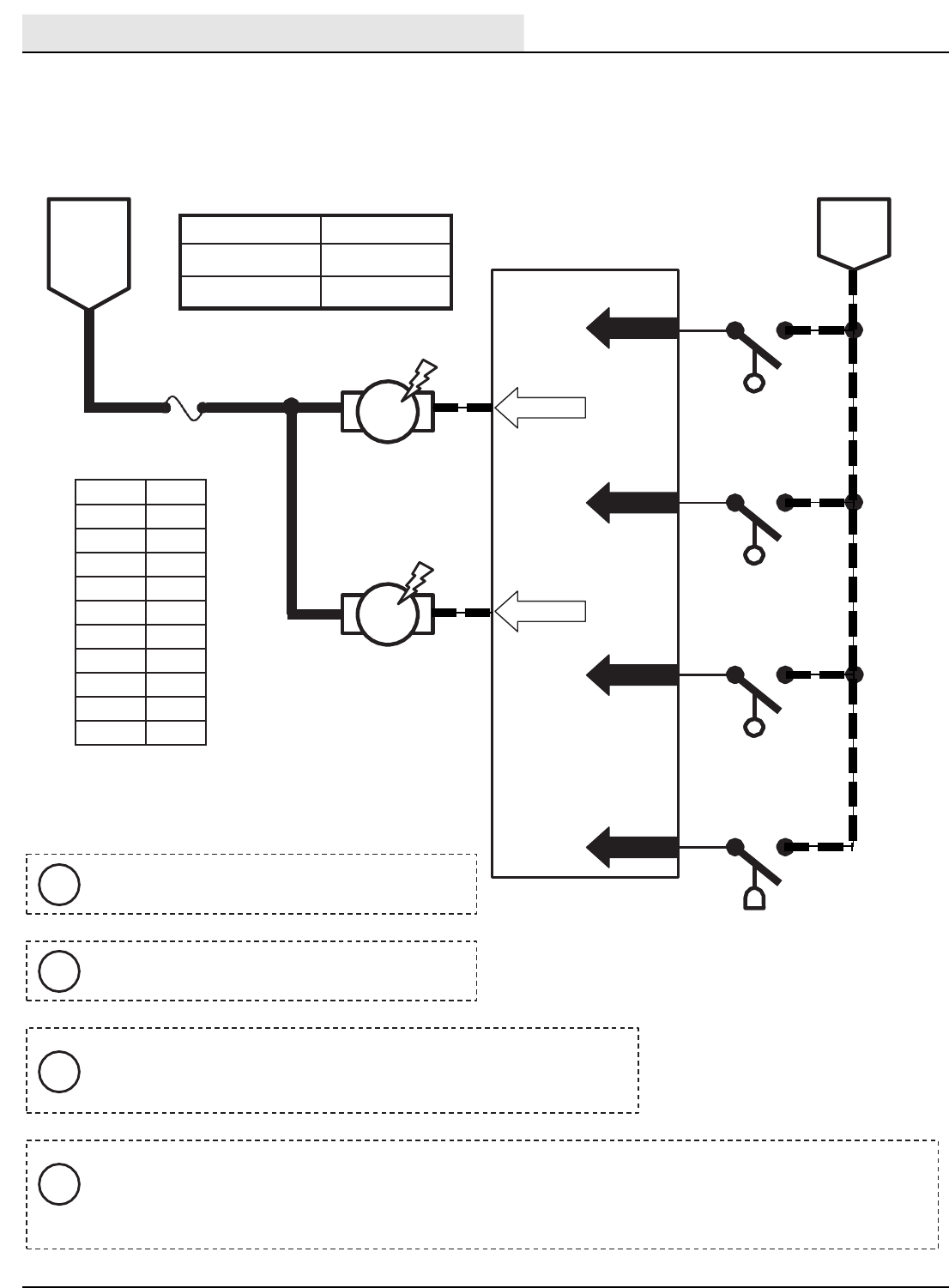
M-Series Side Brush On
Conditions: Key on,enginerunning, scrubbing or sweeping system on, side brush on propel
forward or reverse
Maximum Amp Draw Reading
Typical Default
AmpDraw Readings(+/-15%)
(SWEEPING)
Setting SV-10 Amp Draw
P1 500 mA
P2 540 mA
P3 615 mA
Side Brush On
Conditions: Key On, Engine Running, Scrubbing or Sweeping, Side Brush On, Propelling
ELECTRICAL
M20/M30 9016006 - 3-2017 43
61
6FUSE 6
PIN P2-8
15 AMP
SV-7
15
15
15
15
64
62
SV-10
SV-8
SV-12
ENABLEVALVE
SIDE
BRUSH
PRESSURE
SIDE
BRUSH RUN
SIDE
BRUSH EXTEND
62
PWM
66
SIDE
BRUSHDOWN
SV-11
PIN P2-11
PIN P2-9
PIN P2-12
15
Wiring Color Codes
(Unless otherwise marked)
Typical Default
AmpDraw Readings(+/-15%)
(SCRUBBING)
BATTERY
POSITIVE
FROM
AUX 1
RELAY
CONTACTS
TouchPanel / Control Board
Right Most Digit
of Wire Number
Color of Wire
0 Tan
1Pink
2 Brown
3Orange
4Yellow
5Green
6Blue
7 Purple
8Gray
9White
Component Max Amp Draw
SV-7 1.7 A
SV-8 1.7 A
SV-11 1.7 A
SV-12 1.7 A
Setting SV-10 Amp Draw
P1 530mA
P2 625mA
P3 715mA
SV-10 is controlled by PWM; a higher duty cycle
(More Brush Pressure LED’s lit on Touch Panel) will
result in more Brush Down pressure.
i
iPressure settings P1, P2, & P3 are the Touch
Panel LED indicators for Brush Down Pressure.
M-Series Side Brush On
Conditions: Key on,enginerunning, scrubbing or sweeping system on, side brush on propel
forward or reverse
Maximum Amp Draw Reading
Typical Default
AmpDraw Readings(+/-15%)
(SWEEPING)
Setting SV-10 Amp Draw
P1 500 mA
P2 540 mA
P3 615 mA
122
48
Touch Panel /Control Board
BATTERY
POSITIVE
FROM
AUX 1
RELAY
CONTACTS
15
SV-9
6
SWEEP
VACUUM
FANRUN63
S-9
HOPPER
THERMAL
SENTRY
SWITCH
OPEN = BELOW 140°F
31 13/BLK
BATTERY
NEGATIVE
S-18
OPEN = FILTER OK
CLOSED = FILTER CLOGGED
CLOGGED
SWEEP FILTER
SWITCH 13/BLK
UN-
SWITCHED
BATTERY
POSITIVE
16
CLOSED = ABOVE 140°F
BATTERY
POSITIVE
FROM
AUX 2
RELAY
CONTACTS
BATTERY
NEGATIVE
69
SHAKER
RELAY
SHAKER MOTOR
47
13/BLK
PIN P2-10
PIN P2-16
PIN P1-16
PIN P1-5
Wiring Color Codes
(Unless otherwise marked)
Right Most Digit
of WireNumber
Color of Wire
0Tan
1Pink
2 Brown
3Orange
4Yellow
5Green
6Blue
7Purple
8Gray
9White
M3A
86 85
30
M3B
87
Component Max Amp Draw
M3A 200 mA
SV-9 1.7 A
STATIC GROUND105
FUSE 6
15 AMP
5FUSE 7
15 AMP
1/RED FUSE 2
15 AMP
A short shaker cycle is automatically performed each time the Sweep Vacuum is turned OFF.
i
If the Hopper Thermal Sentry Switch closes (above 140°F in hopper), all sweep functions are
cancelled.
i
If Sweep Filter Clogged Switch closes (restriction in filter), a fault condition will be
displayed, but vacuum fan will continue operating normally.
i
If the shaker system is manually selected when Sweep Vacuum Fan is ON, the fan is turned
OFF during the shaker cycle, and turned back ON when shaker cycle is complete.
i
M-Series Side Brush On
Conditions: Key on,enginerunning, scrubbing or sweeping system on, side brush on propel
forward or reverse
Hopper Thermal
Sentry Switch
Sweep Filter Clogged
Switch (behind bumper)
Side Brush On
Conditions: Key On Engine Running, Scrubbing or Sweeping, Side Brush On, Propelling
ELECTRICAL
M20/M30 9016006 - 3-2017
44
48
Touch Panel /Control Board
BATTERY
POSITIVE
15
SV-9
6
SWEEP
VACUUM
FANRUN63
S-9
HOPPER
THERMAL
SENTRY
SWITCH
OPEN = BELOW 140°F
129 13/BLK
BATTERY
NEGATIVE
S-18
OPEN = FILTER OK
CLOSED = FILTER CLOGGED
UN-
SWITCHED
BATTERY
POSITIVE
16
CLOSED = ABOVE 140°F
BATTERY
POSITIVE
FROM
AUX 2
RELAY
CONTACTS
BATTERY
NEGATIVE
69
SHAKER
RELAY
SHAKER
MOTOR
47 13/BLK
PIN P2-10
PIN P2-16
PIN P1-16
PIN P1-5
M3B
M3A
86 85
12230 87
CLOGGED
SWEEP FILTER
SWITCH 13/BLK
STATIC GROUND105
FUSE 6
15 AMP
5FUSE 7
15 AMP
1/RED FUSE 2
15 AMP
Wiring Color Codes
(Unless otherwise marked)
Right Most Digit
of WireNumber
Color of Wire
0Tan
1Pink
2 Brown
3Orange
4Yellow
5Green
6Blue
7Purple
8Gray
9White
Component Max Amp Draw
M3A 200 mA
SV-9 1.7 A
FROM
AUX 1
RELAY
CONTACTS
BATTERY
NEGATIVE
Hopper Thermal
Sentry Switch
Sweep Filter
Clogged Switch
(behind bumper)
A short shaker cycle is automatically performed each time the Sweep Vacuum is turned OFF.
i
If the Hopper Thermal Sentry Switch closes (above 140°F in hopper), all sweep functions are
cancelled.
i
If Sweep Filter Clogged Switch closes (restriction in filter), a fault condition will be
displayed, but vacuum fan will continue operating normally.
i
If the shaker system is manually selected when Sweep Vacuum Fan is ON, the fan is turned
OFF during the shaker cycle, and turned back ON when shaker cycle is complete.
i
M-Series Shaker Motor On
Conditions: Key on,ONE-STEP sweeping turned off or shaker system on
Shaker Motor On
Conditions: Key On, ONE-STEP Sweeping Turned Off or Shaker System On
ELECTRICAL
M20/M30 9016006 - 3-2017 45
Wiring Color Codes
(Unless otherwise marked)
Right Most Digit
of Wire Number
Color of Wire
0 Tan
1Pink
2 Brown
3Orange
4Yellow
5Green
6Blue
7 Purple
8Gray
9White
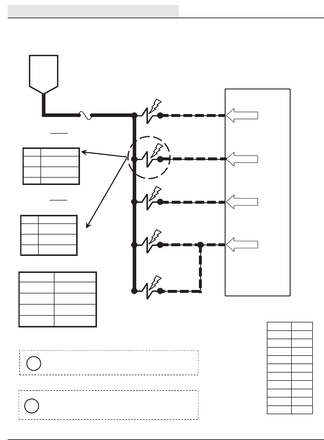
TouchPanel / Control Board
OPEN = EMPTY
CLOSED = NOT EMPTY
46
PIN P1-11 177 13/BLK
BATTERY
NEGATIVE
PIN P1-12
PIN P1-14
45
PIN P1-13
13/BLK
13/BLK
13/BLK
44
OPEN = LESS THAN HALF FULL
CLOSED = HALF FULLOR MORE
OPEN = NOT FULL
CLOSED =FULL
RECOVERYTANK
OPEN = NOT FULL
CLOSED =FULL
RECOVERYTANK
HALFFULLSWITCH
S-16
S-15
FULLSWITCH
S-14
SOLUTION TANK
FULLSWITCH
S-19
SOLUTION TANK
EMPTY SWITCH
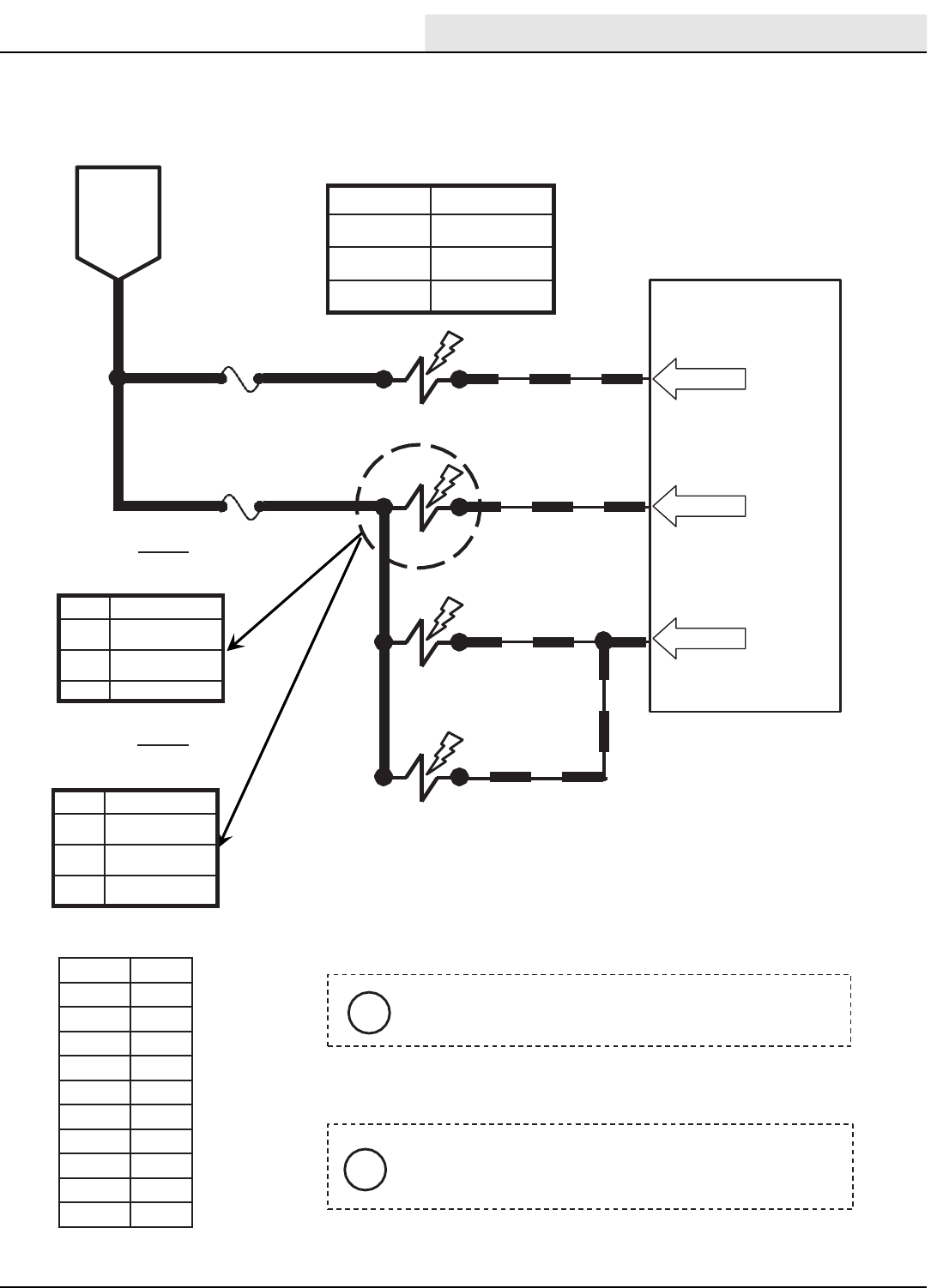
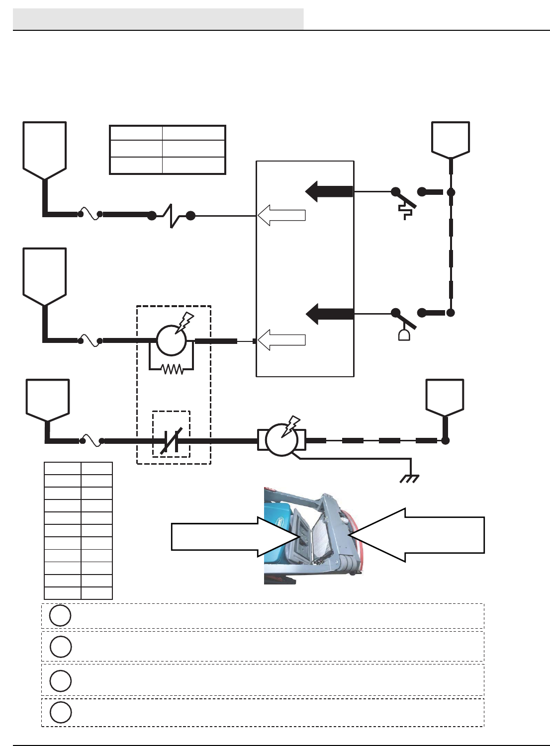
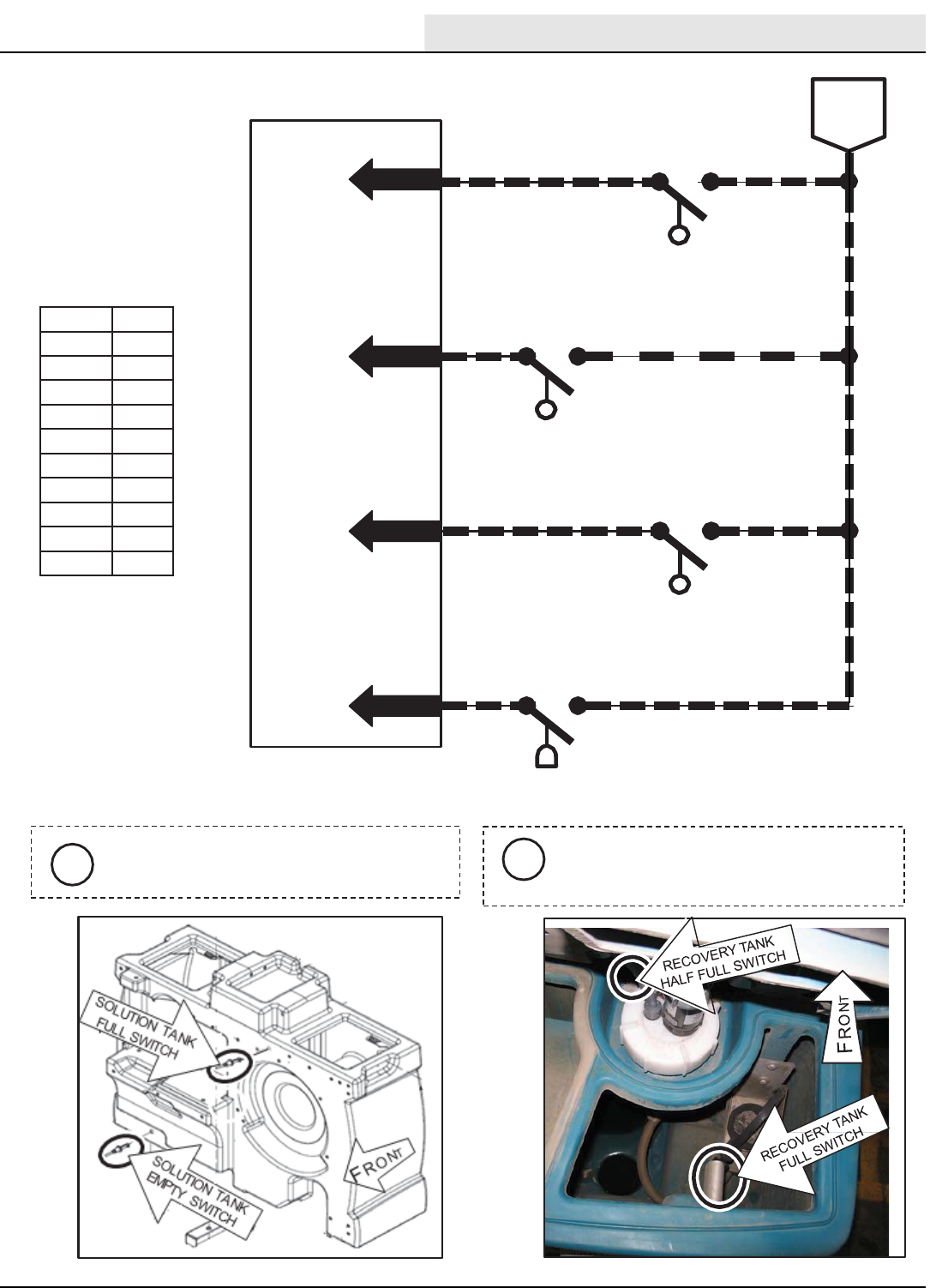
The Tank Level Switches must be
closed for five (5) seconds before any
output is affected.
i
iS-14, SA-15, & S-19 are Float Switches.
S-16 is a Pressure Tube Switch.
M-Series Solution & Recovery Float Switches
Conditions: Key on
Solution & Recovery Float Switches
Conditions: Key On
ELECTRICAL
M20/M30 9016006 - 3-2017
46
FRONT
Wiring Color Codes
(Unless otherwise marked)
91
TouchPanel / Control Board
13/BLK
BATTERY
NEGATIVE
PIN P1-1
BATTERYPOSITIVE
FROMFUSE 5
PROPEL
PEDAL
POSITION
SENSOR
14 131/BLK-WHT
DIGITAL
GROUND
1OUTPUT
23
SENSOR
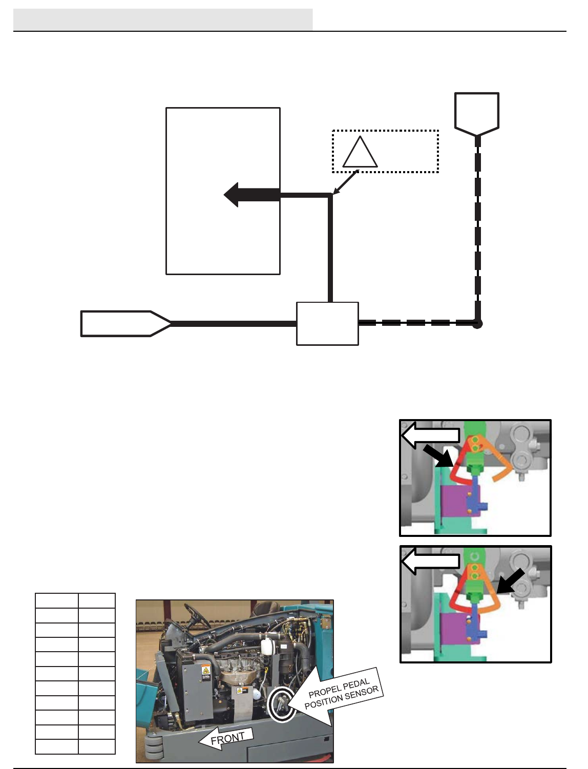
SENSOR OUTPUT VOLTAGES:
2.0 to 2.7 VDC =NEUTRAL
2.8 VDC OR HIGHER =REVERSE
1.9 VDC OR LOWER = FORWARD
!
Propel PedalPositionSensor
Arms Adjustment
FORWARD
ADJUSTMENT
FRONT
REVERSE
ADJUSTMENT
Right Most Digit
of Wire Number
Color of Wire
0 Tan
1Pink
2 Brown
3Orange
4Yellow
5Green
6Blue
7 Purple
8Gray
9White
Forward
Adjustment
Reverse
Adjustment
Front
Front
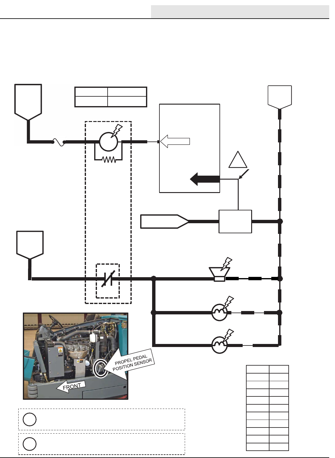
1. Enter Input Diagnostics Mode
2. Loosen sensor arms hardware
3. Tighten top bolt to snug
4. Slide arm until the light goes ON
5. Back arm out until the light goes OFF
6. Retighten all hardware
NOTE: Use the High Engine Speed LED to adjust the arm closest to the
front of machine (forward adjustment), and the Low Engine Speed LED to
adjust the arm closest to the rear of machine (reverse adjustment).
1.9 VDC OR
LOWER IN
FORWARD
M-Series Forward Propel
Conditions: Key on
Forward Propel
Conditions: Key On
ELECTRICAL
M20/M30 9016006 - 3-2017 47
16
TouchPanel / Control Board
65
5FUSE 7
15 AMP
16
67
SOL-1
SOL-2
SOLUTION
TANK AUTO
FILLVALVE
CLOSED = NOT EMPTY
46
PIN P2-14
PIN P1-12
PIN P1-14
RECOVERY
TANK AUTO
FILLVALVE
45
PIN P1-13
13/BLK
13/BLK
13/BLK
44
OPEN = NOT FULL
CLOSED =FULL
OPEN = NOT FULL
CLOSED =FULL
OPEN = EMPTY
177 13/BLK
BATTERY
POSITIVE
FROM
AUX 2
RELAY
CONTACTS
BATTERY
NEGATIVE
PIN P2-13
PIN P1-11
RECOVERYTANK
HALFFULLSWITCH
S-16
S-15
RECOVERYTANK
FULLSWITCH
S-14
SOLUTION TANK
FULLSWITCH
S-19
SOLUTION TANK
EMPTY SWITCH
Wiring Color Codes
(Unless otherwise marked)
Maximum Amp Draw Readings
Right Most Digit
of Wire Number
Color of Wire
0 Tan
1Pink
2 Brown
3Orange
4Yellow
5Green
6Blue
7 Purple
8Gray
9White
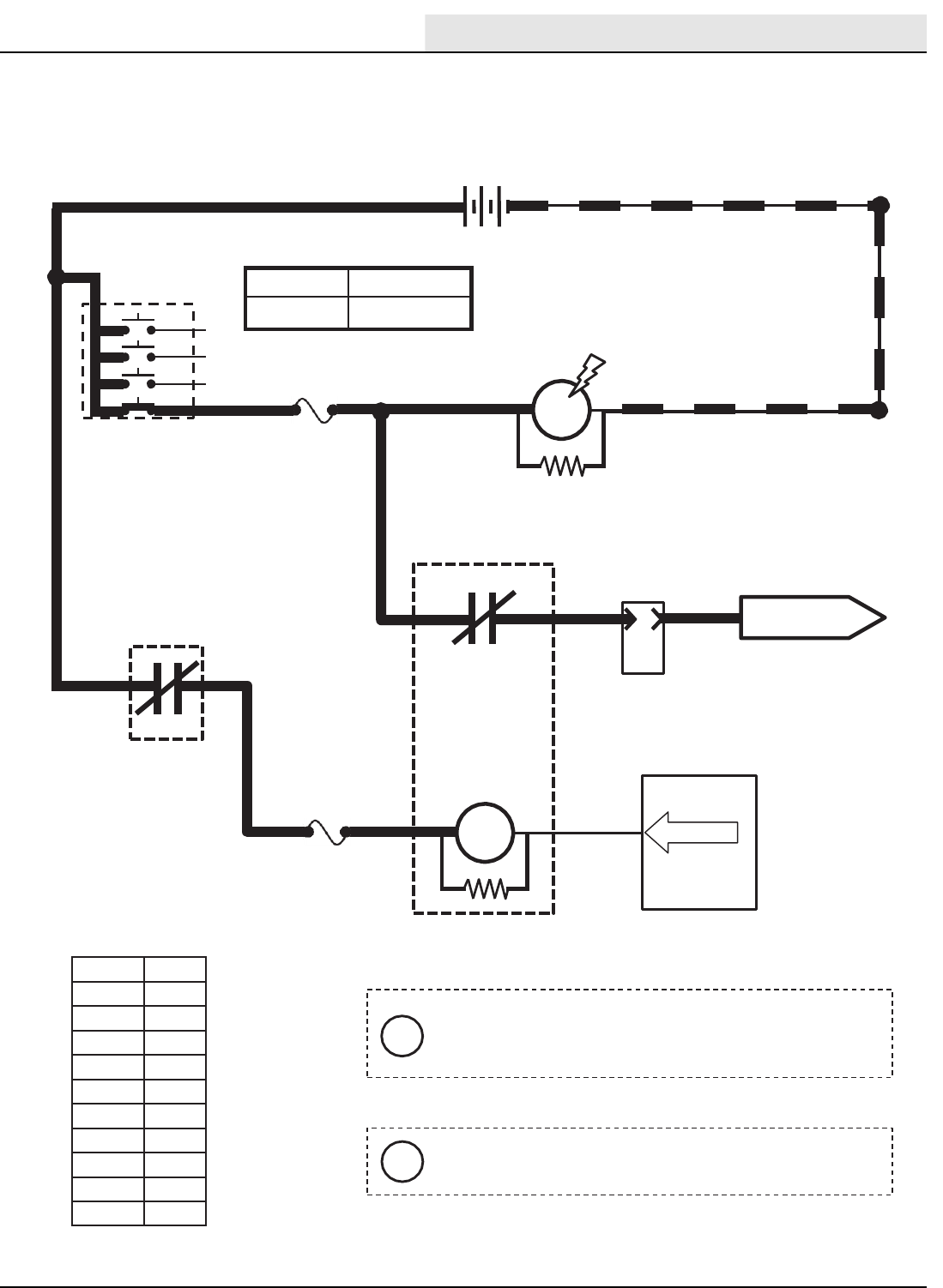
Component Max Amp Draw
SOL-1 1.7 A
SOL-2 1.7 A
OPEN = LESS THAN HALF FULL
CLOSED = HALF FULLOR MORE
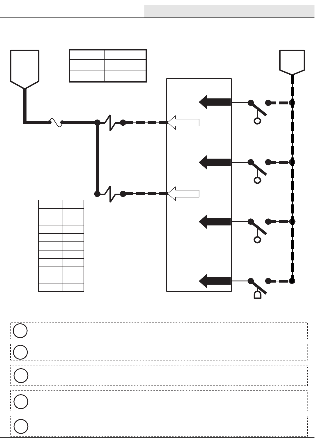
iS-14, S-15, & S-19 are Float Switches.S-16 is a Pressure Tube Switch.
iSolution and Recovery Tank Auto Fill solenoids (SOL-1 & 2) are electro-mechanical devices.
iMachine must be in neutral and Solution Tank Full Switch OPEN (tank not full) to activate
Solution Tank Auto Fill Valve (SOL-1)..
iMachine must be in neutral and Recovery Tank Half Full Switch OPEN (tank less than half
full) to activate Recovery Tank Auto Fill Valve (SOL-2).
iThe Tank Level Switch must be closed for five (5) seconds before any output is affected..
M-Series Auto Fill Solenoids
Conditions: Key on
Auto Fill Solenoids
Conditions: Key On
ELECTRICAL
M20/M30 9016006 - 3-2017
48
TouchPanel / Control Board
74
FUSE 8
15 AMP
517
75
DETERGENT
PUMP
BATTERY
POSITIVE
FROM
AUX 2
RELAY
CONTACTS
PIN P2-21
PIN P2-22
ES
PUMP
PWM
17
17 OPEN = EMPTY
CLOSED = NOT EMPTY
46
PIN P1-11
177 13/BLK
BATTERY
NEGATIVE
PIN P1-12
PIN P1-14
45
PIN P1-13
13/BLK
13/BLK
13/BLK
44
OPEN = NOT FULL
CLOSED =FULL
OPEN = LESS THAN HALF FULL
CLOSED = HALF FULLOR MORE
OPEN = NOT FULL
CLOSED =FULL
RECOVERYTANK
HALFFULLSWITCH
S-16
S-15
RECOVERYTANK
FULLSWITCH
S-14
SOLUTION TANK
FULLSWITCH
S-19
SOLUTION TANK
EMPTY SWITCH
Wiring Color Codes
(Unless otherwise marked)
Maximum Amp Draw Readings
Right Most Digit
of Wire Number
Color of Wire
0 Tan
1Pink
2 Brown
3Orange
4Yellow
5Green
6Blue
7 Purple
8Gray
9White
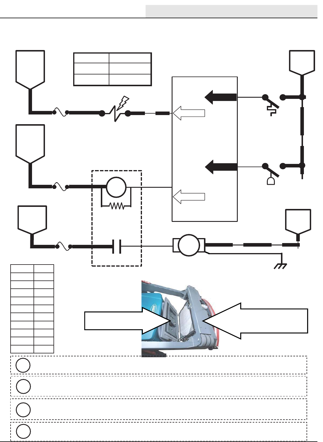
Component Max Amp Draw
Detergent Pump 1.7 A
ES Pump n/a
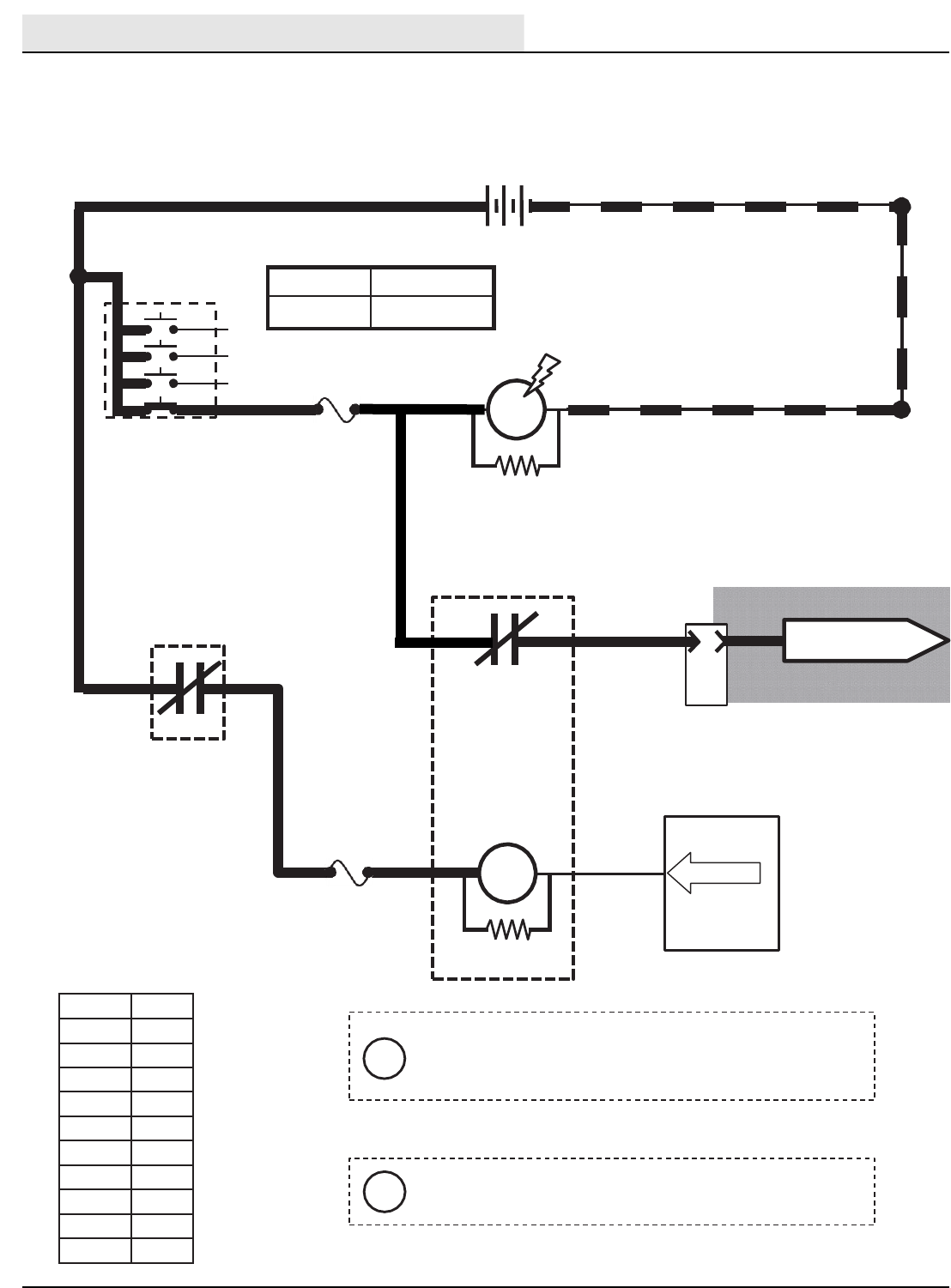
iS-14, S-15, & S-19 are Float Switches, S-16
is a Pressure Tube Switch
iThe Tank Level Switches must be closed for
5 seconds before any output is affected.
i
The Detergent Pump is controlled by PWM; A higher duty cycle
(more Solution LED’s lit on Touch Panel) will result in more
detergent & solution applied to floor
i
The Recovery Tank must be at least half full for ES Pump to turn ON. This will begin a 30 second run
cycle of the ES Pump. If the Recovery Tank is still at least half full after the cycle, another 30 second
cycle will begin. If a full Solution Tank is sensed, the ES Pump will turn OFF before completing 30
second cycle.
M-Series Conventional Detergent Pump & ES Pump
Conditions: Key on, engine running, scrubbing system on, ES system on, two or three solution
LED’s lit
Conventional Detergent Pump & ES Pump
Conditions: Key On, Engine Running, Scrubbing system On, ES System On, Two or Three Solution LED’s Lit
ELECTRICAL
M20/M30 9016006 - 3-2017 49
25 30
1/RED FUSE 3
15 AMP
HORN
RELAY
23 13/BLK
25
S-22
HORN
SWITCH
OPEN =HORN OFF
CLOSED = HORN ON
92 13/BLK
D1
23 13/BLK
Wiring Color Codes
(Unless otherwise marked)
M5A
UN-
SWITCHED
BATTERY
POSITIVE
BATTERY
NEGATIVE
M5B HORN
86 85
87
Right Most Digit
of Wire Number
Color of Wire
0 Tan
1Pink
2 Brown
3Orange
4Yellow
5Green
6Blue
7 Purple
8Gray
9White
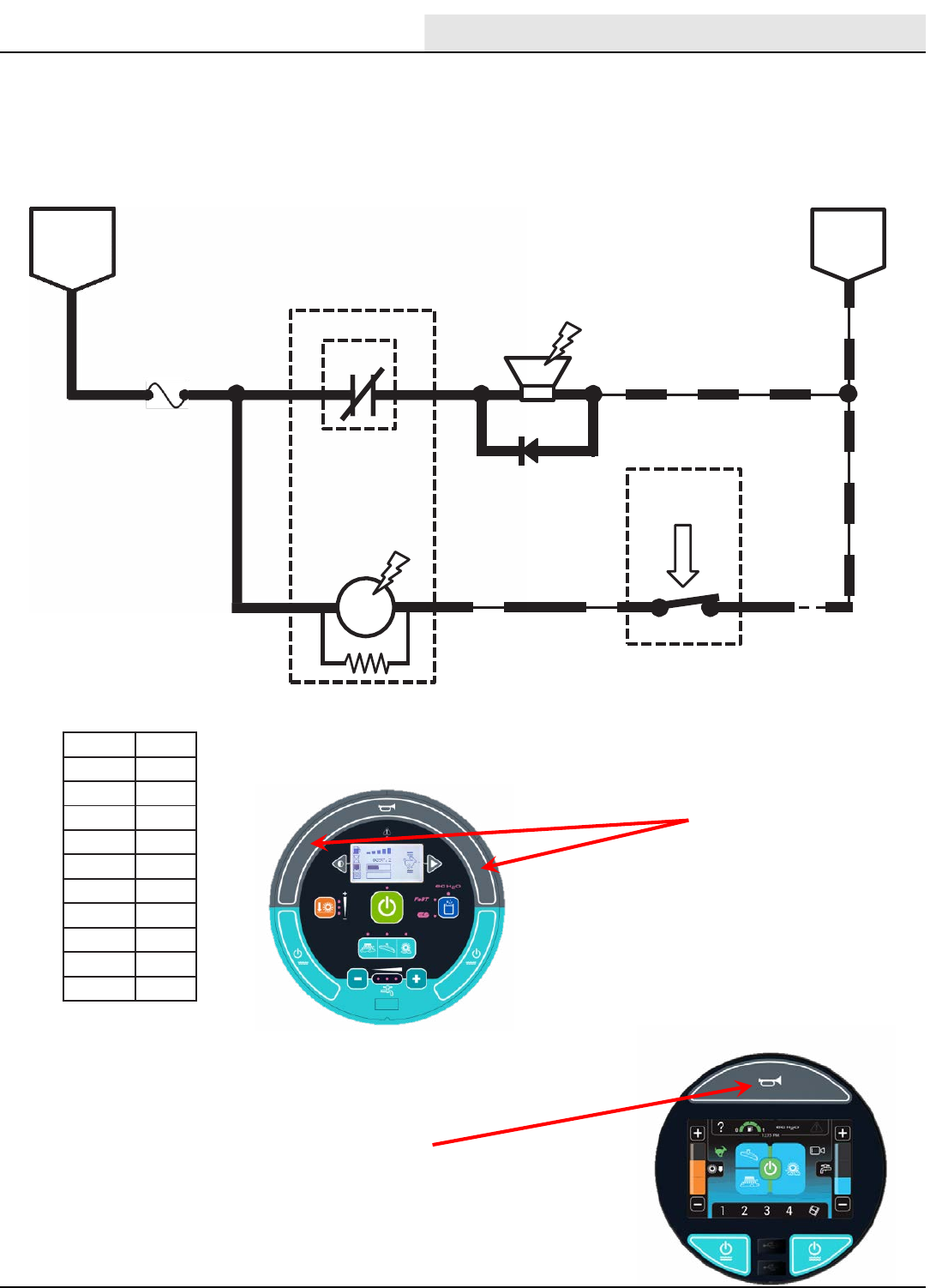
Horn Location
Membrane Panel
Horn Location
Pro Panel
M-Series Horn
Conditions: Key on, switch activated
Horn
Conditions: Key On, Switch Activated
ELECTRICAL
M20/M30 9016006 - 3-2017
50
Touch Panel /Control Board
61
615
SV-7
SV-15
ENABLE
VALVE
5
HOPPER
DOOR OPEN 68
16
BATTERY
POSITIVE
FROM
AUX 1
RELAY
CONTACTS
BATTERY
POSITIVE
FROM
AUX 2
RELAY
CONTACTS
PIN P2-8
PIN P2-15
Wiring Color Codes
(Unless otherwise marked)
Right Most Digit
of WireNumber
Color of Wire
0Tan
1Pink
2 Brown
3Orange
4Yellow
5Green
6Blue
7Purple
8Gray
9White
BATTERY
NEGATIVE
S-13
2
4
HOPPER
DOOR
OPEN/CLOSE
SWITCH
1
42
43
13/BLK
OFF
PIN P1-9
PIN P1-10
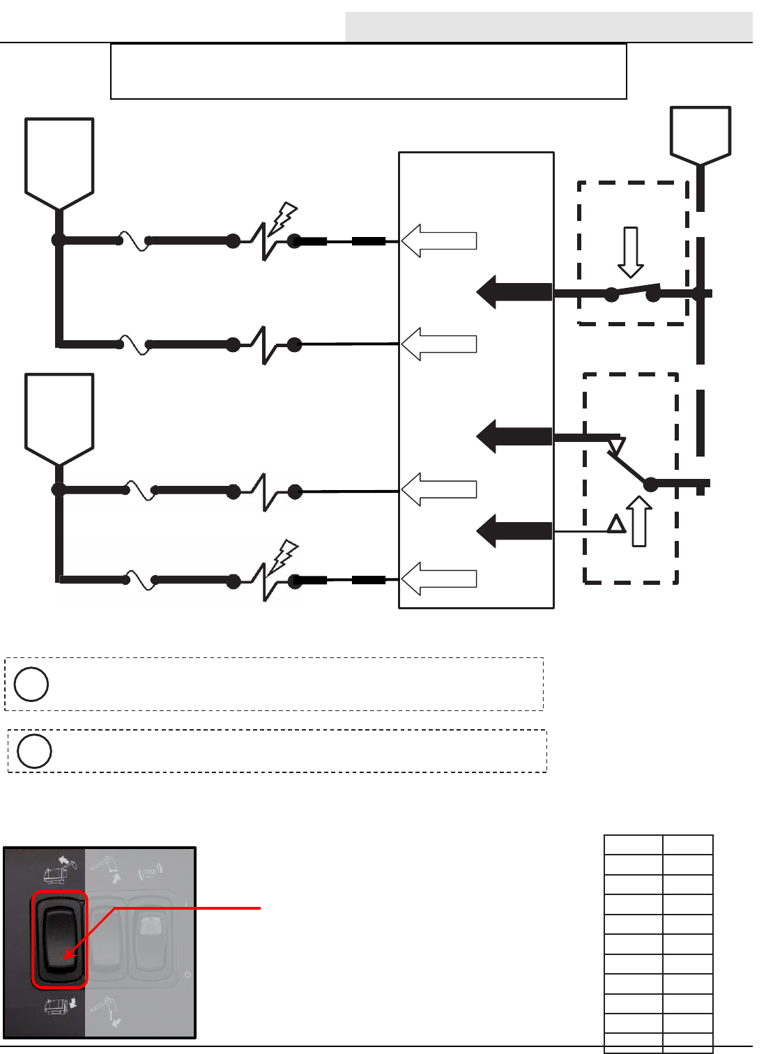
Component Max Amp Draw
SV-7 1.7 A
SV-15 1.7 A
2 & 1 CLOSED = DOOR OPEN
2 & 4 CLOSED = DOOR CLOSE
FUSE 7
15 AMP
FUSE 6
15 AMP
Activating the Hopper Door Switch
to open or close the door will cancel
the sweep or scrub systems and
automatically selects HIGH engine
speed.
i
HOPPER DOOR
SWITCH
PUSH TO CLOSE
DOOR
M-Series Hopper Door Closed
Conditions: Key on, engine running, hopper door close switch activated
Anytime the Enable Valve (SV-7) is ON
and the Hopper Door Open Valve (SV15)
is OFF, the hopper door will close.
i
Hopper Door Closed
Conditions: Key On, Engine Running, Hopper Door Close Switch Activated
ELECTRICAL
M20/M30 9016006 - 3-2017 51
8
91
TouchPanel / Control Board
BATTERY
POSITIVE
FROM
FUSE 1
M4B
20 13/BLK
BATTERY POSITIVE
FROMFUSE 5
PROPEL
PEDAL
POSITION
SENSOR
14 WHT
DIGITAL
2GROUND
3
SENSOR OUTPUT VOLTAGES:
2.0to2.7VDC = NEUTRAL
2.8VDC OR HIGHER = REVERSE
1.9VDC OR LOWER = FORWARD
REVERSEALARM/
WARNINGLIGHT
20
13/BLK
13/BLK
REVERSE
TAIL LIGHT
20 (RIGHT)
20
REVERSE
TAIL LIGHT
(LEFT)
Wiring Color Codes
(Unless otherwise marked)
13/BLK
16
5FUSE 7
15 AMP
Maximum Amp Draw Readings
BATTERY
POSITIVE
FROM
AUX 2
RELAY
CONTACTS
70
REVERSE
RELAY
PIN P2-17
PIN P1-1
131/BLK-
1SENSOR
OUTPUT
M4A
86 85
30 87
Right Most Digit
of Wire Number
Color of Wire
0 Tan
1Pink
2 Brown
3Orange
4Yellow
5Green
6Blue
7 Purple
8Gray
9White
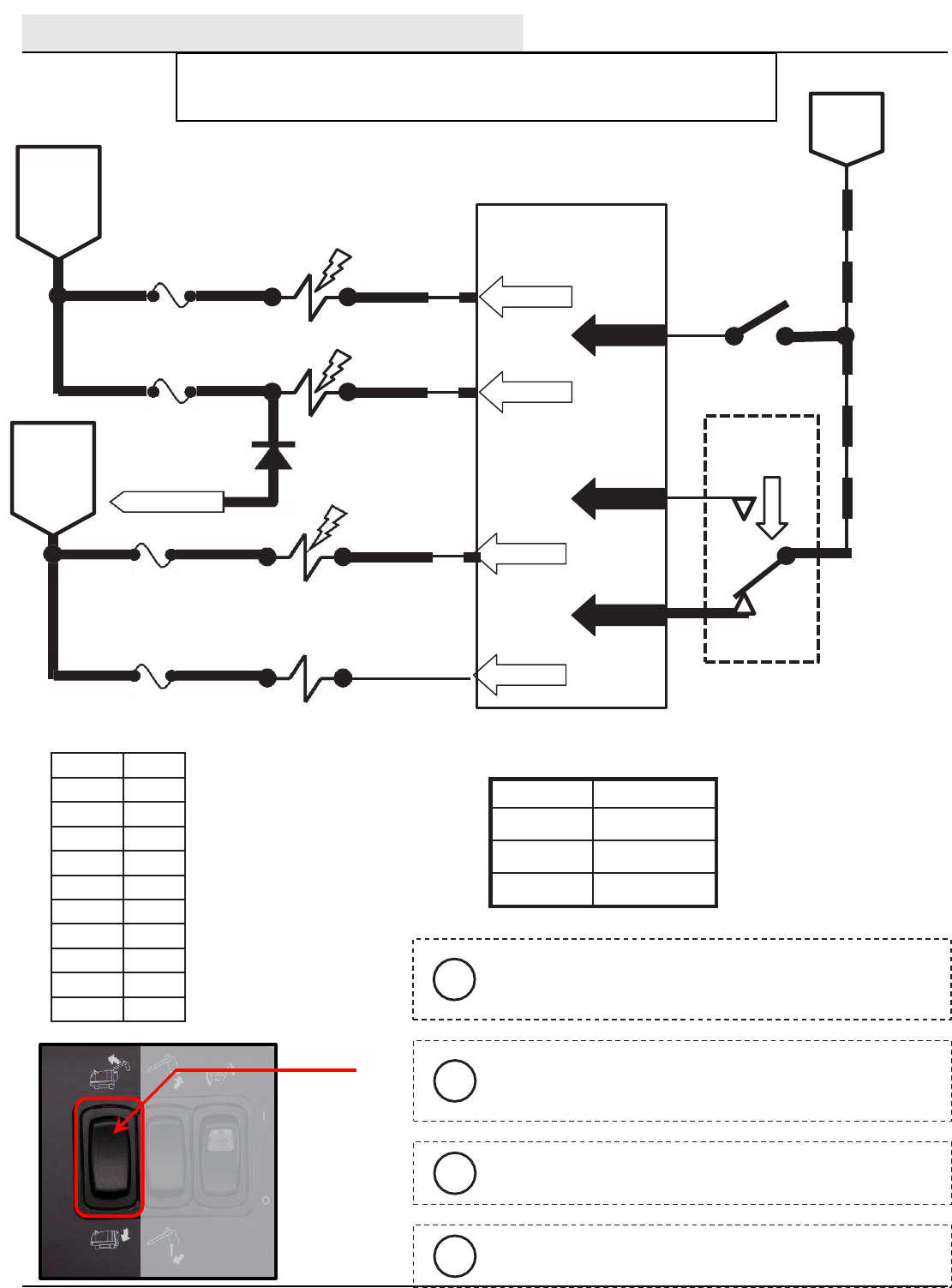
Component Max Amp Draw
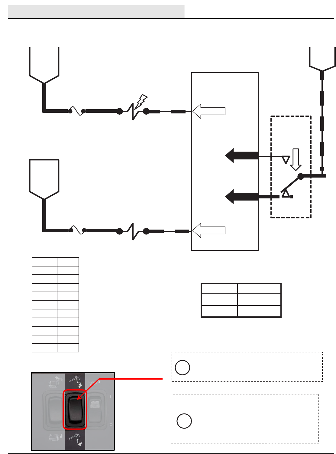
M4A 200mA
2.8 VDC or
HIGHER in
Reverse
i
Reverse propel will turn OFF SV-4 (Pin P2-6) and
raise the side and rear squeegees.
i
See Forward Propel page for information on
adjusting Propel Pedal Position Sensor.
i
BATTERY
NEGATIVE
M-Series Reverse Propel
Conditions: Key on, engine running, propel pedal pushed for reverse
Reverse Propel
Conditions: Key On Engine Running, Propel Pedal Pushed for Reverse
ELECTRICAL
M20/M30 9016006 - 3-2017
52
M6C
OPEN =MACHINE
SHUTDOWN
CLOSED = NORMAL
OPERATION
TouchPanel /
Control Board
165FUSE 7
15 AMP
71
SHUTDOWN
RELAY
PIN P2-18
M6A
1/RED 5
M2B
AUX. 2 RELAY
CONTACTS
87a 38 30
13/BLK
Wiring Color Codes
(Unless otherwise marked)
AUXILIARY
RELAY
A
10
PIN
1/RED 13/BLK
+-
12 VDC
1/RED
3PINK
8
FUSE 1
15 AMP
M2A
KEY SWITCH
RUN
86 85
4 4
ENGINEHARNESS
CONNECTORS
J-11
TO FUSE 1OF
ENGINE HARNESS
Maximum Amp Draw Readings
Right Most Digit
of Wire Number
Color of Wire
0 Tan
1Pink
2 Brown
3Orange
4Yellow
5Green
6Blue
7 Purple
8Gray
9White
Component Max Amp Draw
M6A 200mA
The Shutdown system is used to turn OFF the
engine under certain conditions on machines with
certain optional equipment.
i
When control board turns ON M6A, the engine ECM
loses power, and the engine shuts OFF.
i
M-Series Shutdown Relay (Normal Machine Operation)
-(Gas / LP) -
Shutdown Relay (Normal Machine Operation)
- (Gas / LP) -
ELECTRICAL
M20/M30 9016006 - 3-2017 53
M6C
OPEN =MACHINE
SHUTDOWN
CLOSED = NORMAL
OPERATION
TouchPanel /
Control Board
165FUSE 7
15 AMP
71
SHUTDOWN
RELAY
PIN P2-18
M6A
1/RED 13/BLK
+-
12 VDC
1/RED
1/RED 5
M2B
AUX. 2 RELAY
CONTACTS
3
830
813/BLK
Wiring Color Codes
(Unless otherwise marked)
AUXILIARY
RELAY
A
10
PIN
TO FUELPUMP
RELAY M10
8
FUSE 1
15 AMP
M2A
KEY SWITCH
RUN
86 85
87a
4 4
3
J-11
ENGINEHARNESS
CONNECTOR
Maximum Amp Draw Readings
Right Most Digit
of Wire Number
Color of Wire
0 Tan
1Pink
2 Brown
3Orange
4Yellow
5Green
6Blue
7 Purple
8Gray
9White
Component Max Amp Draw
M6A 200mA
The Shutdown system is used to turn OFF the
engine under certain conditions on machines with
certain optional equipment.
i
When control board turns ON M6A, the engine ECM
loses power, and the engine shuts OFF.
i
M-Series Shutdown Relay (Normal Machine Operation)
-(Diesel) -
Shutdown Relay (Normal Machine Operation)
- (Diesel) -
ELECTRICAL
M20/M30 9016006 - 3-2017
54
A
10
PIN
1/RED 13/BLK
+
1/RED
FUSE 1
15 AMP
1/RED 5
M2B
AUX. 2 RELAY
CONTACTS
8
813/BLK
TouchPanel /
Control Board
16
5FUSE 7
15 AMP
Wiring Color Codes
(Unless otherwise marked)
AUXILIARY
RELAY
8
-
12 VDC
3PINK
PIN P2-18
M2A
KEY SWITCH
RUN
71
SHUTDOWN
RELAY
M6A
87a
830
M6C
OPEN =MACHINE
SHUTDOWN
CLOSED = NORMAL
OPERATION
86 85
4
ENGINEHARNESS
CONNECTORS
J-11
TO FUSE 1OF
ENGINE HARNESS
Maximum Amp Draw Readings
Right Most Digit
of Wire Number
Color of Wire
0 Tan
1Pink
2 Brown
3Orange
4Yellow
5Green
6Blue
7 Purple
8Gray
9White
Component Max Amp Draw
M6A 200mA
The Shutdown system is used to turn OFF the
engine under certain conditions on machines with
certain optional equipment.
i
When control board turns ON M6A, the engine ECM
loses power, and the engine shuts OFF.
i
M-Series Shutdown Relay (Shutdown Mode)
-(Gas / LP) -
Shutdown Relay (Shutdown Mode)
- (Gas / LP) -
ELECTRICAL
M20/M30 9016006 - 3-2017 55
A
10
PIN
1/RED 13/BLK
+-
12 VDC
1/RED
FUSE 1
15 AMP
4
1/RED 5
M2B
AUX. 2 RELAY
CONTACTS
AUXILIARY
RELAY
8
8
13/BLK
13/BLK
TouchPanel /
Control Board
16
5FUSE 7
15 AMP
Wiring Color Codes
(Unless otherwise marked)
AUXILIARY
RELAY
8
8
PIN P2-18
71
SHUTDOWN
RELAY
M6A
830
M6C
OPEN =MACHINE
SHUTDOWN
CLOSED = NORMAL
OPERATION
86 85
87a 3
M1A
M2A
KEY SWITCH
RUN
4
TO FUELPUMP
RELAY M10
J-11
ENGINEHARNESS
CONNECTOR
3
Maximum Amp Draw Readings
Right Most Digit
of Wire Number
Color of Wire
0 Tan
1Pink
2 Brown
3Orange
4Yellow
5Green
6Blue
7 Purple
8Gray
9White
Component Max Amp Draw
M6A 200mA
The Shutdown system is used to turn OFF the
engine under certain conditions on machines with
certain optional equipment.
i
When control board turns ON M6A, the engine ECM
loses power, and the engine shuts OFF.
i
M-Series Shutdown Relay (Shutdown Mode)
-(Diesel) -
Shutdown Relay (Shutdown Mode)
- (Diesel) -
ELECTRICAL
M20/M30 9016006 - 3-2017
56
ENGINE
BLOCK
RED
92 M30 9003947 (6--08)
1/RED 13/BLK
+-
12 VDC
77
TO FUSES
1, 9, &12
2
Right Most Digit
of WireNumber
Color of Wire
0Tan
1Pink
2 Brown
3Orange
4Yellow
5Green
6Blue
7Purple
8Gray
9White
KEY SWITCH
START)
STARTER
MOTOR
ASSEMBLY
F
16
PIN
P1
1/RED
13/BLK
M7B
STARTER
RELAY
ENGINE
BLOCK
86 85
M7A
30 87
Refer to the Engine
Schematics
S1
30 50
17
19
F6
15 AMP
STARTER
RELAY
30
85
86
87
X
X
ACC 4
LT.BLUE/
PINK
ENGINE
HARNESS
CONNECTOR
RED/TAN
13/BLK
WHITE
TO ECM PIN 89
PINK/BLACK
Wiring Color Codes
(Unless otherwise marked)
M-Series Starting System ON
Conditions: Key turned to start position -(Gas / LP) -
Starting System On
Condition: Key Turned To Start Position - (Gas / LP) -
ELECTRICAL
M20/M30 9016006 - 3-2017 57
4
STARTER
RELAY
87 77 77
2
KEY SWITCH
START
Wiring Color Codes
(Unless otherwise marked)
M7A
J
10
PIN
ENGINE
HARNESS
CONNECTOR
J-11
TO BATTERY
NEGATIVE
85 13/BLK
M7B
30
3
M8B
STARTER
RELAY
M8A
85 13/BLK
M9A
STARTER
LOCKOUT
RELAY
86
30 87
TO FUSES
1, 9, & 12
TO
GLOWPLUGS
42
1/RED
1/RED
13/BLK
13/BLK
SWITCHED BATTERY POSITIVE
FROMSHUTDOWNRELAY M6C
STARTER
TIMER
MODULE
A
10
PIN
3 3
3
87a
56 3
77
82
55
55
D-3
PIN 1
GND
PIN 2
LOAD
PIN 6PIN 3
INIT B+
56
86
30 83
85
86
87
TO FUELPUMP RELAY
M10 &GOVERNOR
J-11
ENGINEHARNESS
CONNECTOR
M9B
M9C
1/RED 13/BLK
+-
12 VDC
1/RED
STARTER MOTOR
ASSEMBLY
1/RED
ENGINE
BLOCK
ENGINE
BLOCK
Right Most Digit
of Wire Number
Color of Wire
0 Tan
1Pink
2 Brown
3Orange
4Yellow
5Green
6Blue
7 Purple
8Gray
9White The Starter Timer creates a delay between start attempts.
i
M-Series Starting System ON
Conditions: Key turned to start position -(Diesel) -
Starting System On
Condition: Key Turned To Start Position - (Diesel) -
ELECTRICAL
M20/M30 9016006 - 3-2017
58
Glow
Plug
START
RUN
OFF
KEY SWITCH
KEY SWITCH
START
Wiring Color Codes
(Unless otherwise marked)
KEY SWITCH
GLOW PLUG
42
1/RED
FROM BATTERY
POSITIVE
TO FUSES
1, 9, & 12
TO START
RELAY M7A
GP4
GP3
GP2
CH ASS IS GRO UNDS
FROM BATTERY
NEGATIVE
GLOW PLUG LAMP
13/BLK
FROM BATTERY
POSITIVE
TO FUSES
1, 9, & 12
TO START
RELAY M7A
GLOW PLUGS
GP4
GP3
GP2
GP1
CH ASS IS GRO UNDS
FROM BATTERY
NEGATIVE
GLOW PLUG LAMP
13/BLK
42
42
42
42
42
42
1/RED
42
42
42
42
42
42
GLOW PLUGS
GP1
42
Glow
Plug START
RUN
OFF
KEY SWITCH
Right Most Digit
of Wire Number
Color of Wire
0 Tan
1Pink
2 Brown
3Orange
4Yellow
5Green
6Blue
7 Purple
8Gray
9White
The Glow Plugs are ON ONLY when ignition switch
is in the “Glow Plug” or “Start” Position.
i
M-Series Glow Plugs ON
Conditions: Key turned to glow plugs/start position -(Diesel) -
Glow Plugs On
Condition: Key Turned To Glow Plug / Start Position - (Diesel) -
ELECTRICAL
M20/M30 9016006 - 3-2017 59
PIN P2-19
15 AMP
SOL-3
16
TouchPanel / Control Board
72
FUSE 7
516
181
SOL-7
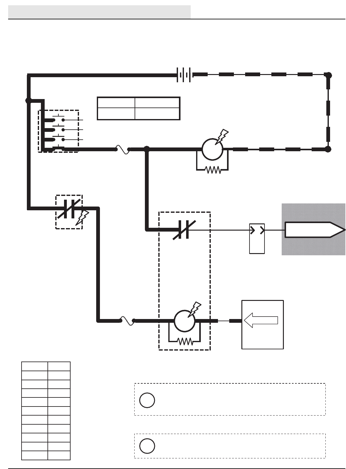
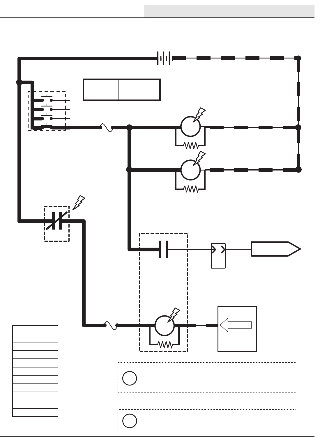
MAINBRUSH
SOLUTION VALVE
M-Series Conventional Main & Side Brush Solution Valves
Conditions: Key on,scrubbing system on, side brush on, forward or reverse propel, oneor more solutionLED’s lit
BATTERY
POSITIVE
FROM
AUX 2
RELAY
CONTACTS
PIN P2-20
SIDEBRUSH
SOLUTION VALVE
Wiring Color Codes
(Unless otherwise marked)
Maximum Amp Draw Readings
Right Most Digit
of Wire Number
Color of Wire
0 Tan
1Pink
2 Brown
3Orange
4Yellow
5Green
6Blue
7 Purple
8Gray
9White
Component Max Amp Draw
SOL-3 1.7 A
SOL-7 1.7 A
The Solution Valves are pulsed slowly to adjust the
solution volume. Less OFF time (more Solution
LED’s lit on Touch Panel) will result in more solution
applied to floor.
i
The Solution Valves will function only while
propelling forward or reverse during scrub operation.
i
Conventional Main & Side Brush Solution Valves
Condition: Key On, Scrubbing System On, Side Brush On, Propelling, One or more Solution LED’s Lit
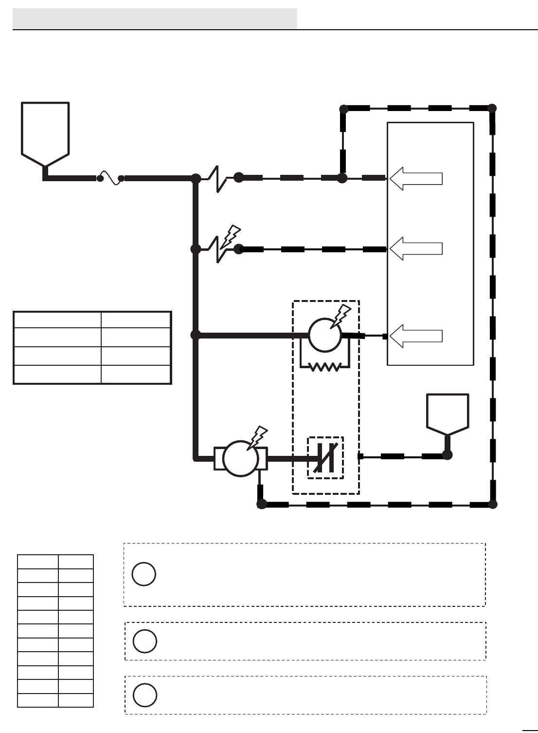
ELECTRICAL
M20/M30 9016006 - 3-2017
60
Wiring Color Codes
(Unless otherwise marked)
Right Most Digit
of WireNumber
Color of Wire
0Tan
1Pink
2 Brown
3Orange
4Yellow
5Green
6Blue
7Purple
8Gray
9White
Touch Panel /
Control Board
79
5
17
17
17
80
SOL-5
SOL-6
FaST SIDE
BRUSH VALVE
BATTERY
POSITIVE
FROM
AUX 2
RELAY
CONTACTS
17
PIN P2-23
PIN P2-26
PIN P2-22
17
BATTERY
NEGATIVE
M16A
FaST WATER
PUMP RELAY
M16B
75
86 13/BLK
86 85
30 87
Component Max Amp Draw
SOL-5 1.7 A
SOL-6 1.7 A
M16A 200 mA
FUSE 8
15 AMP
MTR10
FaST WATER
PUMP
FaST HIGH
FLOW VALVE 79
79 79
79 79
LOW
The FaST Water Pump has two speeds (Low Flow & High Flow).
When there is no input to the pump on Wire 79/White (open),
Low Flow is selected. When Battery Negative is input to the
pump on Wire 79/White, High Flow is selected.
i
One or two Solution LED’s lit selects Low FaST output.
i
FaST High Flow Valve is ON only when all 3 Solution LED’s are lit.
i
M-Series FaST System ON
Conditions: Key on,scrubbing system on, side brush on, forward or reverse propel, oneor more solutionLED’s lit
FaST System On
Condition: Key On, Scrubbing System On, Side Brush On, Propelling, One or More Solution LED’s On
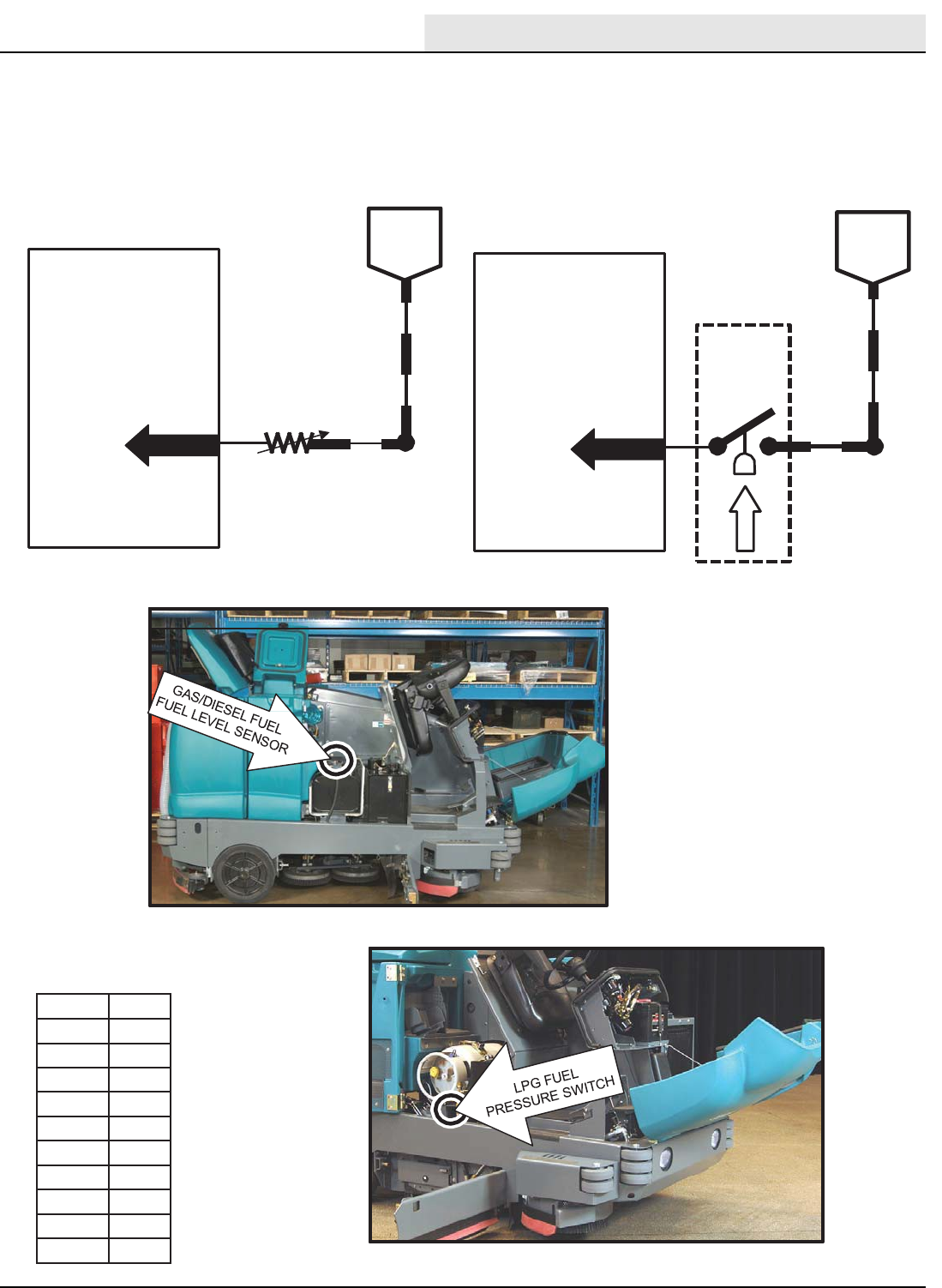
ELECTRICAL
M20/M30 9016006 - 3-2017 61
Wiring Color Codes
(Unless otherwise marked)
30
TouchPanel / Control Board
GAS /
DIESEL
13/BLK
BATTERY
NEGATIVE
100 OHMS = FULL TANK
5 OHMS =EMPTY TANK
S-7
FUELLEVEL
SENDER
PIN P1-4
DIGITAL
GROUND
30
TouchPanel / Control Board
LPG
13/BLK
BATTERY
NEGATIVE
NORMALLYCLOSED, HELD
OPEN BY FUEL PRESSURE
OPEN =MORE THAN 70 PSI
CLOSED =70 PSI OR LOWER
FUEL
PRESSURE
SWITCH
S-8
PIN P1-4 DIGITAL
GROUND
131/BLK-
WHT 131/BLK-
WHT
Right Most Digit
of Wire Number
Color of Wire
0 Tan
1Pink
2 Brown
3Orange
4Yellow
5Green
6Blue
7 Purple
8Gray
9White
M-Series Fuel Level Sensors
Conditions: Key on
Fuel Level Sensor (Gas / LP / Diesel)
Condition: Key On
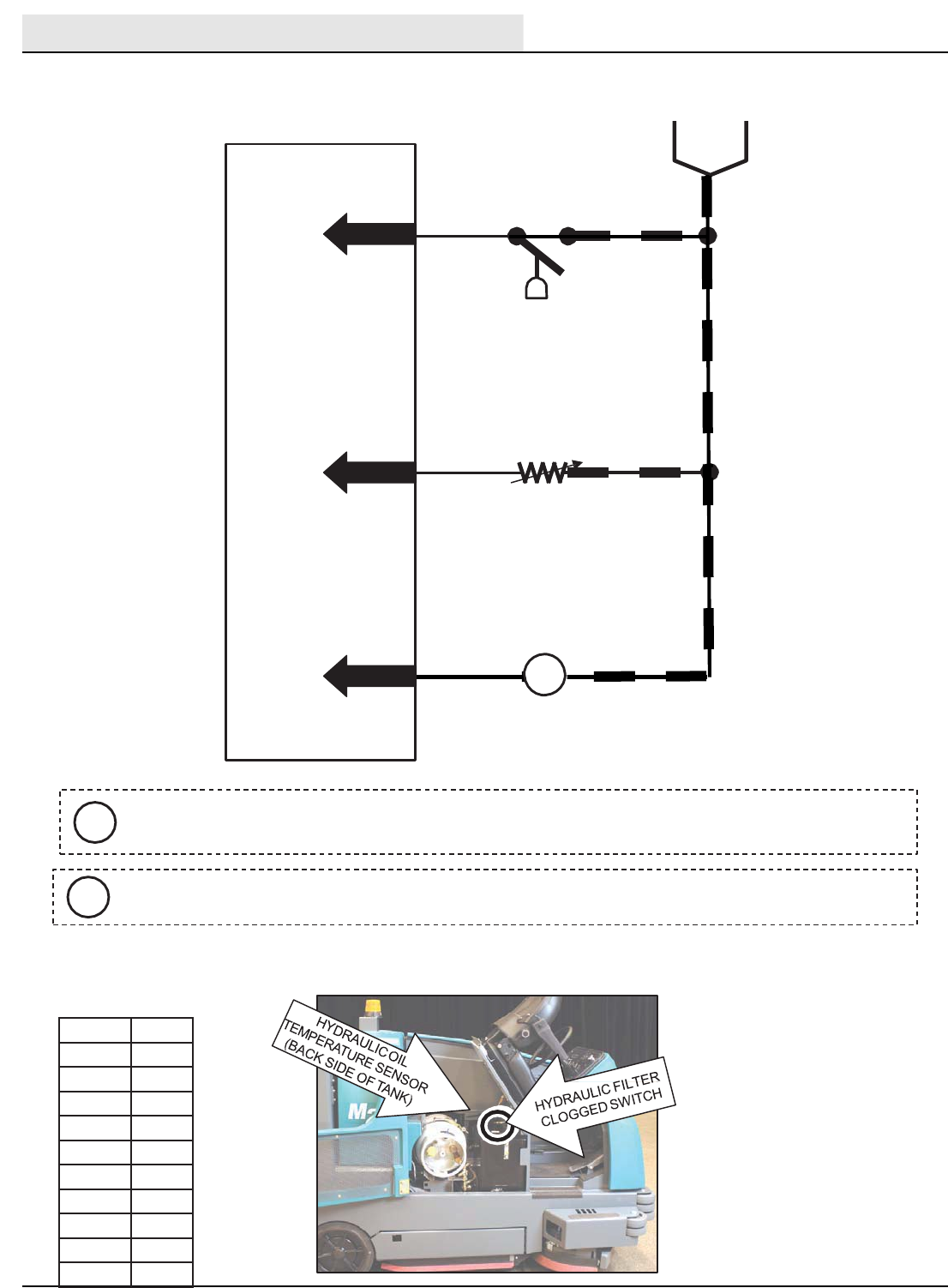
ELECTRICAL
M20/M30 9016006 - 3-2017
62
Wiring Color Codes
(Unless otherwise marked)
BATTERY
NEGATIVE
TouchPanel / Control Board
HYDRAULICFILTER
CLOGGEDSWITCH
S-17
OPEN = LESS THAN 20 PSI (FILTER OK)
CLOSED = MORE THAN 20 PSI (FILTER
CLOGGED)
49
90 13/BLK
PIN P1-15
PIN P1-21
78
PIN P1-17
13/BLK
S-23
OPEN =NO IMPACT DETECTED
CLOSED =IMPACT DETECTED
S-20
HYDRAULIC OIL
TEMPERATURE SENSOR
131/BLK-WHT
DIGITAL
GROUND
IMPACT
SENSOR
0.8 VDC OR LESS =220°F OR HIGHER
ABOVE 0.8 VDC =UNDER 220°F
Right Most Digit
of Wire Number
Color of Wire
0 Tan
1Pink
2 Brown
3Orange
4Yellow
5Green
6Blue
7 Purple
8Gray
9White
The Hydraulic Filter Clogged Switch will not be sensed until after the machine has run for 5
minutes to allow the hydraulic oil to warm up.
i
Impact Sensor S-23 is used only on machines with certain optional equipment.
i
M-Series Impact, Hydraulic Temperature and Filter Sensors
Conditions: Key on
Impact, Hydraulic Temperature & Filter Sensors
Condition: Key On
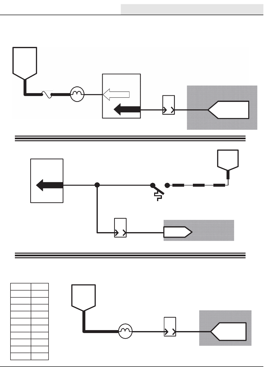
ELECTRICAL
M20/M30 9016006 - 3-2017 63
Wiring Color Codes
(Unless otherwise marked)
12
TouchPanel /
Control Board
PIN P1-18
SW2
OPEN = BELOW 220°F
CLOSED =ABOVE 220°F
B
8
PIN TO ECM
PIN 35
BATTERY
NEGATIVE
HIGH ENGINE
TEMPERATURE
SWITCH 13/BLK
12
12
J-12
ENGINE HARNESS
CONNECTOR
F
10
PIN
10
SWITCHED
BATTERY
POSITIVE
FROM
FUSE 1
8MIL SIGNAL
FROMECM
PIN 26
MIL (CHECK
ENGINE LAMP)
J-11
ENGINE HARNESS
CONNECTOR
6FUSE 5
15 AMP
FROM
AUX 1
RELAY
CONTACTS
TouchPanel /
Control Board
PIN P2-27
14 28
LOW ENGINE OIL
PRESSURE LAMP
J-12
8
PIN
A
9
PIN P1-19
OIL PRESSURE
SIGNAL FROM
ECM PIN 30
ENGINE HARNESS
CONNECTOR OPEN = LOW OIL PRESSURE
BATTERY NEG.= OIL PRESSURE OK
- Engine Oil Pressure -
- Engine Temperature Switch -
- Malfunction Indicator Lamp -
LT.BLUE/WHITE
TAN/DK.GREEN
LT.BLUE/BLK
Refer to theEngine
Controllerschematics
Refer to theEngine
Controllerschematics
Refer to theEngine
Controllerschematics
Right Most Digit
of Wire Number
Color of Wire
0 Tan
1Pink
2 Brown
3Orange
4Yellow
5Green
6Blue
7 Purple
8Gray
9White
BATTERY
POSITIVE
M-Series EngineOilPressure,Temperature, & MILSystems
Conditions: Key turned to run position -(Gas / LP) -
Engine Oil Pressure, Temperature, and MIL System
Condition: Key Turned To Run Position - (Gas / LP) -

ELECTRICAL
M20/M30 9016006 - 3-2017
64
A
B
C
Wiring Color Codes
(Unless otherwise marked)
Right Most Digit
of WireNumber
Color of Wire
0Tan
1Pink
2 Brown
3Orange
4Yellow
5Green
6Blue
7Purple
8Gray
9White
12
Touch Panel /
Control Board
PIN P1-18
S2
OPEN = BELOW 220°F
CLOSED = ABOVE 220°F
BATTERY
NEGATIVE
HIGH ENGINE
TEMPERATURE
SWITCH 13/BLK
S4
ENGINE OIL
PRESSURE SWITCH
6
BATTERY
POSITIVE
FROM
AUX 1
RELAY
CONTACTS Touch Panel /
Control Board
PIN P2-27
28
LOW ENGINE OIL
PRESSURE LAMP
B&C CLOSED = LOW OIL PRESSURE
A&B CLOSED = OIL PRESSURE OK
13/BLK
BATTERY
NEGATIVE
9
12
PIN P1-19
This drawing shown with key switch ON, and engine running
i
- Engine Temperature Switch -
- Engine Oil Pressure Switch -
9
TO FUEL PUMP
RELAY M10
9A
16
PIN
J1/P2
ENGINE
HARNESS
CONNECTOR
9
FUSE 5 14
15 AMP
B
8
PIN
J12
ENGINE
HARNESS
CONNECTOR
M-Series EngineOilPressure,Temperature
Conditions: Key turned to run position -(Diesel) -
Engine Oil Pressure and Temperature Sensor
Condition:Key Turned to Run Position - (Diesel) -
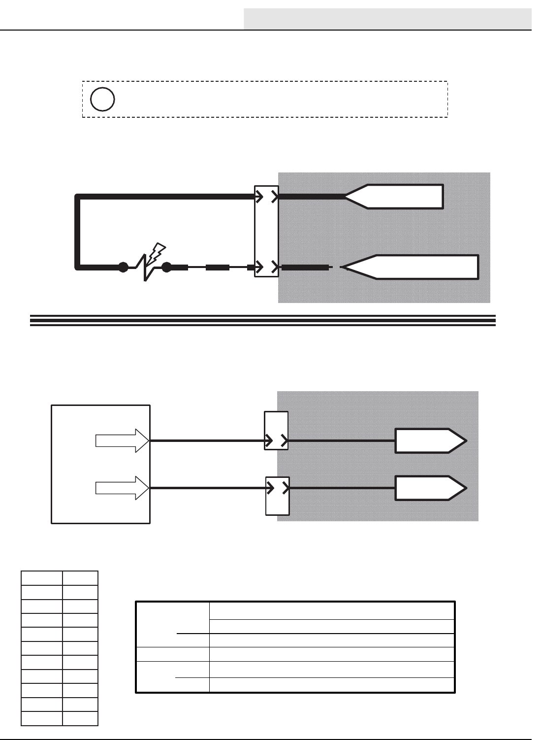
ELECTRICAL
M20/M30 9016006 - 3-2017 65
Wiring Color Codes
(Unless otherwise marked)
D
6
PIN
ENGINE HARNESS
CONNECTOR
J-10
BLACK
E
FROM FUSE 4 OF
ENGINE HARNESS
19
13/BLK
PINK/YEL
19
FUEL PUMP
TouchPanel / Control Board
11
18 Governor Speed “B”
PIN P2-24
PIN P2-25 B
6
PIN
J-10
8
PIN
E
J-12
ENGINE HARNESS
CONNECTORS
TO PIN 34
OF ECM
TO PIN 48
OF ECM
GRAY/DK.BLUE
YEL/DK.BLUE
Governor Speed “A”
FROMCHASSIS GROUND
OF ENGINE HARNESS
Refer to theEngine
Controllerschematics
Refer to theEngine
Controllerschematics
Right Most Digit
of Wire Number
Color of Wire
0 Tan
1Pink
2 Brown
3Orange
4Yellow
5Green
6Blue
7 Purple
8Gray
9White
This drawing is shown with key switch ON, and engine running.
i
Speed Control T20 M20 M30
Diesel Idle 950 +/-50 RPM 950 +/-50 RPM 1350 +/-50 RPM
Run 2400 +/-RPM 2400 +/-RPM 2800 +/-50 RPM
LP / Gas Idle 1350 +/-50 RPM 1350 +/-50 RPM 1350 +/-50 RPM
Run 2300 +/-50 RPM 2300 +/-50 RPM 2300 +/-50 RPM
M-Series EngineOilPressure,Temperature
Conditions: Key on, engine running -(Gas / LP) -
-Fuel Pump (Gas Only) -
-Speed Control Output -
Fuel Pump and Speed Control Output
Condition: Key On Engnie Running - (Gas / LP) -
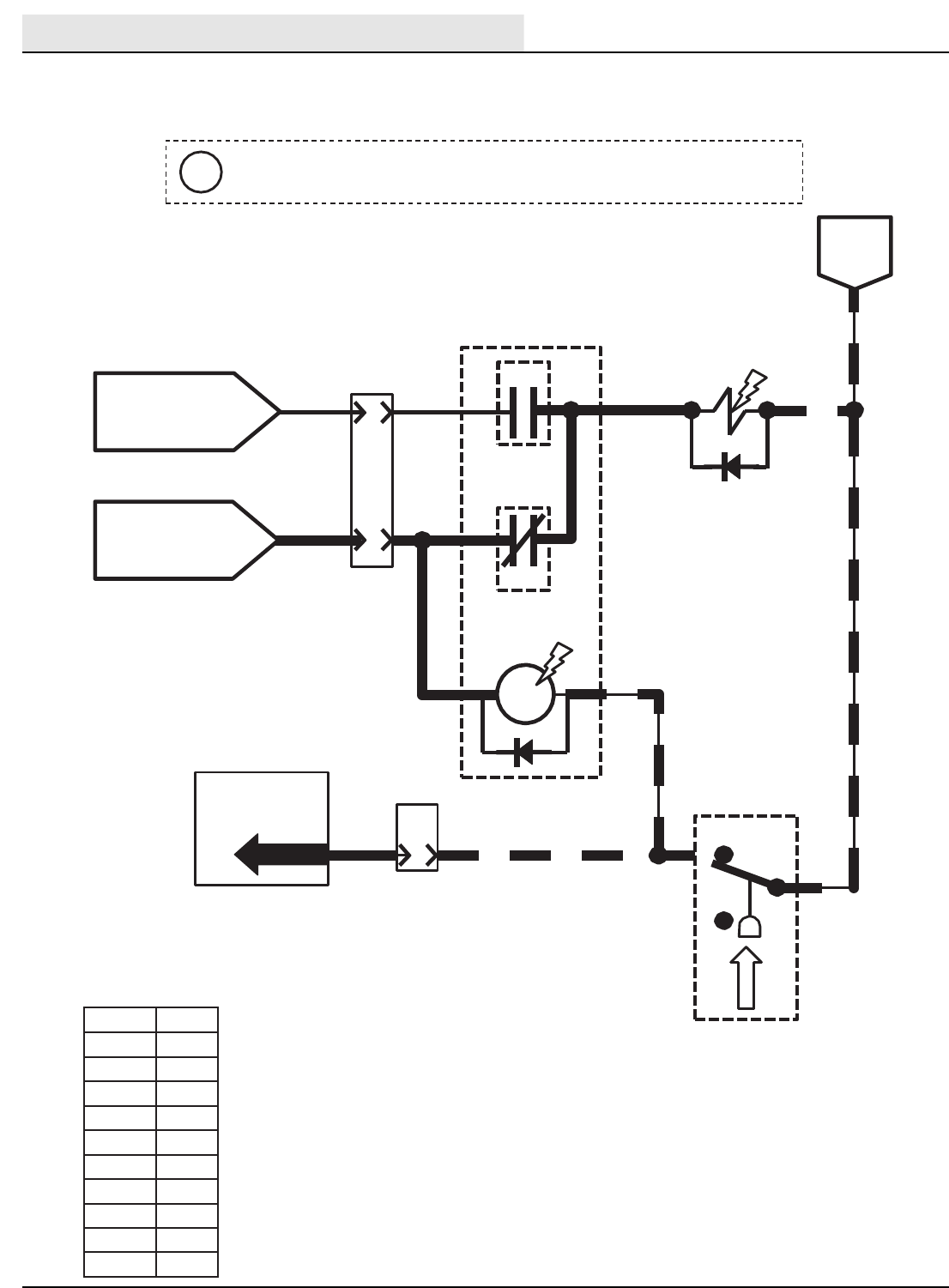
ELECTRICAL
M20/M30 9016006 - 3-2017
66
Wiring Color Codes
(Unless otherwise marked)
J
START RELAY M7B
10
PIN
ENGINE HARNESS
CONNECTOR
J-11
A
D-5
3
FUEL PUMP
85
M10A
FUEL
PUMP
RELAY
86
30
387
87a
M10B
M10C
OILPRESSURE
SWITCH
S-3
B&C CLOSED = LOW OIL PRESSURE
A&B CLOSED =OIL PRESSURE OK
B13/BLK
A
C
5 5
BATTERY
POSITIVE WHILE
CRANKING FROM
13/BLK
BATTERY
NEGATIVE
SWITCHED
BATTERY POSITIVE
FROM SHUTDOWN
RELAY M6C
TouchPanel /
Control Board
8
PIN
A
9
PIN P1-19
5
J-12
ENGINE HARNESS
CONNECTORS
3
77
77
3
67
5
Right Most Digit
of Wire Number
Color of Wire
0 Tan
1Pink
2 Brown
3Orange
4Yellow
5Green
6Blue
7 Purple
8Gray
9White
M-Series Fuel Pump
Conditions: Key on, engine running -(Diesel) -
This drawing is shown with key switch ON, and engine running.
i
Fuel Pump
Condition: Key On Engnie Running - (Diesel) -
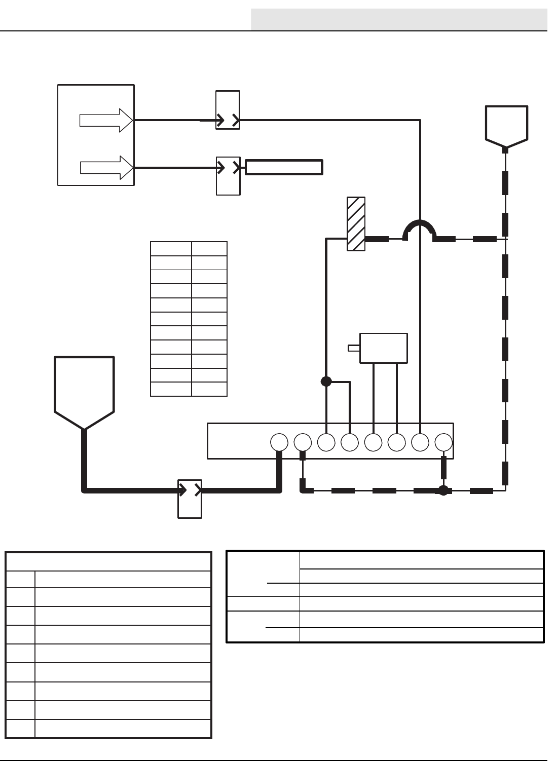
ELECTRICAL
M20/M30 9016006 - 3-2017 67
Wiring Color Codes
(Unless otherwise marked)
TouchPanel /
Control Board
11
18
PIN P2-24
B
6
PIN
J-10
8
PIN
E
J-12
ENGINE HARNESS
CONNECTORS
Governor Speed “
A
”
Governor Speed “
B
”
NO CONNECTION
GOVERNOR
A
10
PIN
33
J-11
ENGINE HARNESS
CONNECTOR
CONTROLLER
A
SWITCHED
BATTERY
POSITIVE
FROM
SHUTDOWN
RELAY M6C
3
3
B C D E F G H
BATTERY
NEGATIVE
PIN P2-25
THROTTLE
ACTUATOR
+ -
MAGNETIC
PICK-UP
(ENGINE SPEED)
SENSOR
13/BLK
13/BLK13/BLK
29
29
13/BLK
6059
61 61
61
29
Right Most Digit
of Wire Number
Color of Wire
0 Tan
1Pink
2 Brown
3Orange
4Yellow
5Green
6Blue
7 Purple
8Gray
9White
GovernorControllerPinChart
pin description
AINPUT – Battery Positive
BINPUT – BatteryNegative
CINPUT – EngineSpeed Sensor
DINPUT – EngineSpeed Sensor
EOUTPUT – Throttle Actuator (PWM)
FOUTPUT – Throttle Actuator
GINPUT – EngineSpeed Selection“A”
HINPUT – EngineSpeed Selection“B”
Speed Control T20 M20 M30
Diesel Idle 950 +/-50 RPM 950 +/-50 RPM 1350 +/-50 RPM
Run 2400 +/-RPM 2400 +/-RPM 2800 +/-50 RPM
LP / Gas Idle 1350 +/-50 RPM 1350 +/-50 RPM 1350 +/-50 RPM
Run 2300 +/-50 RPM 2300 +/-50 RPM 2300 +/-50 RPM
T20 Engine Speed Control
Conditions: Key on, engine running -(Diesel) -
Engine Speed Control
Condition: Key On Engnie Running - (Diesel) -
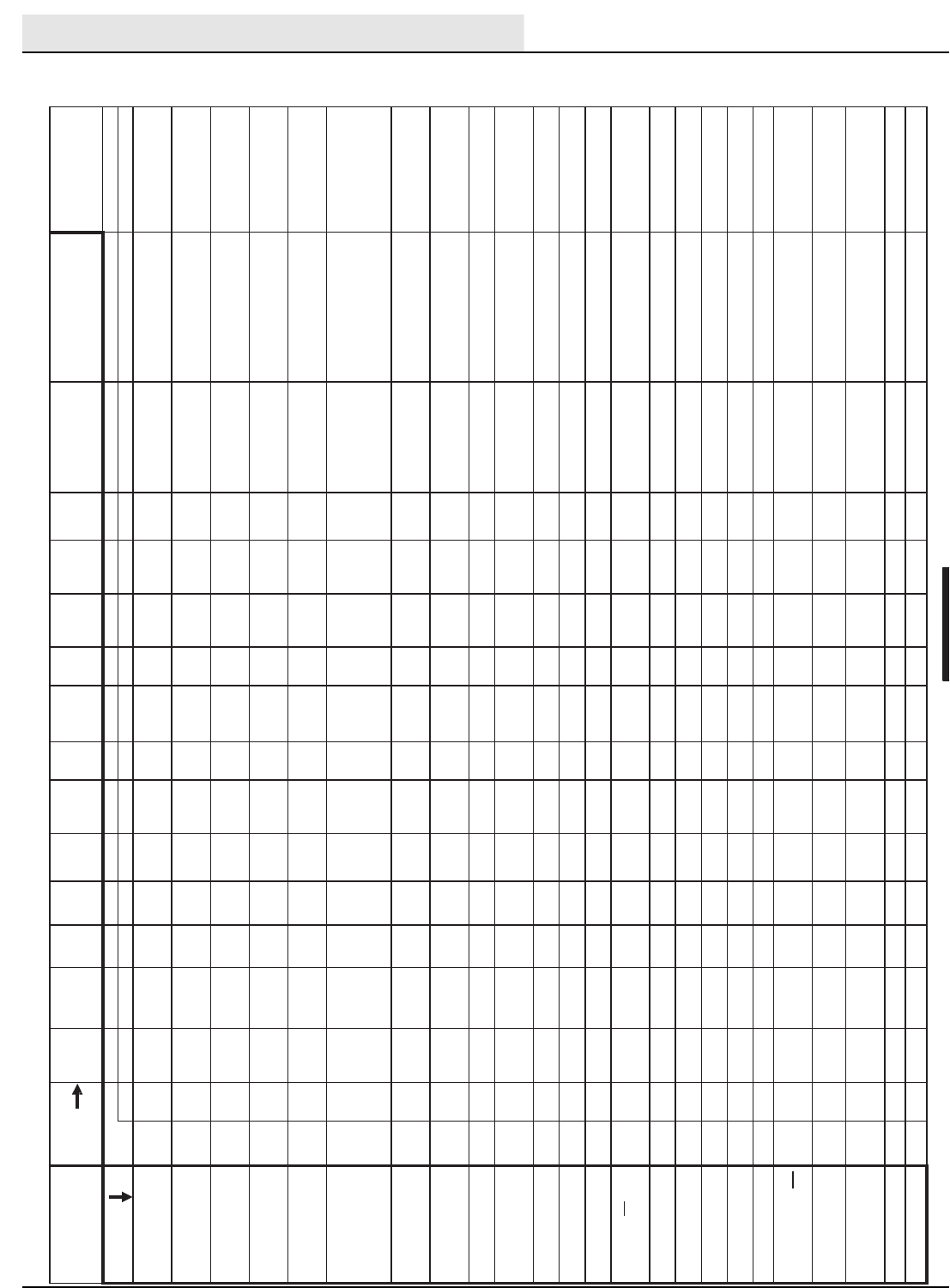
ELECTRICAL
M20/M30 9016006 - 3-2017
68
ON
Lower Valve ON
ON
Speed
Valve ON
ON
ON
Valve ON
Valve ON
Valve ON
Enable Valve, Air Pump &
ON
ON
FaST Detergent Pump ON
Lamp
E= Input required to ENABLE output D = Input req
SABLE
I
D
to
uired
output
ponent #
T20 Enable/Disable Chart
119
E
Notes
Propel required to to get full
operational down pressure
Propel required to to get full
operational down pressure
Propel required to to get full
operational down pressure
Turns OFF automatically if
not required (SV-7 is
required for all hydraulic
functions EXCEPT sweep
and scrub vacuum fans)
If low oil pressure, engine
ECM
will shutdown the
engine after a time delay
Touch Panel Input(s)
Required to DISABLE
OneStep Scrub OFF;
Squeegee/Scrub Vacuum OFF;
Low Engine Speed Selected
OneStep Scrub OFF; Low Engine
Speed Selected
OneStep Scrub OFF; Low Engine
Speed Selected
OneStep Scrub OFF; Low Engine
Speed Selected; Squeegee/Scrub
Vacuum OFF
OneStep Scrub OFF; Low Engine
Speed Selected
Refer to Notes
OneStep Scrub OFF; Low Engine
Speed Selected; Side Brush OFF
OneStep Scrub OFF; Low Engine
Speed Selected; Side Brush OFF
OneStep Scrub OFF; Low Engine
Speed Selected; Side Brush OFF
Touch Panel Input(s)
Required to ENABLE
OneStep Scrub ON;
Squeegee/Scrub
VacuumON
OneStep Scrub ON
OneStep Scrub ON
OneStep Scrub ON;
Squeegee/Scrub
VacuumON
OneStep Scrub ON
Turning ON Any Touch
Panel Function OR
Sel
ecting High Engine
Side Br
ush ON (after
OneStep Scrub ON)
Side Br
ush ON (after
OneStep Scrub ON)
Side Br
ush ON (after
OneStep Scrub ON)
Propel
Pedal
Sensor
NEUTRAL
n/a
P1-1
R
efer to
Notes
R
efer to
Notes
E
R
efer to
Notes
Propel Pedal
Sensor
REVERSE
n/a
P1-1
E
see notes
E
see notes
D
E
see notes
E
E
E
Propel Pedal
Sensor
FORWARD
n/a
P1-1
E
see notes
E
see notes
E
E
see notes
E
E
E
Impact
Sensor
Closed
S-23
P1-21
Hydraulic Oil
Temperature
Sensor above
230F
S-20
P1-17
E
Soution
Tank
Empty
Switch
Closed
S-19
P1-11
E
Clogged
Hydraulic
Filter Switch
Closed
S-17
P1-15
E
Recovery
Tank Half
Full Switch
Closed
S-16
P1-14
D
E
ES only
Recovery
Tank Full
Switch
Closed
S-15
P1-13
D
D
D
D
D
D
D
D
D
D
D
D
D
D
D
Solution
Tank Full
Switch
Closed
S-14
P1-12
D
D
ES only
Fuel Pressure
Switch Closed
(LPG)
S-8
P1-4
E
when low
Fuel Level
Sender (Gas,
Diesel)
S-7
P1-4
E
when low
Input
pin
P2-28
P2-4
P2-5
P2-6
P2-5
P2-8
P2-9
P2-11
P2-12
P2-9
P2-13
P2-14
P2-19
P2-22
P2-23
P2-26
P2-20
P2-17
P2-18
P2-21
P2-29
P2-27
P2-24
P2-25
com
SV-1
SV-2
SV-3
SV-4
SV-6
SV-7
SV-8
SV-10
SV-11
SV-12
SOL
-1
SOL
-2
SOL
-3
SOL-4,
M11
SOL
-5
SOL
-6
SOL
-7
M4A
M6A
n/a
n/a
n/a
n/a
n/a
M20 Control Board
Inputs and the Outputs
they Control
Output
Scrub Vacuum Fan Valve
Main Brush Head Down
Pressure Valve ON
Main Brush Head Lower
Valve ON
Rear and Side Squeegees
Main Brushes Spin Valve
ON
Hydraulic Enable Valve
Side Brush Spin ValveON
Side Br
ush Down Pressure
Side Brush Lower Valve
Side Brush Extend Valve
Auto-Fill Solution Tank
Auto-Fill Recovery Tank
Main Brushes Solution
ES Pump ON OR FaST
Water Pump Relay ON
FaST High Flow Valve ON
FaST Side Brush Valve
Side Brush Solution Valve
Rever
se PropelRelay ON
Shut Down Relay ON
Detergent Pump ON OR
Audible Alarm
Low Engine Oil Pressure
Governor Speed Bit "A"
Governor Speed Bit "B"
M_Series Enable / Disable Chart
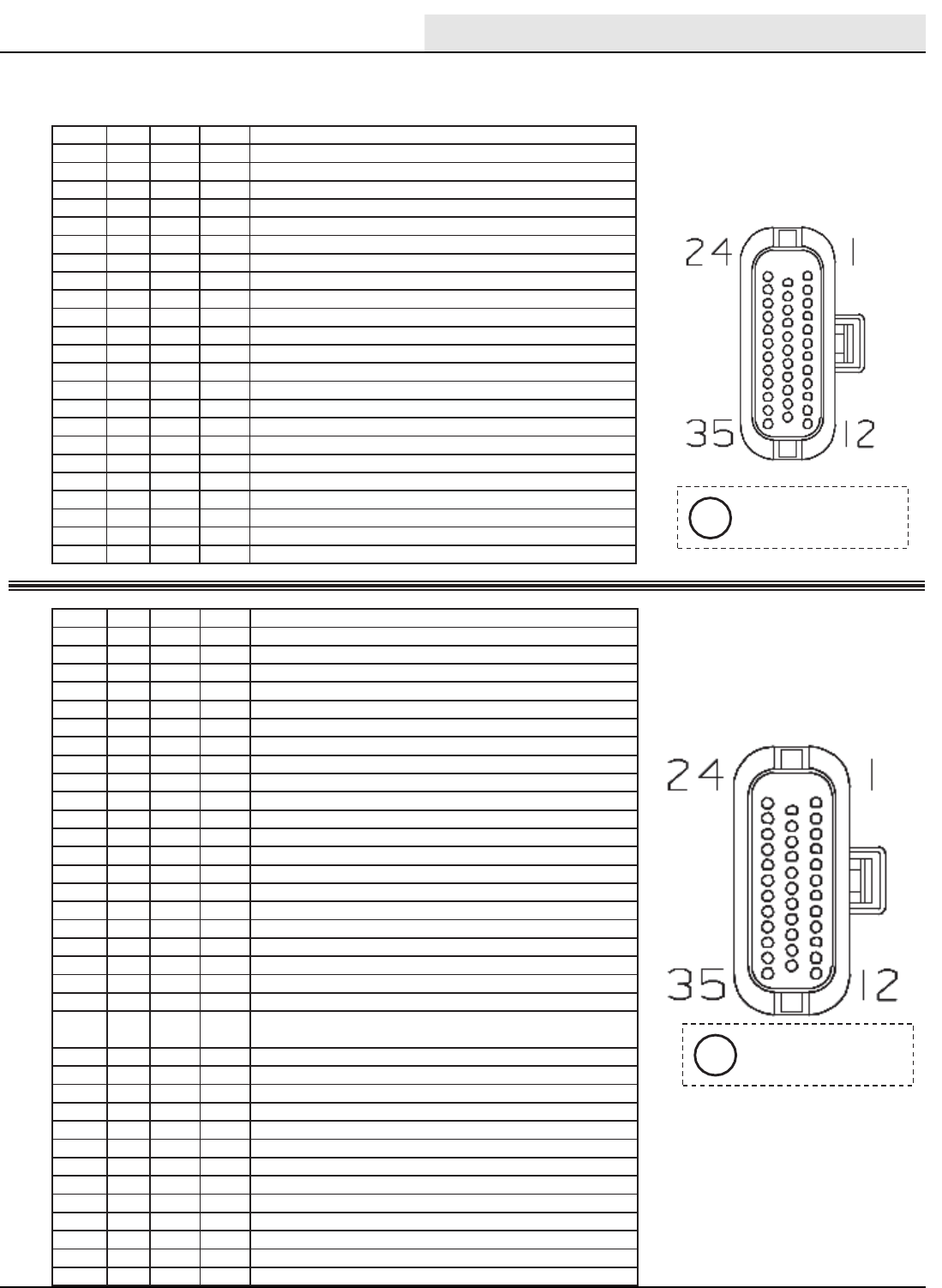
ELECTRICAL
M20/M30 9016006 - 3-2017 69
T20 Control Board Connectors
Connector
P1
Connector
P2
120
socket # wire # color type goes to
P1-1 91 pink input Forward/Reverse PropelSensor
P1-2 13 black input Unswitched Battery Negative
P1-3 x x x empty
P1-4 30 tan input S-7 or S-8 Fuel Level Sensor or LPG Pressure Switch
P1-5 x x x empty
P1-6 x x x empty
P1-7 x x x empty
P1-8 x x x empty
P1-9 x x x empty
P1-10 x x x empty
P1-11 177 purple input S-19 Solution Tank Empty Switch
P1-12 44 yellow input S-14 Solution Tank Full Switch
P1-13 45 green input S-15 Recovery Tank Full Switch
P1-14 46 blue input S-16 Recovery Tank Half FullSwitch
P1-15 90 tan input S-17 Clogged Hydraulic Filter Switch
P1-16 x x x empty
P1-17 78 gray input S-20 Hydraulic Temperature Sensor
P1-18 12 brown input SW2 HighEngine Temperature Switch
P1-19 9 white input Engine Oil Pressure Signal
P1-20 x x x empty
P1-21 49 white input S-23 Impact Sensor
P1-22 x x x empty
P1-23 105 green ground Static Ground
socket # wire # color type goesto
P2-1 14 yellow power Switched Battery Positive
P2-2 14 yellow power Switched Battery Positive
P2-3 81 pink power Unswitched Battery Positive
P2-4 57 purple output SV-2 Brush Head Pressure Solenoid Valve
P2-5 58 gray output SV-3, SV-6 Brush Head Down & ON Solenoid Valves
P2-6 59 white output SV-4 Squeegees Down Solenoid Valve
P2-7 x x x empty
P2-8 61 pink output SV-7 HydraulicEnable Solenoid Valve
P2-9 62 brown output SV-8, SV-12 Side Brush ON & Down SolenoidValves
P2-10 x x x empty
P2-11 64 yellow output SV-10 SideBrushPressure SolenoidValve
P2-12 66 blue output SV-11 Side Brush Down Solenoid Valve
P2-13 65 green output SOL-1 Solution Tank Auto Fill Water Valve
P2-14 67 purple output SOL-2 Recovery Tank AutoFill WaterValve
P2-15 x x x empty
P2-16 x x x empty
P2-17 70 tan output M4A Reverse Relay
P2-18 71 pink output M6A Shutdown Relay
P2-19 72 brown output SOL-3 Main Brush Head Water Valve
P2-20 181 pink output SOL-7 Side Brush Water Valve
P2-21 74 yellow output Detergent Pump or FaST Pressure Switch
P2-22 75 green output SOL-4, M11A ES Pump or FaST Enable Valve, Air Pump,
Water Pump Relay
P2-23 79 white output SOL-5 FaST High Flow Valve
P2-24 11 pink output ECM (Governor Speed Bit"A")
P2-25 18 gray output ECM (GovernorSpeedBit"B")
P2-26 80 tan output SOL-6 FaST Side Brush Valve
P2-27 28 gray output Low Engine Oil Pressure Lamp
P2-28 56 blue output SV-1 Scrub Vacuum Fan Valve
P2-29 182 brown output Audible Alarm
P2-30 x x x empty
P2-31 x x x empty
P2-32 x x x empty
P2-33 13 black ground Unswitched Battery Negative
P2-34 13 black ground Unswitched Battery Negative
P2-35 13 black ground Unswitched Battery Negative
Viewed from wire
side of connector.
i
Viewed from wire
side of connector.
i
M_Series Control Board Connectors
ELECTRICAL
M20/M30 9016006 - 3-2017
70
T20FaultIndicators
Thefollowing table describesfault codescommunicated to theoperator. A faultcodeis
indicated by blinking a FaultLED(red),sounding an alarm,andalso by displayingthefault
name on theLCD.Faultscanbeclearedwhentheyarenolongerpresentandone of the
action buttons(i.e.One-Step) is depressed. If there is more than one fault,they are displayed
forabout a second one aftertheother.
121
E
Fault LCDDisplay Description
HydraulicFilter
Clogged
F3:CLOGGEDHYD Indicatesthehydraulicfilter is clogged.
Solution Tankempty F6: SOL. TANK E Indicates the solution tank is empty.
RecoveryTankFull F7:REC.TANKFULL Indicates the recovery tank is fulland
shuts down the entireScrub system.
HighEngine
Temperature
F8: HIGH ENG TEMP Indicateshighenginetemperature.
HighHydraulic
Temperature
F9:HIGHHYDTEMP Indicatesexcessive hydraulic
temperature
LowFuel F10: LOW FUEL Lowfuelindicator(blinking lowestfuel
gaugeblock).
Squeegee
Disconnected
(Option)
F11:OPENSCBVAC Indicatessqueegeemayhavebroken
free.
M_Series Fault Condition Chart
ELECTRICAL
M20/M30 9016006 - 3-2017 71
T20 Condition & Warning Indicators
Thefollowing table describesdisplayedconditions or warnings. If a condition is sensed,
thecondition or warning code will be displayedontheLCD.Conditionsaretypically
caused by activating buttons that areunavailable. Forexample:theSweep vacuumfan
is unavailablewhen thescrubfunctionsareactive.
122
E
Condition LCDDISPLAY Description
FaST system is selected by
theoperatorandthe
machine is notconfigured
withtheFaSToption.
C3: NO FAST MODE Only machineswith the FaST
system installed (and
programmed to be FaST
machines) can turn ON the
FaST system.
ES system is selected by the
operatorandthemachineis
notconfigured withtheES
option.
C4: NO ES MODE Only machineswith the ES
system installed (and
programmed to be ES
machines) can turn ON theES
system.
FaST or ES system is
selected by theoperatorand
the machine is not
configuredwiththe ES or
FaSToption.
C5: NO ES/FAST Only machineswith the ES or
FaST system installed (and
programmed to be ES or Fast
machines) can turn ON theES
or FaST system.
SideBrushbuttonis
activated alonewithout 1-
STEP Sweep/Scrub.
C6: NO SIDEBRUSH TheT20 machine is NOT
programmed to operatewith
onlythe side brush ON.
M_Series Condition and Warning Indicators

HYDRAULICS
M20/M30 9016006 - 3-2017
72
M20 / M30 SERVICE INFORMATION Hydraulic Troubleshooting
HYDRAULIC
Troubleshooting Information
• BEFORE CONDUCTING TESTS:
* Read and Follow ALL Safety Warnings and
Precautions as mentioned at the beginning of this
manual
* Engine & Hydraulic Oil Must Be At Normal
Operating Temperatures after Running Machine
and Hydraulics a Minimum of 5 Minutes
* Examine Machine For Any Linkage Binding or
Mechanical Problems
• DURING TESTS:
* Call Technical Services if Diagnostic Time
Exceeds One Hour With Unknown Cause or
Course of Action
* Maintain Normal Main Brush Pressure as Listed in
Operator’s Manual
NOTE: Troubleshooting charts may be shown with optional equipment. The optional equipment may
not be specified in these charts. Some machines may not be equipped with all components shown.
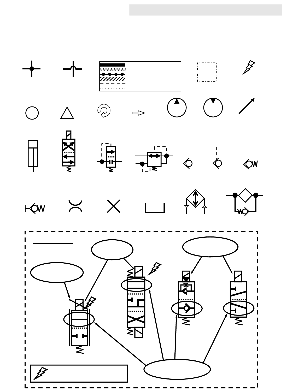
HYDRAULICS
M20/M30 9016006 - 3-2017 73
Commonly Used Hydraulic Symbols
Lines Connected
Together
Lines Not
Connected
Together
Component
is Energized
Information
!
Warning!
Assembly
Pressure / Flow Line
Return or Low Pressure Line
Active Pilot Port Line
Inactive Pilot Port Line
Case Drain Line
Suction Line
Component
is Rotating
Hydraulic
Flow
Hydraulic
Pump
Hydraulic
Motor
Relief Valve
Hydraulic
Cylinder
Hydraulic
Solenoid Valve
Pressure
Reducing Valve
Check
Valve
Spring Loaded
Check Valve
No ConnectionQuick Connect
Test Port
Restrictor or
Orifice
Oil Tank or
Reservoir
Oil Cooler or
Heat Exchanger
Oil Filter
With Bypass
Pilot Port
Check Valve
Variable
or PWM
Indicates Energized Solenoid Valve Coil
EXAMPLES
Circled envelope is
valve position for indicated
hydraulic circuit
SV19
A
B
SV25
Arrow indicates a
PWM (Pulse Width
Modulated) valve
SV14 SV7
Energized
Coils
Non-Energized
Coils
General Information
(Page 1 of 2)
i
General Information
Page 1 of 2
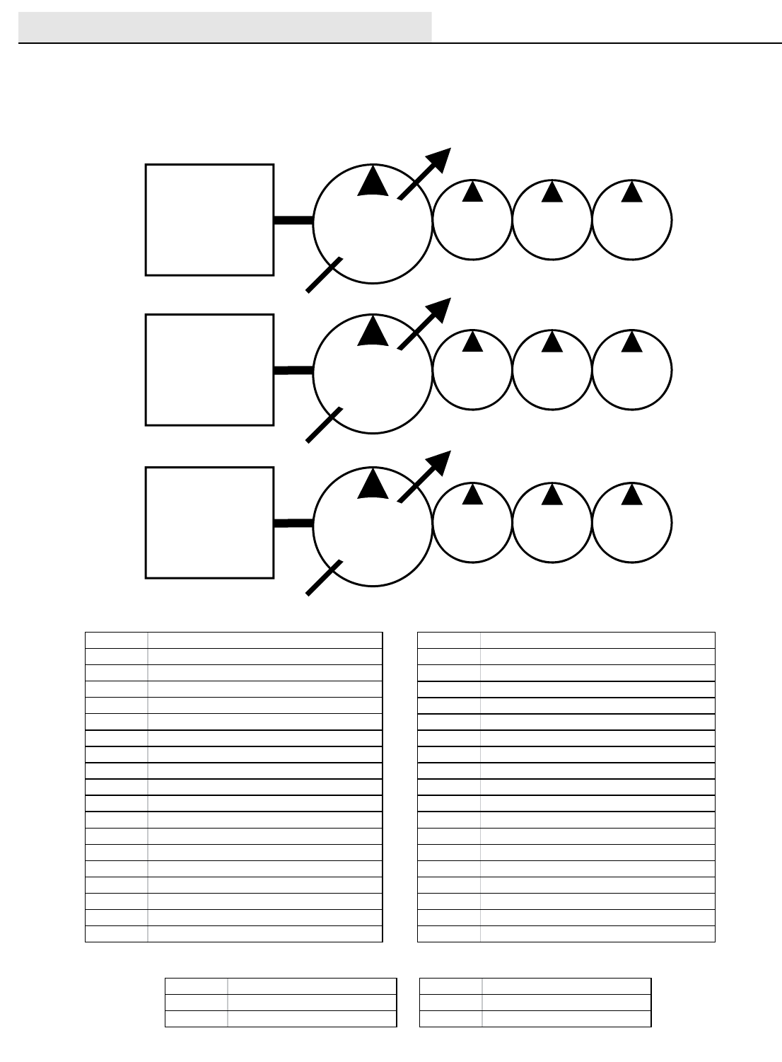
HYDRAULICS
M20/M30 9016006 - 3-2017
74
Hydraulic Pump Flow Rates (typical)
General Information
(Page 2 of 2)
AUX Auxiliary
CIR Cubic Inch Displacement per Revolution
CK Check Valve
CM Centimeters
CONV Conveyor
CU Cubic
CV Control Valve
CYL Cylinder
DC Disconnect Coupler (Hydraulic)
DC Direct Current (Electrical)
E Engine (Combustion)
FLTR Filter
GPM Gallons Per Minute
HTX Heat Exchanger
IN Inches
LH Left Hand
LPM Liters Per Minute
LS Load Sense
M Motor (Combustion)
MFLD Manifold
MTR Motor (Hydraulic)
OR Orifice
PC Pilot Port Check Valve
PMP Pump
PR Pressure Relief Valve
PSI Pounds Per Square Inch
PTO Power Take Off
PWM Pulse Width Modulation
RES Reservoir
RH Right Hand
RPM Revolutions Per Minute
RV Relief Valve
SC Spring Loaded Check Valve
STRN Strainer
SV Solenoid Valve
SW Switch
TV Throttle Valve
V Volts
C Hydraulic Cylinder Connection
G Test Port
LS Load Sense Port
M Hydraulic Motor Connection
P Pump Connection
R or T Return Port (To Tank)
Commonly Used Abbreviations
Typical Hydraulic Manifold Port Markings
GM ENGINE
Gas/LPG: 2700 RPM
Kubota
Diesel: 2800 RPM
4 to 4.2 GPM
(15.1 to 15.9
LPM)
6 to 6.3 GPM
(22.7 to 23.8
LPM)
9.5 to 10 GPM
(35.9 to 37.8
LPM)
PROPEL
PUMP ACCESSORY PUMPS
PUMP
1
PUMP
2
PUMP
3
14.5 to 15 GPM
(54.8 to 56.7 LPM)
maximum
M30
GM ENGINE @
2400 RPM
4 GPM
(15.1 LPM)
6 GPM
(22.7 LPM)
10 GPM
(37.9 LPM)
PROPEL
PUMP ACCESSORY PUMPS
PUMP
1
PUMP
2
PUMP
3
12.5 GPM
(47.3 LPM)
maximum
M20
Mitsubishi
ENGINE @
2300 RPM
3.98 GPM
(15.07 LPM)
5.97 GPM
(22.6 LPM)
8.56 GPM
(32.4LPM)
PROPEL
PUMP ACCESSORY PUMPS
PUMP
1
PUMP
2
PUMP
3
12.35 GPM
(46.75 LPM)
maximum
M20/M30
General Information
Page 2 of 2
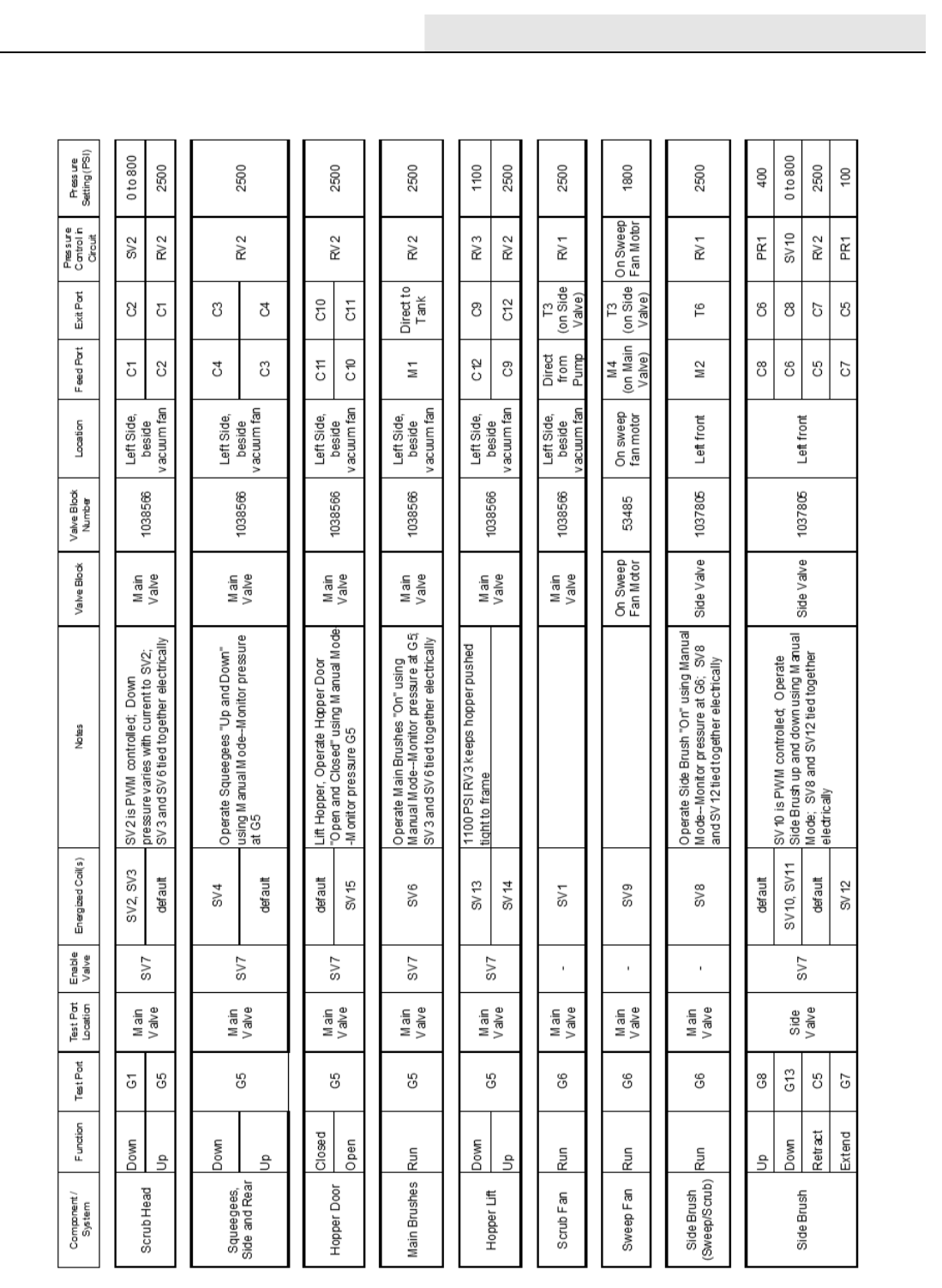
HYDRAULICS
M20/M30 9016006 - 3-2017 75
M20 / M30 Operating Matrix
M20_M30
Operational Matrix
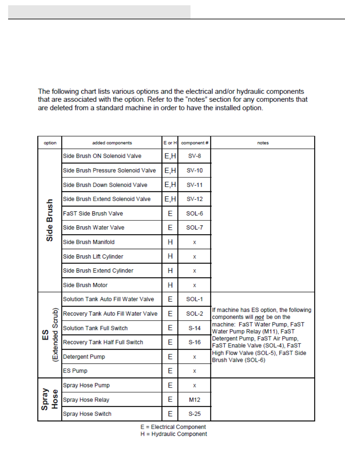
HYDRAULICS
M20/M30 9016006 - 3-2017
76
M20 / M30 Option Components
M20_M30
Option Components
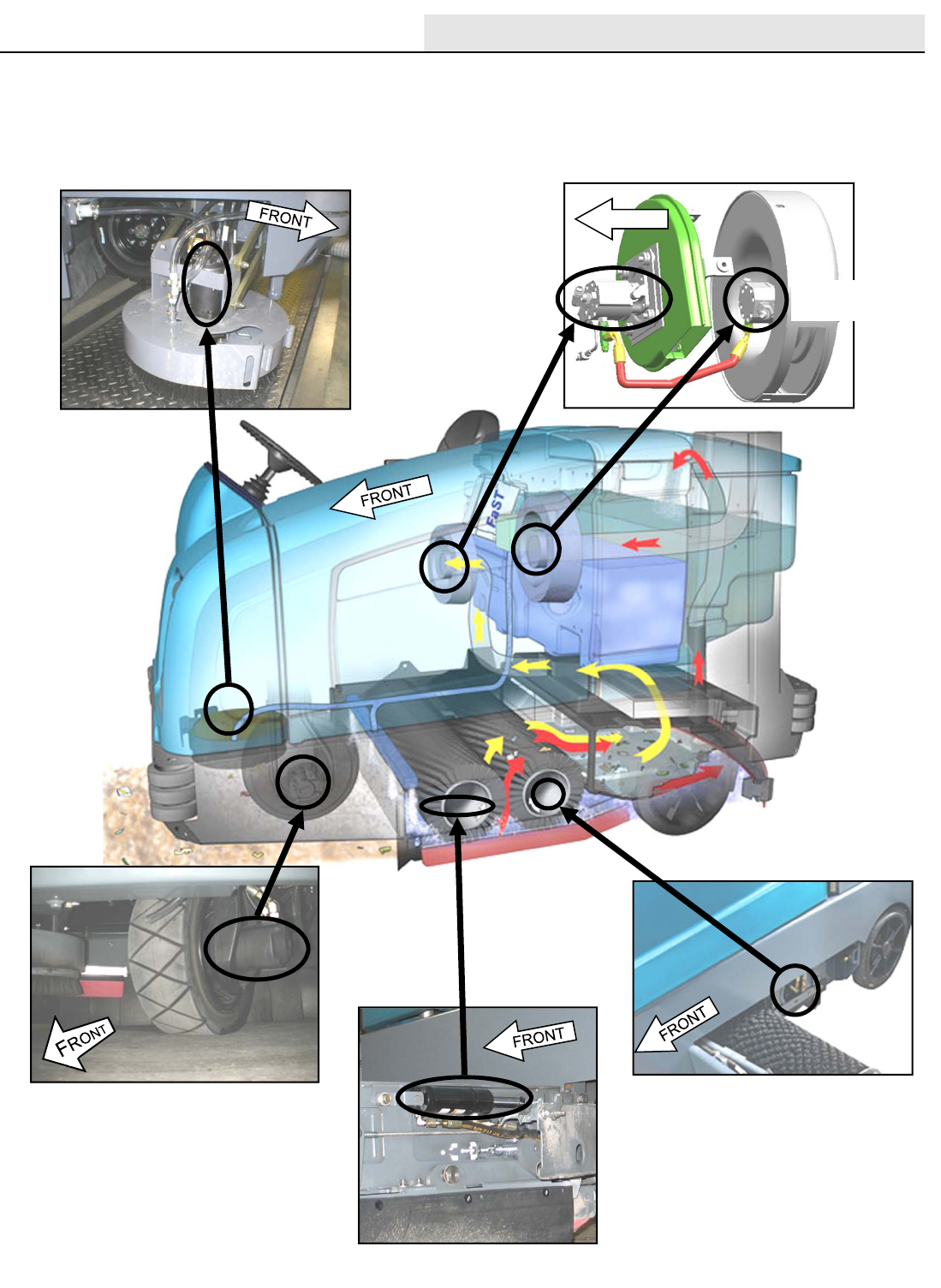
HYDRAULICS
M20/M30 9016006 - 3-2017 77
SWEEP FAN
MOTOR
M20 / M30 Hydraulic Component Locator
Side Brush Motor – Sweep Fan Motor – Scrub Fan Motor
Propel Motor – Main Brush Motor – Side Sq. Lift Cyl.
PROPEL MOTOR
SCRUB FAN
MOTOR
SIDE BRUSH MOTOR
MAIN BRUSH MOTOR (REAR)
FRONT
LEFT SIDE SQUEEGEE LIFT CYLINDER
M20_M30 Hydraulic Component Locator
Side Brush Motor - Sweep Fan Motor - Scrub Fan Motor
Propel Motor - Main Brush Motor - Side Sqeegee Lift Cylinder
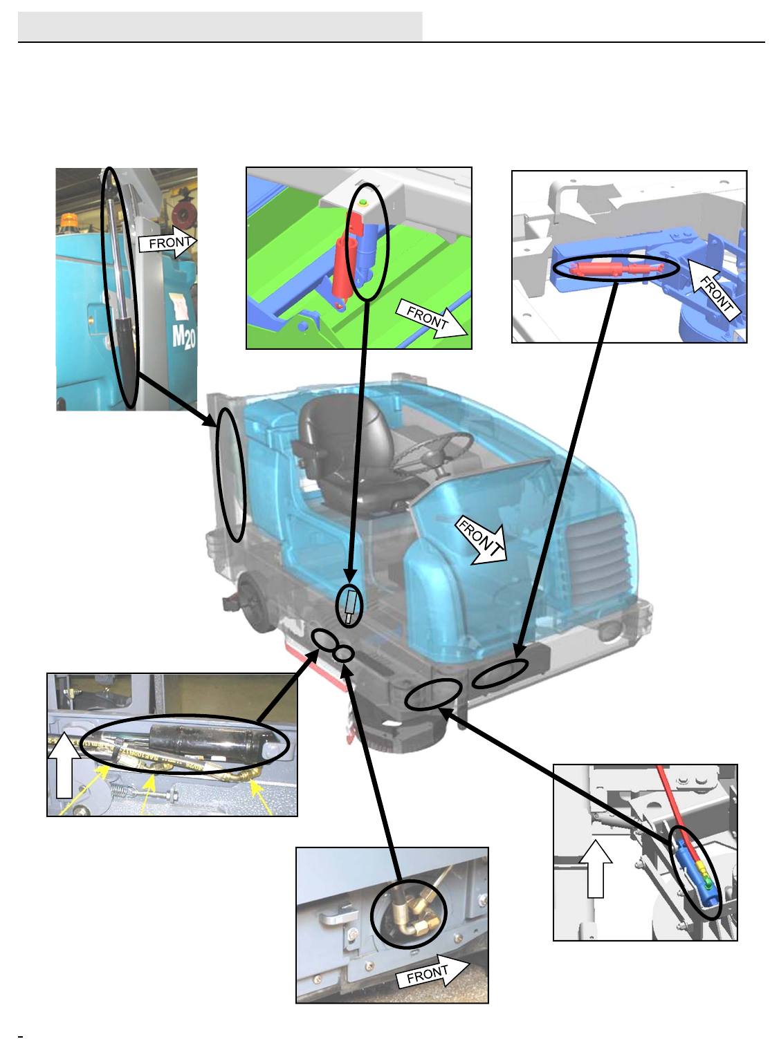
HYDRAULICS
M20/M30 9016006 - 3-2017
78
FRONT BUMPER
(INNER VIEW)
FRONT
MAIN BRUSH MOTOR (FRONT)
SCRUB HEAD LIFT CYLINDER
SIDE BRUSH LIFT CYLINDER
SIDE BRUSH EXTEND CYLINDER
RIGHT SIDE SQUEEGEE LIFT CYLINDER
HOPPER LIFT CYLINDER
FRONT
M20 M30 Hydraulic Component Locator
Hopper Cyl. – Scrub Head Cyl.- Side Brush Extend Cyl.
Side Sq. Cyl. – Main Brush Motor – Side Brush Lift Cyl.
M20_M30 Hydraulic Component Locator
Hopper Cylinder - Scrub Head Cylinder - Side Brush Extend
CylinderSide Squeegee Cylinder - Main Brush Motor
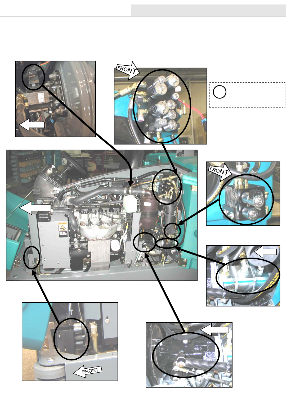
HYDRAULICS
M20/M30 9016006 - 3-2017 79
FRONT
SWEEP FAN VALVE SV9
(BESIDE ENGINE FUSE PANEL)
SCRUB MANIFOLD
SV1, SV2, SV3, SV4,SV6, SV7
RV1, RV2, CV1, PC1, PC2
SWEEP MANIFOLD
SV13, SV14, SV15,
RV3, PC5, PC6
SIDE BRUSH MANIFOLD
SV8, SV10, SV11, SV12, PR1, PC8
FRONT
See pages 00, 00 and 00
for more information on
the Scrub, Sweep, and
Side Brush manifolds
i
FRONT
PROPEL PUMP
ACCESSORY PUMPS
FRONT
M20 M30 Hydraulic Component Locator
Sweep Fan Valve – Scrub Manifold – Sweep Manifold
Accessory Pumps – Side Brush Manifold – Propel Pump
M20_M30 Hydraulic Component Locator
Sweep Fan Valve - Scrub Manifold - Sweep Manifold
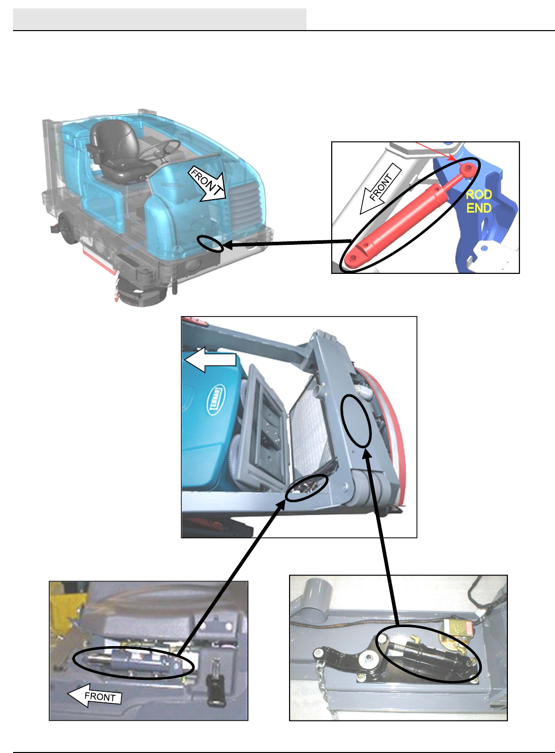
HYDRAULICS
M20/M30 9016006 - 3-2017
80
REAR SQUEEGEE LIFT CYLINDER
(VIEWED BEHIND BUMPER)
HOPPER DOOR CYLINDER
FRONT
STEERING CYLINDER
M20 M30 Hydraulic Component Locator
Steering Cylinder – Hopper Door Cylinder – Rear Sq. Lift Cyl.
M20_M30 Hydraulic Component Locator
Steering Cylinder - Hopper Door Cylinder -
Rear Squeegee Lift Cylinder
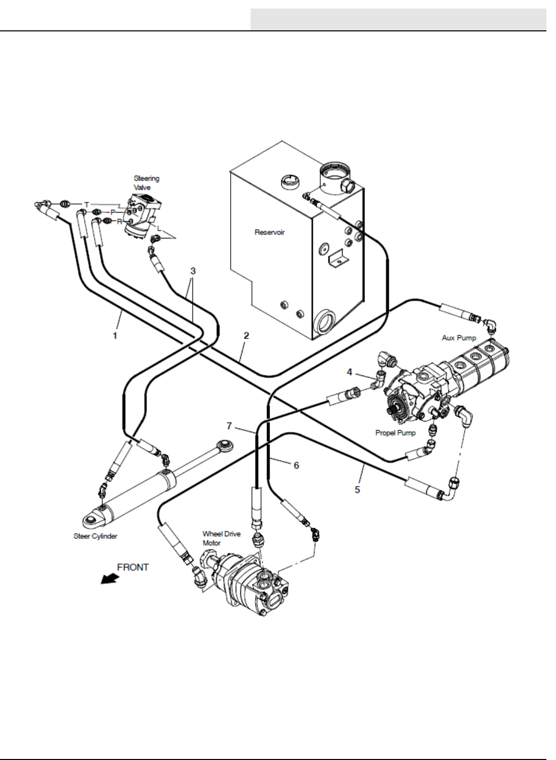
HYDRAULICS
M20/M30 9016006 - 3-2017 81
Hose Group: Steering and Propel
M20_M30 Hydraulic Component Locator
Hose Group - Steering and Propel
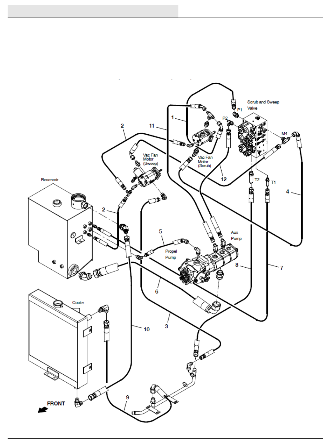
HYDRAULICS
M20/M30 9016006 - 3-2017
82
Hose Group: Pump and Vacuum Fan
M20_M30 Hydraulic Component Locator
Hose Group - Pump and Vacuum Fan
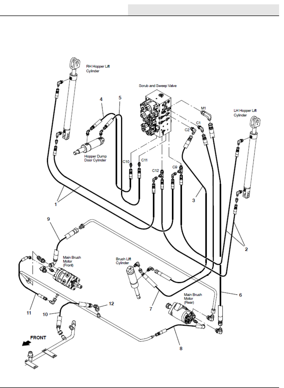
HYDRAULICS
M20/M30 9016006 - 3-2017 83
Hose Group: Brush and Hopper
M20_M30 Hydraulic Component Locator
Hose Group - Brush and Hopper
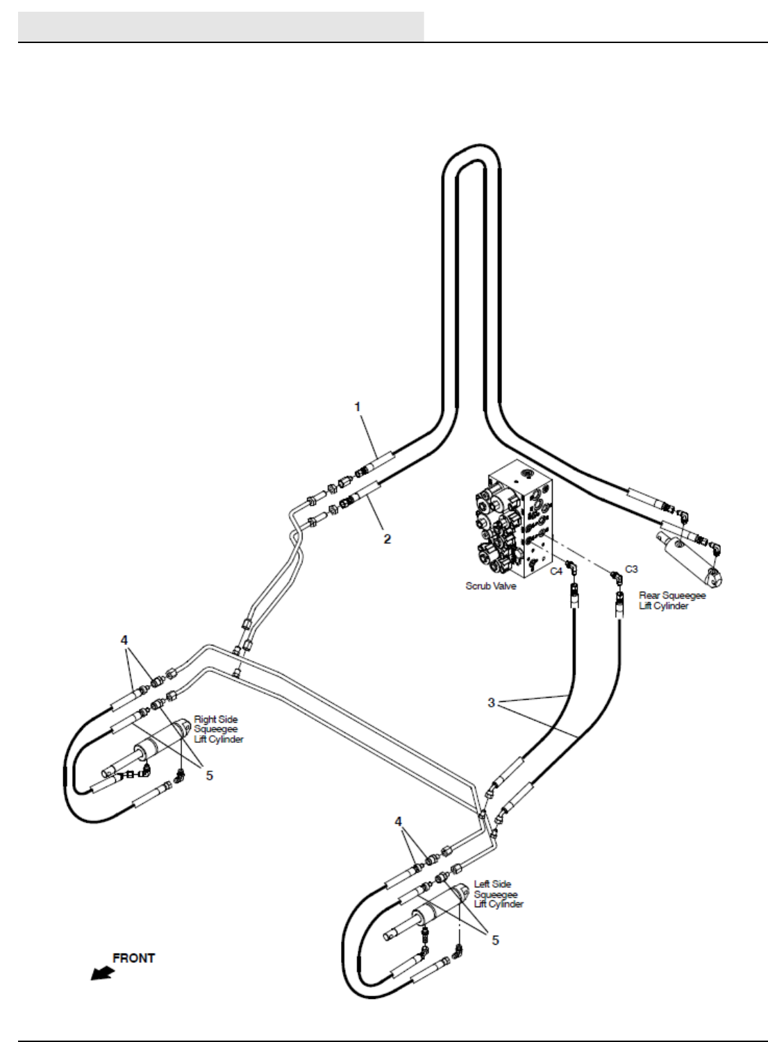
HYDRAULICS
M20/M30 9016006 - 3-2017
84
Hose Group: Squeegee Lift
M20_M30 Hydraulic Component Locator
Hose Group - Squeegee Lift
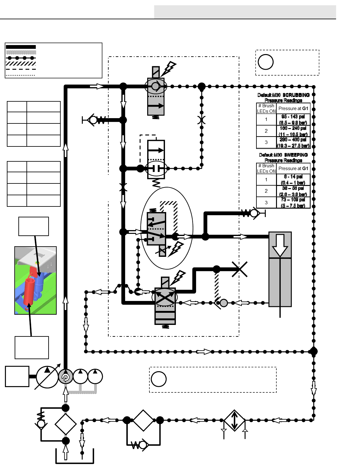
HYDRAULICS
M20/M30 9016006 - 3-2017 85
M20/M30 Scrub/Sweep Head Lower
Engine speed: High
SV7
G5
SV2
SV3
LOWER
G2
G1
P2
T1
C2
C1
SCRUB HEAD
ACTUATOR
T2
SCREEN
MAIN VALVE MANIFOLD
ENGINE
OIL
FILTER
OIL
COOLER
PC1
*PWM*
Pressure / Flow Line
Return or Low Pressure Line
Active Pilot Port Line
Inactive Pilot Port Line
Case Drain Line
Suction Line Gray items are
energized
or activated
Default M20 SCRUBBING
Pressure Readings
The “# Brush Pressure LEDs ON”
are the Touch Panel LED indicators
for Brush down pressure
Scrub
Head
Actuator
NOTE
SPRING
ASSIST
i
i
# Brush
LEDs ON Pressure at G1
195 - 143 psi
(6.5 – 9.8 bar)
2160 – 240 psi
(11 – 16.5 bar)
3280 – 400 psi
(19.3 – 27.5 bar)
ORIFICE
0.040 in
(1.0 mm)
RV2
2500 PSI
(172.4 BAR)
35 PSI
(2.4 BAR)
3 PSI
(20.7 kPa)
OR3
0.140 in
(3.55 mm)
Default M20 SWEEPING
Pressure Readings
# Brush
LEDs ON Pressure at G1
16 - 14 psi
(0.4 – 1 bar)
238 – 56 psi
(2.6 – 3.8 bar)
373 – 109 psi
(5 – 7.5 bar)
M20_M30 Scrub/Sweep Head Lower
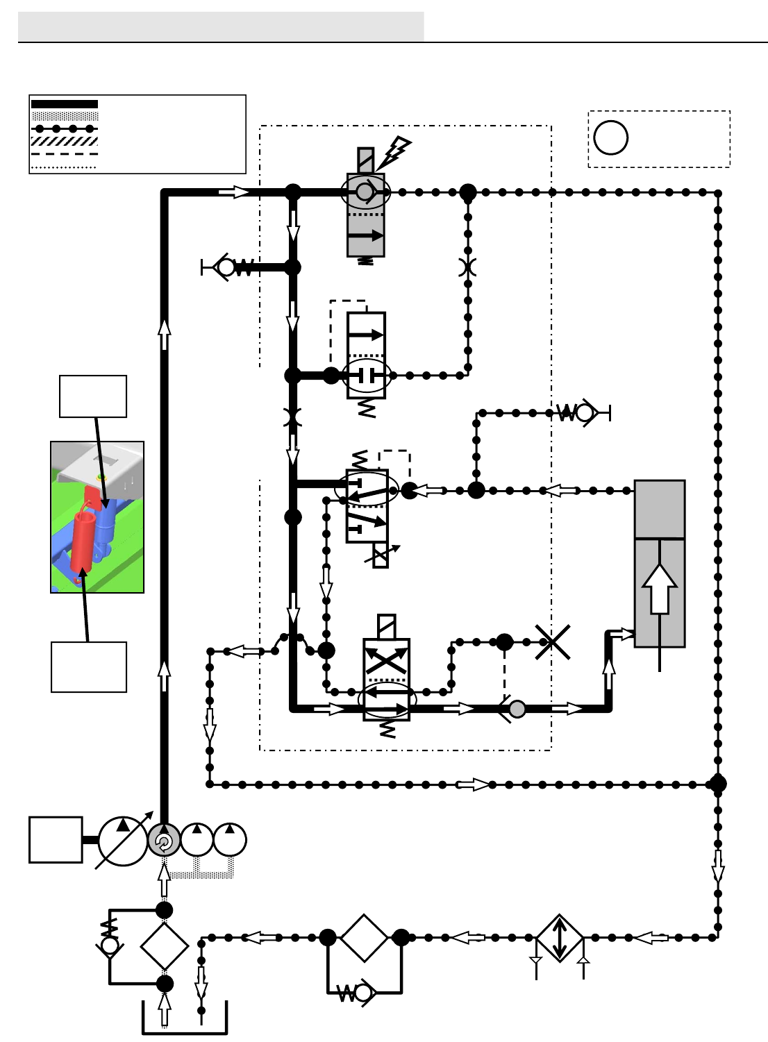
HYDRAULICS
M20/M30 9016006 - 3-2017
86
G2
M20 / M30 Scrub/Sweep Head Lift
Engine speed: High
SV7
G5
SV3
LIFT
G2
G1
P2
T1
C2
C1
SCRUB HEAD
ACTUATOR
T2
SCREEN
OIL
FILTER
OIL
COOLER
PC1
SV2
Pressure / Flow Line
Return or Low Pressure Line
Active Pilot Port Line
Inactive Pilot Port Line
Case Drain Line
Suction Line
ENGINE
Scrub
Head
Actuator
NOTE
SPRING
ASSIST
Gray items are
energized
or activated
i
RV2
2500 PSI
(172.4 BAR)
35 PSI
(2.4 BAR)
3 PSI
(20.7 kPa)
OR3
0.140 in
(3.55 mm)
MAIN VALVE MANIFOLD
M30 ORIFICE
0.040 in
(1.0 mm)
M20 ORIFICE
0.046 in
(1.17 mm)
M20_M30 Scrub/Sweep Head Lift
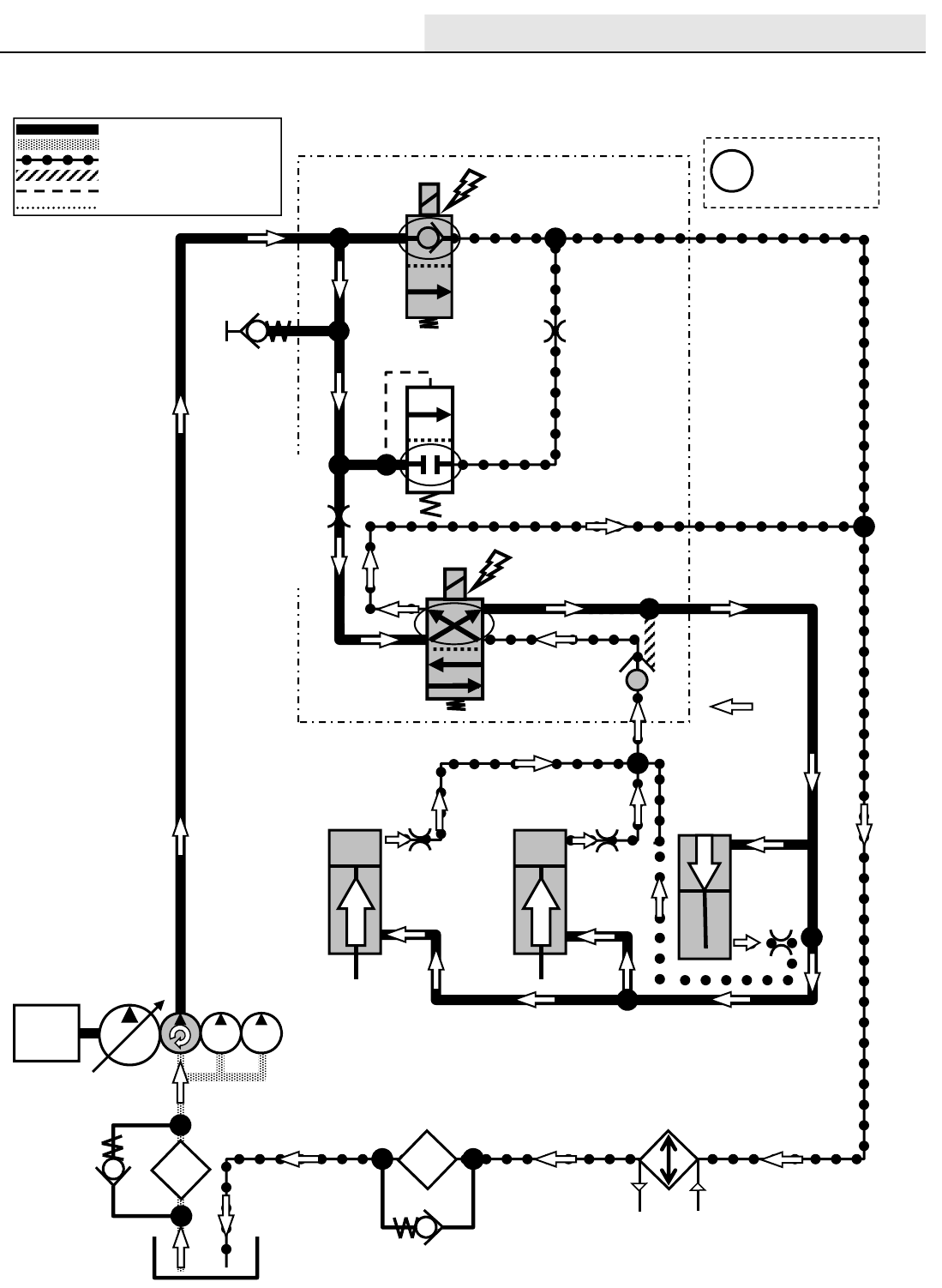
HYDRAULICS
M20/M30 9016006 - 3-2017 87
M20 / M30 Squeegees Lower
Engine speed: High
SV7
G5
P2
SV4
C3
T1
C4
LOWER
LEFT
SQUEEGEE
ACTUATOR
RIGHT
SQUEEGEE
ACTUATOR
REAR
SQUEEGEE
ACTUATOR
T2
SCREEN
OIL
FILTER
OIL
COOLER
PC2
LOWER
LOWER
Pressure / Flow Line
Return or Low Pressure Line
Active Pilot Port Line
Inactive Pilot Port Line
Case Drain Line
Suction Line
ENGINE
Gray items are
energized
or activated
i
RV2
2500 PSI
(172.4 BAR)
35 PSI
(2.4 BAR)
ORIFICE
0.031 in
(0.79 mm)
ORIFICE
0.031 in
(0.79 mm)
3 PSI
(20.7 kPa)
OR3
0.140 in
(3.55 mm)
MAIN VALVE MANIFOLD
M30 ORIFICE
0.040 in
(1.0 mm)
ORIFICE
0.036 in
(0.91 mm)
M20 ORIFICE
0.046 in
(1.17 mm)
M20_M30 Squeegee Lower
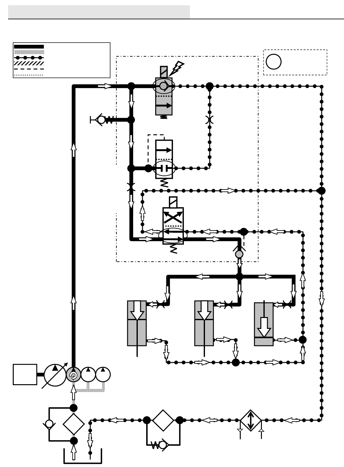
HYDRAULICS
M20/M30 9016006 - 3-2017
88
M20 / M30 Squeegees Lift
Engine speed: High
SV7
G5
OIL
COOLER
P2
SV4
C3
T1
C4
LIFT
LIFT
LIFT
LEFT
SQUEEGEE
ACTUATOR
RIGHT
SQUEEGEE
ACTUATOR
REAR
SQUEEGEE
ACTUATOR
T2
SCREEN
OIL
FILTER
PC2
Pressure / Flow Line
Return or Low Pressure Line
Active Pilot Port Line
Inactive Pilot Port Line
Case Drain Line
Suction Line
ENGINE
Gray items are
energized
or activated
i
RV2
2500 PSI
(172.4 BAR)
35 PSI
(2.4 BAR)
ORIFICE
0.031 in
(0.79 mm)
ORIFICE
0.031 in
(0.79 mm)
3 PSI
(20.7 kPa)
OR3
0.140 in
(3.55 mm)
MAIN VALVE MANIFOLD
ORIFICE
0.036 in
(0.91 mm)
M30 ORIFICE
0.040 in
(1.0 mm)
M20 ORIFICE
0.046 in
(1.17 mm)
M20_M30 Squeegee Lift
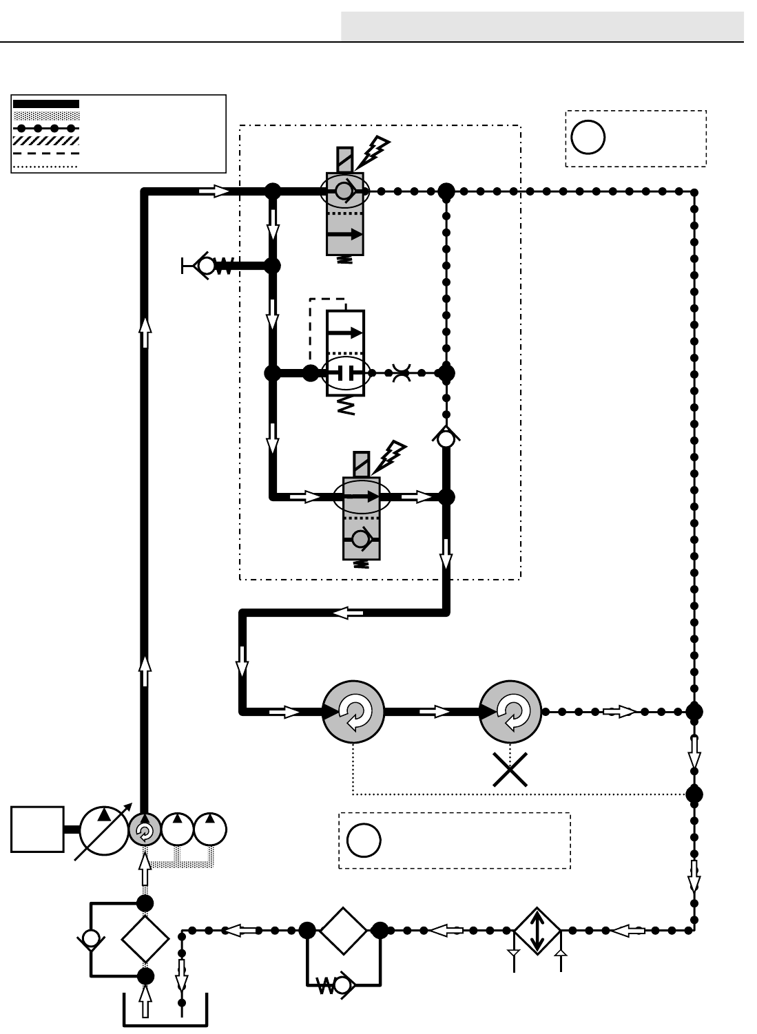
HYDRAULICS
M20/M30 9016006 - 3-2017 89
M20 / M30 Main Brushes ON
Engine speed: High
SV7
G5
OIL
COOLER
P2
SV6
M1
CV1
T2
SCREEN
REAR MAIN
BRUSH
MOTOR
FRONT MAIN
BRUSH
MOTOR
OIL
FILTER
Pressure / Flow Line
Return or Low Pressure Line
Active Pilot Port Line
Inactive Pilot Port Line
Case Drain Line
Suction Line
ENGINE Main Brush Motors speed:
M20 / 420-480
M30 / 460-480 RPM
Gray items are
energized
or activated
i
i
RV2
2500 PSI
(172.4 BAR)
35 PSI
(2.4 BAR)
3 PSI
(20.7 kPa)
OR3
0.140 in
(3.55 mm)
MAIN VALVE
MANIFOLD
M20_M30 Main Brushes On
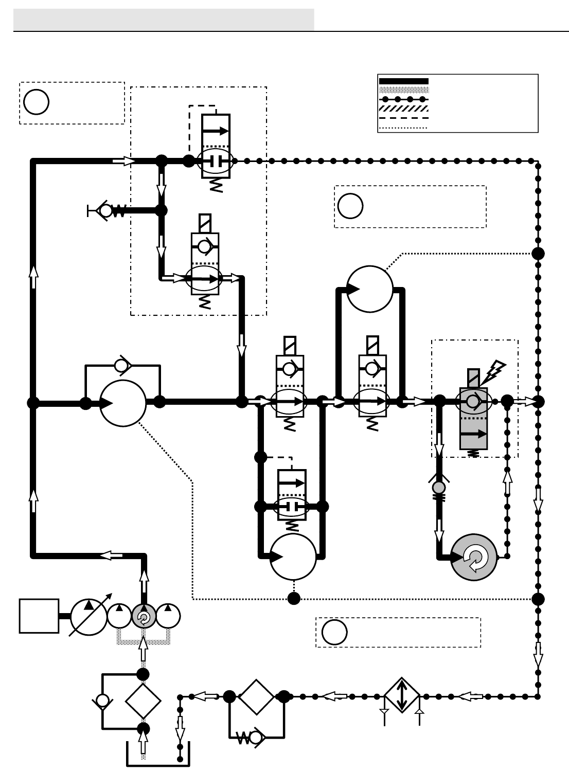
HYDRAULICS
M20/M30 9016006 - 3-2017
90
M20 / M30 Side Brush ON
Engine speed: High
SV1
G6
OIL
COOLER
P1 T2
SCREEN
SV9
1800 PSI
(124 BAR)
SCRUB FAN
MOTOR
OIL
FILTER
SWEEP FAN
MOTOR SIDE BRUSH
MOTOR
SV8
SIDE BRUSH
MANIFOLD
Pressure / Flow Line
Return or Low Pressure Line
Active Pilot Port Line
Inactive Pilot Port Line
Case Drain Line
Suction Line
ENGINE
Side Brush Motor speed:
140-160 RPM
i
RV1
2500 PSI
(172.4 BAR)
35 PSI
(2.4 BAR)
25 PSI
(1.7 BAR)
M4
P3 T3
M2 T6
Side Brush can only be
operated when Main
Brushes are ON
i
3 PSI
(20.7 kPa)
MAIN VALVE MANIFOLD
SOL1
PRESSURE
WASHER
MOTOR
Gray items are
energized
or activated
i
M20_M30 Side Brush On
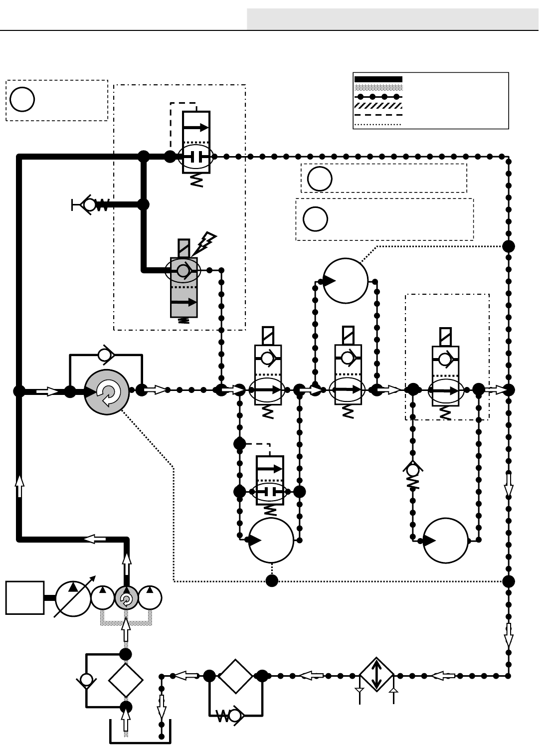
HYDRAULICS
M20/M30 9016006 - 3-2017 91
G6
OIL
COOLER
P1 T2
SCREEN
SV9
1800 PSI
(124 BAR)
SCRUB FAN
MOTOR
OIL
FILTER
SWEEP FAN
MOTOR SIDE BRUSH
MOTOR
SV8
SIDE BRUSH
MANIFOLD
Pressure / Flow Line
Return or Low Pressure Line
Active Pilot Port Line
Inactive Pilot Port Line
Case Drain Line
Suction Line
ENGINE
RV1
2500 PSI
(172.4 BAR)
35 PSI
(2.4 BAR)
25 PSI
(1.7 BAR)
M4
P3 T3
M2 T6
3 PSI
(20.7 kPa)
MAIN VALVE MANIFOLD
SOL1
PRESSURE
WASHER
MOTOR
M20 / M30 Scrub Vacuum Fan ON
Engine speed: High
SV1
Gray items are
energized
or activated
i
Scrub Fan Motor speed:
10,500 RPM (+/- 150 RPM)
i
Scrub Fan Motor vacuum:
30-39 in/H2O (76-99 cm/H2O)
measured at squeegee
i
M20_M30 Scrub Vacuum Fan On

HYDRAULICS
M20/M30 9016006 - 3-2017
92
G6
OIL
COOLER
P1 T2
SCREEN
SV9
1800 PSI
(124 BAR)
SCRUB FAN
MOTOR
OIL
FILTER
SWEEP FAN
MOTOR SIDE BRUSH
MOTOR
Pressure / Flow Line
Return or Low Pressure Line
Active Pilot Port Line
Inactive Pilot Port Line
Case Drain Line
Suction Line
ENGINE
RV1
2500 PSI
(172.4 BAR)
35 PSI
(2.4 BAR)
M4
3 PSI
(20.7 kPa)
MAIN VALVE MANIFOLD
SOL1
PRESSURE
WASHER
MOTOR
SV1
Gray items are
energized
or activated
i
Scrub Fan Motor speed:
10,500 RPM (+/- 150 RPM)
i
Scrub Fan Motor vacuum:
30-39 in/H2O (76-99 cm/H2O)
measured at squeegee
i
M20 / M30 Scrub Vacuum Fan & Side Brush ON
Engine speed: High
SV8
SIDE BRUSH
MANIFOLD
25 PSI
(1.7 BAR)
P3 T3
M2 T6
Side Brush Motor speed:
140-160 RPM
i
Side Brush can only be
operated when Main
Brushes are ON
i
M20_M30 Scrub Vacuum Fan & Side Brush On
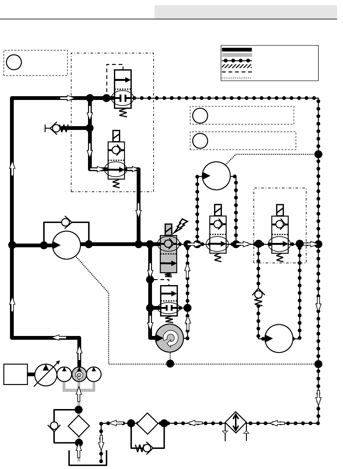
HYDRAULICS
M20/M30 9016006 - 3-2017 93
SV1
G6
OIL
COOLER
P1 T2
SCREEN
SV9
SCRUB FAN
MOTOR
OIL
FILTER
SWEEP FAN
MOTOR SIDE BRUSH
MOTOR
SV8
SIDE BRUSH
MANIFOLD
Pressure / Flow Line
Return or Low Pressure Line
Active Pilot Port Line
Inactive Pilot Port Line
Case Drain Line
Suction Line
ENGINE
RV1
2500 PSI
(172.4 BAR)
35 PSI
(2.4 BAR)
25 PSI
(1.7 BAR)
M4
P3 T3
M2 T6
3 PSI
(20.7 kPa)
MAIN VALVE MANIFOLD
SOL1
PRESSURE
WASHER
MOTOR
Gray items are
energized
or activated
i
M20 / M30 Sweep Vacuum Fan ON
Engine speed: High
1800
PSI
(124
BAR)
Sweep Fan Motor speed:
7,000 RPM (+/- 150 RPM)
Sweep Fan Motor vacuum:
18-24 in/H2O (45-61 cm/H2O)
i
i
M20_M30 Scrub Vacuum Fan On
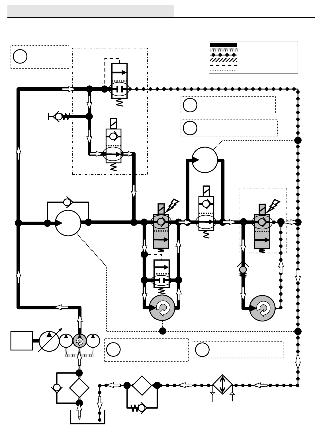
HYDRAULICS
M20/M30 9016006 - 3-2017
94
SV1
G6
OIL
COOLER
P1 T2
SCREEN
SV9
SCRUB FAN
MOTOR
OIL
FILTER
SWEEP FAN
MOTOR SIDE BRUSH
MOTOR
Pressure / Flow Line
Return or Low Pressure Line
Active Pilot Port Line
Inactive Pilot Port Line
Case Drain Line
Suction Line
ENGINE
RV1
2500 PSI
(172.4 BAR)
35 PSI
(2.4 BAR)
M4
3 PSI
(20.7 kPa)
MAIN VALVE MANIFOLD
SOL1
PRESSURE
WASHER
MOTOR
Gray items are
energized
or activated
i
1800
PSI
(124
BAR)
Sweep Fan Motor speed:
7,000 RPM (+/- 150 RPM)
Sweep Fan Motor vacuum:
18-24 in/H2O (45-61 cm/H2O)
i
i
M20 / M30 Sweep Vacuum Fan & Side Brush ON
Engine speed: High
SV8
SIDE BRUSH
MANIFOLD
25 PSI
(1.7 BAR)
P3 T3
M2 T6
Side Brush Motor speed:
140-160 RPM
i
Side Brush can only be
operated when Main
Brushes are ON
i
M20_M30 Scrub Vacuum Fan & Side Brush On
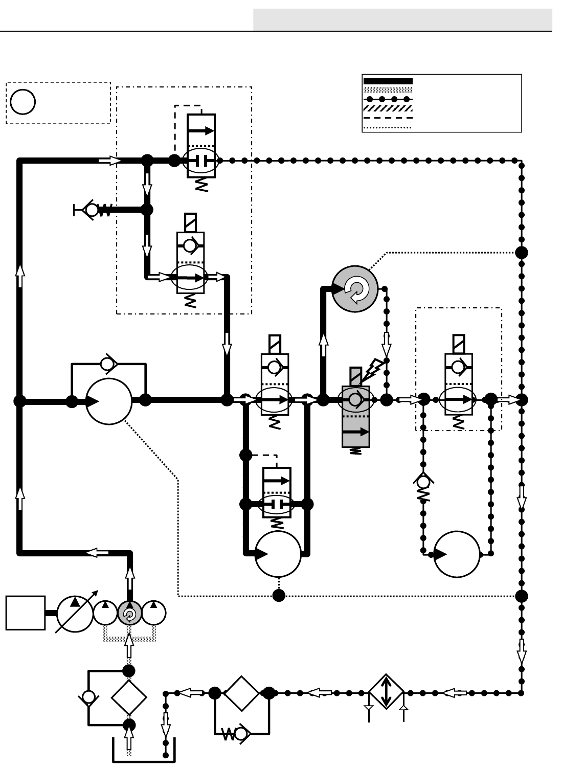
HYDRAULICS
M20/M30 9016006 - 3-2017 95
M20 / M30 Pressure Washer ON
Engine speed: High
SV1
G6
OIL
COOLER
P1 T2
SCREEN
SV9
1800 PSI
(124 BAR)
SCRUB FAN
MOTOR
OIL
FILTER
SWEEP FAN
MOTOR
Pressure / Flow Line
Return or Low Pressure Line
Active Pilot Port Line
Inactive Pilot Port Line
Case Drain Line
Suction Line
ENGINE
RV1
2500 PSI
(172.4 BAR)
35 PSI
(2.4 BAR)
M4
3 PSI
(20.7 kPa)
MAIN VALVE MANIFOLD
SOL1
PRESSURE
WASHER
MOTOR
Gray items are
energized
or activated
i
SIDE BRUSH
MOTOR
SV8
SIDE BRUSH
MANIFOLD
25 PSI
(1.7 BAR)
P3 T3
M2 T6
M20_M30 Pressure Washer On
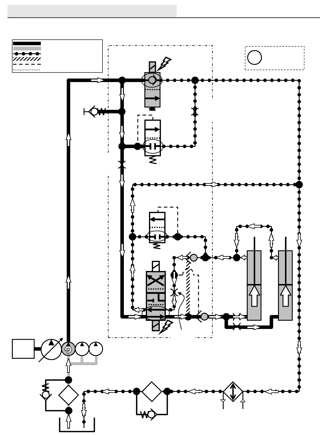
HYDRAULICS
M20/M30 9016006 - 3-2017
96
M20 / M30 Hopper Lift
Engine speed: High
SV7
G5
P2
HOPPER LIFT
ACTUATORS
T2
SCREEN
OIL
FILTER
OIL
COOLER
C12
C9
SV14
RV3
1100 PSI (75.8 BAR)
PC5
SV13
Pressure / Flow Line
Return or Low Pressure Line
Active Pilot Port Line
Inactive Pilot Port Line
Case Drain Line
Suction Line
ENGINE
Gray items are
energized
or activated
i
RV2
2500 PSI
(172.4 BAR)
35 PSI
(2.4 BAR)
ORIFICES
0.028 in
(0.71 mm)
OR3
0.140 in
(3.55 mm)
MAIN VALVE MANIFOLD
ORIFICE
0.040 in
(1.0 mm)
T1
LIFT
LIFT
PC7
OR1
0.031 in
(0.79 mm)
M20_M30 Hopper Lift
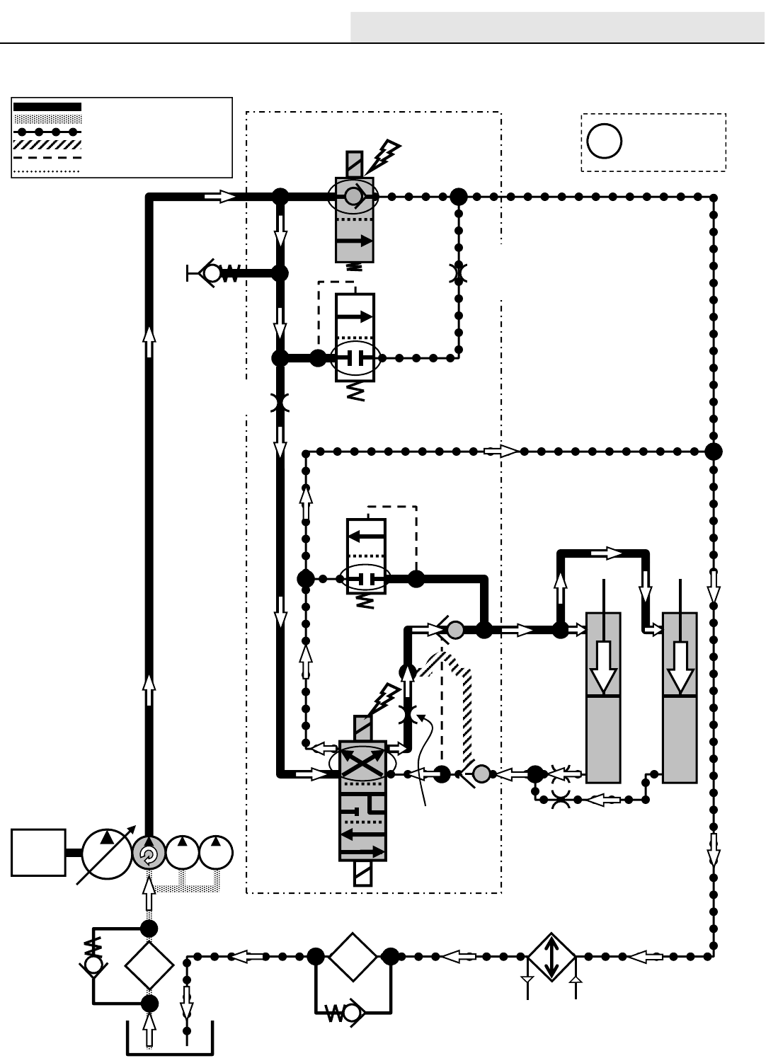
HYDRAULICS
M20/M30 9016006 - 3-2017 97
SV7
G5
P2
HOPPER LIFT
ACTUATORS
T2
SCREEN
OIL
FILTER
OIL
COOLER
C12
C9
SV14
RV3
1100 PSI (75.8 BAR)
PC5
SV13
Pressure / Flow Line
Return or Low Pressure Line
Active Pilot Port Line
Inactive Pilot Port Line
Case Drain Line
Suction Line
ENGINE
Gray items are
energized
or activated
i
RV2
2500 PSI
(172.4 BAR)
35 PSI
(2.4 BAR)
ORIFICES
0.028 in
(0.71 mm)
OR3
0.140 in
(3.55 mm)
MAIN VALVE MANIFOLD
T1
PC7
OR1
0.031 in
(0.79 mm)
M20 / M30 Hopper Lower
Engine speed: High
LOWER
LOWER
M30 ORIFICE
0.040 in
(1.0 mm)
M20 ORIFICE
0.046 in
(1.17 mm)
M20_M30 Hopper Lower
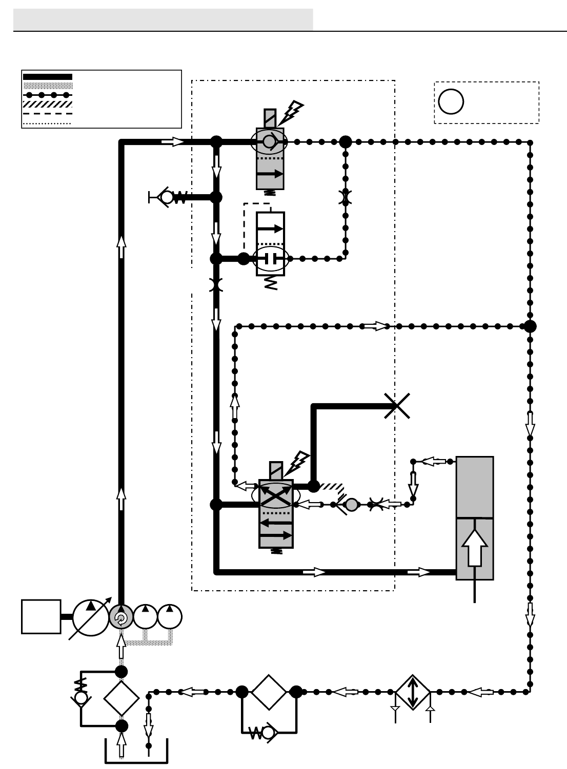
HYDRAULICS
M20/M30 9016006 - 3-2017
98
M20 / M30 Hopper Door Open
Engine speed: High
SV7
G5
P2
HOPPER DOOR
ACTUATOR
T2
SCREEN
OIL
FILTER
OIL
COOLER
T1
C11
SV15
OR2
0.040 in
(1.0 mm)
PC6
OPEN
G11
C10
Pressure / Flow Line
Return or Low Pressure Line
Active Pilot Port Line
Inactive Pilot Port Line
Case Drain Line
Suction Line
ENGINE
Gray items are
energized
or activated
i
RV2
2500 PSI
(172.4 BAR)
35 PSI
(2.4 BAR)
OR3
0.140 in
(3.55 mm)
MAIN VALVE MANIFOLD
M30 ORIFICE
0.040 in
(1.0 mm)
M20 ORIFICE
0.046 in
(1.17 mm)
RV2 Opens when
the Hopper Door
Actuator reaches
the End of Stroke.
M20_M30 Hopper Door Open
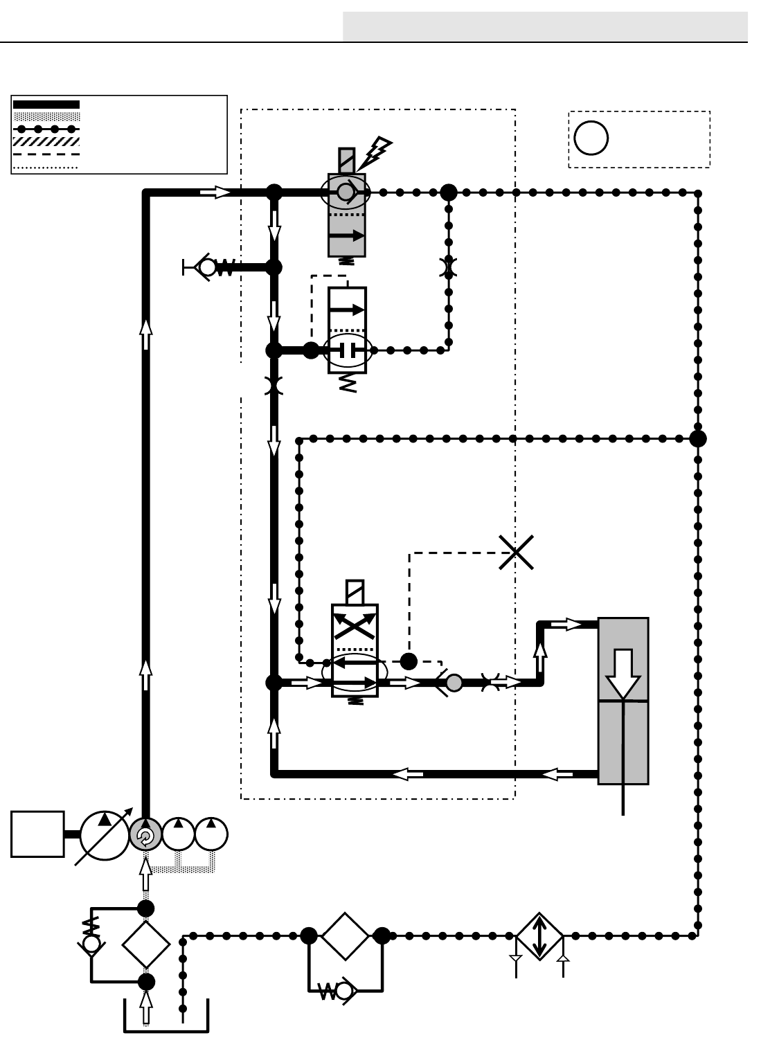
HYDRAULICS
M20/M30 9016006 - 3-2017 99
M20 / M30 Hopper Door Close
Engine speed: High
SV7
G5
P2
HOPPER DOOR
ACTUATOR
SCREEN
OIL
FILTER
OIL
COOLER
C11
SV15
PC6
G11
C10
CLOSE
Pressure / Flow Line
Return or Low Pressure Line
Active Pilot Port Line
Inactive Pilot Port Line
Case Drain Line
Suction Line
ENGINE
Gray items are
energized
or activated
i
RV2
2500 PSI
(172.4 BAR)
35 PSI
(2.4 BAR)
OR2
0.040 in
(1.0 mm)
OR3
0.140 in
(3.55 mm)
MAIN VALVE MANIFOLD
T1
T2
M30 ORIFICE
0.040 in
(1.0 mm)
M20 ORIFICE
0.046 in
(1.17 mm)
RV2 Opens when
the Hopper Door
Actuator reaches
the End of Stroke.
M20_M30 Hopper Door Close
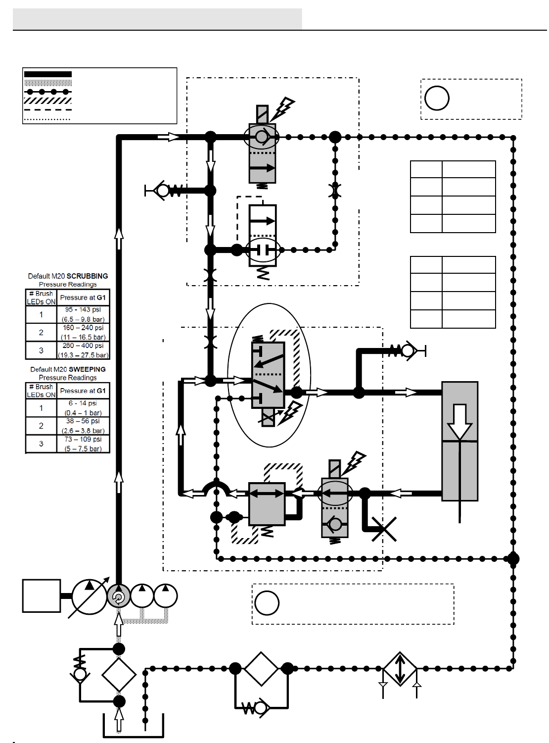
HYDRAULICS
M20/M30 9016006 - 3-2017
100
M20 / M30 Side Brush Lower
Engine speed: High
SV7
G5
P2
SIDE BRUSH
LIFT ACTUATOR
T2
SCREEN
OIL
FILTER
OIL
COOLER
P7
P4
G13
LOWER
SV10
SV11
PR1A
400 PSI
(27.6 BAR)
G8
C6
C8
T4
*PWM*
SIDE BRUSH
MANIFOLD
Pressure / Flow Line
Return or Low Pressure Line
Active Pilot Port Line
Inactive Pilot Port Line
Case Drain Line
Suction Line
ENGINE
Gray items are
energized
or activated
i
RV2
2500 PSI
(172.4 BAR)
35 PSI
(2.4 BAR)
ORIFICE
0.055 in
(1.4 mm)
OR3
0.140 in
(3.55 mm)
MAIN VALVE MANIFOLD
The “# Brush Pressure LEDs ON”
are the Touch Panel LED indicators
for Brush down pressure
i
Default M30SCRUBBING
Pressure Readings
# Brush
LEDs ON Pressure at G13
1320 - 370 psi
(22 – 25.5 bar)
2410 – 450 psi
(28.3 – 31 bar)
3510 – 560 psi
(35.1 – 38.6 bar)
Default M30 SWEEPING
Pressure Readings
# Brush
LEDs ON Pressure at G13
1275 - 340 psi
(18.9 – 23.4 bar)
2310 – 370 psi
(21.3 – 25.5 bar)
3400 – 480 psi
(27.5 – 33 bar)
M30 ORIFICE
0.040 in
(1.0 mm)
M20 ORIFICE
0.046 in
(1.17 mm)
RV2 Opens when
the Side Brush Lift
Actuator reaches
the End of Stroke.
M20_M30 Side Brush Lower
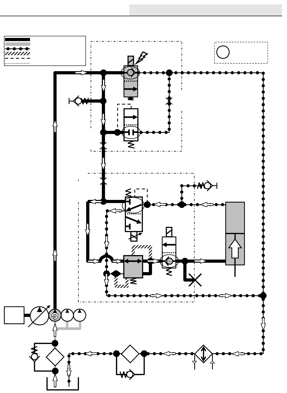
HYDRAULICS
M20/M30 9016006 - 3-2017 101
M20 / M30 Side Brush Lift
Engine speed: High
SV7
G5
P2
SIDE BRUSH
LIFT ACTUATOR
T2
SCREEN
OIL
FILTER
OIL
COOLER
P7
P4
SIDE BRUSH MANIFOLD G13
SV11
LIFT
SV10
C6
C8
Pressure / Flow Line
Return or Low Pressure Line
Active Pilot Port Line
Inactive Pilot Port Line
Case Drain Line
Suction Line
ENGINE
Gray items are
energized
or activated
i
RV2
2500 PSI
(172.4 BAR)
35 PSI
(2.4 BAR)
ORIFICE
0.055 in
(1.4 mm)
OR3
0.140 in
(3.55 mm)
MAIN VALVE MANIFOLD
PR1A
400 PSI
(27.6 BAR)
G8
T4
M30 ORIFICE
0.040 in
(1.0 mm)
M20 ORIFICE
0.046 in
(1.17 mm)
M20_M30 Side Brush Lift
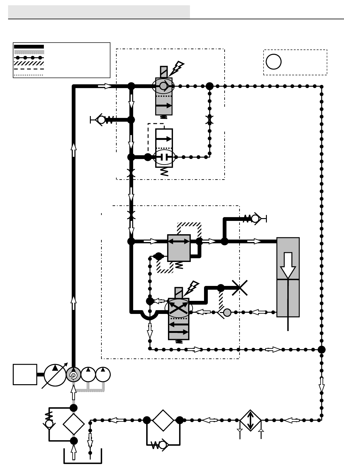
HYDRAULICS
M20/M30 9016006 - 3-2017
102
M20 / M30 Side Brush Extend
Engine speed: High
SV7
G5
P2
SIDE BRUSH
EXTEND ACTUATOR
T2
SCREEN
OIL
FILTER
OIL
COOLER
P7
P4
SIDE BRUSH MANIFOLD G7
EXTEND
C7
C5
T4
SV12
PC8
G10
Pressure / Flow Line
Return or Low Pressure Line
Active Pilot Port Line
Inactive Pilot Port Line
Case Drain Line
Suction Line
ENGINE
Gray items are
energized
or activated
i
RV2
2500 PSI
(172.4 BAR)
35 PSI
(2.4 BAR)
ORIFICE
0.055 in
(1.4 mm)
PR1B
100 PSI
(6.9 BAR)
OR3
0.140 in
(3.55 mm)
MAIN VALVE MANIFOLD
RV2 Opens when
the Side Brush
Extend Actuator
reaches the End
of Stroke.
M30 ORIFICE
0.040 in
(1.0 mm)
M20 ORIFICE
0.046 in
(1.17 mm)
M20_M30 Side Brush Extend
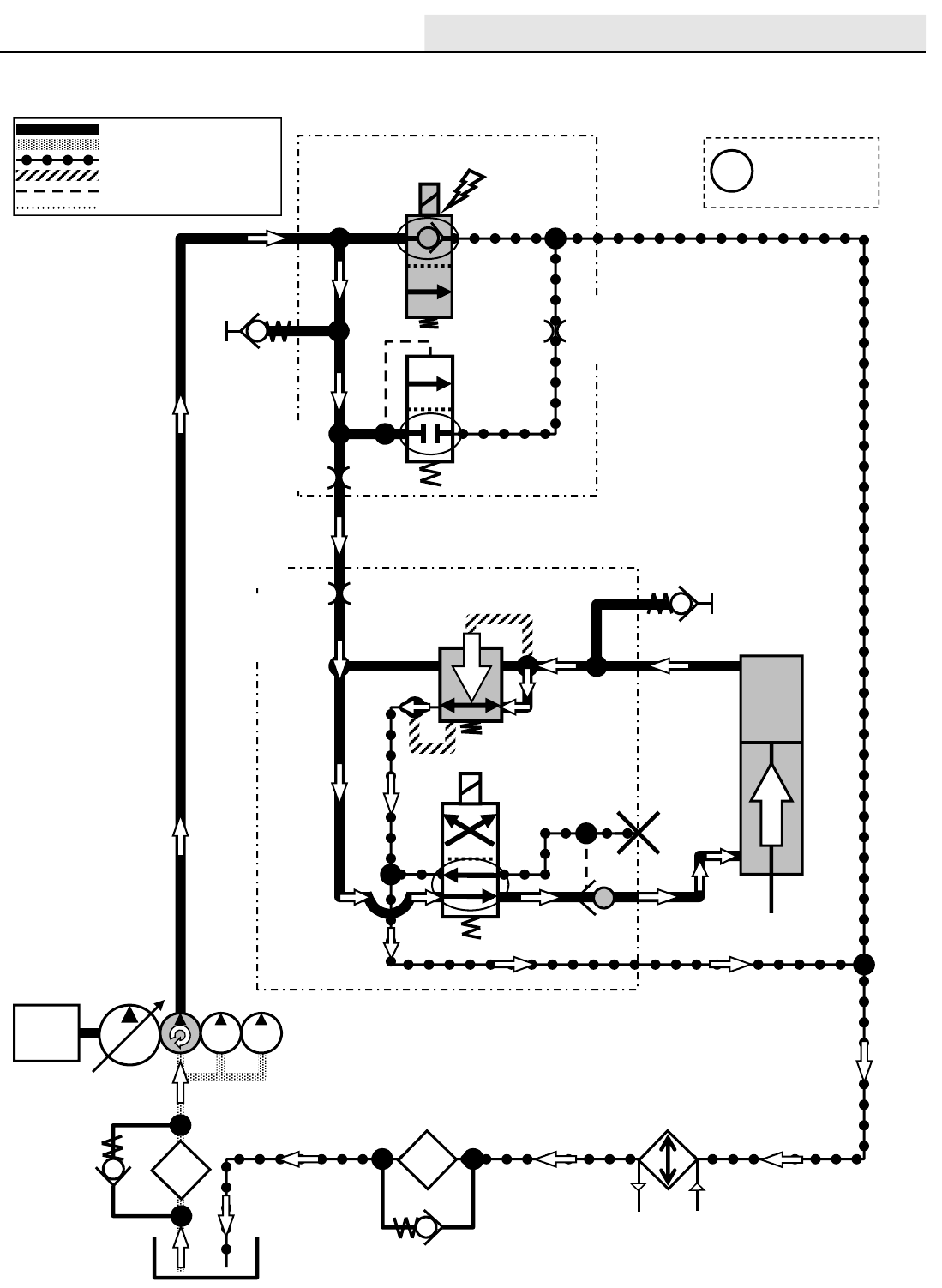
HYDRAULICS
M20/M30 9016006 - 3-2017 103
M20 / M30 Side Brush Retract
Engine speed: High
SV7
G5
P2
SIDE BRUSH
EXTEND ACTUATOR
T2
SCREEN
OIL
FILTER
OIL
COOLER
P7
P4
SIDE BRUSH MANIFOLD G7
C7
C5
T4
SV12
PC8
G10
100 PSI
RETRACT
Pressure / Flow Line
Return or Low Pressure Line
Active Pilot Port Line
Inactive Pilot Port Line
Case Drain Line
Suction Line
ENGINE
Gray items are
energized
or activated
i
RV2
2500 PSI
(172.4 BAR)
35 PSI
(2.4 BAR)
ORIFICE
0.055 in
(1.4 mm)
OR3
0.140 in
(3.55 mm)
MAIN VALVE MANIFOLD
PR1B
100 PSI
(6.9 BAR)
RV2 Opens when
the Side Brush
Extend Actuator
reaches the End
of Stroke.
M30 ORIFICE
0.040 in
(1.0 mm)
M20 ORIFICE
0.046 in
(1.17 mm)
M20_M30 Side Brush Retract
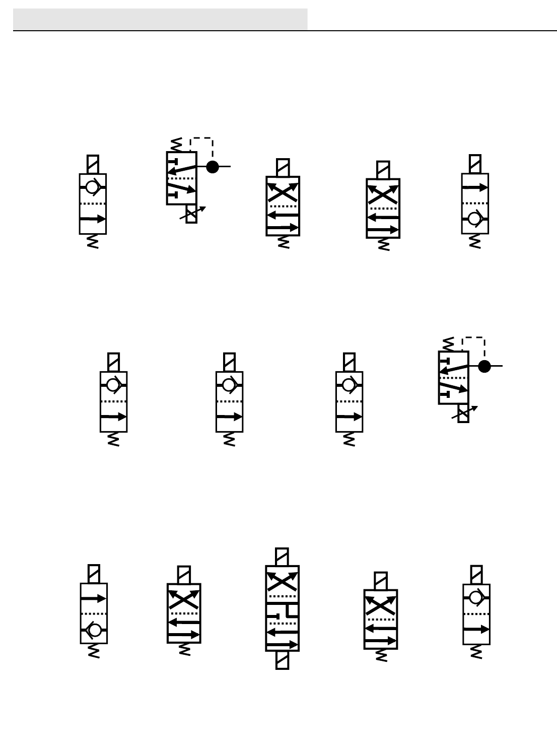
HYDRAULICS
M20/M30 9016006 - 3-2017
104
Hydraulic Solenoid Valve Details
SV1
SV2
*PWM*
SV3 SV4 SV6
SV7 SV8 SV9
SV10
*PWM*
SV11 SV12
SV14
SV13
SV15
Scrub Fan Motor Main Brushes
Lift/Lower Actuator
Main Brushes
Lift/Lower Actuator
Side & Rear
Squeegees
Lift/Lower Actuator
Main Brush Motors
Enable Valve Side Brush Motor Sweep Fan Motor
Side Brush
Lift/Lower Actuator
Side Brush
Lift/Lower Actuator
Side Brush
Extend/Retract
Actuator
Hopper
Lift/Lower Actuator
Hopper Door
Actuator
Pressure Washer
Motor
SOL1
Hydraulic Solenoid Valve Details
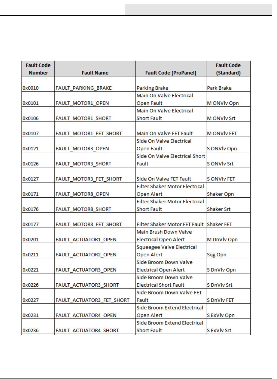
FAULT CODES
M20/M30 9016006 - 3-2017 105
M20_M30 Fault Codes
(ProPanel and Standard Panel)
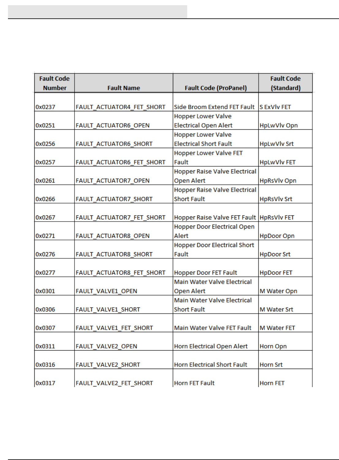
FAULT CODES
M20/M30 9016006 - 3-2017
106
M20_M30 Fault Codes
(ProPanel and Standard Panel)
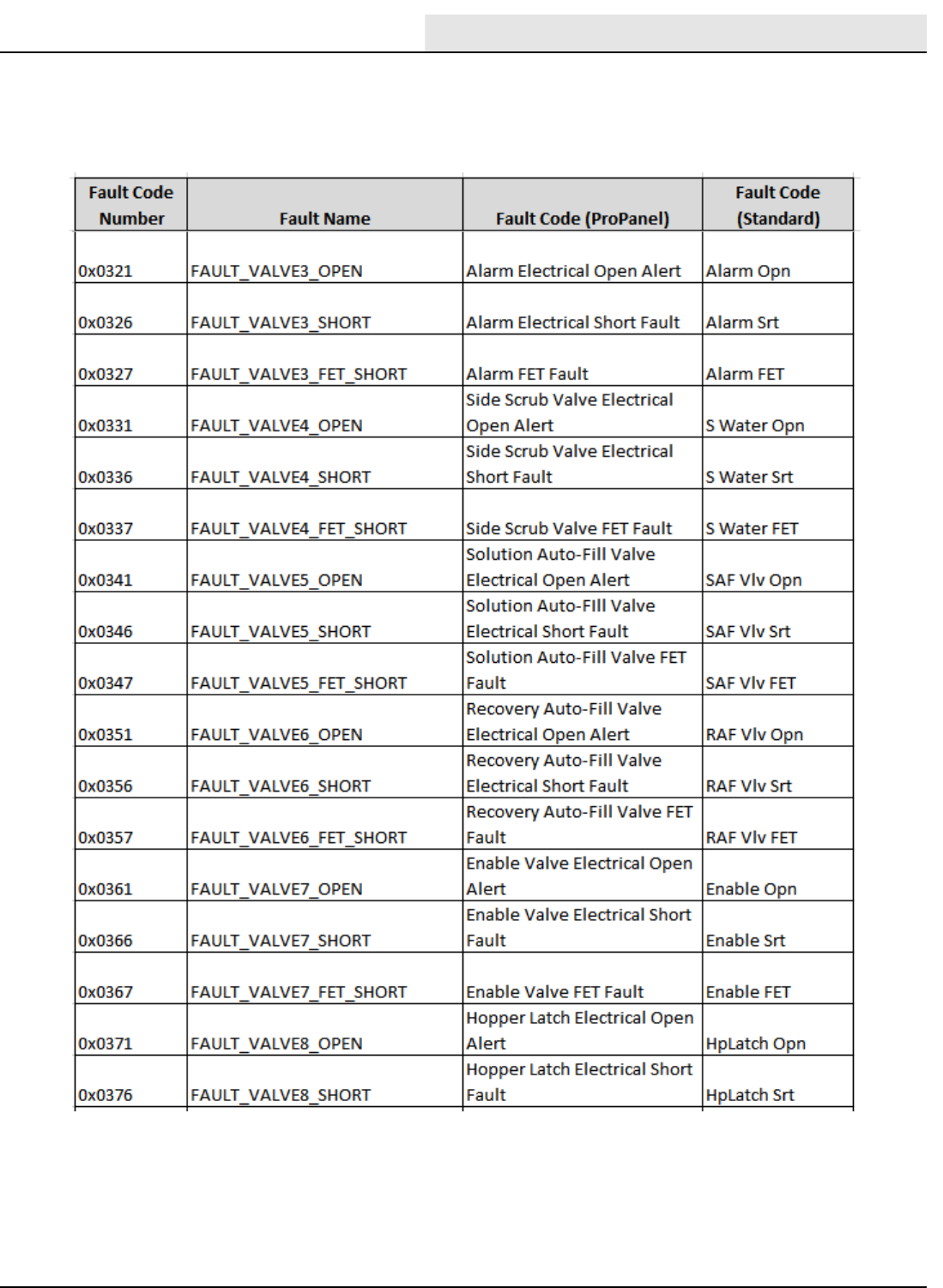
FAULT CODES
M20/M30 9016006 - 3-2017 107
M20_M30 Fault Codes
(ProPanel and Standard Panel)
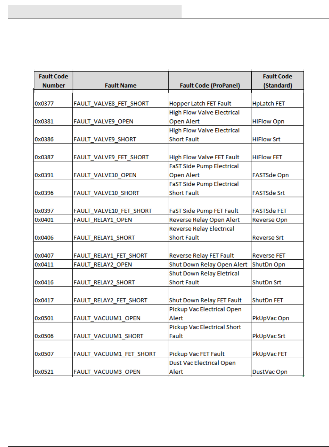
FAULT CODES
M20/M30 9016006 - 3-2017
108
M20_M30 Fault Codes
(ProPanel and Standard Panel)
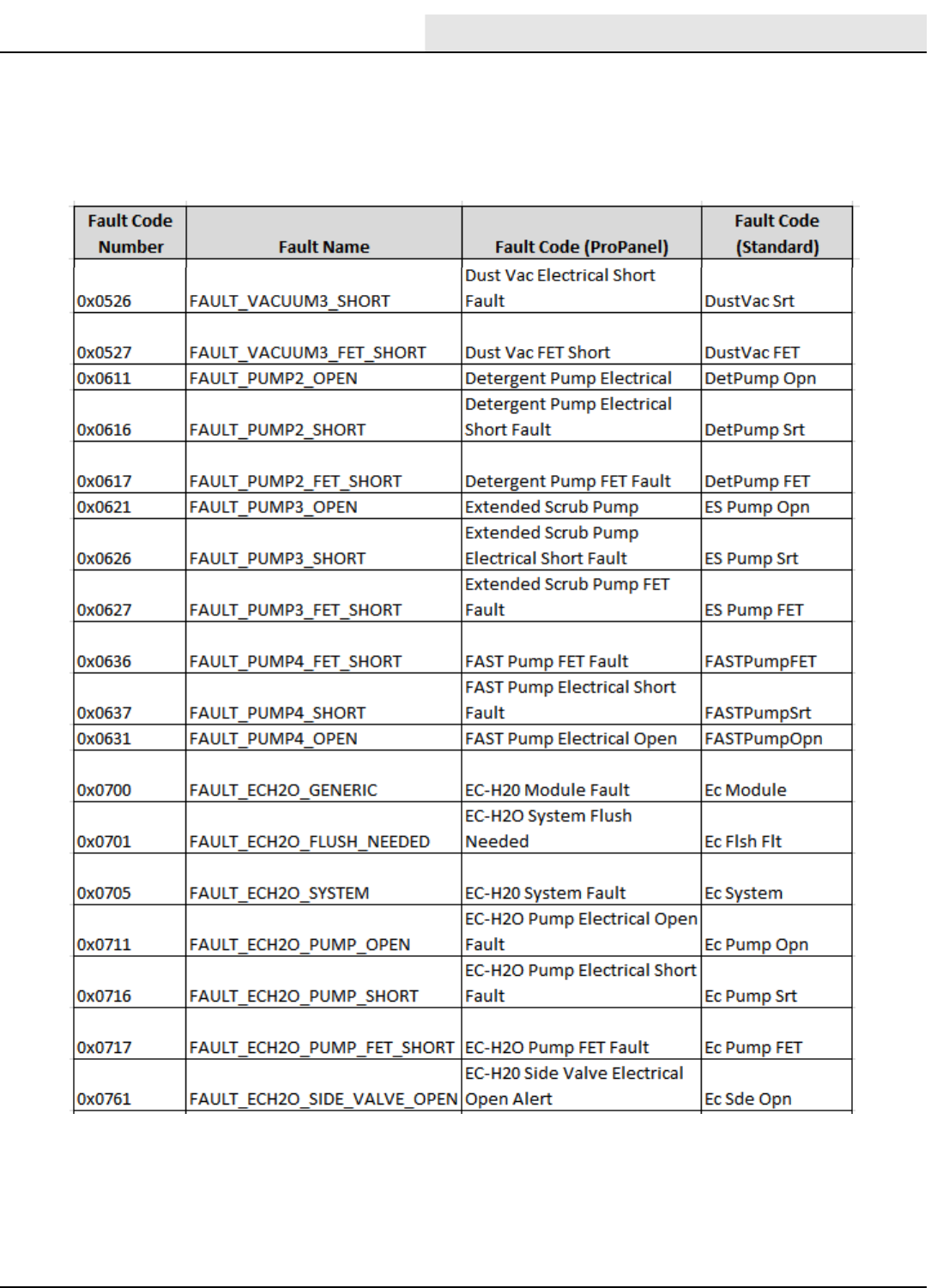
FAULT CODES
M20/M30 9016006 - 3-2017 109
M20_M30 Fault Codes
(ProPanel and Standard Panel)
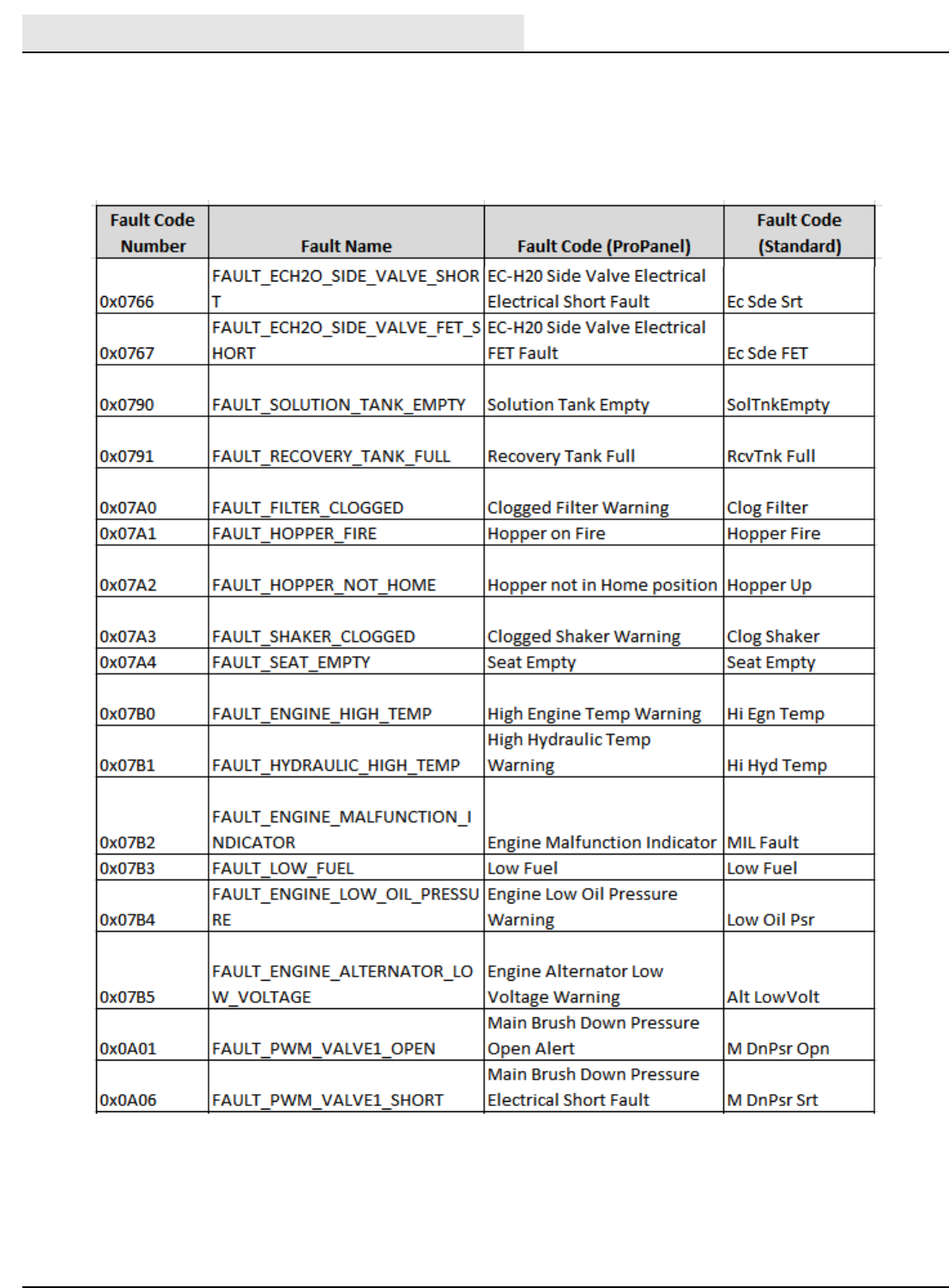
FAULT CODES
M20/M30 9016006 - 3-2017
110
M20_M30 Fault Codes
(ProPanel and Standard Panel)
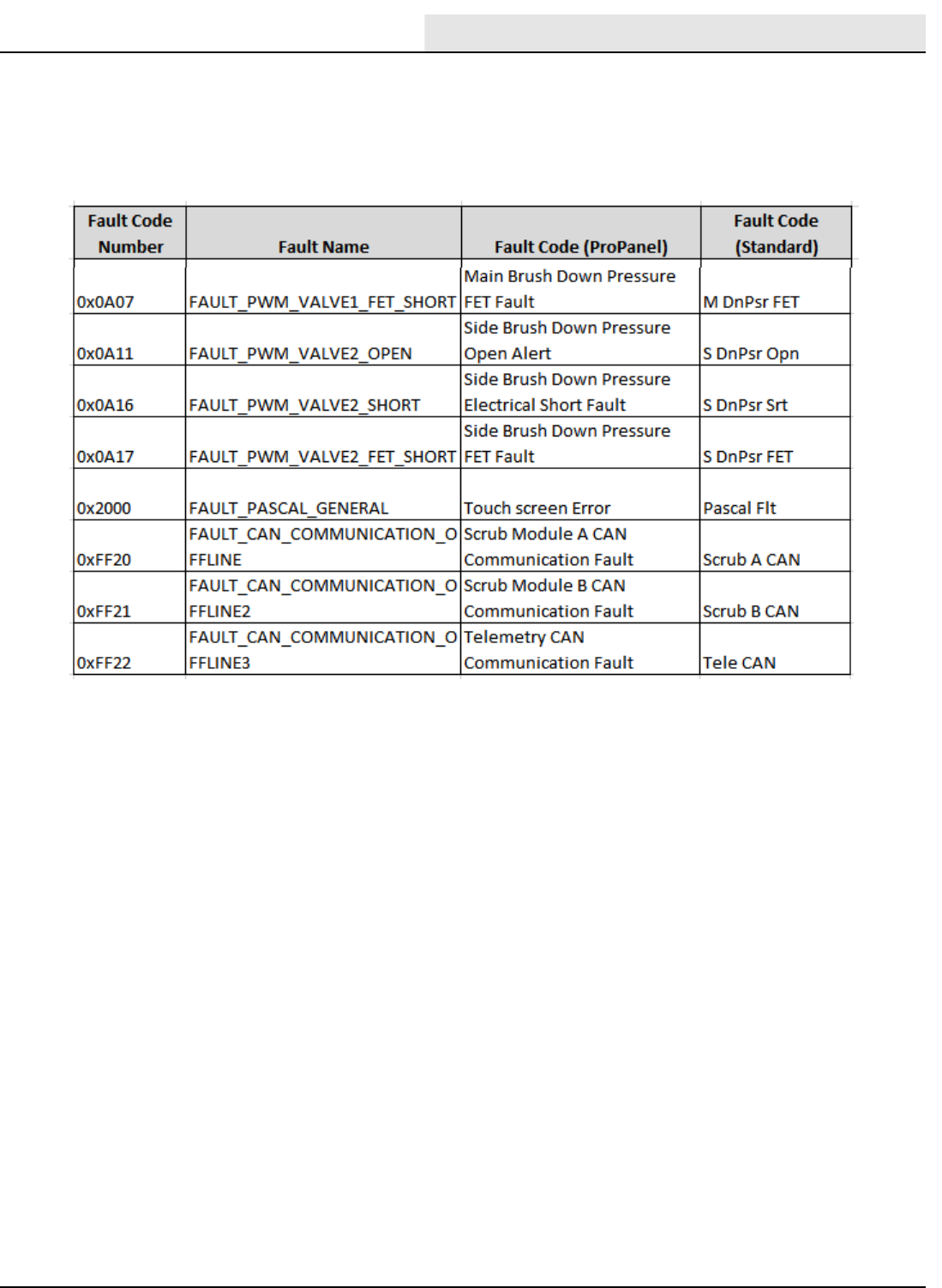
FAULT CODES
M20/M30 9016006 - 3-2017 111
M20_M30 Fault Codes
(ProPanel and Standard Panel)
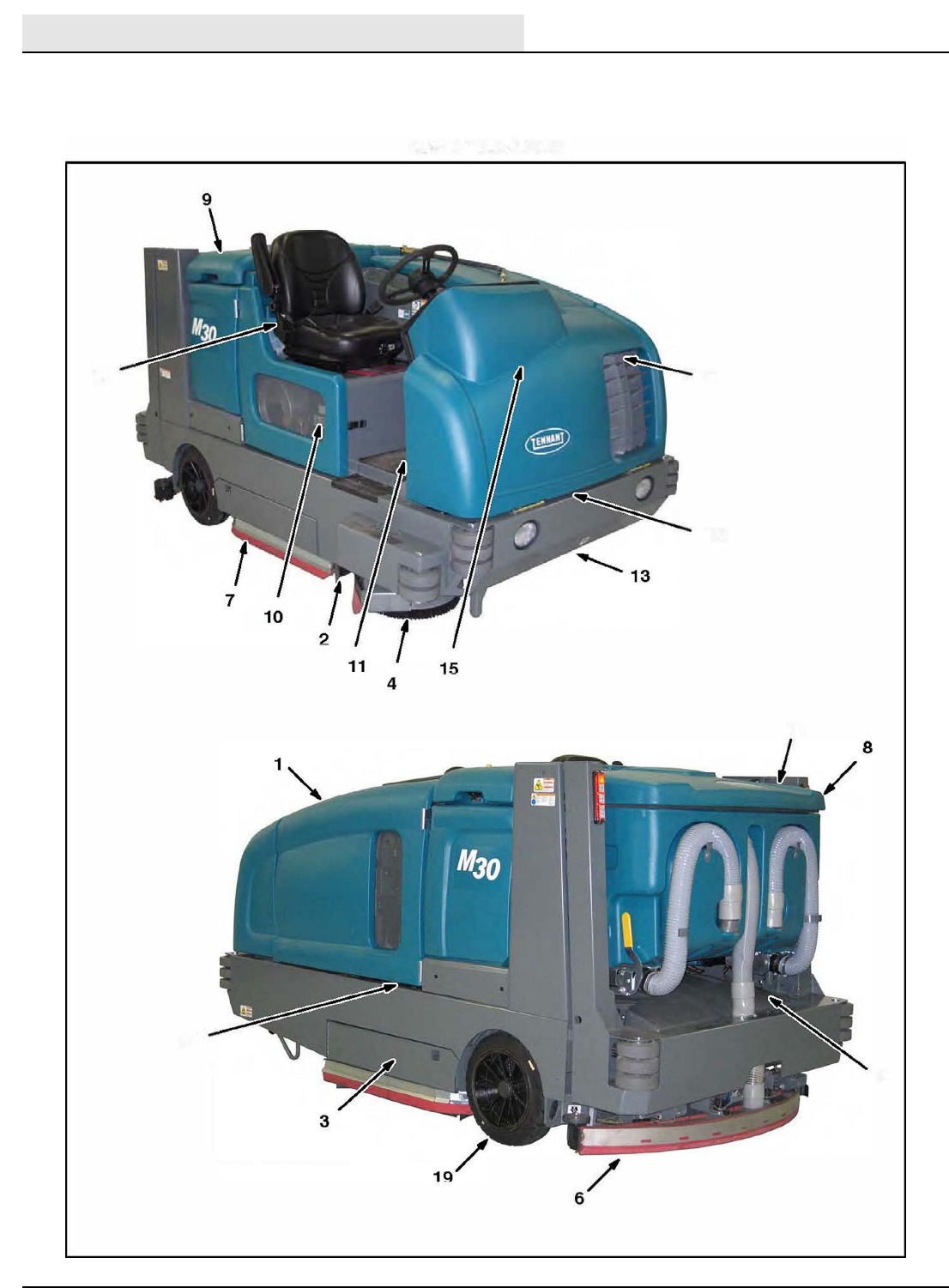
MAINTENANCE
M20/M30 9016006 - 3-2017
112
MAINTENANCE
16 18
12
14
17
5
M Series Maintenance
MAINTENANCE
M20/M30 9016006 - 3-2017 113
Person
Resp.
0
0
10
° °
-
MAINTENANCE
M20/M30 9016006 - 3-2017
114
Person
Resp.
10 *
10 *
*
° °
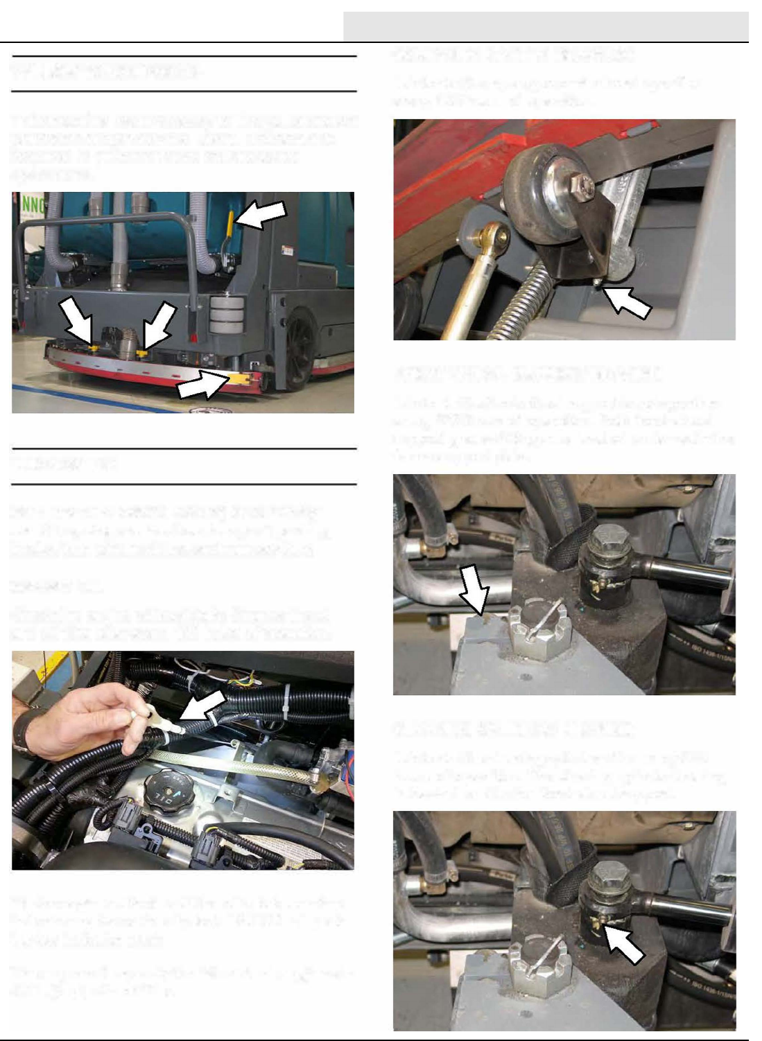
MAINTENANCE
M20/M30 9016006 - 3-2017 115
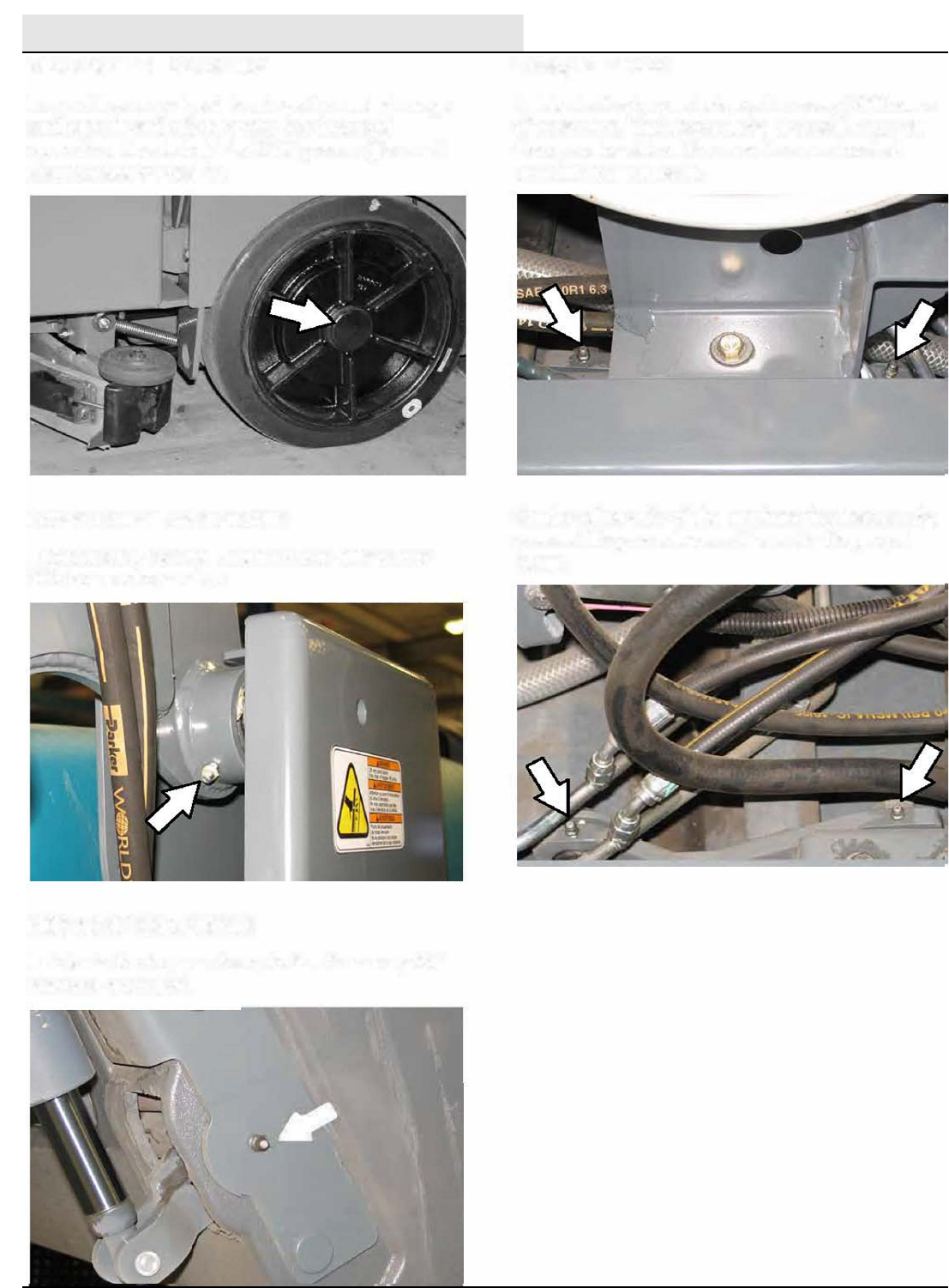
MAINTENANCE
M20/M30 9016006 - 3-2017
116
.
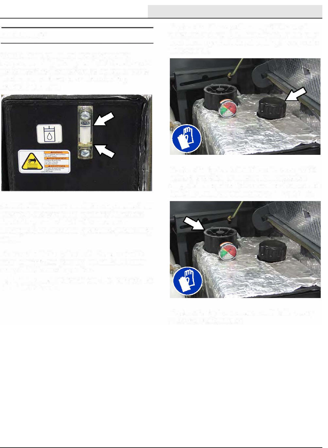
MAINTENANCE
M20/M30 9016006 - 3-2017 117
A
BOO
° °
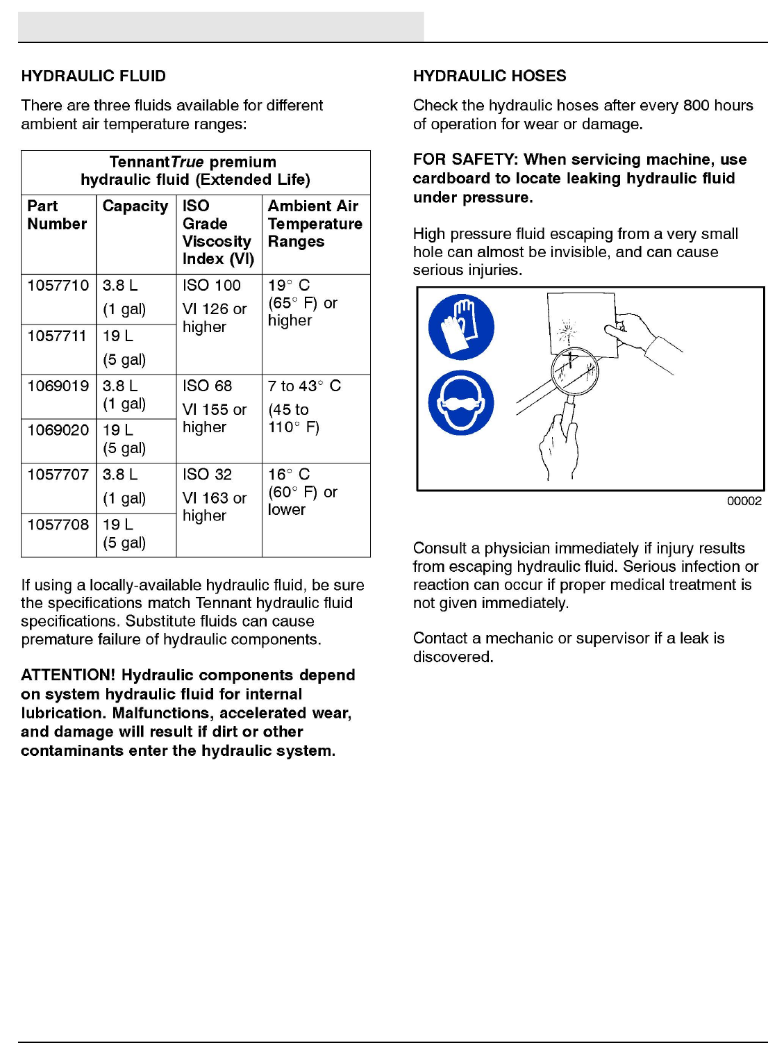
MAINTENANCE
M20/M30 9016006 - 3-2017
118
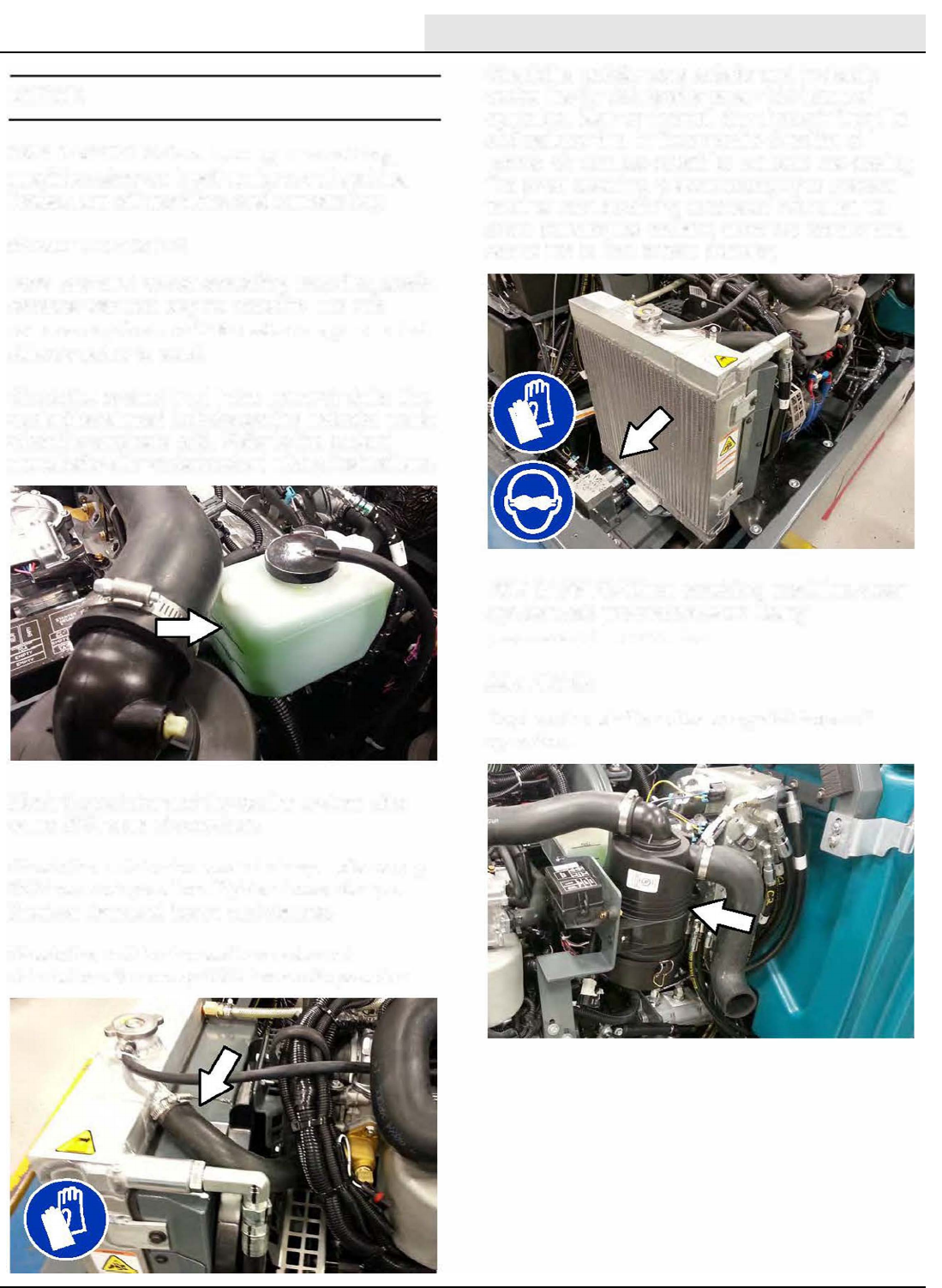
MAINTENANCE
M20/M30 9016006 - 3-2017 119
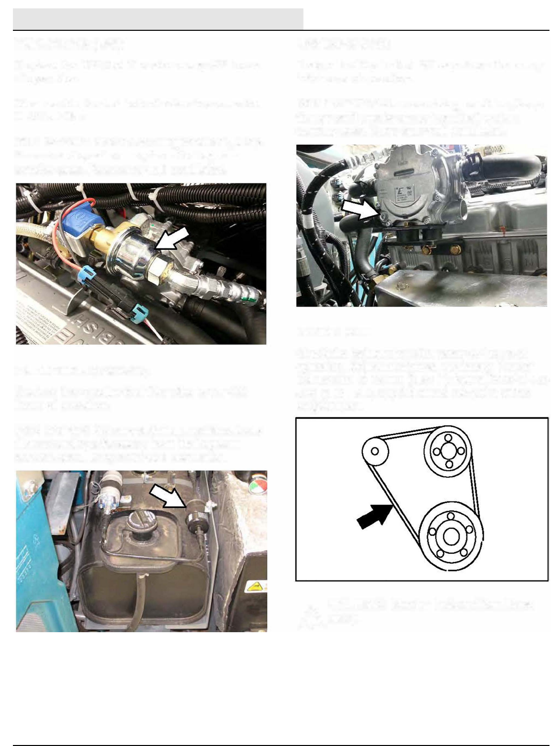
MAINTENANCE
M20/M30 9016006 - 3-2017
120
A
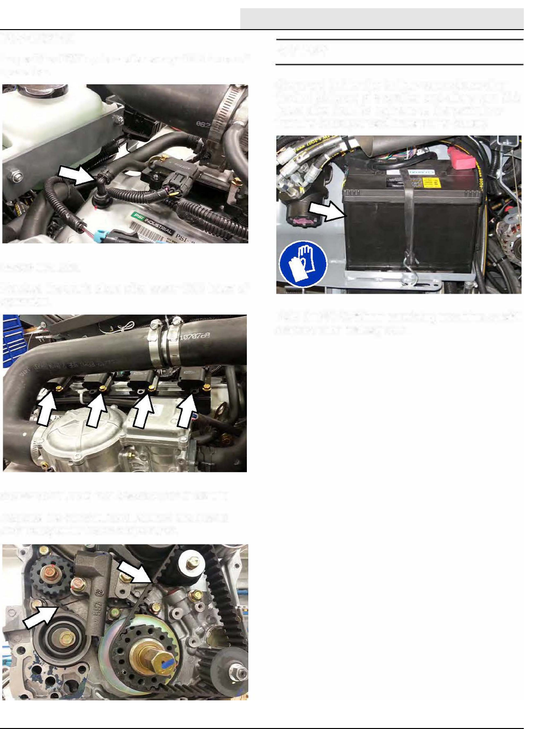
MAINTENANCE
M20/M30 9016006 - 3-2017 121
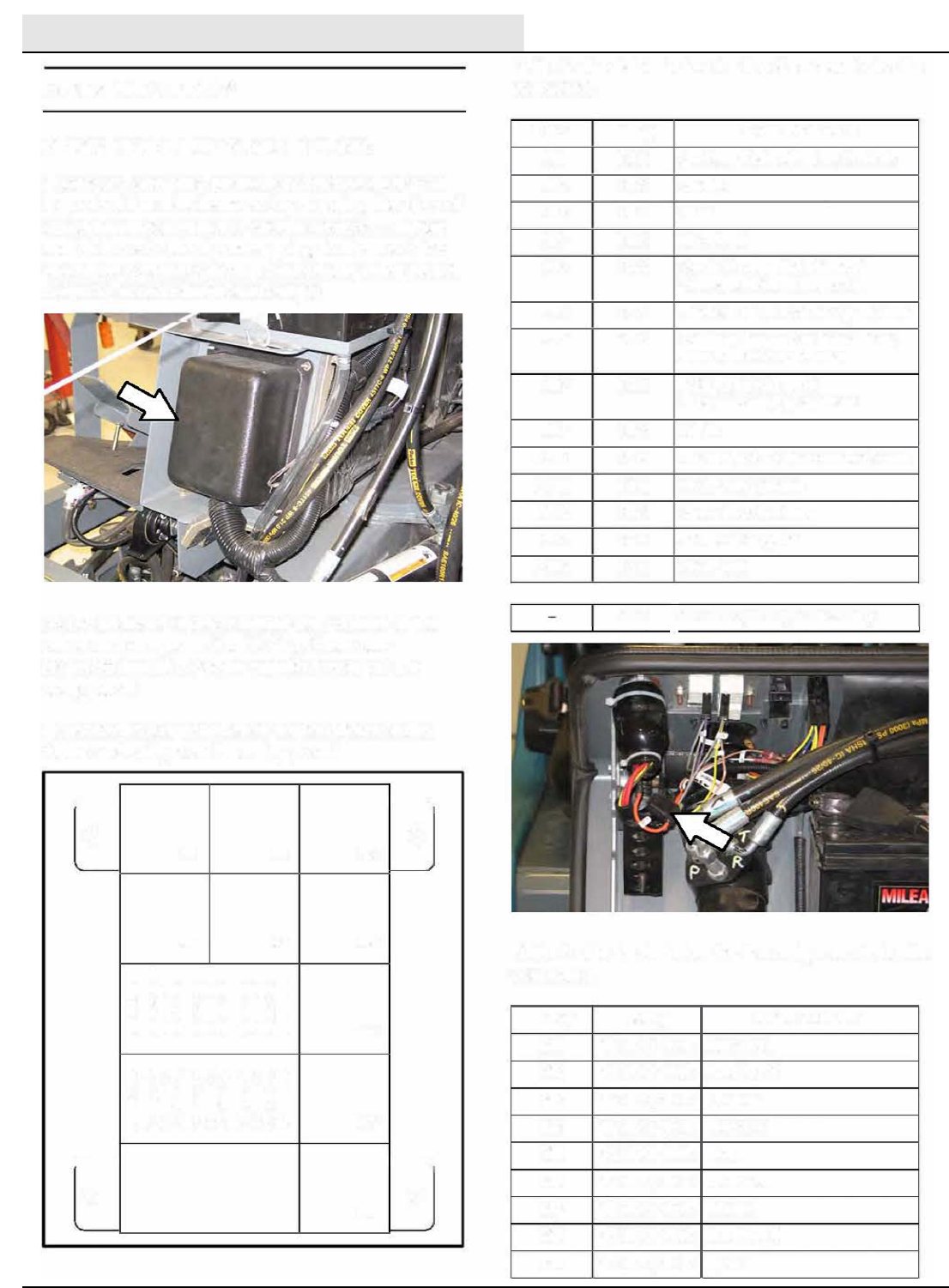
MAINTENANCE
M20/M30 9016006 - 3-2017
122
a
�
Ml M3 M9
�2 M4 M5
MG
M7
�
8
ec-H20
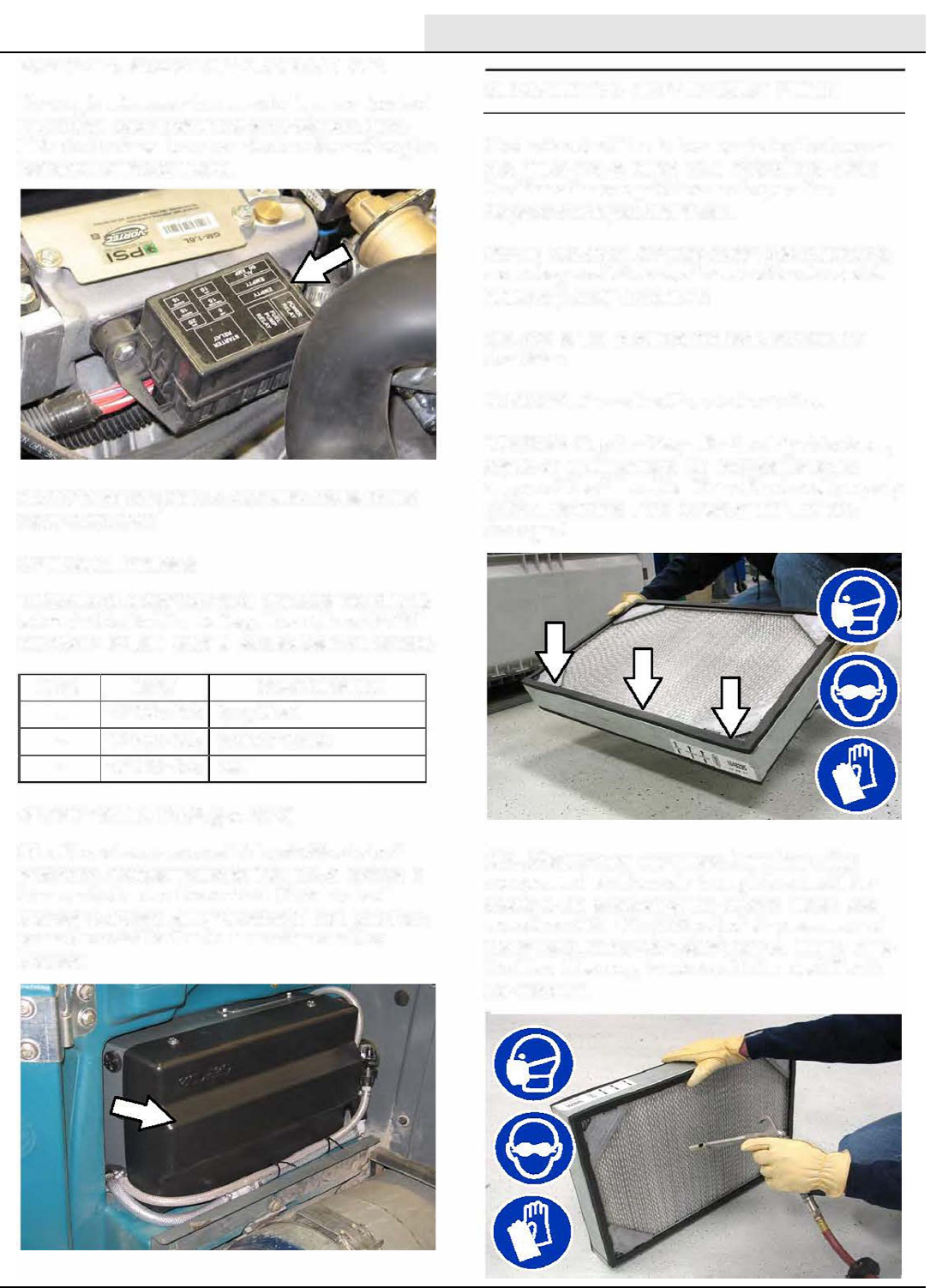
MAINTENANCE
M20/M30 9016006 - 3-2017 123
se
(ec-
Do not damage the
edges of the filter.
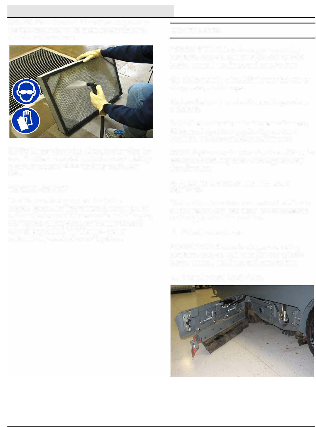
MAINTENANCE
M20/M30 9016006 - 3-2017
124
is
is
Do Not
sets
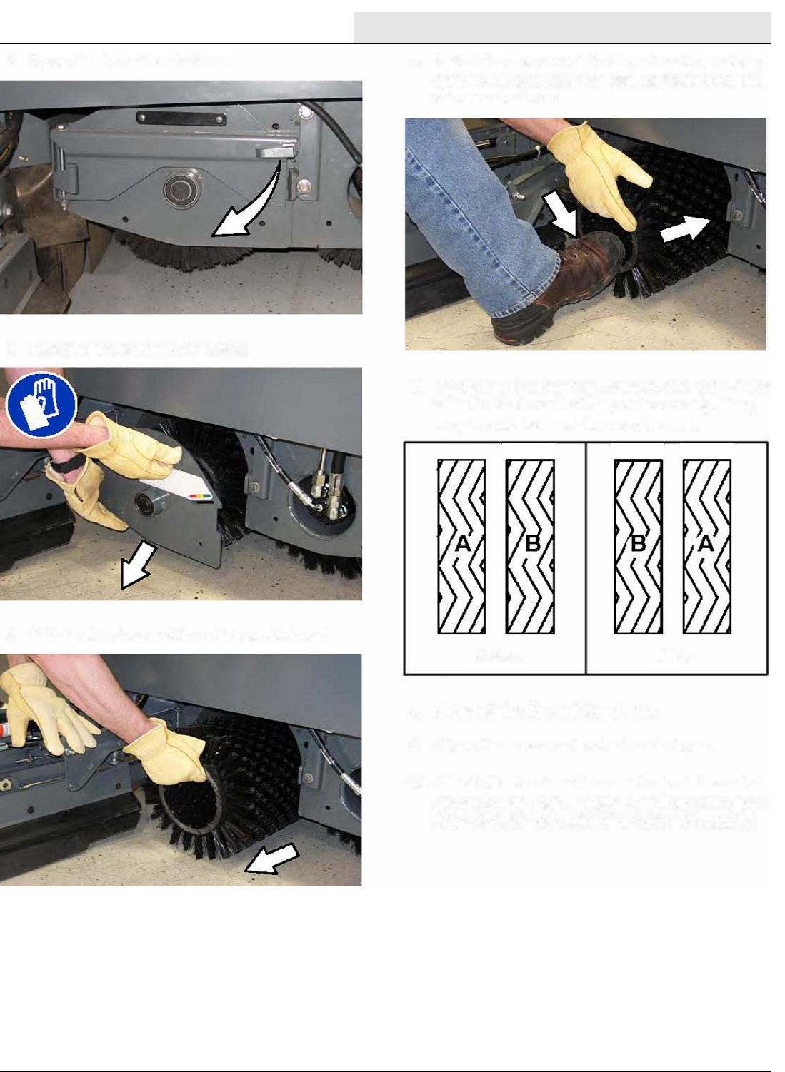
MAINTENANCE
M20/M30 9016006 - 3-2017 125
MA
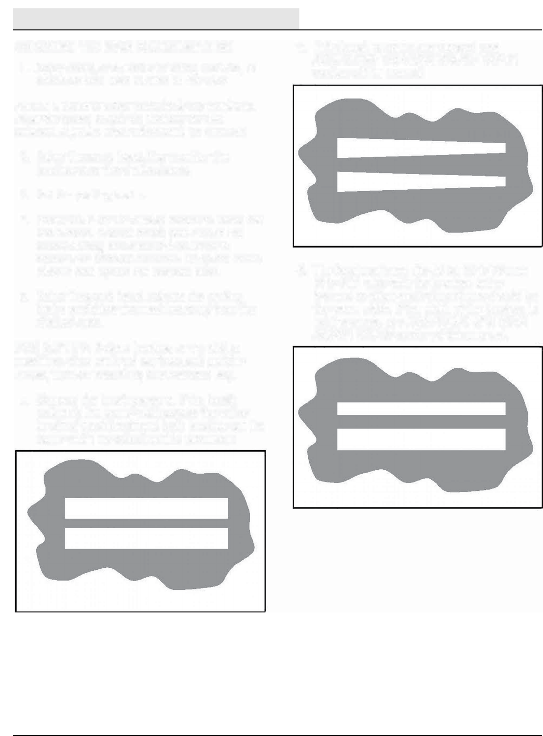
MAINTENANCE
M20/M30 9016006 - 3-2017
126
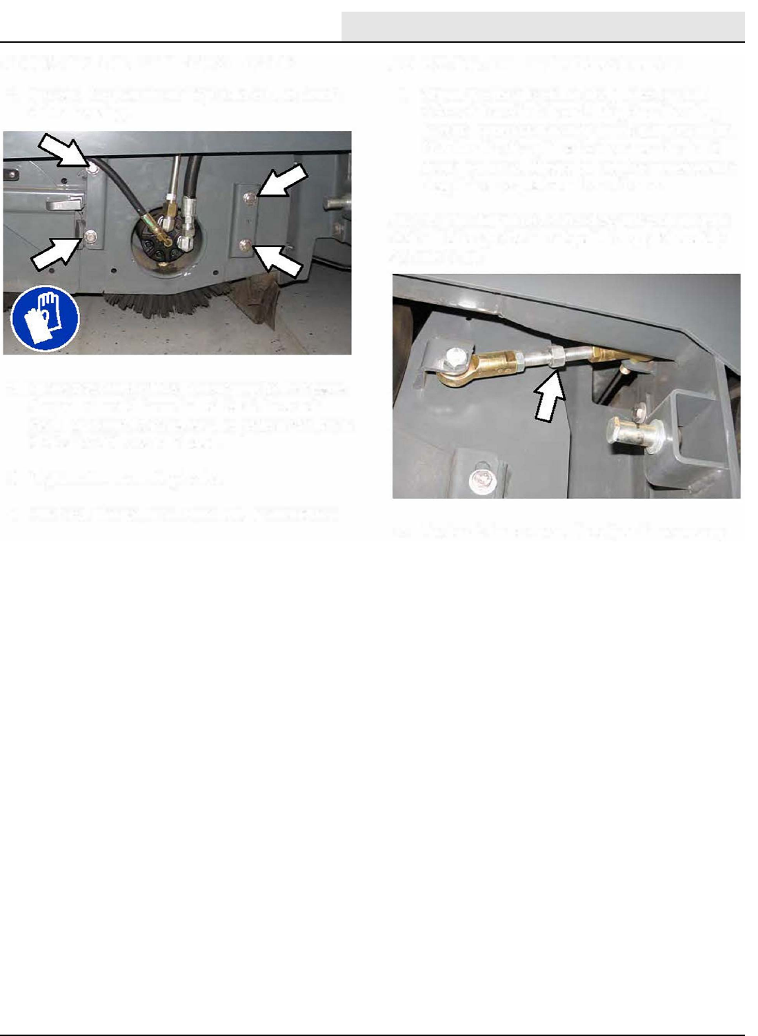
MAINTENANCE
M20/M30 9016006 - 3-2017 127
ADJUSTING THE MAIN BRUSH TAPER
ADJUSTING THE MAIN BRUSH WIDTH
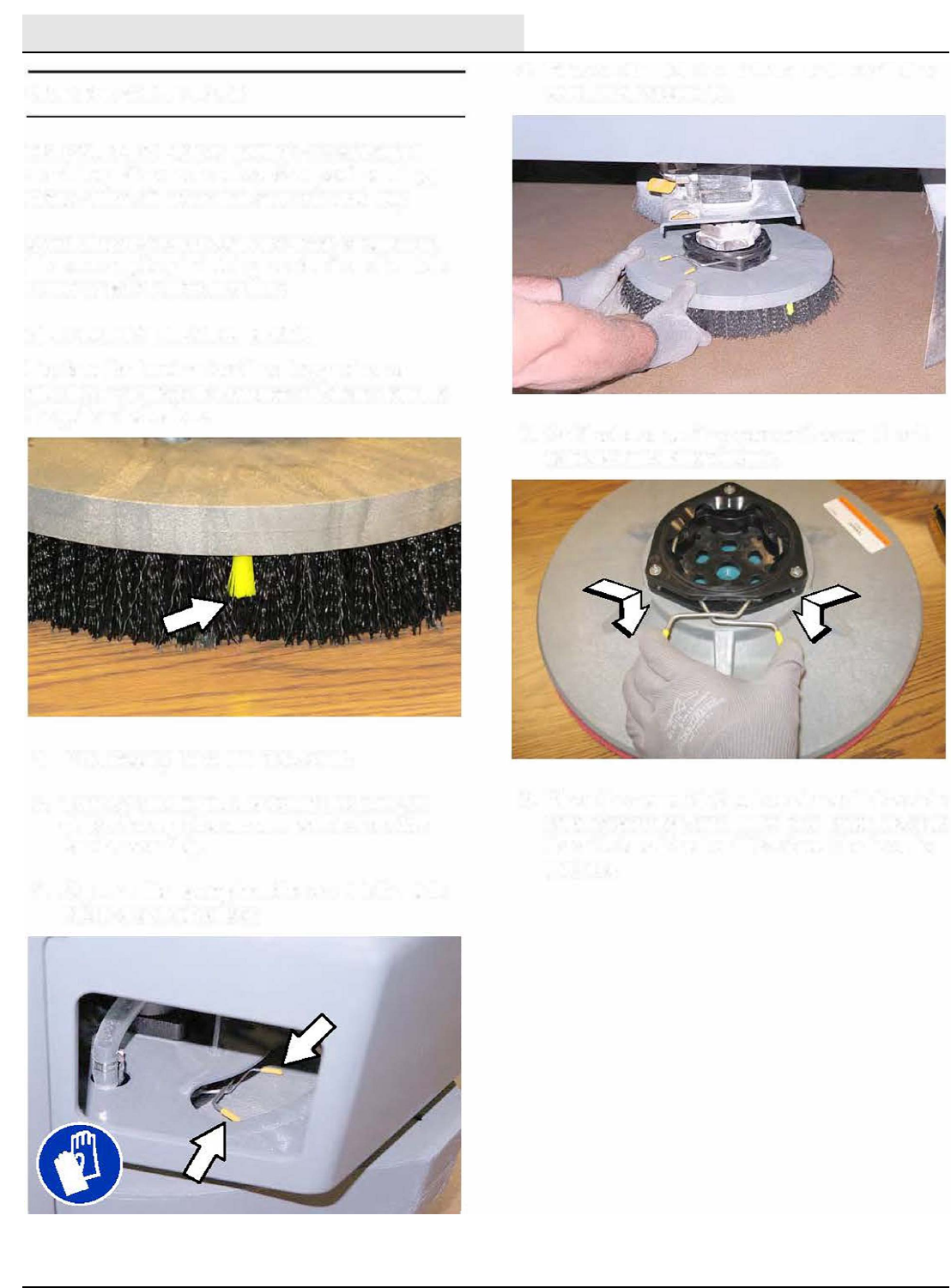
MAINTENANCE
M20/M30 9016006 - 3-2017
128
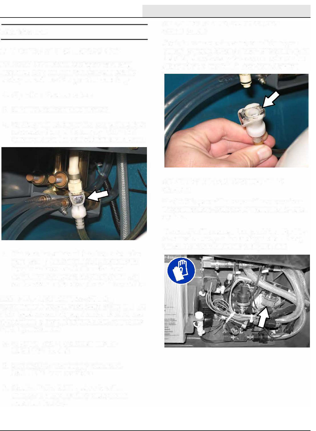
MAINTENANCE
M20/M30 9016006 - 3-2017 129
t
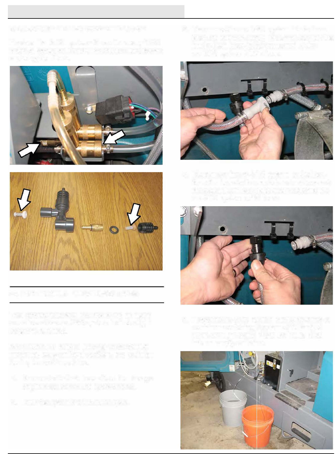
MAINTENANCE
M20/M30 9016006 - 3-2017
130
ec-H20
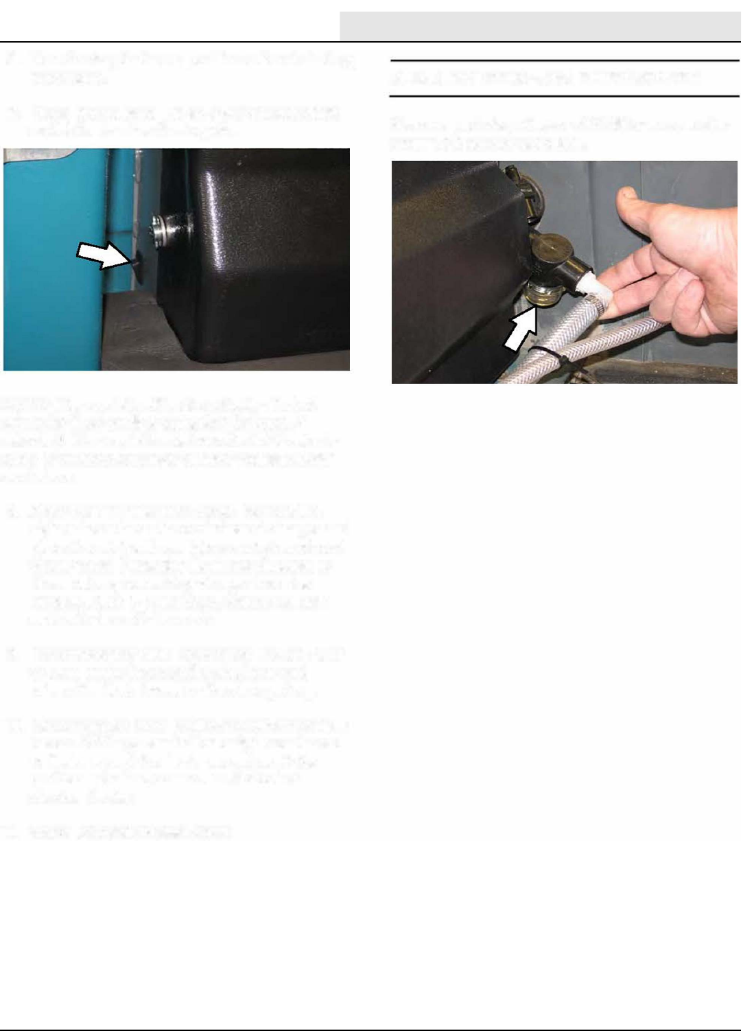
MAINTENANCE
M20/M30 9016006 - 3-2017 131
o.
-H20
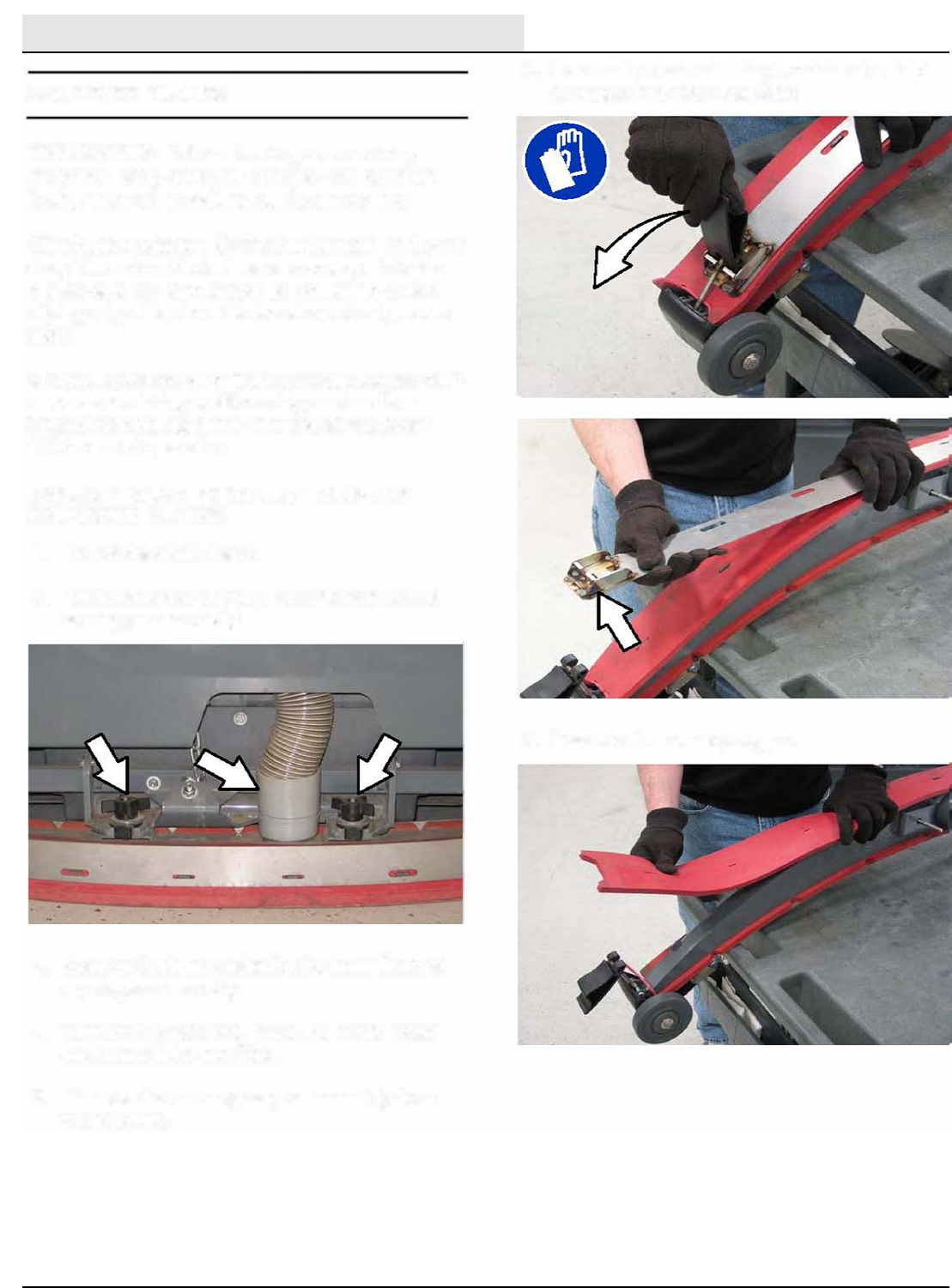
MAINTENANCE
M20/M30 9016006 - 3-2017
132
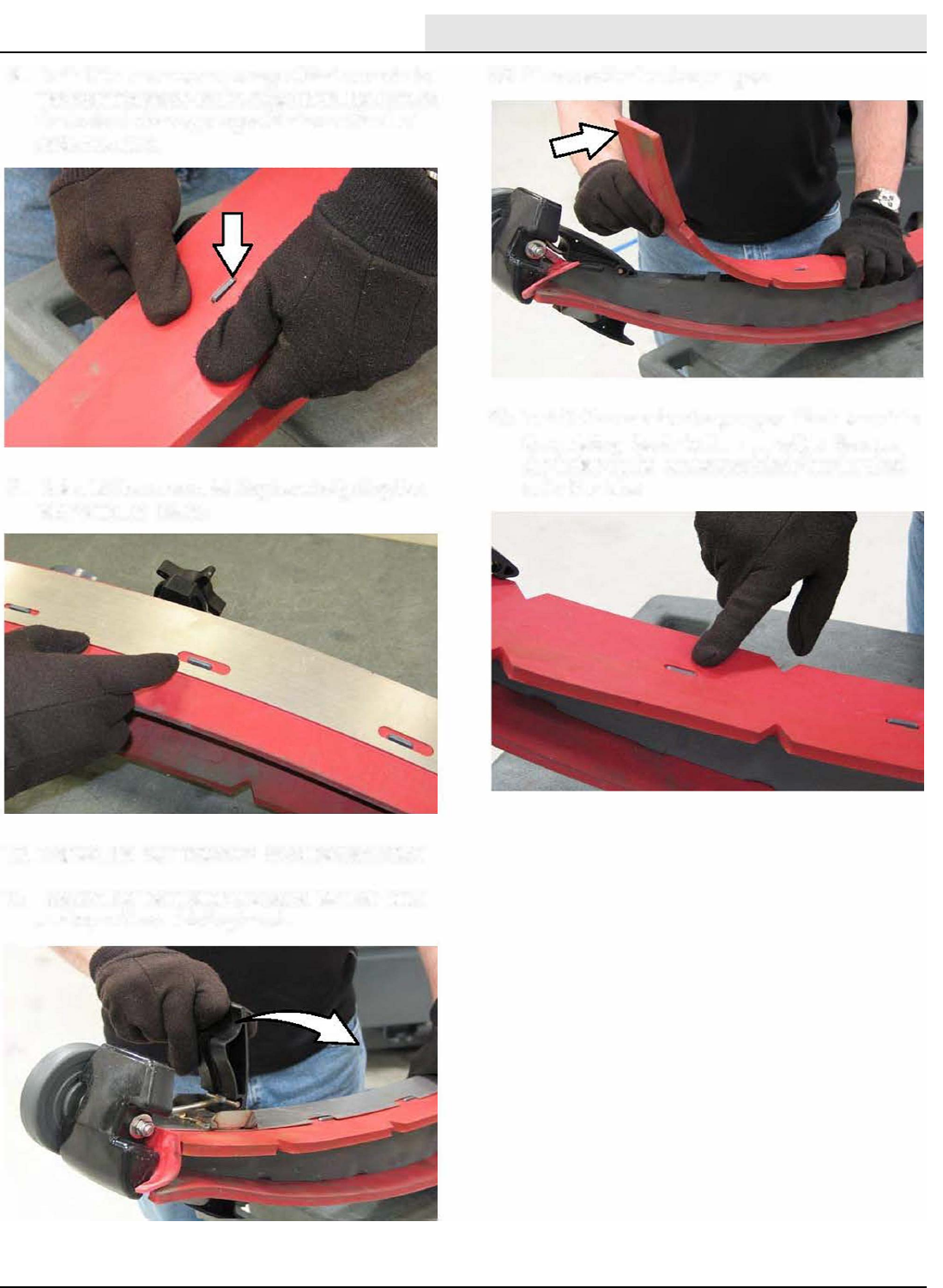
MAINTENANCE
M20/M30 9016006 - 3-2017 133
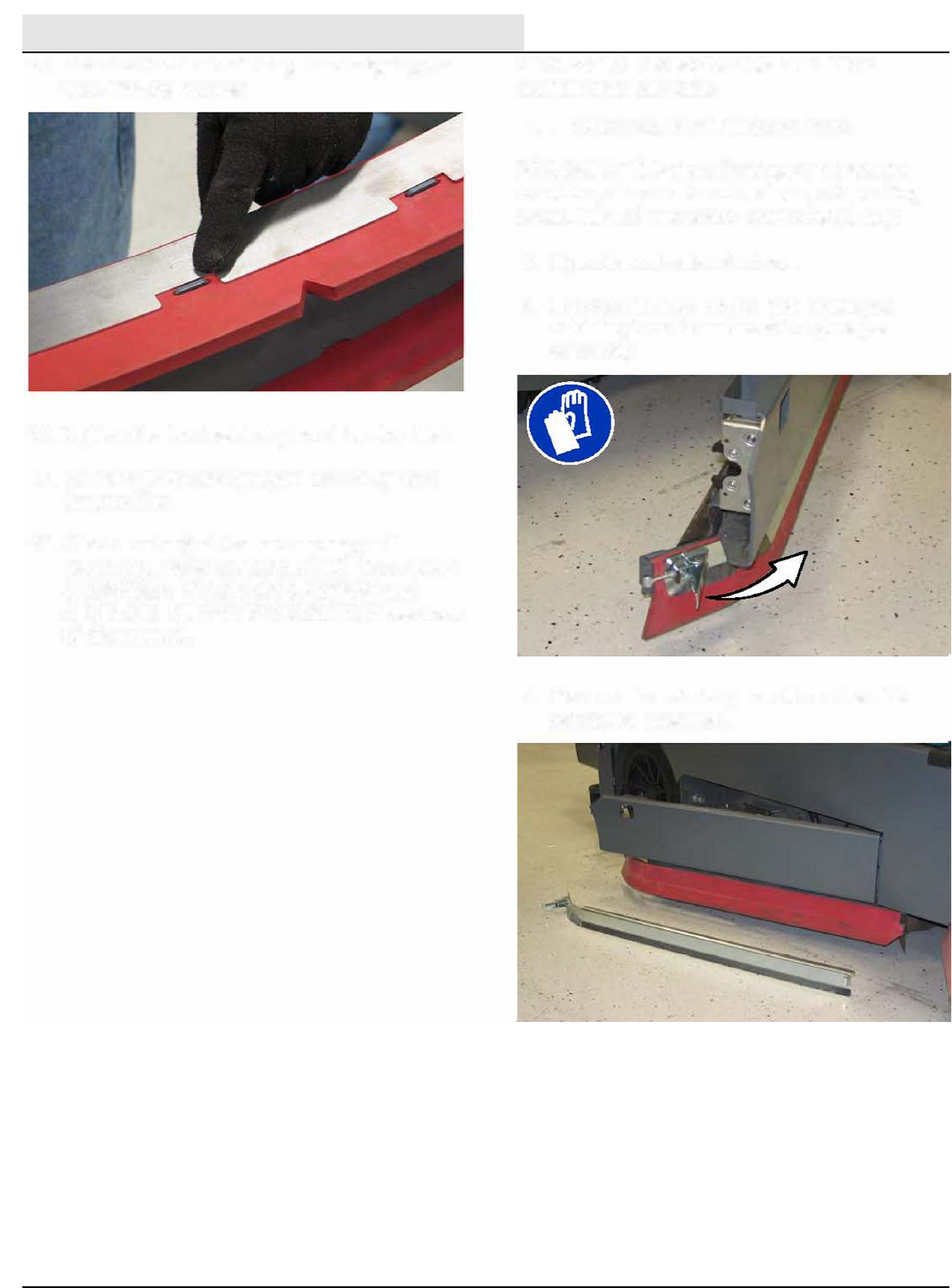
MAINTENANCE
M20/M30 9016006 - 3-2017
134
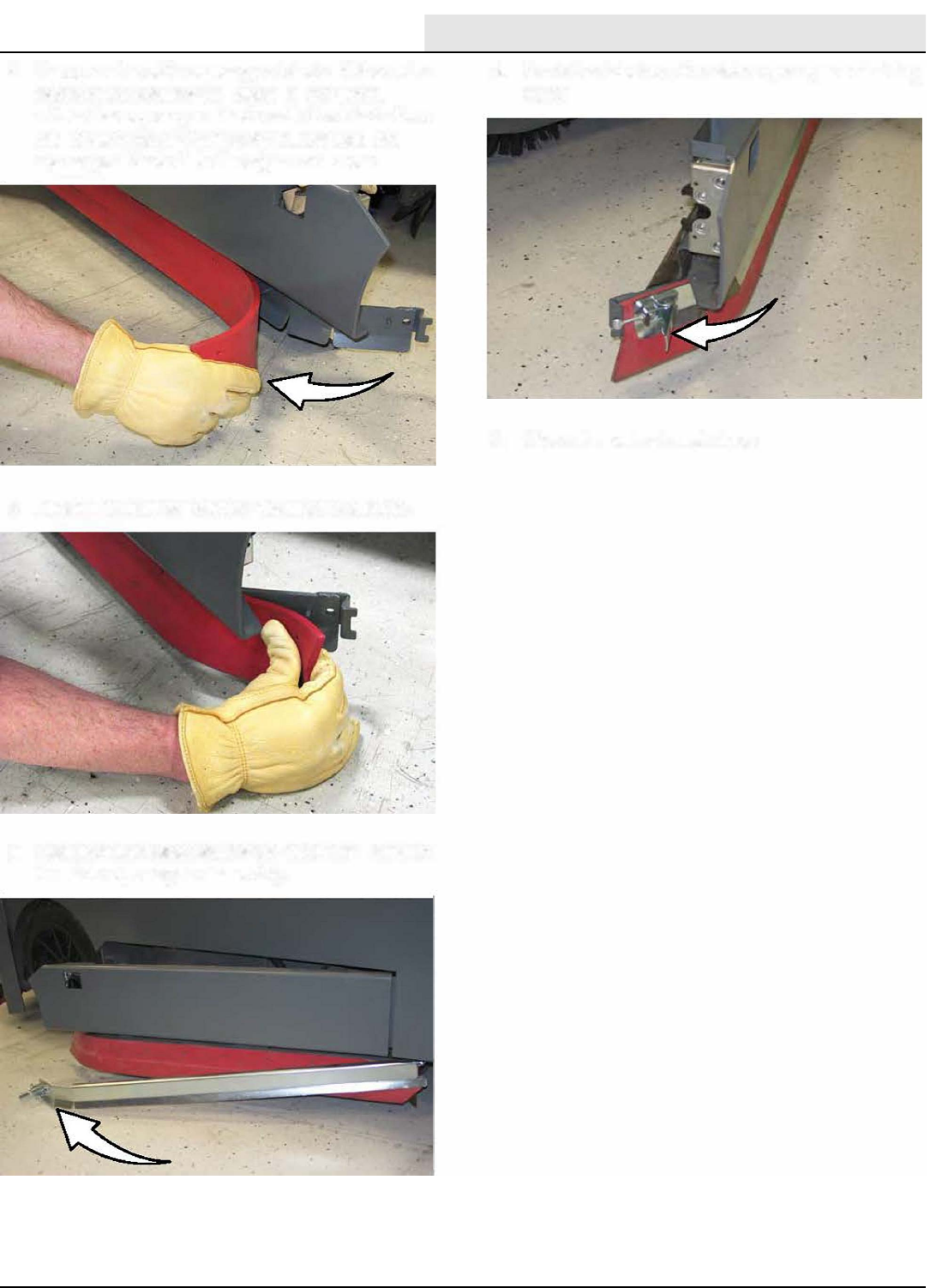
MAINTENANCE
M20/M30 9016006 - 3-2017 135
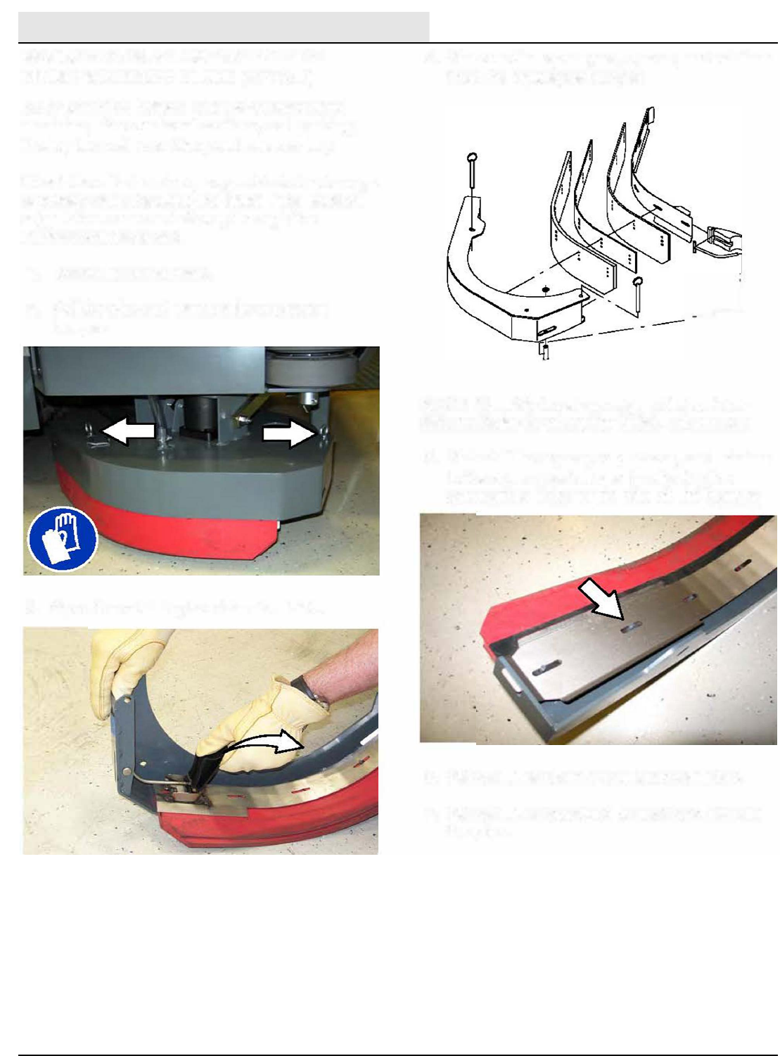
MAINTENANCE
M20/M30 9016006 - 3-2017
136
_1
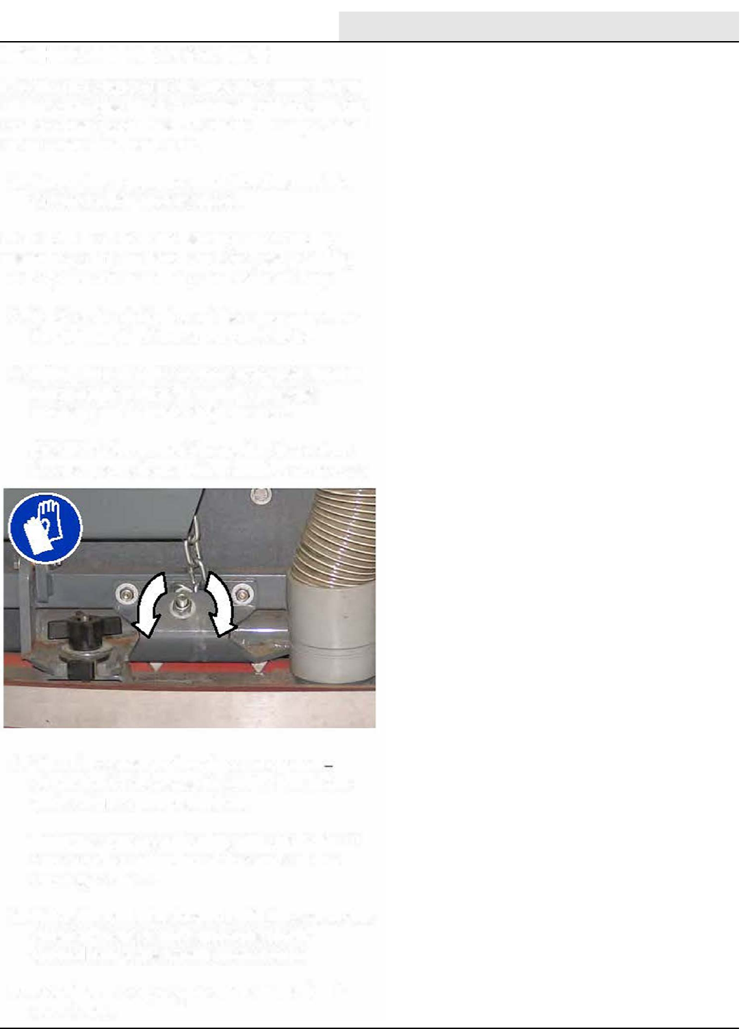
MAINTENANCE
M20/M30 9016006 - 3-2017 137
DO NOT
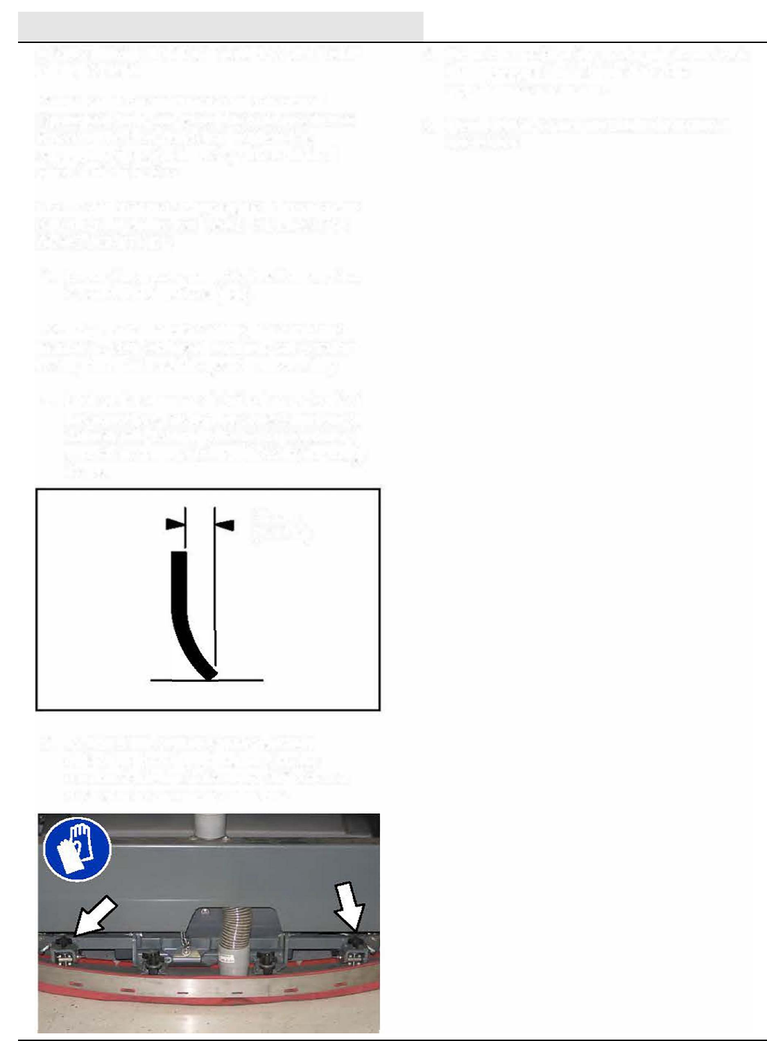
MAINTENANCE
M20/M30 9016006 - 3-2017
138
is
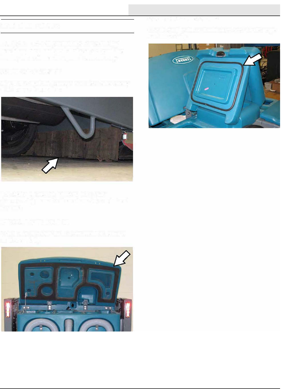
MAINTENANCE
M20/M30 9016006 - 3-2017 139
oo
o
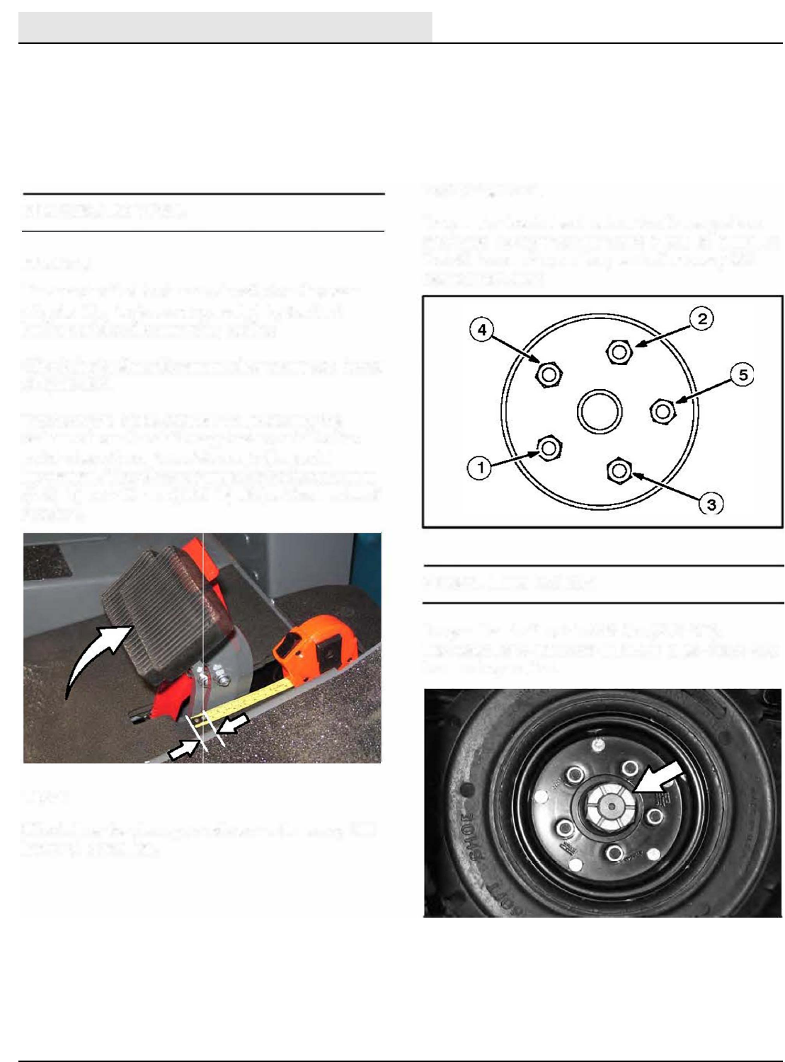
MAINTENANCE
M20/M30 9016006 - 3-2017
140
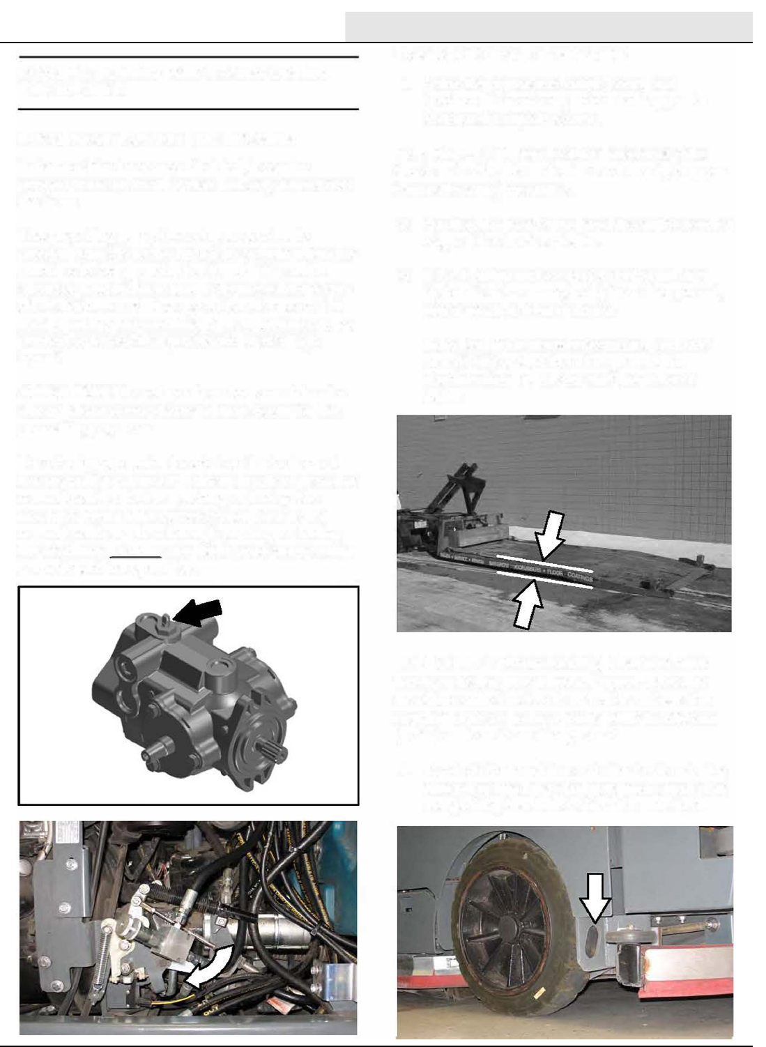
MAINTENANCE
M20/M30 9016006 - 3-2017 141
°
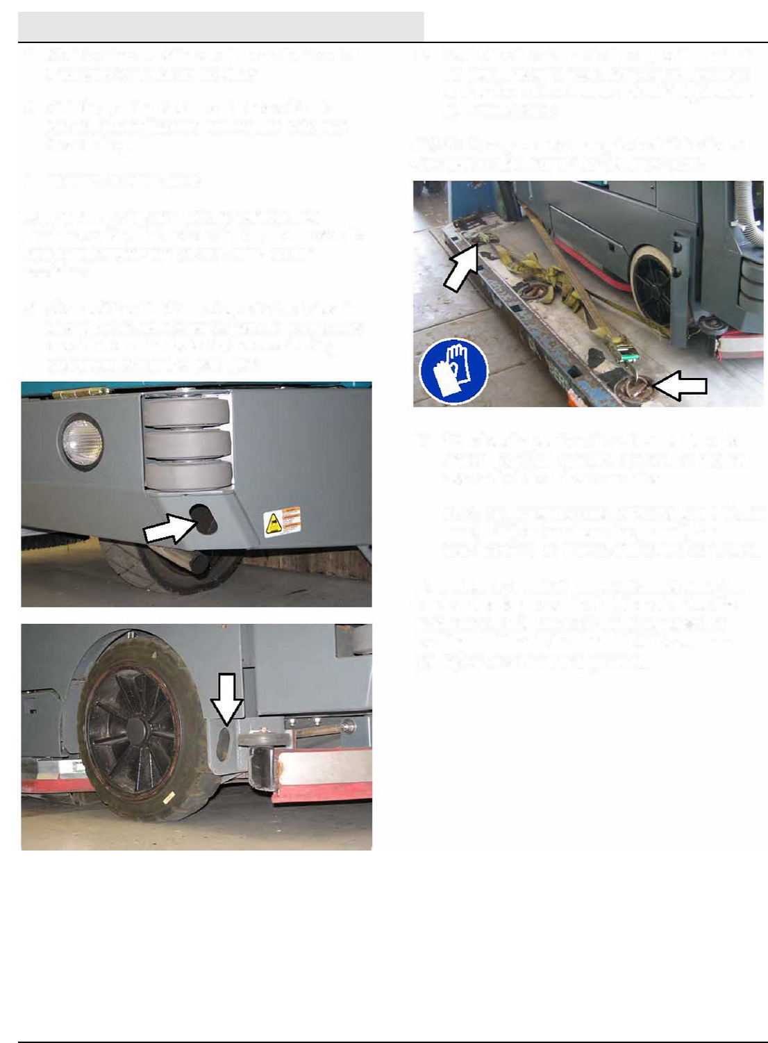
MAINTENANCE
M20/M30 9016006 - 3-2017
142
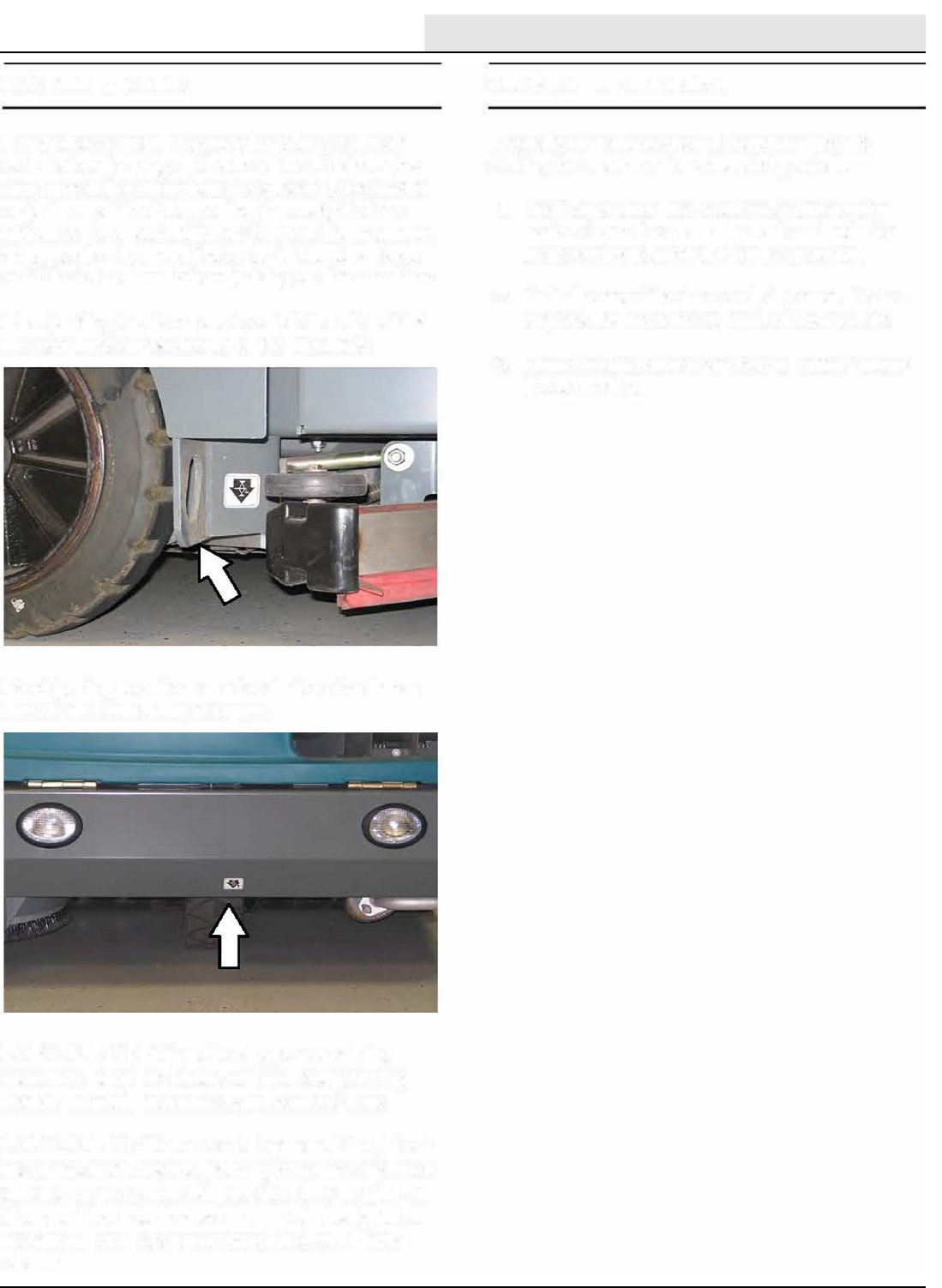
MAINTENANCE
M20/M30 9016006 - 3-2017 143
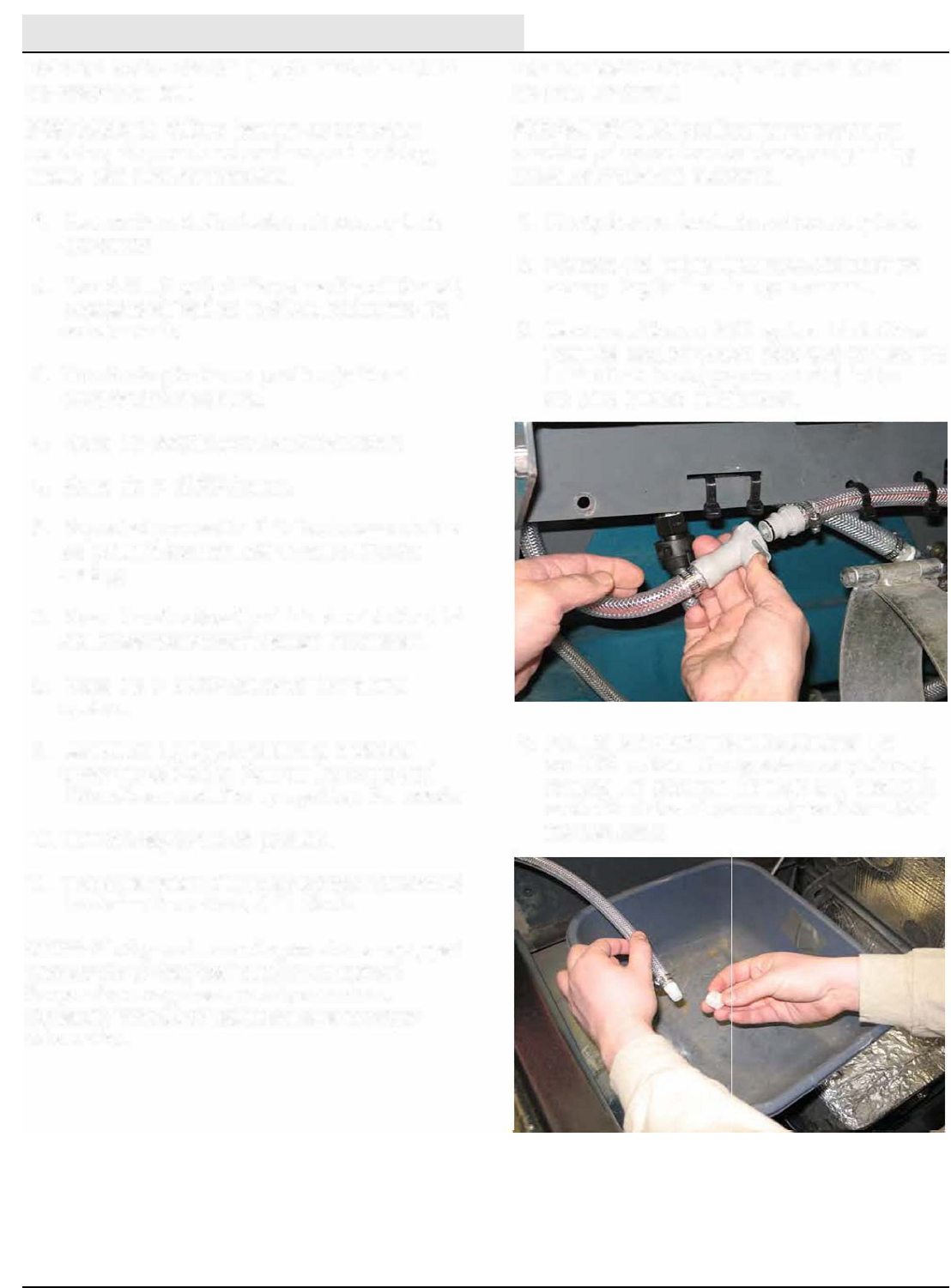
MAINTENANCE
M20/M30 9016006 - 3-2017
144
{+)
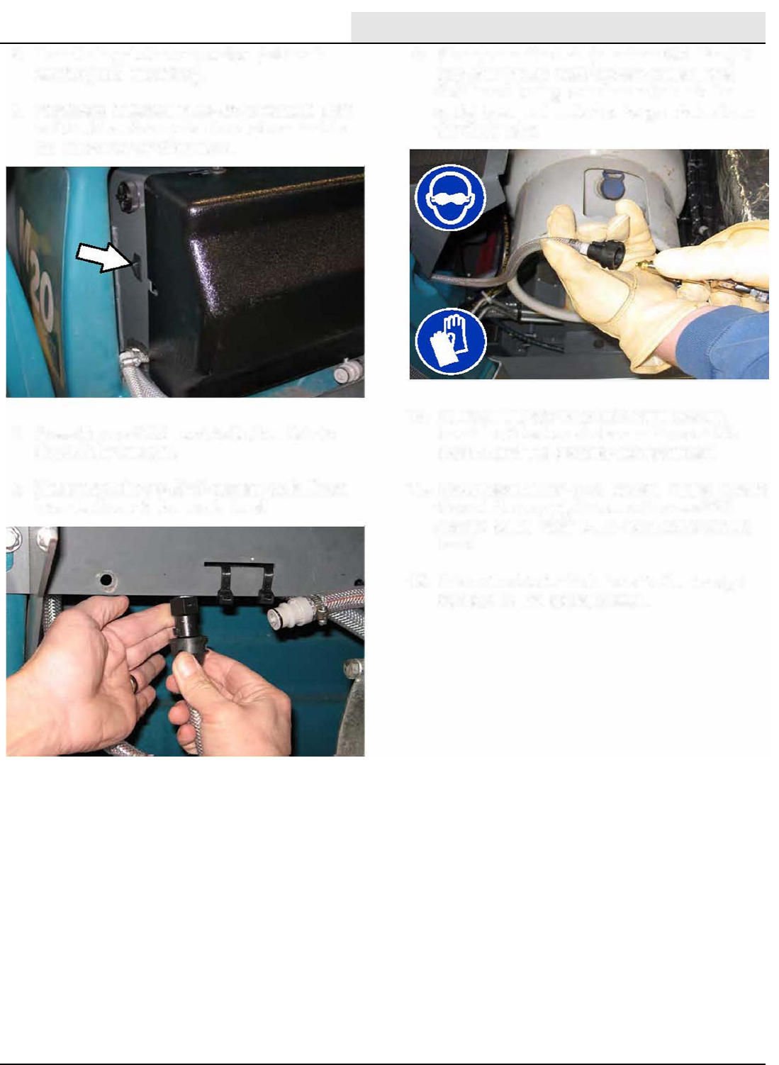
MAINTENANCE
M20/M30 9016006 - 3-2017 145
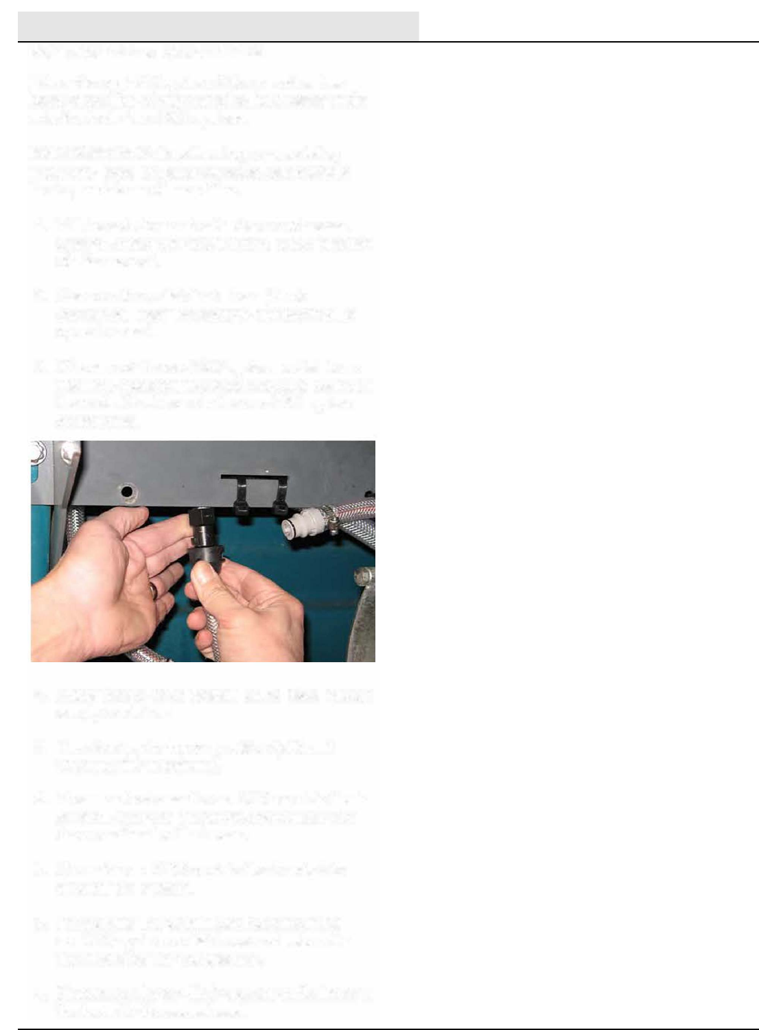
MAINTENANCE
M20/M30 9016006 - 3-2017
146
ec-H20
TA
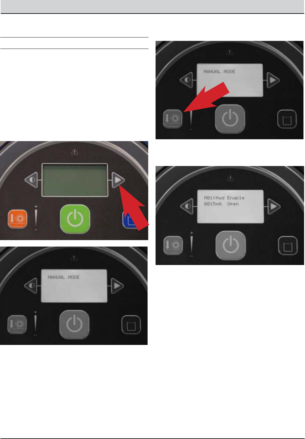
M20/M30 Service Information 147
TROUBLESHOOTING
TROUBLESHOOTING
M20/M30 MEMBRANE PANEL SERVICE MODES
SERVICE MODE
The Service Modes are designed for Service
Technician use only. A qualied Service
Technician can interface with the machine to
congure the machine and to test specic
components.
1. Hold the Right Arrow next to the display down and
turn the key switch on. Continue to hold the Right
Arrow down until you see the message ‘Manual Mode’.
2. You can continue to press the right arrow until you
see the mode you want to enter. The available modes
are:
• Manual Mode
• Congure Mode
• Self Test Mode
• Input Display
• Throttle Adjust
• Down Pressure Adjust
• Membrane Test
3. When you see the mode you want to enter, press the
Orange Down Pressure Button to enter that mode.
Note: Theimagebelowistherstmessage
displayed when you enter the Manual Mode.
4. When the key switch is turned off, the machine will
return to ‘Normal Mode’ when the key is turned on
again.
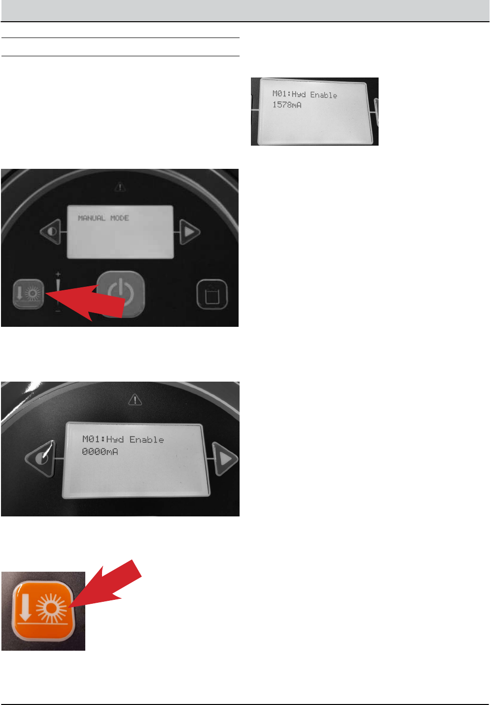
148 M20/M30 Service Information
TROUBLESHOOTING
M20/M30 PROPANEL SERVICE MODES
MANUAL MODE
1. Enter the Service Mode (See SERVICE MODE)
and if needed, press the right arrow to scroll to the
,MANUAL MODE screen.
2. To enter the Manual Mode, press the ‘Orange Down
Pressure Button’ .
3. The rst Component displayed in Manual Mode is
the Hydraulic Enable Valve. It is turned off so there
is 0000mA being delivered to the solenoid valve.
4. To turn on the Hydraulic Enable solenoid valve, press
the Orange Down Pressure Button.
5. When a component is turn on, the amperage being
output to that component, or the RPM of that
component is displayed and testing can be done.
6. With the current component turned o, you can
advance to another component by pressing the right
arrow.
7. There are many components that can be turned on
and o, so testing can be done.
M01: Hyd Enable = Hydraulic Enable
M02: MB Down Act = Main Brush Down Actuator
M03: MB ON Motor = Main Brush Motor ON
M04: MB DP PWM = Main Brush Down Pressure
M05: MB WaterVlv - Main Brush Water Valve
M06: SB Ext. Act = Side Brush Extend Actuator
M07: SB Down Act = Side Brush Down Actuator
M08: SB ON Motor = Side Brush Motor ON
M09: SB DP PWM = Side Brush Down Pressure
M10: SB WaterVlv = Side Brush Water Valve
M11: Water Vac = Water Vacuum
M12: Dust Vac = Dust Vacuum
M13: Squeegee Act = Squeegee Actuator
M14: Hopper Valve1 -= Hopper Valve 1
M14: Hopper Valve2 = Hopper Valve 2
M15: Hp Latch = Hopper Latch
M16: Hp Door = Hopper Door
M17: Shaker - Shaker
M18: Reverse = Reverse Sensor
M19: Shutdown = Shutdown Relay
M20: Alarm = Alarm
M21: Horn = Horn
M22: Det Pump = Detergent Pump
M23: Alt Pump = Alternate Pump
M24: AltHighFlow = Alternate High Flow
M25: AltSideBrush = Alternate Side Brush
M26: Sol AutoFill = Solution Auto Fill
M27: Rec AutoFill = Recovery Auto Fill
M28: Engine Speed = Engine RPM
Note: If a component is not installed on the machine,
the message ‘Not Installed’ is displayed.
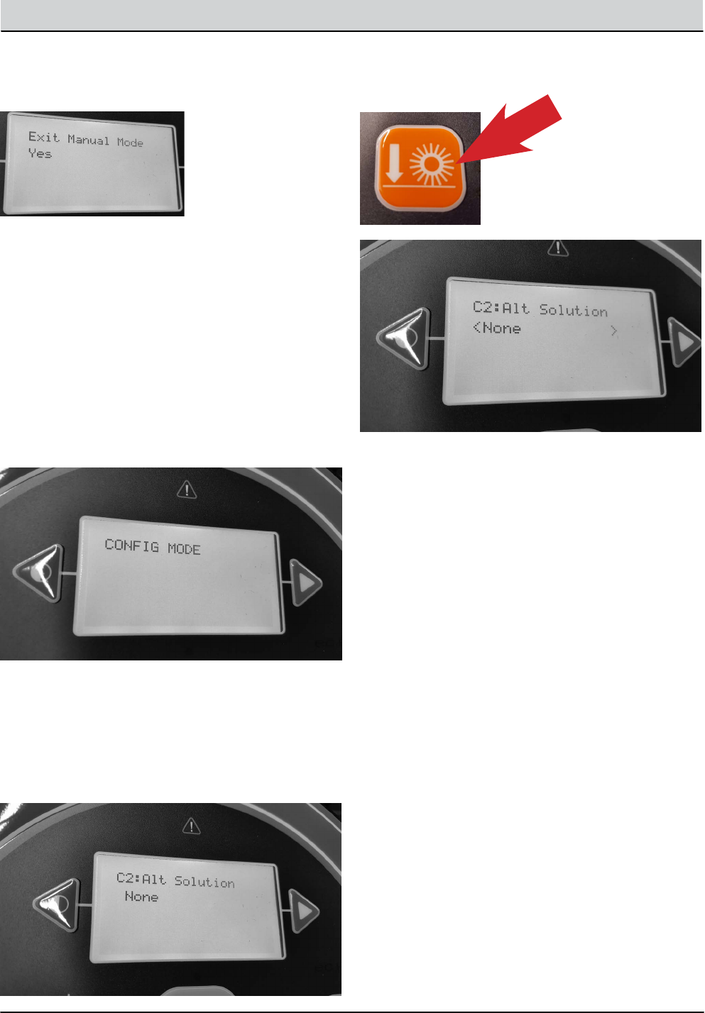
M20/M30 Service Information 149
TROUBLESHOOTING
8. To Exit Manual Mode, press the right arrow until you
see ‘Exit Manual Mode’, then press the Orange Down
Pressure Button Twice, or turn o the key switch.
CONFIGURATION MODE
Conguration Mode is an onboard diagnostic utility that
congures controller software to operate optional equip-
ment and to electronically adjust certain output func-
tions.
1. Enter the Service Mode (See SERVICE MODE) and
press the right arrow to scroll to the CONFIG MODE
screen.
2. To enter the CONFIG MODE, press the Orance Down
Pressure Button’.
3. The C1: MainBrushHead choice feature is not used
on the M20 / M30 machines, as only Cylindrical Scrub
Heads are available on these models.
4. Press the right arrow to scroll to the next
conguration option, in this example we will
explore setting the ‘Alternate Solution Options’.
5. Press the ‘Orange Down Pressure Button’ to allow
changing the Alternate Solution setting.
6. Press the ‘right arrow until the correct Alternate
Solution’ is displayed and press the Orange Down
Pressure Button to accept the change.
The Alternate Solution Options are:
• None
• EcH2O
• ES
• FaST
Choose the option that is installed on the machine.
7. To congure other options on the machine,
continuously press the right arrow to scroll to the
desired conguration option and press the ‘Orange
Down Pressure Button ’ to choose that option and
adjust the settings.
The configuration options are:
C2: Alt Solution = Alternate Solution
C5: Side Brush = Side Brush Type
C6: Seat Switch = Seat Switch Installed?
C7: Water Level = Solution Flow Rate
C8 IRIS Module = IRIS Module Installed?
C9: Run-In. Mode = End of Line Factory Use
C10: Neut. Scrub = Neutral Scrub Enabled?
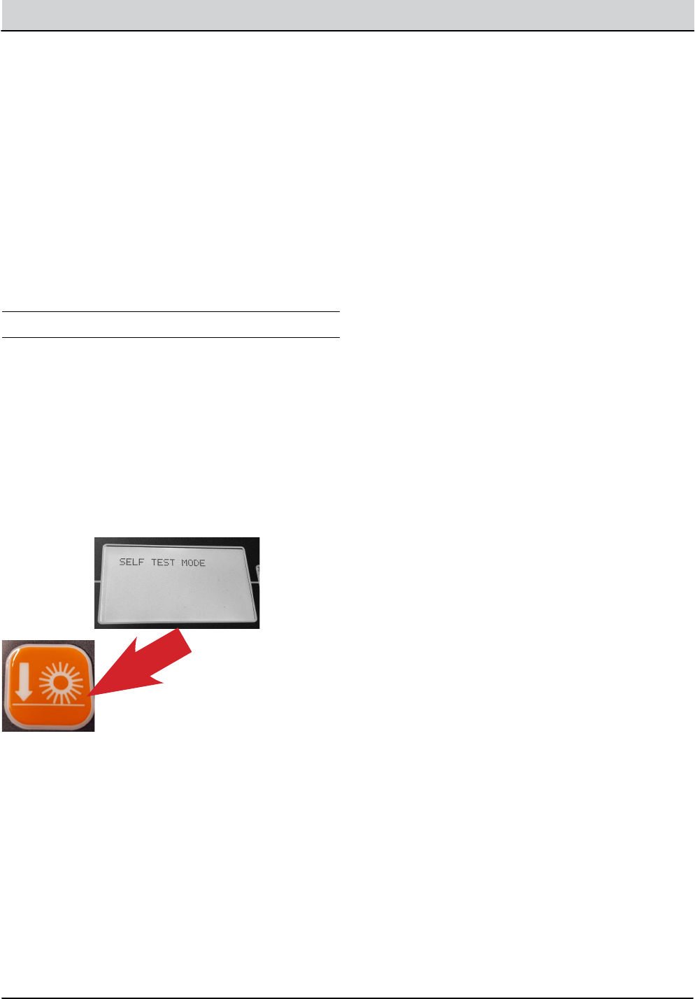
150 M20/M30 Service Information
TROUBLESHOOTING
Additional Water Level Setting Information:
There are three water level range setting options.
• Economy
• Normal
• Heavy
When a settings is chosen, the operator can adjust three
ow rate settings within that range.
8. After all of the ‘Conguration’ settings have been
made. Press the right arrow until you see ‘Exit
Conguration Mode’, then press the Orange Down
Pressure Button Twice, or turn o the key switch.
SELF TEST MODE
Self Test Mode is an onboard diagnostic utility that
tests for open or shorted output circuits. Once com-
pleted, open and/or shorted output faults, are dis-
played.
1. Enter the Service Mode (See SERVICE MODE)
and press the right arrow to scroll to the SELF
TEST MODE screen.
2. To enter the SELF TEST MODE, press the ‘Orange
Down Pressure Button’.
3. The self test will automatically begin.
CAUTION: Many of the machine functions will
automatically turn on. Stay clear of the machine
during the self test.
These are a few examples of the tests per-
formed during the Self Test process. The
table on the next page shows all of the test
names and descriptions.
• Test Hydraulic Enable Valve
• Test Main Brush Down Actuator
• Test Main Brush Motor
• Test Main Brush PWM Valve
• Test Main Brush Water Valve
Some of the tests listed will only be performed if the
machine has that specific option and it is configured
correctly.
4. When the self test is completed, faults found will be
displayed as an open or shorted load.
5. If faults exist, continually press the right arrow icon to
display all faults found.
If there are no other faults found or no faults found
initially, ‘Self Test End’ is displayed. Pressing the right
arrow again will display any faults found again.
All successful tests performed will result in the message
‘Done’. This indicates that test passed.
If a fault is found during the ‘Self Test’ , either ‘Open’ or
‘Short’ will be displayed for that test.
“Open” (Indicates current could not be delivered to
that circuit). There is an Open Load.
“Short” (The current draw is over the threshold, indi-
cating a short circuit)
Follow the diagnostic steps in this manual for
diagnosing an open or shorted circuit.
To exit the self test mode, turn off the machine key.
The machine will return to normal operational mode
when the key switch is turned on again.
M20/M30 Service Information 151
TROUBLESHOOTING
Self Test Name: Test Description:
1:Enable Valve Test the valve which enables machine hydraulics.
2:MBrush Down Actuator Tests the valve which controls ‘Main Brush Down’ actuation.
3:MBrush Motor... Tests the valve which controls the Main Brush motor
4:MBrush PWM Valve Tests PWM control of the Main Brush Down valve (for down pressure control).
5:MBrush Water Valve Tests the valve which controls solution delivery to the Main Brush.
6:SBrush Down Actuator Tests the valve which controls ‘Side Brush Down’ actuation.
7:SBrush Ext Actuator Tests the valve which controls ‘Side brush Extension’ actuation.
8:SBrush Motor... Test the valve which controls the Side Brush motor.
9:SBrush PWM Valve Tests PWM control of the Side Brush Down valve (for down pressure control).
10:SBrush Water Valve Tests the valve which controls solution delivery to the Side Brush
11:Scrub Vacuum Fan Tests the vacuum fan for the scrub subsystem (‘water pickup fan).
12:Sweep Vacuum Fan Tests the vacuum fan for the sweep subsystem.
13: Squeegee Actuator Tests the valve which controls the Squeegee Actuator.
14: SolTnk AF Tests the Autoll valve for the Solution Tank. (If Congured)
15:RecTnk AF Tests the Autoll valve for the Recovery Tank. (If Congured)
16:Reverse Relay Tests the relay for reverse driving.
17:Shaker Relay Tests the relay for the lter shaker.
18:Horn Horn test.
19:Alarm Backup alarm test.
20:Hopper Door Actuator Tests the valve which controls the hopper door actuator.
21:Hopper Latch... Tests the hopper latch.
22:Hopper Up Valve Tests the valve which controls raising of the hopper.
23:Hopper Down Valve Tests the valve which controls lowering of the hopper.
24:Detergent Pump Tests the detergent pump.
25:Alt Pump Tests the Alternative Solution pump (FAST). (If Congured)
26:Alt High Flow Tests the High Flow Rate function of FAST. (If Congured)
27:Alt Side Brush Tests the valve which controls alternative solution (FAST/ECH2O) to the Side Brush. (If Congured)
28:Shutdown Relay Tests the emergency engine shutdown relay.
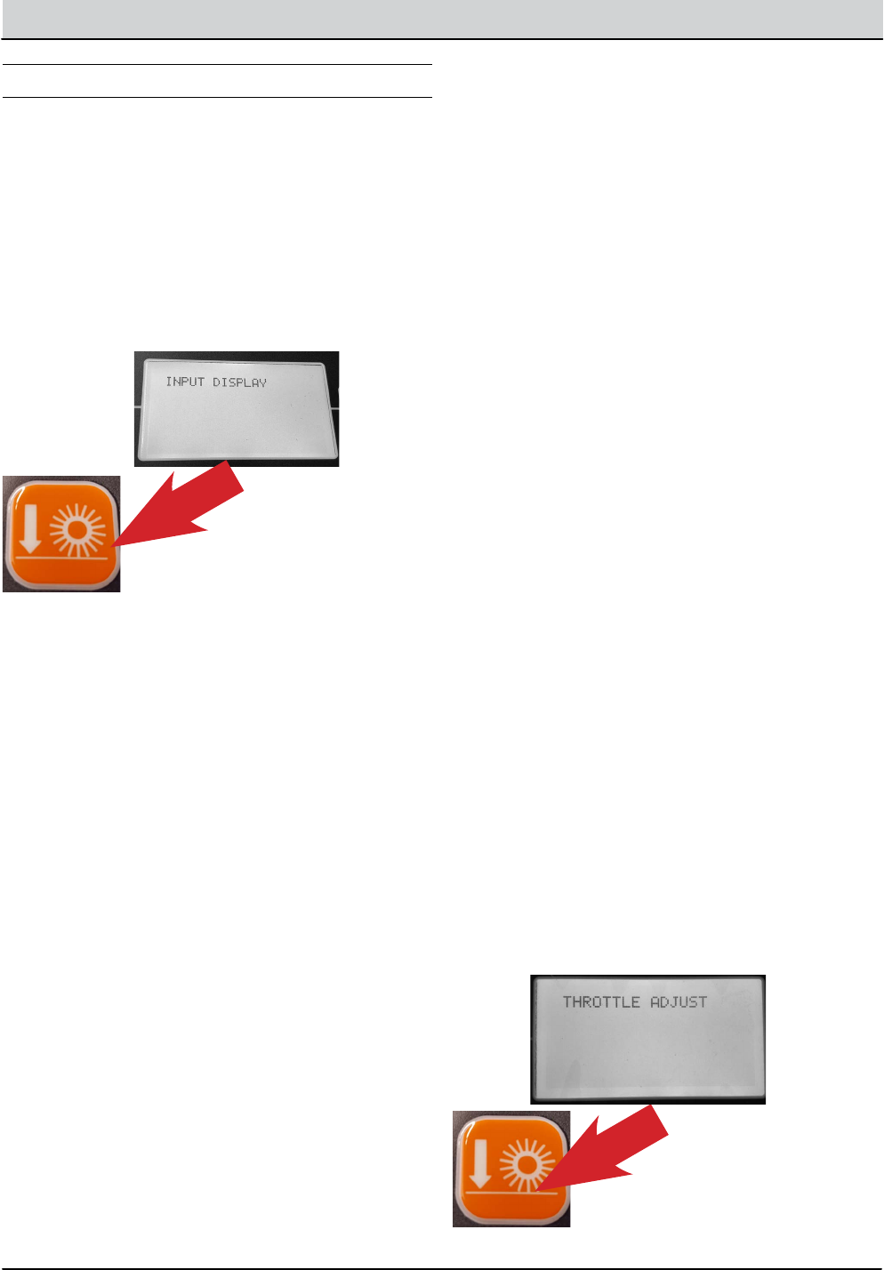
152 M20/M30 Service Information
TROUBLESHOOTING
INPUT DISPLAY MODE
Input Display Mode is an onboard diagnostic utility
that displays controller input conditions. Input Display
Mode displays text messages for hard-wired switch,
sensor, and touch panel button inputs.
1. Enter the Service Mode (See SERVICE MODE)
and press the right arrow to scroll to the INPUT
DISPLAY MODE screen.
2. To enter the INPUT DISPLAY MODE, press the
‘Orange Down Pressure Button’.
3. The display will indicate the switch or sensor being
tested. When the position of the switch or the state
of the sensor is changed, the results of that change is
displayed.
The components that can be tested with
Input Display Mode Include:
• I1: SolTnk Empty
• I2: SolTnk Full
• I3: RecTnk Full
• I4: RedTank 1/2Full
• I5: Clogged HpFlt
• I6: CloggedHydFlt
• I7: ThermalSentry
• I8: Seat Switch
• I9: Brake Switch
• I10: HighEngTemp
• I11: Low Oil Psr
• I12: Check Engine
• I13: EcH2o Green
• I14: EcH2o Red
• I15: Hp Position
• I16: FilterShaker
• I17: Hp Up Rocker
• I18: HPDownRocker
• I19: HpDoor Open
• I20: HPDoor Close
I21: Alternator
• I22: Throttle
• I23: Fuel Sender
• I24: Hyd Temp
4. To Exit the Input Display Mode, press the right arrow
until you see ‘Exit Input Display Mode’, then press the
Orange Down Pressure Button Twice, or turn o the
key switch.
THROTTLE ADJUST MODE
1. Enter the Service Mode (See SERVICE MODE)
and press the right arrow to scroll to the
THROTTLE ADJUST MODE screen.
2. To enter the THROTTLE ADJUST MODE, press
the ‘Orange Down Pressure Button’.
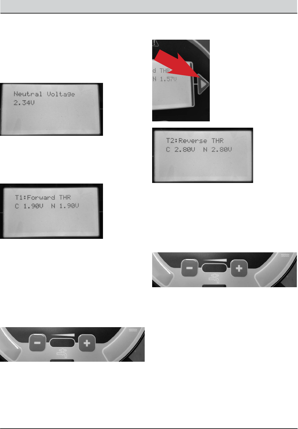
M20/M30 Service Information 153
TROUBLESHOOTING
3. The actual ‘Neutral Voltage’ value of the throttle
position sensor is displayed. Pressing the ‘Orange
Down Pressure Button’ sets the Forward and
Reverse sense voltage values, based on this
Neutral Voltage value. The machine operation
should be tested to conrm the rear squeegee
raises and lowers at the proper times when the
machine is propelled forward and backward.
4. If the rear squeegee raises and lowers too soon
or too late, you will need to adjust the Forward
voltage value and/or the Reverse voltage value.
Press the right arrow to proceed to the Forward
Threshold voltage value.
Note: the ‘C’ indicates the Current voltage value
and the ‘N’ indicates the New voltage value you are
setting.
5. Press the ‘minus’ icon to reduce the N (New) value
and the ‘Positive’ icon to increase the N value.
The higher the Forward THR value, the quicker the
system will react to forward direction movement. Press
the Orange Down Pressure Button’ to make your ‘N’
New value the ‘C’ Current value.
6. Press the right arrow to proceed to the Reverse
Threshold voltage value.
7. If the Reverse Threshold requires adjustment
press either the ‘minus’ icon to reduce the N
voltage or the ‘plus’ icon to increase the N voltage.
The higher the value, the quicker the system will
react to reverse direction movement. Once the desired
setting is achieved, press the ‘Check Mark’ to accept the
change and conrm proper machine operation.
8. To Exit the Throttle Adjust Mode, press the right arrow
until you see ‘Exit Throttle Adjust Mode’, then press
the Orange Down Pressure Button Twice, or turn o
the key switch.
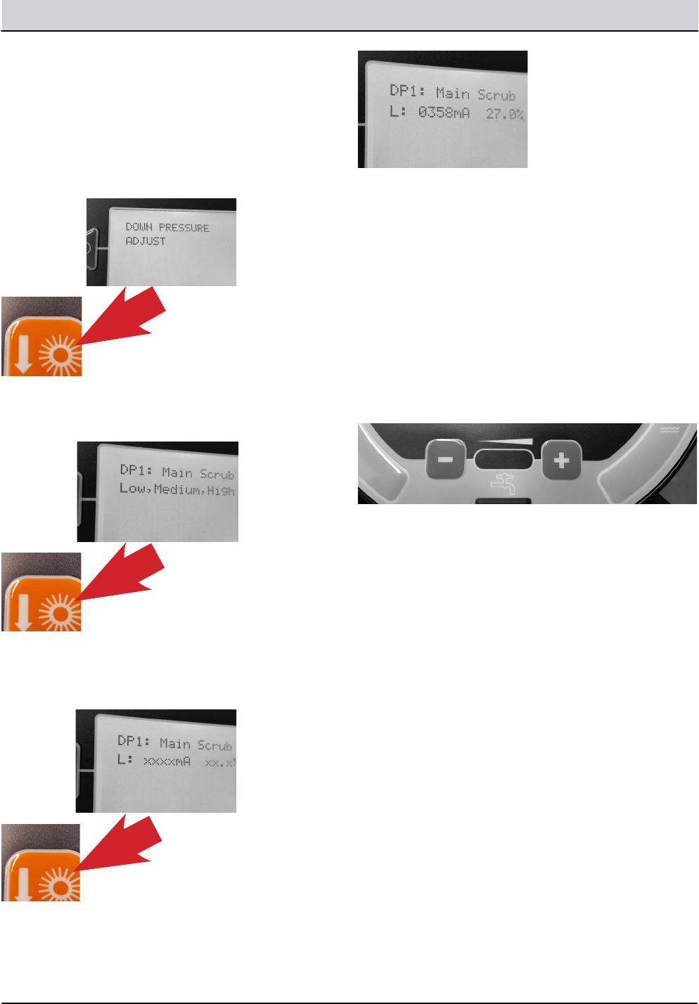
154 M20/M30 Service Information
TROUBLESHOOTING
DOWN PRESSURE ADJUST MODE
1. Enter the Service Mode (See SERVICE MODE)
and press the right arrow to scroll to the DOWN
PRESSURE ADJUST MODE screen.
2. To enter the DOWN PRESSURE ADJUST MODE, press
the ‘Orange Down Pressure Button’.
3. To enter the DOWN PRESSURE ADJUST MODE
for the Main Scrub Brushes, press the ‘Orange
Down Pressure Button’ , again.
4. To enter the ‘L’ (Low Down Pressure Setting
Mode) for the Main Scrub Brushes, press the
‘Orange Down Pressure Button’ , again.
Note: With the setting numbers displayed for the Low
main Scrub Brush Pressure adjustments can be made
to that setting.
Note: The electrical signal transmitted to the control
solenoid is measured in mA (milliamperes).
5. To increase the Low Setting Down Pressure for the
Main Scrub Brushes, press the ‘Plus’ icon to increase
the mA setting for the control valve. To decrease
the pressure, press the ‘Minus’ icon to decrease the
mA setting for the control valve. Each time an icon
is pressed, the electrical signal to the solenoid is
changed.
6. To allow adjustment to the Medium down pressure
setting, press the ‘Orange Down Pressure Button’
to move backwards, then the ‘Right Arrow’ to move
to the M: (Medium Down Pressure Setting) then
press the ‘Orange Down Pressure Button’ to allow
you to set the Medium down pressure setting, if
desired.
7. To allow adjustment to the High down pressure
setting, press the ‘Orange Down Pressure Button’
to move backwards, then the ‘Right Arrow’ to
move to the H: (Heavy Down Pressure Setting)
then press the ‘Orange Down Pressure Button’ to
allow you to set the Heavy down pressure setting,
if desired.
8. When all down pressure adjustments are completed
for the Main Scrub Brushes, press the ‘Orange Down
Pressure Button’ to move backwards, then the ‘Right
Arrow’ to move to the Main Scrub Exit.
9. Press the ‘Orange Down Pressure Button’ to Exit
the Main Scrub Down Pressure Setting Mode.
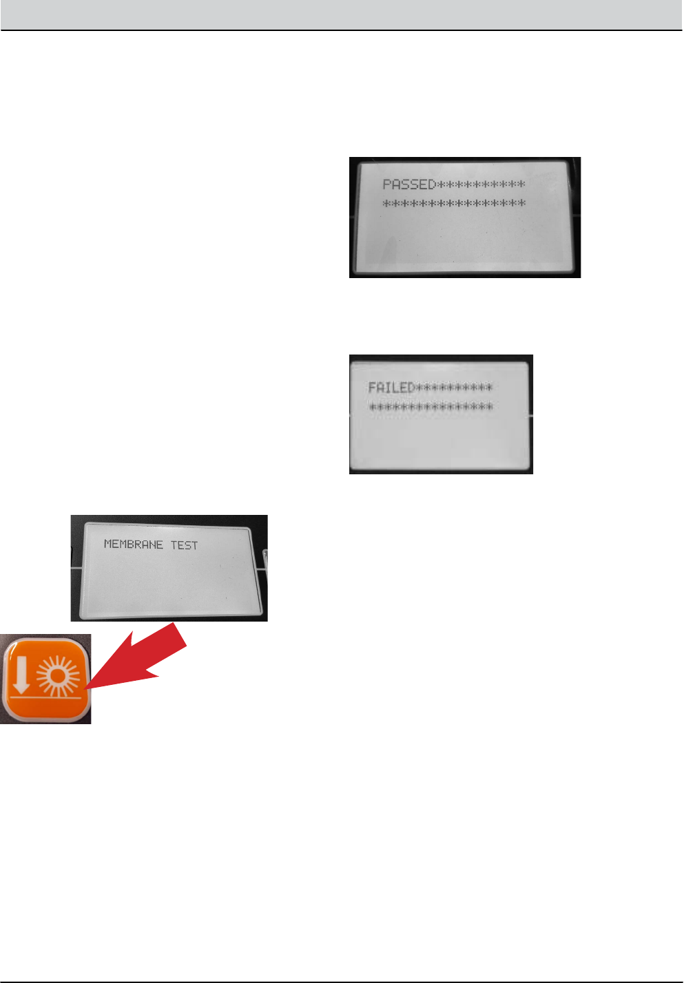
M20/M30 Service Information 155
TROUBLESHOOTING
10. Press the ‘Right Arrow’ button to move to the Side
Scrub Brush Down Pressure Adjust Mode. Follow
the same process as above to make adjustments
to the Side Scrub Brush Down pressure, if desired.
You can press the ‘Right Arrow’ button again to
move to the Main Sweeping Brush Down Pressure
Adjust Mode and again for the Side Sweeping
Brush Down Pressure Adjust Mode.
Follow the same adjustment procedures outlined for
the Main Scrub Brush Down Pressure Settings.
11. To exit the Down Pressure Adjust Modes, press
the Right Arrow until you see Exit DP Adjust. Press
the ‘Orange Down Pressure Button’ twice to exit
this mode.
12. To exit the Service Modes, turn off the key switch
and then turn it on again.
MEMBRANE TEST MODE
1. Enter the Service Mode (See SERVICE MODE) and
press the right arrow to scroll to the MEMBRANE TEST
MODE screen.
2. To enter the MEMBRANE TEST MODE, press the
‘Orange Down Pressure Button’.
3. The MEMBRANE TEST MODE allows you to test
the touch button functions, on the control panel.
When you are in the Membrane Test Mode, you
are directed to press each Membrane Button to
test it’s functionality.
NOTE: If you delay too long prior to pressing the
required button, this delay may be reported with a
‘Failed’ message, in the display. If this happens, turn
off the key switch and restart all testing procedures.
4. When you press a button as directed, if the button
functions properly, you will be directed to press
another button until all button tests are completed.
If all of the tests were completed successfully, you
will receive the message ‘Passed’ in the display
window.
5. If a button fails to function as designed, you will
receive the message ‘FAILED’ in the display
window.
6. To exit the Service Modes, turn o the key switch and
then turn it on again.
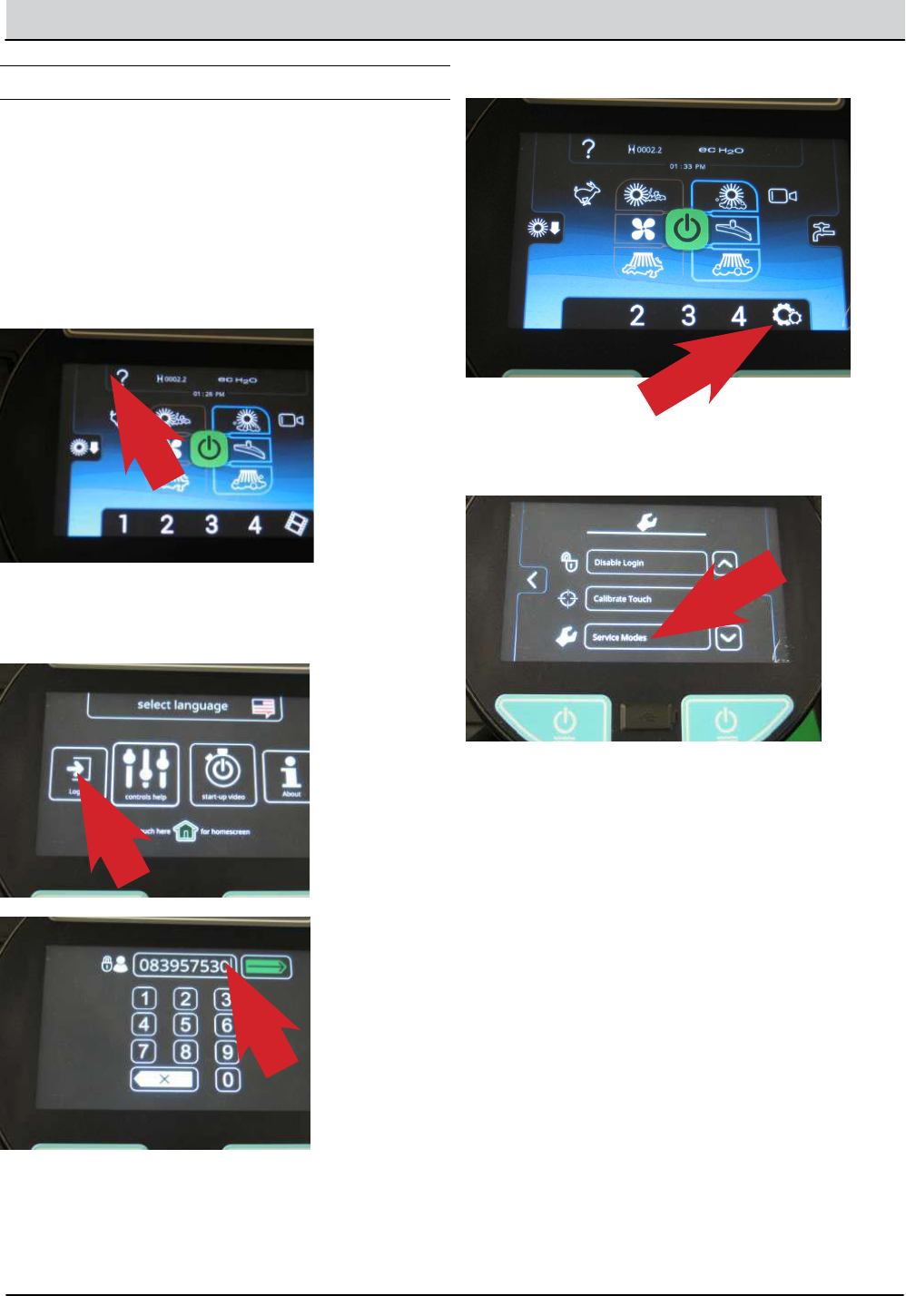
156 M20/M30 Service Information
TROUBLESHOOTING
M20/M30 ProPanel Service Modes
SERVICE MODE
The Service Modes are designed for Service
Technician use only. A qualied Service Technician
can interface with the machine to congure the
machine and to test specic components.
1. Key switch on. With the machine display powered
on, press the ‘Question Mark’ Icon.
2. Press the Logout Icon and enter the Service
Mode Login number and press the enter icon.
(083957530)
3. Press the ‘Gears’ icon.
4. Using the down arrow, scroll to the bottom of the
listed functions.
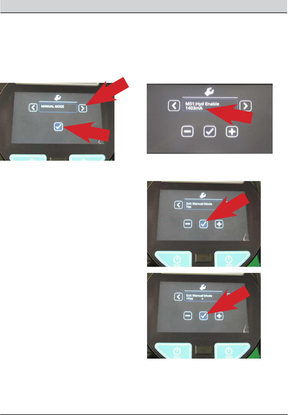
M20/M30 Service Information 157
TROUBLESHOOTING
M20/M30 PROPANEL SERVICE MODES
1. Enter the Service Mode (See SERVICE MODE) and
press the right arrow to scroll to the ,MANUAL MODE
screen.
2. To enter the Manual Mode, press the ‘Check
Mark’.
3. Manual Mode allows viewing many component
amperage draws or RPM.
This includes:
M01: Hyd Enable = Hydraulic Enable
M02: MB Act = Main Brush Actuator
M03: MB ON Motor = Main Brush Motor ON
M04: MB DP PWM = Main Brush Down Pressure
M05: MB WaterVlv - Main Brush Water Valve
M06: SB Ext. Act = Side Brush Extend Actuator
M07: SB Down Act = Side Brush Down Actuator
M08: SB ON Motor = Side Brush Motor ON
M09: SB DP PWM = Side Brush Down Pressure
M10: SB WaterVlv = Side Brush Water Valve
M11: Water Vac = Water Vacuum
M12: Dust Vac = Dust Vacuum
M13: Squeegee Act = Squeegee Actuator
M14: Hopper Valve1 -= Hopper Valve 1
M14: Hopper Valve2 = Hopper Valve 2
M15: Hp Latch = Hopper Latch
M16: Hp Door = Hopper Door
M17: Shaker - Shaker
M18: Reverse = Reverse Sensor
M19: Shutdown = Shutdown Relay
M20: Alarm = Alarm
M21: Horn = Horn
M22: Det Pump = Detergent Pump
M23: Alt Pump = Alternate Pump
M24: AltHighFlow = Alternate High Flow
M25: AltSideBrush = Alternate Side Brush
M26: Sol AutoFill = Solution Auto Fill
M27: Rec AutoFill = Recovery Auto Fill
M28: Engine Speed = Engine RPM
Note: If a component is not installed on the machine, the
message ‘Not Installed’ is displayed.
4. To activate a component, press the check mark. To
deactivate a component, press the check mark again.
Note: When a component is active, the amperage
output to that component or the RPM of that
component is displayed.
5. To exit Manual Mode, press the ‘Check Mark’ icon
twice.
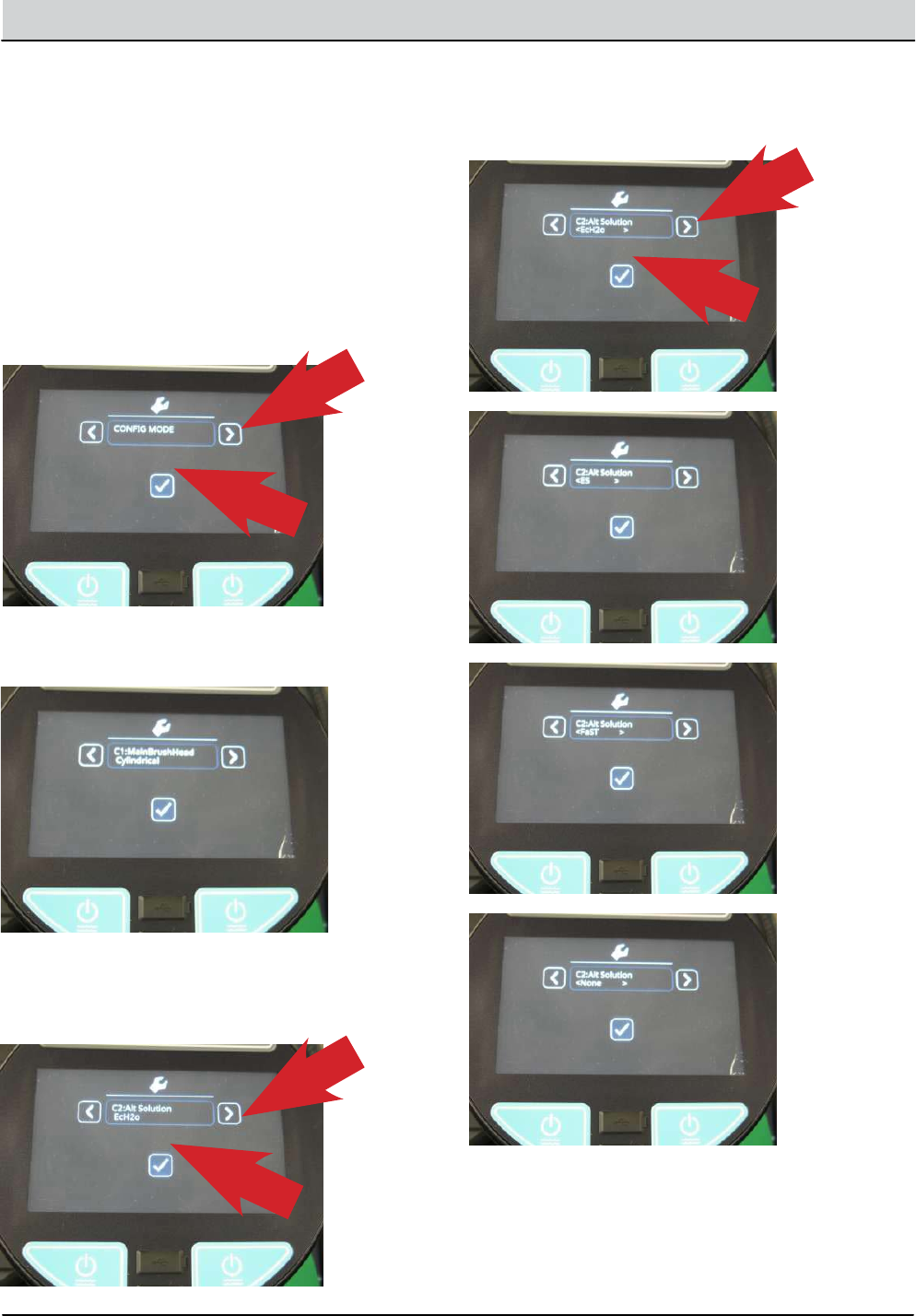
158 M20/M30 Service Information
TROUBLESHOOTING
CONFIGURATION MODE
Conguration Mode is an onboard diagnostic utility that
congures controller software to operate optional equip-
ment and to electronically adjust certain output func-
tions.
1. Enter the Service Mode (See SERVICE MODE)
and press the right arrow to scroll to the CONFIG
MODE screen.
2. To enter the CONFIG MODE, press the ‘Check
Mark’ icon.
3. The C1: MainBrushHead choice feature is not
used on the M20 / M30 machines.
4. Press the right arrow to scroll to the next
conguration option and the ‘Check Mark’ icon to
change settings.
5. Continuously press the right arrow to scroll to the
desired conguration option and press the ‘Check
Mark’ icon to choose a setting .
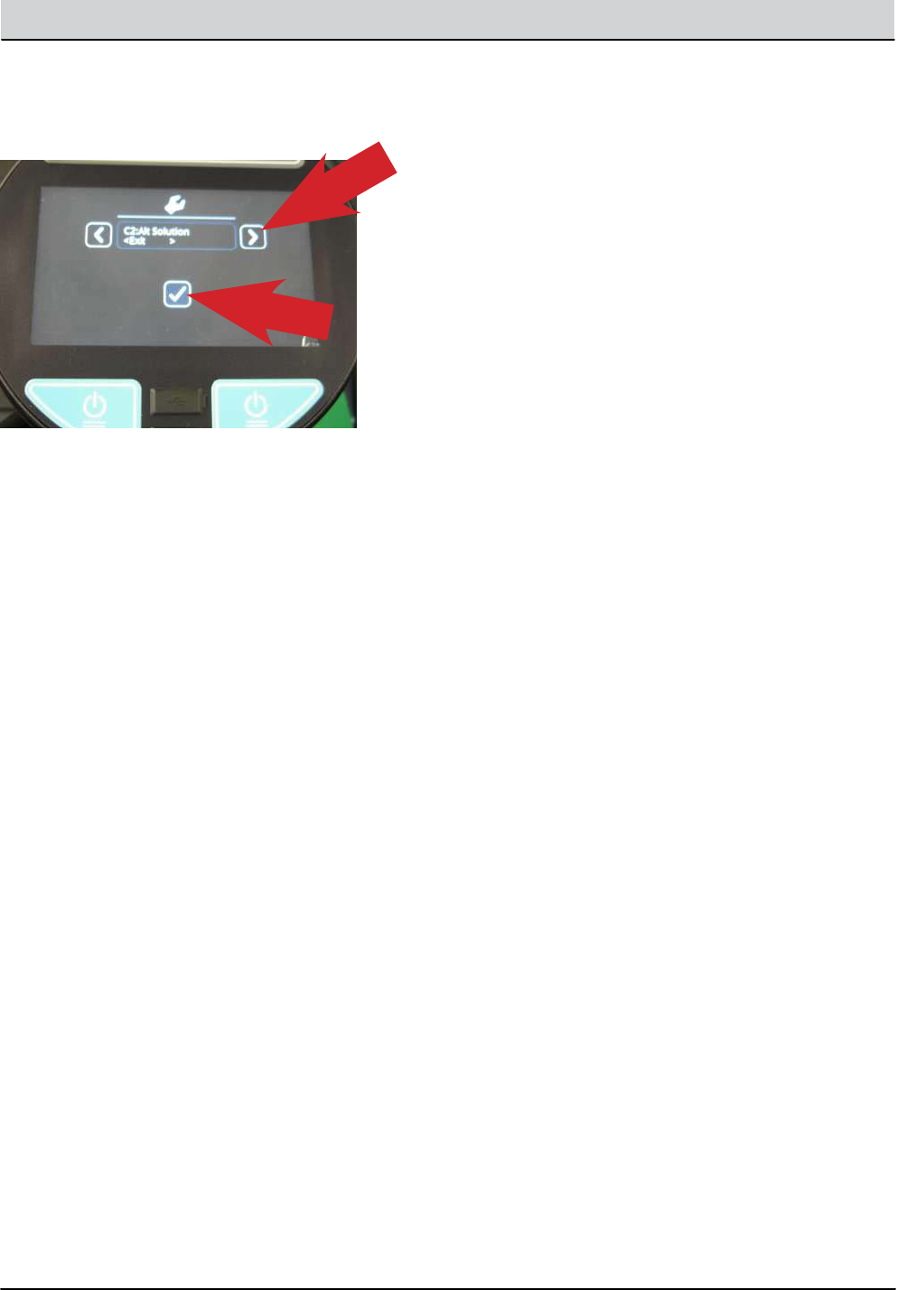
M20/M30 Service Information 159
TROUBLESHOOTING
6. If no change is required, press the right arrow until
you see the ‘Exit’ option and press the ‘Check
Mark’ icon twice, to exit.
7. Follow the same procedure for other optional
equipment and water ow rate setup.
Including:
• C1: Side Brush
• C6: Seat Switch
• C7: Water Level
• C8: IRIS Module
Additional Water Level Setting Information:
There are three water level range setting options.
• Economy
• Normal
• Heavy
When a settings is chosen, the operator can adjust
three flow rate settings within that range.
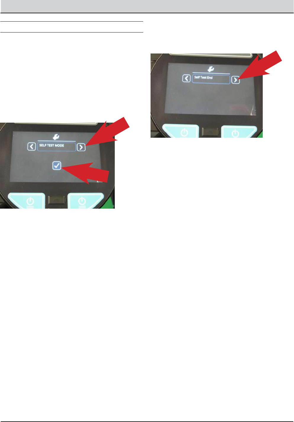
160 M20/M30 Service Information
TROUBLESHOOTING
SELF TEST MODE
Self Test Mode is an onboard diagnostic utility that
tests for open or shorted output circuits. Once com-
pleted, open and/or shorted output faults, are dis-
played.
1. Enter the Service Mode (See SERVICE MODE)
and press the right arrow to scroll to the SELF
TEST MODE screen.
2. To enter the SELF TEST MODE, press the ‘Check Mark’
icon.
3. The self test will automatically begin.
CAUTION: Many of the machine functions will
automatically turn on. Stay clear of the machine
during the self test.
These are a few examples of the tests performed
during the Self Test process. The table on the next
page shows all of the test names and descriptions.
• Test Hydraulic Enable Valve
• Test Main Brush Down Actuator
• Test Main Brush Motor
• Test Main Brush PWM Valve
• Test Alternate Solution Pump
Some of the tests listed will only be performed if the
machine has that specific option and it is configured
correctly.
4. When the self test is completed, faults found will be
displayed as an open or shorted load.
5. If faults exist, continually press the right arrow icon
to display all faults found.
If there are no other faults found or no faults
found initially, ‘Self Test End’ is displayed.
Pressing the right arrow again will display
any faults found again.
All successful tests performed will result in the mes-
sage ‘Done’. This indicates that test passed.
If a fault is found during the ‘Self Test’ , either ‘Open’
or ‘Short’ will be displayed for that test.
“Open” (Indicates current could not be delivered to
that circuit)
“Short” (The current draw is over the threshold, indi-
cating a short circuit)
Follow the diagnostic steps in this manual for
diagnosing an open or shorted circuit.
6. To exit the self test mode, turn off the machine
key. The machine will return to normal operational
mode when the key switch is turned on again.
M20/M30 Service Information 161
TROUBLESHOOTING
Self Test Name: Test Description:
1:Enable Valve Test the valve which enables machine hydraulics.
2:MBrush Down Tests the valve which controls ‘Main Brush Down’ actuation.
3:MBrush Motor Tests the valve which controls the Main Brush motor
4:MBrush PWM Tests PWMed control of the Main Brush Down valve (for down pressure control).
5:MBrush Water Tests the valve which controls solution delivery to the Main Brush.
6:SBrush Down Tests the valve which controls ‘Side Brush Down’ actuation.
7:SBrush Ext Tests the valve which controls ‘Side brush Extension’ actuation.
8:SBrush Motor Test the valve which controls the Side Brush motor.
9:SBrush PWM Tests PWMed control of the Side Brush Down valve (for down pressure control).
10:SBrush Water Tests the valve which controls solution delivery to the Side Brush
11:Scrub Vac Fan Tests the vacuum fan for the scrub subsystem (‘water pickup fan).
12:Sweep Vac Fan Tests the vacuum fan for the sweep subsystem.
13: Squeegee Act Tests the valve which controls the Squeegee Actuator.
14: SolTnk AF Tests the Autoll valve for the Solution Tank.
15:RecTnk AF Tests the Autoll valve for the Recovery Tank.
16:ReverseRelay Tests the relay for reverse driving.
17:ShakerRelay Tests the relay for the lter shaker.
18:Horn Horn test.
19:Alarm Backup alarm test.
20:Hopper Door Tests the valve which controls the hopper door actuator.
21:Hopper Latch Tests the hopper latch.
22:HopperUpVlv Tests the valve which controls raising of the hopper.
23:HopperDownVlv Tests the valve which controls lowering of the hopper.
24:DetergentPump Tests the detergent pump.
25:AltPump Tests the Alternative Solution pump (FAST).
26:AltHighFlow Tests the High Flow Rate function of FAST.
27:AltSideBrush Tests the valve which controls alternative solution (FAST/ECH2O) to the Side Brush.
28:ShutdownRelay Tests the emergency engine shutdown relay.
29:ScrubControlA Tests CAN communication to node A on the Main Board.
30:ScrubControlB Tests CAN communication to node B on the Main Board.
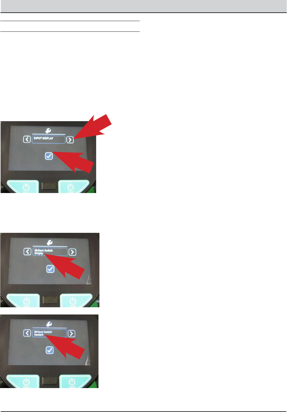
162 M20/M30 Service Information
TROUBLESHOOTING
INPUT DISPLAY MODE
Input Display Mode is an onboard diagnostic utility
that displays controller input conditions. Input Display
Mode displays text messages for hard-wired switch,
sensor, and touch panel button inputs.
1. Enter the Service Mode (See SERVICE MODE)
and press the right arrow to scroll to the INPUT
DISPLAY MODE screen.
2. To enter the INPUT DISPLAY MODE, press the
‘Checkmark’ icon.
3. The display will indicate the switch or sensor being
tested. When the position of the switch or the state
of the sensor is changed, the results of that change is
displayed.
The components that can be tested with
Input Display Mode Include:
• I1: SolTnk Empty
• I2: SolTnk Full
• I3: RecTnk Full
• I4: RedTank 1/2Full
• I5: Clogged HpFlt
• I6: CloggedHydFlt
• I7: ThermalSentry
• I8: Seat Switch
• I9: Brake Switch
• I10: HighEngTemp
• I11: Low Oil Psr
• I12: Check Engine
• I13: EcH2o Green
• I14: EcH2o Red
• I15: Hp Position
• I16: FilterShaker
• I17: Hp Up Rocker
• I18: HPDownRocker
• I19: HpDoor Open
• I20: HPDoor Close
• I21: Alternator
• I22: Throttle
• I23: Fuel Sender
• I24: Hyd Temp
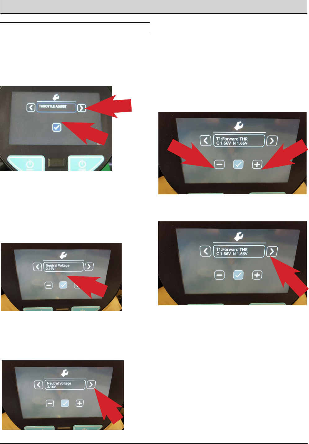
M20/M30 Service Information 163
TROUBLESHOOTING
THROTTLE ADJUST MODE
1. Enter the Service Mode (See SERVICE MODE) and
press the right arrow to scroll to the THROTTLE
ADJUST MODE screen.
2. To enter the THROTTLE ADJUST MODE, press the
‘Check Mark’ icon.
3. The actual ‘Neutral Voltage’ value of the throttle
position sensor is displayed. Pressing the ‘Check
Mark’ sets the Forward and Reverse sense voltage
values, based on this Neutral Voltage value. The
machine operation should be tested to conrm
the rear squeegee raises and lowers at the proper
times when the machine is propelled forward and
backward.
4. If the rear squeegee raises and lowers too soon
or too late, you will need to adjust the Reverse
voltage value and/or the Forward voltage value.
Press the right arrow to proceed to the Forward
Threshold voltage value.
5. Note: the ‘C’ indicates the Current voltage value
and the ‘N’ indicates the New voltage value you
are setting.
6. Press the ‘minus’ icon to reduce the N (New) value and
the ‘Positive’ icon to increase the N value.
The higher the value (a value closer to the Neutral
Voltage value), the quicker the system will react
to forward direction movement. Press the ‘Check
Mark’ to make your ‘N’ New value the ‘C’ Current
value.
7. Press the right arrow to proceed to the Reverse
Threshold voltage value.
8. If the Reverse Threshold requires adjustment press
either the ‘minus’ icon to reduce the N voltage or the
‘plus’ icon to increase the N voltage. The lower the
value (a value closer to the Neutral Voltage value),
the quicker the system will react to reverse direction
movement. Once the desired setting is achieved,
press the ‘Check Mark’ to accept the change and
conrm proper machine operation.
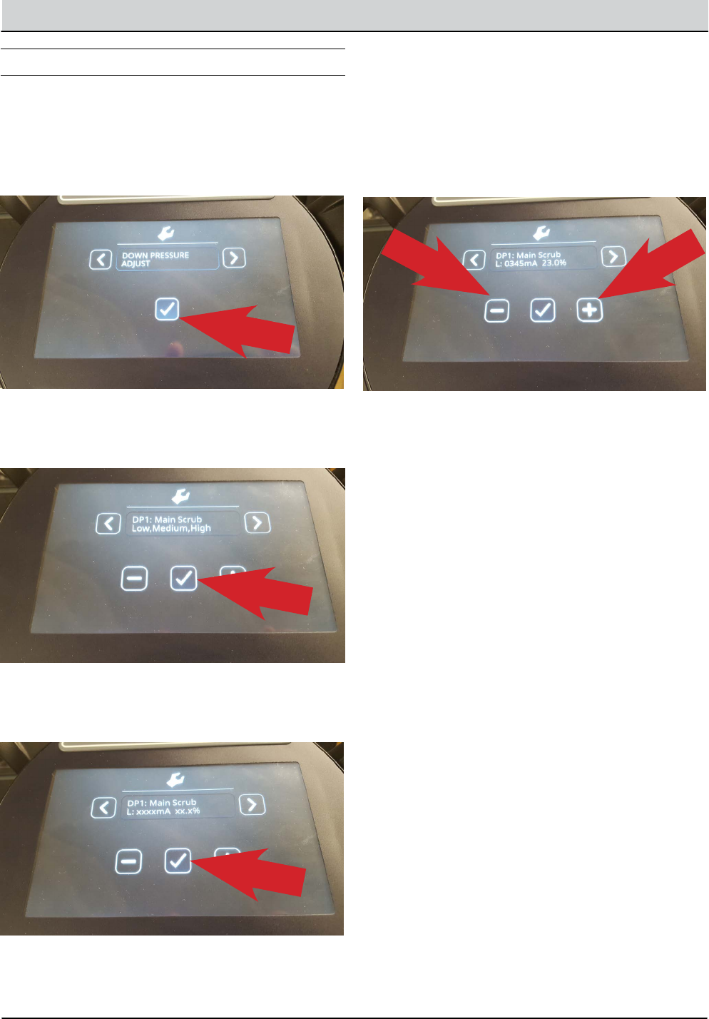
164 M20/M30 Service Information
TROUBLESHOOTING
DOWN PRESSURE ADJUST MODE
1. Enter the Service Mode (See SERVICE MODE)
and press the right arrow to scroll to the DOWN
PRESSURE ADJUST MODE screen.
2. To enter the DOWN PRESSURE ADJUST MODE,
press the ‘Check Mark’ icon.
3. To enter the DOWN PRESSURE ADJUST MODE
for the Main Scrub Brushes, press the ‘Check
Mark’ icon.
4. To enter the ‘L’ (Low Down Pressure Setting
Mode) for the Main Scrub Brushes, press the
‘Check Mark’ icon.
5. To increase the Low Setting Down Pressure for
the Main Scrub Brushes, press the ‘Plus’ icon to
increase the mA setting for the control valve. To
decrease the pressure, press the ‘Minus’ icon
to decrease the mA setting for the control valve.
Each time an icon is pressed, the electrical signal
to the solenoid is changed. This electrical signal is
measured in mA (milliamperes).
6. Press the ‘Check Mark’ icon to move backwards,
then the ‘Right Arrow’ to move to the M: (Medium
Down Pressure Setting) then press the ‘Check
Mark’ to allow you to set the Medium down
pressure setting, if desired.
7. Press the ‘Check Mark’ icon to move backwards,
then the ‘Right Arrow’ to move to the H: (High
Down Pressure Setting) then press the ‘Check
Mark’ to allow you to set the High down pressure
setting, if desired.
8. Press the ‘Check Mark’ icon to move backwards,
then the ‘Right Arrow’ to move to move to Main
Scrub Exit.
9. Press the ‘Check Mark’ icon to Exit the Main Scrub
Down Pressure Setting Mode.
10. Press the ‘Right Arrow’ icon to move to the Side
Scrub Brush Down Pressure Adjust Mode. Follow
the same process as above to make adjustments
to the Side Scrub Brush Down pressure, if desired.
You can press the ‘Right Arrow’ icon again to
move to the Main Sweeping Brush Down Pressure
Adjust Mode and again for the Side Sweeping
Brush Down Pressure Adjust Mode.
Follow the same adjustment procedures outlined
for the Main Scrub Brush Down Pressure Settings.
NOTE: Refer to the ‘Default Down Pressure List’ below, for
the factory default down pressure settings.
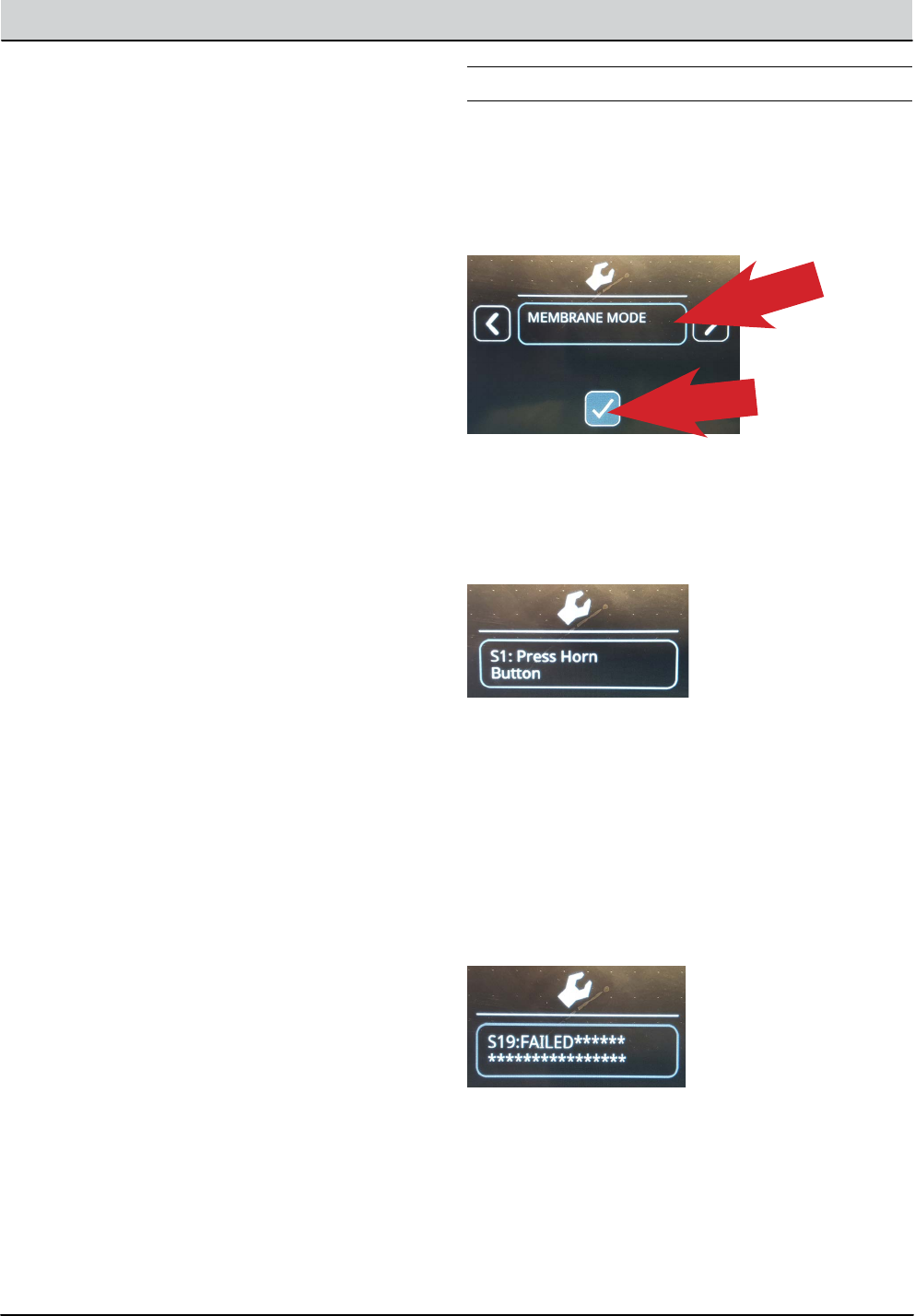
M20/M30 Service Information 165
TROUBLESHOOTING
DEFAULT DOWN PRESSURE LIST
Note: There is a low limit of 100mA and a high limit of
950mA for each brush pressure setting.
Main Scrub Brushes:
• Disk Low Pressure Default Setting, 358mA.
• Disk Medium Pressure Default Setting, 458mA.
• Disk High Pressure Default Setting, 548mA.
• Cyl. Low Pressure Default Setting, 340mA.
• Cyl. Medium Pressure Default Setting, 440mA.
• Cyl. High Pressure Default Setting, 530mA.
Main Sweep Brushes:
• Cyl. Low Pressure Default Setting, 250mA.
• Cyl. Medium Pressure Default Setting, 310mA.
• Cyl. High Pressure Default Setting, 350mA.
Side Scrub Brush:
• Low Pressure Default Setting, 600mA.
• Medium Pressure Default Setting, 675mA.
• High Pressure Default Setting, 730mA.
Side Sweep Brush:
• Low Pressure Default Setting, 570mA.
• Medium Pressure Default Setting, 570mA.
• High Pressure Default Setting, 570mA.
11. To exit the Down Pressure Adjust Modes, press
the Right Arrow until you see Exit DP Adjust. Press
the ‘Check Mark’ two times to exit this mode.
12. To exit the Service Modes, turn off the key switch
and then turn it on again.
MEMBRANE TEST MODE
1. Enter the Service Mode (See SERVICE MODE)
and press the right arrow to scroll to the
MEMBRANE TEST MODE screen.
2. To enter the MEMBRANE TEST MODE, press the
‘Check Mark’ icon.
3. The MEMBRANE TEST MODE allows you to test
the touch button functions, on the control panel.
When you are in the Membrane Test Mode, you
are directed to press each Membrane Button to
test it’s functionality.
4. When you press a button as directed, if the button
functions properly, you will be directed to press
another button.
Note: If you delay pressing the requested button too
long, you may see a ‘FAILED’ message displayed. If
this happens, restart the testing procedures.
If a button fails to function as designed, you will
receive the message ‘FAILED’ in the display
window.
5. To exit the Service Modes, turn off the key switch
and then turn it on again.

166 M20/M30 Service Information
TROUBLESHOOTING
