S20 Service Manual Tennant Battery Rider Floor Sweeper
2018-06-12
: Sweepscrub Tennant-S20-Battery-Rider-Floor-Sweeper-Service-Manual tennant-s20-battery-rider-floor-sweeper-service-manual 2745 file product_file
Open the PDF directly: View PDF ![]() .
.
Page Count: 50
S20
www.tennantco.com
North America / International
SweepSmart
t
System
ShakeMax
t
360
(Electric)
Sweeper
Service Information Manual
*9006709*
9006709
Rev. 00 (11-2009)
Ref Part No. Serial Number Description Qty.
1 82681 (000000--- ) Bracket Wldt, Lpg Mount 1
o2 63810 (000000--- ) Latch Assy, Lpg Tank Mtg, W/Nut 4
Y3 51839 (000000--- ) Nut Adjustable, Lpg Tank Mtg 2
4 49263 (000000--- ) Tie, Cable 3
5 82556 (000000---001039 ) Bracket, Vaporizer 1
6 54930 (000000--- ) Vaporizer, LPG 1
C
D
AB
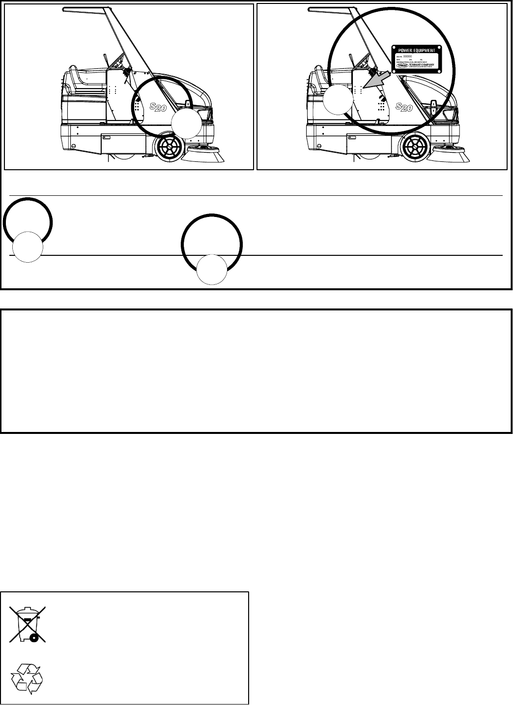
FOR REPLACEMENT PARTS
Identify machine model and serial number.
1. (A) Identify the machine model.
2. (B) Identify the machine serial number from the data plate.
Refer to the TENNANT Parts Manual.
NOTE: Only use TENNANT Company supplied or equivalent parts. Parts and supplies may be ordered
online, by phone, by fax or by mail.
Read this manual completely and understand the machine before operating or servicing it.
This machine will provide excellent service. However, the best results will be obtained at minimum costs if:
SThe machine is operated with reasonable care.
SThe machine is maintained regularly - per the machine maintenance instructions provided.
SThe machine is maintained with manufacturer supplied or equivalent parts.
PROTECT THE ENVIRONMENT
Please dispose of packaging materials,
old machine components such as
batteries, hazardous fluids, including
antifreeze and oil, in an
environmentally safe way according to
local waste disposal regulations.
Always remember to recycle.

MACHINE DATA
Please fill out at time of installation for future reference.
Model No. --
Serial No. --
Machine Options --
Sales Rep. --
Sales Rep. phone no. --
Customer Number --
Installation Date --
Tennant Company
PO Box 1452
Minneapolis, MN 55440
Phone: (800) 553--8033 or (763) 513--2850
www.tennantco.com
Thermo--Sentry, Perma--Filter, InstantAccess, Lower Total Cost of Ownership, and Duramer are US registered and unregistered trademarks of Tennant
Company.
Specifications and parts are subject to change without notice.
Original Instructions, Copyright E2009 TENNANT Company, Printed in U.S.A.
iv
S20 ELECTRIC TABLE OF CONTENTS
SAFETY PRECAUTIONS vii...................................
GENERAL MACHINE INFORMATION 1.....................
SPECIFICATIONS 2.........................................
GENERAL MACHINE DIMENSIONS/CAPACITIES 2..........
GENERAL MACHINE PERFORMANCE 2....................
POWER TYPE 3..........................................
STEERING 3.............................................
HYDRAULIC SYSTEM 3...................................
BRAKING SYSTEM 3.....................................
TIRES 3.................................................
MACHINE DIMENSIONS 4.................................
COMPONENT LOCATOR 5................................
SYMBOL DEFINITIONS 6.................................
MAINTENANCE & REPAIR 9.................................
HOPPER DUST FILTER 10.................................
REPLACING THE HOPPER DUST FILTER 10.................
HOPPER DUST FILTER MEASUREMENT 11.................
FILTER SEAL HEIGHT ADJUSTMENT 11....................
HYDRAULIC TROUBLESHOOTING INFORMATION 12..............
HYDRAULIC TROUBLESHOOTING INFORMATION 12...........
GENERAL INFORMATION 14...............................
General Information 15.....................................
HYDRAULIC SCHEMATIC 16...............................
OVERALL HYDRAULIC HOSE DIAGRAM 17..................
SIDE BRUSH ON (STANDARD) 18...........................
SIDE BRUSHES ON (WITH OPTIONAL LEFT SIDE BRUSH) 19.
SIDE BRUSH(ES) DOES NOT TURN ON 20..................
SIDE BRUSH(ES)DOES NOT TURN OFF 21..................
HOPPER DOOR OPEN 22..................................
HOPPER DOES NOT OPEN 23.............................
HOPPER DOOR CLOSE 24.................................
HOPPER DOOR DOES NOT CLOSE 25......................
HOPPER DOOR DOES NOT STAY CLOSED 26...............
HOPPER LIFT 27..........................................
HOPPER DOES NOT RAISE 28.............................
HOPPER DOES NOT STAY IN RAISED POSITION 29..........
v
HOPPER LOWER 30.......................................
HOPPER DOES NOT LOWER 31............................
STEERING SYSTEM -- RIGHT TURN 32.....................
STEERING SYSTEM -- LEFT TURN 33.......................
STEERING SYSTEM NOT WORKING PROPERLY 34..........
ELECTRICAL INFORMATION 35...............................
ELECTRICAL CONTROL BOX GROUP 36....................
ELECTRICAL SCHEMATIC FIG 1 37.........................
ELECTRICAL SCHEMATIC FIG 2 38.........................
ELECRICAL SCHEMATIC FIG. 3 39..........................
ELECTRICAL SCHEMATIC FIG. 4 40........................
vi

S20 Service Information
vii
S20 Electric 9006709 (11--09)
SAFETY PRECAUTIONS
The following precautions are used throughout
this manual as indicated in their description:
WARNING: To warn of hazards or
unsafe practices that could result in
severe personal injury or death.
CAUTION: To warn of unsafe practices
that could result in minor or moderate
personal injury.
FOR SAFETY: To identify actions that must be
followed for safe operation of equipment.
Do not use the machine other than described in
this Operator Manual. The machine is not
designed for use on public roads.
The following information signals potentially
dangerous conditions to the operator or
equipment:
WARNING: Batteries emit hydrogen gas.
Explosion or fire can result. Keep
sparks and open flame away. Keep
covers open when charging.
WARNING: Lift arm pinch point. Stay
clear of hopper lift arms.
WARNING: Raised hopper may fall.
Engage hopper support bar.
WARNING: Moving belt and fan. Keep
away.
WARNING: Machine can emit excessive
noise. Hearing loss can result. Wear
hearing protection. (Cab option only).
WARNING: Accident may occur. Do not
operate vacuum wand while driving.
(Vacuum wand option only)
FOR SAFETY:
1. Do not operate machine:
-- Unless trained and authorized.
-- Unless operator manual is read and
understood.
-- If it is not in proper operating
condition.
-- In flammable or explosive areas.
-- In areas with possible falling objects
unless equipped with overhead guard.
2. Before starting machine:
-- Make sure all safety devices are in
place and operate properly.
-- Check brakes and steering for proper
operation.
-- Adjust seat and fasten seat belt (if so
equipped).
3. When starting machine:
-- Keep foot on brake and directional
pedal in neutral.
4. When using machine:
-- Do not pick up burning or smoking
debris, such as cigarettes, matches or
hot ashes
-- Use brakes to stop machine.
-- Go slow on inclines and slippery
surfaces.
-- Use care when reversing machine.
-- Move machine with care when hopper
is raised.
-- Make sure adequate clearance is
available before raising hopper.
-- Do not raise hopper when machine is
on an incline.
-- Do not carry passengers on machine.
-- Always follow safety and traffic rules.
-- Report machine damage or faulty
operation immediately.
5. Before leaving or servicing machine:
-- Stop on level surface.
-- Set parking brake.
-- Turn off machine and remove key.

S20 Service Information
S20 Electric 9006709 (11--09)
viii
6. When servicing machine:
-- Avoid moving parts. Do not wear loose
clothing or jewelry.
-- Block machine tires before jacking
machine up.
-- Jack machine up at designated
locations only. Support machine with
jack stands.
-- Use hoist or jack that will support the
weight of the machine.
-- Wear eye and ear protection when
using pressurized air or water.
-- Disconnect battery connections before
working on machine.
-- Avoid contact with battery acid.
-- Use cardboard to locate leaking
hydraulic fluid under pressure.
-- Use Tennant supplied or approved
replacement parts.
7. When loading/unloading machine
onto/off truck or trailer:
-- Turn off machine.
-- Use truck or trailer that will support
the weight of the machine.
-- Use winch. Do not drive the machine
onto/off the truck or trailer unless the
load height is 380 mm (15 in) or less
from the ground.
-- Set parking brake after machine is
loaded.
-- Block machine tires.
-- Tie machine down to truck or trailer.
S20 Service Information
ix
S20 Electric 9006709 (11--09)
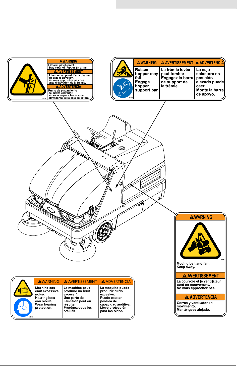
The following safety labels are mounted on the
machine in the locations indicated. If any label
becomes damaged or illegible, install a new label
in its place.
HOPPER LIFT ARMS LABEL --
Located on both hopper lift arms.
FAN AND BELT LABEL --
Located on belt guard.
354590
RAISED HOPPER LABEL -- Located on the
hopper support bar.
HEARING PROTECTION LABEL -- Located only
on machines with cab option.
S20 Service Information
S20 Electric 9006709 (11--09)
x
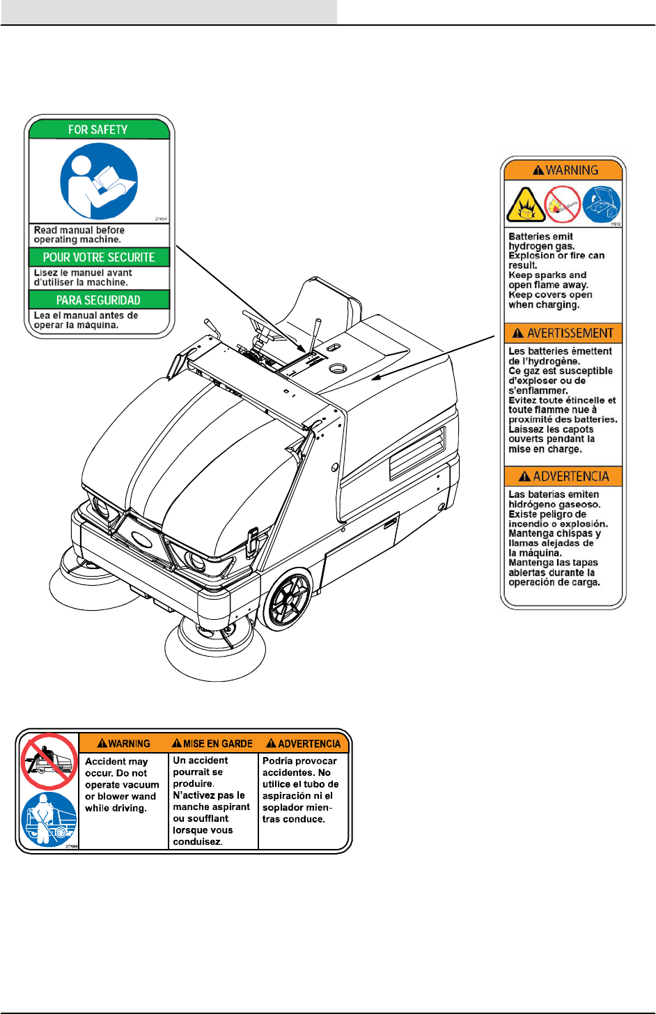
BATTERY CHARGING
LABEL -- Located on
back of main electrical
panel.
354590
VACUUM WAND LABEL -- Located on the
optional vacuum wand.
FOR SAFETY LABEL --
Located on the side of the
operator compartment.

S20 Service Information
1
S20 Electric 9006709(11--09)
GENERAL
MACHINE
INFORMATION
BEFORE CONDUCTING TESTS:
* Read and Follow ALL Safety Warnings and Precautions as
mentioned at the beginning of this manual
* Always unhook Battery when removing or replacing components
DURING TESTS:
* If Diagnostic Time Exceeds One Hour With Unknown Cause or
Course of Action, Call Technical Services.

S20 Service Information
S20 Electric 9006709 (11--09)
2
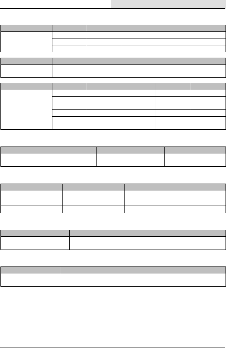
SPECIFICATIONS
GENERAL MACHINE DIMENSIONS/CAPACITIES
Item Dimension/capacity
Length 2090 mm (82.3 in)
Length with side brush 2248 mm (88.5 in)
Width 1230 mm (48.5 in)
Width with side brush 1395 mm (55 in)
Height without overhead guard 1260 mm (49.5 in)
Height with overhead guard 2085 mm (82.1 in)
Track 1135 mm (44.7 in)
Wheelbase 1135 mm (44.7 in)
Main sweeping brush diameter 355 mm (14 in)
Main sweeping brush length 910 mm (36 in)
Side brush diameter 580 mm (23 in)
Sweeping path width with side brush 1270 mm (50 in)
Sweeping path width with dual side brushes 1575 mm (62 in)
Main sweeping brush pattern width 50 to 75 mm (2 to 3 in)
Hopper weight capacity 295 kg (650 lb)
Hopper volume capacity 310 L (11 ft3)
Dust filter area 7.4 m2(80 ft2)
Minimum ceiling dump height 2490 mm (98 in)
Weight -- without batteries 1045 kg (2300 lb)
Weight -- with batteries 1350 kg (2975 lb)
GVWR (Gross Vehicle Weight Rating) 2028 kg (4470 lb)
Operating sound level at operator ear N/A
Vibration level at steering wheel does not exceed 2.5 m/s@
GENERAL MACHINE PERFORMANCE
Item Measure
Maximum forward speed 8km/h (5mph)
Maximum reverse speed 4.8 km/h (3 mph)
Minimum aisle turn width, left 2415 mm (95 in)
Minimum turning radius, right 2113 mm (83.2 in)
Minimum turning radius, left 1625 mm (64 in)
Maximum rated incline with empty hopper 10_/ 17.6%
Maximum rated incline with full hopper 8_/ 14.1%
S20 Service Information
3
S20 Electric 9006709(11--09)
POWER TYPE
Type Quantity Volts Ah Rating Weight
Batteries 66315 @ hr rate 58 kg (127 lb)
218 340 @ hr rate 245 kg (540 lb)
218 440 @ hr rate 299 kg (660 lb)
Type Use VDC Kw (hp)
Electric Motors Propelling 36 1.6 (2.1)
Accessory 36 3(4)
Type VDC AHz Phase VAC
Chargers 36 50 60 1240
36 75 60 1variable
36 75 60 3variable
36 50 50 1230
36 75 50 3variable
36 45 50/60 1variable
STEERING
Type Power source Emergency steering
Rear wheel, hydraulic cylinder and rotary
valve controlled
Hydraulic accessory pump Manual
HYDRAULIC SYSTEM
System Capacity Fluid Type
Hydraulic reservoir 10.6 L (2.8 gal) TENNANT part no. 65870
Hydraulic total 12.1 L (3.2 gal)
Propelling gearbox 2.6L(2.7qt) SAE 90 Gear weight lubricant
BRAKING SYSTEM
Type Operation
Service brakes Mechanical drum brakes (2), one per front wheel, cable actuated
Parking brake Utilizes service brakes, cable actuated
TIRES
Location Type Size
Front (2) Solid 89 x 410 mm (3.5 X 16 in)
Rear (1) Solid 102 x 410 mm (4 x 16 in)
S20 Service Information
S20 Electric 9006709 (11--09)
4
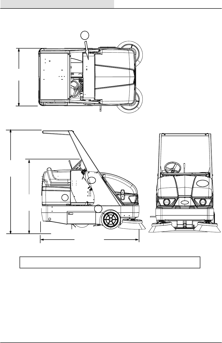
MACHINE DIMENSIONS
TOP VIEW
SIDE VIEW
2090 mm
(82.3 in)
1230 mm
(48.5 in)
2085 mm
(82.1 in)
FRONT VIEW
1260 mm
(49.5 in)
1
23&4
6
Numbering above refers to component locations shown on next page.
5
354901
S20 Service Information
5
S20 Electric 9006709(11--09)
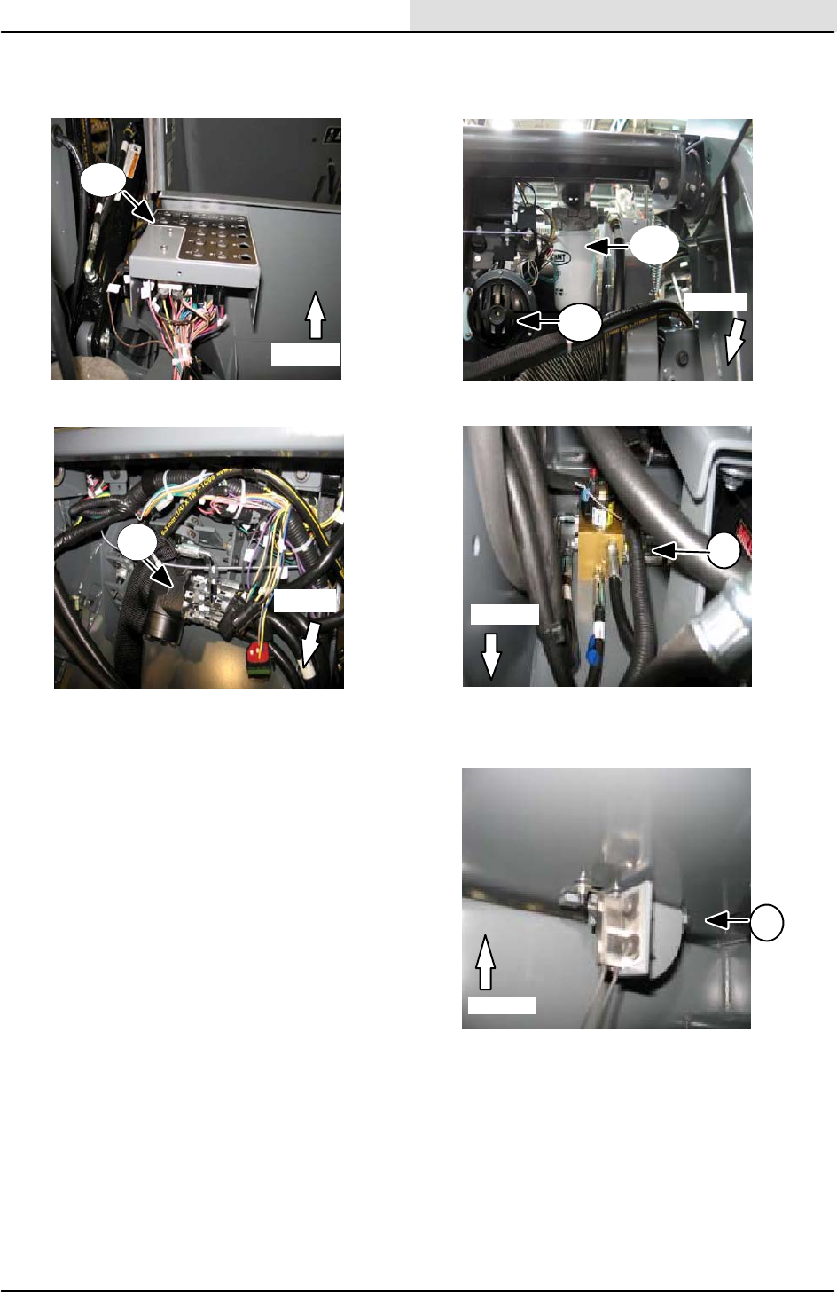
COMPONENT LOCATOR
1
1. Fuse & relay panel
2. Steering Valve
3. Horn
4. Hydraulic filter
5. Hydraulic valve
6. Brake light switch
3
5
6
Located under floor panel
in operators compartment
2
Front
Front
Front
Front
Front
4
4
S20 Service Information
S20 Electric 9006709 (11--09)
6
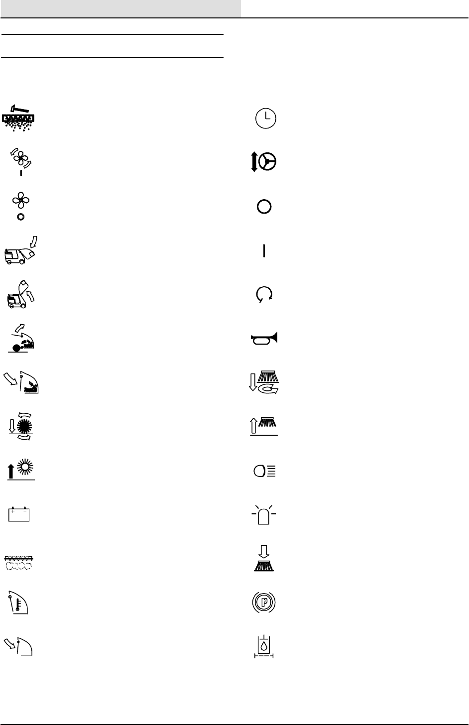
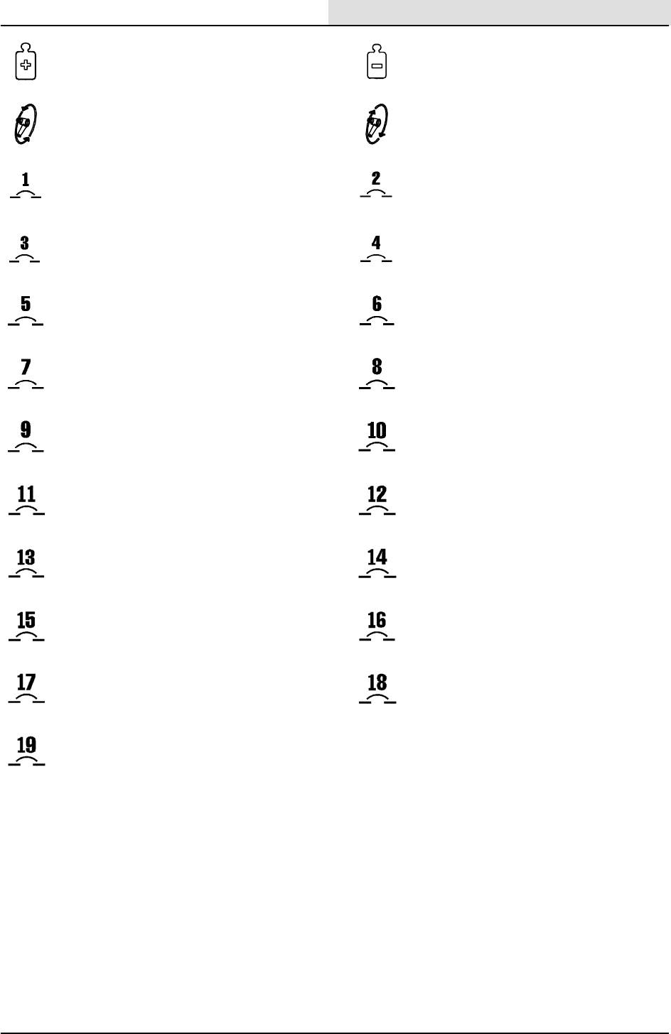
SYMBOL DEFINITIONS
These symbols identify controls, displays, and
features on the machine:
Filter shaker Hour meter
Vacuum fan on Steering wheel tilt
Vacuum fan off Off
Hopper down On
Hopper up Start
Hopper door open Horn
Hopper door close (lever) Side brush down and on
Main brush down and on Side brush up and off
Main brush up and off Operating lights
Battery charging system Hazard light
Clogged dust filter Side brush pressure
Thermo--Sentry Parking brake
Hopper door closed (light) Clogged hydraulic filter
S20 Service Information
7
S20 Electric 9006709(11--09)
Brush pressure (Increase) Brush pressure (Decrease)
Turn counterclockwise Turn clockwise
Circuit breaker #1 Circuit breaker #2
Circuit breaker #3 Circuit breaker #4
Circuit breaker #5 Circuit breaker #6
Circuit breaker #7 Circuit breaker #8
Circuit breaker #9 Circuit breaker #10
Circuit breaker #11 Circuit breaker #12
Circuit breaker #13 Circuit breaker #14
Circuit breaker #15 Circuit breaker #16
Circuit breaker #17 Circuit breaker #18
Circuit breaker #19

S20 Service Information
S20 Electric 9006709 (11--09)
8
FOR OPERATOR AND MAINTENANCE CHARTS, REFER TO OPERATORS MANUAL.

S20 Service Information
9
S20 Electric 9006709 (11--09)
MAINTENANCE
& REPAIR
BEFORE CONDUCTING TESTS:
* Read and Follow ALL Safety Warnings and Precautions as
mentioned at the beginning of this manual
* Always unhook Battery when removing or replacing electrical
components
DURING TESTS:
* If Diagnostic Time Exceeds One Hour With Unknown Cause or
Course of Action, Call Technical Services.
S20 Service Information
10 S20 Electric 9006709 (11--09)
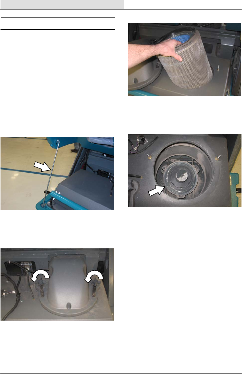
HOPPER DUST FILTER
REPLACING THE HOPPER DUST FILTER
Shake the dust filter at the end of every shift and
before removing the filter from the machine.
Inspect and clean the filter after every 100 hours
of operation. Replace damaged dust filters.
NOTE: Clean the filter more often if used in
extremely dusty conditions.
FOR SAFETY: Before leaving or servicing
machine, stop on level surface, set parking
brake, and turn off machine.
1. Unlatch and open the hopper cover. Support
the hopper cover open with the hopper cover
prop rod.
2. Remove the dust filter cover.
NOTE: Do not operate filter shaker or raise
hopper with dust filter cover removed.
Shaker motor damage can occur.
3. Remove the dust filter from the hopper.
4. Clean or discard the dust filter element. Refer
to CLEANING THE DUST FILTER.
5. Clean dust and debris from the dust filter tray.
6. Reinstall the dust filter.
7. Reinstall the dust filter cover.
8. Close the hopper cover.
S20 Service Information
11
S20 Electric 9006709 (11--09)
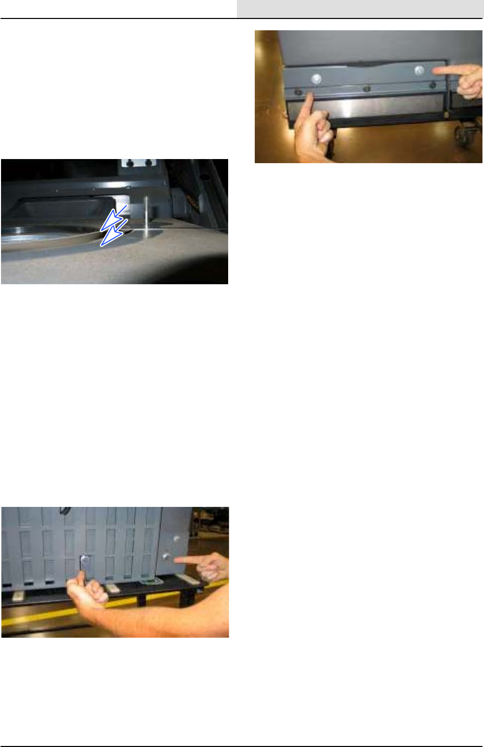
HOPPER DUST FILTER MEASUREMENT
Check 1/8” thick shaker spacer for wear, replace
as necessary. With hopper dust filter cover
removed and cyclone cover latches locked,
check filter seal measurement for proper height.
Top of seal should measure 7.62 mm (.25”) above
filter cover mounting base, as shown below. This
will allow proper sealing of filter with filter cover
installed and seal compressed.
FILTER SEAL HEIGHT ADJUSTMENT
Filter Seal Height Adjustment
*Safety Note* Cyclone filter box assembly is
heavy, assistance recommended for removal.
Remove filter box assembly from hopper. With
cyclone cover in place and latched, mark seal
height measurement at 4 places; RF--LF--RR--and
LR areas of filter box. 4 -- M10 screw locations
for shaker mounting tray are shown below.
Loosen shaker tray mounting bolts and adjust tray
to obtain proper seal filter height measurement
and tighten as necessary. Reassemble filter box,
using new seals as needed.
Front side of filter box assembly
Rear side of filter box assembly

S20 Service Information
12 S20 Electric 9006709 (11--09)
HYDRAULIC
TROUBLESHOOTING
INFORMATION
BEFORE CONDUCTING TESTS:
* Read and Follow ALL Safety Warnings and Precautions as
mentioned at the beginning of this manual
*Hydraulic Oil Must Be At Normal Operating Temperatures after
Running Machine and Hydraulics a Minimum of 5 Minutes
* Examine Machine For Any Linkage Binding or Mechanical
Problems
DURING TESTS:
* Call Technical Services if Diagnostic Time Exceeds One Hour With
Unknown Cause or Course of Action
* Maintain Normal Main Brush Pressure as Listed in Operator’s
Manual

S20 Service Information
13
S20 Electric 9006709 (11--09)
NOTE: Troubleshooting charts may be shown with optional equipment. The optional
equipment may not be specified in these charts. Some machines may not be equipped with
all components shown.
S20 Service Information
14 S20 Electric 9006709 (11--09)
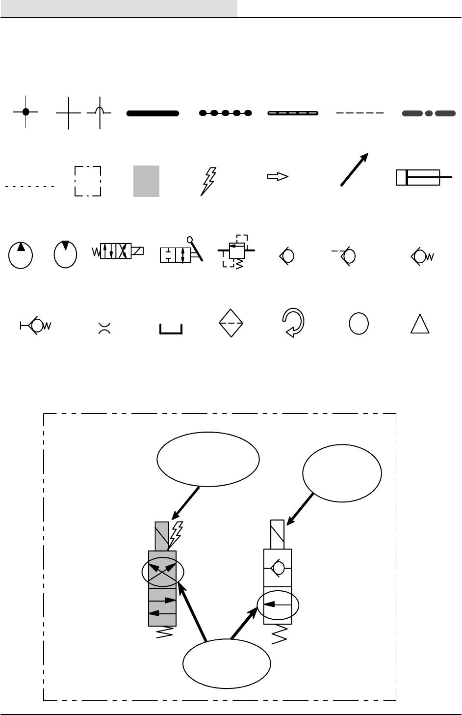
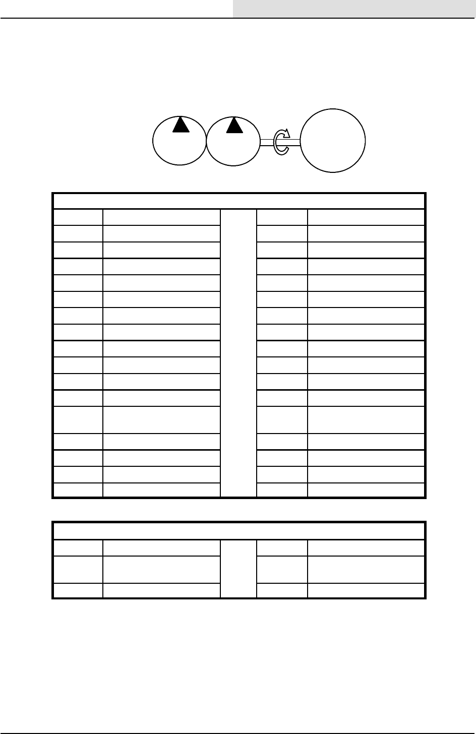
GENERAL INFORMATION
Page1of2
Commonly Used Hydraulic Symbols
i
LINES NOT
CONNECTED
ASSEMBLY
CYLINDER OR
RAM
ACTIVATED
COMPONENT
ENERGIZED
COMPONENT
INFORMATION
HIGH
PRESSURE OR
FLOW LINE
RETURN OR
LOW
PRESSURE
LINE
NON--ACTIVE
PILOT PORT
LINE
!
WARNING
LINES
CONNECTED
SUCTION
LINE
ACTIVE
PILOT
PORT LINE
CASE
DRAIN
LINE HYDRAULIC
FLOW OR
MOVEMENT
VARIABLE
OR PWM
ROTATING
COMPONENT
PUMP MOTOR SOLENOID
VALVE
MANUAL
VALVE RELIEF
VALVE
CHECK
VALVE
PILOT PORT
CHECK VALVE
SPRING
LOADED
CHECK VALVE
QUICK
CONNECT
TEST PORT
RESTRICTOR
OR ORIFICE
TANK OR
RESERVOIR
FILTER OR
STRAINER
Energized
Solenoid
Valve
Non--ener-
gized
Solenoid
Valve
Valve position for
indicated circuit
EXAMPLES
S20 Service Information
15
S20 Electric 9006709 (11--09)
General Information
Page2of2
Hydraulic Pump Flow Rates (typical)
ACCESSORY PUMPS
7.4 cc
per rev.
(0.453 ci)
5.3 cc
per rev.
(0.323 ci)
PUMP
1B
PUMP
1A
MOTOR
Commonly Used Abbreviations
AUX Auxiliary MFLD Manifold
CC Cubic Centimeters MTR Motor
CK Check Valve OR Orifice
CM Centimeters PC Pilot Port Check Valve
CU Cubic PMP Pump
CV Control Valve PSI Pounds Per Square Inch
CYL Cylinder PSWITCH Pressure Switch
DC Direct Current PWM Pulse Width Modulation
DCn Disconnect (Test Port) RES Reservoir
FLTR Filter RH Right Hand
GPM Gallons Per Minute RPM Revolutions Per Minute
HTX Heat Exchanger RV Relief Valve
IN Inches SC
Spring Loaded Check
Valve
kPa KiloPascals STRN Strainer
LH Left Hand SV Solenoid Valve
LPM Liters Per Minute SW Switch
MMotor (Combustion) VVolts
Hydraulic Manifold Port Markings
CCylinder Connection PPump Connection
GTest Port PS
Pressure Switch Connec-
tion
MMotor Connection TTank Connection
S20 Service Information
16 S20 Electric 9006709 (11--09)
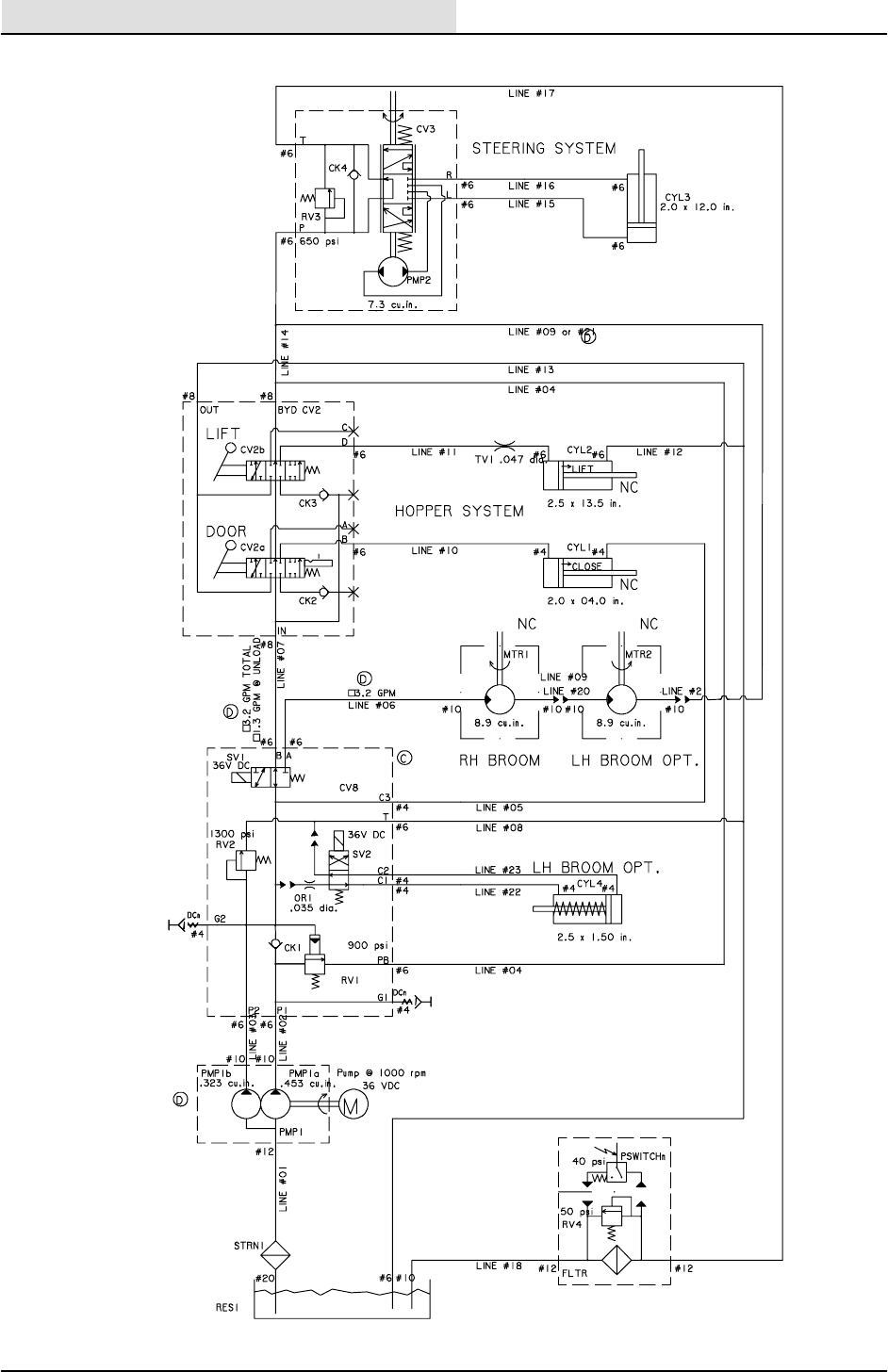
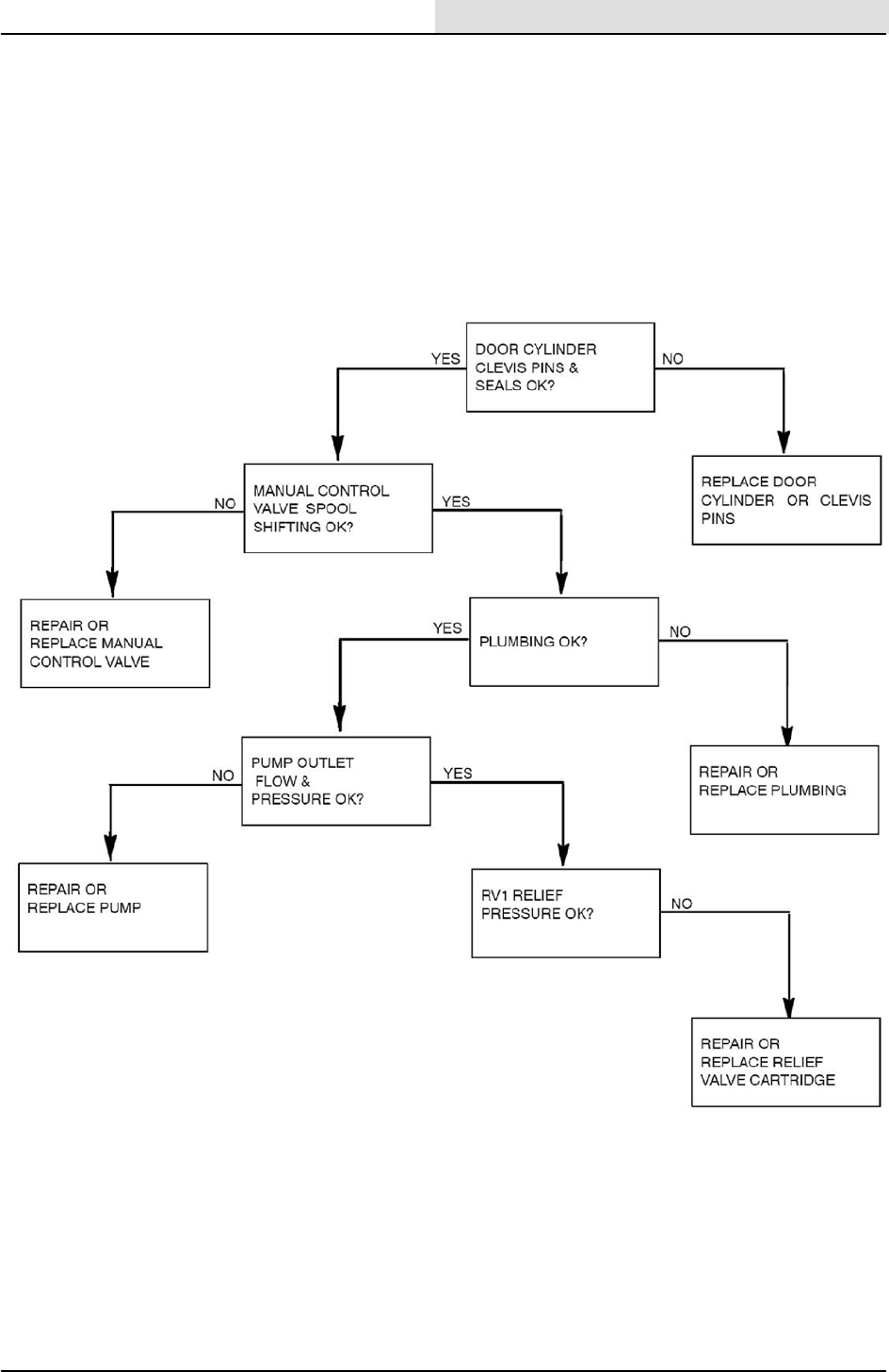
HYDRAULIC SCHEMATIC
S20 Service Information
17
S20 Electric 9006709 (11--09)
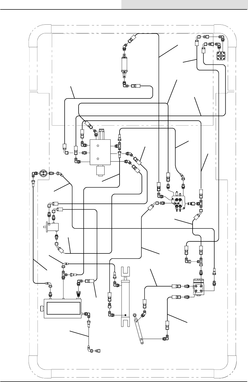
OVERALL HYDRAULIC HOSE DIAGRAM
B
PB
C3
A
T
P1
P2
R
L
T
BYD
C
DB
AIN
OUT
P
IN
OUT
1
2
2
3
4
5
6
7
8
9
10
11
12
13
14
15
16
17
18
RESERVOIR
S20 Service Information
18 S20 Electric 9006709 (11--09)
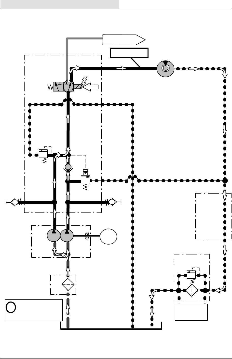
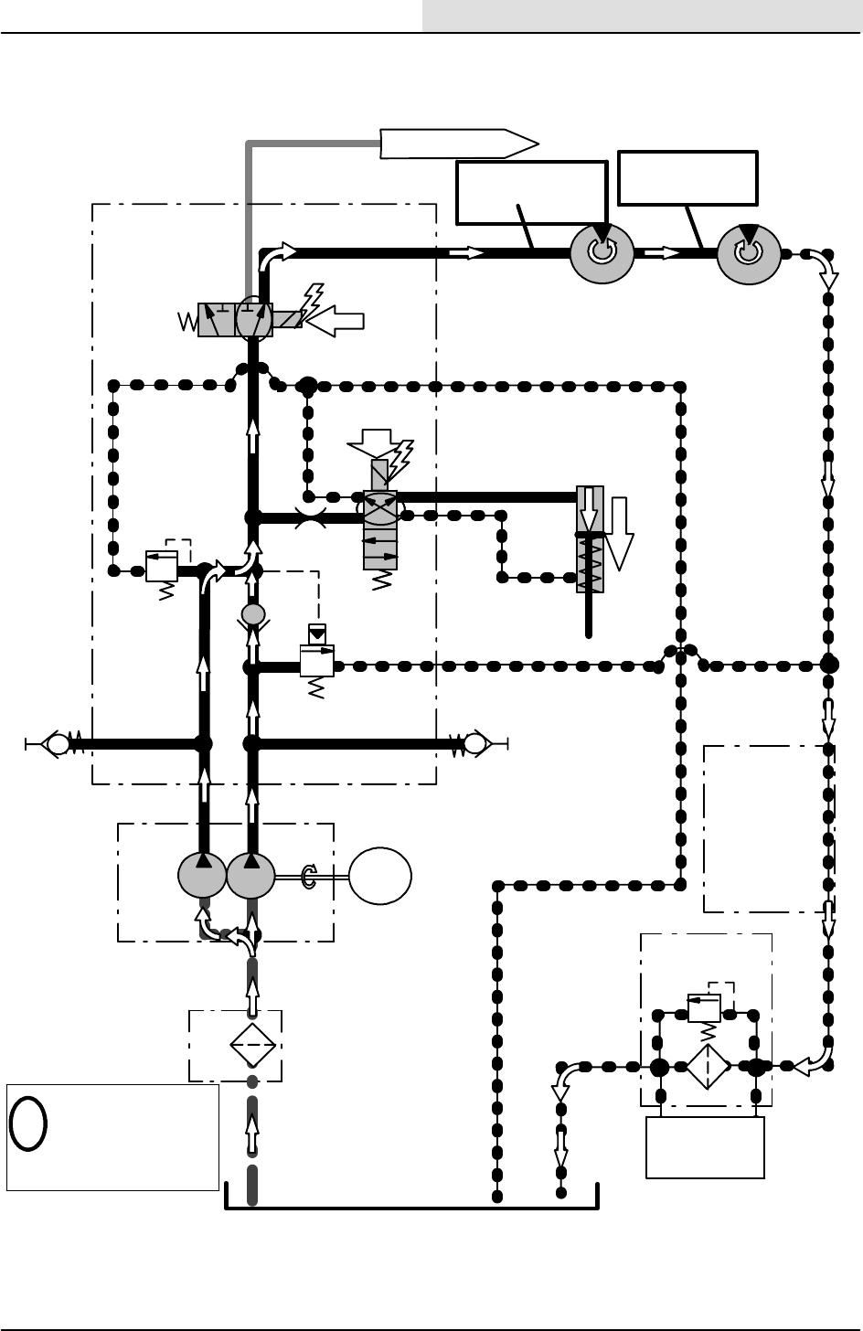
SIDE BRUSH ON (STANDARD)
Conditions: Key ON, Side Brush Lowered
RESERVOIR
STRN
1
P1
G1
P
89.6 BAR
(1300
psi)
T
SV1
(50 psi)
FLT
R
PB
3.4 BAR
PRESSURE
2.8 BAR (40 psi)
SWITCH
B
MTR
1
T
(1.4 GPM)
5.2 LPM
PRESSURE READINGS
BASED ON HYDRAULIC OIL
TEMPERATURE OF 65.5_C
(150_F)
i
RIGHT SIDE
BRUSH MOTOR
85 RPM +/-- 10 RPM
15.5 BAR (225 PSI)
CV8
SOLENOID
VALVE
MANIFOLD
G2
PUMP
1B
PUMP
1A
P2
MOTOR
@1000RPM
TO CV2 HOPPER VALVE
MANIFOLD
STEERING
VALVE
ASSEMBLY
CV3
(1.9 GPM)
7.3 LPM
62 BAR
RV1
(900 psi)
RV2
TEST PORT
15.5 BAR
(225 PSI)
TEST PORT
15.5 BAR
(225 PSI)
A
TURNS PUMPS
CK1
12.5 LPM (3.3 GPM)
MOTOR
RV4
S20 Service Information
19
S20 Electric 9006709 (11--09)
SIDE BRUSHES ON (WITH OPTIONAL LEFT SIDE BRUSH)
Conditions: Key ON, Side Brushes Lowered
RESERVOIR
STRN1
P1
G1
P
89.6 BAR
(1300 psi)
T
SV1
(50 psi)
FLT
R
PB
3.4 BAR
PRESSURE
2.8 BAR
(40 psi)
SWITCH
B
MTR1
T
PRESSURE
READINGS BASED ON
HYDRAULIC OIL
TEMPERATURE OF
65.5_C (150_F)
i
RIGHT SIDE
BRUSH MOTOR
85 RPM +/--10RPM
CV8
SOLENOID
VALVE
MANIFOLD
G2
P2
TO CV2 HOPPER
VALVE MANIFOLD
STEERING
VALV
E
ASSEMBLY
CV3
62 BAR
RV1
(900 psi)
RV2
TEST PORT
TEST PORT
A
MTR2
LEFT SIDE
BRUSH MOTOR
85 RPM +/--10RPM
SV3
C1
C2
LEFT SIDE BRUSH
CYL4
LIFT/LOWER
CYLINDER
LOWER
31 BAR
(450 PSI)
(450 PSI) 31 BAR
CK1
(1.4 GPM)
5.2 LPM
PUMP
1B
PUMP 1A
MOTOR
@ 1000 RPM
(1.9 GPM)
7.3 LPM
TURNS PUMPS
OR1
(0.035 in)
0.89 mm
31 BAR (450 PSI)
12.5 LPM (3.3 GPM)
15.5 BAR (225 PSI)
12.5 LPM (3.3 GPM)
MOTOR
RV4
S20 Service Information
20 S20 Electric 9006709 (11--09)
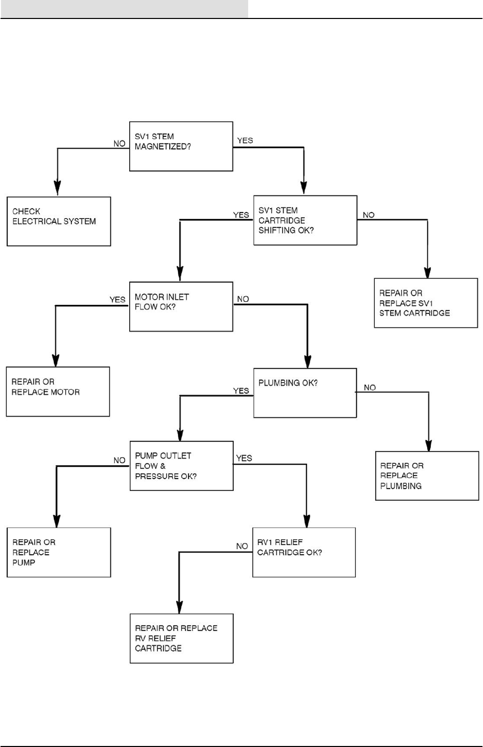
SIDE BRUSH(ES) DOES NOT TURN ON
S20 Service Information
21
S20 Electric 9006709 (11--09)
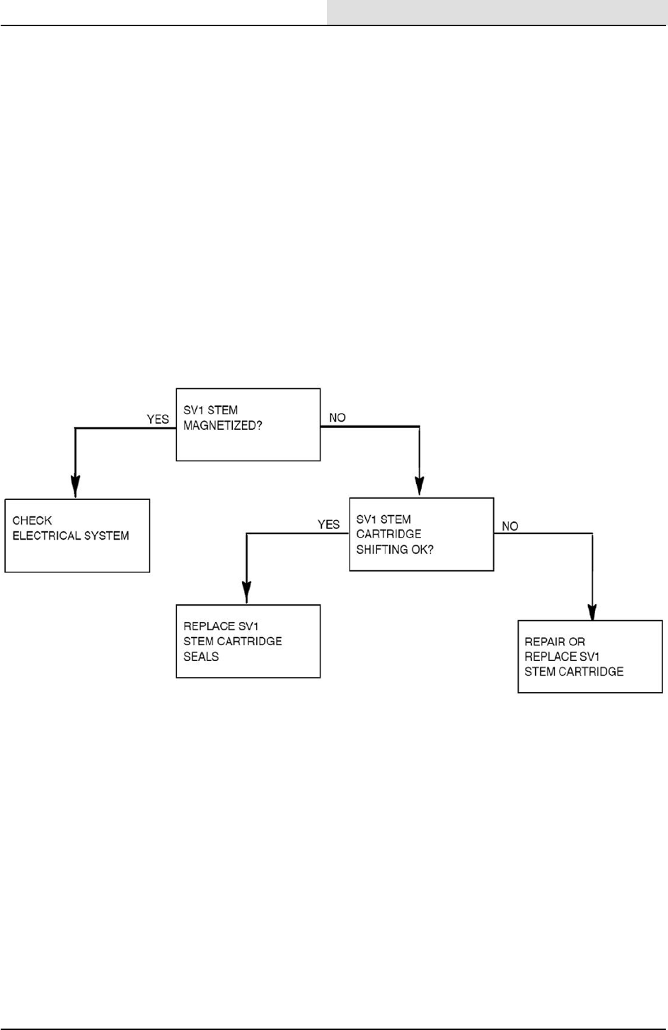
SIDE BRUSH(ES)DOES NOT TURN OFF
S20 Service Information
22 S20 Electric 9006709 (11--09)
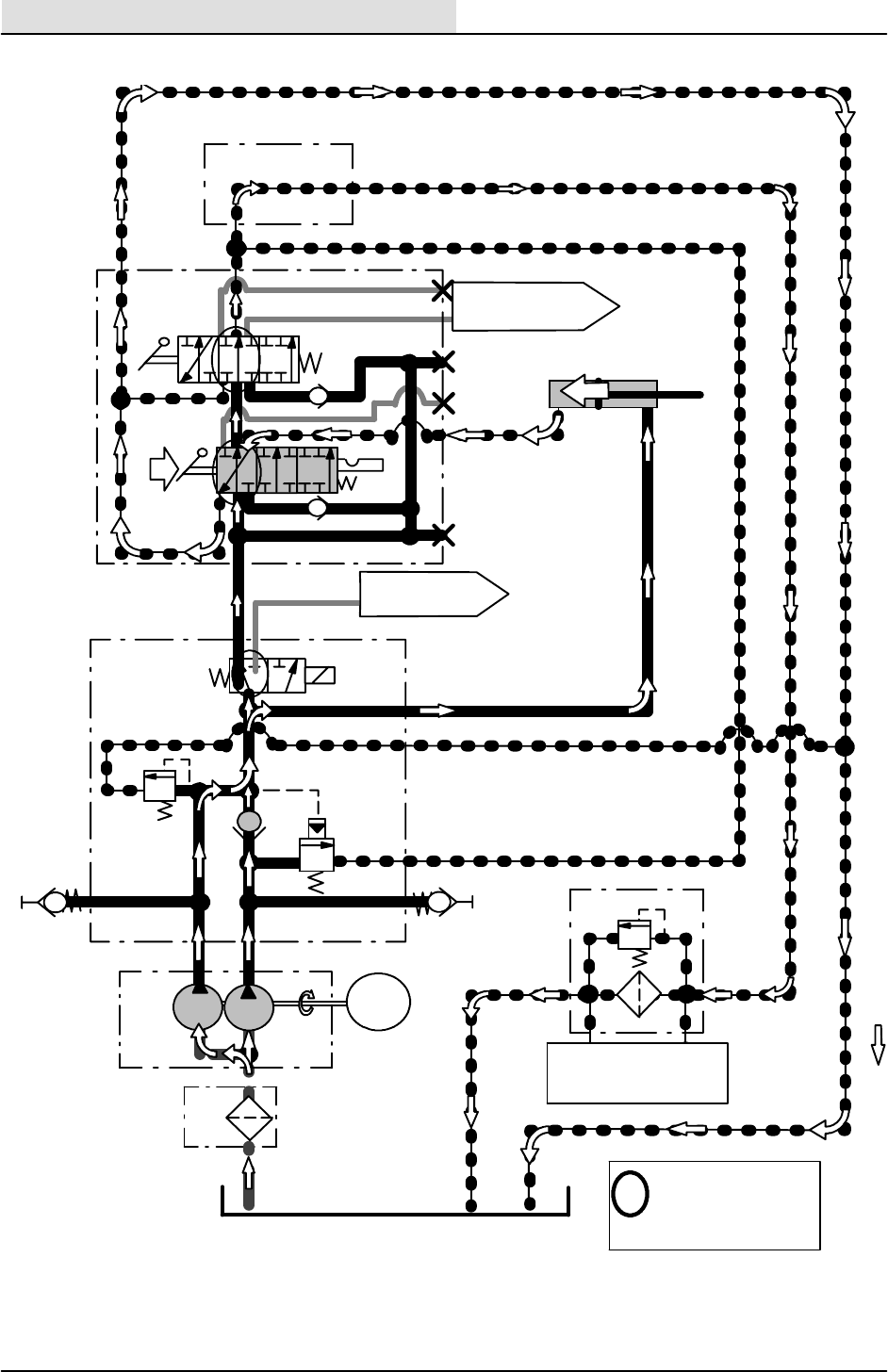
HOPPER DOOR OPEN
RESERVOIR
STRN
1
(50 psi)
3.4 BAR
PRESSURE
2.8 BAR (40 psi)
SWITCH
G1
89.6 BAR
(1300 psi)
T
PB
B
CV8
SOLENOID
VALVE
MANIFOLD
G2
62 BAR
(900 psi)
RV2
TEST
PORT
TEST
PORT
A
CK1
(1.4 GPM)
5.2 LPM
PUMP
1B
PUMP
1A
MOTOR
@ 1000 RPM
(1.9 GPM)
7.3 LPM
TURNS PUMPS
PRESSURE READINGS BASED
ON HYDRAULIC OIL
TEMPERATURE OF 65.5_C
(150_F)
i
PT
STEERING
VALVE ASSEMBLY
CV3
TO MTR1 SIDE
BRUSH MOTOR
TO CYL2 HOPPER
LIFT CYLINDER
OPEN
HOPPER
CYLINDER
DOOR
OUT BYD
A
B
C
D
CK2
CK3
IN
CYL1
CV2
VALVE
MANIFOLD
HOPPER
HOPPER
LIFT
HOPPER
DOOR
C3
RV1
SV1
P2
P1
P1 RV4
FLTR
S20 Service Information
23
S20 Electric 9006709 (11--09)
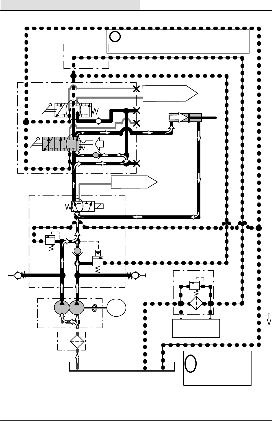
HOPPER DOES NOT OPEN
S20 Service Information
24 S20 Electric 9006709 (11--09)
HOPPER DOOR CLOSE
RESERVOIR
STRN
1
(50 psi)
3.4 BAR
PRESSURE
2.8 BAR (40 psi)
SWITCH
G1
89.6 BAR
(1300 psi)
T
PB
CV8
SOLENOID
VALVE
MANIFOLD
G2
62 BAR
(900 psi)
RV2
TEST PORT
TEST PORT
A
CK1
(1.4 GPM)
5.2 LPM
PUMP
1B
PUMP
1A
MOTOR
@ 1000 RPM
(1.9 GPM)
7.3 LPM
TURNS PUMPS
PRESSURE
READINGS BASED
ON HYDRAULIC OIL
TEMPERATURE OF
65.5_C (150_F)
i
PT
STEERING
VALVE ASSEMBLY
CV3
TO MTR1 SIDE
BRUSH MOTOR
TO CYL2 HOPPER
LIFT CYLINDER
OUT BYD
A
B
C
D
CK2
CK3
IN
CV2
VALVE
MANIFOLD
HOPPER
HOPPER LIFT
HOPPER
DOOR
C3
RV1
CLOSE
i-- Surface area differential in hydraulic cylinder causes
-- When Hopper Door Cylinder reaches the end of travel,
Hopper Door Cylinder to extend
Relief Valves (RV1 & RV2) will open to prevent excessivepressure build--up.
62 BAR
(900 psi)
89.6 BAR
(1300 psi)
(DOOR
HELD
CLOSED)
(DOOR HELD
CLOSED)
HOPPER
CYLINDER
DOOR
CYL1
SV1
P2 P1
B
FLTR
S20 Service Information
25
S20 Electric 9006709 (11--09)
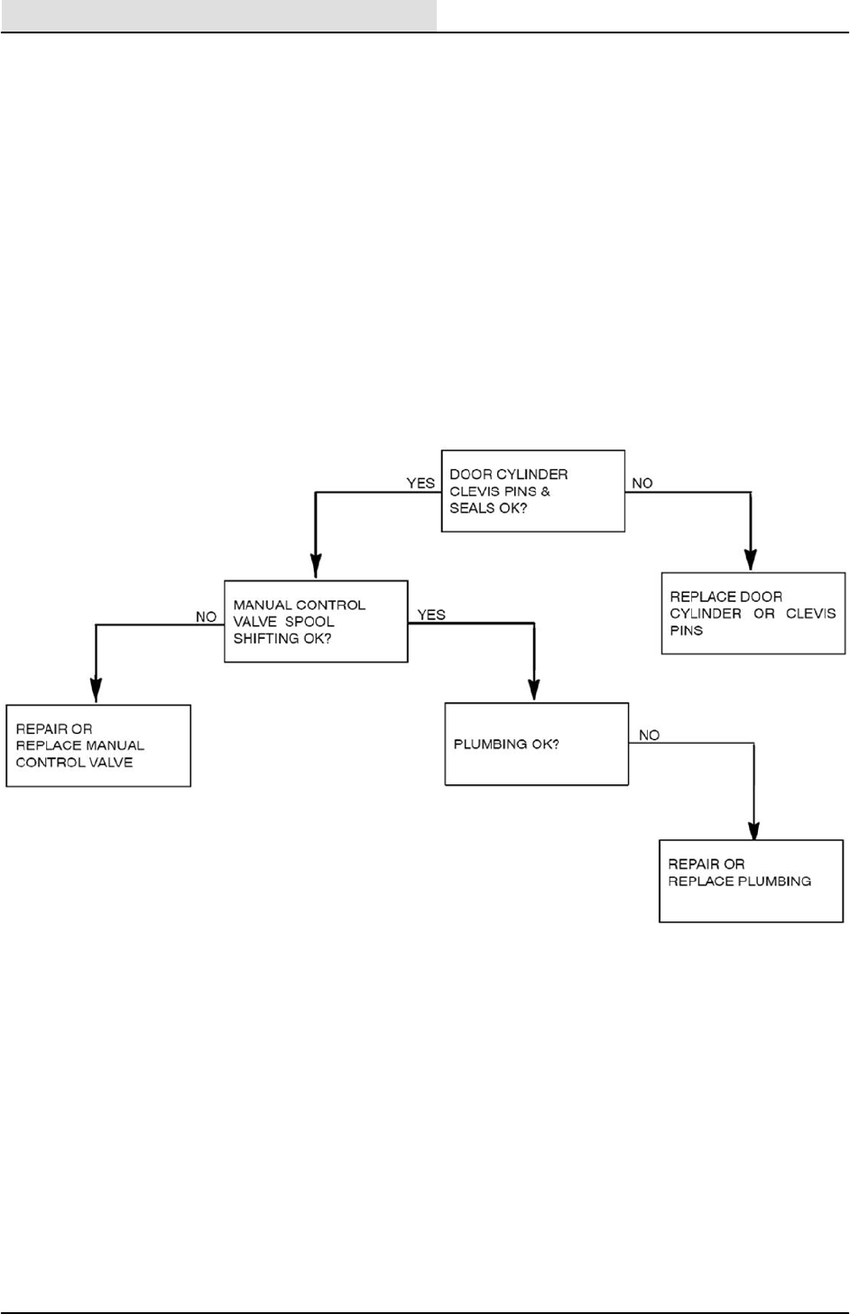
HOPPER DOOR DOES NOT CLOSE
S20 Service Information
26 S20 Electric 9006709 (11--09)
HOPPER DOOR DOES NOT STAY CLOSED
S20 Service Information
27
S20 Electric 9006709 (11--09)
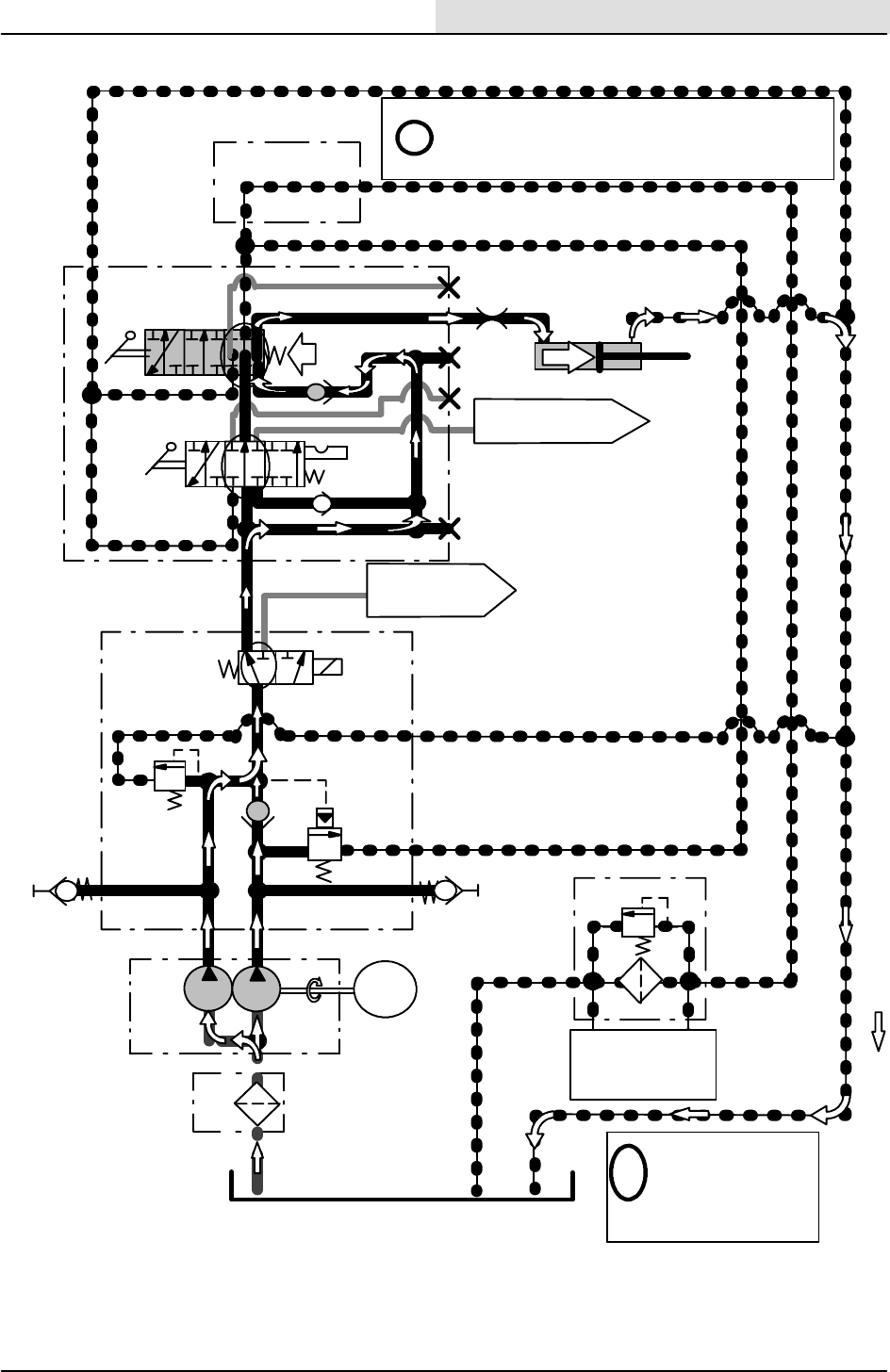
HOPPER LIFT
RESERVOIR
STRN
1
(50 psi)
3.4 BAR
PRESSURE
2.8 BAR (40 psi)
SWITCH
G1
89.6 BAR
(1300 psi)
T
PB
CV8
SOLENOID
VALVE
MANIFOLD
G2
62 BAR
(900 psi)
RV2
TEST PORT
TEST PORT
CK1
(1.4 GPM)
5.2 LPM
PUMP
1B
PUMP
1A MOTOR
@ 1000 RPM
(1.9 GPM)
7.3 LPM TURNS PUMPS
PRESSURE
READINGS BASED
ON HYDRAULIC OIL
TEMPERATURE OF
65_5 C (150_F)
i
PT
STEERING
VALVE ASSEMBLY
CV3
TO MTR1 SIDE
BRUSH MOTOR
TO CYL1 HOPPER
DOOR CYLINDER
HOPPER
CYLINDER
LIFT
OUT
BYD
A
B
C
D
CK2
CK3
IN
CYL2
CV2
VALVE
MANIFOLD
HOPPER
HOPPER LIFT
HOPPER
DOOR
RV4
RV1
LIFT
i
-- When Hopper Lift Cylinder reaches the end of travel,
Relief Valves (RV1 & RV2) will open to prevent excessive
pressure build-- up.
(HOPPER HELD
RAISED)
TV1
(0.047 in)
1.2 mm
(HOPPER HELD
RAISED)
SV1
BA
P2 P1
FLTR
S20 Service Information
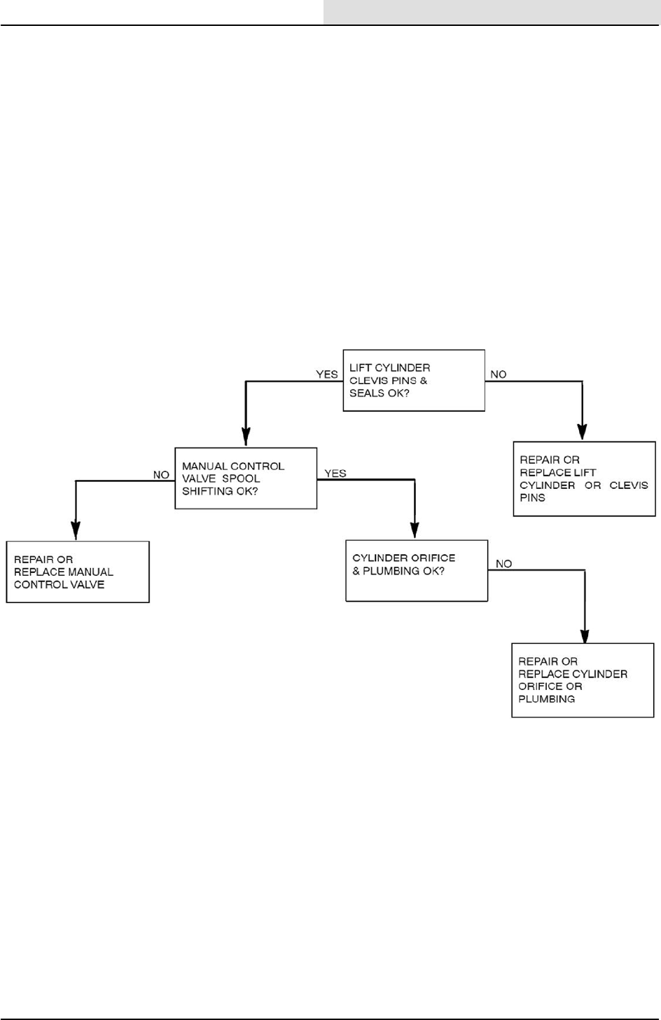
28 S20 Electric 9006709 (11--09)
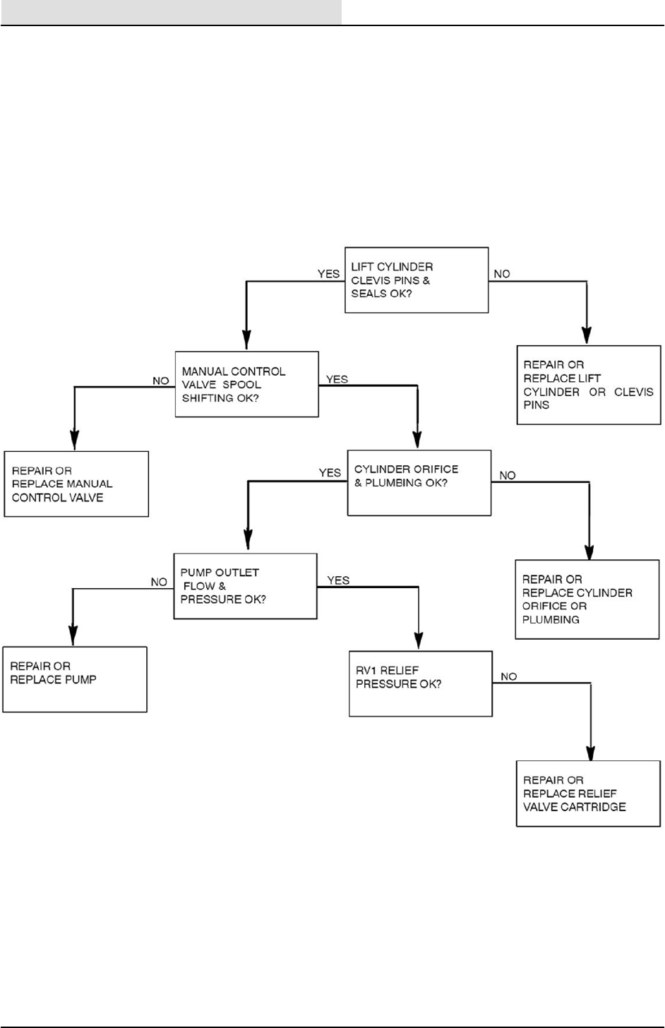
HOPPER DOES NOT RAISE
S20 Service Information
29
S20 Electric 9006709 (11--09)
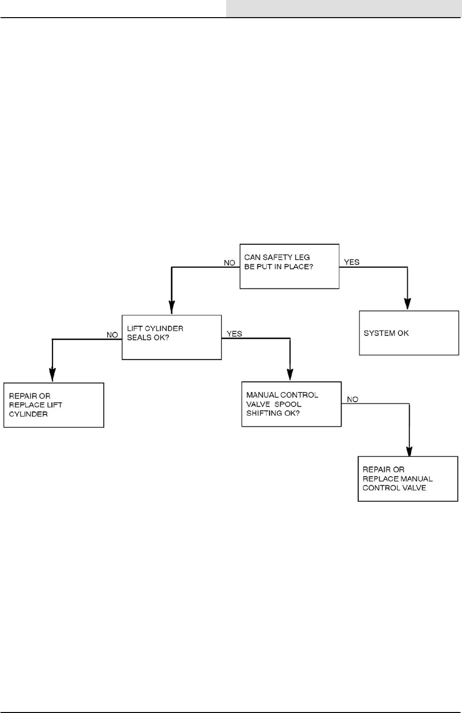
HOPPER DOES NOT STAY IN RAISED POSITION
S20 Service Information
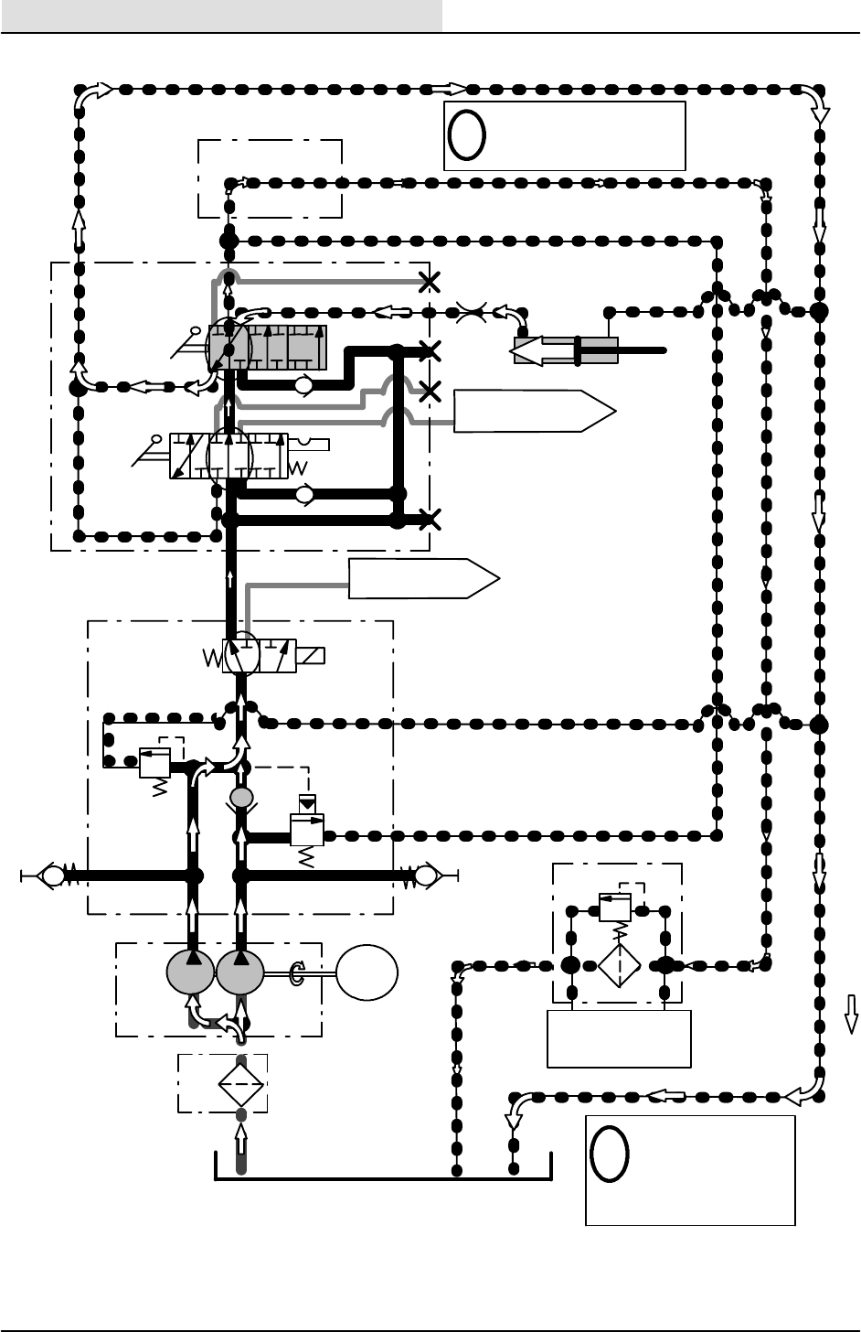
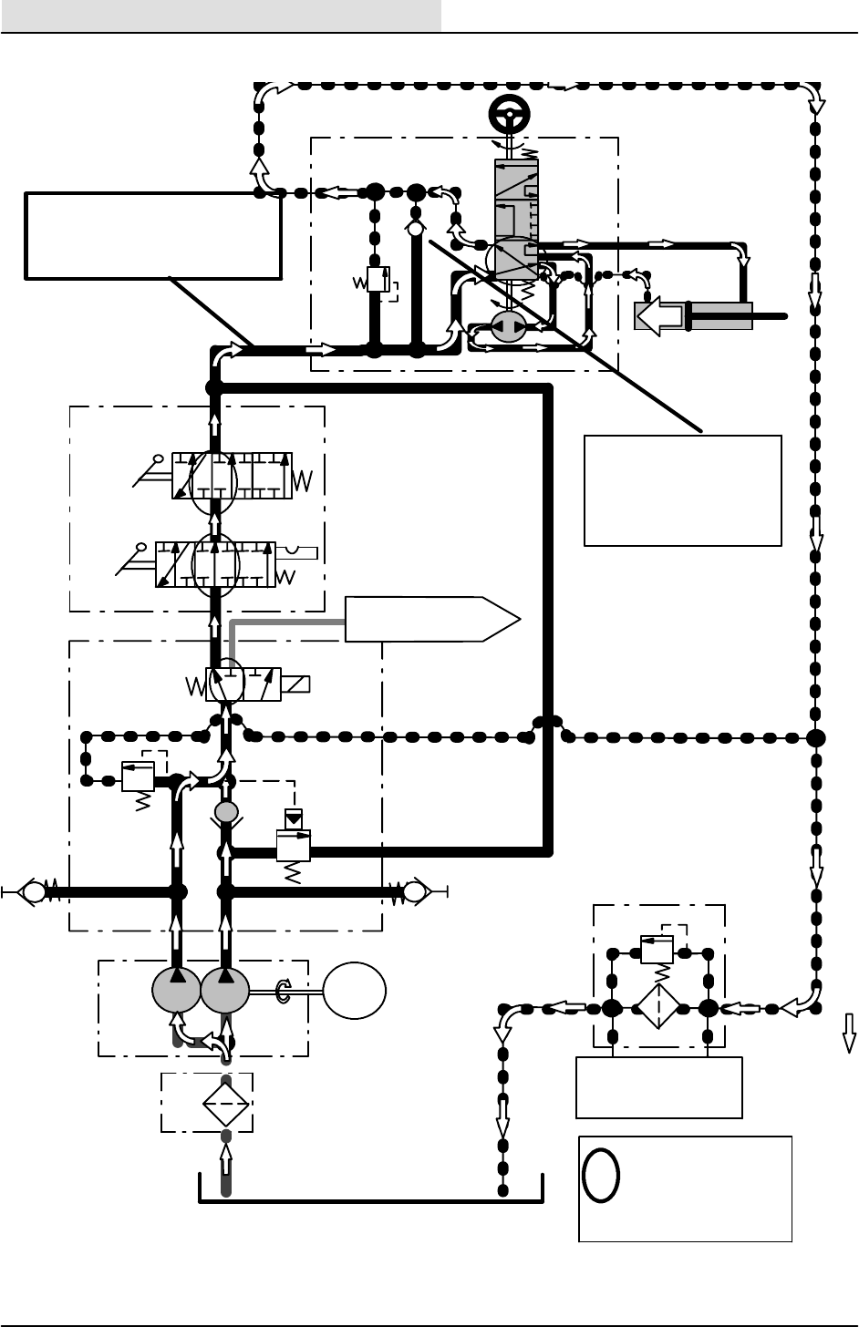
30 S20 Electric 9006709 (11--09)
HOPPER LOWER
RESERVOIR
STRN
1
(50 psi)
3.4 BAR
G1
89.6 BAR
(1300 psi)
T
PB
CV8
SOLENOID
VALVE
MANIFOLD
G2
62 BAR
(900 psi)
RV2
TEST PORT
TEST PORT
A
CK
1
(1.4 GPM)
5.2 LPM
PUMP
1B
PUMP
1A MOTOR
@ 1000 RPM
(1.9 GPM)
7.3 LPM TURNS PUMPS
PRESSURE
READINGS BASED
ON HYDRAULIC OIL
TEMPERATURE OF
65.5_C (150_F)
i
PT
STEERING
VALVE
ASSEMBLY CV3
TO MTR1 SIDE
BRUSH MOTOR
TO CYL1 HOPPER
DOOR CYLINDER
HOPPER
CYLINDER
LIFT
OUT BYD
A
B
C
D
CK2
CK3
IN
CYL2
CV2
VALVE
MANIFOLD
HOPPER
HOPPER
LOWER
HOPPER
DOOR
RV4
RV1
LOWER
TV1
(0.047 in)
1.2 mm
Lowering of hopper is due
to gravity (weight of hop-
per)
i
SV1
B
P1
P2
FLTR PRESSURE
SWITCH
2.8 BAR (40 psi)
S20 Service Information
31
S20 Electric 9006709 (11--09)
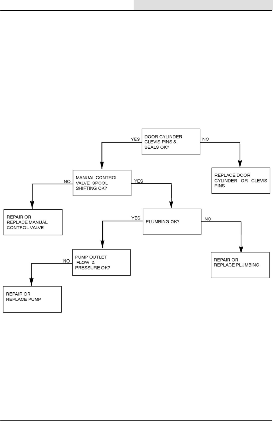
HOPPER DOES NOT LOWER
S20 Service Information
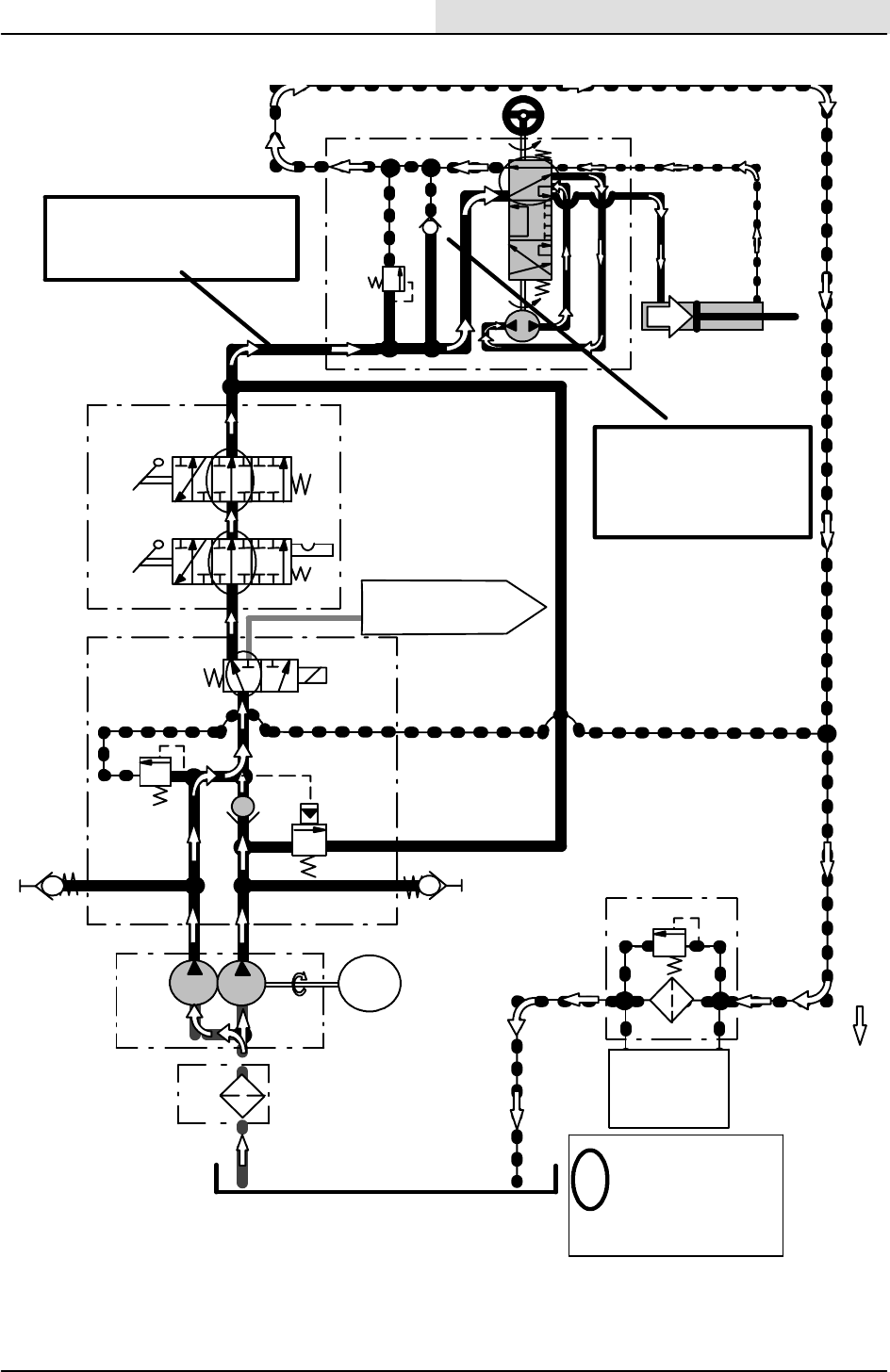
32 S20 Electric 9006709 (11--09)
STEERING SYSTEM -- RIGHT TURN
RESERVOIR
STRN
1
(50 psi)
3.4 BAR
P1
G1
89.6 BAR
(1300 psi)
T
PB
CV8
SOLENOID
VALVE
MANIFOLD
G2
P2
62 BAR
(900 psi)
RV2
TEST PORT
TEST PORT
A
CK1
(1.4 GPM)
5.2 LPM
PUMP
1B
PUMP
1A MOTOR
@ 1000 RPM
(1.9 GPM)
7.3 LPM TURNS PUMPS
PRESSURE
READINGS BASED ON
HYDRAULIC OIL
TEMPERATURE OF
65.5_C (150_F)
i
TO MTR1 SIDE
BRUSH MOTOR
BY
D
IN
CV2
VALV
E
MANIFOLD
HOPPER
HOPPER
LIFT
HOPPER
DOOR
RV4
STEERING VALV
E
ASSEMBLY CV3
RIGHT TURN
P
T
RV1
STEERING CYLINDER
STEERING
WHEEL
CK4
45 BAR
RV3
(650 psi)
PMP2
CYL3
45 BAR (650 PSI) HELD AT
STOP
12 BAR (175 PSI) TURNING
3.5 BAR (50 PSI) STATIONARY
SV1
B
FLTR PRESSURE
SWITCH
2.8 BAR (40 psi)
Ck4 used for steer-
ing fluid supply in
the event of main
supply pump and/-
or motor failure.
S20 Service Information
33
S20 Electric 9006709 (11--09)
STEERING SYSTEM -- LEFT TURN
RESERVOIR
STRN
1
(50 psi)
3.4 BAR
PRESSURE
2.8 BAR (40 psi)
SWITCH
G1
89.6 BAR
(1300 psi)
T
PB
B
CV8
SOLENOID
VALVE
MANIFOLD
G2
62 BAR
(900 psi)
RV2
TEST PORT
TEST PORT
A
CK1
(1.4 GPM)
5.2 LPM
PUMP
1B
PUMP
1A MOTOR
@ 1000 RPM
(1.9 GPM)
7.3 LPM TURNS PUMPS
PRESSURE
READINGS BASED
ON HYDRAULIC OIL
TEMPERATURE OF
65.5_C (150_F)
i
TO MTR1 SIDE
BRUSH MOTOR
BYD
IN
CV2
VALVE
MANIFOLD
HOPPER
HOPPER
LIFT
HOPPER
DOOR
RV4
STEERING
VALVE ASSEMBLY
CV3
LEFT TURN
P
T
RV1
STEERING CYLINDER
STEERING
WHEEL
CK4
45 BAR
RV3
(650 psi)
PMP2
CYL3
45 BAR (650 PSI) HELD AT STOP
12 BAR (175 PSI) TURNING
3.5 BAR (50 PSI) STATIONARY
SV1
P2 P1
FLTR
B
CV2
Ck4 used for steer-
ing fluid supply in
the event of main
supply pump and/-
or motor failure.
S20 Service Information
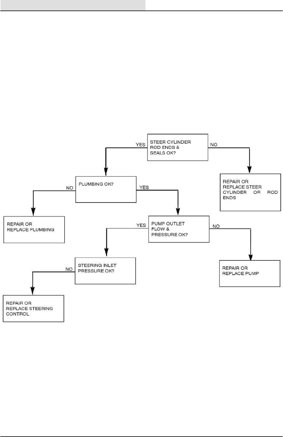
34 S20 Electric 9006709 (11--09)
STEERING SYSTEM NOT WORKING PROPERLY

S20 Service Information
35
S20 Electric 9006709 (11--09)
ELECTRICAL
INFORMATION
BEFORE CONDUCTING TESTS:
* Read and Follow ALL Safety Warnings and Precautions as
mentioned at the beginning of this manual
*Hydraulic Oil Must Be At Normal Operating Temperatures after
Running Machine and Hydraulics a Minimum of 5 Minutes
* Examine Machine For Any Linkage Binding or Mechanical
Problems
DURING TESTS:
* Call Technical Services if Diagnostic Time Exceeds One Hour With
Unknown Cause or Course of Action
* Maintain Normal Main Brush Pressure as Listed in Operator’s
Manual
S20 Service Information
36 S20 Electric 9006709 (11--09)
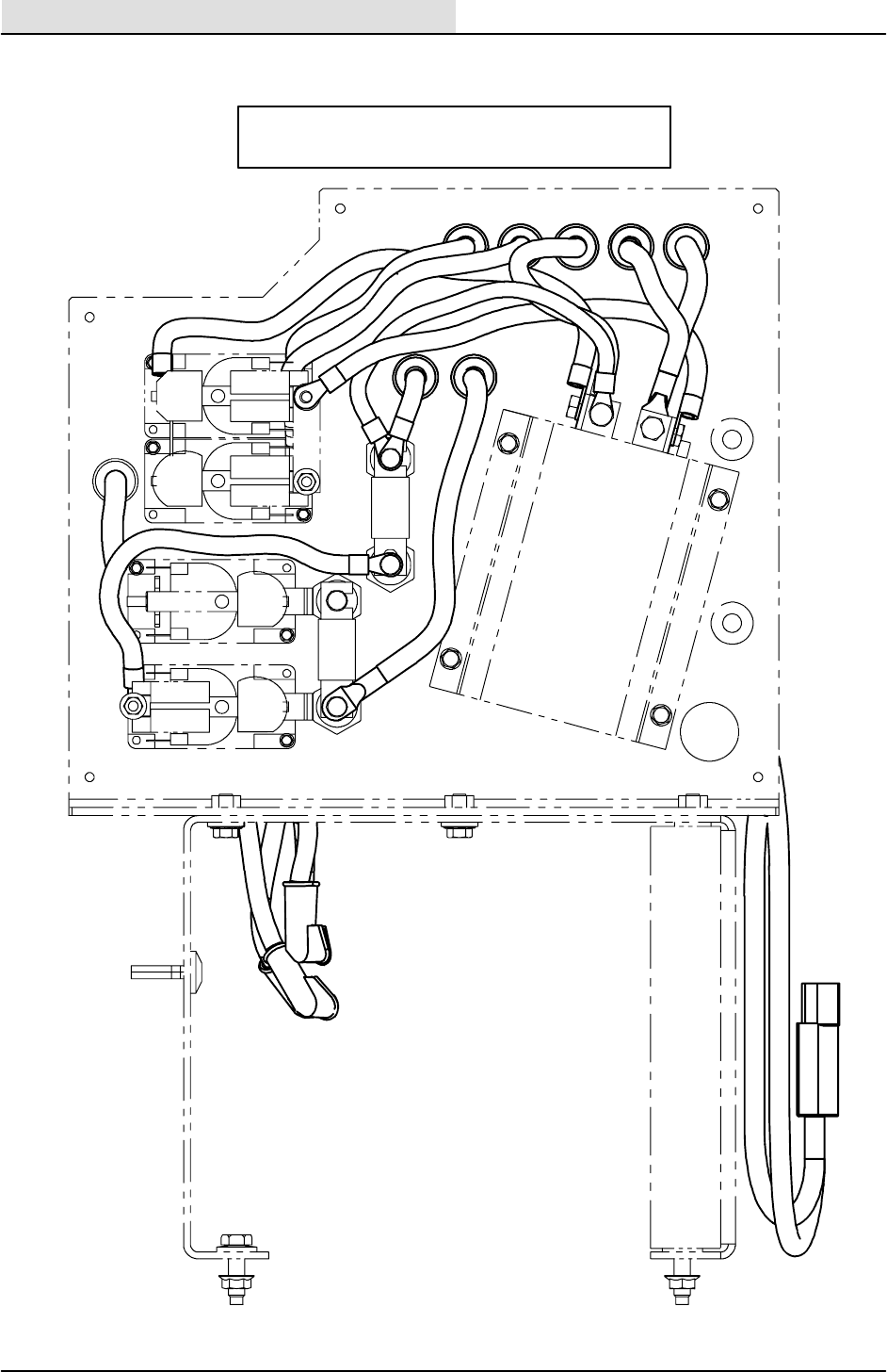
ELECTRICAL CONTROL BOX GROUP
M3 M4 A2 B-- B--
M3
M4
M1
M2
100
80
80 100
B--
B+
A2
M--
M2
Contactor locations
S20 Service Information
37
S20 Electric 9006709 (11--09)
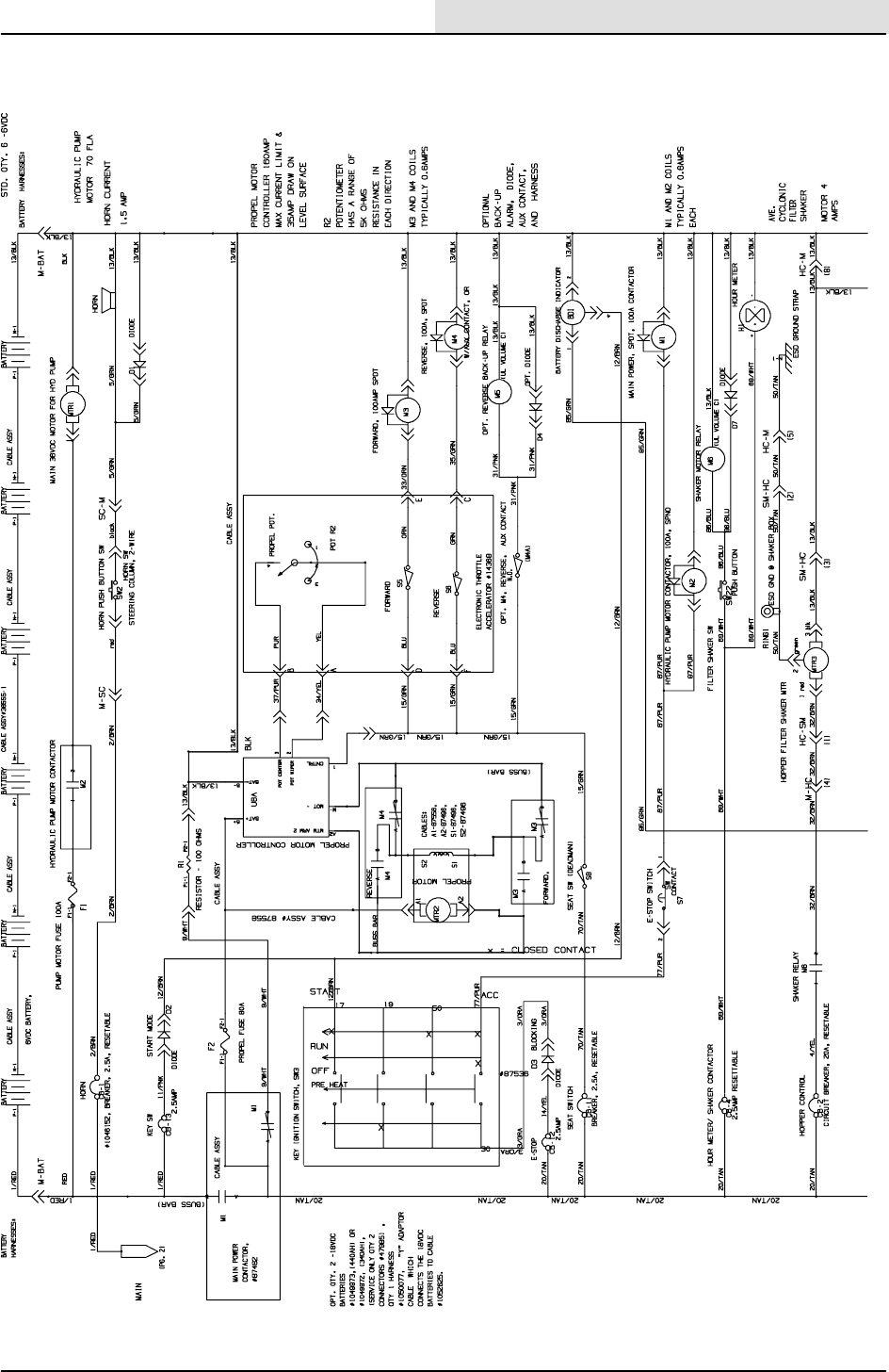
ELECTRICAL SCHEMATIC FIG 1
1
2
4
3
354987, 1048610 -- E
S20 Service Information
38 S20 Electric 9006709 (11--09)
ELECTRICAL SCHEMATIC FIG 2
1
2
3
4
354987, 1048610 -- E
S20 Service Information
39
S20 Electric 9006709 (11--09)
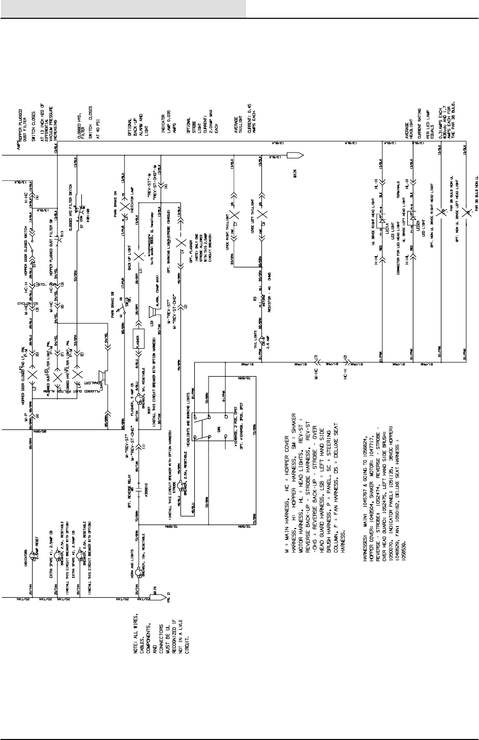
ELECRICAL SCHEMATIC FIG. 3
354987, 1048610 -- E
S20 Service Information
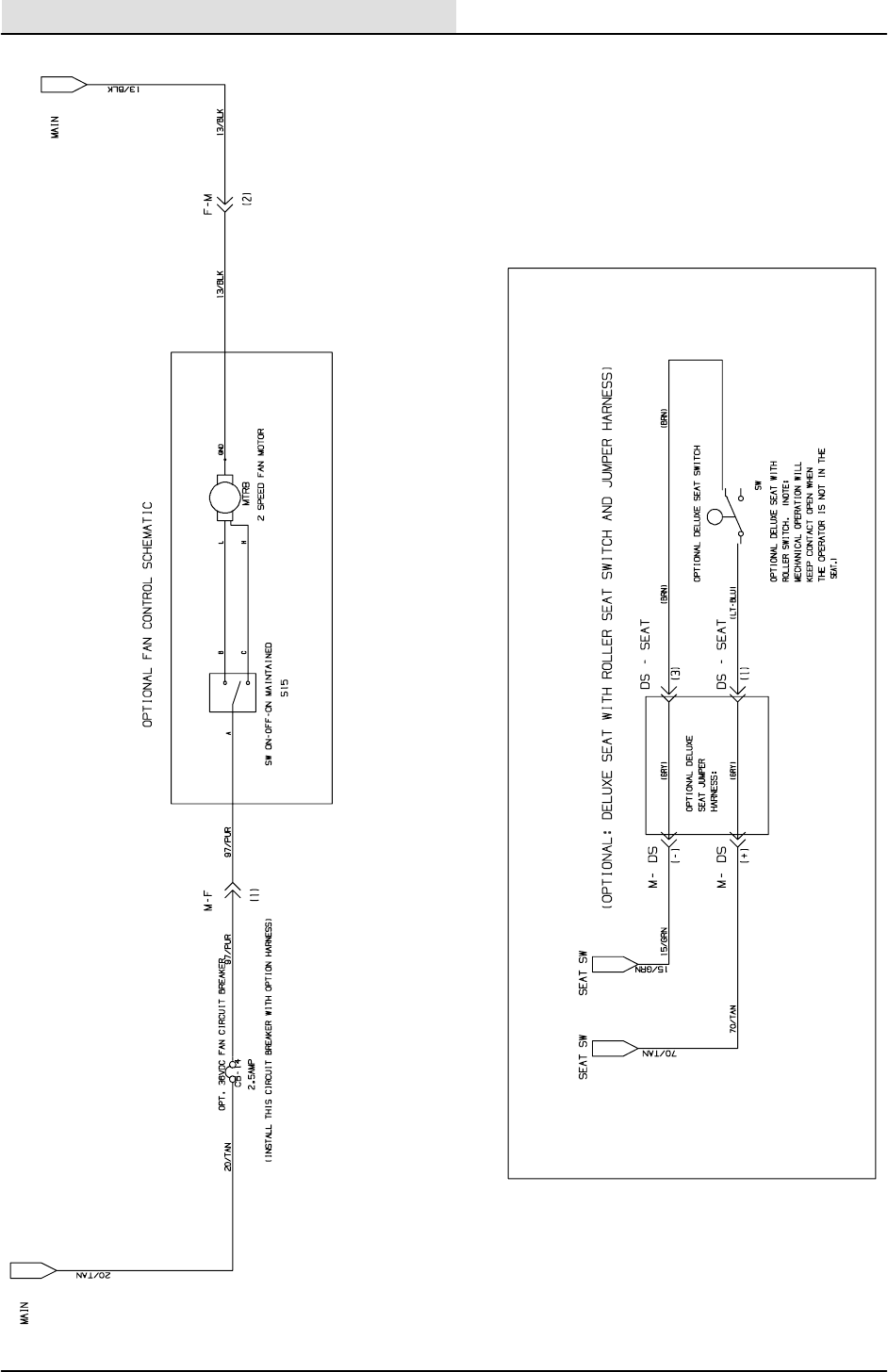
40 S20 Electric 9006709 (11--09)
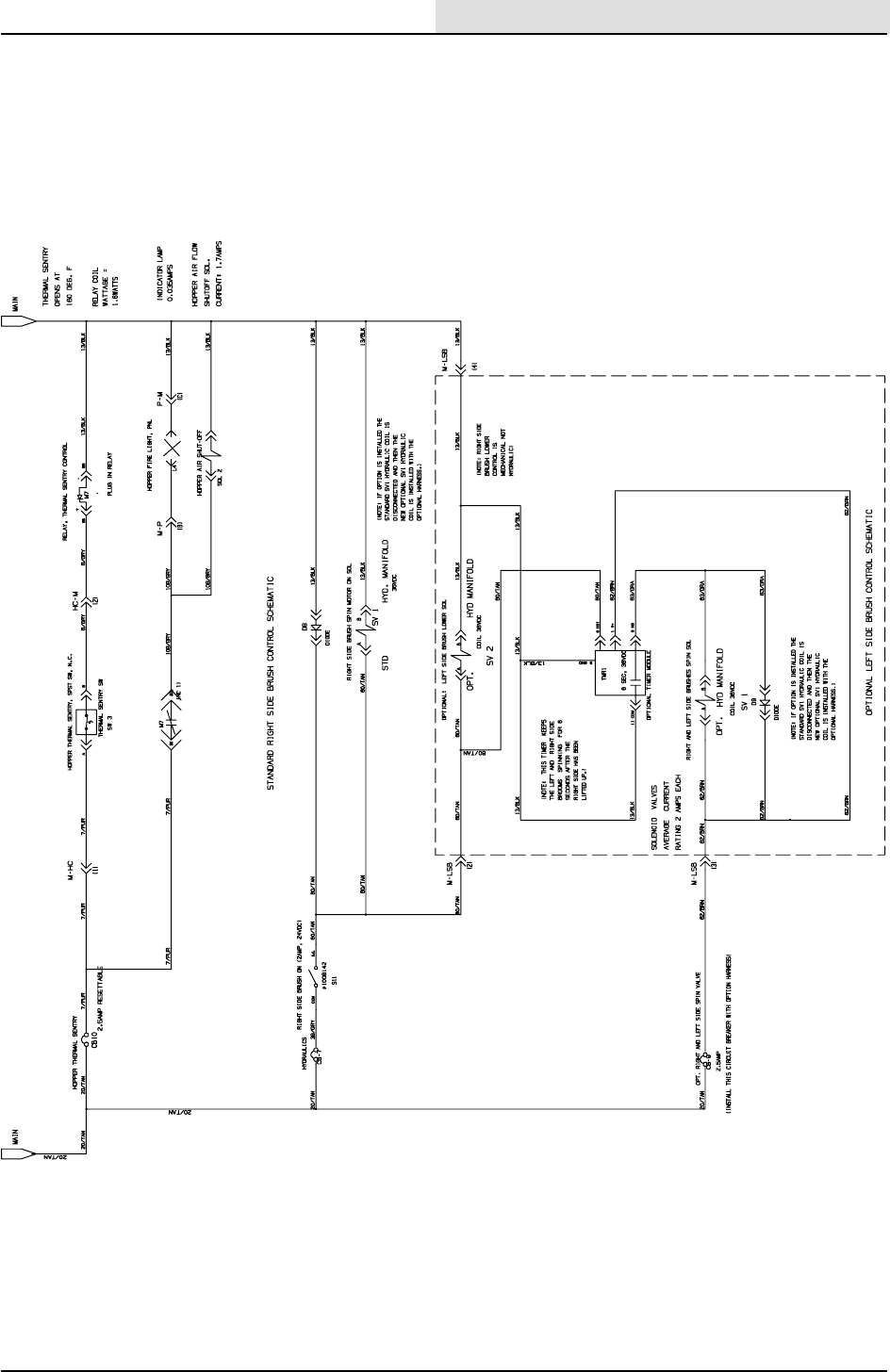
ELECTRICAL SCHEMATIC FIG. 4
354987, 1048610 -- E
