T12 Service Manual Tennant Rider Floor Scrubber
2018-06-20
: Sweepscrub Tennant-T12-Rider-Floor-Scrubber-Service-Manual tennant-t12-rider-floor-scrubber-service-manual 2786 file product_file
Open the PDF directly: View PDF ![]() .
.
Page Count: 178 [warning: Documents this large are best viewed by clicking the View PDF Link!]
- Start
- Contents
- SAFETY PRECAUTIONS
- General Information
- Maintenance
- Maintenance Chart
- Lubrication
- Batteries
- Charging the Batteries (On-Board Charger)
- Flow-Rite Battery Watering System (Option)
- Circuit Breakers
- Electric Motors
- Scrub Brushes
- Side Brush (Option)
- Squeegee Blades
- Skirts and Seals
- Belts
- Tires
- Pushing, Towing, and Transporting the Machine
- Machine Jacking
- ec-H2O Module Flush Procedure
- Storage Information
- Priming the ec-H2O System
- Troubleshooting
- Service
T12
9009917
Rider Scrubber
Service Information Manual
9009917
Rev. 00 (12-2012)
(Battery)
North America / International
To view, print or download
the latest parts or operator’s
manual, visit:
ww
w
.tennantco.com/manuals
The Safe Scrubbing AlternativeR
TennantTrueRParts
IRISta Tennant Technology

INTRODUCTION
This manual providesnecessary service and maintenance instructions.
Read thismanual completely and understand
the machine before servicing it.
This machinewill provide excellent service. However, the best results will be obtained at minimum costs if:
SThe machine is operated with reasonable care.
SThe machine is maintained regularly-per the machine maintenance instructions provided.
SThe machine is maintainedwith manufacturer supplied or equivalentparts.
PROTECT THE ENVIRONMENT
Please dispose of packaging materials,
old machine components and fluids in
an environmentally safe way according
to local waste disposal regulations.
Always remember to recycle.
ModelNo. --
SerialNo. --
InstallationDate --
Please fillout at time of installation for future reference.
MACHINE DATA
INTENDED USE
The T12 is an industrial/commercial rider machinedesigned to wet scrub both roughand smooth hard surfaces
(concrete, tile, stone, synthetic, etc). Typical applicationsinclude schools, hospitals / health care facilities, office
buildings, and retail centers. Do not use this machine on soil, grass, artificial turf, or carpeted surfaces. This machine
is intended for indoor use only. This machine is notintended for use on public roadways.
Tennant Company
PO Box 1452
Minneapolis, MN 55440
Phone: (800)553--8033 or (763)513--2850
www.tennantco.com
Touch--N--Go, 1--STEP, Grip--N--Go, Dura--Track, SmartRelease, Duramer, are US registered andunregistered trademarks of Tennant Company.
Flow-Rite is a registered trademark of Flow-Rite Controls
Specificationsandparts are subject to change withoutnotice.
Original Instructions, copyrightE2013 TENNANT Company, Printed in U.S.A.

T12 Service Information 9009917 (12-12) 3
CONTENTS
SAFETY PRECAUTIONS .......................11
GENERAL INFORMATION ..................... 21
COMPONENT LOCATOR .................... 22
ELECTRICAL SCHEMATIC, MASTER .........24
ELECTRICAL SCHEMATIC SYMBOLS ..... 29
OPERATIONAL MATRIX .................... 210
SPECIFICATIONS ..........................212
FASTENER TORQUE ....................212
MACHINE DIMENSIONS ................213
GENERAL MACHINE DIMENSIONS/
CAPACITIES .........................214
GENERAL MACHINE PERFORMANCE ...214
POWER TYPE ..........................215
TIRES ..................................215
ECH2O SYSTEM OPTION .............215
ELECTRICAL COMPONENTS ............216
MAINTENANCE
MAINTENANCE CHART .....................32
LUBRICATION .............................. 34
BATTERIES ................................. 35
CHARGING THE BATTERIES
OFFBOARD CHARGER ............. 36
CHARGING THE BATTERIES
ONBOARD CHARGER .............. 37
ONBOARD CHARGER ERROR CODES ... 38
ONBOARD CHARGER SETTINGS ........39
CHANGING THE ONBOARD BATTERY
CHARGER FUSE .....................310
FLOWRITE™ BATTERY
WATERING SYSTEM .................311
CIRCUIT BREAKERS .......................313
ELECTRIC MOTORS .......................314
SCRUB BRUSHES ..........................315
DISK BRUSHES AND PADS .............315
REPLACING DISK BRUSHES
OR PAD DRIVERS ................315
REPLACING DISK SCRUB PADS ......316
CYLINDRICAL BRUSHES ................317
REPLACING CYLINDRICAL
BRUSHES .........................317
CHECKING CYLINDRICAL SCRUB
BRUSH PATTERN .................. 318
ADJUSTING CYLINDRICAL
BRUSH TAPER ....................321
ADJUSTING CYLINDRICAL BRUSH
PATTERN WIDTH .................. 322
SIDE BRUSH OPTION ....................323
REPLACING THE SIDE BRUSH ........... 323
SQUEEGEE BLADES .......................324
REPLACING OR ROTATING THE
Contents Page
REAR SQUEEGEE BLADES ...........324
LEVELING THE REAR SQUEEGEE ........327
ADJUSTING THE REAR SQUEEGEE
BLADE DEFLECTION ................328
REPLACING OR ROTATING THE SIDE
SQUEEGEE BLADES .................329
REPLACING OR ROTATING THE SIDE BRUSH
SQUEEGEE BLADES OPTION .......330
SKIRTS AND SEALS ........................ 331
BELTS ..................................331
TIRES ..................................331
PUSHING, TOWING, AND TRANSPORTING
THE MACHINE .........................333
MACHINE JACKING .......................335
ec-H2O MODULE FLUSH PROCEDURE .....336
STORAGE INFORMATION .................. 338
FREEZE PROTECTION ..................338
PREPARING THE MACHINE FOR
OPERATION AFTER STORAGE .......340
PRIMING THE ECH2O SYSTEM .........3-42
TROUBLESHOOTING
ONBOARD DIAGNOSTICS .................. 42
SELFTEST MODE ....................... 42
CONFIGURATION MODE ................ 44
LCD WARNINGS ......................... 46
LCD FAULTS. . . . . . . . . . . . . . . . . . . . . . . . . . . . . 47
PROPEL DIAGNOSTIC MODE ............ 49
CURTIS 1232 CONTROLLER
DIAGNOSTICS ......................411
DIAGNOSTIC LED OPERATION. . . . . . . 411
DIAGNOSTIC CODES ................412
INPUT DISPLAY MODE .................420
MANUAL MODE .......................422
CAN CONTROLLER AREA NETWORK
DIAGNOSTIC MODE ................. 424
FIRMWARE UPDATE MODE ............. 425
BATTERY CHARGER, STANDARD. . . . . . . . 426
OPERATION .........................426
CONFIGURATION ...................426
FAULTS .............................426
BATTERY CHARGER, ONBOARD OPT. ...427
OPERATION ......................427
CONFIGURATION .................427
FAULTS ...........................427
SUBSYSTEM TROUBLESHOOTING .........428
BACKUP ALARM/LIGHT ...............428
BATTERY CHARGING ...................430
ONBOARD ..........................430
OFF BOARD ......................... 432
PARKING BRAKE, ELECTROMAGNETIC ..434
LIGHTING .............................. 436
Contents Page

CONTENTS
4T12 Service Information 9009917 (12-12)
MAIN SCRUB BRUSHES ................438
POWERUP ............................440
PROPEL ................................ 442
REAR SQUEEGEE LIFT ..................444
SCRUB HEAD LIFT .....................446
SIDE BRUSH ...........................448
SIDE BRUSH LIFT ....................... 450
SOLUTION CONTROL, CONVENTIONAL 454
MAIN BRUSH .......................454
SIDE BRUSH ........................456
SOLUTION CONTROL, ECH2O ..........458
SPRAY NOZZLE ........................460
VACUUM FAN .......................... 462
SERVICE
SERVICE PROCEDURES ..................... 52
REAR SQUEEGEE LIFT ACTUATOR ....... 52
REMOVAL ............................ 52
INSTALLATION ....................... 53
SIDE BRUSH LIFT ACTUATOR ............ 54
REMOVAL ............................ 54
INSTALLATION ....................... 54
ADUSTING SIDE BRUSH
SPRING TUBE ASSEMBLY ........... 55
SIDE BRUSH MOTOR .................... 56
REMOVAL ............................ 56
INSTALLATION ....................... 57
CARBON BRUSHES ................... 57
MAIN BRUSH LIFT ACTUATOR ........... 58
REMOVAL ............................ 58
INSTALLATION ....................... 58
MAIN SCRUB HEAD ..................... 59
REMOVAL ............................ 59
INSTALLATION ......................510
MAIN SCRUB BRUSH MOTOR
CYLINDRICAL .....................511
REMOVAL ........................511
INSTALLATION. . . . . . . . . . . . . . . . . . . . 512
CARBON BRUSHES ...............512
INSTRUMENT PANEL ...................513
REMOVAL ........................... 513
INSTALLATION ......................513
LOGIC BOARD REPLACEMENT. . . . . . . . . . 514
REMOVAL ........................... 514
INSTALLATION ......................515
STEERING WHEEL TIMING ..............516
WHEEL DRIVE ASSEMBLY ..............517
REMOVAL ........................... 517
INSTALLATION ......................518
TIRE REPLACEMENT ................. 519
Contents Page
VACUUM FAN ASSEMBLY ..............520
REMOVAL ..........................520
INSTALLATION ......................521
COMPONENT TESTING ....................522
TANK LEVEL SENSORS .................522
PARKING BRAKE, ELECTROMAGNETIC ..524
PROPEL MOTOR AND ENCODER ......527
PROPEL MOTOR CABLES ...............529
THROTTLE/BRAKE SENSOR ............531
SIDE BRUSH LIFT ACTUATOR ...........533
MAIN BRUSH LIFT ACTUATOR ..........534
COMPONENT TESTING CONTINUED
REAR SQGE LIFT ACTUATOR. . . . . . . . . . . . 535
VACUUM FAN .......................... 536
MAIN SCRUB BRUSH MOTORS .........537
SIDE BRUSH MOTOR ...................538
ECH2O PUMP .........................539
ECH2O PRESSURE SWITCH ............540
Contents Page

T12 Service Information 9009917 (12-12) 1-1
SAFETY PRECAUTIONS
IMPORTANTSAFETY INSTRUCTIONS -- SAVE THESEINSTRUCTIONS
The following precautions are used throughout
this manual as indicated in theirdescription:
WARNING: To warn of hazards or
unsafe practices that couldresult in
severe personal injury or death.
FOR SAFETY: To identify actions that must be
followed for safe operation of equipment.
The followinginformation signalspotentially
dangerous conditions to the operator. Knowwhen
these conditions can exist. Locate all safety
devices on the machine.Report machinedamage
or faulty operation immediately.
WARNING: Batteries emit hydrogen gas.
Explosion or fire canresult. Keep
sparks and open flame away. Keep
coversopen when charging.
WARNING: Flammablematerials can
cause an explosion or fire. Do not use
flammablematerials in tank(s).
WARNING: Flammablematerials or
reactive metals cancause an explosion
or fire. Do notpick up.
WARNING: ElectricalHazard
-- DisconnectBatteryCables and
Charger PlugBefore Servicing
Machine.
-- Do Not Charge Batteries with
Damaged Power Supply Cord. Do Not
Modify Plug.
If the charger supply cord is damaged or
broken, it must be replaced by the
manufacturer or its service agent or a
similarly qualified person in order to avoid a
hazard.
FOR SAFETY:
1. Do notoperate machine:
-- Unless trained and authorized.
-- Unlessoperator manual is read and
understood.
-- Under the influence of alcohol or
drugs
-- While using a cell phone or other
types of electronic devices
-- Unlessmentally and physically
capable of followingmachine
instructions.
-- With brakedisabled.
-- If it is not in proper operating
condition.
-- In areaswhere flammable
vapors/liquids or combustibledusts
are present.
-- In areas that are too dark to safely see
the controlsoroperate the machine
unlessoperating / headlights are
turned on.
-- In areaswith possible fallingobjects
unless equipped with overheadguard.
2. Before startingmachine:
-- Checkmachine for fluid leaks.
-- Keep sparks and open flame away
from refuelingarea.
-- Makesure all safety devicesare in
place and operate properly.
-- Check brakes and steering for proper
operation.
-- Adjust seat and fasten seat belt (if
equipped).
3. When usingmachine:
-- Useonly as described in thismanual.
-- Use brakes to stop machine.
-- Go slowly on inclines and slippery
surfaces.
-- Reduce speedwhen turning.
-- Keep all parts of bodyinside operator
stationwhilemachine is moving.
-- Usecarewhen reversingmachine.
-- Never allow childrentoplay on or
aroundmachine.
-- Do notcarry passengers on machine.
-- Always followsafety and traffic rules.
-- Report machine damage or faulty
operation immediately.
-- Follow mixing, handling and disposal
instructions on chemical containers.
-- Followsafety guidelines concerning
wet floors.
SAFETY PRECAUTIONS

1-2 T12 Service Information 9009917 (12-12)
SAFETY PRECAUTIONS
SAFETY PRECAUTIONS
4. Before leaving or servicingmachine:
-- Stop on level surface.
-- Turn off machine and remove key.
5. When servicingmachine:
-- All work must be donewith sufficient
lighting and visibility.
-- Avoid moving parts. Do not wearloose
clothing, jewelry and secure long hair.
-- Block machine tires before jacking
machineup.
-- Jackmachine up at designated
locationsonly. Support machinewith
jack stands.
-- Usehoist or jack that will support the
weight of the machine.
-- Do notpush or tow the machine on
inclines with the brakedisabled.
-- Do notpower spray or hose off
machine near electrical components.
-- Disconnect battery connections before
workingonmachine.
-
- Avoid contactwith batteryacid.
-- All repairs must be performed by a
trained service mechanic.
-- Do not modify the machine from its
original design.
-- Use Tennant supplied or approved
replacement parts.
-- Wear personal protective equipment
as needed and whererecommended in
thismanual.
For Safety: wear hearing protection.
For Safety: wear protective gloves.
For Safety: weareye protection.
For Safety: wear protective dust mask.
6. When loading/unloadingmachine
onto/off truck or trailer.
-- Drain tanks before loadingmachine.
-- Lower scrub head and squeegee
before tyingdownmachine.
-- Turn off machine and remove key.
-- Useramp, truck or trailer that will
support the weight of the machine and
operator.
-- Use winch. Do notpush the machine
onto/off the truck or trailer unless the
load height is 380 mm (15 in) or less
from the ground.
-- Block machine tires.
-- Tie machinedown to truck or trailer.
T12 Service Information 9009917 (12-12) 1-3
SAFETY PRECAUTIONS
SAFETY PRECAUTIONS
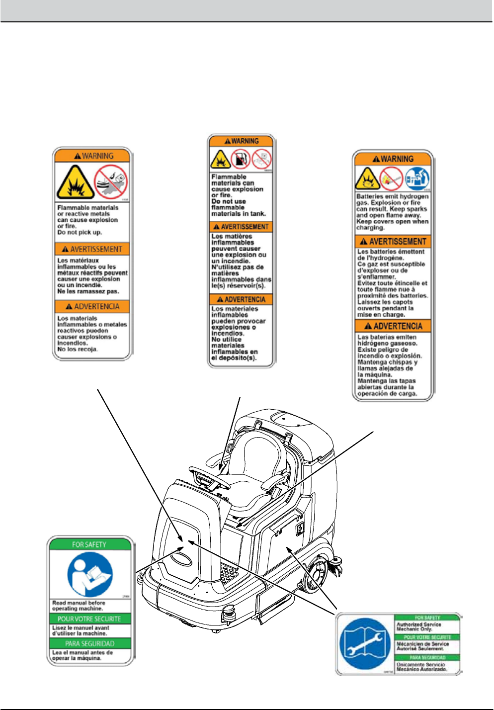
The safety labelsappear on the machine in the
locationsindicated.Replace damagedlabels.
WARNING LABEL -- Batteries
emit hydrogen gas. Explosion
or fire canresult. Keep sparks
and open flame away. Keep
coversopen when charging
FOR SAFETY LABEL --
Readmanual before
operatingmachine.
WARNING LABEL --
Flammablematerials
or reactive metals can
cause explosion or
fire. Do notpick up.
Located on
electrical panel.
Located on
electrical panel.
Located inside
battery compartment.
WARNING LABEL -- Flammable
materials cancause explosion
or fire. Do not use flammable
materials in tank
Located on recovery tank,
above solution tank cap.
FOR SAFETY LABEL --
Authorized Service
MechanicOnly.
Located on circuitboard
cover and electrical panel.

1-4 T12 Service Information 9009917 (12-12)
SAFETY PRECAUTIONS

GENERAL INFORMATION ..................... 21
COMPONENT LOCATOR .................... 22
ELECTRICAL SCHEMATIC, MASTER ......... 24
ELECTRICAL SCHEMATIC SYMBOLS ..... 29
OPERATIONAL MATRIX .................... 210
SPECIFICATIONS ..........................212
FASTENER TORQUE ....................212
MACHINE DIMENSIONS ................213
GENERAL MACHINE DIMENSIONS/
CAPACITIES .........................214
GENERAL MACHINE PERFORMANCE ...214
POWER TYPE ..........................215
TIRES ..................................215
ECH2O SYSTEM OPTION .............215
ELECTRICAL COMPONENTS ............216
GENERAL INFORMATION
SECTION 2
Contents Page
2-1
T12 Service Information 9009917 (12-12)
2-2 T12 Service Information 9009917 (12-12)
GENERAL INFORMATION
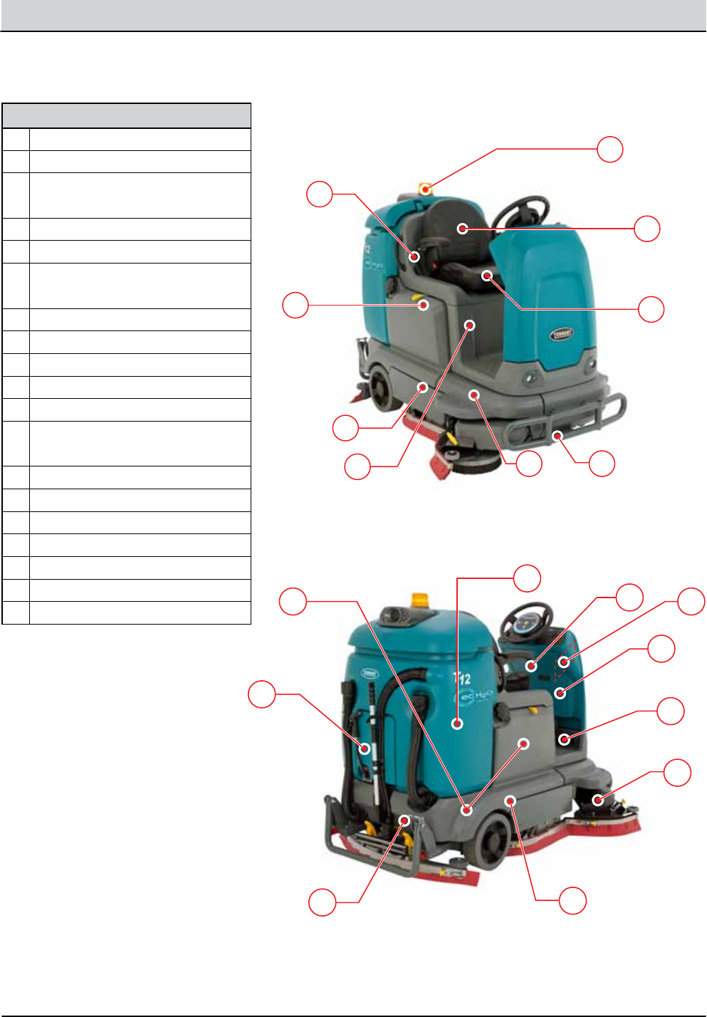
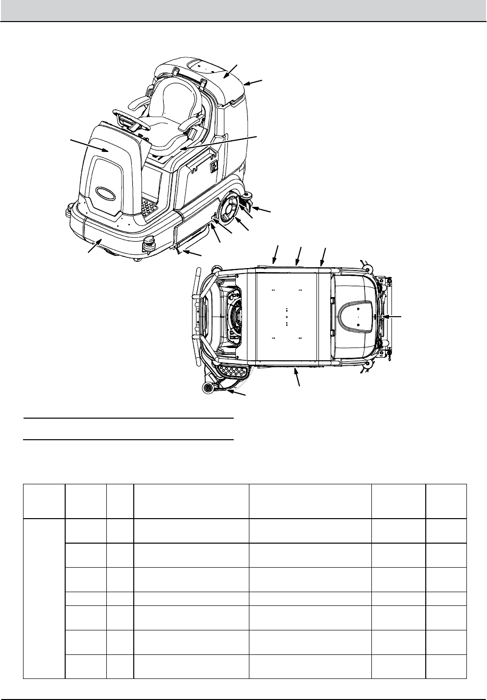
COMPONENT LOCATOR
A
B
C
DE F
G
H
I
J
K
LM
N
O
P
QP1
R
Components
Aec-H2O System Components*
BIRIS™ Inline 2 Amp Fuse Holder*
Cec-H2O, Side Brush, and Spray
Nozzle Pumps*
DBatteries
ESV-3 Side Brush Water Valve*
FWheel Drive Assembly (Motor,
Encoder, Temp Sender
GSeat Switch
HCircuit Breakers (1-8)
IWarning Light/ Backup Alarm*
JSolution Tank
KVacuum Fan Housing
LRear Squeegee Lift Actuator
Level Switch, Solution Tank
MSV-2 Main Water Valve
NSide Brush Motor*
OThrottle/Brake Sensor
PCircuit Breakers (9-16)
P1Module, Side Scrub
QModule, Curtis 1232
RRecovery Tank
* Optional Equipment
T12 Service Information 9009917 (12-12) 2-3
GENERAL INFORMATION
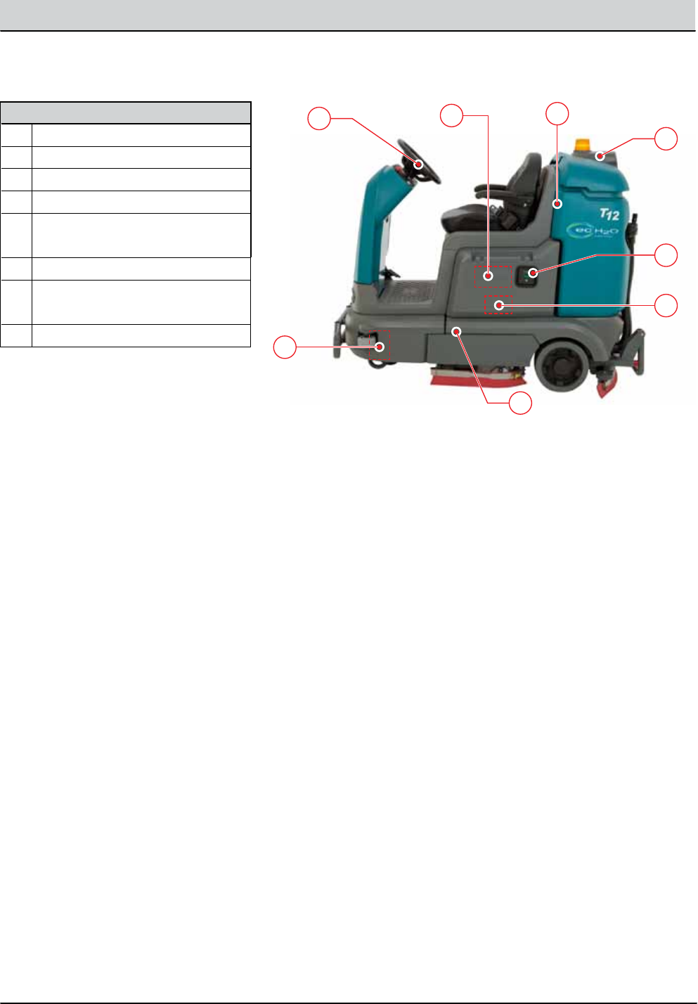
COMPONENT LOCATOR, continued
S
T
U
Y
Z
X
W
V
Components
SModule, Main Scrub
TModule, Interface
UModule, IRIS™ Telemetry
VMain Scrub Head Lift Actuator
WModule, Water Pickup
Diodes 1, 2, and 3
XOnboard Battery Charger
YM2 Relay, Circuit Breaker 17
(Inside Warning Light/BU Alarm)
ZLevel Switch, Recovery Tank
* Optional Equipment
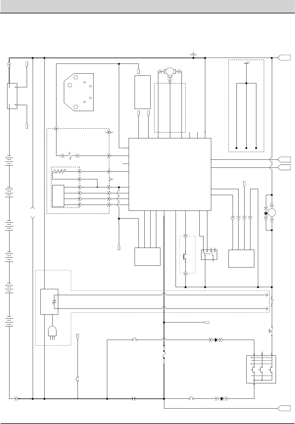
2-4 T12 Service Information 9009917 (12-12)
GENERAL INFORMATION
36VDC BATTERIES
TO: BATTERY B+ AT M1.
ISOLATED GROUND
POST = STAND OFF
SEAT SWITCH HARNESS
TO: OPTIONAL BACK UP
LIGHT
AC PROPEL MOTOR
(INCLUDES ENCODER,
TEMP SENDER AND BRAKE SOL.)
SV-1
NOT USED
YEL
W
U
V
B2: BRN
T2: YEL
T1: YEL
B1: PUR
A+
W1
A-
AC PROPEL MOTOR
PIN OUT
(FACING MOTOR)
YEL
AMER
ENCODER
PROPEL MOTOR CONTROL
HARNESS
B1 B2
ORAGRN
WHT
E-STOP SWITCH CHARGER INTERLOCK
TO: GROUND POST
AC PLUG
B+ TO M1/GND
CABLE, M1 TO FUSE-1
2/BRN
KEY SWITCH
SWITCHED B+ (@ CURTIS B+)
CHARGER HARNESS
FUSED B+
SHUNT HIGHSHUNT LOW
TO: SHUNT HIGH
SHUNT LOW
IN-LINE (OPTIONAL)
OPTIONAL TELEMETRY CABLES:
OPTIONAL TELEMETRY CABLES:
STATIC GROUND LINES
(IN THE MAIN HARNESS)
BLK
71/PNK
YEL
17/PUR
BLU
70/TAN
69/WHT
58/GRY
RED
16/BLU
14/YEL
58/GRY
58/GRY
8/GRY
POWER/GND TO CURTIS.
YRG/8YRG/8
8/GRY
18/GRY
11/PNK
9/WHT
15/GRN
W/WHT
U/ORA
V/GRN
12/BRN
62/BRN
61/PNK
58/GRY
17/PUR
59/WHT
66/BLU
17/PUR
5/GRN
3/ORA
2/BRN
4/YEL
1/RED
7/PUR6/BLU
10/TAN
1/RED
13/BLK
2/BRN
8/GRY
13/BLK
CABLE: POWER/GND TO CURTIS.
22/BRN
YRG/8YRG/8
1/RED
CAN+ /YEL
79/WHT
77/PUR
94/YEL
POWER/GND TO CURTIS.
CABLE: B+ TO M1/GND.
13/BLK-WHT79/WHT
13/BLK-WHT13/BLK-WHT
CAN- /GRN
105/GRNTO: SCRUB MODULE MOUNTING PLATE
TO: EC-H20/FAST MOUNTING PLATE
TO: SIDE BR. MODULE MOUNTING PLATE
58
58
17
15
22
13
79
77
94
79
13
M1B
MAIN CONTACTOR
CURTIS 1232 CONTROLLER
KSI
J1-1
DRV2
J1-5
DRV1
J1-6
INTERLOCK
J1-9
I/O GND
J1-7
36VDC
J1-13
BRAKE IN
J1-24
THROTTLE
J1-16
CAN TERM H
J1-21
FWD
J1-22
CAN+
J1-23
+5V
J1-26
PHASE A
J1-31
PHASE B
J1-32
REV
J1-33
CAN TERM L
J1-34
CAN-
J1-35
U
U
V
V
W
W
B+
B+
GND
GND
THERMISTOR
J1-8
DRV3
J1-4
DRV4
J1-3
PROG+
J1-25
TX
J1-28
RX
J1-29
4
4
5
3
CB2
2.5A-REAR
CONN7A
A
6 VDC
+ --
PROGRAMMING PORT
GND
2
B+
4
RX
1
TX
3
CB-8
2.5A-TELEMETRY
D-1
1
6 VDC
+ --
4
6 VDC
+ --
CB3
2.5A-REAR
CHG-1
OPT: ON BOARD CHARGER
P1-C
2
GND
P1-B
B+
P1-A
P1-D
1
8
5
6
6
SHUNT-1
TELEMETRY SHUNT
D-2
AC PROPEL MOTOR
MTR
53
2
M1A
MAIN CONTACTOR
+
-
B
THROTTLE SENSOR
BRAKE
P1-C
THROTTLE
P1-B
B+
P1-A
GND
P1-D
7
A
6
6 VDC
+ --
FUSE-1
80A-REAR
1
4
2
3
ON
OFF
FWD/REV SW.
8
6
4
1
5
2
PARK BRAKE
2
1
1
3
6 VDC
+ --
BLU
BLK
WHT
RED
8
2
6 VDC
+ --
D-3
B
6
2
5
6
STIGN
BATT
START
ACC
X
XX
X
75
15
5030
SENDER, TEMP
T2
T1
7
SEAT SWITCH
P1-6
P1-7
A
B
C
D
ELECTRICAL SCHEMATIC (1 of 6)
T12 Service Information 9009917 (12-12) 2-5
GENERAL INFORMATION
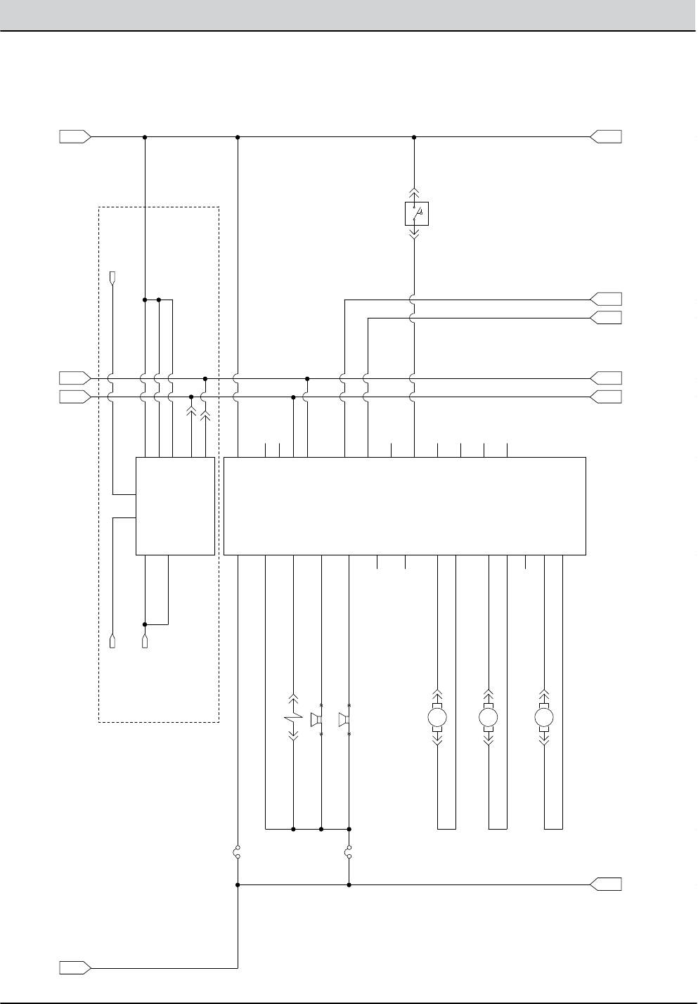
ELECTRICAL SCHEMATIC (2 of 6)
18 AMPS
ROTAUTCA ND/PU EGQS
10-25 AMPS
CYL=USE ADAPTOR AT FRONT BRUSH MOTOR
10-25 AMPS
KEY SWITCH
SV-2
TO: FUSED B+
TO: SHUNT HIGH
SHUNT LOW
STATIC GROUND LINES
(IN THE MAIN HARNESS)
OPEN SWITCH = EMPTY
OPT. TELEMETRY HARNESS
BLK
YEL
RED
14/YEL
58/GRY
8/GRY
5/GRN
4/YEL
7/PUR6/BLU
2/BRN
31/PNK
8/GRY
56/BLU
23/ORA
28/GRY
32/BRN
25/GRN
24/YEL
26/BLU
27/PUR
THW-KLB/57THW-KLB/57
ARO/37ARO/37
13/BLK
CABLE: POWER/GND TO CURTIS.
13/BLK
20/TAN34/YEL
21/PNK34/YEL
19/WHT34/YEL
34/YEL34/YEL
33/ORA33/ORA2/BRN
2/BRN
13/BLK
YRG/8YRG/8
CAN+ /YEL
13/BLK36/BLU
CAN+ /YEL
79/WHT
CAN- /GRN
13/BLK
13/BLK
13/BLK
13/BLK
13/BLK-WHT13/BLK-WHT
77/PUR
77/PUR
CAN- /GRN
30/TAN
29/WHT
105/GRNTO: SCRUB MODULE MOUNTING PLATE
TO: EC-H20/FAST MOUNTING PLATE
TO: SIDE BR. MODULE MOUNTING PLATE
58
13
79
77
1
CB-4
2.5A-REAR
MAIN NO DRIP VALVE
ALARM-1
VARIABLE VOLUMN AUDIBLE ALARM
P1-1P2-1
B+
J1-1
GND
J1-4
SQGE_ACT1
J2-2
SQGE_ACT2
J2-3
VAC1-
J1-2
VAC1+
J1-3
NOT_USED
J4-4
SHIELD
J4-3
CAN-
J4-2
CAN+
J4-1
OPEN2
J2-10
MTR
VAC FAN #1
2 1
RIGHT/REAR BRUSH MOTOR
21
1
SOL. TANK EMPTY
A B
M1A
MAIN CONTACTOR
+
-
2
EXTEND LIMIT SW.
RETRACT LIMIT
BLK
RED
BLK
RED
MTR
1
2
THROTTLE
P1-B
B+
P1-A
GND
P1-D
MTR
SCRUB UP/DOWN
21
MTR
MTR
LEFT/FRONT BRUSH MOTOR
2 1
CB-5
60A-REAR
SCRUB MODULE
B+ POST
P1-1
GND. POST
P2-1
SCRUB_ACT1
J6-7
SCRUB_ACT2
J6-8
LEFT_BRUSH-
J5-1
LEFT_BRUSH+
J5-2
OPEN3
J5-3
RT_BRUSH-
J5-4
FLYBACK
J6-1
MAIN H20 DRIP
J6-2
OPEN5
J6-10
OPEN6
J6-11
OPEN7
J6-12
LOW SOL.
J6-13
HORN
J6-3
AUD. ALARM
J6-4
OPEN1
J6-5
OPEN2
J6-6
OPEN4
J6-9
DIGITAL_GND
J6-15
CAN_SHIELD
J6-14
NOT_USED
J3-4
SHIELD
J3-3
CAN-
J3-2
RT_BRUSH+
J5-5
CAN+
J3-1
+12VDC
J6-16
HORN-1
HORN
P1-1P2-1
2
1
D-3
CB-5
25A-REAR
STIGN
BATT
START
ACC
X
XX
X
75
15
5030
TELEMETRY MODULE
B+
P1-22
B+
P1-23
GND
P1-21
SHUNT+
P1-6
SHUNT-
P1-7
CAN+
P1-3
CAN-
P1-11
GND
P1-20
GND
P1-19
2
A
B
C
E
H
I
J
F
G
D
2-6 T12 Service Information 9009917 (12-12)
GENERAL INFORMATION
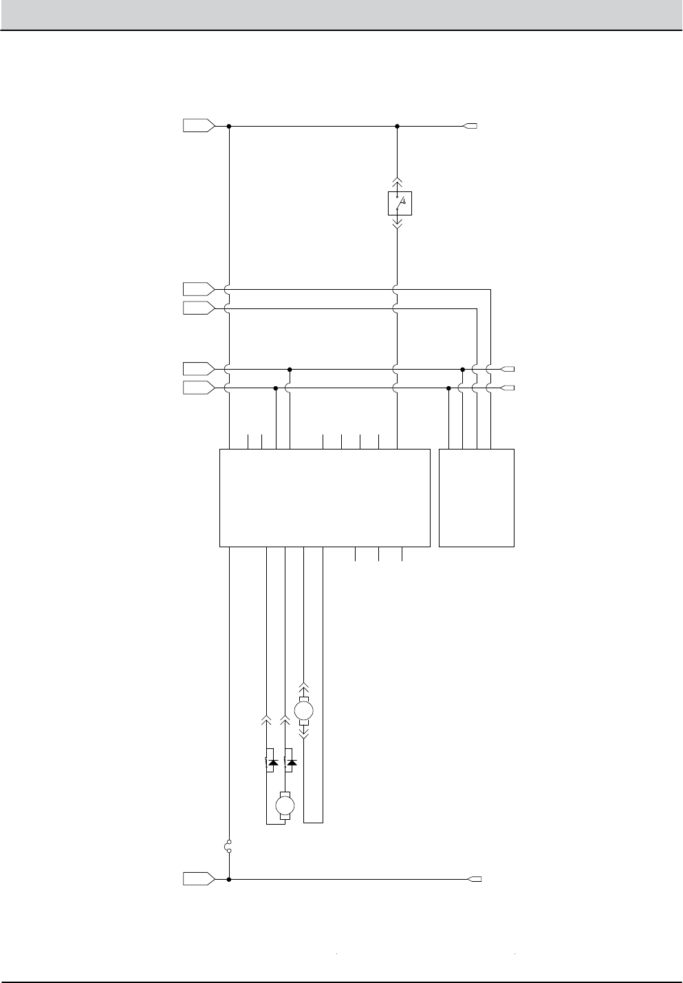
ELECTRICAL SCHEMATIC (3 of 6)
SWITCHED B+
GROUND
18 AMPS
ROTAUTCA ND/PU EGQS
10-25 AMPS
CYL=USE ADAPTOR AT FRONT BRUSH MOTOR
10-25 AMPS
CAN BUS SEE
SECTION E15
OPEN SWITCH = EMPTY
CLOSED SWITCH = FULL
2/BRN
31/PNK
2/BRN
56/BLU
23/ORA
28/GRY
32/BRN
13/BLK
25/GRN
24/YEL
26/BLU
27/PUR
CAN+ /YEL
THW-KLB/57THW-KLB/57
ARO/37ARO/37
13/BLK
CAN+ /YEL
13/BLK36/BLU
13/BLK35/GRN
CAN- /GRN CAN- /GRN
30/TAN
29/WHT
2
13
CAN-
CAN+
2.5A-REAR
H2O PICK-UP MOD.
B+
J1-1
GND
J1-4
SQGE_ACT1
J2-2
SQGE_ACT2
J2-3
VAC1-
J1-2
VAC1+
J1-3
SOL. FULL
J2-6
NOT_USED
J4-4
SHIELD
J4-3
CAN-
J4-2
CAN+
J4-1
EXTRA_OUT1
J2-5
EXTRA_OUT2
J2-4
FLYBACK
J2-1
OPEN2
J2-10
OPEN1
J2-9
EXTRA_IN2
J2-8
EXTRA_IN1
J2-7
MTR
VAC FAN #1
2 1
RIGHT/REAR BRUSH MOTOR
21
SOL. TANK EMPTY
A B
EXTEND LIMIT SW.
RETRACT LIMIT
BLK
RED
BLK
RED
MTR
1
2
REC. TANK FULL
A B
MTR
SCRUB UP/DOWN
21
MTR
MTR
LEFT/FRONT BRUSH MOTOR
2 1
SCRUB MODULE
SCRUB_ACT1
J6-7
SCRUB_ACT2
J6-8
LEFT_BRUSH-
J5-1
LEFT_BRUSH+
J5-2
OPEN3
J5-3
RT_BRUSH-
J5-4
OPEN5
J6-10
OPEN6
J6-11
OPEN7
J6-12
LOW SOL.
J6-13
OPEN1
J6-5
OPEN2
J6-6
OPEN4
J6-9
DIGITAL_GND
J6-15
CAN_SHIELD
J6-14
RT_BRUSH+
J5-5
CB-1
25A-REAR
INTERFACE PANEL
DIGITAL_GND
J1-3
+12VDC
J1-4
CAN-
J1-2
CAN+
J1-1
E
H
I
J
F
G
T12 Service Information 9009917 (12-12) 2-7
GENERAL INFORMATION
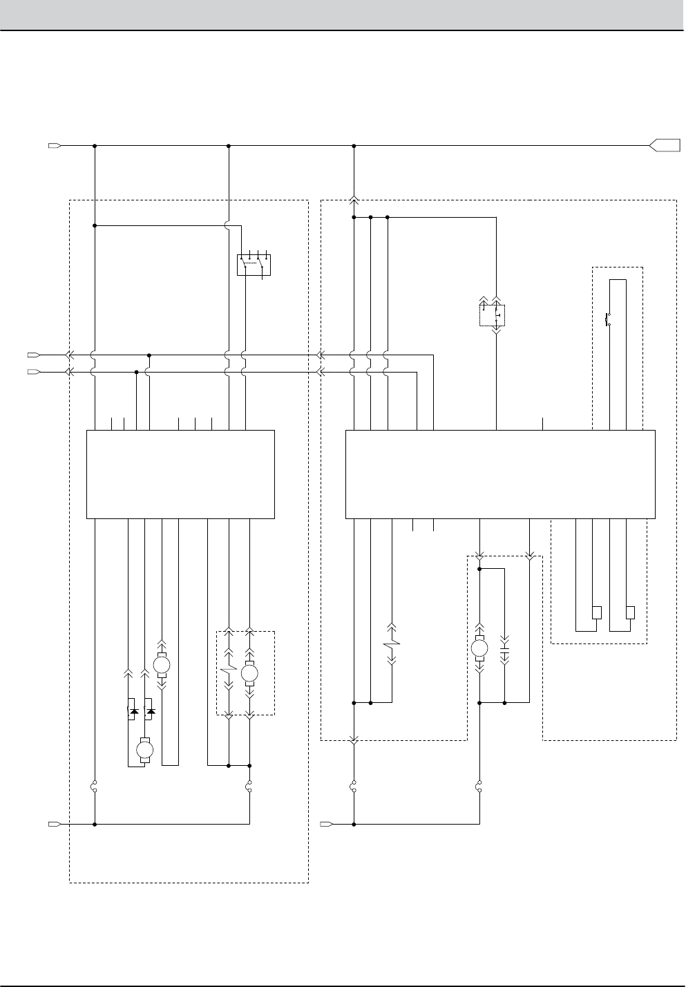
ELECTRICAL SCHEMATIC (4 of 6)
ELUDOM 02H-CE
SWITCHED B+
(@ CURTIS B+)
GROUND
(ECHO sparger)
(ECHO cell)
EC-H20 FLUSH SW.
OPT. EC-H2O HARNESS
SIDE BRUSH MODULE
(A) (B)
OPT. EC-H2O MODULE HARNESS
SWITCHED B+ (@ CURTIS B+)
SWITCHED B+ (@ M1 CONTACTOR)
OPT. SIDE BRUSH HARNESS
ECHO/FAST PUMP
CLOSED SWITCH = ENABLE SIDE BR.
MAIN HARNESS
13 AMPS
SIDE BRUSH UP/DN ACTUATOR
OPT. SIDE BRUSH HARNESS
60/TAN
8EA/GRY
7EA/PUR
3EA/ORA
4EA/YEL
37/PUR22/BRN
2/BRN
2/BRN
46/BLU
13EA/BLK
9EA/WHT
46/BLU 13/BLK
45/GRN
CAN+/YEL
52/BRN
52/BRN50/TAN
50/TAN
50/TAN 50/TAN
51/PNK46/BLU
CAN+/YEL
CAN-/GRN CAN-/GRN
40/TAN
39/WHT
38/GRY
38/GRY
38/GRY
22/BRN
43/ORA
53/ORA
42/BRN
44/YEL
22
13
CAN+
CAN-
22
2
32
2
CB-7
2.5A-REAR
PRESS NC, OPENS @ 25PSI +/-2PSI = FAULT
COM NC
NO
3
CB-9
20A-FRONT
+ -
C-1
CAPACITOR, 0.01UF, 200V
5
CB-10
2.5A-FRONT
1
EC-H20 MODULE
VCC_1
J4-1
GND_1
J4-14
FLYBACK
J4-3
SIDE BR. VALVE
J4-5
NOT USED #1
J4-6
VCC_2
J4-2
GND_2
J5-13
SPGR_A
J5-1
SPGR_B
J5-2
CELL_A
J5-3
CELL_B
J5-4
FLUSH_GND
J5-6
FLUSH_SW
J5-5
PRESS_IN
J4-9
CAN+
J4-10
CAN-
J4-11
GND_3
J5-12
PUMP
J4-4
NOT USED #2
J4-7
OPEN1
J4-8
1
2
16
1
4
MTR
SIDE BRUSH MOTOR
2 1
SIDE BRUSH MOD.
B+
J1-1
GND
J3-4
SIDE_ACT1
J5-2
SIDE_ACT2
J5-3
SIDE MTR-
J3-2
SIDE MTR+
J3-3
ENABLE
J5-6
NOT_USED
J2-4
SHIELD
J2-3
CAN-
J2-2
CAN+
J2-1
SIDE PUMP
J5-5
SIDE VALVE
J5-4
FLYBACK
J5-1
OPEN2
J5-10
OPEN1
J5-9
EXTRA_IN1
J5-8
SIDE SEL.
J5-7
SIDE H20 PUMP
MTR
3
3
1
1
SIDE BR. NO DRIP WATER
MTR
ON
OFF
SIDE BRUSH SW.
8
6
4
1
5
2
5
1
4
6
EXTEND LIMIT SW.
RETRACT LIMIT
BLK
RED
BLK
RED
MTR
1
2
ECH20 SIDE BR. VALVE
CB-6
2.5A-REAR
2
4
4
2
K
2-8 T12 Service Information 9009917 (12-12)
GENERAL INFORMATION
ELECTRICAL SCHEMATIC (5 of 6)
STHGILDNAW YARPS
ELUDO
BACK UP
ALARM/LIGHT
OPT. LIGHT KIT
STROBE LT.
FLASHING LT.
NOT USED
(FOR CUSTOM OPT.)
STROBE LT.
FLASHING LT.
LIGHTS OFF/DN = 2-1, 6-5
WARN. LIGHT ON/CENTER = 2-3, 6-7
HEAD & WARN ON/UP = 3-4, 7-8
OPT. LIGHT / ALARM HARNESS
OPT. OHG WARNING LIGHT HARNESS
LOCATED INSIDE
LIGHT ASSEMBLY
+36VDC FROM CONTROLLER
(ECHO sparger)
(ECHO cell)
EC-H20 FLUSH SW.
OPT. EC-H2O HARNESS
OPT. EC-H2O MODULE HARNESS
SWITCHED B+ (@ CURTIS B+)
67/PUR
67/PUR
65/GRN
65/GRN 13/BLK
65/GRN
13/BLK
85/GRN-WHT
85/GRN-WHT
90/TAN 15/GRN
13/BLK
93/ORA68/GRY 13/BLK
92/BRN
90/TAN
90/TAN
92/BRN
76/BLU 13/BLK
13/BLK
17/PUR17/PUR
22/BRN
8EA/GRY
7EA/PUR
3EA/ORA
4EA/YEL
63/ORA
13/BLK13/BLK13/BLK64/YEL
64/YEL64/YEL
13/BLK13/BLK
13EA/BLK
9EA/WHT
22/BRN
15/GRN
50/TAN 50/TAN
22/BRN
76/BLU
76/BLU
13/BLK
94/YEL
15
17
22
94
1
OHG FLASH/STROBE LIGHT
3
5
CB-16
NOT USED-FRONT
RIGHT HEADLIGHT (LED)
+ -
C-1
CAPACITOR, 0.01UF, 200V
2
5
4
M2A
OPT. REVERSE RELAY
8586
2
EC-H20 MODULE
FLYBACK
J4-3
SPGR_A
J5-1
SPGR_B
J5-2
CELL_A
J5-3
CELL_B
J5-4
FLUSH_GND
J5-6
FLUSH_SW
J5-5
OPEN1
J4-8
WHT, BACK UP LIGHT (LED)
LIGHT SWITCH
12
4
3
56
78
RED TAILLIGHT (LED)
CB-14
2.5A-FRONT
6
ALARM-2
REVERSE ALARM
P1-1P2-1
3
CB-13
2.5A-FRONT
CB-15
2.5A-FRONT
1
S-11
SPRAY NOZZLE SWITCH
1
24
5
68
910
1
5
CB11
15A-FRONT
21
2
LT-2
5
SPRAY NOZZLE PUMP
MTR
FLASH/STROBE LIGHT
LT-3
4
LEFT HEADLIGHT (LED)
M2B
30
87
CB-12
15A-FRONT
D-4
6
CB-17
2.5A
K
T12 Service Information 9009917 (12-12) 2-9
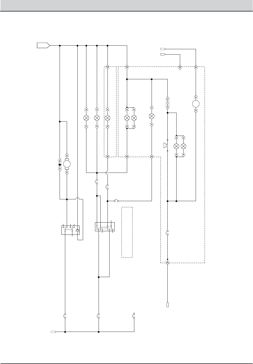
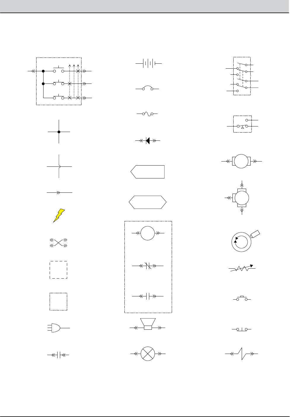
GENERAL INFORMATION
ELECTRICAL SCHEMATIC SYMBOLS
1
2
2
1
+ -
+ -
Switched B+
From Buss Bar
Switched B+
B- From
Stando
B- From
Stando
S-5 Seat Switch (N.O.)
Amer
Encoder
Cable
C1 Capacitor (0.01Uf)
R1
(11 Ω/40W)
+ -
MTR
ecH2O
Pump
J3-2 Brush RT-
J3-5 Brush LT+
J3-6 Brush LT-
Right/Rear Brush
Left/Front* Brush
* Cylindrical = Uses Adaptor
ecH2O
Control
Module
T16
Control
Board
VCC_A
Alarm
Com N.C.
N.O.
S-14 Pressure Sw.
N.C. Opens @ 25 +/- 2 psi
Enable
GND_A
GND_B
Pressure IN
(ECH2O SW)
(ECH2O SW)
VCC_B
VCC_C
Pump
(SOL-A)
ecH2O Valve
Sparger
e-Cell
65EA/BLU
5EA/GRN
8EA/GRY
7EA/PUR
3EA/ORA
4EA/YEL
(SOL-B)
(SPA-A)
(SPA-B)
(CELL-A)
(CELL-B)
(LED GND)
(LED RED)
(LED GRN)
Squeegee
Actuator
Battery Positive +
Battery Negative -
D-8
FU2
100A
70/TAN
M4A
86 85
B+
J7-1 B+ Control
B-
Cable
8/GRY
FU1
100A
FU1
100A
102/BRN
Sweep OFF/Down = 2-1, 6-5
Sweep ON/Center = 2-3, 6-7
Vac & Sweep ON/Up = 3-4, 7-8
Cable
Pre-Sweep
Brush Relay
CB3 (2.5A)
CB19 (25A)
CB16 (15A)
J7-4 Sweep
Note:
ecH2O Enable:
J7-10 Low=Turn ON ecH2O
Note:
Pre-Sweep Enable:
J6-10 B+ = Sweep Enable ON
Sweep Enable J6-10
37/PUR
38/GRY
CB9 (2.5A) 79/WHT
CB10 (2.5A)
Note:
ecH2O Side Brush
J7-12 Low=SV3 H20 Valve ON
ecH2O Pump ON 100%
13/BLK
88/GRY
9EA/WHT
S-15
Flush Switch
13EA/BLK
21/PNK
Extend
Limit Sw.
22/BRN
MTR 26/BLU
25/GRN
2/BRN
Switched B+
From Buss Bar
Switched B+
From Buss Bar
Switched B+
To: CAN Open-
(J6-14)
To: Throttle
Sensor (GND)
To: Curtis 1234
(I/O GND)
To: CAN Open+
(J6-13)
To: Back-Up
Light Circuit
To: Back-Up
Alarm Circuit
80/TAN
PMC001
12
12
MTR
10 4
1
3
2
7
9
6-4
6-8
5
6
11
12
8
6-1
6-2
6-3
6-6
6-5
6-7
ON
OFF
6
2
8
5
4
1
FWD
REV
6
2
8
BA
5
4 J1-33
GND Cable
J1-34
J1-21
W/WHT
V/GRN
U/ORN
J1-3
J1-4
J1-13
J1-11
BLU2 J1-32
J1-26
J1-31
J1-7
J1-18
J1-15
66/BLU
61/PNK
62/BRN
12/BRN
17/PUR
Propel Motor Assembly
17/PUR
15/GRN
87/PUR
Temp Sender
Brake
Solenoid
59/WHT
58GRY
RED1
WHT5
BLK6
YEL
T2
B1 B2
T1
YEL
J1-16
J1-35
J1-23
P1-C
BLU
YEL
P1-B
P1-D
BLK
P1-A
RED
J1-22
J1-9
J1-1
B+
J1-29
J1-28
J1-25
1
1
3
5
7
2
4
6
8
Pre-Sweep Switch
Sweep OFF/Down = 2-1, 6-5
Sweep ON/Center = 2-3, 6-7
Vac & Sweep ON/Up = 3-4, 7-8
1
3
5
7
2
4
6
8
M3B
MTR
MTR
MTR
MTR
FaST/ES Pump
D-9
D-6
D-7
D-12
67/PUR
64/YEL 81/PNK
Pre-Sweep
Vacuum Fan
LH Side Broom Motor
Main Broom Motor
13/BLK
13/BLK
65/GRN
65/GRN
65/GRN
68/GRY
69/WHT
D-11
30 87
M3A
Curtis 1234
Controller
PROG +
TX
RX
B+
KSI
INTERLOCK
FWD
FWD/REV Switch
Throttle Sensor
REV
B -
GND
B+
THROTTLE
BRAKE
CAN TERM L
CAN TERM H
U
DRV3
DRV4
DRV1
THERMISTOR
I/O GND
PHASE A
PHASE B
+5V
DRV2
COIL RETURN
V
W
BRAKE IN
(0-5 vdc)
(0-5 vdc) THROTTLE
CAN L
8/GRY 8/GRY
18/GRY
16/BLU
94/YEL
9/WHT
11/PNK
14/YEL
58/GRY
58/GRY
CAN H
6 Volt
IGN
15
ACC
30
BAT T
75
50 Start
ST
To: Back-Up
Alarm Circuit
+ -
Com N.C.
N.O.
1
3
5
7
2
4
6
8
MTR MTR
M3B
30 87
M3B
30 87a
M3A
IGN ST
+ -
Note: Key Switch ON
Key Switch
Battery
DPDT Switch
Pressure Switch
Motor
3 Phase AC
Induction Motor
Motor Encoder
Momenary Switch N.O.
Contact Switch N.C.
Solenoid Valve
Sensor
(Variable Resistor)
Circuit Breaker
Fuse
Diode
Single Continuation Tab
Double Continuation Tab
Relay Coil
N.C. Relay Contacts
N.O. Relay Contacts
Horn or Alarm
Light
Connected
Not Connected
Connector
Energized
Adaptor Harness
Notes
Assembly
AC Plug
Capacitor
Electro-
Magnetic
Brake
Enabled (Applied)
• Key O
• Neutral - Ready State
• Brake Command
• Seat Switch Open
• Curtis 1234 Fault
(See Troubleshooting)
• Throttle Command
• Seat Switch Closed
Disabled (Released)
Operational Matrix:
Propel
Enabled
• Seat Switch Closed
• Foot Throttle
Command
• Fwd/Rev Switch Input
• Seat Switch Open
• Neutral-Ready State
• Brake Command
• Curtis 1234 Fault
Disabled
Operational Matrix:
* SV2 Water Valve Voltage
Range
Low 1-LED
2-LEDs
3-LEDs
1-LED
2-LEDs
3-LEDs
1-LED
2-LEDs
3-LEDs
20%
30%
45%
30%
55%
80%
55%
80%
100%
7.2 Volts
10.8 Volts
16.2 Volts
10.8 Volts
19.8 Volts
28.8 Volts
19.8 Volts
28.8 Volts
36 Volts
Med
(Default)
High
Level PWM% @ Nominal
36 VDC

2-10 T12 Service Information 9009917 (12-12)
GENERAL INFORMATION
FUNCTION ENABLED
T12 OPERATIONAL MATRIX
DISABLED
Vacuum Fan, Scrubbing • 1-STEP Scrub ON
• Squeegee/Vacuum ON
• 1-STEP Scrub OFF
• Squeegee/Vacuum OFF
• Recovery Tank Full
• Very Low Battery Voltage
• Load Current Fault
Rear Squeegee Down • 1-STEP Scrub ON
• Squeegee/Vacuum ON
• 1-STEP Scrub OFF
• Squeegee/Vacuum OFF
• Reverse Propel
• Recovery Tank Full
• Very Low Battery Voltage
• Load Current Fault
Rear Squeegee Up • 1-STEP Scrub ON
• Squeegee/Vacuum ON
• 1-STEP Scrub OFF
• Squeegee/Vacuum OFF
• Reverse Propel
• Recovery Tank Full
• Very Low Battery Voltage
• Load Current Fault
Main Scrub Brushes • 1-STEP Scrub ON
• Fwd/Rev Throttle Command
• 1-STEP Scrub OFF
• Neutral - Ready State
• Recovery Tank Full
• Solution Tank Empty
• Very Low Battery Voltage
• Load Current Fault
Scrub Head Down • 1-STEP Scrub ON
• Fwd/Rev Throttle Command
• 1-STEP Scrub OFF
• Neutral - Ready State
• Recovery Tank Full
• Solution Tank Empty
• Very Low Battery Voltage
• Load Current Fault
Scrub Head Up • 1-STEP Scrub ON
• Fwd/Rev Throttle Command
• 1-STEP Scrub OFF
• Neutral - Ready State
• Recovery Tank Full
• Solution Tank Empty
• Very Low Battery Voltage
• Load Current Fault
Side Brush Extend/Down • 1-STEP Scrub ON
• Side Brush Switch ON
• 1-STEP Scrub OFF
• Side Brush Switch OFF
• Recovery Tank Full
• Solution Tank Empty
• Very Low Battery Voltage
• Load Current Fault
MOM001

T12 Service Information 9009917 (12-12) 2-11
GENERAL INFORMATION
Back-Up Alarm/Lights • Reverse Switch Input
• Reverse Throttle Command
• Forward Switch Input
• Neutral - Ready State
• Curtis 1232 Fault
Electromagnetic Parking
Brake
• Key OFF
• Emergency Stop Switch Open (Down)
• Neutral (1-2 Second Delay)
• Seat Switch Open
• Curtis 1232 Fault
• Key ON
• Emergency Stop Switch Closed (Up)
• Fwd/Rev Throttle Command
• Seat Switch Closed
Propel • Seat Switch Closed
• Fwd/Rev Throttle Command
• Fwd/Rev Switch Input
• Seat Switch Open
• Neutral - Ready State
• Brake Command
• Curtis 1232 Fault
FUNCTION ENABLED
T12 OPERATIONAL MATRIX, continued
DISABLED
Solution Control
(ecH2O)
• 1-STEP Scrub ON
• Solution Control ON
• ecH2O Button ON
• Fwd/Rev Throttle Command
• 1-STEP Scrub OFF
• Solution Control OFF
• ecH2O Button OFF
• Neutral - Ready State
• Recovery Tank Full
• Solution Tank Empty
• Very Low Battery Voltage
• ecH2O System Fault
• Load Current Fault
MOM002
Solution Control
(Conventional)
• 1-STEP Scrub ON
• Solution Control ON
• Fwd/Rev Throttle Command
• 1-STEP Scrub OFF
• Solution Control OFF
• Neutral - Ready State
• Recovery Tank Full
• Solution Tank Empty
• Very Low Battery Voltage
• Load Current Fault
Side Brush Retract/Up • 1-STEP Scrub ON
• Side Brush Switch ON
• 1-STEP Scrub OFF
• Side Brush Switch OFF
• Recovery Tank Full
• Solution Tank Empty
• Very Low Battery Voltage
• Load Current Fault
Side Brush • 1-STEP Scrub ON
• Side Brush Switch ON
• Fwd/Rev Throttle Command
• 1-STEP Scrub OFF
• Side Brush Switch OFF
• Neutral - Ready State
• Recovery Tank Full
• Solution Tank Empty
• Very Low Battery Voltage
• Load Current Fault

2-12 T12 Service Information 9009917 (12-12)
GENERAL INFORMATION
FASTENER TORQUE
Thread
Size
SAE
Grade 1
SAE
Grade 2
Carriage
Bolts
Thread
Cutting
Thread
Rolling
SAE
Grade 5
Socket &
Stainless
Steel
SAE
Grade 8
Headless
Socket Set
Screws
Square
Head Set
Screws
4 (.112) (5) - (6.5) (4) - (6)
Inch Pounds
5 (.125) (6) - (8) (9) - (11)
6 (.138) (7) - (9) (20) - (24) (9) - (11)
8 (.164) (12) - (16) (40) - (47) (17) - (23)
10 (.190) (20) - (26) (50) - (60) (31) - (41)
1/4 (.250) 4 - 5 5 - 6 7 - 10 7 - 10 10 - 13 6 - 8 17 - 19
Foot Pounds
5/16 (.312) 7 - 9 9 - 12 15 - 20 15 - 20 20 - 26 13 - 15 32 - 38
3/8 (.375) 13 - 17 16 - 21 27 - 35 36 - 47 22 - 26 65 - 75
7/16 (.438) 20 - 26 26 - 34 43 - 56 53 - 76 33 - 39 106 - 124
1/2 (.500) 27 - 35 39 - 51 65 - 85 89 - 116 48 - 56 162 - 188
5/8 (.625) 80 - 104 130 - 170 171 - 265 228 - 383
3/4 (.750) 129 - 168 215 - 280 313 - 407 592 - 688
1 (1.000) 258 - 335 500 - 650 757 - 984 1281 - 1489
Thread
Size
4.8/5.6 8.8
Stainless Steel
10.9 12.9 Set
Screws
M3 43 - 56 Ncm 99 - 128 Ncm 139 - 180 Ncm 166 - 215 Ncm 61 - 79 Ncm
M4 99 - 128 Ncm 223 - 290 Ncm 316 - 410 Ncm 381 - 495 Ncm 219 - 285 Ncm
M5 193 - 250 Ncm 443 - 575 Ncm 624 - 810 Ncm 747 - 970 Ncm 427 - 554 Ncm
M6 3.3 - 4.3 Nm 7.6 - 9.9 Nm 10.8 - 14 Nm 12.7 - 16.5 Nm 7.5 - 9.8 Nm
M8 8.1 - 10.5 Nm 18.5 - 24 Nm 26.2 - 34 Nm 31 - 40 Nm 18.3 - 23.7 Nm
M10 16 - 21 Nm 37 - 48 Nm 52 - 67 Nm 63 - 81 Nm
M12 28 - 36 Nm 64 - 83 Nm 90 - 117 Nm 108 - 140 Nm
M14 45 - 58 Nm 102 - 132 Nm 142 - 185 Nm 169 - 220 Nm
M16 68 - 88 Nm 154 - 200 Nm 219 - 285 Nm 262 - 340 Nm
M20 132 - 171 Nm 300 - 390 Nm 424 - 550 Nm 508 - 660 Nm
M22 177 - 230 Nm 409 - 530 Nm 574 - 745 Nm 686 - 890 Nm
M24 227 - 295 Nm 520 - 675 Nm 732 - 950 Nm 879 - 1140 Nm
METRIC
SAE (STANDARD)
T12 Service Information 9009917 (12-12) 2-13
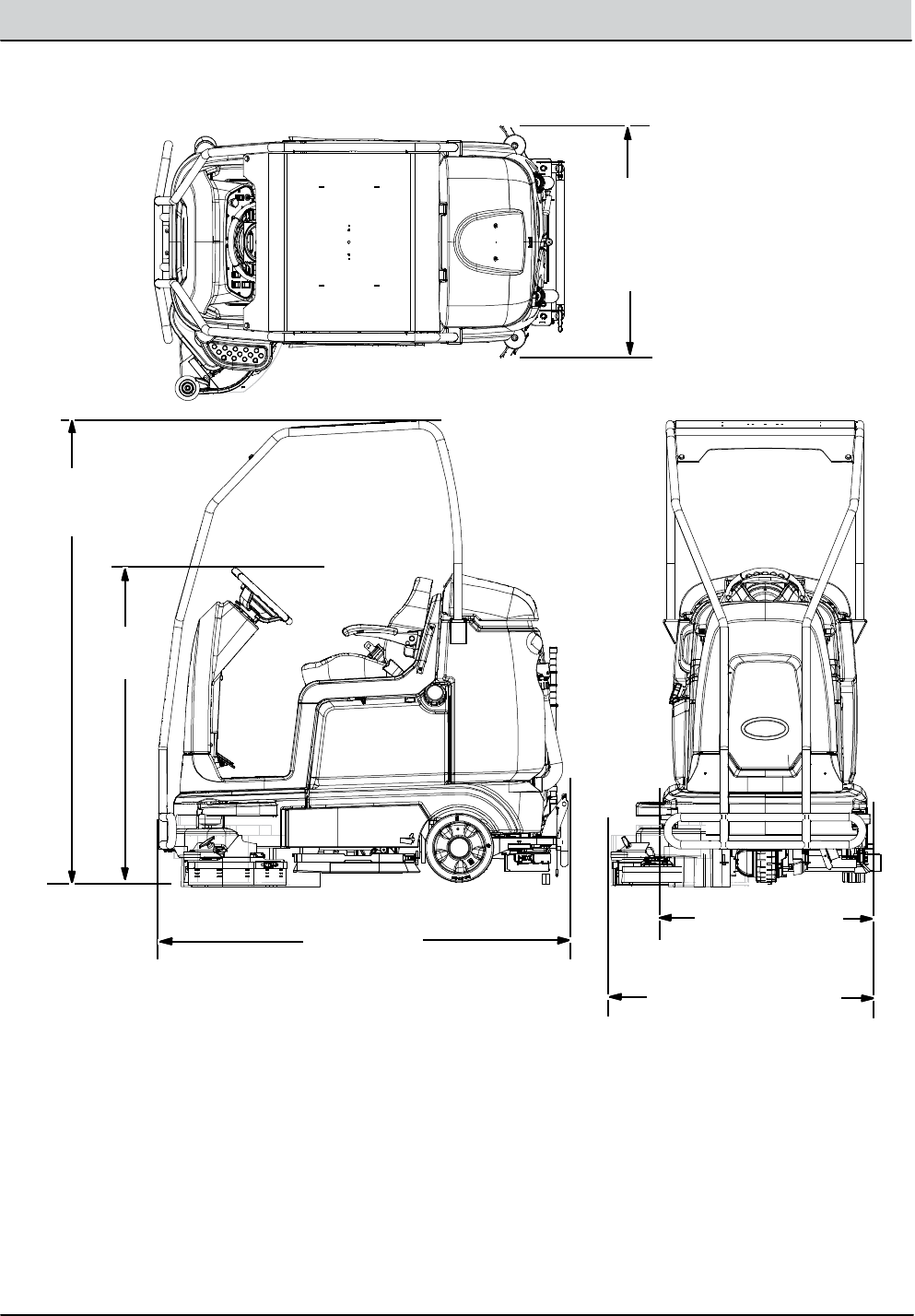
GENERAL INFORMATION
MACHINE DIMENSIONS
Frame
(roller to roller)
945 mm (37.25 in)
1420 mm
(56 in)
1710 mm
(67.25 in)
Rear
Squeegee
990 mm
(39 in)
Width
(with side brush)
1065 mm (42 in)
2095 mm
(82.5 in)

2-14 T12 Service Information 9009917 (12-12)
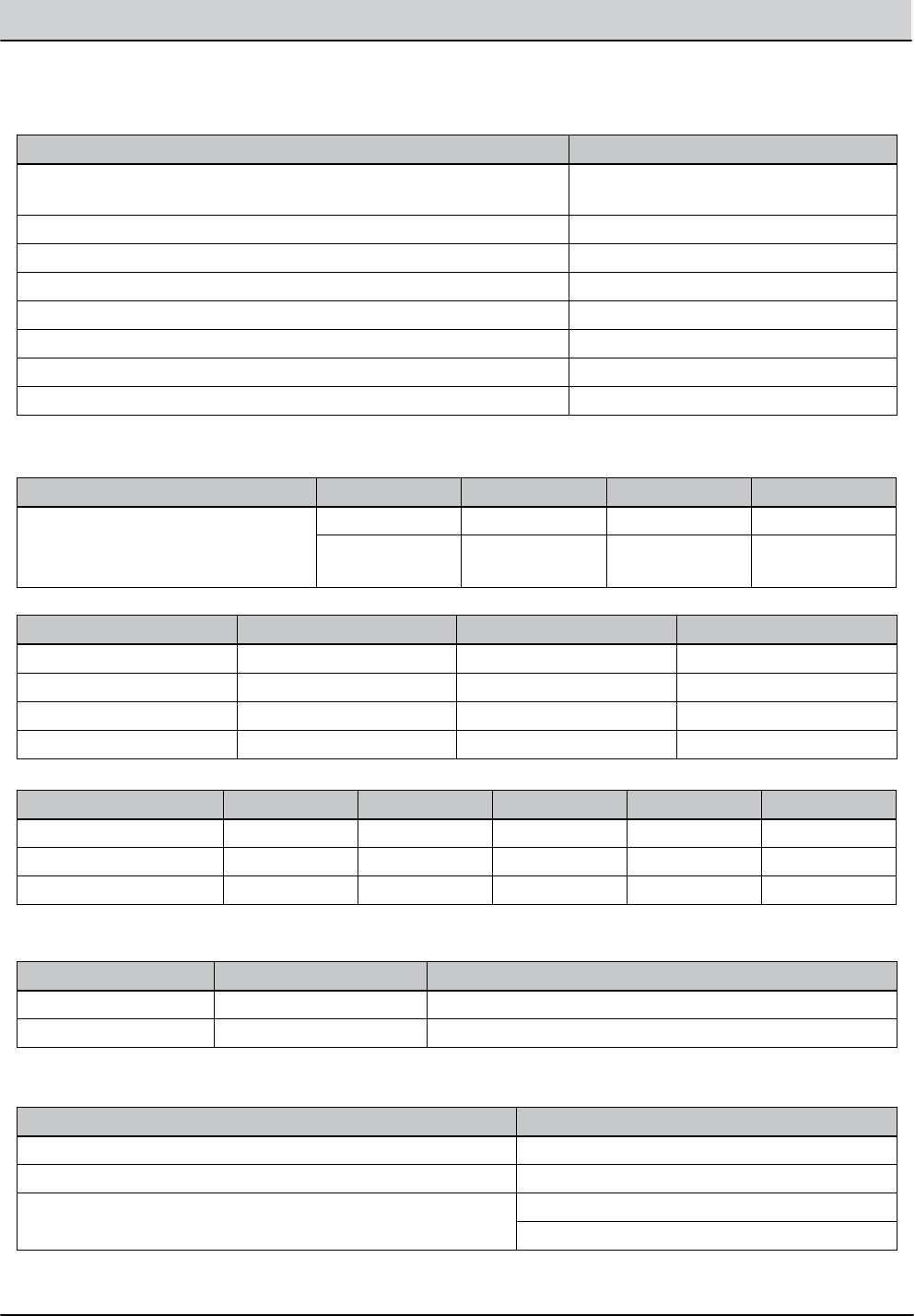
GENERAL INFORMATION
SPECIFICATIONS
Item Dimension/Capacity
Length 1710 mm (67.25 in)
Width (less squeegee) 945 mm (37.25 in)
Width (with squeegee) 990 mm (39 in)
Width (with side brush) 1065 mm (42 in)
Height 1420 mm (56 in)
Height with overhead guard 2095 mm (82.5 in)
Disk brush diameter for side brush (option) 330 mm (13 in)
Disk brush diameter 405 mm (16 in)
Cylindrical brush diameter 180 mm (7 in)
Cylindrical brush length 780 mm (30.7 in)
Scrubbing path width 810 mm (32 in)
Scrubbing path width (with side brush) 1040 mm (41 in)
Solution tank capacity 132 L (35 gallons)
Recovery tank capacity 166 L (44 gallons)
Demisting Chamber 34 L (9 gallons)
Weight (Empty) 468 Kg (1030 lbs)
Weight (with standard 240 AH batteries) 664 Kg (1460 lbs)
GVWR 1000 Kg (2200 lbs)
GENERAL MACHINE DIMENSIONS/CAPACITIES
Item Measure
Aisle turnaround width 1854 mm (73 in)
Travel Speed (Forward) 8 Km (5 mph)
Travel Speed while scrubbing (Forward) 6.1 Km (3.8 mph)
Travel Speed (Reverse) 4 Km (2.5 mph)
Maximum rated climb and descent angle for transport - Empty 20%
Maximum rated climb angle for scrubbing 7%
Maximum rated climb and descent angle at gross weight (GVWR) 14.1%
Maximum ambient temperature for machine operation 43° C (110° F)
Minimum temperature for operating machine scrubbing functions 0° C (32° F)
Values determined as per EN 60335-2-72 Measure -
Cylindrical scrub head
Measure-
Disk scrub head
Sound pressure level LpA 63 dB(A) 62 dB(A)
Sound uncertainty KpA 3.0 dB(A) 3.0 dB(A)
Sound power level LWA + Uncertainty KWA - -
Vibration - Hand-arm - -
Vibration - Whole body - -
Vibration uncertainty K - -
GENERAL MACHINE PERFORMANCE
T12 Service Information 9009917 (12-12) 2-15
GENERAL INFORMATION
Item Measure
Runtime (economy mode) 240 AH, Up to 2.5 hours
360 AH, Up to 4.5 hours
Ground clearance (transport) 65 mm (2.5 in)
Vacuum fan speed 14500 RPM
Vacuum fan water lift 1650 mm (65 in)
Disk main brush speed 325 RPM
Disk main brush down pressure Up to 114 kg (250 lb)
Cylindrical main brush speed 600 RPM
Cylindrical main brush down pressure Up to 91 kg (200 lb)
GENERAL MACHINE PERFORMANCE
Type Quantity Volts Ah Rating Weight
Batteries (Max. battery dimensions:
177.8 mm (7 in) W x 299.7 mm (11.8
in) L x 380 mm (15 in) H)
6 36 240 @ 20 hr rate 30 kg (67 lb)
6 36 360 @ 20 hr rate 44 kg (97 lb)
POWER TYPE
Type Use Voltage kW (hp)
Electric Motors Scrub brush (disk) 36 VDC 0.75 (1.00)
Scrub brush (cylindrical) 36 VDC 0.75 (1.00)
Vacuum Fan 36 VDC 0.6 (0.8)
Propelling 36 VAC 0.9 (1.2)
Type VDC Amperage Hz Phase VAC
Chargers (Smart) 36 21 45-65 1 85-265
Chargers (On-board) 36 20 50-60 1 85-130
Chargers (On-board CE) 36 20 50-60 1 230/240
Location Type Size
Front (1) Solid 90 mm wide x 250 mm OD (3.5 in wide x 10 in OD)
Rear (2) Solid 102 mm wide x 300 mm OD (4 in wide x 12 in OD)
TIRES
SPECIFICATIONS
Item Measure
Solution pump 36 Volt DC, 5A, 5.13 LPM (1.36 GPM) open ow,
Solution ow rate (machines without optional side brush) 1.9 LPM (0.5 GPM) maximum
Solution ow rate (machines with optional side brush) 1.9 LPM (0.5 GPM) - (To main scrub head)
0.95 LPM (0.25 GPM) - (To side brush)
ec-H2O SYSTEM (OPTION)

2-16 T12 Service Information 9009917 (12-12)
GENERAL INFORMATION
Component Measure
Contactor Coil, M1 126 Ω +/- 5%
Contactor Coil, M2 0.810 kΩ +/- 5%
Actuator, Scrub head lift 1 - 3 Amps continuous
Actuator, Side brush lift 1 - 3 Amps continuous, Internal limit switches
Actuator, Rear squeegee lift 2 - 4 Amps continuous, Internal limit switches
Motor, Vacuum Fan(s) 14 - 20 Amps continuous (16 Amps average)
Motor, Propelling
(5.0 mph transport speed)
15 - 25 Amps continuous (20 amps average), 40-60 Amps Peak
Motors, Main cylindrical brush
Down pressure #1 10 - 11 Amps/Motor (default 10 Amps)
Down pressure #2 11 - 16 Amps/Motor (default 14.5 Amps)
Down pressure #3 11 - 22 Amps/Motor (default 19 Amps)
Motors, Main disk brush
Down pressure #1 11 Amps/Motor (Fixed)
Down pressure #2 11 - 16 Amps/Motor (default 16 Amps)
Down pressure #3 11 - 22 Amps/Motor (default 21 Amps)
Motor, Side Brush 5 - 8 Amps
Pump, ec-H2O 4 - 6 Amps
Pump, Spray Nozzle 2 - 3 Amps
Pump, Side Brush 0.5 - 2 Amps
Valve, ec-H2O Side Brush 129 Ω +/- 5%
Valve, Conventional Side Brush 108 Ω +/- 10%
Valve, Conventional Main Brush 108 Ω +/- 10%
ELECTRICAL COMPONENTS (For Reference Only)
SPECIFICATIONS

MAINTENANCE
SECTION 3
3-1
T12 Service Information 9009917 (12-12)
MAINTENANCE
MAINTENANCE CHART .....................32
LUBRICATION .............................. 34
BATTERIES ................................. 35
CHARGING THE BATTERIES
OFFBOARD CHARGER ............. 36
CHARGING THE BATTERIES
ONBOARD CHARGER .............. 37
ONBOARD CHARGER ERROR CODES ... 38
ONBOARD CHARGER SETTINGS ........39
CHANGING THE ONBOARD BATTERY
CHARGER FUSE .....................310
FLOWRITE™ BATTERY
WATERING SYSTEM .................311
CIRCUIT BREAKERS .......................313
ELECTRIC MOTORS .......................314
SCRUB BRUSHES ..........................315
DISK BRUSHES AND PADS .............315
REPLACING DISK BRUSHES
OR PAD DRIVERS ................315
REPLACING DISK SCRUB PADS ......316
CYLINDRICAL BRUSHES ................317
REPLACING CYLINDRICAL
BRUSHES .........................317
CHECKING CYLINDRICAL SCRUB
BRUSH PATTERN .................. 318
ADJUSTING CYLINDRICAL
BRUSH TAPER ....................321
ADJUSTING CYLINDRICAL BRUSH
PATTERN WIDTH .................. 322
SIDE BRUSH OPTION ....................323
REPLACING THE SIDE BRUSH ........... 323
SQUEEGEE BLADES .......................324
REPLACING OR ROTATING THE
REAR SQUEEGEE BLADES ...........324
LEVELING THE REAR SQUEEGEE ........327
ADJUSTING THE REAR SQUEEGEE
BLADE DEFLECTION ................328
REPLACING OR ROTATING THE SIDE
SQUEEGEE BLADES .................329
REPLACING OR ROTATING THE SIDE BRUSH
SQUEEGEE BLADES OPTION .......330
SKIRTS AND SEALS ........................ 331
BELTS ..................................331
TIRES ..................................331
PUSHING, TOWING, AND TRANSPORTING
THE MACHINE .........................333
MACHINE JACKING .......................335
Contents Page
ec-H2O MODULE FLUSH PROCEDURE .....336
STORAGE INFORMATION .................. 338
FREEZE PROTECTION ..................338
PREPARING THE MACHINE FOR
OPERATION AFTER STORAGE .......340
PRIMING THE ECH2O SYSTEM .........3-42
Contents Page
3-2 T12 Service Information 9009917 (12-12)
MAINTENANCE
MAINTENANCE
1
2
3
4
5
6
7
8
9
10
11
12
1
8
13
13 13
356389356290
MAINTENANCECHART
The tablebelowindicates the Person Responsiblefor each procedure.
O = Operator.
T = Trained Personnel.
Interval
Person
Resp. KeyDescription Procedure
Lubricant/
Fluid
No. of
Service
Points
DailyO 1 Sideand rear squeegeesCheck for damageand
wear
-- 4
O 2 Main brushesCheck for damage,wear,
anddebris
-- 2
O 3 Recovery tankClean tankand check
cover seal
-- 1
O 4 Vacuum fan inlet filter Clean -- 1
O 5 Cylindrical brushesonly:
Debris tray
Clean -- 1
O 12 Side brush (Option)Check for damage,wear,
debris
-- 1
O 12 Side brush squeegee
(Option)
Check for damageand
wear
-- 1

T12 Service Information 9009917 (12-12) 3-3
MAINTENANCE
Interval
Person
Resp. KeyDescription Procedure
Lubricant/
Fluid
No. of
Service
Points
Weekly T 7 Battery cellsCheck electrolyte level DW 12
50
Hours
T 6 Squeegee caster wheel
pivot points
Lubricate SPL 2
T 1 Sideand rear squeegeesCheck deflectionand
leveling
-- 4
O 2 Main brushes(cylindrical)Rotate brushes from front
to rear
-- 2
T 13 Scrub headskirts (disk)Check skirts for damage
andwear
-- 2
100
Hours
T 7 Battery watering system
(option)
Check hoses and
connections for damage
andwear
-- Multiple
200
Hours
T 7 Battery terminalsand
cables
Check and clean -- 12
T 8 Cylindrical brush drive
belts
Check for damageand
wear
-- 2
T 13 Steering chain
(T12XP Only)
Lubricate, check tension,
and check for damageand
wear.
GL 1
T 9 Steeringgear chainLubricate, check tension,
and check for damageand
wear.
GL 1
500
Hours
T 10 Vacuum fan motor(s) Check motor brushes -- 1 (2)
O 11 Tires Check for damageand
wear
-- 3
1000
Hours
T 8 Main brush motors Check motor brushes
(Checkevery100hours
after initial 1000hour
check)
-- 2 (4)
T 12 Side brush motor Check motor brushes
(Checkevery100hours
after initial 1000hour
check)
-- 1
LUBRICANT/FLUID
DW Distilledwater.....
SPL Speciallubricant, Lubriplate EMB grease (Tennantpart number01433--1)...
GL SAE 90 weightgearlubricant....
NOTE: More frequent maintenance intervals may be required in extremelydusty conditions.
3-4 T12 Service Information 9009917 (12-12)
MAINTENANCE
LUBRICATION
FOR SAFETY: Before leaving or servicing
machine, stop on level surface, turn off
machine, and remove key.
STEERING CHAIN (T12XP ONLY)
The steering chain is located on the steering
column directly under the control panel.Check for
damage or wearandlubricate the steering chain
after every 200hours.
STEERING GEAR CHAIN
The steeringgear chain is located directly above
the front tire. Check for damage or wearand
lubricate the steeringgear chain after every 200
hours.
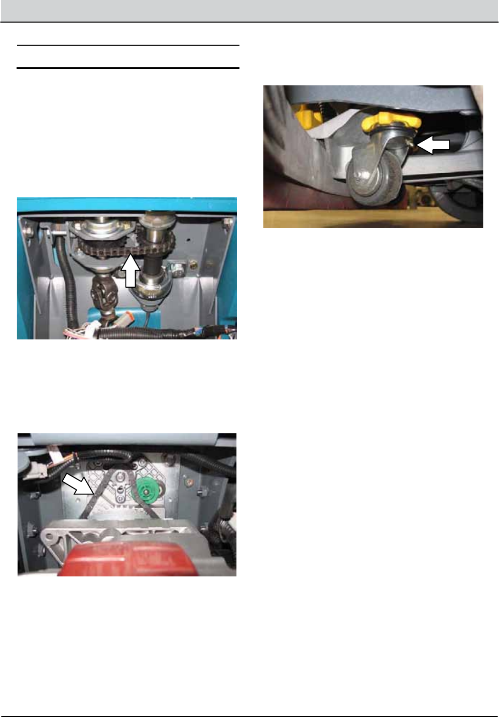
REAR SQUEEGEE CASTERS
Lubricate the rear squeegee caster pivot point on
each squeegee caster after every 50 hours.
T12 Service Information 9009917 (12-12) 3-5
MAINTENANCE
BATTERIES
The lifetime of the batteriesislimited to the
number of charges the batteries receive. To get
the most life from the batteries, only recharge the
batterieswhen the battery discharge indicator is
down to the last bar. It’s also important to
maintain the properelectrolyte levelsduring the
life of the battery.
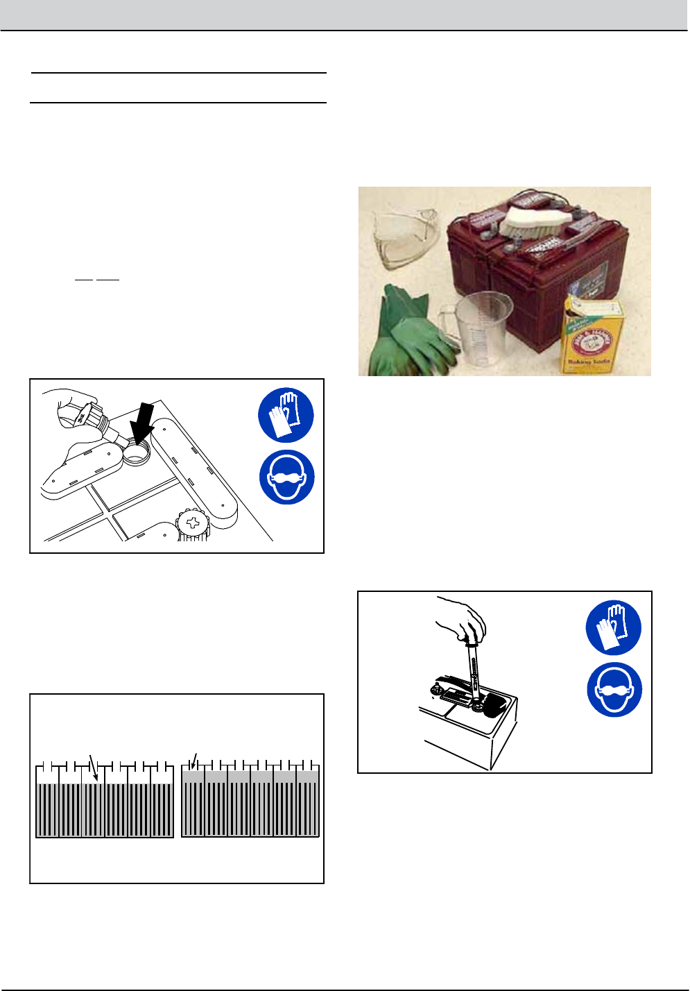
CHECKING THE ELECTROLYTE LEVEL
NOTE: Do Not check the electrolyte level if the
machine is equippedwith the battery watering
system. Proceed to HYDROLINK BATTERY
WATERING SYSTEM (OPTION).
Check the battery electrolyte level weekly for
machinesequippedwith wet/lead acid batteries.
08247
FOR SAFETY: When servicingmachine, avoid
contactwith batteryacid.
The level should be slightly above the battery
plates as shownbefore charging. Add distilled
water if low. DO NOT OVERFILL. The electrolyte
will expandand may overflowwhen charging.
Before Charging After Charging
NOTE: Make sure the battery caps are in place
while charging.
CHECKING CONNECTIONS / CLEANING
After every 200hours of use check for loose
battery connectionsand clean the surface of the
batteries, including terminalsand cable clamps,
withastrong solution of baking sodaandwater.
Replace anyworn or damagedwires. Do not
remove battery capswhen cleaningbatteries.
Objects made of metal can potentially short circuit
the batteries. Keepall metallicobjects off the
batteries.
MEASURING THE SPECIFIC GRAVITY
Measuring the specific gravity, using a
hydrometer, is a way to determine the charge
level and condition of the batteries. If one or more
of the battery cells test lower than the other
battery cells (0.050 or more), the cell is damaged,
shorted, or is about to fail.
04380
FOR SAFETY: When maintaining or servicing
machine, avoid contactwith batteryacid.
NOTE: Do not take readings immediately after
addingdistilled water. If the water and acid are not
thoroughly mixed, the readings may not be
accurate. Check the hydrometer readingsagainst
the following chart to determine the remaining
battery charge level:
3-6 T12 Service Information 9009917 (12-12)
MAINTENANCE
CHARGING THE BATTERIES
(OFF--BOARDCHARGER)
IMPORTANT: Before charging,make sure that
the charger setting is properly set for the
battery type.
1. Drive the machine toaflat, dry surface in a
well--ventilated area.
2. Stop the machineand turn off the machine
power.
FOR SAFETY: Before leaving or servicing
machine, stop on level surface, turn off
machine, and remove key.
3. Lift the operator seatopenandengage the
seat support.
NOTE: Make sure the batterieshave the proper
electrolyte level before charging. See CHECKING
THE ELECTROLYTE LEVEL.
4. Plug the charger AC power supply cord into a
properly groundedoutlet.
5. Plug the charger connector into the remote
battery charge connector.
WARNING: Batteries emit hydrogen gas.
Explosion or fire canresult. Keep
sparks and open flame away. Keep
coversopen when charging.
NOTE: If the charger “FAULT CODE” lights flash
when the batteries are pluggedinto the charger,
refer to the charger manufacturer manual for fault
codedefinitions.
6. The Tennant chargerwill start automatically.
When the batteries are fully charged, the
Tennant chargerwillautomatically turn off.
7. After the chargerhas turned off, unplug the
charger connector from the remote battery
charge connector.
ATTENTION: Do notdisconnect the charger
DC cord from the machinereceptacle when
the charger is operating.Arcingmayresult. If
the charger must be interrupted during
charging,disconnect the AC power supply
cord first.
8. Close the operator seat.
SPECIFIC GRAVITY
at 27_C (80_F)
BATTERY
CHARGE
1.277100%Charged
1.23875%Charged
1.19550%Charged
1.14825%Charged
1.100Discharged
NOTE: If the readings are taken when the battery
electrolyte is any temperature other than shown,
the reading must be temperature corrected. Add
or subtract to the specific gravity reading 0.004, 4
points, for each 6_C(10_F) above or below
25_C (77_F).
T12 Service Information 9009917 (12-12) 3-7
MAINTENANCE
CHARGING THE BATTERIES
(ON--BOARDCHARGER)
IMPORTANT: Before charging,make sure that
the charger setting is properly set for the
battery type. See ON- BOARDCHARGER
SETTINGS.
1. Drive the machine toaflat, dry surface in a
well--ventilated area.
2. Stop the machineand turn off the machine
power.
FOR SAFETY: Before leaving or servicing
machine, stop on level surface, turn off
machine, and remove key.
3. Lift the operator seatopenandengage the
seat support.
NOTE: Make sure the batterieshave the proper
electrolyte level before charging. See CHECKING
THE ELECTROLYTE LEVEL.
4. Plug the on--board battery charger cord into a
properly groundedwalloutlet.
WARNING: Batteries emit hydrogen gas.
Explosion or fire canresult. Keep
sparks and open flame away. Keep
coversopen when charging.
NOTE: The machinewillnotoperate when
charging.
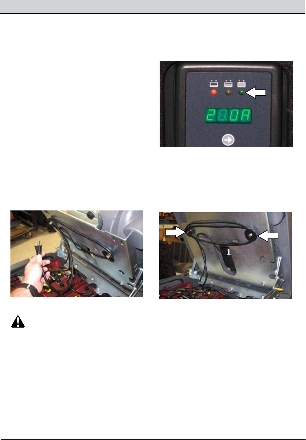
5. The on--board chargerwill start charging the
batteries. Once the charging cyclebegins, the
indicator lights will progress from red, yellow
to green. When the greenindicator light stays
on, the charging cycle is done.
If the chargerdetects a problem, the chargerwill
display an error code (See ON--BOARD
BATTERY CHARGER ERROR CODES).
6. Unplug the on--board battery charger from the
walloutletandneatly stow the cord inside the
battery compartment.
7. Close the operator seat.

3-8 T12 Service Information 9009917 (12-12)
MAINTENANCE
ON--BOARD BATTERY CHARGER ERROR
CODES
Display CodeFault Solution
batLoose or damagedbattery cable.Check battery cable connection.
Battery exceeded maximum voltagelevel. No actionnecessary.
E01 Exceeded maximum battery voltage
allowed. Interrupts charging cycle.
No actionnecessary.
E02 Safety thermostat exceeded maximum
internal temperature. Interrupts charging
cycle.
Ensure the charger vents are not
obstructed.Clearobstructions.
E03 Exceeded maximum time for charging
phase, leaving the batteriesundercharged
due toasulfated or faulty battery. Interrupts
charging cycle.
Repeat the chargingcycle. If the error
code E03 reappears check battery or
replace it.
SCt Safety timer exceeded maximum charging
time. Interrupts charging cycle.
Replace battery.
Srt Possibleinternal short circuit. Contact a Tennant service
representative.
T12 Service Information 9009917 (12-12) 3-9
MAINTENANCE
ON--BOARDCHARGER SETTINGS
If the machine is equippedwith the on--board
charger, the charger settings are properly set at
the factory. If differentbatteries are put in the
machine, the settings must be changed to match
the newbattery type before charging. Failure to
properly set the chargerwill result in battery
damage.
Refer to the battery label for the battery type.
Contact the battery manufacturer if battery is not
labeled.
To verify the setting of the charger, connect the
charger cord into an electrical outlet. The charger
willdisplay a sequence of the following codes
(three--digits + the code)when the cord is
connected:
A = Charging current
U = Battery Voltage
h = Charging time
C = Charging ampere--hours [Ah]
E = Energy used [Kwh]
“GEL” or “Acd” = Battery type for which the
charger is currently set. Before charging
make sure battery type matches the display:
GEL=Sealed, Acd=WET (lead acid).
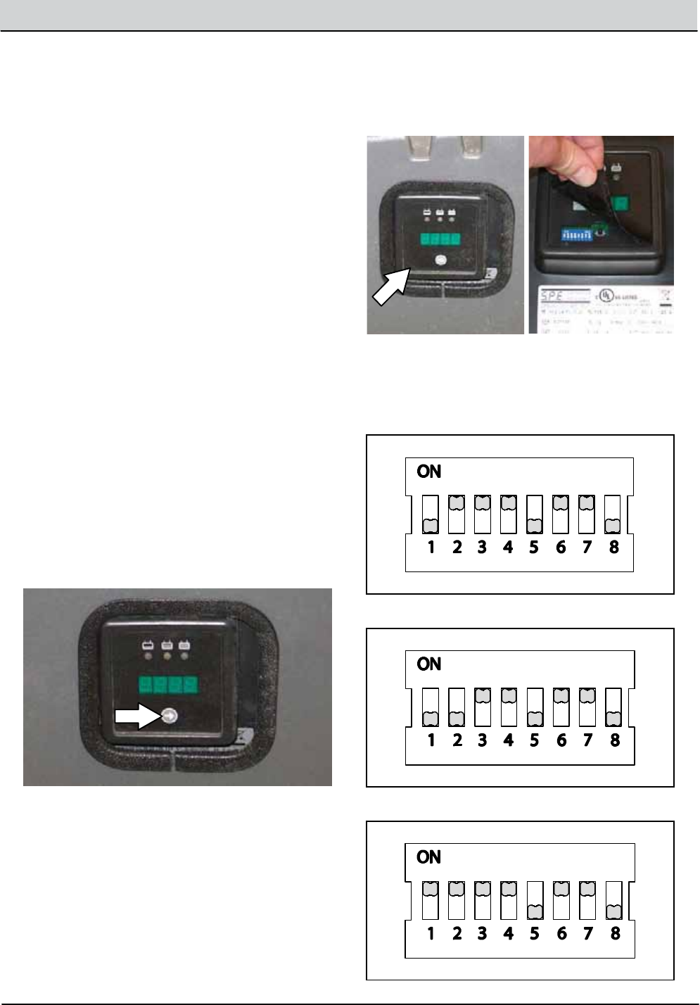
Press the arrow button to review the codes. Refer
to the battery type codetodetermine the charger
battery type setting.
To change the setting,unplug the chargerand
peel up the corner of the displaylabel to access
the switches. The charger cord must be
unpluggedwhen resetting.
Adjust the switches to the correct setting for the
batteries.
Lead Acid 240Ah:
Lead Acid 360Ah:
Gel:
3-10 T12 Service Information 9009917 (12-12)
MAINTENANCE
CHANGING THE ON--BOARD BATTERY
CHARGER FUSE
FOR SAFETY: Before leaving or servicing
machine, stop on level surface, turn off
machine, and remove key.
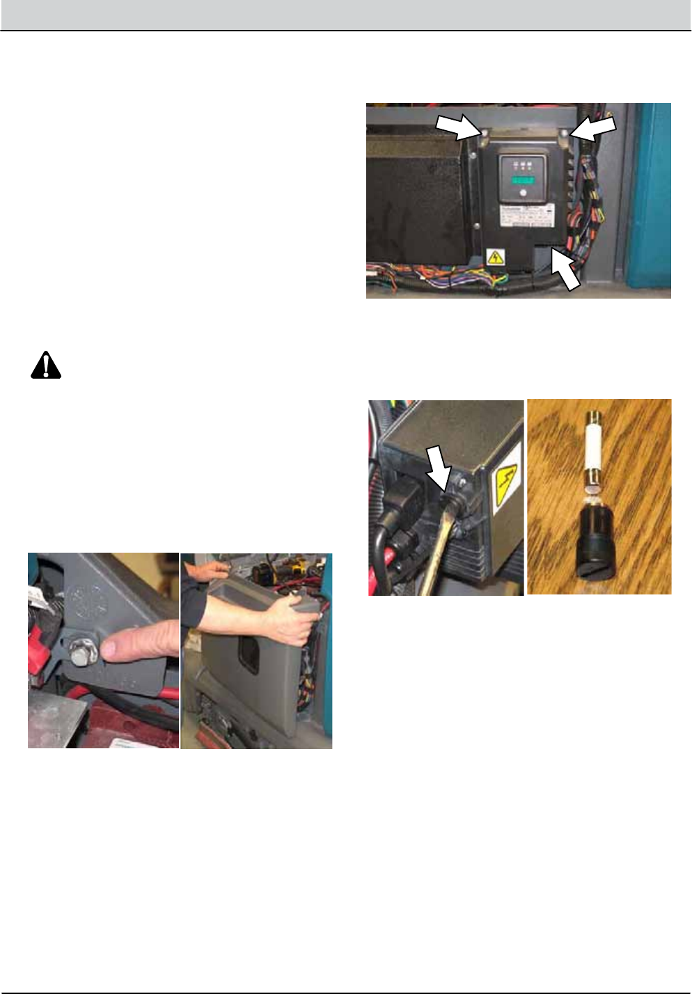
A 15 Amp fuse protects the on--board charger.
Follow the instructionsbelow to replaceablown
fuse. Never substituteahigher Amp rated fuse
than specified.
1. Lift the operator seatopenandengage the
seat support.
2. Unplug the charger AC power supply cord
from the walloutlet.
WARNING: ElectricalHazard. Unplug
charger before servicingmachine.
3. Disconnect the battery cables from the
batteries.
FOR SAFETY: When servicingmachine,
disconnect battery connection before working
on machine.
4. Remove the hardware holding the sidepanel
to the machineand remove the sidepanel
from the machine.
5. Remove the hardware holding the on--board
battery chargeronto the machine
6. Carefullypull the on--board chargerout to
access the fuse.
7. Remove the fuse cap and replace the fuse.
8. Reinstall the on--board battery chargerand
sidepanelonto the machine.
T12 Service Information 9009917 (12-12) 3-11
MAINTENANCE
FLOW--RITEtBATTERY WATERING SYSTEM
(OPTION)
The optional Flow--Rite battery wateringsystem
provides a safe andeasy way to maintain the
properelectrolyte levels in the batteries.
Check for the battery watering system hoses and
connections for damage or wear after every 100
hours.
FOR SAFETY: Before leaving or servicing
machine, stop on level surface, turn off
machine, and remove key.
1. Lift the operator seatopenandengage the
seat support.
2. Fully charge batteries prior to using the
battery watering system. Do notaddwater to
batteriesbefore charging, the electrolyte level
will expandand may overflowwhen charging.
See CHARGING THE BATTERIES
(OFF--BOARD CHARGER) or CHARGING
THE BATTERIES (ON--BOARD CHARGER).
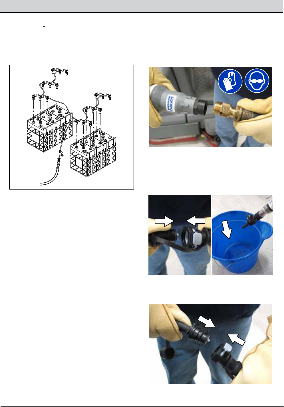
3. Connect the water supplyhose to the fill
regulator.
NOTE: Water quality is important to maintain the
life of the battery. Always use water that meets
battery manufacturer requirements.
NOTE: The water supply to the battery water
system must always be 7.57 LPM (2 GPM) or
more. Use the purger to confirm the water supply
pressure. Refer to Flow--Rite Operator Manual for
additionalinformation.
4. Remove the dust cover from the battery fill
tubeand connect the fill regulator.
3-12 T12 Service Information 9009917 (12-12)
MAINTENANCE
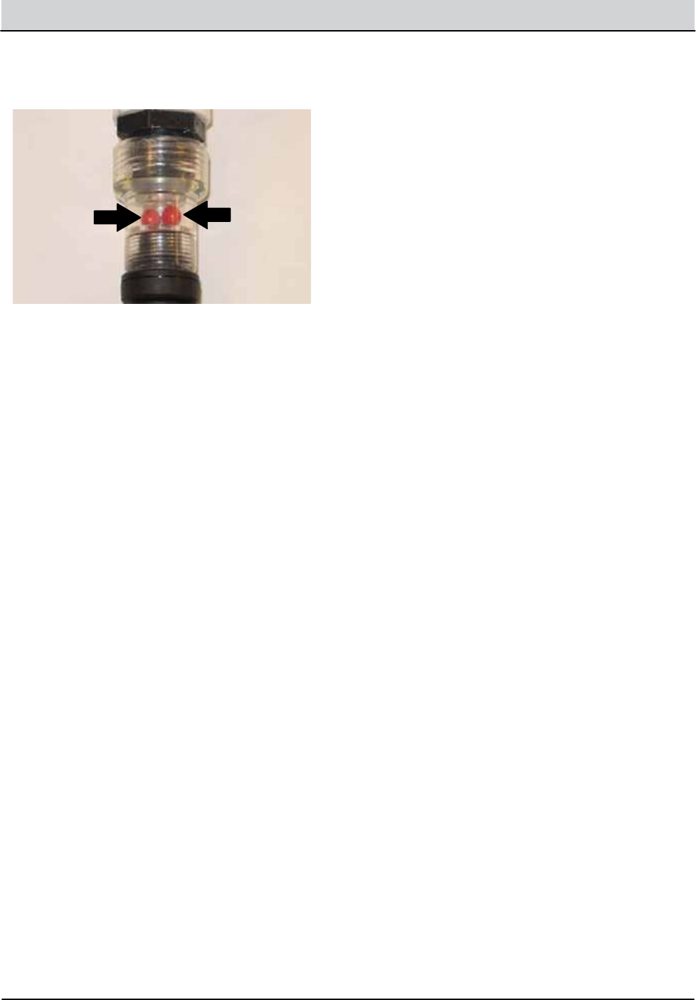
5. Turn on the water supply. The red ballsinside
the flowindicator will spin. The red balls stop
spinningwhen the batteries are full.
6. Disconnect the battery fill tube from the fill
regulator.
7. Turn off the water supply.
8. After addingwater, replace the dust cap on
the battery fillhose and return the fill regulator
to the storagelocation for future use.
T12 Service Information 9009917 (12-12) 3-13
MAINTENANCE
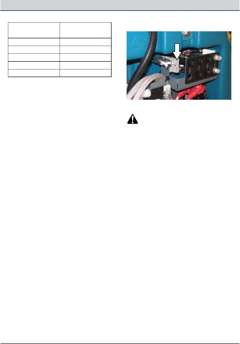
CIRCUIT BREAKERS
Circuit breakers are resettableelectrical circuit
protectiondevices designed to stop the flow of
current in the event of a circuit overload. Once a
circuit breaker is tripped, reset it manually by
pressing the reset button after the breaker has
cooleddown.
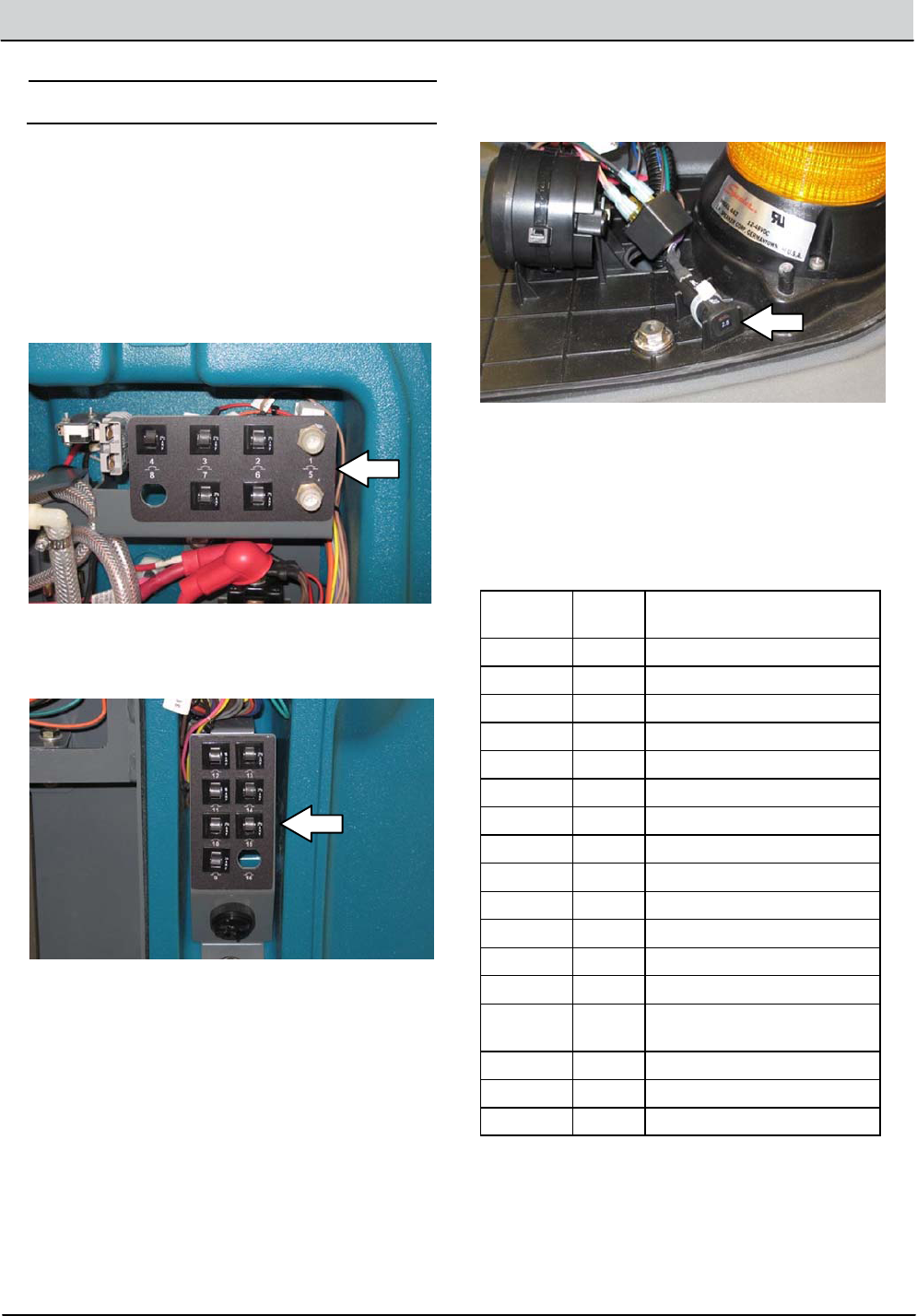
Circuit breakers 1 through8are located behind
the operator seat.
Circuit breakers 9 through 16 are located behind
the steering shroud access panel.
Circuit breaker 17 is located inside the optional
light assembly mounted on top of the recovery
tank.
If the overload that caused the circuit breaker to
trip is still present, the circuit breaker will continue
to stop current flowuntil the problem is corrected.
The chart below shows the circuit breakers and
the electrical components they protect.
Circuit
BreakerRating Circuit Protected
CB1 80 A Propelsystem
CB2 2 A Telemetry system
CB3 2.5 A Key switch -- Start
CB4 2.5 A Scrub system
CB5 60 A Scrub module
CB6 2.5 A ec--H2Omodule (Option)
CB7 2.5 A ec--H2Opump (Option)
CB8 2.5 A Not used
CB9 20 A Side brush module (Option)
CB10 2.5 A Side brushsystem (Option)
CB11 15 A Spray nozzle pump (Option)
CB12 15 A Lights (Option)
CB13 2.5 A Headlight/Tail lights (Option)
CB14 2.5 A Overheadguard warning light
(Option)
CB15 2.5 A Warning lights (Option)
CB16 N/A Not used
CB17 2.5A Reverse alarm light (Option)

3-14 T12 Service Information 9009917 (12-12)
MAINTENANCE
ELECTRIC MOTORS
Inspect the carbon brushes on the vacuum fan
motor after every 500hours of operation. Inspect
the carbon brushes on the main brush motors and
side brush motor after the first 1000hours of
operationand every 100hours after the initial
check. Refer to the tablebelow for carbon brush
replacementintervals.
Carbon Brush Replacement Hours
Main Brush Motors 1000*
Side Brush Motor (Option)1000*
Vacuum Motor 500
*Replace carbon brushes every 100hours after
the initial1000hour change.
T12 Service Information 9009917 (12-12) 3-15
MAINTENANCE
SCRUBBRUSHES
The machine can be equippedwith eitherdisk or
cylindrical scrub brushes. Check scrub brushes
daily for wire or string tangled around the brush or
brush drive hub. Also check brushesorpads for
damageandwear.
DISK BRUSHES AND PADS
Replace the brushesorpadswhen they no longer
clean effectively.
Cleaningpads must be placed on pad drivers
before they are ready to use. The cleaningpad is
held in place withacenter disk. Both sides of the
pad can be used for scrubbing. Turn the pad over
to use the other side.
Cleaningpadsneed to be cleaned immediately
after use with soapandwater. Do notwash the
padswithapressure washer. Hangpads, or lay
pads flat to dry.
NOTE: Always replace brushesandpads in sets.
Otherwise one brush or padwill be more
aggressive than the other.
REPLACING DISK BRUSHES OR PAD
DRIVERS
1. Raise the scrub head.
2. Turn off the machine.
FOR SAFETY: Before leaving or servicing
machine, stop on level surface, turn off
machine, and remove key.
3. Open the main brush access doorand side
squeegee support door.
4. Turn the brush until the springhandles are
visible.
5. Squeeze the springhandlesandlet the brush
drop to the floor.
6. Push the new brush under the scrub head,
align the brush drive socket with the brush
drive hub,andlift the brush up onto the brush
drive hub.
7. Ensure the brush is securely mounted on the
brush drive hub.
8. Close and secure the squeegee support door
and close the main brush access door.
9. Repeat procedure for the other brush.

3-16 T12 Service Information 9009917 (12-12)
MAINTENANCE
REPLACING DISK SCRUB PADS
1. Remove the pad driver from the machine.
2. Squeeze the spring clip togetherand remove
the center disk from the pad driver.
3. Remove the scrub pad from the pad driver.
4. Flip or replace the scrub pad.Center the
scrub pad on the pad driver and reinstall the
center disk to secure the padinplace on the
pad driver.
5. Reinstall the pad driver onto the machine.
T12 Service Information 9009917 (12-12) 3-17
MAINTENANCE
CYLINDRICALBRUSHES
Rotate the brushes from front-to-rear after every
50 hours of operation.
Replace the brusheswhen they no longer clean
effectively.
NOTE: Replace worn brushes in pairs. Scrubbing
with brushes of unequal bristle length will result in
diminished scrubbingperformance.
REPLACING CYLINDRICAL SCRUB BRUSHES
FOR SAFETY: Before leaving or servicing
machine, stop on level surface, turn off
machine, and remove key.
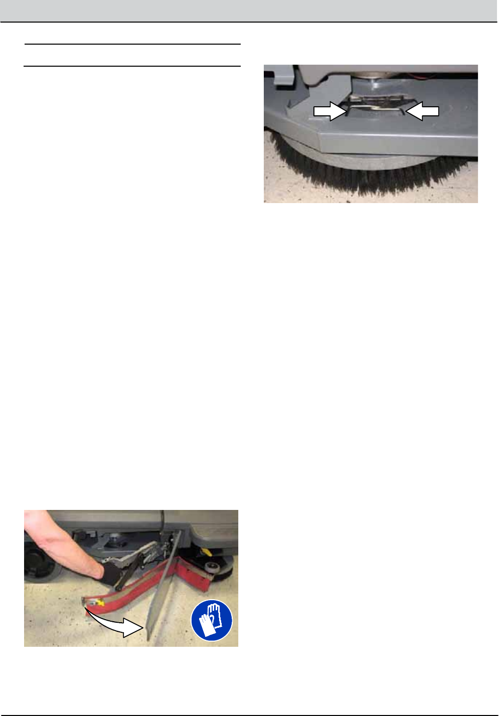
1. Open the main brush access doorand side
squeegee support door.
2. Remove the idlerplate from the scrub head.
3. Remove the brush from the scrub head
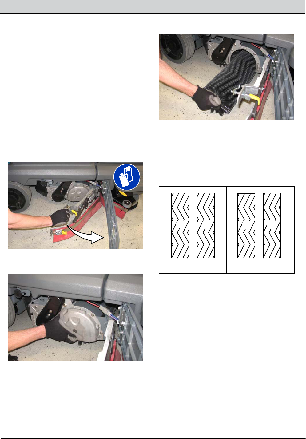
4. Position the brush with the double row end
towards the scrub headopening.Guide the
new brush onto the drive hub.
5. If rotating the brushes, always rotate the front
with the back so that theywear evenly. They
may be rotated end for end as well.
Before After
ABAB
6. Reinstall the idlerplate onto the scrub head.
7. Close and secure the squeegee support door
and close the main brush access door.
8. Repeat for the brush on the other side of the
scrub head.
3-18 T12 Service Information 9009917 (12-12)
MAINTENANCE
CHECKING CYLINDRICAL SCRUB BRUSH
PATTERN
FOR SAFETY: Before leaving or servicing
machine, stop on level surface and turn o
machine.
1. Apply chalk, or a similar marking material, to
a smooth andlevel section of oor.
NOTE: If chalk or other material is not available,
allow the brush to spin on the oor for two
minutes. A polish mark will remain on the oor.
2. Park the machine several feetbehind the
chalked area and shuto the machine.
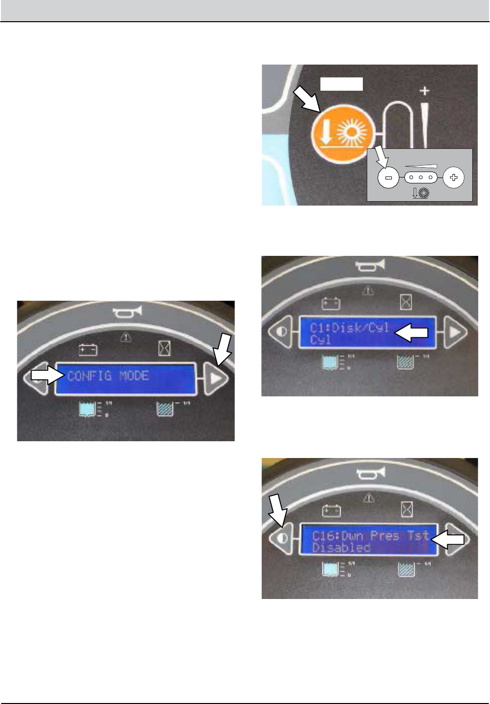
3. Press andhold the conguration mode button
while turning the key to the on position.
Continueholdingthe conguration mode
button until CONFIG MODE appears on the
LCDdisplay. Release the conguration mode
button.
4. Press the Brush pressure button to enter the
machine conguration modes.
C1: Disk/CylCyl should appear in the LCD
display.
5. Press the Contrast control button once to
scroll to C16: Dwn Pres Tst Disabled (Down
Pressure Test Disabled).
T12 STANDARD
T12 XP
T12 Service Information 9009917 (12-12) 3-19
MAINTENANCE
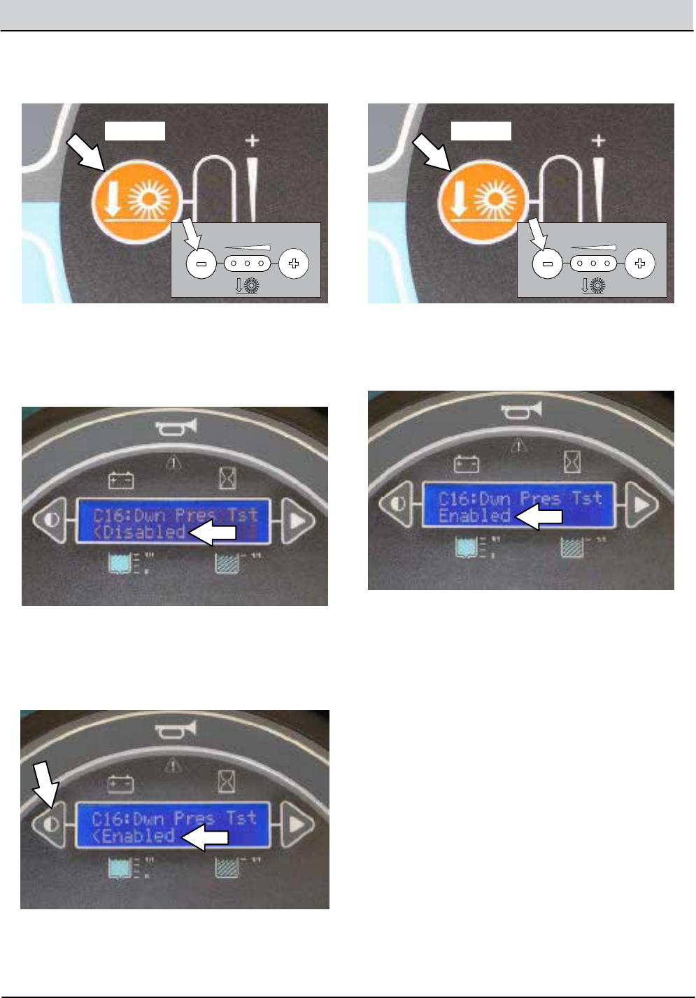
6. Press the Brush pressure button to enter the
down pressure test selection mode.
C16: Dwn Pres Tst <Disabled (Down
Pressure Test Disabled) shouldappear on the
LCDdisplay. The < symbol must appear in
front of Disabled .
7. Press the Contrast control button once to
select C16:Dwn Pres Tst <Enabled (Down
Pressure Test Enabled). The < symbol must
appear in front of Enabled.
8. Press the Brush pressure button to enable
the brush pressure test.
C16: Dwn Pres Tst Enabled should appear
on the LCDdisplay. The < symbol should no
longerappear in front of Enabled
9. Turn the key to the o position to save the
Down Pressure Test Enabled modeand then
turn the key back to the on position to
continuewith the procedure.
Note: Do Not turn o the machine second time
after the Down Pressure Test Enabled modehas
been saved. The entire procedure to get the
machineinto the Down Pressure Test Modewill
need to be repeated if the machine is turned o a
second time.
T12 STANDARD
T12 XP
T12 STANDARD
T12 XP
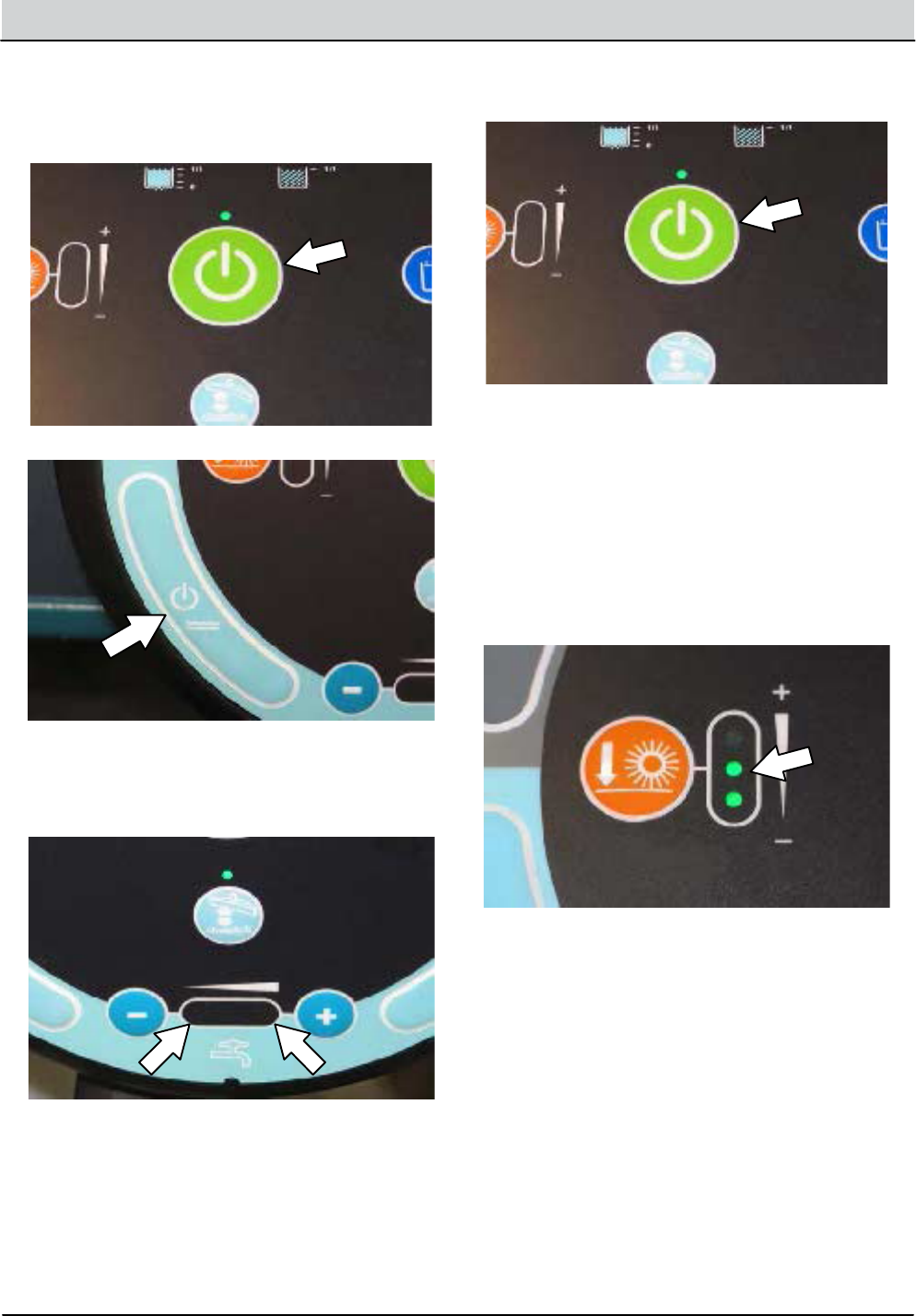
3-20 T12 Service Information 9009917 (12-12)
MAINTENANCE
10. Press the 1-STEP button and then
immediately press one of the Solution on/o
buttons to shut o the solution supplyand
prevent the brushes from getting wet.
11. Observe the solution ow indicator lights.
None of the indicator lights should be
illuminated.
12. Press the 1-STEP button to raise the scrub
head.
13. Position the machine over the chalked area.
14. Press the 1-STEP button to lower the scrub
headandallow the brushes to operate for 15
to 20 seconds. Keep the scrub headinone
spot in the chalked area.
NOTE: If necessary, press the Brush pressure
button to set the brush pressure to the medium
setting.
15. Press the 1--STEP button to raise the scrub
headand drive the machineaway from the
chalked area.
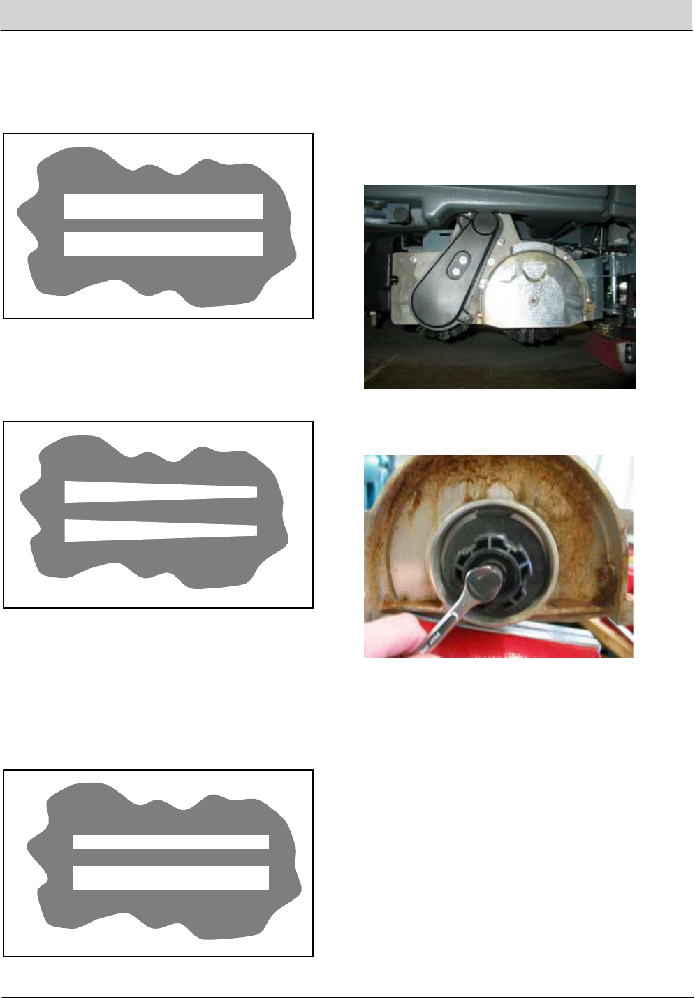
T12 Service Information 9009917 (12-12) 3-21
MAINTENANCE
16. Observe the brush patterns. If the brush
pattern is the same width across the entire
length of each brush andboth brushes are the
same width, no adjustment is necessary.
10355
17. If the brush patterns are tapered, see
ADJUSTING THE CYLINDRICAL BRUSH
TAPER section of this manual.
10652
18. The brush patterns should be 25 to 38 mm
(1 to 1.5 in)widewith the brushes in the
lowered positionandboth patterns should be
the same width. If the width of the brushes is
not the same, see ADJUSTING THE
CYLINDRICAL BRUSH WIDTH section of this
manual.
10653
19. Turn the key to the o position to return to
normal operation.
ADJUSTING CYLINDRICAL BRUSH TAPER
FOR SAFETY: Before leaving or servicing
machine, stop on level surface and turn o
machine.
1. Open the side squeegee support door.
2. Remove the idler door and loosen the idler
shaft. The shaft is a concentric cam.
3. Raise or lower the end of the brush using the
shaft adjustment as necessary to straighten the
brush pattern.
4. Retighten the mounting screw on the idler
door.
5. Close the side squeegee support door.
6. Recheck the pattern. Readjust if necessary.
7. Repeat procedure for the other brush located
on other side of the scrub head.
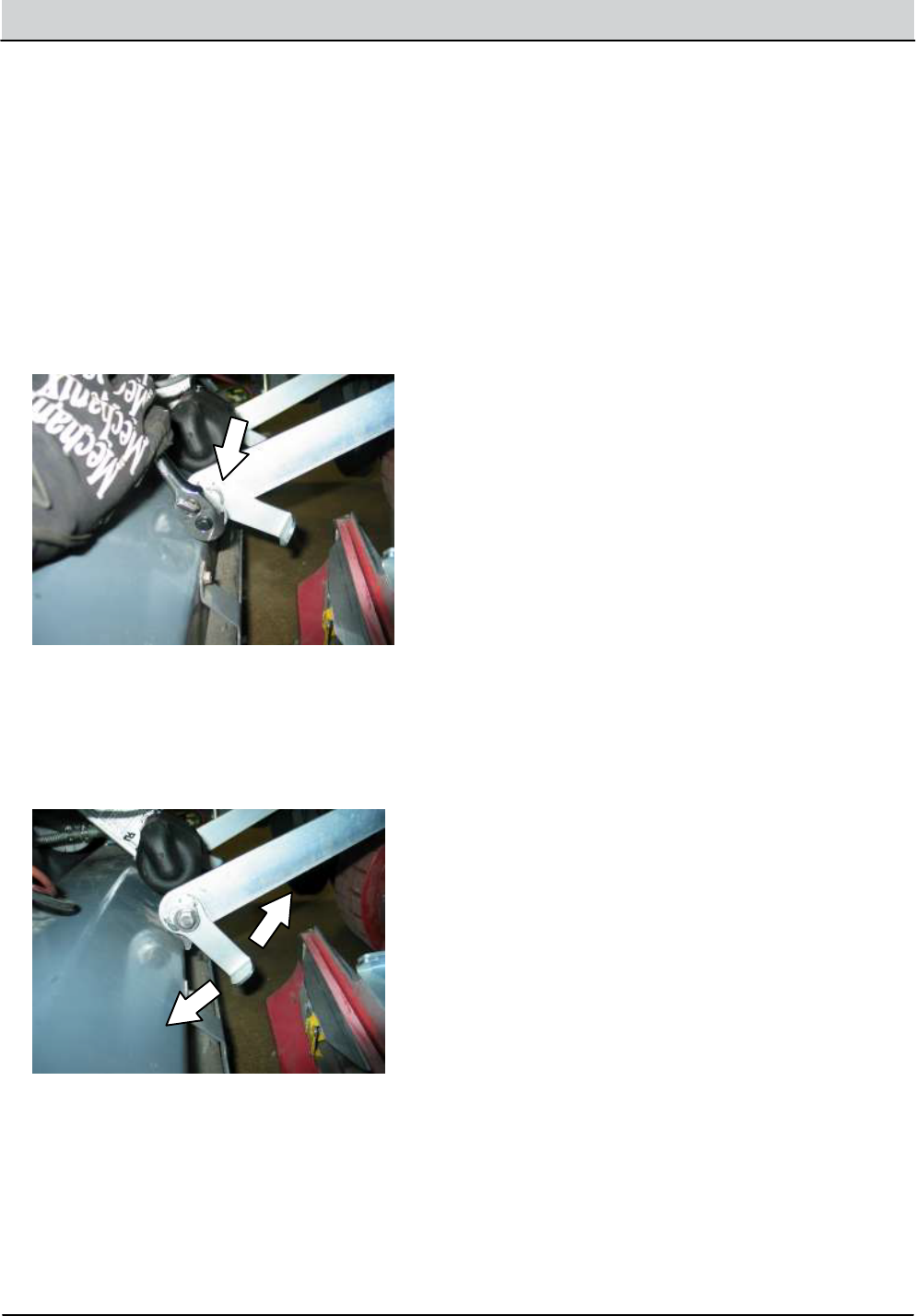
3-22 T12 Service Information 9009917 (12-12)
MAINTENANCE
ADJUSTING CYLINDRICAL BRUSH PATTERN WIDTH
FOR SAFETY: Before leaving or servicing
machine, stop on level surface and turn o
machine.
1. Start the machine, completelylower the scrub
head,and turn o the machine.
2. Open the side squeegee support door.
3. Loosen the bolt securing the adjustment bracket
located on the front of the scrub head frame.
4. Rotate the adjustment bracket to adjust the
cylindrical brush pattern width.
NOTE: The adjustment bracket rotates a concentric cam,
which changes the height of the scrub head.
5. Retighten the lock boltlocated against the
bracket.
6. Recheck the pattern. Readjust if necessary.
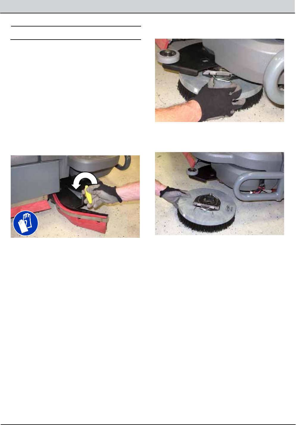
T12 Service Information 9009917 (12-12) 3-23
MAINTENANCE
SIDE BRUSH (OPTION)
FOR SAFETY: Before leaving or servicing
machine, stop on level surface, turn off
machine, and remove key.
Check the side brush daily for wearordamage.
Remove any tangled string or wire from the side
brush or side brush drive hub.
REPLACING THE SIDE BRUSH
Replace the brush when it no longer cleans
effectively.
1. Loosen the side brush squeegee assembly
handleand remove the squeegee assembly
from the machine.
2. Squeeze the springhandlesandlet the side
brush drop to the floor.
3. Remove the side brush from under the side
brush assembly.
4. Place the new side brush underneath the side
brush assemblyandlift the side brush up onto
the side brush hubuntil the brush locks onto
the hub.
5. Reinstall the side brush squeegee assembly
onto the side brush assembly.
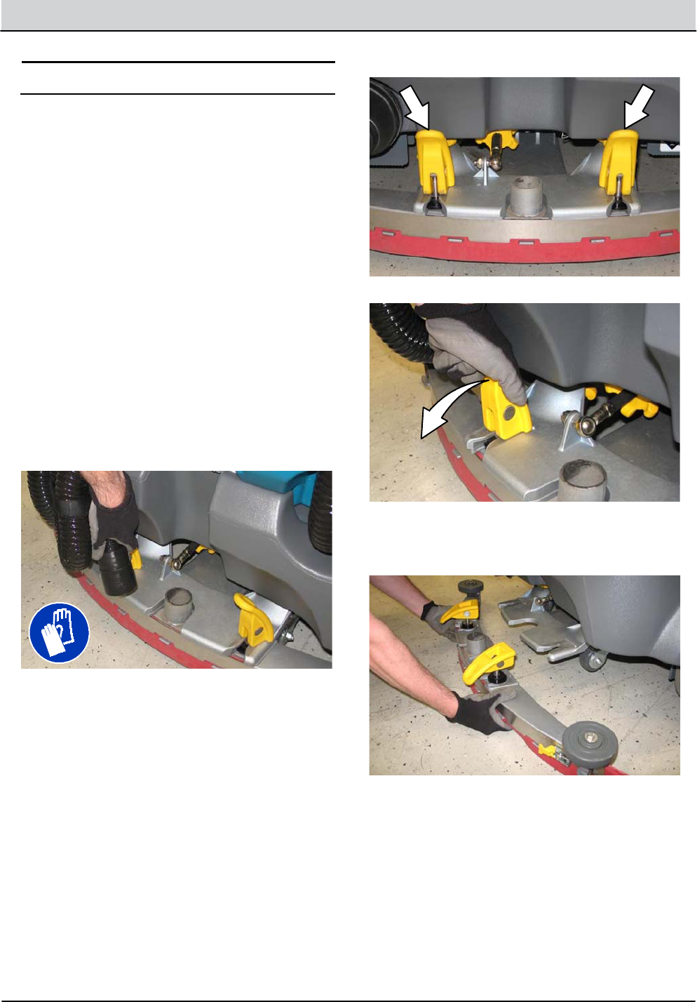
3-24 T12 Service Information 9009917 (12-12)
MAINTENANCE
SQUEEGEE BLADES
Check the squeegeeblades for damageandwear
daily. When the bladesbecome worn, rotate the
bladesend--for--end or top--to--bottom toanew
wipingedge.Replace bladeswhenalledges are
worn.
Check the deflection of the squeegeebladesdaily
or when scrubbingadifferent type of surface.
Check the leveling of the rear squeegee every 50
hours of operation.
REPLACING (OR ROTATING) THE REAR
SQUEEGEE BLADES
1. Lower the scrub head.
FOR SAFETY: Before leaving or servicing
machine, stop on level surface, turn off
machine, and remove key.
2. Disconnect the vacuumhose from the rear
squeegee assembly.
3. Loosen both squeegee mountinghandles.
4. Pull the rear squeegee assembly from the
machine.
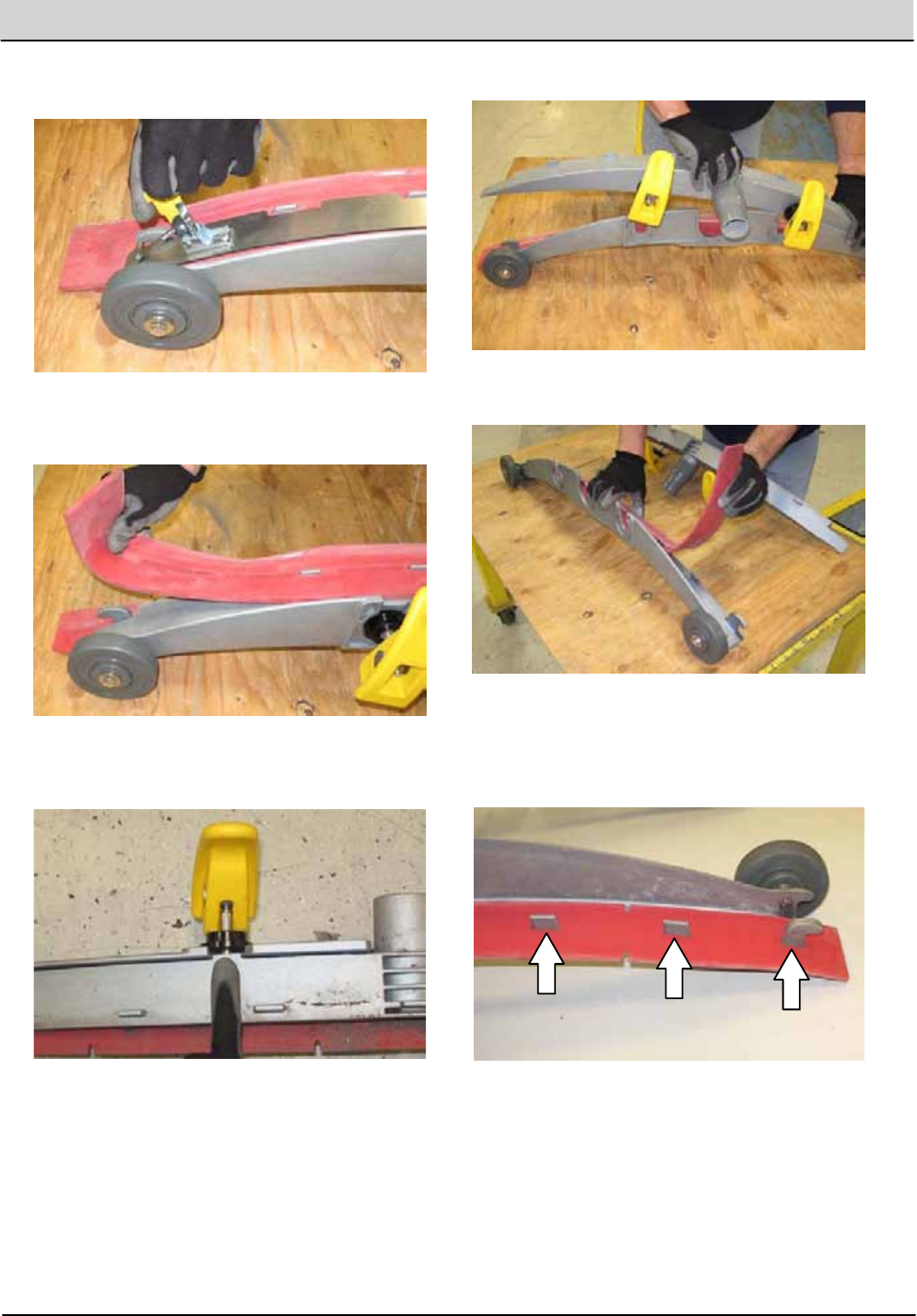
T12 Service Information 9009917 (12-12) 3-25
MAINTENANCE
5. Loosen the retainerlatch and remove the
retainer from the squeegee assembly.
6. Remove the squeegee from the squeegee
assembly.
7. Slideboth retainers outaway from the
squeegee assembly.
8. Remove the inner frame from the outer frame.
9. Remove the squeegee from the outer frame.
10. Install the rotated or new squeegeebladeinto
the outer frame. Be sure the squeegee is
completely sliddownonto each tab on the
outer frame.
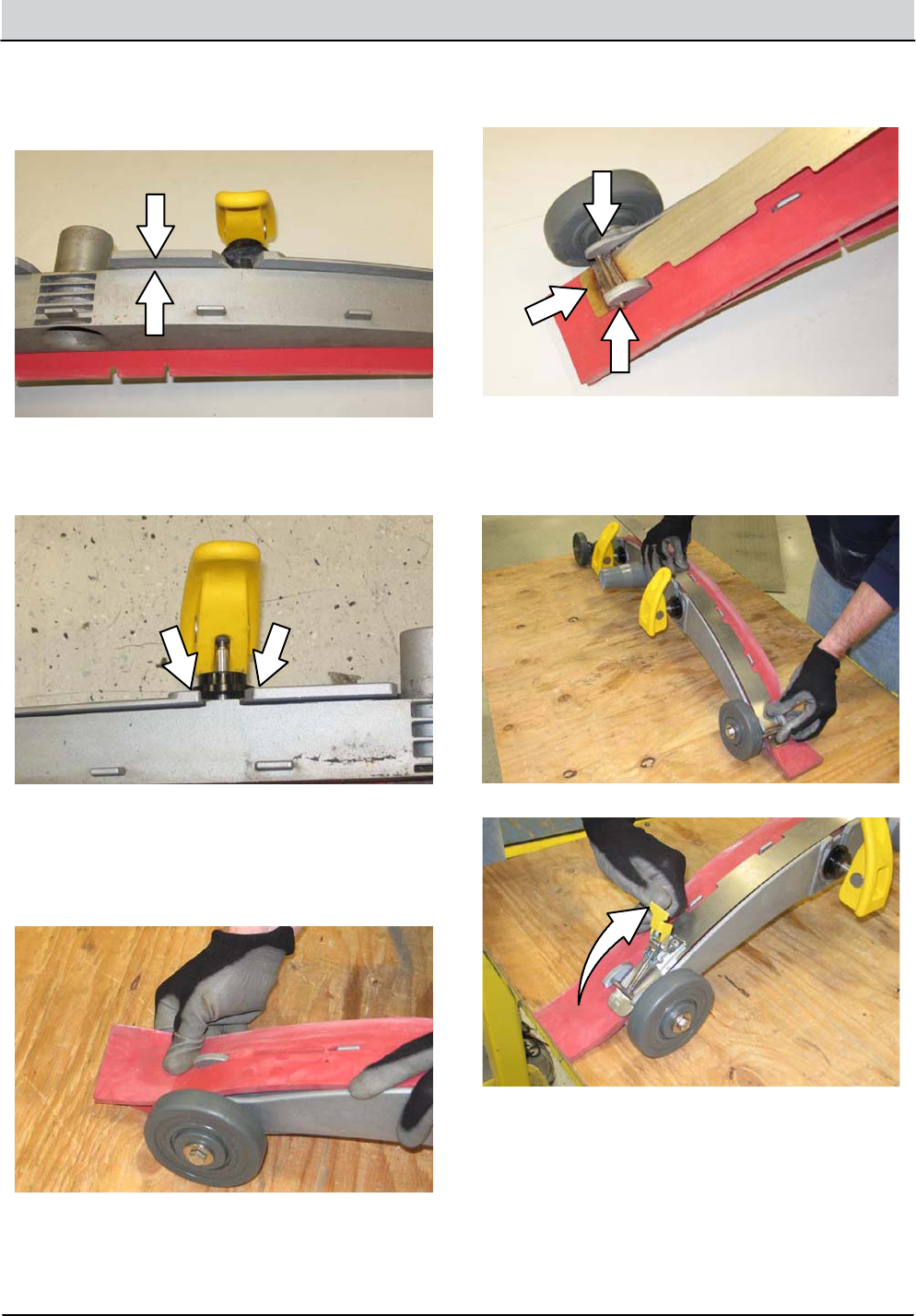
3-26 T12 Service Information 9009917 (12-12)
MAINTENANCE
11. Install the inner frame over the squeegeeand
onto the outer frame. Be sure the inner frame
is tightagainst the top of the outer frame.
12. Slideboth retainers into the squeegee
assembly.
13. Place the rotated or new squeegeebladeonto
the inner frame. Be sure the squeegee is
securely attachedoneach tab on the inner
frame.
14. Insert the hingeend of the retainerinto the
hooks in the inner frame.
15. Install the retaineralong the rest of the
squeegee assemblyand fasten the latch onto
the otherend of the squeegee assembly.
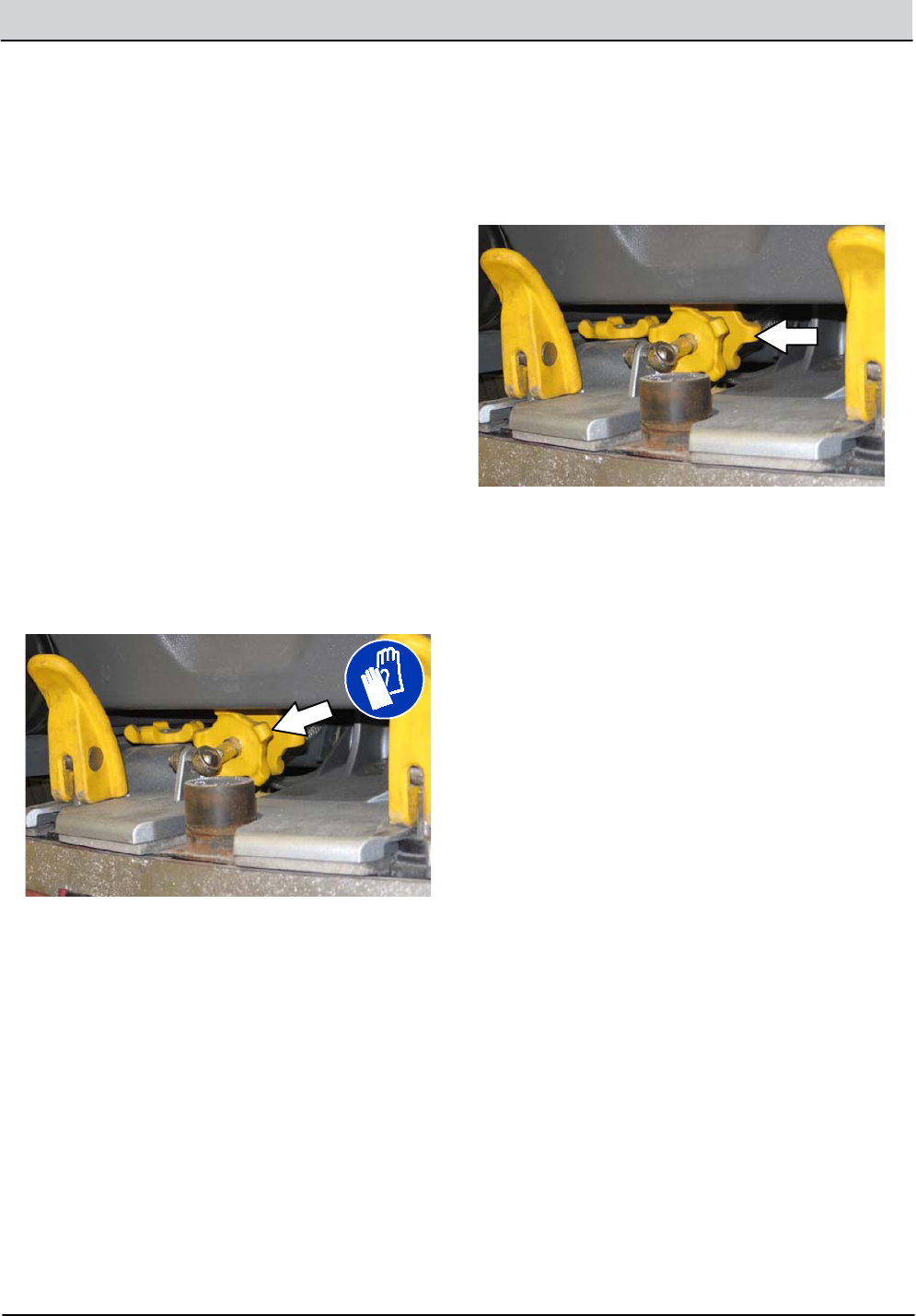
T12 Service Information 9009917 (12-12) 3-27
MAINTENANCE
LEVELING THE REAR SQUEEGEE
Leveling the squeegeeensures the entire length
of the squeegeeblade is in even contact with the
surface being scrubbed. Perform thisadjustment
on an even andlevel floor.
1. Lower the squeegeeand drive the machine
several meters (feet) forward and slowly bring
the machine toastop.
FOR SAFETY: Before leaving or servicing
machine, stop on level surface, turn off
machine, and remove key.
2. Check the squeegeedeflection over the full
length of the squeegeeblade.
3. If the deflection is not the same over the full
length of the blade, use the tiltadjust knob to
make adjustments.
DO NOT disconnect the vacuumhose from
the squeegee frame whenleveling squeegee.
4. To adjust the squeegeeleveling,loosen the tilt
lock knob.
5. Turn the squeegee tiltadjust knob
counter-clockwise to decrease the deflection
at the ends of the squeegeeblade.
Turn the squeegee tiltadjust knob clockwise
to increase the deflection at the ends of the
squeegeeblade.
6. Tighten the tiltlock knob.
7. Drive the machine forward with the squeegee
down to recheck the squeegeeblade
deflection if adjustments were made.
8. Readjust the squeegeebladedeflection if
necessary.
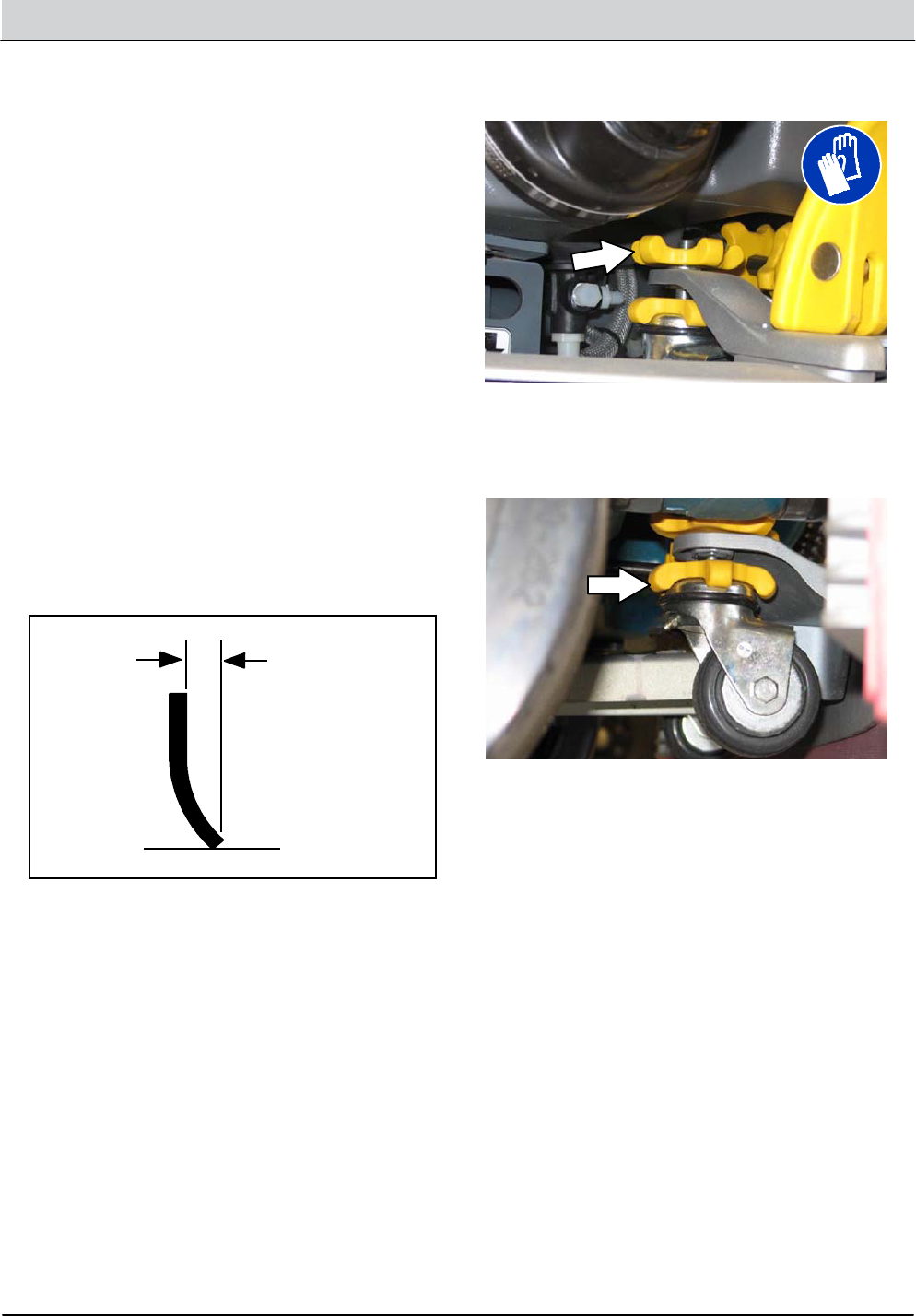
3-28 T12 Service Information 9009917 (12-12)
MAINTENANCE
ADJUSTING THE REAR SQUEEGEE BLADE
DEFLECTION
Deflection is the amount of curl the overall
squeegeebladehaswhen the machine moves
forward. The best deflection is when the
squeegeewipes the floor dry withaminimal
amountofdeflection.
NOTE: Make sure the squeegee is level before
adjusting the deflection. See LEVELING THE
REAR SQUEEGEE.
1. Lower the squeegeeand drive the machine
several meters (feet) forward and slowly bring
the machine toastop.
FOR SAFETY: Before leaving or servicing
machine, stop on level surface, turn off
machine, and remove key.
2. Look at the amountofdeflection or “curl” of
the squeegeeblade. The correct amount of
deflection is 12 mm (0.50 in) for scrubbing
smooth floors and 15 mm (0.62 in) for rough
floors.
3. To adjust the overall squeegeeblade
deflection,loosen the lock knob.
4. Turn the adjustment knobs counterclockwise
to increase deflection or clockwise to
decrease deflection.
5. Retighten the lock knob.
6. Drive the machine forward again to recheck
the squeegeebladedeflection.
7. Readjust the squeegeebladedeflection if
necessary.
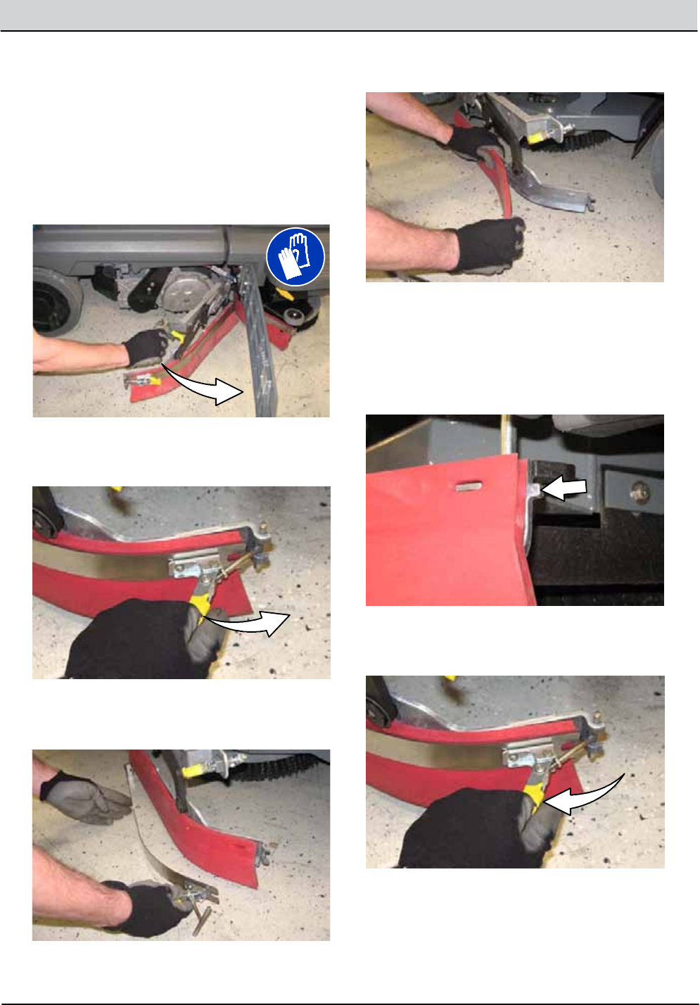
T12 Service Information 9009917 (12-12) 3-29
MAINTENANCE
REPLACING OR ROTATING THE SIDE
SQUEEGEE BLADES
1. If necessary, raise the scrub head.
FOR SAFETY: Before leaving or servicing
machine, stop on level surface, turn off
machine, and remove key.
2. Open the main brush access doorand side
squeegee support door.
3. Unhook the retainingbandlatch from the side
squeegee assembly.
4. Remove the retainingband from the side
squeegee assembly.
5. Remove the squeegeeblade from the side
squeegee assembly.
6. Install the rotated or new rear squeegeeblade
onto the side squeegee assembly.
7. Hook the retainingbandonto the retaining
band retainer tab on the side squeegee
assembly.
8. Fasten the retainingbandlatch onto the side
squeegee assembly.
9. Close and secure the squeegee support door
and close the main brush access door.
10.Repeat for the side squeegee on the other
side of the scrub head.
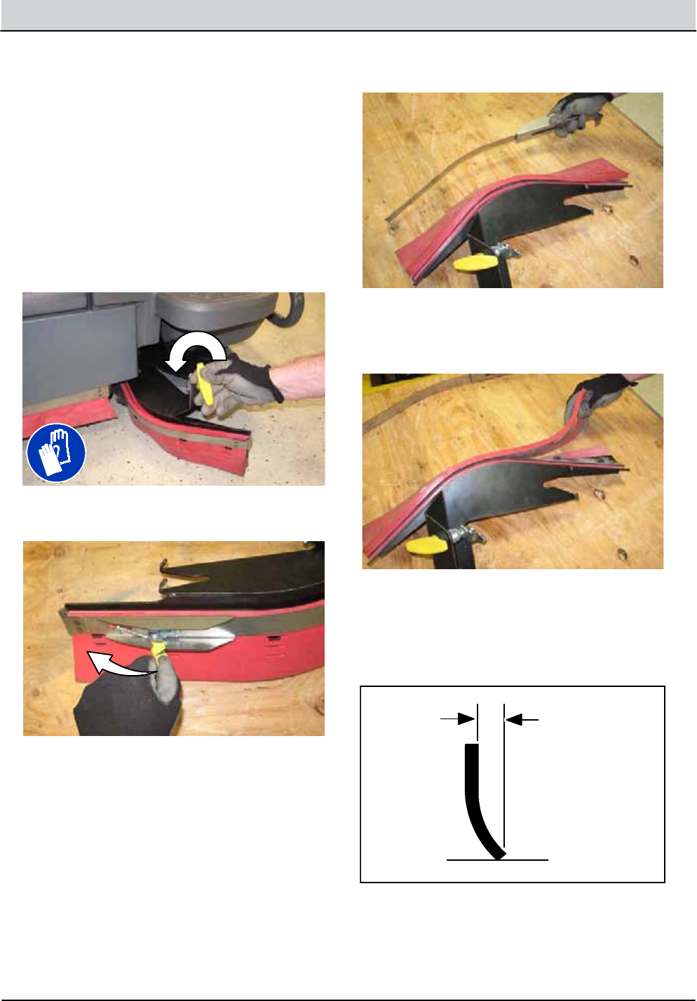
3-30 T12 Service Information 9009917 (12-12)
MAINTENANCE
REPLACING OR ROTATING THE SIDE
BRUSH SQUEEGEE BLADES (OPTION)
FOR SAFETY: Before leaving or servicing
machine, stop on level surface, turn off
machine, and remove key.
Check the side brush squeegeeblade for damage
andweardaily. Replace or rotate the blade if the
leadingedge is torn or worn half-way through the
thickness of the blade.
1. Loosen the side brush squeegee assembly
handleand remove the squeegee assembly
from the machine.
2. Loosen the retainingbandlatch.
3. Remove the retainingband, squeegeeblades,
and spacer from the squeegee frame.
NOTE: Observe which squeegee slots were
installed on the squeegee frame before removing
the squeegee.
NOTE: The squeegeeblade(s) have two sets of
slots for adjusting the squeegeebladedeflection.
Install / reinstall squeegees so the deflection is
approximately 12 mm (0.50 in)for smooth floors
and 15 mm (0.62 in)for rough floors.

T12 Service Information 9009917 (12-12) 3-31
MAINTENANCE
4. Install the rotated / new squeegeeblades,
spacer, and retainingbandonto the side
brush assembly.
5. Fasten the side brush retainingbandlatch.
6. Reinstall the side brush squeegee assembly
onto the side brush assembly.
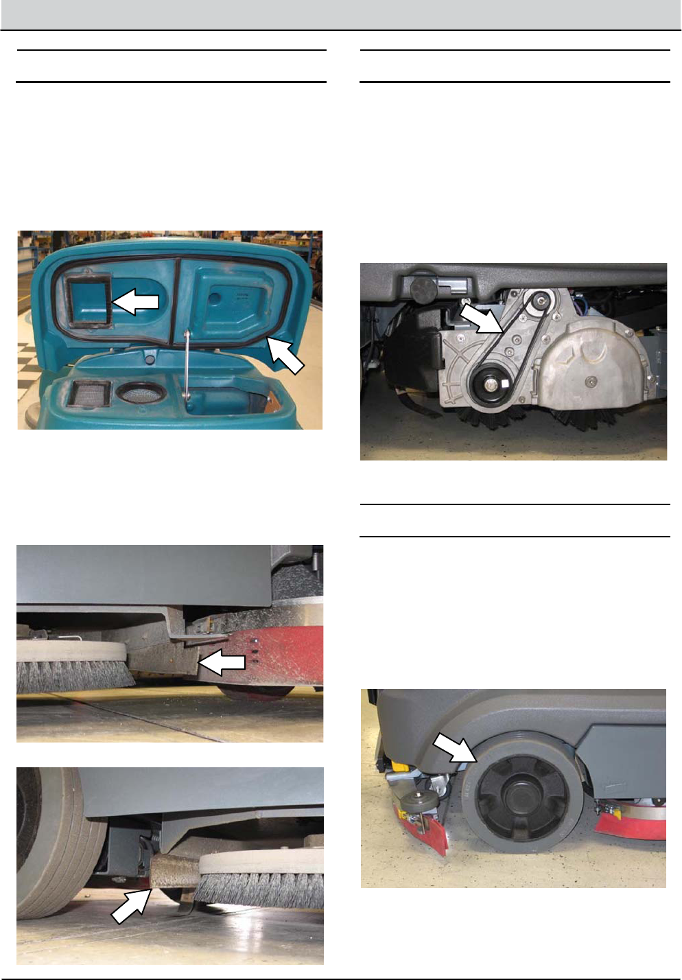
3-32 T12 Service Information 9009917 (12-12)
MAINTENANCE
SKIRTS AND SEALS
FOR SAFETY: Before leaving or servicing
machine, stop on level surface, turn off
machine, and remove key.
RECOVERY TANK SEAL
Check the recovery tank cover seal for damage
andweardaily.
SCRUB HEAD SKIRTS (DISK SCRUB HEADS
ONLY)
Check the scrub head skirts for damageandwear
after every 50 hours of operation.
BELTS
CYLINDRICALBRUSH DRIVE BELTS
FOR SAFETY: Before leaving or servicing
machine, stop on level surface, turn off
machine, and remove key.
The brush drive belts are located on the
cylindrical brush scrub head.Check the belts for
damageandwear after every 200hours of
operation.
TIRES
FOR SAFETY: Before leaving or servicing
machine, stop on level surface, turn off
machine, and remove key.
The machinehas three solid rubber tires: one in
front, and two in the rear of the machine.Check
tires for damageandwear after every 500hours
of operation.
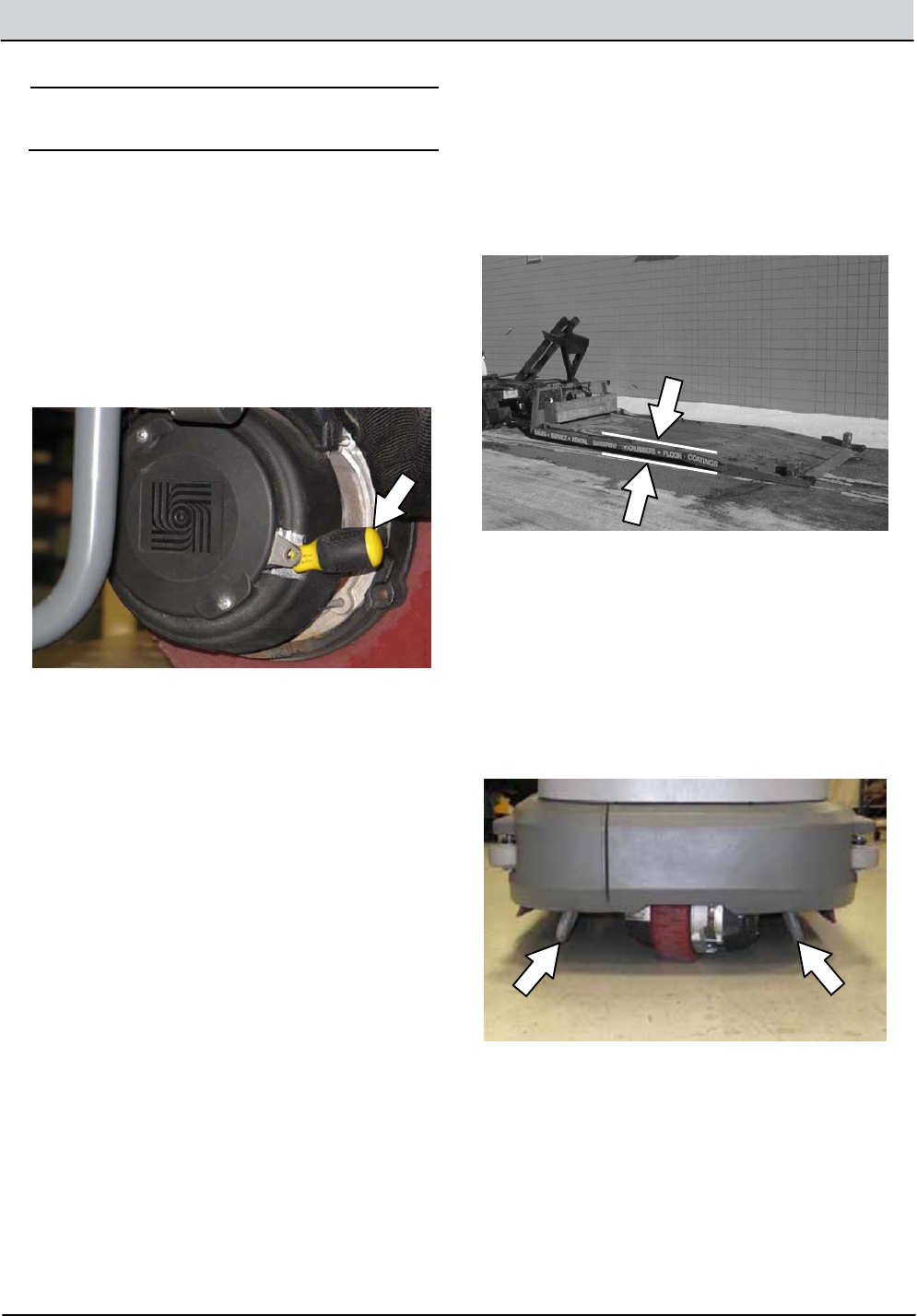
T12 Service Information 9009917 (12-12) 3-33
MAINTENANCE
PUSHING, TOWING, AND TRANSPORTING
THE MACHINE
PUSHING OR TOWING THE MACHINE
If the machinebecomes disabled, it can be
pushed or towed from the front or rear.
The parking brake must be disabledbefore towing
or pushing the machine. To disable the brake,
insert the tip of a small screw driver between the
electronic brake lever and the hub. The machine
can move freelywhen the parking brake is
disabled.
Onlypush or tow the machine for a very short
distance anddonot exceed 3.2 kp/h (2 mph). It is
NOT intended to be pushed or towed for a long
distance or at a high speed.
ATTENTION! Do notpush or tow machine for
a longdistance or damage may occur to the
propellingsystem.
Immediately after pushing the machine, remove
the screw driver from between the electronic
brake leverand the hub.NEVERoperate the
machinewith the parking brake disabled.
FOR SAFETY: Do notoperate machinewith
brakedisabled.
TRANSPORTING THE MACHINE
1. Raise the squeegee, scrub head,and
brushes.
FOR SAFETY: When loading/unloading
machineonto/off truck or trailer, drain tanks
before loadingmachine.
2. Position the machine at the loadingedge of
the truck or trailer.
3. If the loading surface is nothorizontal or is
higher than380 mm (15 in) from the ground,
useawinch to load machine.
If the loading surface is horizontal AND is
380 mm (15 in)orless from the ground, the
machine may be driven onto the truck or
trailer.
FOR SAFETY: When loadingmachineonto
truck or trailer, use winch. Do not drive the
machineonto the truck or trailer unless the
loading surfaceishorizontal AND is 380 mm
(15 in) or less from the ground.
4. To winch the machineonto the truck or trailer,
attach the winching chains to the stabilizer
legs.
5. Position the machine as close to the front of
the trailer or truck as possible. If the machine
starts to veer off the center line of the truck or
trailer, stop and turn the steeringwheel to
center the machine.
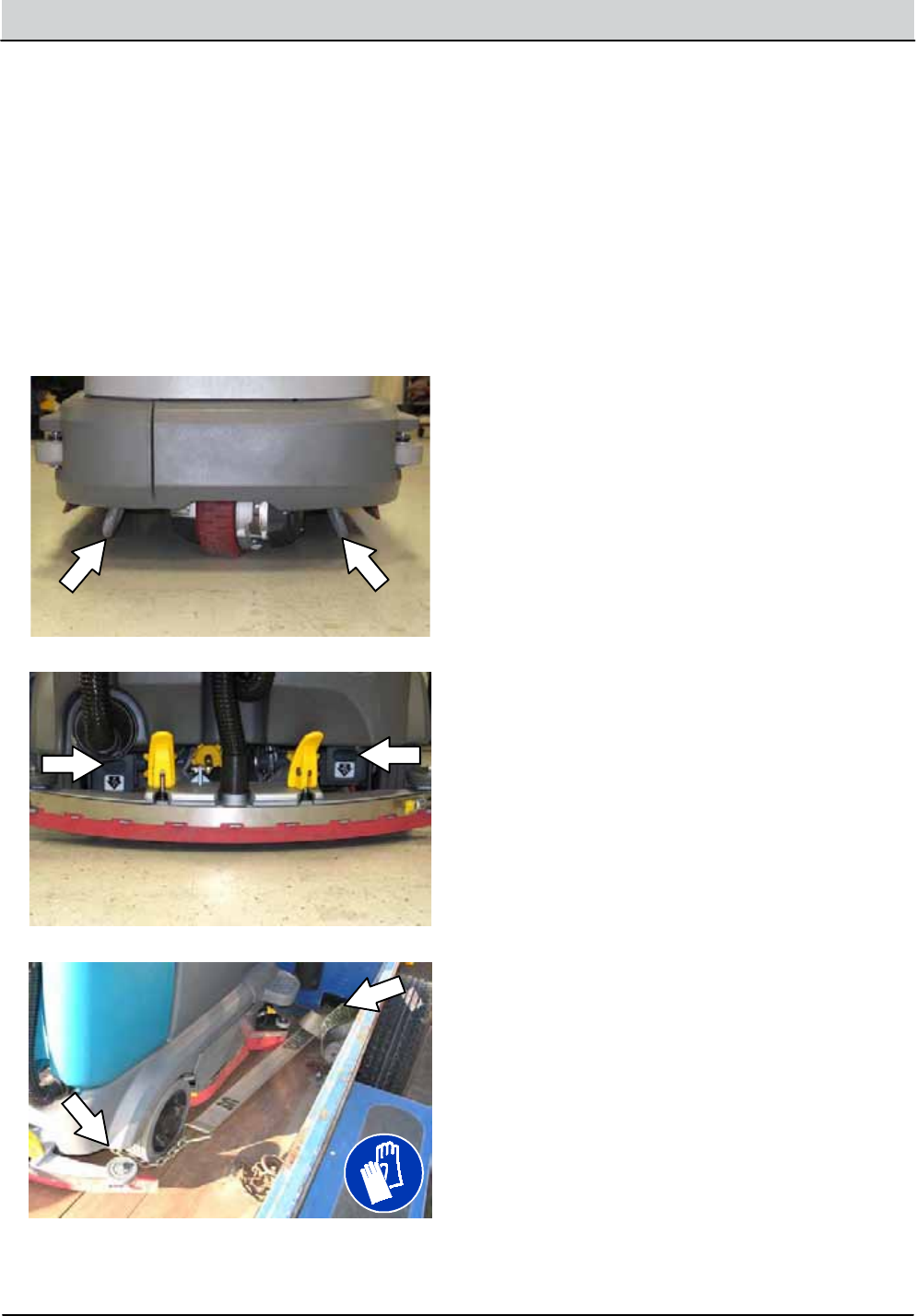
3-34 T12 Service Information 9009917 (12-12)
MAINTENANCE
6. Placeablock behindeach wheel to prevent
the machine from rolling.
7. Lower the scrub headand turn off machine.
FOR SAFETY: When loading/unloading
machineonto/off truck or trailer, lower scrub
head and squeegee before tyingdown
machine.
8. Connect the tie--down straps to the rightand
left stabilizer bars in front of the machineand
the holes in the rearjacking brackets at the
rear of the machine.
9. If the loading surface is nothorizontal or is
higher than380 mm (15 in) from the ground,
useawinch to unload machine.
If the loading surface is horizontal AND is
380 mm (15 in)orless from the ground, the
machine may be driven off the truck or trailer.
FOR SAFETY: When unloadingmachine off
truck or trailer, use winch. Do not drive the
machine off the truck or trailer unless the
loading surface is horizontal AND380 mm
(15 in) or less from the ground.
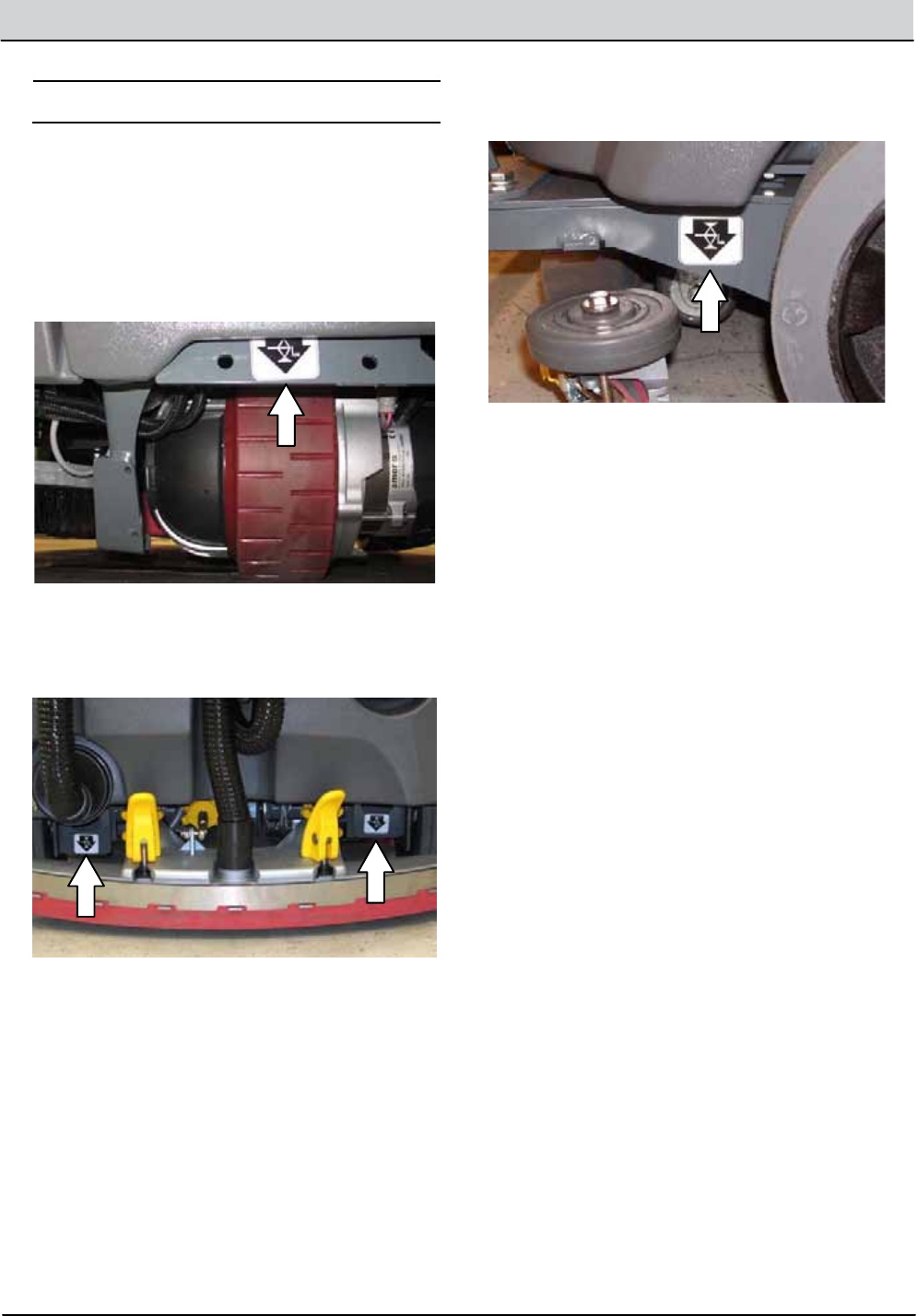
T12 Service Information 9009917 (12-12) 3-35
MAINTENANCE
MACHINE JACKING
FOR SAFETY: Before leaving or servicing
machine, stop on level surface, turn off
machine, and remove key.
Empty the recovery and solution tanks before
jacking the machine.
Jackingpointlocation at the frontofall machines.
Jackingpointlocation at the rear of machinesnot
equippedwith the optional rear squeegee
protector.
Jackingpointlocation at the rear of machines
equippedwith the optional rear squeegee
protector.
FOR SAFETY: When servicingmachine, block
machine tires before jackingmachineup.Use
ahoist or jack that will support the weight of
the machine. Jackmachine up at designated
locationsonly. Support machinewith jack
stands.
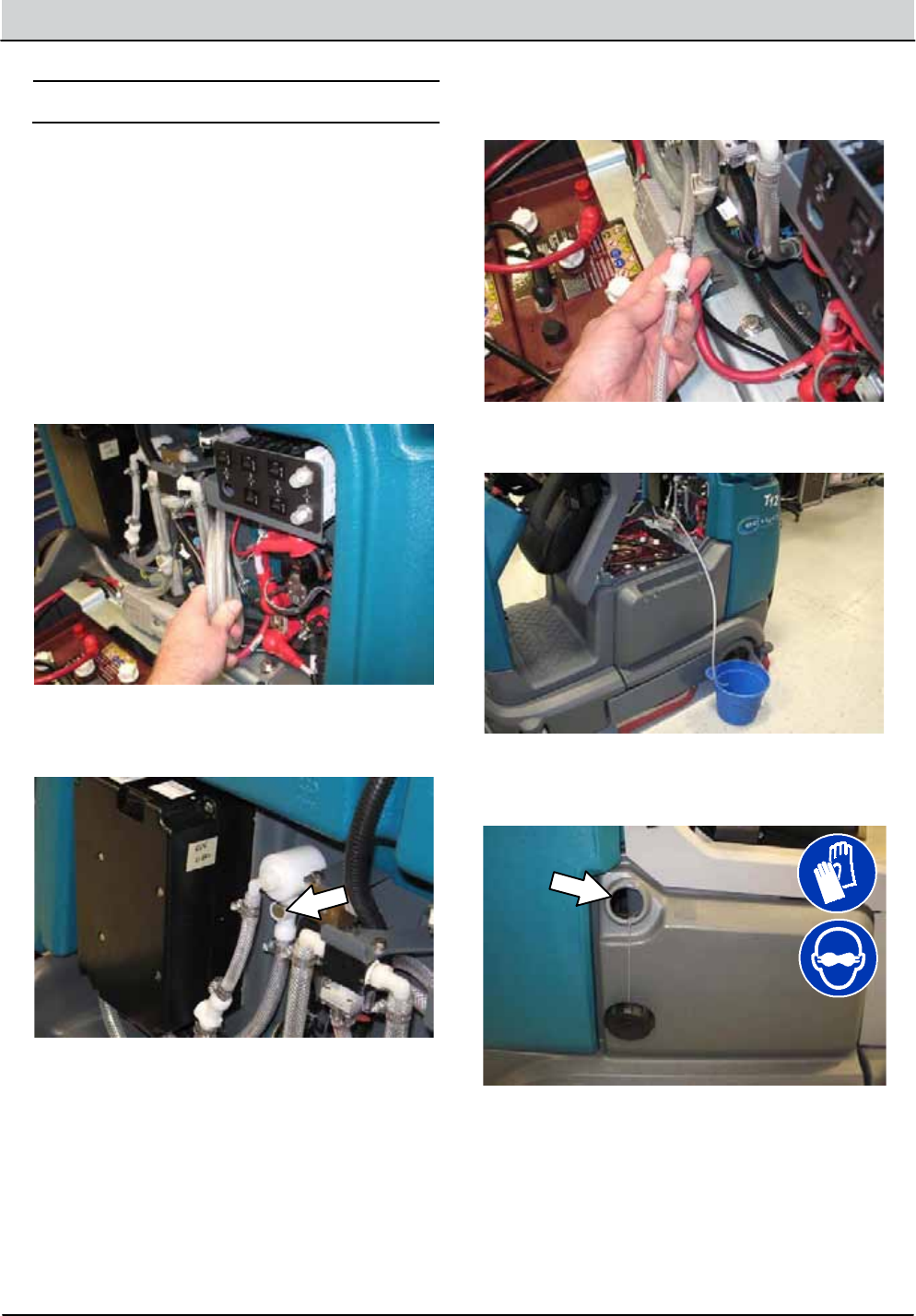
3-36 T12 Service Information 9009917 (12-12)
MAINTENANCE
ec- H2OMODULE FLUSH PROCEDURE
This procedure is only required when an alarm
soundsand the ec--H2Osystem indicator light
begins to blink.
FOR SAFETY: Before leaving or servicing
machine, stop on level surface and turn off
machine.
1. Lift the operator seatopenandengage the
seat support.
2. Remove the drainhose from the ec--H2O
compartment.
3. Press the connector button to disconnect the
outlethose from the ec--H2Omanifold.
4. Connect the drainhose to the ec--H2O
manifoldhose disconnected from the ec--H2O
manifold in the previous step.
5. Place the drainhose intoaempty container.
6. Pour 2 gallons (7.6 liters) of white or rice
vinegarinto the solution tank.

T12 Service Information 9009917 (12-12) 3-37
MAINTENANCE
7. Start the machine.
8. Press and release the ec--H2Omodule flush
switch to start the flush cycle.
NOTE: The modulewillautomatically shut off
when the flushcycle is complete (approximately 7
minutes). The module must run the full 7--minute
cycle in order to reset the system indicator light
andalarm.
9. Pour 2 gallons (7.6 liters) of cool cleanwater
into the solution tank.
10. Press and release the flush switch to rinse
any remaining vinegar from the module. After
1--2 minutes, press the flush switch to turn off
the module.
11. Disconnect the drainhose from the ec--H2O
manifoldhose.
12.Reconnect the outlethose to the the scrub
head to the ec--H2Omanifold.
13. Place the drainhose back into the ec--H2O
compartment.
14.Close the operator seat.
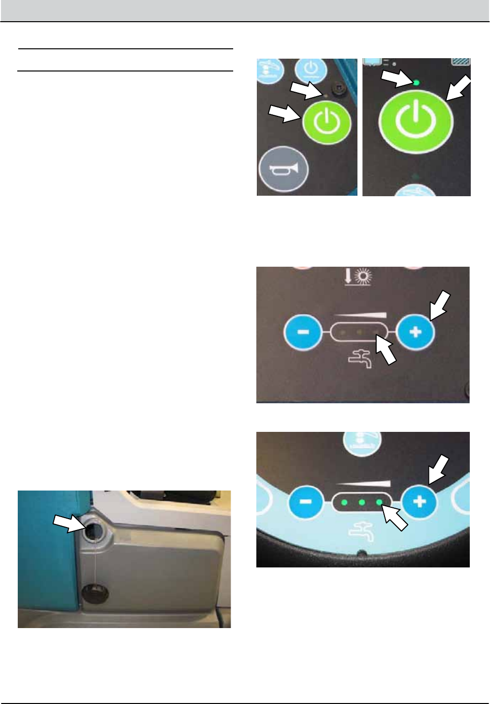
3-38 T12 Service Information 9009917 (12-12)
MAINTENANCE
STORAGE INFORMATION
The following steps should be taken when storing
the machine for extendedperiods of time.
1. Charge the batteries before storing machine
to prolong the life of the batteries.
2. Thoroughly drainand rinse the solution and
recovery tanks.
3. Store the machine inadry area with the
squeegeeand scrub head in the up position.
ATTENTION: Do notexpose machine to rain,
store indoors.
4. Open the recovery tank cover to promote air
circulation.
5. If storing machine in freezing temperatures,
proceed to FREEZE PROTECTION.
NOTE: To preventpotential machinedamage
store machine inarodentandinsect free
environment.
FREEZE PROTECTION
FOR SAFETY: Before leaving or servicing
machine, stop on level surface and turn off
machine.
1. Completely drain the solution tankand
recovery tank.
2. Pour 7.6L(2 gal) of Propylene Glycol Based /
Recreational Vehicle (RV) antifreeze into the
solution tank.
3. Turn on the machine.
4. Press the 1--Step button.
T12 T12XP
5. Repeatedly press the Solutionincrease button
(+) until the solution flow is at the highest
setting.
T12
T12XP
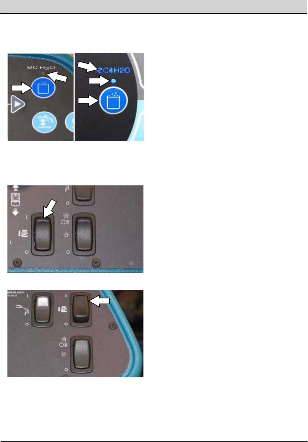
T12 Service Information 9009917 (12-12) 3-39
MAINTENANCE
6. Machines with ec- H2Ooptiononly: Press
the scrub modebutton to place machineinto
the ec--H2Omode. The ec--H2Oindicator
lightwillilluminate.
T12 T12XP
7. Machines with side brush optiononly:
Press the side brush switch to activate the
side brush.
T12
T12XP
8. Drive the machine to circulate the RV
antifreeze completely throughall the systems
and clearoutany remainingwater.
9. Machines with side brush optiononly:
Press the side brush switch to turn off the
side brush.
10. Stop the machine.
11. Machines with spraynozzle optiononly:
Operate the wand for a few seconds to
protect the pump.
12. Press the 1--STEP button to turn off the
system.
13. Turn off the machine.
14. The remaining RV antifreeze doesnotneed to
be drained from the solution or recovery tank.
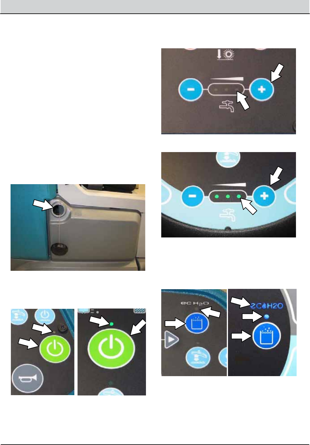
3-40 T12 Service Information 9009917 (12-12)
MAINTENANCE
PREPARING THE MACHINE FOR OPERATION
AFTER STORAGE
All Propylene Glycol Based / Recreational Vehicle
(RV) Antifreeze must be completely cleaned from
the scrubbingsystem before the machine can be
used for scrubbing.
FOR SAFETY: Before leaving or servicing
machine, stop on level surface and turn off
machine.
1. Completely drainall Propylene Glycol Based /
Recreational Vehicle (RV) antifreeze from the
solution tank.
2. Rinse out the solution tank. Refer to
DRAINING AND CLEANING THE SOLUTION
TANK in the OPERATIONsection for
instructionshow to clean the solution tank.
3. Pour 11.4L(3 gal) of cool cleanwater into the
solution tank.
4. Start the machine
5. Press the 1--STEP button.
T12 T12XP
6. Repeatedly press the Solutionincrease button
(+) until the solution flow is at the highest
setting.
T12
T12XP
7. Machines with ec- H2Ooptiononly: Press
the scrub modebutton to place machineinto
the ec--H2Omode. The indicator lightwill
illuminate.
T12 T12XP
NOTE: The ec--H2O systems on machines
equippedwith ec--H2O must be primed before the
machine is ready for operation. See PRIMING
THE ec--H2O SYSTEM for additionalinstructions.
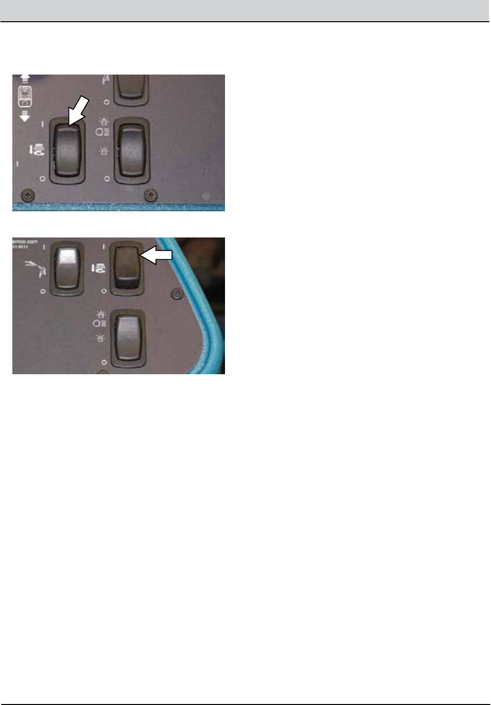
T12 Service Information 9009917 (12-12) 3-41
MAINTENANCE
8. Machines with side brush optiononly:
Press the side brush switch to activate the
side brush.
T12
T12XP
9. Drive the machine to circulate the cleanwater
completely through the system andclearout
the RV antifreeze.
10.Machines with side brush optiononly:
Press the side brush switch to turn off the
side brush.
11. Stop the machine.
12.Machines with spraynozzle optiononly:
Operate the wand for a few seconds to clean
the RV antifreeze from the pump.
13. Press the 1--STEP button to turn off the
system.
14. Turn off the machine.
15. The remainingwater doesnotneed to be
drained from the solution tank.
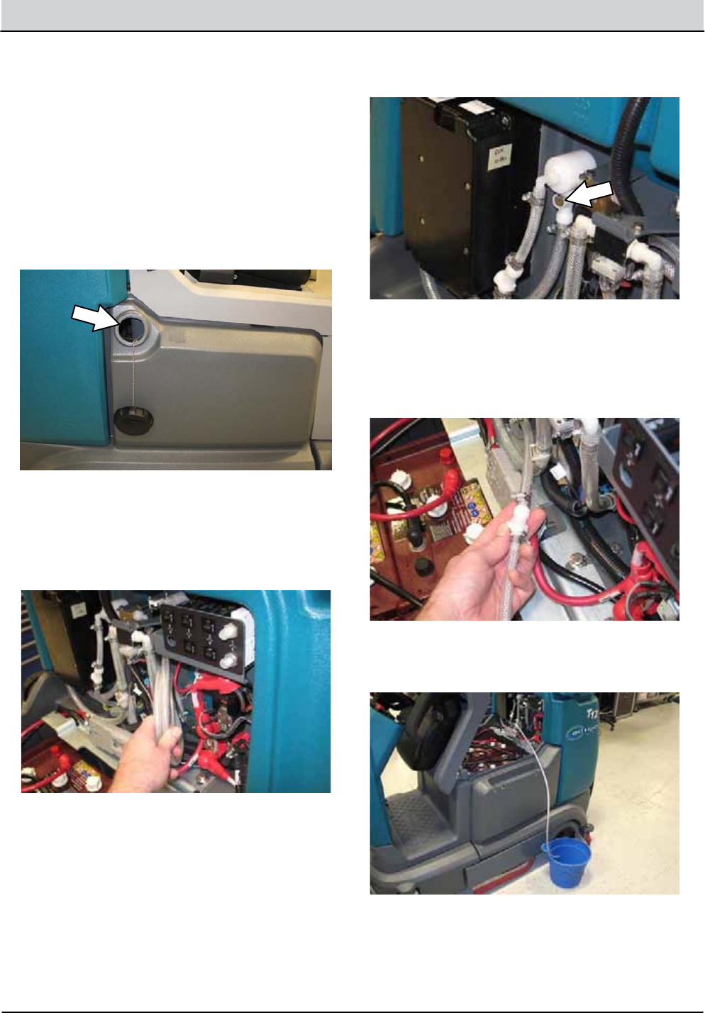
3-42 T12 Service Information 9009917 (12-12)
MAINTENANCE
PRIMING THE ec- H2OSYSTEM
Prime the ec--H2Osystem if the machinehas
been stored for a longperiodwith no water in the
solution tank / ec--H2Osystem.
FOR SAFETY: Before leaving or servicing
machine, stop on level surface and turn off
machine.
1. Fill the solution tankwith clean coolwater.
See FILLING THE SOLUTION TANK section
of this manual.
2. Lift the operator seatopenandengage the
seat support.
3. Remove the drainhose from the ec--H2O
compartment.
4. Disconnect the outlethose to the scrub head
from the ec--H2Omanifold.
5. Place the drainhose into an empty container.
6. Connect the drainhose to the ec--H2O
manifoldhose disconnected from the outlet
hose in the previous step.
7. Place the ec--H2Osystem outlethose into an
empty container.
8. Start the machine.

T12 Service Information 9009917 (12-12) 3-43
MAINTENANCE
9. Press and release the ec--H2Omodule flush
switch. Allow the system to drainwater into
the container for 2 minutes.
10. Press the ec--H2Omodule flush switch to
shut off the system.
11. Disconnect the drainhose from the ec--H2O
manifoldhose.
12.Reconnect the outlethose to the scrub head
to ec--H2Omanifoldhose.
13. Place the drainhose back into the ec--H2O
compartment.
14.Close the operator seat cover.

3-44 T12 Service Information 9009917 (12-12)
MAINTENANCE

TROUBLESHOOTING
ONBOARD DIAGNOSTICS .................. 42
SELFTEST MODE ....................... 42
CONFIGURATION MODE ................ 44
LCD WARNINGS ......................... 46
LCD FAULTS. . . . . . . . . . . . . . . . . . . . . . . . . . . . . 47
PROPEL DIAGNOSTIC MODE ............ 49
CURTIS 1232 CONTROLLER
DIAGNOSTICS ......................411
DIAGNOSTIC LED OPERATION. . . . . . . 411
DIAGNOSTIC CODES ................412
INPUT DISPLAY MODE .................420
MANUAL MODE .......................422
CAN CONTROLLER AREA NETWORK
DIAGNOSTIC MODE .................424
FIRMWARE UPDATE MODE .............425
BATTERY CHARGER, STANDARD. . . . . . . . 426
OPERATION .........................426
CONFIGURATION ...................426
FAULTS .............................426
BATTERY CHARGER, ONBOARD OPT. ...427
OPERATION ......................427
CONFIGURATION .................427
FAULTS ...........................427
SUBSYSTEM TROUBLESHOOTING .........428
BACKUP ALARM/LIGHT ...............428
BATTERY CHARGING ...................430
ONBOARD ..........................430
OFF BOARD ......................... 432
PARKING BRAKE, ELECTROMAGNETIC ..434
LIGHTING .............................. 436
MAIN SCRUB BRUSHES ................438
POWERUP ............................440
PROPEL ................................ 442
REAR SQUEEGEE LIFT ..................444
SCRUB HEAD LIFT .....................446
SIDE BRUSH ...........................448
SIDE BRUSH LIFT ....................... 450
SOLUTION CONTROL, CONVENTIONAL 454
MAIN BRUSH .......................454
SIDE BRUSH ........................456
SOLUTION CONTROL, ECH2O ..........458
SPRAY NOZZLE ........................460
VACUUM FAN .......................... 462
TROUBLESHOOTING
SECTION 4
Contents Page
4-1
T12 Service Information 9009917 (12-12)
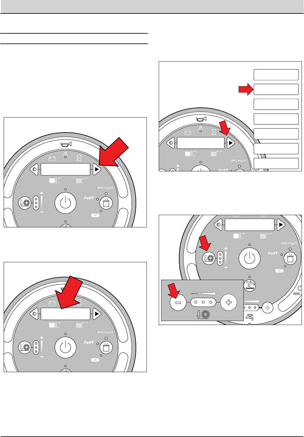
4-2 T12 Service Information 9009917 (12-12)
TROUBLESHOOTING
SELF TEST MODE
+ - + - + - + - + - + -
Scrub Head
Down
Enabled
• 1-STEP Scrub ON
• Squeegee/Vac ON • 1-STEP Scrub OFF
• Squeegee/Vac OFF
• Recovery Tank Full
• Low Batt Voltage
• Load Current Fault
Disabled
Operational Matrix:
Scrub Head
Down
Enabled
• 1-STEP Scrub ON
• Fwd/Rev Propel
• 1-STEP Scrub OFF
• Neutral-Ready State
• Recovery Tank Full
• Solution Tank Empty
• Low Batt Voltage
• Load Current Fault
Disabled
Operational Matrix:
Tennant Quantum
UI ver1.0
Tennant Quantum
UI ver X.X
Tennant Quantum
UI ver X.X
T16
Control
Board
6 Volt
Key Switch
IGN
15
ACC
30
BATT
Switched B+
From Buss Bar
75
50 Start S-2
E-Stop
Switch
S-3
Charger
Interlock
ST
M1B
M1A
J7-1
B+(Control)
B+
B-
Battery Positive +
Battery Negative -
CAN +12V J2-1
J2-2
J2-3
J2-4
RED #1
RED #2
BLK #2
BLK #1
CAN +
CAN -
CAN GROUND
D-4
D-2 D-3
CB1
2.5A
FU2
100A
6 Volt 6 Volt 6 Volt 6 Volt 6 Volt
CB2
2.5A
1/RED
13/BLK
6/BLU 7/PUR
Cable
Shield
Instrument Panel Assembly
Cable
3/ORA
8/GRY
4/YEL
Cable to Ground Stand O
5/GRN
10/TAN
2/BRNCable
STP001
1. Turn Key Off.
1. Key switch O. Press and hold the conguration
mode button.
2. Key switch On. Release the conguration mode
button when “CONFIG MODE” appears on the LCD.
+ - + - + - + - + - + -
Scrub Head
Down
Enabled
• 1-STEP Scrub ON
• Squeegee/Vac ON • 1-STEP Scrub OFF
• Squeegee/Vac OFF
• Recovery Tank Full
• Low Batt Voltage
• Load Current Fault
Disabled
Operational Matrix:
Scrub Head
Down
Enabled
• 1-STEP Scrub ON
• Fwd/Rev Propel
• 1-STEP Scrub OFF
• Neutral-Ready State
• Recovery Tank Full
• Solution Tank Empty
• Low Batt Voltage
• Load Current Fault
Disabled
Operational Matrix:
Tennant Quantum
UI ver1.0
Tennant Quantum
UI ver X.X
CONFIG MODE
T16
Control
Board
6 Volt
Key Switch
IGN
15
ACC
30
BATT
Switched B+
From Buss Bar
75
50 Start S-2
E-Stop
Switch
S-3
Charger
Interlock
ST
M1B
M1A
J7-1
B+(Control)
B+
B-
Battery Positive +
Battery Negative -
CAN +12V J2-1
J2-2
J2-3
J2-4
RED #1
RED #2
BLK #2
BLK #1
CAN +
CAN -
CAN GROUND
D-4
D-2 D-3
CB1
2.5A
FU2
100A
6 Volt 6 Volt 6 Volt 6 Volt 6 Volt
CB2
2.5A
1/RED
13/BLK
6/BLU 7/PUR
Cable
Shield
Instrument Panel Assembly
Cable
3/ORA
8/GRY
4/YEL
Cable to Ground Stand O
5/GRN
10/TAN
2/BRNCable
STP002
1. Turn Key Off.
SELF TEST
CONFIG MODE
SELF TEST
MANUAL MODE
INPUT DISPLAY
CAN DIAG MODE
PROPEL DIAG MODE
FIRMWARE UPDATE
3. Press and release the conguration mode button to
scroll through a list of utilities until “SELF TEST”
appears on the LCD.
****SELF-TEST***
STARTING
T12 STANDARD
T12 XP
4. Press and release the brush pressure button to
activate the self test. “SELF-TEST STARTING” will appear
on the LCD.
Self Test Mode is an onboard diagnostic utility that tests
for open or shorted output circuits. Once completed,
open and/or shorted output pins are displayed on the
LCD (liquid crystal display).
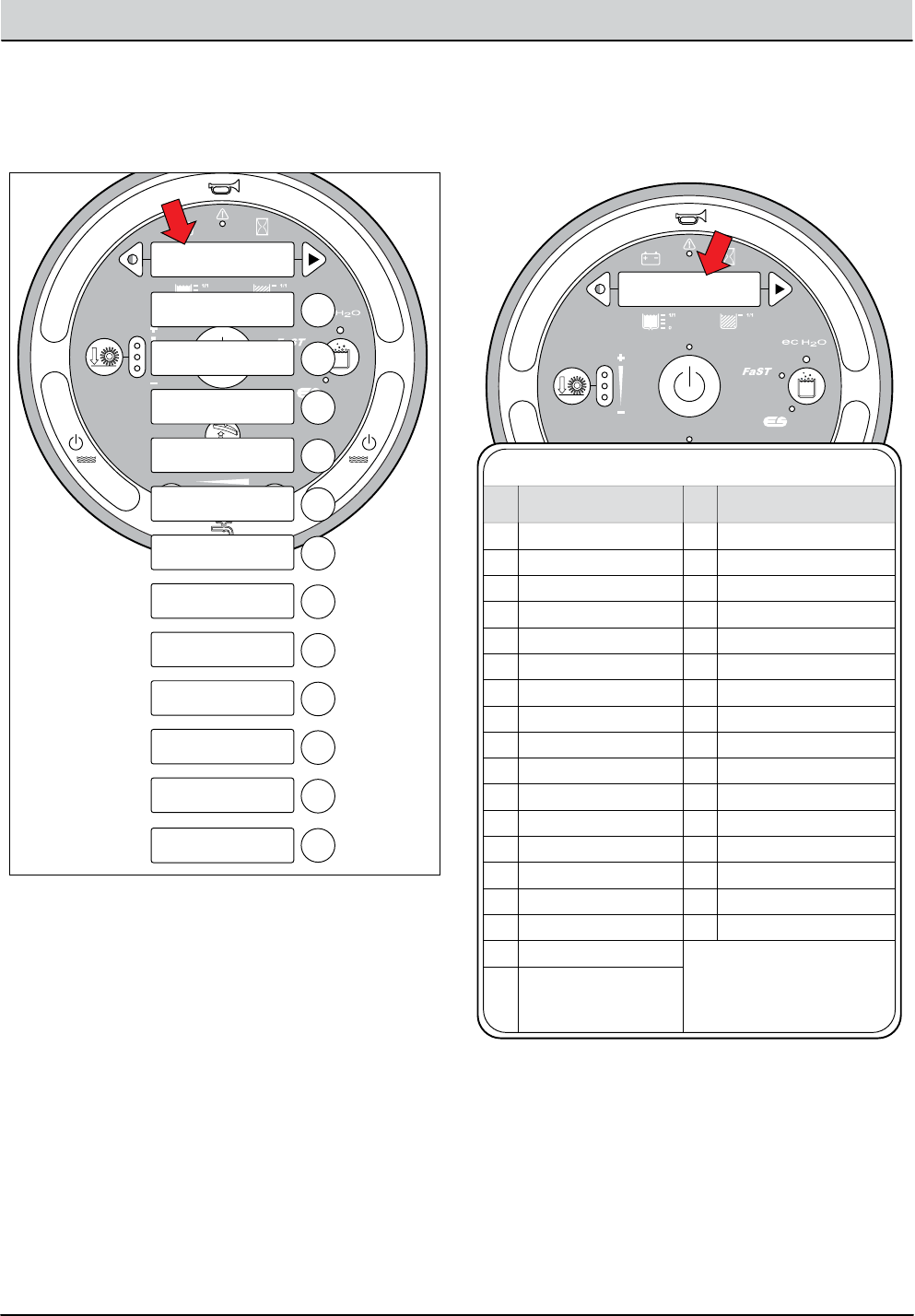
T12 Service Information 9009917 (12-12) 4-3
TROUBLESHOOTING
****SELF-TEST***
STARTING
1
2
3
4
5
6
7
8
9
10
11
12
Testing Main
Scrub Brushes...
Testing Side
Scrub Brush...
Testing Vacuum
Fan Motors...
Testing Main
Scrub Actuator...
Testing Squeegee
Actuator...
Testing Side
Brush Actuator...
Testing Side
Pump...
Testing Side
Valve...
Testing Main
Valve...
Testing Horn
Output...
Testing Alarm
Output...
Testing Curtis CAN
Communication...
5. The controller sequentially tests each output circuit
as shown below.
S1: **SELF-TEST**
< RESULTS >
STP006
T12 Self Test Codes
S1 S19S1:Self Test “Done” or “<Results>” S19:Side Brush J3-2,3/Short
S2 S20S2:Front/Left Br J5-1,2/Open S20:Side Act J5-2,3/Open
S3 S21S3:Front/Left Br J5-1,2/Short S21:Side Act J5-2,3/Short
S4 S22S4:Rear/Right Br J5-4,5/Open S22:Side Pump J5-5/Open
S5 S23S5:Rear/Right Br J5-4,5/Short S23:Side Pump J5-5/Short
S6 S24S6:Main Act J6-7,8/Open S24:Side Valve J5-4/Open
S7 S25S7:Main Act J6-7,8/Short S25:Side Valve J5-4/Short
S8 S34S8:Main Valve J6-2/Open S34:Ec-H2O Pump J4-4/Open
S9 S35S9:Main Valve J6-2/Short S35:Ec-H2O Pump J4-4/Short
S10 S36S10:Horn J6-3/Open S36:Ec-H2O Side Br. J4-5/Open
S11 S37S11:Horn J6-3/Short S37:Ec-H2O Side Br. J4-5/Short
S12 S38S12:Alarm J6-4/Open S38:Curtis CAN/J6-13,14 No Comm
S13 S50S13:Alarm J6-4/Short S50:Scrub Module/Oine
S14 S51S14:Vac Fan J3-2,3/Open S51:Pickup Module/Oine
S15 S52S15:Vac Fan J3-2,3/Short S52:ECH2O Module/Oine
S16 S53S16:Sqge Act. J5-2,3/Open S53:Side Module/Oine
S17 S17:Sqge Act. J5-2,3/Short
S18 S18:Side Brush J3-2,3/Open
CODE LCD MESSAGE CODE LCD MESSAGE
6. The self test results are displayed in “JX-X,X” format.
JX = Connector, “-X,X” = Control board output pins as
shown on the electrical schematic.
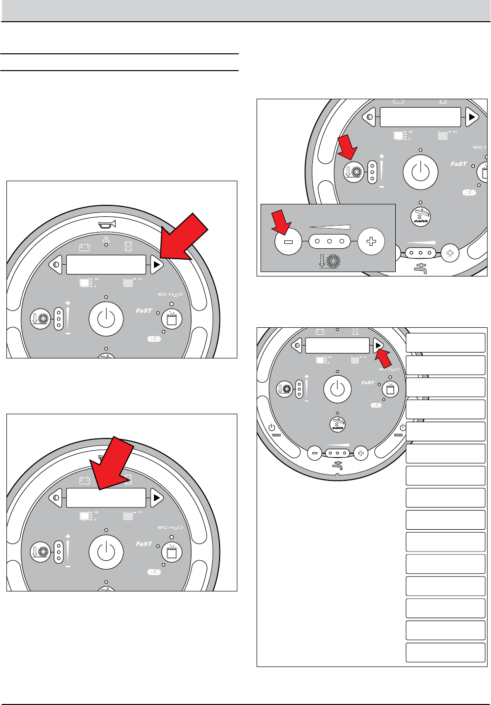
4-4 T12 Service Information 9009917 (12-12)
TROUBLESHOOTING
+ - + - + - + - + - + -
Scrub Head
Down
Enabled
• 1-STEP Scrub ON
• Squeegee/Vac ON • 1-STEP Scrub OFF
• Squeegee/Vac OFF
• Recovery Tank Full
• Low Batt Voltage
• Load Current Fault
Disabled
Operational Matrix:
Scrub Head
Down
Enabled
• 1-STEP Scrub ON
• Fwd/Rev Propel
• 1-STEP Scrub OFF
• Neutral-Ready State
• Recovery Tank Full
• Solution Tank Empty
• Low Batt Voltage
• Load Current Fault
Disabled
Operational Matrix:
Tennant Quantum
UI ver1.0
Tennant Quantum
UI ver X.X
Tennant Quantum
UI ver X.X
T16
Control
Board
6 Volt
Key Switch
IGN
15
ACC
30
BATT
Switched B+
From Buss Bar
75
50 Start S-2
E-Stop
Switch
S-3
Charger
Interlock
ST
M1B
M1A
J7-1
B+(Control)
B+
B-
Battery Positive +
Battery Negative -
CAN +12V J2-1
J2-2
J2-3
J2-4
RED #1
RED #2
BLK #2
BLK #1
CAN +
CAN -
CAN GROUND
D-4
D-2 D-3
CB1
2.5A
FU2
100A
6 Volt 6 Volt 6 Volt 6 Volt 6 Volt
CB2
2.5A
1/RED
13/BLK
6/BLU 7/PUR
Cable
Shield
Instrument Panel Assembly
Cable
3/ORA
8/GRY
4/YEL
Cable to Ground Stand O
5/GRN
10/TAN
2/BRNCable
STP001
1. Turn Key Off.
1. Key switch O. Press and hold the conguration
mode button.
2. Key switch On. Release the conguration mode
button when “CONFIG MODE” appears on the LCD.
+ - + - + - + - + - + -
Scrub Head
Down
Enabled
• 1-STEP Scrub ON
• Squeegee/Vac ON • 1-STEP Scrub OFF
• Squeegee/Vac OFF
• Recovery Tank Full
• Low Batt Voltage
• Load Current Fault
Disabled
Operational Matrix:
Scrub Head
Down
Enabled
• 1-STEP Scrub ON
• Fwd/Rev Propel
• 1-STEP Scrub OFF
• Neutral-Ready State
• Recovery Tank Full
• Solution Tank Empty
• Low Batt Voltage
• Load Current Fault
Disabled
Operational Matrix:
Tennant Quantum
UI ver1.0
Tennant Quantum
UI ver X.X
CONFIG MODE
T16
Control
Board
6 Volt
Key Switch
IGN
15
ACC
30
BATT
Switched B+
From Buss Bar
75
50 Start S-2
E-Stop
Switch
S-3
Charger
Interlock
ST
M1B
M1A
J7-1
B+(Control)
B+
B-
Battery Positive +
Battery Negative -
CAN +12V J2-1
J2-2
J2-3
J2-4
RED #1
RED #2
BLK #2
BLK #1
CAN +
CAN -
CAN GROUND
D-4
D-2 D-3
CB1
2.5A
FU2
100A
6 Volt 6 Volt 6 Volt 6 Volt 6 Volt
CB2
2.5A
1/RED
13/BLK
6/BLU 7/PUR
Cable
Shield
Instrument Panel Assembly
Cable
3/ORA
8/GRY
4/YEL
Cable to Ground Stand O
5/GRN
10/TAN
2/BRNCable
STP002
1. Turn Key Off.
Conguration Mode is an onboard diagnostic utility that
congures controller software to operate optional equip-
ment and to electronically adjust certain output func-
tions.
C1:Disk/Cyl
T12 STANDARD
T12 XP
3. Press and release the brush pressure button to enter
Conguration Mode. “C1:Disk/Cyl” will appear on the
LCD.
C1:Disk/Cyl
C2:Ec/No
C4:Reset Press.?
C5:Main Press #1
11.0 A
C7:Main Press #3
22.0 A
C6:Main Press #2
16.0 A
C8:Transport Spd
XX.X MPH
C9:Scrubbing Spd
XX.X MPH
C10:Propel H.M.
XXXX.X Hrs
C11:Main Water
Low/Med/High
C12:Side Brush?
Sweep/Scrub
C13:Scrub H.M.
XXXX.X Hr
C14:Reset
C15:Battery Type
C16:Dwn Pres Tst
C5:Main Press #1
XX Amps
4. Press and release the conguration mode button to
scroll through a list of utilities as shown below.
CONFIGURATION MODE
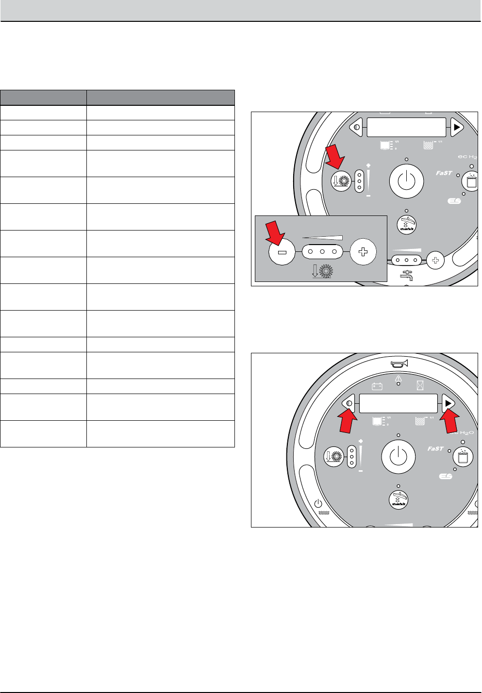
T12 Service Information 9009917 (12-12) 4-5
TROUBLESHOOTING
5. Use the table below for further description of each
Conguration Mode utility.
LCD TEXT DESCRIPTION
C1:Disk/Cyl Congure scrub head type
C2:Ec/No Congure ec-H2O or none
C4:Reset Press.?* Restore down pressure settings
C5:Main Press #1** Set max down pressure #1
(11 Amps-Fixed)
C6:Main Press #2** Set max down pressure #2
(11-16 Amps, Default 16 Amps)
C7:Main Press #3** Set max down pressure #3
(11-22 Amps, Default 22 Amps)
C8:Transport Spd
XX.X MPH
Adjust maximum forward trans-
port mode speed
C9:Scrubbing Spd
XX.X MPH
Adjust maximum forward scrub
mode speed
C10:Propel H.M.
XXXX.X Hrs
Display/edit propel hour meter.
Password protected
C11:Main Water Select water ow range: (Low,
Medium, High)
C12:Side Brush? Congure side brush option
C13:Scrub H.M.
XXXX.X Hr
Display/edit scrub hour meter.
Password protected
C14:Reset Restore factory default values.
C15:Battery Type Congure battery type for acid or
AGM
C16:Dwn Pres Tst*** Initiate brush pattern testing
(Disable/Enable)
C5:Main Press #1
<XX Amps
T12 STANDARD
T12 XP
6. Press and release the brush pressure button to enable
the change. A “<” symbol will appear on the bottom
line of the LCD indicating the conguration utility is
now enabled.
+ - + - + - + - + - + -
Scrub Head
Down
Enabled
• 1-STEP Scrub ON
• Squeegee/Vac ON • 1-STEP Scrub OFF
• Squeegee/Vac OFF
• Recovery Tank Full
• Low Batt Voltage
• Load Current Fault
Disabled
Operational Matrix:
Scrub Head
Down
Enabled
• 1-STEP Scrub ON
• Fwd/Rev Propel
• 1-STEP Scrub OFF
• Neutral-Ready State
• Recovery Tank Full
• Solution Tank Empty
• Low Batt Voltage
• Load Current Fault
Disabled
Operational Matrix:
Tennant Quantum
UI ver1.0
Tennant Quantum
UI ver X.X
T16
Control
Board
6 Volt
Key Switch
IGN
15
ACC
30
BATT
Switched B+
From Buss Bar
75
50 Start S-2
E-Stop
Switch
S-3
Charger
Interlock
ST
M1B
M1A
J7-1
B+(Control)
B+
B-
Battery Positive +
Battery Negative -
CAN +12V J2-1
J2-2
J2-3
J2-4
RED #1
RED #2
BLK #2
BLK #1
CAN +
CAN -
CAN GROUND
D-4
D-2 D-3
CB1
2.5A
FU2
100A
6 Volt 6 Volt 6 Volt 6 Volt 6 Volt
CB2
2.5A
1/RED
13/BLK
6/BLU 7/PUR
Cable
Shield
Instrument Panel Assembly
Cable
3/ORA
8/GRY
4/YEL
Cable to Ground Stand O
5/GRN
10/TAN
2/BRNCable
CMP004
1. Turn Key Off.
CONFIG MODE
C5:Main Press #1
<XX Amps
SELF TEST
MANUAL MODE
INPUT DISPLAY
PROPEL DIAG MODE
7. Press and release the contrast or conguration
mode buttons to change settings. Turn key O
to save selection.
*** C16 Dwn Pres Tst (Down Pressure Test) pertains to
checking the cylindrical scrub brush pattern. See CHECKING
CYLINDRICAL SCRUB BRUSH PATTERN in the MAINTENANCE
section of this manual.
** C5, C6, and C7 Main Press (Main Brush Pressure) adjust-
ments set the maximum brush motor amp draw for each
down pressure setting; 1 LED, 2 LEDs, or 3 LEDs. C5 (#1) down
pressure is not adjustable.
* C4:Reset Press.? mode. Press the brush pressure button
after “No” changes to “Yes” following step 7. This completes
the reset process.

4-6 T12 Service Information 9009917 (12-12)
TROUBLESHOOTING
WARNING
MESSAGE
WARNING
CODE WARNING DESCRIPTION SET/CLEAR
T12 LCD Warning Messages
W1 W1:Batt Low Low Battery
W2 W2:Sqge Stall SET: Rear squeegee actuator stall condition.
CLEAR: Correct warning condition.
Rear Squeegee Actuator Stalled
W3 W3:Side Stall SET: Side brush actuator stall condition.
CLEAR: Correct warning condition.
Side Brush Actuator Stalled
W4 W4:Unavailable SET: Operator selects a solution technology that
is not congured on the machine.
CLEAR: Release button.
No Optional Solution Enabled
W5 W5:No Side Brush SET: Operator selects the side brush when the
side brush is not enabled in conguration mode.
CLEAR: Release button.
No Side Brush Enabled
W6 W6: Ec Oine SET: Ec-H2O technology is congured and there
is no CAN connectivity to the ec-H2O module.
CLEAR: Correct warning condtion.
Ec-H2O Module Oine
W7 W7:Not Active SET: Operator selects a button and the related
function is inactive.
CLEAR: Correct warning condition.
Inactive Button
W8 W8:No Vac Amps SET: Controller senses no current to the vacuum
fan circuit when the output is turned ON.
CLEAR: Correct open circuit condition.
Vacuum Fan Motor, No Current
W9 W9:Open R/R Brush SET: Controller senses no current to the
Right (Disk) or Rear (Cyl) motor circuit when the
output is turned ON.
CLEAR: Correct open circuit condition.
SET: Controller senses no current to the
Left (Disk) or Front (Cyl) motor circuit when the
output is turned ON.
CLEAR: Correct open circuit condition.
SET: Controller senses no current to the side
brush motor circuit when the output is turned ON.
CLEAR: Correct open circuit condition.
Open Right/Rear Brush Motor
W10 W10:Open L/F Brush Open Left/Front Brush Motor
W11 W11:Open SD Brush Open Side Brush Motor
W12 W12:Solution O SET: Solution is OFF during scrub mode for 15
seconds.
CLEAR: Correct warning condition.
Solution Water is O
W13 W13: Side Oine SET: Side brush is congured and there is no
CAN connectivity to the side brush module.
CLEAR: Correct warning condtion.
Side Module Oine
WMM001
SET: Battery discharge threshold of 30-32 Volts
at KSI terminal or 32-33 Volts at batteries.
CLEAR: Charge batteries to BDI reset threshold
of 37 Volts at KSI terminal or 38 Volts at batteries
Terms:
KSI = Key Switch Interlock
BDI = Battery Discharge Indicator

T12 Service Information 9009917 (12-12) 4-7
TROUBLESHOOTING
FAULT
CODE FAULT MESSAGE FAULT DESCRIPTION SET/CLEAR
T12 LCD Fault Messages
F1
F2
F3
F4
F5
F6
F6
F2:SolTank Empty
F3:Vac#Flt#
F4:Batt Very Low
F5:Propel Error
F6:Left Br Flt#
F6:Frnt Br Flt#
F1:Rcv Tank Full
Solution Tank Empty
Over Current Vacuum Fan # (1 or 2) Motors,
Fault Type (1, 2, 3).
SET: Fault #1 = Over Current for 15 Seconds;
Fault #2 = Current Exceeds 25A for 30 Seconds;
Fault #3 = Current Exceeds 35A for 2 Seconds.
CLEAR: Cycle key switch.
SET: Fault #1 = Current Exceeds 30A for 30 Seconds;
Fault #2 = Current Exceeds 40A for 5 Seconds;
Fault #3 = Over Current for 10 Seconds.
CLEAR: Cycle key switch.
SET: Fault #1 = Current Exceeds 30A for 30 Seconds;
Fault #2 = Current Exceeds 40A for 5 Seconds;
Fault #3 = Over Current for 10 Seconds.
CLEAR: Cycle key switch.
SET: Solution tank empty for 60 seconds
CLEAR: Cycle key switch.
SET: Battery discharge threshold of 30.2 Volts
at KSI terminal of PMC or 31.6 Volts at battery.
CLEAR: Charge batteries to BDI reset threshold
of 37 Volts at KSI terminal of PMC or 38.3 Volts
at batteries.
SET: Curtis 1232 PMC to T12 logic board
CAN-bus connectivity problem or
Curtis 1232 PMC power supply problem.
CLEAR: See “Curtis 1232 Controller Diagnostics.”
SET: Recovery tank full for 5 seconds.
CLEAR: Recovery tank not full for 5 seconds.
Very Low Battery Voltage
Propel Controller CAN-bus Connectivity
Error
Left Brush Over Current, Fault #
Front Brush Over Current, Fault #
Recovery Tank Full
FMM001
Terms:
KSI = Key Switch Interlock
PMC = Propel Motor Control

4-8 T12 Service Information 9009917 (12-12)
TROUBLESHOOTING
FAULT
CODE FAULT MESSAGE FAULT DESCRIPTION SET/CLEAR
T12 LCD Fault Messages, continued
F7
F7
F8
F11
F12
F13
F7:Right Br Flt#
F7:Rear Br Flt#
F8:Hi B3 Current
F11:Act Timeout
F12:Check Brushes
F13:Brush Motor Flt
Right Brush Over Current, Fault #
Rear Brush Over Current, Fault #
Over Current for Side Brush Motor
Main Head Actuator Timed Out Fault.
Check Main Brushes Error Fault (Down Shift)
Brush Motor Fault
FMM002
SET: Fault #1 = Current Exceeds 30A for 30 Seconds;
Fault #2 = Current Exceeds 40A for 5 Seconds;
Fault #3 = Over Current for 10 Seconds.
CLEAR: Cycle key switch.
SET: Fault #1 = Current Exceeds 30A for 30 Seconds;
Fault #2 = Current Exceeds 40A for 5 Seconds;
Fault #3 = Over Current for 10 Seconds.
CLEAR: Cycle key switch.
SET: Fault #1 = Current Exceeds 30A for 30 Seconds;
Fault #2 = Current Exceeds 40A for 5 Seconds;
Fault #3 = Over Current for 10 Seconds.
CLEAR: Cycle key switch.
SET: Unable to achieve target brush motor
current after 60 seconds of actuator adjustments.
CLEAR: Correct fault condition and cycle key
switch or 1-STEP scrub.
F9 F9:Pickup Error Pickup module CAN Fault SET: CAN connectivity to pickup module failed.
CLEAR: Correct fault condition and cycle
key switch.
F10 F10:Scrub Error Scrub module CAN Fault SET: CAN connectivity to scrub module failed.
CLEAR: Correct fault condition and cycle
key switch.
SET: Head lift actuator stalled while trying to
reduce down pressure.
CLEAR: Cycle key switch or 1-STEP scrub.
F14 F14:EcH2O Error Ec-H2O Module CAN Fault SET: CAN connectivity to ec-H2O module failed.
CLEAR: Correct fault condition and cycle key
switch.
SET: Controller failed to achieve minimum target
brush motor current after down shifting to the
lowest down pressure setting.
CLEAR: Correct fault condition and cycle
key switch.
Terms:
KSI = Key Switch Interlock
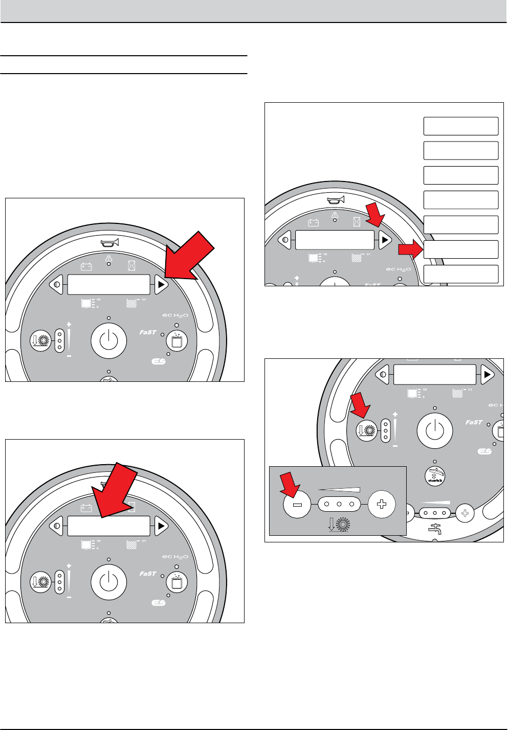
T12 Service Information 9009917 (12-12) 4-9
TROUBLESHOOTING
+ - + - + - + - + - + -
Scrub Head
Down
Enabled
• 1-STEP Scrub ON
• Squeegee/Vac ON • 1-STEP Scrub OFF
• Squeegee/Vac OFF
• Recovery Tank Full
• Low Batt Voltage
• Load Current Fault
Disabled
Operational Matrix:
Scrub Head
Down
Enabled
• 1-STEP Scrub ON
• Fwd/Rev Propel
• 1-STEP Scrub OFF
• Neutral-Ready State
• Recovery Tank Full
• Solution Tank Empty
• Low Batt Voltage
• Load Current Fault
Disabled
Operational Matrix:
Tennant Quantum
UI ver1.0
Tennant Quantum
UI ver X.X
Tennant Quantum
UI ver X.X
T16
Control
Board
6 Volt
Key Switch
IGN
15
ACC
30
BATT
Switched B+
From Buss Bar
75
50 Start S-2
E-Stop
Switch
S-3
Charger
Interlock
ST
M1B
M1A
J7-1
B+(Control)
B+
B-
Battery Positive +
Battery Negative -
CAN +12V J2-1
J2-2
J2-3
J2-4
RED #1
RED #2
BLK #2
BLK #1
CAN +
CAN -
CAN GROUND
D-4
D-2 D-3
CB1
2.5A
FU2
100A
6 Volt 6 Volt 6 Volt 6 Volt 6 Volt
CB2
2.5A
1/RED
13/BLK
6/BLU 7/PUR
Cable
Shield
Instrument Panel Assembly
Cable
3/ORA
8/GRY
4/YEL
Cable to Ground Stand O
5/GRN
10/TAN
2/BRNCable
STP001
1. Turn Key Off.
1. Key switch O. Press and hold the conguration
mode button.
2. Key switch On. Release the conguration mode
button when “CONFIG MODE” appears on the LCD.
+ - + - + - + - + - + -
Scrub Head
Down
Enabled
• 1-STEP Scrub ON
• Squeegee/Vac ON • 1-STEP Scrub OFF
• Squeegee/Vac OFF
• Recovery Tank Full
• Low Batt Voltage
• Load Current Fault
Disabled
Operational Matrix:
Scrub Head
Down
Enabled
• 1-STEP Scrub ON
• Fwd/Rev Propel
• 1-STEP Scrub OFF
• Neutral-Ready State
• Recovery Tank Full
• Solution Tank Empty
• Low Batt Voltage
• Load Current Fault
Disabled
Operational Matrix:
Tennant Quantum
UI ver1.0
Tennant Quantum
UI ver X.X
CONFIG MODE
T16
Control
Board
6 Volt
Key Switch
IGN
15
ACC
30
BATT
Switched B+
From Buss Bar
75
50 Start S-2
E-Stop
Switch
S-3
Charger
Interlock
ST
M1B
M1A
J7-1
B+(Control)
B+
B-
Battery Positive +
Battery Negative -
CAN +12V J2-1
J2-2
J2-3
J2-4
RED #1
RED #2
BLK #2
BLK #1
CAN +
CAN -
CAN GROUND
D-4
D-2 D-3
CB1
2.5A
FU2
100A
6 Volt 6 Volt 6 Volt 6 Volt 6 Volt
CB2
2.5A
1/RED
13/BLK
6/BLU 7/PUR
Cable
Shield
Instrument Panel Assembly
Cable
3/ORA
8/GRY
4/YEL
Cable to Ground Stand O
5/GRN
10/TAN
2/BRNCable
STP002
1. Turn Key Off.
PROPEL DIAG MODE
CONFIG MODE
SELF TEST
MANUAL MODE
INPUT DISPLAY
CAN DIAG MODE
PROPEL DIAG MODE
FIRMWARE UPDATE
3. Press and release the conguration mode button to
scroll through a list of utilities until “PROPEL DIAG
MODE” appears on the LCD.
P1: Curtis Online/
Error
T12 STANDARD
T12 XP
4. Press and release the brush pressure button to
enter Propel Diagnostic Mode. “P1:Curtis Online...” will
appear on the LCD.
Propel Diagnostic Mode (Propel Input Mode) is an on-
board diagnostic utility that displays Curtis 1232 control-
ler inputs on the instrument panel LCD (Liquid Crystal
Display). The input data is transmitted to the T12 control-
ler through a CAN-bus (Controller Area Network).
PROPEL DIAGNOSTIC MODE
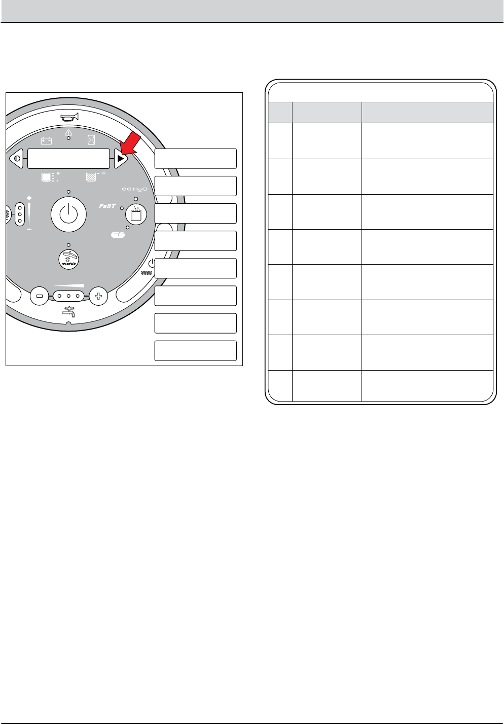
4-10 T12 Service Information 9009917 (12-12)
TROUBLESHOOTING
+ - + - + - + - + - + -
Scrub Head
Down
Enabled
• 1-STEP Scrub ON
• Squeegee/Vac ON • 1-STEP Scrub OFF
• Squeegee/Vac OFF
• Recovery Tank Full
• Low Batt Voltage
• Load Current Fault
Disabled
Operational Matrix:
Scrub Head
Down
Enabled
• 1-STEP Scrub ON
• Fwd/Rev Propel
• 1-STEP Scrub OFF
• Neutral-Ready State
• Recovery Tank Full
• Solution Tank Empty
• Low Batt Voltage
• Load Current Fault
Disabled
Operational Matrix:
Tennant Quantum
UI ver1.0
Tennant Quantum
UI ver X.X
P1: Curtis Online/
Error
T16
Control
Board
6 Volt
Key Switch
IGN
15
ACC
30
BATT
Switched B+
From Buss Bar
75
50 Start S-2
E-Stop
Switch
S-3
Charger
Interlock
ST
M1B
M1A
J7-1
B+(Control)
B+
B-
Battery Positive +
Battery Negative -
CAN +12V J2-1
J2-2
J2-3
J2-4
RED #1
RED #2
BLK #2
BLK #1
CAN +
CAN -
CAN GROUND
D-4
D-2 D-3
CB1
2.5A
FU2
100A
6 Volt 6 Volt 6 Volt 6 Volt 6 Volt
CB2
2.5A
1/RED
13/BLK
6/BLU 7/PUR
Cable
Shield
Instrument Panel Assembly
Cable
3/ORA
8/GRY
4/YEL
Cable to Ground Stand O
5/GRN
10/TAN
2/BRNCable
1. Turn Key Off.
CONFIG MODE
SELF TEST
MANUAL MODE
INPUT DISPLAY
PROPEL DIAG MODE
P1:Curtis Online/
Error
P2:Throttle
XXXX.X V
P3:Brake Pedal
On/Off
P4:Direction Fwd/
Rev
P5:Speed
XXXX.X Mph
P6:Curtis Temp
XXXX.XC XXXX.XF
P7:Motor Temp
XXXX.XC XXXX.XF
P8:PropelCurrent
XXXX.X A
PDM003
5. Press and release the conguration mode button
to scroll through a list of Curtis 1232 controller inputs.
6. The table below describes how each input operates.
PDM004
T12 Propel Diagnostic Mode
Curtis/T12 controllers CAN-bus
connection status
P1:Curtis Online/
Error
P1
Displays foot throttle commanded
voltage (0-5V).
P2:Throttle
XXXX.X v
P2
Displays brake pedal command
(On/O).
P3:Brake Pedal
On/O
P3
Displays directional switch input
(Fwd/Rev).
P4:Direction Fwd/
Rev
P4
Displays propel speed from motor
encoder located in drive assembly.
P5:Speed
XXXX.X Mph
P5
Displays Curtis 1232 controller
temperature
P6:Curtis Temp
XXXX.XC XXXX.XF
P6
Displays drive motor temperature.
Thermistor located in drive assembly.
P7:Motor Temp
XXXX.XC XXXX.XF
P7
Displays propel motor current.P8:PropelCurrent
XXXX.X A
P8
LCD MESSAGECODE DESCRIPTION
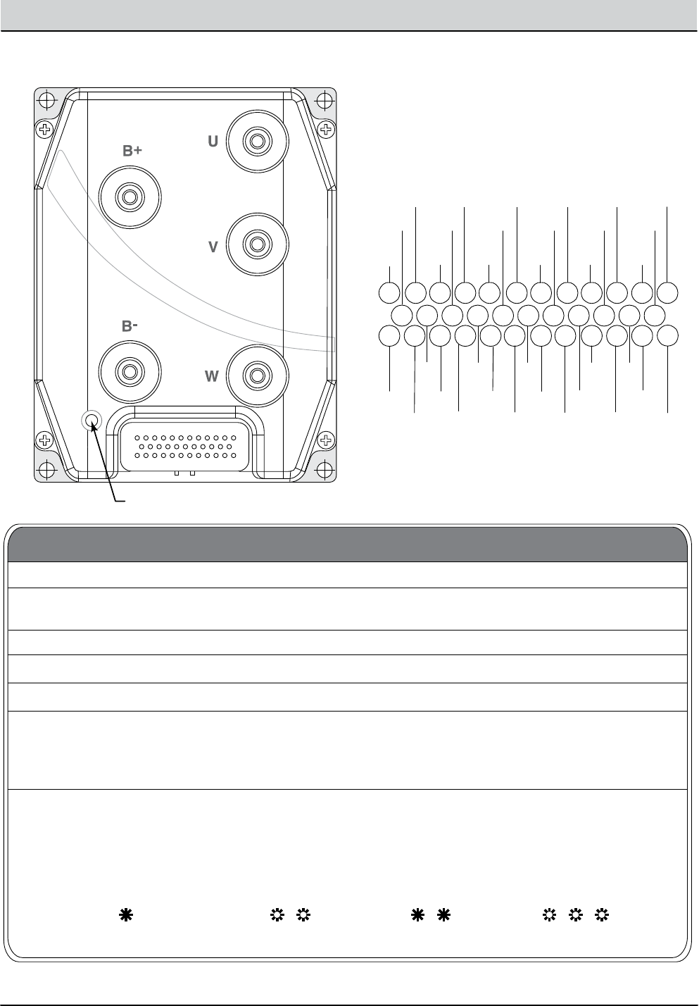
T12 Service Information 9009917 (12-12) 4-11
TROUBLESHOOTING
Curtis 1232 Controller Diagnostic LED Operation
ENC
PHASE B
1
2
3
4567
8
9
10
1112
242526272829303132333435
13141516171819202122
23
KSI
PROP
DRIVER
DRIVER 4
DRIVER
3
DRIVER
7
DRIVER 2
DRIVER 1
I/O GND
SW2/ANA2
SW3
SW4
SW5
SW6
SW16
THR
WIPER
POT
LOW
SW7
SW1/ANA1
COIL
RETURN
+12V
+5V
THR POT
HI
BRK
POT HI
TX
BRK
WIPER
RX
N/U
DRIVER 6
ENC
PHASE
A
CAN
TERM H
SW8
CAN H
CAN L
CAN
TERM L
PMC002
Display
LED o Controller is not powered on, has a dead battery,
or is severely damaged.
Yellow LED ashing Controller is operating normally.
Yellow LED on solid Controller is in Flash program mode.
Red LED on solid Watchdog failure. Cycle KSI to restart.
Red LED and yellow LED ashing
alternately
*The red LED ashes once to indicate that the rst digit of the code will follow; the yellow LED then ashes the
appropriate number of times for the rst digit. The red LED ashes twice to indicate that the second digit of the code
will follow; the yellow LED ashes the appropriate number of times for the second digit.
Controller has detected a fault. 2-digit code*
ashed by yellow LED identies the specic fault;
one or two ashes by red LED indicate whether
rst or second code digit will follow.
Status
Types of LED Display
Example: Battery Undervoltage (Code 23)
RED REDYELLOW YELLOW
(rst digit) (second digit)(2) (3)
Status LED
12
35
23
1
24
13

4-12 T12 Service Information 9009917 (12-12)
TROUBLESHOOTING
Curtis 1232 Controller Diagnostic Codes, continued
13
14
15
16
17
Severe Undervoltage
Reduced drive torque.
TROUBLESHOOTING CHART
FAULT CONDITION
CODE EFFECT OF FAULT POSSIBLE CAUSE SET/CLEAR CONDITIONS
12
Controller Overcurrent
ShutdownMotor;
ShutdownMainContactor;
ShutdownEMBrake;
ShutdownThrottle;
FullBrake;
ShutdownPump.
1. Leakage to vehicle frame from phase
U, V, or W (short in motor stator).
2. Controller defective.
Current Sensor Fault
ShutdownMotor;
ShutdownMainContactor;
ShutdownEMBrake;
ShutdownThrottle;
FullBrake;
ShutdownPump.
1. External load on capacitor bank (B+
connection terminal) that prevents
the capacitor bank from charging.
2. See Monitor menu » Battery:
Capacitor Voltage.
Precharge Failed
ShutdownMotor;
ShutdownMainContactor;
ShutdownEMBrake;
ShutdownThrottle;
FullBrake;
ShutdownPump.
1. See Monitor menu » Controller:
Temperature.
2. Controller is operating in an extreme
environment.
Controller Severe Undertemp
ShutdownMotor;
ShutdownMainContactor;
ShutdownEMBrake;
ShutdownThrottle;
FullBrake;
ShutdownPump.
1. See Monitor menu » Controller:
Temperature.
2. Controller is operating in an extreme
environment.
3. Excessive load on vehicle.
4. Improper mounting of controller.
Controller Severe Overtemp
ShutdownMotor;
ShutdownMainContactor;
ShutdownEMBrake;
ShutdownThrottle;
FullBrake;
ShutdownPump.
1. Battery Menu parameters are
misadjusted.
2. Non-controller system drain on
battery.
3. Battery resistance too high.
4. Battery disconnected while driving.
5. See Monitor menu » Battery:
Capacitor Voltage.
6. Blown B+ fuse or main contactor
did not close.
Set: Controller current sensors have
invalid oset reading.
Clear: Cycle KSI.
Set: Phase current exceeded the
current measurement limit.
Clear: Cycle KSI.
Set: Precharge failed to charge the
capacitor bank to the KSI voltage.
Clear: Cycle interlock input or use VCL
function.
Set: Heatsink temperature below -40˚C.
Clear: Bring heatsink temperature
above -40˚C, and cycle interlock or KSI.
Set: Heatsink temperature above +95˚C.
Clear: Bring heatsink temperature
below +95˚C, and cycle interlock or KSI.
Set: Capacitor bank voltage dropped
below the severe undervoltage limit
with FET bridge enabled.
Clear: Bring capacitor voltage above
severe undervoltage limit.
1. External short of phase U, V, or W
motor connections.
2. Motor parameters are mis-tuned.
3. Controller defective.
PMC003
Terms:
KSI = Key Switch Interlock
FET = Field-Eect Transistor

T12 Service Information 9009917 (12-12) 4-13
TROUBLESHOOTING
Curtis 1232 Controller Diagnostic Codes, continued
13
14
15
16
17
Severe Undervoltage
Reduced drive torque.
TROUBLESHOOTING CHART
FAULT CONDITION
CODE EFFECT OF FAULT POSSIBLE CAUSE SET/CLEAR CONDITIONS
12
Controller Overcurrent
ShutdownMotor;
ShutdownMainContactor;
ShutdownEMBrake;
ShutdownThrottle;
FullBrake;
ShutdownPump.
1. Leakage to vehicle frame from phase
U, V, or W (short in motor stator).
2. Controller defective.
Current Sensor Fault
ShutdownMotor;
ShutdownMainContactor;
ShutdownEMBrake;
ShutdownThrottle;
FullBrake;
ShutdownPump.
1. External load on capacitor bank (B+
connection terminal) that prevents
the capacitor bank from charging.
2. See Monitor menu » Battery:
Capacitor Voltage.
Precharge Failed
ShutdownMotor;
ShutdownMainContactor;
ShutdownEMBrake;
ShutdownThrottle;
FullBrake;
ShutdownPump.
1. See Monitor menu » Controller:
Temperature.
2. Controller is operating in an extreme
environment.
Controller Severe Undertemp
ShutdownMotor;
ShutdownMainContactor;
ShutdownEMBrake;
ShutdownThrottle;
FullBrake;
ShutdownPump.
1. See Monitor menu » Controller:
Temperature.
2. Controller is operating in an extreme
environment.
3. Excessive load on vehicle.
4. Improper mounting of controller.
Controller Severe Overtemp
ShutdownMotor;
ShutdownMainContactor;
ShutdownEMBrake;
ShutdownThrottle;
FullBrake;
ShutdownPump.
1. Battery Menu parameters are
misadjusted.
2. Non-controller system drain on
battery.
3. Battery resistance too high.
4. Battery disconnected while driving.
5. See Monitor menu » Battery:
Capacitor Voltage.
6. Blown B+ fuse or main contactor
did not close.
Set: Controller current sensors have
invalid oset reading.
Clear: Cycle KSI.
Set: Phase current exceeded the
current measurement limit.
Clear: Cycle KSI.
Set: Precharge failed to charge the
capacitor bank to the KSI voltage.
Clear: Cycle interlock input or use VCL
function.
Set: Heatsink temperature below -40˚C.
Clear: Bring heatsink temperature
above -40˚C, and cycle interlock or KSI.
Set: Heatsink temperature above +95˚C.
Clear: Bring heatsink temperature
below +95˚C, and cycle interlock or KSI.
Set: Capacitor bank voltage dropped
below the severe undervoltage limit
with FET bridge enabled.
Clear: Bring capacitor voltage above
severe undervoltage limit.
1. External short of phase U, V, or W
motor connections.
2. Motor parameters are mis-tuned.
3. Controller defective.
TROUBLESHOOTING CHART, continued
FAULT CONDITION
CODE EFFECT OF FAULT POSSIBLE CAUSE SET/CLEAR CONDITIONS
18 Severe Overvoltage 1. See Monitor menu » Battery: Set: Capacitor bank voltage exceeded
the Severe Overvoltage limit with FET
bridge enabled.
Clear: Bring capacitor voltage below
Severe Overvoltage limit, and then
cycle KSI.
ShutdownMotor;
Capacitor Voltage.
ShutdownMainContactor; 2. Battery menu parameters are
ShutdownEMBrake; misadjusted.
ShutdownThrottle; 3. Battery resistance too high for given
FullBrake; regen current.
ShutdownPump.
4. Battery disconnected while regen braking.
22 Controller Overtemp Cutback 1. See Monitor menu » Controller: Set: Heatsink temperature exceeded
85˚C.
Clear: Bring heatsink temperature
below 85˚C.
Reduced drive and brake
Temperature.
torque. 2. Controller is performance-limited
at this temperature.
3. Controller is operating in an extreme
environment.
4. Excessive load on vehicle.
5. Improper mounting of controller.
23 Undervoltage Cutback 1. Normal operation. Fault shows that Set: Capacitor bank voltage dropped
below the Undervoltage limit with the
FET bridge enabled.
Clear: Bring capacitor voltage above
the Undervoltage limit.
Reduced drive torque.
the batteries need recharging.
Controller is performance limited
at this voltage.
2. Battery parameters are misadjusted.
3. Non-controller system drain on battery.
4. Battery resistance too high.
5. Battery disconnected while driving.
6. See Monitor menu » Battery:
Capacitor Voltage.
7. Blown B+ fuse or main contactor
did not close.
24 Overvoltage Cutback 1. Normal operation. Fault shows that Set: Capacitor bank voltage exceeded
the Overvoltage limit with the FET
bridge enabled.
Clear: Bring capacitor voltage below
the Overvoltage limit.
Reduced brake torque.
regen braking currents elevated the
battery voltage during regen braking.
Controller is performance limited
at this voltage.
2. Battery parameters are misadjusted.
3. Battery resistance too high for given
regen current.
4. Battery disconnected while regen braking.
5. See Monitor menu » Battery:
Capacitor Voltage.
25 +5V Supply Failure 1. External load impedance on the Set: +5V supply (pin 26) outside the
+5V +/-10% range.
Clear: Bring voltage within range.
None, unless a fault action
+5V supply (pin 26) is too low.
is programmed in VCL. 2. See Monitor menu » outputs:
5 Volts and Ext Supply Current.
26 Digital Out 6 Overcurrent 1. External load impedance on Digital Set: Digital Output 6 (pin 19) current
exceeded 15 mA.
Clear: Remedy the overcurrent cause
and use the VCL function Set_DigOut()
to turn the driver on again.
Digital Output 6 driver Output 6 driver (pin 19) is too low.
will not turn on.
PMC004
Terms:
KSI = Key Switch Interlock
FET = Field-Eect Transistor

4-14 T12 Service Information 9009917 (12-12)
TROUBLESHOOTING
Curtis 1232 Controller Diagnostic Codes, continued
TROUBLESHOOTING CHART, continued
FAULT CONDITION
CODE EFFECT OF FAULT POSSIBLE CAUSE SET/CLEAR CONDITIONS
27 Digital Out 7 Overcurrent 1. External load impedance on Digital Set: Digital Output 7 (pin 20) current
exceeded 15 mA.
Clear: Remedy the overcurrent cause
and use the VCL function Set_DigOut()
to turn the driver on again.
Digital Output 7 driver Output 7 driver (pin 20) is too low.
will not turn on.
28 Motor Temp Hot Cutback 1. Motor temperature is at or above Set: Motor temperature is at or above
the Temperature Hot parameter
setting.
Clear: Bring the motor temperature
within range.
Reduced drive torque.
the programmed Temperature Hot
setting, and the requested current
is being cut back.
2. Motor Temperature Control Menu
parameters are mis-tuned.
3. See Monitor menu » Motor:
Temperature and » Inputs: Analog2.
4. If the application doesn’t use a mo-
tor thermistor, Temp Compensation
and Temp Cutback should be
programmed O.
29 Motor Temp Sensor Fault 1. Motor thermistor is not connected Set: Motor thermistor input (pin 8) is at
the voltage rail (0 or 10V).
Clear: Bring the motor thermistor input
voltage within range.
MaxSpeed reduced (LOS, properly.
Limited Operating Strategy), 2. If the application does not use a
and motor temperature thermistor, Temp Compensation
cutback disabled.
and Temp Cutback should be
programmed O.
3. See Monitor menu » Motor:
Temperature and » Inputs: Analog2.
31 Coil1 Driver Open/Short 1. Open or short on driver load. Set: Driver 1 (pin 6) is either open or
shorted.
Clear: Correct open or short, and cycle driver.
ShutdownDriver1. 2. Dirty connector pins.
3. Bad crimps or faulty wiring.
32 EMBrake Open/Short 1. Open or short on driver load. Set: Electromagnetic brake driver (pin 5)
is either open or shorted.
Clear: Correct open or short, and cycle
driver.
ShutdownEMBrake; 2. Dirty connector pins.
ShutdownThrottle; 3. Bad crimps or faulty wiring.
FullBrake.
33 Coil3 Driver Open/Short 1. Open or short on driver load. Set: Driver 3 (pin 4) is either open or
shorted.
Clear: Correct open or short, and cycle driver.
ShutdownDriver3. 2. Dirty connector pins.
3. Bad crimps or faulty wiring.
34 Coil4 Driver Open/Short 1. Open or short on driver load. Set: Driver 4 (pin3) is either open or
shorted.
Clear: Correct open or short, and cycle driver.
ShutdownDriver4. 2. Dirty connector pins.
3. Bad crimps or faulty wiring.
PMC005
Terms:
KSI = Key Switch Interlock
FET = Field-Eect Transistor
VCL = Vehicle Control Language

T12 Service Information 9009917 (12-12) 4-15
TROUBLESHOOTING
Curtis 1232 Controller Diagnostic Codes, continued
13
14
15
16
17
Severe Undervoltage
Reduced drive torque.
TROUBLESHOOTING CHART
FAULT CONDITION
CODE EFFECT OF FAULT POSSIBLE CAUSE SET/CLEAR CONDITIONS
12
Controller Overcurrent
ShutdownMotor;
ShutdownMainContactor;
ShutdownEMBrake;
ShutdownThrottle;
FullBrake;
ShutdownPump.
1. Leakage to vehicle frame from phase
U, V, or W (short in motor stator).
2. Controller defective.
Current Sensor Fault
ShutdownMotor;
ShutdownMainContactor;
ShutdownEMBrake;
ShutdownThrottle;
FullBrake;
ShutdownPump.
1. External load on capacitor bank (B+
connection terminal) that prevents
the capacitor bank from charging.
2. See Monitor menu » Battery:
Capacitor Voltage.
Precharge Failed
ShutdownMotor;
ShutdownMainContactor;
ShutdownEMBrake;
ShutdownThrottle;
FullBrake;
ShutdownPump.
1. See Monitor menu » Controller:
Temperature.
2. Controller is operating in an extreme
environment.
Controller Severe Undertemp
ShutdownMotor;
ShutdownMainContactor;
ShutdownEMBrake;
ShutdownThrottle;
FullBrake;
ShutdownPump.
1. See Monitor menu » Controller:
Temperature.
2. Controller is operating in an extreme
environment.
3. Excessive load on vehicle.
4. Improper mounting of controller.
Controller Severe Overtemp
ShutdownMotor;
ShutdownMainContactor;
ShutdownEMBrake;
ShutdownThrottle;
FullBrake;
ShutdownPump.
1. Battery Menu parameters are
misadjusted.
2. Non-controller system drain on
battery.
3. Battery resistance too high.
4. Battery disconnected while driving.
5. See Monitor menu » Battery:
Capacitor Voltage.
6. Blown B+ fuse or main contactor
did not close.
Set: Controller current sensors have
invalid oset reading.
Clear: Cycle KSI.
Set: Phase current exceeded the
current measurement limit.
Clear: Cycle KSI.
Set: Precharge failed to charge the
capacitor bank to the KSI voltage.
Clear: Cycle interlock input or use VCL
function.
Set: Heatsink temperature below -40˚C.
Clear: Bring heatsink temperature
above -40˚C, and cycle interlock or KSI.
Set: Heatsink temperature above +95˚C.
Clear: Bring heatsink temperature
below +95˚C, and cycle interlock or KSI.
Set: Capacitor bank voltage dropped
below the severe undervoltage limit
with FET bridge enabled.
Clear: Bring capacitor voltage above
severe undervoltage limit.
1. External short of phase U, V, or W
motor connections.
2. Motor parameters are mis-tuned.
3. Controller defective.
TROUBLESHOOTING CHART, continued
FAULT CONDITION
CODE EFFECT OF FAULT POSSIBLE CAUSE SET/CLEAR CONDITIONS
18 Severe Overvoltage 1. See Monitor menu » Battery: Set: Capacitor bank voltage exceeded
the Severe Overvoltage limit with FET
bridge enabled.
Clear: Bring capacitor voltage below
Severe Overvoltage limit, and then
cycle KSI.
ShutdownMotor;
Capacitor Voltage.
ShutdownMainContactor; 2. Battery menu parameters are
ShutdownEMBrake; misadjusted.
ShutdownThrottle; 3. Battery resistance too high for given
FullBrake; regen current.
ShutdownPump.
4. Battery disconnected while regen braking.
22 Controller Overtemp Cutback 1. See Monitor menu » Controller: Set: Heatsink temperature exceeded
85˚C.
Clear: Bring heatsink temperature
below 85˚C.
Reduced drive and brake
Temperature.
torque. 2. Controller is performance-limited
at this temperature.
3. Controller is operating in an extreme
environment.
4. Excessive load on vehicle.
5. Improper mounting of controller.
23 Undervoltage Cutback 1. Normal operation. Fault shows that Set: Capacitor bank voltage dropped
below the Undervoltage limit with the
FET bridge enabled.
Clear: Bring capacitor voltage above
the Undervoltage limit.
Reduced drive torque.
the batteries need recharging.
Controller is performance limited
at this voltage.
2. Battery parameters are misadjusted.
3. Non-controller system drain on battery.
4. Battery resistance too high.
5. Battery disconnected while driving.
6. See Monitor menu » Battery:
Capacitor Voltage.
7. Blown B+ fuse or main contactor
did not close.
24 Overvoltage Cutback 1. Normal operation. Fault shows that Set: Capacitor bank voltage exceeded
the Overvoltage limit with the FET
bridge enabled.
Clear: Bring capacitor voltage below
the Overvoltage limit.
Reduced brake torque.
regen braking currents elevated the
battery voltage during regen braking.
Controller is performance limited
at this voltage.
2. Battery parameters are misadjusted.
3. Battery resistance too high for given
regen current.
4. Battery disconnected while regen braking.
5. See Monitor menu » Battery:
Capacitor Voltage.
25 +5V Supply Failure 1. External load impedance on the Set: +5V supply (pin 26) outside the
+5V +/-10% range.
Clear: Bring voltage within range.
None, unless a fault action
+5V supply (pin 26) is too low.
is programmed in VCL. 2. See Monitor menu » outputs:
5 Volts and Ext Supply Current.
26 Digital Out 6 Overcurrent 1. External load impedance on Digital Set: Digital Output 6 (pin 19) current
exceeded 15 mA.
Clear: Remedy the overcurrent cause
and use the VCL function Set_DigOut()
to turn the driver on again.
Digital Output 6 driver Output 6 driver (pin 19) is too low.
will not turn on.
TROUBLESHOOTING CHART, continued
FAULT CONDITION
CODE EFFECT OF FAULT POSSIBLE CAUSE SET/CLEAR CONDITIONS
27 Digital Out 7 Overcurrent 1. External load impedance on Digital Set: Digital Output 7 (pin 20) current
exceeded 15 mA.
Clear: Remedy the overcurrent cause
and use the VCL function Set_DigOut()
to turn the driver on again.
Digital Output 7 driver Output 7 driver (pin 20) is too low.
will not turn on.
28 Motor Temp Hot Cutback 1. Motor temperature is at or above Set: Motor temperature is at or above
the Temperature Hot parameter
setting.
Clear: Bring the motor temperature
within range.
Reduced drive torque.
the programmed Temperature Hot
setting, and the requested current
is being cut back.
2. Motor Temperature Control Menu
parameters are mis-tuned.
3. See Monitor menu » Motor:
Temperature and » Inputs: Analog2.
4. If the application doesn’t use a mo-
tor thermistor, Temp Compensation
and Temp Cutback should be
programmed O.
29 Motor Temp Sensor Fault 1. Motor thermistor is not connected Set: Motor thermistor input (pin 8) is at
the voltage rail (0 or 10V).
Clear: Bring the motor thermistor input
voltage within range.
MaxSpeed reduced (LOS, properly.
Limited Operating Strategy), 2. If the application doesn’t use a mo-
and motor temperature tor thermistor, Temp Compensation
cutback disabled.
and Temp Cutback should be
programmed O.
3. See Monitor menu » Motor:
Temperature and » Inputs: Analog2.
31 Coil1 Driver Open/Short 1. Open or short on driver load. Set: Driver 1 (pin 60) is either open or
shorted.
Clear: Correct open or short, and cycle driver.
ShutdownDriver1. 2. Dirty connector pins.
3. Bad crimps or faulty wiring.
31 Main Open/Short 1. Open or short on driver load. Set: Main contactor driver (pin 6) is
either open or shorted.
Clear: Correct open or short, and cycle
driver.
ShutdownMotor;
2. Dirty connector pins.
ShutdownMainContactor; 3. Bad crimps or faulty wiring.
ShutdownEMBrake;
ShutdownThrottle;
FullBrake;
ShutdownPump.
32 Coil2 Driver Open/Short 1. Open or short on driver load. Set: Driver 2 (pin 5) is either open or
shorted.
Clear: Correct open or short, and cycle driver.
ShutdownDriver2. 2. Dirty connector pins.
3. Bad crimps or faulty wiring.
32 EMBrake Open/Short 1. Open or short on driver load. Set: Electromagnetic brake driver (pin 5)
is either open or shorted.
Clear: Correct open or short, and cycle
driver.
ShutdownEMBrake; 2. Dirty connector pins.
ShutdownThrottle; 3. Bad crimps or faulty wiring.
FullBrake.
33 Coil3 Driver Open/Short 1. Open or short on driver load. Set: Driver 3 (pin 4) is either open or
shorted.
Clear: Correct open or short, and cycle driver.
ShutdownDriver3. 2. Dirty connector pins.
3. Bad crimps or faulty wiring.
34 Coil4 Driver Open/Short 1. Open or short on driver load. Set: Driver 4 (pin3) is either open or
shorted.
Clear: Correct open or short, and cycle driver.
ShutdownDriver4. 2. Dirty connector pins.
3. Bad crimps or faulty wiring.
TROUBLESHOOTING CHART, continued
FAULT CONDITION
CODE EFFECT OF FAULT POSSIBLE CAUSE SET/CLEAR CONDITIONS
35 PD Open/Short 1. Open or short on driver load. Set: Proportional driver (pin 2) is either
open or shorted.
Clear: Correct open or short, and cycle driver.
ShutdownPD. 2. Dirty connector pins.
3. Bad crimps or faulty wiring.
36 Encoder Fault 1. Motor encoder failure. Set: Motor encoder phase failure
detected.
Clear: Cycle KSI.
ShutdownEMBrake. 2. Bad crimps or faulty wiring.
3. See Monitor menu » Motor:
Motor RPM.
37 Motor Open 1. Motor phase is open. Set: Motor phase U, V, or W detected
open.
Clear: Cycle KSI.
ShutdownMotor; 2. Bad crimps or faulty wiring.
ShutdownMainContactor;
ShutdownEMBrake;
ShutdownThrottle;
FullBrake;
ShutdownPump.
38 Main Contactor Welded 1. Main contactor tips are welded Set: Just prior to the main contactor
closing, the capacitor bank voltage (B+
connection terminal) was loaded for a
short time and the voltage did not
discharge.
Clear: Cycle KSI
ShutdownMotor; closed.
ShutdownMainContactor; 2. Motor phase U or V is disconnected
ShutdownEMBrake; or open.
ShutdownThrottle; 3. An alternate voltage path (such as an
FullBrake; external precharge resistor) is
ShutdownPump.
providing a current to the capacitor
bank (B+ connection terminal).
39 Main Contactor Did Not Close 1. Main contactor did not close. Set: With the main contactor
commanded closed, the capacitor
bank voltage (B+ connection terminal)
did not charge to B+.
Clear: Cycle KSI.
ShutdownMotor; 2. Main contactor tips are oxidized,
ShutdownMainContactor; burned, or not making good contact.
ShutdownEMBrake; 3. External load on capacitor bank
ShutdownThrottle; (B+ connection terminal) that pre-
FullBrake; vents capacitor bank from charging.
ShutdownPump.
4. Blown B+ fuse.
41 Throttle Wiper High 1. See Monitor menu » Inputs: Set: Throttle pot wiper (pin 16) voltage
is higher than the high fault threshold
(can be changed with the VCL function
Setup_Pot_Faults())
Clear: Bring throttle pot wiper voltage
below the fault threshold.
ShutdownThrottle. Throttle Pot.
2. Throttle pot wiper voltage too high.
42 Throttle Wiper Low 1. See Monitor menu » Inputs: Set: Throttle pot wiper (pin 16) voltage
is lower than the low fault threshold
(can be changed with the VCL function
Setup_Pot_Faults()).
Clear: Bring throttle pot wiper voltage
above the fault threshold.
ShutdownThrottle. Throttle Pot.
2. Throttle pot wiper voltage too low.
43 Pot2 Wiper High 1. See Monitor menu » Inputs: Set: Pot2 wiper (pin 17) voltage is
higher than the high fault threshold
(can be changed with the VCL function
Setup_Pot_Faults()).
Clear: Bring Pot2 wiper voltage below
the fault threshold.
FullBrake. Pot2 Raw.
2. Pot2 wiper voltage too high.
Table 5 TROUBLESHOOTING CHART, continued
PROGRAMMER LCD DISPLAY
CODE EFFECT OF FAULT POSSIBLE CAUSE SET/CLEAR CONDITIONS
35 PD Open/Short 1. Open or short on driver load. Set: Proportional driver (pin 2) is either
ShutdownPD.
2. Dirty connector pins. open or shorted.
3. Bad crimps or faulty wiring. Clear: Correct open or short, and cycle driver.
36 Encoder Fault 1. Motor encoder failure. Set: Motor encoder phase failure detected.
ShutdownEMBrake.
2. Bad crimps or faulty wiring. Clear: Cycle KSI.
3. See Monitor menu » Motor:
Motor RPM.
37 Motor Open 1. Motor phase is open. Set: Motor phase U, V, or W detected
ShutdownMotor;
2. Bad crimps or faulty wiring. open.
ShutdownMainContactor; Clear: Cycle KSI.
ShutdownEMBrake;
ShutdownThrottle;
FullBrake;
ShutdownPump.
38 Main Contactor Welded 1. Main contactor tips are welded Set: Just prior to the main contactor
ShutdownMotor;
closed. closing, the capacitor bank voltage (B+
ShutdownMainContactor; 2. Motor phase U or V is disconnected connection terminal) was loaded for a
ShutdownEMBrake;
or open. short time and the voltage did not
ShutdownThrottle;
3. An alternate voltage path (such as an discharge.
FullBrake; external precharge resistor) is Clear: Cycle KSI
ShutdownPump.
providing a current to the capacitor
bank (B+ connection terminal).
39 Main Contactor Did Not Close 1. Main contactor did not close. Set: With the main contactor commanded
ShutdownMotor;
2. Main contactor tips are oxidized, closed, the capacitor bank voltage (B+
ShutdownMainContactor; burned, or not making good contact. connection terminal) did not charge to B+.
ShutdownEMBrake;
3. External load on capacitor bank Clear: Cycle KSI.
ShutdownThrottle;
(B+ connection terminal) that pre-
FullBrake; vents capacitor bank from charging.
ShutdownPump.
4. Blown B+ fuse.
41 Throttle Wiper High 1. See Monitor menu » Inputs: Set: Throttle pot wiper (pin 16) voltage
ShutdownThrottle.
Throttle Pot. is higher than the high fault threshold
2. Throttle pot wiper voltage too high. (can be changed with the VCL function
Setup_Pot_Faults() ).
Clear: Bring throttle pot wiper voltage
below the fault threshold.
42 Throttle Wiper Low 1. See Monitor menu » Inputs: Set: Throttle pot wiper (pin 16) voltage
ShutdownThrottle.
Throttle Pot. is lower than the low fault threshold
2. Throttle pot wiper voltage too low. (can be changed with the VCL function
Setup_Pot_Faults() ).
Clear: Bring throttle pot wiper voltage
above the fault threshold.
43 Pot2 Wiper High 1. See Monitor menu » Inputs: Set: Pot2 wiper (pin 17) voltage
FullBrake. Pot2 Raw. is higher than the high fault threshold
2. Pot2 wiper voltage too high. (can be changed with the VCL function
Setup_Pot_Faults() ).
Clear: Bring Pot2 wiper voltage below
the fault threshold.
PMC006
Terms:
KSI = Key Switch Interlock
FET = Field-Eect Transistor
VCL = Vehicle Control Language

4-16 T12 Service Information 9009917 (12-12)
TROUBLESHOOTING
Curtis 1232 Controller Diagnostic Codes, continued
TROUBLESHOOTING CHART, continued
FAULT CONDITION
CODE EFFECT OF FAULT POSSIBLE CAUSE SET/CLEAR CONDITIONS
44 Pot2 Wiper Low 1. See Monitor menu » Inputs: Set: Pot2 wiper (pin 17) voltage
is lower than the low fault threshold
(can be changed with the VCL function
Setup_Pot_Faults() ).
Clear: Bring Pot2 wiper voltage
above the fault threshold.
FullBrake. Pot2 Raw.
2. Pot2 wiper voltage too low.
45 Pot Low Overcurrent 1. See Monitor menu » Outputs: Set: Pot low (pin 18) current exceeds
10 mA.
Clear: Clear pot low overcurrent
condition and cycle KSI.
ShutdownThrottle; Pot Low.
FullBrake. 2. Combined pot resistance connected
to pot low is too low.
46 EEPROM Failure 1. Failure to write to EEPROM Set: Controller operating system tried
to write to EEPROM memory and failed.
Clear: Download the correct software
(OS) and matching parameter default
settings into the controller and cycle
KSI.
memory. This can be caused by
EEPROM memory writes initiated
by VCL, by the CAN bus, by
adjusting parameters with the
programmer, or by loading new
software into the controller.
47 HPD/Sequencing Fault 1. KSI, interlock, direction, and throttle Set: HPD (High Pedal Disable) or
sequencing fault caused by incorrect
sequence of KSI, interlock, direction
and throttle inputs.
Clear: Reapply inputs in correct sequence.
ShutdownThrottle.
51 Throttle SRO Fault 1. Both throttle and brake inputs are
active at the same time.
2. Faulty throttle and/or brake inputs.
Set: Throttle and brake inputs applied at
the same time.
Clear: Release throttle and brake pedals.
ShutdownThrottle/brake.
Shutdown Motor.
inputs applied in incorrect sequence.
2. Faulty wiring, crimps, or switches at
KSI, interlock, direction, or throttle
inputs.
3. See Monitor menu » Inputs.
49 Parameter Change Fault 1. This is a safety fault caused by a Set: Adjustment of a parameter setting
that requires cycling of KSI.
Clear: Cycle KSI
ShutdownMotor; change in certain parameter
ShutdownMainContactor; settings so that the vehicle will not
ShutdownEMBrake; operate until KSI is cycled.
ShutdownThrottle; For example, if a user changes the
FullBrake; Throttle Type this fault will appear
ShutdownPump.
and require cycling KSI before the
vehicle can operate.
52 HPD Fault 1. Throttle is pressed before key
switch is turned on.
2. Throttle is pressed before operator
presses the seat switch.
Set: Throttle is pressed before key
switch is turned on or throttle is pressed
before operator sits on the seat switch.
Clear: Release throttle and properly
sequence key switch, seat switch and then
throttle.
ShutdownThrottle/brake.
Shutdown Motor.
ShutdownMotor;
ShutdownMainContactor;
ShutdownEMBrake;
ShutdownThrottle;
ShutdownInterlock;
ShutdownDriver1;
ShutdownDriver2;
ShutdownDriver3;
ShutdownDriver4;
ShutdownPD;
FullBrake;
ShutdownPump.
PMC007
Terms:
KSI = Key Switch Interlock
FET = Field-Eect Transistor
VCL = Vehicle Control Language

T12 Service Information 9009917 (12-12) 4-17
TROUBLESHOOTING
Curtis 1232 Controller Diagnostic Codes, continued
13
14
15
16
17
Severe Undervoltage
Reduced drive torque.
TROUBLESHOOTING CHART
FAULT CONDITION
CODE EFFECT OF FAULT POSSIBLE CAUSE SET/CLEAR CONDITIONS
12
Controller Overcurrent
ShutdownMotor;
ShutdownMainContactor;
ShutdownEMBrake;
ShutdownThrottle;
FullBrake;
ShutdownPump.
1. Leakage to vehicle frame from phase
U, V, or W (short in motor stator).
2. Controller defective.
Current Sensor Fault
ShutdownMotor;
ShutdownMainContactor;
ShutdownEMBrake;
ShutdownThrottle;
FullBrake;
ShutdownPump.
1. External load on capacitor bank (B+
connection terminal) that prevents
the capacitor bank from charging.
2. See Monitor menu » Battery:
Capacitor Voltage.
Precharge Failed
ShutdownMotor;
ShutdownMainContactor;
ShutdownEMBrake;
ShutdownThrottle;
FullBrake;
ShutdownPump.
1. See Monitor menu » Controller:
Temperature.
2. Controller is operating in an extreme
environment.
Controller Severe Undertemp
ShutdownMotor;
ShutdownMainContactor;
ShutdownEMBrake;
ShutdownThrottle;
FullBrake;
ShutdownPump.
1. See Monitor menu » Controller:
Temperature.
2. Controller is operating in an extreme
environment.
3. Excessive load on vehicle.
4. Improper mounting of controller.
Controller Severe Overtemp
ShutdownMotor;
ShutdownMainContactor;
ShutdownEMBrake;
ShutdownThrottle;
FullBrake;
ShutdownPump.
1. Battery Menu parameters are
misadjusted.
2. Non-controller system drain on
battery.
3. Battery resistance too high.
4. Battery disconnected while driving.
5. See Monitor menu » Battery:
Capacitor Voltage.
6. Blown B+ fuse or main contactor
did not close.
Set: Controller current sensors have
invalid oset reading.
Clear: Cycle KSI.
Set: Phase current exceeded the
current measurement limit.
Clear: Cycle KSI.
Set: Precharge failed to charge the
capacitor bank to the KSI voltage.
Clear: Cycle interlock input or use VCL
function.
Set: Heatsink temperature below -40˚C.
Clear: Bring heatsink temperature
above -40˚C, and cycle interlock or KSI.
Set: Heatsink temperature above +95˚C.
Clear: Bring heatsink temperature
below +95˚C, and cycle interlock or KSI.
Set: Capacitor bank voltage dropped
below the severe undervoltage limit
with FET bridge enabled.
Clear: Bring capacitor voltage above
severe undervoltage limit.
1. External short of phase U, V, or W
motor connections.
2. Motor parameters are mis-tuned.
3. Controller defective.
TROUBLESHOOTING CHART, continued
FAULT CONDITION
CODE EFFECT OF FAULT POSSIBLE CAUSE SET/CLEAR CONDITIONS
68 VCL Run Time Error 1. VCL code encountered a runtime Set: Runtime VCL code error condition.
Clear: Edit VCL application software to
x this error condition; ash the new
compiled software and matching
parameter defaults; cycle KSI.
VCL error.
2. See Monitor menu » Controller:
VCL Error Module and VCL Error.
This error can then be compared to
the runtime VCL module ID and
error code denitions found in the
specic OS system information le.
69 External Supply Out of Range 1. External load on the 5V and 12V Set: The external supply current (com-
bined current used by the 5V supply
[pin 26] and 12V supply [pin 25]) is either
greater than the lower current threshold.
The two thresholds are dened by the
External Supply Max and External Supply
Min parameter settings.
Clear: Bring the external supply current
within range.
None, unless a fault action
supplies draws either too much or
is programmed in VCL. too little current.
2. Fault Checking Menu parameters
Ext Supply Max and Ext Supply Min
are mis-tuned.
3. See Monitor menu » Outputs:
Ext Supply Current.
71 OS General
1. Internal controller fault. Set: Internal controller fault detected.
Clear: Cycle KSI
72 PDO Timeout 1. Time between CAN PDO messages Set: Time between CAN PDO messages
received exceeded the PDO Timeout
Period.
Clear: Cycle KSI.
ShutdownInterlock; received exceeded the PDO
CAN NMT State set Timeout Period.
to Pre-operational.
73 Stall Detected 1. Stalled motor. Set: No motor encoder movement
detected.
Clear: Either cycle KSI, or
detect valid motor encoder signals
while operating in LOS mode and
return Throttle Command = 0 and
Motor RPM= 0
ShutdownEMBrake. 2. Motor encoder failure.
3. Bad crimps or faulty wiring.
4. Problems with power supply for
the motor encoder.
5. See Monitor menu » Motor:
Motor RPM.
ShutdownMotor;
ShutdownMainContactor;
ShutdownEMBrake;
ShutdownThrottle;
ShutdownInterlock;
ShutdownDriver1;
ShutdownDriver2;
ShutdownDriver3;
ShutdownDriver4;
ShutdownPD;
FullBrake;
ShutdownPump.
ShutdownMotor;
ShutdownMainContactor;
ShutdownEMBrake;
ShutdownThrottle;
ShutdownInterlock;
ShutdownDriver1;
ShutdownDriver2;
ShutdownDriver3;
ShutdownDriver4;
ShutdownPD;
FullBrake;
ShutdownPump.
PMC008
Terms:
KSI = Key Switch Interlock
FET = Field-Eect Transistor
VCL = Vehicle Control Language
CAN = Controller Area Network

4-18 T12 Service Information 9009917 (12-12)
TROUBLESHOOTING
Curtis 1232 Controller Diagnostic Codes, continued
13
14
15
16
17
Severe Undervoltage
Reduced drive torque.
TROUBLESHOOTING CHART
FAULT CONDITION
CODE EFFECT OF FAULT POSSIBLE CAUSE SET/CLEAR CONDITIONS
12
Controller Overcurrent
ShutdownMotor;
ShutdownMainContactor;
ShutdownEMBrake;
ShutdownThrottle;
FullBrake;
ShutdownPump.
1. Leakage to vehicle frame from phase
U, V, or W (short in motor stator).
2. Controller defective.
Current Sensor Fault
ShutdownMotor;
ShutdownMainContactor;
ShutdownEMBrake;
ShutdownThrottle;
FullBrake;
ShutdownPump.
1. External load on capacitor bank (B+
connection terminal) that prevents
the capacitor bank from charging.
2. See Monitor menu » Battery:
Capacitor Voltage.
Precharge Failed
ShutdownMotor;
ShutdownMainContactor;
ShutdownEMBrake;
ShutdownThrottle;
FullBrake;
ShutdownPump.
1. See Monitor menu » Controller:
Temperature.
2. Controller is operating in an extreme
environment.
Controller Severe Undertemp
ShutdownMotor;
ShutdownMainContactor;
ShutdownEMBrake;
ShutdownThrottle;
FullBrake;
ShutdownPump.
1. See Monitor menu » Controller:
Temperature.
2. Controller is operating in an extreme
environment.
3. Excessive load on vehicle.
4. Improper mounting of controller.
Controller Severe Overtemp
ShutdownMotor;
ShutdownMainContactor;
ShutdownEMBrake;
ShutdownThrottle;
FullBrake;
ShutdownPump.
1. Battery Menu parameters are
misadjusted.
2. Non-controller system drain on
battery.
3. Battery resistance too high.
4. Battery disconnected while driving.
5. See Monitor menu » Battery:
Capacitor Voltage.
6. Blown B+ fuse or main contactor
did not close.
Set: Controller current sensors have
invalid oset reading.
Clear: Cycle KSI.
Set: Phase current exceeded the
current measurement limit.
Clear: Cycle KSI.
Set: Precharge failed to charge the
capacitor bank to the KSI voltage.
Clear: Cycle interlock input or use VCL
function.
Set: Heatsink temperature below -40˚C.
Clear: Bring heatsink temperature
above -40˚C, and cycle interlock or KSI.
Set: Heatsink temperature above +95˚C.
Clear: Bring heatsink temperature
below +95˚C, and cycle interlock or KSI.
Set: Capacitor bank voltage dropped
below the severe undervoltage limit
with FET bridge enabled.
Clear: Bring capacitor voltage above
severe undervoltage limit.
1. External short of phase U, V, or W
motor connections.
2. Motor parameters are mis-tuned.
3. Controller defective.
TROUBLESHOOTING CHART, continued
FAULT CONDITION
CODE EFFECT OF FAULT POSSIBLE CAUSE SET/CLEAR CONDITIONS
68 VCL Run Time Error 1. VCL code encountered a runtime Set: Runtime VCL code error condition.
Clear: Edit VCL application software to
x this error condition; ash the new
compiled software and matching
parameter defaults; cycle KSI.
VCL error.
2. See Monitor menu » Controller:
VCL Error Module and VCL Error.
This error can then be compared to
the runtime VCL module ID and
error code denitions found in the
specic OS system information le.
69 External Supply Out of Range 1. External load on the 5V and 12V Set: The external supply current (com-
bined current used by the 5V supply
[pin 26] and 12V supply [pin 25]) is either
greater than the lower current threshold.
The two thresholds are dened by the
External Supply Max and External Supply
Min parameter settings.
Clear: Bring the external supply current
within range.
None, unless a fault action
supplies draws either too much or
is programmed in VCL. too little current.
2. Fault Checking Menu parameters
Ext Supply Max and Ext Supply Min
are mis-tuned.
3. See Monitor menu » Outputs:
Ext Supply Current.
71 OS General
1. Internal controller fault. Set: Internal controller fault detected.
Clear: Cycle KSI
72 PDO Timeout 1. Time between CAN PDO messages Set: Time between CAN PDO messages
received exceeded the PDO Timeout
Period.
Clear: Cycle KSI.
ShutdownInterlock; received exceeded the PDO
CAN NMT State set Timeout Period.
to Pre-operational.
73 Stall Detected 1. Stalled motor. Set: No motor encoder movement
detected.
Clear: Either cycle KSI, or
detect valid motor encoder signals
while operating in LOS mode and
return Throttle Command = 0 and
Motor RPM= 0
ShutdownEMBrake. 2. Motor encoder failure.
3. Bad crimps or faulty wiring.
4. Problems with power supply for
the motor encoder.
5. See Monitor menu » Motor:
Motor RPM.
ShutdownMotor;
ShutdownMainContactor;
ShutdownEMBrake;
ShutdownThrottle;
ShutdownInterlock;
ShutdownDriver1;
ShutdownDriver2;
ShutdownDriver3;
ShutdownDriver4;
ShutdownPD;
FullBrake;
ShutdownPump.
ShutdownMotor;
ShutdownMainContactor;
ShutdownEMBrake;
ShutdownThrottle;
ShutdownInterlock;
ShutdownDriver1;
ShutdownDriver2;
ShutdownDriver3;
ShutdownDriver4;
ShutdownPD;
FullBrake;
ShutdownPump.
87 Motor Characterization Fault 1. Motor characterization failed during Set: Motor characterization failed during
the motor characterization process.
Clear: Correct fault; cycle KSI.
ShutdownMotor; characterization process. See Monitor
ShutdownMainContactor; menu » Controller: Motor
ShutdownEMBrake; Characterization Error for cause:
ShutdownThrottle;
0=none
FullBrake; 1=encoder signal seen, but step size
ShutdownPump.
not determined; set Encoder Step
Size manually
2=motor temp sensor fault
3=motor temp hot cutback fault
4= controller overtemp cutback fault
5=controller undertemp cutback fault
6=undervoltage cutback fault
7=severe overvoltage fault
8=encoder signal not seen, or one or
both channels missing
9=motor parameters out of character-
ization range.
89 Motor Type Fault 1. The Motor_Type parameter value Set: Motor_Type parameter is set to an
illegal value.
Clear: Set Motor_Type to correct value
and cycle KSI.
ShutdownMotor;
is out of range.
ShutdownMainContactor;
ShutdownEMBrake;
ShutdownThrottle;
FullBrake;
ShutdownPump.
91 VCL/OS Mismatch 1. The VCL software in the controller Set: VCL and OS software do not match;
when KSI cycles, a check is made to
verify that they match and a fault is
issued when they do not.
Clear: Download the correct VCL and
OS software into the controller.
does not match the OS software in
the controller.
92 EM Brake Failed to Set 1. Vehicle movement sensed after the Set: After the EM Brake was commanded
to set and time has elapsed to allow the
brake to fully engage, vehicle movement
has been sensed.
Clear: Activate the throttle.
ShutdownEMBrake; EM Brake has been commanded
ShutdownThrottle. to set.
2. EM Brake will not hold the motor
from rotating.
93 Encoder LOS (Limited 1. Limited Operating Strategy (LOS) Set: Encoder Fault (Code 36) or Stall
Detect Fault (Code 73) was activated,
and Brake or Interlock has been applied
to activate LOS control mode, allowing
limited motor control.
Clear: Cycle KSI, or if LOS mode was acti-
vated by the Stall Fault, clear by ensuring
encoder senses proper operation, Motor
RPM = 0, and Throttle Command = 0.
Operating Strategy)
control mode has been activated, as
Enter LOS control mode. a result of either an Encoder Fault
(Code 36) or a Stall Detect Fault
(Code 73).
2. Motor encoder failure.
3. Bad crimps or faulty wiring.
4. Vehicle is stalled.
TROUBLESHOOTING CHART, continued
FAULT CONDITION
CODE EFFECT OF FAULT POSSIBLE CAUSE SET/CLEAR CONDITIONS
ShutdownMotor;
ShutdownMainContactor;
ShutdownEMBrake;
ShutdownThrottle;
ShutdownInterlock;
ShutdownDriver1;
ShutdownDriver2;
ShutdownDriver3;
ShutdownDriver4;
ShutdownPD;
FullBrake;
ShutdownPump.
PMC009 Terms:
KSI = Key Switch Interlock
FET = Field-Eect Transistor VCL = Vehicle Control Language

T12 Service Information 9009917 (12-12) 4-19
TROUBLESHOOTING
Curtis 1232 Controller Diagnostic Codes, continued
13
14
15
16
17
Severe Undervoltage
Reduced drive torque.
TROUBLESHOOTING CHART
FAULT CONDITION
CODE EFFECT OF FAULT POSSIBLE CAUSE SET/CLEAR CONDITIONS
12
Controller Overcurrent
ShutdownMotor;
ShutdownMainContactor;
ShutdownEMBrake;
ShutdownThrottle;
FullBrake;
ShutdownPump.
1. Leakage to vehicle frame from phase
U, V, or W (short in motor stator).
2. Controller defective.
Current Sensor Fault
ShutdownMotor;
ShutdownMainContactor;
ShutdownEMBrake;
ShutdownThrottle;
FullBrake;
ShutdownPump.
1. External load on capacitor bank (B+
connection terminal) that prevents
the capacitor bank from charging.
2. See Monitor menu » Battery:
Capacitor Voltage.
Precharge Failed
ShutdownMotor;
ShutdownMainContactor;
ShutdownEMBrake;
ShutdownThrottle;
FullBrake;
ShutdownPump.
1. See Monitor menu » Controller:
Temperature.
2. Controller is operating in an extreme
environment.
Controller Severe Undertemp
ShutdownMotor;
ShutdownMainContactor;
ShutdownEMBrake;
ShutdownThrottle;
FullBrake;
ShutdownPump.
1. See Monitor menu » Controller:
Temperature.
2. Controller is operating in an extreme
environment.
3. Excessive load on vehicle.
4. Improper mounting of controller.
Controller Severe Overtemp
ShutdownMotor;
ShutdownMainContactor;
ShutdownEMBrake;
ShutdownThrottle;
FullBrake;
ShutdownPump.
1. Battery Menu parameters are
misadjusted.
2. Non-controller system drain on
battery.
3. Battery resistance too high.
4. Battery disconnected while driving.
5. See Monitor menu » Battery:
Capacitor Voltage.
6. Blown B+ fuse or main contactor
did not close.
Set: Controller current sensors have
invalid oset reading.
Clear: Cycle KSI.
Set: Phase current exceeded the
current measurement limit.
Clear: Cycle KSI.
Set: Precharge failed to charge the
capacitor bank to the KSI voltage.
Clear: Cycle interlock input or use VCL
function.
Set: Heatsink temperature below -40˚C.
Clear: Bring heatsink temperature
above -40˚C, and cycle interlock or KSI.
Set: Heatsink temperature above +95˚C.
Clear: Bring heatsink temperature
below +95˚C, and cycle interlock or KSI.
Set: Capacitor bank voltage dropped
below the severe undervoltage limit
with FET bridge enabled.
Clear: Bring capacitor voltage above
severe undervoltage limit.
1. External short of phase U, V, or W
motor connections.
2. Motor parameters are mis-tuned.
3. Controller defective.
TROUBLESHOOTING CHART, continued
FAULT CONDITION
CODE EFFECT OF FAULT POSSIBLE CAUSE SET/CLEAR CONDITIONS
68 VCL Run Time Error 1. VCL code encountered a runtime Set: Runtime VCL code error condition.
Clear: Edit VCL application software to
x this error condition; ash the new
compiled software and matching
parameter defaults; cycle KSI.
VCL error.
2. See Monitor menu » Controller:
VCL Error Module and VCL Error.
This error can then be compared to
the runtime VCL module ID and
error code denitions found in the
specic OS system information le.
69 External Supply Out of Range 1. External load on the 5V and 12V Set: The external supply current (com-
bined current used by the 5V supply
[pin 26] and 12V supply [pin 25]) is either
greater than the lower current threshold.
The two thresholds are dened by the
External Supply Max and External Supply
Min parameter settings.
Clear: Bring the external supply current
within range.
None, unless a fault action
supplies draws either too much or
is programmed in VCL. too little current.
2. Fault Checking Menu parameters
Ext Supply Max and Ext Supply Min
are mis-tuned.
3. See Monitor menu » Outputs:
Ext Supply Current.
71 OS General
1. Internal controller fault. Set: Internal controller fault detected.
Clear: Cycle KSI
72 PDO Timeout 1. Time between CAN PDO messages Set: Time between CAN PDO messages
received exceeded the PDO Timeout
Period.
Clear: Cycle KSI.
ShutdownInterlock; received exceeded the PDO
CAN NMT State set Timeout Period.
to Pre-operational.
73 Stall Detected 1. Stalled motor. Set: No motor encoder movement
detected.
Clear: Either cycle KSI, or
detect valid motor encoder signals
while operating in LOS mode and
return Throttle Command = 0 and
Motor RPM= 0
ShutdownEMBrake. 2. Motor encoder failure.
3. Bad crimps or faulty wiring.
4. Problems with power supply for
the motor encoder.
5. See Monitor menu » Motor:
Motor RPM.
ShutdownMotor;
ShutdownMainContactor;
ShutdownEMBrake;
ShutdownThrottle;
ShutdownInterlock;
ShutdownDriver1;
ShutdownDriver2;
ShutdownDriver3;
ShutdownDriver4;
ShutdownPD;
FullBrake;
ShutdownPump.
ShutdownMotor;
ShutdownMainContactor;
ShutdownEMBrake;
ShutdownThrottle;
ShutdownInterlock;
ShutdownDriver1;
ShutdownDriver2;
ShutdownDriver3;
ShutdownDriver4;
ShutdownPD;
FullBrake;
ShutdownPump.
87 Motor Characterization Fault 1. Motor characterization failed during Set: Motor characterization failed during
the motor characterization process.
Clear: Correct fault; cycle KSI.
ShutdownMotor; characterization process. See Monitor
ShutdownMainContactor; menu » Controller: Motor
ShutdownEMBrake; Characterization Error for cause:
ShutdownThrottle;
0=none
FullBrake; 1=encoder signal seen, but step size
ShutdownPump.
not determined; set Encoder Step
Size manually
2=motor temp sensor fault
3=motor temp hot cutback fault
4= controller overtemp cutback fault
5=controller undertemp cutback fault
6=undervoltage cutback fault
7=severe overvoltage fault
8=encoder signal not seen, or one or
both channels missing
9=motor parameters out of character-
ization range.
89 Motor Type Fault 1. The Motor_Type parameter value Set: Motor_Type parameter is set to an
illegal value.
Clear: Set Motor_Type to correct value
and cycle KSI.
ShutdownMotor;
is out of range.
ShutdownMainContactor;
ShutdownEMBrake;
ShutdownThrottle;
FullBrake;
ShutdownPump.
91 VCL/OS Mismatch 1. The VCL software in the controller Set: VCL and OS software do not match;
when KSI cycles, a check is made to
verify that they match and a fault is
issued when they do not.
Clear: Download the correct VCL and
OS software into the controller.
does not match the OS software in
the controller.
92 EM Brake Failed to Set 1. Vehicle movement sensed after the Set: After the EM Brake was commanded
to set and time has elapsed to allow the
brake to fully engage, vehicle movement
has been sensed.
Clear: Activate the throttle.
ShutdownEMBrake; EM Brake has been commanded
ShutdownThrottle. to set.
2. EM Brake will not hold the motor
from rotating.
93 Encoder LOS (Limited 1. Limited Operating Strategy (LOS) Set: Encoder Fault (Code 36) or Stall
Detect Fault (Code 73) was activated,
and Brake or Interlock has been applied
to activate LOS control mode, allowing
limited motor control.
Clear: Cycle KSI, or if LOS mode was acti-
vated by the Stall Fault, clear by ensuring
encoder senses proper operation, Motor
RPM = 0, and Throttle Command = 0.
Operating Strategy)
control mode has been activated, as
Enter LOS control mode. a result of either an Encoder Fault
(Code 36) or a Stall Detect Fault
(Code 73).
2. Motor encoder failure.
3. Bad crimps or faulty wiring.
4. Vehicle is stalled.
TROUBLESHOOTING CHART, continued
FAULT CONDITION
CODE EFFECT OF FAULT POSSIBLE CAUSE SET/CLEAR CONDITIONS
ShutdownMotor;
ShutdownMainContactor;
ShutdownEMBrake;
ShutdownThrottle;
ShutdownInterlock;
ShutdownDriver1;
ShutdownDriver2;
ShutdownDriver3;
ShutdownDriver4;
ShutdownPD;
FullBrake;
ShutdownPump.
PMC010
TROUBLESHOOTING CHART, continued
FAULT CONDITION
CODE EFFECT OF FAULT POSSIBLE CAUSE SET/CLEAR CONDITIONS
94 Emer Rev Timeout 1. Emergency Reverse was activated Set: Emergency Reverse was activated
and ran until the EMR Timeout timer
expired.
Clear: Turn the emergency reverse
input O.
ShutdownEMBrake; and concluded because the EMR
ShutdownThrottle. Timeout timer has expired.
2. The emergency reverse input is
stuck On.
98 Illegal Model Number
1. Model_Number variable contains Set: Illegal Model_Number variable; when
KSI cycles a check is made to conrm
a legal Model_Number, and a fault is
issued if one is not found.
Clear: Download appropriate software
for your controller model.
ShutdownMotor;
illegal value (not 1234, 1236, 1238,
ShutdownMainContactor; or 1298).
ShutdownEMBrake; 2. Software and hardware do not match.
ShutdownThrottle; 3. Controller defective.
FullBrake;
ShutdownPump.
Terms:
KSI = Key Switch Interlock
FET = Field-Eect Transistor
EMR = Emergency Reverse
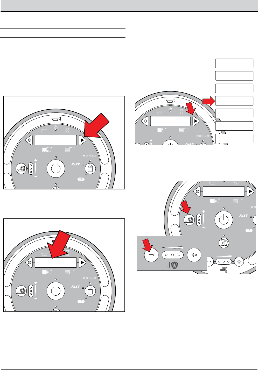
4-20 T12 Service Information 9009917 (12-12)
TROUBLESHOOTING
+ - + - + - + - + - + -
Scrub Head
Down
Enabled
• 1-STEP Scrub ON
• Squeegee/Vac ON • 1-STEP Scrub OFF
• Squeegee/Vac OFF
• Recovery Tank Full
• Low Batt Voltage
• Load Current Fault
Disabled
Operational Matrix:
Scrub Head
Down
Enabled
• 1-STEP Scrub ON
• Fwd/Rev Propel
• 1-STEP Scrub OFF
• Neutral-Ready State
• Recovery Tank Full
• Solution Tank Empty
• Low Batt Voltage
• Load Current Fault
Disabled
Operational Matrix:
Tennant Quantum
UI ver1.0
Tennant Quantum
UI ver X.X
Tennant Quantum
UI ver X.X
T16
Control
Board
6 Volt
Key Switch
IGN
15
ACC
30
BATT
Switched B+
From Buss Bar
75
50 Start S-2
E-Stop
Switch
S-3
Charger
Interlock
ST
M1B
M1A
J7-1
B+(Control)
B+
B-
Battery Positive +
Battery Negative -
CAN +12V J2-1
J2-2
J2-3
J2-4
RED #1
RED #2
BLK #2
BLK #1
CAN +
CAN -
CAN GROUND
D-4
D-2 D-3
CB1
2.5A
FU2
100A
6 Volt 6 Volt 6 Volt 6 Volt 6 Volt
CB2
2.5A
1/RED
13/BLK
6/BLU 7/PUR
Cable
Shield
Instrument Panel Assembly
Cable
3/ORA
8/GRY
4/YEL
Cable to Ground Stand O
5/GRN
10/TAN
2/BRNCable
STP001
1. Turn Key Off.
1. Key switch O. Press and hold the conguration
mode button.
2. Key switch On. Release the conguration mode
button when “CONFIG MODE” appears on the LCD.
+ - + - + - + - + - + -
Scrub Head
Down
Enabled
• 1-STEP Scrub ON
• Squeegee/Vac ON • 1-STEP Scrub OFF
• Squeegee/Vac OFF
• Recovery Tank Full
• Low Batt Voltage
• Load Current Fault
Disabled
Operational Matrix:
Scrub Head
Down
Enabled
• 1-STEP Scrub ON
• Fwd/Rev Propel
• 1-STEP Scrub OFF
• Neutral-Ready State
• Recovery Tank Full
• Solution Tank Empty
• Low Batt Voltage
• Load Current Fault
Disabled
Operational Matrix:
Tennant Quantum
UI ver1.0
Tennant Quantum
UI ver X.X
CONFIG MODE
T16
Control
Board
6 Volt
Key Switch
IGN
15
ACC
30
BATT
Switched B+
From Buss Bar
75
50 Start S-2
E-Stop
Switch
S-3
Charger
Interlock
ST
M1B
M1A
J7-1
B+(Control)
B+
B-
Battery Positive +
Battery Negative -
CAN +12V J2-1
J2-2
J2-3
J2-4
RED #1
RED #2
BLK #2
BLK #1
CAN +
CAN -
CAN GROUND
D-4
D-2 D-3
CB1
2.5A
FU2
100A
6 Volt 6 Volt 6 Volt 6 Volt 6 Volt
CB2
2.5A
1/RED
13/BLK
6/BLU 7/PUR
Cable
Shield
Instrument Panel Assembly
Cable
3/ORA
8/GRY
4/YEL
Cable to Ground Stand O
5/GRN
10/TAN
2/BRNCable
STP002
1. Turn Key Off.
INPUT DISPLAY
CONFIG MODE
SELF TEST
MANUAL MODE
INPUT DISPLAY
CAN DIAG MODE
PROPEL DIAG MODE
FIRMWARE UPDATE
3. Press and release the conguration mode button to
scroll through a list of utilities until “INPUT DISPLAY”
appears on the LCD.
I1:Solution Tank
Full Closed
T12 STANDARD
T12 XP
4. Press and release the brush pressure button to enter
Input Display Mode. “I1:Solution Tank, Full Closed” will
appear on the LCD.
Input Display Mode is an onboard diagnostic utility that
displays controller input conditions. Input Display Mode
displays LCD text messages for hard-wired switch, sensor,
and touch panel button inputs.
INPUT DISPLAY MODE
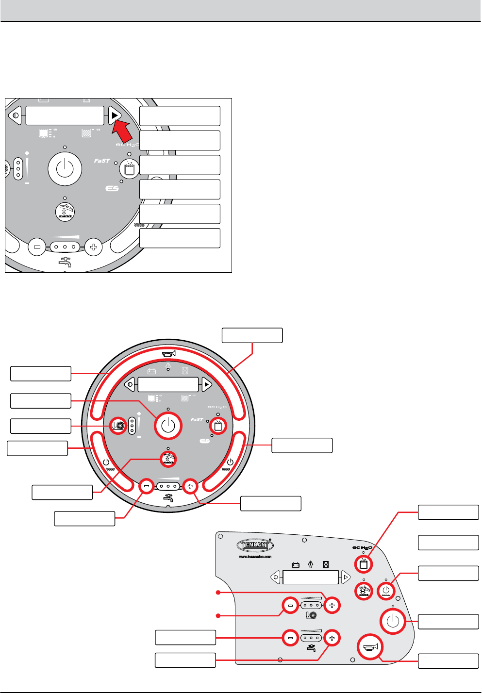
T12 Service Information 9009917 (12-12) 4-21
TROUBLESHOOTING
I1:Solution Tank
Full Closed
IDM003
I2:Recovery Tank
Not Full Open
I4:Seat Switch:
Seated
I7:Side Br Off
Seated
I1:Solution Tank
Full Closed
I5: Horn Button
Pressed
I6:Vac Button
Pressed
5. Press and release the conguration mode button to
scroll through a list of hard-wired switch and sensor
inputs.
IX:Input Mode
Message Here
I5: Horn Button
Pressed
I6:Vac Button
Pressed I9:Inc Solution
Button Pressed
I10:Dec Solution
Button Pressed
I11:Left Water Off
Button Pressed
I12:Right Water Off
Button Pressed
I13:One Step
Button Pressed
I14:Down Pres.
Button Pressed
I15:Alt Solution
Button Pressed
T12 XP
T12 STANDARD
I5: Horn Button
Pressed
I6:Vac Button
Pressed
I9:Inc Solution
Button Pressed
I10:Dec Solution
Button Pressed
N/A
N/A
I11:Left Water Off
Button Pressed
I15:Alt Solution
Button Pressed
I13:One Step
Button Pressed
6. Press any other touch panel button to display a
corresponding LCD text message. The message
conrms that the control board received the input.

4-22 T12 Service Information 9009917 (12-12)
TROUBLESHOOTING
+ - + - + - + - + - + -
Scrub Head
Down
Enabled
• 1-STEP Scrub ON
• Squeegee/Vac ON • 1-STEP Scrub OFF
• Squeegee/Vac OFF
• Recovery Tank Full
• Low Batt Voltage
• Load Current Fault
Disabled
Operational Matrix:
Scrub Head
Down
Enabled
• 1-STEP Scrub ON
• Fwd/Rev Propel
• 1-STEP Scrub OFF
• Neutral-Ready State
• Recovery Tank Full
• Solution Tank Empty
• Low Batt Voltage
• Load Current Fault
Disabled
Operational Matrix:
Tennant Quantum
UI ver1.0
Tennant Quantum
UI ver X.X
Tennant Quantum
UI ver X.X
T16
Control
Board
6 Volt
Key Switch
IGN
15
ACC
30
BATT
Switched B+
From Buss Bar
75
50 Start S-2
E-Stop
Switch
S-3
Charger
Interlock
ST
M1B
M1A
J7-1
B+(Control)
B+
B-
Battery Positive +
Battery Negative -
CAN +12V J2-1
J2-2
J2-3
J2-4
RED #1
RED #2
BLK #2
BLK #1
CAN +
CAN -
CAN GROUND
D-4
D-2 D-3
CB1
2.5A
FU2
100A
6 Volt 6 Volt 6 Volt 6 Volt 6 Volt
CB2
2.5A
1/RED
13/BLK
6/BLU 7/PUR
Cable
Shield
Instrument Panel Assembly
Cable
3/ORA
8/GRY
4/YEL
Cable to Ground Stand O
5/GRN
10/TAN
2/BRNCable
STP001
1. Turn Key Off.
1. Key switch O. Press and hold the conguration
mode button.
2. Key switch On. Release the conguration mode
button when “CONFIG MODE” appears on the LCD.
+ - + - + - + - + - + -
Scrub Head
Down
Enabled
• 1-STEP Scrub ON
• Squeegee/Vac ON • 1-STEP Scrub OFF
• Squeegee/Vac OFF
• Recovery Tank Full
• Low Batt Voltage
• Load Current Fault
Disabled
Operational Matrix:
Scrub Head
Down
Enabled
• 1-STEP Scrub ON
• Fwd/Rev Propel
• 1-STEP Scrub OFF
• Neutral-Ready State
• Recovery Tank Full
• Solution Tank Empty
• Low Batt Voltage
• Load Current Fault
Disabled
Operational Matrix:
Tennant Quantum
UI ver1.0
Tennant Quantum
UI ver X.X
CONFIG MODE
T16
Control
Board
6 Volt
Key Switch
IGN
15
ACC
30
BATT
Switched B+
From Buss Bar
75
50 Start S-2
E-Stop
Switch
S-3
Charger
Interlock
ST
M1B
M1A
J7-1
B+(Control)
B+
B-
Battery Positive +
Battery Negative -
CAN +12V J2-1
J2-2
J2-3
J2-4
RED #1
RED #2
BLK #2
BLK #1
CAN +
CAN -
CAN GROUND
D-4
D-2 D-3
CB1
2.5A
FU2
100A
6 Volt 6 Volt 6 Volt 6 Volt 6 Volt
CB2
2.5A
1/RED
13/BLK
6/BLU 7/PUR
Cable
Shield
Instrument Panel Assembly
Cable
3/ORA
8/GRY
4/YEL
Cable to Ground Stand O
5/GRN
10/TAN
2/BRNCable
STP002
1. Turn Key Off.
MANUAL MODE
CONFIG MODE
SELF TEST
MANUAL MODE
INPUT DISPLAY
CAN DIAG MODE
PROPEL DIAG MODE
FIRMWARE UPDATE
3. Press and release the conguration mode button to
scroll through a list of utilities until “MANUAL MODE”
appears on the LCD.
M01: Left Brush
00% XX.XA
T12 STANDARD
T12 XP
4. Press and release the brush pressure button to
enter Manual Mode. “M01: Left Brush, 00% XX.XA” will
appear on the LCD.
Manual Mode is an onboard diagnostic utility that manu-
ally activates machine functions and displays output cur-
rent in “XX.X Amps” format. This mode bypasses interlock-
ing inputs and should be used for diagnostic purposes
only.
MANUAL MODE
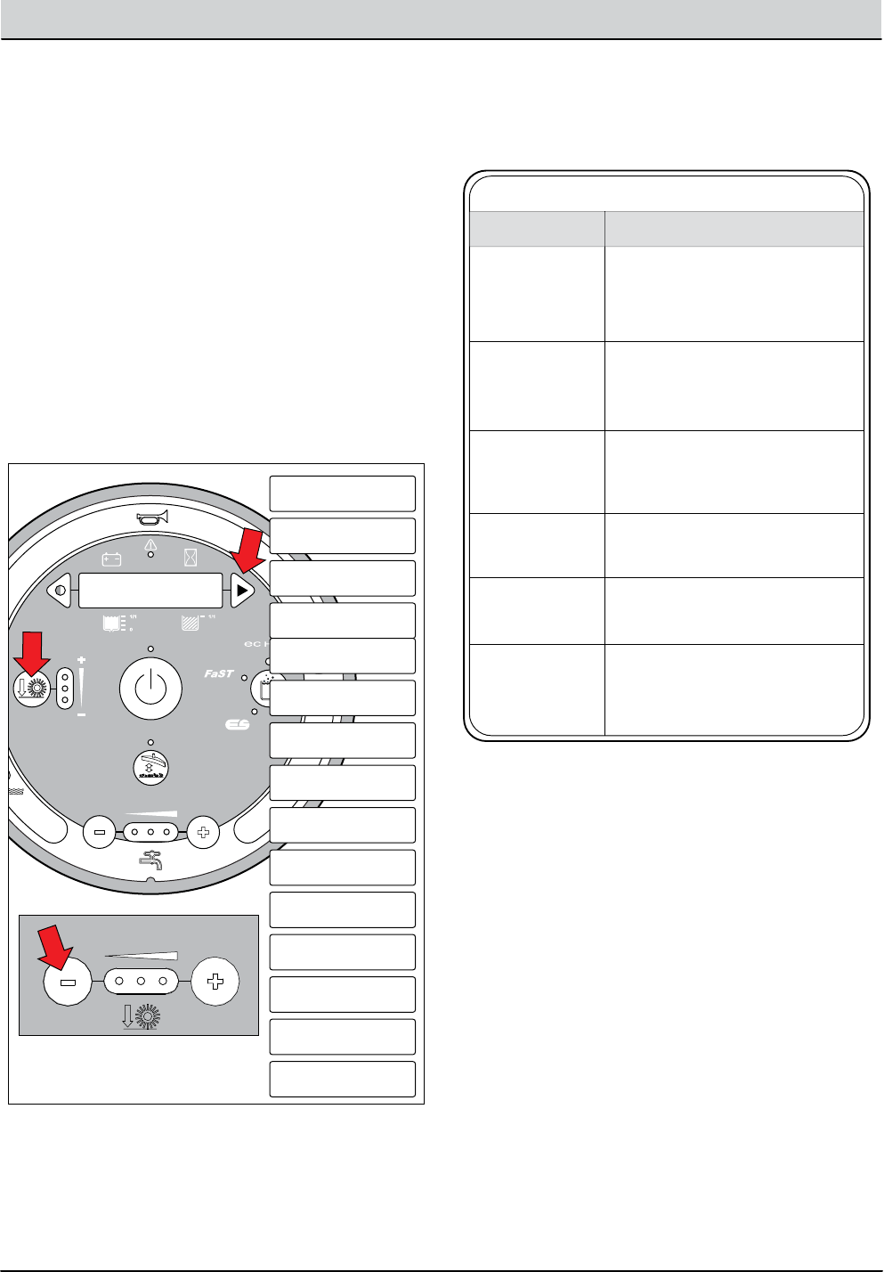
T12 Service Information 9009917 (12-12) 4-23
TROUBLESHOOTING
M01: Left Brush
00% XX.XA
M01: Left Brush
00% XX.XA
M02: Right Brush
00% XX.XA
M03: Side Brush
00% XX.XA
M04: Vac Fan
00% XX.XA
M05: Side Pump
00.00V 00% X.XXA
M06: Ec Pump
00.00V 00% X.XXA
M07: Water Valve
Close OK X.XXA
M08: Side Valve
Closed OK X.XXA
M09: Ec Valve
Closed OK X.XXA
M10: Ec Sparger
00% X.XXA
M11: Ec Cell
00% X.XXA
M12: Scrub Act
R 0.00% XX.XXA
M13: Sqge Act
R 0.00% XX.XA
M14: Side Act
R 00.0% XX.XA
Exit Manual Mode
Yes
T12 STANDARD
T12 XP
5. Press and release the conguration mode button
to scroll through a list of output functions. Press the
brush down pressure button to activate the function
displayed on the LCD (except functions in Step 6).
6. The output functions listed below have specic op-
erating instructions. Follow the instructions listed in
the table below.
T12 Manual Mode Operation
Water Flow (-) = Completely Down
Water Flow (+) = Completely Up
LH Water Button = Momentary Down
RH Water Button* = Momentary Up
* XP models only. Standard models have a single water button
used for momentary downward actuator control. Use Water Flow (+)
button to raise scrub head.
Scrub Head
Lift Actuator
(When M12... is
displayed on LCD)
Water Flow(-) Button = Down
Water Flow(+) Button = Up
Rear Squeegee
Lift Actuator
(When M13... is
displayed on LCD)
Water Flow(-) Button = Down
Water Flow(+) Button = Up
Side Brush
Lift Actuator
(When M14...is
displayed on LCD)
Water Flow (+) and (-) Buttons Adjust
Flow (Low, Med, High)
No LEDs illuminated turns valve O
Side Valve
(When side pump
M05... is On)
Ec Valve
(When Ec Pump
M06... is On)
Water Flow (+) and (-) Buttons Adjust
Flow (Low, Med, High)
No LEDs illuminated turns valve O
Water Valve-Main
When M01..., M02...,
or M07... is displayed
on the LCD)
Water Flow (+) and (-) Buttons Adjust
Flow (Low, Med, High)
No LEDs illuminated turns main valve O
FUNCTION OPERATION
NOTE: “XX.X A” format indicates that the actual amper-
age value will vary. See the “Specications” section of this
manual for approximate amp draw values.
NOTE: “R” or “E” in the lower left corner of the LCD indicates
Retracted or Extended actuator position.
NOTE: “XX%” refers to the duty cycle of the ciruit load when
activated.
NOTE: “OK” indicates that the displayed function is not open
or shorted.
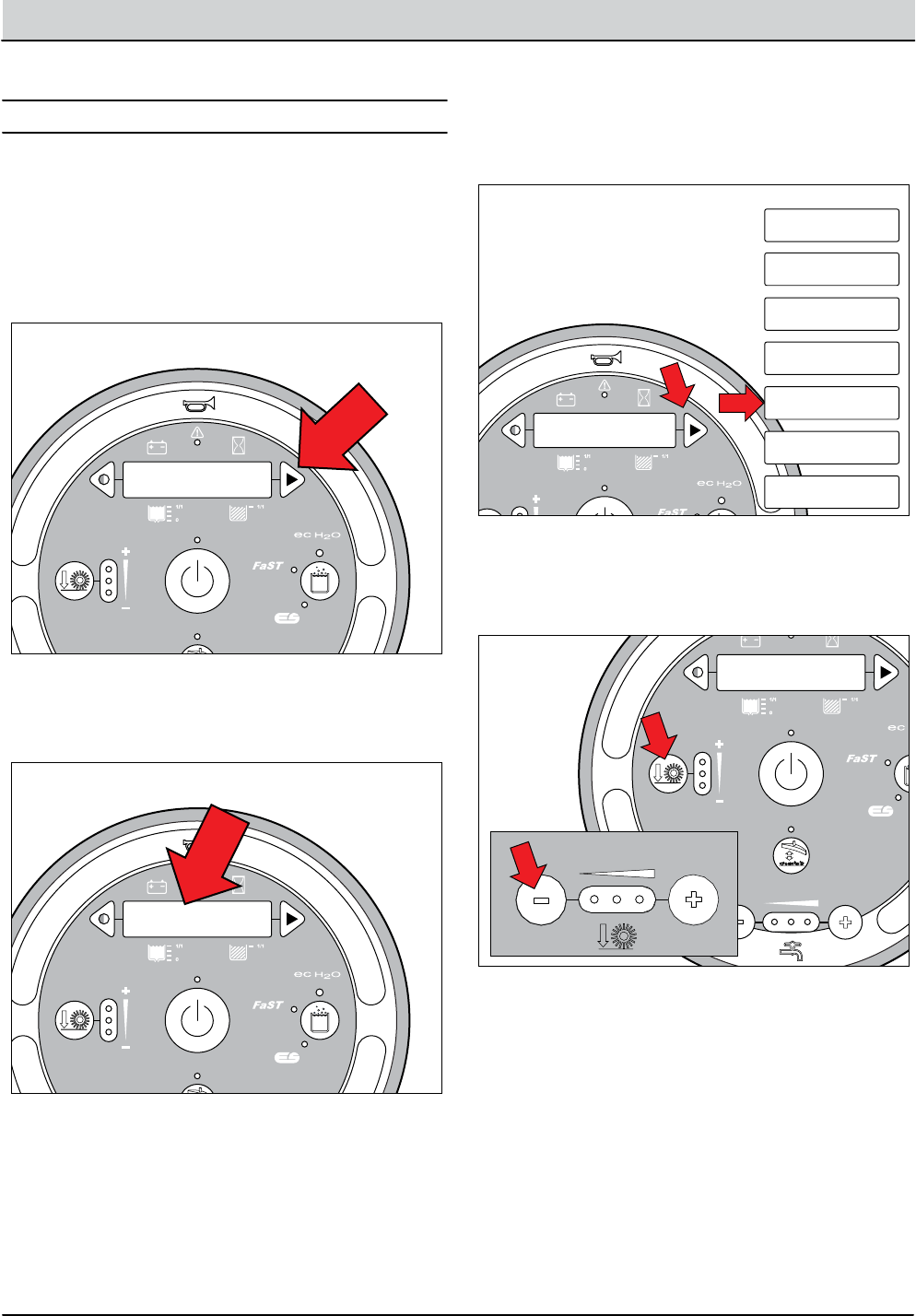
4-24 T12 Service Information 9009917 (12-12)
TROUBLESHOOTING
+ - + - + - + - + - + -
Scrub Head
Down
Enabled
• 1-STEP Scrub ON
• Squeegee/Vac ON • 1-STEP Scrub OFF
• Squeegee/Vac OFF
• Recovery Tank Full
• Low Batt Voltage
• Load Current Fault
Disabled
Operational Matrix:
Scrub Head
Down
Enabled
• 1-STEP Scrub ON
• Fwd/Rev Propel
• 1-STEP Scrub OFF
• Neutral-Ready State
• Recovery Tank Full
• Solution Tank Empty
• Low Batt Voltage
• Load Current Fault
Disabled
Operational Matrix:
Tennant Quantum
UI ver1.0
Tennant Quantum
UI ver X.X
Tennant Quantum
UI ver X.X
T16
Control
Board
6 Volt
Key Switch
IGN
15
ACC
30
BATT
Switched B+
From Buss Bar
75
50 Start S-2
E-Stop
Switch
S-3
Charger
Interlock
ST
M1B
M1A
J7-1
B+(Control)
B+
B-
Battery Positive +
Battery Negative -
CAN +12V J2-1
J2-2
J2-3
J2-4
RED #1
RED #2
BLK #2
BLK #1
CAN +
CAN -
CAN GROUND
D-4
D-2 D-3
CB1
2.5A
FU2
100A
6 Volt 6 Volt 6 Volt 6 Volt 6 Volt
CB2
2.5A
1/RED
13/BLK
6/BLU 7/PUR
Cable
Shield
Instrument Panel Assembly
Cable
3/ORA
8/GRY
4/YEL
Cable to Ground Stand O
5/GRN
10/TAN
2/BRNCable
STP001
1. Turn Key Off.
1. Key switch O. Press and hold the conguration
mode button.
2. Key switch On. Release the conguration mode
button when “CONFIG MODE” appears on the LCD.
+ - + - + - + - + - + -
Scrub Head
Down
Enabled
• 1-STEP Scrub ON
• Squeegee/Vac ON • 1-STEP Scrub OFF
• Squeegee/Vac OFF
• Recovery Tank Full
• Low Batt Voltage
• Load Current Fault
Disabled
Operational Matrix:
Scrub Head
Down
Enabled
• 1-STEP Scrub ON
• Fwd/Rev Propel
• 1-STEP Scrub OFF
• Neutral-Ready State
• Recovery Tank Full
• Solution Tank Empty
• Low Batt Voltage
• Load Current Fault
Disabled
Operational Matrix:
Tennant Quantum
UI ver1.0
Tennant Quantum
UI ver X.X
CONFIG MODE
T16
Control
Board
6 Volt
Key Switch
IGN
15
ACC
30
BATT
Switched B+
From Buss Bar
75
50 Start S-2
E-Stop
Switch
S-3
Charger
Interlock
ST
M1B
M1A
J7-1
B+(Control)
B+
B-
Battery Positive +
Battery Negative -
CAN +12V J2-1
J2-2
J2-3
J2-4
RED #1
RED #2
BLK #2
BLK #1
CAN +
CAN -
CAN GROUND
D-4
D-2 D-3
CB1
2.5A
FU2
100A
6 Volt 6 Volt 6 Volt 6 Volt 6 Volt
CB2
2.5A
1/RED
13/BLK
6/BLU 7/PUR
Cable
Shield
Instrument Panel Assembly
Cable
3/ORA
8/GRY
4/YEL
Cable to Ground Stand O
5/GRN
10/TAN
2/BRNCable
STP002
1. Turn Key Off.
CAN DIAG MODE
CONFIG MODE
SELF TEST
MANUAL MODE
INPUT DISPLAY
CAN DIAG MODE
PROPEL DIAG MODE
FIRMWARE UPDATE
3. Press and release the conguration mode button to
scroll through a list of utilities until “MANUAL MODE”
appears on the LCD.
CD1: Scrub
T12 STANDARD
T12 XP
4. Press and release the brush pressure button to
enter CAN Diagnostic Mode. “CD1: Scrub” will
appear on the LCD.
CAN (Controller Area Network) Diagnostic Mode is an on-
board diagnostic utility that displays connectivity status
and a software revision date for each module.
CAN DIAGNOSTIC MODE
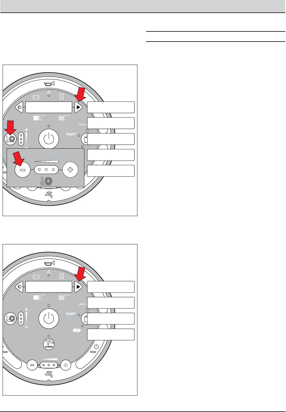
T12 Service Information 9009917 (12-12) 4-25
TROUBLESHOOTING
Firmware Update Mode is an onboard diagnostic utility
that allows for software updates via an SD card. This mode
should only be used by Tennant Service Personnel follow-
ing an update kit IB (Instruction Bulletin).
CD1: Scrub
T12 STANDARD
T12 XP
CD1: Scrub
CD2: Pickup
CD3: Propel
CD4: Side
CD5: Ec
CD1: Scrub
Online CD1: Scrub
Online
CD1: Scrub
Scrub(XX-XX-XX)
CD1: Scrub
Production Boot
CD1: Scrub
Revision X.XX
5. Press and release the conguration mode button
to scroll through a list of CAN modules. Press the
brush down pressure button to select a specic mod-
ule.
6. Press and release the conguration mode button
to scroll through a list of CAN module information.
FIRMWARE UPDATE MODE
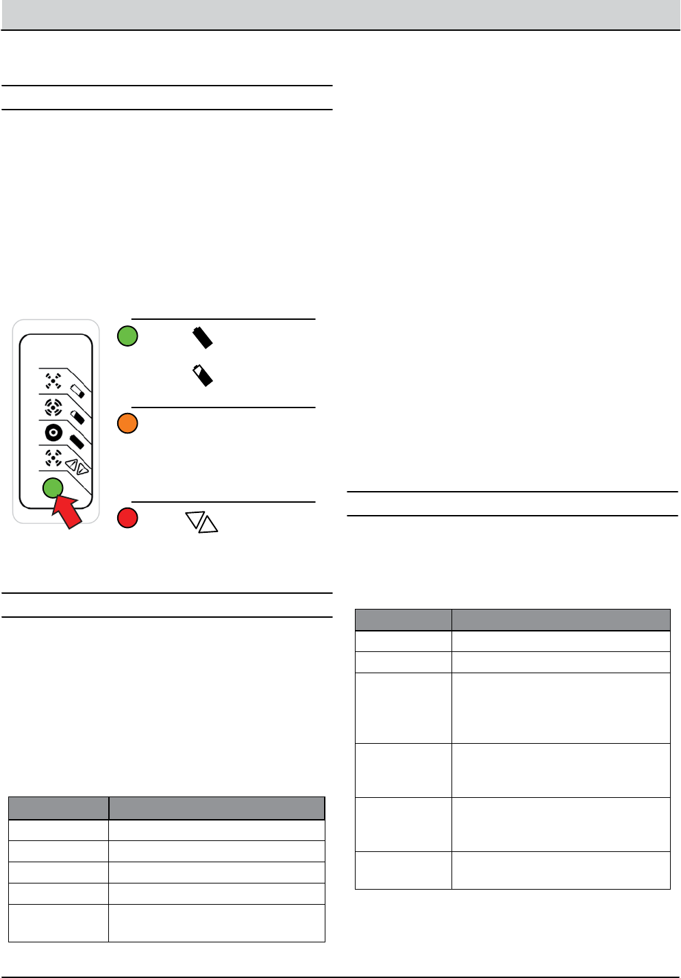
4-26 T12 Service Information 9009917 (12-12)
TROUBLESHOOTING
Battery Charger, Standard and Export
RED FLASHES POSSIBLE CAUSE
1Battery High Voltage
2Battery Low Voltage
3Charge timeout. Batteries failed to
reach required voltage. Charger
output was reduced due to high
temperatures.
4Check battery. Battery could not
be trickle charged up to minimum
voltage.
5Over-Temperature: Charger shut
down due to high internal tempera-
ture.
6Charger internal fault. Disconnect
for 15 seconds and reset charger.
This charger is programmable for standard lead-acid,
heavy duty lead-acid batteries. The setting is displayed
using the blink on/o method each time the battery
charger is connected to an AC power supply and the
charger is disconnected from the batteries.
The standard battery charger utilizes a single-LED
display. The LED ashes green during the charging cycle
and changes to solid green when the charging cycle is
complete.
OPERATION
FAU LTS
CONFIGURATION
1. Key O. Disconnect battery charger from AC power
supply and the batteries. Wait 30 seconds before
proceeding to step 2 to allow for capacitor discharge.
* @ 20 hour rate
ALGORITHM # BATTERY TYPE
3Lead-Acid, 240 Ah* (Trojan T105)
7Lead-Acid, 360 Ah* (Trojan J305)
12 GEL, 240 Ah* (Exide DF06240)
28 GEL, 180 Ah* (Deka 8GGC2)
43 AGM, 300 Ah* (Discover EVL16A,
EVGC6A)
4. Optional Charger Single-LED Display (internal or external)
LED indications following “Power-On Self Test”:
Green Solid: Charging complete. Charger in
Maintenance Mode.
Flashing: Short: <80% Charge.
Long: >80% Charge.
When battery is not connected: Algorithm
Number display.
Amber Flashing: Reduced Power Mode: Low AC Voltage or
High internal charger temperature.
Red Flashing: Charger error. Reset charger power and
refer to Troubleshooting below.
Maintenance Instructions
1. For flooded lead-acid batteries, regularly check water levels of each battery cell after charging
and add distilled water as required to level specified by battery manufacturer. Follow the
maintenance and safety instructions recommended by the battery manufacturer.
2. Make sure charger connections to battery terminals are tight and clean.
3. Do not expose charger to oil, dirt, mud or direct heavy water spray when cleaning vehicle.
Troubleshooting Instructions
If a fault occurs, count the number of red flashes between pauses and refer to the table below:
noituloS esuaC sehsalF deR
Battery High Voltage Check battery size and condition and
reset charger (interrupt AC power for
15 seconds).
Battery Low Voltage Check battery size and condition and
reset charger (interrupt AC power for
15 seconds).
Charge Timeout caused by
battery pack not reaching
required voltage. Charger
output was reduced due to
high temperatures
Check connections.
Operate charger at a lower ambient
temperature.
Check Battery: battery could
not be trickle charged up to
minimum voltage
Check for shorted or damaged cells.
Over-Temperature: Charger
shut down due to high internal
temperature.
Ensure sufficient cooling air flow and
reset charger (interrupt AC power for
15 seconds).
Charger Internal Fault Reset charger (interrupt AC power
for 15 seconds). Return to qualified
service depot if fault persists.
Green Solid: Charge
Complete
Flashing:
Charging
Amber Flashing:
Reduced Power
Mode. Low AC
Voltage or Hi
Charger Temp
Red Flashing:
Charger Error
See Faults Below
!
!
DQC001
2. Connect charger to AC supply and observe the
LED display. It will blink on/o to indicate the cur-
rent battery charger setting for 11 seconds.
1. Key O. Disconnect battery charger from AC power
supply and the batteries. Wait 30 seconds before
proceeding to step 2 to allow for capacitor discharge.
DISPLAYING CURRENT CHARGER SETTING
CHANGING CHARGER SETTING
2. Connect charger to AC supply and observe the
LED display. It will blink on/o to indicate the cur-
rent battery charger setting for 11 seconds.
3. Connect the battery charger to the batteries for 2
seconds and then disconnect from the batteries,
during the 11 second window, to advance to the
next highest setting.
NOTE: The 11 second window expands to 30 seconds after
the rst change has been made.
4. Wait 45 seconds after a change has been made to
save the new charger setting.
NOTE: There are 10 total algorithms. The advancement
sequence increases each time and then loops back to #1.
A ashing red LED indicates a charger error. Count the
number of ashes separated by a long pause and then
use the table below to identify a possible cause.
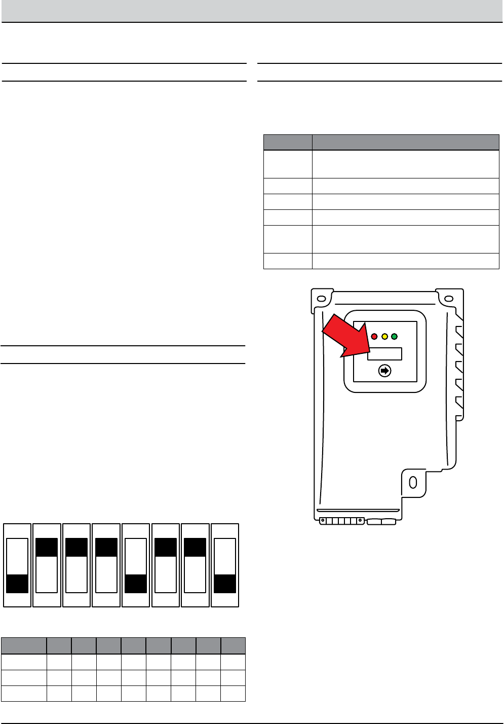
T12 Service Information 9009917 (12-12) 4-27
TROUBLESHOOTING
* @ 20 hour rate
Battery Charger, Onboard (Option)
FAULT POSSIBLE CAUSE
“bat” Poor or no battery connection or reversed
polarity
“E01” Maximum battery voltage exceeded.
“E02” Maximum battery temperature exceeded.
“E03” Maximum charging time exceeded.
“SCt” The total safety timer has interrupted
charging.
“Srt” Internal charger short circuit possible.
OBC003
Each time the battery charger is connected to an AC
power supply, the charger displays; “SPE,” the software
revision date, battery voltage, charging current, charg-
ing curve number, and nally the words “GEL” (Gel) or
“Acd” (Lead-Acid) depending on how the charger is
congured from the factory.
The onboard battery charger utilizes a 4 character digi-
tal display, 3 control indicator LEDs and a scroll button.
The red control indicator illuminates at the beginning of
the charging cycle. The yellow control indicator illumi-
nates when the nal phase of the charging cycle begins
and the green control indicator illuminates when the
charging cycle is complete.
OPERATION FAULTS
Pressing the scroll button during the charge cycle will
change the display mode between; A (charging cur-
rent), U (battery voltage), h (charging time), C (charging
amp-hours), and E (energy used KWh).
CONFIGURATION, LEAD ACID/GEL
1. Key O. Disconnect battery charger from AC power
supply and the batteries.
2. Carefully remove the charger display cover decal to
access the programmable dip swtiches.
3. Use the table below to set the dip switches for
Lead-Acid or Gel batteries.
OBC005
ON
OFF
ON
OFF
ON
OFF
ON
OFF
ON
OFF
ON
OFF
ON
OFF
ON
OFF
Dip #1 #2 #3 #4 #5 #6 #7 #8
NOTE: The dip switches below are shown in the default
240AH Lead-Acid position.
Fault messages automatically display when a fault exists.
Use the table below to identify possible causes.
TYPE #1 #2 #3 #4 #5 #6 #7 #8
GEL ON ON ON ON OFF ON ON OFF
240 Ah* OFF ON ON ON OFF ON ON OFF
360 Ah* OFF OFF ON ON OFF ON ON OFF
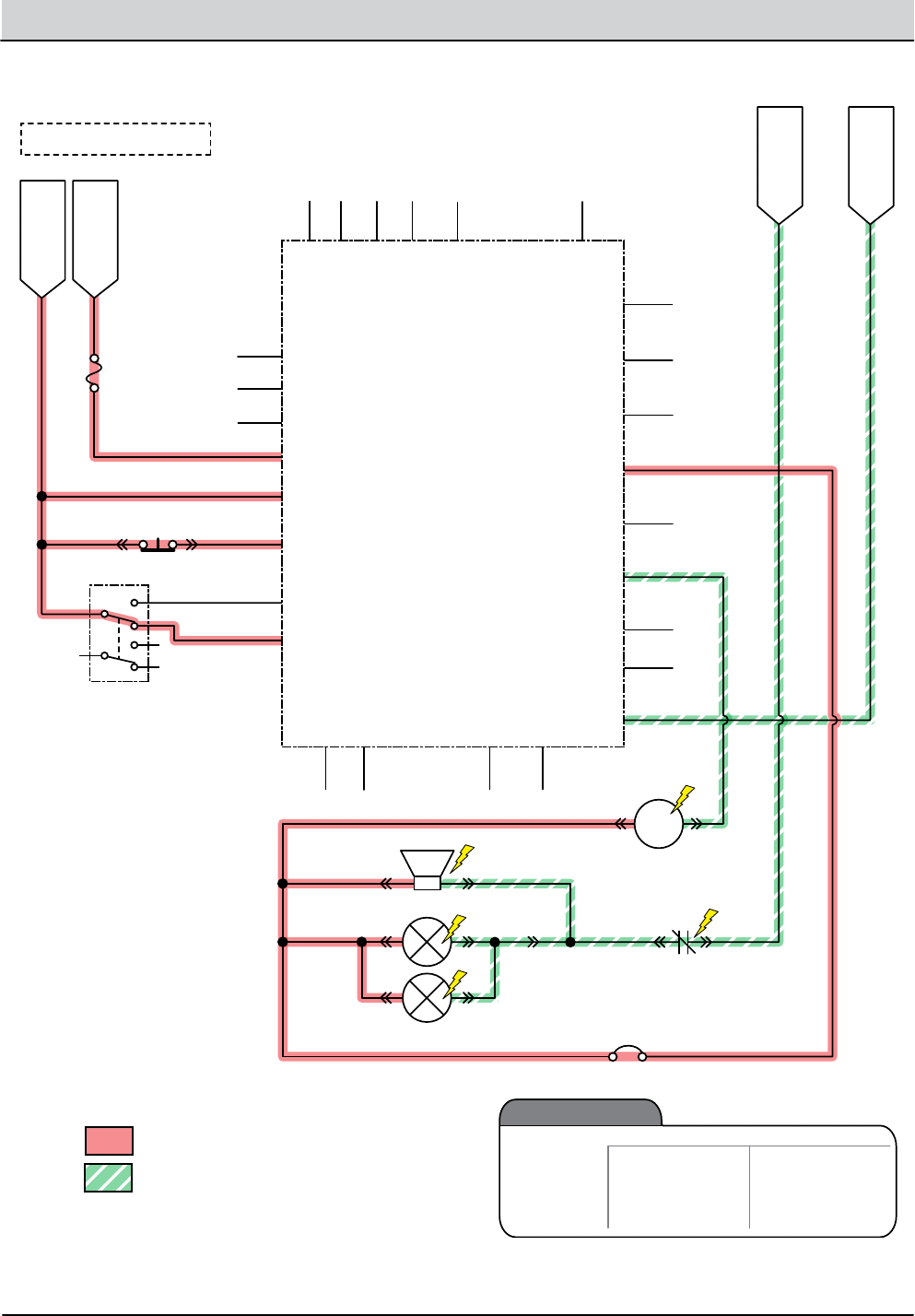
4-28 T12 Service Information 9009917 (12-12)
TROUBLESHOOTING
Back-Up Alarm/Light ON
B- From
Stando
Battery -
S-5 Seat Switch (N.O.)
Cable
Battery Positive +
Battery Negative -
FU1
80A
Note: Key Switch ON
Switched B+
From Buss Bar
Switched B+
PMC011
FWD
REV
6
2
8
BA
5
4 J1-33
GND
Cable
J1-34
P2-1P1-1
J1-21
W/WHT
V/GRN
U/ORN
J1-4
J1-3
J1-13
J1-24
J1-32
J1-26
J1-31
J1-7
J1-18
J1-15
17/PUR
17/PUR
90/TAN
85/GRN-WHT
13/BLK13/BLK
15/GRN
J1-16
J1-35
J1-23
J1-22
J1-9
J1-1
B+
J1-29
J1-28
J1-25
1
Curtis 1232
Controller
PROG +
TX
RX
B+
KSI
INTERLOCK
FWD
FWD/REV Switch
REV
B -
CAN TERM L
CAN TERM H
U
DRV4
DRV3
DRV1
THERMISTOR
I/O GND
PHASE A
PHASE B
+5V
DRV2
COIL RETURN
V
W
BRAKE IN
(0-5 vdc) THROTTLE
CAN -
8/GRY
18/GRY
9/WHT
11/PNK
CAN +
CB17 (2.5A)
Back-Up Alarm
White Back Up Lights (LEDs)
M2A
Opt. Reverse
Relay
86 85
M2B
30 87
Back-Up
Alarm/Lights
Enabled
• Rev Switch Input
• Rev Throttle Command
• Fwd Switch Input
• Neutral - Ready State
• Curtis 1232 Fault
Disabled
Operational Matrix:

T12 Service Information 9009917 (12-12) 4-29
TROUBLESHOOTING
Back-Up Alarm/Light Failed to Turn ON
STEP ACTION VALUES YES NO
1• Key On
• Enable back-up alarm/lights
• Is there a pertinent LCD warning or fault message
displayed?
See “LCD
Warnings” or
“LCD Faults”
Sections
Go to Step #2
2• Key On
• Enable back-up alarm/lights
• See “Curtis 1232 Controller Diagnostics”
• Is there a pertinent Curtis 12342 fault displayed?
Correct Fault
Condition
Go to Step #3
3• Key O
• See “Propel Diagnostic Mode” section of this manual
• Check the “P4:Direction Fwd/Rev” input from the
directional switch
• Check the “P2:Throttle” (0-5 vdc) input from the direc-
tional pedal
• Are the P2 and P4 inputs operating properly?
Go to Step # 4 Correct Faulty
Input Condi-
tion
4• Key O
• Remove M2 relay from connector (see component
locator)
• Connect an Ohmmeter between relay terminals 30
and 87 (should test open or “O.L.”)
• Apply battery voltage to relay terminals 86 (+) and
85 (-) using fuse-protected jumper leads
• Does the relay “click” and do the N.O. (normally open)
terminals 30 and 87 close?
Go to Step #5 Replace Relay
5• Key O
• Disconnect back-up alarm/light from main harness
• Apply battery voltage to back-up alarm/light using
fuse-protected jumper leads
• Does the back-up alarm/light turn On?
Go to Step #6 Replace Back-
Up Alarm/
Light
6• Key On
• Reconnect back-up alarm/light to main harness
• Enable back-up alarm/light
• Backprobe using a voltmeter between 15/GRN and
17/PUR at the Curtis 1232 controller connection
• Is there battery voltage applied?
Repair or
Replace Wire
Harness
Replace Curtis
1232 Control-
ler
Terms:
LCD = Liquid Crystal Display
Backprobe = To insert voltmeter probe(s) into the back of a connector to contact a terminal(s) while the circuit oper-
ates or should be operating.
VDC = DC Voltage
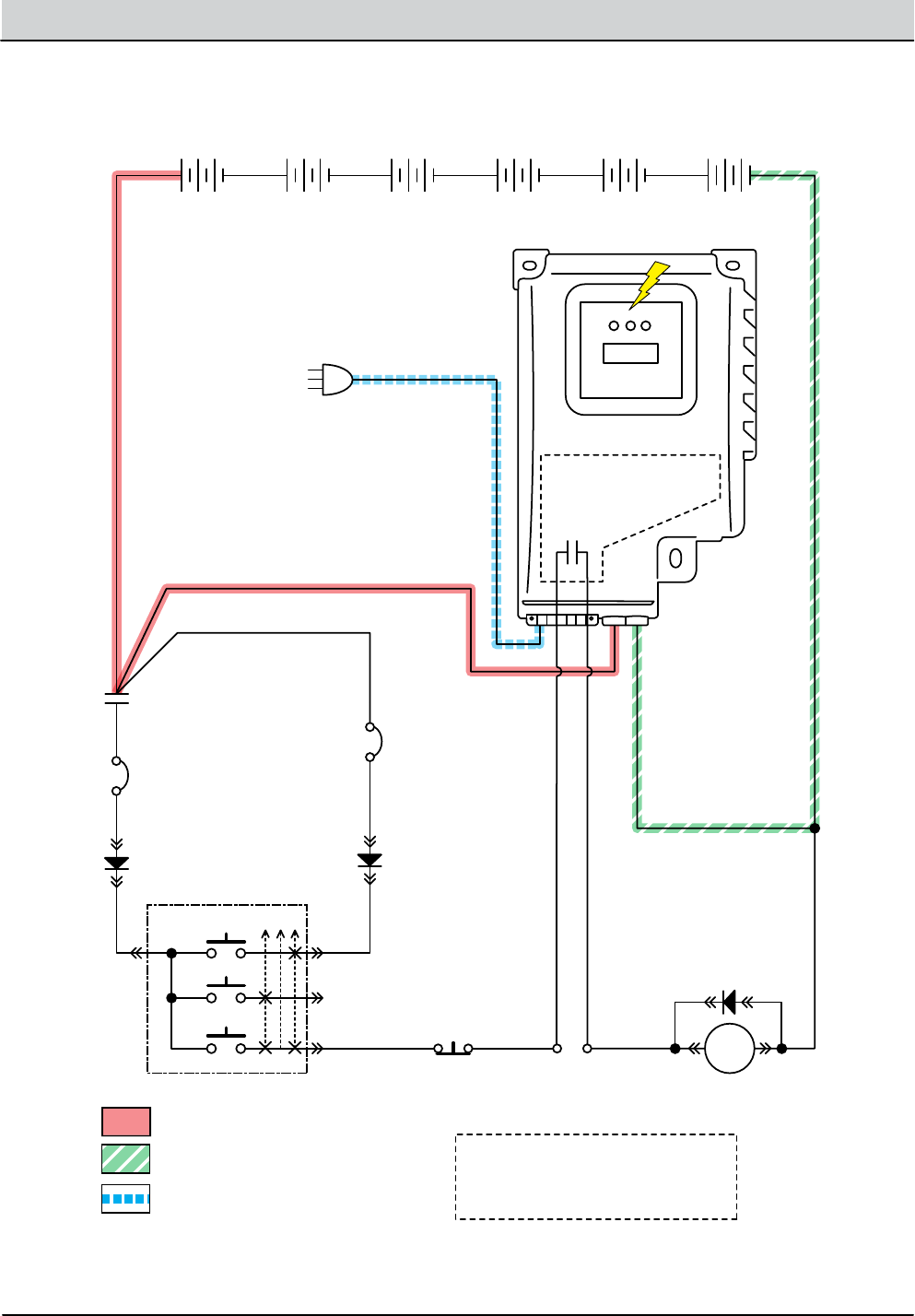
4-30 T12 Service Information 9009917 (12-12)
TROUBLESHOOTING
+ - + - + - + - + - + -
D-2
OBC001
+ -
On Board Battery Charger
RED
BLK
BLK
BLK
6 Volt
Key Switch
IGN
15
ACC
30
BAT T
75
50 Start S-2
E-Stop
Switch
S-3
Interlock
Connection
Note: Battery charger interlock
harness connects to main
harness S-3 interlock connection.
ST
M1B
M1A
Battery Positive +
Battery Negative -
D-3
D-1
CB3
2.5A
6 Volt 6 Volt 6 Volt 6 Volt 6 Volt
CB2
2.5A
1/RED
Note:
Internal Switch Opens
When Connected
to AC Supply
AC Plug
13/BLK
6/BLU 7/PUR 8/GRY
3/ORA 4/YEL
Cable to Ground Stand O
5/GRN
10/TAN
2/BRNCable
AC Volts
Onboard Battery Charging ON

T12 Service Information 9009917 (12-12) 4-31
TROUBLESHOOTING
Batteries Failed to Charge
STEP ACTION VALUES YES NO
1• Key O
• Is there a pertinent fault displayed on the onboard
charger (bat, E01, E02, E03, SCt, or Srt)?
See “Onboard
Battery Char-
ger Faults”
Section of This
Manual
Go to Step #2
2• Key O
• Check AC power supply
• Is the rated AC supply voltage present?
Go to Step #3 Check AC
Supply Circuit
Protection
3• Key O
• Disconnect batteries
• Unplug charger from AC supply
• Check fuse located on bottom side of charger
• Is the fuse blown?
Replace Fuse
and Test Char-
ger Operation
Go to Step #4
4• Key O
• Inspect battery and charger cables for damage, cor-
rosion, contamination or terminal problems
• Do any of the above conditions exist?
Repair or Re-
place Battery
and/or Char-
ger Cables
Go to Step #5
5• Skip this step for sealed, AGM, or gel batteries
• Key O
• Disconnect batteries
• Check water level of all battery cells
• Are the lead plates submerged?
Go to Step #6 Add Distilled
Water Until
Lead Plates are
Covered.
6• Key O
• Load test all batteries (AGM, Gel, Lead-Acid)
• -or-
• Test specic gravity of each cell using a hydrometer
or refractometer (Lead-Acid)
• Do the batteries pass a load test or are all battery
cells within 0.050 (50 points) specic gravity of each
other?
Replace Bat-
tery Charger
Replace
Battery or Bat-
teries
Terms:
AC = Alternating Current
AGM = Absorbed Glass Mat
Specic Gravity = Relative density of a substance compared to water (1.000 specic gravity)
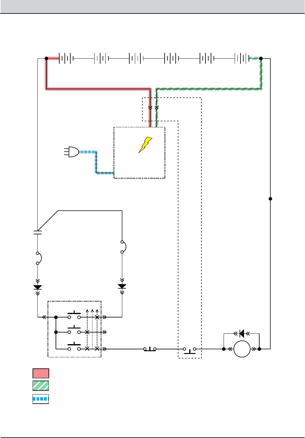
4-32 T12 Service Information 9009917 (12-12)
TROUBLESHOOTING
+ - + - + - + - + - + -
D-2
OBC002
O Board
Battery Charger
6 Volt
Key Switch
IGN
15
ACC
30
BAT T
75
50 Start S-2
E-Stop
Switch
S-3 Charger
Interlock Switch
(N.C.)
ST
M1B
M1A
Battery Positive +
Battery Negative -
D-3
D-1
Charger
Connector
6 Volt 6 Volt 6 Volt 6 Volt 6 Volt
CB2
2.5A
CB3
2.5A
1/RED
RED BLACK
AC Plug
13/BLK
6/BLU 7/PUR 8/GRY
3/ORA 4/YEL
Cable to Ground Stand O
5/GRN
10/TAN
2/BRNCable
AC Volts
O Board Battery Charging ON

T12 Service Information 9009917 (12-12) 4-33
TROUBLESHOOTING
Batteries Failed to Charge
STEP ACTION VALUES YES NO
1• Key O
• Check AC power supply
• Is the rated AC supply voltage present?
Go to Step #2 Check AC
Supply Circuit
Protection
2• Key O
• Disconnect batteries
• Unplug charger from AC supply
• Check charger fuse or circuit breaker (if equipped)
• Is a fuse blown or circuit breaker tripped?
Replace Fuse
or Reset
Circuit Breaker
and Test Char-
ger Operation
Go to Step #3
3• Key O
• Inspect battery and charger cables for damage, cor-
rosion, contamination or terminal problems
• Do any of the above conditions exist?
Repair or Re-
place Battery
and/or Char-
ger Cables
Go to Step #4
4• Skip this step for sealed, AGM, or gel batteries
• Key O
• Disconnect batteries
• Check water level of all battery cells
• Are the lead plates submerged?
Go to Step #5 Add Distilled
Water Until
Lead Plates are
Covered.
5• Key O
• Load test all batteries (AGM, Gel, Lead-Acid)
• -or-
• Test specic gravity of each cell using a hydrometer
or refractometer ((Lead-Acid)
• Do the batteries pass a load test or are all battery
cells within 0.050 (50 points) specic gravity of each
other?
Replace Bat-
tery Charger
Replace
Battery or Bat-
teries
Terms:
AC = Alternating Current
AGM = Absorbed Glass Mat
Specic Gravity = Relative density of a substance compared to water (water = 1.000 specic gravity)
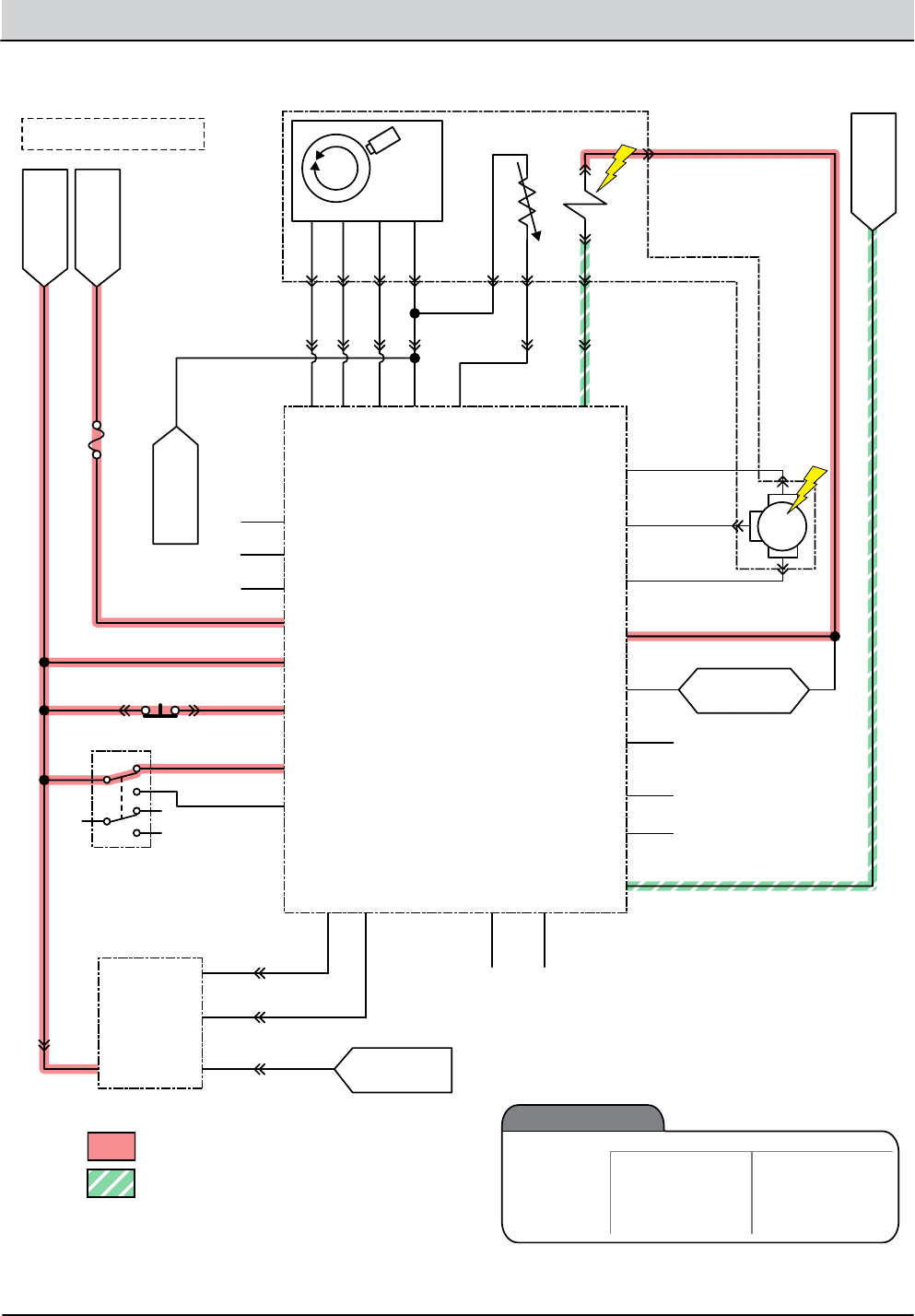
4-34 T12 Service Information 9009917 (12-12)
TROUBLESHOOTING
B- From
Stando
S-5 Seat Switch (N.O.)
Amer
Encoder
Cable
Battery Positive +
Battery Negative -
FU1
80A
Switched B+
From Buss Bar
Switched B+
To: Throttle
Sensor (GND)
To: Curtis 1232
(I/O GND)
To: Back-Up
Light Circuit
PMC012
FWD
REV
6
2
8
BA
5
4 J1-33
GND Cable
J1-34
J1-21
W/WHT
V/GRN
U/ORN
J1-3
J1-4
J1-13
J1-24
BLU2 J1-32
J1-26
J1-31
J1-7
J1-18
J1-15
66/BLU
61/PNK
62/BRN
12/BRN
17/PUR
Propel Motor Assembly
17/PUR
15/GRN
Temp Sender
Brake
Solenoid
59/WHT
58GRY
RED1
WHT5
BLK6
YEL
T2
B1 B2
T1
YEL
J1-16
J1-35
J1-23
P1-C
BLU
YEL
P1-B
P1-D
BLK
P1-A
RED
J1-22
J1-9
J1-1
B+
J1-29
J1-28
J1-25
1
MTR
Curtis 1232
Controller
PROG +
TX
RX
B+
KSI
INTERLOCK
FWD
FWD/REV Switch
Throttle Sensor
REV
B -
GND
B+
THROTTLE
BRAKE
CAN TERM L
CAN TERM H
U
DRV3
DRV4
DRV1
THERMISTOR
I/O GND
PHASE A
PHASE B
+5V
DRV2
COIL RETURN
V
W
BRAKE IN
(0-5 vdc)
(0-5 vdc) THROTTLE
CAN -
8/GRY 8/GRY
16/BLU
18/GRY
9/WHT
11/PNK
14/YEL
58/GRY
58/GRY
CAN +
Note: Key Switch ON
Electro-
Magnetic
Brake
Enabled (Applied)
• Key Off
• E-Stop Switch Open (Up)
• Neutral (1-2 Second Delay)
• Seat Switch Open
• Curtis 1232 Fault
• Key ON
• E-Stop Switch
Closed (Down)
• Throttle Command
• Seat Switch Closed
Disabled (Released)
Operational Matrix:
Parking Brake, Electromagnetic (Released)

T12 Service Information 9009917 (12-12) 4-35
TROUBLESHOOTING
Parking Brake Failed to Release/Apply
STEP ACTION VALUES YES NO
1• Key On
• Is there a pertinent LCD warning or fault message
displayed?
See “LCD
Warnings” or
“LCD Faults”
Sections
Go to Step #2
2• Key On
• See “Curtis 1232 Controller Diagnostics” section
• Is there a pertinent Curtis 1232 fault displayed?
Correct Fault
Condition
Go to Step #3
3• Key O
• See “Propel Diagnostic Mode”
• Is P1:Curtis Online?
• Does P2:Throttle input voltage (0-5 vdc) change pro-
portionally with throttle pedal movement?
• Does P3:Brake pedal input turn On/O with brake
pedal activation?
• Does P4:Direction input correspond with Fwd/Rev
rocker switch position?
• Does P5:Speed input from drive assembly encoder
(speed, direction, position sensor) read “0000.0
Mph?”
• Does P8:Propel motor current read “0000.0 Amps?”
• Is the answer “Yes” to all of the above?
Go to Step #4 Correct Faulty
Input Condi-
tion
4• Key O
• See TESTING PARKING BRAKE, ELECTROMAGNETIC
in the SERVICE section of this manual
• Does the brake pass the testing?
See TEST-
ING PARK-
ING BRAKE,
ELECTROMAG-
NETIC
Go to Step #5 Repair or Re-
place Parking
Brake Assem-
bly
5• Reconnect parking brake assembly to propel harness
• Key On
• Disable(Release) brake
• Test voltage applied to the parking brake as shown
on the electrical schematic
• Are the electrical circuits operating as shown on the
electrical schematic?
Go Back to
Step #1
Identify Volt-
age Drop
Location and
Repair or Re-
place Neces-
sary Compo-
nents
Terms:
LCD = Liquid Crystal Display
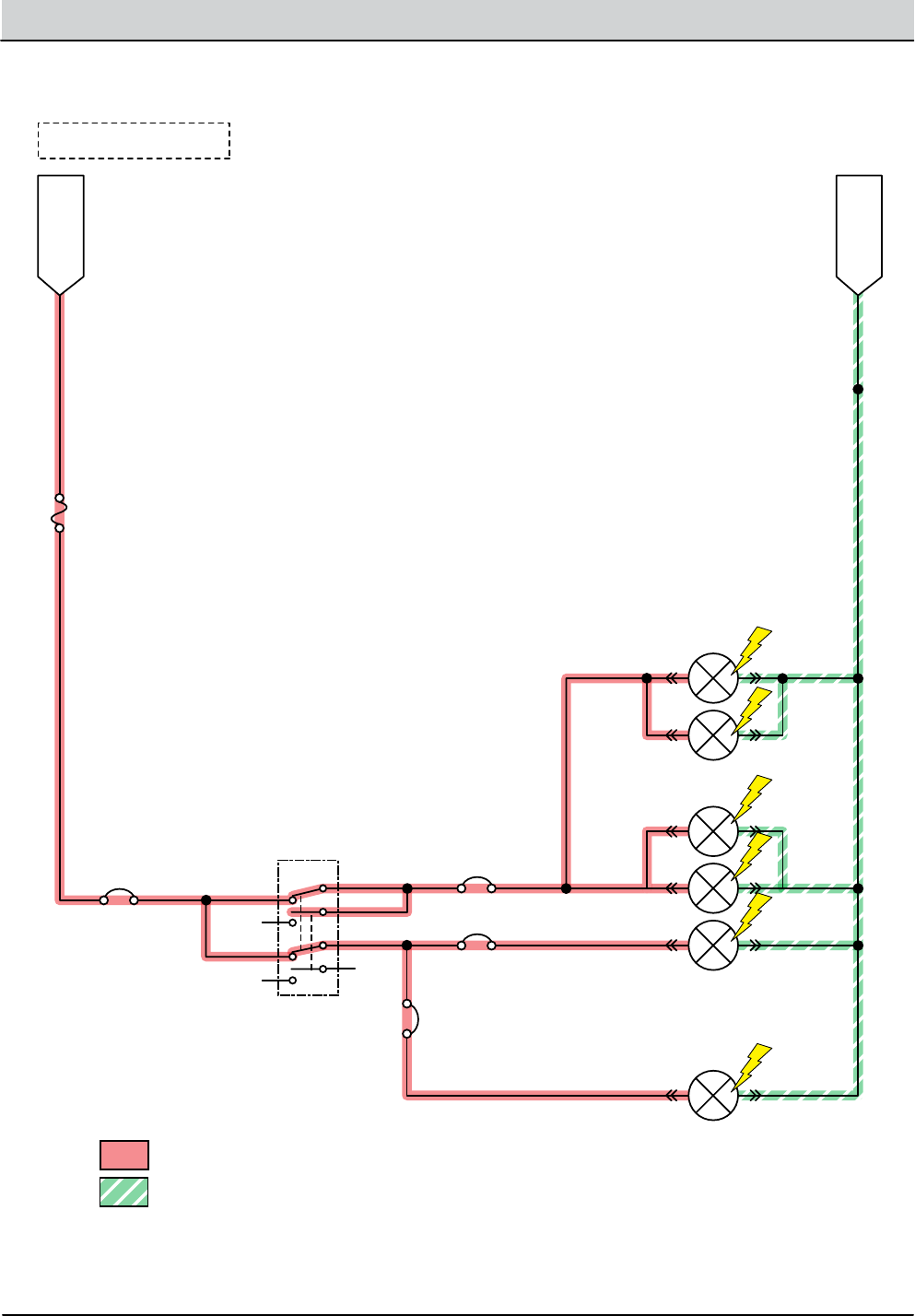
4-36 T12 Service Information 9009917 (12-12)
TROUBLESHOOTING
B- From
Stando
Battery Positive +
Battery Negative -
65/GRN
Curtis 1232
Switched B+
ELC001
Light Switch Position
Lights OFF/Down = 2-1, 6-5
Headlight ON/Center = 2-3, 6-7
Headlight and Flashing ON/Up = 3-4, 7-8
1
3
5
7
2
4
6
8
76/BLU
93/ORA
92/BRN
68/GRY
67/PUR
13/BLK 13/BLK
13/BLK
13/BLK
22/BRN
FU1
80A
Note: Key Switch ON
CB12
(15A) CB13 (2.5A)
Headlights (LED)
Red Taillights (LED)
OHG Flash/
Strobe Light
CB14 (2.5A)
CB15
(2.5A)
Flash/Strobe Light
Lighting ON

T12 Service Information 9009917 (12-12) 4-37
TROUBLESHOOTING
Lighting Failed to Turn ON
STEP ACTION VALUES YES NO
1• Key On
• Light switch On
• Firmly press circuit breaker #12 to reset
• Is circuit breaker #12 tripped?
Reset and
Test Lighting
Operation
Go to Step #2
2• Key On
• Light switch On
• Firmly press circuit breaker #13 (Option) to reset
• Is circuit breaker #13 tripped?
Reset and
Test Lighting
Operation
Go to Step #3
3• Key On
• Light switch On
• Firmly press circuit breaker #14 (Option) to reset
• Is circuit breaker #14 tripped?
Reset and
Test Lighting
Operation
Go to Step #4
4• Key On
• Light switch On
• Firmly press circuit breaker #15 (Option) to reset
• Is circuit breaker #15 tripped?
Reset and
Test Lighting
Operation
Go to Step #5
5• Key On
• Light switch On
• Test voltage applied to the lighting subsystem as
shown on the electrical schematic
• Are the electrical circuits operating as shown on the
electrical schematic?
Go Back to
Step #1
Identify Volt-
age Drop
Location and
Repair or Re-
place Neces-
sary Compo-
nents
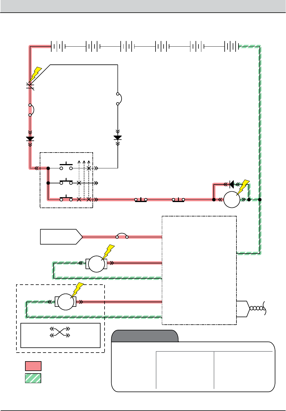
4-38 T12 Service Information 9009917 (12-12)
TROUBLESHOOTING
+ - + - + - + - + - + -
1
2
2
1
T12 Scrub Module
6 Volt
Key Switch
IGN
15
ACC
30
BATT
Switched B+
From Buss Bar
75
50 Start S-2
E-Stop
Switch
S-3
Charger
Interlock
ST
M1B
M1A
MTR J5-5 Brush RT+
J5-4 Brush RT-
J5-1 Brush LT-
J5-2 Brush LT+
Rear/Right Brush
Front*/Left Brush
*Front Cylindrical = Uses Adaptor
P1-1 (B+)
(B-) P2-1
CAN (-)
J3-2
CAN +
J3-3
Battery Positive +
Battery Negative -
D-3
D-1 D-2
CB3
2.5A
CB-1
60A
6 Volt 6 Volt 6 Volt 6 Volt 6 Volt
CB2
2.5A
1/RED
13/BLK
6/BLU 7/PUR
33/ORA2/BRN
13/BLK
26/BLU
27/PUR
MTR
24/YEL
25/GRN
3/ORA 4/YEL
Cable to Ground Stand O
5/GRN
10/TAN
2/BRNCable
MSC001
1 2
12
Main Scrub
Brushes
Enabled
• 1-STEP Scrub ON
• Fwd/Rev Propel
• 1-STEP Scrub OFF
• Neutral-Ready State
• Recovery Tank Full
• Solution Tank Empty
• Very Low Batt Voltage
• Load Current Fault
Disabled
Operational Matrix:
Twisted
Pair
Main Scrub Brushes ON

T12 Service Information 9009917 (12-12) 4-39
TROUBLESHOOTING
Main Scrub Brushes Failed to Turn ON
STEP ACTION VALUES YES NO
1• Key On
• Enable main scrub brushes subsystem
• Is there a pertinent LCD warning or fault message
displayed?
See “LCD
Warnings” or
“LCD Faults”
Sections
Go to Step #2
2• Key O
• See “Manual Mode” section of this manual
• Activate the main scrub brushes in manual mode
• Do the scrub brushes turn On?
Go to Step #6 Go to Step #3
3• Key O
• See “Self-Test Mode”
• Does the Self-Test display output circuits J5-5, J5-4,
J5-2, or J5-1 as open or shorted?
Correct Open
or Short Cir-
cuit Condition
Go to Step #4
4• Proceed to Step #5 for disk scrub head models
• Key O
• Remove cylindrical brushes from scrub head
• Check for worn out brushes (see maintenance sec-
tion)
• Check brushes for entangled debris
• Check brush idler plugs and bearings for excessive
wear, damage, seizure, etc.
• Check main brush drive belts for excessive wear,
damage, etc
• Do any of the above conditions exist?
Repair or Re-
place Neces-
sary Cylindri-
cal Scrub Head
Components
Go to Step #5
5• Key O
• See TESTING MAIN SCRUB BRUSH MOTORS in the
SERVICE section of this manual
• Do the scrub brush motors pass the testing?
See TESTING
MAIN SCRUB
BRUSH MO-
TORS
Go to Step #6 Repair or
Replace Main
Scrub Brush
Motors
6• Key O
• Reconnect main scrub brush motors to main harness
• Key On
• Enable main scrub brush motors
• Test voltage applied to the main scrub brush motor
subsystem as shown on the electrical schematic
• Are the electrical circuits operating as shown on the
electrical schematic?
Go Back to
Step #1
Identify Volt-
age Drop
Location and
Repair or Re-
place Neces-
sary Compo-
nents
Terms:
LCD = Liquid Crystal Display
J5-5 = T12 Scrub Module Connector #5, Pin #5
J5-4 = T12 Scrub Module Connector #5, Pin #4
J5-2 = T12 Scrub Module Connector #5, Pin #2
J5-1 = T12 Scrub Module Connector #5, Pin #1
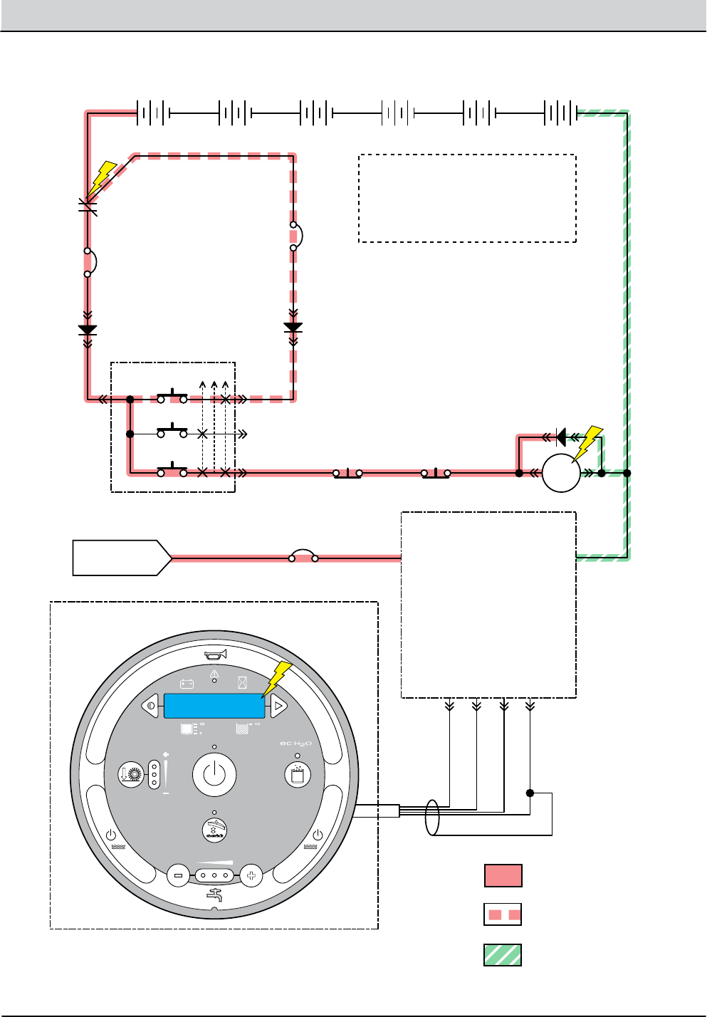
4-40 T12 Service Information 9009917 (12-12)
TROUBLESHOOTING
Power-Up ON
+ - + - + - + - + - + -
T12 Scrub Module
6 Volt
Key Switch
IGN
15
ACC
30
BAT T
Switched B+
From Buss Bar
75
50 Start S-2
E-Stop
Switch
S-3
Charger
Interlock
ST
M1B
M1A
P1-1 (B+) (B-) P2-1
Battery Positive +
(Key - On Position)
Battery Positive +
(Key - Start Position)
+12 VDC J6-16
J3-1
J3-2
J6-15
73/ORA
YEL
GRN
75/BLK-WHT
CAN +
CAN -
GROUND
D-3
D-1 D-2
CB3
2.5A
CB-1
60A
6 Volt 6 Volt 6 Volt 6 Volt 6 Volt
CB2
2.5A
1/RED
13/BLK
6/BLU 7/PUR 8/GRY
33/ORA2/BRN
Shield
Instrument Panel Assembly
13/BLK
3/ORA 4/YEL
Cable to Ground Stand O
5/GRN
10/TAN
2/BRNCable
Battery Negative -
PUC001
NOTE: The power-up circuit is a
latching type circuit. The “50” terminal
of the key switch is the primary supply
and the “30” terminal is the secondary
supply after the M1B contacts close.
Tennant T12
UI ver X.X

T12 Service Information 9009917 (12-12) 4-41
TROUBLESHOOTING
Machine Failed to Power Up
STEP ACTION VALUES YES NO
1• Key in Start Position
• Test the total battery voltage using a voltmeter
• Is the total battery voltage greater than 30 VDC?
Go to Step #2 Recharge
Batteries and
Test Power-Up
Circuit Opera-
tion
2• Key O
• Firmly press circuit breaker #2 to reset
• Is circuit breaker #2 tripped?
Reset and Test
Power-Up Cir-
cuit Operation
Go to Step #3
3• Key O
• Firmly press circuit breaker #3 to reset
• Is circuit breaker #3 tripped?
Reset and Test
Power-Up Cir-
cuit Operation
Go to Step #4
4• Key O
• Firmly press circuit breaker #1 to reset
• Is circuit breaker #1 tripped?
Reset and Test
Power-Up Cir-
cuit Operation
Go to Step #5
5• Cycle key switch from Start to On Position
• Test voltage applied to the power-up subsystem as
shown on the electrical schematic
• Are the electrical circuits operating as shown on the
electrical schematic?
Go Back to
Step #1
Identify Volt-
age Drop
Location and
Repair or Re-
place Neces-
sary Compo-
nents
Terms:
VDC = DC Voltage
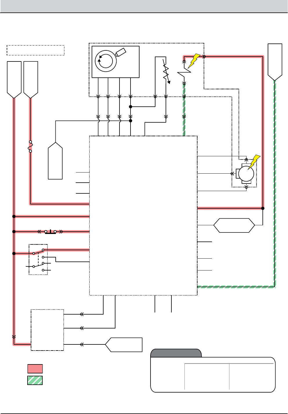
4-42 T12 Service Information 9009917 (12-12)
TROUBLESHOOTING
Propel Subsystem, Forward
B- From
Stando
S-5 Seat Switch (N.O.)
Amer
Encoder
Cable
Battery Positive +
Battery Negative -
FU1
80A
Switched B+
From Buss Bar
Switched B+
To: Throttle
Sensor (GND)
To: Curtis 1232
(I/O GND)
To: Back-Up
Light Circuit
PMC014
FWD
REV
6
2
8
BA
5
4 J1-33
GND Cable
J1-34
J1-21
W/WHT
V/GRN
U/ORN
J1-3
J1-4
J1-13
J1-24
BLU2 J1-32
J1-26
J1-31
J1-7
J1-18
J1-15
66/BLU
61/PNK
62/BRN
12/BRN
17/PUR
Propel Motor Assembly
17/PUR
15/GRN
Temp Sender
Brake
Solenoid
59/WHT
58GRY
RED1
WHT5
BLK6
YEL
T2
B1 B2
T1
YEL
J1-16
J1-35
J1-23
P1-C
BLU
YEL
P1-B
P1-D
BLK
P1-A
RED
J1-22
J1-9
J1-1
B+
J1-29
J1-28
J1-25
1
MTR
Curtis 1232
Controller
PROG +
TX
RX
B+
KSI
INTERLOCK
FWD
FWD/REV Switch
Throttle Sensor
REV
B -
GND
B+
THROTTLE
BRAKE
CAN TERM L
CAN TERM H
U
DRV3
DRV4
DRV1
THERMISTOR
I/O GND
PHASE A
PHASE B
+5V
DRV2
COIL RETURN
V
W
BRAKE IN
(0-5 vdc)
(0-5 vdc) THROTTLE
CAN -
8/GRY 8/GRY
16/BLU
18/GRY
9/WHT
11/PNK
14/YEL
58/GRY
58/GRY
CAN +
Note: Key Switch ON
Propel
Enabled
• Seat Switch Closed
• Foot Throttle
Command
• Fwd/Rev Switch Input
• Seat Switch Open
• Neutral-Ready State
• Brake Command
• Curtis 1232 Fault
Disabled
Operational Matrix:

T12 Service Information 9009917 (12-12) 4-43
TROUBLESHOOTING
Machine Failed to Propel
STEP ACTION VALUES YES NO
1• Key On
• See “Curtis 1232 Controller Diagnostics” section of
this manual
• Does a Curtis 1232 controller fault condition exist?
Correct Fault
Condition
Go to Step #2
2• Key O
• See “Propel Diagnostic Mode”
• Is P1:Curtis Online?
• Does P2: Throttle input voltage (0-5 vdc) change
proportionally with throttle pedal movement?
• Does P3 :Brake pedal input turn On/O with brake
pedal activation?
• Does P4: Direction input correspond with Fwd/Rev
rocker switch position?
• Does P5:Speed input from drive assembly encoder
(speed, direction, position sensor) read “0000.0
Mph?”
• Does P8:Propel motor current read “0000.0 Amps?”
• Is the answer “Yes” to all of the above?
Go to Step #3 Correct Faulty
Input Condi-
tion
3• Key O
• Place machine on jackstands so drive wheel is lifted
o the oor
• Enable forward propel
• Test voltage applied to the propel subsystem as
shown on the electrical schematic
• Are the electrical circuits operating as shown on the
electrical schematic?
Go Back to
Step #1
Identify Volt-
age Drop
Location and
Repair or Re-
place Neces-
sary Compo-
nents
Terms:
LCD = Liquid Crystal Display
VDC = Direct Current Voltage
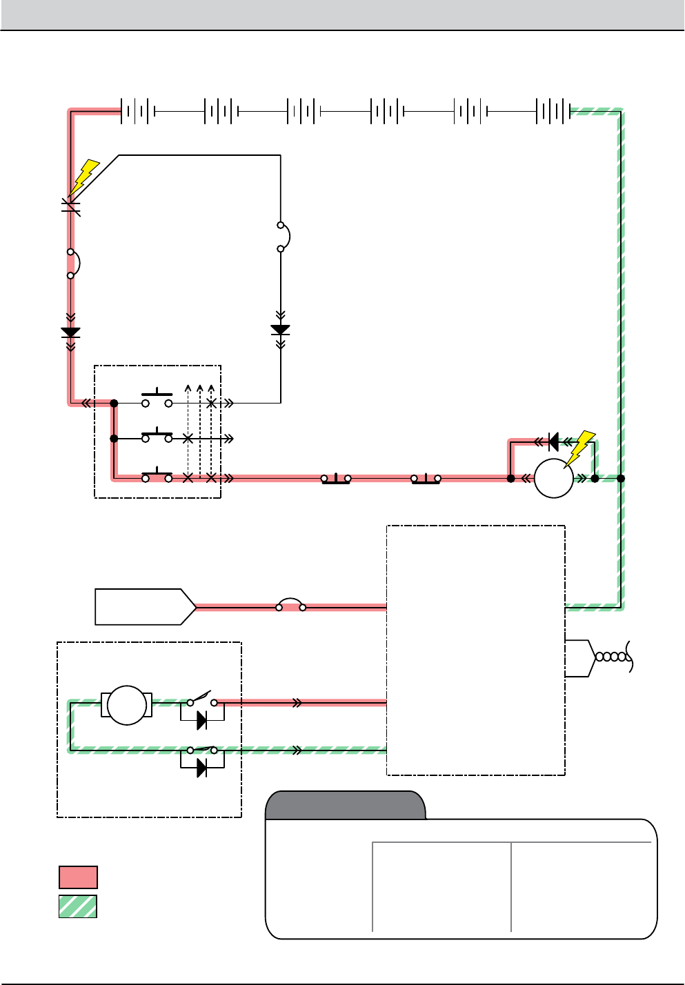
4-44 T12 Service Information 9009917 (12-12)
TROUBLESHOOTING
Rear Squeegee Down, OFF
+ - + - + - + - + - + -
T12 Water
Pick-Up Module
6 Volt
Key Switch
IGN
15
ACC
30
BATT
Switched B+
From Buss Bar
75
50 Start S-2
E-Stop
Switch
S-3
Charger
Interlock
ST
M1B
M1A
MTR
J5-2 SQGE ACT 1
J3-1 B+ B- J3-4
CAN (-) J2-2
CAN (+) J2-1
J5-3 SQGE ACT 2
Squeegee
Actuator
Battery Positive +
Battery Negative -
D-3
D-1 D-2
CB3
2.5A
CB5
25A
6 Volt 6 Volt 6 Volt 6 Volt 6 Volt
CB2
2.5A
1/RED
13/BLK
6/BLU 7/PUR 8/GRY
31/PNK2/BRN 13/BLK
29/WHT
Extend
Limit Sw.
Retract
Limit Sw.
30/TAN
BLU
BRN
3/ORA 4/YEL
Cable to Ground Stand O
5/GRN
10/TAN
2/BRNCable
RSL001
1
2
Squeegee
Down
Enabled
• 1-STEP Scrub ON
• Squeegee/Vac ON
• 1-STEP Scrub OFF
• Squeegee/Vac OFF
• Reverse Propel
• Recovery Tank Full
• Very Low Batt Voltage
• Load Current Fault
Disabled
Operational Matrix:
Twisted
Pair

T12 Service Information 9009917 (12-12) 4-45
TROUBLESHOOTING
Rear Squeegee Failed to Raise/Lower
STEP ACTION VALUES YES NO
1• Key On
• Enable rear squeegee down
• Is there a pertinent LCD warning or fault message
displayed?
See “LCD
Warnings” or
“LCD Faults”
Sections
Go to Step #2
2• Key O
• See “Manual Mode” section of this manual
• Activate the rear squeegee in manual mode
• Does the rear squeegee raise/lower?
Go to Step #5 Go to Step #3
3• Key O
• See “Self-Test Mode”
• Does the Self-Test display output circuits J5-3 and
J5-2 as open or shorted?
Correct Open
or Short Cir-
cuit Condition
Go to Step #4
4• Key O
• See TESTING REAR SQUEEGEE LIFT ACTUATOR in the
SERVICE section of this manual
• Does the rear squeegee lift actuator pass the testing?
See TESTING
REAR SQUEE-
GEE LIFT
ACTUATOR in
the SERVICE
section of this
manual.
Go to Step #5 Replace Rear
Squeegee Lift
Actuator
5• Key O
• Reconnect rear squeegee lift actuator to main wire
harness
• Test voltage applied to rear squeegee lift subsystem
as shown on the electrical schematic
• Are the electrical circuits operating as shown on the
electrical schematic?
Go Back to
Step #1
Identify Volt-
age Drop
Location and
Repair or
Replace Neces-
sary Compo-
nents
Terms:
LCD = Liquid Crystal Display
J5-3 = Water PU Module Connector #5, Pin #3
J5-2 = Water PU Module Connector #5, Pin #2
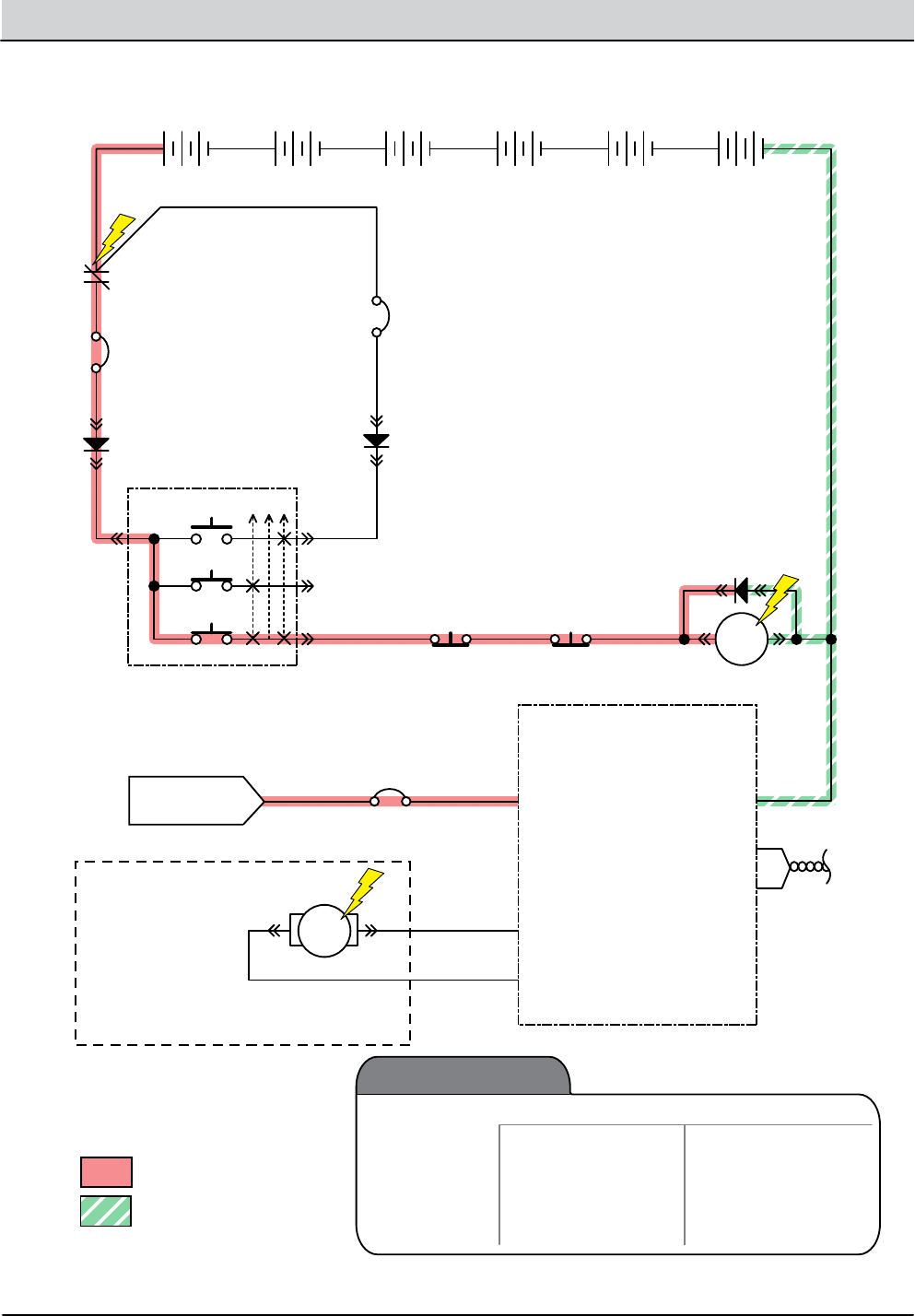
4-46 T12 Service Information 9009917 (12-12)
TROUBLESHOOTING
+ - + - + - + - + - + -
T12 Scrub Module
6 Volt
Key Switch
IGN
15
ACC
30
BATT
Switched B+
From Buss Bar
75
50 Start S-2
E-Stop
Switch
S-3
Charger
Interlock
ST
M1B
M1A
P1-1 B+ B(-) P2-1
CAN(-) J3-2
CAN(+) J3-1
MTR
Scrub Head Lift Actuator
J6-7 Scrub Act. 1
Battery Positive +
Battery Negative -
J6-8 Scrub Act. 2
D-3
D-1 D-2
CB3
2.5A
CB1
60A
6 Volt 6 Volt 6 Volt 6 Volt 6 Volt
CB2
2.5A
1/RED
13/BLK
6/BLU 7/PUR 8/GRY
56/BLU
33/ORA2/BRN
13/BLK
23/ORA
3/ORA 4/YEL
Cable to Ground Stand O
5/GRN
10/TAN
2/BRNCable
MSL001
12
Note:
B+ @ 23/ORA = Retract/Down
B+ @ 56/BLU = Extend/Up
Scrub Head
Down
Enabled
• 1-STEP Scrub ON
• Fwd/Rev Propel
• 1-STEP Scrub OFF
• Neutral-Ready State
• Recovery Tank Full
• Solution Tank Empty
• Very Low Batt Voltage
• Load Current Fault
Disabled
Operational Matrix:
Twisted
Pair
Scrub Head Lift

T12 Service Information 9009917 (12-12) 4-47
TROUBLESHOOTING
Scrub Head Failed to Raise/Lower
STEP ACTION VALUES YES NO
1• Key On
• Enable scrub head down
• Is there a pertinent LCD warning or fault message
displayed?
See “LCD
Warnings” or
“LCD Faults”
Sections
Go to Step #2
2• Key O
• See “Manual Mode” section of this manual
• Activate the scrub head in manual mode
• Does the scrub head raise/lower?
Go to Step #5 Go to Step #3
3• Key O
• See “Self-Test Mode”
• Does the Self-Test display output circuits J6-8 and
J6-7 as open or shorted?
Correct Open
or Short Cir-
cuit Condition
Go to Step #4
4• Key O
• See TESTING MAIN BRUSH LIFT ACTUATOR in the
SERVICE section of this manual
• Does the scrub head lift actuator pass the testing?
See TESTING
MAIN BRUSH
LIFT ACTUA-
TOR
Go to Step #5 Replace Scrub
Head Lift
Actuator
5• Key O
• Reconnect scrub head lift actuator to main wire har-
ness
• Test voltage applied to scrub head lift subsystem as
shown on the electrical schematic
• Are the electrical circuits operating as shown on the
electrical schematic?
Go Back to
Step #1
Identify Volt-
age Drop
Location and
Repair or Re-
place Neces-
sary Compo-
nents
Terms:
LCD = Liquid Crystal Display
J6-8 = Scrub Module Connector #6, Pin #8
J6-7 = Scrub Module Connector #6, Pin #7

4-48 T12 Service Information 9009917 (12-12)
TROUBLESHOOTING
Side Brush ON (Option)
+ - + - + - + - + - + -
T12 Side Scrub
Module
6 Volt
Key Switch
IGN
15
ACC
30
BATT
Switched B+
From Buss Bar
75
50 Start S-2
E-Stop
Switch
S-3
Charger
Interlock
ST
M1B
M1A
J3-1 B(+)
Side Br Sel J5-7
MTR
Side Brush Motor
Note:
Congurable Option
Side Scrub = 100% Battery VDC
Side Sweep = 50% Battery VDC
J3-2 Side Br -
Battery Positive +
Battery Negative -
J3-3 Side Br +
CAN+ J2-1
CAN- J2-2
Enable J5-6
B(-) J3-4
D-3
D-1 D-2
CB3
2.5A
CB9
20A
6 Volt 6 Volt 6 Volt 6 Volt 6 Volt
CB2
2.5A
1/RED
13/BLK
6/BLU 7/PUR 8/GRY
43/ORA
37/PUR22/BRN
13/BLK
Side Brush
44/YEL
45/GRN
3/ORA 4/YEL
Cable to Ground Stand O
5/GRN
10/TAN
2/BRNCable
SBC001
1 2
ON
OFF
6
2
8
5
4
1
Twisted Pair
Side Brush
Enabled
• 1-STEP Scrub ON
• Side Brush Switch ON
• Fwd/Rev Propel
• 1-STEP Scrub OFF
• Side Brush Switch OFF
• Recovery Tank Full
• Solution Tank Empty
• Very Low Batt Voltage
• Load Current Fault
• Neutral (Ready State)
Disabled
Operational Matrix:

T12 Service Information 9009917 (12-12) 4-49
TROUBLESHOOTING
Side Brush Failed to Turn ON (Option)
STEP ACTION VALUES YES NO
1• Key On
• Enable side brush
• Is there a pertinent LCD warning or fault message
displayed?
See “LCD
Warnings” or
“LCD Faults”
Sections
Go to Step #2
2• Key O
• See “Manual Mode” section of this manual
• Activate the side brush in manual mode
• Do the side brush turn On?
Go to Step #6 Go to Step #3
3• Key O
• See “Self-Test Mode”
• Does the Self-Test display output circuits J3-3 and
J3-2 as open or shorted?
Correct Open
or Short Cir-
cuit Condition
Go to Step #4
4• Key O
• See “Input Display Mode”
• Does I7: Side Br On/O input correspond with side
brush rocker switch position?
Go to Step #5 Correct Faulty
Input Condi-
tion
5• Key O
• See TESTING SIDE BRUSH MOTOR in the SERVICE sec-
tion of this manual
• Does the side brush motor pass the testing?
See TESTING
SIDE BRUSH
MOTOR
Go to Step #6 Replace Side
Brush Motor
6• Key O
• Reconnect side brush motor to main wire harness
• Test voltage applied to side brush subsystem as
shown on the electrical schematic
• Are the electrical circuits operating as shown on the
electrical schematic?
Go Back to
Step #1
Identify Volt-
age Drop
Location and
Repair or Re-
place Neces-
sary Compo-
nents
Terms:
LCD = Liquid Crystal Display
J3-2 = Side Scrub Module Connector #3, Pin #2
J3-3 = Side Scrub Module Connector #3, Pin #3
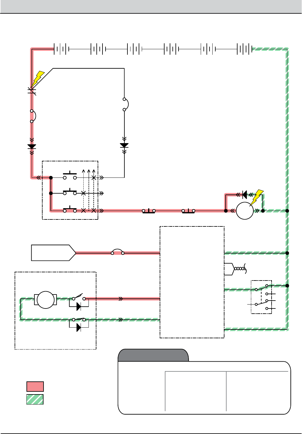
4-50 T12 Service Information 9009917 (12-12)
TROUBLESHOOTING
Side Brush Extend/Down, OFF (Option)
+ - + - + - + - + - + -
T12 Side Scrub
Module
6 Volt
Key Switch
IGN
15
ACC
30
BATT
Switched B+
From Buss Bar
75
50 Start S-2
E-Stop
Switch
S-3
Charger
Interlock
ST
M1B
M1A
J3-1 B(+)
Side Br Sel J5-7
Battery Positive +
Battery Negative -
CAN+ J2-1
CAN- J2-2
Enable J5-6
B(-) J3-4
D-3
D-1 D-2
CB3
2.5A
CB9
20A
6 Volt 6 Volt 6 Volt 6 Volt 6 Volt
CB2
2.5A
1/RED
13/BLK
6/BLU 7/PUR 8/GRY
37/PUR22/BRN
13/BLK
Side Brush
45/GRN
3/ORA 4/YEL
Cable to Ground Stand O
5/GRN
10/TAN
2/BRNCable
SBC002
ON
OFF
6
2
8
5
4
1
MTR
J5-2 Side Act 1
J5-3 Side Act 2
Side Brush
Actuator
42/BRN
Extend
Limit Sw.
Retract
Limit Sw.
53/ORA
BLK
BLK
2
1
Side Brush
Extend/Down
Enabled
• 1-STEP Scrub ON
• Side Brush Switch ON
• 1-STEP Scrub OFF
• Side Brush Switch OFF
• Recovery Tank Full
• Solution Tank Empty
• Very Low Batt Voltage
• Load Current Fault
Disabled
Operational Matrix:
Twisted Pair

T12 Service Information 9009917 (12-12) 4-51
TROUBLESHOOTING
Side Brush Failed to Extend/Lower (Option)
STEP ACTION VALUES YES NO
1• Key On
• Enable side brush extend/down
• Is there a pertinent LCD warning or fault message
displayed?
See “LCD
Warnings” or
“LCD Faults”
Sections
Go to Step #2
2• Key O
• See “Manual Mode” section of this manual
• Extend/Lower the side brush in manual mode
• Does the side brush extend/lower?
Go to Step #6 Go to Step #3
3• Key O
• See “Self-Test Mode”
• Does the Self-Test display output circuits J5-3 and
J5-2 as open or shorted?
Correct Open
or Short Cir-
cuit Condition
Go to Step #4
4• Key O
• See “Input Display Mode”
• Does I7: Side Br On/O input correspond with side
brush rocker switch position?
Go to Step #5 Correct Faulty
Input Condi-
tion
5• Key O
• See TESTING SIDE BRUSH LIFT ACTUATOR in the SER-
VICE section of this manual
• Does the side brush lift actuator pass the testing?
See TESTING
SIDE BRUSH
LIFT ACTUA-
TOR
Go to Step #6 Replace Side
Brush Lift
Actuator
6• Key O
• Reconnect side brush lift actuator to main wire har-
ness
• Key On
• Side brush extend/down enabled
• Test voltage applied to side brush lift subsystem as
shown on the electrical schematic
• Are the electrical circuits operating as shown on the
electrical schematic?
Go Back to
Step #1
Identify Volt-
age Drop
Location and
Repair or Re-
place Neces-
sary Compo-
nents
Terms:
LCD = Liquid Crystal Display
J5-2 = Side Scrub Module Connector #5, Pin #2
J5-3 = Side Scrub Module Connector #5, Pin #3
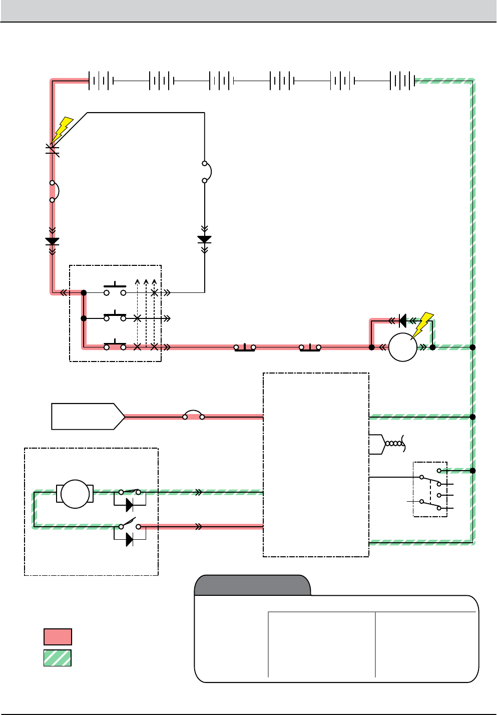
4-52 T12 Service Information 9009917 (12-12)
TROUBLESHOOTING
Side Brush Retract/Up, OFF (Option)
+ - + - + - + - + - + -
T12 Side Scrub
Module
6 Volt
Key Switch
IGN
15
ACC
30
BATT
Switched B+
From Buss Bar
75
50 Start S-2
E-Stop
Switch
S-3
Charger
Interlock
ST
M1B
M1A
J3-1 B(+)
Side Br Sel J5-7
Battery Positive +
Battery Negative -
CAN+ J2-1
CAN- J2-2
Enable J5-6
B(-) J3-4
D-3
D-1 D-2
CB3
2.5A
CB9
20A
6 Volt 6 Volt 6 Volt 6 Volt 6 Volt
CB2
2.5A
1/RED
13/BLK
6/BLU 7/PUR 8/GRY
37/PUR22/BRN
13/BLK
Side Brush
45/GRN
3/ORA 4/YEL
Cable to Ground Stand O
5/GRN
10/TAN
2/BRNCable
SBC003
ON
OFF
6
2
8
5
4
1
MTR
J5-2 Side Act 1
J5-3 Side Act 2
Side Brush
Actuator
42/BRN
Extend
Limit Sw.
Retract
Limit Sw.
53/ORA
BLK
BLK
2
1
Side Brush
Retract/Up
Enabled
• 1-STEP Scrub ON
• Side Brush Switch ON
• 1-STEP Scrub OFF
• Side Brush Switch OFF
• Recovery Tank Full
• Solution Tank Empty
• Very Low Batt Voltage
• Load Current Fault
Disabled
Operational Matrix:
Twisted Pair

T12 Service Information 9009917 (12-12) 4-53
TROUBLESHOOTING
Side Brush Failed to Retract/Raise (Option)
STEP ACTION VALUES YES NO
1• Key On
• Enable side brush retract/up
• Is there a pertinent LCD warning or fault message
displayed?
See “LCD
Warnings” or
“LCD Faults”
Sections
Go to Step #2
2• Key O
• See “Self-Test Mode”
• Does the Self-Test display output circuits J5-3 and
J5-2 as open or shorted?
Correct Open
or Short Cir-
cuit Condition
Go to Step #3
3• Key O
• See “Input Display Mode”
• Does I7: Side Br On/O input correspond with side
brush rocker switch position?
Go to Step #4 Correct Faulty
Input Condi-
tion
4• Key O
• See TESTING SIDE BRUSH LIFT ACTUATOR in the SER-
VICE section of this manual
• Does the side brush lift actuator pass the testing?
See TESTING
SIDE BRUSH
LIFT ACTUA-
TOR
Go to Step #5 Replace Side
Brush Lift
Actuator
5• Key On
• Side brush switch O
• Test voltage applied to side brush lift subsystem as
shown on the electrical schematic
• Are the electrical circuits operating as shown on the
electrical schematic?
Go Back to
Step #1
Identify Volt-
age Drop
Location and
Repair or Re-
place Neces-
sary Compo-
nents
Terms:
LCD = Liquid Crystal Display
J5-2 = Side Scrub Module Connector #5, Pin #2
J5-3 = Side Scrub Module Connector #5, Pin #3
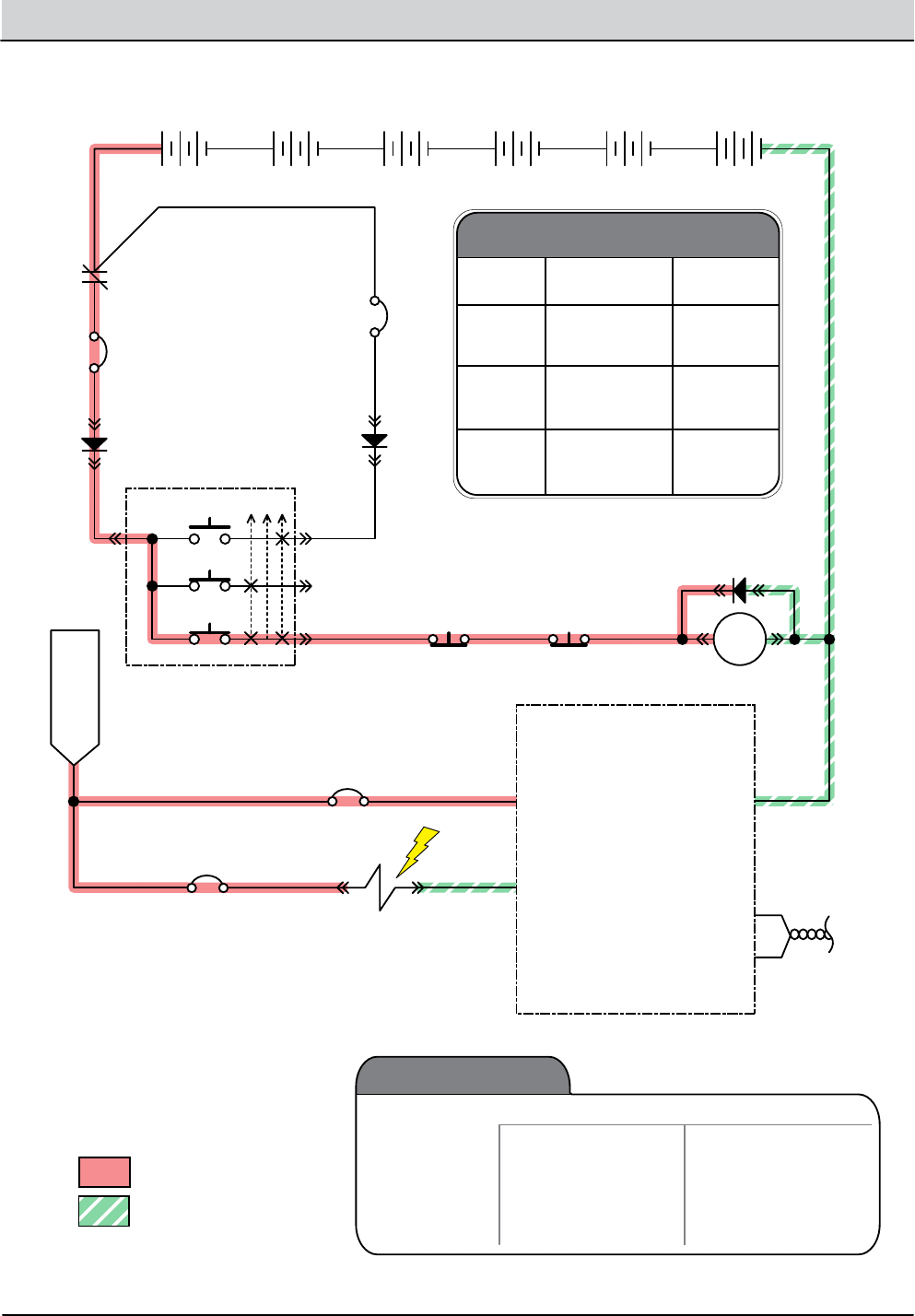
4-54 T12 Service Information 9009917 (12-12)
TROUBLESHOOTING
Solution Control ON - Main Brush (Conventional)
+ - + - + - + - + - + -
T12 Scrub Module
6 Volt
Key Switch
IGN
15
ACC
30
BATT
Switched B+
From Buss Bar
75
50 Start S-2
E-Stop
Switch
S-3
Charger
Interlock
ST
M1B
M1A
P1-1 B+ B(-) P2-1
CAN(-) J3-2
CAN(+) J3-1
Battery Positive +
Battery Negative -
D-3
D-1 D-2
CB3
2.5A
CB1
60A
6 Volt 6 Volt 6 Volt 6 Volt 6 Volt
CB2
2.5A
1/RED
13/BLK
6/BLU 7/PUR 8/GRY
33/ORA2/BRN
13/BLK
3/ORA 4/YEL
Cable to Ground Stand O
5/GRN
10/TAN
2/BRNCable
CSC002
* SV2 (J6-2) H2O Valve Voltages
Range
Low 1-LED
2-LEDs
3-LEDs
1-LED
2-LEDs
3-LEDs
1-LED
2-LEDs
3-LEDs
20%
36%
53%
36%
53%
70%
53%
70%
87%
Med
(Default)
High
Level PWM%
J6-2 MAIN H2O
CB4
2.5A
*SV2 Main Scrub
H2O Valve
19/WHT34/YEL
Solution
Control - Main
(Conventional)
Enabled
• 1-STEP Scrub ON
• Solution Control ON
• Fwd/Rev Propel
• 1-STEP Scrub OFF
• Solution Control OFF
• Neutral-Ready State
• Recovery Tank Full
• Solution Tank Empty
• Very Low Batt Voltage
• Load Current Fault
Disabled
Operational Matrix:
Twisted
Pair

T12 Service Information 9009917 (12-12) 4-55
TROUBLESHOOTING
Solution Control Failed to Turn ON - Main Brush (Conventional)
STEP ACTION VALUES YES NO
1• Key On
• Enable solution control (conventional)
• Is there a pertinent LCD warning or fault message
displayed?
See “LCD
Warnings” or
“LCD Faults”
Sections
Go to Step #2
2• Key O
• See “Manual Mode” section of this manual
• Activate solution control in manual mode
• Does the machine dispense water to the oor?
Go to Step #7 Go to Step #3
3• Key O
• See “Self-Test Mode”
• Does the Self-Test display output circuit J6-2 as open
or shorted?
Correct Open
or Short Cir-
cuit Condition
Go to Step #4
4• Key O
• Firmly press circuit breaker #4 to reset
• Is circuit breaker #4 tripped?
Reset and Test
Solution Con-
trol Operation
Go to Step #5
5• Key O
• Disconnect SV2 from main wire harness
• Apply battery voltage to SV2 using fuse-protected
jumper leads
• Does the main brush dispense solution?
Go to Step #6 Repair or Re-
place SV2
6• Key O
• Reconnect SV2 to main wire harness
• Key On
• Enable solution control (conventional)
• Test voltage applied to solution control subsystem as
shown on the electrical schematic
• Are the electrical circuits operating as shown on the
electrical schematic?
Go Back to
Step #1
Identify Volt-
age Drop
Location and
Repair or Re-
place Neces-
sary Compo-
nents
Terms:
LCD = Liquid Crystal Display
J6-2 = Scrub Module Connector #6, Pin #2
SV2 = Solenoid Valve #2 (Main Brush)
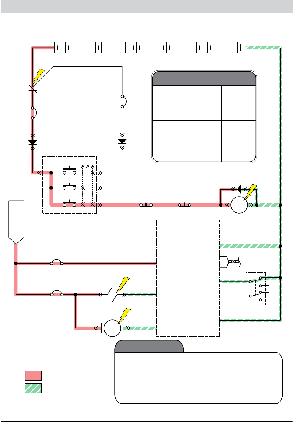
4-56 T12 Service Information 9009917 (12-12)
TROUBLESHOOTING
Solution Control ON - Side Brush (Conventional)
+ - + - + - + - + - + -
T12 Side Scrub
Module
6 Volt
Key Switch
IGN
15
ACC
30
BATT
75
50 Start S-2
E-Stop
Switch
S-3
Charger
Interlock
ST
M1B
M1A
J3-1 B(+)
Side Br Sel J5-7
Battery Positive +
Battery Negative -
CAN+ J2-1
CAN- J2-2
Enable J5-6
B(-) J3-4
D-3
D-1 D-2
CB3
2.5A
CB9
20A
6 Volt 6 Volt 6 Volt 6 Volt 6 Volt
CB2
2.5A
1/RED
13/BLK
6/BLU 7/PUR 8/GRY
37/PUR22/BRN
13/BLK
Side Brush
45/GRN
3/ORA 4/YEL
Cable to Ground Stand O
5/GRN
10/TAN
2/BRNCable
SBC004
ON
OFF
6
2
8
5
4
1
J5-4 Side H2O Valve
J5-5 Side H2O Pump
CB10
2.5A
40/TAN
39/WHT
38/GRY
22/BRN
SV3 Side Br.
H2O Valve
*Side Br.
Water Pump
MTR
Switched B+
From Buss Bar
Twisted Pair
Solution
Control-Side
(Conventional)
Enabled
• 1-STEP Scrub ON
• Side Brush Switch ON
• Fwd/Rev Propel
• 1-STEP Scrub OFF
• Side Brush Switch OFF
• Recovery Tank Full
• Solution Tank Empty
• Very Low Batt Voltage
• Load Current Fault
• Neutral (Ready State)
Disabled
Operational Matrix:
* Side Pump (J5-5) Voltages
Range
Low 1-LED
2-LEDs
3-LEDs
1-LED
2-LEDs
3-LEDs
1-LED
2-LEDs
3-LEDs
10.5 V
16.5 V
22 V
16.5 V
22 V
27 V
22 V
27 V
32.5 V
Med
(Default)
High
Level Voltage

T12 Service Information 9009917 (12-12) 4-57
TROUBLESHOOTING
Solution Control Failed to Turn ON - Side Brush (Conventional)
STEP ACTION VALUES YES NO
1• Key On
• Enable side brush solution control (conventional)
• Is there a pertinent LCD warning or fault message
displayed?
See “LCD
Warnings” or
“LCD Faults”
Sections
Go to Step #2
2• Key O
• See “Manual Mode” section of this manual
• Activate solution control in manual mode
• Does the machine dispense water to the side brush?
Go to Step #7 Go to Step #3
3• Key O
• See “Self-Test Mode”
• Does the Self-Test display output circuits J5-4 or J5-5
as open or shorted?
Correct Open
or Short Cir-
cuit Condition
Go to Step #4
4• Key O
• Firmly press circuit breaker #9 to reset
• Is circuit breaker #9 tripped?
Reset and Test
Solution Con-
trol Operation
Go to Step #5
5• Key O
• Firmly press circuit breaker #10 to reset
• Is circuit breaker #10 tripped?
Reset and Test
Solution Con-
trol Operation
Go to Step #6
6• Key O
• Disconnect SV3 and side brush water pump from
main wire harness
• Apply battery voltage to SV3 and side brush water
pump using fuse-protected jumper leads
• Does the side brush dispense solution?
Go to Step #7 Repair or
Replace SV3
or Side Brush
Water Pump
7• Key O
• Reconnect SV3 and side brush water pump to main
wire harness
• Key On
• Enable side brush solution control (conventional)
• Test voltage applied to the side brush solution con-
trol subsystem as shown on the electrical schematic
• Are the electrical circuits operating as shown on the
electrical schematic?
Go Back to
Step #1
Identify Volt-
age Drop
Location and
Repair or Re-
place Neces-
sary Compo-
nents
Terms:
LCD = Liquid Crystal Display
J5-4 = Side Scrub Module Connector #5, Pin #4
J5-5 = Side Scrub Module Connector #5, Pin #5
SV3 = Solenoid Valve #3 (Side Brush)
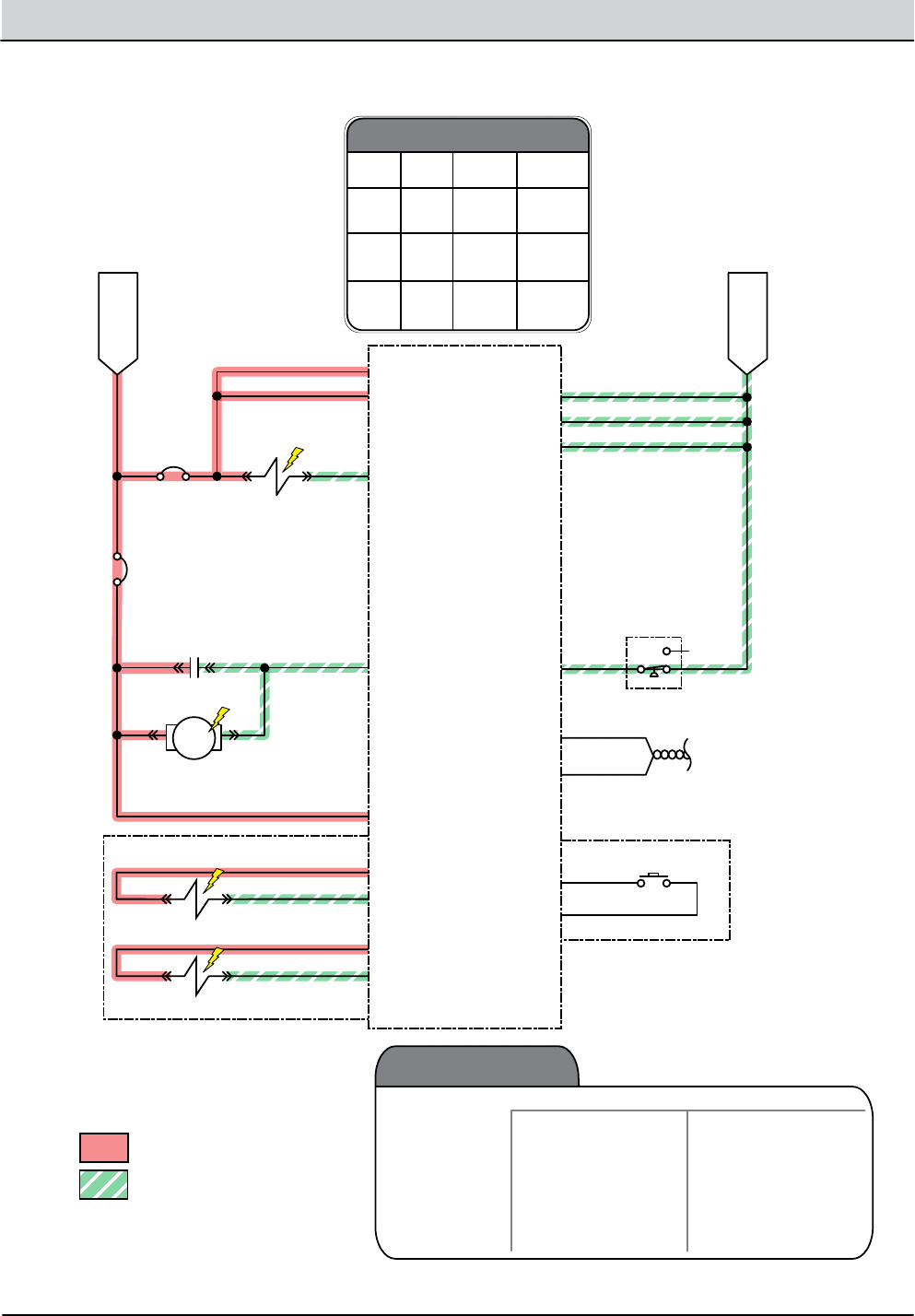
4-58 T12 Service Information 9009917 (12-12)
TROUBLESHOOTING
Solution Control ON (ec-H2O)
Switched B+
From Buss Bar
B- From
Stando
C1 Capacitor (0.01Uf)
+ -
ec-H2O Pump
ec-H2O
Module
J4-1 VCC_1
Com N.C.
N.O.
N.C. Opens @
25 +/- 2 psi = Fault
GND J4-14
GND J4-13
GND J4-12
CAN (+) J4-10
CAN (-) J4-11
Pressure IN
J4-9
(ec-H2O SW)
J5-6
(ec-H2O SW)
J5-5
J4-2 VCC_2
J4-5 Side Br. Valve
J4-4 Pump
J4-3 Flyback
Sparger
e-Cell
8EA/GRY
7EA/PUR
3EA/ORA
4EA/YEL
J5-1 (SPA-A)
J5-2 (SPA-B)
J5-3 (CELL-A)
J5-4 (CELL-B)
Battery Positive +
Battery Negative -
SV4 ec-H2O
Side Br. Valve
CB6
2.5A
46/BLU 51/PNK
52/BRN
50/TAN
CB7
2.5A
13/BLK
CAN-/GRN
CAN+/YEL
60/TAN
9EA/WHT
Flush Switch
13EA/BLK
2/BRN 50/TAN
ECC001
MTR
Solution
Control
(ec-H2O)
Enabled
• 1-STEP Scrub ON
• Solution Control ON
• ec-H2O Button ON
• Fwd/Rev Propel
• 1-STEP Scrub OFF
• Solution Control OFF
• ec-H2O Button OFF
• Neutral-Ready State
• Recovery Tank Full
• Solution Tank Empty
• Very Low Batt Voltage
• ec-H2O System Fault
• Load Current Fault
Disabled
Operational Matrix:
Twisted Pair
* Ec Pump (J4-4) Voltages
Range
Low 1-LED
2-LEDs
3-LEDs
1-LED
2-LEDs
3-LEDs
1-LED
2-LEDs
3-LEDs
5 V
7 V
9 V
7 V
9 V
11.5 V
9 V
11.5 V
17 V
9.5 V
12 V
14.3 V
12 V
14.3 V
16.7 V
14.3 V
16.7 V
19.3 V
Med
(Default)
High
Level Voltage + Side Br

T12 Service Information 9009917 (12-12) 4-59
TROUBLESHOOTING
Solution Control Failed to Turn ON (ec-H2O)
STEP ACTION VALUES YES NO
1• Key On
• Enable solution control (ec-H2O)
• Is there a pertinent LCD warning or fault message
displayed?
See “LCD
Warnings” or
“LCD Faults”
Sections
Go to Step #2
2• Key O
• Firmly press circuit breakers #6 and #7 to reset
• Is a circuit breaker tripped?
Reset and Test
ec-H2O Solu-
tion Control
Operation
Go to Step #3
3• Key O
• Enable solution control (ec-H2O)
• Is the ec-H2O LED ashing RED, indicating a system
restriction or low water conductivity*?
See “ec-H2O
Module Flush
Procedure”
Section. Then
Proceed to
Step #4
Go to Step #5
4• Key O
• See “ec-H2O Module Flush Procedure” section of this
manual
• Did the ush procedure x the problem?
System OK See “Testing
ec-H2O Pres-
sure Switch”
5• Key O
• See “Manual Mode” section of this manual
• Activate solution control (ec-H2O) in manual mode
• Does solution control (ec-H2O) turn On?
Go to Step #8 Go to Step #6
6• Key O
• See “Self-Test Mode”
• Does the Self-Test display output circuits J4-4, J4-5,
J5-1, or J5-2, J5-3, or J5-4 as open or shorted?
See “Self-Test
Mode”
Correct Open
or Short Cir-
cuit Condition
Go to Step #7
7• Key O
• Disconnect ec-H2O water pump from wire harness
• Apply battery voltage to ec-H2O water pump using
fuse-protected jumper leads
• Does the ec-H2O water pump dispense water?
Go to Step #8 Repair or Re-
place ec-H2O
Water Pump
8• Key O
• Reconnect ec-H2O water pump to wire harness
• Key On
• Enable solution control (ec-H2O)
• Test voltage applied to solution control (ec-H2O)
system as shown on the electrical schematic
• Are the electrical circuits operating as shown on the
electrical schematic?
Go to Step #9 Identify Volt-
age Drop
Location and
Repair or Re-
place Neces-
sary Compo-
nents
9• Key On
• Enable solution control (ec-H2O)
• Is the ec-H2O LED solid RED, indicating an overcur-
rent condition on a system component?
Replace
ec-H2O
Module
Go Back to
Step #1
Terms:
LCD = Liquid Crystal Display
LED = Light Emitting Diode
J4-4 = ec-H2O Module Connector #4, Pin #4
J4-5 = ec-H2O Module Connector #4, Pin #5
*NOTE: Add 1/2 tablespoon of salt for every 10 gallons of water in the solution tank to increase water conductivity.
J5-1 = ec-H2O Module Connector #5, Pin #1
J5-2 = ec-H2O Module Connector #5, Pin #2
J5-3 = ec-H2O Module Connector #5, Pin #3
J5-4 = ec-H2O Module Connector #5, Pin #4
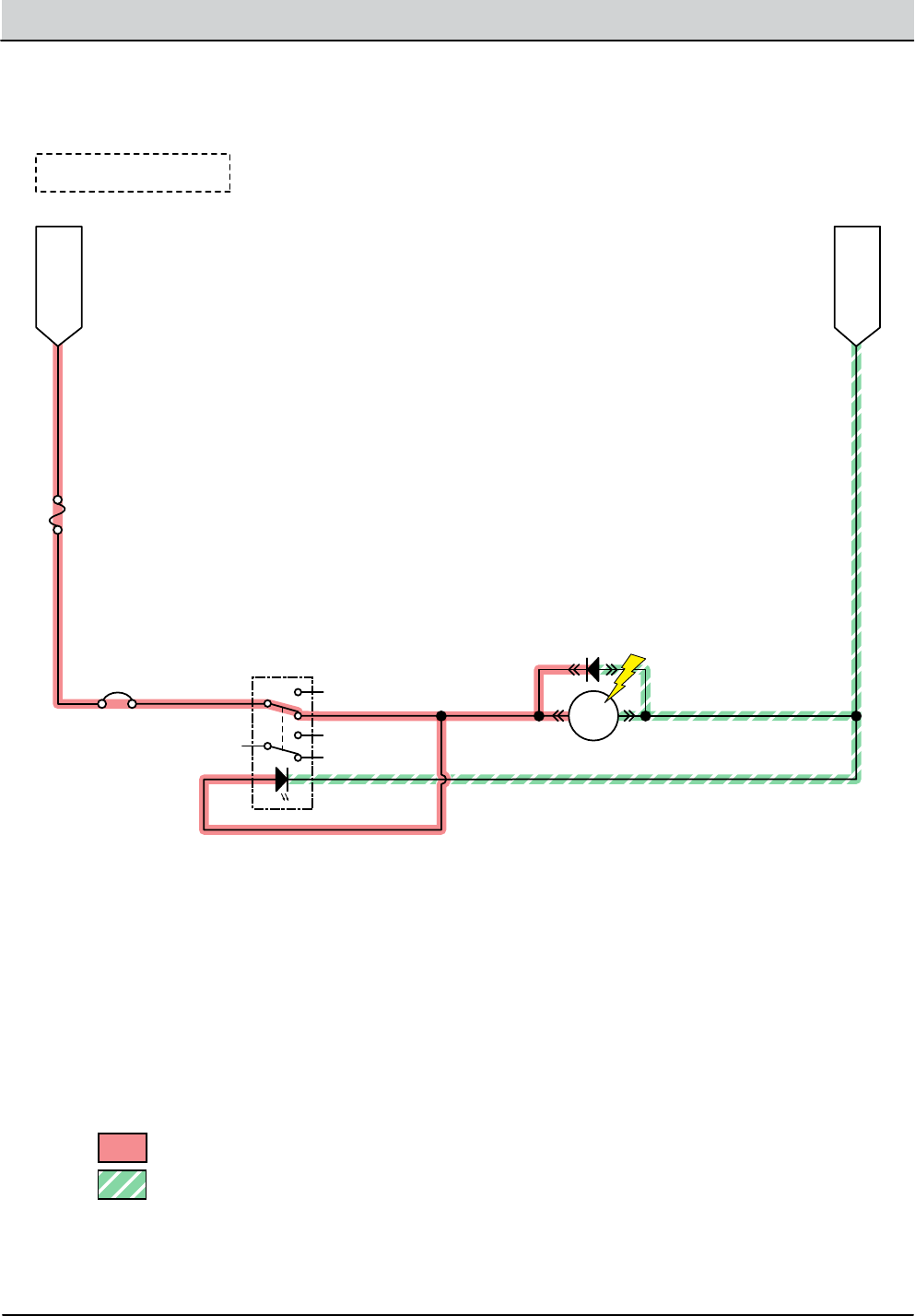
4-60 T12 Service Information 9009917 (12-12)
TROUBLESHOOTING
Spray Nozzle ON (Option)
B- From
Stando
Battery Positive +
Battery Negative -
MTR
D-4
13/BLK
13/BLK
63/ORA
Switched B+
From Buss Bar
SNC001
6
10
2
8
9
5
4
1
13/BLK
Spray Nozzle Pump
Spray Nozzle Switch
64/YEL
64/YEL
22/BRN
FU1
80A
CB11
15A
Note: Key Switch ON

T12 Service Information 9009917 (12-12) 4-61
TROUBLESHOOTING
Spray Nozzle Failed to Turn ON (Option)
STEP ACTION VALUES YES NO
1• Key On
• Enable spray nozzle subsystem
• Is there a pertinent LCD warning or fault message
displayed?
See “LCD
Warnings” or
“LCD Faults”
Sections
Go to Step #2
2• Key O
• Firmly press circuit breaker #11 to reset
• Is circuit breaker #11 tripped?
Reset and Test
Spray Nozzle
Operation
Go to Step #3
3• Key O
• Disconnect spray nozzle water pump from wire har-
ness
• Apply battery voltage to spray nozzle water pump
using fuse-protected jumper leads
• Does the spray nozzle water pump dispense water?
Go to Step #4 Repair or
Replace Spray
Nozzle Water
Pump
4• Key O
• Reconnect spray nozzle water pump to wire harness
• Key On
• Turn spray nozzle switch On
• Test voltage applied to spray nozzle subsystem as
shown on the electrical schematic
• Are the electrical circuits operating as shown on the
electrical schematic?
Go Back to
Step #1
Identify Volt-
age Drop
Location and
Repair or Re-
place Neces-
sary Compo-
nents
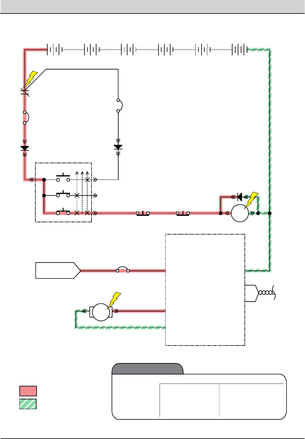
4-62 T12 Service Information 9009917 (12-12)
TROUBLESHOOTING
Vacuum Fan ON
+ - + - + - + - + - + -
T12 Water
Pick-Up Module
6 Volt
Key Switch
IGN
15
ACC
30
BATT
Switched B+
From Buss Bar
75
50 Start S-2
E-Stop
Switch
S-3
Charger
Interlock
ST
M1B
M1A
J3-1 B+ B- J3-4
CAN (-) J2-2
CAN (+) J2-1
Battery Positive +
Battery Negative -
D-3
D-1 D-2
CB3
2.5A
CB5
25A
6 Volt 6 Volt 6 Volt 6 Volt 6 Volt
CB2
2.5A
1/RED
13/BLK
6/BLU 7/PUR 8/GRY
31/PNK2/BRN 13/BLK
3/ORA 4/YEL
Cable to Ground Stand O
5/GRN
10/TAN
2/BRNCable
VFC002
MTR
Vacuum Fan
J3-3 Vac Fan +
J3-2 Vac Fan -
32/BRN
28/GRY
21
Vacuum Fan
Enabled
• 1-STEP Scrub ON
• Squeegee/Vac ON • 1-STEP Scrub OFF
• Squeegee/Vac OFF
• Recovery Tank Full
• Very Low Batt Voltage
• Load Current Fault
Disabled
Operational Matrix:
Twisted
Pair

T12 Service Information 9009917 (12-12) 4-63
TROUBLESHOOTING
Vacuum Fan Failed to Turn ON
STEP ACTION VALUES YES NO
1• Key On
• Enable scrubbing vacuum fan(s)
• Is there a pertinent LCD warning or fault message
displayed?
See “LCD
Warnings” or
“LCD Faults”
Sections
Go to Step #2
2• Key O
• See “Manual Mode” section of this manual
• Activate vacuum fan(s) in manual mode
• Does the vacuum fan(s) turn On?
Go to Step #5 Go to Step #3
3• Key O
• See “Self-Test Mode”
• Does the Self-Test display output circuits J3-3, or J3-2
as open or shorted?
Correct Open
or Short Cir-
cuit Condition
Go to Step #4
4• Key O
• See TESTING VACUUM FAN (SCRUBBING) in the SER-
VICE section of this manual
• Do the vacuum fan motor pass the testing?
See TESTING
VACUUM FAN
(SCRUBBING)
Go to Step #5 Repair or Re-
place Vacuum
Fan Motor
5• Key O
• Reconnect vacuum fan motor to main wire harness
• Key On
• Enable scrubbing vacuum fan subsystem
• Test voltage applied to the scrubbing vacuum fan
subsystem as shown on the electrical schematic
• Are the electrical circuits operating as shown on the
electrical schematic?
Go Back to
Step #1
Identify Volt-
age Drop
Location and
Repair or Re-
place Neces-
sary Compo-
nents
Terms:
LCD = Liquid Crystal Display
J3-3 = Water PU Module Connector #3, Pin #3
J3-2 = Water PU Module Connector #3, Pin #2

4-64 T12 Service Information 9009917 (12-12)
TROUBLESHOOTING

SERVICE
SECTION 5
5-1
T12 Service Information 9009917 (12-12)
SERVICE
SERVICE PROCEDURES ..................... 52
REAR SQUEEGEE LIFT ACTUATOR ....... 52
REMOVAL ............................ 52
INSTALLATION ....................... 53
SIDE BRUSH LIFT ACTUATOR ............ 54
REMOVAL ............................ 54
INSTALLATION ....................... 54
ADUSTING SIDE BRUSH
SPRING TUBE ASSEMBLY ........... 55
SIDE BRUSH MOTOR .................... 56
REMOVAL ............................ 56
INSTALLATION ....................... 57
CARBON BRUSHES ................... 57
MAIN BRUSH LIFT ACTUATOR ........... 58
REMOVAL ............................ 58
INSTALLATION ....................... 58
MAIN SCRUB HEAD ..................... 59
REMOVAL ............................ 59
INSTALLATION ......................510
MAIN SCRUB BRUSH MOTOR
CYLINDRICAL .....................511
REMOVAL ........................511
INSTALLATION. . . . . . . . . . . . . . . . . . . . 512
CARBON BRUSHES ...............512
INSTRUMENT PANEL ...................513
REMOVAL ........................... 513
INSTALLATION ......................513
LOGIC BOARD REPLACEMENT. . . . . . . . . . 514
REMOVAL ........................... 514
INSTALLATION ......................515
STEERING WHEEL TIMING ..............516
WHEEL DRIVE ASSEMBLY ..............517
REMOVAL ........................... 517
INSTALLATION ......................518
TIRE REPLACEMENT ................. 519
VACUUM FAN ASSEMBLY ..............520
REMOVAL ..........................520
INSTALLATION ......................521
COMPONENT TESTING ....................522
TANK LEVEL SENSORS .................522
PARKING BRAKE, ELECTROMAGNETIC ..524
PROPEL MOTOR AND ENCODER ......527
PROPEL MOTOR CABLES ...............529
THROTTLE/BRAKE SENSOR ............531
SIDE BRUSH LIFT ACTUATOR ...........533
MAIN BRUSH LIFT ACTUATOR ..........534
COMPONENT TESTING CONTINUED
REAR SQGE LIFT ACTUATOR. . . . . . . . . . . . 535
VACUUM FAN .......................... 536
MAIN SCRUB BRUSH MOTORS .........537
SIDE BRUSH MOTOR ...................538
ECH2O PUMP .........................539
ECH2O PRESSURE SWITCH ............540
Contents ContentsPage Page
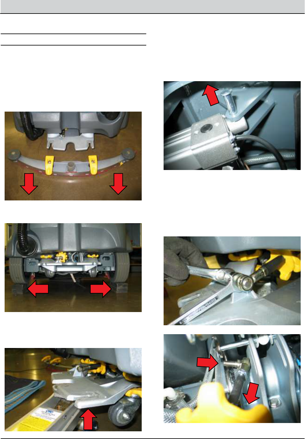
5-2 T12 Service Information 9009917 (12-12)
SERVICE
REAR SQUEEGEE LIFT ACTUATOR
REMOVING REAR SQUEEGEE LIFT ACTUATOR
FOR SAFETY: Before leaving or servicing machine, stop
on level surface, turn o machine and remove key.
1.
2.
3.
4.
5.
6.
7.
Drain solution and recovery tanks.
NOTE: Remove caster wheels to further lower the lift mecha-
nism and allow for additional clearance.
NOTE: Cylindrical Scrub Head Only: Remove debris tray
from rear of scrub head to allow for additional clearance.
Remove rear squeegee and set aside.
Chock front drive tire and place rear wheels on
blocks.
Proceed to next step if actuator failed in lowered posi-
tion. Carefully support rear squeegee mounting
bracket using a oor jack. Do not apply excessive
force.
Remove forward lift actuator cotter and clevis pins
and set hardware aside. Cut zip tie and disconnect lift
actuator from wire harness.
Lower oor jack supporting rear squeegee and re-
move oor jack.
Remove squeegee adjustment rod mounting hard-
ware (2) and set rod and hardware aside.
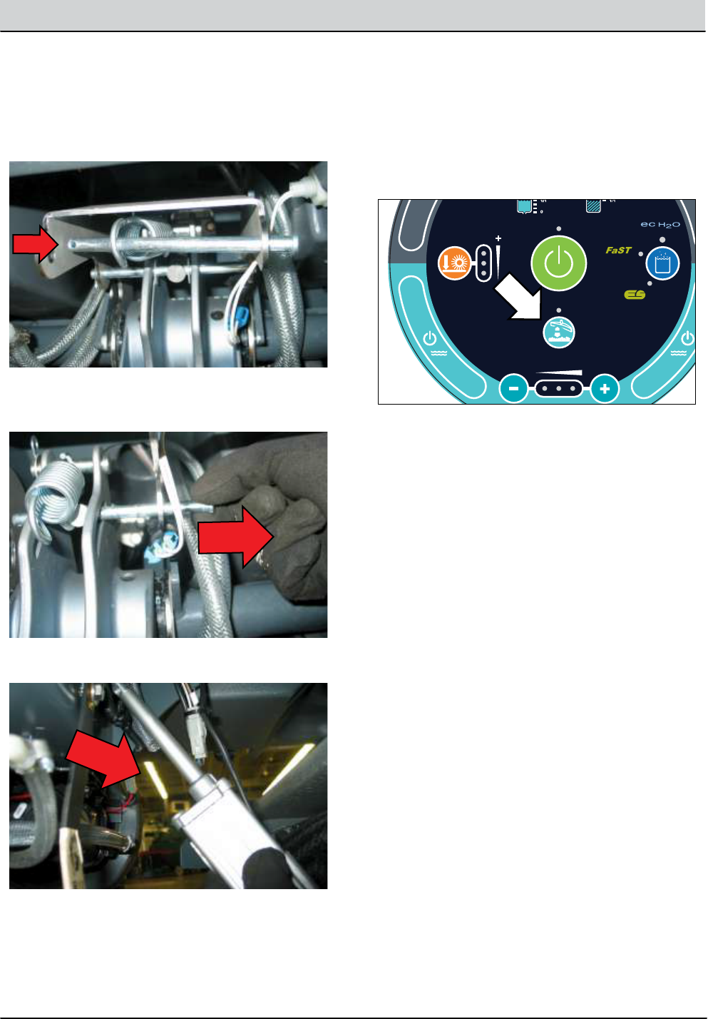
T12 Service Information 9009917 (12-12) 5-3
SERVICE
INSTALLING REAR SQUEEGEE LIFT ACTUATOR
+ - + - + - + - + - + -
Scrub Head
Down
Enabled
• 1-STEP Scrub ON
• Squeegee/Vac ON • 1-STEP Scrub OFF
• Squeegee/Vac OFF
• Recovery Tank Full
• Low Batt Voltage
• Load Current Fault
Disabled
Operational Matrix:
Scrub Head
Down
Enabled
• 1-STEP Scrub ON
• Fwd/Rev Propel
• 1-STEP Scrub OFF
• Neutral-Ready State
• Recovery Tank Full
• Solution Tank Empty
• Low Batt Voltage
• Load Current Fault
Disabled
Operational Matrix:
Tennant Quantum
UI ver1.0
Tennant Quantum
UI ver X.X
T16
Control
Board
6 Volt
Key Switch
IGN
15
ACC
30
BAT T
Switched B+
From Buss Bar
75
50 Start S-2
E-Stop
Switch
S-3
Charger
Interlock
ST
M1B
M1A
J7-1
B+(Control)
B+
B-
Battery Positive +
Battery Negative -
CAN +12V J2-1
J2-2
J2-3
J2-4
RED #1
RED #2
BLK #2
BLK #1
CAN +
CAN -
CAN GROUND
D-4
D-2 D-3
CB1
2.5A
FU2
100A
6 Volt 6 Volt 6 Volt 6 Volt 6 Volt
CB2
2.5A
1/RED
13/BLK
6/BLU 7/PUR
Cable
Shield
Instrument Panel Assembly
Cable
3/ORA
8/GRY
4/YEL
Cable to Ground Stand O
5/GRN
10/TAN
2/BRNCable
RSAA001
1. Turn Key Off.
CONFIG MODE
C1:Disk/Cyl
SELF TEST
MANUAL MODE
INPUT DISPLAY
PROPEL DIAG MODE
1.
2.
3.
8.
9.
10.
Connect new lift actuator to wire harness.
Key On, Squeegee/Vacuum On and wait for actuator
to extend completely and then turn key O.
Remainder of installation is reverse of removal.
NOTE: Use a pry bar to stretch the coil spring while inserting
the clevis pin through the lift mechanism.
Allow lift mechanism to pivot downward to release
some of the spring tension and provide clearance
for clevis pin removal. Slide the clevis pin out and set
spring and hardware aside.
Remove lift actuator cotter and clevis pins. Note
hardware orientation for re-assembly.
Remove lift actuator from space behind scrub head.
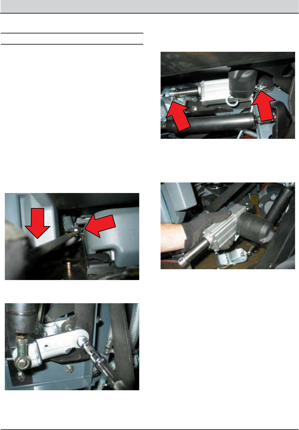
5-4 T12 Service Information 9009917 (12-12)
SERVICE
SIDE BRUSH LIFT ACTUATOR
NOTE: The side brush lift mechanism is under spring tension
when in the raised/retracted position.
FOR SAFETY: Before leaving or servicing machine, stop
on level surface, turn o machine and remove key.
REMOVING SIDE BRUSH LIFT ACTUATOR
1.
2.
3.
4.
5.
Proceed to step 2 if the actuator failed in the extended/
lowered position. It is dicult to access the side brush
lift mechanism if the actuator fails in the raised (Re-
tracted) position. Use a pry bar to release the rod-end
from the ball stud as shown below. Replace the rod-
end assembly after this is done.
Remove actuator pivot bracket mounting bolt (1).
Remove actuator mounting clevis (2) and cotter (2)
pins.
Cut zip tie securing actuator connector to wire har-
ness and disconnect actuator from wire harness.
Remove lift actuator.
NOTE: The side brush spring tube assembly must be adjust-
ed following the installation of the lift actuator or machine
damage will occur.
NOTE: Using a pry bar to separate the ball stud from the rod
end will damage the rod end assembly. The rod end must
be replaced if this is done.
TIP: Remove the RH headlight assembly to access the pin
insertion cutout of the main frame. Use a needle nose pliers
to drop the clevis pin in from above.
FOR SAFETY: Before leaving or servicing machine, stop
on level surface, turn o machine and remove key.
INSTALLING SIDE BRUSH LIFT ACTUATOR
1. Installation is the reverse of removal.
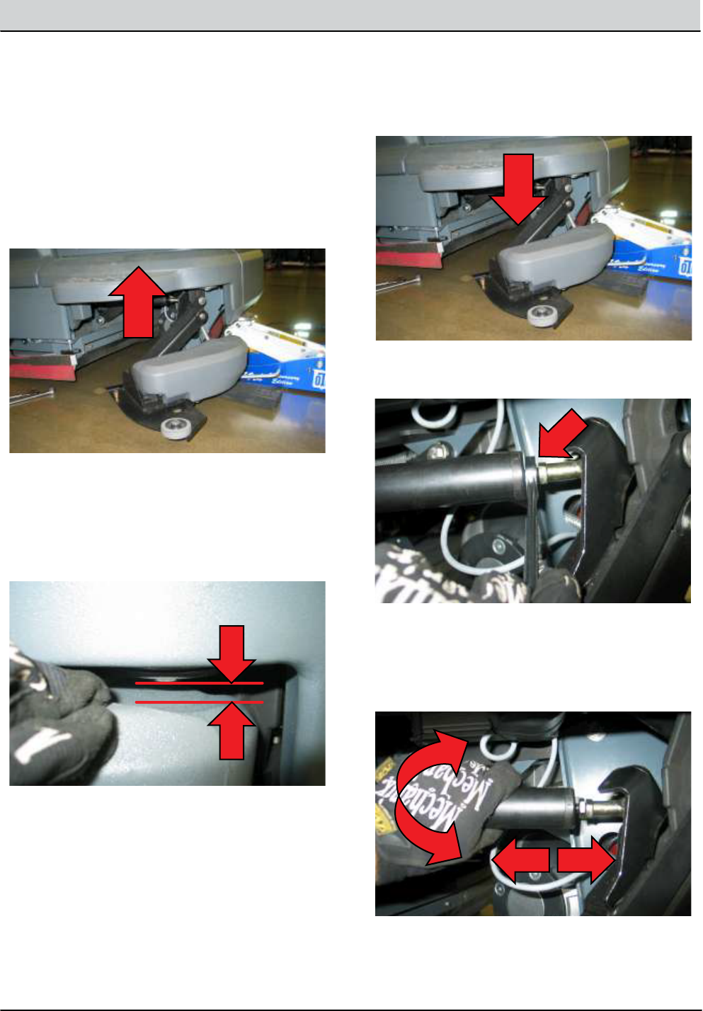
T12 Service Information 9009917 (12-12) 5-5
SERVICE
0.25 in(6.4 mm) Gap
NOTE: Failure to adjust this gap properly could result in
actuator failure.
NOTE: Jack the front of the machine to allow improved ac-
cess to the side brush spring tube assembly.
FOR SAFETY: Before leaving or servicing machine, stop
on level surface, turn o machine and remove key.
ADJUSTING SIDE BRUSH SPRING TUBE ASSEMBLY 3.
1.
2.
4.
5.
6.
Key On, 1-STEP scrub On, side brush switch On. Allow
the side brush to lower completely and then turn the
key o.
Key On. Allow the side brush to lift/retract completely
and then turn the key o.
Inspect the adjustment gap between the side brush
cover and the inside mounting bolt as shown below.
The gap should be approximately 0.25in (6.4mm)
while applying 2 lbs(9 N) of downward force on the
cover. This is necessary because light spring tension on
the lift mechanism may close the gap.
Loosen forward jam nut on side brush spring tube
assembly.
Turn the spring tube assembly CW to shorten the
tube, thereby opening the adjustment gap in Step 2.
Turn the spring tube assembly CCW to lengthen the
tube, therby closing the adjustment gap in Step 2.
Cycle the side brush up down to check the gap.
Tightent the jam nut.
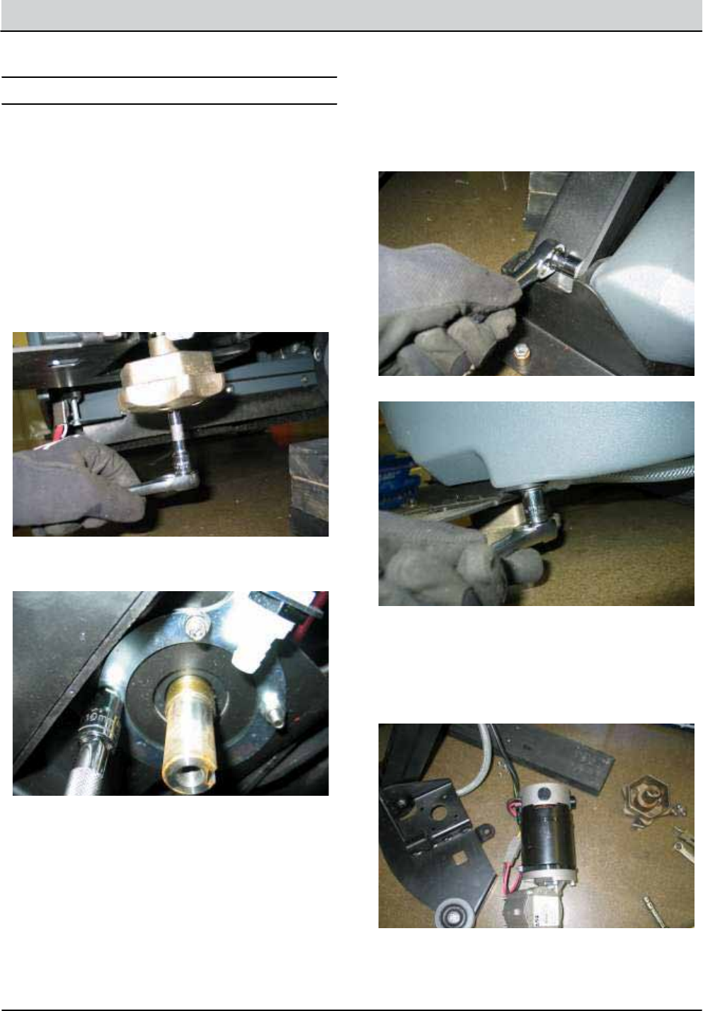
5-6 T12 Service Information 9009917 (12-12)
SERVICE
SIDE BRUSH MOTOR
REMOVING SIDE BRUSH MOTOR
FOR SAFETY: Before leaving or servicing machine, stop
on level surface.
2.
3.
4.
5.
6.
7.
8.
1.
Remove side brush and side brush squeegee assem-
bly and set aside.
Remove side brush hub mounting bolt (1) and hub
and set aside.
Remove motor mounting hardware (4) and set aside.
Key On, 1-STEP Scrub On, side brush On and allow
side brush motor to lower completely. Turn Key O.
Remove side brush cover mounting hardware (2) and
set aside.
Cut zip tie securing solution hose and wire harness to
side brush cover and set cover aside.
Disconnect side brush motor from wire harness and
remove side brush motor.
Jack front of machine and support using jack stands
or support blocks.
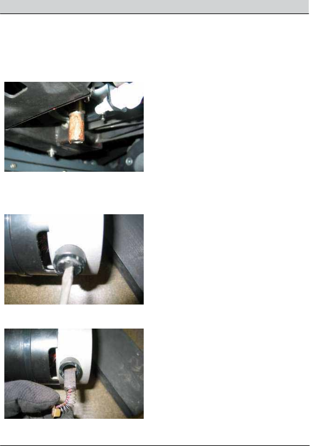
T12 Service Information 9009917 (12-12) 5-7
SERVICE
INSTALLING SIDE BRUSH MOTOR
REPLACING CARBON BRUSHES
1.
1.
2.
Installation is the reverse of removal. .
NOTE: Apply anti-seize to side brush motor shaft and mo-
tor/hub mounting hardware.
Remove carbon brush caps (4).
Remove carbon brushes (4).
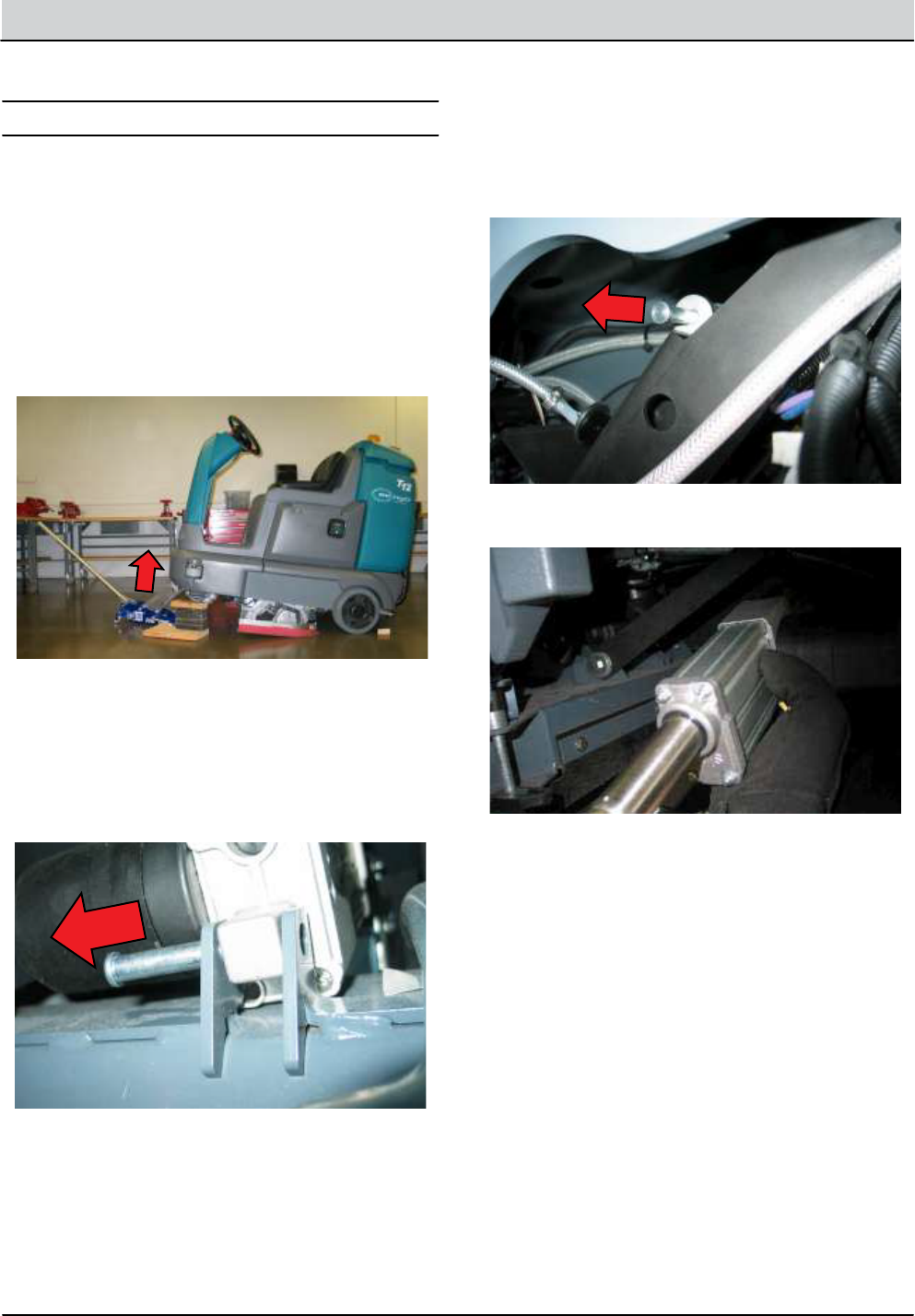
5-8 T12 Service Information 9009917 (12-12)
SERVICE
MAIN BRUSH LIFT ACTUATOR
REMOVING MAIN BRUSH LIFT ACTUATOR
INSTALLING MAIN BRUSH LIFT ACTUATOR
NOTE: This actuator does not require an installation adjust-
ment. Turn the actuator tube manually to align the mount-
ing holes and insert clevis and cotter pins.
FOR SAFETY: Before leaving or servicing machine, stop
on level surface, turn o machine and remove key.
2.
3.
4.
5.
6.
7.
8.
9.
1.
1.
2.
Jack front of machine and support using jack stands
or support blocks.
Remove scrub brushes.
Support scrub head using support blocks.
Remove actuator lower mounting pin from scrub
head.
Carefully remove scrub head support blocks and
lower scrub head to the oor.
Cut zip tie securing actuator wire harness and discon-
nect actuator from wire harness.
Remove actuator upper mounting pin from lift
mechanism.
Remove lift actuator.
Key O. Disconnect batteries.
Key O. Disconnect batteries.
Installation is the reverse of removal.
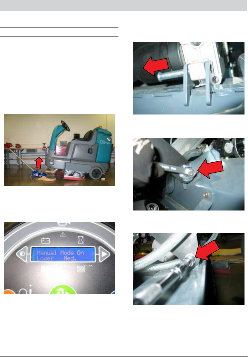
T12 Service Information 9009917 (12-12) 5-9
SERVICE
MAIN SCRUB HEAD
REMOVING MAIN SCRUB HEAD
1.
2.
3.
4.
5.
6.
7.
Drain solution tank and turn key O.
Remove scrub brushes and debris tray (cylindrical
only).
Lift front of machine as shown below. Be sure to use
wheel chocks and jack stands or support blocks.
Enter Manual Mode and lower scrub head completely
(See Manual Mode in the Troubleshooting section of
this manual). Turn key O immediately when head
touches the oor.
Remove lift actuator cotter and clevis pins from scrub
head frame and set hardware aside.
Remove front scrub head linkage bolts (2) and set
hardware aside.
Remove rear scrub head linkage bolts (2) and set
hardware aside.
FOR SAFETY: Before leaving or servicing machine, stop
on level surface, turn o machine and remove key.
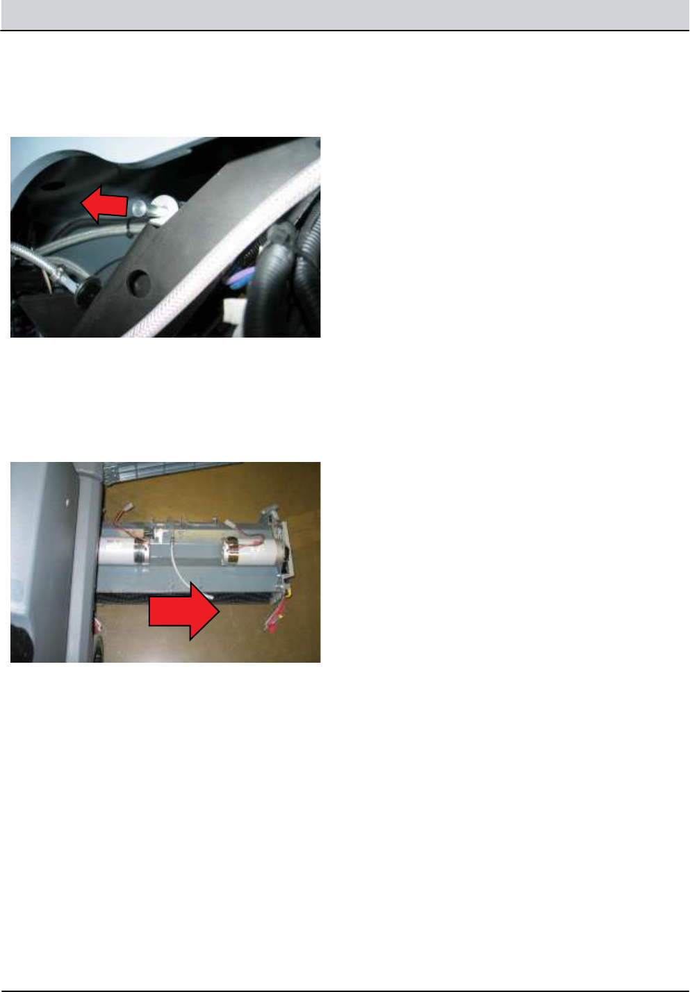
5-10 T12 Service Information 9009917 (12-12)
SERVICE
INSTALLING MAIN SCRUB HEAD
8.
1.
9.
10.
11.
Remove upper lift actuator cotter and clevis pins.
Disconnect lift actuator from wire harness. Remove
lift actuator and set aside.
Installation is the reverse of removal.
Disconnect water hoses from scrub head.
Disconnect water valve and brush motors from wire
harness.
Remove the scrub head assembly.
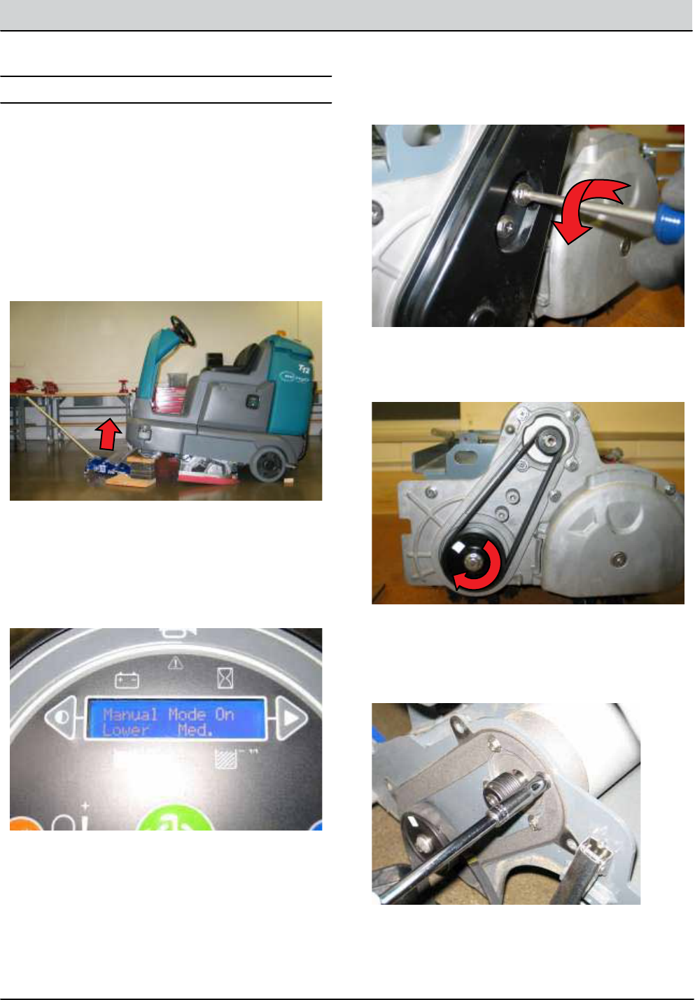
T12 Service Information 9009917 (12-12) 5-11
SERVICE
MAIN SCRUB BRUSH MOTOR CYLINDRICAL
REMOVING MAIN BRUSH MOTOR
FOR SAFETY: Before leaving or servicing machine, stop
on level surface, turn o machine and remove key.
FOR SAFETY: When servicing machine, jack machine
up at designated locations only. Block machine up with
jack stands.
3.
4.
4.
5.
6.
2.
1.
Enter Manual Mode and lower scrub head completely
(See Manual Mode in the Troubleshooting section of
this manual). Turn key O immediately when head
touches the oor.
Remove belt cover bolts (2) and set cover and hard-
ware aside.
Remove belt by turning pulleys and applying out-
ward pressure on the belt.
Loosen set screws (2) securing the drive pulley onto
the motor shaft and remove belt drive pulley.
Remove motor mounting hardware (4) and set aside.
Remove scrub brushes.
Jack front of machine and support using jack stands
or support blocks.
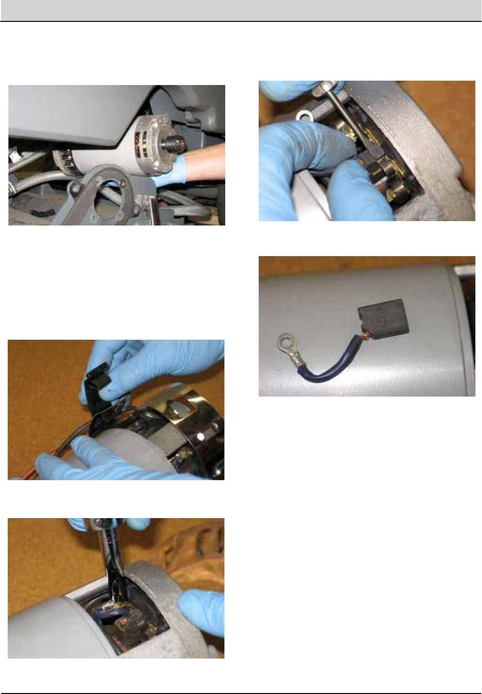
5-12 T12 Service Information 9009917 (12-12)
SERVICE
REPLACING CARBON BRUSHES
INSTALLING MAIN BRUSH MOTOR
7.
1.
1.
2.
3.
4.
5.
Disconnect motor from wire harness and remove
motor.
Installation is reverse of removal.
Release the motor band clamp and set aside.
Remove carbon brush mounting screws (4) and set
aside.
Release spring tabs using a small screwdriver.
Remove carbon brushes.
Installation is the reverse of removal.
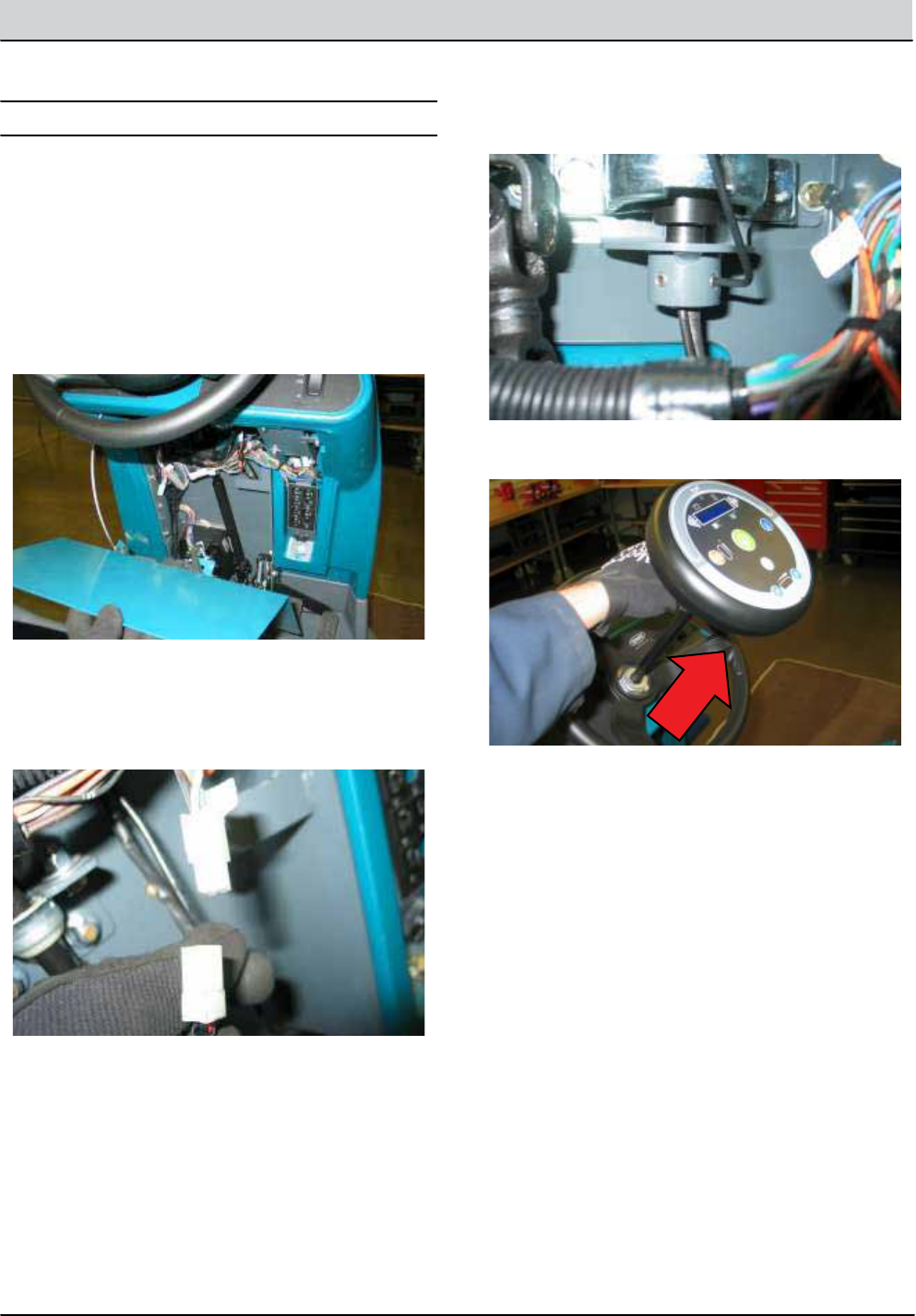
T12 Service Information 9009917 (12-12) 5-13
SERVICE
INSTRUMENT PANEL
REMOVING INSTRUMENT PANEL
INSTALLING INSTRUMENT PANEL
FOR SAFETY: When servicing machine, disconnect bat-
tery connections before working on machine.
1.
2.
3.
4.
5.
6.
1.
2.
Key O. Disconnect battery.
Remove front access panel.
Cut zip tie securing instrument panel wire harness
connections.
Disconnect instrument panel connector.
Loosen set screws (2) securing instrument panel
mounting tube.
Remove instrument panel assembly.
Installation is the reverse of removal.
See CONFIGURATION MODE in the troubleshooting
section of this manual to congure the new instru-
ment panel.
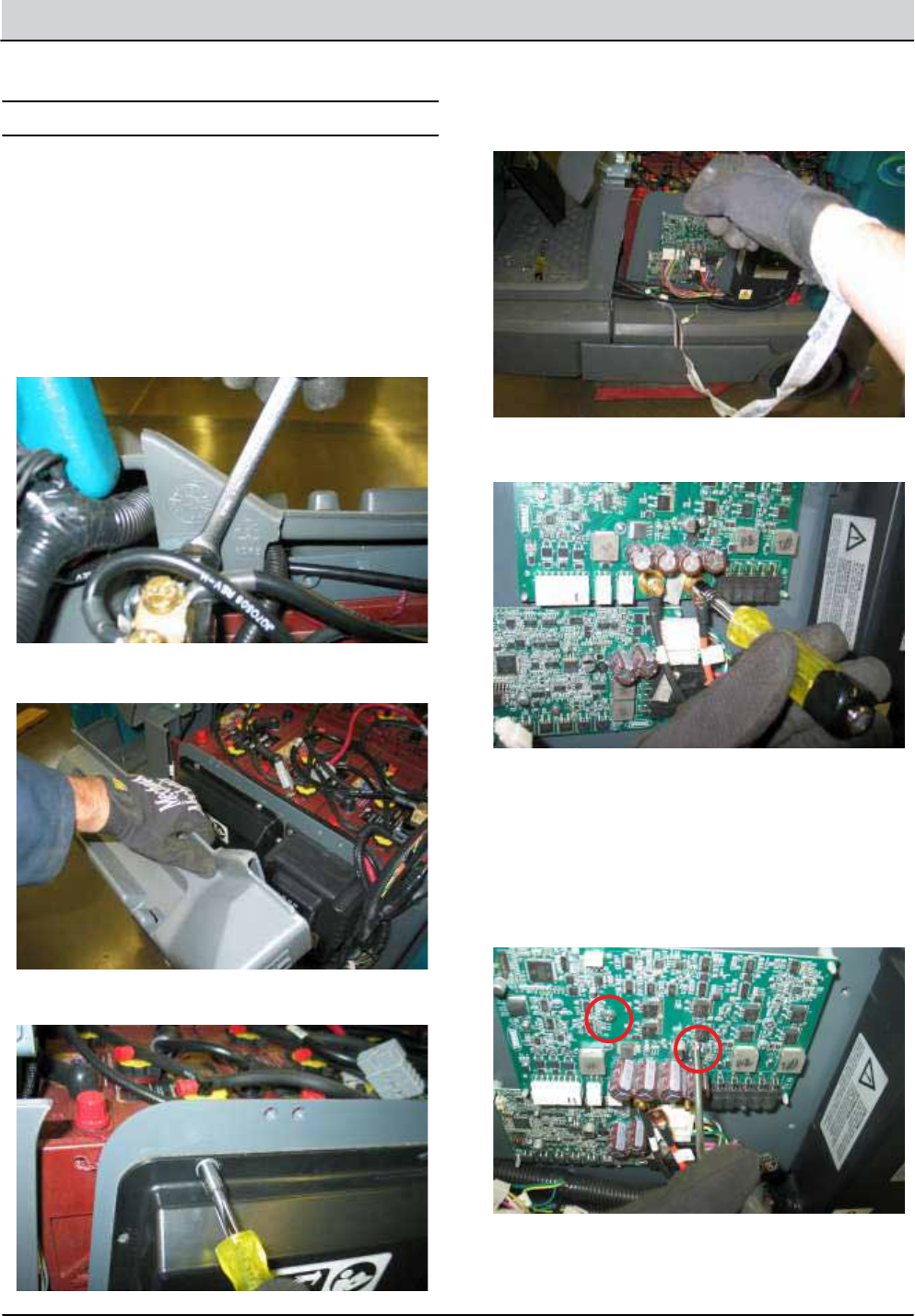
5-14 T12 Service Information 9009917 (12-12)
SERVICE
LOGIC BOARD REPLACEMENT
REMOVING LOGIC BOARD
FOR SAFETY: When servicing machine, disconnect bat-
tery connections before working on machine.
NOTE: Always use two wrenches when securing the power
supply terminals or damage to the circuit board will occur.
Also, make sure the power supply terminals are secured on
the new board before installation. The torque specication
is 52 in-lbs (6 Nm).
1.
2.
3.
4.
5.
6.
7.
8.
Key O. Disconnect batteries.
Lift seat.
Remove side access panel mounting bolt (1).
Remove side access panel and set aside.
Remove circuit board cover mounting hardware (6).
Attach a wrist static strap tool to a bare metal frame
surface.
Disconnect logic board connectors and cables.
Remove logic board mounting screws (2).
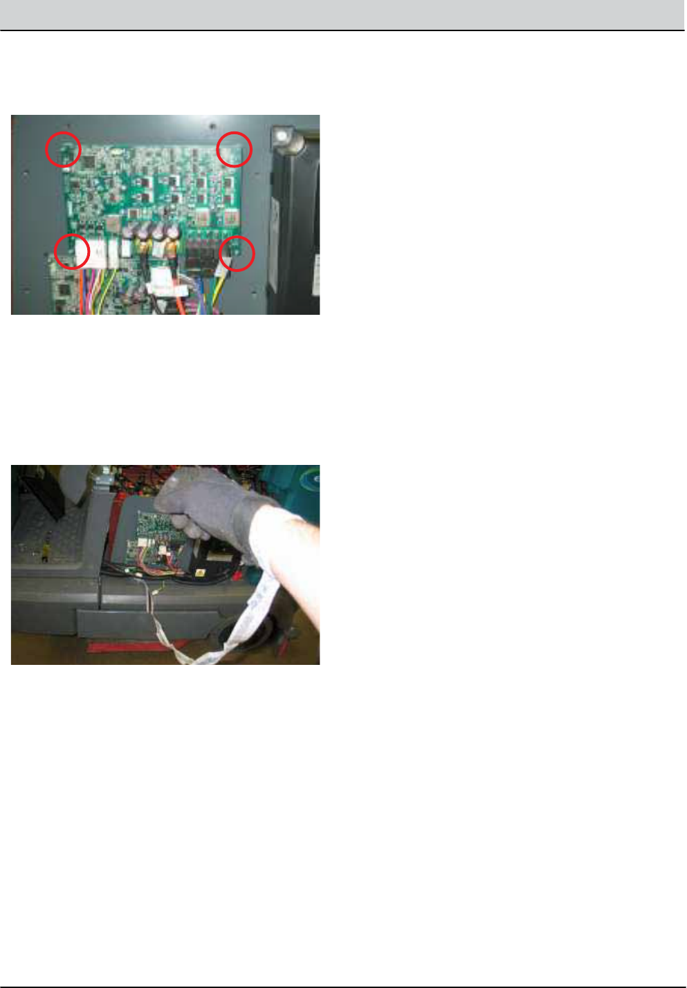
T12 Service Information 9009917 (12-12) 5-15
SERVICE
INSTALLING LOGIC BOARD
FOR SAFETY: When servicing machine, disconnect bat-
tery connections before working on machine.
NOTE: Always use two wrenches when securing the power
supply terminals or damage to the circuit board will occur.
Also, make sure the power supply terminals are secured on
the new board before installation. The torque specication
52 in-lbs (6 Nm).
2.
9.
Remainder of installation is the reverse of removal.
Carefully squeeze the plastic standos and remove
the logic board.
1. Attach a wrist static strap tool to a bare metal frame
surface.
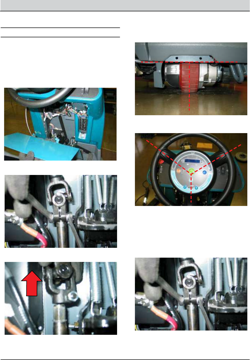
5-16 T12 Service Information 9009917 (12-12)
SERVICE
STEERING WHEEL TIMING
FOR SAFETY: Before leaving or servicing machine, stop
on level surface, turn o machine and remove key.
3.
4.
5.
6.
7.
Loosen steering shaft hardware.
Lift steering u-joint o splined shaft.
Align the front drive tire with the centerline of the
machine.
Orientate the steering wheel as shown below.
Carefully reinstall the steering u-joint onto the
splined steering shaft without changing the orienta-
tion of the steering wheel or drive assembly.
2.
1.
Remove front access panel.
Key O. Disconnect batteries.
NOTE: Check for rotational interference between the hard-
ware and the adjacent pedal assembly. If necessary, raise
the steering u-joint enough to clear the pedal assembly.
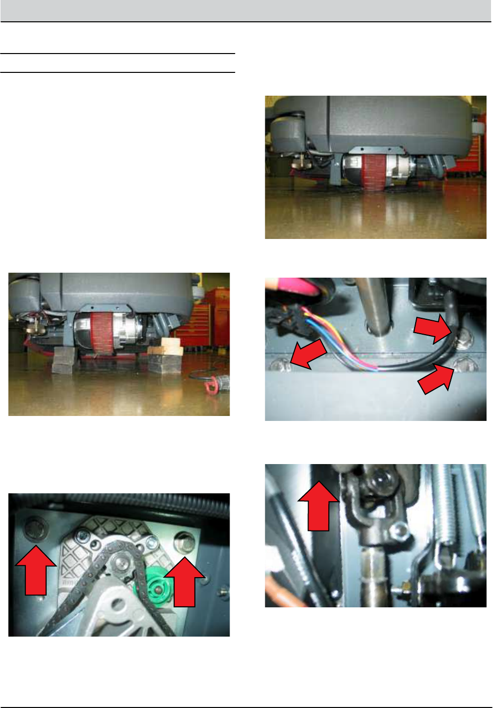
T12 Service Information 9009917 (12-12) 5-17
SERVICE
WHEEL DRIVE ASSEMBLY
REMOVING WHEEL DRIVE ASSEMBLY
FOR SAFETY: Before leaving or servicing machine, stop
on level surface, turn o machine and remove key.
FOR SAFETY: When servicing machine, jack machine
up at designated locations only. Block machine up with
jack stands.
FOR SAFETY: When servicing machine, disconnect bat-
tery connection before working on machine.
1.
2.
3.
4.
5.
6.
Key O. Disconnect batteries.
Jack front of machine and support using jack stands
or support blocks and chock rear tires.
Remove steering plate mounting hardware (4).
Jack front of machine and remove jack stands or sup-
port blocks so wheel drive assembly is supported by
the oor.
Remove front access panel and remove steering plate
mounting hardware (3).
Loosen steering u-joint hardware and lift u-joint o
splined steering shaft.
NOTE: Drive assembly will not release. The steering plate
is secured to the main frame with (3) additional fasteners
from the top (see Step 5).
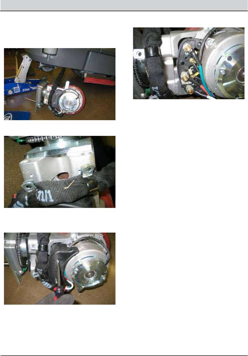
5-18 T12 Service Information 9009917 (12-12)
SERVICE
INSTALLING WHEEL DRIVE ASSEMBLY
FOR SAFETY: Before leaving or servicing machine, stop
on level surface, turn o machine and remove key.
FOR SAFETY: When servicing machine, jack machine
up at designated locations only. Block machine up
with jack stands.
FOR SAFETY: When servicing machine, disconnect bat-
tery connection before working on machine.
7.
8.
9.
1.
2.
Carefully jack front of machine until the drive wheel
assembly can be removed from the side of the ma-
chine.
Remove propel cable clamp mounting hardware (2).
Remove terminal cover and disconnect cables from
drive assembly.
Installation is the reverse of removal.
See STEERING WHEEL TIMING in the SERVICE section
of this manual.
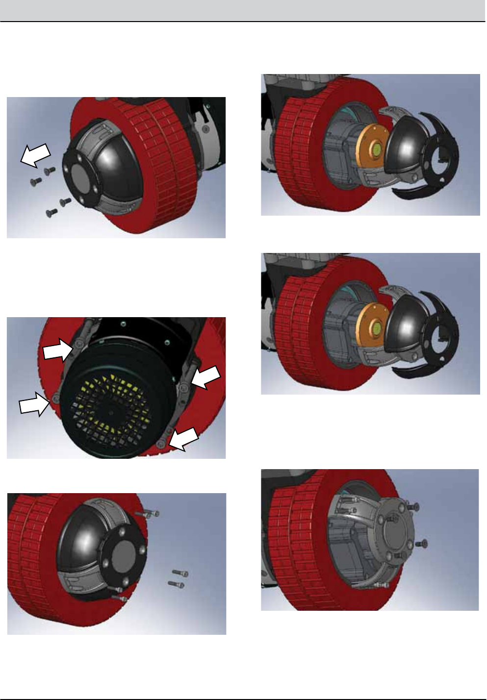
T12 Service Information 9009917 (12-12) 5-19
SERVICE
REPLACING THE DRIVE TIRE
1. Remove (4) at head screws.
2. Use (4) M10-1.5 x 70 (Class 12.9) socket head bolts to
mechanically press o the tire. Tighten the bolts
evenly in a diagonal pattern. REMOVE THE BOLTS
AFTER THIS STEP IS COMPLETE.
3. Remove (6) socket head screws.
4. Remove aluminum hub and plastic cover.
5. Replace the drive tire.
6. Installation is the reverse of removal. Use a plastic
mallet to reassemble the wheel drive assembly.
Torque M6 hardware to 15Nm (11 ft-lbs) and M8
hardware to 22 Nm (16 ft-lbs).
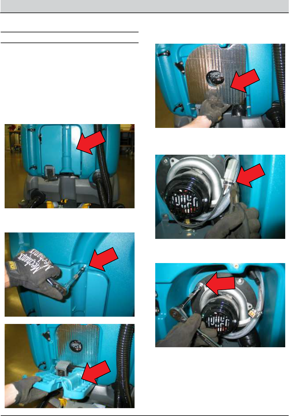
5-20 T12 Service Information 9009917 (12-12)
SERVICE
VACUUM FAN ASSEMBLY
1.
2.
3.
4.
REMOVING VACUUM FAN ASSEMBLY
FOR SAFETY: Before leaving or servicing machine, stop
on level surface, turn o machine and remove key.
Key O.
Disconnect hose from rear squeegee and move spray
nozzle away from the vacuum fan access cover.
Remove hardware (1) and vacuum fan access cover
and set aside.
Remove sound insulation and set aside.
5. Cut zip tie and disconnect vacuum fan from wire
harness.
6. Remove vacuum fan mounting hardware (5).

T12 Service Information 9009917 (12-12) 5-21
SERVICE
10. Loosen the clamp and remove mounting ange from
vacuum fan assembly.
1.
2.
INSTALLING VACUUM FAN ASSEMBLY
Secure mounting ange to new vacuum fan assem-
bly and apply 1/4” bead of silicone as shown below.
Remainder of installation is reverse of removal.
7. Carefully pry on the vacuum fan mounting ange to
break the silicone seal. Remove the vacuum fan as-
sembly and set aside.
8. Remove any residual silicone from the tank mounting
surface in preparation for the replacement vacuum
fan assembly.
9. Draw a line across the vacuum fan assembly and the
mounting ange as an orientation indicator for re-
assembly.
NOTE: The worm-drive clamp must be orientated on the
mounting ange to t into a tank recess during reassembly.
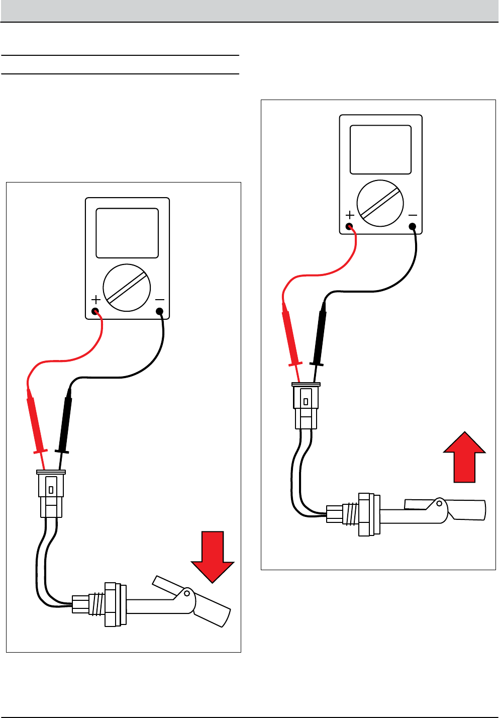
5-22 T12 Service Information 9009917 (12-12)
SERVICE
TESTING TANK LEVEL SENSORS
1. Test the resistance of the recovery tank level sensor
using an ohmmeter as shown below. The tank level
switch should test as “O.L.” or open.
Terminals:
1. Power
2. Ground
3. Voltage Output
Specications:
Thread Size 1/8-27NPT
Input: 8-30 Vdc
Output: 1-5 Vdc
Mating Packard Connector:
Packard Connector
Packard #12065287
Packard Terminal
Packard #12103881
VDC
Ω
A
B
C
D
E
F
G
H
I
J
K
L
M
N
O
P
Q
R
S
T
U
V
W
X
Y
Z
Battery Voltage =
WIRE POS.TERMINALS
113C/BLK-WHT A
49C/WHT B
53/ORA C
B+
B-
Vdc Output
RLT001
ABC
A B C
Solution Tank Sensor Output
Tank Level
0% (Empty)
20%
40%
60%
80%
100% (Tank Full)
1.0 - 1.17 Volts
1.17 - 1.6 Volts
1.6 - 1.89 Volts
1.89 - 2.25 Volts
2.25 - 2.4 Volts
2.4 + Volts
Voltage at “C”
A B
Terminals:
1. Power
2. Ground
3. Voltage Output
Specications:
Thread Size 1/8-27NPT
Input: 8-30 Vdc
Output: 1-5 Vdc
Mating Packard Connector:
Packard Connector
Packard #12065287
Packard Terminal
Packard #12103881
VDC
Ω
A
B
C
D
E
F
G
H
I
J
K
L
M
N
O
P
Q
R
S
T
U
V
W
X
Y
Z
Battery Voltage =
WIRE POS.TERMINALS
113C/BLK-WHT A
49C/WHT B
53/ORA C
B+
B-
Vdc Output
RLT002
ABC
A B C
A B
Solution Tank Sensor Output
Tank Level
0% (Empty)
20%
40%
60%
80%
100% (Tank Full)
1.0 - 1.17 Volts
1.17 - 1.6 Volts
1.6 - 1.89 Volts
1.89 - 2.25 Volts
2.25 - 2.4 Volts
2.4 + Volts
Voltage at “C”
2. Test the resistance of the recovery tank level sensor
using an ohmmeter as shown below. The tank level
switch should test at 0-1 ohms or closed.
FOR SAFETY: Before leaving or servicing machine, stop
on level surface.
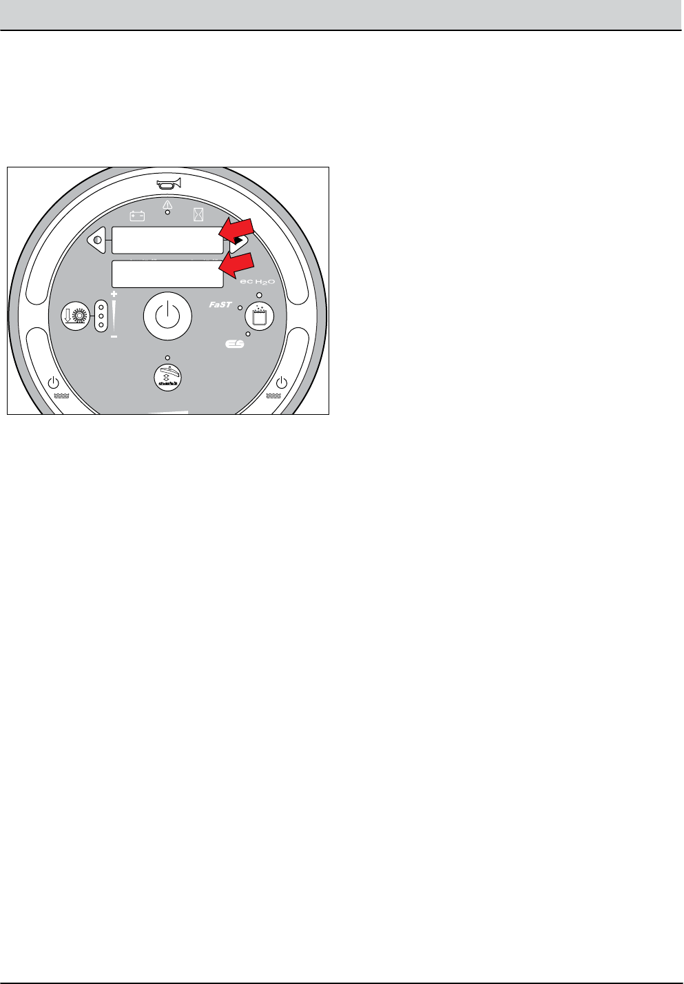
T12 Service Information 9009917 (12-12) 5-23
SERVICE
3. The solution and recovery tank full sensor conditions
are also viewable in Input Display Mode. See “Input
Display Mode” in the TROUBLESHOOTING section of
this manual.
RLT003
I1: Solution Tank
Full Closed
I2: Recovery Tank
Not Full Open
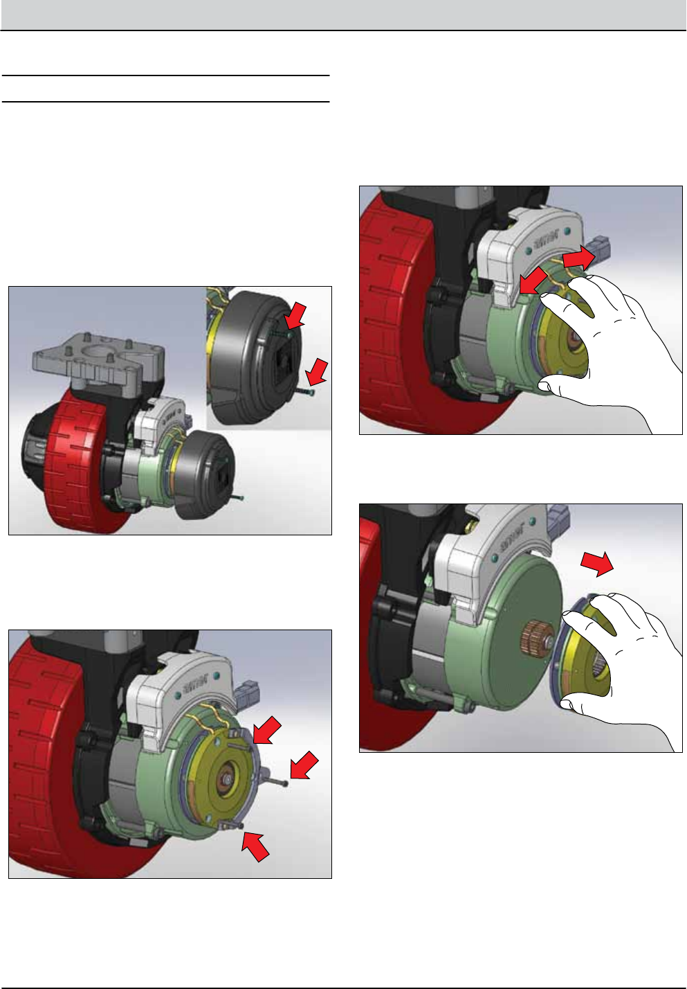
5-24 T12 Service Information 9009917 (12-12)
SERVICE
TESTING PARKING BRAKE, ELECTROMAGNETIC
1. Key O. Remove brake cover mounting screws and set
cover and hardware aside.
BET001
BET002
2. Key O. Remove brake assembly mounting screws
and set aside. Leave brake assembly on the splined
shaft.
3. Key O. The brake applies when the key switch is
turned o. Attempt to manually rotate the brake as-
sembly on the splined shaft as shown below. The
brake assembly SHOULD NOT rotate freely on the
splined shaft when the wheel is in a xed position.
BET003
4. Disconnect brake wires and slide the brake assembly
o the splined shaft
BET005
FOR SAFETY: Before leaving or servicing machine, stop
on level surface, turn o machine and remove key.
FOR SAFETY: When servicing machine, disconnect bat-
tery connection before working on machine.
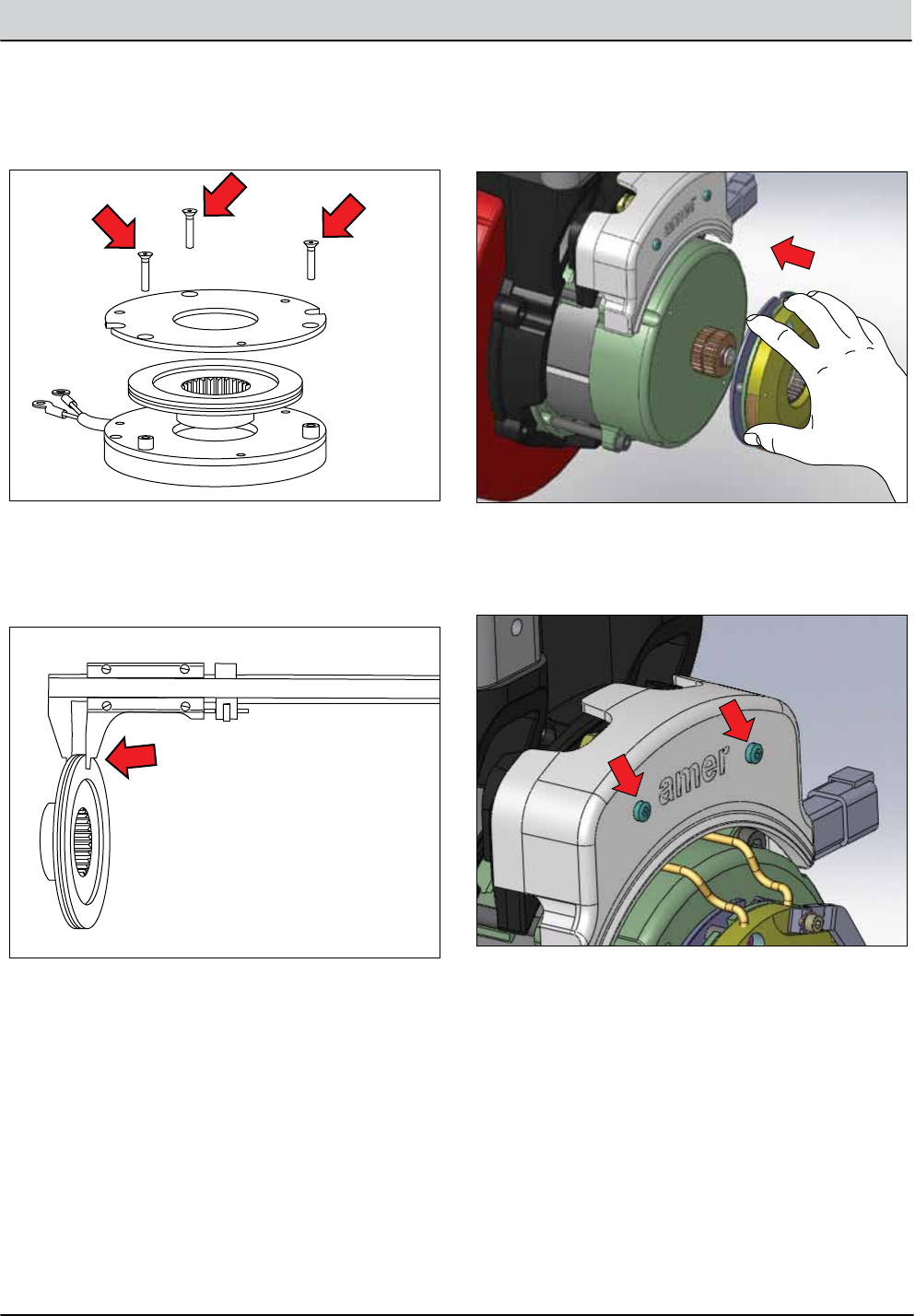
T12 Service Information 9009917 (12-12) 5-25
SERVICE
5. Remove three at head screws to disassemble the
brake assembly.
BET004
0 10 20 30 40 50 60 70 80 90 100 110 120 130 140 150 160 170 180 190 200
BET006
New = 6.3mm (0.25in)
Minimum = 4.4mm (0.17in)
6. Measure the thickness of the brake rotor using a
vernier caliper. Replace the rotor if it is less than
4.4mm (0.17in) thickness.
7. Reassemble the brake assembly and slide it back onto
the splined shaft.
BET008
8. Remove connection box cover screws and set cover
aside.
BET009
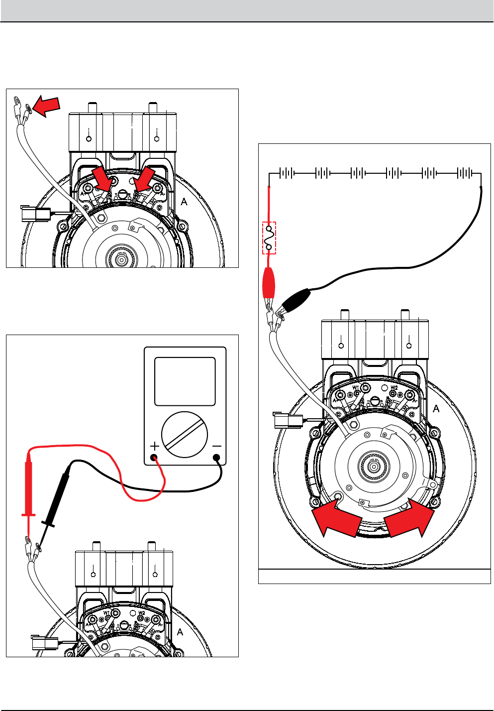
5-26 T12 Service Information 9009917 (12-12)
SERVICE
9. Remove brake wires from the B1 and B2 terminals
in the connection box.
BET010
Ω
Brake Coil Resistance:
50-60 Ohms at 70° F
10. Test the resistance of the brake coil using an
ohmmeter as shown below. The resistance should be
approximately 50-60 Ohms.
BET007
Ω
Brake Coil Resistance:
50-60 Ohms
11. Apply battery voltage to the brake assembly using
fuse-protected jumper leads as shown below. The
brake energizes to release. Attempt to manually rotate
the brake assembly while battery voltage is applied.
Replace the brake assembly if it DOES NOT rotate
freely on the splined shaft.
BET011
Ω
Brake Coil Resistance:
50-60 Ohms at 70° F
+ - + - + - + - + - + -
6 Volt 6 Volt 6 Volt 6 Volt 6 Volt 6 Volt
10 Amp
Fuse
12. Clean and inspect the brake assembly as required.
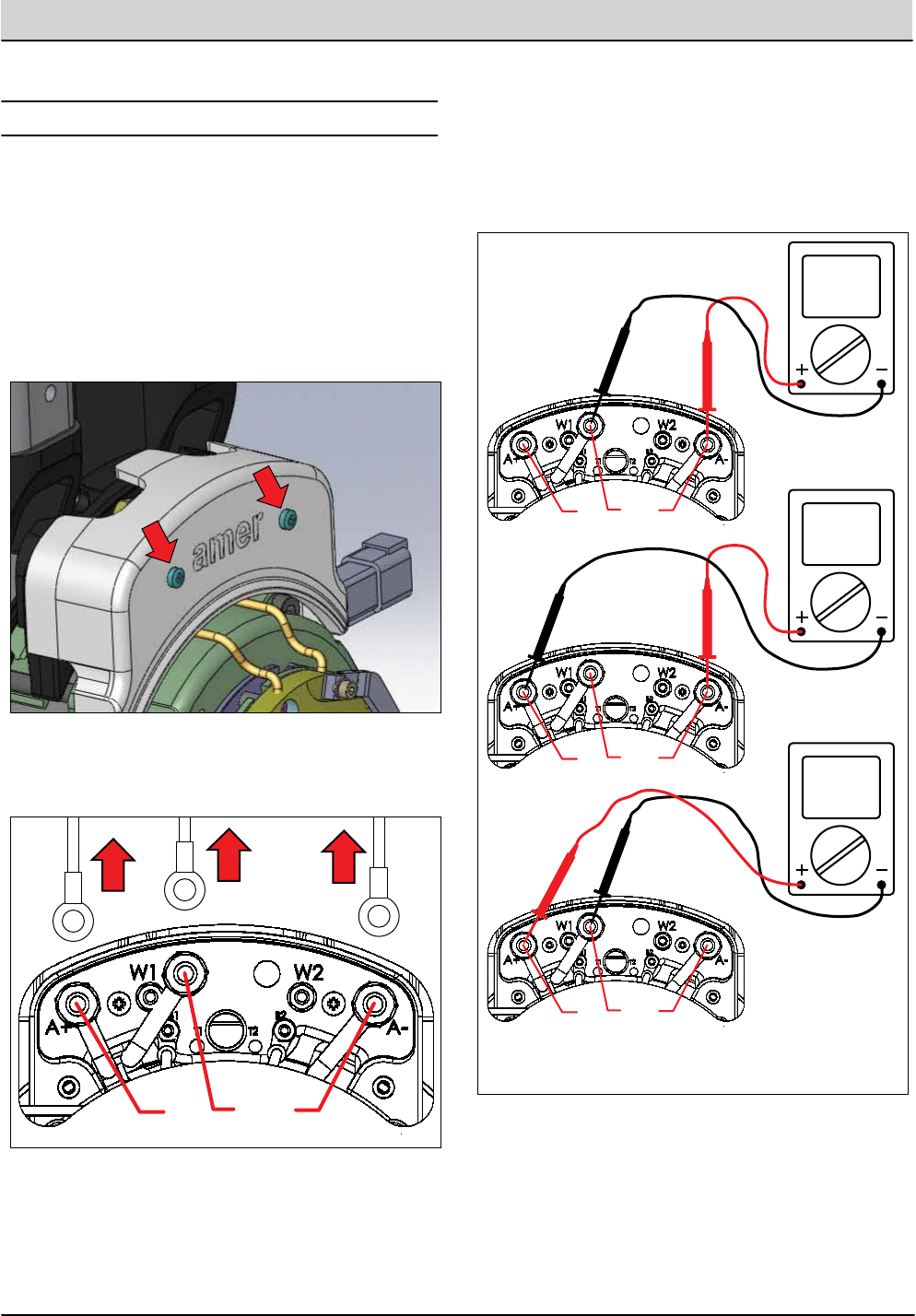
T12 Service Information 9009917 (12-12) 5-27
SERVICE
TESTING PROPEL MOTOR
1. Key O. Remove terminal box cover screws and set
cover aside.
BET009
2. Disconnect U, V, and W cables from W1, A-, and A+
terminals (respectively).
PMT002
WU V
3. Test the resistance of all three motor windings using
an ohmmeter as shown below. The resistances of each
winding should be within 5% of each other. An open
or shorted winding indicates a faulty motor.
PMT003
WU V
Ω
WU V
Ω
WU V
Ω
1.
2.
3.
FOR SAFETY: Before leaving or servicing machine, stop
on level surface, turn o machine and remove key.
FOR SAFETY: When servicing machine, disconnect bat-
tery connection before working on machine.
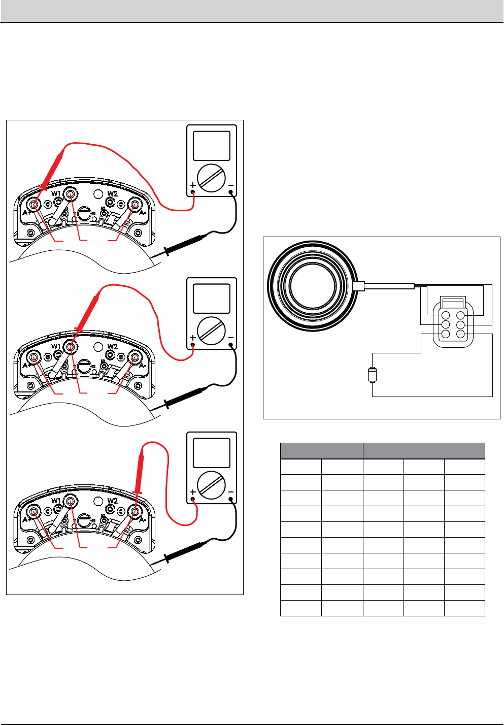
5-28 T12 Service Information 9009917 (12-12)
SERVICE
4. Test the resistance between all three motor terminals
and the motor case as shown below. The ohmmeter
should read “O.L.” or open. A shorted winding indi
cates a faulty motor.
PMT004
WU V
Ω
1.
2.
3.
Motor
Casing
WU V
Ω
Motor
Casing
WU V
Ω
Motor
Casing
5. The motor encoder and temperature sender are
non-serviceable components of the drive motor. The
motor encoder senses rotor position, speed, and
direction. The encoder is integrated into an internal
roller bearing assembly. See “Curtis 1232 LED Faults”
in the TROUBLESHOOTING section for encoder related
faults.
The temperature sender senses the propel motor
temperature. Test the resistance of the temperature
sender using an ohmmeter and then compare the
values to the chart below. Replace the motor
assembly if the resistance values are out of the
specied range.
PMT005
Encoder/Bearing
Assembly
Temperature Sender
6
5
4
1
2
3
YEL
RED
BLU
BLK
WHT
YEL
TEMPERATURE RESISTANCE Ω
(°C) (°F) MIN. T Y P. MAX
-30 -22 362 381 368
0 32 464 486 507
25 77 565 588 611
30 86 587 610 633
50 122 679 704 728
70 158 781 806 831
80 176 835 860 885
100 212 950 975 1000
110 230 1007 1036 1064
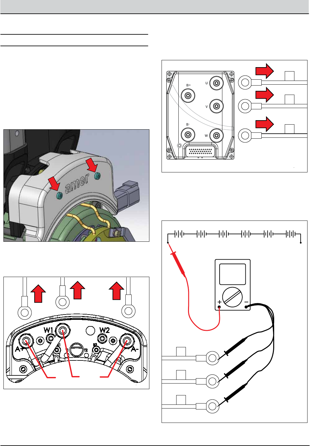
T12 Service Information 9009917 (12-12) 5-29
SERVICE
TESTING PROPEL MOTOR CABLES
1. Key O. Disconnect batteries. Remove terminal box
cover screws and set cover aside.
BET009
2. Disconnect U, V, and W cables from W1, A-, and A+
terminals (respectively).
PMT002
WU V
PMT006
U
V
W
12
35
23
1
24
13
3. Disconnect U, V, and W cables from Curtis 1232
controller as shown below.
4. Reconnect battery connection and test each cable
using an Ohmmeter for a short to battery + as shown
below. Each cable should test as “O.L.” or open to
battery +. Replace shorted cable(s).
PMT007
WU V
Ω
WU V
Ω
WU V
Ω
1.
2.
3.
3.
U
V
W
+ - + - + - + - + - + -
6 Volt 6 Volt 6 Volt 6 Volt 6 Volt 6 Volt
FOR SAFETY: Before leaving or servicing machine, stop
on level surface, turn o machine and remove key.
FOR SAFETY: When servicing machine, disconnect bat-
tery connection before working on machine.
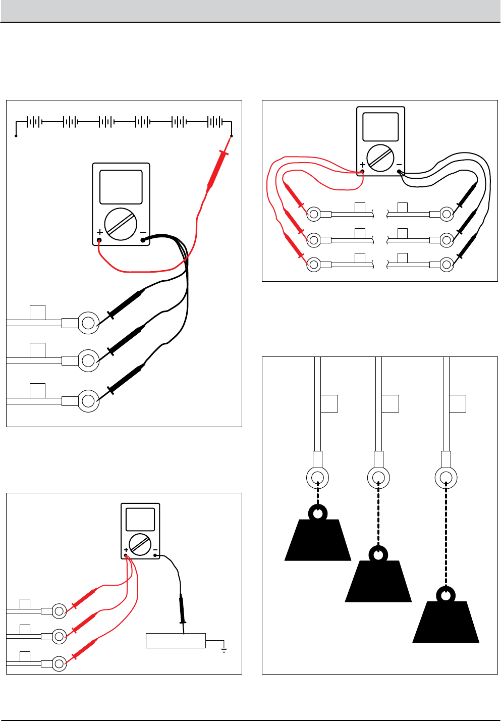
5-30 T12 Service Information 9009917 (12-12)
SERVICE
5. Test each cable using an ohmmeter for a short to
battery - as shown below. Each cable should test as
“O.L.” or open to battery -. Replace shorted cable(s).
PMT008
WU V
Ω
WU V
Ω
WU V
Ω
1.
2.
3.
3.
U
V
W
+ - + - + - + - + - + -
6 Volt 6 Volt 6 Volt 6 Volt 6 Volt 6 Volt
6. Test each cable using an ohmmeter for a short to
chassis as shown below. Each cable should test as
“O.L.” or open to chassis. Replace shorted cable(s).
PMT009
WU V
Ω
WU V
Ω
WU V
Ω
1.
2.
3.
3.
U
V
CHASSIS
W
+ - + - + - + - + - + -
6 Volt 6 Volt 6 Volt 6 Volt 6 Volt 6 Volt
7. Test each cable using an ohmmeter for end-to-end
continuity. Each cable should test between 0-1 ohm
resistance. Replace open cable(s).
PMT010
WU V
U
V
W
U
V
W
Ω
1.
2.
3.
1.
2.
3.
8. “Tug test” each cable (motor end) to determine if
a cable is broken inside the insulation. Do not exceed
10 lbs (45 N) of force as cable damage may occur.
Replace broken cables.
PMT011
WU
U
V
10 lbs
(5 kg)
V W
1.
2.
3.
10 lbs
(5 kg)
10 lbs
(5 kg)
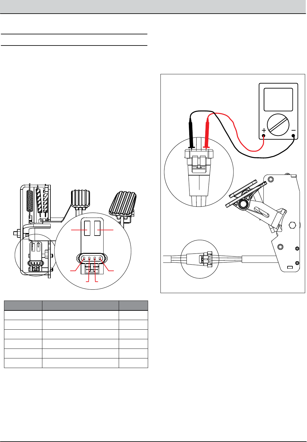
T12 Service Information 9009917 (12-12) 5-31
SERVICE
TESTING THROTTLE/BRAKE SENSOR
2. The throttle and brake hall eect sensor is a
component of the pedal subassembly.
TBS001
A
BC
D
E F
PIN/CAVITY NOTES COLOR
A POWER (BATTERY +) RED
BFORWARD OUTPUT (0-5Vdc) YELLOW
C BRAKE (0-5Vdc) BLUE
D GROUND (BATTERY -) BLACK
E GATE A N/A
F GATE B N/A
3. Key On. Backprobe the power supply to the throttle/
brake sensor terminals A and D using a voltmeter
as shown below. The voltmeter should display battery
voltage.
ABCD
ABCD
TBS002
VDC
VDC
FOR SAFETY: Before leaving or servicing machine, stop
on level surface.
FOR SAFETY: When servicing machine, jack machine
up at designated locations only. Block machine up with
jack stands.
1. Jack machine up so front drive wheel is not touching
the oor. Block machine up with jack stands.
FOR SAFETY: When servicing machine, avoid moving
parts. Do not wear loose jackets, shirts, or sleeves when
working on machine .
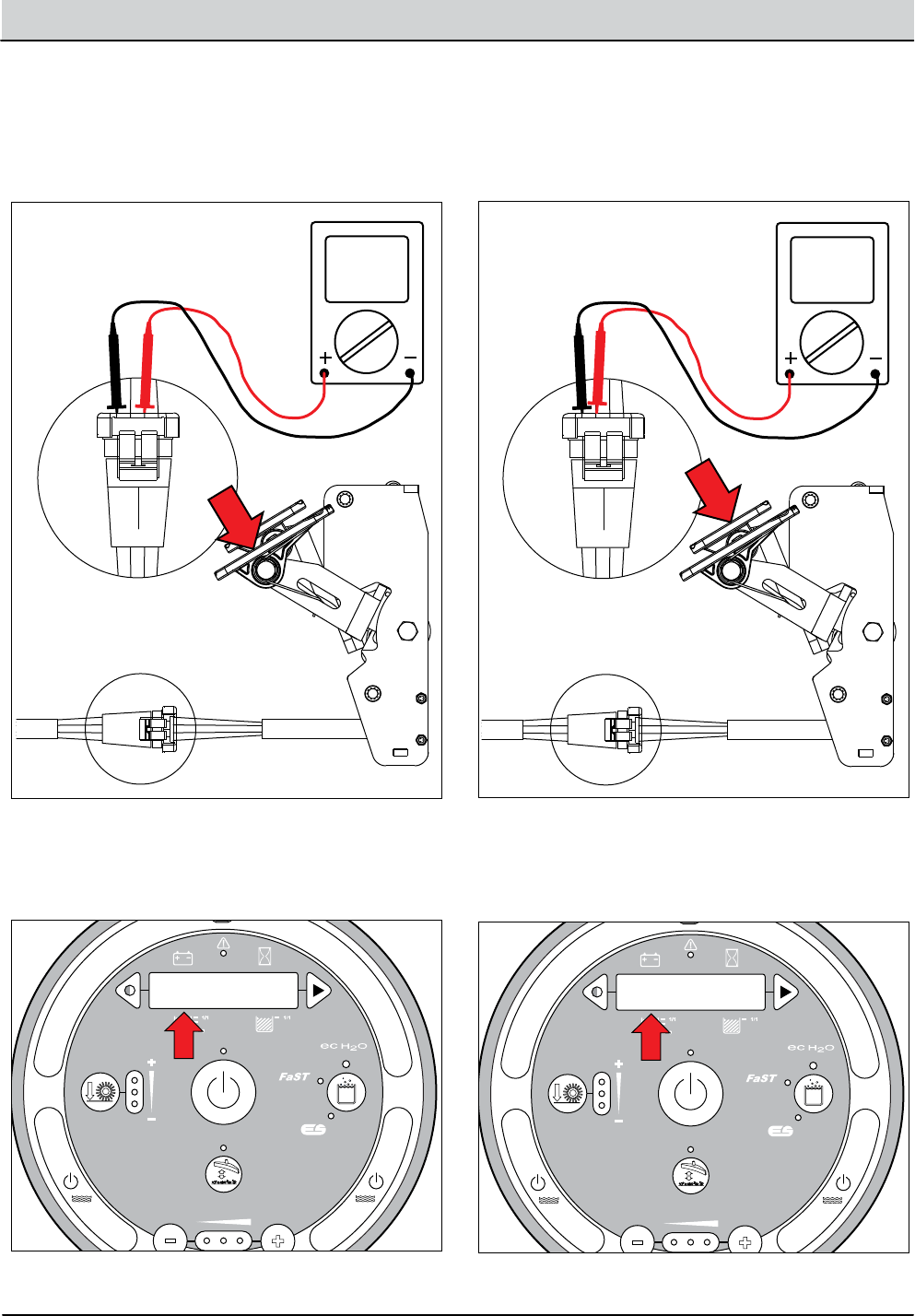
5-32 T12 Service Information 9009917 (12-12)
SERVICE
4. Key On. Backprobe the throttle sensor output
terminals B and D using a voltmeter as shown below.
The voltmeter should display 0-5 volts proportional
to 0-100% propel pedal movement.
ABCD
ABCD
TBS003
VDC
VDC
5. See “Propel Diagnostic Mode” in the TROUBLE
SHOOTING section. The voltage in step 3 should
match the LCD displayed voltage in Propel Diagnostic
Mode.
+ - + - + - + - + - + -
Scrub Head
Down
Enabled
• 1-STEP Scrub ON
• Squeegee/Vac ON • 1-STEP Scrub OFF
• Squeegee/Vac OFF
• Recovery Tank Full
• Low Batt Voltage
• Load Current Fault
Disabled
Operational Matrix:
Scrub Head
Down
Enabled
• 1-STEP Scrub ON
• Fwd/Rev Propel
• 1-STEP Scrub OFF
• Neutral-Ready State
• Recovery Tank Full
• Solution Tank Empty
• Low Batt Voltage
• Load Current Fault
Disabled
Operational Matrix:
Tennant Quantum
UI ver1.0
Tennant Quantum
UI ver X.X
T16
Control
Board
6 Volt
Key Switch
IGN
15
ACC
30
BATT
Switched B+
From Buss Bar
75
50 Start S-2
E-Stop
Switch
S-3
Charger
Interlock
ST
M1B
M1A
J7-1
B+(Control)
B+
B-
Battery Positive +
Battery Negative -
CAN +12V J2-1
J2-2
J2-3
J2-4
RED #1
RED #2
BLK #2
BLK #1
CAN +
CAN -
CAN GROUND
D-4
D-2 D-3
CB1
2.5A
FU2
100A
6 Volt 6 Volt 6 Volt 6 Volt 6 Volt
CB2
2.5A
1/RED
13/BLK
6/BLU 7/PUR
Cable
Shield
Instrument Panel Assembly
Cable
3/ORA
8/GRY
4/YEL
Cable to Ground Stand O
5/GRN
10/TAN
2/BRNCable
1. Turn Key Off.
CONFIG MODE
SELF TEST
MANUAL MODE
INPUT DISPLAY
PROPEL DIAG MODE
P1:Curtis Online/
Error
P2:Throttle
XXXX.X V
P2:Throttle
XXXX.X V
P3:Brake Pedal
On/Off
P4:Direction Fwd/
Rev
P5:Speed
XXXX.X Mph
P6:Curtis Temp
XXXX.XC XXXX.XF
P7:Motor Temp
XXXX.XC XXXX.XF
P8:PropelCurrent
XXXX.X A
TBS004
6. Key On. Backprobe the brake sensor terminals
C and D using a voltmeter as shown below. The volt-
meter should display 5 volts when the brake pedal is
activated.
ABCD
ABCD
TBS006
VDC
VDC
7. See “Propel Diagnostic Mode” in the TROUBLE
SHOOTING section. The change in voltage in step 5
should correspond to a brake pedal “On” or “O” LCD
message.
+ - + - + - + - + - + -
Scrub Head
Down
Enabled
• 1-STEP Scrub ON
• Squeegee/Vac ON • 1-STEP Scrub OFF
• Squeegee/Vac OFF
• Recovery Tank Full
• Low Batt Voltage
• Load Current Fault
Disabled
Operational Matrix:
Scrub Head
Down
Enabled
• 1-STEP Scrub ON
• Fwd/Rev Propel
• 1-STEP Scrub OFF
• Neutral-Ready State
• Recovery Tank Full
• Solution Tank Empty
• Low Batt Voltage
• Load Current Fault
Disabled
Operational Matrix:
Tennant Quantum
UI ver1.0
Tennant Quantum
UI ver X.X
T16
Control
Board
6 Volt
Key Switch
IGN
15
ACC
30
BATT
Switched B+
From Buss Bar
75
50 Start S-2
E-Stop
Switch
S-3
Charger
Interlock
ST
M1B
M1A
J7-1
B+(Control)
B+
B-
Battery Positive +
Battery Negative -
CAN +12V J2-1
J2-2
J2-3
J2-4
RED #1
RED #2
BLK #2
BLK #1
CAN +
CAN -
CAN GROUND
D-4
D-2 D-3
CB1
2.5A
FU2
100A
6 Volt 6 Volt 6 Volt 6 Volt 6 Volt
CB2
2.5A
1/RED
13/BLK
6/BLU 7/PUR
Cable
Shield
Instrument Panel Assembly
Cable
3/ORA
8/GRY
4/YEL
Cable to Ground Stand O
5/GRN
10/TAN
2/BRNCable
1. Turn Key Off.
CONFIG MODE
SELF TEST
MANUAL MODE
INPUT DISPLAY
PROPEL DIAG MODE
P1:Curtis Online/
Error
P2:Throttle
XXXX.X V
P3:Brake Pedal
On/Off
P4:Direction Fwd/
Rev
P5:Speed
XXXX.X Mph
P6:Curtis Temp
XXXX.XC XXXX.XF
P7:Motor Temp
XXXX.XC XXXX.XF
P8:PropelCurrent
XXXX.X A
TBS005
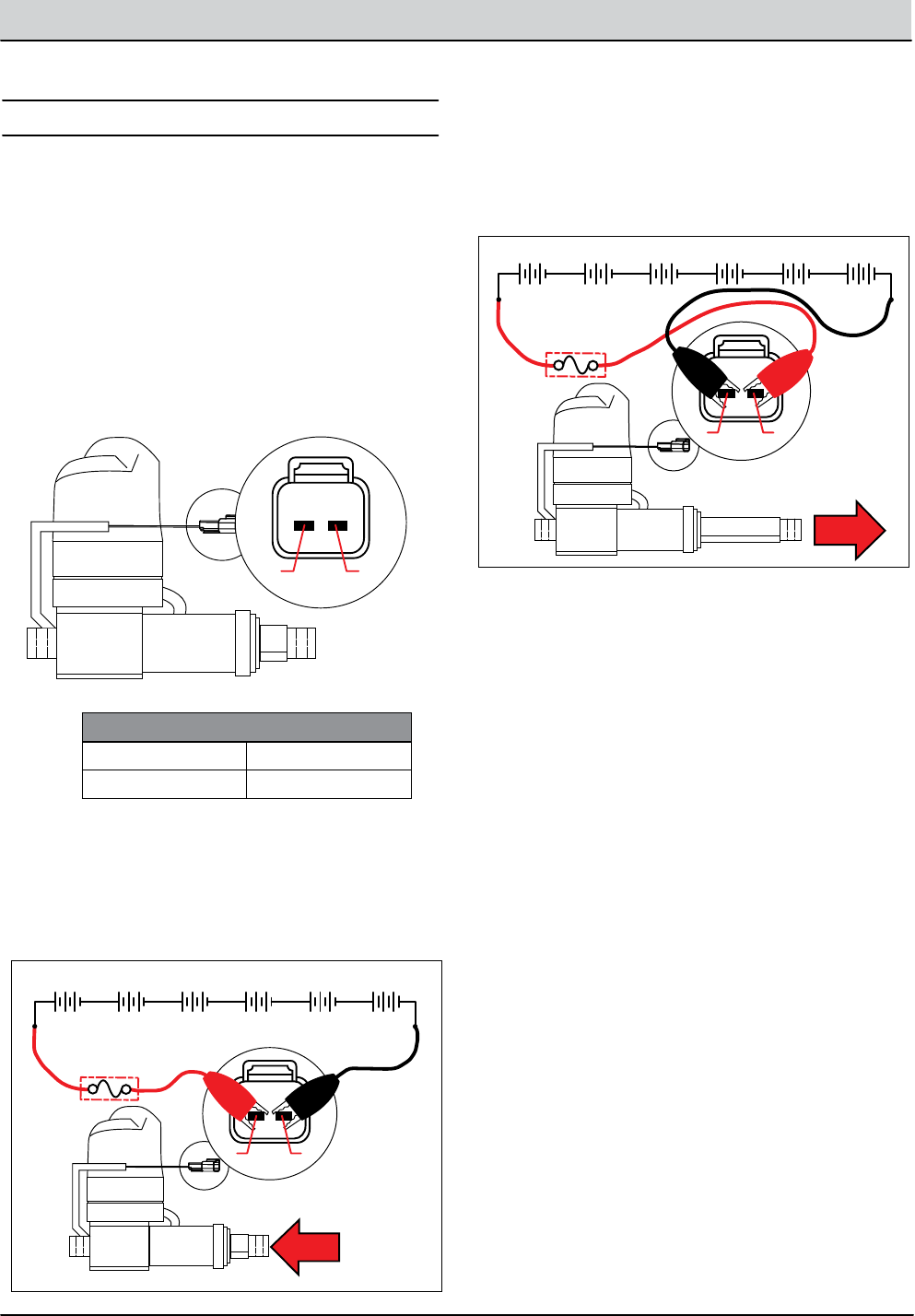
T12 Service Information 9009917 (12-12) 5-33
SERVICE
TESTING SIDE BRUSH LIFT ACTUATOR
1. Key O. Disconnect the side brush lift actuator from
the wire harness.
RSLA001
12
2. Apply battery voltage to the lift actuator using
fuse-protected jumper leads as shown below. Be sure
to connect battery + to terminal 1 and battery - to
terminal 2. The actuator should retract completely.
Replace the actuator if it fails to retract.
RSLA002
1 2
+ - + - + - + - + - + -
6 Volt 6 Volt 6 Volt 6 Volt 6 Volt 6 Volt
10 Amp
Fuse
PIN ASSIGNMENT
2 BLACK
1 BLACK
3. Reverse polarity and apply battery voltage to the lift
actuator using fuse-protected jumper leads as shown
below. Connect battery - to terminal 1 and battery +
to terminal 2. The actuator should extend completely.
Replace the actuator if it fails to extend.
RSLA003
1 2
+ - + - + - + - + - + -
6 Volt 6 Volt 6 Volt 6 Volt 6 Volt 6 Volt
10 Amp
Fuse
FOR SAFETY: Before leaving or servicing machine, stop
on level surface, turn o machine and remove key.
FOR SAFETY: When servicing machine, disconnect bat-
tery connection before working on machine.
FOR SAFETY: When servicing machine, avoid moving
parts. Do not wear loose jackets, shirts, or sleeves when
working on machine .
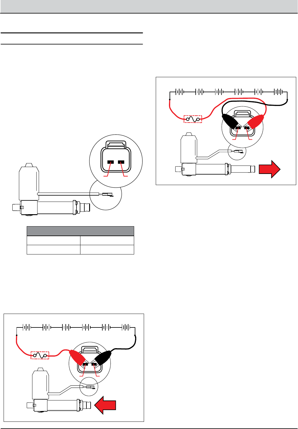
5-34 T12 Service Information 9009917 (12-12)
SERVICE
TESTING MAIN BRUSH LIFT ACTUATOR
1. Key O. Disconnect the main brush lift actuator from
the wire harness.
MSLA001
1 2
2. Apply battery voltage to the lift actuator using
fuse-protected jumper leads as shown below. Be sure
to connect battery + to terminal 1 and battery - to
terminal 2. The actuator should retract completely.
Replace the actuator if it fails to retract.
1 2
+ - + - + - + - + - + -
6 Volt 6 Volt 6 Volt 6 Volt 6 Volt 6 Volt
10 Amp
Fuse
MSLA002
PIN ASSIGNMENT
2 RED
1 BLACK
3. Reverse polarity and apply battery voltage to the lift
actuator using fuse-protected jumper leads as shown
below. Connect battery - to terminal 1 and battery +
to terminal 2. The actuator should extend completely.
Replace the actuator if it fails to extend.
1 2
MSLA003
+ - + - + - + - + - + -
6 Volt 6 Volt 6 Volt 6 Volt 6 Volt 6 Volt
10 Amp
Fuse
FOR SAFETY: Before leaving or servicing machine, stop
on level surface, turn o machine and remove key.
FOR SAFETY: When servicing machine, disconnect bat-
tery connection before working on machine.
FOR SAFETY: When servicing machine, avoid moving
parts. Do not wear loose jackets, shirts, or sleeves when
working on machine .
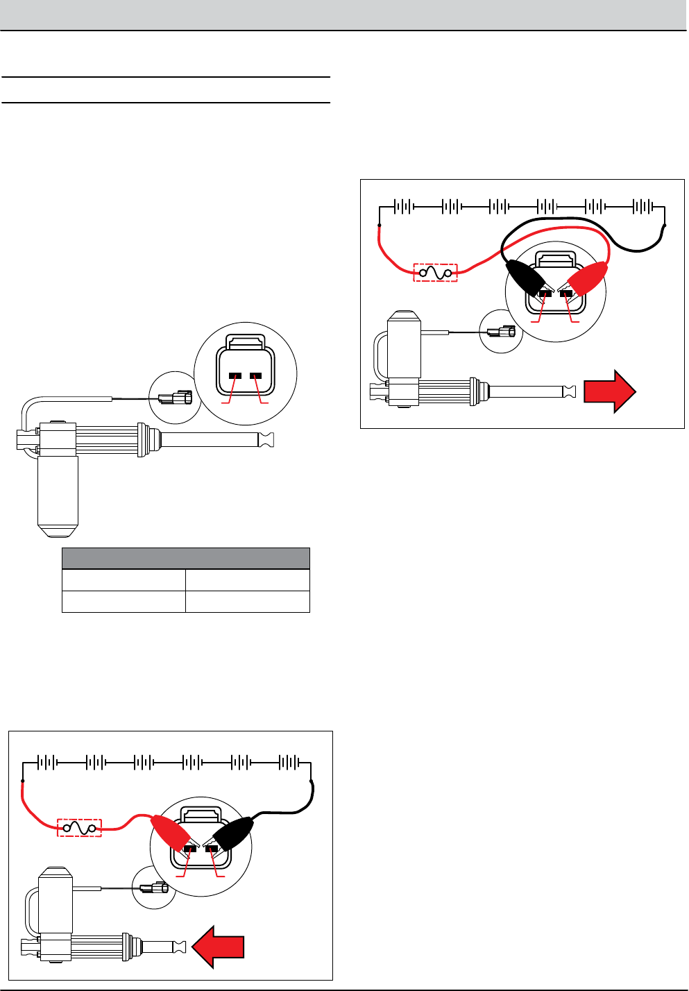
T12 Service Information 9009917 (12-12) 5-35
SERVICE
TESTING REAR SQUEEGEE LIFT ACTUATOR
1. Key O. Disconnect the rear squeegee lift actuator
from the wire harness.
RSLA005
12
2. Apply battery voltage to the lift actuator using
fuse-protected jumper leads as shown below. Be sure
to connect battery + to terminal 1 and battery - to
terminal 2. The actuator should retract completely.
Replace the actuator if it fails to retract.
RSLA006
12
+ - + - + - + - + - + -
6 Volt 6 Volt 6 Volt 6 Volt 6 Volt 6 Volt
10 Amp
Fuse
PIN ASSIGNMENT
2 BLUE
1 BROWN
3. Reverse polarity and apply battery voltage to the lift
actuator using fuse-protected jumper leads as shown
below. Connect battery - to terminal 1 and battery +
to terminal 2. The actuator should extend completely.
Replace the actuator if it fails to extend.
RSLA007
1 2
+ - + - + - + - + - + -
6 Volt 6 Volt 6 Volt 6 Volt 6 Volt 6 Volt
10 Amp
Fuse
FOR SAFETY: Before leaving or servicing machine, stop
on level surface, turn o machine and remove key.
FOR SAFETY: When servicing machine, disconnect bat-
tery connection before working on machine.
FOR SAFETY: When servicing machine, avoid moving
parts. Do not wear loose jackets, shirts, or sleeves when
working on machine .
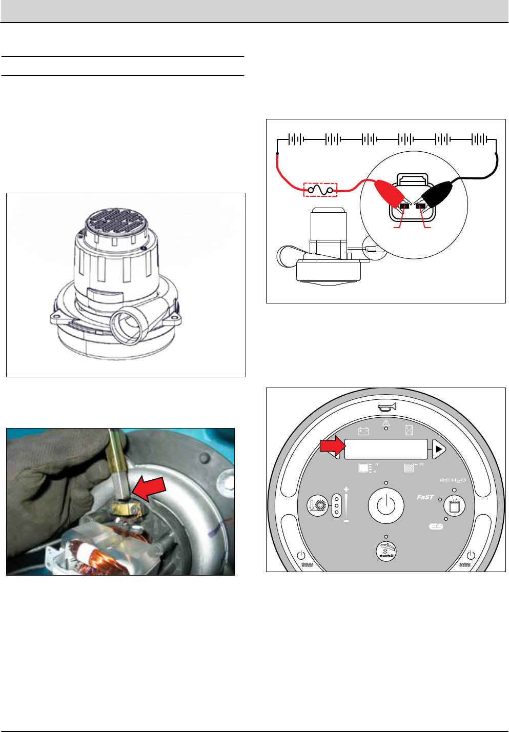
5-36 T12 Service Information 9009917 (12-12)
SERVICE
TESTING VACUUM FAN
1. Key O. Disconnect vacuum fan from wire harness.
2. Key O. Inspect carbon brushes. Replace carbon
brushes if they are shorter than 10mm (0.375 in).
3. Apply battery voltage to the vacuum fan(s) using
fuse-protected jumper leads as shown below. The fan
should turn On. Replace the vacuum fan if it fails to
turn On.
VFM003
+ - + - + - + - + - + -
6 Volt 6 Volt 6 Volt 6 Volt 6 Volt 6 Volt
25 Amp
Fuse
1 2
4. Reconnect vacuum fan(s) to wire harness. See “Manual
Mode” in the TROUBLESHOOTING section. Activate
the vacuum fan in Manual Mode. The amperage
displayed should be approximately 14-20 Amps (avg.
16 Amps)
VFM004
M04: Vac Fan
00% XX.XA
FOR SAFETY: Before leaving or servicing machine, stop
on level surface, turn o machine and remove key.
FOR SAFETY: When servicing machine, disconnect bat-
tery connection before working on machine.
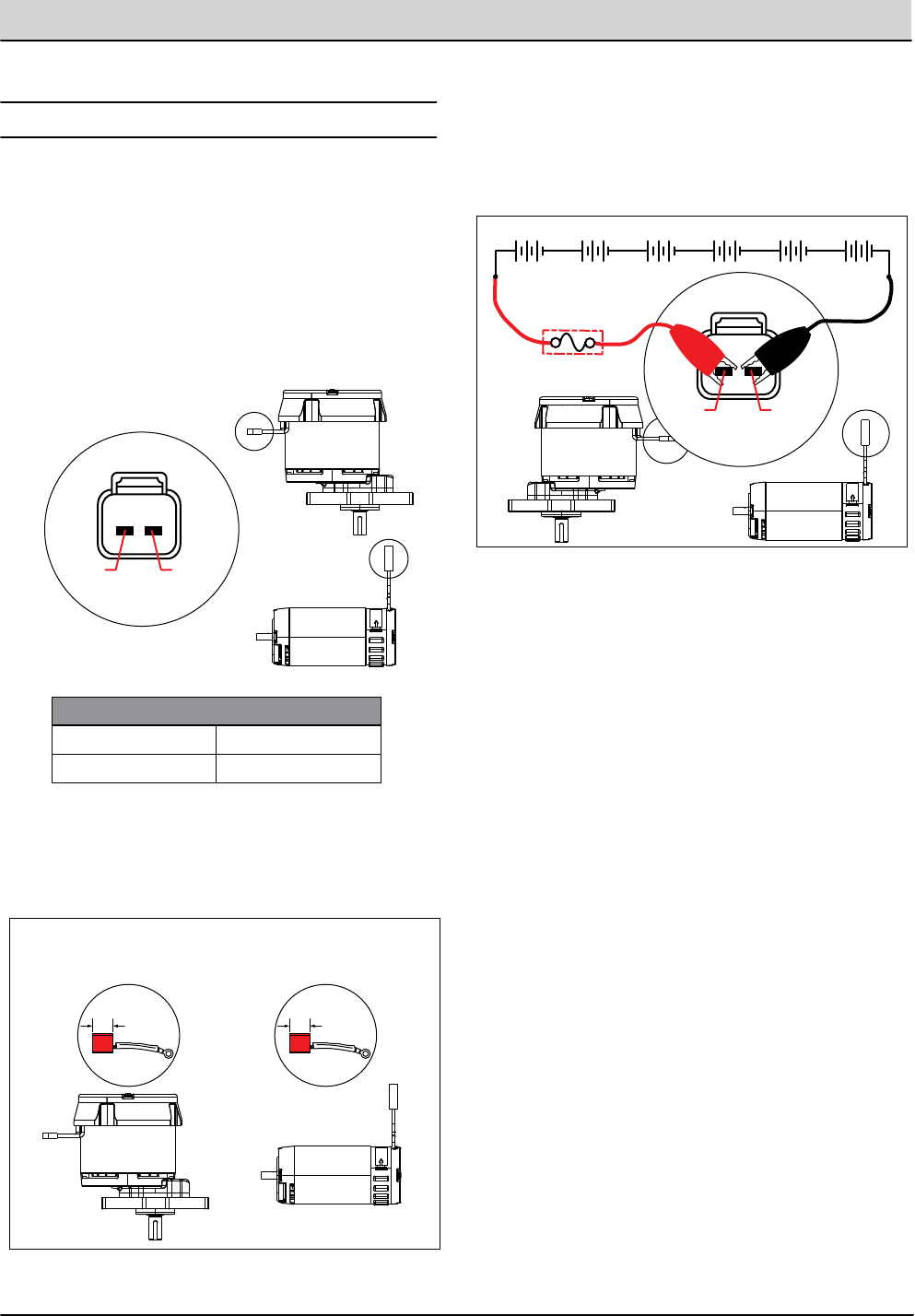
T12 Service Information 9009917 (12-12) 5-37
SERVICE
TESTING MAIN SCRUB BRUSH MOTORS
PIN ASSIGNMENT
2 BLACK
1 RED
1. Key O. Disconnect the main brush motor from
the wire harness.
MBM001
+ - + - + - + - + - + -
6 Volt 6 Volt 6 Volt 6 Volt 6 Volt 6 Volt
25 Amp
Fuse
Replacement Carbon Brush Length:
10mm (0.375 in)
1 2
Cylindrical
Disk
1 2
2. Inspect carbon brushes. Replace carbon brushes if
they are shorter than; Disk = 11mm (0.43 in), Cylindri-
cal = 10mm (0.39 in).
MBM002
+ - + - + - + - + - + -
6 Volt 6 Volt 6 Volt 6 Volt 6 Volt 6 Volt
25 Amp
Fuse
Replacement Carbon Brush Length:
10mm (0.375 in)
1 2
Disk = 11mm (0.43 in) Cyl = 10mm (0.39 in)
1 2
Carbon Brush Wear Limit:
3. Apply battery voltage to the main brush motor(s) us
ing fuse-protected jumper leads as shown below. The
brush motor should turn On. Replace the brush motor
if it fails to turn On.
MBM003
+ - + - + - + - + - + -
6 Volt 6 Volt 6 Volt 6 Volt 6 Volt 6 Volt
10 Amp
Fuse
Replacement Carbon Brush Length:
10mm (0.375 in)
1 2
Disk = Xmm (X in) Cylindrical = Xmm (X in)
1 2
Replacement Carbon Brush Length:
Disk Cylindrical
FOR SAFETY: Before leaving or servicing machine, stop
on level surface, turn o machine and remove key.
FOR SAFETY: When servicing machine, disconnect bat-
tery connection before working on machine.
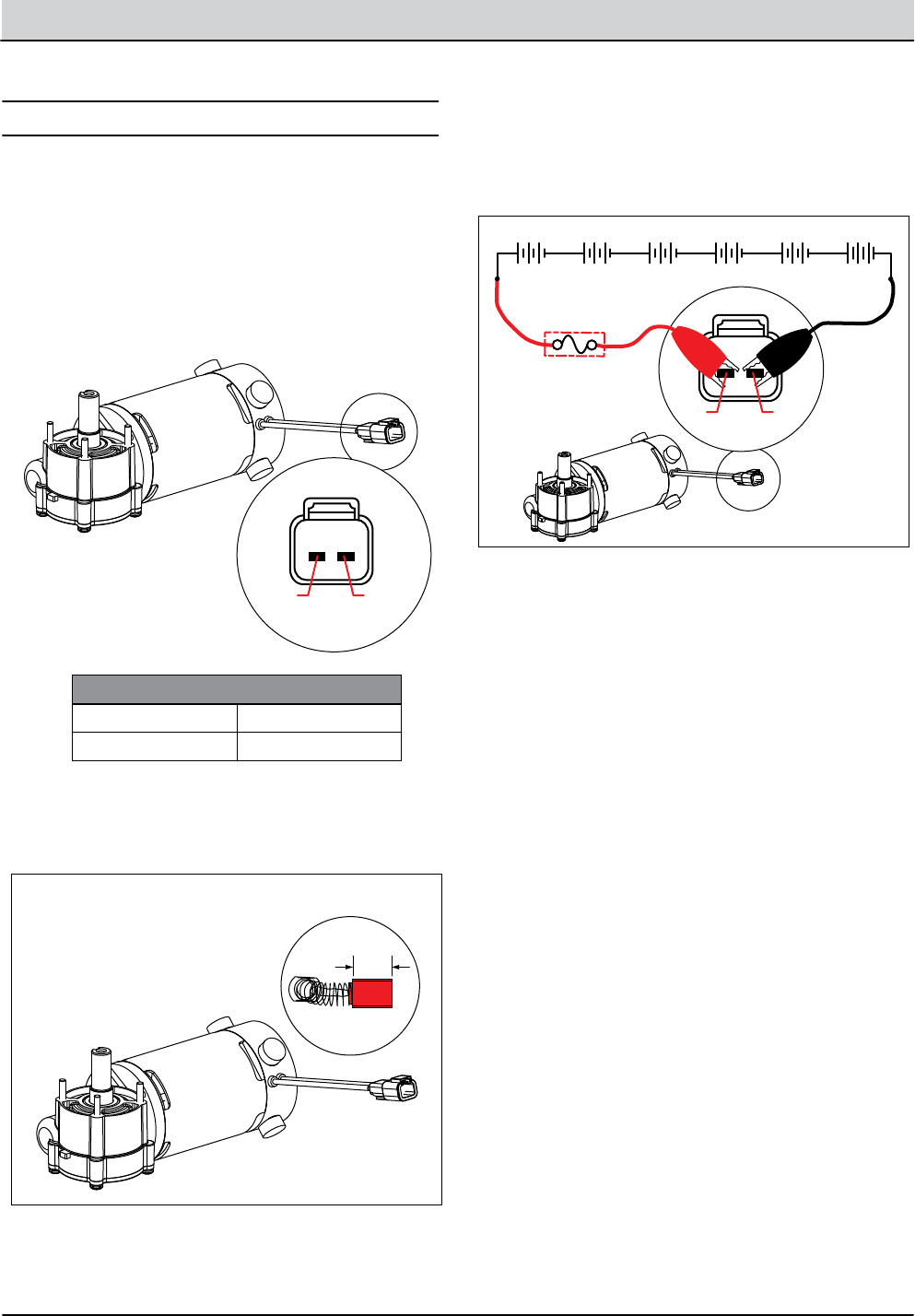
5-38 T12 Service Information 9009917 (12-12)
SERVICE
TESTING SIDE BRUSH MOTOR
1. Key O. Disconnect the side brush motor from the
wire harness.
SBM001
+ - + - + - + - + - + -
6 Volt 6 Volt 6 Volt 6 Volt 6 Volt 6 Volt
25 Amp
Fuse
Replacement Carbon Brush Length:
10mm (0.375 in)
1 2
Disk
1 2
SBM002
+ - + - + - + - + - + -
6 Volt 6 Volt 6 Volt 6 Volt 6 Volt 6 Volt
25 Amp
Fuse
Replacement Carbon Brush Length:
10mm (0.375 in)
1 2
Disk = Xmm (X in)
1 2
Carbon Brush Wear Limit:
10mm (0.39 in)
1 2
2. Key O. Inspect carbon brushes. Replace carbon
brushes if they are shorter than 10mm (0.375 in).
PIN ASSIGNMENT
2 BLACK
1 RED
SBM003
+ - + - + - + - + - + -
6 Volt 6 Volt 6 Volt 6 Volt 6 Volt 6 Volt
10 Amp
Fuse
Replacement Carbon Brush Length:
10mm (0.375 in)
Disk = Xmm (X in) Cylindrical = Xmm (X in)
1 2
Replacement Carbon Brush Length:
1 2
3. Apply battery voltage to the side brush motor using
fuse-protected jumper leads as shown below. The side
brush motor should turn On. Replace the side brush
motor if it fails to turn On.
FOR SAFETY: Before leaving or servicing machine, stop
on level surface, turn o machine and remove key.
FOR SAFETY: When servicing machine, disconnect bat-
tery connection before working on machine.
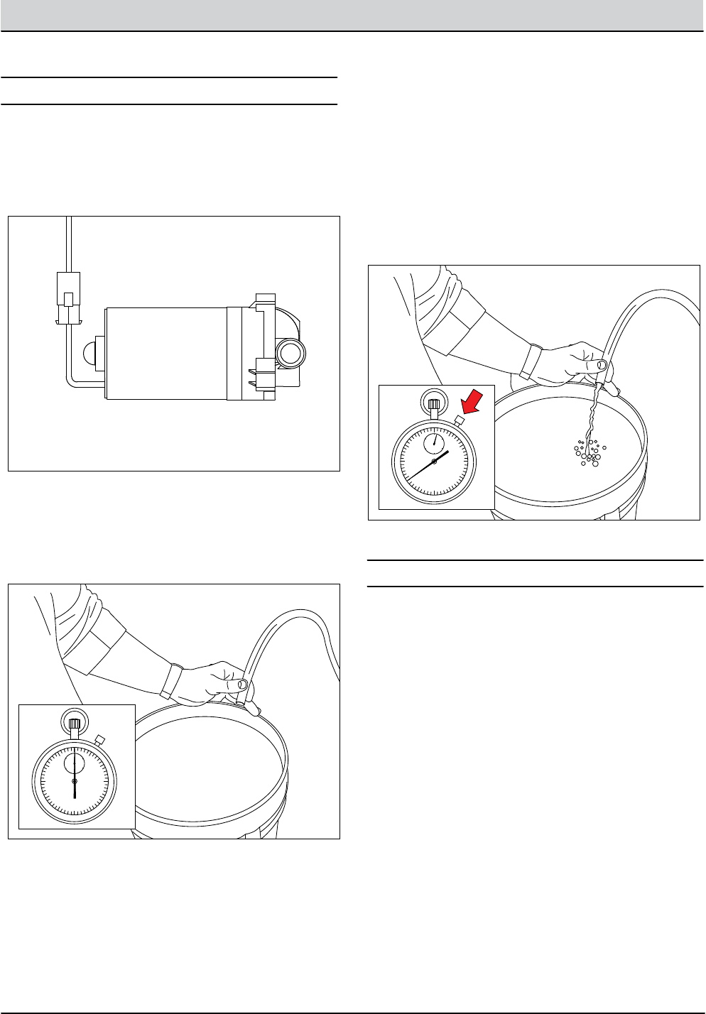
T12 Service Information 9009917 (12-12) 5-39
SERVICE
TESTING ec-H20 PUMP
1. Key O. Disconnect ec-H2O pump outlet hose.
ECP002
5
10
15
20
25
30
35
40
45
50
55 10
20
30
40
50 60
POFT002
2. Fill the solution tank.
3. Connect a temporary outlet hose to the pump. The
hose must be long enough to reach a 5 gallon bucket.
4. Enter Manual Mode and enable the ec-H2O system.
See Manual Mode in the Troubleshooting section of
this manual.
5. Use a stop watch to time how long it takes to ll a 5
gallon bucket. The open ow specication for the
ec-H2O pump is 1.35 GPM. The pump should ll the
5 gallon bucket in approximately 3.5 - 4.0 minutes.
Replace the pump if it takes longer than 4 minutes
to ll and the pump has an adequate water supply.
NOTE: Open ow is dierent than system ow and should
not be used for scrubbing mode water consumption calcu-
lations.
5
10
15
20
25
30
35
40
45
50
55 10
20
30
40
50 60
POFT003
FOR SAFETY: Before leaving or servicing machine, stop
on level surface.
ADJUSTING ec-H2O FLOW RATE
See Conguration Mode in the Troubleshooting section of
this manual.
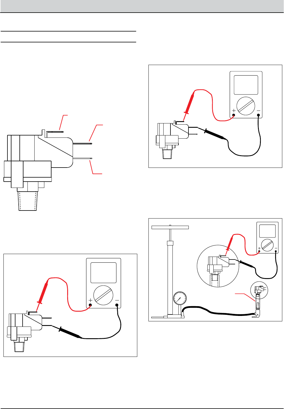
5-40 T12 Service Information 9009917 (12-12)
SERVICE
TESTING ec-H2O PRESSURE SWITCH
ECP001
Common
Normally
Open
Normally
Closed
1. Key O. Disconnect the pressure switch from the
wire harness and remove the switch from the
machine.
2. Test the resistance of the switch using an ohmmeter
between the common and normally closed terminals.
There should be 0-1 ohms resistance. Replace the
switch if the N.C. contacts are open.
ECP003
WU V
Ω
WU V
Ω
WU V
Ω
1.
2.
3.
3.
U
V
CHASSIS
W
+ - + - + - + - + - + -
6 Volt 6 Volt 6 Volt 6 Volt 6 Volt 6 Volt
Normally
Open
3. Test the resistance of the switch using an ohmmeter
between the common and normally open terminals.
The switch should test as “O.L.” or open. Replace the
switch if the N.O. contacts are shorted.
ECP004
WU V
Ω
WU V
Ω
WU V
Ω
1.
2.
3.
3.
U
V
CHASSIS
W
+ - + - + - + - + - + -
6 Volt 6 Volt 6 Volt 6 Volt 6 Volt 6 Volt
Normally
Open
4. Use a bicycle pump with pressure gauge to apply
pressure to the switch as shown below. The
normally open contacts should close at 25 +/-
2 psi (1.7 Bar), increasing pressure. Replace the switch
if it does not open correctly.
ECP005
WU V
Ω
WU V
Ω
WU V
Ω
1.
2.
3.
3.
U
V
CHASSIS
W
+ - + - + - + - + - + -
6 Volt 6 Volt 6 Volt 6 Volt 6 Volt 6 Volt
Normally
Open
3/8” I.D. Tube
0
5
10
15
2025 30 35 40
45
50
55
60
PSI
FOR SAFETY: Before leaving or servicing machine, stop
on level surface, turn o machine and remove key.
FOR SAFETY: When servicing machine, disconnect bat-
tery connection before working on machine.

We Need Your Help...
As part of Tennant’s Zero Defects Program, we want to know about errors you have
found or suggestions you may have regarding our machine manuals. If you find an
error or have a suggestion, please complete this postage-paid form and mail it to us.
Thank you for helping us make zero defects a way of life at Tennant.
Manual No. Rev. No. Publish Date Page
Machine -Report Error -Suggestion
Name Date
Customer Number
Company
Address
City/State/Zip Code
Tape hereFold along dotted lines
NO POSTAGE
NECESSARY
IF MAILED
IN THE
UNITED SATES
BUSINESS REPLY MAIL
FIRST CLASS MAIL PERMIT NO. 94 MINNEAPOLIS, MN
POSTAGE WILL BE PAID BY ADDRESSEE
Technical Publications #15
701 North Lilac Drive
P.O. Box 1452
Minneapolis, MN 55440--9947
TENNANT COMPANY

We Need Your Help...
As part of Tennant’s Zero Defects Program, we want to know about errors you have
found or suggestions you may have regarding our machine manuals. If you find an
error or have a suggestion, please complete this postage-paid form and mail it to us.
Thank you for helping us make zero defects a way of life at Tennant.
Manual No. Rev. No. Publish Date Page
Machine -Report Error -Suggestion
Name Date
Customer Number
Company
Address
City/State/Zip Code

Tape hereFold along dotted lines
NO POSTAGE
NECESSARY
IF MAILED
IN THE
UNITED SATES
BUSINESS REPLY MAIL
FIRST CLASS MAIL PERMIT NO. 94 MINNEAPOLIS, MN
POSTAGE WILL BE PAID BY ADDRESSEE
Technical Publications #15
701 North Lilac Drive
P.O. Box 1452
Minneapolis, MN 55440--9947
TENNANT COMPANY
