T1 Service Manual Tennant Walk Behind Floor Scrubber
2018-06-20
: Sweepscrub Tennant-T1-Walk-Behind-Floor-Scrubber-Service-Manual tennant-t1-walk-behind-floor-scrubber-service-manual 2785 file product_file
Open the PDF directly: View PDF ![]() .
.
Page Count: 42
T1
9008975
Rev. 00 (06--2011)
9008975
www.tennantco.com
Service Information
Manual
Battery Floor Scrubber
Models:
9008636 - T1, AGM Battery
9008639 - T1, Lithium--ion Battery
North America / International
Read this manual completely and
understand the machine before
operating or servicing it.
This machine will provide excellent service. However,
the best results will be obtained at minimum costs if:
• The machine is operated with reasonable care
according to instructions provided.
• The machine is maintained regularly - per the
machine maintenance instructions provided.
• The machine is maintained with manufacturer -
supplied or equivalent parts.
Use the parts manual to order replacement parts.
UNCRATING MACHINE: Carefully check carton for
signs of damage. Report damages at once to carrier.
PROTECT THE ENVIRONMENT
Please dispose of packaging materials
and old machine components in an envi-
ronmentally safe way according to local
waste disposal regulations.
Always remember to recycle.
Tennant Company
PO Box 1452
Minneapolis, MN 55440 USA
Tel: (800) 553--8033 ou (763) 513--2850
www.tennantco.com
Speci cations and parts are subject to change without notice. Original
Instructions. Copyright© 2011 Tennant Company. All rights reserved.
MACHINE DATA
Model No. --
Serial No. --
Sales Rep. --
Sales Rep. phone no. --
Customer Number --
Installation Date --

T1 Battery - Service Information 9008975 (6-11) 3
CONTENTS
Safety Precautions ...........................1-1
General Information . . . . . . . . . . . . . . . . . . . . . . . . . .2-1
Component Locator . . . . . . . . . . . . . . . . . . . . . . . . 2-2
Electrical Schematics . . . . . . . . . . . . . . . . . . . . . . . 2-3
Symbols ................................ 2-3
Lithium-ion Battery (1 of 2) . . . . . . . . . . . . . . 2-4
Lithium-ion Battery (2 of 2) . . . . . . . . . . . . . . 2-5
AGM Battery (1 of 2) . . . . . . . . . . . . . . . . . . . . . 2-6
AGM Battery (2 of 2) . . . . . . . . . . . . . . . . . . . . . 2-7
Specications .............................. 2-8
Fastener Torque ......................... 2-8
Machine Specications . . . . . . . . . . . . . . . . . . 2-9
Machine Dimensions . . . . . . . . . . . . . . . . . . . . 2-9
Electrical Components . . . . . . . . . . . . . . . . . 2-10
Maintenance .................................3-1
Machine Maintenance . . . . . . . . . . . . . . . . . . . . . . 3-2
After Each Use .......................... 3-2
After Weekly Use . . . . . . . . . . . . . . . . . . . . . . . . 3-2
Vacuum Hose ........................... 3-3
Squeegee Blade Replacement . . . . . . . . . . . 3-4
Transporting Machine . . . . . . . . . . . . . . . . . . . . . . 3-4
Storing Machine ........................... 3-5
Troubleshooting .............................4-1
Battery Charger and BMS, Lithium-ion . . . . . . 4-2
Operation. . . . . . . . . . . . . . . . . . . . . . . . . . . . . . . 4-2
Faults ................................... 4-2
Battery Management System (BMS) . . . . . . 4-2
Battery Charger, AGM . . . . . . . . . . . . . . . . . . . . . . 4-3
Operation. . . . . . . . . . . . . . . . . . . . . . . . . . . . . . . 4-3
Conguration ........................... 4-3
Displaying Current Settings . . . . . . . . . . . 4-3
Checking DIP Switches . . . . . . . . . . . . . . . 4-3
Faults ................................... 4-3
Subsystem Troubleshooting . . . . . . . . . . . . . . . . 4-4
Lithium-ion Battery .................... 4-4
Charger Connected (0-5 Seconds) . . . . 4-4
Electrical Schematic . . . . . . . . . . . . . . . . 4-4
Troubleshooting . . . . . . . . . . . . . . . . . . . 4-5
Charger Connected (5+ Seconds) . . . . . 4-6
Electrical Schematic . . . . . . . . . . . . . . . . 4-6
Troubleshooting . . . . . . . . . . . . . . . . . . . 4-7
Power Up Circuit (0-5 Seconds) . . . . . . . 4-8
Electrical Schematic . . . . . . . . . . . . . . . . 4-8
Troubleshooting . . . . . . . . . . . . . . . . . . . 4-9
Power Up Circuit (5+ Seconds) . . . . . . . 4-10
Electrical Schematic . . . . . . . . . . . . . . . 4-10
Troubleshooting . . . . . . . . . . . . . . . . . . 4-11
Contents Page
AGM Battery ..........................4-12
Charger Connected . . . . . . . . . . . . . . . . . 4-12
Electrical Schematic . . . . . . . . . . . . . . . 4-12
Troubleshooting . . . . . . . . . . . . . . . . . . 4-13
Power Up Circuit . . . . . . . . . . . . . . . . . . . . 4-14
Electrical Schematic . . . . . . . . . . . . . . . 4-14
Troubleshooting . . . . . . . . . . . . . . . . . . 4-15
Contents Page

CONTENTS
4T1 Battery Service Information 9008975 (6-11)

T1 Battery - Service Information 9008975 (6-11) 1-1
SAFETY PRECAUTIONS
SAFETY PRECAUTIONS
This machine is intended for commercial use. It is
designed exclusively to scrub hard oors in an
indoor environment and is not constructed for any
other use. Use only recommended brushes and
commercially approved oor cleaners intended for
machine application.
All operators must read, understand and practice
the following safety precautions.
The following warning alert symbol and the “FOR
SAFETY” heading are used throughout this manual as
indicated in their description:
WARNING: To warn of hazards or unsafe
practices which could result in severe personal
injury or death.
FOR SAFETY: To identify actions which must be
followed for safe operation of equipment.
The following safety precautions signal potentially
dangerous conditions to the operator or
equipment.
WARNING: Fire Or Explosion Hazard
-- Do Not Use or Pick Up Flammable Materials
-- Only Use Commercially Available Floor
Cleaners Intended for Machine Application.
-- Do Not Use Near Flammable Liquids, Vapors or
Combustible Dusts.
-- Batteries Emit Hydrogen Gases. Keep Machine
Away from Heat, Sparks and Open Flame.
This machine is not equipped with explosion proof
motors. The electric motors will spark upon start
up and during operation which could cause a ash
re or explosion if machine is used in an area
where ammable vapors/liquids or combustible
dusts are present.
WARNING: Electrical Hazard
-- Do Not Charge Batteries with Damaged Cord.
Do Not Modify Plug.
If the charger cord is damaged or broken, it must
be replaced by the manufacturer or its service
agent or a similarly qualied person in order to
avoid a hazard.
-- Disconnect Battery Cable and Charger Cord
Before Servicing.
WARNING: Spinning Brush. Keep Hands
Away.
WARNING: Electrical Shock Hazard.
Do Not Use Outdoors. Do Not Expose To
Rain/Moisture. Store Indoors.
FOR SAFETY:
1. Do not operate machine:
-- Unless trained and authorized.
-- Unless operator manual is read and
understood.
-- Unless mentally and physically capable of
following machine instructions.
-- In an area where ammable vapors/liquids
or combustible dusts are present.
-- Outdoors.
-- If not in proper operating condition.
-- If battery emits an unusual odor, Move
machine to a ventilated area and contact
Customer Service immediately.
-- If battery is leaking any substance, Avoid
contact with battery substance and contact
Customer Service immediately.
-- If battery becomes excessively hot,
Disconnect battery charger. Move machine
to a ventilated area and contact Customer
Service immediately.
2. Before operating machine:
-- Make sure all safety devices are in place
and operate properly.
-- Wear non--slip shoes.
-- Follow safety guidelines concerning wet
oors.
-- Follow mixing, handling and disposal
instructions on chemical containers.
3. When operating machine:
-- Report machine damage or faulty operation
immediately.
-- Do not allow children to play on or around
machine.
-- If foam or liquid begins to leak from
machine, immediately shut o machine.
-- Do not operate on inclines.
4. Before leaving machine:
-- Stop on level surface.
-- Turn the main power switch to the o
position.
5. When servicing machine:
-- Stop on level surface.
-- Turn the main power switch to the o
position.
-- Do not tilt machine back unless main
power switch is turned o and tanks are
empty.
1-2 T1 Battery - Service Information 9008975 (6-11)
SAFETY PRECAUTIONS
-- Disconnect battery connections before
working on machine.
-- Do not disconnect the charger’s DC cord
from the machine’s receptacle when the
charger is operating. Arcing may result. If
the charger must be interrupted during
charging, disconnect the AC power supply
cord rst.
-- The use of incompatible battery chargers
may damage battery and potentially cause
a re hazard.
-- Wear protective gloves and eye protection
when handling batteries or battery cables.
-- Avoid contact with battery acid.
-- Use manufacturer supplied or approved
replacement parts.
-- All repairs must be performed by a
qualied service person.
-- Avoid moving parts. Do not wear loose
clothing or jewelry.
-- Do not power spray or hose o machine.
Electrical malfunction may occur.
-- Do not modify the machine from its original
design.
6. When transporting machine:
-- Turn the main power switch to the o
position.
-- Get assistance or use a mechanical lift
when lifting machine.
-- Do not wheel up or down stairs.
-- Do not tilt on rear casters or wheels.
-- Use tie--down straps to secure machine
when transporting by vehicle.
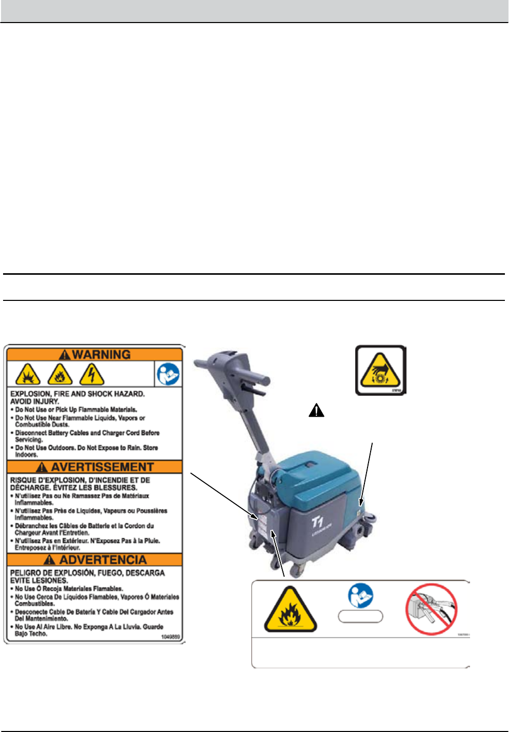
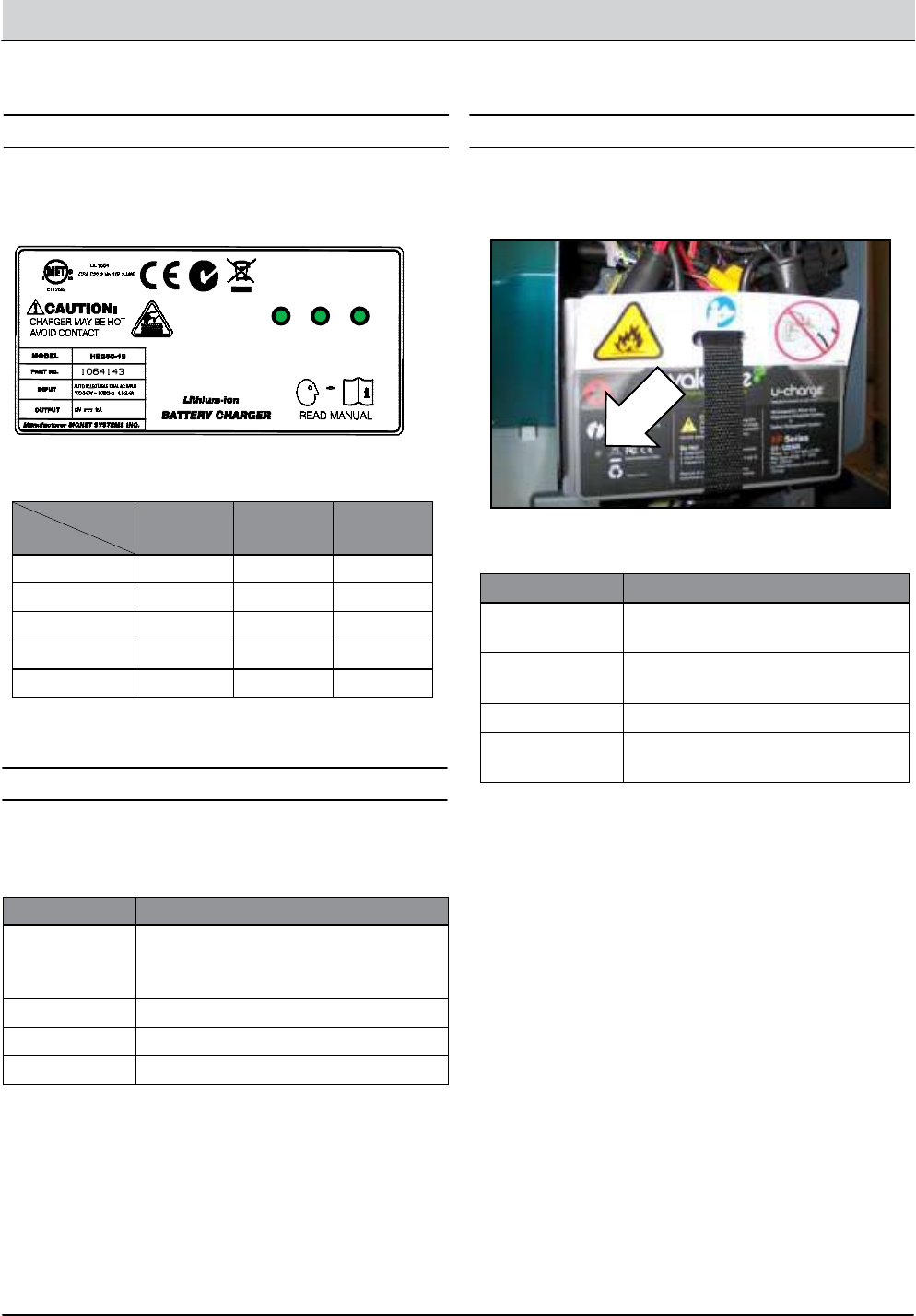
SAFETY LABELS
The safety labels appear on the machine in the locations indicated. Replace labels if they are missing or become
damaged or illegible.
WARNING: Spinning Brush.
Keep Hands Away. Turn O Power
Before Working On Machine.
FOR SAFETY: When servicing machine, the use
of incompatible battery chargers may damage
battery and potentially cause a re hazard.
Lithium--ion Battery Model

General Information . . . . . . . . . . . . . . . . . . . . . . . . . .2-1
Component Locator . . . . . . . . . . . . . . . . . . . . . . . . 2-2
Electrical Schematics . . . . . . . . . . . . . . . . . . . . . . . 2-3
Symbols ................................ 2-3
Lithium-ion Battery (1 of 2) . . . . . . . . . . . . . . 2-4
Lithium-ion Battery (2 of 2) . . . . . . . . . . . . . . 2-5
AGM Battery (1 of 2) . . . . . . . . . . . . . . . . . . . . . 2-6
AGM Battery (2 of 2) . . . . . . . . . . . . . . . . . . . . . 2-7
Specications .............................. 2-8
Fastener Torque ......................... 2-8
Machine Specications . . . . . . . . . . . . . . . . . . 2-9
Machine Dimensions . . . . . . . . . . . . . . . . . . . . 2-9
Electrical Components . . . . . . . . . . . . . . . . . 2-10
GENERAL INFORMATION
SECTION 2
Contents Page
2-1
T1 Battery - Service Information 9008975 (6-11)
2-2 T1 Battery - Service Information 9008975 (6-11)
GENERAL INFORMATION
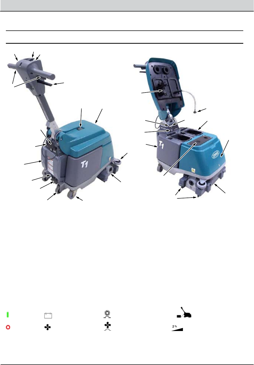
MACHINE COMPONENTS
123
5
4
8, 8a, 8b,
8c, 8d, 8e
6
7
14 13
12
15
16
20
27, 27a, 27b,
27c, 27d, 27e, 27f
18 17
23
21
22
19
10
11 24
26
25
9
1. Adjustable Control Handle
2. Main Power ON/OFF Switch
3. Battery Discharge Indicator
4. Start Triggers
5. Handle Adjustment Lever
6. Battery Charger Connector
7. Vacuum Power ON/OFF Switch
8. Rear Access Cover
a. Relays
b. Timer
c. Solution Check Valve
d. Battery
e. BMS (battery management system)
9. Transport Release Pedal
10. Scrub Head Lift Pedal
11. Curb Climbing Wheels
12. Main Wheels
13. Tank Cover
14. Recovery Window
15. Vacuum Shut-O Float
16. Solution Tank Screen
17. Brush Circuit Breaker Button
18. Vacuum Circuit Breaker Button
19. Recovery Tank
20. Solution Tank
21. Hour Meter
22. Vacuum Intake Screen
23. Scrub Head
24. Squeegee Blades
25. Brush Housing
26. Bumper Wheel
27. Front Access Cover
a. Fuses
b. Solution Pump
c. Spray Nozzles
d. Brush Motor
e. Suction Hoses
f. Vacuum Fan
Brush Circuit Breaker
MACHINE OPERATION SYMBOLS
Vacuum Circuit Breaker
Power On
Power O
Battery Discharge
Indicator
Vacuum
Battery
Charging
2% (1 °) Maximum
Grade Level
T1 Battery - Service Information 9008975 (6-11) 2-3
GENERAL INFORMATION
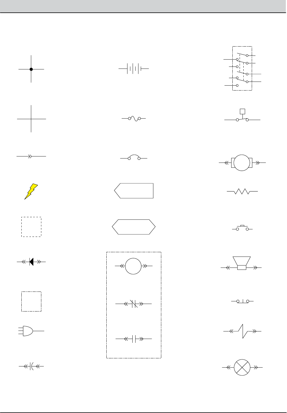
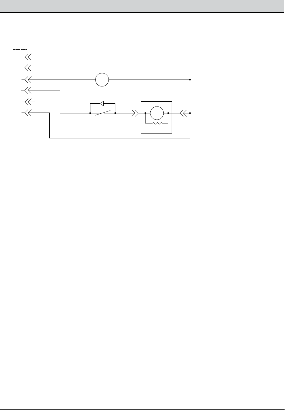
ELECTRICAL SCHEMATIC SYMBOLS
+ -
Battery
DPDT Switch
P
Pressure Switch
Motor
Momenary Switch N.O.
Contact Switch N.C.
Solenoid Valve
Resistor
Circuit Breaker
Fuse
Diode
Single Continuation Tab
Double Continuation Tab
Relay Coil
N.C. Relay Contacts
N.O. Relay Contacts
Horn or Alarm
Light
Connected
Not Connected
Connector
Notes
Assembly
AC Plug
+-
Capacitor
Energized
2-4 T1 Battery - Service Information 9008975 (6-11)
GENERAL INFORMATION
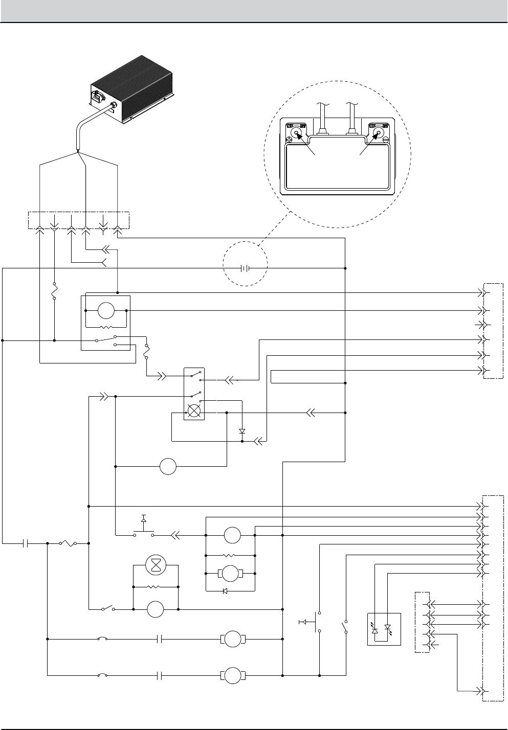
+ -
6-Pin Battery
Charging Connector
Battery Charger
Lithium-Ion Battery
6-Pin Lithium
Harness Connector
12 Pin Connector
(Not Used)
WHITE
11B/PNK
1A FUSE
1B/RED
1A/RED
29/WHT
63/ORG
68/GRY
13L/BLK
AGM
LITHIUM
1A/RED
1G/RED
19G/WHT
72/BRN
72A/BRN
16/BLU
78/GRY
PNK BLU
23
56
7 8
1A FUSE
1K/RED
R1
560 OHM
CHARGER RELAY
41D/PNK
+ -
13M/BLK
13B/BLK
D7
ORG
BLKGRY
WHT
WHT
29B/WHT
A1
A2
A3
A4
A5
A6
VBLK
-+
DPDT SWITCH,
MAIN POWER
BATTERY METER
13O/BLK
13P/BLK
41C/PNK
12V BATTERY
S2 P2 P1 S1
GREEN
BLACK
Diagnostic Port
(Not Used)
29A/WHT
20A/TAN
27A/PUR
20C/TAN 46/BLU 45/GRN 13K/BLK
13A/BLK
13I/BLK
13F/BLK
13U/BLK
VAC RELAY
VAC RELAY
SUPPRESSION DIODE
SOLUTION PUMP
680 OHM
BRUSH RELAY
680 OHM
HOURMETER
BRUSH RELAY
BRUSH MOTOR
VAC MOTOR
20B/TAN
29C/WHT 27/PUR
31/PNK 32/BRN
30A
VACUUM SW.
35A
20/TAN
5A FUSE
DISCHARGE
RELAY
TRIGGER SWITCH
21C/PNK
13R/BLK
E1
E2
E3
E4
E5
E6
E7
E8
E9
E10
E11
E12
13E/BLK
91/PNK
92/BRN
93/ORG
94/YEL
13T/BLK 102/BRN
FLUSH INPUT (NOT USED )
BI-COLOR LED
(NOT USED)
GREEN
RED
MODE SWITCH (NOT USED)
37/PUR
81/PNK
88/GRY
13V/BLK
21/PNK
21A/PNK 21B/PNK
BRNWHT
1
2
3
4
5
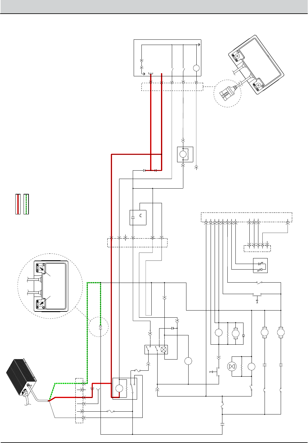
ELECTRICAL SCHEMATIC - LITHIUM BATTERY (1 of 2)
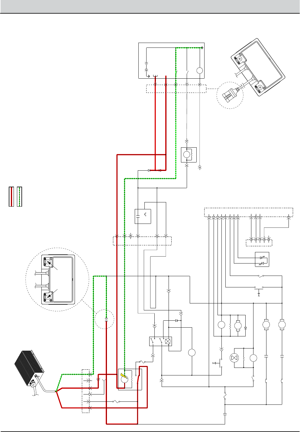
T1 Battery - Service Information 9008975 (6-11) 2-5
GENERAL INFORMATION
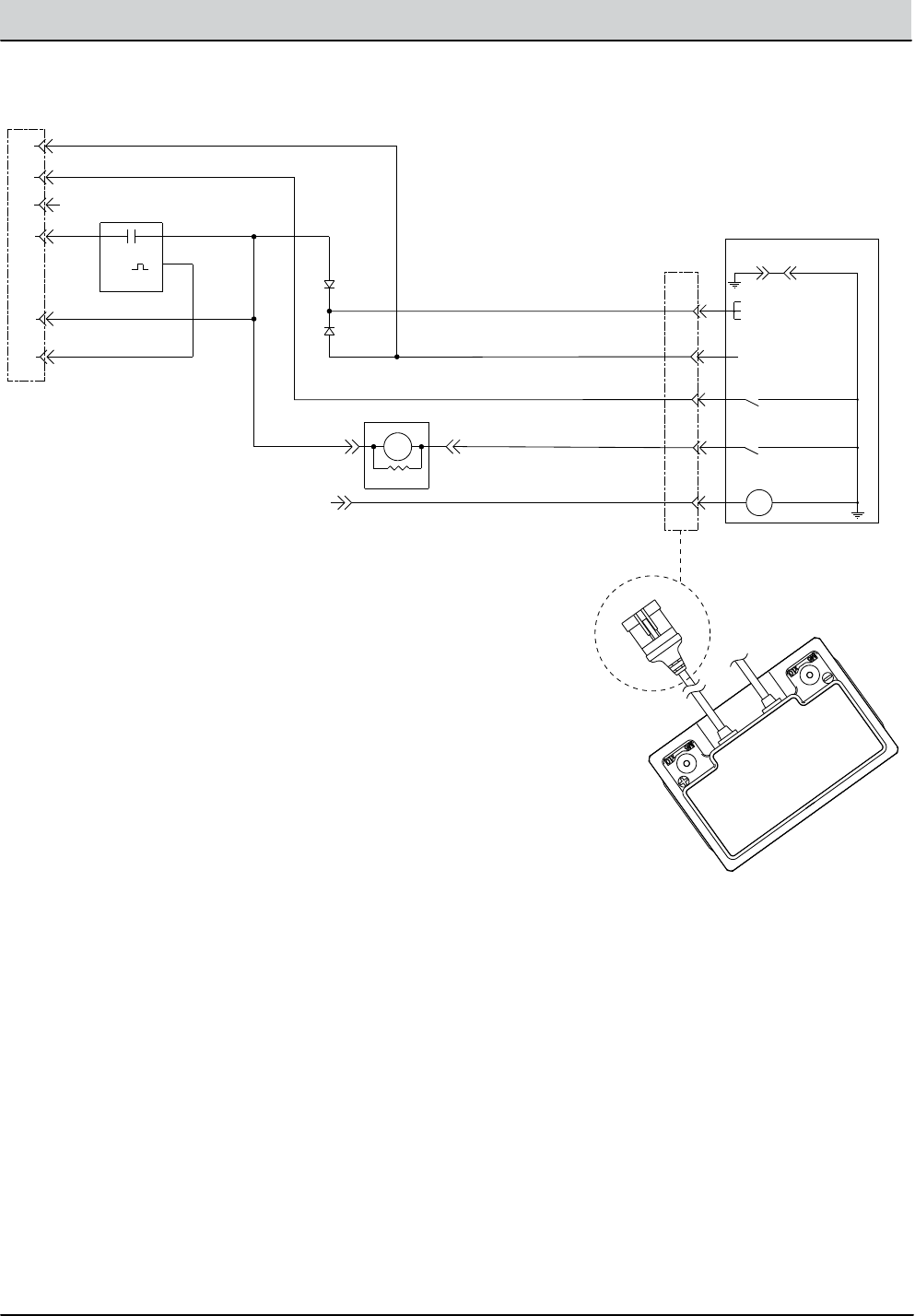
ELECTRICAL SCHEMATIC LITHIUM BATTERY (2 of 2)
Lithium-Ion Battery
A1
A2
A3
A4
A5
A6
5-Pin Battery Management
System (BMS) Connector
Battery Management System (BMS)
Controller, Internal to Lithium Battery
94C/YEL
25/GRN
17/PUR
18/GRY
NOTE:
D6 PREVENTS THE TIMER
OR MAIN SWITCH FROM
POWERING THE CHARGER
RELAY AND AUX 2 INPUT
94B/YEL
25/GRN
12V SYS GND
(INTERNAL CONNECTION)
BATT POS+
12V IGNITION
12V SYS
AUX 2
(CHARGER MODE INPUT)
CHARGE RELAY GROUND
DISCHARGE RELAY GROUND
SOC (STATE OF CHARGE) IND.
(5V = FULL, 0V = EMPTY)
17A/PUR
SOC LINE
5V = FULL
0V = EMPTY
19/WHT
99/WHT
D6
B1
B2
B3
B4
B5 V
C2 C1
D8
15/GRN
INPUT
DISCHARGE RELAY
680 OHM
5 SEC.
TIMER MODULE
5 SECONDS ON MAKE
OUTPUT
17B/PUR
13Y/BLK
6-Pin Lithium
Harness Connector
1
3
2
2-6 T1 Battery - Service Information 9008975 (6-11)
GENERAL INFORMATION
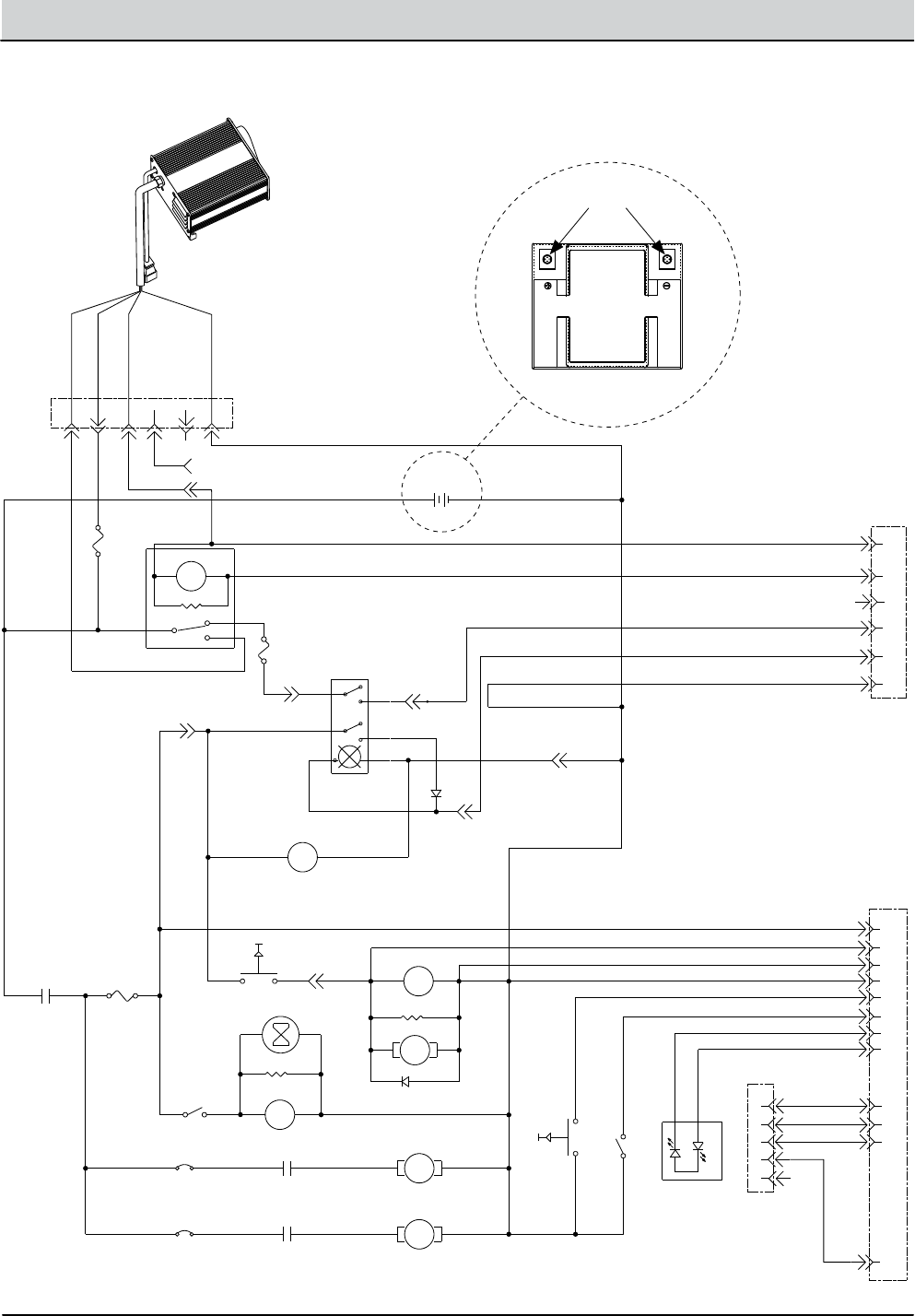
ELECTRICAL SCHEMATIC - AGM BATTERY (1 of 2)
+ -
6-Pin Battery
Charging Connector
Battery Charger
AGM Battery
6-Pin AGM
Harness Connector
12 Pin Connector
(Not Used)
RED
WHITE
11B/PNK
1A FUSE
1B/RED
1A/RED
29/WHT
63/ORG
68/GRY
13L/BLK
AGM
LITHIUM
1A/RED
1G/RED
19G/WHT
72/BRN
72A/BRN
16/BLU
78/GRY
PNK BLU
23
56
7 8
1A FUSE
1K/RED
R1
560 OHM
CHARGER RELAY
41D/PNK
+ -
13M/BLK
13B/BLK
D7
ORG
BLKGRY
WHT
WHT
29B/WHT
A1
A2
A3
A4
A5
A6
VBLK
-+
DPDT SWITCH,
MAIN POWER
BATTERY METER
13O/BLK
13P/BLK
41C/PNK
12V BATTERY
S2 P2 P1 S1
GREEN
BLACK
Diagnostic Port
(Not Used)
29A/WHT
20A/TAN
27A/PUR
20C/TAN 46/BLU 45/GRN 13K/BLK
13A/BLK
13I/BLK
13C/BLK
13U/BLK
VAC RELAY
VAC RELAY
SUPPRESSION DIODE
SOLUTION PUMP
680 OHM
BRUSH RELAY
680 OHM
HOURMETER
BRUSH RELAY
BRUSH MOTOR
VAC MOTOR
20B/TAN
29C/WHT 27/PUR
31/PNK 32/BRN
30A
VACUUM SW.
35A
20/TAN
5A FUSE
DISCHARGE
RELAY
TRIGGER SWITCH
21C/PNK
13R/BLK
E1
E2
E3
E4
E5
E6
E7
E8
E9
E10
E11
E12
13E/BLK
91/PNK
92/BRN
93/ORG
94/YEL
13T/BLK 102/BRN
FLUSH INPUT (NOT USED)
BI-COLOR LED
(NOT USED)
GREEN
RED
MODE SWITCH (NOT USED)
37/PUR
81/PNK
88/GRY
13V/BLK
13T/BLK
21/PNK
21A/PNK 21B/PNK
BRNWHT
1
2
3
4
5
T1 Battery - Service Information 9008975 (6-11) 2-7
GENERAL INFORMATION
ELECTRICAL SCHEMATIC - AGM BATTERY (2 of 2)
A1
A2
A3
A4
A5
A6
13U/BLK
13V/BLK
DISCHARGE RELAY
13O/BLK
680 OHM
C1C2
13X/BLK
17 PUR
BATTERY DISCHARGE
METER (HIDDEN)
V
11A/PNK
16/BLU
NOTE:
THIS BATTERY DISCHARGE METER IS USED AS A LOW
VOLTAGE CUT-OFF RELAY ONLY. IT IS LOCATED BEHIND
THE ACCESS COVER. CONTACTS OPEN AT ≤10.4 VOLTS.
6-Pin AGM
Harness Connector

2-8 T1 Battery - Service Information 9008975 (6-11)
GENERAL INFORMATION
FASTENER TORQUE
Thread
Size
SAE
Grade 1
SAE
Grade 2
Carriage
Bolts
Thread
Cutting
Thread
Rolling
SAE
Grade 5
Socket &
Stainless
Steel
SAE
Grade 8
Headless
Socket Set
Screws
Square
Head Set
Screws
4 (.112) (5) - (6.5) (4) - (6)
5 (.125) (6) - (8) (9) - (11)
6 (.138) (7) - (9) (20) - (24) (9) - (11)
8 (.164) (12) - (16) (40) - (47) (17) - (23)
10 (.190) (20) - (26) (50) - (60) (31) - (41)
1/4 (.250) 4 - 5 5 - 6 7 - 10 7 - 10 10 - 13 6 - 8 17 - 19
5/16 (.312) 7 - 9 9 - 12 15 - 20 15 - 20 20 - 26 13 - 15 32 - 38
3/8 (.375) 13 - 17 16 - 21 27 - 35 36 - 47 22 - 26 65 - 75
7/16 (.438) 20 - 26 26 - 34 43 - 56 53 - 76 33 - 39 106 - 124
1/2 (.500) 27 - 35 39 - 51 65 - 85 89 - 116 48 - 56 162 - 188
5/8 (.625) 80 - 104 130 - 170 171 - 265 228 - 383
3/4 (.750) 129 - 168 215 - 280 313 - 407 592 - 688
1 (1.000) 258 - 335 500 - 650 757 - 984 1281 - 1489
Thread
Size
4.8/5.6 8.8
Stainless Steel
10.9 12.9 Set
Screws
M3 43 - 56 Ncm 99 - 128 Ncm 139 - 180 Ncm 166 - 215 Ncm 61 - 79 Ncm
M4 99 - 128 Ncm 223 - 290 Ncm 316 - 410 Ncm 381 - 495 Ncm 219 - 285 Ncm
M5 193 - 250 Ncm 443 - 575 Ncm 624 - 810 Ncm 747 - 970 Ncm 427 - 554 Ncm
M6 3.3 - 4.3 Nm 7.6 - 9.9 Nm 10.8 - 14 Nm 12.7 - 16.5 Nm 7.5 - 9.8 Nm
M8 8.1 - 10.5 Nm 18.5 - 24 Nm 26.2 - 34 Nm 31 - 40 Nm 18.3 - 23.7 Nm
M10 16 - 21 Nm 37 - 48 Nm 52 - 67 Nm 63 - 81 Nm
M12 28 - 36 Nm 64 - 83 Nm 90 - 117 Nm 108 - 140 Nm
M14 45 - 58 Nm 102 - 132 Nm 142 - 185 Nm 169 - 220 Nm
M16 68 - 88 Nm 154 - 200 Nm 219 - 285 Nm 262 - 340 Nm
M20 132 - 171 Nm 300 - 390 Nm 424 - 550 Nm 508 - 660 Nm
M22 177 - 230 Nm 409 - 530 Nm 574 - 745 Nm 686 - 890 Nm
M24 227 - 295 Nm 520 - 675 Nm 732 - 950 Nm 879 - 1140 Nm
METRIC
SAE (STANDARD)

T1 Battery - Service Information 9008975 (6-11) 2-9
GENERAL INFORMATION
SPECIFICATIONS
MODEL T1 BATTERY
Length 27.4 in / 695 mm with handle folded
Width 19.8 in / 502 mm
Height 23.4 in / 594 mm with handle folded
38 in / 965 mm with handle in working position
Weight 110 lb / 50 kg with Lithium-ion battery
126 lb / 57 kg with AGM battery
Solution Tank Capacity 2.5 gal / 9.5 L
Recovery Tank Capacity 3.4 gal / 12.9 L
Productivity Rate - AVG.* 7743 ft / 719 m/hr
Cleaning Path Width 15 in / 381 mm
Squeegee Width 17.5 in / 444 mm
Brush Pressure 38 lb / 17 kg
Brush Motor 12.8 VDC, 0.65 hp / 0.49 kW, 900 brush RPM
Vacuum Motor 12.8 VDC, 0.5 hp / 0.38 kW, 1-Stage 5.7 in
Water Lift 12.0 in / 305 mm Operating - 25.0 in / 635 mm Sealed
Solution Pump 12.8 VDC, 0.16 hp / 11.9 W
Solution Flow Rate 0.10 gal / 0.38 L/min
Battery Capacity 12V Lithium-ion, 40 Ah / 512Wh
12V AGM, 50 Ah / 600Wh
Machine Run Time Up to 60 min-Lithium-ion battery, Up to 45 min - AGM battery
Voltage 12 VDC Nominal
Total Power Consumption 500W
Battery Charger (Supplied with AGM Model) 120/220-240 VAC, 4.8/2.4 A, 50/60 Hz, 14.6 VDC, 10 A Output
Battery Charger (Supplied with Lithium-ion Model) 120/220-240 VAC, 4.8/2.4 A, 50/60 Hz, 14.6 VDC, 15 A Output
Decibel Rating at Operator’s Ear, Indoors**
Level of Uncertainty
68 dBA
3 dBA
Vibrations at Hand Controls <2.5m/s
Protection Grade IPX3
MACHINE SPECIFICATIONS
MACHINE DIMENSIONS
* Estimated coverage rates use the practical speed and empty/ll time standards from the 2004 ISSA Cleaning Times handbook.
** Sounds levels (ISO 11201) as recommended by the American Association of Cleaning Equipment Manufacturers (AACEM) and OSHA.
27.3 in
695 mm
23.8 in
594 mm
19.7 in
502 mm

2-10 T1 Battery - Service Information 9008975 (6-11)
GENERAL INFORMATION
Component Measure
Relay Coil, Charge 70 Ω +/- 5%
Relay Coil, Discharge 70 Ω +/- 5%
Relay Coil, Brush 70 Ω +/- 5%
Relay Coil, Vacuum 70 Ω +/- 5%
Motor, Solution Pump 0.9 - 2 Amps Continuous
Motor, Brush 7 - 12 Amps Continuous
Motor, Vacuum 25 - 32 Amps Continuous
ELECTRICAL COMPONENTS (For Reference Only)
SPECIFICATIONS

MAINTENANCE
SECTION 3
3-1
T1 Battery - Service Information 9008975 (6-11)
Maintenance .................................3-1
Machine Maintenance . . . . . . . . . . . . . . . . . . . . . . 3-2
After Each Use .......................... 3-2
After Weekly Use . . . . . . . . . . . . . . . . . . . . . . . . 3-2
Vacuum Hose ........................... 3-3
Squeegee Blade Replacement . . . . . . . . . . . 3-4
Transporting Machine . . . . . . . . . . . . . . . . . . . . . . 3-4
Storing Machine ........................... 3-5
Contents Page
3-2 T1 Battery - Service Information 9008975 (6-11)
MAINTENANCE
MACHINE MAINTENANCE
To keep the machine in good working condition, simply
follow the machine’s maintenance procedures.
FOR SAFETY: Before performing any maintenance
procedures turn the main power switch to the o
position.
FOR SAFETY: When servicing machine, all repairs
must be performed by a qualied service person.
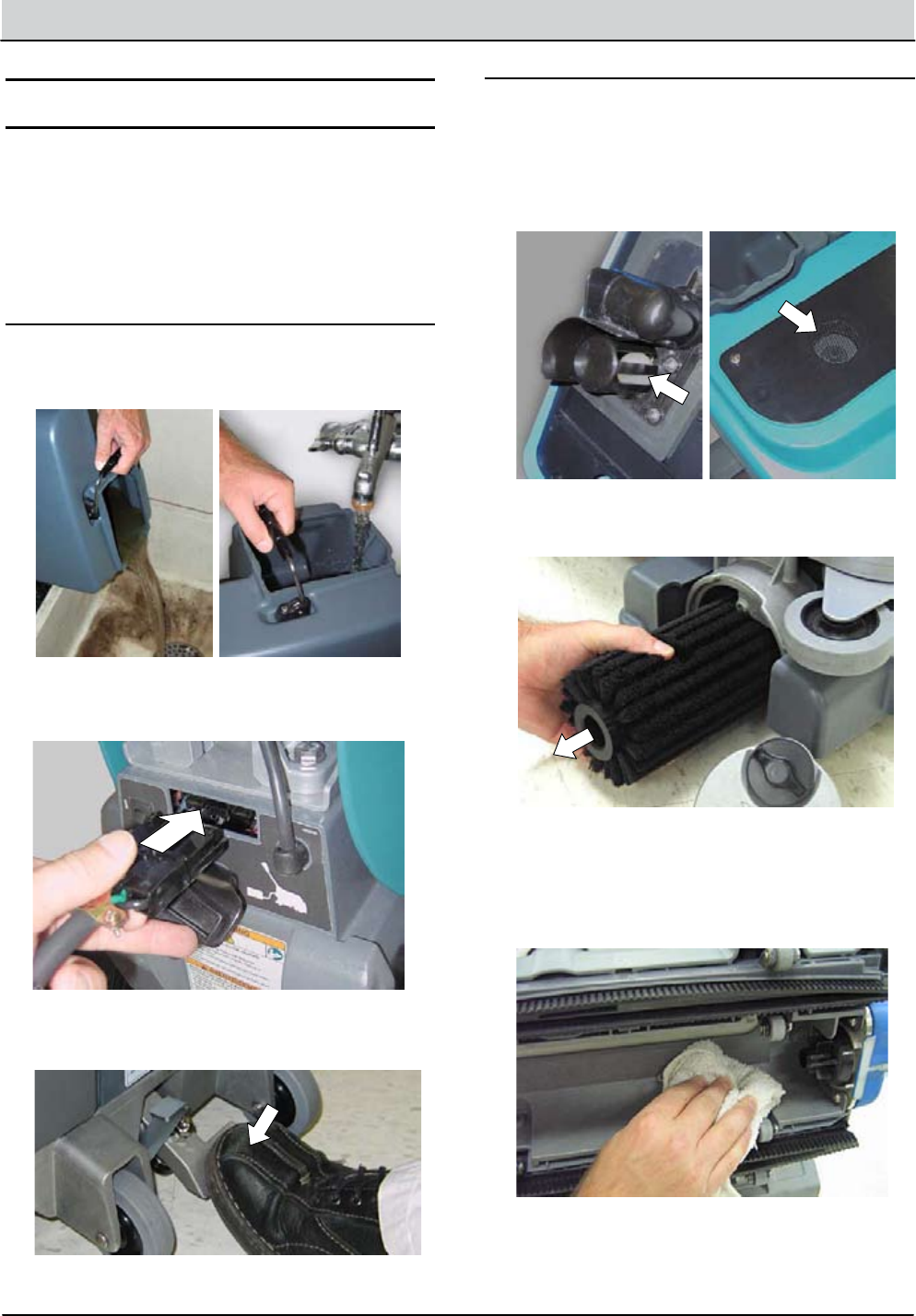
AFTER EACH USE
1. Empty the recovery tank and thoroughly rinse with
clean water (Figure 25).
FIG. 25
2. Recharge the battery (Figure 26).
FIG. 26
FIG. 27
3. Raise the scrub head to the transport position to
prevent at spot on brush (Figure 27).
AFTER WEEKLY USE
1. Clean the vacuum shut-o oat with damp cloth
(Figure 28) and remove any debris buildup from
vacuum intake screen (Figure 29).
ATTENTION: Be careful not to get water in vacuum
intake screen, vacuum damage may result.
FIG. 28 FIG. 29
2. Remove the brush and check for entangled debris
(Figure 30). Replace brush if damaged or worn.
FIG. 30
3. Tilt the machine back and clean the underside of
the scrub head (Figure 31).
FOR SAFETY: Before tilting machine, turn the main
power switch to the o position and empty tanks.
FIG. 31
T1 Battery - Service Information 9008675 (6-11) 3-3
MAINTENANCE
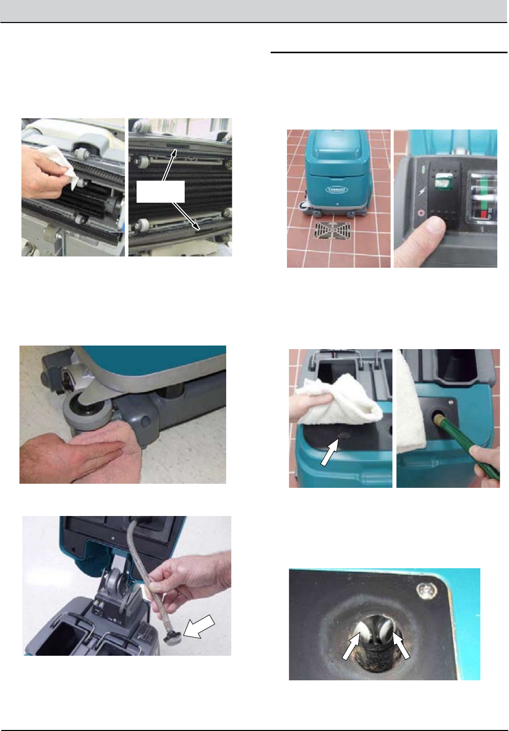
4. Wipe the squeegee blades (Figure 32). Replace
the blades if worn or damaged. Remove any
clogged debris inside both inlet openings.
FOR SAFETY: Before tilting machine, turn the main
power switch to the o position and empty tanks.
Inlet
Openings
FIG. 32
5. Clean the machine with an all purpose cleaner and
damp cloth (Figure 33).
FOR SAFETY: When cleaning machine, do not
power spray or hose o machine. Electrical
malfunction may occur.
FIG. 33
6. Clean the solution hose screen (Figure 34).
FIG. 34
VACUUM HOSE MAINTENANCE
To prevent debris buildup in vacuum system, ush
vacuum hose as described below:
1. Place machine over oor drain and turn the main
power switch to the o position (Figure 35).
FIG. 35
2. Place a dry towel over the vacuum intake screen to
prevent water from entering vacuum motor (Figure
36).
3. With water turned o, insert a garden hose into the
vacuum intake hose as shown (Figure 37).
FIG. 36 FIG. 37
4. Slowly turn on water to prevent back-splash if
vacuum system is clogged. Increase water
pressure to ush out debris buildup.
NOTE: The vacuum hose is Y-shaped. Make sure to
ush out both sides (Figure 38).
FIG. 38
3-4 T1 Battery - Service Information 9008975 (6-11)
MAINTENANCE
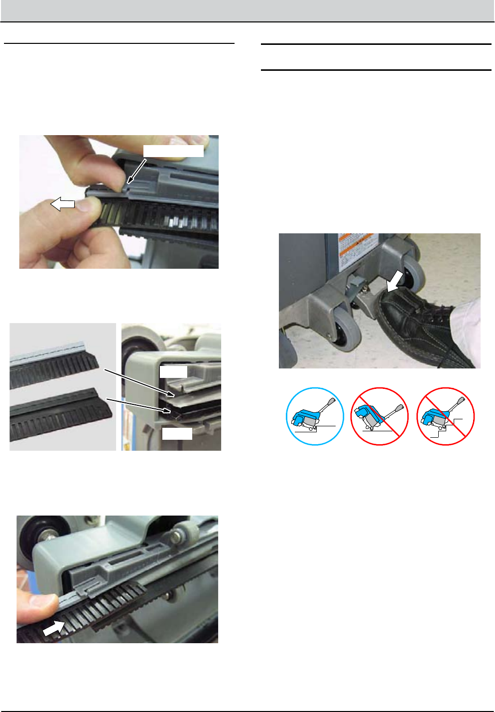
SQUEEGEE BLADE REPLACEMENT
Tilt the machine back to access the squeegee blades.
FOR SAFETY: Before tilting machine, turn the main
power switch to the o position and empty tanks.
To remove the squeegee blades, lift the blade retainer
clip and pull the blade from the channel (Figure 39).
Retainer Clip
FIG. 39
For easy blade installation, the squeegee blades are
color coded to match the scrub head blade channel
(Figure 40).
Gray -- Outside Blade
Black -- Inside Blade
Gray
Black
FIG. 40
To install blade, slide each blade into the appropriate
channel until retainer clip engages blade (Figure 41).
The squeegee blade ribs should face away from each
other.
FIG. 41
TRANSPORTING MACHINE
Before transporting machine, empty water from tanks
and turn the main power switch to the o position.
FOR SAFETY: When transporting machine, get
assistance or use a mechanical lift when lifting
machine.
FOR SAFETY: When transporting machine, use
tie-down straps to secure machine.
To wheel machine from room to room, raise the scrub
head to the transport position and push the machine
forward (Figure 42).
DO NOT tilt machine on the rear wheels. Only use the rear
wheels to transport machine up and down a curb.
FIG. 42
Curb
FOR SAFETY: When transporting machine, do not
tilt on rear wheels and do not wheel up or down
stairs. Get assistance or use a mechanical lift when
lifting machine.

T1 Battery - Service Information 9008675 (6-11) 3-5
MAINTENANCE
STORING MACHINE
Before storing machine, empty tanks and fully charge the
battery.
Store the machine in an open, well-ventilated, dry and
clean area less than 113°F/45°C in the upright position.
Raise the scrub head to the transport position.
If storing machine in freezing temperatures, make
sure to purge all water from solution system.
To purge water from solution system, empty solution
tank, and operate the machine as normal for
approximately 15 seconds.
WARNING: Electrical Shock Hazard. Do Not
Use Outdoors. Do Not Expose to Rain/Moisture.
Store Indoors.

3-6 T1 Battery - Service Information 9008975 (6-11)
MAINTENANCE
Notes:

Troubleshooting .............................4-1
Battery Charger and BMS, Lithium-ion . . . . . . 4-2
Operation. . . . . . . . . . . . . . . . . . . . . . . . . . . . . . . 4-2
Faults ................................... 4-2
Battery Management System (BMS) . . . . . . 4-2
Battery Charger, AGM . . . . . . . . . . . . . . . . . . . . . . 4-3
Operation. . . . . . . . . . . . . . . . . . . . . . . . . . . . . . . 4-3
Conguration ........................... 4-3
Displaying Current Settings . . . . . . . . . . . 4-3
Checking DIP Switches . . . . . . . . . . . . . . . 4-3
Faults ................................... 4-3
Subsystem Troubleshooting . . . . . . . . . . . . . . . . 4-4
Lithium-ion Battery .................... 4-4
Charger Connected (0-5 Seconds) . . . . 4-4
Electrical Schematic . . . . . . . . . . . . . . . . 4-4
Troubleshooting . . . . . . . . . . . . . . . . . . . 4-5
Charger Connected (5+ Seconds) . . . . . 4-6
Electrical Schematic . . . . . . . . . . . . . . . . 4-6
Troubleshooting . . . . . . . . . . . . . . . . . . . 4-7
Power Up Circuit (0-5 Seconds) . . . . . . . 4-8
Electrical Schematic . . . . . . . . . . . . . . . . 4-8
Troubleshooting . . . . . . . . . . . . . . . . . . . 4-9
Power Up Circuit (5+ Seconds) . . . . . . . 4-10
Electrical Schematic . . . . . . . . . . . . . . . 4-10
Troubleshooting . . . . . . . . . . . . . . . . . . 4-11
AGM Battery ..........................4-12
Charger Connected . . . . . . . . . . . . . . . . . 4-12
Electrical Schematic . . . . . . . . . . . . . . . 4-12
Troubleshooting . . . . . . . . . . . . . . . . . . 4-13
Power Up Circuit . . . . . . . . . . . . . . . . . . . . 4-14
Electrical Schematic . . . . . . . . . . . . . . . 4-14
Troubleshooting . . . . . . . . . . . . . . . . . . 4-15
TROUBLESHOOTING
SECTION 4
Contents Page
4-1
T1 Battery - Service Information 9008975 (6-11)
4-2 T1 Battery - Service Information 9008975 (6-11)
TROUBLESHOOTING
Battery Charger and BMS, Lithium-ion
3 LED FAULT* POSSIBLE CAUSE
Blinking 1x • Output open or shorted
• Output voltage over limit
• Output terminals polarity reversed
Blinking 2x • Input voltage out of range
Blinking 3x • High internal temperature
Blinking 4x • Output current exceeds limit
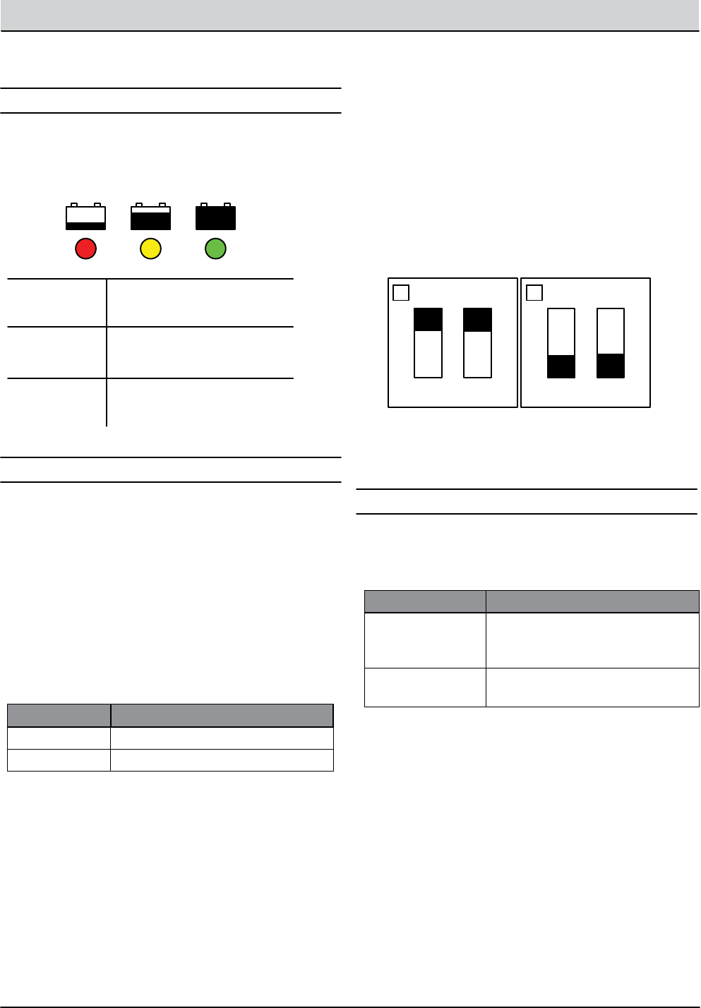
The Lithim-ion battery charger utilizes 3 green control
indicator LEDs; 100%, 75%, and 50% as shown below.
OPERATION, BATTERY CHARGER
FAULTS
Fault messages automatically display when a fault exists.
Use the table below to identify possible causes.
100% 75% 50%
See the table below for normal LED operation.
LED 100% 75% 50%
0-50% O O Blinking
50-75% O Blinking On
75-100% Blinking On On
100% On On On
Abnormal* Blinking O O
CHARGE
* Abnormal cycle = > 5 hours constant current or > 8 hours total
charging time.
* 3 LED FAULT = All 3 LEDs blink on/o simultaneously. 1x, 2x, 3x,
and 4x refers to groups of blinking LEDs separated by a long pause.
BATTERY MANAGEMENT SYSTEM BMS
The Lithim-ion battery has a built-in BMS. The BMS has a
single status LED as shown below.
See the table below for status LED operation.
LED STATUS POSSIBLE CAUSE
Green Flashing
(Normal)
• 1 per 5 seconds = Active Mode
• 1 per 20 seconds = Sleep Mode
Yellow Flashing • High internal temperature/High
load
Red Flashing • Very low or very high cell voltage
No LED • Contact Tennant Technical Sup-
port
T1 Battery - Service Information 9008975 (6-11) 4-3
TROUBLESHOOTING
Battery Charger, AGM
FLASHING LED POSSIBLE CAUSE
Yellow • Unsuitable Battery
• Battery Not Connected
• Output Circuit Shorted
Red • Safety Timer Exceeded
• Internal Short Circuit
The AGM battery charger utilizes 3 control indicator
LEDs; Red, Yellow, and Green. See the table below for
normal LED operation.
OPERATION
FAULTS
CONFIGURATION
1. Key O. Disconnect battery charger from AC power
supply and the battery. Wait 30 seconds before
proceeding to step 2 to allow for capacitor discharge.
LED BATTERY TYPE
Green Congured for AGM
Red Congured for Lead-acid (Wet)
Green LED On
Yellow LED On
Red LED On
Charge complete
Second phase of charge in
progress
First phase of charge in
progress
2. Connect charger to AC supply and observe the
LED display. The green or red LED ashes twice
indicating the current charger setting. The yellow LED
ashes continuously after the initial charger setting is
displayed.
1. Key O. Disconnect battery charger from AC power
supply and the battery. Wait 30 seconds before
proceeding to step 2 to allow for capacitor discharge.
DISPLAYING CURRENT CHARGER SETTING
CHECKING CHARGER DIP SWITCH SETTING
2. Remove screws that fasten the vented cover to the
charger body to expose the dip switches.
3. Check the dip switches to be sure they are in the
AGM battery position as shown below.
4. Reinstall vented cover mounting screws and
reconnect battery cables.
A ashing red or yellow LED indicates a charging error.
See the table below for ashing LED faults.
1
ON
2 1
ON
2
4-4 T1 Battery - Service Information 9008975 (6-11)
TROUBLESHOOTING
Battery Charger
AC Supply
WHITE
GREEN
BLACK
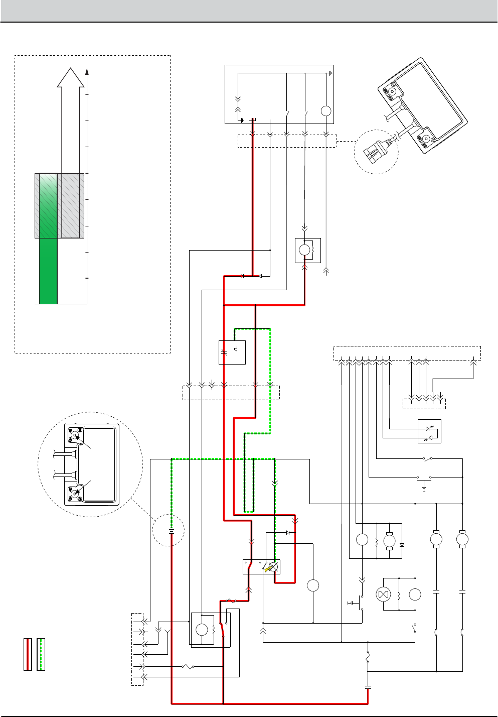
• 12 volts applied to BMS pins # B1 and B2
from battery charger
Battery +
Battery -
+ -
6-Pin Battery
Charging Connector
Lithium-Ion Battery
Lithium-Ion Battery
12-Pin Connector
11B/PNK
1A FUSE
1B/RED
1A/RED
29/WHT
63/ORG
68/GRY
13L/BLK
AGM
LITHIUM
1A/RED
1G/RED
19G/WHT
72/BRN
72A/BRN
16/BLU
78/GRY
PNK BLU
23
56
7 8
1A FUSE
1K/RED
R1
560 OHM
CHARGE RELAY
41D/PNK
+ -
13M/BLK
13B/BLK
D7
ORG
BLKGRY
WHT
WHT
29B/WHT
A1
A2
A3
A4
A5
A6
VBLK
-+
DPDT SWITCH,
MAIN POWER
BATTERY METER
13O/BLK
13P/BLK
41C/PNK
12V BATTERY
S2 P2 P1 S1
Diagnostic Port
(Not Used)
29A/WHT
20A/TAN
27A/PUR
20C/TAN 46/BLU 45/GRN 13K/BLK
13A/BLK
13I/BLK
13C/BLK
13U/BLK
VAC RELAY
VAC RELAY
SUPPRESSION DIODE
SOLUTION PUMP
680 OHM
BRUSH RELAY
680 OHM
HOURMETER
BRUSH RELAY
BRUSH MOTOR
VAC MOTOR
20B/TAN
29C/WHT 27/PUR
31/PNK 32/BRN
30A
VACUUM SW.
35A
20/TAN
5A FUSE
DISCHARGE
RELAY
TRIGGER SWITCH
21C/PNK
13R/BLK
E1
E2
E3
E4
E5
E6
E7
E8
E9
E10
E11
E12
13E/BLK
91/PNK
92/BRN
93/ORG
94/YEL
13T/BLK 102/BRN
FLUSH INPUT (NOT USED)
BI-COLOR LED
(NOT USED)
GREEN
RED
MODE SWITCH (NOT USED)
37/PUR
81/PNK
88/GRY
13V/BLK
13F/BLK
21/PNK
21A/PNK 21B/PNK
BRNWHT
1
2
3
4
5
5-Pin Battery Management
System (BMS) Connector
Battery Management System (BMS)
Controller, Internal to Lithium Battery
94C/YEL
25/GRN
17/PUR
18/GRY
NOTE:
D6 PREVENTS THE TIMER
OR MAIN SWITCH FROM
POWERING THE CHARGER
RELAY AND AUX 2 INPUT
94B/YEL
25/GRN
12V SYS GND
(INTERNAL CONNECTION)
BATT POS+
12V IGNITION
12V SYS
AUX 2
(CHARGER MODE INPUT)
CHARGE RELAY GROUND
DISCHARGE RELAY GROUND
SOC (STATE OF CHARGE) IND.
(5V = FULL, 0V = EMPTY)
17A/PUR
SOC LINE
5V = FULL
0V = EMPTY
19/WHT
99/WHT
D6
B1
B2
B3
B4
B5 V
C2 C1
D8
15/GRN
INPUT
DISCHARGE RELAY
680 OHM
5 SEC.
TIMER MODULE
5 SECONDS ON MAKE
OUTPUT
17B/PUR
13Y/BLK
6-Pin Lithium
Harness Connector
1
3
2
Battery Charger Connected, Lithium-ion (0-5 Seconds)

T1 Battery - Service Information 9008975 (6-11) 4-5
TROUBLESHOOTING
STEP ACTION VALUES YES NO
1Main power switch O
Connect battery charger to AC supply and scrubber
charging connector
Is there a pertinent fault displayed on the battery
charger?
•
•
•
See “Bat-
tery Charger,
Lithium-ion,
Faults” Section
of This Manual
Correct Fault
Condition
Go to Step #2
2Main power switch O
Check AC power supply
Is the rated AC supply voltage present?
•
•
•
Go to Step #3 Check AC
Supply Circuit
Protection
3Main power switch O
Remove rear access panel from scrubber to expose
battery and BMS (battery management system)
Check the BMS status LED
Is the status LED indicating a fault?
•
•
•
•
See “Battery
Management
System” in the
troubleshoot-
ing Section of
This Manual
Correct Fault
Condition
Go to Step #4
4Main power switch O
Inspect battery, charger, charger cables, and charging
connector for damage, corrosion, contamination or
terminal problems
Do any of the above conditions exist?
•
•
•
Repair or
Replace Faulty
Components
Go to Step #5
5Main power switch O
Connect battery charger to AC supply and scrubber
charging connector
Test voltage applied to the electrical circuits, during
the rst 5 seconds after connection, as shown on the
electrical schematic
Are the electrical circuits operating as shown on the
electrical schematic?
•
•
•
•
See “Bat-
tery Failed
to Charge,
Lithium-ion
(5+ Seconds)”
Troubleshoot-
ing Procedure
Identify Volt-
age Drop
Location and
Repair or Re-
place Neces-
sary Compo-
nents
Terms:
AC = Alternating Current (facility power)
BMS = Battery Management System. Protects Lithium-ion batteries against deep discharge, which will damage the
battery.
LED = Light Emitting Diode
Battery Failed to Charge, Lithium-ion (0-5 Seconds)
4-6 T1 Battery - Service Information 9008975 (6-11)
TROUBLESHOOTING
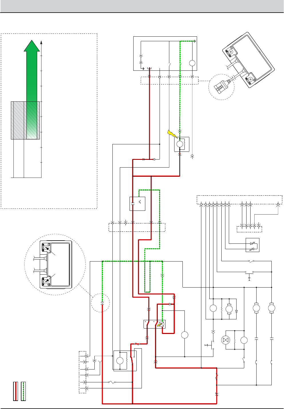
• BMS turns On Charge Relay Output pin # B3
• This overrides (disables) all scrubbing functions
• Charger now has closed path to battery through charge relay
• Charging begins
Battery Charger
WHITE
GREEN
BLACK
AC Supply
Battery +
Battery -
+ -
6-Pin Battery
Charging Connector
Lithium-Ion Battery
Lithium-Ion Battery
12-Pin Connector
11B/PNK
1A FUSE
1B/RED
1A/RED
29/WHT
63/ORG
68/GRY
13L/BLK
AGM
LITHIUM
1A/RED
1G/RED
19G/WHT
72/BRN
72A/BRN
16/BLU
78/GRY
PNK BLU
23
56
7 8
1A FUSE
1K/RED
R1
560 OHM
CHARGE RELAY
41D/PNK
+ -
13M/BLK
13B/BLK
D7
ORG
BLKGRY
WHT
WHT
29B/WHT
A1
A2
A3
A4
A5
A6
VBLK
-+
DPDT SWITCH,
MAIN POWER
BATTERY METER
13O/BLK
13P/BLK
41C/PNK
12V BATTERY
S2 P2 P1 S1
Diagnostic Port
(Not Used)
29A/WHT
20A/TAN
27A/PUR
20C/TAN 46/BLU 45/GRN 13K/BLK
13A/BLK
13I/BLK
13C/BLK
13U/BLK
VAC RELAY
VAC RELAY
SUPPRESSION DIODE
SOLUTION PUMP
680 OHM
BRUSH RELAY
680 OHM
HOURMETER
BRUSH RELAY
BRUSH MOTOR
VAC MOTOR
20B/TAN
29C/WHT 27/PUR
31/PNK 32/BRN
30A
VACUUM SW.
35A
20/TAN
5A FUSE
DISCHARGE
RELAY
TRIGGER SWITCH
21C/PNK
13R/BLK
E1
E2
E3
E4
E5
E6
E7
E8
E9
E10
E11
E12
13E/BLK
91/PNK
92/BRN
93/ORG
94/YEL
13T/BLK 102/BRN
FLUSH INPUT (NOT USED)
BI-COLOR LED
(NOT USED)
GREEN
RED
MODE SWITCH (NOT USED)
37/PUR
81/PNK
88/GRY
13V/BLK
13F/BLK
21/PNK
21A/PNK 21B/PNK
BRNWHT
1
2
3
4
5
5-Pin Battery Management
System (BMS) Connector
Battery Management System (BMS)
Controller, Internal to Lithium Battery
94C/YEL
25/GRN
17/PUR
18/GRY
NOTE:
D6 PREVENTS THE TIMER
OR MAIN SWITCH FROM
POWERING THE CHARGER
RELAY AND AUX 2 INPUT
94B/YEL
25/GRN
12V SYS GND
(INTERNAL CONNECTION)
BATT POS+
12V IGNITION
12V SYS
AUX 2
(CHARGER MODE INPUT)
CHARGE RELAY GROUND
DISCHARGE RELAY GROUND
SOC (STATE OF CHARGE) IND.
(5V = FULL, 0V = EMPTY)
17A/PUR
SOC LINE
5V = FULL
0V = EMPTY
19/WHT
99/WHT
D6
B1
B2
B3
B4
B5 V
C2 C1
D8
15/GRN
INPUT
DISCHARGE RELAY
680 OHM
5 SEC.
TIMER MODULE
5 SECONDS ON MAKE
OUTPUT
17B/PUR
13Y/BLK
6-Pin Lithium
Harness Connector
1
3
2
Battery Charger Connected, Lithium-ion (5+ Seconds)

T1 Battery - Service Information 9008975 (6-11) 4-7
TROUBLESHOOTING
Battery Failed to Charge, Lithium-ion (5+ Seconds)
STEP ACTION VALUES YES NO
1Main power switch O
Has the “Battery Failed to Charge, Lithium-ion (0-5
Seconds)” troubleshooting procedure been com-
pleted?
•
•
Go to Step #2 See “Bat-
tery Failed
to Charge,
Lithium-ion (0-
5 Seconds)”
2Main power switch O
Connect battery charger to AC supply and scrubber
charging connector
Wait for 5 seconds after connection and then test
voltage applied to the electrical circuits as shown on
the electrical schematic
Are the electrical circuits operating as shown on the
electrical schematic?
•
•
•
•
Go back to
Step #1
Identify Volt-
age Drop
Location and
Repair or Re-
place Neces-
sary Compo-
nents
Terms:
AC = Alternating Current (facility power)
4-8 T1 Battery - Service Information 9008975 (6-11)
TROUBLESHOOTING
• Timer contacts close for ≈5 Seconds
• Main power switch LED illuminates
• BMS Discharge Relay Ground output remains Off
• BMS assesses battery depth-of-discharge (DOD)
NOTE: Circuit highlights do NOT include overlap period for simplicity.
Battery +
Battery -
0 1 2 3 4 5 6 7 8
Time (Seconds), Main Power ON
“0-5 Seconds”
“Latching” Overlap Period
“5+ Seconds”
+ -
6-Pin Battery
Charging Connector
Lithium-Ion Battery
Lithium-Ion Battery
12-Pin Connector
11B/PNK
1A FUSE
1B/RED
1A/RED
29/WHT
63/ORG
68/GRY
13L/BLK
AGM
LITHIUM
1A/RED
1G/RED
19G/WHT
72/BRN
72A/BRN
16/BLU
78/GRY
PNK BLU
23
56
7 8
1A FUSE
1K/RED
R1
560 OHM
CHARGE RELAY
41D/PNK
+ -
13M/BLK
13B/BLK
D7
ORG
BLKGRY
WHT
WHT
29B/WHT
A1
A2
A3
A4
A5
A6
VBLK
-+
DPDT SWITCH,
MAIN POWER
BATTERY METER
13O/BLK
13P/BLK
41C/PNK
12V BATTERY
S2 P2 P1 S1
Diagnostic Port
(Not Used)
29A/WHT
20A/TAN
27A/PUR
20C/TAN 46/BLU 45/GRN 13K/BLK
13A/BLK
13I/BLK
13C/BLK
13U/BLK
VAC RELAY
VAC RELAY
SUPPRESSION DIODE
SOLUTION PUMP
680 OHM
BRUSH RELAY
680 OHM
HOURMETER
BRUSH RELAY
BRUSH MOTOR
VAC MOTOR
20B/TAN
29C/WHT 27/PUR
31/PNK 32/BRN
30A
VACUUM SW.
35A
20/TAN
5A FUSE
DISCHARGE
RELAY
TRIGGER SWITCH
21C/PNK
13R/BLK
E1
E2
E3
E4
E5
E6
E7
E8
E9
E10
E11
E12
13E/BLK
91/PNK
92/BRN
93/ORG
94/YEL
13T/BLK 102/BRN
FLUSH INPUT (NOT USED)
BI-COLOR LED
(NOT USED)
GREEN
RED
MODE SWITCH (NOT USED)
37/PUR
81/PNK
88/GRY
13V/BLK
13F/BLK
21/PNK
21A/PNK 21B/PNK
BRNWHT
1
2
3
4
5
5-Pin Battery Management
System (BMS) Connector
Battery Management System (BMS)
Controller, Internal to Lithium Battery
94C/YEL
25/GRN
17/PUR
18/GRY
NOTE:
D6 PREVENTS THE TIMER
OR MAIN SWITCH FROM
POWERING THE CHARGER
RELAY AND AUX 2 INPUT
94B/YEL
25/GRN
12V SYS GND
(INTERNAL CONNECTION)
BATT POS+
12V IGNITION
12V SYS
AUX 2
(CHARGER MODE INPUT)
CHARGE RELAY GROUND
DISCHARGE RELAY GROUND
SOC (STATE OF CHARGE) IND.
(5V = FULL, 0V = EMPTY)
17A/PUR
SOC LINE
5V = FULL
0V = EMPTY
19/WHT
99/WHT
D6
B1
B2
B3
B4
B5 V
C2 C1
D8
15/GRN
INPUT
DISCHARGE RELAY
680 OHM
5 SEC.
TIMER MODULE
5 SECONDS ON MAKE
OUTPUT
17B/PUR
13Y/BLK
6-Pin Lithium
Harness Connector
1
3
2
Main Power Switch On, Lithium-ion (0-5 Seconds)

T1 Battery - Service Information 9008975 (6-11) 4-9
TROUBLESHOOTING
Main Power Up Failure, Lithium-ion (0-5 Seconds)
STEP ACTION VALUES YES NO
1Main power switch On
Does the main power switch illuminate for approxi-
mately 5 seconds and then turn O?
•
•
Battery Volt-
age Must be >
11.2 Volts
Recharge
Battery and if
Necessary Go
to Step #2
Go to Step #2
2Main power switch O
Remove rear access panel from scrubber to expose
battery and BMS (battery management system)
Check the BMS status LED
Is the status LED indicating a fault?
•
•
•
•
See “Battery
Management
System” in the
troubleshoot-
ing Section of
This Manual
Correct Fault
Condition
Go to Step #3
3Main power switch O
Inspect battery, cables, and connections for damage,
corrosion, contamination or terminal problems
Do any of the above conditions exist?
•
•
•
Repair or
Replace Faulty
Components
Go to Step #4
4Main power switch On
Test voltage applied to the electrical circuits dur-
ing the rst 5 seconds as shown on the electrical
schematic
Are the electrical circuits operating as shown on the
electrical schematic?
•
•
•
See “Main
Power Up
Failure,
Lithium-ion
(5+ Seconds)”
Troubleshoot-
ing Procedure
Identify Volt-
age Drop
Location and
Repair or
Replace Neces-
sary Compo-
nents
Terms:
BMS = Battery Management System. Protects Lithium-ion batteries against deep discharge, which will damage the
battery.
LED = Light Emitting Diode
4-10 T1 Battery - Service Information 9008975 (6-11)
TROUBLESHOOTING
Main Power Switch On, Lithium-ion (5+ Seconds)
• If battery voltage is > 11.2 volts, then the BMS
turns On the Discharge Relay Ground output.
• N.O. Discharge Relay contacts close (Latch)
• Timer contacts opens
• Scrubbing functions are now enabled
NOTE: Circuit highlights do NOT include overlap period for simplicity.
Battery +
Battery -
+ -
6-Pin Battery
Charging Connector
Lithium-Ion Battery
Lithium-Ion Battery
12-Pin Connector
11B/PNK
1A FUSE
1B/RED
1A/RED
29/WHT
63/ORG
68/GRY
13L/BLK
AGM
LITHIUM
1A/RED
1G/RED
19G/WHT
72/BRN
72A/BRN
16/BLU
78/GRY
PNK BLU
23
56
7 8
1A FUSE
1K/RED
R1
560 OHM
CHARGE RELAY
41D/PNK
+ -
13M/BLK
13B/BLK
D7
ORG
BLKGRY
WHT
WHT
29B/WHT
A1
A2
A3
A4
A5
A6
VBLK
-+
DPDT SWITCH,
MAIN POWER
BATTERY METER
13O/BLK
13P/BLK
41C/PNK
12V BATTERY
S2 P2 P1 S1
Diagnostic Port
(Not Used)
29A/WHT
20A/TAN
27A/PUR
20C/TAN 46/BLU 45/GRN 13K/BLK
13A/BLK
13I/BLK
13C/BLK
13U/BLK
VAC RELAY
VAC RELAY
SUPPRESSION DIODE
SOLUTION PUMP
680 OHM
BRUSH RELAY
680 OHM
HOURMETER
BRUSH RELAY
BRUSH MOTOR
VAC MOTOR
20B/TAN
29C/WHT 27/PUR
31/PNK 32/BRN
30A
VACUUM SW.
35A
20/TAN
5A FUSE
DISCHARGE
RELAY
TRIGGER SWITCH
21C/PNK
13R/BLK
E1
E2
E3
E4
E5
E6
E7
E8
E9
E10
E11
E12
13E/BLK
91/PNK
92/BRN
93/ORG
94/YEL
13T/BLK 102/BRN
FLUSH INPUT (NOT USED)
BI-COLOR LED
(NOT USED)
GREEN
RED
MODE SWITCH (NOT USED)
37/PUR
81/PNK
88/GRY
13V/BLK
13F/BLK
21/PNK
21A/PNK 21B/PNK
BRNWHT
1
2
3
4
5
5-Pin Battery Management
System (BMS) Connector
Battery Management System (BMS)
Controller, Internal to Lithium Battery
94C/YEL
25/GRN
17/PUR
18/GRY
NOTE:
D6 PREVENTS THE TIMER
OR MAIN SWITCH FROM
POWERING THE CHARGER
RELAY AND AUX 2 INPUT
94B/YEL
25/GRN
12V SYS GND
(INTERNAL CONNECTION)
BATT POS+
12V IGNITION
12V SYS
AUX 2
(CHARGER MODE INPUT)
CHARGE RELAY GROUND
DISCHARGE RELAY GROUND
SOC (STATE OF CHARGE) IND.
(5V = FULL, 0V = EMPTY)
17A/PUR
SOC LINE
5V = FULL
0V = EMPTY
19/WHT
99/WHT
D6
B1
B2
B3
B4
B5 V
C2 C1
D8
15/GRN
INPUT
DISCHARGE RELAY
680 OHM
5 SEC.
TIMER MODULE
5 SECONDS ON MAKE
OUTPUT
17B/PUR
13Y/BLK
6-Pin Lithium
Harness Connector
1
3
2
0 1 2 3 4 5 6 7 8
Time (Seconds), Main Power ON
“0-5 Seconds”
“Latching” Overlap Period
“5+ Seconds”

T1 Battery - Service Information 9008975 (6-11) 4-11
TROUBLESHOOTING
Main Power Up Failure, Lithium-ion (5+ Seconds)
STEP ACTION VALUES YES NO
1Main power switch O
Has the “Main Power Up Failure, Lithium-ion (0-5 Sec-
onds)” troubleshooting procedure been completed?
•
•
Go to Step #2 See “Main
Power Up
Failure,
Lithium-ion (0-
5 Seconds)”
2Main power switch On
Wait for 5 seconds after activating main power
switch and then test voltage applied to the electrical
circuits as shown on the electrical schematic
Are the electrical circuits operating as shown on the
electrical schematic?
•
•
•
Go back to
Step #1
Identify Volt-
age Drop
Location and
Repair or Re-
place Neces-
sary Compo-
nents
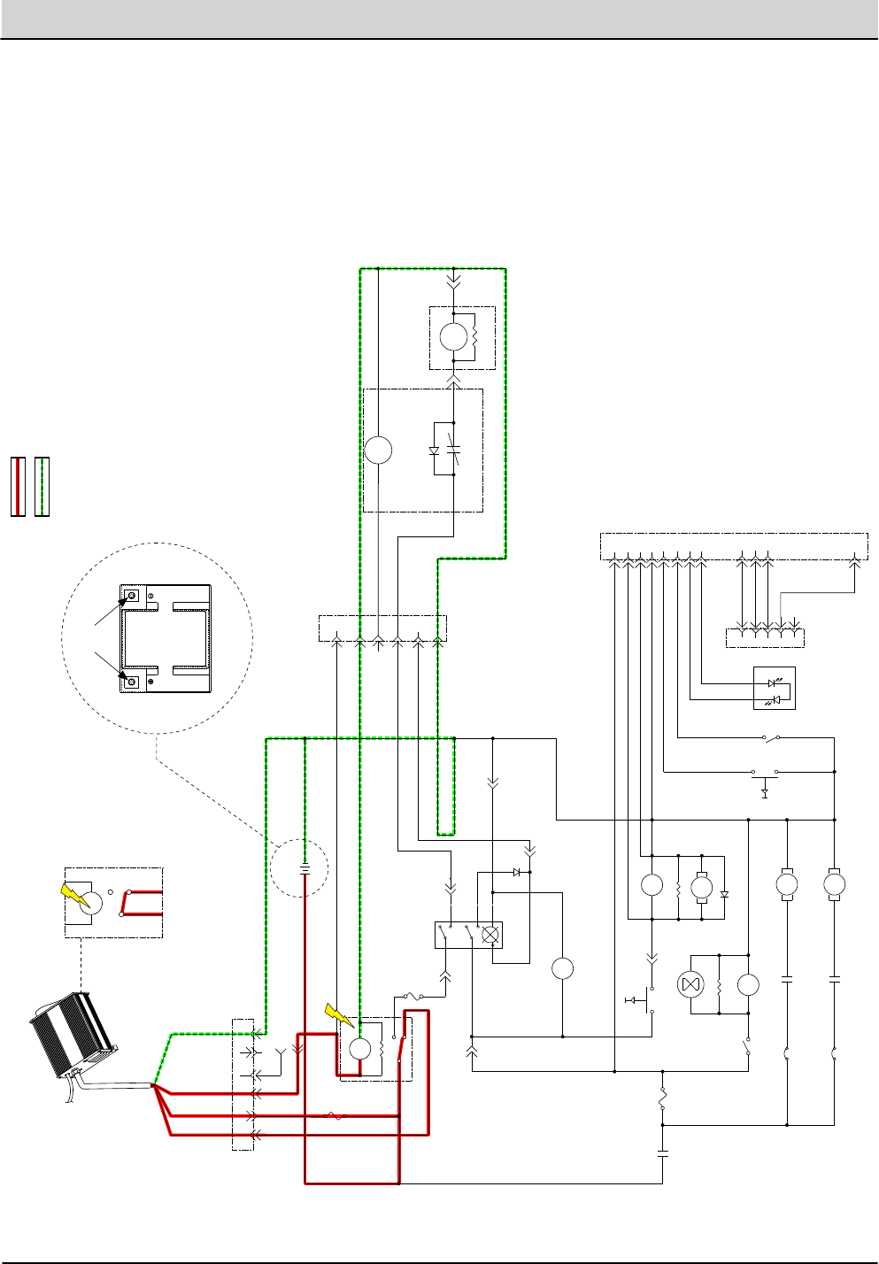
4-12 T1 Battery - Service Information 9008975 (6-11)
TROUBLESHOOTING
Battery Charger Connected, AGM
• Battery charger connected
• Charger Interlock Relay contacts close (internal)
• Charge Relay N.O. contacts close
• Charger now has a closed path to battery through
Charge Relay.
• Charging begins
+ -
6-Pin Battery
Charging Connector
Battery Charger
AC Supply
Battery Charger
Interlock Relay (Internal)
NOTE: CONTACTS CLOSE WHEN
CONNECTED TO AC SUPPLY
AGM Battery
6-Pin AGM
Harness Connector
12 Pin Connector
RED
WHITE
11B/PNK
1A FUSE
1B/RED
1A/RED
29/WHT
63/ORG
68/GRY
13L/BLK
AGM
LITHIUM
1A/RED
1G/RED
19G/WHT
72/BRN
72A/BRN
16/BLU
78/GRY
PNK BLU
23
56
7 8
1A FUSE
1K/RED
R1
560 OHM
CHARGE RELAY
41D/PNK
+ -
13M/BLK
13B/BLK
D7
ORG
BLKGRY
WHT
WHT
29B/WHT
A1
A2
A3
A4
A5
A6
VBLK
-+
DPDT SWITCH,
MAIN POWER
BATTERY METER
13O/BLK
13P/BLK
41C/PNK
12V BATTERY
S2 P2 P1 S1
GREEN
WHITE
GREEN
BLACK
Diagnostic Port
(Not Used)
29A/WHT
20A/TAN
27A/PUR
20C/TAN 46/BLU 45/GRN 13K/BLK
13A/BLK
13I/BLK
13C/BLK
13U/BLK
VAC RELAY
VAC RELAY
SUPPRESSION DIODE
SOLUTION PUMP
680 OHM
BRUSH RELAY
680 OHM
HOURMETER
BRUSH RELAY
BRUSH MOTOR
VAC MOTOR
20B/TAN
29C/WHT 27/PUR
31/PNK 32/BRN
30A
VACUUM SW.
35A
20/TAN
5A FUSE
DISCHARGE
RELAY
TRIGGER SWITCH
21C/PNK
13R/BLK
E1
E2
E3
E4
E5
E6
E7
E8
E9
E10
E11
E12
13E/BLK
91/PNK
92/BRN
93/ORG
94/YEL
13T/BLK 102/BRN
FLUSH INPUT (NOT USED)
BI-COLOR LED
(NOT USED)
GREEN
RED
MODE SWITCH (NOT USED)
37/PUR
81/PNK
88/GRY
13V/BLK
13T/BLK
21/PNK
21A/PNK 21B/PNK
BRNWHT
1
2
3
4
5
13U/BLK
13V/BLK
DISCHARGE RELAY
13O/BLK
680 OHM
C1C2
13X/BLK
17 PUR
BATTERY DISCHARGE
METER (HIDDEN)
V
11A/PNK
16/BLU
NOTE:
THIS BATTERY DISCHARGE METER IS USED AS A LOW
VOLTAGE CUT-OFF RELAY ONLY. IT IS LOCATED BEHIND
THE ACCESS COVER. CONTACTS OPEN AT ≈ 10.4 VOLTS (1.73 VOLTS/CELL)
Battery +
Battery -

T1 Battery - Service Information 9008975 (6-11) 4-13
TROUBLESHOOTING
Battery Failed to Charge, AGM
STEP ACTION VALUES YES NO
1Main power switch O
Connect battery charger to AC supply and scrubber
charging connector
Is there a pertinent fault displayed on the battery
charger?
•
•
•
See “Battery
Charger, AGM,
Faults” Section
of This Manual
Correct Fault
Condition
Go to Step #2
2Main power switch O
Check AC power supply
Is the rated AC supply voltage present?
•
•
•
Go to Step #3 Check AC
Supply Circuit
Protection
3Main power switch O
Inspect battery, charger, charger cables, and charging
connector for damage, corrosion, contamination or
terminal problems
Do any of the above conditions exist?
•
•
•
Repair or
Replace Faulty
Components
Go to Step #4
4Main power switch O
Load test AGM battery using a standard load tester
Does the AGM battery pass a load test?
•
•
•
Go to Step #5 Replace
Battery
5Main power switch O
Connect battery charger to AC supply and scrubber
charging connector
Test voltage applied to the electrical circuits as
shown on the electrical schematic
Are the electrical circuits operating as shown on the
electrical schematic?
•
•
•
•
Go Back to
Step #1
Identify Volt-
age Drop
Location and
Repair or Re-
place Neces-
sary Compo-
nents
Terms:
AC = AC = Alternating Current (facility power)
AGM = Absorbed Glass Mat is a spill proof, maintenance-free battery type.
BMS = Battery Management System. Protects Lithium-ion batteries against deep discharge, which will damage the
battery.
LED = Light Emitting Diode
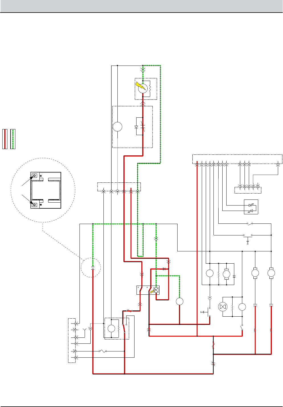
4-14 T1 Battery - Service Information 9008975 (6-11)
TROUBLESHOOTING
Main Power Switch On, AGM
• Main Power Switch On
• Discharge Relay N.O. contacts close
• Main Power Switch LED illuminates
• Scrubbing functions enabled
+ -
AGM Battery
6-Pin AGM
Harness Connector
12 Pin Connector
11B/PNK
1A FUSE
1B/RED
1A/RED
29/WHT
63/ORG
68/GRY
13L/BLK
AGM
LITHIUM
1A/RED
1G/RED
19G/WHT
72/BRN
72A/BRN
16/BLU
78/GRY
PNK BLU
23
56
7 8
1A FUSE
1K/RED
R1
560 OHM
CHARGE RELAY
41D/PNK
+ -
13M/BLK
13B/BLK
D7
ORG
BLKGRY
WHT
WHT
29B/WHT
A1
A2
A3
A4
A5
A6
VBLK
-+
DPDT SWITCH,
MAIN POWER
BATTERY METER
13O/BLK
13P/BLK
41C/PNK
12V BATTERY
S2 P2 P1 S1
Diagnostic Port
(Not Used)
29A/WHT
20A/TAN
27A/PUR
20C/TAN 46/BLU 45/GRN 13K/BLK
13A/BLK
13I/BLK
13C/BLK
13U/BLK
VAC RELAY
VAC RELAY
SUPPRESSION DIODE
SOLUTION PUMP
680 OHM
BRUSH RELAY
680 OHM
HOURMETER
BRUSH RELAY
BRUSH MOTOR
VAC MOTOR
20B/TAN
29C/WHT 27/PUR
31/PNK 32/BRN
30A
VACUUM SW.
35A
20/TAN
5A FUSE
DISCHARGE
RELAY
TRIGGER SWITCH
21C/PNK
13R/BLK
E1
E2
E3
E4
E5
E6
E7
E8
E9
E10
E11
E12
13E/BLK
91/PNK
92/BRN
93/ORG
94/YEL
13T/BLK 102/BRN
FLUSH INPUT (NOT USED)
BI-COLOR LED
(NOT USED)
GREEN
RED
MODE SWITCH (NOT USED)
37/PUR
81/PNK
88/GRY
13V/BLK
13T/BLK
21/PNK
21A/PNK 21B/PNK
BRNWHT
1
2
3
4
5
13U/BLK
13V/BLK
DISCHARGE RELAY
13O/BLK
680 OHM
C1C2
13X/BLK
17 PUR
BATTERY DISCHARGE
METER (HIDDEN)
V
11A/PNK
16/BLU
NOTE:
THIS BATTERY DISCHARGE METER IS USED AS A LOW
VOLTAGE CUT-OFF RELAY ONLY. IT IS LOCATED BEHIND
THE ACCESS COVER. CONTACTS OPEN AT ≈ 10.4 VOLTS (1.73 VOLTS/CELL)
Battery +
Battery -
6-Pin Battery
Charging Connector

T1 Battery - Service Information 9008975 (6-11) 4-15
TROUBLESHOOTING
Main Power Up Failure, AGM
STEP ACTION VALUES YES NO
1Main power switch On
Does the main power switch light illuminate?
•
•
Battery Volt-
age Must be
> 10.4 Volts
Go to Step #2 Recharge
Battery and if
Necessary Go
to Step #2
2Main power switch O
Inspect battery, cables, and connections for damage,
corrosion, contamination or terminal problems
Do any of the above conditions exist?
•
•
•
Repair or
Replace Faulty
Components
Go to Step #3
3Main power switch On
Test voltage applied to the electrical circuits as
shown on the electrical schematic
Are the electrical circuits operating as shown on the
electrical schematic?
•
•
•
Go Back to
Step #1
Identify Volt-
age Drop
Location and
Repair or Re-
place Neces-
sary Compo-
nents
Terms:
LED = Light Emitting Diode

4-16 T1 Battery - Service Information 9008975 (6-11)
TROUBLESHOOTING
Notes:

We Need Your Help...
As part of Tennant’s Zero Defects Program, we want to know about errors you have
found or suggestions you may have regarding our machine manuals. If you find an
error or have a suggestion, please complete this postage-paid form and mail it to us.
Thank you for helping us make zero defects a way of life at Tennant.
Manual No. Rev. No. Publish Date Page
Machine -Report Error -Suggestion
Name Date
Customer Number
Company
Address
City/State/Zip Code
Tape hereFold along dotted lines
NO POSTAGE
NECESSARY
IF MAILED
IN THE
UNITED SATES
BUSINESS REPLY MAIL
FIRST CLASS MAIL PERMIT NO. 94 MINNEAPOLIS, MN
POSTAGE WILL BE PAID BY ADDRESSEE
Technical Publications #15
701 North Lilac Drive
P.O. Box 1452
Minneapolis, MN 55440--9947
TENNANT COMPANY

We Need Your Help...
As part of Tennant’s Zero Defects Program, we want to know about errors you have
found or suggestions you may have regarding our machine manuals. If you find an
error or have a suggestion, please complete this postage-paid form and mail it to us.
Thank you for helping us make zero defects a way of life at Tennant.
Manual No. Rev. No. Publish Date Page
Machine -Report Error -Suggestion
Name Date
Customer Number
Company
Address
City/State/Zip Code

Tape hereFold along dotted lines
NO POSTAGE
NECESSARY
IF MAILED
IN THE
UNITED SATES
BUSINESS REPLY MAIL
FIRST CLASS MAIL PERMIT NO. 94 MINNEAPOLIS, MN
POSTAGE WILL BE PAID BY ADDRESSEE
Technical Publications #15
701 North Lilac Drive
P.O. Box 1452
Minneapolis, MN 55440--9947
TENNANT COMPANY
