Sweepscrub Tennant T500 Walk Behind Floor Scrubber Operator Manual User
2017-10-24
User Manual: Sweepscrub Tennant-T500-Walk-Behind-Floor-Scrubber-Operator-Manual tennant-t500-walk-behind-floor-scrubber-operator-manual 2346 file product_file sweepscrub
Open the PDF directly: View PDF ![]() .
.
Page Count: 65
R
T500
9015223
Rev. 02 (02-2017)
Walk-Behind Floor Scrubber
*9015223*
For the latest Parts manuals and other
language Operator manuals, visit:
www.tennantco.com/manuals
Hygenic®Fully Cleanable Recovery Tank
TennantTrue®Parts
IRIS®a Tennant Technology
Pro-Panel™ Controls
Insta-Fit™ Adapter
Smart-Fill™ Automatic Battery Watering
English EN
Operator Manual
2Tennant T500 (02-2017)
INTRODUCTION
This manual is furnished with each new model.
It provides necessary operation and maintenance
instructions.
Read this manual completely and
understand the machine before
operating or servicing it.
This machine will provide excellent service. However,
the best results will be obtained at minimum costs if:
SThe machine is operated with reasonable care.
SThe machine is maintained regularly - per the
maintenance instructions provided.
SThe machine is maintained with manufacturer
supplied or equivalent parts.
To view, print or download manuals online visit
www.tennantco.com/manuals
PROTECT THE ENVIRONMENT
Please dispose of packaging materials and
used machine components such as
batteries in an environmentally safe way
according to your local waste disposal
regulations.
Always remember to recycle.
Tennant Company
PO Box 1452
Minneapolis, MN 55440
Phone: (800) 553- 8033
www.tennantco.com
1-STEP, Pro-Membrane, Severe Environment, Zone Settings and Quiet-Mode
are trademarks of Tennant Company.
Trojan and HydroLINK are registered trademarks of Trojan Battery Company.
This product may contain portions of software that have various 3rd party
licenses. More information can be found at: www.tennantco.com/opensource
Specifications and parts are subject to change without notice.
Original Instructions. Copyright ©2017 Tennant Company.
All rights reserved.
INTENDED USE
The T500 walk-behind floor scrubber is intended for
commercial use, for example in hotels, schools,
hospitals, factories, shops, offices and rental
businesses. It is designed to scrub hard floor surfaces
(concrete, tile, stone, synthetic, etc.) in an indoor
environment. This machine is not intended for cleaning
carpets or sanding wood floors. Use only
recommended pads/brushes and commercially
available floor cleaning detergents.Do not use this
machine other than described in this Operator Manual.
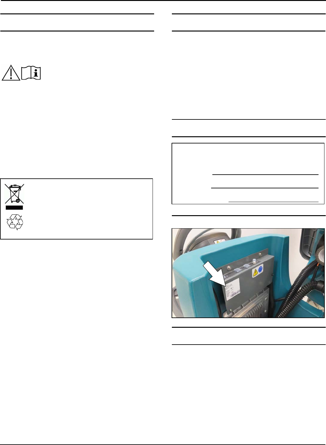
MACHINE DATA
Please fill out at time of installation
for future reference.
Model No. -
Serial No. -
Installation Date -
SERIAL NUMBER LABEL LOCATION
UNCRATING MACHINE
Carefully check machine for signs of damage. Report
damages at once to carrier. Contact distributor or
Tennant for missing items.
To uncrate the machine, remove straps, wheel blocks
and shipping brackets. Using the supplied ramp
carefully back the machine off the pallet. Make sure
scrub head is in the raised position.
ATTENTION: Do not remove machine from pallet
without using ramp, machine damage may occur.

CONTENTS
Tennant T500 (01-2017) 3
INTRODUCTION 2............................
INTENDED USE 2............................
MACHINE DATA 2............................
SERIAL NUMBER LABEL LOCATION 2......
UNCRATING MACHINE 2.....................
SAFETY
IMPORTANT SAFETY INSTRUCTIONS 5.......
SAFETY LABELS 7...........................
OPERATION
MACHINE COMPONENTS 8...................
MACHINE COMPONENTS 9...............
SCRUB HEAD TYPES 9...................
CONTROL PANEL COMPONENTS 10...........
PRO-MEMBRANE CONTROL PANEL 10.....
PRO-PANEL CONTROLS MODEL 10.........
MACHINE SYMBOLS 11.......................
PRO-PANEL SYMBOLS 11..................
INSTALLING BATTERIES 12...................
HOW THE MACHINE WORKS 12...............
BRUSH AND PAD INFORMATION 13............
MACHINE SETUP 13..........................
ATTACHING SQUEEGEE ASSEMBLY 13.....
INSTALLING DISK BRUSHES/PADS 14......
INSTALLING ORBITAL PADS 15.............
INSTALLING CYLINDRICAL BRUSHES 15....
FILLING SOLUTION TANK 16...............
USING SOLUTION TANK AUTO-FILL 16......
FILLING SEVERE ENVIRONMENT DETERGENT
TANK 17..................................
FILLING AUTOMATIC BATTERY WATERING
TANK 18..................................
ec-H2O WATER CONDITIONING CARTRIDGE 18
ACCESSORY RAILS 19.....................
CONTROL PANEL OPERATION 20.............
PRO-MEMBRANE CONTROL PANEL 20.....
1-STEP BUTTON 20.....................
BRUSH PRESSURE BUTTON 20.........
SOLUTION FLOW BUTTON 20...........
SEVERE ENVIRONMENT BUTTON 20....
QUIET-MODE BUTTON 21...............
PRESET ZONE CONTROL BUTTONS 21..
ec-H2O INDICATOR 21..................
SERVICE INDICATOR 21................
BATTERY DISCHARGE INDICATOR 22...
SPRAY NOZZLE INDICATOR 22..........
AUTOMATIC BATTERY WATERING
INDICATOR 22........................
PRO-PANEL CONTROLS 23................
HOME SCREEN 23......................
HELP BUTTON 23.......................
LOGIN SCREEN 23.....................
ec-H2O INDICATOR 24..................
1-STEP BUTTON 24.....................
BRUSH PRESSURE BUTTON 24.........
SOLUTION FLOW BUTTON 24...........
SEVERE ENVIRONMENT BUTTON 24....
MAXIMUM SCRUB SPEED BUTTON 25...
QUIET-MODE BUTTON 25...............
SPRAY NOZZLE INDICATOR (Option) 25..
BATTERY DISCHARGE INDICATOR 25...
VIDEO TUTORIAL BUTTON 26...........
PRESET ZONE CONTROL BUTTONS 26..
SERVICE INDICATOR BUTTON 27.......
FAULT SCREENS 27....................
MACHINE SETTINGS BUTTON 28........
MACHINE OPERATION 28.....................
PRE-OPERATION CHECK LIST 28...........
OPERATING MACHINE 28..................
EMERGENCY SHUT-OFF BUTTON 30.......
OPERATING SPRAY NOZZLE 30............
WHILE OPERATING MACHINE 30...........
CIRCUIT BREAKER PANEL 31..............
HOUR METER 31..........................
DRAINING TANKS 31..........................
DRAINING RECOVERY TANK 31............
DRAINING SOLUTION TANK 32.............
SERVICE INDICATOR CODES 33...............
ON-BOARD BATTERY CHARGER SERVICE
INDICATOR CODES 35....................
ec-H2O SYSTEM SERVICE INDICATOR
CODES 36................................
MAINTENANCE
MAINTENANCE CHART 37.....................
MACHINE MAINTENANCE 38..................
AFTER DAILY USE 38......................
AFTER WEEKLY USE 40...................
AFTER EVERY 50 HOURS OF USE 40.......
AFTER EVERY 100 HOURS OF USE 41......
ELECTRIC MOTORS 41....................
BELTS (Cylindrical Brush Model) 41..........

CONTENTS
4Tennant T500 (01-2017)
BATTERIES 42................................
MAINTENANCE-FREE BATTERIES 42.......
FLOODED (WET) LEAD-ACID BATTERIES 42
CHECKING CONNECTIONS / CLEANING 43..
CHARGING BATTERIES 42.................
BATTERY CHARGER SETTINGS 44.........
HYDROLINK BATTERY WATERING SYSTEM 46
AUTOMATIC BATTERY WATERING SYSTEM 47
SQUEEGEE BLADE REPLACEMENT 47.........
ec-H2O WATER CONDITIONING CARTRIDGE
REPLACEMENT 48...........................
MACHINE JACKING 49........................
TRANSPORTING MACHINE 50.................
STORING MACHINE 50........................
FREEZE PROTECTION 50..................
TROUBLESHOOTING 52.......................
SPECIFICATIONS
GENERAL MACHINE
DIMENSIONS/CAPACITIES/PERFORMANCE 54.
MACHINE DIMENSIONS 56....................
SUPERVISOR CONTROLS
SUPERVISOR CONTROLS 59..................
PRO-MEMBRANE CONTROL PANEL MODEL 59
PRO-PANEL CONTROLS MODEL 60.........
To Add/Edit User Profiles 61................
Enabling the Login 63......................
Disabling the Login 64......................
Changing the Factory-Assigned Supervisor Login
Code 65..................................

SAFETY
Tennant T500 (11-2016) 5
IMPORTANT SAFETY INSTRUCTIONS - SAVE THESE INSTRUCTIONS
The following warning precautions are used throughout
this manual as indicated in their description:
WARNING: To warn of hazards or unsafe
practices which could result in severe personal
injury or death.
FOR SAFETY: To identify actions which must be
followed for safe operation of equipment.
The following information signals potentially
dangerous conditions to the operator. Know when
these conditions can exist. Locate all safety devices on
the machine. Report machine damage or faulty
operation immediately.
WARNING: To Reduce the Risk of Fire,
Explosion, Electric Shock or Injury:
- Read manual before operating machine.
- Do not use or pick up flammable materials or
reactive metals.
- Do not use near flammable liquids, vapors or
combustible dusts.
This machine is not equipped with an
explosion proof motor. The electric motor will
spark upon start up and during operation
which could cause a flash fire or explosion if
machine is used in an area where flammable
vapors/liquids or combustible dusts are
present.
- Batteries emit hydrogen gas. Explosion or fire
can result. Keep sparks and open flame away
when charging.
- Disconnect battery cables and charger cord
before cleaning and servicing machine.
- Do not charge batteries with damaged cord. Do
not modify plug.
If the charger supply cord is damaged or
broken, it must be replaced by the
manufacturer or its service agent or a similarly
qualified person in order to avoid a hazard.
- Do not use outdoors. Store indoors.
- Spinning pad/brush, keep hands away.
WARNING: This machine contains chemicals
known to the state of California to cause cancer,
birth defects, or other reproductive harm.
IRIS Telemetry - This machine may be equipped
with technology that automatically communicates
over the cellular network. If the machine will be
operated where cell phone use is restricted
because of concerns related to equipment
interference, please contact a Tennant
representative for information on how to disable
the cellular communication functionality.
FOR SAFETY:
1. Do not operate machine:
- Unless trained and authorized.
- Unless operator manual is read and
understood.
- Unless mentally and physically capable of
following machine instructions.
- Under the influence of alcohol or drugs.
- While using a cell phone or other types of
electronic devices.
- If not in proper operating condition.
- In outdoor areas. This machine is for
indoor use only.
- In areas where flammable vapors/liquids or
combustible dusts are present.
- With pads or accessories not supplied or
approved by Tennant. The use of other
pads may impair safety.
- In areas with possible falling objects.
- In areas that are too dark to safely see the
controls or operate machine.
2. Before operating machine:
- Check machine for fluid leaks.
- Make sure all safety devices are in place
and operate properly.
3. When operating machine:
- Use only as described in this manual.
- Report machine damage or faulty operation
immediately.
- Wear closed-toe, non-slip work shoes.
- Reduce speed when turning.
- Go slowly on inclines and slippery
surfaces.
- The machine may only be operated on
gradients up to 2%.
- Follow site safety guidelines concerning
wet floors.
- Follow mixing, handling and disposal
instructions on chemical containers.
- Do not carry passengers on machine.
- Use care when reversing machine.

SAFETY
6Tennant T500 (11-2016)
- Keep children and unauthorized persons
away from machine.
- Do not allow machine to be used as a toy.
- Do not use spray nozzle for off-aisle
cleaning, slip hazard may occur.
- Do not leave machine unattended when
filling solution tank with auto-fill feature.
- Park machine on level surface when filling
solution tank with auto-fill feature.
4. Before leaving or servicing machine:
- Stop on level surface.
- Set the parking brake, if equipped.
- Turn off machine and remove key.
5. When servicing machine:
- Disconnect battery connection and charger
cord before working on machine.
- All work must be done with sufficient
lighting and visibility.
- All repairs must be performed by trained
personnel.
- Use Tennant supplied or approved
replacement parts.
- Do not modify the machine from its original
design.
- Block machine tires before jacking machine
up.
- Jack machine up at designed locations
only. Support machine with jack stands.
- Use hoist or jack that will support the
weight of the machine.
- Avoid moving parts. Do not wear loose
clothing or jewelry and secure long hair.
- Do not disconnect the off-board charger's
DC cord from the machine's receptacle
when the charger is operating. Arcing may
result. If the charger must be interrupted
during charging cycle, disconnect the AC
power supply cord first.
- Do not use incompatible battery chargers
as this may damage battery packs and
potentially cause a fire hazard.
- Inspect charger cord regularly for damage.
- Keep work area well ventilated.
- Avoid contact with battery acid.
- Keep all metal objects off batteries.
- Do not power spray or hose off machine.
Electrical malfunction may occur. Use
damp cloth.
- Use a hoist or adequate assistance when
lifting batteries.
- Battery installation must be done by trained
personnel.
- Only use distilled water when filling the
automatic battery watering tank.
- Wear personal protection equipment as
needed and where recommended in this
manual.
For Safety: wear protective gloves.
For Safety: wear eye protection.
6. When loading/unloading machine onto/off
truck or trailer:
- Drain tanks before loading machine.
- Use a ramp that can support the machine
weight and operator.
- The machine may only be operated on
gradients up to 2%.
- Lower the scrub head and squeegee before
tying down machine.
- Turn machine off and remove key.
- Set parking brake (if equipped).
- Block machine wheels.
- Use tie-down straps to secure machine.
SAFETY
Tennant T500 (11-2016) 7
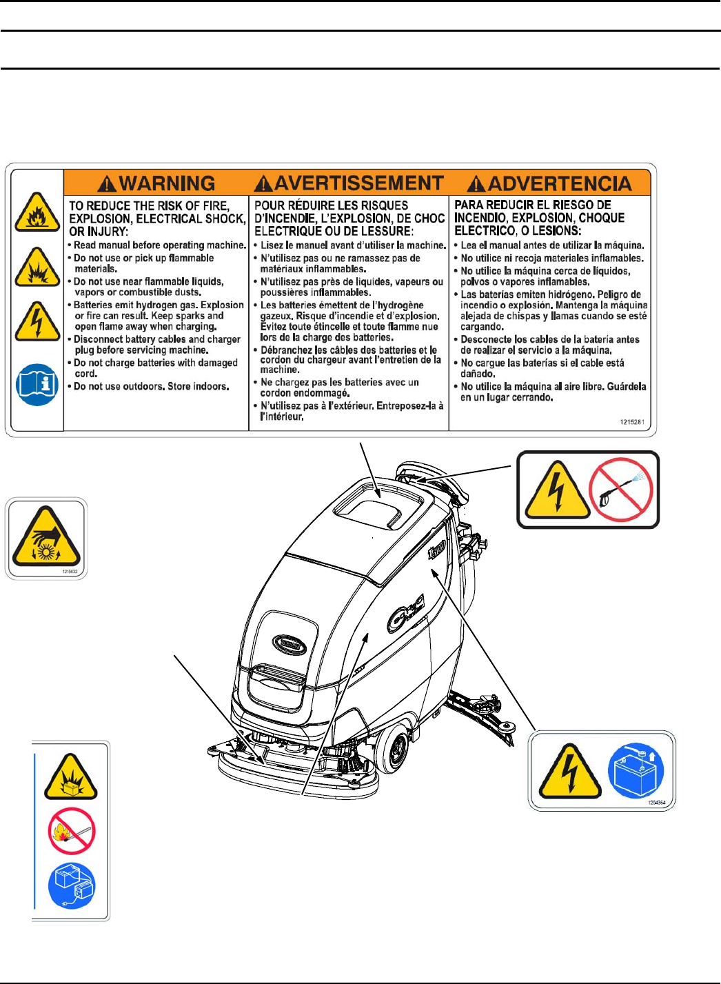
SAFETY LABELS
The safety labels appear on the machine in the locations indicated. Replace labels if they are missing or become
damaged or illegible.
WARNING LABEL - Located on recovery tank cover.
WARNING LABEL -
Electrical hazard.
Disconnect battery
cables before servicing
machine.
Located on circuit breaker
panel.
WARNING LABEL -
Batteries emit hydrogen gas.
Explosion or fire can result. Keep
sparks and open flame away when
charging.
Located on bottom side of recovery tank.
WARNING LABEL -
Spinning brush. Keep hands away.
Located on scrub head.
FOR SAFETY LABEL -
Do not power spray or
hose off machine.
Electrical malfunction
may occur.
Located on control console
OPERATION
8Tennant T500 (01-2017)
MACHINE COMPONENTS
1
11
26
25
27 30
29
34
36
37
38
2035
39
40
32
28
31
2
17
12
5
4
2
16
15
14
11
7
6
10
13
8
9
18
41
42
43
33
25
44
21
24
23
22
1
3
19
20
OPERATION
Tennant T500 (01-2017) 9
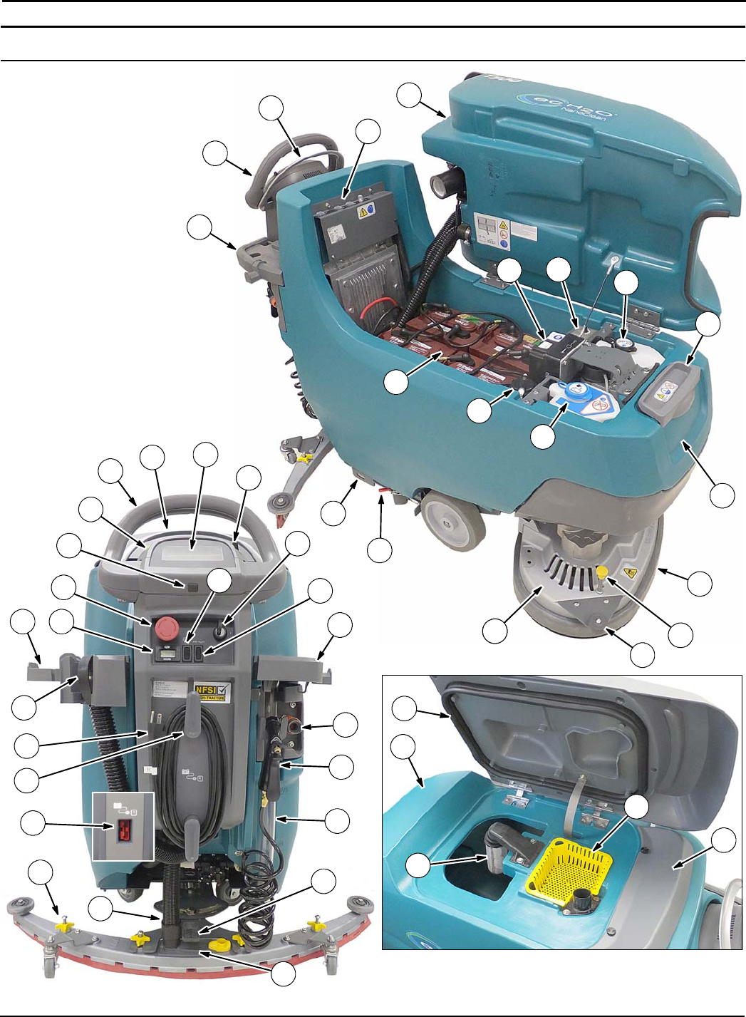
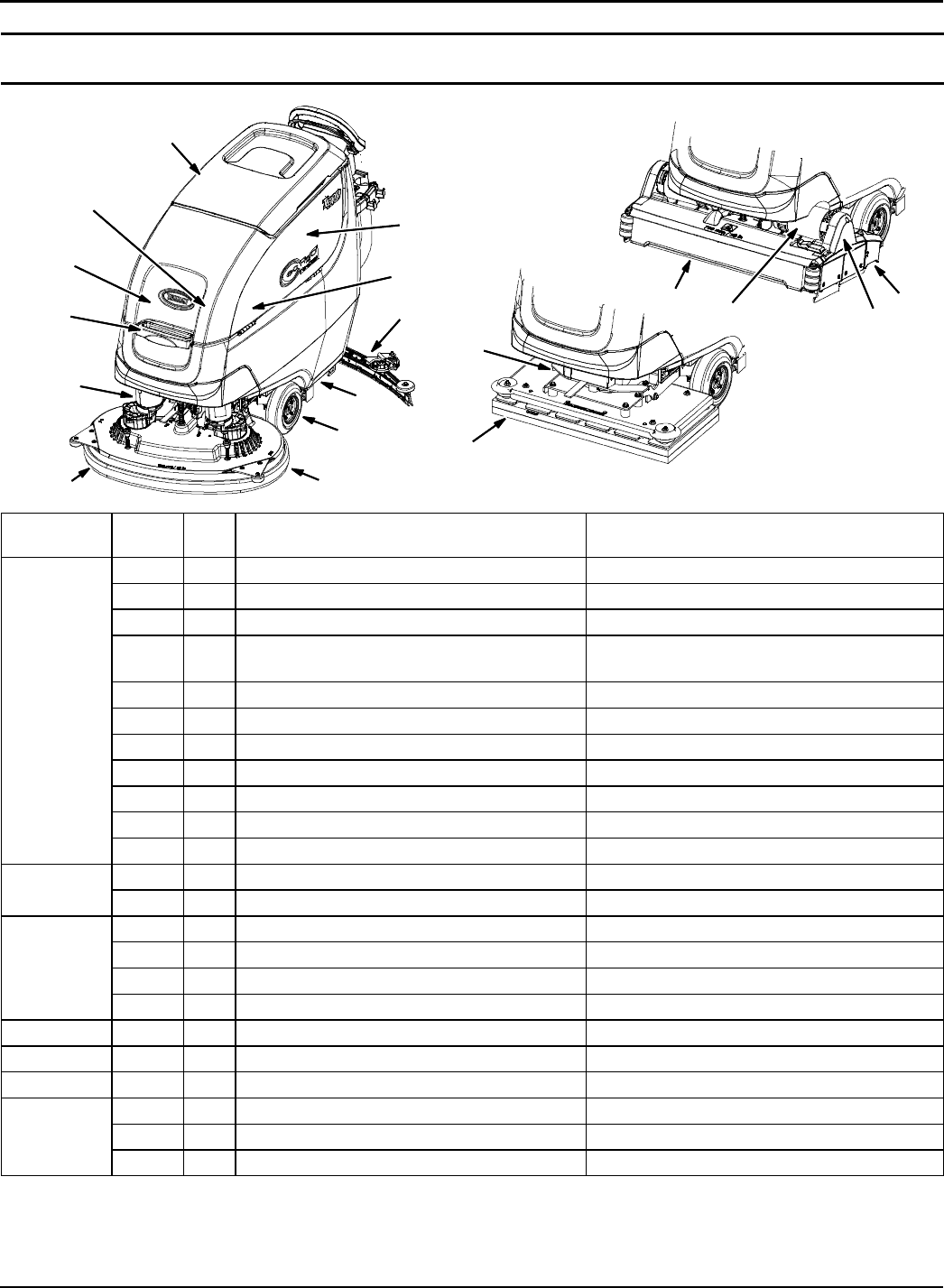
MACHINE COMPONENTS
1. Control handle
2. Control handle start bail
3. Control panel
4. Forward/Reverse lever
5. Speed control knob
6. USB port (Service only)
7. Key switch
8. ec-H2O on/off switch (option)
9. Spray nozzle on/off switch (option)
10. Emergency shut-off button
11. Accessory rails
12. Accessory rail clips (option)
13. Hour meter
14. Solution tank rear hose fill-port
15. Tank rinse out spray nozzle (option)
16. Solution tank level/drain hose
17. Recovery tank drain hose
18. On-board battery charger cord
19. On-board battery charger cord hooks
20. Off-board battery charger receptacle
21. Squeegee lower/lift foot pedal
22. Squeegee assembly
23. Squeegee vacuum hose
24. Squeegee debris/drip tray
25. Recovery tank
26. Circuit breaker panel
27. ec-H2O module (option)
28. ec-H2O water conditioning cartridge
29. Severe environment detergent tank
(ec-H2O option)
30. Detergent mixing ratio knob
(Severe environment option)
31. Battery compartment
32. Automatic battery watering tank (option)
33. Solution tank
34. Solution tank front bucket fill-port
35. Scrub head
36. Scrub head skirt
37. Pad release plunger
38. Wall rollers
39. Parking brake (option)
40. Transport tie-down bracket
41. Recovery tank lid
42. Recovery tank float shut-off screen
43. Recovery tank debris tray
44. Splash guard
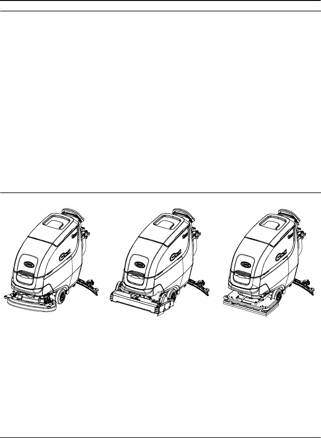
SCRUB HEAD TYPES
26 in / 650 mm Dual Disk
28 in / 700 mm Dual Disk
32 in / 800 mm Dual Disk
28 in / 700 mm Cylindrical Brush 28 in / 700 mm Orbital Pad
OPERATION
10 Tennant T500 (01-2017)
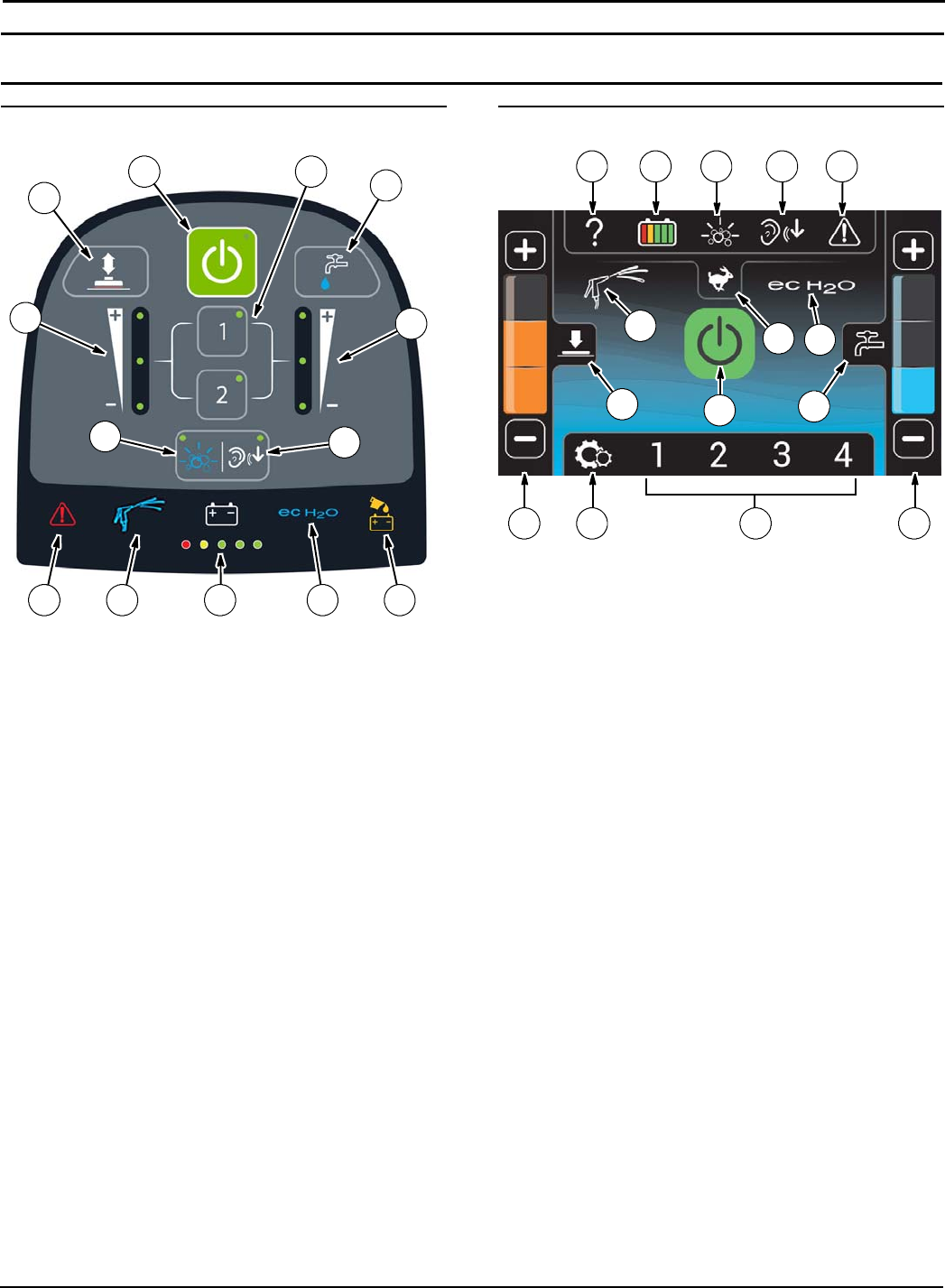
CONTROL PANEL COMPONENTS
PRO-MEMBRANE CONTROL PANEL MODEL
1
35
2
46
8
7
910 11 12 13
1. 1-Step button
2. Preset zone control buttons
3. Brush pressure button
4. Brush pressure indicator
5. Solution flow button
6. Solution flow indicator
7. Severe environment button (option)
8. Quiet-mode button
9. Service Indicator
10. Spray nozzle indicator (option)
11. Battery discharge indicator (BDI)
12. ec-H2O indicator (option)
13. Automatic battery watering indicator
(option)
PRO-PANEL CONTROLS MODEL
1 2 3 4 5
1411 13
12
10
79
8
6
15
1. Help button
2. Battery discharge indicator (BDI)
3. Severe environment button
4. Quiet mode button
5. Service indicator button
6. 1-Step button
7. Spray nozzle indicator (option)
8. Maximum scrub speed button
9. ec-H2O indicator (option)
10. Brush pressure button
11. Brush pressure indicator
12. Solution flow button
13. Solution flow indicator
14. Machine Settings button
15. Preset zone control buttons
OPERATION
Tennant T500 (01-2017) 11
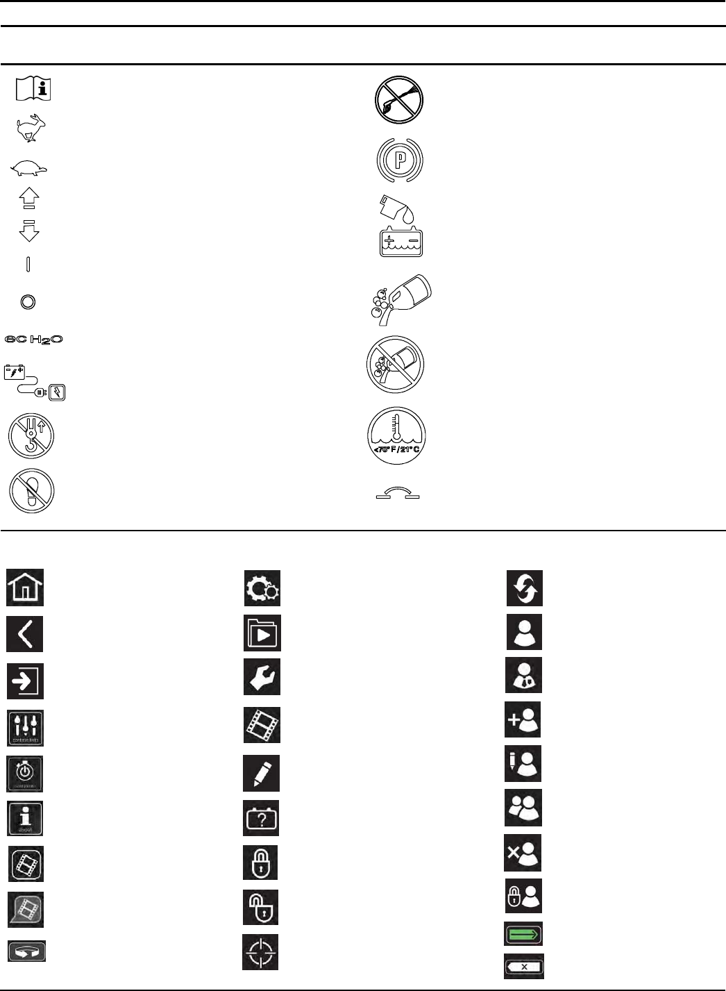
MACHINE SYMBOLS
ec-H2O scrubbing (option)
Circuit breaker
Do not lift by accessory rails
No step
No detergent (ec-H2O option)
Water temperature (ec-H2O option)
Battery charge
Fast speed (drive model)
Slow speed (drive model)
Parking brake
Forward / Reverse (drive model)
Key On
Key Off
Automatic Battery Watering Tank
(Option)
Detergent (ec-H2O Severe environment
option)
Read Manual Do not power spray
PRO-PANEL SYMBOLS
Home screen
Back arrow
Login
Control help
Start-up video
About
Video list button
Video button
Video rotate view
Supervisor menu
Machine settings
Video Help
Enable login
Disable login
Calibrate touch
Factory reset
Backspace
Add/Edit profiles
Battery selection
Operator
Supervisor
Add profile
Edit profile
Copy profile
Delete profile
Enter
Operator videos
User login
OPERATION
12 Tennant T500 (02-2017)
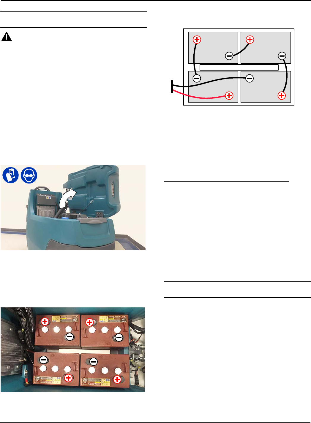
INSTALLING BATTERIES
WARNING: Batteries emit hydrogen gas.
Explosion or fire can result. Keep sparks and open
flame away when charging.
FOR SAFETY: When servicing machine, wear
appropriate personal protection equipment as
needed. Avoid contact with battery acid.
BATTERY SPECIFICATIONS
Requires four 6 volt deep-cycle batteries, ≤260 Ah @
20 hr.
Contact distributor or Tennant for battery
recommendations.
FOR SAFETY: Before leaving or servicing machine,
stop on level surface, turn off machine, remove key
and set parking brake if equipped.
1. Lift the recovery tank to access the battery
compartment (Figure 1).
FIG. 1
2. Carefully install the batteries into the battery
compartment tray and arrange the battery posts as
shown (Figure 2). Position foam spacer between
batteries as shown.
FOR SAFETY: When servicing machine, use a
hoist or adequate assistance when lifting batteries.
FOAM SPACER
FIG. 2
3. Using the supplied battery post boots, connect the
cables to battery posts, RED TO POSITIVE (+) &
BLACK TO NEGATIVE (-) (Figure 3).
BLACK
RED
FOAM SPACER
FIG. 3
IMPORTANT: Before charging batteries, make sure
the battery charger and the machine's battery
discharge indicator are properly set for battery
type. Failure to properly set will result in battery
damage. See BATTERY CHARGER SETTINGS.
ATTENTION: Do not disconnect battery cables
while charger is plugged in, circuit board damage
may result.
IRIS®Battery Charging Metrics Notification:
Machines equipped with capability to report battery
charging data via IRIS are supplied with a charger and
set of batteries from the factory. When a battery
reaches its end of life and must be replaced, Tennant
highly recommends that the same battery type be used
to continue to maximize the machines performance. In
the event a battery with a different amp hour (AH), type
(Flooded, AGM, Gel), or manufacturer is selected for
replacement please contact Tennant technical service
department for assistance in determining the feasibility
of the replacement batteries and if so, selecting the
correct charging profile. Availability of IRIS battery
metric reporting is not guaranteed with third party
supplied batteries.
HOW THE MACHINE WORKS
Conventional scrubbing:
When using the conventional scrubbing mode, water
and detergent mixture from the solution tank flows to
the floor and the rotating brush(es)/pad(s) scrub the
floor clean. As the machine moves forward, the
squeegee with vacuum suction picks up the dirty
solution from the floor into the recovery tank.
ec-H2O NanoClean Technology (option):
When using the ec-H2O NanoClean technology,
normal water passes through a module where it is
electrically converted into a cleaning solution. The
electrically converted water attacks the dirt, allowing
the machine to easily scrub away the suspended soil.
The converted water then returns to normal water in
the recovery tank.
OPERATION
Tennant T500 (01-2017) 13
BRUSH AND PAD INFORMATION
For best cleaning results use the appropriate brush or
pad for your cleaning application. Listed below are
brushes and pads and the applications for which each
is best suited.
NOTE: The amount and type of soilage play an
important role in determining the type of brush or pad
to use. Contact a Tennant representative for specific
recommendations.
Soft nylon bristle scrub brush (White) -
Recommended for cleaning coated floors without
removing finish. Cleans without scuffing.
Polypropylene bristle scrub brush (Black) -
This general purpose polypropylene bristle scrub brush
is used for scrubbing lightly compacted soilage. This
brush works well for maintaining concrete, wood and
grouted tile floors.
Super abrasive bristle scrub brush (Gray) -
Nylon fiber impregnated with abrasive grit to remove
stains and soilage. Strong action on any surface.
Performs well on buildup, grease, or tire marks.
Polishing pad (White) -
Used to maintain highly polished or burnished floors.
Buffing pad (Red) - Used for light duty scrubbing
without removing floor finish.
Scrubbing pad (Blue) - Used for medium to
heavy-duty scrubbing. Removes dirt, spills, and scuffs
and leaves surface clean ready for re-coating.
Stripping pad (Brown) - Used for stripping of floor
finish to prepare the floor for recoating.
Heavy duty stripping pad (Black) - Used for
aggressive stripping of heavy finishes/sealers, or very
heavy duty scrubbing.
Surface preparation pad (Maroon) - Used for very
aggressive chemical free removal of floor finish to
prepare the floor for re-coating.
Turf scrubbing pad (Green) - Used to scrub uneven
floor surfaces with crevices, cracks and deep grout
lines.
MACHINE SETUP
ATTACHING SQUEEGEE ASSEMBLY
FOR SAFETY: Before leaving or servicing machine,
stop on level surface, turn off machine, remove key
and set parking brake if equipped.
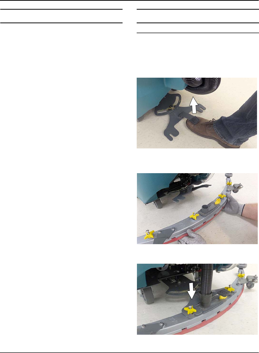
1. Lift the squeegee mount bracket to the raised
position. Place foot under pedal to lift (Figure 4).
FIG. 4
2. Mount the squeegee assembly to the squeegee
mount bracket (Figure 5). Tighten knobs to secure
squeegee assembly to bracket.
FIG. 5
3. Connect the vacuum hose to the squeegee
assembly (Figure 6).
FIG. 6
OPERATION
14 Tennant T500 (01-2017)
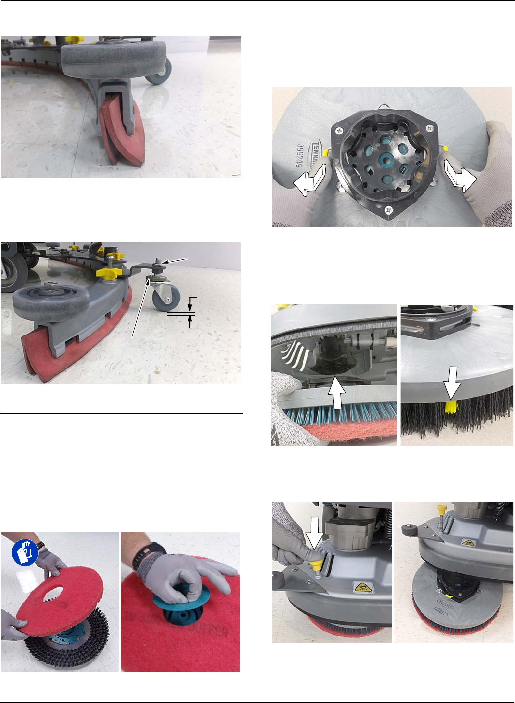
5. Check the squeegee blades for proper deflection.
The blades should deflect as shown (Figure 7).
FIG. 7
6. To adjust the blade deflection, loosen the jam nut
and turn the caster hex plate until there is a 1/16”
(2mm) space between caster and floor. Re-tighten
jam nut and repeat step on other caster (Figure 8).
1/16 in
2mm
Jam Nut
Caster hex plate
FIG. 8
INSTALLING DISK BRUSHES/PADS
(Disk Scrub Head Model)
1. Raise scrub head off floor and remove key.
FOR SAFETY: Before leaving or servicing machine,
stop on level surface, turn off machine, remove key
and set parking brake if equipped.
2. Attach the pad to the pad driver before installing
the driver. Secure pad with center-lock (Figure 9).
FIG. 9
FOR SAFETY: Do not operate machine with pads
or accessories not supplied or approved by
Tennant. The use of other pads may impair safety.
3. Set the yellow spring clips to the open position to
make brush installation easier. Press clips down
and outward to set (Figure 10).
FIG. 10
4. Align the pad driver or brush under the motor hub
and push it upward to engage hub (Figure 11).
Replace pads or brushes when they no longer
clean effectively or when the bristles on the brush
disk are worn to the yellow indicator (Figure 11).
FIG. 11
5. To remove the pad drivers/brushes, raise the scrub
head and press down on the yellow pad release
plunger (Figure 12). Pad will drop to floor.
FIG. 12
OPERATION
Tennant T500 (01-2017) 15
INSTALLING ORBITAL PADS
(Orbital Scrub Head Model)
For best cleaning performance and to avoid damaging
the pad driver plate or floor surface, always use backer
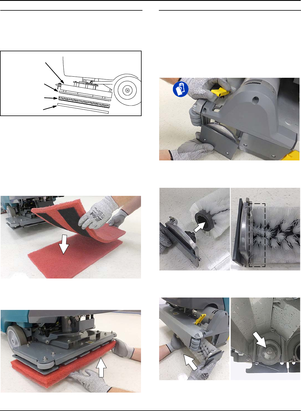
pad with working pads (Figure 13).
Backer pad
Working pad
Orbital scrub head
Pad driver plate
FIG. 13
1. Raise scrub head off floor and remove key.
FOR SAFETY: Before leaving or servicing machine,
stop on level surface, turn off machine, remove key
and set parking brake if equipped.
FOR SAFETY: Do not operate machine with pads
or accessories not supplied or approved by
Tennant. The use of other pads may impair safety.
2. Attach backer pad, retaining strips facing
downward, to working pad (Figure 14).
FIG. 14
3. Attach the two pads to the bottom of the scrub
head (Figure 15). Make sure pad is centered on
scrub head.
FIG. 15
INSTALLING CYLINDRICAL BRUSHES
(Cylindrical Brush Scrub Head Model)
1. Raise scrub head off floor and remove key.
FOR SAFETY: Before leaving or servicing machine,
stop on level surface, turn off machine, remove key
and set parking brake if equipped.
2. Unfasten yellow latch and remove the idler plate
from the scrub head (Figure 16).
FIG. 16
3. Attach idler plate to brush end with double row of
bristles (Figure 17).
Double row of bristles
FIG. 17
4. Guide brush onto the drive hub and refasten latch
(Figure 18).
Double row of
bristles
FIG. 18
OPERATION
16 Tennant T500 (02-2017)
FILLING SOLUTION TANK
FOR SAFETY: Before leaving or servicing machine,
stop on level surface, turn off machine, remove key
and set parking brake if equipped.
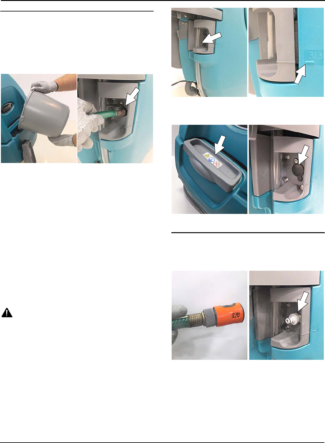
The machine is equipped with two solution tank fill-port
locations. A front bucket fill-port and a rear hose fill-port
(Figure 19).
FIG. 19
1. Fill the solution tank with water until level reaches
the ”3/3” mark on the solution tank drain hose
indicator (Figure 20).
ec-H2O Scrubbing (Option)- Fill solution tank
with only cool clean water (less than 70°F/21°C).
Do not add conventional floor cleaning detergents.
An ec-H2O system fault will occur if cleaning
detergents are added.
Conventional Scrubbing - Fill solution tank with
water (not to exceed 60°C/140°F). Pour a
recommended cleaning detergent into the solution
tank according to mixing instructions on the
container.
ATTENTION: For Conventional Scrubbing, only use
commercially approved cleaning detergents. Machine
damage due to improper detergent usage will void the
manufacturer's warranty.
WARNING: Flammable materials can cause an
explosion or fire. Do not use flammable materials
in tank(s).
NOTE: Do not use the ec-H2O system when there are
conventional cleaning detergents in the solution tank.
Drain, rinse, and refill the solution tank with clear cool
water before operating the ec-H2O system.
Conventional cleaning detergents will cause an ec-H2O
system fault.
FIG. 20
2. Replace the front and rear fill-port cover after filling
solution tank (Figure 21).
FIG. 21
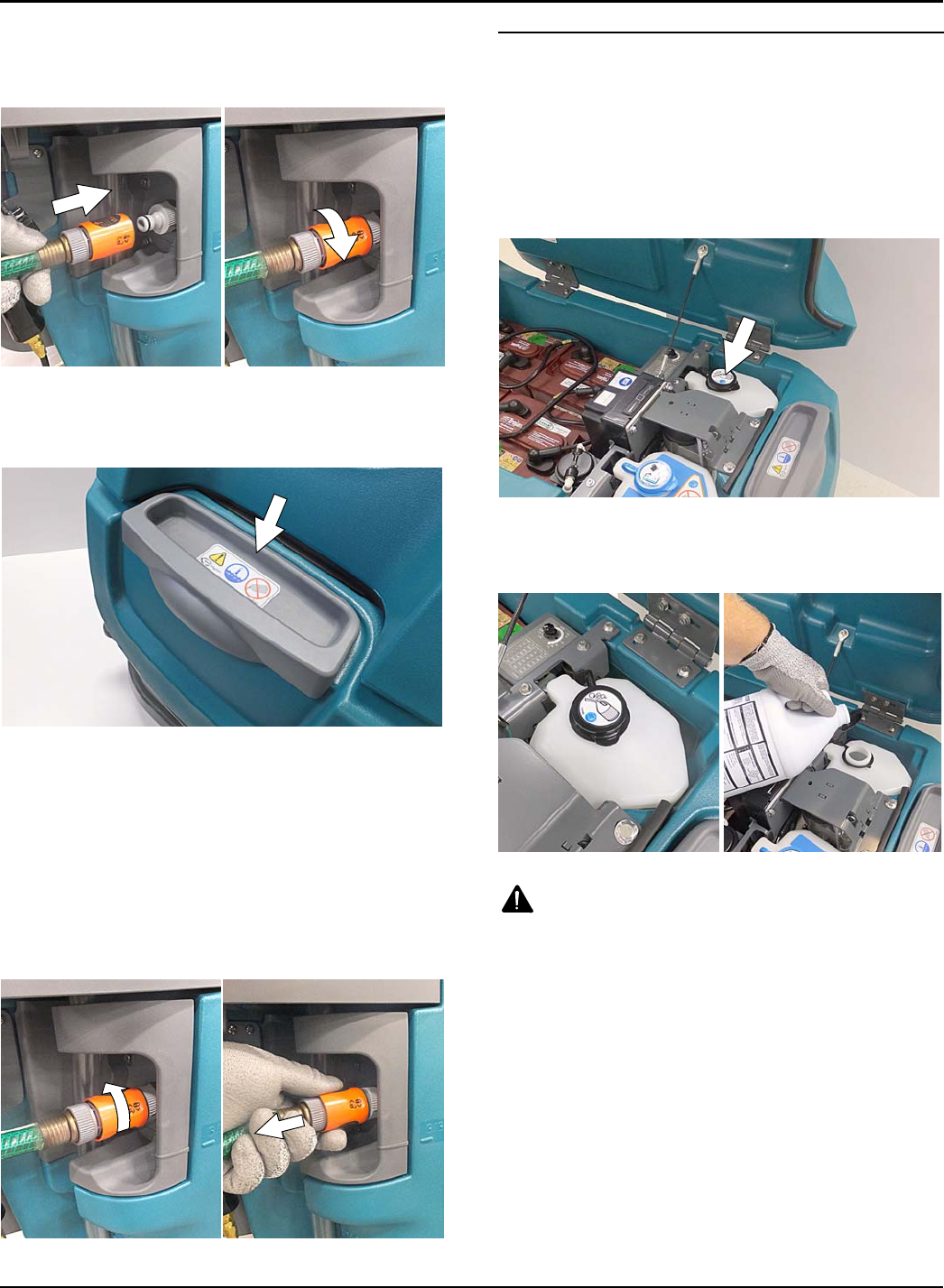
USING SOLUTION TANK AUTO-FILL (OPTION)
1. Connect the quick-disconnect auto-fill coupler to
the water supply hose and connect the nipple fitting
to the machine (Figure 22).
FIG. 22
OPERATION
Tennant T500 (01-2017) 17
2. Press the quick-disconnect coupler into the nipple
fitting unit it clicks (Figure 23). To prevent hose
from being pulled out while tank is being filled, turn
collar on coupler clockwise to lock connection.
FIG. 23
3. Before filling the solution tank with the auto-fill
option make sure the front fill-port cover is securely
in place (Figure 24).
FIG. 24
4. Turn the water supply on. The water flow will
automatically stop when solution tank is full.
FOR SAFETY: When operating machine, do not
leave machine unattended when filling solution
tank with auto-fill feature.
5. After solution tank is full, turn water supply off.
6. Turn collar on coupler counter-clockwise to unlock
connection. Then simply pull back on coupler to
disconnect hose from machine (Figure 25).
FIG. 25
FILLING SEVERE ENVIRONMENT DETERGENT
TANK (ec-H2O MODEL OPTION)
FOR SAFETY: Before leaving or servicing machine,
stop on level surface, turn off machine, remove key
and set parking brake if equipped.
1. Lift the recovery tank to access the severe
environment detergent tank (Figure 26). Drain
recovery tank before lifting tank.
FIG. 26
2. Remove black cap from detergent tank and add a
recommended cleaning detergent at full
concentration (Figure 27). Do not add water.
FIG. 27
WARNING: Flammable materials can cause an
explosion or fire. Do not use flammable materials
in tank(s).
ATTENTION: Only use commercially approved
cleaning detergents in the severe environment tank. Do
not use cleaners based with d-limonene. Machine
damage due to improper detergent usage will void the
manufacturer's warranty.
NOTE: To prevent from running out of detergent while
operating, it is recommended to refill the severe
environment tank when refilling the solution tank.
3. Replace cap on detergent tank.
OPERATION
18 Tennant T500 (01-2017)
4. Adjust the detergent mixing ratio knob according to
the cleaning detergent's mixing instructions (Figure
28).
FIG. 28
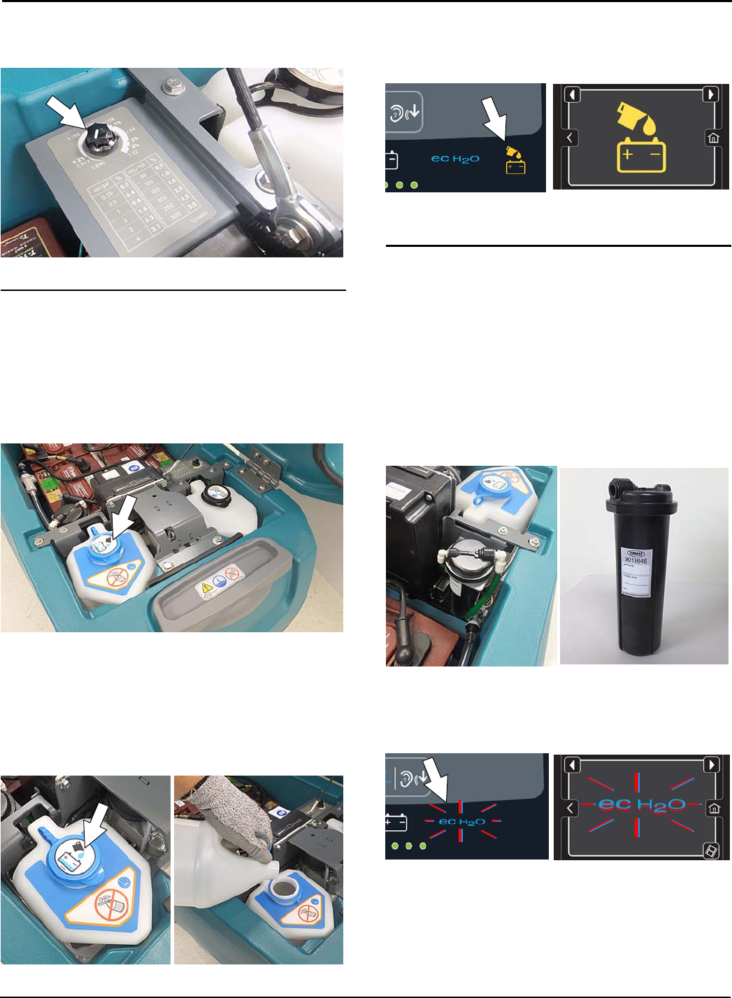
FILLING AUTOMATIC BATTERY WATERING TANK
(OPTION)
FOR SAFETY: Before leaving or servicing machine,
stop on level surface, turn off machine, remove key
and set parking brake if equipped.
1. Lift the recovery tank to access the automatic
battery watering tank (Figure 29). Drain recovery
tank before lifting tank.
FIG. 29
2. Remove the blue cap from the automatic battery
watering tank (Figure 30).
3. Pour distilled water into tank (Figure 30).
FOR SAFETY: When operating machine, only use
distilled water when filling the automatic battery
watering tank.
FIG. 30
4. When the tank needs refilling, the automatic
battery watering indicator will alert user to add
distilled water (Figure 31). See CONTROL PANEL
OPERATION for further details.
Pro-Panel Model
Pro-membrane Model
FIG. 31
ec-H2O WATER CONDITIONING CARTRIDGE
(ec-H2O MODEL)
The ec-H2O system is equipped with a water
conditioning cartridge (Figure 32). The cartridge is
designed to protect the machine's plumbing system
from potential scaling.
The cartridge is required to be replaced when it
reaches its maximum water usage or expiration time on
when the cartridge was activated, which ever comes
first.
Depending on machine usage a new cartridge can last
anywhere from 12 to 24 months.
FIG. 32
The control panel will signal the following code when
it's time to replace the cartridge (Figure 33). The
ec-H2O icon will begin to blink blue and red. See
SERVICE INDICATOR CODES for further details.
Pro-Panel Model
Pro-membrane Model
FIG. 33
OPERATION
Tennant T500 (01-2017) 19
All cartridges are labeled with a manufacture date. The
shelf-life of an un-installed cartridge is one year from
manufacture date. For new cartridge replacement, the
ec-H2O module timer must be reset. See ec-H2O
WATER CONDITIONING CARTRIDGE
REPLACEMENT.
ATTENTION: During first time use and after replacing
the water conditioning cartridge, the ec-H2O system
will automatically override the selected solution flow
rateforupto75minutes.
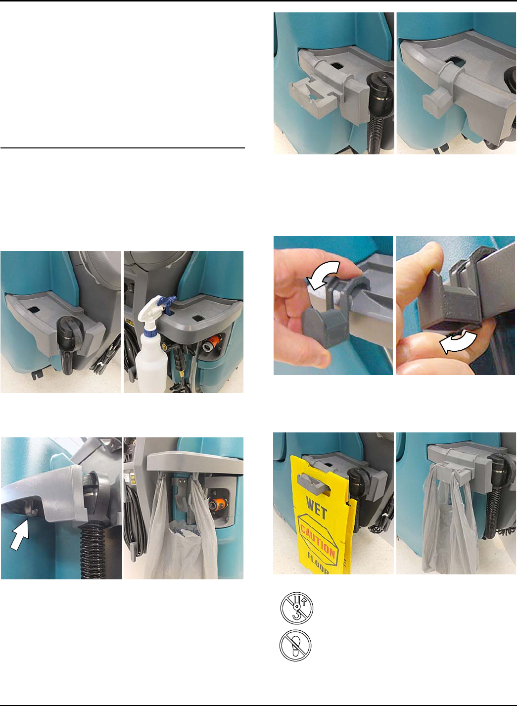
ACCESSORY RAILS
The machine is equipped with two accessory rails
which straddle the control console. The left side rail
also serves as the recovery tank and solution tank
drain hose holder.
The accessory rails are designed to store spray bottles
and other accessory items (Figure 34).
FIG. 34
The J-hooks on the underside of the rails allow for
debris bag storage (Figure 35).
FIG. 35
ACCESSORY CLIPS (Option) - If model is equipped
with the optional accessory clips, the clips easily clip on
and off the rails for additional accessory storage
(Figure 36).
FIG. 36
To install the accessory clips, hook the clip over the rail
and push downward until it snaps into position. To
remove the accessory clip, reach under the clip and
carefully pull the latch tab downward to release from
rail (Figure 37).
FIG. 37
The optional accessory clips allow for storage of wet
floor signs, spray bottles, debris bags and other items
(Figure 38).
FIG. 38
ATTENTION: Do not use the accessory
rails to lift machine, damage may occur.
ATTENTION: Do not step on accessory
rails, damage may occur.
OPERATION
20 Tennant T500 (02-2017)
CONTROL PANEL OPERATION
The control panel operation can be set up with lockout
functionality by using the Supervisor Controls feature.
This will prevent the operator from changing or saving
the settings. See SUPERVISOR CONTROLS
instructions at the back of the manual.
The supervisor controls feature will lower machine
variability for consistent, repeatable cleaning results,
provide machine quality assurance regardless of user
experience, and reduce user training requirements.
PRO-MEMBRANE CONTROL PANEL
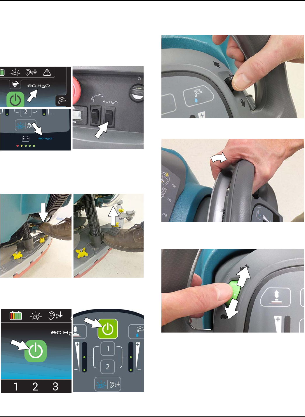
1-STEP BUTTON
With key turned on, press the 1-STEP button to
activate the scrub function (Figure 39). The scrub head
will lower to floor. Press button again to stop the scrub
function and to raise scrub head.
FIG. 39
BRUSH PRESSURE BUTTON
Press the brush pressure button to increase or
decrease the brush pressure (Figure 40). The brush
pressure indicator will display the pressure setting. One
LED = Low pressure, two LED's = Medium pressure,
three LED's = High pressure.
FIG. 40
NOTE: Orbital scrub head model - If brush pressure is
set too high for scrubbing conditions, the brush
pressure setting will automatically reduce to a lower
setting and begin flashing. The flashing LED alerts the
operator to reduce the brush pressure setting to
prevent brush motor overload.
SOLUTION FLOW BUTTON
Press the solution flow button to increase or decrease
the solution flow rate (Figure 41). The solution flow
indicator will display flow setting.
No LED = No flow, One LED = Low flow, two LED's =
Medium flow, three LED's = High flow.
FIG. 41
SEVERE ENVIRONMENT BUTTON
(ec-H2O Model Option)
Press the Severe Environment button to deliver a boost
of cleaning detergent for areas with excessive soil
buildup (Figure 42).
Press button one time for a 30 second boost. A
green LED in the corner will blink slowly when
dispensing. During the last 5 seconds, the LED will
blink rapidly as an alert that the dispensing is about
to stop.
To deliver a continuous detergent boost, press and
hold button for 2 seconds until green LED turns
solid green. Press button at anytime to turn off.
To alert user when detergent tank is empty, the
bubbles icon will blink for 15 seconds. If button is
pressed when tank is empty, the bubbles icon will
continue to blink for 15 seconds until tank is
refilled.
NOTE: When the severe environment mode is
turned on, the ec-H2O system will automatically
turn off and the brush pressure and solution flow
settings will increase to the high settings. When
turned off, the settings will revert back to the
original settings. When operating the Severe
Environment mode for extended periods, if desired,
the solution flow rate and the down pressure can
be decreased to a lower setting to conserve
solution and detergent usage and optimize battery
run time.
FIG. 42
OPERATION
Tennant T500 (01-2017) 21
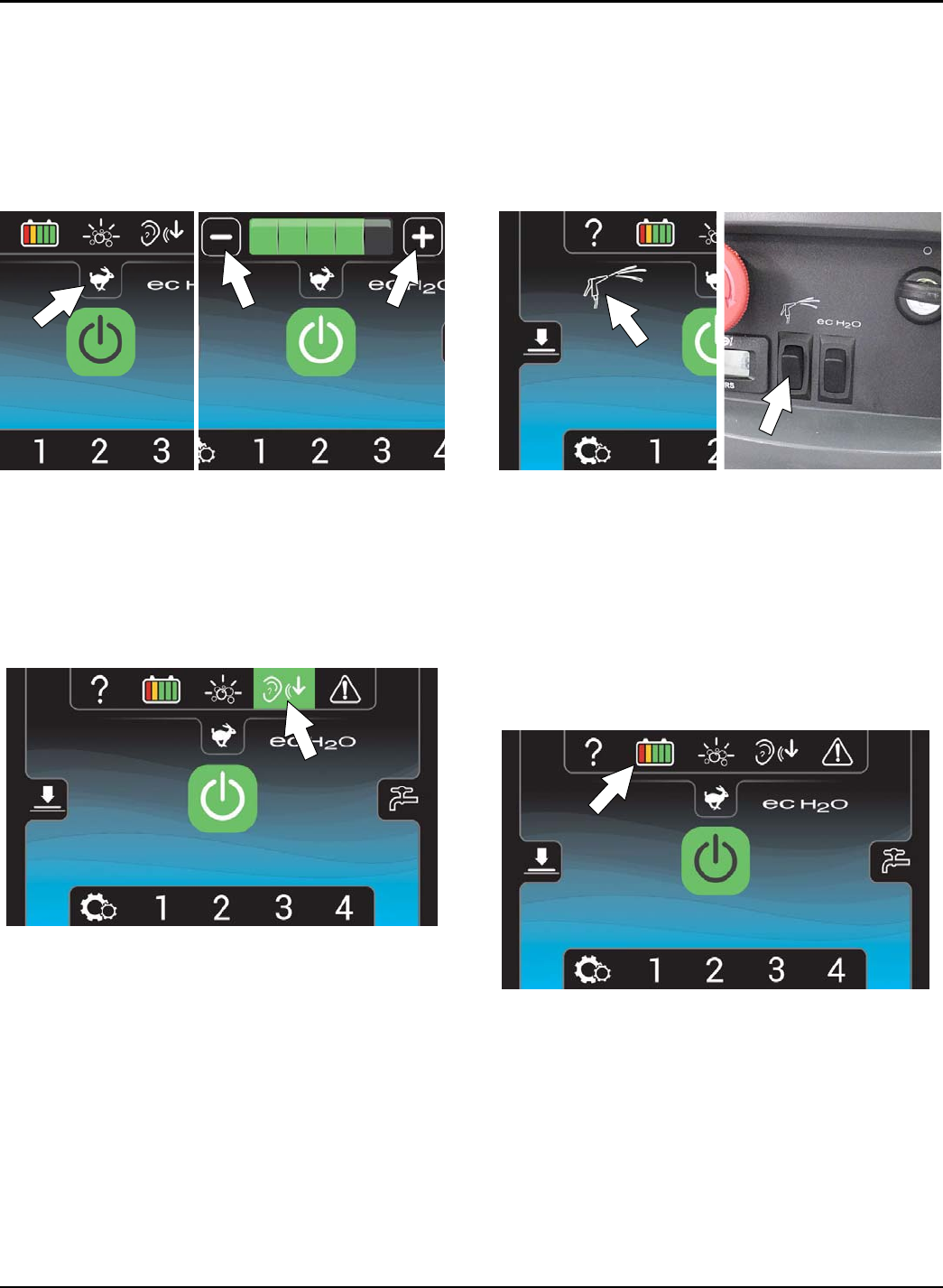
QUIET-MODE BUTTON
Press the Quiet-Mode button to reduce the vacuum
motor sound . A green LED in the corner will turn on
when activated. Press button to turn off.
FIG. 43
PRESET ZONE CONTROL BUTTONS
Use the zone control buttons to preset up to three
zones with different solution flow rates, brush
pressures, scrub speeds and scrub modes (Figure 44).
Zone 1 = Preset Zone Control Button 1
Zone 2 = Preset Zone Control Button 2
Zone 3 = Preset Zone Control Buttons 1 & 2
The zone control buttons are factory preset for different
scrubbing applications. To use Zone 3, press zone
buttons 1 & 2 at the same time. A green LED in the
corner will turn on when activated.
FIG. 44
To preset the zone control buttons for different
scrubbing applications, select the desired settings
from list below, then press and hold the zone
button until the green LED blinks three times to
save preset. To preset zone 3, press and hold
zone buttons 1 & 2 at the same time.
- Brush pressure setting
- Solution flow rate
- Quiet-Mode on or off
- ec-H2O system on or off (option)
- Severe Environment mode on or off (option)
- Maximum scrub speed (see Supervisor Controls)
NOTE: The severe environment mode and ec-H2O
system cannot be preset together.
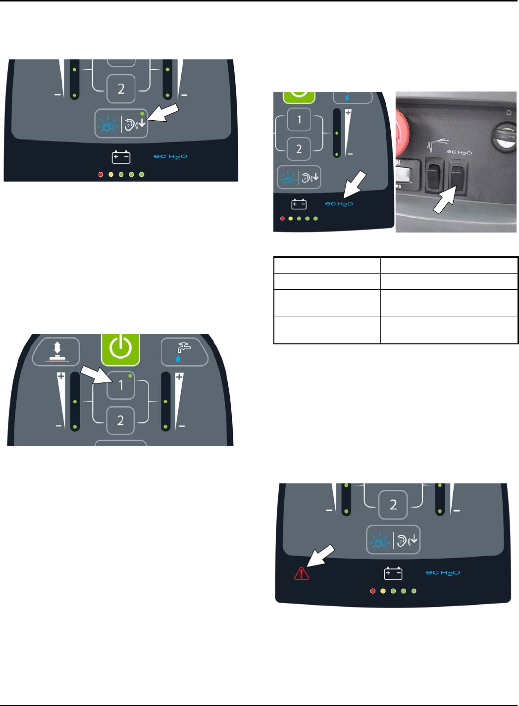
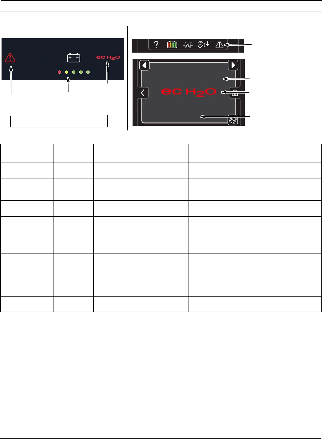
ec-H2O INDICATOR (Option)
The ec-H2O system automatically turns on at each key
start. A blue ec-H2O indicator will appear on the control
panel indicating that the system is activated. To turn off
the ec-H2O system, press the ec-H2O switch located
below the key switch. The blue ec-H2O indicator will
disappear (Figure 45).
FIG. 45
ec-H2O INDICATOR CONDITION
Solid blue Normal operation
Blinking blue/red Water conditioning cartridge
expired. Replace cartridge.
Solid or blinking red A system fault has occurred.
See Service Indicator Codes.
NOTE: If a fault occurs to the ec-H2O system, the
machine may automatically turn off the ec-H2O system
and convert over to conventional scrubbing. The
service indicator icon will remain solid red or continue
to blink red until the ec-H2O fault is serviced.
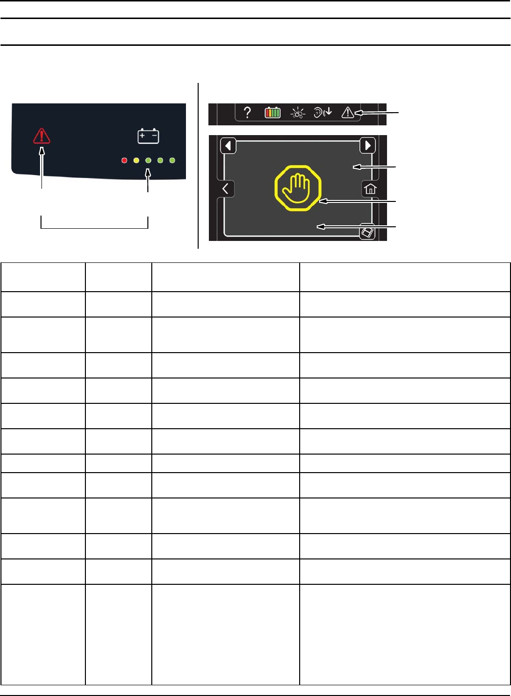
SERVICE INDICATOR
When the machine or on-board battery charger detects
a fault, the service indicator will light up and begin
flashing (Figure 46). The battery discharge indicator
lights will also flash a fault code. See SERVICE
INDICATOR CODES to diagnose machine fault.
FIG. 46
OPERATION
22 Tennant T500 (01-2017)
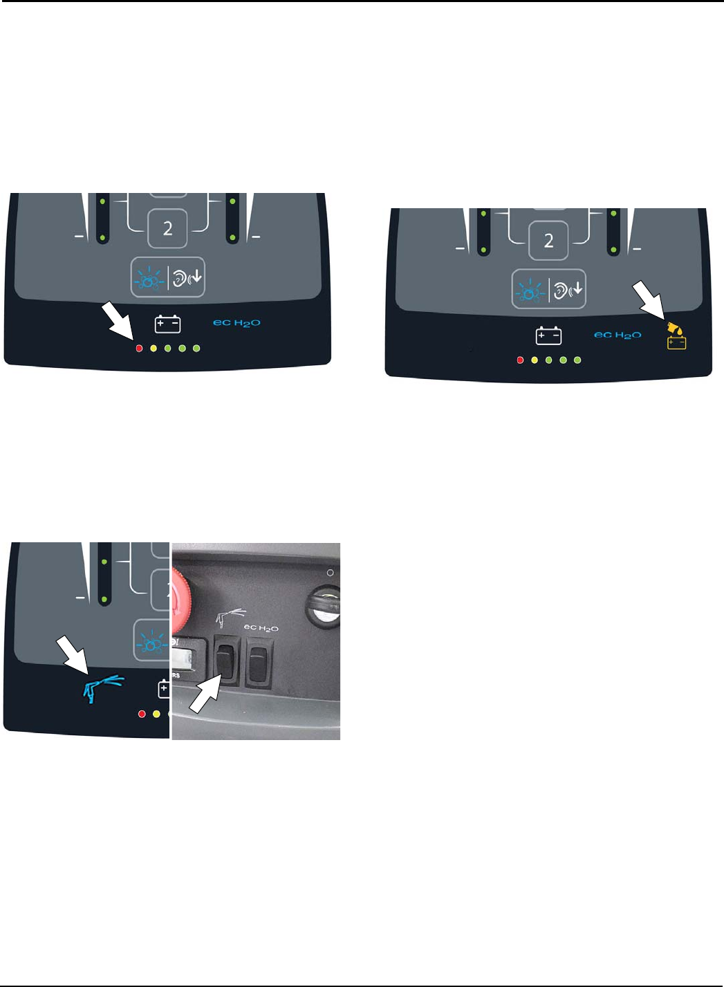
BATTERY DISCHARGE INDICATOR
The battery discharge indicator (BDI) displays the
charge level of the batteries while the machine is
operating. When the batteries are fully charged, all five
indicators are lit (Figure 47). When the discharge level
reaches the red light, stop scrubbing and recharge the
batteries. When the red light begins to flash, the scrub
function will be disabled to protect the batteries from
total discharge. The machine will still propel when the
red light is flashing. This will allow user to transport the
machine to the charging station.
FIG. 47
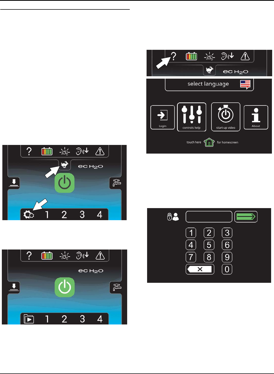
SPRAY NOZZLE INDICATOR (Option)
The spray nozzle indicator will display when the spray
nozzle switch is pressed (Figure 48). The switch
activates the spray nozzle pump and disables the
machine's propel when in use. If bail is pulled, the
spray nozzle indicator will flash indicating that the spray
nozzle pump is turned on. Press switch again to turn
off spray nozzle pump. See OPERATING SPRAY
NOZZLE.
FIG. 48
AUTOMATIC BATTERY WATERING INDICATOR
(Option)
The automatic battery watering indicator will flash when
the battery watering tank is empty and needs refilling
(Figure 49).
To protect the batteries from damage, the machine's
scrub function will be disabled after 10 hours of
continued use if tank is not refilled. When the indicator
flashes rapidly, the scrub function will be disabled. Add
distilled water and restart key to clear the flashing
indicator. See FILLING AUTOMATIC BATTERY
WATERING TANK.
FIG. 49
OPERATION
Tennant T500 (01-2017) 23
PRO-PANEL CONTROLS
HOME SCREEN
There are two types of user modes that will interface
with the home screen.
Supervisor Mode - Capable of machine operation with
full use of all controls, along with configuring
permissions and restrictions for the operator mode and
login capability.
Operator Mode - Capable of machine operation with
permissions and restrictions controlled by the
supervisor.
At key start up, a new machine from the factory will
automatically start up in the supervisor mode.
To configure the home screen with permissions and
restrictions and login capability for Operator Mode, see
SUPERVISOR CONTROLS instructions at the back of
the manual.
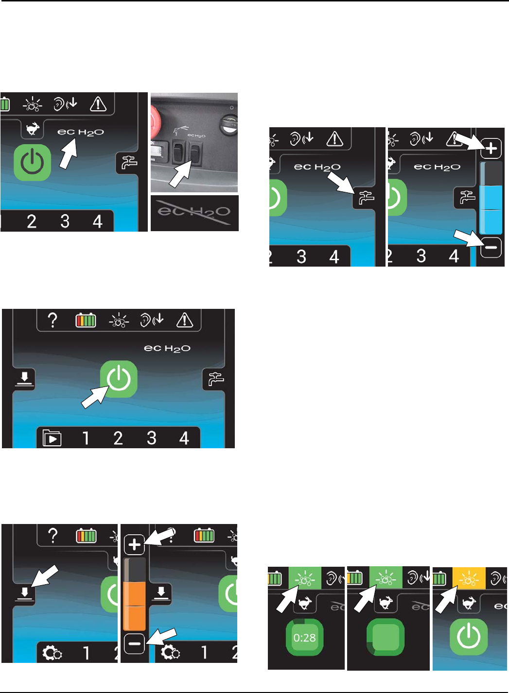
Supervisor Mode home screen provides access to
the machine settings button and to the maximum scrub
speed button (Figure 50).
FIG. 50
Operator Mode home screen restricts access to the
machine settings button and maximum scrub speed
button (Figure 51).
FIG. 51
HELP BUTTON
For first time users, press the help button (?) to access
the help screen. The help screen will allow you to
select a different screen language, enable login
settings, help identify control panel icons, view machine
start-up video and access machine system information
(Figure 52).
FIG. 52
LOGIN SCREEN
When login is enabled in the supervisor mode, a login
screen will appear at key start up (Figure 53 ). Enter
your assigned login code and press the green arrow to
access the home screen. See SUPERVISOR
CONTROLS instructions at the back of the manual to
enable login at start up.
FIG. 53
OPERATION
24 Tennant T500 (02-2017)
ec-H2O INDICATOR (Option)
The ec-H2O system automatically turns on at each key
start. The ec-H2O icon will appear on the home screen
indicating that the system is activated (Figure 54). To
turn off the ec-H2O system, press the ec-H2O switch
located below the key switch. A slash mark over the
icon will indicate that the ec-H2O system is turned off.
FIG. 54
1-STEP BUTTON
Press the 1-STEP button to activate the scrub function
(Figure 55). The scrub head will lower to floor. Press
button again to stop the scrub function and to raise
scrub head.
FIG. 55
BRUSH PRESSURE BUTTON
Press the brush pressure button to display the brush
pressure indicator (Figure 56). Press the (+) button to
increase brush pressure. Press the (-) button to
decrease the brush pressure.
FIG. 56
NOTE: If brush pressure is set too high for scrubbing
conditions, the brush pressure setting will automatically
reduce to a lower setting and begin flashing. When
flashing, reduce brush pressure to prevent brush motor
overload.
SOLUTION FLOW BUTTON
Press the solution flow button to display the solution
flow indicator (Figure 57). Press the (+) button to
increase solution flow. Press the (-) button to decrease
theflowsolutionortoturnitoff.
FIG. 57
SEVERE ENVIRONMENT BUTTON
(ec-H2O Model Option)
Press the Severe Environment button to deliver a boost
of cleaning detergent for areas with excessive soil
buildup (Figure 58).
Press button one time for a 30 second detergent
boost. The button will turn green and a 30 second
count down timer will start. Press button at anytime
to turn off.
To deliver a continuous detergent boost, press and
hold button for 2 seconds until a continuous timer is
displayed. Press button at anytime to turn off.
To alert user when the severe environment
detergent tank is empty, the button will blink yellow.
NOTE: When the severe environment mode is
turned on, the ec-H2O system will automatically
turn off and the brush pressure and solution flow
settings will increase to the high settings. When
turned off, the settings will revert back to the
original settings. When operating the Severe
Environment mode for extended periods, if desired,
the solution flow rate and the down pressure can
be decreased to a lower setting to conserve
solution and detergent usage and optimize battery
run time.
FIG. 58
OPERATION
Tennant T500 (01-2017) 25
MAXIMUM SCRUB SPEED BUTTON
Press the maximum scrub speed button to access the
maximum speed scrub settings (Figure 59). Press the
(+) button to increase the maximum scrub speed.
Press the (-) button to decrease the maximum scrub
speed. The maximum scrub speed button is only
accessible in the Supervisor Mode. See SUPERVISOR
CONTROLS instructions at the back of the manual for
further details.
FIG. 59
QUIET-MODE BUTTON
Press the Quiet-Mode button to reduce the vacuum
motor sound for noise restricted areas (Figure 60). The
button will turn green when activated. Press button
again to turn off.
NOTE: When the Quiet-Mode is activated the
water pickup will slightly be reduced.
FIG. 60
SPRAY NOZZLE INDICATOR (Option)
The spray nozzle indicator will display when the spray
nozzle switch is pressed (Figure 61). The switch
activates the spray nozzle pump and disables the
machine's propel when in use. If bail is pulled, the
spray nozzle indicator will flash indicating that the spray
nozzle pump is turned on. To turn off spray nozzle,
press the spray nozzle indicator or press switch again.
See OPERATING SPRAY NOZZLE.
FIG. 61
BATTERY DISCHARGE INDICATOR
The battery discharge indicator (BDI) displays the
charge level of the batteries while the machine is
operating. When the batteries are fully charged, all five
indicators are lit (Figure 62). When the discharge level
reaches the red light, stop scrubbing and recharge the
batteries. When the red light begins to flash, the scrub
function will be disabled to protect the batteries from
total discharge. The machine will still propel when the
red light is flashing. This will allow user to transport the
machine to the charging station.
FIG. 62
OPERATION
26 Tennant T500 (01-2017)
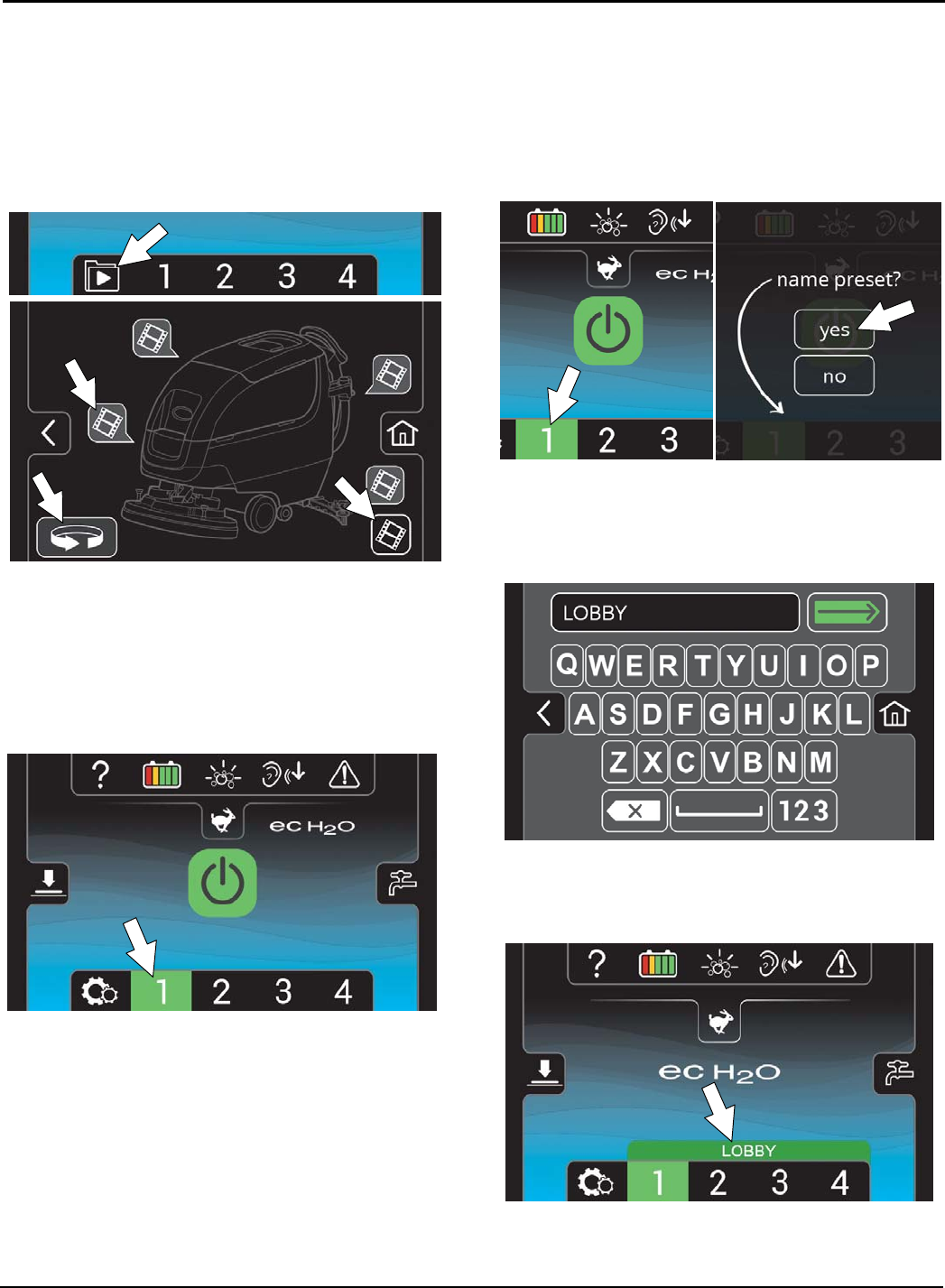
VIDEO TUTORIAL BUTTON
(Operator Mode Home Screen)
Press the video tutorial button to access the video
tutorial screen (Figure 63). It includes videos on how to
perform specific operation and maintenance
procedures. Press the video buttons to start video.
Press the rotate button for additional videos. The lower
right video button provides a list of additional tutorial
videos.
FIG. 63
PRESET ZONE CONTROL BUTTONS
Use the zone control buttons to preset up to four zones
with different solution flow rates, brush pressing, scrub
speeds and scrub modes (Figure 64).
The four zone control buttons are factory preset for
different scrubbing applications. The zone control
button will turn green when zone is activated.
FIG. 64
To preset the zone control buttons for different
scrubbing applications:
NOTE: Only the supervisor mode has the capability
to change the factory zone settings (See
SUPERVISOR CONTROLS instructions at back of
manual).
1. Select the desired settings from list below,
- Brush pressure rate
- Solution flow rate
- Quiet-Mode on or off
- ec-H2O system on or off (option)
- Severe Environment mode on or off (option)
- Maximum scrub speed
NOTE: The severe environment mode and ec-H2O
system cannot be preset together.
2. Then press and hold a zone button until a screen
prompts you to name the new preset zone. Select
“yes” to name the preset zone (Figure 65).
FIG. 65
3. If the zone settings are configured to scrub a lobby
for example, name the zone “LOBBY” (Figure 66).
Press the green arrow to save the new zone
preset.
FIG. 66
4. The name will appear above the zone setting
number when the zone button is pressed (Figure
67). Repeat process for other zone presets.
FIG. 67
OPERATION
Tennant T500 (01-2017) 27
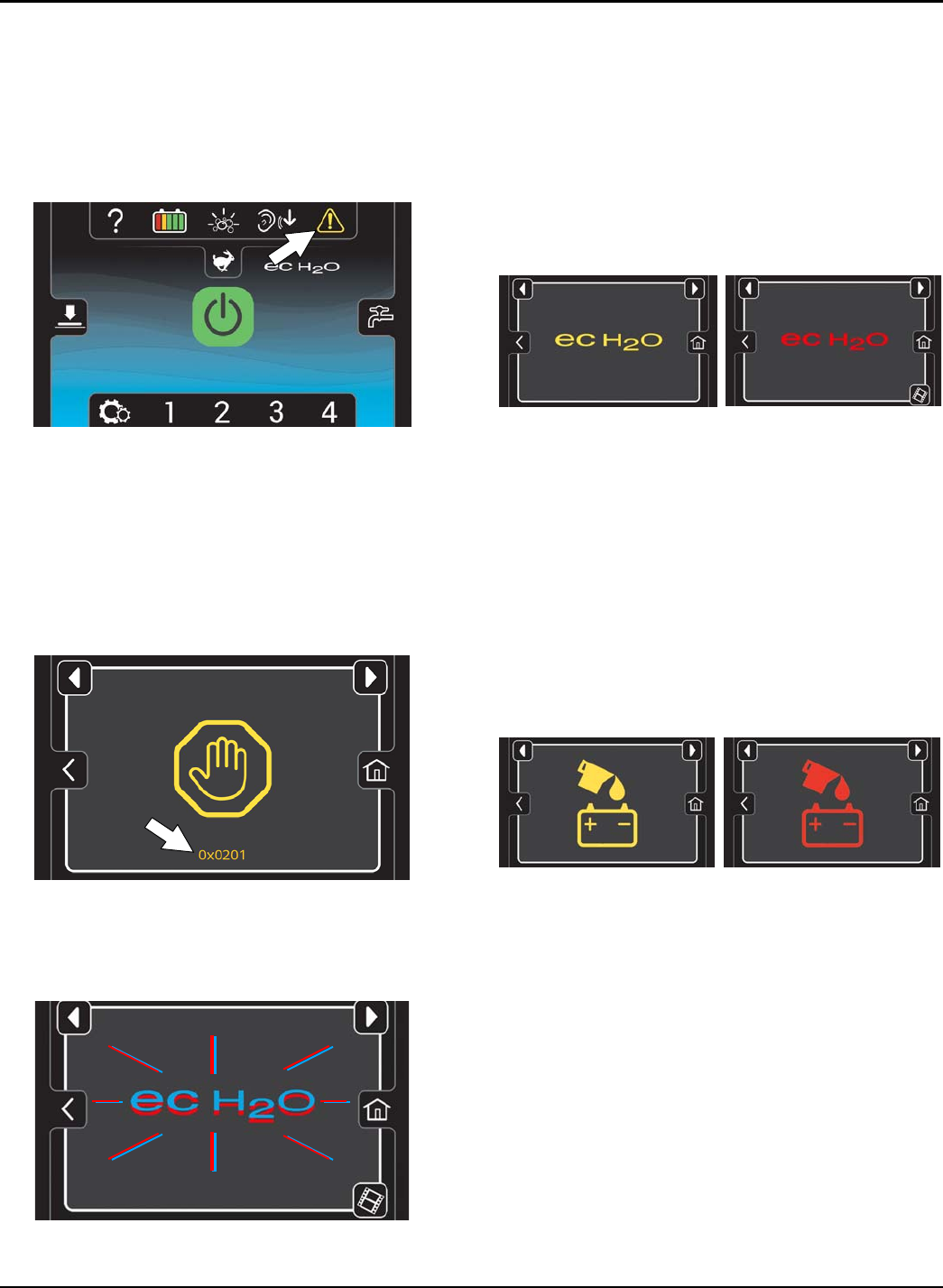
SERVICE INDICATOR BUTTON
The service indicator button will flash yellow or red
when a machine fault is detected (Figure 68). Press the
service indicator button to view fault screen.
Flashing yellow indicates a warning that requires
service, but machine is still operable. Flashing red
indicates a fault which will shut down the machine and
require service. See FAULT SCREENS below.
FIG. 68
FAULT SCREENS
When a fault is initially detected, the following fault
screens will automatically pop up to indicate the fault.
Press the left and right arrow button at top of screen to
scroll through the fault screens.
Yellow machine fault Screen (Figure 69) - Machine
fault has been detected. A fault code will appear below
the fault icon. See SERVICE INDICATOR CODES.
FIG. 69
Flashing Blue and Red ec-H2O Screen (Figure 70) -
The water conditioning cartridge has expired. See
ec-H2O WATER CONDITIONING CARTRIDGE
REPLACEMENT.
0x0707
FIG. 70
Yellow ec-H2O Fault Screen - Machine detected an
ec-H2O system water or plumbing fault (Figure 71).
Red ec-H2O Fault Screen - Machine detected an
ec-H2O system electrical fault (Figure 71).
A fault code will appear below the ecH2O icon. See
SERVICE INDICATOR CODES.
NOTE: If a fault occurs to the ec-H2O system, the
machine may automatically turn off the ec-H2O system
and convert over to conventional scrubbing. The
service indicator button will continue to flash until the
ec-H2O fault is serviced.
0x0708 0x0741
FIG. 71
Yellow Automatic Battery Watering Fault Screen -
The Automatic Battery Watering tank is empty and
needs refilling (Figure 72). To protect the batteries from
damage, the machine's scrub function will be disabled
after 10 hours of continued use if tank is not refilled.
Add distilled water to the battery watering tank and
restart key to clear fault. See FILLING AUTOMATIC
BATTERY WATERING TANK.
Red Automatic Battery Watering Fault Screen - The
Automatic Battery Watering tank is empty and needs
refilling. The scrub function is disabled until tank is
refilled (Figure 72). Add distilled water battery watering
tank and restart key to clear fault. See FILLING
AUTOMATIC BATTERY WATERING TANK.
FIG. 72
OPERATION
28 Tennant T500 (01-2017)
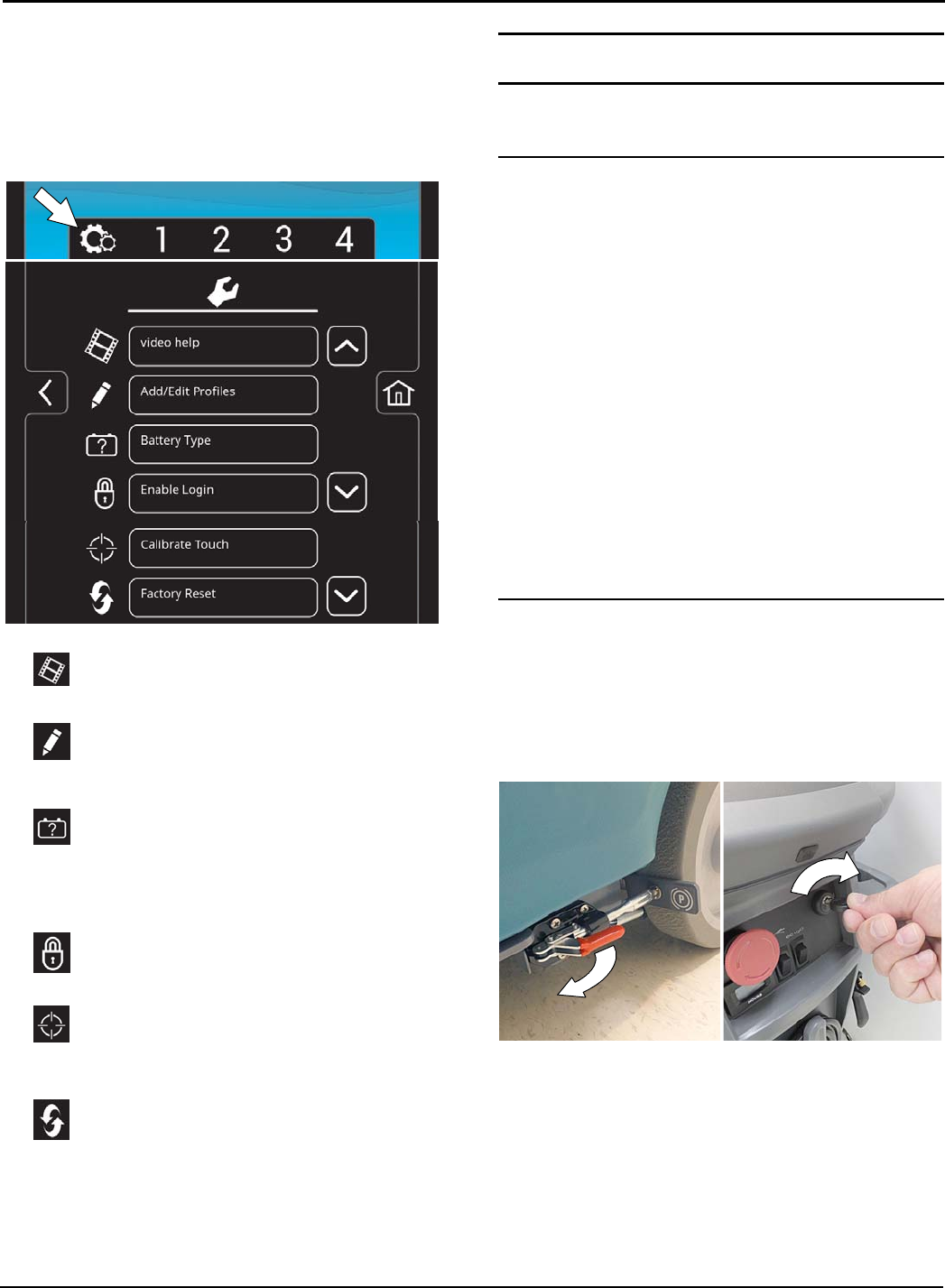
MACHINE SETTINGS BUTTON
Press the machine settings button to access the
following menu options (Figure 73).
The home screen must be in the supervisor mode to
access the machine settings button. See
SUPERVISOR CONTROLS instructions at back of
manual for further details.
FIG. 73
Video help - Use to view specific operation
and maintenance procedures. See Figure 63.
Add/Edit Profiles - Use to add/edit user
profiles for machine use. See SUPERVISOR
CONTROLS.
Battery Type - Use to configure the machine
for different battery types. This ensures the
on-board battery charger charging profile is
properly programmed to your battery type. See
BATTERIES.
Enable Login - Use to activate a required
login code at machine start up to operate machine.
Calibrate Touch - Use this to recalibrate the
touch screen if the touch points become
misaligned.
Factory Reset - Resets the supervisor login
code back to the factory default code, removes
user profiles and resets any custom preset zone
control buttons back to the factory preset zones.
See SUPERVISOR CONTROLS.
MACHINE OPERATION
FOR SAFETY: Do not operate machine unless
operator manual is read and understood.
PRE-OPERATION CHECK LIST
Sweep area and remove any obstructions.
Check brushes/pads for wear and damage.
Check squeegee blades for wear and damage.
Confirm recovery tank is empty, debris tray is clean
and the float shut-off screen is installed and clean.
Check scrub head skirt for wear and damage.
Cylindrical brush model - confirm debris trough is
empty and clean.
ec-H2O Scrubbing: Confirm solution tank is filled
with clear cool water only.
ec-H2O Scrubbing: Confirm all conventional
cleaning agents/restorers are drained and rinsed
from solution tank.
Check machine for proper operation.
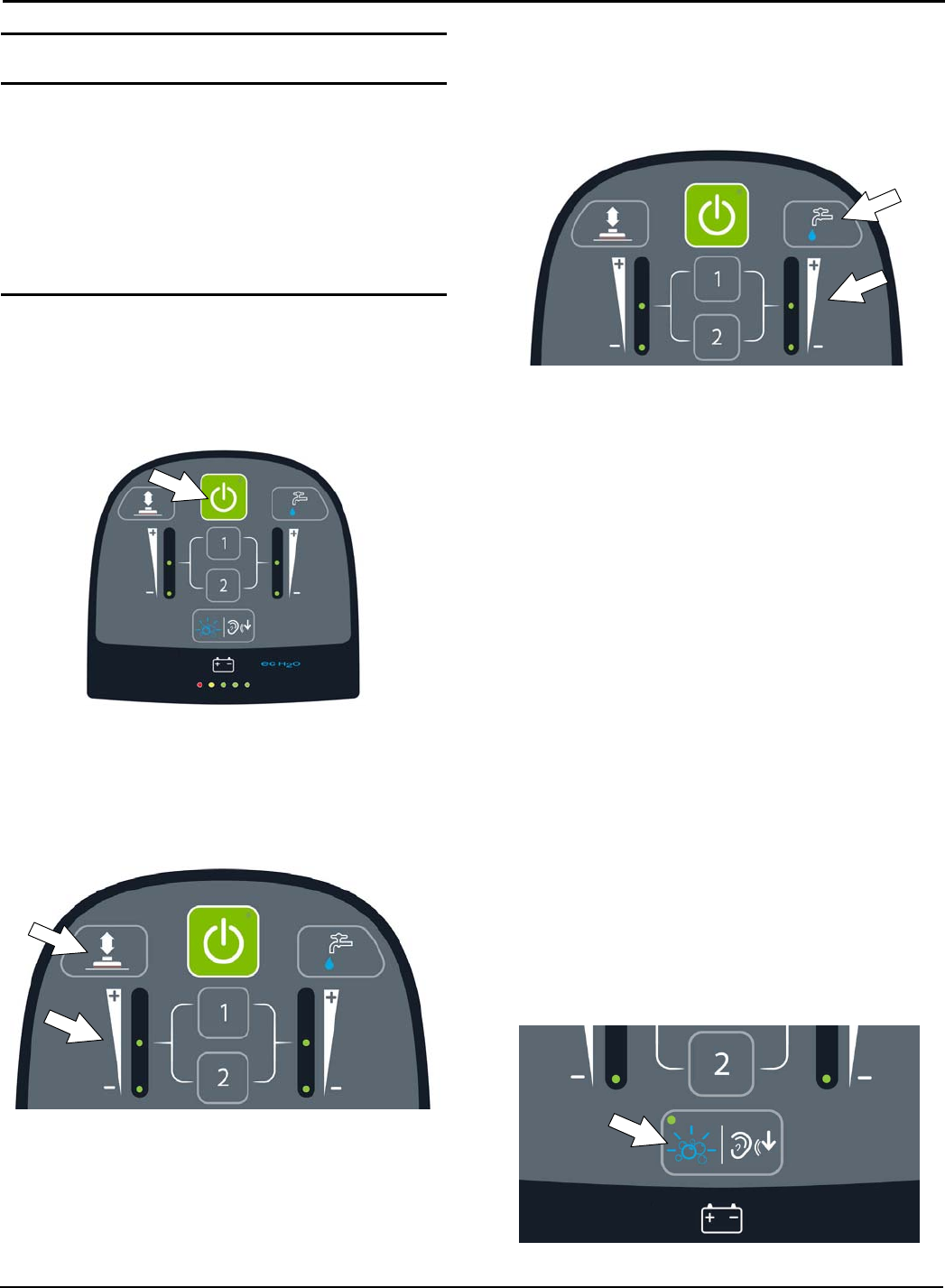
OPERATING MACHINE
For control panel operating instructions, see
CONTROL PANEL OPERATION.
1. Release the parking brake lever, if equipped
(Figure 74)
2. Turn the key to the on ( I ) position (Figure 74).
FIG. 74
3. ec-H2O models - The ec-H2O system will
automatically turn on at key start up. The ec-H2O
indicator will appear on the control panel indicating
that the system is activated (Figure 75).
OPERATION
Tennant T500 (01-2017) 29
ATTENTION: When conventional scrubbing with
cleaning detergents in solution tank, make sure to turn
off the ec-H2O system by pressing the ec-H2O switch
(Figure 75). If cleaning detergent is accidentally cycled
through ec-H2O system, a system fault will occur. To
clear fault, drain solution tank, add clear water and
operate the ec-H2O system to clear fault. If fault
repeats, continue to recycle key until fault clears. See
SERVICE INDICATOR CODES for further detail.
FIG. 75
4. Lower the squeegee assembly to floor by stepping
on foot pedal (Figure 76). To raise squeegee
assembly, place foot under foot pedal and lift. The
vacuum motor will automatically start when
squeegee is lowered to floor.
FIG. 76
5. Press the 1-STEP button to activate the scrub
function (Figure 77). The scrub head will lower to
floor.
FIG. 77
6. Push the directional lever forward to go forward
(Figure 78). Pull the lever back to maneuver
machine in reverse. Lift squeegee assembly when
backing machine.
FIG. 78
7. To begin scrubbing, pull the start bail (Figure 79).
FIG. 79
8. Adjust the scrubbing speed by turning the speed
dial to the desired speed (Figure 80).
FIG. 80
9. To stop scrubbing, release the start bail, press the
1-STEP button and raise the squeegee assembly
off floor. Turn key off and set parking brake, if
equipped.
NOTE: To pick up any remaining water left on floor
after scrub head is raised continue to drive machine
forward with squeegee down.
OPERATION
30 Tennant T500 (01-2017)
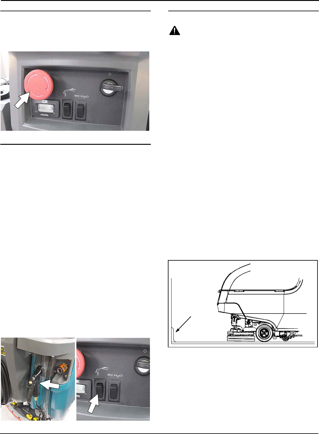
EMERGENCY SHUT-OFF BUTTON
Push the emergency shut-off button in the event of an
emergency (Figure 81). This red button shuts off all
power to machine. To regain power, turn the button
clockwise and restart the key.
FIG. 81
OPERATING SPRAY NOZZLE (Option)
Use spray nozzle for the following. The water supply is
provided from the machine's solution tank. If cleaning
detergent was added to solution tank, do not use spray
nozzle for rinsing proposes.
- Rinse out recovery tank
- Clean squeegee assembly
- Clean scrub head skirt
- Clean brushes and underside of scrub head
- Clean areas above floor (baseboards, etc.)
Do not use spray nozzle in areas where the machine is
unable to pick up the excess water, such as off-aisle
cleaning. Do not use spray nozzle to clean body of
machine.
FOR SAFETY: When operating machine, do not
use spray nozzle for off-aisle cleaning, slip hazard
may occur.
FOR SAFETY: When servicing machine, do not
power spray or hose off machine. Electrical
malfunction may occur. Use damp cloth.
Press the spray nozzle switch to activate spray pump
(Figure 82). Press switch again to turn off spray nozzle.
NOTE: When the spray nozzle switch is activated,
machine operation will be disabled.
FIG. 82
WHILE OPERATING MACHINE
WARNING: Flammable materials or reactive
metals can cause an explosion or fire. Do not pick
up.
1. Overlap each scrub path by 2 inches/5 cm.
2. Keep machine moving to prevent damage to floor
finish.
3. Wipe squeegee blades with a cloth if blades leave
streaks.
4. Avoid bumping the machine into posts and walls.
5. When draining and refilling machine, always top off
the optional Severe Environment tank with
detergent.
FOR SAFETY: When operating machine, the
machine may only be operated on gradients up to
2%.
6. Pour a recommended foam control solution into the
recovery tank if excessive foam appears.
ATTENTION: Foam buildup will not activate the
float shut-off screen, vacuum motor damage will
result.
7. Use the double scrubbing method for heavily soiled
areas. First scrub the area with the squeegee up,
let solution set for 3-5 minutes, then scrub the area
a second time with squeegee down.
8. Orbital Scrub Head Model - Use caution when
working near the tile cove (Figure 83) and floor
mounted fixtures such as pedestal sinks and other
breakable items. Keep the metal scrub head edge
away to avoid possible damage.
Tile Cove
FIG. 83
9. When leaving the machine unattended, park on
level surface, turn machine off, remove key and set
the parking brake, if equipped.
10. Do not operate machine in areas where the
ambient temperature is above 110ºF/43ºC or below
freezing 36ºF/2ºC.
OPERATION
Tennant T500 (01-2017) 31
CIRCUIT BREAKER PANEL
The machine is equipped with resettable circuit
breakers to protect the machine from a current
overload. If a circuit breaker trips, disconnect the
battery cable connection and reset the breaker by
pressing the reset button after the breaker has cooled
down. Reconnect the battery cable connection. If the
circuit breaker does not reset or continues to trip
contact service personnel.
The circuit breaker panel is located near the battery
compartment and identified as described below
(Figure 84).
FIG. 84
Circuit
Breaker Rating Circuit protected
CB1 4A Key switch, control board
CB2 10 A ec-H2O system, Automatic
battery watering system
CB3 15 A Spray nozzle pump
CB4 60 A Propel
FOR SAFETY: When servicing machine, all repairs
must be performed by trained personnel.
HOUR METER
The hour meter records the number of hours the
machine has been operated. Use the hour meter to
perform specific maintenance procedures and to record
service history (Figure 85).
FIG. 85
DRAINING TANKS
FOR SAFETY: Before leaving or servicing machine,
stop on level surface, turn off machine, remove key
and set parking brake if equipped.
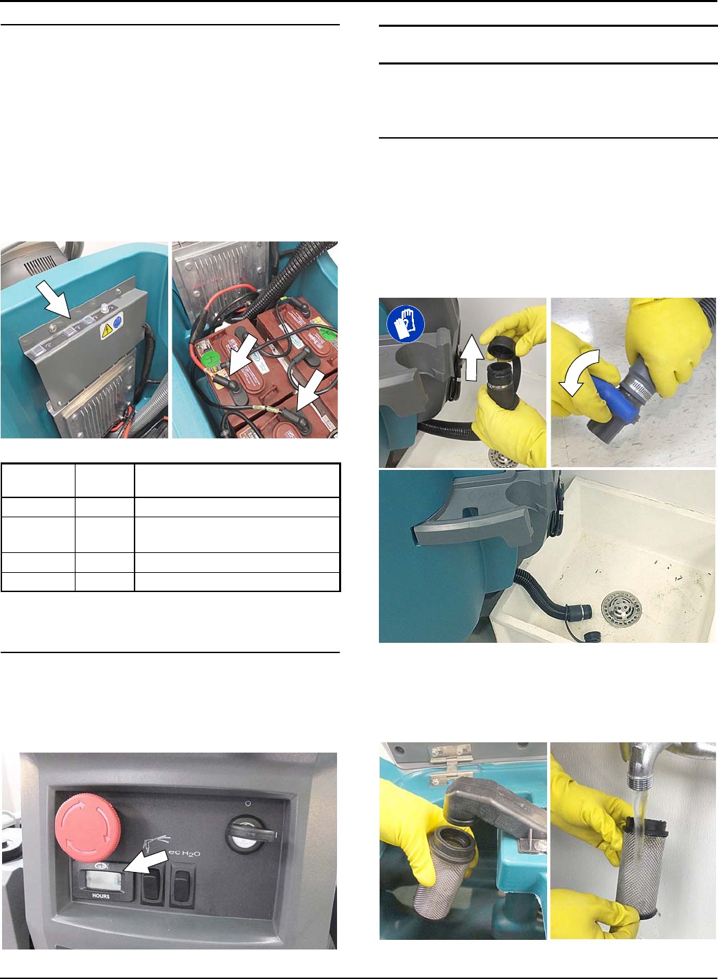
DRAINING RECOVERY TANK
Drain and clean the recovery tank after each use.
1. Transport the machine to drain area.
2. For models equipped with drain hose caps, hold
the hose upward, remove cap then slowly lower
hose to drain. For models equipped with flow
control valve drain hose, lower hose and slowly
open valve to drain (Figure 86).
FIG. 86
NOTE: When using a bucket to drain the machine, do
not use the same bucket to fill the solution tank.
3. Remove and clean the float shut-off screen (Figure
87).
FIG. 87
OPERATION
32 Tennant T500 (01-2017)
4. Remove the debris tray and empty (Figure 88).
FIG. 88
5. Rinse out the recovery tank with clean water and
wipe clean of any soil residue (Figure 89).
FIG. 89
If machine is equipped with spray nozzle option, use
spray nozzle to rinse out recovery tank (Figure 90).
The water supply is provided from the machine's
solution tank. If cleaning detergent was added to
solution tank, do not use spray nozzle for rinsing
proposes.
FOR SAFETY: When servicing machine, do not
power spray or hose off machine. Electrical
malfunction may occur. Use damp cloth.
FIG. 90
DRAINING SOLUTION TANK
Drain the solution tank daily.
1. Transport the machine to drain area.
FOR SAFETY: Before leaving or servicing machine,
stop on level surface, turn off machine, remove key
and set parking brake if equipped.
2. To drain remaining water from solution tank, pull
the solution tank level hose from the accessory rail
(Figure 91). Firmly reconnect the hose to the
accessory rail after draining tank.
FIG. 91
3. Rinse solution tank with clean water (Figure 92).
FIG. 92
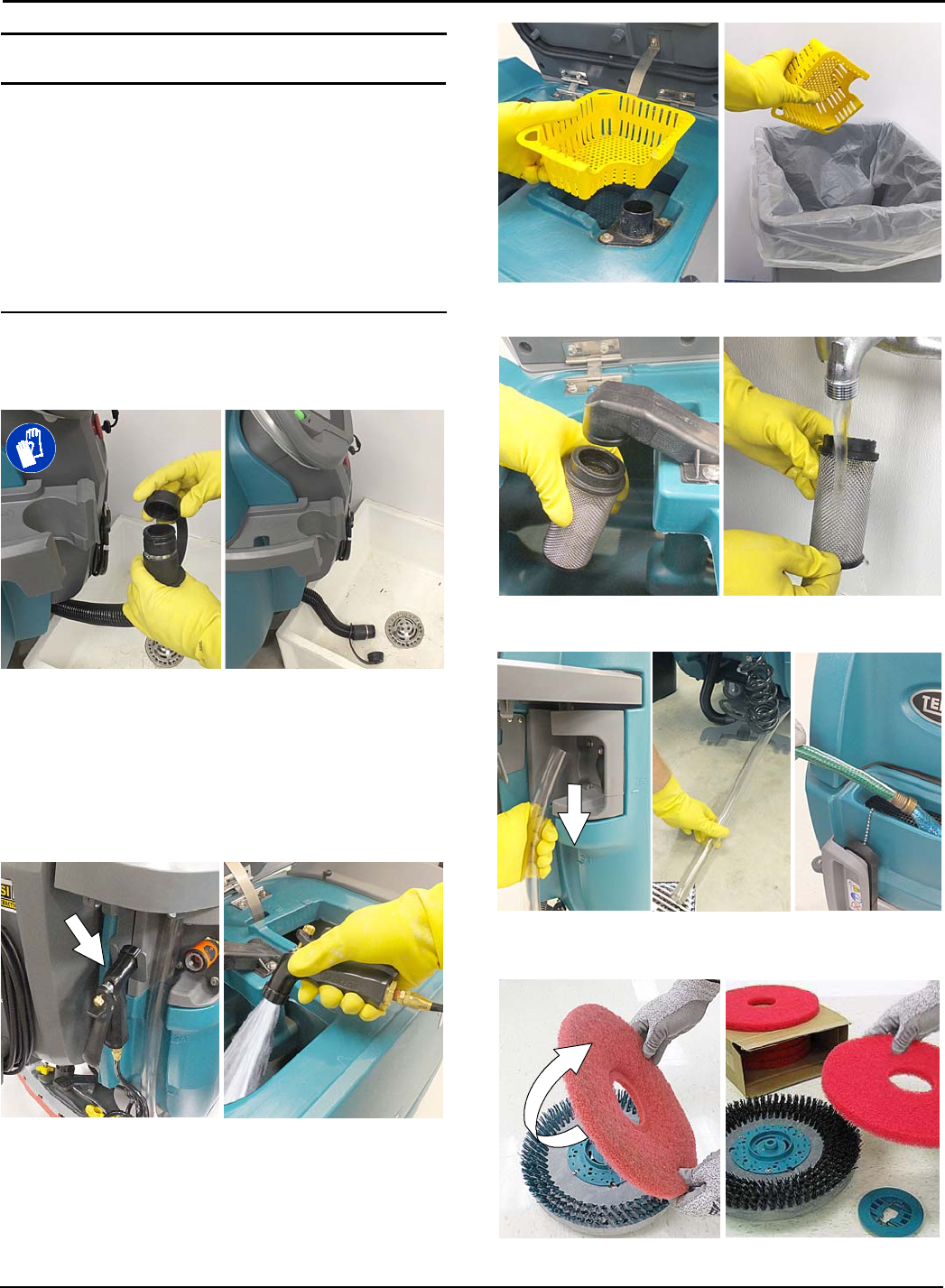
4. Remove the solution tank filter and clean screen
after every 50 hours of use (Figure 93). Solution
filter is located under machine at rear. Drain
solution tank before removing filter.
FIG. 93
OPERATION
Tennant T500 (01-2017) 33
SERVICE INDICATOR CODES
When the machine or battery charger detects a fault, the service indicator will flash. A fault code will be provided to
determine problem as described below.
Flashing service
indicator
Flashing LED
fault code
Pro-Membrane Control Panel Pro-Panel Controls (LCD)
Fault code
xxxxxx
Flashing service indicator
Press service indicator to
access fault code screen
Fault code screen
Yellow machine fault icon
LED Fault Code
☼= Flashing
LCD Fault
Code CAUSE SOLUTION
☼☼☼☼☼ 0xFFF0 Emergency shut-off button
activated
Release emergency shut-off button and restart
machine
SSS☼S0x0201
Head lift actuator, wiring,
connector or control board
problem
Contact service
SSS☼☼ 0x0101
0x0111
Brush motor wiring, connector
or control board problem
Contact service
☼☼☼☼ S0x0102
0x0112
Brush motor 1 voltage loss
Brush motor 2 voltage loss
Contact service
S☼☼ S☼0x0208 Actuator stalled Check for blockage. If fault repeats, contact
service.
S☼SS☼0x0301 Solution valve wiring, connector
or control board problem
Check connections. Contact service
S☼S☼☼ 0x0303 Solution valve over current. Contact service
SS☼SS 0x0501 Vacuum motor wiring, connec-
tor or control board problem
Contact service
SS☼S☼0x0601
Severe environment detergent
pump wiring, connector or
control board problem
Contact service
SS☼☼ S0x1005 Scrub motor under current Use a more aggressive pad. If fault repeats,
contact service.
SS☼☼☼ 0x0901 Propel motor wiring, connector
or control board problem
Contact service
☼SSS☼
0x0900
0x0903
0x0904
0x0905
0x0906
0x0907
0x09200x0942
0x0910
0x0950
Propel I-Drive fault
Propel I-Drive communication lost
Propel power cycle fault
Propel current limit fault
Propel motor shorted fault
Propel motor shorted fault
Propel faults
Propel circuit breaker tripped
Propel incorrect profile
Reset circuit breaker or restart machine. If
fault repeats, contact service.

OPERATION
34 Tennant T500 (01-2017)
SERVICE INDICATOR CODES - Continued
LED Fault Code
☼= Flashing
LCD Fault
Code CAUSE SOLUTION
☼SS☼S0x0B11 Battery watering pump wiring,
connector or control board problem.
Contact service
☼SS☼☼
0x0103
0x0104
0x0105
0x0109
0x0106
Brush motor 1 over current
Brush motor 1 over current
Brush motor 1 over current
Brush motor 1 over temp fault
Brush motor 1 short fault
Check pad for floor type. If fault repeats
contact service.
Contact service
☼☼ S☼☼
0x0113
0x0114
0x0115
0x0119
0x0116
Brush motor 2 over current
Brush motor 2 over current
Brush motor 2 over current
Brush motor 2 over temp fault
Brush motor 2 short fault
Check pad for floor type. If fault repeats
contact service.
Contact service
☼S☼S☼0x0902 Start bail is pulled or obstructed
before turning machine on.
Release start bail or remove bail obstruction
before turning machine on.
☼S☼☼ S
0x0107
0x0117
0x0207
0x0307
0x0507
0x0607
0x0617
0x0B17
0x0717
Brush motor 1 control board fault
Brush motor 2 control board fault
Actuator motor control board fault
Solution valve control board fault.
Vacuum motor control board fault
Detergent pump control board fault
Spray pump control board fault
Battery watering pump board fault
ec-H2O pump control board fault
Disconnect battery cable connection and
contact service to replace control board.
☼S☼☼☼
0x0503
0x0504
0x0505
0x0506
Vacuum motor over current
Vacuum motor shorted fault
Check for obstruction. Contact service.
☼☼ SSS
0x0613
0x0614
0x0615
0x0616
Spray nozzle pump fault Contact service
☼SSSS 0x0611 Spray pump wiring, connector
or control board problem.
Contact service
☼☼ SS☼
0x0603
0x0604
0x0605
0x0606
Severe environment detergent
pump over current
Severe environment detergent
pump shorted fault
Contact service
☼☼ S☼S0x0B01
0x0B02
0x0B13-16
Battery watering system fault Contact service
☼☼☼ S☼0x1006 Scrub head imbalance Check brush wear. Contact service.
S☼☼☼ S
0xF103
0xFF20
0x0704
0x0B04
Charger communication fault
Scrub control board communi-
cation fault
ec-H2O system communication
fault
Battery watering CAN fault
Restart. If fault repeats, contact service.

OPERATION
Tennant T500 (01-2017) 35
ON-BOARD BATTERY CHARGER SERVICE INDICATOR CODES
LED Fault Code
☼= Flashing
LCD Fault
Code CAUSE SOLUTION
☼☼☼ SS
0xF100
0xF104
Charger error condition.
Charger timer exceeded
maximum charging time.
Interrupts charging cycle.
Contact service
Replace batteries
S☼☼ SS 0xF101 Charger is not connected to bat-
tery pack
Check cable connections
S☼SSS 0xF102
Charger overheated Let charger cool. Move to well ventilated area.
Charge batteries in areas with temperatures
80F/27C or less. If fault persists, contact
service.
S☼☼☼ S0xF103 Charger communication fault Restart charger. If fault code persists, contact
service.
OPERATION
36 Tennant T500 (01-2017)
ec-H2O SYSTEM SERVICE INDICATOR CODES - OPTION
Flashing
service
indicator
Flashing
LED fault
code
Pro-membrane Control Panel Pro-Panel Controls (LCD)
Fault code
xxxxxx
Flashing service indicator
Press icon to access fault
code screen
Fault code screen
Red or yellow ec-H2O
fault icon
Solid or
blinking Red
ec-H2O
indicator
LED Fault Code
☼= Flashing
LCD Fault
Code CAUSE SOLUTION
S☼S☼S0x0711 ec-H2O pump wiring, connector
or control board problem.
Contact service
S☼☼☼☼ 0x0713
0x0714
0x0715
ec-H2O pump over current Contact service
☼S☼SS 0x0703
0x0712
ec-H2O system breaker tripped
ec-H2O pump breaker tripped
Reset circuit breaker. If trip repeats, contact
service.
ecH2O indicator
solid red
0x0716
0x0727
0x072A
0x0741
0x0746
ec-H2O pump shorted fault
ec-H2O control board fault
ec-H2O electrode fault
Water conditioning pump open
Water conditioning pump fault
Contact service
ecH2O indicator
blinking red*
0x0702
0x0708*
0x0721
0x0723
0x0726
0x0728
ec-H2O pressure switch trip
ec-H2O system over regulation
No ec-H2O cell current
ec-H2O cell over current
ec-H2O cell shorted fault
ec-H2O fault
Contact service
ecH2O indicator
blinking blue/red 0x0707 Water conditioning cartridge
expired
Replace water conditioning cartridge.
*Verify if cleaning detergent was added to solution tank. If ec-H2O system was operated with cleaning detergent,
drain solution tank, add clear water and operate the ec-H2O system until the fault code clears. If fault repeats,
continue to recycle key until fault clears.
MAINTENANCE
Tennant T500 (01-2017) 37
MAINTENANCE CHART
13
14
6
4
1
3
1
714
14
12
10
15
9
11
8
5
2
Interval Person
Resp. Key Description Procedure
Daily O 1 Pads Check, flip or replace
O 1 Brushes Check, clean
O 2 Cylindrical brushes Check, clean
O 3 Recovery tank Drain, rinse, clean float shut-off screen
and debris tray
O 4 Solution tank Drain, rinse
O 5 Severe environment tank (option) Check, refill
O 6 Automatic battery watering tank (option) Check, refill
O 7 Squeegee Clean, check for damage and wear
O 8 Batteries Charge if necessary
O 9 Debris trough Clean
O10 Scrub head skirt Check for damage and wear
Weekly O 8 Battery cells Check electrolyte level
O 7 Squeegee assembly drip trap reservoir Check, clean
50 Hours O 2 Cylindrical brushes. Rotate brushes. Check for wear
O 2 Cylindrical scrub head Clean underside of scrub head
O 3 Recovery tank lid seal Check for wear.
O11 Solution tank filter Remove and clean
100 Hours O 8 Battery watering system (option) Check hoses for damage and wear
200 Hours O 8 Batteries, terminals and cables Check and clean
750 Hours T12 Vacuum motor Replace carbon brushes
1250 Hours T13 Propel motor Replace carbon brushes
T14 Brush motor Replace carbon brushes
T15 Brush belt Replace belt
O = Operator T = Trained Personnel
MAINTENANCE
38 Tennant T500 (01-2017)
MACHINE MAINTENANCE
To keep the machine in good working condition, simply
perform the following maintenance procedures.
FOR SAFETY: Before leaving or servicing machine,
stop on level surface, turn off machine, remove key
and set parking brake if equipped.
FOR SAFETY: When servicing machine wear
personal protection equipment as needed. All
repairs must be performed by trained personnel
AFTER DAILY USE
1. Drain and rinse out the recovery tank (Figure 94).
See DRAINING TANKS.
FIG. 94
If machine is equipped the spray nozzle option, use
spray nozzle to rinse out recovery tank (Figure 95). If
cleaning detergent was added to solution tank, do not
use spray nozzle for rinsing proposes.
FOR SAFETY: When servicing machine, do not
power spray or hose off machine. Electrical
malfunction may occur. Use damp cloth.
FIG. 95
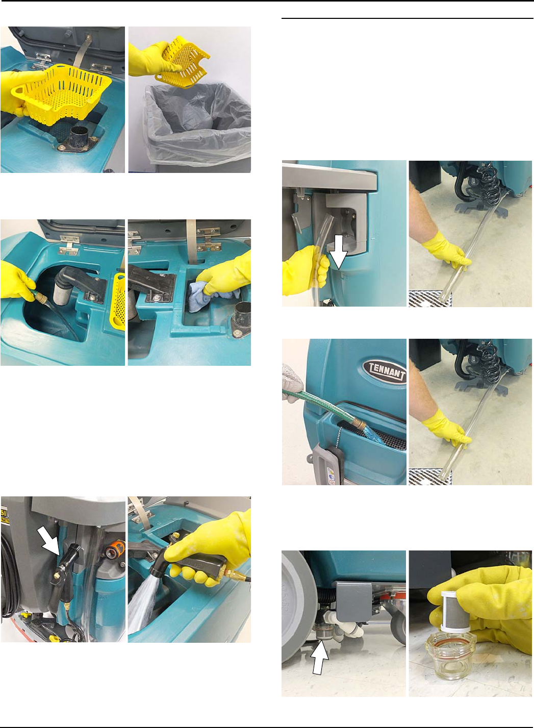
2. Remove the debris tray and empty (Figure 96).
FIG. 96
3. Remove and clean the float shut-off screen (Figure 97).
FIG. 97
4. Drain and rinse out the solution tank (Figure 98).
FIG. 98
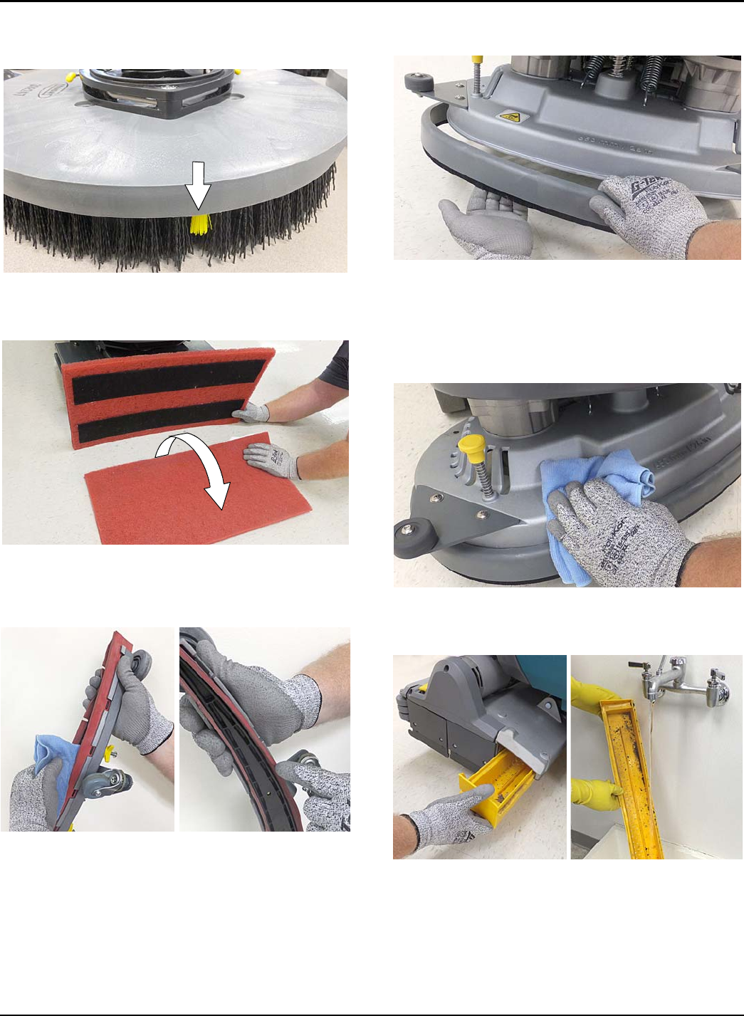
5. Disk scrub head - Turn pad over or replace when
worn (Figure 99).
FIG. 99
MAINTENANCE
Tennant T500 (01-2017) 39
6. Replace brushes when they no longer clean
effectively or when the bristles are worn to the
yellow indicator (Figure 100).
FIG. 100
Orbital scrub head - Turn the working pad over or
replace when worn (Figure 101).
FIG. 101
7. Wipe the squeegee blades clean. Inspect blades
for wear and damage (Figure 102). Rotate blade if
worn. See SQUEEGEE BLADE REPLACEMENT.
FIG. 102
8. Clean scrub head skirt. Check for wear or damage
(Figure 103). Replace if worn or damaged.
FIG. 103
9. Clean the outside surface of the machine with an
all purpose cleaner and damp cloth (Figure 104).
FOR SAFETY: When servicing machine, do not
power spray or hose off machine. Electrical
malfunction may occur. Use damp cloth.
FIG. 104
10. Cylindrical brush scrub head - Remove and clean
debris trough (Figure 105).
FIG. 105
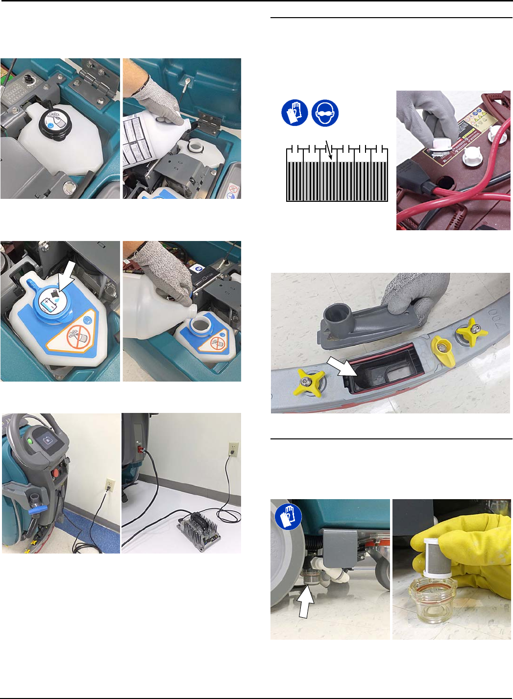
MAINTENANCE
40 Tennant T500 (01-2017)
11. Severe environment option - Refill the severe
environment tank with a recommended cleaning
detergent at full concentration (Figure 106).
Replace cap.
FIG. 106
12. Automatic battery watering option - Refill tank with
distilled water (Figure 107). Replace cap.
FIG. 107
13. Charge batteries (Figure 108). See BATTERIES.
FIG. 108
ATTENTION: Do not disconnect battery cables
while charger is plugged in, circuit board damage
may result.
AFTER WEEKLY USE
1. Check the electrolyte level in all batteries (Figure
109). See BATTERIES.
NOTE: If machine is equipped with the automatic or
manual battery watering system, See BATTERIES.
FIG. 109
2. Remove the drip trap cover from the squeegee
assembly and clean reservoir (Figure 110).
FIG. 110
AFTER EVERY 50 HOURS OF USE
1. Drain solution tank. Remove the solution tank filter
and clean screen (Figure 111). Turn the filter bowl
counter-clockwise to remove.
FIG. 111
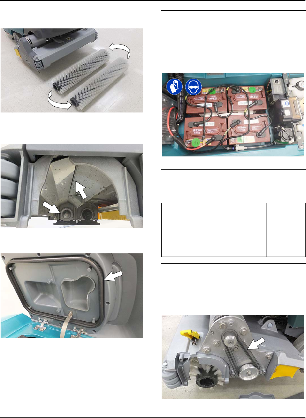
MAINTENANCE
Tennant T500 (01-2017) 41
2. Cylindrical brushes - Rotate brushes from front to
rear (Figure 112). Replace brushes when they no
longer clean effectively.
FIG. 112
3. Cylindrical scrub head - Remove debris buildup
from underside of scrub head, including the idler
plates and drive hubs (Figure 113).
FIG. 113
4. Inspect and clean the seal on the recovery tank lid
(Figure 114). Replace seal if damaged.
FIG. 114
AFTER EVERY 100 HOURS OF USE
If machine is equipped with the optional battery
watering system, check hoses for leaks, loose hose
connections and for damage or wear (Figure 115).
Replace system if damaged.
FOR SAFETY: When servicing batteries, wear
personal protection equipment as needed. Avoid
contact with battery acid.
FIG. 115
ELECTRIC MOTORS
Replace motor carbon brushes as indicated. Contact
trained personnel for carbon brush replacement.
Carbon Brush Replacement Hours
Vacuum motor 750
Propel motor 1250
Disk brush motors 1250
Cylindrical brush motors 1250
Orbital brush motor 1250
BELTS (Cylindrical Brush Model)
FOR SAFETY: Before leaving or servicing machine,
stop on level surface, turn off machine, remove key
and set parking brake if equipped.
Replace belts every 1250 hours. Contact trained
personnel for belt replacement (Figure 116).
FIG. 116
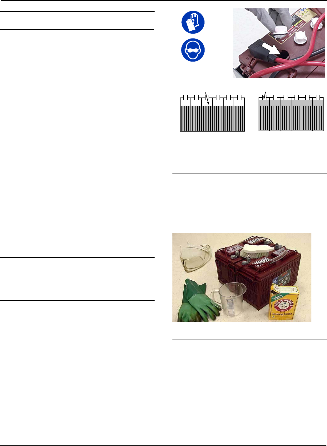
MAINTENANCE
42 Tennant T500 (01-2017)
BATTERIES
FOR SAFETY: Before servicing machine, stop on
level surface, turn off machine, remove key and set
parking brake if equipped.
The lifetime of the batteries depends on their proper
maintenance. To get the most life from the batteries;
SDo not charge the batteries more than once a day
and only after running the machine for a minimum of
15 minutes.
SDo not leave the batteries partially discharged for
long period of time.
SOnly charge the batteries in a well-ventilated area to
prevent gas build up. Charge batteries in areas with
ambient temperatures 80ºF/27ºC or less.
SAllow the charger to complete charging the batteries
before re-using the machine.
SMaintain the proper electrolyte levels of flooded (wet)
batteries by checking levels weekly.
Your machine is equipped with either flooded (wet)
lead-acid or maintenance-free (Sealed AGM) batteries
supplied by Tennant.
FOR SAFETY: When servicing machine, keep all
metal objects off batteries. Avoid contact with
battery acid.
MAINTENANCE-FREE BATTERIES
Maintenance-free (Sealed AGM) batteries do not
require watering. Cleaning and other routine
maintenance is still required.
FLOODED (WET) LEAD-ACID BATTERIES
The flooded (wet) lead-acid batteries require routine
watering as described below. Check the battery
electrolyte level weekly.
NOTE: If machine is equipped with the automatic or
manual battery watering system, proceed to the
BATTERY WATERING SYSYEM instructions.
The electrolyte level should be slightly above the
battery plates as shown before charging (Figure 117).
Add distilled water if low. DO NOT OVERFILL. The
electrolyte will expand and may overflow when
charging. After charging, distilled water can be added
up to about 3 mm (0.12 in) below the sight tubes.
Before Charging After Charging
FIG. 117
NOTE: Make sure the battery caps are in place while
charging. There may be a sulfur smell after charging
batteries. This is normal.
CHECKING CONNECTIONS / CLEANING
After every 200 hours of use, check for loose battery
connections and clean the surface of the batteries,
including terminals and cable clamps to prevent battery
corrosion. Use a scrub brush with a strong mixture of
baking soda and water (Figure 118). Do not remove
battery caps when cleaning batteries.
FIG. 118
CHARGING BATTERIES
The charging instructions in this manual are intended
for the battery charger supplied with your machine. The
use of other battery chargers that are not supplied and
approved by Tennant are prohibited.
If your machine is equipped with an off-board battery
charger refer to the charger's owners manual for
operating instructions. Contact distributor or Tennant
for battery charger recommendations if machine is not
equipped with charger.
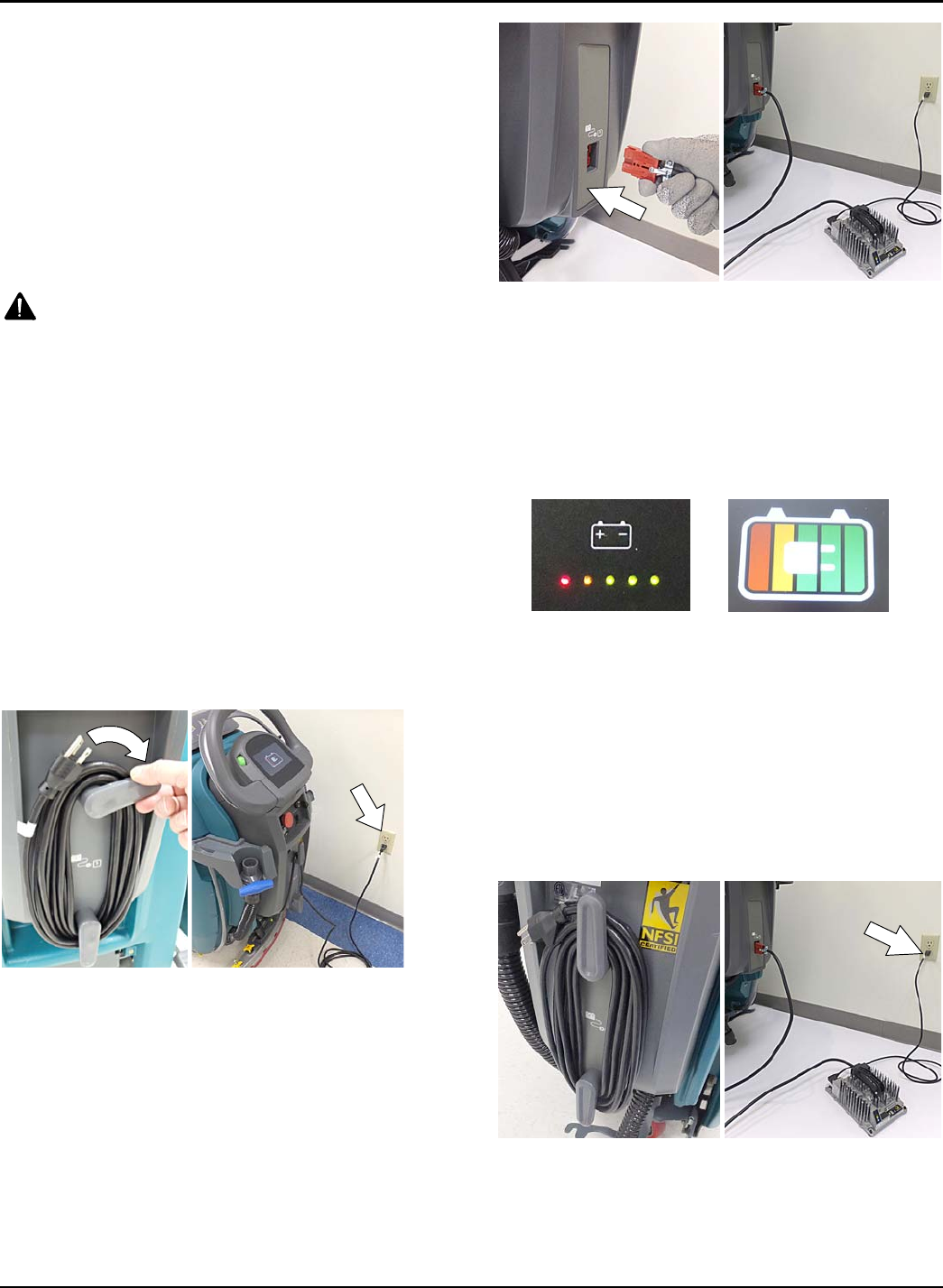
MAINTENANCE
Tennant T500 (01-2017) 43
FOR SAFETY: The use of incompatible battery
chargers may damage battery packs and
potentially cause a fire hazard.
IMPORTANT NOTICE: The battery charger is set to
charge the battery type supplied with your machine. If
you choose to change to a different battery type or
capacity (i.e. flooded (wet) lead-acid,
maintenance-free, sealed, AGM batteries, etc.), the
charger's charging profile must be changed to prevent
battery damage. See BATTERY CHARGER
SETTINGS.
1. Transport the machine to a well-ventilated area.
WARNING: Batteries emit hydrogen gas.
Explosion or fire can result. Keep sparks and open
flame away when charging.
2. Park the machine on a flat, dry surface, turn off
machine and remove key.
FOR SAFETY: When servicing batteries, stop on
level surface, turn off machine, remove key and set
parking brake if equipped.
3. If the machine is equipped with flooded (wet) lead-
acid batteries check the battery electrolyte level
weekly before charging. For models equipped with
the automatic battery watering system, check if the
automatic battery water tank needs refilling. Add
distilled water if low.
4. For models equipped with an on-board charger,
remove the charger's power cord from the storage
hooks and plug power cord into a properly
grounded wall outlet (Figure 119).
FIG. 119
For models equipped with off-board chargers, first
connect the charger's DC cord into the machine's
battery charge receptacle then plug the AC power
supply cord into a properly grounded wall outlet
(Figure 120). Refer to the off-board battery
charger's owner manual for operating instructions.
FOR SAFETY: Do not disconnect the off-board
charger's DC cord from the machine's receptacle
when the charger is operating. Arcing may result. If
the charger must be interrupted during charging,
disconnect the AC power supply cord first.
FIG. 120
5. The charger will automatically begin charging and
and shut off when fully charged. The maximum
charging cycle may take up to 6-12 hours
depending on battery type.
On-board battery charger: The battery discharge
indicator lights will ripple back and forth during the
charging cycle. When all five lights repeatedly flash
two times, the charging cycle is complete (Figure
121).
Pro-
p
anel
Pro
-
membrane
FIG. 121
ATTENTION: Do not disconnect battery cables
while charger is plugged in, circuit board damage
may result.
6. After charging batteries unplug the power supply
cord and wrap cord around the cord hooks
(Figure 122).
For models equipped with an off-board charger,
always disconnect the AC power supply cord first
before disconnecting charger from machine
(Figure 122).
FIG. 122
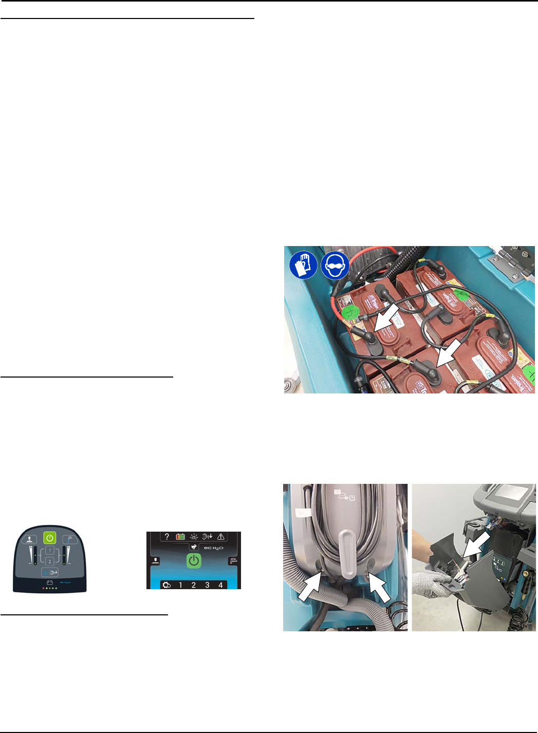
MAINTENANCE
44 Tennant T500 (02-2017)
BATTERY CHARGER SETTINGS
The battery charger is set to charge the battery type
supplied with your machine. If you choose to change to
a different battery type or capacity, the charger's
charging profile must be changed to prevent battery
damage.
The machine's battery discharge indicator (BDI) must
also be reprogrammed to match battery type to prevent
battery damage and/or short run-time.
NOTE: For machines shipped without batteries, the
battery discharge indicator and the on-board battery
charger are set for GEL batteries as the default. If you
choose to use a different battery type, the settings
must be changed as described as below.
NOTE: For machines shipped without batteries and
supplied with an Off-Board Charger, the off-board
battery charger is set for wet lead-acid batteries from
the factory. The machine's battery discharge indicator
is set for GEL batteries as the default. The battery
discharge indicator must be reprogrammed to match
charger settings (See OFF-BOARD BATTERY
CHARGER below).
IRIS MODELS: For models equipped with capability to
report battery charging data via IRIS, Tennant
recommends using the same battery type. If a different
amp hour or battery type is desired, contact Tennant
Service Department.
OFF-BOARD BATTERY CHARGER:
1. To change the off-board battery charger settings,
refer to the off-board charger's owner manual.
2. To reprogram the machine's battery discharge
indicator (BDI), see below:
Pro-Membrane Model - Service application software
required, contact service.
Pro-Panel Model -See CHANGING ON-BOARD
BATTERY CHARGER SETTINGS for Pro-Panel
model.
Pro-Membrane Model Pro-Panel Model (LCD)
ON-BOARD BATTERY CHARGER:
Pro-Membrane Model - To change the on-board
battery charger settings, service application software
required, contact service. As an alternative, the charger
profile may be manually changed. See CHANGING
ON-BOARD BATTERY CHARGER SETTINGS for
Pro-Membrane model. The battery discharge indicator
will automatically reprogram to match battery type
when the battery charger profile is changed.
Pro-Panel Model - To change the on-board battery
charger settings, see CHANGING ON-BOARD
BATTERY CHARGER SETTINGS for Pro-Panel
model. The battery discharge indicator will
automatically reprogram to match battery selection.
CHANGING ON-BOARD BATTERY CHARGER
SETTINGS (Pro-Membrane model)
To manually change the on-board battery charger
settings for a different battery type, carefully follow
instructions as described below :
NOTE: The manual method is only an alternative if
unable to change setting by use of the Service
Application Software performed by Service.
1. Disconnect the battery cable connection at
machine (Figure 123).
FOR SAFETY: When servicing machine, stop on
level surface, turn off machine, remove key and set
parking brake if equipped.
FIG. 123
2. Unwrap the battery charger power cord from the
cord hooks.
3. Using a T25 star screwdriver, remove the two
screws located at the bottom of the control console
to access battery charger (Figure 124).
FIG. 124
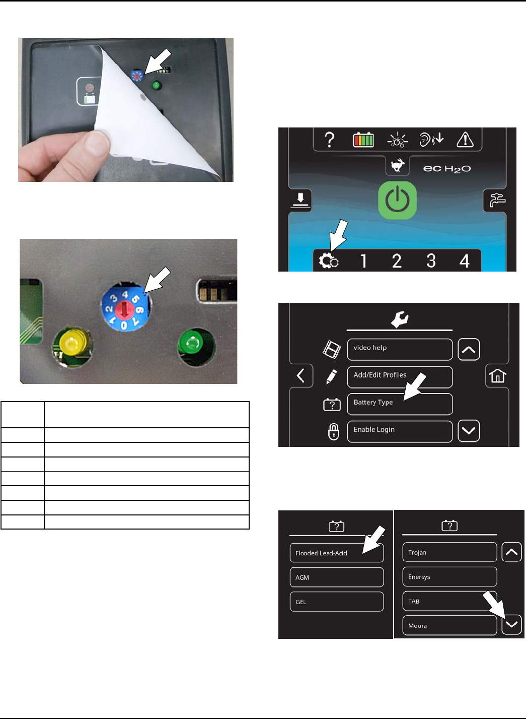
MAINTENANCE
Tennant T500 (01-2017) 45
4. Carefully peel back the charger display label to
access the dial settings (Figure 125).
FIG. 125
5. Using a small standard screwdriver, turn the dial to
the appropriate battery type according to the
following chart (Figure 126).
FIG. 126
Dial
Position Battery Description Settings
with AH Ranges
0CAN-BUS setting*
1Wet, Trojan 180-260 AH
2Wet, Trojan 270-360 AH
3Wet, Enersys/Tab 200-350 AH
4AGM, Tianneng 180-260 AH
5AGM, Discover 200-350 AH
6Gel, Sonnenschein 80-150 AH
* The CAN-BUS setting, dial position “0”, is the
software setting that is programmed to match battery
type supplied with machine. When the dial is manually
changed to a different setting, it should not be reset
back to “0” otherwise battery damage may result.
Service Application Software is required to reset dial
back to “0”. Contact Service.
6. Re-apply the display label.
7. Replace the control console.
8. To set the BDI for the new battery type, plug the
on-board battery charger cord into an electrical
outlet. The machine's software will automatically
reprogram the BDI to the new battery type.
CHANGING ON-BOARD BATTERY CHARGER
SETTINGS (Pro-Panel model)
NOTE: To perform this procedure, machine must be in
supervisor mode. See SUPERVISOR CONTROLS
instructions at back of manual.
1. Turn the key to the on position.
2. Press the settings button located on the home
screen (Figure 127).
FIG. 127
3. Press the Battery Type button (Figure 128).
FIG. 128
4. Select battery type and brand installed in machine
(Figure 129). See battery label to determine type
and brand. Press the up and down arrows to scroll
through battery selection.
FIG. 129
NOTE: The battery charger profile and battery
discharge indicator will automatically reprogram when
battery type is selected.
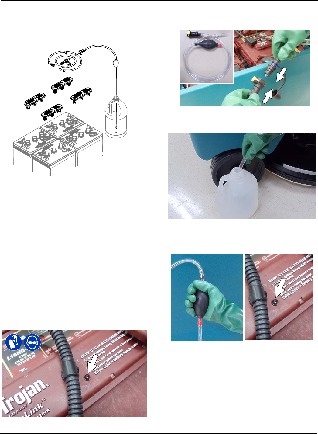
MAINTENANCE
46 Tennant T500 (01-2017)
HYDROLINK®BATTERY WATERING SYSTEM
(Trojan®Battery OPTION)
The following instructions are for models equipped with
the HydroLink battery watering system option.
The optional HydroLink battery watering system
provides a safe and easy way to maintain the proper
electrolyte levels in your batteries. It is designed
exclusively for Trojan flooded (wet) lead-acid batteries.
FOR SAFETY: When servicing machine, wear
personal protection equipment as needed. Avoid
contact with battery acid.
Before using the battery watering system check hoses
and connections for damage or wear.
1. Fully charge batteries prior to using the battery
watering system. Do not add water to batteries
before charging, the electrolyte level will expand
and may overflow when charging.
2. After charging batteries, check the battery
electrolyte level indicators located on the battery
covers (Figure 130). If the level indicator is white
add water as described in the following
instructions. If the level indicators are black the
electrolyte is at the correct level, no water is
required.
FIG. 130
3. Locate the battery fill hose coupler inside the
battery compartment. Remove the dust cap and
connect the hand pump hose (Figure 131).
FIG. 131
4. Submerge the other end of the hand pump hose
into a bottle of distilled water (Figure 132).
Distilled
Water
FIG. 132
5. Squeeze the bulb on the hand pump hose until firm
(Figure 133). The level indicators will turn black
when full.
FIG. 133
6. After adding water, replace the dust cap on the
battery fill hose and store the hand pump hose
inside the machine's battery compartment for future
use.
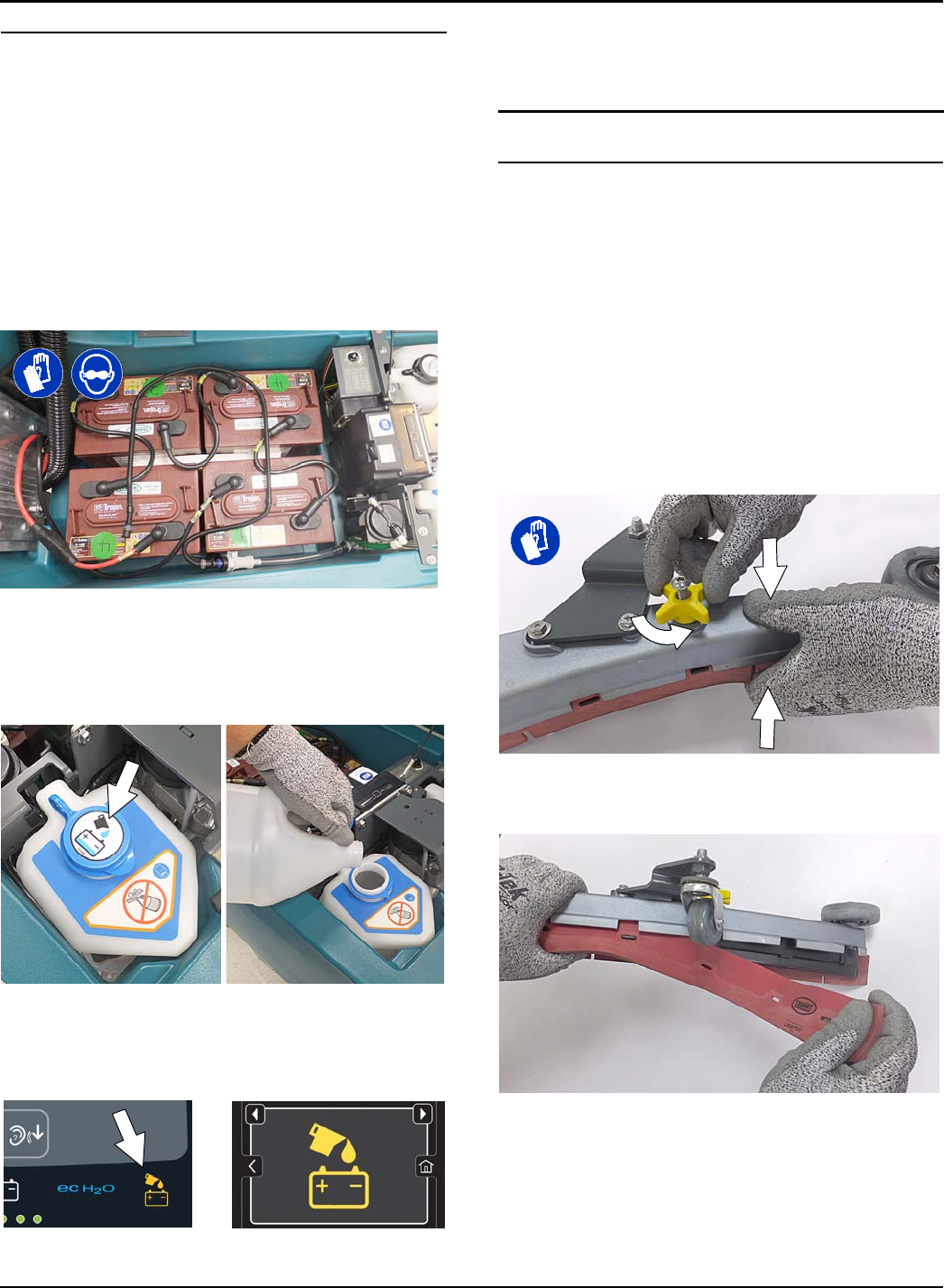
MAINTENANCE
Tennant T500 (01-2017) 47
AUTOMATIC BATTERY WATERING SYSTEM
(Trojan®Battery OPTION)
FOR SAFETY: Before leaving or servicing machine,
stop on level surface, turn off machine, remove key
and set parking brake if equipped.
The automatic battery watering system is designed to
automatically refill the batteries after the machine
reaches a limited number of charge cycles. Do not
remove battery caps and manually add water to the
batteries.
Check the automatic battery watering system for leaks,
loose hose connections and for damage or wear.
(Figure 134). Replace if damaged.
FIG. 134
Check the water level in the automatic watering tank
periodically. Add distilled water when low (Figure 135).
FOR SAFETY: When servicing machine, only use
distilled water when filling the automatic battery
watering tank.
FIG. 135
The automatic battery watering indicator will also alert
user to add distilled water when tank is empty (Figure
136). See CONTROL PANEL OPERATION for further
details.
FIG. 136
To store machine equipped with the automatic battery
watering system in freezing temperatures, see
STORING MACHINE/FREEZE PROTECTION.
SQUEEGEE BLADE REPLACEMENT
FOR SAFETY: Before leaving or servicing machine,
stop on level surface, turn off machine, remove key
and set parking brake if equipped.
Each squeegee blade has four wiping edges. When the
blades become worn, simply rotate the blades
end-for-end or top-to-bottom for a new wiping edge.
Replace blade if all four edges are worn.
1. Remove the squeegee assembly from the
machine.
2. Fully loosen the two outside knobs on squeegee
assembly. This will separate the spring loaded
blade retainer from squeegee frame (Figure 137).
To loosen the knobs quickly, squeeze the blade
retainer and squeegee frame together.
FIG. 137
3. Remove worn blade(s) from the blade retainer
(Figure 138).
FIG. 138
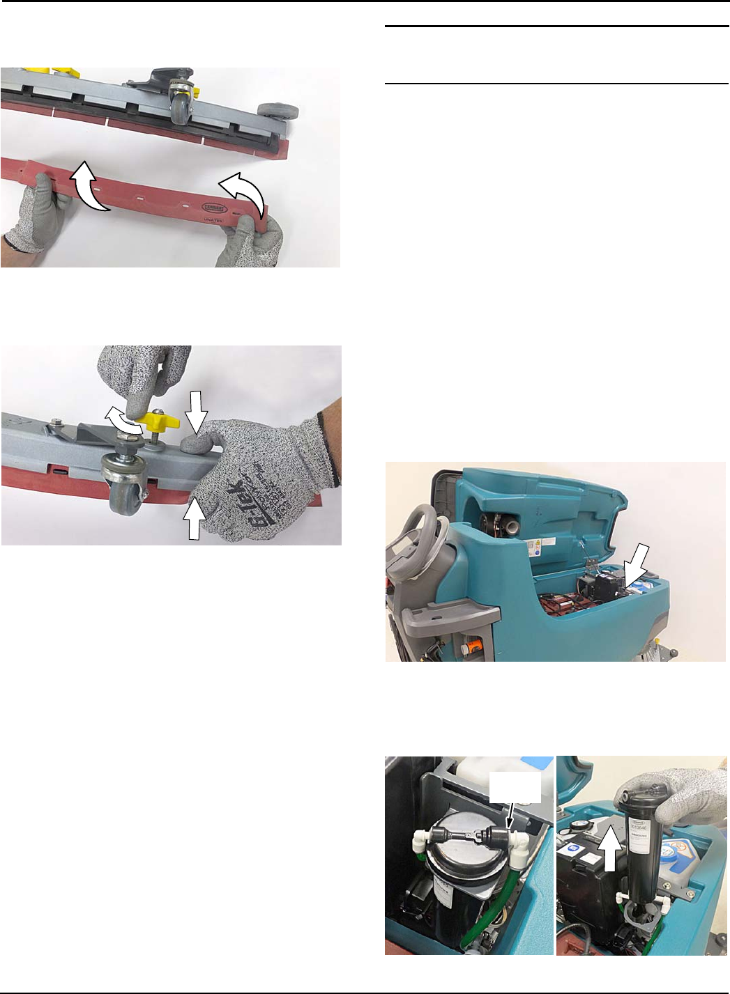
MAINTENANCE
48 Tennant T500 (01-2017)
4. Rotate the rear blade to a new wiping edge and
reinstall blade (Figure 139). Make sure to align the
slots in the blade with retainer tabs.
FIG. 139
5. Squeeze the squeegee frame and blade retainer
together and re-tighten the two outside knobs
(Figure 140).
FIG. 140
ec-H2O WATER CONDITIONING
CARTRIDGE REPLACEMENT
FOR SAFETY: Before leaving or servicing machine,
stop on level surface, turn off machine, remove key
and set parking brake if equipped.
The water conditioning cartridge is required to be
replaced when it reaches its maximum water usage or
expiration time of when the cartridge was activated,
which ever comes first. The control panel will signal a
code when it's time to replace cartridge. See
CONTROL PANEL OPERATION for further details.
Depending on machine usage, on average, a new
cartridge can last anywhere from 12 months for heavy
machine usage to 24 months for light machine usage.
ATTENTION: During first time use and after replacing
the water conditioning cartridge, the ec-H2O system
will automatically override the selected solution flow
rateforupto75minutes.
1. Park the machine on a level surface, remove the
key and set parking brake, if equipped.
2. Lift the recovery tank to access the ec-H2O water
conditioning cartridge (Figure 141). Drain recovery
tank before lifting tank.
FIG. 141
3. Disconnect the two hose connectors from the top
of the cartridge by pressing the gray collars inward
and pulling the connectors outward (Figure 142).
Lift cartridge to remove.
Gray
Collar
FIG. 142
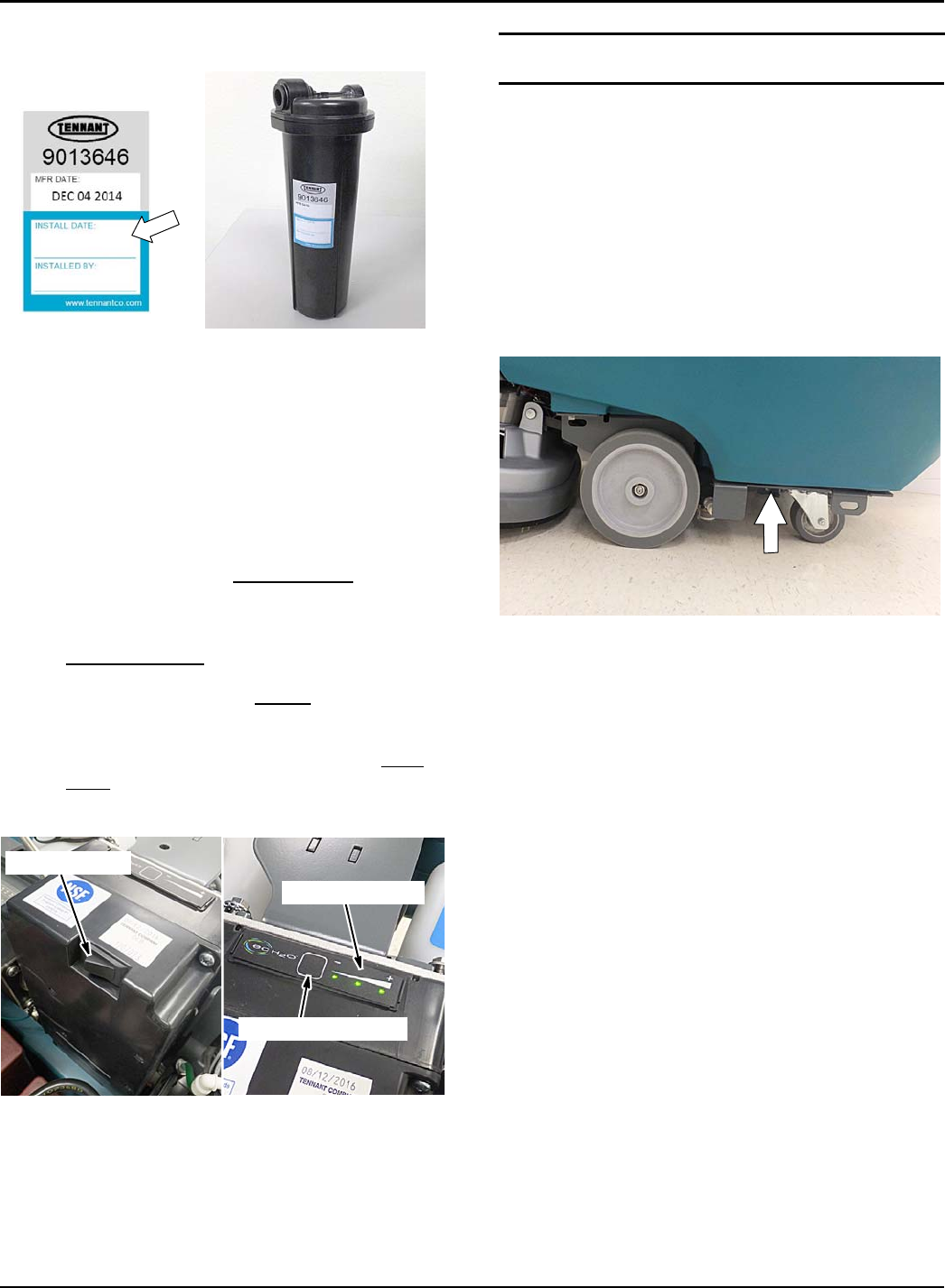
MAINTENANCE
Tennant T500 (01-2017) 49
4. Fill in the installation date on the new cartridge
label (Figure 143).
FIG. 143
5. Install the new cartridge and reconnect the two
hoses. Make sure the hose connectors are fully
inserted into the cartridge.
6. Reset timer for new cartridge.
Carefully read and understand all steps first before
performing procedure.
a. Turn key on.
b. Press and hold the service switch, located on
the ec-H2O module, for 10 seconds. After
releasing service switch, the three solution flow
indicator lights will begin to (ripple) move back
and forth (Figure 144).
c. Within 5 seconds after releasing the service
switch, while the three indicator lights are
moving back and forth, quickly press and
release the solution flow button located on
ec-H2O module (Figure 144).
The three indicator lights will then blink three
times to indicate timer has been reset.
Repeat process if the three indicator lights do
not blink three times.
Service switch
3 indicator lights
Solution flow button
FIG. 144
MACHINE JACKING
FOR SAFETY: Before leaving or servicing machine,
stop on level surface, turn off machine, remove key
and set parking brake if equipped.
Use the designated locations to jack up the machine for
service (Figure 145). Empty the recovery and solution
tanks and position the machine on a level surface
before jacking.
FOR SAFETY: When servicing machine, jack
machine up at designated locations only. Support
machine with jack stands. Use jack or hoist that
will support the weight of the machine.
FIG. 145
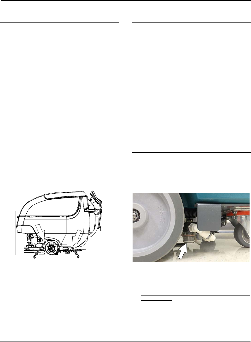
MAINTENANCE
50 Tennant T500 (01-2017)
TRANSPORTING MACHINE
When transporting the machine by use of trailer or
truck, carefully follow loading and tie-down procedure:
1. Drain tanks, raise the scrub head and the remove
squeegee assembly.
2. Carefully load machine in trailer or on truck.
FOR SAFETY: When loading/unloading, use a
ramp that can support the machine weight and
operator.
FOR SAFETY: When loading/unloading, the
machine may only be operated on gradients up to
2%.
3. Once loaded, position the front of the machine up
against the front of the trailer or truck. Lower the
scrub head, turn key off and set parking brake, if
equipped.
4. Place a block behind each wheel (Figure 146).
5. Using tie-down straps, secure the machine using
the four tie-down brackets located on the machine
frame (Figure 146). It may be necessary to install
tie-down brackets to the floor of your trailer or
truck.
NOTE: When transporting machine in an open truck or
trailer, secure recovery tank lid.
ATTENTION: Do not use control console area
or accessory storage rails for tie-down
locations, damage may occur.
FIG. 146
STORING MACHINE
The following steps should be taken when storing the
machine for extended periods of time.
1. Charge the batteries before storing machine to
prolong the life of the batteries. Recharge batteries
once a month.
2. Disconnect batteries before storing.
3. Drain and rinse recovery tank and solution tank.
4. Store the machine in a dry area with squeegee and
scrub head in the up position.
ATTENTION: Do not expose machine to rain, store
indoors.
5. Open the recovery tank lid to promote air
circulation.
6. If storing machine machine in freezing
temperatures, proceed to FREEZE PROTECTION.
NOTE: To prevent potential machine damage store
machine in a rodent and insect free environment.
FREEZE PROTECTION
Storing machine in freezing temperatures.
1. Completely drain solution tank and recovery tank.
2. Empty the water from the solution tank filter located
under machine. Replace filter (Figure 147).
FIG. 147
3. Pour 1 gallon / 4 liters of propylene glycol based
recreational vehicle (RV) antifreeze into the
solution tank.
Models equipped with optional Severe Environment
detergent tank - Lift tank from machine and empty
the detergent from tank (Figure 148). Return tank.
Pour a 1/4 gallon / 1 liter of propylene glycol based
recreational vehicle (RV) antifreeze into the
detergent tank.
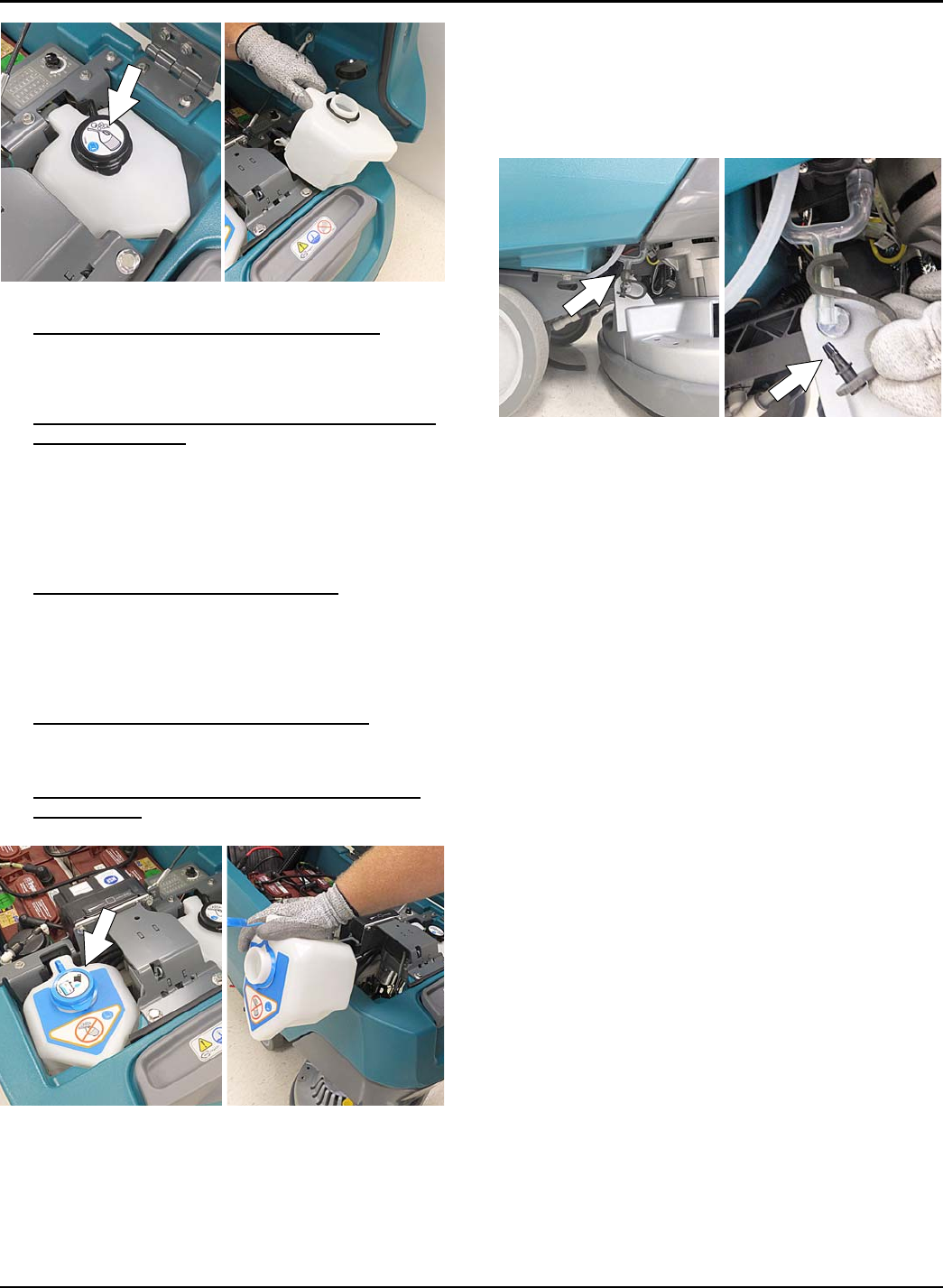
MAINTENANCE
Tennant T500 (01-2017) 51
FIG. 148
4. Models not equipped with ec-H2O system - Turn
machine on and operate the solution flow system.
Turn the machine off when the antifreeze is visible
on the floor.
Models equipped with ec-H2O system and Severe
Environment mode - Set the detergent ratio dial to
the highest flow rate. Turn machine on and set
solution flow rate to high. Operate ec-H2O
scrubbing and press the severe environment button
to cycle the antifreeze through both systems. Turn
machine off when antifreeze is visible on the floor.
This may take up to two minutes.
Models equipped with ec-H2O system -Turn
machine and set the solution flow rate on and
operate ec-H2O scrubbing to cycle antifreeze
through system. Turn machine off when antifreeze
is visible on the floor. This may take up to two
minutes.
Models equipped with spray nozzle option -
Operate the spray nozzle to cycle antifreeze
through pump.
5. Models equipped with optional automatic battery
watering tank - Lift tank from machine and empty
the water from tank (Figure 149).
FIG. 149
Drain remaining water from system by removing
the drain hose cap located below the tank (Figure
150). Leave cap off tank when draining system.
After draining, replace cap on drain hose.
IMPORTANT: DO NOT add antifreeze to the
automatic battery watering tank.
FIG. 150
6. After storing machine in freezing temperatures,
drain any remaining antifreeze from the solution
tank and from the optional Severe Environment
detergent tank. Add clean water to solution tank
and to optional detergent tank and operate the
machine to flush system.
7. Refill the automatic battery watering tank with
distilled water, if equipped.

MAINTENANCE
52 Tennant T500 (01-2017)
TROUBLESHOOTING
PROBLEM CAUSE SOLUTION
Service indicator icon is
flashing
Machine or on-board battery charger
fault has been detected
See SERVICE INDICATOR CODES
ec-H2O icon is red or
flashing red
ec-H2O system fault has been
detected
See SERVICE INDICATOR CODES
Machine will not operate Emergency shut-off button activated Turn button to reset
Machine fault detected See SERVICE INDICATOR CODES
Batteries discharged Recharge batteries
Loose battery cable(s) Tighten loose cables
Faulty battery(s) Replace battery(s)
Faulty key switch Contact service
Faulty start bail switch Contact service
Circuit breaker tripped Reset circuit breaker
Faulty control board Contact service
On-board battery charger
will not operate
Plug not connected to power supply Check plug connection
Batteries over discharged Replace batteries
Battery charger fault detected See SERVICE INDICATOR CODES
Faulty charger Replace charger
Faulty power supply cord Replace power supply cord
Machine will not propel Propel fault has been detected See SERVICE INDICATOR CODES
Circuit breaker tripped Reset circuit breaker
Faulty propel motor or wiring Contact service
Worn carbon brushes in motor Contact service
Brush motor will not
operate
Brush motor fault has been detected. See SERVICE INDICATOR CODES
Faulty pad motor or wiring Contact service
Worn carbon brushes in motor Contact service
Broken or loose belt (cylindrical brush
model)
Contact service
Vacuum motor will not
operate
Squeegee assembly is raised off floor Lower squeegee assembly to floor
Vacuum motor fault has been
detected
See SERVICE INDICATOR CODES
Faulty vacuum motor or wiring Contact service
Poor scrubbing
performance
Debris caught in brush/pad Remove debris
Worn brush/pad Replace brush/pad
Incorrect brush pressure Adjust brush pressure
Wrong brush/pad type Use correct brush/pad for application
Low battery charge Recharge batteries
Uneven brush pressure Scrub head/brushes not level. Contact service
Broken or loose belt (cylindrical brush
model)
Contact service

MAINTENANCE
Tennant T500 (01-2017) 53
TROUBLESHOOTING - Continued
PROBLEM CAUSE SOLUTION
Trailing water - poor or
no water pickup
Full recovery tank or excessive foam
buildup
Drain recovery tank
Loose drain hose cap or flow control
valve is open
Replace cap or close flow control valve on
drain hose
Worn squeegee blades Rotate or replace squeegee blades
Clogged drip trap (Squeegee
assembly)
Remove cover and clean
Clogged squeegee assembly Clean squeegee assembly
Loose vacuum hose connection Secure vacuum hose connection
Clogged vacuum hose Flush vacuum hose
Damaged vacuum hose Replace vacuum hose
Clogged float shut-off screen in
recovery tank
Clean screen
Recovery tank lid not completely
closed
Check lid for obstructions
Defective seals on recovery tank lid Replaced seal
Little or no solution flow Empty solution tank Refill solution tank
Low solution flow rate set Increase solution flow rate
Clogged solution tank filter Clean filter
Plugged solution supply line Flush solution supply line
Severe environment tank
does not dispense
detergent
No detergent Refill tank
Faulty float switch Contact service
Defective pump Contact service
Defective pump potentiometer Contact service
Faulty control panel Contact service
Automatic battery
watering tank does not
dispense water
Tank is empty Refill tank
Faulty float switch Contact service
Defective pump Contact service
Pump not priming Contact service
Faulty control board Contact service
Short run time Low battery charge Charge batteries
Batteries need maintenance See BATTERIES
Defective battery or end of battery life Replace batteries
Battery discharge indicator (BDI)
programmed incorrectly
See CHARGING BATTERIES
Faulty charger Replace battery charger
Brush pressure set too high Lower brush pressure
Solution tank auto-fill
does not function
properly
Coupler not properly connected Connect coupler
Faulty shut-off float Replace float. Contact service
Machine not on level surface Machine must be on level surface
Excessive scrub head
noise (Orbital model)
Damaged scrub head isolators Replace isolators. Contact service

SPECIFICATIONS
54 Tennant T500 (02-2017)
GENERAL MACHINE DIMENSIONS/CAPACITIES/PERFORMANCE
MODEL 26 in / 650 mm Dual Disk 28 in / 700 mm Dual Disk 32 in / 800 mm Dual Disk
Length 58.5 in / 1486 mm 59.1 in / 1501 mm 61.1 in / 1552 mm
Width 27.5 in / 700 mm 29.5 in / 750 mm 33.5 in / 850 mm
Height 43.3 in / 1100 mm 43.3 in / 1100 mm 43.3 in / 1100 mm
Weight 320 Ib / 145 kg 330 Ib / 150 kg 355 Ib / 161 kg
Weight (with batteries) 610 Ib / 277 kg 620 Ib / 281 kg 645 Ib / 293 kg
GVW 800 Ib / 363 kg 810 Ib / 367 kg 835 Ib / 379 kg
Squeegee width 38.3 in / 973 mm 41.3 in / 1049 mm 46.6 in / 1234 mm
Solution tank capacity 22.5 gal / 85 L
Recovery tank capacity 27 gal / 102 L
Severe Environment tank capacity 0.66 gal / 2.5 L
Automatic battery watering tank capacity 0.66 gal / 2.5 L
Scrubbing path width 26 in / 650 mm 28 in / 700 mm 32 in / 800 mm
Down pressure Low: 40 lbs / 18 kg, Med: 80 lbs / 36 kg, High: 120 lbs / 54 kg
Scrubbing speed 2.5 mph / 4.0 km/h (220 fpm / 67 mpm)
Transport speed 2.7 mph / 4.4 km/h (240 fpm / 73 mpm)
Reverse speed 1.6 mph / 2.6 km/h (144 fpm / 44 mpm)
Productivity rate - estimated actual 20,571 ft2/hr / 1911 m2/hr 22,286 ft2/hr / 2070 m2/hr 25,714 ft2/hr / 2389 m2/hr
ec-H2O productivity rate - est. actual 23,124 ft2/hr / 2148 m2/hr 23,680 ft2/hr / 2200 m2/hr 27,323 ft2/hr / 2538 m2/hr
Aisle turnaround width 59 in / 1499 mm 59.6 in / 1514 mm 61.6 in / 1565 mm
Maximum operating gradient 2%
Solution flow rate Low: .30 gpm / 1.1 L/min, Med: .40 gpm / 1.5 L/min, High: .50 gpm / 1.9 L/min
ec-H2O solution flow rate Low: .15 gpm / 0.57 L/min,
Med: .22 gpm / 0.84 L/min,
High: .30 gpm / 1.14 L/min
Low: .22 gpm / 0.84 L/min,
Med: .33 gpm / 1.25 L/min,
High: .44 gpm / 1.67 L/min
Low: .22 gpm / 0.84 L/min,
Med: .33 gpm / 1.25 L/min,
High: .44 gpm / 1.67 L/min
Brush motor 2-24 VDC, 0.75 hp/0.55 kW, 29 A, 220 rpm
Propel motor 24 VDC, 0.63 hp / 0.48 kW, 20A
Vacuum motor 24 VDC, 0.63hp / .47 kW,19.5 A
Water lift 46 in / 1170 mm
Water lift Quiet-mode 32 in / 810 mm
ec-H2O solution pump 24 VDC, 2 A, 1.0 gpm / 3.8 L/min, min open flow
Severe environment detergent pump 24 VDC, 1.7 A, 2.0 oz/min / 59 ml/min, min open flow
Automatic battery watering pump 12 VDC, 1.8 A, 0.37 gpm / 1.4 L/min, min open flow
Spray nozzle pump 24 VDC, 5 A, 4.0 gpm / 15 L/min, min open flow
Machine voltage 24 VDC
Battery capacity 4-6V 225AH C/20 Wet, 4-6V 260AH C/20 Wet, 4-6V 220AH C/20 AGM
Total power consumption 66 A nominal / 1.6 kW
Battery Charger - on-board 115-240VAC, 50/60Hz, 24VDC, 25A
Battery Charger - smart off-board 85-265VAC, 50/60Hz, 24VDC, 25A
Protection grade IPX3
Sound pressure level LpA*66.5 dB(A) 66.5 dB(A) 66.5 dB(A)
Sound pressure level LpA* - Quiet mode 61.7 dB(A) 61.7 dB(A) 61.7 dB(A)
Sound uncertainty KpA*0.8 dB(A) 0.8 dB(A) 0.8 dB(A)
Sound power level uncertainty LpA -
uncertainty KpA*83.7 dB(A) 83.7 dB(A) 83.7 dB(A)
Machine vibration at hand-arm* <2.5 m/s2
Ambient operating temperature Min: 36F/2C, Max: 110F/43C
*Values per IEC 60335-2-72. Specifications are subject to change without notice.

SPECIFICATIONS
Tennant T500 (02-2017) 55
GENERAL MACHINE DIMENSIONS/CAPACITIES/PERFORMANCE - Continued
MODEL 28 in / 700 mm Cylindrical Brush 28 in / 700 mm Orbital
Length 59.1 in / 1501 mm 58.5 in / 1486 mm
Width 30.7 in / 780 mm 28 in / 710 mm
Height 43.3 in / 1100 mm 43.3 in / 1100 mm
Weight 370 Ib / 168 kg 370 Ib / 168 kg
Weight (with batteries) 660 Ib / 299 kg 660 Ib / 299 kg
GVW 850 Ib / 386 kg 850 Ib / 386 kg
Squeegee width 46.6 in / 1234 mm 41.3 in / 1049 mm
Solution tank capacity 22.5 gal / 85 L
Recovery tank capacity 27 gal / 102 L
Severe Environment tank capacity 0.66 gal / 2.5 L
Automatic battery watering tank capacity 0.66 gal / 2.5 L
Scrubbing path width 28 in / 700 mm
Down pressure Low: 40 lbs / 18 kg
Med: 80 lbs / 36 kg
High: 120 lbs / 54 kg
Low: 110 lbs / 48 kg
Med: 140 lbs / 63 kg
High: 170 lbs / 77 kg
Scrubbing speed 2.5 mph / 4.0 km/h (220 fpm / 67 mpm)
Transport speed 2.7 mph / 4.4 km/h (240 fpm / 73 mpm)
Reverse speed 1.6 mph / 2.6 km/h (144 fpm / 44 mpm)
Productivity rate - estimated actual 22,286 ft2/hr / 2070 m2/hr 20,260 ft2/hr / 1882 m2/hr
ec-H2O productivity rate - est. actual 23,680 ft2/hr / 2200 m2/hr 21,527 ft2/hr / 2000 m2/hr
Aisle turnaround width 59.6 in / 1514 mm 59 in / 1499 mm
Maximum operating gradient 2%
Solution flow rate Low: .30 gpm / 1.1 L/min, Med: .40 gpm / 1.5 L/min, High: .50 gpm / 1.9 L/min
ec-H2O solution flow rate Low: .22 gpm / 0.84 L/min, Med: .33 gpm / 1.25 L/min, High: .44 gpm / 1.67 L/min
Brush motor 2-24 VDC, 0.63 hp/0.47 kW, 23 A, 1500 rpm 24 VDC, 0.75 hp/0.55 kW, 28 A, 2200 rpm
Propel motor 24 VDC, 0.63 hp / 0.48 kW, 20A
Vacuum motor 24 VDC, 0.63hp / .47 kW,19.5 A
Water lift 46 in / 1170 mm
Water lift Quiet-mode 32 in / 810 mm
ec-H2O solution pump 24 VDC, 2 A, 1.0 gpm / 3.8 L/min, min open flow
Severe environment detergent pump 24 VDC, 1.7 A, 2.0 oz/min / 59 ml/min, min open flow
Automatic battery watering pump 12 VDC, 1.8 A, 0.37 gpm / 1.4 L/min, min open flow
Spray nozzle pump 24 VDC, 5 A, 4.0 gpm / 15 L/min, min open flow
Machine voltage 24 VDC
Battery capacity 4-6V 225AH C/20 Wet, 4-6V 260AH C/20 Wet, 4-6V 220AH C/20 AGM
Total power consumption 66 A nominal / 1.6 kW
Battery Charger - on-board 115-240VAC, 50/60Hz, 24VDC, 25A
Battery Charger - smart off-board 85-265VAC, 50/60Hz, 24VDC, 25A
Protection grade IPX3
Sound pressure level LpA*66.4 dB(A) 67 dB(A)
Sound pressure level LpA* - Quiet mode 61.8 dB(A) 60.6 dB(A)
Sound uncertainty KpA*0.8 dB(A) 0.8 dB(A)
Sound power level uncertainty LpA -
uncertainty KpA*85.2 dB(A) 84.0 dB(A)
Machine vibration at hand-arm* <2.5 m/s2
Ambient operating temperature Min: 36F/2C, Max: 110F/43C
*Values per IEC 60335- 2- 72. Specifications are subject to change without notice.
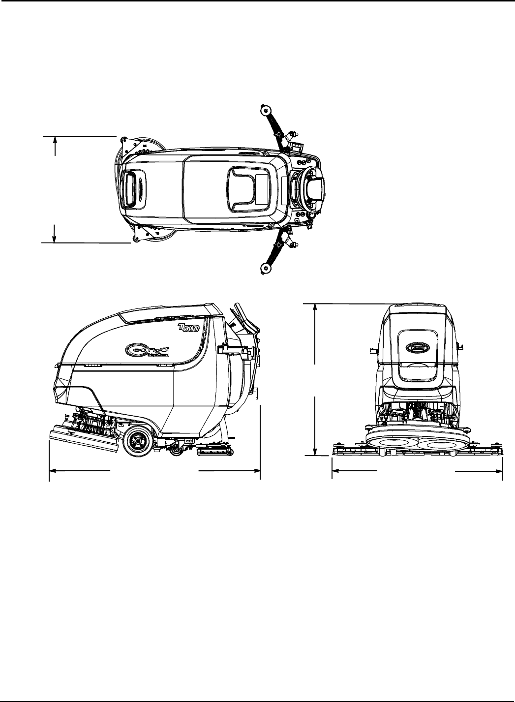
SPECIFICATIONS
56 Tennant T500 (01-2017)
MACHINE DIMENSIONS
43.3 in
1100 mm
27.5 in / 700 mm
26 in / 650 mm Model
DUAL DISK MODEL
58.5 in / 1486 mm
26 in / 650 mm Model
38.3 in / 937 mm
26 in / 650 mm Model
41.3 in / 1049 mm
28 in / 700 mm Model
29.5 in / 750 mm
26 in / 700 mm Model
33.5 in / 800 mm
26 in / 800 mm Model
59.1 in / 1501 mm
28 in / 700 mm Model
61.1 in / 1552 mm
32 in / 800 mm Model
46.6 in / 1234 mm
32 in / 800 mm Model
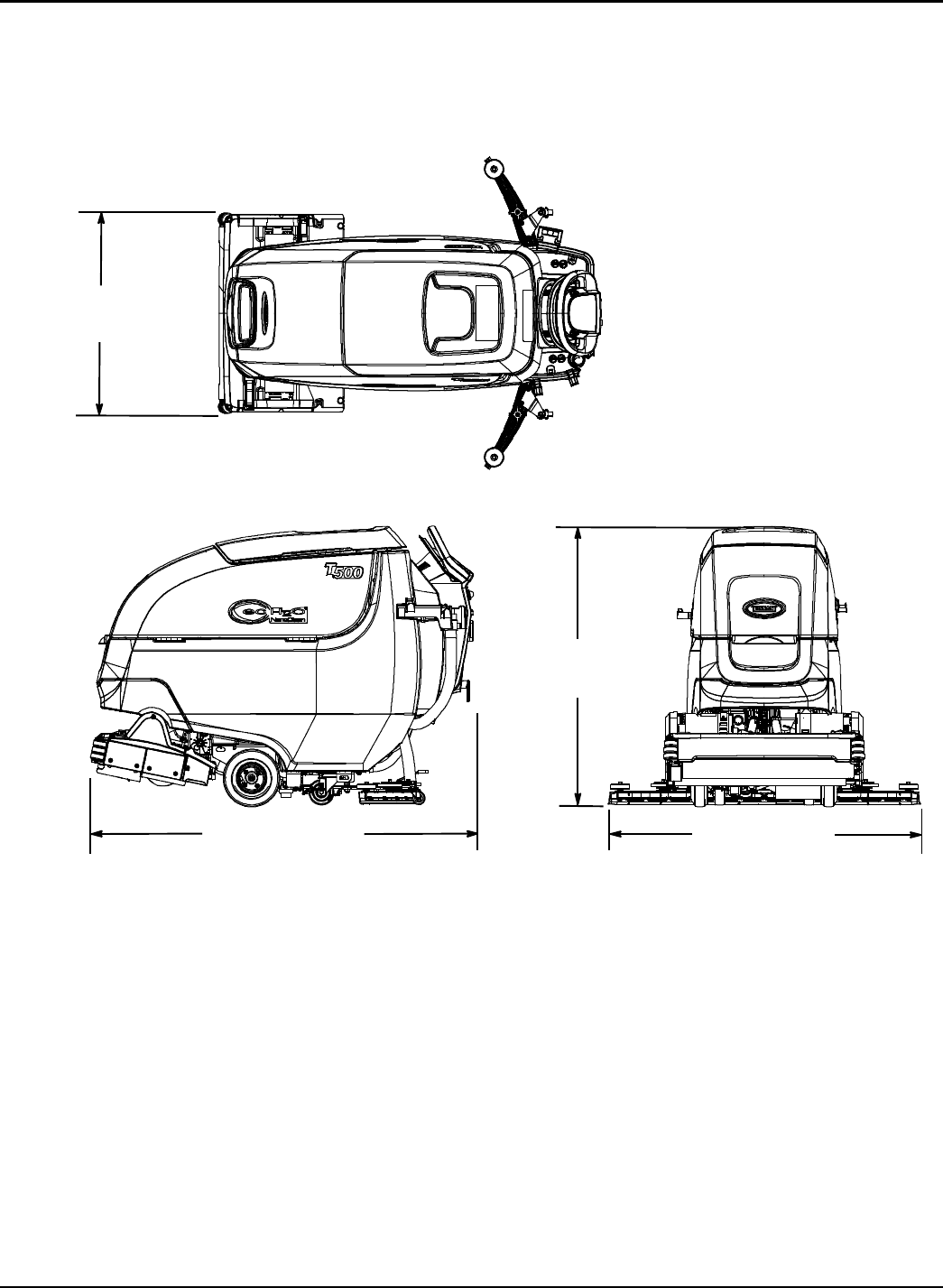
SPECIFICATIONS
Tennant T500 (01-2017) 57
43.3 in
1100 mm
30.7 in / 780 mm
CYLINDRICAL BRUSH MODEL
59.1 in / 1501 mm 46.6 in / 1234 mm
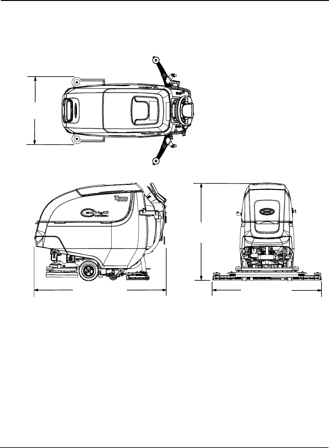
SPECIFICATIONS
58 Tennant T500 (01-2017)
43.3 in
1100 mm
28 in / 710 mm
ORBITAL PAD MODEL
58.5 in / 1486 mm 41.3 in / 1049 mm
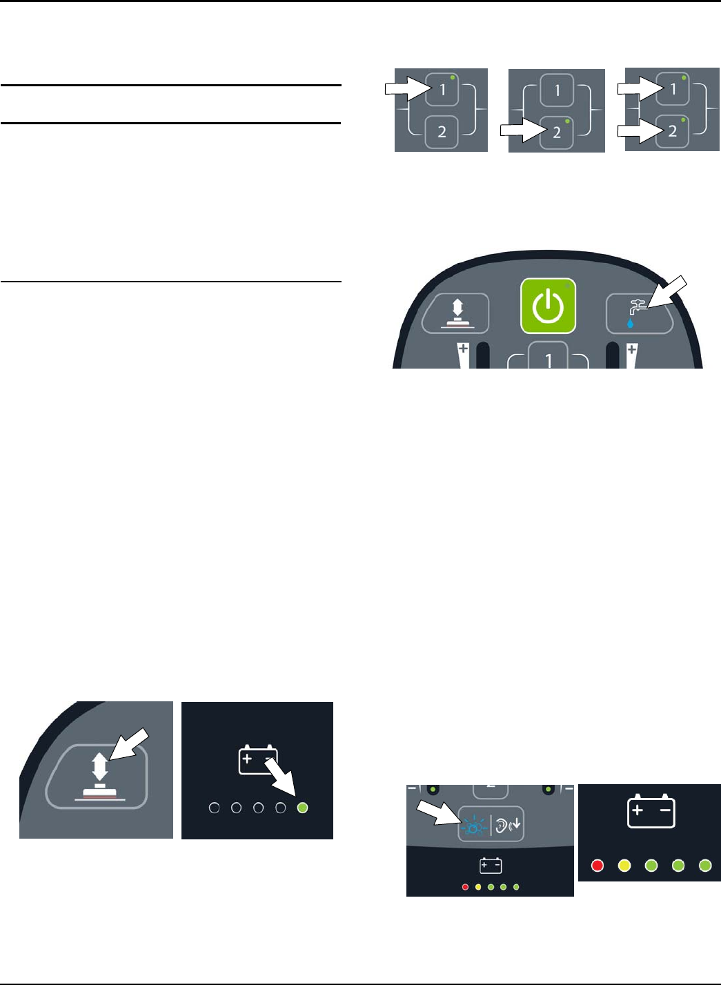
SUPERVISOR CONTROLS
Tennant T500 (01-2017) 59
ATTENTION: The following instructions are intended
for supervisor use only. Remove pages from manual if
necessary.
SUPERVISOR CONTROLS
The supervisor controls feature allows a supervisor to
program the machine's scrubbing settings for operator
use. The lockout functionality will prevent the operator
from changing or saving the Zone Settings.
The supervisor controls feature will lower machine
variability for consistent, repeatable cleaning results,
provide machine quality assurance regardless of user
experience, and reduce user training requirements.
PRO-MEMBRANE CONTROL PANEL MODEL
The machine has three supervisor control modes of
operation to choose from:
Unlocked Mode 1: Operator has full control of all
scrubbing parameters with the ability to reconfigure the
preset zone control buttons. The Unlocked Mode 1 is
the factory default setting.
Lockout Mode 2: Zone control buttons are preset and
locked by supervisor. Operator has the ability to
reconfigure the preset zone control buttons, but are not
able to save them.
Lockout Mode 3: Zone control buttons are preset and
locked by supervisor. Operator is restricted to only use
the zone control buttons preset by supervisor.
Entering the Supervisor Control Modes
1. Park the machine on a level surface and turn the
key to off ( O ) position.
2. Press and hold the brush pressure button while
turning the key on. Release button when the far
right battery discharge indicator LED turns on
(Figure 151). After releasing button, the active
supervisor control mode will display as described in
step 3 (Figure 152),
FIG. 151
3. To select or change a supervisor control mode,
press and hold the specific zone control button until
the LED blinks three times (Figure152). For lockout
mode 3, press and hold zone control buttons 1 and
2 at same time. After selection is made, the LED
will turn solid to indicate new mode.
Unlocked mode 1 = Zone control button 1
Lockout mode 2 = Zone control button 2
Lockout mode 3 = Zone control buttons 1 & 2
Unlocked Mode 1 Lockout Mode 2 Lockout Mode 3
FIG. 152
4. Press the solution flow button to configure the zone
control button presets for lockout modes 2 or 3
(Figure 153).
FIG. 153
5. Configure the zone control button presets from list
below, then press and hold zone control button
until it blinks three times to save preset. Repeat
process for other two zones. To preset zone
control 3, press zone control buttons 1 and 2 at the
same time.
Zone control presets:
- Brush pressure rate
- Solution flow rate
- Quiet-Mode button on or off
- ec-H2O mode switch on or off
- Severe Environment button on or off
(Hold button for 3 seconds until LED turns on)
- Maximum scrubbing speed setting
To adjust the maximum scrub speed setting, press
the severe environment button to cycle through the
five speed selections as described below (Figure
154). For models without the severe environment
button, press area on panel as shown. The button
is hidden.
The speed selection is displayed by the battery
discharge indicator LED's. The red LED represents
the lowest speed. The far right green LED
represents the highest speed (Figure 154).
Low →High
Speed Selection
FIG. 154
NOTE: The maximum scrub speed setting can only be
adjusted in supervisor control lockout modes 2 and 3.
6. To exit the supervisor control mode, turn key off.
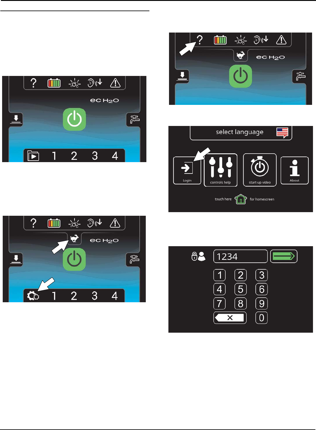
SUPERVISOR CONTROLS
60 Tennant T500 (01-2017)
PRO-PANEL CONTROLS MODEL
There are two types of user modes that will interface
with the home screen.
Operator Mode - Capable of machine operation with
permissions and restrictions controlled by the
supervisor. The operator mode home screen restricts
access to the machine settings button and maximum
scrub speed button (Figure 155).
FIG. 155
Supervisor Mode - Capable of machine operation
with full use of all controls, along with configuring
permissions and restrictions for the operator mode and
login capability. The supervisor mode home screen
provides access to the machine settings button and to
the maximum scrub speed button (Figure 156).
FIG. 156
A new machine from the factory will automatically start
up in the supervisor mode with a preassigned default
supervisor profile. The machine's factory-assigned
supervisor login code is ”1234”. This login code is not
required until it is enabled. The default supervisor
profile name and login code can be changed as
described in this section. If the new assigned
supervisor mode login code is forgotten, use the
recovery login code 836626826.
Entering the Supervisor Mode -
1. Turn on the machine. The home screen will display
at start up (Figure 157). Press the help button.
FIG. 157
2. Press the login button (Figure 158).
FIG. 158
3. First time use - Enter the factory-assigned
supervisor mode login code “1234” then press the
green enter button (Figure 159).
FIG. 159
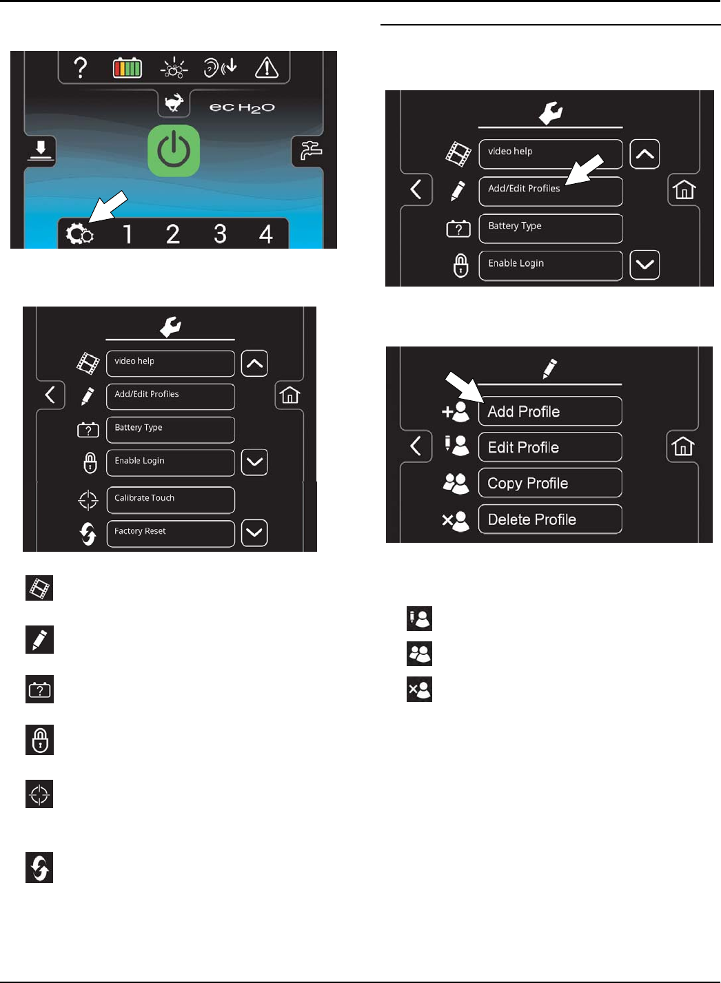
SUPERVISOR CONTROLS
Tennant T500 (01-2017) 61
4. The supervisor mode home screen will appear
(Figure 160). Press the machine settings button.
FIG. 160
5. The machine's setting screen provides access to
the following menu (Figure 161).
FIG. 161
Video help - Use to view specific operation
and maintenance procedures.
Add/Edit Profiles - Use to add/edit user
profiles for machine use.
Battery Type - Use to configure the machine
for different battery types. See BATTERIES.
Enable Login - Use to activate a required
login code at machine start up to operate machine.
Calibrate Touch - Use this to recalibrate the
touch screen if the touch points become
misaligned.
Factory Reset - Resets the supervisor login
code back to the factory default code “1234”,
removes user profiles and resets any custom
preset zone control buttons back to the factory
preset zones.
To Add/Edit User Profiles
1. Press the Add/Edit Profiles button to enter a new
user profile (Figure 162).
FIG. 162
2. Press the Add Profile button to add a new user
profile (Figure 163).
FIG. 163
Use the edit, copy and delete profile buttons to
manage the current user profiles.
Press to edit an existing user profile
Press to copy an existing user profile
Press to delete a user profile
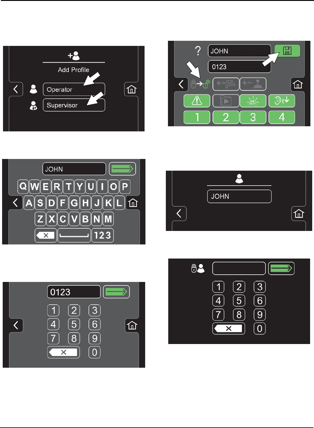
SUPERVISOR CONTROLS
62 Tennant T500 (01-2017)
3. Press the Operator button to add an Operator
mode profile or press the Supervisor button to add
an additional supervisor mode profile (Figure 164).
Note: The machine's default supervisor profile can not
be deleted from profile list.
FIG. 164
4. Enter the name of the new user profile then press
the green enter button (Figure 165).
FIG. 165
5. Assign a login code for the new user profile then
press the green enter button (Figure 166). The new
login code can be any combination of numbers
ranging from 3 to 8 digits in length.
FIG. 166
6. Select the controls the new user should only have
access to use (Figure 167). Green represents
unlocked controls and gray represents locked
controls.Presstheflashingsavebuttontosave
new profile.
FIG. 167
7. The new user profile is now saved to the operator
profile list as shown (Figure 168). Multiple Operator
and Supervisor user profiles can be added. Press
the back arrow to return to the previous screen to
add more user profiles.
FIG. 168
8. To enable the login screen at start up (Figure 169),
see Enabling the Login.
FIG. 169
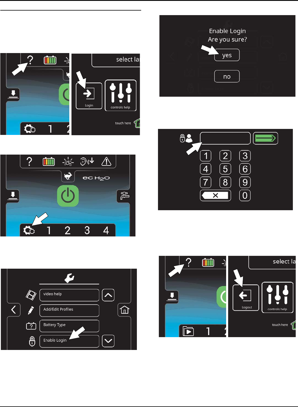
SUPERVISOR CONTROLS
Tennant T500 (01-2017) 63
Enabling the Login Screen
1. Turn on the machine.
2. Press the help button and log into the machine as
supervisor mode (Figure 170). See Entering the
Supervisor Mode.
FIG. 170
3. Press the machine settings button (Figure 171).
FIG. 171
4. Press the Enable Login button (Figure 172). The
Enable button will change from Enable Login to
Disable Login.
FIG. 172
5 Press the yes button to enable login (Figure 173).
FIG. 173
6 Now at machine start up, the login screen will
display (Figure 174). The user will need to enter
their assigned login code to operator machine.
FIG. 174
7. When the user is done operating the machine, it is
recommended the user log out by pressing the help
button, and then pressing the logout button (Figure
175). Turning the key to the off position is another
way to also logout
FIG. 175
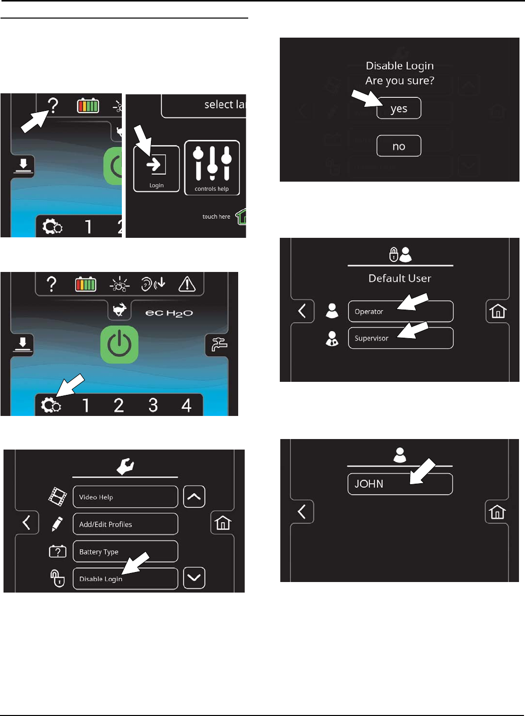
SUPERVISOR CONTROLS
64 Tennant T500 (01-2017)
Disabling the Login Screen
1. Turn on the machine.
2. Press the help button and log into the machine as
supervisor mode (Figure 176). See Entering the
Supervisor Mode.
FIG. 176
3. Press the machine settings button (Figure 177).
FIG. 177
4. Press the Disable Login button (Figure 178).
FIG. 178
5 Press the yes button to disable the login at
machine start up (Figure 179).
FIG. 179
6 Press either the Operator button or Supervisor
button to select desired user profile as your home
screen default without login (Figure 180).
FIG. 180
7. Select a pre-assigned user profile. In this example,
operator profile ”JOHN” is selected (Figure 181).
Turn the key off to apply the setting.
FIG. 181
8. At start up, the home screen is now set for the
desired user profile as the default without login.
NOTE: To change to a different user profile as the
default home screen without login, you must re-enable
login and repeat the disabling login instructions.
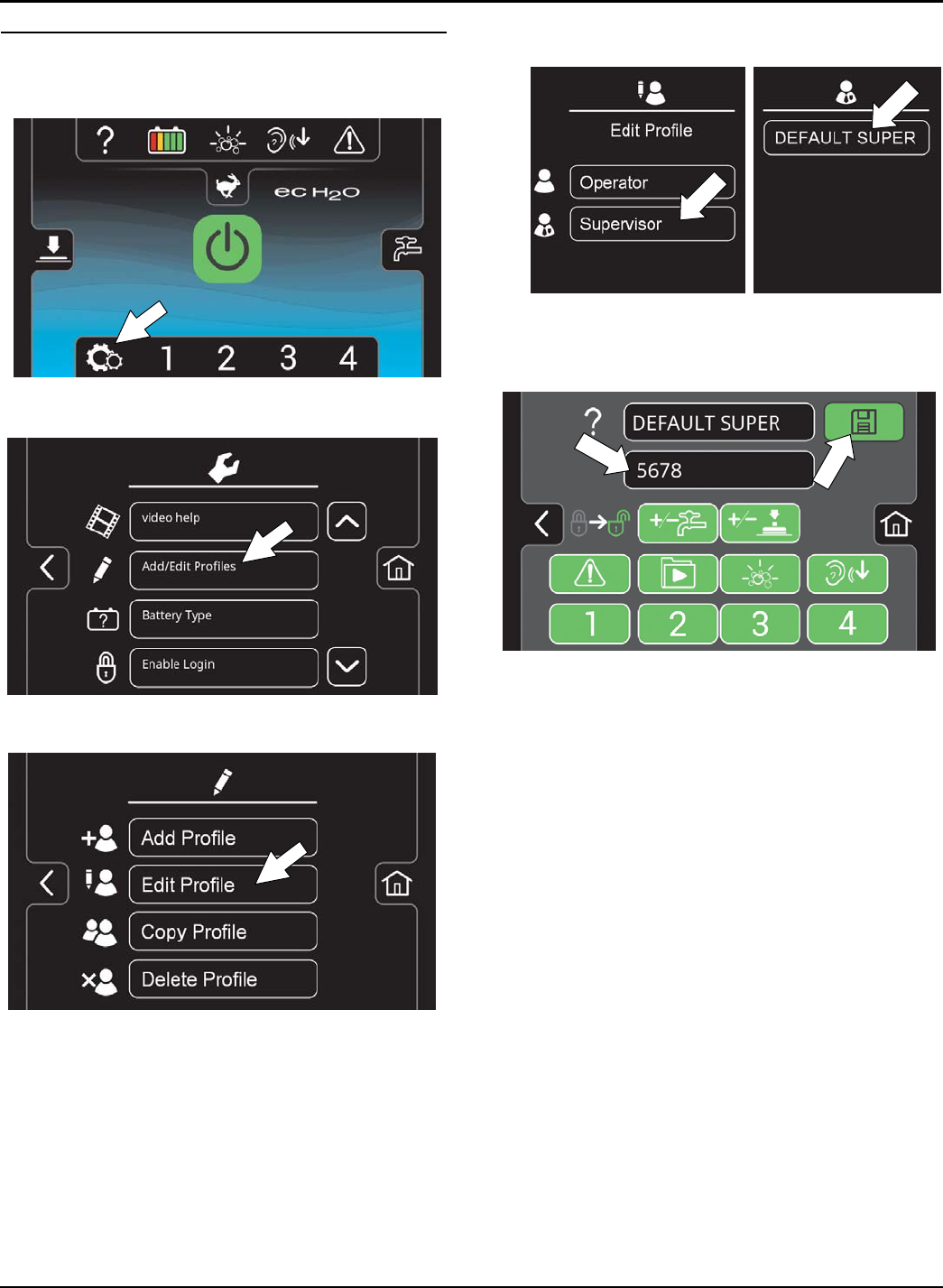
SUPERVISOR CONTROLS
Tennant T500 (01-2017) 65
Changing the Factory-Assigned Supervisor Login
Code
1. Press the machine's setting button (Figure 182)
FIG. 182
2. Press the Add/Edit Profiles button (Figure 183).
FIG. 183
3. Press the Edit Profile button (Figure 184).
FIG. 184
4. Press the Supervisor button then press the
DEFAULT SUPER button (Figure 185 ).
FIG. 185
5. Press the factory-assigned login code and enter a
new login code (Figure 186). Press the flashing
save button to save the new login code.
FIG. 186
