T7 Service Manual Tennant Rider Floor Scrubber
2018-06-20
: Sweepscrub Tennant-T7-Rider-Floor-Scrubber-Service-Manual tennant-t7-rider-floor-scrubber-service-manual 2777 file product_file
Open the PDF directly: View PDF ![]() .
.
Page Count: 48
- T7 Service Information
- Table of Contents
- Electrical Troubleshooting Information
- Commonly Used Electrical Symbols & Terms
- Ladder Schematic
- Wire Harness Group
- Key OFF, Operator NOT on Seat
- Key OFF, Battery Charger Plugged In
- Key ON, Operator on Seat
- Tank Level Switches
- Horn & Hour Meter Systems
- Propel Forward System
- Propel Reverse System
- Braking System
- Scrub Head & Squeegee Actuator Systems
- Scrub Brush Motors System
- Vacuum Fan System
- FaST System
- Conventional Solution System
- LED Locations & Descriptions
- Operational Modes & Interlocks
- Diagnostic & Fault Alarms
- Diagnostic & Configuration Modes
- Display Software Revision Mode
- Self Test Mode
- Input Display Mode
- Manual Mode
- Propel/Brake Diagnostics
- Battery Select Mode & Voltage Levels
- Reverse Alarm & Propel Speed Select Modes
- Inputs & Outputs Table
- Torque Standard
T7
331045
Rev. 00
Service
Information
*331045*
®
Hygenic Fully Cleanable Tanks
Featuring
The safe scrubbing alternative
t
t

This manual provides service information for the TENNANT Model T7.
This machine will provide excellent service. However, the best results will be obtained at minimum
costs if:
DThe machine is operated with reasonable care.
DThe machine is maintained regularly -- per the maintenance instructions provided.
DThe machine is maintained with TENNANT supplied or approved parts.
Manual Number -- 331045
Revision: 00
Published: 12--04
Tennant Company
PO Box 1452
Minneapolis, MN 55440
Phone: (800) 553--8033 or (763) 513--2850
www.tennantco.com
FaST Foam Scrubbing Technology logo is a United States registered trademark of Tennant Company.
Copyright E2003 TENNANT, Printed in U.S.A.
Table of Contents
Electrical Troubleshooting Information ...................................................................................... 1
Commonly Used Electrical Symbols & Terms........................................................................ 2
Ladder Schematic ..................................................................................................................3
Wire Harness Group............................................................................................................... 5
Key OFF, Operator NOT on Seat........................................................................................... 9
Key OFF, Battery Charger Plugged In ................................................................................. 10
Key ON, Operator on Seat ................................................................................................... 11
Tank Level Sensors..............................................................................................................12
Horn & Hour Meter Systems ................................................................................................ 13
Propel Forward System........................................................................................................ 14
Propel Reverse System........................................................................................................ 15
Braking System ....................................................................................................................16
Scrub Head & Squeegee Actuator Systems ........................................................................17
Scrub Brush Motors System.................................................................................................19
Vacuum Fan System ............................................................................................................ 20
FaST System........................................................................................................................ 21
Conventional Solution System................................................................................................. 22
LED Locations & Descriptions..............................................................................................23
Operational Modes & Interlocks........................................................................................... 24
Diagnostic & Fault Alarms....................................................................................................25
Alarm Codes ..................................................................................................................... 25
High Current Faults........................................................................................................... 25
Diagnostic & Configuration Modes....................................................................................... 26
Display Software Revision Mode .........................................................................................27
Self Test Mode ..................................................................................................................... 28
Input Display Mode...............................................................................................................29
Manual Mode........................................................................................................................30
Propel / Brake Diagnostics................................................................................................... 31
Battery Select Mode & Voltage Levels................................................................................. 32
Battery Select Mode..........................................................................................................32
Voltage Levels................................................................................................................... 32
Reverse Alarm & Propel Speed Select Modes ....................................................................33
Reverse Alarm Select Mode ............................................................................................. 33
Propel Speed Select Mode ............................................................................................... 33
Inputs & Outputs Table.........................................................................................................34
Torque Standard...................................................................................................................... 35
Inch Fasteners......................................................................................................................35
METRIC Fasteners............................................................................................................... 37
Nylon Insert Lock Nuts .........................................................................................................39
Nut-Hex Light THIN..............................................................................................................39
Wheel Bolt and Nuts............................................................................................................. 40
Wheel Bearing Adjustment................................................................................................... 40
Tightening Nuts on Tapered Shafts .....................................................................................41
Shoulder Bolts ......................................................................................................................42
Taper Lockr Bushings ..........................................................................................................43
Sequence Tightening ...........................................................................................................44
i
ii

T7
ELECTRICAL
Troubleshooting Information
BEFORE CONDUCTING TESTS:
DURING TESTS:
* Read and Follow ALL Safety Warnings and Precautions in
Operator's Manual
* Always use an ESD (Electrostatic Discharge) strap when
working near the Control Board
* Be cautious when working near Control Board – Battery
voltage is always present, even with Key OFF
* Always unplug Positive Battery Cable when removing or
replacing components
* Call Technical Services if Diagnostic Time Exceeds One Hour
With Unknown Cause or Course of Action
NOTE:Troubleshooting charts may be shown with optional equipment. The optional equipment may not
be specified in these charts. Some machines may not be equipped with all components shown.
2005.01.05 T7ETI REV 00
1
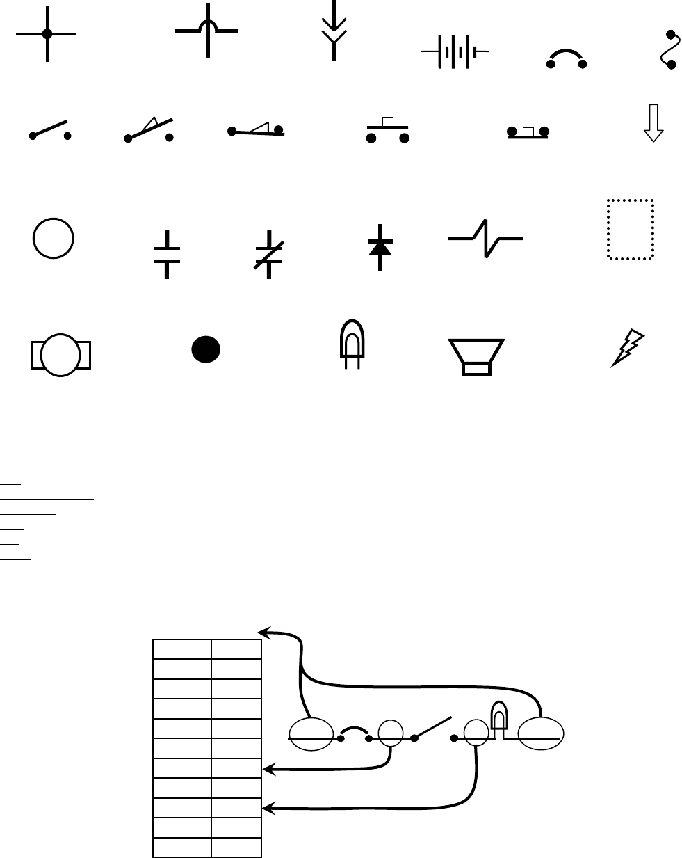
Commonly Used Electrical Symbols & Terms
NOTE: The term “NORMALLY” refers to the components’ “at rest” or “de-energized” position
+-
Battery Fuse
Normally Closed
Push-Button Switch
Normally Open
Switch
Wires Connected
Together
Normally Open
Push-Button Switch
Plug-in
Connection
Wires Not
Connected Together Circuit Breaker
Indicates Movement
from Normal Position
Normally Open
Limit Switch Normally Closed
Limit Switch
Indicates Component in
Position Other than Normal
Relay Contacts (Part 2 of Relay)
Normally Open Normally Closed
Solenoid (Valve
or Actuator)
M1
Relay Coil
(Part 1 of Relay) Diode
Lamp
(Light Bulb) Indicates Component
is Energized
Motor
X
Wiring Standoff
(Connection Point) Horn or Alarm
Terms & Abbreviations
BDI – Battery Discharge Indicator
Dynamic Braking – A method of using the generating nature of an electric motor to slow the machine
Hall Effect – A voltage developed as a result of current flow in the presence of a magnetic field
LED – Light Emitting Diode
PM – Permanent Magnet
PWM (Pulse Width Modulation) – A method of using controlled on/off times to regulate the voltage and current supplied to an
electrical device
Wiring Color Codes
(Unless otherwise marked)
0
1
2
3
4
5
6
7
8
9
Tan
Pink
Brown
Orange
Yellow
Green
Blue
Purple
Gray
White
Right Most Digit
of Wire Number Color of Wire
Example of Wiring Numbers & Colors:
1 RED 25 7 13 BLK
2
1
2
3
4
5
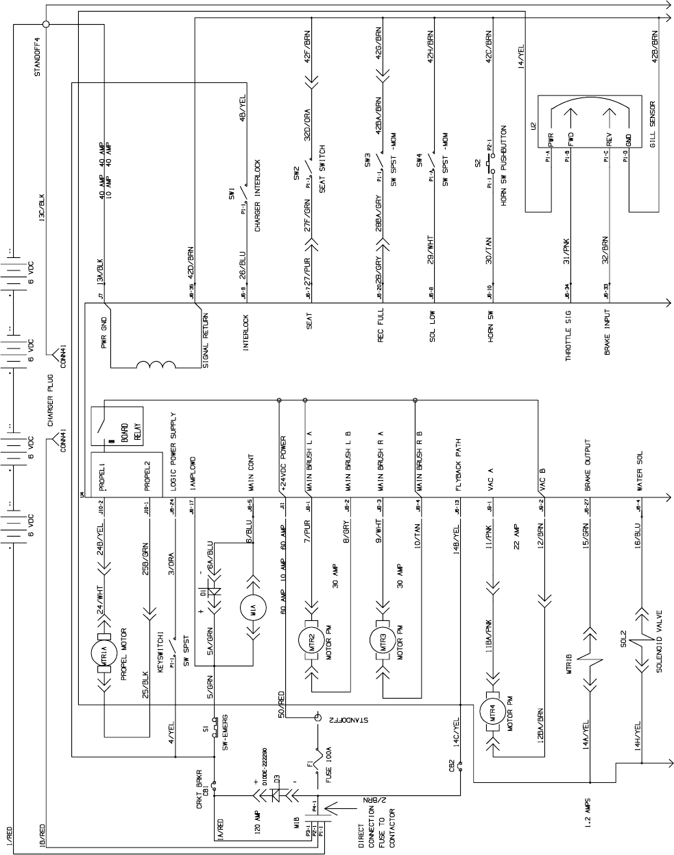
1021038
T7 – Ladder Schematic (page 1 of 2)
3
1
2
3
4
5
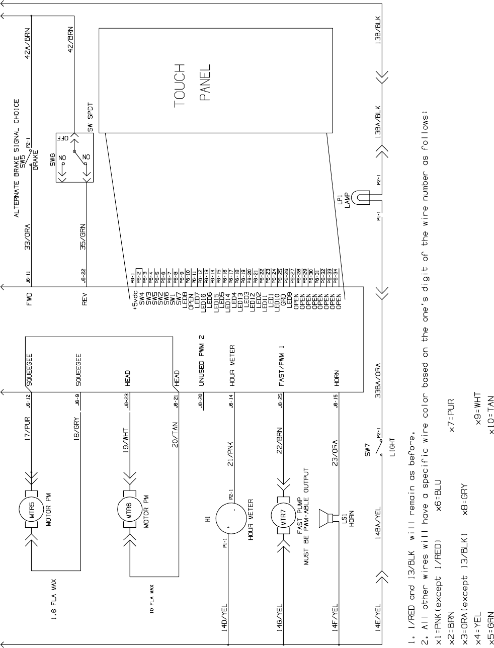
1021038
T7 – Ladder Schematic (page 2 of 2)
4
1
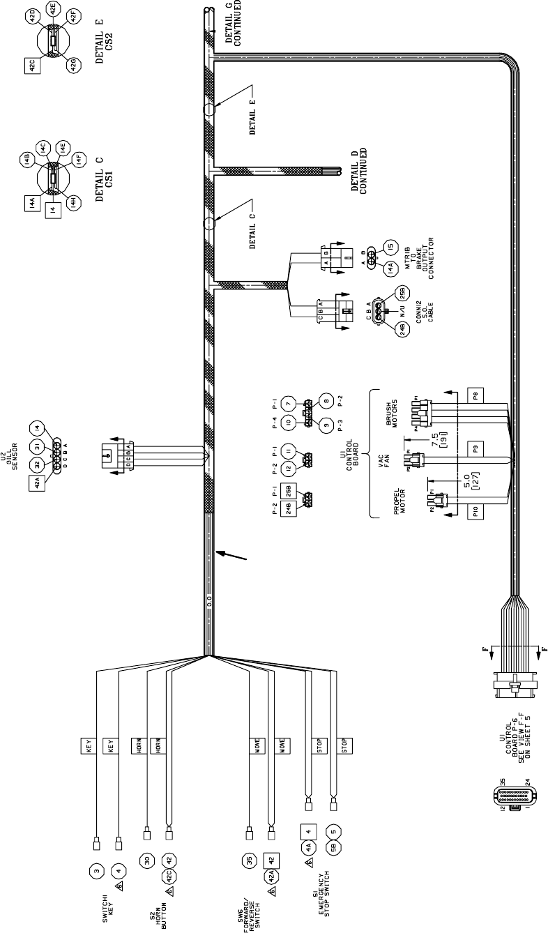
T7 – Wire Harness Group (page 1 of 4)
5
1
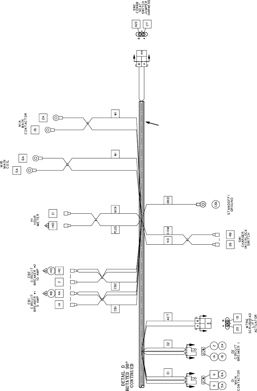
T7 – Wire Harness Group (page 2 of 4)
6
1
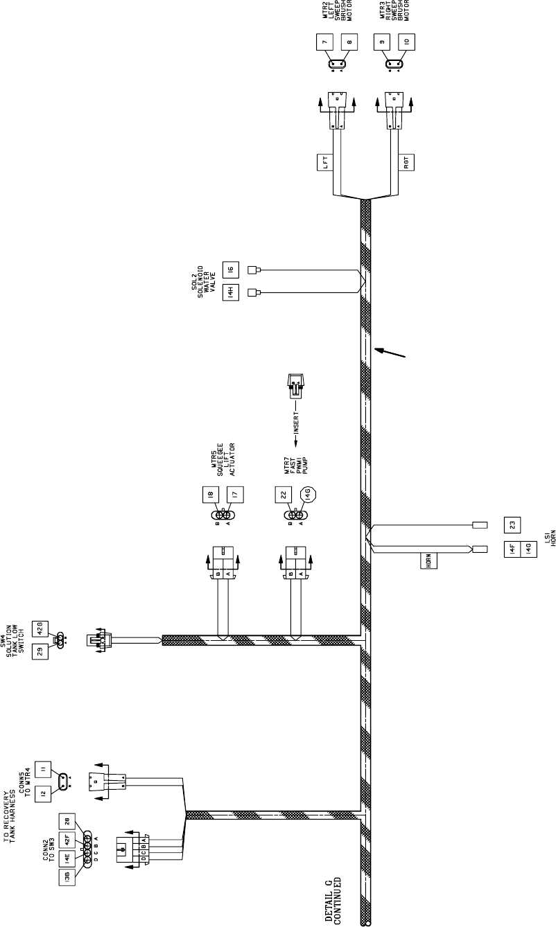
T7 – Wire Harness Group (page 3 of 4)
7
2
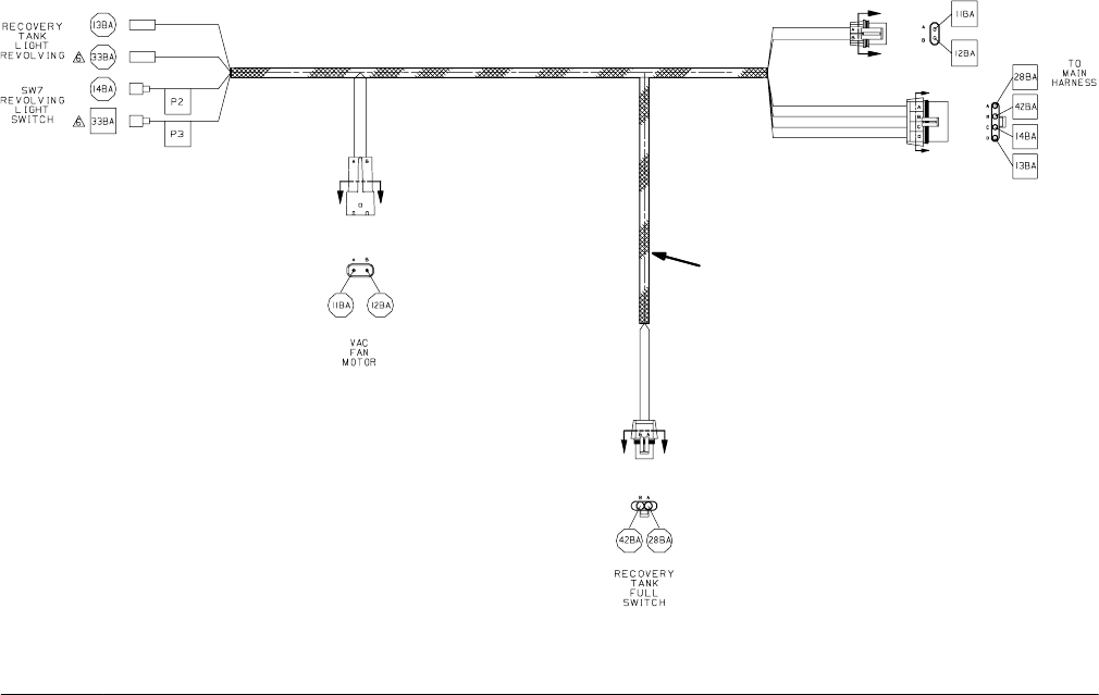
T7 – Wire Harness Group (page 4 of 4)
8
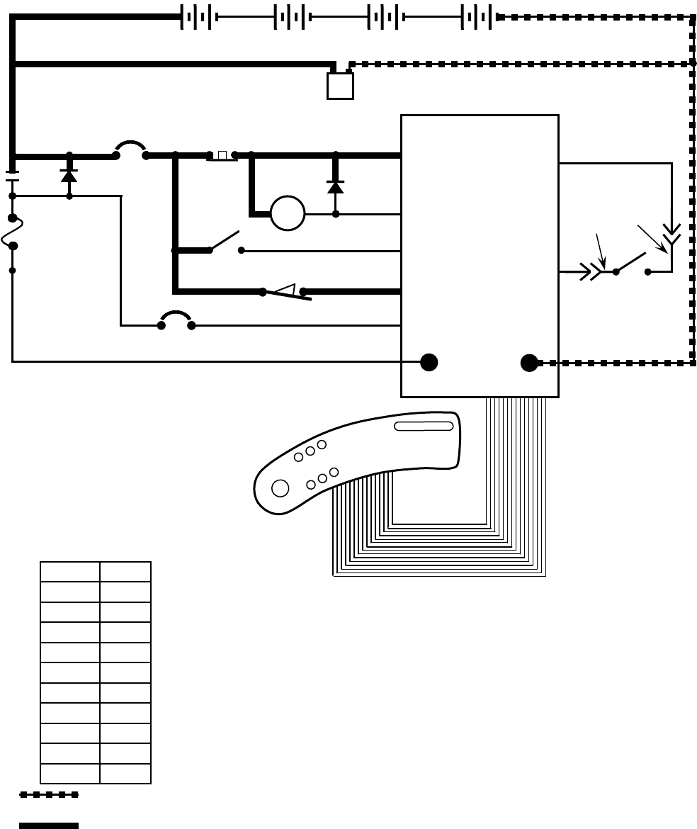
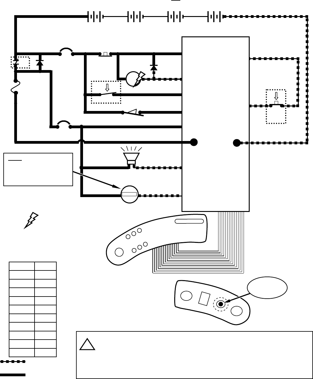
T7 - Key OFF, Operator NOT on Seat
D3
1 RED 13 BLK
14
13 BLK
2
POS
RIBBON CABLE CONNECTOR P6
CONTROL BOARD
STANDOFF 2
+-
6 VDC +-
6 VDC +-
6 VDC +-
6 VDC
v
M1B
v
1 RED
1 RED
CHARGER
PLUG
STANDOFF 4
13 BLK
NEG
TOUCH
PANEL
50 RED
F1
100 A
S1
M1A
D1
CB1
5 A
CB2
15 A
KEYSWITCH
CHARGER INTERLOCK
+
RIBBON CABLE
-
EMERGENCY
STOP SWITCH
X
X
50 RED
2
214
MAIN
CONTACTOR
6
55
56
3
26
3
26
4
4
4
44
PIN J6-17
PIN J6-5
PIN J6-24
PIN J6-6
PIN J6-13
14
1 RED
1 RED 13 BLK
50 RED
1 RED
13 BLK
POST J11 POST J7
SW1 SW2
SEAT
SWITCH
PIN J6-35
PIN J6-7
42
42
27
LOGIC GROUND
32
ORG
27
GRN
Wiring Color Codes
(Unless otherwise marked)
0
1
2
3
4
5
6
7
8
9
Tan
Pink
Brown
Orange
Yellow
Green
Blue
Purple
Gray
White
Right Most Digit
of Wire Number Color of Wire
= Battery Negative
or Logic Ground
= Battery Positive
or Positive Output
9
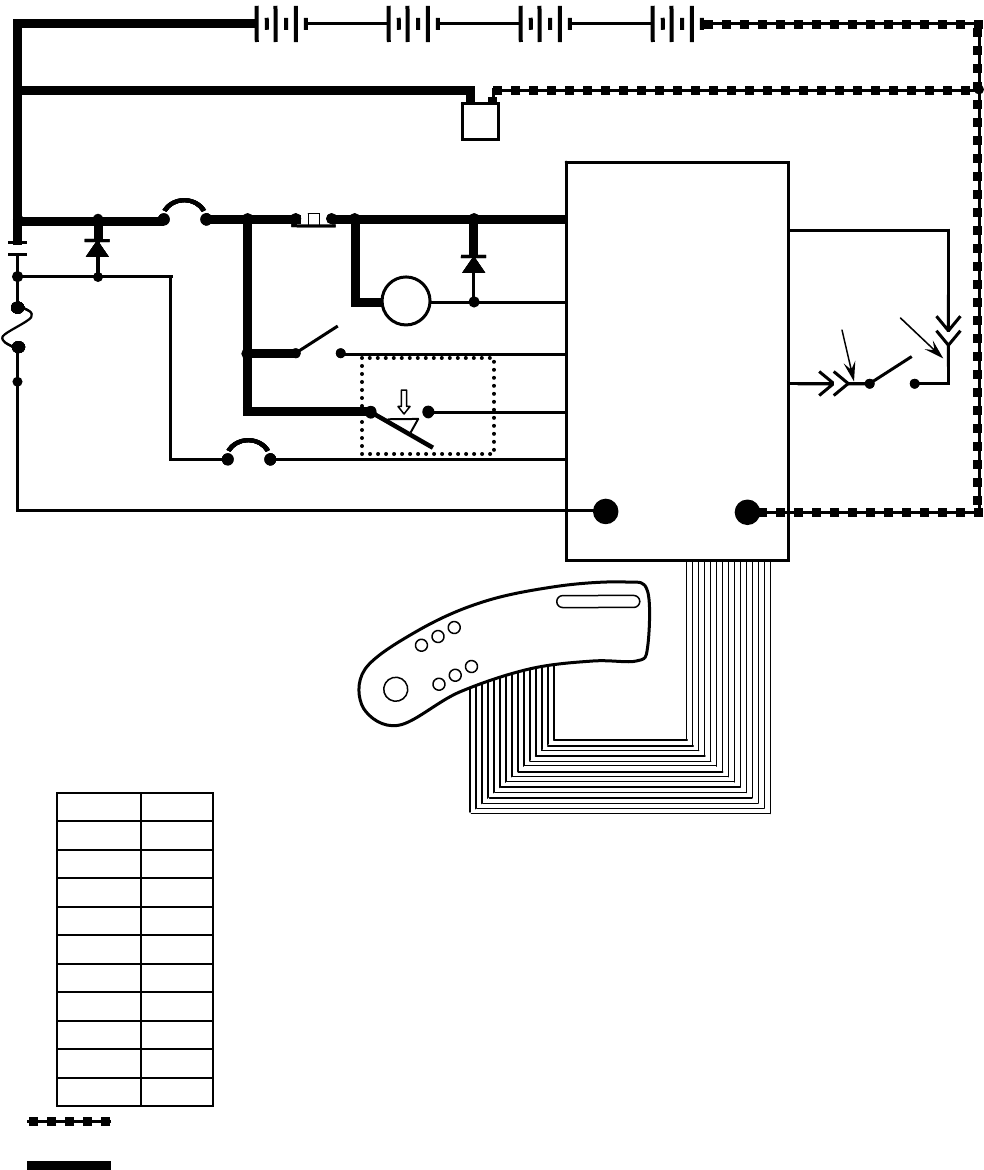
T7 - Key OFF, Battery Charger Plugged In
D3
1 RED 13 BLK
14
13 BLK
2
POS
RIBBON CABLE CONNECTOR P6
CONTROL BOARD
STANDOFF 2
+-
6 VDC +-
6 VDC +-
6 VDC +-
6 VDC
v
M1B
v
1 RED
1 RED
CHARGER
PLUG
STANDOFF 4
13 BLK
NEG
TOUCH
PANEL
50 RED
F1
100 A
S1
M1A
D1
CB1
5 A
CB2
15 A
KEYSWITCH CHARGER
INTERLOCK
+
RIBBON CABLE
-
EMERGENCY
STOP SWITCH
X
X
50 RED
2
214
MAIN
CONTACTOR
6
55
56
3
26
3
26
4
4
4
44
PIN J6-17
PIN J6-5
PIN J6-24
PIN J6-6
PIN J6-13
14
1 RED
1 RED 13 BLK
50 RED
1 RED
13 BLK
POST J11 POST J7
SW1 SW2
SEAT
SWITCH
PIN J6-35
PIN J6-7
42
42
27
LOGIC GROUND
32
ORG
27
GRN
Wiring Color Codes
(Unless otherwise marked)
0
1
2
3
4
5
6
7
8
9
Tan
Pink
Brown
Orange
Yellow
Green
Blue
Purple
Gray
White
Right Most Digit
of Wire Number Color of Wire
= Battery Negative
or Logic Ground
= Battery Positive
or Positive Output
10
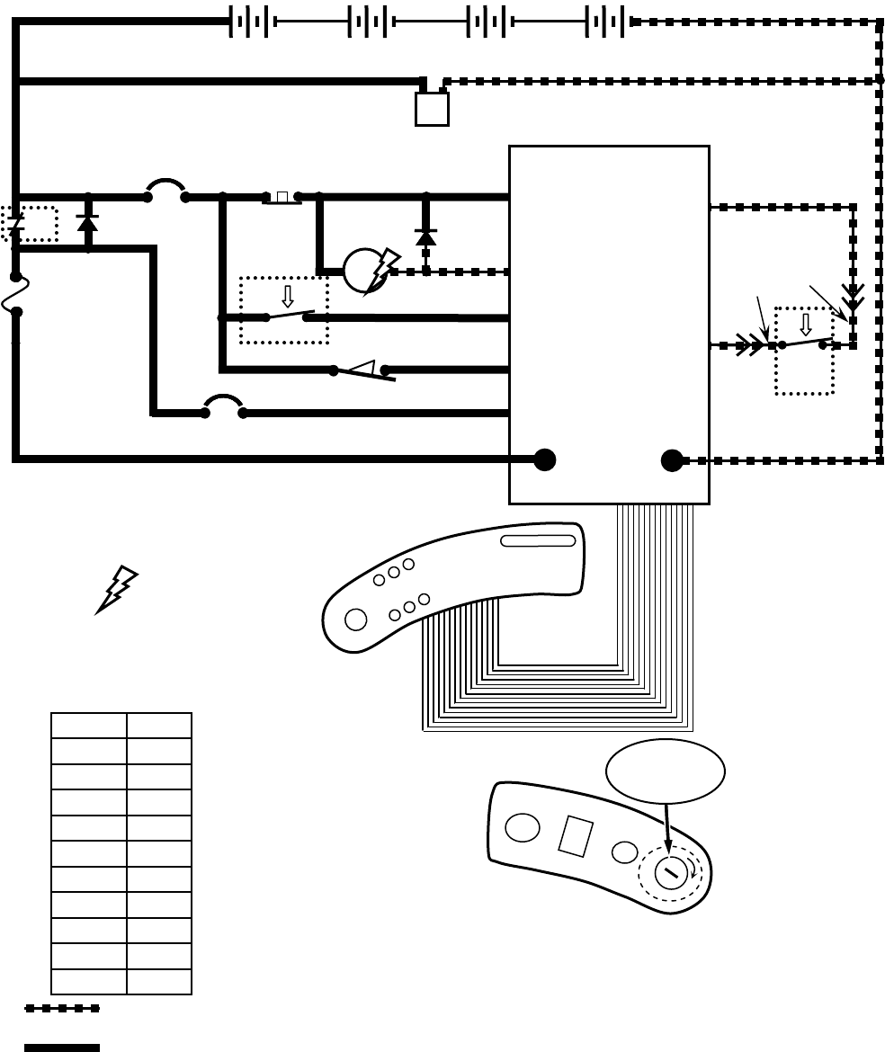
T7 - Key ON, Operator on Seat
D3
1 RED 13 BLK
14
13 BLK
2
POS
CONTROL BOARD
STANDOFF 2
+-
6 VDC +-
6 VDC +-
6 VDC
v
M1B
v
1 RED
1 RED
CHARGER
PLUG
STANDOFF 4
13 BLK
NEG
TOUCH
PANEL
50 RED
F1
100 A
S1
M1A
D1
CB1
5 A
CB2
15 A
KEYSWITCH
+
RIBBON CABLE
-
EMERGENCY
STOP SWITCH
X
X
50 RED
2
214
MAIN
CONTACTOR
6
55
56
3
26
3
4
4
4
4
PIN J6-17
PIN J6-5
PIN J6-24
PIN J6-6
PIN J6-13
14
1 RED
1 RED 13 BLK
50 RED
1 RED
13 BLK
RIBBON CABLE CONNECTOR P6
POST J11 POST J7
CHARGER INTERLOCK
26
4SW1 PIN J6-7 27
32
ORG
42
42
27
GRN
SW2
SEAT
SWITCH
PIN J6-35 LOGIC GROUND
v
+-
6 VDC
RIGHT SIDE
DASH PANEL
O
I
KEY
SWITCH
Indicates Component
is Energized
Wiring Color Codes
(Unless otherwise marked)
0
1
2
3
4
5
6
7
8
9
Tan
Pink
Brown
Orange
Yellow
Green
Blue
Purple
Gray
White
Right Most Digit
of Wire Number Color of Wire
= Battery Negative
or Logic Ground
= Battery Positive
or Positive Output
11
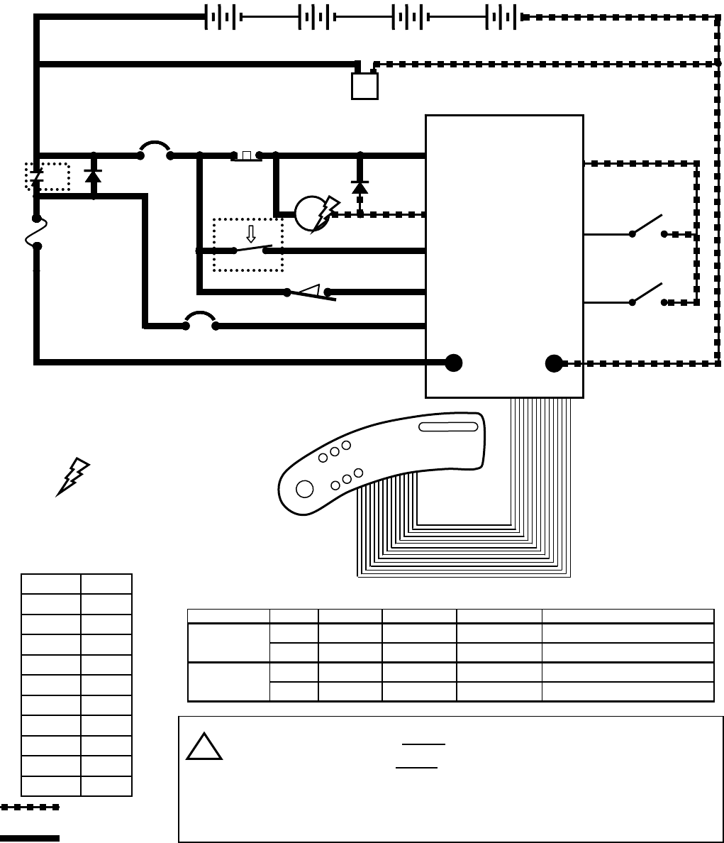
28
29
42
42
RECOVERY TANK
FULL SWITCH
LOGIC GROUND
42
SW3
SW4
D3
1 RED 13 BLK
14
13 BLK
2
POS
CONTROL BOARD
STANDOFF 2
+-
6 VDC +-
6 VDC +-
6 VDC
v
M1B
v
1 RED
1 RED
CHARGER
PLUG
STANDOFF 4
13 BLK
NEG
TOUCH
PANEL
50 RED
F1
100 A
S1
M1A
D1
CB1
5 A
CB2
15 A
KEYSWITCH
+
RIBBON CABLE
-
EMERGENCY
STOP SWITCH
X
X
50 RED
2
214
MAIN
CONTACTOR
6
55
56
3
26
3
4
4
4
4
PIN J6-17
PIN J6-5
PIN J6-24
PIN J6-6
PIN J6-13
14
1 RED
1 RED 13 BLK
50 RED
1 RED
13 BLK
RIBBON CABLE CONNECTOR P6
POST J11 POST J7
CHARGER INTERLOCK
26
4SW1
v
+-
6 VDC
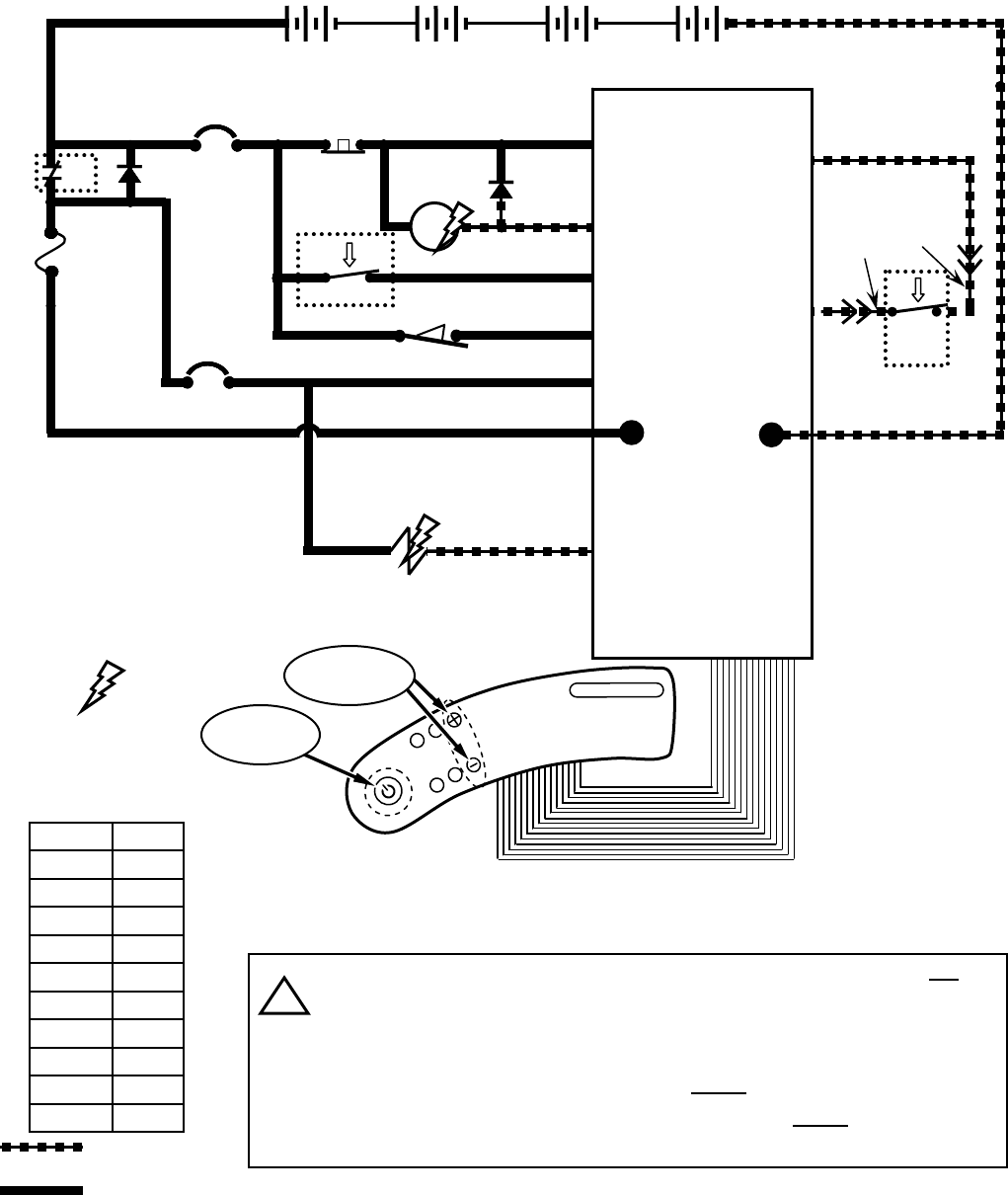
T7 – Tank Level Switches
CONDITIONS: key ON
PIN J6-20
PIN J6-35
PIN J6-8
SOLUTION TANK
LOW SWITCH
Recovery Tank Full Switch closes when recovery tank is full
Solution Tank Low Switch opens when solution tank is low
Tank Level Switches are ALWAYS in the OPEN position with low or
empty tank
Tank Level Switches are ALWAYS in the CLOSED position with full tank
i
Indicates Component
is Energized
Wiring Color Codes
(Unless otherwise marked)
0
1
2
3
4
5
6
7
8
9
Tan
Pink
Brown
Orange
Yellow
Green
Blue
Purple
Gray
White
Right Most Digit
of Wire Number Color of Wire
= Battery Negative
or Logic Ground
= Battery Positive
or Positive Output
switch tank full tank empty switch OPEN switch CLOSED indicator
xx
Solution Tank Empty LED OFF
xx Solution Tank Empty LED ON
xx
Recovery Tank Full LED ON
xx Recovery Tank Full LED OFF
Solution Tank
Recovery Tank
Tank Level Switches Logic Chart
12
T7 – Horn & Hour Meter Systems
1 RED
D3
13 BLK
13 BLK
POS
CONTROL BOARD
STANDOFF 2
+-
6 VDC +-
6 VDC +-
6 VDC +-
6 VDC
vv
1 RED
STANDOFF 4
NEG
TOUCH
PANEL
50 RED
F1
100 A
S1
D1
CB1
5 A
CB2
15 A
KEYSWITCH
RIBBON CABLE
-
EMERGENCY
STOP SWITCH
X
50 RED
14
MAIN
CONTACTOR
6
55
56
3
26
3
4
4
4
4
PIN J6-17
PIN J6-5
PIN J6-24
PIN J6-6
PIN J6-13
14
1 RED
50 RED
13 BLK
RIBBON CABLE CONNECTOR P6
POST J11 POST J7
CHARGER INTERLOCK
26
4SW1
23
X
+
21
PIN J6-15
PIN J6-14
LEFT SIDE
DASH PANEL
Horn pulses ON & OFF when Directional Switch is in REVERSE
Hour Meter is ON only when propelling (forward or reverse), or anytime
Squeegee/Vacuum Fan is ON
Horn pulses when a fault is detected (Directional Switch must be in FORWARD
Position) – refer to “Diagnostic/Beep Code” chart
i
CONDITIONS: key ON, operator on seat, in motion OR Vacuum Fan running (for Hour Meter)
22
2
30
42
PIN J6-35 LOGIC GROUND
42
PIN J6-10
LS1
HORN
H1
HOUR METER
14
23
14
14
14
21
RIGHT SIDE
DASH PANEL
HORN
SWITCH
M1B
M1A
00000
NOTE: Hour Meter is active
only when propelling
(forward or reverse), OR
anytime Squeegee/
Vacuum Fan is active
S2
HORN
SWITCH
Indicates Component
is Energized
Wiring Color Codes
(Unless otherwise marked)
0
1
2
3
4
5
6
7
8
9
Tan
Pink
Brown
Orange
Yellow
Green
Blue
Purple
Gray
White
Right Most Digit
of Wire Number Color of Wire
= Battery Negative
or Logic Ground
= Battery Positive
or Positive Output
13
13 BLK13 BLK
27
42
42
SW2
SEAT
SWITCH
LOGIC GROUND
14
PROPEL PEDAL
POSITION SENSOR
31 PROPEL
SIGNAL POWER
GND 42
14
X
35
PROPEL
DIRECTION
SWITCH
4242
REVERSE
FORWARD
HALL
EFFECT
SENSOR
PROPEL MOTOR
FORWARD
24
25
24 WHT
25 BLK
25
14 MTR1A
1515
14
14
T7 – Propel Forward System
CONDITIONS: key ON, operator on seat, propel pedal depressed
D3
1 RED 13 BLK
POS
CONTROL BOARD
STANDOFF 2
+-
6 VDC +-
6 VDC +-
6 VDC +-
6 VDC
vv
1 RED
STANDOFF 4
TOUCH
PANEL
50 RED
F1
100 A
S1
D1
CB1
5 A
CB2
15 A
KEYSWITCH
RIBBON CABLE
EMERGENCY
STOP SWITCH
X
50 RED
14
MAIN
CONTACTOR
6
55
56
3
26
3
4
4
4
4
PIN J6-17
PIN J6-5
PIN J6-24
PIN J6-6
PIN J6-13
14
1 RED
50 RED
RIBBON CABLE CONNECTOR P6
POST J11
CHARGER INTERLOCK
26
4SW1
X
+
LEFT SIDE
DASH PANEL
22
2
M1B
M1A
i
FORWARD
REVERSE
RIGHT SIDE
DASH PANEL
DIRECTIONAL
SWITCH
PIN J10-2
PIN J10-1
PIN J6-27
NEG -
POST J7
PIN J6-7
PIN J6-35
PIN J6-34
PIN J6-22
14 14
NOTE: Brake Solenoid
is energized to release
parking brake.
32
ORG
27
GRN
MTR1B
BRAKE
SOLENOID
Indicates Component
is Energized
Wiring Color Codes
(Unless otherwise marked)
0
1
2
3
4
5
6
7
8
9
Tan
Pink
Brown
Orange
Yellow
Green
Blue
Purple
Gray
White
Right Most Digit
of Wire Number Color of Wire
= Battery Negative
or Logic Ground
= Battery Positive
or Positive Output
= Output that can
Change Polarity
Typical Propel Motor Current Draw: 1 to 20 Amps in motion, higher at start-up
Propel Motor Voltage: 0 to 24 VDC - FORWARD
Approx. 0 to 17 VDC - REVERSE
Propel Motor is controlled by PWM (Pulse Width Modulation)
The Propel Pedal Position HALL EFFECT Sensor sends a varying voltage
signal (1 to 4 Volts) to control board, based upon position of the propel pedal
NOTE: Refer to the
“Propel/Brake Diagnostics”
page for more information
SW6
U2
14

25
25 BLK
25
13 BLK13 BLK
27
42
42
SW2
SEAT
SWITCH
LOGIC GROUND
14
PROPEL PEDAL
POSITION SENSOR
31 PROPEL
SIGNAL POWER
GND 42
14
X
35
4242
REVERSE
FORWARD
HALL
EFFECT
SENSOR
PROPEL MOTOR
REVERSE
14 MTR1A
MTR1B
BRAKE
SOLENOID
1515
14
14
D3
1 RED 13 BLK
POS
CONTROL BOARD
STANDOFF 2
+-
6 VDC +-
6 VDC +-
6 VDC
vv
1 RED
STANDOFF 4
TOUCH
PANEL
50 RED
F1
100 A
S1
D1
CB1
5 A
CB2
15 A
KEYSWITCH
RIBBON CABLE
EMERGENCY
STOP SWITCH
X
50 RED
14
MAIN
CONTACTOR
6
55
56
3
26
3
4
4
4
4
PIN J6-17
PIN J6-5
PIN J6-24
PIN J6-6
PIN J6-13
14
1 RED
50 RED
RIBBON CABLE CONNECTOR P6
POST J11
CHARGER INTERLOCK
26
4SW1
X
+
LEFT SIDE
DASH PANEL
22
2
M1B
M1A
PIN J10-2
PIN J10-1
NEG -
POST J7
PIN J6-7
PIN J6-35
PIN J6-34
PIN J6-22
14 14
NOTE: Brake Solenoid
is energized to release
parking brake.
32
ORG
27
GRN
T7 – Propel Reverse System
CONDITIONS: key ON, operator on seat, propel pedal depressed
FORWARD
REVERSE
DIRECTIONAL
SWITCH RIGHT SIDE
DASH PANEL
+-
6 VDC
Indicates Component
is Energized
Wiring Color Codes
(Unless otherwise marked)
0
1
2
3
4
5
6
7
8
9
Tan
Pink
Brown
Orange
Yellow
Green
Blue
Purple
Gray
White
Right Most Digit
of Wire Number Color of Wire
= Battery Negative
or Logic Ground
= Battery Positive
or Positive Output
= Output that can
Change Polarity
24
24 WHT
Typical Propel Motor Current Draw: 1 to 20 Amps in motion, higher at start-up
Propel Motor Voltage: 0 to 24 VDC - FORWARD
Approx. 0 to 17 VDC - REVERSE
Propel Motor is controlled by PWM (Pulse Width Modulation)
The Propel Pedal Position HALL EFFECT Sensor sends a varying voltage
signal (1 to 4 Volts) to control board, based upon position of the propel pedal
i
PIN J6-27
PROPEL
DIRECTION
SWITCH
SW6
U2
NOTE: Refer to the
“Propel/Brake Diagnostics”
page for more information
15
T7 – Braking System
CONDITIONS: key ON, operator on seat, brake pedal depressed
13 BLK13 BLK
27
42
42
SW2
SEAT
SWITCH
LOGIC GROUND
14
BRAKE PEDAL
POSITION SENSOR
32 BRAKE
SIGNAL POWER
GND 42
14
HALL
EFFECT
SENSOR
PROPEL MOTOR
24
25
24 WHT
25 BLK
25
14
1515
14
14
D3
1 RED 13 BLK
POS
CONTROL BOARD
STANDOFF 2
+-
6 VDC +-
6 VDC +-
6 VDC
vv
1 RED
STANDOFF 4
TOUCH
PANEL
50 RED
F1
100 A
S1
D1
CB1
5 A
CB2
15 A
KEYSWITCH
RIBBON CABLE
EMERGENCY
STOP SWITCH
X
50 RED
14
MAIN
CONTACTOR
6
55
56
3
26
3
4
4
4
4
PIN J6-17
PIN J6-5
PIN J6-24
PIN J6-6
PIN J6-13
14
1 RED
50 RED
RIBBON CABLE CONNECTOR P6
POST J11
CHARGER INTERLOCK
26
4SW1
X
+
LEFT SIDE
DASH PANEL
22
2
M1B
M1A
PIN J10-2
PIN J10-1
NEG -
POST J7
PIN J6-7
PIN J6-35
PIN J6-33
14 14
32
ORG
27
GRN
Indicates Component
is Energized
Wiring Color Codes
(Unless otherwise marked)
0
1
2
3
4
5
6
7
8
9
Tan
Pink
Brown
Orange
Yellow
Green
Blue
Purple
Gray
White
Right Most Digit
of Wire Number Color of Wire
= Battery Negative
or Logic Ground
= Battery Positive
or Positive Output
MTR1B
BRAKE
SOLENOID
NOTE: Brake Solenoid is DE-
energized to apply parking
brake. Dynamic Braking will
occur before Brake Solenoid is
de-energized.
MTR1A
+-
6 VDC
The brake pedal position HALL EFFECT sensor sends a varying voltage
signal (1 to 4 Volts) to control board, based upon position of the brake pedal
Brake Solenoid is DE-energized to apply brake.
Dynamic Braking will occur before Brake Solenoid is de-energized.
i
PIN J6-27
U2
NOTE: Refer to the
“Propel/Brake Diagnostics”
page for more information
16
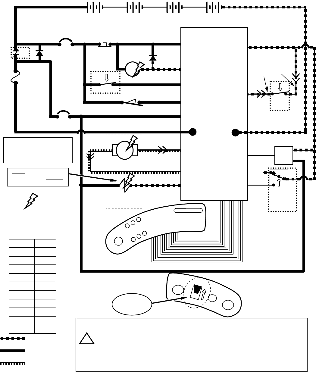
T7 – Scrub Head & Squeegee Actuator Systems
(page 1 of 2)
CONDITIONS: key ON, operator on seat, forward travel, propel pedal depressed, One Step Scrub Button pressed
SQUEEGEE ACTUATOR
17
18
MTR5
18 17
SCRUB HEAD ACTUATOR
19
20
20 19
Pressing the “One Step Scrub Button” will lower the squeegee and scrub head
Only one actuator will be energized at any given time – squeegee is lowered
first, then the scrub head
Squeegee actuator uses internal limit switches to stop travel in upward and
downward travel
Scrub head actuator travel is controlled by monitoring actuator current in
upward travel and brush motor current in downward travel
Squeegee actuator can also be operated by pressing the “Vacuum Fan/
Squeegee Button”, without operating scrub brushes
i
D3
1 RED 13 BLK
13 BLK
POS
CONTROL BOARD
STANDOFF 2
+-
6 VDC +-
6 VDC +-
6 VDC +-
6 VDC
vv
1 RED
STANDOFF 4
NEG
50 RED
F1
100 A
S1
D1
CB1
5 A
CB2
15 A
KEYSWITCH
-
EMERGENCY
STOP SWITCH
X
50 RED
14
MAIN
CONTACTOR
6
55
56
3
26
3
4
4
4
4
PIN J6-17
PIN J6-5
PIN J6-24
PIN J6-6
PIN J6-13
14
1 RED
50 RED
13 BLK
RIBBON CABLE CONNECTOR P6
POST J11 POST J7
CHARGER INTERLOCK
26
4SW1
X
+
22
2
M1B
M1A
PIN J6-7 27
32
ORG
42
42
27
GRN
SW2
SEAT
SWITCH
PIN J6-35 LOGIC GROUND
PIN J6-12
PIN J6-9
PIN J6-23
PIN J6-21
TOUCH
PANEL
RIBBON CABLE
LEFT SIDE
DASH PANEL
One Step
Scrub Button
Vacuum Fan/
Squeegee Button
NOTE: Actuator voltage switches
polarity when direction of actuator
travel changes (see next page for
more information)
MTR6
Indicates Component
is Energized
Wiring Color Codes
(Unless otherwise marked)
0
1
2
3
4
5
6
7
8
9
Tan
Pink
Brown
Orange
Yellow
Green
Blue
Purple
Gray
White
Right Most Digit
of Wire Number Color of Wire
= Battery Negative
or Logic Ground
= Battery Positive
or Positive Output
= Output that can
Change Polarity
17
T7 – Scrub Head & Squeegee Actuator Systems
(page 2 of 2)
Actuator Voltage Data
Actuator Travel Direction Wire # Color Polarity Notes
17 Purple
−
18 Gray
"+"
17 Purple
"+"
18 Gray
−
19 White
−
20 Tan
"+"
19 White
"+"
20 Tan
−
DOWN
UP
Squeegee
Voltage at actuator connector will be
approx. 24 VDC for 2 seconds, then
approx. 12 VDC for 2 seconds for both
UP & DOWN travel
Scrub
Head
DOWN
UP
Voltage at actuator connector will be
approx. 24 VDC for 4 seconds
Voltage at actuator connector will be
approx. 24 VDC for 4 seconds, then
approx. 11 to 12 VDC for 2 to 4 seconds
Pressing the “One Step Scrub Button” will lower the squeegee and scrub head
Only one actuator will be energized at any given time – squeegee is lowered
first, then the scrub head
Squeegee actuator uses internal limit switches to stop travel in upward and
downward travel
Scrub head actuator travel is controlled by monitoring actuator current in
upward travel and brush motor current in downward travel
Squeegee actuator can also be operated by pressing the “Vacuum Fan/
Squeegee Button”, without operating scrub brushes
i
18
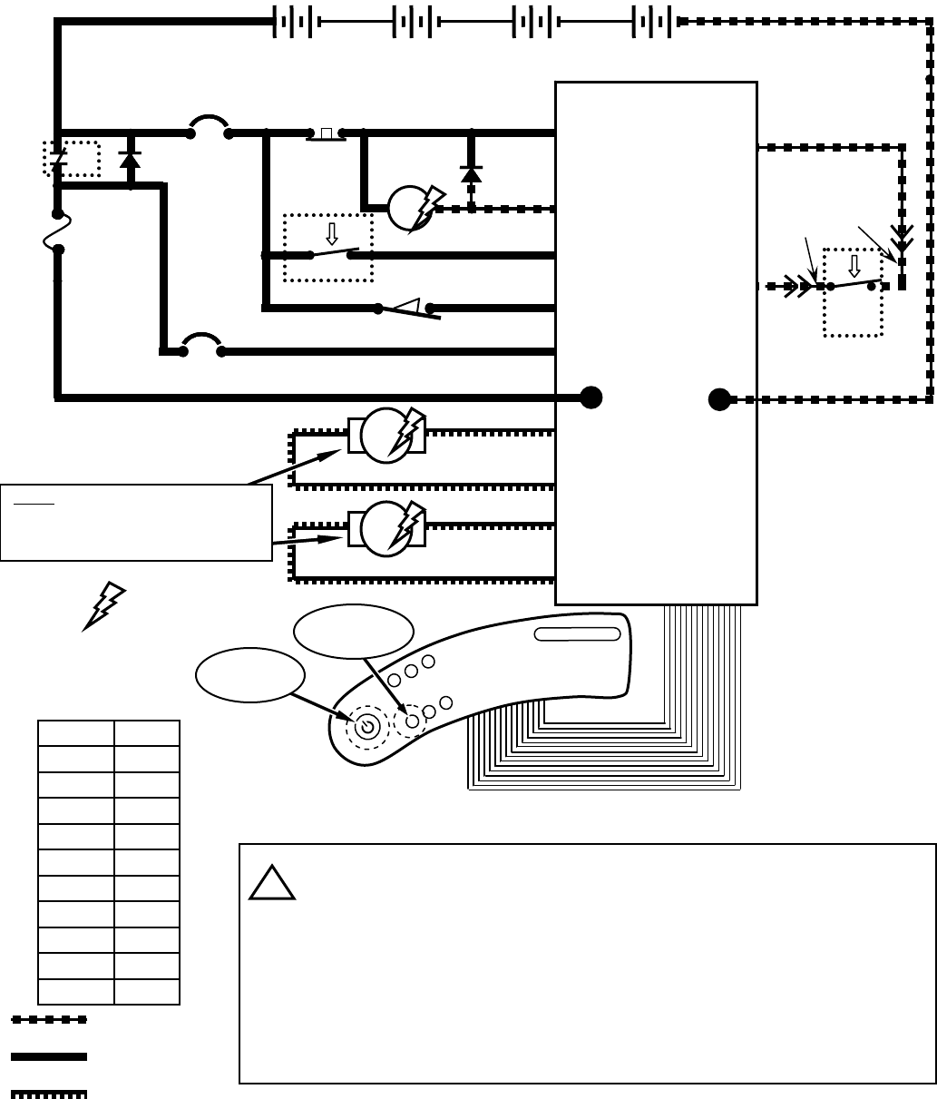
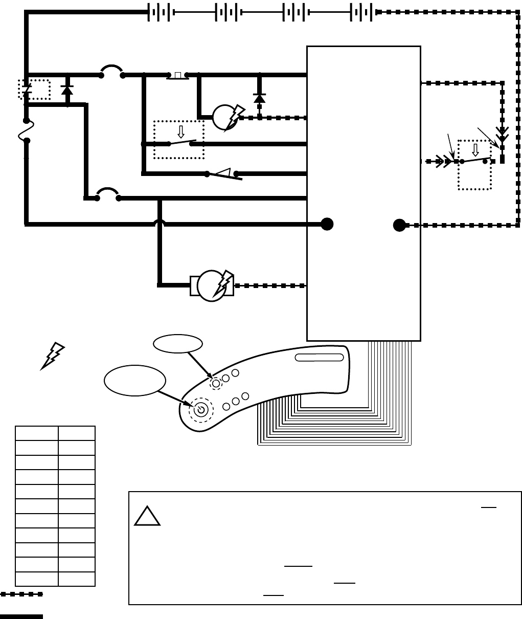
T7 – Scrub Brush Motors System
CONDITIONS: key ON, operator on seat, forward travel, propel pedal depressed, One Step Scrub Button pressed
Brush Motor Current Draw: Approx. 10 to 20 Amps per motor, varying upon
selected brush pressure setting
Brush Motor Voltage: Approx. 18 VDC in Economy Mode
Approx. 21.5 VDC in All Other Modes
Scrub Brush Motors are controlled by PWM (Pulse Width Modulation)
Pressing the “One Step Scrub Button” will turn on the Scrub Brush Motors
(after lowering squeegee and scrub head)
Scrub Brush Motors will function only when propelling either forward or reverse
Scrub Brush Pressure is controlled by monitoring brush motor current
i
D3
1 RED 13 BLK
13 BLK
POS
CONTROL BOARD
STANDOFF 2
+-
6 VDC +-
6 VDC +-
6 VDC +-
6 VDC
vv
1 RED
STANDOFF 4
NEG
50 RED
F1
100 A
S1
D1
CB1
5 A
CB2
15 A
KEYSWITCH
-
EMERGENCY
STOP SWITCH
X
50 RED
14
MAIN
CONTACTOR
6
55
56
3
26
3
4
4
4
4
PIN J6-17
PIN J6-5
PIN J6-24
PIN J6-6
PIN J6-13
14
1 RED
50 RED
13 BLK
RIBBON CABLE CONNECTOR P6
POST J11 POST J7
CHARGER INTERLOCK
26
4SW1
X
+
22
2
M1B
M1A
PIN J6-7 27
32
ORG
42
42
27
GRN
SW2
SEAT
SWITCH
PIN J6-35 LOGIC GROUND
TOUCH
PANEL
RIBBON CABLE
LEFT SIDE
DASH PANEL
One Step
Scrub Button
Brush Pressure
Buttons
LEFT SCRUB BRUSH MOTOR
7
8
MTR2
87
9
10
MTR3
10 9
PIN J8-1
PIN J8-2
PIN J8-3
PIN J8-4
RIGHT SCRUB BRUSH MOTOR
Indicates Component
is Energized
Wiring Color Codes
(Unless otherwise marked)
0
1
2
3
4
5
6
7
8
9
Tan
Pink
Brown
Orange
Yellow
Green
Blue
Purple
Gray
White
Right Most Digit
of Wire Number Color of Wire
= Battery Negative
or Logic Ground
= Battery Positive
or Positive Output
19
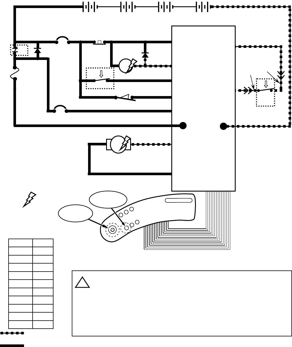
T7 – Vacuum Fan System
CONDITIONS: key ON, operator on seat, forward travel, One Step Scrub Button pressed
VACUUM FAN
11
12
MTR4
12 11
Vacuum Fan Motor Current Draw: Approx. 18 to 21 Amps
Vacuum Fan Motor Voltage: Approx. 18 VDC in Economy Mode
Approx. 21.5 VDC in All Other Modes
Vacuum Fan Motor is controlled by PWM (Pulse Width Modulation)
Pressing the “One Step Scrub Button” will activate Vacuum Fan
Vacuum Fan can also be operated by pressing the “Vacuum Fan/Squeegee
Button”, without operating scrub brushes
i
D3
1 RED 13 BLK
13 BLK
POS
CONTROL BOARD
STANDOFF 2
+-
6 VDC +-
6 VDC +-
6 VDC +-
6 VDC
vv
1 RED
STANDOFF 4
NEG
50 RED
F1
100 A
S1
D1
CB1
5 A
CB2
15 A
KEYSWITCH
-
EMERGENCY
STOP SWITCH
X
50 RED
14
MAIN
CONTACTOR
6
55
56
3
26
3
4
4
4
4
PIN J6-17
PIN J6-5
PIN J6-24
PIN J6-6
PIN J6-13
14
1 RED
50 RED
13 BLK
RIBBON CABLE CONNECTOR P6
POST J11 POST J7
CHARGER INTERLOCK
26
4SW1
X
+
22
2
M1B
M1A
PIN J6-7 27
32
ORG
42
42
27
GRN
SW2
SEAT
SWITCH
PIN J6-35 LOGIC GROUND
TOUCH
PANEL
RIBBON CABLE
LEFT SIDE
DASH PANEL
One Step
Scrub Button
Vacuum Fan/
Squeegee Button
PIN J9-1
PIN J9-2
Indicates Component
is Energized
Wiring Color Codes
(Unless otherwise marked)
0
1
2
3
4
5
6
7
8
9
Tan
Pink
Brown
Orange
Yellow
Green
Blue
Purple
Gray
White
Right Most Digit
of Wire Number Color of Wire
= Battery Negative
or Logic Ground
= Battery Positive
or Positive Output
20
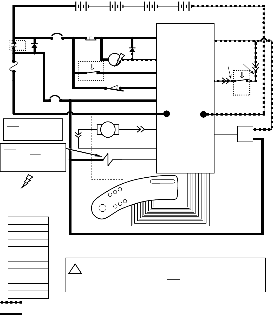
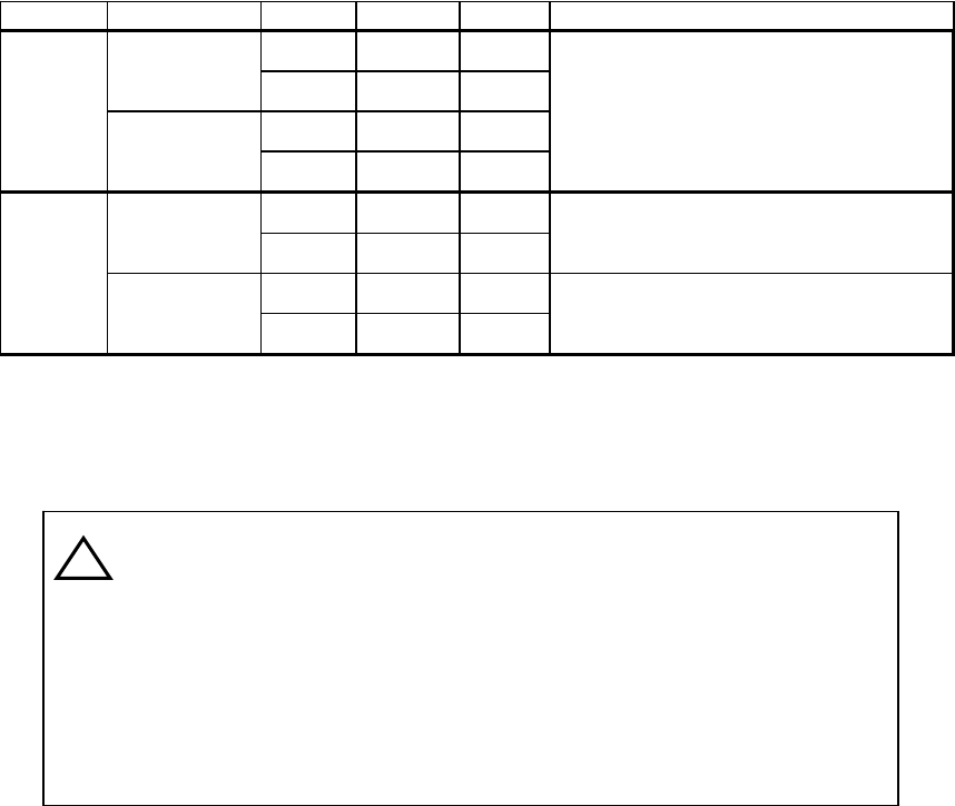
T7 – FaST System
CONDITIONS: key ON, operator on seat, forward travel, propel pedal depressed, One Step Scrub Button pressed
D3
1 RED 13 BLK
13 BLK
POS
CONTROL BOARD
STANDOFF 2
+-
6 VDC +-
6 VDC +-
6 VDC +-
6 VDC
vv
1 RED
STANDOFF 4
NEG
50 RED
F1
100 A
S1
D1
CB1
5 A
CB2
15 A
KEYSWITCH
-
EMERGENCY
STOP SWITCH
X
50 RED
14
MAIN
CONTACTOR
6
55
56
3
26
3
4
4
4
4
PIN J6-17
PIN J6-5
PIN J6-24
PIN J6-6
PIN J6-13
14
1 RED
50 RED
13 BLK
RIBBON CABLE CONNECTOR P6
POST J11 POST J7
CHARGER INTERLOCK
26
4SW1
X
+
22
2
M1B
M1A
PIN J6-7 27
32
ORG
42
42
27
GRN
SW2
SEAT
SWITCH
PIN J6-35 LOGIC GROUND
TOUCH
PANEL
RIBBON CABLE
LEFT SIDE
DASH PANEL
One Step
Scrub Button
Pressing the “One Step Scrub Button” will activate FaST Pump Motor OR
Solution Solenoid Valve as Scrub Brush Motors engage
Pressing the FaST button will toggle from FaST scrubbing to Conventional
scrubbing
FaST system will operate ONLY if FaST LED is ON
Solution Volume Control Buttons will NOT operate & Solution Volume
Control LED’s will be OFF during FaST scrubbing
i
FaST PUMP MOTOR
22
MTR7
14 22 PIN J6-25
FaST Button
Indicates Component
is Energized
Wiring Color Codes
(Unless otherwise marked)
0
1
2
3
4
5
6
7
8
9
Tan
Pink
Brown
Orange
Yellow
Green
Blue
Purple
Gray
White
Right Most Digit
of Wire Number Color of Wire
= Battery Negative
or Logic Ground
= Battery Positive
or Positive Output
14
21
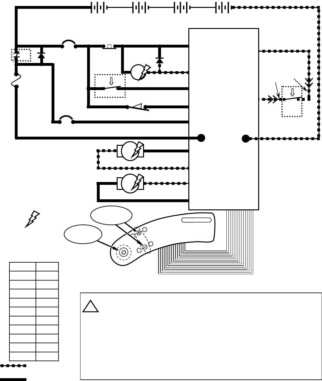
T7 – Conventional Solution System
CONDITIONS: key ON, operator on seat, forward travel, propel pedal depressed, One Step Scrub Button pressed
D3
1 RED 13 BLK
13 BLK
POS
CONTROL BOARD
STANDOFF 2
+-
6 VDC +-
6 VDC +-
6 VDC +-
6 VDC
vv
1 RED
STANDOFF 4
NEG
50 RED
F1
100 A
S1
D1
CB1
5 A
CB2
15 A
KEYSWITCH
-
EMERGENCY
STOP SWITCH
X
50 RED
14
MAIN
CONTACTOR
6
55
56
3
26
3
4
4
4
4
PIN J6-17
PIN J6-5
PIN J6-24
PIN J6-6
PIN J6-13
14
1 RED
50 RED
13 BLK
RIBBON CABLE CONNECTOR P6
POST J11 POST J7
CHARGER INTERLOCK
26
4SW1
X
+
22
2
M1B
M1A
PIN J6-7 27
32
ORG
42
42
27
GRN
SW2
SEAT
SWITCH
PIN J6-35 LOGIC GROUND
TOUCH
PANEL
RIBBON CABLE
LEFT SIDE
DASH PANEL
One Step
Scrub Button
16
14 PIN J6-4
Indicates Component
is Energized
Wiring Color Codes
(Unless otherwise marked)
0
1
2
3
4
5
6
7
8
9
Tan
Pink
Brown
Orange
Yellow
Green
Blue
Purple
Gray
White
Right Most Digit
of Wire Number Color of Wire
= Battery Negative
or Logic Ground
= Battery Positive
or Positive Output
14
SOLUTION SOLENOID VALVE
16
Solution Volume
Control Buttons
Pressing the “One Step Scrub Button” will activate FaST Pump Motor OR
Solution Solenoid Valve as Scrub Brush Motors engage
Pressing the FaST button will toggle from FaST scrubbing to Conventional
scrubbing
Conventional Solution system will operate ONLY if FaST LED is OFF
Solution Volume Control Buttons & LED’s will operate ONLY during
Conventional scrubbing
i
SOL2
22
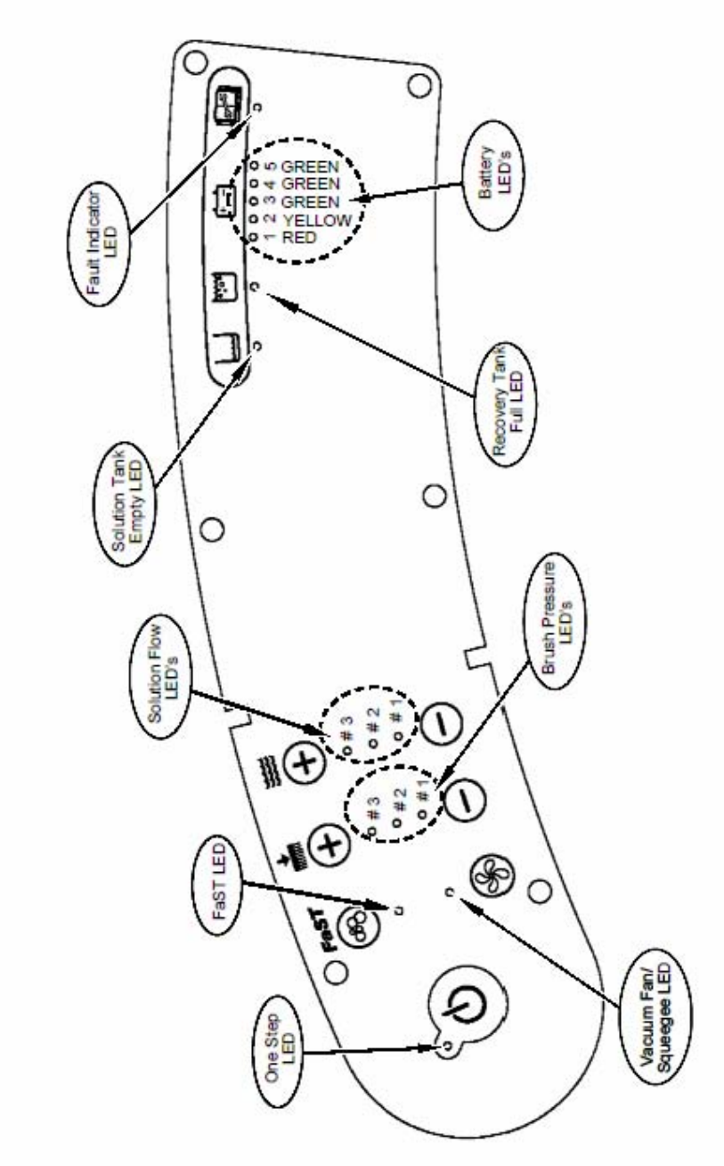
T7 – LED Locations & Descriptions
23

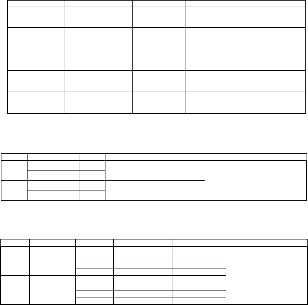
T7 – Operational Modes & Interlocks
Mode Entry Sequence Indicator Function
−Directional Switch Forward
−Propel Pedal Depressed
−Directional Switch Reverse −Directional Switch in Reverse position
−Propel Pedal Depressed −Horn Sounding continuously ON & OFF (except in
"Hospital" mode)
Scrub Mode
−Press One Step Scrub Button
(ON) −One Step Scrub LED ON
Activate Scrub Brush, Squeegee,
Vacuum Fan & Solution Flow
operations
−Press One Step Scrub Button
(ON) −One Step Scrub & FaST LED's ON
−Press FaST Button (ON) −Solution Flow LED's OFF
−Press One Step Scrub Button
(ON) −One Step Scrub & Solution Flow LED(s) ON
−Press FaST Button (OFF) −FaST LED OFF
−Press One Step Scrub Button
(ON) −One Step Scrub LED ON
−Press Vacuum Fan/Squeegee
Button (OFF) −Vacuum Fan/Squeege LED OFF
−One Step Scrub LED OFF
−Vacuum Fan/Squeegee LED ON
−Lower Brush Pressure (#1) LED ON; Middle (#2) &
Upper (#3) LED's OFF
−Lower Solution Flow (#1) LED ON; Middle (#2) &
Upper (#3) LED's OFF
−Press Brush Pressure
Decrease (-) to one LED
−Lower Brush Pressure (#1) LED ON; Middle (#2) &
Upper (#3) LED's OFF
−Press FaST Button (ON) −FaST LED ON (Solution Flow LED's OFF)
Recovery Tank
Full
−Recovery Tank Full (Float
Switch Closed) −Recovery Tank Full LED ON
Disable Scrub function (Operator can
get an additional minute of operation by
re-engaging scrub system with One
Step button)
Battery
Discharged
−Battery voltage at or below full
discharge voltage −Red LED (on Battery Gauge) blinking
Disable Scrub function (Operator can
get an additional minute of operation by
re-engaging scrub system with One
Step button)
−Fault LED ON and any one or more of the
followin
g
:
Lower Brush Pressure (#1) LED ON (Right Motor)
Upper Brush Pressure (#3) LED ON (Left Motor)
Upper Solution Flow (#3) LED ON (Vacuum Fan)
Prevent damage to Scrub Brush
Motors or Vacuum Fan Motor –
Scrub function shuts off
Double Scrub
(no water
pickup)
Water pickup
(no Scrub)
Accessory
Motor High
Current Fault
−Controller sensed an Over
Current condition in the
Scrub Brush Motors or
Vacuum Fan Motor
Forward
Reverse
FaST Mode
Conventional
Solution Mode
−Press Brush Pressure
Decrease (-) to one LED
−Press Solution Flow Decrease
(-) to one LED
−Solution Tank Empty LED ON
Disable Scrub function (Operator can
get an additional minute of operation by
re-engaging scrub system with One
Step button)
Low Power
Mode
Low Power
Mode w/ FaST
Solution Tank
Empty
Reduce Scrub Brush and Fan speeds
(to prolong battery life, reduce noise,
lower water usage)
Reduce Scrub Brush and Fan speeds
(to prolong battery life, reduce noise,
lower water usage)
−Solution Tank Empty (Float
Switch Open)
Activate Conventional solution flow
when scrub and propel are engaged
Apply cleaning solution with no water
pickup
−Press Vacuum Fan/Squeegee
Button (ON)
Collect solution on floor with squeegee,
without scrubbing floor
−Directional Switch in Forward position Forward movement of machine
Reverse movement of machine
Activate FaST foam solution flow when
scrub and propel are engaged
24
T7 – Diagnostic & Fault Alarms
Alarm Codes
Mode Directional
Switch Entry Sequence Alarm Sequence Function
Back-Up Alarm
REVERSE Directional switch
placed in REVERSE Horn sounds 1 beep cycle (repeats)
Alerts nearby persons of machine
backward movement (Note: Back-
up alarm will not sound when
machine is placed in "Hospital"
mode)
Propel Interlock:
Seat Switch Released
FORWARD
Propel Pedal depressed
with operator NOT on
seat Horn sounds 2 beep cycle (repeats) Prevents movement of machine
when operator not in place
Propel interlock:
High Pedal Disable
FORWARD
Key switch turned ON
with Propel
Pedal engaged Horn sounds 4 beep cycle (repeats)
Prevents movement of machine
when key switched ON while throttle
depressed
Propel Interlock:
Throttle Fault
FORWARD
Controller sensed
an out-of range
Throttle signal
Horn sounds 5 beep cycle (repeats)
(Also FAULT and FaST LED's blink)
Prevents movement of machine
with invalid throttle voltage. Scrub
function shuts off.
Propel Interlock:
Parking Brake Fault
FORWARD
Controller sensed an out-
of range
Brake signal
Horn sounds 6 beep cycle (repeats)
(Also FAULT and Vacuum Fan/
Squeegee LED's blink)
Prevents movement of machine
with invalid brake voltage. Scrub
function shuts off.
Propel Interlock:
Parking Brake Unplugged
FORWARD Controller sensed open
circuit on parking brake
Horn sounds 7 beep cycle (repeats)
(Also FAULT and Lower Solution Flow
LED's blink)
Prevents movement of machine
with ineffective parking brake. Scrub
function shuts off.
Propel Interlock:
E-STOP Switch Activated
FORWARD
Controller sensed open
circuit on Emergency
Stop Switch circuit
Horn sounds 8 beep cycle (repeats)
(When in Input Display Mode, FAULT
LED will also blink)
Disables all functions
(Note: To reset, key switch must be
cycled OFF and ON after the
E-STOP switch has closed)
Propel Interlock:
Charger Plugged In
FORWARD
Battery charger plugged
into machine with
Key Switch ON Horn sounds 9 beep cycle (repeats) Prevents movement of the machine
with charger plugged in
High Current Faults
Fault Entr
y
Se
q
uence Indicato
r
Excessive Left Brush
Motor Current
Left brush motor current higher than 30 Amps Blinking FAULT LED,
Blinking Brush Pressure LED #3
Excessive Right Brush
Motor Current
Right brush motor current higher than 30 Amps Blinking FAULT LED,
Blinking Brush Pressure LED #1
Excessive Vacuum Fan
Motor Current
Vacuum Fan Motor current higher than 27 Amps Blinking FAULT LED,
Blinking Vacuum Fan/Squeegee LED
Excessive Propel
Motor Current
Blinking FAULT LED,
Propel disabled
Propel Motor Current Higher than 40 Amps
for 15 min. OR Higher than 55 Amps for 6 min.
OR Higher than 68 Amps for 4 min.
25

T7 – Diagnostic & Configuration Modes
Mode Entry Sequence Indicator Function
Upper Brush Pressure LED blinks Tens of
days of month, Upper Solution Flow LED
blinks Single day of month
Middle Brush Pressure LED blinks Tens of
month, Middle Solution Flow LED blinks
Single month
Lower Brush Pressure LED blinks Tens of
year, Lower Solution Flow LED blinks out
Single year
Self Test
Mode
Press and hold FaST and
Vacuum Fan/Squeegee
Buttons, turn key switch ON,
wait 10 seconds, release
buttons
Start of test - Left Scrub Brush turns ON
End of test - Horn sounds
Solid lit One Step LED indicates OK, A
Flashing LED indicates an OPEN Fault,
A Solid lit LED (other than One Step)
indicates a SHORT Fault
Input Display
Mode
Press and hold Decrease
Solution Flow (-) Button, turn
key switch ON, release
button after forth battery
LED starts to blink
Fourth battery LED blinks Shows state of control board inputs from
various switches and sensors
Manual Mode
Press and hold Decrease
Brush Pressure (-) Button,
turn key switch ON, release
after Lowest Brush Pressure
LED starts to blink.
Lowest down pressure LED will blink
Allows operation of individual functions
without the safety interlocks affecting or
controlling them
Propel/Brake
Diagnostic
Mode
Press and hold FaST
and Increase Brush
Pressure (+) Buttons, turn
key switch ON, release after
battery LED's are OFF
FaST LED ON if in Forward OR Vacuum
Fan/Squeegee LED ON if in Reverse -
Solution Flow LED's display position of
Propel Pedal, Brush Pressure LED's display
position of Brake Pedal, Battery LED's
display Propel Motor current level
Provides information regarding brake
pedal signal, propel pedal signal, and
propel motor current
Battery Select
Mode
Press and hold the Increase
Solution Flow (+) Button,
turn key switch ON, release
after one Battery LED starts
to blink
Any one of lower 4 battery LED’s blinks Allows selection of battery type. See
“Battery Select Mode Settings” table.
Reverse
Alarm Select
Mode
Put directional switch in
Reverse, press & hold Horn
Button, turn key switch ON
Horn sounds or is silent Allows enable/disable of
Backup alarm (Hospital Mode)
Propel Speed
Selection
Mode
Press and hold FaST
Button, turn key switch ON,
release after selecting
desired Brush Pressure LED
setting
Brush Pressure Lower, Middle, and Upper
LED’s represents LOW, MEDIUM and HIGH
maximum Forward Propel Speed selection
Allows selection of maximum forward
speed during scrubbing
LOWER (#1) LED = 2.0 mph / 3.2 kph
MIDDLE (#2) LED = 2.7 mph / 4.3 kph
UPPER (#3) LED = 3.5 mph / 5.5 kph
Display
Software
Revision
Mode
Press and hold One Step
Button, turn key switch ON,
wait 10 seconds, release
One Step Button
Blinking Brush Pressure and Solution
Flow LED’s indicate revision date
26
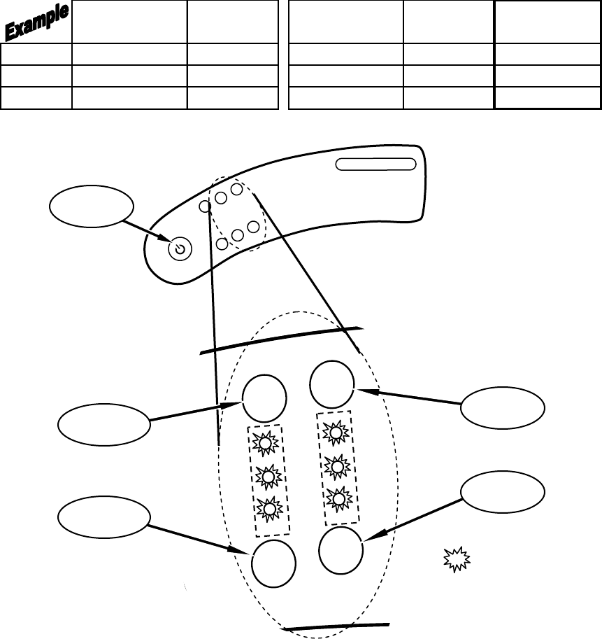
T7 – Display Software Revision Mode
TO ENTER: • Press and hold One Step Button
• Turn key switch ON, wait 10 seconds
• Release One Step Button
READING THE SOFTWARE REVISION:
•Upper Brush Pressure LED blinks TENS of DAYS of MONTH,
Upper Solution Flow LED blinks SINGLE DAY of MONTH
•Middle Brush Pressure LED blinks TENS of MONTH,
Middle Solution Flow LED blinks SINGLE MONTH
•Lower Brush Pressure LED blinks TENS of YEAR,
Lower Solution Flow LED blinks SINGLE YEAR
Brush Pressure
LED's
# of
Blinks
Solution Flow
LED's
# of
Blinks
Revision
Date
Day # 3 (Upper) 2 # 3 (Upper) 6
26th
Month # 2 (Middle) 1 # 2 (Middle) 1
November
Year # 1 (Lower) 0 (LED OFF) # 1 (Lower) 4
2004
TOUCH
PANEL LEFT SIDE
DASH PANEL
++
--
Brush Pressure
Increase Button
Solution Flow
Increase Button
DAY
MONTH
YEAR
LED 3
LED 2
LED 1
LED 3
LED 2
LED 1
TENSONES
= BLINKING (except if zero)
One Step
Scrub Button
NOTE: An LED that does NOT
blink is the digit ZERO (0)
Solution Flow
Decrease Button
Brush Pressure
Decrease Button
27

T7 – Self Test Mode
TO ENTER: • Press and hold FaST & Vacuum Fan/Squeegee Buttons
• Turn key switch ON, wait 10 seconds
• Release Buttons
• The entire Self Test takes approximately 40 seconds
AFTER THE SELF TEST IS COMPLETE:
• If the One Step LED is lit solid, NO FAULTS were found
• If any LED is blinking, an OPEN FAULT was found –
refer to table below
• If any LED (other than One Step) is lit solid,
a SHORT FAULT was found – refer to table below
Self Test Results
LED (Flashing = OPEN, Solid = SHORT) System at Fault
One Step LED No Faults Found
FaST LED Fast Pump
Vacuum Fan/Squeegee LED Vacuum-Fan
# 3 (Upper) Brush Pressure LED Right Brush
# 2 (Middle) Brush Pressure LED Left Brush
# 1 (Lower) Brush Pressure LED Head Actuator
# 3 (Upper) Solution Flow LED Water Valve
# 2 (Middle) Solution Flow LED Squeegee Actuator
# 1 (Lower) Solution Flow LED Brake
Recovery Tank Full LED Horn/Back-up Alarm
28

T7 – Input Display Mode
INPUT ASSOCIATED LED LED IS ON WHEN: LED IS OFF WHEN: NOTES
Charger Interlock Switch FaST LED Battery charger IS NOT plugged in
(switch is CLOSED)
Battery charger IS plugged in
(switch is OPEN)
FaST system will still operate, but without
indicator
Seat Switch # 5 (Green) Battery LED Operator IS NOT sitting on seat (switch
is OPEN)
Operator IS sitting on Seat (switch is
CLOSED)
Recovery Tank Float
Switch Recovery Tank Full LED
Recovery tank IS FULL (switch must be
CLOSED for 5 to 7 seconds after One
Ste
p
Button is activated
)
Recovery tank IS NOT FULL (switch
is OPEN)
Opening switch and pushing the the One Step
Button turns LED off again
Solution Tank Float
Switch Solution Tank Empty LED
Solution tank IS EMPTY (switch must be
OPEN for 5 to 7 seconds after One Step
Button is activated
)
Solution tank IS NOT EMPTY
(switch is CLOSED)
Closing switch and pushing the the One Step
Button turns LED off again
Emergency Stop Switch Fault Indicator LED (Blinking) Emergency Stop Switch IS ACTIVATED
(switch is OPEN)
Emergency Stop Switch IS NOT
ACTIVATED (switch is CLOSED)
Horn will repeat 8 beep cycle when Emergency
Stop Switch is activated
One Step Button One Step LED Scrub system IS ACTIVATED Scrub system IS NOT ACTIVATED
Vacuum Fan/Squeegee
Button Vacuum Fan/Squeegee LED Vacuum Fan & Squeegee ARE
ACTIVATED
Vacuum Fan & Squeegee ARE NOT
ACTIVATED
Battery Voltage # 1 (Red) Battery LED Battery needs charging (LED is
BLINKING) Battery has sufficient charge level
Left Scrub Brush
Low Pressure # 1
(
Lower
)
Brush Pressure LED LOW scrub brush current sensed
Medium Pressure # 2
(
Middle
)
Brush Pressure LED MEDIUM scrub brush current sensed
Hi
g
h Pressure # 3
(
U
pp
er
)
Brush Pressure LED HIGH scrub brush current sensed
Right Scrub Brush
Low Pressure # 1
(
Lower
)
Solution Flow LED LOW scrub brush current sensed
Medium Pressure # 2
(
Middle
)
Solution Flow LED MEDIUM scrub brush current sensed
Hi
g
h Press
TO ENTER: • Press and hold the Decrease Solution Flow (-) Button
• Turn key switch ON
• Release Button after the # 4 Battery LED blinks
The purpose of the Input Display Mode is to show the condition of various control board inputs
NOTE: For Propel & Brake signal troubleshooting, refer to the Propel Diagnostics Mode page
ure # 3
(
U
pp
er
)
Solution Flow LED HIGH scrub brush current sensed
Scrub system IS NOT ACTIVATED
Scrub system IS NOT ACTIVATED
29

T7 – Manual Mode
FUNCTION BUTTON ACTION INDICATOR NOTES
Lower Scrub Head One Step Press & Hold One Step LED ON Scrub head will continue to lower as long as button is held
Operate Scrub Brushes One Step Release button after
lowering scrub head One Step LED ON Scrub head stops lowering after One Step Button is released
Turn OFF Scrub Brushes
and Raise Scrub Head One Step Press & Release One Step LED OFF Scrub head raises to to top of stroke and stops
Turn ON Vacuum Fan
and Lower Squeegee
Vacuum Fan/
Squeegee Press & Release Vacuum Fan/
Squeegee LED ON
In this mode, pressing the One Step Button during lowering of
the squeegee will stop squeegee travel
Turn OFF Vacuum Fan
and Raise Squeegee
Vacuum Fan/
Squeegee Press & Release Vacuum Fan/
Squeegee LED OFF
In this mode, pressing the One Step Button during raising of
the squeegee will stop squeegee travel
Turn ON FaST pump FaST Press & Release FaST LED ON
Turn OFF FaST pump FaST Press & Release FaST LED OFF
Increase Solution
Flow Rate
Increase Solution
Flow (+) Press & Release Solution Flow LED's In this mode, the Solution Flow automatic
ON/OFF interlock is disabled
Decrease Solution
Flow Rate
Decrease Solution
Flow (-) Press & Release Solution Flow LED's In this mode, the Solution Flow automatic
ON/OFF interlock is disabled
• When the Solution Empty switch is un-grounded for a short time, the Solution Empty LED will light
• If the Recovery Full LED or the Solution Empty LED is ON, and the Scrub System or Vacuum Fan/Squeegee system is activated, the Recovery Full LED and
Solution Empty LED will turn OFF and the sensing of both switches will be disabled for about a minute
• For safety considerations, the "High Pedal Disable" and "Seat Switch Disable" interlocks & alarms are still active in Manual Mode
• With the Directional Switch in REVERSE, the Back-up Alarm will sound but automatic raising of the squeegee is disabled
ADDITIONAL NOTES
• When the Recovery Full switch is grounded for a short time, the Recovery Full LED will light
!
CAUTION : Do not hold One Step Button down too long - actuator stall will occur, possibly damaging actuator or control board
!
CAUTION : In this mode, automatic raising of the squeegee when in REVERSE is disabled
The purpose of the Manual Mode is to allow functioning of the individual systems on the machine without regard of most safety interlocks
TO ENTER: • Press and hold the Decrease Brush Pressure (-) Button
• Turn key switch ON
• Release Button after # 1 (Lower) Brush Pressure LED blinks
30
T7 – Propel/Brake Diagnostics
TO ENTER: • Press and hold FaST & Increase Brush Pressure (+) Buttons
• Turn key switch ON
• Release Buttons after FaST LED (if in Forward) or Vacuum Fan/Squeegee LED
(if in Reverse) is lit
TEST ACTION INDICATOR NOTES
Directional Switch -
Forward Place Directional Switch in
Forward Propel position FaST LED ON LED will be illuminated if the controller senses the
Directional Switch in Forward Position - Machine will not
propel if any of the Brake LED’s are illuminated
Directional Switch -
Reverse Place Directional Switch in
Reverse Propel position
Vacuum Fan/
Squeegee LED ON
LED will be illuminated if the controller senses the
Directional Switch in Reverse Position - Machine will not
propel if any of the Brake LED’s are illuminated
Brake Pedal Depress Brake Pedal Brush Pressure
LED's
LED’s will display the sensed position of the brake
pedal - No LED’s indicate pedal is released, 3 LED’s
indicate that the pedal is fully depressed
Accelerator Pedal Depress Accelerator Pedal Solution Flow
LED's
LED’s will display the sensed position of the accelerator
pedal - No LED’s indicate the pedal is released, 3 LED’s
indicate that the pedal is fully depressed
Propel Motor Current Depress Accelerator Pedal Battery LED's Battery gauge LED’s display the current level being drawn
by the Propel Motor - Each LED represents
7 Amps of current (ex: 3 LED's = 21 Amps)
Propelling System Data
Direction Wire # Color Polarity
25 Green
−
24 Yellow
"+"
25 Green
"+"
24 Yellow
−
Releasing the Propel Pedal will initiate
Dynamic Braking; As machine slows to a
halt, the Brake solenoid is De-energized,
applying the Parking Brake
Notes
Forward
Reverse
Voltage during FORWARD travel will vary
between 0 to 24 VDC
Voltage during REVERSE travel will vary
between approximately 0 to 17 VDC
Propel & Brake Pedal Data
Pedal LED group Lit LED's Pedal Position Input Voltage Level Notes
0 Released below 1.35 VDC
1 Slightly Depressed 1.35 to 1.89 VDC
2 Halfway Depressed 1.89 to 2.27 VDC
3 Fully Depressed 2.27 to 4.0 VDC
0 Released below 1.5 VDC
1 Slightly Depressed 1.5 to 1.89 VDC
2 Halfway Depressed 1.89 to 2.27 VDC
3 Fully Depressed 2.27 to 4.0 VDC
Propel Machine must be in Propel
Diagnostic Mode when testing;
LED's will display the sensed
position of the pedal; No LED's
indicate pedal is released; 3
LED's indicate pedal is fully
depressed
Brake
Solution Flow
Brush Pressure
31
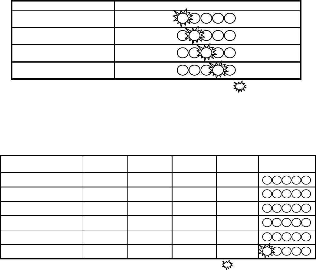
T7 – Battery Select Mode & Voltage Levels
Battery Select Mode
TO ENTER: • Press and hold Increase Solution Flow (+) Button
• Turn key switch ON
• Release Button after one of the Battery LED’s begins blinking
Location / Type
Worldwide / Wet
Europe** / Wet
TNV** / Wet
Worldwide / Gel
LED's: R=RED Y=YELLOW G=GREEN =OFF =BLINKING
BDI Indicator LED's
**Used only under instruction of battery manufacturer
x x
x x x x
x x x x
x x x x
x x
x
G
G
Y
R
Voltage Levels*
Battery Level Worldwide
Voltage (Wet)
European**
Voltage (Wet)
TNV**
Voltage (Wet)
Worldwide
Voltage (Gel)
BDI Indicator
LED's
Full Battery Voltage 24.5 24.5 24.5 24.5
Level 4 23.8 23.9 23.9 24.0
Level 3 23.1 23.2 23.3 23.5
Level 2 22.4 22.6 22.7 23.0
Level 1 21.7 21.9 22.1 22.6
Full discharge 21.0 21.3 21.6 22.2
*Voltage measured at circuit board - Assume 0.5 Volts higher at batteries (under load)
LED's: R=RED Y=YELLOW G=GREEN =OFF =BLINKING
**Used only under instruction of battery manufacturer
x
R Y G G G
R Y G G
x
R Y G
x x
R Y
x x x
R
x x x x
R
x x x
x
32

T7 – Reverse Alarm & Propel Speed Select Modes
Reverse Alarm Select Mode
Reverse Alarm Select Mode allows enabling or disabling of the Backup Alarm
TO ENTER: • Put directional switch in Reverse
• Press & Hold Horn Button
• Turn key switch ON
• If Back-up Alarm is silent, Hospital (Quiet) Mode has been selected
• If Back-up Alarm is sounding, Normal mode has been selected
• Cycle key switch OFF, then ON again
• Verify correct mode has been chosen
Propel Speed Select Mode
Propel Speed Select Mode allows selection of maximum forward speed during scrubbing
TO ENTER: • Press and hold FaST Button
• Turn key switch ON
• Release Buttons after selecting desired Brush Pressure LED
• Refer to table below for speed selection
BRUSH PRESSURE LED MAXIMUM SCRUB SPEED
# 1 (Lower) LED 2.0 mph / 3.2 kph
# 2 (Middle) LED 2.7 mph / 4.3 kph
# 3 (Upper) LED 3.5 mph / 5.5 kph
33

Main Contactor EDD
Propel Forward EEDD EDED
Propel Reverse EEDD DE**ED
Dynamic Braking
Force - Increase EE D E
Parking Brake EE DE***
Scrub Motors EDDE DD ED
Scrub Head
Pressure Control EDDE DD ED
Vacuum Motor EDD EDD
Squeegee Down EDD EDDED
FaST System EDDEEDD ED
Solution Solenoid EDDE
Hour Meter
Operation EE*
Horn EE**
E*
T7 – Inputs & Outputs Table
E
Battery Gauge
Reset E
E = Input that will ENABLE Output
D = Input that will DISABLE Output
* Activating Vacuum Fan OR Propelling machine will enable the Hour Meter
** Horn will sound when Directional Switch is selected for Reverse (except in Hospital Mode)
*** Parking Brake activated after timer has expired
Outputs
Inputs and the
Outputs they
Control
Directional
Switch
Reverse
Directional
Switch
Forward
Throttle
Input (Pedal
pressed)
Brake Input
(Pedal
pressed)
Horn Button
(Pressed)
In
p
uts
Charger
Switch
(Charger
plugged in to
machine)
Recovery
Tank Full
Switch (Tan
k
Full)
Solution
Tank Empty
Switch (Tank
Empty)
Key Switch
(ON)
Seat Switch
(Operator on
seat)
Emergency
Stop Switch
(Pressed)
One Step
Switch (ON)
FaST Switch
(ON)
Vacuum
Fan/
Squeegee
Switch (ON)
34

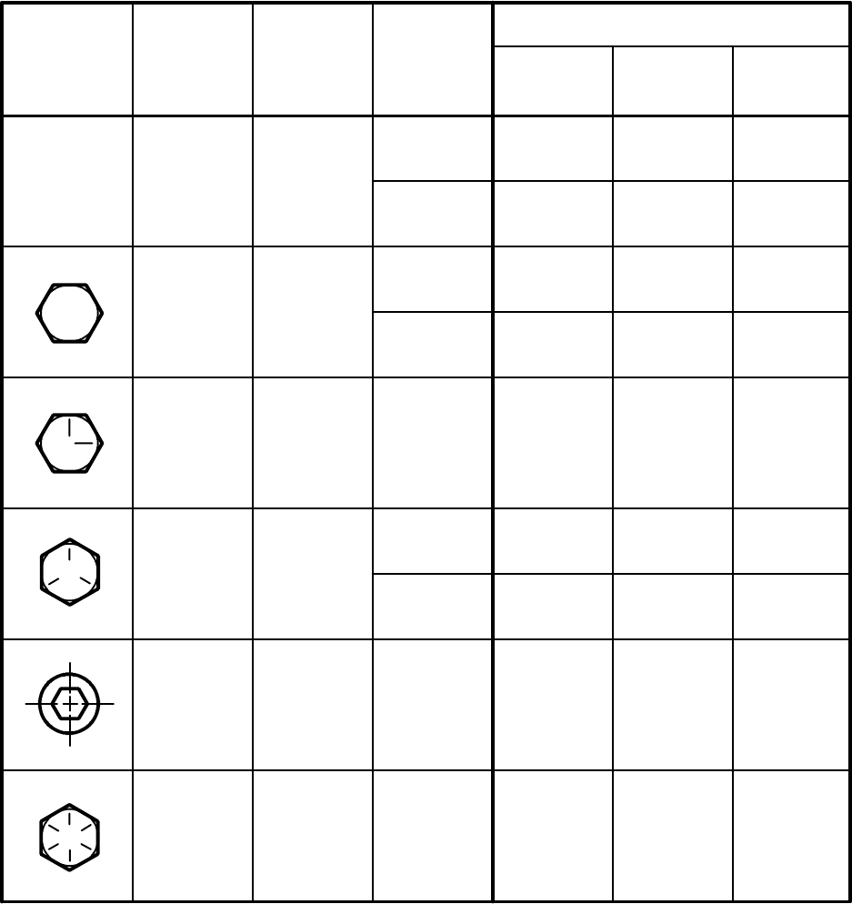
Fasteners and Torque Control (10---90)
Torque Standard
Inch Fasteners
(5)--(6.5)
Thread
Size
SAE
Grade 1
SAE
Grade 2
Carriage
Bolts
Thread
Cutting
Thread
Rolling
SAE
Grade 5
Socket
and
Stainless
Steel
SAE
Grade 8
Headless
Socket
Set
Screws
Square
Head Set
Screws
4 (.112) (4)--(6)
5 (.125) (6)-- (8) (9)--(11)
6 (.138) (7) -- (9) (20)--(24) (9)--(11)
8 (.164) (12) --(16) (40)--(47) (17)--(23)
10 (.190) (20)--(26) (50)--(60) (31)--(41)
1/4 (.250) 4--5 5-- 6 7--10 7--10 10-- 13 6--8 17--19
5/16 (.312) 7--9 9--12 15--20 15--20 20--26 13--15 32--38
3/8 (.375) 13--17 16--21 27-- 35 36--47 22--26 65--75
7/16 (.438) 20-- 26 26--34 43--56 53--76 33--39 106-- 124
1/2 (.500) 27--35 39--51 65--85 89--116 48--56 162--188
5/8 (.625) 80-- 104 130--170 171--265 228-- 383
3/4 (.750) 129--168 215--280 313--407 592--688
1 (1.000) 258-- 335 500-- 650 757-- 984 1281-- 1489
I
N
C
H
P
O
N
U
D
S
F
O
O
T
P
O
U
N
D
S
Torque Foot Pounds (Inch Pounds) Zinc Plated
35
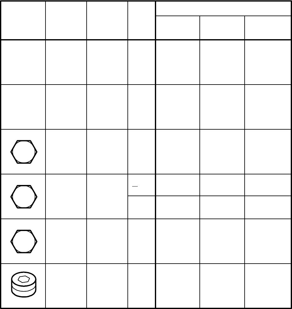
Fasteners and Torque Control (10---90)
Torque Standard
Inch Fasteners
Fastener
Identification Type Material
Nominal
Size
Proof Load
(PSI)
Te n s i l e
Strength
Min (PSI)
Yield
Strength
Min (PSI)
Mechanical Properties
SAE
Grade 1
Machine
Screws
Low or
Medium
Carbon
Steel
#2 Thru
#10
1/4 Thru
11/2 33,000 36,000
55,000
60,000
SAE
Grade 2
Carriage
Bolts
Low or
Medium
Carbon
Steel
1/4 Thru
3/4
Over 3/4
Thru 1 1/2
55,000
33,000
57,000 74,000
36,000 60,000
Stainless
Steel
18-- 8
Austenitic
Stainless
Steel
50,000 90,000
SAE
Grade 5
Medium
Carbon
Steel
Quenched
Tempered
1/4 Thru 1
Over 1 to
11/2
85,000
74,000
92,000
81,000
120,000
105,000
Socket
Screws
High Carbon
Alloy Steel
Quenched
Tempered
136,000 160,000
SAE
Grade 8
Medium
Carbon Al-
loy
Quenched
Tempered
1/4 Thru
11/2 120,000 130,000 150,000
36

Fasteners and Torque Control (10---90)
Torque Standard
METRIC Fasteners
747-- 970 Ncm
18.3--23.7 Nm
Thread
Size 4.8/5.6
8.8
Stainless
Steel 10.9 12.9
Set
Screws
M3 43-- 56 Ncm 99--128 Ncm 139--180 Ncm 166-- 215 Ncm 61--79 Ncm
M4 99--128 Ncm 223--290 Ncm 316--410 Ncm 381--495 Ncm 219--285 Ncm
M5 193-- 250 Ncm 443--575 Ncm 624--810 Ncm 427--554 Ncm
M6 3.3--4.3 Nm 7.6--9.9 Nm 10.8--14 Nm 12.7--16.5 Nm 7.5--9.8 Nm
M8 8.1--10.5 Nm 18.5--24 Nm 26.2-- 34 Nm 31-- 40 Nm
M10 16--21 Nm 37--48 Nm 52--67 Nm 63--81 Nm
M12 28--36 Nm 64-- 83 Nm 90--117 Nm 108--140 Nm
M14 45--58 Nm 102--132 Nm 142--185 Nm 169--220 Nm
M16 68--88 Nm 154--200 Nm 219--285 Nm 262--340 Nm
M20 132--171 Nm 300-- 390 Nm 424-- 550 Nm 508--660 Nm
N
E
W
T
O
N
C
E
N
T
I
M
E
T
E
R
S
N
E
W
T
O
N
M
E
T
E
R
S
M22 177--230 Nm 409-- 530 Nm 574-- 745 Nm 686--890 Nm
M24 227--295 Nm 520-- 675 Nm 732-- 950 Nm 879--1140 Nm
Zinc Plated
Conversion Tables
Ncm to Inch Pound x 0.08851 Inch Pound to Ncm x 11.2982
Nm to Foot Pound x 0.7376 Foot Pound to Nm x 1.3558
37
Fasteners and Torque Control (1---01)
Torque Standard
METRIC Fasteners
Fastener
Identification
Type
Material
Nominal
Size
Yield Stress
(Min) MPa
Yield Point
.2% Elongati
(Min) MPa
Te n s i l e
Strength
(Min) MPa
Mechanical Properties
3.6/4.6
Carriage
Bolts
Low or
Medium
Carbon
Steel
4.8 Pan
Head
Machine
Screws
Low or
Medium
Carbon
Steel
A2-- 70
Stainless
Steel
Austenitic
Stainless
Steel
8.8 Hex
Head
(Grade 5)
Medium
Carbon
Steel
Quenched
Tempered
10.9
Hex Head
Flat Head
(Grade 8)
12.9
Socket Head
Class
190
(27,550 PSI)
240
(34,800 PSI)
330
(47,850 PSI)
400
(58,000 PSI)
340
(49,300 PSI)
420
(60,900 PSI)
450
(65,300 PSI)
700
(101,000 PSI)
<M16
>M16
640
(92,800 PSI)
800
(116,000 PSI)
660
(95,700 PSI)
830
(120,350 PSI)
Medium
Carbon
Steel
Quenched
Tempered
940
(136,300 PSI)
1040
(150,800 PSI)
Alloy
Steel
A 2 --- 7 0
8.8
A
10.9
12.9
1100
(159,500 PSI)
1220
(176,900 PSI)
Conversion Table
Mega Pascals to Pounds per Square Inch x 145.138
38
Fasteners and Torque Control (10---90)
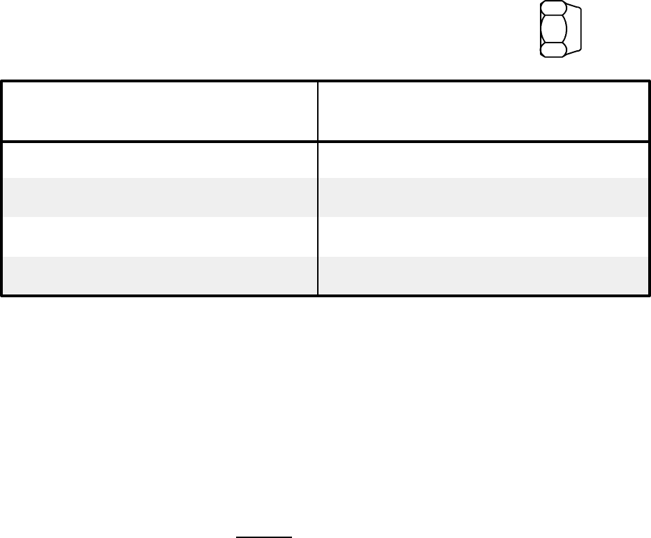
Size Grade 2 Bolt Grade 5 Bolt
1 / 4 --- 2 0 5 --- 8 7 --- 8
1 / 4 --- 2 8 4 --- 6 5 --- 6
5/16---18 8---14 13---14
5/16---24 9---14 13---14
3/8---16 12---18 15---18
3/8---24 12---18 16---18
1/2---13 26---40 37---40
1/2---20 27---42 41---42
5/8---11 58---89 73---89
5/8---18 60---92 82---92
Torque Standard
Nylon Insert Lock Nuts
Nut-Hex Light THIN
(Cad or Zinc Plated)
Torque in Foot Pounds
39
Fasteners and Torque Control (10---90)
Stud or Bolt Size
and Thread
Recommended Torque in
Foot Pounds
7/16---20 75---85
1/2---20 75---85
9/16---18 80---90
5/8---18 140---170
Torque Standard
Wheel Bolt and Nuts
Wheel Bearing Adjustment
1. Tighten the spindle nut to 12 ft lbs while turning the wheel assembly forward by hand to
fully seat the bearings.
2. Back off the nut to the “just loose” position.
3. Hand tighten the spindle nut. Loosen the spindle nut until either hole in the spindle lines
up with a slot in the nut. (Not more than 1/2 flat.)
4. Install the cotter pin. Bend the ends of the cotter pin against the nut, cut off extra length
to ensure ends will not interfere with the dust cap.
40
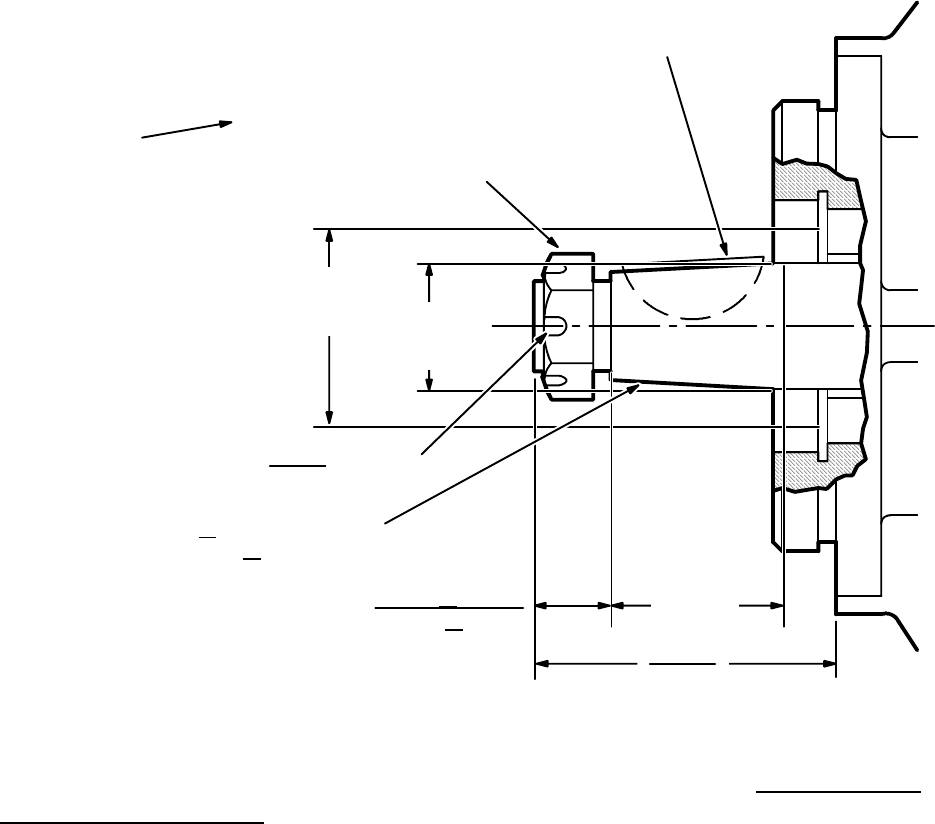
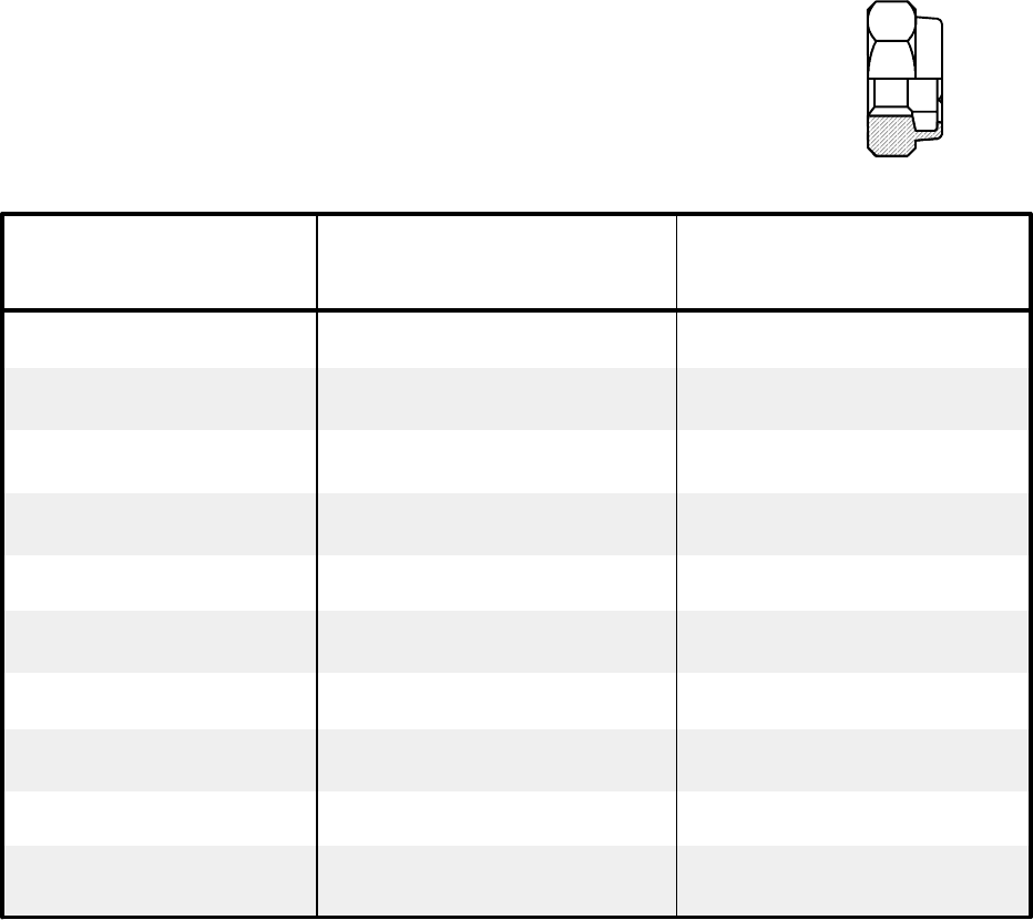
Fasteners and Torque Control (10---90)
Tightening Nuts on Tapered Shafts
.3730
1”--20 UNEF--2B SLOTTED
HEX LOCKNUT PER SAE
J--501 (EXCEPT 1.50/38,1
ACROSS FLATS).
RECOMMENDED TOQUE TO
175 FT LB PLUS TORQUE
REQUIRED TO ALIGN
SLOTTED NUT TO SHAFT
HOLE
2.27/57,7
CLEARANCE
DIA. P
SHAFT
DIA.
1.500 + .002 TAPER PER
FOOT/125 + 0,17 MM TAPER
PER METER
.750 + .010
19,05 + 0,25
1.890
48,01
+.0010
--.00000 /9,474 +0,025
-- 0
3.00
76,2
KEY WIDTH
.156
3,96 DIA. THRU
Example of
recommended
torque.
Check with the manufacturer to see what the recommended maximum torque is.
Tighten the slotted nut to a lower torque, and then tighten the nut to align the cotter pin
hole with the slot on the nut. Do not exceed the recommended torque. Do not back off
the nut to align the holes.
Motor Tapered Shaft Nut Info. Torque Specification Recommendations
A&H Series 1.00 dia. .75--16 UNF 150 ft lb dry
1.107 Hex 125 ft lb lubricated
Plus torque to align for pin
2000 Series 1.25 dia. 1--20 UNEF 225 ft lb dry
1.44 Hex 225 ft lb lubricated
PLUS torque to align for pin
4000 Series 1.625 dia. 1.25--18 UNEF 475 ft lb dry
2.187 Hex 375 ft lb lubricated
PLUS torque to align for pin
6000 Series 1.75 dia. 1.25--18 UNEF 475 ft lb dry
2.187 Hex 375 ft lb lubricated
PLUS torque to align for pin
41
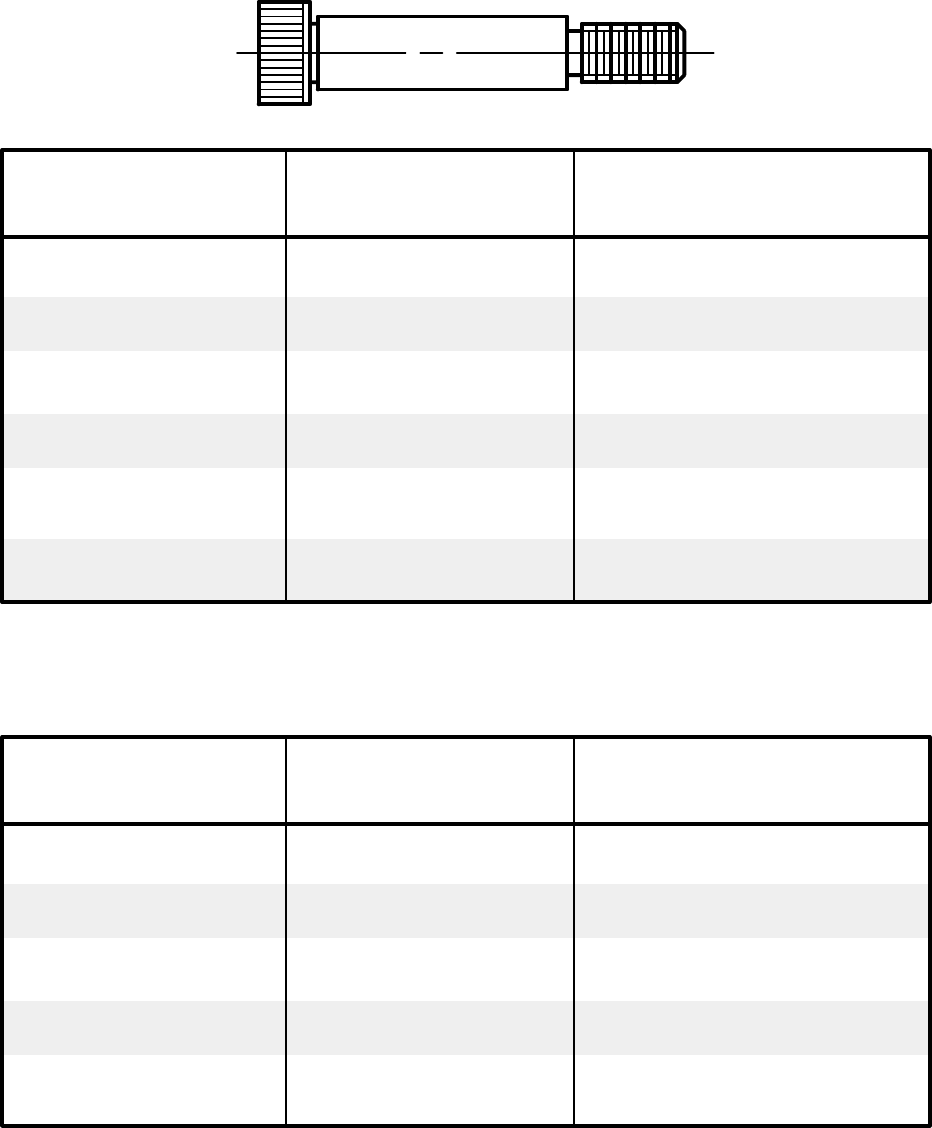
Fasteners and Torque Control (10---90)
Nominal Diameter
Torque Standard
Shoulder Bolts
Thread Size Recommended Seating
To rq u e
.250 10--24
.312
45 In Lbs
1/4--20 9 Ft Lbs
.375 5/16--18 19 Ft lbs
.500 3/8--16 32 Ft Lbs
.625 1/2--13 82 Ft Lbs
.750 5/8--11 164 Ft Lbs
Nominal Diameter Thread Size Recommended Seating
To rq u e
6
8
7Nm
M6x1.0 12 Nm
10 M8x1.25 29 Nm
12 M10x1.5 57 Nm
16 M12x1.75 100 Nm
M5x0.8
Metric
42
Fasteners and Torque Control (10---90)
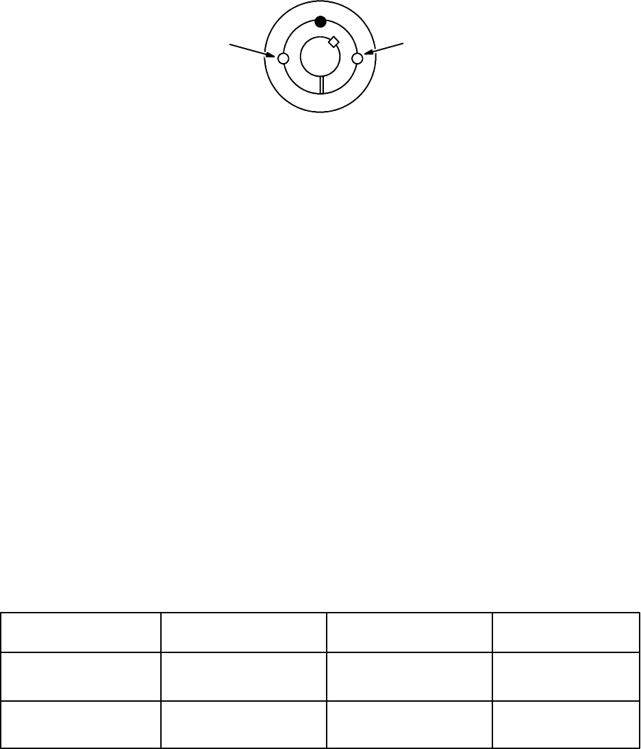
Ta p er L o c k rBushings
IMPORTANT: Follow all these instructions carefully. This is necessary to insure
satisfactory performance.
CC
1008 to 3030
To I n s t a l l
1. Clean shaft, bore and outside of bushing, and hub bore of all oil, lacquer, and dirt.
2. Insert bushing in hub. Match the hole pattern, not threaded holes (each hole will be
threaded on one side only).
3. Oil setscrews and thread into those half threaded holes indicated by C on above
diagram.
4. Alternately torque setscrews to recommended torque setting in chart below.
5. Using a block, sleeve, or drift, hammer large end of bushing (do not hammer bushing
directly).
6. Repeat steps 4 and 5 until torque wrench reading after hammering is the same as
before hammering.
7. Fill all unoccupied holes with grease.
To R e m o v e
1. Remove all setscrews.
2. Insert setscrews in holes indicated by Don the diagram. Loosen bushing by alternately
tightening setscrews.
3. To reinstall, complete all seven (7) steps installation steps.
Recommended Wrench Torque
Bushing No. Screws
Wrench Torque
(Pound-Inch)
Hammer
Size
1008, 1108
1210, 1215, 1310
1610, 1615
1/4” Setscrews
3/8” Setscrews
3/8” Setscrews
55
175
175
6lb
6lb
6lb
2012
2517, 2525
3020, 3030
7/16” Setscrews
1/2” Setscrews
5/8” Setscrews
280
430
800
6lb
6lb
6lb
If two bushings are used on same component and shaft, fully tighten one bushing before
working on the other.
43
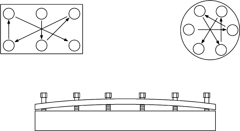
Fasteners and Torque Control (10---90)
Sequence Tightening
On some assemblies, it is advisable to use a crisscross pattern. Always avoid starting in
one spot and tightening one after another in a row. Remember that the object is to tighten
the parts in such a manner that even stress is set up throughout, at the same time allowing
the parts to be drawn together so that their mating surfaces will contact.
513
426
12
5
3
64
123456
Torque in Steps
1. Run each fastener, in proper sequence, up to the recommended torque.
2. Repeat the process of running up each fastener, in proper sequence, up to the
recommended torque.
3. If necessary, repeat step two until all the fasteners are tightened to the recommended
torque.
44
