Tornado Br 33 30 Ride On Floor Scrubber Operators Manual
2017-01-25
: Sweepscrub Tornado-Br-33-30-Ride-On-Floor-Scrubber-Operators-Manual tornado-br-33-30-ride-on-floor-scrubber-operators-manual 2161 file product_file
Open the PDF directly: View PDF ![]() .
.
Page Count: 46

TORNADO INDUSTRIES, LLC
333 CHARLES COURT
WEST CHICAGO, IL 60185
(630)-818-1300 FAX (630)-818-1301
WWW.TORNADOVAC.COM
Tornado® Operations & Maintenance Manual
MODEL NO.
99785 BR 33/30
L9726AB 2014 Tornado Industries All rights reserved.

1
Table of Contents
PRODUCT SPECIFICATIONS 1
WARRANTY 2
LEGEND PANEL OF CONTROLS 3
LEGEND MACHINE 3
INTRODUCTORY COMMENT 4
GENERAL RULES 5
SYMBOLS 5
BEFORE USE 6
Handling of the packed machine 6
Unpacking of the machine 6
Access to the battery compartment 6
Battery installation and setting of the battery type 6
Assembling the rollbar 6
Battery charger 6
Battery recharging 6
Battery disposal 6
Connecting battery connector and switching on the machine 6
Battery charge level indicator 7
Hour meter 7
Squeegee assembly 7
Squeegee adjustment 7
Adjustment height side rubbers 7
Brush assembly and disassembly 7
FLOOR CLEANING 8
Recovery tank 8
Detergent solution tank 8
STARTING OF THE MACHINE 8
Forward and backward movement 8
Horn 8
Working brake 8
Emergency-parking brake 9
Automatic squeegee lift when going backwards 9
Working in automatic mode 9
Working in manual mode 9
Flow adjustment of detergent solution 9
Brush pressure adjustment 10
Electric protection 10
Overflow device 10
STOPPING THE MACHINE AFTER CLEANING OPERATION 10
DAILY MAINTENANCE 10
Recovery tank emptying and cleaning 10
Emptying and cleaning the collection box 10
Suction filter cleaning 11
Brush cleaning 11
Squeegee cleaning 11
WEEKLY MAINTENANCE 11
Rear squeegee rubber check 11
Check of the side rubbers 11
Squeegee hose cleaning 11
Cleaning of the solution tank and of the outer filter 11
TWO-MONTH MAINTENANCE 12
Front squeegee rubber check 12
SIX-MONTH MAINTENANCE 12
Cleaning the inner filter solution tank 12
Check the brake 12
TROUBLESHOOTING GUIDE 12
The vacuum motor does not work 12
The brush motor does not work 12
The traction motor does not work 12
The water does not come down onto the brushes or is insufficient 12
The machine does not clean properly 12
The squeegee does not dry properly 12
Excessive foam production 12
PROGRAMMED MAINTENANCE 13
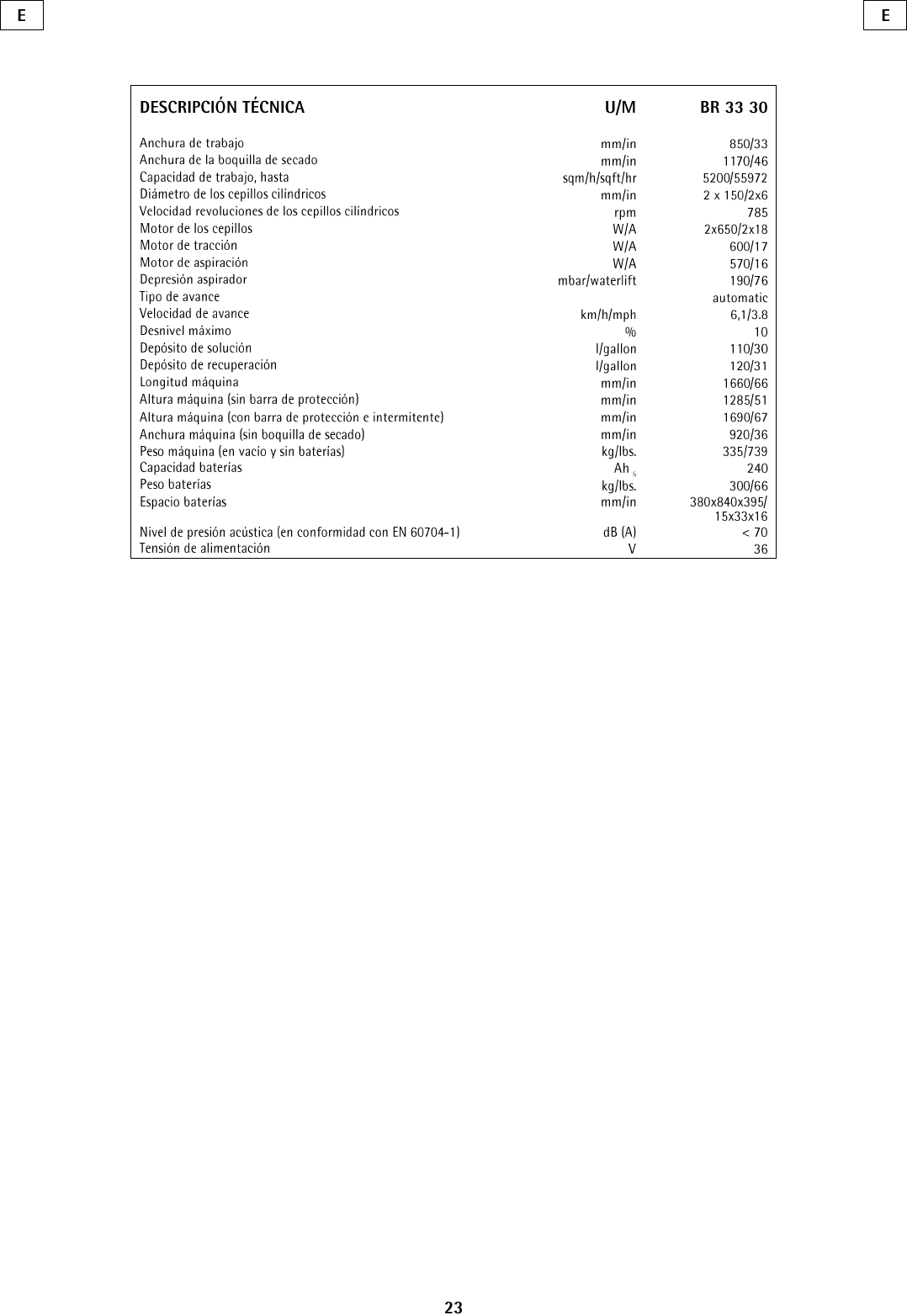
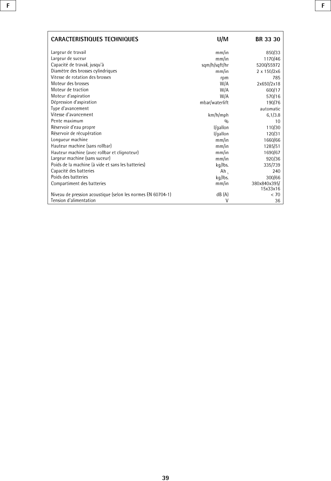
PRODUCT SPECIFICATIONS
Model
BR 33/30
Machine Dimensions
L X W X H
65” X 36” X 51”
Net Weight
739 lbs.
Solution / Recovery Tank
30 / 32 gal.
Squeegee Width
45”
Design Characters
Tank Construction
Polyethylene
Cleaning System
Brush Type
Cylindrical
Brush Width
33”
Brush RPM
785
Brush Pressure
176 lbs. (max)
Cleaning Path
33”
Productivity
Cleaning Rate (Sq. Ft Per Hour)
14,851
Motors
Vacuum Motor
.8 hp
Brush Motor
0.9 hp
Sound Level
70 dB
Battery
Voltage
36
Amps
240
2
3
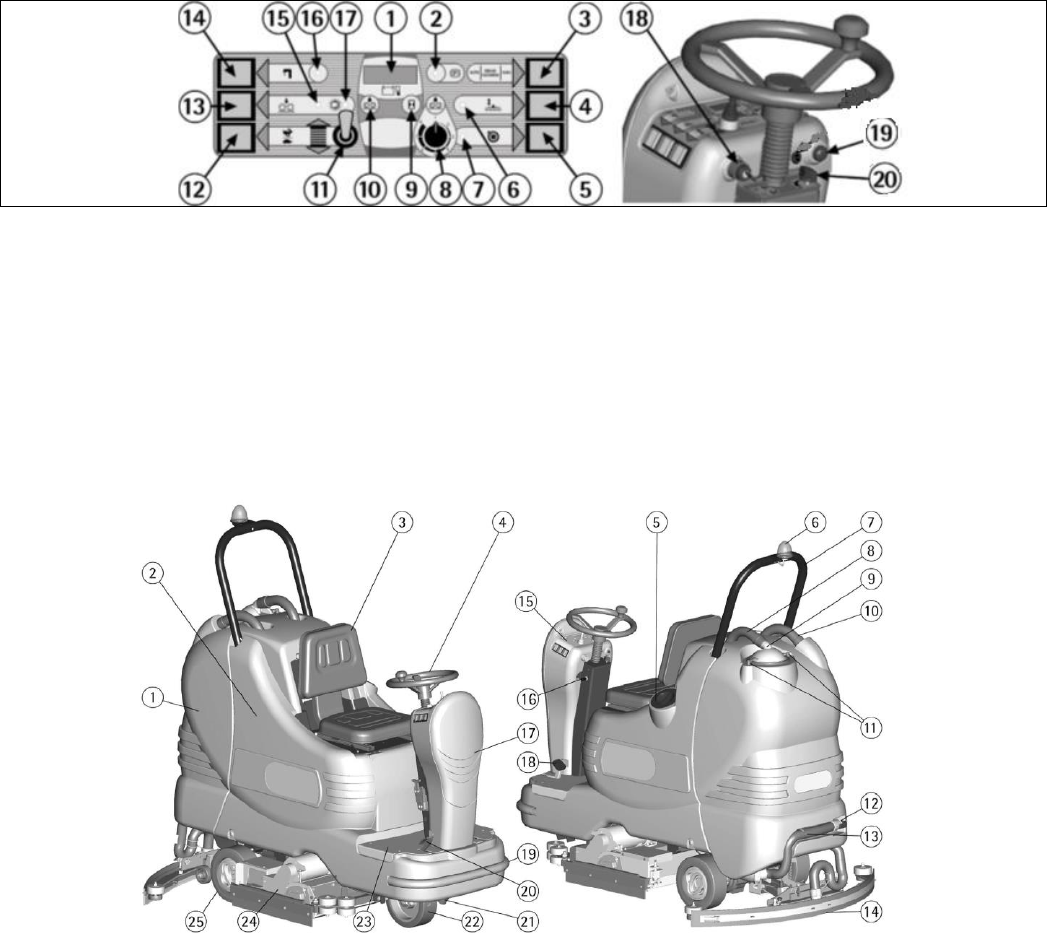
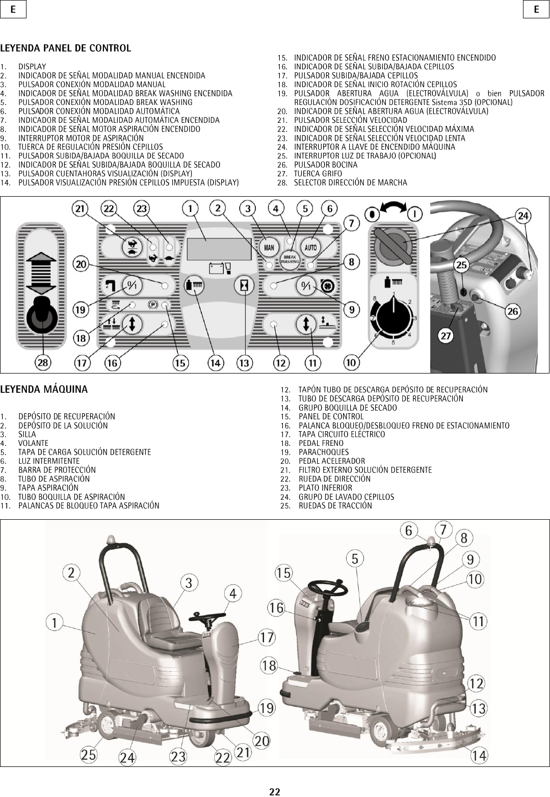
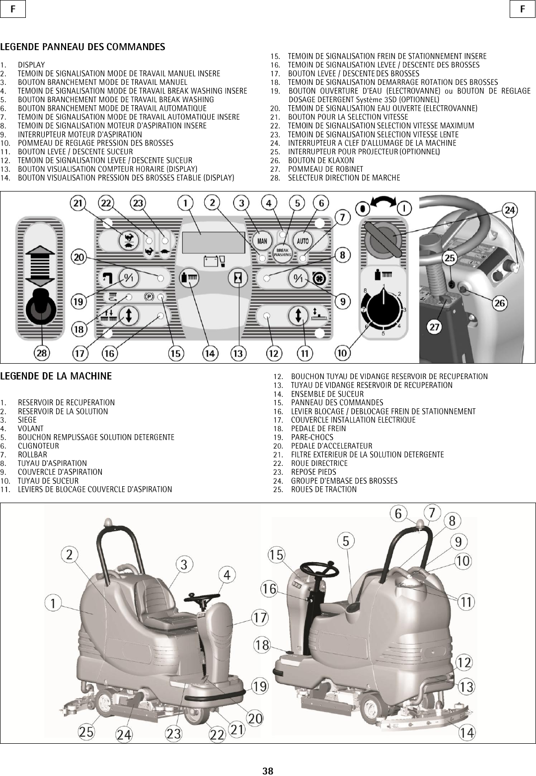
LEGEND PANEL OF CONTROLS
1. DISPLAY
2. SIGNAL LAMP: PARKING BRAKE
3. AUTOMATIC/MANUAL SELECTOR
4. UP/DOWN SQUEEGEE PUSH BUTTON
5. SUCTION MOTOR SWITCH
6. SIGNAL LAMP: UP/DOWN SQUEEGEE
7. SIGNAL LAMP: SUCTION MOTOR ON
8. BRUSH PRESSURE ADJUSTMENT KNOB
9. PUSH BUTTON VISUALIZATION HOUR METER (DISPLAY)
10. PUSH BUTTON VISUALIZATION BRUSH PRESSURE SET (DISPLAY)
11. SELECTOR: FORWARDS/BACKWARDS
12. SELECTOR: SPEED
13. UP/DOWN BRUSHES PUSH BUTTON
14. WATER OPENING (SOLENOID VALVE) SWITCH
15. SIGNAL LAMP: UP/DOWN BRUSHES
16. SIGNAL LAMP: WATER OPEN (SOLENOID VALVE)
17. SIGNAL LAMP: STARTING BRUSHES ROTATION
18. KEY SWITCH
19. HORN PUSH BUTTON
20. KNOB FOR SOLUTION VALVE
LEGEND MACHINE
1. RECOVERY TANK
2. SOLUTION TANK
3. SEAT
4. DRIVE WHEEL
5. SCREW CAP FOR INLET DETERGENT SOLUTION
6. BLINKING LIGHT
7. ROLLBAR
8. SUCTION HOSE
9. SUCTION COVER
10. SQUEEGEE HOSE
11. SUCTION COVER BLOCKING LEVERS
12. RECOVERY TANK EXHAUST HOSE PLUG
13. RECOVERY TANK EXHAUST HOSE
14. SQUEEGEE ASSEMBLY
15. PANEL CONTROLS
16. BLOCK/RELEASE PARKING BRAKE LEVER
17. ELECTRICAL LAYOUT COVER
18. BRAKE PEDAL
19. BUMPER
20. ACCELERATOR PEDAL
21. OUTER FILTER DETERGENT SOLUTION
22. STEERING WHEEL
23. BOTTOM PLATE
24. BRUSH BASE GROUP
25. TRACTION WHEELS
4
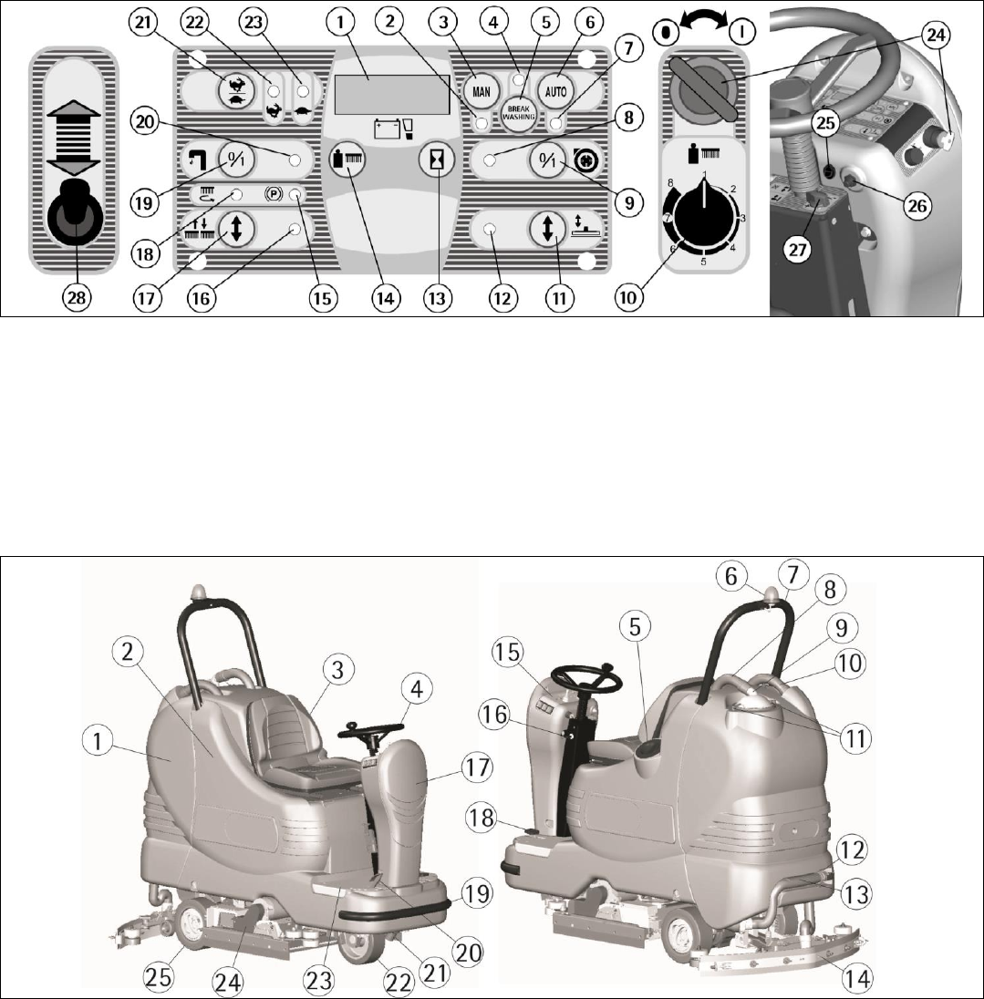
LEGEND PANEL OF CONTROLS
1. DISPLAY
2. SIGNAL LAMP MANUAL MODE ON
3. PUSH BUTTON CONNECTION MANUAL MODE
4. SIGNAL LAMP MODE BREAK WASHING ON
5. PUSH BUTTON CONNECTION MODE BREAK WASHING
6. PUSH BUTTON CONNECTION MODE AUTOMATIC
7. SIGNAL LAMP AUTOMATIC MODE ON
8. SIGNAL LAMP SUCTION MOTOR ON
9. SWITCH SUCTION MOTOR
10. ADJUSTMENT KNOB BRUSHES PRESSURE
11. PUSH BUTTON UP/DOWN SQUEEGEE
12. SIGNAL LAMP UP/DOWN SQUEEGEE
13. PUSH BUTTON VISUALIZATION HOUR METER (DISPLAY)
PUSH BUTTON VISUALIZATIO
14. N BRUSHES PRESSURE SET (DISPLAY)
15. SIGNAL LAMP PARKING BRAKE ON
16. SIGNAL LAMP UP/DOWN BRUSHES
17. PUSH BUTTON UP/DOWN BRUSHES
18. SIGNAL LAMP STARTING BRUSHES ROTATION
19. PUSH BUTTON WATER OPENING (SOLENOID VALVE) or PUSH
BUTTON ADJUSTMENT DETERGENT DOSAGE 3SD system (OP-
TIONAL)
20. SIGNAL LAMP WATER OPEN (SOLENOID VALVE)
21. PUSH BUTTON FOR SPEED SELECTION
22. SIGNAL LAMP SELECTION MAXIMUM SPEED
23. SIGNAL LAMP SELECTION SLOW SPEED
24. KEY SWITCH MACHINE ON
25. SWITCH FOR FRONT LIGHT (OPTIONAL)
26. PUSH BUTTON HORN
27. KNOB FOR SOLUTION VALVE
28. SELECTOR DIRECTION OF DRIVE
LEGEND MACHINE
1. RECOVERY TANK
2. SOLUTION TANK
3. SEAT
4. DRIVE WHEEL
5. SCREW CAP FOR INLET DETERGENT SOLUTION
6. BLINKING LIGHT
7. ROLLBAR
8. SUCTION HOSE
9. SUCTION COVER
10. SQUEEGEE HOSE
11. BLOCKING LEVERS SUCTION COVER
12. PLUG EXHAUST HOSE RECOVERY TANK
13. EXHAUST HOSE RECOVERY TANK
14. SQUEEGEE ASSEMBLY
15. PANEL CONTROLS
16. LEVER BLOCK/RELEASE PARKING BRAKE
17. COVER ELECTRICAL LAYOUT
18. BRAKE PEDAL
19. BUMPER
20. PEDAL ACCELERATOR
21. OUTER FILTER DETERGENT SOLUTION
22. STEERING WHEEL
23. BOTTOM PLATE
24. BRUSHES BASE GROUP
25. TRACTION WHEELS
5
INTRODUCTORY COMMENT
Thank you for choosing our machine. This floor-
cleaning machine is used for industrial and
commercial cleaning and is able to clean any type of
floor. During its forward movement, the action of
the brush and detergent solution removes the dirt,
which is picked up by the suction system, resulting
in a dry surface.
The machine must be used only for this purpose. It
gives the best performance if it is used correctly and
properly. Therefore, we ask you to read this
instruction booklet carefully whenever difficulties
arise in the course of the machine’s use. If needed,
please contact our service department for advice
and/or service.
GENERAL RULES
The rules below have to be followed carefully in or-
der to avoid damage to the machine and injuries to
the operator.
- Read the labels carefully on the machine. Do not
cover them for any reason and replace them imme-
diately if damaged.
- The machine must be used exclusively by author-
ized staff that has been instructed for its use.
- When using the machine, pay attention to other
people, especially children.
- In case of danger, immediately use the emergency
brake.
- To park the machine, take off the key and put on
the parking brake.
- Do not mix different detergents to avoid harmful
odors.
- Do not place any liquid containers onto the ma-
chine.
- The storage temperature has to be between -13°F
and +131°F.
- The operating temperature should be between 32°F
and 104°F.
- The humidity should be between 30 and 95%.
- Do not use the machine in an explosive atmosphere.
- Do not use the machine as a means of transporta-
tion.
- Do not use acidic solutions, which could damage
the machine and/or injure people.
- Do not use the machine on surfaces covered with
inflammable liquids or dusts (for example hydrocar-
bons, ashes or soot).
- In case of fire, use a powder fire-extinguisher.
Do not use water.
- Watch out for shelves and/or scaffoldings, when
operating the machine.
- Use the appropriate speed based on floor condi-
tions (type of floor, dirtiness, etc).
- Do not use the machine on areas that have a higher
gradient than the one stated on the number plate.
- The machine has to carry out simultaneously the
operations of washing and drying. Different opera-
tions must be carried out in restricted areas prohibit-
ed to non-authorized personnel.
- Signal the areas of moist floors with suitable signs.
- If the machine does not work properly, check by
conducting simple maintenance procedures. Other-
wise, contact an authorized technical assistant for
advice.
- Where parts are required, ask for ORIGINAL spare
parts to the distributor or an authorized dealer.
- Use only ORIGINAL brushes.
- When cleaning and performing maintenance opera-
tions, disconnect the power supply plug from the
machine.
- Do not wash the machine with corrosive material,
direct water jets or high water pressure.
- Every 200 working hours, have the machine
checked by an authorized service center.
- In order to avoid scales on the solution tank filter,
do not fill the detergent solution hours before it is
used.
- Before using the machine, check that all panels and
coverings are in position as indicated in this use and
maintenance catalog.
- Be sure the recovery tank is empty before lifting it.
- Restore all electrical connections after any
maintenance operation.
- When your machine has to stop activity, provide
the appropriate waste disposal for its materials,
especially oils, battery and electronic components.
Consider that the machine itself has been
constructed by recyclable materials.
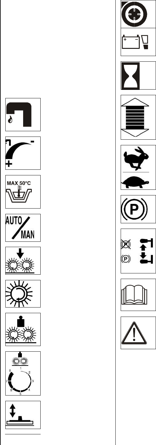
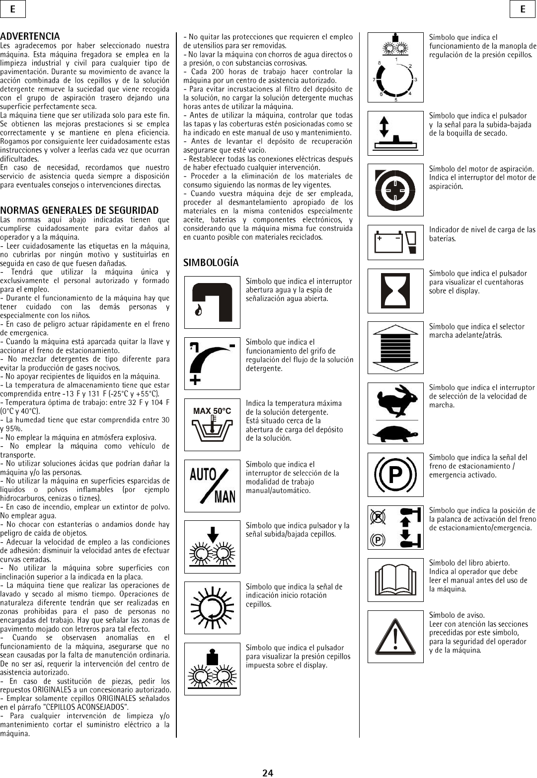
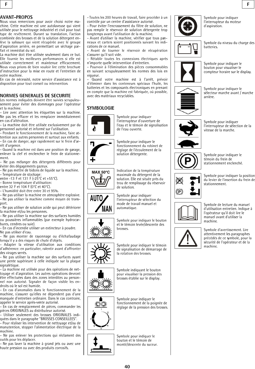
SYMBOLS
Symbol denoting the switch for the
water opening and the signal lamp
that the water is open.
Symbol denoting the functioning
of the solution valve adjusting the
flow of the detergent solution.
Indication of the maximum
temperature of the detergent
solution. It is placed near the
charging hole of the solution tank.
Symbol denoting the selection
switch of the operation mode
manual/automatic.
Symbol denoting the push button
and the signal lamp up/down
brushes.
Symbol denoting the signal lamp
of the starting of the brushes
rotation.
Symbol denoting the push button
to visualize on the display the
brush pressure set.
Symbol denoting the functioning
of the adjustment knob of the brush
pressure.
Symbol denoting the push button
and the signal lamp up/down of the
squeegee.
Symbol denoting the switch of the
vacuum motor.
Symbol denoting the charge level
of the battery.
Symbol denoting the push button
to visualize the hour meter on the
display.
Symbol denoting the drive selector
forwards/backwards.
Symbol denoting the selection
switch of the operation speed.
Symbol denoting the signal lamp
of the parking brake switched on.
Symbol denoting the lever position
for the connection of the parking
brake.
Symbol denoting the open book.
Indicates that the operator has to
read the manual before the use of
the machine.
Warning symbol.
Read carefully the sections marked
with this symbol, for the security
of both the operator and the
machine.
6
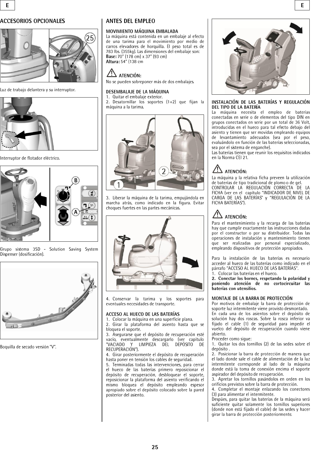
BEFORE USE
HANDLING OF THE PACKED MACHINE
The machine is supplied with suitable packing for
fork lift truck handling.
The total weight is 783 lbs.
Packing dimensions:
Base: 71 in x 37 in
Height: 54 in
ATTENTION:
Do not place more than 2 packings on top of each
other.
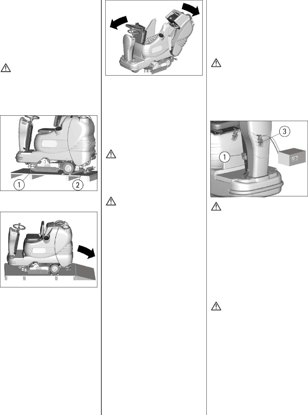
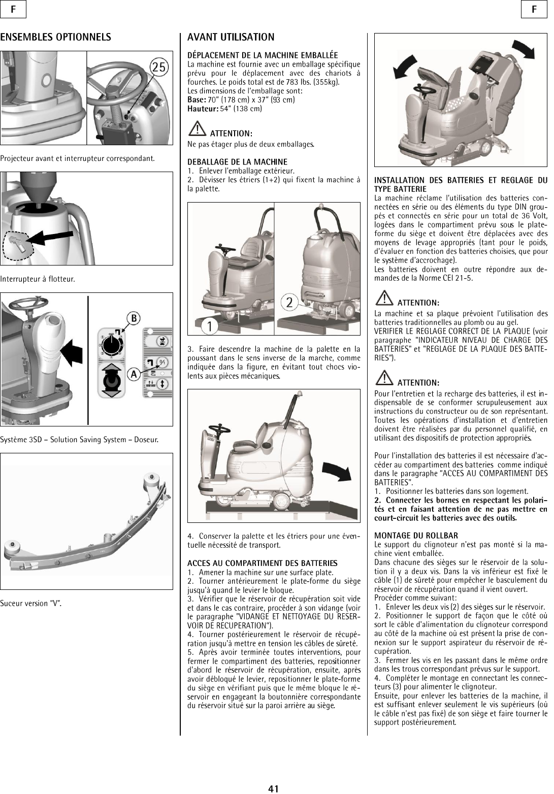
UNPACKING OF THE MACHINE
1. Remove the external packing.
2. Unscrew the brackets (1+2) that secure the
machine to the pallet.
3. Move the machine backwards, as indicated in the
figure, avoiding heavy contacts to mechanical parts.
4. Keep the pallet and the brackets for future
transport.
ACCESS TO THE BATTERY
COMPARTMENT
1. Bring the machine on a leveled surface.
2. Rotate the seat platform forward up to the
blocking of the support.
3. Make sure that the recovery tank is empty,
otherwise proceed to its emptying (see
“RECOVERY TANK EMPTYING AND
CLEANING”).
4. Rotate the recovery tank backwards until the
safety cables are put in tension.
5. To close the battery compartment, reposition the
recovery tank, then, after having released the support,
reposition the seat platform being careful that it is
going to block the tank engaging the slot placed on
the rear part of the tank to the seat.
BATTERY INSTALLATION AND SETTING
OF THE BATTERY TYPE
The machine is equipped either with a battery in
serial connection or elements of DIN-type
assembled together and connected in series for a
total of 36 Volts, placed in its appropriate
compartment under the seat platform. It must be
handled using suitable lifting equipment (due to
weight, considering the type of battery chosen, and
coupling system).
The battery must be in accordance with
CEI 21-5 Norms.
ATTENTION:
CHECK THE SETTING OF THE CHECK
CARD (see under paragraph "BATTERY
CHARGE LEVEL INDICATOR").
In case of WET battery installation, it is
necessary to set the battery check card. Please
contact an authorized technical assistant.
ATTENTION:
Strictly follow manufacturer/distributor
indications for the maintenance and recharge of
the battery. All installation and maintenance
operations must be executed by specialized staff
using suitable protection accessories.
For battery installation it is necessary to reach the
battery compartment as indicated under the
paragraph “ACCESS TO THE BATTERY
COMPARTMENT”.
1. Place the battery in its compartment.
2. Connect the terminals, respecting the polarities,
avoiding contact with other parts that could create a
short circuit.
ASSEMBLING THE ROLLBAR
For packing reasons, the support of the blinking light
is supplied disassembled.
In each seat on the solution tank there are two
screws. On the lower screw the safety cable (1) is
fixed to prevent the overturn of the recovery tank
when this is being opened.
Proceed as follows:
1. Take off the two screws (2) from the seats on the
tank.
2. Place the roll bar in its position so that the side,
where the cable of the blinking light comes out,
corresponds to the side of the machine where the
cable on the tank is present.
3. Fasten the screws through the holes of the roll
bar.
4. Complete the assembly connecting the
connectors (3) to supply the blinking light.
To remove the battery from the machine, take off
only the upper screws (where the cable is not fixed)
from their seats and rotate the roll bar backwards.
BATTERY CHARGER
Make sure that the battery charger is suitable for the
installed battery both for their capacities and for type
(WET and equivalent).
In the plastic bag containing the use and
maintenance you will find the coupling connector
for the charger. It must be assembled onto the cables
of your charger, following the instructions given by
the manufacturer.
ATTENTION:
This operation must be carried out by qualified
staff. A wrong or faulty cable connection can
cause serious damage.
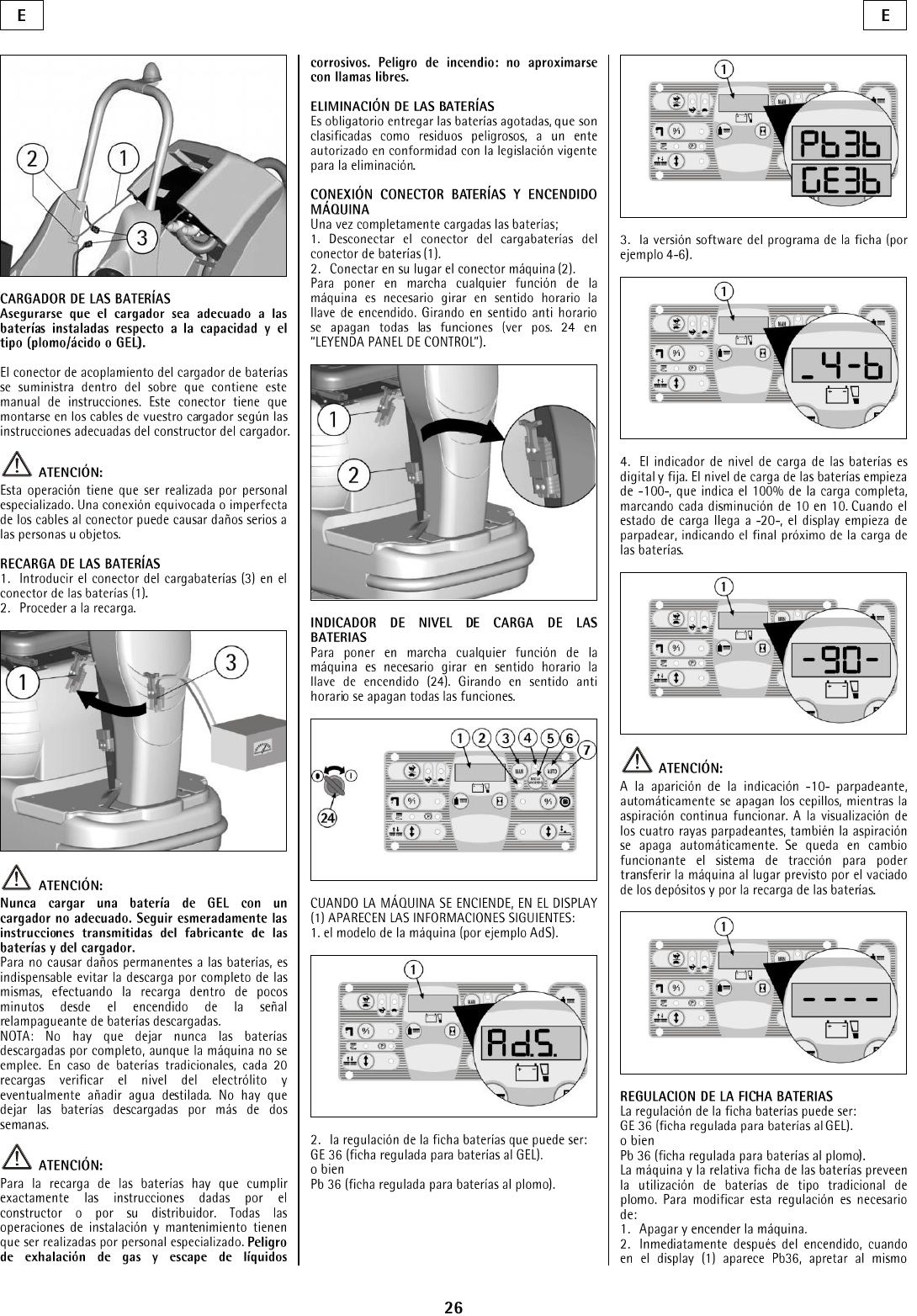
BATTERY RECHARGING
1. Plug the connector (3) of the battery charger into
the battery connector (1) fixed on the steering
column.
2. Proceed to recharging.
ATTENTION:
Never charge a WET battery with a non-suitable
recharger. Strictly follow the instructions
supplied by the battery and recharger
manufacturer.
In order not to cause permanent damage to the
battery, it is necessary to avoid their complete
discharge, providing for the recharging within a
few minutes after that the battery discharge
signal starts blinking.
NOTE: Never leave the battery completely
discharged even if the machine is not used. In
case of traditional battery, please check the
electrolyte level every 20 recharging cycles and
eventually top them up with distilled water.
Never leave the battery discharged for more than
two weeks.
ATTENTION:
For the recharging of the battery it is necessary
to follow strictly all the indications given by the
manufacturer/distributor. All the installation and
maintenance operations must be carried out by
qualified staff. Danger: gas exhalations and
emission of corrosive liquids. Do not approach in
case of fire.
BATTERY DISPOSAL
Hand over exhausted battery, classified as dangerous
waste, to an authorized institution according to the
current laws.
CONNECTING BATTERY CONNECTOR AND
SWITCHING ON THE MACHINE
Once the battery recharging has been completed:
1. Disconnect the connector of the battery recharger
from the battery connector (1).
2. Connect instead the machine connector (2).
7
To start any function of the machine, rotate the key
switch clock-wise. Rotating it counterclockwise will
turn off all functions (see “LEGEND PANEL OF
CONTROLS”).
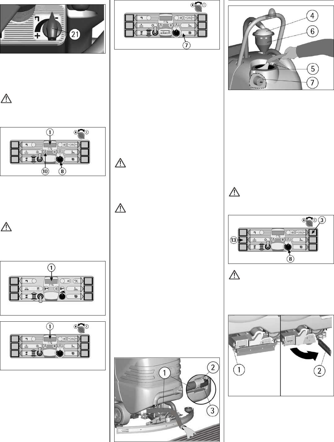
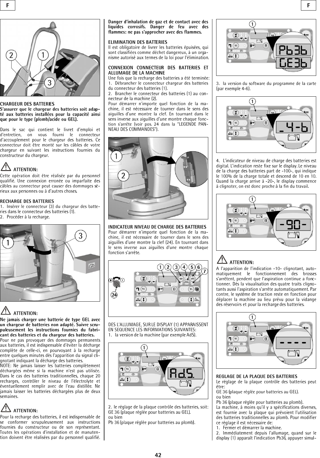
BATTERY CHARGE LEVEL INDICATOR
WHEN THE MACHINE IS SWITCHED ON, THE
SCREEN (1) DISPLAYS THE FOLLOWING
INFORMATION:
1. the version (for example A003) of software
installed on the machine.
2. the setting of the battery check card, which can
be:
GE 36: check card set for WET battery.
or
3. The battery charge level indicator is digital and
remains fixed on the display. The battery charge
level starts from 100, which indicates the 100% of
the total charge and decreases from 10 to 10. When
the charge level reaches 20%, the display starts
blinking.
ATTENTION:
A few seconds after the 10% indication, the
blinking of four lines will appear. All the
functions stop automatically. With the remaining
charge, it is possible to finish the drying
operation before proceeding to the recharge.
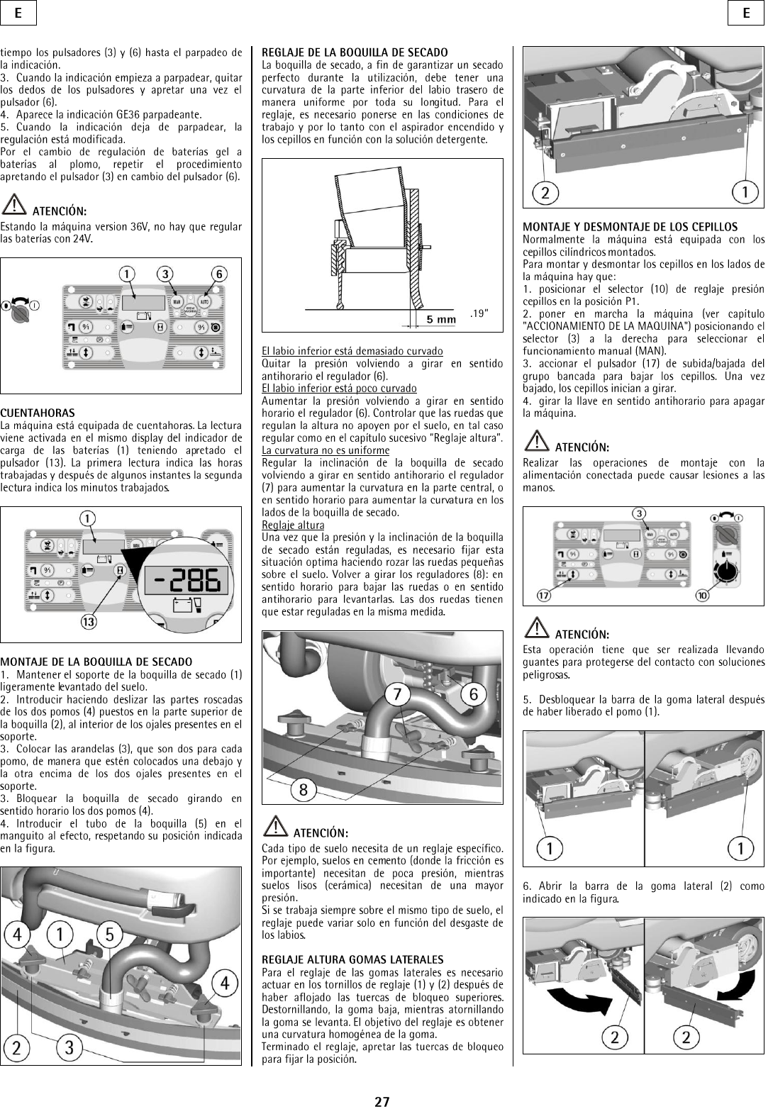
HOUR METER
The machine is equipped with an hour meter located
on the same display (1) of the battery charge level
indicator. Hold the button (9) to show the working
hours on the screen. Hold the button a few more
seconds for the working minutes to appear.
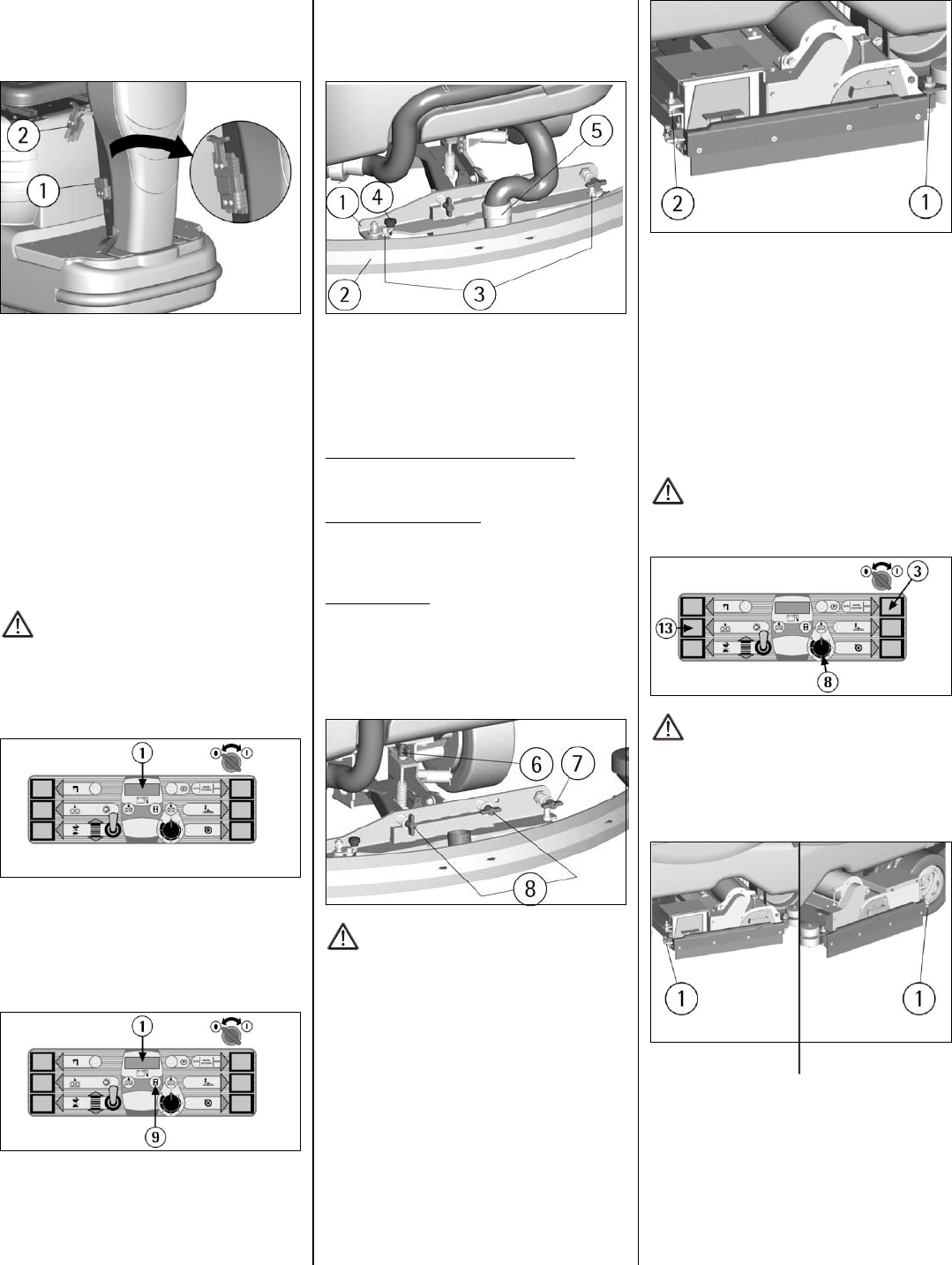
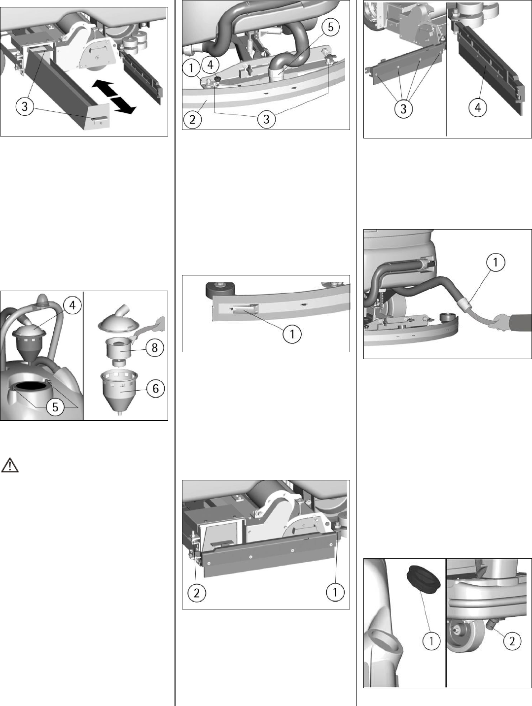
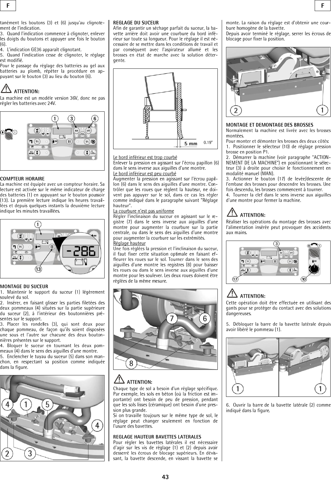
SQUEEGEE ASSEMBLY
1. Keep the squeegee support (1) slightly lifted
from the floor.
2. Insert the two stud bolts (3) placed on the upper
part of the squeegee (2) inside the slots on the
support.
3. Block the squeegee by rotating the lever (4)
clockwise.
4. Insert the squeegee hose (5) into its coupling,
respecting its position as indicated in the figure.
SQUEEGEE ADJUSTMENT
In order to have better drying result with the
squeegee, the rear rubber must have its lower
bending uniformly adjusted in all its length. For the
adjustment, the vacuum motor has to be switched on
and the brushes have to function together with the
detergent solution.
Adjusting the bend: lower part of the rubber
Adjust the pressure by rotating the wind nut (6). To
increase: rotate clock-wise. To decrease, rotate the
lever counter-clockwise.
The bending is not uniform
Adjust the squeegee inclination by rotating counter-
clockwise the wing nut (7) to increase the bend in
the central part, and clockwise to increase the bend
on the extremities.
Height adjustment
Once the pressure and inclination of the squeegee
have been adjusted, make sure that the wheels
slightly touch the floor. Rotate the registers (8)
counter-clockwise to lower the wheels or clockwise
to raise them. Both wheels must be adjusted in the
same measure.
ATTENTION:
Every type of floor requires a specific adjustment.
For example, concrete floors (where friction
results to be high) need little pressure, while
smooth floors (ceramics) need higher pressure.
If the cleaning operations are always made on the
same type of floor, adjust according to rubber
wear.
ADJUSTMENT HEIGHT SIDE RUBBERS
Loosen the upper blocking nuts. Use the adjusting
screws (1) and (2) to adjust the height of the side
rubbers: unscrewing lowers the rubber while
screwing down lifts the rubber. Tighten the blocking
nuts after adjustments are made.
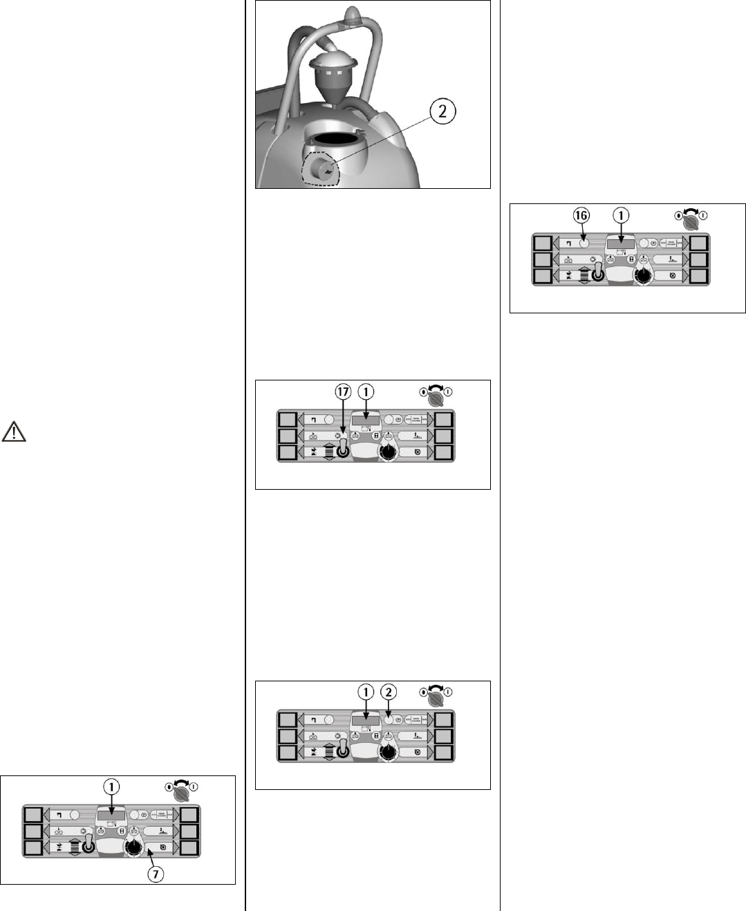
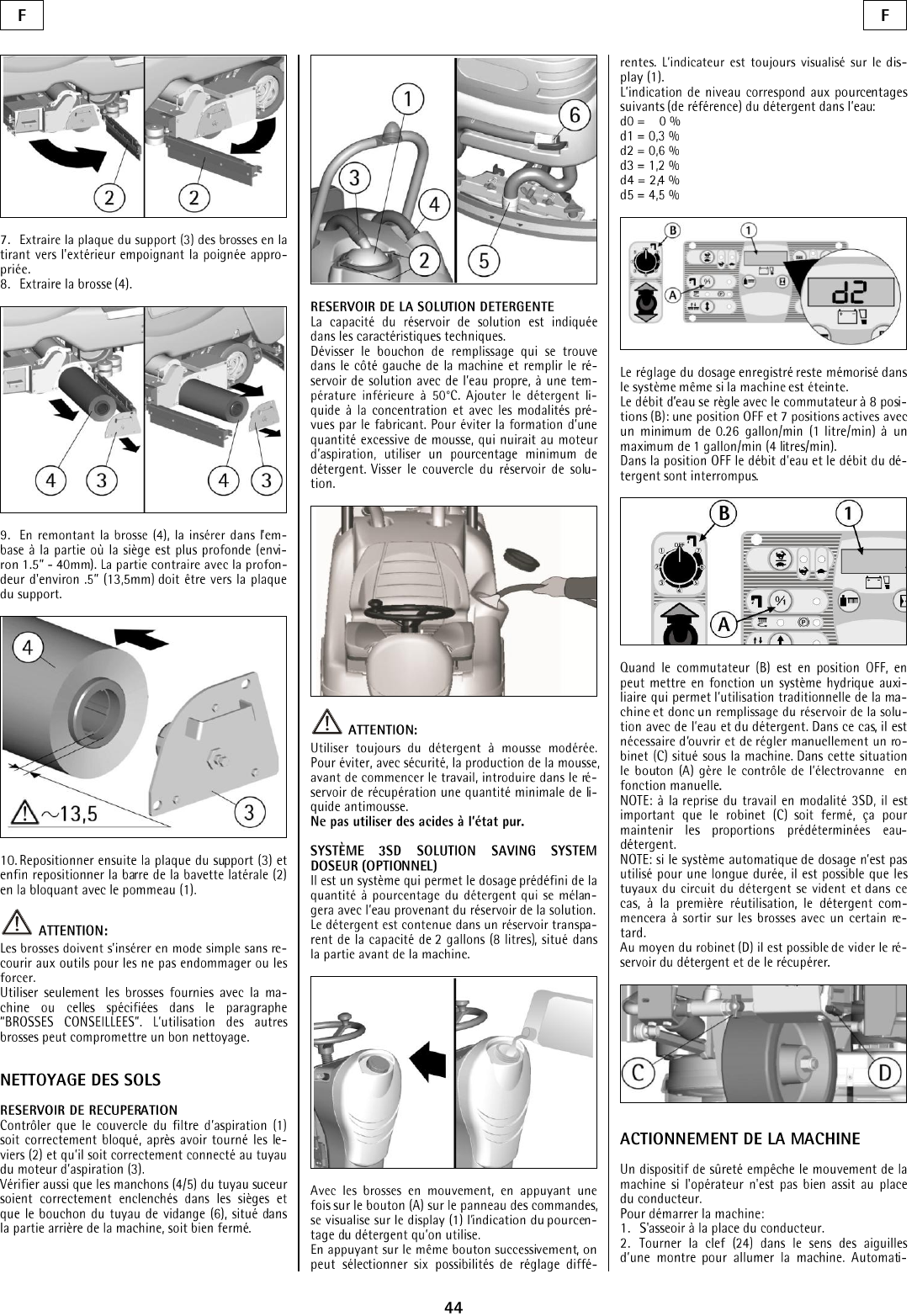
BRUSH ASSEMBLY AND DISASSEMBLY
To assemble and disassemble the brushes on both
sides of the machine:
1. Position the selector (8) for the adjustment of the
brush pressure on position P1.
2. Activate the machine (see “STARTING OF THE
MACHINE”) positioning the selector (3) to the right
to choose the manual mode (MAN).
3. Activate the selector (13) of up/down of the
brush base to lower the brushes. Once it is lowered,
the brushes begin to turn.
4. Turn the key counter clockwise to turn off the
machine.
ATTENTION:
Carrying out brush assembly operations with the
electric supply on may cause damages.
ATTENTION:
This operation must be carried out with the use
of gloves for protection from dangerous solutions.
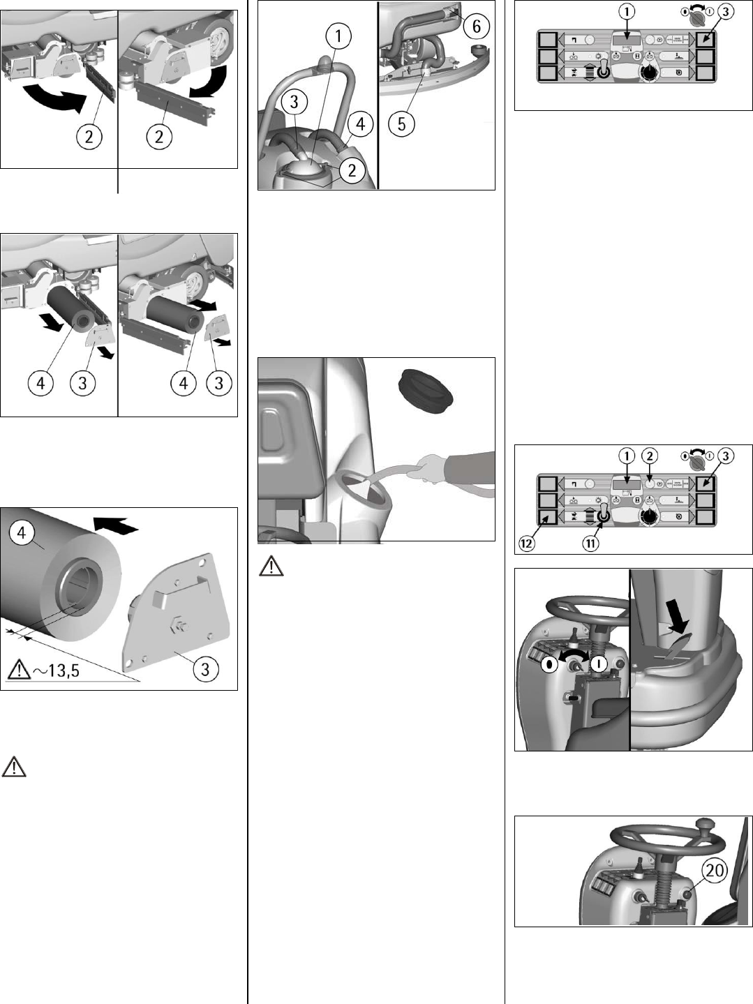
5. Released the knob (1), unblock the bar of the
side rubber.
6. Open the bar of the side rubber (2) as shown in
the figure.
8
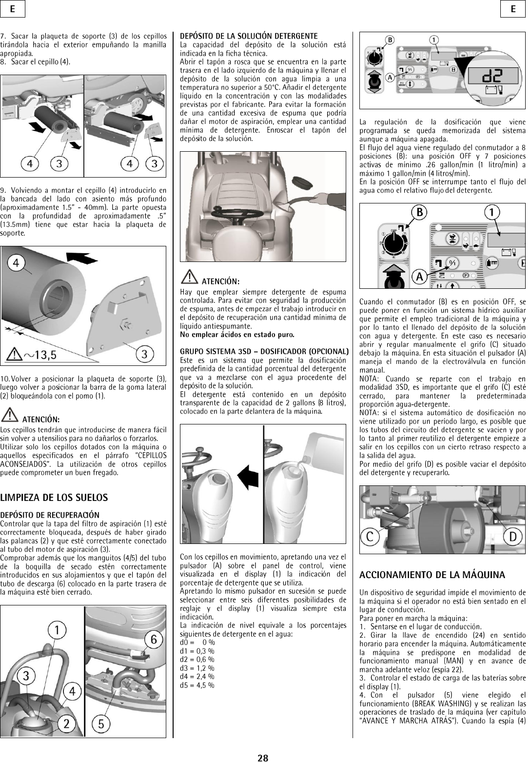
7. Extract the support plate (3) of the brushes by
pulling it outwards while holding its handle.
8. Extract the brush (4).
9. During the reassembly of the brush (4), insert it
into the brush base from the part where the seat is
deeper (about 40mm). The opposite part with a
depth of about 13,5mm has to look towards the
support plate.
10. Place the support plate (3) into its position, then
put back the bar of the side rubber (2) blocking it
with the knob (1).
ATTENTION:
Use only the brushes supplied with the machine
or the ones indicated in the paragraph
“RECOMMENDED BRUSHES”. The use of
other brushes may produce poor cleaning results.
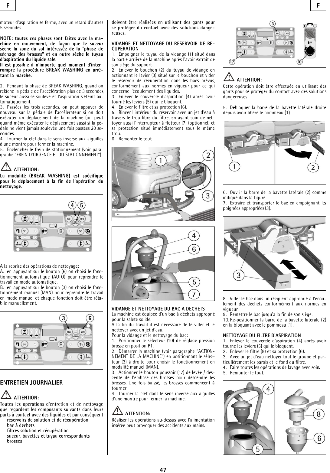
FLOOR CLEANING
RECOVERY TANK
Rotate the levers (2). Check that the cover of the
suction filter (1) is correctly secured, and that the
vacuum motor hose (3) is correctly connected to it.
Verify also that the squeegee hose couplings (4/5)
are correctly inserted into their seats and that the
exhaust hose plug (6) is placed in the lower rear part
of the machine.
DETERGENT SOLUTION TANK
The capacity of the detergent solution tank is
indicated in the technical data.
Open the screw plug placed in the left part of the
machine and fill the detergent solution tank with
clean water at a maximum temperature of 122°F.
Add the liquid detergent in the percentage and
conditions shown by the manufacturer. To avoid
excessive foam presence, use the minimum
percentage of detergent. Screw down the plug to
close the tank.
ATTENTION:
Always use low foam detergent. To avoid foam
presence, pour into the recovery tank a minimum
quantity of anti-foam product.
Never use pure acid.
STARTING OF THE MACHINE
A safety device avoids the machine’s movement if
the operator is not seated correctly on the guiding
place.
To switch on the machine:
1. Sit on the guiding place.
2. Turn the key switch clockwise to switch on the
machine.
3. Check the charge level of the battery on the
display (1).
4. With the selector (3) in central position (BREAK
WASHING) the transfer operations of the machine
is carried out (see “FORWARD AND
BACKWARD MOVEMENT").
5. Moving the selector (3) to the left chooses the
automatic (AUTO) function. Moving it to the right
chooses the manual (MAN) function:
A. If the selector (3) is in position (AUTO) the
machine activates and deactivates all the working
functions in an automatically (see “WORKING IN
AUTOMATIC MODE”).
B. If the selector (3) is in position (MAN) every
function of the machine has to be activated or
deactivated manually (see “WORKING IN
MANUAL MODE”).
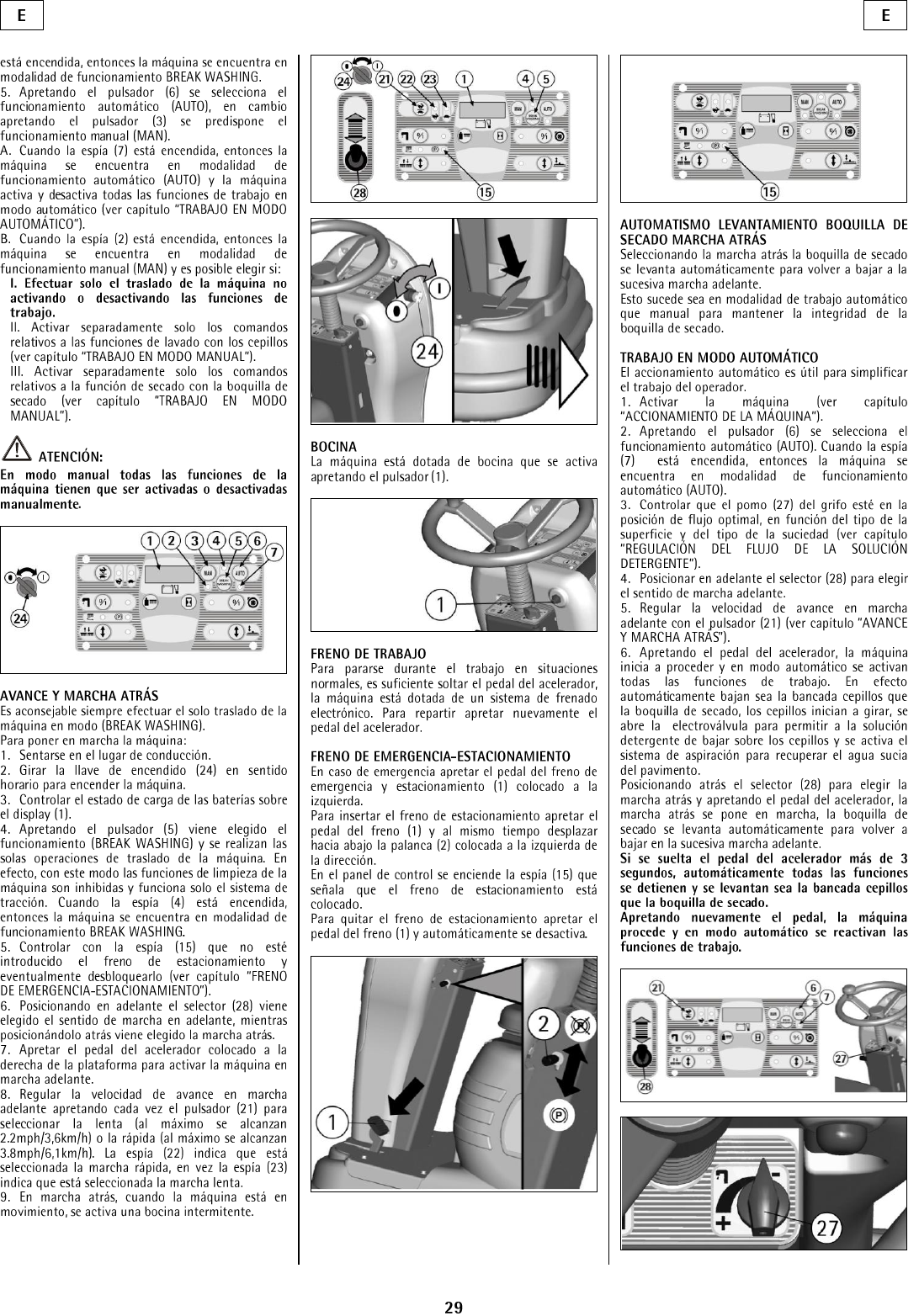
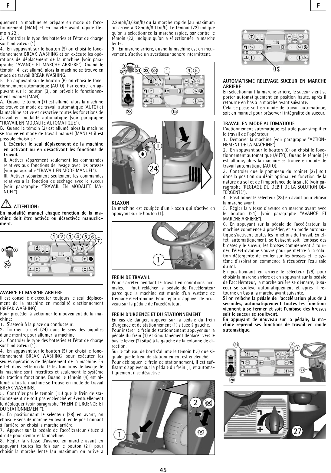
FORWARD AND BACKWARD MOVEMENT
It is recommendable to carry out the transfer of the
machine in mode (BREAK WASHING).
To proceed to activate the movement of the machine:
1. Sit on the guiding place.
2. Turn the key switch clockwise to switch on the
machine.
3. Check the charge level of the battery on the
display (1).
4. Release the parking brake. If the brake were
inserted, the signal lamp (12) would be switched on
(see "EMERGENCY-PARKING BRAKE”).
5. Bring the selector (3) in central position
(BREAK WASHING) to carry out the transfer of the
machine. In this mode, only the traction system
functions are on.
6. Use the selector (11) to go forward or backwards.
7. Press the accelerator pedal placed on the right
side to start the machine.
8. Adjust the driving speed by pressing the selector
(12). To go slow, press downwards. To go fast, press
upwards.
In backward movement, an intermittent warning
device is activated.
HORN
The machine is equipped with a horn, press push
button (20) to use it.
WORKING BRAKE
To stop the machine during normal working
situations, release the accelerator pedal. The
machine has an electronic brake system. To restart,
press the accelerator pedal.
9
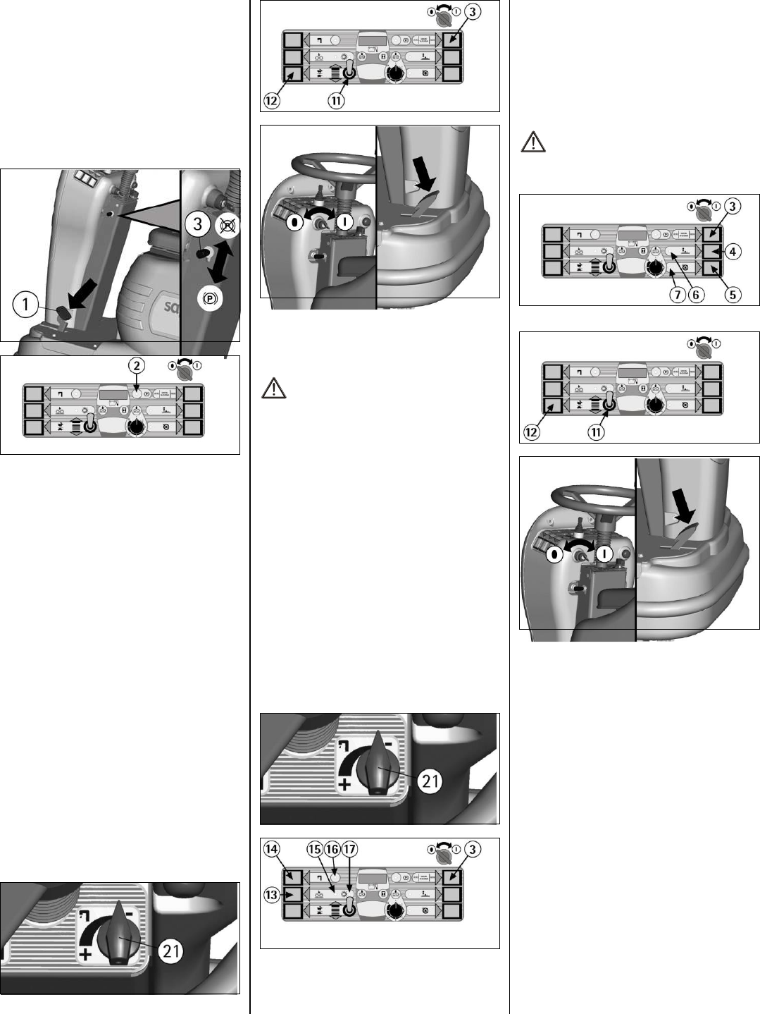
EMERGENCY-PARKING BRAKE
In case of an emergency press the pedal of the
emergency and parking brake (1) placed on the left
side.
To insert the parking brake press the brake pedal (1)
and simultaneously move downwards the lever (3)
placed on the left side of the steering column.
On the instrument board the signal lamp (2) comes
on which signals that the parking brake is inserted.
To release the parking brake press the brake pedal (1)
and simultaneously lift the lever (3) upwards.
AUTOMATIC SQUEEGEE LIFT WHEN
GOING BACKWARDS
By selecting the backward movement, the squeegee
is lifted up automatically. It will lower itself during
forward movement.
This feature is both for automatic and manual modes.
WORKING IN AUTOMATIC MODE
The automatic operation is useful to simplify the
operator’s work.
1. Activate the machine by pressing the selector (3)
upward to choose the automatic function (AUTO),
(see “STARTING THE MACHINE”).
2. Check that the solution valve knob (21),
Depending on the type of floor and the type of dirt,
(see “FLOW ADJUSTMENT OF THE
DETERGENT SOLUTION”).
3. Adjust the movement speed in forward with the
selector (12) (see “STARTING THE MACHINE”).
Use the selector (11) to go forward and press the
accelerator pedal. The machine starts to move and
all working functions are activated automatically.
During backward movement, the squeegee lifts
automatically and will then return to lower itself
during the next forward movement.
If the accelerator pedal is released for more than 3
seconds, all functions are switched off and both the
brush base and squeegee are lifted.
To reactivate the machine, just press the pedal and
proceed with the operation.
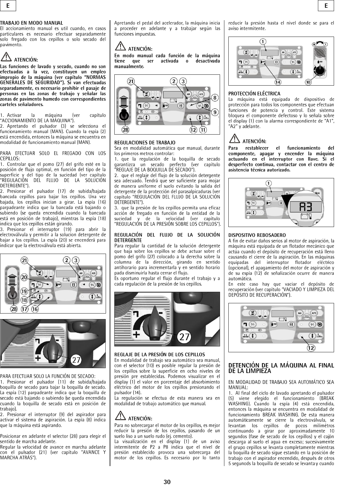
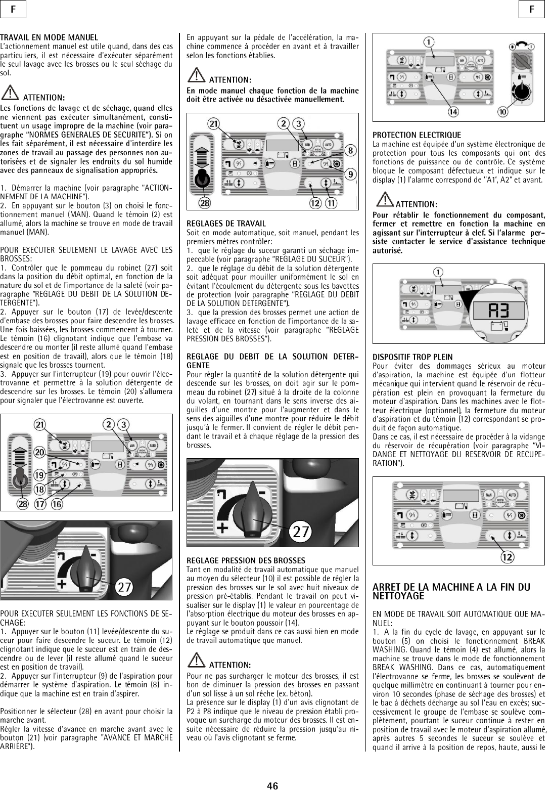
WORKING IN MANUAL MODE
The manual mode is useful when the operator wants
to carry out separately the washing and drying of the
floor.
ATTENTION:
Washing and drying functions that are not
carried out simultaneously represent an
improper use of the machine (see under
paragraph “GENERAL RULES OF
SECURITY”). If they are carried out separately,
forbid the working areas to the passage of non-
authorized personnel. Signal the areas of moist
floors with suitable signs.
Activate the machine (see “STARTING OF THE
MACHINE”) positioning the selector (3) to the right
to choose the manual mode (MAN).
TO CARRY OUT THE WASHING FUNCTION:
1. Press the push button (13) of the brush base to
lower the brush. Once it is lowered, the brushes
begin to turn. The signal lamp (15) indicates that the
brush base is lowering or lifting, while the signal
lamp (17) signals that the brushes are turning.
2. Press the switch (14) to open the solenoid valve,
allowing the detergent solution to flow onto the
brush. The signal lamp (16) will indicate that the
solenoid valve is open.
TO CARRY OUT THE DRYING FUNCTION :
1. Press the push button (4) to lower the squeegee.
The signal lamp (6) will indicate the lowering or
lifting of the squeegee.
2. Press the switch (5) of the vacuum motor to start
the suction system. The signal lamp (7) indicates
that the machine is drying.
Adjust the movement speed using the selector (12)
(see “STARTING THE MACHINE”).
When the selector (11) is turned on and the
accelerator pedal is pressed, the machine begins to
move forward. It works according to the set
functions.
ATTENTION:
In manual mode every function of the machine
has to be activated or deactivated manually.
Working Check whether the following is working
properly:
1. The squeegee adjustment results in a dry floor
(see “ADJUSTMENT OF THE SQUEEGEE”).
2. The adjustment of the detergent solution flow is
sufficient to wet the floor uniformly avoiding the
leakage of detergent from the splashguards (see
“FLOW ADJUSTMENT OF THE DETERGENT
SOLUTION”).
3. The brush pressure permits an efficient washing
action. (see “BRUSH PRESSURE
ADJUSTMENT”).
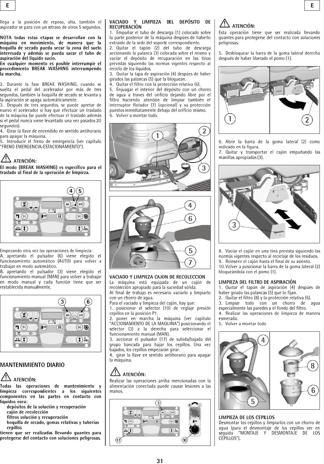
FLOW ADJUSTMENT OF DETERGENT
SOLUTION
To adjust the detergent solution quantity that flows
down onto the brush, turn the solution valve knob (1)
placed on the right of the steering column. Rotate
counter-clockwise to increase the flow, clock-wise
to reduce the flow.
10
BRUSH PRESSURE ADJUSTMENT
Turn the knob (8) to adjust the brush pressure onto
the floor in three pre-set pressure levels. The display
(1) shows the pressure in lbs., which was previously
set by pressing the push button (10).
ATTENTION:
To avoid overload of the brush motor, reduce the
brush pressure when going from smooth floors to
rough ones (ex. concrete).
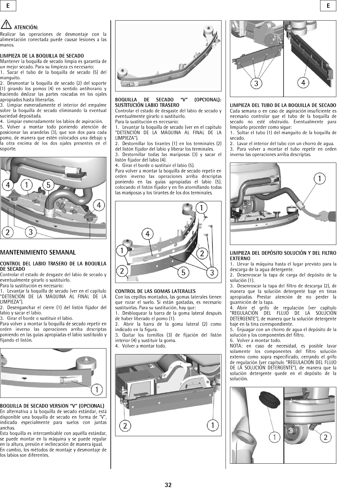
ELECTRIC PROTECTION
The machine is equipped with an electronic system
of protection for all components that carry out
functions of power or control. This device blocks the
defective component and indicates on the display (1)
the corresponding alarm from”AL01” to “AL20”.
ATTENTION:
To restore the function of the component, turn off
the machine and restart it using the key switch. If
the problem persists, please contact an
authorized technical assistant.
OVERFLOW DEVICE
In order to avoid serious damage to the vacuum
motor, the machine is equipped with a float that
intervenes when the recovery tank is full, closing the
suction, switching off the signal lamp (7) and
consequently the drying stops.
When this happens, empty the recovery tank (see
“RECOVERY TANK EMPTYING AND
CLEANING”).
STOPPING THE MACHINE AFTER
CLEANING OPERATION
IN AUTOMATIC OR MANUAL WORKING
MODE:
1. Put the selector (3) into the central position
(BREAK WASHING). This automatically lifts the
brush and shuts down the solenoid valve. Finish the
drying operation.
1. Release the foot from the accelerator pedal for
more than 3 seconds.
2. Turn the switch key counter-clockwise to switch
off the machine.
3. Insert the parking brake (see under paragraph
“EMERGENCY-PARKING BRAKE”).
ATTENTION:
The mode (BREAK WASHING) is specific for
the transfer at the end of the cleaning operation.
DAILY MAINTENANCE
ATTENTION:
For protection against dangerous solutions, all
the following maintenance and cleaning
operations that refer to the following components
must be carried out using gloves:
Solution and recovery tanks
Solution and recovery filters
Squeegee with their rubbers and hoses
Brushes
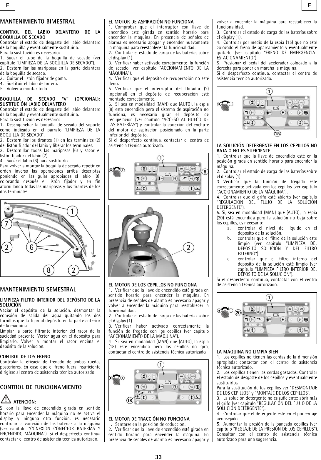
RECOVERY TANK EMPTYING AND
CLEANING
1. Hold the exhaust hose (1) placed in the rear
lower part of the machine after having taken it off
from its fixing support.
2. Take off the plug (2) from the exhaust hose by
pulling its lever (3). Empty the recovery tank into
appropriate containers. Comply rules concerning
liquid disposal.
3. Take off the suction cover (4) after rotating the
blocking levers (5).
4. Take off the filter and filter protection (6).
5. Rinse the inside of the tank with a water jet
through the tank opening and clean the float screen.
6. Reassemble all parts.
EMPTYING AND CLEANING THE
COLLECTION BOX
The machine is equipped with a collection box for
solid dirt.
At the end of the cleaning operation it is necessary
to empty and to clean it with a water jet.
For the emptying and the cleaning of the box:
1. Using the selector (8), adjust the brush pressure
to position P1.
2. Activate the machine (see “STARTING OF THE
MACHINE”) choosing manual mode (MAN).
3. Activate the selector (13) of the brush base to
lower the brushes.
4. Turn the key counter-clockwise to turn off the
machine.
ATTENTION:
Carrying out above operations with the electric
supply on may cause damages.
ATTENTION:
This operation must be carried out using gloves
for protection from dangerous solutions.
5. Unblock the bar of the side rubber after having
released the knob (1).
6. Open the bar of the side rubber (2) as shown in
the figure.
7. Extract and carry the box by using its handles (3).
11
8. Empty the box into appropriate containers, in
compliance with rules of liquid disposal.
9. Put the collection box back into its position up to
the end seat.
10. Place the bar of the side rubber (2) into its
position blocking it with the knob (1).
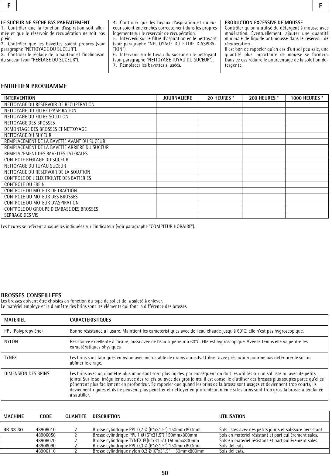
SUCTION FILTER CLEANING
1. Take off suction cover (4) after rotating the
blocking levers (5).
2. Take off the filter (8) and its filter protection (6).
3. Clean all parts with a water jet, especially the
inside surfaces and the filter bottom.
4. Carry out cleaning operations carefully.
5. Reassemble all parts.
BRUSH CLEANING
Disassemble the brush and clean them with a water
jet (see “BRUSH DISASSEMBLY”).
ATTENTION:
Carrying out brush disassembly operations with
the electric supply on may cause injury.
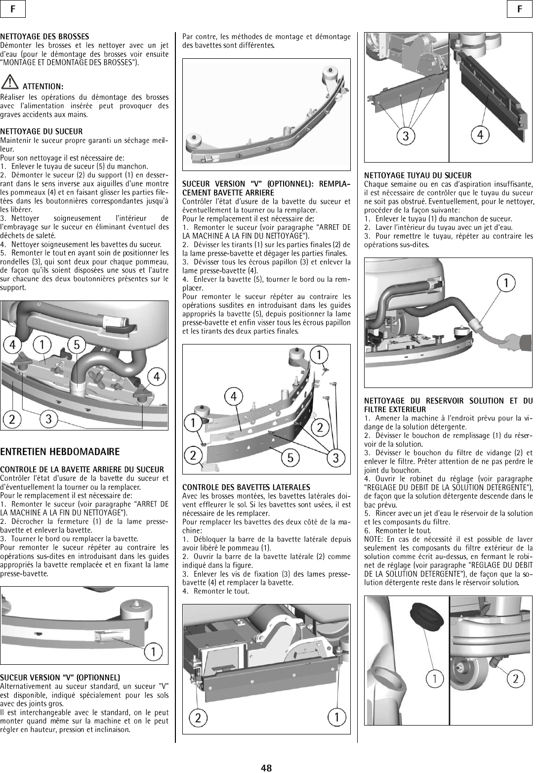
SQUEEGEE CLEANING
Keep the squeegee clean for the best drying results.
For cleaning it is necessary to:
1. Take off the squeegee hose (5) from the coupling.
2. Disassemble the squeegee (2) from its support (1)
by rotating the lever (4) counter-clockwise, making
slide the stud bolts (3) in the slots up to their release.
3. Clean with care the internal part of the squeegee
inlet eliminating dirt residuals.
4. Clean with care the squeegee rubbers.
5. Reassemble all parts.
WEEKLY MAINTENANCE
REAR SQUEEGEE RUBBER CHECK
Check the wear of the squeegee rubber.
For the replacement, it is necessary to:
1. Lift the squeegee (see “STOP OF MACHINE
AFTER CLEANING OPERATION”).
2. Release the hook (1) of the rubber holder blade
and take off the rubber.
3. Turn the rubber to a new side or replace it.
To reassemble the squeegees follow the directions
above in reverse, inserting the rubber on the guides
and blocking it with the rubber holder blade.
CHECK OF THE SIDE RUBBERS
With the brushes assembled, the side rubbers must
touch the floor. If they are worn, they have to be
replaced.
To replace the rubbers on both sides of the machine:
1. Unblock the bar of the side rubber after releasing
the knob (1).
2. Open the bar of the side rubber (2) as shown in
the figure.
3. Take off the fixing screws (3) of the rubber blade
(4) and replace the rubber.
4. Reassemble all parts.
SQUEEGEE HOSE CLEANING
Weekly or in case of insufficient suction, check that
the squeegee hose is not obstructed. To clean it,
proceed as follows:
1. Take off the hose (1) from the squeegee coupling.
2. Wash the inside of the hose with a water jet.
3. To reassemble the hose follow the directions
above in reverse.
CLEANING OF THE SOLUTION TANK AND
OF THE OUTER FILTER
1. Bring the machine to an appropriate place to
drain the detergent solution
2. Unscrew the solution tank cap (1).
3. Unscrew the cap of the exhaust filter (2) and take
off the filter. Be careful not to lose the gasket of the
cap.
4. Open the solution valve (see “FLOW
ADJUSTMENT OF DETERGENT SOLUTION”),
so that the detergent solution flows down into
appropriate containers.
5. Rinse with a water jet the solution tank and the
components of the filter.
6. Reassemble all parts.
NOTE: if needed it is possible to wash only the
components of the outer solution filter as above-
mentioned by closing the solution valve adjustment
(see “FLOW ADJUSTMENT OF THE
DETERGENT SOLUTION”), so that the detergent
solution remains in the solution tank.
12
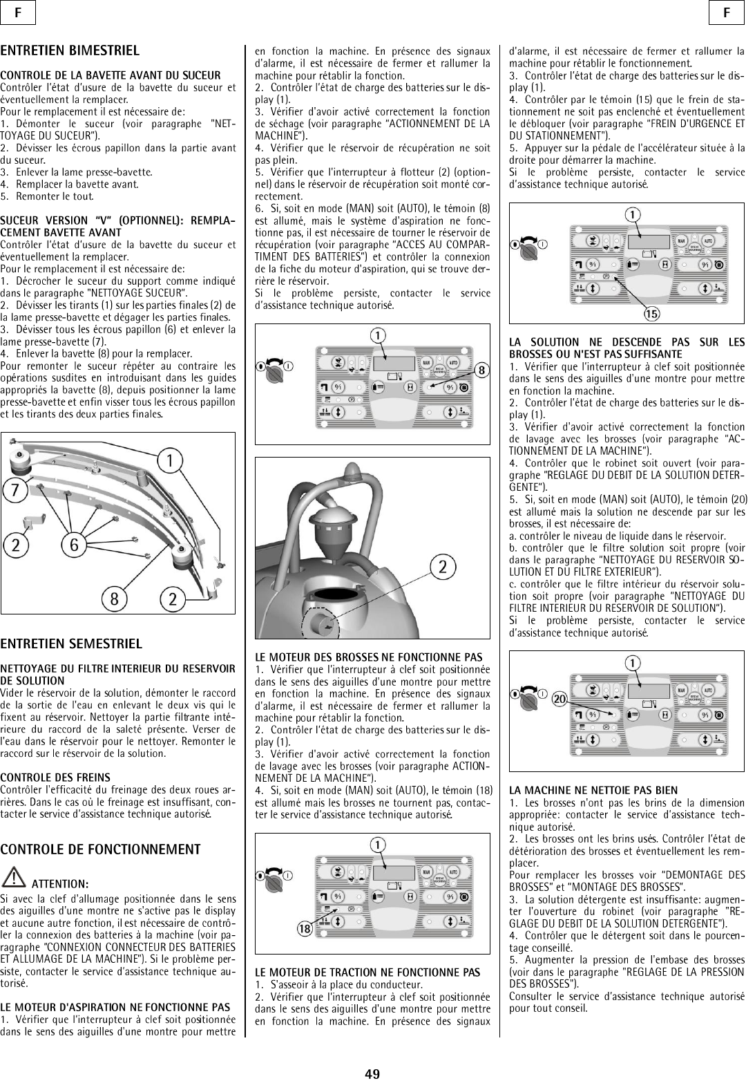
TWO-MONTH MAINTENANCE
FRONT SQUEEGEE RUBBER CHECK
Check the wear of the squeegee rubber and replace it
if needed.
For the replacement:
1. Take off the squeegee (see under paragraph
“SQUEEGEE CLEANING”).
2. Unscrew the wing nuts in the front part of the
squeegee.
3. Take off the rubber holder blade.
4. Replace the front rubber.
5. Reassemble all parts.
SIX-MONTH MAINTENANCE
CLEANING THE INNER FILTER SOLUTION
TANK
Empty the solution tank; remove the fitting of the
water outlet by taking off the two screws that fix it
to the tank in the front part of the machine. Clean the
inside filtrating part of the fitting from dirt. Pour
some water into the tank to clean it. Reassemble the
fitting onto the solution tank.
CHECK THE BRAKE
Check the braking efficiency of both rear wheels.
Should the braking be insufficient, please contact an
authorized technical assistant.
TROUBLESHOOTING GUIDE
ATTENTION:
If the machine is on, and the display and/or other
functions are not activated, check the battery
connection of the machine (see “CONNECTING
BATTERY' AND SWITCHING ON THE
MACHINE”). If the problem persists, please
contact an authorized technical assistant.
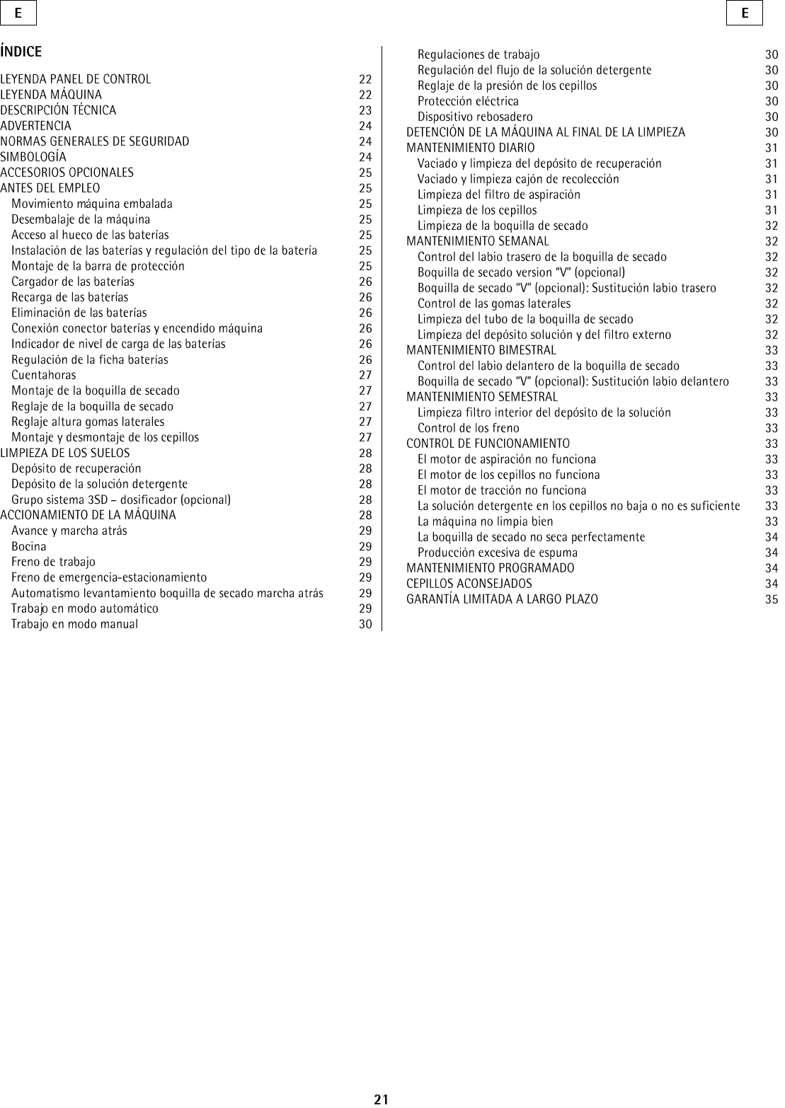
THE VACUUM MOTOR DOES NOT WORK
1. Verify that the machine is on. If alarm signals
appear, turn off the machine and restart it.
2. Check the charge level of the battery on the
display (1).
3. Verify that the drying function is activated
correctly (see “STARTING THE MACHINE”).
4. Check that the recovery tank is not full.
5. Check that the float switch (2) in the recovery
tank is assembled correctly.
6. For both in mode (MAN) as (AUTO), if the
signal lamp (7) is on but the suction system does not
work, it is necessary to rotate the recovery tank (see
“ACCESS TO THE BATTERY
COMPARTMENT”). Check the connection of the
vacuum motor plug at the bottom of the tank.
If the problems persist, please contact an authorized
technical assistant.
THE BRUSH MOTOR DOES NOT WORK
1. Verify that the machine is on. If alarm signals
appear, turn off the machine and restart it.
2. Check the charge level of the battery on the
display (1).
3. Verify that the function of washing with the
brush is activated (see “STARTING THE
MACHINE”).
4. If the signal lamp (17) is on but the brush does
not turn, please contact an authorized technical
assistant
.If problems persist, please contact an authorized
technical assistant.
THE TRACTION MOTOR DOES NOT WORK
1. Sit on the guiding place.
2. Verify that the machine is on. If alarm signals
appear, turn off the machine and restart it.
3. Check the charge level of the battery on the
display (1).
4. Check through the signal lamp (2) that the
parking brake is not inserted.
(see “EMERGENCY-PARKING BRAKE”).
5. Press the accelerator pedal placed on the right
side to start the machine.
If problems persist, please contact an authorized
technical assistant.
THE WATER DOES NOT COME DOWN
ONTO THE BRUSHES OR IS INSUFFICIENT
1. Verify that machine is on.
2. Check the charge level of the battery on the
display (1).
3. Verify that the function of washing with the
brush is activated correctly (see “STARTING THE
MACHINE”).
4. Check that the solution valve is open (see
“FLOW ADJUSTMENT OF DETERGENT
SOLUTION”).
5. If the signal lamp (16) is on but the detergent
solution does not come down onto the brush, do the
following:
a. check the level of the liquid in the tank.
b. check that the solution filter is clean (see
“CLEANING THE SOLUTION TANK AND
OF THE OUTER FILTER”).
c. check that the inner filter of the solution tank is
clean (see under paragraph “CLEANING THE
INNER FILTER SOLUTION TANK”).
If the problem persists, please contact an authorized
technical assistant.
THE MACHINE DOES NOT CLEAN
PROPERLY
1. The brushes do not have suitable bristle
dimension, contact an authorized technical assistant.
2. The brushes have worn bristles. Check the brush
wear condition. If needed, replace them (the brushes
have to be replaced when the bristles have reached a
height of .60 in).
To replace the brushes, see instructions under
“BRUSH DISASSEMBLY” and “BRUSH
ASSEMBLY”.
3. The detergent solution is insufficient: open more
the solution valve (see “FLOW ADJUSTMENT OF
DETERGENT SOLUTION”).
4. Check that the liquid detergent is in the
recommended percentage.
5. Increase the brush base pressure (see " BRUSH
PRESSURE ADJUSTMENT").
Contact authorized technical assistance for advice.
THE SQUEEGEE DOES NOT DRY
PROPERLY
1. Check that the suction function is on and that the
recovery tank is not full.
2. Check that the squeegee rubbers are clean (see
“SQUEEGEE CLEANING”).
3. Check the height and the inclination of the
squeegee (see “ADJUSTMENT OF THE
SQUEEGEE”).
4. Check that the suction and the squeegee hoses
are correctly inserted in their proper seats on the
recovery tank.
5. Clean the suction filter (see “SUCTION FILTER
CLEANING”).
6. Clean the squeegee hose ( “SQUEEGEE HOSE
CLEANING”).
7. Replace the rubbers if worn out.
EXCESSIVE FOAM PRODUCTION
Check that low foam detergent has been used. Add
small quantities of anti foam liquid into the recovery
tank.
Please be aware that a bigger quantity of foam is
produced when the floor is not very dirty. In this
case please dilute detergent solution.

13
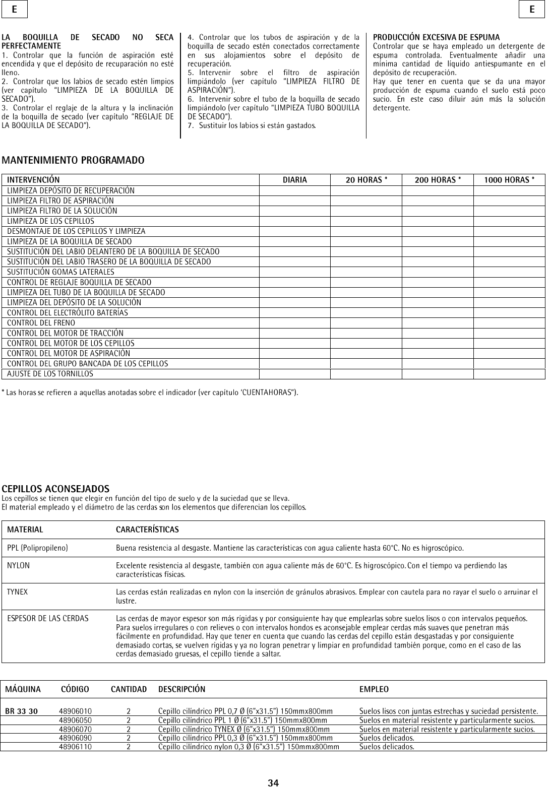
PROGRAMMED MAINTENANCE
INTERVENTION
DAILY
20 HOURS *
200 HOURS *
1000 HOURS *
RECOVERY TANK CLEANING
SUCTION FILTER CLEANING
SOLUTION TANK FILTER CLEANING
BRUSH CLEANING
BRUSH DISASSEMBLY AND CLEANING
SQUEEGEE CLEANING
FRONT SQUEEGEE RUBBER REPLACEMENT
REAR SQUEEGEE RUBBER REPLACEMENT
REPLACEMENT SIDE RUBBERS
CHECK SQUEEGEE ADJUSTMENT
SQUEEGEE HOSE CLEANING
SOLUTION TANK CLEANING
CHECK BATTERY ELECTROLYTE
CHECKING THE BRAKE
TRACTION MOTOR CHECK
BRUSH MOTOR CHECK
VACUUM MOTOR CHECK
CHECK BRUSH BASE GROUP
SCREW TIGHTENING
* The hours refer to the ones indicated on the display (see under paragraph”HOUR METER”).

14
Facility Description (please circle all that apply)
1. School
9. Hospital
17. U.S. Govt.
2. Retail Store
10. Nursing Home
18. Other Govt.
3. Restaurant
11. Religious Institution
19. Auto Service
4. Office Building
12. Airport
20. Airport
5. Contract Cleaning
13. Warehouse
21. Non-Profit
6. Light Manufacturing
14. Apartment/Condo
22. Other (specify)
7. Heavy Manufacturing
15. Warehouse
8. College/University
16. Supermarket
Warranty
REGISTRATION
FORM
PLEASE PROVIDE ADDITIONAL INFORMATION ON
Tornado equiptment: (Check choices below)
__ Automatic Scrubbers __Sweepers
__Propane Floor Machines __Rotary Floor Machine
__High Speed Burnishers __Carpet Vacuums
__Carpet Extractors & Spotters __Wet/Dry Vacs
__ Steam Cleaners __Jumbo Vacs
__Ride-On Equiptment __Pressure Washers
See complete product info at www.tornadovac@.com
_______________________________________________________________________________
Company/Institution
_____________________________________ ____________________________________
Contact Name Title
_____________________________________ ____________________________________
Address City/State/Zip Code
_____________________________________ ____________________________________
Phone Fax
_____________________________________ ____________________________________
Date of Purchase Email
Please Print Cleary
See white metal plate or sticker on unit for his information.
MACHINE TYPE/MODEL NUMBER:
MACHINE SERIAL NUMBER:
1.
1.
2.
2.
3.
3.
4.
4.
How did you first lean about
Tornado cleaning and
maintenance equipment?
In square feet
(meters)
Total Hard Floor Area
Total Carpeted Area
Square feet (square meters)
o Contacted by local dealer
o Previous experience with
Tornado products
o Reputation/Recommendation
o Advertising
o Direct mail
o Internet
o Other
o 0-10,000 (0-930)
o 10-50,000 (930-4,650)
o 50-250,000 (4,650-23,250)
o Over 250,000 (over
23,260)
o 0-10,000 (0-930)
o 10-50,000 (930-4,650)
o 50-250,000 (4,650-23,250)
o Over 250,000 (over
23,260)
Selling Dealer:(Required)__________________________
Damage or defect arising from abuse, neglect or other misuse is excluded from this warranty. Other items may or
may not apply based on your specific machine. If any defect occurs, the warranty is voided if service is attempted
by non-Authorized Tornado Service Centers.
©2013 Tornado Industries. All rights reserved.
X8449-TOR 3/2013
Return to:
Tornado Industries
333 Charles Ct.Unit 109
West Chicago, IL 60185
Fax: (630)818-1301
° °
° °
Tornado Industries, Inc. (Tornado) garantiza al consumidor final que los productos de Tornado no
presentarán defectos materiales o de fabricación durante el periodo especificado abajo. Esta garantía
limitada NO cubre máquinas y/o componentes sujetos a uso y desgaste normal, daños durante el
envío, fallas ocasionadas por modificaciones, accidentes, operación en lugares inadecuados, mal uso,
abuso, descuido o mantenimiento inapropiado de su parte. Para obtener más detalles comuníquese
con el Distribuidor Autorizado de Tornado, el Centro de Servicio o el Departamento de Servicio Técnico
de Tornado. Los representantes de venta y servicio de Tornado no están autorizados a modificar o
anular los términos de esta garantía, ni a extender las obligaciones de Tornado bajo la garantía.
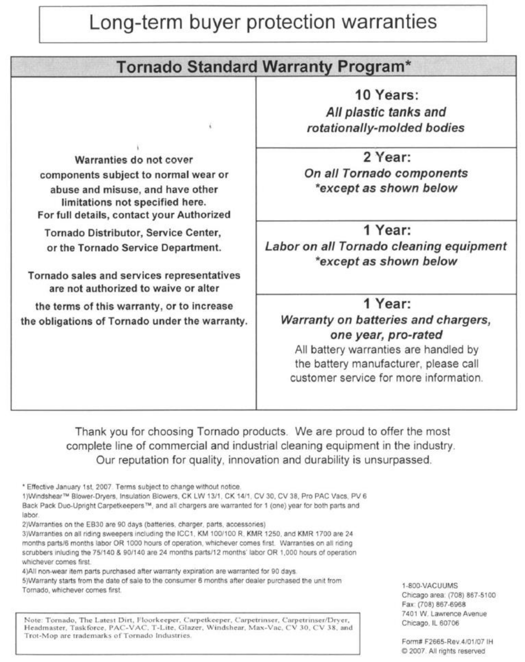
10 Años*
Tanques de agua de plástico y cuerpos giratorios moldeados
2 Años*
Partes de todo el equipo de limpieza de Tornado
1 Año*
Trabajo de reparación en todo el equipo de limpieza de Tornado
1 Año*
Garantía para baterías, prorrateo de un año.
Las garantías de baterías son administradas por el fabricante de baterías, en base a un año de prorrateo.
*Con vigencia a partir del 1 de enero de 2013. Términos sujetos a cambios sin previo aviso.
1. A excepción de todas las Sopladoras-Secadoras WindshearTM, las Sopladoras de Aislamiento, Laterales y de Corriente Descendente, CV 30, CV 38, CW 50, CW 100,
EB30, CK14/1, CK LW 13/1, CV 38/48 Dual, PV6, PV10 y todos los cargadores tienen garantía de partes y servicio de 1 (uno) año.
2. Todos los repuestos sin desgaste comprados después del vencimiento de la garantía tienen garantía por 30 días.
3. La garantía tiene vigencia a partir de la fecha de compra del consumidor o, a criterio de Tornado, 6 meses después de que el distribuidor compre la unidad a Tornado,
lo que ocurra primero.
4. EB 30 tiene un periodo de garantía de 90 días para partes y servicio.
5. La garantía para motores utilizados en equipos a gas propano está sujeta a la garantía del fabricante del motor.
6. Las fregadoras con conductor tienen garantía por 24 meses para partes, 6 meses para servicio o 1000 horas, lo que ocurra primero.
Nota: Tornado, The Latest Dirt, Floorkeeper, Carpetkeeper, Carpetrinser,
Carpetrinser/Dryer, Headmaster, Taskforce, PAC-VAC, T-Lite, Glazer, Windshear,
Max-Vac y Trot-Mop son marcas registradas de Tornado Industries.
Sitio web: www.tornadovac.com
Teléfono 1.800.VACUUMS
Dirección: 333 Charles Court, Suite 109
West Chicago, IL 60185
80 años innovando en la limpieza
° °
° °
Tornado
Garantie limitée de la protection à long terme de l’acheteur
Tornado Industries Inc. (Tornado) garantit au client ou à l’utilisateur final que les produits Tornado seront exempts de défauts en ce qui a trait à
la fabrication ou à l’assemblage pour la durée indiquée ci-dessous. Cette garantie limitée NE couvre PAS les machines et/ou composants
soumis à l’usure normale, la détérioration ou des dommages causés par l’expédition, des défaillances découlant de modifications, un accident,
un environnement de fonctionnement inadéquat, une mauvaise utilisation, un abus, une négligence ou un mauvais entretien de votre part. Pour
obtenir tous les détails, veuillez communiquer avec votre distributeur Tornado autorisé, le centre d’entretien autorisé ou le département de
service technique de Tornado. Les représentants des ventes et du service de Tornado ne sont pas autorisés à renoncer ou à modifier les
modalités de la présente garantie ni à augmenter les obligations de Tornado aux termes de celle-ci.
10 ans*
Réservoirs d’eau en plastique et cadres moulés par rotation
2 ans*
Pièces pour tous les équipements de nettoyage Tornado
1 an*
Main d’œuvre pour tous les équipements de nettoyage Tornado
1 an*
Garantie sur les batteries, une année au prorata.
Toutes les garanties sur les batteries sont traitées directement par le fabricant de la batterie, au prorata d’une année
*À compter du 1er janvier 2013. Modalités susceptibles d’être modifiées sans préavis.
1. À l’exception de tous les sécheurs munis d'un ventilateur WindshearTM, de côtés et horizontaux, CV 30, CV 38, CW 50, CW 100,
EB30, CK14/1, CK LW 13/1, CV 38/48 double, PVE, PV10 et tous les chargeurs sont garantis pour 1 (une) année pour les pièces et
la main d’œuvre.
2. Toutes les pièces sans usure achetées après l’expiration de la garantie sont garanties pour 90 jours.
3. La garantie commence à la date de la vente au consommateur ou, à la discrétion de Tornado, 6 mois après que le détaillant ait
acheté l’unité de Tornado, selon la date qui arrive en premier.
4. EB 30 est garanti pour une période de 90 jours pour les pièces et la main d’œuvre.
5. La garantie sur les moteurs utilisés sur des équipements alimentés en gaz propane est limitée à la garantie du fabricant du moteur.
6. La garantie sur les nettoyeurs est de 24 mois pour les pièces, 6 mois sur la main d’œuvre ou 1 000 heures, selon le premier délai à
survenir.
Note : Tornado, The Latest Dirt, Floorkeeper, Carpetkeeper,
Carpetrinser, Carpertrinser/Dryer, Headmaster, Taskforce,
PAC-VAC, T-Lite, Glazer, Windshear, Max-Vac et Trot-Mop
sont des marques de commerces de Tornado Industries.
Site Web : www.tornadovac.com
Tél. : 1 800 VACCUMS
Télec. : 630 818-1301
Adresse : 333, Charles Court, bureau 105
West Chicago, IL 60185
1 800 VACUUMS
80 années d’innovation en nettoyage
Une entreprise Tacony
