5A3A5C4A756E6F5CB4F2D3A15044465C56463839303030D7DCD7B0A3A8CBB5 Viper Fang 15b Parts And Operator Manual
2016-09-29
: Sweepscrub Viper-Fang-15B-Parts-And-Operator-Manual viper-fang-15b-parts-and-operator-manual 1270 file product_file
Open the PDF directly: View PDF ![]() .
.
Page Count: 30
- CVD Manual v20
- CVD Manual v19
- CVD Manual v18
- CVD Manual v17
- CVD Manual 16
- CVD Manual 15
- CVD Manual 14
- CVD Manual 13
- FANG15B - CVD MANUAL v12
- FANG15B - CVD MANUAL v11
- FANG15B Control Panel
- Cover
- FANG15B - CVD MANUAL v12
- RearCover
- CVD Manual 13
- FANG15B-COMPLETEMACHINE
- CVD Manual 14
- FANG15B-BRUSHDECKASSY
- CVD Manual 15
- FANG15B-BRUSHSKIRTBRUSH
- CVD Manual 16
- Cover
- CVD Manual v17
- COVER
- CVD Manual v18
- Wiring Diagram 15B
- CVD Manual v19
- page 10
2014-6-9
VF89027-US REV.05
15-Inch
FANG15B
www.usviper.com

1
!!!!!!!!!!!!!!!!!!!!!!!!!!!!!!!!!!!!!!!!!!!!!!!!!!USER!MANUAL!
SAFETY PRECAUTIONS
This machine is intended for commercial use. It is constructed for use in an indoor environment and is
not intended for any other use. Use only with recommended accessories.
All operators shall read, understand and exercise the following safety precautions:
1) DO NOT OPERATE MACHINE:
Unless trained and authorized.
Unless you have read and understand the operators manual.
In flammable or explosive areas.
If not in proper operating condition.
In outdoor areas.
2) BEFORE OPERATING MACHINE:
Make sure all safety devices are in place and operate properly.
3) WHEN USING MACHINE:
Go slow on inclines and slippery surfaces.
Follow all safety guidelines.
Be very careful when using the machine in reverse.
Report and fix any damage to machine prior to operating it.
4) BEFORE LEAVING OR SERVICING MACHINE:
Stop machine on level ground.
Turn machine off.
5) WHEN SERVICING MACHINE:
Read operators manual thoroughly prior to operating or servicing this machine.
Use manufacturer supplied or approved replacement parts.
Secure machine with wheel blocks prior to jacking the machine up.
Use approved jack or hoist to safely elevate the machine.
Disconnect batteries prior to working on machine.
Wear gloves when handling batteries or battery cables.
Avoid any contact with battery acid.
Avoid moving parts; do not wear loose fitting clothing while servicing machine.
WARNING!
Batteries emit hydrogen gas. Explosion or fire can result from hydrogen gas. Keep
Sparks and open flames away! Keep battery compartment open when charging.
WARNING!
Flammable materials can cause an explosion or fire. Do not use flammable materials
in tanks.
WARNING!
Flammable materials or reactive metals can cause explosion or fire .Do not pick up.
2
!!!!!!!!!!!!!!!!!!!!!!!!!!!!!!!!!!!!!!!!!!!!!!!!!!USER!MANUAL!
MACHINE SET UP & INSTALLATION
UNCRATING MACHINE
Be sure and check packing carton for any damage. Immediately report any damage to carrier.
Check contents of package to ensure that the following items are included:
1. Machine
2. Batteries(x2)
3. Squeegee assembly
4. Owners Manual
5. Electric Battery Charger Manual(if equipped)
6. Connecting wire for battery and charger (if equipped)
7. Brush
BATTERY DISASSMBLY AND INSTALLATION
1. Switch off the main switch. (47)
2. Remove the recovery tank. (2)
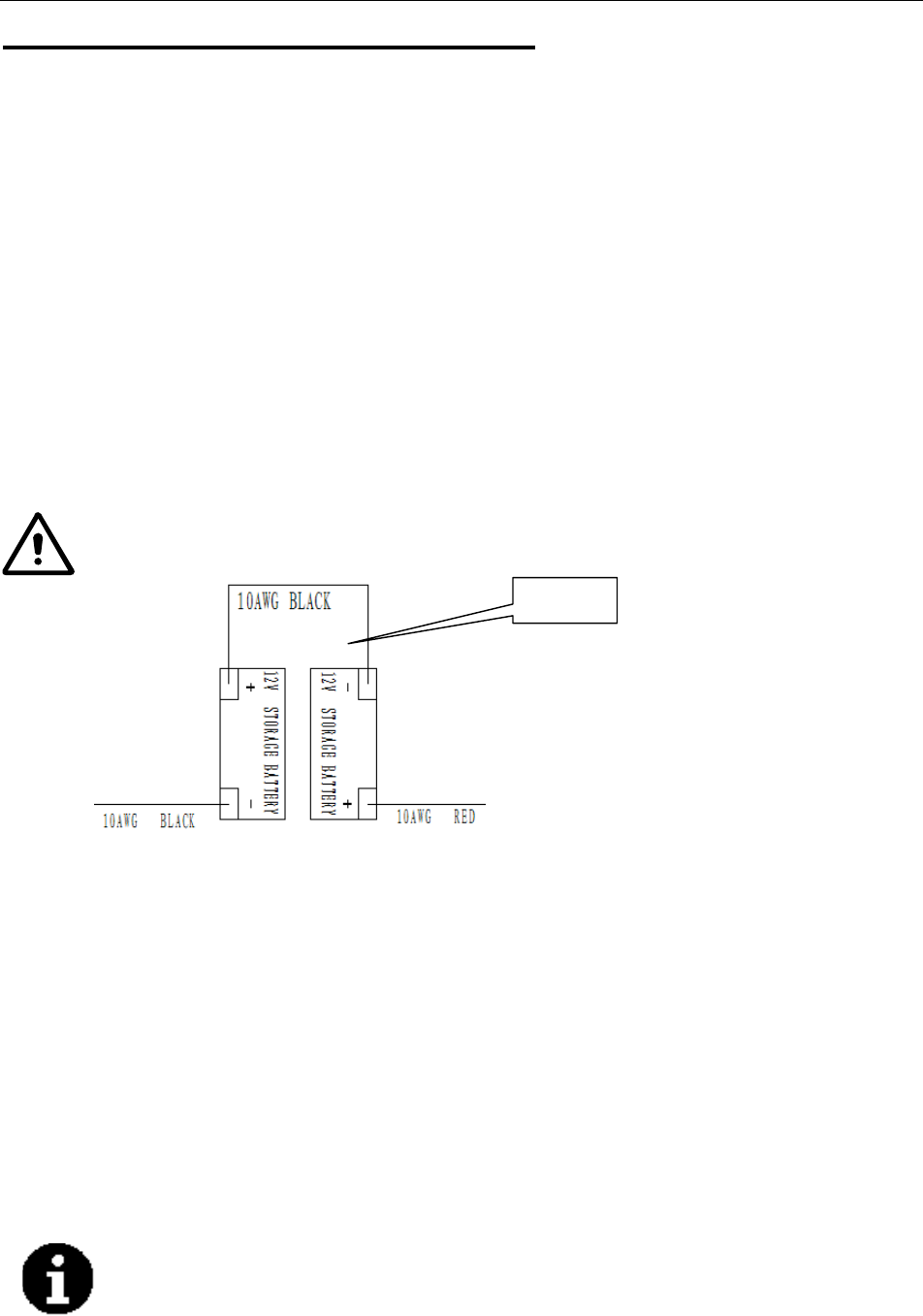
3. Remove the bolt from batteries. (16) Remove or change batteries.
4. Install the batteries on the machine according to the diagram below.
5. Install the recovery tank.
WARNING
Do not connect+ to +,or - to-,when disassembly or install the batteries. It is very dangerous.
!!!!!!!!! !!!!!!!!!!!!!!!!!!!!!!!!!!!!!!!!!!!!!!!!!!!!!!!!!!!
!
Battery charging
Charge the batteries. (see Maintenance section)
MACHINE SET UP
Pre-operation checks
1. Sweep or dust mop the surface to be cleaned.
2. Check that squeegee is properly installed.
3. Lower the squeegee (33) with the lever. (26)
4. Ensure batteries are fully charged. (see Battery Charging section)
5. Check that brush is properly installed.
Brush/Pad driver installation and disassembly
NOTE
Only install manually. If automatically installed, it will wear brush hub.
Make sure that the tanks are empty before removing the brush.
1. Turn off the machine.
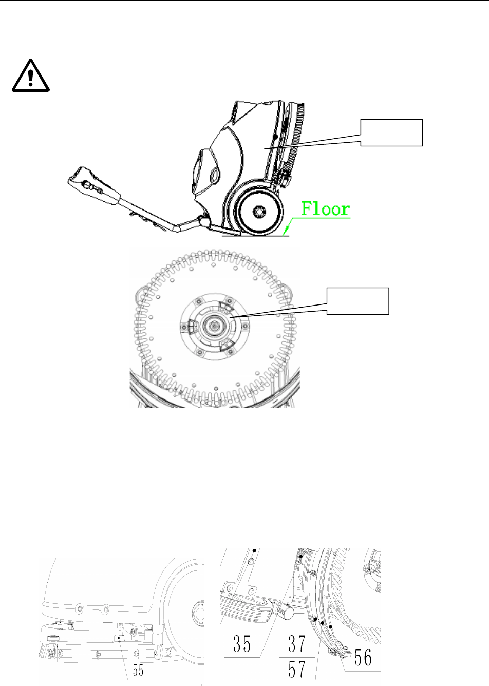
2. Lay down the machine in the position shown in figure 2. Pull up lift lever (26) to raise the
squeegee. (33)
Figure!1!
3
!!!!!!!!!!!!!!!!!!!!!!!!!!!!!!!!!!!!!!!!!!!!!!!!!!USER!MANUAL!
3. Mount the brush or pad driver onto the drive wheel hub and then rotate counterclockwise until it
locks, as indicated in figure3.
4. To remove the brush/pad, rotate the brush/pad clockwise until it is released from drive hub.
WARNING
Do not turn on the machine in this position as below. In case of brush/pad come out or cause injury.
Squeegee installation
1. Turn off the machine. (47)
2. Pull down the squeegee lift lever (26) to put down the squeegee in the “working” position.
3. Lay down the machine in this position as shown in figure2.
4. Loosen the two knobs (55) on the squeegee and slide the squeegee into the slots on the
squeegee brackets.
5. Tighten the knobs securely. (unscrew the knobs, if to remove)
6. To replace the front/rear squeegee, (56/57) unscrew the thumb knobs. (37)
Figure!3!
Figure!2!

4
!!!!!!!!!!!!!!!!!!!!!!!!!!!!!!!!!!!!!!!!!!!!!!!!!!USER!MANUAL!
Solution tank filling
NOTE
The machine can be filled with a hose or bucket. Do not remove the Solution filter (21) while filling.
1. Fill water into solution tank (3) from the inlet (20) through hose or bucket.
2. Do not overfill the solution tank. It is best to leave a an inch from the top edge.
3. The water temperature must not exceed 40℃.
CAUTION!
Use only low-foam and non-flammable detergents, intended for automatic scrubber applications.
Solution tank draining
NOTE
Solution tank should be drained and cleaned after each scrubber operation is
completed.
1. Unscrew the drain cap (22) on the bottom of solution tank. The solution/water will flow freely
into a bucket or floor drain.
2. Rinse the solution tank with clean water after every use. This will help prevent chemical
buildup and clogging of the solution lid.
3. Replace the drain cap. (22)
Recovery tank draining
NOTE
Recovery tank should be drained and cleaned after each scrubber operation is
completed.
1. Turn the latch (17) on the recovery tank. Remove the recovery tank from machine by
grasping two grooves of tank and pulling up. Open the lid (1) and overturn the recovery tank
to drain the dirty water into a container, or unscrew the drain cap (22) to let water drain into a
bucket.
2. Clean and Rinse the recovery tank with clean water after every use.
3. Re-place the recovery tank on the machine and turn the latch (17) to lock the tank in place.
MACHINE OPERATION
1. Set the handle to a comfortable height by pressing level. (25)
2. Lower the squeegee (33) onto floor by pulling down the lift handle. (26)
3. Turn on the main power switch. (47)
4. Turn on the brush motor switch (48) and the solution switch. (50)
5. Turn on the vacuum motor switch. (49)
6. If necessary, adjust the water flow by manually turning the ball valve. (31)
7. Pull one or both operating triggers. (24) The brush will spin & solution will begin to flow. Push
the machine forward to start cleaning.
NOTE
If the battery indicator light (51) is green, the machine can be used. If it is yellow or red,
the batteries must be charged.
.

5
!!!!!!!!!!!!!!!!!!!!!!!!!!!!!!!!!!!!!!!!!!!!!!!!!!USER!MANUAL!
CAUTION!
Before lifting the brush, turn off the main power switch. (47)
CAUTION!
If the control panel (46) lights flash simultaneously, this indicates the machine is overloaded. Please turn off
all the switches on the control panel (46) to reset the machine. If problem persists, contact authorized
service provider.
CAUTION!
Operating machine with discharged batteries may cause harm to the batteries or to the machine.
AFTER EACH USE
After scrubbing, please proceed with below actions before storing the machine:
1. Remove the brush / pad-holder.
2. Empty the tanks as shown in the previous paragraph.
3. Perform the daily maintenance procedures. (see Maintenance section)
4. Store the machine in a clean and dry place, with the brush / pad-holder and the squeegee up.
5. If storing in an area that may reach freezing temperatures, be sure to drain all fluids from the
machine prior to storage. Any damage caused by freezing will void the warranty.
MACHINE STORAGE
If the machine is not going to be used for more than 30-days, please proceed with below actions:
1. Perform the procedures shown in ‘After Each Use’ section above.
2. Disconnect the battery connector.
MAINTENANCE
The lifespan of the machine and its maximum operating safety are ensured by correct and regular
maintenance. The following chart provides the scheduled maintenance. The intervals shown may
vary according to individual working conditions.
WARNING
Maintenance procedures must be performed with the machine switched off and the batteries/battery charger
cable disconnected. Moreover, carefully read the instruction in the Safety chapter.
All maintenance procedures must be performed by qualified personnel, or by an authorized Service
Center.
This Manual describes only the most common maintenance procedures.
For additional maintenance procedures, contact your local Service Center.
Inlet filter cl
6
!!!!!!!!!!!!!!!!!!!!!!!!!!!!!!!!!!!!!!!!!!!!!!!!!!USER!MANUAL!
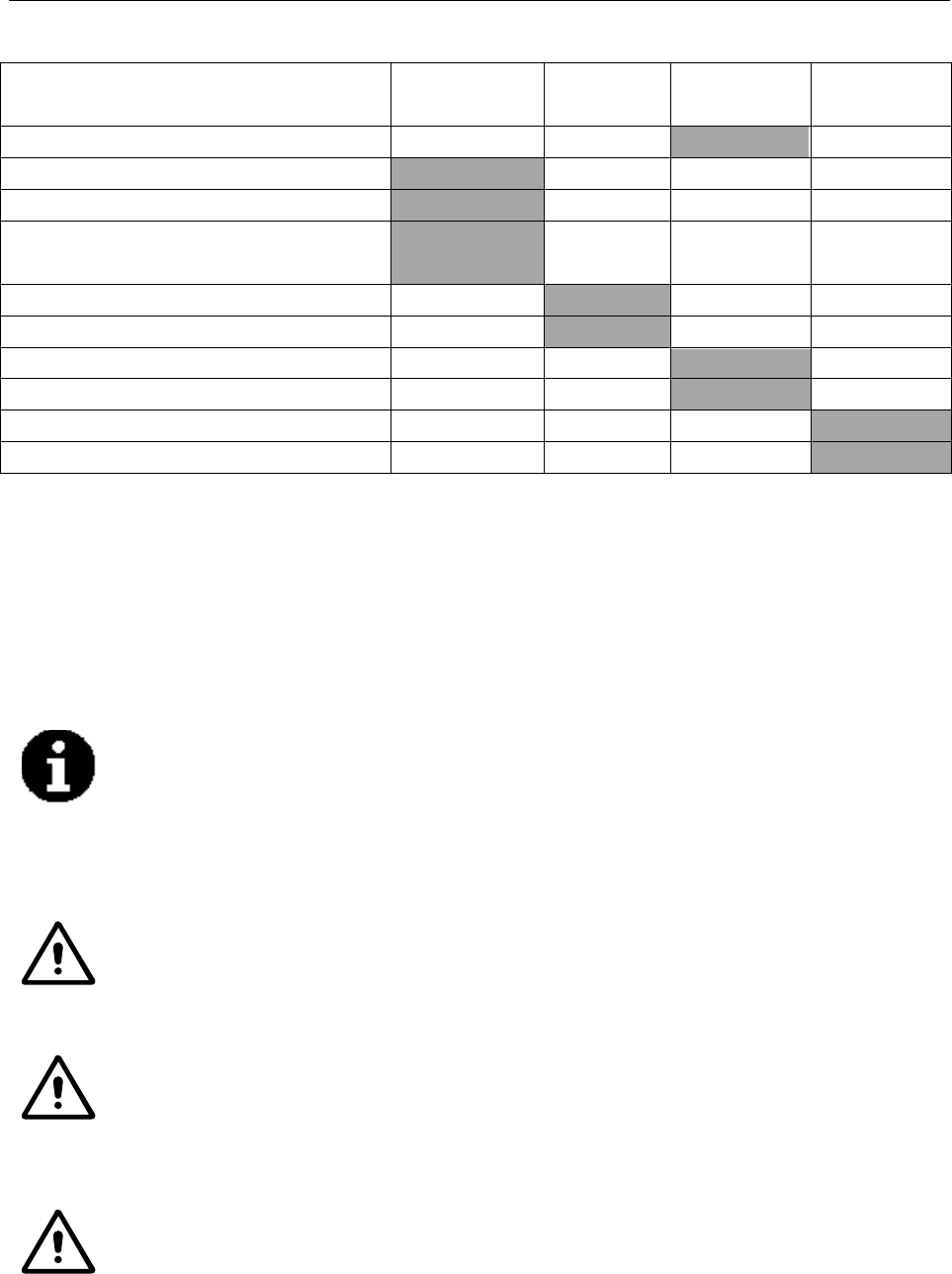
SCHEDULED MAINTENANCE TABLE
Procedure
After each use Weekly Every six
months
Annually
Battery charging
Squeegee cleaning
Brush cleaning
Clean tank, vacuum screen & check top cover
gasket
Squeegee blade check and replacement
eaning
Screw and nut tightening check
(1)
Lubricate rotary parts
(1)
Check brush motor carbon brushes
(2)
Check vacuum motor carbon brushes
(2)
(1)After the first 8 working hours.
(2)This maintenance procedure must be performed by an authorized Service Center.
BATTERY CHARGING
NOTE
Charge the batteries when the yellow or red indicator, (51) or at the end of every work cycle.
CAUTION!
Proper battery care will extend battery life
CAUTION!
If the machine is not equipped with on-board battery charger, choose an external battery charger suitable for
the type of batteries installed.
WARNING!
Please use Viper approved charger to charge the batteries.

7
!!!!!!!!!!!!!!!!!!!!!!!!!!!!!!!!!!!!!!!!!!!!!!!!!!USER!MANUAL!
1.
Place charger and machine in a well ventilated area.
2.
Turn
machine off.
(47)
3.
Remove the recovery tank,
(2)
exposing battery compartment.
4.
Plug the charging cable to the grounded wall outlet (100v~240v).
Connect the charging cable to
the machine socket.
5.
The charging light (30) indicates the batteries are charging. A green light indicates battery charging
is completed.
6.
Upon the completion of charging, first unplug the charging cable from the wall outlet and then
disconnect from machine.
7.
Replace
the recovery tank.
NOTE
For further information about the operation of the battery charger, (29) see the charger section.
SQUEEGEE CLEANING
NOTE
For optimal performance, the squeegee blades must be clean, dry and undamaged.
CAUTION !
It is advisable to wear protective gloves when cleaning the squeegee because there may be sharp debris.
SQUEEGEE BLADE CHECK AND REPLACEMENT
1.
Take off the squeegee as shown in the previously.
2.
Check the edges of the front
& rear blades for cracks. If necessary replace with new blades.
3.
Unscrew six the thumb nuts (37) to remove the blades.
4.
Check the front & rear blades for cuts and tears. If damage is found, you can flip the blades once &
re-install. If already flipped, please replace with new blades.
5.
Install the squeegee in the reverse order of removal.

8
!!!!!!!!!!!!!!!!!!!!!!!!!!!!!!!!!!!!!!!!!!!!!!!!!!USER!MANUAL!
BRUSH /PAD DRIVER CLEANING
CAUTION!
It is advisable to wear protective gloves when cleaning the brush/pad because there may be sharp debris.
1. Remove the brush/pad as shown in “Machine Use” section.
2. Clean and wash the brush/pad with water and detergent.
3. Check the brush bristles for integrity and wear. If necessary, replace the brush.
4. Check the pad for wear. If necessary, replace the pad driver.
RECOVERY TANK MAINTENANCE
CAUTION!
It is advisable to wear protective gloves when cleaning the tank and vacuum/suction assembly because there
may be sharp debris.
1.
Move the machine to the appointed draining area.
2.
Turn off the main switch.
(47)
3.
Remove the recovery tank, (2) clean and rinse both solution/recovery tank, and drain out.
4.
Remove vacuum gasket & filter. Clean and re-install.
5.
Check the recovery tank lid gasket and the vacuum rubber connector
(18) for wear. Replace if
necessary.
NOTE
The gasket ring of recovery tank and the rubber connector between two tanks create vacuum
in the tank. If necessary, replace them.
9
!!!!!!!!!!!!!!!!!!!!!!!!!!!!!!!!!!!!!!!!!!!!!!!!!!USER!MANUAL!
!
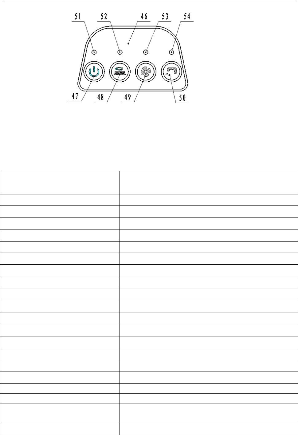
Control Panel
46. Control panel 51.Battery indicator
47. Main switch 52.Brush motor indicator
48. Brush motor switch 53.Vacuum motor indicator
49. Vacuum motor switch 54.Solution indicator
50. Solution switch
TECHINICAL DATA
MODEL
FANG15B
Machine length / width / height 770x500x550MM
Solution tank capacity 15L
Recovery tank capacity 15L
Wheel diameter 254MM
Brush motor 24V/250W
Vacuum motor 24V/250W
Solenoid valve 24V
Maximum gradient when working 2%
Sound level 70dBA
Standard Batteries Dry:(2×12V)24V 33Ah
Batteries size 196 x 130 x 175mm
Power cable length N / A
Cleaning productivity 750m2/hour
Squeegee width 490mm
Brush diameter 380mm
Brush rpm 150rpm
Charger Input 110-224Vac,50-60HZ;Output 24Vdc,5A
Machine net weight 60kg
Machine weight(with charger and
package) 65kg
Carton spec 780x415x590MM
66
10
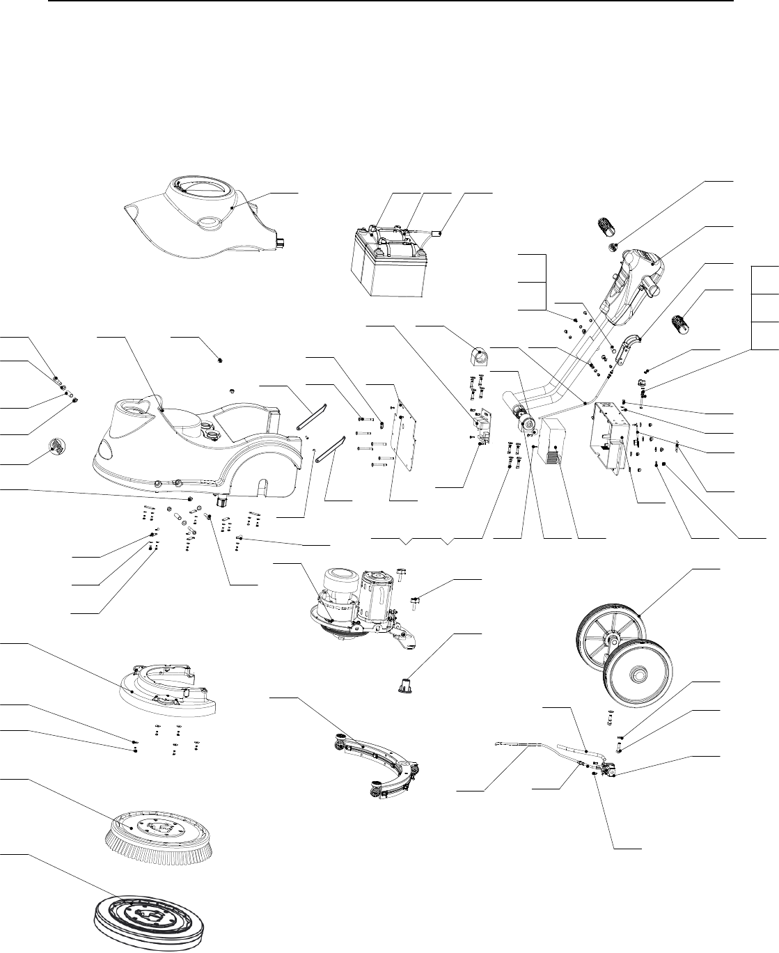
cCOMPLETE ASSEMBLY
47
58
61
2 6
4 2
4 3
1
3
4
5
6
7
8
9
1 0
1 1
1 2
1 3 1 5
1 6
1 7
1 8
1 9
2 0
2 22 32 4 2 9
3 0
2
1 4
1 4
3 3
3 4
3 5
3 6
3 8
3 9
4 0
4 1
4 5
4 4
4 6
4 8
4 9
5 0
5 1
5 2
3 1
2 4
5
6
2 1
5 3
5 5 5 65 75 9
5 4
3 7
6 0
2 5
2 6
2 7
2 8
5 2
PART LIST
PART LISTPART LISTPART LIST
63
6 5
3 2
62
64
13

1
1
PIPE SI, D4XD8, 0.4M
PIPE SI, D6XD10, 0.7M
VF89817
VF89830
VF89821
11
Item Part No. Description Qty
1 VF89100 KIT, SOLUTION TANK 1
2 VF89018 LABEL, SOLUTION TANK 1
3 VF89200 KIT, AXLE WHEEL 1
4 VF14251 BOLT, M8X30, HEX HEAD 2
5 VF13514A WASHER, D8X1XD16.5 5
6 VF14516 NUT, NYLON INSERT, M8 4
7 VF89831 KIT, MOTOR MOUNTING PLATE 1
8 VF85698 HEX SOCKET SCREW, M8X55 2
9 VF89030 BUSHING 2
10 VF14258 HEX SOCKET SCREW, M8X40 1
11 VF14503 NUT, M8 1
12 VF89400 KIT, SKIRT ASSEMBLY 1
13 VV13664 WASHER, D4X1XD8 15
14 VF13491 PH SCREW, M4X12 16
15 KIT, SQUEEGEE 1
16 VF89029A HOSE, CONNECT SQUEEGEE 1
17 VF85420 THUMB SCREW 2
18 VF89600 KIT, HANDLE ASSEMBLY 1
19 VF89001 HANDLE BLOCK, LEFT 1
20 VF89002 HANDLE BLOCK, RIGHT 1
21 VF89003 CIRCUIT BOX 1
22 VV60220S1 HEX SOCKET SCREW, M6X15 8
23 VV20290 WASHER LOCK, ¢6 8
24 VF13614 WASHER, ¢6 14
25 GT13027 PH SCREW, M5X45 1
26 VA13482 WASHER, D5X1XD10 6
27 VF89004 LATCH, RECOVERY TANK 1
28 VF89005 SPRING, PRESS 1
29 VF89023 KIT, CHARGER 1
30 VF89025-1 PLATE, MAIN CONTROL 1
31 VF89006 CIRCUIT COVER 1
32 VF14301 SCREW, M4X12 2
33 VF89034 HEX BOLT M6X50 4
34 VF89052 COVER, WATERPROOF 1
35 VF89037 PLUG, RUBBER 1
36 VF89035 COVER NUT, M6 6
37 VF89016 LABEL, CHARGE DISPLAY 1
38 VF89012 HANDLE GRIP, RUBBER 2
39 VF89017 LABEL, REAR HOUSING 1
40 VF89007 CABLE, SQUEEGEE LIFT 1
41 VF89008 HANDLE, SQUEEGEE LIFT 1
42 VV20509 PH SCREW, M5X10 3
43 VF89010 ROTATE AXLE, SQUEEGEE LIFT CABLE 2
44 VF89011 AXLE, SQUEEGEE LIFT CABLE 1
45 VF89009A ROTATE AXLE, SQUEEGEE LIFT CABLE
46 VF89056 SOLENOID VALVE, 24V 1
47 VF14514 NUT, NYLON INSERT, M5 1
48 VF89033 HOSE
49 VF89013
50 VF89014
51 VF89015 PLATE 6
BRUSH ASSEMBLY 1
PAD DRIVER 1
52
COMPLETE(MACHINE(-(FANG15B
2
VF89007-1 CABLE, SQUEEGEE LIFT 1
2
VF89034A HEX BOLT M6X55 2

12
Item Part No. Description Qty
53 VF85102 SMALL CLAMP 1
54 VF89055 RUBBER PLUG, CHARGER INSERT 1
55 VF89020 BATTERY, 2-12V 35Ah 1
56 VF89036 POWER WIRE 1
57 VF89021 KIT, BATTERY CONNECT LINE 1
58 VA13473 PH SCREW, M4X16 5
59 VF89827 KIT, RECOVERY TANK 1
60 VF85141 BIG CLAMP 1
61 VA13472 PH SCREW, M4X8 2
COMPLETE(MACHINE(-(FANG15B
62
63
VS00001
VS00002
1
1
SUPPORT,LEFT
SUPPORT,RIGHT
65
SCREW, M5X12
64 GT13054 2
VV13650A SCREW, M4X10 11
66 VF14214 SCREW, M5X8 1
13
PART LIST
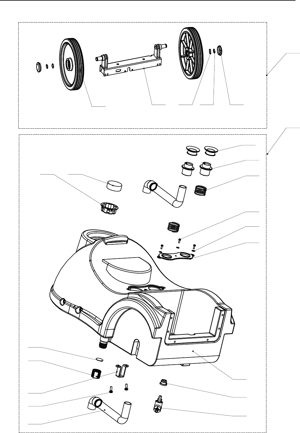
SOLUTION TANK ASSEMBLY
1
10
11
13
14 15
8
9
4
12
18
3
5
6
16
17
2
7
19
20 21 22 23
PART LISTPART LISTPART LIST

14
Item Part No. Description Qty
1 VF89101 SOLUTION TANK 1
2 VF89102 HOSE, CONNECT VACUUM
3 VF89103 SPRING, PRESS 2
4 VF89104 VACUUM HOSE
5 1
6 VF89106 PLASTIC PLATE, HOSE LIMIT 1
7 VF89107 RUBBER SEAL 2
8 VF89115 GASKET 1
9 VF89110 CAP, DRAIN 1
10 VF85302 RUBBER BUSHING 1
11 VF89091 SOLUTION TAP 1
12 VF89112 CABLE BRACKET 1
13 VF14200 PH SCREW, M6X15 2
14 VF89113 SEAT, INLET, FRESH WATER TANK 1
15 VF89114 FILTER, INLET, FRESH WATER TANK 1
16 VF13491 PH SCREW, M4X12 3
17 VV13664 WASHER ¢4 3
18 VF89100 KIT, SOLUTION TANK 1
19 VF89201 WHEEL AXLE 1
20 VF89202 DRIVE WHEEL, 10" 2
21 VF14563 WASHER,WAVE 2
22 VF14552 SNAP SPRING 2
23 VF89202-3 CAP, WHEEL 2
VF89200 KIT, WHEEL AXLE
SOLUTION(TANK(ASSY(,(FANG(15B
2
2
15
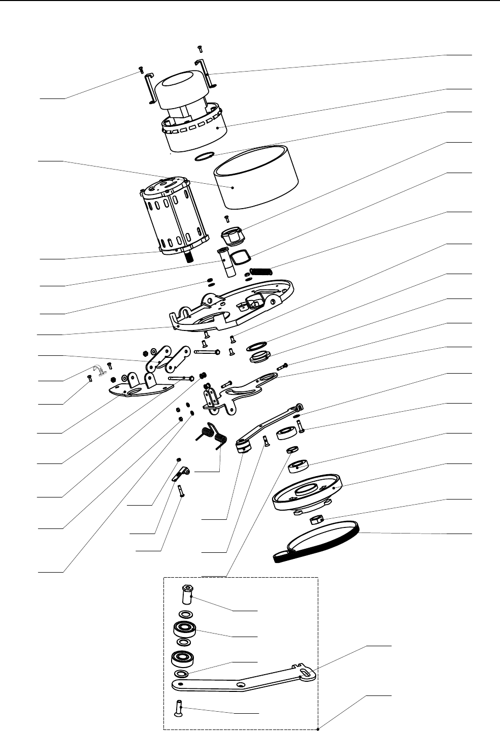
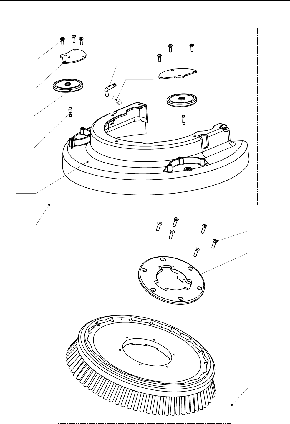
BRUSH DECK ASSEMBLY
15 1 8
1 7
2 5
2 8
2 7
2 6
2 4
2 1
2 0
1 2
1 5
2 3
1 1
3
2 2
5
6
7
8
9
1 0
2
4
1 9
2 9
1
3 0
1 3
3 1
1 6
1 4
1 7
3 3
3 4
3 5
3 6
3 7
3 8
3 2
3 9
4 0
PART LIST
PART LISTPART LISTPART LIST
42
41

VF89823
16
Item Part No. Description Qty
1 VF89301 PLATE, MOTOR MOUNT 1
2 VF89302 BRUSH MOTOR ASSEMBLY 1
3 VF89303 SCREW, M6X14 4
4 VF89304 BOLT, DIRVE BELT 1
5 VF89305 O-RING, BIG 1
6 VF89306 SEALING COVER, VACUUM 1
7 VF89307 O-RING, SMALL 1
8 VF89309 KIT, VACUUM MOTOR 1
9 VF89310 BRACKET, VAC MOTOR 2
10 VF13491 PH SCREW, M4X12 3
11 VF89311 WASHER, THIN 1
12 VF89312 PLATE, SQUEEGEE ROTATE 1
13 VF89313 GUIDE WHEEL, SQUEEGEE 2
14 VA13482 WASHER ¢5 2
15 VA13475 PH SCREW, M5X25 3
16 VF14514 NUT, NYLON INSERT, M5 2
17 VF89314 KIT, BELT ADJUSTMENT 1
18 VF14223 SCREW, M6X25 1
19 VF14506 NUT, NYLON INSERT, M6 4
20 VF13614 WASHER, ¢6 3
21 VV20058 BOLT, M6X25, HEX 1
22 VF89318 SPRING 1
23 VF89319 BUSHING, SQUEEGEE ROTATE 1
24 ZD45425 BEARING, 6204 2
25 VF89320 BUSHING 1
26 VF89321 DRIVE HUB 1
27 VF89322 NUT, M20 1
28 VF89323 DRIVE BELT, PJ270 1
29 VF89324 PLATE, SQUEEGEE LIFT 1
30 VF89325 PLATE, SQUEEGEE BRACKET 1
31 VF89326 ROTATE BOLT, SQUEEGEE LIFT 2
32 TORSION SPRING 1
33 VF89315 PLATE, BELT ADJUSTMENT 1
34 VF89316 BOLT, BEARING 1
35 VF51126A BEARING, 6201 2
36 VF89317 WASHER, D12.2XD20X1 3
37 GT13084 SCREW, M6X20 1
38 VF89308 SILENCER SPONGE 1
39 VV13633 NUT, M5 1
40 VF89337 PRESSURE ADJUSTMENT PLATE 1
BRUSH&DECK&ASSY&-&FANG&15B
CLAMP DRAIN HOSE
SCREW, M4X8
VV1366742
VF8909241 1
2
11
17
BRUSH SKIRT BRUSH
9
6
5
3
4
2
1
7
8
10
PART LIST
PART LISTPART LISTPART LIST
&

HOSEVF8982411
VF89838
VF89817
18
Item Part No. Description Qty
1 VF89400 BRUSH SKIRT ASSEMBLY 1
2 VF89401 BRUSH SKIRT 1
3 VF89402 WHEEL, BUMPER 2
4 VF89403 COVER, WHEEL 2
5 VF89404 SHAFT 2
6 VF14401 SCREW, ST4X10 6
7VF89051 ELBOW 1
VF89830 BRUSH ASSEMBLY 1
PAD DRIVER ASSEMBLY 1
9 MF-VF002-4A SCREW, ST6.5X25 6
10 VF89803 BRUSH HUB 1
8
!"#$%&$'(")&*&!"#$%&+&,-./&01!
ELBOW 1
1
19
23
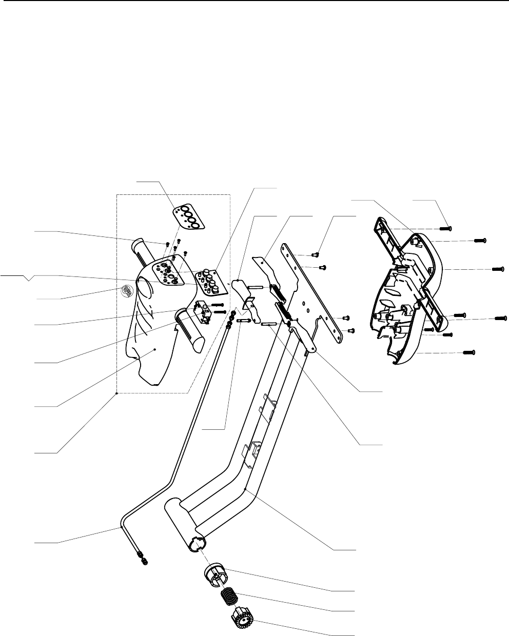
HANDLE CONTROL ASSEMBLY
1
2
4
5
6
7
8
9
10
11
12
15
17
1819
20
21
22
16
1413
3
PART LIST
PART LISTPART LISTPART LIST

80405A
20
Item Part No. Description Qty
1VF89601 HANDLE TUBE ASSY 1
2 VF89607 KIT, FRONT CONTROL HOUSING 1
3 PH SCREW, M5X12 4
4 VF89610 TRIGGER, HANDLE ADJUSTMENT 1
5 VF89611 CABLE, HANDLE ADJUSTMENT 1
6 VF89612 BUSHING, GUIDE GEAR 1
7 VF89613 SPRING, HANDLE GEAR 1
8 VF89614 GEAR, HANDLE ADJUSTMENT 1
9 VF89615 TRIGGER, LEFT 1
10 VF89616 TRIGGER, RIGHT 1
11 VF89617 PIN, HANDLE ADJUSTMENT 1
12 VF89621 PIN, TRIGGER 2
13 VF89618 CONTROL HOUSING, REAR 1
14 VF80407A PH SCREW ,M5X25 8
15 VF89619 LABEL, SWITCH 1
16 VF89608 CONTROL HOUSING, FRONT 1
17 33005101 PH SCREW, M3X8 5
18 VF89622 BOLT, INSULATION, M3X15 5
19 VV13617 NUT, M3 5
20 VF40263A SWITCH 1
21 VF14244 PH SCREW, M3X20 2
22 VF89025-2 CIRCUIT BOARD 1
23 VF89017 LABEL, CONTROL HOUSING 1
HANDLE'ASSY'*'FANG'15B
VF89601A HANDLE TUBE ASSY 1
21
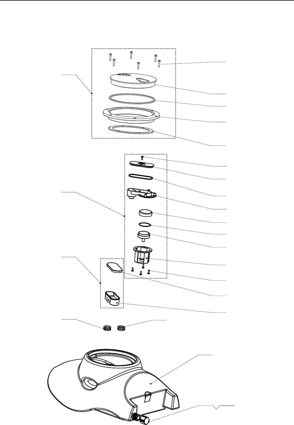
RECOVERY TANK ASSEMBLY
1
19
18
17
16
15
14
13
12
9
10
11
7
6
5
4
2 3
PART LIST
PART LISTPART LISTPART LIST
24
23
21
20
8
22

24
22
Item Part No. Description Qty
1 VF89701 RECOVERY TANK 1
2 VF89115 GASKET 1
3 VF89110 CAP, DRAIN 1
4 VF89810 RUBBER BUSHING, TANK 1
5 VF89811 RUBBER BUSHING, TANK, GREY 1
6 VF89828 KIT, SQUEEGEE SUCTION 1
7 VF89829 KIT, SQUEEGEE VACCUM 1
8VF89716 KIT, RECOVERY TANK COVER 1
9 VF89813 BASE, OUTLET 1
10 VF89712 COVER, RUBBER 1
11 VA50523 SCREW, ST4X8 4
12 VF89709 GUIDE BASE, PLUG VACUUM 1
13 VF89711 PLUG, BASE 1
14 VF89712 O-RING, PLUG 1
15 VF89710 PLUG, COVER 1
16 VF89814 BASE, VACUUM 1
17 VF89705 O-RING 1
18 VF89706 COVER, VACUUM 1
19 VA13477 SCREW, ST4X15 2
20 SEAL, LID
21
22
23
RECOVERY'TANK','FANG'15B
VF89716A KIT, RECOVERY TANK COVER 1
SCREW, M4X12 6
LID, RECOVERY TANK
VF89079
VF89080
1
1
VF89077
VV96001S 1
SEAT,FOR LID
VF89078 SEAL, LID 1
18
23
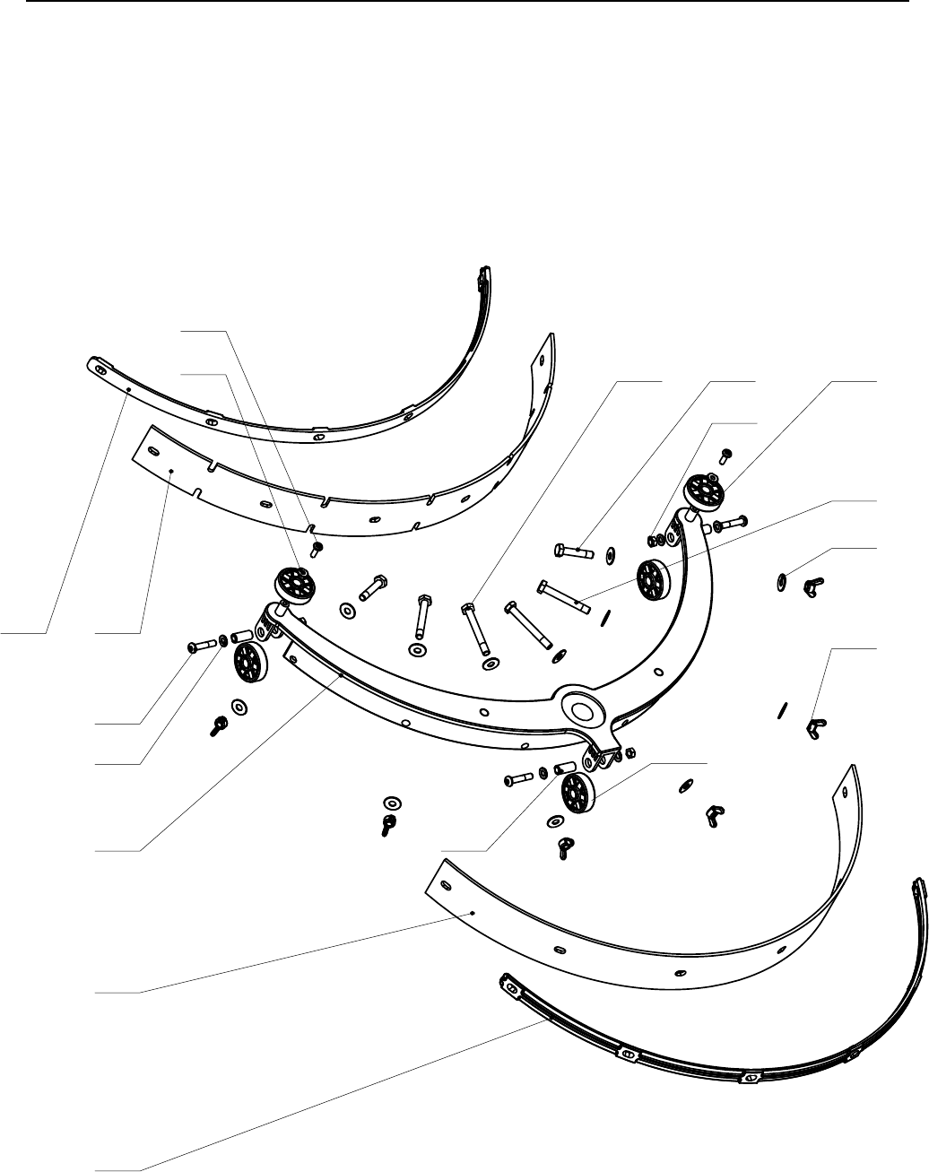
SQUEEGEE ASSEMBLY
1
2
3
4
5
67
8
9
10
11
12
13
14
15
16
17
PART LIST
PART LISTPART LISTPART LIST

18 3VF89809
VF89808-PU
VF89807-PU
VF89808
VF89807
VF89815
24
Item Part No. Description Qty
1 SQUEEGEE BRACKET 1
SQUEEGEE BLADE, FRONT 1
SQUEEGEE BLADE, FRONT (PU - OPTIONAL) 1
SQUEEGEE BLADE, REAR 1
SQUEEGEE BLADE, REAR (PU - OPTIONAL) 1
4 VF89504 STRAP, SQUEEGEE FRONT 1
5 VF89505 STRAP, SQUEEGEE REAR 1
6 VF89506 WHEEL, SQUEEGEE 2
7 VA13479 BOLT, M6X30, HEX STAINLESS 2
8 VF89507 BOLT, M6X45, HEX STAINLESS 2
9 VF14264 BOLT, M6X50, HEX STAINLESS 2
10 VF13614 WASHER, D6.3XD12.6X1.2, STAINLESS 12
11 VF89509 NUT, THUMB, M6 6
12 VA13475 PH SCREW, M5X25 3
13 VA13482 WASHER, D5XD10X1.0, STAINLESS 6
14 VF14514 NUT, NYLON INSERT, M5 3
15 VF13491 PH SCREW, M4X12 2
16 VV13664 WASHER, D4XD12X1MM, STAINLESS 2
17 VF89508 BUSHING 3
2
3
SQUEEGEE&ASSY&)&FANG&15B
WHEEL, SQUEEGEE
25
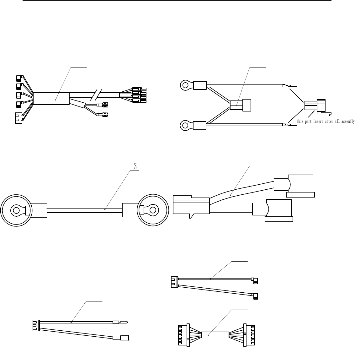
ELECTRICAL
1 2
4
5
6
7
PART LIST
PART LISTPART LISTPART LIST

26
Item Part No. Description Qty
1 VF89026 MOTOR WIRE 1
2 VF89022 MAIN POWER WIRE 1
3 VF89021 BATTERY CONNECT WIRE 1
4 VF89036 POWER WIRE 1
5 VF89024 CHARGER INPUT WIRE 1
6 VF89620 KIT, 4-LEG SWITCH 1
7 VF89025-3 COMMUNICATION WIRE 1
ELECTRICAL(PARTS(+(FANG(15B

27
!!!!!!!!!!!!!!!!!!!!!!!!!!!!!!!!!!!!!!!!!!!!!!!!!!USER!MANUAL!
!
TROUBLESHOOTING
Trouble Possible Cause Remedy
The battery connector is disconnected Connect
The batteries are completely discharged Charge the batteries
The machine does not work, indicator
light (51) do not turns on The power line disconnected from the power Connect
The machine does not work, indicator
light (51) display red
The batteries are discharged Charge the batteries
Brush motor does not work, brush
indicator light (52) does not turn on.
The PCB or key board is broken Change the PCB or key
board
The deck motor is overloaded Use less aggressive
brushes suitable for the
floor to be cleaned
Brush motor does not work, brush
indicator light (52) flashes
Obstruction preventing the brush from
rotating
Clean the brush hub
Vacuum system motor does not work,
vacuum motor indicator light (53) does
not turn on
The PCB or key board is broken Change the PCB or key
board
Vacuum system motor does not work,
brush indicator lights (53) flash
The vacuum motor is overloaded Check the vacuum motor
The recovery tank is full Empty the recovery tank.
The hose is disconnected from the
squeegee
Re-connect
Vacuum assembly is clogged Clean or check
The squeegee is dirty, or the squeegee
blades are worn or damaged
Clean and check the
squeegee
The recovery tank do not latched closed Lock the latch (17)
Insufficient vacuuming / water pickup
The tank cover is not properly closed, or the
gasket is damaged
Close the cover properly
or replace the gasket
The solution filter is dirty Clean the filter
The solution is empty Refill solution tank
Solution flow control valve (31) is clogged Clean the valve
The solution flow is insufficient
The solution is dirty Clean the solution
There is debris under the squeegee blades Remove the debris
The squeegee leaves marks on the floo. The squeegee blades are worn, chipped or
torn
Replace the blades
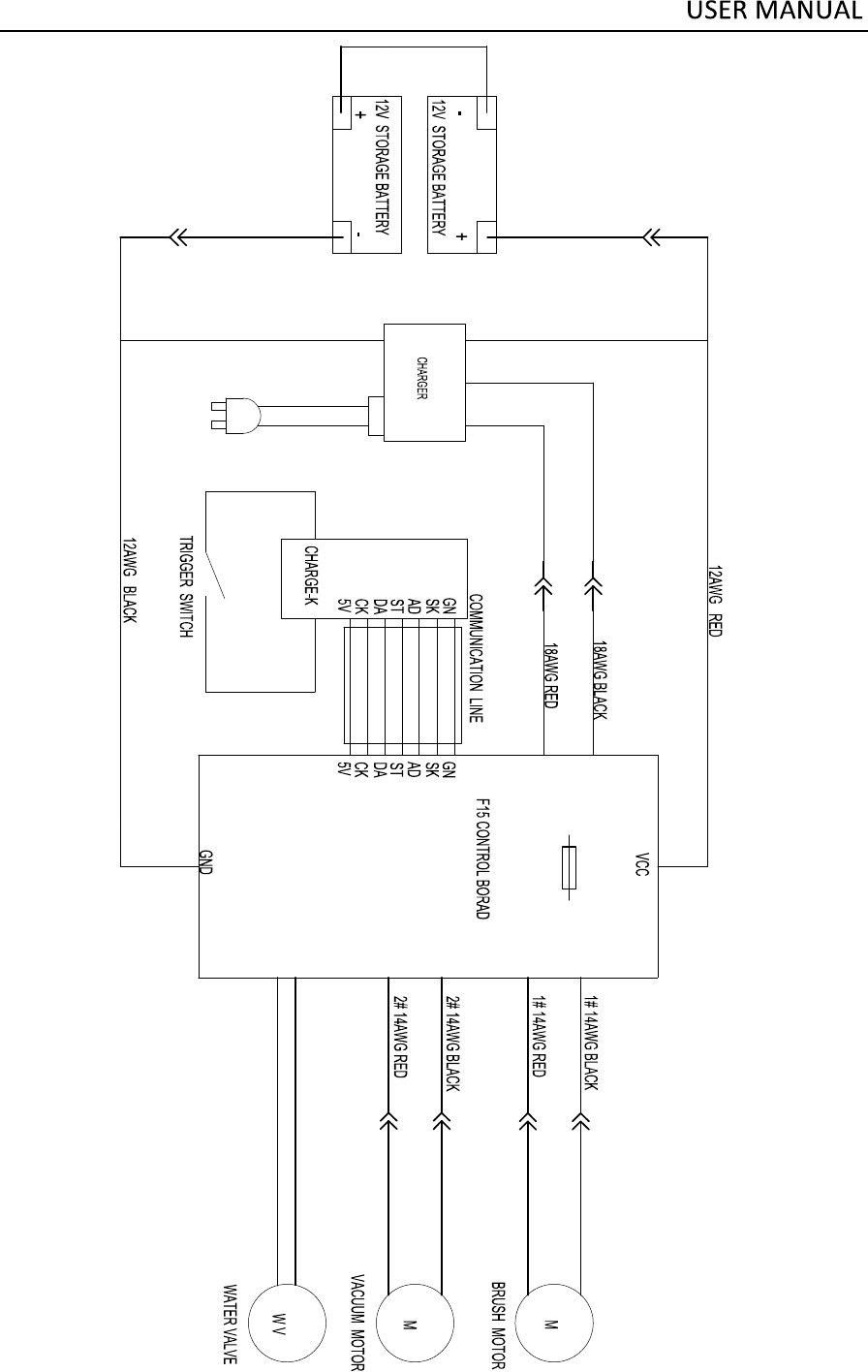
îðßÉÙÉØ×ÌÛ
ïêßÉÙÎÛÜ
ïêßÉÙÞÔßÝÕ
ïîßÉÙÎÛÜ
ïîßÉÙÞÔßÝÕ
ÞÎËÍØÓÑÌÑÎ
ÛÊ
îðßÉÙÉØ×ÌÛ
ÊßÝËËÓÓÑÌÑÎ
ÍÉ×ÌÝØ
ÚïëÕÛÇóÐÎÛÍÍÞÑÎßÜ
ïîßÉÙÞÔßÝÕ
28

www.usviper.com
