8 640 950 0 Manual Operators Armada BRC 40 22 Windsor Carpet Extractor Service Parts
2016-12-28
: Sweepscrub Windsor-Armada-Brc-40-22-Carpet-Extractor-Service-Parts-Manual windsor-armada-brc-40-22-carpet-extractor-service-parts-manual 1764 file product_file
Open the PDF directly: View PDF ![]() .
.
Page Count: 73
86409500-C 07/20/16
Armada BRC 40/22 120V
Carpet Extractor
Operating Instructions (ENG)
MODELS: BRC 40/22
1.008-060.0
Warranty Registration
Thank you for purchasing a Kärcher North America product. Warranty registration is quick
and easy. Your registration will allow us to serve you better over the lifetime of the product.
To register your product go to :
http://warranty.karcherna.com/
For customer assistance:
1-800-444-7654
286409500 Operator’s Manual - Armada BRC 40/22
Machine Data Label
Overview
This carpet extractor is an electrical powered, portable carpet extractor intended for commercial use. The appliance
sprays a cleaning solution onto the carpet, agitates the wet carpet, and then extracts the soiled solution back into
the unit's recovery tank. The appliance is available with an optional hand tool for cleaning upholstery and stairs.

3
Table of Contents
Machine Data Label. . . . . . . . . . . . . . . . . . . . . . . . . .2
Overview. . . . . . . . . . . . . . . . . . . . . . . . . . . . . . . . . .2
Table of Contents . . . . . . . . . . . . . . . . . . . . . . . . . . .3
How To Use This Manual . . . . . . . . . . . . . . . . . . . . .4
Safety Labels . . . . . . . . . . . . . . . . . . . . . . . . . . . . . .4
Safety
Safety Labels . . . . . . . . . . . . . . . . . . . . . . . . . . . . . .5
IMPORTANT SAFETY INSTRUCTIONS . . . . . . . . .6
CONSIGNES DE SÉCURITÉ IMPORTANTES . . . .7
HAZARD INTENSITY LEVEL . . . . . . . . . . . . . . . . . .8
NIVEAU D'INTENSITÉ DU DANGER. . . . . . . . . . . .9
Grounding Instructions . . . . . . . . . . . . . . . . . . . . . .10
Operations
How This Machine Works . . . . . . . . . . . . . . . . . . . .11
Technical Specification . . . . . . . . . . . . . . . . . . . . . .12
Controls. . . . . . . . . . . . . . . . . . . . . . . . . . . . . . . . . .14
Components . . . . . . . . . . . . . . . . . . . . . . . . . . . . . .16
Pre Run Setup . . . . . . . . . . . . . . . . . . . . . . . . . . . .17
Filling The Solution Tank . . . . . . . . . . . . . . . . . . . .18
Operating The Machine . . . . . . . . . . . . . . . . . . . . .19
Brush Height Adjustment . . . . . . . . . . . . . . . . . . . .19
Rear Cover Storage . . . . . . . . . . . . . . . . . . . . . . . .19
Operating The Machine . . . . . . . . . . . . . . . . . . . . .20
To Clean Under Desks Or Dead End Hallways . . .22
Emptying Recovery Tank . . . . . . . . . . . . . . . . . . . .22
Emptying Solution Tank . . . . . . . . . . . . . . . . . . . . .22
Accessory Tool Connection and Use . . . . . . . . . . .23
Maintenance
Service Schedule . . . . . . . . . . . . . . . . . . . . . . . . . .25
Components . . . . . . . . . . . . . . . . . . . . . . . . . . . . . .26
Periodic Maintenance . . . . . . . . . . . . . . . . . . . . . . .26
Daily / Regular Maintenance. . . . . . . . . . . . . . . . . .26
Vacuum Shoe Cleaning . . . . . . . . . . . . . . . . . . . . .27
Scrub Deck . . . . . . . . . . . . . . . . . . . . . . . . . . . . . . .28
Scrub Head Maintenance . . . . . . . . . . . . . . . . . . . .29
Scrub Brush Removal . . . . . . . . . . . . . . . . . . . . . . .29
Scrub Brush Replacement . . . . . . . . . . . . . . . . . . .29
Circuit Protection. . . . . . . . . . . . . . . . . . . . . . . . . . .30
Troubleshooting . . . . . . . . . . . . . . . . . . . . . . . . . . .31
Suggested Spare Parts. . . . . . . . . . . . . . . . . . . . . .33
86409500 Operator’s Manual - Armada BRC 40/22
4
How To Use This Manual
This manual contains the following sections:
• How to Use This Manual
•Safety
• Operations
• Maintenance
The HOW TO USE THIS MANUAL section will tell you
how to find important information for ordering correct
repair parts.
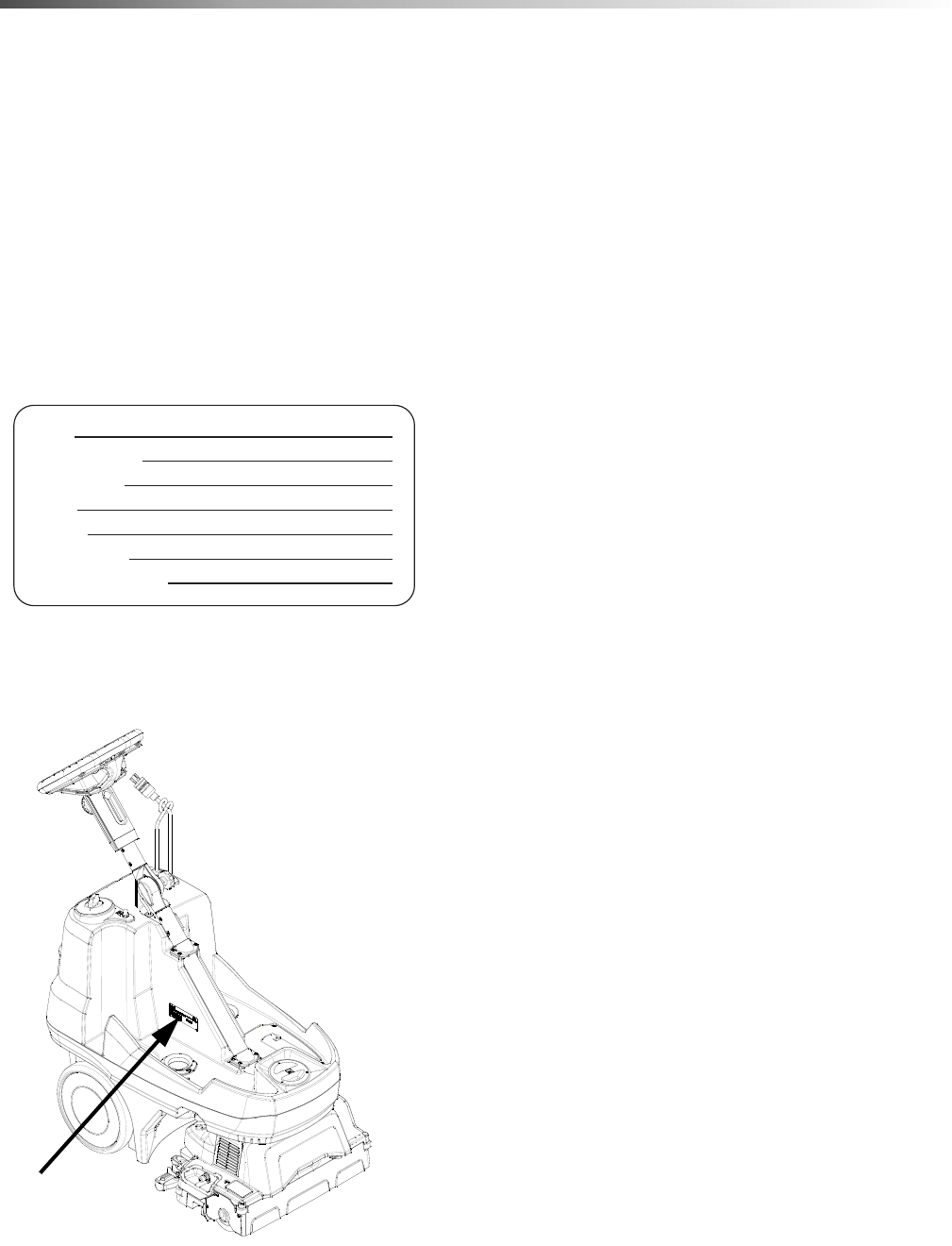
Parts may be ordered from authorized dealers. When
placing an order for parts, the machine model and
machine serial number are important. Refer to the
MACHINE DATA box which is filled out during the
installation of your machine. The MACHINE DATA box
is located on the inside of the front cover of this manual.
The model and serial number of your machine is
located under the recovery tank as shown
below:
The SAFETY section contains important information
regarding hazardous or unsafe practices of the
machine. Levels of hazards are identified that could
result in product damage, personal injury, or severe
injury resulting in death.
The OPERATIONS section is to familiarize the operator
with the operation and function of the machine.
The MAINTENANCE section contains preventive
maintenance information to keep the machine and its
components in good working condition. They are listed
in this general order:
• Service Schedule
• Components
• Periodic Maintenance
• Daily/Regular Maintenance
• Scrub Deck & Brush Replacement
• Circuit Protection
• Troubleshooting
NOTE: If a service or option kit is installed on your
machine, be sure to keep the KIT INSTRUCTIONS
which came with the kit. It contains replacement parts
numbers needed for ordering future parts.
NOTE: The manual part number is located on the
lower right corner of the front cover.
Safety Labels
NOTE: These drawings indicate the location of safety
labels on the machine. If at any time the labels become
illegible, promptly replace them.
EMPLACEMENT DE L'ÉTIQUETTE DE SÉCURITÉ
REMARQUE : Ces dessins indiquent l'emplacement
des étiquettes de sécurité sur la machine. Si, à tout
moment,
les étiquettes deviennent illisibles, contactez votre
représentant autorisé pour un remplacement rapid
Model:
Date of Purchase:
Serial Number:
Dealer:
Address:
Phone Number:
Sales Representative:
86409500 Operator’s Manual - Armada BRC 40/22
5
Safety
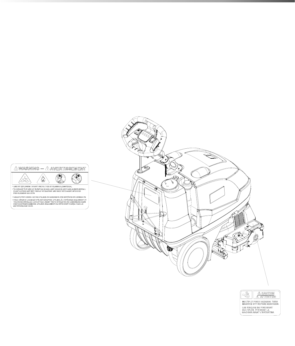
Safety Labels
NOTE: These drawings indicate the location of safety labels on the machine. If at any time the labels become illeg-
ible, promptly replace them.
EMPLACEMENT DE L'ÉTIQUETTE DE SÉCURITÉ
REMARQUE : Ces dessins indiquent l'emplacement des étiquettes de sécurité sur la machine. Si, à tout moment,
les étiquettes deviennent illisibles, contactez votre représentant autorisé pour un remplacement rapid
WARNING LABEL
86242230
WARNING LABEL
86402490
86409500 Operator’s Manual - Armada BRC 40/22

6
Safety
IMPORTANT SAFETY INSTRUCTIONS
When using this machine, basic precaution
must always be followed, including the following:
READ ALL INSTRUCTIONS BEFORE USING THIS MACHINE.
To reduce the risk of fire, electric shock, or injury:
Connect to a properly grounded outlet. See Grounding Instructions.
Do not leave the machine unattended. Unplug machine from outlet when not in use and before maintenance or
service.
Use only indoors. Do not use outdoors or expose to rain.
Do not allow machine to be used as a toy. Close attention is necessary when used by or near children.
Use only as described in this manual. Use only manufacturer's recommended components and attachments.
Do not use damaged electrical cord or plug. Follow all instructions in this manual concerning grounding the
machine. If the machine is not working properly, has been dropped, damaged, left outdoors, or dropped into water,
return it to an authorized service center.
Do not pull or carry machine by electrical cord, use as a handle, close a door on cord, or pull cord around sharp
edges or corners.
Do not run machine over cord. Keep cord away from heated surfaces.
Do not unplug machine by pulling on cord. To unplug, grasp the electrical plug, not the electrical cord.
Do not handle the electrical plug or machine with wet hands.
Do not operate the machine with any openings blocked. Keep openings free of debris that may reduce airflow.
This machine is intended for cleaning carpet only.
Do not vacuum anything that is burning or smoking, such as cigarettes, matches, or hot ashes.
This machine is not suitable for picking up health endangering dust.
Turn off all controls before unplugging.
Do not operate this machine near flammable fluids, dust or vapors. Do not pick up flammable or combustible liquids
such as gasoline, and do not operate in locations where they may be of such liquids.
Maintenance and repairs must be done by qualified personnel.
If foam or liquid comes out of machine, switch off immediately.
READ AND SAVE THESE INSTRUCTIONS
86409500 Operator’s Manual - Armada BRC 40/22

7
Safety
CONSIGNES DE SÉCURITÉ IMPORTANTES
Lors de l'utilisation de cette machine, des précautions de base
doivent toujours être prises, y compris les précautions suivantes :
LIRE TOUTES LES INSTRUCTIONS AVANT D'UTILISER CETTE MACHINE.
Pour réduire le risque d'incendie, d'électrocution
ou de blessure :
Cet appareil ne doit être connecter qu a des prises ayant une sortie de terre.
Ne pas laisser l'appareil sans surveillance lorsqu'il est branché. Débrancher lorsque l'appareil n'est pas utilisé et
avant l'entretien.
Pour reduire les risques de choc electrique, ne pas utiliser à l exterieur et ne pas aspirer de matières humides.
Ne pas permettre aux enfants de jouer avec l'appareil. Une attention particulière est nécessaire lorsque l'appareil
est utilisé par des enfants ou à proximité de ces derniers.
Utiliser cet appareil conformément aux instructions du présent manuel uniquement. N'utiliser que conformément à
cette notice avec les accessoires recommandés par le fabricant.
Ne pas utiliser si le cordon ou la fiche est endommagé. Retourner l'appareil à un atelier de réparation s'il ne
fonctionne pas bien, s'il est tombé ou s'il a été endommagé, oublié à l'extérieur ou immergé.
Ne pas tirer soulever ou traîner l'appareil par le cordon. Ne pas utiliser le cordon comme une poignée, le coincer
dans l'embrasure d'unée porte ou l'appuyer contre des arêtes vives ou des coins. Ne pas faire rouler l'appareil sur
le cordon.
Garder le cordon à l'écart des surfaces chaudes.
Ne pas débrancher en tirant sur le cordon. Tirer plutôt la fiche.
Ne pas toucher la fiche ou l'appareil lorsque vos mains sont humides.
N'insérer aucun objet dans les ouvertures. Ne pas utiliser l'appareil lorsqu'une ouverture est bloquée. S'assure
que de la poussière, de la peluche, des cheveux ou d'autres matières ne réduisent pas le débit d'air.
Cette machine est destinée pour nettoyer tapis seulement.
Ne pas aspirer de matiéres en combustion ou qui dégagent de la fumée, comme des cigarettes, des allumettes ou
des cendres chaudes.
Cette machine n'est pas adaptée au ramassage de poussières dangereuses.
Mettre toutes les commandes à la position ARRÊT avant de débrancher l'appareil.
Ne pas l'utiliser près de liquides, de poussières ou de vapeurs inflammables. Ne pas aspirer des liquides inflamma-
bles ou combustibles, comme de l'essence, et ne pas faire fonctionner dans des endroits où peuvent se trouver de
tels liquides.
L'entretien et les réparations de la machine doivent être effectuées par un personnel qualifié.
Si de la mousse ou du liquide sort de la machine, la mettre hors tension immédiatement.
LIRE ET CONSERVER CES INSTRUCTIONS
86409500 Operator’s Manual - Armada BRC 40/22

8
Safety
The following symbols are used throughout this guide as indicated in their descriptions:
HAZARD INTENSITY LEVEL
There are three levels of hazard intensity identified by signal words -WARNING and CAUTION and FOR SAFETY.
The level of hazard intensity is determined by the following definitions:
WARNING - Hazards or unsafe practices which COULD result in severe personal injury or death.
CAUTION - Hazards or unsafe practices which could result in minor personal injury or product or property damage.
FOR SAFETY: To Identify actions which must be followed for safe operation of equipment.
Report machine damage or faulty operation immediately. Do not use the machine if it is not in proper operating
condition. Following is information that signals some potentially dangerous conditions to the operator or the equip-
ment. Read this information carefully. Know when these conditions can exist. Locate all safety devices on the
machine. Please take the necessary steps to train the machine operating personnel.
FOR SAFETY:
DO NOT OPERATE MACHINE:
Unless Trained and Authorized.
Unless Operation Guide is Read and understood.
In Flammable or Explosive areas.
In areas with possible falling objects
WHEN SERVICING MACHINE:
Avoid moving parts. Do not wear loose clothing; jackets, shirts, or sleeves when working on the machine. Use
manufacturer approved replacement parts.
86409500 Operator’s Manual - Armada BRC 40/22

9
Safety
Les symboles suivants sont utilisés dans tout ce manuel, tels que décrits ici :
NIVEAU D'INTENSITÉ DU DANGER
Il existe trois niveaux d'intensité du danger, identifiés par des termes d'avertissement - AVERTISSEMENT,
ATTENTION et POUR VOTRE SÉCURITÉ. Le niveau d'intensité du danger est déterminé par les définitions
suivantes :
AVERTISSEMENT - Les dangers ou des pratiques contraires à la sécurité qui POURRAIENT entraîner des
blessures personnelles ou la mort.
ATTENTION - Les dangers ou des pratiques contraires à la sécurité qui pourraient entraîner des blessures person-
nelles légères ou des dégâts sur le produit ou d'autres biens.
POUR DES RAISONS DE SÉCURITÉ : Pour identifier les actions qui doivent être exécutées pour un fonc-
tionnement sûr de l'équipement.
Signaler immédiatement tout dommage subi par la machine ou fonctionnement défectueux. Ne pas utiliser la
machine si elle ne fonctionne pas correctement. Ci-dessous se trouvent les informations indiquant les conditions
potentiellement dangereuses pour l'opérateur ou l'équipement. Lire attentivement ces informations. Être conscient
que ces conditions peuvent survenir. Repérer tous les dispositifs de sécurité sur la machine. Suivre les étapes
nécessaires de formation du personnel qui utilise la machine.
POUR DES RAISONS DE SÉCURITÉ :
NE PAS FAIRE FONCTIONNER LA MACHINE :
Sauf si le personnel est formé et autorisé.
Sauf si le manuel d'utilisation est lu et compris.
Dans des zones inflammables ou explosives.
Dans des zones contenant des objets susceptibles de tomber
LORS DE L'ENTRETIEN DE LA MACHINE :
Éviter les pièces mobiles. Ne pas porter de vêtements, vestes, chemises ou manches vagues lors de l'entretien de
la machine. Utiliser les pièces de rechange approuvées par le fabricant.
86409500 Operator’s Manual - Armada BRC 40/22
10
Safety
Grounding Instructions
THIS PRODUCT IS FOR COMMERCIAL
USE ONLY.
Electrical:
In the USA this machine operates on a standard 15
amp 120V, 60 hz, A.C. power circuit. The amp, hertz,
and voltage are listed on the data label found on each
machine. Using voltages above or below those
indicated on the data label will cause serious damage
to the motors.
Extension Cords:
If an extension cord is used, the wire size must be at
least one size larger than the power cord on the
machine, and must be limited to 50 feet (15.5m) in
length.
Grounding Instructions:
This appliance must be grounded. If it should malfunc-
tion or break down, grounding provides a path of least
resistance for electric current to reduce the risk of
electric shock. This appliance is equipped with a cord
having an equipment-grounding conductor and
grounding plug. The plug must be inserted into an
appropriate outlet that is properly installed and
grounded in accordance with all local codes and ordi-
nances.
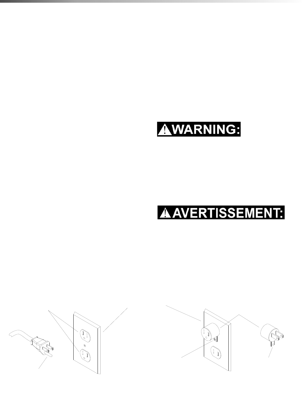
120 Volt Models:
This appliance is for use on a nominal 120-volt circuit,
and has a grounded plug that looks like the plug in "Fig.
A". A temporary adapter that looks like the adapter in
"Fig. C" may be used to connect this plug to a 2-pole
receptacle as shown in "Fig. B", if a properly grounded
outlet is not available. The temporary adapter should
be used only until a properly grounded outlet (Fig. A)
can be installed by a qualified electrician. The green
colored rigid ear, lug, or wire extending from the
adapter must be connected to a permanent ground
such as a properly grounded outlet box cover.
Whenever the adapter is used, it must be held in place
by a metal screw.
Improper connection of the equipment-grounding
conductor can result in a risk of electric shock.
Check with a qualified electrician or service person
if you are in doubt as to whether the outlet is
properly grounded. Do not modify the plug
provided with the appliance - if it will not fit the
outlet, have a proper outlet installed by a qualified
electrician.
Le raccordement incorrect du conducteur de terre
d'équipement peut entraîner des risques d'électro-
cution. Vérifiez auprès d'un électricien qualifié ou
d'un responsable de l'entretien si vous avez
quelque doute que ce soit quant au raccordement à
la terre de votre prise murale. Ne modifiez pas la
fiche fournie avec l'appareil : si elle ne correspond
pas à la prise murale, faites installer une prise
adéquate par un électricien qualifié.
86409500 Operator’s Manual - Armada BRC 40/22
GROUNDING
PIN
GROUNDED
OUTLET ADAPTER
METAL SCREW TAB FOR
GROUNDING SCREW
GROUNDED
OUTLET BOX
(A) (B) (C)

11
Operations
How This Machine Works
This carpet extractor is an electrical powered, self
contained portable carpet extractor intended for
commercial use. The appliance sprays a cleaning
solution onto the carpet, agitates the wet carpet and
then extracts the soiled solution back into the unit's
recovery tank. The appliance is usable with an optional
hand tool for cleaning upholstery and stairs.
The machine is also designed to restore your carpet
using carpet extraction chemicals.
The machine is designed to apply cleaning solution
onto carpeted floor, scrub the carpet with its brush, and
then vacuum the soiled water back into the recovery
tank.
The machine is designed to maintain your carpet using
the Encapsulating Interim Carpet Cleaning Process. By
using the Interim Carpet Maintainer in conjunction with
Windsor Red Carpet Encapsulating Interim Cleaning
(W450-4) or Encapsulating Interim Cleaning with
Carpet Protection (W455-4) chemical solution, you can
perform a regular light cleaning and grooming of your
carpet very quickly, and have the carpet dry and ready
for traffic within 30 minutes.
The machine's primary systems are the solution
system, scrub system, recovery system and operator
control system.
The function of the solution system is to store mixed
solution and deliver solution to the appropriate spray
jet(s) or port. The solution system consists of the
solution tank, strainer, pump, solenoid valves, spray
jets and accessory port. The solution tank stores the
water and chemical solution The strainer protects the
system from debris. The solution pump moves the
cleaning solution flow. The solenoids control the
direction of the solution flow. The jets deliver the
solution to the floor. The accessory port allows connec-
tion to a hand tool.
The function of the scrub system is to scrub the carpet,
mix the cleaning solution with the soil and lift and groom
the carpet pile as well as provide machine propel assis-
tance. The scrub system consists of a cylindrical brush,
a motor and brush height adjustments. The brush
scrubs the carpet as the motor drives the brush. The
brush height adjustment allows for the proper amount
of agitation given various carpet types and brush wear.
The function of the recovery system is to vacuum the
soiled water back into the recovery tank. The recovery
system consists of the vacuum shoe, vacuum motor,
float ball filter and recovery tank. The vacuum shoe
extracts the dirty solution from the carpet as the
machine moves forward. The vacuum motor provides
suction to draw the dirty solution off the floor and into
the recovery tank. The float ball filter protects the
vacuum fan from debris and foam. The recovery tank
stores the dirty solution.
The function of the operator control system is to allow
the operator to select the desired function to perform.
NOTE: For best results, use this machine
immediately after vacuuming. Do not use this
machine as a vacuum cleaner. It is not intended to
vacuum dry dust, only soiled water.
This appliance is not suitable for picking up hazardous
dust.
Cet appareil n'est pas conçu pour aspirer des pous-
sières dangereuses.
86409500 Operator’s Manual - Armada BRC 40/22
12
Operations
Technical Specification
This appliance is not intended for use by persons (including children) with reduced physical, sensory or mental
capabilities, or lack of experience and knowledge, unless they have been given supervision or instruction
concerning use of the appliance by a person responsible for their safety. Children should be supervised to ensure
that they do not play with the appliance.
Cet appareil n'est pas prévu à l'usage des personnes (enfants y compris) avec des possibilités physiques, sensori-
elles ou mentales réduites, ou le manque d'expérience et de connaissance, à moins qu'ils aient été donnés la
surveillance ou l'instruction au sujet de l'utilisation de l'appareil par une personne chargée de leur sûreté. Des
enfants devraient être dirigés pour s'assurer qu'ils ne jouent pas avec l'appareil.
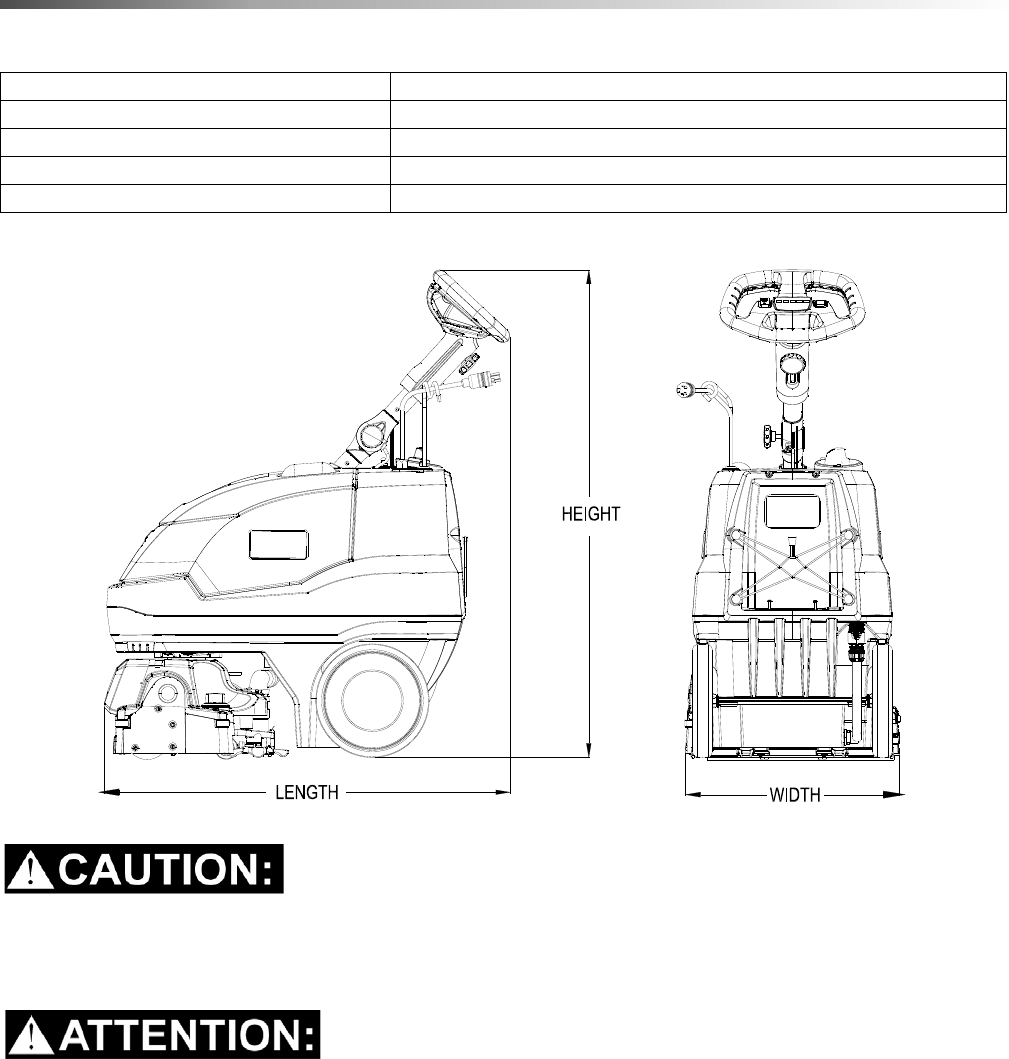
ITEM MEASURE
Height 44 inches (1118 mm)
Length 35 inches (889 mm)
Width 18.5 inches (470 mm)
Width of scrub path 16 inches (406 mm)
86409500 Operator’s Manual - Armada BRC 40/22

13
Operations
Technical Specifications
ITEM DIMENSION/CAPACITY
Construction Plastic Injection-molded chassis with rotationally molded polyethylene tank
Vacuum Motor Three stage, bypass, 1.5 hp (1,119 watts), 100 cfm (2.8m³/min), 120" (3050
mm) waterlift
Solution Pump 50 psi (3.5 bar) - Interim
100 psi (7 bar) - Restorative
Brush Motor .53 hp (400 watts) DC
Brush 16” (406 mm), ABS core
Cleaning Path 16" (40.6 cm)
Flow Rate Interim - 0.10 gpm ( 0.38 lpm)
Restorative - 0.65 gpm (2.5 lpm)
Solution Spray Interim - One quick-disconnect jet
Restorative - Two quick-disconnect jet
Solution Tank 6 gallons ( 22 L)
Recovery Tank 5 gallons (19 L)
Vacuum Shoe 19" (483 mm) wide
Wheels 10" (254 mm) non-marking rubber
Power Cable 50' (15 m) detachable
Weight 100 lbs (45.5 kg) with cord
86409500 Operator’s Manual - Armada BRC 40/22
14
Operations
Controls
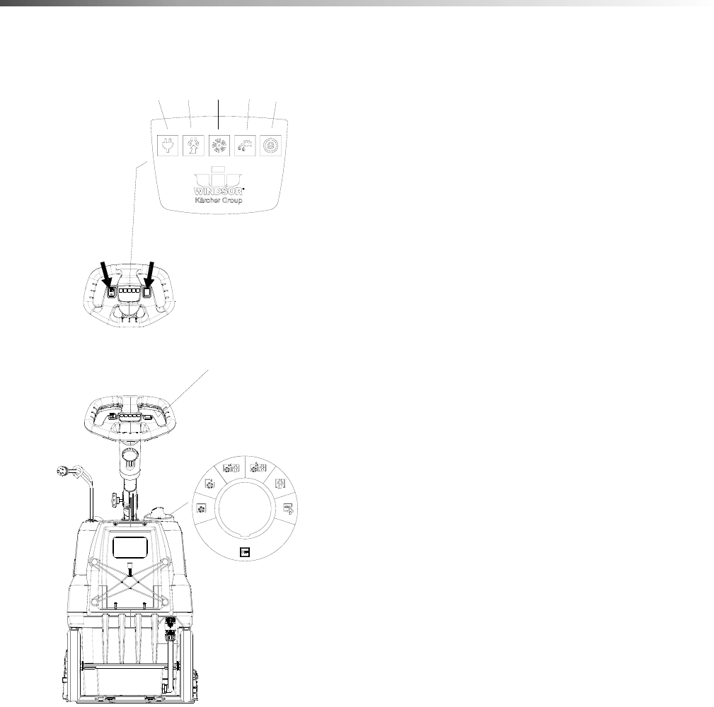
Display
The LED lights in the center are (from left to right):
1. Power
2. Vacuum
3. Brush
4. Solution
5. Eco! Mode.
The switch on the left controls the solution flow. The
switch on the right allows the operator to reverse the
brush motor, effectively moving the machine in an
opposite direction.
The yellow trigger switch on the steering wheel will turn
on the brush and solutions depending on which mode
the control switch is in.
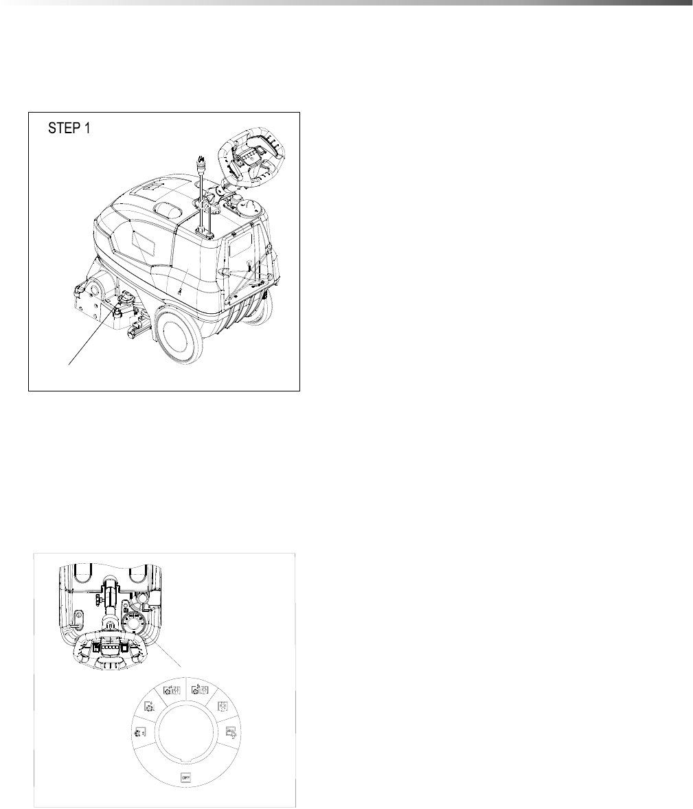
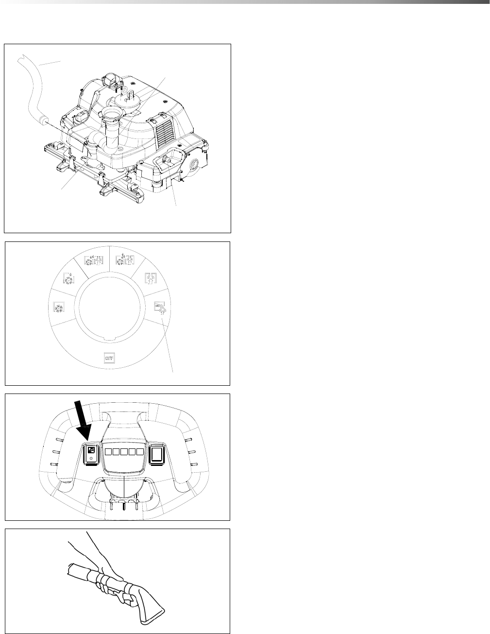
Main Rotary Control Switch
Beginning with the off position and working clockwise,
the modes of operation are:
Brush Only
Encapsulation Mode
Eco! Mode Extraction
Deep Extraction
Vacuum Only
Accessory Tool
Solution Switch Reverse
Yellow Trigger Switch
1234
5
86409500 Operator’s Manual - Armada BRC 40/22

15
Operations
Display
1. Power Light
• Green indicates that the machine has power.
• Off indicates the machine does not have power or rotary switch is set to the off position.
• See Trouble Shooting section if Green light is not on when it should be.
2. Vacuum Light
• Green indicates the vacuum motor is running properly.
• Flashing Red light: See Trouble Shooting section
3. Brush Light
• Green indicates the brush is set and working properly.
• Amber (Orange) indicates the brush motor is overworking: See Troubleshooting section.
• Flashing Red light: See Trouble Shooting section.
4. Solution Light
• Green indicates that the solution pump is working properly
• Flashing Red light: See Trouble Shooting section.
5. Eco! Light
• Blue indicates the machine is in Eco! mode.
Main Rotary Control Switch Modes
Brush Only
• The brush will spin (when the yellow trigger switch is engaged). If the reverse switch is also
engaged, the brush will spin backwards.
Encapsulation
• The brush will spin and solution will be sprayed from the interim jet. If in reverse, no solution
will spray.
Eco! Extraction
• The brush will spin, the solution will be sprayed from the deep jets at a reduced flow and
vacuum motor will run at a reduced pressure and lower sound level.
Deep Extraction
• The brush will spin, the solution will be sprayed from the deep jets and the vacuum motor will
run.
Vacuum Only
• The vacuum motor will run and the brush will spin.
Accessory Tool
• The vacuum motor will run and solution will be supplied to the accessory port if the solution
switch is turned on.
86409500 Operator’s Manual - Armada BRC 40/22
16
Operations
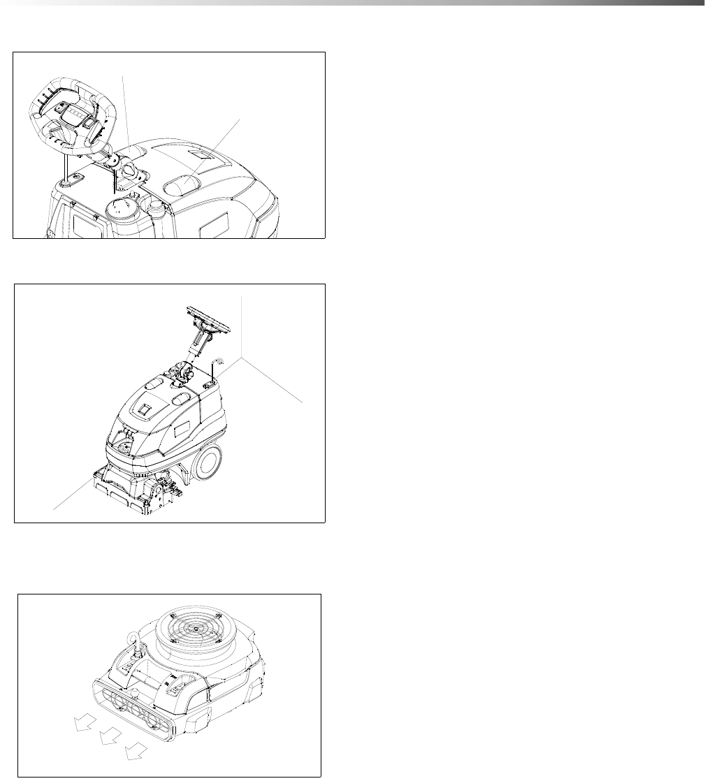
Transporting The Machine Over Stairs
The machine should be carried up or down stairs by two people. One person to grab the front of the solution tank
using the two grip points / pockets on the front lower section. With the steering wheel fully extended, the second
person can grab the steering wheel
NOTE: Never grab the brush deck and the steering wheel as the machine will pivot around the steering column.
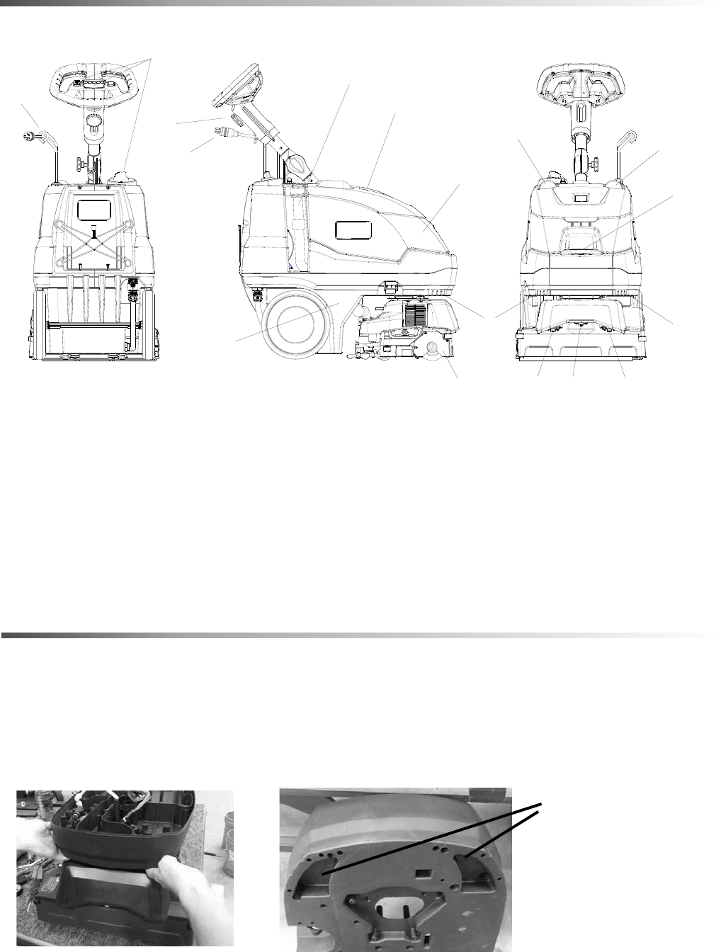
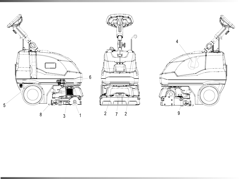
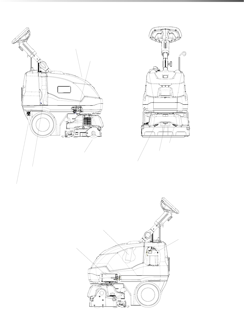
Components
1. Operator Controls and Display 8. Dirty Water Clear Observation Cover
2. Recovery Lid 9. Recovery Drain Hose
3. Recovery Tank 10. Control Height Adjustment - Operator Controls
4. Scrub Deck 11. Deep Extraction Jets
5. Solution Fill Cover 12. Interim Jet
6. Solution Tank 13. Power Cord Connection
7. Vacuum Air Clear Observation Cover 14. Cord Holder
15. Grips for lifting machine
86409500 Operator’s Manual - Armada BRC 40/22
6
1
2
3
4
5
7
8
9
10
12 11
14
13
11 11
1515
Grip pockets for
lifting machine.
17
Operations
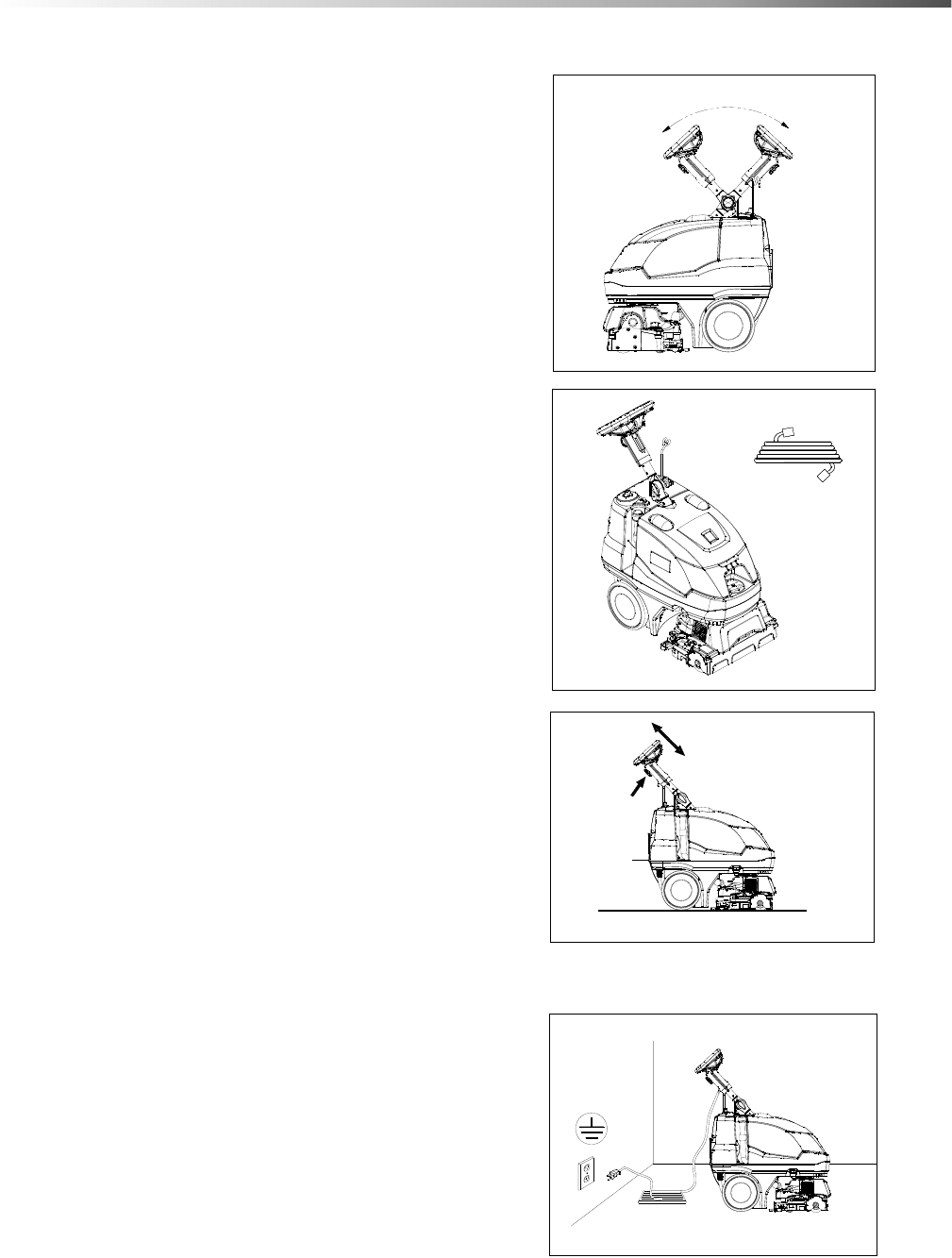
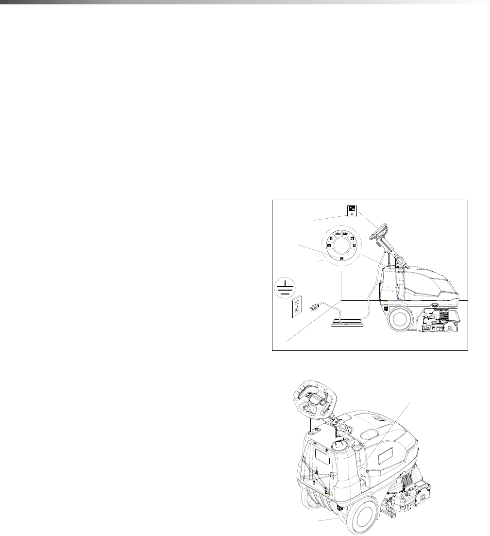
Pre Run Setup
1. To unfold handle, loosen knob, rotate upper
steering column and steering wheel back to stop.
Tighten knob.
2. Install the vacuum shoe and brush. Fill solution
tank with water and chemical. (see Filling the
Solution Tank instructions).
3. To adjust handle to comfortable operating position,
loosen knob, slide to comfortable height and
tighten.
4. Plug cord into grounded outlet. Place the power
cord in its holder on the machine by wrapping it
through the Cord Holder and plugging it into the
pigtail of the machine.
STEP 2
OPERATION
STORAGE
STEP 1
FOR
STEP 3
STEP 4
86409500 Operator’s Manual - Armada BRC 40/22
18
Operations
Filling The Solution Tank
Do not put defoamer or solvent chemicals in the
solution tank.
Do not allow water to spill into vacuum motor inlet.
Dry spills from top of solution tank.
Do not tip machine on back when full as water may
spill from machine.
Use only the suitable chemicals listed below. Using
incompatible chemicals will damage the machine.
Damages of this type are not covered under warranty.
Carefully read ingredients on manufacturer's label
before using any product in this machine.
*Product Trademark Names
FILL LINE
FILL CAP
INDICATOR
UNDER FILL CAP
FRONT TOP VIEW
MAXIMUM FILL
REMOVE SOLUTION
FILL COVER
STEP 1
STEP 2
OR
ADD WATER
6 Gal. MAX
(22 Lt)
STEP 3
ADD CLEANING
CHEMICAL PER
CHEMICAL LABELING
REPLACE SOLUTION
FILL COVER
STEP 4
86409500 Operator’s Manual - Armada BRC 40/22
CHEMICALS
Suitable Chemicals
Alkalis
Detergents
Hydroxides
Soaps
Vinegar
NON-COMPATIBLE
CHEMICALS
Aldehydes
Aromatic Hydrocarbons
SP Butyls
Carbon Tetrachloride
Clorox*
Chlorinated Bleaches
Chlorinated Hydrocarbons
Lysol*
Methyl Ethel Ketone (MEK)
Perchorethylene (perc)
Phenolics
Trichlorethylene
D-Limonene
19
Operations
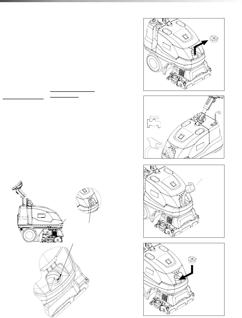
Operating The Machine Brush Height Adjustment
Before adjusting brush height, transport the machine to
the work area by lifting the scrubbing head off of the
ground and rolling the machine on the rear wheels.
1. To set brush height for cleaning mode and carpet
type:
• Place the machine on the deck kick stand by
tipping the machine back about 30 degrees and
then setting the machine deck back to the
ground.
• Rotate the brush height adjustment knob to
position “1” which is the highest brush position.
Roll the machine forward to lower the machine
off the kickstand.
• Run the machine on the carpet to be cleaned.
The machine should now assist in the forward
direction due to the brush running on the carpet.
If not, raise the deck back onto the kickstand
and rotate the brush height adjustment knob to
the next lower brush position.
• Re-run the machine on the carpet and test for
forward assist; repeat previous step if neces-
sary.
• If after a few seconds of running the brush light
flashes red, rotate the brush height adjustment
knob to the next lower number position which
raises the brush and retest. If the brush light
continues to flash red, consult the Trouble-
shooting section.
2. Select a mode from the Main Rotary Control Switch
for the desired results.
See Controls section for detailed description of
each function.
Rear Cover Storage
Use the rear storage area to hold small cleaning bottles
and tools. Do not use the elastic straps to hold large
heavy objects.
Brush Height Adjustment Knob
STEP 2
86409500 Operator’s Manual - Armada BRC 40/22
20
Operations
Operating The Machine
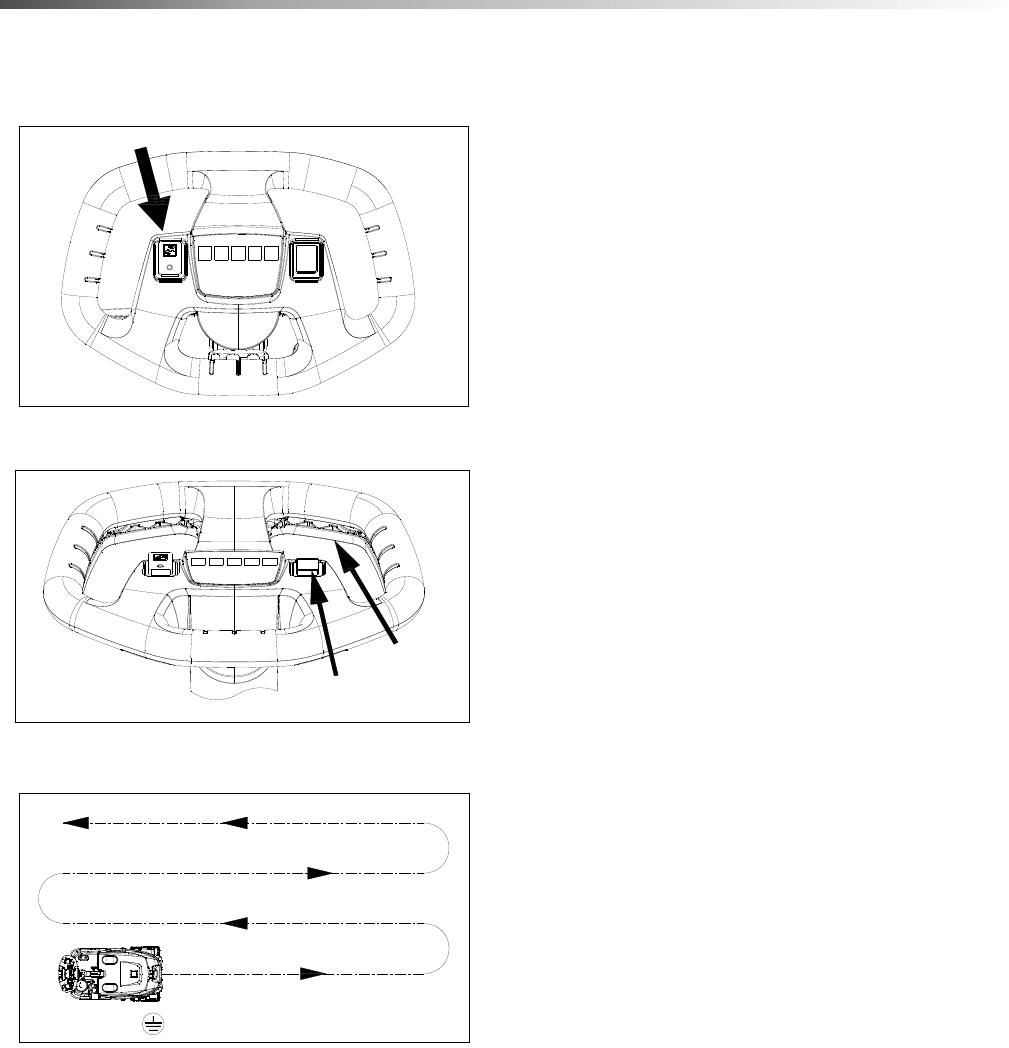
3. Turn on Solution Switch.
• Press the bottom of the switch to turn solution
on.
• Press the top of the switch to turn solution off.
4. Squeeze the large Yellow Trigger Switch to make
the machine move, run the brush and dispense
solution. Use the steering wheel to guide the
machine in the intended direction. Press the
bottom of the Reverse Switch to make the machine
travel backward while the yellow trigger switch is
depressed.
5. Start at wall closest to power outlet. For large
areas, operate machine in parallel passes, overlap-
ping brush path. Clean perimeter last with right
side of machine toward outside of perimeter.
STEP 3
STEP 4
REVERSE
SWITCH
YELLOW
TRIGGER
SWITCH
CLEANING PATH
STEP 5
CLEANING PATH
WALL OUTLET
86409500 Operator’s Manual - Armada BRC 40/22
21
Operations
6. During operation, observe the following:
This machine is equipped with clear dome to facili-
tate operator viewing of dirty solution and vacuum
air flow.
During operation, observe the vacuum intake:
Any amount of water or foam entering the vacuum
system can damage the vacuum motor. If you
notice either condition, shut down the machine
immediately. Empty recovery tank and/or add
defoamer to recovery tank.
7. Use right side of machine for cleaning along walls.
8. To speed drying, use an airmover fan.
STEP 6
SOLUTION INTAKE
VACUUM INTAKE
STEP 7
86409500 Operator’s Manual - Armada BRC 40/22
22
Operations
To Clean Under Desks Or Dead End
Hallways
By activating the momentary reverse switch, the brush
will spin in the opposite direction. Along with the
reverse switch, the trigger switch around the steering
wheel must also be engaged.
If the deck is pointing forward, jets in front, the machine
will propel backwards when the switch is pushed. This
is useful when cleaning under a desk or in a dead end
hallway where it is hard to turn around. This can be
used to scrub back and forth over a spot on the floor.
If the deck is spun 180 degrees, vacuum shoe in the
front, the machine will propel forward when the switch
is pushed. This is useful to drive the machine under a
desk or in a dead end hallway to be able to get the
vacuum shoe close to the wall.
Emptying Recovery Tank
If solution tank is empty, recovery tank is full or cleaning
is finished for the day, empty the recovery tank.
1. Turn off all controls, and carefully unplug machine.
2. Bring either the whole machine or just the recovery
tank to an approved drain.
3. Remove the recovery lid and rinse off any debris.
4. Empty recovery tank by releasing recovery drain
hose. Use a hose with cold water to clean out the
recovery tank.
5. Remove the recovery drain hose end above water
line and remove the cap. Squeeze the hose
section below the cap and lower the hose towards
the drain. Regulate the flow by the amount you
squeeze the hose.
6. Rotate the tank in a spiral direction to drain all dirty
water from the back left corner. If recovery tank is
still on the machine while draining, make sure the
deck is not on the kickstand to ensure the recovery
tank is emptied completely.
7. Use cold water to rinse all debris from the inside of
tank. Turn tank upside down and run water through
the two molded-in tubes going through the tank.
Turn tank right side up and rinse inside again.
8. Rotate the tank in a spiral motion to ensure all
water is drained from the back left corner.
9. Ensure that the two lip seals are in place on the
base machine to line up with the molded-in tubes in
the recovery tank and clean off any debris.
10. Place the tank back onto the base machine by
putting the front in first and then lowering the back
into place. Install the recovery drain cap and hang
back into place.
11. When finished for the day, prop recovery lid open
to allow tank to dry and to decrease odors. Drain
any extra clean solution and prop open the solution
fill lid.
12. Always store the machine with the deck lifted up on
the automatic kickstand.
13. If continuing to clean, replace recovery lid and fill
solution tank. (See Filling Solution Tank section)
Emptying Solution Tank
To drain extra solution from tank, disconnect the
solution drain hose by sliding down the sleeve of the
yellow fitting to release the latch. Then pull the fitting
and hose down off of the tank mounting barb. When
reinstalling, fully engage the yellow fitting over the barb
on the tank until you hear it click.
SHUT
DOWN
OFF
POSITION
DOWN
STEP 1
PUMP SWITCH
SWITCH
CONTROL
MAIN
RECOVERY
DRAIN HOSE
SOLUTION
DRAIN HOSE
86409500 Operator’s Manual - Armada BRC 40/22
23
Operations
Accessory Tool Connection and Use NOTE: Use only manufacturer supplied accessory
tools. See Optional Accessories section.
1. Spin the deck 180° so that the vacuum shoe is at
the front of the machine.
2. To connect solution hose pull back collar and insert
over machine mounted fitting, then release collar to
lock into place. Solution connection can remain
connected at all times.
3. Disconnect vacuum hose from the vacuum shoe
and connect the hand tool to the vacuum hose
connection as shown.
4. Select hand tool position on main rotary control
switch.
5. Press the top of the switch to turn solution on.
6. Press the bottom of the switch to turn solution off if
only the Vacuum will be used for any extended
period of time.
7. Squeeze handle on accessory tool to begin
cleaning.
SOLUTION QUICK
DISCONNECT
VACUUM HOSE
CONNECTION
HAND TOOLHAND TOOL VACUUM HOSE
HANDTOOL POSITION
86409500 Operator’s Manual - Armada BRC 40/22

24
Notes
86409500 Operator’s Manual - Armada BRC 40/22

25
Maintenance
Service Schedule
MAINTENANCE DAILY WEEKLY QUARTERLY
Check machine for cord damage *
Check recovery dome and gasket for damage and cleanliness *
Check brushes - should be clean with no lint or strings attached *
Clean debris tray behind brush *
Clean the underside of the brush deck area *
Observe spray pattern *
Inspect vac shoe for blockage; Remove and rinse any debris *
Check hoses for wear, blockages, or damage *
Check handles, switches, and knobs for damage *
Run one gallon of water through solution system at end of day *
Clean out recovery tank, clean float screen and check float ball to
make sure it moves freely *
Clean out solution tank *
Clean outside of all tanks and check for damage *
Run vac motor for at least one minute to allow motor to dry *
Store with recovery dome and solution lid removed to allow the tank
to dry *
Remove bearing cap from end of brush. Clean bearing and cap. *
Check all bearings for noise *
Check all gaskets for wear and leakage *
Check and clean solution screen *
Check brush for wear; ensure bristles are not damaged *
Check condition of vac shoe and frame for damage *
Remove the bearing end cap off of the brush and clean *
Check overall performance of machine *
Clean debris from height adjust wheels *
Check belts for wear and replace as necessary *
Check cables for fraying *
Check pump pressure; observe spray pattern and check with gauge
if necessary *
86409500 Operator’s Manual - Armada BRC 40/22
26
Maintenance
Periodic Maintenance
NOTE: Before making any adjustments or repairs to the
machine, disconnect the power cord from electrical
source
Twice a month, flush a white vinegar solution (One
quart vinegar to two gallons of water) or anti-browning
solution (mixed as directed) through the extractor. This
will prevent build-up of alkaline residue in the system. If
spray jets become clogged, remove the spray tips,
wash them thoroughly, and blow-dry.
NOTE: Do not use pins, wire, etc. to clean nozzles as
this could destroy spray pattern.
Periodically inspect all hoses, electrical cables and
connections on your machine. Frayed or cracked hoses
should be repaired or replaced to eliminate vacuum or
solution pressure loss. If the cable insulation is broken
or frayed, repair or replace it immediately. Do not take
chances with electrical fire or shock.
Daily / Regular Maintenance
1. Empty unused cleaning solution from the solution
tank.
2. Flush pumping system with 4 or 7 liters of clean,
hot water.
3. After each use, rinse tank with fresh water. Periodi-
cally inspect the recovery tank and decontaminate
if necessary, using a Hospital Grade Virucide or a
1-10 bleach to water solution. Waste water should
be disposed of properly.
4. Check for and remove any lint or debris around vac
shoe and deck wheels.
5. Check spray jets for full spray pattern.
Components
1. Brush 6. Solution Strainer
2. Deep Extraction Jets 7. Spray Jet - Interim
3. Debris Tray 8. Vacuum Shoe
4. Float Shut-off 9. Height Adjust Wheels
5. Solution Drain Hose
86409500 Operator’s Manual - Armada BRC 40/22
27
Maintenance
6. Remove lint and dirt build-up from brush and
housing.
7. Check float and shut-off screen and clean as
necessary.
8. Remove and clean debris tray.
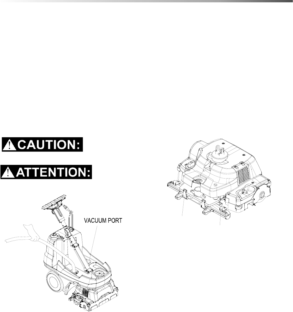
Vacuum Shoe and Hose
NOTE: Vacuum Shoe and hose flush should be done
daily after use. Place machine over drainage area
before beginning.
1. Remove recovery tank.
2. Insert water hose into vacuum hose.
3. With water pressure on high, rinse out hose and
vacuum shoe. Water should flow freely from
vacuum shoe.
Do not allow any water into the vacuum port.
Ne pas laisser d'eau dans l'orifice d'aspiration.
Vacuum Shoe Cleaning
1. Unplug the power cord and move the machine to a
safe level area.
2. To remove the vacuum shoe assembly, spin the
deck around 180 degrees so vacuum shoe is at the
front of the machine,
3. Remove the recovery tank and set to the side.
4. Tip the machine back and let it rest at approxi-
mately a 45 degree angle.
5. Remove the hose from the top of the vacuum shoe.
6. Release (2) steel clips. (as shown below)
7. Rotate the (2) retaining clips (one on each end) to
remove clear vacuum shoe for easy cleaning.
RETAINING CLIP
STEEL CLIP
86409500 Operator’s Manual - Armada BRC 40/22
28
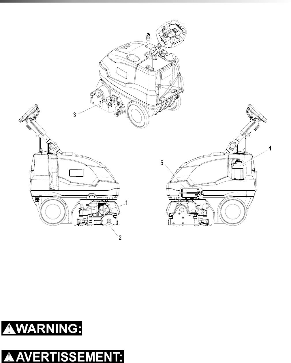
Maintenance
Scrub Deck
1. Scrub Brush Motor
2. Scrub Brush
3. Brush Height Adjustment
4. Vacuum Motor
5. Solution Pump
Only qualified maintenance personnel are to perform the following repairs.
Seul le personnel d'entretien qualifié peut effectuer des réparations.
86409500 Operator’s Manual - Armada BRC 40/22
29
Maintenance
Scrub Head Maintenance
The cylindrical scrub head is designed to scrub
chemicals into the carpet and propel the machine.
The Scrub brush should be replaced when the brush is
no longer able to keep the front of the deck from
touching the ground.
Scrub Brush Removal
The scrub brush is removed from the right side of the
machine.
1. Disconnect all power.
2. Drain recovery tank.
3. Tip the machine back.
4. Push in on the brush end cap and then downward.
5. The brush assembly and end cap should drop
down. Then pull the brush down far enough to
clear the bottom of the housing.
6. Pull brush out with a rocking motion to free brush
from drive hub.
7. Check brush roller for wear, and replace when the
brush is no longer able to keep the front of the deck
from touching the ground.
8. Check to see if the end cap and bearing spin freely
and smoothly. Clean and replace if necessary.
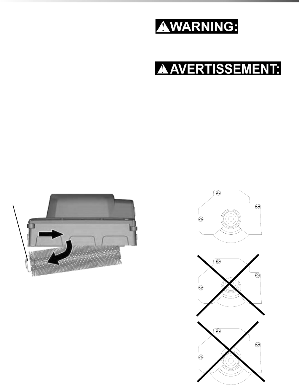
Scrub Brush Replacement
Only use the brush provided with the appliance or
those specified in the instructions manual. The use
of other brushes may impair safety.
Utilisez uniquement la brosse fournie avec
l’appareil ou celles spécifiées dans le manuel
d'instructions. L’utilisation d’autres brosses
pourrait compromettre la sécurité.
1. Lift the drive side of the brush and push it onto
drive hub until a positive stop is felt. The brush
cannot be installed until the brush is fully seated on
the drive hub.
2. Slide brush up into the retaining clip until it clicks in
place.
3. Ensure the end cap is aligned with its mounting
plate.
END CAP &
BEARING
86409500 Operator’s Manual - Armada BRC 40/22
30
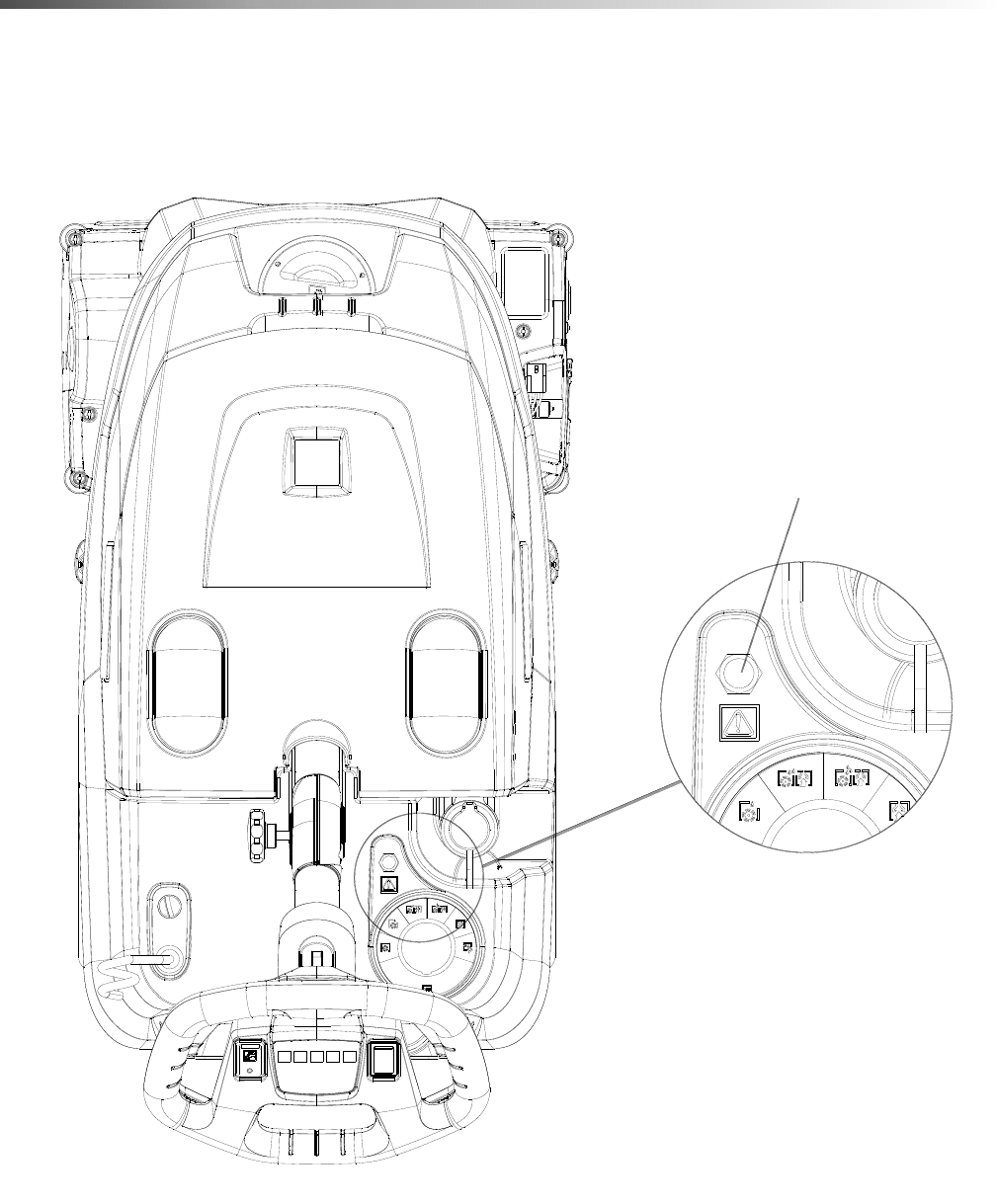
Maintenance
Circuit Protection
Circuit breakers interrupt the flow of power in the event of an electrical overload. When a circuit breaker is tripped,
reset it by pressing the button. If a circuit breaker continues to trip, contact your service representative.
Circuit Breaker
86409500 Operator’s Manual - Armada BRC 40/22

31
Maintenance
Troubleshooting
PROBLEM CAUSE SOLUTION
Cord is not plugged in Plug in cord.
No power, nothing runs, no Circuit breaker tripped on machine. Reset breaker.
green light on power icon with Circuit breaker tripped in building. Reset breaker.
switch on. Faulty switch. Call for service.
Faulty power cord or pigtail. Call for service.
Recovery tank full Empty tank. Clean float screen.
Vacuum motor will not run, red
light on vacuum icon. Faulty main vacuum switch. Call for service.
Loose wiring. Call for service.
Faulty vac motor. Call for service.
Debris lodged in vac shoe. Remove debris from vac shoe.
Vacuum motor runs but suction
is poor. Dome or lid gasket defective or
missing. Replace as necessary.
Vacuum hose cracked or hose cuff
loose. Replace or repair as necessary.
Recovery tank full / float ball stuck
in the up position. Turn off vac motor. Drain and rinse
recovery tank. Clean float screen.
Poor or no water flow
(Carpet Is streaky) Jets clogged or missing. Clean using a vinegar /water solution or
replace.
Solution filter clogged. Clean solution filter.
Faulty solenoid. Call for service.
Brush does not spin, Main switch off or in hand tool
mode. Turn main switch to machine mode.
No brush light on brush icon. Brush belt broken. Call for service.
Faulty brush motor. Call for service.
Brush light blinks orange. Brush motor power is exceeding
the normal operating limit.
Reduce brush motor load by adjusting deck
height to lower number setting with deck
height knob.
Check for worn brush.
Brush light turns solid red. Brush motor does not have any
load. Check for missing brush.
Check control board heat sink for debris.
Machine stops working and
brush light blinks red 2 times. Control board is overheating. Check function of control board cooling fan.
Reduce brush motor load by adjusting deck
height to lower number setting with deck
height knob.
Machine stops working and
brush light blinks red 3 times. Brush motor has stalled. Remove brush and remove entanglement
Remove all impediments from the path of
the machine.
86409500 Operator’s Manual - Armada BRC 40/22

32
Maintenance
Troubleshooting
PROBLEM CAUSE SOLUTION
Machine stops working and
brush light blinks red 5 times Brush motor is overheating
Allow brush motor to cool and reduce brush
motor load by adjusting deck height to
lower number setting with deck height
knob.
Brush motor temperature sensor is
disconnected. Call for service.
Machine stops working and
brush light blinks red 6 times Brush motor is still cooling from
and overheat condition
Allow brush motor to cool and reduce brush
motor load by adjusting deck height to
lower number setting with deck height
knob.
Machine stops working and
vacuum light blinks red 2 times Vacuum has stalled Check vacuum motor for debris.
Machine stops working and
vacuum light blinks red 4 times Vacuum motor is working above
recommended range. Check vacuum motor for debris.
86409500 Operator’s Manual - Armada BRC 40/22
33
Suggested Spare Parts
86003630 FLOAT SHUT-OFF
86256090 STRAINER
86412780 JET MINI PROMAX (2)
86012550 JET PROMAX
86004570 JET BODY (3)
86411180 ROLLER BRUSH
86402850 GASKET, LID
86402570 RECOVERY DRAIN HOSE
86403340 SOLUTION HOSE
86414120 VACUUM MOTOR
86405260 PUMP
86409500 Operator’s Manual - Armada BRC 40/22

86409510-G 12/14‘/16
Spare Parts List
(1.008-060.0)
Armada BRC 40-22
From Serial Number (Ref No1*)
*See Serial Number Page
or call manufacturer

286409510 - Spare Parts List - Armada BRC 40-22
How to Use this Spare Parts List
The PARTS LIST section contains assembled parts illustrations and corresponding parts list. The parts lists include
a number of columns of information:
• REF - column refers to the reference number on the parts illustration.
• PART NO. - column lists the part number for the part.
• QTY - column lists the quantity of the part used in that area of the machine.
• DESCRIPTION - column is a brief description of the part.
• SERIAL NO. FROM - If this column has an (*) and a Reference number, see the SERIAL NUMBERS page
in the back of your manual. If column has two asterisk (**), call manufacturer for serial number. The serial
number indicates the first machine the part number is applicable to. The main illustration shows the most
current design of the machine. When a boxed illustration is shown, it displays the older design.
• NOTES - column for information not noted by the other columns.
NOTE: If a service or option kit is installed on your machine, be sure to keep the KIT INSTRUCTIONS which
came with the kit. It contains replacement parts numbers needed for ordering future parts.

3
Table of Contents
How to Use this Spare Parts List . . . . . . . . . . . . . . .2
Table of Contents . . . . . . . . . . . . . . . . . . . . . . . . . . .3
Access Cover . . . . . . . . . . . . . . . . . . . . . . . . . . . . . 4
Decals. . . . . . . . . . . . . . . . . . . . . . . . . . . . . . . . . . . 6
Deck . . . . . . . . . . . . . . . . . . . . . . . . . . . . . . . . . . . . 8
Deck - Lower. . . . . . . . . . . . . . . . . . . . . . . . . . . . . 10
Deck - Upper. . . . . . . . . . . . . . . . . . . . . . . . . . . . . 12
Electrical . . . . . . . . . . . . . . . . . . . . . . . . . . . . . . . . 14
Frame . . . . . . . . . . . . . . . . . . . . . . . . . . . . . . . . . . 16
Recovery. . . . . . . . . . . . . . . . . . . . . . . . . . . . . . . . 18
Solution. . . . . . . . . . . . . . . . . . . . . . . . . . . . . . . . . 20
Steering. . . . . . . . . . . . . . . . . . . . . . . . . . . . . . . . . 22
Tower . . . . . . . . . . . . . . . . . . . . . . . . . . . . . . . . . . 24
Vacuum. . . . . . . . . . . . . . . . . . . . . . . . . . . . . . . . . 26
Vacuum Shoe . . . . . . . . . . . . . . . . . . . . . . . . . . . . 28
Flow Diagram . . . . . . . . . . . . . . . . . . . . . . . . . . . . 30
Wiring 1. . . . . . . . . . . . . . . . . . . . . . . . . . . . . . . . . 32
Wiring 2. . . . . . . . . . . . . . . . . . . . . . . . . . . . . . . . . 34
Wiring 3. . . . . . . . . . . . . . . . . . . . . . . . . . . . . . . . . 36
Serial Number. . . . . . . . . . . . . . . . . . . . . . . . . . . . 38
86409510 - Spare Parts List - Armada BRC 40-22
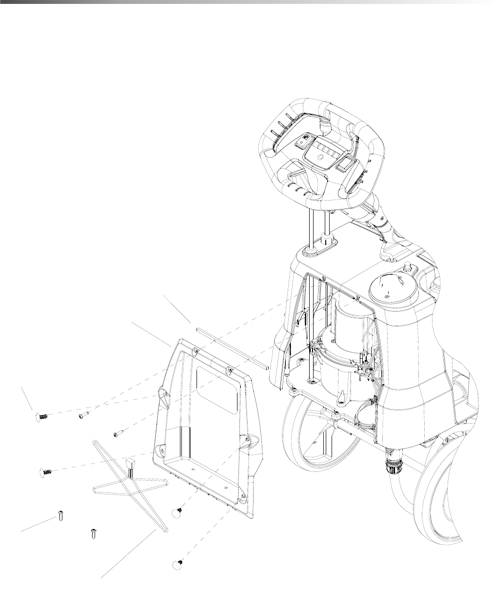
4
Access Cover
4
3
2
1
5
86409510 - Spare Parts List - Armada BRC 40-22

586409510 - Spare Parts List - Armada BRC 40-22
Access Cover
REF PART NO. QTY DESCRIPTION SERIAL NO.
FROM NOTES
1 86403350 4 SCREW, KA50X20 TSLTD SS BLK ZNPLT
2 86403000 1 CARGO NET
3 86397130 1 DOOR, COVER, TOWER
4 86379330 4 CLIP, X-MAS TREE, BLACK
5 86413120 1 GASKET, ACCESS PANEL
6
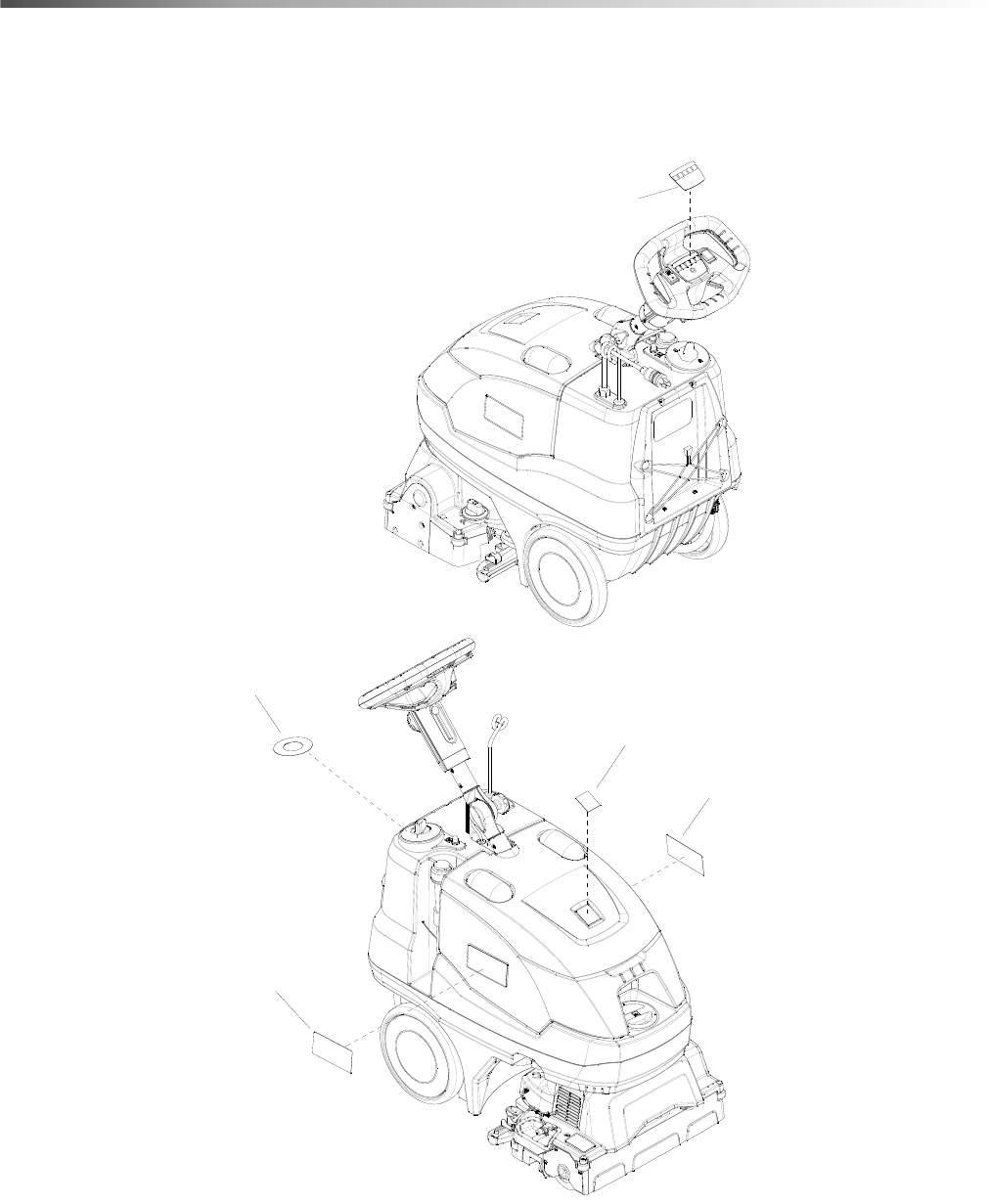
Decals
4
3
2
3
1
86409510 - Spare Parts List - Armada BRC 40-22

786409510 - Spare Parts List - Armada BRC 40-22
Decals
REF PART NO. QTY DESCRIPTION SERIAL NO.
FROM NOTES
1 86402300 1 LABEL, ARMADA LIGHT PANEL
2 86403620 1 LABEL, LOGO
3 86402320 2 LABEL, ARMADA SIDE
4 86402310 1 LABEL ARMADA ROTARY SWITCH
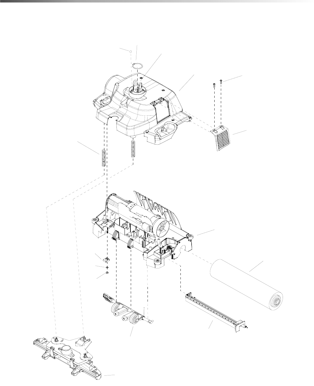
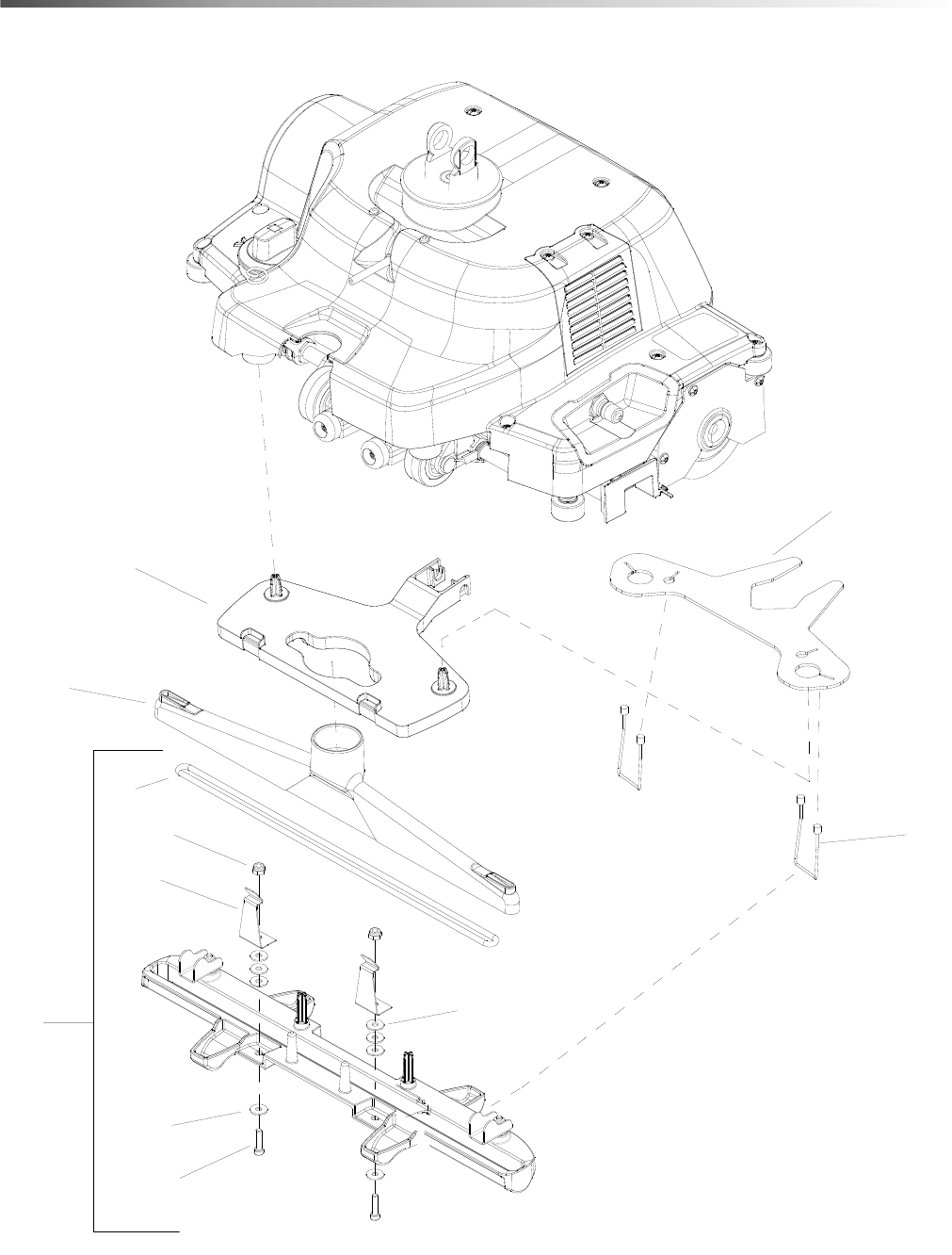
8
Deck
SEE DECK - LOWER
SEE DECK - UPPER
SEE VACUUM SHOE
11
1
2
34
5
6
7
8
9
10
TO LOWER STEERING PILLAR
86409510 - Spare Parts List - Armada BRC 40-22

986409510 - Spare Parts List - Armada BRC 40-22
Deck
REF PART NO. QTY DESCRIPTION SERIAL NO.
FROM NOTES
1 86403350 2 SCREW, KA50X20 TSLTD SS BLK ZNPLT
2 86403340 2 SPRING, .085" X .072" X 4.0"
3 74019170 1 SPHERE 10,0 G100-1.4301 DIN 5401
4 73430190 1 LOCKING RING 45x1,75-FST-RF DIN 471
5 73122320 1 SERRATED LOCK WASHER A6,4-FSt-A3E
DIN 6
6 73110030 1 HEXAGON NUT M6 -8-A2E ISO 4032
7 50373030 1 SLIDE PART HEIGHT ADJUSTMENT
8 50372680 1 COVER REFRIGERATION MOTOR
9 50372630 1 SWEEP DRAWER
10 86411180 1 ROLLER BRUSH ARMADA COMPLETE
11 40370290 1 CARRIAGE COMPLETE

10
Deck - Lower
1
3
4
5
20
7
9
10
11
12
13
14
15
16
17
18
8
21
2
2
2
2
22
2
6
19
86409510 - Spare Parts List - Armada BRC 40-22

1186409510 - Spare Parts List - Armada BRC 40-22
Deck - Lower
REF PART NO. QTY DESCRIPTION SERIAL NO.
FROM NOTES
1 86409470 2 ROLLER AXLE - M3X24 SS
2 86403350 15 SCREW, KA50X20 TSLTD SS BLK ZNPLT
3 86403210 1 PLATE, TOW PIVOT REINFORCEMENT
4 86402130 1 SPRAY SHIELD
5 86397180 1 LOWER DECK
6 86411250 1 MOTOR ASSY, 120VDC, 56HP INCLUDES
86385340
7 86173330 1 WASHER, M5 SS ISO7093
8 50370080 2 PLATE STOP
9 73122320 4 SERRATED LOCK WASHER, A6,4-FSt-A3E
DIN 6
10 73060900 4 SCREW, M6x16 -8.8-R3R (In6Rd)
11 73030390 4 SCREW, M5x16 -St-A2R (In6Rd)
12 55152770 2 ROLLER
13 50373400 1 BAFFLE PLATE BRUSH HEAD
14 50373130 1 COUPLER
15 50372750 1 COVER GEAR CASE
16 50372620 4 DEFLECTOR ROLL
17 50372600 1 SWIVEL JOINT SUCTION BEAM RETRAC-
TION
18 50372590 1 PLATE BRUSH HOLDER
19 63484800 1 TOOTHED BELT
20 86385340 1 FAN, BRUSH MOTOR
21 40370330 1 GEAR CASE REPLACEMENT
12
Deck - Upper
1
2
3
4
5
18
8
9
10
11
12
15
17
19
20
21
23
24
25
26
27
27
29
30
31
32
33
3
3
3
3
3
13
19
13
13
14
14
14
14
28
28
6
7
18
18
16
16
22
3
26
34
19
20
35
3
86409510 - Spare Parts List - Armada BRC 40-22

1386409510 - Spare Parts List - Armada BRC 40-22
Deck - Upper
REF PART NO. QTY DESCRIPTION SERIAL NO.
FROM NOTES
1 50372670 1 DECK PIVOT
2 86403640 1 STEM ADAPTER, JG 1/4" MPT X 1/4" STEM
3 86403350 27 SCREW, KA50X20 TSLTD SS BLK ZNPLT
4 86403200 2 HOSE, 1/4, 6 INCH
5 86403190 1 HOSE, 1/4, 15 INCH
6 86403180 1 HOSE, 1/4, 8 INCH
7 86403170 1 HOSE, 1/4, 9.5 INCH
8 86403160 1 HOSE, 1/4, 30 INCH
9 86403150 1 HOSE, 1/4, 23.5 INCH
10 86403140 1 NIPPLE BRACE
11 86403130 1 NIPPLE CLAMP HOLDER
12 86403120 1 SOLENOID PLATE
13 86403110 3 STEM ADAPTER, JG 1/8" MPT X 1/4" STEM
14 86400850 6 NOZZLE HOLDER
15 86397200 1 UPPER DECK
16 86379880 2 ELBOW, JG, 1/4
17 86373610 1 CONNECTOR, JG, 1/4 TUBE X 1/8 MNPT
18 86367170 3 TEE, UNION, JG, 1/4 TUBE
19 86412480 2 ASSEMBLY, SOLENOID, 120V
20 86270990 3 NUT, 10-32 HEX NYLOCK SS
21 86412780 2 JET, MINI PROMAX 8003
22 86198440 4 CLAMP, 1/4 PLASTIC CABLE
23 86173300 1 WASHER, M8 FLT SS ISO7098
24 86012550 1 JET, PROMAX, 11001
25 86353090 4 SCREW, 8-32 X 0.313 PHPNHMS SS
26 86005580 1 NIPPLE, 1/4 FPT QD
27 86004570 3 JET BODY, MINI PROMAX BODY
28 86002480 3 CONNECTOR, 1/8FPT X 1/4 TUBEQC
29 73433000 1 LOCK WASHER, 7-A2 DIN 6799
30 53322070 1 HELICAL SPRING
31 50373320 1 SPLASH GUARD BRUSH-HEAD
32 50373020 1 THREADED PART
33 50373010 1 BUTTON HEIGHT ADJUSTMENT
34 86385960 1 SPACER, ACCY NIPPLE
35 86417120 1 SOLUTION BRACKET ASSEMBLY
14
Electrical
86409510 - Spare Parts List - Armada BRC 40-22

1586409510 - Spare Parts List - Armada BRC 40-22
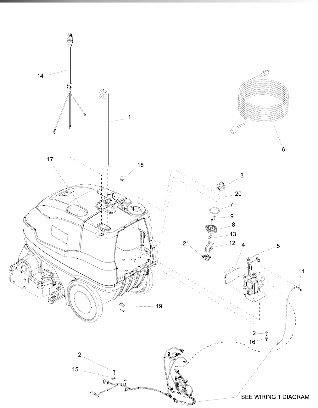
Electrical
REF PART NO. QTY DESCRIPTION SERIAL NO.
FROM NOTES
1 86409790 1 ROD, CORD HOLDER, PAINTED
2 86403350 4 SCREW, KA50X20 TSLTD SS BLK ZNPLT
3 53217380 1 HANDHOLD OPERATIONAL CONCEPT
4 86403090 1 POWER SUPPLY
5 86387520 1 ASSEMBLY, PCB, 120V, SERVICE
6 86234110 1 CORD SET,14/3 SJTW-A X 50' YLW
7 86354810 1 GASKET, ROTARY SWITCH
8 86354560 1 BEZEL, ROTARY SWITCH
9 86349400 2 SCREW, M4-.7 X 20 FLHMS SS
10 86274570 8 SCREW, 4-40 X .25 PHPNHMS STL ZNPLT
11 86005700 2 NUT, 10-32 HEXSTRW LK STL ZNPLT
12 66832700 1 SWITCH, EASY OPERATION
13 86254320 4 SPACER, .17IDX.25ODX3/16LG
14 86234320 1 CORD ASM, 14/3 X 22" YLW
15 86198440 3 CLAMP, 1/4 PLASTIC CABLE
16 86173330 1 WASHER, M5 SS ISO7093
17 86005670 1 NUT, 1/2-14 CONDUIT LK STL ZNPLT
18 86002010 1 BOOT, 3/8 CIRCUIT BREAKER
19 86001730 1 BREAKER, 18A 250VAC, 50VDC
20 63130140 1 SPRING ELEMENT
21 66832710 1 SWITCH, EASY OPERATION
16
Frame
1
2
3
4
5
6
7
86409510 - Spare Parts List - Armada BRC 40-22

1786409510 - Spare Parts List - Armada BRC 40-22
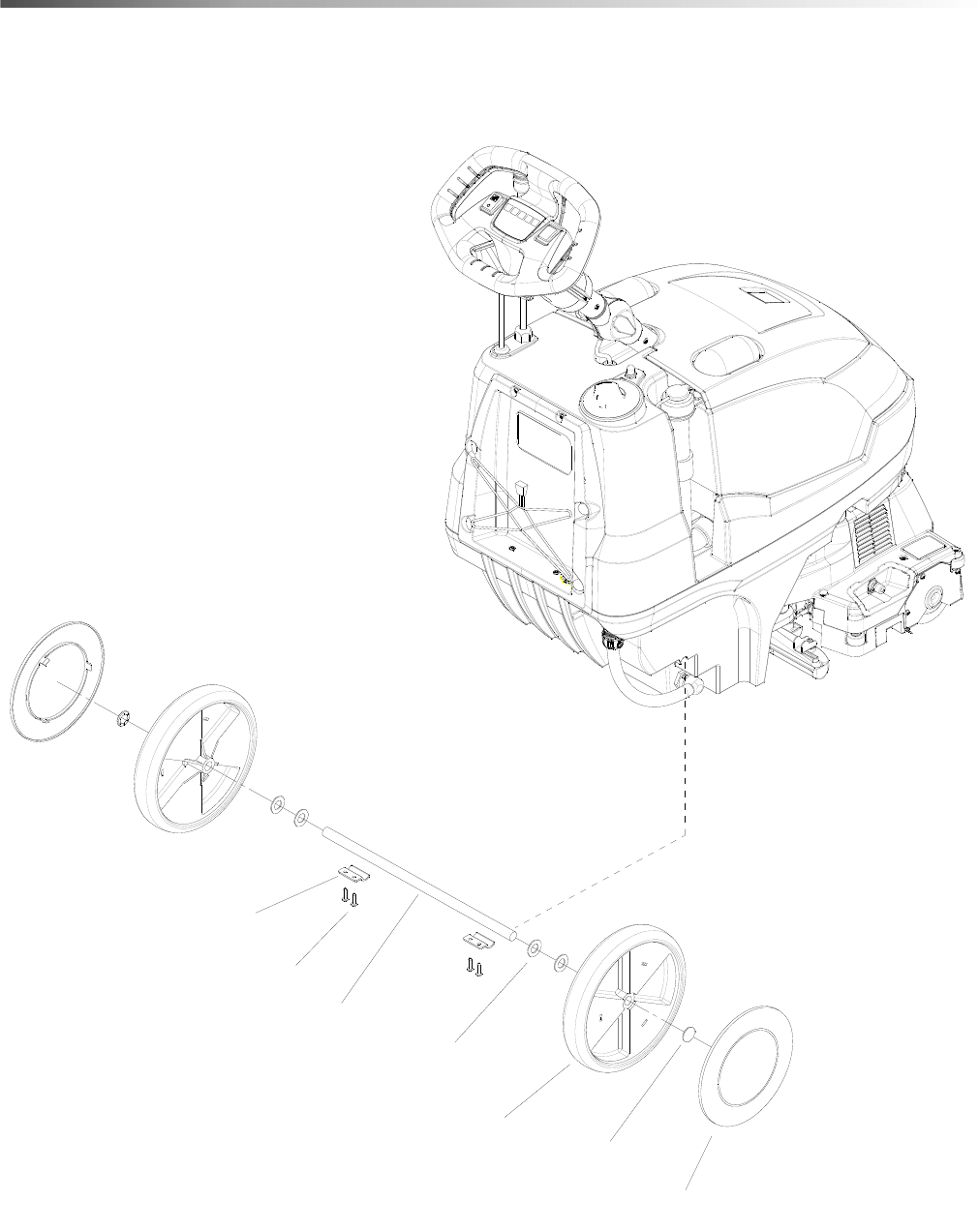
Frame
REF PART NO. QTY DESCRIPTION SERIAL NO.
FROM NOTES
1 86403350 4 SCREW, KA50X20 TSLTD SS BLK ZNPLT
2 86400680 1 AXLE, 5/8" OD
3 86226050 2 WHEEL, 9.75" X 1.5"
4 86219480 2 HUBCAP, 9.75" WHEEL
5 86010730 4 WASHER, 5/8 X .64 X 1.188 SS
6 86001660 2 HUBCAP, 5/8" SHAFT
7 50373090 2 FIXING AXLE
18
Recovery
1
2
3
4
5
6
7
8
9
10
11
12
86409510 - Spare Parts List - Armada BRC 40-22

1986409510 - Spare Parts List - Armada BRC 40-22
Recovery
REF PART NO. QTY DESCRIPTION SERIAL NO.
FROM NOTES
1 86403410 2 GASKET, DOME, .25" THICK
2 86403350 7 SCREW, KA50X20 TSLTD SS BLK ZNPLT
3 86402850 1 GASKET, LID, 28.75"
4 86402740 1 ARMADA RECOVERY TANK, TRIMMED
5 86402570 1 RECOVERY DRAIN HOSE, 12" LG
6 86397190 2 DOME, CLEAR, RECOVERY
7 86397140 1 LID, DOME, RECOVERY
8 86278390 1 SPACER, 1/2"ODX.219IDX1/2"NYLO
9 86273540 2 SCREW, 10-32 X .5 SCHCS SS
10 86218530 1 HANDLE, RECOVERY TANK
11 86177050 1 CLAMP, HOSE #20
12 86003630 1 FLOAT SHUT-OFF
20
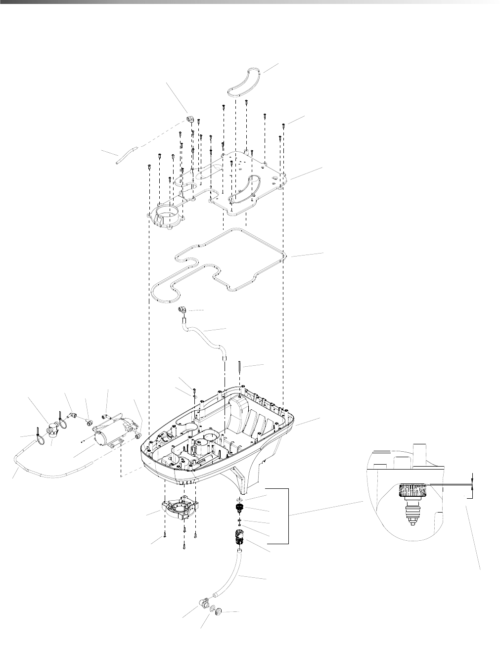
Solution
22
2
28
8
6
7
1
9
10
13
14
15
16
17
18
20
21
14
19
24 12
11
5
3
16 16
9
23
4
.05
LEAVE .05 GAP WHEN TIGHTENING
9
25
26
27
9
29
86409510 - Spare Parts List - Armada BRC 40-22

2186409510 - Spare Parts List - Armada BRC 40-22
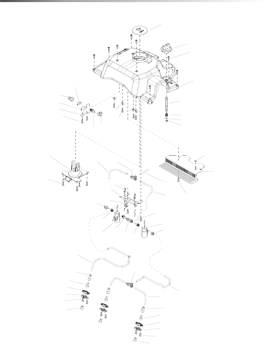
Solution
WHEN INSTALLING 64650310 CONNECTION 3/4, DISCARD WASHER GASKET AND REPLACE WITH
86394080 WASHER GASKET.
• WHEN REMOVING SOLUTION TANK LID, DO NOT REUSE 86405250 GASKET.
REF PART NO. QTY DESCRIPTION SERIAL NO.
FROM NOTES
1 86412830 1 SCREW, 8-32 X 2.25 PHPNHMS SS
2 86405260 1 PUMP ASSEMBLY
3 26451910 1 HOSE COUPLING ENTRY UNIVERSAL
4 86270850 1 NUT, 8-32 HEX NYLOCK SS
5 50372850 1 BEARING - BRUSH HEAD
6 86403390 1 HOSE, 3/8" OD, 17" LENGTH
7 86403380 1 HOSE, 3/8" OD, 27" LENGTH
8 86412820 1 WASHER, .18 X .60 FLT SS
9 86403350 27 SCREW, KA50X20 TSLTD SS BLK ZNPLT
10 86403040 1 HOSE, 9/16"ID X 3/4"OD, 10.375" L
11 55152530 1 SEAL D34
12 63100040 1 HEXAGON NUT G 1/2”
13 86397100 1 TANK, SOLUTION BASE
14 86367640 2 ELBOW, UNION, JG, 3/8 TUBE
15 86367130 1 ELBOW, JG, 3/8 STEM X 1/4 TUBE
16 86367120 3 ELBOW, JG, 3/8 STEM X 3/8 TUBE
17 86417260 1 FIELD KIT, SOLUTION TANK LID ASSY •
18 86415310 1 ASSEMBLY, SUCTION TUBE
19 86394080 1 WASHER, .500 X 1 X .188 NPRN
20 86264940 2 CABLE TIE, 11.38" UL/CSA
21 86198440 1 CLAMP, 1/4 PLASTIC CABLE
22 86409460 1 STRAINER, ASSEMBLY
23 64650310 1 CONNECTION 3/4
24 63951630 1 ANGLE BUSHING G1-2
25 86313160 - CAP, STRAINER SHORT PART OF
86409460
26 86005870 - O-RING SEAL FILTER SEAL RON-VIK PART OF
86409460
27 86313580 - SCREEN, 60 MESH STRAINER SHORT PART OF
86409460
28 86405250 1 GASKET, .25 X .36 X 101 PART OF
86417260
29 86360270 1 GASKET, .188 X .31 X 22.8 PART OF
86417260
22
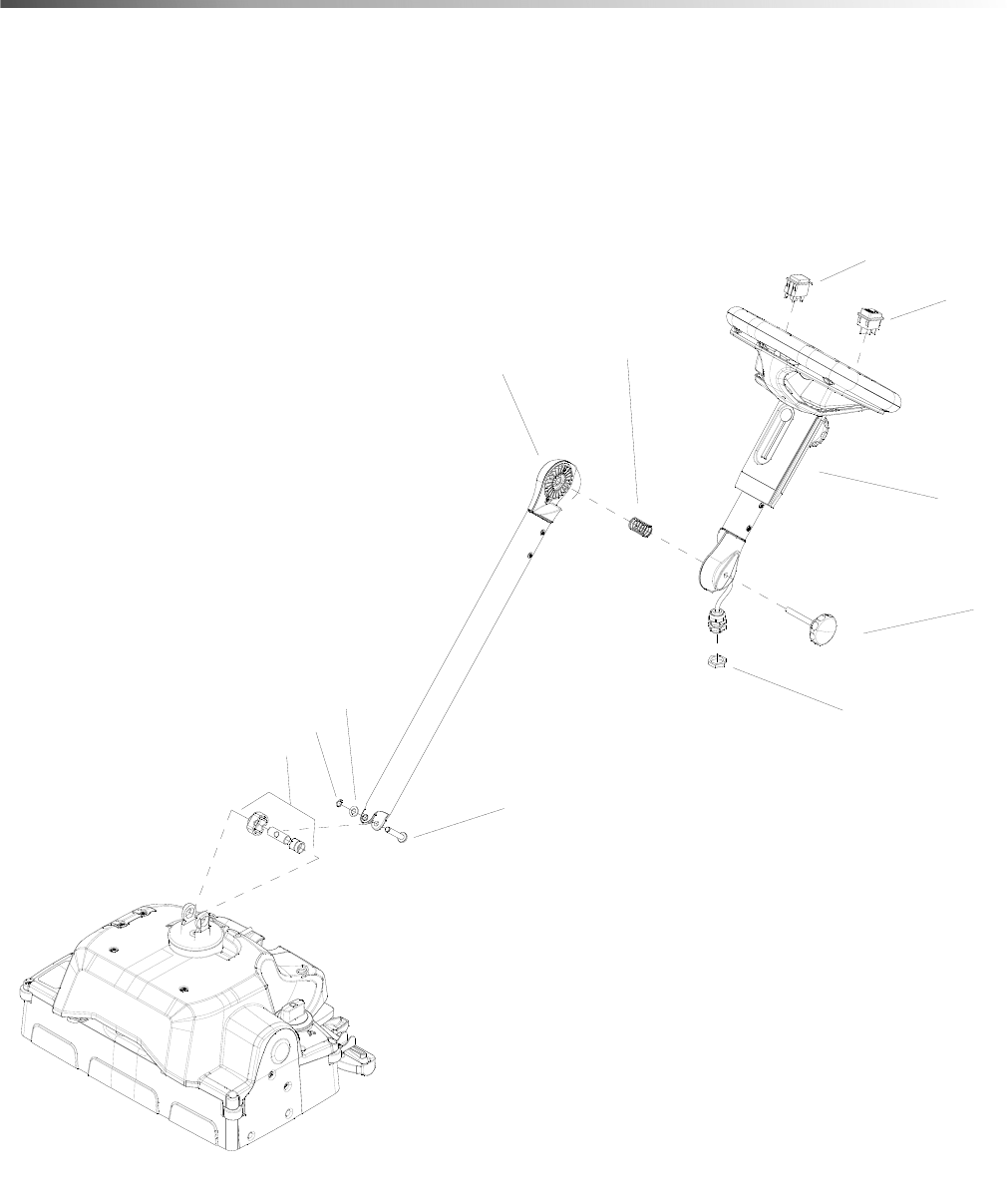
Steering
1
3
2
4
5
6
7
8
9
10
11
86409510 - Spare Parts List - Armada BRC 40-22

2386409510 - Spare Parts List - Armada BRC 40-22
Steering
REF PART NO. QTY DESCRIPTION SERIAL NO.
FROM NOTES
1 86404710 1 LOWER STEERING PILLAR
2 86403430 1 UPPER STEERING PILLAR
3 86403520 1 SWITCH, ROCKER, MARQUARDT 1661.0101
4 86173300 1 WASHER, M8 FLT SS ISO7098
5 73430140 1 LOCKING RING, 8 x0,8-FST-PHR DIN 471
6 63211790 1 STAR GRIP
7 53329810 1 PRESSURE SPRING
8 50373180 1 BOLT STEERING PILLAR
9 40370040 1 BEARING SET
10 66484160 1 LOCKNUT BLACK M20
11 66325420 1 SWITCH, PUMP
24
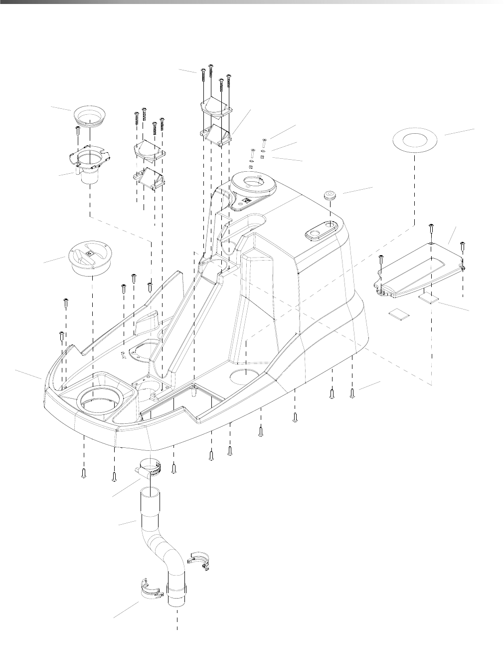
Tower
17
1
3
2
4
5
6
7
8
9
10
11
13
12
14
15
16
TO VACUUM SHOE
86409510 - Spare Parts List - Armada BRC 40-22

2586409510 - Spare Parts List - Armada BRC 40-22
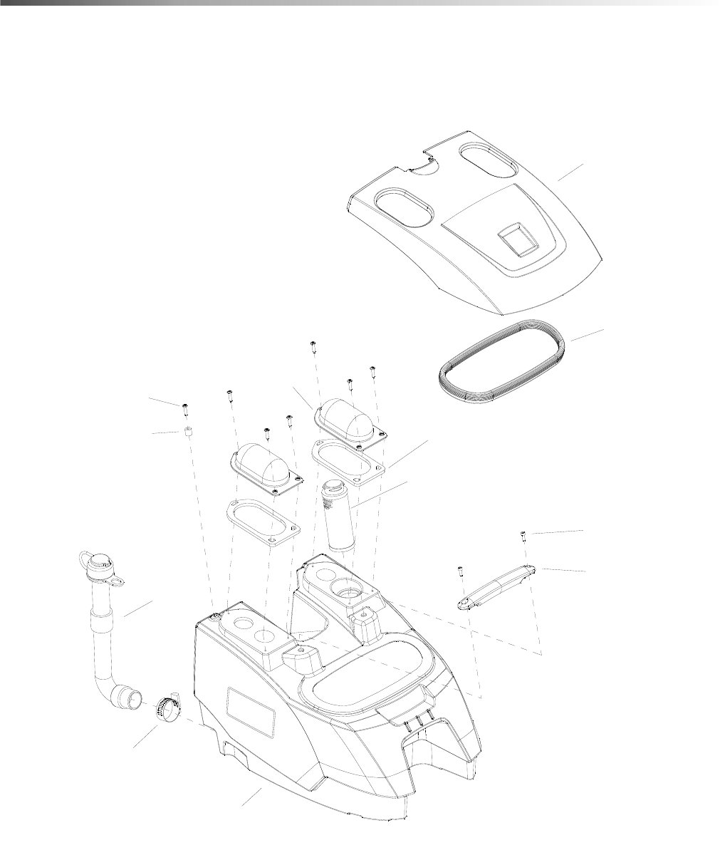
Tower
REF PART NO. QTY DESCRIPTION SERIAL NO.
FROM NOTES
1 86404440 1 GROMMET, 5/16” ID X 1/8” GROOVE
2 86403350 18 SCREW, KA50X20 TSLTD SS BLK ZNPLT
3 86403060 1 HOSE ASM, 1.5" X 16" LENGTH
4 86399970 2 GASKET, PUMP, W/ ADHESIVE
5 86398260 1 COVER, PUMP, SOLUTION
6 86397770 1 SEAL, RECOVERY LIP
7 86397760 1 TUBE, RECOVERY
8 86397120 1 TOWER, SOLUTION
9 86349400 2 SCREW, M4-.7 X 20 FLHMS SS
10 86279080 2 WASHER, M4 FLT STL DIN125A ZNPLT
11 86177050 1 CLAMP, HOSE #20
12 86172630 2 NUT, M4X.7 LK ISO7040 SS
13 73030860 8 SCREW, 5 X 30 -10.9-R2R (K-In6Rd)
14 50503590 1 COVER METERING, FRESH WATER
15 50373490 2 HOSE HANGER
16 50372890 4 HALF SHELL BEARING OPERATING UNIT
17 86413200 1 SEAL, VAC TUBE
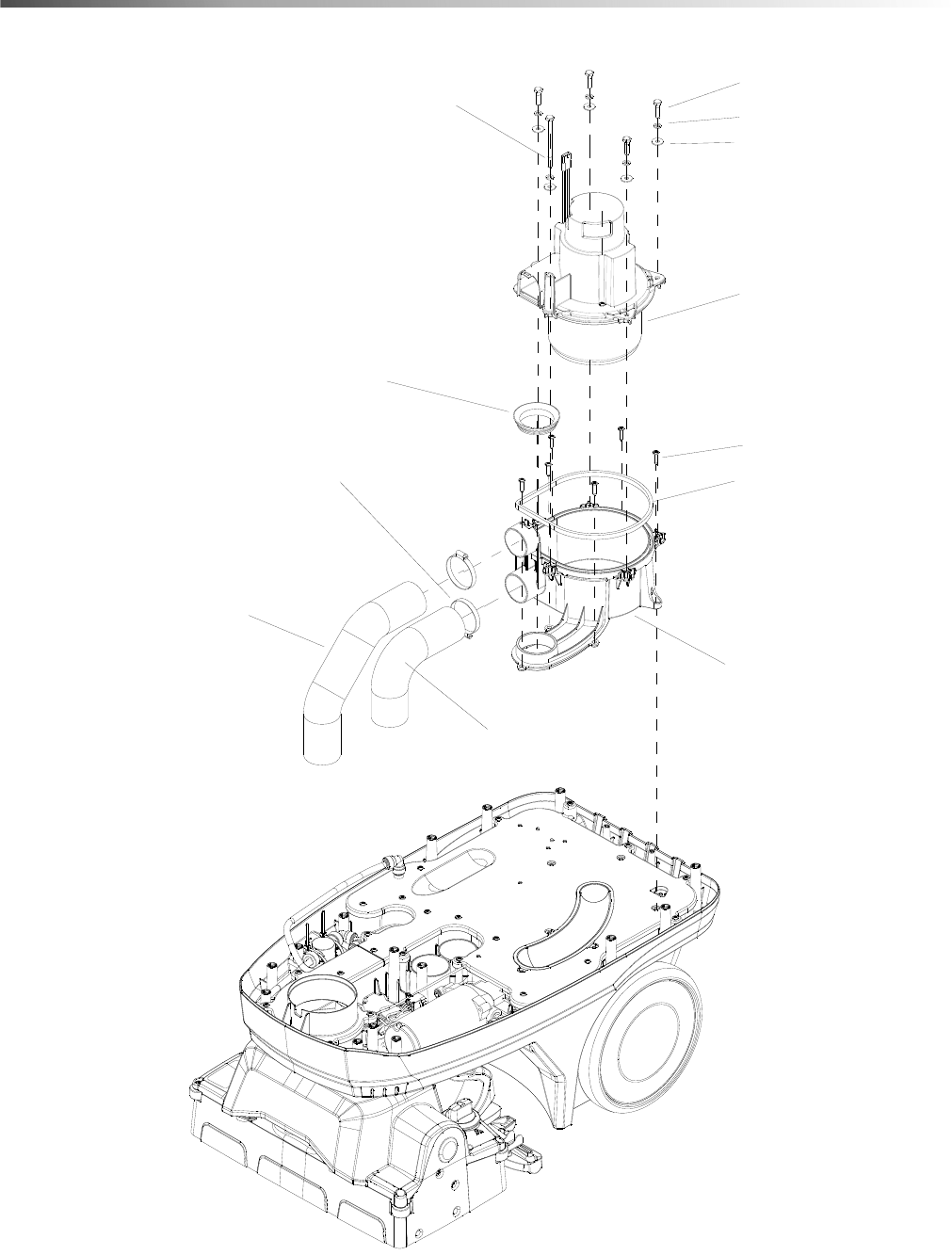
26
Vacuum
2
6
3
1
5
4
10
8
12
11
7
9
86409510 - Spare Parts List - Armada BRC 40-22

2786409510 - Spare Parts List - Armada BRC 40-22
Vacuum
REF PART NO. QTY DESCRIPTION SERIAL NO.
FROM NOTES
1 86414120 1 ASSEMBLY, VACUUM 120V
2 86403510 1 HOSE, 2" ID X 14" LENGTH
3 86403500 1 HOSE, 2" ID X 11" LENGTH
4 86403480 1 SCREW, M6X1.00X90 HHCS DIN 931 ZNPLT
5 86403470 4 SCREW, M6 X 1.00 X 25 HHCS DIN 933
ZNPLT
6 86403350 6 SCREW, KA50X20 TSLTD SS BLK ZNPLT
7 86397770 1 SEAL, RECOVERY LIP
8 86397730 1 VAC HOUSING, LOWER
9 86002380 2 CLAMP, 2.25" WORM GEAR
10 86360270 1 GASKET, .188 X .31 X 22.8
11 86173310 5 WASHER, M6 SPL SS DIN127B
12 86013850 5 WASHER, M6 FNDR SS ISO7093
28
Vacuum Shoe
1
9
3
5
7
2
4
6
6
8
10
86409510 - Spare Parts List - Armada BRC 40-22

2986409510 - Spare Parts List - Armada BRC 40-22
Vacuum Shoe
REF PART NO. QTY DESCRIPTION SERIAL NO.
FROM NOTES
1 86397230 1 LINKAGE, VACUUM SHOE
2 86275080 2 SCREW, 10-32 X .75 SCHCS SS
3 86397210 1 COVER, VACUUM SHOE
4 86270990 2 NUT, 10-32 HEX NYLOCK SS
5 86371770 1 O-RING, 3/16 DIA X 9.5 DIA FOAM
6 86173330 8 WASHER, M5 SS ISO7093
7 86340850 2 CLIP, DEBRIS TRAY SPRING
8 86385390 1 VAC SHOE ALIGNMENT BRACKET
9 86412470 1 ASSEMBLY, VACUUM SHOE, BRC 40/22
10 86387810 2 CABLE W/STOPS, 5.5IN
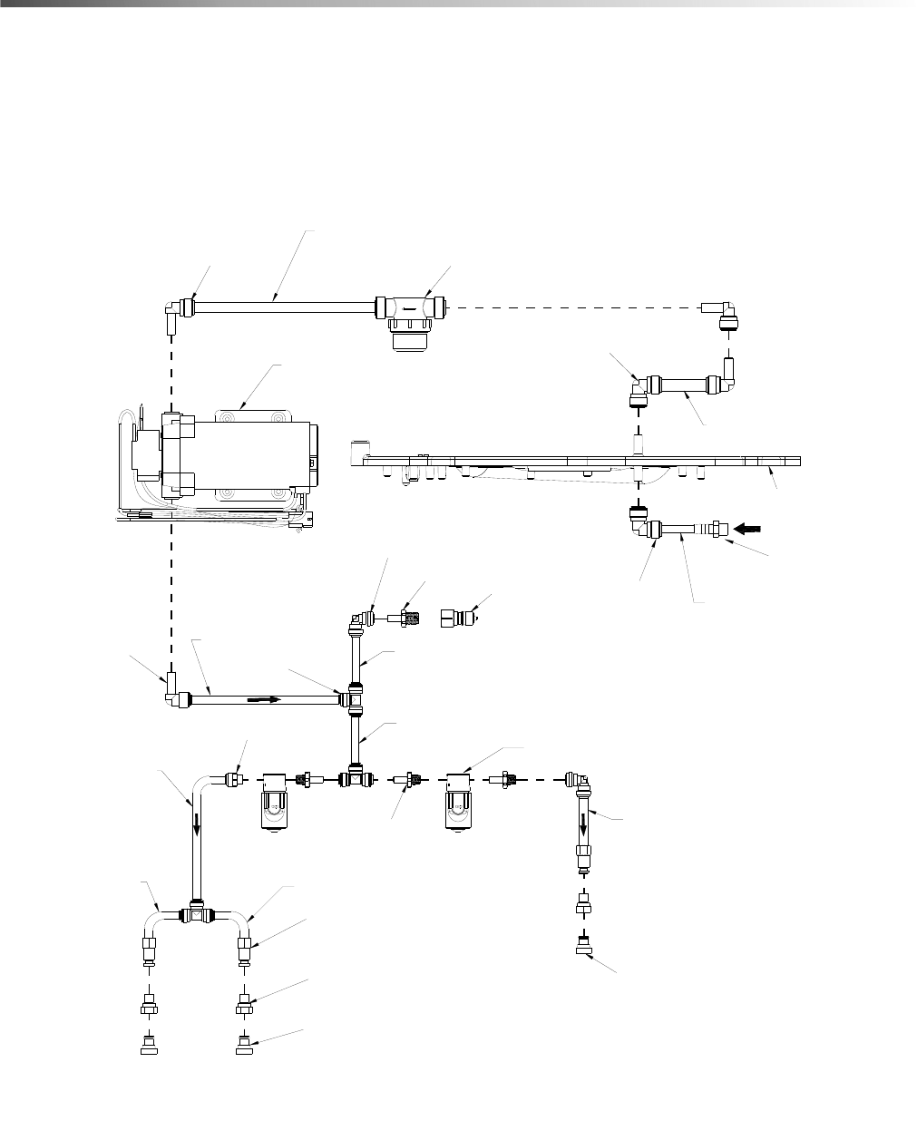
30
Flow Diagram
(86002480) (3)
(86004570) (3)
(86412780) (2)
(86012550)
(86403110) (3)
(86403360)
(86005580)
(86403640)
(86379880) (2)
(86367170) (3)
(86373610)
(86367130)
(86367640)
SOLUTION PLATE
STRAINER
(86367120) (3)
(86403390 YELLOW)
FLOW DIRECTION
(86403180 YELLOW)
(86403170 GREEN)
(86403160 BLACK)
(86403190 BLUE)
(86403200 GREY) (86403200 GREY)
SOLENOID (2)
(86403380 BLACK)
(86403380 BLACK)
PUMP
(86403150 RED)
(86367640)
86409510 - Spare Parts List - Armada BRC 40-22

3186409510 - Spare Parts List - Armada BRC 40-22
Notes
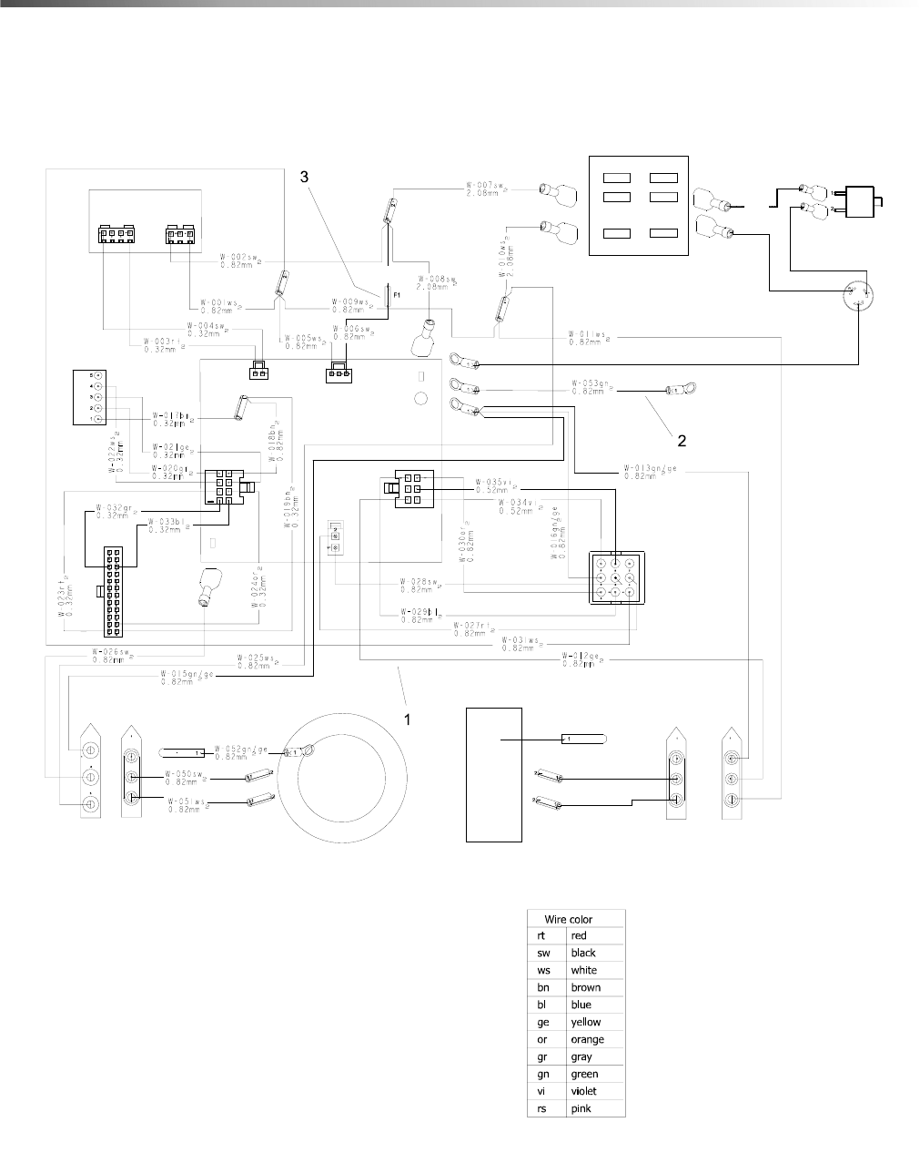
32
Wiring 1
ROTARY PWR
W-036sw
2.08mm%%172
W-056sw
0.82mm%%172
SSPT
BSH
GROUND
LINE
SP-ROT1
ROT
ROT1
POWER SUPPLY
PS1 PS2 SP-CBREAK
CB1
PW1
SP-PWR
PW2-1
PW2-2
PW2-2
CIRCUIT BREAKER
PWR PLUG
TO CORD
HOLDER
TO DECK
HARNESS
CN2
CN1
MGC PUMP
BS2
BS1
PUMP
VAC
MOTOR
GDM
BS2
BS1
MGC
VAC1
TCU1
VAC
PCB
12V AC/IN
SP-PWR-2
T1
GD1
86409510 - Spare Parts List - Armada BRC 40-22

3386409510 - Spare Parts List - Armada BRC 40-22
Wiring 1
REF PART NO. QTY DESCRIPTION SERIAL NO.
FROM NOTES
1 86403230 1 HARNESS, MAIN
2 86267400 1 WIRE, 22" GRN/18 76011 X 76011
3 86364350 1 FUSE, 7A 1/4" X 1 1/4"
34
Wiring 2
1
2
PCB
LED BOARD
STEERING
W-049vi
0.52mm%%172
W-048vi
0.52mm%%172
W-042gn/ge
0.82mm%%172
W-045gn/ge
0.82mm%%172
W-041sw
0.82mm%%172
W-040rt
0.82mm%%172
W-044vi
0.52mm%%172
W-043vi
0.52mm%%172
W-038bl
0.82mm%%172
W-047ws
0.82mm%%172
W-04 6ws
0.82mm%%172
W-037ws
0.82mm%%172
W-039or
0.82mm%%172
86409510 - Spare Parts List - Armada BRC 40-22

3586409510 - Spare Parts List - Armada BRC 40-22
Wiring 2
REF PART NO. QTY DESCRIPTION SERIAL NO.
FROM NOTES
1 86404230 1 HARNESS, DECK
2 86405190 1 HARNESS, THERMISTER, 12"
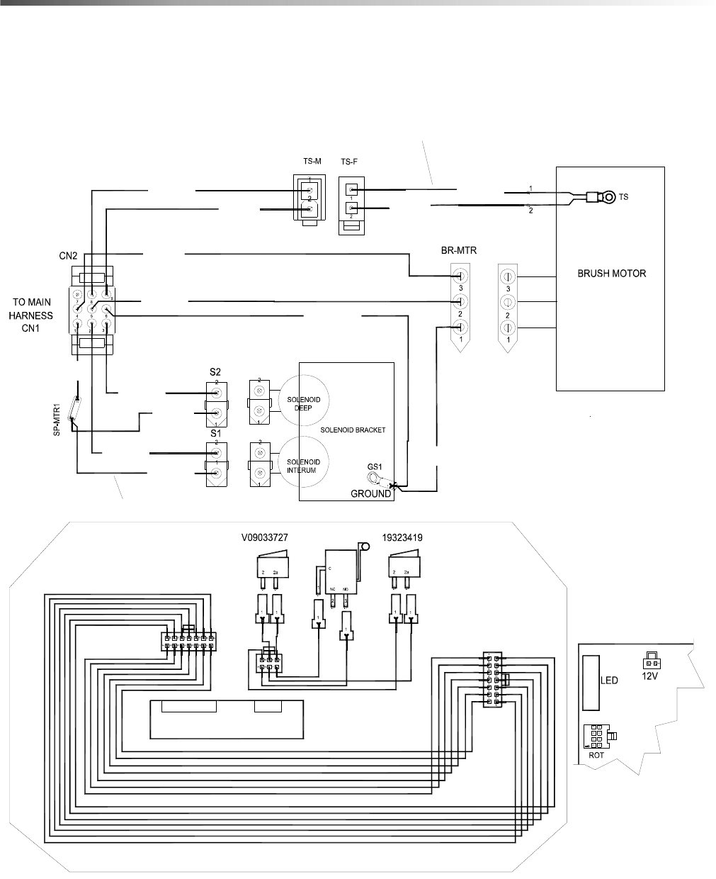
36
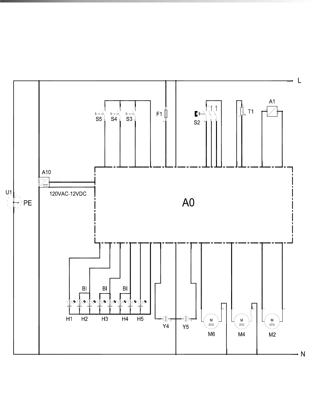
Wiring 3
86409510 - Spare Parts List - Armada BRC 40-22

3786409510 - Spare Parts List - Armada BRC 40-22
Wiring 3
REF DESCRIPTION
A0 CPU MODULE
A1 TCU
A10 POWER SUPPLY
M2 BRUSH MOTOR
M4 VACUUM MOTOR
M6 PUMP MOTOR
Y4 SOLENOID
Y5 SOLENOID
S2 ROTARY SWITCH
S3 FWR/REV SWITCH
S4 WATER SWITCH
S5 TRIGGER
T1 TEMP MONITOR
H1 LED GN POWER
H2 LED GN/RT VAC
H3 LED GN/RT BRUSH
H4 LED GN/RT WATER
H5 LED BL ECO
U1 MAINS CONNECTION, 120V / 60HZ/15A
F1 IN-LINE FUSE

38
Serial Number
REF.
NO. MODEL: SERIAL #
1 RESERVED
86409510 - Spare Parts List - Armada BRC 40-22

39
