Swisher T1260 T1360 T1460 Users Manual Microsoft T60 2000
!! Swisher-46 Swisher Lawn Mower Manuals - Lawn Mower Manuals – The Best Lawn Mower Manuals Collection
!! 250091 Swisher Lawn Mower Manuals - Lawn Mower Manuals – The Best Lawn Mower Manuals Collection
Preview ! 250091 Swisher Lawn Mower Manuals - Lawn Mower Manuals – The Best Lawn Mower Manuals Collection
T1260, T1360, T1460 to the manual dd778048-f82a-4d9b-89f4-64f8fd3a1621
2015-02-02
: Swisher Swisher-T1260-T1360-T1460-Users-Manual-448965 swisher-t1260-t1360-t1460-users-manual-448965 swisher pdf
Open the PDF directly: View PDF ![]() .
.
Page Count: 20
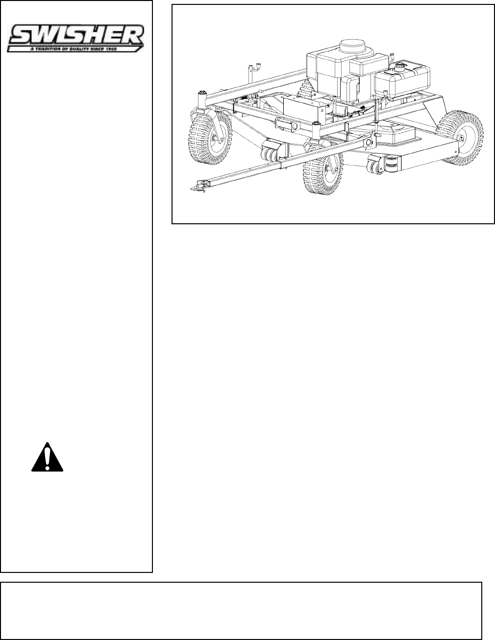
60” UNIVERSAL
TRAILMOWER
P.O. BOX 67, WARRENSBURG, MISSOURI 64093 PHONE 660-747-8183 FAX 660-747-8650
Manufacturing quality lawn care equipment since 1945
Assembly
Operation
Service and Adjustment
Repair Parts
Made In The
USA
OWNER’S
MANUAL
MODEL NO.
T1260
T1360
T1460
Rev.04-288
Read and follow all
Safety Precautions and
Instructions before
operating this
equipment.
IMPORTANT
ONT60
STARTING SERIAL #:
99-307001
LIMITED WARRANTY
The manufacturer’s warranty to the original consumer purchaser is: This product
is free from defects in materials and workmanship for a period of one (1) year
from the date of purchase by the original consumer purchaser. We will repair or
replace, at our discretion, parts found to be defective due to materials or
workmanship. This warranty is subject to the following limitations and
exclusions:
1) Engine Warranty All engines utilized on our products have a separate
warranty extended to them by the individual engine
manufacturer. Any engine service difficulty is the
responsibility of the engine manufacturer and in no
way is Swisher Mower Co., Inc. or its agents
responsible for the engine warranty. The Briggs &
Stratton Engine Service Hot-Line is 1-800-233-
3723. The Tecumseh Engine Service Hot-Line is 1-
800-558-5402.
2) Commercial Use The warranty period for this product used for
commercial or rental is limited to ninety (90) days
from the date of original purchase.
3) Limitations This warranty applies only to products which have
been properly assembled, adjusted, and operated in
accordance with the instructions contained within
this manual. This warranty does not apply to any
product of Swisher Mower Co., Inc., that has been
subject to alteration, misuse, abuse, improper
assembly or installation, shipping damage, or to
normal wear of the product.
4) Exclusions Excluded from this warranty are normal wear,
normal adjustments, and normal maintenance.
In the event you have a claim under this warranty, you must return the product to
an authorized service dealer. All transportation charges, damage, or loss incurred
during transportation of parts submitted for replacement or repair under this
warranty shall be borne by the purchaser. Should you have any questions
concerning this warranty, please contact us toll-free at 1-800-222-8183. The
model number, serial number, date of purchase, and the name of the authorized
Swisher dealer from whom you purchased the mower will be needed before any
warranty claim can be processed.
2

SAFETY PRECAUTIONS
• Read the manual. Learn to operate this machine safely.
• Always disconnect the spark plug wire and place the wire where it cannot contact
the spark plug, to prevent accidental starting the engine when setting up,
transporting, adjusting or making repairs.
• Keep all shields and guards in place.
• Understand the speed, steering and stability of this machine. Know the positions
and operations of all controls before you operate this machine. Check all of the
controls in a safe area before starting to work with this machine.
• Allow only responsible adults who are familiar with these instructions to operate
this machine. Never allow children to operate this machine.
• Clear the area of objects such as rocks, toys, wire, etc. that can be picked up and
thrown by the blade.
• Be sure the area is clear of other people before mowing. Be aware of the mower
discharge direction and do not point at anyone. Stop the machine if anyone enters
the mowing area. Children are often attracted to the machine and the mowing
activity. Never assume that children will remain where you last saw them.
Keep children under the watchful care of another responsible adult.
• No riders!
• Do not put hands or feet near or under rotating parts. Keep clear of the discharge
opening at all times.
• Do not mow in reverse. Always look down and behind before and while backing.
This Safety Alert Symbol indicates important messages in this
manual. When you see this symbol, carefully read the message that
follows and be alert to the possibility of personal injury.
Read this manual completely. This machine can amputate hands, feet, and throw
objects. Failure to observe the following safety instructions could result in serious
injury or death.
3

4
SAFETY DECALS
Replace decals immediately if damaged.Order by part number from Swisher Mowers
OD45- Warning Decal
OD11- No step Decal
OD55- Danger Decal
OD33- Speed Decal
OD29- Danger Decal
OD43- Flying Debris Decal
•
T u r n o f f t h e b la d e s w h e n n o t m o w i n g . B e fo r e le a v i n g th e m a c h in e , t u r n o f f th e b la d e s a n d
s t o p th e e n g in e .
• W a tc h f o r tr a ff ic w h e n o p e ra tin g n e a r o r c ro s s in g r o a d w a y s .
• D o n o t o p e ra te th e m o w e r i f i t h a s b e e n d ro p p e d o r d a m a g e d i n a n y m a n n e r o r i f t h e m o w e r
v ib r a te s e x c e s s iv e ly . E x c e s s iv e v ib r a tio n is a n in d i c a ti o n o f d a m a g e . R e p a ir m o w e r a s
n e c e s s a r y .
• D r e s s p r o p e rl y . D o n o t o p e ra te th e m o w e r w h e n b a re f o o t o r w e a r in g o p e n s a n d a l s . W e a r
o n ly s o li d s h o e s w i th g o o d tra c tio n w h e n m o w i n g .
• D o n o t o p e ra te th e m a c h i n e w h ile u n d e r t h e in f lu e n c e o f a lc o h o l o r d r u g s .
• D o n o t o p e ra te o n s lo p e s g re a t e r t h a n 1 5 d e g r e e s .
• N e v e r ta m p e r w it h s a f e t y d e v ic e s . C h e c k th e ir p r o p e r o p e r a tio n r e g u l a rl y .
• S to p a n d in s p e c t t h e e q u i p m e n t if y o u s tr ik e a n o b je c t . R e p a ir , if n e c e s s a ry , b e f o r e re s t a rt in g .
• N e v e r m a k e a d ju s tm e n ts o r re p a i r s w i th th e e n g in e ru n n in g .
• M o w e r b l a d e s a r e s h a rp a n d c a n c u t. W r a p th e b l a d e s o r w e a r g lo v e s , a n d u s e e x t r a c a u tio n
w h e n s e rv i c i n g th e m .
REQUIRED ASSEMBLY
FRONT WHEEL CASTER ASSEMBLY
1. Remove single nut and washers from caster shaft.
2. Place one washer on the shaft of the caster/wheel sub-assembly.
3. Slide same shaft through the bearing/frame with wheel towards the ground.
4. Place the other washer on the shaft; it should be resting on the top bearing.
5. Thread nyloc jam nut onto shaft.
6. Tighten nut snuggly, making sure shaft threads enter the nyloc of the nut. Over-
tightening of this nut will bind caster.
7. Repeat process for other front side.
REAR WHEEL ASSEMBLY
1. Remove cotter pin from axle.
2. Slide washer [ NB149 ] if necessary and wheel[ valve stem out] onto axle and replace
cotter pin.
3. Bend cotter pin so it will not fall out.
4. Repeat process for other wheel.
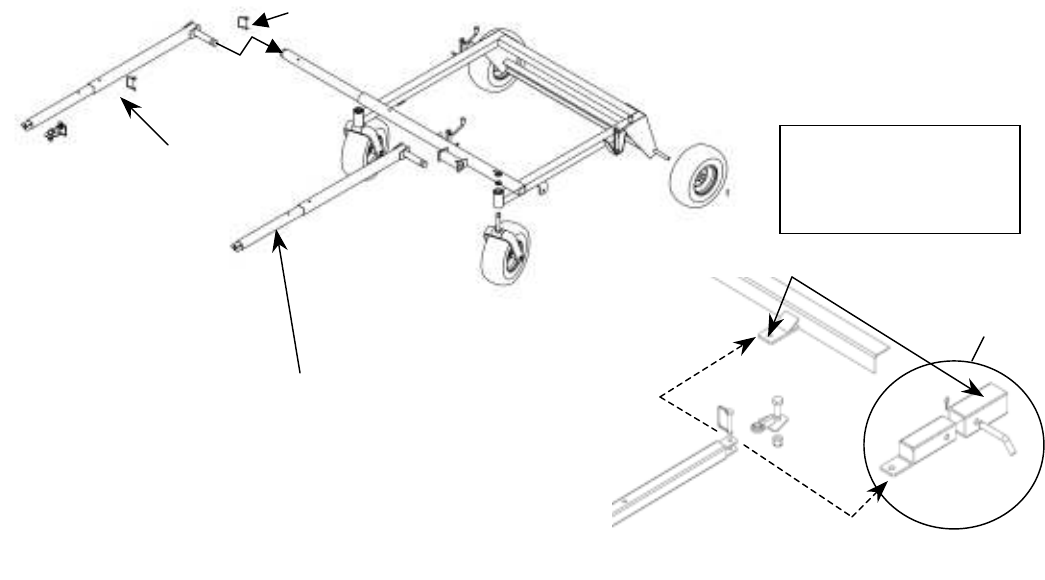
OFFSET & CENTER TOW HITCH BAR ASSEMBLY
1. Lay out parts according to the diagram.
2. Insert part 661A into part 662 and pin with the hitch pin (H11).
3. Insert part 661 into part 661A. Choose from the 3 holes to set the desired hitch length.
Pin with a hitch pin.
4. Part 662 slides into the front tube o
f the frame. Again, choose from the 3 holes to arrange
desired offset. Pin with a hitch pin (H11).
5. Eliminate step 3 for hitching from the center bracket. Only one method can be used at a
time.
5
CENTER TOWING
POSITION
OFFSET TOWING
POSITION
Bent Pin, Hair Pin
and Receiver
supplied by others.
Existing Rear Hitch.
ATV or Utility
Vehicle Attachment
Instructions
661
661A
662
H11

OPERATING YOUR TRAILMOWER
INTENDED USE
This TrailMower is designed to produce a quality finish cut on lawns, golf courses, etc.
It is not designed to clear brush or cut saplings. Your TrailMower should be towed
behind an ATV, a golf cart, lawn tractor, or similar approved vehicle. It is not meant for
speeds exceeding 5 MPH.
ATTACHING TRAILMOWER TO TOW VEHICLE
• Place mower behind vehicle and back vehicle up to desired attaching position.
• When offsetting TrailMower do so to side opposite the discharge of the tow
vehicle.
• Bolt swivel hitch (H10) to vehicle tow receiver.
• Attach tow hitch (661) to the swivel hitch with hitch pin (H11). Make certain
hitch pin goes completely through each piece and is clipped to prevent accidental
separation.
• Attach red safety tether (H9C) to both the towing vehicle and to the TrailMower
toggle switch (685SP), located on the throttle housing (6155). Its purpose is to
manually stop mower engine or to stop mower engine in case the two machines
become separated.
• It is extremely important the safety tether is secured properly to both the
toggle switch and the towing vehicle.
STARTING THE ENGINE
See engine manufacturer’s instructions for the type and amount of oil and fuel used.
TrailMowers with electric start engines will need a battery (sold separately). Swisher
recommends using a standard “U 1 R” lawn & garden battery.
• Engine must be level to accurately check and fill oil. Do not overfill.
The operation of any mower can produce foreign objects to be thrown into the
eyes, resulting in severe eye damage. Always wear certified safety glasses or
wide-vision safety goggles over spectacles before staring any cutting machine and
while operating such a machine.
The operation of any cutter produces sound waves that are damaging to the
human ear. Ear protection is recommended.
CAUTION!
Tragic accidents can occur if the operator is not alert to the presence of
children. Children are often attracted to the machine and the mowing
activity. Never assume that children will remain where you last saw them.
6

•
Make sure the tow vehicle parking brake is set, mower is level, and blades are
disengaged.
• Check spark plug wire, oil, and fuel.
• Check all electrical connections (See Schematics).
• Make sure toggle switch is turned “ON” and the red tether is properly attached.
• Set engine idle to “CHOKE” position.
• With feet clear of mower deck, turn key switch to the “START” position; [ if unit is
equipped with 12 volt system ] release when engine begins to run.
• For units NOT equipped with electric start turn key to “ON” position and pull starter
Rope until engine starts.
• Set engine idle at desired RPM.
BREAKING IN YOUR MOWER
• Set vehicle parking brake or chock wheels to prevent accidental rolling.
• Start engine properly.
• Slowly, engage blade control.
• In a safe environment, i.e. no children, allow blades to rotate and engine to idle for 5
minutes. This breaks in the belts and the engine.
• Stop mower properly.
MOWER HEIGHT ADJUSTMENT
• Adjust while mower is not running.
• The cutting range is approximately 1.5” to 4.5”. The height has been measured from the
ground to the blade tip without the engine running.
• Rotate height adjust crank handles (H7N) in a clockwise direction to lift the mower deck.
A counter-clockwise direction is used to lower the mower deck.
• Make sure the height adjustment is the same at side crank handles. For best results, see
“SUGGESTED PRACTICE” section. Graduated scales are for reference only, not the
actual cutter height.
• Place crank handle in a retracted position to maintain height adjustment.
STARTING TO MOW
• Adjust the cutting height.
• Double check vehicle to mower attachment.
• Start mower engine properly.
• Slowly, activate the blade engage lever (681N) by rotating it forward and left until the
lever locks into place.
• Carefully mount tow vehicle and start mowing slowly.
STOPPING THE MOWING SESSION
• Pull safety tether to shut toggle switch “OFF”. If the engine fails to stop or if the safety
tether has become inoperable, then use Alternative Stopping Method.
CAUTION!
SHUT OFF MOWER ENGINE AND REMOVE SPARK PLUG WIRE FROM
SPARK PLUG BEFORE MAKING ANY ADJUSTMENTS TO THE MOWER.
7

ALTERNATIVE STOPPING METHOD
• Bring vehicle to complete stop, shut off engine, and set parking brake.
• Disengage blade engage lever (681N).
• Manually shut toggle and key switches to their “OFF” positions.
• Always remember to remove keys to avoid irresponsible usage.
TRANSPORTING MOWER
• Stop mower properly.
• Place mower deck in its highest position.
• If transporting unattached from tow vehicle, then remove spark plug wire and
place where it cannot contact the spark plug.
SUGGESTED MOWING PRACTICES
• Operate mower engine at full throttle to assure the best cutting performance and
maximum material discharge.
• Allow wet grass to dry. Clumps of wet grass will collect under the mowing deck.
• Mowing should be started with tow vehicle in low gear and increased only as safe
mowing conditions permit. This speed should not exceed 5 MPH.
• The average lawn should be cut to approximately 2.5” during the cool season and
to over 3” during the hot months.
• For a healthier lawn and better aesthetics, your lawn should be mowed often and
after moderate growth.
• When cutting high or dense grass areas go slowly. Some areas may need to be
mowed twice. The second cut should be at 90 degrees to the first, if possible.
• Mowing thick or high grass. Raise rear height crank handle to .5”-.75” above
the other two handles.
• Creating a manicured lawn. Lower rear height crank handle to .25”-.5” below
front of deck. This allows grass blades to be cut twice. It also continually cuts
clippings to produce a mulching effect.
GENERAL TROUBLE SHOOTING
• The mower is not cutting level.
o Level deck, making sure the side crank-handles are equal.
o Check air pressure of all tires; make sure they are equal (about 15-18 psi).
o Examine blades for damage, while mower engine is not running.
• The engine will not start.
o Disengage blades, turn toggle switch to “ON” position, check battery and
all other electrical connections, and inspect spark plug and wire.
o Check for fuel in the engine.
• Engine runs poorly.
o See engine manual.
o Check throttle adjuster.
o Replace fuel, clean fuel filter and fuel line.
IF PROBLEMS PERSIST HAVE A QUALIFIED MECHANIC SERVICE THE
MOWER. NEVER ATTEMPT TO MAKE AN ADJUSTMENT THAT YOU ARE
NOT SURE IS CORRECT. DOING SO CAN CAUSE OTHER PROBLEMS.
8
MOWER MAINTENANCE
GENERAL RECOMMENDATIONS
The warranty on this Trailmower does not cover items that have been subjected to operator abuse or negligence.
To receive full value from the warranty, operator must maintain unit as instructed in this manual.
Some adjustments will need to be made periodically to maintain your unit properly.
All adjustments in this manual should be checked at least once each season.
BEFORE EACH USE
• Check engine oil level on a level surface. (Check twice to insure an accurate reading.)
• Check condition of air filter; clean and replace as necessary.
• Check blade operation; keep blades in good condition.
• Check for loose fasteners and tighten them as needed.
AFTER EACH USE
• Keep blades sharp.
• Remove fresh grass clippings with garden hose.
• Grass clippings can harden to the underside should be scraped out with a putty knife.
• Keep fluids at proper levels.
• Cover unit to prevent rain or other debris build-up. Definitely cover the engine.
BEFORE AND/OR AFTER EACH SEASON
• Replace the spark plug.
• Clean or replace the air filter.
• A new spark plug and clean air filter assure proper air-fuel mixture and help your engine run better and
last longer.
• Check blades and belts for wear. Replace as necessary.
STORAGE RECOMMENDATIONS
CAUTION! Do not store engine indoors or other poorly ventilated area. Keep engine away from gas
appliances where fumes could contact open flame, pilot lights, or sparks.
If engine is to be stored for 30 or more days, prepare unit as follows:
• Drain fuel outside into an approved container.
• Start engine properly and run until unit is out of fuel.
• Let engine cool.
• Remove remaining gasoline from carburetor and fuel tank to prevent gum deposits from forming
within the engine. Gum deposits can cause malfunction in the engine.
• Store mower with blades disengaged to prevent belts from being permanently stretched.
BLADE CARE AND SERVICE
For best results cutter blades must be kept sharp. The blades can be sharpened with a few strokes of a file or
grinding wheel. Do not attempt to sharpen blades while they are on the cutter. Disconnect spark plug wire
before servicing unit.
Important: Replace blades that have been damaged or deeply nicked.
Important: Check blade and spindle hardware on a regular basis to make sure nuts are tight.
Only a qualified mechanic should be used for any
adjustments, disassembly or other kind of repairs.
9
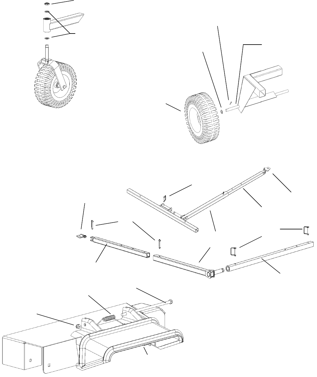
Figure 01
Figure 02
Figure 03
NB195
F4157WF
661A
661
H10TK
662
H11
H11
661
H10TK
H11
Figure 04
NB181
CH5S NB136
6031TK steel chute replaces plastic chute
shown
10
NB149
NB126
664N
NB122
11
08
01
02 03 05 06 07
08 10 09 11 12
Figure 05
02
04
SERIAL
NUMBER
13
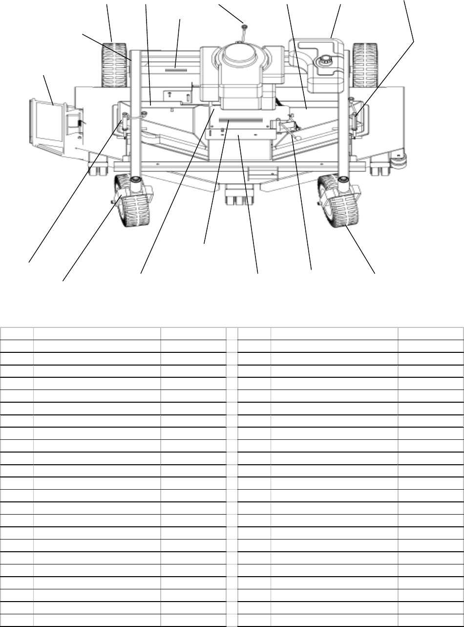
Item # Description Part # Item # Description Part #
1 Grass Chute 6031TK 8 Height Adjust Assembly H7N
Bolt/Nut NB136/NB181 Eye Bolt 6599
Spring CH5S Stabilizer Arm 6696
2 Tire/Wheel/Bearing F4157W Plastic Bushing T2PB
3 Right Belt Guard 6155RN Ruler Decal OD41
Acorn Nut NB120 Knob H7K
4 No Step Decal OD11 5/16 Pal Nut NB276
5 Height Adjust Assembly H7N 9 Engine Plate 6155NFC
Plastic Bushing T2PB 10 Front Caster Assembly 6774C
Ruler Decal OD41 Tire/Wheel/Bearing F4157W
Eye Bolt 6599 Bolt/Nut NB624/NB595
Knob H7K Spacer (Exterior) 663L
5/16 Pal Nut NB276 Washer NB178
6 Left Belt Guard 6155LN Caster Fork 665C
Acorn Nut NB120 Caster Nut NB122
7 Gas Tank 6102T Washer NB195
Gas Cap 6102NC 11 Throttle Plate 6155THC
Gas Tank Mount 6102NTK 12 Engage Lever 6720C
Rubber Bushing AS119 13 Swisher Decal OD99116
Fuel Shutoff Valve AS120
Fuel Line Hose Clamp 6FLC
Fuel Line AS140
12
28
Figure 06
15
15
16 17 18
16
26
21
16 18
19
20 25 24
22
28
LEFT
RIGHT
REAR
FRONT
KEY
SWITCH
2727
14
23
29
29
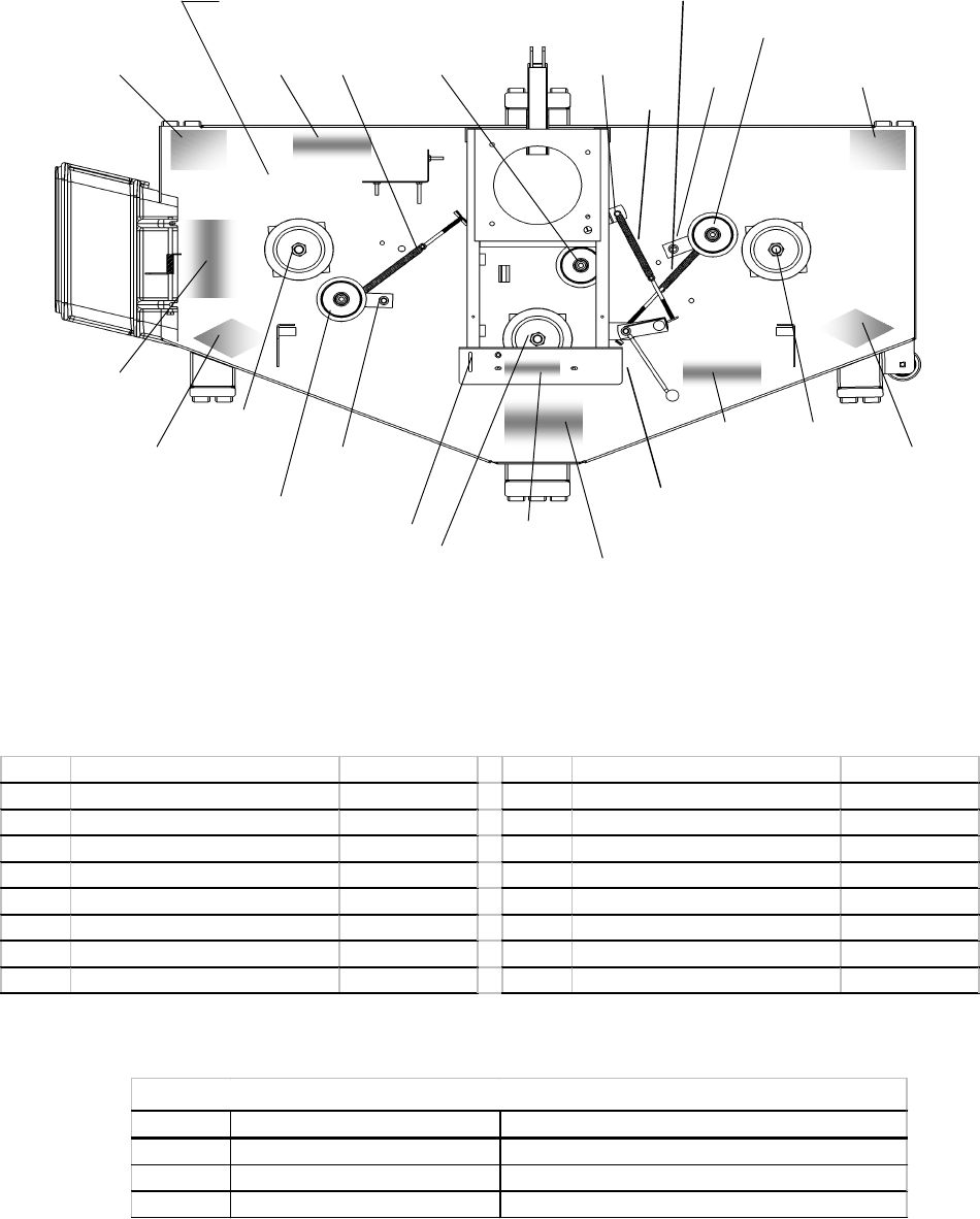
Item # Description Part # Item # Description Part #
14 Clutch Idler Rod/Spring 3123TK/682S 22 Blade Driver Left 9086
15 Idler Rod/Spring 6704TK/682S 23 Deck 6725C
16 Idler Pulley B527 24 Warning Serious Injury Decal OD45
17 Clutch Idler Arm 6709TK 25 5 MPH Decal OD33
18 Idler Bracket 6681TK 26 Caution - Deflector Decal OD43
19 Throttle Decal OD58 27 60" Decal OD99128
20 Blade Driver Center 9084 28 Danger Triangle Decal OD55
21 Blade Driver Right 9085 29 Danger Decal OD29
Position Part # Replaces
Center 9084 Blade Driver Assembly 6769 Blade Driver Assembly and 9002 Shaft
Right 9085 Blade Driver Assembly 9059 Blade Driver Assembly and 9000 Shaft
Left 9086 Blade Driver Assembly 9059 Blade Driver Assembly and 9001 Shaft
Blade Driver Update
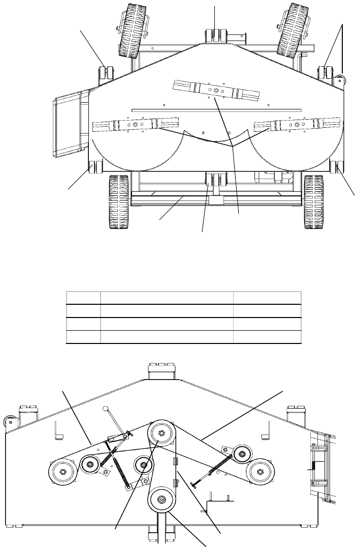
Figure 07
31
31
26
30
31
31
31
31
32
Item # Description Part #
30 Blade (3) 9004
31 Anti-Scalp Roller AS001
32 Rear Axle 664N
13
BELT CONFIGURATION
BOTTOM CENTER
BLADE DRIVER
PULLEY BELT 66LR2
MIDDLE CENTER
BLADE DRIVER
PULLEY BELT 66LR2
TOP CENTER BLADE
DRIVER PULLEY ENGINE
PULLEY
LEFT
REAR
RIGHT
ENGINE PULLEY BELT 644
14
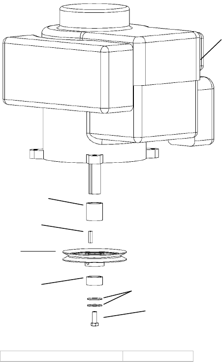
Not Shown OIL DRAIN VALVE + CAP AS122, AS123
ENGINE PULLEY ASSEMBLY
ENGINE
689L
9031
688
689S 699
NB238N (Tecumseh)
NB452N (Briggs & Honda)

BLADE DRIVER ASSEMBLIES
EFFECTIVE AFTER SERIAL# L199307001
RIGHT
NB175 AS155
6114
NB179
B98
9077 shaft replaces
both the 9000 shaft
and the 9010
spacer B99TK
B98
NB179
NB216
9008
9004
NB166
NB238N
NB607
NB179
NB216
NB175
NB607
6114
NB179
B98
9008
9004
NB166
AS155
NB238N
B98
6114CS
9091TK (re-enforcement
will vary from what is
shown)
9075 shaft replaces
both the 9002 shaft &
9010 spacer
CENTER
NB607
15
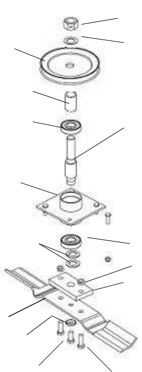
16
NB175
AS155
6114
6104RS
B98 9078 shaft replaces both
the 9001 shaft and the
9010 spacer
B99TK
B98NB179
NB216
9008
9004
NB166
NB238N
NB607
LEFT
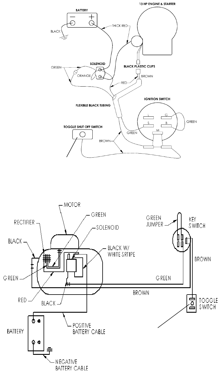
ATTACH RED TETHER HERE
ELECTRIC START WIRING
SCHEMATIC
HONDA WIRING SCHEMATIC
ATTACH RED
TETHER HERE
17

18
Item Part #
Wiring Harness (Briggs) WHN60B
Wiring Harness (Tecumseh) WHN60T
Wiring Harness (Honda) WHN60H
Solenoid 9043
Frame Caster Bearings B98
Key Switch KS12
Battery Cable - Red BCSR
Battery Cable - Black BCS
Engine Belt 644
Blade Driver Belts 66LR2
Items Not Shown

19
NOTES

OWNER’S
MANUAL
MODEL NO.
T1260
T1360
T1460
HOW TO ORDER
REPAIR PARTS:
60” UNIVERSAL
TRAILMOWER
Each mower has its own model number. Each engine has its
own model number. The model number for the mower will be
found on the right hand side of the frame above the right rear
wheel. The model number for the engine will be found on the
top of the blower fan housing.
All mower parts listed herein may be ordered directly from
Swisher Mower & Machine Co. Inc. or your nearest Swisher
dealer.
All engine parts may be ordered from the nearest dealer of the
engine supplied with your mower
.
WHEN ORDERING PARTS, PLEASE HAVE THE
FOLLOWING INORMATION AVAILABLE:
* PRODUCT – T-60 TRAILMOWER
* SERIAL NUMBER - _______________
* MODEL NUMBER - _______________
* ENGINE MODEL NUMBER - _______________
TYPE - _______________
* PART NUMBER
* PART DESCRIPTION
TELEPHONE - 1-800-222-8183
FAX - 1-660-747-8650
SWISHER MOWER & MACHINE CO. INC.
P.O. BOX 67
WARRENSBURG, MO 64093
SWISHER MOWER & MACHINE CO. INC.
PRINTED IN U.S.A.
