Sylvania Mp3 Player 1000 Users Manual 02MusGT(4809628 V2.1)
1000 379a9f63-ac2a-4c32-8372-a1a11a46581c Sylvania MP3 Player 1000 User Guide |
2015-02-04
: Sylvania Sylvania-Sylvania-Mp3-Player-1000-Users-Manual-389515 sylvania-sylvania-mp3-player-1000-users-manual-389515 sylvania pdf
Open the PDF directly: View PDF ![]() .
.
Page Count: 44
- TOC
- FOREWORD
- TABLE OF CONTENTS
- IMPORTANT NOTES
- 1.1 INITIAL PREPARATION AND ...
- 2.1 SUPERCHARGER MOUNTING BR...
- 3.1 FAN RESISTOR RELOCATION
- 4.1 PREPARING TO MOUNT THE S...
- 5.1 OIL FEED AND DRAIN LINES
- 6.1 INTAKE TRACT MODIFICATIONS
- 7.1 ENGINE CONTROL COMPUTER ...
- 8.1 IN-TANK FUEL PUMP INSTAL...
- 9.1 FINAL ASSEMBLY AND CHECK
- APPENDIX
- List of Appendices
- Appendix A 1011816 ASY, S/C...
- Appendix B 1015309 ASY, RADI...
- Appendix C 1016630 ASY, S/C ...
- Appendix D 1015933 ASY, AIR ...
- Appendix E 1017017 ASY, AIR ...
- Appendix F 1019336 ASY, OIL ...
- Appendix G 1019328 ASY, OIL ...
- Appendix H 1015506 ASY, COMP...
- Appendix I 1015530 ASY, FAN ...
- Appendix J 1017734 ASY, FUEL...
- Appendix K 7000170 DIAGRAM, ...
- APPENDIX LIST
- Appendix A 1011816 ASY, S/C...
- Appendix B 1015309 ASY, RADI...
- Appendix C 1016630 ASY, S/C ...
- Appendix D 1015933 ASY, AIR ...
- Appendix E 1017017 ASY, AIR ...
- Appendix F 1019336 ASY, OIL ...
- Appendix G 1019328 ASY, OIL ...
- Appendix H 1015506 ASY, COMP...
- Appendix I 1015530 ASY, FAN ...
- Appendix J 1017734 ASY, FUEL...
- Appendix K 7000170 DIAGRAM, ...

DP/N: 4809628 - V2.1 06/05/03
Owner’s Installation Guide for the
Paxton Automotive
Novi 1000 Supercharger
for the
2001-2003 4.6L SOHC Mustang GT
Paxton Automotive . 1300 Beacon Place . Oxnard CA 93033
805 604-1336 . FAX (805) 604-1337

P/N: 4809628
©2003 Paxton Automotive
All Rights Reserved, Intl. Copr. Secured
05JUN03 v2.1 MusGT(4809628 v2.1) ii
FOREWORD
Before you start the installation of your supercharger Paxton supercharger
kit, you will have to find the Paxton Computer Chip Voucher located in
your information packet. The 2001-2003 Mustang GT Supercharger Kit
requires a computer chip upgrade. You will need to fill out the chip vouch-
er and send it and your computer to Paxton Automotive to receive your
chip upgrade. Please refer to section 7 of this manual for the procedure for
removing your engine control module.
Complete the Paxton Automotive/Ford Computer Chip Voucher and
return it to Paxton Automotive to receive the proper computer module for
your vehicle.
© 2003 PAXTON AUTOMOTIVE
All rights recerved. No parts of this publication may be reproduced, transmitted, transcrived, or translated into
another language in any form, by any means without written permission of Paxton Automotive.

P/N: 4809628
©2003 Paxton Automotive
All Rights Reserved, Intl. Copr. Secured
05JUN03 v2.1 MusGT(4809628 v2.1)
iii
TABLE OF CONTENTS
FOREWORD . . . . . . . . . . . . . . . . . . . . . . . . . . . . . . . . . . . . . . . . . . . . . . . . . . . . . . . . . . . . . . . . . . . . .ii
TABLE OF CONTENTS . . . . . . . . . . . . . . . . . . . . . . . . . . . . . . . . . . . . . . . . . . . . . . . . . . . . . . . . . . . .iii
IMPORTANT NOTES . . . . . . . . . . . . . . . . . . . . . . . . . . . . . . . . . . . . . . . . . . . . . . . . . . . . . . . . . . . . . .iv
1.1 INITIAL PREPARATION AND REMOVAL . . . . . . . . . . . . . . . . . . . . . . . . . . . . . . . . . . . . . .1-1
2.1 SUPERCHARGER MOUNTING BRACKET ATTACHMEMT . . . . . . . . . . . . . . . . . . . . . . . .2-1
3.1 FAN RESISTOR RELOCATION . . . . . . . . . . . . . . . . . . . . . . . . . . . . . . . . . . . . . . . . . . . . . . . .3-1
4.1 PREPARING TO MOUNT THE SUPERCHARGER . . . . . . . . . . . . . . . . . . . . . . . . . . . . . . . . .4-1
5.1 OIL FEED AND DRAIN LINES . . . . . . . . . . . . . . . . . . . . . . . . . . . . . . . . . . . . . . . . . . . . . . . .5-1
6.1 INTAKE TRACT MODIFICATIONS . . . . . . . . . . . . . . . . . . . . . . . . . . . . . . . . . . . . . . . . . . . .6-1
7.1 ENGINE CONTROL COMPUTER REMOVAL AND MODIFICATION . . . . . . . . . . . . . . . . .7-1
8.1 IN-TANK FUEL PUMP INSTALLATION . . . . . . . . . . . . . . . . . . . . . . . . . . . . . . . . . . . . . . . . .8-1
9.1 FINAL ASSEMBLY AND CHECK . . . . . . . . . . . . . . . . . . . . . . . . . . . . . . . . . . . . . . . . . . . . . .9-1
APPENDIX . . . . . . . . . . . . . . . . . . . . . . . . . . . . . . . . . . . . . . . . . . . . . . . . . . . . . . . . . . . . . . . . . . . . . .A-1
List of Appendices . . . . . . . . . . . . . . . . . . . . . . . . . . . . . . . . . . . . . . . . . . . . . . . . . .A-2
Appendix A 1011816 ASY, S/C NOVI 1000 . . . . . . . . . . . . . . . . . . . . . . . . . . . . . . . . .A-3
Appendix B 1015309 ASY, RADIATOR HOSE MODIFICATION . . . . . . . . . . . . . . . .A-4
Appendix C 1016630 ASY, S/C MOUNTING BRACKET . . . . . . . . . . . . . . . . . . . . . .A-5
Appendix D 1015933 ASY, AIR INTAKE . . . . . . . . . . . . . . . . . . . . . . . . . . . . . . . . . . .A-6
Appendix E 1017017 ASY, AIR DISCHARGE . . . . . . . . . . . . . . . . . . . . . . . . . . . . . . .A-7
Appendix F 1019336 ASY, OIL SUPPLY . . . . . . . . . . . . . . . . . . . . . . . . . . . . . . . . . . .A-8
Appendix G 1019328 ASY, OIL RETURN . . . . . . . . . . . . . . . . . . . . . . . . . . . . . . . . . .A-9
Appendix H 1015506 ASY, COMPRESSOR BYPASS . . . . . . . . . . . . . . . . . . . . . . . . .A-10
Appendix I 1015530 ASY, FAN RESISTOR RELOC. . . . . . . . . . . . . . . . . . . . . . . . .A-11
Appendix J 1017734 ASY, FUEL PUMP . . . . . . . . . . . . . . . . . . . . . . . . . . . . . . . . . .A-12
Appendix K 7000170 DIAGRAM, BELT ROUTING . . . . . . . . . . . . . . . . . . . . . . . . . .A-13

P/N: 4809628
©2003 Paxton Automotive
All Rights Reserved, Intl. Copr. Secured
05JUN03 v2.1 MusGT(4809628 v2.1) iv
IMPORTANT NOTES
Congratulations! You have purchased the
finest street supercharger available for the
Mustang GT. The centerpiece of this kit is
the High Efficiency PAXTON Supercharger, a
mechanically driven centrifugal blower.
This kit comes with all the parts you will need to
install the supercharger. The instruction manual has
been edited in order of sequence, and photographs
and drawings have been included to illustrate the
text. This will allow you quick part identification
and orientation.
The installation will require metric and SAE sock-
ets and wrenches, a hand drill and bits, an Air
Hammer (and compressor), a 3/8” x 18 NPT tap,
screwdrivers, and a supply of buckets for the
reserve of coolant and oils.
We suggest that you obtain a copy of a Mustang
shop manual for your model of car. This may be
obtained from your dealer, or may be ordered by
mail from Helm Publications at (800) 782-4356.
Become familiar with the details of your car’s sys-
tem. If it is not operating within normal parame-
ters, we do not recommend the installation or use
of the supercharger.
For the quickest installation time, we suggest that
you read this manual thoroughly before beginning.
Make sure that you understand the process, have
identified the areas of the car that you will be
working on, and have the tools that you will need
on hand. The average installation time is 8 to 10
hours, but your time will depend on your working
conditions, experience installing superchargers,
personal skill level, and preparedness for the job.
This estimate does not include time for the initial
vehicle inspection, cleaning, fine tuning, or trou-
ble-shooting. Once again, we recommend reading
the manual before beginning the process. We are
available for tech support at (805) 604-1336,
Monday through Friday, 7AM - 3 PM PST.
After reading the manual, verify that all major assembly groups are present in the main kit box. As you
remove a box or bag, note the identification label and compare it to the parts list.
PAXTON AUTOMOTIVE makes every effort to insure
that all parts are included in the box. If you
discover that you are missing any part,
or that a part was damaged in shipping, call PAXTON
immediately. DO NOT begin installation if a part
is missing. Failure to contact PAXTON prior to
beginning installation will result in a charge for
the missing part.
We suggest that the engine compartment be
cleaned before the installation. You can clean the
engine with a pressure washer that is found at self-
serve car washes. Use a safe-for-aluminum clean-
er/degreaser, and cover the distributor and any
electronics with a plastic bag to prevent water from
entering.

P/N: 4809628
©2003 Paxton Automotive
All Rights Reserved, Intl. Copr. Secured
05JUN03 v2.1 MusGT(4809628 v2.1)
v
You are undoubtedly eager to get started, but
please take a little more time to insure that
your safety is not in jeopardy. A moment’s
lack of attention may cause a serious injury to you,
or to someone else who happens to be standing
around. By following some simple safety precau-
PAXTON Automotive thanks you for your purchase. We welcome your
comments and suggestions to help us improve our product.
tions, you can avoid many potential dangers. The
following list is not meant to be a comprehensive
list, but rather it is meant to make you aware of
some of the risks, and encourage you to take a
safety minded approach to your work area.
•Never rely solely on a floor jack when working under-
neath a vehicle. Always use jack stands that are rated
for the weight of your vehicle, use them at the recom-
mended lift points, and place your vehicle in ‘PARK’ or
‘FIRST’ gear with the parking brake set.
•Always use eye protection when using power tools, such
as drills, saws, and grinders, or when working under-
neath a vehicle.
•Never smoke, use an open flame, or have spark produc-
ing items around gasoline or flammable objects. Always
have a fire extinguisher that is rated for chemical and
electrical fires handy when working on motor vehicles.
Also, make sure that the extinguisher is fully charged.
•Operate engines only in a well ventilated area. Carbon
Monoxide, gasoline, and solvent vapors are colorless
and sometimes odorless, and may asphyxiate and
explode without warning.
•Always disconnect the battery from your engine before
doing work on the electrical or fuel systems, or doing
underdash work.
•The chemicals used in the vehicle systems, such as oils
and coolants, are poisonous. Clean up any spills imme-
diately, and dispose of waste materials properly. Pets,
wild animals, and children may die if they ingest the liq-
uid.

P/N: 4809628
©2003 Paxton Automotive
All Rights Reserved, Intl. Copr. Secured
05JUN03 v2.1 MusGT(4809628 v2.1) vi
This Page Left Intentionally Blank.
1-1 P/N: 4809628
©2003 Paxton Automotive
All Rights Reserved, Intl. Copr. Secured
05JUN03 v2.1 MusGT(4809628 v2.1)
Section 1
INITIAL PREPARATION AND REMOVAL
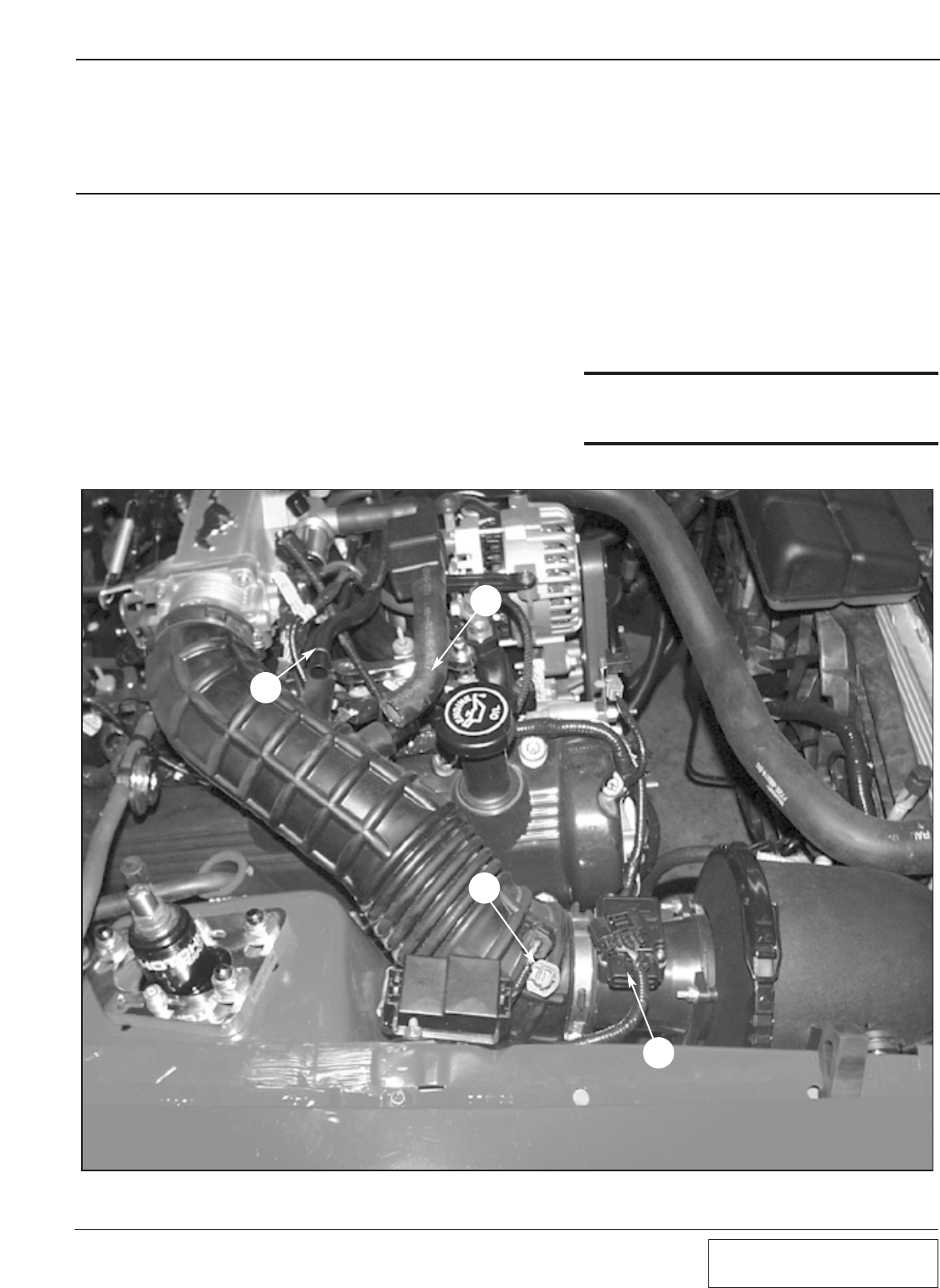
B. Before the air intake assembly can be
removed, you must first disconnect the plas-
tic crankcase breather hose (A) and air idle
bypass hose (B). Unplug the air temperature
sensor (C) and mass air flow sensor (D).
(See Fig. 1-a.)
***NOTE***
(2002-2003 GT only) The air intake temperature sen-
sor is now located in the MAF. (Step “C” no longer
applies.)
Fig. 1-a
A
B
C
D
1.1 INITIAL PREPARATION AND REMOVAL
A. Begin the initial preparation and disassem-
bly process by first disconnecting the nega-
tive side of the battery, and draining one gal-
lon of coolant from the coolant reservoir. To
do this, open the valve at the bottom of the
radiator and allow to drain into a suitable
container. DO NOT allow coolant to drain
onto floor, and be sure to mop up any
coolant splatter immediately. Animals like
the taste of coolant, and if they drink it, it
will kill them.
1-2
P/N: 4809628
©2003 Paxton Automotive
All Rights Reserved, Intl. Copr. Secured
05JUN03 v2.1 MusGT(4809628 v2.1)
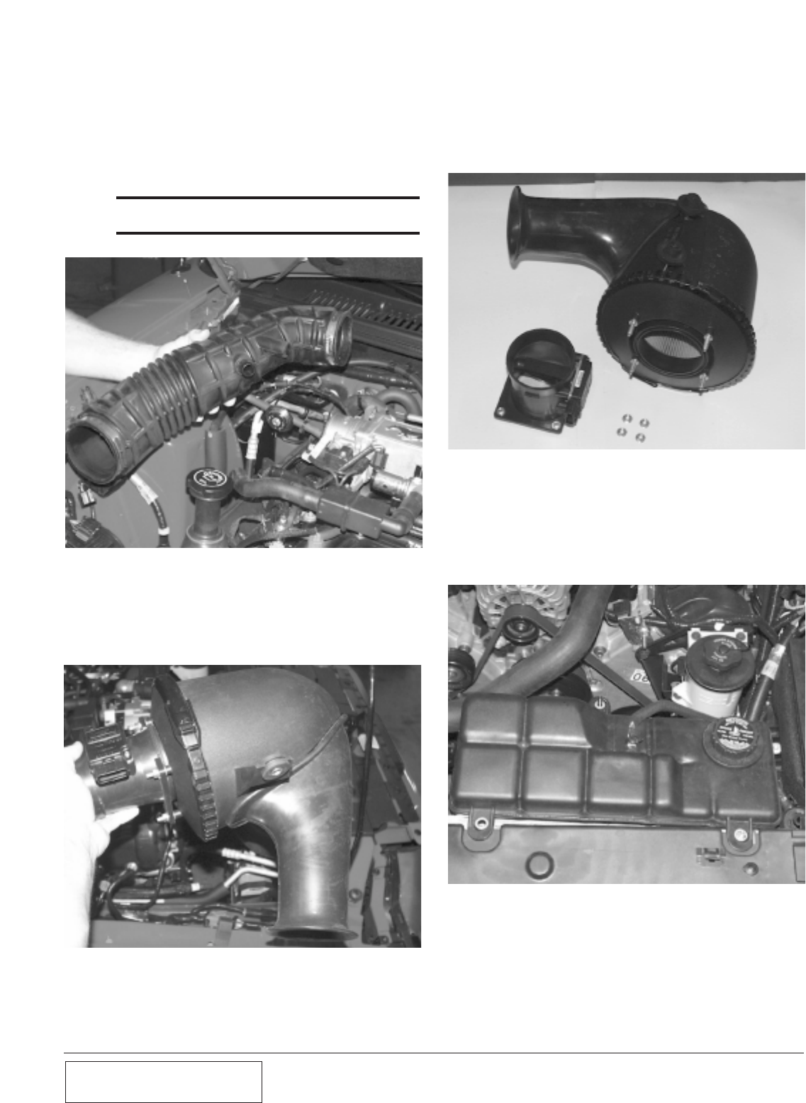
Fig. 1-b
Fig. 1-c
E. Once the assembly is out of the car, use a
10mm socket to remove the mass air flow
sensor and screen from the air filter housing
(see Fig 1-d). Place the mass air flow sensor
aside to be re-installed in a later step.
C. Using a flat-head screwdriver, loosen the
hose clamps at the mass air flow sensor and
the throttle body, and remove the air intake
hose (see Fig 1-b). Remove the air tempera-
ture sensor from the air intake hose and
place it aside—it will be re-installed in a
later step.
NOTE: On 2002-2003 GTs this step will not be
done.
D. Use an 8mm socket to remove the single air
filter housing retaining bolt. The air filter
and mass air sensor can then be removed as
an assembly. (See Fig 1-c.)
Fig. 1-d
E. The coolant reservoir is secured by three
nuts (see Fig 1-e). Use a 10mm socket to
remove these, and place the reservoir aside.
Remove the upper radiator hose.
Fig. 1-e
2-1 P/N: 4809628
©2003 Paxton Automotive
All Rights Reserved, Intl. Copr. Secured
05JUN03 v2.1 MusGT(4809628 v2.1)
Section 2
SUPERCHARGER MOUNTING BRACKET ATTACHMENT
2.1 SUPERCHARGER MOUNTING BRACKET ATTACHMENT
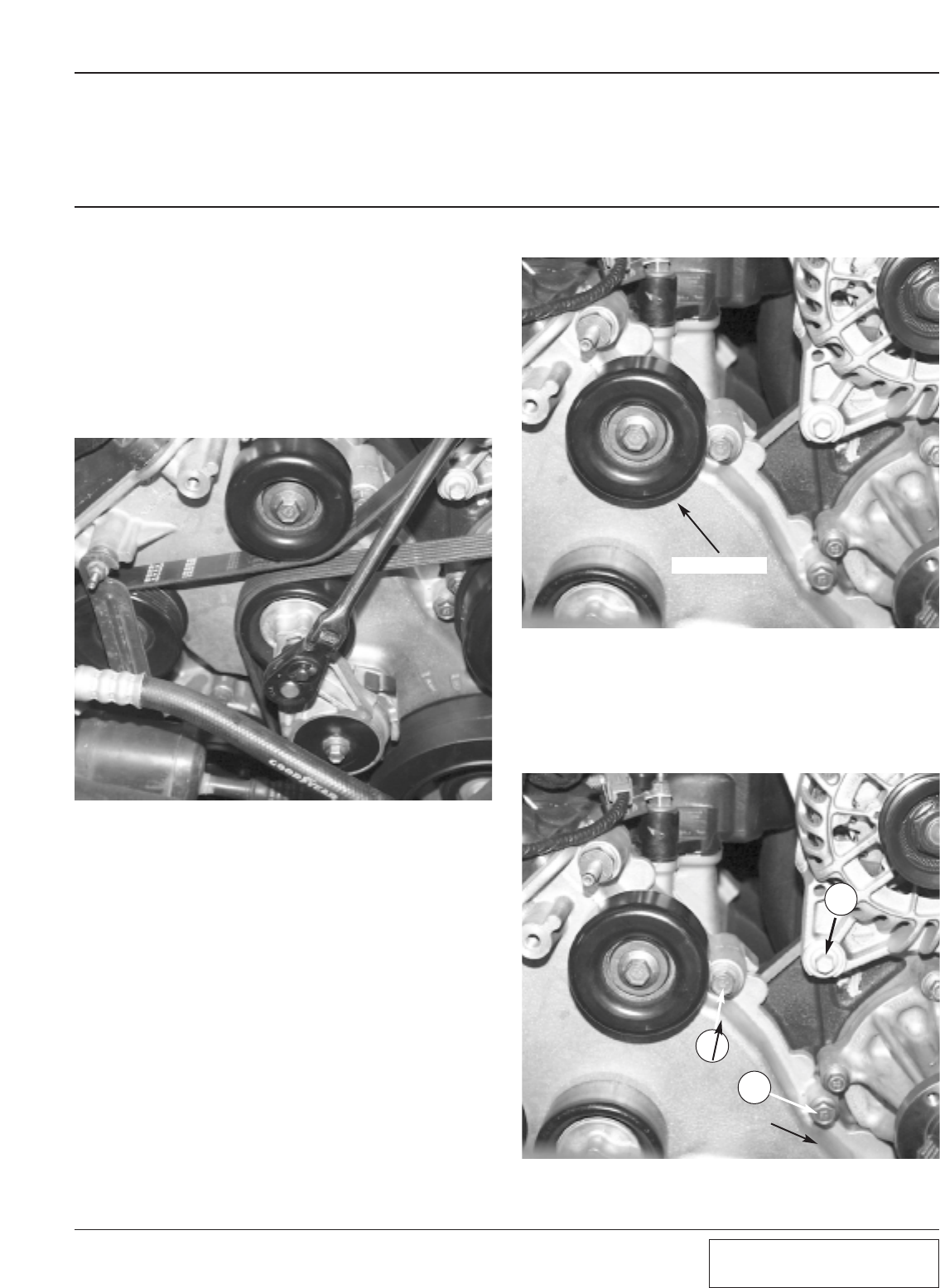
Fig. 2-a
A. Loosen (but do not remove) the four 10 mm
head bolts securing the water pump pulley.
Next, remove the accessory drive belt using
a 3/8-inch drive ratchet or breaker bar into
the square at the end of the tensioner, and
rotate the tensioner clockwise. This will
relieve the tension on the belt so it can be
removed. It will not be re-used. (See
Fig. 2-a.)
B. Use a 13 mm socket to remove the idler pul-
ley, located above the belt tensioner (see Fig
2-b). Place the pulley aside to be used in a
later step. Now, you may finish removing
the four 10mm bolts securing the water
pump pulley, and place the pulley and its
fasteners aside for use in a later step.
IDLER PULLEY
Fig. 2-b
C. Next, remove three bolts at the front of the
engine (see Fig 2-c). A 10mm alternator
mounting bolt (A), and two 13 mm timing
cover bolts (Band C).
Fig. 2-c
C
B
A
2-2
P/N: 4809628
©2003 Paxton Automotive
All Rights Reserved, Intl. Copr. Secured
05JUN03 v2.1 MusGT(4809628 v2.1)
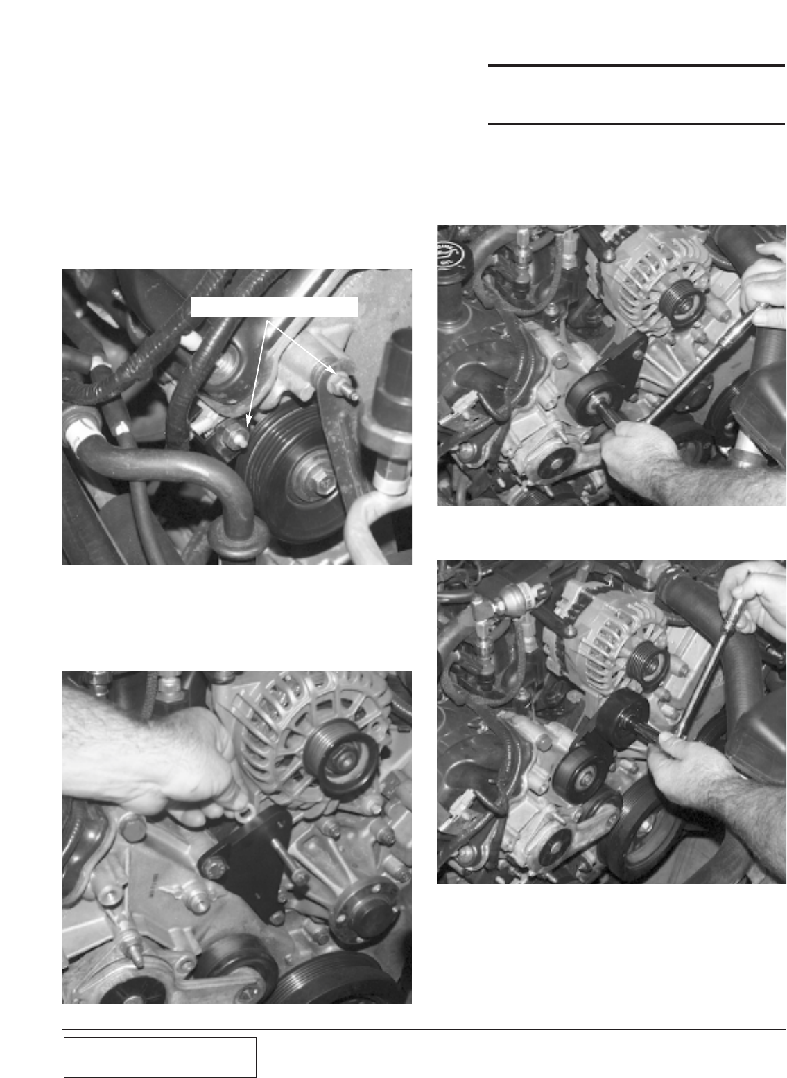
D. Remove both nuts using a 10mm and 13mm
socket. Then remove both studs using a
13mm and 18mm socket. Enlarge the hole in
the tab that held the wiring harness to the
outermost stud. Using a round file, enlarge
the hole so that it will slip over the large
diameter of the stud. This tab will get sand-
wiched between the cylinder head and a
spacer in a later step.(See Fig 2-d.)Note that
on some of the 2001-2003 GTs this step will
not be required and a .065 shim will go in
its place.
REMOVE THESE TWO STUD BOLTS
Fig. 2-d
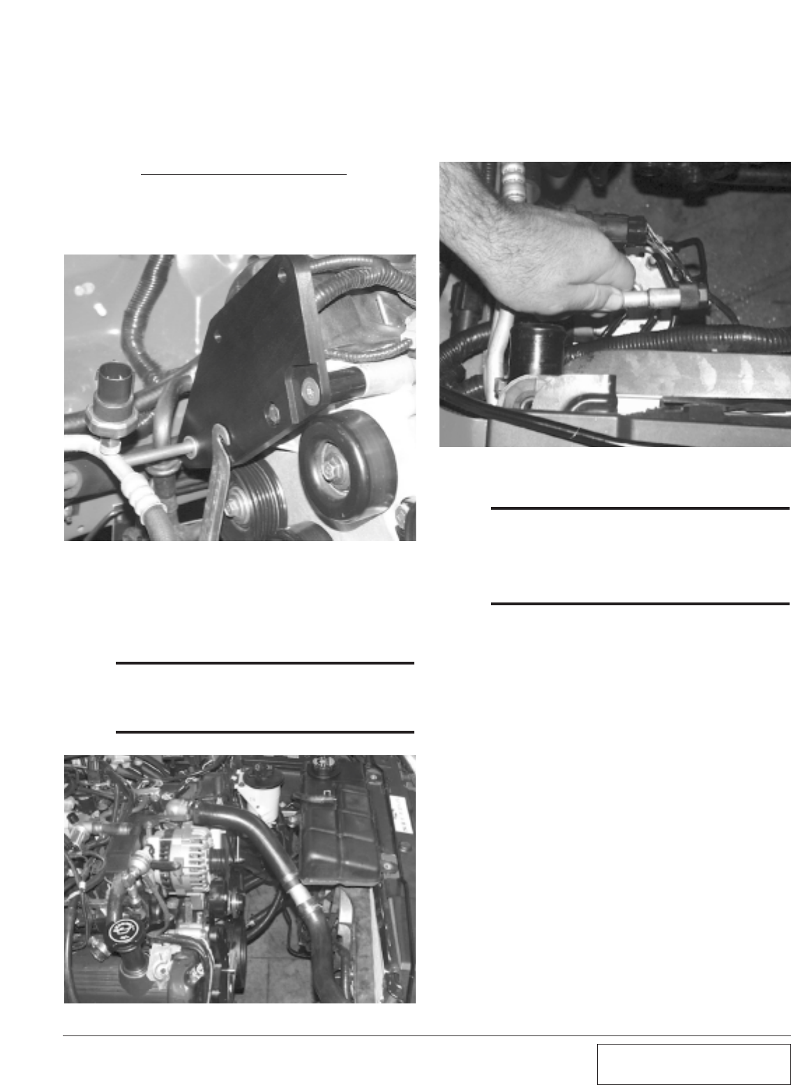
E. Install the supercharger idler pulley bracket
using the supplied hardware. Be sure to
install spacer between bracket and alternator.
(See Fig 2-e)
Fig. 2-e
***NOTE***
This photo is for illustration purposes. It will be easi-
er for you to install this bolt/spacer first, then install
the other two mounting bolts.
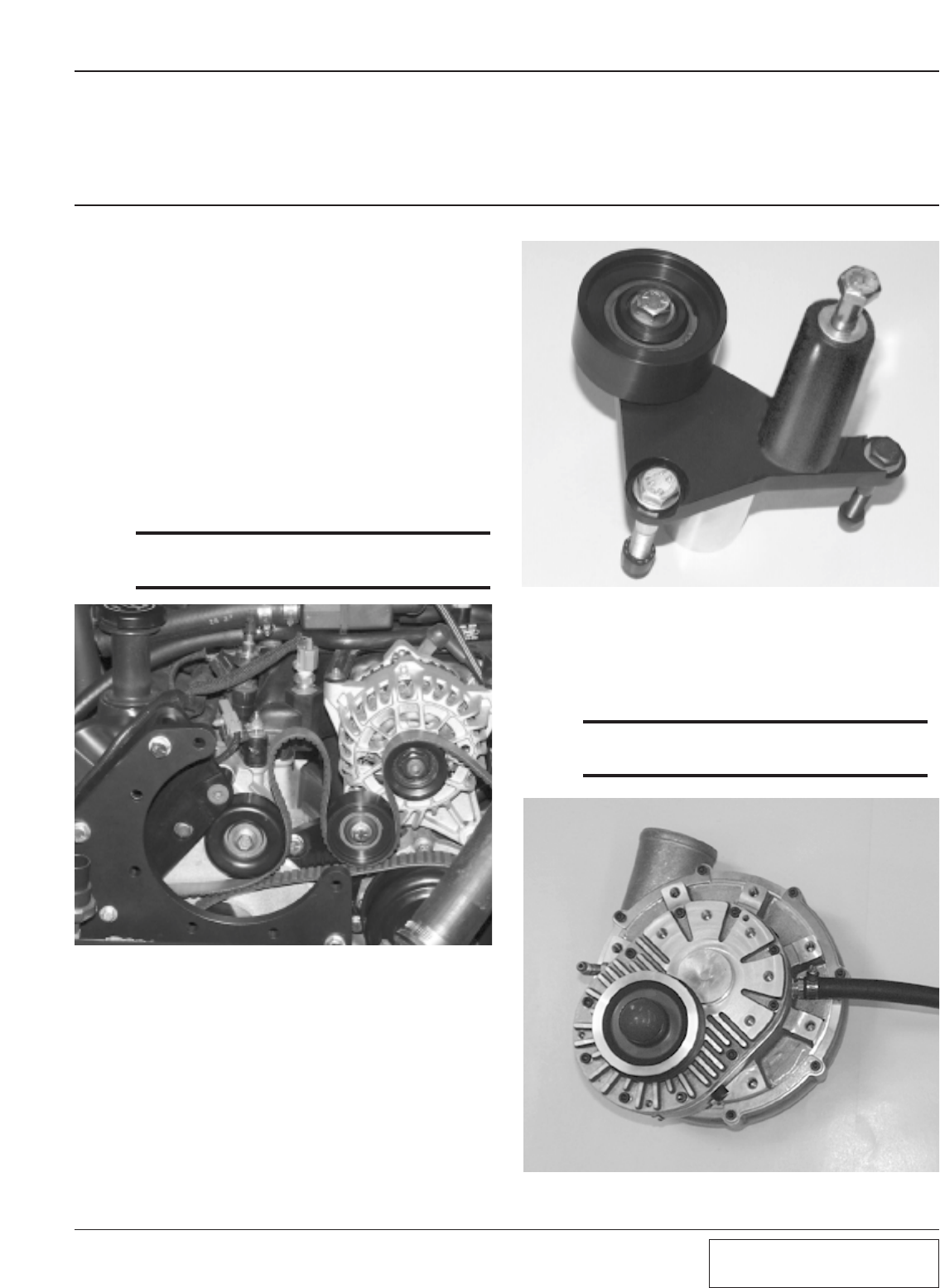
F. Re-install the factory idler pulley using the
factory hardware (see Fig. 2-f), followed by
the supplied supercharger idler pulley (see
Fig. 2-g).
Fig. 2-f
Fig. 2-g
2-3 P/N: 4809628
©2003 Paxton Automotive
All Rights Reserved, Intl. Copr. Secured
05JUN03 v2.1 MusGT(4809628 v2.1)
G. Install the supercharger rear support bracket
as shown in Fig 2-h. Temporarily install the
long 10mm bolt to line up the bracket.
Leave the bolts finger tight, as it will be
necessary to move the bracket when you
install the main supercharger bracket.
(This photo is for illustration only. You will
have to install the supercharger and acces-
sory belt before installing the bracket. There
won’t be clearance after the bracket is
installed.)
Fig. 2-h
Fig. 2-i
H. Modify the previously removed upper radia-
tor hose with supplied hose, aluminum cou-
pler and clamps. See Appendix ‘B’
(1015309) for diagram of modification.
***NOTE***
The radiator hose assembly needs to clear the super-
charger, so it is better to leave it long and trim the
assembly later than to end up short. The finished
radiator assembly is shown in Fig. 2-i.
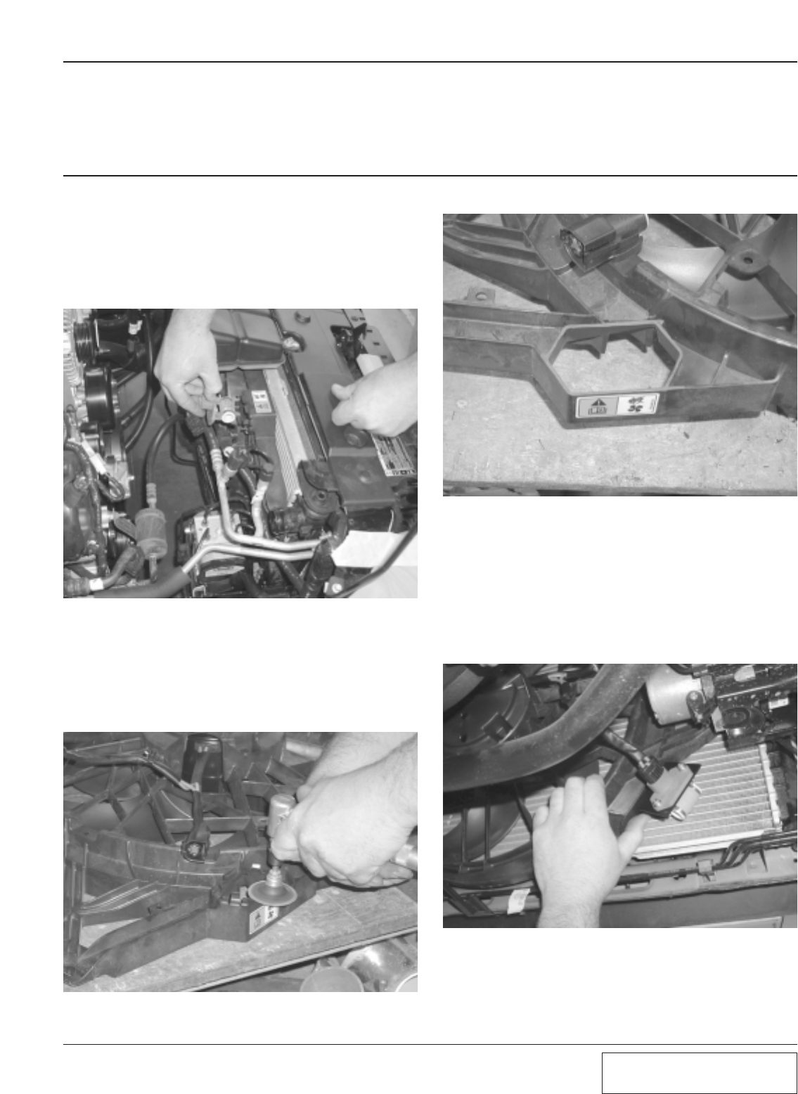
I. Before installing the main supercharger
bracket, the A/C refrigerant refilling port
must be bent from its upright position down-
ward, so that the cap is facing the driver’s
side fender. (See Fig 2-j.)
Fig. 2-j
***NOTE***
If possible, use a proper tubing bender for this step.
If one is not available, the line can be bent by hand,
but extreme care must be taken as the refrigerant
within the line is under very high pressure. In any
case, use a pair of heavy gloves and eye protection to
prevent injury in the event of a ruptured line.

2-4
P/N: 4809628
©2003 Paxton Automotive
All Rights Reserved, Intl. Copr. Secured
05JUN03 v2.1 MusGT(4809628 v2.1)
This Page Left Intentionally Blank.
3-1 P/N: 4809628
©2003 Paxton Automotive
All Rights Reserved, Intl. Copr. Secured
05JUN03 v2.1 MusGT(4809628 v2.1)
Section 3
FAN RESISTOR RELOCATION
3.1 FAN RESISTOR RELOCATION
A. Disconnect the wiring harness from the fan
resistor. (See Fig. 3-a.) Remove clips hold-
ing the fan resistor to the fan shroud. Attach
the fan resistor to the supplied bracket using
the supplied hardware.
Fig. 3-a
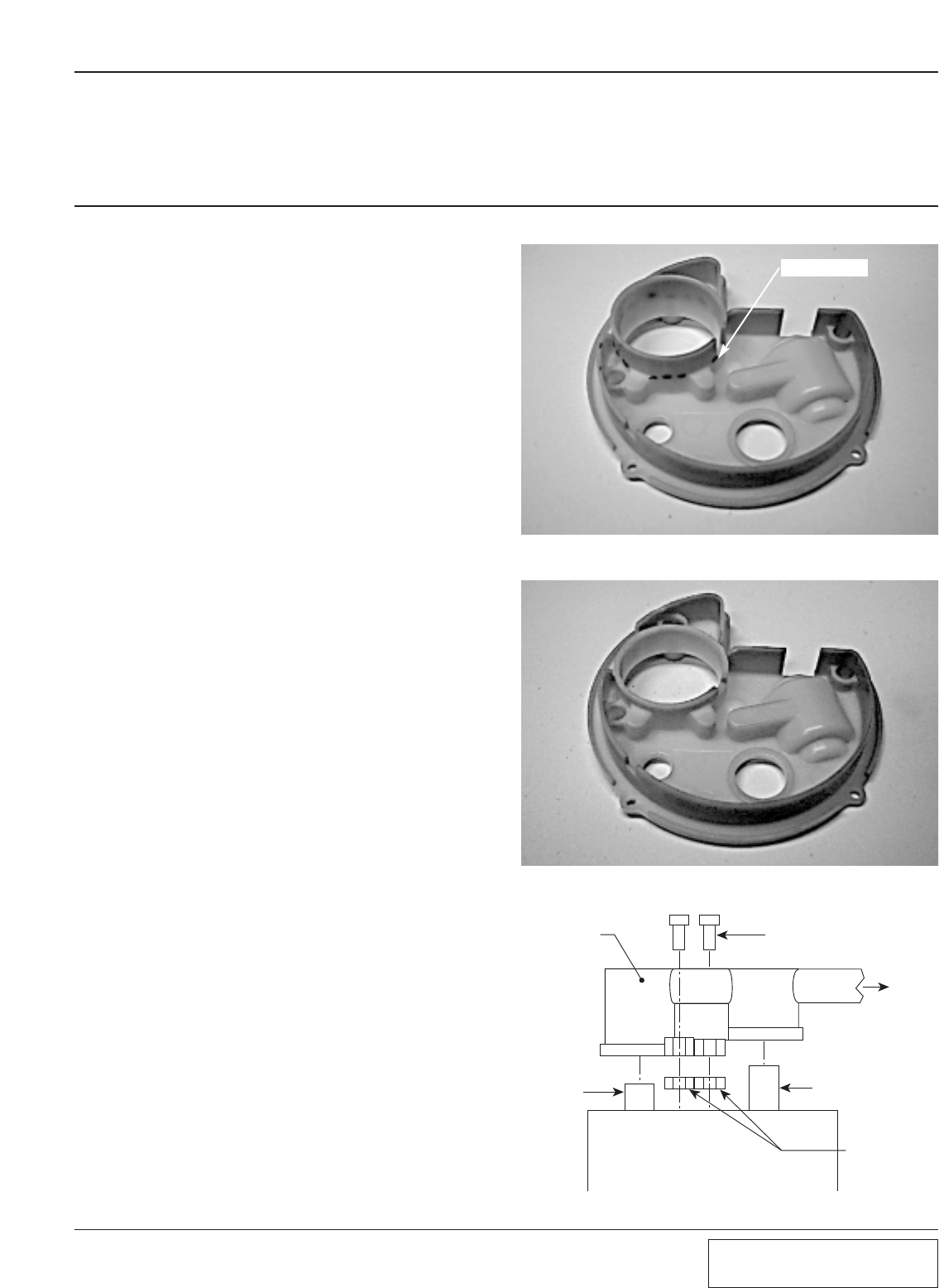
B. Trim the fan resistor mounting tabs on the
fan shroud to provide clearance for the air
intake assembly.(See Fig. 3-b.) The fan
shroud should look like this after trim-
ming.(See Fig. 3-c.)
Fig. 3-b
Fig. 3-c
C. Re-attach the fan resistor to the wiring har-
ness to ensure adequate wire length. (See
Fig. 3-d.) Position the fan bracket on the
passenger side of the lower fan shroud.
Mark two mounting points along the fan
shroud and drill the holes. Attach the mount-
ing bracket with the supplied hardware.
Fig. 3-d

3-2
P/N: 4809628
©2003 Paxton Automotive
All Rights Reserved, Intl. Copr. Secured
05JUN03 v2.1 MusGT(4809628 v2.1)
This Page Left Intentionally Blank.
4-1 P/N: 4809628
©2003 Paxton Automotive
All Rights Reserved, Intl. Copr. Secured
05JUN03 v2.1 MusGT(4809628 v2.1)
Section 4
PREPARING TO MOUNT THE SUPERCHARGER
A. Mount the main supercharger bracket,
installing the two 3/8 bolts and spacers in
the upper portion of the bracket. Install the
long 6mm bolt and spacer in the lower mid-
dle portion of the bracket, sandwiching the
A/C support between the spacer and rear
mounting bracket. Next, install the lower
most bolt and two spacers: one in between
the support and main brackets, one in
between the two brackets and the other
between the rear bracket and the cylinder
head. The small metal tab securing the
wiring harness gets sandwiched between the
cylinder head and the spacer. Leave every-
thing finger tight at this point.
***NOTE***
The drive belt, shown in this picture, should be
installed at this point.(See Fig. 4-a.)
4.1 PREPARING TO MOUNT THE SUPERCHARGER
Fig. 4-a
B. Next, install the bolt and spacer at lower
right portion of the bracket. (See Fig. 4-b.)
Go back and tighten all bolts on the mount-
ing bracket, being careful not to over torque
the small 6mm bolt. Install the supplied
drive belt as shown. (See Fig. 4-a.)
Fig. 4-b
C. Install the supercharger oil drain-back hose
on the supercharger. (See Fig. 4-c.)
***NOTE***
The hose clamp screw head should be parallel to
the supercharger mounting base.
Fig. 4-c
4-2
P/N: 4809628
©2003 Paxton Automotive
All Rights Reserved, Intl. Copr. Secured
05JUN03 v2.1 MusGT(4809628 v2.1)
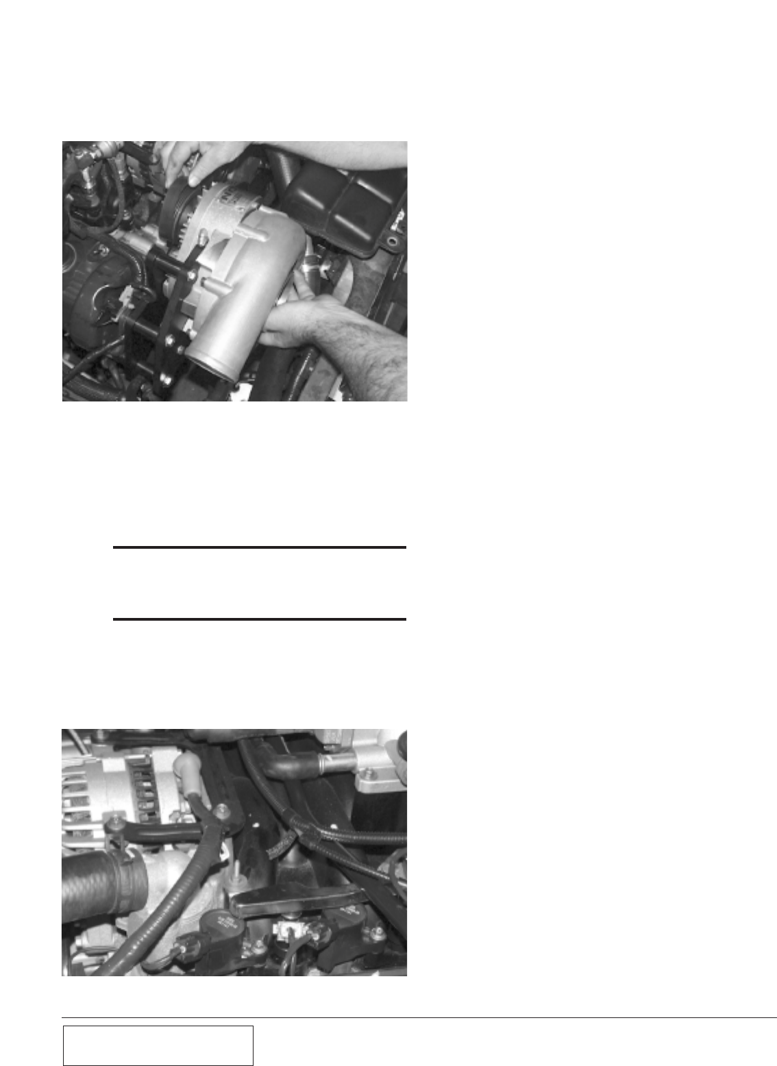
D. Remove the drive belt from the alternator
pulley. Install the supercharger into the main
bracket, while looping the drive belt around
the supercharger pulley. (See Fig. 4-d.)
Fig. 4-d
E. Tighten the supercharger mounting bolts.
Once the supercharger is installed, release
the belt tensioner and loop the belt back
around the alternator pulley. (See
Appendix K for a diagram of the drive belt
routing.)
***NOTE***
For maximum performance, PAXTON Automotive rec-
ommends the factory stock platinum spark plugs be
replaced with a copper spark plug (Autolite 764 or
equivalent) gapped to .035.
F. Remove the two 8mm bolts on either end of
the Fuel Injector Rail and lift the unit out.
Replace the stock injectors with the supplied
injectors. Use white lithium grease on the
O-rings to insure a smooth fit.
Fig. 4-e
5-1 P/N: 4809628
©2003 Paxton Automotive
All Rights Reserved, Intl. Copr. Secured
05JUN03 v2.1 MusGT(4809628 v2.1)
Section 5
OIL FEED AND DRAIN LINES
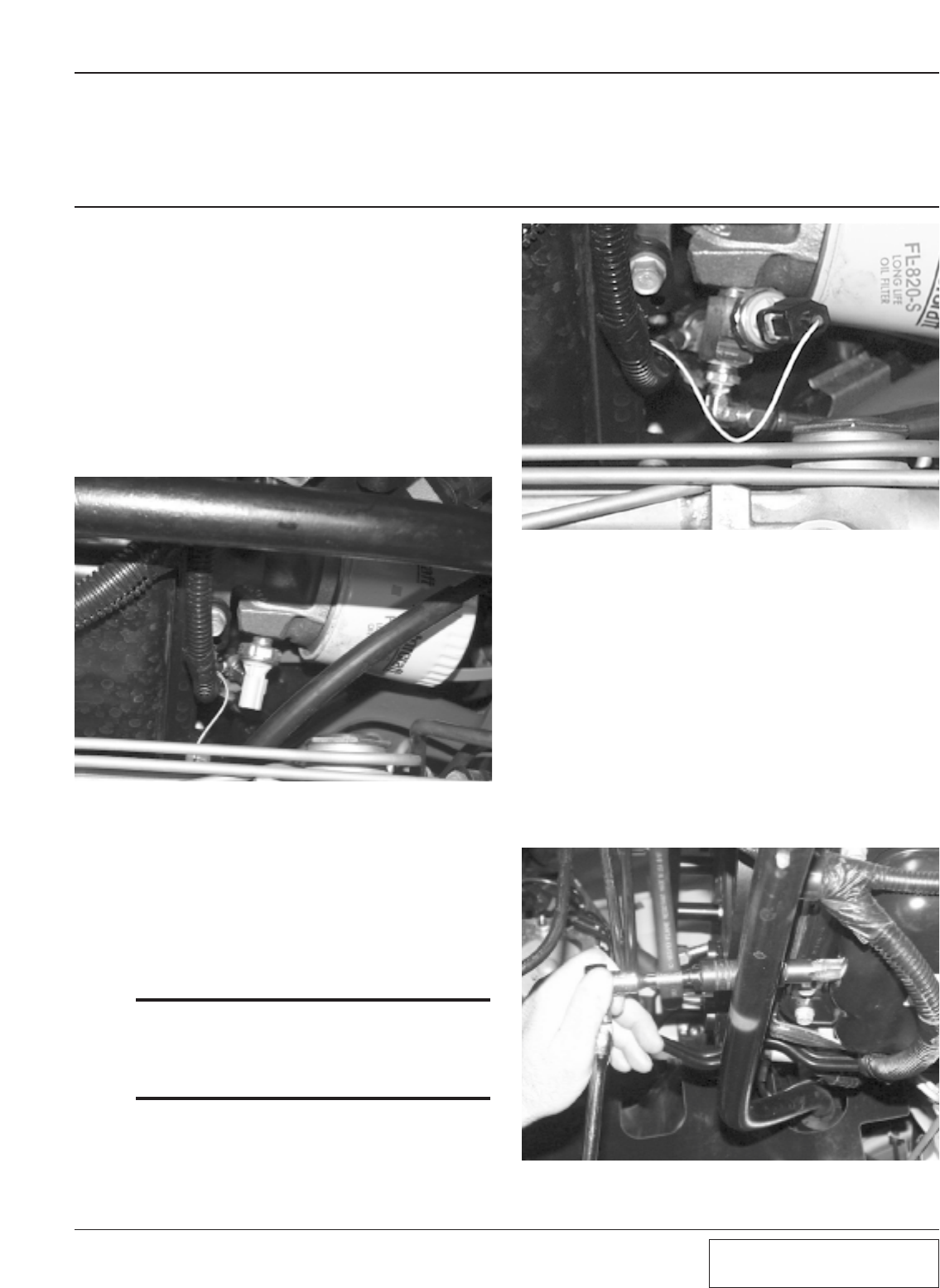
5.1 OIL FEED AND DRAIN LINES
A. Your Paxton Automotive NOVI 1000 super-
charger uses pressurized engine oil for lubri-
cation. Use an oil sending unit socket (Snap-
On tools; part number 6152 or equivalent) to
remove the oil sending unit on the underside
of the oil filter housing (see Fig 5-a). Install
the supplied brass junction fitting using a
small amount of Teflon paste. DO NOT
USE TEFLON TAPE. Once installed, the
junction fitting should be oriented so that
the opening faces toward the front of the car.
Fig. 5-a
B. Install the oil sending unit in the end of the
brass junction. Install the 90 degree 1/8-inch
to -4 fitting into the side of the brass junc-
tion, and orient this fitting to face towards
the driver’s side frame rail. Attach the sup-
plied length of braided stainless steel feed
line, and route upwards to the 90 degree fit-
ting on the supercharger.
***NOTE***
Be sure to stay clear of any moving parts or coolant
hoses (engine vibration can cause the stainless line
to chafe the rubber coolant hose, creating a leak over
time). Install the line, and tighten moderately—no
sealant is required. (See Fig. 5-b.)
Fig. 5-b
C. Mark the front of the oil pan 1" inch below
the pan rail and between the the two pan rail
bolts, directly in the center of the small
‘hump’. (See Appendix G.) Cover a 3/16-
inch drill bit with heavy grease and drill a
pilot hole (see Fig. 5-c). The grease will
help prevent metal particles from falling into
the pan. Once the hole has been drilled,
insert a straight length of welding rod or
heavy wire (such as a coat hanger) into the
hole approximately three inches to make
sure no interference is encountered. If the
path is blocked, turn the engine over until
the pathway is clear.
Fig. 5-c
5-2
P/N: 4809628
©2003 Paxton Automotive
All Rights Reserved, Intl. Copr. Secured
05JUN03 v2.1 MusGT(4809628 v2.1)
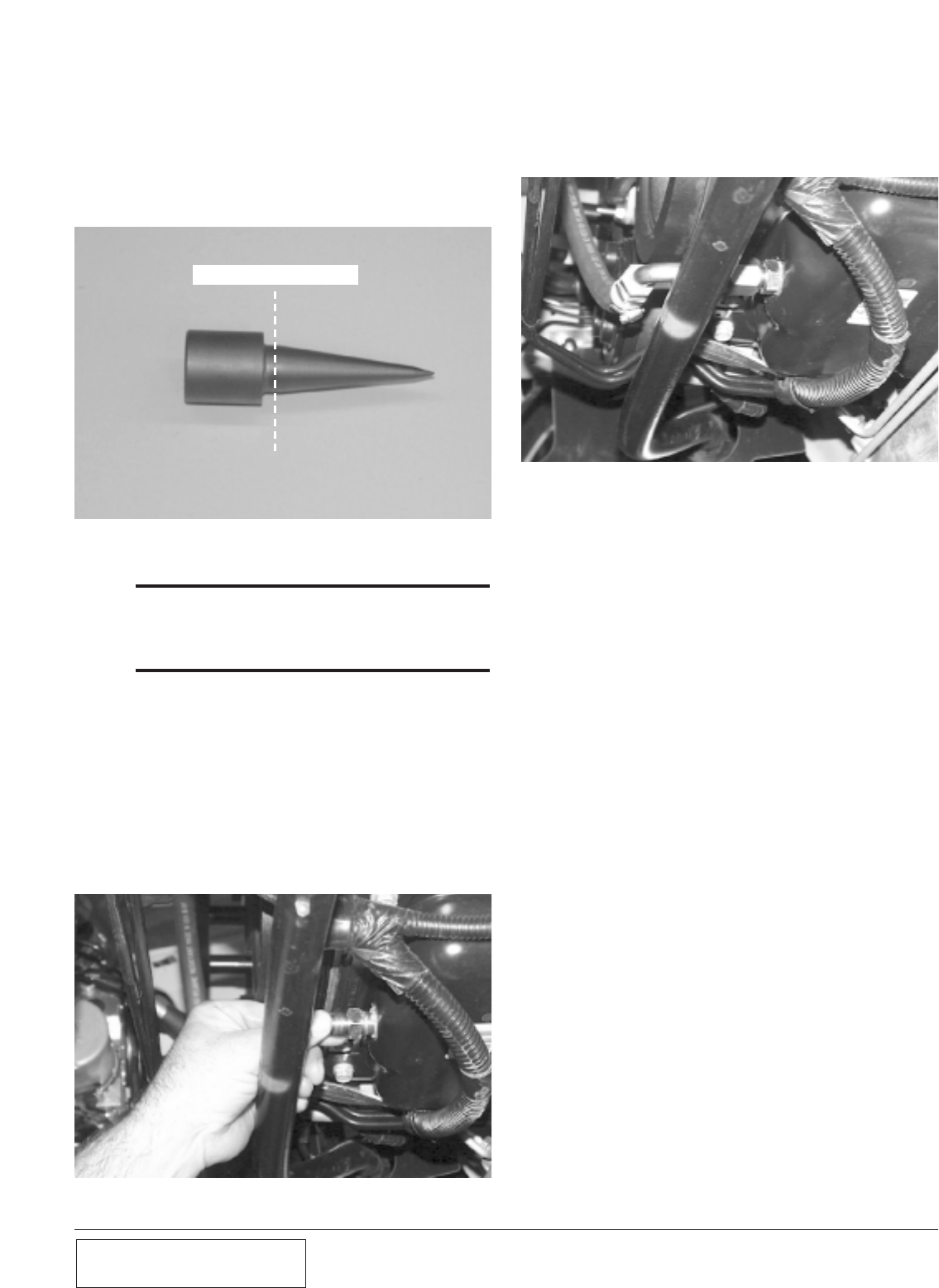
D. Next, apply a small amount of anti-seize
lubricant to the tip of the punch, and insert it
into the pilot hole. Hit the punch with an air
hammer carefully using small bursts, until
the punch is inserted up to its shoulder. The
hole should measure 9/16". (See Fig 5-d.)
NO DEEPER THAN THIS
Fig. 5-d
***NOTE***
Do not use hand tools. Using an ordinary hammer
will dent the pan. Use extreme caution not to make
the hole to big, or the drain fitting will not fit and the
pan will be ruined.
E. Apply a liberal amount of heavy grease to a
3/8 inch x 16 NPT tap (not included), and
gradually thread into the hole. Clean the
threads using a clean rag and an approved
solvent, such as carburetor cleaner.
F. Apply a ample amount of silicone RTV to
the threads of the supplied 3/8-inch pipe to -
8 fitting and insert into the hole, being care-
ful not to over-tighten. (See Fig. 5-e.)
Fig. 5-e
G. Install the supercharger drain-back hose fit-
ting so that the elbow is oriented toward the
passenger side, away from the harmonic bal-
ancer/crank pulley.(See Fig 5-f.)
Fig. 5-f
6-1 P/N: 4809628
©2003 Paxton Automotive
All Rights Reserved, Intl. Copr. Secured
05JUN03 v2.1 MusGT(4809628 v2.1)
Section 6
INTAKE TRACT MODIFICATIONS
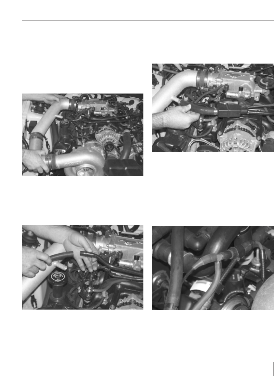
6.1 INTAKE TRACT MODIFICATIONS
A. Install the discharge tube assembly as
shown, using the supplied rubber sleeves
and stainless steel clamps. (See Fig. 6-a.)
Fig. 6-a
B. Install the supplied length of rubber hose to
the end of the hard crank case ventilation
line that runs from the driver’s side valve
cover across the engine, (see Fig 6-b). Route
the hose over the passenger side valve cover
and towards the front of the engine.
Fig. 6-b
C. Install the idle air control valve to the throt-
tle body housing with the original hose, and
to the discharge tube with the supplied
length of rubber hose and hose clamps. (See
Fig 6-c.)
Fig. 6-c
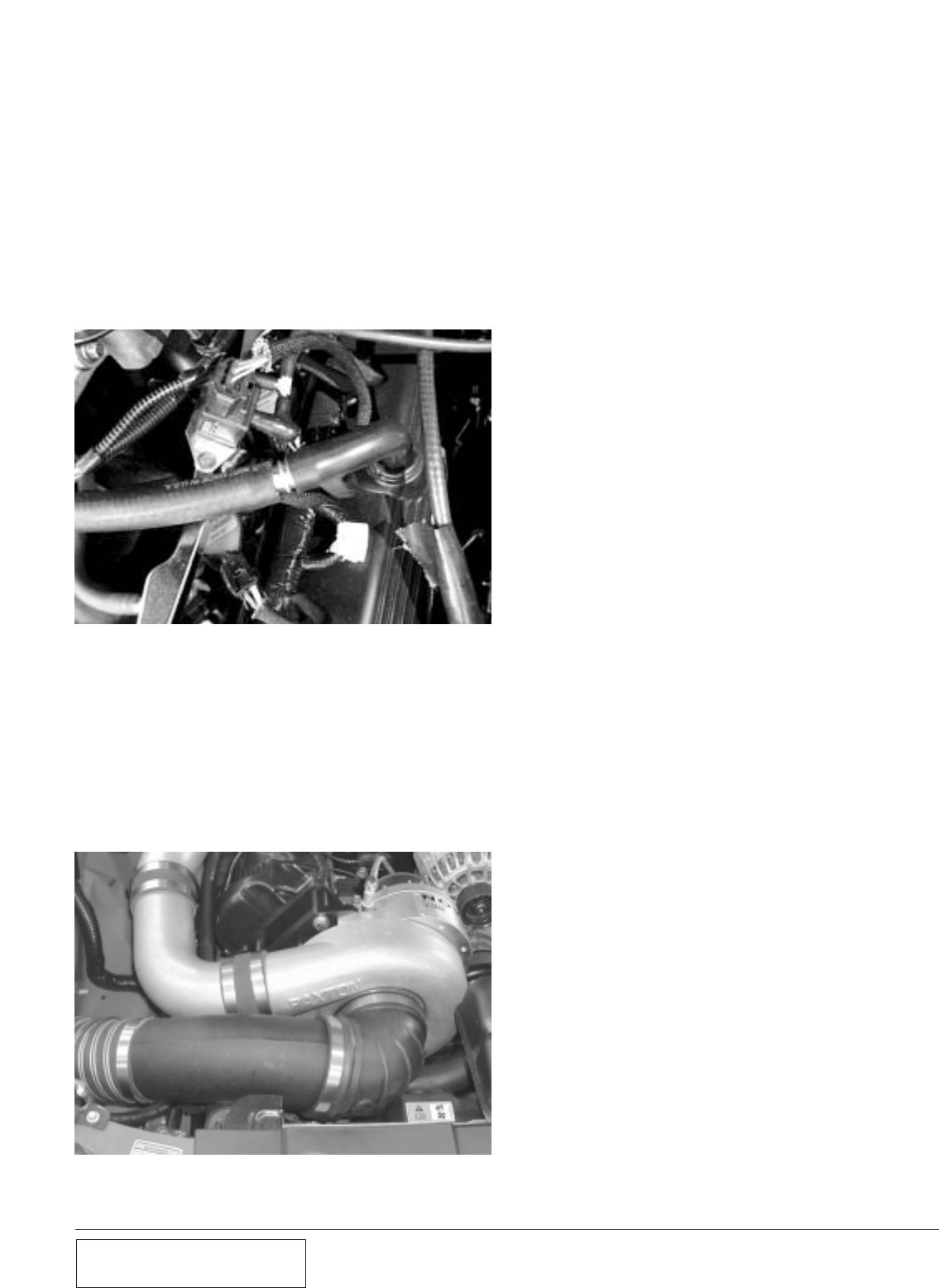
D. The supercharger bypass valve requires a
vacuum source. Remove the existing plastic
coupler in the vacuum hose that runs along
the firewall on the passenger side. Replace
with the supplied vacuum ‘T’.( See Fig 6-d.)
Attach the supplied length of vacuum hose,
and route along the passenger side frame rail
towards the supercharger. It will be connect-
ed to the bypass valve assembly in a later
step.
Fig. 6-d
6-2
P/N: 4809628
©2003 Paxton Automotive
All Rights Reserved, Intl. Copr. Secured
05JUN03 v2.1 MusGT(4809628 v2.1)
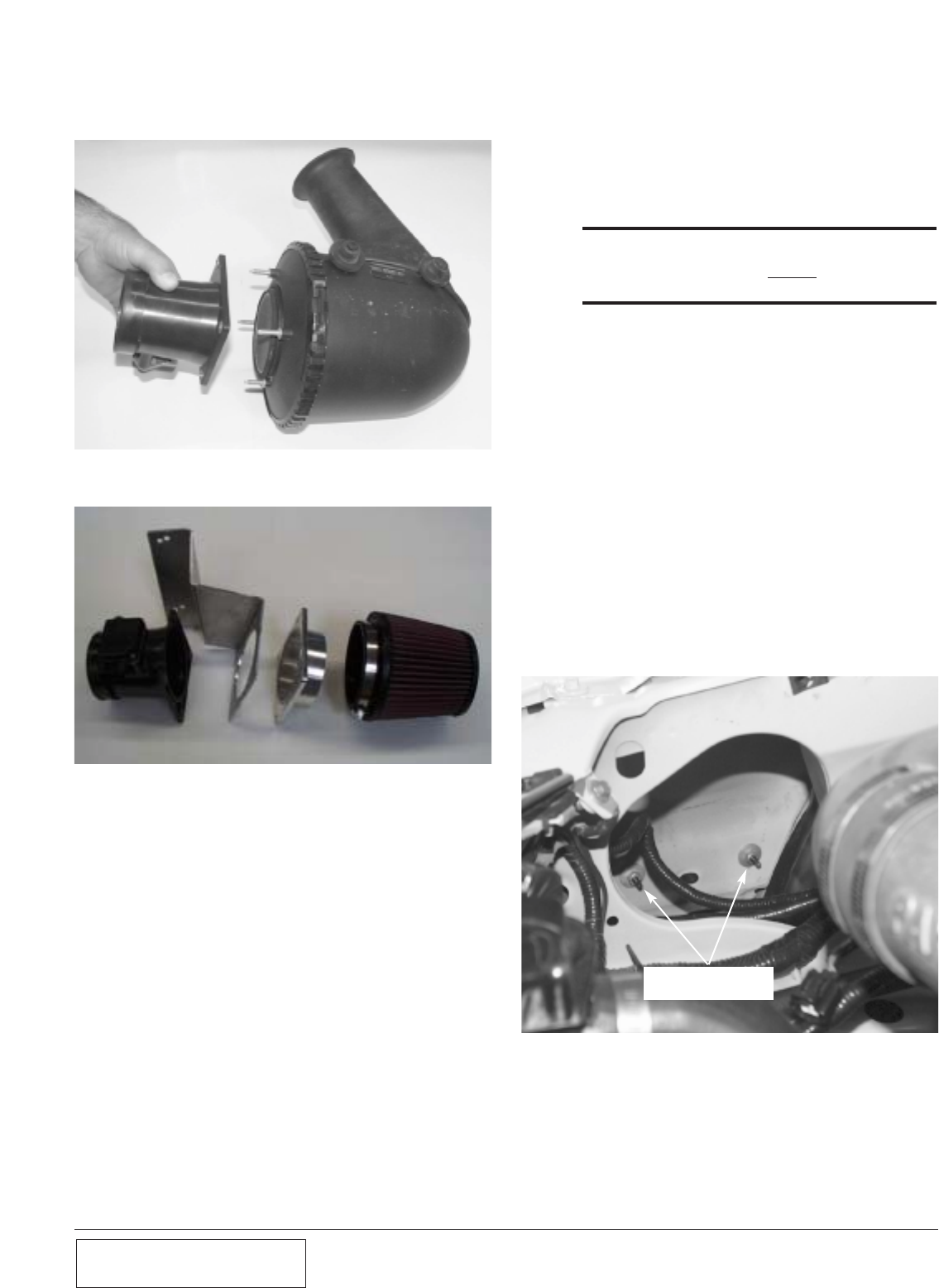
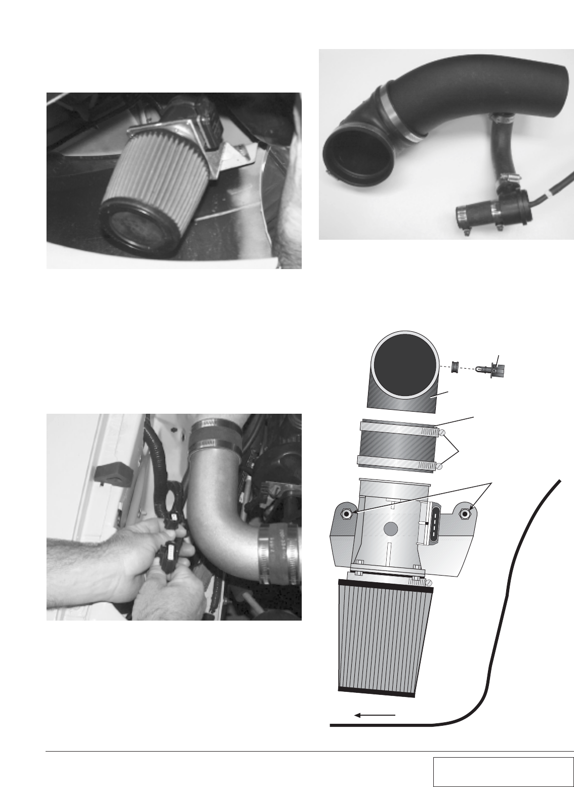
E. Remove the screen from the MAF, which
was removed in step 4.(See Fig. 6-e.)
Fig. 6-e
F. Assemble the MAF, mounting bracket,
MAF/air filter adapter and air filter. The
MAF bracket assembly may look different
from what you receive in your kit, but the
assembly procedure is the same.
G. Using the supplied 1/4-20 hardware, mount
the MAF meter to the MAF bracket and
secure. Remove the factory MAF screen
before attaching the meter to the new brack-
et.
Fig. 6-f
Fig. 6-g
H. Attach the supplied K & N air filter, 3-1/2”
sleeve, 90° 3-1/2” elbow and #56 hose
clamps to the MAF and secure.
I. Insert the factory air temperature sensor into
the rubber grommet located on the side of
the supplied 3-1/2" x 90° elbow. Lubricate
for easier fit.
***NOTE***
2002-2003 models do not have a separate IAT sen-
sor. Use the supplied elbow without ahole or grom-
met for 2002-2003 models only.
J. Using a #52 hose clamp, connect the piece
of 3-1/2” flex hose to the elbow attached to
the MAF meter and route it through the
opening in the right side inner fender toward
the supercharger. Make sure the 3 1/2” flex
hose does not contact or rub on the edge of
the inner fender opening. (Eventual hose
failure will result if the hose is not properly
routed.)
K. The MAF/air filter assembly will be relocat-
ed inside the passenger fender. Remove the
two nuts that secure the passenger side
bumper cover to the inner fender. (See Fig.
6-g.) Next, locate the screw at the forward,
lower edge of the passenger side wheel
opening and remove it. This will allow the
plastic inner fender to be pulled back so the
MAF/air filter assembly can be installed.
MAF BRACKET
MOUNTING LOCATION
6-3 P/N: 4809628
©2003 Paxton Automotive
All Rights Reserved, Intl. Copr. Secured
05JUN03 v2.1 MusGT(4809628 v2.1)
Fig. 6-h
L. Place the MAF/air filter bracket over the
existing studs, then secure with the original
nuts. (See Fig. 6-h.)
M. Carefully open the main wiring harness
(runs from the passenger side inner fender
into the engine compartment) with a razor
blade, making an incision that is approxi-
mately 6-inches long. Pull the MAF wiring
upwards, until the wires are long enough to
be routed back through the opening in the
inner fender, and down to the MAF. (See
Fig. 6-i.)
Fig. 6-i
P. Connect the plastic inlet duct (with bypass
valve and hoses attached) to the supercharg-
er inlet. This is to illustrates what the MAF
assembly should look like after assembly.
(See Fig. 6-k.)
FRONT
INSIDE
RIGHT FRONT
PASSENGER
FENDERWELL
#56 CLAMPS
FACTORY AIR
TEMPERATURE SENSOR
(NOT ON 2002+ MODELS)
3-1/2" ELBOW
SLEEVE
FACTORY
STUDS & NUTS
Fig. 6-k
N. Insert the 1" x 10" rubber hose to the inlet of
the compressor bypass valve. Secure both
hoses with the supplied #16 hose clamps.
O. Install the bypass valve assembly on the
underside of the secondary intake tube. (See
Fig. 6-j.) Tighten the hose clamp to secure
the valve assembly to the intake tube.
Fig. 6-j
6-4
P/N: 4809628
©2003 Paxton Automotive
All Rights Reserved, Intl. Copr. Secured
05JUN03 v2.1 MusGT(4809628 v2.1)
Fig. 6-l
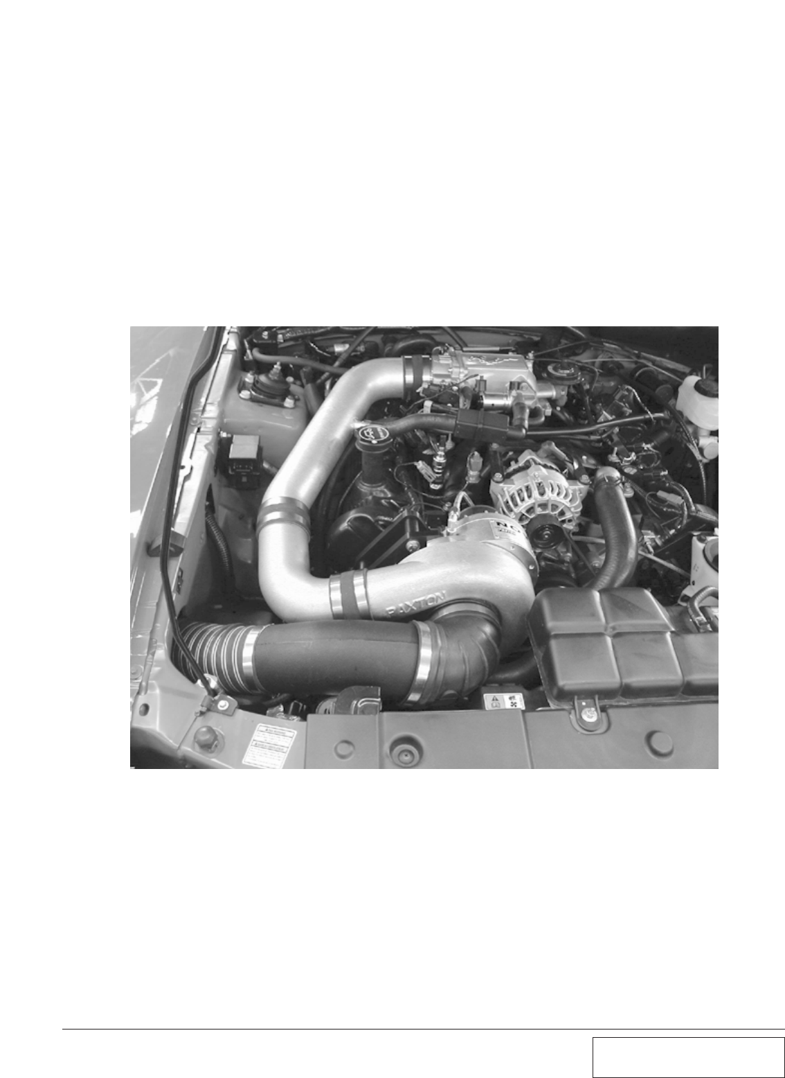
T. Place the secondary intake tube/bypass
valve assembly on the supercharger inlet,
and attach it to the flex hose. Attach the
other end of the bypass valve to the dis-
charge tube. Connect the hose that was pre-
viously installed on the hard plastic crank
case ventilation line to the brass fitting on
the intake tube. Tighten the clamps. The fin-
ished installation appear as in Fig. 6-m.
Fig. 6-m
Q. Join the supercharger inlet duct to the previ-
ously installed MAF hose with the supplied
#52 hose clamp.
R. Connect the opposite ends of each hose to
the crankcase breather fitting on the driver’s
side valve cover (5/8” hose) and the idle air
control resonator (3/x4” hose). Trim hose
length if required.
S. Install the 5/8” hose union into the
crankcase breather line. It may be necessary
to trim this line to ensure a proper fit. (See
Fig. 6-l.)
7-1 P/N: 4809628
©2003 Paxton Automotive
All Rights Reserved, Intl. Copr. Secured
05JUN03 v2.1 MusGT(4809628 v2.1)
Fig. 7-a
Section 7
ENGINE CONTROL COMPUTER REMOVAL AND MODIFICATION
7.1 ENGINE CONTROL COMPUTER
REMOVAL AND MODIFICATION
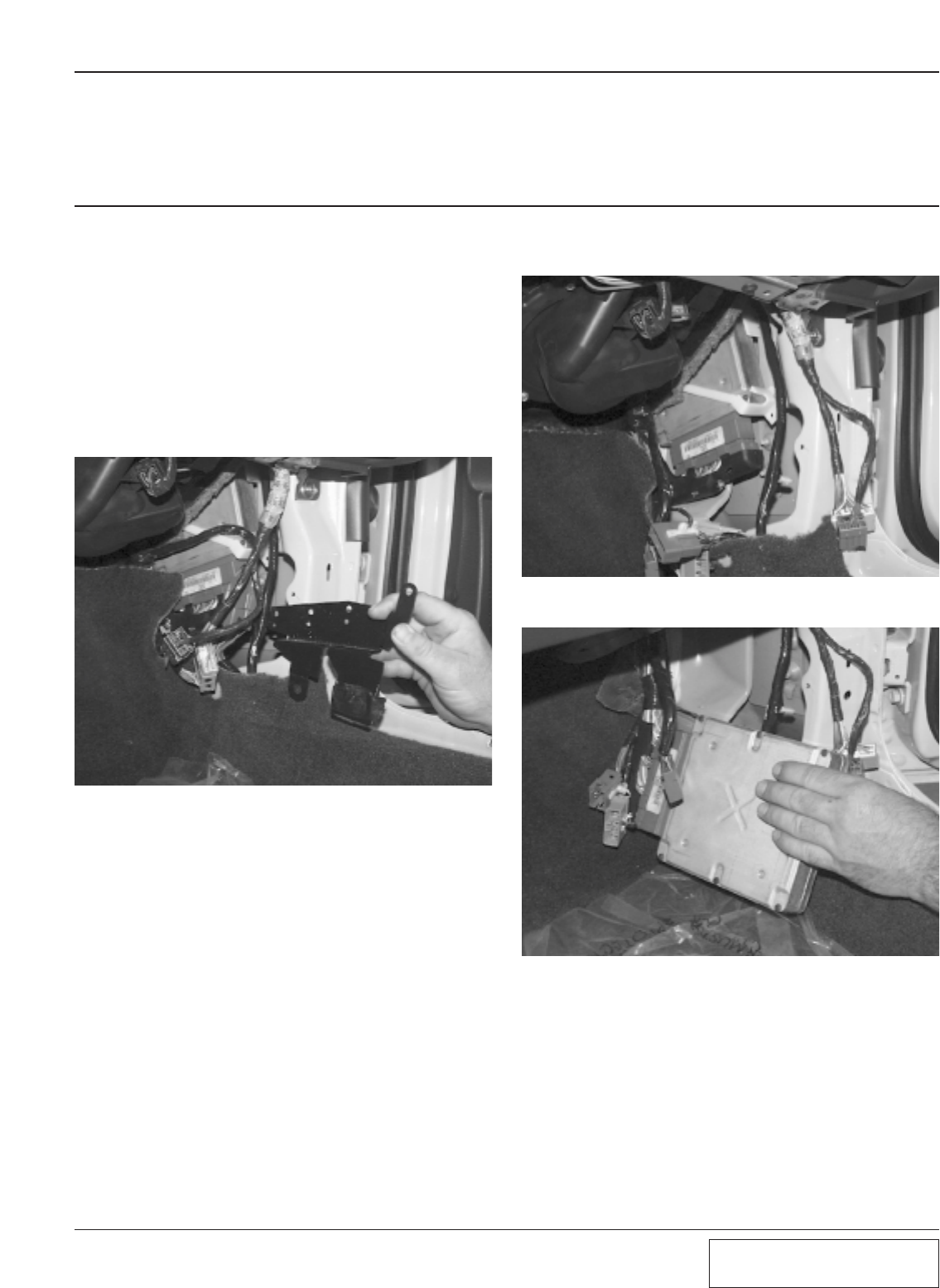
B. Pull the harnesses down and out of the way,
creating unobstructed access to the comput-
er. Remove the 7/32 screw that secures the
retention strap (see Fig. 7-b) and pull the
computer out of the foot well.(see Fig. 7-c.)
A. Remove the passenger side door sill plate,
followed by the passenger side kick panel.
This will reveal the engine control computer
and its harnesses. The harnesses are secured
using clips, which are attached to a small
metal bracket. Pull the harnesses off the
bracket, then remove the two 7/32-inch bolts
that secure the bracket itself. Remove the
bracket.(See Fig. 7-a.)
Fig. 7-b
Fig. 7-c
7-2
P/N: 4809628
©2003 Paxton Automotive
All Rights Reserved, Intl. Copr. Secured
05JUN03 v2.1 MusGT(4809628 v2.1)
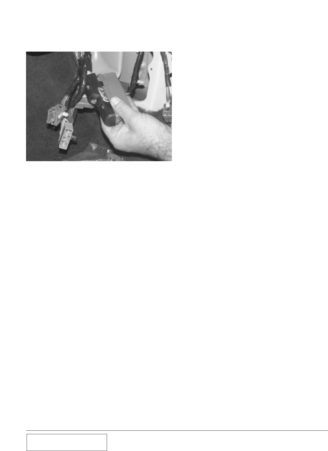
D. Remove the 10mm bolt that secures the
main harness to the computer, and remove
the harness. (See Fig. 7-d.)
E. Once the computer is removed from the car,
you will need to send your computer and the
chip voucher to Paxton Automotive. The
computer will be cleaned, a computer chip
installed and returned to you, ready to be
install back into your vehicle.
Fig. 7-d
8-1 P/N: 4809628
©2003 Paxton Automotive
All Rights Reserved, Intl. Copr. Secured
05JUN03 v2.1 MusGT(4809628 v2.1)
Section 8
IN-TANK FUEL PUMP INSTALLATION
8.1 IN-TANK FUEL PUMP INSTALLATION (2001-2002 Models Only)
A. Raise the rear of the car and support it with
jack stands.
B. Open the fuel door and remove the fuel cap
and the three filler neck screws using a
10mm socket.
C. Remove the fuel filter inlet line with a 3/8"
spring-lock tool.
D. With the weight of the fuel tank supported
with a jack, remove the bolts securing the
two fuel tank straps.
E. Slowly lower the fuel tank, allowing it to
lean over with the filler side up until the
electrical connections leading to the center
mounted fuel pump are revealed. Disconnect
these two electrical connections.
F. Remove the six bolts securing the fuel pump
access cover (on top of the fuel tank) with
an 8mm wrench. Depress the two clips
securing the plastic fuel pump enclosure and
slide it out of the tank. The fuel sender float
is attached to the fuel pump enclosure and
must be handled with care. Ensure that the
tank has been lowered enough to remove the
fuel pump enclosure.
G. Remove the two screws securing the plastic
fuel pump outlet manifold to the enclosure
cap. Pull the manifold up and away from the
fuel pump.
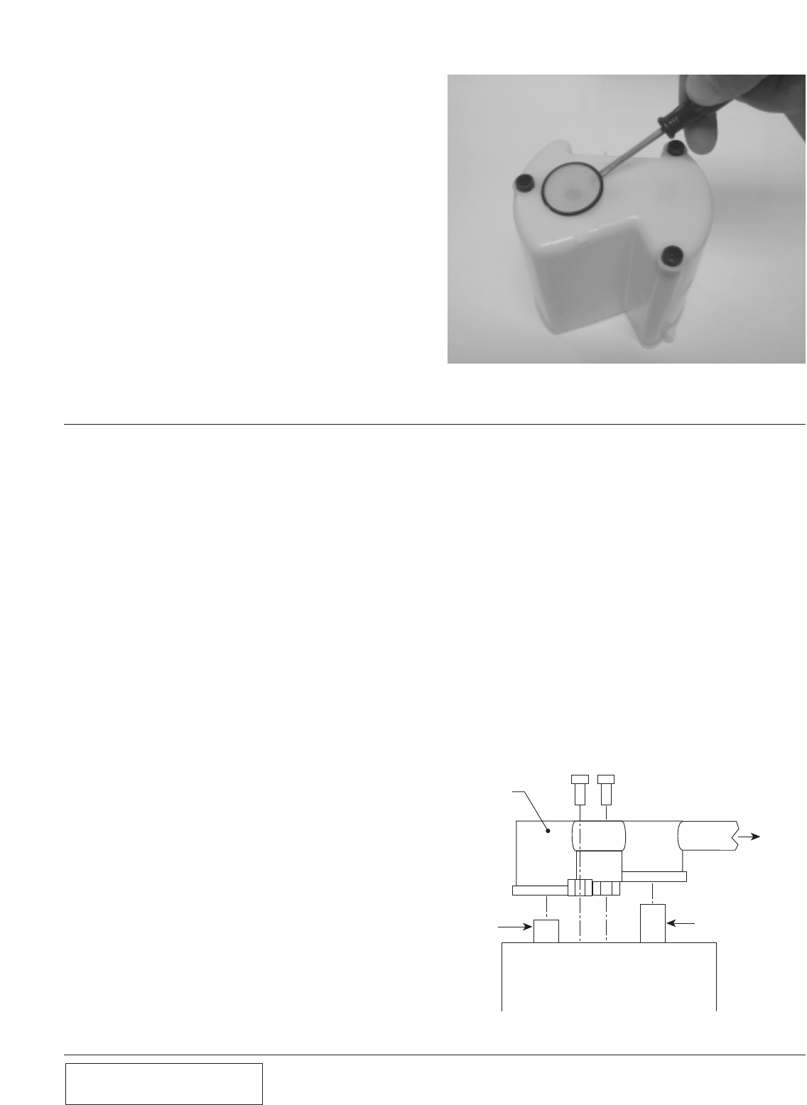
H. Remove the three screws securing the fuel
pump enclosure's cover using a 3/16" nut
driver and remove the cover. Modify the
fuel pump cover as shown. (See Figs. 8.1-a,
8.1-b.)
I. This allows the larger O.D. pump to fit in
the cover.
J. Remove the stock fuel pump from its enclo-
sure. Separate the rubber pump support from
beneath the filter and install it on the sup-
plied pump. Secure the support with the new
pump provided.
K. Cut the two fuel pump power wires about 1"
from the fuel pump electrical connector.
Noting the corresponding (+) and (-) con-
nections, splice the supplied wiring harness
into place using two butt connectors.
L. Using the supplied fuel pump, reassemble
the fuel pump assembly and canister with
cap. Install the supplied 1/8" spacers beneath
the pump outlet manifold and canister cap
and install the modified pump assembly.
(See Fig. 8.1-c.)
Fig. 8.1-a
Fig. 8.1-b
TRIM TO TABS
BYPASS
TUBE
PLASTIC
FUEL PUMP
OUTLET
MANIFOLD
VORTECH SUPPLIED
#6 x .75" SCREWS
FUEL
OUTLET
HOSE
FUEL PUMP OUTLET
SUPPLIED 1/8"
SPACERS
PUMP CANISTER
Fig. 8.1-c
8-2
P/N: 4809628
©2003 Paxton Automotive
All Rights Reserved, Intl. Copr. Secured
05JUN03 v2.1 MusGT(4809628 v2.1)
BYPASS
TUBE
PLASTIC
FUEL PUMP
OUTLET
MANIFOLD
FUEL
OUTLET
HOSE
FUEL PUMP OUTLET
PUMP CANISTER
Fig. 8.2-a
M. Remove the screen from the bottom of the
canister assembly being careful not to punc-
ture flapper valve. (See Fig. 8.2-b.)
N. Reinstall the fuel tank, reconnect the fuel
filter inlet line, reattach the fuel filler neck,
and reinstall the fuel pump.
O. Turn the ignition key on and check for fuel
leaks.
The installation is complete.
Congratulations!
Fig. 8.2-b
A. Raise the rear of the car and support it with
jack-stands.
B. Open the fuel door and remove the fuel-cap
and the three filler neck screws using a
10mm socket.
C. Remove the fuel filter inlet line with a 3/8
springlock tool.
D.With the weight of the fuel tank supported
with a jack, remove the bolts securing the
two fuel tank straps.
E. Slowly lower the fuel tank, allowing it to
lean over with the filler side up, until the
electrical connections leading to the center
mounted fuel pump are revealed. Disconnect
these two electrical connections.
F. Remove the six bolts securing the fuel pump
access cover (on top of the fuel tank) with
an 8mm wrench. Depress the two clips
securing the plastic fuel pump enclosure and
slide it out of the tank. The fuel sender float
is attached to the fuel pump enclosure and
must be handled with care. Ensure that the
tank has been lowered enough to remove the
fuel pump enclosure.
G. Remove the two screws securing the plastic
fuel pump outlet manifold to the enclosure
cap. Pull the manifold up and away from the
fuel pump. (See Fig. 8.2-a.)
H. Remove the three screws securing the fuel
pump enclosure’s cover using a 3/16 nut-
driver and remove the cover.
8.1 IN-TANK FUEL PUMP INSTALLATION (2001-2002 Models Only), cont’d.
8.2 IN-TANK FUEL PUMP INSTALLATION (2003 Models Only)
I. Remove the stock fuel pump from its enclo-
sure. Separate the rubber pump support from
beneath the filter and install it on the sup-
plied pump. Secure the support with the new
filter provided.
J. Using the supplied fuel pump, reassemble
the fuel pump assembly and canister with
cap.
K. Reinstall the canister assembly into the fuel
tank and reattach the electrical connections.
L. Reinstall the fuel tank, reconnect the fuel fil-
ter inlet line, reattach the fuel filler neck and
reinstall the fuel cap.
M. Turn the ignition key on and check the fuel
pump for leaks.
8-3 P/N: 4809628
©2003 Paxton Automotive
All Rights Reserved, Intl. Copr. Secured
05JUN03 v2.1 MusGT(4809628 v2.1)
Fig. 8-c / Completed Installation

8-4
P/N: 4809628
©2003 Paxton Automotive
All Rights Reserved, Intl. Copr. Secured
05JUN03 v2.1 MusGT(4809628 v2.1)
This Page Left Intentionally Blank.

9-1 P/N: 4809628
©2003 Paxton Automotive
All Rights Reserved, Intl. Copr. Secured
05JUN03 v2.1 MusGT(4809628 v2.1)
Section 9
FINAL ASSEMBLY AND CHECK
We know that you are anxious to get out
and drive your new vehicle, but please
take a little bit more time to perform
these simple check-out steps.
AInspect all wiring harnesses and electrical
connections. Make sure that all items are
properly routed, connected and secured. If
available, check grounds with an amp meter.
If the ground connection is suspect, connect
to the battery ground.
B. Check all hoses, lines, and fittings for prop-
erly secured connections..
C. Make certain all fasteners, brackets, and
clamps are installed and properly tightened.
D. Check serpentine accessory belt and super-
charger drive belts for proper tension and
alignment.
E. Cycle ignition key from “off” to the “on”
position 4-5 times.
F. Check the entire fuel system for possible
leaks.
G. Start engine and verify that the oil pressure
is within normal range.
H. Allow the engine to come up to normal
operating temperature.Turn the engine off.
I. Check the coolant level in the coolant recov-
ery bottle and top off as needed.
J. Check the following:
•Fluid Leaks
•Fluid Levels
•Belt Slippage
•Throttle Response
Now that the work is done, it’s time to enjoy.
PAXTON Automotive wants to thank you for
choosing our product, and wants to remind you that
the performance and response of your vehicle is
now different that what you are used to. Please
drive cautiously until you have grown accustomed
to the feel of your vehicle.
Please see the service manual included in your kit
for information on the service and maintenance of
your PAXTON Supercharger. Belt tightening,
troubleshooting, special tuning requirements, and
warranty information is also included in the
Service Manual.
9.1 FINAL ASSEMBLY AND CHECK

9-2
P/N: 4809628
©2003 Paxton Automotive
All Rights Reserved, Intl. Copr. Secured
05JUN03 v2.1 MusGT(4809628 v2.1)
This Page Left Intentionally Blank.

A-1 P/N: 4809628
©2003 Paxton Automotive
All Rights Reserved, Intl. Copr. Secured
05JUN03 v2.1 MusGT(4809628 v2.1)
APPENDIX

A-2
P/N: 4809628
©2003 Paxton Automotive
All Rights Reserved, Intl. Copr. Secured
05JUN03 v2.1 MusGT(4809628 v2.1)
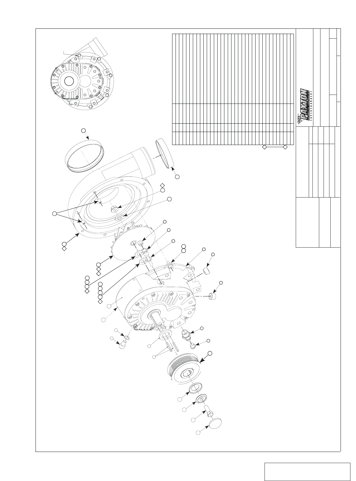
Please realize that PAXTON Automotive is con-
stantly improving the performance and look of the
NOVI 1000 supercharger. Parts in your kit may
appear differently than what is pictured in this manu-
al. This is due to photographs taken in pre-produc-
tion, a change in material, costs, or an improvement
in performance.
Rest assured that you have purchased the best quality
kit that PAXTON Automotive manufactures at this
time. The installation of the materials will remain the
same.
List of Appendices
Appendix Number.... ..DWG Number............... .DWG Title
Appendix A 1011816 ASY, S/C NOVI 1000
Appendix B 1015309 ASY, RADIATOR HOSE MODIFICATION
Appendix C 1016630 ASY, S/C MOUNTING BRACKET
Appendix D 1015933 ASY, AIR INTAKE
Appendix E 1017017 ASY, AIR DISCHARGE
Appendix F 1019336 ASY, OIL SUPPLY
Appendix G 1019328 ASY, OIL RETURN
Appendix H 1015506 ASY, COMPRESSOR BYPASS
Appendix I 1015530 ASY, FAN RESISTOR RELOC.
Appendix J 1017734 ASY, FUEL PUMP
Appendix K 7000170 DIAGRAM, BELT ROUTING
A-3 P/N: 4809628
©2003 Paxton Automotive
All Rights Reserved, Intl. Copr. Secured
05JUN03 v2.1 MusGT(4809628 v2.1)
SCALE:
SIZE DWG. NO.
DSHEET 1 OF 1
REV.
DATE
APPROVALS
DRAWN
ENGINEERING
R&D
UNLESS OTHERWISE SPECIFIED
DIMENSIONS ARE IN INCHES
TOLERANCES ARE:
DECIMALS: .XX± .01
.XXX±.005
MATERIAL
FINISH NONE
SEE PARTS LIST
DO NOT SCALE DRAWING
WEIGHT 20.8 LBS 3:4 1011816 B
FRACTIONS:
ANGLES: ±1/16
±1/2•
ASY, S/C NOVI 1000 REVERSE ROTATION,
4.6L 2V, 2000-2001, SATIN
APPR.
G. COMPTON 12/04/01 98-03 4.6L MUSTANG GT
A. PROCTOR
G. COMPTON
12/04/01
10/4/01
1300 BEACON PLACE OXNARD, CA 93033
TEL: (805) 604-1336 FAX: (805) 604-1337
CAD GENERATED DRAWING,
DO NOT MANUALLY UPDATE
---------- -----
2
2
1
2
3
4
5
6
7
8
9
10
11
12
13
14
15
16
17
18
19
20
21
22
23
24
25
26
26
27
27
28
29
30
31
32
1
1
2
2
1
1
2
2
1
1
1
1
1
1
1
6
6
2
1
1
1
4
1
1
1
1
0
0
1
0
0
0
0
0
ITEM NO. QTY. PART NO. DESCRIPTION
2H229-000
7PP375-017
7P375-016
7J375-024
7PP375-090
7P375-104
008704
7U100-075
2H017-185
2H036-325
2H040-021
2H040-011
008718
7B375-110
2H019-021
2H100-040
7A250-051
7A250-052
008706
008719
2H100-030
7U100-021
2H021-201
2H017-021
7G010-155
2H060-030
2H060-030
2H100-003
2H100-003
2H100-005
2H100-010
2H060-031
2H060-040
2H060-041
ASY, GEARCASE, NOVI 1000, CCW
FTG, NIPPLE, 3/8NPT X 1/2 HOSE, MODIFIED
FTG, PLUG 3/8NPT WITH MAGNET
WASHER, COPPER CRUSH, 3/8
OIL JET, LG.
SCREW, SCHD, 3/8-16UNC-2A X 1.00 LG.
CAP, SHIPPING, T2
KEY, 1/8 SQ X 1.25 LG.
SPACER, PULLEY, .185 THK.
PULLEY, S/C 6 GRV 3.25
RET, CUP BLWR PULLEY
RET, PULLEY, S/C, 3/8
CAP, TAMPER PROOF
SCREW, HXHD, 3/8-24UNF-2A X 1.00 LG.
VOLUTE, NOVI 1000, CCW, STR DISCHARGE
CLAMP, VOLUTE
SCREW, HXHD, 1/4-20UNC-2A X .50 LG.
SCREW, SET, 1/4-20UNC-2A X .50 LG.
CAP, SHIPPING, 3"
CAP, SHIPPING, 4"
NAMEPLATE, NOVI 1000
SCREW, DRIVE, #4 X .187 LG.
IMPELLER, NOVI 1000, CCW, BALANCED
WASHER, ANTI-ROTATION
NUT, 3/8-24UNF-2B, FLG LOCK
MATING RING, .090 THK
MATING RING, .090 THK
SHIM, IMP, .003 THK.
SHIM, IMP, .003 THK.
SHIM, IMP, .005 THK.
SHIM, IMP, .010 THK.
MATING RING, .099 THK
MATING RING, .103 THK
MATING RING, .112 THK
20
18
15
2
24
3
25
19
7
4
6 REQD.
16 17
3
3
1
7
2
11
12
14
13
SHORT HUB AWAY
FROM S/C
10
89
64
22
4 REQD
AS REQD. 32
31
30
26
2
AS REQD.
29
28
27
2
423
2
21
5
NUT CORNER IN
LINE WITH EDGE
SAME ROTATION
AS 1011810
S/C ROTATION
Appendix A 1011816 ASY, S/C NOVI 1000
A-4
P/N: 4809628
©2003 Paxton Automotive
All Rights Reserved, Intl. Copr. Secured
05JUN03 v2.1 MusGT(4809628 v2.1)
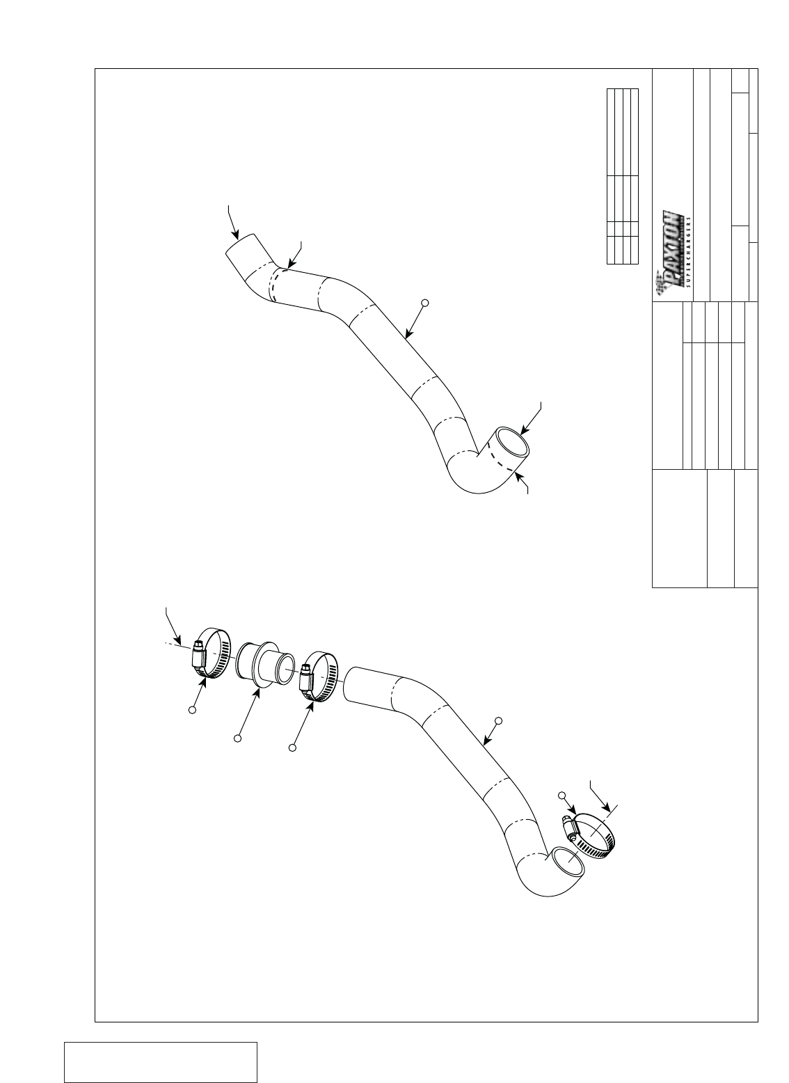
ITEM NO. QTY. PART NO. DESCRIPTION
237R002-024 CLAMP, HOSE #24
314PFH014-011 REDUCER, RADIATOR HOSE
414PFH014-020-1
SCALE:
SIZE DWG. NO.
DSHEET 1 OF 1
REV.
DATE
APPROVALS
DRAWN
ENGINEERING
R&D
UNLESS OTHERWISE SPECIFIED
DIMENSIONS ARE IN INCHES
TOLERANCES ARE:
DECIMALS: .XX± .01
.XXX±.005
MATERIAL
FINISH NONE
SEE PARTS LIST
DO NOT SCALE DRAWING
WEIGHT ?.? LBS 1:1.25 1015309 A
FRACTIONS:
ANGLES: ±1/16
±1/2•
ASY, RADIATOR HOSE MODIFICATION
APPR.
9/18/00 99-03 4.6L MUSTANG GT
AP
1300 BEACON PLACE OXNARD, CA 93033
TEL: (805) 604-1336 FAX: (805) 604-1337
CAD GENERATED DRAWING,
DO NOT MANUALLY UPDATE
TO MODIFIED STOCK RADIATOR HOSE
2
TO RADIATOR
MODIFIED
4
2
3
2
CUT HERE (1" FROM END)
1.50" INTERNAL DIAMETER
1
1.25" INTERNAL DIAMETER
CUT HERE
Appendix B 1015309 ASY, RADIATOR HOSE MODIFICATION
A-5 P/N: 4809628
©2003 Paxton Automotive
All Rights Reserved, Intl. Copr. Secured
05JUN03 v2.1 MusGT(4809628 v2.1)
SCALE:
SIZE DWG. NO.
DSHEET 1 OF 1
REV.
DATE
APPROVALS
DRAWN
ENGINEERING
R&D
UNLESS OTHERWISE SPECIFIED
DIMENSIONS ARE IN INCHES
TOLERANCES ARE:
DECIMALS: .XX± .01
.XXX±.005
MATERIAL
FINISH NONE
SEE PARTS LIST
DO NOT SCALE DRAWING
WEIGHT 7.3 LBS 1:1.5 1016630 B
FRACTIONS:
ANGLES: ±1/16
±1/2•
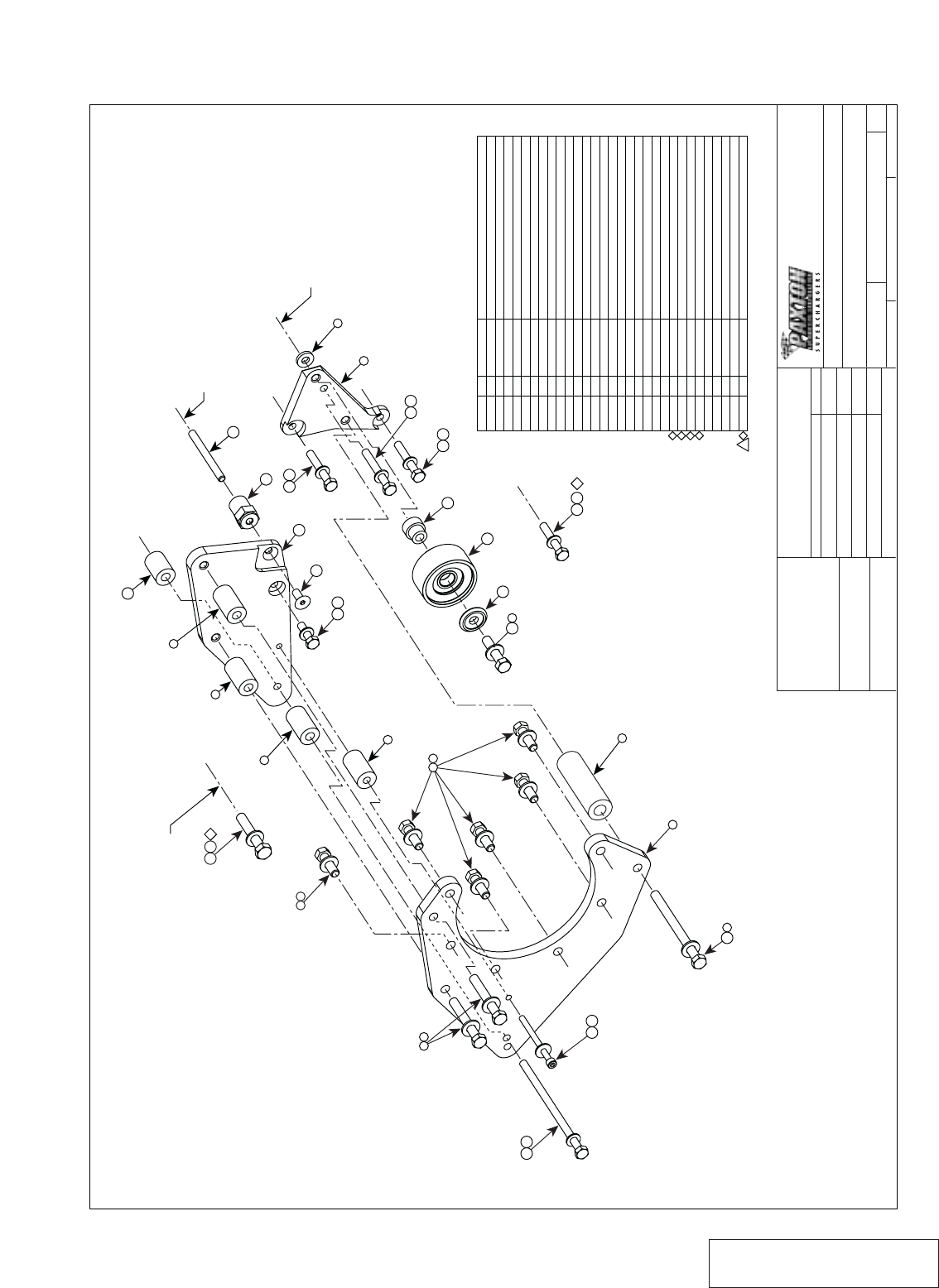
ASY, S/C NOVI 1000 FOWARD ROTATION
PROWLER, POLISHED WITH UPGRADE
APPR.
G. COMPTON 10/25/00 99-03 4.6L MUSTANG GT
A. PROCTOR
G. COMPTON
11/6/00
12/11/00
1300 BEACON PLACE OXNARD, CA 93033
TEL: (805) 604-1336 FAX: (805) 604-1337
CAD GENERATED DRAWING,
DO NOT MANUALLY UPDATE
L. KECK 12/11/00
1
2223
REPLACE STOCK FLANGE-HEAD
2
27 14
13
2221
26 22
12
29
10 26 22
15
20
TO ENGINE
TO STOCK
8
9
16
5
5
TO ENGINE
2
19
1
7
TO S/C
32
6
TO S/C
23
25 24 1
5
TO ENGINE
18 17
TO ENGINE
28 22
4 2
TO STOCK
REPLACE STOCK STUD
ON TIMING COVER
2211
NOTES: UNLESS OTHERWISE SPECIFIED:
ITEM NO. QTY. PART NO. DESCRIPTION
1
2
3
4
5
6
7
8
9
10
11
12
13
14
15
16
17
18
19
20
21
22
23
24
25
26
27
28
29
30
1
10
6
2
3
1
1
1
1
1
1
1
1
1
1
1
1
1
1
1
1
6
1
1
1
2
1
1
1
1
4PFL010-034
7J375-044
7A375-124
7A375-276
2A017-875-02
2A017-876-02
4PFL017-011
4PFL010-021
2A017-750-03
4PFL010-044
7C080-030
4PFH017-021
1210517
2H040-011
4PFL017-021
2A017-875-06
7J006-093
7C060-080
7A375-475
7PC080-335
7C080-066
7K312-001
7C080-051
7J010-002
7C010-060
7C080-056
7A375-178
7C080-160
7C080-023
2A046-073
PLATE, FRONT, S/C MTG BRKT
WASHER, FLAT, 3/8
SCREW, HXHD, 3/8-16UNC-2A x 1.25 LG.
SCREW, HXHD, 3/8-16UNC-2A x 2.75 LG.
SPACER, .875 x .404 x 1.565 LG.
SPACER, .875 x .328 x 1.500
SPACER, FLARED, 3/8
PLATE, IDLER MTG
SPACER, .750 x .328 x .130 LG.
PLATE, REAR, S/C MTG BRKT
SCREW, HXHD, M8 x 1.25 x 30mm
COLLAR, IDLER
PULLEY, IDLER
RET, PULLEY, 3/8
SPACER, .875 HEX x 1.275 LG.
SPACER, .875 x .404 x 1.235 LG.
WASHER, FLAT, 6mm
SCREW, SCHD, M6 x 1.00 x 80mm
SCREW, HXHD, 3/8-16UNC-2A x 4.75 LG.
STUD, M8 x 1.25 X 3.35" LG.
SCREW, HXHD, M8 x 1.25 x 65mm
WASHER, FLAT, 5/16
SCREW, HXHD, M8 x 1.25 x 50mm
WASHER, FLAT, 10mm
SCREW, HXHD, M10 x 1.50 x 60mm
SCREW, HXHD, M8 x 1.25 x 55mm
SCREW, HXHD, 3/8-16UNC-2A x 1.75 LG.
SCREW, HXHD, M8 x 1.25 x 160mm
SCREW, FHSH, M8 x 1.25 x 20mm
BELT, 6 GRV
A1
1
1
1
1
Appendix C 1016630 ASY, S/C MOUNTING BRACKET
A-6
P/N: 4809628
©2003 Paxton Automotive
All Rights Reserved, Intl. Copr. Secured
05JUN03 v2.1 MusGT(4809628 v2.1)
SCALE:
SIZE DWG. NO.
DSHEET 1 OF 1
REV.
DATE
APPROVALS
DRAWN
ENGINEERING
R&D
UNLESS OTHERWISE SPECIFIED
DIMENSIONS ARE IN INCHES
TOLERANCES ARE:
DECIMALS: .XX± .01
.XXX±.005
MATERIAL
FINISH NONE
SEE PARTS LIST
DO NOT SCALE DRAWING
WEIGHT 10.3 LBS 1:2 1015933 D
FRACTIONS:
ANGLES: ±1/16
±1/2•
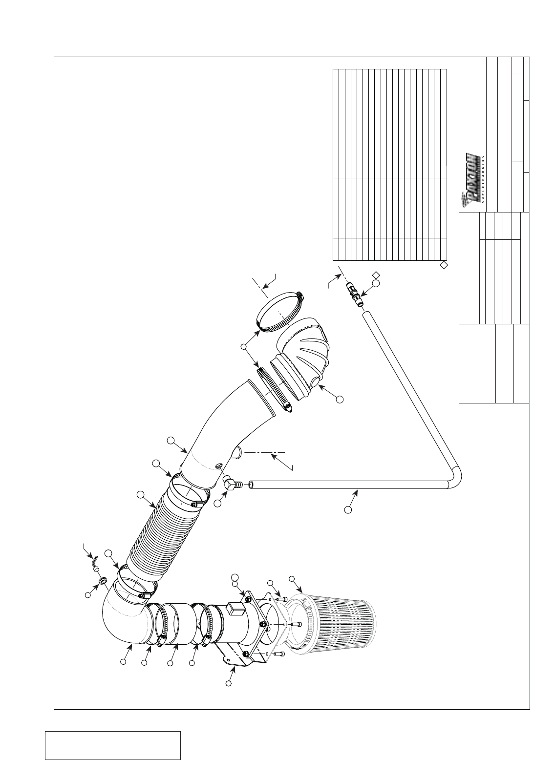
ASY, AIR INTAKE
APPR.
G. COMPTON 10/23/00 99-03 4.6L MUSTANG/MUSTANG GT
A. PROCTOR
G. COMPTON
10/30/00
10/30/00
1300 BEACON PLACE OXNARD, CA 93033
TEL: (805) 604-1336 FAX: (805) 604-1337
CAD GENERATED DRAWING,
DO NOT MANUALLY UPDATE
L. KECK 10/30/00
NOTES: UNLESS OTHERWISE SPECIFIED
4
910
4
8
4
1
6
3
11
7STOCK AIR SENSOR
12
11
13
TO COMPRESSOR
14
16 15
TO STOCK
PVC HOSE
1
17
5
2
3
TO S/C INLET
1
ITEM NO. QTY. PART NO. DESCRIPTION
1
2
4
5
6
7
8
9
11
12
13
14
15
16
17
18
19
31
1
2
1
3
1
1
4
4
4
2
1
1
1
1
1
1
14FH010-050-BENT
7PS350-200
7R002-056
8H040-090
7R002-064
4FH012-012
7U100-052
7A250-075
7J250-001
7F250-021
7R002-052
7U035-001
4PFK012-011
7P375-055
7S400-001
7U030-036 x 45
7P500-001
Mustang MAF
SLEEVE, 3.50" ID x 2.00"L
CLAMP, HOSE, #56
FILTER, AIR w/CLAMP
CLAMP, HOSE, #64
INTAKE ELBOW, 90°
GROMMET, RUBBER 7/16"
SCREW, 1/4-20 x 3/4", ZINC
WASHER, 1/4" SAE
NUT, 1/4-20 w/NYLOCK
CLAMP, HOSE, #52
HOSE, FLEX, 3.50" ID x 9.0"L
TUBE, AIR INTAKE, MODIFIED
FTG, ELBOW, 90°, 1/2" HOSE BARB x 3/8 NPT
ELBOW, RUBBER, 4" ID x 90°
COUPLING, INLINE HOSE, 1/2"
1/2" OIL DRAIN HOSE
MAF BRACKET
Appendix D 1015933 ASY, AIR INTAKE
A-7 P/N: 4809628
©2003 Paxton Automotive
All Rights Reserved, Intl. Copr. Secured
05JUN03 v2.1 MusGT(4809628 v2.1)
L. KECK 10/30/00
SCALE:
SIZE DWG. NO.
DSHEET 1 OF 1
REV.
DATE
APPROVALS
DRAWN
ENGINEERING
R&D
UNLESS OTHERWISE SPECIFIED
DIMENSIONS ARE IN INCHES
TOLERANCES ARE:
DECIMALS: .XX± .01
.XXX±.005
MATERIAL
FINISH NONE
SEE PARTS LIST
DO NOT SCALE DRAWING
WEIGHT 3.6 LBS 1:1.75 1017017 A
FRACTIONS:
ANGLES: ±1/16
±1/2•
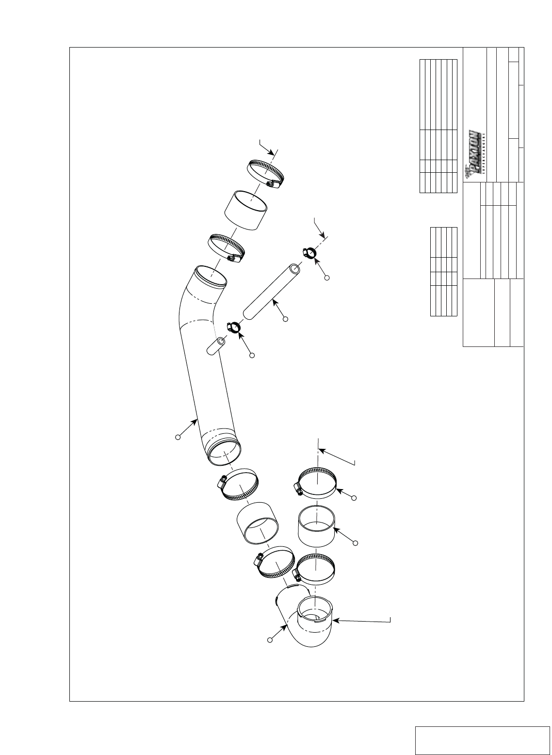
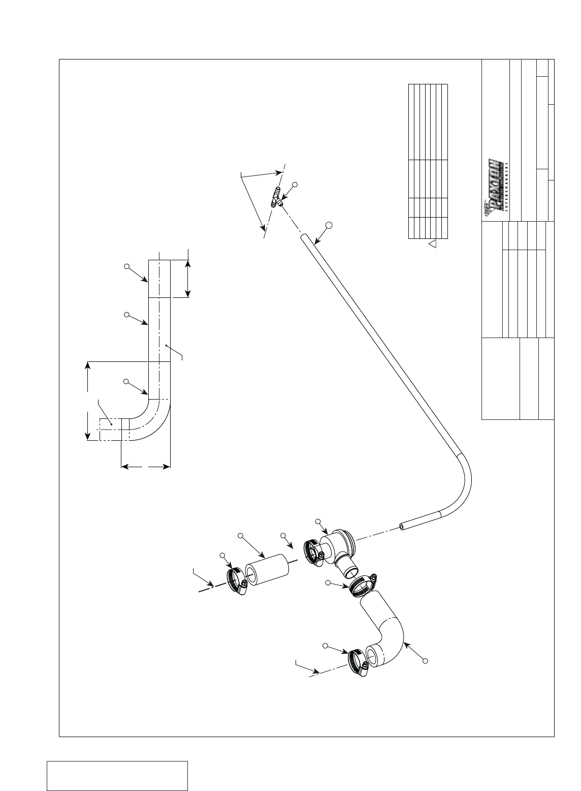
ASY, AIR DISCHARGE
APPR.
G. COMPTON 10/20/00 99-03 4.6L MUSTANG GT
A. PROCTOR
G. COMPTON
10/23/00
10/30/00
1300 BEACON PLACE OXNARD, CA 93033
TEL: (805) 604-1336 FAX: (805) 604-1337
CAD GENERATED DRAWING,
DO NOT MANUALLY UPDATE
23
46
52
71
81
91
1017017-P
1017018
SLV, BLK, 3.00D x 2.00
HOSE CLAMP,
CLAMP, HOSE #10
ITEM NO. QTY. PART NO. DESCRIPTION
7PS300-200
7R002-048
7R002-010
4PFH012-020
4PFH012-041
7U038-000-9
1
3
1
1
1
1
1
TEST1
4PFH012-020
4PFH012-048
4PFH012-028
ASY ITEM QT PART
NIPPLE ON P/N 4810127-6
3
26
4TO S/C OUTLET
7
5
9
TO ANTI-REVERSION
5
TO THROTTLE BODY
8
Appendix E 1017017 ASY, AIR DISCHARGE
A-8
P/N: 4809628
©2003 Paxton Automotive
All Rights Reserved, Intl. Copr. Secured
05JUN03 v2.1 MusGT(4809628 v2.1)
1300 BEACON PLACE OXNARD, CA 93033
TEL: (805) 604-1336 FAX: (805) 604-1337
CAD GENERATED DRAWING,
DO NOT MANUALLY UPDATE
SCALE:
SIZE DWG. NO.
CSHEET 1 OF 1
REV.
DATE
APPROVALS
DRAWN
ENGINEERING
R&D
UNLESS OTHERWISE SPECIFIED
DIMENSIONS ARE IN INCHES
TOLERANCES ARE:
DECIMALS: .XX± .01
.XXX±.005
MATERIAL
FINISH NONE
SEE PARTS LIST
DO NOT SCALE DRAWING
WEIGHT .2 LBS 3:4 1019336 B
FRACTIONS:
ANGLES: ±1/16
±1/2•
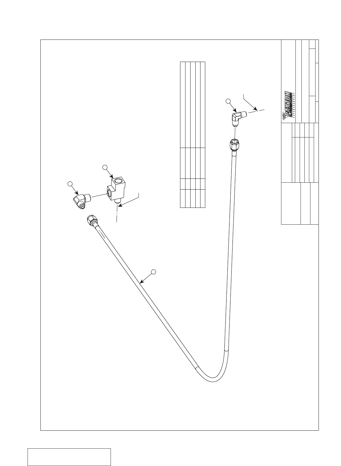
ASY, S/C OIL SUPPLY
APPR.
6/14/99 99-03 4.6L MUSTANG GT
JFC
1
1
2
3
4
1
1
1
1
HOSE, OIL SS BRAID, AN4 x AN4, 46.5" LG.
ITEM NO. QTY. PART NO. DESCRIPTION
7U250-000-465
7P250-034
7P125-004
7P250-082
FTG, STREET TEE, 1/4NPT
FTG, 90° ELBOW, AN4 x 1/8NPT
FTG, 90° ELBOW, AN4 x 1/4NPT
OIL FEED HOSE, 46.5" -4 STRT
3
TO S/C ASY
STOCK OIL SENDER LOCATION
2
4
Appendix F 1019336 ASY, OIL SUPPLY
A-9 P/N: 4809628
©2003 Paxton Automotive
All Rights Reserved, Intl. Copr. Secured
05JUN03 v2.1 MusGT(4809628 v2.1)
SCALE:
SIZE DWG. NO.
CSHEET 1 OF 1
REV.
DATE
APPROVALS
DRAWN
ENGINEERING
R&D
UNLESS OTHERWISE SPECIFIED
DIMENSIONS ARE IN INCHES
TOLERANCES ARE:
DECIMALS: .XX± .01
.XXX±.005
MATERIAL
FINISH NONE
SEE PARTS LIST
DO NOT SCALE DRAWING
WEIGHT .8 LBS 3:4 1019328 C
FRACTIONS:
ANGLES: ±1/16
±1/2•
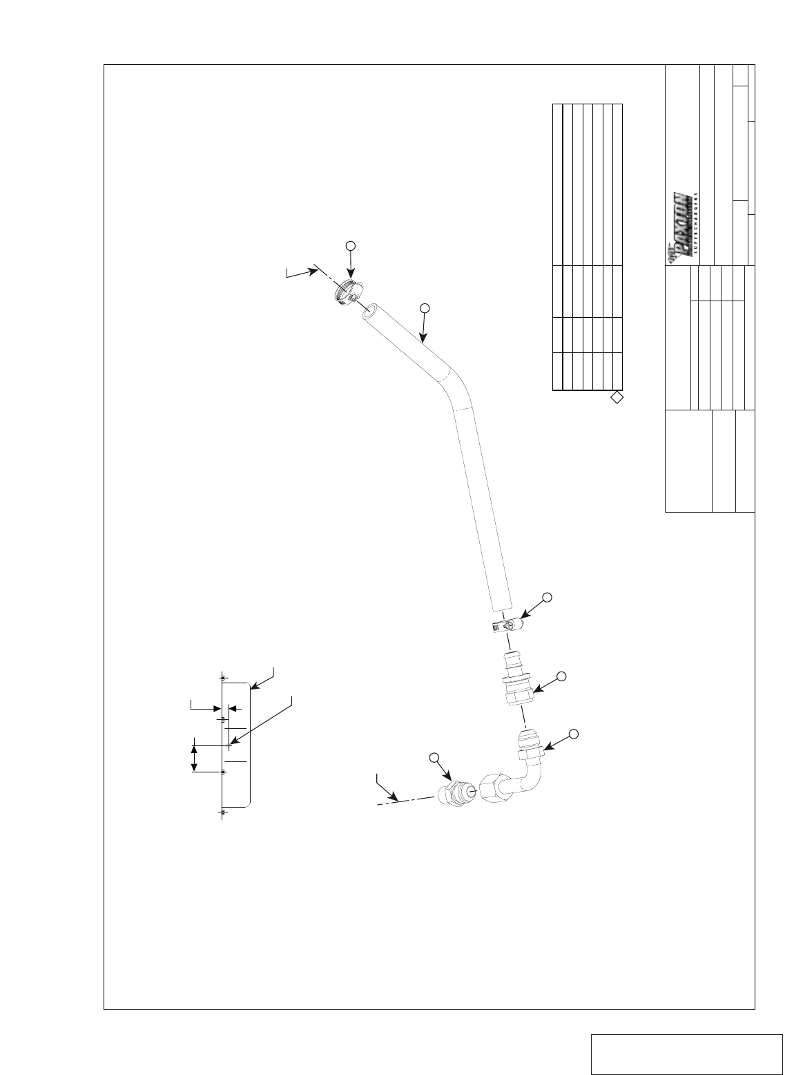
ASY, OIL RETURN
APPR.
4/5/00 99-03 4.6L MUSTANG
JFC
1300 BEACON PLACE OXNARD, CA 93033
TEL: (805) 604-1336 FAX: (805) 604-1337
CAD GENERATED DRAWING,
DO NOT MANUALLY UPDATE
LOCATION FOR ITEM 5
(FRONT OF OIL PAN)
1
2
3
4
5
6
7
1
1
1
2
1
1
7P500-063
7P500-052
7P375-053
7R002-010
7T640-011
7U030-036x13
FTG, HOSE END, AN8 X 1/2 BARB
FTG, 90^ SWIVEL, AN8 MALE X AN8 FEM
FTG, STR, AN8 X 3/8 NPT
CLAMP, HOSE, #10
PUNCH, OIL PAN
ITEM NO. QTY. PART NO. DESCRIPTION
2
5
5
7
TO S/C ASY
3
4
TO OIL PAN
PUNCH HOLE
WITH ITEM 6
OIL PAN
1.00
1.75
NOTES: UNLESS OTHERWISE SPECIFIED
1. SHIP THIS ITEM LOOSE.
Appendix G 1019328 ASY, OIL RETURN
A-10
P/N: 4809628
©2003 Paxton Automotive
All Rights Reserved, Intl. Copr. Secured
05JUN03 v2.1 MusGT(4809628 v2.1)
SCALE:
SIZE DWG. NO.
DSHEET 1 OF 1
REV.
DATE
APPROVALS
DRAWN
ENGINEERING
R&D
UNLESS OTHERWISE SPECIFIED
DIMENSIONS ARE IN INCHES
TOLERANCES ARE:
DECIMALS: .XX± .01
.XXX±.005
MATERIAL
FINISH NONE
SEE PARTS LIST
DO NOT SCALE DRAWING
WEIGHT 2.8 LBS 3:4 1015506 D
FRACTIONS:
ANGLES: ±1/16
±1/2•
ASY, COMPRESSOR BY-PASS
APPR.
8/22/99 99-03 4.6L MUSTANG
JFC
1300 BEACON PLACE OXNARD, CA 93033
TEL: (805) 604-1336 FAX: (805) 604-1337
CAD GENERATED DRAWING,
DO NOT MANUALLY UPDATE
-01 5
4
TO AIR INTAKE ASY
4
1
10
6
TO EXISTING VACUUM LINE
TO AIR DISCHARGE ASY
4
-02
5
4
D
ITEM NO. QTY. PART NO. DESCRIPTION
1
4
6
10
11
12
1
4
1
1
1
1
8D001-001
7R002-016
7P156-082
7U030-046 x 36"
7U133-100-02
7U133-100-01
VALVE, BY-PASS
CLAMP, HOSE #16
TEE, VACUUM, 1/4"
2.50±.06
3.25±.06
5.25±.06
DISCARD
-01
5-02
5
5
ITEM 5 MODIFICATION DETAIL
DISCARD
Appendix H 1015506 ASY, COMPRESSOR BYPASS
A-11 P/N: 4809628
©2003 Paxton Automotive
All Rights Reserved, Intl. Copr. Secured
05JUN03 v2.1 MusGT(4809628 v2.1)
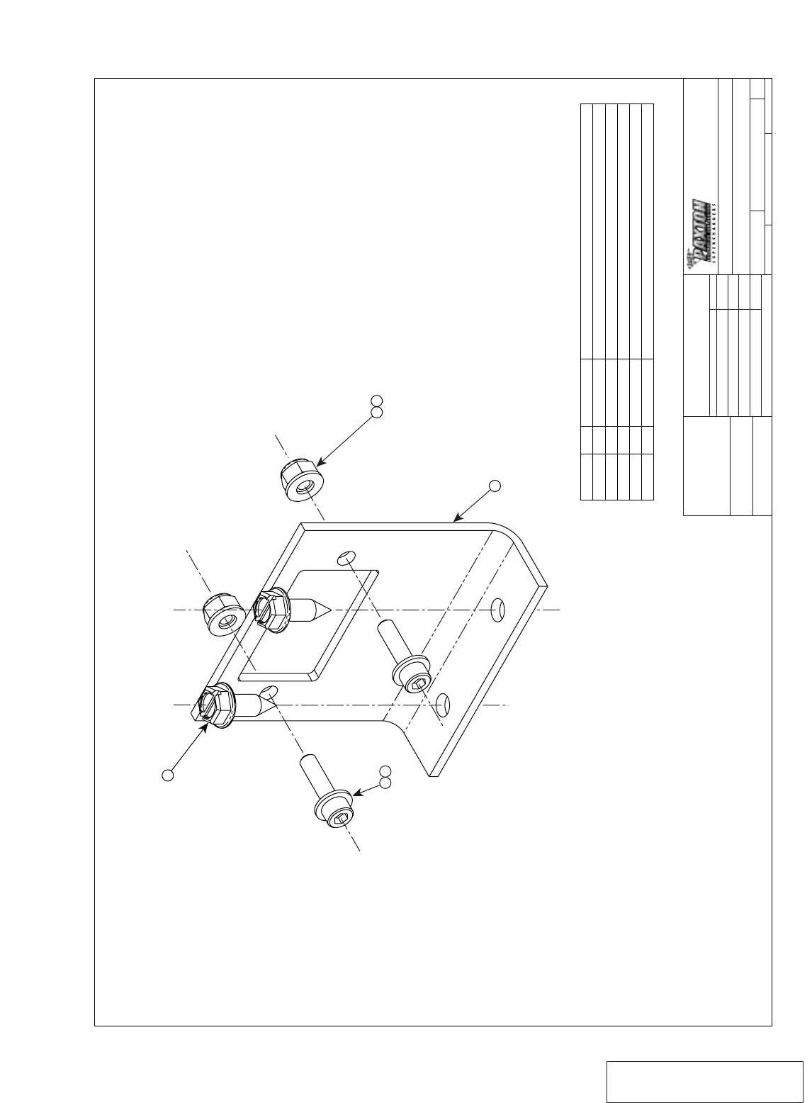
ITEM NO. QTY. PART NO. DESCRIPTION
1
2
3
4
5
1
2
4
2
2
4PFL010-041
7E014-075
7J010-001
7F010-024
7C010-075
BRKT, FAN RESISTOR RELOCATION
SCREW, #14 X .75 LG, SELF TAPPING
WASHER, FLAT, #10
NUT, HEX, 10-24UNC-2B, STEEL WITH NYLOK
SCREW, SHCS, 10-24UNC-2A X .75 LG, STEEL GR5
L. KECK 12/11/00
SCALE:
SIZE DWG. NO.
CSHEET 1 OF 1
REV.
DATE
APPROVALS
DRAWN
ENGINEERING
R&D
UNLESS OTHERWISE SPECIFIED
DIMENSIONS ARE IN INCHES
TOLERANCES ARE:
DECIMALS: .XX± .01
.XXX±.005
MATERIAL
FINISH NONE
SEE PARTS LIST
DO NOT SCALE DRAWING
WEIGHT .2 LBS 2:1 1015530 A
FRACTIONS:
ANGLES: ±1/16
±1/2•
ASY, FAN RESISTOR RELOCATION
APPR.
G. COMPTON 11/7/00 2001 4.6L MUSTANG GT
G. COMPTON
G. COMPTON
11/7/00
12/11/00
1300 BEACON PLACE OXNARD, CA 93033
TEL: (805) 604-1336 FAX: (805) 604-1337
CAD GENERATED DRAWING,
DO NOT MANUALLY UPDATE
2 REQD 2
2 REQD
3 5
1
2 REQD
43
Appendix I 1015530 ASY, FAN RESISTOR RELOC.
A-12
P/N: 4809628
©2003 Paxton Automotive
All Rights Reserved, Intl. Copr. Secured
05JUN03 v2.1 MusGT(4809628 v2.1)
ITEM NO. QTY. PART NO. DESCRIPTION
PIGTAIL CONNCTR, FUEL PUMP
SPACER, .312 OD/.14 ID
14-16AWG SOLDERLESS CONNECTOR
SCREW, SHTMTL, HXHD, #6 x .75 LG.
2
3
4
5
1
2
2
2
5W001-052
2A017-048
5W001-013
7E006-075
SCALE:
SIZE DWG. NO.
BSHEET 1 OF 1
REV.
DATE
APPROVALS
DRAWN
ENGINEERING
R&D
UNLESS OTHERWISE SPECIFIED
DIMENSIONS ARE IN INCHES
TOLERANCES ARE:
DECIMALS: .XX± .01
.XXX±.005
MATERIAL
FINISH NONE
SEE PARTS LIST
DO NOT SCALE DRAWING
WEIGHT 2 LBS 1:1 1017734 NC
FRACTIONS:
ANGLES: ±1/16
±1/2•
ASY, FUEL PUMP
APPR.
5/3/01 99-02 4.6L MUSTANG GT
G. COMPTON
NOTES: UNLESS OTHERWISE SPECIFIED
1. ALL ITEMS SHIPPED LOOSE. 1300 BEACON PLACE OXNARD, CA 93033
TEL: (805) 604-1336 FAX: (805) 604-1337
CAD GENERATED DRAWING,
DO NOT MANUALLY UPDATE
Appendix J 1017734 ASY, FUEL PUMP

A-13 P/N: 4809628
©2003 Paxton Automotive
All Rights Reserved, Intl. Copr. Secured
05JUN03 v2.1 MusGT(4809628 v2.1)
WATER PUMP
POWER STEERING
ALTERN
SUPERCHARG
A/C
CRANK
1300 BEACON PLACE OXNARD, CA 93033
TEL: (805) 604-1336 FAX: (805) 604-1337
CAD GENERATED DRAWING,
DO NOT MANUALLY UPDATE
SCALE:
SIZE DWG. NO.
BSHEET 1 OF 1
REV.
DATE
APPROVALS
DRAWN
ENGINEERING
R&D
UNLESS OTHERWISE SPECIFIED
DIMENSIONS ARE IN INCHES
TOLERANCES ARE:
DECIMALS: .XX± .01
.XXX±.005
MATERIAL
FINISH NONE
SEE PARTS LIST
DO NOT SCALE DRAWING
WEIGHT 1:1 7000170 NC
FRACTIONS:
ANGLES: ±1/16
±1/2•
DIAGRAM, BELT ROUTING
APPR.
7/10/00 1999-2003 MUSTANG GT
A. PROCTOR
Appendix K 7000170 DIAGRAM, BELT ROUTING

P/N: 4809628
©2003 Paxton Automotive
All Rights Reserved, Intl. Copr. Secured
05JUN03 v2.1 MusGT(4809628 v2.1)
Paxton Automotive . 1300 Beacon Place . Oxnard CA 93033
805 604-1336 . FAX (805) 604-1337
