Symbol Technologies 2192955 802.11a/b/g WLAN SDIO Radio Module User Manual Manual
Symbol Technologies Inc 802.11a/b/g WLAN SDIO Radio Module Manual
Manual

21-92955 Integration Guide
Copyright 2006 Symbol Technologies, Inc. Page 1 of 11
21-92955: 802.11abg SDIO radio module
Integration Guide
USA – FCC 28 Mar 07

21-92955 Integration Guide
Copyright 2006 Symbol Technologies, Inc. Page 2 of 11
Table of Contents
1. INTRODUCTION 3
1.1 BACKGROUND 3
1.2 PURPOSE 3
1.3 PART NUMBER 3
1.4 KEY FEATURES AND STANDARDS SUPPORTED 3
2. HARDWARE 4
2.1 INTRODUCTION 4
2.2 OPERATING CHANNELS 4
2.3 ELECTRICAL INTERFACE 6
3. REGULATORY PRODUCT COMPLIANCE 6
3.1 FINAL PRODUCT COMPLIANCE 6
3.2 REFERENCE ANTENNA 7
PRODUCT MARKINGS 8
3.3 8
3.4 NATIONAL COUNTRY REQUIREMENTS 8
3.4.1 United States of America 8
3.5 STATEMENTS REQUIRED FOR THE USER GUIDE 9
3.5.1 General Statements 9
3.5.2 FCC Statements 9
21-92955 Integration Guide
Copyright 2004 Symbol Technologies, Inc. Page 3 of 11
1. Introduction
1.1 Background
21-92955 is the next generation SDIO radio module for Symbol embedded
solutions and is intended for handheld applications.
1.2 Purpose
The purpose of this document is to define the functional characteristics (electrical,
mechanical) of the module and provide regulatory information helpful to the
product teams to integrate or embed the module in a variety of systems. A
section outlining Good Design Practices is also incorporated to help with the
overall integration of the device.
1.3 Part Number
Part Number SKU
21-92955-01 Diversity version with RF
connection through BGA
pins
1.4 Key Features and Standards supported
The module supports all required modes of operation as an 802.11g and 802.11a
Mobile Unit (MU). In 802.11g mode, the radio supports three different modulation
modes: Legacy 1 and 2Mbps, Complimentary Code Keying (CCK), and
Orthogonal Frequency Division Multiplexing (OFDM). The radio supports the
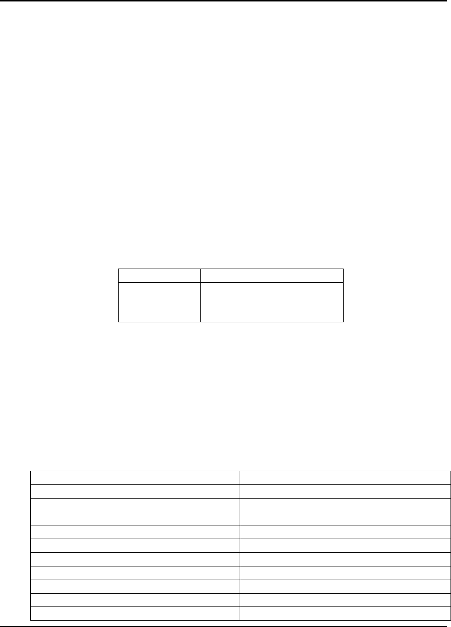
following 12 data rates in 802.11b/g mode:
Data Rate (Mbps) Modulation
1 DBPSK
2 DQPSK
5.5 CCK
6 OFDM with BPSK Carrier Modulation
9 OFDM with BPSK Carrier Modulation
11 CCK
12 OFDM with QPSK Carrier Modulation
18 OFDM with QPSK Carrier Modulation
24 OFDM with 16QAM Carrier Modulation
36 OFDM with 16QAM Carrier Modulation
21-92955 Integration Guide
Copyright 2004 Symbol Technologies, Inc. Page 4 of 11
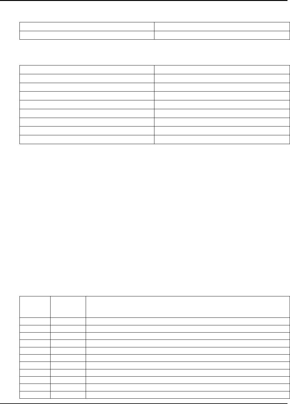
48 OFDM with 64QAM Carrier Modulation
54 OFDM with 64QAM Carrier Modulation
The radio supports 8 data rates in 802.11a mode:
Data Rate (Mbps) Modulation
6 OFDM with BPSK Carrier Modulation
9 OFDM with BPSK Carrier Modulation
12 OFDM with QPSK Carrier Modulation
18 OFDM with QPSK Carrier Modulation
24 OFDM with 16QAM Carrier Modulation
36 OFDM with 16QAM Carrier Modulation
48 OFDM with 64QAM Carrier Modulation
54 OFDM with 64QAM Carrier Modulation
2. Hardware
2.1 Introduction
The 21-92955 module can be used in handheld mobile devices to provide
wireless network access. The module communicates using Radio Frequencies
(RF) between two or more users or between a user and the wired network. The
module implements the IEEE 802.11a and IEEE802.11g physical (RF)
specification. The chipset used provides for modulation, demodulation, spreading
and despreading of the RF signals.
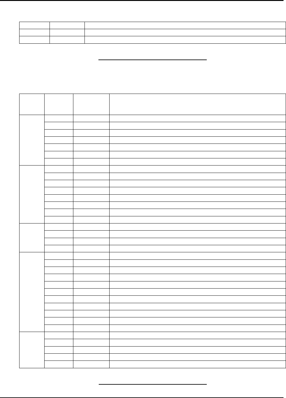
2.2 Operating Channels
Channel
Number Channel
Frequency
(MHz)
Countries
1 2412 USA, Canada, EU, Japan
2 2417 USA, Canada, EU, Japan
3 2422 USA, Canada, EU, Japan
4 2427 USA, Canada, EU, Japan
5 2432 USA, Canada, EU, Japan
6 2437 USA, Canada, EU, Japan
7 2442 USA, Canada, EU, Japan
8 2447 USA, Canada, EU, Japan
9 2452 USA, Canada, EU, Japan
10 2457 USA, Canada, EU, Japan
11 2462 USA, Canada, EU, Japan
21-92955 Integration Guide
Copyright 2004 Symbol Technologies, Inc. Page 5 of 11
12 2467 EU, Japan
13 2472 EU, Japan
14 2484 Japan
Table 1. IEEE 802.11g Channels
UNII
BAND Channel
Number Channel
Frequency
(MHz)
Countries
240 4920 Japan
244 4940 Japan
248 4960 Japan
252 4980 Japan
5040 Japan
5060 Japan
5080 Japan
34 5170 Japan
36 5180 USA, Canada, EU, Japan
38 5190 Japan
40 5200 USA, Canada, EU, Japan
42 5210 Japan
44 5220 USA, Canada, EU, Japan
46 5230 Japan
Lower Band
48 5240 USA, Canada, EU, Japan
52 5260 USA, Canada, EU, Japan
56 5280 USA, Canada, EU, Japan
60 5300 USA, Canada, EU, Japan
Middle
Band
64 5320 USA, Canada, EU, Japan
100 5500 USA, Canada, EU, Japan
104 5520 USA, Canada, EU, Japan
108 5540 USA, Canada, EU, Japan
112 5560 USA, Canada, EU, Japan
116 5580 USA, Canada, EU, Japan
120 5600 USA, Canada, EU, Japan
124 5620 USA, Canada, EU, Japan
128 5640 USA, Canada, EU, Japan
132 5660 USA, Canada, EU, Japan
136 5680 USA, Canada, EU, Japan
140 5700 USA, Canada, EU, Japan
149 5745 USA, Canada
153 5765 USA, Canada
157 5785 USA, Canada
161 5805 USA, Canada
Upper
(ISM)
165 5825 USA, Canada
Table 2. IEEE 802.11a Channels

21-92955 Integration Guide
Copyright 2004 Symbol Technologies, Inc. Page 6 of 11
2.3 Electrical Interface
The electrical interface for the module is SDIO. The chipset used supports this
interface; therefore no external component is required. The host must support the
SDIO interface as well.
3. Regulatory Product Compliance
Legal Disclaimer: This Guide may contain information on regulatory matters. The
information should be used with the understanding that Symbol is not engaged in
rendering any legal, regulatory or other professional opinion. Each country has
specific laws and regulations governing the use of radio communications. Please
consult the official code for each country of interest. Symbol does not warrant
the accuracy of the information contained herein and accepts no liability or
responsibility for any use or misuse of the information
Symbol’s wireless network devices are designed to be compliant with rules and
regulations in locations they are sold.
Any changes or modifications to Symbol Technologies equipment, not expressly
approved by Symbol Technologies, could void the user’s authority to operate the
equipment.
IMPORTANT NOTE:
End product user guide must NOT include any information regarding how
to install or remove this RF module.
3.1 Final Product Compliance
The model Number used for Regulatory Approvals is: 21-92955
The module has been regulatory approved for integrations which meet the
following conditions:
1. The radio integration is embedded
2. The antenna must be installed such that 20 cm is maintained between the
antenna and users
21-92955 Integration Guide
Copyright 2004 Symbol Technologies, Inc. Page 7 of 11
3. The ‘Type’ and ‘Gain’ of the antenna selected for the integration of the
external antenna must meet the requirements as detailed in section.
Used outside of these conditions will trigger re-approval
As the integrator, you are responsible to determine what additional specific
regulatory requirements are required of the country in which your product will be
marketed. Final product may require non-radio frequency approvals such as
Product Safety, EMC, and SAR.
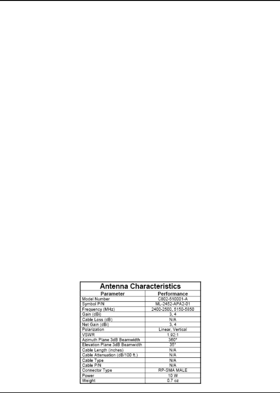
3.2 Reference Antenna
A reference antenna has been used during the approval process.
Specific details of the reference antenna used for testing is detailed in the table
below.
Important Note:
Use of an antenna which is the same ‘type’ (eg. Dipole) and has a gain equal to
or less that the reference antenna can be used without recertification.
Use of an alternative antenna, different ‘type’ or same ‘type’ but higher gain will
invalidate the country approvals. Under this instant the integrator is responsible
for re-evaluating the end product and obtaining separate approvals.
Antenna Type: Dipole
Antenna Characteristics:
ML-2452-APA2-01

21-92955 Integration Guide
Copyright 2004 Symbol Technologies, Inc. Page 8 of 11
3.3 Product Markings
Regulatory markings are applied to signify the radio module has been approved
in the following countries: USA.
3.4 National Country Requirements
NOTE:
The sections below assume that all the conditions detailed in section 3.1 have
been met.
3.4.1 United States of America
The radio card is already approved under the requirements of the FCC.
End-product requirements with this module installed should include:
• FCC Part 15 (emissions class B)
Final product markings must include:
Contains an approved Radio Module
Model: 21-92955
FCC ID: H9P2192955
IMPORTANT NOTES
1. Co-location
The FCC approval EXCLUDES co-location with any other transmitter.
If the module is co-located with another transmitter (eg, Bluetooth Module), the
integrator is responsible for re-evaluating the end product and obtaining a
separate FCC authorization.
2. Portable Use
The FCC approval of the module covers ‘mobile’ applications.

21-92955 Integration Guide
Copyright 2004 Symbol Technologies, Inc. Page 9 of 11
If the final product used in a manner where the antenna is closer than 20cm from
the user (portable use), the OEM is integrator is responsible for re-evaluating the
end product and obtaining a separate FCC authorization.
Symbol recommends the use of an accredited Laboratory to carry out the
necessary tasks.
3. Channels
For use in the USA the available 802.11b/g channels are limited from 1 to 11.
3.5 Statements required for the User Guide
The following statements are for required in the final product guide.
Many on the statements are dependent on the application of the final product.
Symbol recommends that the Integration team seeks the advice from an a TCB.
3.5.1 General Statements
Any changes or modifications not expressly approved by Symbol Technologies,
Inc. could void the user’s authority to operate the equipment.
Ad hoc Mode (5GHz)
Ad Hoc operation of the MODULE in the 5Ghz band will be limited to 5150 –
5250MHz (UNII 1).
3.5.2 FCC Statements
Co-located statement
To comply with FCC RF exposure compliance requirement, the antenna used for
this transmitter must not be co-located or operating in conjunction with any other
transmitter/antenna except those already approved in this filling.
Handheld Devices
To comply with FCC RF exposure requirements, this device must be operated in
21-92955 Integration Guide
Copyright 2004 Symbol Technologies, Inc. Page 10 of 11
the hand with a minimum separation distance of 20 cm or more from a person’s
body. Other operating configurations should be avoided.
Remote and Standalone Antenna Configurations
To comply with FCC RF exposure requirements, antennas that are mounted
externally at remote locations or operating near users at stand-alone desktop of
similar configurations must operate with a minimum separation distance of 20 cm
from all persons.
Radio Frequency Interference Requirements – FCC
Note: This equipment has been tested and found to comply with the limits for a
Class B digital device, pursuant to Part 15 of the FCC rules. These limits are
designed to provide reasonable protection against harmful interference in a
residential installation. This equipment generates, uses and can radiate radio
frequency energy and, if not installed and used in accordance with the
instructions, may cause harmful interference to radio communications. However
there is no guarantee that interference will not occur in a particular installation. If
this equipment does cause harmful interference to radio or television reception,
which can be determined by turning the equipment off and on, the user is
encouraged to try to correct the interference by one or more of the following
measures:
• Reorient or relocate the receiving antenna
• Increase the separation between the equipment and receiver
• Connect the equipment into an outlet on a circuit different from that to which
the receiver is connected
• Consult the dealer or an experienced radio/TV technician for help.
Radio Transmitters (Part 15)
This device complies with Part 15 of the FCC Rules. Operation is subject to the
following two conditions: (1) this device may not cause harmful interference, and
(2) this device must accept any interference received, including interference that
may cause undesired operation.

21-92955 Integration Guide
Copyright 2004 Symbol Technologies, Inc. Page 11 of 11
2.4GHz band operation
The available channels for 802.11 b/g operation in the US are Channels 1 to 11.
The range of channels is limited by firmware.
UNII band 1
The use in the UNII (Unlicensed National Information Infractructure) band 1 5150-
5250 MHz band is restricted to Indoor Use Only; any other use will make the
operation of this device illegal.