Symbol Technologies AP5131S Symbol WLAN 802.11abg Access Point User Manual 72E 70931 01
Symbol Technologies Inc Symbol WLAN 802.11abg Access Point 72E 70931 01
Users Manual
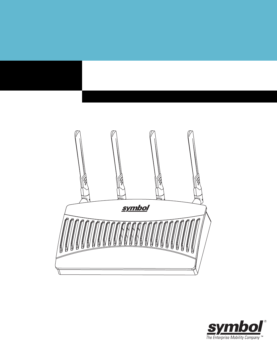
AP-5131 Access Point
INSTALLATION GUIDE
© 2001-2005 by Symbol Technologies, Inc. All rights reserved.
No part of this publication may be modified or adapted in any way, for any purposes without
permission in writing from Symbol Technologies, Inc. (Symbol). The material in this manual is
subject to change without notice. Symbol reserves the right to make changes to any product to
improve reliability, function, or design. No license is granted, either expressly or by implication,
estoppels, or otherwise under any Symbol Technologies, Inc., intellectual property rights. An
implied license only exists for equipment, circuits and subsystems contained in Symbol
products. Symbol and the Symbol logo are registered trademarks of Symbol Technologies, Inc.
Patents
This product is covered by one or more of the U.S. and foreign patents listed at:
http://www.symbol.com/patents
Symbol Technologies, Inc.
One Symbol Plaza
Holtsville, New York 11742-1300
http://www.symbol.com

Contents
1.0 Introduction . . . . . . . . . . . . . . . . . . . . . . . . . . . . . . . . . . . . . . . . . 1
1.1 Document Conventions . . . . . . . . . . . . . . . . . . . . . . . . . . . . . . . . . . 1
1.2 Warnings . . . . . . . . . . . . . . . . . . . . . . . . . . . . . . . . . . . . . . . . . . . . . 2
1.3 Site Preparation . . . . . . . . . . . . . . . . . . . . . . . . . . . . . . . . . . . . . . . 2
2.0 AP-5131 Specifications . . . . . . . . . . . . . . . . . . . . . . . . . . . . . . . 3
2.1 Physical Characteristics . . . . . . . . . . . . . . . . . . . . . . . . . . . . . . . . . 3
2.2 Electrical Characteristics . . . . . . . . . . . . . . . . . . . . . . . . . . . . . . . . 3
2.3 Radio Characteristics . . . . . . . . . . . . . . . . . . . . . . . . . . . . . . . . . . . 4
3.0 Hardware Installation . . . . . . . . . . . . . . . . . . . . . . . . . . . . . . . . . 5
3.1 Precautions. . . . . . . . . . . . . . . . . . . . . . . . . . . . . . . . . . . . . . . . . . . . 5
3.2 Package Contents . . . . . . . . . . . . . . . . . . . . . . . . . . . . . . . . . . . . . . 5
3.3 AP-5131 Placement . . . . . . . . . . . . . . . . . . . . . . . . . . . . . . . . . . . . . 6
AP-5131 Install Guide

3.4 Mounting the AP-5131 . . . . . . . . . . . . . . . . . . . . . . . . . . . . . . . . . 11
3.5 LED Indicators . . . . . . . . . . . . . . . . . . . . . . . . . . . . . . . . . . . . . . . . 21
4.0 Basic AP-5131 Configuration . . . . . . . . . . . . . . . . . . . . . . . . . 22
4.1 Configuring Basic AP-5131 Device Settings . . . . . . . . . . . . . . . . . 25
4.2 Where to Go From Here? . . . . . . . . . . . . . . . . . . . . . . . . . . . . . . . 34
5.0 Regulatory Compliance . . . . . . . . . . . . . . . . . . . . . . . . . . . . . . 35
6.0 Waste Electrical and Electronic Equipment (WEEE) . . . . . 39
7.0 Support and Sales . . . . . . . . . . . . . . . . . . . . . . . . . . . . . . . . . . . 41
Introduction 1
1 Introduction
The Symbol AP-5131 Access Point (AP) provides a bridge between Ethernet wired LANs or WANs and
wireless networks. It provides connectivity between Ethernet wired networks and radio-equipped
mobile units (MUs). MUs include the full line of Symbol terminals, bar-code scanners adapters (PC
cards, Compact Flash cards and PCI adapters) and other devices.
The AP-5131 provides a maximum 54Mbps data transfer rate via each radio. It monitors Ethernet
traffic and forwards appropriate Ethernet messages to MUs over the network. It also monitors MU
radio traffic and forwards MU packets to the Ethernet LAN.
The AP-5131 is available in two radio versions, a single-radio and dual-radio model. One version of
the device firmware runs on the AP-5131 regardless of its radio configuration.
The Symbol AP-5131 Access Point is available in the following base models:
• Single 802.11a/g radio, external antenna (Part No. AP-5131-4002X-WW)
• Dual 802.11a+g radio, external antenna (Part No. AP-5131-1304X-WW)
If new to the AP-5131 and access point technology, refer to the AP-5131 Product Reference Guide to
familiarize yourself with access point technology and the feature set exclusive to the Symbol
AP-5131. The guide is on the CD-ROM shipped with the AP-5131, or can be found at
(http://www.symbol.com/services/downloads.html).
1.1 Document Conventions
The following graphical alerts are used in this document to indicate notable situations:
NOTE Tips, hints, or special requirements that you should take note of.
CAUTION Care is required. Disregarding a caution can result in data loss or
equipment malfunction.
WARNING! Indicates a condition or procedure that could result in personal injury or
equipment damage.
!

AP-5131 Access Point: Installation Guide
2
1.2 Warnings
•Read all installation instructions and site survey reports, and verify correct equipment installation before
connecting the AP-5131 to its power source.
•Remove jewelry and watches before installing this equipment.
•Verify that the unit is grounded before connecting it to the power source.
•Verify that any device connected to this unit is properly wired and grounded.
•Connect all power cords to a properly wired and grounded electrical circuit.
•Verify that the electrical circuits have appropriate overload protection.
•Attach only approved power cords to the device.
•Verify that the power connector and socket are accessible at all times during the operation of the
equipment.
•Do not work with power circuits in dimly lit spaces.
•Do not install this equipment or work with its power circuits during thunderstorms or other weather
conditions that could cause a power surge.
•Verify there is adequate ventilation around the device, and that ambient temperatures meet equipment
operation specifications.
1.3 Site Preparation
•Consult your site survey and network analysis reports to determine specific equipment placement, power
drops, and so on.
•Assign installation responsibility to the appropriate personnel.
•Identify and document where all installed components are located.
•Provide a sufficient number of power drops for your equipment.
•Ensure adequate, dust-free ventilation to all installed equipment.
•Identify and prepare Ethernet and console port connections.
•Verify that cable lengths are within the maximum allowable distances for optimal signal transmission.

AP-5131 Specifications 3
2 AP-5131 Specifications
2.1 Physical Characteristics
The AP-5131 has the following physical characteristics:
2.2 Electrical Characteristics
The AP-5131 has the following electrical characteristics:
Dimensions 5.32 inches long x 9.45 inches wide x 1.77 inches thick.
135 mm long x 240 mm wide x 45 mm thick.
Housing Metal, Plenum Housing (UL2043)
Weight 1.95 lbs/0.88 Kg (single-radio model)
2.05 lbs/0.93 Kg (dual-radio model)
Operating
Temperature
-20 to 50° Celsius
Storage Temperature -40 to 70° Celsius
Altitude 8,000 feet/2438 m @ 28° Celsius (operating)
15,000 feet/4572 m @ 12° Celsius (storage)
Vibration Vibration to withstand .02g/Hz, random, sine, 20-2k Hz
Humidity 5 to 95% (operating) 5 to 85% (storage)
Electrostatic
Discharge
15kV (air)
8kV (contact)
Drop Bench drop 36 inches to concrete (excluding side with connectors)
Operating Voltage 48Vdc (Nom)
Operating Current 200mA (Peak) @ 48Vdc
170mA (Nom) @ 48Vdc.

AP-5131 Access Point: Installation Guide
4
2.3 Radio Characteristics
The AP-5131 has the following radio characteristics:
Transmitter Power 22 dBm Maximum (country, channel and data-rate dependant)
802.11b/g
19 dBm +/- 1 dBm @ 1, 2, 5.5, 11 Mbps
19 dBm +/- 1 dBm @ 6 and 9 Mbps
18 dBm +/- 1 dBm @ 12 and 18 Mbps
17 dBm +/- 1 dBm @ 24 and 36 Mbps
16 dBm +/- 1 dBm @ 48 and 54 Mbps
802.11a
17 dBm +/- 1 dBm @ 6 and 9 Mbps
16 dBm +/- 1 dBm @ 12 and 18 Mbps
15 dBm +/- 1 dBm @ 24 and 36 Mbps
14 dBm +/- 1 dBm @ 48 and 54 Mbps
Operating Channels 802.11a radio - Channels 1-35 (4920-5825 MHz)
802.11b/g radio - Channels 1-13 (2412-2472 MHz)
802.11b/g radio - Channel 14 (2484 MHz Japan only)
Actual operating frequencies depend on regulatory rules and
certification agencies.
Radio Data Rates 802.11a radio 6, 9, 12, 18, 24, 36, 48, and 54 Mbit/Sec
802.11g radio 6, 9, 12, 18, 24, 36, 48, and 54 Mbit/Sec
802.11b radio 1, 2, 5.5, 11 Mbps
Wireless Medium Direct Sequence Spread Spectrum (DSSS)
Orthogonal Frequency Division Multiplexing (OFDM)
Hardware Installation 5
3 Hardware Installation
An AP-5131 installation includes mounting the AP-5131 on a table-top, wall, ceiling T-bar or above
the ceiling orientation, connecting the AP-5131 to the network (LAN or WAN port connection),
connecting antennas and applying power. Installation procedures vary for different environments.
3.1 Precautions
Before installing the AP-5131 verify the following:
• Do not install in wet or dusty areas without additional protection. Contact a Symbol
representative for more information.
• Verify the environment has a continuous temperature range between -20° C to 50° C.
3.2 Package Contents
Check package contents for the correct model AP-5131 and applicable AP-5131 accessories. Each
available configuration (at a minimum), contains:
• AP-5131 (two base models available)
• Single 802.11a/g radio, external antenna (Part No. AP-5131-4002X-WW)
• Dual 802.11a+g radio, external antenna (Part No. AP-5131-1304X-WW)
• AP-5131 Software and Documentation CD-ROM
• AP-5131 Install Guide
• Accessories Bag (4 rubber feet for desk mounting and a LED light pipe and badge with label
for above the ceiling installations)
Verify the model indicated on the bottom of the AP-5131 is correct. Contact the Symbol Support
Center to report missing or improperly functioning items.
NOTE There are numerous SKUs available containing at least one AP-5131
radio model (either 802.11a or 802.11b/g), CD-ROM, Install Guide and
Accessories Bag. However, some SKUs contain various antenna and
Symbol Power Injector combinations.
Refer to the AP-5131 Product Reference Guide to familiarize yourself with
all available AP-5131 product SKUs. The guide is on the CD-ROM shipped
with the AP-5131, or can be found at
(http://www.symbol.com/services/downloads.html).
AP-5131 Access Point: Installation Guide
6
3.3 AP-5131 Placement
For optimal performance, install the AP-5131 away from transformers, heavy-duty motors, fluorescent
lights, microwave ovens, refrigerators and other industrial equipment. Signal loss can occur when
metal, concrete, walls or floors block transmission. Install the AP-5131 in open areas or add access
points as needed to improve coverage.
Place the AP-5131 using the following guidelines:
• Install the AP-5131 at an ideal height of 10 feet from the ground.
• Orient the AP-5131 antenna vertically for best reception.
• Point the AP-5131 antenna(s) downward if attaching to the ceiling.
Symbol recommends conducting a site survey to define and document radio interference obstacles
before installing the AP-5131 to maximize its radio coverage area.
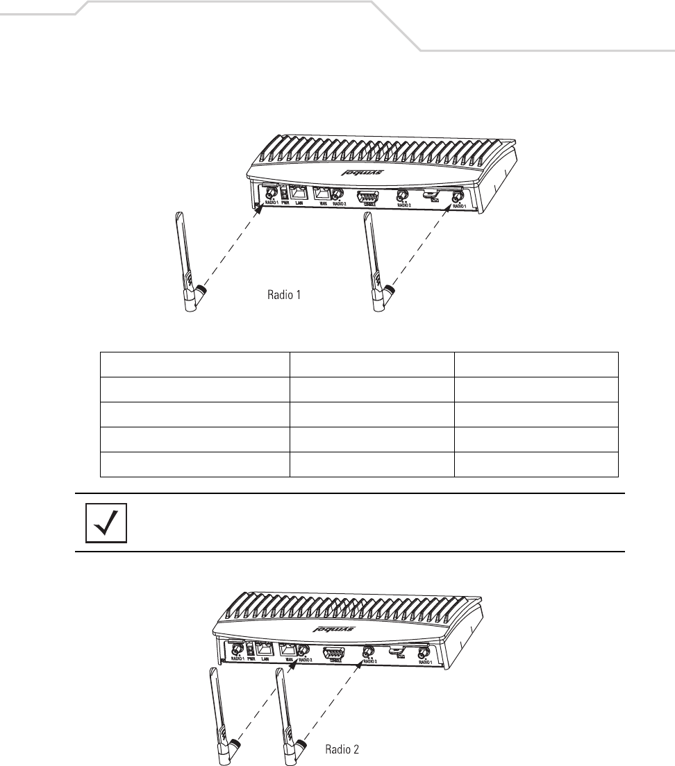
3.3.1 AP-5131 Antenna Options
Both Radio 1 and Radio 2 require one antenna and can optimally use two antennae per radio (4
antennae total for dual-radio models). Two antennae per radio provides diversity that can improve
performance and signal reception. Symbol supports two antenna suites for the AP-5131. One antenna
suite supporting the 2.4 GHz band and another antenna suite supporting the 5.2 GHz band. Select an
antenna model best suited to the intended operational environment of your AP-5131.
Antenna connectors for Radio 1 are located in a different location from the Radio 2 antenna
connectors. On single radio versions, the R-SMA connectors can support both bands and should be
connected to a R-SMA dual-band antenna or an appropriate single band antenna. If necessary a R-
SMA to R-BNC adapter (Part No. 25-72178-01) can be purchased separately from Symbol.
NOTE On a single-radio AP-5131, Radio 1 can be configured to be either a 2.4
GHz or 5.2 GHz radio. On a dual-radio model, Radio 1 refers to the AP-
5131’s 2.4 GHz radio and Radio 2 refers to the AP-5131 5.2 GHz radio.
However, there could be some cases where a dual-radio AP-5131 is
performing a Rogue AP detector function. In this scenario, the AP-5131 is
receiving in either 2.4 GHz or 5.2 GHz over the Radio 1 or Radio 2
antennae depending on which radio is selected for the scan.
Hardware Installation 7
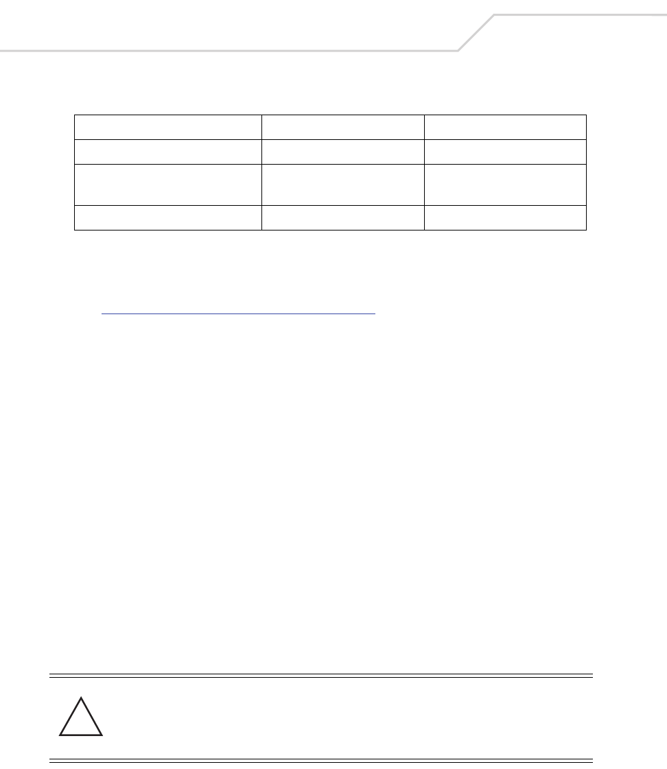
Certain Rogue AP Detection and Intrusion Detection features use an AP-5131 radio to perform dual-
band scanning. The dedicated radio should be connected to an appropriate dual-band dipole antenna
(Part No. ML-2452-APA2-01).
The 2.4 GHz antenna suite includes the following models:
Symbol Part Number Antenna Type Nominal Net Gain (dBi)
ML-2499-11PNA2-01 Wide Angle Directional 8.5
ML-2499-HPA3-01 Omni-Directional Antenna 3.3
ML-2499-BYGA2-01 Yagi Antenna 13.9
ML-2452-APA2-01 Dual-Band 3.0
NOTE An additional adapter is required to use ML-2499-11PNA2-01 and
ML-2499-BYGA2-01 model antennas. Please contact Symbol for more
information.
AP-5131 Access Point: Installation Guide
8
The 5.2 GHz antenna suite includes the following models:
For detailed specifications on the antennas available to the AP-5131, refer to the AP-5131 Product
Reference Guide. Appendix A of that document contains detailed AP-5131 antenna specifications and
their instructions for optimal use. The guide is on the CD-ROM shipped with the AP-5131, or can be
found at (http://www.symbol.com/services/downloads.html).
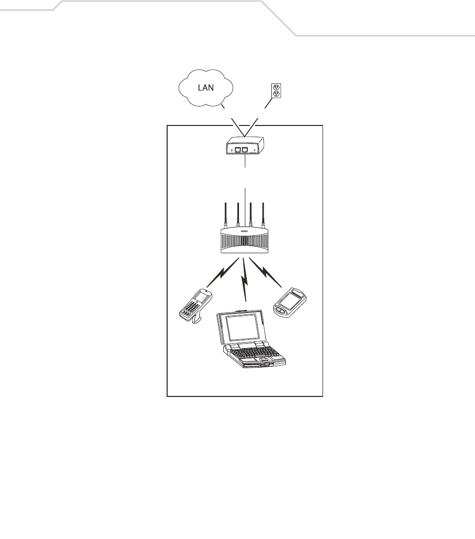
3.3.2 Symbol Power Injector System
The AP-5131 can receive power either directly form a Symbol 48V AC-DC power supply
(Part No. 50-24000-050) or via an Ethernet cable connected to the LAN port (using the 802.3af
standard).
When users purchase a Symbol WLAN solution, they often need to place access points in obscure
locations. In the past, a dedicated power source was required for each access point in addition to the
Ethernet infrastructure. This often required an electrical contractor to install power drops at each
access point location. An approved power injector solution merges power and Ethernet into one
cable, reducing the burden of installation and allows optimal AP-5131 placement in respect to the
intended radio coverage area.
The Symbol Power Injector is included in certain AP-5131 kits. The Symbol Power Injector
(Part No. AP-PSBIAS-T-1P-AF) is an integrated AC-DC converter and 802.3af power injector which
requires 110-220V AC power to combine low-voltage DC with Ethernet data in a single cable
connecting to the AP-5131.
The Symbol AP-5131 Power Supply (Part No. 50-24000-050) is not included in the kit and is orderable
separately as an accessory.
Symbol Part Number Antenna Type Nominal Net Gain (dBi)
ML-5299-WPNA1-01 Panel Antenna 13.0
ML-5299-HPA1-01 Wide-Band Omni-Directional
Antenna
5.0
ML-2452-APA2-01 Dual-Band 4.0
CAUTION The AP-5131 supports any standards-based 802.3af compliant power
source (including non-Symbol power sources). However, using the
wrong solution (including a POE system used on a legacy Symbol
access point) could severely damage the AP-5131 and void the
product warranty.
!
Hardware Installation 9
A separate Power Injector is required for each AP-5131 comprising the network.
The Power Injector can be installed free standing, on an even horizontal surface or wall mounted
using the power injector’s wall mounting key holes. The following guidelines should be adhered to
before cabling the Power Injector to an Ethernet source and an AP-5131:
• Do not block or cover airflow to the Power Injector.
• Keep the Power Injector away from excessive heat, humidity, vibration and dust.
• The Power Injector is not a repeater, and does not amplify the Ethernet data signal. For
optimal performance, ensure the Power Injector is placed as close as possible to the
network data port.
to AP-5131 LAN
Port
Data Power
AP-5131
Power
Injector
Wireless LAN
AP-5131 Access Point: Installation Guide
10
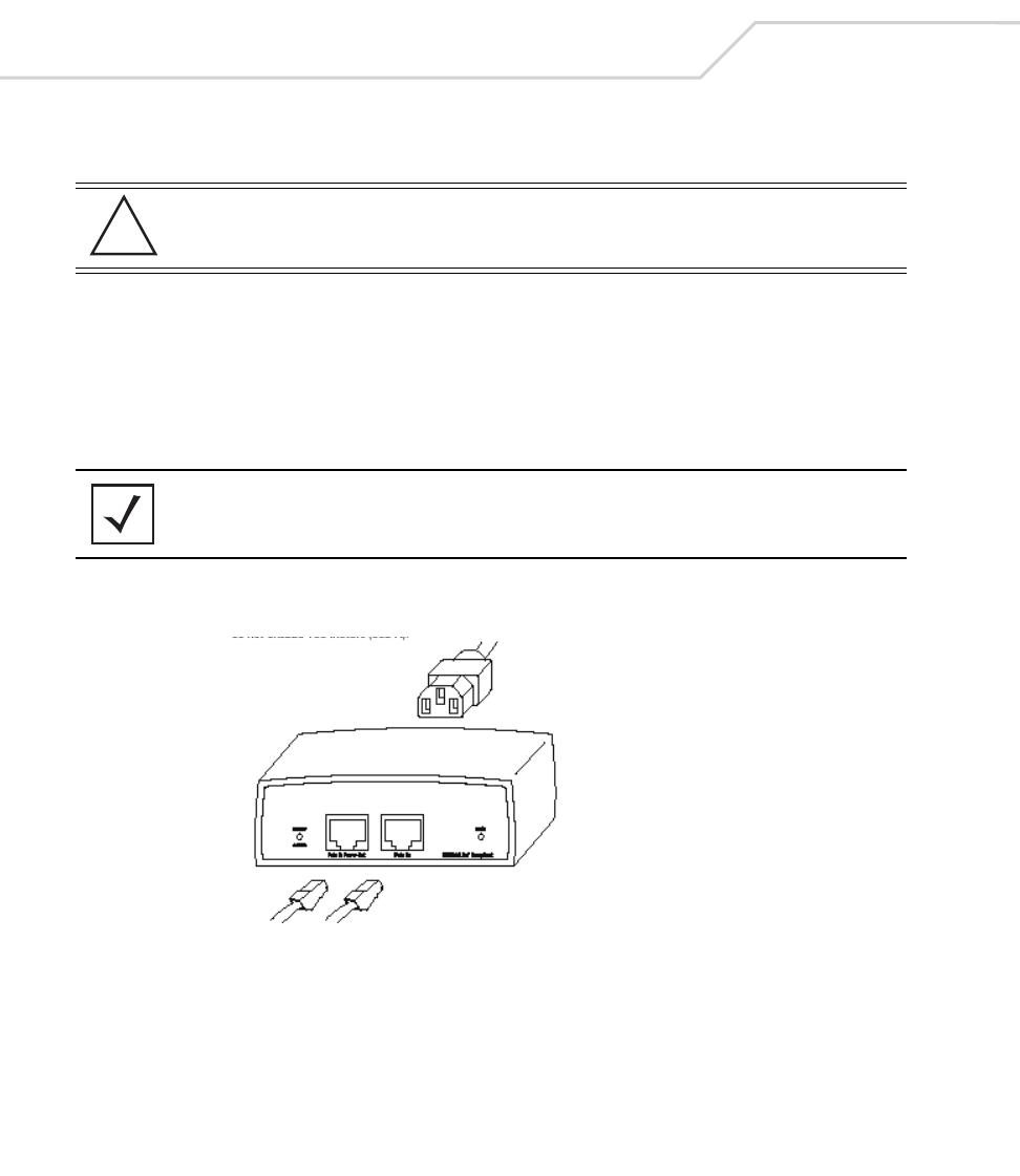
To install the Power Injector to an Ethernet data source and AP-5131:
1. Connect the Power Injector to an AC outlet (110VAC to 220VAC).
2. Connect an RJ-45 Ethernet cable between the network data supply (host) and the Power
Injector Data In connector.
3. Connect an RJ-45 Ethernet cable between the Power Injector Data & Power Out connector
and the Symbol AP-5131 LAN port.
Ensure the cable length from the Ethernet source (host) to the Power Injector and AP-5131
does not exceed 100 meters (333 ft).
The Power Injector has no On/Off power switch. The Power Injector receives power and is
ready for AP-5131 device connection and operation as soon as AC power is applied.
CAUTION Ensure AC power is supplied to the Power Injector using an AC cable
with an appropriate ground connection approved for the country of
operation.
NOTE Cabling the Power Injector to the AP-5131’s WAN port renders the
AP-5131 non-operational. Only use a AP-BIAS-T-1P-AF model power
injector with the AP-5131’s LAN port.
!

Hardware Installation 11
The Power Injector demonstrates the following LED behavior under normal and/or problematic
operating conditions:
For more information and device specifications for the Symbol Power Injector, refer to the Power
Injector Quick Install Guide (Part No. # 72-66153-01) available from the Symbol Web site or the AP-
5131 Software and documentation CD-ROM.
3.4 Mounting the AP-5131
The AP-5131 can rest on a flat surface, attach to a wall, mount under a suspended T-Bar or above a
ceiling (plenum or attic). Choose one of the following mounting options based on the physical
environment of the coverage area. Do not mount the AP-5131 in a location that has not been
approved in a site survey.
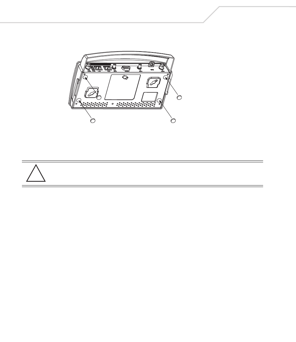
3.4.1 Desk Mounting
The desk mount option uses rubber feet (found in the accessories bag shipped with the AP-5131)
allowing the unit to sit on most flat surfaces.
To install the AP-5131 in a desk mount orientation:
1. Turn the AP-5131 upside down.
2. Remove the backings from the four (4) rubber feet and attach them to the four rubber feet
recess areas on the AP-5131.
LED AC (Main) Port
Green (Steady) Power Injector is receiving
power from AC outlet
Indicates a device is
connected to the
Power Injector’s outgoing
Data & Power cable
Green (Blinking) Output voltage source is out
of range
The Power Injector is
overloaded or has a
short circuit
AP-5131 Access Point: Installation Guide
12
3. Attach the Radio 1 and/or Radio 2 antennas to their correct connectors.
For information on the antennas available to the AP-5131, see
“AP-5131 Antenna Options” on page 6.
4. Cable the AP-5131 using either the Symbol Power Injector solution or an approved line cord
and power supply.
For Symbol Power Injector installations:
a. Connect a RJ-45 Ethernet cable between the network data supply (host) and the Power
Injector Data In connector.
b. Connect a RJ-45 Ethernet cable between the Power Injector Data & Power Out
connector and the Symbol AP-5131 LAN port.
c. Ensure the cable length from the Ethernet source (host) to the Power Injector and
AP-5131 does not exceed 100 meters (333 ft). The Power Injector has no On/Off power
switch. The Power Injector receives power as soon as AC power is applied. For more
information on using the Power Injector, see “Symbol Power Injector System” on
page 8.
For standard power adapter (non Power Injector) and line cord installations:
a. Connect RJ-45 Ethernet cable between the network data supply (host) and the AP-5131
LAN port.
b. Verify the power adapter is correctly rated according the country of operation.
CAUTION Ensure you are placing the antennae on the correct connectors
(depending on your single or dual-radio model and frequency used) to
ensure the successful operation of the AP-5131.
!
Hardware Installation 13
c. Connect the power supply line cord to the power adapter.
d. Attach the power adapter cable into the power connector on the AP-5131.
e. Attach the power supply line cord to a power supply
5. Verify the behavior of the AP-5131 LEDs. For more information, see “LED Indicators” on
page 21.
6. Return the AP-5131 to an upright position and place it in the location you wish it to operate.
Ensure the AP-5131 is sitting evenly on all four rubber feet.
7. The AP-5131 is ready to configure. For information on basic AP-5131 device configuration,
see “Configuring “Basic” Device Settings” on page 25.
3.4.2 Wall Mounting
Wall mounting requires hanging the AP-5131 along its width (or length) using the pair of slots on the
bottom of the unit and using the AP-5131 itself as a mounting template for the screws.
The mounting hardware and tools (customer provided) required to install the AP-5131 on a wall
consists of:
• Two Phillips pan head self-tapping screws
(ANSI Standard) #6-18 X 0.875in. Type A or AB Self-Tapping screw, or
(ANSI Standard Metric) M3.5 X 0.6 X 20mm Type D Self-Tapping screw
• Two wall anchors
• Security cable (optional)
To mount the AP-5131 on a wall:
1. Orient the AP-5131 on the or ceiling by its width or length.
2. Using the arrows on one edge of the case as guides, move the edge to the midline of the
mounting area and mark points on the midline for the screws.
CAUTION Do not actually connect to the power source until the cabling portion
of the installation is complete.
CAUTION An AP-5131 should be wall mounted to concrete or plaster-wall-board
(dry wall) only. Do not wall mount an AP-5131 to combustible
surfaces.
!
!
AP-5131 Access Point: Installation Guide
14
3. At each point, drill a hole in the wall, insert an anchor, screw into the anchor the wall
mounting screw and stop when there is 1mm between the screw head and the wall.
If pre-drilling a hole, the recommended hole size is 2.8mm (0.11in.) if the screws are going
directly into the wall and 6mm (0.23in.) if wall anchors are being used.
4. If required, install and attach a security cable to the AP-5131 lock port.
5. Place the large corner of each of the mount slots over the screw heads.
6. Slide the AP-5131 down along the mounting surface to hang the mount slots on the screw
heads.
7. Attach the Radio 1 and/or Radio 2 antennas to their correct connectors.
For information on the antennas available to the AP-5131, see
“AP-5131 Antenna Options” on page 6.
8. Cable the AP-5131 using either the Symbol Power Injector solution or an approved line cord
and power supply.
For Symbol Power Injector installations:
a. Connect a RJ-45 Ethernet cable between the network data supply (host) and the Power
Injector Data In connector.
b. Connect a RJ-45 Ethernet cable between the Power Injector Data & Power Out
connector and the Symbol AP-5131 LAN port.
c. Ensure the cable length from the Ethernet source (host) to the Power Injector and
AP-5131 does not exceed 100 meters (333 ft). The Power Injector has no On/Off power
switch. The Power Injector receives power as soon as AC power is applied. For more
information on using the Power Injector, see “Symbol Power Injector System” on
page 8.
For standard power adapter (non Power Injector) and line cord installations:
CAUTION Ensure you are placing the antennae on the correct connectors
(depending on your single or dual-radio model and frequency used) to
ensure the successful operation of the AP-5131.
NOTE The AP-5131 must be mounted with the RJ45 cable connector oriented
upwards to ensure proper operation.
!
Hardware Installation 15
a. Connect RJ-45 Ethernet cable between the network data supply (host) and the AP-5131
LAN port.
b. Verify the power adapter is correctly rated according the country of operation.
c. Connect the power supply line cord to the power adapter.
d. Attach the power adapter cable into the power connector on the AP-5131.
e. Attach the power supply line cord to a power supply
9. Verify the behavior of the AP-5131 LEDs. For more information, see “LED Indicators” on
page 21.
10. The AP-5131 is ready to configure. For information on basic AP-5131 device configuration,
see “Configuring “Basic” Device Settings” on page 25.
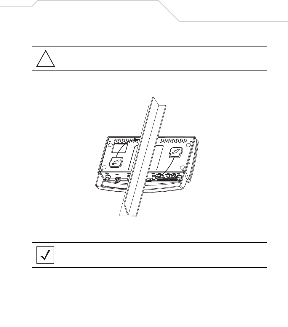
3.4.3 Suspended Ceiling T-Bar Installations
A suspended ceiling mount requires holding the AP-5131 up against the T-bar of a suspended ceiling
grid and twisting the AP-5131 chassis onto the T-bar.
The mounting hardware and tools (customer provided) required to install the AP-5131 on a ceiling
T-bar consists of:
• Safety wire (recommended)
• Security cable (optional)
To install the AP-5131 on a ceiling T-bar:
1. If required, loop a safety wire — with a diameter of at least 1.01 mm (.04 in.), but no more
than 0.158 mm (.0625 in.) — through the tie post (above the AP-5131’s console connector)
and secure the loop.
2. If required, install and attach a security cable to the AP-5131 lock port.
3. Attach the Radio 1 and/or Radio 2 antennas to their correct connectors.
CAUTION Do not actually connect to the power source until the cabling portion
of the installation is complete.
NOTE If the AP-5131 is utilizing remote management antennas, a wire cover
can be used to provide a clean finished look to the installation. Contact
Symbol for more information.
!
AP-5131 Access Point: Installation Guide
16
For information on the antennas available to the AP-5131, see
“AP-5131 Antenna Options” on page 6.
4. Cable the AP-5131 using either the Symbol Power Injector solution or an approved line cord
and power supply.
For Symbol Power Injector installations:
a. Connect a RJ-45 Ethernet cable between the network data supply (host) and the Power
Injector Data In connector.
b. Connect a RJ-45 Ethernet cable between the Power Injector Data & Power Out
connector and the Symbol AP-5131 LAN port.
c. Ensure the cable length from the Ethernet source (host) to the Power Injector and
AP-5131 does not exceed 100 meters (333 ft). The Power Injector has no On/Off power
switch. The Power Injector receives power as soon as AC power is applied. For more
information, see “Symbol Power Injector System” on page 8.
For standard power adapter (non Power Injector) and line cord installations:
a. Connect RJ-45 Ethernet cable between the network data supply (host) and the AP-5131
LAN port.
b. Verify the power adapter is correctly rated according the country of operation.
c. Connect the power supply line cord to the power adapter.
d. Attach the power adapter cable into the power connector on the AP-5131.
e. Attach the power supply line cord to a power supply.
5. Verify the behavior of the AP-5131 LEDs. For more information, see “LED Indicators” on
page 21.
6. Align the bottom of the ceiling T-bar with the back of the AP-5131.
7. Orient the AP-5131 chassis by its length and the length of the ceiling T-bar.
8. Rotate the AP-5131 chassis 45 degrees clockwise, or about 10 o’clock.
CAUTION Ensure you are placing the antennae on the correct connectors
(depending on your single or dual-radio model and frequency used) to
ensure the successful operation of the AP-5131.
CAUTION Do not actually connect to the power source until the cabling portion
of the installation is complete.
!
!
Hardware Installation 17
9. Push the back of the AP-5131 chassis on to the bottom of the ceiling T-bar.
10. Rotate the AP-5131 chassis 45 degrees counter-clockwise.
The clips click as they fasten to the T-bar.
11. The AP-5131 is ready to configure. For information on basic AP-5131 device configuration,
see “Configuring “Basic” Device Settings” on page 25.
3.4.4 Above the Ceiling (Plenum) Installations
An AP-5131 above the ceiling installation requires placing the AP-5131 above a suspended ceiling
and installing the provided light pipe under the ceiling tile for viewing the rear panel status LEDs of
CAUTION Ensure the safety wire and cabling used in the T-Bar AP-5131
installation is securely fastened to the building structure in order to
provide a safe operating environment.
NOTE If the AP-5131 is utilizing remote management antennas, a wire cover
can be used to provide a clean finished look to the installation. Contact
Symbol for more information.
!
AP-5131 Access Point: Installation Guide
18
the unit. An above the ceiling AP-5131 installation enables installations compliant with drop ceilings,
suspended ceilings and industry standard tiles from.625 to.75 inches thick.
The mounting hardware required to install the AP-5131 above a ceiling consists of:
• Light pipe
• Badge for light pipe
• Decal for badge
• Safety wire (strongly recommended)
• Security cable (optional)
To install the AP-5131 above a ceiling:
1. If possible, remove the adjacent ceiling tile from its frame and place it aside.
2. If required, install a safety wire, between 1.5mm (.06in.) and 2.5mm (.10in.) in diameter, in
the ceiling space.
3. If required, install and attach a security cable to the AP-5131’s lock port.
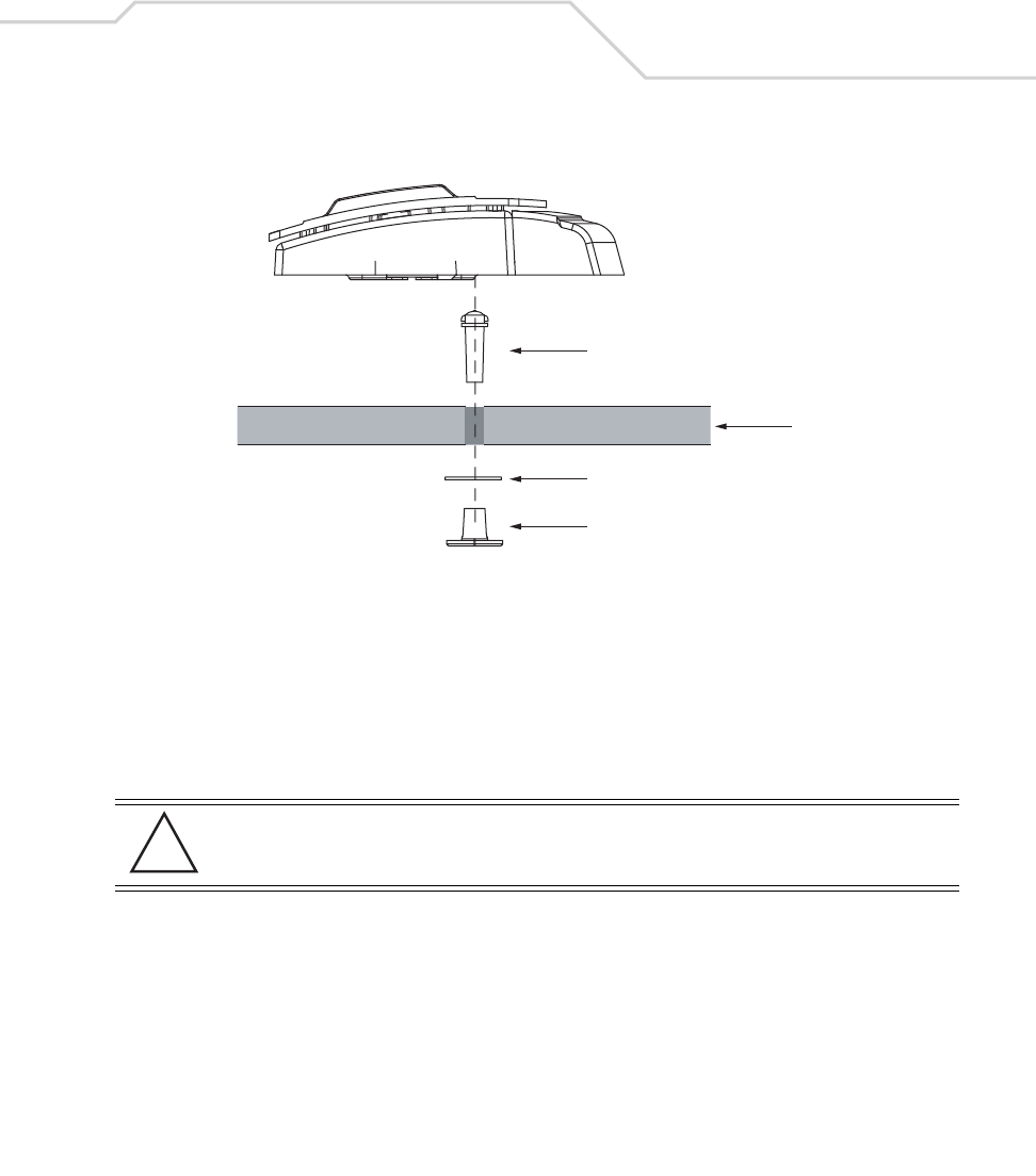
4. Mark a point on the finished side of the tile where the light pipe is to be located.
5. Create a light pipe path hole in the target position on the ceiling tile.
6. Use a drill to make a hole in the tile the approximate size of the AP-5131 LED light pipe.
7. Remove the light pipe’s rubber stopper (from the AP-5131) before installing the light pipe.
NOTE The AP-5131 is Plenum rated to UL2043 and NEC1999 for above the
ceiling installations.
CAUTION Symbol does not recommend mounting the AP-5131 directly to any
suspended ceiling tile with a thickness less than 12.7mm (0.5in.) or a
suspended ceiling tile with an unsupported span greater than 660mm
(26in.). Symbol strongly recommends fitting the AP-5131 with a safety
wire suitable for supporting the weight of the device. The safety wire
should be a standard ceiling suspension cable or equivalent steel wire
between 1.59mm (.062in.) and 2.5mm (.10in.) in diameter.
CAUTION Symbol recommends care be taken not to damage the finished surface
of the ceiling tile when creating the light pipe hole and installing the
light pipe.
!
!
Hardware Installation 19
8. Connect the light pipe to the bottom of the AP-5131. Align the tabs and rotate approximately
90 degrees. Do not over tighten.
9. Snap the clips on the light pipe into the bottom of the AP-5131.
10. Fit the light pipe into hole in the tile from its unfinished side.
11. Place the decal on the back of the badge and slide the badge onto the light pipe from the
finished side of the tile.
12. Attach the Radio 1 and/or Radio 2 antennas to their correct connectors.
For information on the antennas available to the AP-5131, see
“AP-5131 Antenna Options” on page 6.
13. Attach safety wire (if used) to the AP-5131 safety wire tie point or security cable (if used) to
the AP-5131’s lock port.
14. Align the ceiling tile into its former ceiling space.
15. Cable the AP-5131 using either the Symbol Power Injector solution or an approved line cord
and power supply.
For Symbol Power Injector installations:
a. Connect a RJ-45 Ethernet cable between the network data supply (host) and the Power
Injector Data In connector.
CAUTION Ensure you are placing the antennae on the correct connectors
(depending on your single or dual-radio model and frequency used) to
ensure the successful operation of the AP-5131.
Light Pipe
Decal
Badge
Ceiling Tile
!
AP-5131 Access Point: Installation Guide
20
b. Connect a RJ-45 Ethernet cable between the Power Injector Data & Power Out
connector and the Symbol AP-5131 LAN port.
c. Ensure the cable length from the Ethernet source (host) to the Power Injector and
AP-5131 does not exceed 100 meters (333 ft). The Power Injector has no On/Off power
switch. The Power Injector receives power as soon as AC power is applied. For more
information on using the Power Injector, see “Symbol Power Injector System” on
page 8.
For standard power adapter (non Power Injector) and line cord installations:
a. Connect RJ-45 Ethernet cable between the network data supply (host) and the AP-5131
LAN port.
b. Verify the power adapter is correctly rated according the country of operation.
c. Connect the power supply line cord to the power adapter.
d. Attach the power adapter cable into the power connector on the AP-5131.
e. Attach the power supply line cord to a power supply.
16. Verify the behavior of the AP-5131 LED light pipe. For more information, see “LED
Indicators” on page 21.
17. Place the ceiling tile back in its frame and verify it is secure.
18. The AP-5131 is ready to configure. For information on basic AP-5131 device configuration,
see “Configuring “Basic” Device Settings” on page 25.
CAUTION Do not actually connect to the power source until the cabling portion
of the installation is complete.
!
Hardware Installation 21
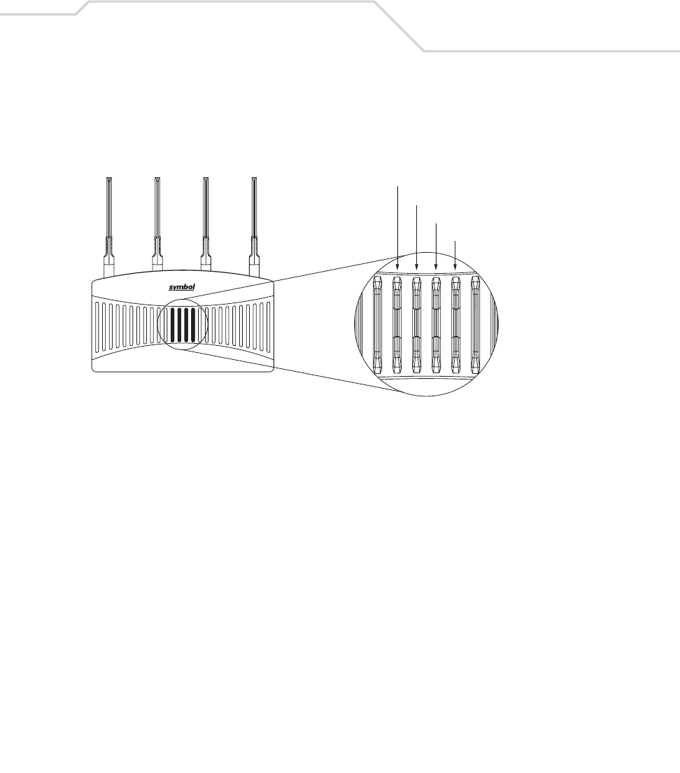
3.5 LED Indicators
The AP-5131 utilizes seven LED indicators. Five LEDs display within four LED slots on the front of the
AP-5131 (on top of the AP-5131 housing) and two LEDs (for above the ceiling installations) are located
on the back of the device (the side containing the LAN, WAN and antenna connectors).
The five LEDs on the top housing of the AP-5131 are clearly visible in table-top, wall and below ceiling
installations. The five AP-5131 top housing LEDs have the following display and functionality:
Boot and Power Status Solid white indicates the AP-5131 is adequately
powered.
Error Conditions Solid red indicates the AP-5131 is experiencing
a problem condition requiring immediate
attention.
Ethernet Activity Flashing white indicates data transfers and
Ethernet activity.
802.11a Radio Activity Flickering amber indicates beacons and data
transfers over the AP-5131 802.11a radio.
Data Over Ethernet
802.11a Radio Activity
802.11b/g Radio Activity
Power and Error Conditions (Split LE
D)
AP-5131 Access Point: Installation Guide
22
The LEDs on the rear of the AP-5131 are viewed using a single (customer installed) extended light
pipe, adjusted as required to suit above the ceiling installations. The LEDs displayed using the light
pipe have the following color display and functionality:
4 Basic AP-5131 Configuration
For the basic setup described in this guide, the Java-based Web UI will be used to configure the
AP-5131. Use the AP-5131’s LAN interface for establishing a link with the AP-5131. Configure the
AP-5131 as a DHCP client. For optimal viewing of the Web UI, the screen resolution should be set to
1024 x 768 pixels or greater.
802.11b/g Radio Activity Flickering green indicates beacons and data
transfers over the AP-5131 802.11b/g radio.
Boot and Power Status Solid white indicates the AP-5131 is adequately
powered.
Error Conditions Solid red indicates the AP-5131 is experiencing
a problem condition requiring immediate
attention.
Blinking red indicates the AP-5131 Rogue AP
Detection feature has located a rogue device.
NOTE For advanced configuration options beyond the scope of this guide, refer
to the AP-5131 Product Reference Guide. The guide is on the CD-ROM
shipped with the AP-5131, or can be found at
(http://www.symbol.com/services/downloads.html).
Basic AP-5131 Configuration 23
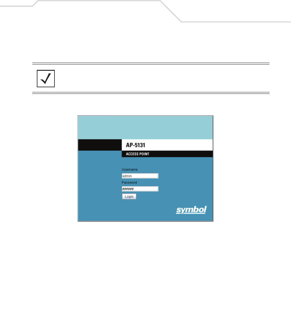
1. Start Internet Explorer and enter the following IP address in the address field:
192.168.0.1
The AP-5131 login screen displays.
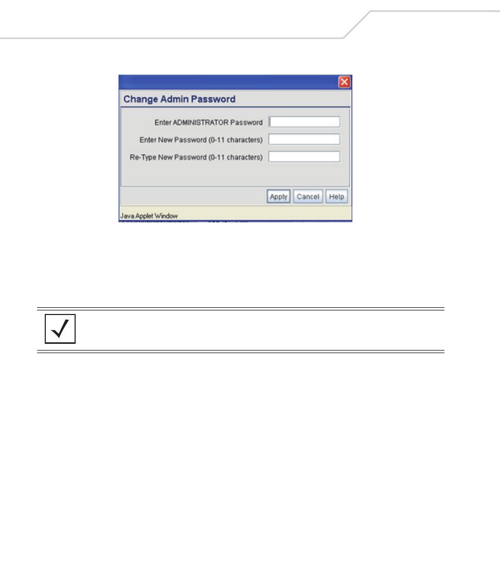
2. Log in using admin as the default User ID and symbol as the default password. If the
default login is successful, the Change Admin Password window displays.
3. Change the password.
NOTE For optimum compatibility, use Sun Microsystems’ JRE 1.5 or higher
(available from Sun’s Website), and be sure to disable Microsoft’s Java
Virtual Machine if installed.
AP-5131 Access Point: Installation Guide
24
Enter the current password and a new admin password in fields provided, and click Apply.
Once the admin password has been updated, a warning message displays stating the AP-
5131 could be operating illegally unless set to operate in the correct country. Proceed to
“Configuring “Basic” Device Settings” on page 25 to ensure the country setting is
defined correctly.
3.1.1 Resetting the AP-5131 Password
The AP-5131 Command Line Interface (CLI) enables users who forget their password to reset it to the
factory default (symbol). From there, a new password can be defined. To reset the AP-5131 password
back to its default setting:
1. Connect one end of a null modem serial cable to the AP-5131’s serial connector. Attach the
other end of the null modem serial cable to the serial port of a PC running HyperTerminal or
a similar emulation program.
2. Set the HyperTerminal program to use 19200 baud, 8 data bits, 1 stop bit, no parity, no flow
control and auto-detect for terminal emulation.
3. Press <ESC> or <Enter> to access the AP-5131 CLI.
A serial connection has now been established and the user should be able to view the serial
connection window.
NOTE Though the AP-5131 can have its basic settings defined using a number of
different screens, Symbol recommends using the AP-5131 Quick Setup
screen to define a minimum required configuration from one location.

Basic AP-5131 Configuration 25
4. Reset the AP-5131. An AP-5131 can be reset by removing and re-inserting the LAN cable or
removing and re-inserting the power cable.
As the AP-5131 is re-booting, a “Press esc key to run boot firmware” message displays.
5. Quickly press <ESC>.
If the <ESC> key is pressed within three seconds a boot> prompt displays.
6. Type the following at the boot prompt:
passwd default
7. Reset the AP-5131 by typing the following at the boot prompt:
reset system
When the AP-5131 re-boots again, the password will return to its default value of “symbol.”
You can now access the AP-5131.
4.1 Configuring “Basic” Device Settings
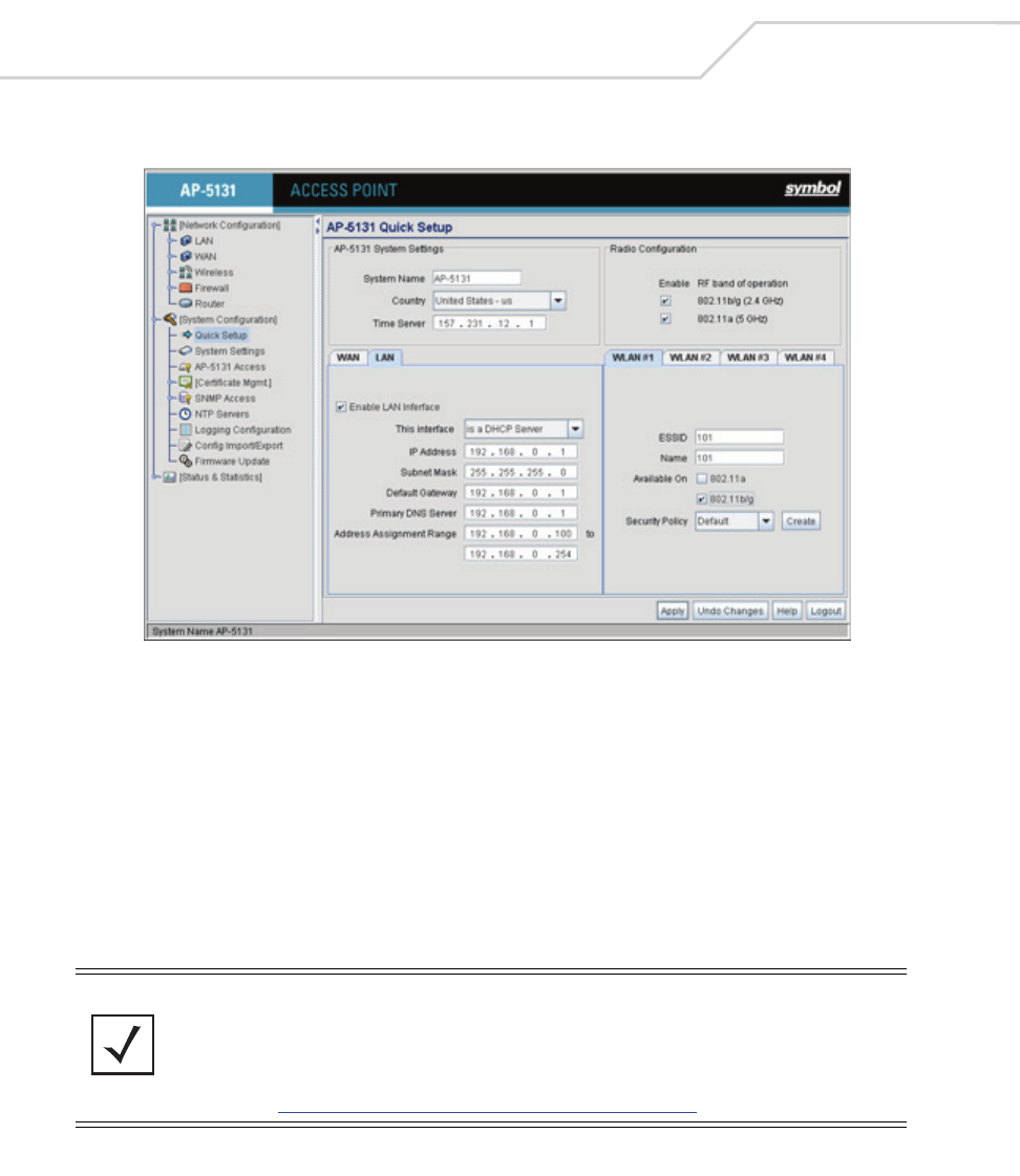
Configure a set of minimum required device settings within the AP-5131 Quick Setup screen. The
values defined within the Quick Setup screen are also configurable in numerous other locations
within the AP-5131 menu tree. When you change the settings in the Quick Setup screen, the values
also change within the screen where these parameters also exist. Additionally, if the values are
updated in these other screens, the values initially set within the Quick Setup screen will be updated.
To define a basic AP-5131 configuration:
CAUTION If the <ESC> key is not pressed within three seconds after the “Press
esc key to run boot firmware” message displays, the AP-5131 will
continue to boot.
!
AP-5131 Access Point: Installation Guide
26
1. Select System Configuration -> Quick Setup from the AP-5131 menu tree.
2. Enter a System Name for the AP-5131.
The System Name is useful if multiple Symbol devices are being administered.
3. Select the Country for the AP-5131’s country of operation from the drop-down menu.
The AP-5131 prompts the user for the correct country code on the first login. A warning
message also displays stating that an incorrect country setting may result in illegal radio
operation. Selecting the correct country is central to legally operating the AP-5131. Each
country has its own regulatory restrictions concerning electromagnetic emissions and the
maximum RF signal strength that can be transmitted. To ensure compliance with national
and local laws, be sure to set the Country accurately. CLI and MIB users cannot configure
their AP-5131 until a two character country code (for example, United States - us) is set.
NOTE The System Name and Country are also configurable within the System
Settings screen. Refer to the AP-5131 Product Reference Guide to
optionally set a system location and admin email address for the AP-5131
or to change other default settings. The guide is on the CD-ROM shipped
with the AP-5131, or can be found at
(http://www.symbol.com/services/downloads.html).

Basic AP-5131 Configuration 27
4. Optionally enter the IP address of the server used to provide system time to the AP-5131
within the Time Server field.
Once the IP address is entered, the AP-5131’s Network Time Protocol (NTP) functionality is
engaged automatically. Refer to the AP-5131 Product Reference Guide for information on
defining alternate time servers and setting a synchronization interval for the AP-5131 to
adjust its displayed time. The guide is on the CD-ROM shipped with the AP-5131, or can be
found at (http://www.symbol.com/services/downloads.html).
5. Click the WAN tab to set a minimum set of parameters for using the WAN interface.
a. Select the Enable WAN Interface checkbox to enable a connection between the
AP-5131 and a larger network or outside world through the WAN port. Disable this
option to effectively isolate the AP-5131’s WAN connection. No connections to a larger
network or the Internet will be possible. MUs cannot communicate beyond the
configured subnets.
b. Select the This Interface is a DHCP Client checkbox to enable DHCP for the AP-5131
WAN connection. This is useful, if the target corporate network or Internet Service
Provider (ISP) uses DHCP. DHCP is a protocol that includes mechanisms for IP address
allocation and delivery of host-specific configuration parameters from a DHCP server to
a host. Some of these parameters are IP address, network mask, and gateway.
c. Specify an IP address for the AP-5131’s WAN connection. An IP address uses a series
of four numbers expressed in dot notation, for example, 190.188.12.1.
d. Specify a Subnet Mask for the AP-5131’s WAN connection. This number is available
from the ISP for a DSL or cable-modem connection, or from an administrator if the
AP-5131 connects to a larger network. A subnet mask uses a series of four numbers
expressed in dot notation. For example, 255.255.255.0 is a valid subnet mask.
e. Specify a Default Gateway address for the AP-5131’s WAN connection. The ISP or a
network administrator provides this address.
f. Specify the address of a Primary DNS Server. The ISP or a network administrator
provides this address.
6. Optionally, use the Enable PPP over Ethernet checkbox to enable Point-to-Point over
Ethernet (PPPoE) for a high-speed connection that supports this protocol. Most DSL
providers are currently using or deploying this protocol. PPPoE is a data-link protocol for
dialup connections. PPPoE will allow the AP-5131 to use a broadband modem (DSL, cable
modem, etc.) for access to high-speed data networks.
a. Select the Keep Alive checkbox to enable occasional communications over the WAN
port even when client communications to the WAN are idle. Some ISPs terminate

AP-5131 Access Point: Installation Guide
28
inactive connections, while others do not. In either case, enabling Keep-Alive maintains
the WAN connection, even when there is no traffic. If the ISP drops the connection after
the idle time, the AP-5131 automatically reestablishes the connection to the ISP.
b. Specify a Username entered when connecting to the ISP. When the Internet session
begins, the ISP authenticates the username.
c. Specify a Password entered when connecting to the ISP. When the Internet session
starts, the ISP authenticates the password.
7. Click the LAN tab to set a minimum set of parameters to use the AP-5131 LAN interface.
a. Select the Enable LAN Interface checkbox to forward data traffic over the AP-5131
LAN connection. The LAN connection is enabled by default.
b. Use the This Interface drop-down menu to specify how network address information
is defined over the AP-5131’s LAN connection. Select DHCP Client if the larger
corporate network uses DHCP. DHCP is a protocol that includes mechanisms for IP
address allocation and delivery of host-specific configuration parameters from a DHCP
server to a host. Some of these parameters are IP address, network mask, and gateway.
Select DHCP Server to use the AP-5131 as a DHCP server over the LAN connection.
c. Enter the network-assigned IP Address of the AP-5131.
d. The Subnet Mask defines the size of the subnet. The first two sets of numbers specify
the network domain, the next set specifies the subset of hosts within a larger network.
These values help divide a network into subnetworks and simplify routing and data
transmission.
e. Enter a Default Gateway to define the IP address of a router the AP-5131 uses on the
Ethernet as its default gateway.
f. Enter the Primary DNS Server IP address.
g. If using DHCP Server, use the Address Assignment Range parameter to specify a
range of IP address reserved for mapping clients to IP addresses. If a manually (static)
mapped IP address is within the IP address range specified, that IP address could still be
assigned to another client. To avoid this, ensure all statically mapped IP addresses are
outside of the IP address range assigned to the DHCP server.
NOTE For additional AP-5131 WAN and LAN port configuration options, as well
as radio, WLAN and Quality of Service (QoS) options, refer to the AP-5131
Product Reference Guide. The guide is on the CD-ROM shipped with the
AP-5131, or can be found at
(http://www.symbol.com/services/downloads.html).
Basic AP-5131 Configuration 29
8. Enable the radio(s) using the Radio Enable checkbox(es). If using a single radio model,
enable the radio, then select either 802.11a (5 GHz) or 802.11b/g (2.4 GHz) from the RF Band
of Operation field. Only one RF band option at a time is permissible in a single-radio model.
If using a dual-radio AP-5131, the user can enable both RF bands.
9. Select the WLAN #1 tab (WLANs 1 - 4 are available within the Quick Setup screen) to define
its ESSID security scheme for basic operation.
a. Enter the Extended Services Set Identification (ESSID) and name associated with the
WLAN.
b. Use the Available On checkboxes to define whether the target WLAN is operating over
the 802.11a or 802.11b/g radio. Ensure the radio selected has been enabled (see step 8).
c. Even an AP-5131 configured with minimal values must protect its data against theft and
corruption. A security policy should be configured for WLAN1 as part of the basic
configuration outlined in this guide. A security policy can be configured for the WLAN
from within the Quick Setup screen. Policies can be defined over time and saved to be
used as needed as the AP-5131’s security requirements change. Symbol recommends
you familiarize yourself with the security options available on the AP-5131 before
defining a security policy. Refer to Configuring Basic AP-5131 Security on page -30.
10. Click Apply to save any changes to the AP-5131 Quick Setup screen. Navigating away from
the screen without clicking Apply results in all changes to the screens being lost, unless you
use the Un-applied Changes pop-up window to overwrite the current settings.
11. Click Undo Changes (if necessary) to undo any changes made. Undo Changes reverts the
settings displayed on the AP-5131 Quick Setup screen to the last saved configuration.
NOTE A maximum of 16 WLANs are configurable within the AP-5131 Wireless
Configuration screen. The limitation of 16 WLANs exists regardless of
whether the AP-5131 has a single or dual-radio.
AP-5131 Access Point: Installation Guide
30
4.1.1 Configuring Basic AP-5131 Security
For testing basic connectivity, there is no reason to configure a server supported authentication
scheme. WEP 128 is described in this guide as a basic security scheme sufficient to protect the
AP-5131’s initial transmissions. For details on configuring more sophisticated authentication and
encryption options available to the AP-5131, refer to the AP-5131 Product Reference Guide. The guide
is on the CD-ROM shipped with the AP-5131, or can be found at
(http://www.symbol.com/services/downloads.html).
To configure WEP 128:
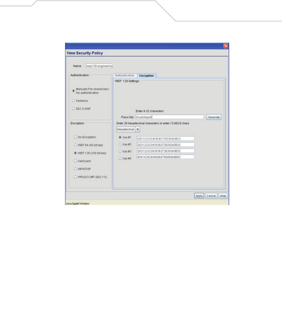
1. From the AP-5131 Quick Setup screen, click the Create button to the right of the Security
Policy item.
The New Security Policy screen displays with the Manually Pre-shared key/No
authentication and No Encryption options selected. Naming and saving such a policy (as is)
would provide no security and might only make sense in a guest network wherein no
sensitive data is either transmitted or received. Consequently, at a minimum, a basic
security scheme (in this case WEP 128) is recommended.
2. Ensure the Name of the security policy entered suits the intended configuration or function
of the policy.
Multiple WLANs can share the same security policy, so be careful not to name security
policies after specific WLANs or risk defining a WLAN to single policy. Symbol recommends
naming the policy after the attributes of the authentication or encryption type selected.
3. Select the WEP 128 (104 bit key) checkbox.
NOTE For information on configuring the other (more sophisticated) encryption
and authentication options available to the AP-5131, refer to the AP-5131
Product Reference Guide. The guide is on the CD-ROM shipped with the
AP-5131, or can be found at
(http://www.symbol.com/services/downloads.html).
Basic AP-5131 Configuration 31
The WEP 128 Setting field displays within the New Security Policy screen.

AP-5131 Access Point: Installation Guide
32
4. Configure the WEP 128 Setting field as required to define the Pass Key used to generate
the WEP keys.
5. Click the Apply button to save the security policy and return to the AP-5131 Quick Setup
screen.
At this point, you can either restrict specific MU access to the AP-5131 (using the AP-5131
ACL) or test the AP-5131 for MU interoperability.
4.1.2 Excluding MUs from AP-5131 Association
Optionally, use the AP-5131 Access Control List ACL to specify which MUs can or cannot gain access
to an AP-5131 managed WLAN. By default, all mobile units can gain access. For specific information
on configuring (restricting) MU access, refer to the AP-5131 Product Reference Guide. The guide is on
the CD-ROM shipped with the AP-5131, or can be found at
(http://www.symbol.com/services/downloads.html).
Pass Key Specify a 4 to 32 character pass key and click the Generate button.
The AP-5131, other proprietary routers and Symbol MUs use the
same algorithm to convert an ASCII string to the same hexadecimal
number. Non-Symbol clients and devices need to enter WEP keys
manually as hexadecimal numbers. The AP-5131 and its target
client(s) must use the same pass key to interoperate.
Keys #1-4 Use the Key #1-4 fields to specify key numbers. The key can be
either a hexidecimal or ASCII depending on which option is
selected from the drop-down menu. For WEP 64 (40-bit key), the
keys are 10 hexadecimal characters in length or 5 ASCII characters.
For WEP 128 (104-bit key), the keys are 26 hexadecimal characters
in length or 13 ASCII characters. Select one of these keys for
activation by clicking its radio button. The AP-5131 and its target
client(s) must use the same key to interoperate.
Basic AP-5131 Configuration 33
4.1.3 Testing Mobile Unit Connectivity
Verify the AP-5131’s link with an MU by sending Wireless Network Management Protocol (WNMP)
ping packets to the associated MU. Use the Echo Test screen to specify a target MU and configure
the parameters of the ping test. The WNMP ping test only works with Symbol MUs. Only use a
Symbol MU to test AP-5131 connectivity using WNMP.
To ping a specific MU to assess its connection with an AP-5131:
1. Select Status and Statistics - > MU Stats from the AP-5131 menu tree.
2. Select the Echo Test button from within the MU Stats Summary screen.
3. Define the following ping test parameters:
4. Click the Ping button to begin transmitting ping packets to the MU address specified.
Refer to the Number of Responses value to assess the number of responses from the
target MU versus the number of pings transmitted by the AP-5131. Use the ratio of packets
sent versus packets received to assess the link quality between MU and the AP-5131.
Click the Ok button to exit the Echo Test screen and return to the MU Stats Summary screen.
With basic AP-5131 and associated MU connectivity verified, the AP-5131 is now ready to
operate as defined within this guide or have its more advanced features configured.
NOTE Before testing for connectivity, the target MU needs to be set to the same
ESSID as the AP-5131. Since WEP 128 has been configured for the AP-
5131, the MU also needs to be configured for WEP 128 and use the same
WEP keys. Ensure the MU is associated with the AP-5131 before testing
for connectivity.
Station Address The station address is the IP address of the target MU. Refer to the
MU Stats Summary screen for associated MU IP address
information.
Number of ping Specify the number of ping packets to transmit to the target MU.
The default is 100.
Packet Length Specify the length of each data packet transmitted to the target
MU during the ping test. The default is 100 bytes.

AP-5131 Access Point: Installation Guide
34
4.2 Where to Go From Here?
Once basic connectivity has been verified, the AP-5131 can be fully configured to meet the needs of
the network and the users it supports. The sections referenced below are located within the
AP-5131 Product Reference Guide available on your product CD-ROM or from the Symbol Web site
(http://www.symbol.com/services/downloads).
• Refer to Chapter 4 to define System Settings (beyond the scope of the Quick Setup
screen), configure AP-5131 device access, set SNMP values, log AP-5131 system events,
set the AP-5131 system time and import device firmware and configuration files.
• See Chapter 5 for information on configuring the AP-5131 LAN and WAN ports, define
up to 16 individual WLANs and their QoS policies and configure AP-5131 router settings.
• Refer to Chapter 6 for detailed information on configuring specific encryption (WEP,
KeyGuard, WPA/TKIP and WPA2/CCMP) and authentication (Kerberos and 802.1x EAP)
security schemes.
• See Chapter 7 for information on accessing statistics helpful in monitoring the
connection between the AP-5131 and its connected devices.
• Refer to Chapter 8 for information on using the AP-5131 Command Line Interface (CLI),
as accessed through the serial port or Telnet.
• See Appendix A for device specifications.
Regulatory Compliance 35
5 Regulatory Compliance
All Symbol devices are designed to be compliant with rules and regulations in locations they are sold and will be labeled
as required. Any changes or modifications to Symbol Technologies equipment, not expressly approved by Symbol
Technologies, could void the user's authority to operate the equipment.
Symbol's devices are professionally installed, the Radio Frequency Output Power will not exceed the maximum allowable
limit for the country of operation.
Antennas: Use only the supplied or an approved replacement antenna. Unauthorized antennas, modifications, or
attachments could cause damage and may violate regulations.
This guide is available in local languages, translations can be downloaded from the following website:
http://www.symbol.com/services/manuals/.
Country Approvals
Regulatory markings are applied to the device signifying the radio (s) are approved for use in the following countries: United
States, Canada, Australia, Japan and Europe (see notes 1 and 2).
Please refer to the Symbol Declaration of Conformity (DoC) for details of other country markings. This is available at
http://www2.symbol.com/doc/.
Note 1: For 2.4GHz Products: Europe includes, Austria, Belgium, Czech Republic, Cyprus, Denmark, Estonia, Finland, France,
Germany, Greece, Hungary, Iceland, Ireland, Italy, Latvia, Liechtenstein, Lithuania, Luxembourg, Malta, Netherlands,
Norway, Poland, Portugal, Slovak Republic, Slovenia, Spain, Sweden, Switzerland and the United Kingdom.
Note 2: The use of 5GHz RLAN's has varying restrictions of use; please refer to the Symbol Declaration of Conformity (DoC)
for details.
Operation of the device without regulatory approval is illegal.
Health and Safety Recommendations
Warnings for the use of Wireless Devices
Please observe all warning notices with regard to the usage of wireless devices
Potentially Hazardous Atmospheres
You are reminded to observe restrictions on the use of radio devices in fuel depots, chemical plants etc. and areas where
the air contains chemicals or particles (such as grain, dust, or metal powders) and any other area where you would normally
be advised to turn off your vehicle engine.

AP-5131 Access Point: Installation Guide
36
Safety in Hospitals
Wireless devices transmit radio frequency energy and may affect medical electrical equipment. When installed adjacent to
other equipment, it is advised to verify that the adjacent equipment is not adversely affected.
FCC / EU RF Exposure Guidelines
Safety Information
The device complies with Internationally recognized standards covering Specific Absorption Rate (SAR) related to human
exposure to electromagnetic fields from radio devices.
Reducing RF Exposure—Use Properly
It is advisable to use the device only in the normal operating position.
Remote and Standalone Antenna Configurations
To comply with FCC RF exposure requirements, antennas that are mounted externally at remote locations or operating near
users at stand-alone desktop of similar configurations must operate with a minimum separation distance of 20 cm from all
persons.
Power Supply
Use only a Symbol approved power supply (p/n 50-24000-050) output rated 48 Vdc and minimum 0.25 A. The power supply
is certified to EN60950-1 with SELV outputs. Use of alternative power supply will invalidate the 60950-1 approval given to
this device and may be dangerous.
The AP5131 can also be powered from a 802.3af compliant power source. Use only a certified and correctly rated device as
appropriate for the country of operation.
Wireless Devices - Countries
Country Selection
Select only the country in which you are using the device. Any other selection will make the operation of this device illegal.
Operation in the US
The use on UNII (Unlicensed National Information Infrastructure) Band 1 5150-5250 MHz is restricted to indoor use only, any
other use will make the operation of this device illegal.
The available channels for 802.11 b/g operation in the US are Channels 1 to 11. The range of channels is limited by firmware.

Regulatory Compliance 37
Radio Frequency Interference Requirements—FCC
This equipment has been tested and found to comply with the limits for a Class B digital device,
pursuant to Part 15 of the FCC rules. These limits are designed to provide reasonable protection
against harmful interference in a residential installation. This equipment generates, uses and can
radiate radio frequency energy and, if not installed and used in accordance with the instructions, may
cause harmful interference to radio communications. However there is no guarantee that interference will not occur in a
particular installation. If this equipment does cause harmful interference to radio or television reception, which can be
determined by turning the equipment off and on, the user is encouraged to try to correct the interference by one or more of
the following measures:
• Reorient or relocate the receiving antenna
• Increase the separation between the equipment and receiver
• Connect the equipment into an outlet on a circuit different from that to which the receiver is connected
• Consult the dealer or an experienced radio/TV technician for help.
Radio Transmitters (Part 15)
This device complies with Part 15 of the FCC Rules. Operation is subject to the following two conditions: (1) this device may
not cause harmful interference, and (2) this device must accept any interference received, including interference that may
cause undesired operation.
Radio Frequency Interference Requirements – Canada
This Class B digital apparatus complies with Canadian ICES-003.
Cet appareil numérique de la classe B est conforme à la norme NMB-003 du Canada.
Radio Transmitters
This device complies with RSS 210 of Industry & Science Canada. Operation is subject to the following two conditions: (1)
this device may not cause harmful interference and (2) this device must accept any interference received, including
interference that may cause undesired operation.
To reduce potential radio interference to other users, the antenna type and its gain should be so chosen that the equivalent
isotropically radiated power (EIRP) is not more than that permitted for successful communication.
This device has been designed to operate with the antennas listed in section 3.3.1 of this installation guide, and having a
maximum gain of 13.9dBi (2.4GHz) and 13dBi (5GHz). Antennas not included in this list or having a gain greater than 13.9dBi
(2.4GHz) and 13dBi (5GHz) are strictly prohibited for use with this device. The required antenna impedance is 50 ohms.
Label Marking: The Term "IC:" before the radio certification signifies that Industry Canada technical specifications were met.

AP-5131 Access Point: Installation Guide
38
CE Marking and European Economic Area (EEA)
The use of 2.4GHz RLAN’s, for use through the EEA, have the following restrictions:
• Maximum radiated transmit power of 100 mW EIRP in the frequency range 2.400 -2.4835 GHz.
• France outside usage, the equipment is restricted to 2.400-2.45 GHz frequency range.
• Italy requires a user license for outside usage.
The use of 5GHz RLAN’s has varying restrictions for use within the EEA; please refer to the Symbol Declaration of Conformity
(DoC) for details at http://www2.symbol.com/doc/.
Statement of Compliance
Symbol Technologies, Inc., hereby, declares that this device is in compliance with the essential requirements and other
relevant provisions of Directive 1999/5/EC. A Declaration of Conformity may be obtained from
http://www2.symbol.com/doc/.
Other Countries
Mexico - Restrict Frequency Range to: 2.450 - 2.4835 GHz.
Sri Lanka - Restrict Frequency Range to: 2.400 – 2.430 GHz.
Waste Electrical and Electronic
Equipment (WEEE)
39
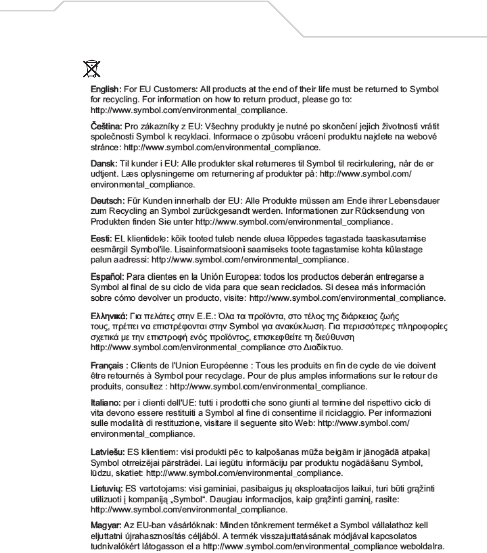
6Waste Electrical and Electronic Equipment (WEEE)
AP-5131 Access Point: Installation Guide
40

Support, and Sales 41
7 Support, and Sales
Symbol Technologies provides its customers with prompt and accurate customer support. Use the
Symbol Support Center as the primary contact for any technical problem, question or support issue
involving Symbol products. If the Symbol Customer Support specialists cannot solve a problem,
access to all technical disciplines within Symbol becomes available for further assistance and
support. Symbol Customer Support responds to calls by email, telephone or fax within the time limits
set forth in individual contractual agreements.
When contacting Symbol Customer Support, please provide the following information:
• Serial number of unit
• Model number or product name
• Software type and version number
North American Contacts
International Contacts
Outside North America, contact Symbol at:
Symbol Customer Contact Centre
44 800 328 2424 (toll free UK)
042 053 333 6123 (Brno)
+ “in country” local numbers in EMEA
For other sales offices use the Symbol Services Web site for contact information
http://www.symbol.com/services/howto/howto_contact_us.html
Inside North America, contact Symbol at:
For sales and product information: For product support and service:
Symbol Technologies, Inc.
One Symbol Plaza
Holtsville, New York 11742-1300
Telephone: 1-631-738-2400/1-800-SCAN 234
Fax: 1-631-738-5990
Symbol Global Support Center:
Telephone: 1-800-653-5350
+1-631-738-6213 (Outside North America)
Fax: 1-631-738-5410
Email: support@symbol.com

AP-5131 Access Point: Installation Guide
42
Web Support Sites
Comprehensive On-line support is available at the MySymbolCare Web site. Registration is free and
a variety of services can be linked through this web-portal.
MySymbolCare
http://www.symbol.com/services/msc
Symbol Services Homepage
http://www.symbol.com/services
Symbol Software Updates
http://www.symbol.com/services/downloads
Symbol Developer Program Web site
http://devzone.symbol.com
Additional Information
Obtain additional information by contacting Symbol at:
1-800-722-6234 (Inside North America)
+1-631-738-5200 (Inside/Outside North America)
http://www.symbol.com/

Symbol Technologies, Inc.
One Symbol Plaza
Holtsville, New York 11742-1300
http://www.symbol.com
72-70931-01
Revision B - October 2005