Symbol Technologies LA3021-500 WLAN PC Card User Manual LA3021 Users Manual
Symbol Technologies Inc WLAN PC Card LA3021 Users Manual
UserManual.wiki
>
Symbol Technologies
>
LA3021 500 User Manual
LA3021 Users Manual
Navigation menu
Upload a User Manual
Namespaces
Wiki Guide
HTML
PDF
Info
Views
User Manual
Discussion / Help
Navigation

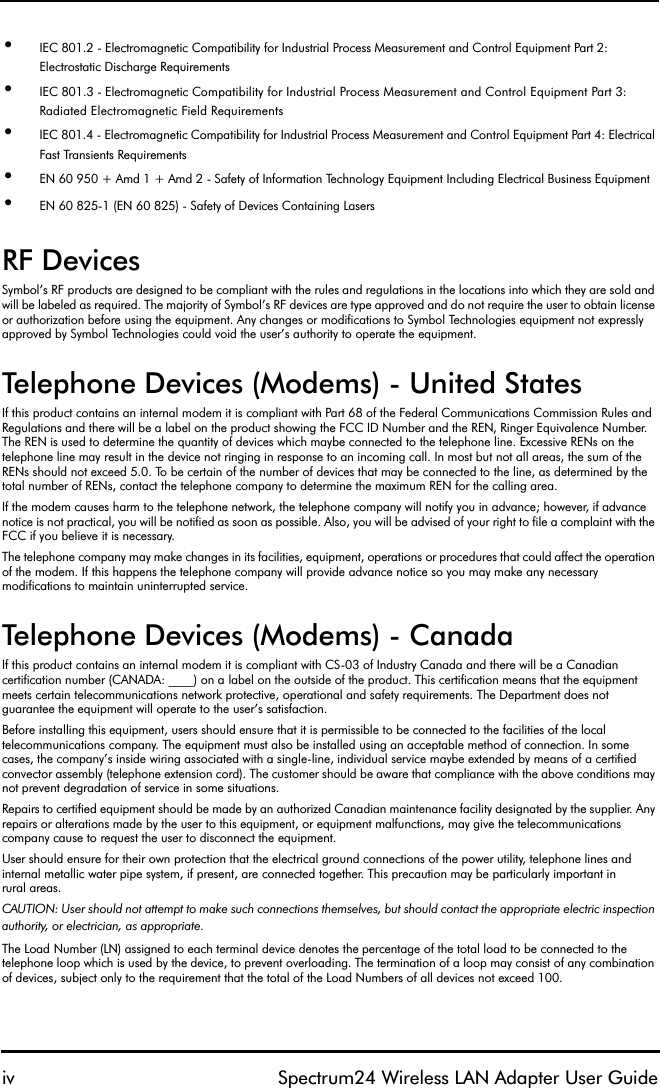

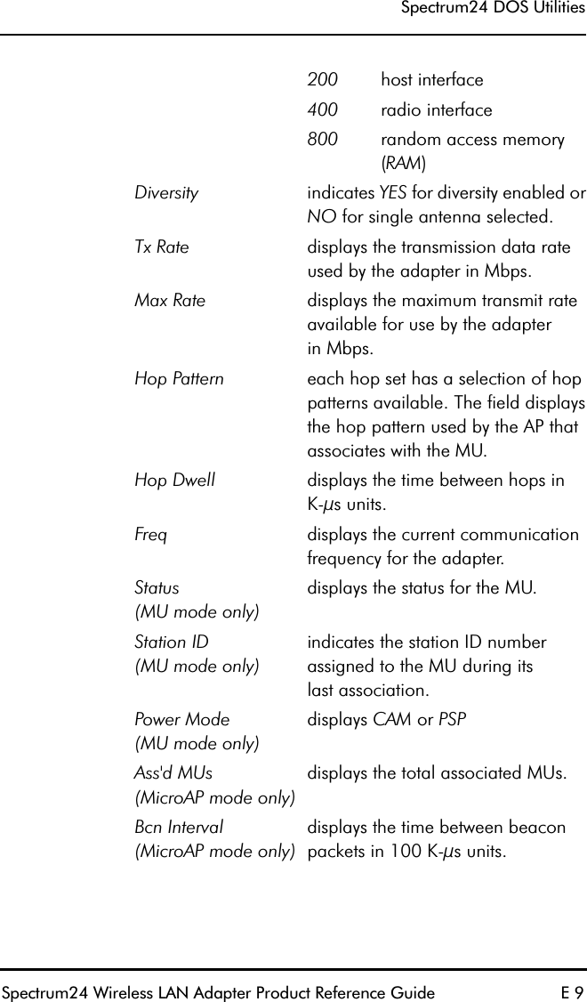
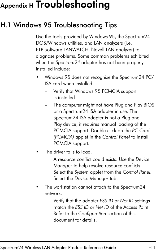
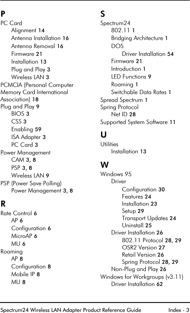
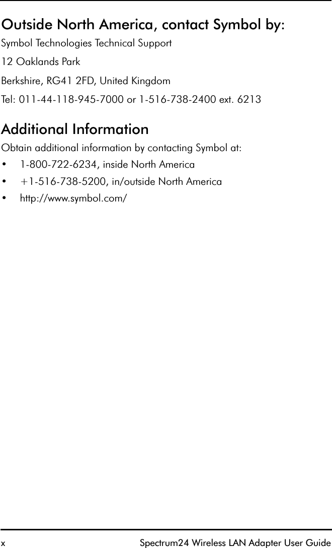
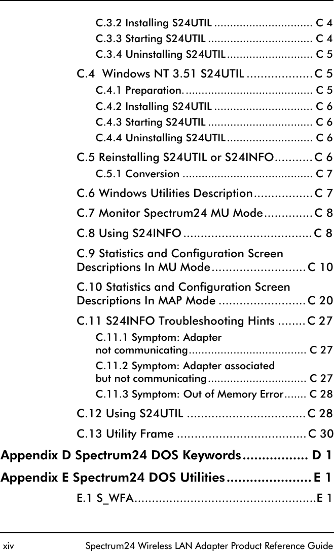
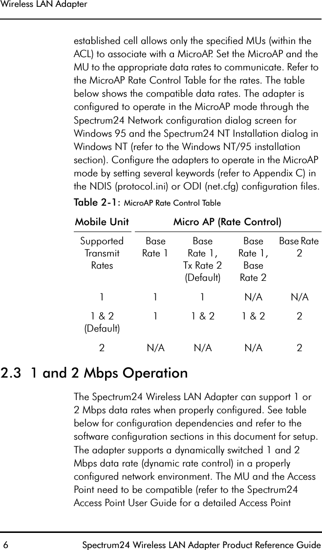
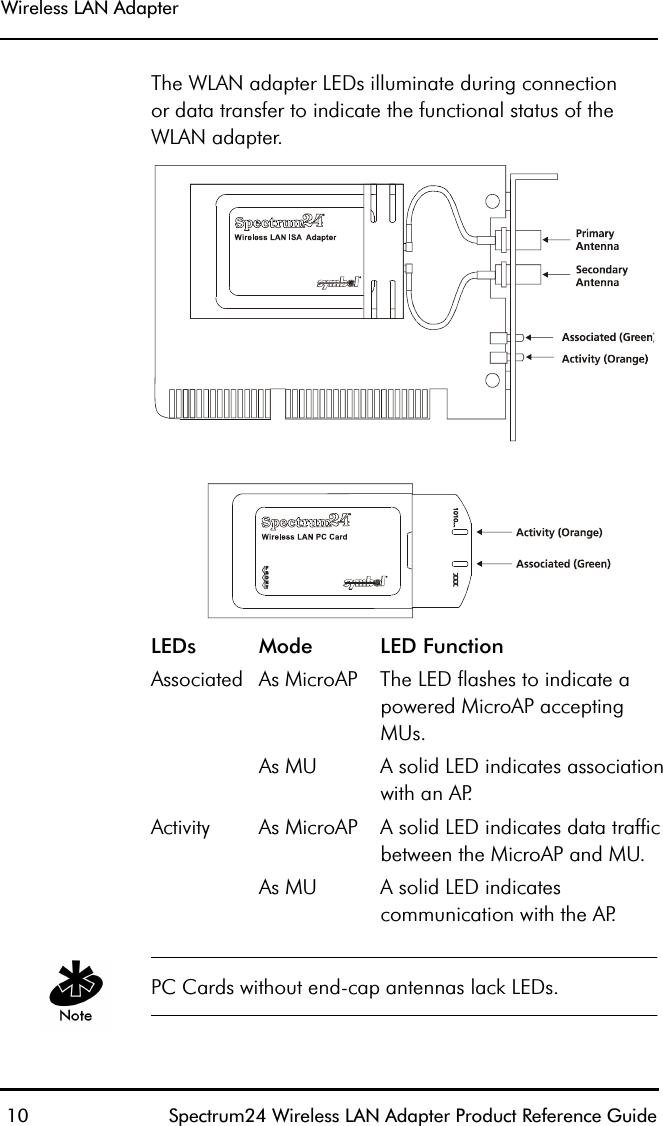
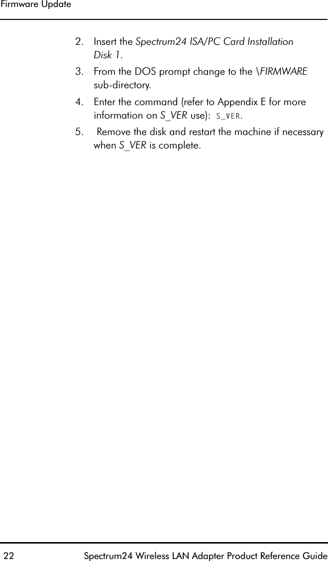
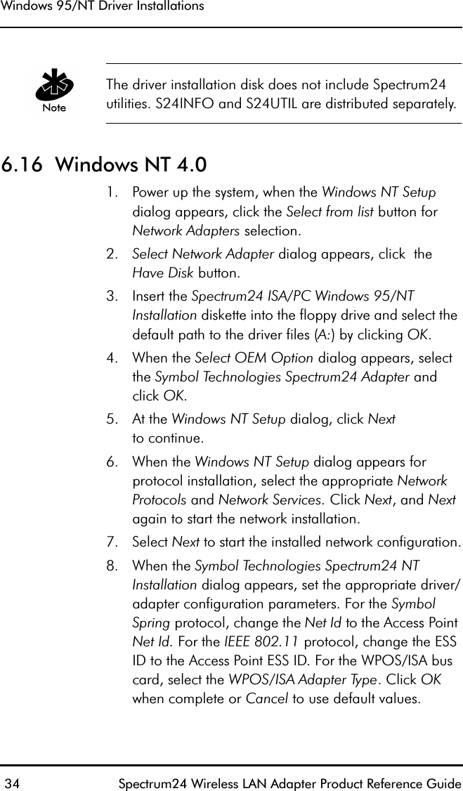
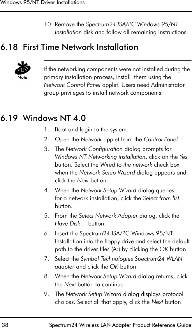
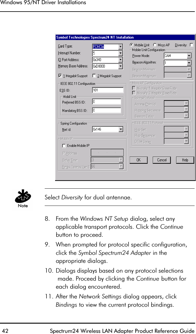
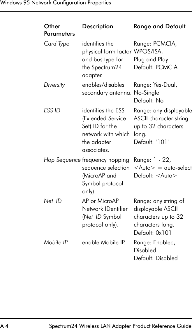
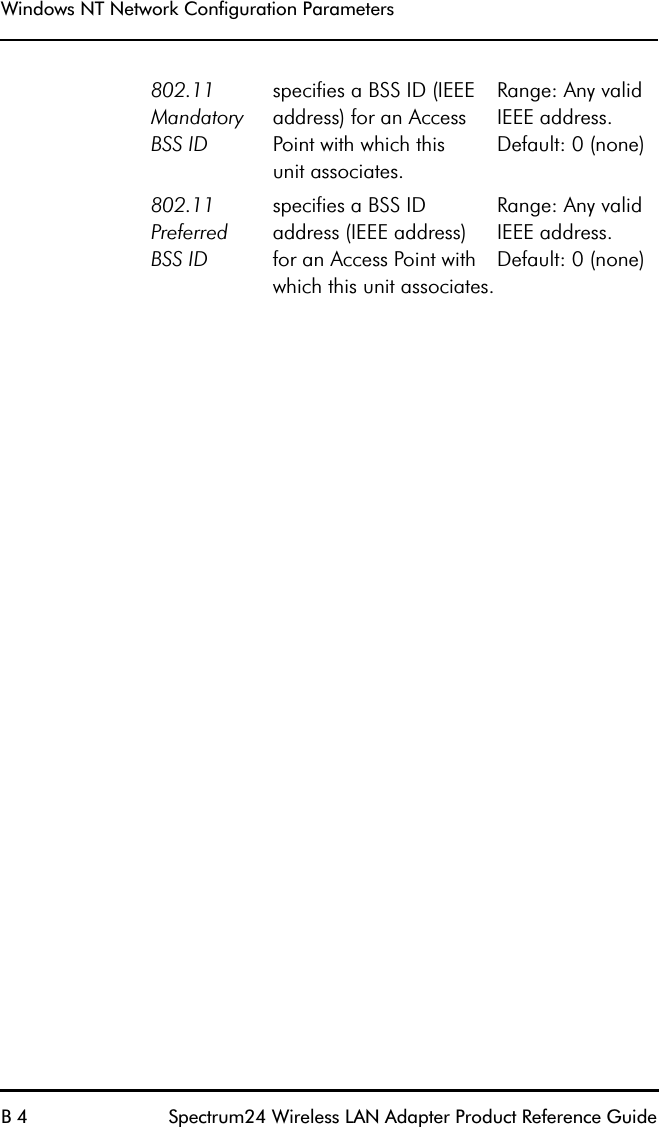
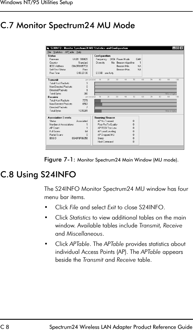
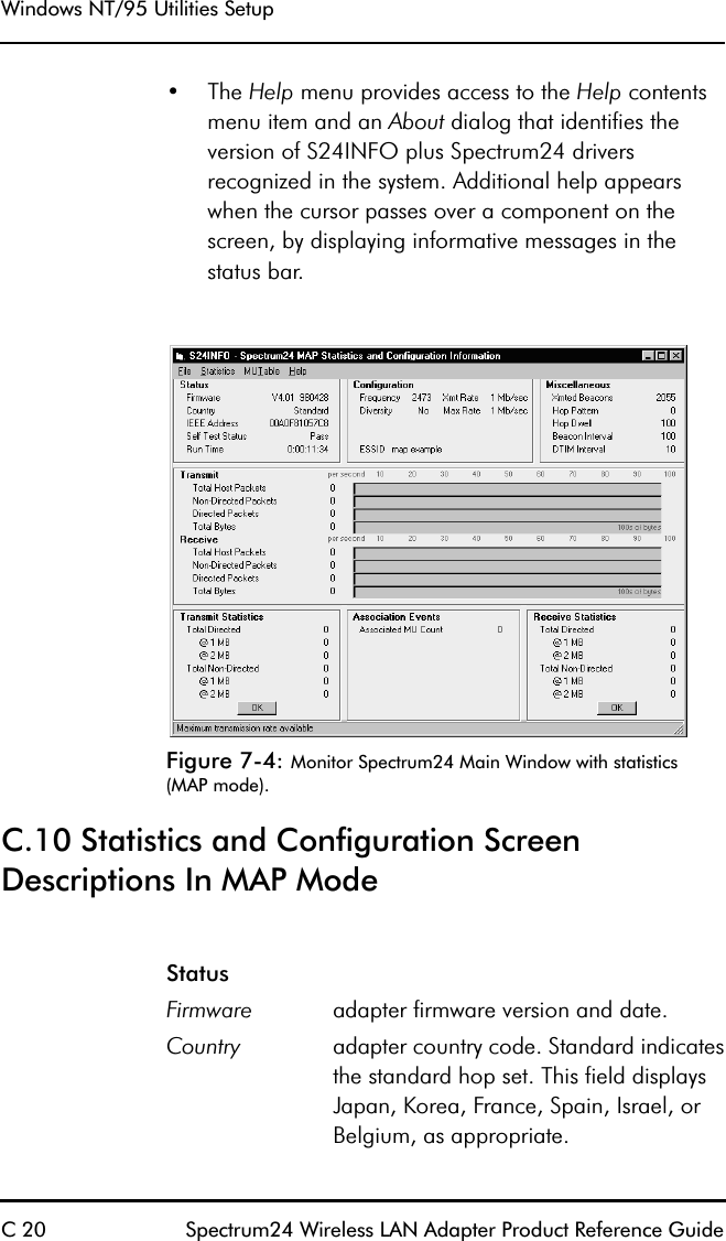
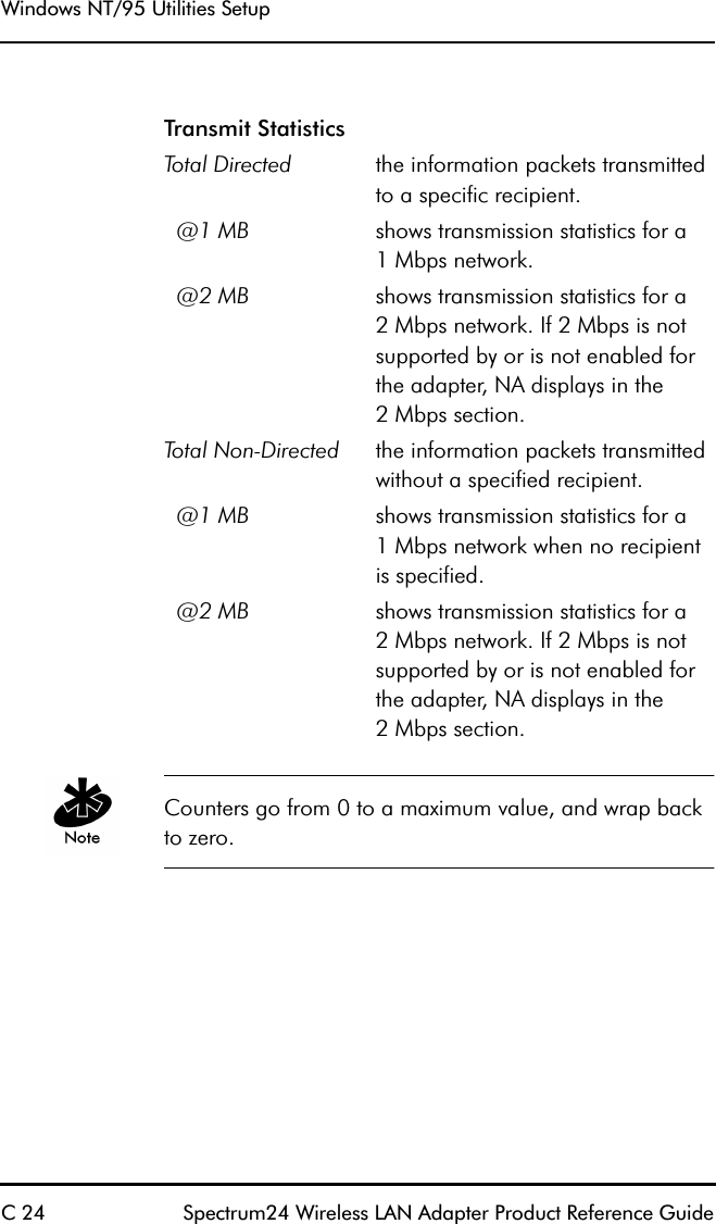
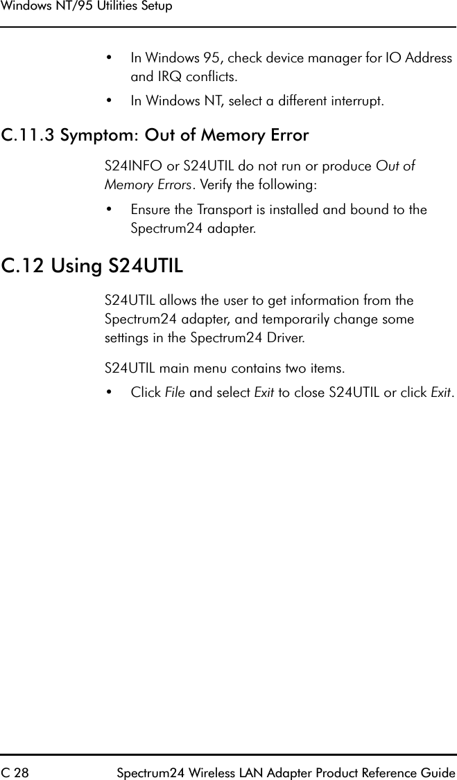
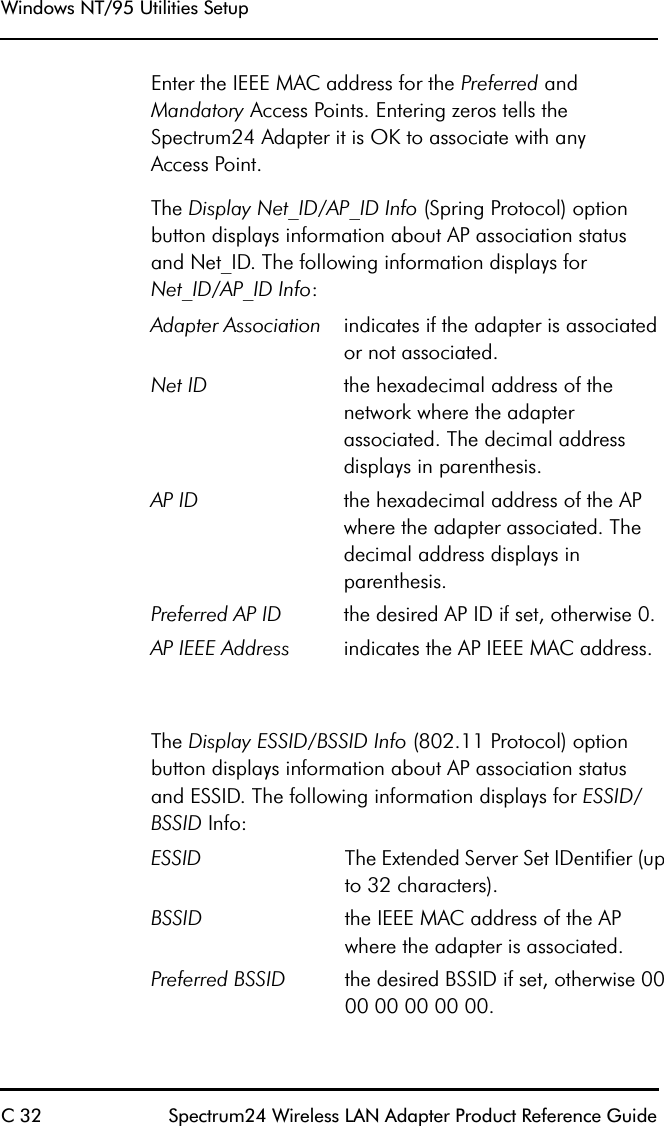
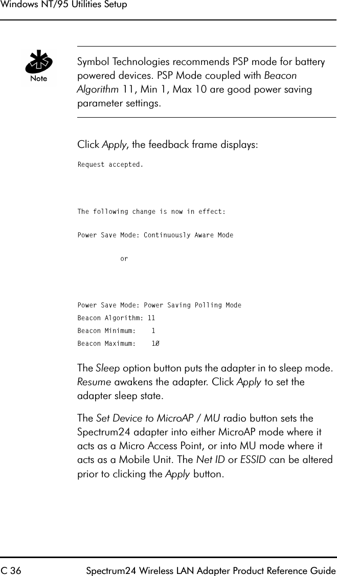
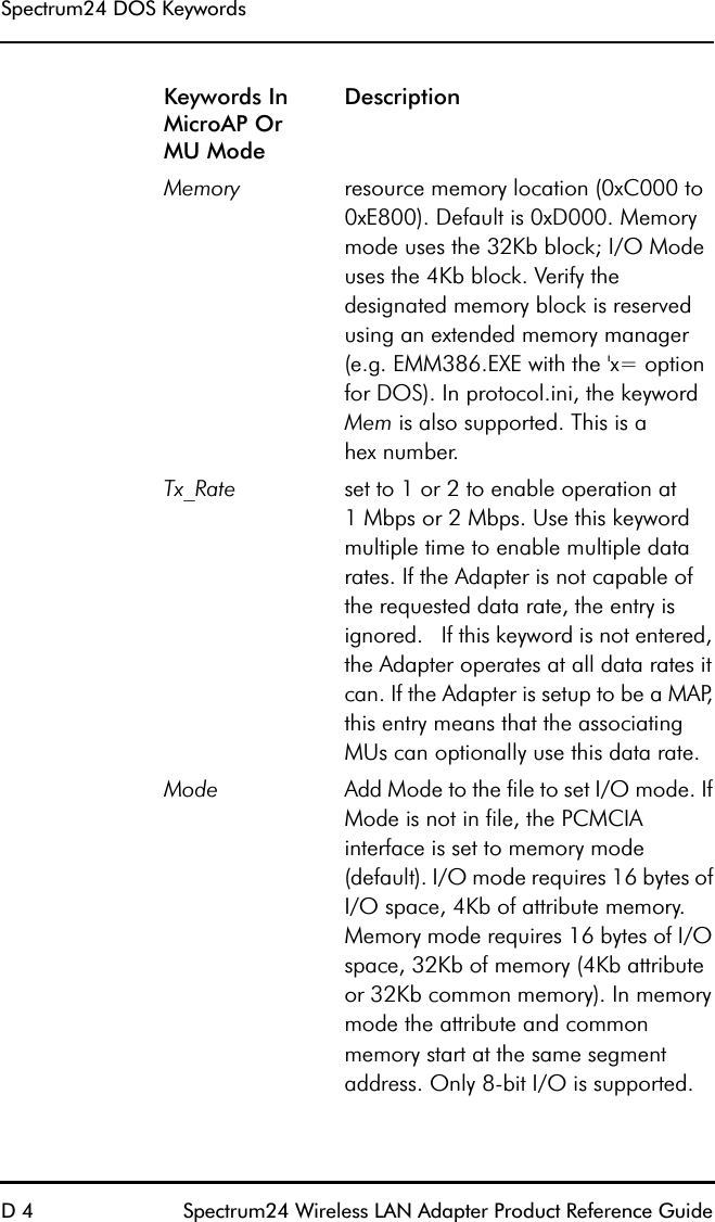
![Spectrum24 Wireless LAN Adapter User Guide viiAbout This DocumentReference DocumentsThis Reference Guide refers to the following documents: RFC’s (Request For Comments) may be found on the Web at: http://www.ctrl-c.lin.se/ftp/DOC/RFC.ConventionsTerminal text is depicted as shown on a 4140 terminal screen.Keystrokes are indicated as follows: Typeface conventions used include.Part Number Document Title70-20135-02 Single High Performance Antenna (ML-2499-HPA1-00/Twin High Performance Diversity Antenna (ML-2499-DVA 1-00)70-20136-01 Mountable F-Plane Antenna (ML-2499-DSA1-00)70-20137-02 Universal Acess Point Wall Bracket (ML-2499-APB1-00)ENTER identifies a key.FUNC, CTRL, C identifies a key sequence. Press and release each keyin turn.Press A+B means to press the indicated keys simultaneously.Hold A+B means to hold down the indicated keys. Used in combination with another keystroke.<angles> indicates mandatory parameters in a given syntax.[brackets] for command line, indicates available parameters; in configuration files brackets act as separators for options.Italics indicates the first time a term is used, a book title, information to be replaced by an actual value, andmenu titles.](https://usermanual.wiki/Symbol-Technologies/LA3021-500/User-Guide-48934-Page-7.png)
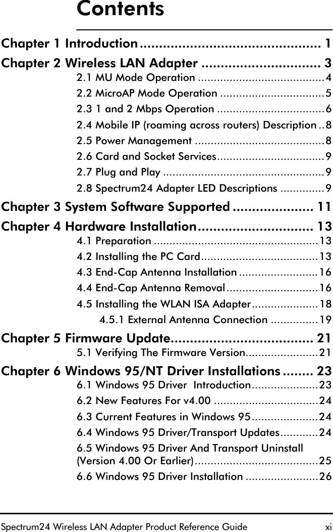
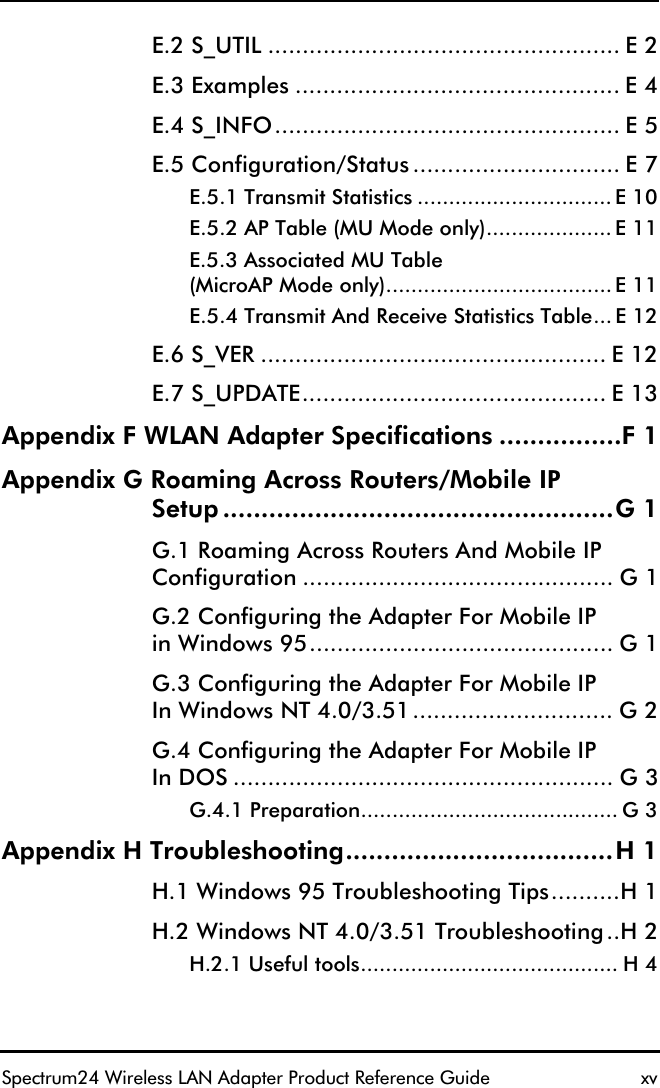
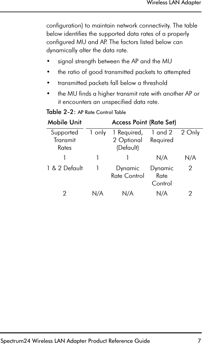
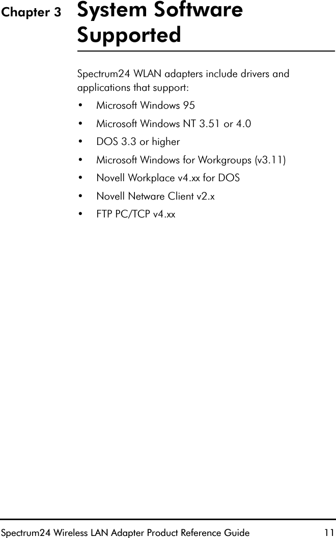
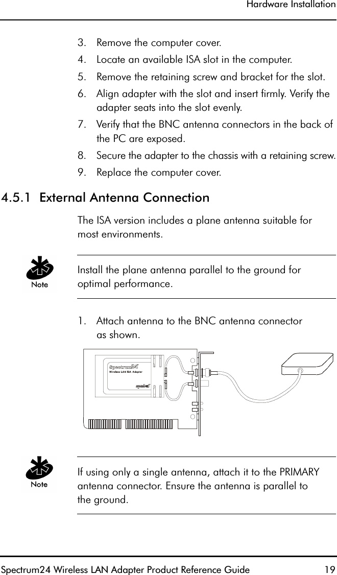
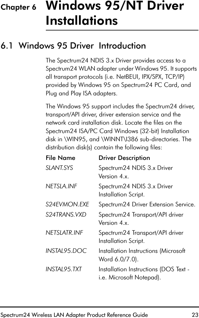
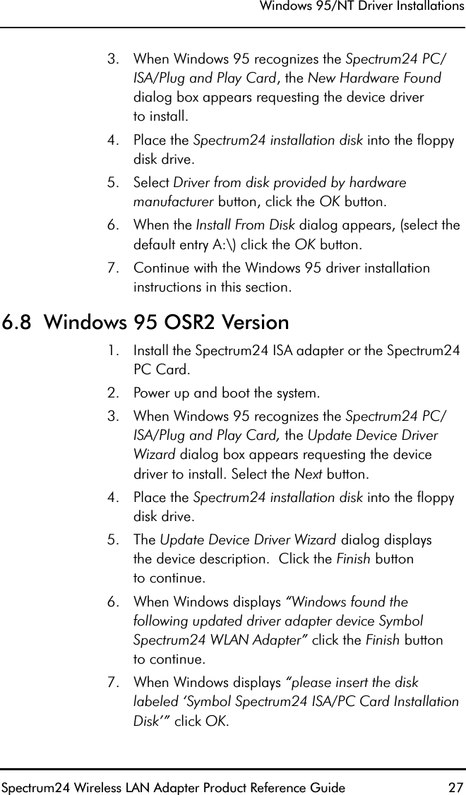
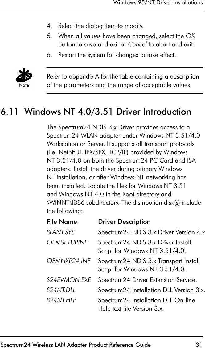
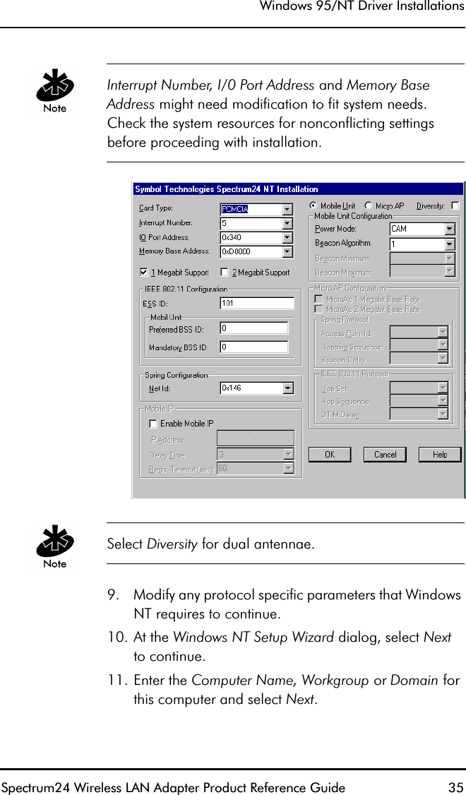
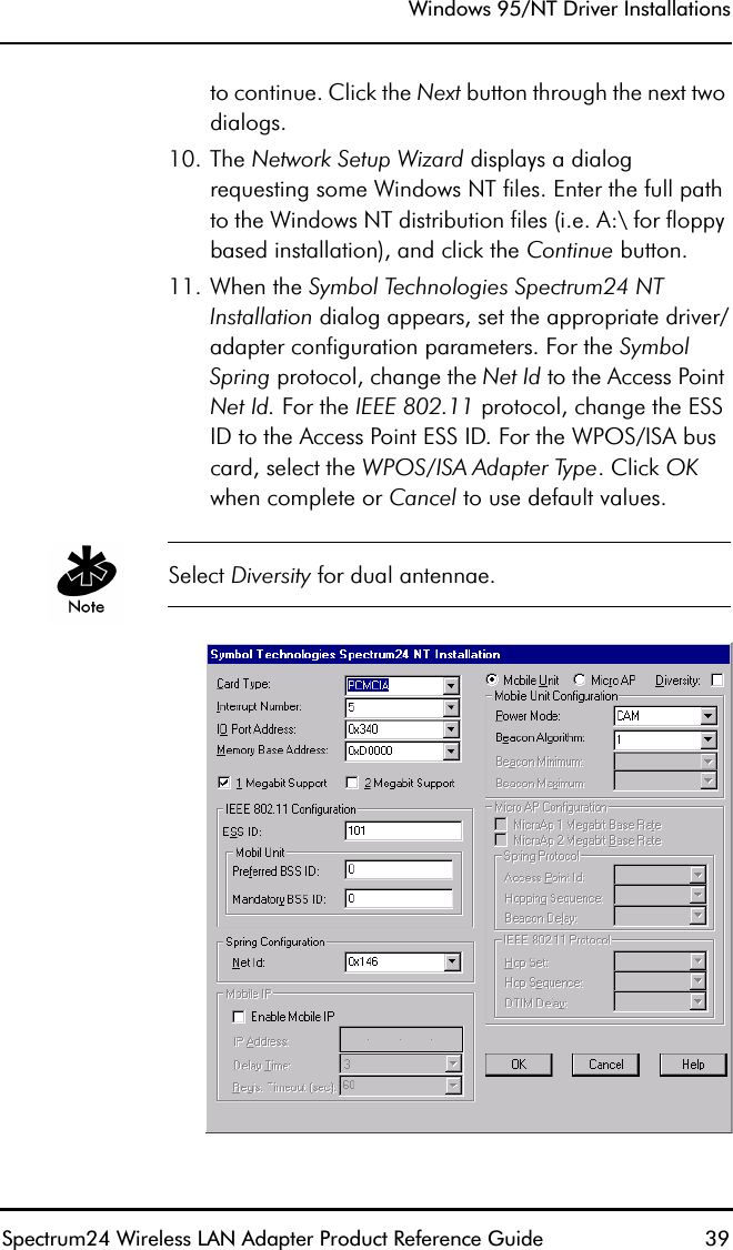
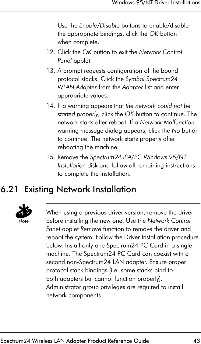
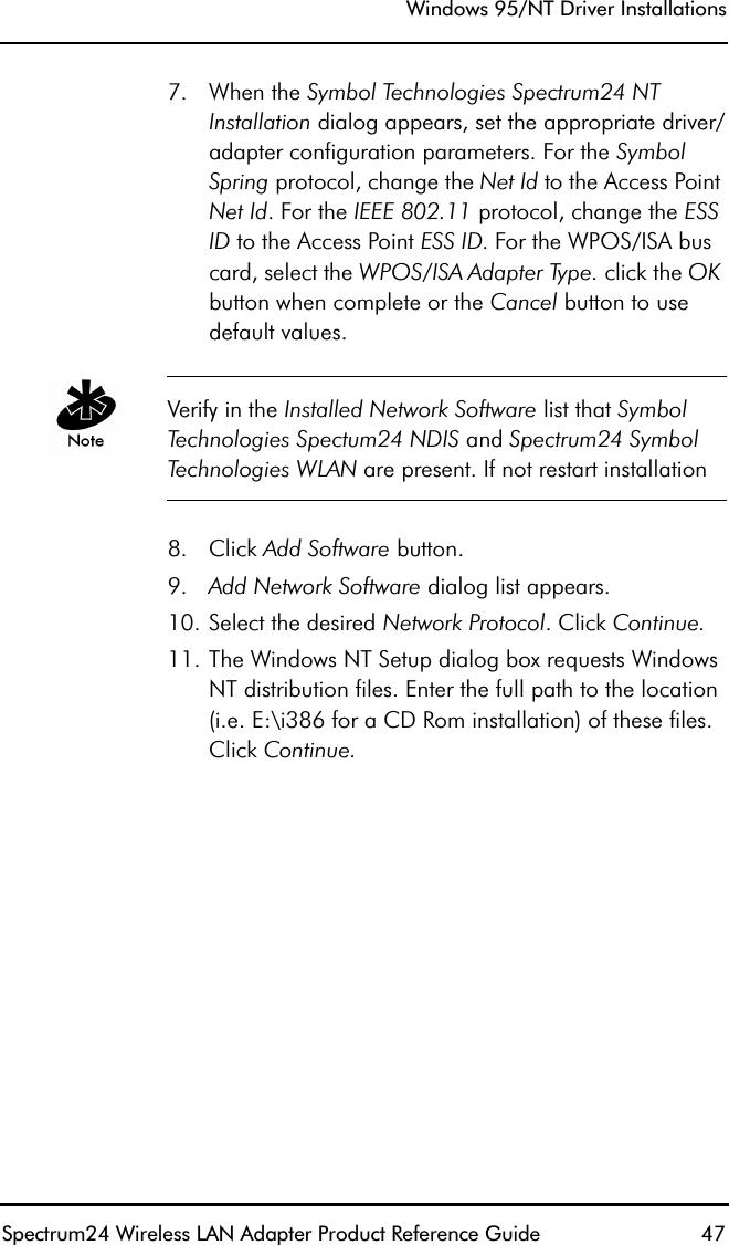
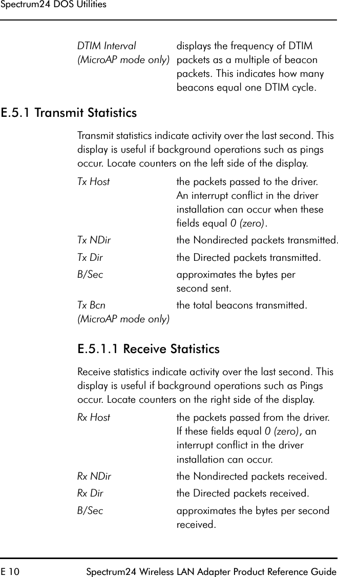
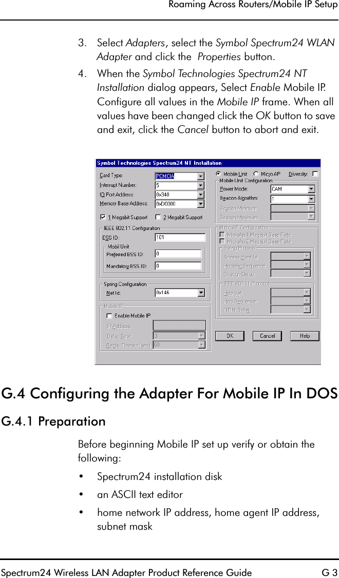
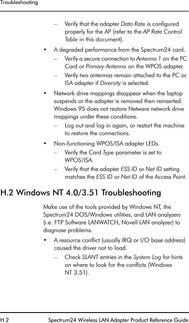
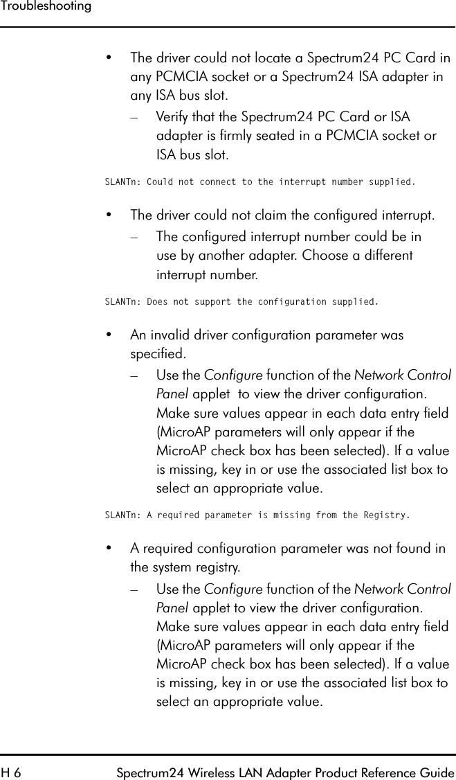
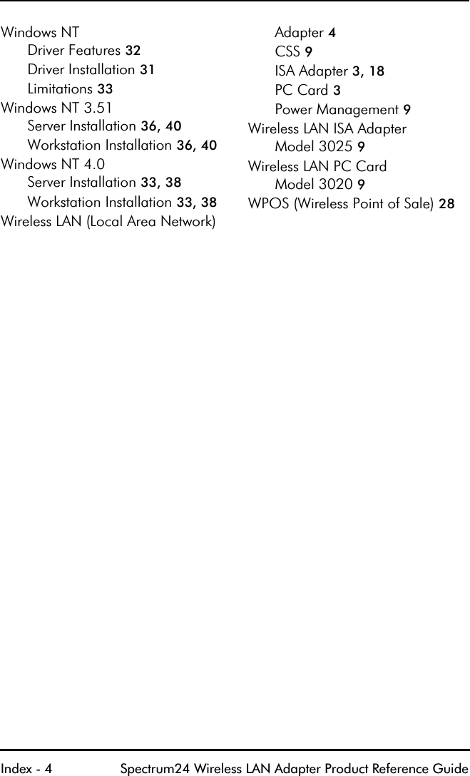
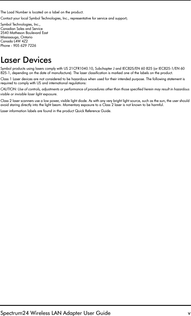
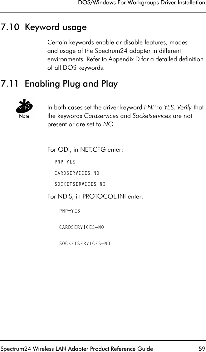
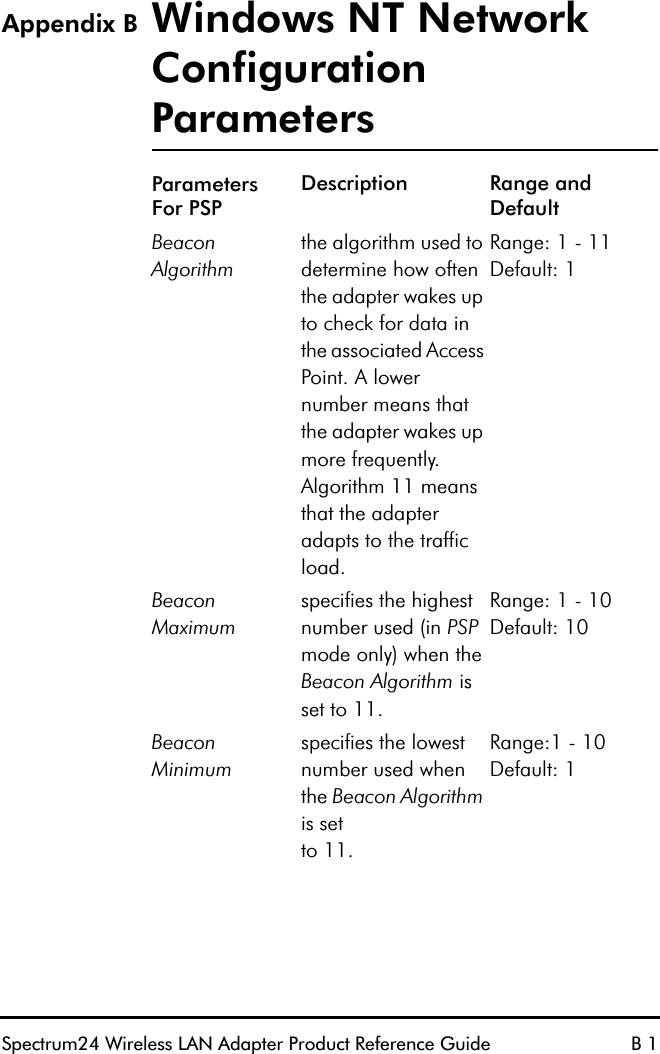
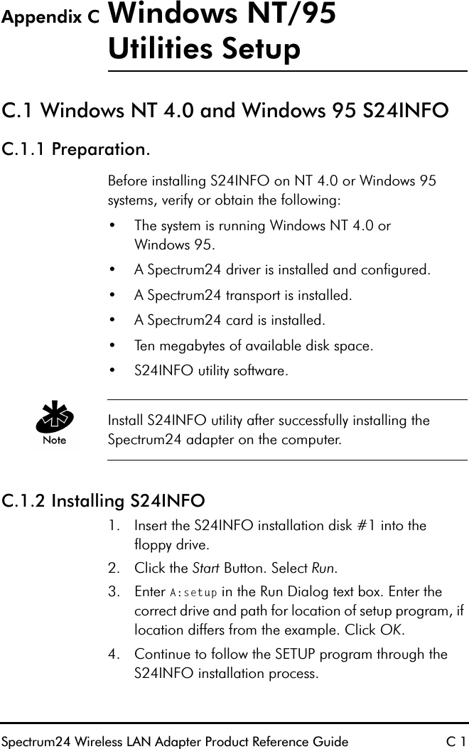
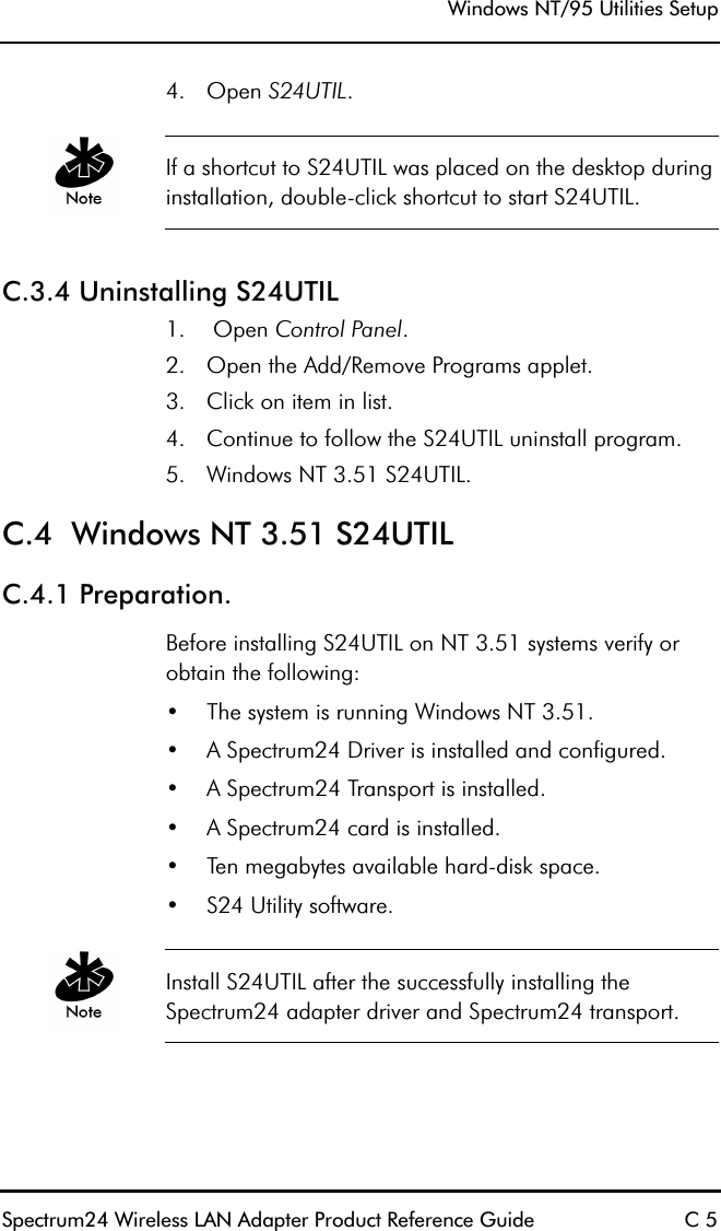
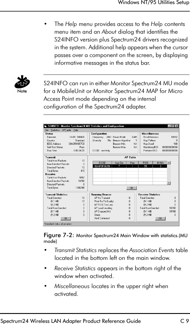
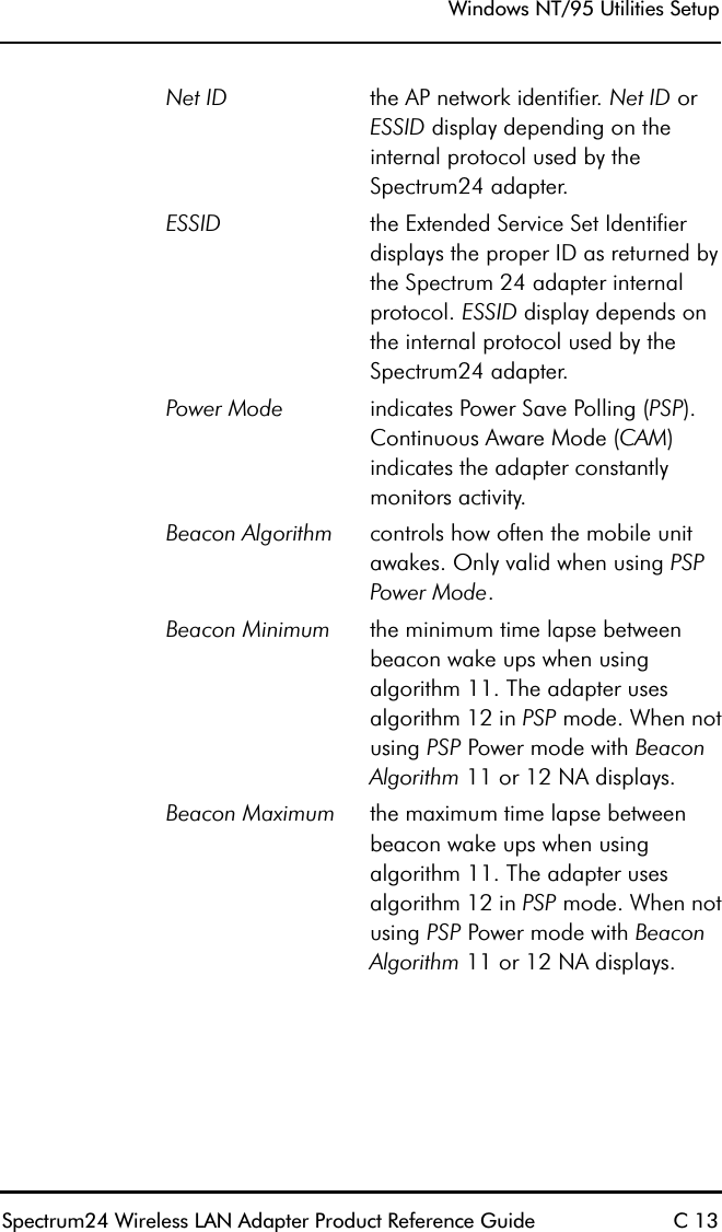
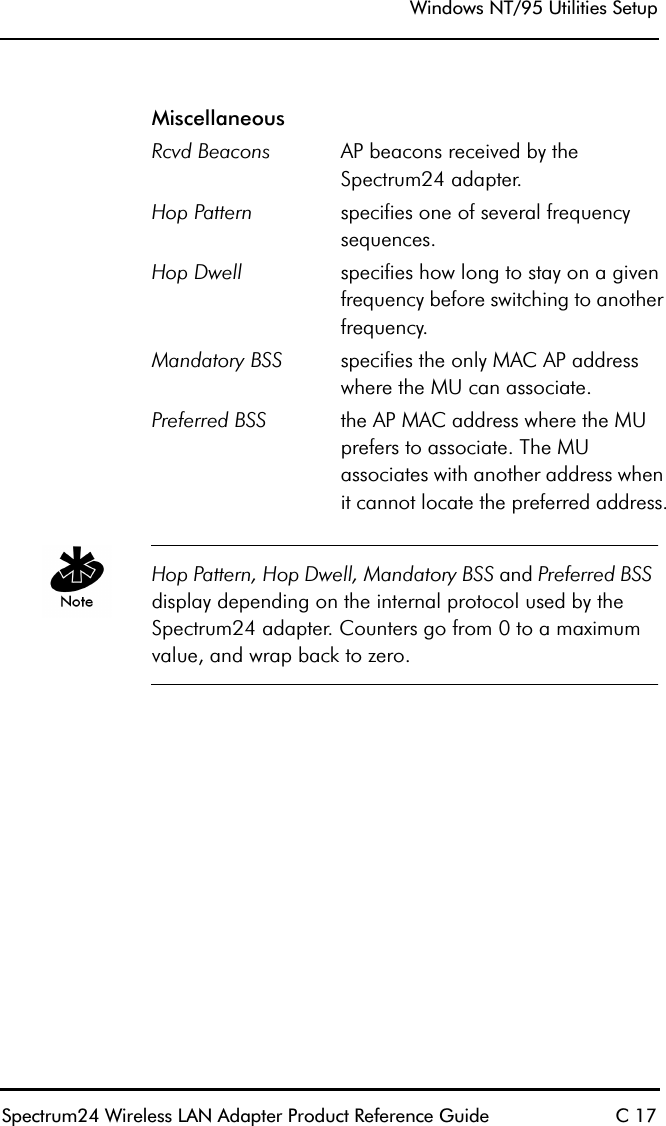
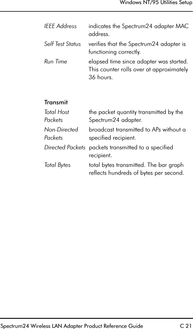
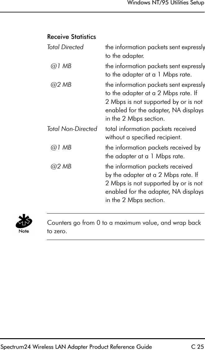
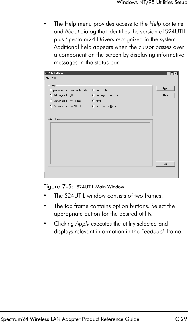
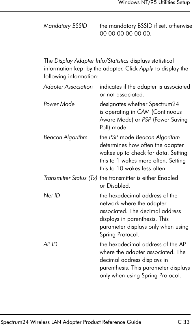
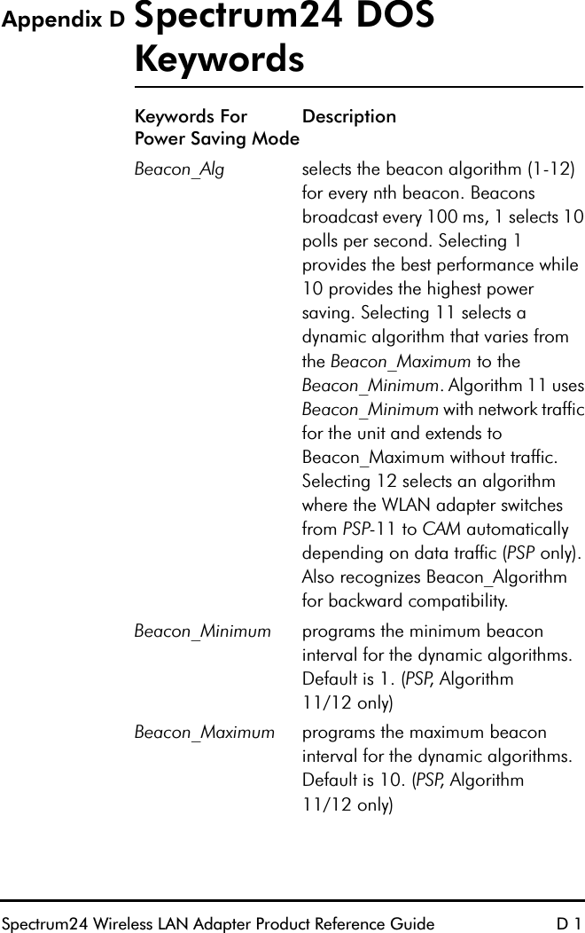
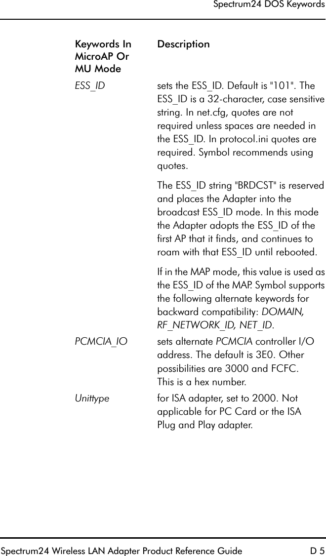
![Spectrum24 Wireless LAN Adapter Product Reference Guide 53Chapter 7 DOS/Windows For Workgroups Driver Installation7.1 Preventing Memory Range ConflictsThe ISA Plug and Play WLAN card requires users to load SLAINIT.EXE prior to loading the driver or updating the firmware. Ensure the firmware is up to date. Refer to firmware update section for instructions on firmware version verification.1. To prevent conflicts with other devices, use an extended memory manager (i.e., EMM386, etc.). Exclude the upper memory block where the adapter resides. Modify the memory manager device line in CONFIG.SYS, if the adapter has a memory location starting at 0xD000 operating in memory mode and EMM386 is being used.– For memory mode operation:[DEVICE]=[path]EMM386.EXE X=D000-D7FF– For I/O mode operation:[DEVICE]=[path]EMM386.EXE X=D000-D0FF2. Modify the network configuration to include the memory range used by the WLAN adapter.– Exclude a 4 KB memory range for I/O Mode operation.](https://usermanual.wiki/Symbol-Technologies/LA3021-500/User-Guide-48934-Page-69.png)
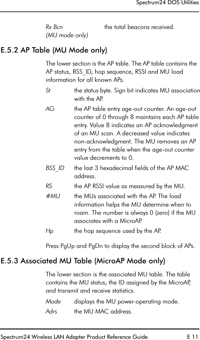
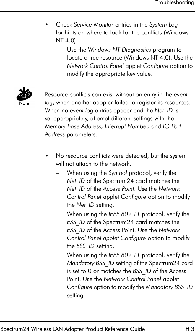
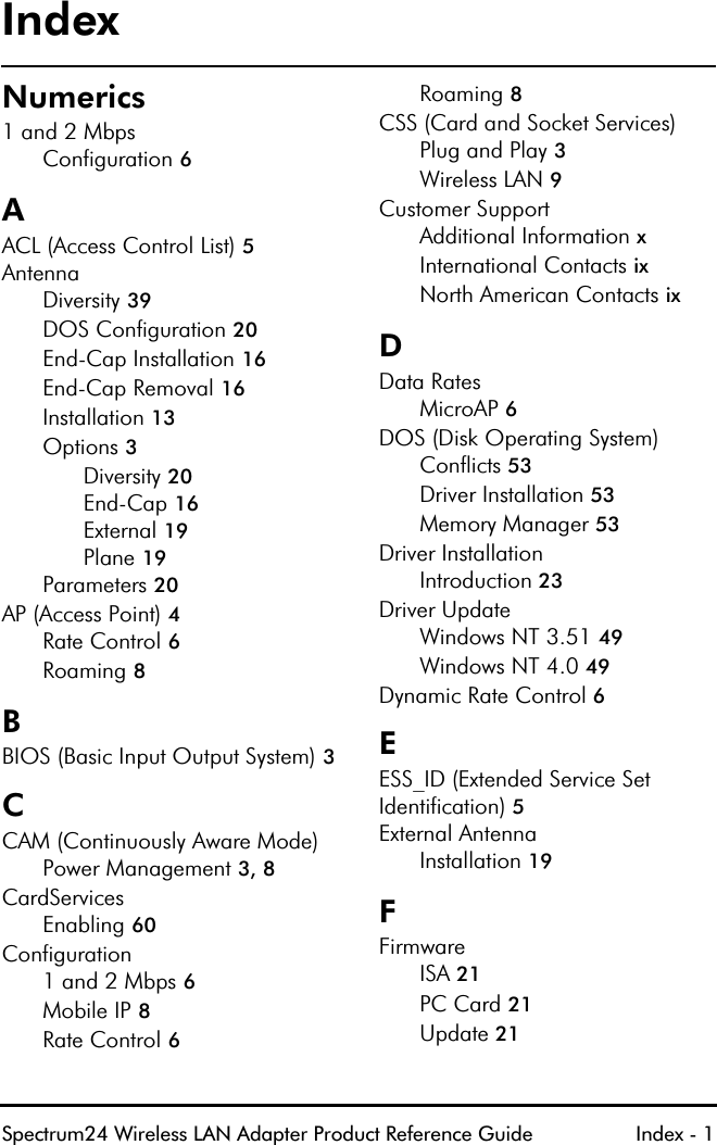
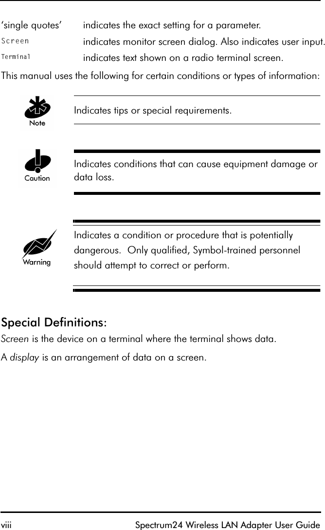
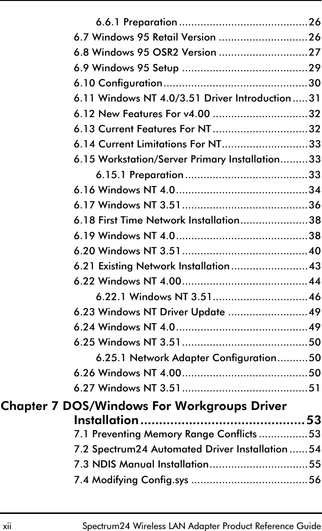
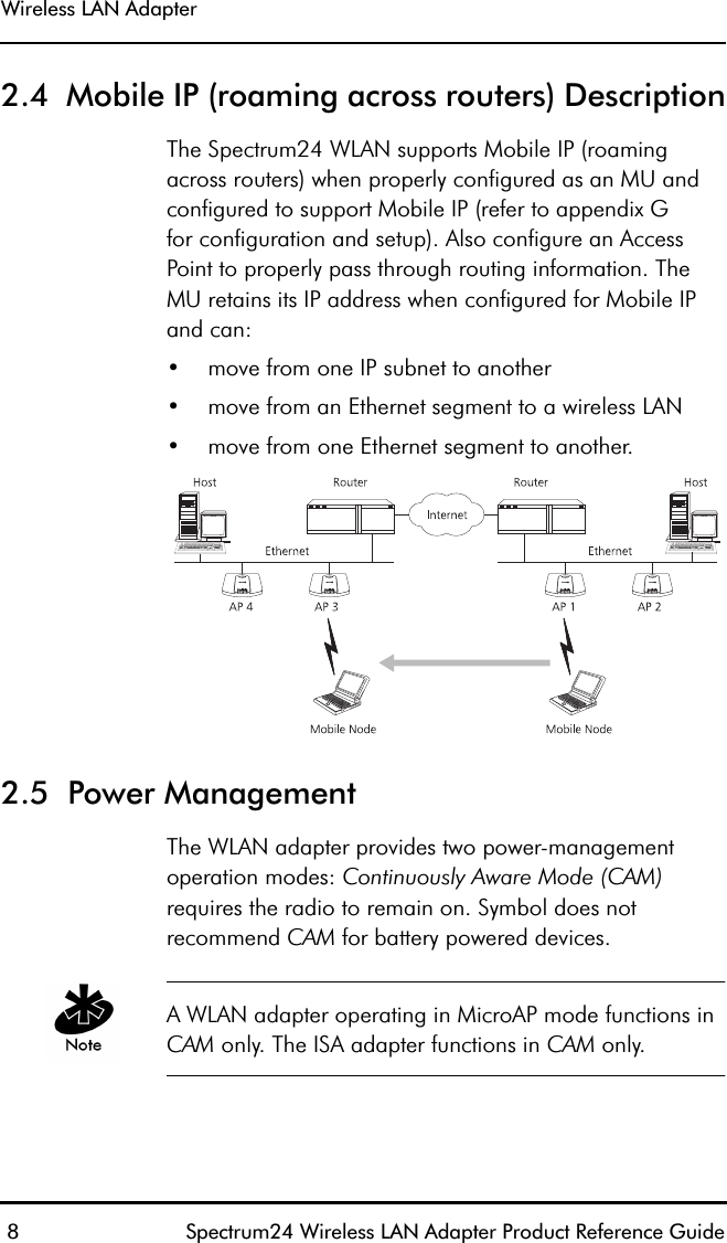
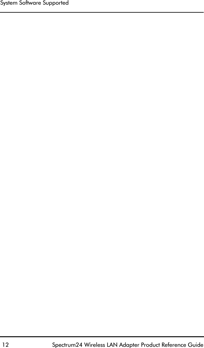
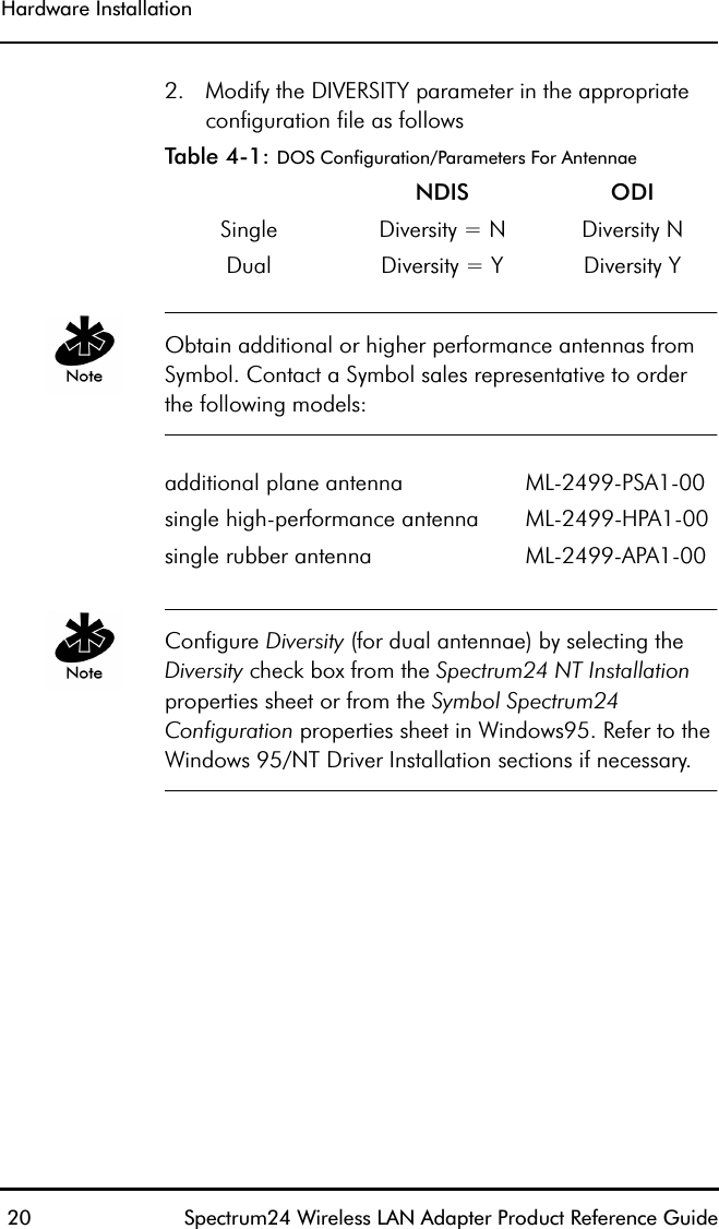
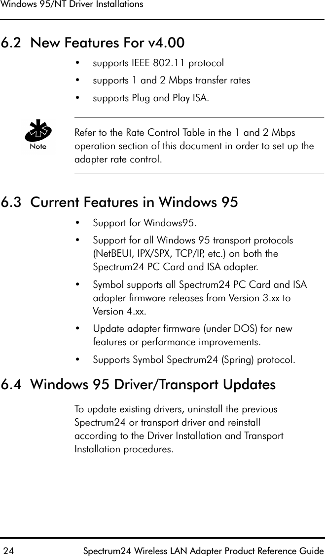
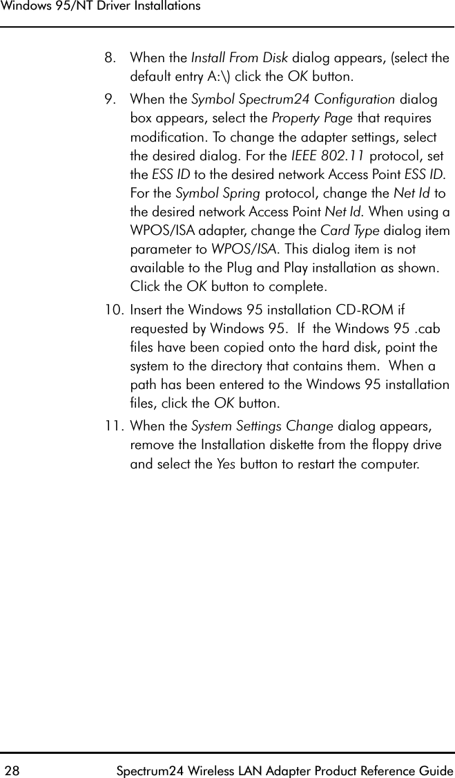
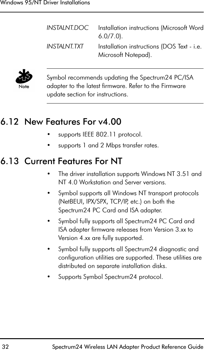
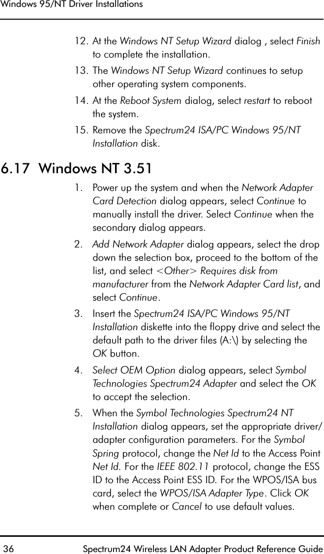
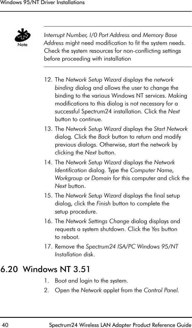
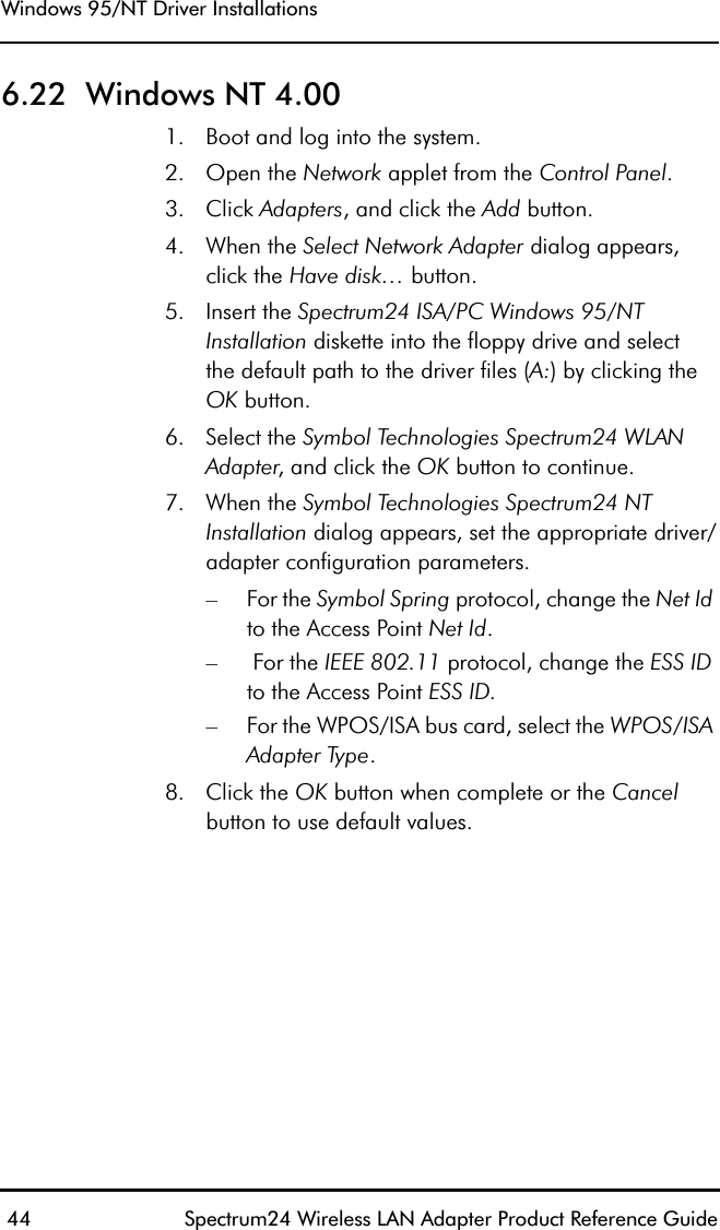
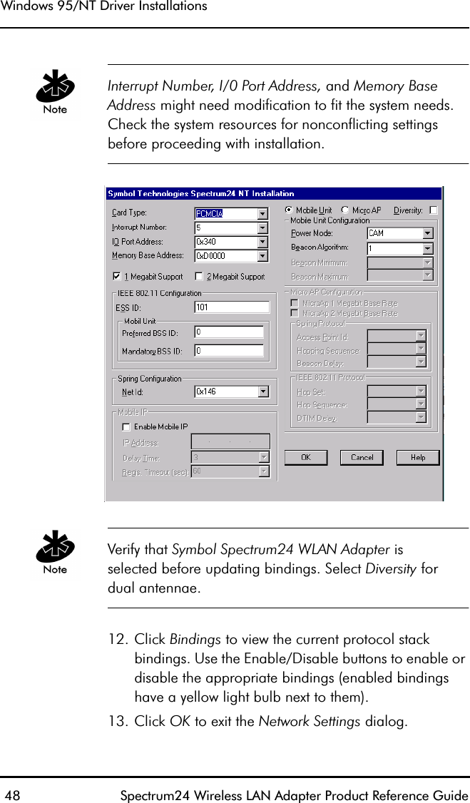
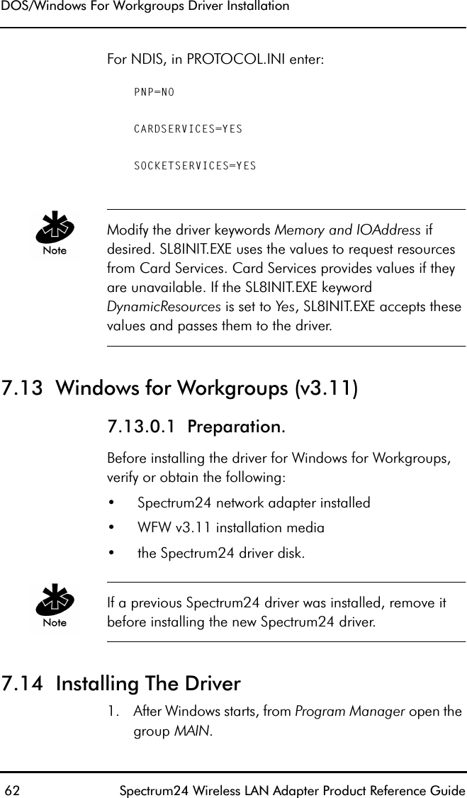
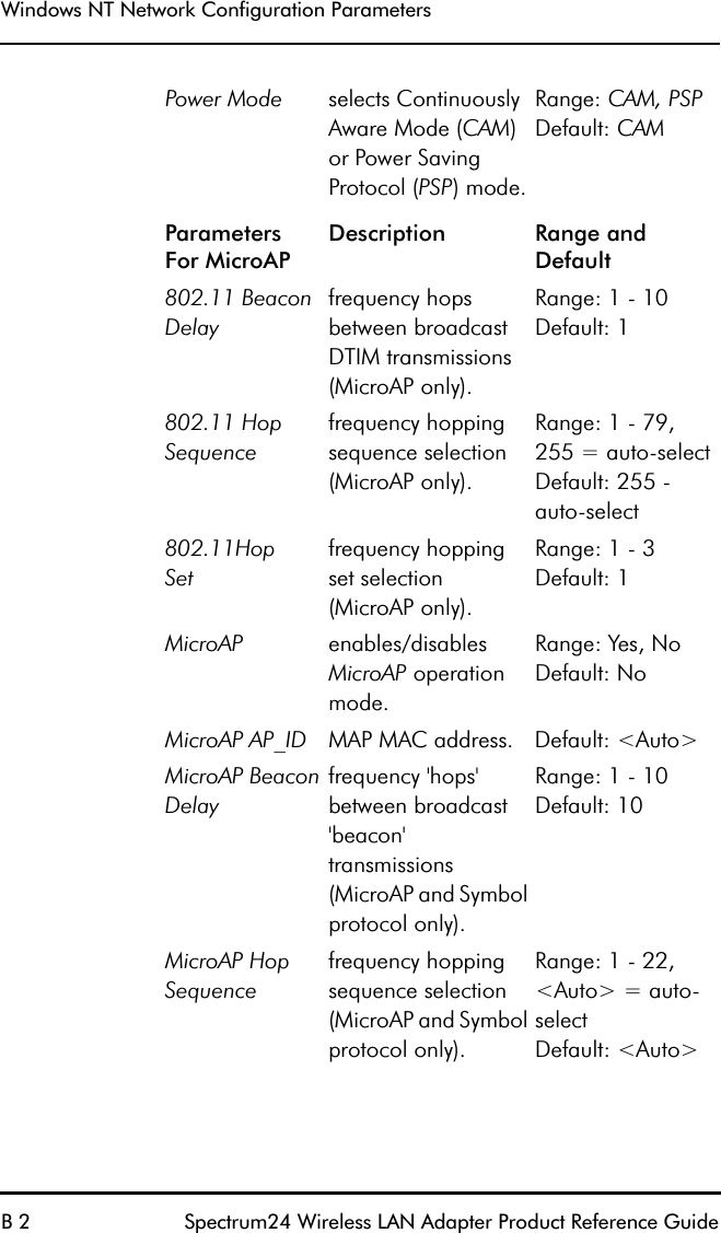
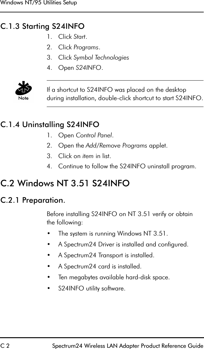
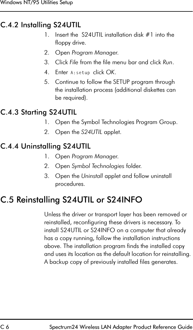
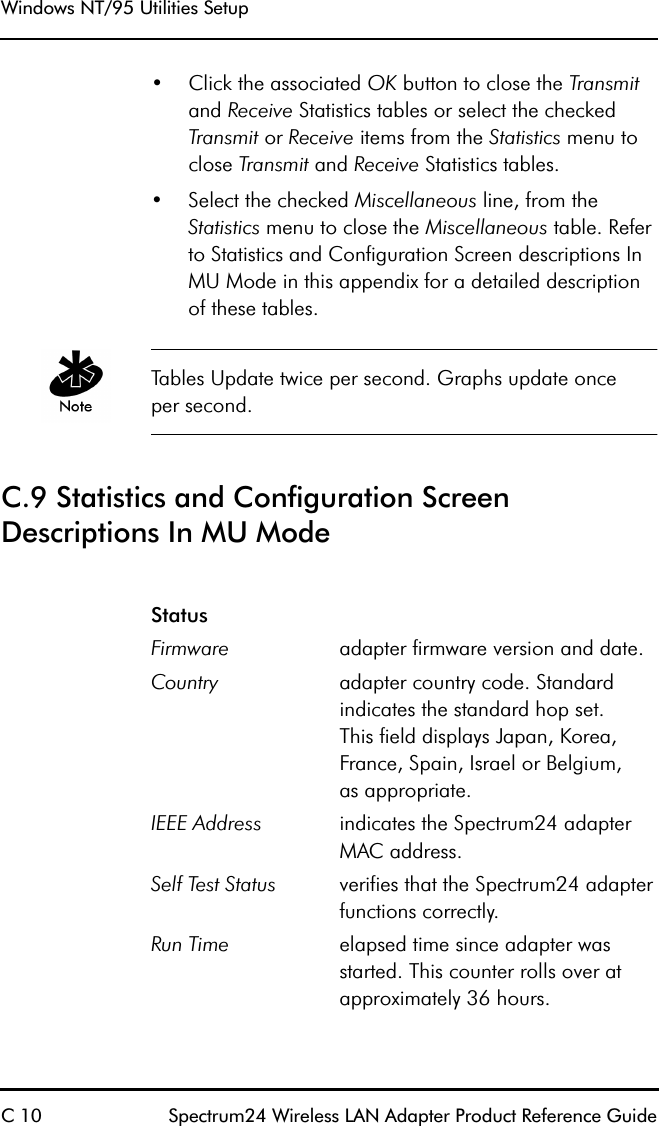
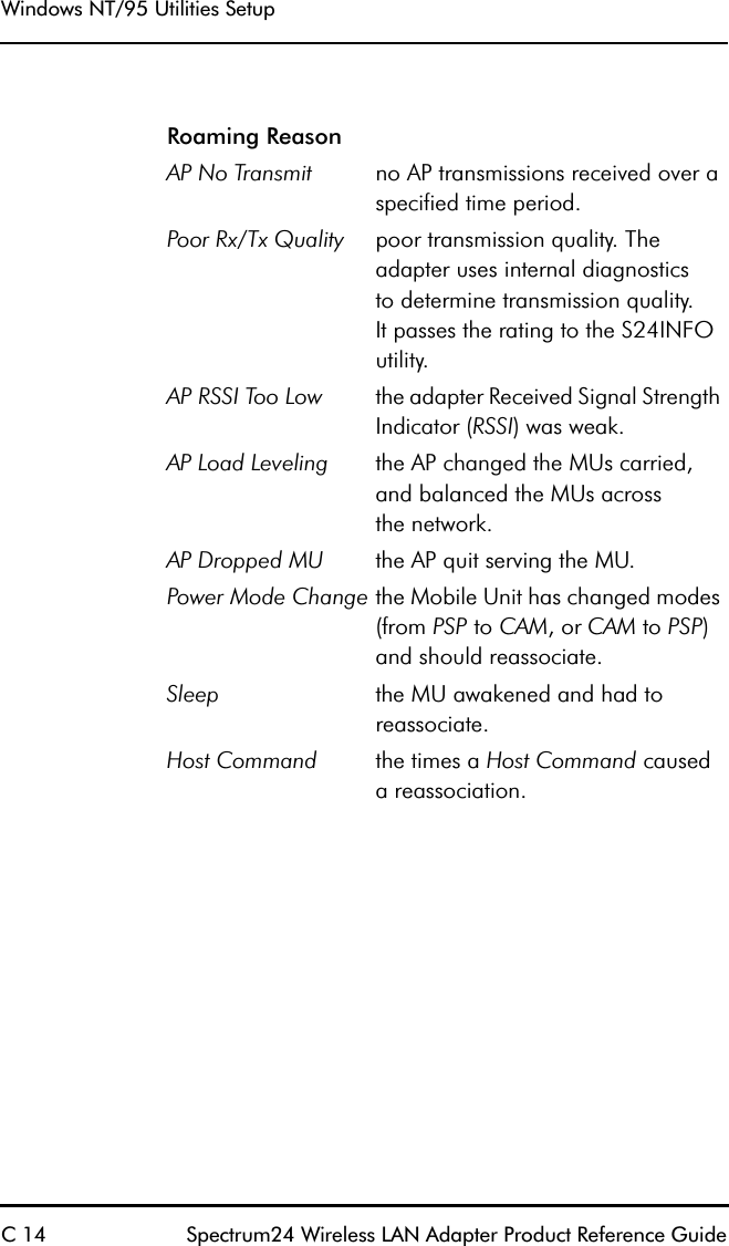
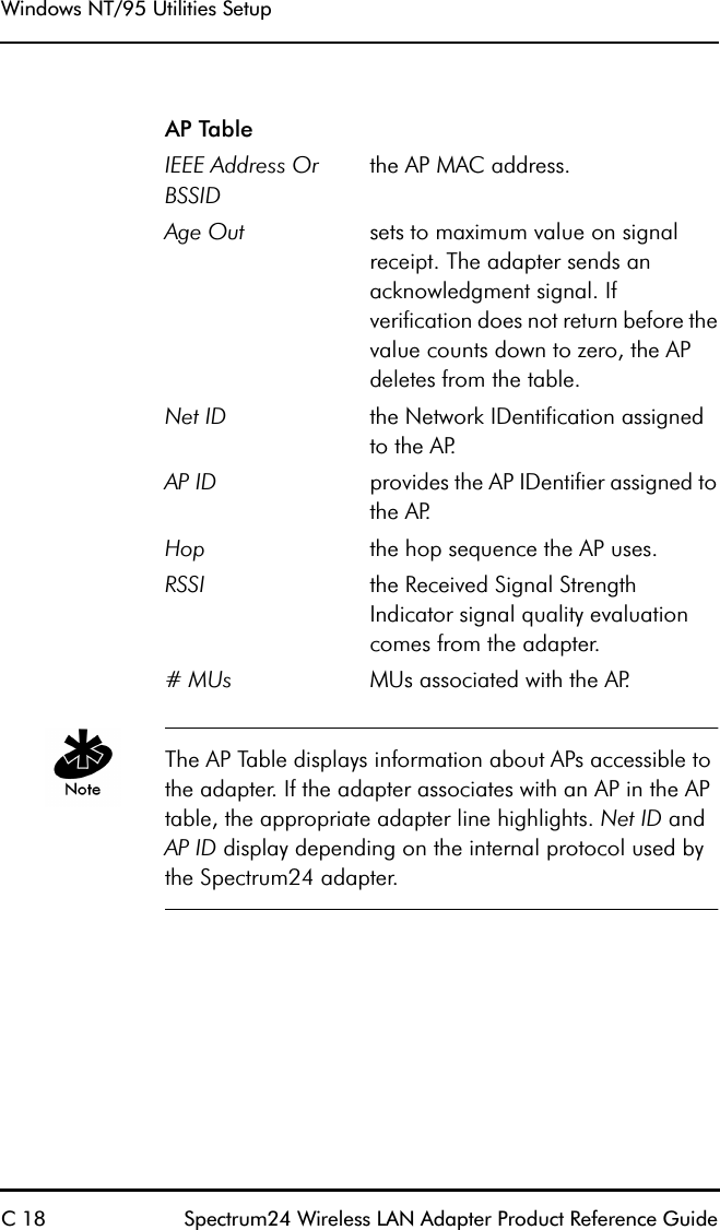
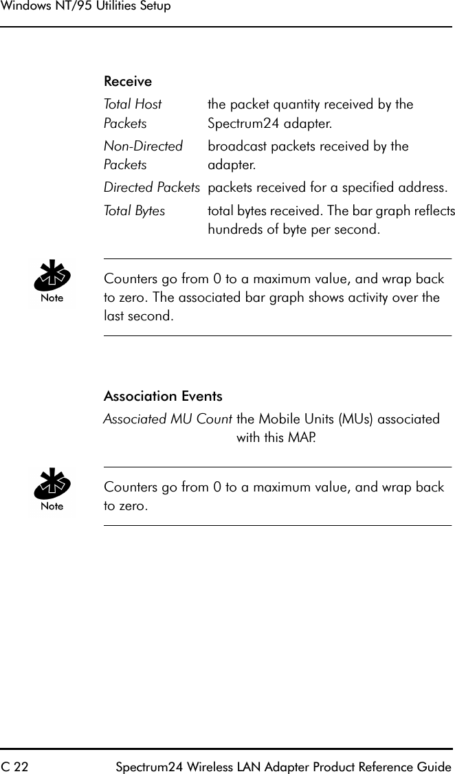
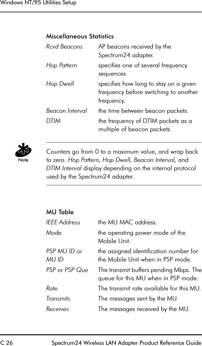
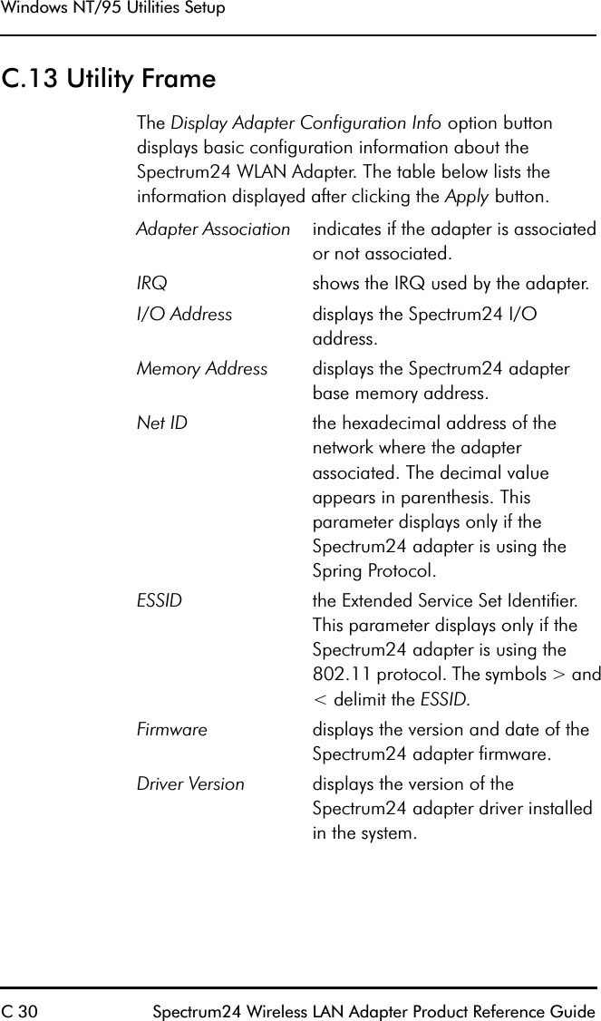
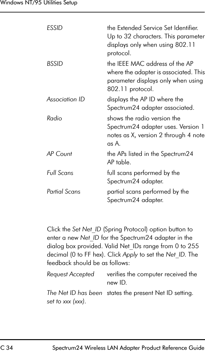
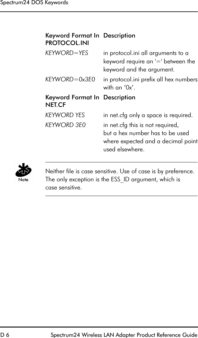
![DOS/Windows For Workgroups Driver Installation 56 Spectrum24 Wireless LAN Adapter Product Reference Guide•SL8NDIS.EXE - The Spectrum24 radio device driver.•PROTMAN - A protocol manager to bind NDIS drivers to the protocol stack.•NETBIND - a network bind program for all networkstack components.•Other protocol drivers as requiredLocate NDIS network parameters in Protocol.ini. Edit Protocol.ini using an ASCII text editor. The following example assumes a default installation of the third party network software. Refer to individual vendor documentation for setup of specific network software being used. [PATH] refers to the location of files on the hard drive. If the automatic installation program was not used, copy the files as needed (PROTMAN.DOS, SL8NDIS.EXE, NETBIND.COM) from the Drivers and Utilities Installation diskette to the appropriate directory on the hard disk.7.4 Modifying Config.sys Verify the following lines in Config.sys are present:DEVICE=[PATH]\PROTMAN.DOS /C:\DEVICE=[PATH]\SL8NDIS.exe•other protocol drivers as required7.5 Modifying Autoexec.batIn AUTOEXEC.BAT verify the following:[PATH]\NETBIND.COM](https://usermanual.wiki/Symbol-Technologies/LA3021-500/User-Guide-48934-Page-72.png)
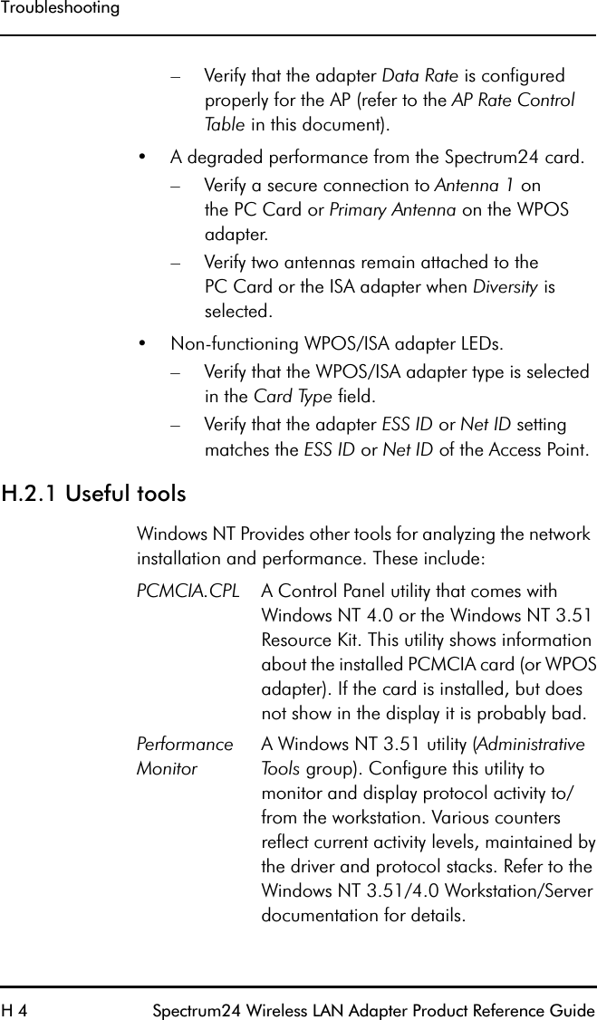
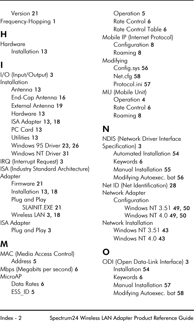
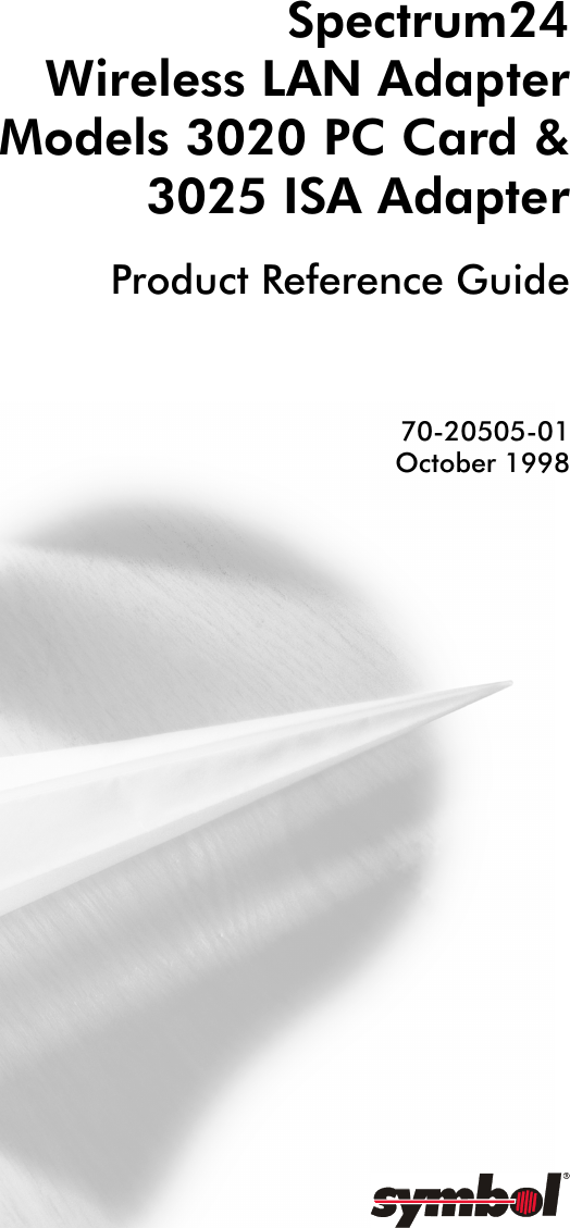
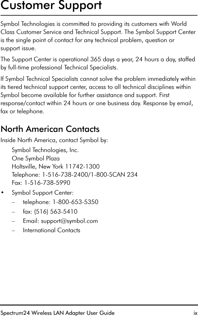
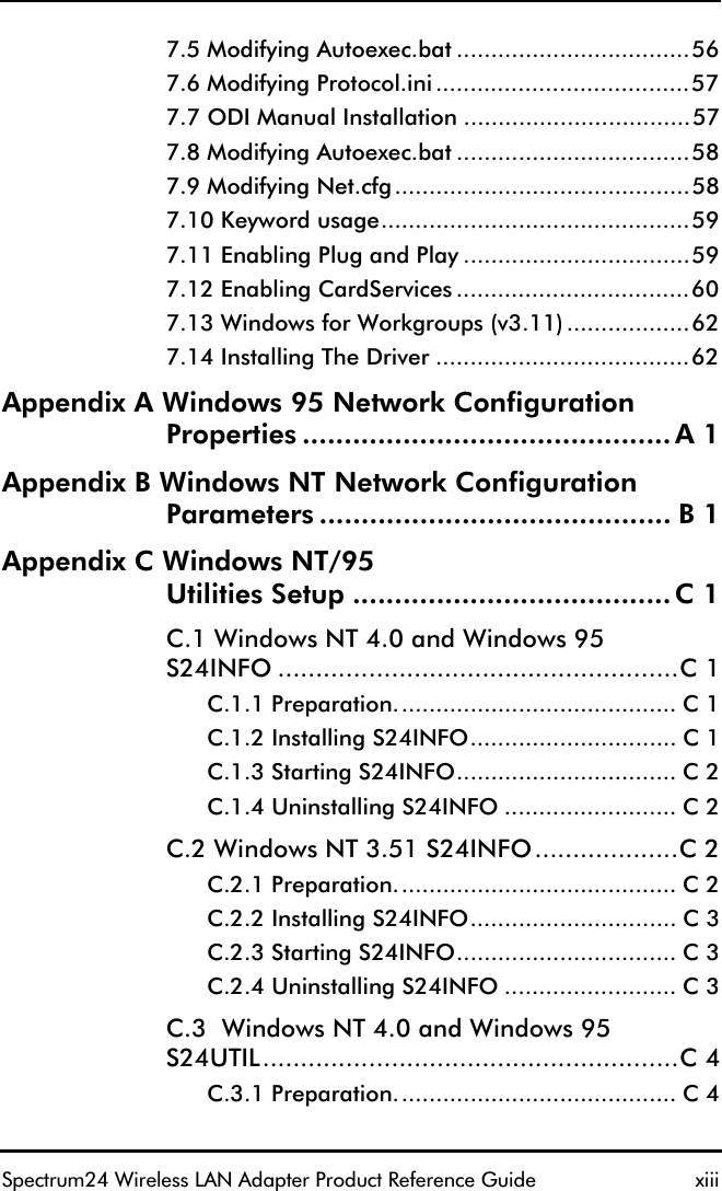
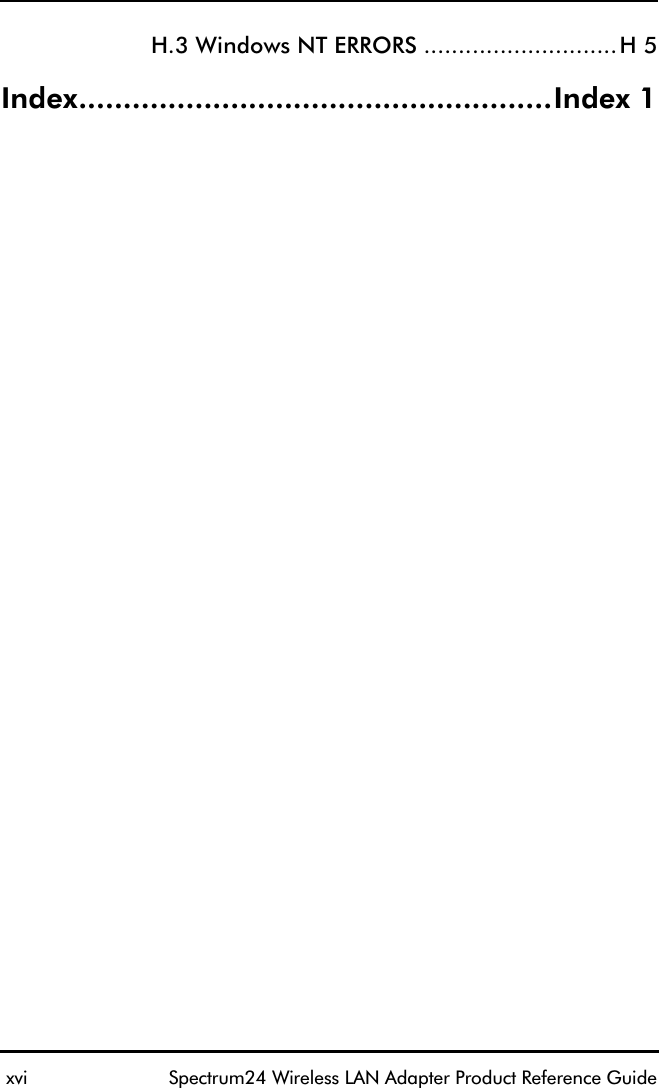
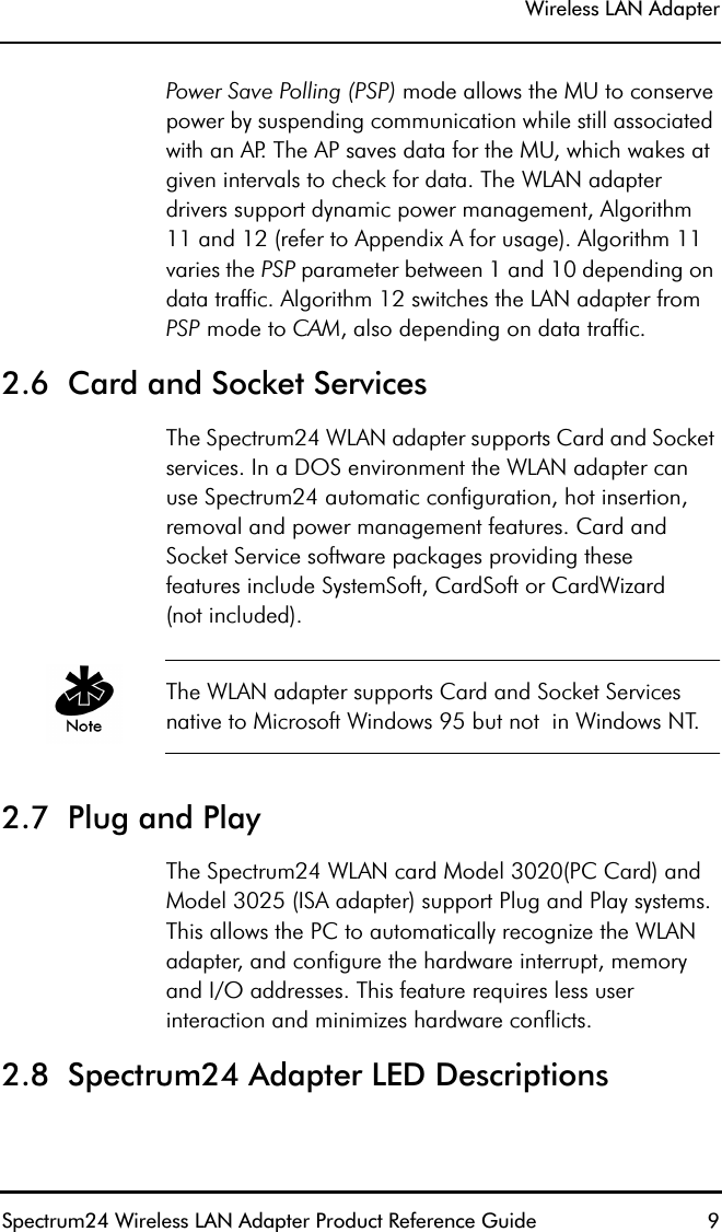
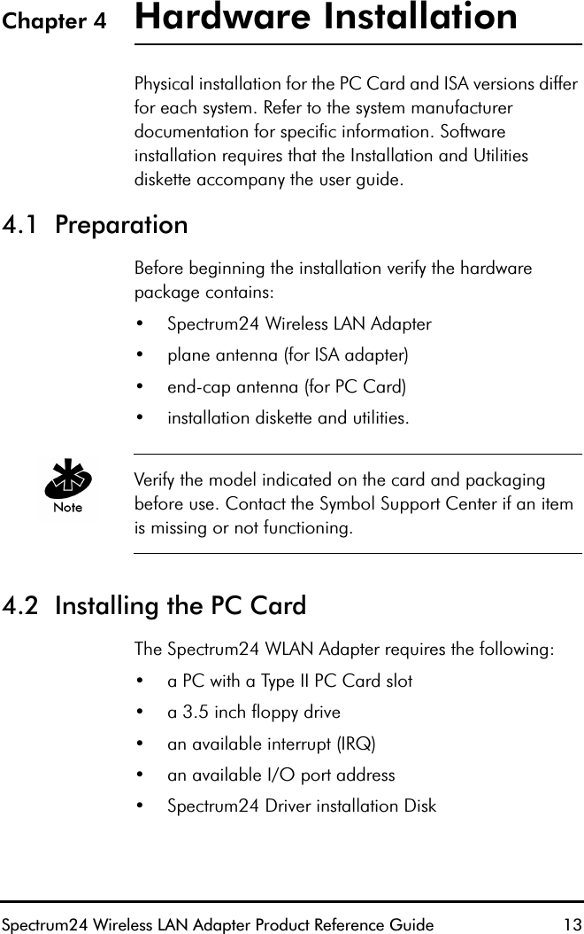
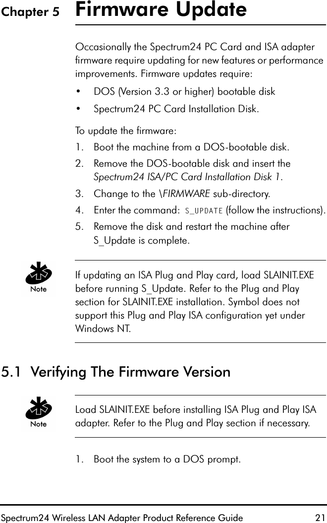
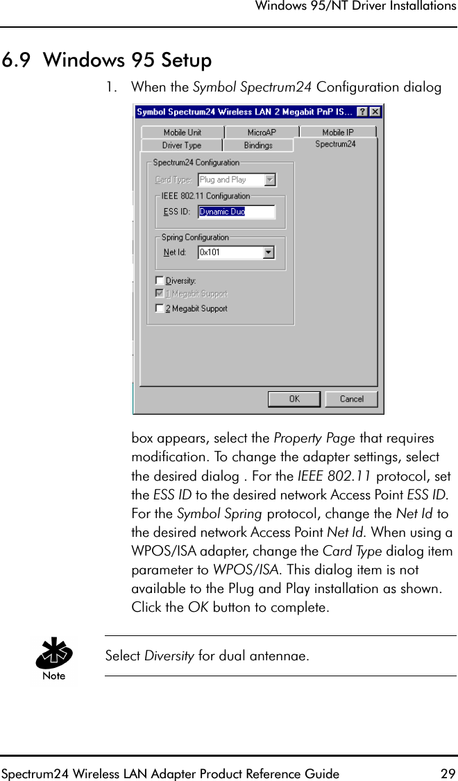
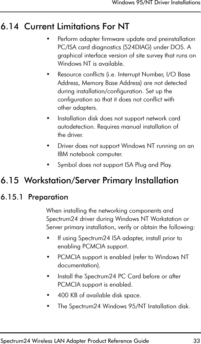
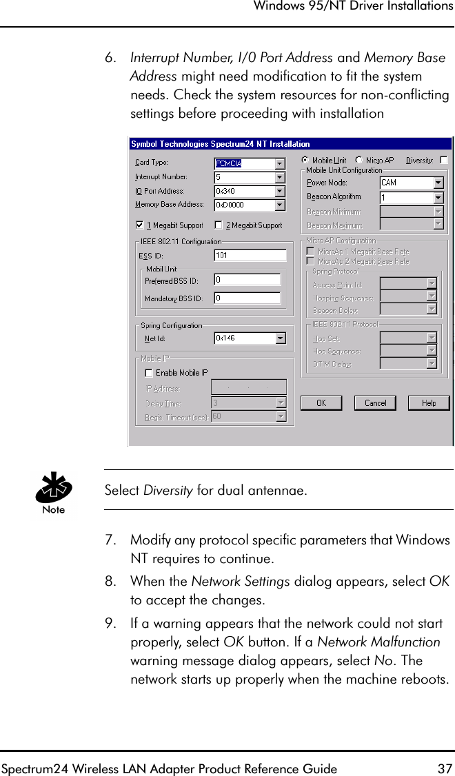
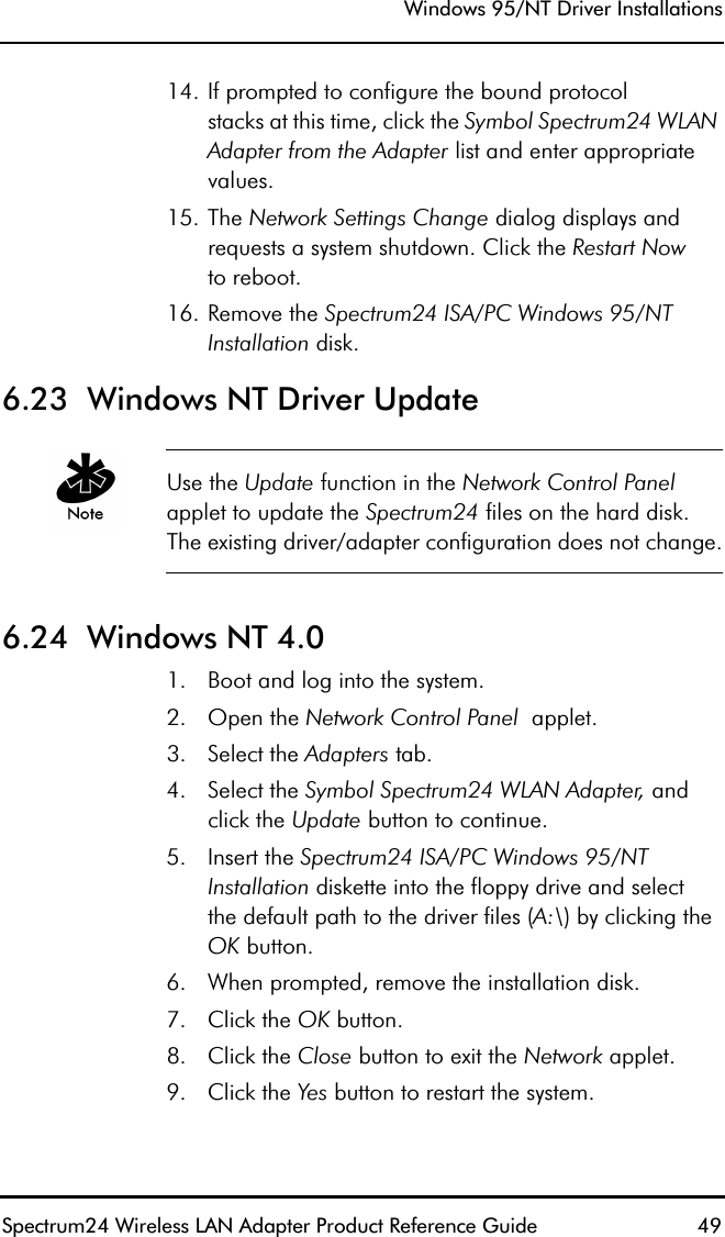
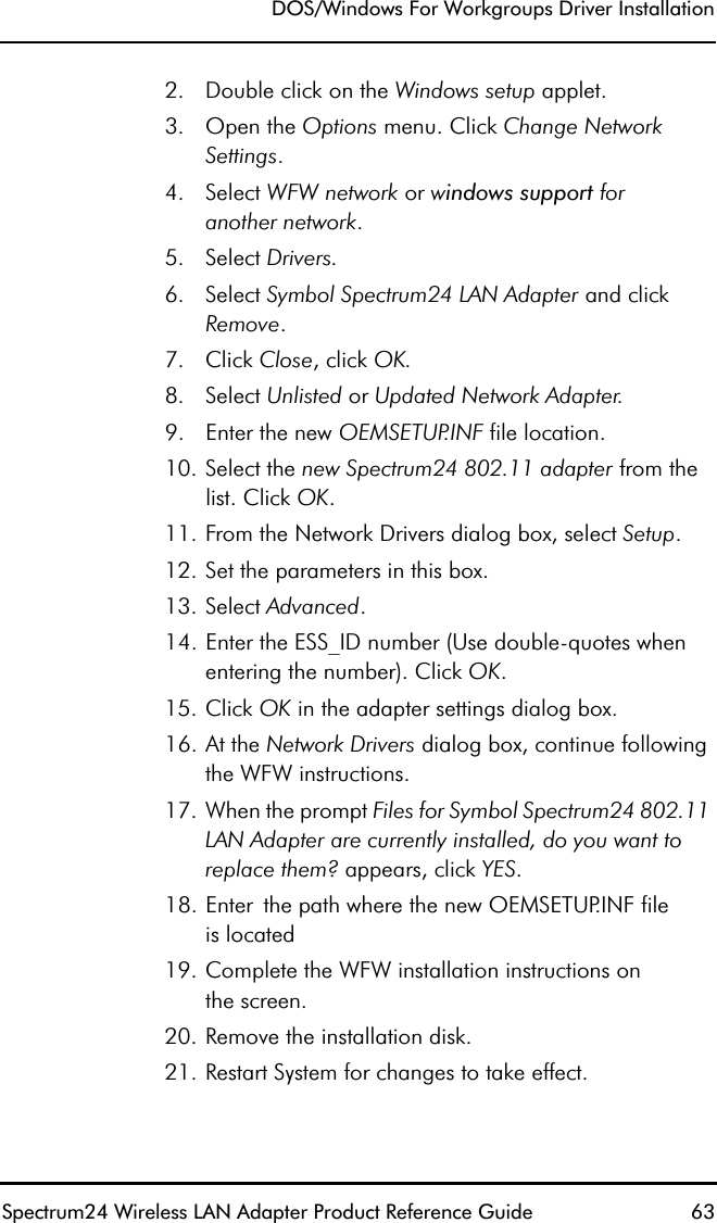
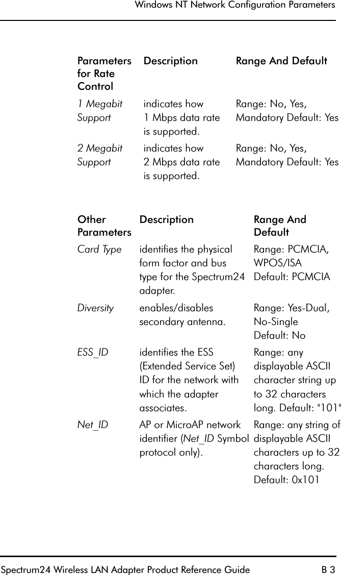
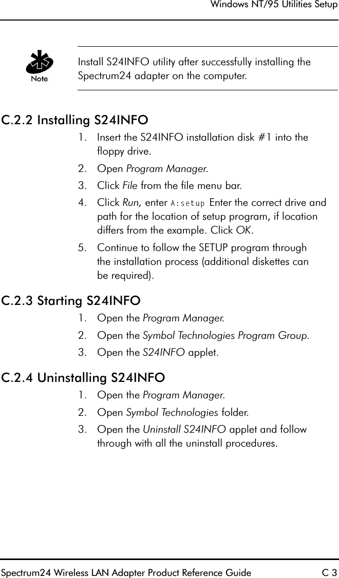
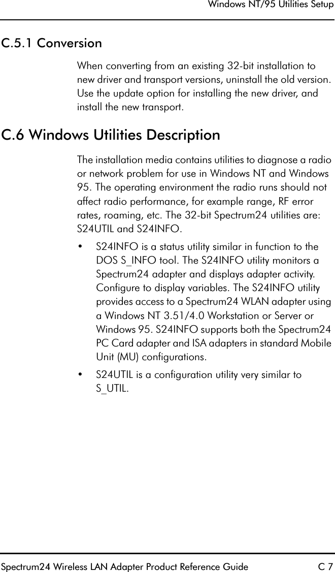
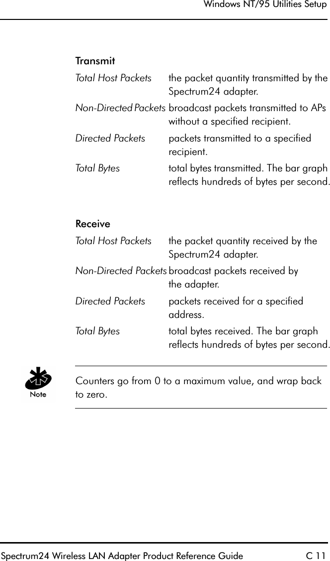
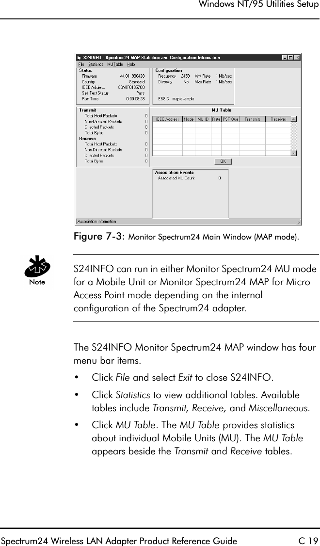
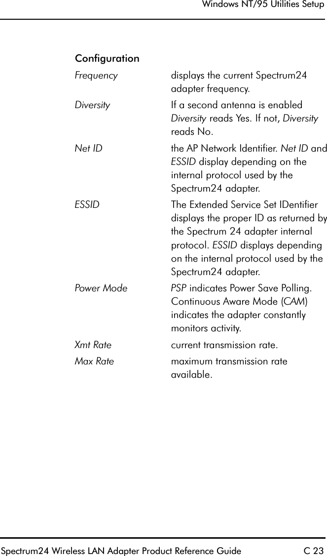
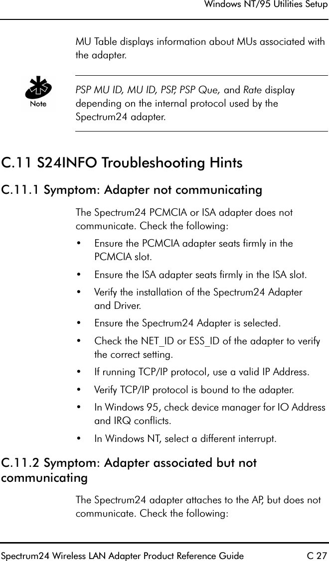
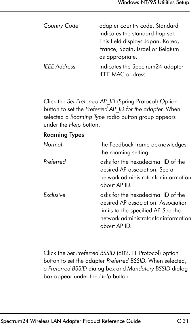
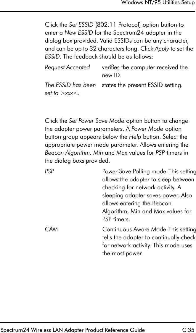
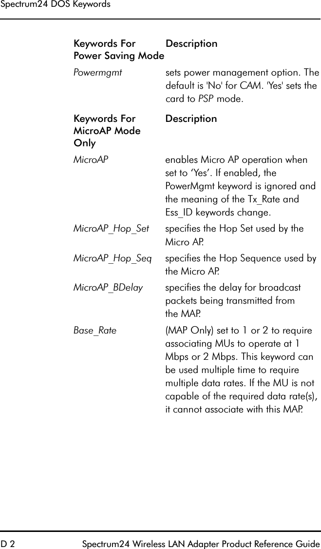
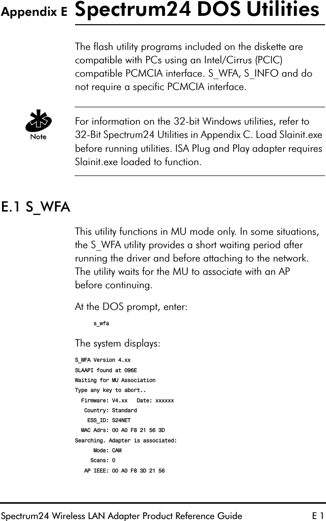
![DOS/Windows For Workgroups Driver InstallationSpectrum24 Wireless LAN Adapter Product Reference Guide 577.6 Modifying Protocol.iniModify PRTOCOL.INI to include:[sample PROTOCOL.INI entry for SYMBOL NDIS driver][protman]DriverName=SYMBOL$[SYMBOLNET]DRIVERNAME=SYMBOL$IOADDRESS=0x300INT=5MEM=0xD000ESS_ID=101DIVERSITY=NO •other Keywords as required from appendix D.[Other protocol driver sections as required]7.7 ODI Manual Installation For ODI, MUs require a Multiple Link Interface Driver (MLID) called SL8ODIPC.COM. SL8ODIPC.COM is the radio device driver. The multiple stacks the MU uses (e.g. TCP/IP) are known as the Multiple Protocol Interfaces (MPI). A link support layer (LSL) program provides the link between MLID and MPI. ODI loads as a Terminate and Stay Resident (TSR) program. ODI program files run from the command line or as part of a batch file.Edit ODI binding and configuration information stored in NET.CFG with an ASCII text editor using the appropriate keywords found in Appendix D. The following examples assume a default installation of third party network](https://usermanual.wiki/Symbol-Technologies/LA3021-500/User-Guide-48934-Page-73.png)
![DOS/Windows For Workgroups Driver Installation 58 Spectrum24 Wireless LAN Adapter Product Reference Guideprograms. [PATH] refers to the location of files on the hard drive. If the automatic installation program was not used, copy the files as needed (LSL.COM, SL8ODIPC.COM, ) from the Drivers and Utilities Installation diskette to the appropriate directory on the hard disk.7.8 Modifying Autoexec.bat Modify AUTOEXEC.BAT to include the following:[PATH]\LSL[PATH]\SLAINIT (If using an ISA card)[PATH]\SL8ODIPC•other protocol drivers as required.7.9 Modifying Net.cfg With an ASCII text editor, create NET.CFG in the network directory. Include the following statements:LINK DRIVER SLAODIFRAME ETHERNET_IIMODE IOIOADDRESS 300INTERRUPT 5ESS_ID 101Verify the values do not conflict with other system interrupts, I/O and memory ranges. Refer to Appendix D for a detailed description of DOS keyword definitions.](https://usermanual.wiki/Symbol-Technologies/LA3021-500/User-Guide-48934-Page-74.png)
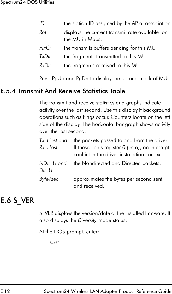
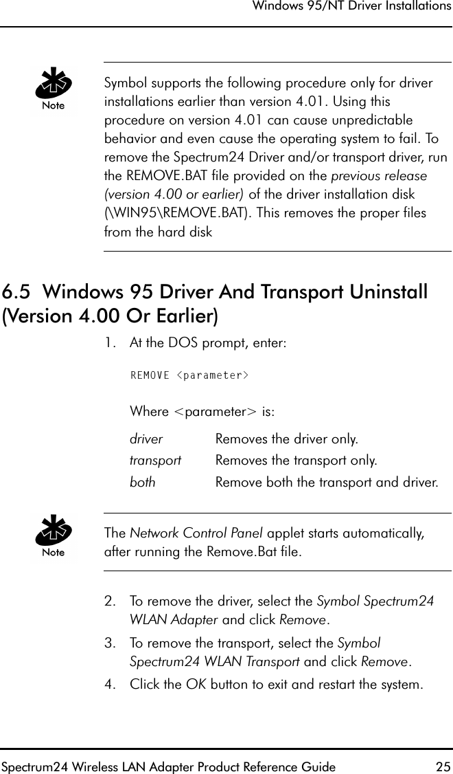
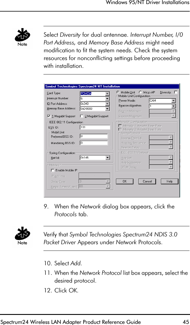
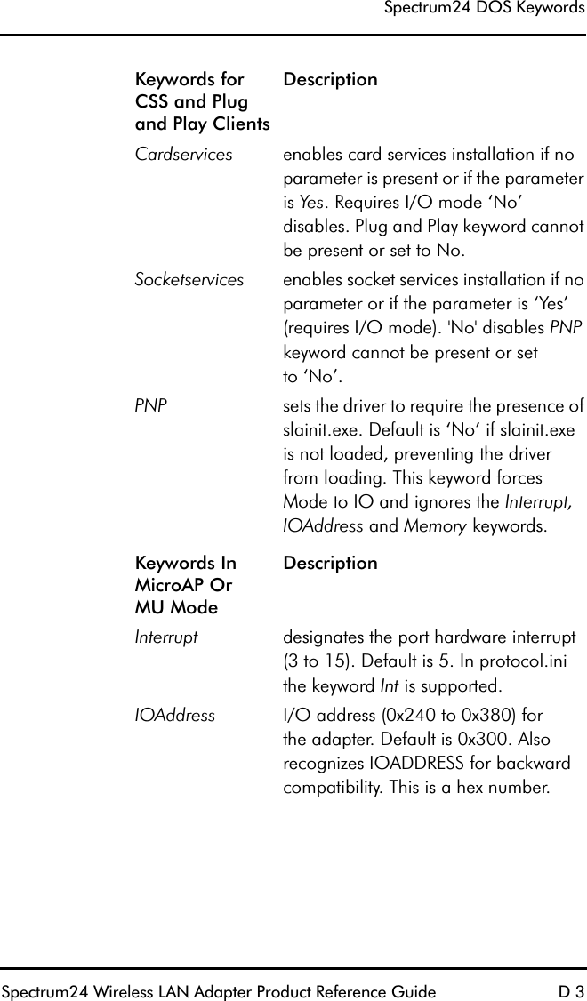
![DOS/Windows For Workgroups Driver Installation 60 Spectrum24 Wireless LAN Adapter Product Reference GuideThe ISA Plug and Play WLAN card requires users to load SLAINIT.EXE prior to loading the driver or updating the firmware. For ODI, from the command line or in a batch file load the following:LSL.COMSLAINIT.EXESL8ODIPC.COM•other protocol drivers as required.For NDIS, in the config.sys file include:[DEVICE]=[PATH]\PROTMAN.DOS[DEVICE]=[PATH]\SLAINIT.EXE[DEVICE]=[PATH]\SL8NDIS.EXE•other protocol drivers as required.7.12 Enabling CardServicesLoad SLAINIT.EXE prior to loading the driver in order to use Card and Socket Services with the PCMCIA Adapter card. Using Card and Socket Services allows Hot Swapping the PCMCIA Adapter card. It also provides protection against resource conflicts.](https://usermanual.wiki/Symbol-Technologies/LA3021-500/User-Guide-48934-Page-76.png)
![DOS/Windows For Workgroups Driver InstallationSpectrum24 Wireless LAN Adapter Product Reference Guide 61For ODI, from the command line or in a batch file enter:LSL.COMSLAINIT.EXESL8ODIPC.COM•other protocol drivers as required.For NDIS, in config.sys enter:[DEVICE]=[PATH]\PROTMAN.DOS[DEVICE]=[PATH]\SLAINIT.EXE[DEVICE]=[PATH]\SL8NDIS.EXE•other protocol drivers as required.Ensure that the driver keywords Cardservices and Socketservices have been set to Yes. Verify that PNP is not present or has been set to No.For ODI, in NET.CFG enter:PNP NOCARDSERVICES YESSOCKETSERVICES YES](https://usermanual.wiki/Symbol-Technologies/LA3021-500/User-Guide-48934-Page-77.png)
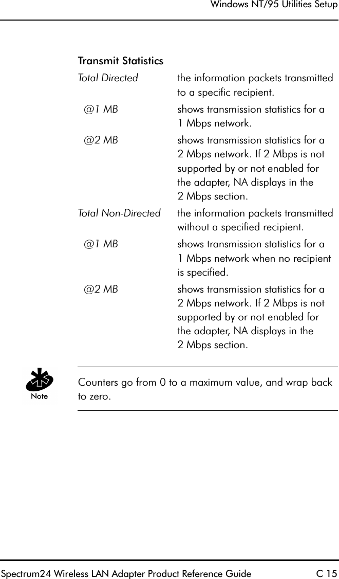
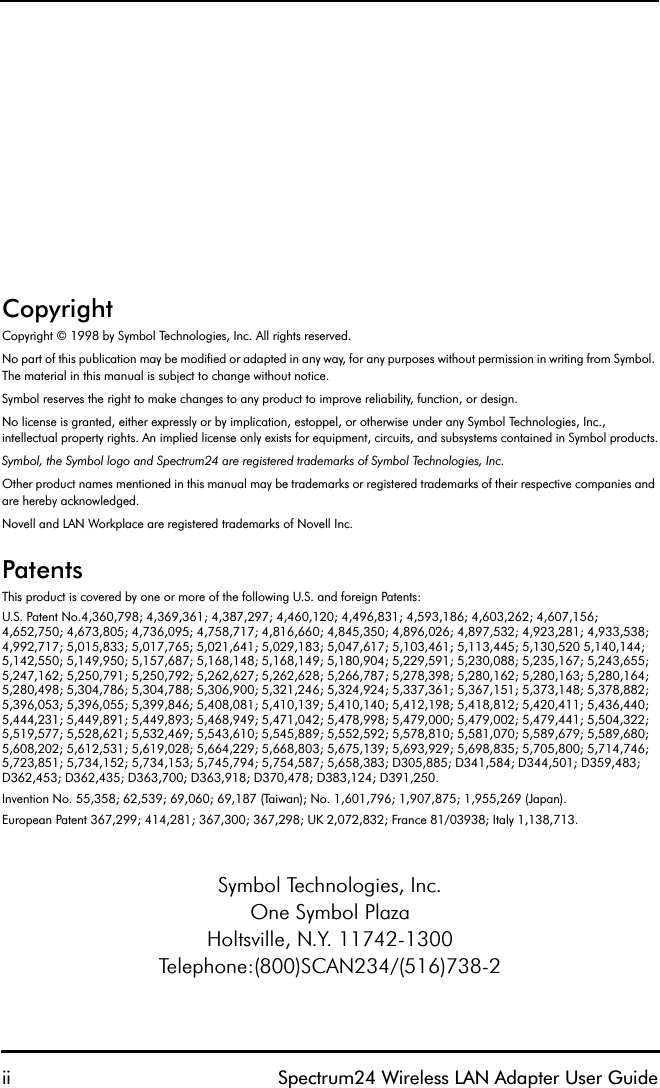
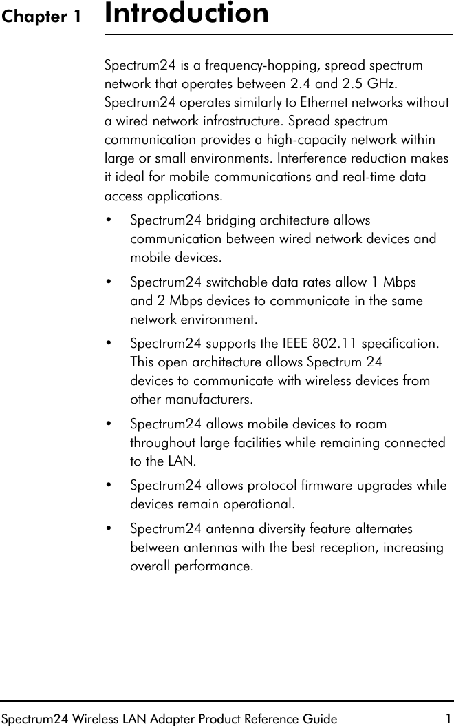
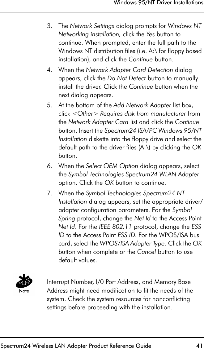
![Spectrum24 DOS UtilitiesE 2 Spectrum24 Wireless LAN Adapter Product Reference GuideE.2 S_UTILS_UTIL is a DOS-utility program that can configure the adapter and obtain statistics. S_UTIL runs only after the driver has been installed.The program provides a list of available commands in the absence of a command line parameter. Each command requires a one-letter code to display current configuration parameters or statistics. Some commands allow optional parameters to change driver/firmware settings only for the current session.At the DOS prompt, enter:s_util <func> [parms]:where func and parms:Adisplays LAN adapter configuration including interrupt, I/O address, memory address, ESS_ID, firmware version, IEEE table number (country code) and IEEE MAC address.Bdisplays the BSS_IDs of the associated AP, preferred AP and mandatory AP. B [hh hh hh hh hh hh] sets the preferred AP BSS_ID for the adapter to associate. The BSS_ID represents the AP MAC address.Csets the unit to CAM. The P parameter sets it to PSP. (MUmode only).E <ESS_ID String> sets the 32-character ESS_ID forthe adapter.](https://usermanual.wiki/Symbol-Technologies/LA3021-500/User-Guide-48934-Page-132.png)
![Spectrum24 DOS UtilitiesSpectrum24 Wireless LAN Adapter Product Reference Guide E 3I <all> displays association status, power mode, beacon algorithm and transmit status. This also displaysthe ESS_ID, station ID and radio type. The last line shows the APsin the AP table and the numberof scans. The all option displays additional transmit and receive statistics. S_INFO also providesthis information.J [hh hh hh hh hh hh] sets the mandatory AP BSS_IDfor the adapter to associate.The BSS_ID represents the APMAC address.L <value> get/set options that apply only to Symbol radio terminals. The value 40 selects no power down in Symbol terminals, and the value 20 automatically powers down the terminals in a cradle.O <option> sets the firmware option forthe adapter.Psets the unit to PSP mode. The C parameter sets it to CAM. (MUmode only)T <u> [v] [w] get/set beacon parameters. The u parameter indicates the algorithm. The v parameter indicates the minimum beacon interval. The w parameter indicates the maximum beacon interval. (MU mode only)](https://usermanual.wiki/Symbol-Technologies/LA3021-500/User-Guide-48934-Page-133.png)
![Spectrum24 DOS UtilitiesE 4 Spectrum24 Wireless LAN Adapter Product Reference GuideE.3 ExamplesWith no parameters, S_UTIL displays:Spectrum24 API Utility V1.06aUsage: S_UTIL <function code> [<optional parameters>,,,]Function codes and [optional] parameters: A - Display Adapter Configuration info B - Display ESS_ID/BSS_ID info B <BSS_ID> - Set Preferred BSS_ID. B X to clear C - Set Continuous Power Mode (CAM) E <ESS_ID String> - Set ESS_ID I - Display Adapter Info/Statistics J <BSS_ID> - Set Mandatory BSS_ID. J X to clear L - Get/Set SYMBOL_OPTIONS (L <value> to set) O <option> - Set Firmware Option P - Set Power Save Mode (PSP) T - Display Beacon/PSP Parameters T [<Algorithm> [<min> [<max>]]] - Set Beacon parameters The following apply to the MicroAP - W - Display Access Control List (ACL) X <IEEE address> - Add ACL Entry Y <IEEE address> - Delete ACL Entry Z - Clear ACLFor example, to view current adapter parameters from the DOS prompt, enter:s_util AUsed In MicroAP OnlyWdisplays the MicroAP ACL.X<hh hh hh hh hh hh> adds a MAC address to the ACL. The ACL allows a maximum of 16 entries. Duplicate ACL entries are not detected.Y<hh hh hh hh hh hh> removes a MAC address fromthe ACL.Zclears the ACL of all entries.](https://usermanual.wiki/Symbol-Technologies/LA3021-500/User-Guide-48934-Page-134.png)