Symbol Technologies MC7095 Enterprise Digital Assistant User Manual
Symbol Technologies Inc Enterprise Digital Assistant
Contents
- 1. User manual 1
- 2. User manual 2
- 3. User manual 1 - MC70 regulatory info sheet
- 4. User manual 2 - MC70 Quick Start
- 5. User manual MC70 series
- 6. User manual BT
- 7. User manual Phone
- 8. User manual WLAN
- 9. user manual MC70 series
- 10. user manual BT
- 11. user manual phone
- 12. user manual WLAN
- 13. user manual MC70 series - MC70 Quick Start
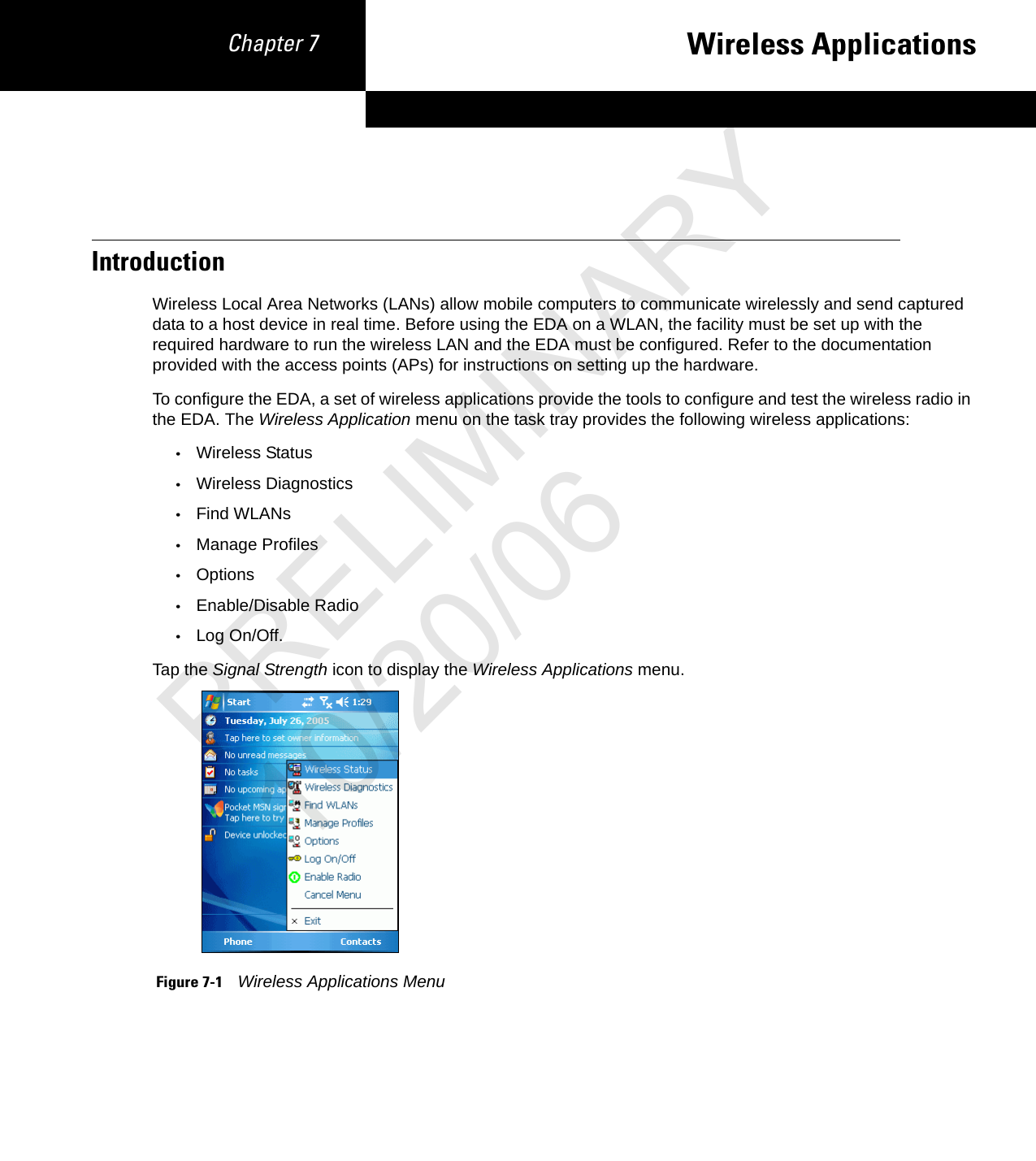
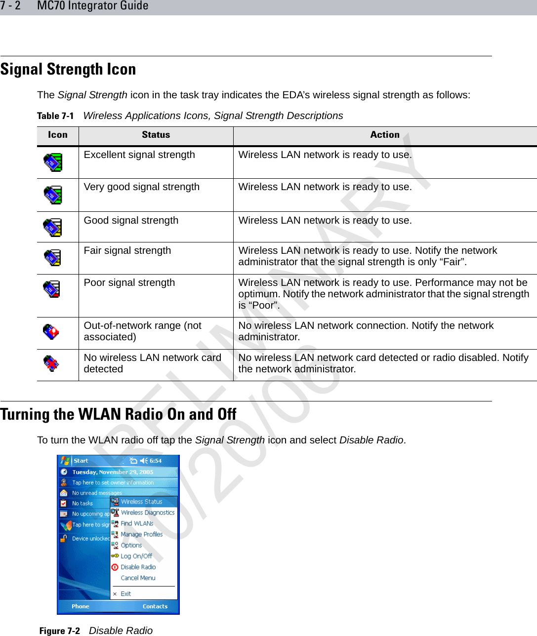
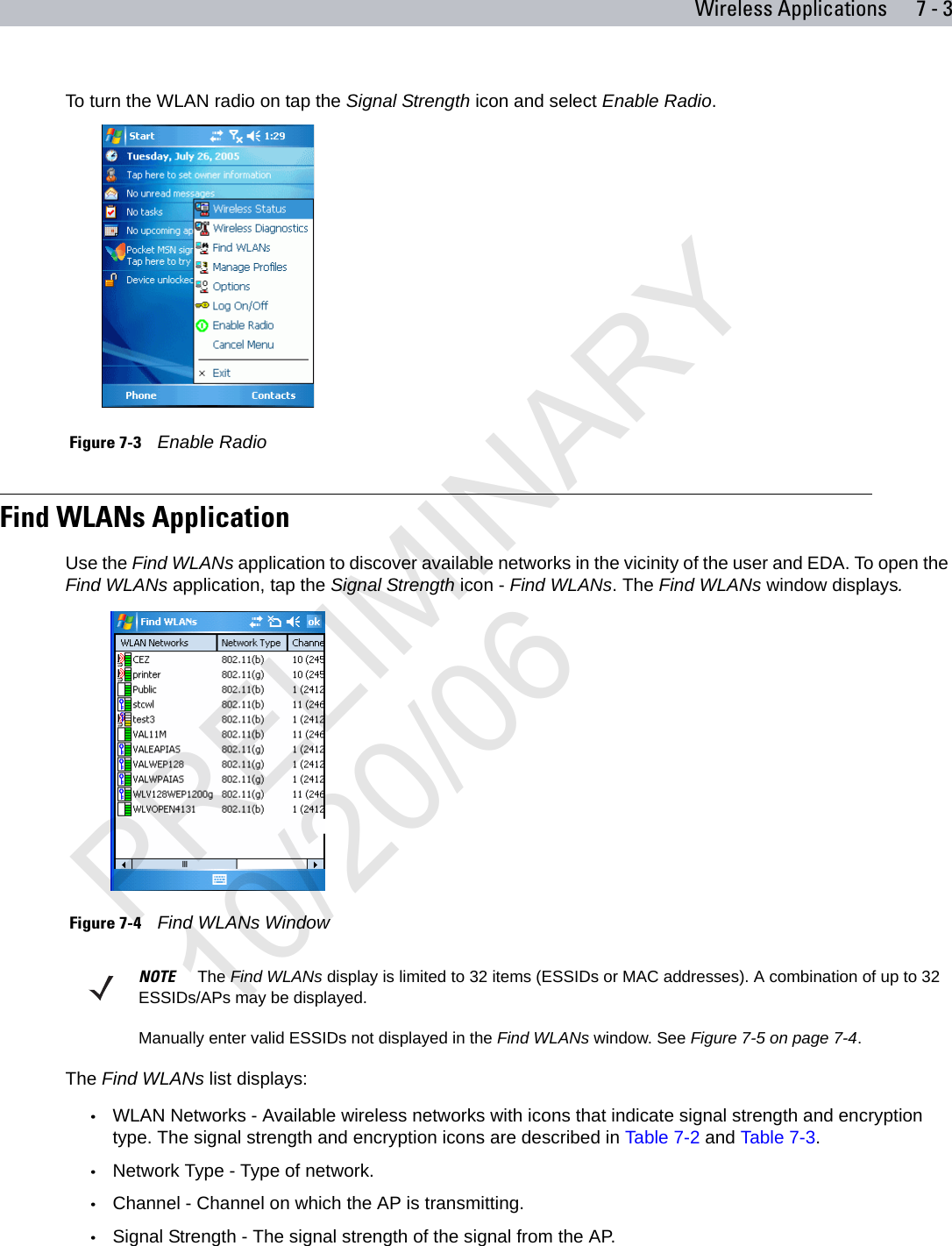
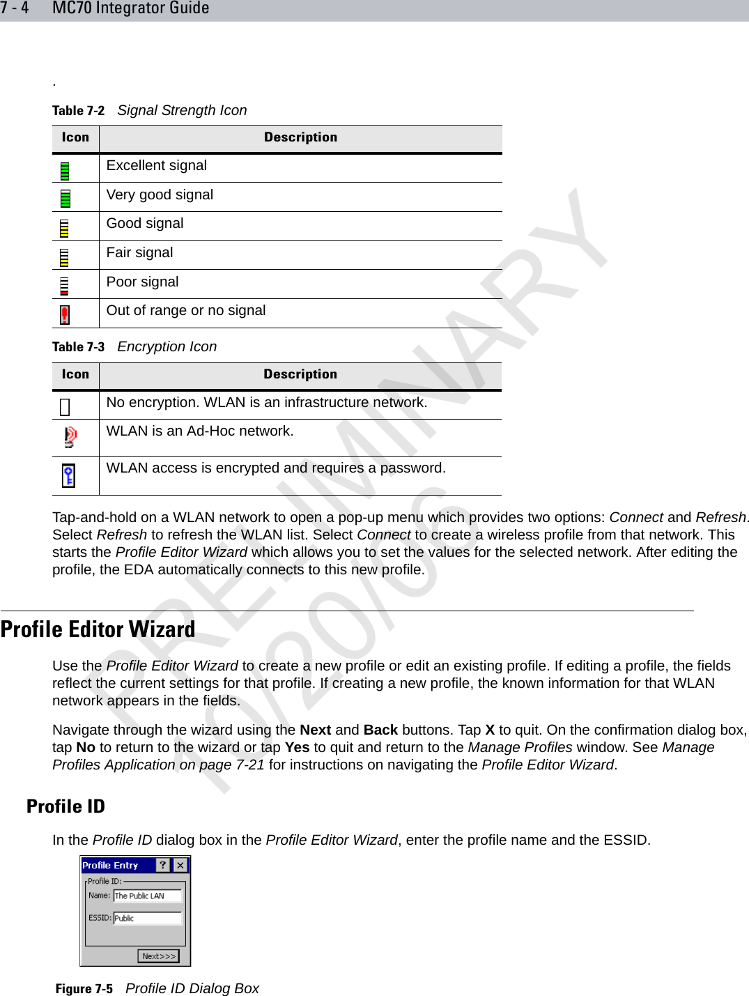
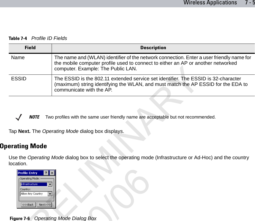
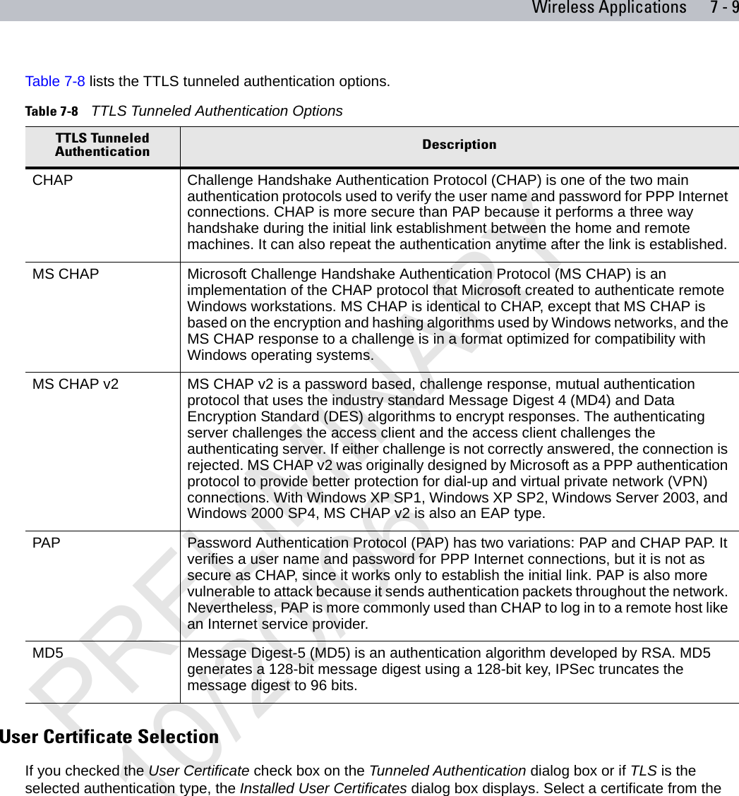
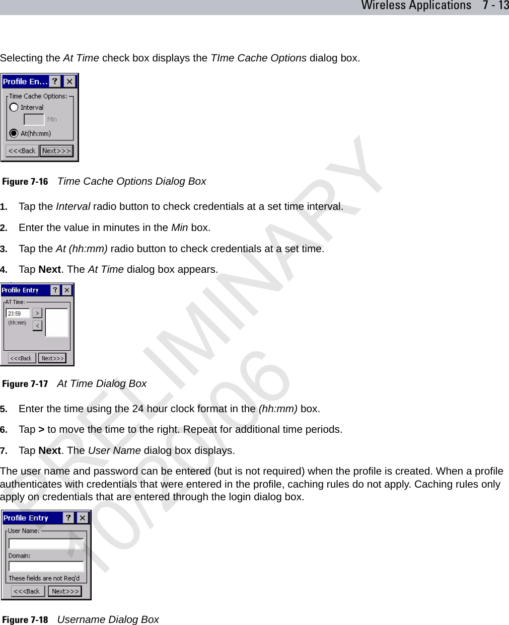
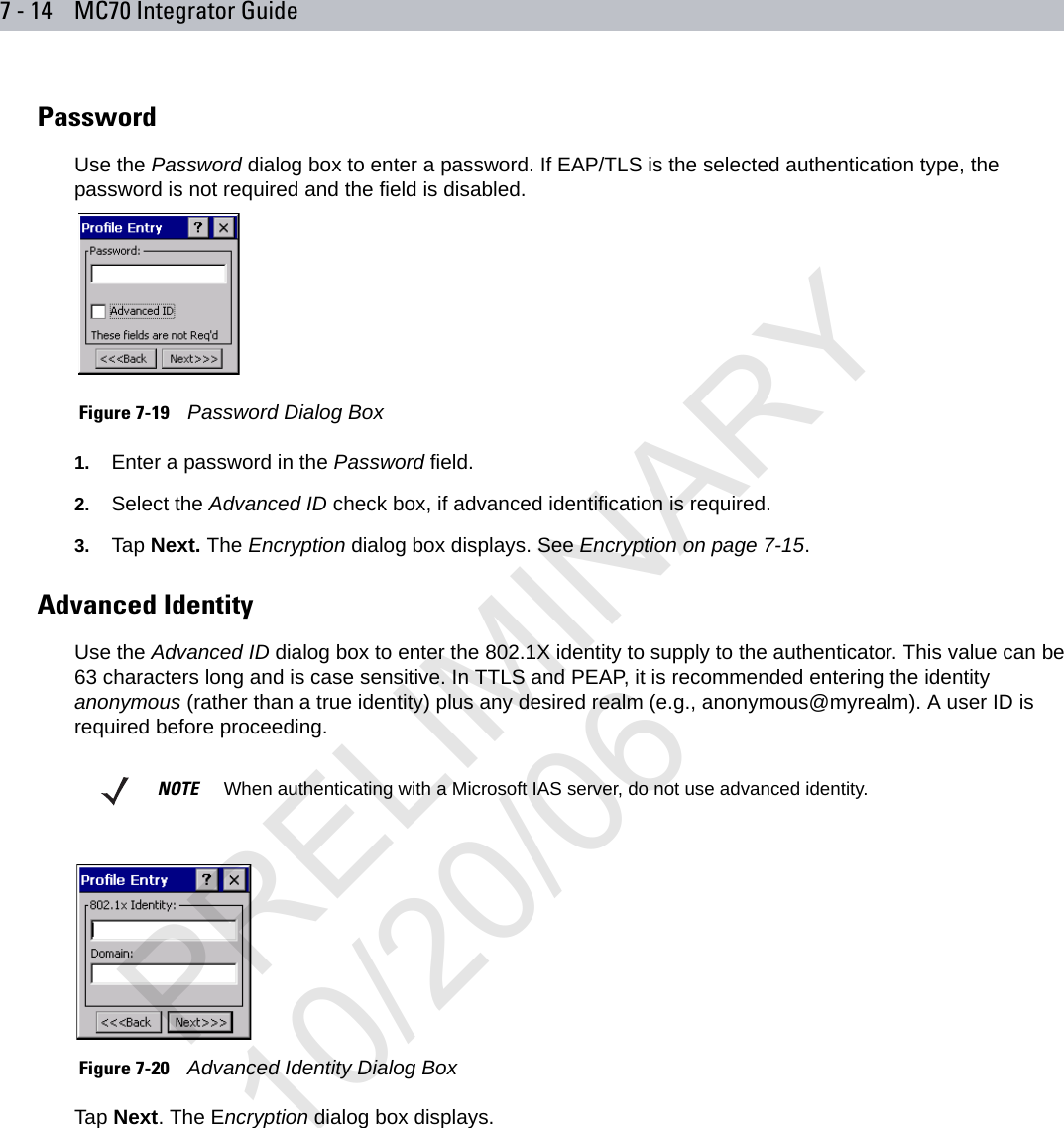
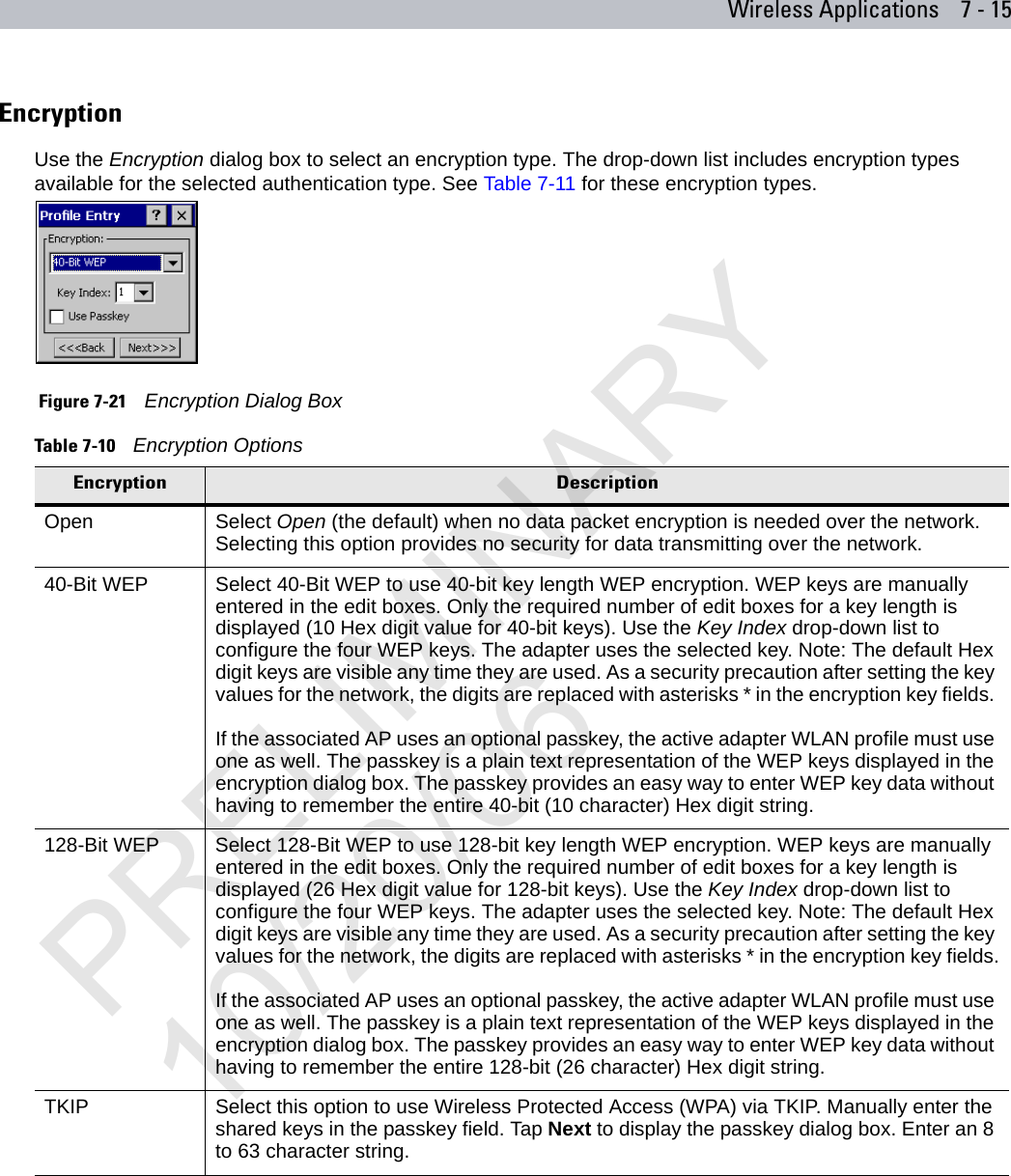
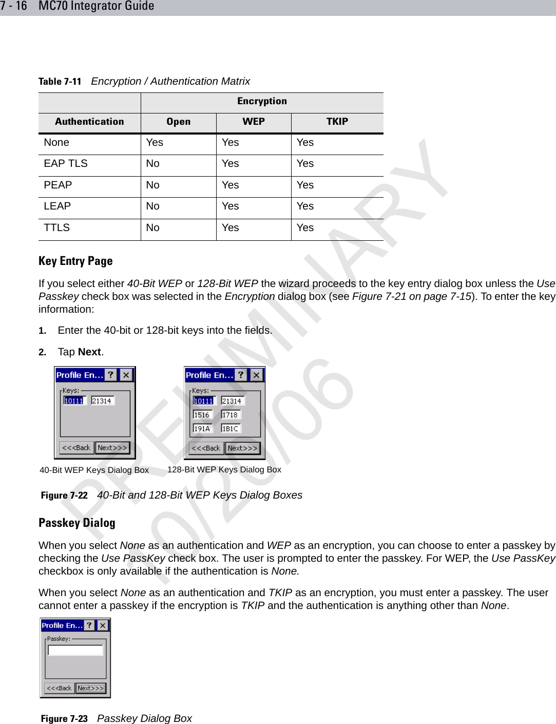
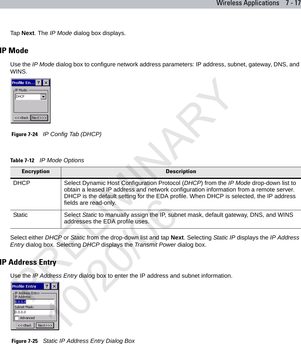
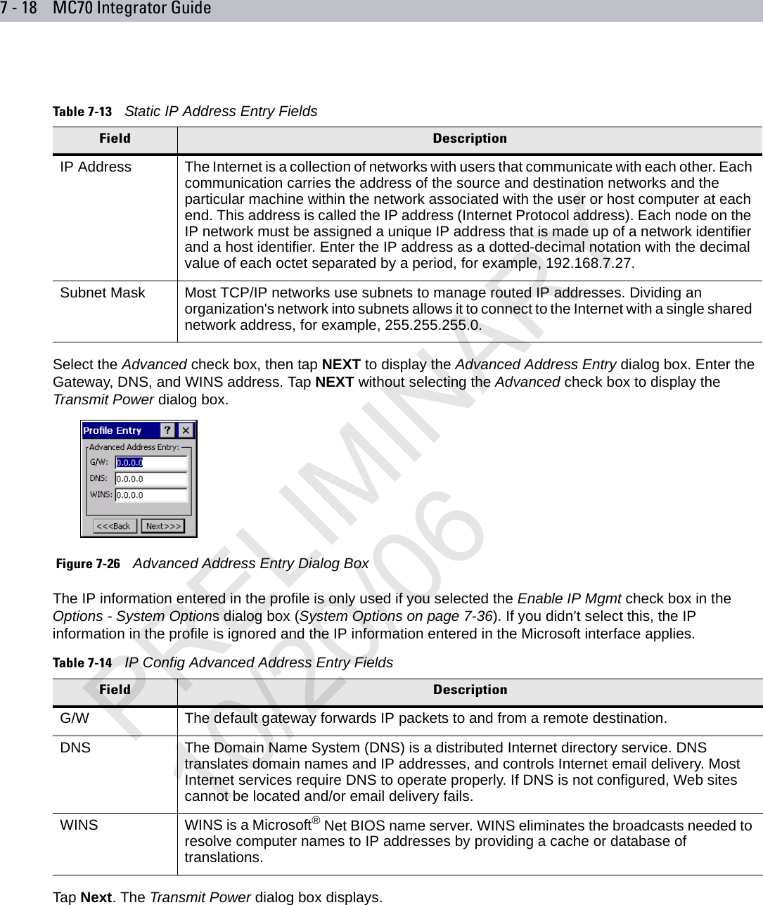
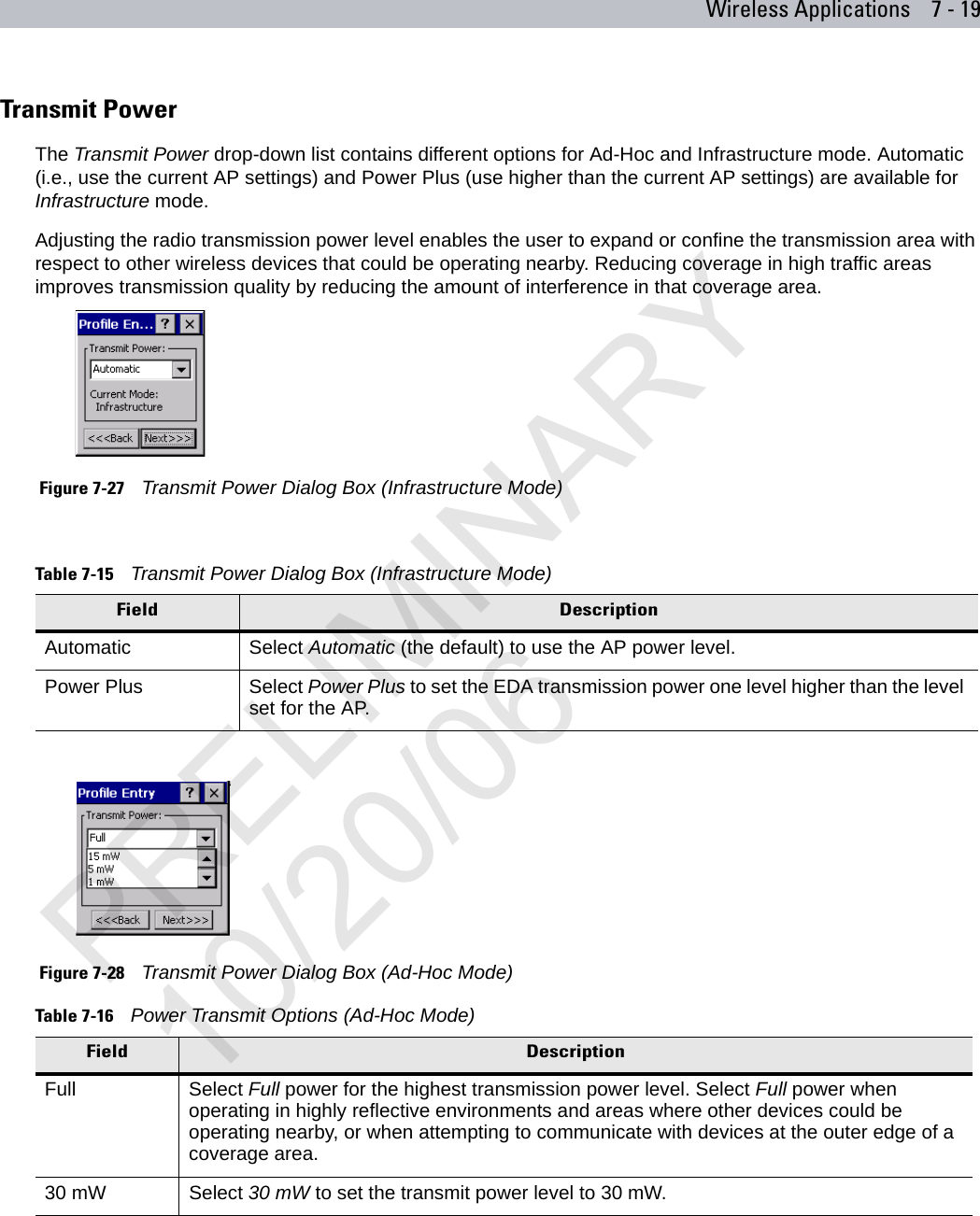
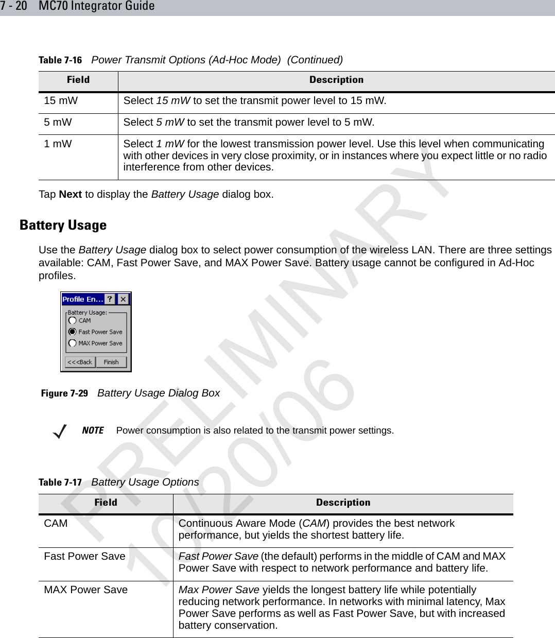
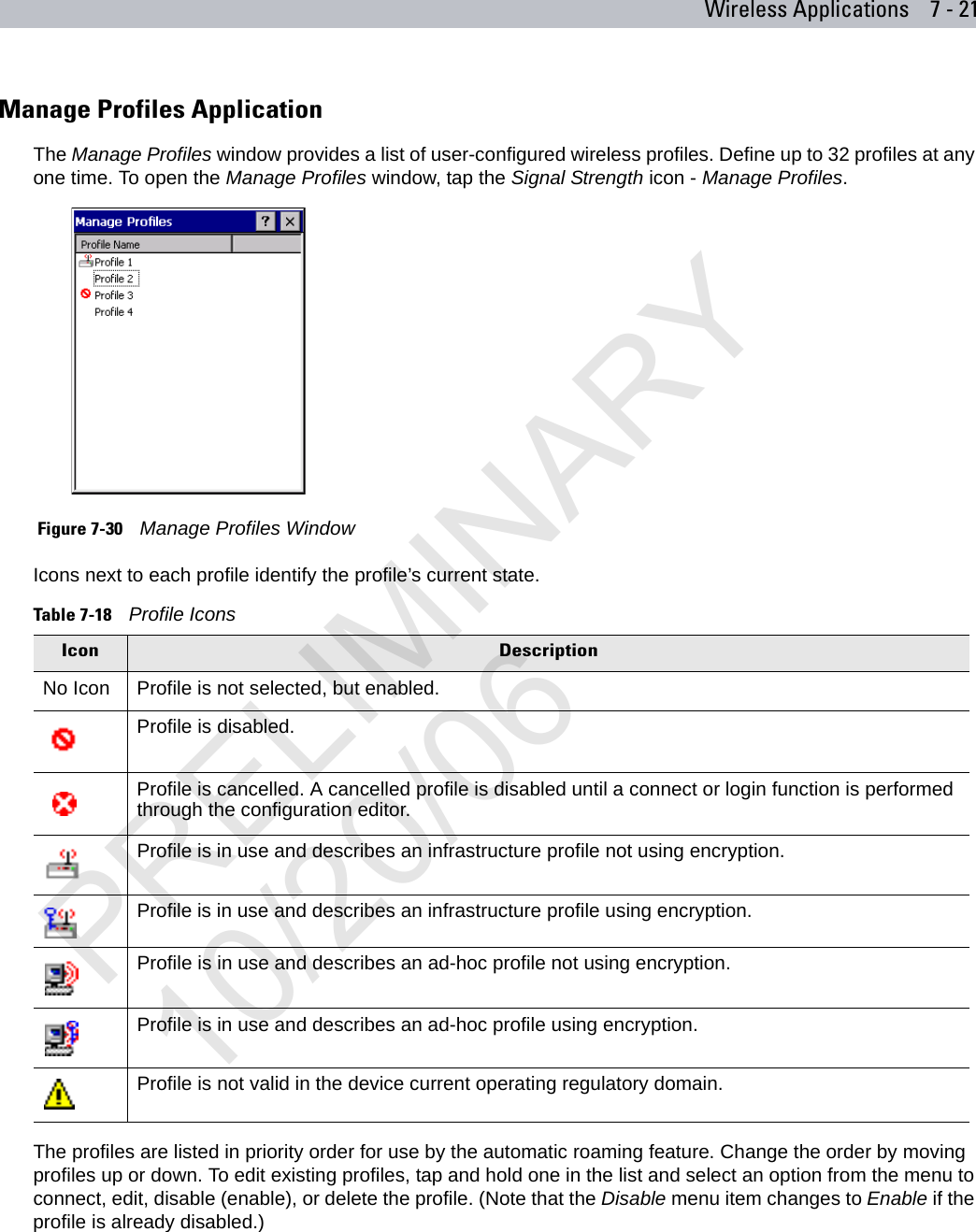
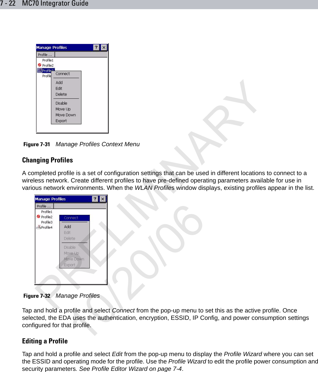
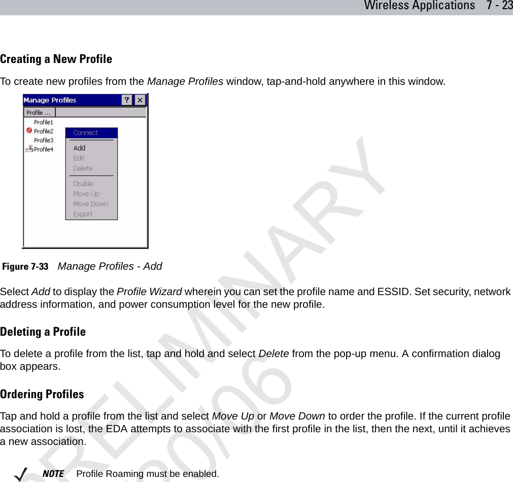
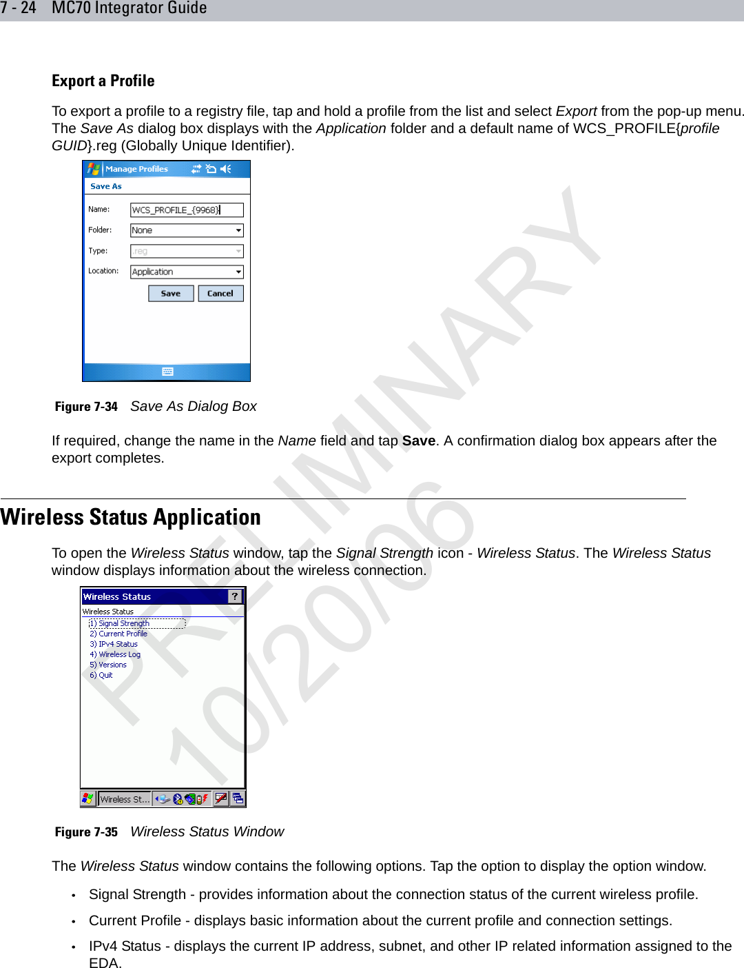
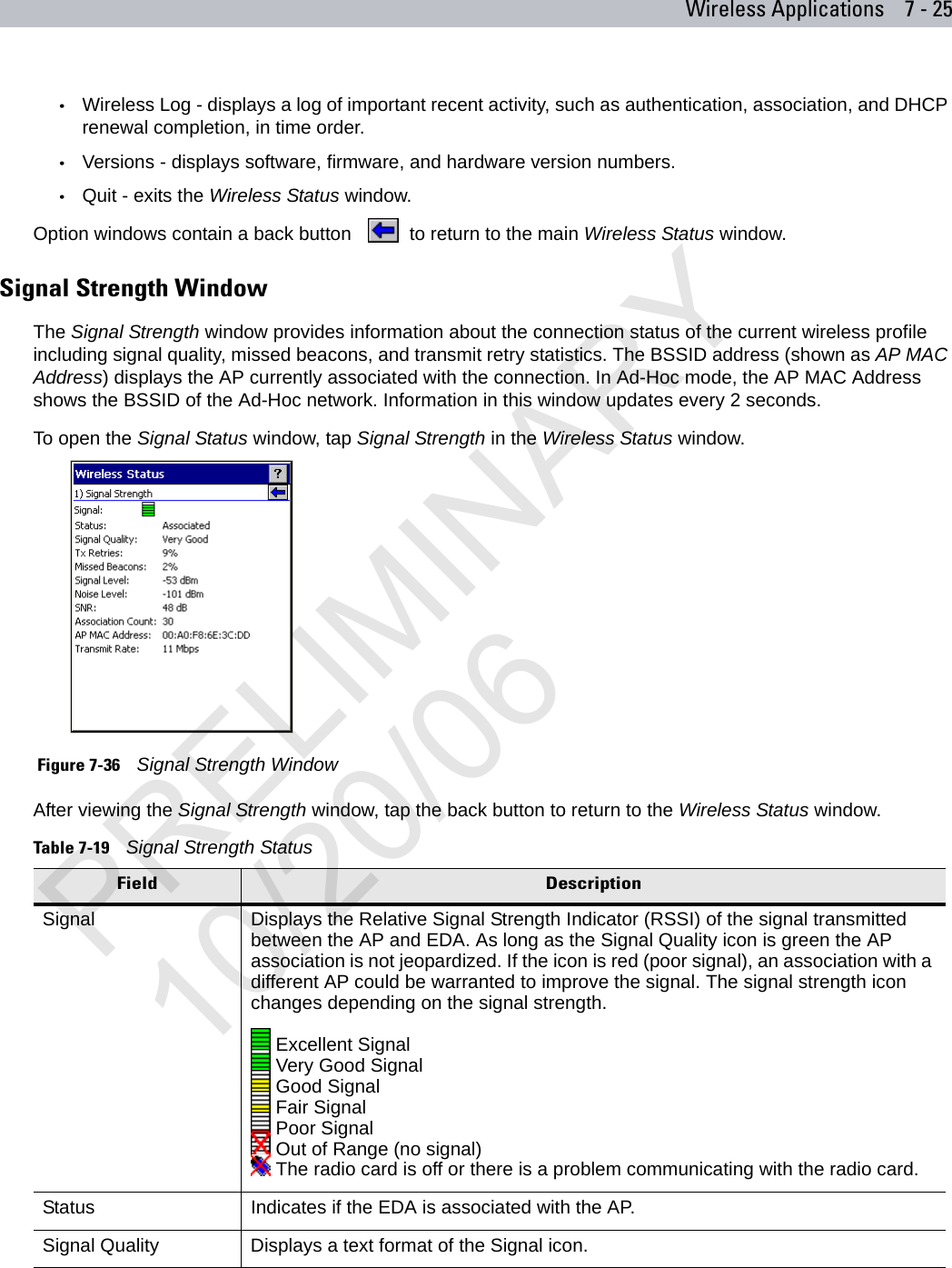
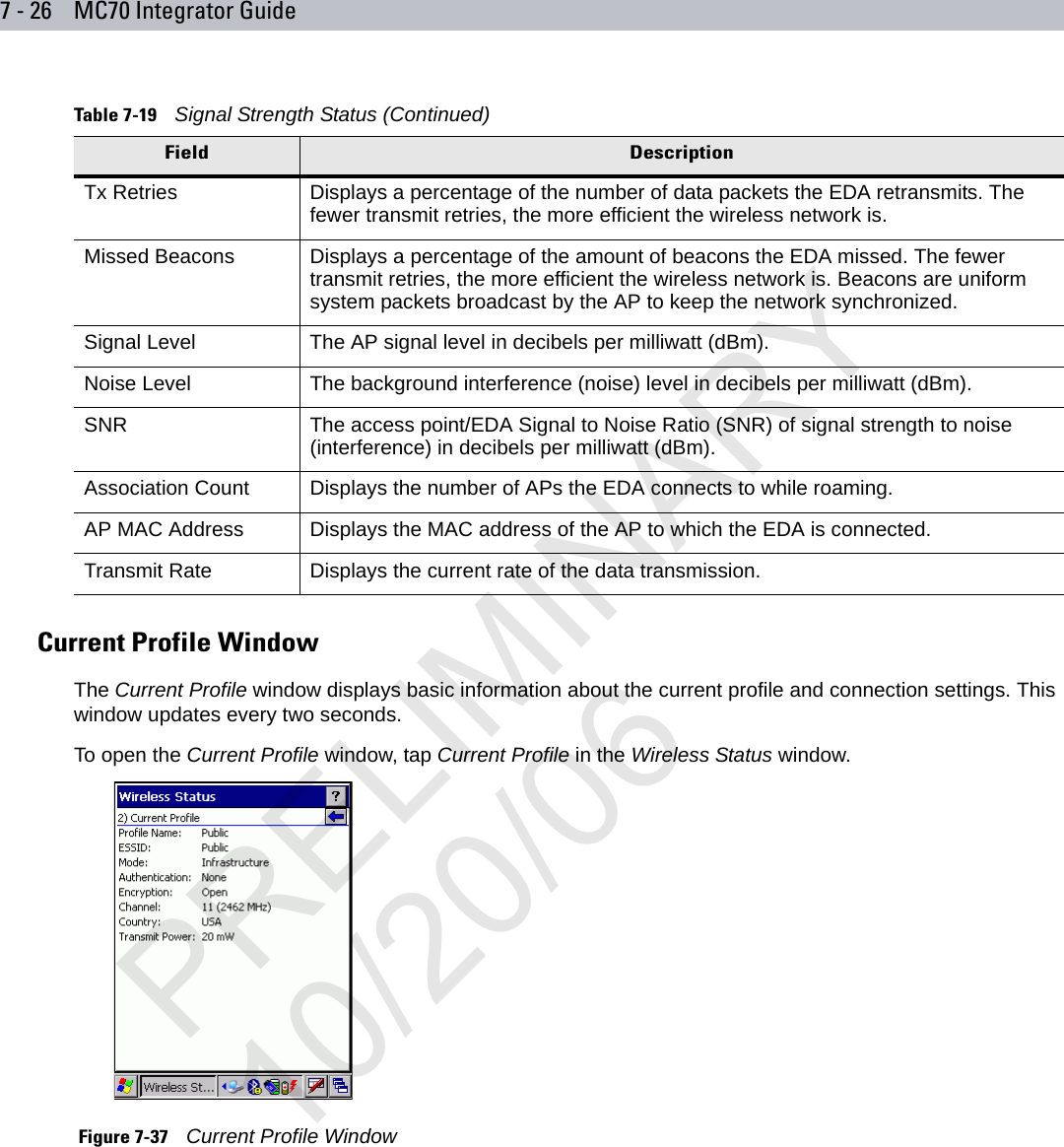
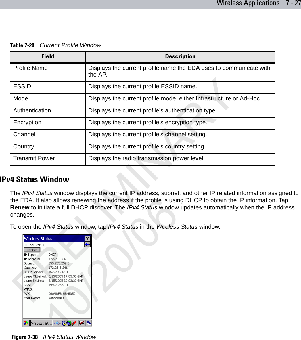
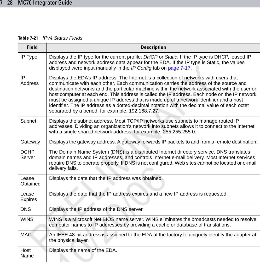
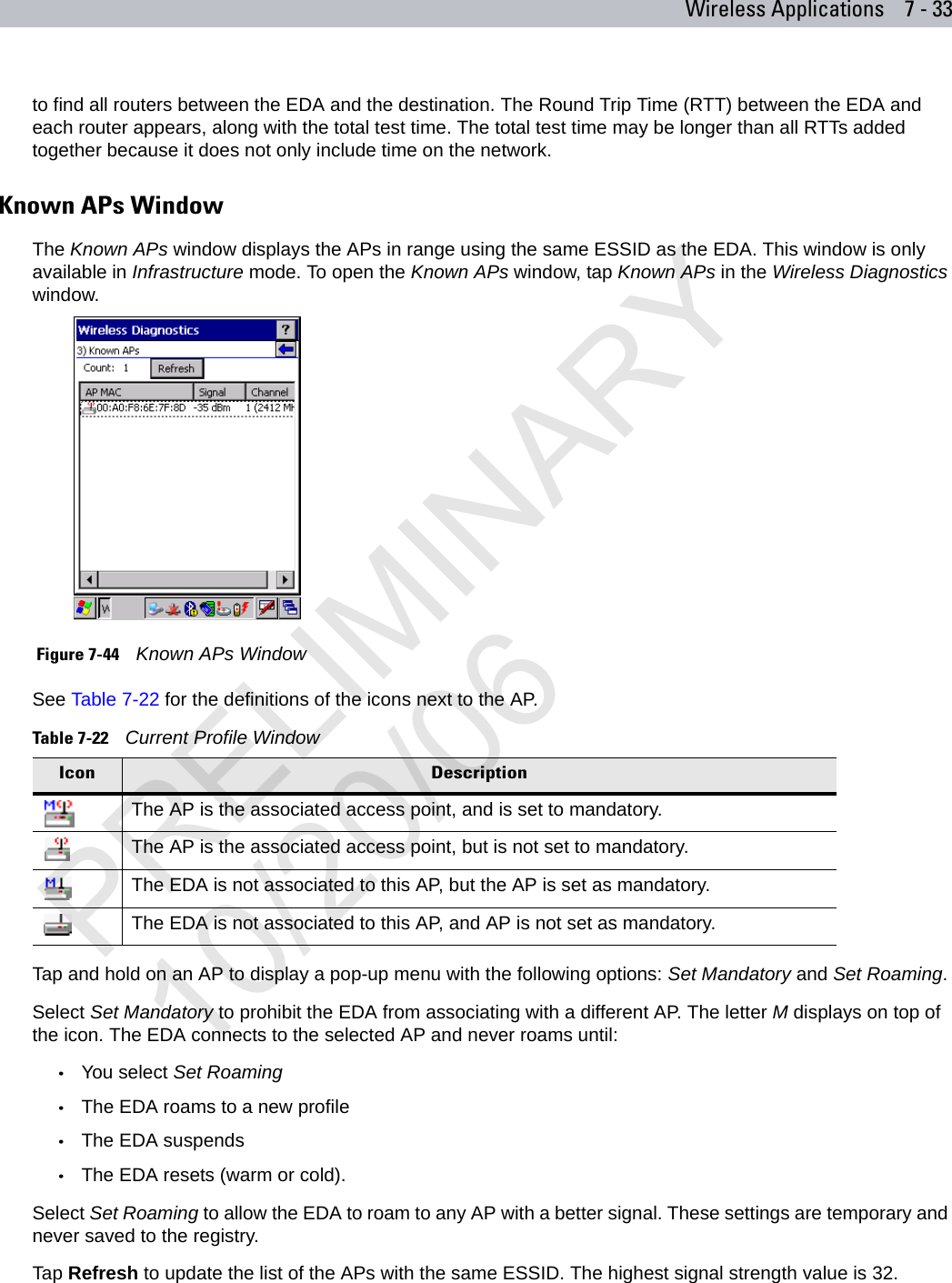
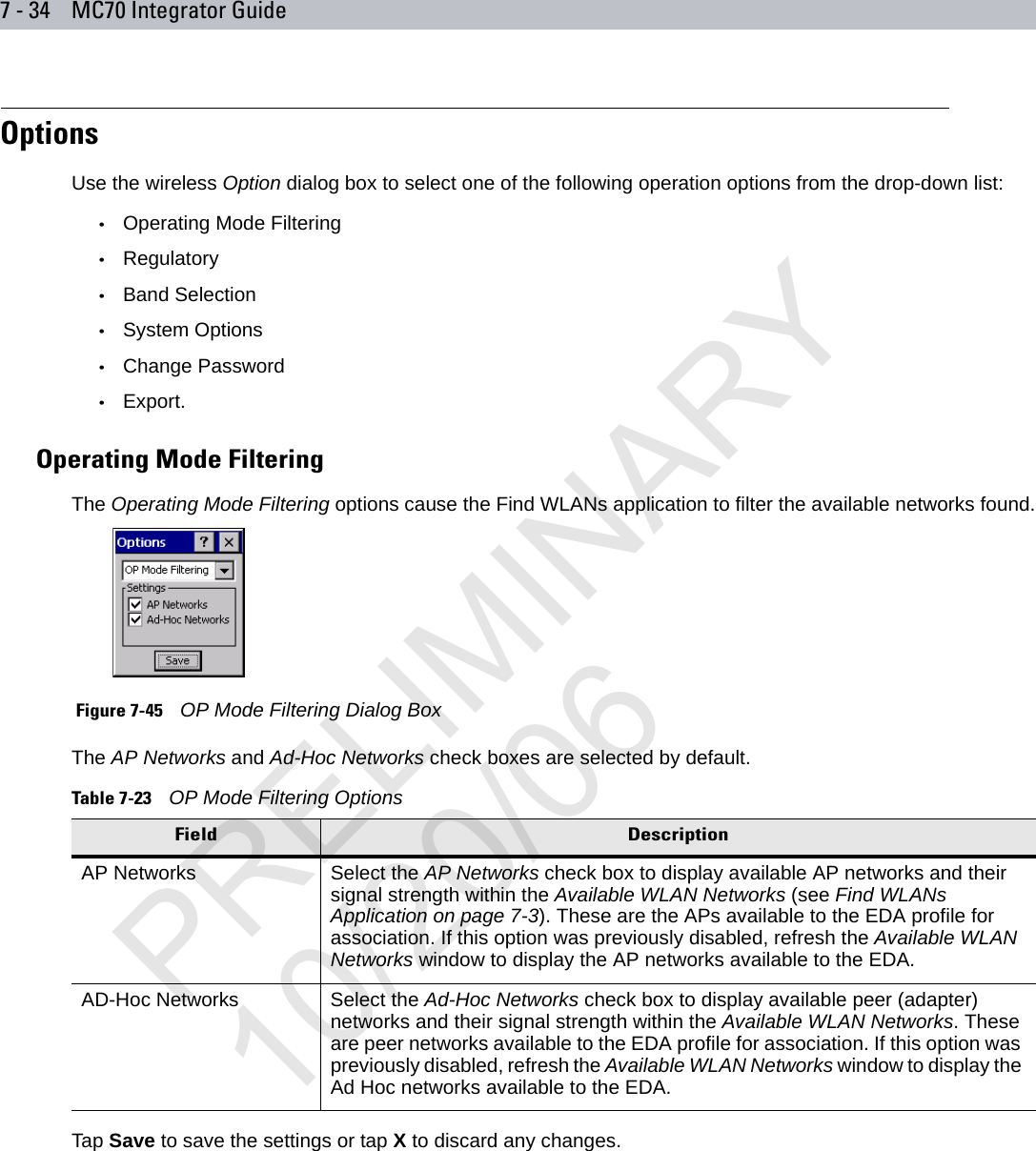
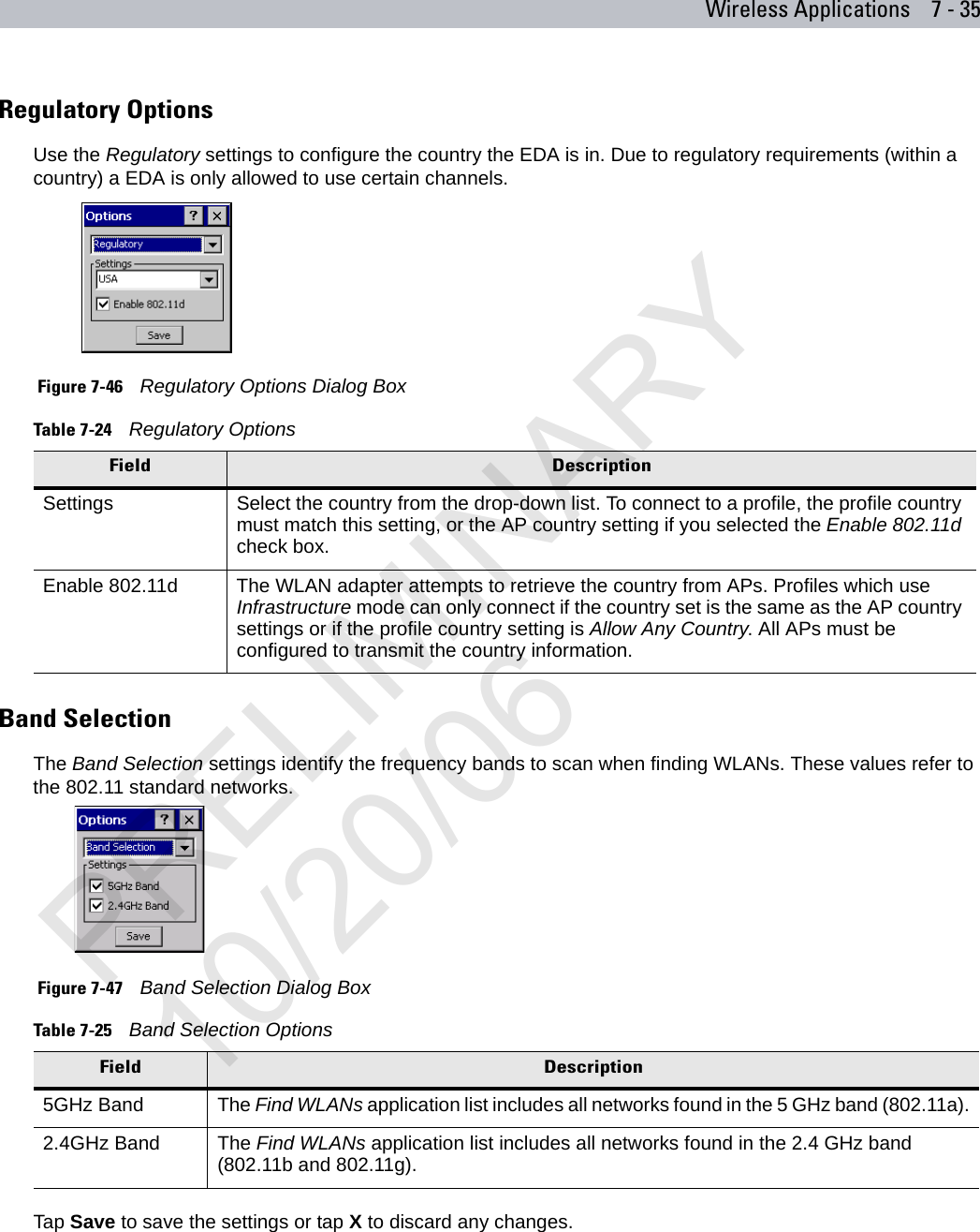
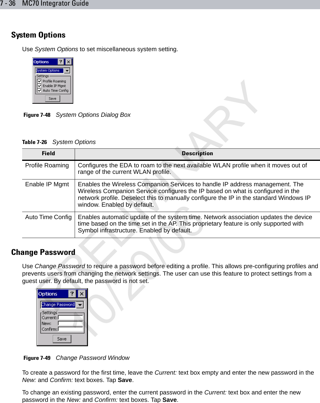
user manual WLAN