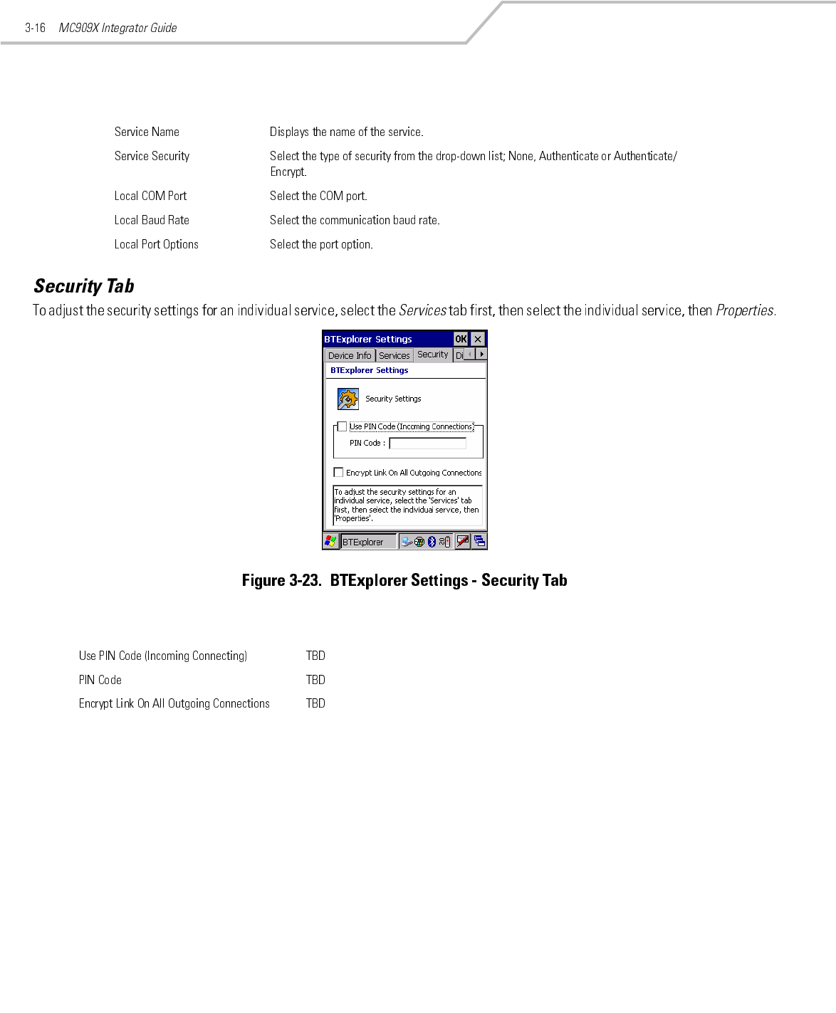
Symbol Technologies MC9097 Symbol Technologies MC9094 User Manual user guide for bluetooth and RLAN
Symbol Technologies Inc Symbol Technologies MC9094 user guide for bluetooth and RLAN
Contents
- 1. user guide for bluetooth and RLAN
- 2. user guide for iDEN
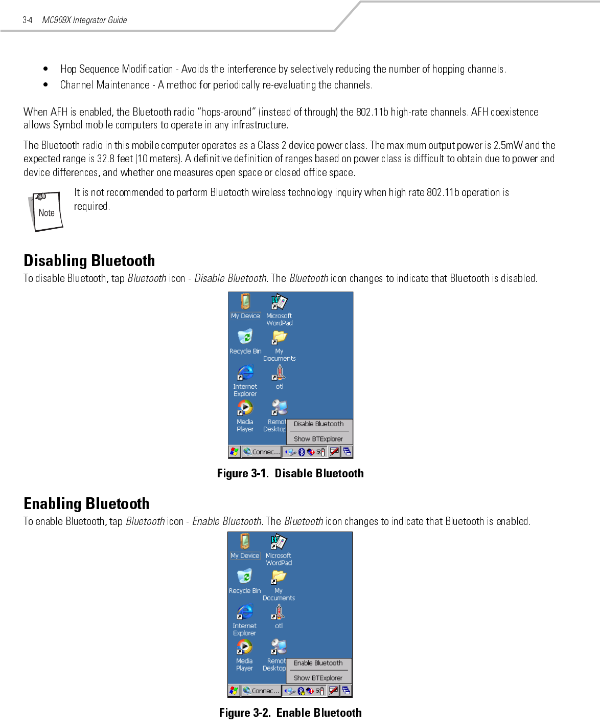
- 3. User guide for bluetooth and RLAN
- 4. User guide for iDEN
- 5. Bluetooth and RLAN user guide
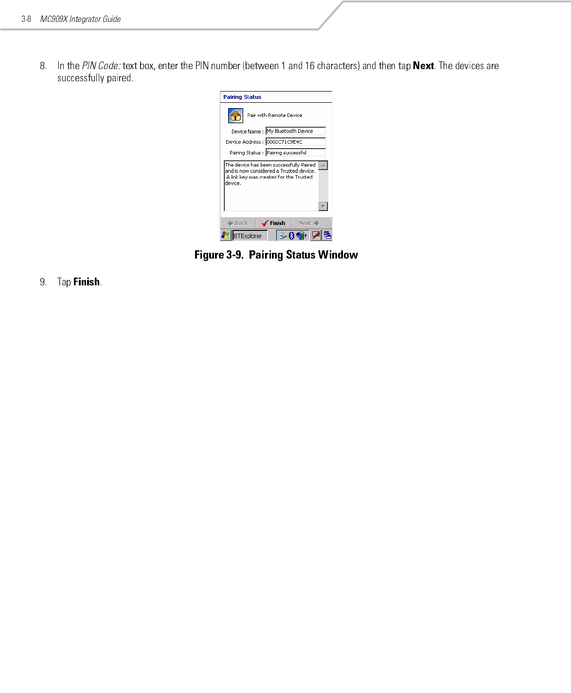
- 6. iDEN user guide
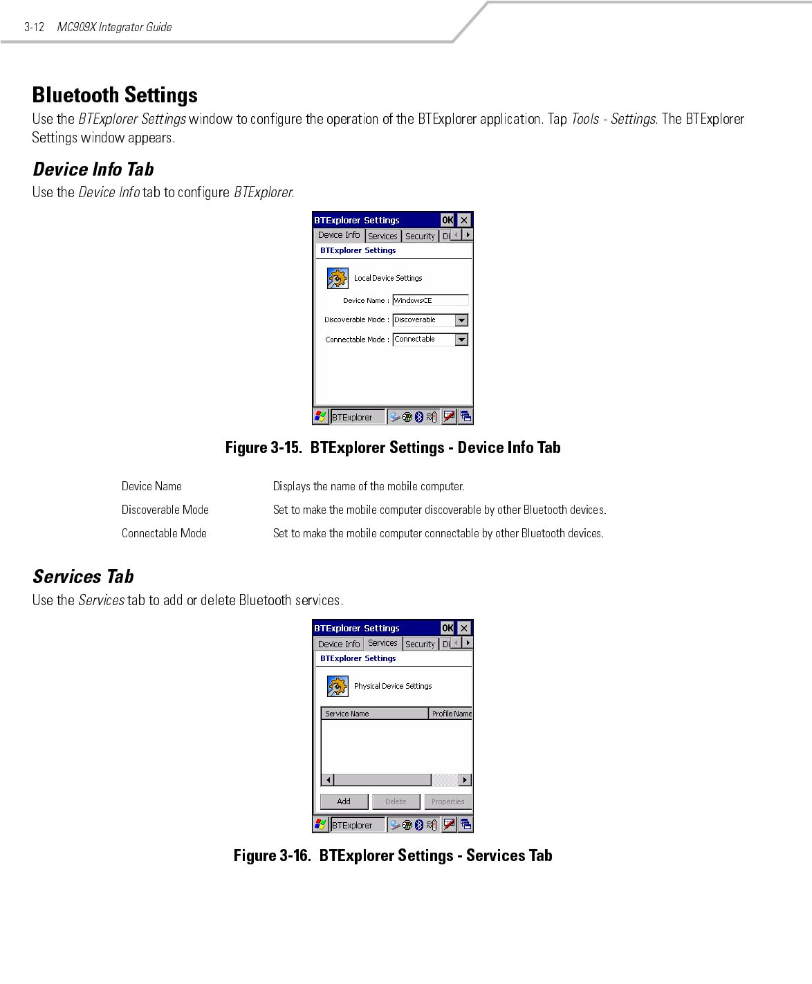
user guide for bluetooth and RLAN

Preliminary

Preliminary

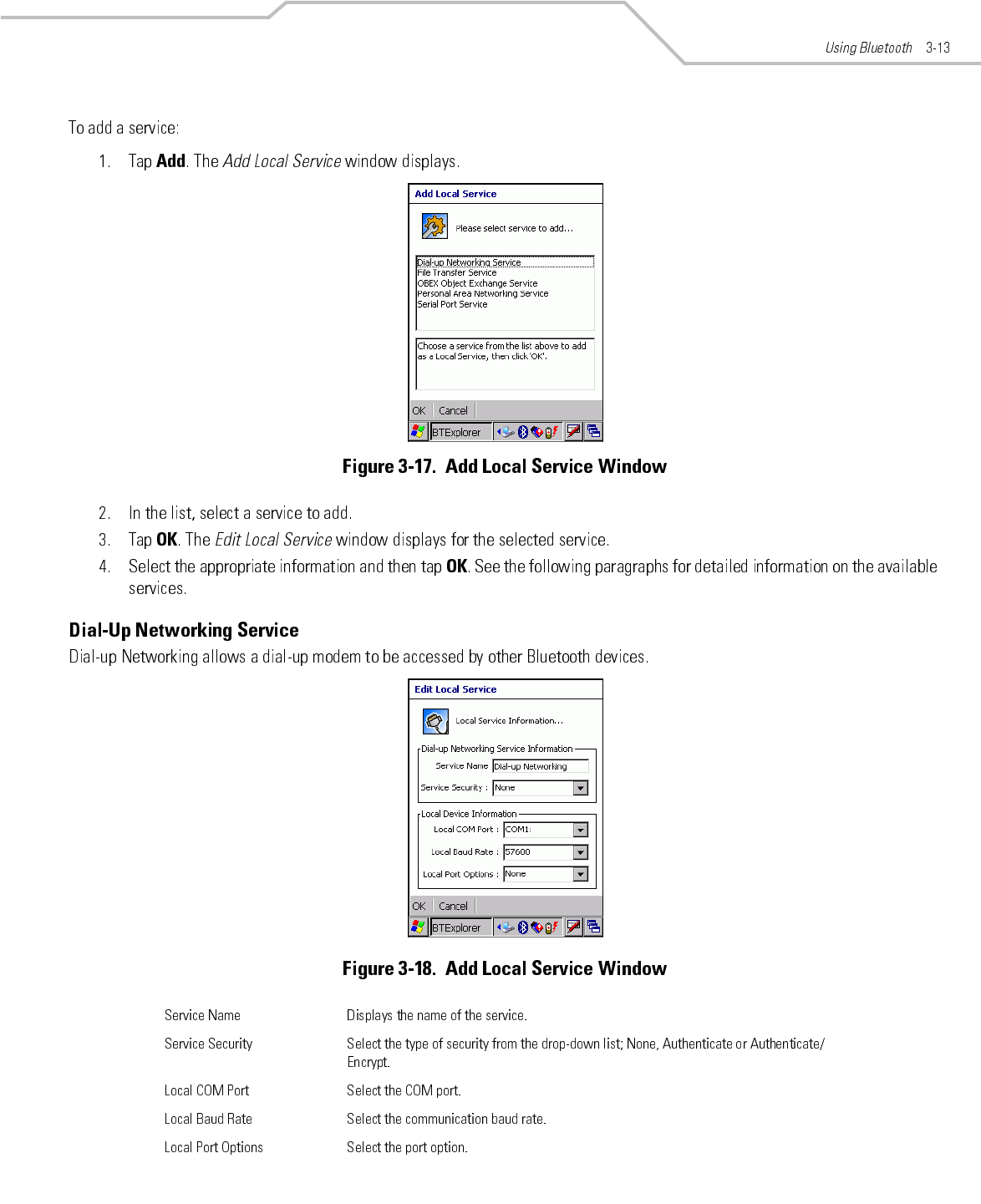
Preliminary

Preliminary

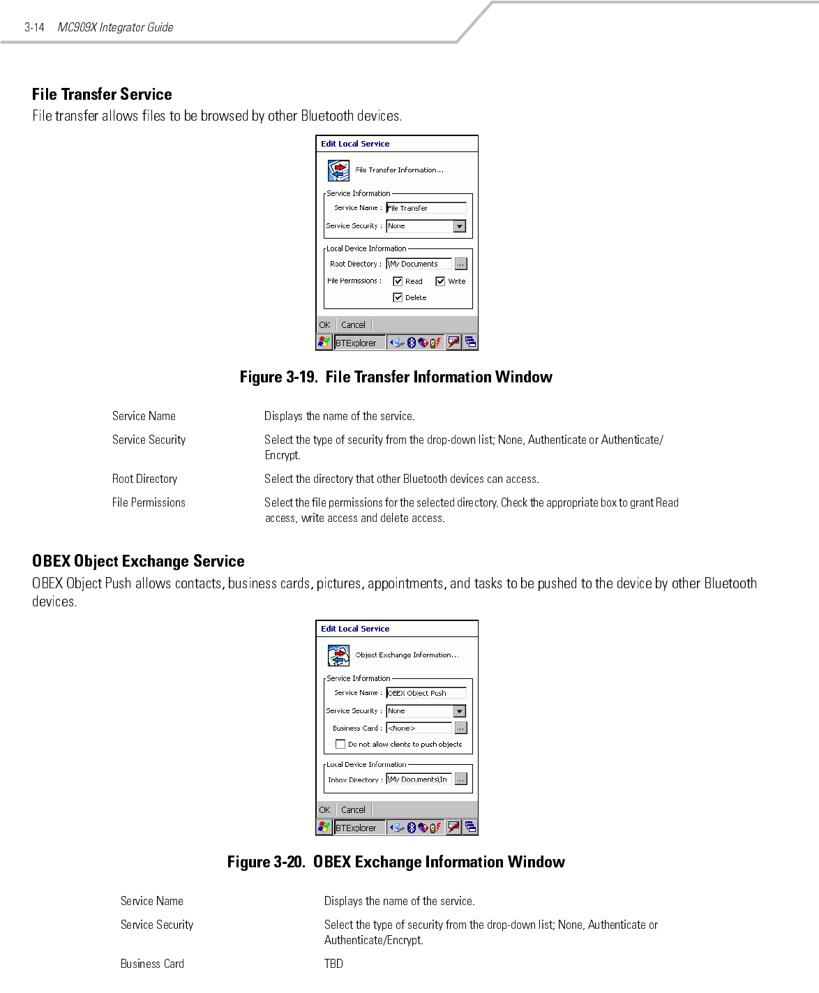
Preliminary
Preliminary
Preliminary
Preliminary
Preliminary
Preliminary
Preliminary
Preliminary
Preliminary
Preliminary
Preliminary
Preliminary
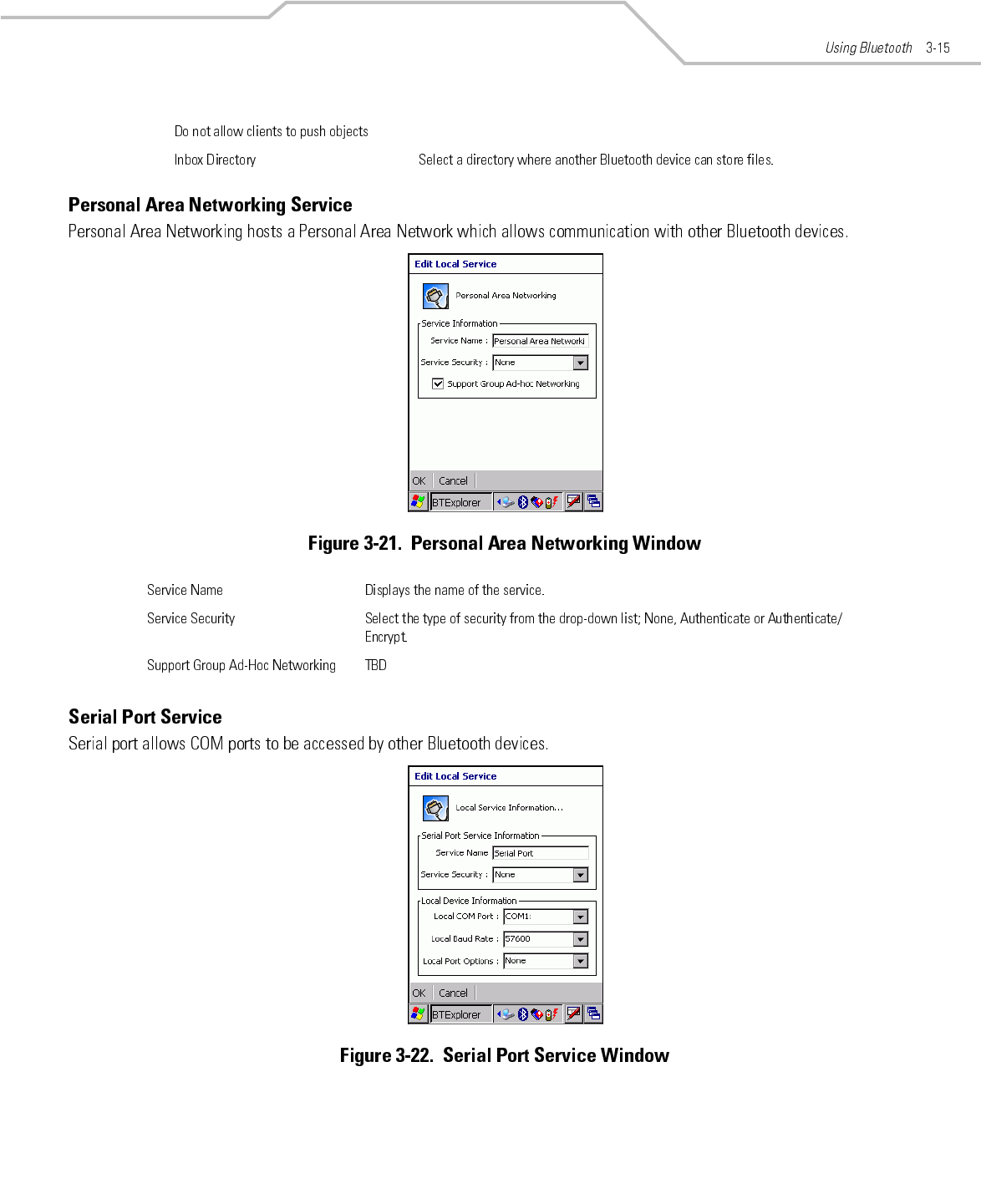
Preliminary
Preliminary
Preliminary
Preliminary

Wireless Applications
Contents

MC909X Integrator Guide4-2
Wireless Applications 4-3
Introduction
Wireless LANs allow mobile computers to communicate wirelessly and to send captured data to a host device in real time. Before a
mobile computer can be used on a Spectrum24 WLAN, the facility must be set up with the required hardware to run the wireless LAN
and the mobile computer must be properly configured. Refer to the documentation that came with the Access Points (APs) for
instructions on setting up the hardware.
To configure the mobile computer, a set of wireless applications provide the user with the tools to configure and test the wireless
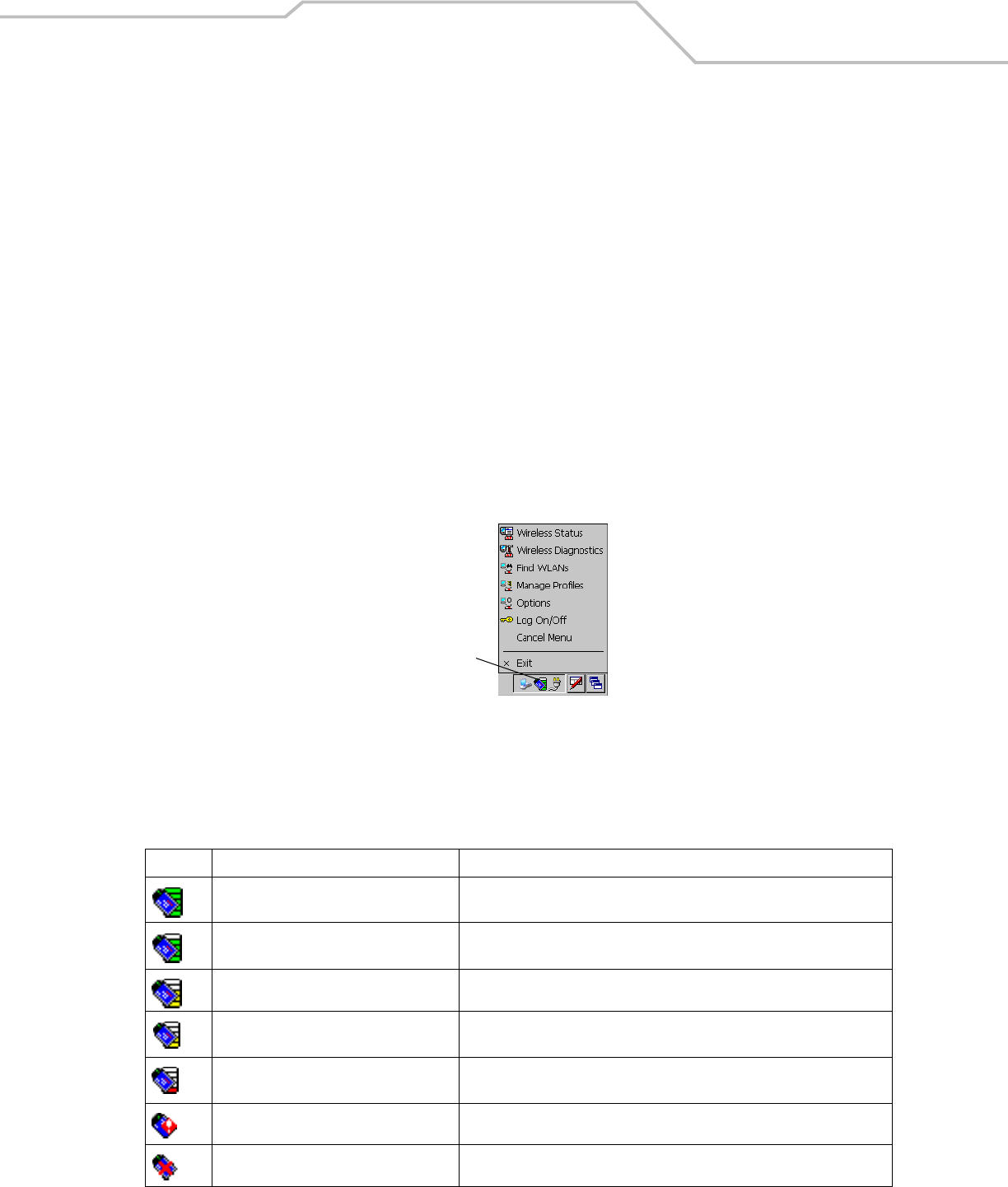
radio embedded the mobile computer. The following wireless applications are available on the task tray from the Wireless Application
menu:
• Wireless Status
• Wireless Diagnostics
• Find WLANs
• Manage Profiles
• Options
• Log On/Off.
Tap the Signal Strength icon to display the Wireless Application menu.
Figure 4-1. Wireless Applications Menu
Signal Strength Icon
The Signal Strength icon in the task tray indicates the mobile computer’s wireless signal strength as follows:
Table 4-1. Wireless Applications Icons, Signal Strength Descriptions
Icon Status Action
Excellent signal strength Wireless LAN network is ready to use.
Very good signal strength Wireless LAN network is ready to use.
Good signal strength Wireless LAN network is ready to use.
Fair signal strength Wireless LAN network is ready to use. Notify the network administrator that the
signal strength is only “Fair”.
Poor signal strength Wireless LAN network is ready to use. Performance may not be optimum. Notify
the network administrator that the signal strength is “Poor”.
Out-of-network range (not associated) No wireless LAN network connection. Notify the network administrator.
No wireless LAN network card detected. No wireless LAN network card detected. Notify the network administrator.
Signal Strength Icon
MC909X Integrator Guide4-4
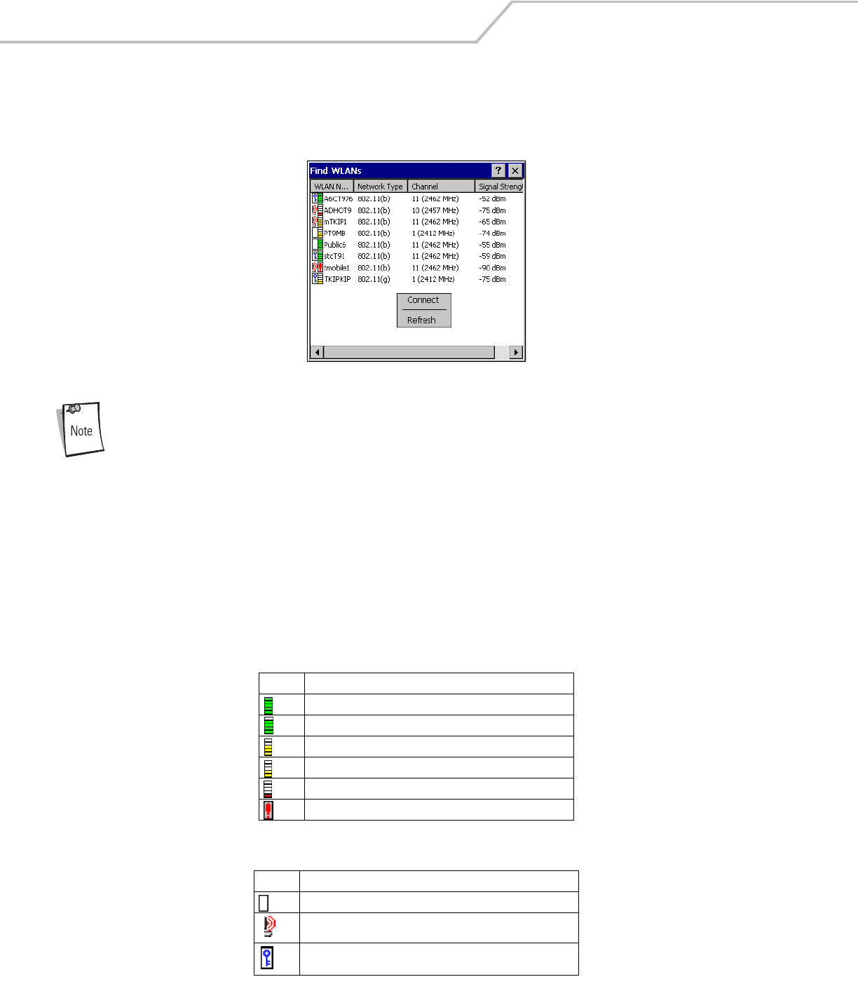
Find WLANs Application
Use the Find WLANs application to discover available networks in the vicinity of the user and mobile computer. To open the Find
WLANs application, tap the Signal Strength icon - Find WLANs. The Find WLANs window displays.
Figure 4-2. Find WLAN Window
Find WLAN display is limited to 32 items (ESSIDs or MAC addresses). A combination of up to 32 ESSIDs/APs
may be displayed.
Valid ESSIDs that were not displayed in the Find WLAN Window may be entered manually. See Figure 4-3 on
page 4-5.
The Find WLANs list displays:
• WLAN Networks - Available wireless networks with an icon that indicates signal strength and encryption type. The signal
strength and encryption icon is described in tables Table 4-2 and Table 4-3.
• Network Type - Type of network.
• Channel - Channel that the AP is transmitting on.
• Signal Strength - Displays the signal strength of the signal from the AP.
Table 4-2. Signal Strength Icon
Icon Description
Excellent signal
Very good signal
Good signal
Fair signal
Poor signal
Out of range or no signal
Table 4-3. Encryption Icon
Icon Description
No encryption WLAN is an infrastructure network.
WLAN is an Ad-Hoc network.
WLAN access is encrypted and requires a password.
Wireless Applications 4-5
Tap-and-hold on a WLAN network to launch a context sensitive menu. The menu provides two options: Connect and Refresh. Select
Refresh to refresh the WLAN list. Wireless profiles may also be created from one of the listed networks by selecting a network from
the list and then selecting Connect. Selecting Connect displays the Profile Editor Wizard. The wizard is initialized to set the values
for the selected network. After the profile editing is completed, it automatically connects to the newly edited profile.
Profile Editor Wizard
The Profile Editor Wizard displays when creating a new profile, or editing an existing profile. If editing a profile, the fields are
populated with the current settings for that profile. If creating a new profile, the known information for that WLAN network are
populated into the fields.
Navigate through the wizard using the Next and Back buttons. Tap X to quit, a notification box appears asking the user to confirm
the quit. Tap No to return to the wizard or tap Yes to quit and return to the Manage Profiles window.
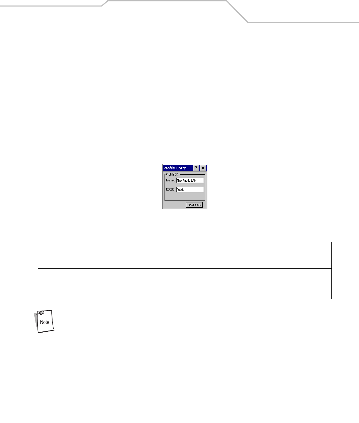
Profile ID
The Profile ID dialog box is the first dialog box in the Profile Editor Wizard. Use the Profile ID dialog box to input the fields for the
profile name and the ESSID.
Figure 4-3. Profile ID Dialog Box
Two profiles with the same user friendly name are valid but not recommended.
Tap Next. The Operating Mode dialog box displays.
Table 4-4. Profile ID Fields
Field Description
Name Populated with the name and (WLAN) identifier of the network connection. Use the Name: field to enter a user friendly name
of the mobile computer profile used to connect to either an AP or another networked computer. Example: The Public LAN.
ESSID Populated with the name and (WLAN) identifier of the network connection, or use the ESSID field to enter the name and (WLAN)
identifier of a WLAN network connection that was not listed on the Find WLANs window.
The ESSID is the 802.11 extended service set identifier. The ESSID is 32-character (maximum) string identifying the WLAN. The
ESSID assigned to the mobile computer is required to match the AP ESSID for the mobile computer to communicate with the AP.
MC909X Integrator Guide4-6
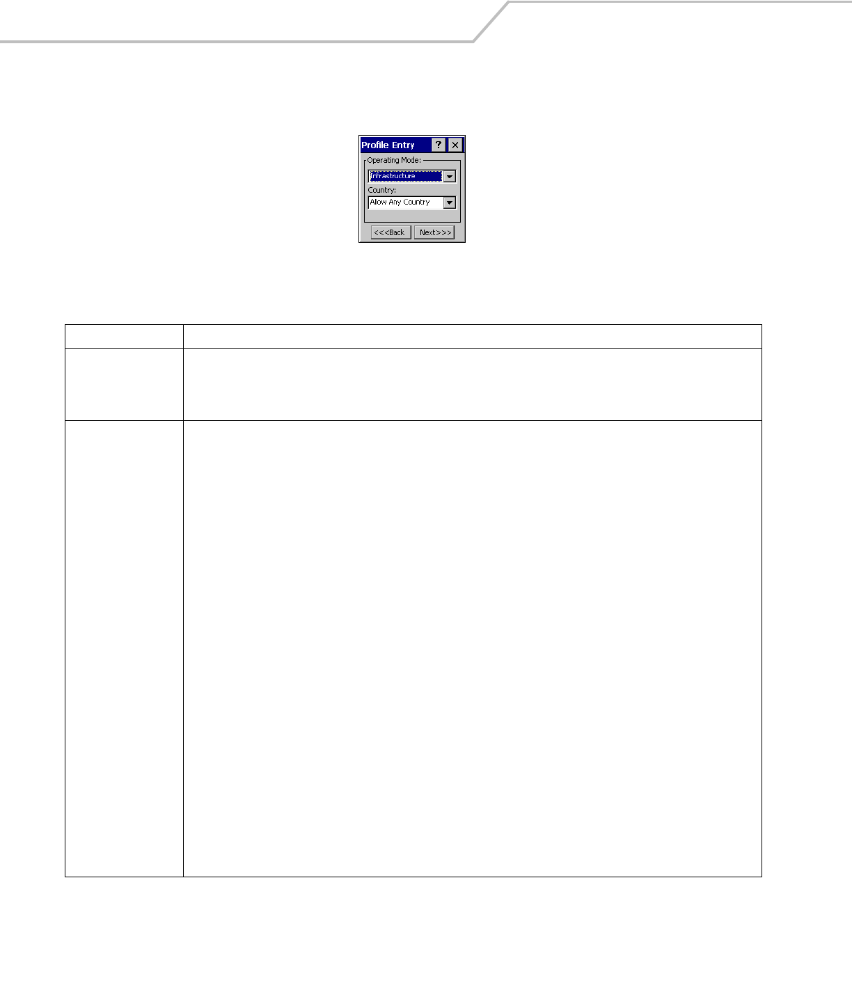
Operating Mode
Use the Operating Mode dialog box to select the operating mode (Infrastructure or Ad-Hoc) and the country location.
Figure 4-4. Operating Mode Dialog Box
Tap Next. If Ad-Hoc mode was selected the Ad-Hoc dialog box displays. If Infrastructure mode was selected the Authentication dialog
box displays. See Authentication on page 4-7 for instruction on setting up authentication.
Table 4-5. Operating Mode Fields
Field Description
Operating Mode Infrastructure: Select Infrastructure to enable the mobile computer to transmit and receive data with an AP. Infrastructure is the
mobile computer default mode.
Ad Hoc: Select Ad Hoc to enable the mobile computer to form its own local network where mobile computers communicate peer-
to-peer without APs using a shared ESSID.
Country Country is used to determine if the profile is valid for the country of operation. The profile country must match the country in the
options page or it must match the acquired country if 802.11d is enabled.
Single Country Use:
When the device is only to be used in a single country, set every profile country to Allow Any Country. In the Options - Regulatory
dialog box (see Figure 4-45 on page 4-38), set the country to the specific country the device is to be used in, and deselect
(uncheck) the Enable 802.11d option. This is the most common and the efficient configuration. It eliminates the initialization
overhead associated with acquiring a country via 802.11d.
Multiple Country Use:
When the device may be used in more than one country, select (check) the Enable 802.11d option in the Regulatory Options
dialog box (see Figure 4-45 on page 4-38). This eliminates the need for reprograming the country (in Options - Regulatory) each
time a new country is entered. However, this only works if the infrastructure (i.e. APs) support 802.11d (some infrastructures do
not support 802.11d, including some Cisco APs). When the Enable 802.11d option is selected, the Options - Regulatory - Country
setting is not used. For a single profile that can be used in multiple countries, with infrastructure that supports 802.11d (including
Symbol infrastructure), set the Profile Country to Allow Any Country. Under Options - Regulatory, select Enable 802.11d. The
Options - Regulatory - Country setting is not used.
For a single profile that can be used in multiple countries, but with infrastructure that does not support 802.11d, set the profile
country to Allow Any Country, and de-select (uncheck) Enable 802.11d. In this case, the Options - Regulatory - Country setting
must always be set to the country the device is currently in. This configuration option is the most efficient and may be chosen
for use with any infrastructure. However, the Options - Regulatory - Country setting must be manually changed when a new
country is entered.
Note that using a single profile in multiple countries implies that there is a common ESSID to connect to in each country. This
is less likely than having unique ESSIDs in each country, this requires unique profiles for each country.
For additional efficiency when using multiple profiles that can be used in multiple countries, the country setting for each profile
can be set to a specific country. If the current country (found via 802.11d or set by Options - Regulatory - Country when 802.11d
is disabled) does not match the country set in a given profile, then that profile is disabled. This can make profile roaming occur
faster. For example, if two profiles are created and configured for Japan, and two more profiles are created and configured for
USA, then when in Japan only the first two profiles are active, and when in USA only the last two are active. If they had all been
configured for Allow Any Country, then all four would always be active, making profile roaming less efficient.
Wireless Applications 4-7
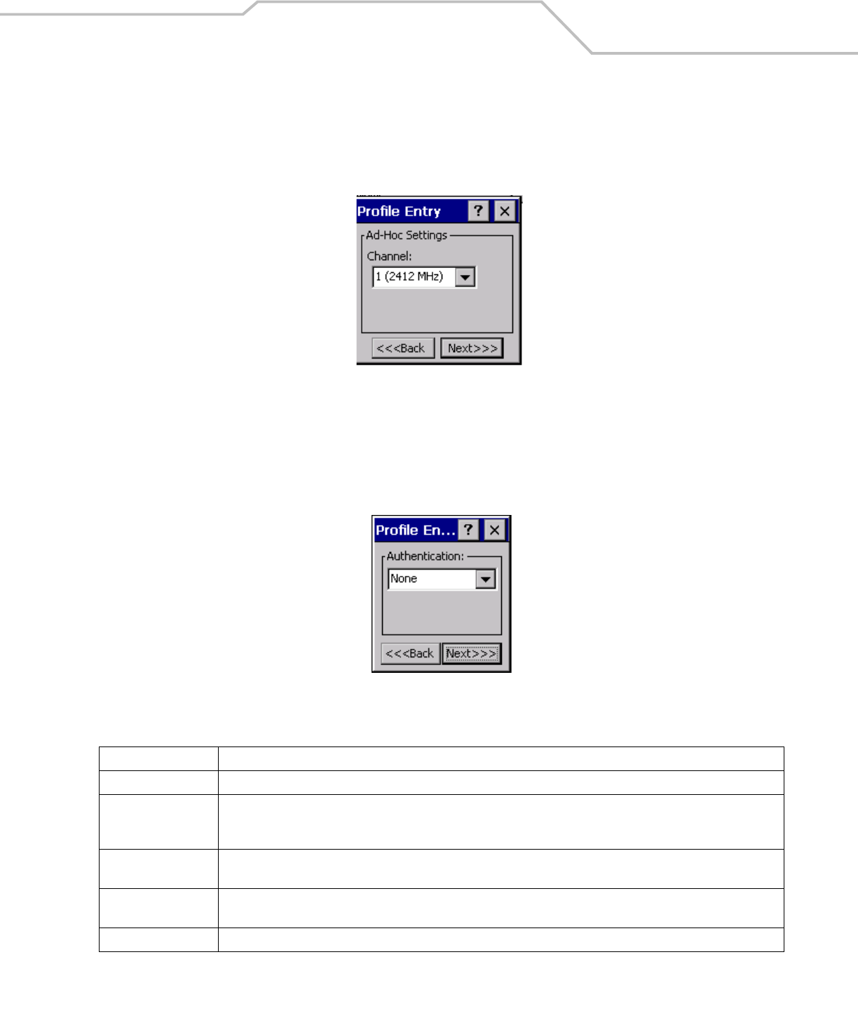
Ad-Hoc
Use the Ad-Hoc dialog box to select the necessary information to control Ad-Hoc mode. This dialog box does not display if
Infrastructure mode is selected. To Select Ad-Hoc mode:
1. Select a channel number from the Channel drop-down list. The default is Channel 1 (2412 MHz).
Figure 4-5. Ad-Hoc Settings Dialog Box
2. Tap Next. The Authentication dialog box displays.
Authentication
Use the Authentication dialog box to configure authentication. If Ad-Hoc mode is selected, the user can only select None because
Ad-Hoc authentication is not supported. Table 4-6 lists the available authentication options.
Figure 4-6. Authentication Dialog Box
Select an authentication type from the drop-down list and tap Next. If PEAP or TTLS is selected, the Tunneled dialog box displays. If
None, EAP TLS or LEAP is selected the Encryption dialog box displays. See Encryption on page 4-15 for encryption options.
Table 4-6. Authentication Options
Authentication Description
None Default setting when authentication is not required on the network.
EAP TLS Select this option to enable EAP TLS authentication. EAP TLS is an authentication scheme through IEEE 802.1x. It
authenticates users and ensures only valid users can connect to the network. It also restricts unauthorized users from
accessing transmitted information. EAP TLS achieves this through secure authentication certificates.
PEAP Select this option to enable PEAP authentication. This method uses a digital certificate to verify and authenticate a user's
identity.
LEAP Select this option to enable LEAP authentication. LEAP is founded on mutual authentication. The AP and the mobile computer
attempting to connect to it require authentication before access to the network is permitted.
TTLS Select this option to enable TTLS authentication.
MC909X Integrator Guide4-8
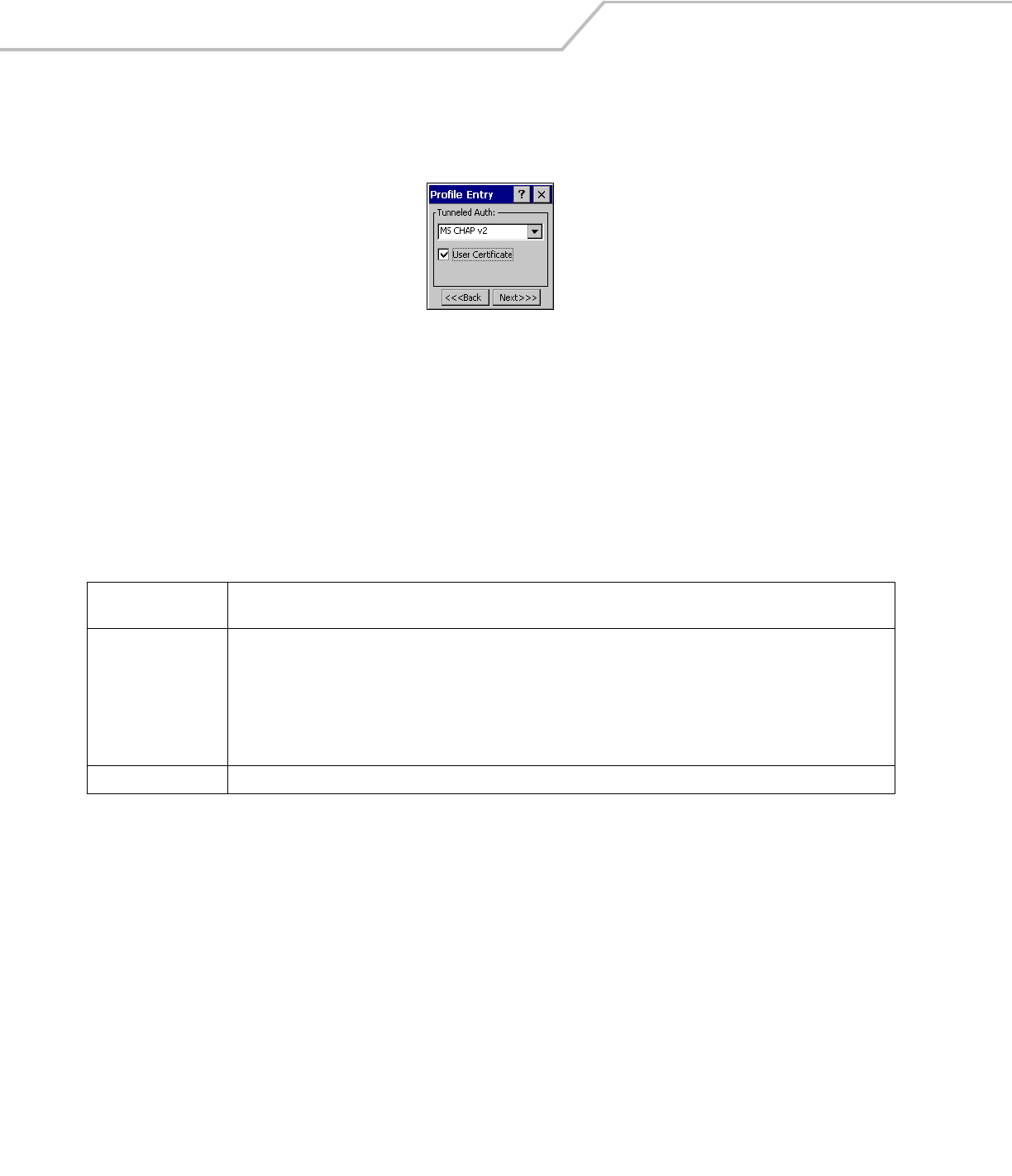
Tunneled Authentication
Use the Tunneled Authentication dialog box to select the tunneled authentication options. There are different selections available for
PEAP or TTLS authentication. To select a tunneled authentication type
Figure 4-7. Tunneled Auth Dialog Box
1. Tap a tunneled authentication type from the drop-down list.
2. Select the User Certificate check box if a certificate is required. The TLS tunnel type requires a user certificate, so the check
box is automatically selected.
3. Tap Next. The Installed User Certs dialog box appears.
Table 4-7 lists the PEAP tunneled authentication options.
Table 4-7. PEAP Tunneled Authentication Options
PEAP Tunneled
Authentication Description
MS CHAP v2 Microsoft Challenge Handshake Authentication Protocol version 2 (MS CHAP v2) is a password-based, challenge-response,
mutual authentication protocol that uses the industry-standard Message Digest 4 (MD4) and Data Encryption Standard (DES)
algorithms to encrypt responses. The authenticating server challenges the access client and the access client challenges
the authenticating server. If either challenge is not correctly answered, the connection is rejected. MS CHAP v2 was
originally designed by Microsoft as a PPP authentication protocol to provide better protection for dial-up and virtual private
network (VPN) connections. With Windows XP SP1, Windows XP SP2, Windows Server 2003, and Windows 2000 SP4, MS
CHAP v2 is also an EAP type.
TLS EAP TLS is used during the phase 2 of the authentication process. This method uses a user certificate to authenticate.

Wireless Applications 4-9
Table 4-8 lists the TTLS tunneled authentication options.
Table 4-8. TTLS Tunneled Authentication Options
TTLS Tunneled
Authentication Description
CHAP Challenge Handshake Authentication Protocol (CHAP) is one of the two main authentication protocols used to verify the user
name and password for PPP Internet connections. CHAP is more secure than PAP because it performs a three way handshake
during the initial link establishment between the home and remote machines. It can also repeat the authentication anytime
after the link has been established.
MS CHAP Microsoft Challenge Handshake Authentication Protocol (MS CHAP) is an implementation of the CHAP protocol that
Microsoft created to authenticate remote Windows workstations. In most respects, MS CHAP is identical to CHAP, but there
are a few differences. MS CHAP is based on the encryption and hashing algorithms used by Windows networks, and the
MS CHAP response to a challenge is in a format optimized for compatibility with Windows operating systems.
MS CHAP v2 MS CHAP v2 is a password based, challenge response, mutual authentication protocol that uses the industry standard
Message Digest 4 (MD4) and Data Encryption Standard (DES) algorithms to encrypt responses. The authenticating server
challenges the access client and the access client challenges the authenticating server. If either challenge is not correctly
answered, the connection is rejected. MS CHAP v2 was originally designed by Microsoft as a PPP authentication protocol
to provide better protection for dial-up and virtual private network (VPN) connections. With Windows XP SP1, Windows XP
SP2, Windows Server 2003, and Windows 2000 SP4, MS CHAP v2 is also an EAP type.
PAP Password Authentication Protocol (PAP), has two variations PAP and CHAP PAP. It verifies a user name and password for PPP
Internet connections, but it is not as secure as CHAP, since it works only to establish the initial link. PAP is also more
vulnerable to attack because it sends authentication packets throughout the network. Nevertheless, PAP is more commonly
used than CHAP to log in to a remote host like an Internet service provider.
MD5 Message Digest-5 (MD5) is an authentication algorithm developed by RSA. MD5 generates a 128-bit message digest using
a 128-bit key, IPSec truncates the message digest to 96 bits.
MC909X Integrator Guide4-10
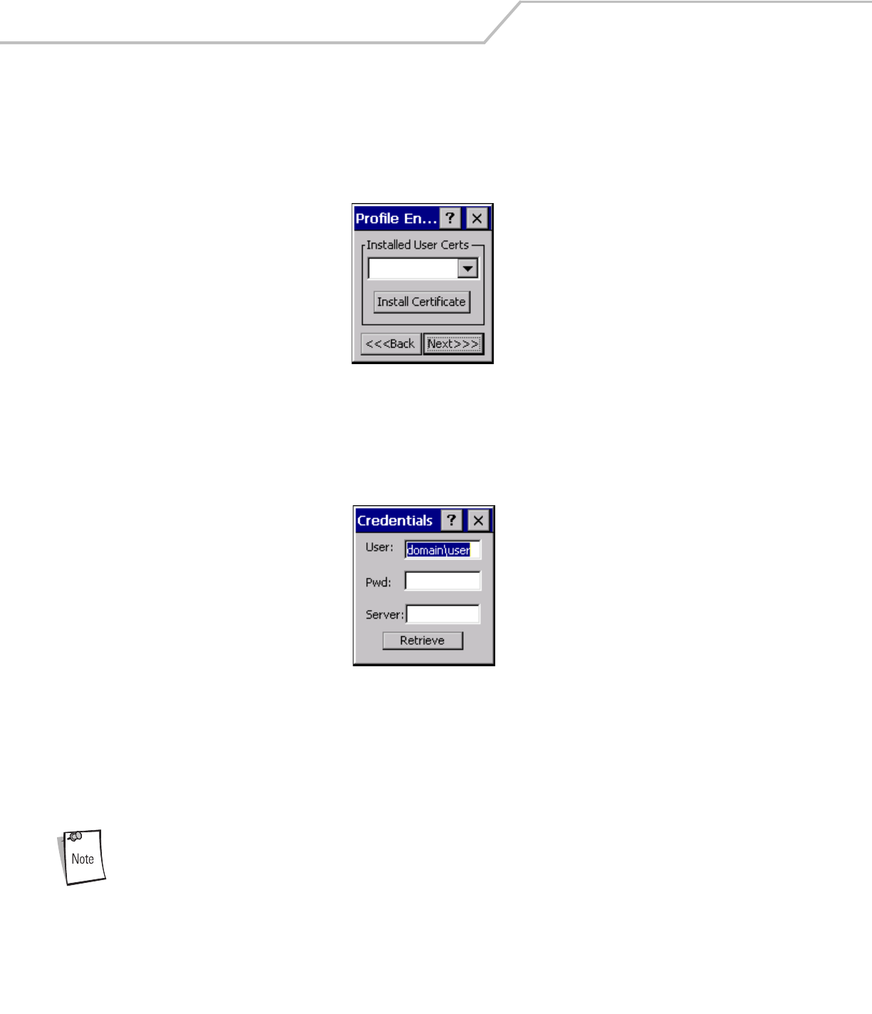
User Certificate Selection
If the User Certificate check box on the Tunneled Authentication dialog box is checked or if TLS is the selected authentication type,
then the Installed User Certificates dialog box displays. The user is required to select a certificate before proceeding. Select a
certificate from the drop-down list of currently installed certificates. When a certificate is selected its name appears in the drop-down
list. If the required certificate is not in the list, it must be installed.
Figure 4-8. Installed User Certs Dialog Box
User Certificate Installation
To install a user certificate (EAP TLS only) and a server certificate for EAP TLS and PEAP authentication:
1. Tap Install Certificate. The Credentials dialog box appears.
Figure 4-9. Credentials Dialog Box
2. Enter the User:, Pwd: (password), and Server: information in their respective text boxes.
3. Tap Retrieve. A Progress dialog appears to indicate the status of the certificate retrieval.
4. Tap ok to exit.
After the installation is compete, the Installed User Certs dialog box displays.
In order to successfully install a user certificate, the mobile computer must already be connected to a network
from which the server is accessible.
*********
Wireless Applications 4-11
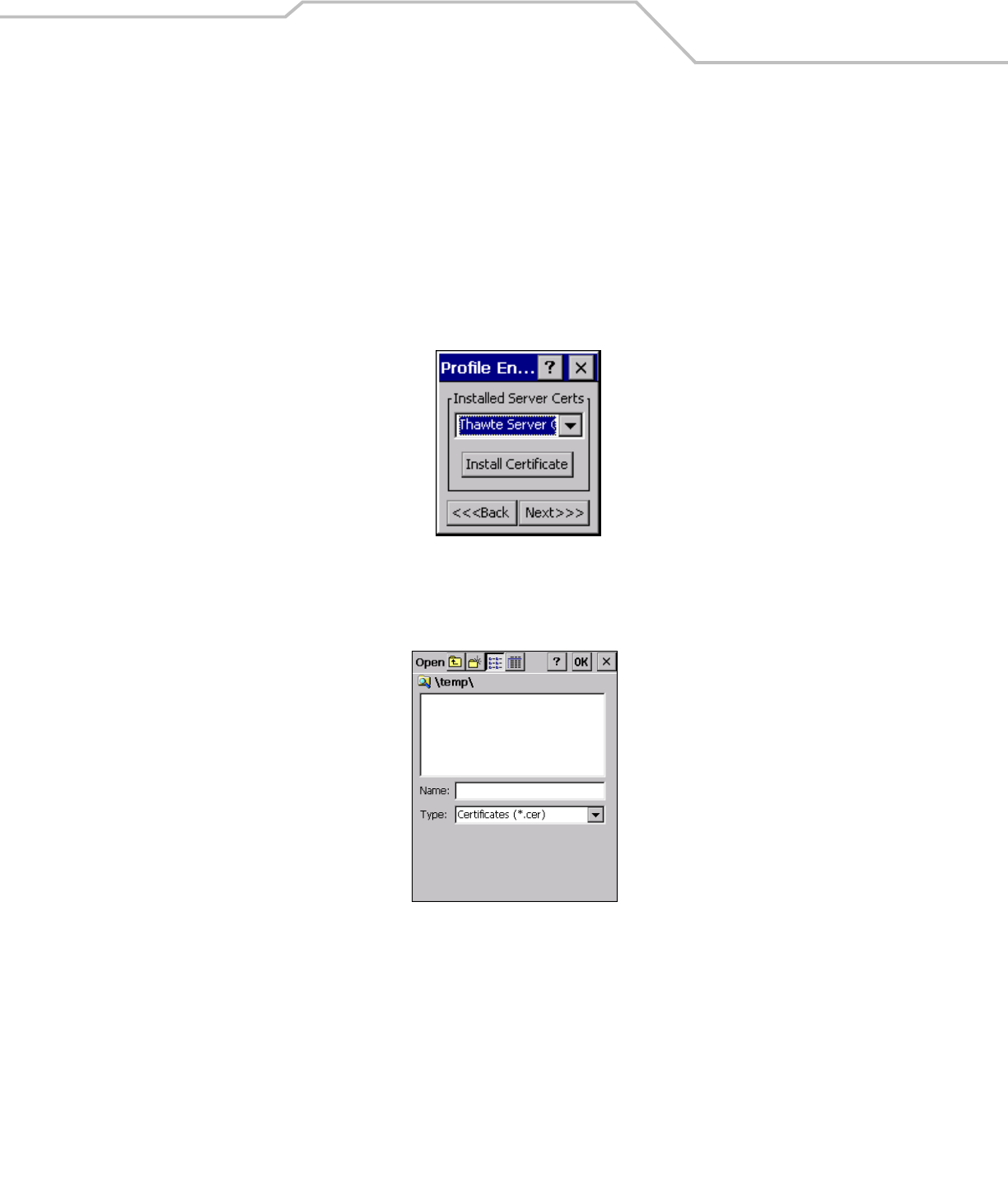
Server Certificate Selection
If the Validate Server Cert check box is checked, a server certificate is required. The wizard displays the Installed Server Certs dialog
box and a certificate must be selected before proceeding. An hour glass may be displayed as the wizard populates the existing
certificate list. If the required certificate is not listed, then it must be installed.
To select a certificate:
1. Tap the down arrow on the drop-down list to display the list of currently installed certificates.
2. Tap a certificate to select and its name appears in the drop-down list.
3. Tap the Install Certificate button to install a certificate.
Figure 4-10. Installed Server Certs Dialog Box
A dialog is displayed that lists the currently loaded certificate files. This dialog lists the certificate files found in the default directory
(\Application\FusionApps\Certs) with the default extension.
Figure 4-11. Browse Server Certificates
MC909X Integrator Guide4-12
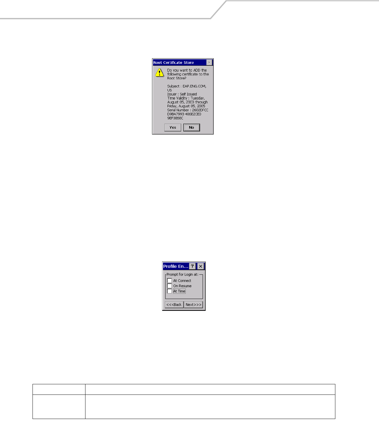
The default path or extension can be changed (and a new path searched) when the ENT key is pressed. A certificate must be selected
before tapping the Install button.
Figure 4-12. Confirmation Dialog Box
A confirmation dialog displays verifying the installation. If the information in this dialog is correct, tap the Yes button, If the
information in this dialog is not correct tap the No button. The wizard returns to the Installed Server Certs dialog box.
Credential Cache Options
If any of the password based authentication types are chosen, then different credential caching options may be specified. These
options allow an administrator to specify when the network credentials prompts appear. The network credentials prompts can be set
to appear; at connection, on each resume, or at a specified time.
An administrator can enter the credentials directly into the profile which permanently caches the credentials. In this case, user login
to the mobile computer is not required. If a profile does not contain credentials entered through the configuration editor, then the user
must login to the mobile computer before connecting.
Caching options only apply on credentials that are entered through the login dialog box.
Figure 4-13. Prompt for Login at Dialog Box
If mobile computer does not have the credentials, the user is prompted to enter a username and password. If the mobile computer
has the credentials (previous entered via a login dialog box), it uses these credentials unless the caching options require the mobile
computer to prompt for new credentials. If the credentials were entered via the profile, the mobile computer does not prompt for new
credentials. Table 4-9 lists the caching options.
Table 4-9. Cache Options
Description
At Connect
If this option is selected, then a user is prompted for credentials whenever the WCS tries to connect to a new profile. If this
option is not set, then the cached credentials are used to authenticate. If the credentials are not cached, then the user is
prompted to enter credentials. This option only applies if a user is logged in.
Wireless Applications 4-13
When a user enters the credentials, the credentials are applied to a particular profile. If a user logs out, all of the cached credentials
are cleared. If a profile is edited, then all cached credentials for that profile are cleared.
The following authentication types have credential caching:
•EAP TLS
• PEAP
•LEAP
• TTLS.
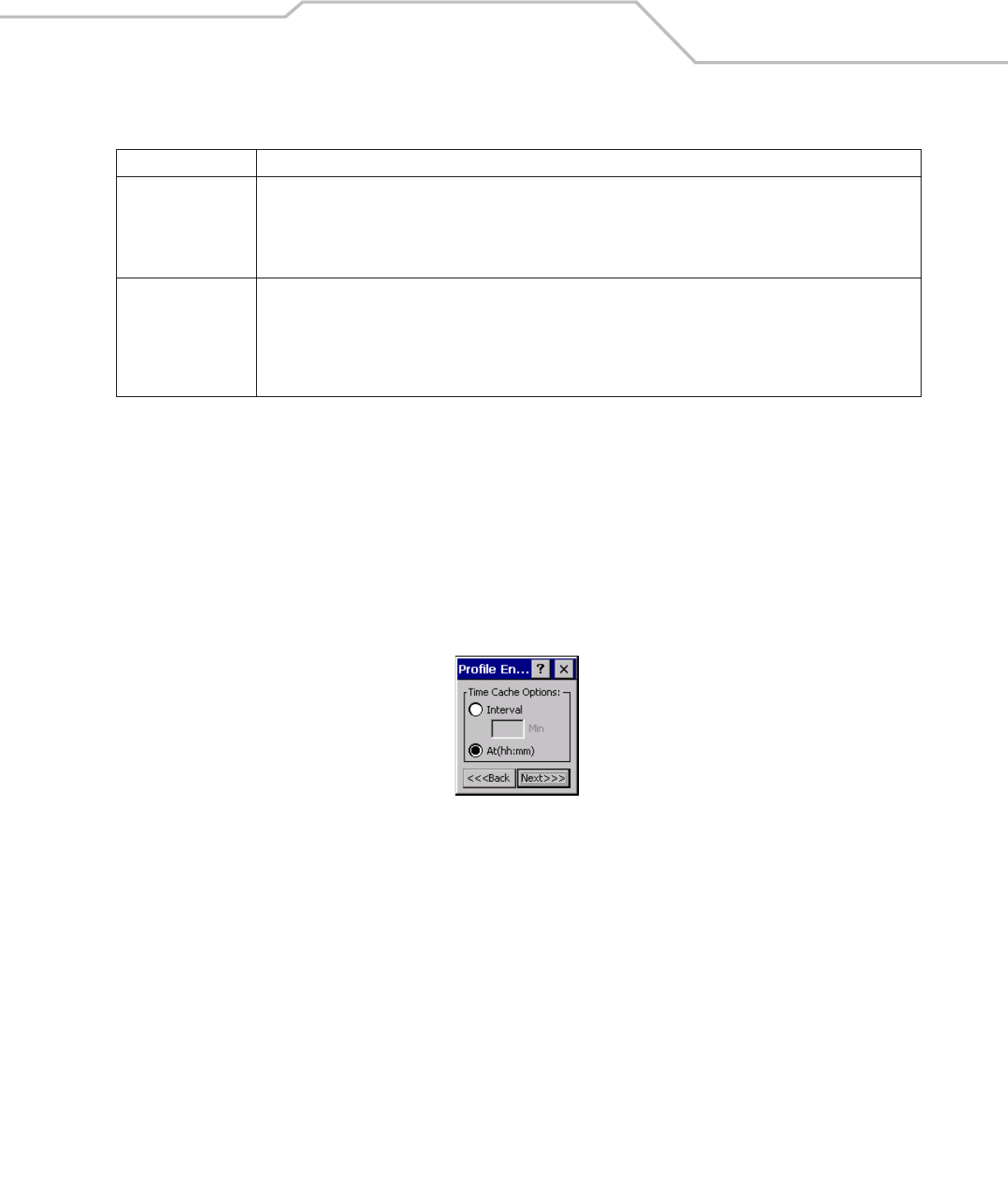
If the At Time check box is selected the TIme Cache Options dialog box displays.
Figure 4-14. Time Cache Options Dialog Box
1. Tap the Interval radio button to check credentials at a set time interval.
2. Enter the value in minutes, in the Min box.
3. Tap Next to continue.
4. Tap the At (hh:mm) radio button to check credentials at a set time.
5. Tap Next. The At Time dialog box appears.
On Resume
If the On Resume option is selected, an authenticated user is reauthenticated when a suspend/resume occurs. Once the user
is reauthenticated, the user is prompted for credentials. If the user does not enter the same credentials that were entered
prior to the suspend/resume, the user is disconnected from the network. The user may try up to three times to enter the
correct credentials. If the correct credentials are entered, then the network connection remains intact. This option only
applies if a user is logged in.
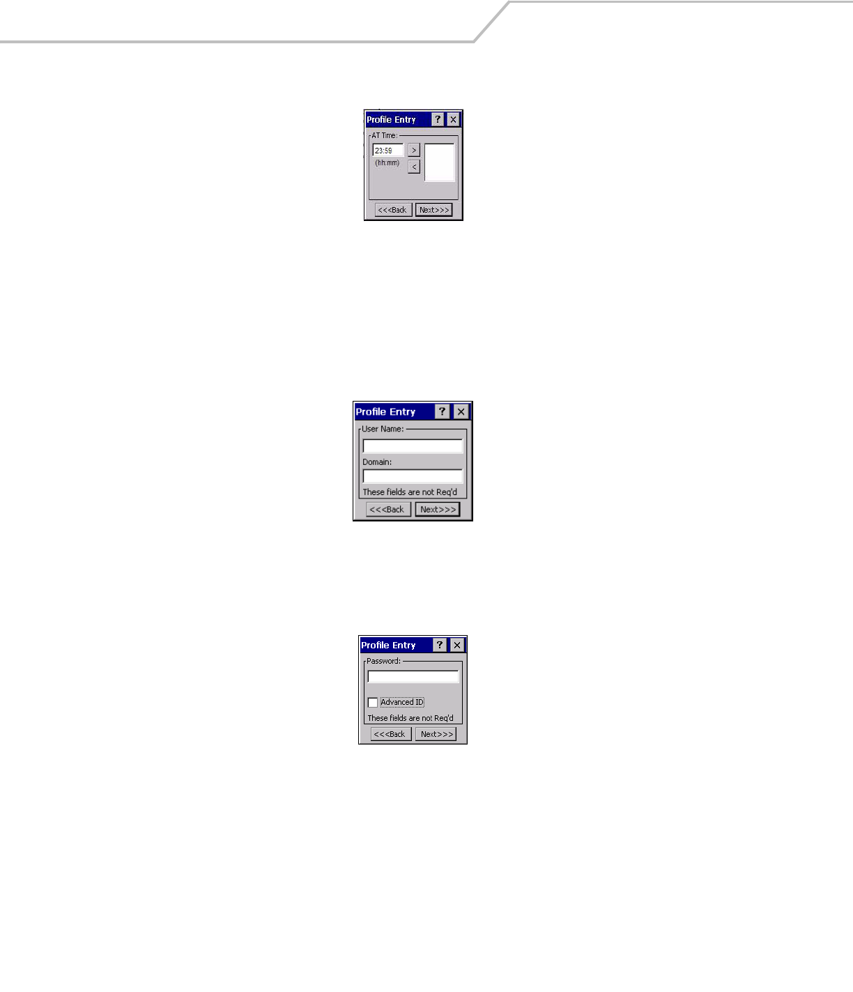
At Time
Use this option to perform a local verification on an authenticated user at a specified time. The time can be an absolute time
or a relative time from the authentication, the times should be at least 5 minutes intervals. Once the time has passed, the
user is prompted for credentials. If the user enters the correct credentials, the network connection remains intact. If the user
enters the wrong credentials, the user is disconnected from the network. The user may try up to three times to enter the
correct credentials. If the correct credentials are enter, then the network connection remains intact. This option only applies
if a user is logged in.
Table 4-9. Cache Options (Continued)
Description
MC909X Integrator Guide4-14
Figure 4-15. At Time Dialog Box
6. Enter the time using the 24 hour clock format in the (hh:mm) box.
7. Tap > to move the time to the right. Repeat for additional time periods.
8. Tap Next. The User Name dialog box displays.
The user name and password can be entered (but is not required) when the profile is created. When a profile authenticates with
credentials that were entered in the profile, caching rules do not apply. Caching rules only apply on credentials that are entered
through the login dialog box.
Figure 4-16. Username Dialog Box
Password
Use the Password dialog box to enter a password. If EAP/TLS is the selected authentication type, the password is not required and
the field is disabled.
Figure 4-17. Password Dialog Box
1. Enter a password in the Password field.
2. Select the Advanced ID check box, if advanced identification is required.
3. Tap Next, the Encryption dialog box displays. See Encryption on page 4-15 for setting the encryption information.
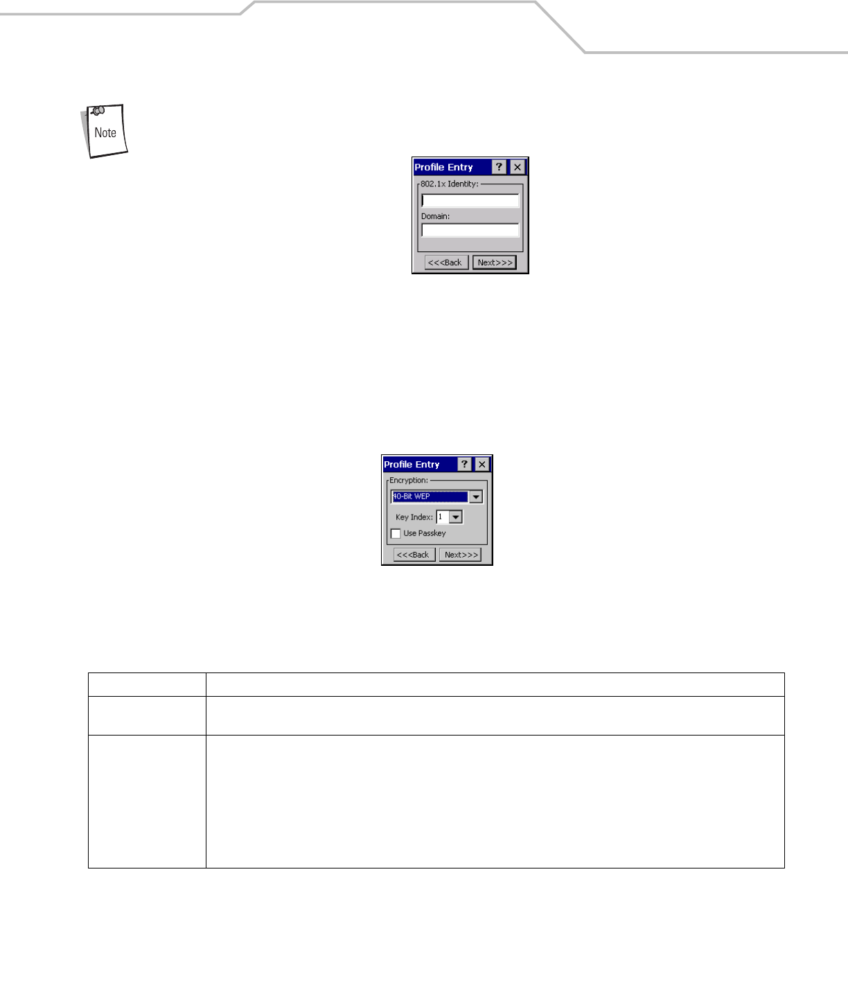
Advanced Identity
Use the Advanced ID dialog box to enter the 802.1X identity. The 802.1X identity value can be 63 characters long and is a case
sensitive identity supplied to the authenticator. In TTLS and PEAP, it is recommended that this field not contain a true identity, but
instead the identity anonymous, plus any desired realm (e.g. anonymous@myrealm). A user ID is required before proceeding.
Wireless Applications 4-15
When authenticating with a Microsoft IAS server, do not use advanced identity.
Figure 4-18. Advanced Identity Dialog Box
Tap Next, the Encryption dialog box displays.
Encryption
Use the Encryption dialog box to select an encryption type. The Encryption dialog box only allows encryption types that can be used
with the currently selected authentication type. See Table 4-11 for the encryption types available with each authentication type.
Figure 4-19. Encryption Dialog Box
Table 4-10. Encryption Options
Encryption Description
Open Use the Open option as the default setting when no data packet encryption is needed over the network. Selecting this option
provides no security for the data being transmitted over the network.
40-Bit WEP Select 40-Bit WEP for the adapter to use the 40-bit key length WEP encryption. WEP keys are manually entered in the edit boxes.
Only the required number of edit boxes for a key length is displayed (10 Hex digit value for 40-bit keys). Use the Key Index drop-
down list to configure the four WEP keys. The adapter uses the selected key. Note: The default Hex digit keys are visible any
time they are used. As a security precaution after setting the key values for the network, the digits are replaced with asterisks
* within the encryption key fields.
If the associated AP is using an optional passkey, the active adapter WLAN profile is required to use one as well. The passkey
is a plain text representation of the WEP keys displayed in the encryption dialog box. The passkey provides an easy way to enter
WEP key data without having to remember the entire 40-bit (10 character) Hex digit string.

MC909X Integrator Guide4-16
128-Bit WEP Select 128-Bit WEP for the adapter to use the 128-bit key length WEP encryption. WEP keys are manually entered in the edit
boxes. Only the required number of edit boxes for a key length is displayed (26 Hex digit value for 128-bit keys). Use the Key
Index drop-down list to configure the four WEP keys. The adapter uses the selected key. Note: The default Hex digit keys are
visible any time they are used. As a security precaution after setting the key values for the network, the digits are replaced with
asterisks * within the encryption key fields.
If the associated AP is using an optional passkey, the active adapter WLAN profile is required to use one as well. The passkey
is a plain text representation of the WEP keys displayed in the encryption dialog box. The passkey provides an easy way to enter
WEP key data without having to remember the entire 128-bit (26 character) Hex digit string.
TKIP Select this option to use Wireless Protected Access (WPA) via TKIP. Manually enter the shared keys in the passkey field. Tap
Next to display the passkey dialog box. Enter an 8 to 63 character string.
Table 4-11. Encryption / Authentication Matrix
Encryption
Authentication Open WEP TKIP
None Yes Yes Yes
EAP TLS No Yes Yes
PEAP No Yes Yes
LEAP No Yes Yes
TTLS No Yes Yes
Table 4-10. Encryption Options (Continued)
Encryption Description
Wireless Applications 4-17
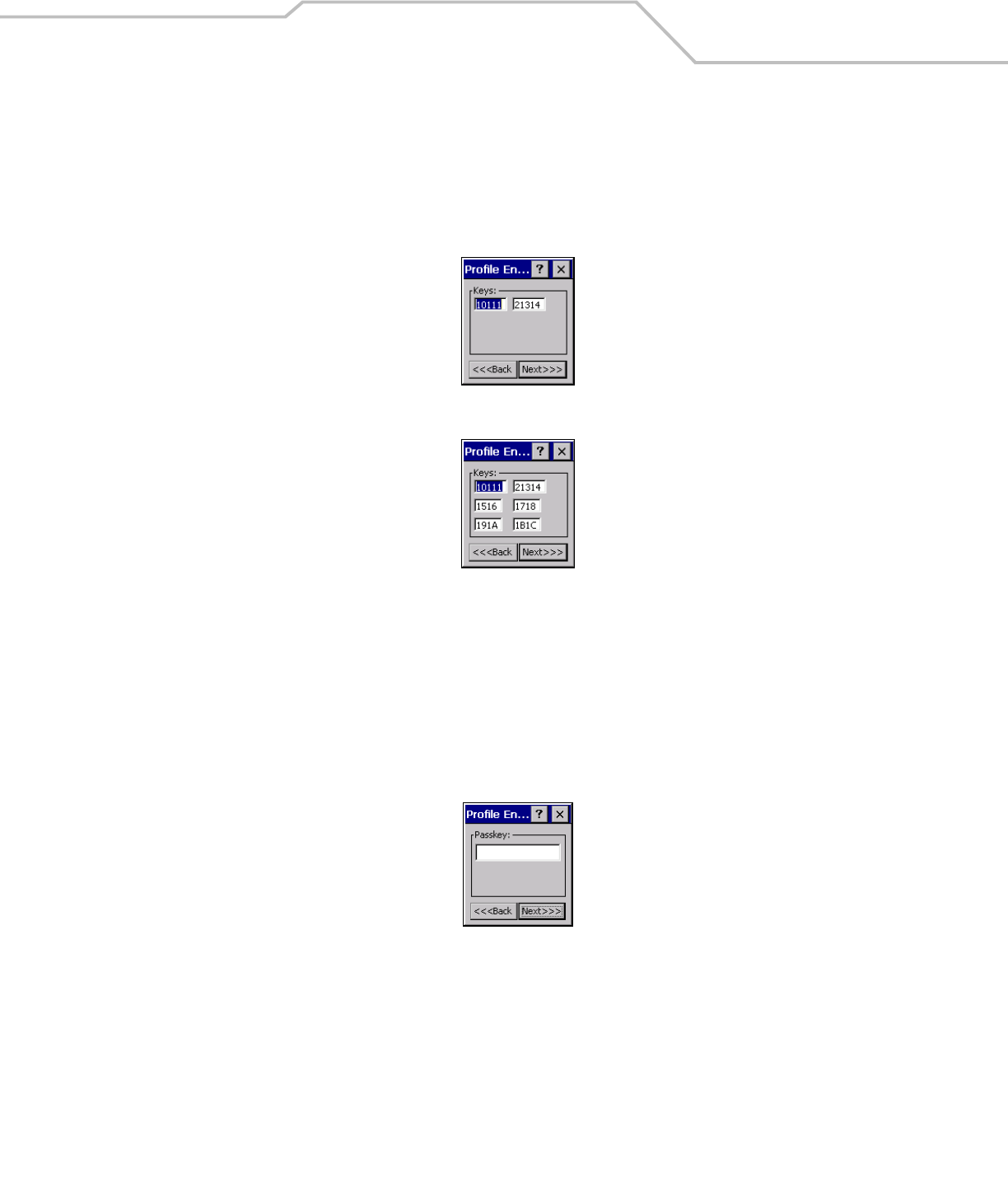
Key Entry Page
If either 40-Bit WEP or 128-Bit WEP is selected the wizard proceeds to the key entry dialog box unless the Use Passkey check box
was selected in the Encryption Dialog Box (see Figure 4-19 on page 4-15). To enter the key information:
1. Enter the 40-bit or 128-bit keys into the fields.
2. Tap Next.
Figure 4-20. 40-Bit WEP Keys Dialog Box
Figure 4-21. 128-Bit WEP Keys Dialog Box
Passkey Dialog
When a user selects None as an authentication and WEP as an encryption, the user can chose to enter a passkey by checking the Use
PassKey check box. The user is prompted to enter the passkey. For WEP, the Use PassKey checkbox is only available if the
authentication is None.
When a user selects None as an authentication and TKIP as an encryption, the user is forced to enter a passkey. The user cannot enter
a passkey if the encryption is TKIP and the authentication is anything other than None.
Figure 4-22. Passkey Dialog Box
Tap Next. The IP Mode dialog box displays.
MC909X Integrator Guide4-18
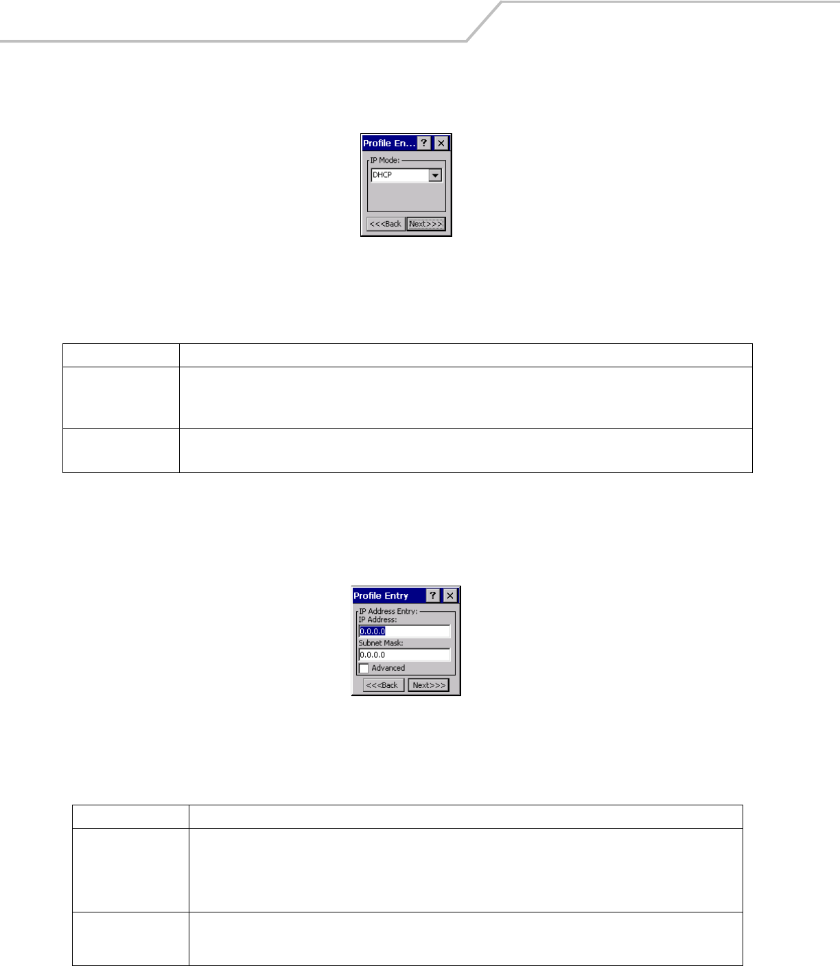
IP Mode
Use the IP Mode dialog box to configure network address parameters: IP address, subnet, gateway, DNS and WINS.
Figure 4-23. IP Config Tab (DHCP)
Select either DHCP or Static from the drop-down list and then tap Next. If Static IP is selected, the IP Address Entry dialog box
displays. If DHCP is selected, the Transmit Power dialog box displays.
IP Address Entry
Use the IP Address Entry dialog box to enter the IP address and subnet information.
Figure 4-24. Static IP Address Entry Dialog Box
Table 4-12. IP Mode Options
Encryption Description
DHCP Select Dynamic Host Configuration Protocol (DHCP) from the IP Mode drop-down list to obtain a leased
IP address and network configuration information from a remote server. DHCP is the default setting for
the mobile computer profile. When DHCP is selected, the IP address fields are read-only.
Static Select Static to manually assign the IP, subnet mask, default gateway, DNS and WINS addresses used
by the mobile computer profile.
Table 4-13. Static IP Address Entry Fields
Field Description
IP Address The Internet is a collection of networks with users that communicate with each other. Each communication carries the
address of the source and destination networks and the particular machine within the network associated with the user or
host computer at each end. This address is called the IP address (Internet Protocol address). Each node on the IP network
must be assigned a unique IP address that is made up of a network identifier and a host identifier. Enter the IP address as a
dotted-decimal notation with the decimal value of each octet separated by a period, for example, 192.168.7.27.
Subnet Mask Most TCP/IP networks use subnets in order to effectively manage routed IP addresses. Having an organization's network
divided into subnets allows it to be connected to the Internet with a single shared network address, for example,
255.255.255.0.
Wireless Applications 4-19
Select the Advanced check box to enter additional address information.
If the Advanced check box is selected then tapping NEXT displays the Advanced Address Entry dialog box to enter the Gateway, DNS,
and WINS address. If the Advanced check box is not selected then tapping NEXT displays the Transmit Power dialog box.
Figure 4-25. Advanced Address Entry Dialog Box
The IP information that is entered in the profile is only used when the Enable IP Mgmt check box is enabled in the Options - System
Options dialog box (System Options on page 4-39). When Enable IP Mgmt check box is disabled, the IP information in the profile is
ignored and the IP information entered in the Microsoft interface applies.
Tap Next. The Transmit Power dialog box displays.
Transmit Power
The transmit power can be selected for both Ad-Hoc and Infrastructure network types. The Transmit Power drop-down list contains
different options for each mode. Automatic (i.e. use the current AP settings) and Power Plus (use higher than the current AP settings)
are available for Infrastructure mode.
Adjusting the Radio Transmission Power level enables the user to expand or confine the transmission area with respect to other
wireless devices that could be operating nearby. Reducing a coverage area in high traffic areas improves transmission quality by
reducing the amount of interference in that coverage area.
Figure 4-26. Transmit Power Dialog Box (Infrastructure Mode)
Table 4-14. IP Config Advanced Address Entry Fields
Field Description
G/W The default Gateway is a device that is used to forward IP packets to and from a remote destination.
DNS The Domain Name System (DNS) is a distributed Internet directory service. DNS is used mostly to translate domain names
and IP addresses. It is also used to control Internet email delivery. Most Internet service requires DNS to operate properly.
If DNS is not configured, Web sites cannot be located and/or email delivery fails.
WINS WINS is a Microsoft® Net BIOS name server. WINS eliminates the broadcasts needed to resolve computer names to IP
addresses by providing a cache or database of translations.
MC909X Integrator Guide4-20
Figure 4-27. Transmit Power Dialog Box (Ad-Hoc Mode)
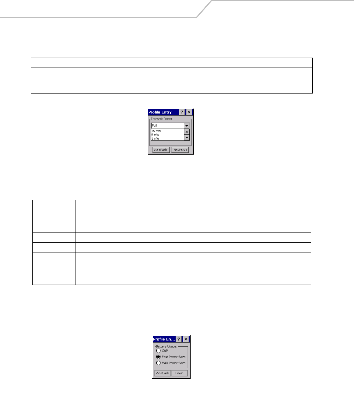
Tap Next to implement power consumption changes for the mobile computer profile. the Battery Usage dialog box displays.
Battery Usage
Use the Battery Usage dialog box to select power consumption of the wireless LAN. There are three settings available: CAM, Fast
Power Save and MAX Power Save. Battery Usage cannot be configured in Ad-Hoc profiles.
Figure 4-28. Battery Usage Dialog Box
Table 4-15. Transmit Power Dialog Box (Infrastructure Mode)
Field Description
Automatic Select Automatic to use the AP power level. Automatic is the default mode for mobile computers operating in
Infrastructure mode.
Power Plus Select Power Plus to set the mobile computer transmission power one level higher than the level set for the AP.
Table 4-16. Power Transmit Options (Ad-Hoc Mode)
Field Description
Full Select Maximum power to set the mobile computer to the highest transmission power level. Select Maximum power when
operating in highly reflective environments and areas where other devices could be operating nearby. Additionally, use the
maximum power level when attempting to communicate with devices at the outer edge of a coverage area.
30 mW Select 30 mW, to set the transmit power level to that power level.
15 mW Select 15 mW, to set the transmit power level to that power level.
5 mW Select 5 mW to set the transmit power level to that power level.
1 mW Select Minimum power to set the mobile computer to the lowest transmission power level. Use the minimum power level
when communicating with other devices in very close proximity. Additionally, select minimum power in instances where little
or no radio interference from other devices is anticipated.

Wireless Applications 4-21
Power consumption is also related to the transmit power settings.
Table 4-17. Battery Usage Options
Field Description
CAM
Continuous Aware Mode (CAM) provides the best network performance, but yields the shortest
battery life.
Fast Power Save
Fast Power Save performs in the middle of CAM and MAX Power Save with respect to network
performance and battery life. Default.
MAX Power Save
Max Power Save yields the longest battery life while potentially reducing network performance.
In networks with minimal latency. Max Power Save will perform just as well as Fast Power Save,
but with increased battery savings.
MC909X Integrator Guide4-22
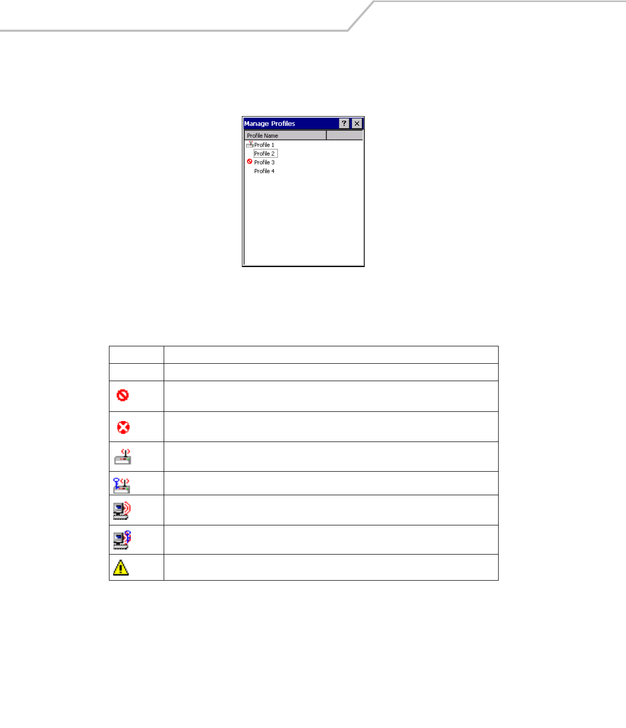
Manage Profiles Application
The Manage Profiles window provides a list of user configured wireless profiles. Up to 32 profiles can be defined at any one time. To
open the Manage Profiles window, tap the Signal Strength icon - Manage Profiles. The Manage Profiles window displays.
Figure 4-29. Manage Profiles Window
Icons next to each profile identify the profiles current state.
Table 4-18. Profile Icons
Icon Description
No Icon Profile is not selected, but enabled.
Profile is disabled.
Profile is Cancelled. A Cancelled profile is disabled until a connect or login function is performed
through the configuration editor.
Profile is currently in use and describes an infrastructure profile not using encryption.
Profile is currently in use and describes an infrastructure profile using encryption.
Profile is currently in use and describes an ad-hoc profile not using encryption.
Profile is currently in use and describes an ad-hoc profile using encryption.
Profile is not valid in the device current operating regulatory domain.
Wireless Applications 4-23
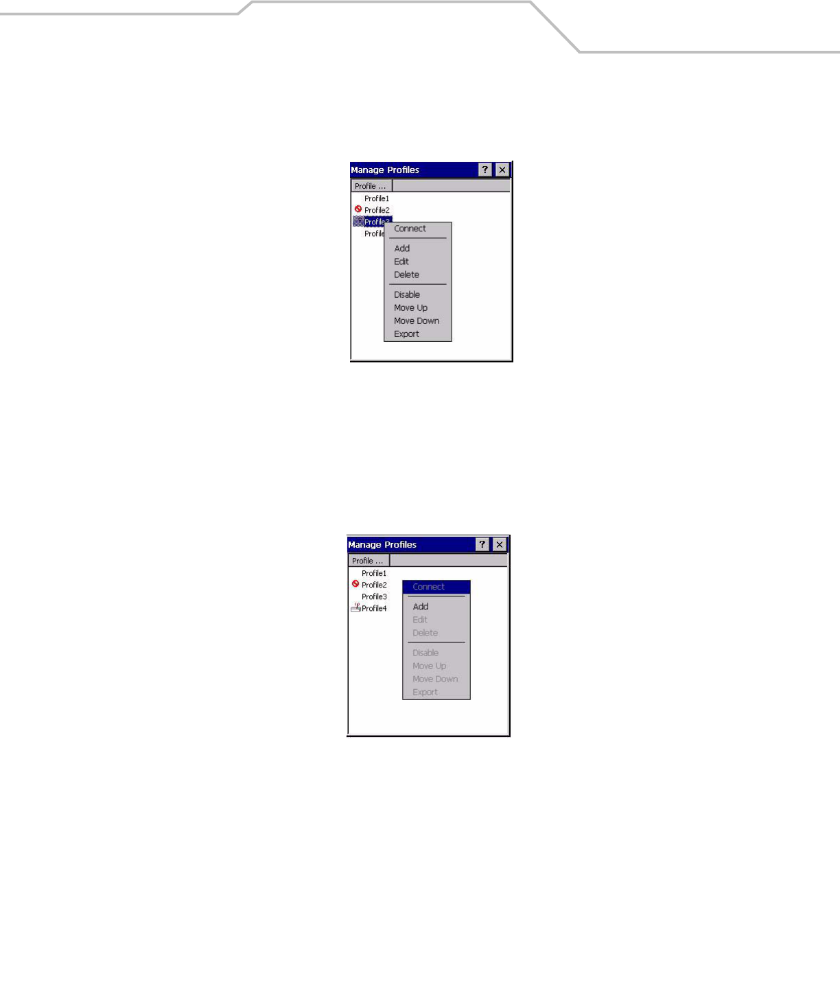
The profiles are listed in priority order for use by the automatic roaming feature. Change the order by moving profiles up or down. Edit
existing profiles by selecting one in the list and then tap-and-hold to display the menu. The menu allows the selected profile to be
connected, edited, disabled (enabled) or deleted. (Note: the Disable menu item changes to Enable if the profile is already disabled.)
Figure 4-30. Manage Profiles Context Menu
A dialog displays to confirm the users desire to delete a profile, if selected.
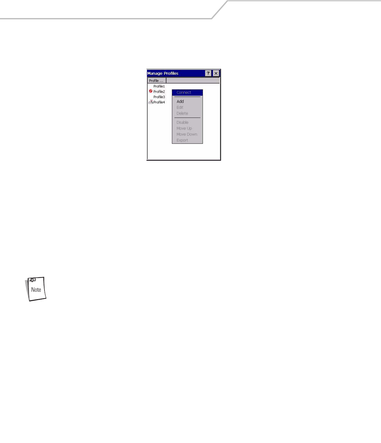
Changing Profiles
A completed profile is a set of configuration settings that can be used in different locations to connect to a wireless network. Creating
different profiles is a good way of having pre-defined operating parameters available for use in various network environments. When
the WLAN Profiles window initially displays, existing profiles appear in the list.
Figure 4-31. Manage Profiles
Select a profile from the list. Select Connect from the pop-up menu to set that profile as the active profile. Once selected, the mobile
computer uses the authentication, encryption, ESSID, IP Config and power consumption settings initially configured for that profile.
Editing a Profile
Select a profile from the list. Select Edit from the pop-up menu to display the Profile Wizard where the ESSID and operating mode
can be changed for the profile. Use the wizard to edit the profile power consumption and security parameters. See Profile Editor
Wizard on page 4-5 for procedure on using the wizard.
MC909X Integrator Guide4-24
Creating a New Profile
Create new profiles from the Manage Profiles window by performing a tap-and-hold anywhere in this window. A menu with only the
Add highlighted displays.
Figure 4-32. Manage Profiles - Add
Select Add to display the Profile Wizard wherein the profile name and ESSID can be set. Use the Profile Wizard to set security,
network address information and power consumption level for the new profile.
Deleting a Profile
To delete a profile from the list and select Delete from the pop-up menu. A confirmation dialog box appears.
Ordering Profiles
Select a profile from the list and select Move Up or Move Down from the pop-up to order the profile. If the current profile
association is lost, the mobile computer attempts to associate with the first profile in the list and then the next until a new association
is achieved.
Profile Roaming must be enabled.
Wireless Applications 4-25
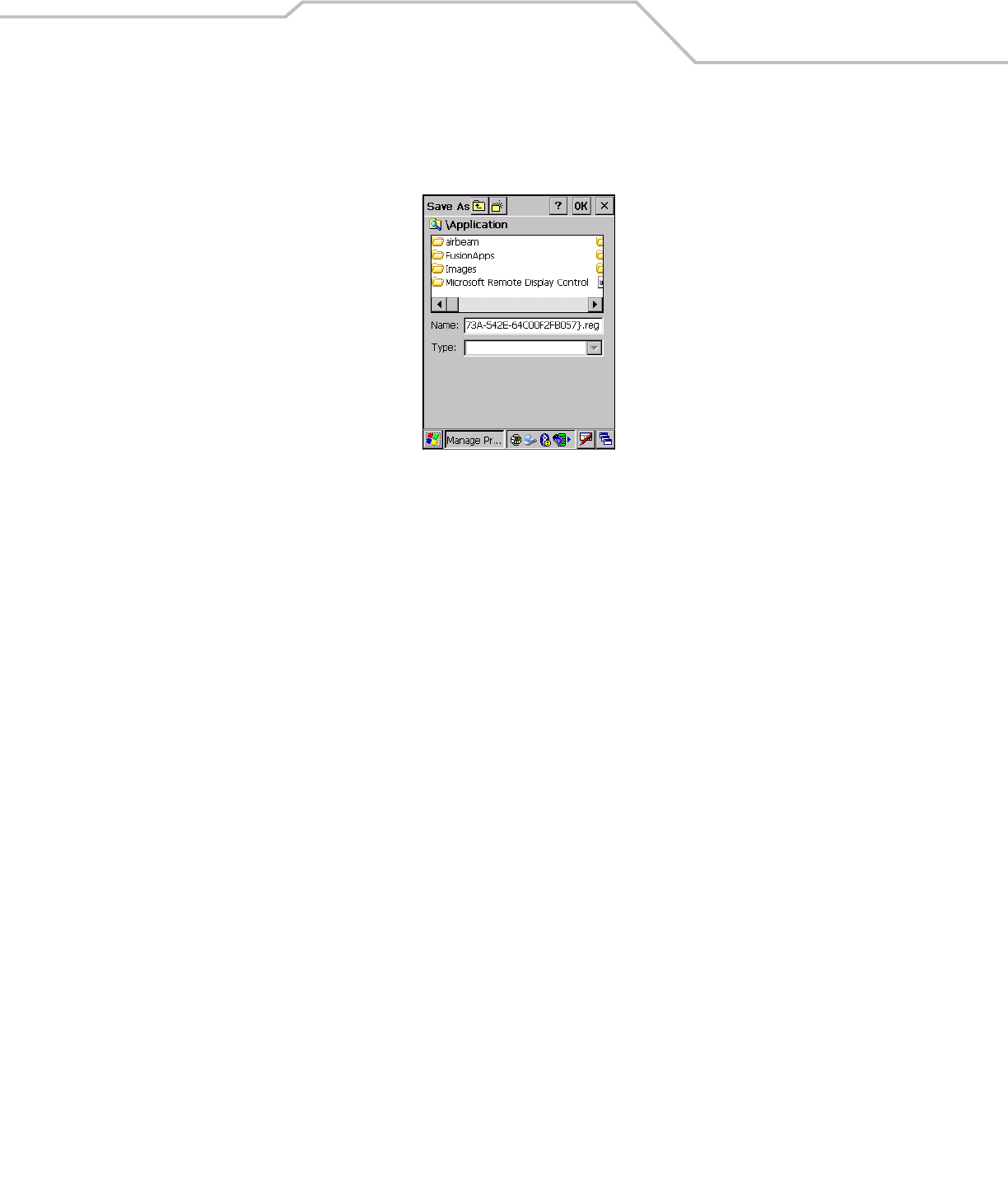
Export a Profile
To export a profile to a registry file, select a profile from the list and select Export from the pop-up menu. The save As dialog box
displays with the Application folder and a default name of WCS_PROFILE{profile GUID}.reg (Globally Unique Identifier).
Figure 4-33. Save As Dialog Box
If required, change the Name field and tap OK. A confirmation dialog box appears after the export is complete.
MC909X Integrator Guide4-26
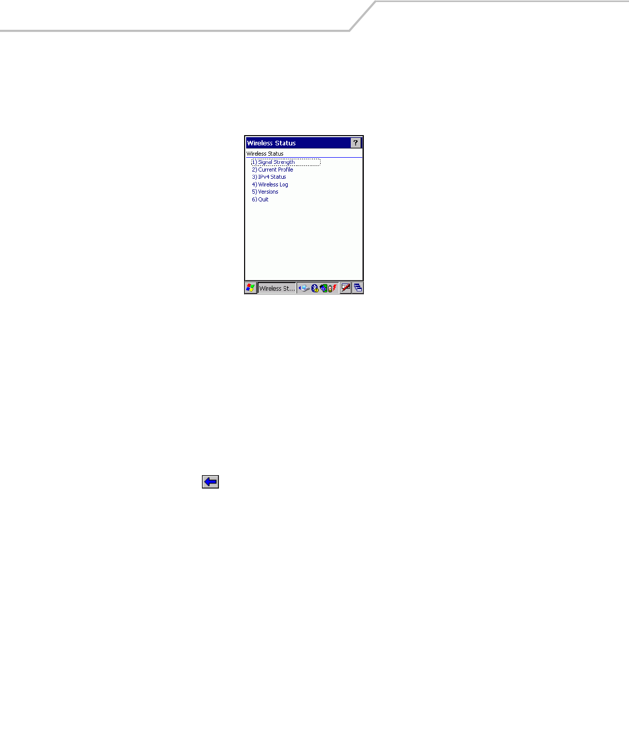
Wireless Status Application
The Wireless Status application window displays the current wireless connection status and information about the wireless
connection.
To open the Wireless Status window, tap the Signal Strength icon - Wireless Status. The Wireless Status window displays.
Figure 4-34. Wireless Status Window
The Wireless Status window contains the following options. Tap the option to display the option window.
• Signal Strength - provides information about the connection status of the current wireless profile.
• Current Profile - displays basic information about the current profile and connection settings
• IPv4 Status - displays the current IP address, subnet and other IP related information assigned to the mobile computer
• Wireless Log - displays a log of important recent activity, such as authentication, association, DHCP renewal completion, in
time order
• Versions - displays software, firmware and hardware version numbers
• Quit - Exits the Wireless Status window.
Option windows contain a back button to return to the main Wireless Status window.
Wireless Applications 4-27
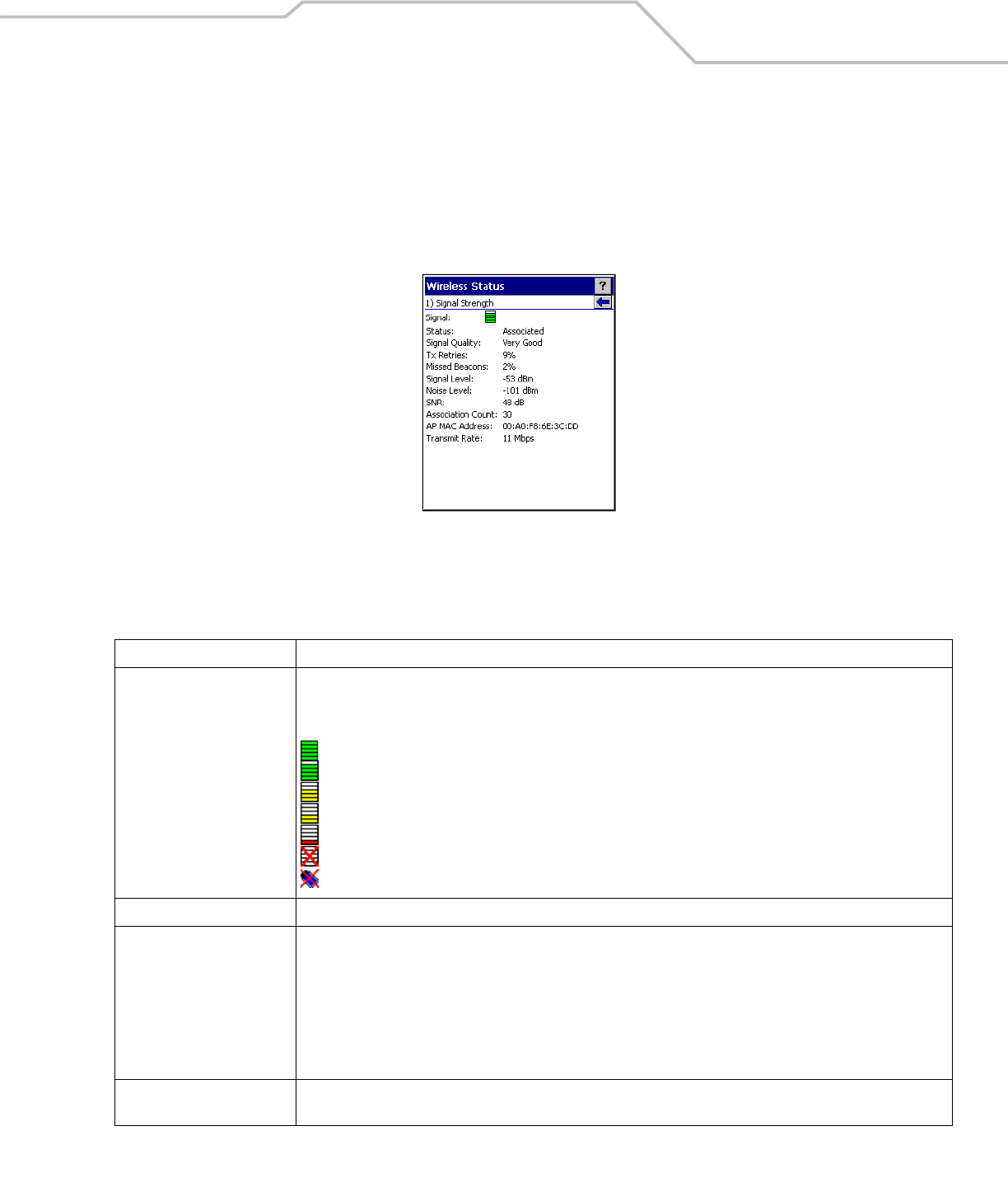
Signal Strength Window
The Signal Strength window provides information about the connection status of the current wireless profile that includes signal
quality, missed beacons and transmit retry statistics. The BSSID address (shown as “AP MAC Address) displays the AP currently
associated with the connection. If Ad-Hoc mode is in use, the AP MAC Address shows the BSSID of the Ad-Hoc network. All
information in this window updates every 2 seconds.
To open the Signal Status window, tap Signal Strength in the Wireless Status window. The Signal Strength window displays.
Figure 4-35. Signal Strength Window
After viewing the Signal Strength window, tap the back button to go back to the Wireless Status window.
Table 4-19. Signal Strength Status
Field Description
Signal Quality Displays the Relative Signal Strength Indicator (RSSI) of the signal transmitted between the AP and mobile computer. As
long as the Signal Quality icon is green the AP association is not jeopardized. If the icon is red (poor signal), an association
with a different AP could be warranted to improve the signal. The signal strength icon changes depending on the signal
strength.
Excellent Signal
Very Good Signal
Good Signal
Fair Signal
Poor Signal
Out of Range (no signal)
The radio card is turned off or there are issues communicating to the radio card.
Status Indicates if the mobile computer is associated with the AP.
Signal Quality Displays a text format of the Signal Quality icon.
• Excellent Signal
• Very Good Signal
• Good Signal
• Fair Signal
• Poor Signal
• Out of Range (No Signal).
Tx Retries Displays a percentage of the number of data packets retransmitted by the mobile computer. The fewer transmit retries, the
more efficient the wireless network is.

MC909X Integrator Guide4-28
Missed Beacons Displays a percentage of the amount of beacons missed by the mobile computer. The fewer transmit retries, the more
efficient the wireless network is. Beacons are uniform system packets broadcast by the AP to keep the network
synchronized.
Signal Level The AP signal level in decibels per milliwatt (dBm).
Noise Level The background interference (noise) level in decibels per milliwatt (dBm).
SNR The access point/mobile computer Signal to Noise Ratio (SNR) of signal strength to noise (interference) in decibels per
milliwatt (dBm).
Roaming Count Displays the number of APs that the mobile computer has connect to while roaming.
AP MAC Address Displays the MAC address of the AP to which the mobile computer is currently connected to.
Transmit Rate Displays the current rate of the data transmission.
Table 4-19. Signal Strength Status
Field Description
Wireless Applications 4-29
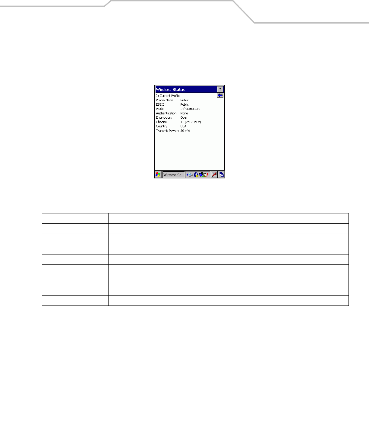
Current Profile Window
The Current Profile window displays basic information about the current profile and connection settings. This window updates every
two seconds.
To open the Current Profile window, tap Current Profile in the Wireless Status window. The Current Profile window displays.
Figure 4-36. Current Profile Window
Table 4-20. Current Profile Fields
Field Description
Profile Name Displays the current profile name that the mobile computer is using to communicate with the AP.
ESSID Displays the current profile ESSID name.
Mode Displays the current profile mode, either Infrastructure or Ad-Hoc.
Authentication Displays the current profile’s authentication type.
Encryption Displays the current profile’s encryption type.
Channel Displays the current profile channel setting.
Country Displays the current profile country setting.
Transmit Power Displays the radio transmission power level.
MC909X Integrator Guide4-30
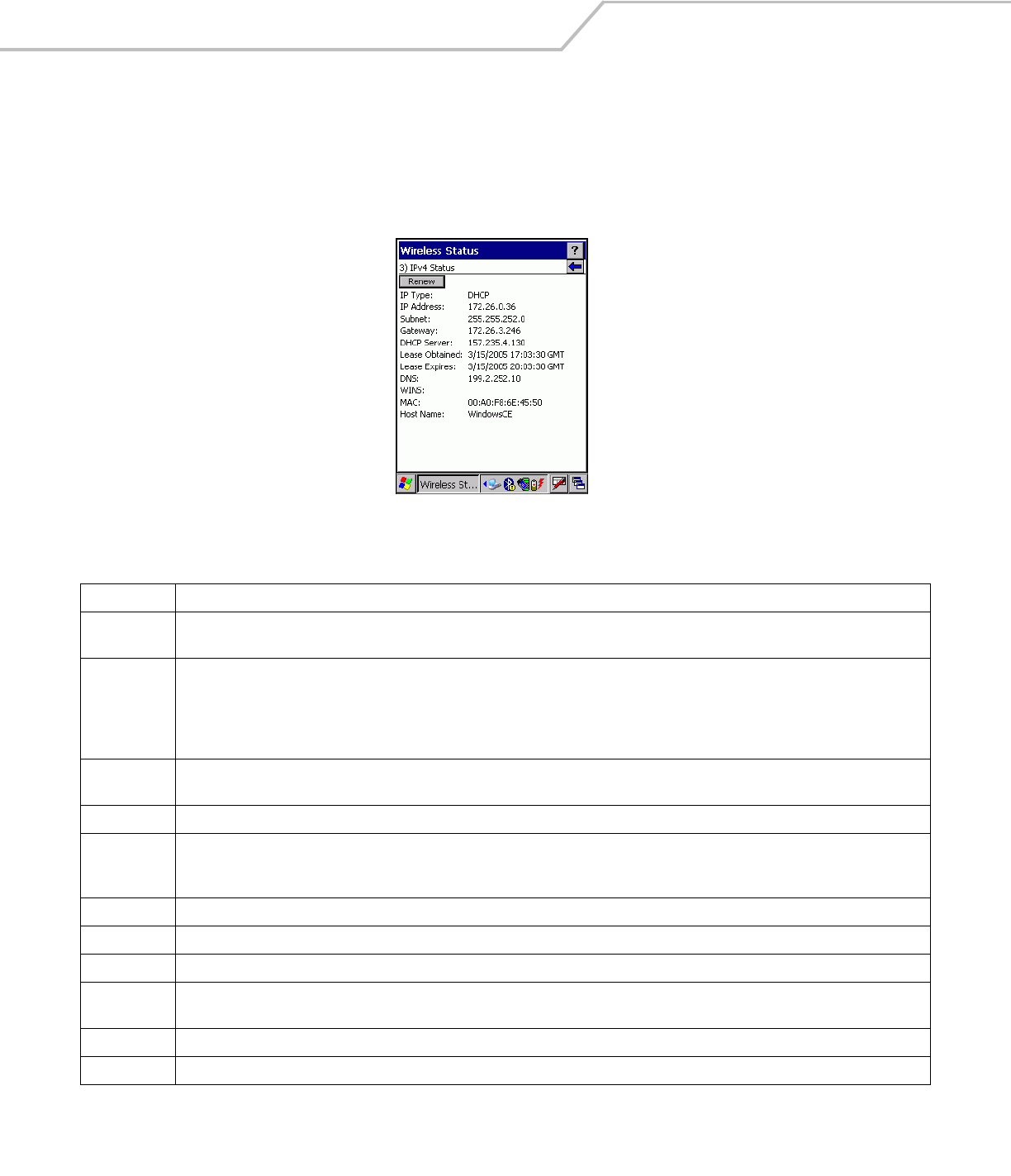
IPv4 Status Window
The IPv4 Status window displays the current IP address, subnet and other IP related information assigned to the mobile computer. It
also allows the address to be renewed if it the profile is currently using DHCP to obtain the IP information. When the user tap Renew
a full DHCP discover initiates. The IPv4 Status window should update automatically when the IP address changes.
To open the IPv4 Status window, tap IPv4 Status in the Wireless Status window. The IPv4 Status window displays.
Figure 4-37. IPv4 Status Window
Table 4-21. IPv4 Status Fields
Field Description
IP Type DIsplays the IP type for the current profile, either DHCP or Static. If the current IP type is DHCP, leased IP address and network address data
display for the mobile computer. If the current IP type is Static, the values displayed were input manually in the IP Config tab on page 4-18.
IP Address Displays the IP address assigned to the mobile computer. The Internet is a collection of networks with users that communicate with each
other. Each communication carries the address of the source and destination networks and the particular machine within the network
associated with the user or host computer at each end. This address is called the IP address. Each node on the IP network must be assigned
a unique IP address that is made up of a network identifier and a host identifier. The IP address as a dotted-decimal notation with the decimal
value of each octet separated by a period, for example, 192.168.7.27.
Subnet Displays the subnet address. Most TCP/IP networks use subnets in order to effectively manage routed IP addresses. Having an organization's
network divided into subnets allows it to be connected to the Internet with a single shared network address, for example, 255.255.255.0.
Gateway Displays the gateway address. A gateway is a device that is used to forward IP packets to and from a remote destination.
DCHP Server The Domain Name System (DNS) is a distributed Internet directory service. DNS is used mostly to translate domain names and IP addresses.
It is also used to control Internet e-mail delivery. Most Internet service requires DNS to operate properly. If DNS is not configured, Web sites
cannot be located or e-mail delivery fails.
Lease Obtained Displays the date that the IP Address was obtained.
Lease Expires Displays the date that the IP Address expires and a new IP Address is requested.
DNS Displays the IP Address of the DNS server.
WINS WINS is a Microsoft Net BIOS name server. WINS eliminates the broadcasts needed to resolve computer names to IP addresses by providing
a cache or database of translations.
MAC An IEEE 48-bit address the mobile computer is assigned at the factory that uniquely identifies the adapter at the physical layer.
Host Name Displays the name of the mobile computer.
Wireless Applications 4-31
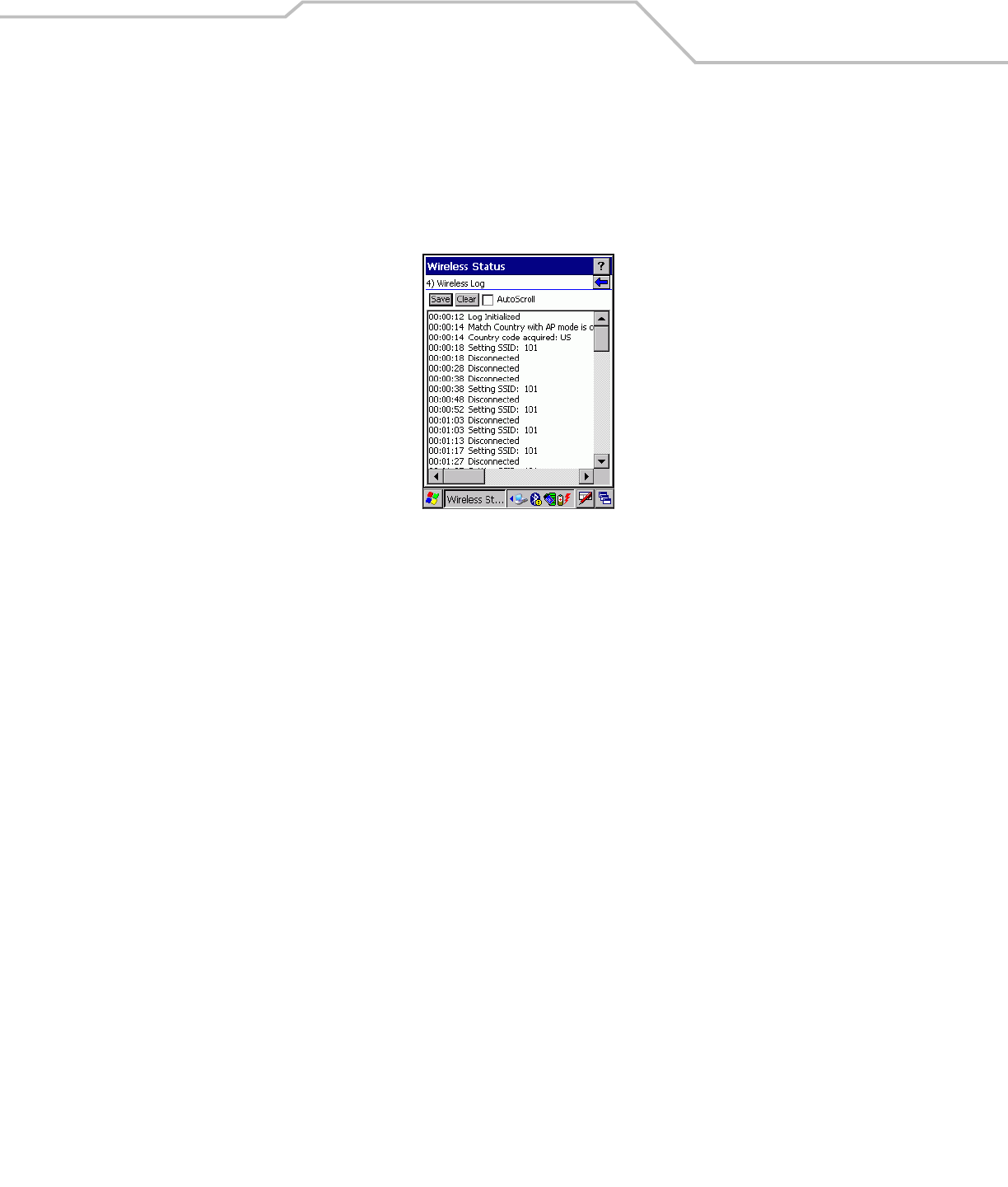
Wireless Log Window
The Wireless Log window displays a log of important recent activity, such as authentication, association, DHCP renewal completion,
in time order. Users can choose to save the log to a file or to clear the log (within this instance of the application only). There is also
an auto scroll feature to automatically scroll down when new items are added to the log.
To open the Wireless Log window, tap Wireless Log in the Wireless Status window. The Wireless Log window displays.
Figure 4-38. Wireless Log Window
Saving a Log
To save a Wireless Log:
1. Tap the Save button. The Save As dialog box displays.
2. Navigate to the desired folder.
3. In the Name filed, enter a file name and then tap OK. A text file is saved in the selected folder.
Clear the Log
To clear the log, tap Clear.
MC909X Integrator Guide4-32
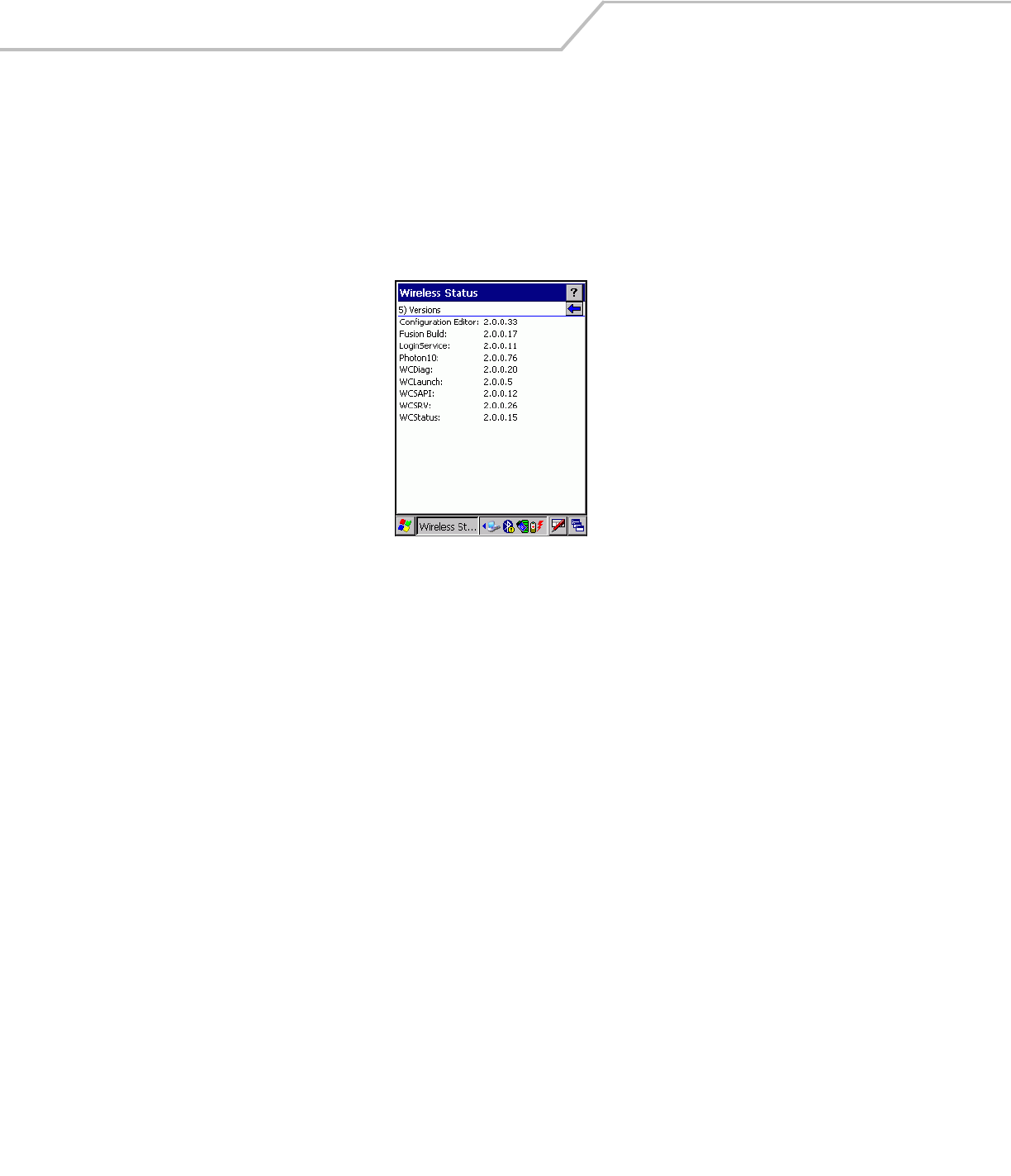
Versions Window
The Versions window displays software, firmware and hardware version numbers. This window only updates each time it is
displayed. There is no need to update constantly. The content of the window is determined at runtime, along with the actual hardware
and software to display in the list. Executable paths of the software components on the list are defined in registry, so that the
application can retrieve version information from the executable. “File not found” is displayed if the executable cannot be found at
the specified path.
To open the Versions window, tap Versions in the Wireless Status window. The Versions window displays.
Figure 4-39. Versions Window
The window displays software version numbers for the following:
• Configuration Editor
• Fusion Build
• LoginService
• Photon1.0
•WCDig
• WCLaunch
•WCSAPI
• WCSRV
• WCStatus.
Wireless Applications 4-33
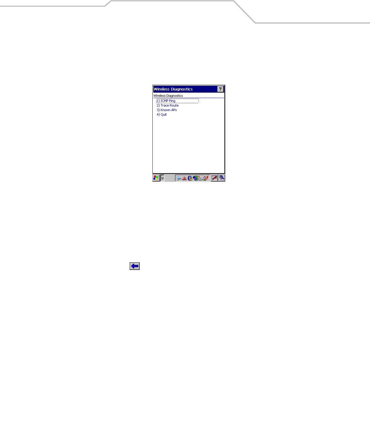
Wireless Diagnostics Application
The Wireless Diagnostics application window provides links to perform ICMP Ping, Trace Routing and Known APs.
To open the Wireless Diagnostics window, tap the Signal Strength icon - Wireless Diagnostics. The Wireless Diagnostics window
displays.
Figure 4-40. Wireless Diagnostics Window
The Wireless Diagnostics window contains the following options. Tap the option to display the option window.
• ICMP Ping - tests the wireless network connection.
• Trace Route - tests a connection at the network layer between the mobile computer and any place on the network.
• Known APs - displays the APs in range using the same ESSID as the mobile computer.
• Quit - Exits the Wireless Diagnostics window.
Option windows contain a back button to return to the main Wireless Diagnostics window.
MC909X Integrator Guide4-34
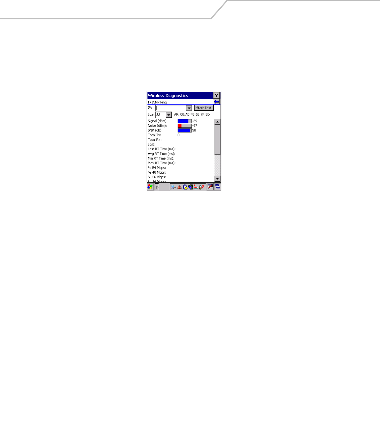
ICMP Ping Window
The ICMP Ping window allows a user to test a connection at the network layer (part of the IP protocol), between the mobile computer
and an AP. Ping tests only stop when the user taps the Stop Test button, closes the Wireless Diagnostics application, or if the mobile
computer switches between infrastructure and ad-hoc modes.
To open the ICMP Ping window, tap the ICMP Ping in the Wireless Diagnostics window. The ICMP Ping window displays.
Figure 4-41. ICMP Ping Window
To perform an ICMP ping:
1. In the IP field, enter an IP address or select an IP address from the drop-down list.
2. From the Size drop-down list, select a size value.
3. Tap Start Test. The ICMP Ping test starts. Information of the ping test displays in the appropriate fields.
Wireless Applications 4-35
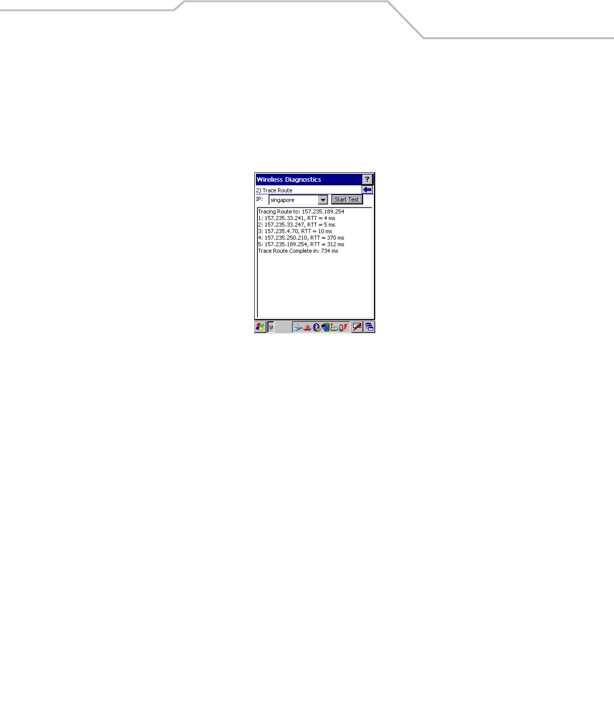
Trace Route Window
Trace Route traces a packet from a computer to a host, showing how many hops the packet requires to reach the host and how long
each hop takes. The Trace Route utility identifies where the longest delays are occurring.
The Trace Route window allows a user to test a connection at the network layer (part of the IP protocol), between the mobile computer
and any place on the network.
To open the Trace Route window, tap Trace Route in the Wireless Diagnostics window. The Trace Route window dispalys.
Figure 4-42. Trace Route Window
A user can enter an IP address or a DNS Name in the IP combo box, and tap Start Test. The IP combo box should match the same
information as shown in the ICMP Ping window’s IP combo box. When a test is started, the trace route attempts to find all routers
between the mobile computer and the destination. The Round Trip Time (RTT) between the mobile computer and each router is shown,
and then the total test time is also shown. The total test time may be longer than all RTTs added together because it is not just
including time on the network.
MC909X Integrator Guide4-36
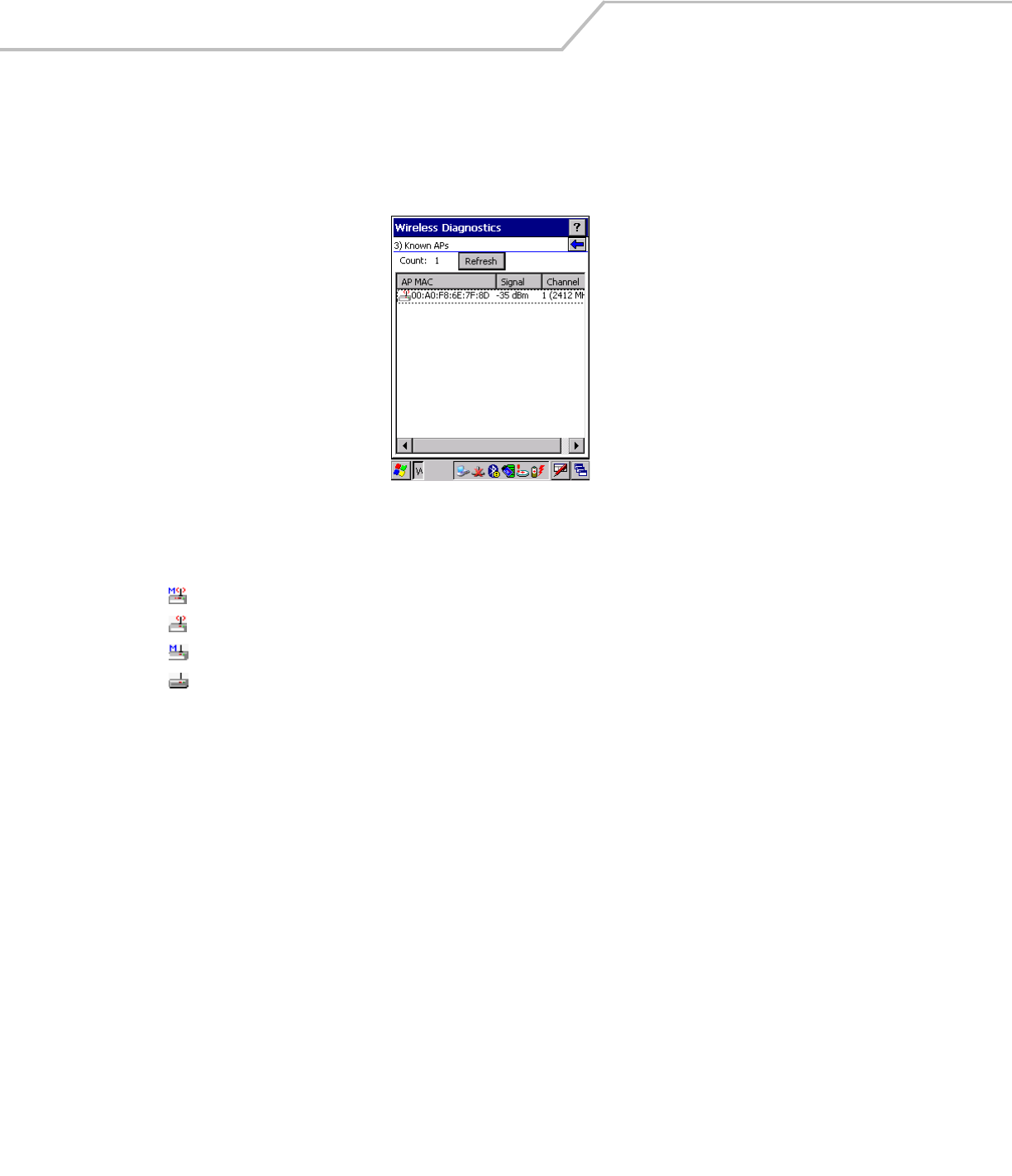
Known APs Window
The Known APs window displays the APs in range using the same ESSID as the mobile computer. This window only available when
in the Infrastructure mode.
To open the Known APs window, tap Known APs in the Wireless Diagnostics window. The Known APs window displays.
Figure 4-43. Known APs Window
The icon next to the AP indicates:
Tapping and holding the stylus on a specific AP displays a context sensitive menu with the options: Set Mandatory and Set Roaming.
Selecting the Set Mandatory option prohibits the mobile computer from associating with a different AP. The letter M displays on top
of the icon when the Set Mandatory option is selected. The mobile computer connects to the selected AP and never roams until:
•Set Roaming is chosen
• The mobile computer roams to a new profile
• The mobile computer is suspended
• The mobile computer resets (warm or cold).
Selecting Set Roaming allows the mobile computer to roam to any AP with a better signal. These settings are temporary and never
saved to the registry.
Tap Refresh to update the list of the APs with the same ESSID. A signal strength value of 32 is the highest possible.
The AP is the currently associated access point, and it is set to mandatory.
The AP is the currently associated access point, but it is not set to mandatory.
The mobile computer is not currently associated to this AP, but the AP is set as mandatory.
The mobile computer is not currently associated to this AP, and AP is not set as mandatory.
Wireless Applications 4-37
Options
Use the wireless Option dialog box to select various operation settings. The options are saved when Save is tapped. If the user taps
X before saving and an option was changed, a dialog box displays asking the user to close without saving the changes.
The options are:
• Operating Mode Filtering
• Regulatory
• Band Selection
• System Options
• Change Password
• Export.
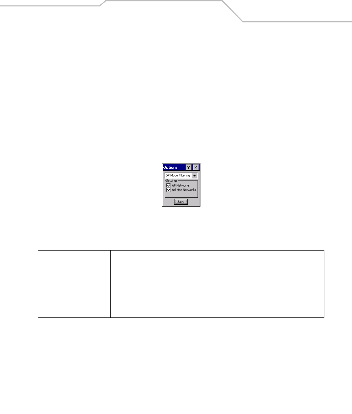
Operating Mode Filtering
The Operating Mode Filtering options cause the Find WLANs application to filter the available networks found.
Figure 4-44. OP Mode Filtering Dialog Box
The default value has both AP Networks and Ad-Hoc Networks enabled.
Tap Save to save the settings or tap X to discard any changes.
Table 4-22. OP Mode Filtering Options
Field Description
AP Networks
Select the AP Networks check box to display available AP networks and their signal strength within the Available
WLAN Networks (see Find WLANs Application on page 4-4). These are the APs available to the mobile computer
profile for association. If this option was previously disabled, refresh the Available WLAN Networks window to
display the AP networks available to the mobile computer.
AD-Hoc Networks
Select the Ad-Hoc networks check box to display available peer (adapter) networks and their signal strength within
the Available WLAN Networks. These are peer networks available to the mobile computer profile for association.
If this option was previously disabled, refresh the Available WLAN Networks window to display the Ad Hoc
networks available to the mobile computer.
MC909X Integrator Guide4-38
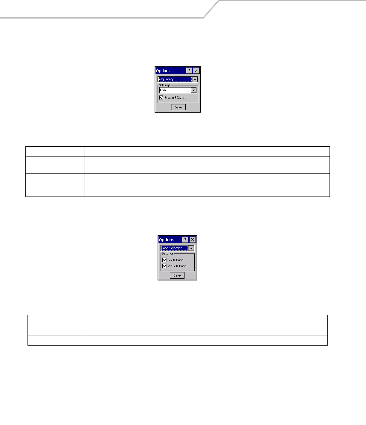
Regulatory Options
Use the Regulatory settings to configure the country the mobile computer is in. Due to regulatory requirements (within a country) a
mobile computer is only allowed to use certain channels.
Figure 4-45. Regulatory Options Dialog Box
Band Selection
The Band Selection settings identify the frequency bands to be scanned when finding WLANs. These values refer to the 802.11
standard networks.
Figure 4-46. Band Selection Dialog Box
Tap Save to save the settings or tap X to discard any changes.
Table 4-23. Regulatory Options
Field Description
Settings
Select the country of use from the drop-down list. In order to connect to a profile, the profile country must match this setting,
or the AP country setting if the Enable 802.11d check box is selected.
Enable 802.11d
With this check box selected, the WLAN adapter attempts to retrieve the country from APs. Profiles which use Infrastructure
mode are only able to connect if the country set is the same as the AP country settings or if the profile country setting is set
to Allow Any Country. Check this box requires that ALL APs be configured to transmit the country information.
Table 4-24. Band Selection Options
Field Description
5GHz Band With this box checked, the Find WLANs application list includes all networks found in the 5 GHz band (802.11a).
2.4GHz Band With this box checked, the Find WLANs application list includes all networks found in the 2.4 GHz band (802.11b and 802.11g).
Wireless Applications 4-39
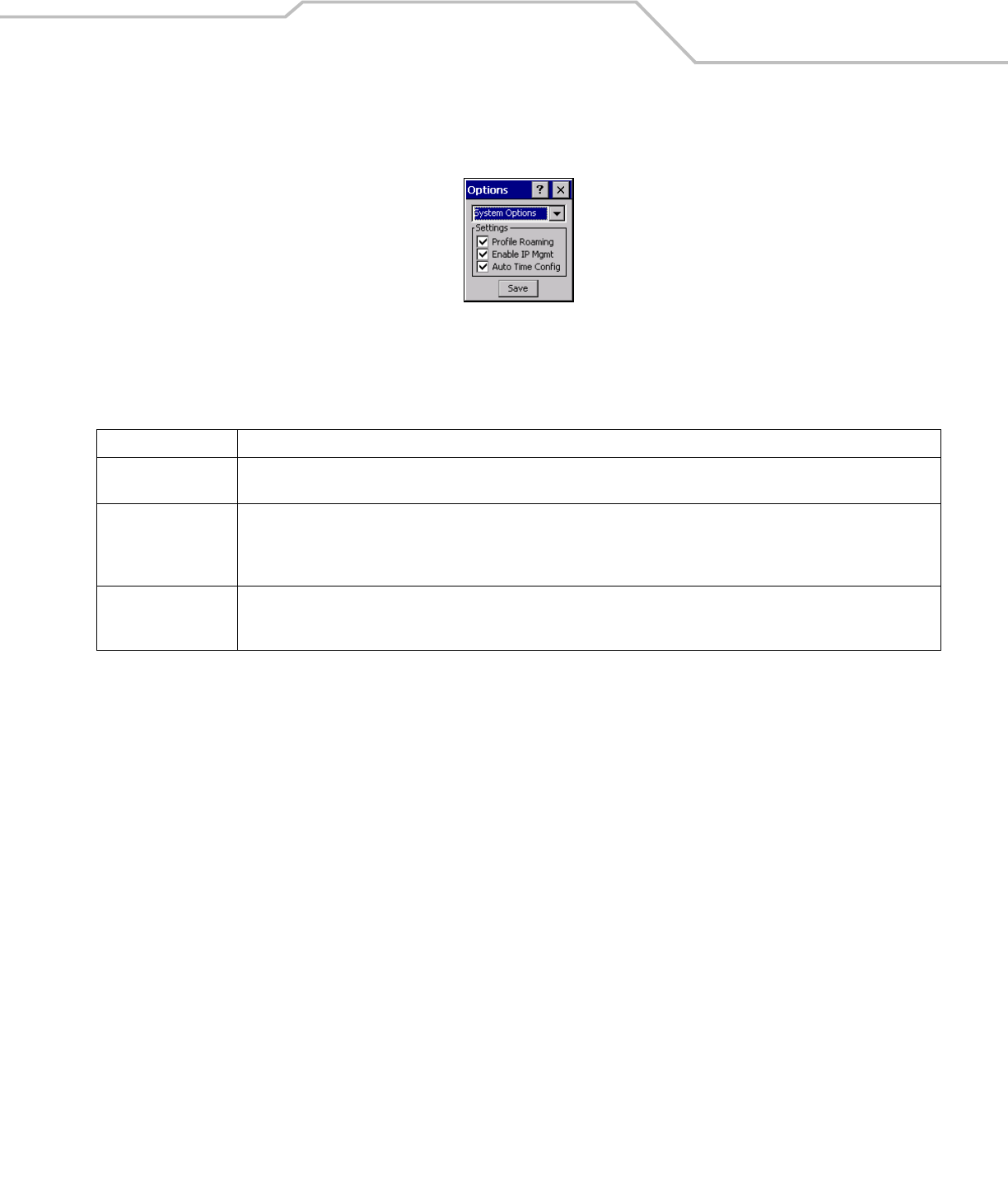
System Options
Use the system options to set miscellaneous system setting.
Figure 4-47. System Options Dialog Box
Table 4-25. Band Selection Options
Field Description
Profile Roaming
Select the Profile Roaming check box to configure the mobile computer to roam to the next available WLAN profile when it moves
out of range of the current WLAN profile.
Enable IP Mgmt
Select Enable IP Mgmt check box to enable the Wireless Companion Services to handle IP Address management. When checked,
the Wireless Companion Service configures the IP based on what is configured in the network profile. If unchecked, the Wireless
Companion Service does not configure the IP information. For this case, the user must configure the IP in the standard Windows IP
dialog screen. Enabled by default.
Auto Time Config
Select Auto Time Config check box to enable automatic update of the system time. The device time is updated during network
association, based on the time as set in the AP. This proprietary feature is only supported with Symbol infrastructure. Enabled by
default.
MC909X Integrator Guide4-40
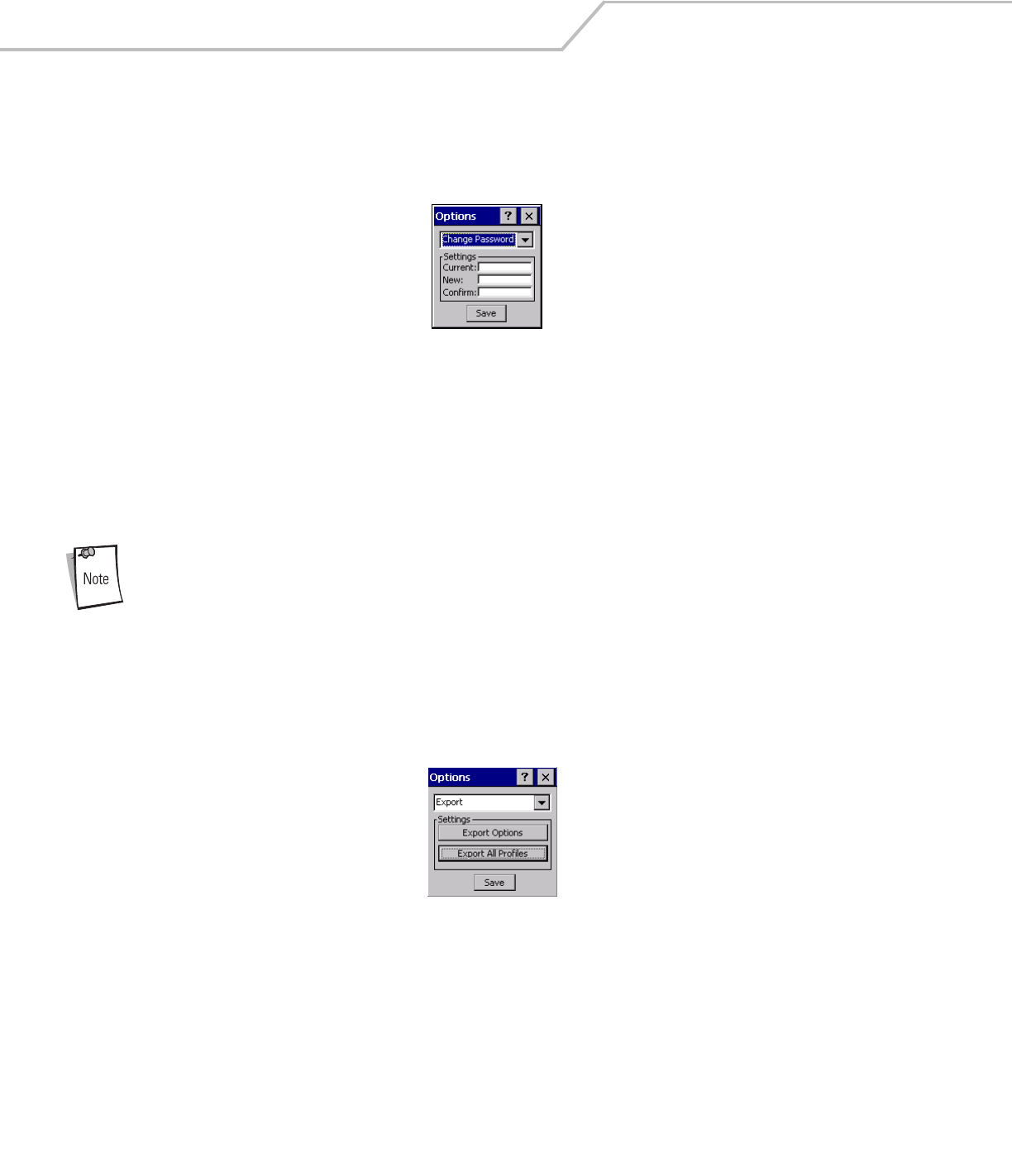
Change Password Dialog Box
Use the Change Password dialog box to require a password before any profile can be edited. This allows system administrators to
pre-configure profiles and not allow a user to change the network settings. The user could also use this feature to protect their
settings from a guest user. By default, the password is not set.
Figure 4-48. Change Password Window
1. To create a password for the first time, leave the Current: text box empty and enter the new password in the New: and
Confirm: text boxes. Tap Save.
2. To change an existing password, enter the current password in the Current: text box, enter the new password in the New:
and Confirm: text boxes.Tap Save.
3. Delete the password, in this case enter the current password in the Current: text box and leave the New: and Confirm: text
boxes empty.
Passwords are case sensitive and can not exceed 10 characters.
Export
Use the Export dialog box to export all profiles to a registry file, and to export the options to a registry file. Each of these export
functions prompts the user for a filename that is used as the registry file. The “save” dialog box defaults to the application folder,
and has a default file name to use. For exporting all profiles, the default filename is: WCS_PROFILES.REG. For exporting the options,
the default filename is: WCS_OPTIONS.REG.
Figure 4-49. Options - Export Dialog Box
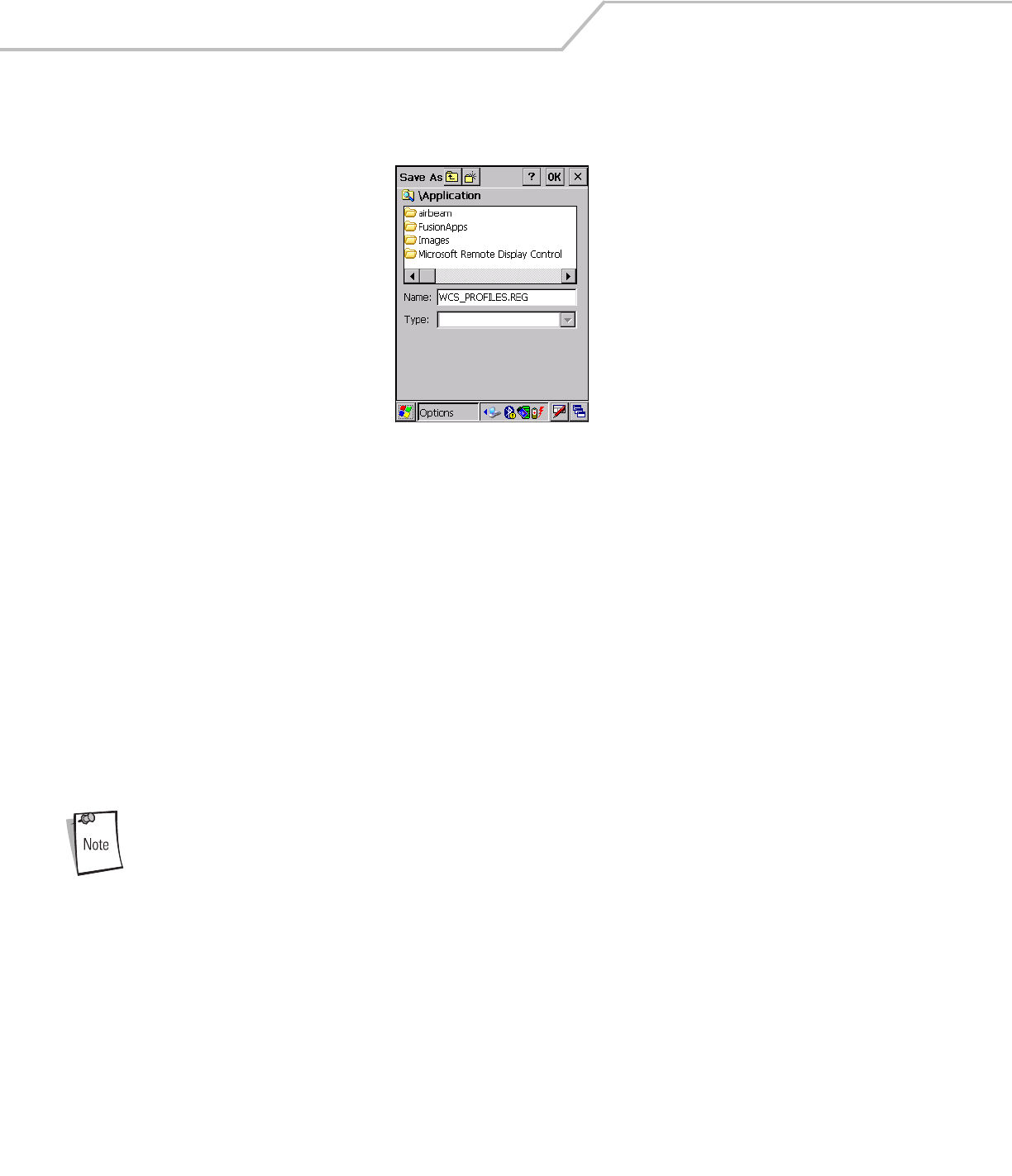
To export options:
1. Tap Export Options. The Save As dialog box displays.
Wireless Applications 4-41
Figure 4-50. Export Options Save As Dialog Box
2. The default folder is \Application\FusionApps\Certs\.
3. In the Name field, enter a file name.
4. Tap OK.
MC909X Integrator Guide4-42
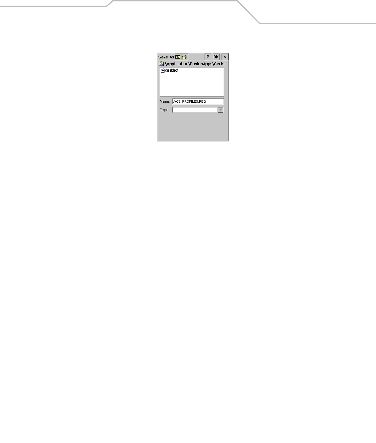
To export all profiles:
1. Tap Export All Profiles. The Save As dialog box displays.
Figure 4-51. Export All Profiles Save AS Dialog Box
2. Navigate to the desired folder.
3. In the Name field, enter a file name.
4. Tap OK.
When Export All Profiles is selected the current profile is also saved. This information is used to determine which profile to connect
with after a warm boot or cold boot.
Cold Boot Persistence
Exporting options and profiles can be used to provide cold boot persistence. If the exported registry files are saved in the Application
folder, they are automatically utilized on a cold boot, restoring previous profile and option settings.
Currently, only server certificates can be saved for cold boot persistence. To save server certificates for cold boot persistence, the
certificate files must be placed in the folder Application\Certs. Saving the certificates to this folder causes the certificates to be
installed automatically on a cold boot.
User certificates cannot be saved for cold boot persistence at this time.

Wireless Applications 4-43
Registry Settings
Some of the parameters can be modified through a registry key. The registry path is:
HKLM\SOFTWARE\Symbol Technologies, Inc.\Configuration Editor
Table 4-26. Registry Parameter Settings
Key Type Default Description
CertificateDirectory REG_SZ \\Windows The default directory to find certificates.
EncryptionMask REG_DWORD 0x0000001F Defines the encryption types that are currently supported. This is a bitwise mask with each bit
corresponding to an encryption type. 1 = Type is supported, 0 = Type is not supported
Bit Number Encryption Type
0None
1 40-Bit WEP
2 128-Bit WEP
3TKIP
MenuShortCut REG_SZ Alt-M Describes the key combination to use in place of Tap-and-hold or shortcut key sequence to
display menus. This value can be a system key sequence (i.e. preceded with ALT) or a single key
which triggers the context sensitive menu when the appropriate dialog is visible.
RefreshTime REG_DWORD 4000 This registry key defines the number of milliseconds between refreshes of the Manage Profiles
dialog.

MC909X Integrator Guide4-44
Log On/Off Application
When the user launches the Log On/Off application, the mobile computer may be in two states; the user may be logged onto the
mobile computer by already entering credentials through the login box, or there are no user logged on. Each of these states have a
separate set of use cases and a different look to the dialog box.
User Already Logged In
If a user is already logged into the mobile computer, that user may launch the login dialog box for the following reasons:
• Connect to and re-enable a cancelled profile. To do this, a user would:
• Launch the password dialog
• Select the cancelled profile from the profile list
• Login to the profile.
NOTE: Cancelled profiles can also be re-enabled by using the Profile Editor Wizard and choosing to connect to the cancelled
profile. Cancelled profiles are also be re-enabled when a new user logs on.
• Logoff the mobile computer - to prevent another user from accessing the current users network privileges.
• Switch mobile computer users - to quickly logoff the mobile computer and allow another user to log into the mobile
computer.
No User Logged In
If no user is logged into the mobile computer, a user must launch the login dialog box and login so that user profiles may be accessed.
Login Dialog box
The dialog displays with slightly different if it is:
• Launched by WCS, because the service is connecting to a new profile that needs credentials.
• Launched by WCS, because the service is trying to verify the credentials due to credential caching rules.
• Launched by a user, when a user is logged in.
• Launched by a user, when no user is logged in.
Table 4-27. Log On/Off Options
Field Description
Wireless Profile Field When a user launches the login application, the Wireless Profile field has all the wireless profiles that require credentials
available. This currently includes profiles that use EAP TLS, PEAP, LEAP, and EAP-TTLS.
Profile Status Icon The profile status icon in the dialog (shown next to the profile name) would show one of three states.
• The profile selected has been cancelled.
• The profile selected is enabled but is not the current profile
• The profile is the current profile (always the case for WCS Launched)
Network Username and Password
Fields
The Network Username and Network Password fields are used as credentials for the profile selected/shown in the
Wireless Profile field. Currently these fields are limited to 159 characters.
Mask Password Checkbox The Mask Password checkbox determines whether the password field is masked (i.e. displays only the '*' character) or
unmasked (i.e. displays the actual text being entered). If the box is checked, the password is unmasked. Unchecking the
box causes the password to be masked. The default state is unchecked to cause masked passwords.
Status Field The status field is used for displaying status that is important to the login dialog. If the user opens the dialog and needs
to prompt for credentials for a particular profile at this time, it can use the status field to let the user know that the network
is being held up by the password dialog being open.

Wireless Applications 4-45
Tapping OK sends the credentials though WCS API. If there are no credentials entered, a dialog box displays informing the user which
field was not entered.
The Log Off button only displays when a user is already logged on. When the Log Off button is tapped, the user is prompted with
three options: Log Off, Switch Users, and Cancel. Switching users logs off the current user and re-initialize the login dialog box to be
displayed for when there is no user logged on. Logging off logs off the current user and close the login dialog box. Tapping Cancel
closes the Log Off dialog box and the Login dialog box displays.
When the user is logged off, the mobile computer only roams to profiles that do not require credentials or to profiles that were created
with the credentials entered into the profile
The Cancel button closes the dialog without logging into the network. If the login dialog was launched by the wCS and not by the
user, tapping Cancel first causes a message box to display a warning that the cancel disables the current profile. If the user still
chooses to cancel the login at this point, the profile is cancelled.
Once a profile is cancelled, the profile is suppressed until a user actively re-enables it or a new user logs onto the mobile computer.

MC909X Integrator Guide4-46