Symbol Technologies MR400 MR400 RFID Reader Module User Manual
Symbol Technologies Inc MR400 RFID Reader Module
Manual
MR400 RFID Reader Module
Integration Guide

MR400 RFID Reader Module, Integration Guide
72E-89971-01
Revision 1
October 2006

© 2006 by Symbol Technologies, Inc. All rights reserved.
No part of this publication may be reproduced or used in any form, or by any electrical or mechanical means, without
permission in writing from Symbol. This includes electronic or mechanical means, such as photocopying, recording, or
information storage and retrieval systems. The material in this manual is subject to change without notice.
The software is provided strictly on an “as is” basis. All software, including firmware, furnished to the user is on a
licensed basis. Symbol grants to the user a non-transferable and non-exclusive license to use each software or
firmware program delivered hereunder (licensed program). Except as noted below, such license may not be assigned,
sublicensed, or otherwise transferred by the user without prior written consent of Symbol. No right to copy a licensed
program in whole or in part is granted, except as permitted under copyright law. The user shall not modify, merge, or
incorporate any form or portion of a licensed program with other program material, create a derivative work from a
licensed program, or use a licensed program in a network without written permission from Symbol. The user agrees to
maintain Symbol’s copyright notice on the licensed programs delivered hereunder, and to include the same on any
authorized copies it makes, in whole or in part. The user agrees not to decompile, disassemble, decode, or reverse
engineer any licensed program delivered to the user or any portion thereof.
Symbol reserves the right to make changes to any software or product to improve reliability, function, or design.
Symbol does not assume any product liability arising out of, or in connection with, the application or use of any product,
circuit, or application described herein.
No license is granted, either expressly or by implication, estoppel, or otherwise under any Symbol Technologies, Inc.,
intellectual property rights. An implied license only exists for equipment, circuits, and subsystems contained in Symbol
products.
Symbol, MR400, Spectrum One, and Spectrum24 are registered trademarks of Symbol Technologies, Inc. Bluetooth is
a registered trademark of Bluetooth SIG. Microsoft, Windows and ActiveSync are either registered trademarks or
trademarks of Microsoft Corporation. Other product names mentioned in this manual may be trademarks or registered
trademarks of their respective companies and are hereby acknowledged.
Symbol Technologies, Inc.
One Symbol Plaza
Holtsville, New York 11742-1300
http://www.symbol.com
Patents
This product is covered by one or more of the patents listed on the web site: www.symbol.com/patents

Revision History
Changes to the original manual are listed below:
Change Date Description
-01 Rev 1 10/2006 BETA


Table of Contents
Chapter 1
Table of Contents
Revision History............................................................................................................. iii
Table of Contents
About This Guide
Introduction .................................................................................................................... i
Documentation Set .................................................................................................. i
Configurations................................................................................................................ i
Chapter Descriptions ..................................................................................................... i
Notational Conventions.................................................................................................. ii
Notes, Cautions and Warnings ................................................................................ ii
Related Documents ....................................................................................................... iii
Service Information........................................................................................................ iii
Chapter 1: Introduction
Overview ....................................................................................................................... 1-1
Theory of Operation ...................................................................................................... 1-2
Block Diagram ......................................................................................................... 1-2
Controller ........................................................................................................... 1-2
Baseband Processor ......................................................................................... 1-3
Transceiver ....................................................................................................... 1-3
External Hardware Interfaces ....................................................................................... 1-3
Input Voltage ........................................................................................................... 1-3
Antenna Interface .................................................................................................... 1-3
Host Interface .......................................................................................................... 1-4
Mechanical Characteristics ........................................................................................... 1-5
Dimensions ............................................................................................................. 1-5
Weight ..................................................................................................................... 1-5
Enclosure and EMI Shielding .................................................................................. 1-5
Environmental Characteristics ...................................................................................... 1-6
Thermal Management ............................................................................................. 1-6
Temperature and Humidity ..................................................................................... 1-6
ESD ......................................................................................................................... 1-6
Shock ...................................................................................................................... 1-6
Vibration .................................................................................................................. 1-6

vi MR400 RFID Reader Module, Integration Guide
Chapter 2: Installation
Overview ....................................................................................................................... 2-1
Unpacking ..................................................................................................................... 2-1
Mounting ....................................................................................................................... 2-1
MR400 Installation ........................................................................................................ 2-2
Housing Design ............................................................................................................ 2-2
Environment ............................................................................................................ 2-2
Grounding ..................................................................................................................... 2-2
ESD .............................................................................................................................. 2-2
Location and Positioning ............................................................................................... 2-2
Using the MR400 .......................................................................................................... 2-3
Accessories .................................................................................................................. 2-3
Developer Kit ................................................................................................................ 2-3
Chapter 3: Byte Stream Protocol
Byte Stream Protocol With the MR 400 ........................................................................ 3-1
Request and Response Packets ............................................................................. 3-1
Byte Stream Command List .......................................................................................... 3-3
Read Full Field Command (22hex) ......................................................................... 3-3
Set Parameter Block Command (23hex) ................................................................ 3-3
Get Parameter Block Command (24hex) ................................................................ 3-3
Get Reader Status Command (14hex) ................................................................... 3-3
Set Frequency Channel Command (1Chex) ........................................................... 3-3
Read With Payload Command (31hex) .................................................................. 3-4
Kill Specific (32 hex) ............................................................................................... 3-4
Write Tag (33hex) ................................................................................................... 3-4
Appendix A: MR400 Specifications
Overview ....................................................................................................................... A-1
Technical Specifications ............................................................................................... A-1
Read/Write Ranges ...................................................................................................... A-2

Table of Contents vii
Appendix B: Regulatory Information
Regulatory Requirements ............................................................................................. B-1
Regulatory Statement ................................................................................................... B-1
Regulatory Standards ................................................................................................... B-2
Regulatory Approvals .................................................................................................... B-2
Reference Antenna ....................................................................................................... B-3
Reader Module Regulatory Markings ........................................................................... B-3
Final Product Compliance ............................................................................................. B-4
National Country Requirements .................................................................................... B-5
United States of America ........................................................................................ B-5
Canada ................................................................................................................... B-5
Recycling ...................................................................................................................... B-7
RoHS Compliance ........................................................................................................ B-7
Index

viii MR400 RFID Reader Module, Integration Guide

About This Guide
Introduction
This guide provides information about using the MR400 RFDI reader module.
Documentation Set
The documentation set for the MR400 RFDI reader module is divided into guides provide information for
specific user needs.
•
Microsoft® Windows Mobile 5.0 Applications User Guide for Symbol Devices - describes how to use
Microsoft developed applications.
•
Symbol Application Guide - describes how to use Symbol developed sample applications.
Configurations
This guide covers the following configurations:
•
MR400 RFDI reader module - TBD.
Chapter Descriptions
Topics covered in this guide are as follows:
•
Chapter 1, MR400 Integration GuideIntroduction provides installation procedures for the MR400.
•
Chapter 2, Using the Interfaces provides basic instructions for interfacing with the MR400.
•
Chapter 3, Using the Interfaces explains the MR400 software interface.
•
Appendix A, MR400 RFID Reader Module, Integration GuideMR400 SpecificationsMR400 Specifications
provides the MR400 technical specifications.
•
Appendix B, Regulatory InformationRegulatory InformationMR400 RFID Reader Module, Integration
Guide, provides the required regulatory information.
NOTE Screens and windows pictured in this guide are samples and can differ from actual screens.
ii MR400 RFID Reader Module, Integration Guide
Notational Conventions
The following conventions are used in this document:
•
Italics are used to highlight the following:
-Chapters and sections in this and related documents
-Dialog box, window and screen names
-Drop-down list and list box names
-Check box and radio button names
-Icons on a screen.
•
Bold text is used to highlight the following:
-Key names on a keypad
-Button names on a screen.
•
Bullets (•) indicate:
-Action items
-Lists of alternatives
-Lists of required steps that are not necessarily sequential
•
Sequential lists (e.g., those that describe step-by-step procedures) appear as numbered lists.
Notes, Cautions and Warnings
Note
Caution
Warning
NOTE Notes comprise additional information that aids in the use or understanding of the equipment or subject.
Notes are not safety related.
CAUTION Cautions advise users of actions that could result in damage to equipment, loss of data or potential
long-term health hazard.
WARNING!Warnings advise users of actions that could result in physical harm to the user or bystanders.

About This Guide iii
Related Documents
•
Microsoft® Windows Mobile 5.0 Applications User Guide for Symbol Devices, p/n 72E-xxxxx-xx
•
Symbol Application Guide, p/n 72E-65258-xx
•
Symbol Mobility Developer Kit for C (SMDK for C), available at: http://devzone.symbol.com/.
For the latest version of this guide go to:http://www.symbol.com/manuals.
Service Information
For service information, warranty information or technical assistance contact or call the Symbol Support
Center. Contact information is provided on the Symbol contact web site go to:
http://www.symbol.com/contactsupport
If the problem cannot be solved over the phone, the equipment may need to be returned for servicing. If that is
necessary, specific directions will be provided.
If the Symbol product was purchased from a Symbol Business Partner, contact that Business Partner for
service.
NOTE Symbol Technologies is not responsible for any damages incurred during shipment if the approved
shipping container is not used. Shipping the units improperly can possibly void the warranty.

iv MR400 RFID Reader Module, Integration Guide

Chapter 1
Introduction
Chapter 1
Chapter 1
MR400 Integration GuideIntroduction
Overview
The MR400 is a RFID Reader that supports the GEN 2 EPC (Electronic Product Code). protocol, in the UHF
frequency band.
The reader architecture is intended to address the requirements of operation in different world regions with
different frequencies, data rates and compliance specifications. However, different Versions of modules with
modified design, and/or component stuffing, may be required to address the various regulatory requirements.
In order to keep track of these versions, the following designation are used:
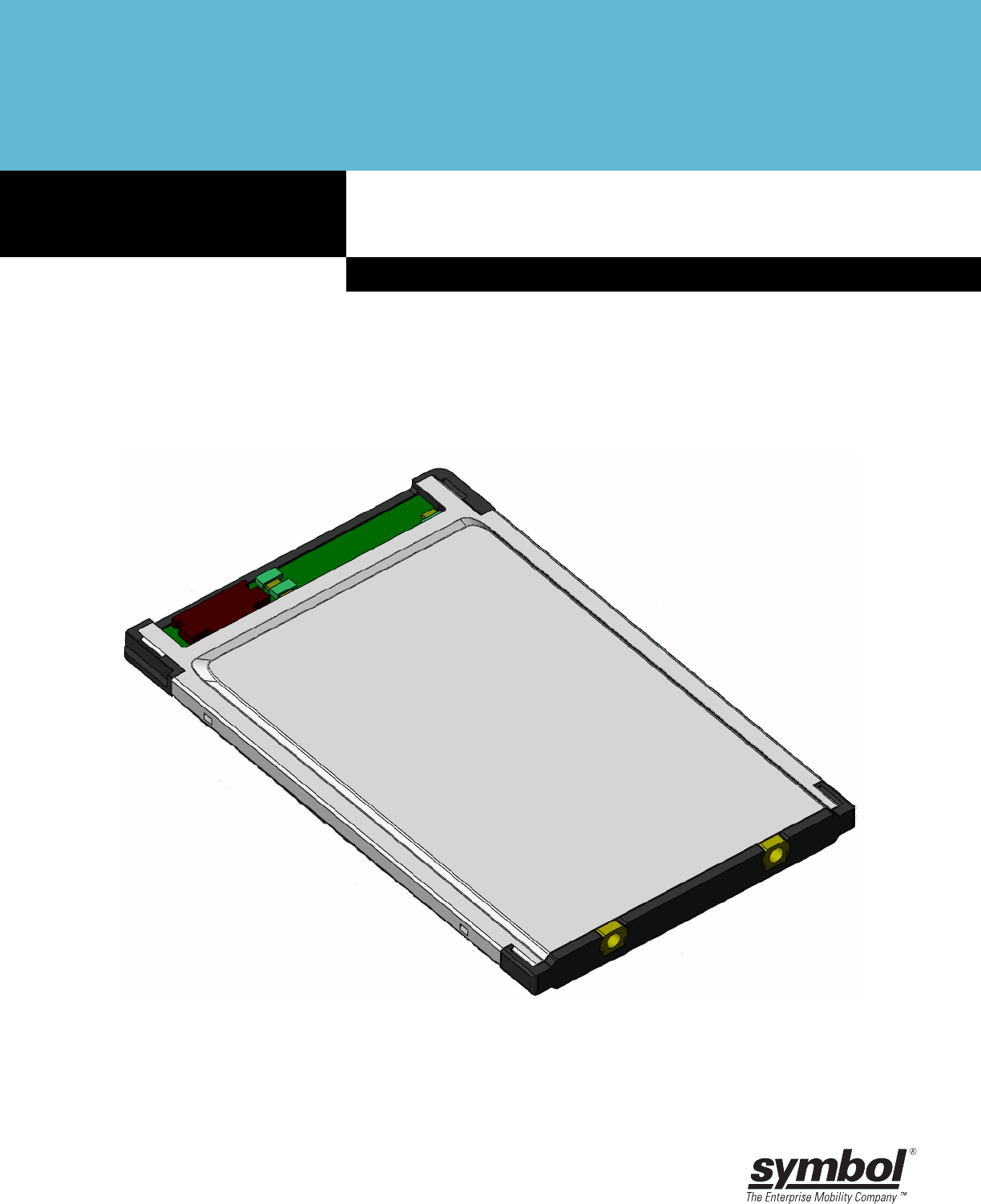
Figure 1-1
MR400 RFID Reader Module
1 - 2 MR400 RFID Reader Module, Integration Guide
Theory of Operation
The MR400 is a UHF (860MHz - 928MHz) RFID reader module. The MR400 RFID Reader Module is used to
read and write UHF passive RFID tags complying to EPCglobal Gen2 standard. Communication between a
reader and a tag occurs in a half-duplex reader-talks-first manner. Commands from the reader is sent to the
tags on the forward link modulated on the transmit carrier followed by a CW transmission. The tags are
powered by the energy by the reader EM field, this wakes up the tags and they are now ready to receive reader
commands. After decoding the command data, the tags response by back scattering with encoded data,
modulated on the CW transmission.
The MR400 is designed as an embedded module and will be used as an integral part of a RFID system.
Typical system included but not limited to the followings:
•
Forklift systems
•
Handheld or portable devices
•
Tag Decode and Encode Printers
•
Remote Read Points
Block Diagram
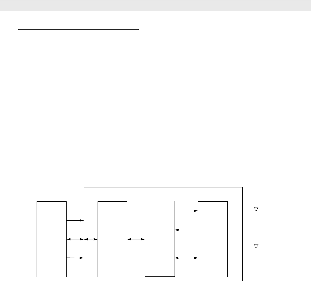
the MR400 consists of a single port transceiver with option for dual diversity antennas, a controller and a
baseband processor with interfaces to external antenna(s) and a host system. Depending on a specific
application, the host could be a single board or a computer system.
Figure 1-2
MR400 RFID Reader Module Block Diagram
Controller
The main functions of the Controller are to communicate with the host, issue protocol commands to the
Baseband Processor to address a population of RFID tags for read and write. In turn, the Baseband Processor
configures the Transceiver frequency and power during the interrogation process. The MR400 is designed to
access tags upon command received from host. To conserve power for battery operated applications, the
Controller also perform power management of the entire reader.
Host Controller Baseband
Processor Transceiver
MR400
Antenna(s)
+5Vdc
Serial
GPIO

Introduction 1 - 3
Baseband Processor
The Baseband Processor responsible for sending out appropriate commands in accordance to a selected tag
protocol to interrogating or accessing tags. Upon receiving the base band data from the Transceiver, the
Baseband Processor applies the appropriate algorithm to detect and extract the tag responses from the
incoming data stream. The data then will be buffered and sent to Controller for uploading to the Host.
Transceiver
The transceiver receives protocol command data from the Controller via Baseband Processor. Data from the
Baseband Processor will be modulated, up converted and sent to the antenna to power and accessing tags
that are resided within the field of the reader's antenna. Tags that receive reader's commands will respond
back with their data in the form of back scattering. Receiving through the reader's antenna, the Transceiver
down converts the tags responses to base band and passes the data to Baseband Processor for bit processing
in accordance to a Gen2 tag protocol.
External Hardware Interfaces
The MR400 hardware interface include the input voltage, antenna interface and the host interface.
Input Voltage
The input voltage requirement is; regulated +5Vdc +/- 5% @1.5A peak.
Antenna Interface
Two bi-directional antenna ports, J3 and J4, user selects transceiver port via host command. Connector type
MMCX board edge mounted, p/n STI 50-22100-028.

1 - 4 MR400 RFID Reader Module, Integration Guide
Host Interface
The host interface connector consists of a PCB connector p/n Molex 54548-1470, 0.50mm (.020") pitch
FFC/FPC connector, 1.20mm (.047") height, right angle, SMT, ZIF, bottom contact style, with 14 circuits.
Table 1-1
Host Interface Connector J1
Pin # Signal
Names
Dir Description
1
+5Vdc I Regulated +5Vdc (4V - 5.5V), 2A max,
2
+5Vdc I Regulated +5Vdc (4V - 5.5V), 2A max,
3
+5Vdc I Regulated +5Vdc (4V - 5.5V), 2A max,
4
WAKE I wake reader up from sleep mode
5
READY O reader is ready to accept command
6
GPIO_1 IO General purpose input or output, 3.3V TTL, user configurable, default to input
7
GND I Ground
8
RESET_N I reset reader to default state
9
GPI_2 IO General purpose input or output, 3.3V TTL, user configurable, default to input
10
GPIO_3 IO General purpose input or output, 3.3V TTL, user configurable, default to input
11
GND I Ground
12
TTL_TX O
•
3.3V TTL Serial Transmit Data, 5V tolerant,
13
TTL-RX I
•
3.3V TTL Serial Receive Data, 5V tolerant,
14
GND I
•
Ground

Introduction 1 - 5
Mechanical Characteristics
The MR400 mechanical characteristics include the physical dimensions, the weight and the enclosure and EMI
shielding.
Dimensions
Dimensions: 85.6mm long, by 54mm wide, by 5 mm thick
Weight
Weight TBD
Enclosure and EMI Shielding
The MR400 is enclosed in a standard frame similar to PCMCIA type II card. The housing frame has two MMCX
board edge antenna connectors at one end, and a 14pin FFC/FPC connector at the other end for host
interface.
In addition to the enclosure, there are two internal EMI shields, one on each side of the board to compartment
isolate the RF and digital circuits on the PCB.

1 - 6 MR400 RFID Reader Module, Integration Guide
Environmental Characteristics
Thermal Management
A heat sink is required on the MR400 to transfer the heat to the outer case.
Temperature and Humidity
Operating: -20oC to 65oC (RH 5% to 85%, non-condensing)
Storage: -40oC to 70oC (RH 5% to 85%, non-condensing), non-operational.
Thermal Shock: -20oC to +65oC, 30 min dwell, 100 cycles.
ESD
Pin Discharge: +/- 2 kVdc
Indirect Discharge: +/- 8kVdc
Contact Case: +/- 1.5kVdc
Shock
Shock: 2000g +/- 5% applied via the mounting surfaces @ -20C, 23C, and 60C for a period of 0.85 +/- 0.05 ms
(3 axes), 6 shocks per axis.
Vibration
Vibration: 20Hz to 2KHz, 15gs Pk Sine.

Chapter 2
Installation
Chapter 2
Chapter 2
InstallationMR400 RFID Reader Module, Integration GuideInstallation
Overview
This chapter provides information for mounting and installing the MR400. Physical and electrical
considerations are presented, together with recommended window properties and housing designs.
Unpacking
Remove the MR400 from its packing and inspect the reader for evidence of physical damage. If the reader was
damaged in transit, call the Symbol Support Center at the telephone number listed on page xiii.
Keep the packing
It is the approved shipping container and should be used if the equipment needs to be returned for servicing.
Mounting
The MR400 RFID reader module may be mounted in any orientation without any degradation in performance.

2 - 2 MR400 RFID Reader Module, Integration Guide
MR400 Installation
Before installing the MR400 RFID reader module into the host equipment, consider the following:
•
TBD
•
TBD
•
TBD
Housing Design
The RFID reader module housing design must protect the module from impact and adverse environments.
Environment
The RFID reader module must be sufficiently enclosed to prevent moisture and/or dust from interfering with the
MR400 operation.
Grounding
The RFID reader module is grounded through the host interface connector consists, pin no. 14 (see Host
Interface on page 1-4).
ESD
The RFID reader module are protected from ESD events that may occur in an ESD-controlled environment.
Always exercise care when handling the module. Use grounding wrist straps and handle in a properly
grounded work area. for ESD specifications, see ESD on page 1-6.
Location and Positioning
The general location and positioning guidelines provided, do not consider unique application characteristics. It
is recommended that an RFID engineer perform an analysis prior to integration.
Location and Positioning Guidelines:
•
TBD
•
TBD
•
TBD

Installation 2 - 3
Using the MR400
Some applications require the MR400 be mounted to read tags that are automatically presented, or that are
presented in a pre-determined location. In these applications MR400 positioning (with respect to the symbol) is
critical. Failure to properly position the MR400 with respect to the tag may lead to degraded or unsatisfactory
reading performance.
Locating Parameters:
•
TBD
•
TBD
•
TBD
Accessories
The available accessories for the RFID reader module.
•
MR400 Developer’s Kit XXX-XXXX-XXX
•
TBD
•
TBD
Developer Kit
The RFID reader module Developer Kit (DK) provides the tools necessary to develop products and systems
around Symbol's reader using Windows 98, 2000, and XP platforms. The kit provides the software and
hardware tools required to design and test embedded RFID reader module applications before integration into
the host device.
The developer's kit is a complete package that enables development using Symbol's Simple Serial Interface
(SSI). The software CD contains an SSI ActiveX component that simplifies most RFID reader module
applications. It also contains a DLL (with source) that provides developers with the ability to customize the
functionality provided or to port that functionality to another OS or platform. In addition the kit contains a
working demo applications (with source) that shows how to implement common tasks using the DK.
The DK supports the RFID reader module and contains:
•
TBD
•
TBD
•
TBD

2 - 4 MR400 RFID Reader Module, Integration Guide

Chapter 3
Byte Stream Protocol
Chapter 3
Chapter 3
MR400 RFID Reader Module, Integration Guide
Byte Stream Protocol With the MR 400
The Byte Stream Protocol can be used to communicate with the MR 400 reader, using a two wire serial link
TTL at 115200 baud rate.
Request and Response Packets
The byte stream packet follows generalized packet format for request and response packet. This section
describes the packet format which most request and response examples in this document will use. In practical
implementation, most of the times, these packets are arrays of bytes where elements are arranged as per
specified format.
A general request packet that is being sent to MR400 over host interface must be formatted as follows:
Table 3-1
Byte Stream Packet Descriptions
Field
Number of
Bytes
(Size)
Value Description
SOF 1 0x01 Start Of Frame
Node Address 1 0~0x1F i.e. 0 to 31. Node address that had been set on the reader
Packet
Length 1 See
Description Size of the packet that is being sent. This should not include the
size of SOF but should include the size of CRC.
Command 1 See
Description Each Reader API Command corresponds to a number. This
number tells the reader which command to fire. Populate this byte
with the value of the command which you want the reader to fire.
Data Variable See
Description Depending upon the command you are executing you may need
to send different number of bytes formatted differently. See the
definition of the command you want to execute for more details. A
Typical Request data packet can be 0 to 64 bytes.
CRC 2 (1 for
LSB & 1
for MSB)
Dependent Bitwise inversion of the 16-bit CCITT-CRC of the packet excluding
SOF, with the LSB (Least Significant Byte) first.

3 - 2 MR400 RFID Reader Module, Integration Guide
For every request sent to the reader there may be one / more response packets that the reader sends back to
the host. A Typical Response Packet has been described in the following table:
Table 3-2
Field
Number of
Bytes
(Size)
Value Description
SOF 1 0x01 Described in Request Packet description.
Node Address 1 0~0x1F Described in Request Packet description.
Packet Length 1 See
Description Described in Request Packet description.
Command
Mirror 1 See
Description Mirror of the original command in the response packet.
Status 1 See
Description The result or status of a command execution. See Status Field
Description section for more details.
Data Variable See
Description In a typical response packet the size of data field may vary from 0
- to 250 bytes. The first byte of response data usually contains the
error code if error bit of status field has been set. For more
information on error bit see Status Field Description section. For
more information on error codes see Error Codes Described
section.
CRC 2 (1 for
LSB & 1
for MSB)
Dependent Bitwise inversion of the 16-bit CCITT-CRC of the packet
excluding SOF, with the LSB (Least Significant Byte) first.

Byte Stream Protocol 3 - 3
Byte Stream Command List
The following commands are supported by the MR400 reader.
•
Read Full Field Command (22hex)
•
Set Parameter Block Command (23hex)
•
Get Parameter Block Command (24hex)
•
Get Reader Status Command (14hex)
•
Set Frequency Channel Command (1Chex)
•
Read With Payload Command (31hex)
•
Kill Specific (32 hex)
•
Write Tag (33hex)
Read Full Field Command (22hex)
Read all RFID tags using one antenna port of the addressed reader. With the MR400 you can use this
command to read tags using the first and only antenna port of the reader. Other antenna ports (2-4) should not
be used while using the command with the MR400. For more information on this command refer to the Matrics
API Programmers Manual.
Set Parameter Block Command (23hex)
Set parameters related to the first and only antenna port of the address MR400 reader. For other readers this
command is capable of initializing more than one antenna simultaneously. However, for MR400 only the first
antenna port must be initialized.
While using this command also ensure that you do not use combination features since MR400 supports only
one antenna and does not support combination. For more information on this command refer to the Matrics
API Programmers Manual.
Get Parameter Block Command (24hex)
Get parameters for one specific antenna port. For the MR-100 this command should be used only by passing
the logical indicator of the first (only) antenna in the request packet. For more information on this command
refer to the Matrics API Programmers Manual.
Get Reader Status Command (14hex)
For more information on this command refer to the Matrics API Programmers Manual.
Set Frequency Channel Command (1Chex)
For more information on this command refer to the Matrics API Programmers Manual.

3 - 4 MR400 RFID Reader Module, Integration Guide
Read With Payload Command (31hex)
Only the first antenna port must be passed in the request packet while using this command with the MR400
reader. No Antenna combination options should be used with this command when using it with the MR400
since the MR400 does not support combination of antennas. For more information on this command refer to
the Matrics API Programmers Manual.
Kill Specific (32 hex)
This command can be used to kill a tag using the MR400 to ensure that it is not read with further read
operations. While using this command with MR400 always use the first antenna port of the reader while
forming the request packet. For more information on this command refer to the Matrics API Programmers
Manual.
Write Tag (33hex)
While using this command with MR400 always use the first antenna port of the reader while forming the
request packet. For more information on this command refer to the Matrics API Programmers Manual.

Byte Stream Protocol 3 - 5

3 - 6 MR400 RFID Reader Module, Integration Guide

Appendix A
MR400 Specifications
Appendix A
MR400 RFID Reader Module, Integration GuideMR400 SpecificationsMR400 Specifications
Overview
This chapter provides the technical specifications for the MR400 RFID reader module.
Technical Specifications
Table 3-1 provides the MR400 RFID reader module technical specifications.
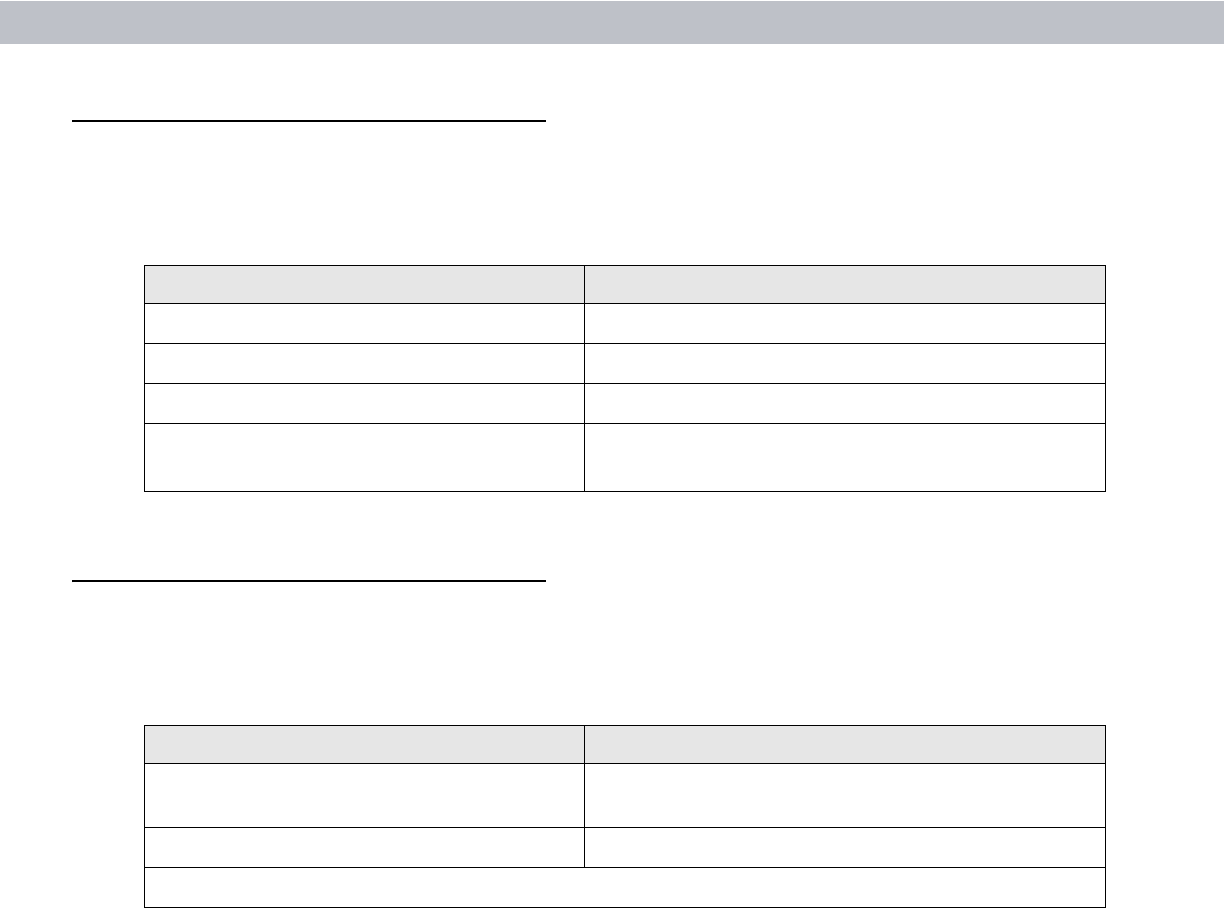
Table A-1
Technical specifications
Specification Value
Mechanical Characteristics
Dimensions 85.6mm long, by 54mm wide, by 5 mm thick
Weight TBD
Enclosure and EMI Shielding Standard frame similar to PCMCIA type II card enclosure.
Two internal EMI shields, one on each side of the board to
compartment isolate the RF and digital circuits.
Electrical Characteristics
Input Voltage regulated +5Vdc +/- 5% @1.5A peak.
Environmental Characteristics
Operating Temperature
-20°C to 65°C (RH 5% to 85%, non-condensing)
Storage Temperature -40
°
C to 70
°
C (RH 5% to 85%, non-condensing), non-operational
Thermal Shock Temperature -20
°
C to +65
°
C, 30 min dwell, 100 cycles

A - 2 MR400 RFID Reader Module, Integration Guide
Read/Write Ranges
The reader module has a read/write ranges are typical values, actual values will be effected by the reflective
and absorption properties of the reading environment.
Figure A-1
Typical Read/Write Ranges
Shock and Vibration
Shock 2000g +/- 5% applied via the mounting surfaces @ -20
°
C, 23
°
C, and
60
°
C for a period of 0.85 +/- 0.05 ms (3 axes), 6 shocks per axis
Vibration
20Hz to 2KHz, 15gs Pk Sine
Table A-1
Technical specifications (Continued)
Specification Value
TBSTTBS

Appendix A: MR400 Specifications A - 3

A - 4 MR400 RFID Reader Module, Integration Guide

Appendix A: MR400 Specifications A - 5

A - 6 MR400 RFID Reader Module, Integration Guide

Appendix B
Regulatory Information
Appendix B
Regulatory InformationRegulatory InformationMR400 RFID Reader Module, Integration Guide
Regulatory Requirements
The following sections describe the documentation and labeling requirements.
•
Regulatory Statement
•
Regulatory Standards
•
Regulatory Approvals
•
Reference Antenna
•
Reader Module Regulatory Markings
•
Final Product Compliance
•
National Country Requirements
•
Recycling
•
RoHS Compliance
Regulatory Statement
Symbol's wireless network devices are designed to be compliant with rules and regulations in locations they
are sold.
Any changes or modifications to Symbol Technologies equipment, not expressly approved by Symbol
Technologies, could void the user's authority to operate the equipment.
The MR400 has connections for External Antenna and are intended for OEM embedded applications.
The MR400 is designed to be permanently installed in an OEM product. The OEM integrator must not provide
information in the end product user guides that would provide the end user with information on how to remove
or install this RF module. Service procedures must be performed only by qualified OEM service personnel.
B - 2 MR400 RFID Reader Module, Integration Guide
Regulatory Standards
MR400 has been approved to comply with the following standards:
Regulatory Approvals
The MR400 will be approved in the following countries:
Table B-1
Development Test Interface Connector J2
Requirement Description
Electrical Safety: Certified to UL / cUL 60950-1, IEC 60950-1
RF: USA: FCC Part 15.247, 15.407, Canada: RSS-210
EMI: North America: FCC Part 15, Canada: ICES 003 Class B
SAR / MPE
(Product Operated more than 23cm from Body)
USA: FCC Part 2, FCC OET Bulletin 65 Supplement C
Canada: RSS-102
Table B-2
Country Approvals
Country Approving Agency
USA - North America Federal Communications Commission (FCC), US
Equipment Authorization
Canada Industry Canada (IC)
For countries outside USA, Canada consult your local Symbol representative

Appendix B: Regulatory Information B - 3
Reference Antenna
A reference antenna has been used during the approval process for the Reader Module. Specific details of the
reference antenna used for testing provided in the table below.
Important Regulatory Information:
Use of an antenna which the same 'type' (eg. Circular Polarized) and has a gain equal to or less that the
reference antenna can be used without recertification.
Use of an alternative antenna, different type or same type but higher gain will invalidate the FCC approval.
Under this instant the OEM integrator is responsible for re-evaluating the end product and obtaining a separate
FCC authorization.
Antenna Type: AN200:
Reader Module Regulatory Markings
Regulatory markings are applied to the Reader Module signifying it's approved for use in the following the
United States and Canada.
Please refer to the Symbol Declaration of Conformity (DoC) for details of other country markings. This is
available at http://www2.symbol.com/doc/.
Table B-3
Antenna Characteristics
Parameter Performance
Model Number AN200
Symbol Part Number ANT-71720/1 0=Right 1=Left
Frequency (MHz) 902-928MHz
Gain (dBi) 6dBi
Polarization Circular
Azimuth and Elevation Beamwidth 60 degrees nominal
Connector Type Type N Female
VSWR (Return Loss) 20dB (1.22)
Input Power 20 Watts
Dimensions 11 x 11 x 1.9 in
Weight 3 lbs

B - 4 MR400 RFID Reader Module, Integration Guide
Final Product Compliance
The MR400 is intended only for OEM integration under the following conditions:
1. The radio integration is embedded
2. The antenna must be installed such that 23 cm is maintained between the antenna and users
3. The 'Type' and 'Gain' of the antenna selected for the integration shall not exceed the figures shown in
section 1.5
As long as the 3 conditions above are met further transmitter testing will not be required.
Used outside of these conditions will trigger re-approval, Symbol advise the use of an accredited test
laboratory for advice. Be prepared, the certification process for your product may take from a few weeks to
several months.
The integrator, must determine what additional specific regulatory requirements are required of the country in
which the final product will be marketed. Final product may require non-radio frequency approvals such as
Product Safety, EMC, and SAR.

Appendix B: Regulatory Information B - 5
National Country Requirements
United States of America
The radio card is already approved under the requirements of the FCC.
End-product requirements with this module installed should include:
•
FCC Part 15 (emissions class B)
Final product markings must include:
•
This product contains an approved Radio Module
•
Model: MR400
•
FCC ID: H9PMR400
Important Notes
Co-location
The FCC approval excludes co-location with any other transmitter. If the MR400 is collated with another
transmitter (e.g. 802.11 a/b/g or Bluetooth Module), the OEM is integrator is responsible for re-evaluating the
end product and obtaining a separate FCC authorization. Symbol recommends the use of an accredited
Laboratory to carry out the necessary tasks.
Portable Use
The FCC approval of the Reader Module covers 'mobile' use. If the final product used in a manner where the
antenna is closer than 23cm from the user (portable use), the OEM is integrator is responsible for re-evaluating
the end product and obtaining a separate FCC authorization. Symbol recommends the use of an accredited
Laboratory to carry out the necessary tasks.
Canada
The radio part is already approved under the requirements of Industry Canada.
End-product requirements with this module installed should include:
•
Canadian Interference-Causing Equipment Regulations (ICES-003).
Final product markings must include:
•
This product contains an approved Radio Module
•
Model: MR400
•
IC: 1549D-MR400
B - 6 MR400 RFID Reader Module, Integration Guide
Statements required for the User Guide
The following statements are for guidance only, and must not be considered as final.
Final liability statement --- TBS.
Many on the statements are dependent on the application of the final product. Symbol recommends that the
OEM seeks the advice from an accredited test laboratory.
General Statements
Any changes or modifications not expressly approved by Symbol Technologies Inc., could void the user's
authority to operate the equipment.
RF Exposure Guidelines
Reducing RF Influence - Use Properly
It is advisable to use the device only in the normal operating position.
International
The device complies with Internationally recognized standards covering Specific Absorption Rate (SAR)
related to human exposure to electromagnetic fields from radio devices.
FCC Statements
Co-located statement
To comply with FCC RF exposure compliance requirement, the antenna used for this transmitter must not be
co-located or operating in conjunction with any other transmitter/antenna except those already approved in this
filling.
Handheld Devices
To comply with FCC RF exposure requirements, this device must be operated in the hand with a minimum
separation distance of 23 cm or more from a person's body. Other operating configurations should be avoided.
Remote and Standalone Antenna Configurations
To comply with FCC RF exposure requirements, antennas that are mounted externally at remote locations or
operating near users at stand-alone desktop of similar configurations must operate with a minimum separation
distance of 23 cm from all persons.
Radio Frequency Interference Requirements - FCC

Appendix B: Regulatory Information B - 7
•
Reorient or relocate the receiving antenna
•
Increase the separation between the equipment and receiver
•
Connect the equipment into an outlet on a circuit different from that to which the receiver is
connected
•
Consult the dealer or an experienced radio/TV technician for help.
Radio Transmitters (Part 15)
This device complies with Part 15 of the FCC Rules. Operation is subject to the following two conditions: (1)
this device may not cause harmful interference, and (2) this device must accept any interference received,
including interference that may cause undesired operation.
Industry Canada Statements
Radio Frequency Interference Requirements
This Class B digital apparatus complies with Canadian ICES-003. Cet appareil numérique de la classe B est
conforme à la norme NMB-003 du Canada.
Radio Transmitters
This device complies with RSS 210 of Industry & Science Canada. Operation is subject to the following two
conditions: (1) this device may not cause harmful interference and (2) this device must accept any interference
received, including interference that may cause undesired operation.
Label Marking: The Term "IC:" before the radio certification only signifies that Industry Canada technical
specifications were met.
Recycling
The Customer is responsible for complying with all recycling laws and regulations, including European
Directive: Waste Electrical and Electronic Equipment (WEEE). Symbol has no responsibility for collecting the
products sold to Customer.
RoHS Compliance
This product is RoHS compliant.
NOTE This equipment has been tested and found to comply with the limits for a Class B digital device, pursuant
to Part 15 of the FCC rules. These limits are designed to provide reasonable protection against harmful
interference in a residential installation. This equipment generates, uses and can radiate radio frequency energy
and, if not installed and used in accordance with the instructions, may cause harmful interference to radio
communications. However there is no guarantee that interference will not occur in a particular installation. If this
equipment does cause harmful interference to radio or television reception, which can be determined by turning
the equipment off and on, the user is encouraged to try to correct the interference by one or more of the following
measures:.

B - 8 MR400 RFID Reader Module, Integration Guide

Index
IndexIndex
B
baseband processor . . . . . . . . . . . . . . . . . . . . . . . . . 1-3
block diagram . . . . . . . . . . . . . . . . . . . . . . . . . . . . . . 1-2
bullets . . . . . . . . . . . . . . . . . . . . . . . . . . . . . . . . . . . . . . ii
C
cautions . . . . . . . . . . . . . . . . . . . . . . . . . . . . . . . . . . . . . ii
controller . . . . . . . . . . . . . . . . . . . . . . . . . . . . . . . . . . 1-2
conventions
notational . . . . . . . . . . . . . . . . . . . . . . . . . . . . . . . . ii
D
dimensions . . . . . . . . . . . . . . . . . . . . . . . . . . . . . . . . 1-5
E
EMI shielding . . . . . . . . . . . . . . . . . . . . . . . . . . . . . . 1-5
enclosure . . . . . . . . . . . . . . . . . . . . . . . . . . . . . . . . . 1-5
ESD . . . . . . . . . . . . . . . . . . . . . . . . . . . . . . . . . . . . . . 1-6
F
FCC . . . . . . . . . . . . . . . . . . . . . . . . . . . B-2, B-3, B-5, B-6
G
GEN 2 . . . . . . . . . . . . . . . . . . . . . . . . . . . . . . . . . . . . 1-1
H
humidity . . . . . . . . . . . . . . . . . . . . . . . . . . . . . . . . . . . 1-6
I
Industry Canada . . . . . . . . . . . . . . . . . . . . . . . . B-2, B-5
information, service . . . . . . . . . . . . . . . . . . . . . . . . . . . . iii
interface . . . . . . . . . . . . . . . . . . . . . . . . . . . . . . . . . . 1-3
M
mechanical characteristics . . . . . . . . . . . . . . . . . . . . . 1-5
N
notational conventions . . . . . . . . . . . . . . . . . . . . . . . . . . ii
notes . . . . . . . . . . . . . . . . . . . . . . . . . . . . . . . . . . . . . . . ii
O
operation . . . . . . . . . . . . . . . . . . . . . . . . . . . . . . . . . . 1-2
P
product regulatory compliance . . . . . . . . . . . . . . . . . . B-4
R
recycling . . . . . . . . . . . . . . . . . . . . . . . . . . . . . . . . . . . B-7
reference antenna . . . . . . . . . . . . . . . . . . . . . . . . . . . B-3
regulatory . . . . . . . . . . . . . . . . . . . . . . . . . . . . . . . . . . B-1
RoHS . . . . . . . . . . . . . . . . . . . . . . . . . . . . . . . . . . . . . B-7
S
service information . . . . . . . . . . . . . . . . . . . . . . . . . . . . iii
shock . . . . . . . . . . . . . . . . . . . . . . . . . . . . . . . . . . . . . 1-6
SMDK for C . . . . . . . . . . . . . . . . . . . . . . . . . . . . . . . . . iii
Symbol Mobility Developer Kit for C . . . . . . . . . . . . . . iii
T
temperature . . . . . . . . . . . . . . . . . . . . . . . . . . . . . . . . 1-6
theory of operation . . . . . . . . . . . . . . . . . . . . . . . . . . . 1-2
thermal . . . . . . . . . . . . . . . . . . . . . . . . . . . . . . . . . . . . 1-6
transceiver . . . . . . . . . . . . . . . . . . . . . . . . . . . . . . . . . 1-3


Symbol Technologies, Inc.
One Symbol Plaza
Holtsville, New York 11742-1300
http://www.symbol.com
72E-89971-01
Revision 1 - October 2006