Symbol Technologies RD11320 XR400 RFID Reader User Manual
Symbol Technologies Inc XR400 RFID Reader
Manual
XR400 RFID Reader
Integrator Guide


XR400 RFID Reader Integrator Guide
72-71773-01
Revision .2
April 2005

© 2005 by Symbol Technologies, Inc. All rights reserved.
No part of this publication may be reproduced or used in any form, or by any electrical or mechanical means, without permission in writing from
Symbol. This includes electronic or mechanical means, such as photocopying, recording, or information storage and retrieval systems. The material
in this manual is subject to change without notice.
The software is provided strictly on an “as is” basis. All software, including firmware, furnished to the user is on a licensed basis. Symbol grants
to the user a non-transferable and non-exclusive license to use each software or firmware program delivered hereunder (licensed program). Except
as noted below, such license may not be assigned, sublicensed, or otherwise transferred by the user without prior written consent of Symbol. No
right to copy a licensed program in whole or in part is granted, except as permitted under copyright law. The user shall not modify, merge, or
incorporate any form or portion of a licensed program with other program material, create a derivative work from a licensed program, or use a
licensed program in a network without written permission from Symbol. The user agrees to maintain Symbol’s copyright notice on the licensed
programs delivered hereunder, and to include the same on any authorized copies it makes, in whole or in part. The user agrees not to decompile,
disassemble, decode, or reverse engineer any licensed program delivered to the user or any portion thereof.
Symbol reserves the right to make changes to any software or product to improve reliability, function, or design.
Symbol does not assume any product liability arising out of, or in connection with, the application or use of any product, circuit, or application
described herein.
No license is granted, either expressly or by implication, estoppel, or otherwise under any Symbol Technologies, Inc., intellectual property rights.
An implied license only exists for equipment, circuits, and subsystems contained in Symbol products.
Symbol, Spectrum One, and Spectrum24 are registered trademarks of Symbol Technologies, Inc. Bluetooth is a registered trademark of Bluetooth
SIG. Microsoft, Windows and ActiveSync are either registered trademarks or trademarks of Microsoft Corporation. Other product names mentioned
in this manual may be trademarks or registered trademarks of their respective companies and are hereby acknowledged.
Symbol Technologies, Inc.
One Symbol Plaza
Holtsville, New York 11742-1300
http://www.symbol.com
Patents
This product is covered by one or more of the patents listed on the website: www.symbol.com/patents

Contents
About This Guide
Introduction . . . . . . . . . . . . . . . . . . . . . . . . . . . . . . . . . . . . . . . . . . . . . . . . . . . . . . . . . . . . . . . . . . . . . . . . . . . . . ix
Chapter Descriptions . . . . . . . . . . . . . . . . . . . . . . . . . . . . . . . . . . . . . . . . . . . . . . . . . . . . . . . . . . . . . . . . . . . . . . . ix
Notational Conventions . . . . . . . . . . . . . . . . . . . . . . . . . . . . . . . . . . . . . . . . . . . . . . . . . . . . . . . . . . . . . . . . . . . . . ix
Related Documents and Software . . . . . . . . . . . . . . . . . . . . . . . . . . . . . . . . . . . . . . . . . . . . . . . . . . . . . . . . . . . . . ix
Service Information . . . . . . . . . . . . . . . . . . . . . . . . . . . . . . . . . . . . . . . . . . . . . . . . . . . . . . . . . . . . . . . . . . . . . . . . x
Symbol Support Center . . . . . . . . . . . . . . . . . . . . . . . . . . . . . . . . . . . . . . . . . . . . . . . . . . . . . . . . . . . . . . . . . . . . . . . . . . . x
Chapter 1. Getting Started
Introduction . . . . . . . . . . . . . . . . . . . . . . . . . . . . . . . . . . . . . . . . . . . . . . . . . . . . . . . . . . . . . . . . . . . . . . . . . . . . 1- 3
RFID Technology. . . . . . . . . . . . . . . . . . . . . . . . . . . . . . . . . . . . . . . . . . . . . . . . . . . . . . . . . . . . . . . . . . . . . . . . . .1-3
RFID Components. . . . . . . . . . . . . . . . . . . . . . . . . . . . . . . . . . . . . . . . . . . . . . . . . . . . . . . . . . . . . . . . . . . . .1-3
The XR400 RFID Reader . . . . . . . . . . . . . . . . . . . . . . . . . . . . . . . . . . . . . . . . . . . . . . . . . . . . . . . . . . . . . . . . . . . .1-4
Multiple Connection Options . . . . . . . . . . . . . . . . . . . . . . . . . . . . . . . . . . . . . . . . . . . . . . . . . . . . . . . . . . . .1-4
Flexible Read Point Configurations . . . . . . . . . . . . . . . . . . . . . . . . . . . . . . . . . . . . . . . . . . . . . . . . . . . . . . .1-4
Configuration and Upgrading. . . . . . . . . . . . . . . . . . . . . . . . . . . . . . . . . . . . . . . . . . . . . . . . . . . . . . . . . . . .1-4
Tag Management Features . . . . . . . . . . . . . . . . . . . . . . . . . . . . . . . . . . . . . . . . . . . . . . . . . . . . . . . . . . . . .1-5
Event Management . . . . . . . . . . . . . . . . . . . . . . . . . . . . . . . . . . . . . . . . . . . . . . . . . . . . . . . . . . . . . . . . . . .1-5
Device Management . . . . . . . . . . . . . . . . . . . . . . . . . . . . . . . . . . . . . . . . . . . . . . . . . . . . . . . . . . . . . . . . . .1-5
Security Features . . . . . . . . . . . . . . . . . . . . . . . . . . . . . . . . . . . . . . . . . . . . . . . . . . . . . . . . . . . . . . . . . . . . .1-5
LED Indicators. . . . . . . . . . . . . . . . . . . . . . . . . . . . . . . . . . . . . . . . . . . . . . . . . . . . . . . . . . . . . . . . . . . . . . . . . . . .1-6
Chapter 2. Installation and Communication
XR400 Parts . . . . . . . . . . . . . . . . . . . . . . . . . . . . . . . . . . . . . . . . . . . . . . . . . . . . . . . . . . . . . . . . . . . . . . . . . . . . 2- 3
XR400 Ports . . . . . . . . . . . . . . . . . . . . . . . . . . . . . . . . . . . . . . . . . . . . . . . . . . . . . . . . . . . . . . . . . . . . . . . . . . . . .2-3

XR400 RFID Reader Integrator Guideiv
Installing the XR400 . . . . . . . . . . . . . . . . . . . . . . . . . . . . . . . . . . . . . . . . . . . . . . . . . . . . . . . . . . . . . . . . . . . . . . .2-4
Mounting Tips. . . . . . . . . . . . . . . . . . . . . . . . . . . . . . . . . . . . . . . . . . . . . . . . . . . . . . . . . . . . . . . . . . . . . . . .2-4
Mounting the XR400. . . . . . . . . . . . . . . . . . . . . . . . . . . . . . . . . . . . . . . . . . . . . . . . . . . . . . . . . . . . . . . . . . .2-4
Connecting Antennas to the XR400 . . . . . . . . . . . . . . . . . . . . . . . . . . . . . . . . . . . . . . . . . . . . . . . . . . . . . . .2-4
Portal Setup . . . . . . . . . . . . . . . . . . . . . . . . . . . . . . . . . . . . . . . . . . . . . . . . . . . . . . . . . . . . . . . . . . . . . . . . .2-5
Powering the XR400 . . . . . . . . . . . . . . . . . . . . . . . . . . . . . . . . . . . . . . . . . . . . . . . . . . . . . . . . . . . . . . . . . . .2-5
Verifying Hardware Functionality. . . . . . . . . . . . . . . . . . . . . . . . . . . . . . . . . . . . . . . . . . . . . . . . . . . . . . . . .2-5
Connecting the XR400 for Communication . . . . . . . . . . . . . . . . . . . . . . . . . . . . . . . . . . . . . . . . . . . . . . . . . . . . .2-6
Ethernet Connection . . . . . . . . . . . . . . . . . . . . . . . . . . . . . . . . . . . . . . . . . . . . . . . . . . . . . . . . . . . . . . . . . . .2-6
RS232 Connection . . . . . . . . . . . . . . . . . . . . . . . . . . . . . . . . . . . . . . . . . . . . . . . . . . . . . . . . . . . . . . . . . . . .2-6
Reading Tags . . . . . . . . . . . . . . . . . . . . . . . . . . . . . . . . . . . . . . . . . . . . . . . . . . . . . . . . . . . . . . . . . . . . . . . . . . . .2-7
Chapter 3. Administrator Console
Managing the XR400 . . . . . . . . . . . . . . . . . . . . . . . . . . . . . . . . . . . . . . . . . . . . . . . . . . . . . . . . . . . . . . . . . . . . . 3- 3
Status . . . . . . . . . . . . . . . . . . . . . . . . . . . . . . . . . . . . . . . . . . . . . . . . . . . . . . . . . . . . . . . . . . . . . . . . . . . . . . . . . .3-4
Scan Control . . . . . . . . . . . . . . . . . . . . . . . . . . . . . . . . . . . . . . . . . . . . . . . . . . . . . . . . . . . . . . . . . . . . . . . . . . . . .3-5
Scheduling a Periodic Scan Read Point . . . . . . . . . . . . . . . . . . . . . . . . . . . . . . . . . . . . . . . . . . . . . . . . . . . .3-6
Query. . . . . . . . . . . . . . . . . . . . . . . . . . . . . . . . . . . . . . . . . . . . . . . . . . . . . . . . . . . . . . . . . . . . . . . . . . . . . . . . . .3-10
Writing a Tag . . . . . . . . . . . . . . . . . . . . . . . . . . . . . . . . . . . . . . . . . . . . . . . . . . . . . . . . . . . . . . . . . . . . . . . . . . .3-12
Writing Tips . . . . . . . . . . . . . . . . . . . . . . . . . . . . . . . . . . . . . . . . . . . . . . . . . . . . . . . . . . . . . . . . . . . . . . . .3-13
Filtering. . . . . . . . . . . . . . . . . . . . . . . . . . . . . . . . . . . . . . . . . . . . . . . . . . . . . . . . . . . . . . . . . . . . . . . . . . . . . . . .3-14
Creating a Filter Rule . . . . . . . . . . . . . . . . . . . . . . . . . . . . . . . . . . . . . . . . . . . . . . . . . . . . . . . . . . . . . . . . .3-14
Read Point Classes . . . . . . . . . . . . . . . . . . . . . . . . . . . . . . . . . . . . . . . . . . . . . . . . . . . . . . . . . . . . . . . . . . . . . . .3-20
Read Point Zones . . . . . . . . . . . . . . . . . . . . . . . . . . . . . . . . . . . . . . . . . . . . . . . . . . . . . . . . . . . . . . . . . . . . . . . .3-21
Adding and modifying Read Point Zones . . . . . . . . . . . . . . . . . . . . . . . . . . . . . . . . . . . . . . . . . . . . . . . . . .3-22
Renaming, Enabling, and Disabling the Reader. . . . . . . . . . . . . . . . . . . . . . . . . . . . . . . . . . . . . . . . . . . . . . . . .3-23
Configuring Individual Read Points . . . . . . . . . . . . . . . . . . . . . . . . . . . . . . . . . . . . . . . . . . . . . . . . . . . . . .3-25
Event Notification. . . . . . . . . . . . . . . . . . . . . . . . . . . . . . . . . . . . . . . . . . . . . . . . . . . . . . . . . . . . . . . . . . . . . . . .3-26
Visibility Events . . . . . . . . . . . . . . . . . . . . . . . . . . . . . . . . . . . . . . . . . . . . . . . . . . . . . . . . . . . . . . . . . . . . .3-26
Threshold Event . . . . . . . . . . . . . . . . . . . . . . . . . . . . . . . . . . . . . . . . . . . . . . . . . . . . . . . . . . . . . . . . . . . . .3-26
Network Status Event. . . . . . . . . . . . . . . . . . . . . . . . . . . . . . . . . . . . . . . . . . . . . . . . . . . . . . . . . . . . . . . . .3-26
Exception Events. . . . . . . . . . . . . . . . . . . . . . . . . . . . . . . . . . . . . . . . . . . . . . . . . . . . . . . . . . . . . . . . . . . . .3-26
Committing / Discarding Changes . . . . . . . . . . . . . . . . . . . . . . . . . . . . . . . . . . . . . . . . . . . . . . . . . . . . . . . . . . .3-27
Managing Trusted Hosts . . . . . . . . . . . . . . . . . . . . . . . . . . . . . . . . . . . . . . . . . . . . . . . . . . . . . . . . . . . . . . . . . .3-28
Managing Users . . . . . . . . . . . . . . . . . . . . . . . . . . . . . . . . . . . . . . . . . . . . . . . . . . . . . . . . . . . . . . . . . . . . . . . . .3-29
User Maintenance . . . . . . . . . . . . . . . . . . . . . . . . . . . . . . . . . . . . . . . . . . . . . . . . . . . . . . . . . . . . . . . . . . .3-30
Chapter 4. Maintenance and Troubleshooting
Introduction. . . . . . . . . . . . . . . . . . . . . . . . . . . . . . . . . . . . . . . . . . . . . . . . . . . . . . . . . . . . . . . . . . . . . . . . . . . . . 4- 3
Reader Maintenance - Changing Communication Settings. . . . . . . . . . . . . . . . . . . . . . . . . . . . . . . . . . . . . . . . .4-3
Setting Date and Time . . . . . . . . . . . . . . . . . . . . . . . . . . . . . . . . . . . . . . . . . . . . . . . . . . . . . . . . . . . . . . . . . . . . .4-6
Getting Firmware Version Number. . . . . . . . . . . . . . . . . . . . . . . . . . . . . . . . . . . . . . . . . . . . . . . . . . . . . . . . . . . .4-7
Updating Firmware . . . . . . . . . . . . . . . . . . . . . . . . . . . . . . . . . . . . . . . . . . . . . . . . . . . . . . . . . . . . . . . . . . . . . . . .4-8
Monitoring Logs . . . . . . . . . . . . . . . . . . . . . . . . . . . . . . . . . . . . . . . . . . . . . . . . . . . . . . . . . . . . . . . . . . . . . . . . . .4-9
Backing Up the Configuration. . . . . . . . . . . . . . . . . . . . . . . . . . . . . . . . . . . . . . . . . . . . . . . . . . . . . . . . . . . . . . . .4-9
Logging Out from the Console . . . . . . . . . . . . . . . . . . . . . . . . . . . . . . . . . . . . . . . . . . . . . . . . . . . . . . . . . . . . . .4-10
Troubleshooting . . . . . . . . . . . . . . . . . . . . . . . . . . . . . . . . . . . . . . . . . . . . . . . . . . . . . . . . . . . . . . . . . . . . . . . . .4-11

Contents v
Appendix A. Specifications
Technical Specifications. . . . . . . . . . . . . . . . . . . . . . . . . . . . . . . . . . . . . . . . . . . . . . . . . . . . . . . . . . . . . . . . . . A- 3
Cable Pinouts . . . . . . . . . . . . . . . . . . . . . . . . . . . . . . . . . . . . . . . . . . . . . . . . . . . . . . . . . . . . . . . . . . . . . . . . . . . A-5
Ethernet Connections . . . . . . . . . . . . . . . . . . . . . . . . . . . . . . . . . . . . . . . . . . . . . . . . . . . . . . . . . . . . . . . . . A-5
RS232 Port Connections. . . . . . . . . . . . . . . . . . . . . . . . . . . . . . . . . . . . . . . . . . . . . . . . . . . . . . . . . . . . . . . A-5
GPIO Port Connections . . . . . . . . . . . . . . . . . . . . . . . . . . . . . . . . . . . . . . . . . . . . . . . . . . . . . . . . . . . . . . . . A-6

XR400 RFID Reader Integrator Guidevi

About This Guide
Introduction . . . . . . . . . . . . . . . . . . . . . . . . . . . . . . . . . . . . . . . . . . . . . . . . . . . . . . . . . . . . . . . . . . . . . . . . . . . . . ix
Chapter Descriptions . . . . . . . . . . . . . . . . . . . . . . . . . . . . . . . . . . . . . . . . . . . . . . . . . . . . . . . . . . . . . . . . . . . . . . . ix
Notational Conventions . . . . . . . . . . . . . . . . . . . . . . . . . . . . . . . . . . . . . . . . . . . . . . . . . . . . . . . . . . . . . . . . . . . . . ix
Related Documents and Software . . . . . . . . . . . . . . . . . . . . . . . . . . . . . . . . . . . . . . . . . . . . . . . . . . . . . . . . . . . . . ix
Service Information . . . . . . . . . . . . . . . . . . . . . . . . . . . . . . . . . . . . . . . . . . . . . . . . . . . . . . . . . . . . . . . . . . . . . . . . x
Symbol Support Center . . . . . . . . . . . . . . . . . . . . . . . . . . . . . . . . . . . . . . . . . . . . . . . . . . . . . . . . . . . . . . . . . . . . . . . . . . . x

XR400 RFID Reader Integrator Guideviii

ix
Introduction
This Integrator Guide provides information about installing, configuring, and using the XR400 RFID Reader. The XR400 is a multi-
protocol RFID reader providing real-time, seamless tag processing for all EPC-compliant tags: Class 0 (Read Only), Class 0 (Read/
Write, also known as Class 0+), and Class 1 (Read/Write).
Chapter Descriptions
Topics covered in this guide are as follows:
•Chapter 1, Getting Started provides an overview of RFID technology and components, and a description of the XR400 Reader
and its features.
•Chapter 2, Installation and Communication provides information on installing the XR400 and setting it up for communication.
•Chapter 3, Administrator Console describes how to use the web-based Administrator Console to configure and manage the
XR400 reader.
•Chapter 4, Maintenance and Troubleshooting describes how to use the reader maintenance console to perform low-level
reader maintenance tasks, and how to upgrade the reader with new firmware and FPGA versions. It also includes
troubleshooting tips.
•Appendix A, Specifications lists the hardware specifications and reader interface details.
Notational Conventions
The following conventions are used in this document:
•Italics are used to highlight the following:
• chapters and sections in this and related documents
• dialog box, window and screen names
• drop-down list and list box names
• check box and radio button names
• icons on a screen.
•Bold text is used to highlight the following:
• key names on a keypad
• button names on a screen.
• Bullets (•) indicate:
• action items
• lists of alternatives
• lists of required steps that are not necessarily sequential.
• Sequential lists (e.g., those that describe step-by-step procedures) appear as numbered lists.
Related Documents and Software
The following documents provide more information about the XR400 RFID Reader.
• XR400 Quick Reference Guide, p/n 72-71466-xx
•DC200 Portal Integrator Guide, p/n 72E-71772-01
•RFID API Programmer Guide, p/n 72E-71803-xx
•TagVis Programmer Guide, p/n 72E-71804-xx
•ReaderComm5DLL Developer Guide, p/n 72E-71805-xx

XR400 RFID Reader Integrator Guidex
For the latest version of this guide and all guides, go to: http://www.symbol.com/manuals.
Service Information
If you have a problem with the equipment, contact the Symbol Support Center for your region. See page x for contact information.
Before calling, have the model number, serial number and several bar code symbols at hand.
Call the Support Center from a phone near the scanning equipment so that the service person can try to talk you through the problem.
If the equipment is found to be working properly and the problem is symbol readability, the Support Center will request samples of
bar codes for analysis at our plant.
If the problem cannot be solved over the phone, you may need to return the equipment for servicing. If that is necessary, you will be
given specific directions.
Symbol Technologies is not responsible for any damages incurred during shipment if the approved shipping
container is not used. Shipping the units improperly can possibly void the warranty. If the original shipping
container was not kept, contact Symbol to have another sent to you.
Symbol Support Center
For service information, warranty information or technical assistance contact or call the Symbol Support Center in:
United States
Symbol Technologies, Inc.
One Symbol Plaza
Holtsville, New York 11742-1300
1-800-653-5350
Canada
Symbol Technologies Canada, Inc.
5180 Orbitor Drive
Mississauga, Ontario, Canada L4W 5L9
1-866-416-8545 (Inside Canada)
905-629-7226 (Outside Canada)
United Kingdom
Symbol Technologies
Symbol Place
Winnersh Triangle, Berkshire RG41 5TP
United Kingdom
0800 328 2424 (Inside UK)
+44 118 945 7529 (Outside UK)
Asia/Pacific
Symbol Technologies Asia, Inc. (Singapore
Branch)
230 Victoria Street #05-07/09
Bugis Junction Office Tower
Singapore 188024
Tel: +65-6796-9600
Fax: +65-6337-6488
Australia
Symbol Technologies Pty. Ltd.
432 St. Kilda Road
Melbourne, Victoria 3004
1-800-672-906 (Inside Australia)
+61-3-9866-6044 (Outside Australia)
Austria/Österreich
Symbol Technologies Austria GmbH
Prinz-Eugen Strasse 70 / 2.Haus
1040 Vienna, Austria
01-5055794-0 (Inside Austria)
+43-1-5055794-0 (Outside Austria)
Denmark/Danmark
Symbol Technologies AS
Dr. Neergaardsvej 3
2970 Hørsholm
7020-1718 (Inside Denmark)
+45-7020-1718 (Outside Denmark)
Europe/Mid-East Distributor Operations
Contact your local distributor or call
+44 118 945 7360
Finland/Suomi
Oy Symbol Technologies
Kaupintie 8 A 6
FIN-00440 Helsinki, Finland
9 5407 580 (Inside Finland)
+358 9 5407 580 (Outside Finland)
France
Symbol Technologies France
Centre d'Affaire d'Antony
3 Rue de la Renaissance
92184 Antony Cedex, France
01-40-96-52-21 (Inside France)
+33-1-40-96-52-50 (Outside France)
Germany/Deutschland
Symbol Technologies GmbH
Waldstrasse 66
D-63128 Dietzenbach, Germany
6074-49020 (Inside Germany)
+49-6074-49020 (Outside Germany)
Italy/Italia
Symbol Technologies Italia S.R.L.
Via Cristoforo Columbo, 49
20090 Trezzano S/N Navigilo
Milano, Italy
2-484441 (Inside Italy)
+39-02-484441 (Outside Italy)

xi
If you purchased your Symbol product from a Symbol Business Partner, contact that Business Partner for service.
Latin America Sales Support
2730 University Dr.
Coral Springs, FL 33065 USA
1-800-347-0178 (Inside United States)
+1-954-255-2610 (Outside United States)
954-340-9454 (Fax)
Mexico/México
Symbol Technologies Mexico Ltd.
Torre Picasso
Boulevard Manuel Avila Camacho No 88
Lomas de Chapultepec CP 11000
Mexico City, DF, Mexico
5-520-1835 (Inside Mexico)
+52-5-520-1835 (Outside Mexico)
Netherlands/Nederland
Symbol Technologies
Kerkplein 2, 7051 CX
Postbus 24 7050 AA
Varsseveld, Netherlands
315-271700 (Inside Netherlands)
+31-315-271700 (Outside Netherlands)
Norway/Norge
Symbol’s registered and mailing address:
Symbol Technologies Norway
Hoybratenveien 35 C
N-1055 OSLO, Norway
Symbol’s repair depot and shipping address:
Symbol Technologies Norway
Enebakkveien 123
N-0680 OSLO, Norway
+47 2232 4375
South Africa
Symbol Technologies Africa Inc.
Block B2
Rutherford Estate
1 Scott Street
Waverly 2090 Johannesburg
Republic of South Africa
11-809 5311 (Inside South Africa)
+27-11-809 5311 (Outside South Africa)
Spain/España
Symbol Technologies S.L.
Avenida de Bruselas, 22
Edificio Sauce
Alcobendas, Madrid 28108
Spain
91 324 40 00 (Inside Spain)
+34 91 324 40 00 (Outside Spain)
Fax: +34.91.324.4010
Sweden/Sverige
“Letter” address:
Symbol Technologies AB
Box 1354
S-171 26 SOLNA
Sweden
Visit/shipping address:
Symbol Technologies AB
Solna Strandväg 78
S-171 54 SOLNA
Sweden
Switchboard: 08 445 29 00 (domestic)
Call Center: +46 8 445 29 29 (international)
Support E-Mail:
Sweden.Support@se.symbol.com

XR400 RFID Reader Integrator Guidexii

Getting Started
Introduction . . . . . . . . . . . . . . . . . . . . . . . . . . . . . . . . . . . . . . . . . . . . . . . . . . . . . . . . . . . . . . . . . . . . . . . . . . . . 1- 3
RFID Technology. . . . . . . . . . . . . . . . . . . . . . . . . . . . . . . . . . . . . . . . . . . . . . . . . . . . . . . . . . . . . . . . . . . . . . . . . .1-3
RFID Components. . . . . . . . . . . . . . . . . . . . . . . . . . . . . . . . . . . . . . . . . . . . . . . . . . . . . . . . . . . . . . . . . . . . .1-3
The XR400 RFID Reader . . . . . . . . . . . . . . . . . . . . . . . . . . . . . . . . . . . . . . . . . . . . . . . . . . . . . . . . . . . . . . . . . . . .1-4
Multiple Connection Options . . . . . . . . . . . . . . . . . . . . . . . . . . . . . . . . . . . . . . . . . . . . . . . . . . . . . . . . . . . .1-4
Flexible Read Point Configurations . . . . . . . . . . . . . . . . . . . . . . . . . . . . . . . . . . . . . . . . . . . . . . . . . . . . . . .1-4
Configuration and Upgrading. . . . . . . . . . . . . . . . . . . . . . . . . . . . . . . . . . . . . . . . . . . . . . . . . . . . . . . . . . . .1-4
Tag Management Features . . . . . . . . . . . . . . . . . . . . . . . . . . . . . . . . . . . . . . . . . . . . . . . . . . . . . . . . . . . . .1-5
Event Management . . . . . . . . . . . . . . . . . . . . . . . . . . . . . . . . . . . . . . . . . . . . . . . . . . . . . . . . . . . . . . . . . . .1-5
Device Management . . . . . . . . . . . . . . . . . . . . . . . . . . . . . . . . . . . . . . . . . . . . . . . . . . . . . . . . . . . . . . . . . .1-5
Security Features . . . . . . . . . . . . . . . . . . . . . . . . . . . . . . . . . . . . . . . . . . . . . . . . . . . . . . . . . . . . . . . . . . . . .1-5
LED Indicators. . . . . . . . . . . . . . . . . . . . . . . . . . . . . . . . . . . . . . . . . . . . . . . . . . . . . . . . . . . . . . . . . . . . . . . . . . . .1-6

XR400 RFID Reader Integrator Guide1-2
Getting Started 1-3
Introduction
The XR400 is a ready-to-connect network element that offers a variety of options for connecting to corporate networks via Ethernet
or serial connections. A Setup Wizard facilitates reader configuration.
RFID Technology
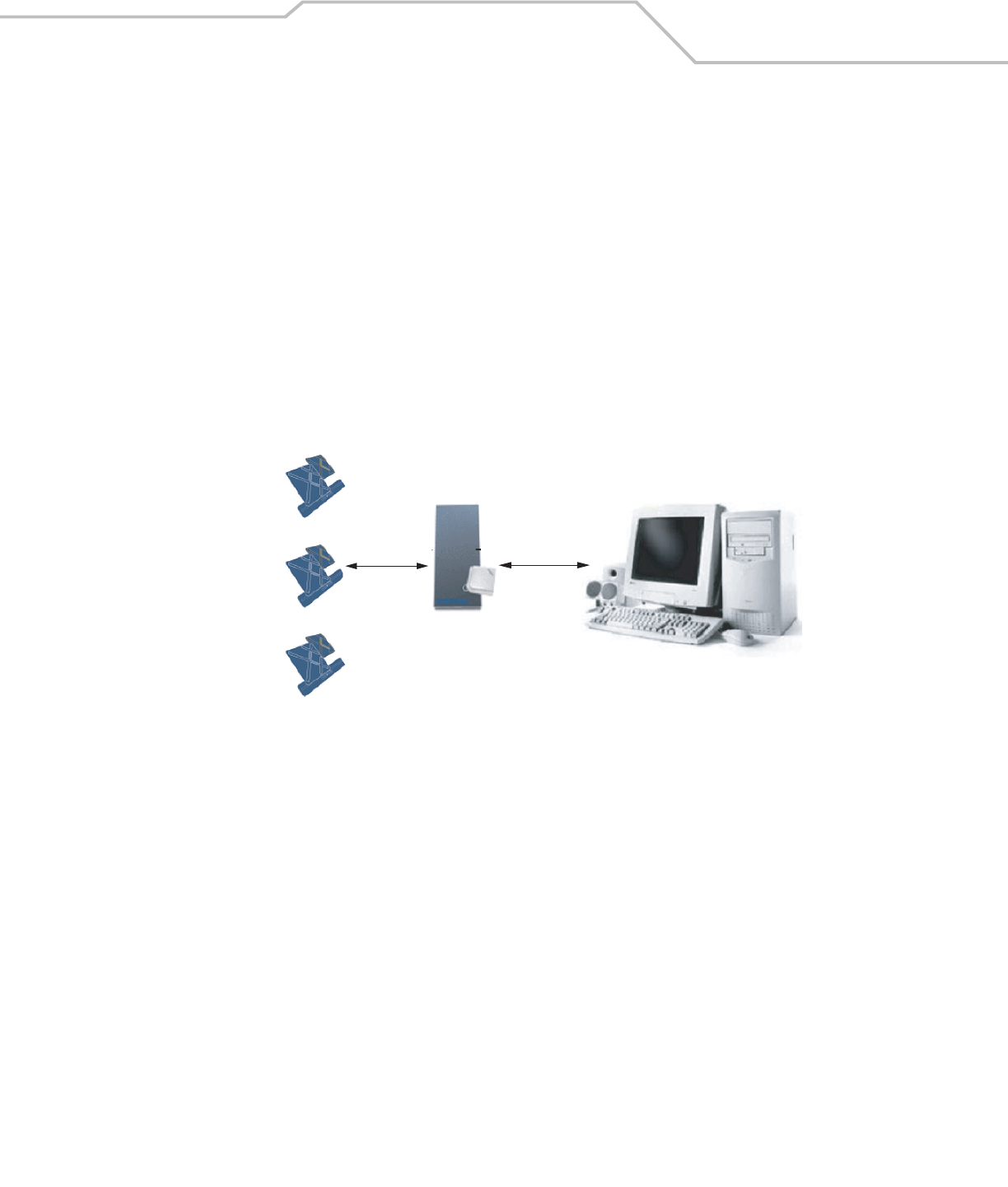
Radio Frequency Identification (RFID) is an advanced automatic identification (Auto ID) technology that uses radio frequency signals
to identify “tagged” items. A typical RFID system consists of transponders called tags, readers, and antennas, which function as
follows:
• An RFID tag contains a chip that can store a limited amount of data. This data may be pre-encoded or can be encoded in the
field. Tags come in a variety of shapes and sizes.
• A reader sends out radio frequency waves using attached antennas. This RF field powers and charges the tags, which are
tuned to receive radio waves. The tags use this power to transmit data back to the reader, which the reader converts to a
format for computer storage. The computer application translates the data into an understandable format.
Figure 1-1. RFID System Elements
RFID Components
Symbol’s Radio Frequency Identification (RFID) solutions offer low cost, long read range, and a very high read rate, providing real-
time, end-to-end visibility of products and assets in the factory, distribution center, retail outlet, or other facility. A typical Symbol
RFID system consists of the following components:
• Silicon-based RFID tags that can be attached to vehicles, trailers, containers, pallets, boxes, etc.
• Different types of antennas to support applications such as dock door (area antennas), conveyor and, in the future, Smart
Shelf (Shelf Antennas)
• Readers that power and communicate with the tags for data capture and provide host connectivity for data migration.
Tags
Tags contain embedded chips that store information unique to the objects to which they are applied. Available in various shapes and
sizes, tags, often called transponders, receive and respond to requests for their data. Tags require power to send data, and are
available with two power options:
• Active Tags: typically powered by light-weight batteries and have limited life.
• Passive Tags: powered by the reader’s RF field. Passive tags are much lighter, less expensive, and have a much longer life
than active tags.
Tags
Reader &
Antenna Host Computer
RF Wave
and
Response
Physical/Network
Connection
XR400 RFID Reader Integrator Guide1-4
Antennas
Antennas transmit and receive radio frequency signals under the control of a reader. Antennas do not perform processing. A read
point is the RF range of an antenna.
Readers
Readers are devices that provide a means for communicating with the tags and transferring their data to a host computer. Readers
also provide features such as filtering, parity checks, and tag writing.
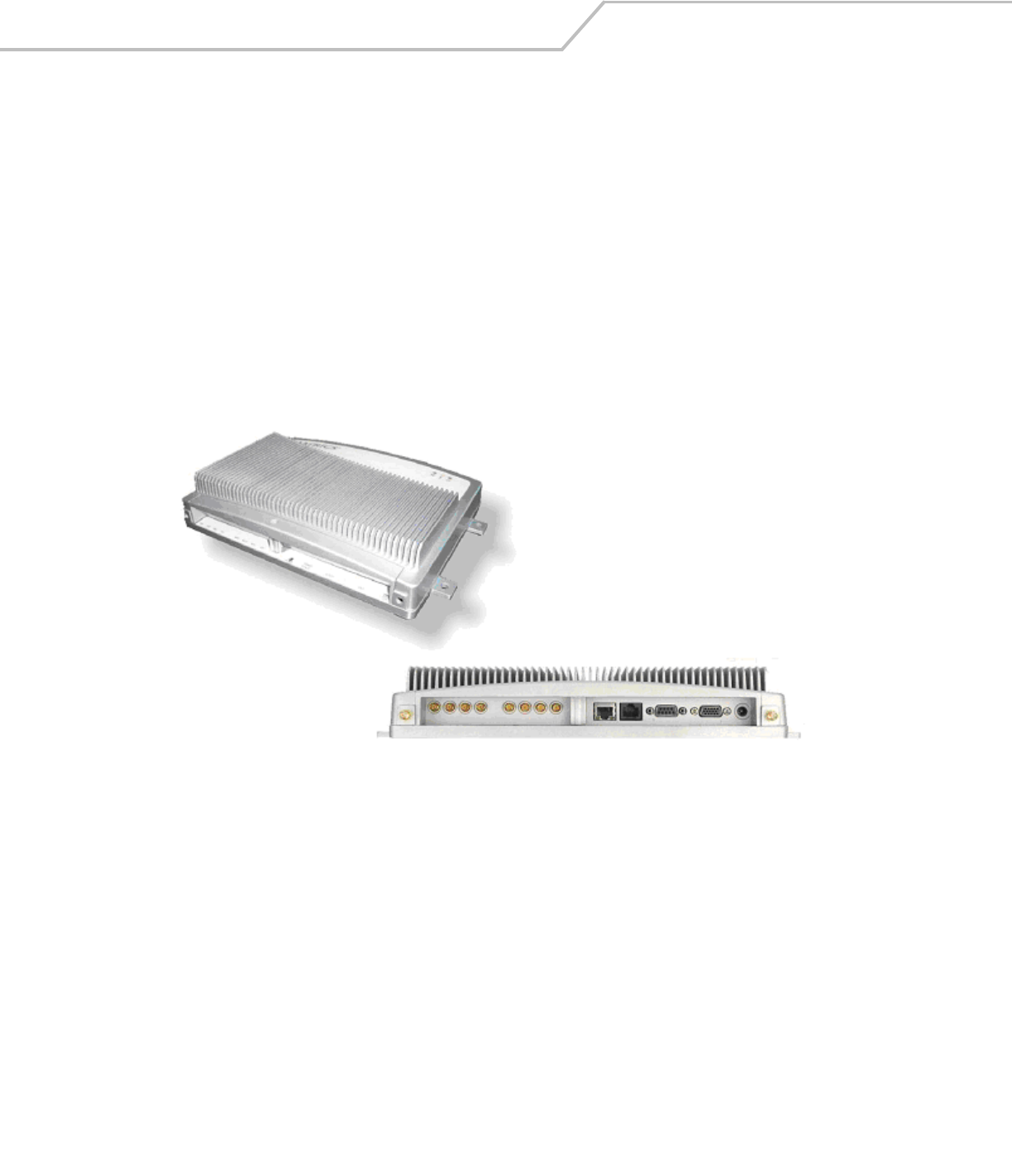
The XR400 RFID Reader
The Symbol XR400 is an intelligent, multi-protocol reader that provides real-time, seamless tag processing for all EPC-compliant tags:
Class 0 (Read Only), Class 0 (Read/Write, also known as Class 0+), and Class 1 (Read/Write). Class 0 and Class 1 protocols are run in
the Ultra-High Frequency range (~900MHz).
The XR400 offers a variety of options for connecting to corporate networks via Ethernet or serial connection. A Setup Wizard
simplifies configuration.
Figure 1-2. XR400, Top and Side Views
The XR400 provides a wide range of features that enable implementation of complete, high-performance, and intelligent RFID
solutions.
Multiple Connection Options
The XR400 provides flexibility for connecting to networks via Ethernet or serial connection. Because each XR400 is identified by its
unique IP address, it is accessible from anywhere on the network. The XR400 can also be configured to obtain its IP Address from a
DHCP server, automating the IP address and default Gateway configurations.
Flexible Read Point Configurations
Connect up to eight antennas (four transmit and four receive) to a single XR400. This decreases the per-read-point cost. Logically
combine antennas to create a single, “wide” read point with a much greater range than that of a single antenna.
Configuration and Upgrading
The XR400 is easy to reconfigure for an application via the Setup Wizard. The XR400 can also accept new firmware and configuration
under host control.

Getting Started 1-5
Tag Management Features
Ad Hoc Querying
Use ad hoc querying to send a query about tag visibility. The XR400 replies with either “Tag(s) Visible,” “Not Known” (never seen or
imported), or “Not Visible” (previously seen but now missing, with last seen timestamp).
Tag Filtering
Use tag filtering to apply filters during read operations. A filter can include or exclude a tag based on the specified bit pattern. The
XR400 offers two types of filtering:
• Pre-Processing: The XR400 restricts its ability to read tags as directed by the include or exclude filtering specification.
• Post Processing: The XR400 reads all tags it sees, and applies its filters before it reports these tags to the host computer.
Tag List
Use the tag list feature to send information about tags from the host to the reader. The host can purge the tag list to remove this
information from the reader when it’s not needed.
Event Management
Event Notification
Use event notification to receive notification about certain events. For example, receive immediate notification of a tag visibility
change, or bundle all notifications and receive them later.
Exception Notification and Heart Beat Notification
The XR400 supports sending exception notifications via SNMP. The "heart beat" notification feature sends periodic messages that
indicate whether or not the reader is functional.
Device Management
Quick Backup and Recovery
To back up and restore reader configuration, use any Web browser to download the configuration XML file, then download the file to
the reader using the Reader Administrator console.
SNMP Integration
The XR400 can send real-time notification of specific events and failures to the SNMP server.
Security Features
Trusted Hosts
The XR400 allows specifying the IP addresses of hosts that are allowed to connect to the reader. Use this security feature to prevent
unauthorized network hosts from communicating with the reader.
User Level Security
The XR400 recognizes three access levels to assign to users:
•View - view reader configuration settings.
•Edit - view and edit configuration settings.
•Maintenance - view and edit configuration settings, and perform administrative tasks such as updating reader firmware.

XR400 RFID Reader Integrator Guide1-6
Use this feature to assign different access levels to users, allowing them to perform necessary tasks without compromising security.
Logging
The XR400 keeps a log of all system-related activities for security and troubleshooting. Use the log, which includes time-stamped
system activities such as good and bad tag reads, login attempts, hardware failures, and other events, to pinpoint problems to
facilitate quick resolution, and to identify administrators who require additional training to prevent future problems.
LED Indicators
The XR400 LEDs indicate reader status as described in Table 1-1.
Table 1-1.
LED Description
Green Reader is powered on
Red Error condition or non-operational mode, e.g., boot-up
Yellow Successful tag read

Installation and Communication
XR400 Parts . . . . . . . . . . . . . . . . . . . . . . . . . . . . . . . . . . . . . . . . . . . . . . . . . . . . . . . . . . . . . . . . . . . . . . . . . . . . 2- 3
XR400 Ports . . . . . . . . . . . . . . . . . . . . . . . . . . . . . . . . . . . . . . . . . . . . . . . . . . . . . . . . . . . . . . . . . . . . . . . . . . . . .2-3
Installing the XR400 . . . . . . . . . . . . . . . . . . . . . . . . . . . . . . . . . . . . . . . . . . . . . . . . . . . . . . . . . . . . . . . . . . . . . . .2-4
Mounting Tips . . . . . . . . . . . . . . . . . . . . . . . . . . . . . . . . . . . . . . . . . . . . . . . . . . . . . . . . . . . . . . . . . . . . . . .2-4
Mounting the XR400 . . . . . . . . . . . . . . . . . . . . . . . . . . . . . . . . . . . . . . . . . . . . . . . . . . . . . . . . . . . . . . . . . .2-4
Connecting Antennas to the XR400. . . . . . . . . . . . . . . . . . . . . . . . . . . . . . . . . . . . . . . . . . . . . . . . . . . . . . .2-4
Portal Setup . . . . . . . . . . . . . . . . . . . . . . . . . . . . . . . . . . . . . . . . . . . . . . . . . . . . . . . . . . . . . . . . . . . . . . . . .2-5
Powering the XR400. . . . . . . . . . . . . . . . . . . . . . . . . . . . . . . . . . . . . . . . . . . . . . . . . . . . . . . . . . . . . . . . . . .2-5
Verifying Hardware Functionality . . . . . . . . . . . . . . . . . . . . . . . . . . . . . . . . . . . . . . . . . . . . . . . . . . . . . . . .2-5
Connecting the XR400 for Communication . . . . . . . . . . . . . . . . . . . . . . . . . . . . . . . . . . . . . . . . . . . . . . . . . . . . .2-6
Ethernet Connection. . . . . . . . . . . . . . . . . . . . . . . . . . . . . . . . . . . . . . . . . . . . . . . . . . . . . . . . . . . . . . . . . . .2-6
RS232 Connection . . . . . . . . . . . . . . . . . . . . . . . . . . . . . . . . . . . . . . . . . . . . . . . . . . . . . . . . . . . . . . . . . . . .2-6
Reading Tags . . . . . . . . . . . . . . . . . . . . . . . . . . . . . . . . . . . . . . . . . . . . . . . . . . . . . . . . . . . . . . . . . . . . . . . . . . . .2-7

XR400 RFID Reader Integrator Guide2-2
Installation and Communication 2-3
XR400 Parts
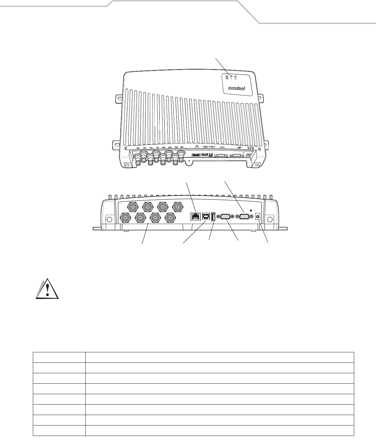
Figure 2-1. XR400 Parts
Use only the parts provided with the XR400 reader or recommended by Symbol. Substituting other cables or
parts can degrade system performance, damage the reader, and/or void the warranty.
XR400 Ports
The following table lists the ports available on the XR400.
Table 2-1. XR400 Port Descriptions
Port Description
Antenna/Read Points Connect up to eight antennas (four transmit, four receive)
10/100BaseT Ethernet Insert an RJ45 Ethernet cable for connection to an Ethernet network or an Ethernet card on a host PC.
USB Client Insert a USB cable for USB client connection to a host device.
USB Host Insert a USB cable for USB host connection to a client device.
GPIO Insert a DB15 serial cable for connection to the DC200 Portal. The XR400 controls the DC200 LEDs and motion sensor.
RS232 Insert a DB9 serial cable for RS232 connection to a host PC.
Power Connect a 24 V 1.2 A power supply. The power supply’s DC connector connects to an AC adapter that varies depending on the country.
Antenna/Read Points USB Client
10/100BaseT Ethernet
GPIO
RS232
Power
LEDs
USB Host
CAUTION
XR400 RFID Reader Integrator Guide2-4
Installing the XR400
Mounting Tips
Consider the following before selecting a location for the XR400 Reader:
• Mount the XR400 indoors, in operating range, and out of direct sunlight, high moisture, or extreme temperatures.
• Mount the XR400 in an area free from electromagnetic interference. Sources of interference include generators, pumps,
converters, non-interruptible power supplies, AC switching relays, light dimmers, and computer CRT terminals.
• Mount the XR400 within 15 feet of the antennas.
• Ensure the XR400’s power cord can reach the power source outlet.
• Mount the XR400 onto a permanent fixture, such as a wall or a shelf, where it won't be disturbed, bumped, or damaged.
Allow a minimum of five inches of clearance on all sides of the XR400.
When installing the antenna, ensure a minimum separation distance of 23 cm between the antenna
and human beings.
Mounting the XR400
1. Position the XR400 on the wall or shelf, ensuring five inches of clearance on all sides of the XR400.
2. Using the pre-drilled holes at the corners of the XR400 as a guide, drill four holes in the wall or shelf for mounting the reader.
For mounting dimensions, see Table A-1 on page A-3.
3. Secure the XR400 to the wall or shelf using four 1-inch long #10 screws.
Connecting Antennas to the XR400
Power off the XR400 before connecting the antennas. Never disconnect the antennas while the XR400 is
powered on or reading tags (when the yellow LED is lit). Doing so can damage the reader.
Do not turn on the antenna ports from a host to which antennas are not connected.
1. Attach the N-Male plug (large end) of an antenna connector cable to antenna 1.
2. Attach the DIN 1.0/2.3 jack connectors (small ends) of the cable to the TX1 and RX1 connectors on the XR400.
3. Secure the cable using wire ties. Do not bend the cable.
Repeat these steps to connect antenna 2 to Tx2/Rx2, antenna 3 to TX3/RX3, and antenna 4 to TX4/RX4.
WARNING
CAUTION
Installation and Communication 2-5
Portal Setup
In portal situations such as dock doors, ensure the TX from one side of the portal faces the TX of the opposing antenna. Similarly,
ensure the respective RXs face each other, as shown in Figure 2-2.
Figure 2-2. Portal Alignment
Powering the XR400
Connect the antennas before supplying power to the XR400.
To power on (and off) the XR400:
1. Connect the 24 VDC power supply (provided) to the XR400’s unit power port.
2. Plug the power supply into a 24 V power outlet. The green Power LED on the XR400 lights to indicate the device is powered
on.
3. To power off the XR400, unplug the power supply from the power outlet. The green Power LED turns off to indicate that the
device is powered off and the system is not operational.
Verifying Hardware Functionality
Power On Test
The red Error LED lights when power is supplied to the XR400, then turns off. The green Power LED lights when the reader completes
power-up and is operational.
Read Test
After the XR400 powers up, test the read range to verify that it meets requirements.
1. Enable polling using the Web-based XR400 Administrator Console. See Scan Control on page 3-5.
2. Control the XR400 through a real-time application such as TagVis. Refer to the TagVis User Guide.
3. Present a tag so it is facing the antenna.
4. Walk slowly toward the antenna until the XR400 lights the yellow Read LED to indicate that it detected and read the tag.
The distance between the tag and the antenna is the approximate read range.
For optimal read results, do not hold the tag at an angle or wave the tag, as this can cause the read distance
to vary.
TX1
RX1
TX2
RX2
CAUTION
Note

XR400 RFID Reader Integrator Guide2-6
Connecting the XR400 for Communication
Connect the XR400 to a host or network via Ethernet, RS232, RS422, or USB Client.
Ethernet Connection
The XR400 communicates to the host via a 10/100Base-T Ethernet cable and receives power via a Symbol AC power supply. Ethernet
connection allows access to the XR400’s Administrator Console, used to change reader settings.
To connect the XR400 via Ethernet:
1. Connect the RJ45 Ethernet cable to the wired Ethernet port on the XR400. See Figure 2-1 on page 2-3. Ensure the Ethernet
cable is terminated according to Table A-2 on page A-5.
2. Plug the other end of the Ethernet cable into the host system’s LAN port.
If not connecting to an Ethernet network, connect one end of an Ethernet crossover cable (not provided) to the Ethernet card
on the computer, and the other end to the TCP/IP port on the XR400.
3. On a networked computer, open an Internet browser and enter the IP address of the XR400 (the default IP address of the
XR400 is 192.168.127.254).
4. Log in to the XR400 Administrator Console. If desired, change settings for the XR400, such as the IP address. See Chapter
3, Administrator Console.
RS232 Connection
Serial communication allows accessing the reader’s Administrator Console using terminal software in order to change reader
settings. Use this method of administration rather than the Web-based method in the following situations:
• When the IP address of the reader is unknown.
• When the reader obtains IP address via DHCP but you need to know the IP address.
• When crossover cables are not available and you need to change the IP address of the reader as per the network's
addressing scheme.
• Other situations when reader administration is necessary without connecting to the Web-based Administrator Console.
• The Web-based Administrator Console is disabled.
To connect the XR400 via RS232:
1. Connect an DB9 serial cable to the XR400’s RS232 port. See Figure 2-1 on page 2-3. Ensure the cable is terminated according
to Table A-3 on page A-5.
2. Plug the other end of the cable into the host computer.
3. On the host computer, launch a terminal emulation program (such as HyperTerminal) and configure it as follows:
• Terminal Type: VT-100
• Port: COM 1-4 (depending on the COM port used)
• Terminal Settings:
38400 bps transfer rate
8 data bits
no parity
1 stop bit
no flow control
no hardware compression
4. After establishing a connection with the XR400, type AdvancedReaderConsole on the host computer and press Enter.

Installation and Communication 2-7
5. Enter admin as the username and change as the password. These are the default settings. You cannot change the password
from the serial console. To change the password (or create a new user account) use the Web-based Administrator Console.
The host displays the Current Configuration menu:
Current Configuration:
Serial Number : redacted
MAC Address : redacted
1 -- DHCP : ON
2 -- IP Address : 192.168.127.254
3 -- IP Port : 3000
4 -- Network Mask : 255.255.255.0
5 -- Gateway : 192.168.1.1
6 -- DNS Host : 192.168.1.1
7 -- HTTP Server is : ON
8 -- HTTP Port is : 80
9 -- Telnet Server : Enabled
10 -- FTP Server : Enabled
11 -- Watchdog : Disabled
12 -- Trusted Hosts Only : OFF
13 -- Commit Change
14 -- Discard Change
15 -- Exit
16 -- Reboot
17 -- Show system log
18 -- Trace system log : OFF
Select the menu number to change the item value:
6. To change a setting, enter the menu number, press Enter, then enter the new configuration value. For example, to change
the IP address, enter 2 to select IP Address, then press Enter. Enter a new IP address value.
7. Enter 9, then press Enter, to apply the change.
Reading Tags
To read tags while communicating with the host serially, connect the XR400’s RS-422/485 interface to a serial port on the host
computer. Symbol provides an RS485-to-USB SeaLevel converter box and cable which connects the reader to the host's USB port for
serial communication.
To connect the reader to a host computer and read tags in real time, connect through TCP/IP and use a real-time application such as
TagVis. Refer to the TagVis Developer Guide, or the user guide provided with the application.

XR400 RFID Reader Integrator Guide2-8

Administrator Console
Managing the XR400 . . . . . . . . . . . . . . . . . . . . . . . . . . . . . . . . . . . . . . . . . . . . . . . . . . . . . . . . . . . . . . . . . . . . . 3- 3
Status . . . . . . . . . . . . . . . . . . . . . . . . . . . . . . . . . . . . . . . . . . . . . . . . . . . . . . . . . . . . . . . . . . . . . . . . . . . . . . . . . .3-4
Scan Control . . . . . . . . . . . . . . . . . . . . . . . . . . . . . . . . . . . . . . . . . . . . . . . . . . . . . . . . . . . . . . . . . . . . . . . . . . . . .3-5
Scheduling a Periodic Scan Read Point . . . . . . . . . . . . . . . . . . . . . . . . . . . . . . . . . . . . . . . . . . . . . . . . . . . .3-6
Query . . . . . . . . . . . . . . . . . . . . . . . . . . . . . . . . . . . . . . . . . . . . . . . . . . . . . . . . . . . . . . . . . . . . . . . . . . . . . . . . .3-10
Writing a Tag . . . . . . . . . . . . . . . . . . . . . . . . . . . . . . . . . . . . . . . . . . . . . . . . . . . . . . . . . . . . . . . . . . . . . . . . . . .3-12
Writing Tips . . . . . . . . . . . . . . . . . . . . . . . . . . . . . . . . . . . . . . . . . . . . . . . . . . . . . . . . . . . . . . . . . . . . . . . .3-13
Filtering. . . . . . . . . . . . . . . . . . . . . . . . . . . . . . . . . . . . . . . . . . . . . . . . . . . . . . . . . . . . . . . . . . . . . . . . . . . . . . . .3-14
Creating a Filter Rule . . . . . . . . . . . . . . . . . . . . . . . . . . . . . . . . . . . . . . . . . . . . . . . . . . . . . . . . . . . . . . . . .3-14
Read Point Classes. . . . . . . . . . . . . . . . . . . . . . . . . . . . . . . . . . . . . . . . . . . . . . . . . . . . . . . . . . . . . . . . . . . . . . .3-20
Read Point Zones . . . . . . . . . . . . . . . . . . . . . . . . . . . . . . . . . . . . . . . . . . . . . . . . . . . . . . . . . . . . . . . . . . . . . . . .3-21
Adding and modifying Read Point Zones. . . . . . . . . . . . . . . . . . . . . . . . . . . . . . . . . . . . . . . . . . . . . . . . . .3-22
Renaming, Enabling, and Disabling the Reader. . . . . . . . . . . . . . . . . . . . . . . . . . . . . . . . . . . . . . . . . . . . . . . . .3-23
Configuring Individual Read Points . . . . . . . . . . . . . . . . . . . . . . . . . . . . . . . . . . . . . . . . . . . . . . . . . . . . . .3-25
Event Notification. . . . . . . . . . . . . . . . . . . . . . . . . . . . . . . . . . . . . . . . . . . . . . . . . . . . . . . . . . . . . . . . . . . . . . . .3-26
Visibility Events . . . . . . . . . . . . . . . . . . . . . . . . . . . . . . . . . . . . . . . . . . . . . . . . . . . . . . . . . . . . . . . . . . . . .3-26
Threshold Event . . . . . . . . . . . . . . . . . . . . . . . . . . . . . . . . . . . . . . . . . . . . . . . . . . . . . . . . . . . . . . . . . . . . .3-26
Network Status Event . . . . . . . . . . . . . . . . . . . . . . . . . . . . . . . . . . . . . . . . . . . . . . . . . . . . . . . . . . . . . . . .3-26
Exception Events . . . . . . . . . . . . . . . . . . . . . . . . . . . . . . . . . . . . . . . . . . . . . . . . . . . . . . . . . . . . . . . . . . . .3-26
Committing / Discarding Changes . . . . . . . . . . . . . . . . . . . . . . . . . . . . . . . . . . . . . . . . . . . . . . . . . . . . . . . . . . .3-27
Managing Trusted Hosts . . . . . . . . . . . . . . . . . . . . . . . . . . . . . . . . . . . . . . . . . . . . . . . . . . . . . . . . . . . . . . . . . .3-28
Managing Users . . . . . . . . . . . . . . . . . . . . . . . . . . . . . . . . . . . . . . . . . . . . . . . . . . . . . . . . . . . . . . . . . . . . . . . . .3-29
User Maintenance . . . . . . . . . . . . . . . . . . . . . . . . . . . . . . . . . . . . . . . . . . . . . . . . . . . . . . . . . . . . . . . . . . .3-30

XR400 RFID Reader Integrator Guide3-2
Administrator Console 3-3
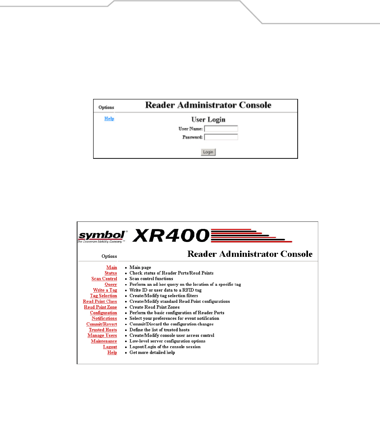
Managing the XR400
The XR400 includes a Reader Administrator Console used to manage and configure the reader. Use a Web browser on a host PC to
access the XR400’s Administrator Console.
1. To access the Administrator Console, enter the IP address of the XR400 in a web browser. The Console’s login window
appears.
Figure 3-1. Console Login
2. If this is the first visit to the Console, enter the username admin and the password change. A second window prompts to
change the password. Enter and confirm the new password, then click Change. Use this new password for subsequent visits
to the Console.
The Console’s main menu window appears.
Figure 3-2. Console Main Menu
XR400 RFID Reader Integrator Guide3-4
Status
Click Status on the Console main menu to view the Reader Status window, which displays information about read points and the
XR400’s kernel.
Figure 3-3. Reader Status Window
Table 3-1 describes the elements in the Reader Status window.
Table 3-1. Reader Status Window Elements
Item Value Format Description
Reader and Read Points
Total Number Number of readers connected. Since a single reader is connected to the
Administrator Console, this number is always 1
Enabled Number Total number of readers enabled for reading. Since a single reader is connected to
the Administrator Console, this number is always 1 or 0 (if the reader is disabled).
User Disabled Number Number of user-disabled readers / read points. This value is always 1 or 0.
For information on how to disable readers, see Renaming, Enabling, and Disabling
the Reader on page 3-23.
System Disabled Number Number of system-disabled readers / read point. If a device becomes non-
operational, the system disables it, but allows other system components to
continue to operate. This value is always 1 or 0.
Parent Disabled Number Devices dependent on a non-operational parent device are marked Parent
Disabled. For example, when a reader is system-disabled, its read points are
marked parent disabled.
Administrator Console 3-5
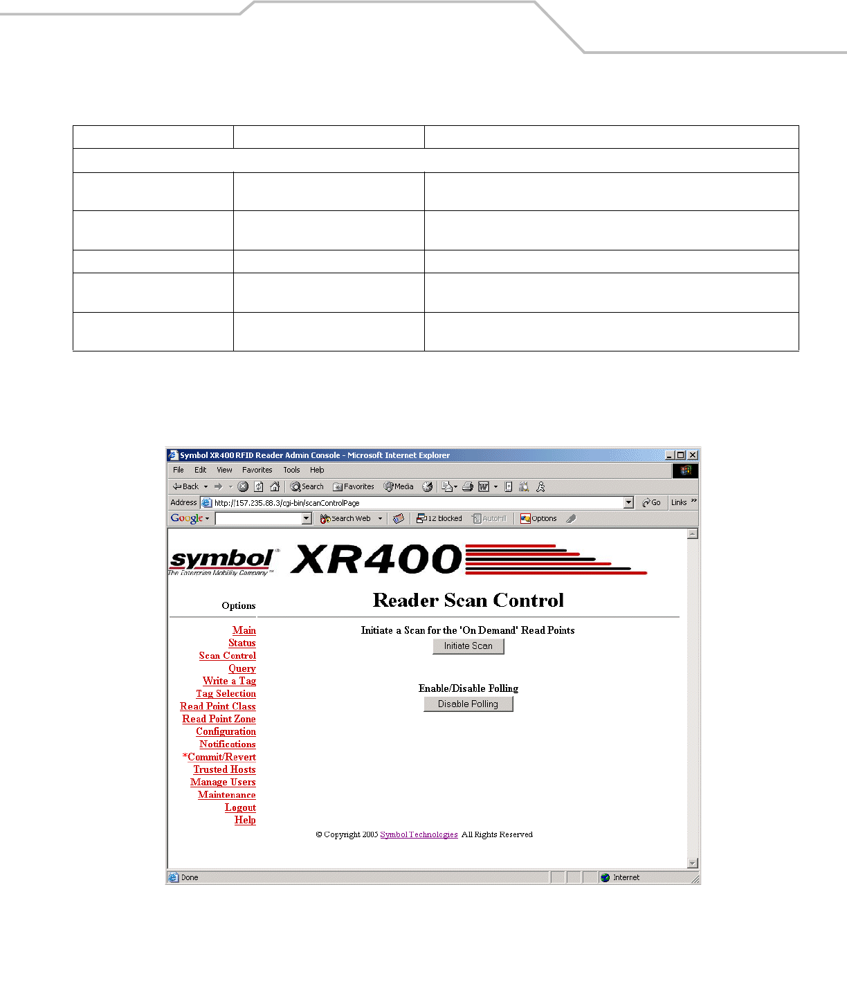
Scan Control
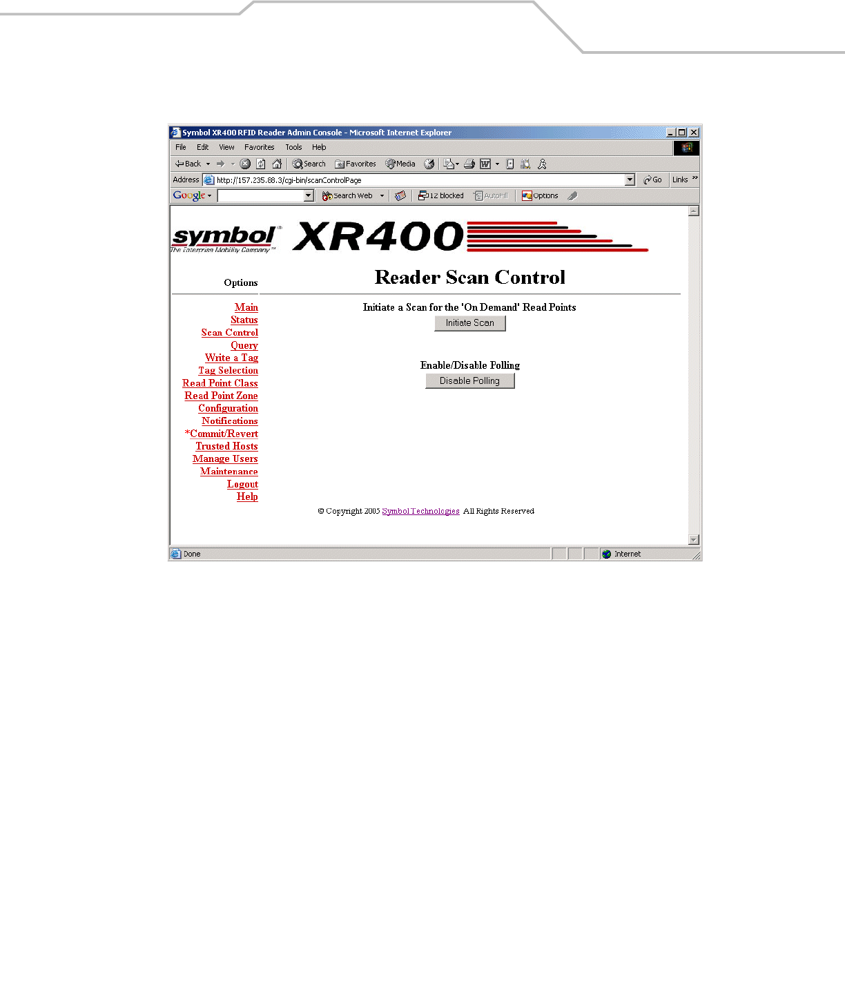
Click Scan Control on the Console main menu to view the Scan Control window, which allows initiating an on-demand scan and
enabling / disabling polled read points. For periodic read points, the window displays when the next scan is scheduled.
Figure 3-4. Scan Control Window
To initiate a scan for on-demand read points click Initiate Scan.
To enable or disable polling for polled read points click Enable Polling or Disable Polling.
Reader Information
System Clock “[Weekday] [Month] [Day of the Month]
[Hour:Minute:Second] [Year]
Time of the reader system clock. Click on this to change the time of the reader
system clock.
System Up Time “[Number of Day] [Number of Hour]
[Number of Minute] [Number of Second]
The length of time that the reader has been running.
Memory Usage Number of bytes Total amount of device memory, and amount of memory in use and available.
Flash Usage Number of bytes Total amount of flash memory, and amount of memory in use and available. Also
broken down by flash partitions (application, platform, and data).
Automatic Enable Period Minutes After the specified number of minutes the system attempts to enable any degraded
device that was system-disabled.
Table 3-1. Reader Status Window Elements (Continued)
Item Value Format Description
XR400 RFID Reader Integrator Guide3-6
Scheduling a Periodic Scan Read Point
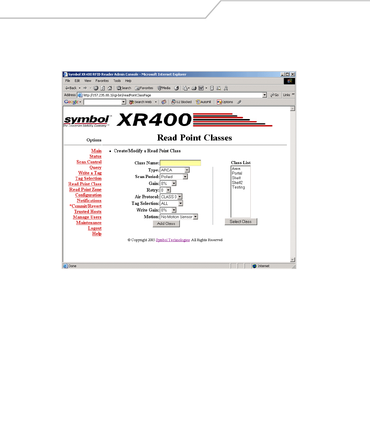
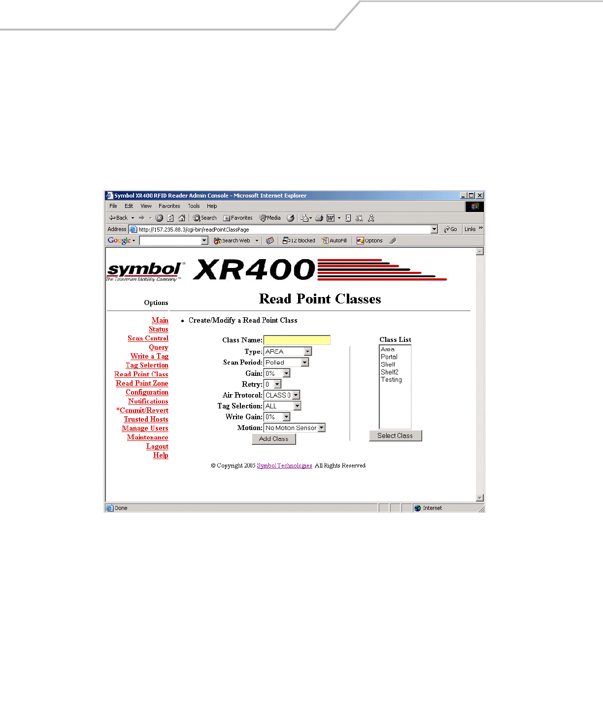
To schedule a periodic scan for a read point, modify the read point class setting:
1. Click Read Point Class.
Figure 3-5. Read Point Classes Window
2. Enter a name for the read point class in the Class Name: field.
3. Select the antenna type from the Type: drop-down list. Options are AREA (long range), COMBINED (for when operating on
portals or areas where multiple read points cover the same space), SHELFv1 (existing short range shelf type), or SHELFv2
(next-generation short range shelf type).
4. In the Scan Period: drop-down list select how often to scan a read point for tags. Options are:
•On Demand: Only scan read points when the user initiates a scan request.
•Polled: Scan read points continuously.
•Periodic: Select the time interval for which to scan read points.
5. In the Gain: drop-down list select the gain (a percentage) to designate the antenna’s power setting for reading RFID tags.
6. Select how many times to repeat the read command when performing a scan from the Retry: drop-down list.
7. Select the type of tags to read from the Air Protocol: drop-down list. Options are CLASS 0, CLASS 1, or ALL.
8. Select a filter from the Tag Selection: drop-down list to specify which tags to read. See Query on page 3-10 for information
on creating filters.
9. In the Write Gain: drop-down list select the gain (a percentage) to designate the antenna’s power setting for writing RFID
tags.
Administrator Console 3-7
10. Select which motions sensors, if any, are used from the Motion: drop-down list.
11. Click Add Class. The new class appears in the Class List.
12. Click Commit / Revert. See Committing / Discarding Changes on page 3-27.
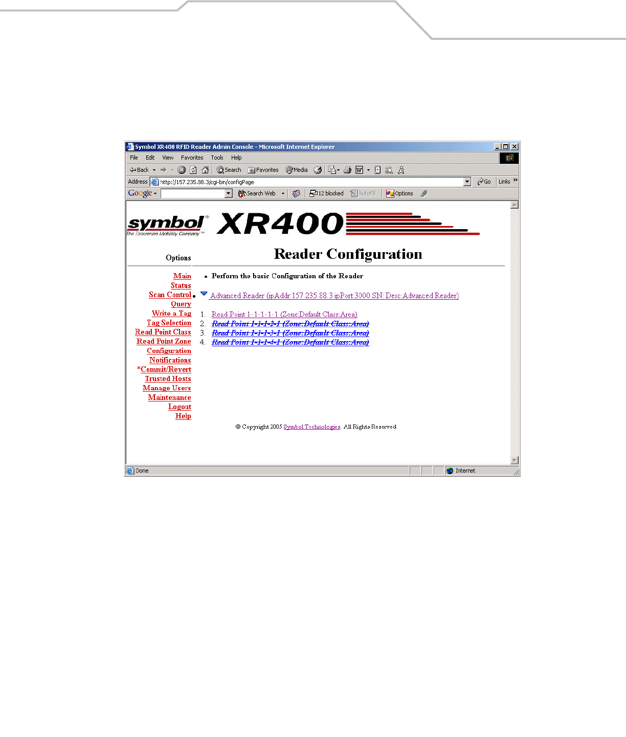
13. Click Configuration. The Configuration window displays a list of antennas (read points).
Figure 3-6. Reader Configuration Window
XR400 RFID Reader Integrator Guide3-8
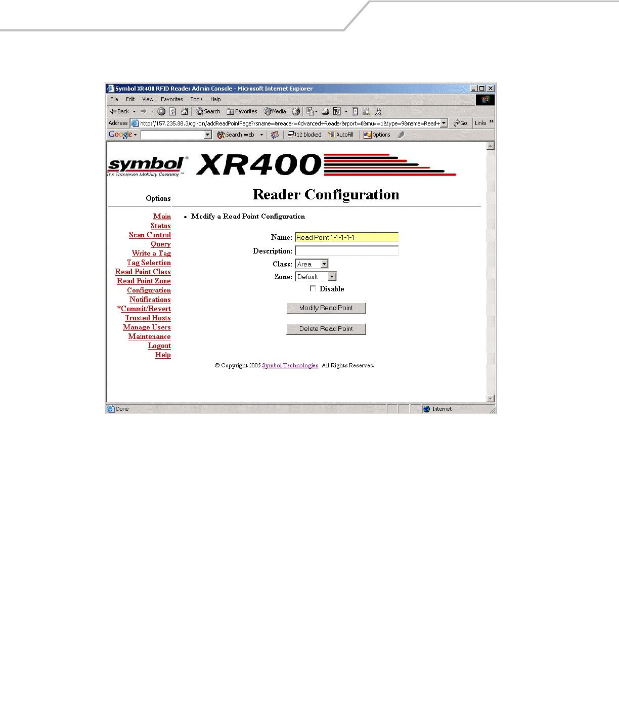
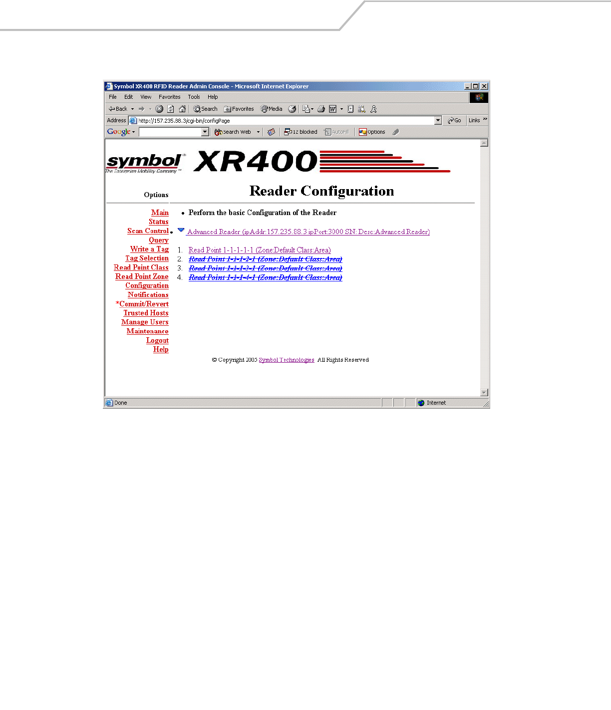
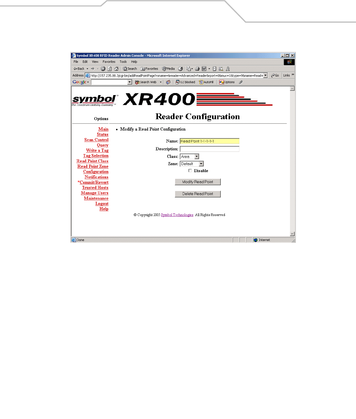
14. Select the read point on which to schedule periodic scans. The following window provides details about the read point.
Figure 3-7. Read Point Configuration Window
15. Select the new read point class from the Class: drop-down list. This associates the read point with the new read point class.
16. Click Modify Read Point, then Commit/Revert to apply the changes. See Committing / Discarding Changes on page 3-27.
Administrator Console 3-9
17. Click Scan Control to open the Scan Control window. This window indicates when the next periodic scan is scheduled.
Figure 3-8. Reader Scan Control Window
Periodic scan scheduled in 4 minutes
XR400 RFID Reader Integrator Guide3-10
Query
Use the query feature to read tags and get their status information. The reader replies with one of the following tag status indications:
• The tag is not known to the system. (The tag was never seen or imported.)
• The tag is not visible to the system. (The tag is known to the system, but is currently not visible to any read point.)
• The tag is visible at one or more read points. (A list of read points where the tag can be seen displays.)
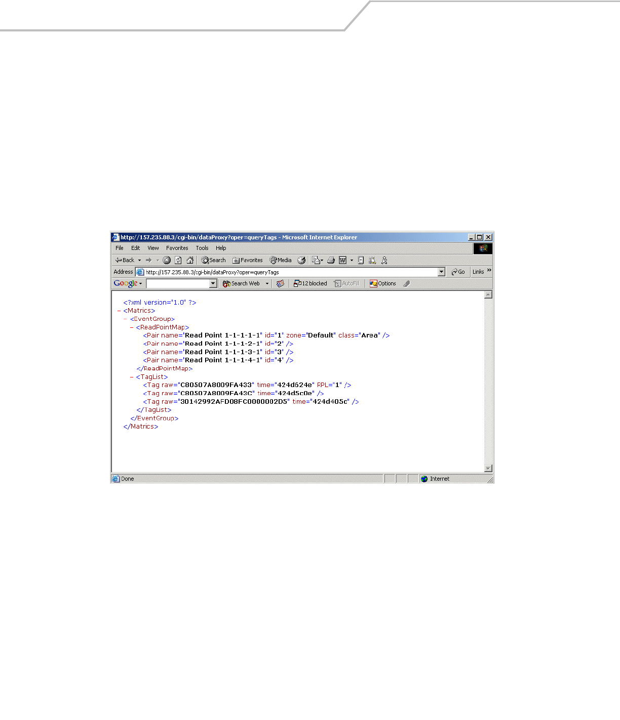
The tag ID and the type of the tag is required to query a tag. To obtain the tag ID and type of all tags the reader is reading:
1. Enable polling at the reader and configure read point classes as polled classes.
2. Open a new browser window and enter the following URL: http://[Reader IP Address] /cgi-bin/dataProxy?oper=queryTags
XML containing the tag ID and type of all tags being read appears.
Figure 3-9. Query Tags XML Window
3. Note the ID and type of the tag to query.
4. Open the Administrator Console and click Query.
5. Enter the type and ID from Step 3 in the Type: and Id: fields.
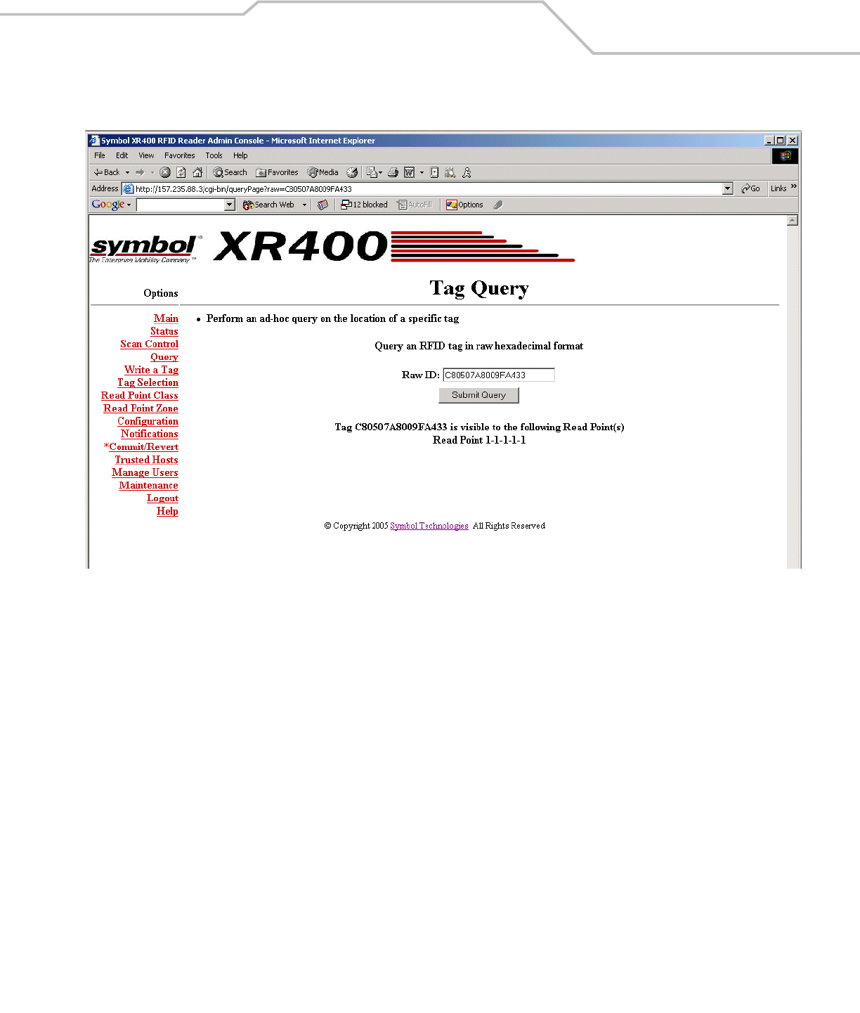
Administrator Console 3-11
6. Click Submit Query. The XR400 responds with the read point of the antenna that is reading the tag.
Figure 3-10. Tag Query Window
XR400 RFID Reader Integrator Guide3-12
Writing a Tag
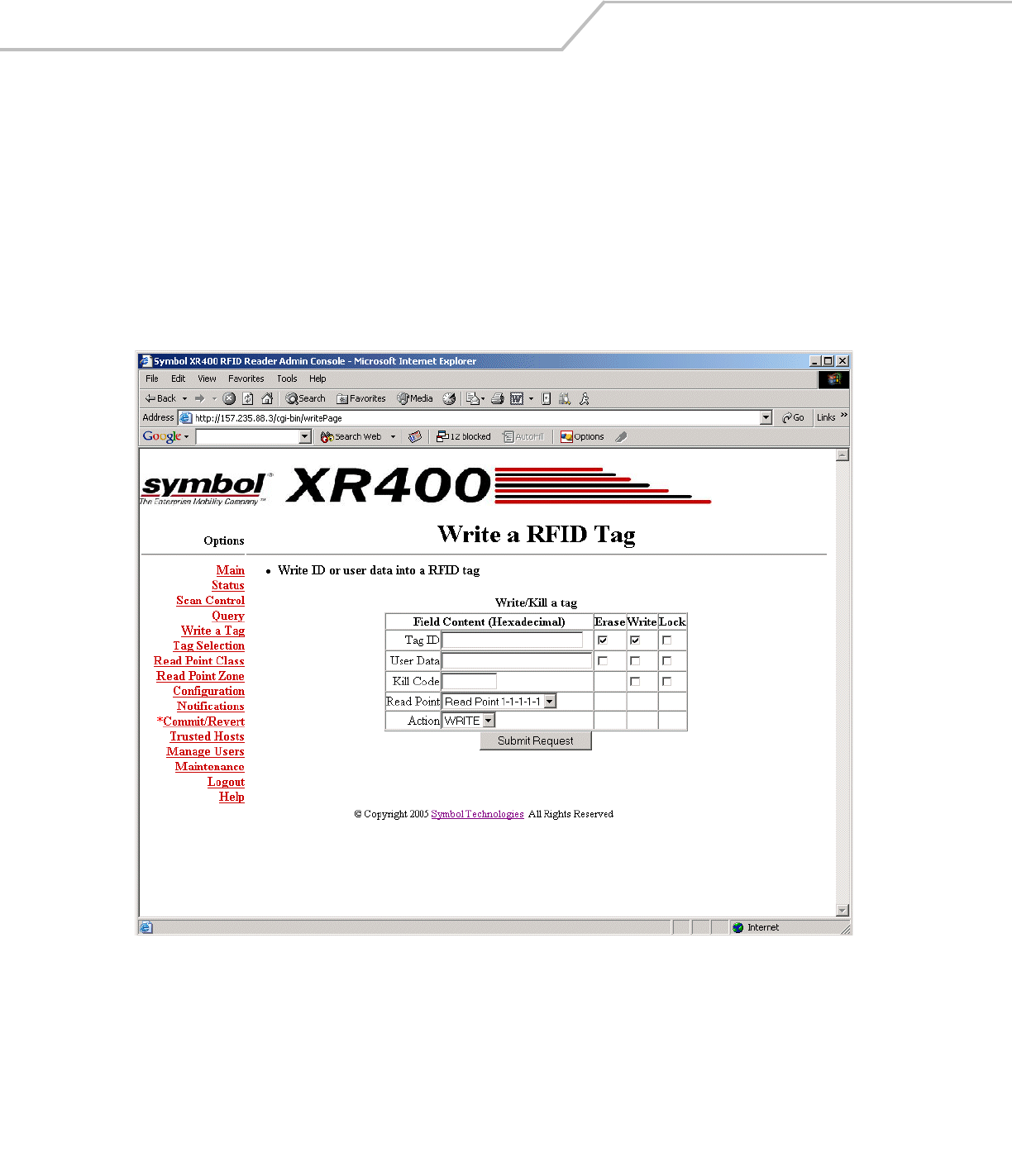
Use the Write a Tag option to perform the following with a R/W tag:
• Write, erase, and/or lock the tag ID.
• Write, erase, and/or lock the user data.
• Write or lock a kill code.
• Kill a tag.
To write a tag:
1. Click Write a Tag.
Figure 3-11. Write an RFID Tag Window
2. Enter the TagID to write on the tag. If the tag already contains an ID, select the Erase and Write checkboxes next to the Tag
ID field to overwrite it.
To disable changes of the tag ID select the Lock checkbox next to the Tag ID field.
3. Enter the data to write on the tag in the User Data field. If the tag already contains user data select the Erase and Write
checkboxes next to this field to overwrite it.
To disable changes of the user data select the Lock checkbox next to the User Data field.

Administrator Console 3-13
4. To write a kill code, enter six hex digits in the Kill Code field. To lock the kill code select the Write and Lock checkboxes.
5. Select the antenna port to use for the write operation from the Read Point drop-down list.
6. Select whether to write information on a tag or kill a tag from the Action drop-down list.
Writing Tips
Before writing to tags consider the following tips:
• Locking a tag ID and/or user data prevents further erasing and writing the tag ID and user data on this tag.
• After writing and locking the kill code, the kill code is required to kill the tag.
• Killing a tag voids it for all read and write operations, rendering it useless for future operations.
XR400 RFID Reader Integrator Guide3-14
Filtering
The XR400 allows setting filters based on rules and then associating the filters with a specific read point. This prevents the reader
from reporting specific tags. Filtering out tags involves the following steps:
• Creating a filter rule
• Creating a filter and associating it with the rule
• Associating a filter to a read point class
• Associating a read point class to an antenna.
The following sections describe these processes.
Creating a Filter Rule
To create a filter rule:
1. Click Tag Selection.
Figure 3-12. Tag Selection Filter Window
Administrator Console 3-15
2. Click Create A New Rule.
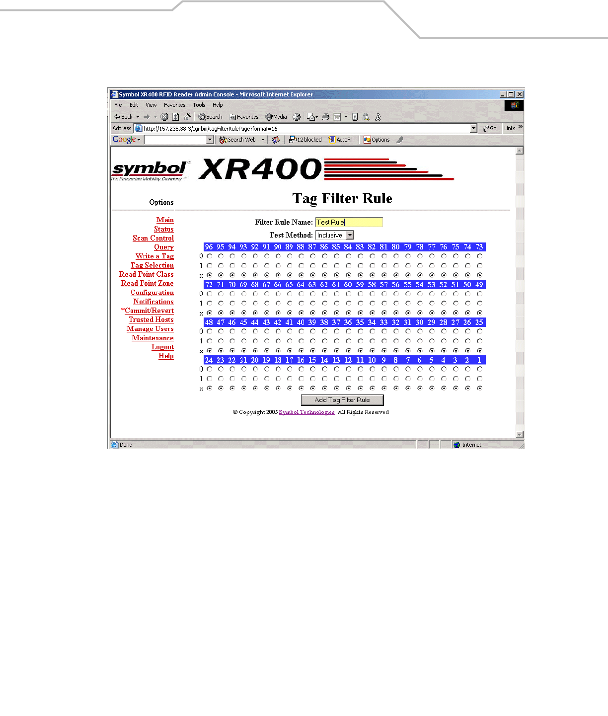
Figure 3-13. Tag Filter Rule Window
3. Choose the values for specific bits on which to base the filter.
4. Enter a name for the rule in the Filter Rule Name: field.
5. Select an option from the Test Method drop-down list. Inclusive indicates that all tags matching the rule are reported.
Exclusive indicates that all tags matching the rule are not reported.
6. Click Add Tag Filter Rule to return to the Tag Selection Filter window. The new rule appears in the Tag Filter Rule List.
7. Enter a name for the filter in the Name: field.
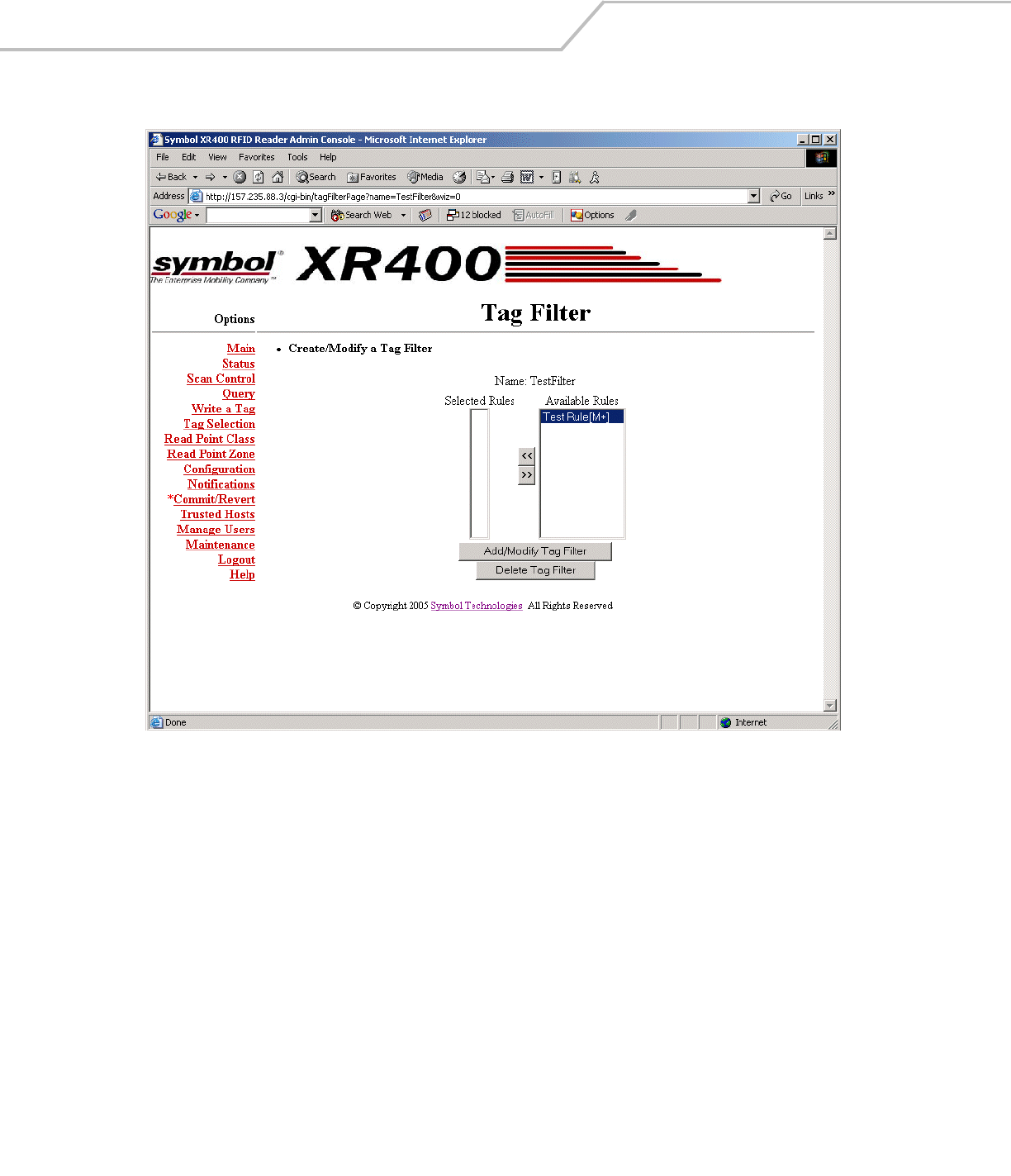
XR400 RFID Reader Integrator Guide3-16
8. Click Create a New Filter.
Figure 3-14. Tag Filter Window
9. Select the new rule from the Available Rules list and click <<. The rule moves to the Selected Rules list, adding it to the filter.
10. Click Add/Modify Tag Filter. The Tag Selection Filter window appears with the new filter in the Tag Filter List.
11. Click Commit/Revert to apply the changes. See Committing / Discarding Changes on page 3-27.
Administrator Console 3-17
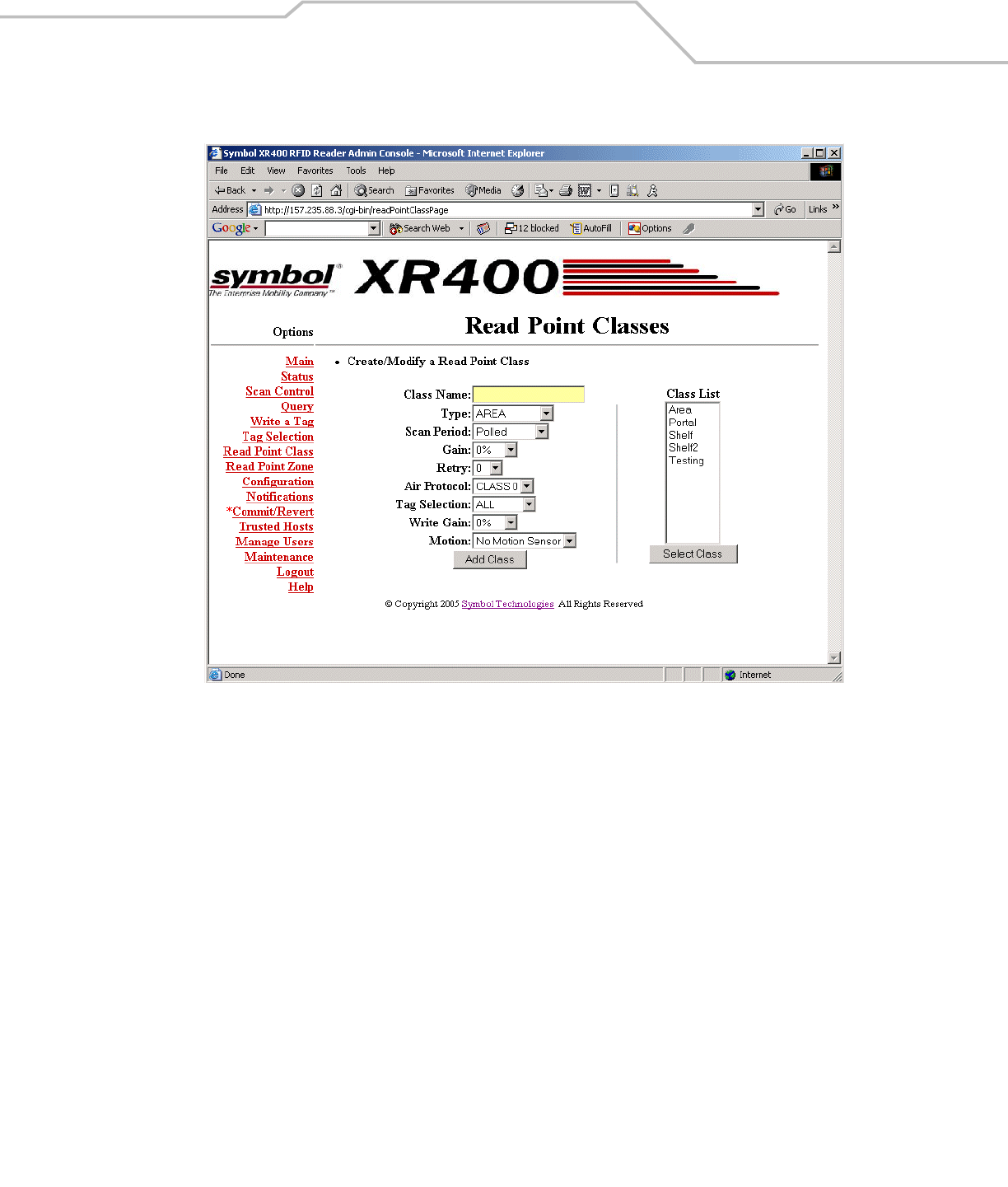
12. Click on Read Point Class.
Figure 3-15. Read Point Classes Window
13. Enter a class name in the Class Name: field.
14. Select settings for the class from the drop-down lists. See Scheduling a Periodic Scan Read Point on page 3-6.
15. Select the new filter from the Tag Selection drop-down list.
16. Click Add/Modify Class.
17. Click Commit/Revert to apply the changes. See Committing / Discarding Changes on page 3-27.
XR400 RFID Reader Integrator Guide3-18
18. Click Configuration.
Figure 3-16. Selecting a Read Point
Administrator Console 3-19
19. Select the read point with which to associate the new filter.
Figure 3-17. Modifying Read Point Configuration
20. Select the new class which contains the new filter from the Class drop-down list.
21. Click Modify Read Point. The Reader Configuration window displays the new read point class associated with the selected
antenna. The selected read point of the reader now reports tags as per the selected rule.
XR400 RFID Reader Integrator Guide3-20
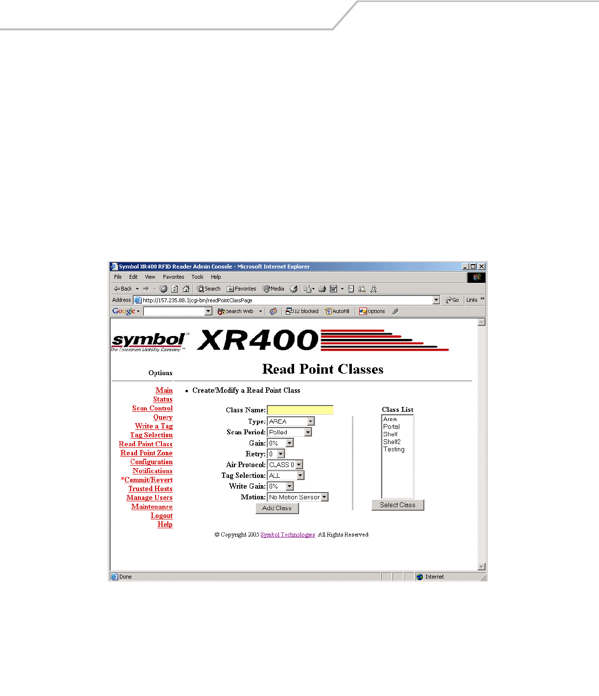
Read Point Classes
Read point classes are a set of configuration parameters assigned to one or more read points (antennas). Create a read point class
in one of two ways:
• Create a new read point class by defining the class.
• Use an existing read point class as a template, copy it, change its settings, and save the new class with a different name.
The XR400 includes several read point classes to use as templates. To create a new class based on one of the existing classes:
1. Click Read Point Class.
Figure 3-18. Creating a New Read Point Class
2. Select a class from the Class List and click Select Class to display the settings of this class.
3. Enter a new name in the Class Name: field.
4. Select settings for the class from the drop-down lists. See Scheduling a Periodic Scan Read Point on page 3-6.
5. Click Add Class.
Administrator Console 3-21
Read Point Zones
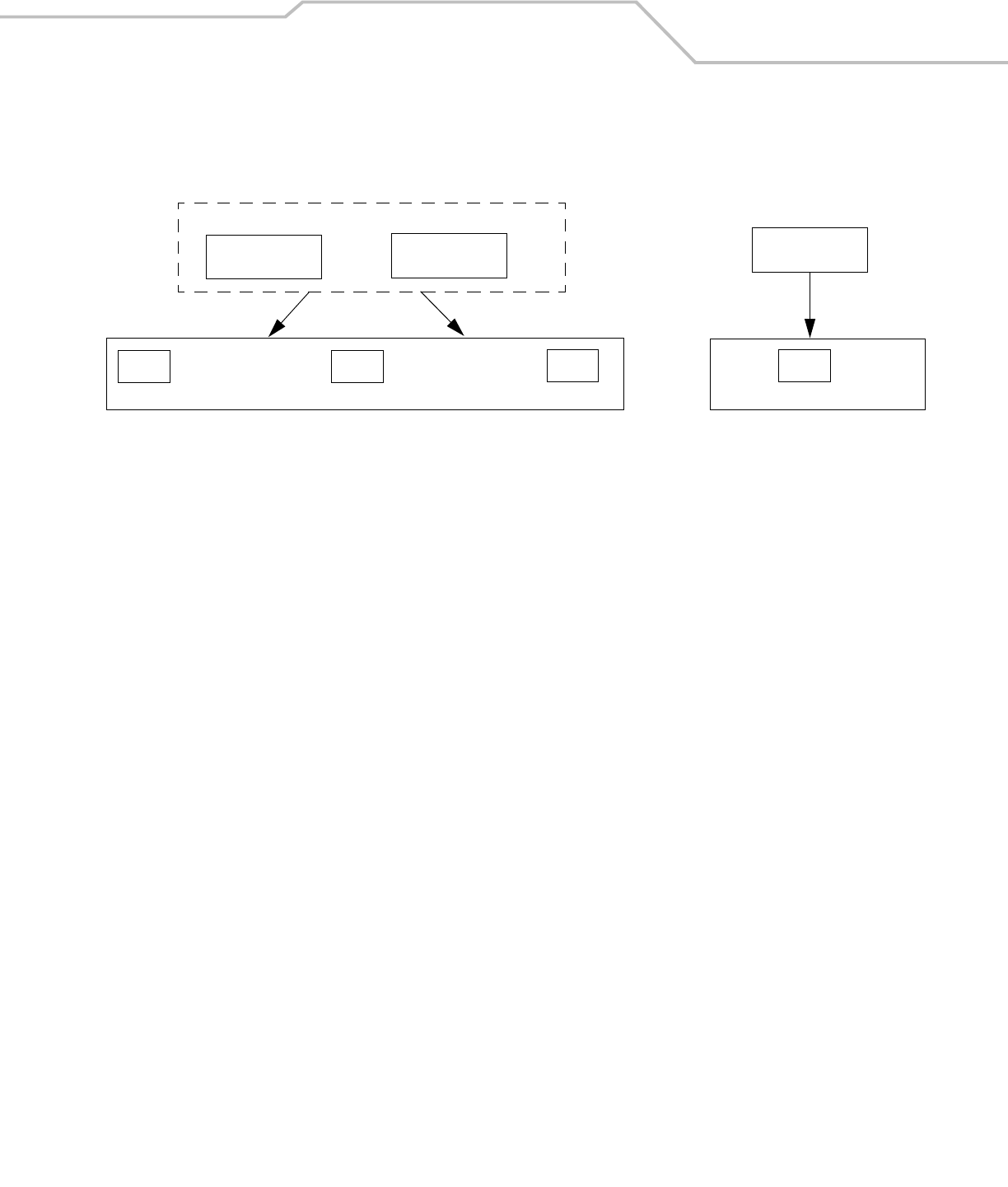
Read point zones provide a logical way of grouping one or more read points on the same reader or across readers. A read point zone
facilitates arbitrary user aggregations of read points.
Figure 3-19. Read Point Zone Diagram
In Figure 3-19 Read Point 1 and 2 are logically grouped using Read Point Zone 1. Tags read by either read point are reported as read
by Read Point Zone 1. Similarly, read point class names can also facilitate aggression. This section describes how to configure and
administer read point zones.
Read Point Zone 1
Read Point 1 Read Point 2 Read Point 3
Tag 1 Tag 2 Tag 3 Tag 4
Read Range of Antenna 3
Read Range of Read Point Zone 1
XR400 RFID Reader Integrator Guide3-22
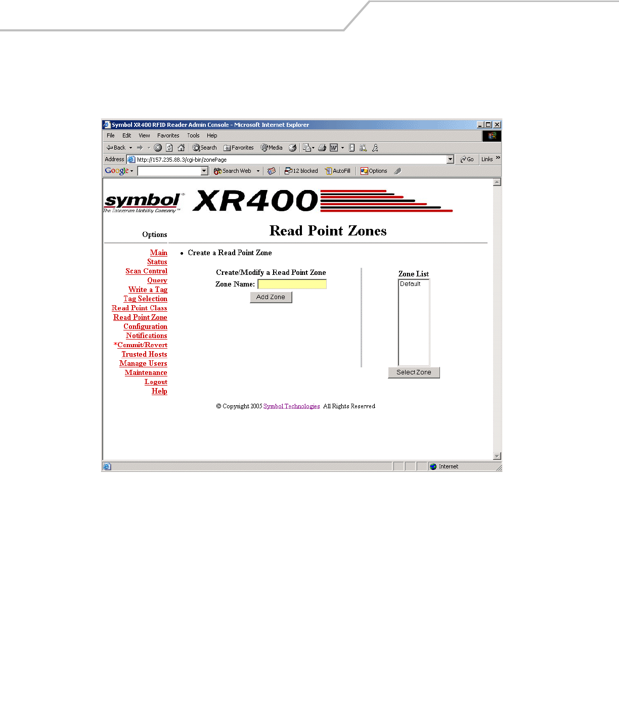
Adding and modifying Read Point Zones
To create a zone:
1. Click Read Point Zone.
Figure 3-20. Read Point Zone Diagram
2. Manage read point zones as follows:
• To add a zone, enter a name for the zone in the Zone Name: field and click Add Zone.
• To change the name of a zone, select the zone name from the Zone List and click Select Zone.
Enter a new name for the zone in the Zone Name: field and click Modify Zone to update the Zone List.
• To delete the zone being modified, click Delete Zone.
Administrator Console 3-23
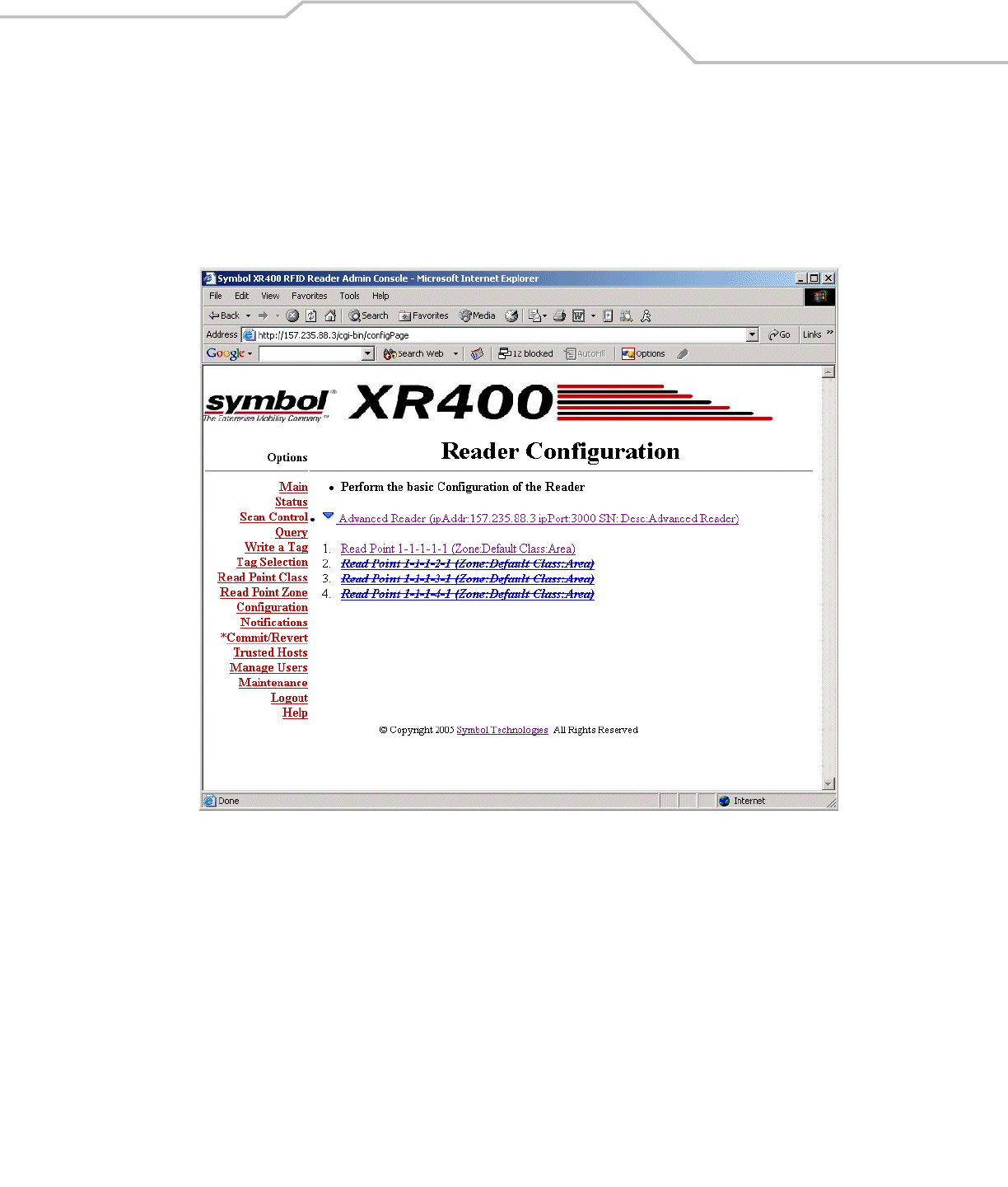
Renaming, Enabling, and Disabling the Reader
Assign a new name and description to the XR400 to use later to identify readers on the network. If desired, disable the reader for all
future operations.
To rename or disable a reader:
1. Click Configuration.
Figure 3-21. Reader Configuration Window
XR400 RFID Reader Integrator Guide3-24
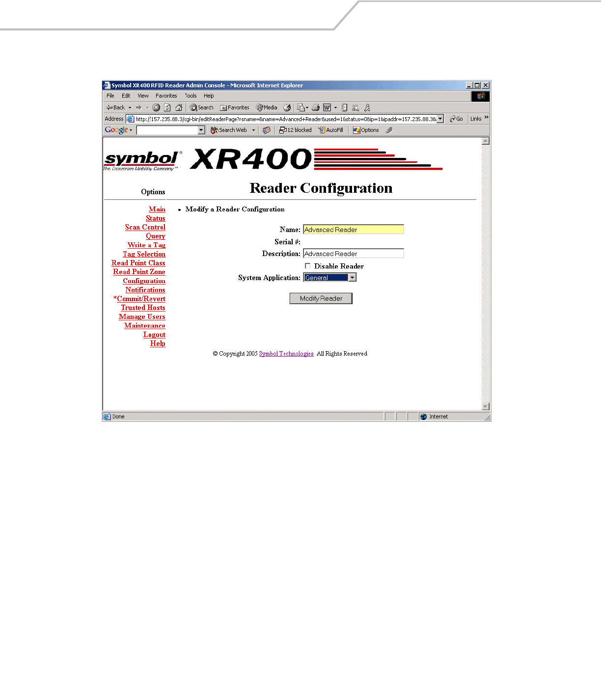
2. Select the reader to modify.
Figure 3-22. Modify Reader Configuration Window
3. To modify the name and description of the reader, enter this information in the Name: and Description: fields. Note that the
serial number cannot be modified.
4. To disable the reader, select the Disable Reader checkbox.
5. Click Modify Reader.
Administrator Console 3-25
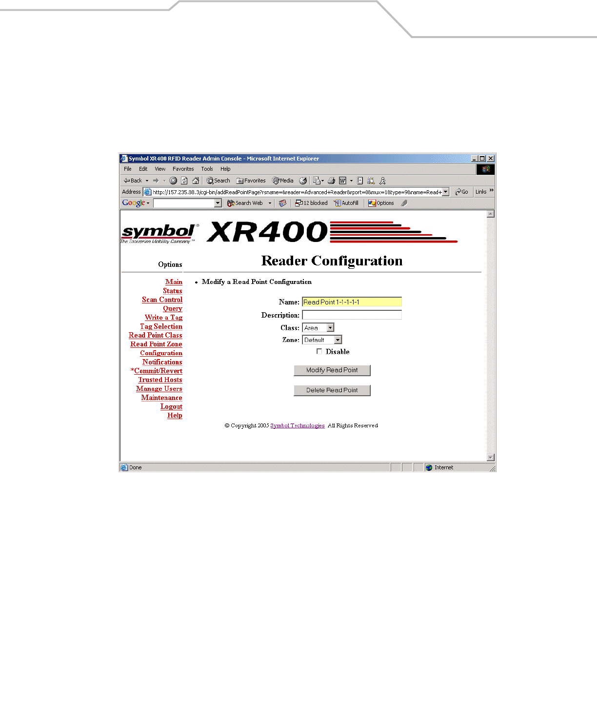
Configuring Individual Read Points
The Reader Configuration window also allows configuring and managing read points connected to the reader. To manage an antenna:
1. Select the specific read point from the Reader Configuration window, shown in Figure 3-21.
2. Clicking on a specific read points opens up the following window that allows you to associate that read point with a class
and a read point zone.
Figure 3-23. Modify Read Point Configuration Window
3. If desired, enter a new name and description in the Name: and Description: fields.
4. Select an associated read point class and zone from the Class: and Zone: drop-down lists.
5. Click Commit/Revert to save the changes. See Committing / Discarding Changes on page 3-27.

XR400 RFID Reader Integrator Guide3-26
Event Notification
The XR400 reader provides notification when particular events occur. Select the events to subscribe to using the Event Notification
window. Select whether to receive event notifications, and select from three different types of events:
• Visibility events
• Threshold events
• Network status events.
Visibility Events
These events occur when tag visibility changes. There are three types of visibility events:
•New tag event: occurs every time the XR400 reads a new tag.
•Tag not visible event: occurs when the system knows about the tag but the tag is no longer visible.
•Visibility changed event: a generic event that occurs when the read point that read the tag changes.
Threshold Event
Threshold events occur when the number of visible tags drops below or rises above a threshold specified via a tag list notification
reply.
Network Status Event
Network status events indicate a change in reader status, e.g., a problem with the reader. There are two types of network status
events:
•Device
•Program.
Device events can indicate whether the status change is reported for device or in association with a parent device. For example for
a disabled reader, the reader receives a 'user/disable' status notification, and the read point(s) associated with the reader receive a
'user/disable/parent' notification.
Similarly, if a device fault occurs for the reader, all corresponding events for the device fault also occur for each read point associated
with that reader. After correcting the fault, enabling the reader also enables 'parent disabled' devices associated with it.
Exception Events
Exception events provide the same type of information available via SNMP, but using XML. An exception event provides information
when a device goes off-line, polling is turned off, etc. Select this option if there is no SNMP support, but you require notification if
the device/program changes state.
The Event Notification window provides the following parameters:
• Host Notification: web-based notifications of events are sent to this link. Typically this is the URL of the web server which
is running an application which can trap and display these notifications.
• Send SNMP Trap To: This is the IP address of the SNMP server to which to send event traps.
Administrator Console 3-27
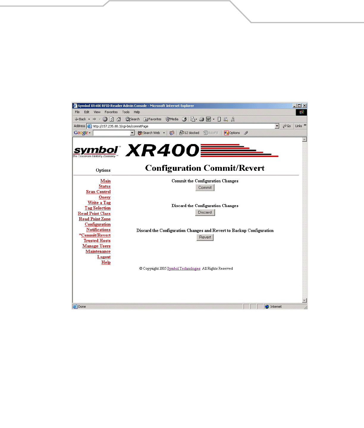
Committing / Discarding Changes
To apply reader configuration modifications made using the Reader Administrator Console, click Commit/Revert to save these
changes and notify the reader to update its configuration file, which updates the physical reader configuration. While a successful
update can take several seconds, the system continues to operate with only a one or two-second period where no polling occurs.
To save changes when using the Reader Administrator Console:
1. Click Commit/Revert.
Figure 3-24. Commit/Revert Window
2. Click Commit to save a new configuration and apply changes to the reader's configuration file.
3. Click Discard to discard changes made to the reader configuration during this session.
4. Click Revert only if a saved backup configuration exists to discard current changes and revert reader configuration to the
backup configuration.
XR400 RFID Reader Integrator Guide3-28
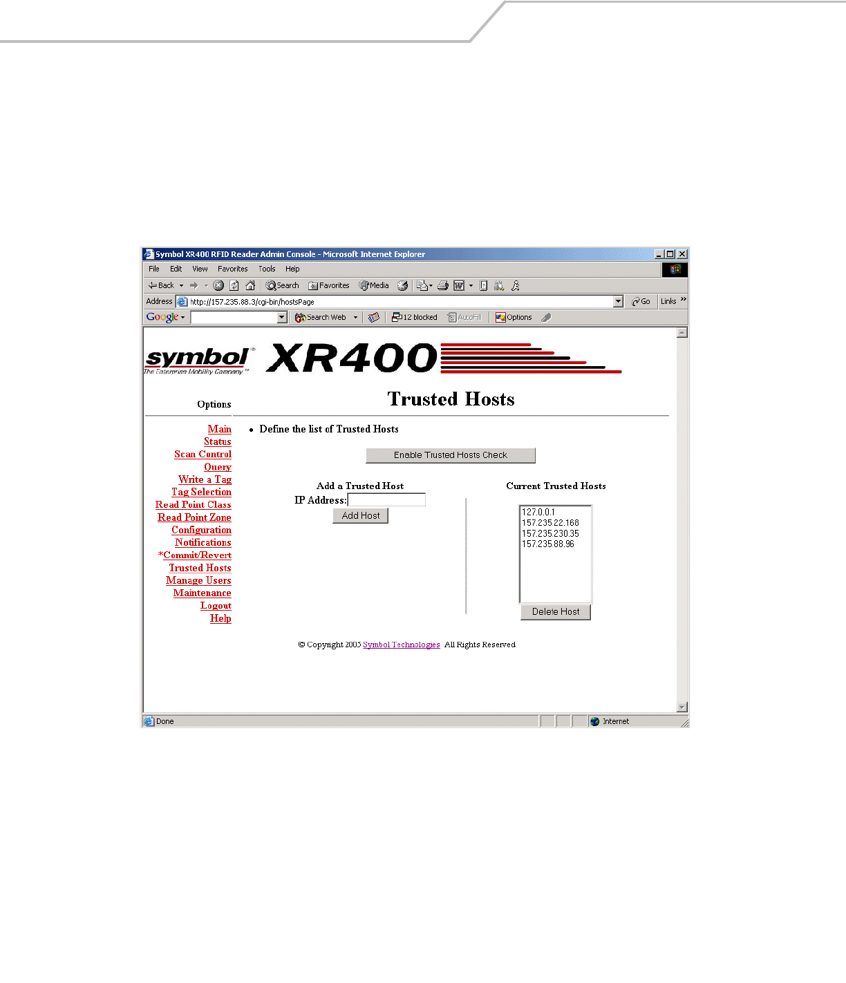
Managing Trusted Hosts
Trusted hosts are authorized computers with which the reader is allowed to communicate. Enable this feature to allow only computers
listed in the trusted host list to access the Administrator Console. This allows administrators to restrict unauthorized hosts from
accessing the reader even if they are on the same network as the reader. When disabled (the default), the reader logs the IP addresses
of any computers that attempt to access the reader to provide a history of attempted accesses.
To manage trusted hosts:
1. Click Trusted Hosts.
Figure 3-25. Trusted Hosts Window
2. To add a trusted host to the list, enter the IP address in the IP Address: field, then click Add Host.
3. To delete a trusted host, select the host’s address from the Current Trusted Hosts list, then click Delete Host.
4. Click Enable Trusted Host Check to prevent computers not in the trusted host list from accessing the reader.
5. To allow all hosts in the network to access the reader, click Disable Trusted Host Check.
Administrator Console 3-29
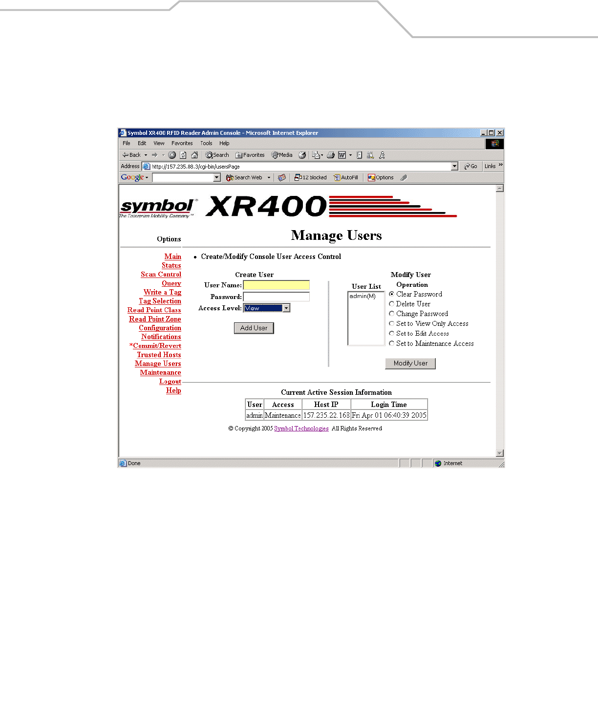
Managing Users
To add or modify users in order to grant rights and permissions:
1. Click Manage Users.
Figure 3-26. Manage Users Window
2. Enter the name of the new user in the User Name: field.
3. Enter a password to assign to the user in the Password: field.
4. Select an option from the Access Level: drop-down list for the new user:
•View: Allows the user to connect to the Administrator Console and view reader settings.
•Edit: Allows the user to make configuration changes excluding tasks such as updating the firmware.
•Maintenance: This provides administrator privilege, and allows the user to access all functionality of the Administrator
Console.
XR400 RFID Reader Integrator Guide3-30
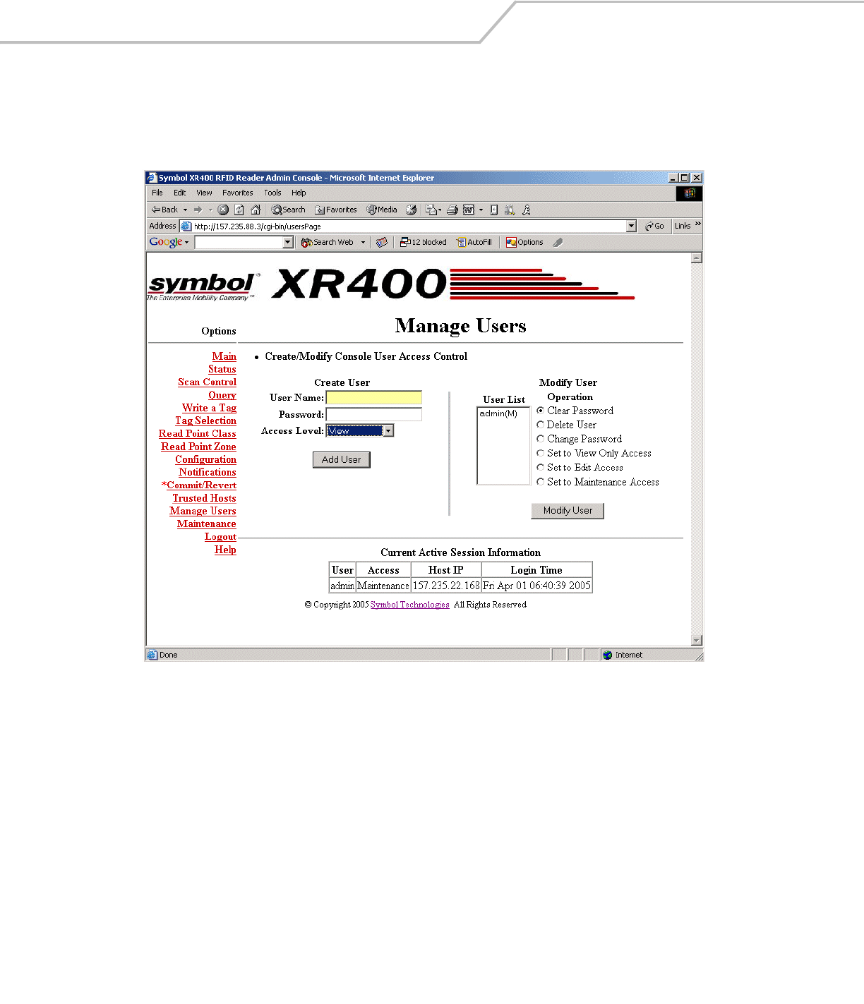
User Maintenance
To modify the access level or other account parameters and settings for an existing user:
1. Click Manage Users.
Figure 3-27. Modifying Users Window
2. To assign the default password (change) to a user, select the user from the User List, select the Clear Password radio button,
and click Modify User.
3. To delete the user, select the user from the User List, select the Delete User radio button, and click Modify User.
4. To assign a new password to the user, select the user from the User List, select the Change Password radio button, and click
Modify User. In the window that appears, enter the old user password, then enter and confirm the new password.
5. To change the access level of the user, select the Set to View Only Access, Set to Edit Access, or Set to Maintenance Access
radio button. Note that you can not grant an access level higher than your own.

Maintenance and Troubleshooting
Introduction . . . . . . . . . . . . . . . . . . . . . . . . . . . . . . . . . . . . . . . . . . . . . . . . . . . . . . . . . . . . . . . . . . . . . . . . . . . . 4- 3
Reader Maintenance - Changing Communication Settings. . . . . . . . . . . . . . . . . . . . . . . . . . . . . . . . . . . . . . . . .4-3
Setting Date and Time . . . . . . . . . . . . . . . . . . . . . . . . . . . . . . . . . . . . . . . . . . . . . . . . . . . . . . . . . . . . . . . . . . . . .4-6
Getting Firmware Version Number . . . . . . . . . . . . . . . . . . . . . . . . . . . . . . . . . . . . . . . . . . . . . . . . . . . . . . . . . . .4-7
Updating Firmware. . . . . . . . . . . . . . . . . . . . . . . . . . . . . . . . . . . . . . . . . . . . . . . . . . . . . . . . . . . . . . . . . . . . . . . .4-8
Monitoring Logs . . . . . . . . . . . . . . . . . . . . . . . . . . . . . . . . . . . . . . . . . . . . . . . . . . . . . . . . . . . . . . . . . . . . . . . . . .4-9
Backing Up the Configuration . . . . . . . . . . . . . . . . . . . . . . . . . . . . . . . . . . . . . . . . . . . . . . . . . . . . . . . . . . . . . . .4-9
Logging Out from the Console . . . . . . . . . . . . . . . . . . . . . . . . . . . . . . . . . . . . . . . . . . . . . . . . . . . . . . . . . . . . . .4-10
Troubleshooting . . . . . . . . . . . . . . . . . . . . . . . . . . . . . . . . . . . . . . . . . . . . . . . . . . . . . . . . . . . . . . . . . . . . . . . . .4-11

XR400 RFID Reader Integrator Guide4-2
Maintenance and Troubleshooting 4-3
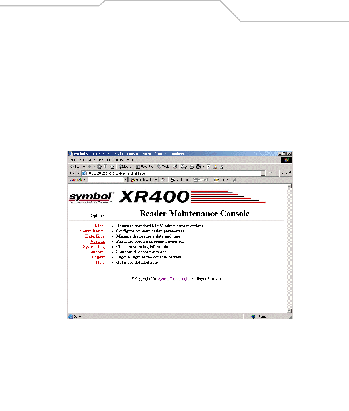
Introduction
Use the Maintenance option in the Administrator Console to perform low-level reader maintenance tasks.
Reader Maintenance - Changing Communication Settings
The XR400 provides typical configuration settings that make the reader a plug-and-play device. The Administrator Console allows
customizing these communication parameters. For example, it enables changing the default IP address of the reader when the
network does not have a DHCP server.
To change the reader’s communication settings:
1. Open a web browser.
2. In the address bar enter the reader’s URL (http:// followed by the reader’s IP address) and press Enter.
3. Log in using your administrator username and password to access the reader’s Administrator Console.
4. Click Maintenance.
Figure 4-1. Maintenance Console Main Menu
XR400 RFID Reader Integrator Guide4-4
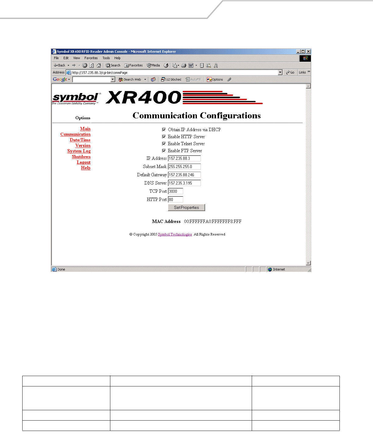
5. Click Communication.
Figure 4-2. Communication Configuration Window
6. Change communication-related settings as desired by entering information in the text boxes or using the drop-down lists.
See Table 4-3 for descriptions of available options.
7. Click Set Properties.
8. Click Main to return to the Administrator Console main window.
9. Click Commit / Revert.
10. Click Commit to save the changes or Discard to discard the changes. See Committing / Discarding Changes on page 3-27.
Table 4-1. Communication Configuration Options
Setting Description Possible Values
Obtain IP Address via DHCP The Dynamic Host Configuration Protocol server running on networks
can assign a dynamic IP address to the host and readers. Contact the
system administrator to find out if the network supports DHCP.
Checked (enabled) / unchecked (disabled)
Enable HTTP Server Select whether to enable the web interface. Checked (enabled) / unchecked (disabled)
Enable Telnet Server Select whether to enable Telnet to the reader. Checked (enabled) / unchecked (disabled)

Maintenance and Troubleshooting 4-5
Enable FTP Server Select whether to enable the FTP server on the reader. Checked (enabled) / unchecked (disabled)
IP Address If manually assigning an IP address to the reader, check with the
system administrator to ensure the IP address is valid in the network.
IP address to assign to the reader
Subnet Mask A mask used to determine to what subnet an IP address belongs. IP address dynamically assigned or user-
entered
Default Gateway The reader uses this IP address to access another network. Depends on network configuration
DNS Server The reader uses the Domain Name System (DNS) IP address to
translate domain names.
Depends on network configuration
TCP Port The port used for TCP/IP communication. User-entered
Default: 3000
HTTP Port The port used for communication over HTTP. User-entered
Default: 80
Table 4-1. Communication Configuration Options (Continued)
Setting Description Possible Values
XR400 RFID Reader Integrator Guide4-6
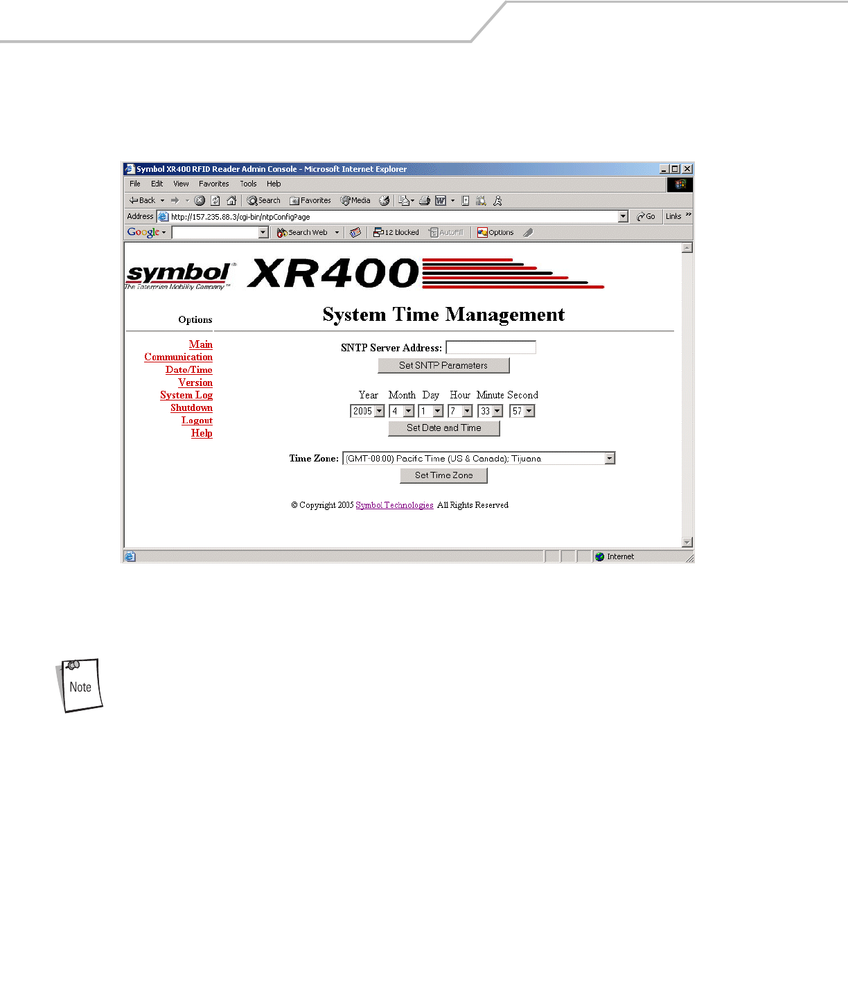
Setting Date and Time
To set the reader’s date and time:
1. Select Date/Time in the Communication window.
Figure 4-3. System Time Management Window
2. To synchronize the reader’s clock with a particular SNTP server, enter the server’s address in the SNTP Server Address: field
and click Set SNTP Parameters.
SNTP (Simple Network Time Protocol) is an Internet standard protocol (built on TCP/IP) that assures accurate
synchronization to the millisecond of computer clock times in a network of computers.
3. To set the reader’s system time manually, use the drop-down lists to select units of time, then click Set Date and Time.
4. Use the Time Zone: drop-down list to set the reader’s time zone, then click Set Time Zone.
Maintenance and Troubleshooting 4-7
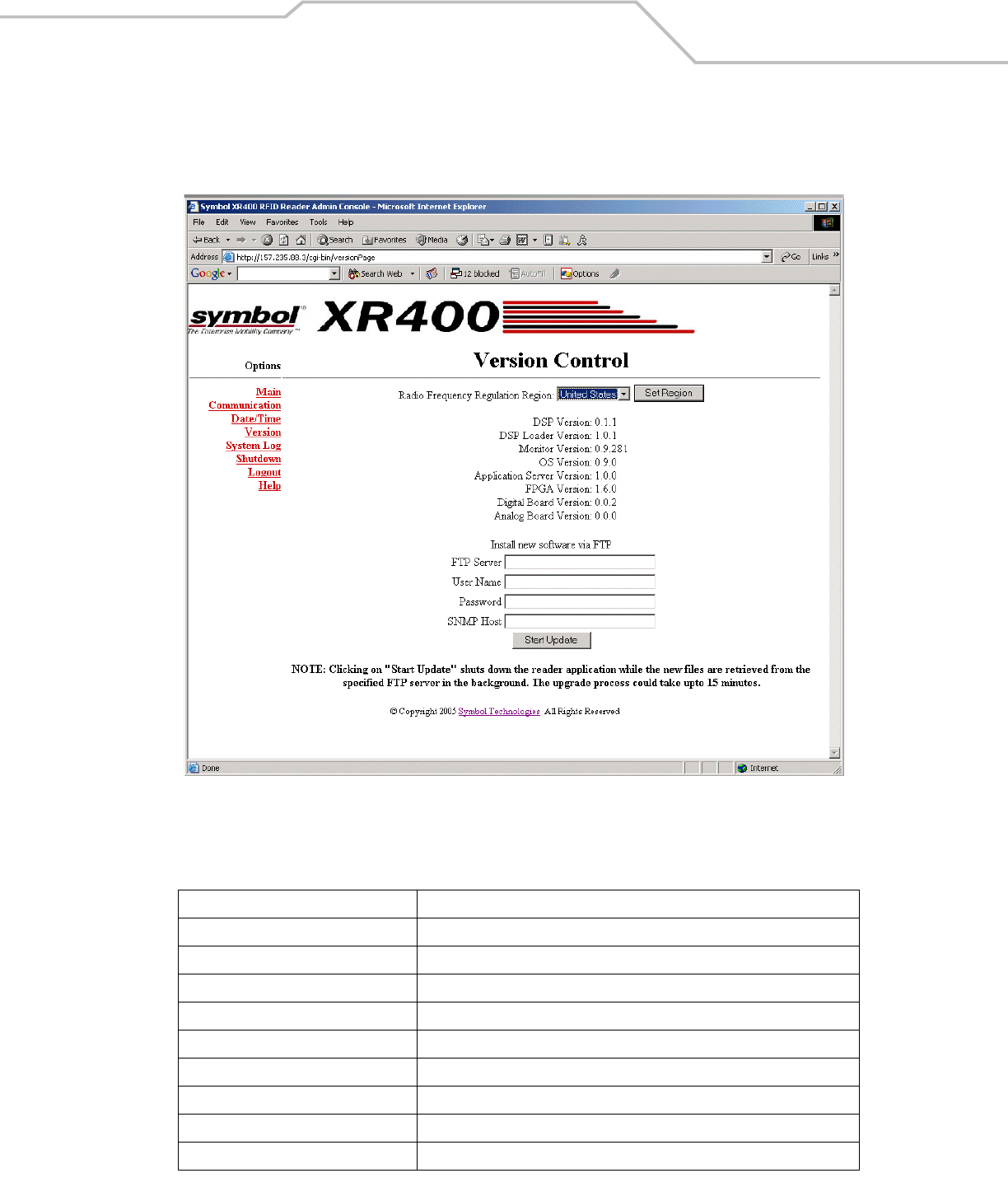
Getting Firmware Version Number
The Version Control window displays the current firmware version and allows upgrading to new firmware. To view this window, select
Version.
Figure 4-4. Version Control Window
See Table 4-2 for version control parameter descriptions.
Table 4-2. Version Control Parameters
Access Level Setting Description
Radio Frequency Regulation Region Select a Radio Frequency Regulation region for the XR400 and click Set Region.
DSP Version The version of the DSP firmware.
DSP Loader Version The version of the DSP loader.
Monitor Version The version of the monitor utility.
OS Version The version of the operating system build.
Application Server Version The version of the application software.
FPGA Version The version of the FPGA image.
Digital Board Version The version of the reader's digital board.
Analog Board Version The version of the reader's analog board.

XR400 RFID Reader Integrator Guide4-8
Updating Firmware
Before updating firmware using a local image file, perform the following:
• Acquire the new image(s) from Symbol, which can include the monitor partition, the OS partition, the platform partition, the
application partition, the data partition, and the partition table.
• Obtain the utility OsUpdate.exe, FlashUpdateUtility.dll, and the Response.txt file from Symbol. The Response.txt file
contains the list of files to be updated.
• Obtain FTP server access to upload the images from the host PC, and download images from the reader.
• Upload the image file(s) to the FTP server.
Use the Version Control window to update firmware by downloading the software to the reader from an FTP server. To update the
firmware version:
1. Click Maintenance from the main menu.
2. Click Version. See Figure 4-4 for the Version Control window.
3. In the FTP Server field, enter the IP address of the FTP server that contains the image file to download.
4. Enter the username and password in the FTP User Name and Password fields.
5. In the SNTP Host field, enter the SNMP host address to which the SNMP traps are sent while the new files are downloading
to the reader.
6. Click Start Update. The XR400 application software first downloads the OsUpdate.exe, FlashUpdateUtility.dll, and
Response.txt files, starts OsUpdate, and shuts down.
7. OsUpdate downloads the files specified in Response.txt to RAM, then writes them to flash.
8. The reader reboots. If an error occurs during file transfer, the reader reboots without writing the files to flash.

Maintenance and Troubleshooting 4-9
Monitoring Logs
Network administrators can use logs for auditing and troubleshooting the XR400. XR400 supports two types of logs:
•System Log - includes the log information generated by the reader's internal instructions. This is a circular queue which can
hold a maximum of 200 records.
•Access History - provides a history log for access to this reader. This log records every successful access to the reader
through the web interface. This is also a circular queue which can hold a maximum of 20 records.
Backing Up the Configuration
The reader supports the following backup configuration functions:
• Rolling back maintenance errors and restoring the reader to a particular date and time.
• Pushing reader-specific changes made to the config.xml file to multiple readers, simplifying multi-reader management.
• General configuration backup that can be restored when required, such as hardware replacement.
TTo back up the reader's configuration:
1. Open the browser and enter the URL http://[Reader IP address]/Config.xml.
For example, if the reader’s IP address is 192.168.127.254, enter:
http://192.168.127.254/Config.xml
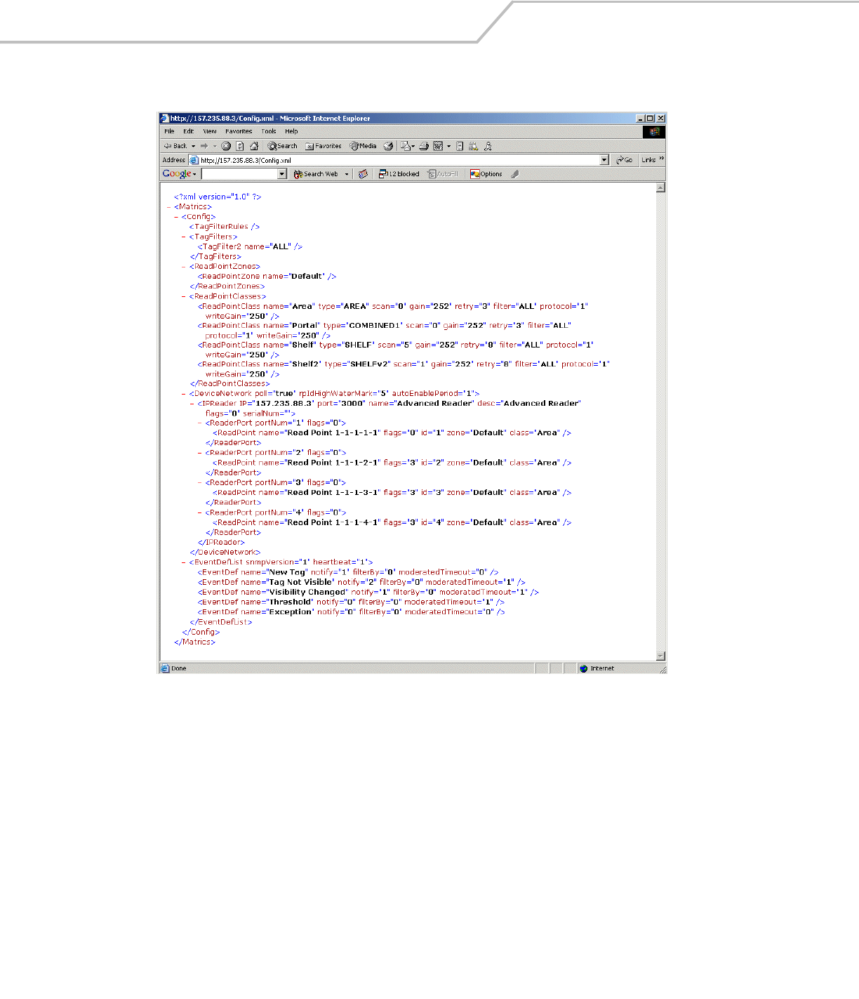
XR400 RFID Reader Integrator Guide4-10
An xml file similar to the following appears, depicting the current reader configuration.
Figure 4-5. Sample Reader Configuration XML File
2. Save the XML file with a naming / date convention that facilitates recognizing the reader and the date of the backup. Most
browsers allow saving xml files to the hard disk. In Internet Explorer, select File - Save As…
3. Click Save and use Windows Explorer to verify that the file is saved correctly.
Logging Out from the Console
Before closing the browser, log out of the console. Click Logout from either the maintenance menu or the main menu. If unsaved
changes are pending, the Commit / Revert window appears. See Committing / Discarding Changes on page 3-27.
If you forget to log out or leave your browser idle, the session automatically logs out.

Maintenance and Troubleshooting 4-11
Troubleshooting
If problems still occur, contact the distributor or call the local Symbol Support Center. See page x for the
telephone numbers.
Table 4-3. Troubleshooting
Problem Possible Causes Possible Solutions
XR400 error LED lights after the reader has been
in operation.
The CPU cannot communicate with the
DSP and cannot reload the DSP
firmware to it.
Refer to the system log for error messages.
XR400 error LED stays lit on powerup. An error occurred during the powerup
sequence.
If the web interrface is available, refer to the system log for the cause
of the error, otherwise refer to the debug messages from the serial
console.
Cannot connect to the reader. Username and password is unknown. The default username is admin and the default password is
change. To change the username and password, see Connecting the
XR400 for Communication on page 2-6.
XR400 is not reading tags. The tag is out of its read range. Move the tag into the read range. See Read Test on page 2-5.
Cannot access the Administrator Console. The reader’s IP address is unknown. See Connecting the XR400 for Communication on page 2-6 to view
the reader’s IP address.
Cannot log in to the terminal-based
Administrator Console.
The web-based Administrator Console
is in use for that reader.
Log out of the web-based console and restart the terminal software
to re-attempt log in.
Certain real-time applications are no longer
functional.
You changed the node address, IP
address, or other reader configuration
parameter(s) using the Administrator
Console, and the application expects
the previous configuration.
Update the settings within the application. Refer to the application’s
manual.
Polling is enabled.-** Some real-time applications require disabling polling. Refer to the
application’s manual, and if required, disable polling using the Scan
Control feature of the Administrator Console. See Scan Control on
page 3-5.
The user closed the browser without
logging out of the Administrator
Console, so other applications cannot
connect to the reader.
Log out of the Administrator Console.

XR400 RFID Reader Integrator Guide4-12

Specifications
Technical Specifications . . . . . . . . . . . . . . . . . . . . . . . . . . . . . . . . . . . . . . . . . . . . . . . . . . . . . . . . . . . . . . . . . A- 3
Cable Pinouts . . . . . . . . . . . . . . . . . . . . . . . . . . . . . . . . . . . . . . . . . . . . . . . . . . . . . . . . . . . . . . . . . . . . . . . . . . . A-5
Ethernet Connections. . . . . . . . . . . . . . . . . . . . . . . . . . . . . . . . . . . . . . . . . . . . . . . . . . . . . . . . . . . . . . . . . A-5
RS232 Port Connections. . . . . . . . . . . . . . . . . . . . . . . . . . . . . . . . . . . . . . . . . . . . . . . . . . . . . . . . . . . . . . . A-5
GPIO Port Connections . . . . . . . . . . . . . . . . . . . . . . . . . . . . . . . . . . . . . . . . . . . . . . . . . . . . . . . . . . . . . . . . A-6

XR400 RFID Reader Integrator GuideA-2

Specifications A-3
Technical Specifications
The following table summarizes the reader’s intended operating environment and general technical hardware specifications.
Table A-1. Technical Specifications
Feature Description
Physical Specifications
Dimensions 8.75" H x 11.75" W x 2" D (22.23 cm H x 29.85 cm W x 5.08 cm D)
Mounting Dimensions (Mounting Holes) 4.75" H x 12.73" W (12.05 cm H x 32.30 cm W)
Weight ~ 6 lbs (2722 g)
Base Material Aluminum, Silver; Die-cast
LEDs Power (Green), Activity (Yellow), Error (Red)
Power +24vDC @ 1.2 amps
Environmental Specifications
Environmental Sealing IEC 529 IP54
Operational Temperature IEC 60068-2-1/2/14
32° to +131° F (0° to +55° C)
Storage Temperature IEC 60068-2-1/2/14
-4° to +158° F (-20° to +70° C)
Humidity EC 60068-30/56
5-95% non-condensing
Vibration IEC 60068-2-6
Connectivity
Network RS422/485 via RJ45 connector
10-BaseT Ethernet via RJ45 connector
RS232 console management via DB15 connector.
Control I/O Port (6, user programmable) via DB9 connector.
RF Conductors Reverse TNC
Read Points (Channels) 4 read points (transmit and receive).
Individual antennas can be combined logically into a single “wide” read point.
Compliance Information
Safety EMI/RF Emissions
Regulatory Region 1, FCC Part 15
Operational Specifications
Frequency UHF band, 902-928 MHz
Method Frequency Hopping Spread Spectrum (FHSS)
Power Output Up to 30 dBm (only 1 Watt Part 15)
Air Link Protocol EPC global: Class 0, Class 0+, and Class 1
Tag Communication Interleaved
Tag Buffering Local or steaming

XR400 RFID Reader Integrator GuideA-4
Synchronization Network Time Protocol (NTP)
IP Addressing Static or dynamic (DHCP)
Host Interface Protocol XML or byte stream
Network Management
Protocol SNMP
Configuration Via setup wizard
Event Management Auto reported events
user controlled thresholds, damping and filtering
Administrative Management Security / privilege controls, change tracebility
Tag Management ID-based selection ability
user defined association to tag IDs
Taglist management features for reconciliation and visibility
Connectors
RJ45 Connector 10/100Base-T Ethernet
DB9 Connector RS232 console (management)
DB15 Connector Control I/O Port (6 input and 6 output with some programmable control to change the mix)
RS422/RS485 Connector Connect to host PC
Reverse TNC Antenna Connectors Connect to external antennas (4 Transmit and 4 Receive.)
Table A-1. Technical Specifications (Continued)
Feature Description

Specifications A-5
Cable Pinouts
Ethernet Connections
RS232 Port Connections
Table A-2. Ethernet Connector: RJ45 10-Pin
Pin Description
Pin 1 Reserved/Do not use
Pin 2 TXD (+)
Pin 3 TXD (-)
Pin 4 RXD (+)
Pin 5 Reserved/Do not use
Pin 6 Reserved/Do not use
Pin 7 RXD (-)
Pin 8 Reserved/Do not use
Pin 9 Reserved/Do not use
Pin 10 Reserved/Do not Use
Table A-3. RS232 Connector: DB9 9-Pin
Pin Description
Pin 1 NC
Pin 2 Tx
Pin 3 Rx
Pin 4 NC
Pin 5 Ground
Pin 6 NC
Pin 7 NC
Pin 8 NC
Pin 9 NC

XR400 RFID Reader Integrator GuideA-6
GPIO Port Connections
Table A-4. GPIO Port: 15-Pin
Pin Description
Pin 1 Ground
Pin 2 Output4
Pin 3 Output2
Pin 4 Output0
Pin 5 Input4
Pin 6 Input2
Pin 7 Input0
Pin 8 Ground
Pin 9 Output5
Pin 10 Output3
Pin 11 Output1
Pin 12 Input5
Pin 13 Input3
Pin 14 Input1
Pin 15 Vcc +5V power supply

Thank you for your input—We value your comments.
Tell Us What You Think...
We’d like to know what you think about this Manual. Please take a moment to fill out this questionnaire and fax this form
to: (631) 738-3318, or mail to:
Symbol Technologies, Inc.
One Symbol Plaza M/S B-4
Holtsville, NY 11742-1300
Attention: Technical Publications Manager
IMPORTANT: If you need product support, please call the appropriate customer support number provided. Unfortunately,
we cannot provide customer support at the fax number above.
Manual Title:___________________________________________
(please include revision level)
How familiar were you with this product before using this manual?
Did this manual meet your needs? If not, please explain.
______________________________________________________________________________________
______________________________________________________________________________________
______________________________________________________________________________________
______________________________________________________________________________________
What topics need to be added to the index, if applicable?
______________________________________________________________________________________
______________________________________________________________________________________
______________________________________________________________________________________
______________________________________________________________________________________
What topics do you feel need to be better discussed? Please be specific.
______________________________________________________________________________________
______________________________________________________________________________________
______________________________________________________________________________________
______________________________________________________________________________________
What can we do to further improve our manuals?
______________________________________________________________________________________
______________________________________________________________________________________
______________________________________________________________________________________
______________________________________________________________________________________
Very familiar Slightly familiar Not at all familiar


Symbol Technologies, Inc.
One Symbol Plaza
Holtsville, New York 11742-1300
http://www.symbol.com
72-71773-01
Revision .2 - April 2005