Symbol Technologies RDR001 Frequency Hopping Spread Spectrum Transmitter User Manual Stationary Reader User s Manual
Symbol Technologies, Inc Frequency Hopping Spread Spectrum Transmitter Stationary Reader User s Manual
UserManual.wiki
>
Symbol Technologies
>
RDR001 User Manual
Users Manual
Navigation menu
Upload a User Manual
Namespaces
Wiki Guide
HTML
PDF
Info
Views
User Manual
Discussion / Help
Navigation


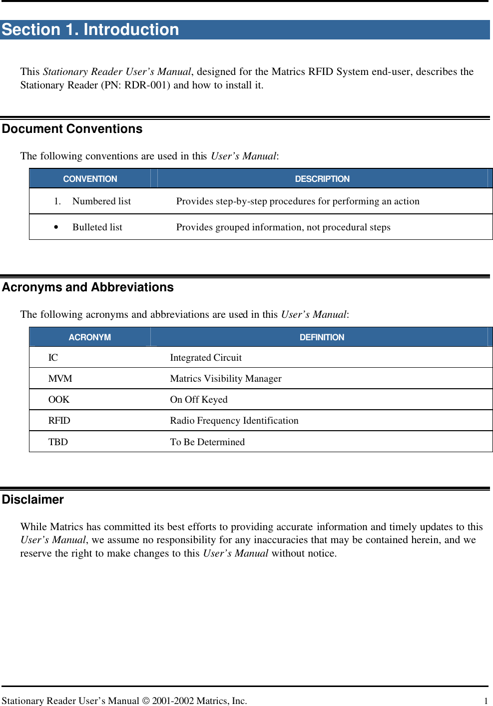
![2 Stationary Reader User’s Manual 2001-2002 Matrics, Inc. Section 2. System Description Matrics develops and markets Radio Frequency Identification (RFID) solutions that are effective and affordable by offering a combination of low cost, long read range, and a very high read rate unmatched by other RFID systems. A Matrics RFID System gives you real-time, end-to-end visibility of products and assets in your factory, distribution center, retail outlet, or other facility. A typical Matrics RFID system consists of three main components: • Silicon-based RFID tags that can be attached to containers, pallets, boxes, trays, etc., to create a “people-free” wireless environment for tracking objects as they travel through the supply chain, • Reader network components (readers, antennas, cables, connectors, power supplies, etc.) that power and communicate with the tags, and • The Matrics Visibility Manager (MVM) software that runs on your choice of host computer and collects tag data automatically. Product Description The Matrics Stationary Reader (PN: RDR-001) is an industrial strength fixed Reader targeted to indoor applications, such as warehouses. The Reader offers superior and robust read range capabilities, anti-collision features, and very high data read rates unmatched by other systems. It can be easily mounted in areas of ingress and egress where large numbers of tagged objects are inbound or outbound in a logistics process. It is packaged ready to be interfaced to your host computer, and can easily be programmed to perform specific tasks. The Reader provides all of the RF and control functions required to power and communicate with Matrics passive RFID tags (PN: SDR-001 and DDS-001.) It sends digital data to the tag (through one antenna at any given time) on a pulse width modulated On Off Keyed (OOK) transmitter signal, demodulates the identification signal received from the tag, and then sends the data to your host computer. The Matrics Reader network is structured to allow for flexibility in system configurations and in the arrangement of read points to optimize coverage at a low overall cost. In its maximum configuration, a single Reader can support a total of thirty-two (32) lower performance antennas [with eight (8) lower performance antennas attached to each of up to four (4) multiplexers attached to a Reader], or four (4) high performance antennas attached directly to a Reader. Any combination (up to the maximum) of high performance antennas (directly attached to the Reader) and lower performance antennas (attached to the Reader via multiplexers) can be implemented. The system also employs a unique, patented reader-driven interrogation protocol that allows up to two hundred (200) tags to be read each second. This powerful read rate supplies the muscle to overcome interference in noisy environments, and to guarantee acceptable read rates at each read point when large numbers of antennas are multiplexed together. Readers can be powered either locally or through the network cable in the event there is not a local power source near by, and to minimize overall network infrastructure costs.](https://usermanual.wiki/Symbol-Technologies/RDR001/User-Guide-267517-Page-6.png)
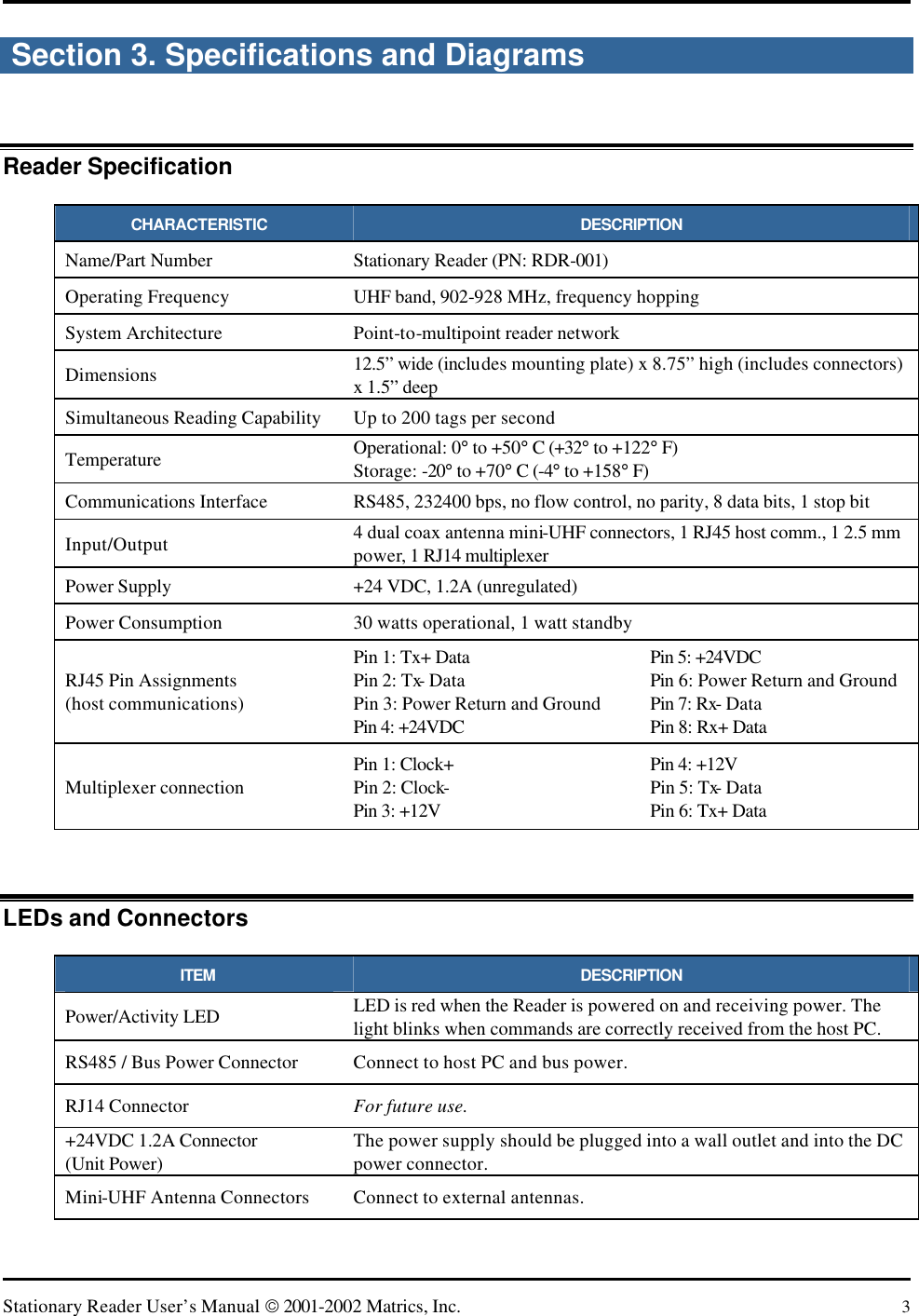
![Stationary Reader User’s Manual 2001-2002 Matrics, Inc. 5 Connections Diagram unspec.485convertorHost/PCStationary ReaderRDR-001GeneralPurposeAntennaGeneralPurposeAntennaGeneralPurposeAntennaGeneralPurposeAntennaRG-142B(25' max.)123 4LocalPower(optional)WiringBlock5' PatchWiringBlockBelden #88757or equivalent(22 ga. CAT3)RJ45RJ45 CAT5std patch5' max.miniUHFWiringBlockBus PowerWiringBlockWiringBlock Reader 20 (max. for bus power)Reader 32 (max. for local power)WiringBlockStd 485 BusTerminatorRx ± ] 120ΩTx ± ] 120Ω250'max.buspowered-or-500'max.locallypoweredFunctional System ConnectionsMatrics, Inc. 04/10/02Reader 1Std 485 BusTerminatorRx ± ] 120ΩTx ± ] 120Ω](https://usermanual.wiki/Symbol-Technologies/RDR001/User-Guide-267517-Page-9.png)