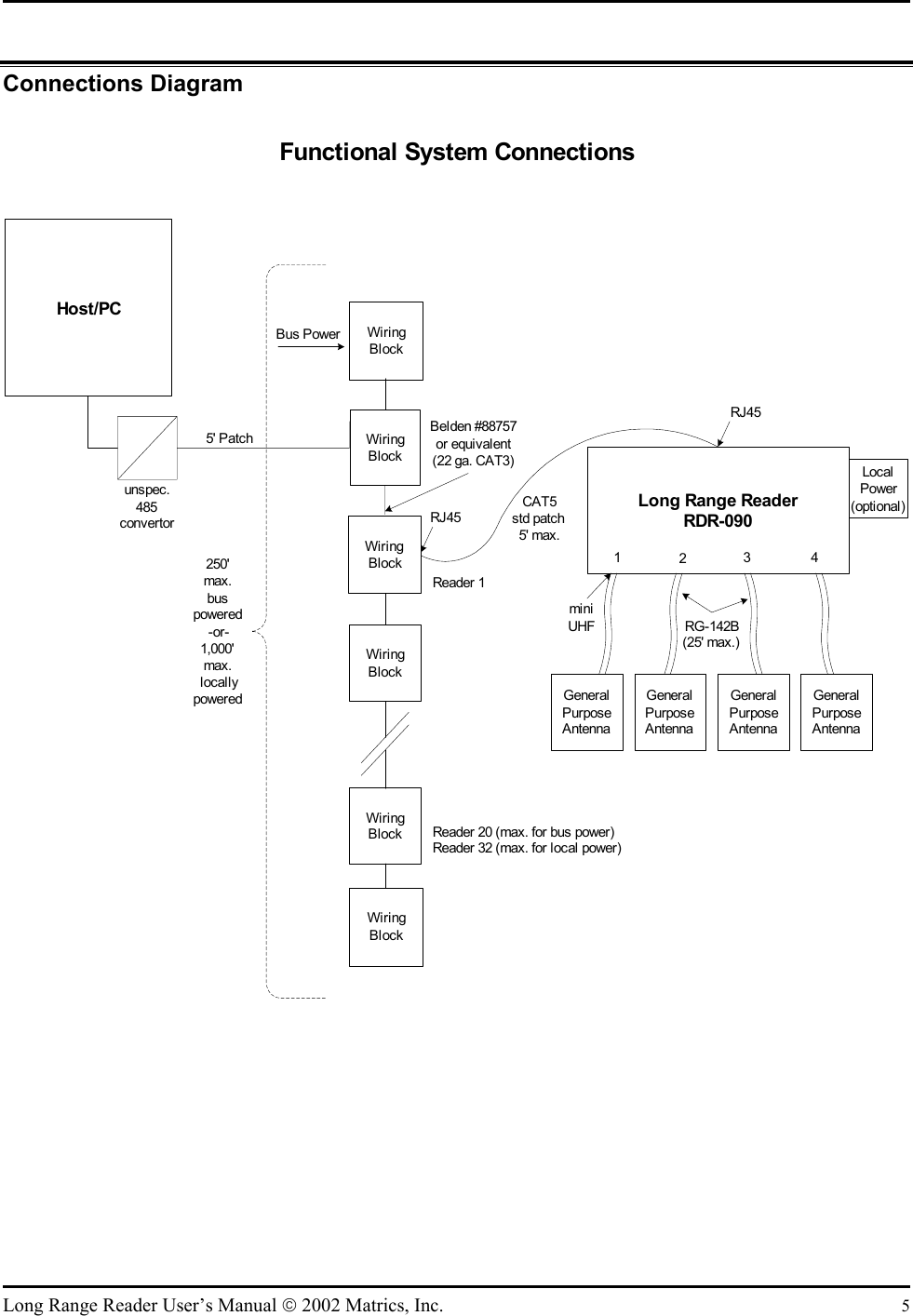
Symbol Technologies RDR090 Tag Reader User Manual Long Range Reader User s Manual

Symbol Technologies, Inc Tag Reader Long Range Reader User s Manual

Manual

             Long Range Reader User’s Manual  Published: November 26, 2002 Document Control Number: MNI02H006                Matrics, Inc. 8850 Stanford Boulevard Suite 3000 Columbia, MD 21045 Tel:  410.872.0300  Fax: 410.872.0700  http://www.matrics.com
  Notices Copyright  2002 Matrics, Inc. All rights reserved. This document is protected by copyright with all rights reserved. No part of the document may be reproduced or transmitted by any means or in any form without prior consent in writing from Matrics, Inc.  Trademarks Matrics is a trademark of Matrics, Inc. All other product names or logos mentioned herein are used for identification purposes only, and are the trademarks of their respective owners.  Statement of Rights IMPORTANT – READ CAREFULLY: Matrics products incorporate technology that is protected by U.S. patent and other intellectual property (IP) rights owned by Matrics, Inc, and other rights owners. Use of these products constitutes your legal agreement to honor Matrics’ IP rights as protected by applicable laws. Reverse engineering, decompiling, or disassembly of Matrics products is strictly prohibited. Violators will be prosecuted.  ii  Long Range Reader User’s Manual  2002 Matrics, Inc.
 Contents SECTION 1. INTRODUCTION ................................................................................................1 Document Conventions..................................................................................................1 Acronyms and Abbreviations ........................................................................................1 Disclaimer......................................................................................................................1 SECTION 2. SYSTEM DESCRIPTION .....................................................................................2 Product Description .......................................................................................................2 SECTION 3. SPECIFICATIONS AND DIAGRAMS ....................................................................3 Reader Specification ......................................................................................................3 LEDs and Connectors ....................................................................................................3 Reader Diagram .............................................................................................................4 Connections Diagram.....................................................................................................5 SECTION 4. GETTING STARTED...........................................................................................6 What’s Included? ...........................................................................................................6 SECTION 5. INSTALLATION..................................................................................................7 Mount the Reader...........................................................................................................7 Connect Antenna(s) to the Reader .................................................................................8 Connect the Reader to a Host Computer .......................................................................8 Power On (and Off) the Reader .....................................................................................8 Verify the Reader Installation........................................................................................9 Reader On? ......................................................................................................................... 9 Test Read Range .................................................................................................................9 SECTION 6. CAUTIONS, NOTES, AND APPROVALS ............................................................10 SECTION 7. WARRANTIES AND RETURNS .........................................................................11 Limited Warranty.........................................................................................................11 Return Material Authorization (RMA) ........................................................................11 SECTION 8. TROUBLESHOOTING .......................................................................................12 SECTION 9. CONTACT US..................................................................................................13    Long Range Reader User’s Manual  2002 Matrics, Inc.  iii
  This page left intentionally blank. iv  Long Range Reader User’s Manual  2002 Matrics, Inc.
 Section 1. Introduction This Long Range Reader User’s Manual, designed for the Matrics RFID System end-user, describes the Long Range Reader (PN: RDR-090) and how to install it. Document Conventions The following conventions are used in this User’s Manual: CONVENTION DESCRIPTION 1.  Numbered list  Provides step-by-step procedures for performing an action •  Bulleted list  Provides grouped information, not procedural steps  Acronyms and Abbreviations The following acronyms and abbreviations are used in this User’s Manual: ACRONYM DEFINITION IC Integrated Circuit MVM  Matrics Visibility Manager OOK  On Off Keyed RFID  Radio Frequency Identification TBD  To Be Determined  Disclaimer While Matrics has committed its best efforts to providing accurate information and timely updates to this User’s Manual, we assume no responsibility for any inaccuracies that may be contained herein, and we reserve the right to make changes to this User’s Manual without notice.  Long Range Reader User’s Manual  2002 Matrics, Inc.  1
 Section 2. System Description Matrics develops and markets Radio Frequency Identification (RFID) solutions that are effective and affordable by offering a combination of low cost, long read range, and a very high read rate unmatched by other RFID systems. A Matrics RFID System gives you real-time, end-to-end visibility of products and assets in your factory, distribution center, retail outlet, or other facility. A typical Matrics RFID system consists of three main components:  •  Silicon-based RFID tags that can be attached to vehicles, trailers, containers, pallets, boxes, etc., to create a “people-free” wireless environment for tracking assets,  •  Reader network components (readers, antennas, cables, connectors, power supplies, etc.) that power and communicate with the tags, and •  The Matrics Visibility Manager (MVM) software that runs on your choice of host computer and collects tag data automatically. Product Description The Matrics Long Range Reader (PN: RDR-090) is an industrial strength fixed Reader targeted to indoor applications, such as warehouses. The Reader offers superior and robust read range capabilities, anti-collision features, and very high data read rates unmatched by other systems. It can be easily mounted in areas of ingress and egress where large numbers of tagged objects are inbound or outbound in a logistics process. It is packaged ready to be interfaced to your host computer, and can easily be programmed to perform specific tasks. The Reader provides all of the RF and control functions required to power and communicate with Matrics passive RFID tags (PN: SDR-001 and DDS-001.) It sends digital data to the tag (through one antenna at any given time) on a pulse width modulated On Off Keyed (OOK) transmitter signal, demodulates the identification signal received from the tag, and then sends the data to your host computer.  The Matrics Reader network is structured to allow for flexibility in system configurations and in the arrangement of read points to optimize coverage at a low overall cost. A typical configuration consists of up to four (4) high performance antennas attached directly to a single Reader. The system also employs a unique, patented reader-driven interrogation protocol that allows several hundred tags to be read each second. This powerful read rate supplies the muscle to overcome interference in noisy environments, and to guarantee the accuracy of reads when tags are moving at high velocities. It also assures acceptable data collection timing when reading large volumes of inventory. Readers can be powered either locally or through the network cable in the event there is not a local power source near by, and to minimize overall network infrastructure costs.  2  Long Range Reader User’s Manual  2002 Matrics, Inc.
  Section 3. Specifications and Diagrams Reader Specification CHARACTERISTIC DESCRIPTION Name/Part Number  Long Range Reader (PN: RDR-090) Operating Frequency  UHF band, FCC Part 90 (909.75-921.75 MHz) Operating Channels  16 System Architecture  Point-to-point and Point-to-multipoint reader network Dimensions  12.5” wide (includes mounting plate) x 8.75” high (includes connectors) x 1.5” deep Temperature  Operational: 0° to +50° C (+32° to +122° F) Storage: -20° to +70° C (-4° to +158° F) Communications Interface  RS485, 232400 bps, no flow control, no parity, 8 data bits, 1 stop bit Input/Output  4 dual coax antenna mini-UHF connectors, 1 RJ45 host comm., 1 2.5 mm power, 1 RJ14 multiplexer Power Supply  +24 VDC, 1.2A (unregulated) Power Consumption  30 watts operational, 1 watt standby RJ45 Pin Assignments (host communications) Pin 1: Tx+ Data Pin 2: Tx- Data Pin 3: Power Return and Ground Pin 4: +24VDC Pin 5: +24VDC Pin 6: Power Return and Ground Pin 7: Rx- Data Pin 8: Rx+ Data Special Features connection (RJ14) Pin 1: Clock+ Pin 2: Clock- Pin 3: +12V Pin 4: +12V Pin 5: Tx- Data Pin 6: Tx+ Data  LEDs and Connectors ITEM DESCRIPTION Power/Activity LED  LED is red when the Reader is powered on and receiving power. The light blinks when commands are correctly received from the host PC. RS485 / Bus Power Connector  Connect to host PC and bus power. RJ14 Connector  For future use. +24VDC 1.2A Connector (Unit Power) The power supply should be plugged into a wall outlet and into the DC power connector. Mini-UHF Antenna Connectors  Connect to external antennas.    Long Range Reader User’s Manual  2002 Matrics, Inc.  3
 Reader Diagram  Long Range ReaderPart No. RDR-090Special FeaturesConnectorTx4Tx3Tx2Tx1Rx4Rx3Rx2Rx1485 / Bus PowerConnector Power/ActivityLED+24VDC1.2A Connector(Unit Power)MountingPlateMountingPlate12.5" wide (includes mounting plate)x 8.75" high (includes connectors)Antenna Connectors 4  Long Range Reader User’s Manual  2002 Matrics, Inc.
 Connections Diagram  unspec.485convertorHost/PCLong Range ReaderRDR-090GeneralPurposeAntennaGeneralPurposeAntennaGeneralPurposeAntennaGeneralPurposeAntennaRG-142B(25' max.)1234LocalPower(optional)WiringBlock5' PatchWiringBlockBelden #88757or equi valent(22 ga. CAT3)RJ45RJ45CAT5std patch5' max.miniUHFWiringBlockBus PowerWiringBlockWiringBlock Reader 20 (max. for bus power)Reader 32 (max. for local power)WiringBlock250'max.buspowered-or-1,000'max.locallypoweredFunctional System ConnectionsReader 1   Long Range Reader User’s Manual  2002 Matrics, Inc.  5
 Section 4. Getting Started What’s Included? Before you proceed with your Reader installation, check that you have all of the items you need. Contact Matrics (refer to the “Contact Us” section in this User’s Manual) if any of the parts listed in this section are missing from your Reader package, or any of the items you received are damaged. NOTE: You should use ONLY those parts provided in your Reader package or specifically recommended by Matrics. Do not substitute any other cables, etc., since doing so may degrade your system’s performance, damage your Reader, and void your warranty. In addition to this User’s Manual, you should have received the following items in your package:   PART NUMBER (PN)  QTY.  DESCRIPTION RDR-090  1  Long Range Reader    1  CAT3 cable termination block (“wiring block”)   1  3-foot data cable  In addition, you will need: •  Matrics Reader Networking Kit (PN: NKT-001) to connect the Reader to your host computer, •  A power supply for your Reader (such as PN: PWR-001, available from Matrics), •  (4) screws for mounting the Reader, and •  several wire ties to secure any extra lengths of cable. 6  Long Range Reader User’s Manual  2002 Matrics, Inc.
 Section 5. Installation Follow the steps listed below (and detailed in the following sections) to install, configure, and test your Reader: 1.  Mount the Reader in a location chosen for optimal surveillance. 2.  Connect antenna(s) to the Reader. 3.  Connect the Reader to your host computer. 4.  Power on the Reader. 5.  Verify that your Reader installation is operational.  Mount the Reader Before mounting the Reader, you must select a location for it. For best results, consider the following when determining the optimal placement for your Reader:  Mount the Reader indoors, in operating range, and out of direct sunlight, high moisture, or extreme temperatures.  Mount the Reader in an area free from electromagnetic interference. Such sources of interference may include: generators, pumps, converters, non-interruptible power supplies, AC switching relays, light dimmers, computer CRT terminals, etc.  Mount the Reader within 15 feet of your antennas (antenna connector cables from Matrics are 15-feet long.)  Make sure the local power supply cord, when attached to the Reader, can reach the power source outlet.  Do not mount the Reader within 12 inches of a computer CRT terminal.  Make sure that you will be mounting the Reader onto a permanent fixture (wall or shelf) where it won’t get disturbed, bumped, or damaged. Keep in mind that you will need five (5) inches of clearance on all sides of the Reader.  CAUTION: If the Reader is not installed properly, it could be damaged and your system performance diminished.  Long Range Reader User’s Manual  2002 Matrics, Inc.  7
 To mount the Reader: 1.  Position the Reader (PN: RDR-090) at the desired mounting position on the wall, shelf, or enclosure. Make sure that there are five (5) inches of clearance on all sides of the Reader. 2.  Using the pre-drilled holes at the corners of the Reader to guide you, drill four holes for mounting the reader. 3.  Securely affix the Reader to the wall of shelf using the four screws that you provided. Connect Antenna(s) to the Reader Attach your antenna(s) to the Reader in sequential order (first connecting Antenna 1 to Reader connectors Tx1 and Rx1, then Antenna 2 to Reader connectors Tx2 and Rx2, Antenna 3 to the Tx3/Rx3 connectors next, and Antenna 4 to the Tx4/Rx4 connectors last.) 1.  Attach the large ends of your antenna connector cables to the large connectors on the antenna. 2.  Attach the small ends of the cables to the corresponding connectors on the Reader (Antenna 1 to Reader connectors Tx1 and Rx1, etc.) 3.  Secure your cables using wire ties (do not bend the cables.) WARNING: Do not disconnect antenna cables when actively reading tags (if the LED is lit on the Reader, don’t disconnect the antenna cables.) You could severely damage your Reader. Make sure that you unplug the power supply to power off the system first before disconnecting cables. Connect the Reader to a Host Computer The steps you must follow to interface the Reader with your system depend upon the software package you choose to use. Contact Matrics for more information. Regardless of the software you use to do it, you must change your Readers’ factory-assigned xFF address to a unique address for communicating with your host computer. Power On (and Off) the Reader 1.  Connect a 24V DC power supply (such as PN: PWR-001, available from Matrics) to the Reader’s Unit Power port. 2.  To power on the system, insert the plug end of the power supply into a power outlet. The Power/Activity LED on the Reader should light red, indicating that the Reader is powered on and the system is live. 8  Long Range Reader User’s Manual  2002 Matrics, Inc.
 3.  To power off the Reader, unplug the power supply from the power outlet. The Power/Activity LED on the Reader should turn off, indicating that the Reader is powered off and the system is not operational. Verify the Reader Installation  Reader On? After you have installed the Reader as described in this User’s Manual, test that the Reader is on by following the instructions provided above in the “Power on (and Off) the Reader” section. To verify that the Reader is operational, power it on by plugging the power supply (attached to the Reader) into the appropriate power outlet. The Power/Activity LED on the Reader should light red, indicating that the Reader is powered on and the system is operational. Test Read Range After you have installed the Reader as described in this User’s Manual, you should test the read distance of your hardware configuration to verify that it meets your needs. To do so, you’ll need a tag, and access to an application (such as the one provided in Matrics’ Evaluation System) that can communicate with your Reader to process tag data in a continuously polling mode of operation. 1.  Remove all but one tag from the 50-foot test area. 2.  Load and run your application that will communicate with (and process tag data from) the Reader. 3.  Verify that the Reader’s LED is flashing, indicating that it is properly communicating with your application. 4.  Hold a tag in front of you (with the tag face parallel to the Reader face) close to the Reader antenna. NOTE: For purposes of this test, we recommend that you do not hold the tag at an angle, or wave the tag in front of the Reader, as that may cause inconsistencies in your test results. 5.  Using your application, verify that Reader has detected and read the tag. 6.  Walk slowly with the tag, moving it around to the extreme edges of the test area. 7.  Using your application, adjust the Reader’s power output to ensure desired areas read the tag and undesired areas do not. 8.  Repeat this procedure for each antenna on all Readers in your system.   Long Range Reader User’s Manual  2002 Matrics, Inc.  9
 Section 6. Cautions, Notes, and Approvals Matrics products are approved (or approval pending) by the appropriate regulatory agencies: •  Federal Communications Commission (FCC), Part 90  Note: This equipment has been tested and found to comply with the limits for a Class A digital device, pursuant to Part 90 of the FCC Rules. These limits are designed to provide reasonable protection against harmful interference when the equipment is operated in a commercial environment. This equipment generates, uses, and can radiate radio frequency energy and, if not installed and used in accordance with the User’s Manual, may cause harmful interference to radio communications. Operation of this equipment in a residential area is likely to cause harmful interference in which case the user will be required to correct the interference at his or her own expense. CAUTION: Changes or modifications not expressly approved by the party responsible for compliance could void the user’s authority to operate the equipment. Information to the User: This device complies with Part 90 of the FCC Rules. Operation is subject to the following two conditions: (1) This device may not cause harmful interference, and (2) This device must accept any interference received, including interference that may cause undesired operation. WARNING: This device must be installed in a location that is not accessible to the general public. Install the device so that the antenna is at least two (2) meters from unsuspecting personnel. Failure to install this device as described will result in a failure to comply with FCC rules for RF exposure and is discouraged. Disclaimer: Operation of any radio transmitting equipment, including this product, may interfere with the functionality of inadequately protected medical devices. Consult a physician or the manufacturer of the medical device if you have any questions. Other electronic equipment may also be subject to interference. 10  Long Range Reader User’s Manual  2002 Matrics, Inc.
 Section 7. Warranties and Returns Limited Warranty Matrics warrants its products to the original purchaser to be free of defects in workmanship and material for a period of ninety (90) days from date of receipt. Matrics’ sole and complete responsibility under this warranty is expressly limited to repair or replacement of the defective product. Replacement products may be new or reconditioned. All products that are replaced shall become the property of Matrics. The warranty for replacement products is the same as the equivalent newly purchased product. Any tampering or modification to the product, or subjecting of product to abnormal electrical, mechanical, or environmental abuse will void this product warranty. Return Material Authorization (RMA)  You must obtain a return material authorization (RMA) number from Matrics Customer Service (refer to the “Contact Us” section in this User’s Manual) before you return any parts for repair or replacement. This RMA number must be clearly marked on the outside of the returned package, and referenced in any correspondence contained within the package. NOTE: If you return parts to Matrics without a RMA number, they may be returned to you at your own expense. Before you call Matrics to receive a RMA number, make sure that you have the following information available for the Customer Service technician:  A description of the returning item.  Serial numbers (if applicable.)  A description of the fault or failure. (Example: The antenna cable appears to have been pulled out of the antenna, and the system is not functioning.)  Fault or Error message (if applicable.)    Long Range Reader User’s Manual  2002 Matrics, Inc.  11
 Section 8. Troubleshooting In the event that you encounter a problem with your system, refer to the following table for possible solutions: PROBLEM POSSIBLE CAUSE SOLUTION The Reader’s Power/Activity LED doesn’t light. The AC outlet may not be working or may be controlled by a wall switch. Plug a different electrical appliance into the outlet and turn it on. If the appliance doesn’t work, plug the Reader into a different outlet. The Reader’s Power/Activity LED is on but doesn’t blink. The Reader isn’t communicating with the host PC  -or-  The host PC isn’t communicating with the Reader. Check that your host PC’s port settings are configured properly.  Make sure that you used the Utility software to change the Reader’s factory-assigned xFF address to a unique address for communicating with your host PC.  Check to ensure proper network cabling (including terminators at both ends.)   Verify communications at a fixed 230,400 rate. Read range has degraded noticeably. The environment may not be free from sources of electromagnetic interference. Check that your Reader is installed in a location free from electromagnetic interference sources such as: generators, pumps, converters, non-interruptible power supplies, AC switching relays, light dimmers, computer CRT terminals, etc.  Run system cabling away from other data carrying cables.   12  Long Range Reader User’s Manual  2002 Matrics, Inc.
  Long Range Reader User’s Manual  2002 Matrics, Inc.  13 Section 9. Contact Us For sales, service, and technical assistance, contact Matrics at: Tel: 410.872.0300   Monday-Friday 8:30 a.m. – 5:00 p.m. EST Fax: 410.872.0700  http://www.matrics.com/  Matrics, Inc. 8850 Stanford Boulevard Suite 3000 Columbia, MD 21045 USA

Navigation menu