Symbol Technologies Mc9000 K Users Manual
MC9000-S to the manual 78a8bc03-479a-4e41-9c42-64c0c20f0f66
2015-02-02
: Symbol-Technologies Symbol-Technologies-Mc9000-K-Users-Manual-449065 symbol-technologies-mc9000-k-users-manual-449065 symbol-technologies pdf
Open the PDF directly: View PDF ![]() .
.
Page Count: 534 [warning: Documents this large are best viewed by clicking the View PDF Link!]
- MC9000-K/S
- Contents
- About This Guide
- Getting Started
- Operating the MC9000-K/S
- Settings
- Communications
- Applications
- Spectrum24 Network Configuration
- Accessories
- Introduction
- Keypads
- Multi Media Card (MMC)
- Single Slot Serial/USB Cradle
- Vehicle Cradle
- Four Slot Ethernet Cradle
- Four Slot Charge Only Cradle
- Four Slot Spare Battery Charger
- Magnetic Stripe Reader
- Magnetic Stripe Reading
- Cable Adapter Module
- Universal Battery Charger (UBC) Adapter
- Modem Module
- Wall Mounting Bracket and Shelf Slide
- Software Installation
- AirBEAM Smart
- Mobile Computer Configuration
- Desktop Emulator
- Maintenance and Troubleshooting
- Technical Specifications
- Keypad Maps
- Glossary
- Index
- Tell Us What You Think...
MC9000-K/S
Product Reference Guide
for Embedded Windows® CE .NET


MC9000-K/S for Embedded Windows® CE .NET
Product Reference Guide
72-65262-03
Revision A
June 2004

© 2004 by Symbol Technologies, Inc. All rights reserved.
No part of this publication may be reproduced or used in any form, or by any electrical or mechanical means,
without permission in writing from Symbol. This includes electronic or mechanical means, such as
photocopying, recording, or information storage and retrieval systems. The material in this manual is subject to
change without notice.
The software is provided strictly on an “as is” basis. All software, including firmware, furnished to the user is
on a licensed basis. Symbol grants to the user a non-transferable and non-exclusive license to use each
software or firmware program delivered hereunder (licensed program). Except as noted below, such license may
not be assigned, sublicensed, or otherwise transferred by the user without prior written consent of Symbol. No
right to copy a licensed program in whole or in part is granted, except as permitted under copyright law. The
user shall not modify, merge, or incorporate any form or portion of a licensed program with other program
material, create a derivative work from a licensed program, or use a licensed program in a network without
written permission from Symbol. The user agrees to maintain Symbol’s copyright notice on the licensed
programs delivered hereunder, and to include the same on any authorized copies it makes, in whole or in part.
The user agrees not to decompile, disassemble, decode, or reverse engineer any licensed program delivered to
the user or any portion thereof.
Symbol reserves the right to make changes to any software or product to improve reliability, function, or design.
Symbol does not assume any product liability arising out of, or in connection with, the application or use of any
product, circuit, or application described herein.
No license is granted, either expressly or by implication, estoppel, or otherwise under any Symbol Technologies,
Inc., intellectual property rights. An implied license only exists for equipment, circuits, and subsystems
contained in Symbol products.
Symbol, Spectrum One, and Spectrum24 are registered trademarks of Symbol Technologies, Inc. Bluetooth is a
registered trademark of Bluetooth SIG. Microsoft, Windows and ActiveSync are either registered trademarks
or trademarks of Microsoft Corporation. Other product names mentioned in this manual may be trademarks or
registered trademarks of their respective companies and are hereby acknowledged.
Symbol Technologies, Inc.
One Symbol Plaza
Holtsville, New York 11742-1300
http://www.symbol.com

Revision History
Changes to the previous manual are listed below:
Change Date Description
-01 to -02 1/15/04 Updated Operating system to Win CE 4.2. Added new screens and menus,
Chapter 2 and Chapter 3.
Updated Chapter 6, to include Mobile Companion upgrade from version 3.9.1 to
version 3.9.2.
-02 to -03 6/18/04 Updated Chapter 3, to include new Bluetooth setup and to include new Power
settings.
Updated Chapter 6, to include additional Mobile Companion upgrades for version
3.9.2.
Added new VCD9000 Vehicle Cradle to Chapter 7, Accessories.
Added new MDM9000 Modem Module to Chapter 7, Accessories.


Contents
Chapter. About This Guide
Introduction. . . . . . . . . . . . . . . . . . . . . . . . . . . . . . . . . . . . . . . . . . . . . . . . . . . . . . . . .xix
Chapter Descriptions . . . . . . . . . . . . . . . . . . . . . . . . . . . . . . . . . . . . . . . . . . . . . . . . . xx
Notational Conventions . . . . . . . . . . . . . . . . . . . . . . . . . . . . . . . . . . . . . . . . . . . . . . .xxi
Related Documents and Software . . . . . . . . . . . . . . . . . . . . . . . . . . . . . . . . . . . . . . xxii
Service Information. . . . . . . . . . . . . . . . . . . . . . . . . . . . . . . . . . . . . . . . . . . . . . . . . . xxii
Symbol Support Center. . . . . . . . . . . . . . . . . . . . . . . . . . . . . . . . . . . . . . . . . . .xxiii
Chapter 1. Getting Started
Introduction. . . . . . . . . . . . . . . . . . . . . . . . . . . . . . . . . . . . . . . . . . . . . . . . . . . . . . . . 1-3
Unpacking . . . . . . . . . . . . . . . . . . . . . . . . . . . . . . . . . . . . . . . . . . . . . . . . . . . . . . . . . 1-6
Accessories. . . . . . . . . . . . . . . . . . . . . . . . . . . . . . . . . . . . . . . . . . . . . . . . . . . . . . . . 1-7
Symbol Windows CE SDK and SMDK . . . . . . . . . . . . . . . . . . . . . . . . . . . . . . . . . . . 1-8
Getting Started . . . . . . . . . . . . . . . . . . . . . . . . . . . . . . . . . . . . . . . . . . . . . . . . . . . . . 1-8
Main Battery Insertion and Removal . . . . . . . . . . . . . . . . . . . . . . . . . . . . . . . . . . . . 1-9
Insert the Main Battery. . . . . . . . . . . . . . . . . . . . . . . . . . . . . . . . . . . . . . . . . . . 1-9
Main Battery Removal . . . . . . . . . . . . . . . . . . . . . . . . . . . . . . . . . . . . . . . . . . 1-10

MC9000-K/S for Embedded Windows® CE .NET Product Reference Guide
vi
Battery Charging. . . . . . . . . . . . . . . . . . . . . . . . . . . . . . . . . . . . . . . . . . . . . . . . . . . 1-11
Main Battery and Memory Backup Battery Charging . . . . . . . . . . . . . . . . . . 1-11
Mobile Computer Charging Procedures . . . . . . . . . . . . . . . . . . . . . . . . . . . . . 1-13
Spare Battery Charging. . . . . . . . . . . . . . . . . . . . . . . . . . . . . . . . . . . . . . . . . . . . . . 1-13
Stylus . . . . . . . . . . . . . . . . . . . . . . . . . . . . . . . . . . . . . . . . . . . . . . . . . . . . . . . . . . . 1-14
Hand Strap . . . . . . . . . . . . . . . . . . . . . . . . . . . . . . . . . . . . . . . . . . . . . . . . . . . . . . . 1-15
Starting the Mobile Computer . . . . . . . . . . . . . . . . . . . . . . . . . . . . . . . . . . . . . . . . 1-17
Calibration Screen . . . . . . . . . . . . . . . . . . . . . . . . . . . . . . . . . . . . . . . . . . . . . 1-18
Mobile Computer Configuration. . . . . . . . . . . . . . . . . . . . . . . . . . . . . . . . . . . . . . . 1-19
Chapter 2. Operating the MC9000-K/S
Introduction. . . . . . . . . . . . . . . . . . . . . . . . . . . . . . . . . . . . . . . . . . . . . . . . . . . . . . . . 2-3
Keypads. . . . . . . . . . . . . . . . . . . . . . . . . . . . . . . . . . . . . . . . . . . . . . . . . . . . . . . . . . . 2-3
28-Key Keypad . . . . . . . . . . . . . . . . . . . . . . . . . . . . . . . . . . . . . . . . . . . . . . . . . 2-4
43-Key Keypad . . . . . . . . . . . . . . . . . . . . . . . . . . . . . . . . . . . . . . . . . . . . . . . . . 2-8
53-Key Keypad . . . . . . . . . . . . . . . . . . . . . . . . . . . . . . . . . . . . . . . . . . . . . . . . 2-11
3270 Emulator. . . . . . . . . . . . . . . . . . . . . . . . . . . . . . . . . . . . . . . . . . . . . . . . . 2-14
5250 Emulator. . . . . . . . . . . . . . . . . . . . . . . . . . . . . . . . . . . . . . . . . . . . . . . . . 2-17
VT Emulator . . . . . . . . . . . . . . . . . . . . . . . . . . . . . . . . . . . . . . . . . . . . . . . . . . 2-20
Keypad Special Functions. . . . . . . . . . . . . . . . . . . . . . . . . . . . . . . . . . . . . . . . 2-23
Power Button . . . . . . . . . . . . . . . . . . . . . . . . . . . . . . . . . . . . . . . . . . . . . . . . . . . . . 2-24
Headphone . . . . . . . . . . . . . . . . . . . . . . . . . . . . . . . . . . . . . . . . . . . . . . . . . . . . . . . 2-24
Series 9000 Demo Window . . . . . . . . . . . . . . . . . . . . . . . . . . . . . . . . . . . . . . . . . . 2-25
Taskbar . . . . . . . . . . . . . . . . . . . . . . . . . . . . . . . . . . . . . . . . . . . . . . . . . . . . . . . . . . 2-27
Sart Button . . . . . . . . . . . . . . . . . . . . . . . . . . . . . . . . . . . . . . . . . . . . . . . . . . . 2-29
Keyboard Input Panel Button . . . . . . . . . . . . . . . . . . . . . . . . . . . . . . . . . . . . . 2-29
Desktop Button . . . . . . . . . . . . . . . . . . . . . . . . . . . . . . . . . . . . . . . . . . . . . . . . 2-29
Taskbar Icons . . . . . . . . . . . . . . . . . . . . . . . . . . . . . . . . . . . . . . . . . . . . . . . . . 2-30
Status Icons . . . . . . . . . . . . . . . . . . . . . . . . . . . . . . . . . . . . . . . . . . . . . . 2-30
Active Programs Icons . . . . . . . . . . . . . . . . . . . . . . . . . . . . . . . . . . . . . . 2-30
AC Power/Battery Status Icons . . . . . . . . . . . . . . . . . . . . . . . . . . . . . . . 2-30
Task Manager and Properties. . . . . . . . . . . . . . . . . . . . . . . . . . . . . . . . . . . . . . . . . 2-31
Task Manager. . . . . . . . . . . . . . . . . . . . . . . . . . . . . . . . . . . . . . . . . . . . . 2-31
Properties . . . . . . . . . . . . . . . . . . . . . . . . . . . . . . . . . . . . . . . . . . . . . . . . 2-32

Contents vii
Entering Information. . . . . . . . . . . . . . . . . . . . . . . . . . . . . . . . . . . . . . . . . . . . . . . . 2-34
Entering Information Using Keypad . . . . . . . . . . . . . . . . . . . . . . . . . . . . . . . . 2-34
Entering Information Using the Keyboard Input Panel. . . . . . . . . . . . . . . . . . 2-34
Entering Data via the Bar Code Scanner (Scan Wedge) . . . . . . . . . . . . . . . . 2-34
Data Capture. . . . . . . . . . . . . . . . . . . . . . . . . . . . . . . . . . . . . . . . . . . . . . . . . . . . . . 2-35
Laser Scanning . . . . . . . . . . . . . . . . . . . . . . . . . . . . . . . . . . . . . . . . . . . . . . . . 2-35
Indicator LED Bar . . . . . . . . . . . . . . . . . . . . . . . . . . . . . . . . . . . . . . . . . . . . . . 2-35
Scanning Considerations . . . . . . . . . . . . . . . . . . . . . . . . . . . . . . . . . . . . . . . . 2-36
Imaging . . . . . . . . . . . . . . . . . . . . . . . . . . . . . . . . . . . . . . . . . . . . . . . . . . . . . . . . . . 2-37
Imager. . . . . . . . . . . . . . . . . . . . . . . . . . . . . . . . . . . . . . . . . . . . . . . . . . . . . . . 2-37
Operational Modes. . . . . . . . . . . . . . . . . . . . . . . . . . . . . . . . . . . . . . . . . . . . . 2-37
Decode Mode . . . . . . . . . . . . . . . . . . . . . . . . . . . . . . . . . . . . . . . . . . . . . 2-37
Aiming the Imager . . . . . . . . . . . . . . . . . . . . . . . . . . . . . . . . . . . . . . . . . . . . . 2-38
Resetting the Mobile Computer . . . . . . . . . . . . . . . . . . . . . . . . . . . . . . . . . . . . . . . 2-39
Performing a Warm Boot . . . . . . . . . . . . . . . . . . . . . . . . . . . . . . . . . . . . . . . . 2-39
Performing a Cold Boot. . . . . . . . . . . . . . . . . . . . . . . . . . . . . . . . . . . . . . . . . . 2-40
Waking the Mobile Computer . . . . . . . . . . . . . . . . . . . . . . . . . . . . . . . . . . . . . . . . 2-41
File System Directory Structure . . . . . . . . . . . . . . . . . . . . . . . . . . . . . . . . . . . . . . . 2-42
Flash Storage . . . . . . . . . . . . . . . . . . . . . . . . . . . . . . . . . . . . . . . . . . . . . . . . . . . . . 2-43
Startup Folder . . . . . . . . . . . . . . . . . . . . . . . . . . . . . . . . . . . . . . . . . . . . . . . . . . . . . 2-43
Run Files . . . . . . . . . . . . . . . . . . . . . . . . . . . . . . . . . . . . . . . . . . . . . . . . . . . . . . . . . 2-43
Audio Event Aliasing. . . . . . . . . . . . . . . . . . . . . . . . . . . . . . . . . . . . . . . . . . . . . . . . 2-43
Terminal Emulators. . . . . . . . . . . . . . . . . . . . . . . . . . . . . . . . . . . . . . . . . . . . . . . . . 2-44
Chapter 3. Settings
Introduction. . . . . . . . . . . . . . . . . . . . . . . . . . . . . . . . . . . . . . . . . . . . . . . . . . . . . . . . 3-5
Windows Control Panel Menu . . . . . . . . . . . . . . . . . . . . . . . . . . . . . . . . . . . . . . . . . 3-5
Bluetooth Device Properties. . . . . . . . . . . . . . . . . . . . . . . . . . . . . . . . . . . . . . . 3-8
Bluetooth/S24 Power Settings. . . . . . . . . . . . . . . . . . . . . . . . . . . . . . . . . 3-8
Starting Bluetooth . . . . . . . . . . . . . . . . . . . . . . . . . . . . . . . . . . . . . . . . . 3-11
Certificates . . . . . . . . . . . . . . . . . . . . . . . . . . . . . . . . . . . . . . . . . . . . . . . . . . . 3-15
Date/Time. . . . . . . . . . . . . . . . . . . . . . . . . . . . . . . . . . . . . . . . . . . . . . . . . . . . 3-16
Device Management . . . . . . . . . . . . . . . . . . . . . . . . . . . . . . . . . . . . . . . . . . . 3-17
Dialing. . . . . . . . . . . . . . . . . . . . . . . . . . . . . . . . . . . . . . . . . . . . . . . . . . . . . . . 3-18

MC9000-K/S for Embedded Windows® CE .NET Product Reference Guide
viii
Display . . . . . . . . . . . . . . . . . . . . . . . . . . . . . . . . . . . . . . . . . . . . . . . . . . . . . . 3-20
Background Tab . . . . . . . . . . . . . . . . . . . . . . . . . . . . . . . . . . . . . . . . . . . 3-20
Appearance Tab . . . . . . . . . . . . . . . . . . . . . . . . . . . . . . . . . . . . . . . . . . . 3-21
Input Panel . . . . . . . . . . . . . . . . . . . . . . . . . . . . . . . . . . . . . . . . . . . . . . . . . . . 3-22
Keyboard. . . . . . . . . . . . . . . . . . . . . . . . . . . . . . . . . . . . . . . . . . . . . . . . . . . . . 3-23
Mouse. . . . . . . . . . . . . . . . . . . . . . . . . . . . . . . . . . . . . . . . . . . . . . . . . . . . . . . 3-24
Network and Dial-up Connections . . . . . . . . . . . . . . . . . . . . . . . . . . . . . . . . . 3-25
Owner . . . . . . . . . . . . . . . . . . . . . . . . . . . . . . . . . . . . . . . . . . . . . . . . . . . . . . . 3-26
Identification Tab . . . . . . . . . . . . . . . . . . . . . . . . . . . . . . . . . . . . . . . . . . 3-26
Notes Tab . . . . . . . . . . . . . . . . . . . . . . . . . . . . . . . . . . . . . . . . . . . . . . . . 3-27
Network ID Tab. . . . . . . . . . . . . . . . . . . . . . . . . . . . . . . . . . . . . . . . . . . . 3-27
PC Connection. . . . . . . . . . . . . . . . . . . . . . . . . . . . . . . . . . . . . . . . . . . . . . . . . 3-28
Regional Settings . . . . . . . . . . . . . . . . . . . . . . . . . . . . . . . . . . . . . . . . . . . . . . 3-29
Region Tab . . . . . . . . . . . . . . . . . . . . . . . . . . . . . . . . . . . . . . . . . . . . . . . 3-29
Number Tab . . . . . . . . . . . . . . . . . . . . . . . . . . . . . . . . . . . . . . . . . . . . . . 3-30
Currency Tab. . . . . . . . . . . . . . . . . . . . . . . . . . . . . . . . . . . . . . . . . . . . . . 3-30
Time Tab. . . . . . . . . . . . . . . . . . . . . . . . . . . . . . . . . . . . . . . . . . . . . . . . . 3-31
Date Tab . . . . . . . . . . . . . . . . . . . . . . . . . . . . . . . . . . . . . . . . . . . . . . . . . 3-31
Remove Programs. . . . . . . . . . . . . . . . . . . . . . . . . . . . . . . . . . . . . . . . . . . . . . 3-32
Stylus . . . . . . . . . . . . . . . . . . . . . . . . . . . . . . . . . . . . . . . . . . . . . . . . . . . . . . . 3-33
Double-Tap Tab . . . . . . . . . . . . . . . . . . . . . . . . . . . . . . . . . . . . . . . . . . . 3-33
Calibrate Tab . . . . . . . . . . . . . . . . . . . . . . . . . . . . . . . . . . . . . . . . . . . . . 3-34
System . . . . . . . . . . . . . . . . . . . . . . . . . . . . . . . . . . . . . . . . . . . . . . . . . . . . . . 3-35
General Tab . . . . . . . . . . . . . . . . . . . . . . . . . . . . . . . . . . . . . . . . . . . . . . 3-35
Memory Tab . . . . . . . . . . . . . . . . . . . . . . . . . . . . . . . . . . . . . . . . . . . . . . 3-36
Device Name Tab . . . . . . . . . . . . . . . . . . . . . . . . . . . . . . . . . . . . . . . . . . 3-37
Copyrights Tab . . . . . . . . . . . . . . . . . . . . . . . . . . . . . . . . . . . . . . . . . . . . 3-38
Series 9000 Demo Window . . . . . . . . . . . . . . . . . . . . . . . . . . . . . . . . . . . . . . . . . . 3-39
Control Panel. . . . . . . . . . . . . . . . . . . . . . . . . . . . . . . . . . . . . . . . . . . . . . . . . . . . . . 3-40
About Ctl Panel. . . . . . . . . . . . . . . . . . . . . . . . . . . . . . . . . . . . . . . . . . . . . . . . 3-42
System Version. . . . . . . . . . . . . . . . . . . . . . . . . . . . . . . . . . . . . . . . . . . . . . . . 3-43
Unique Unit ID . . . . . . . . . . . . . . . . . . . . . . . . . . . . . . . . . . . . . . . . . . . . . . . . 3-44
Persist . . . . . . . . . . . . . . . . . . . . . . . . . . . . . . . . . . . . . . . . . . . . . . . . . . . . . . . 3-45
Battery . . . . . . . . . . . . . . . . . . . . . . . . . . . . . . . . . . . . . . . . . . . . . . . . . . . . . . 3-46
Power Settings . . . . . . . . . . . . . . . . . . . . . . . . . . . . . . . . . . . . . . . . . . . . . . . . 3-47

Contents ix
Bluetooth Settings . . . . . . . . . . . . . . . . . . . . . . . . . . . . . . . . . . . . . . . . . . . . . 3-51
Date and Time . . . . . . . . . . . . . . . . . . . . . . . . . . . . . . . . . . . . . . . . . . . . . . . . 3-52
Printer Settings. . . . . . . . . . . . . . . . . . . . . . . . . . . . . . . . . . . . . . . . . . . . . . . . 3-53
Comm Settings . . . . . . . . . . . . . . . . . . . . . . . . . . . . . . . . . . . . . . . . . . . . . . . . 3-56
Display Settings . . . . . . . . . . . . . . . . . . . . . . . . . . . . . . . . . . . . . . . . . . . . . . . 3-57
Audio Settings . . . . . . . . . . . . . . . . . . . . . . . . . . . . . . . . . . . . . . . . . . . . . . . . 3-58
Scanner Settings . . . . . . . . . . . . . . . . . . . . . . . . . . . . . . . . . . . . . . . . . . . . . . 3-59
Reader Parameters. . . . . . . . . . . . . . . . . . . . . . . . . . . . . . . . . . . . . . . . . 3-60
Interface Parameters . . . . . . . . . . . . . . . . . . . . . . . . . . . . . . . . . . . . . . . 3-61
Scan Parameters. . . . . . . . . . . . . . . . . . . . . . . . . . . . . . . . . . . . . . . . . . . 3-62
WAV File. . . . . . . . . . . . . . . . . . . . . . . . . . . . . . . . . . . . . . . . . . . . . . . . . 3-64
Device Information . . . . . . . . . . . . . . . . . . . . . . . . . . . . . . . . . . . . . . . . . 3-65
Scanner Version . . . . . . . . . . . . . . . . . . . . . . . . . . . . . . . . . . . . . . . . . . . 3-66
Chapter 4. Communications
Introduction. . . . . . . . . . . . . . . . . . . . . . . . . . . . . . . . . . . . . . . . . . . . . . . . . . . . . . . . 4-3
Installing Communication Software. . . . . . . . . . . . . . . . . . . . . . . . . . . . . . . . . . . . . 4-3
Installing ActiveSync . . . . . . . . . . . . . . . . . . . . . . . . . . . . . . . . . . . . . . . . . . . . 4-3
Setting up a Partnership. . . . . . . . . . . . . . . . . . . . . . . . . . . . . . . . . . . . . . 4-4
Communication Setup. . . . . . . . . . . . . . . . . . . . . . . . . . . . . . . . . . . . . . . . . . . . . . . . 4-9
Serial Communications Setup . . . . . . . . . . . . . . . . . . . . . . . . . . . . . . . . . . . . 4-10
Serial Connection Setup. . . . . . . . . . . . . . . . . . . . . . . . . . . . . . . . . . . . . 4-10
USB Connection Setup . . . . . . . . . . . . . . . . . . . . . . . . . . . . . . . . . . . . . . . . . . 4-13
Using ActiveSync . . . . . . . . . . . . . . . . . . . . . . . . . . . . . . . . . . . . . . . . . . . . . . 4-15
Ethernet Setup . . . . . . . . . . . . . . . . . . . . . . . . . . . . . . . . . . . . . . . . . . . . . . . . 4-16
Installing MobileDox Cradle Manager. . . . . . . . . . . . . . . . . . . . . . . . . . 4-16
Installing eConnect. . . . . . . . . . . . . . . . . . . . . . . . . . . . . . . . . . . . . . . . . 4-17
Mobile Computer Configuration. . . . . . . . . . . . . . . . . . . . . . . . . . . . . . . 4-20
DHCP Server Configuration . . . . . . . . . . . . . . . . . . . . . . . . . . . . . . . . . . 4-22
Cradle Configuration. . . . . . . . . . . . . . . . . . . . . . . . . . . . . . . . . . . . . . . . 4-23
Connecting to the Internet on a Wireless Network . . . . . . . . . . . . . . . . . . . . . . . . 4-27

MC9000-K/S for Embedded Windows® CE .NET Product Reference Guide
x
Chapter 5. Applications
Introduction. . . . . . . . . . . . . . . . . . . . . . . . . . . . . . . . . . . . . . . . . . . . . . . . . . . . . . . . 5-3
ScanSamp2. . . . . . . . . . . . . . . . . . . . . . . . . . . . . . . . . . . . . . . . . . . . . . . . . . . . . . . . 5-6
ScanSamp2 Windows . . . . . . . . . . . . . . . . . . . . . . . . . . . . . . . . . . . . . . . . . . . 5-6
Parameters Window. . . . . . . . . . . . . . . . . . . . . . . . . . . . . . . . . . . . . . . . . . . . . 5-7
Codes Window . . . . . . . . . . . . . . . . . . . . . . . . . . . . . . . . . . . . . . . . . . . . . . . . . 5-8
InkWiz File Browser . . . . . . . . . . . . . . . . . . . . . . . . . . . . . . . . . . . . . . . . . . . . . . . . . 5-9
Internet Explorer . . . . . . . . . . . . . . . . . . . . . . . . . . . . . . . . . . . . . . . . . . . . . . . 5-10
Browsing the Web . . . . . . . . . . . . . . . . . . . . . . . . . . . . . . . . . . . . . . . . . 5-10
Setting up a Proxy Server. . . . . . . . . . . . . . . . . . . . . . . . . . . . . . . . . . . . 5-11
Remote Desktop . . . . . . . . . . . . . . . . . . . . . . . . . . . . . . . . . . . . . . . . . . . . . . . 5-12
Connecting to a Terminal Server . . . . . . . . . . . . . . . . . . . . . . . . . . . . . . 5-12
Disconnecting Without Ending a Session . . . . . . . . . . . . . . . . . . . . . . . 5-12
Disconnecting and Ending a Session . . . . . . . . . . . . . . . . . . . . . . . . . . . 5-13
AudioSamp . . . . . . . . . . . . . . . . . . . . . . . . . . . . . . . . . . . . . . . . . . . . . . . . . . . . . . . 5-13
Images . . . . . . . . . . . . . . . . . . . . . . . . . . . . . . . . . . . . . . . . . . . . . . . . . . . . . . 5-14
PC Link . . . . . . . . . . . . . . . . . . . . . . . . . . . . . . . . . . . . . . . . . . . . . . . . . . . . . . 5-16
Copying Files. . . . . . . . . . . . . . . . . . . . . . . . . . . . . . . . . . . . . . . . . . . . . . 5-16
About OTL . . . . . . . . . . . . . . . . . . . . . . . . . . . . . . . . . . . . . . . . . . . . . . . . . . . . 5-17
Self Test . . . . . . . . . . . . . . . . . . . . . . . . . . . . . . . . . . . . . . . . . . . . . . . . . . . . . 5-18
Notify . . . . . . . . . . . . . . . . . . . . . . . . . . . . . . . . . . . . . . . . . . . . . . . . . . . . . . . 5-21
Keyboard. . . . . . . . . . . . . . . . . . . . . . . . . . . . . . . . . . . . . . . . . . . . . . . . . . . . . 5-22
Display . . . . . . . . . . . . . . . . . . . . . . . . . . . . . . . . . . . . . . . . . . . . . . . . . . . . . . 5-23
Memory. . . . . . . . . . . . . . . . . . . . . . . . . . . . . . . . . . . . . . . . . . . . . . . . . . . . . . 5-24
MSR9000 . . . . . . . . . . . . . . . . . . . . . . . . . . . . . . . . . . . . . . . . . . . . . . . . . . . . 5-25
MSR Cameo . . . . . . . . . . . . . . . . . . . . . . . . . . . . . . . . . . . . . . . . . . . . . . . . . . 5-26
Printing . . . . . . . . . . . . . . . . . . . . . . . . . . . . . . . . . . . . . . . . . . . . . . . . . . . . . . . . . . 5-27

Contents xi
Chapter 6. Spectrum24 Network Configuration
Introduction. . . . . . . . . . . . . . . . . . . . . . . . . . . . . . . . . . . . . . . . . . . . . . . . . . . . . . . . 6-3
Mobile Companion . . . . . . . . . . . . . . . . . . . . . . . . . . . . . . . . . . . . . . . . . . . . . . . . . . 6-4
Finding WLANs. . . . . . . . . . . . . . . . . . . . . . . . . . . . . . . . . . . . . . . . . . . . . . . . . 6-6
Status . . . . . . . . . . . . . . . . . . . . . . . . . . . . . . . . . . . . . . . . . . . . . . . . . . . . . . . 6-19
Setting Options. . . . . . . . . . . . . . . . . . . . . . . . . . . . . . . . . . . . . . . . . . . . . . . . 6-24
Changing Profiles . . . . . . . . . . . . . . . . . . . . . . . . . . . . . . . . . . . . . . . . . . . . . . 6-26
Editing a Profile . . . . . . . . . . . . . . . . . . . . . . . . . . . . . . . . . . . . . . . . . . . 6-26
Creating a New Profile. . . . . . . . . . . . . . . . . . . . . . . . . . . . . . . . . . . . . . 6-26
Deleting a Profile . . . . . . . . . . . . . . . . . . . . . . . . . . . . . . . . . . . . . . . . . . 6-26
Ordering Profiles. . . . . . . . . . . . . . . . . . . . . . . . . . . . . . . . . . . . . . . . . . . 6-26
Using LEAP for Wireless Network Security . . . . . . . . . . . . . . . . . . . . . . . . . . . . . . 6-27
Configuring Advanced Password Options . . . . . . . . . . . . . . . . . . . . . . . 6-27
Spectrum24 Frequency Hopping (FH) Settings (1 and 2 MB Radios) . . . . . . . . . . . 6-30
Mobile Unit Tab . . . . . . . . . . . . . . . . . . . . . . . . . . . . . . . . . . . . . . . . . . . . . . . 6-31
MicroAP Tab . . . . . . . . . . . . . . . . . . . . . . . . . . . . . . . . . . . . . . . . . . . . . . . . . . 6-33
Encryption Tab . . . . . . . . . . . . . . . . . . . . . . . . . . . . . . . . . . . . . . . . . . . . . . . . 6-34
WLAN Adapter Tab . . . . . . . . . . . . . . . . . . . . . . . . . . . . . . . . . . . . . . . . . . . . 6-36
Password Protecting NCPA . . . . . . . . . . . . . . . . . . . . . . . . . . . . . . . . . . 6-37
Configuring the S24 DS (11 Mb) Radio Using a Registry File . . . . . . . . . . . . . . . . 6-38
Configuring the S24 FH (2 Mb) Radio Using a Registry File. . . . . . . . . . . . . . . . . . 6-38
Chapter 7. Accessories
Introduction. . . . . . . . . . . . . . . . . . . . . . . . . . . . . . . . . . . . . . . . . . . . . . . . . . . . . . . . 7-5
Cradles . . . . . . . . . . . . . . . . . . . . . . . . . . . . . . . . . . . . . . . . . . . . . . . . . . . . . . . 7-5
Keypads . . . . . . . . . . . . . . . . . . . . . . . . . . . . . . . . . . . . . . . . . . . . . . . . . . . . . . 7-5
Miscellaneous . . . . . . . . . . . . . . . . . . . . . . . . . . . . . . . . . . . . . . . . . . . . . . . . . 7-5
Snap-on Modules . . . . . . . . . . . . . . . . . . . . . . . . . . . . . . . . . . . . . . . . . . . . . . . 7-6
Keypads. . . . . . . . . . . . . . . . . . . . . . . . . . . . . . . . . . . . . . . . . . . . . . . . . . . . . . . . . . . 7-7
Replacing the Keypad. . . . . . . . . . . . . . . . . . . . . . . . . . . . . . . . . . . . . . . . . . . . 7-7
Multi Media Card (MMC) . . . . . . . . . . . . . . . . . . . . . . . . . . . . . . . . . . . . . . . . . . . . . 7-8
Single Slot Serial/USB Cradle . . . . . . . . . . . . . . . . . . . . . . . . . . . . . . . . . . . . . . . . 7-10
Setup. . . . . . . . . . . . . . . . . . . . . . . . . . . . . . . . . . . . . . . . . . . . . . . . . . . . . . . . 7-12
Battery Charging. . . . . . . . . . . . . . . . . . . . . . . . . . . . . . . . . . . . . . . . . . . . . . . 7-13
Vehicle Cradle. . . . . . . . . . . . . . . . . . . . . . . . . . . . . . . . . . . . . . . . . . . . . . . . . . . . . 7-14
Setup. . . . . . . . . . . . . . . . . . . . . . . . . . . . . . . . . . . . . . . . . . . . . . . . . . . . . . . . 7-17

MC9000-K/S for Embedded Windows® CE .NET Product Reference Guide
xii
Mounting . . . . . . . . . . . . . . . . . . . . . . . . . . . . . . . . . . . . . . . . . . . . . . . . 7-18
Power Connection. . . . . . . . . . . . . . . . . . . . . . . . . . . . . . . . . . . . . . . . . . 7-20
Serial Connection . . . . . . . . . . . . . . . . . . . . . . . . . . . . . . . . . . . . . . . . . . 7-23
Mobile Computer Insertion and Removal. . . . . . . . . . . . . . . . . . . . . . . . . . . . 7-24
Mobile Computer Battery Charging . . . . . . . . . . . . . . . . . . . . . . . . . . . . . . . . 7-25
Spare Battery Insertion and Removal. . . . . . . . . . . . . . . . . . . . . . . . . . . . . . . 7-26
Spare Battery Charging . . . . . . . . . . . . . . . . . . . . . . . . . . . . . . . . . . . . . . . . . 7-26
LED Indicators. . . . . . . . . . . . . . . . . . . . . . . . . . . . . . . . . . . . . . . . . . . . . . . . . 7-27
Care and Cleaning . . . . . . . . . . . . . . . . . . . . . . . . . . . . . . . . . . . . . . . . . . . . . 7-27
Four Slot Ethernet Cradle . . . . . . . . . . . . . . . . . . . . . . . . . . . . . . . . . . . . . . . . . . . . 7-28
Setup. . . . . . . . . . . . . . . . . . . . . . . . . . . . . . . . . . . . . . . . . . . . . . . . . . . . . . . . 7-29
Battery Charging Indicators . . . . . . . . . . . . . . . . . . . . . . . . . . . . . . . . . . . . . . 7-30
Four Slot Charge Only Cradle . . . . . . . . . . . . . . . . . . . . . . . . . . . . . . . . . . . . . . . . . 7-30
Setup. . . . . . . . . . . . . . . . . . . . . . . . . . . . . . . . . . . . . . . . . . . . . . . . . . . . . . . . 7-31
Battery Charging Indicators . . . . . . . . . . . . . . . . . . . . . . . . . . . . . . . . . . . . . . 7-31
Four Slot Spare Battery Charger. . . . . . . . . . . . . . . . . . . . . . . . . . . . . . . . . . . . . . . 7-32
Spare Battery Charging with the Four Slot Spare Battery Charger . . . . . . . . 7-33
LED Charge Indications. . . . . . . . . . . . . . . . . . . . . . . . . . . . . . . . . . . . . . . . . . 7-33
Magnetic Stripe Reader . . . . . . . . . . . . . . . . . . . . . . . . . . . . . . . . . . . . . . . . . . . . . 7-34
MSR and CAM Installation/Removal . . . . . . . . . . . . . . . . . . . . . . . . . . . . . . . 7-35
Power Connection. . . . . . . . . . . . . . . . . . . . . . . . . . . . . . . . . . . . . . . . . . . . . . 7-36
LED Charge Indications. . . . . . . . . . . . . . . . . . . . . . . . . . . . . . . . . . . . . . . . . . 7-36
Serial/USB Connection. . . . . . . . . . . . . . . . . . . . . . . . . . . . . . . . . . . . . . . . . . 7-37
Magnetic Stripe Reading . . . . . . . . . . . . . . . . . . . . . . . . . . . . . . . . . . . . . . . . . . . . 7-38
Cable Adapter Module . . . . . . . . . . . . . . . . . . . . . . . . . . . . . . . . . . . . . . . . . . . . . . 7-40
CAM and MSR Communications Setup . . . . . . . . . . . . . . . . . . . . . . . . . . . . . 7-41
Universal Battery Charger (UBC) Adapter . . . . . . . . . . . . . . . . . . . . . . . . . . . . . . . 7-42
Modem Module . . . . . . . . . . . . . . . . . . . . . . . . . . . . . . . . . . . . . . . . . . . . . . . . . . . 7-45
Setup. . . . . . . . . . . . . . . . . . . . . . . . . . . . . . . . . . . . . . . . . . . . . . . . . . . . . . . . 7-46
Connecting to the Mobile Computer . . . . . . . . . . . . . . . . . . . . . . . . . . . 7-46
Connecting to the Single Slot Serial/USB Cradle . . . . . . . . . . . . . . . . . 7-47
Configuring the Mobile Computer for the Modem. . . . . . . . . . . . . . . . . . . . . 7-47
Connecting the Modem . . . . . . . . . . . . . . . . . . . . . . . . . . . . . . . . . . . . . . . . . 7-49
Modem Country Setup . . . . . . . . . . . . . . . . . . . . . . . . . . . . . . . . . . . . . . . . . . 7-50
AT Commands. . . . . . . . . . . . . . . . . . . . . . . . . . . . . . . . . . . . . . . . . . . . . . . . . 7-51
Changing the Initialization String. . . . . . . . . . . . . . . . . . . . . . . . . . . . . . 7-51
Basic AT Command Syntax. . . . . . . . . . . . . . . . . . . . . . . . . . . . . . . . . . . 7-53

Contents xiii
Commands . . . . . . . . . . . . . . . . . . . . . . . . . . . . . . . . . . . . . . . . . . . . . . . 7-54
Modem LED Indicators . . . . . . . . . . . . . . . . . . . . . . . . . . . . . . . . . . . . . . . . . . 7-58
Wall Mounting Bracket and Shelf Slide. . . . . . . . . . . . . . . . . . . . . . . . . . . . . . . . . 7-59
Installing the Wall Mount Bracket . . . . . . . . . . . . . . . . . . . . . . . . . . . . . . . . . 7-59
Attaching the Shelf Slide to the Wall Mount Bracket . . . . . . . . . . . . . . . . . . 7-60
One Single Slot Cradle/Four Slot Battery Charger. . . . . . . . . . . . . . . . . 7-60
Two Single Slot Cradles/Four Slot Battery Chargers. . . . . . . . . . . . . . . . . . . 7-60
Four Slot Cradle . . . . . . . . . . . . . . . . . . . . . . . . . . . . . . . . . . . . . . . . . . . 7-61
Installing the Cradle/Charger on the Bracket. . . . . . . . . . . . . . . . . . . . . . . . . 7-62
Chapter 8. Software Installation
Introduction. . . . . . . . . . . . . . . . . . . . . . . . . . . . . . . . . . . . . . . . . . . . . . . . . . . . . . . . 8-3
Symbol Windows CE SMDK. . . . . . . . . . . . . . . . . . . . . . . . . . . . . . . . . . . . . . . . . . . 8-3
Hardware Requirements. . . . . . . . . . . . . . . . . . . . . . . . . . . . . . . . . . . . . . . . . . 8-3
Software Requirements . . . . . . . . . . . . . . . . . . . . . . . . . . . . . . . . . . . . . . . . . . 8-3
SMDK Components . . . . . . . . . . . . . . . . . . . . . . . . . . . . . . . . . . . . . . . . . . . . . 8-4
Installing the SMDK . . . . . . . . . . . . . . . . . . . . . . . . . . . . . . . . . . . . . . . . . . . . . 8-4
Software Updates. . . . . . . . . . . . . . . . . . . . . . . . . . . . . . . . . . . . . . . . . . . . . . . 8-4
Chapter 9. AirBEAM Smart
Introduction. . . . . . . . . . . . . . . . . . . . . . . . . . . . . . . . . . . . . . . . . . . . . . . . . . . . . . . . 9-3
AirBEAM Package Builder . . . . . . . . . . . . . . . . . . . . . . . . . . . . . . . . . . . . . . . . . . . . 9-3
AirBEAM Smart Client . . . . . . . . . . . . . . . . . . . . . . . . . . . . . . . . . . . . . . . . . . . . . . . 9-3
AirBEAM Smart License . . . . . . . . . . . . . . . . . . . . . . . . . . . . . . . . . . . . . . . . . . 9-4
Configuring the AirBEAM Smart Client . . . . . . . . . . . . . . . . . . . . . . . . . . . . . . 9-4
Packages(1) Tab . . . . . . . . . . . . . . . . . . . . . . . . . . . . . . . . . . . . . . . . . . . . 9-5
Packages(2) Tab . . . . . . . . . . . . . . . . . . . . . . . . . . . . . . . . . . . . . . . . . . . . 9-5
Server Tab. . . . . . . . . . . . . . . . . . . . . . . . . . . . . . . . . . . . . . . . . . . . . . . . . 9-6
Misc(1) Tab. . . . . . . . . . . . . . . . . . . . . . . . . . . . . . . . . . . . . . . . . . . . . . . . 9-7
Misc(2) Tab. . . . . . . . . . . . . . . . . . . . . . . . . . . . . . . . . . . . . . . . . . . . . . . . 9-8
Misc(3) Tab. . . . . . . . . . . . . . . . . . . . . . . . . . . . . . . . . . . . . . . . . . . . . . . 9-10
Synchronizing with the Server . . . . . . . . . . . . . . . . . . . . . . . . . . . . . . . . . . . . 9-10
Manual Synchronization. . . . . . . . . . . . . . . . . . . . . . . . . . . . . . . . . . . . . 9-10
Automatic Synchronization. . . . . . . . . . . . . . . . . . . . . . . . . . . . . . . . . . . 9-11
AirBEAM Smart Staging. . . . . . . . . . . . . . . . . . . . . . . . . . . . . . . . . . . . . . . . . . . . . 9-11

MC9000-K/S for Embedded Windows® CE .NET Product Reference Guide
xiv
Chapter 10. Mobile Computer Configuration
Introduction. . . . . . . . . . . . . . . . . . . . . . . . . . . . . . . . . . . . . . . . . . . . . . . . . . . . . . . 10-3
Starting Terminal Configuration Manager . . . . . . . . . . . . . . . . . . . . . . . . . . . . . . . 10-4
Defining Script Properties. . . . . . . . . . . . . . . . . . . . . . . . . . . . . . . . . . . . . . . . . . . . 10-7
Creating the Script for the Hex Image . . . . . . . . . . . . . . . . . . . . . . . . . . . . . . . . . . 10-8
Opening a New or Existing Script . . . . . . . . . . . . . . . . . . . . . . . . . . . . . . . . . 10-9
Updating TCM 1.X Scripts . . . . . . . . . . . . . . . . . . . . . . . . . . . . . . . . . . . . . . . 10-9
Copying Components to the Script. . . . . . . . . . . . . . . . . . . . . . . . . . . . . . . . . 10-9
Saving the Script . . . . . . . . . . . . . . . . . . . . . . . . . . . . . . . . . . . . . . . . . . . . . . 10-9
Building the Image . . . . . . . . . . . . . . . . . . . . . . . . . . . . . . . . . . . . . . . . . . . . . . . . 10-10
Sending the Hex Image. . . . . . . . . . . . . . . . . . . . . . . . . . . . . . . . . . . . . . . . . . . . . 10-11
TCM Error Messages . . . . . . . . . . . . . . . . . . . . . . . . . . . . . . . . . . . . . . . . . . . . . . 10-21
IPL Error Detection . . . . . . . . . . . . . . . . . . . . . . . . . . . . . . . . . . . . . . . . . . . . . . . . 10-23
Creating a Splash Screen . . . . . . . . . . . . . . . . . . . . . . . . . . . . . . . . . . . . . . . . . . . 10-26
Splash Screen Format. . . . . . . . . . . . . . . . . . . . . . . . . . . . . . . . . . . . . . . . . . 10-26
Flash Storage . . . . . . . . . . . . . . . . . . . . . . . . . . . . . . . . . . . . . . . . . . . . . . . . . . . . 10-27
FFS Partitions . . . . . . . . . . . . . . . . . . . . . . . . . . . . . . . . . . . . . . . . . . . . . . . . 10-27
Working with FFS Partitions. . . . . . . . . . . . . . . . . . . . . . . . . . . . . . . . . . . . . 10-27
RegMerge.dll . . . . . . . . . . . . . . . . . . . . . . . . . . . . . . . . . . . . . . . . . . . . 10-28
CopyFiles. . . . . . . . . . . . . . . . . . . . . . . . . . . . . . . . . . . . . . . . . . . . . . . . 10-29
Non-FFS Partitions . . . . . . . . . . . . . . . . . . . . . . . . . . . . . . . . . . . . . . . . . . . . 10-29
Downloading Partitions to the Terminal . . . . . . . . . . . . . . . . . . . . . . . . . . . 10-30
IPL . . . . . . . . . . . . . . . . . . . . . . . . . . . . . . . . . . . . . . . . . . . . . . . . . . . . . . . . . . . . . 10-30
Partition Update vs. File Update. . . . . . . . . . . . . . . . . . . . . . . . . . . . . . . . . . 10-30
Upgrade Requirements. . . . . . . . . . . . . . . . . . . . . . . . . . . . . . . . . . . . . . . . . 10-31
Chapter 11. Desktop Emulator
Introduction. . . . . . . . . . . . . . . . . . . . . . . . . . . . . . . . . . . . . . . . . . . . . . . . . . . . . . . 11-3
Software Requirements . . . . . . . . . . . . . . . . . . . . . . . . . . . . . . . . . . . . . . . . . . . . . 11-3
Installation Procedures. . . . . . . . . . . . . . . . . . . . . . . . . . . . . . . . . . . . . . . . . . . . . . 11-3
Starting the Emulator . . . . . . . . . . . . . . . . . . . . . . . . . . . . . . . . . . . . . . . . . . . . . . . 11-3
Emulator Parameter Settings and Displays . . . . . . . . . . . . . . . . . . . . . . . . . . . . . . 11-7
Emulator Tab. . . . . . . . . . . . . . . . . . . . . . . . . . . . . . . . . . . . . . . . . . . . . . . . . . 11-9
Storage Tab . . . . . . . . . . . . . . . . . . . . . . . . . . . . . . . . . . . . . . . . . . . . . . . . . 11-10
Scanner Tab . . . . . . . . . . . . . . . . . . . . . . . . . . . . . . . . . . . . . . . . . . . . . . . . . 11-11
Spectrum24 Tab . . . . . . . . . . . . . . . . . . . . . . . . . . . . . . . . . . . . . . . . . . . . . . 11-12

Contents xv
Battery Tab . . . . . . . . . . . . . . . . . . . . . . . . . . . . . . . . . . . . . . . . . . . . . . . . . . 11-13
Status Tab. . . . . . . . . . . . . . . . . . . . . . . . . . . . . . . . . . . . . . . . . . . . . . . . . . . 11-14
Using the Emulator . . . . . . . . . . . . . . . . . . . . . . . . . . . . . . . . . . . . . . . . . . . . . . . . 11-16
User Inputs . . . . . . . . . . . . . . . . . . . . . . . . . . . . . . . . . . . . . . . . . . . . . . . . . . 11-16
Mouse Inputs . . . . . . . . . . . . . . . . . . . . . . . . . . . . . . . . . . . . . . . . . . . . 11-16
Keypad Inputs. . . . . . . . . . . . . . . . . . . . . . . . . . . . . . . . . . . . . . . . . . . . 11-16
Taskbar . . . . . . . . . . . . . . . . . . . . . . . . . . . . . . . . . . . . . . . . . . . . . . . . . . . . . 11-16
Start Button . . . . . . . . . . . . . . . . . . . . . . . . . . . . . . . . . . . . . . . . . . . . . 11-16
AC Power/Battery Status Icons . . . . . . . . . . . . . . . . . . . . . . . . . . . . . . 11-17
Taskbar Icons and Buttons . . . . . . . . . . . . . . . . . . . . . . . . . . . . . . . . . . 11-17
Open Programs . . . . . . . . . . . . . . . . . . . . . . . . . . . . . . . . . . . . . . . . . . . 11-17
Main Menu . . . . . . . . . . . . . . . . . . . . . . . . . . . . . . . . . . . . . . . . . . . . . . . . . . . . . . 11-17
Start Menu . . . . . . . . . . . . . . . . . . . . . . . . . . . . . . . . . . . . . . . . . . . . . . . . . . 11-17
Exiting the Emulator . . . . . . . . . . . . . . . . . . . . . . . . . . . . . . . . . . . . . . . . . . . . . . . 11-17
Resetting the Emulator. . . . . . . . . . . . . . . . . . . . . . . . . . . . . . . . . . . . . . . . . . . . . 11-18
Chapter 12. Maintenance and Troubleshooting
Introduction. . . . . . . . . . . . . . . . . . . . . . . . . . . . . . . . . . . . . . . . . . . . . . . . . . . . . . . 12-3
Maintaining the Mobile Computer. . . . . . . . . . . . . . . . . . . . . . . . . . . . . . . . . . . . . 12-3
Troubleshooting . . . . . . . . . . . . . . . . . . . . . . . . . . . . . . . . . . . . . . . . . . . . . . . . . . . 12-4
Four Slot Charge Only Cradle . . . . . . . . . . . . . . . . . . . . . . . . . . . . . . . . . . . . . 12-7
Four Slot Ethernet Cradle . . . . . . . . . . . . . . . . . . . . . . . . . . . . . . . . . . . . . . . . 12-8
Four Slot Spare Battery Charger. . . . . . . . . . . . . . . . . . . . . . . . . . . . . . . . . . 12-10
Single Slot Serial/USB Cradle . . . . . . . . . . . . . . . . . . . . . . . . . . . . . . . . . . . 12-10
Cable Adapter Module . . . . . . . . . . . . . . . . . . . . . . . . . . . . . . . . . . . . . . . . . 12-12
Magnetic Stripe Reader . . . . . . . . . . . . . . . . . . . . . . . . . . . . . . . . . . . . . . . . 12-12
MDM9000 Modem Module . . . . . . . . . . . . . . . . . . . . . . . . . . . . . . . . . . . . . 12-14
VCD9000 Vehicle Cradle. . . . . . . . . . . . . . . . . . . . . . . . . . . . . . . . . . . . . . . . 12-16

MC9000-K/S for Embedded Windows® CE .NET Product Reference Guide
xvi
Appendix A. Technical Specifications
Mobile Computer Technical Specifications . . . . . . . . . . . . . . . . . . . . . . . . . . . . . . . A-3
MDM9000 Modem Module Technical Specifications . . . . . . . . . . . . . . . . . . . . . . . A-5
Mobile Computer Pin-Outs . . . . . . . . . . . . . . . . . . . . . . . . . . . . . . . . . . . . . . . . . . . . A-7
Accessory CAM and MSR Pin-Outs . . . . . . . . . . . . . . . . . . . . . . . . . . . . . . . . . . . . . A-8
Appendix B. Keypad Maps
Introduction. . . . . . . . . . . . . . . . . . . . . . . . . . . . . . . . . . . . . . . . . . . . . . . . . . . . . . . . B-3
Keypads. . . . . . . . . . . . . . . . . . . . . . . . . . . . . . . . . . . . . . . . . . . . . . . . . . . . . . . . . . . B-3
28-Key Keypad (MC9000-K) . . . . . . . . . . . . . . . . . . . . . . . . . . . . . . . . . . . . . . . B-5
43-Key Keypad (MC9000-K) . . . . . . . . . . . . . . . . . . . . . . . . . . . . . . . . . . . . . . B-25
53-Key Keypad (MC9000-K) . . . . . . . . . . . . . . . . . . . . . . . . . . . . . . . . . . . . . . B-36
3270 Emulator. . . . . . . . . . . . . . . . . . . . . . . . . . . . . . . . . . . . . . . . . . . . . . . . . B-46
5250 Emulator. . . . . . . . . . . . . . . . . . . . . . . . . . . . . . . . . . . . . . . . . . . . . . . . . B-54
VT Emulator Keypad . . . . . . . . . . . . . . . . . . . . . . . . . . . . . . . . . . . . . . . . . . . . B-62
28-Key Keypad (MC9000-S) . . . . . . . . . . . . . . . . . . . . . . . . . . . . . . . . . . . . . . B-72
Glossary
Index
Tell Us What You Think...

About This Guide
Chapter Contents
Introduction. . . . . . . . . . . . . . . . . . . . . . . . . . . . . . . . . . . . . . . . . . . . . . . . . . . . . . . . . . . . . . . . . . . . . . . . xix
Chapter Descriptions . . . . . . . . . . . . . . . . . . . . . . . . . . . . . . . . . . . . . . . . . . . . . . . . . . . . . . . . . . . . . . . . . xx
Notational Conventions . . . . . . . . . . . . . . . . . . . . . . . . . . . . . . . . . . . . . . . . . . . . . . . . . . . . . . . . . . . . . . . xxi
Related Documents and Software . . . . . . . . . . . . . . . . . . . . . . . . . . . . . . . . . . . . . . . . . . . . . . . . . . . . . . xxii
Service Information . . . . . . . . . . . . . . . . . . . . . . . . . . . . . . . . . . . . . . . . . . . . . . . . . . . . . . . . . . . . . . . . . xxii
Symbol Support Center. . . . . . . . . . . . . . . . . . . . . . . . . . . . . . . . . . . . . . . . . . . . . . . . . . . . . . . . . . . xxiii

MC9000-K/S for Embedded Windows® CE .NET Product Reference Guide
xviii

About This Guide xix
Introduction
The MC9000-K/S Product Reference Guide provides information about the MC9000-K and
MC9000-S mobile computers using the Embedded Windows® CE .NET operating system and its
accessories. The MC9000-K and MC9000-S includes the following variations:
• MC9000-K: Windows® CE operating system performs 1-dimensional bar code scanning
with batch communication; memory configuration (32 or 64) MB ROM/(32 or 64) MB RAM;
28-key, 43-key and 53-key interchangeable keypads; QVGA color touch panel display.
• MC9060-K: Windows® CE operating system performs 1-dimensional bar code scanning
(models with an integrated laser scanner), or 1-dimensional and 2-dimensional bar code
scanning (models with an integrated imager); 802.11b Spectrum24® wireless technology to
perform wireless local area network (WLAN) communication; monochrome or QVGA color
touch panel display; memory configuration (32 or 64) MB ROM/(32 or 64) MB RAM; 28-key,
43-key and 53-key interchangeable keypads.
• MC9000-S: Windows® CE operating system performs 1-dimensional bar code scanning
with batch communication; memory configuration (32 or 64) MB ROM/(32 or 64) MB RAM;
28-key keypad; QVGA color touch panel display.
• MC9010-S: Windows® CE operating system performs 1-dimensional bar code scanning
with integrated laser scanner; 802.11 Spectrum24® wireless technology to perform
wireless local area network (WLAN) communication; memory configuration (32 or 64) MB
ROM/(32 or 64) MB RAM; 28-key keypad; QVGA monochrome touch panel display.
• MC9060-S: Windows® CE operating system performs 1-dimensional bar code scanning
with integrated laser scanner; 802.11b Spectrum24® wireless technology to perform
wireless local area network (WLAN) communication; memory configuration (32 or 64) MB
ROM/(32 or 64) MB RAM; 28-key keypad; monochrome or QVGA color touch panel display.

MC9000-K/S for Embedded Windows® CE .NET Product Reference Guide
xx
Chapter Descriptions
Topics covered in this guide are as follows:
•Chapter 1, Getting Started describes the mobile computer’s physical characteristics,
explains how to install and charge the batteries, explains how to replace the strap lanyard,
and explains how to start the mobile computer for the first time.
•Chapter 2, Operating the MC9000-K/S explains how to use the mobile computer. This
includes instructions for powering on and resetting the mobile computer, entering and
scanning.
•Chapter 3, Settings explains how to adjust settings on the mobile computer.
•Chapter 4, Communications explains how to use Microsoft® ActiveSync™ for
communications between the mobile computer and host computer.
•Chapter 5, Applications explains how to use the installed applications.
•Chapter 6, Spectrum24 Network Configuration explains how to configure the Spectrum24
wireless connection.
•Chapter 7, Accessories describes the mobile computer accessories, including setup and
configuration.
•Chapter 8, Software Installation provides an overview of the Software Mobility Developer’s
Kit (SMDK) installation and its uses.
•Chapter 9, AirBEAM Smart explains how to set up the mobile computer to synchronize with
a server using the AirBEAM Smart Client and AirBEAM Staging applications.
•Chapter 10, Mobile Computer Configuration describes how to use the Terminal
Configuration Manager (TCM) and describes how to use the Initial Program Loader (IPL).
•Chapter 11, Desktop Emulator provides instructions for installing the desktop emulator on
the host computer and using the desktop emulator as an aid in developing applications.
•Chapter 12, Maintenance and Troubleshooting provides information on proper mobile
computer maintenance and troubleshooting.
•Appendix A, Technical Specifications includes the technical specifications and connector pin
outs for the mobile computer.
•Appendix B, Keypad Maps provides the keypad mapping information for the mobile
computer.

About This Guide xxi
Notational Conventions
The following conventions are used in this document:
• “Mobile computer” refers to any Symbol terminal.
• “User” refers to anyone using an application on the terminal.
•Italics are used to highlight the following:
• chapters and sections in this and related documents
• dialog box, window and screen names
• drop-down list and list box names
• check box and radio button names
• icons on a screen.
•Bold text is used to highlight the following:
• key names on a keypad
• button names on a screen.
• Bullets (•) indicate:
• action items
• lists of alternatives
• lists of required steps that are not necessarily sequential.
• Sequential lists (e.g., those that describe step-by-step procedures) appear as numbered
lists.

MC9000-K/S for Embedded Windows® CE .NET Product Reference Guide
xxii
Related Documents and Software
The following documents provide more information about the MC9000-K and MC9000-S.
•MC9000-G Quick Start Guide (poster), p/n 72-63360-xx
•MC9000-G Licensing, Patent and Regulatory Information, p/n 72-65260-xx
•Windows CE Help File for Symbol Terminals, p/n 72E-38880-xx
•UBC 2000 Quick Reference Guide 70-33188-xx.
•Symbol Mobility Developer Kit for .NET (SMDK for .NET), available at:
http://www.symbol.com/mc9000-k and http://www.symbol.com/mc9000-s
• Symbol Windows CE SMDK for Series 9000, available at:
http://www.symbol.com/mc9000-k and http://www.symbol.com/mc9000-s
• eConnect software, available at: http://devzone.symbol.com
• ActiveSync software, available at the Microsoft web site:
http://www.microsoft.com.
Service Information
If you have a problem with your equipment, contact the Symbol Support Center for your region. See
page xxiii for contact information. Before calling, have the model number, serial number and several
of your bar code symbols at hand.
Call the Support Center from a phone near the scanning equipment so that the service person can try
to talk you through your problem. If the equipment is found to be working properly and the problem
is symbol readability, the Support Center will request samples of your bar codes for analysis at our
plant.
If your problem cannot be solved over the phone, you may need to return your equipment for servicing.
If that is necessary, you will be given specific directions.
Symbol Technologies is not responsible for any damages incurred
during shipment if the approved shipping container is not used.
Shipping the units improperly can possibly void the warranty. If the
original shipping container was not kept, contact Symbol to obtain a
new shipping container.

About This Guide xxiii
Symbol Support Center
For service information, warranty information or technical assistance contact or call the Symbol
Support Center in:
United States
Symbol Technologies, Inc.
One Symbol Plaza
Holtsville, New York 11742-1300
Tel: 1-800-653-5350
Canada
Symbol Technologies Canada, Inc.
2540 Matheson Boulevard East
Mississauga, Ontario, Canada L4W 4Z2
Tel: 905-629-7226
United Kingdom
Symbol Technologies
Symbol Place
Winnersh Triangle, Berkshire RG41 5TP
United Kingdom
Tel: 0800 328 2424 (Inside UK)
Tel: +44 118 945 7529 (Outside UK)
Asia/Pacific
Symbol Technologies Asia, Inc (Singapore Branch)
230 Victoria Street #05-07/09
Bugis Junction Office Tower
Singapore 188024
Tel: +65-6796-9600
Fax: +65-6337-6488
Australia
Symbol Technologies Pty. Ltd.
432 St. Kilda Road
Melbourne, Victoria 3004
Tel: 1-800-672-906 (Inside Australia)
Tel: +61-3-9866-6044 (Outside Australia)
Austria/Österreich
Symbol Technologies Austria GmbH
Prinz-Eugen Strasse 70 / 2.Haus
1040 Vienna, Austria
Tel: 01-5055794-0 (Inside Austria)
Tel: +43-1-5055794-0 (Outside Austria)
Denmark/Danmark
Symbol Technologies AS
Dr. Neergaardsvej 3
2970 Hørsholm
Tel: 7020-1718 (Inside Denmark)
Tel: +45-7020-1718 (Outside Denmark)
Europe/Mid-East Distributor Operations
Contact your local distributor or call:
Tel: +44 118 945 7360
Finland/Suomi
Oy Symbol Technologies
Kaupintie 8 A 6
FIN-00440 Helsinki, Finland
Tel: 9 5407 580 (Inside Finland)
Tel: +358 9 5407 580 (Outside Finland)
France
Symbol Technologies France
Centre d'Affaire d'Antony
3 Rue de la Renaissance
92184 Antony Cedex, France
Tel: 01-40-96-52-21 (Inside France)
Tel: +33-1-40-96-52-50 (Outside France)

MC9000-K/S for Embedded Windows® CE .NET Product Reference Guide
xxiv
Germany/Deutchland
Symbol Technologies GmbH
Waldstrasse 66
D-63128 Dietzenbach, Germany
Tel: 6074-49020 (Inside Germany)
Tel: +49-6074-49020 (Outside Germany)
Italy/Italia
Symbol Technologies Italia S.R.L.
Via Cristoforo Columbo, 49
20090 Trezzano S/N Navigilo
Milano, Italy
Tel: 2-484441 (Inside Italy)
Tel: +39-02-484441 (Outside Italy)
Latin America Sales Support
2730 University Dr.
Coral Springs, FL 33065 USA
Tel: 1-800-347-0178 (Inside United States)
Tel: +1-954-255-2610 (Outside United States)
Fax: 954-340-9454
Mexico/México
Symbol Technologies Mexico Ltd.
Torre Picasso
Boulevard Manuel Avila Camacho No 88
Lomas de Chapultepec CP 11000
Mexico City, DF, Mexico
Tel: 5-520-1835 (Inside Mexico)
Tel: +52-5-520-1835 (Outside Mexico)
Netherlands/Nederland
Symbol Technologies
Kerkplein 2, 7051 CX
Postbus 24 7050 AA
Varsseveld, Netherlands
Tel: 315-271700 (Inside Netherlands)
Tel: +31-315-271700 (Outside Netherlands)
Norway/Norge
Symbol’s registered and mailing address:
Symbol Technologies Norway
Hoybratenveien 35 C
N-1055 OSLO, Norway
Symbol’s repair depot and shipping address:
Symbol Technologies Norway
Enebakkveien 123
N-0680 OSLO, Norway
Tel: +47 2232 4375
South Africa
Symbol Technologies Africa Inc.
Block B2
Rutherford Estate
1 Scott Street
Waverly 2090 Johannesburg
Republic of South Africa
Tel: 11-809 5311 (Inside South Africa)
Tel: +27-11-809 5311 (Outside South Africa)
Spain/España
Symbol Technologies S.L.
Avenida de Bruselas, 22
Edificio Sauce
Alcobendas, Madrid 28108
Spain
Tel: 91 324 40 00 (Inside Spain)
Tel: +34 91 324 40 00 (Outside Spain)
Fax: +34.91.324.4010

About This Guide xxv
If the Symbol product was purchased from a Symbol Business Partner, contact that Business Partner
for service.
For the latest version of this guide go to:http://www.symbol.com/manuals.
Sweden/Sverige
“Letter” address:
Symbol Technologies AB
Box 1354
S-171 26 SOLNA
Sweden
Visit/shipping address:
Symbol Technologies AB
Solna Strandväg 78
S-171 54 SOLNA
Sweden
Tel: Switchboard: 08 445 29 00 (domestic)
Tel: Call Center: +46 8 445 29 29 (international)
Support E-Mail: Sweden.Support@se.symbol.com

MC9000-K/S for Embedded Windows® CE .NET Product Reference Guide
xxvi

Getting Started
Chapter Contents
Introduction. . . . . . . . . . . . . . . . . . . . . . . . . . . . . . . . . . . . . . . . . . . . . . . . . . . . . . . . . . . . . . . . . . . . . . . . .1-3
Unpacking . . . . . . . . . . . . . . . . . . . . . . . . . . . . . . . . . . . . . . . . . . . . . . . . . . . . . . . . . . . . . . . . . . . . . . . . . .1-6
Accessories. . . . . . . . . . . . . . . . . . . . . . . . . . . . . . . . . . . . . . . . . . . . . . . . . . . . . . . . . . . . . . . . . . . . . . . . .1-7
Symbol Windows CE SDK and SMDK . . . . . . . . . . . . . . . . . . . . . . . . . . . . . . . . . . . . . . . . . . . . . . . . . . . .1-8
Getting Started . . . . . . . . . . . . . . . . . . . . . . . . . . . . . . . . . . . . . . . . . . . . . . . . . . . . . . . . . . . . . . . . . . . . . .1-8
Main Battery Insertion and Removal . . . . . . . . . . . . . . . . . . . . . . . . . . . . . . . . . . . . . . . . . . . . . . . . . . . . .1-9
Insert the Main Battery . . . . . . . . . . . . . . . . . . . . . . . . . . . . . . . . . . . . . . . . . . . . . . . . . . . . . . . . . . .1-9
Main Battery Removal . . . . . . . . . . . . . . . . . . . . . . . . . . . . . . . . . . . . . . . . . . . . . . . . . . . . . . . . . . .1-10
Battery Charging. . . . . . . . . . . . . . . . . . . . . . . . . . . . . . . . . . . . . . . . . . . . . . . . . . . . . . . . . . . . . . . . . . . .1-11
Main Battery and Memory Backup Battery Charging . . . . . . . . . . . . . . . . . . . . . . . . . . . . . . . . . . .1-11
Mobile Computer Charging Procedures . . . . . . . . . . . . . . . . . . . . . . . . . . . . . . . . . . . . . . . . . . . . . .1-13

MC9000-K/S for Embedded Windows® CE .NET Product Reference Guide
1-2
Spare Battery Charging. . . . . . . . . . . . . . . . . . . . . . . . . . . . . . . . . . . . . . . . . . . . . . . . . . . . . . . . . . . . . . .1-13
Stylus . . . . . . . . . . . . . . . . . . . . . . . . . . . . . . . . . . . . . . . . . . . . . . . . . . . . . . . . . . . . . . . . . . . . . . . . . . . .1-14
Hand Strap . . . . . . . . . . . . . . . . . . . . . . . . . . . . . . . . . . . . . . . . . . . . . . . . . . . . . . . . . . . . . . . . . . . . . . . .1-15
Starting the Mobile Computer . . . . . . . . . . . . . . . . . . . . . . . . . . . . . . . . . . . . . . . . . . . . . . . . . . . . . . . . .1-17
Calibration Screen . . . . . . . . . . . . . . . . . . . . . . . . . . . . . . . . . . . . . . . . . . . . . . . . . . . . . . . . . . . . . .1-18
Mobile Computer Configuration. . . . . . . . . . . . . . . . . . . . . . . . . . . . . . . . . . . . . . . . . . . . . . . . . . . . . . . .1-19
Getting Started 1-3
Introduction
This chapter describes the mobile computer’s physical characteristics, how to install and charge the
batteries, replace the strap lanyard, remove and replace the stylus and start the mobile computer for
the first time.
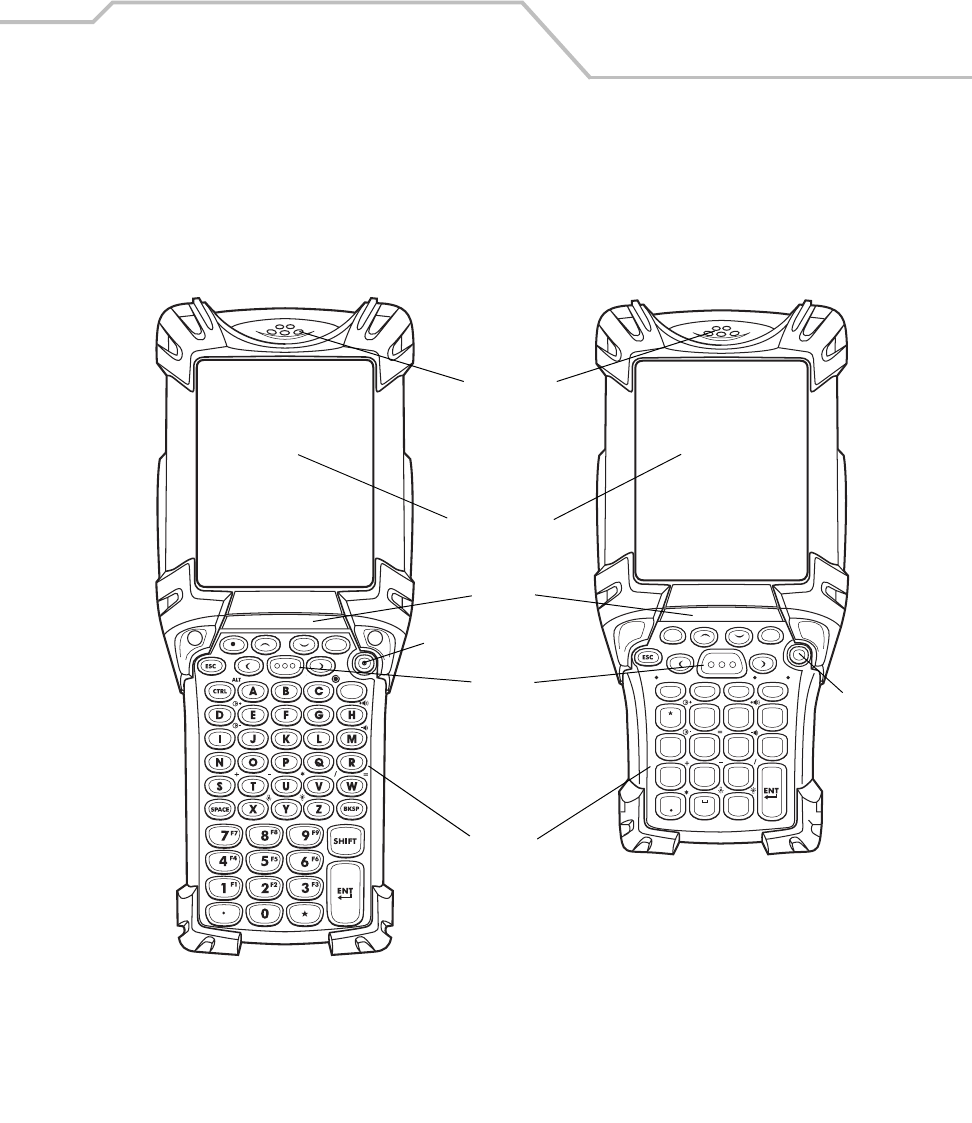
Figure 1-1. MC9000-K and MC9000-S: Front View
Touch Screen
CTRL SPACE ALPHA
BKSP
SHIFT
ALT
12
ABC 3
DEF
4
GHI
7
PQRS 8
0#
TUV 9
WXYZ
5
JKL 6
MNO
Keypad
Indicator
LED Bar
Microphone
Power
Scan
Button Power
MC9000-K MC9000-S
MC9000-K/S for Embedded Windows® CE .NET Product Reference Guide
1-4
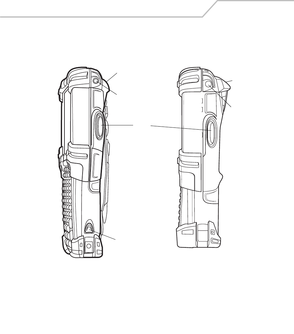
Figure 1-2. MC9000-K and MC9000-S: Side View
Exit Window
Headphone Jack
(optional)
Exit
Window
Headphone
Jack (optional)
Scan
Button
MC9000-K MC9000-S
Primary Battery
Release
Getting Started 1-5
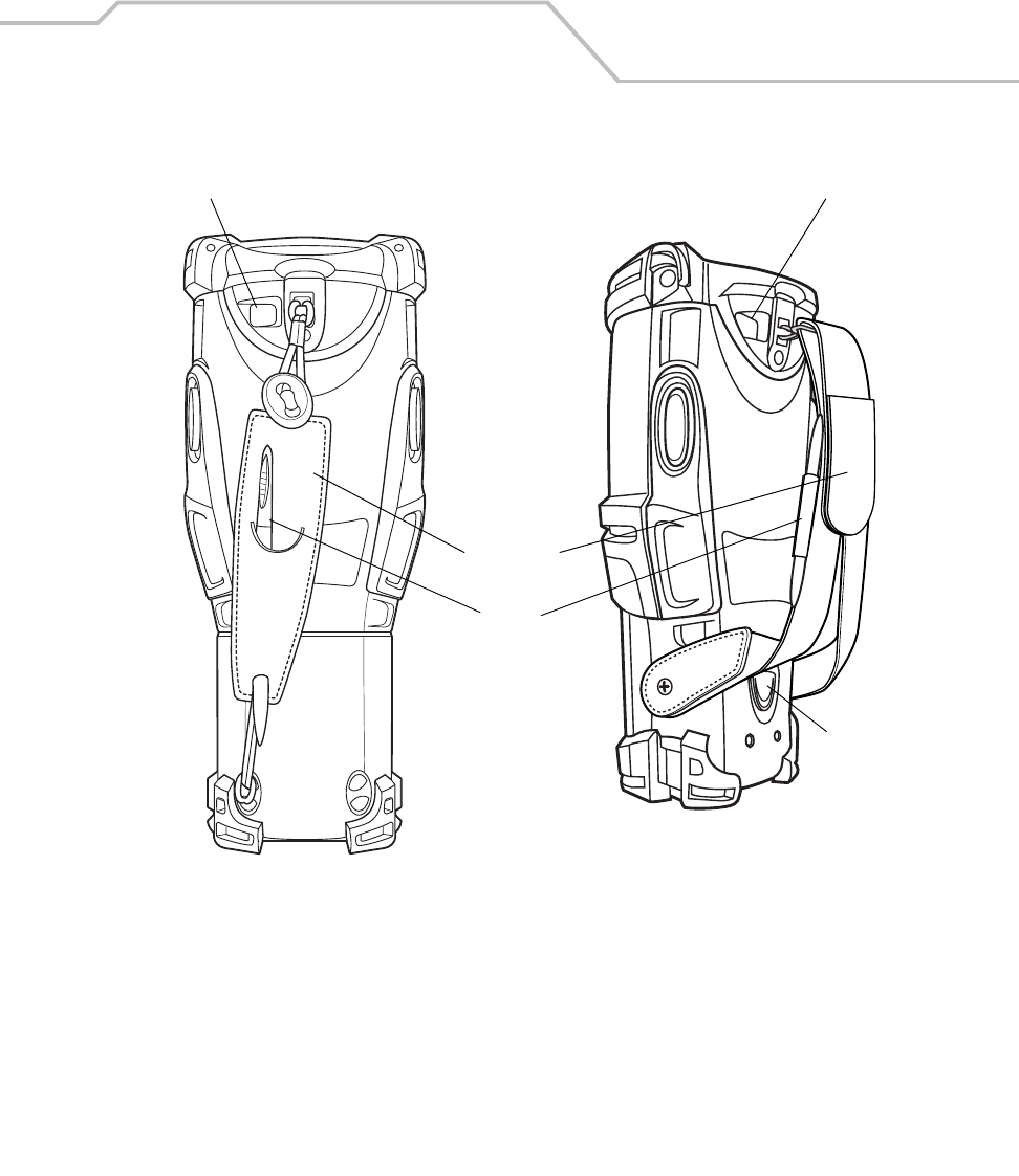
Figure 1-3. MC9000-K and MC9000-S: Back View
MC9000-S
Stylus
Hand Strap
MC9000-K
Primary Battery
Release
Color Camera (optional) Color Camera (optional)

MC9000-K/S for Embedded Windows® CE .NET Product Reference Guide
1-6
Unpacking
Carefully remove all protective material from around the mobile computer and save the shipping
container for storage and/or re-shipping.
Verify that all of the equipment listed below was received:
• MC9000-K or MC9000-S mobile computer
• Lithium-ion battery
• Strap, attached to the mobile computer
• Stylus, in the hand strap pocket
• Regulatory Guide
• Quick Start Guide (poster).
Inspect the equipment for damage. If any equipment is missing or damaged, contact the Symbol
Technologies Support Center immediately. See page xxiii for contact information.

Getting Started 1-7
Accessories
• Single Slot Serial/USB Cradle, charges the mobile computer main battery and a spare
battery. It also synchronizes the mobile computer with a host computer through a serial or a
USB connection.
• Four Slot Ethernet Cradle, charges the mobile computer main battery and synchronizes the
mobile computer with a host computer through an Ethernet connection.
• Four Slot Charge Only Cradle, charges the mobile computer main battery.
• Four Slot Spare Battery Charger, charges up to four mobile computer spare batteries.
• Magnetic Stripe Reader (MSR), snaps on to the mobile computer and adds magstripe read
capabilities.
• Cable Adapter Module (CAM), snap-on required to connect the following cables to the
mobile computer:
• AC line cord (country-specific) and power supply, charges the mobile computer.
• Auto charge cable, charges the mobile computer using a vehicle’s cigarette lighter.
• DEX cable, connects the mobile computer to a vending machine.
• Serial cable, adds serial communication capabilities.
• USB cable, adds USB communication capabilities.
• Printer cable, adds printer communication capabilities.
• Universal Battery Charger (UBC) Adapter, adapts the UBC for use with series 9000 batteries.
• Wall Mounting Bracket and Shelf Slide: Use for wall mounting applications.
• Optional Keypads: Application specific keypads.
• Multimedia Card (MMC): Provides secondary non-volatile storage.
• Wall Mounting Bracket and Shelf Slide, use for wall mounting applications.
• Spare lithium-ion batteries, MC9000-K (2200 mAh) and MC9000-S (1550 mAh).
• Short Battery Adapter: Required for charging MC9000-S (1550 mAh) batteries on the Four
Slot Spare Battery Charger and the Single Slot Serial/USB Cradle.
• Stylus, performs pen functions.
•Device Configuration Package for .NET (SMDK for .NET), available at:
http://www.symbol.com/mc9000-k and http://www.symbol.com/mc9000-s
• Symbol Windows CE SMDK for Series 9000, available at:
http://www.symbol.com/mc9000-k and http://www.symbol.com/mc9000-s
• Holsters, to hold the mobile computer when not in use.
• Headphone, use in noisy environments.

MC9000-K/S for Embedded Windows® CE .NET Product Reference Guide
1-8
Symbol Windows CE SDK and SMDK
Symbol offers two development kits for the MC9000-G:
•Symbol Mobility Developer Kit for .NET (SMDK for .NET), available at:
http://www.symbol.com/mc9000-k and http://www.symbol.com/mc9000-s
• Symbol Windows CE SDK for Series 9000, available at:
http://www.symbol.com/mc9000-k and http://www.symbol.com/mc9000-s
The Symbol Windows CE SDK for Series 9000 allows users to develop Windows® CE applications for
Series 9000 mobile computers. This SDK contains libraries and other Symbol value-add software not
available in the standard Microsoft® Windows® CE Platform SDK. For detailed information, see
Software Installation on page 8-1. Symbol also offers other development kits, see:
http://software.symbol.com.
Getting Started
The main battery can be charged before insertion into the mobile computer or after it is installed. Use
one of the spare battery chargers to charge the main battery (out of the mobile computer) or one of
the cradles to charge the main battery while it is installed in the mobile computer.
After installing and charging the battery, press the Power button to start the mobile computer.
Mobile computer startup procedures:
•Insert the Main Battery on page 1-9
•Main Battery Removal on page 1-10
•Battery Charging on page 1-11
•Starting the Mobile Computer on page 1-17.
Getting Started 1-9
Main Battery Insertion and Removal
Insert the main battery into the mobile computer before use. If the main battery is charged the mobile
computer can be used immediately. If the main battery is not charged see Battery Charging on page
1-11.
Insert the Main Battery
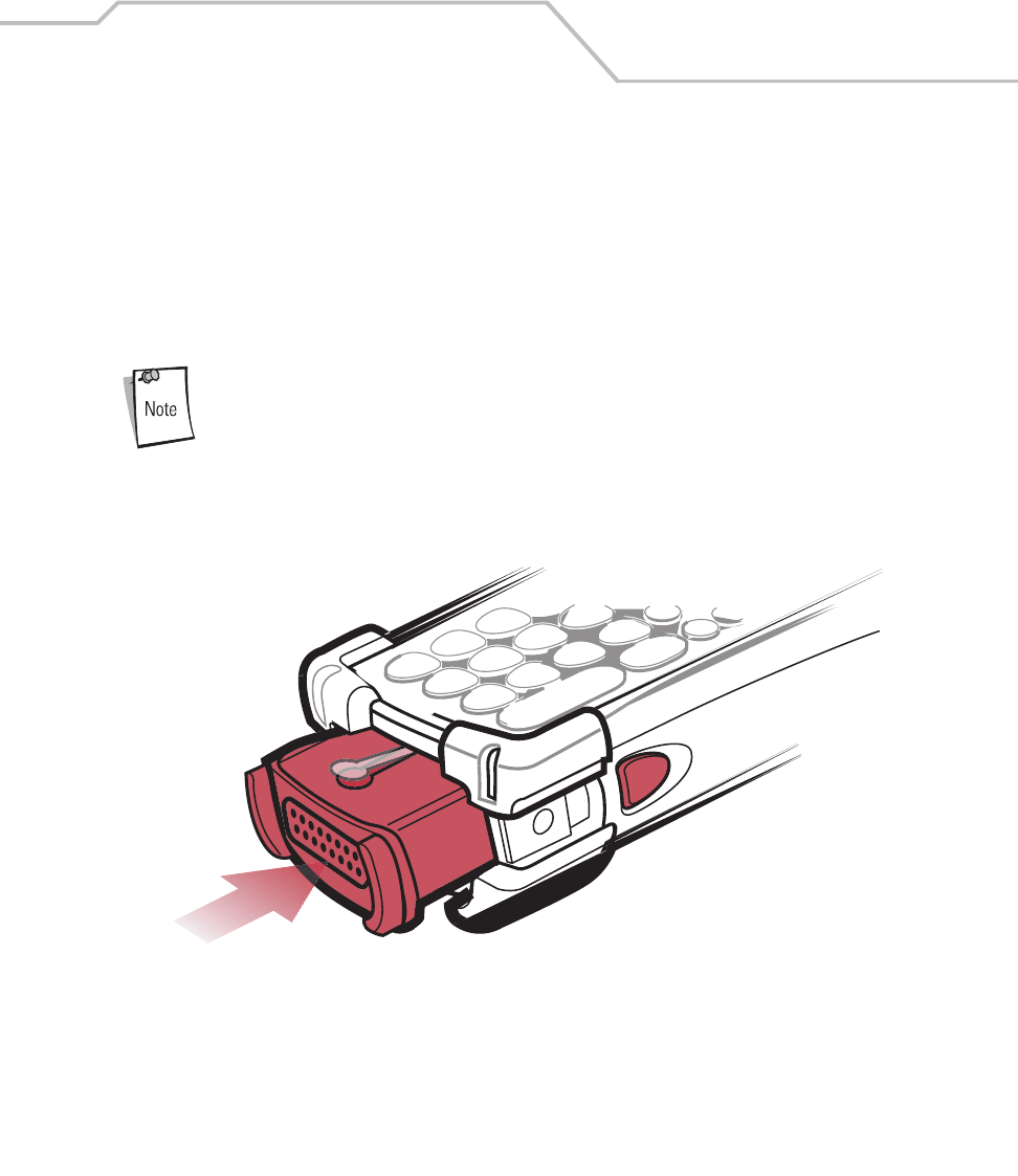
To insert the main battery, slide the battery into the mobile computer, see Figure 1-4.
Ensure the battery is fully inserted. Two audible clicks can be heard as the
battery is fully inserted. A partially inserted battery may result in
unintentional data loss.
Figure 1-4. Insert Main Battery

MC9000-K/S for Embedded Windows® CE .NET Product Reference Guide
1-10
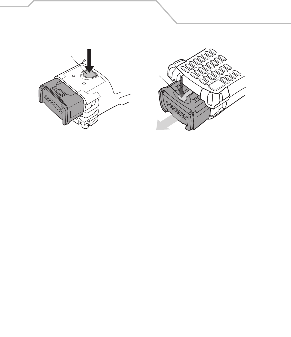
Main Battery Removal
To remove the main battery:
1. Prior to removing the battery, press the red Power button to turn off the screen. This sets the
mobile computer to suspend mode.
2. Simultaneously press both primary battery releases. The battery partially ejects from the
mobile computer.
3. Pause 3-4 seconds while the mobile computer performs battery removal shutdown.
4. Press the secondary battery release, on top of the battery and slide the battery out of the
mobile computer.
Figure 1-5. MC9000-K: Main Battery Removal
Primary Battery Releases
Secondary Battery Release
Getting Started 1-11
Figure 1-6. MC9000-S: Main Battery Removal
Battery Charging
Main Battery and Memory Backup Battery Charging
The mobile computer’s cradles, snap-ons and spare battery chargers can be used to charge the mobile
computer’s main battery.
Before using the mobile computer for the first time, fully charge the main battery (until the charge
indicator light remains lit) see Table 1-1 on page 1-13. Charge time is approximately four hours. The
mobile computer can be charged using a cradle, a CAM or MSR (with a charging cable) or the main
battery can be removed and charged using a spare battery charger.
The mobile computer is equipped with a memory backup battery which automatically charges from
the fully-charged main battery. When the mobile computer is used for the first time, the backup
battery requires approximately 15 hours to fully charge. This is also true any time the backup battery
is discharged which occurs when the main battery is removed for several hours. The backup battery
retains data in memory for at least 30 minutes after the mobile computer's main battery is removed.
When the mobile computer reaches very low battery state, the combination of main battery and
backup battery will retain data in memory for at least 72 hours.
Primary Battery Release
Secondary Battery
Release
Bottom View Top View

MC9000-K/S for Embedded Windows® CE .NET Product Reference Guide
1-12
Do not remove the main battery within the first 15 hours of use. If the main
battery is removed before the backup battery is fully charged, data may be
lost.
The following accessories can be used to charge batteries.
• Cradles: The mobile computer slips into the cradles for charging the battery in the mobile
computer (and spare batteries, where applicable). For detailed cradle setup and charging
procedures see:
• Single Slot Serial/USB Cradle on page 7-10.
• Four Slot Ethernet Cradle on page 7-28 and Four Slot Charge Only Cradles on page 7-30.
• Accessories: The mobile computer’s snap-on accessories provide charging capability, when
used with one of the accessory charging cables. For detailed snap-on setup and charging
procedures see:
•CAM on page 7-40
•MSR on page 7-34.
• Chargers: The mobile computer’s spare battery charging accessories are used to charge
batteries that are removed from the mobile computer. For detailed spare battery charging
accessories setup and charging procedures see:
• Single Slot Serial/USB Cradle on page 7-10
• Four Slot Spare Battery Charger onpage 7-32
• Universal Battery Charger (UBC) on page 7-42.

Getting Started 1-13
Mobile Computer Charging Procedures
The mobile computer main and backup batteries can be charged using a cradle, the CAM or the MSR.
The CAM and the MSR also require a charging cable and a Symbol approved power supply.
1. Connect the charging accessory to the appropriate power source, see Chapter 7,
Accessories for setup information.
2. Insert the mobile computer into a cradle or attach the appropriate snap-on module.
3. The mobile computer starts to charge automatically. The amber charge LED, in the Indicator
LED Bar, lights to show the charge status. See Table 1-1 for charging indications.
The main battery usually fully charges in less than four hours.
Spare Battery Charging
The mobile computer has three accessories that can be used to charge spare batteries.
• Single Slot Serial/USB Cradle
• Four Slot Spare Battery Charger
•UBC Adapter.
To charge a spare battery:
1. Connect the charging accessory to the appropriate power source, see Chapter 7,
Accessories for setup.
2. Insert the spare battery into the spare battery charging slot and gently press down on the
battery to ensure proper contact.
3. The battery starts to charge automatically. The amber charge LED on the accessory lights to
show the charge status. See Chapter 7, Accessories for charging indications.
Table 1-1. Mobile Computer LED Charge Indicators
LED Indication
Off Mobile computer not in cradle/CAM/MSR; mobile computer not placed correctly;
charger is not powered.
Fast Blinking Amber Error in charging; check placement of the mobile computer.
Slow Blinking Amber Mobile computer is charging.
Solid Amber Charging complete.
Note: When the battery is initially inserted in the mobile computer, the amber LED
flashes once if the battery power is low or the battery is not fully inserted.

MC9000-K/S for Embedded Windows® CE .NET Product Reference Guide
1-14
The battery usually fully charges in less than four hours.
A Short Battery Adapter is required to charge the MC9000-S spare battery in either the
Single Slot Serial/USB Cradle or the Four Slot Spare Battery Charger, see Single Slot
Serial/USB Cradle on page 7-10 or Four Slot Spare Battery Charger on page 7-32.
Stylus
Use the mobile computer stylus for selecting items and entering information. The stylus functions as
a mouse. Tap the touch screen once with the stylus to select options and open menu items. The stylus
pocket is located in the strap, see Figure 1-3 on page 1-5.
Note
Getting Started 1-15
Hand Strap
The hand strap may be moved to either the left or right side of the mobile computer to suit user
preferences.
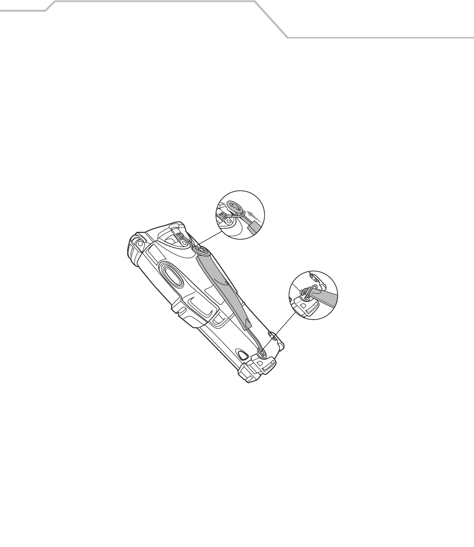
To reposition the MC9000-K hand strap:
1. Disengage the upper portion of the hand strap by disconnecting the button from the loop
connector.
2. Loosen the loop from the bottom of the hand strap and slide the hand strap through.
3. Slide the loop out of the connector post.
Figure 1-7. MC9000-K: Hand Strap Repositioning
4. Reverse the procedure to re-attach the hand strap. Two hand strap connectors are provided
on the mobile computer’s main body. The hand strap may be attached to either connector.
MC9000-K/S for Embedded Windows® CE .NET Product Reference Guide
1-16
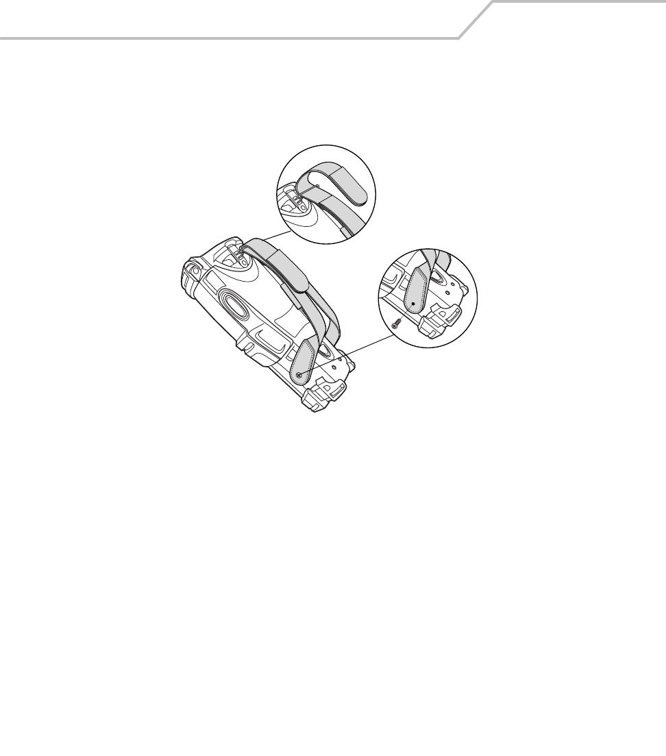
To remove the MC9000-S hand strap:
1. Disengage the upper portion of the hand strap by sliding it through the clip connector.
2. Unscrew the two screws on either side of the mobile computer.
Figure 1-8. MC9000-S: Hand Strap Removal
3. Reverse the procedure to re-attach the hand strap.
Getting Started 1-17
Starting the Mobile Computer
Insert the battery, if the mobile computer does not power on perform a cold boot, see Resetting the
Mobile Computer on page 2-39.
When the mobile computer is powered on for the first time, it initializes its flash file system. The
Symbol splash screen appears for a short period of time, followed by the calibration screen. These
screens also appear when a cold boot is performed.
Figure 1-9. Symbol Splash Screen
MC9000-K/S for Embedded Windows® CE .NET Product Reference Guide
1-18
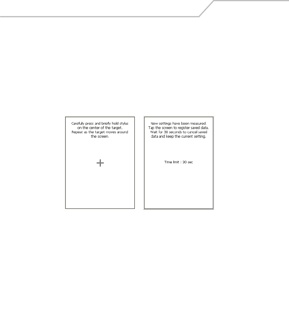
Calibration Screen
Use calibrate screen to align the touch screen:
1. Remove the stylus from the handle.
2. Carefully press and briefly hold the tip of stylus on the center of the calibration screen target.
Repeat the procedure as the target moves and stops at different locations on the screen.
3. If the mobile computer already has screen calibration settings, the confirm calibration
resave screen appears. Tap screen within 30 seconds to overwrite the existing calibration
settings with the new settings or allow the timer to expire and the new calibration settings
will not be saved.
Figure 1-10. Calibration Screen
Calibration Screen Confirm Calibration Resave
Screen

Getting Started 1-19
Mobile Computer Configuration
The following chapters provide the mobile computer configuration information:
• To customize the mobile computer settings, see Chapter 3, Settings.
• To set up ActiveSync to synchronize the mobile computer and accessories with the host
computer, see Chapter 4, Communications.
• To configure the mobile computer for Spectrum24, see Chapter 6, Spectrum24 Network
Configuration.
• To install development software on the development PC, see Chapter 8, Software
Installation.
• To set up AirBEAM to synchronize the mobile computer with the host server, see Chapter 9,
AirBEAM Smart.
• To configure the mobile computer using the Terminal Configuration Manager, see Chapter
10, Mobile Computer Configuration.

MC9000-K/S for Embedded Windows® CE .NET Product Reference Guide
1-20

Operating the MC9000-K/S
Chapter Contents
Introduction. . . . . . . . . . . . . . . . . . . . . . . . . . . . . . . . . . . . . . . . . . . . . . . . . . . . . . . . . . . . . . . . . . . . . . . . .2-3
Keypads . . . . . . . . . . . . . . . . . . . . . . . . . . . . . . . . . . . . . . . . . . . . . . . . . . . . . . . . . . . . . . . . . . . . . . . . . . .2-3
28-Key Keypad . . . . . . . . . . . . . . . . . . . . . . . . . . . . . . . . . . . . . . . . . . . . . . . . . . . . . . . . . . . . . . . . . .2-4
43-Key Keypad . . . . . . . . . . . . . . . . . . . . . . . . . . . . . . . . . . . . . . . . . . . . . . . . . . . . . . . . . . . . . . . . . .2-8
53-Key Keypad . . . . . . . . . . . . . . . . . . . . . . . . . . . . . . . . . . . . . . . . . . . . . . . . . . . . . . . . . . . . . . . . .2-11
3270 Emulator. . . . . . . . . . . . . . . . . . . . . . . . . . . . . . . . . . . . . . . . . . . . . . . . . . . . . . . . . . . . . . . . . .2-14
5250 Emulator. . . . . . . . . . . . . . . . . . . . . . . . . . . . . . . . . . . . . . . . . . . . . . . . . . . . . . . . . . . . . . . . . .2-17
VT Emulator . . . . . . . . . . . . . . . . . . . . . . . . . . . . . . . . . . . . . . . . . . . . . . . . . . . . . . . . . . . . . . . . . . .2-20
Keypad Special Functions. . . . . . . . . . . . . . . . . . . . . . . . . . . . . . . . . . . . . . . . . . . . . . . . . . . . . . . . .2-23
Power Button . . . . . . . . . . . . . . . . . . . . . . . . . . . . . . . . . . . . . . . . . . . . . . . . . . . . . . . . . . . . . . . . . . . . . .2-24
Headphone . . . . . . . . . . . . . . . . . . . . . . . . . . . . . . . . . . . . . . . . . . . . . . . . . . . . . . . . . . . . . . . . . . . . . . . .2-24
Series 9000 Demo Window . . . . . . . . . . . . . . . . . . . . . . . . . . . . . . . . . . . . . . . . . . . . . . . . . . . . . . . . . . .2-25

MC9000-K/S for Embedded Windows® CE .NET Product Reference Guide
2-2
Taskbar . . . . . . . . . . . . . . . . . . . . . . . . . . . . . . . . . . . . . . . . . . . . . . . . . . . . . . . . . . . . . . . . . . . . . . . . . . .2-27
Sart Button . . . . . . . . . . . . . . . . . . . . . . . . . . . . . . . . . . . . . . . . . . . . . . . . . . . . . . . . . . . . . . . . . . . .2-29
Keyboard Input Panel Button . . . . . . . . . . . . . . . . . . . . . . . . . . . . . . . . . . . . . . . . . . . . . . . . . . . . . .2-29
Desktop Button . . . . . . . . . . . . . . . . . . . . . . . . . . . . . . . . . . . . . . . . . . . . . . . . . . . . . . . . . . . . . . . . .2-29
Taskbar Icons . . . . . . . . . . . . . . . . . . . . . . . . . . . . . . . . . . . . . . . . . . . . . . . . . . . . . . . . . . . . . . . . . .2-30
Status Icons . . . . . . . . . . . . . . . . . . . . . . . . . . . . . . . . . . . . . . . . . . . . . . . . . . . . . . . . . . . . . . .2-30
Active Programs Icons . . . . . . . . . . . . . . . . . . . . . . . . . . . . . . . . . . . . . . . . . . . . . . . . . . . . . . .2-30
AC Power/Battery Status Icons . . . . . . . . . . . . . . . . . . . . . . . . . . . . . . . . . . . . . . . . . . . . . . . .2-30
Task Manager and Properties. . . . . . . . . . . . . . . . . . . . . . . . . . . . . . . . . . . . . . . . . . . . . . . . . . . . . . . . . .2-31
Task Manager. . . . . . . . . . . . . . . . . . . . . . . . . . . . . . . . . . . . . . . . . . . . . . . . . . . . . . . . . . . . . .2-31
Properties . . . . . . . . . . . . . . . . . . . . . . . . . . . . . . . . . . . . . . . . . . . . . . . . . . . . . . . . . . . . . . . . .2-32
Entering Information. . . . . . . . . . . . . . . . . . . . . . . . . . . . . . . . . . . . . . . . . . . . . . . . . . . . . . . . . . . . . . . . .2-34
Entering Information Using Keypad . . . . . . . . . . . . . . . . . . . . . . . . . . . . . . . . . . . . . . . . . . . . . . . . .2-34
Entering Information Using the Keyboard Input Panel. . . . . . . . . . . . . . . . . . . . . . . . . . . . . . . . . . .2-34
Entering Data via the Bar Code Scanner (Scan Wedge) . . . . . . . . . . . . . . . . . . . . . . . . . . . . . . . . .2-34
Data Capture. . . . . . . . . . . . . . . . . . . . . . . . . . . . . . . . . . . . . . . . . . . . . . . . . . . . . . . . . . . . . . . . . . . . . . .2-35
Laser Scanning . . . . . . . . . . . . . . . . . . . . . . . . . . . . . . . . . . . . . . . . . . . . . . . . . . . . . . . . . . . . . . . . .2-35
Indicator LED Bar . . . . . . . . . . . . . . . . . . . . . . . . . . . . . . . . . . . . . . . . . . . . . . . . . . . . . . . . . . . . . . .2-35
Scanning Considerations . . . . . . . . . . . . . . . . . . . . . . . . . . . . . . . . . . . . . . . . . . . . . . . . . . . . . . . . .2-36
Imaging . . . . . . . . . . . . . . . . . . . . . . . . . . . . . . . . . . . . . . . . . . . . . . . . . . . . . . . . . . . . . . . . . . . . . . . . . . .2-37
Imager. . . . . . . . . . . . . . . . . . . . . . . . . . . . . . . . . . . . . . . . . . . . . . . . . . . . . . . . . . . . . . . . . . . . . . . .2-37
Operational Modes. . . . . . . . . . . . . . . . . . . . . . . . . . . . . . . . . . . . . . . . . . . . . . . . . . . . . . . . . . . . . .2-37
Decode Mode . . . . . . . . . . . . . . . . . . . . . . . . . . . . . . . . . . . . . . . . . . . . . . . . . . . . . . . . . . . . . .2-37
Aiming the Imager . . . . . . . . . . . . . . . . . . . . . . . . . . . . . . . . . . . . . . . . . . . . . . . . . . . . . . . . . . . . . .2-38
Resetting the Mobile Computer . . . . . . . . . . . . . . . . . . . . . . . . . . . . . . . . . . . . . . . . . . . . . . . . . . . . . . . .2-39
Performing a Warm Boot . . . . . . . . . . . . . . . . . . . . . . . . . . . . . . . . . . . . . . . . . . . . . . . . . . . . . . . . .2-39
Performing a Cold Boot. . . . . . . . . . . . . . . . . . . . . . . . . . . . . . . . . . . . . . . . . . . . . . . . . . . . . . . . . . .2-40
Waking the Mobile Computer . . . . . . . . . . . . . . . . . . . . . . . . . . . . . . . . . . . . . . . . . . . . . . . . . . . . . . . . .2-41
File System Directory Structure . . . . . . . . . . . . . . . . . . . . . . . . . . . . . . . . . . . . . . . . . . . . . . . . . . . . . . . .2-42
Flash Storage . . . . . . . . . . . . . . . . . . . . . . . . . . . . . . . . . . . . . . . . . . . . . . . . . . . . . . . . . . . . . . . . . . . . . .2-43
Startup Folder . . . . . . . . . . . . . . . . . . . . . . . . . . . . . . . . . . . . . . . . . . . . . . . . . . . . . . . . . . . . . . . . . . . . . .2-43
Run Files . . . . . . . . . . . . . . . . . . . . . . . . . . . . . . . . . . . . . . . . . . . . . . . . . . . . . . . . . . . . . . . . . . . . . . . . . .2-43
Audio Event Aliasing. . . . . . . . . . . . . . . . . . . . . . . . . . . . . . . . . . . . . . . . . . . . . . . . . . . . . . . . . . . . . . . . .2-43
Terminal Emulators. . . . . . . . . . . . . . . . . . . . . . . . . . . . . . . . . . . . . . . . . . . . . . . . . . . . . . . . . . . . . . . . . .2-44

Operating the MC9000-K/S 2-3
Introduction
This chapter provides basic instructions for using and navigating the mobile computer.
Keypads
The mobile computer has five interchangeable modular keypad configurations:
• 28-key keypad, see page 2-4
• 43-key keypad, see page 2-8
• 53-key keypad, see page 2-11.
The modular keypads can be changed in the field, as necessary, to support specialized applications.
See Keypads on page 7-7 for installation and removal procedures.
For detailed keypad configurations including ASCII values and VK codes, see
Appendix B, Keypad Maps.
For information about using the soft keyboard input panel, see Entering Information
Using the Keyboard Input Panel on page 2-34.
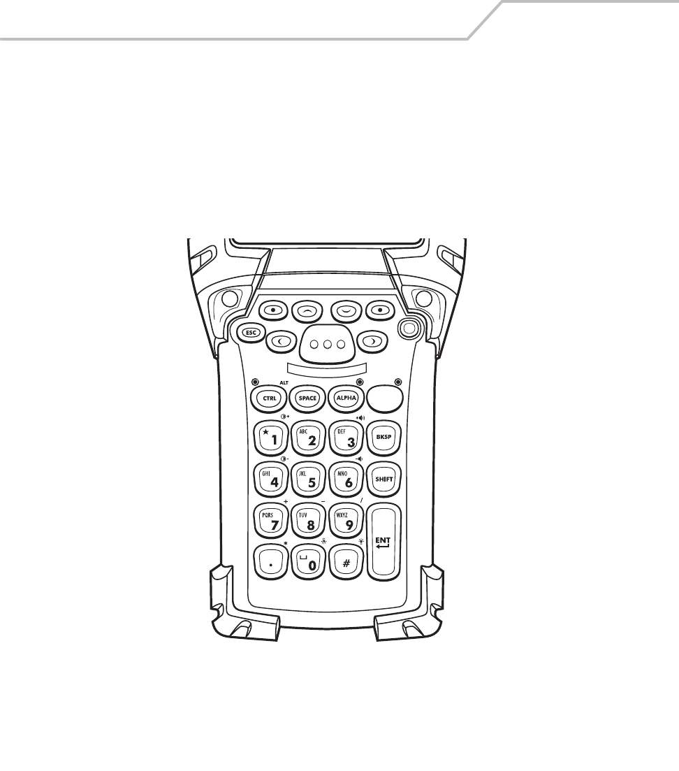
MC9000-K/S for Embedded Windows® CE .NET Product Reference Guide
2-4
28-Key Keypad
The 28-key keypad is used on both the MC9000-K, see Figure 2-1 and the MC9000-S, see Figure 2-2.
It contains a Power button, application keys, scroll keys and a function key. The keypad is color-coded
to indicate the alternate function key (blue) values and the alternate ALPHA key (orange) values. Note
that keypad functions can be changed by an application so the mobile computer’s keypad may not
function exactly as described. See Table 2-1 on page 2-6 for key and button descriptions and Table 2-
7 on page 2-23 for the keypad’s special functions.
Figure 2-1. MC9000-K: 28-Key Keypad
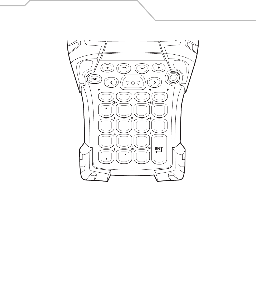
Operating the MC9000-K/S 2-5
Figure 2-2. MC9000-S: 28-Key Keypad
CTRL
SPACE ALPHA
BKSP
SHIFT
ALT
12
ABC
3
DEF
4
GHI
7
PQRS
8
0#
TUV
9
WXYZ
5
JKL
6
MNO
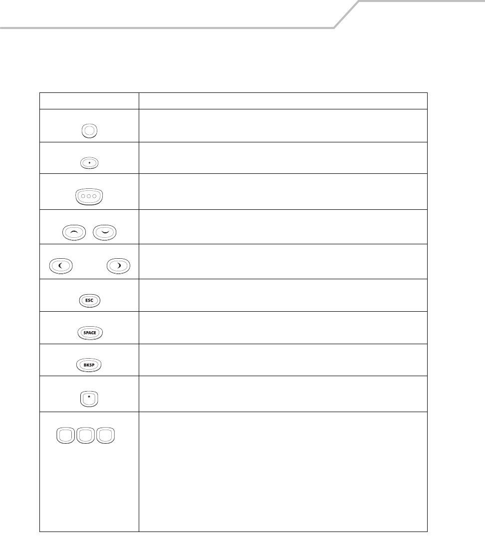
MC9000-K/S for Embedded Windows® CE .NET Product Reference Guide
2-6
Table 2-1. MC9000-K and MC9000-S: 28-Key Keypad Descriptions
Key Description
Power (red) Powers the mobile computer on and off.
Used to reset the mobile computer, see Resetting the Mobile Computer on page 2-39.
Green/Red Dot Unassigned application function key. See Appendix B, Keypad Maps for mapping details.
Scan (yellow) Scan key - used for scanning applications, this key has the same function as pushing the
right scan button.
Scroll Up and Down Moves up and down from one item to another.
Increases/decreases specified values.
Scroll Left and Right Moves left and right from one item to another.
Increases/decreases specified values.
ESC Exits the current operation.
SPACE Performs the space functions.
BKSP Performs the backspace functions.
One/Star Produces the number one in default state.
Produces an asterisk in Alpha state.
Alphanumeric In default state, produces the numeric value on the key.
In Alpha state, produces the lower case alphabetic characters on the key. Each key press
produces the next alphabetic character in sequence. For example, press and release the
ALPHA key and then press the 4 key once to produce the letter ‘g’; press and release
the ALPHA key and then press the 4 key three times to produce the letter ‘i’.
When the SHIFT key is pressed in Alpha state, the upper case alphabetic characters on
the key are produced. For example, press and release the ALPHA key, press and hold the
SHIFT key and then press the 4 key once to produce the letter ‘G’; press and release the
ALPHA key, press and hold the SHIFT key and then press the 4 key three times to
produce the letter ‘I’.
1
. . .
4
GHI 5
JKL 6
MNO
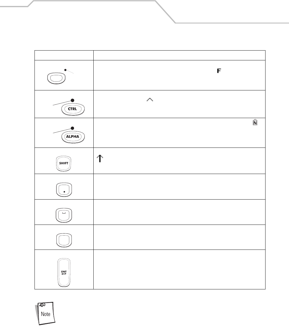
Operating the MC9000-K/S 2-7
For detailed keypad configurations including ASCII values and VK codes, see
Appendix B, Keypad Maps.
Function (blue) Press and release the blue function key to activate the keypad alternate functions
(shown on the keypad in blue). The keypad LED lights and the icon appears on the
taskbar, see Table 2-9 on page 2-27. Press and release the blue function key again to
return to the normal keypad functions.
Control Press and release the CTRL key to activate the keypad alternate CTRL functions. The
keypad LED lights and the icon appears on the taskbar. Press and release the CTRL
key again to return to the normal keypad functions.
ALPHA (orange) The default keypad mode is the num-lock (number lock) mode. The num-lock icon
appears on the taskbar to indicate num-lock mode is active. Press the orange ALPHA key
to de-activate the num-lock mode and to access the alternate ALPHA characters (shown
on the keypad in orange).
Shift Press and release the SHIFT key to activate the keypad alternate SHIFT functions. The
icon appears on the taskbar. Press and release the SHIFT key again to return to the
normal keypad functions.
Period/Decimal Point Produces a period for alpha entries and a decimal point for numeric entries.
Zero In default state, produces a zero.
In Alpha state, produces a space.
Pound Produces a pound/number sign.
Enter Executes a selected item or function.
Table 2-1. MC9000-K and MC9000-S: 28-Key Keypad Descriptions (Continued)
Key Description
LED
LED
LED
0
#
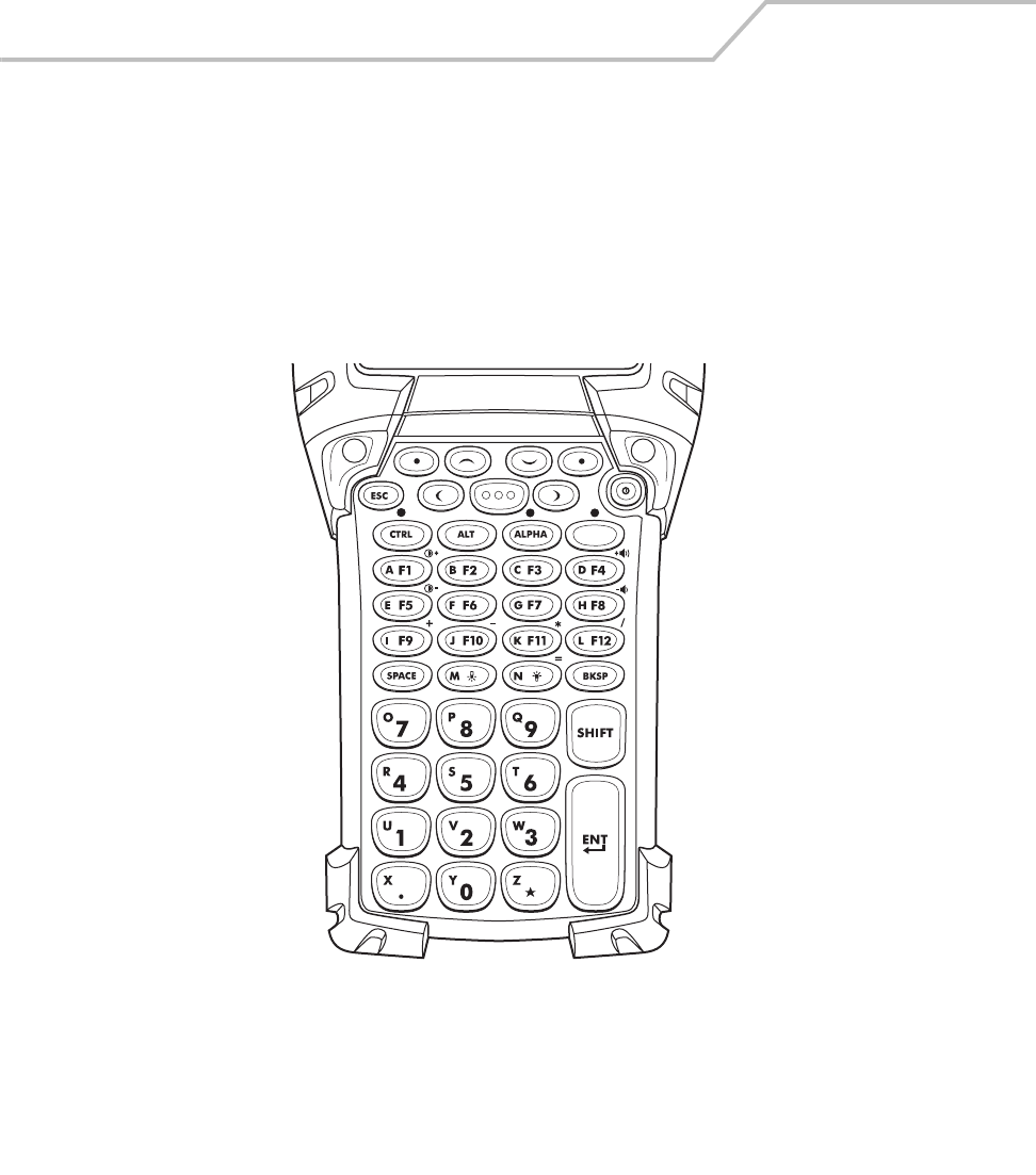
MC9000-K/S for Embedded Windows® CE .NET Product Reference Guide
2-8
43-Key Keypad
The 43-key keypad is available only on the MC9000-K, see Figure 2-3. It contains a Power button,
application keys, scroll keys and a function key. The keypad is color-coded to indicate the alternate
function key (blue) values and the alternate ALPHA key (orange) values. Note that keypad functions
can be changed by an application so the mobile computer’s keypad may not function exactly as
described. See Table 2-2 on page 2-9 for key and button descriptions and Table 2-7 on page 2-23 for
the keypad’s special functions.
Figure 2-3. MC9000-K: 43-Key Keypad
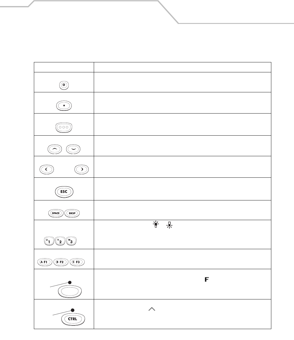
Operating the MC9000-K/S 2-9
Table 2-2. MC9000-K: 43-Key Descriptions
Key Description
Power (red) Powers the mobile computer on and off.
Used to reset the mobile computer, see see Resetting the Mobile Computer on page 2-39.
Green/Red Dot Unassigned application function key. See Appendix B, Keypad Maps for mapping details.
Scan (yellow) Scan key - used for scanning applications, this key has the same function as pushing the
right scan button.
Scroll Up and Down Moves up and down from one item to another.
Increases/decreases specified values.
Scroll Left and Right Moves left and right from one item to another.
Increases/decreases specified values.
ESC Exits the current operation.
SPACE/BKSP Space and backspace functions.
Numeric/Special Function/
Alpha
Numeric or special function ( or ) by default or alpha value when the ALPHA key
is selected.
Alpha/Application These keys can have an application assigned to the function value and have an alpha
value assigned when used with the ALPHA function key.
Function (blue) Press and release the blue function key to activate the keypad alternate functions (shown
on the keypad in blue). The keypad LED lights and the icon appears on the taskbar,
see Table 2-9 on page 2-27. Press and release the blue function key again to return to the
normal keypad functions.
Control Press and release the CTRL key to activate the keypad alternate CTRL functions. The
keypad LED lights and the icon appears on the taskbar. Press and release the CTRL
key again to return to the normal keypad functions.
. . .
. . .
LED
LED
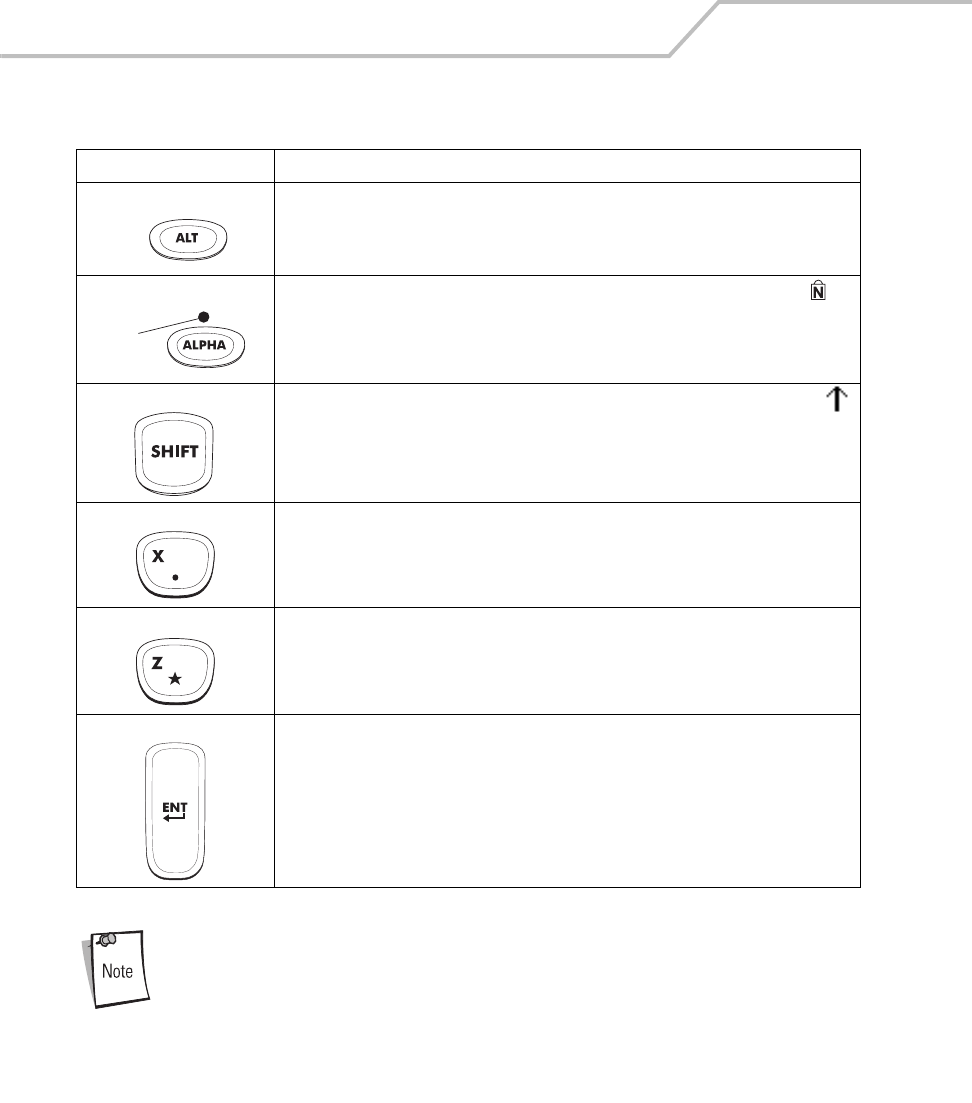
MC9000-K/S for Embedded Windows® CE .NET Product Reference Guide
2-10
For detailed keypad configurations including ASCII values and VK codes, see
Appendix B, Keypad Maps.
ALT Press and release the ALT key to activate the keypad ALT (alternate) functions. The
icon appears on the taskbar. Press and release the ALT key again to return to the normal
keypad functions.
ALPHA (orange) The default keypad mode is the num-lock (number lock) mode. The num-lock icon
appears on the taskbar to indicate num-lock mode is active. Press the orange ALPHA key
to de-activate the num-lock mode and to access the alternate ALPHA characters (shown
on the keypad in orange).
Shift Press and release the SHIFT key to activate the keypad alternate SHIFT functions. The
icon appears on the taskbar. Press and release the SHIFT key again to return to the normal
keypad functions.
Period/Decimal Point Produces a period for alpha entries, a decimal point for numeric entries and the alphabetic
character X when the ALPHA function key is activated.
Star Produces an asterisk and the alphabetic character Z when the ALPHA function key is
activated.
Enter Executes a selected item or function.
Table 2-2. MC9000-K: 43-Key Descriptions (Continued)
Key Description
ALT
LED
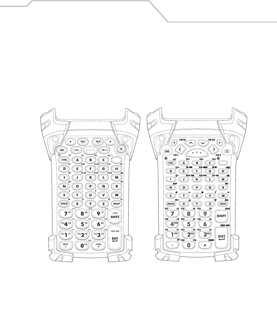
Operating the MC9000-K/S 2-11
53-Key Keypad
There are two physical configurations of the 53-key keypad, however both of the keypads are
functionally identical. The 53-key keypad is available only on the MC9000-K. It contains a Power
button, application keys, scroll keys and function keys. The keypad is color-coded to indicate the
alternate function key (blue) values. Note that keypad functions can be changed by an application so
the mobile computer’s keypad may not function exactly as described. See Table 2-3 on page 2-12 for
key and button descriptions and Table 2-7 on page 2-23 for the keypad’s special functions.
Figure 2-4. MC9000-K: 53-Key Keypad
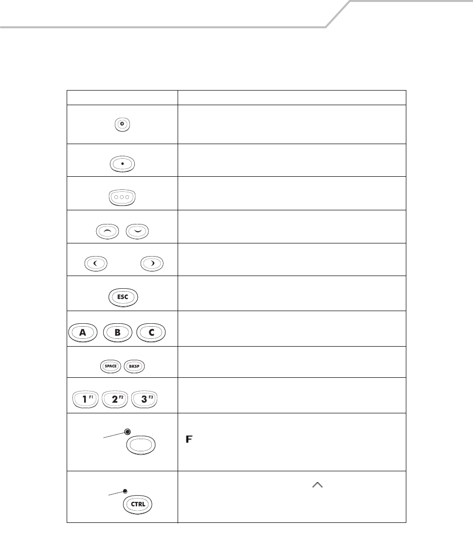
MC9000-K/S for Embedded Windows® CE .NET Product Reference Guide
2-12
Table 2-3. MC9000-K: 53-Key Descriptions
Key Description
Power (red) Powers the mobile computer on and off.
Used to reset the mobile computer, see Resetting the Mobile Computer
on page 2-39.
Green/Red Dot Unassigned application function key. See Appendix B, Keypad Maps for
mapping details.
Scan (yellow) Scan key - used for scanning applications, this key has the same
function as pushing the right scan button.
Scroll Up and Down Moves up and down from one item to another.
Increases/decreases specified values.
Scroll Left and Right Moves left and right from one item to another.
Increases/decreases specified values.
ESC Exits the current operation.
Alpha Use the alpha keys for alphabetic characters.
SPACE/BKSP Space and backspace functions.
Numeric/Application Numeric value keys - can have applications assigned with function
key(s).
Function (blue) Press and release the blue function key to activate the keypad alternate
functions (shown on the keypad in blue). The keypad LED lights and the
icon appears on the taskbar, see Table 2-9 on page 2-27. Press and
release the blue function key again to return to the normal keypad
functions.
Control Press and release the CTRL key to activate the keypad alternate CTRL
functions. The keypad LED lights and the icon appears on the
taskbar. Press and release the CTRL key again to return to the normal
keypad functions.
. . .
. . .
LED
LED
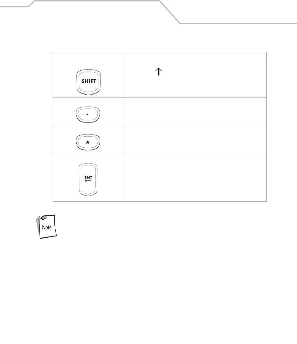
Operating the MC9000-K/S 2-13
For detailed keypad configurations including ASCII values and VK codes, see
Appendix B, Keypad Maps.
Shift Press and release the SHIFT key to activate the keypad alternate SHIFT
functions. The icon appears on the taskbar. Press and release the
SHIFT key again to return to the normal keypad functions.
Period/Decimal Point Produces a period for alpha entries and a decimal point for numeric
entries.
Star Produces an asterisk.
Enter Executes a selected item or function.
Table 2-3. MC9000-K: 53-Key Descriptions (Continued)
Key Description
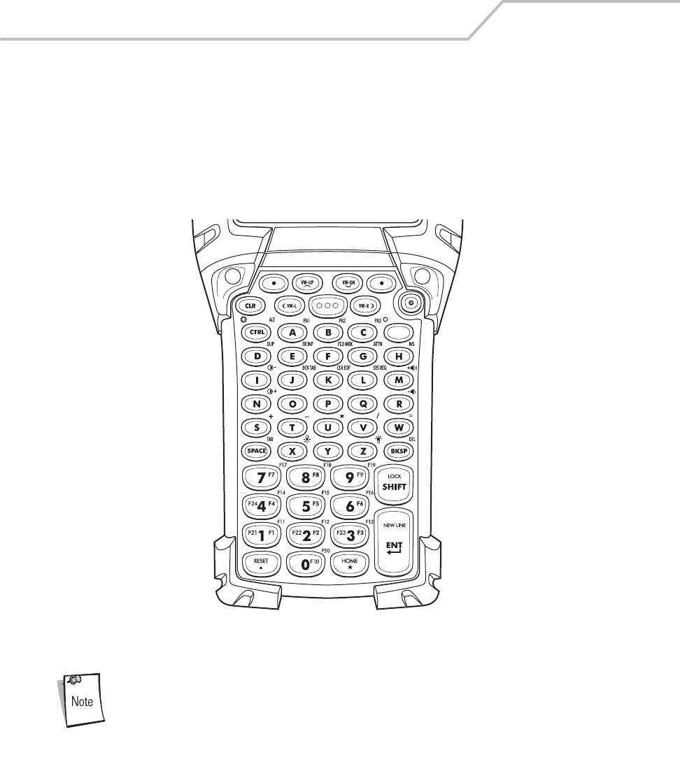
MC9000-K/S for Embedded Windows® CE .NET Product Reference Guide
2-14
3270 Emulator
The 3270 emulator keypad is available only on the MC9000-K. It contains a Power button, application
keys, scroll keys and a function key. The keypad is color-coded to indicate the alternate function key
(blue) values. Note that keypad functions can be changed by an application so the mobile computer’s
keypad may not function exactly as described. See Table 2-4 on page 2-15 for key and button
descriptions and Table 2-7 on page 2-23 for the keypad’s special functions.
Figure 2-5. 3270 Emulator Keypad
The 3270 emulator keypad is only used when the mobile computer is running
the 3270 emulation software. When the mobile computer is not running the
3270 emulation software, the 3270 keypad functions are the same as a 53-
key keypad.
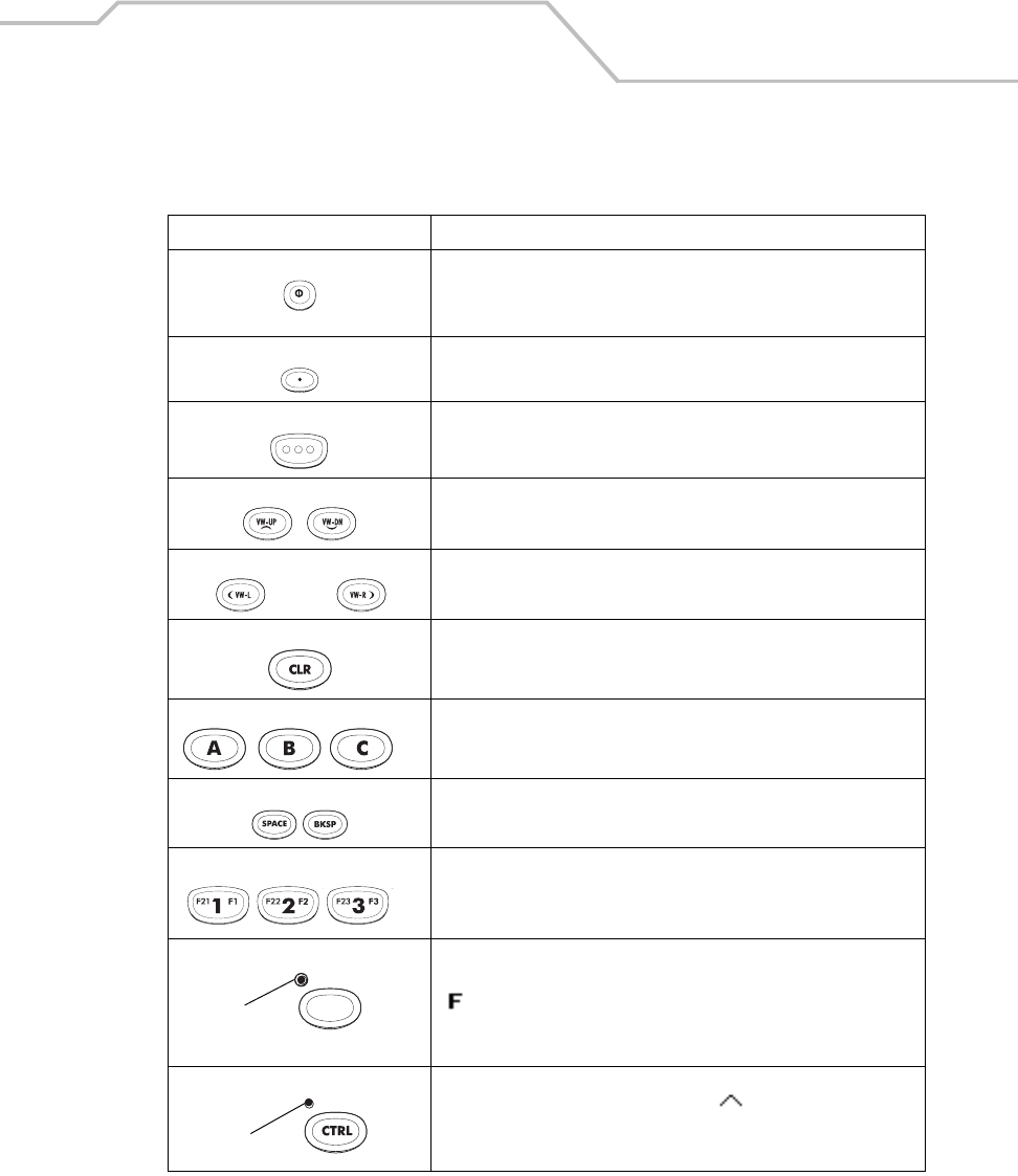
Operating the MC9000-K/S 2-15
Table 2-4. 3270 Emulator Descriptions
Key Description
Power (red) Powers the mobile computer on and off.
Used to reset the mobile computer, see Resetting the Mobile Computer
on page 2-39.
Green/Red Dot Unassigned application function key. See Appendix B, Keypad Maps for
mapping details.
Scan (yellow) Scan key - used for scanning applications, this key has the same
function as pushing the scan button.
Scroll Up and Down Moves up and down from one item to another.
Increases/decreases specified values.
Scroll Left and Right Moves left and right from one item to another.
Increases/decreases specified values.
CLR Exits the current operation.
Alpha Use the alpha keys for alphabetic characters.
SPACE/BKSP Space and backspace functions.
Application These keys can be assigned to an application.
Function (blue) Press and release the blue function key to activate the keypad alternate
functions (shown on the keypad in blue). The keypad LED lights and the
icon appears on the taskbar, see Table 2-9 on page 2-27. Press and
release the blue function key again to return to the normal keypad
functions.
Control Press and release the CTRL key to activate the keypad alternate CTRL
functions. The keypad LED lights and the icon appears on the
taskbar. Press and release the CTRL key again to return to the normal
keypad functions.
. . .
. . .
LED
LED

MC9000-K/S for Embedded Windows® CE .NET Product Reference Guide
2-16
For detailed keypad configurations including ASCII values and VK codes, see
Appendix B, Keypad Maps.
Shift Press and release the SHIFT key to activate the keypad alternate SHIFT
functions. The icon appears on the taskbar. Press and release the
SHIFT key again to return to the normal keypad functions.
Period/Decimal Point Produces a period for alpha entries and a decimal point for numeric
entries.
Star Produces an asterisk.
Enter Executes a selected item or function.
Table 2-4. 3270 Emulator Descriptions (Continued)
Key Description
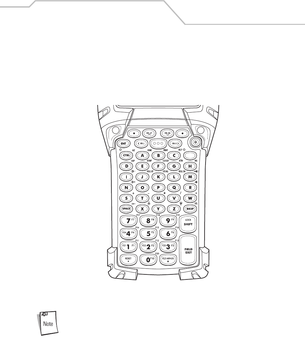
Operating the MC9000-K/S 2-17
5250 Emulator
The 5250 emulator keypad is available only on the MC9000-K. It contains a Power button, application
keys, scroll keys and a function key. The keypad is color-coded to indicate the alternate function key
(blue) values. Note that keypad functions can be changed by an application so the mobile computer’s
keypad may not function exactly as described. See Table 2-5 on page 2-18 for key and button
descriptions and Table 2-7 on page 2-23 for the keypad’s special functions.
Figure 2-6. 5250 Emulator Keypad
The 5250 emulator keypad is only used when the mobile computer is running
the 5250 emulation software. When the mobile computer is not running the
5250 emulation software, the 5250 keypad functions are the same as a 53-
key keypad.
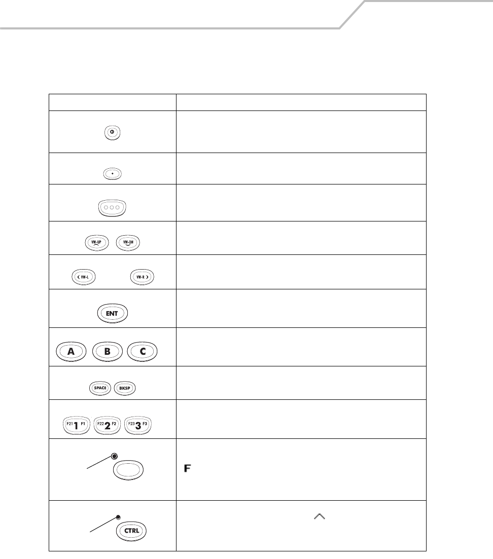
MC9000-K/S for Embedded Windows® CE .NET Product Reference Guide
2-18
Table 2-5. 5250 Emulator Descriptions
Key Description
Power (red) Powers the mobile computer on and off.
Used to reset the mobile computer, see see Resetting the Mobile Computer
on page 2-39.
Green/Red Dot Unassigned application function key. See Appendix B, Keypad Maps for
mapping details.
Scan (yellow) Scan key - used for scanning applications, this key has the same function
as pushing the scan button.
Scroll Up and Down Moves up and down from one item to another.
Scroll Left and Right Moves left and right from one item to another.
ENT Exits the current operation.
Alpha Use the alpha keys for alphabetic characters.
SPACE/BKSP Space and backspace functions.
Application These keys can be assigned to an application.
Function (blue) Press and release the blue function key to activate the keypad alternate
functions (shown on the keypad in blue). The keypad LED lights and the
icon appears on the taskbar, see Table 2-9 on page 2-27. Press and
release the blue function key again to return to the normal keypad
functions.
Control Press and release the CTRL key to activate the keypad alternate CTRL
functions. The keypad LED lights and the icon appears on the taskbar.
Press and release the CTRL key again to return to the normal keypad
functions.
. . .
. . .
LED
LED
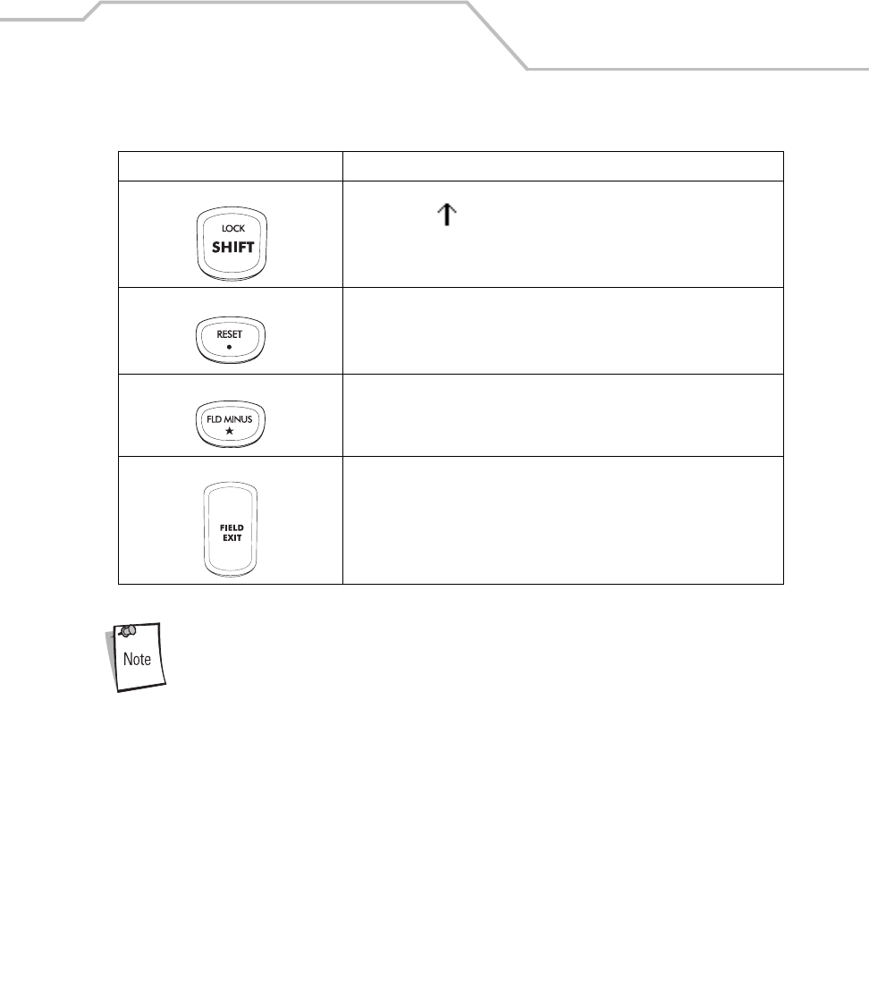
Operating the MC9000-K/S 2-19
For detailed keypad configurations including ASCII values and VK codes, see
Appendix B, Keypad Maps.
Shift Press and release the SHIFT key to activate the keypad alternate SHIFT
functions. The icon appears on the taskbar. Press and release the
SHIFT key again to return to the normal keypad functions.
Period/Decimal Point Produces a period for alpha entries and a decimal point for numeric entries.
Star Produces an asterisk.
Enter Executes a selected item or function.
Table 2-5. 5250 Emulator Descriptions (Continued)
Key Description
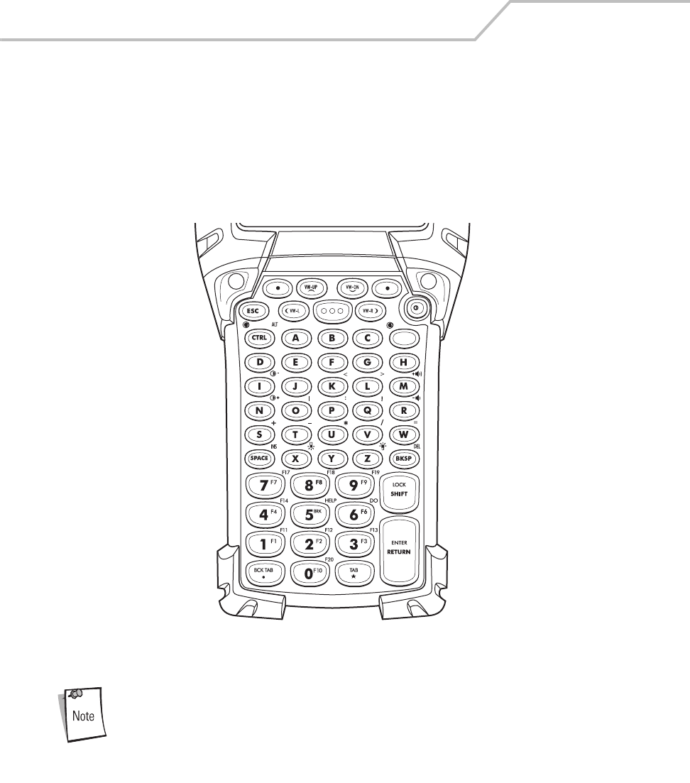
MC9000-K/S for Embedded Windows® CE .NET Product Reference Guide
2-20
VT Emulator
The VT emulator keypad is available only on the MC9000-K. It contains a Power button, application
keys, scroll keys and a function key. The keypad is color-coded to indicate the alternate function key
(blue) values. Note that keypad functions can be changed by an application so the mobile computer’s
keypad may not function exactly as described. See Table 2-6 on page 2-21 for key and button
descriptions and Table 2-7 on page 2-23 for the keypad’s special functions.
Figure 2-7. VT Emulator Keypad
The VT emulator keypad is only used when the mobile computer is running
the VT emulation software. When the mobile computer is not running the VT
emulation software, the VT keypad functions are the same as a 53-key
keypad.
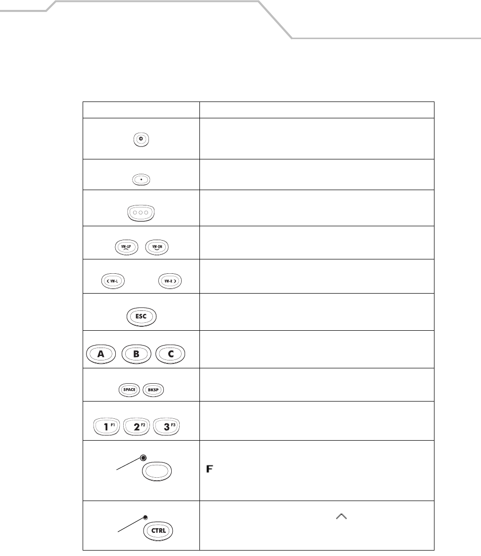
Operating the MC9000-K/S 2-21
Table 2-6. VT Emulator Descriptions
Key Description
Power (red) Powers the mobile computer on and off.
Used to reset the mobile computer, see Resetting the Mobile Computer
on page 2-39.
Green/Red Dot Unassigned application function key. See Appendix B, Keypad Maps for
mapping details.
Scan (yellow) Scan key - used for scanning applications, this key has the same
function as pushing the scan button.
Scroll Up and Down Moves up and down from one item to another.
Scroll Left and Right Moves left and right from one item to another.
ESC Exits the current operation.
Alpha Use the alpha keys for alphabetic characters.
SPACE/BKSP Space and backspace functions.
Application These keys can be assigned to an application.
Function (blue) Press and release the blue function key to activate the keypad alternate
functions (shown on the keypad in blue). The keypad LED lights and the
icon appears on the taskbar, see Table 2-9 on page 2-27. Press and
release the blue function key again to return to the normal keypad
functions.
Control Press and release the CTRL key to activate the keypad alternate CTRL
functions. The keypad LED lights and the icon appears on the
taskbar. Press and release the CTRL key again to return to the normal
keypad functions.
. . .
. . .
LED
LED
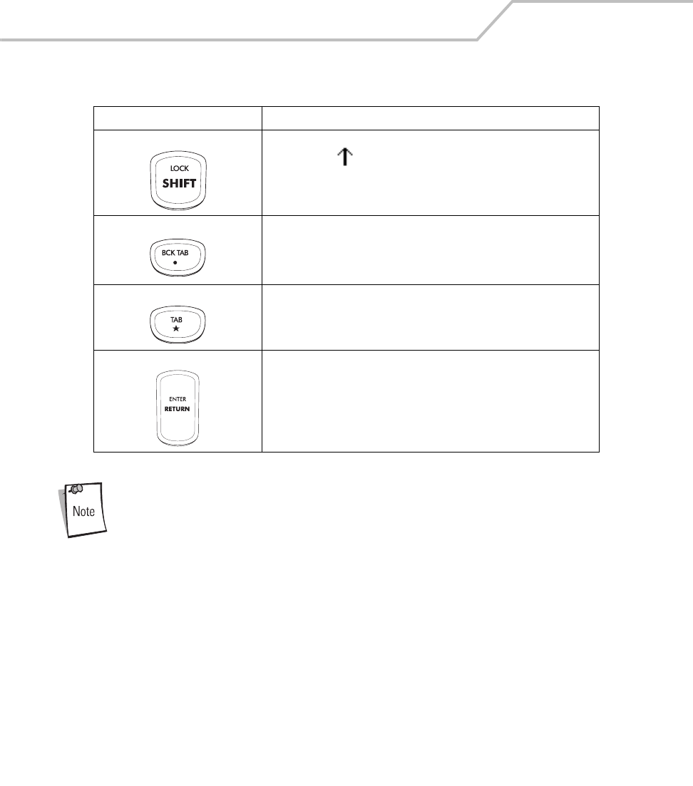
MC9000-K/S for Embedded Windows® CE .NET Product Reference Guide
2-22
For detailed keypad configurations including ASCII values and VK codes, see
Appendix B, Keypad Maps.
Shift Press and release the SHIFT key to activate the keypad alternate SHIFT
functions. The icon appears on the taskbar. Press and release the
SHIFT key again to return to the normal keypad functions.
Period/Decimal Point Produces a period for alpha entries and decimal point for numeric
entries.
Star Produces an asterisk.
Enter Executes a selected item or function.
Table 2-6. VT Emulator Descriptions (Continued)
Key Description
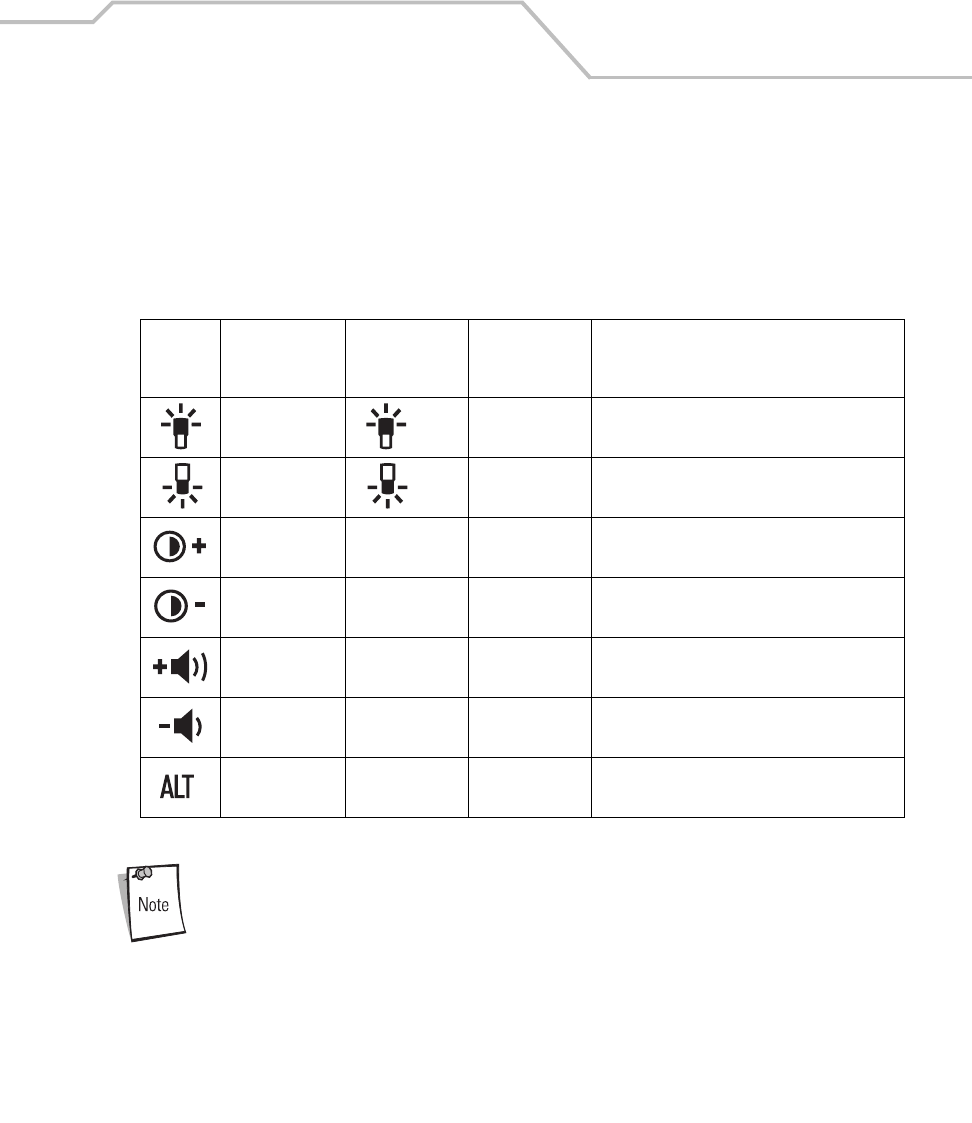
Operating the MC9000-K/S 2-23
Keypad Special Functions
The keypad special functions are color coded on the keypads. For example, on the 53-key keypad, the
display backlight icon is blue indicating that the blue function key must be selected first to access the
display backlight. On the 43-key keypad, the display backlight icon is white indicating that the display
backlight is the default value for that key.
Use of display and keypad backlighting can significantly reduce battery life.
Mobile computers with color screens do not have contrast settings.
Table 2-7. Keypad Special Functions
Icon
28-Key,
Keystrokes
43-Key
Keystrokes
53-Key, 3270,
5250, VT
Keystrokes Special Function
Blue function key
and #
key Blue function key
and Z
Turns on and off the display backlight.
Blue function key
and 0
key Blue function key
and X
Turns on and off the keypad backlight.
Blue function key
and 1
Blue function key
and F1
Blue function key
and D
Increases display contrast (on monochromatic
units only).
Blue function key
and 4
Blue function key
and F5
Blue function key
and I
Decreases display contrast (on monochromatic
units only).
Blue function key
and 3
Blue function key
and F4
Blue function key
and H
Increases beeper volume.
Blue function key
and 6
Blue function key
and F8
Blue function key
and M
Decreases beeper volume.
*Blue function key
and CTRL
Not Available Blue function key
and CTRL
Enables Alt keypad functions.
MC9000-K/S for Embedded Windows® CE .NET Product Reference Guide
2-24
Power Button
Press the red Power button to turn the mobile computer screen on and off. The mobile computer is on
when the display is on and the mobile computer is in suspend mode when the display is off. For more
information, see Starting the Mobile Computer on page 1-17.
Do not hold down any key, button or the scan button, other than the Power
button during a reset.
Cold boot resets the mobile computer, to the default settings. All added applications and
all stored data will be removed. Do not cold boot without support desk approval.
Any data previously synchronized with a computer can be restored during the
next ActiveSync operation. See Chapter 4, Communications for detailed
ActiveSync instructions.
The Power button is also used to reset the mobile computer by performing a warm or cold boot.
• Warm Boot (Soft Reset) - Resets the mobile computer.
• Cold Boot (Hard Reset) - Resets the mobile computer, removes all added applications, stored
data restores the default settings.
For information about rebooting the mobile computer, refer to Resetting the Mobile Computer on page
2-39.
Headphone
An optional headphone is available. The headset plugs into the optional headphone jack located at
the top of the mobile computer, see Figure 1-2 on page 1-4. Set the mobile computer volume
appropriately before putting on the headset. When a headset is plugged into the jack, the speaker is
muted.
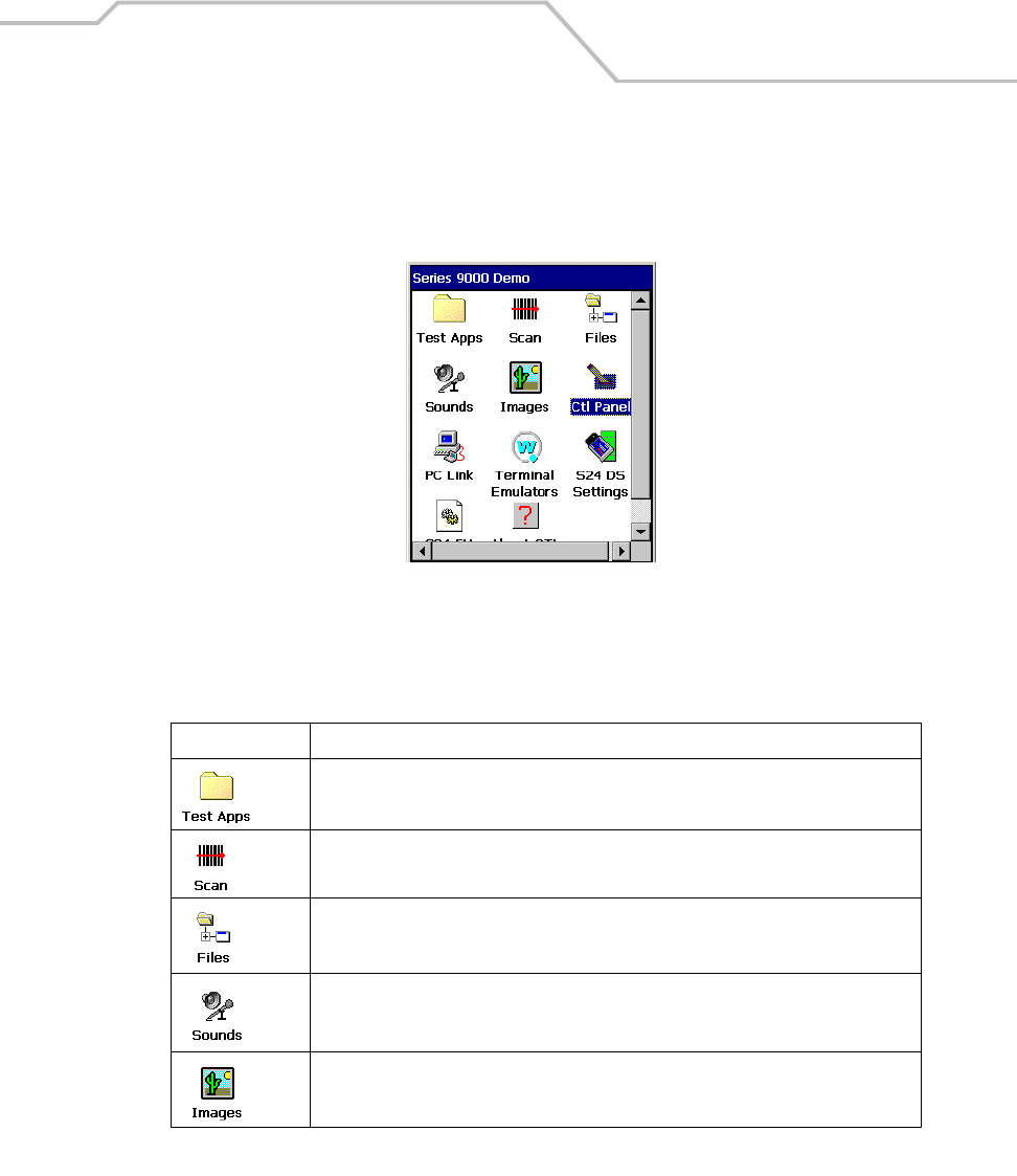
Operating the MC9000-K/S 2-25
Series 9000 Demo Window
On initial power up (or on a warm or cold boot) the Series 9000 Demo window appears. The Series
9000 Demo window icon functions are provided in Table 2-8.
Figure 2-8. Series 9000 Demo Window
Table 2-8. Series 9000 Demo Window Functions
Icon Description
Displays the Test Applications window, see Introduction on page 5-3 for a description of
the Test Applications window.
Use to set up and run the demonstration scan application, see ScanSamp2 on page 5-6.
Displays the system file structure, see InkWiz File Browser on page 5-9.
Displays the AudioSamp sample application, see AudioSamp on page 5-13.
Displays the image viewer sample application, see Images on page 5-14.
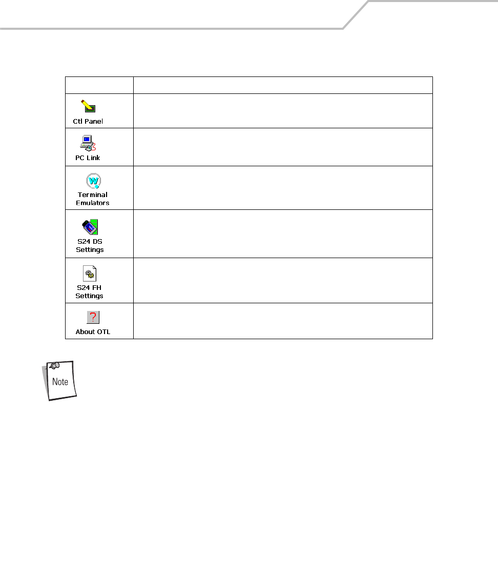
MC9000-K/S for Embedded Windows® CE .NET Product Reference Guide
2-26
The Series 9000 Demo window is the factory default launcher menu.
Application specific shells may vary.
Displays the control panel menu, see Control Panel on page 3-40.
Starts the PC Link application, see PC Link on page 5-16.
Provides access to the terminal emulators, see Terminal Emulators on page 2-44.
Provides access to the S24 DS Settings, see Mobile Companion on page 6-4.
Provides access to the S24 FH Settings, see Spectrum24 Frequency Hopping (FH) Settings
(1 and 2 MB Radios) on page 6-30.
Provides information about the OTL application, see About OTL on page 5-17.
Table 2-8. Series 9000 Demo Window Functions (Continued)
Icon Description
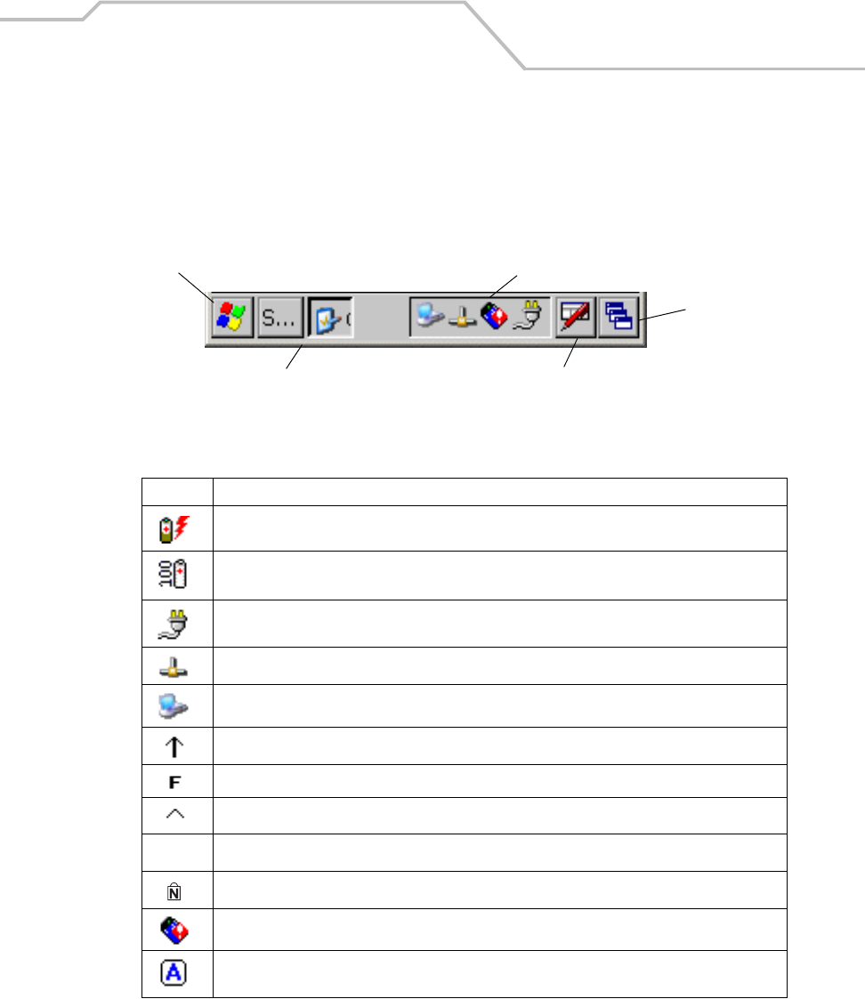
Operating the MC9000-K/S 2-27
Taskbar
The taskbar (at the bottom of the window) displays the Start button, active programs (in this case PC
Link and Mobile Companion), battery status and the communication status. The default taskbar icons
are described in Table 2-9 and the default taskbar buttons are described in Table 2-10 on page 2-28.
The Start button functions are described in Sart Button on page 2-29.
Figure 2-9. Taskbar
.
Table 2-9. Taskbar Icons
Icon Description
Indicates that the battery is charging.
Indicates that the battery charge is fully charged (100% charge).
The battery status icons provide the battery status in 10% increments from 10% to 100%.
Indicates that the battery is fully charged and the mobile computer is running on external power.
Indicates IP status. Only displays when the mobile computer is in emulation mode.
Indicates that the ActiveSync application is running.
Indicates that the Shift character selection is selected.
Indicates that the Function character selection is selected.
Indicates that the Control character selection is selected.
Indicates that the ALT character selection is selected.
Indicates that the Num-lock character selection is selected.
The Mobile Companion utility. Tap to display the LAN status selection menu.
Indicated that the mobile computer is in Alpha mode. The mobile computer automatically enters
Alpha mode when the Terminal Emulators are run.
Start Button Open Programs and Status Icons
Keyboard Input Panel
Desktop
Menu and Application Buttons
ALT
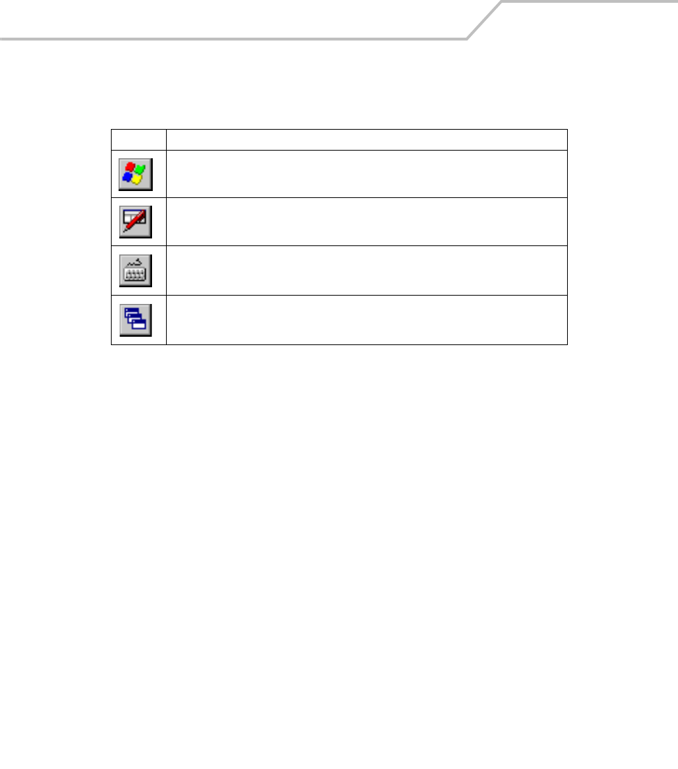
MC9000-K/S for Embedded Windows® CE .NET Product Reference Guide
2-28
Table 2-10. Taskbar Buttons
Icon Description
The Start button. Tap to display the Start menu.
The Keyboard Input Panel, display button. Tap to display the Keyboard Input Panel.
The Keyboard Input Panel hide button. Tap to hide the Keyboard Input Panel.
The Desktop display button. Tap to display the Desktop.
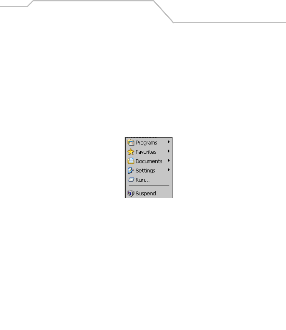
Operating the MC9000-K/S 2-29
Sart Button
Tap the Start button to launch the Start Menu or tap the Start button while in the ALT state and the
Task Manager, Properties menu appears, see Task Manager and Properties on page 2-31.
•Programs: Use to access available programs
•Favorites: Displays files in Favorites
•Documents: Displays files in Documents
•Settings: Accesses the Control Panel, the Network and Dial-up Connections and the Taskbar
and Start Menus.
•Run: Runs a program or application
•Suspend: Suspends the mobile computer.
Figure 2-10. Start Menu
Keyboard Input Panel Button
Use the Keyboard Input Panel as an alternate input device, see Entering Information Using the
Keyboard Input Panel on page 2-34.
Desktop Button
Use the Desktop button to minimize all open programs and display the Desktop.
Major desktop functions include:
• My Computer: Double-tap icon to open My Computer
• Recycle Bin: Deleted files remain in the recycle bin until the recycle bin is emptied. Once
emptied the files cannot be retreived.
• Remote Desktop Connection: Use the Remote Desktop Connection icon to access the
Remote Desktop Connection window.

MC9000-K/S for Embedded Windows® CE .NET Product Reference Guide
2-30
Taskbar Icons
The taskbar icons display the function status, indicate what programs are active and indicate the
battery charge status. The taskbar icons are provided in Table 2-9 on page 2-27.
Status Icons
The status icons indicate the function key status. Icond indicate if the Function, Shift, CTRL or ALT
functions are active.
Active Programs Icons
If more than one program is active, the applications’ icons can be used to toggle between the open
programs (applications). Tap on a taskbar application to maximize the application.
AC Power/Battery Status Icons
The AC Power/Battery Status icons are shown in the taskbar to indicate the present power supply
status of the mobile computer. The battery status icons provide the battery status in 10% increments
from 10% to 100%, see Table 2-9 on page 2-27 . Battery status can also be viewed on the battery
status window, see Battery on page 3-46.
The amber LED in the mobile computer indicator LED bar, see Figure 1-1 on
page 1-3, also indicates low battery status and/or incorrect battery insertion.
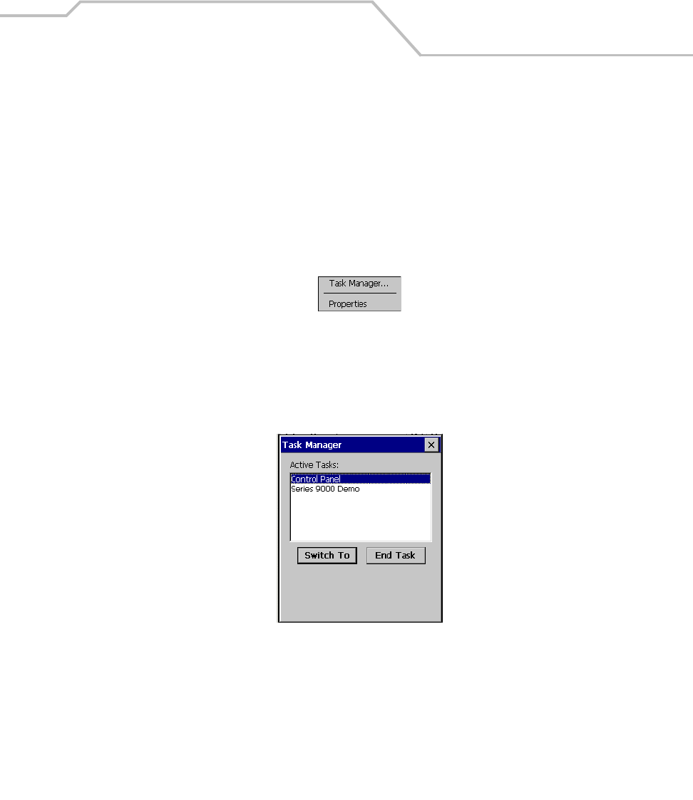
Operating the MC9000-K/S 2-31
Task Manager and Properties
Use the Task Manager to stop applications and use the Properties functions to set display and clock
options.
Task Manager
1. Select Function - CTRL, (to activate the ALT state) and tap the Start button to display the
Task Manager, Properties Selection menu.
2. Tap Task Manager to display the Task Manager window.
Figure 2-11. Task Manager, Properties Selection Menu
3. Tap a task in the Active Tasks list and tap Switch To to make that task the primary task, or
tap End Task to end the selected task.
4. Tap X to exit the Task Manager window.
Figure 2-12. Task Manager Window
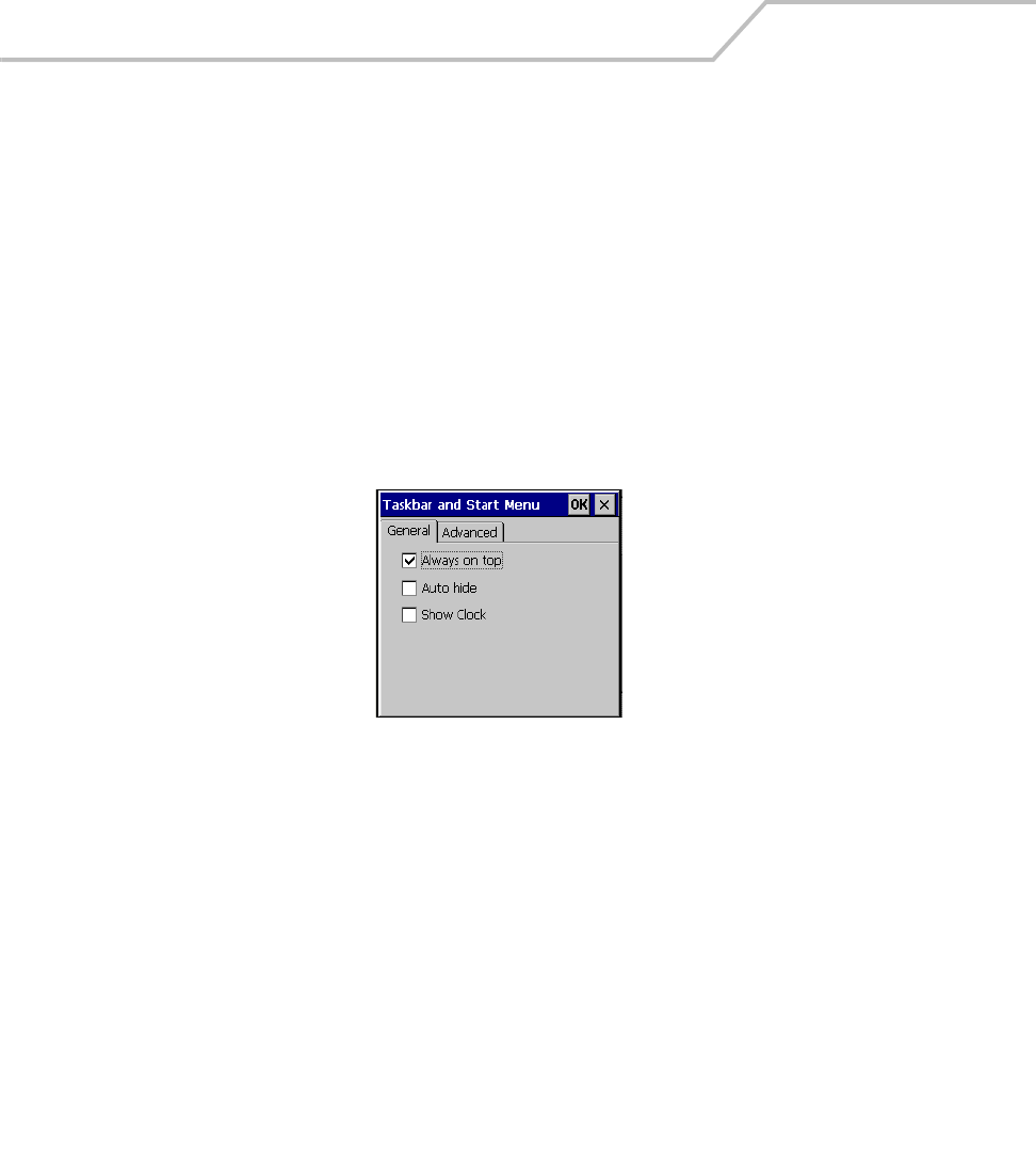
MC9000-K/S for Embedded Windows® CE .NET Product Reference Guide
2-32
Properties
1. Select Function - CTRL, (to activate the ALT state) and tap the Start button to display the
Task Manager, Properties window, see Figure 2-11 on page 2-31.
2. Tap Properties to display the Taskbar and Start Menu, General Tab.
3. This menu provides taskbar options:
• Check the Always on Top checkbox to keep the taskbar on top of all other windows.
• Check the AutoHide checkbox to make the taskbar disappear, touch the bottom of the
display to make the taskbar return.
• Check the Show Clock checkbox to display the clock on the taskbar.
4. Tap OK to save the settings and exit the window.
Figure 2-13. Taskbar and Start Menu, General Tab
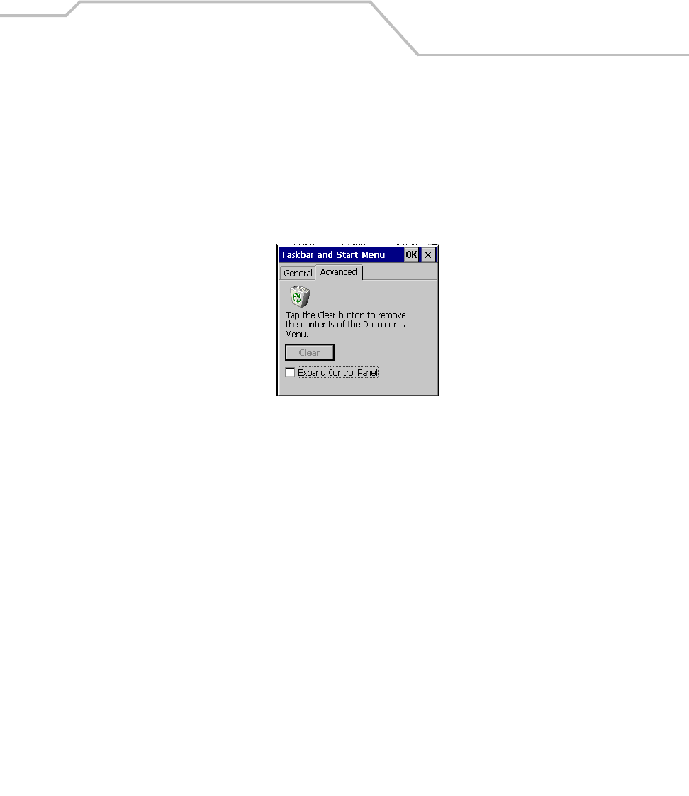
Operating the MC9000-K/S 2-33
Advanced Tab
1. Tap the Advanced tab to enter the Taskbar and Start Menu, Advanced Tab.
2. Tap the Clear button to delete all of the documents listed in the Start - Documents entry,
see Sart Button on page 2-29. Typically this list is empty, but if there were documents in the
list the Clear button would delete them.
3. Tap the Expand Control Panel checkbox to display the entire contents of the MS control
panel in list form, rather than Icons..
Figure 2-14. Taskbar and Start Menu, Advanced Tab
4. Tap OK to save the settings and exit the window.
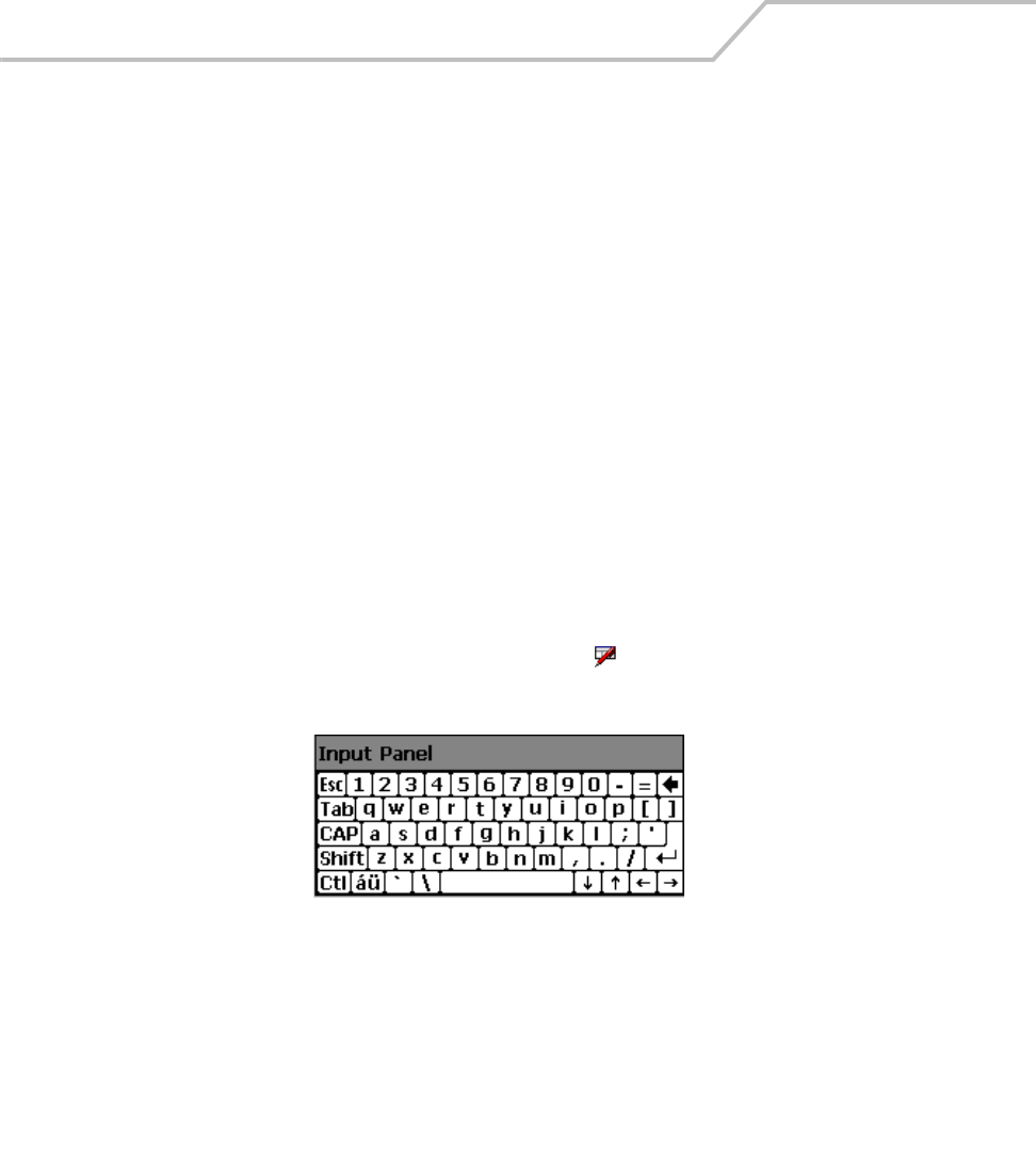
MC9000-K/S for Embedded Windows® CE .NET Product Reference Guide
2-34
Entering Information
To enter information:
• Use the keypad.
• Use the input panel (soft keyboard) to enter typed text.
• Scan bar code data into data fields.
• Use Microsoft® ActiveSync® to synchronize or copy information from the host computer to
the mobile computer. For more information on ActiveSync, see Chapter 4, Communications
or ActiveSync Help on the host computer.
Entering Information Using Keypad
The alphanumeric keypads produce the 26-character alphabet (A-Z), numbers (0-9), function keys and
assorted characters. The keypads’ default characters/functions are printed white and the function
character/functions are printed blue. See Keypads on page 2-3 for keypad configurations and see
Table 2-7 on page 2-23 for keypad special functions.
Entering Information Using the Keyboard Input Panel
Use the keyboard input panel to enter information in any program. To launch the keyboard input panel,
tap Start, tap the Soft KeyBd menu selection and then tap the icon. Tap on a key to enter the key’s
value. Tap on the keyboard selection icon to display or to hide the keyboard input panel.
Figure 2-15. Keyboard Input Panel
Entering Data via the Bar Code Scanner (Scan Wedge)
The integrated bar code scanner uses the Scan Wedge program to scan data into data fields in the
same way data is entered via the keypad. The Scan Wedge program is provided as a sample
application in the SMDK, see Chapter 8, Software Installation for the SMDK installation.
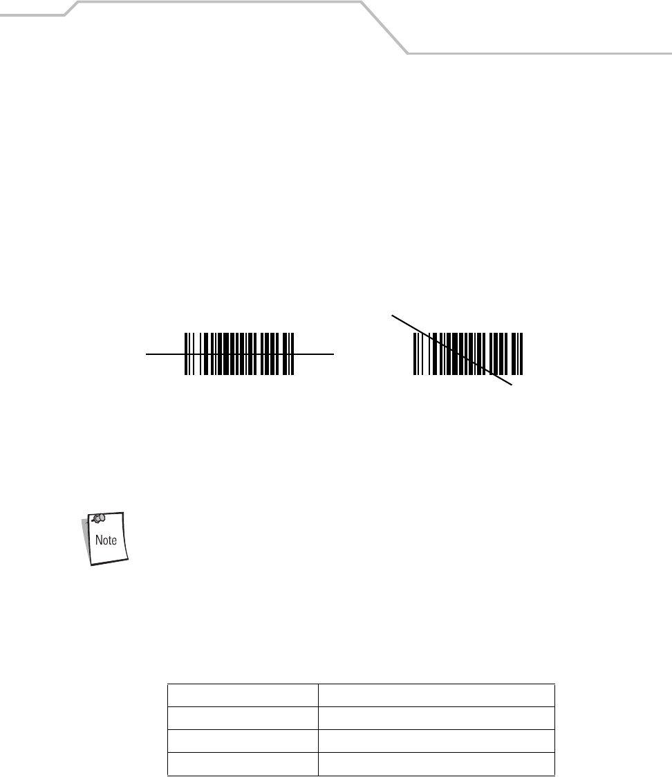
Operating the MC9000-K/S 2-35
Data Capture
The mobile computer has an integrated scanner used to collect data by scanning bar codes.
Laser Scanning
To scan bar codes with the mobile computer:
1. Ensure that the mobile computer is loaded with a scanning application. See ScanSamp2 on
page 5-6 for a sample scanning application.
2. Aim the scan exit window at the bar code.
3. Push the scan button. Ensure the red scan beam covers the entire bar code. The indicator
LED bar illuminates red to indicate that the laser is on. The indicator LED bar illuminates
green and a beep sounds to indicate a successful decode.
Figure 2-16. Laser Aiming
Optimal scanning distance varies with bar code density and scanner optics.
• Hold the scanner farther away for larger symbols.
• Move the scanner closer for symbols with bars that are close together.
Scanning procedures depend on the application and mobile computer
configuration. An application may use different scanning procedures from the
one listed above.
Indicator LED Bar
The Indicator LED bar provides a visual indication of the scan status, see Figure 1-1 on page 1-3.
Table 2-11. Scan LED Indicators
LED Status Indication
Off Not scanning.
Solid Red Laser enabled, scanning in process.
Solid Green Successful decode.
Wrong
Right

MC9000-K/S for Embedded Windows® CE .NET Product Reference Guide
2-36
Scanning Considerations
Typically, scanning is a simple matter of aim, scan/decode and a few quick trial efforts master it.
However, two important considerations can be used to optimize any scanning performance:
• Range
Any scanning device decodes well over a particular working range — minimum and
maximum distances from the bar code. This range varies according to bar code density and
scanning device optics.
Scanning within range brings quick and constant decodes; scanning too close or too far
away prevents decodes. Move the scanner closer and further away to find the right working
range for the bar codes being scanned. However, the situation is complicated by the
availability of various integrated scanning modules. The best way to specify the appropriate
working range per bar code density is through a chart called a decode zone for each scan
module. A decode zone simply plots working range as a function of minimum element widths
of bar code symbols.
• Angle
Scanning angle is important for promoting quick decodes. When laser beams reflect directly
back into the scanner from the bar code, this specular reflection can “blind” the scanner.
To avoid this, scan the bar code so that the beam does not bounce directly back. But don’t
scan at too sharp an angle; the scanner needs to collect scattered reflections from the scan
to make a successful decode. Practice quickly shows what tolerances to work within.
Contact the Symbol Support Center if chronic scanning difficulties develop.
Decoding of properly printed bar codes should be quick and effortless.

Operating the MC9000-K/S 2-37
Imaging
The imager version of the mobile computer has the following features:
• Omnidirectional reading of a variety of bar code symbologies, including the most popular
linear, postal, PDF417 and 2-D matrix code types.
• The ability to capture and download images to a host for a variety of imaging applications.
• Advanced intuitive laser aiming for easy point-and-shoot operation.
Imager
The imager uses digital camera technology to take a digital picture of a bar code, stores the resulting
image in its memory and executes state-of-the-art software decoding algorithms to extract the data
from the image. A typical bar code decoding process is as follows:
1. Aim the imager version of the mobile computer at a bar code and push the scan button.
2. The red laser aiming pattern turns on to assist in aiming the mobile computer.
3. If necessary, the mobile computer turns on its red LEDs to illuminate the target bar code.
4. The mobile computer takes a digital picture (image) of the bar code and stores it in memory
for decoding.
5. An audible beep occurs indicating the bar code was decoded properly.
6. Release the scan button.
This process usually occurs instantaneously. Steps 2 - 4 are repeated on poor or difficult bar codes as
long as the scan button remains pulled.
Operational Modes
The imager version of the mobile computer has two modes of operation: Decode Mode and Image
Capture Mode, activated by pushing the scan button.
Decode Mode
In this default mode, upon pushing the scan button, the Imager attempts to locate and decode
enabled bar codes within its field of view. The Imager remains in this mode as long as the scan button
is pressed, or until a bar code is decoded.
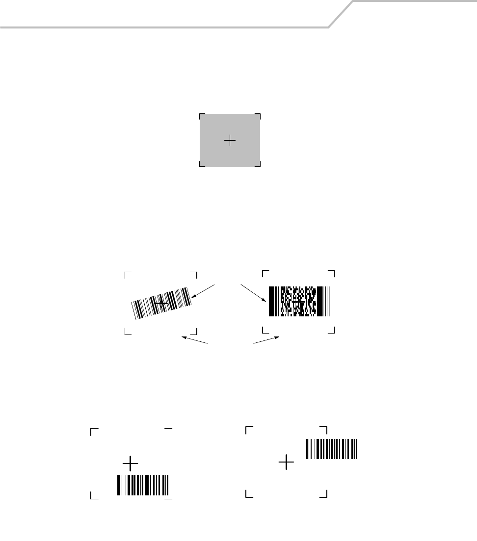
MC9000-K/S for Embedded Windows® CE .NET Product Reference Guide
2-38
Aiming the Imager
The imager version of the mobile computer projects a laser aiming pattern (shown below) similar to
those used on cameras. The aiming pattern is used to position the bar code or object within the field
of view.
Figure 2-17. Laser Aiming Pattern
Imager symbol scanning:
1. Center the symbol in any orientation within the aiming pattern. Ensure the entire symbol is
within the rectangular area formed by the brackets in the aiming pattern.
Figure 2-18. Centering Symbol in Aiming Pattern
The imager can also read a bar code presented within the aiming pattern but not centered,
such as the figure below on the left. The figure on the right, however, can not be decoded.
Figure 2-19. Imager Aiming
Linear bar code PDF417 symbol
Symbol
View Finder
(Aiming Pattern)
Right Wrong

Operating the MC9000-K/S 2-39
2. The aiming pattern is smaller when the Imager is closer to the symbol and larger when it is
farther from the symbol. Scan symbols with smaller bars or elements (mil size) closer to the
unit and those with larger bars or elements (mil size) farther from the unit.
3. Hold the mobile computer between two and nine inches (depending on symbol density) from
the symbol, centering the aiming pattern cross hairs on the symbol.
4. Press and hold the scan button until the mobile computer beeps, indicating the bar code is
successfully decoded.
Resetting the Mobile Computer
If the mobile computer stops responding to input, reset it. There are two reset functions, warm boot
and cold boot. A warm boot restarts the mobile computer by closing all running programs. All data
that is not saved to flash memory is lost.
A cold boot also restarts the mobile computer, but erases all stored records and entries. In addition it
returns formats, preferences and other settings to the factory default settings.
Perform a warm boot first. This restarts the mobile computer and saves all stored records and entries.
If the mobile computer still does not respond, perform a cold boot.
Performing a Warm Boot
Hold down the Power button for approximately five seconds. As soon as the mobile computer starts
to perform a warm boot release the Power button.
Or the the warm boot command can be excuted from the Programs menu, tap Start - Programs - Warm
Boot.
Files that remain open during a warm boot may not be retained.
MC9000-K/S for Embedded Windows® CE .NET Product Reference Guide
2-40
Performing a Cold Boot
A cold boot restarts the mobile computer and erases all user stored records and entries. Never
perform a cold boot unless a warm boot does not solve the problem.
Do not hold down any key, button or the scan button, other than the Power
button during a reset.
Cold boot resets the mobile computer, to the default settings. All added applications and
all stored data will be removed. Do not cold boot without support desk approval.
Any data previously synchronized with a computer can be restored during the
next ActiveSync operation. See Chapter 4, Communications for detailed
ActiveSync instructions.
To perform a cold boot:
1. Press the mobile computer’s primary battery releases to partially eject the battery. The
secondary battery release tab is now visable, see Figure 1-5 on page 1-10.
2. While the battery is partially ejected, press and hold the Power button, while pushing the
battery back into the fully inserted position.
3. Continue holding the Power button for 15 seconds. After the first five seconds the unit may
start to perform a warm boot. The message Warm Boot appears in the upper left hand corner
of the screen. Continue holding the Power button and the unit cycles into a cold boot. The
message Booting System appears in the top center of the screen.
4. As the mobile computer initializes its Flash File system, the Symbol splash window, Figure
1-6 on page 1-11 appears for about a minute.
5. Calibrate the screen. See Calibration Screen on page 1-18 to calibrate the mobile computer
display.
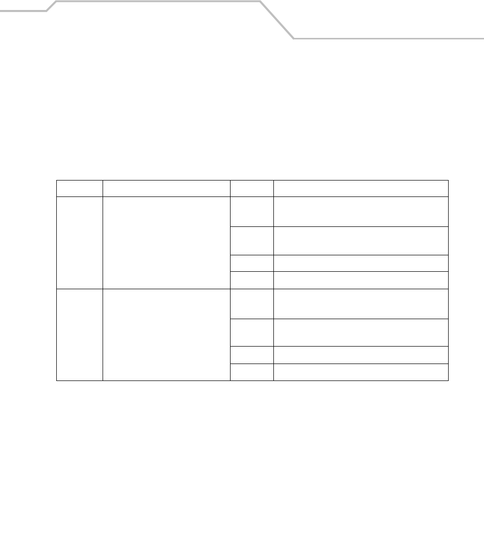
Operating the MC9000-K/S 2-41
Waking the Mobile Computer
The wakeup conditions are configurable and the current factory default settings are subject to
change/update.
The mobile computer wakeup configuration is set in the registry file, registry file editing procedures
are provided in the SMDK, refer to Chapter 8, Software Installation for the SMDK installation. Table
2-12 lists the wakeup conditions settings.
Table 2-12. Wakeup Conditions
Status Description Action Conditions for wakeup
Power Off When the mobile computer goes into
sleep mode by pressing Power,
these actions wake the mobile
computer.
Power 1. Power button is pressed.
2. AC power added or removed.
Scan
Button
Scan button is pressed.
WLAN Wireless LAN accesses the mobile computer.
Clock Real Time Clock set to wake up.
Auto Off When the mobile computer goes into
sleep mode by an automatic power-
off function, these actions wake the
mobile computer.
Power 1. Power button is pressed.
2. AC power added or removed.
Scan
Button
Scan button is pressed.
WLAN Wireless LAN accesses the mobile computer.
Clock Real Time Clock set to sleep.
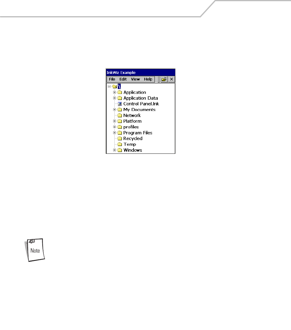
MC9000-K/S for Embedded Windows® CE .NET Product Reference Guide
2-42
File System Directory Structure
The mobile computer directory structure displays all of the file folders, see Figure 2-20. The pre-
installed folders are in flash file system memory and optional removable storage devices (MMC
storage cards).
Figure 2-20. Mobile Computer Directory Structure
•Application and Platform folders are located in flash file system memory.
• The Windows, Program Files, profiles, and My Documents folders are composites, RAM
based folders generated from ROM (many of these files are marked read only).
• The Network folder is a link to file systems mapped using the network redirector. The files
do not physically reside on the terminal.
• The Temp and Recycled folders typically contain RAM based files.
All files copied to the RAM based folders are lost after a cold boot.

Operating the MC9000-K/S 2-43
Flash Storage
In addition to the RAM-based storage the mobile computer is also equipped with a non-volatile Flash-
based storage area which can store data (partitions) that can not be corrupted by a cold boot, see
Flash Storage on page 10-27 for a detailed discussion.
Startup Folder
The Applications/Startup folder is used to launch programs automatically when the mobile computer
is started, either after a warm or cold boot.
The Windows/Startup folder is not supported.
There are two ways to launch programs automatically:
1. Place the executable in the Startup folder of the Application partition.
2. Place a .run file in the Startup folder of the Application partition.
Refer to the Windows CE Help File for Symbol Terminals included with the SMDK for more
information on the Startup folder.
Run Files
A .run file is a simple text file that contains the path to an application as well as the name of the
application to run.
Refer to the Windows CE Help File for Symbol Terminals included with the SMDK for more
information on the Startup folder.
Audio Event Aliasing
Audio Event Aliasing is the means by which standard Windows .wav files are rendered on a non-
audio terminal using only a beeper.
The audio driver of the mobile computer supports a feature called Event Aliasing. This feature allows
a special .wav file to play. This .wav file replaces the sound normally produced when running a .wav
file with other actions (such as LED flashing, etc.).
This feature allows applications that play .wav files to be portable between two devices, one that
supports real audio and one that supports audio aliasing.
MC9000-K/S for Embedded Windows® CE .NET Product Reference Guide
2-44
Terminal Emulators
Use the Terminal Emulators icon to enter the Wavelink terminal emulator application.
From the Series 9000 Demo window, double-tap the Terminal Emulators icon. The Terminal Emulator
window appears.
To exit, tap TelnetCE Options and tap ExitExit.
Figure 2-21. Terminal Emulator Window
Refer to the documentation provided with the terminal emulator software package for setup and use.

Settings
Chapter Contents
Introduction. . . . . . . . . . . . . . . . . . . . . . . . . . . . . . . . . . . . . . . . . . . . . . . . . . . . . . . . . . . . . . . . . . . . . . . . .3-5
Windows Control Panel Menu . . . . . . . . . . . . . . . . . . . . . . . . . . . . . . . . . . . . . . . . . . . . . . . . . . . . . . . . . .3-5
Bluetooth Device Properties. . . . . . . . . . . . . . . . . . . . . . . . . . . . . . . . . . . . . . . . . . . . . . . . . . . . . . . .3-8
Bluetooth/S24 Power Settings. . . . . . . . . . . . . . . . . . . . . . . . . . . . . . . . . . . . . . . . . . . . . . . . . .3-8
Starting Bluetooth . . . . . . . . . . . . . . . . . . . . . . . . . . . . . . . . . . . . . . . . . . . . . . . . . . . . . . . . . .3-11
Certificates . . . . . . . . . . . . . . . . . . . . . . . . . . . . . . . . . . . . . . . . . . . . . . . . . . . . . . . . . . . . . . . . . . . .3-15
Date/Time. . . . . . . . . . . . . . . . . . . . . . . . . . . . . . . . . . . . . . . . . . . . . . . . . . . . . . . . . . . . . . . . . . . . .3-16
Device Management . . . . . . . . . . . . . . . . . . . . . . . . . . . . . . . . . . . . . . . . . . . . . . . . . . . . . . . . . . . .3-17
Dialing. . . . . . . . . . . . . . . . . . . . . . . . . . . . . . . . . . . . . . . . . . . . . . . . . . . . . . . . . . . . . . . . . . . . . . . .3-18
Display . . . . . . . . . . . . . . . . . . . . . . . . . . . . . . . . . . . . . . . . . . . . . . . . . . . . . . . . . . . . . . . . . . . . . . .3-20
Background Tab . . . . . . . . . . . . . . . . . . . . . . . . . . . . . . . . . . . . . . . . . . . . . . . . . . . . . . . . . . . .3-20
Appearance Tab . . . . . . . . . . . . . . . . . . . . . . . . . . . . . . . . . . . . . . . . . . . . . . . . . . . . . . . . . . . .3-21

MC9000-K/S for Embedded Windows® CE .NET Product Reference Guide
3-2
Input Panel . . . . . . . . . . . . . . . . . . . . . . . . . . . . . . . . . . . . . . . . . . . . . . . . . . . . . . . . . . . . . . . . . . . .3-22
Keyboard. . . . . . . . . . . . . . . . . . . . . . . . . . . . . . . . . . . . . . . . . . . . . . . . . . . . . . . . . . . . . . . . . . . . . .3-23
Mouse. . . . . . . . . . . . . . . . . . . . . . . . . . . . . . . . . . . . . . . . . . . . . . . . . . . . . . . . . . . . . . . . . . . . . . . .3-24
Network and Dial-up Connections . . . . . . . . . . . . . . . . . . . . . . . . . . . . . . . . . . . . . . . . . . . . . . . . . .3-25
Owner . . . . . . . . . . . . . . . . . . . . . . . . . . . . . . . . . . . . . . . . . . . . . . . . . . . . . . . . . . . . . . . . . . . . . . . .3-26
Identification Tab . . . . . . . . . . . . . . . . . . . . . . . . . . . . . . . . . . . . . . . . . . . . . . . . . . . . . . . . . . .3-26
Notes Tab . . . . . . . . . . . . . . . . . . . . . . . . . . . . . . . . . . . . . . . . . . . . . . . . . . . . . . . . . . . . . . . . .3-27
Network ID Tab. . . . . . . . . . . . . . . . . . . . . . . . . . . . . . . . . . . . . . . . . . . . . . . . . . . . . . . . . . . . .3-27
PC Connection. . . . . . . . . . . . . . . . . . . . . . . . . . . . . . . . . . . . . . . . . . . . . . . . . . . . . . . . . . . . . . . . . .3-28
Regional Settings . . . . . . . . . . . . . . . . . . . . . . . . . . . . . . . . . . . . . . . . . . . . . . . . . . . . . . . . . . . . . . .3-29
Region Tab . . . . . . . . . . . . . . . . . . . . . . . . . . . . . . . . . . . . . . . . . . . . . . . . . . . . . . . . . . . . . . . .3-29
Number Tab . . . . . . . . . . . . . . . . . . . . . . . . . . . . . . . . . . . . . . . . . . . . . . . . . . . . . . . . . . . . . . .3-30
Currency Tab. . . . . . . . . . . . . . . . . . . . . . . . . . . . . . . . . . . . . . . . . . . . . . . . . . . . . . . . . . . . . . .3-30
Time Tab. . . . . . . . . . . . . . . . . . . . . . . . . . . . . . . . . . . . . . . . . . . . . . . . . . . . . . . . . . . . . . . . . .3-31
Date Tab . . . . . . . . . . . . . . . . . . . . . . . . . . . . . . . . . . . . . . . . . . . . . . . . . . . . . . . . . . . . . . . . . .3-31
Remove Programs. . . . . . . . . . . . . . . . . . . . . . . . . . . . . . . . . . . . . . . . . . . . . . . . . . . . . . . . . . . . . . .3-32
Stylus . . . . . . . . . . . . . . . . . . . . . . . . . . . . . . . . . . . . . . . . . . . . . . . . . . . . . . . . . . . . . . . . . . . . . . . .3-33
Double-Tap Tab . . . . . . . . . . . . . . . . . . . . . . . . . . . . . . . . . . . . . . . . . . . . . . . . . . . . . . . . . . . .3-33
Calibrate Tab . . . . . . . . . . . . . . . . . . . . . . . . . . . . . . . . . . . . . . . . . . . . . . . . . . . . . . . . . . . . . .3-34
System . . . . . . . . . . . . . . . . . . . . . . . . . . . . . . . . . . . . . . . . . . . . . . . . . . . . . . . . . . . . . . . . . . . . . . .3-35
General Tab . . . . . . . . . . . . . . . . . . . . . . . . . . . . . . . . . . . . . . . . . . . . . . . . . . . . . . . . . . . . . . .3-35
Memory Tab . . . . . . . . . . . . . . . . . . . . . . . . . . . . . . . . . . . . . . . . . . . . . . . . . . . . . . . . . . . . . . .3-36
Device Name Tab . . . . . . . . . . . . . . . . . . . . . . . . . . . . . . . . . . . . . . . . . . . . . . . . . . . . . . . . . . .3-37
Copyrights Tab . . . . . . . . . . . . . . . . . . . . . . . . . . . . . . . . . . . . . . . . . . . . . . . . . . . . . . . . . . . . .3-38
Series 9000 Demo Window . . . . . . . . . . . . . . . . . . . . . . . . . . . . . . . . . . . . . . . . . . . . . . . . . . . . . . . . . . .3-39
Control Panel. . . . . . . . . . . . . . . . . . . . . . . . . . . . . . . . . . . . . . . . . . . . . . . . . . . . . . . . . . . . . . . . . . . . . . .3-40
About Ctl Panel. . . . . . . . . . . . . . . . . . . . . . . . . . . . . . . . . . . . . . . . . . . . . . . . . . . . . . . . . . . . . . . . .3-42
System Version. . . . . . . . . . . . . . . . . . . . . . . . . . . . . . . . . . . . . . . . . . . . . . . . . . . . . . . . . . . . . . . . .3-43
Unique Unit ID . . . . . . . . . . . . . . . . . . . . . . . . . . . . . . . . . . . . . . . . . . . . . . . . . . . . . . . . . . . . . . . . .3-44
Persist . . . . . . . . . . . . . . . . . . . . . . . . . . . . . . . . . . . . . . . . . . . . . . . . . . . . . . . . . . . . . . . . . . . . . . . .3-45
Battery . . . . . . . . . . . . . . . . . . . . . . . . . . . . . . . . . . . . . . . . . . . . . . . . . . . . . . . . . . . . . . . . . . . . . . .3-46
Power Settings . . . . . . . . . . . . . . . . . . . . . . . . . . . . . . . . . . . . . . . . . . . . . . . . . . . . . . . . . . . . . . . . .3-47
Bluetooth Settings . . . . . . . . . . . . . . . . . . . . . . . . . . . . . . . . . . . . . . . . . . . . . . . . . . . . . . . . . . . . . .3-51
Date and Time . . . . . . . . . . . . . . . . . . . . . . . . . . . . . . . . . . . . . . . . . . . . . . . . . . . . . . . . . . . . . . . . .3-52
Printer Settings. . . . . . . . . . . . . . . . . . . . . . . . . . . . . . . . . . . . . . . . . . . . . . . . . . . . . . . . . . . . . . . . .3-53

Settings 3-3
Comm Settings . . . . . . . . . . . . . . . . . . . . . . . . . . . . . . . . . . . . . . . . . . . . . . . . . . . . . . . . . . . . . . . . .3-56
Display Settings . . . . . . . . . . . . . . . . . . . . . . . . . . . . . . . . . . . . . . . . . . . . . . . . . . . . . . . . . . . . . . . .3-57
Audio Settings . . . . . . . . . . . . . . . . . . . . . . . . . . . . . . . . . . . . . . . . . . . . . . . . . . . . . . . . . . . . . . . . .3-58
Scanner Settings . . . . . . . . . . . . . . . . . . . . . . . . . . . . . . . . . . . . . . . . . . . . . . . . . . . . . . . . . . . . . . .3-59
Reader Parameters. . . . . . . . . . . . . . . . . . . . . . . . . . . . . . . . . . . . . . . . . . . . . . . . . . . . . . . . . .3-60
Interface Parameters . . . . . . . . . . . . . . . . . . . . . . . . . . . . . . . . . . . . . . . . . . . . . . . . . . . . . . . .3-61
Scan Parameters . . . . . . . . . . . . . . . . . . . . . . . . . . . . . . . . . . . . . . . . . . . . . . . . . . . . . . . . . . .3-62
WAV File. . . . . . . . . . . . . . . . . . . . . . . . . . . . . . . . . . . . . . . . . . . . . . . . . . . . . . . . . . . . . . . . . .3-64
Device Information . . . . . . . . . . . . . . . . . . . . . . . . . . . . . . . . . . . . . . . . . . . . . . . . . . . . . . . . . .3-65
Scanner Version . . . . . . . . . . . . . . . . . . . . . . . . . . . . . . . . . . . . . . . . . . . . . . . . . . . . . . . . . . . .3-66

MC9000-K/S for Embedded Windows® CE .NET Product Reference Guide
3-4
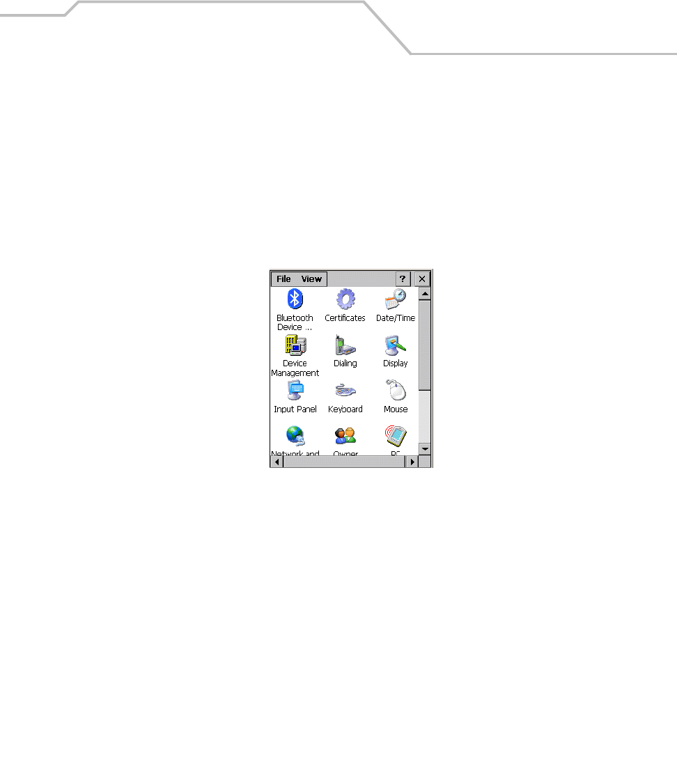
Settings 3-5
Introduction
This chapter provides basic instructions for customizing the mobile computer by adjusting settings.
The system settings are accessed from the Windows CE Control Panel menu (see Table 3-1 on page
3-6) , the Series 9000 Demo menu (see Table 3-4 on page 3-39) and the Control Panel menu (see Table
3-5 on page 3-40).
Windows Control Panel Menu
To view available options for the mobile computer settings, tap Start - Settings - Control Panel.
Figure 3-1. Windows Control Panel Menu
Table 3-1 lists the applications available in the Windows Control Panel Menu.
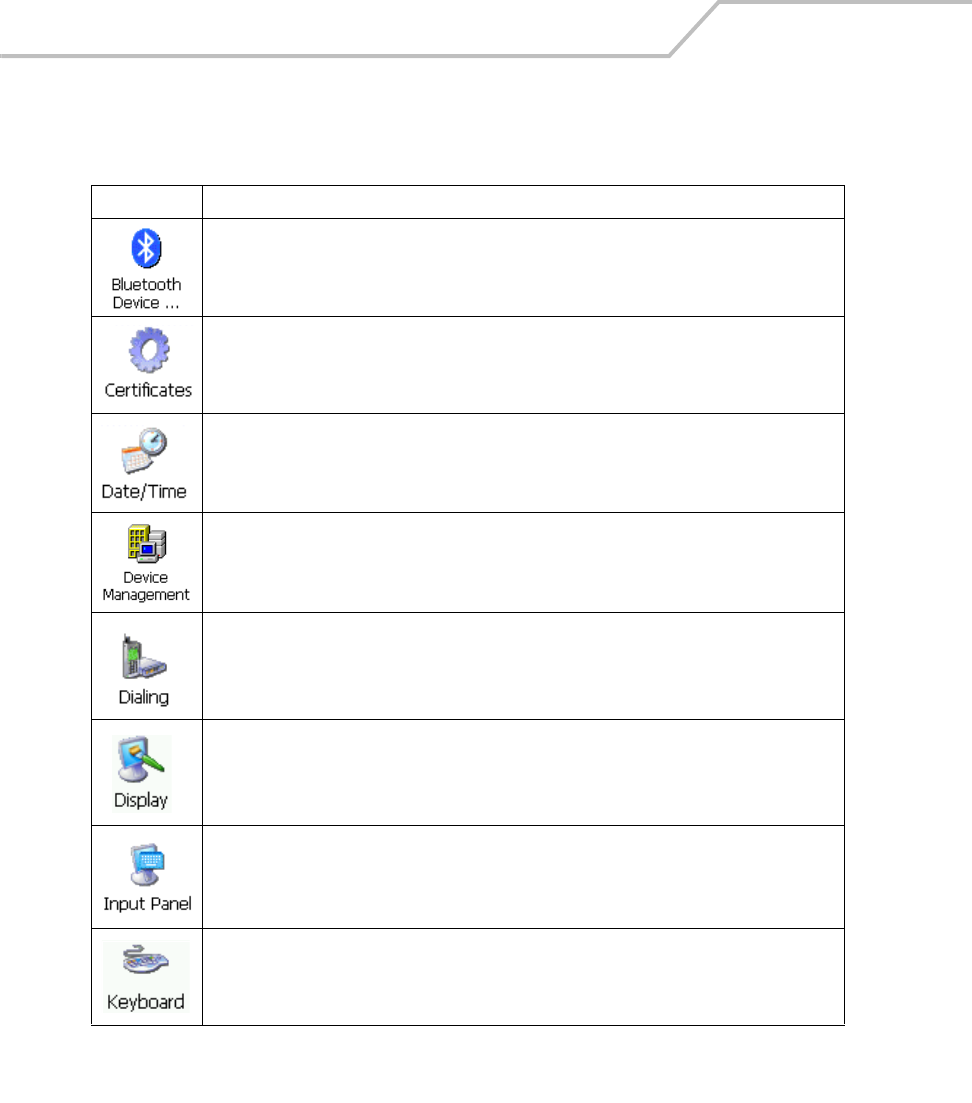
MC9000-K/S for Embedded Windows® CE .NET Product Reference Guide
3-6
Table 3-1. Windows Control Panel Menu Icons
Icon Description
Scan for, and setup Bluetooth compatible hardware, see Bluetooth Device Properties on page 3-8
for more information.
View and modify digital certificates which are used by some applications for establishing trust for
secure communications, see Certificates on page 3-15 for more information.
Change date, time and time zone information, see Date/Time on page 3-16 for more information.
Configure device management, install and view available software, see Device Management on
page 3-17 for more information.
Set dialing properties for modem communication and change telephony settings, see Dialing on
page 3-18 for more information.
Change desktop background, appearance, backlight, and brightness, see Display on page 3-20 for
more information.
Switch input methods and set input options, see Input Panel on page 3-22 for more information.
Change keyboard repeat delay and rate, see Keyboard on page 3-23 for more information.
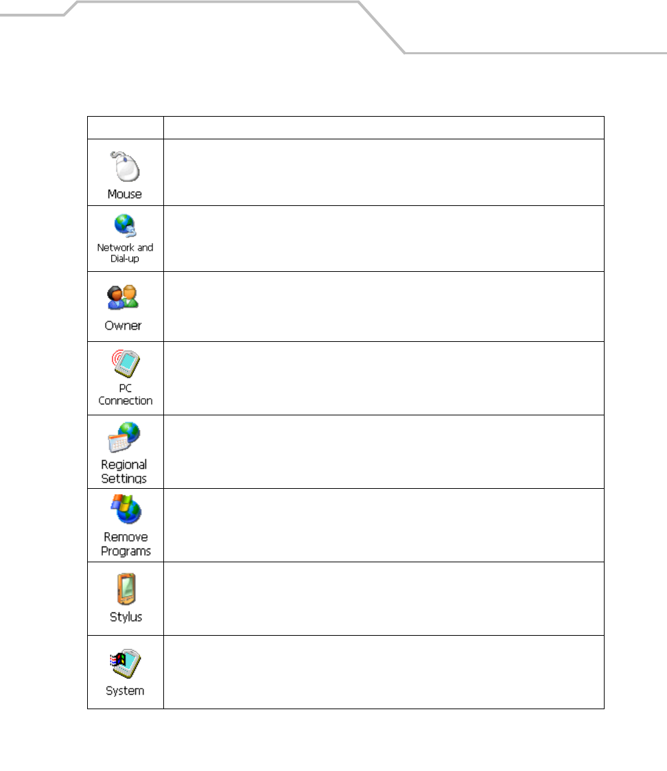
Settings 3-7
Adjust double-click sensitivity for both the speed and timing.
Connect to other computers, networks, and the Internet through a modem, see Certificates on page
3-15 for more information.
Change owner's personal profiles, see Owner on page 3-26 for more information.
Change settings for connectivity of a host computer, see PC Connection on page 3-28 for more
information.
Change how numbers, currencies, dates, and times are displayed, see Regional Settings on page
3-29 for more information.
Remove loaded programs from RAM, see Remove Programs on page 3-32 for more information.
Calibrate the touch screen and adjust double-tap timing, see Stylus on page 3-33 for more
information.
View system information, and change memory settings, see System on page 3-35 for more
information.
Table 3-1. Windows Control Panel Menu Icons (Continued)
Icon Description
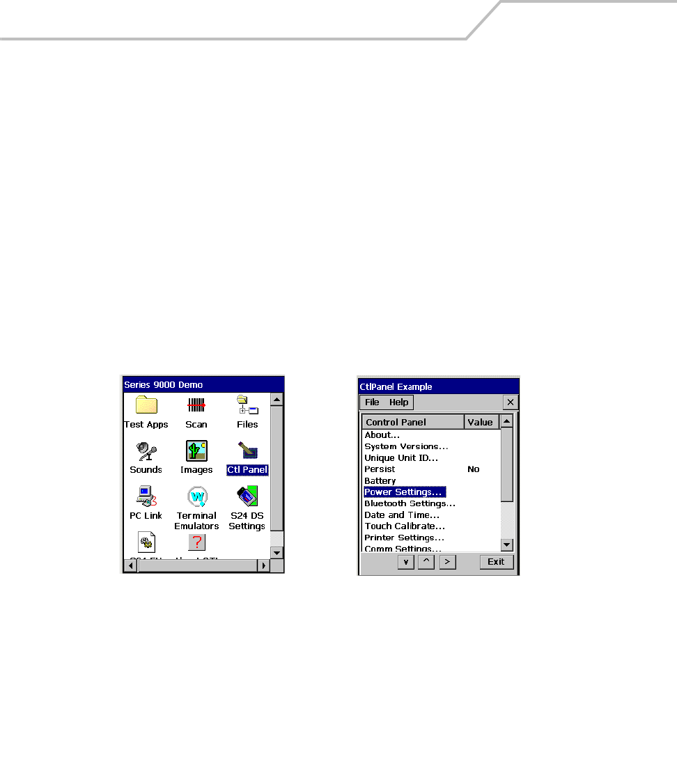
MC9000-K/S for Embedded Windows® CE .NET Product Reference Guide
3-8
Bluetooth Device Properties
Use the Bluetooth Manager window to discover and create bonds with other Bluetooth devices. The
mobile computer can receive information from discovered devices, without creating a bond. However,
the exchange of information between the mobile computer and a bonded device occurs automatically
when the Bluetooth radio is turned on. Creating a bond involves entering the same PIN on the two
devices to bond. Once a bond is created, and the Bluetooth radios are turned on, the devices recognize
the bond and are able to exchange information without re-entering a PIN.
Bluetooth/S24 Power Settings
Both the S24, 802.11b and Bluetooth operate in the same 2.4 GHz unlicensed frequency band. Sharing
the same frequency band could result in performance degradation. To minimize interference use the
power settings to turn off the S24 radio while the Bluetooth radio is being used.
1. To turn off the S24 radio and turn on the Bluetooth radio double tap Control Panel - Power
Settings:
Figure 3-2. Control Panel Power Settings
Control Panel Icon Power Settings
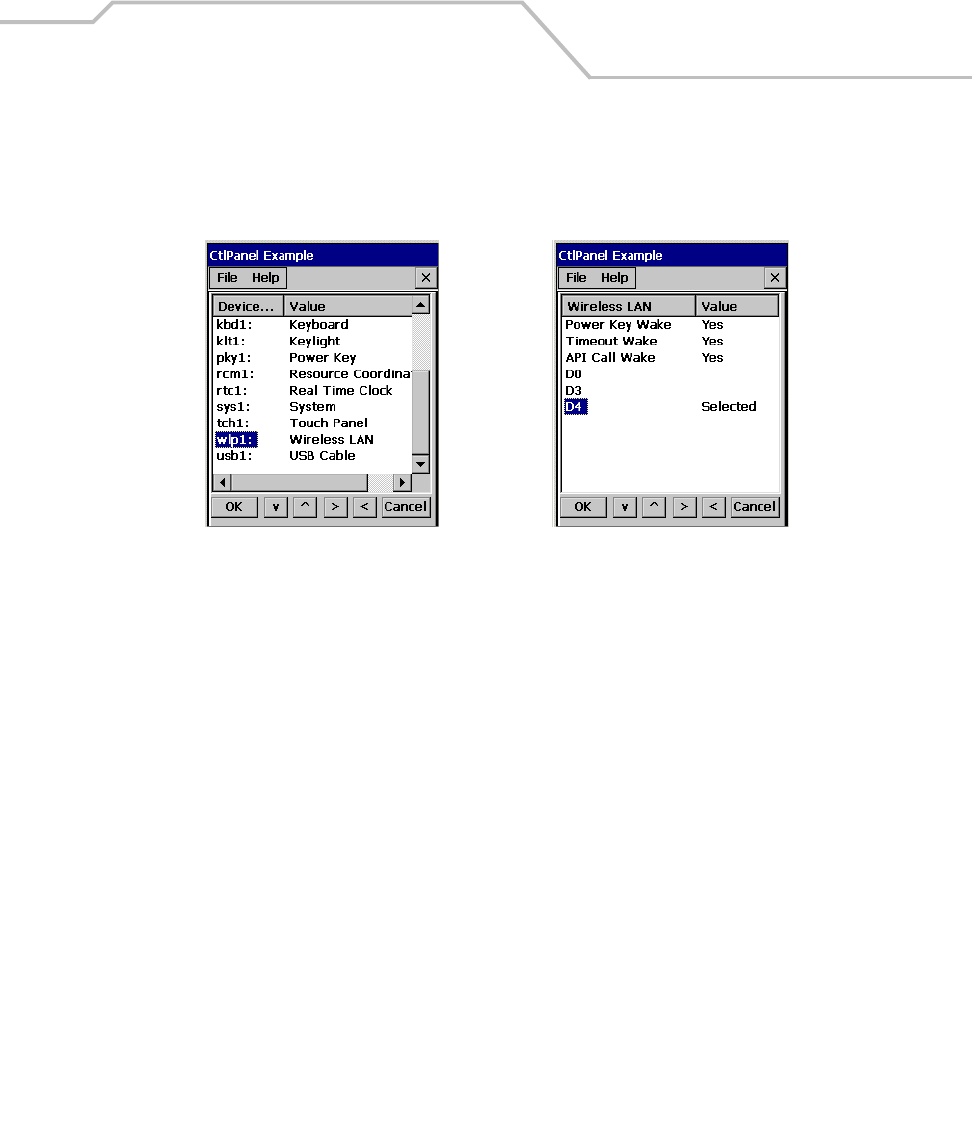
Settings 3-9
2. Scroll down the Power Settings window and double tap wlp1: Wireless LAN.
3. Double tap D4 in the S24 Power Selection window. This setting turns off the S24 radio.
Figure 3-3. S24 Power Settings
S24 Power Settings S24 Power Selection
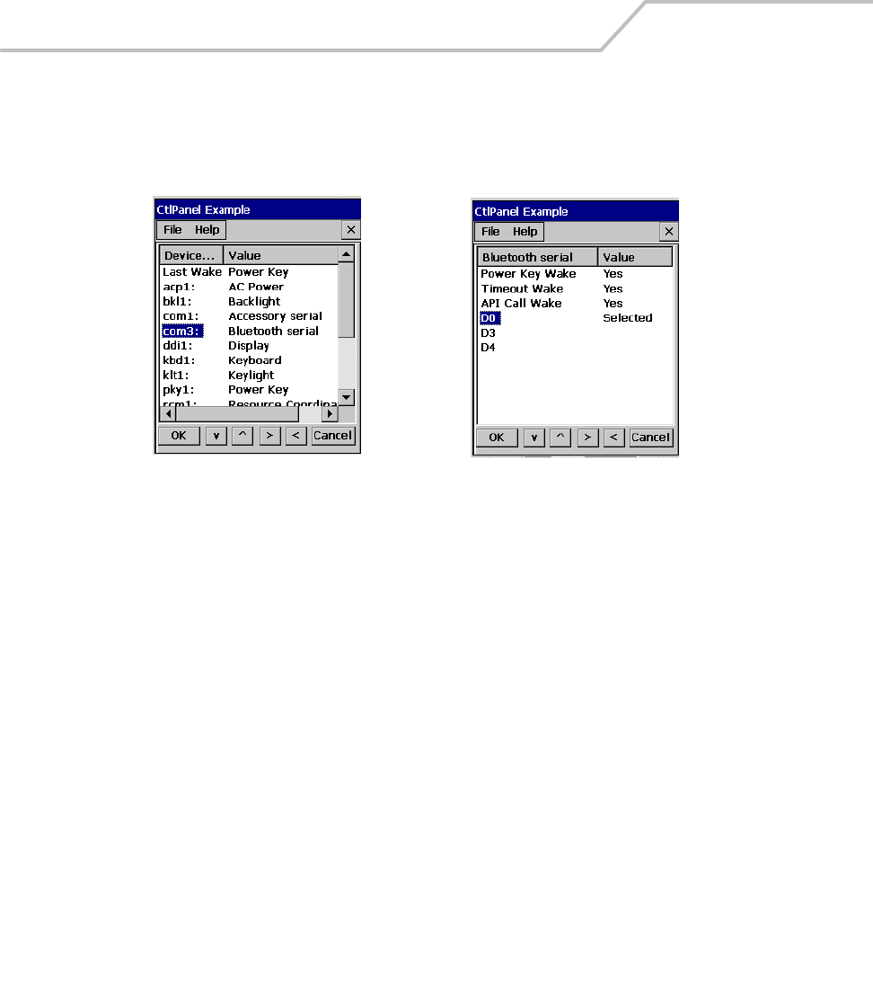
MC9000-K/S for Embedded Windows® CE .NET Product Reference Guide
3-10
4. Scroll up the Power Settings window and double tap com3: Bluetooth serial.
5. Double tap D0 in the Bluetooth Power Selection window. This turns on the Bluetooth radio.
Figure 3-4. Bluetooth Power Settings
Power Settings Bluetooth Power Selection
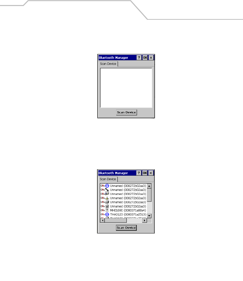
Settings 3-11
Starting Bluetooth
1. Select Start - Settings - Control Panel, and double-tap the Bluetooth Device Properties icon.
Figure 3-5. Bluetooth Manager Window
2. Tap the Scan Device button to initiate a scan for Bluetooth hardware. The Bluetooth
manager lists the Bluetooth devices that it finds, see Figure 3-6. If Bluetooth hardware is not
found the Bluetooth Error window appears, see Figure 3-7. Table 3-2 described the Bluetooth
Icons.
Figure 3-6. Bluetooth Manager Device List Window
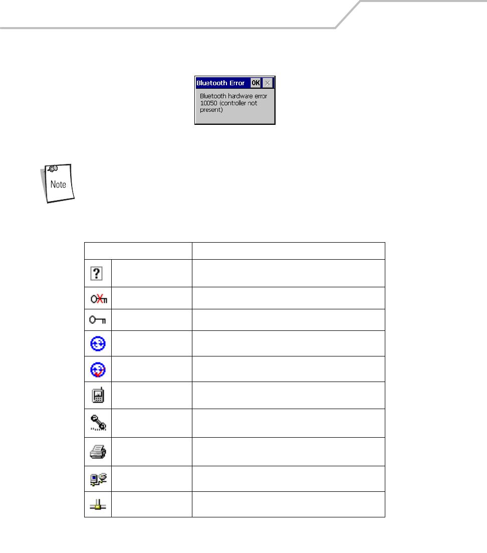
MC9000-K/S for Embedded Windows® CE .NET Product Reference Guide
3-12
Figure 3-7. Bluetooth Error Window
If the device to which the mobile computer is bonding does not appear in the
list, ensure it is turned on, in discoverable mode, and within range (30 feet/
10 meters) of the mobile computer.
Table 3-2. Bluetooth Icons
Icon Description
Unknown device icon Device is not defined
Locked icon Device is locked and cannot be bonded to.
Not locked icon Device is not locked and can be bonded to.
Bluetooth device icon Bluetooth device
Bonded device icon Bonded Bluetooth device
Mobile device icon Device is a mobile device
Phone icon Device is a phone.
Printer icon Device is a printer
Network icon Device is a network.
Linked icon Device is linked.
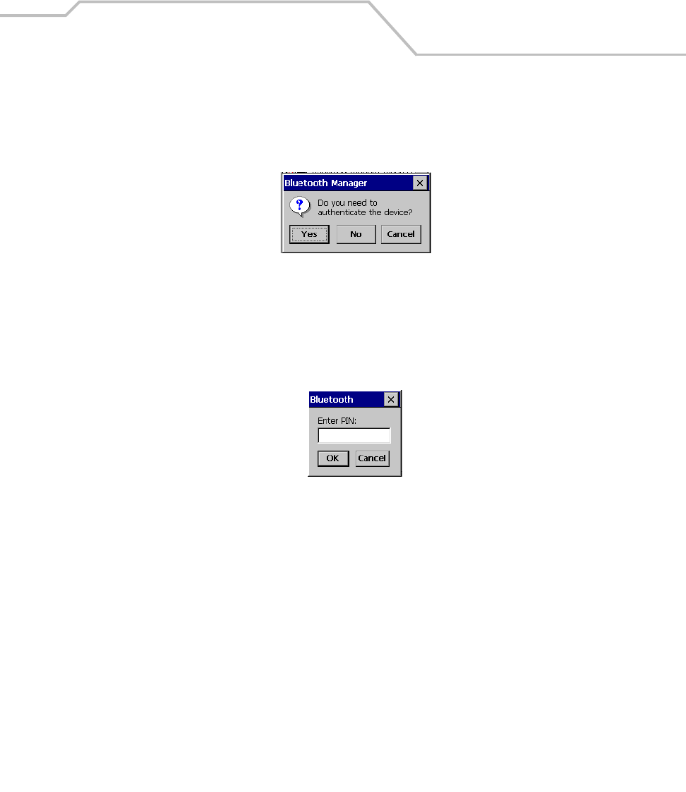
Settings 3-13
3. Double tap the device to connect to on the device list. The Bluetooth Manager
Authentication window appears. Tap No to connect to the device without authentication, or
tap Yes to authenticate the device before connecting.
Figure 3-8. Bluetooth Manager Authentication Window
4. If the Yes button was selected in the Bluetooth Manager Authentication window, the enter
PIN windows appears. Enter a PIN (between 1 and 16 characters) in the Enter PIN: text box,
and tap OK. The mobile computer sends the PIN request to the device for bonding.
Figure 3-9. Bluetooth Enter PIN Window
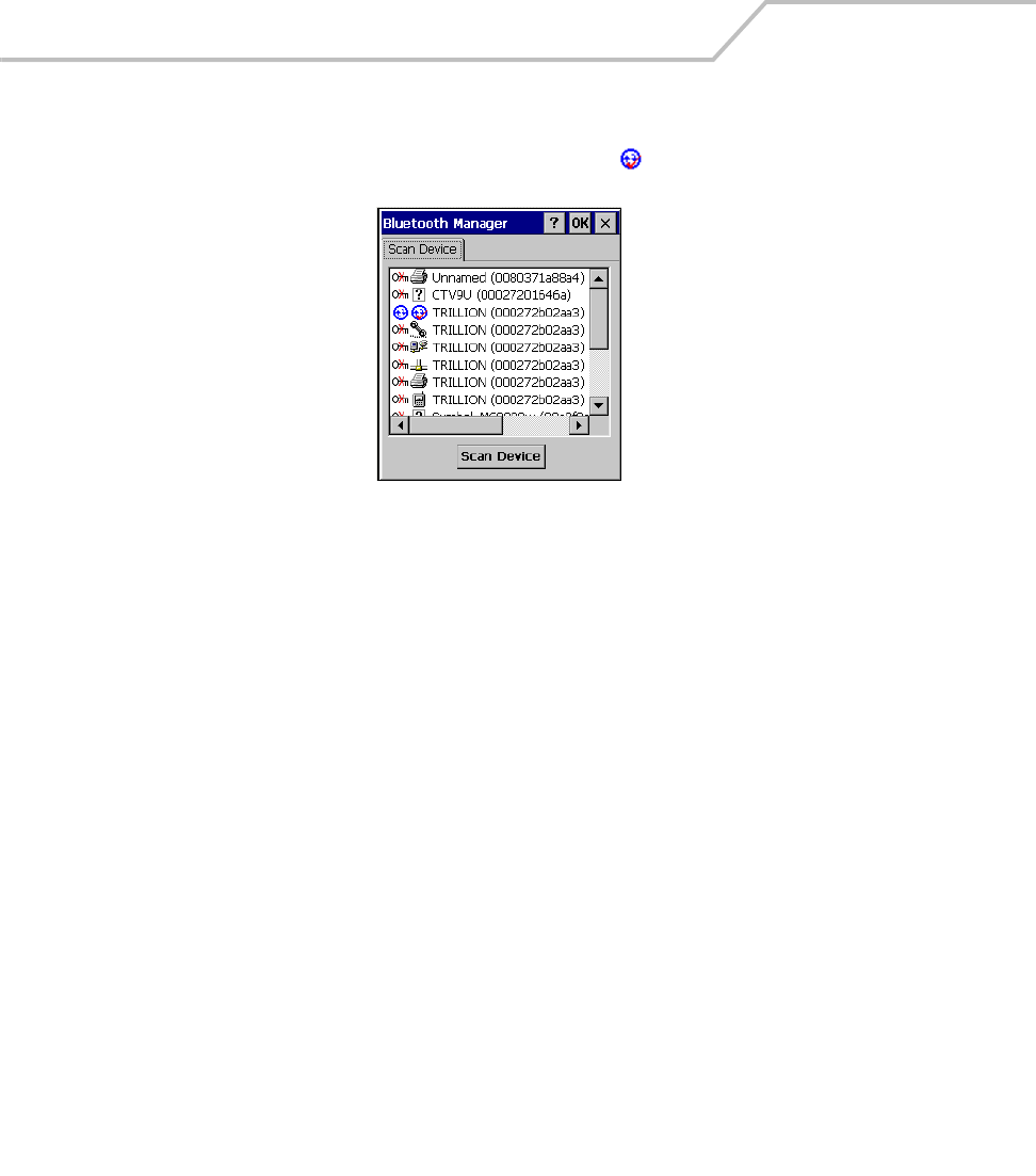
MC9000-K/S for Embedded Windows® CE .NET Product Reference Guide
3-14
5. When prompted, the same PIN must be entered on the other device. When the PIN is
entered correctly on the other device, the bonded icon appears on the device list.
Figure 3-10. Bluetooth Bonded Devices Window
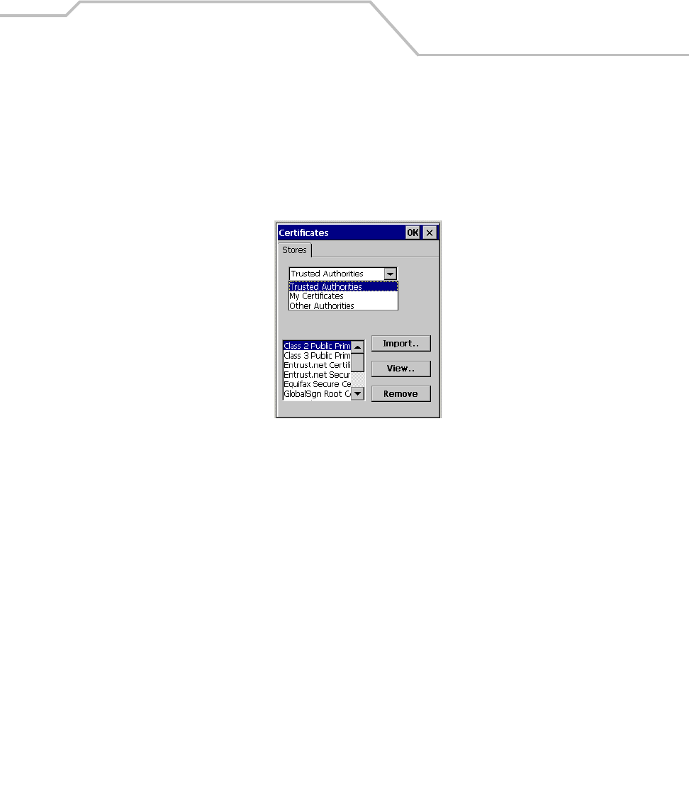
Settings 3-15
Certificates
Certificates are used by some applications for establishing trust and for secure communications.
Certificates are signed and issued by certificate authorities and are valid for a prescribed period of
time. Windows CE manages multiple certificate stores.
1. Select Start - Settings - Control Panel, and double-tap the Certificates icon.
Figure 3-11. Certificates Window
2. Select the certificate group (from the drop-down list) to be viewed or modified.
• The Trusted Authorities store lists the top-level certificates for trusted authorities.
• The My Certificates store contains the personal certificates, which are used for
identification.
•The Other Authorities store lists intermediate certificate authorities that help establish
a chain of trust.
3. To add a certificate or associated private key to the selected store, tap Import.
4. To view more details of the selected certificate, such as the expanded name or expiration
date, tap View.
5. To delete a certificate, select it in the drop-down list and tap Remove.
6. Tap OK for the settings to take effect.
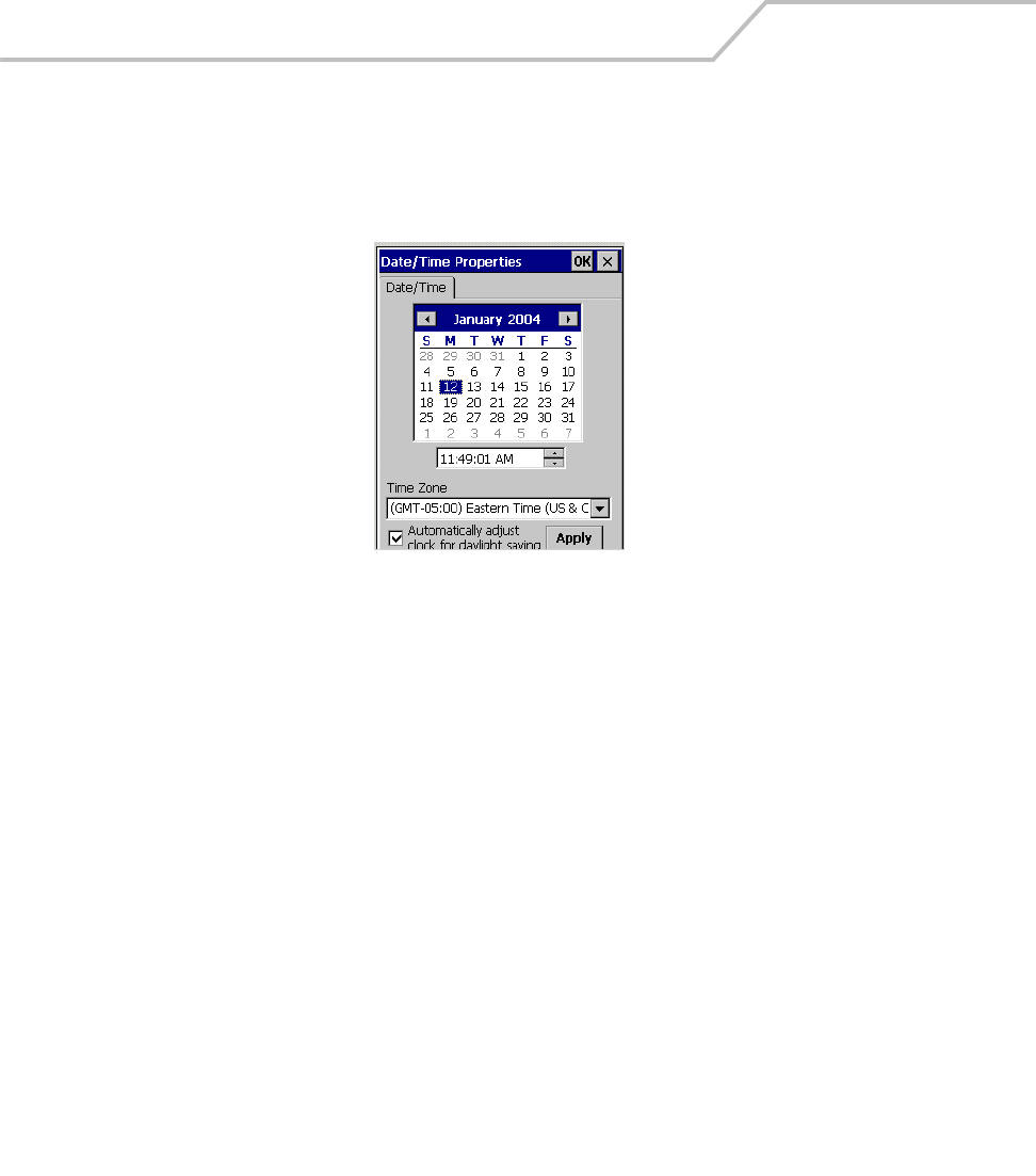
MC9000-K/S for Embedded Windows® CE .NET Product Reference Guide
3-16
Date/Time
Use the Date/Time Properties window to change the date, time and time zone information.
1. Select Start - Settings - Control Panel, and double-tap the Date/Time icon.
Figure 3-12. Date/Time Properties Window
2. Use the arrows to select the month in the Date/Time tab.
3. Tap the date, to select it.
4. Tap to highlight the hours, minutes or seconds entry. Tap the up or down arrows to increment
the highlighted value.
5. Select the appropriate time zone from the Time Zone drop down list.
6. Tap Apply or OK to save the new settings.
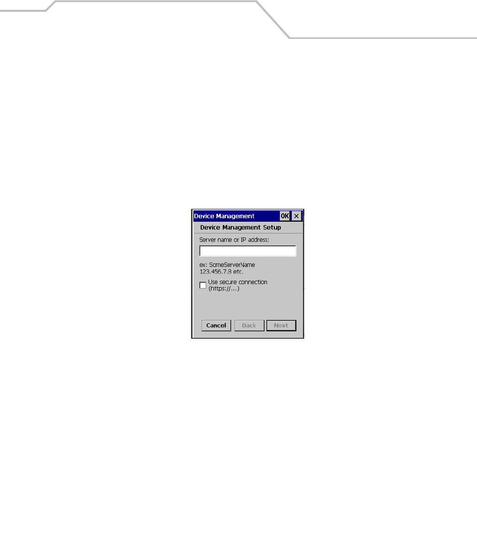
Settings 3-17
Device Management
Use Device Management to keep track of software and hardware, inventory, and configure devices
remotely.
The device management client contains a download/install engine that allows users to receive
software and notifications when there are new applications or Operating System (OS) updates. The
device management system also allows the downloading and running of scripts to enable
configuration and customized management. The Windows CE Device Management Client works with
the Microsoft Systems Management Server (SMS), to provide the required capabilities.
1. Select Start - Settings - Control Panel, and double-tap the Device Management icon.
Figure 3-13. Device Management Window
2. Enter the host system server name or IP address (the System Administrator can supply this
information) in the Server name or IP address field.
3. Tap the Use Secure connection selection box to require that a secure connection is used
4. Tap OK to close the window and set up the next poll to contact the new server.
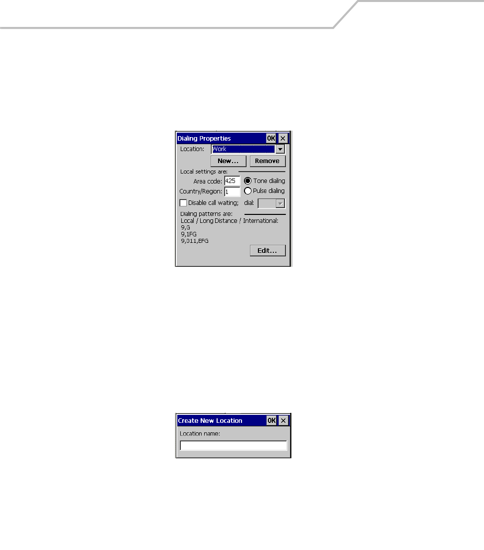
MC9000-K/S for Embedded Windows® CE .NET Product Reference Guide
3-18
Dialing
Use the Dialing Properties window to set dialing properties for modem communication and change
telephony settings.
1. Select Start - Settings - Control Panel, and double-tap the Dialing icon.
Figure 3-14. Dialing Properties Window
2. To remove a location from the Location: drop-down list, select the location and tap Remove.
3. Enter or edit the area code and local country code as needed.
4. Select Tone dialing or Pulse dialing (most phone lines are tone.)
5. Select the Disable call waiting check box to automatically disable call waiting. Then select
the appropriate number sequence from the dial drop-down list, or enter a new sequence.
6. To create a new location, tap New and enter a name for the new location in the Location
name field.
Figure 3-15. Create New Location Window
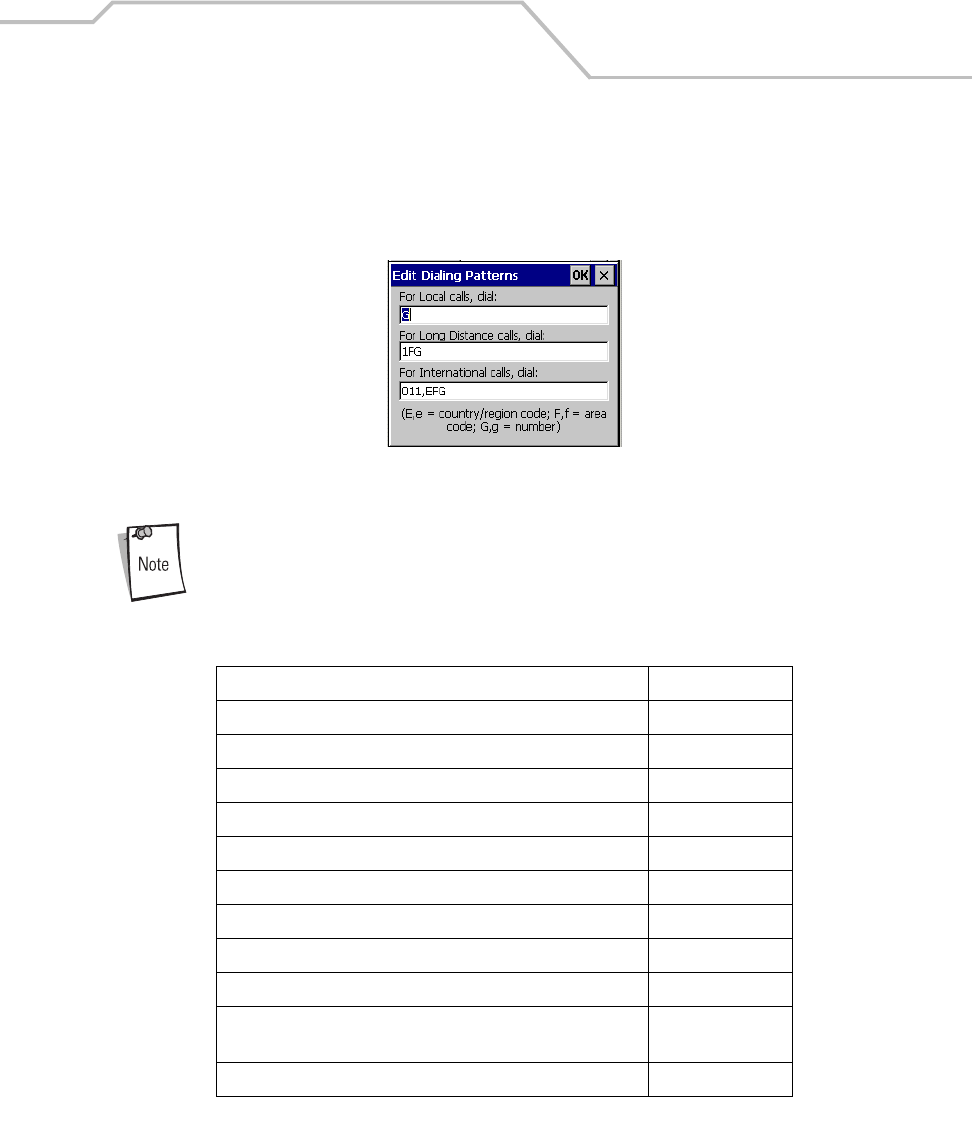
Settings 3-19
7. To edit the dialing properties select the location from the Location: drop-down list, and tap
Edit. The Edit Dialing Patterns window appears.
8. Use the codes listed in Table 3-3, edit the dialing patterns in the Edit Dialing Patterns
window. Tap OK to save the new entries or tap X to exit without saving the new entries.
Figure 3-16. Edit Dialing Patterns Window
To use characters other than the ones listed in Table 3-3, use manual dialing.
Hyphens and spaces in dialing strings are ignored.
Some modems may not respond to the characters listed, even though the mobile
computer lets them to be added to the dial string.
Table 3-3. Dialing Characters
To Enter
Dial country code (specified by the dialing program) E
Dial area code (specified by the dialing program) F
Dial local number (specified by the dialing program) G
Insert a pause (typically 2 seconds) , (comma)
Wait for credit card tone (specified by the dialing program) $(dollar sign)
Wait for second tone (typically used after $) W
Tone-dial the following numbers T
Pulse-dial the following numbers P
Transfer to another extension (0.5 sec on hook, 0.5 sec off hook) ! (hookflash)
Wait for “quiet answer” (typically indicated by 6.5 seconds of
silence followed by a ringing tone)
@
Use special controls on some systems (tone only) ABCD or * or #
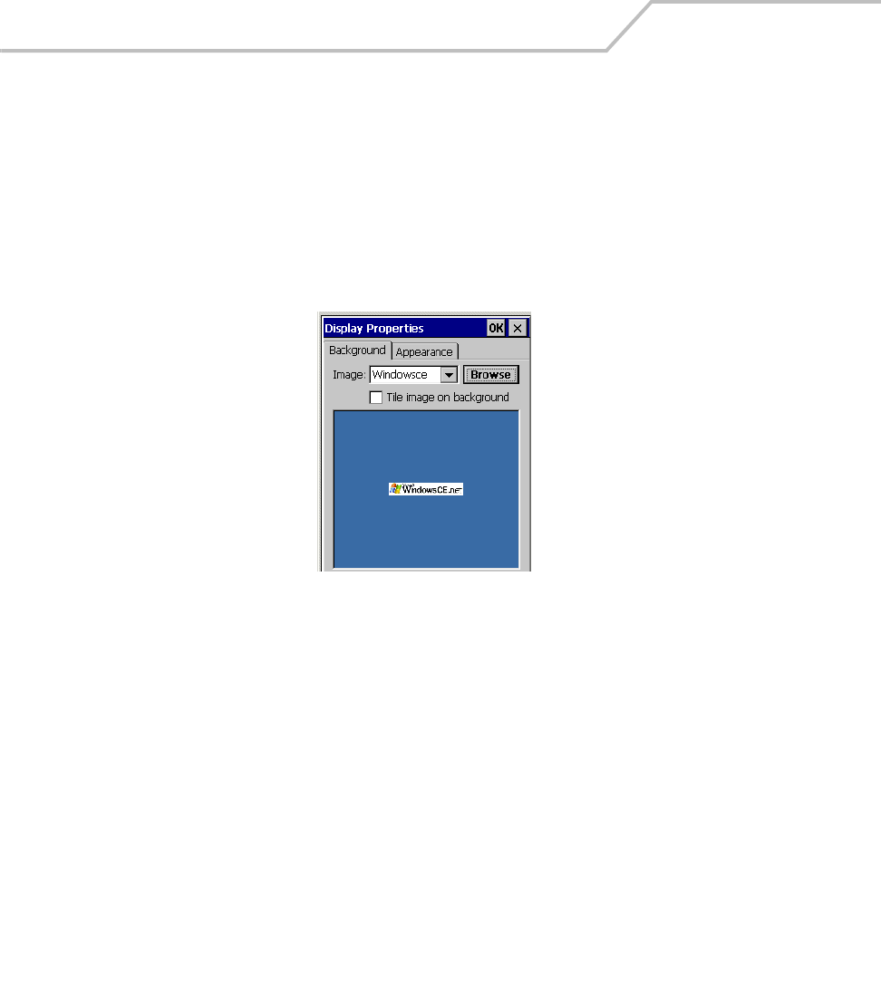
MC9000-K/S for Embedded Windows® CE .NET Product Reference Guide
3-20
Display
Use the Display Properties window to change desktop background image and the display appearance.
Background Tab
To select the background image:
1. Select Start - Settings - Control Panel, and double-tap the Display icon, tap the Background
tab.
Figure 3-17. Display Properties - Background Tab
2. From the Image: drop-down list, select the desktop background image. To locate an image
in another folder, tap Browse.
3. To have the image cover the entire background, select Tile image on background.
4. Tap OK to save settings.

Settings 3-21
Appearance Tab
To change the color scheme:
1. Select Start - Settings - Control Panel, and double-tap the Display icon, tap the Appearance
tab.
Figure 3-18. Display Properties - Appearance Tab
2. From the Scheme: drop-down list, select a scheme.
3. Select the color scheme item from the Item: drop-down list.
4. View the choice in the preview box, tap Apply to apply the scheme
To create a custom scheme:
1. Select Start - Settings - Control Panel, and double-tap the Display icon, tap the Appearance
tab.
2. From the Item: drop-down list, select a display item.
3. Tap the square next to the Item: drop-down list.
4. From the Basic colors: list, select a color, and tap OK.
5. View the color selection(s) in the preview box.
6. Tap Save to save the scheme.
7. In the Save scheme As box, enter a name for the scheme, and tap OK.
8. Tap Apply.
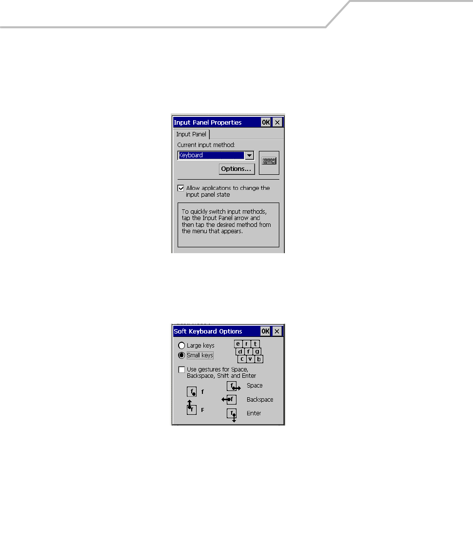
MC9000-K/S for Embedded Windows® CE .NET Product Reference Guide
3-22
Input Panel
Use the Input Panel Properties window to switch input methods and to set the input options.
1. Select Start - Settings - Control Panel, and double-tap the Input Panel icon.
Figure 3-19. Input Panel Properties
2. From the Current input method: drop-down list, select the input method.
3. Tap Options to open the Soft Keyboard Options window.
Figure 3-20. Soft Keyboard Options Window
4. Make the settings changes.
5. Tap OK to save the changes and exit the Soft Keyboard Options window.
6. Tap OK to apply the changes.
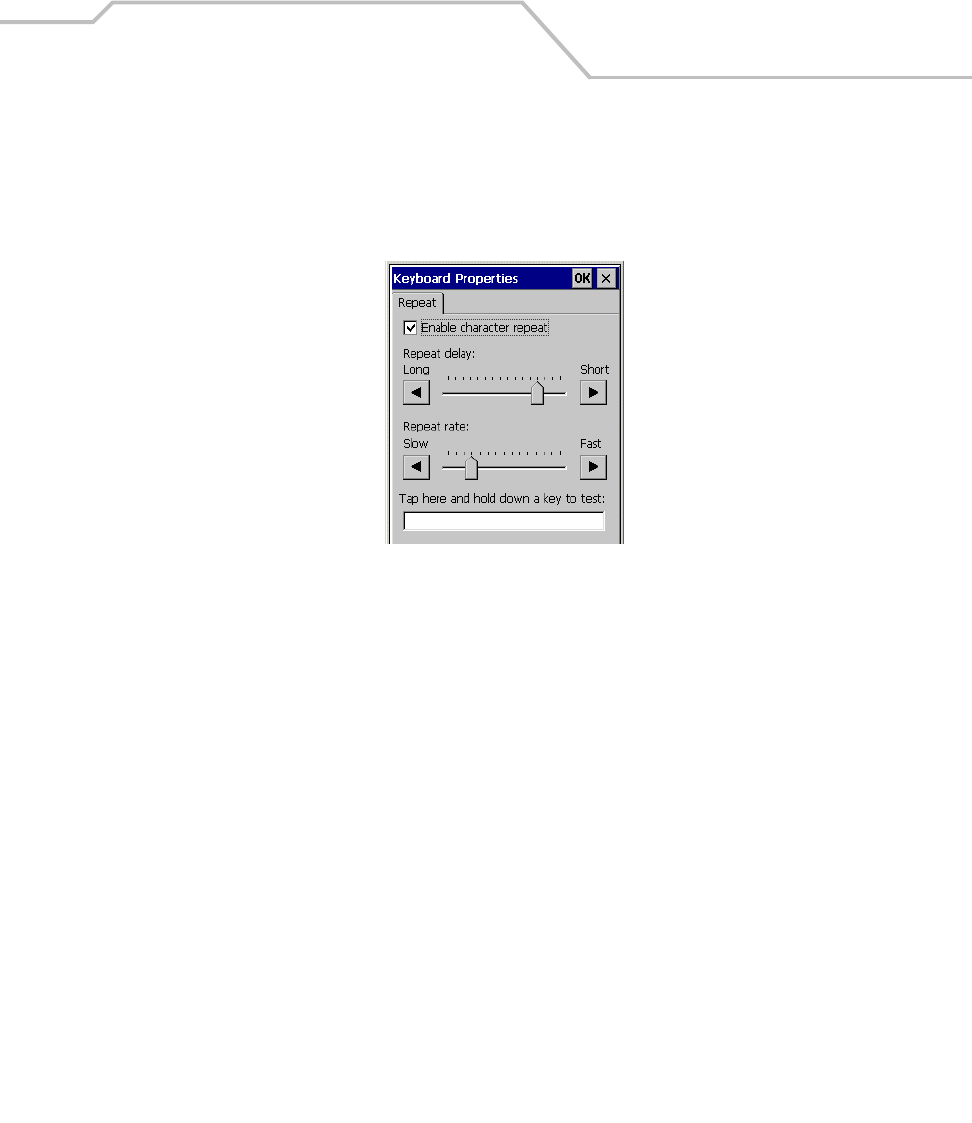
Settings 3-23
Keyboard
Use the Keyboard Properties window to change the keyboard repeat rate and repeat delay.
1. Select Start - Settings - Control Panel, and double-tap the Keyboard icon.
Figure 3-21. Keyboard Properties - Repeat Tab
2. Tap the Enable character repeat check box.
3. Drag the Repeat delay: slider, to change the repeat delay time.
4. Drag the Repeat rate: slider, to change the repeat rate.
5. Test the new settings in the text box provided.
6. Tap OK to apply the changes.
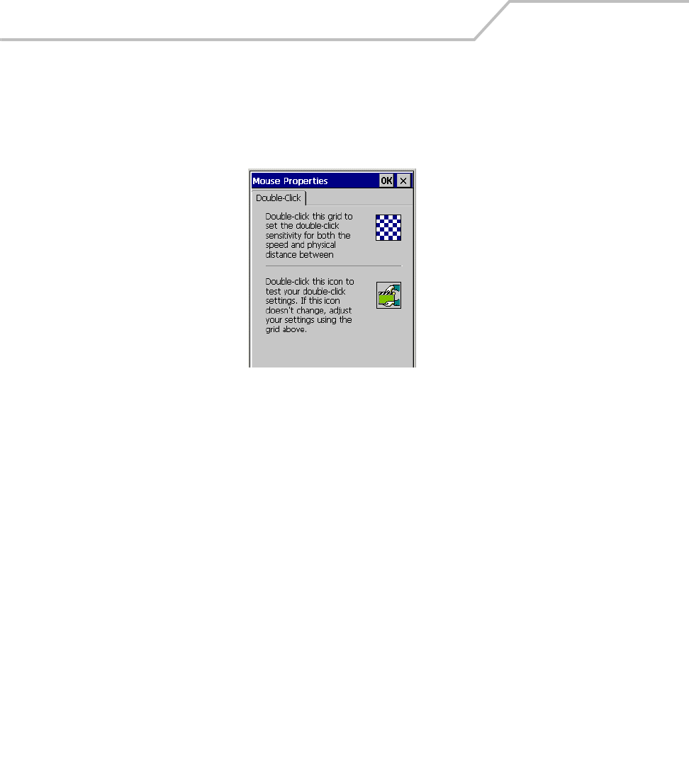
MC9000-K/S for Embedded Windows® CE .NET Product Reference Guide
3-24
Mouse
Use the Mouse Properties window to adjust stylus double-tap timing.
1. Select Start - Settings - Control Panel, and double-tap the Mouse icon.
Figure 3-22. Mouse Properties Window
2. Double-tap the checkerboard grid at a comfortable speed.
3. Double-tap the clapboard to test the settings.
4. Tap OK to apply changes.

Settings 3-25
Network and Dial-up Connections
Use the Connection window to set connections to other computers, networks, and the Internet.
1. Select Start - Settings - Control Panel, and double-tap the Network and Dial-up Connections
icon.
Figure 3-23. Connection Window
2. Double an icon to select a connection type.
3. Follow the connection type instructions.
4. Tap OK to apply changes.
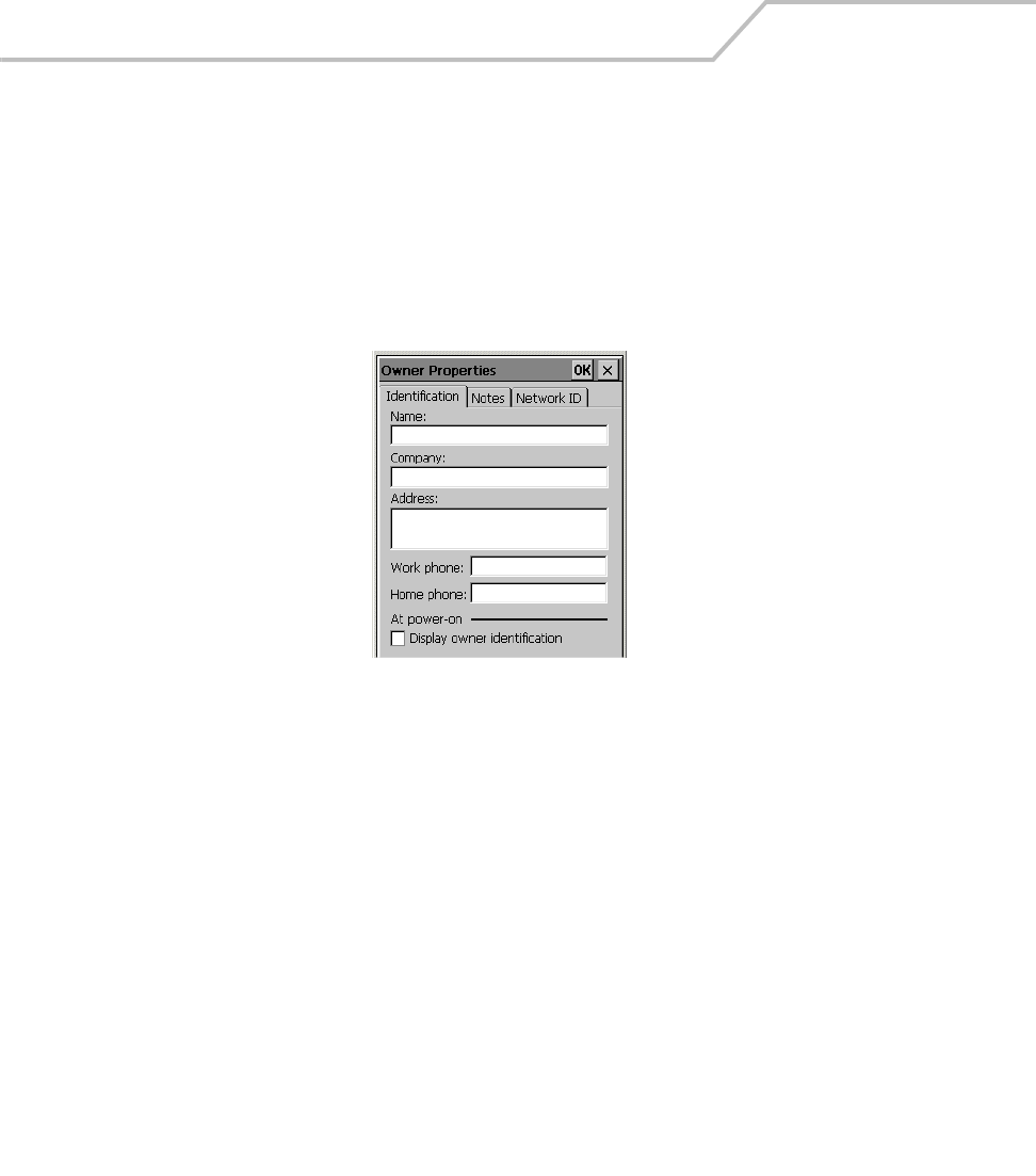
MC9000-K/S for Embedded Windows® CE .NET Product Reference Guide
3-26
Owner
Use the Owner Properties window to enter the owner information. The information can be displayed
when the mobile computer is turned on. To enter information:
Identification Tab
1. Select Start - Settings - Control Panel, and double-tap the Owner icon.
2. Select the Identification tab.
Figure 3-24. Owner Properties Window - Identification Tab
3. Fill in or edit the owner information.
4. Select the Display Owner Identification check box to display this information when the
mobile computer starts.
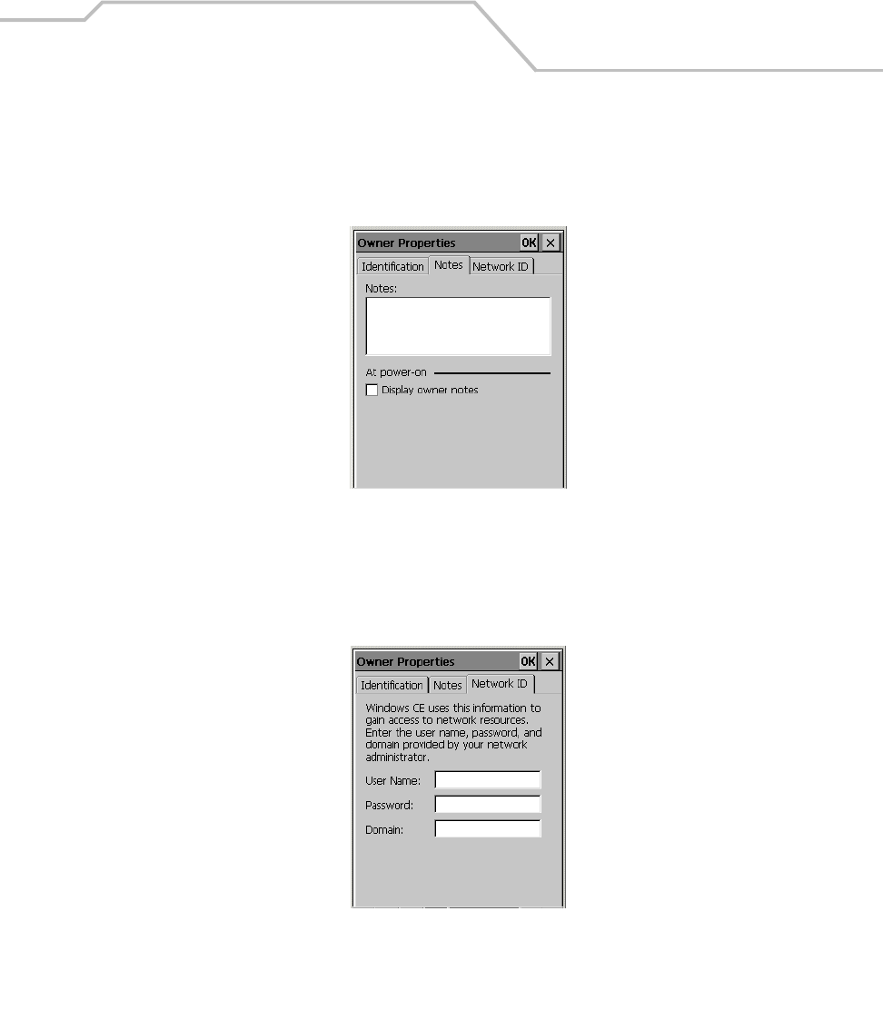
Settings 3-27
Notes Tab
1. Select the Notes tab and enter information in the Notes box to add more information.
2. Select the Display owner notes box to include this information on the startup display.
Figure 3-25. Owner Properties Window - Notes Tab
Network ID Tab
To setup identification for remote networks, select the Network ID tab and enter the user name,
password, and domain name used to log on to the remote network.
Figure 3-26. Owner Properties Window - Network ID Tab
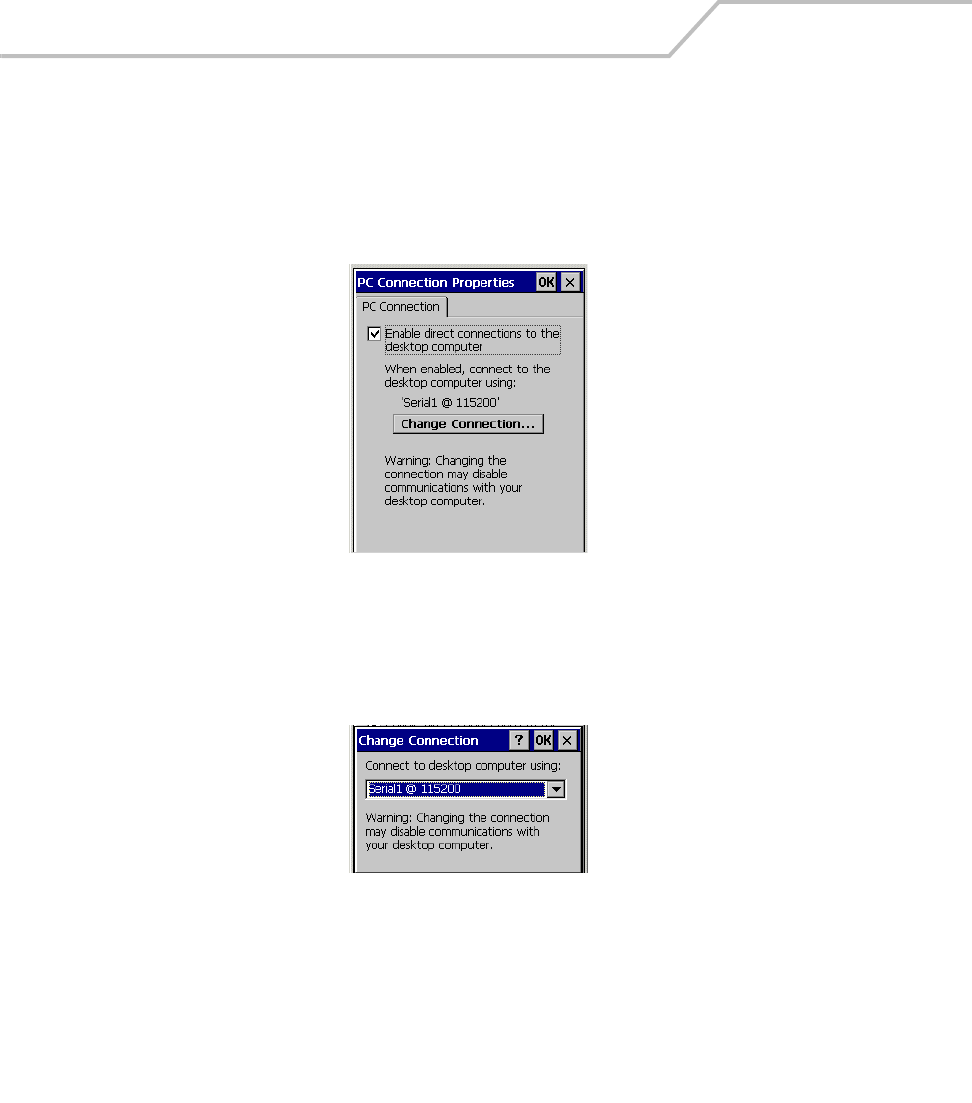
MC9000-K/S for Embedded Windows® CE .NET Product Reference Guide
3-28
PC Connection
Use the PC Connection Properties window to set the mobile computer communication baud rate (with
the host computer).
1. Select Start - Settings - Control Panel, and double-tap the PC Connection icon.
Figure 3-27. PC Connection Properties Window
2. Select the Enable direct connections to the desktop computer checkbox to allow for direct
connections.
3. Tap Change Connection to change the selection.
Figure 3-28. Change Connection Window
4. Select the connection type from the drop-down list.
5. Tap OK to select the connection type and exit the Change Connection window.
6. In the PC Connection Properties window, tap OK to apply the changes.
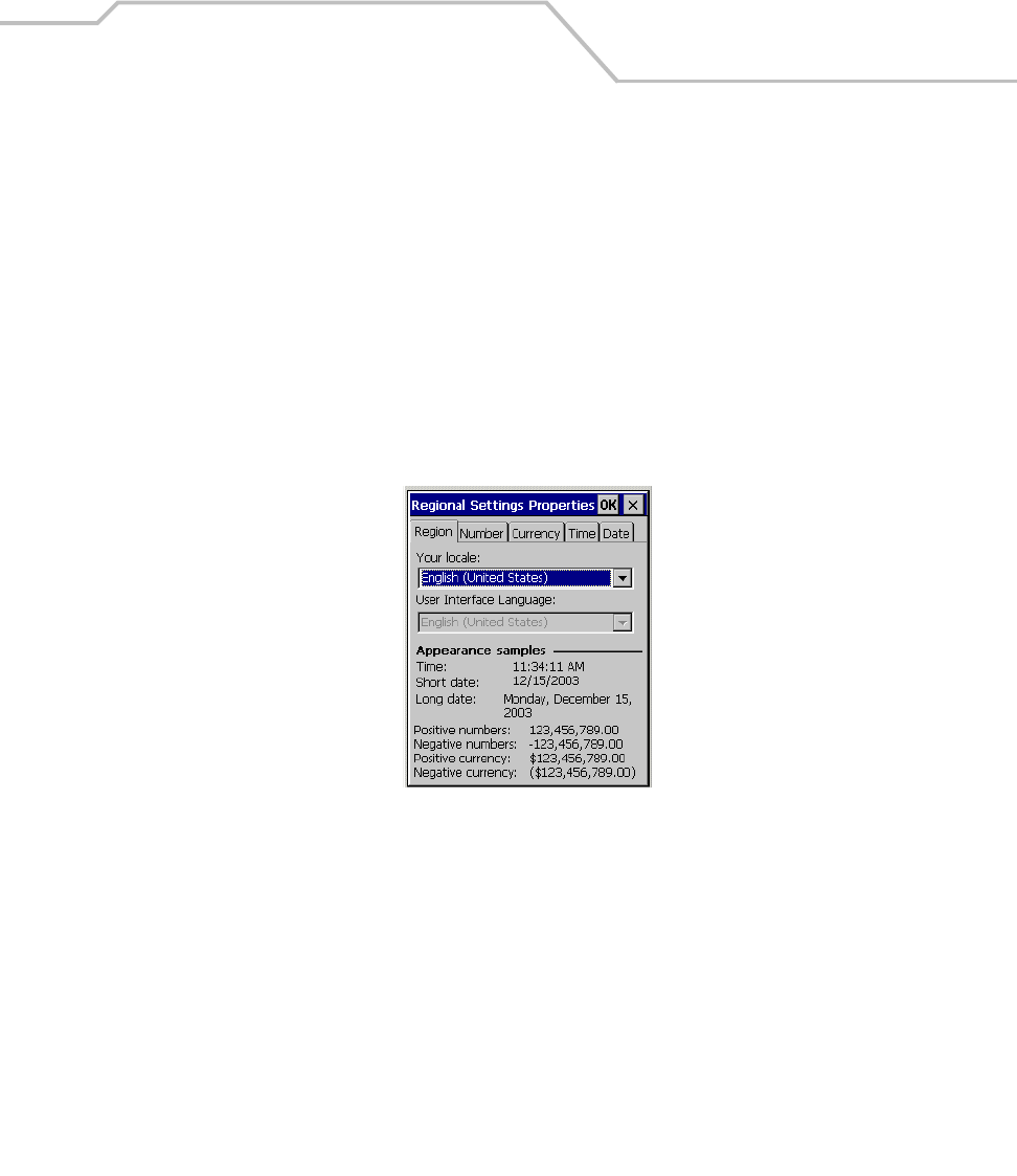
Settings 3-29
Regional Settings
Use the Regional Settings, to set the way the mobile computer displays dates, times, currency
amounts, large numbers, and numbers with decimal fractions. The system of measurement can also
be set to either metric or U.S.
Region Tab
The selectable input locales are listed in the Your local: drop-down list. Corresponding User Interface
Language: choices are provided (where appropriate for a particular location selection). Some location
selections also provide special features, such as font characters or spell checkers designed for
different languages.
1. Select Start - Settings - Control Panel, and double-tap the Regional Settings icon.
Figure 3-29. Regional Settings Properties - Region Tab
2. From the Your locale: drop-down list, select the appropriate location.
3. If applicable, select the appropriate language from the User Interface Language drop-down
list.
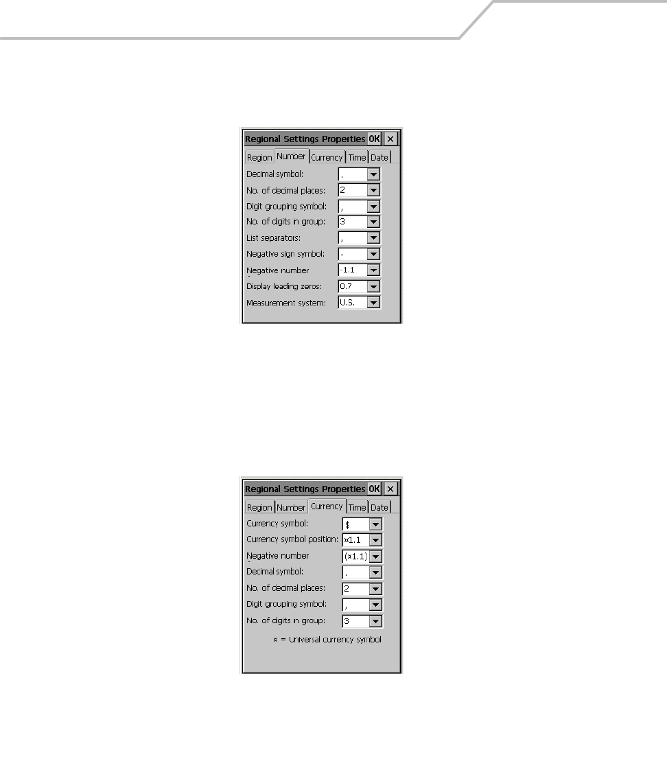
MC9000-K/S for Embedded Windows® CE .NET Product Reference Guide
3-30
Number Tab
1. Select the Number tab.
Figure 3-30. Regional Settings Properties - Number Tab
2. Select desired options. The available options are determined by the Your local: selection and
by the User Interface Language selection (on the Region tab).
Currency Tab
1. Select the Currency tab.
Figure 3-31. Regional Settings Properties - Currency Tab
2. Select desired options. The available options are determined by the Your local: selection and
by the User Interface Language selection (on the Region tab).
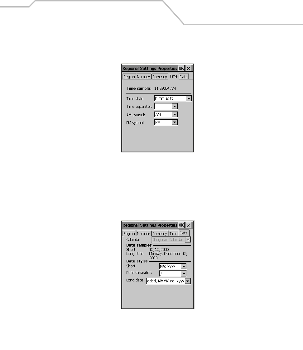
Settings 3-31
Time Tab
1. Select the Time tab.
Figure 3-32. Regional Settings Properties - Time Tab
2. Select desired options. The available options are determined by the Your local: selection and
by the User Interface Language selection (on the Region tab).
Date Tab
1. Select the Date tab.
Figure 3-33. Regional Settings Properties Window - Date Tab
2. Select desired options. The available options are determined by the Your local: selection and
by the User Interface Language selection (on the Region tab).
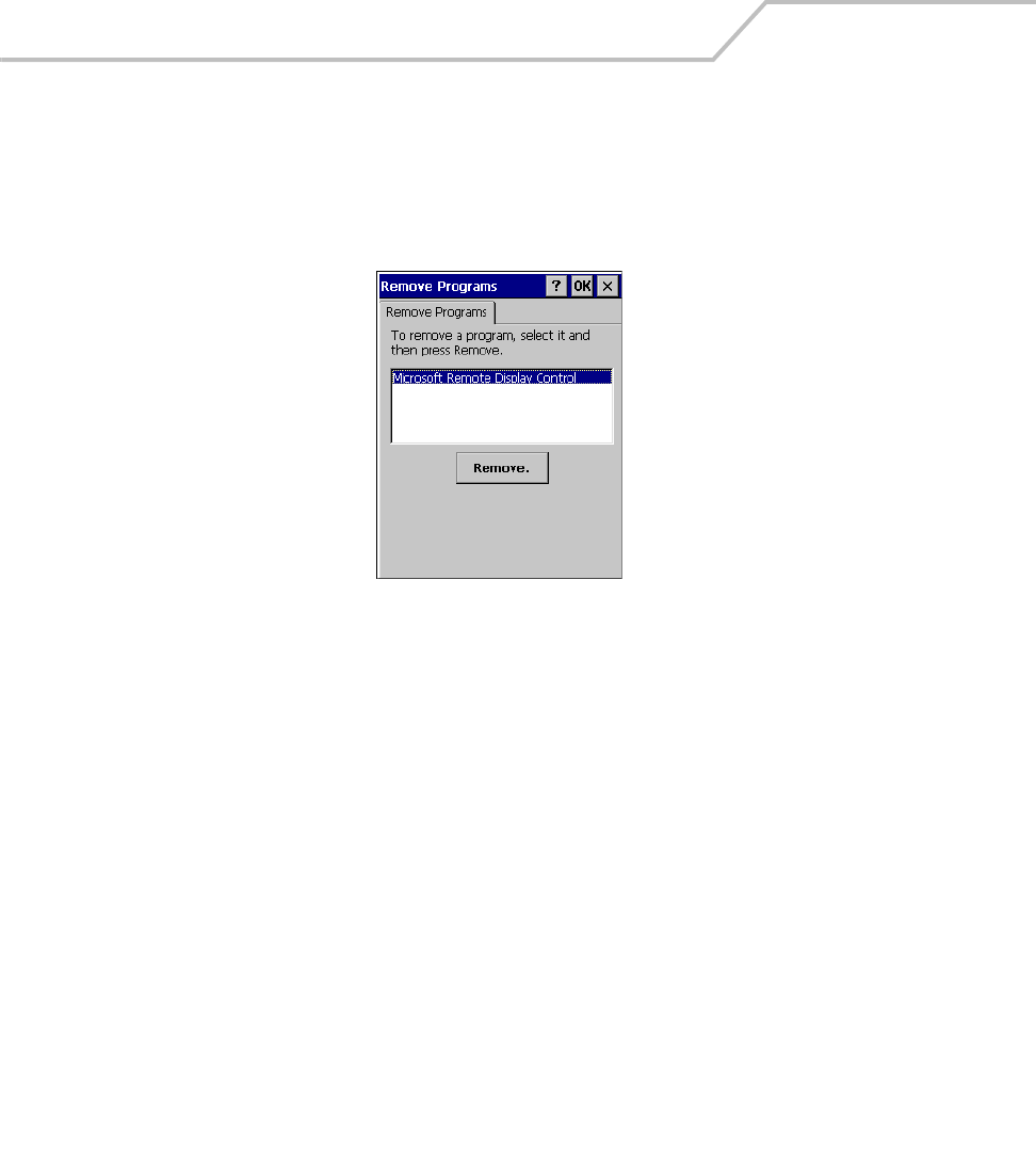
MC9000-K/S for Embedded Windows® CE .NET Product Reference Guide
3-32
Remove Programs
Use the Remove Programs window to remove user installed programs from the mobile computer:
1. Select Start - Settings - Control Panel, and double-tap the Remove Programs icon.
2. Select the program to be removed from the programs list.
Figure 3-34. Remove Programs Window
3. Tap Remove.
4. Tap OK or X to exit the Remove Programs window.
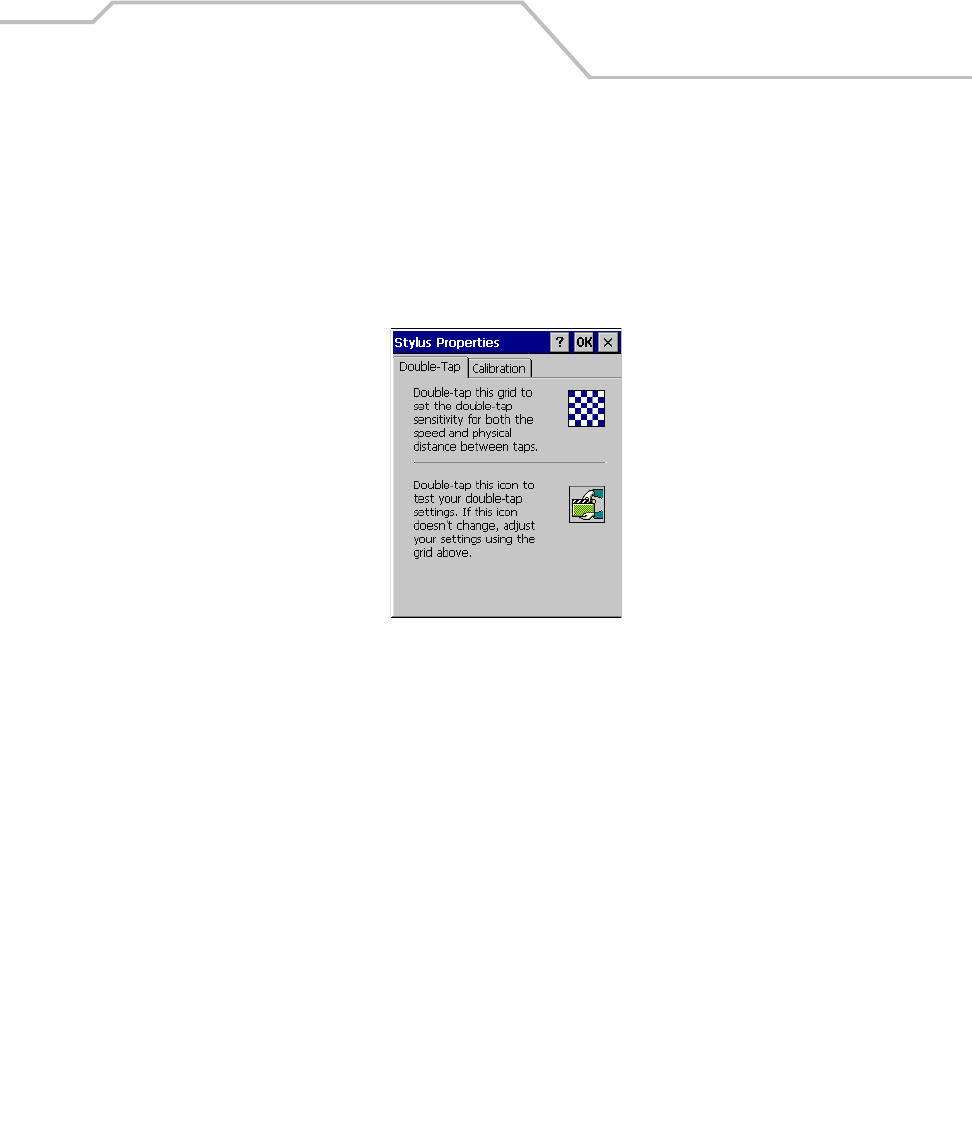
Settings 3-33
Stylus
Use the Stylus Properties window Double-Tap to adjust double-tap timing and use the Calibrate tab
to recalibrate the touch screen.
Double-Tap Tab
1. Select Start - Settings - Control Panel, and double-tap the Stylus icon.
Figure 3-35. Stylus Properties - Double-Tap Tab
2. Select the Double-Tap tab.
3. Double-tap the checkerboard grid at a comfortable speed.
4. Double-tap the clapboard to test the settings.
5. Tap OK to apply changes.
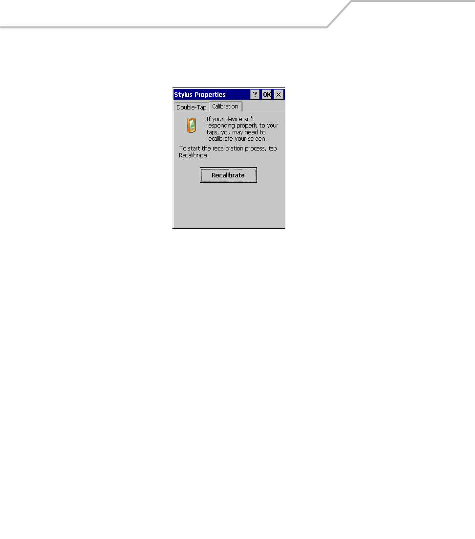
MC9000-K/S for Embedded Windows® CE .NET Product Reference Guide
3-34
Calibrate Tab
1. Select Start - Settings - Control Panel, and double-tap the Stylus icon.
Figure 3-36. Stylus Properties - Calibration Tab
2. Select the Calibration tab.
3. In the Calibration tab, tap Recalibrate.
4. Tap a targets and follow the on-screen messages.
5. Tap OK.
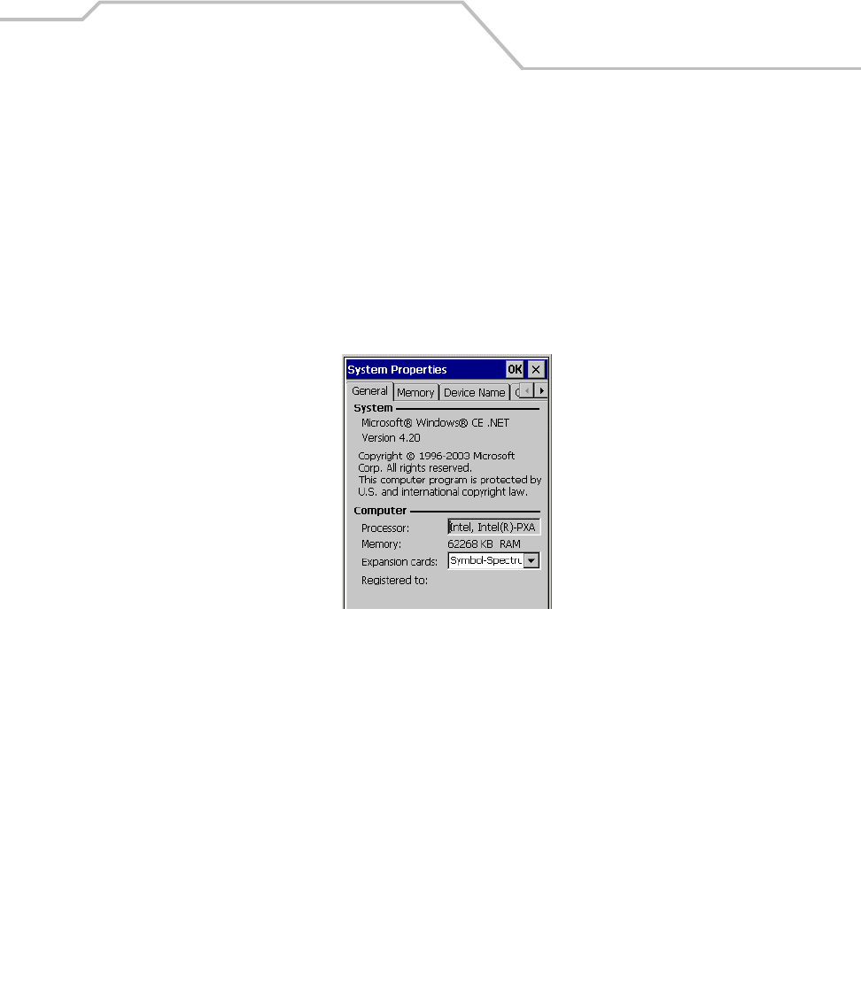
Settings 3-35
System
Use the System Properties window to view general system properties, change memory settings, input
device name and view copyright information.
General Tab
The General tab view displays general system settings:
1. Select Start - Settings - Control Panel, and double-tap the System icon.
2. Select the General tab to view basic system and computer properties.
Figure 3-37. System Properties - General Tab
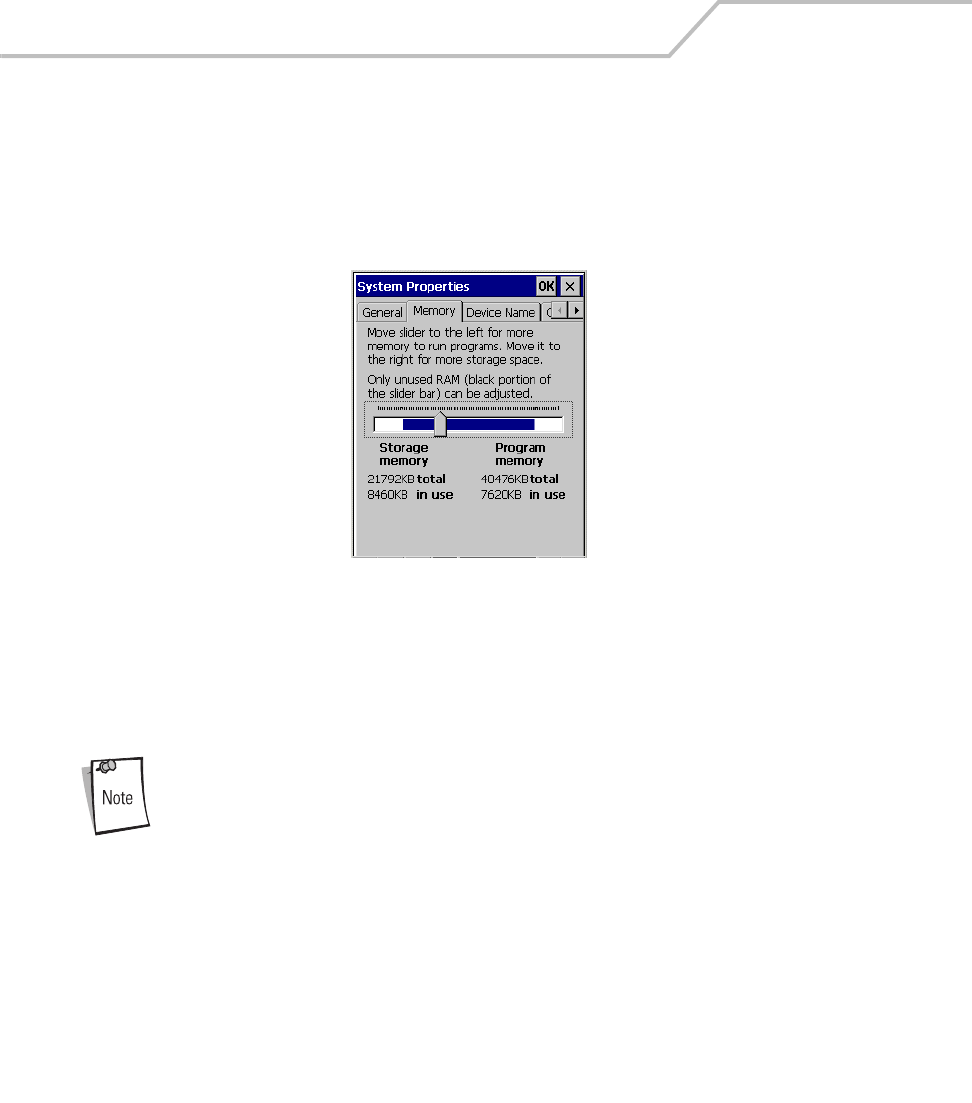
MC9000-K/S for Embedded Windows® CE .NET Product Reference Guide
3-36
Memory Tab
Use the Memory tab to adjust the RAM allocation.
1. Select Start - Settings - Control Panel, and double-tap the System icon.
2. Select the Memory tab.
Figure 3-38. System - Memory Tab
3. To adjust RAM allocation move the slider to allocate more memory for programs or storage.
If there is not enough space for a file, increase the amount of storage memory. If the mobile
computer is running slowly, try increasing the amount of program memory.
Programs supplied with the mobile computer are located in ROM and remain
after a cold boot. User installed programs are located in RAM and need to be
reinstalled after a cold boot. Adjust the RAM allocation as required for
reinstalling user programs.
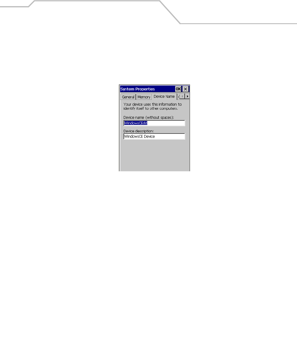
Settings 3-37
Device Name Tab
Use the Device Name tab to customize the device name and description.
1. Select Start - Settings - Control Panel, and double-tap the System icon.
2. Select the Device Name tab.
Figure 3-39. System Properties - Device Name Tab
3. Enter a device name for the mobile computer in the Device name (without spaces): field.
4. Enter a device description for the mobile computer in the Device description: field.
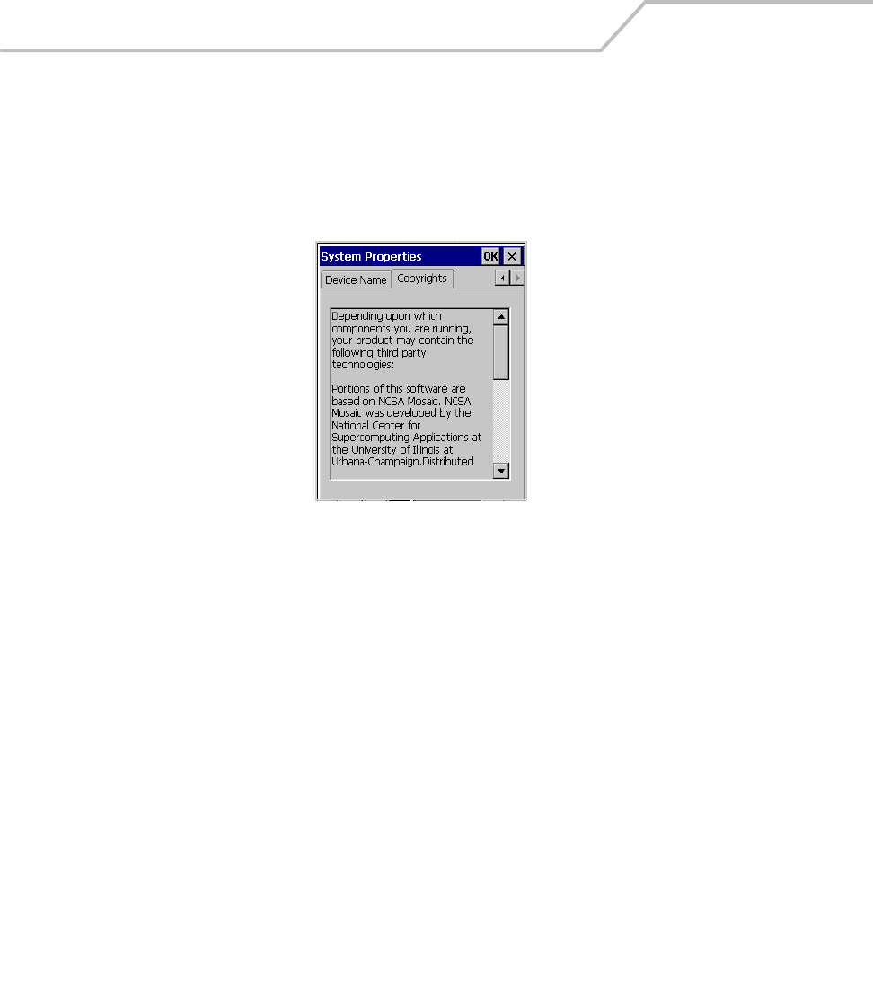
MC9000-K/S for Embedded Windows® CE .NET Product Reference Guide
3-38
Copyrights Tab
The Copyrights tab displays relevant copyright information.
1. Select Start - Settings - Control Panel, and double-tap the System icon.
2. Tap the Copyrights tab to view the copyrights statement.
Figure 3-40. System Properties - Copyrights Tab
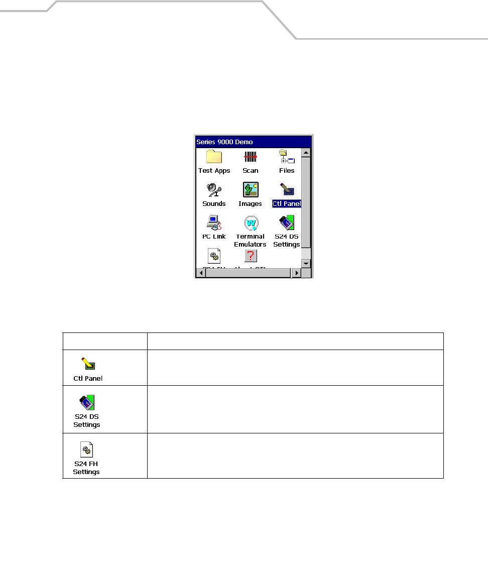
Settings 3-39
Series 9000 Demo Window
On mobile computer power up, the Series 9000 Demo window appears, this window is used to access
the Series 9000 Demo window settings functions and the demo applications. Table 3-4 provides the
settings functions icons and Table 3-4 on page 3-39 provides the demo application icons.
Figure 3-41. Series 9000 Demo Menu
Table 3-4. Series 9000 Demo Window, Settings Functions
Icon Description
Displays the Control Panel window, see Control Panel on page 3-40.
Displays the Mobile Companion window, see Mobile Companion on page 6-4.
Displays the S24 WLAN window, see Spectrum24 Frequency Hopping (FH) Settings (1 and
2 MB Radios) on page 6-30.
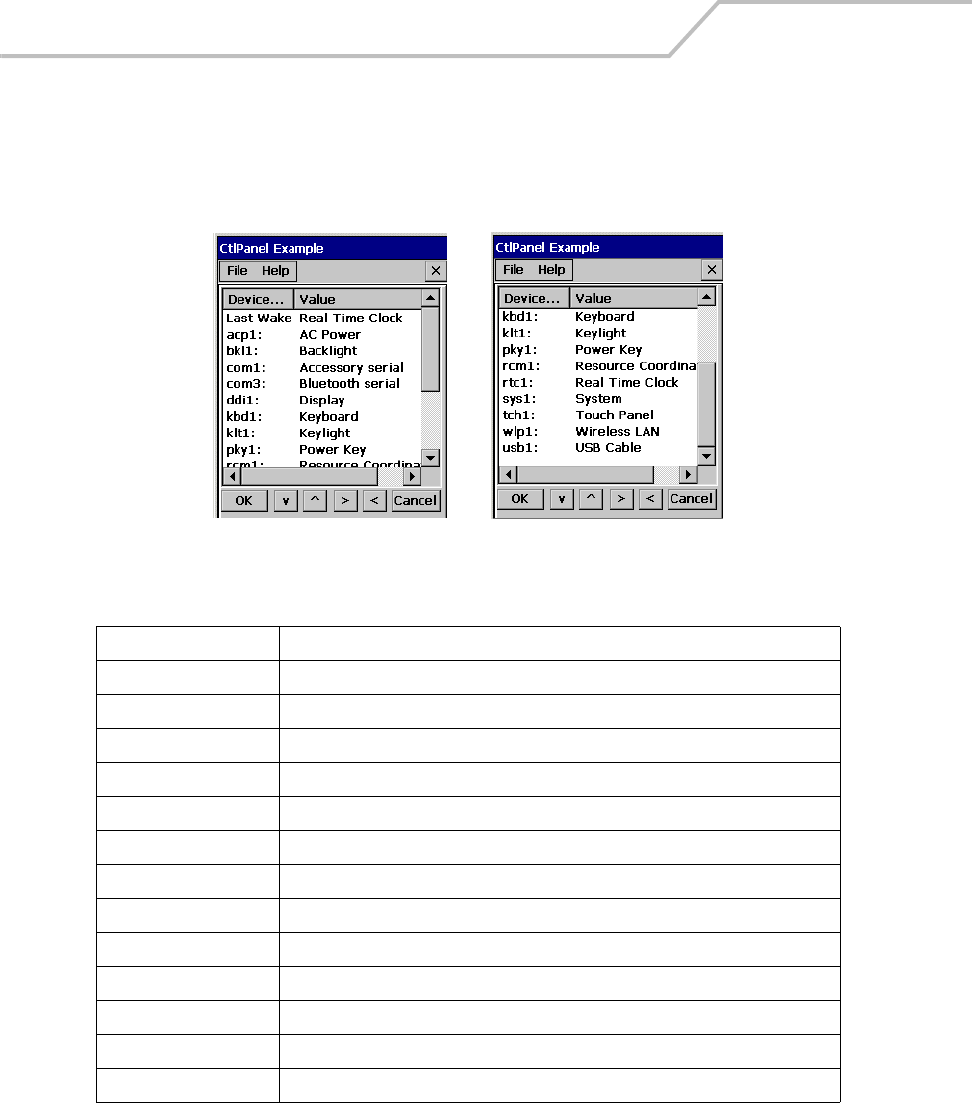
MC9000-K/S for Embedded Windows® CE .NET Product Reference Guide
3-40
Control Panel
Use the Control Panel to change settings for the mobile computer. From the Series 9000 Demo
window, double-tap the Ctl Panel icon to display the Control Panel window.
Figure 3-42. Control Panel Window
Table 3-5. Control Panel Menu
Menu Item Description
About Displays the Control Panel software information, see About Ctl Panel on page 3-42.
System Versions Displays the system software information, see System Version on page 3-43.
Unique Unit ID Displays the Unit ID software information, see Unique Unit ID on page 3-44.
Persist Select the Persist setting, Yes or No, see Persist on page 3-45.
Battery Displays the battery status information, see Battery on page 3-46.
Power settings Select the Power settings, see Power Settings on page 3-47
Bluetooth Settings Select the Bluetooth settings, see Bluetooth Settings on page 3-51.
Date and Time Select the date and time settings, see Date and Time on page 3-52.
Touch Calibrate Calibrate the touch panel, see Calibration Screen on page 1-18.
Printer Settings Select the printer settings, see Printer Settings on page 3-53.
Comm Settings Select the communication settings, see Comm Settings on page 3-56.
Display Settings Select the display settings, see Display Settings on page 3-57
Audio Settings Select the sound settings, see Audio Settings on page 3-58

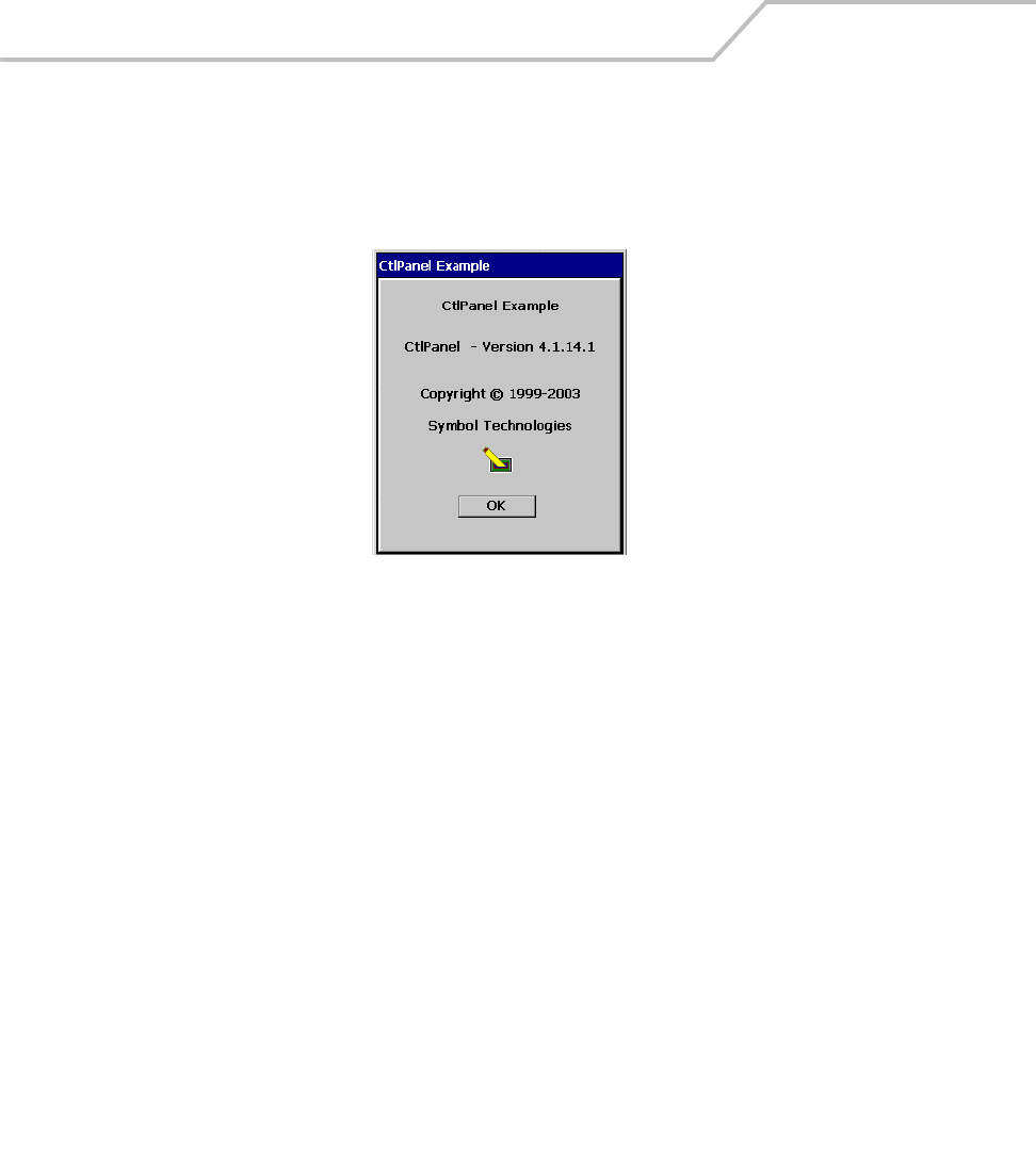
MC9000-K/S for Embedded Windows® CE .NET Product Reference Guide
3-42
About Ctl Panel
Use the About Ctl Panel window to view the system’s control panel software version information.
1. Double-tap the Ctl Panel icon - double-tap About. The About window appears.
Figure 3-43. About Window
2. Tap OK to return to the Control Panel window.
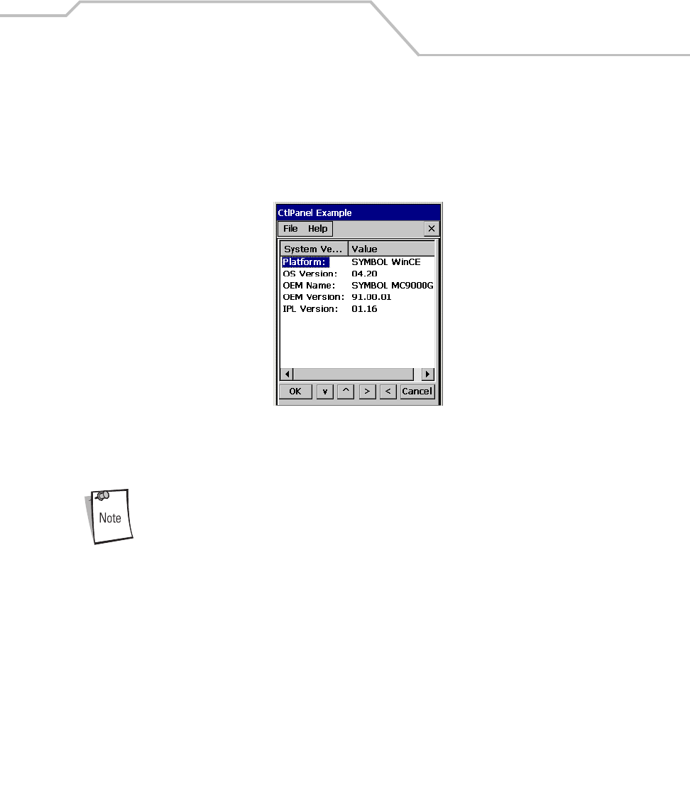
Settings 3-43
System Version
Use the System Version window to view the system software versions.
1. Double-tap the Ctl Panel icon - double-tap System Versions. The System Versions window
appears.
Figure 3-44. System Version Window
2. Tap OK to return to the Control Panel window.
Version data shown is example data only.

MC9000-K/S for Embedded Windows® CE .NET Product Reference Guide
3-44
Unique Unit ID
Use the Unique Unit ID (UUID) window to view the unique unit ID version information. The UUID
provides a way of uniquely identifying each unit. Some software packages require a UUID.
1. Double-tap the Ctl Panel icon - double-tap Unique Unit ID. The Unique Unit ID window
appears.
Figure 3-45. Unique Unit ID Window
2. Tap OK to return to the Control Panel window.

Settings 3-45
Persist
The Persist setting is made in the Control Panel window, see Figure 3-42 on page 3-40. It is used in
conjunction with a parameter settings to save the new setting(s) in a .reg file in the /Applications
directory. Enable Persist prior to changing any settings if the settings are to be saved over a cold boot.
1. From the Control Panel window, tap Persist.
2. Use the right arrow button to toggle the value to between Yes or No.
The created registration files can be found in the root directory of the application drive and the
filenames are the same as the registry key names. For example, for a key called ZOT with a registry
path of \HARDWARE\ONE\FUZZY the filename would be HARDWARE.ONE.FUZZY.ZOT.REG.
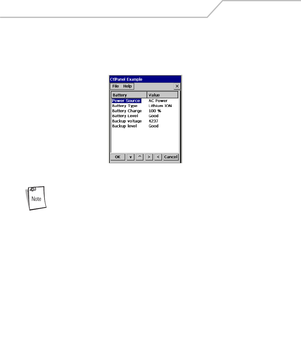
MC9000-K/S for Embedded Windows® CE .NET Product Reference Guide
3-46
Battery
Use the Battery window to view the battery status.
1. Double-tap the Ctl Panel icon - double-tap Battery. The Battery window appears.
Figure 3-46. Battery Status Window
Do not use the Backup voltage value.
2. Tap OK to return to the Control Panel window.
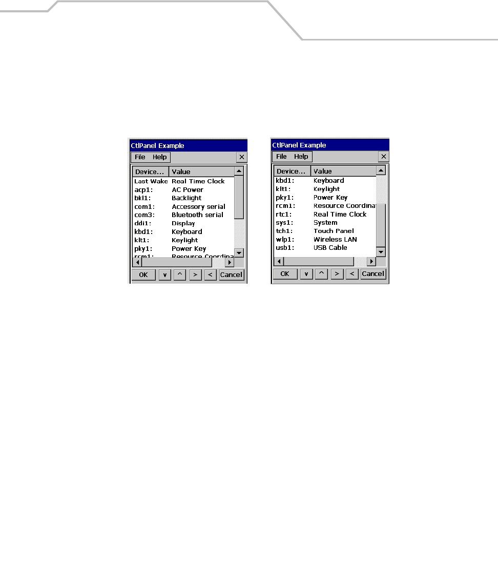
Settings 3-47
Power Settings
Use the Power Settings window to view and set the power setting parameters.
Double-tap the Ctl Panel icon - double-tap Power Settings. The Power Settings window appears.
Figure 3-47. Power Settings Window
The device list as well as the he parameters settings is dependent on the mobile computer setup and
configuration. However, the parameter types are defined.
The parameter types are:
• WakeUp control (Power key, Timeout, and API call) - typical sample device = acp1:
• Timeout control (Battery and AC power) - typical sample device = bkl1:
• State control (D0, D1, D2, D3, D4) - typical sample device = bkl1:
• Activity control (Trigger, Touch, Keyboard, User) - typical sample device = bkl1:
Use the power settings to set the individual power parameters, see Table 3-6 for parameter settings.
Tap the up and down arrow buttons to scroll up or down on the menu selections and tap the left or
right arrow buttons to select a menu item, or to toggle a selection value. The Keypad arrows perform
the same functions as the arrow buttons. Tap OK to save any new selections and return to the
previous window or tap Cancel to return to the previous window without saving any new entries.
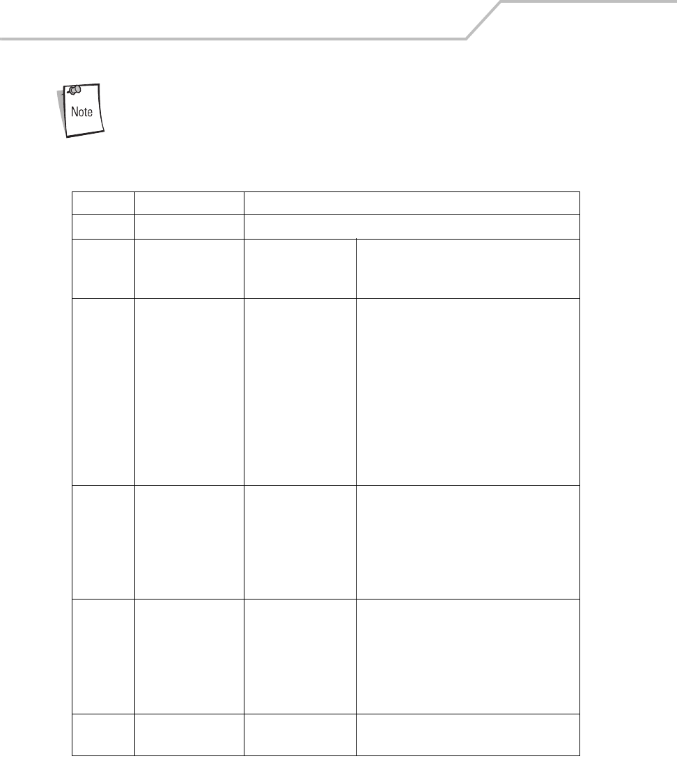
MC9000-K/S for Embedded Windows® CE .NET Product Reference Guide
3-48
Use the power settings with caution. Some of the settings allow the user to
turn off the display, or to disable the keypad/touch screen. If the unit is
inadvertently disabled with the power settings, see Resetting the Mobile
Computer on page 2-39 to restore the factory settings.
Table 3-6. Example Power Setting Parameters
Parameter Value Settings
Last Wake Real Time Clock Displays the event that iintiated the last wake up.
acp1: AC Power Power Key Wake
Timeout Wake
API Call Wake
Set the Wake on=Yes, off=No
Set the Wake on=Yes, off=No
Set the Wake on=Yes, off=No
bkl1: Backlight Battery Timeout
AC Power Timeout
D0
D3
D4
Activities:
Trigger
Touch
Keyboard
User
60 (time value in ms)
0 (time value in ms)
When selected feature is on
When selected feature is on standby
When selected feature is off
Select Yes to set Activities to function on
Battery Power and/or on AC Power. Select No to
set activities not to function on Battery Power
and/or on AC Power.
com1: Accessory serial Power Key Wake
Timeout Wake
API Call Wake
D0
D3
D4
Set the Wake on=Yes, off=No
Set the Wake on=Yes, off=No
Set the Wake on=Yes, off=No
When selected feature is on
When selected feature is on standby
When selected feature is off
com3: Bluetooth serial Power Key Wake
Timeout Wake
API Call Wake
D0
D3
D4
Set the Wake on=Yes, off=No
Set the Wake on=Yes, off=No
Set the Wake on=Yes, off=No
When selected feature is on
When selected feature is on standby
When selected feature is off
ddi1: Display D0
D4
When selected the Display is turned on
When selected the Display is turned off
Settings 3-49
kbd1: Keyboard Power Key Wake
Timeout Wake
API Call Wake
D0
D3
D4
Set the Wake on=Yes, off=No
Set the Wake on=Yes, off=No
Set the Wake on=Yes, off=No
When selected feature is on
When selected feature is on standby
When selected feature is off
klt1: Keylight Battery Timeout
AC Power Timeout
D0
D3
D4
Activities:
Trigger
Touch
Keyboard
User
60 (time value in ms)
0 (time value in ms)
When selected feature is on
When selected feature is on standby
When selected feature is off
Select Yes to set Activities to function on
Battery Power and/or on AC Power. Select No to
set activities not to function on Battery Power
and/or on AC Power.
pky1: Power Key Display only
rcm1: Resource Coordinator Power Key Wake
Timeout Wake
API Call Wake
Set the Wake on=Yes, off=No
Set the Wake on=Yes, off=No
Set the Wake on=Yes, off=No
rtc1: Real Time Clock Display only
sys1: System Battery Timeout
AC Power Timeout
180 (time value in ms)
0 (time value in ms)
tch1: Touch Panel Power Key Wake
Timeout Wake
API Call Wake
D0
D3
D4
Set the Wake on=Yes, off=No
Set the Wake on=Yes, off=No
Set the Wake on=Yes, off=No
When selected the Touch Panel is turned on
When selected feature is on standby
When selected the Touch Panel is turned off
Table 3-6. Example Power Setting Parameters
Parameter Value Settings

MC9000-K/S for Embedded Windows® CE .NET Product Reference Guide
3-50
wlp1: Wireless LAN Power Key Wake
Timeout Wake
API Call Wake
D0
D3
D4
Set the Wake on=Yes, off=No
Set the Wake on=Yes, off=No
Set the Wake on=Yes, off=No
When selected feature is on
When selected feature is on standby
When selected feature is off
usb1: USB Cable Power Key Wake
Timeout Wake
API Call Wake
Set the Wake on=Yes, off=No
Set the Wake on=Yes, off=No
Set the Wake on=Yes, off=No
Table 3-6. Example Power Setting Parameters
Parameter Value Settings
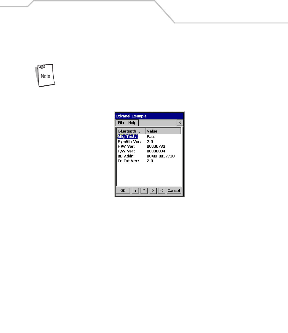
Settings 3-51
Bluetooth Settings
Use the Bluetooth Settings window to display the bluetooth parameters.
Mobile computers that do not have Bluetooth capability display UNKNOWN values.
1. Double-tap the Ctl Panel icon - double-tap Bluetooth Settings. The Bluetooth Settings
window displays.
Figure 3-48. Bluetooth Status Window
2. Tap OK to return to the Control Panel window.
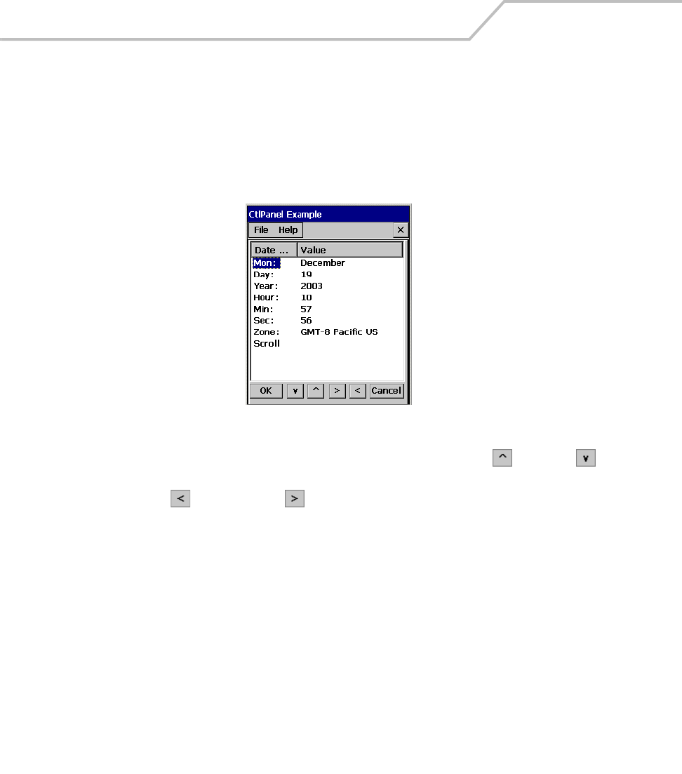
MC9000-K/S for Embedded Windows® CE .NET Product Reference Guide
3-52
Date and Time
Use the Date and Time window to set the date, time and time zone information for the mobile
computer.
1. Double-tap the Ctl Panel icon - double-tap Date and Time. The Date and Time window
appears.
Figure 3-49. Date and Time Window
2. To set the Value for any item in the Date and Time column, use the up and down
arrows to select the item.
3. Use the left and right arrow buttons to select the value.
4. Tap OK to return to the Control Panel window.
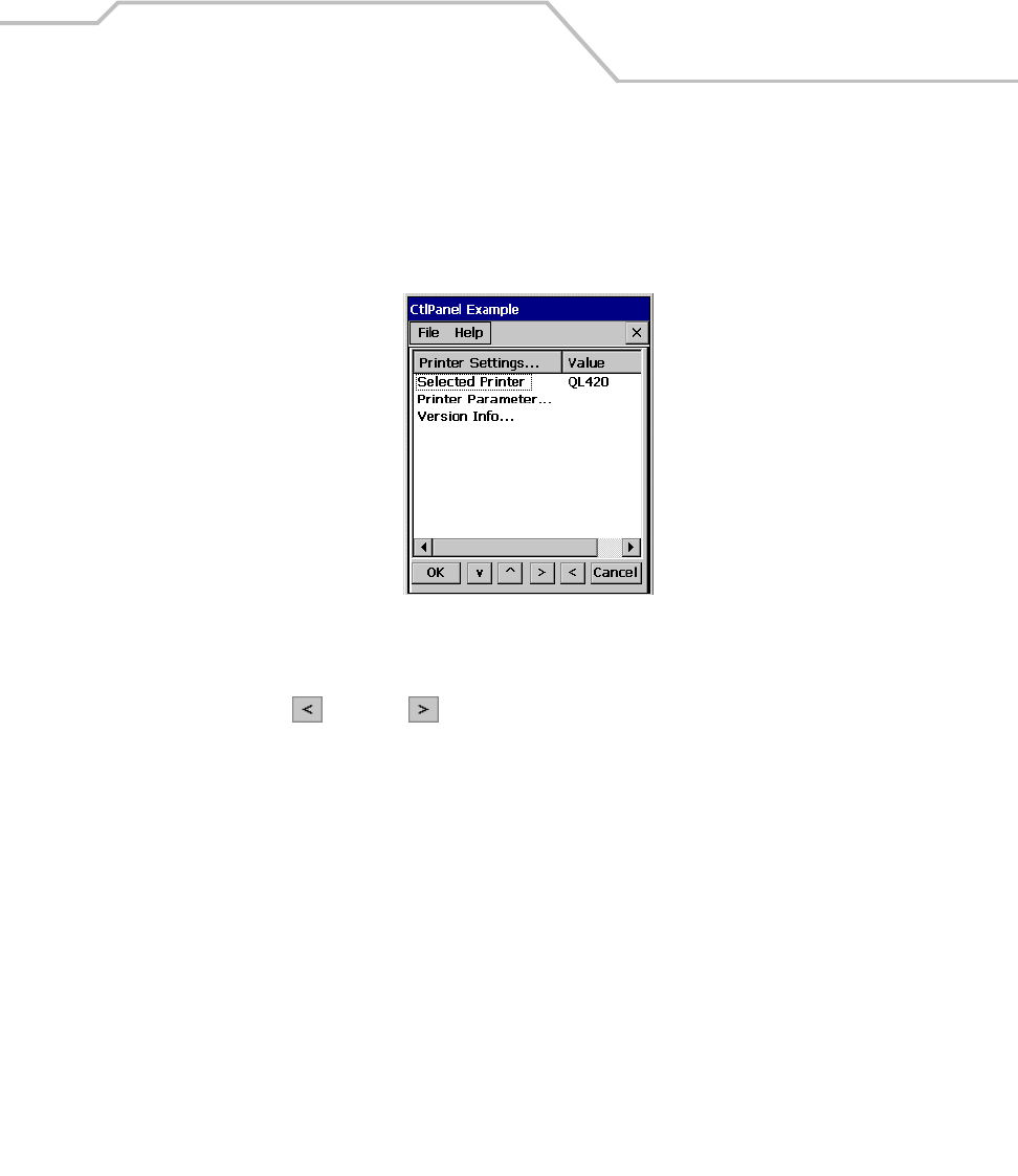
Settings 3-53
Printer Settings
Use the Printer Settings window to select the printer information.
1. Double-tap the Ctl Panel icon - double-tap Printer Settings. The Printer Settings window
appears.
Figure 3-50. Printer Settings Window
2. To select a printer, tap the Selected Printer item in the Printer Settings column.
3. Use the left and right arrows to select the printer. Available printer selections
include:
• QL420
• Cameo_Series
•Comtec_RP3
• Encore_Series
• Monarch9460
• Monarch9490
• QL320.
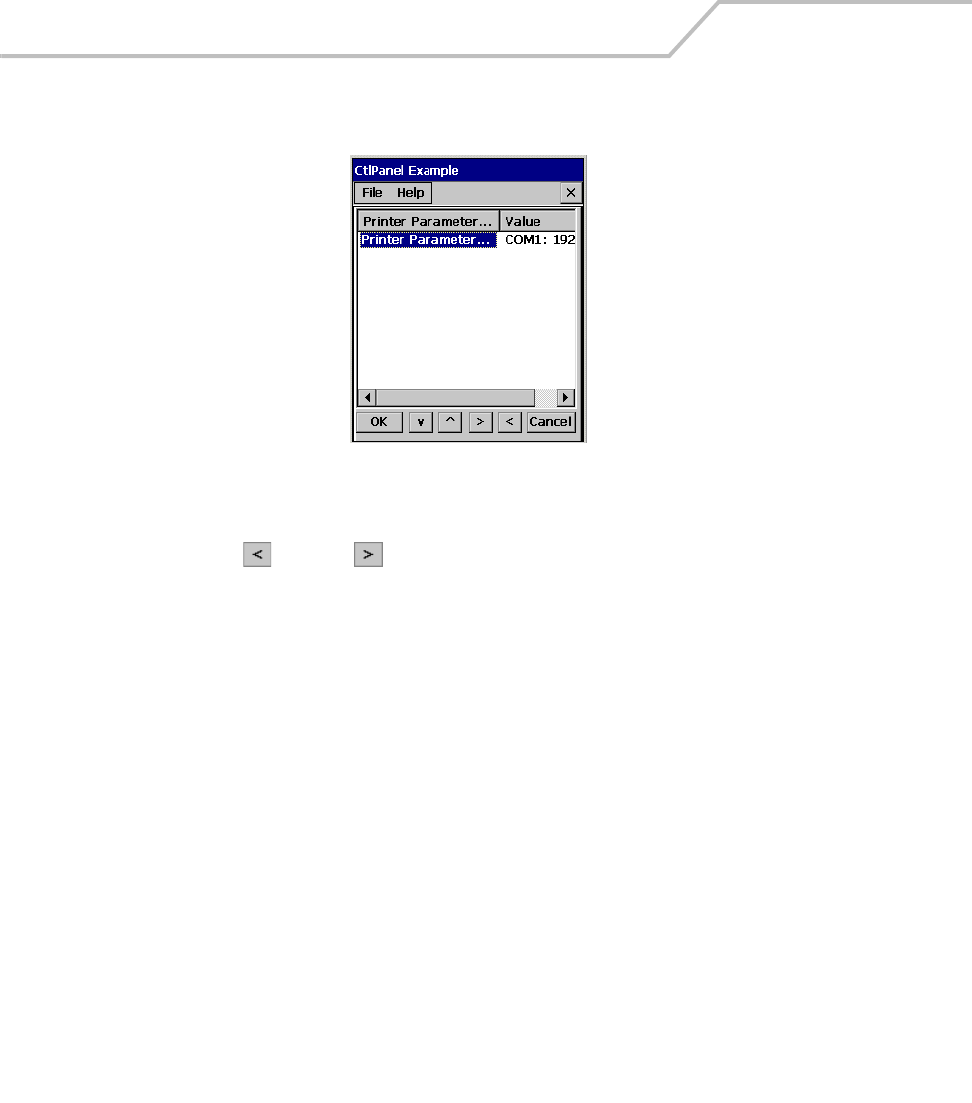
MC9000-K/S for Embedded Windows® CE .NET Product Reference Guide
3-54
4. Double-tap Printer Parameters to enter the Printer Parameters window.
Figure 3-51. Printer Parameters Window
5. Tap the Selected Printer item in the Printer Settings column.
6. Use the left and right arrows to select the communication and baud rate. Values
include:
• Com1: 38400
• Com1: 19200
• Com1: 9600
• Com2: 38400
• Com2: 19200
• Com2: 9600
• Com3: 38400
• Com3: 19200
• Com3: 9600
• Com4: 38400
• Com4: 19200
• Com4: 9600
• LPT1:.
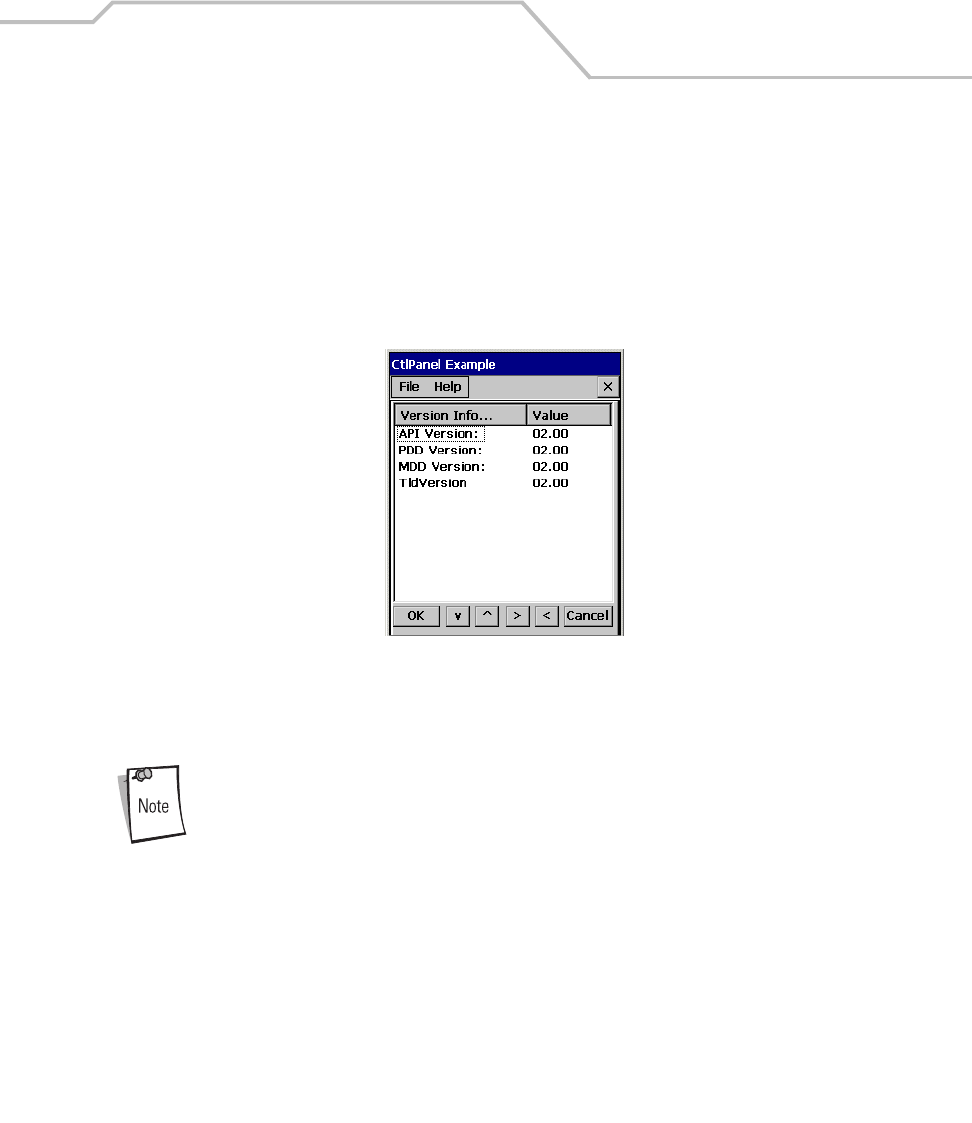
Settings 3-55
7. To view the Version Information, double-tap the Version Info item in the Printer Settings
column.
8. Version information includes:
•API Version
• PDD Version
• MDD Version
• TldVersion.
Figure 3-52. Printer Version Information Window
9. Tap OK to return to the Control Panel window.
Developer support for adding additional Symbol printer drivers is provided in
the SMDK, see Chapter 8, Software Installation for the SMDK installation.
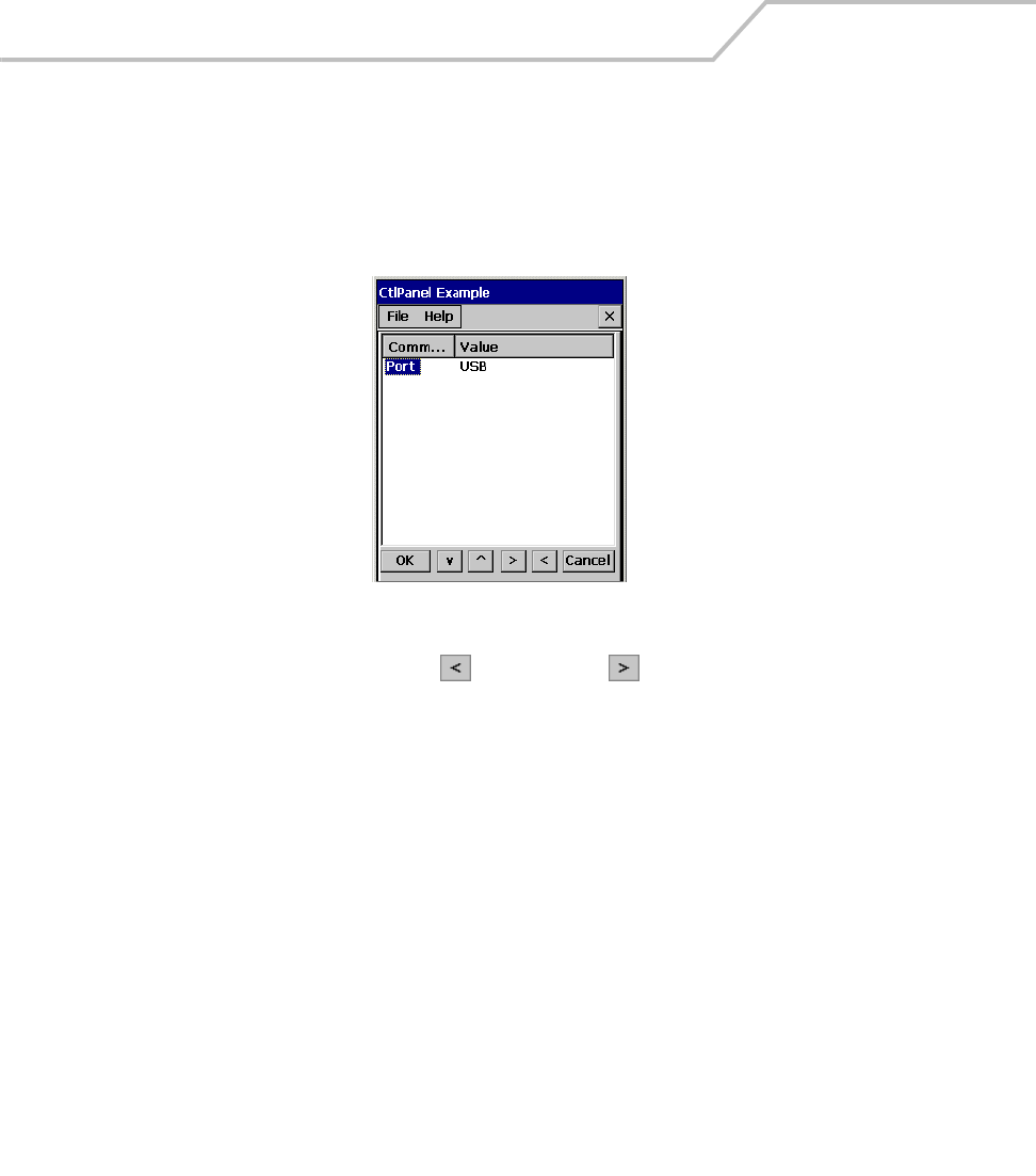
MC9000-K/S for Embedded Windows® CE .NET Product Reference Guide
3-56
Comm Settings
Use the Comm Settings window to select the communications settings.
1. Double-tap the Ctl Panel icon - double-tap Comm Settings. The Comm Settings window
appears.
Figure 3-53. Comm Settings Window
2. With Port highlighted, use the left and right arrow buttons to select the appropriate
communication setting. Comm port selection values are:
• USB (default setting)
• Serial1 @ 115200
• Serial1 @ 57600
• Serial1 @ 38400.
3. Tap OK to return to the Control Panel window.
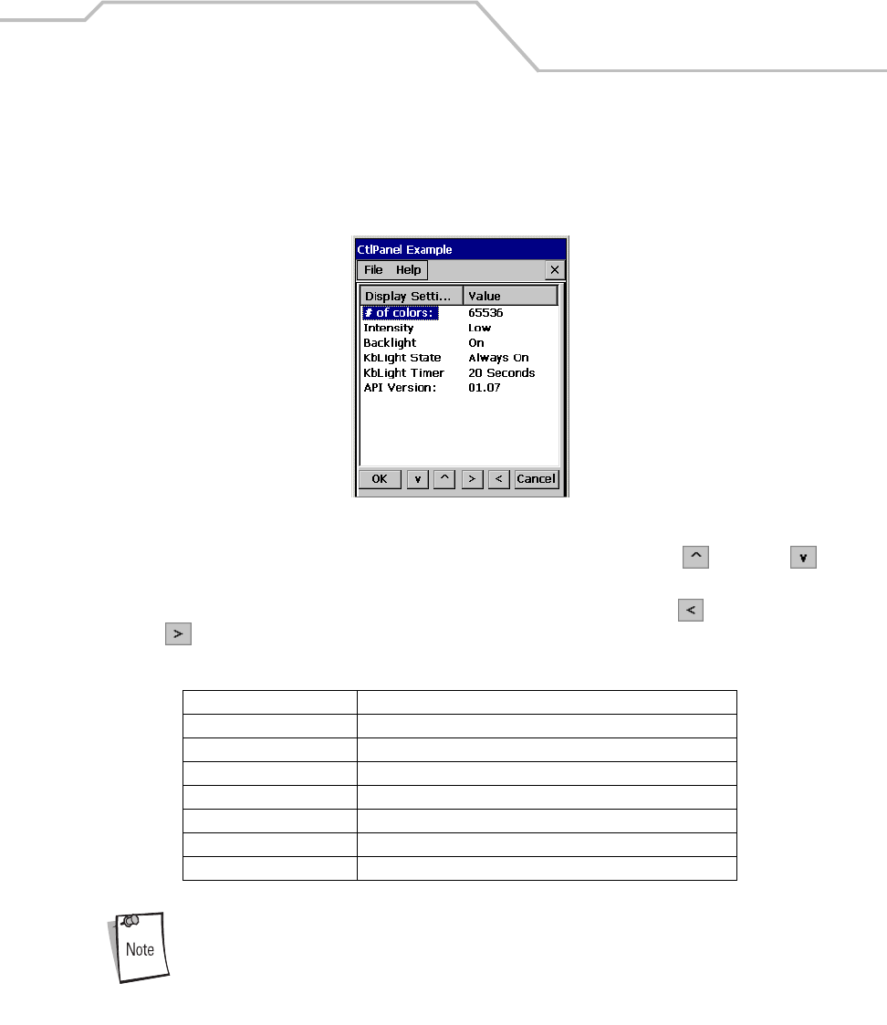
Settings 3-57
Display Settings
Use the Display Settings window to set the display parameters.
1. Double-tap the Ctl Panel icon - double-tap Display Settings. The Display Settings window
appears.
Figure 3-54. Display Settings Window
2. To set the Value for any item in the Display Settings column, use the up and down
arrows to select the item.
3. Once the item in the Display Settings column is highlighted, use the left and right arrow
buttons to select a value. Tap OK to return to the Control Panel window.
To optimize display performance, do not leave the display turned on to a fixed
image for an extended period of time. Turn the mobile computer off, or use
a screen saver when the mobile computer is not in use. Use the mobile
computer Display Settings to automatically turn off the display when the unit
is not in use, or use a screen saver application.
Table 3-7. Display Settings
Display Setting Values
# of colors 65536
Contrast 0 to 15 (only on monochromatic units)
Intensity Low, Medium, High, Super
Backlight On, Off
kbLight State Always off, Always on, Timeout
kbLight Timer 5 Sec, 10 Sec, 20 Sec, 30 Sec, 1 Min, 5 Min
API Version 01.07 (display only, not selectable)
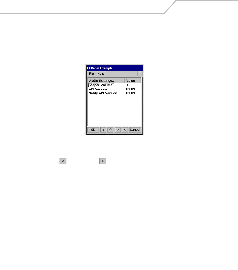
MC9000-K/S for Embedded Windows® CE .NET Product Reference Guide
3-58
Audio Settings
Use the Audio Settings window to set the audio parameters.
1. Double-tap the Ctl Panel icon - double-tap Audio Settings. The Audio Settings window
appears.
Figure 3-55. Audio Settings Window
2. Tap Beeper Volume in the Audio Settings column.
3. Use the left and right arrow buttons to select the volume value to 0, 1, 2, or 3.
4. API Version and Notify API Version are display values only.
5. Tap OK to return to the Control Panel window.
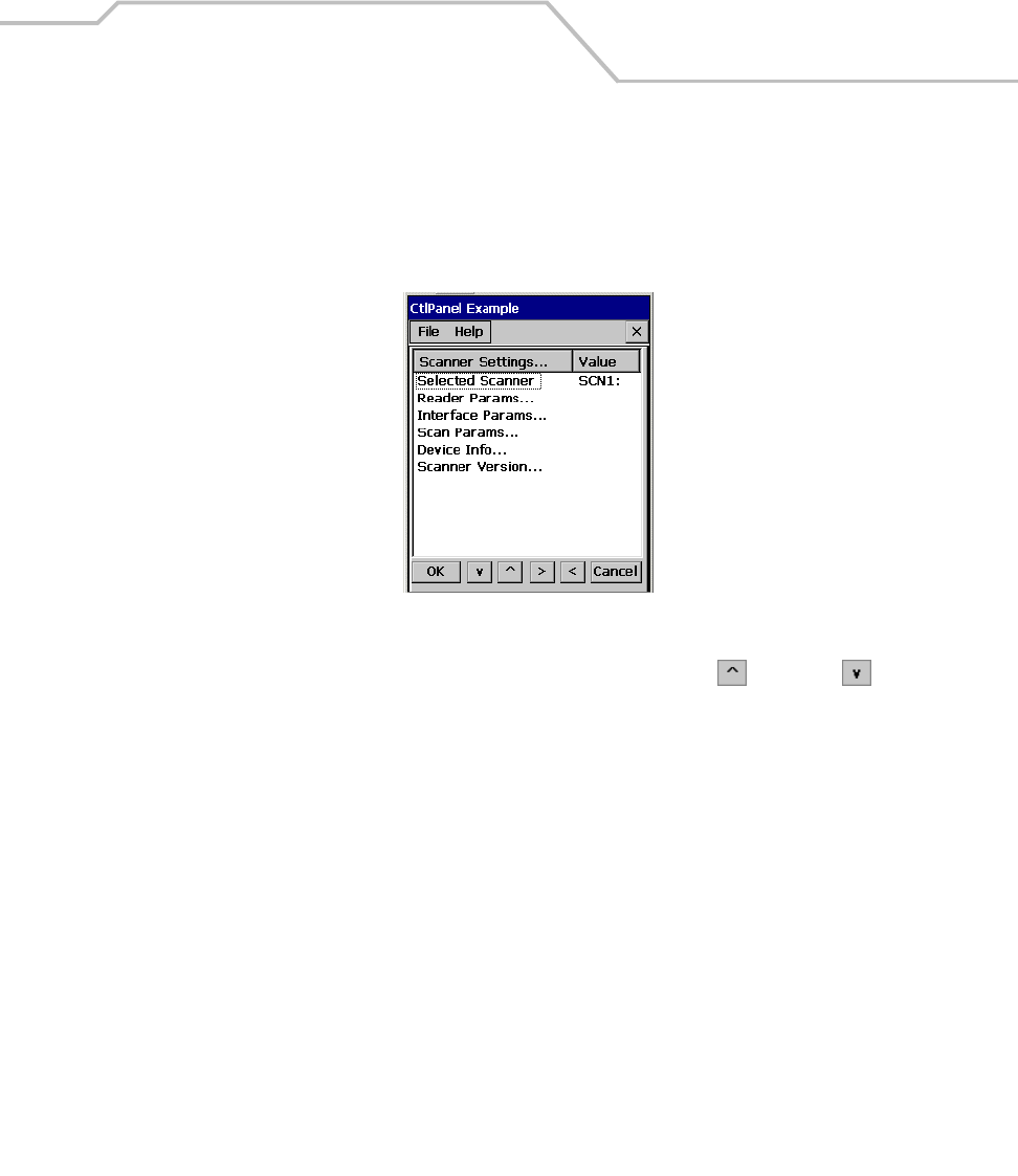
Settings 3-59
Scanner Settings
Use the Scanner Settings window to set the scanner information.
1. Double-tap the Ctl Panel icon - double-tap Scanner Settings. The Scanner Settings window
appears.
Figure 3-56. Scan Settings Window
2. To change any item in the Scanner Settings column, use the up and down arrows
to select the item. Selected Scanner is a display only value.
3. Double-tap the item to open a new window.
•Reader Parameters, see Reader Parameters on page 3-60.
•Interface Parameters, see Interface Parameters on page 3-61.
•Scan Parameters, see Scan Parameters on page 3-62.
•Device Information, see Device Information on page 3-65.
•Scanner Version, see Scanner Version on page 3-66.
4. Tap OK to return to the Control Panel window.
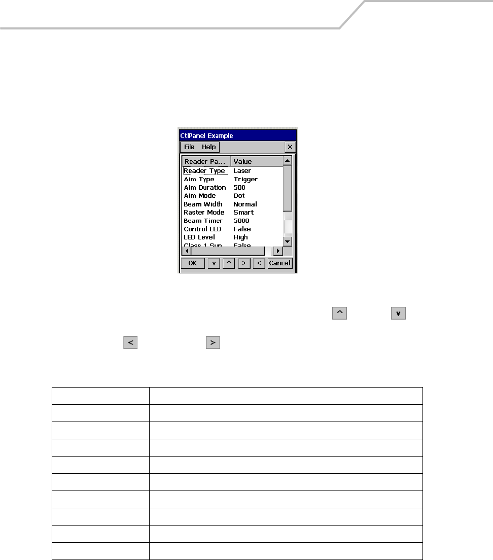
MC9000-K/S for Embedded Windows® CE .NET Product Reference Guide
3-60
Reader Parameters
Use the Reader Parameters window to set the scanning read parameters.
1. Double-tap the Ctl Panel icon - double-tap Scanner Settings - double-tap Reader
Parameters. The Reader Parameters window appears.
Figure 3-57. Reader Parameters Window
2. To change any item in the Reader Parameters column, use the up and down arrows
to select the item.
3. Use the left and right arrow buttons to increment the value. Table 3-8 list the
Reader Parameter value options.
Table 3-8. Reader Parameters
Reader Parameters Values
Reader Type Laser
Aim Type Trigger, Timed hold, Timed Release
Aim Duration 0-60,000 in increments of 100
Aim Mode Dot, Slab, Reticle, None
Beam Width Normal, Narrow
Raster Mode Smart, Cyclone, None, Always Open,
Beam Timer 0-60,000 in increments of 100
Control LED False, True
LED Level High, Low
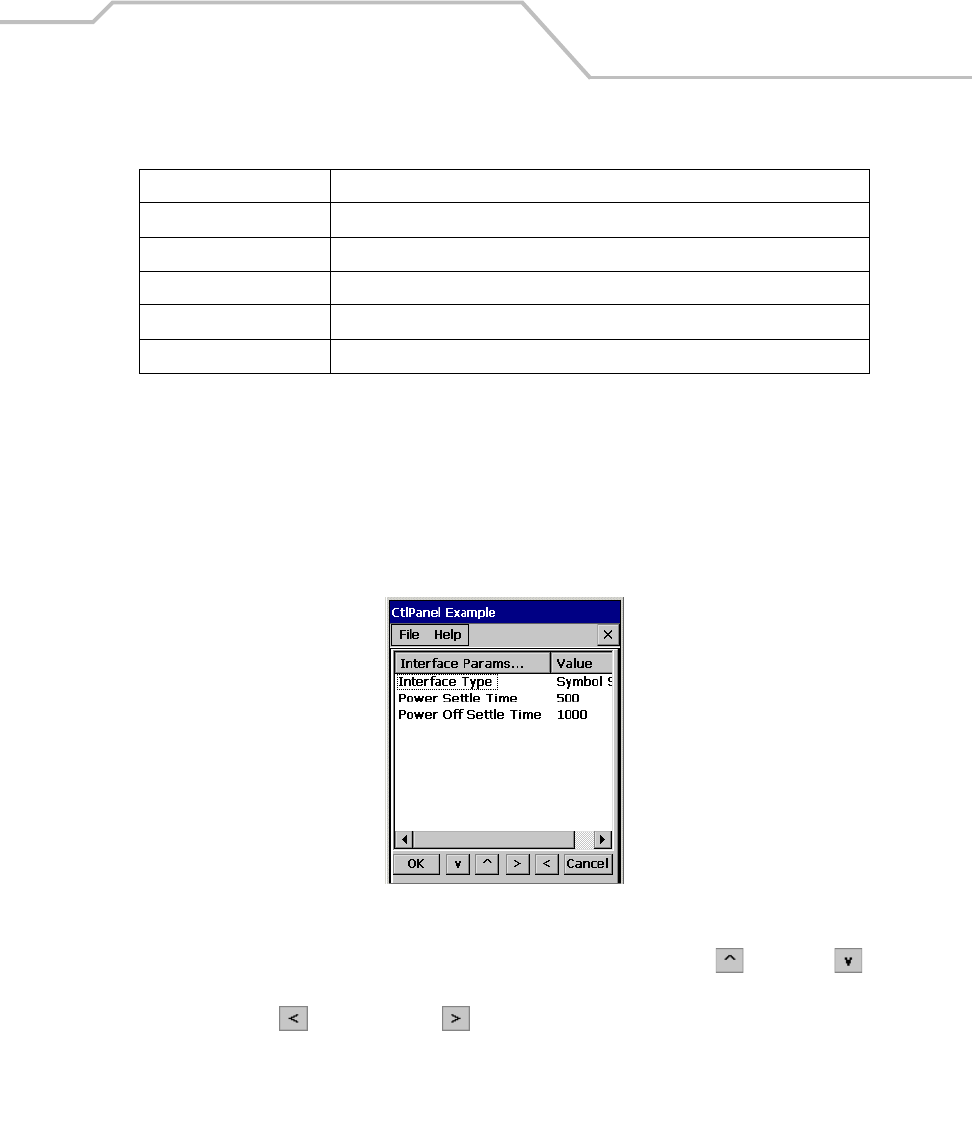
Settings 3-61
4. Tap OK to return to the Control Panel window.
Interface Parameters
Use the Interface Parameters window to set the scanning interface parameters.
1. Double-tap the Ctl Panel icon - double-tap Scanner Settings - double-tap Interface
Parameters. The Interface Parameters window appears
Figure 3-58. Interface Parameters Window
2. To change any item in the Interface Parameters column, use the up and down
arrows to select the item.
3. Use the left and right arrow buttons to increment the value. Table 3-9 list the
Reader Parameter value options.
Class 1 Sup False, True
Redundancy None, Bidirectional
Linear Sec (Short, Redun), (Short, Codabar), (All codes *2), (Long*2, Short*3), (All codes *3)
Pointer Timer 0-60,000 in increments of 100
Raster Height 0-100 in increments of 5
Table 3-8. Reader Parameters (Continued)
Reader Parameters Values
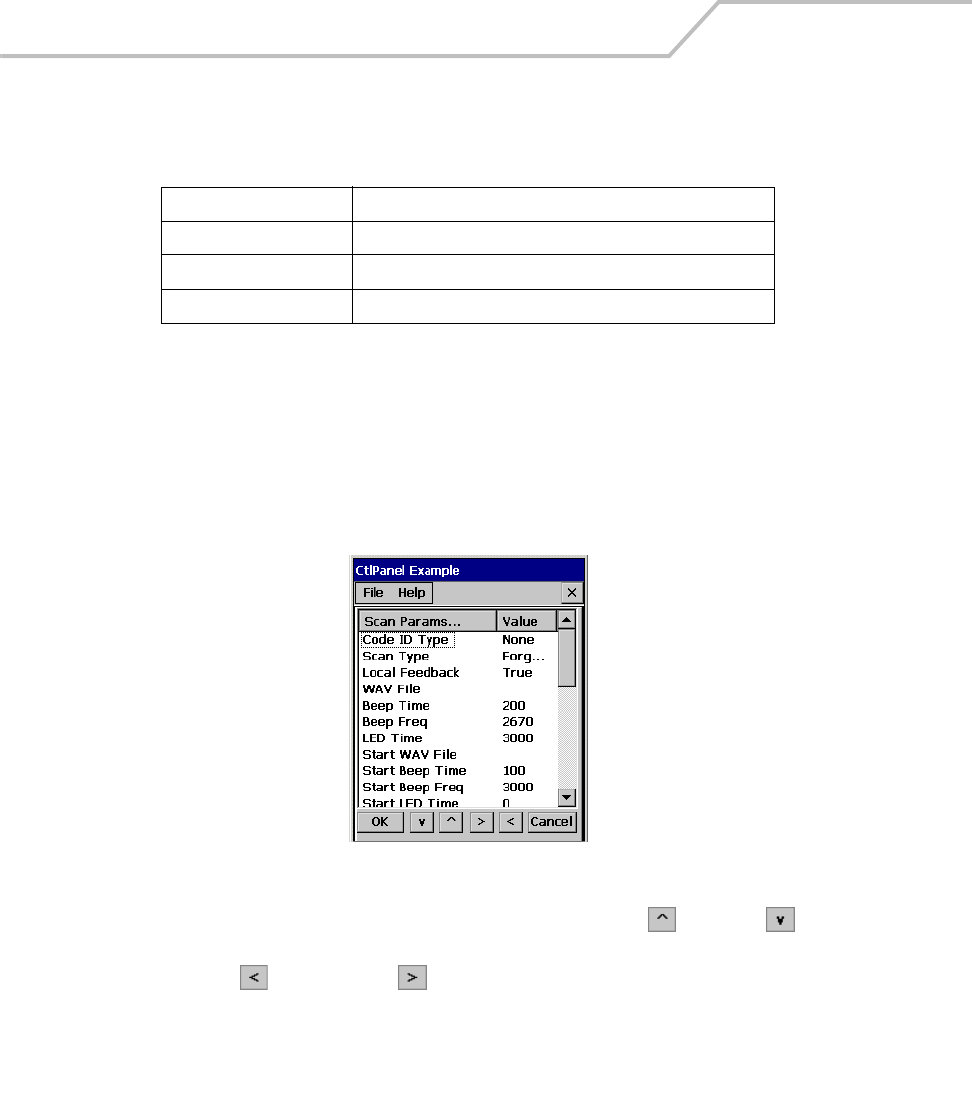
MC9000-K/S for Embedded Windows® CE .NET Product Reference Guide
3-62
4. Tap OK to return to the Control Panel window.
Scan Parameters
Use the Scan Parameters window to set the scan parameters.
1. Double-tap the Ctl Panel icon - double-tap Scanner Settings - double-tap Scan Params. The
Scan Parameters window appears.
Figure 3-59. Scan Parameters Window
2. To change any item in the Scan Parameters column, use the up and down arrows
to select the item.
3. Use the left and right arrow buttons to increment the value. Table 3-10 list the Scan
Parameter value options.
Table 3-9. Interface Parameters
Interface Parameter Values
Interface Type Symbol SSI
Power Settle Time 0-1000 in increments of 50
Power Off Settle Time 0-1000 in increments of 50

Settings 3-63
Table 3-10. Scan Parameters
Scan Parameters Values
Code ID Type None, Symbol, AIM
Scan Type Forgrnd, Bkgrnd, Monitor
Local Feedback True, False
WAV File See Figure 3-60 on page 3-64, Tap Decrement to move back on
the WAV file listing and Increment to move forward on the
WAV file listing. Tap OK to select the WAV file.
Beep Time 0-5000 in increments of 100
Beep Freq 2500-3500 in increments of 10
LED Time 0-5000 in increments of 500
Start WAV File See Figure 3-60 on page 3-64, Tap Decrement to move back on
the WAV file listing and Increment to move forward on the
WAV file listing. Tap OK to select the WAV file.
Start Beep Time 0-5000 in increments of 100
Start Beep Freq 2500-3500 in increments of 10
Start LED Time 0-5000 in increments of 500
Interim WAV File See Figure 3-60 on page 3-64, Tap Decrement to move back on
the WAV file listing and Increment to move forward on the
WAV file listing. Tap OK to select the WAV file.
Interim Beep Time 0-5000 in increments of 100
Interim Beep Freq 2500-3500 in increments of 10
Interim LED Time 0-5000 in increments of 500
Fatal WAV File See Figure 3-60 on page 3-64, Tap Decrement to move back on
the WAV file listing and Increment to move forward on the
WAV file listing. Tap OK to select the WAV file.
Fatal Beep Time 0-5000 in increments of 100
Fatal Beep Freq 2500-3500 in increments of 10
Fatal LED Time 0-5000 in increments of 500
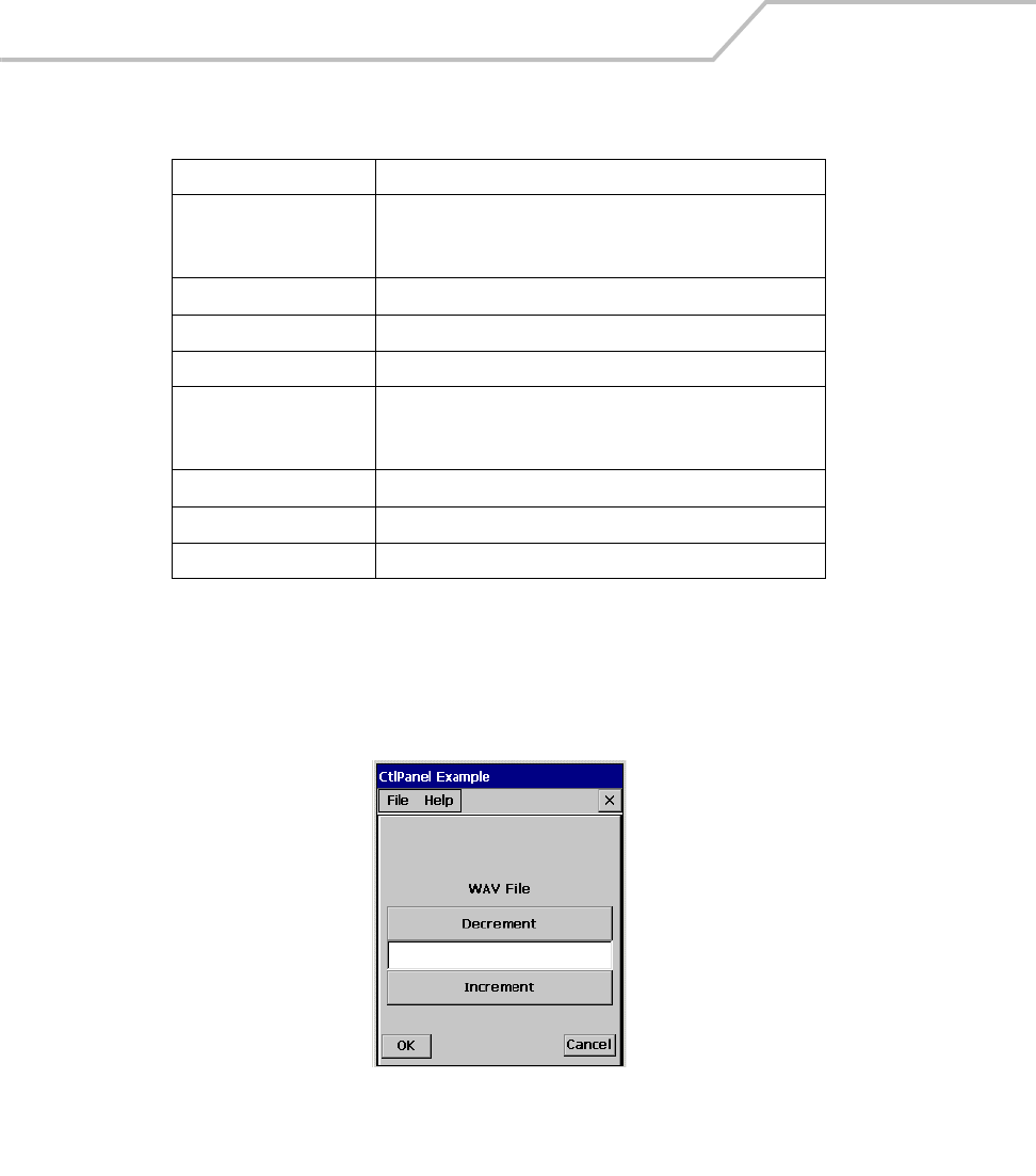
MC9000-K/S for Embedded Windows® CE .NET Product Reference Guide
3-64
4. Tap OK to return to the Control Panel window.
WAV File
Use the WAV File window to select a .wav file. Use the Increment and Decrement buttons to scroll
through the wav file listing.
Figure 3-60. Scan WAV File Window
Tap OK to return to the Control Panel window.
Nonfatal WAV File See Figure 3-60 on page 3-64, Tap Decrement to move back on
the WAV file listing and Increment to move forward on the
WAV file listing. Tap OK to select the WAV file.
Nonfatal Beep Time 0-5000 in increments of 100
Nonfatal Beep Freq 2500-3500 in increments of 10
Nonfatal LED Time 0-5000 in increments of 500
Activity WAV File See Figure 3-60 on page 3-64, Tap Decrement to move back on
the WAV file listing and Increment to move forward on the
WAV file listing. Tap OK to select the WAV file.
Activity Beep Time 0-5000 in increments of 100
Activity Beep Freq 2500-3500 in increments of 10
Activity LED Time 0-5000 in increments of 500
Table 3-10. Scan Parameters (Continued)
Scan Parameters Values
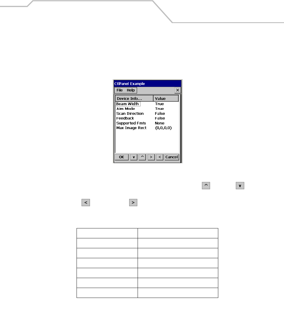
Settings 3-65
Device Information
Use the Device Information window to view the scanner information.
1. Double-tap the Ctl Panel icon - double-tap Scanner Settings - double-tap Scan Parameters.
The Scan Parameters window appears.
Figure 3-61. Device Information Parameters Window
2. To change any item in the Device Information column, use the up and down arrows
to select the item.
3. Use the left and right arrow buttons to increment the value. Table 3-11 list the
Reader Parameter value options.
4. Tap OK to return to the Control Panel window.
Table 3-11. Device Information Parameters
Device Info Parameter Values
Beam Width True
Aim Mode True
Scan Direction False
Feedback False
Supported Fmts None
Max Image Rect (0,0,0,0)
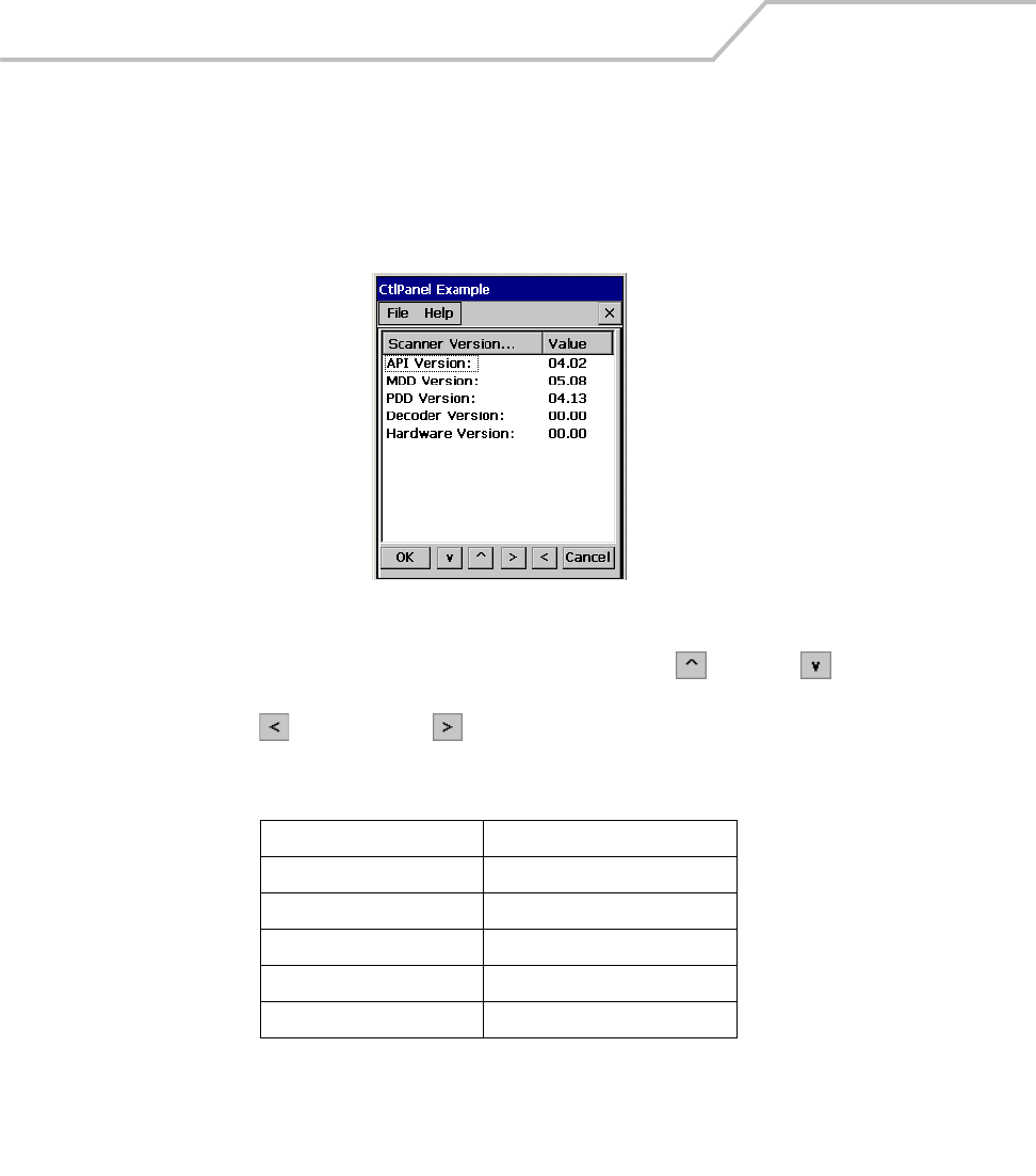
MC9000-K/S for Embedded Windows® CE .NET Product Reference Guide
3-66
Scanner Version
Use the Scanner Version window to view the scanner version information.
1. Double-tap the Ctl Panel icon - double-tap Scanner Settings - double-tap Scanner Version.
The Scanner Version window appears.
Figure 3-62. Scanner Version Window
2. To change any item in the Scanner Version column, use the up and down arrows to
select the item.
3. Use the left and right arrow buttons to increment the value. Table 3-12 list the
Reader Parameter value options.
4. Tap OK to return to the Control Panel window.
Table 3-12. Version Parameters
Version Parameter Values
API Version 04.02
MDD Version 05.06
PDD Version 04.11
Decoder Version 00.00
Hardware Version 00.00

Communications
Chapter Contents
Introduction. . . . . . . . . . . . . . . . . . . . . . . . . . . . . . . . . . . . . . . . . . . . . . . . . . . . . . . . . . . . . . . . . . . . . . . . .4-3
Installing Communication Software. . . . . . . . . . . . . . . . . . . . . . . . . . . . . . . . . . . . . . . . . . . . . . . . . . . . . .4-3
Installing ActiveSync . . . . . . . . . . . . . . . . . . . . . . . . . . . . . . . . . . . . . . . . . . . . . . . . . . . . . . . . . . . . .4-3
Setting up a Partnership. . . . . . . . . . . . . . . . . . . . . . . . . . . . . . . . . . . . . . . . . . . . . . . . . . . . . . .4-4
Communication Setup . . . . . . . . . . . . . . . . . . . . . . . . . . . . . . . . . . . . . . . . . . . . . . . . . . . . . . . . . . . . . . . .4-9
Serial Communications Setup . . . . . . . . . . . . . . . . . . . . . . . . . . . . . . . . . . . . . . . . . . . . . . . . . . . . .4-10
Serial Connection Setup. . . . . . . . . . . . . . . . . . . . . . . . . . . . . . . . . . . . . . . . . . . . . . . . . . . . . .4-10
USB Connection Setup . . . . . . . . . . . . . . . . . . . . . . . . . . . . . . . . . . . . . . . . . . . . . . . . . . . . . . . . . . .4-13
Using ActiveSync . . . . . . . . . . . . . . . . . . . . . . . . . . . . . . . . . . . . . . . . . . . . . . . . . . . . . . . . . . . . . . .4-15

MC9000-K/S for Embedded Windows® CE .NET Product Reference Guide
4-2
Ethernet Setup . . . . . . . . . . . . . . . . . . . . . . . . . . . . . . . . . . . . . . . . . . . . . . . . . . . . . . . . . . . . . . . . .4-16
Installing MobileDox Cradle Manager. . . . . . . . . . . . . . . . . . . . . . . . . . . . . . . . . . . . . . . . . . .4-16
Installing eConnect. . . . . . . . . . . . . . . . . . . . . . . . . . . . . . . . . . . . . . . . . . . . . . . . . . . . . . . . . .4-17
Mobile Computer Configuration. . . . . . . . . . . . . . . . . . . . . . . . . . . . . . . . . . . . . . . . . . . . . . . .4-20
DHCP Server Configuration . . . . . . . . . . . . . . . . . . . . . . . . . . . . . . . . . . . . . . . . . . . . . . . . . . .4-22
Cradle Configuration. . . . . . . . . . . . . . . . . . . . . . . . . . . . . . . . . . . . . . . . . . . . . . . . . . . . . . . . .4-23
Connecting to the Internet on a Wireless Network . . . . . . . . . . . . . . . . . . . . . . . . . . . . . . . . . . . . . . . . .4-27

Communications 4-3
Introduction
The mobile computer is capable of communicating with a number of hosts, including development
computers, serial devices, printers, etc. The available accessories serve as essential data
communication devices, enabling the information to be synchronized on the mobile computer with the
information on the host device using ActiveSync. With the appropriate accessory and software, the
mobile computer can establish a number of connection types, such as a serial connection, a USB
connection and an Ethernet connection.
For an Ethernet connection, use the Four Slot Ethernet Cradle.
For a serial or USB connection, use one of the accessories listed below.
• Single Slot Serial/USB Cradle
• Cable Adapter Module (CAM)
• Magnetic Stripe Reader (MSR).
This chapter provides information on installing the appropriate communication software and setting
up the appropriate accessory to enable communication between the mobile computer and the host
device. For more information about the accessories available for the mobile computer, Chapter 7,
Accessories.
Installing Communication Software
To successfully communicate with the various host devices Microsoft Activesync (version 3.7 or
higher) must be installed on the host computer.
Installing ActiveSync
Use ActiveSync (version 3.7 or higher) to synchronize the information on the mobile computer with
the information on the host computer. Changes made on the mobile computer or host computer
appear in both places after synchronization.

MC9000-K/S for Embedded Windows® CE .NET Product Reference Guide
4-4
ActiveSync software:
• Allows the user to work with mobile computer-compatible host applications on the host
computer. ActiveSync replicates data from the mobile computer so data can be viewed,
entered and modified on the mobile computer with the host application.
• Synchronize files between the mobile computer and host computer. The files are
automatically converted to the correct format.
• Back up the data stored on the mobile computer. Synchronization is a one-step procedure
that ensures the data is always safe and up-to-date.
• Copy (rather than synchronize) files between the mobile computer and host computer.
• Control when synchronization occurs by selecting a synchronization mode, e.g., set to
synchronize continually while the mobile computer is connected to the host computer, or set
to only synchronize on command.
• Select the types of information to synchronize and control how much data is synchronized.
To install ActiveSync on the host computer:
1. Download the latest version of the software from http://www.microsoft.com. Refer to the
installation and RAS instructions included with the ActiveSync software.
2. Set up a partnership via the ActiveSync connection using a serial connection to the host
computer.
Setting up a Partnership
After ActiveSync installation is complete, the ActiveSync Setup Wizard helps the user to connect the
mobile computer to the host computer, set up a partnership to synchronize information between the
mobile computer and host computer and customize synchronization settings.
Before setting up a partnership between the mobile computer and host computer, refer to the
communication setup sections in this chapter for detailed information about Serial, USB and Ethernet
communication setups.
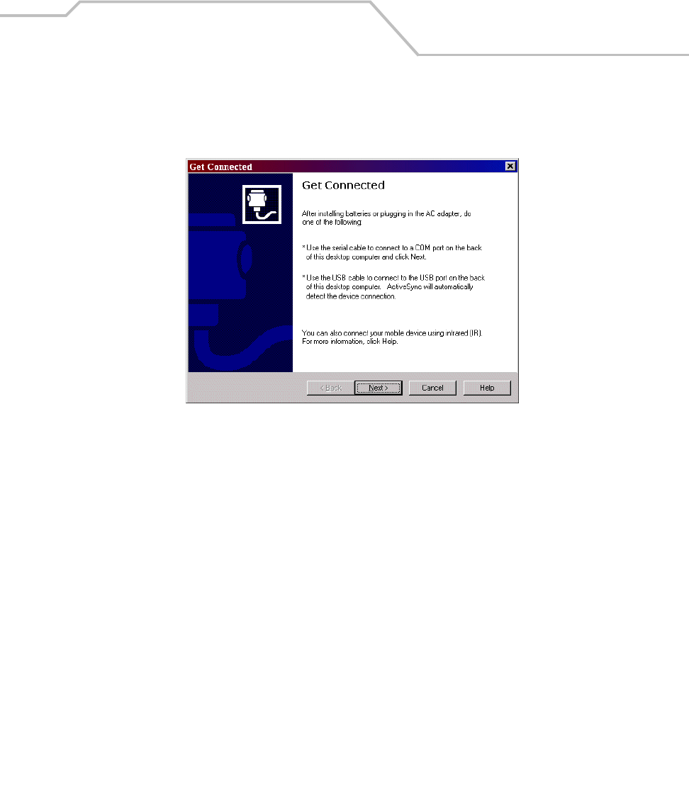
Communications 4-5
To set up a partnership:
1. If the Get Connected window does not appear on the host computer, select Start - Programs
- Microsoft ActiveSync - File - Get Connected.
Figure 4-1. Get Connected Window
2. Connect the mobile computer to the host computer using the appropriate Serial connection
(see Chapter 7, Accessories).
3. On the host computer, select Next in the Get Connected window.
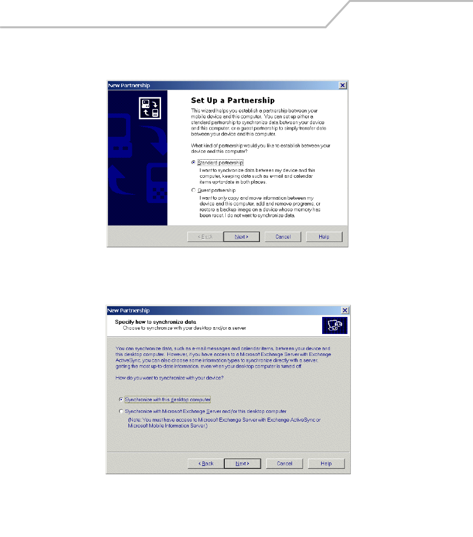
MC9000-K/S for Embedded Windows® CE .NET Product Reference Guide
4-6
4. The host computer and the mobile computer attempt to synchronize. The New Partnership
window appears.
Figure 4-2. New Partnership Window
5. Click the Standard partnership radio button and then select Next. The New Partnership/
Specify how to synchronize data window appears.
Figure 4-3. How To Sync Window
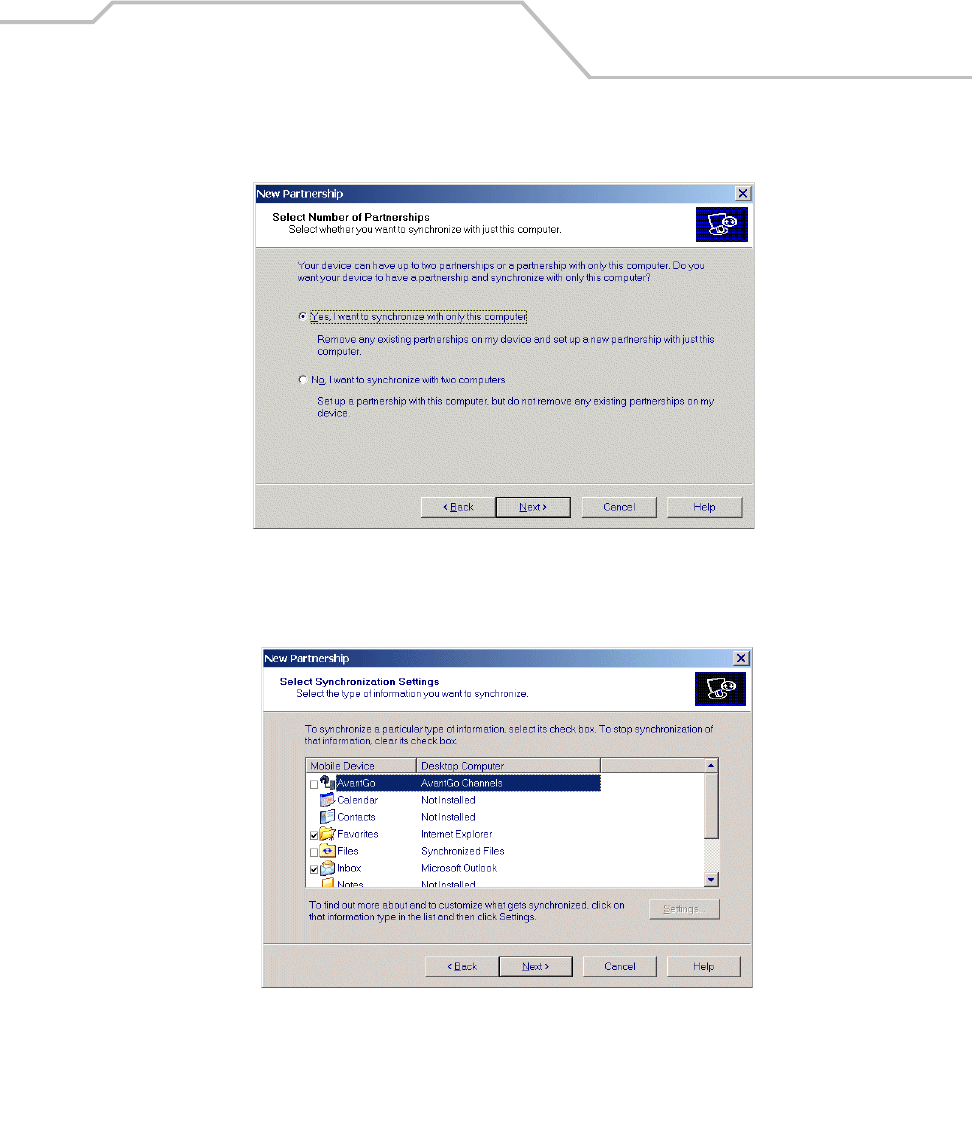
Communications 4-7
6. Click the Synchronize with this desktop computer radio button and select Next. The New
Partnership/Select Number of Partnerships window appears.
Figure 4-4. How To Sync Window
7. Click the Yes, I want to synchronize with only this computer radio button and then select
Next. The New Partnership/Select Synchronization Settings window appears.
Figure 4-5. Select Synchronization Settings Window
8. To synchronize a particular type of information, select its check box. To stop synchronization
of that information, clear its check box.
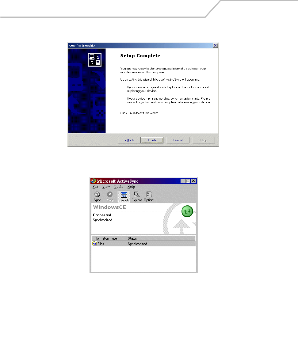
MC9000-K/S for Embedded Windows® CE .NET Product Reference Guide
4-8
9. Select Next. The New Partnership/Setup Complete window appears.
Figure 4-6. Setup Complete Window
10. Select Finish.
Figure 4-7. ActiveSync Connected Window

Communications 4-9
During the first synchronization, information stored on the host computer is copied to the mobile
computer. When the copy is complete and all data is synchronized, the mobile computer can be
disconnect from the host computer.
The first ActiveSync operation must be performed with a local, direct
connection.
To retain partnerships after a cold boot, capture partnership registry
information in a .reg file and save it in the Flash File System, detailed
information is provided in the SMDK Windows CE Help File for Symbol
Mobile Computers. See Chapter 8, Software Installation for the SMDK
installation.
For more information about using ActiveSync, start ActiveSync on the host computer, then see
ActiveSync Help.
Communication Setup
The mobile computer can communicate with the host computer using serial, USB or Ethernet
communications. The communication setup procedures for the Single Slot Serial/USB Cradle and the
Four Slot Ethernet Cradle are provided in this section as an example. See the provided reference for
detailed procedures for setting up other accessories:
Serial or USB Connection:
•Serial Communications Setup on page 4-10
•CAM and MSR Communications Setup on page 7-41
Ethernet connection:
•Ethernet Setup on page 4-16.
For each accessory, follow the instructions on configuring the host computer, setting up the
connection between the mobile computer and the host computer and configuring the mobile
computer.
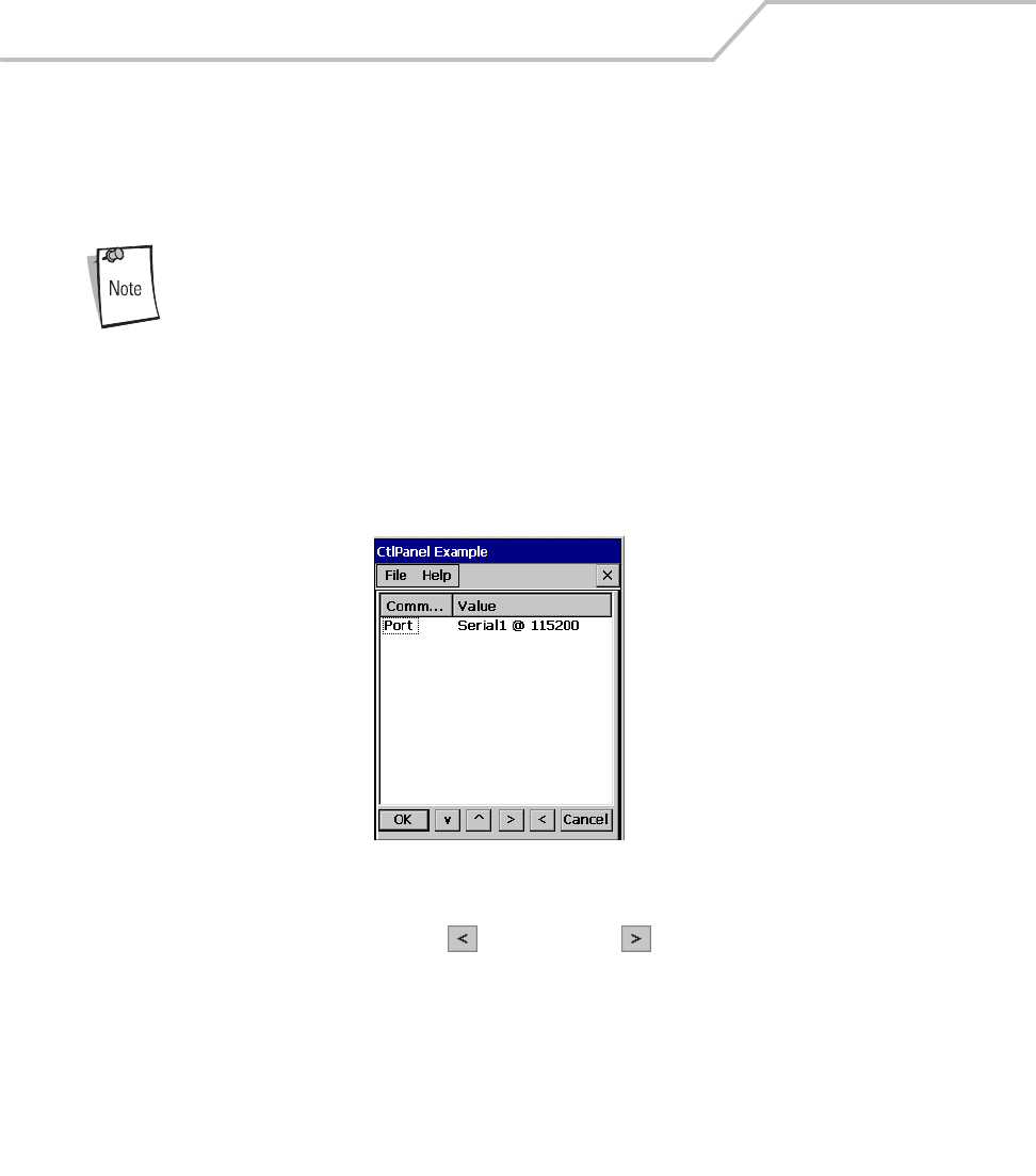
MC9000-K/S for Embedded Windows® CE .NET Product Reference Guide
4-10
Serial Communications Setup
The serial communications setup can be used to set up to communicate with a Single Slot Serial/USB
Cradle, MSR or a CAM.
For serial communications using the Single Slot Serial/USB Cradle, connect
only the serial cable, do not connect both the serial cable and the USB cable.
If both serial and USB communications cables are required, the host
computer USB port must be disabled in ActiveSync before serial
communications can be enabled.
Serial Connection Setup
1. On the mobile computer double-tap the Ctl Panel icon and double-tap on Comm Settings
to enter the Comm Settings, window. For detailed procedures, see Comm Settings on page
3-56.
Figure 4-8. Comm Settings Window
2. With Port highlighted, use the left and right arrow buttons to select the value.
Comm port default value is set to USB, change the value to: Serial1 @ 115200 (or a serial
setting appropriate for the host computer).
3. Tap OK to exit the Comm Settings window and tap Exit to exit the Control Panel window.
4. Ensure that ActiveSync was installed on the host computer and a partnership was created.
See Installing ActiveSync on page 4-3 and Setting up a Partnership on page 4-4.
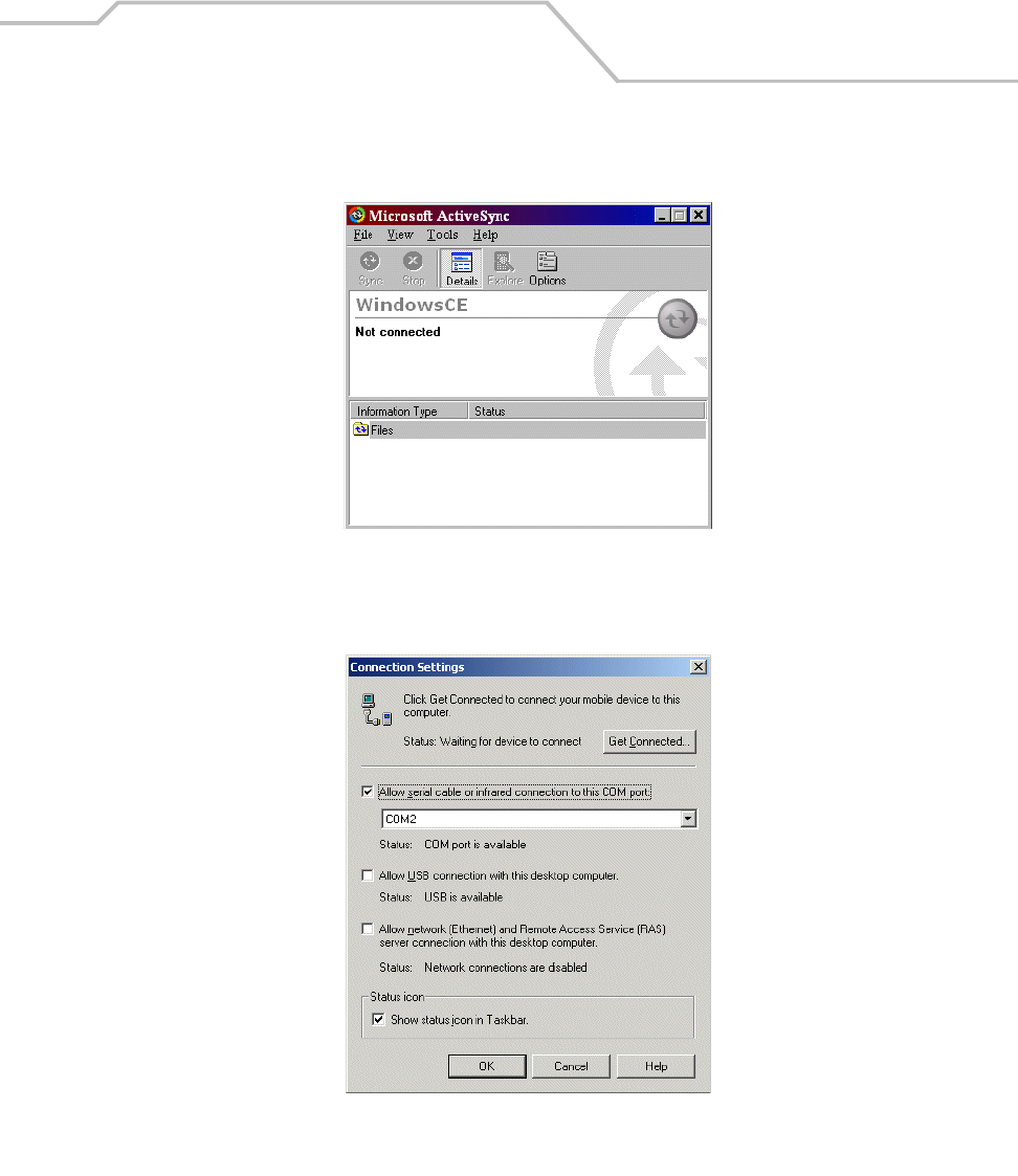
Communications 4-11
5. Start ActiveSync if it is not running on the host computer. To start, select Start -Programs -
Microsoft ActiveSync.
Figure 4-9. ActiveSync - Not Connected
6. In the ActiveSync window, select File - Connection Settings and ensure the selections
shown in Figure 4-10 are made. (Select the appropriate COM port for the host computer.)
Figure 4-10. Serial Connection Settings

MC9000-K/S for Embedded Windows® CE .NET Product Reference Guide
4-12
7. Tap OK to save any changes made.
Every mobile computer should have a unique device name. Never try to
synchronize more than one mobile computer to the same name.
8. Connect the device to the host computer, see Figure 7-6 on page 7-12 to set up a Single Slot
Serial/USB Cradle, or see Figure 7-25 on page 7-37 to set up a MSR or a CAM.
The cradle requires a dedicated port. It cannot share a port with an internal
modem or other device. Refer to the computer user manual supplied to locate
the serial port(s).
9. Upon connection, synchronization occurs automatically.
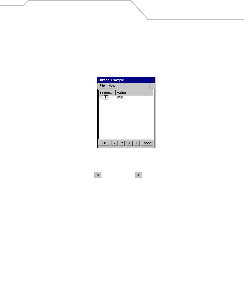
Communications 4-13
USB Connection Setup
1. The USB communications setup can be used to set up to communicate with a Single Slot
Serial/USB Cradle, MSR or a CAM.
2. On the mobile computer double-tap the Ctl Panel icon and double-tap Comm Settings to
enter the Comm Settings, window.
Figure 4-11. Comm Settings Window
3. Confirm that the Comm port default value is set to USB. If it is not set to USB then with Port
highlighted, use the left and right arrow buttons to set the value to USB.
4. Tap OK to exit the Comm Settings window and tap Exit to exit the Control Panel window.
5. Ensure that ActiveSync was installed on the host computer and a partnership was created.
See Installing ActiveSync on page 4-3 and Setting up a Partnership on page 4-4.
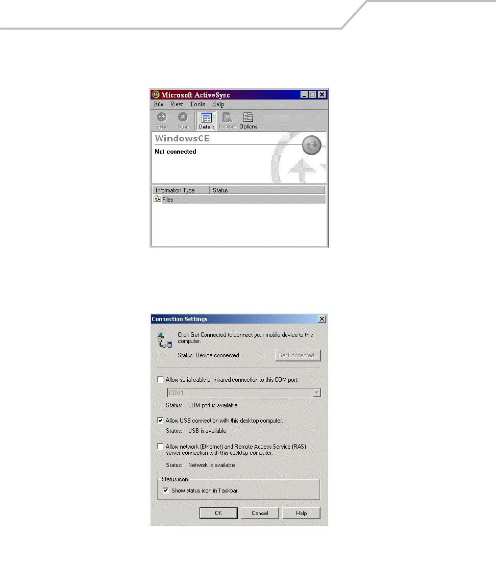
MC9000-K/S for Embedded Windows® CE .NET Product Reference Guide
4-14
6. Start ActiveSync if it is not running on the host computer. To start, select Start -Programs -
Microsoft ActiveSync.
Figure 4-12. ActiveSync - Not Connected
7. In the ActiveSync window, select File - Connection Settings and ensure the selections
shown in Figure 4-13 are made. Select USB port for the host computer.)
Figure 4-13. USB Connection Settings

Communications 4-15
8. Tap OK to save any changes made.
Every mobile computer should have a unique device name. Never try to
synchronize more than one mobile computer to the same name.
9. Connect the device to the host computer, see Figure 7-6 on page 7-12 to set up a Single Slot
Serial/USB Cradle, or see Figure 7-25 on page 7-37 to set up a MSR or a CAM.
The cradle requires a dedicated port. It cannot share a USB port with any
other device. Refer to the computer user manual supplied to locate the
USB(s).
10. Upon connection, synchronization occurs automatically.
Using ActiveSync
1. Review the configuration of the cradle using the MobileDox Cradle Manager.
a. A WIN server must be present on your network. Ensure that the WINS Address provided
in the TCP/IP Settings tab matches the IP address of the WIN server on your network.
b. Ensure that the Use NAT checkbox is not selected in the Port Settings tab.
2. Insert the terminal into the cradle. The mobile computer displays a succession of dialog
boxes appear, indicating the status of the connection. Also the ActiveSync icon on the host
computer’s system tray turns green to indicate that the host computer and the mobile
computer are communicating.

MC9000-K/S for Embedded Windows® CE .NET Product Reference Guide
4-16
Ethernet Setup
The Ethernet connection can only be established with the Four Slot Ethernet cradle. To establish a
connection between the mobile computer and the host computer to communicate over an Ethernet
network, perform the following:
• Install MobileDox Cradle Manager
• Install eConnect
• Mobile computer configuration
• Host computer configuration
• DHCP server configuration
• Cradle configuration.
Installing MobileDox Cradle Manager
MobileDox Cradle Manager is used only when establishing a connection
using the Four Slot Ethernet Cradle.
The Cradle Management software features:
• View cradles that are attached to the network via MobileDox Net
• View cradle status
• Modify cradle settings including:
• IP address settings
• DNS and WINS settings
• Identification settings
• USB port specific settings
• Restart cradles connected to the network via MobileDox Net
• Update the firmware of MobileDox Net.
To install the Cradle Management Software on the host computer, download the latest version of the
software from http://devzone.symbol.com. Refer to the instructions included with the software.
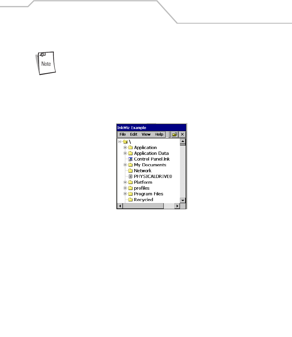
Communications 4-17
Installing eConnect
eConnect is used only when establishing a connection using the Four Slot
Ethernet Cradle.
1. To install the eConnect on the mobile computer, download the latest version of the software
on to the host computer (from http://devzone.symbol.com).
2. On the mobile computer copy the eConnect .cab file to the /Application directory.
Figure 4-14. Copy eConnect .cab File Window
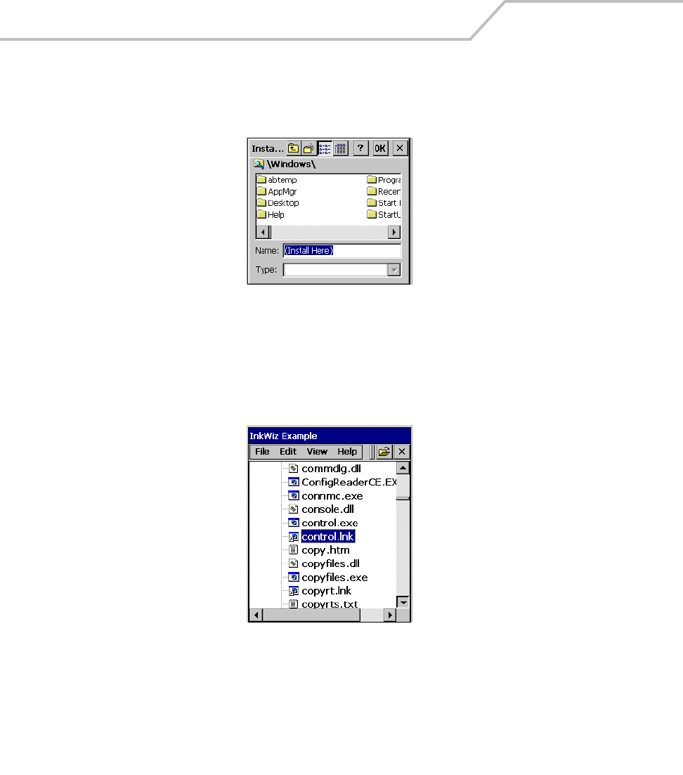
MC9000-K/S for Embedded Windows® CE .NET Product Reference Guide
4-18
3. Double-tap the eConnect .cab file, the eConnect install window appears. Double -tap OK.
Figure 4-15. eConnect Install Window
4. Double-tap the Files icon, open the Windows directory and double-tap the control.lnk file the
eConnect Icon window appears.
Figure 4-16. Windows Directory, control.lnk File
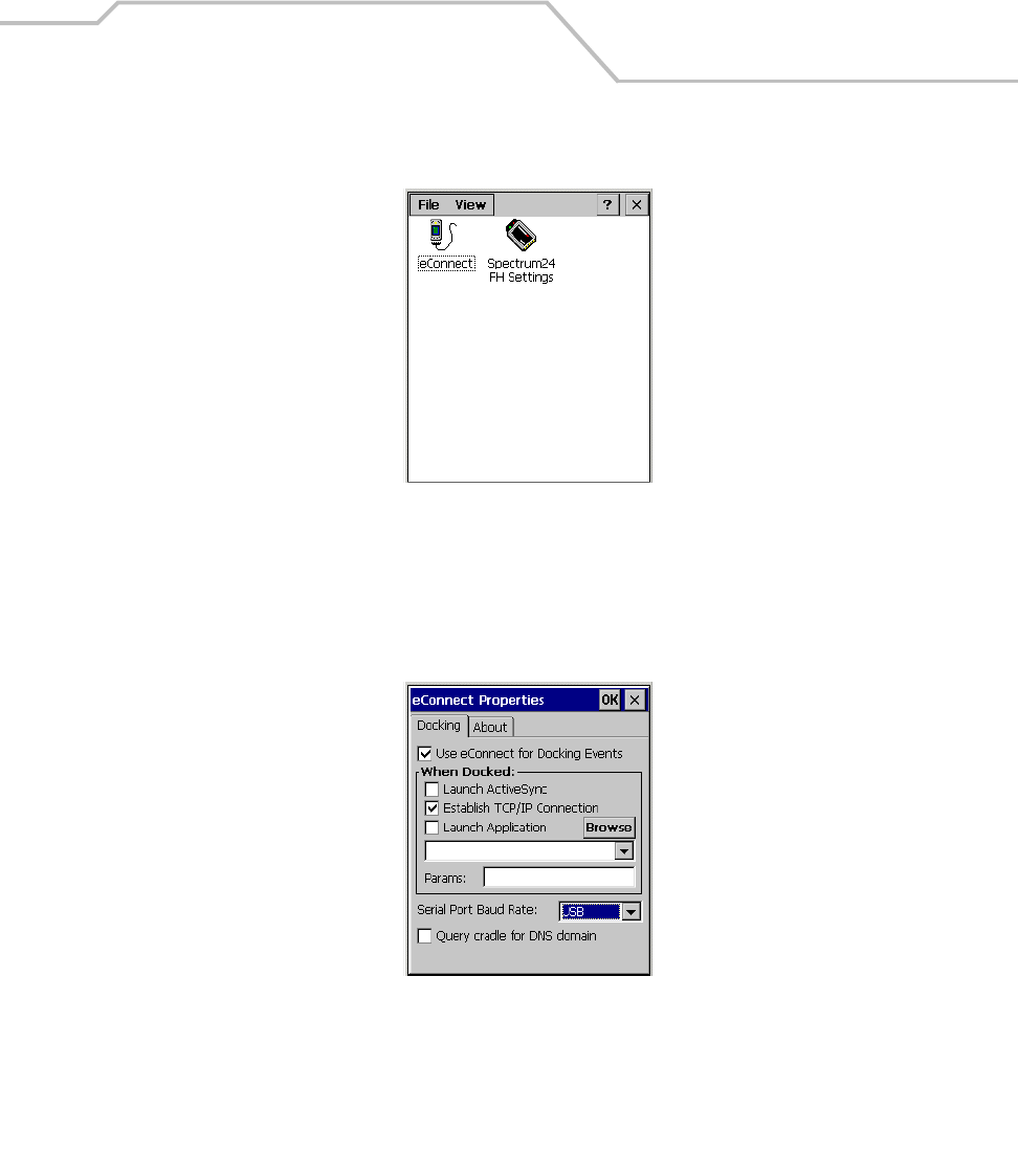
Communications 4-19
5. Double-tap the eConnect icon, the eConnect Properties window appears.
Figure 4-17. eConnect Icon Window
6. Tap the Establish TCP/IP Connection checkbox and select USB from the Serial Port Baud Rate
drop down menu. Double-tap OK to enter the settings and complete the eConnect
installation.
Figure 4-18. eConnect Properties Window
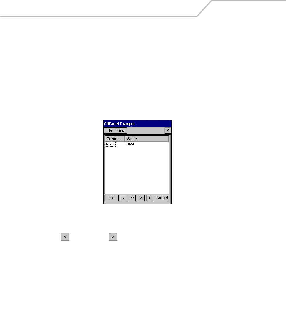
MC9000-K/S for Embedded Windows® CE .NET Product Reference Guide
4-20
Mobile Computer Configuration
Inserting the mobile computer into the cradle provides direct-connect RAS service. Configure each
mobile computer for use with the cradle, just as any remote client would be configured to connect to
an Internet Service Provider (ISP). See Persist on page 3-45 to save the settings to the registry.
The computer comm port to setting was set to USB during the eConnect installation procedure. To
confirm the setting:
1. On the mobile computer double-tap the Ctl Panel icon and double-tap Comm Settings to
enter the Comm Settings, window.
Figure 4-19. Comm Settings Window
2. Confirm that the Port Value is set to USB. To change the setting tap Port to highlight and use
the left and right arrow buttons to select the USB value.
3. Tap OK to exit the Comm Settings window and tap Exit to exit the Control Panel window.

Communications 4-21
Host Computer Configuration
The host computer must be setup with the appropriate communication software and connection
settings. This describes using Microsoft® ActiveSync software on both the terminal and the host
computer. To configure the host computer:
1. Download and install ActiveSync. See Installing ActiveSync on page 4-3.
2. Configure the connection settings. The host computer must be configured for TCP/IP
network communications.
a. Click the ActiveSync icon
b. Click on File - Connection settings
c. In the Connection settings dialog box, select the Allow Network (Ethernet) and Remote
Access Service (RAS) server connection with this desktop computer option.
Other options may be selected, for example, Allow serial cable or infrared connection to
this COM port.
3. Click OK.
Before communicating through an ethernet connection, create a partnership
between the mobile computer and the host computer. See Setting up a
Partnership on page 4-4 for detailed instructions.

MC9000-K/S for Embedded Windows® CE .NET Product Reference Guide
4-22
DHCP Server Configuration
If you use a DHCP server to distribute IP addresses and other network parameters, setup the server
as following:
• IP address pool (1 or 5 IP address per cradle)
• Router/gateway address
• One or more DNS server addresses
• One or more WINS server addresses
• Subnet mask.
To assign the initial cradle IP address, you can either use a DHCP server, as
shown above, or use the MobileDox Cradle Manager, see Installing
MobileDox Cradle Manager on page 4-16. DHCP server is the preferred
method.
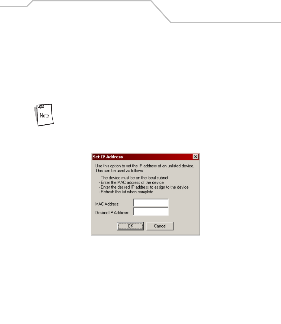
Communications 4-23
Cradle Configuration
The MobileDox Cradle Manager allows you to setup the Device IP Address and modify cradle
settings. See Installing MobileDox Cradle Manager on page 4-16 for instructions to download and
install the software. To connect the cradle, see Four Slot Ethernet Cradle on page 7-28.
Setting the Device IP Address
By default, the cradle will use DHCP to obtain its IP address. However, if DHCP fails, the Cradle
Manager can assign an IP address.
This is used if the cradle is connected to the network, but fails to appear in
MobileDox. Enter the hardware device (MAC) address to locate the cradle
and assign it a new IP address.
1. Launch the MobileDox Cradle Manager on your host computer.
2. Click File - Set IP Address of Unlisted Device. The following screen appears:
Figure 4-20. MobileDox, Set IP Address of Unlisted Device Window
3. Enter the appropriate MAC Address and IP address.
4. Click OK.
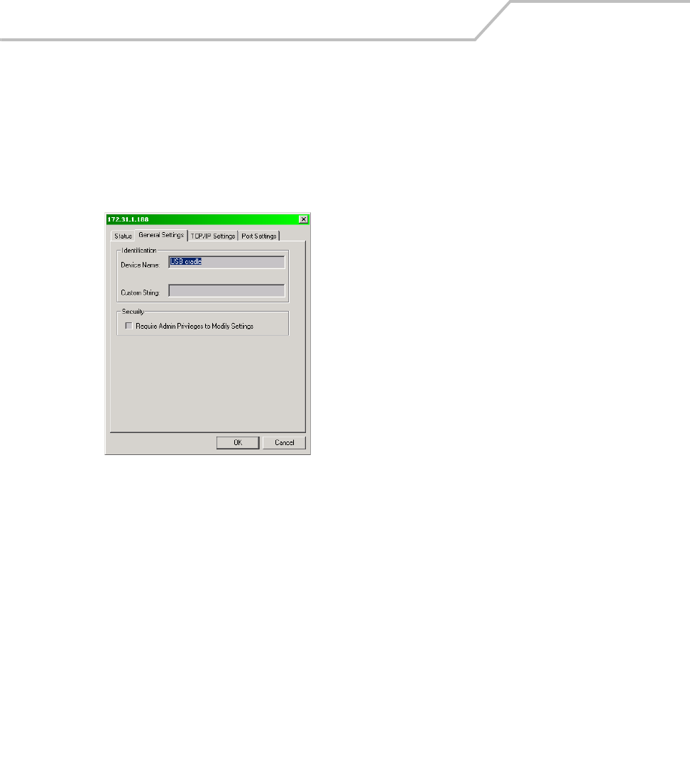
MC9000-K/S for Embedded Windows® CE .NET Product Reference Guide
4-24
Modifying Cradle Settings
1. Launch the MobileDox Cradle Manager on your host computer.
2. Select the name of the cradle you want to configure from the list.
3. Click Device - Modify Settings.
4. Use the General Settings tab to modify the identification settings of the cradle.
Figure 4-21. MobileDox, General Settings Window
Field Description
Device Name A text string used to describe the
MobileDox device. Any 15-character
string may be entered.
Custom String A text string for any desired usage
(examples are: location, asset ID, etc.).
Any 15-character string may be
entered.
Require Admin
Privileges to Modify
Settings checkbox
Selecting this checkbox will require
users to have administrative privileges
in order to modify MobileDox settings.
Administrative privileges are validated
using standard Windows
authentication.
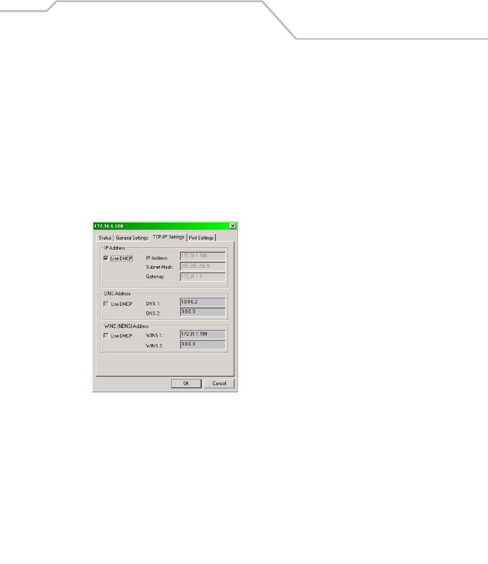
Communications 4-25
5. Use the TPC/IP Settings tab to modify the DNS and WINS identification settings of the
cradle.
Figure 4-22. MobileDox, TPC/IP Settings Window
Field Description
Use DHCP If checkbox is selected, necessary
information will be retrieved from the
DHCP server.
If checkbox is not selected, static
configuration will be used (information
needs to be entered).
IP Address The IP address that the MobileDox will
use when communicating on the
network.
Subnet Mask The subnet mask that the MobileDox
will use when communicating on the
network.
Gateway Address The IP address that the MobileDox will
use to send non-local IP network data.
DNS Address The IP address of a server(s) that can
resolve Internet names into IP
addresses.
WINS Address The IP address of a server(s) that can
resolve Windows network names into IP
addresses.
This field must be populated correctly
when using ActiveSync.
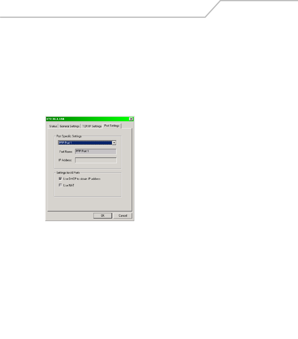
MC9000-K/S for Embedded Windows® CE .NET Product Reference Guide
4-26
6. Use the Port Settings tab to modify the USB port settings of the cradle.
Figure 4-23. MobileDox, Port Settings Window
7. Click OK.
Field Description
Port Name A text string used to describe the device
attached to the port. Any 15-character
string can be entered.
You can specify up to four port names,
one for each of the cradle’s slots.
IP Address The IP address assigned to the cradled
device. There should be one IP address
per cradle slot. This box will be disabled
for all devices if DHCP is used to obtain
the IP address.
Use DHCP to obtain
IP Address checkbox
The cradle will use DHCP to obtain an IP
address for the handheld.
Unchecking this selection allows the
cradle to use Static IP address for the
handheld.
Use NAT checkbox The cradle will use Network Address
Translation (NAT) when forwarding
handheld traffic onto the network. No IP
addresses are necessary for the
handhelds.
This must be disable when using
ActiveSync.
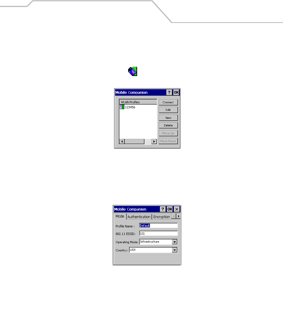
Communications 4-27
Connecting to the Internet on a Wireless Network
The mobile computer can connect to the Internet across a wireless network. To set up a wireless
connection:
1. Tap the Mobile Companion icon , on the taskbar.
2. Tap Find WLANs. The Mobile Companion window appears.
Figure 4-24. Find WLANs Window
3. The mobile computer tries to locate Access Points (APs) in the area. When it locates a
wireless LAN(s), the ESSID name appears in the WLAN Profile list.
4. Tap the ESSID name and then tap Connect.
5. The Mobile Companion Mode tab appears.
Figure 4-25. Mobile Companion - Mode Tab
6. The profile name and ESSID name appears in the respective fields.
7. In the Operating Mode: list, select Infrastructure.
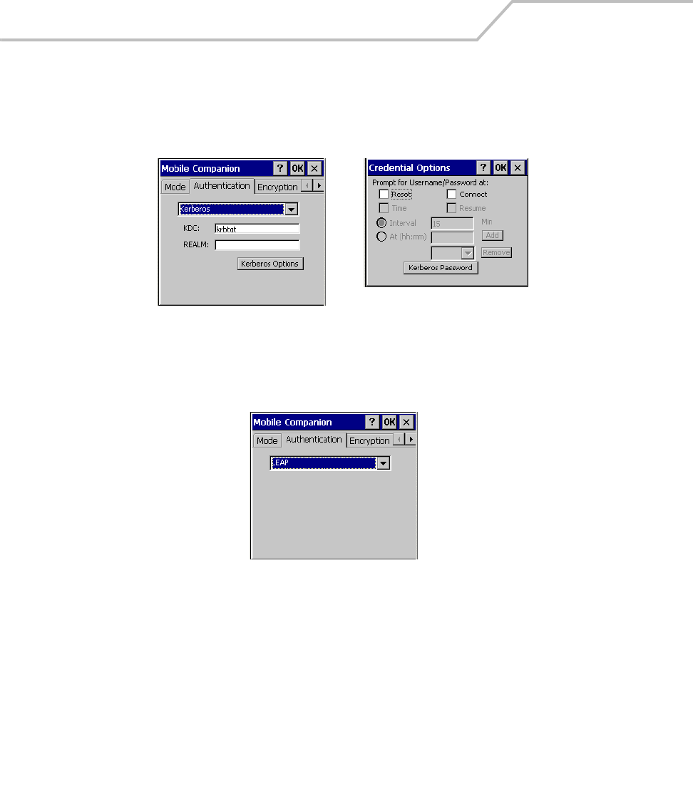
MC9000-K/S for Embedded Windows® CE .NET Product Reference Guide
4-28
8. Select the Authentication tab to configure server-based authentication through IEEE 802.1x
or Kerberos. Select an option (None, Kerberos, LEAP, EAP-TLS, PEAP) from the
Authentication drop-down list.
.
Figure 4-26. Mobile Companion - Authentication Tab (Kerberos)
Figure 4-27. Mobile Companion - Authentication Tab (LEAP)
Kerberos Authentication Credential Caching Settings
(Kerberos Options)
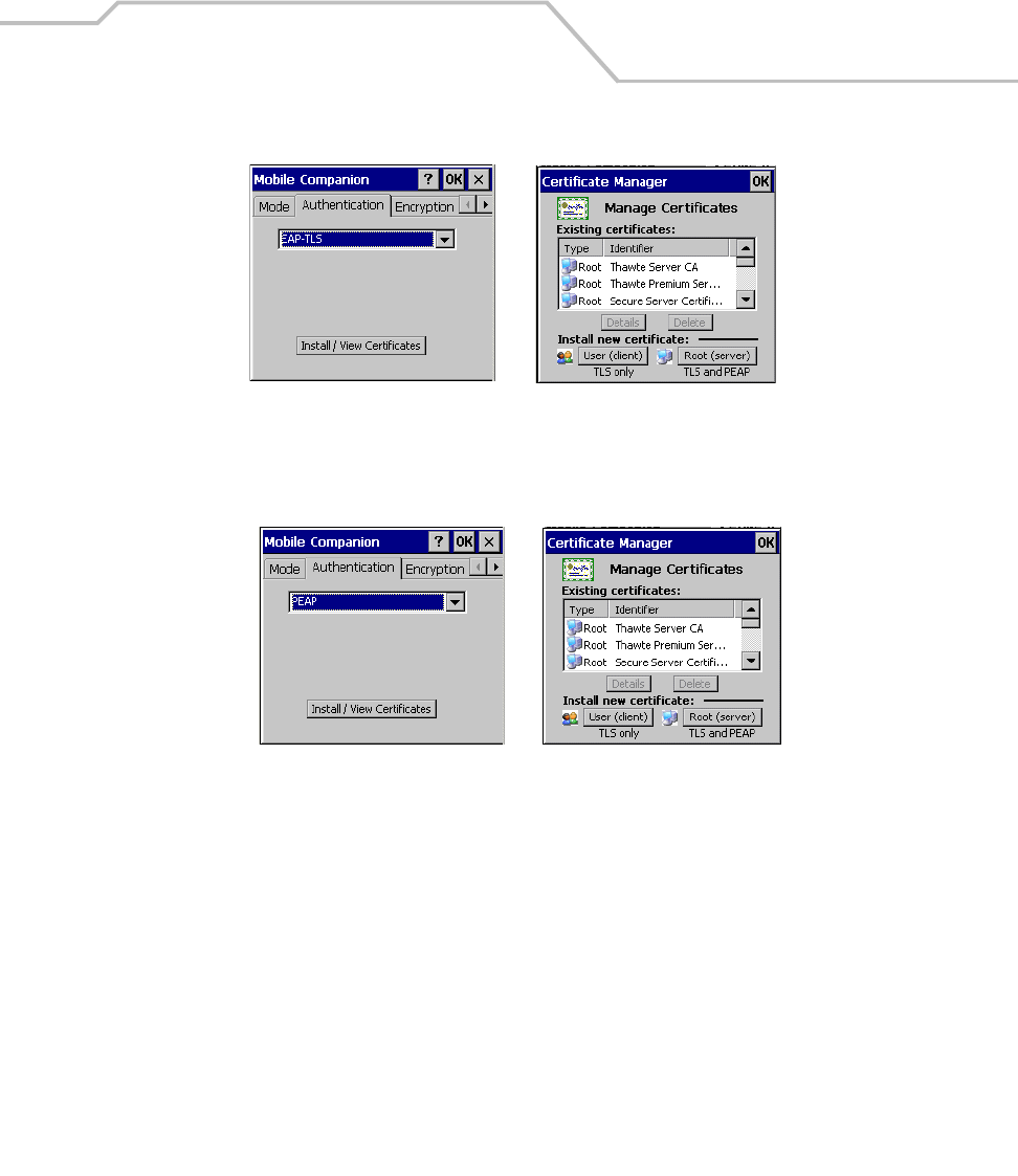
Communications 4-29
Figure 4-28. Mobile Companion - Authentication Tab (EAP-TLS)
Figure 4-29. Mobile Companion - Authentication Tab (PEAP)
EAP-TLS Authentication Install / View Certificates
PEAP Authentication Install / View Certificates
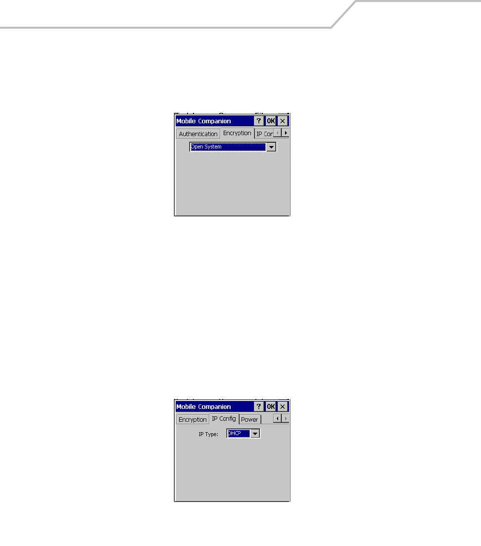
MC9000-K/S for Embedded Windows® CE .NET Product Reference Guide
4-30
9. Select the Encryption tab to set the adapter profile security level by configuring the
encryption scheme and corresponding keys. Select an option (Open System, WEP, Keyguard-
MCM, TKIP (WPA)) from the Encryption drop-down list. See Table 6-7 on page 6-14 for
Encryption option descriptions.
Figure 4-30. Encryption Tab
The absence of a physical connection makes wireless links vulnerable to information theft.
Encryption is an efficient method of preventing data theft and improving data security.
If an AP is set to 40-bit and an adapter is set to 128-bit, the adapter can associate to the AP,
but no data transmission and reception can take place.
10. Select the encryption algorithm used on the wireless network (Open System, 40-bit Shared
Key, 128-bit Shared Key or Kerberos).
To select 40-bit Shared Key, 128-bit Shared Key or Kerberos, enter the required data in the
fields that appear in the window. See the network administrator for this information.
11. Tap the IP Config tab.
Figure 4-31. Mobile Companion - IP Config Tab (DHCP)

Communications 4-31
12. In the IP Type drop-down menu, select either DHCP or Static. To select static IP, enter the
required data in the fields that appear in the window. See the network administrator for this
information.
13. Tap OK and Tap OK.
14. The Mobile Companion wireless status icon indicates that the mobile computer is connected
to the AP. If the status icon does not indicate that the mobile computer is connected to the
AP, see the system administrator.
15. Select Start - Programs - Internet Explorer.
16. In the address bar, enter the URL.

MC9000-K/S for Embedded Windows® CE .NET Product Reference Guide
4-32

Applications
Chapter Contents
Introduction. . . . . . . . . . . . . . . . . . . . . . . . . . . . . . . . . . . . . . . . . . . . . . . . . . . . . . . . . . . . . . . . . . . . . . . . .5-3
ScanSamp2. . . . . . . . . . . . . . . . . . . . . . . . . . . . . . . . . . . . . . . . . . . . . . . . . . . . . . . . . . . . . . . . . . . . . . . . .5-6
ScanSamp2 Windows . . . . . . . . . . . . . . . . . . . . . . . . . . . . . . . . . . . . . . . . . . . . . . . . . . . . . . . . . . . .5-6
Parameters Window. . . . . . . . . . . . . . . . . . . . . . . . . . . . . . . . . . . . . . . . . . . . . . . . . . . . . . . . . . . . . .5-7
Codes Window . . . . . . . . . . . . . . . . . . . . . . . . . . . . . . . . . . . . . . . . . . . . . . . . . . . . . . . . . . . . . . . . . .5-8
InkWiz File Browser . . . . . . . . . . . . . . . . . . . . . . . . . . . . . . . . . . . . . . . . . . . . . . . . . . . . . . . . . . . . . . . . . .5-9
Internet Explorer. . . . . . . . . . . . . . . . . . . . . . . . . . . . . . . . . . . . . . . . . . . . . . . . . . . . . . . . . . . . . . . .5-10
Browsing the Web . . . . . . . . . . . . . . . . . . . . . . . . . . . . . . . . . . . . . . . . . . . . . . . . . . . . . . . . . .5-10
Setting up a Proxy Server. . . . . . . . . . . . . . . . . . . . . . . . . . . . . . . . . . . . . . . . . . . . . . . . . . . . .5-11
Remote Desktop . . . . . . . . . . . . . . . . . . . . . . . . . . . . . . . . . . . . . . . . . . . . . . . . . . . . . . . . . . . . . . . .5-12
Connecting to a Terminal Server . . . . . . . . . . . . . . . . . . . . . . . . . . . . . . . . . . . . . . . . . . . . . . .5-12
Disconnecting Without Ending a Session . . . . . . . . . . . . . . . . . . . . . . . . . . . . . . . . . . . . . . . .5-12
Disconnecting and Ending a Session . . . . . . . . . . . . . . . . . . . . . . . . . . . . . . . . . . . . . . . . . . . .5-13

MC9000-K/S for Embedded Windows® CE .NET Product Reference Guide
5-2
AudioSamp . . . . . . . . . . . . . . . . . . . . . . . . . . . . . . . . . . . . . . . . . . . . . . . . . . . . . . . . . . . . . . . . . . . . . . . .5-13
Images . . . . . . . . . . . . . . . . . . . . . . . . . . . . . . . . . . . . . . . . . . . . . . . . . . . . . . . . . . . . . . . . . . . . . . .5-14
PC Link . . . . . . . . . . . . . . . . . . . . . . . . . . . . . . . . . . . . . . . . . . . . . . . . . . . . . . . . . . . . . . . . . . . . . . .5-16
Copying Files. . . . . . . . . . . . . . . . . . . . . . . . . . . . . . . . . . . . . . . . . . . . . . . . . . . . . . . . . . . . . . .5-16
About OTL . . . . . . . . . . . . . . . . . . . . . . . . . . . . . . . . . . . . . . . . . . . . . . . . . . . . . . . . . . . . . . . . . . . . .5-17
Self Test . . . . . . . . . . . . . . . . . . . . . . . . . . . . . . . . . . . . . . . . . . . . . . . . . . . . . . . . . . . . . . . . . . . . . .5-18
Notify . . . . . . . . . . . . . . . . . . . . . . . . . . . . . . . . . . . . . . . . . . . . . . . . . . . . . . . . . . . . . . . . . . . . . . . .5-21
Keyboard. . . . . . . . . . . . . . . . . . . . . . . . . . . . . . . . . . . . . . . . . . . . . . . . . . . . . . . . . . . . . . . . . . . . . .5-22
Display . . . . . . . . . . . . . . . . . . . . . . . . . . . . . . . . . . . . . . . . . . . . . . . . . . . . . . . . . . . . . . . . . . . . . . .5-23
Memory. . . . . . . . . . . . . . . . . . . . . . . . . . . . . . . . . . . . . . . . . . . . . . . . . . . . . . . . . . . . . . . . . . . . . . .5-24
MSR9000 . . . . . . . . . . . . . . . . . . . . . . . . . . . . . . . . . . . . . . . . . . . . . . . . . . . . . . . . . . . . . . . . . . . . .5-25
MSR Cameo . . . . . . . . . . . . . . . . . . . . . . . . . . . . . . . . . . . . . . . . . . . . . . . . . . . . . . . . . . . . . . . . . . .5-26
Printing . . . . . . . . . . . . . . . . . . . . . . . . . . . . . . . . . . . . . . . . . . . . . . . . . . . . . . . . . . . . . . . . . . . . . . . . . . .5-27
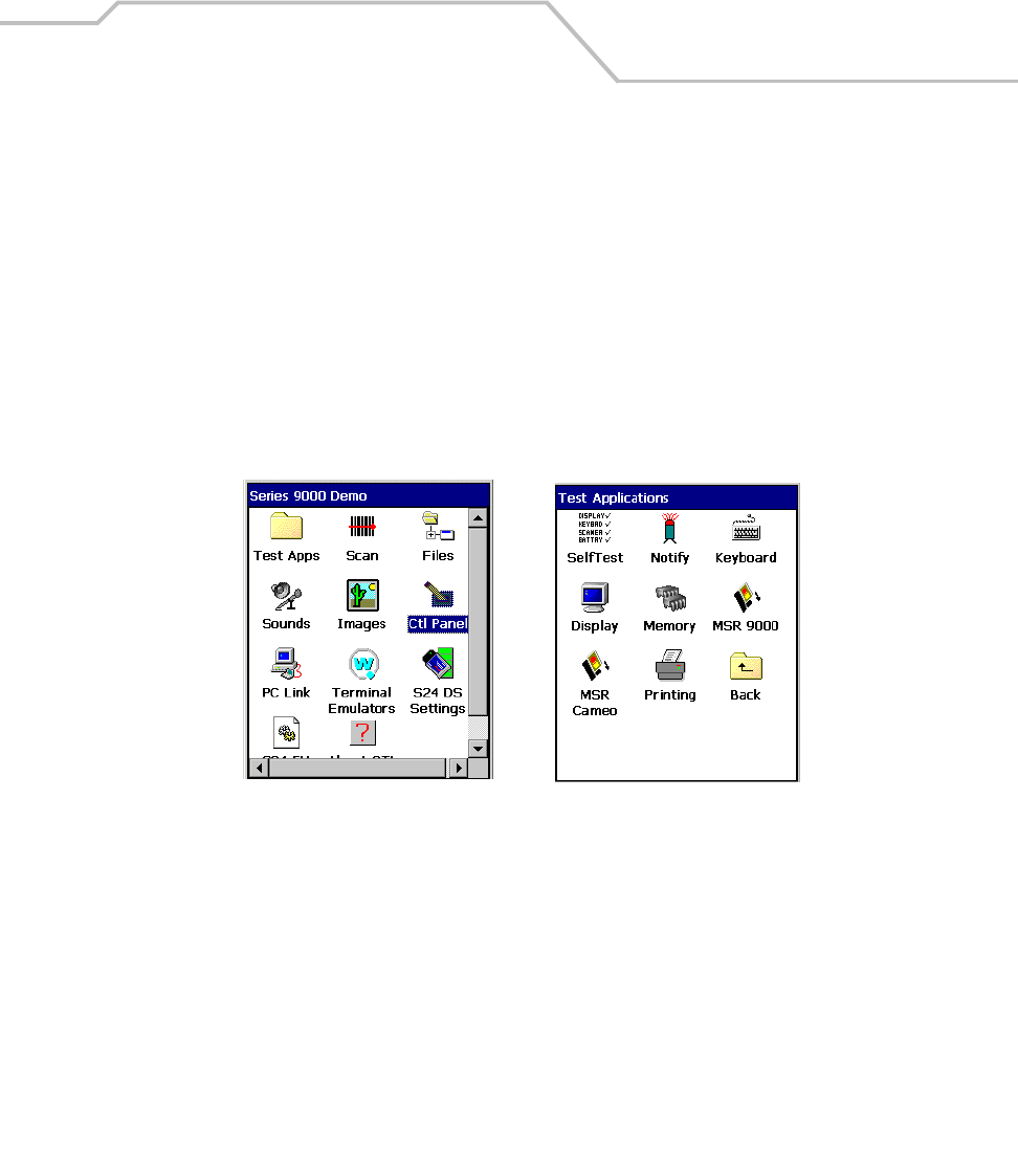
Applications 5-3
Introduction
Two type of applications are provided. Example applications provide the application developer with
sample applications that can be used to assist in application development. The source code is
available for these applications in the Symbol Windows CE SMDK for Series 9000. The remaining
applications are supplied to provide additional mobile computer functionality.
Double-tap the application icon to open the application. The application icons are available in the
Series 9000 Demo window and in the Test Applications window. The Series 9000 Demo window is
the default menu when the unit is turned on. Double-tap the Test Apps icon on the Series 9000 Demo
window to access the Test Applications window. Double-tap the Back icon to return to the Series
9000 Demo window. The Series 9000 Demo window icon functions are provided in Table 5-1.
Figure 5-1. Applications Windows
Series 9000 Demo Window Test Applications Window
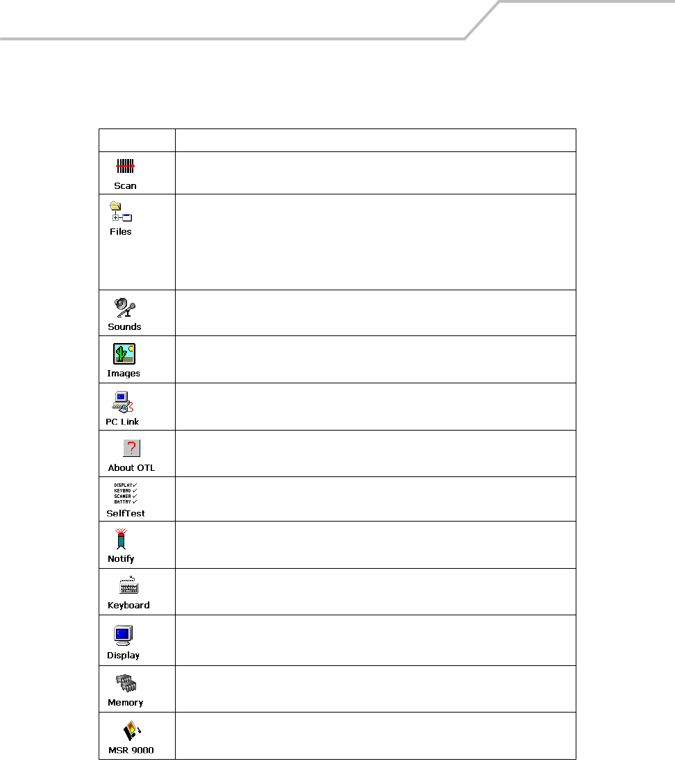
MC9000-K/S for Embedded Windows® CE .NET Product Reference Guide
5-4
Table 5-1. Applications
Icon Description
Displays the ScanSamp2 example application that is used to set up and run the example
scan application, see ScanSamp2 on page 5-6.
Displays the InkWiz sample application. This file browser displays the system’s
file structure, see InkWiz File Browser on page 5-9.
The file browser is also used to access the following applications:
•Internet Explorer on page 5-10
•Remote Desktop on page 5-12.
Displays the AudioSamp sample application, see AudioSamp on page 5-13.
Displays the image viewer sample application, see Images on page 5-14.
PC Link accesses the Microsoft ActiveSync application, see PC Link on page 5-16.
Displays the OTL version information example application, see About OTL on page 5-17.
Displays the self test application, see Self Test on page 5-18.
Displays the notify example application, see Notify on page 5-21.
Displays the keyboard example application, see Keyboard on page 5-22.
Displays the display example application, see Display on page 5-23.
Displays the memory example application, see Memory on page 5-24.
Displays the MSR 9000 setup application, see MSR9000 on page 5-25.
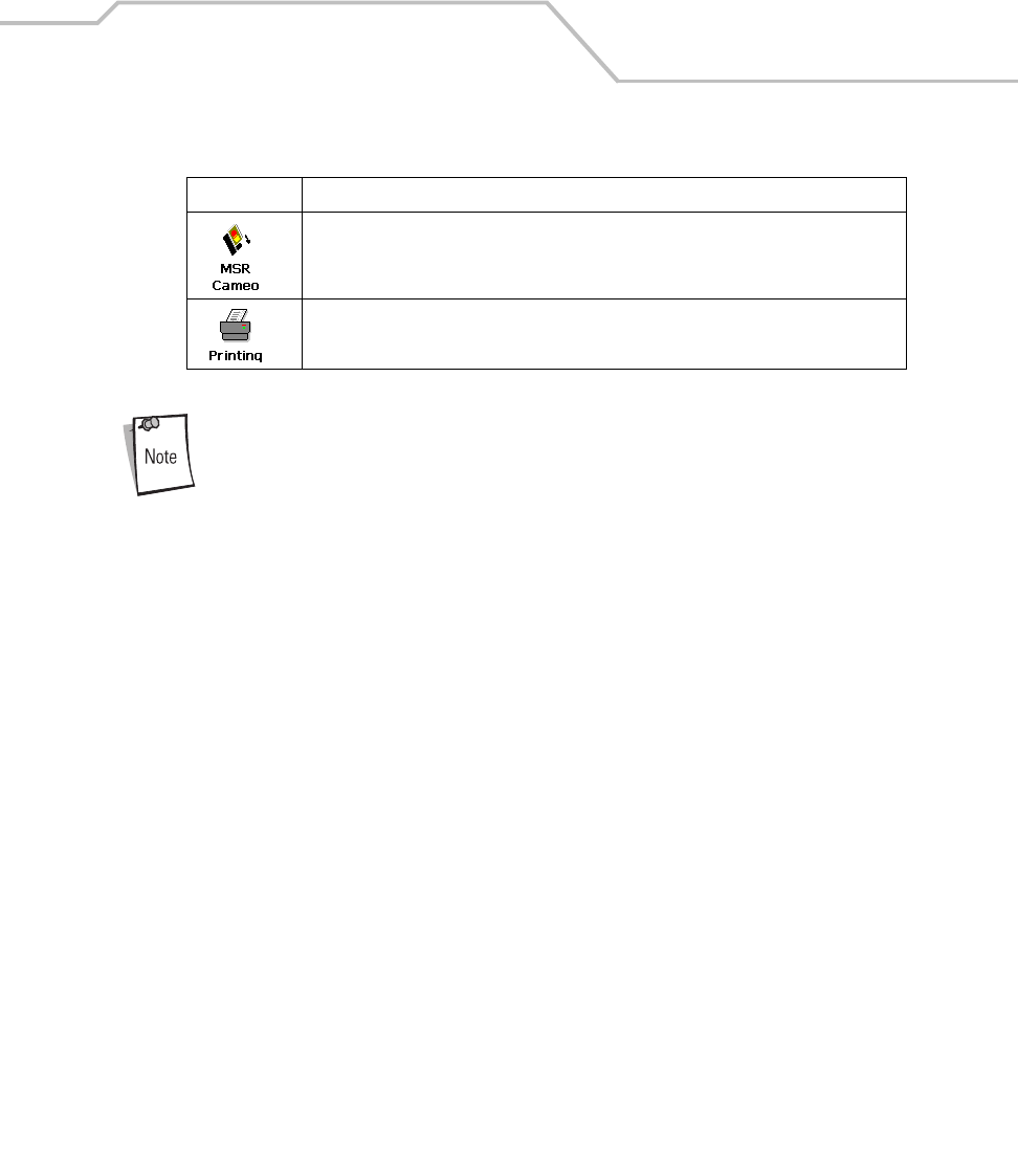
Applications 5-5
The windows shown are configured as part of the factory default demo
program (OTL.exe). OTL.exe can be configured via registry settings to user
specified applications.
Displays the MSR 9000 Cameo setup application, see MSR Cameo on page 5-26.
Displays the Printer application, see Printing on page 5-27.
Table 5-1. Applications (Continued)
Icon Description
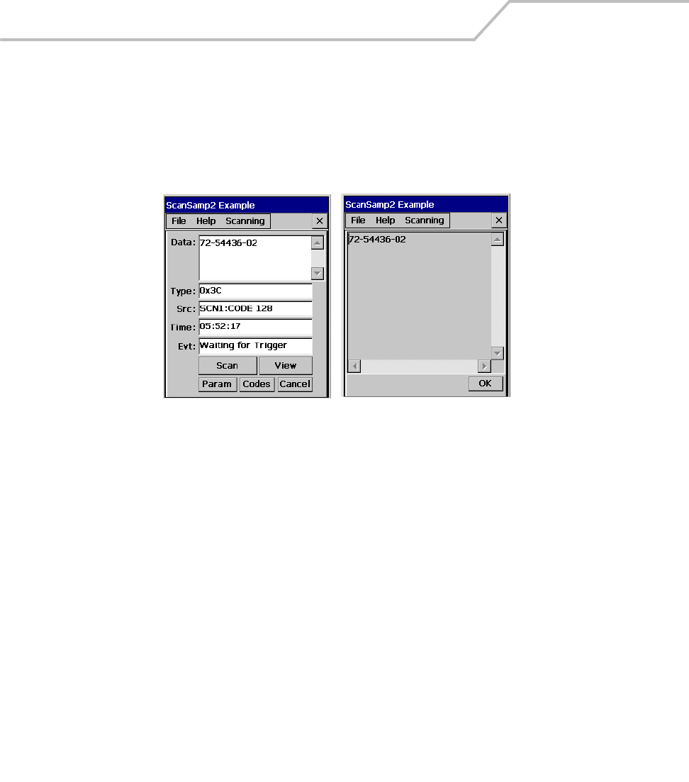
MC9000-K/S for Embedded Windows® CE .NET Product Reference Guide
5-6
ScanSamp2
Use the ScanSamp2 example application to enable the mobile computer’s scanner and display
scanned data. It also allows the user to change the scan parameters.
From the Series 9000 Demo window, double-tap the Scan icon.
Figure 5-2. ScanSamp2 Examples
ScanSamp2 Windows
After a bar code is scanned, the following data displays in the scan window:
•Data - Displays the data encoded in the scanned bar code.
•Type - Indicates the hex type scanned.
•SRC - Indicates the scanner used and the bar code type scanned (e.g., Code 128).
•Time - Displays the time the bar code was scanned.
Tap Scan to start the scanner (alternative to pushing the scan button).
Tap View to display the bar code content in a separate window.
Tap Param to display the Parameters window, see Parameters Window on page 5-7.
Tap Codes to display the Selected Bar Code window, see Codes Window on page 5-8.
ScanSamp2 Window View Window
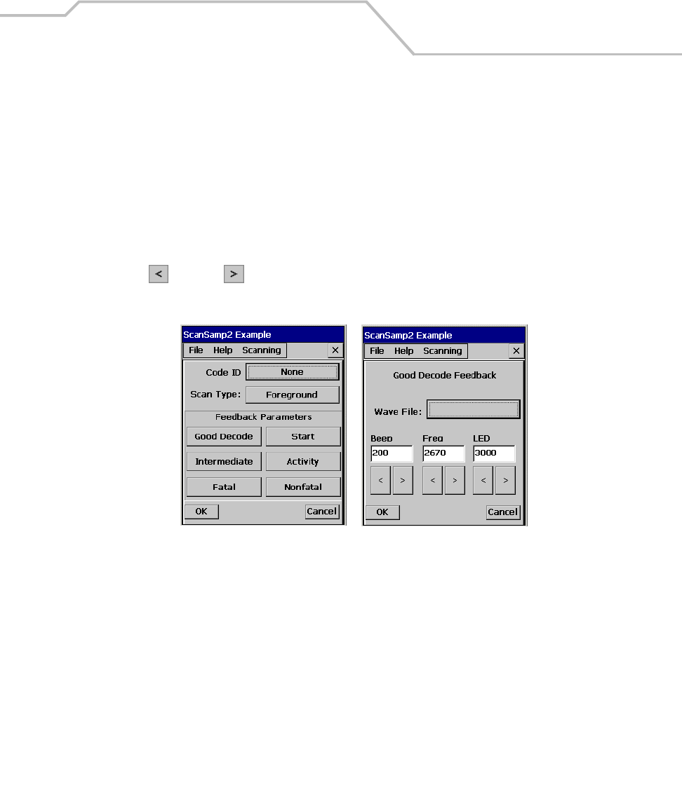
Applications 5-7
Parameters Window
The Parameters window is used to set the scan parameter.
• Tap Code ID to select the code ID value (None, Symbol, AIM).
• Tap Scan Type to select the scan type (Background, Foreground, Monitor).
• Tap Feedback Parameters to select the feedback parameters category (Good Decode,
Intermediate, Fatal, Start, Activity, Nonfatal). All of the parameter categories use the
same format Parameters Input Window, see Figure 5-3.
• To change the beep wave file enter a new path and name into the Wave File box. Use the
left and right arrow buttons to set the values for the Beep, Freq and LED. Note, units
that do not have the optional .wav file capability can not use the new .wav file setting.
Figure 5-3. ScanSamp2 Examples
Parameters Window Parameters Input Windows
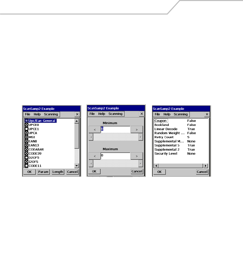
MC9000-K/S for Embedded Windows® CE .NET Product Reference Guide
5-8
Codes Window
The Codes window is used to set the scan type parameter.
• Tap Param to select the code types, tap in the box to select a code type.
• To set parameters for a code type, tap the code type to highlight it and then tap Param to
display the Code Parameters Sample Window, see Figure 5-4. Different code types will have
parameter settings specific to that code type, so the windows will differ.
• To set length for a code type, tap the code type to highlight it and then tap Length to display
the code length sample window, see Figure 5-4. Different code types will have length
settings specific to that code type, so the setting windows will differ.
Figure 5-4. ScanSamp2 Examples
Codes Window Code Parameters Sample Window Code Length Sample Window
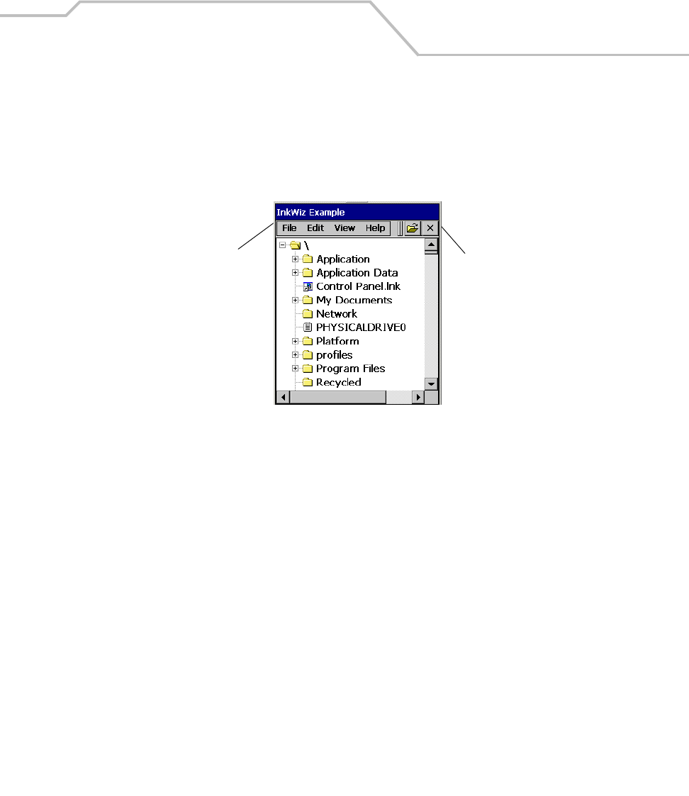
Applications 5-9
InkWiz File Browser
Use the InkWiz file browser example application to browse, cut, copy, paste, delete files and to
execute programs.
From the Series 9000 Demo window, double-tap the Files icon. The InkWiz Example window appears.
Figure 5-5. InkWiz Example Window
The Menu Bar and Button Bar are used to navigate organize files on the mobile computer.
Button Bar
Menu Bar
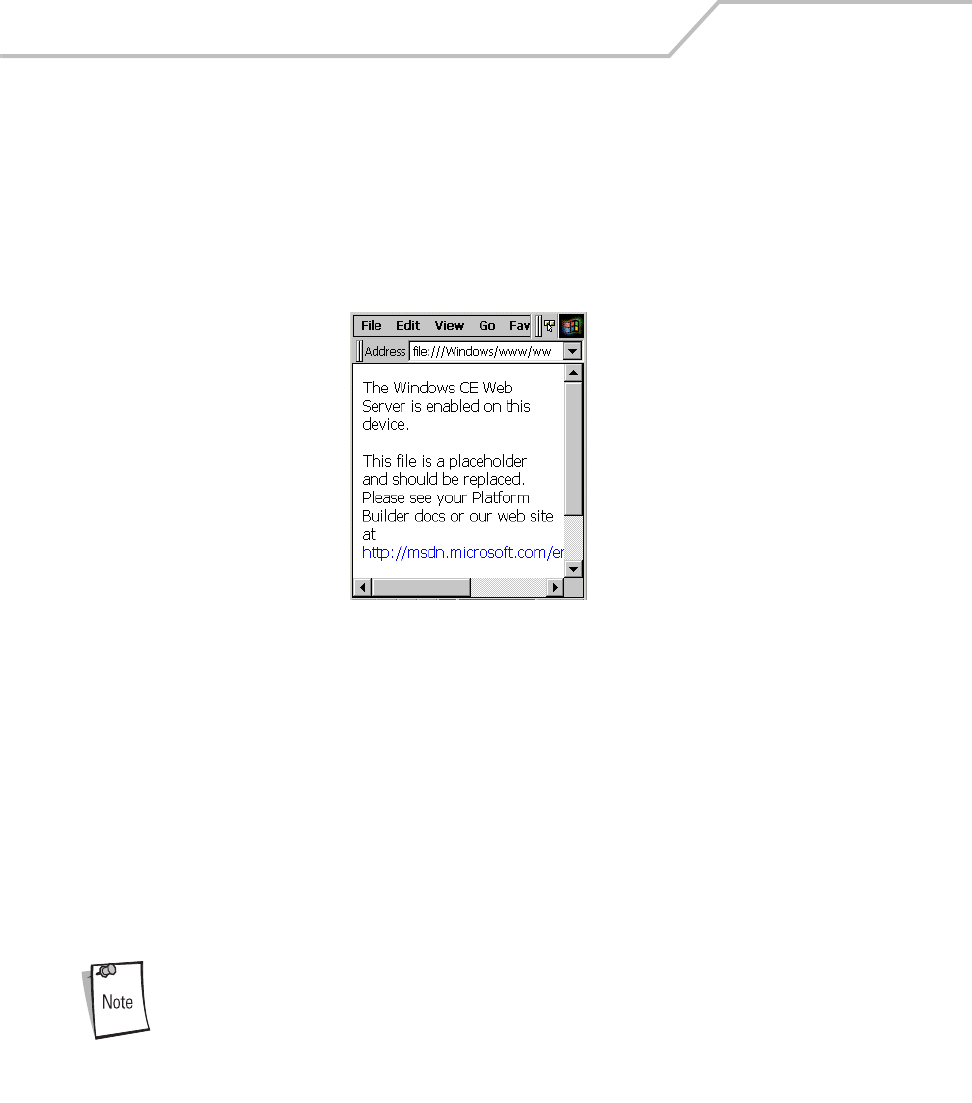
MC9000-K/S for Embedded Windows® CE .NET Product Reference Guide
5-10
Internet Explorer
Use Internet Explorer, to view Internet or intranet Web pages on the mobile computer. A modem, an
Ethernet connection or a Spectrum24 connection is required to connect to an Internet service provider
(ISP) or network.
From the Series 9000 Demo window, double-tap Files icon - double-tap on Application - double-tap
IEBrowser.exe. The Internet Explorer window appears.
Figure 5-6. Internet Explorer Window
Browsing the Web
To browse the Web:
1. Connect to a network using a wireless connection. See Connecting to the Internet on a
Wireless Network on page 4-27.
2. Once connected, go to a specific Web page in one of the following ways:
3. Use the keypad to enter the web address In the address bar, press the ENT key.
4. Tap the address bar drop-down arrow to select a previously entered addresses.
5. To end the connection, select File - Close.
If Internet Explorer is selected before setting up the network connections, a
window may appear to proceed to the connection settings window.

Applications 5-11
Setting up a Proxy Server
Proxy servers are often used when connecting to the Internet through a local network, such as a
corporate network, for added security. To set the proxy server settings:
1. From the menu bar, select View - Options - Proxy Server tab.
2. Select Use Proxy Server.
3. Enter the proxy server address and port. For more information, see the network
administrator.
4. To bypass the proxy server for local addresses, such as corporate intranet pages, select
Bypass Proxy for Local Addresses.
5. Tap OK.
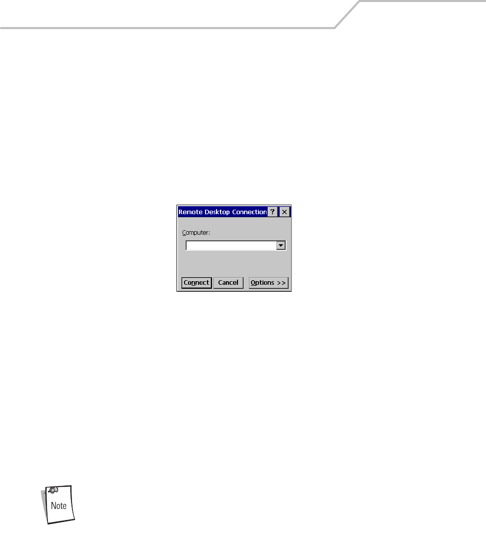
MC9000-K/S for Embedded Windows® CE .NET Product Reference Guide
5-12
Remote Desktop
Use Remote Desktop connection to log onto a Windows Terminal Server and to use the programs
installed on the server. For example, instead of running Microsoft Pocket Word, the desktop version
of Microsoft Word can be run.
Connecting to a Terminal Server
To connect to a terminal server:
1. From the Series 9000 Demo window double-tap on Files icon - Windows - Desktop double-
tap on Remote Desktop Connection.Ink, or run 'MSTSC' from the command prompt. The
initial Remote Desktop Connection window appears.
Figure 5-7. Remote Desktop Connection Window
2. In the Computer drop-down list, type a Terminal Server name or TCP/IP address, or select a
server and tap Connect.
3. In the next Remote Desktop Connection window, type the user name, password and domain
(if required) and then tap OK.
Disconnecting Without Ending a Session
To disconnect a session:
1. In the Remote Desktop Connection window, select Start - Shutdown.
2. Tap Disconnect.
3. Tap OK.
If Terminal Server was disconnected from without ending the session, the
Terminal Server will continue to execute any running processes. Remote
Desktop Connection can later reconnect to this same session (if the
administrator configured Remote Desktop Connection to reconnect to
disconnected sessions).
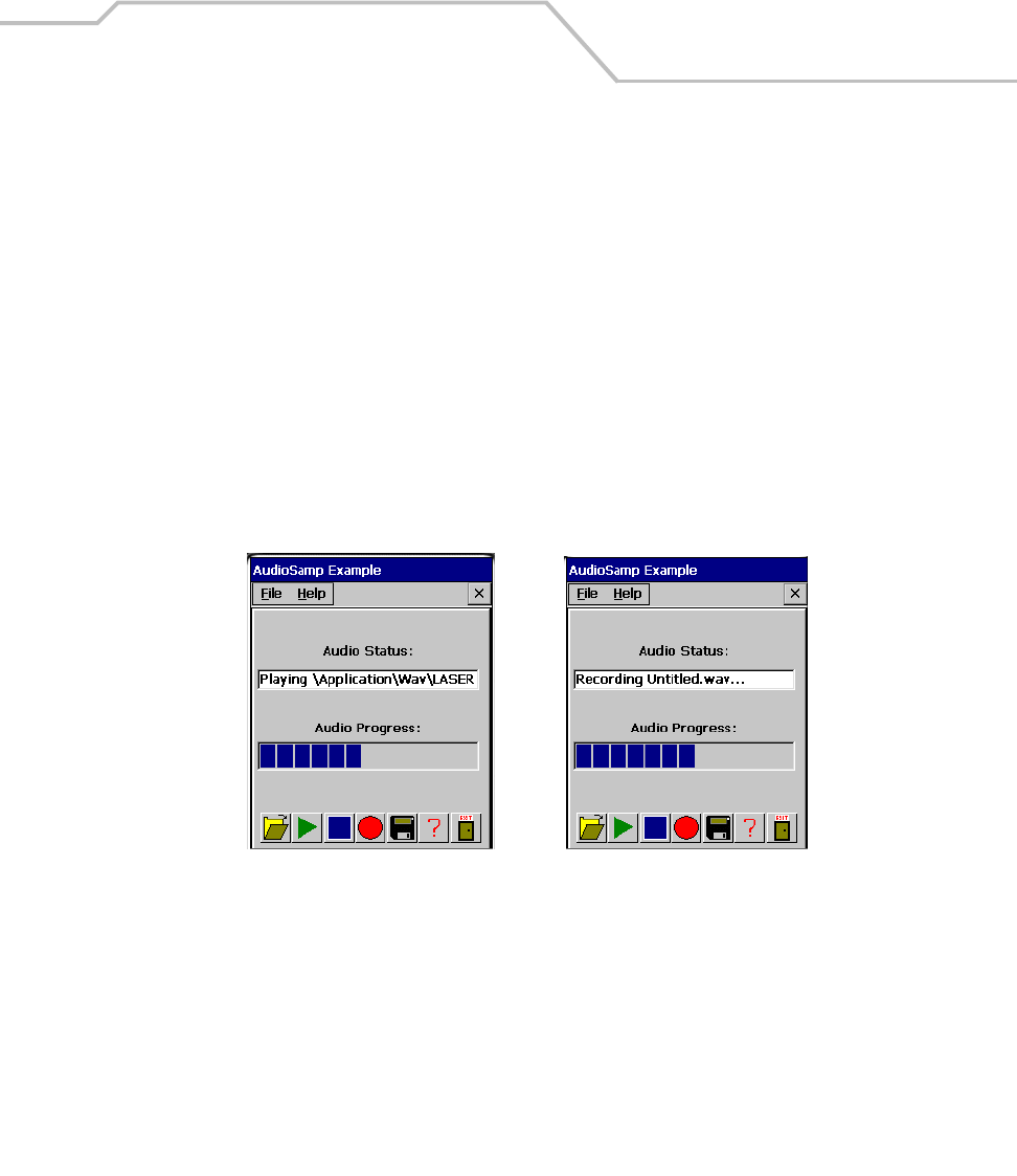
Applications 5-13
Disconnecting and Ending a Session
To end a session:
1. In the Remote Desktop Connection window, select Start - Shutdown.
2. Tap Log Off.
3. Tap OK.
AudioSamp
Use the AudioSamp application as an example of how to work with audio files such as recording and
playback. The AudioSamp application can only be used on mobile computers that have the audio
enabled option.
1. From the Series 9000 Demo window, double-tap the Sounds icon. The AudioSamp Example
window appears.
Figure 5-8. AudioSamp Application Window
2. Tap the file folder to access the sounds files. The default directory location is
\Application\Wav\ this directory provides .wav files that can only be used on the units that
have the optional .wav file capability. For units that do not have the optional .wav file
capability select .wav files from the \Platform\Alias\ directory.
3. Double-tap a file name to select the .wav file.
4. Tap the green triangle button to play the file.
5. Tap Exit to return to the Series 9000 Demo window.
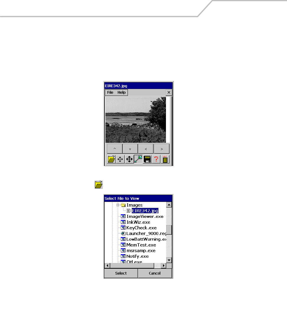
MC9000-K/S for Embedded Windows® CE .NET Product Reference Guide
5-14
Images
Use the Images application as an example of how to work with image files, panning, zooming, saving
and reading.
1. From the Series 9000 Demo window, double-tap the Images icon. The ImagesViewer
Example window appears..
Figure 5-9. Image Window
2. Select the folder icon to display the contents of the images folder.
Figure 5-10. Select File to View Window
3. Double-tap the image name to display it.
4. Use the positioning, sizing and save icons to manipulate and save the image, see Table 5-2
on page 5-15.
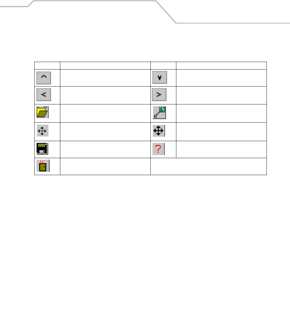
Applications 5-15
Table 5-2. Images Button Descriptions
Button Description Button Description
Pan Up (panning mode), increase vertical size
of image.
Pan Down (panning mode), decrease vertical
size of image.
Pan left (panning mode), decrease horizontal
size of image.
Pan right (panning mode), increase horizontal
size of image.
Open an image file. Set mode to "resize."
Set mode to "fine panning." Set mode to “rough panning.”
Save the current image. Opens the Images About window.
Exit the Image Viewer application.
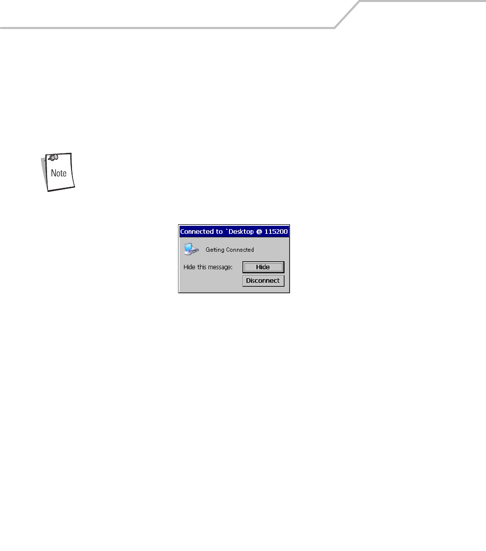
MC9000-K/S for Embedded Windows® CE .NET Product Reference Guide
5-16
PC Link
Use the PC Link icon as a shortcut to the device-side Active-Sync component repllog.exe. Microsoft
ActiveSync, synchronizes the information on the desktop computer with the information on mobile
computer. Synchronization compares the data on the mobile computer with the desktop computer and
updates both computers with the most recent information.
1. From the Series 9000 Demo window, double-tap PC Link icon to start ActiveSync.
ActiveSync automatically connects when the mobile computer is connected
to the host computer.
Figure 5-11. Connecting to Host Computer
Copying Files
Copying a file results in separate versions of a file on the mobile computer and desktop computer.
Since the files are not synchronized, changes made to one file will not affect the other.
1. Connect the mobile computer to the host computer.
2. In ActiveSync on the host computer, click Explore. Windows Explorer will open the Mobile
Device window for the mobile computer.
3. Open a new Windows Explorer and browse to the file to be copied on the mobile computer
or host computer.
4. Do one of the following:
• To copy the file to the mobile computer, right-click the file and select Copy. Place the
cursor in the desired folder on the mobile computer, right-click and select Paste.
• To copy the file to the host computer, right-click the file and select Copy. Open a new
Windows Explorer, browse to the desired folder on the host computer, right-click and
select Paste.
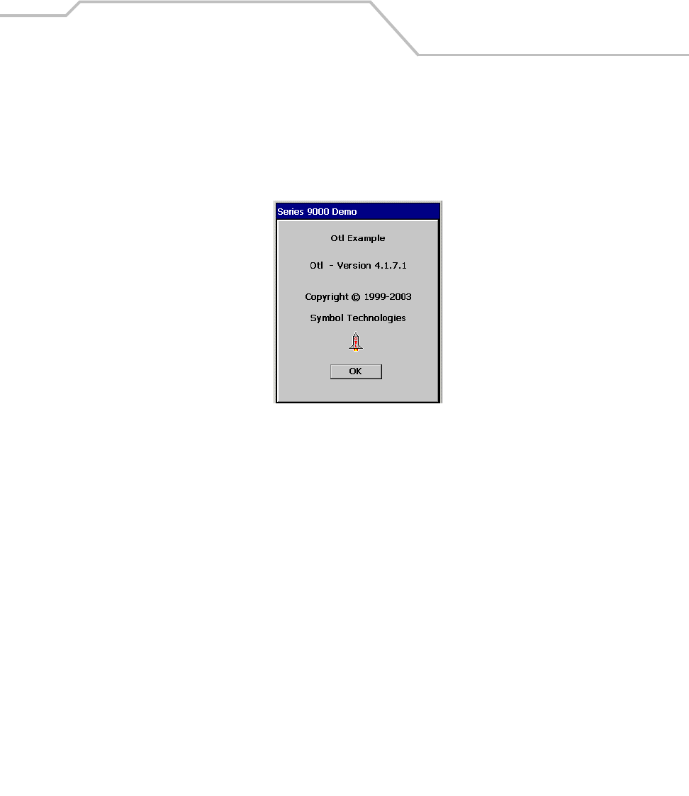
Applications 5-17
About OTL
Use About OTL example application window to display the OTL software version information.
1. From the Series 9000 Demo window, double-tap About OTL icon. The About OTL window
appears.
Figure 5-12. About OTL Window
2. Tap OK to return to the Series 9000 Demo window.
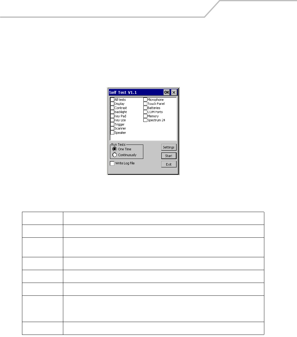
MC9000-K/S for Embedded Windows® CE .NET Product Reference Guide
5-18
Self Test
Use Self Test to test the specified mobile computer functions. Table 5-3 lists the tests and the test
descriptions.
1. From the Series 9000 Demo window, double-tap Test Apps icon - double-tap - Self Test icon.
The Self Test window appears.
Figure 5-13. Self Test Window
Table 5-3. Self Test Descriptions
Test Description
Display Tests the display function.
Contrast Tests the display contrast function. Note, properly functioning color units will return the following
error massage: Device not support contrast levels.
Backlight Tests the display backlight function.
Key Pad Tests the keypad function.
Key Light Tests the keypad backlight function.
Scan Button Pull the scan button or press the yellow scan button to test the scan button function. Tap and hold
the Trig1 Stg1, Trig1 Stg2, Trig2 Stg1, Trig2 Stg1, Trig3 Stg1, or Trig3 Stg2 buttons to test the
software programed scan button sequences.
Scanner Tests the scan function.
Applications 5-19
2. From the Test Applications window (Figure 5-1 on page 5-3), double-tap the Self Test icon to
enter the Self Test window.
Select the One Time radio button to run each of the tests only once, or select
the Continuously radio button to run the tests continuously, or until the
prompt to stop running them is selected.
Select the Write Log File checkbox to save the test results to a log file. The
results are saved to the Selftest.log file located in the \Temp directory. To
view the test results use ActiveSync to move the file to the host computer
and then can view it using a text editor. Only one test log file is saved, the
next write log file test save, appends the existing Selftest.log file.
3. Tap Settings to display the Self Test Settings window. Tap Cancel to accept the default
settings or enter new setting values and tap OK to accept the new settings and return to the
Self Test window.
Speaker Tests the speaker and beeper function with sample beeps. Note, properly functioning that do not
have the optional .wav file capability will return the following error message:
PlaySound(\Windows\windmin.wav) failed, error=00000000 if the Wave File Play button is tapped.
For these units use the Play Beeper button to test the beeper and speaker function.
Microphone Tests the (optional) microphone function.
Touch Panel Provides a test box, the test box is used to test the touch panel.
Batteries Displays a battery status window. Note, do not use the Backup Battery status display.
Com Ports Displays a Com Ports test window.
Memory Displays a memory status window.
Spectrum 24 Displays a S24 Test window.
Table 5-3. Self Test Descriptions (Continued)
Test Description
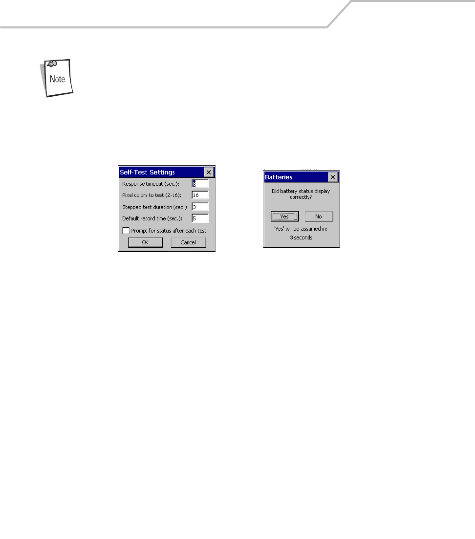
MC9000-K/S for Embedded Windows® CE .NET Product Reference Guide
5-20
Select the Prompt for status after each test, checkbox to display a test
confirmation window after the completion of each test. The test confirmation
window prompts the user to confirm if the test was successfully completed.
If the Write Log File check box is also selected, a test results log file is saved
that includes the user response to confirmation window prompt. Do not
select this checkbox if the confirmation window is not required.
Figure 5-14. Self Test Settings Windows
4. Tap on a self test item from the Self Test list to select the item for testing, tap item again to
de-select the item.
5. Tap Start in the Self Test window to start the self test for the selected items.
6. Follow the prompts provided for the test.
7. Tap Exit to return to the Test Applications window (Figure 5-1 on page 5-3).
Self Test Settings Test Confirm Window
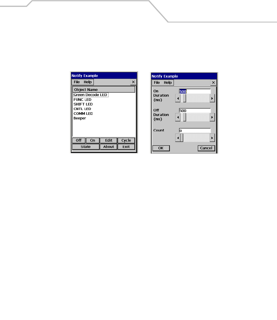
Applications 5-21
Notify
Use Notify to test the mobile computer LED functions.
1. From the Test Applications window, double-tap the Notify icon. The Notify window appears.
Figure 5-15. Notify Windows
2. Tap an Object Name to select the item.
3. Tap Edit to set the parameters. Drag the slide bars to adjust the values.
4. Tap OK to return to the Notify window.
5. Repeat edit procedure, if required, for remaining items. The following Notify window
functions are available:
• Tap Off to turn off the selected item.
• Tap On to turn on the selected item.
• Tap Cycle to cycle the selected item on and off.
• Tap State to display the selected item’s state (on or off).
• Tap About to view the software information.
6. Tap Exit in the Notify window to return to the Test Applications window.
Notify Window Edit Notify Parameters Window
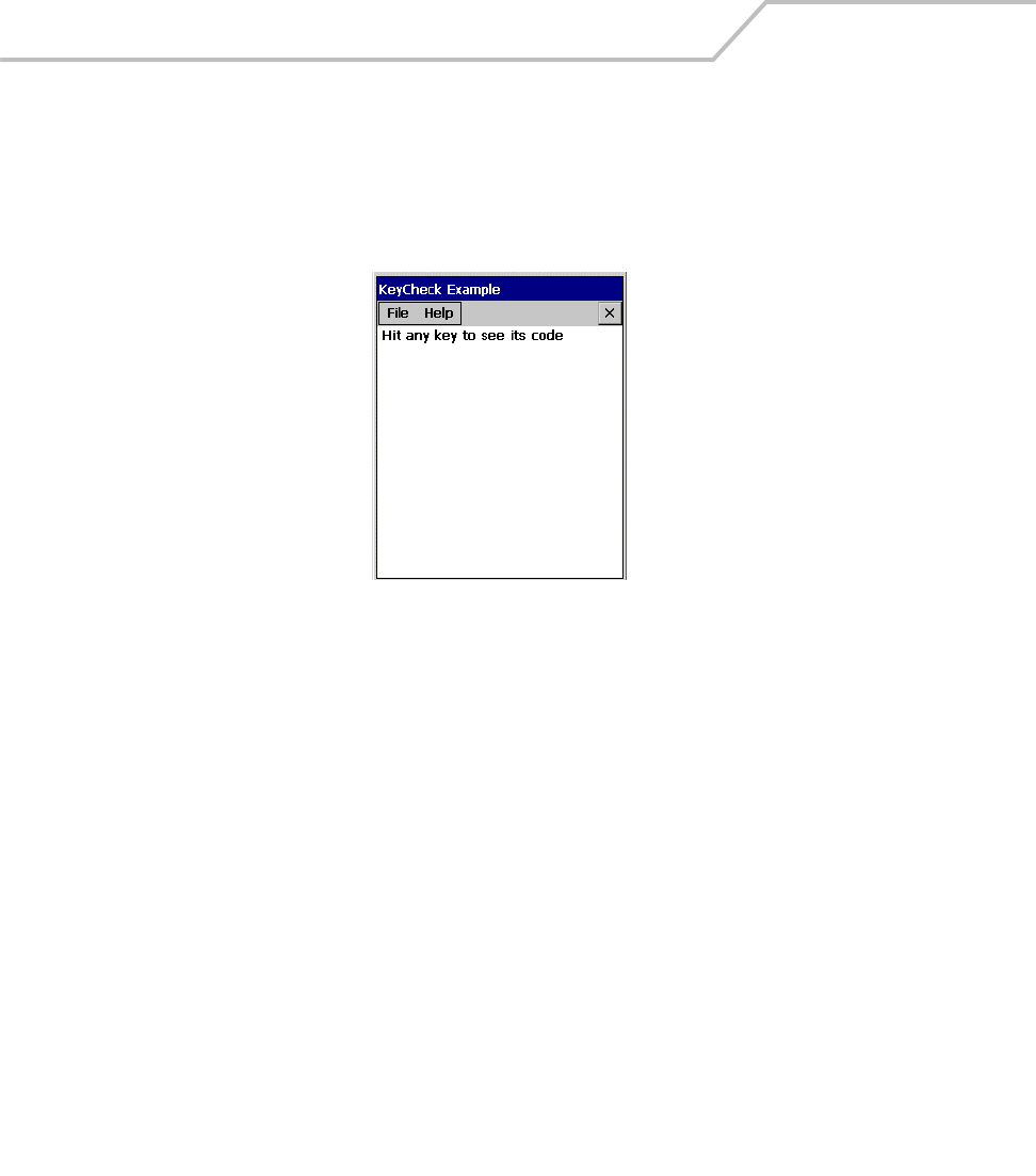
MC9000-K/S for Embedded Windows® CE .NET Product Reference Guide
5-22
Keyboard
Use the Keyboard application to test the mobile computer keypad functions.
1. From the Test Applications window, double-tap Keyboard icon. The KeyCheck window
appears.
Figure 5-16. KeyCheck Window
2. Press any key, the corresponding value displays on the KeyCheck window.
3. Tap File - Exit to close the window.
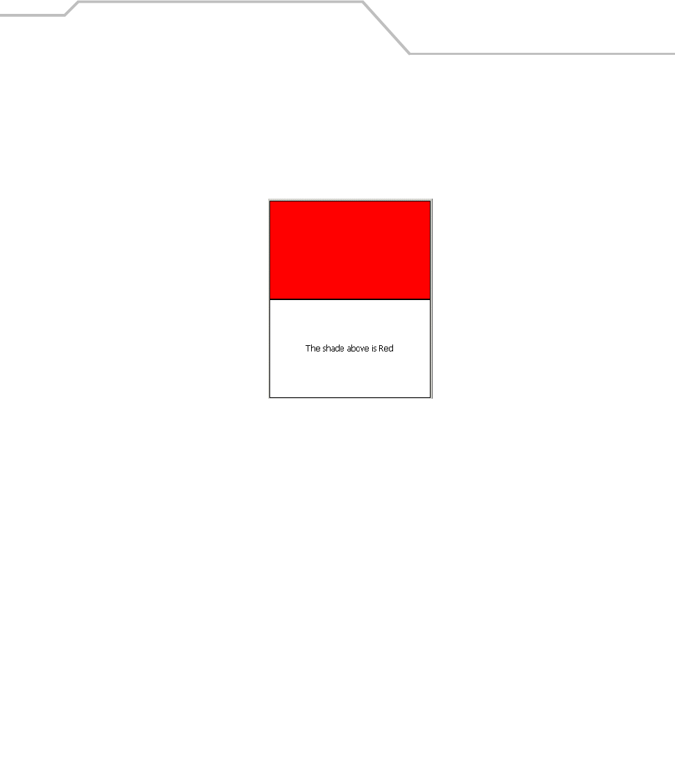
Applications 5-23
Display
Use the Display window to test the mobile computer display functions.
1. From the Test Applications window double-tap Display to enter the Display window. The
display test automatically runs through the display test windows.
Figure 5-17. Display Test Window
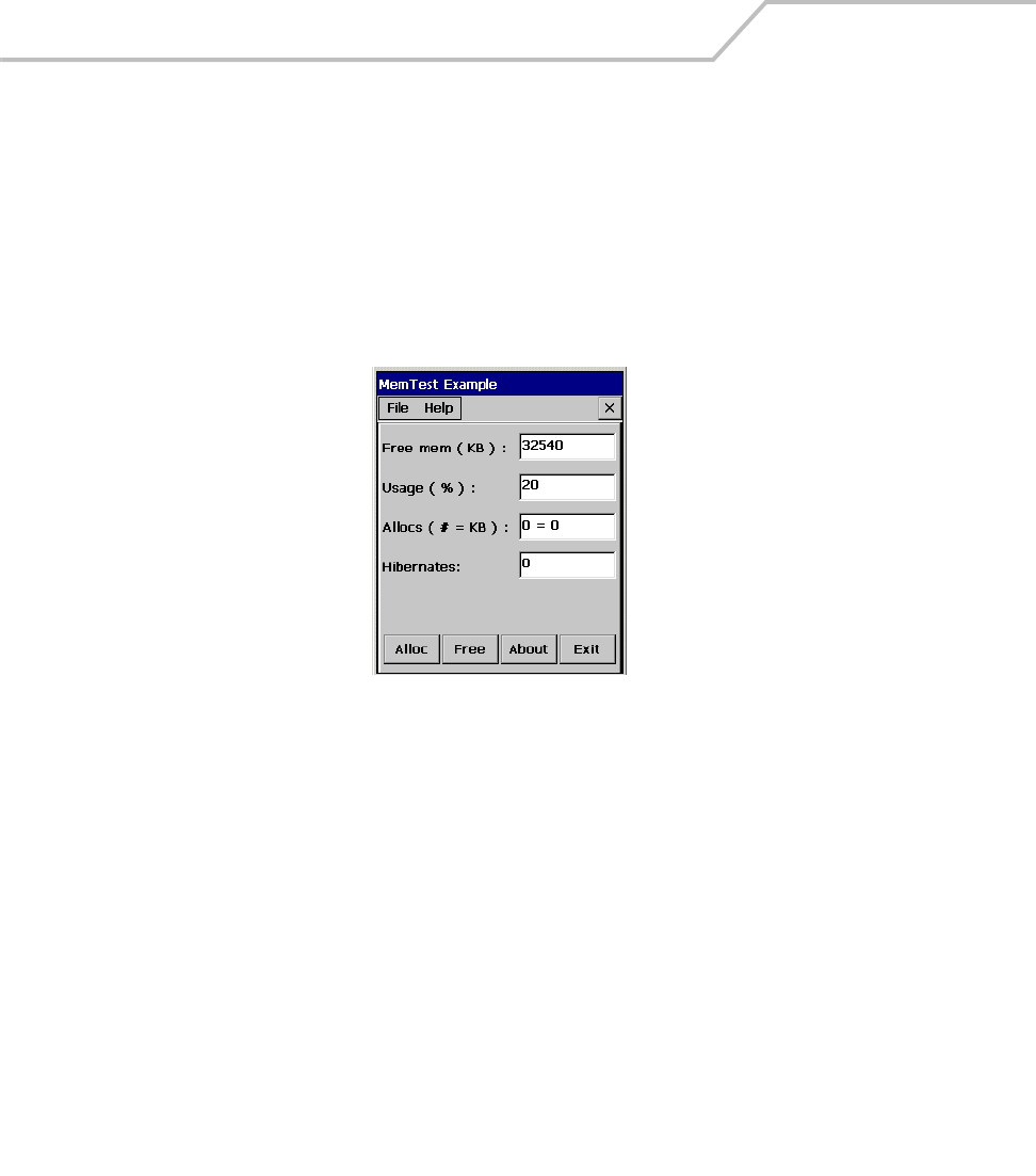
MC9000-K/S for Embedded Windows® CE .NET Product Reference Guide
5-24
Memory
Use the Memory application illustrates how an application should handle memory messages it
receives from the Shell in the event of low memory conditions.
1. From the Test Applications window double-tap the Memory icon. The Memory Test Window
appears.
2. The memory test automatically tests the mobile computer’s memory and displays the
results.
Figure 5-18. Memory Test Window
3. Tap Alloc to increase the amount of allocated memory and correspondingly reduce the
amount of free memory.
4. Tap Free to increase the amount of free memory and correspondingly decrease the amount
of allocated memory.
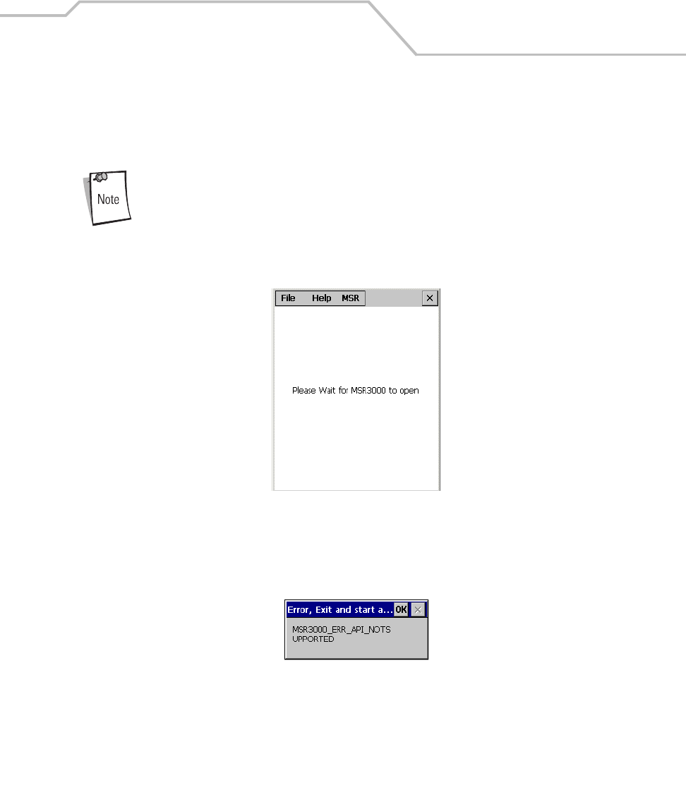
Applications 5-25
MSR9000
The MSR9000 application is designed to work with the MSR. This sample application illustrates how
an application should handle MSR inputs.
The MSR must be attached to the mobile computer before the sample application is
executed.
1. From the Test Applications window, double-tap the MSR9000 icon. The MSR window
appears.
Figure 5-19. MSR Window
2. Swipe a magnetic stripe card. The content on the card displays in the window.
3. If the MSR is not properly attached to the mobile computer the MSR error window appears.
Figure 5-20. MSR Error Window
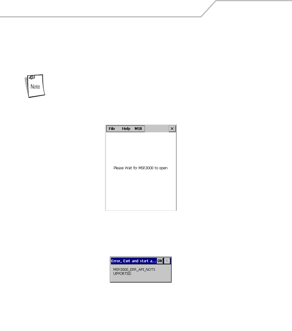
MC9000-K/S for Embedded Windows® CE .NET Product Reference Guide
5-26
MSR Cameo
The MSR Cameo application is designed to work with the MSR Cameo magnetic stripe reader and
printer. This sample application illustrates how an application should handle MSR inputs. See the
MSR Cameo product documentation for use and setup instructions.
The MSR must be attached to the mobile computer before the sample application is
executed.
1. From the Test Applications window, double-tap the MSR9000 icon. The MSR window
appears.
Figure 5-21. MSR Window
2. Swipe a magnetic stripe card. The content on the card displays in the window.
3. If the MSR is not properly attached to the mobile computer the MSR error window appears.
Figure 5-22. MSR Error Window
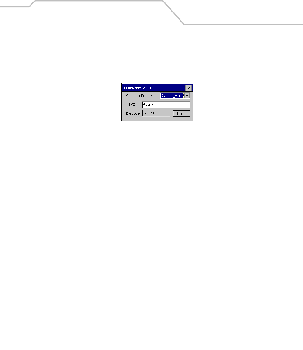
Applications 5-27
Printing
The Printing application illustrates how an application should handle printer outputs.
From the Test Applications window, double-tap the Printer icon. The Printer window appears.
Figure 5-23. Printing Test Window
1. From the Select a Printer drop-down list, select a printer.
2. In the Text text box, enter text to print.
3. Tap Print.
4. The printer prints the contents of the Text text box and Barcode text box.

MC9000-K/S for Embedded Windows® CE .NET Product Reference Guide
5-28

Spectrum24 Network Configuration
Chapter Contents
Introduction. . . . . . . . . . . . . . . . . . . . . . . . . . . . . . . . . . . . . . . . . . . . . . . . . . . . . . . . . . . . . . . . . . . . . . . . .6-3
Mobile Companion . . . . . . . . . . . . . . . . . . . . . . . . . . . . . . . . . . . . . . . . . . . . . . . . . . . . . . . . . . . . . . . . . . .6-4
Finding WLANs. . . . . . . . . . . . . . . . . . . . . . . . . . . . . . . . . . . . . . . . . . . . . . . . . . . . . . . . . . . . . . . . . .6-6
Status . . . . . . . . . . . . . . . . . . . . . . . . . . . . . . . . . . . . . . . . . . . . . . . . . . . . . . . . . . . . . . . . . . . . . . . .6-19
Setting Options. . . . . . . . . . . . . . . . . . . . . . . . . . . . . . . . . . . . . . . . . . . . . . . . . . . . . . . . . . . . . . . . .6-24
Changing Profiles . . . . . . . . . . . . . . . . . . . . . . . . . . . . . . . . . . . . . . . . . . . . . . . . . . . . . . . . . . . . . . .6-26
Editing a Profile . . . . . . . . . . . . . . . . . . . . . . . . . . . . . . . . . . . . . . . . . . . . . . . . . . . . . . . . . . . .6-26
Creating a New Profile. . . . . . . . . . . . . . . . . . . . . . . . . . . . . . . . . . . . . . . . . . . . . . . . . . . . . . .6-26
Deleting a Profile . . . . . . . . . . . . . . . . . . . . . . . . . . . . . . . . . . . . . . . . . . . . . . . . . . . . . . . . . . .6-26
Ordering Profiles. . . . . . . . . . . . . . . . . . . . . . . . . . . . . . . . . . . . . . . . . . . . . . . . . . . . . . . . . . . .6-26
Using LEAP for Wireless Network Security . . . . . . . . . . . . . . . . . . . . . . . . . . . . . . . . . . . . . . . . . . . . . . .6-27
Configuring Advanced Password Options . . . . . . . . . . . . . . . . . . . . . . . . . . . . . . . . . . . . . . . .6-27

MC9000-K/S for Embedded Windows® CE .NET Product Reference Guide
6-2
Spectrum24 Frequency Hopping (FH) Settings (1 and 2 MB Radios) . . . . . . . . . . . . . . . . . . . . . . . . . . . .6-30
Mobile Unit Tab . . . . . . . . . . . . . . . . . . . . . . . . . . . . . . . . . . . . . . . . . . . . . . . . . . . . . . . . . . . . . . . .6-31
MicroAP Tab . . . . . . . . . . . . . . . . . . . . . . . . . . . . . . . . . . . . . . . . . . . . . . . . . . . . . . . . . . . . . . . . . . .6-33
Encryption Tab . . . . . . . . . . . . . . . . . . . . . . . . . . . . . . . . . . . . . . . . . . . . . . . . . . . . . . . . . . . . . . . . .6-34
WLAN Adapter Tab . . . . . . . . . . . . . . . . . . . . . . . . . . . . . . . . . . . . . . . . . . . . . . . . . . . . . . . . . . . . .6-36
Password Protecting NCPA . . . . . . . . . . . . . . . . . . . . . . . . . . . . . . . . . . . . . . . . . . . . . . . . . . .6-37
Configuring the S24 DS (11 Mb) Radio Using a Registry File . . . . . . . . . . . . . . . . . . . . . . . . . . . . . . . . .6-38
Configuring the S24 FH (2 Mb) Radio Using a Registry File. . . . . . . . . . . . . . . . . . . . . . . . . . . . . . . . . . .6-38
Spectrum24 Network Configuration 6-3
Introduction
Wireless LANs allow the mobile computers to communicate wirelessly and to send captured data
“real time” to a host device. Before a mobile computer can be used on a Spectrum24 LAN the facility
must be set up with the equipment required to run the wireless LAN and the mobile computer must
be properly configured. Refer to the documentation that came with the Access Points (APs) for
instructions on setting up the required hardware.
The MC9000-K and MC9000-S Network Adapter settings and Spectrum24 settings configure and
monitor the wireless connection. The Mobile Companion icon appears in the task tray and indicates
mobile computer signal strength as follows:
Icon Status
Excellent signal strength
Very good signal strength
Good signal strength
Fair signal strength
Poor signal strength
Out-of-network range (not associated)
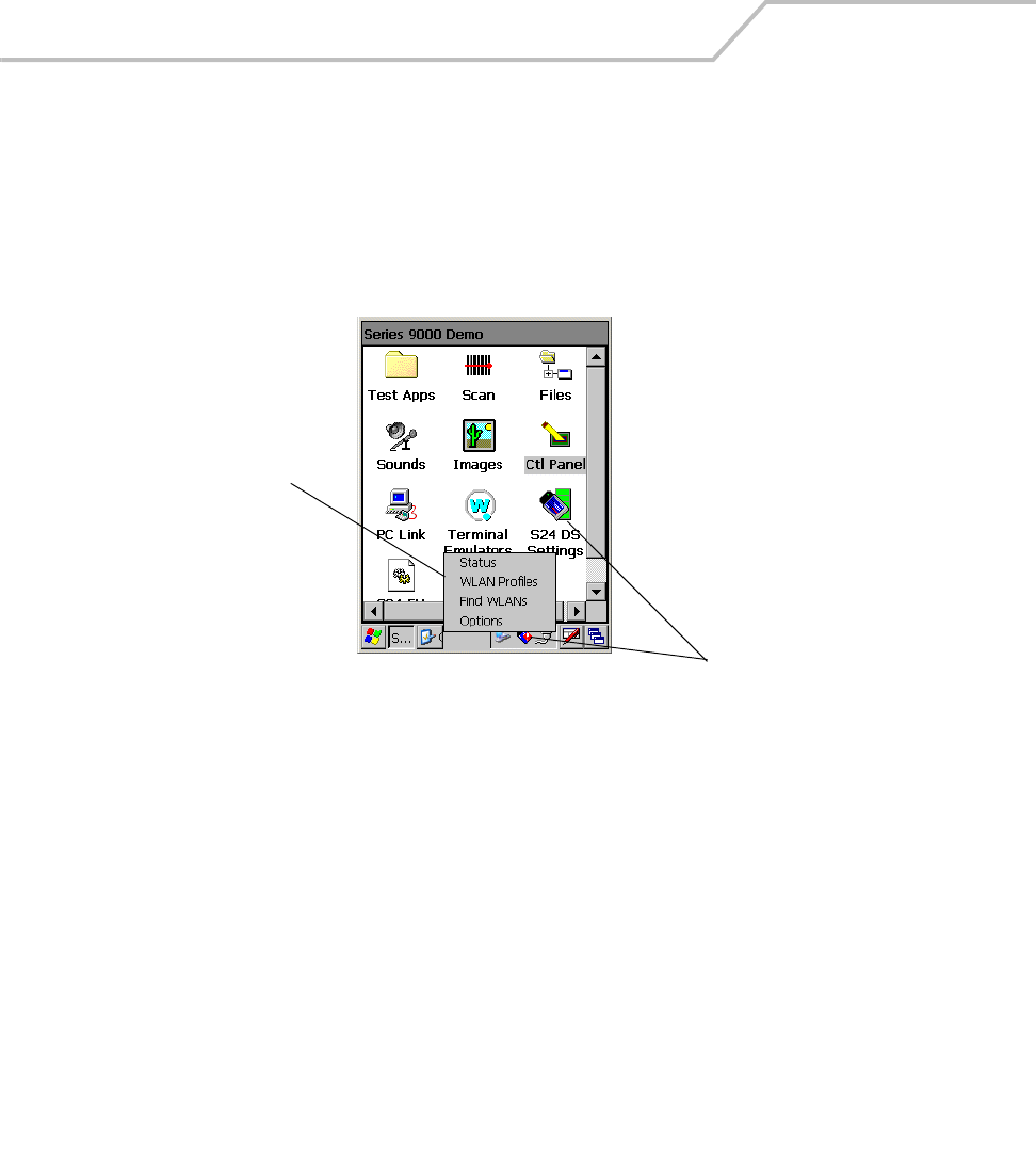
MC9000-K/S for Embedded Windows® CE .NET Product Reference Guide
6-4
Mobile Companion
The Mobile Companion utility is used to configure the mobile computer’s wireless network settings.
The Mobile Companion utility starts automatically and appears as an icon on the task tray. The status
icon changes in real-time to reflect the signal strength and availability of the adapter and the wireless
network. Double-tap the S24 DS Settings icon or tap the task tray Mobile Companion icon to open
the Mobile Companion menu..
Figure 6-1. Mobile Companion Menu
Mobile Companion
icons
Mobile Companion
Menu

Spectrum24 Network Configuration 6-5
When the menu opens, the user can select Status, WLAN Profiles, Find WLANs, or Options menu
options.
Table 6-1. Mobile Companion Menu Descriptions
Menu Item Description
Status Displays the current status and information for the wireless connection.
Signal tab - Displays radio signal transmission strength from the adapter (using its current profile)
to the associated AP.
Info tab - Displays Mobile Companion software, driver, firmware and hardware and country
information for the current WLAN profile.
IP Status tab - Displays network address information.
Ping tab - Displays signal strength data, data rate and conducts data transmission tests between
the mobile computer and associated AP or client.
APs tab - Displays APs with the same ESSID as the current mobile computer profile. The mobile
computer's roaming capabilities can be set from this tab.
Peers tab - Displays the BSSIDs, power modes, transmit rates and data rates of other networked
clients within the Ad Hoc (peer-to-peer) network. When in Ad Hoc operating mode, the Peers tab
appears instead of the APs tab.
WLAN Profiles Displays the current profiles and allows the user to add, edit and delete profiles, for more
information see Changing Profiles on page 6-26.
Find WLANs Displays a list of those Spectrum24 networks (APs and networked peers) available for association.
The networks are listed by their ESSID. To the right of each network is a signal strength icon.
Networks with a signal strength of good (three green bars out of five) or better should be considered
for connection. Tap a network and tap Connect to interoperate with the AP representing that
network. Once connected, the Mode, Encryption, IP Config and power tabs display the ESSID,
security settings, network address information and power consumption level set for that network.
For more information, see Finding WLANs on page 6-6.
Options Displays settings for system sounds, AP and mobile computer association capabilities, profile
roaming options, as well as the password protecting the Mobile Companion utility. For more
information, see Setting Options on page 6-24.
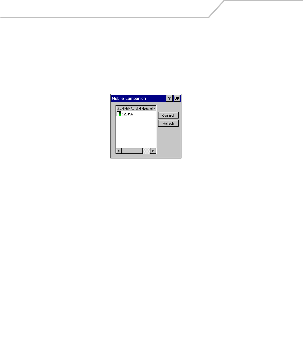
MC9000-K/S for Embedded Windows® CE .NET Product Reference Guide
6-6
Finding WLANs
A completed profile is a set of mobile computer configuration settings that can be used in different
locations to connect to a Spectrum24 network. Creating different profiles is a good way of having pre-
defined operating parameters available for use in various Spectrum24 network environments.
Select Find WLANs from the Mobile Companion menu to locate the APs in the area. The Mobile
Companion window displays the available WLAN networks.
Figure 6-2. Available WLAN Networks
1. Select an available WLAN network from the list.
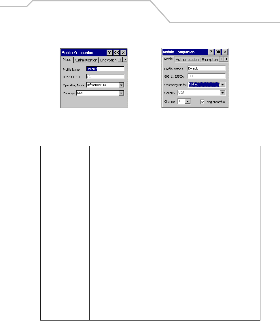
Spectrum24 Network Configuration 6-7
2. Tap Connect. The Mode tab appears.
Figure 6-3. Mode Tab
Table 6-2. Mode Tab Fields
Field Description
Profile Name Populated with the name and (WLAN) identifier of the network connection. The Profile
Name: can bechanged.
Use the Profile Name field to enter the name of the mobile computer profile used to
transmit with either an AP or another networked computer.
802.11 ESSID Populated with the name and (WLAN) identifier of the network connection.
The ESSID is the 802.11 Extended Service Set Identifier. The ESSID is 32-character
(maximum) string identifying the WLAN. The ESSID assigned to the mobile computer is
required to match the AP ESSID for the mobile computer to communicate with the AP.
Operating Mode Select the operating mode from the Operating Mode: drop-down list.
Infrastructure: Select Infrastructure to enable the mobile computer to transmit and
receive data with an AP. Infrastructure is the mobile computer default mode when
Mobile Companion initially appears.
Ad Hoc: Select Ad Hoc to enable the mobile computer to form its own local network
where mobile computers communicate peer-to-peer without APs using a shared ESSID.
Select the Long preamble check box if the mobile computer and its profile are using a
long preamble when transmitting data. A long preamble is approximately 8 bytes of the
packet header attached to the packet prior to transmission. Devices in Ad Hoc mode are
required to use the same preamble length to interoperate. The mobile computer
initiating the Ad Hoc network sets the channel (using the Channel drop-down list) used
by each peer in the Ad Hoc network.
Country Select the country of operation for the mobile computer from the Country: drop-down list.
This ensures the mobile computer is using country code information compatible with the
country code data used by the associated AP.
Infrastructure Mode Ad Hoc Mode
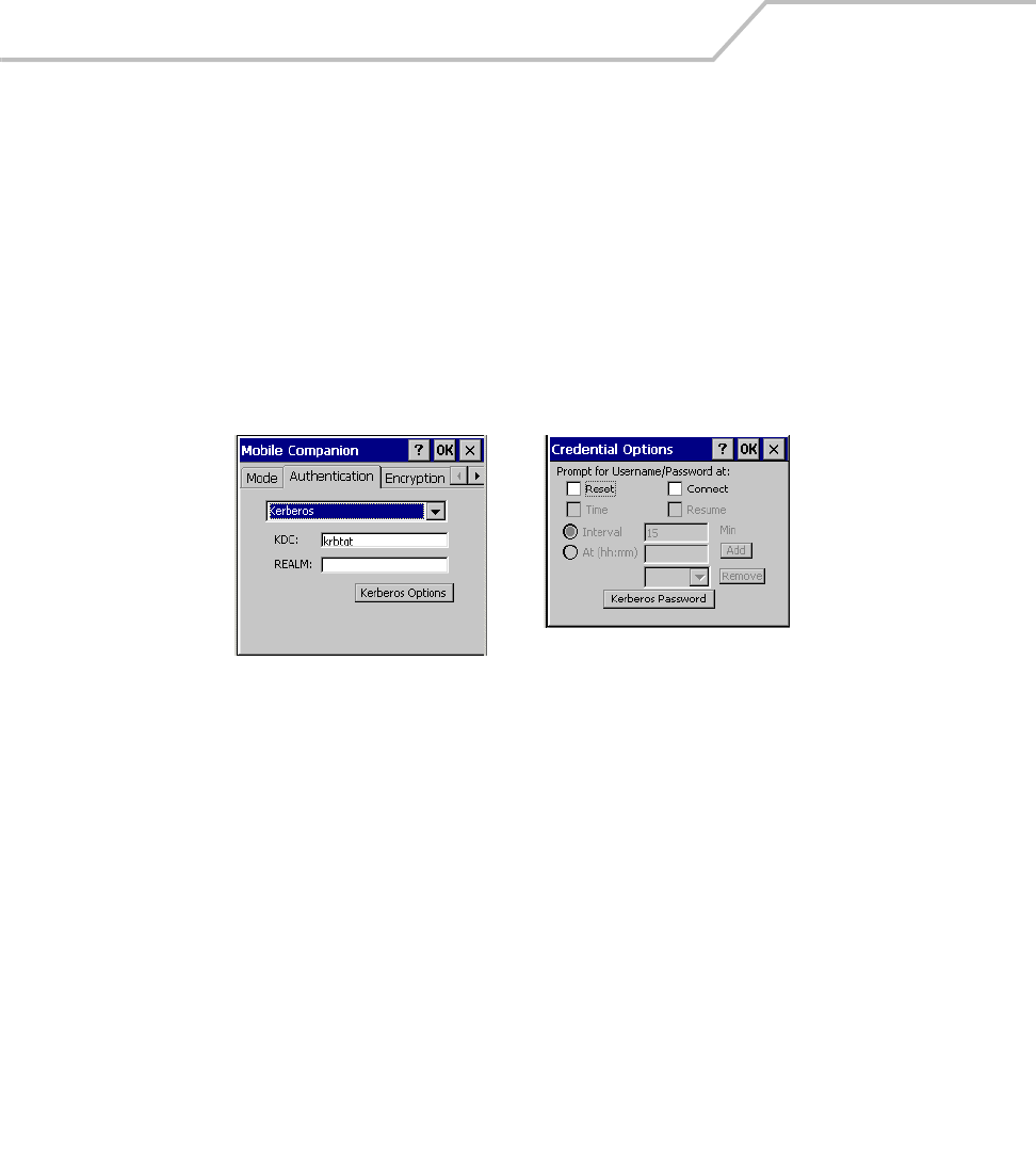
MC9000-K/S for Embedded Windows® CE .NET Product Reference Guide
6-8
3. Select the Authentication tab to configure server-based authentication. Select one of the
following Authentication options from the Authentication drop-down list.
• None - Default setting when authentication is not required on the network. The client
adapter does not use any authentication scheme when Open System is selected on the
Encryption tab.
• Kerberos (see Table 6-3)
• LEAP (see Table 6-4)
• EAP-TLS (see Table 6-5)
• PEAP (see Table 6-6).
.
Figure 6-4. Mobile Companion - Authentication Tab (Kerberos)
Kerberos Authentication Credential Caching Settings
(Kerberos Options)

Spectrum24 Network Configuration 6-9
Table 6-3. Authentication Tab Fields - Kerberos
Authentication Description
Kerberos
(see Figure 6-4)
Kerberos is a different form of 128-bit data security. An adapter is required to have its
request for access point resources authenticated with a Kerberos server before the server
permits the access point to transmit and receive data with the associated adapter. When
Kerberos is selected, the KDC and Realm entry fields appear. The KDC field should remain
with the default KDC name (krbtgt) unless it is changed in the server. Enter the name of the
server that hosts the Kerberos KDC in the Realm field. The KDC is located on a server and
maintains information about the access points and users it supports. The KDC also permits
the transmission and receipt of data once the credentials of the user are verified.
Tap Kerberos Options to configure different caching modes for Kerberos credentials.
When connecting to a Kerberos supported profile, the system can prompt for the
associated user name and password at specified instances during the authentication
process. Caching of credentials is optional.
Kerberos Options:
Select any combination of the following Kerberos Credential Caching settings:
Reset: When selected, the system prompts the user for the username and password
upon a warm boot.
Connect: When selected, the system prompts the user for login information when the
system initiates a connection to the ESSID.
Time: When selected, the system requests a user name and password after the specified
time parameter. Available time parameters are specified as an Interval (in minutes) or At
(hh:mm) a specified time (chosen with the pull-down menu). If a time option is not
selected, authentication continues without a user name and password verification.
Resume: When enabled, the system prompts the user for username and password after the
system is suspended and subsequently resumed. If disabled, the system prompts for a
username and password only if the user's credentials are not in the registry.
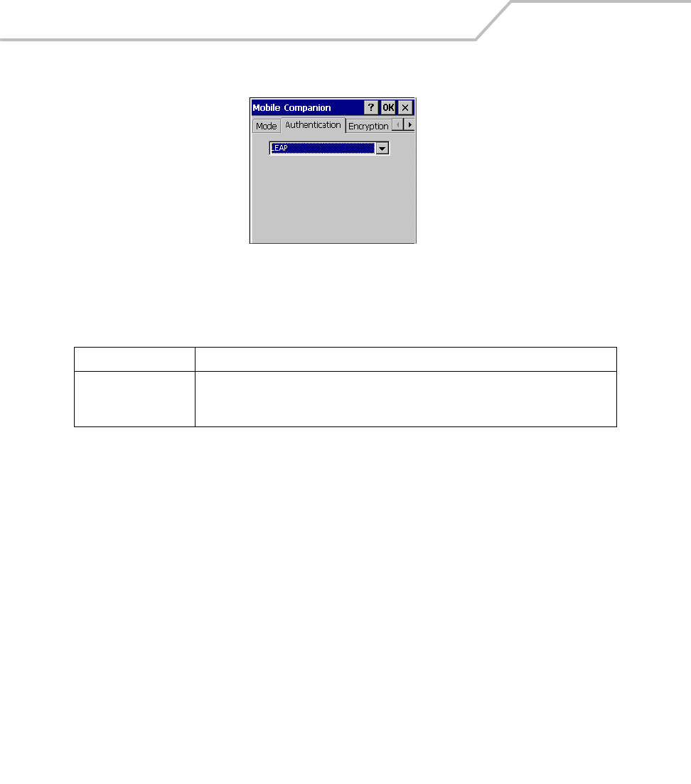
MC9000-K/S for Embedded Windows® CE .NET Product Reference Guide
6-10
Figure 6-5. Mobile Companion - Authentication Tab (LEAP)
Table 6-4. Authentication Tab Fields - LEAP
Authentication Description
LEAP
(see Figure 6-5)
Select this option to enable LEAP authentication. LEAP is founded on mutual
authentication. The AP and the mobile computer attempting to connect to it require
authentication before access to the network is permitted.
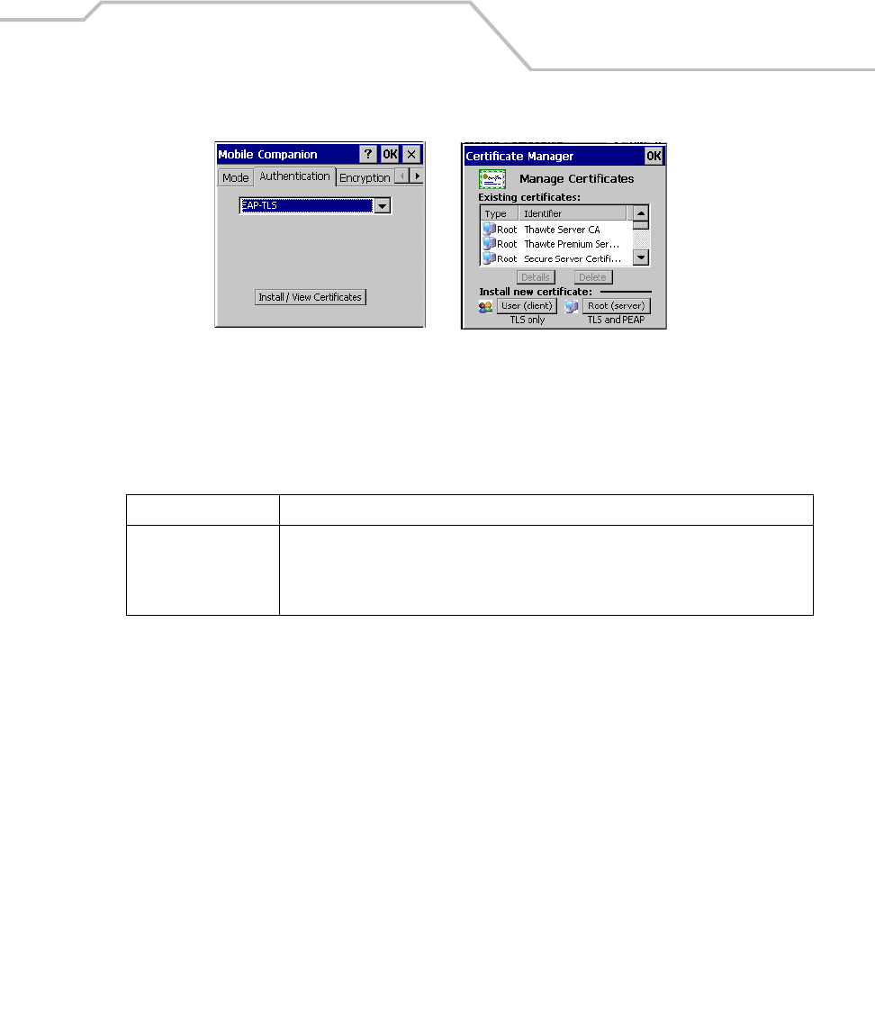
Spectrum24 Network Configuration 6-11
Figure 6-6. Mobile Companion - Authentication Tab (EAP-TLS)
Table 6-5. Authentication Tab Fields - EAP/TLS and PEAP
Authentication Description
EAP/TLS
(see Figure 6-6)
EAP/TLS is an authentication scheme through IEEE 802.1x. It authenticates users and
ensures only valid users can connect to the network. It also restricts unauthorized users
from accessing transmitted information. EAP/TLS achieves this through secure
authentication certificates.
EAP-TLS Authentication Install / View Certificates
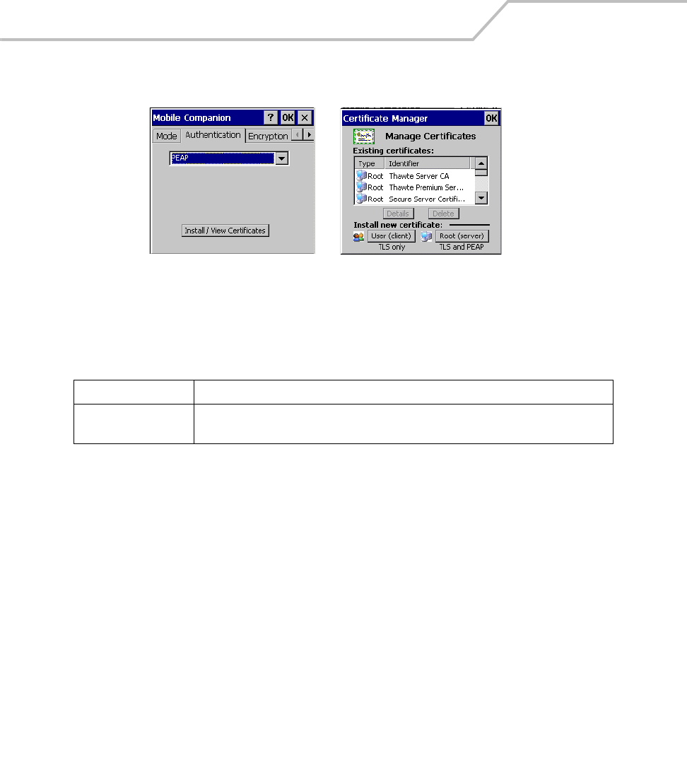
MC9000-K/S for Embedded Windows® CE .NET Product Reference Guide
6-12
Figure 6-7. Mobile Companion - Authentication Tab (PEAP)
Table 6-6. Authentication Tab Fields - EAP/TLS and PEAP
Authentication Description
PEAP
(see Figure 6-7)
Select this option to enable PEAP authentication. This method uses a digital certificate to
verify and authenticate a user's identity.
PEAP Authentication Install / View Certificates
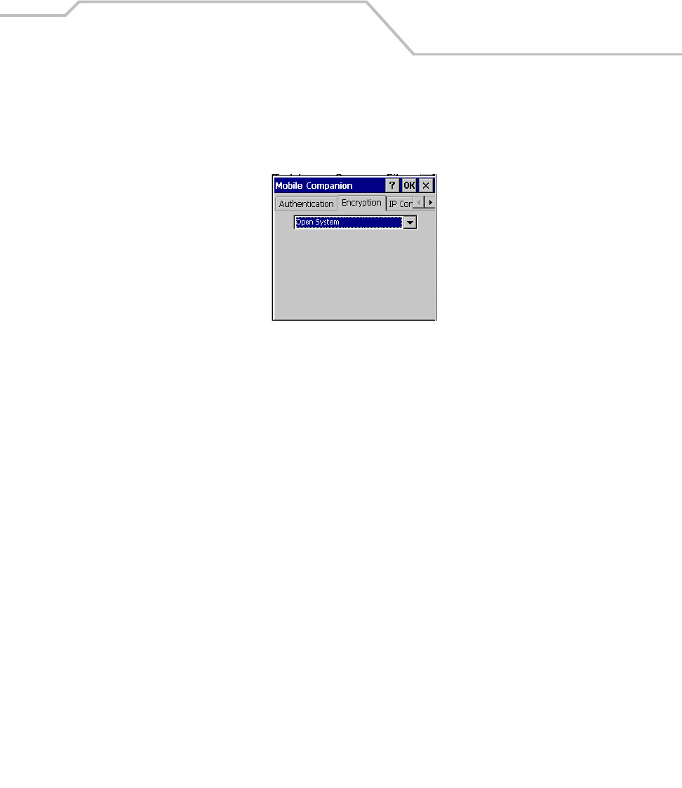
Spectrum24 Network Configuration 6-13
1. Select the Encryption tab to set the adapter profile security level by configuring the
encryption scheme and corresponding keys. Select an option (Open System, WEP, Keyguard-
MCM, TKIP (WPA)) from the Encryption drop-down list. See Table 6-7 on page 6-14 for
Encryption option descriptions.
Figure 6-8. Encryption Tab
The absence of a physical connection makes wireless links vulnerable to information theft.
Encryption is an efficient method of preventing data theft and improving data security.
If an AP is set to 40-bit and an adapter is set to 128-bit, the adapter can associate to the AP,
but no data transmission and reception can take place.

MC9000-K/S for Embedded Windows® CE .NET Product Reference Guide
6-14
Table 6-7. Encryption Options
Encryption Description
Open System Use the Open System option as the default setting when no data packet encryption is
needed over the network. Selecting this option provides no security for the data being
transmitted over the network. The window displays only the OK and Cancel buttons.
WEP Select WEP for the adapter to use the WEP keys for encryption. The window displays
several radio buttons and edit buttons to configure the WEP keys. Select 40-bit or 128-bit
key lengths (128-bit is the default). WEP keys are manually entered in the edit boxes. Only
the required number of edit boxes for a key length is displayed (10 Hex digit value for 40-
bit keys, 26 Hex digit values for 128-bit keys). Use the Key radio buttons to configure the
four WEP keys. The adapter uses the selected key. Tap ResetKeys to set the encryption
key to the default values.
Note: The default Hex digit keys are visible any time they are used. As a security precaution
after setting the key values for the network, the digits are replaced with asterisks * within
the Encryption key fields.
If the associated access point is using an optional Passkey, the "active" adapter WLAN
profile is required to use one as well. The Passkey is a plain text representation of the WEP
keys displayed in the Encryption property window. The Passkey provides an easy way to
enter WEP key data without having to remember the entire 40-bit (10 character) or 128-bit
(26 character) Hex digit string.
Tap Passkey to display the Passkey screen. Enter an easy-to-remember 4 to 32 character
string to be used as the WEP algorithm. Click OK. The access point transforms the Passkey
string into a set of four WEP keys using MD5 algorithms and displays them in the WEP
fields. These are the new WEP keys for the adapter profile. Once displayed in the WEP key
fields, the adapter profile behaves as if the keys were entered manually.
TKIP (WPA) Select this option for the client adapter to use Wireless Protected Access (WPA) via TKIP.
Manually enter the pre-shared keys in the edit boxes. Tap ClearKey to clear all previous
keys and enter new key values. Tap Passkey to display the Passkey screen. Enter an easy-
to-remember 8 to 63 character string.
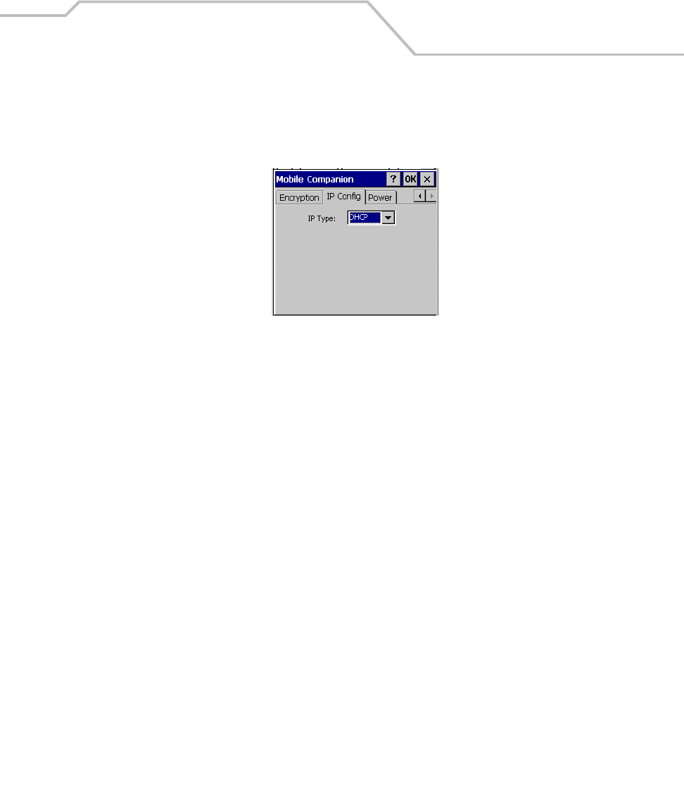
Spectrum24 Network Configuration 6-15
2. Select the IP Config tab to configure the following mobile computer profile network address
parameters: IP address, subnet, gateway, DNS and WINS. Changes made within the IP
Config tab only impact the profile selected in the Mode tab and do not impact the network
address parameters configured for other profiles.
Figure 6-9. Mobile Companion - IP Config Tab (DHCP)
• Select Dynamic Host Configuration Protocol (DHCP) from the IP Type drop down list to
obtain a leased IP address and network configuration information from a DHCP server.
DHCP is the default setting for the mobile computer profile. When DHCP is selected, the
IP address fields are read-only.
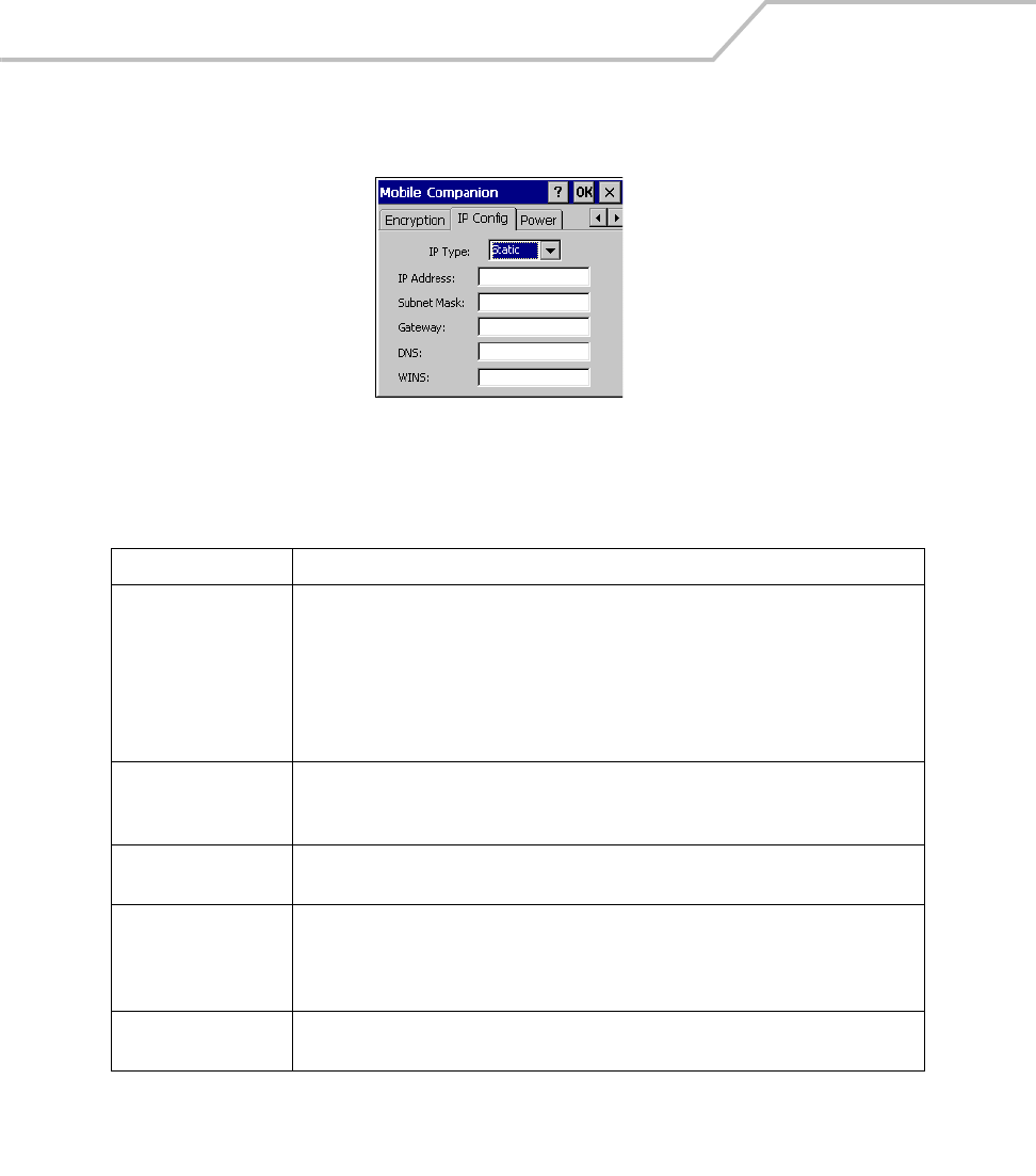
MC9000-K/S for Embedded Windows® CE .NET Product Reference Guide
6-16
• Select Static to manually assign the IP, subnet mask, default gateway, DNS and WINS
addresses used by the mobile computer profile.
Figure 6-10. Mobile Companion - IP Config Tab (Static)
Table 6-8. IP Config Tab Fields
Field Description
IP Address The Internet is a collection of networks with users that communicate with each other. Each
communication carries the address of the source and destination networks and the
particular machine within the network associated with the user or host computer at each
end. This address is called the IP address (Internet Protocol address). Each node on the IP
network must be assigned a unique IP address that is made up of a network identifier and
a host identifier. Enter the IP address as a dotted-decimal notation with the decimal value
of each octet separated by a period, for example, 192.168.7.27.
Subnet Mask Most TCP/IP networks use subnets in order to effectively manage routed IP addresses.
Having an organization's network divided into subnets allows it to be connected to the
Internet with a single shared network address, for example, 255.255.255.0.
Gateway The default gateway is a device that is used to forward IP packets to and from a remote
destination.
DNS The Domain Name System (DNS) is a distributed Internet directory service. DNS is used
mostly to translate domain names and IP addresses. It is also used to control Internet email
delivery. Most Internet service requires DNS to operate properly. If DNS is not configured,
Web sites cannot be located and/or email delivery fails.
WINS WINS is a Microsoft® Net BIOS name server. WINS eliminates the broadcasts needed to
resolve computer names to IP addresses by providing a cache or database of translations.
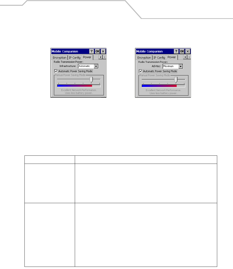
Spectrum24 Network Configuration 6-17
3. Select the Power tab to set the Radio Transmission Power level and the Power Saving
Modes for the mobile computer profile.
Figure 6-11. Mobile Companion - Power Tab)
Adjust the Radio Transmission Power level to expand or confine the transmission area to with
respect to other wireless devices that could be operating nearby. Reducing coverage in a high
traffic area improves transmission quality by reducing the amount of noise in that coverage area.
Table 6-9. Power Tab Fields
Field Description
Radio Transmission Power
In Infrastructure mode There are two transmission power options:
Select Automatic to use the AP power level. Automatic is the default mode for mobile
computers operating in Infrastructure mode.
Select Power Plus to set the mobile computer transmission power one level higher than the
level set for the AP.
In Ad Hoc mode There are five transmission power options:
Select Maximum power to set the mobile computer to the highest transmission power
level. Select Maximum power when operating in highly reflective environments and areas
where other devices could be operating nearby. Additionally, use the maximum power level
when attempting to communicate with devices at the outer edge of a coverage area.
Select 50%, 25% or 10% to set the transmit power level to that percentage of the
maximum power level.
Select Minimum power to set the mobile computer to the lowest transmission power level.
Use the minimum power level when communicating with other devices in very close
proximity. Additionally, select minimum power in instances where little or no radio
interference from other devices is anticipated.
Infrastructure Mode Ad Hoc Mode

MC9000-K/S for Embedded Windows® CE .NET Product Reference Guide
6-18
4. Tap OK to implement power consumption changes for the mobile computer profile.
Automatic Power Saving
Mode
Switches to Best Network Performance when an AC power supply is detected. If a battery
is used, an appropriate setting between Best Network Performance and Acceptable
Network Performance is automatically chosen based on a real-time analysis of network
usage. The Automatic Power Saving Mode is the default setting and extends the operating
time before the battery is recharged.
Manual Power Saving Mode Use to select a performance level suited to intended operation. There are six settings
ranging from the Best Network Performance (using the most battery power) to Acceptable
Network Performance (using the least battery power). A network performance description
is displayed for each power range.
Table 6-9. Power Tab Fields (Continued)
Field Description
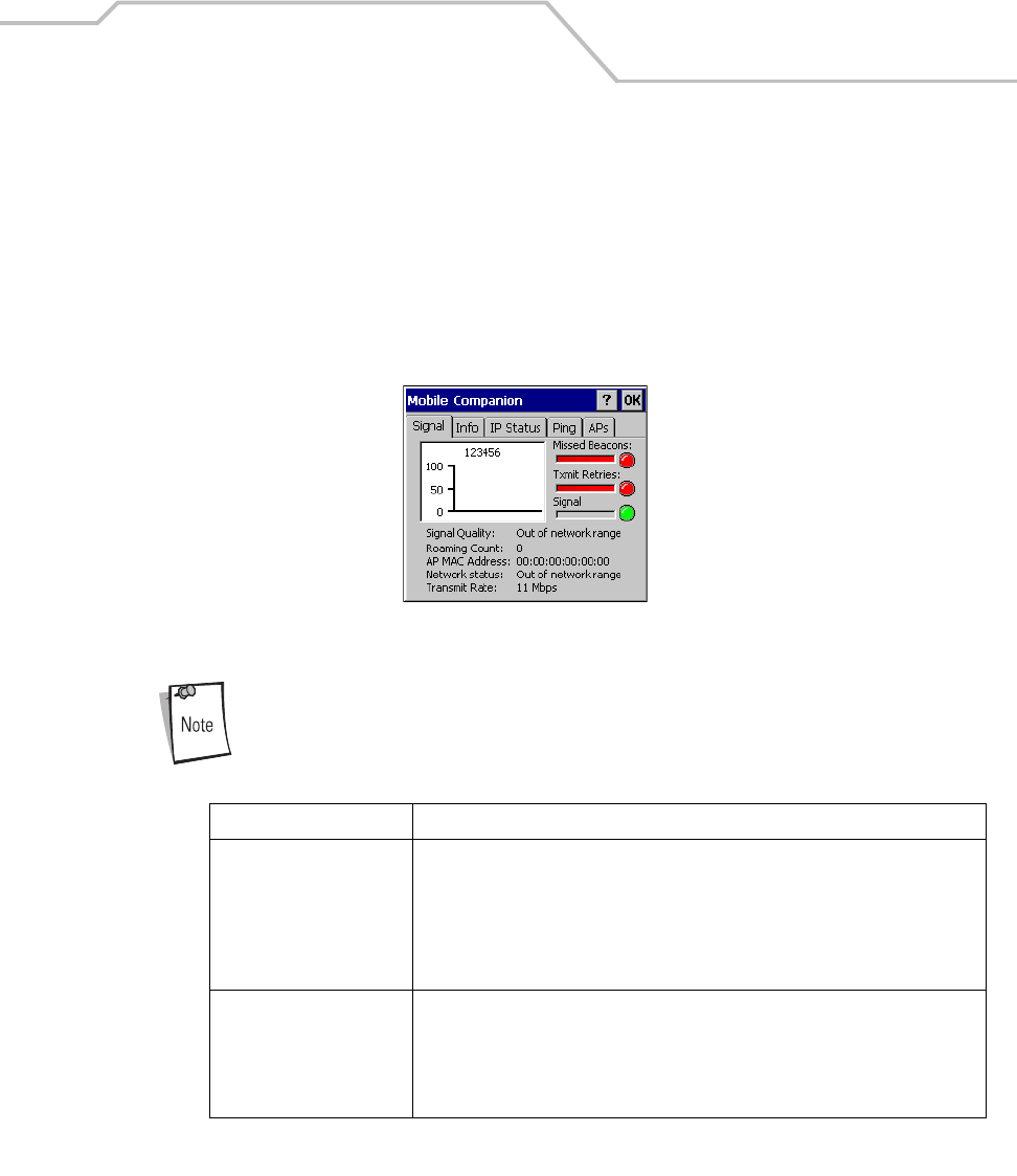
Spectrum24 Network Configuration 6-19
Status
To view the status of the wireless network connection, select Status from the Mobile Companion
menu.
1. Select the Signal tab to display a real-time graph of the signal quality of the mobile
computer to the associated AP (Infrastructure Mode only). The number of times the mobile
computer has roamed to and from APs, the current data rate and the network status are
displayed. Signal quality is an indicator of how clearly the adapter can hear the associated
AP.
Figure 6-12. Mobile Companion - Signal Tab
The Signal tab is view only and is not available if the current operating mode is Ad
Hoc.
Table 6-10. Signal Fields
Field Description
Missed Beacons Displays the amount of beacons (uniform system packets broadcast by the AP to
keep the network synchronized) missed by the mobile computer. The fewer the
missed beacons the better the signal. As long as the LED to the right of the graph is
green the AP association is not jeopardized by an excess of missed AP beacons. If
the LED is Red, an association with a different AP could be warranted to reduce the
amount of missed beacons and improve the signal.
Txmit Retries (Transmit
Retries)
Displays the number of data packets retransmitted by the mobile computer. The
fewer transmit retries the stronger the signal. As long as the LED to the right of the
graph is green the AP association is not jeopardized. If the LED is red, an association
with a different AP could be warranted to reduce the amount of transmit retries and
improve the signal.
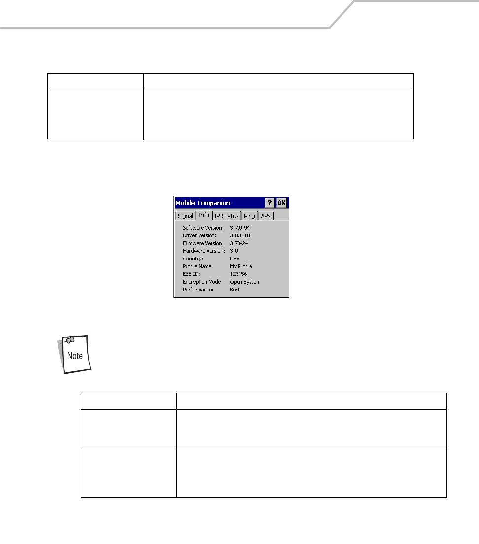
MC9000-K/S for Embedded Windows® CE .NET Product Reference Guide
6-20
2. Select the Info tab to view the mobile computer’s current software and driver revision data
as well as the operating parameters of the current profile.
Figure 6-13. Mobile Companion - Info Tab
The Version and Current Status information on this window may differ from the
actual screen on the mobile computer.
Signal Displays the Relative Signal Strength Indicator (RSSI) of the signal transmitted
between the AP and mobile computer. As long as the LED to the right of the graph
is green the AP association is not jeopardized. If the LED is red, an association with
a different AP could be warranted to improve the signal.
Table 6-11. Info Fields
Field Description
Version Information Displays Mobile Companion software, driver, firmware and hardware versions as
well as country information. This data is consistent for the mobile computer
regardless of which mobile computer profile is the current profile.
Current Status Displays the mobile computer’s current Profile Name, ESSID and Encryption mode.
Mobile computer performance is displayed using a verbal indicator of signal
strength. Mobile computer operating information differs depending on which profile
was enabled as the current profile.
Table 6-10. Signal Fields (Continued)
Field Description
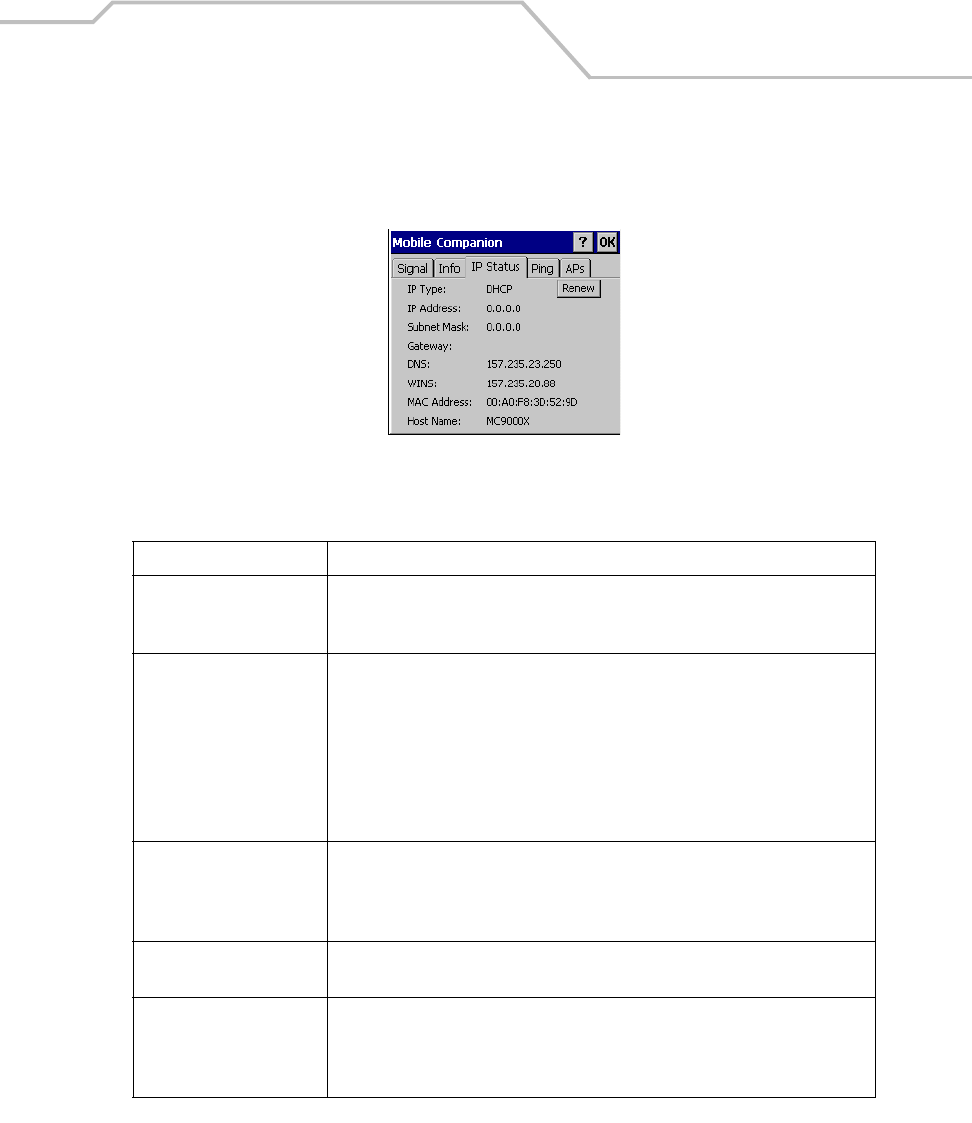
Spectrum24 Network Configuration 6-21
3. Select the IP Status tab to view the mobile computer’s network address information. Unlike
the IP Config tab in Finding WLANs, the IP Status tab is view only with no user-configurable
data fields.
Figure 6-14. Mobile Companion - IP Status Tab
Table 6-12. IP Status Fields
Field Description
IP Type If DHCP was selected from the IP Config tab, leased IP address and network address
data displays for the mobile computer. If Static was selected, the values displayed
were input manually in the IP Config tab on page 15.
IP Address The Internet is a collection of networks with users that communicate with each
other. Each communication carries the address of the source and destination
networks and the particular machine within the network associated with the user
or host computer at each end. This address is called the IP address. Each node on
the IP network must be assigned a unique IP address that is made up of a network
identifier and a host identifier. Enter the IP address as a dotted-decimal notation
with the decimal value of each octet separated by a period, for example,
192.168.7.27.
Subnet Mask Most TCP/IP networks use subnets in order to effectively manage routed IP
addresses. Having an organization's network divided into subnets allows it to be
connected to the Internet with a single shared network address, for example,
255.255.255.0.
Gateway The gateway is a device that is used to forward IP packets to and from a remote
destination.
DNS The Domain Name System (DNS) is a distributed Internet directory service. DNS is
used mostly to translate domain names and IP addresses. It is also used to control
Internet e-mail delivery. Most Internet service requires DNS to operate properly. If
DNS is not configured, Web sites cannot be located or e-mail delivery fails.
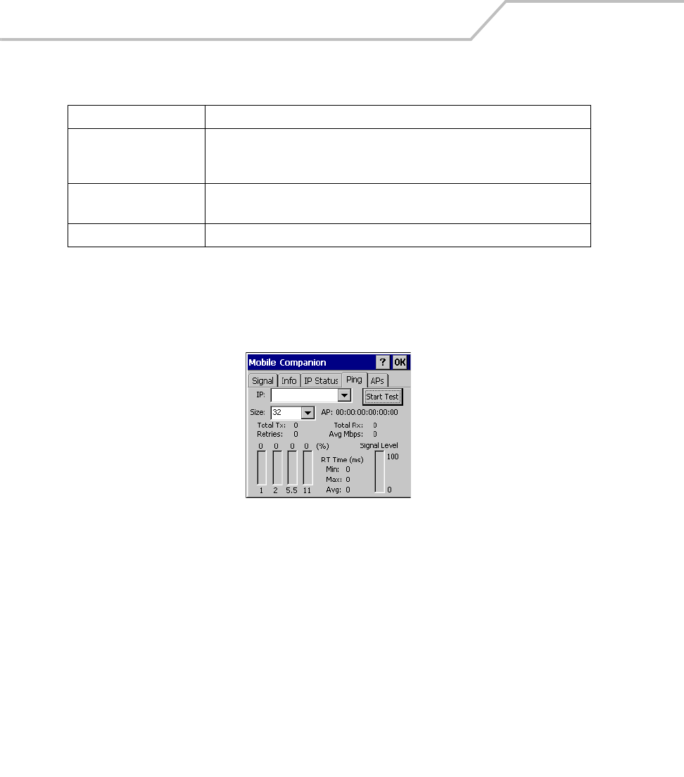
MC9000-K/S for Embedded Windows® CE .NET Product Reference Guide
6-22
4. Tap Renew to refresh the information displayed on the IP Status tab. The mobile device is
releases the existing IP address and requests a new IP address from a DHCP server.
5. Select the Ping tab to send and receive ICMP ping packets across the network to the
specified IP address.
Figure 6-15. Mobile Companion - Ping Tab
6. In the IP drop-down list, select a target device IP address.
7. In the Size drop-down list, select the size of the packet transmission.
8. Tap Start Test to begin the ping test.
9. Tap Stop Test to terminate the ping test.
The average mega-bits per second, signal strength, data rate currently in use, test statistics
and round trip (RT) times are displayed for each test. The associated AP MAC address is also
displayed. The signal strength level and the data transmission rate are displayed in real-time
bar graphs.
WINS WINS is a Microsoft Net BIOS name server. WINS eliminates the broadcasts
needed to resolve computer names to IP addresses by providing a cache or database
of translations.
MAC Address An IEEE 48-bit address the mobile computer is assigned at the factory that uniquely
identifies the adapter at the physical layer.
Host Name Displays the name of the mobile computer.
Table 6-12. IP Status Fields (Continued)
Field Description
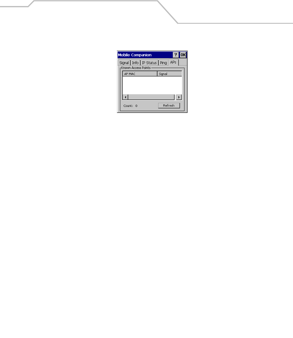
Spectrum24 Network Configuration 6-23
10. Select the APs tab to view APs with the same ESSID as the mobile computer’s profile.
Figure 6-16. Mobile Companion - APs Tab
The associated AP displays a radio wave radiating from its antenna to indicate its
associated status. Tapping the icon displays a menu with Set Mandatory and Set Roaming
options.
Selecting the Set Mandatory item prohibits the mobile computer from associating with a
different AP. The letter M appears on top of the icon when the Set Mandatory option has
been selected.
Selecting Set Roaming allows the mobile computer to roam to any AP with a better signal.
These settings are temporary and never saved to the registry.
Tap Refresh to update the list of the APs with the same ESSID. A signal strength value of
32 is the highest possible. The APs tab only appears when Infrastructure is selected as the
mobile computer operating mode from the Mode tab.
11. If the mobile computer is in Ad Hoc mode, select the Peers tab to display the BSSID or MAC
addresses of the other mobile computers in the network, their operating mode (PSP or CAM),
their transmit rate, their supported data rate and the length of time an adapter has been out
of the Ad Hoc network. Tap Refresh to update the Peers tab to the latest Ad Hoc network
performance and mobile computer membership data.
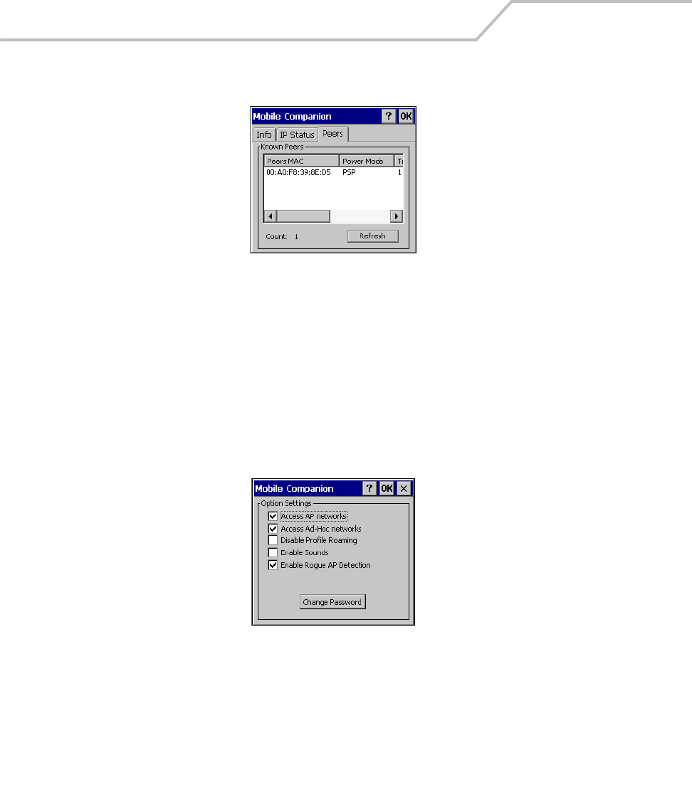
MC9000-K/S for Embedded Windows® CE .NET Product Reference Guide
6-24
Figure 6-17. Mobile Companion - Peers Tab
Setting Options
Select Options from the Mobile Companion menu to:
• Access APs or Ad-Hoc networks for the Find WLAN search
• Enable or disable profile roaming
• Enable system sounds
• Enable Rogue AP Detection to check the system for unauthorized APs
• Place password protection on the current WLAN profile.
Figure 6-18. Mobile Companion - Option Settings
1. Select the Access AP networks checkbox to display available AP networks and their signal
strength within the Available WLAN Networks tab. These are the APs available to the
mobile computer profile for association. If this option was previously disabled, refresh the
Available WLAN Networks tab to display the AP networks available to the mobile computer.
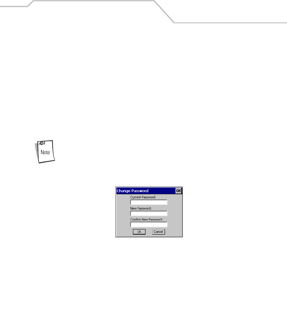
Spectrum24 Network Configuration 6-25
2. Select the Access Ad-Hoc networks checkbox to display available peer (adapter) networks
and their signal strength within the Available WLAN Networks tab. These are peers
available to the mobile computer profile for association. If this option was previously
disabled, refresh the Available WLAN Networks tab to display the Ad Hoc networks
available to the mobile computer.
3. Select the Disable Profile Roaming check box to to configure the adapter profile to not roam
to another AP profile or peer profile (if in Ad Hoc mode) if a stronger signal is detected.
4. Select the Enable Sounds checkbox to initiate an audible signal when performing a ping test
and associating with an AP. The tones are important to notify users if the pinging is received
or if the mobile computer has roamed to another AP.
5. Select the Enable Rogue AP Detection check box to inform the system of unauthorized APs
on the network.
Mobile Companion has a password protection feature. When Mobile
Companion initially appears, the password is off by default.
6. To create a password, tap Change Password.
Figure 6-19. Mobile Companion - Change Password
7. In the Change Password window, tap in the Current Password box and enter the current
password. The password is case sensitive and a maximum of 10 characters. Enter the new
password in both the New Password and the Confirm New Password boxes and tap OK.
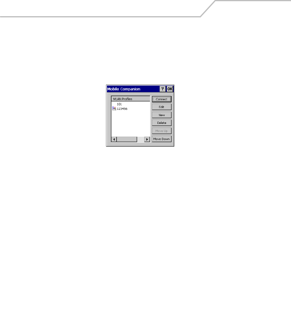
MC9000-K/S for Embedded Windows® CE .NET Product Reference Guide
6-26
Changing Profiles
Select WLAN Profiles from the Mobile Companion menu to view, connect to, create and edit a profile.
A completed profile is a set of adapter configuration settings that can be used in different locations
to connect to a wireless network. Creating different profiles is a good way of having pre-defined
operating parameters available for use in various network environments. When the WLAN Profiles
initially appears, existing profiles appear in the WLAN Profiles list.
Figure 6-20. Mobile Companion - WLAN Profiles
Select a profile from the list and tap Connect to set that profile as the active profile. The active
profile displays the transmit and receive icon to the left. Once selected, the mobile computer is using
the ESSID, encryption and power consumption settings initially configured for that profile.
Editing a Profile
Select a profile from the list and tap Edit to display the Mode tab where the ESSID and operating
mode can be changed for the profile. Use the Encryption, IP Config and Power tabs as necessary to
edit the profile power consumption and security parameters.
Creating a New Profile
Tap New to display the Mode tab, used to set the profile name and ESSID. Use the Encryption, IP
Config and Power tabs as required to set security, network address information and power
consumption level for the new profile.
Deleting a Profile
Select a profile to delete from the list and tap Delete to remove the selected profile.
Ordering Profiles
Select a profile from the list and tap Move Up or Move Down to order the profile. If the current
profile association is lost, Mobile Companion attempts to associate with the first profile in the list
and then the next until a new association is achieved.

Spectrum24 Network Configuration 6-27
Using LEAP for Wireless Network Security
LEAP is a security protocol that provides authentication and encryption for wireless networks.
Authentication is provided through the use of user names and passwords. There are multiple options
for caching of these credentials available to the administrator of the device through the registry.
There are multiple password caching options used for LEAP. The methods are:
• Save the password in the registry.
• Save the password until a warm boot (soft reset), but not saved in the registry. This method
also has a timeout available.
• Never save the password, requiring a dialog box on every power-up (suspend/resume).
The default is set to cache the password until a warm boot, with no timeout. If a different password
caching option is desired, the Spectrum24DS.reg registry file in the Platform folder must be re-
configured.
Configuring Advanced Password Options
All password caching options are configured in the file Spectrum24DS.reg, located in the Platform
folder. The file must be edited on a PC and copied back onto the device after editing is complete. The
section of this file which needs editing reads “[HKEY_LOCAL_MACHINE\Comm\NETWLAN1\Parms].”
Cache the Password
To cache the password, edit the registry file using a text editor with the following changes:
1. Change the LCachePwd value from 1 to 0:
LCachePwd = dword:0
2. Uncomment the UNAME and UPwd values (deleting the semicolons at the beginning of each
line):
UNAME = yLEAPUserName
UPwd = myLEAPPassword
3. Change myLEAPUserName and myLEAPPassword to the correct username and password.
Note that the user name and password should be in quotes. If a domain name is required,
this can be entered in the user name as: domain\username.

MC9000-K/S for Embedded Windows® CE .NET Product Reference Guide
6-28
A backslash is used and most setups do not require a domain name even if
Microsoft Windows® NT/2000 domains are used.
4. After changing the Spectrum24DS.reg file, copy the file onto the mobile computer into the
Platform using ActiveSync and overwriting the old file. Then, cold boot the mobile computer
for the changes to take effect.
Cache the Password until a Warm Boot
Cache the password until a warm boot is the default setting. A timeout value can also be set in the
registry. The timeout forces the user to enter the username and password after a power-on if the
device had not gone through the LEAP authentication processes after the set period of time. Normally,
the device goes through the LEAP authentication process at every power-up and every time it roams
between APs.
The timeout setting can be set in minutes using hexadecimal in the registry file. The default setting
of zero disables the timeout feature. To change the timeout setting, edit the registry file using a text
editor (e.g., Notepad) as follows:
1. Ensure the “LCachePwd” value is set to dword:1.
LCachePwd = dword:1
2. If a timeout is desired, change the LTimeoutMinutes value from 00000000 to a desired value.
Examples are provided in the registry file. The following example is for 240 minutes which
is represented as 000000F0 in hexadecimal.
LTimeoutMinutes = dword:000000F0
3. Ensure that the UNAME and UPwd lines are commented out by putting a semicolon at the
beginning of each line.
4. After these changes are made to the Spectrum24DS.reg file, the file must be copied onto
the terminal. Copy the file into the Platform folder of the device using ActiveSync,
overwriting the old file. Once this is done, cold boot the mobile computer for the changes to
take effect.

Spectrum24 Network Configuration 6-29
Prevent Password Cache
To prevent password caching, edit the registry file using a text editor with the following
changes:
1. Change the LCachePwd value from 1 to 2:
LCachePwd=dword:2
2. Ensure that the UNAME and UPwd lines are commented out by putting a semicolon at the
beginning of each line.
3. After the changes are made use ActiveSync to copy the Spectrum24DS.reg file (overwriting
the old file) onto the mobile computer’s Platform folder. Then cold boot the mobile computer
for the changes to take effect.
LEAP Usage
After LEAP setup is complete, the only noticeable difference is the password dialog box. If
the caching method selected requires a user name and password, then they appear when
required. If the user name is an NT domain user, the domain can be entered in the domain
field if necessary (not normally required).
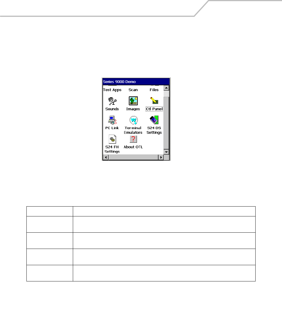
MC9000-K/S for Embedded Windows® CE .NET Product Reference Guide
6-30
Spectrum24 Frequency Hopping (FH) Settings (1 and 2 MB
Radios)
Double-tap the S24 FH Settings icon on the Series 9000 Demo window to open the Symbol
Spectrum24 WLAN menu.
Figure 6-21. Spectrum24 FH Settings Menus
Table 6-13. S24 FH Tab Descriptions
Tab Description
Mobile Unit The Mobile Unit tab configures the mobile computer ESSID, power management, RTS threshold,
International Roaming capability and AP options, see Mobile Unit Tab on page 6-31.
MicroAP The MicroAP tab sets the mobile computer to operate as an AP and establishes a single-cell
wireless network, see MicroAP Tab on page 6-33.
Encryption The Encryption tab sets the WLAN adapter to make the wireless link less vulnerable to
information theft, see Encryption Tab on page 6-34.
WLAN Adapter The WLAN Adapter tab sets the hardware and radio settings. The password protection feature
is turned on and off from the WLAN Adapter tab, seeWLAN Adapter Tab on page 6-36.
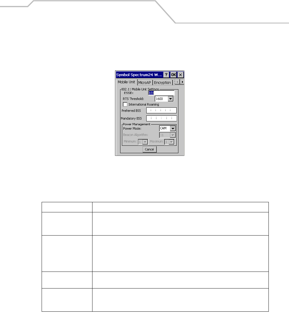
Spectrum24 Network Configuration 6-31
Mobile Unit Tab
Use the Mobile Unit tab to configure the mobile computer ESSID, power management, RTS threshold,
International Roaming capability and AP options.
Figure 6-22. Mobile Unit Tab
Table 6-14. Mobile Unit Tab Fields
Field Description
ESSID Use the ESSID field to set the 802.11 Extended Service Set Identifier. The ESSID is a 32-
character string (maximum) address identifying the wireless LAN. The ESSID assigned to
the mobile computer is required to match the AP ESSID for the two devices to associate.
RTS Threshold Use the RTS Threshold drop-down list to select the data transmission size at which the
mobile computer alerts the AP with a Request To Send (RTS) signal prior to transmission.
Once the mobile computer receives a Clear To Send (CTS) signal from the AP, the mobile
computer transmits the data packet. Establishing an RTS threshold in advance of sending
large volumes of data helps ensure data transmission with little interference.
International Roaming Check the International Roaming check box to enable the mobile computer to associate
with APs with different country codes.
Preferred BSS Use the Preferred BSS field to enter the IEEE MAC address of the AP where the mobile
computer prefers to associate. The mobile computer assigns a higher priority to this AP
when transmitting over the network.

MC9000-K/S for Embedded Windows® CE .NET Product Reference Guide
6-32
Mandatory BSS Use the Mandatory BSS field to enter the IEEE MAC address of the AP where the mobile
computer is required to associate. The mobile computer associates to only this AP when
communicating on the network. Enter an AP MAC address to associate to an AP that has a
compatible ESSID.
Power Mode A Spectrum24 radio has two main power consumption modes, Continuous Aware Mode
(CAM) and Power Save Poll (PSP) mode. Use the Power Mode drop-down list to specify the
power mode to be used by the radio. CAM provides the best performance but uses the most
power. CAM is the preferred mode for devices running on AC power. PSP saves significant
amounts of power over CAM and is the preferred mode for devices running on battery
power.
Table 6-14. Mobile Unit Tab Fields (Continued)
Field Description
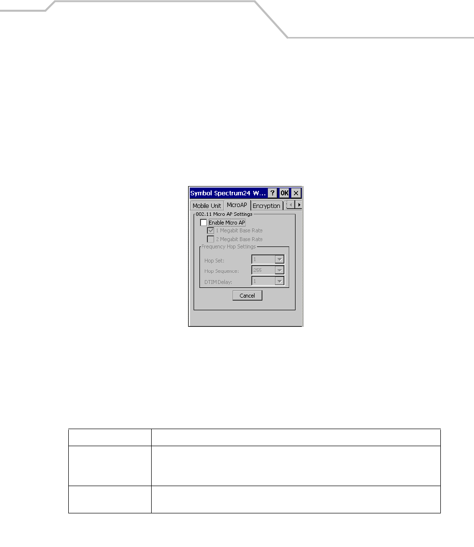
Spectrum24 Network Configuration 6-33
MicroAP Tab
Use the MicroAP tab to configure the mobile computer to operate as an AP. The MicroAP establishes
a single-cell wireless network for devices in mobile unit mode.
Each MicroAP requires a unique ESSID. MicroAP cells can coexist as separate individual networks
within the same site without interference. The MicroAP does not roam, but it does support roaming.
The mobile computer in MicroAP mode operates in CAM, and supports devices operating in both PSP
and CAM. The MicroAP supports up to 16 mobile computers.
Figure 6-23. MicroAP Tab
Figure 6-24.
Table 6-15. MicroAP Tab Fields
Field Description
Enable MicroAP Tap the Enable MicroAP checkbox to support MicroAP operations.
Tap the 1 or 2 Megabit Base Rate check boxes to specify the data rate within the MicroAP
cell. A MicroAP and the mobile computer are required to use the same data rate.
Frequency Hop Settings Tap the Frequency Hop Settings drop-down list to establish the Hop Set, Hop Sequence and
DTIM Delay to be used within the MicroAP cell.

MC9000-K/S for Embedded Windows® CE .NET Product Reference Guide
6-34
Encryption Tab
Use the Encryption tab for configuring encryption settings. The absence of a physical connection
makes wireless links vulnerable to information theft. Encryption is an efficient method of preventing
data theft and improving data security. The firmware supports Open System and Shared Key (40-bit)
Encryption algorithms.
MicroAP Authentication Options A MicroAP can use Open System, Shared Key or both. If Shared Key
is enabled and Open System is not, the MicroAP grants access to adapters that have Shared Key
enabled and are using the correct Encryption Key algorithm.
Adapters using Open System cannot associate to the MicroAP when the MicroAP has Shared Key
enabled. Only when the MicroAP is using Open System can Open System mobile computers associate
to it.
Figure 6-25. Encryption Tab

Spectrum24 Network Configuration 6-35
Table 6-16. Encryption Tab Fields
Field Description
MicroAP Authentication
Options
A MicroAP can use Open System Algorithm, Shared Key Algorithm or both. If Shared Key
is enabled and Open System is not, the MicroAP grants access to adapters that have
Shared Key enabled and are using the correct Encryption Key algorithm.
Adapters using Open System cannot associate to the MicroAP when the MicroAP has
Shared Key enabled. Only when the MicroAP is using Open System can Open System
mobile computers associate to it.
Encryption Algorithm Use the Encryption Algorithm drop-down list to select the adapter Encryption algorithm.
The Open System algorithm (default setting) does not encrypt packets over the network.
Select Open System to disable Encryption for the WLAN adapter and allow for the
transmission and receipt of data with no security.
Shared Encryption Key Use the Shared Encryption Key option to enable 40-bit Encryption. Select the Encryption
Index key radio button (to be used for the mobile computer) and enter 10 hex digits for each
key used. Tap ok to save and implement the encryption key data.
Select an Encryption Index key radio button and tap Reset Keys to clear the entries in the
Shared Encryption Key fields.
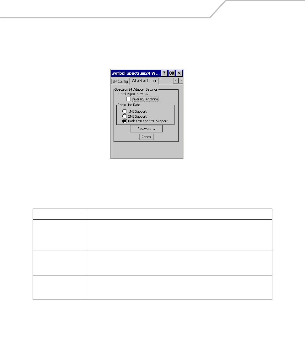
MC9000-K/S for Embedded Windows® CE .NET Product Reference Guide
6-36
WLAN Adapter Tab
Use the WLAN Adapter tab to configure hardware and radio settings. Use the Card Type: PCMCIA to
specify the antenna type and the Radio Link Rate radio buttons to specify the data rate supported.
Figure 6-26. WLAN Adapter Tab
Table 6-17. WLAN Adapter Tab Fields
Field Description
Diversity Antenna Select Diversity Antenna if dual antenna support is required. Diversity improves
communication in highly reflective environments. Do not select diversity if a secondary
antenna is not being used. Using diversity in a single antenna application can cause poor
wireless network performance.
Radio Link Rate Use the Radio Link Rate radio buttons to specify the data rate supported. The mobile
computer can use 1MB, 2MB or both. If Both 1MB and 2MB Support is selected, the mobile
computer defaults to a 1 Mbps data rate if a 2 Mbps data rate cannot be established.
Password Spectrum24 FH settings has a password protection feature that can be turned on and off
from the WLAN Adapter tab. When the Spectrum24 FH program is initially launched, the
password is off (default).

Spectrum24 Network Configuration 6-37
Password Protecting NCPA
NCPA has a password protection feature that can be turned on and off from the WLAN Adapter tab.
When the NCPA program is initially launched, the password is off (default). To create a password for
the NCPA advanced pages:
1. Tap Password... from the WLAN Adapter tab. The Change Password dialog box appears.
Figure 6-27. Change Password
2. Enter the case-sensitive password (10 characters maximum) in the Current Password field
and tap OK.
3. The NCPA advanced pages dialog box is enabled and now appears when the Advanced
button is tapped from Easy Setup window.
4. To disable the password dialog box, enter the current password and leave the New
Password and Confirm New Password fields blank. Tap OK.
5. To change the password, enter the current password and enter a new password in the New
Password and Confirm New Password fields.
6. Tap OK.

MC9000-K/S for Embedded Windows® CE .NET Product Reference Guide
6-38
Configuring the S24 DS (11 Mb) Radio Using a Registry File
Default settings for the Spectrum24 radio card can be set on the mobile computer using registry (.reg)
files. There are two registry files: Spectrum24DS.reg contains the global registry settings for Mobile
Companion and S24Profiles.reg contains the profile specific and operating registry settings for
Mobile Companion.
A sample S24Profiles.reg file is provided as part of the DCP for MC9000w. Edit the file using a text
editor. See notes in the sample file for the key information that can be modified.
Save this text file as S24Profiles.reg. Use ActiveSync to copy this file to the Platform folder on the
mobile computer. Once this file is loaded onto the mobile computer, these settings are restored after
a cold boot.
Configuring the S24 FH (2 Mb) Radio Using a Registry File
Default settings for the Spectrum24 radio card can be set on the mobile computer using registry (.reg)
files. There is one registry file (FHDOTNET.reg) that contains the global registry settings, profile
specific and operating registry settings for Network Interface Card Task Tray Applet (NICTT).
A sample FHDOTNET.reg file is provided as part of the DCP for MC9000w. Edit the file using a text
editor. See notes in the sample file for the key information that can be modified.
Save this text file as FHDOTNET.reg in order to override the existing reg file on the terminal. Use
ActiveSync to copy this file to the Platform folder on the mobile computer. Once this file is loaded
onto the mobile computer, these settings are restored after a cold boot.

Accessories
Chapter Contents
Introduction. . . . . . . . . . . . . . . . . . . . . . . . . . . . . . . . . . . . . . . . . . . . . . . . . . . . . . . . . . . . . . . . . . . . . . . . .7-5
Cradles . . . . . . . . . . . . . . . . . . . . . . . . . . . . . . . . . . . . . . . . . . . . . . . . . . . . . . . . . . . . . . . . . . . . . . . .7-5
Keypads . . . . . . . . . . . . . . . . . . . . . . . . . . . . . . . . . . . . . . . . . . . . . . . . . . . . . . . . . . . . . . . . . . . . . . .7-5
Miscellaneous . . . . . . . . . . . . . . . . . . . . . . . . . . . . . . . . . . . . . . . . . . . . . . . . . . . . . . . . . . . . . . . . . .7-5
Snap-on Modules . . . . . . . . . . . . . . . . . . . . . . . . . . . . . . . . . . . . . . . . . . . . . . . . . . . . . . . . . . . . . . . .7-6
Keypads . . . . . . . . . . . . . . . . . . . . . . . . . . . . . . . . . . . . . . . . . . . . . . . . . . . . . . . . . . . . . . . . . . . . . . . . . . .7-7
Replacing the Keypad. . . . . . . . . . . . . . . . . . . . . . . . . . . . . . . . . . . . . . . . . . . . . . . . . . . . . . . . . . . . .7-7
Multi Media Card (MMC) . . . . . . . . . . . . . . . . . . . . . . . . . . . . . . . . . . . . . . . . . . . . . . . . . . . . . . . . . . . . . .7-8
Single Slot Serial/USB Cradle . . . . . . . . . . . . . . . . . . . . . . . . . . . . . . . . . . . . . . . . . . . . . . . . . . . . . . . . .7-10
Setup. . . . . . . . . . . . . . . . . . . . . . . . . . . . . . . . . . . . . . . . . . . . . . . . . . . . . . . . . . . . . . . . . . . . . . . . .7-12
Battery Charging. . . . . . . . . . . . . . . . . . . . . . . . . . . . . . . . . . . . . . . . . . . . . . . . . . . . . . . . . . . . . . . .7-13

MC9000-K/S for Embedded Windows® CE .NET Product Reference Guide
7-2
Vehicle Cradle. . . . . . . . . . . . . . . . . . . . . . . . . . . . . . . . . . . . . . . . . . . . . . . . . . . . . . . . . . . . . . . . . . . . . .7-14
Setup. . . . . . . . . . . . . . . . . . . . . . . . . . . . . . . . . . . . . . . . . . . . . . . . . . . . . . . . . . . . . . . . . . . . . . . . .7-17
Mounting . . . . . . . . . . . . . . . . . . . . . . . . . . . . . . . . . . . . . . . . . . . . . . . . . . . . . . . . . . . . . . . . .7-18
Power Connection. . . . . . . . . . . . . . . . . . . . . . . . . . . . . . . . . . . . . . . . . . . . . . . . . . . . . . . . . . .7-20
Serial Connection . . . . . . . . . . . . . . . . . . . . . . . . . . . . . . . . . . . . . . . . . . . . . . . . . . . . . . . . . . .7-23
Mobile Computer Insertion and Removal. . . . . . . . . . . . . . . . . . . . . . . . . . . . . . . . . . . . . . . . . . . . .7-24
Mobile Computer Battery Charging . . . . . . . . . . . . . . . . . . . . . . . . . . . . . . . . . . . . . . . . . . . . . . . . .7-25
Spare Battery Insertion and Removal. . . . . . . . . . . . . . . . . . . . . . . . . . . . . . . . . . . . . . . . . . . . . . . .7-26
Spare Battery Charging . . . . . . . . . . . . . . . . . . . . . . . . . . . . . . . . . . . . . . . . . . . . . . . . . . . . . . . . . .7-26
LED Indicators. . . . . . . . . . . . . . . . . . . . . . . . . . . . . . . . . . . . . . . . . . . . . . . . . . . . . . . . . . . . . . . . . .7-27
Care and Cleaning . . . . . . . . . . . . . . . . . . . . . . . . . . . . . . . . . . . . . . . . . . . . . . . . . . . . . . . . . . . . . .7-27
Four Slot Ethernet Cradle . . . . . . . . . . . . . . . . . . . . . . . . . . . . . . . . . . . . . . . . . . . . . . . . . . . . . . . . . . . . .7-28
Setup. . . . . . . . . . . . . . . . . . . . . . . . . . . . . . . . . . . . . . . . . . . . . . . . . . . . . . . . . . . . . . . . . . . . . . . . .7-29
Battery Charging Indicators . . . . . . . . . . . . . . . . . . . . . . . . . . . . . . . . . . . . . . . . . . . . . . . . . . . . . . .7-30
Four Slot Charge Only Cradle . . . . . . . . . . . . . . . . . . . . . . . . . . . . . . . . . . . . . . . . . . . . . . . . . . . . . . . . . .7-30
Setup. . . . . . . . . . . . . . . . . . . . . . . . . . . . . . . . . . . . . . . . . . . . . . . . . . . . . . . . . . . . . . . . . . . . . . . . .7-31
Battery Charging Indicators . . . . . . . . . . . . . . . . . . . . . . . . . . . . . . . . . . . . . . . . . . . . . . . . . . . . . . .7-31
Four Slot Spare Battery Charger. . . . . . . . . . . . . . . . . . . . . . . . . . . . . . . . . . . . . . . . . . . . . . . . . . . . . . . .7-32
Spare Battery Charging with the Four Slot Spare Battery Charger . . . . . . . . . . . . . . . . . . . . . . . . .7-33
LED Charge Indications. . . . . . . . . . . . . . . . . . . . . . . . . . . . . . . . . . . . . . . . . . . . . . . . . . . . . . . . . . .7-33
Magnetic Stripe Reader . . . . . . . . . . . . . . . . . . . . . . . . . . . . . . . . . . . . . . . . . . . . . . . . . . . . . . . . . . . . . .7-34
MSR and CAM Installation/Removal . . . . . . . . . . . . . . . . . . . . . . . . . . . . . . . . . . . . . . . . . . . . . . . .7-35
Power Connection. . . . . . . . . . . . . . . . . . . . . . . . . . . . . . . . . . . . . . . . . . . . . . . . . . . . . . . . . . . . . . .7-36
LED Charge Indications. . . . . . . . . . . . . . . . . . . . . . . . . . . . . . . . . . . . . . . . . . . . . . . . . . . . . . . . . . .7-36
Serial/USB Connection. . . . . . . . . . . . . . . . . . . . . . . . . . . . . . . . . . . . . . . . . . . . . . . . . . . . . . . . . . .7-37
Magnetic Stripe Reading . . . . . . . . . . . . . . . . . . . . . . . . . . . . . . . . . . . . . . . . . . . . . . . . . . . . . . . . . . . . .7-38
Cable Adapter Module . . . . . . . . . . . . . . . . . . . . . . . . . . . . . . . . . . . . . . . . . . . . . . . . . . . . . . . . . . . . . . .7-40
CAM and MSR Communications Setup . . . . . . . . . . . . . . . . . . . . . . . . . . . . . . . . . . . . . . . . . . . . . .7-41
Universal Battery Charger (UBC) Adapter . . . . . . . . . . . . . . . . . . . . . . . . . . . . . . . . . . . . . . . . . . . . . . . .7-42
Modem Module . . . . . . . . . . . . . . . . . . . . . . . . . . . . . . . . . . . . . . . . . . . . . . . . . . . . . . . . . . . . . . . . . . . .7-45
Setup. . . . . . . . . . . . . . . . . . . . . . . . . . . . . . . . . . . . . . . . . . . . . . . . . . . . . . . . . . . . . . . . . . . . . . . . .7-46
Connecting to the Mobile Computer . . . . . . . . . . . . . . . . . . . . . . . . . . . . . . . . . . . . . . . . . . . .7-46
Connecting to the Single Slot Serial/USB Cradle . . . . . . . . . . . . . . . . . . . . . . . . . . . . . . . . . .7-47
Configuring the Mobile Computer for the Modem. . . . . . . . . . . . . . . . . . . . . . . . . . . . . . . . . . . . . .7-47
Connecting the Modem . . . . . . . . . . . . . . . . . . . . . . . . . . . . . . . . . . . . . . . . . . . . . . . . . . . . . . . . . .7-49
Modem Country Setup . . . . . . . . . . . . . . . . . . . . . . . . . . . . . . . . . . . . . . . . . . . . . . . . . . . . . . . . . . .7-50

Accessories 7-3
AT Commands. . . . . . . . . . . . . . . . . . . . . . . . . . . . . . . . . . . . . . . . . . . . . . . . . . . . . . . . . . . . . . . . . .7-51
Changing the Initialization String. . . . . . . . . . . . . . . . . . . . . . . . . . . . . . . . . . . . . . . . . . . . . . .7-51
Basic AT Command Syntax . . . . . . . . . . . . . . . . . . . . . . . . . . . . . . . . . . . . . . . . . . . . . . . . . . .7-53
Commands . . . . . . . . . . . . . . . . . . . . . . . . . . . . . . . . . . . . . . . . . . . . . . . . . . . . . . . . . . . . . . . .7-54
Modem LED Indicators . . . . . . . . . . . . . . . . . . . . . . . . . . . . . . . . . . . . . . . . . . . . . . . . . . . . . . . . . . .7-58
Wall Mounting Bracket and Shelf Slide. . . . . . . . . . . . . . . . . . . . . . . . . . . . . . . . . . . . . . . . . . . . . . . . . .7-59
Installing the Wall Mount Bracket. . . . . . . . . . . . . . . . . . . . . . . . . . . . . . . . . . . . . . . . . . . . . . . . . .7-59
Attaching the Shelf Slide to the Wall Mount Bracket. . . . . . . . . . . . . . . . . . . . . . . . . . . . . . . . . . .7-60
One Single Slot Cradle/Four Slot Battery Charger. . . . . . . . . . . . . . . . . . . . . . . . . . . . . . . . . .7-60
Two Single Slot Cradles/Four Slot Battery Chargers. . . . . . . . . . . . . . . . . . . . . . . . . . . . . . . . . . . .7-60
Four Slot Cradle . . . . . . . . . . . . . . . . . . . . . . . . . . . . . . . . . . . . . . . . . . . . . . . . . . . . . . . . . . . .7-61
Installing the Cradle/Charger on the Bracket. . . . . . . . . . . . . . . . . . . . . . . . . . . . . . . . . . . . . . . . . .7-62

MC9000-K/S for Embedded Windows® CE .NET Product Reference Guide
7-4

Accessories 7-5
Introduction
Series 9000 accessories provide a variety of product support capabilities. Accessories include
cradles, keypads, Magnetic Stripe Reader (MSR) and Cable Adapter Module (CAM) snap-ons, four
slot spare battery charger, headphone. Multimedia Card (MMC), Universal Battery Charger (UBC)
adapter, wall mounting bracket and shelf slide.
Cradles
• Single Slot Serial/USB Cradle charges the mobile computer main battery and/or a spare
battery. It also synchronizes the mobile computer with a host computer through either a
serial or a USB connection.
• Four Slot Charge Only Cradle charges the mobile computer main battery.
• Four Slot Ethernet Cradle charges the mobile computer main battery and synchronizes the
mobile computer with a host computer through an Ethernet connection.
Keypads
• Optional Keypads include the five interchangeable modular application specific keypads
listed below. The modular keypads can be changed in the field as necessary to support
specialized applications.
• 28-key keypad (MC9000-K)
• 43-key keypad (MC9000-K)
• 53-key keypad (MC9000-K)
• 28-key keypad (MC9000-S).
Miscellaneous
• Four Slot Spare Battery Charger charges up to four mobile computer spare batteries.
• Headphone can be used in noisy environments.
• The MMC provides optional secondary non-volatile storage (a SD card may also be used).
• UBC Adapter adapts the UBC for use with the MC9000 batteries.
• Wall Mounting Bracket and Shelf Slide is used for wall mounting applications.
• Short Battery Adapter, required to charge MC9000-S spare batteries in a Single Slot Serial/
USB Cradle or Four Slot Spare Battery Charger.

MC9000-K/S for Embedded Windows® CE .NET Product Reference Guide
7-6
Snap-on Modules
There are two snap on modules:
• MSR snaps on to the mobile computer and adds magstripe read capabilities.
• CAM snaps on to the mobile computer and is used to connect the cables to the mobile
computer.
Both of the snap on modules use the same cables:
• AC line cord (country-specific) and power supply, charges the mobile computer.
• Auto charge cable, charges the mobile computer using a vehicle’s cigarette lighter.
• DEX cable, connects the mobile computer to a vending machine.
• Serial cable, adds serial communication capabilities.
• USB cable, adds USB communication capabilities.
• Printer cable, adds printer communication capabilities.
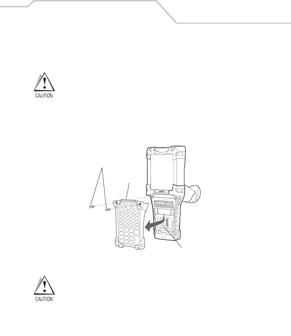
Accessories 7-7
Keypads
The mobile computer has interchangeable modular keypads. The modular keypads can be changed in
the field as necessary to support specialized applications.
Do not remove the keypad while the mobile computer is on and do not operate
the mobile computer with the keypad detached.
Follow proper ESD precautions to avoid damaging the MMC (or SD) card.
Proper ESD precautions include, but are not limited to, working on an ESD mat
and ensuring that the operator is properly grounded.
Replacing the Keypad
1. Suspend the mobile computer.
2. Remove the two keypad screws. Slide the keypad down and lift up.
Figure 7-1. Removing the Keypad
Do not apply more than 4 in-lbs of torque when tightening the keypad
screws.
Multi Media Card Holder
Keypad
Screws
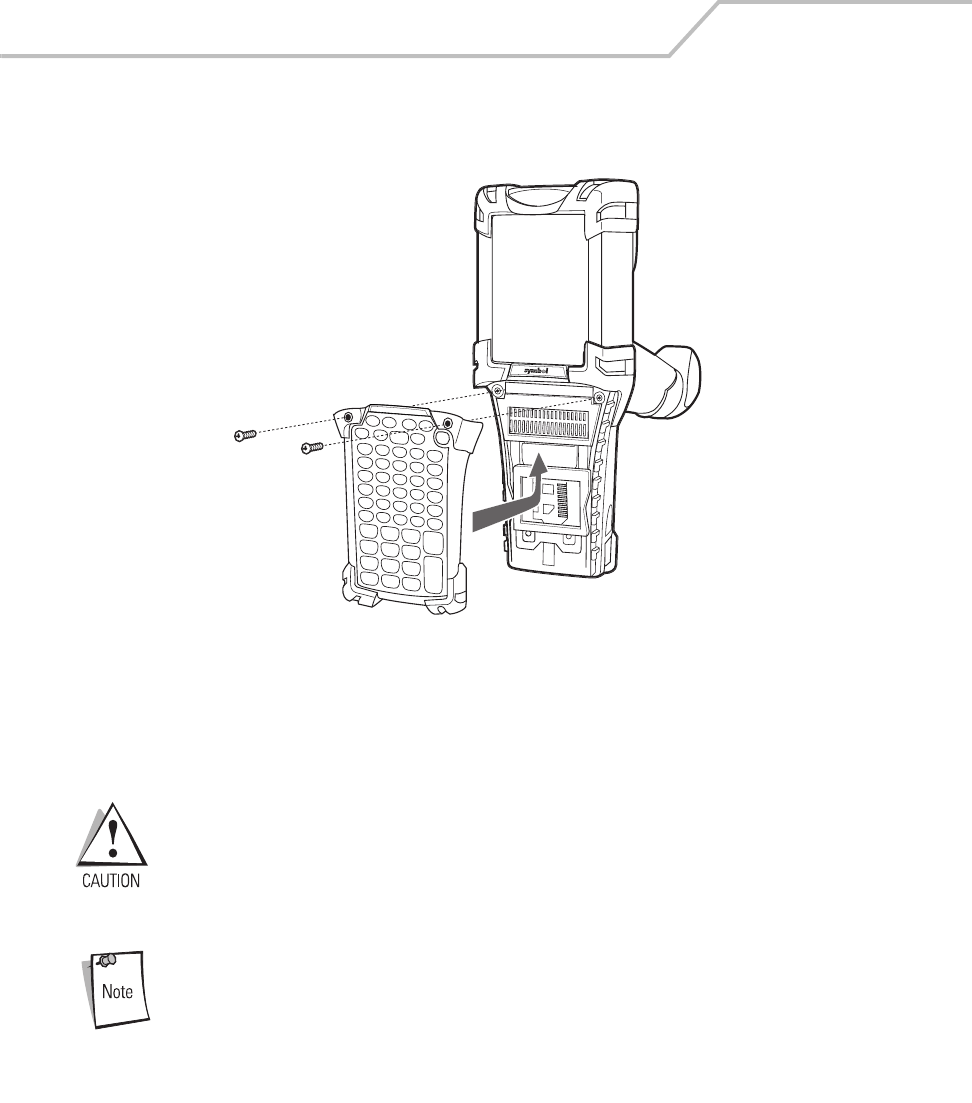
MC9000-K/S for Embedded Windows® CE .NET Product Reference Guide
7-8
3. Replace the keypad and re-attach using the two screws.
Figure 7-2. Installing the Keypad
Multi Media Card (MMC)
The MMC provides secondary non-volatile storage, however the flash memory is slower than RAM.
The MMC is located under the keypad, see Figure 7-1 on page 7-7.
Do not remove the keypad while the mobile computer is on and do not operate
the mobile computer with the keypad detached. Follow proper Electro-Static
Discharge (ESD) precautions to avoid damaging the MMC. Proper ESD
precautions include, but are not limited to, working on an ESD mat and
ensuring that the operator is properly grounded.
A Secure Device (SD) card may also be used, however security is not
supported and only one bit is supported.
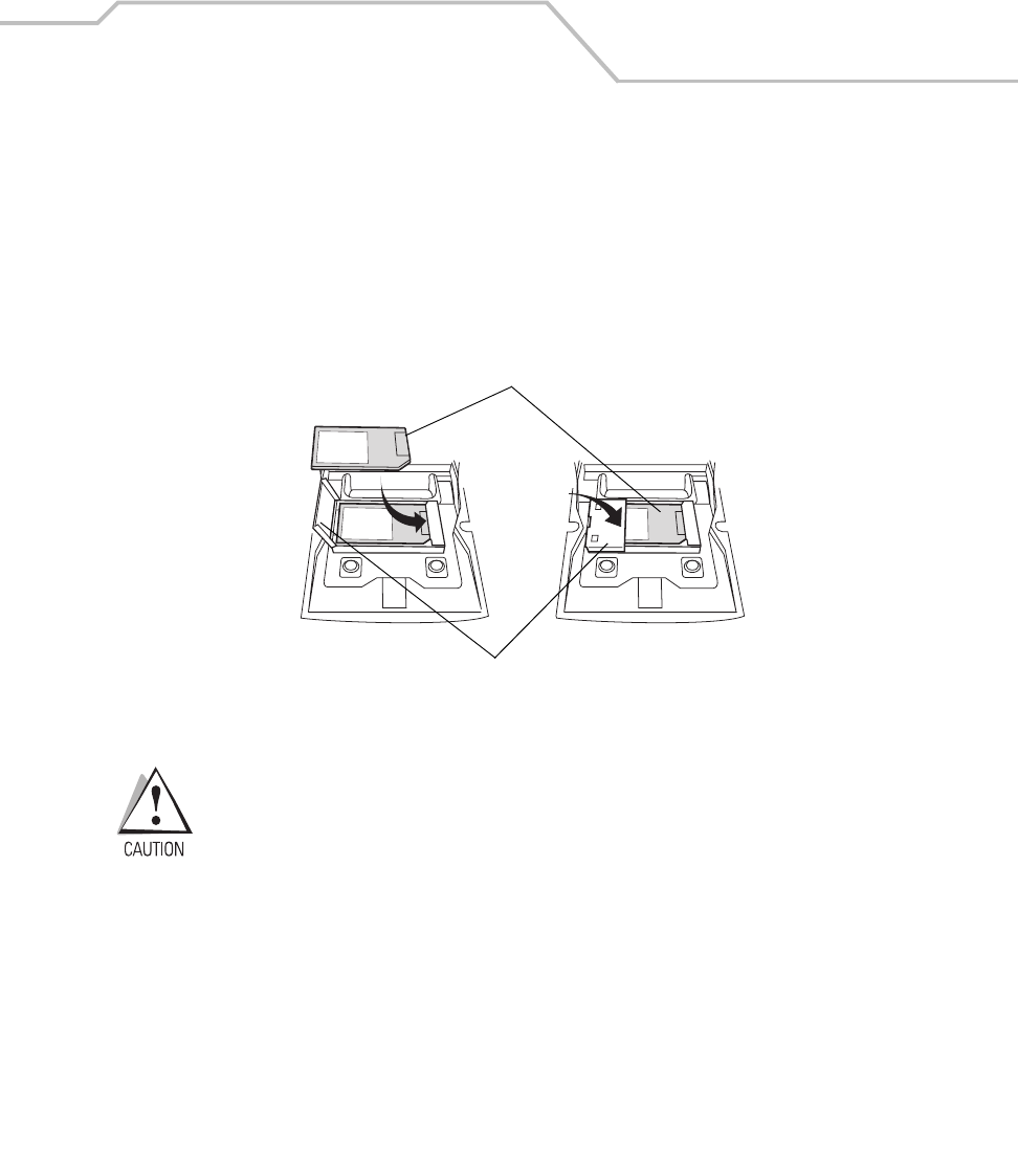
Accessories 7-9
To insert the MMC:
1. Suspend the mobile computer.
2. Remove the two keypad screws and slide the keypad down and lift off (see Figure 7-1 on
page 7-7).
3. Lift the MMC retaining door.
4. Position the MMC, with the contacts down, into the MMC holder. The MMC corner notch
fits into the holder only one way. Snap the retaining door closed.
Figure 7-3. Inserting the MMC
Do not apply more than 4 in-lbs of torque when tightening the keypad screws.
5. Replace the keypad and re-attach using the two screws (see Figure 7-2 on page 7-8).
MMC
MMC Retaining Door
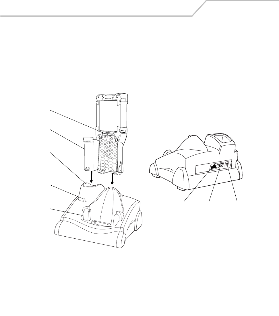
MC9000-K/S for Embedded Windows® CE .NET Product Reference Guide
7-10
Single Slot Serial/USB Cradle
This section describes how to set up and use a CRD 9000-1000S Single Slot Serial/USB Cradle with
the MC9000-K and MC9000-S. For cradle setup see Figure 7-4, for cradle communications setup
procedures see, Serial Communications Setup on page 4-10.
Figure 7-4. Single Slot Serial/USB Cradle
Indicator
LED Bar
Mobile
Computer Slot
Spare
Battery
Spare
Battery
Charging
Well
Spare
Battery
Charging
LED
Power Port
Serial Port USB Port
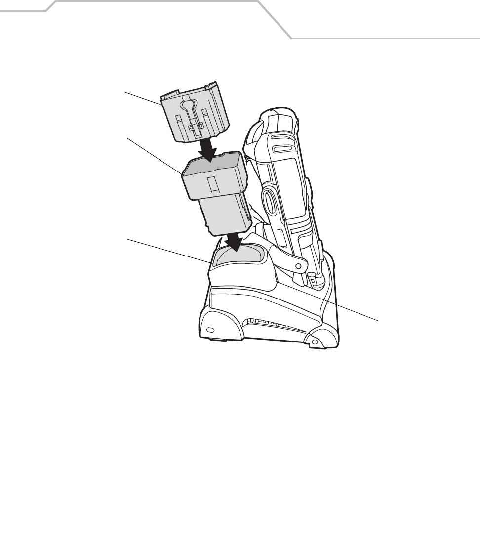
Accessories 7-11
Figure 7-5. MC9000-S Spare Battery Charging
The Single Slot Serial/USB Cradle:
• Provides 15VDC power for operating the mobile computer
• Provides serial/USB ports for data communication between the mobile computer and a host
computer or other serial devices (e.g., a printer)
• Synchronizes information between the mobile computer and a host computer (with
customized or third party software, it can also be used to synchronize the mobile computer
with corporate databases)
• Charges the mobile computer’s battery
• Charges a spare battery.
MC9000-S
Battery
Short Battery
Adapter
Spare
Battery
Charging
Well
Spare
Battery
Charging
LED
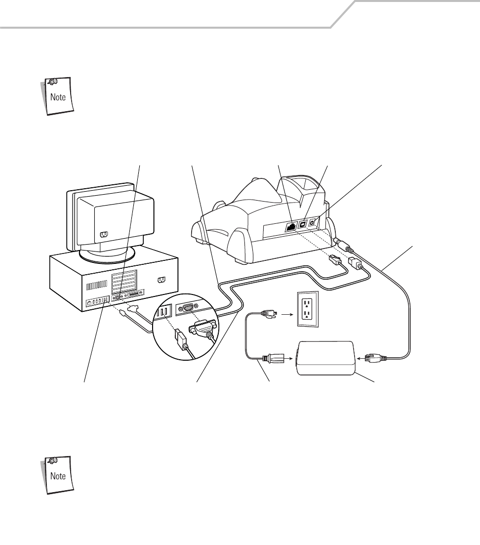
MC9000-K/S for Embedded Windows® CE .NET Product Reference Guide
7-12
Setup
The cradle requires a dedicated port on the host computer.
Figure 7-6. Single Slot Serial/USB Cradle, Power/Serial/USB Connections
Select either serial or USB for communications, do not connect cradle to both
serial and USB ports.
USB Cable
USB Port
USB Port
Serial Port
Serial Port
DC Cable
AC Line Cord Power Supply
Power Port
Serial Cable

Accessories 7-13
Battery Charging
The the single slot serial/USB cradle can charge the mobile computer’s main battery and a spare
battery simultaneously.
The mobile computer’s amber charge LED, located in the Indicator LED Bar (see Figure 1-1 on page
1-3), shows the mobile computer battery charging status.
The cradle has an amber spare battery charging LED (see Figure 7-4 on page 7-10) that shows the
spare battery charging status, see Table 7-1 for charging status indications.
The battery usually charges in less than four hours.
Table 7-1. LED Charging Status Indicators
LED Indication
Mobile Computer Charging (LED on mobile computer)
Off Mobile computer not in cradle; mobile computer not placed correctly; cradle is not powered.
Fast Blinking Amber Error in charging; check placement of mobile computer.
Slow Blinking Amber Mobile computer is charging.
Solid Amber Charging complete.
Spare Battery Charging (LED on cradle)
Off No spare battery in slot; spare battery not placed correctly; cradle is not powered.
Fast Blinking Amber Error in charging; check placement of spare battery.
Slow Blinking Amber Spare battery is charging.
Solid Amber Charging complete.
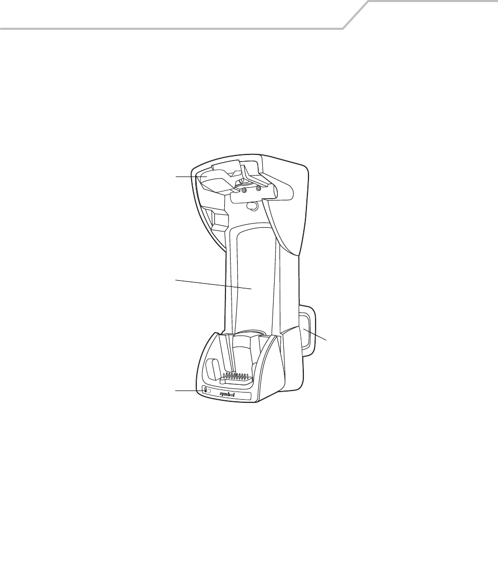
MC9000-K/S for Embedded Windows® CE .NET Product Reference Guide
7-14
Vehicle Cradle
There are two versions of the VCD9000 Vehicle Cradle, one is used with the MC9000-K mobile
computer and one is used with the MC9000-S mobile computer. Both of the VCD9000 Vehicle Cradles
are functionally identical. This section describes how to install and use a VCD9000 vehicle cradle with
the mobile computer.
Figure 7-7. VCD9000 Vehicle Cradle - Front
Mobile computer
release button
Mobile computer
slot
Spare battery
charging LED
Spare battery
slot
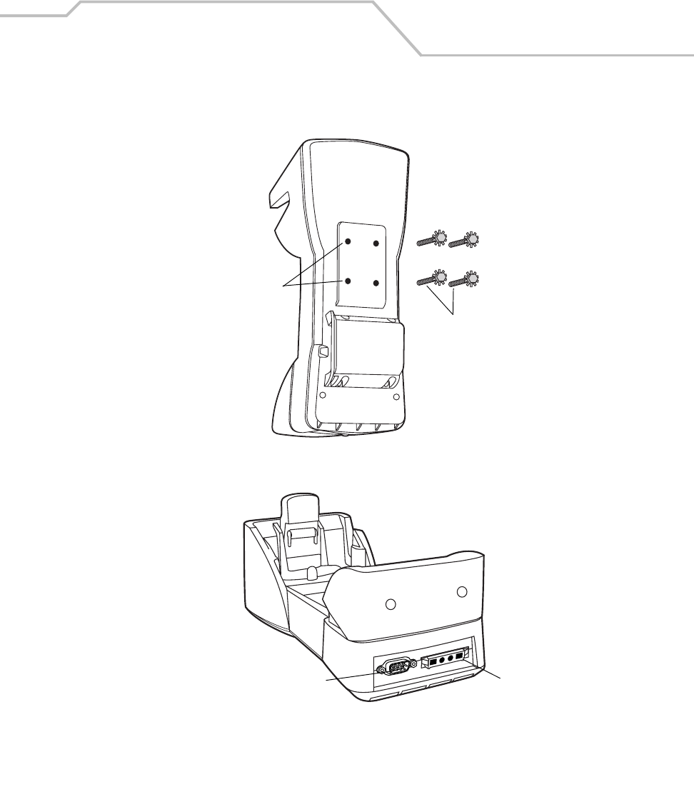
Accessories 7-15
Figure 7-8. VCD9000 Vehicle Cradle - Back / Bottom
BACK
Mounting holes
Self-locking screws
BOTTOM
Serial port Power port
MC9000-K/S for Embedded Windows® CE .NET Product Reference Guide
7-16
The vehicle’s 12 V or 24 V electrical system powers the cradle. The operating voltage range is 9 V to
32 V and requires a maximum current of 4A. Once installed into the cab of the vehicle, the cradle holds
the mobile computer securely in place. In addition, it also:
• Provides power for operating the mobile computer
• Provides a serial port for data communication between the mobile computer and an external
device (e.g., a printer)
• Charges the mobile computer’s battery
• Charges a spare battery.
ROAD SAFETY - Do not use the mobile computer while driving. Park
the vehicle first. Ensure the mobile computer is fully inserted in the
cradle. Do not place it on the seat or where it can break loose in a
collision or sudden stop. Improper insertion can result in property
damage or personal injury. Remember: Safety comes first.
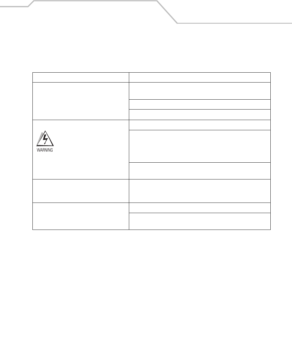
Accessories 7-17
Setup
Table 7-2 lists the requirements for setting up and using the VCD9000.
Table 7-2. VCD9000 Setup Requirements
Feature Requirements
Mounting (See page 7-18)Four 8-32 X 1” long screws with locking washers (provided as part of the
cradle).
Four #8 washers recommended.
A drill with a #6 drill bit (0.204”).
Power Connection (See page 7-20)
For continued protection
agains risk of fire, replace only
with same type and rating of
fuse according to the input
voltage used.
Power input cable (provided) connects to vehicle power.
UL-listed in-line fuse rated 4A or 5A (both included), must be used if not
connecting to vehicle’s fuse panel.
For 12 V operation use UL-listed 5A fuse (included).
For 24 V operation use UL-listed 4A fuse (included).
In-line fuse holder (included), must be used if not connecting to vehicle’s
fuse panel.
Serial Connection (See page 7-23)DB9 female serial cable (some external devices require a null modem
cable). The port is a Standard RS-232 for direct connection to a serial
device.
Communication An MC9000 Series mobile computer.
Setup of mobile computer and external device (as determined by the
application used).
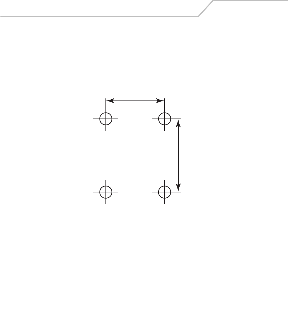
MC9000-K/S for Embedded Windows® CE .NET Product Reference Guide
7-18
Mounting
To mount the Vehicle Cradle without using a mounting bracket or mounting device compatible with
the VCD9000:
1. Prepare the mounting surface to accept four 8-32 X 1” long self-locking screws, using a copy
of the mounting template below. Drill four holes (0.204” diameter) with a #6 drill bit.
Figure 7-9. Mounting Template
1.5”
1.2”
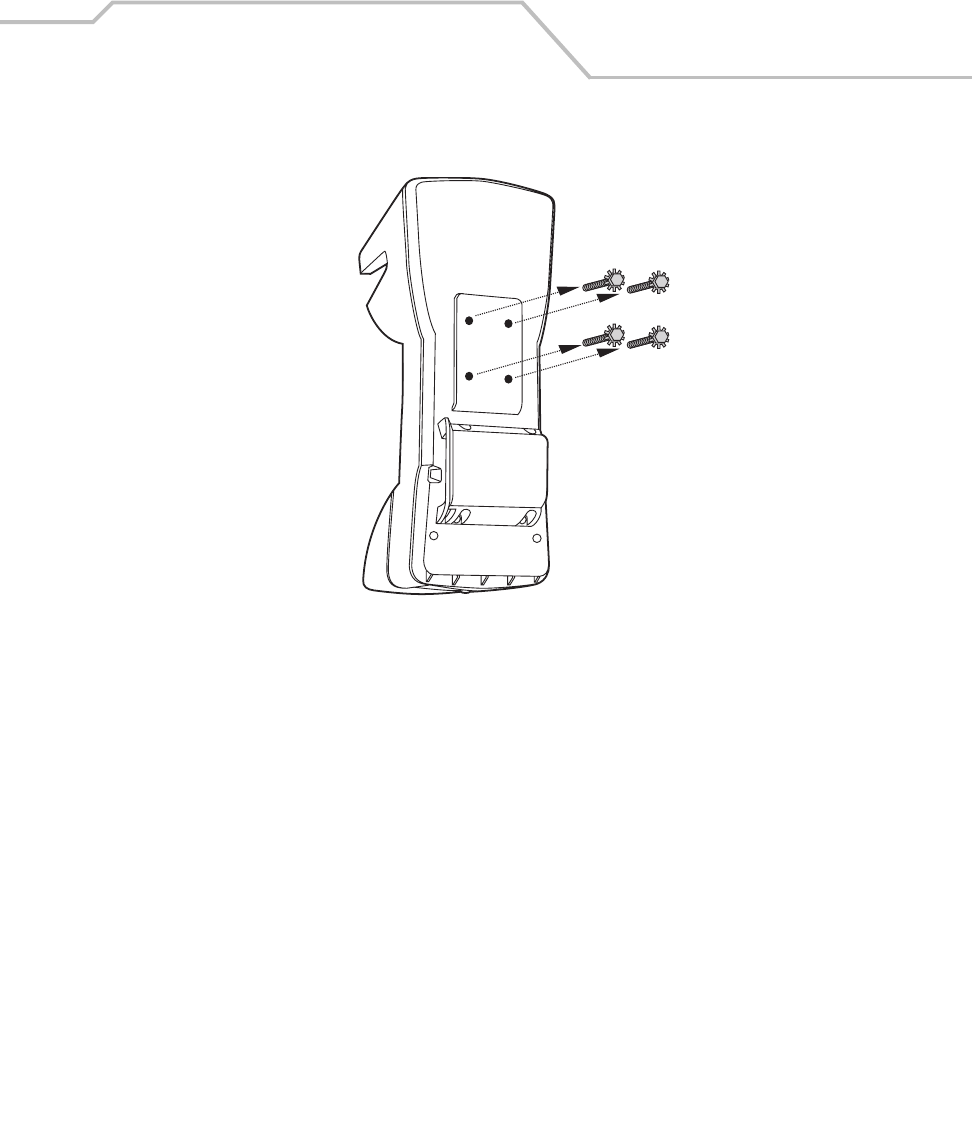
Accessories 7-19
2. Remove the four self-locking screws from the back of the cradle.
Figure 7-10. Vehicle Cradle - Back
3. Place the back of the cradle on the mounting bracket or other mounting device/surface, with
the four holes in the back of the cradle aligned with the four holes in the mounting surface.
4. Insert the four self-locking screws through the holes in the mounting surface, into the back
of the cradle.
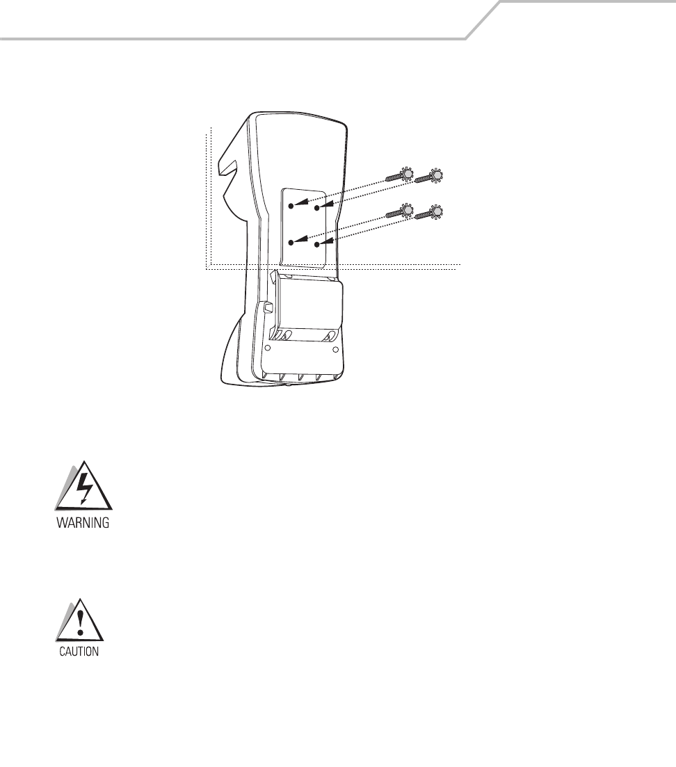
MC9000-K/S for Embedded Windows® CE .NET Product Reference Guide
7-20
Symbol recommends using #8 washers to protect the mounting surface.
Figure 7-11. Sample Mounting Configuration
Do not install the cradle on or near an air bag cover plate or within
an aerobic zone. Also, do not install it in a location that affects
vehicle safety or driving ability.
Power Connection
Read the following instructions completely before beginning.
A properly trained technician must perform the power connection. Improper
connection can damage the vehicle or cradle.
Accessories 7-21
To connect the cradle to power:
1. Locate the vehicle power source.
An accessory output in the vehicle’s fuse panel is the ideal location for
connecting the vehicle cradle power input cable. The vehicle cradle should be
added to a circuit with a maximum load capacity for the cradle and the
original circuit. Refer to the vehicle’s owner’s manual for identification of the
circuit. If a fused output is not available, the cradle must be installed with the
provided in-line fuse holder and UL-listed fuse (rated 4A for 24 V operation,
5A for 12 V operation). The fuse protects the vehicle from an electrical short
on the power line to the cradle.
To use the cradle to charge the mobile computer and spare battery, shut off
the vehicle’s ignition, then connect the cradle to unswitched power.
2. Route the power input cable from the cradle’s power port to the connection point for the
vehicle’s power source.
The means of routing and securing the power input cable from the cradle
through to the vehicle power source is extremely important. Hazards
associated with improper wiring can be severe. To avoid unintentional
contact between the wire and any sharp edges, provide the cable with proper
bushings and clamping where it passes through openings. If the wire is
subject to sharp surfaces and excess engine vibration, the wiring harness
insulation can wear away, causing a short between the bare wire and
chassis. This can start a fire.
3. When using the supplied in-line fuse holder (which must be used if not connecting to the
vehicle’s fuse panel):
a. Ensure the fuse holder contains a UL-listed fuse (rated 4A for 24 V operation, 5A for 12
V operation).
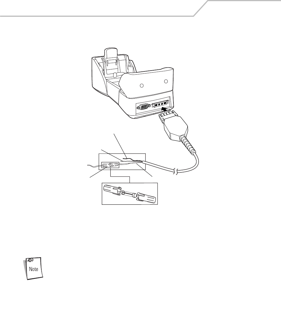
MC9000-K/S for Embedded Windows® CE .NET Product Reference Guide
7-22
b. Splice the fuse holder to the end of the red V+ wire, as shown below. Make the distance
from the fuse to the power connection point as short as possible.
Figure 7-12. Connecting Power to Cradle
4. Prepare the cable termination.
a. Red wire: connect to a +12/24 V vehicle power source.
b. Black wire and shield wire: connect to vehicle ground wire or chassis ground.
How the cable terminates depends on the vehicle. If the vehicle has a power
output connector, attach a mating connector to the end of the power cable.
You may be able to connect to a fuse panel with a simple blade terminal or
commercially available connector. Consult the vehicle owner’s manual for
information on how to access the vehicle’s power supply.
5. Connect the power input cable to the power port on the cradle.
Shield wire
(bare wire)
Ground wire
(black)
V+ power (red)
4A fuse and
fuse holder
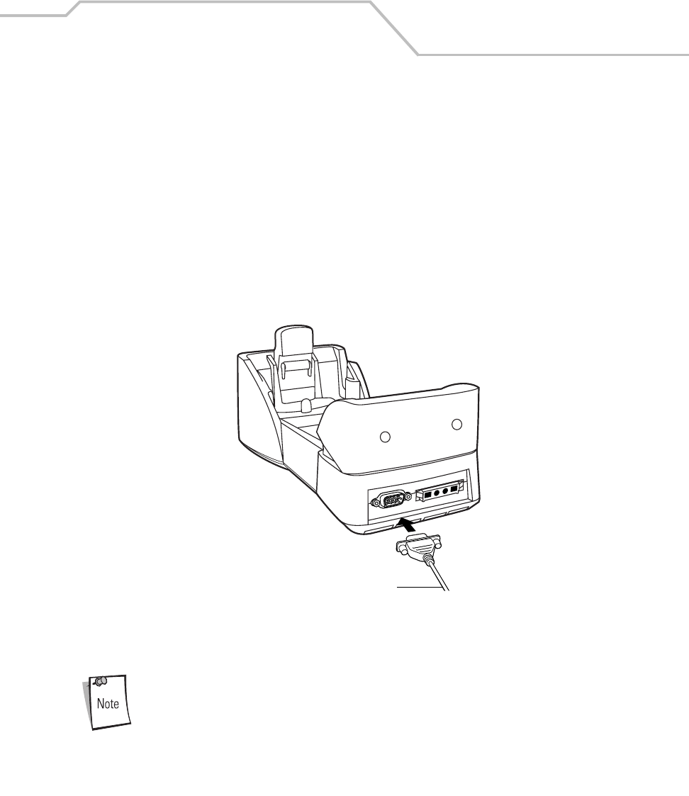
Accessories 7-23
To confirm that the cradle has power, insert the mobile computer. The mobile computer battery
charging LED blinks amber to indicate charging, then turns solid amber when the battery is completely
charged, see LED Indicators on page 7-27 for other indications.
Serial Connection
When the mobile computer is inserted into the cradle, the mobile computer’s serial port connects to
the cradle’s serial port. The mobile computer can then use the cradle’s serial port to communicate
with an external device.
To provide serial communication between the mobile computer and a serial device, connect one end
of the 9-pin serial cable to the serial port on the cradle, and the other end to the serial port on the
serial device.
Figure 7-13. Serial Connection
Some external devices may require a null modem cable.
To serial port of serial
device
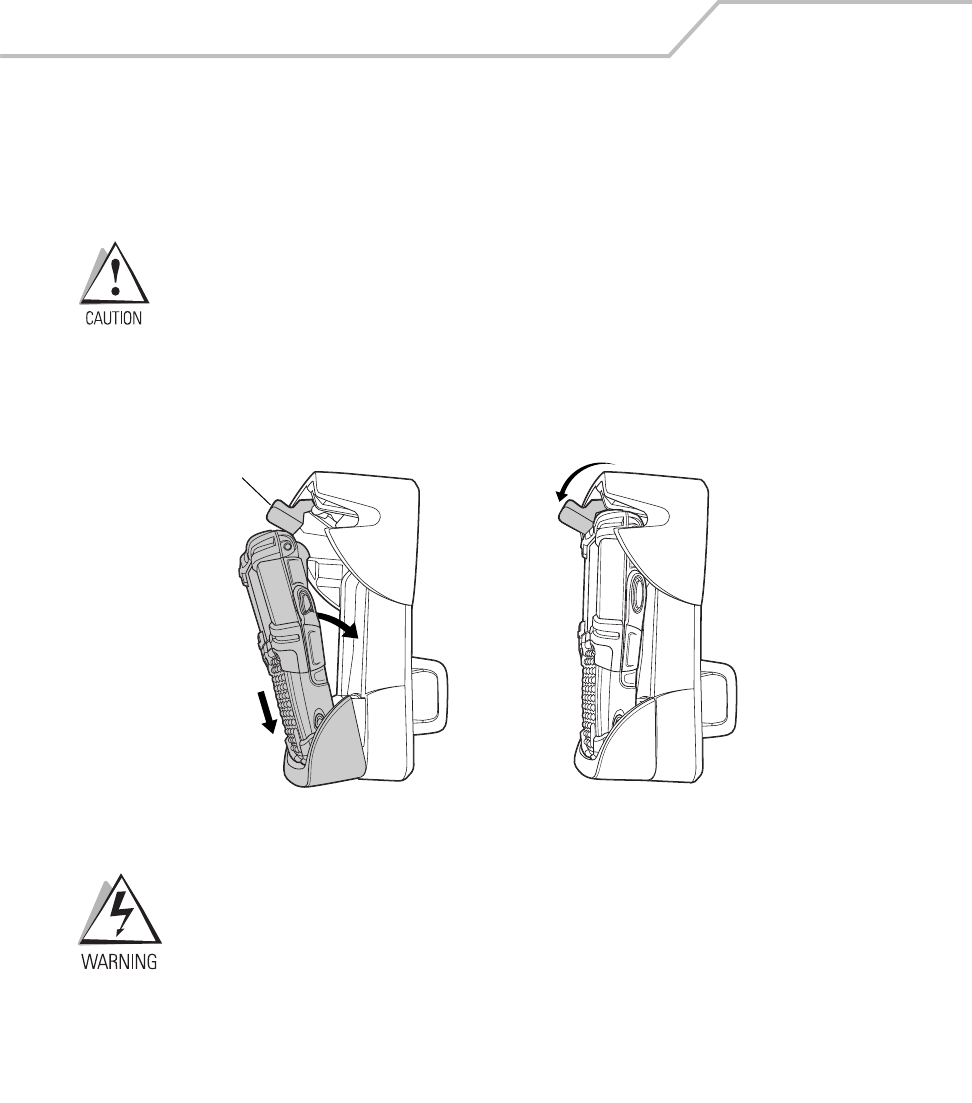
MC9000-K/S for Embedded Windows® CE .NET Product Reference Guide
7-24
To begin communication:
1. Insert the mobile computer into the cradle.
2. Initiate communication on the mobile computer, as determined by the application used.
Removing the mobile computer during communication disrupts
communication between the mobile computer and the attached device.
Mobile Computer Insertion and Removal
To insert the mobile computer into the cradle, place the bottom of the mobile computer into the
bottom of the cradle, then press the mobile computer back into the cradle until the release button
locks it in place.
Figure 7-14. Inserting the Vehicle Cradle
Ensure the mobile computer is fully inserted into the cradle.
Improper insertion can result in property damage or personal
injury. Do not use the product while driving.
Release button
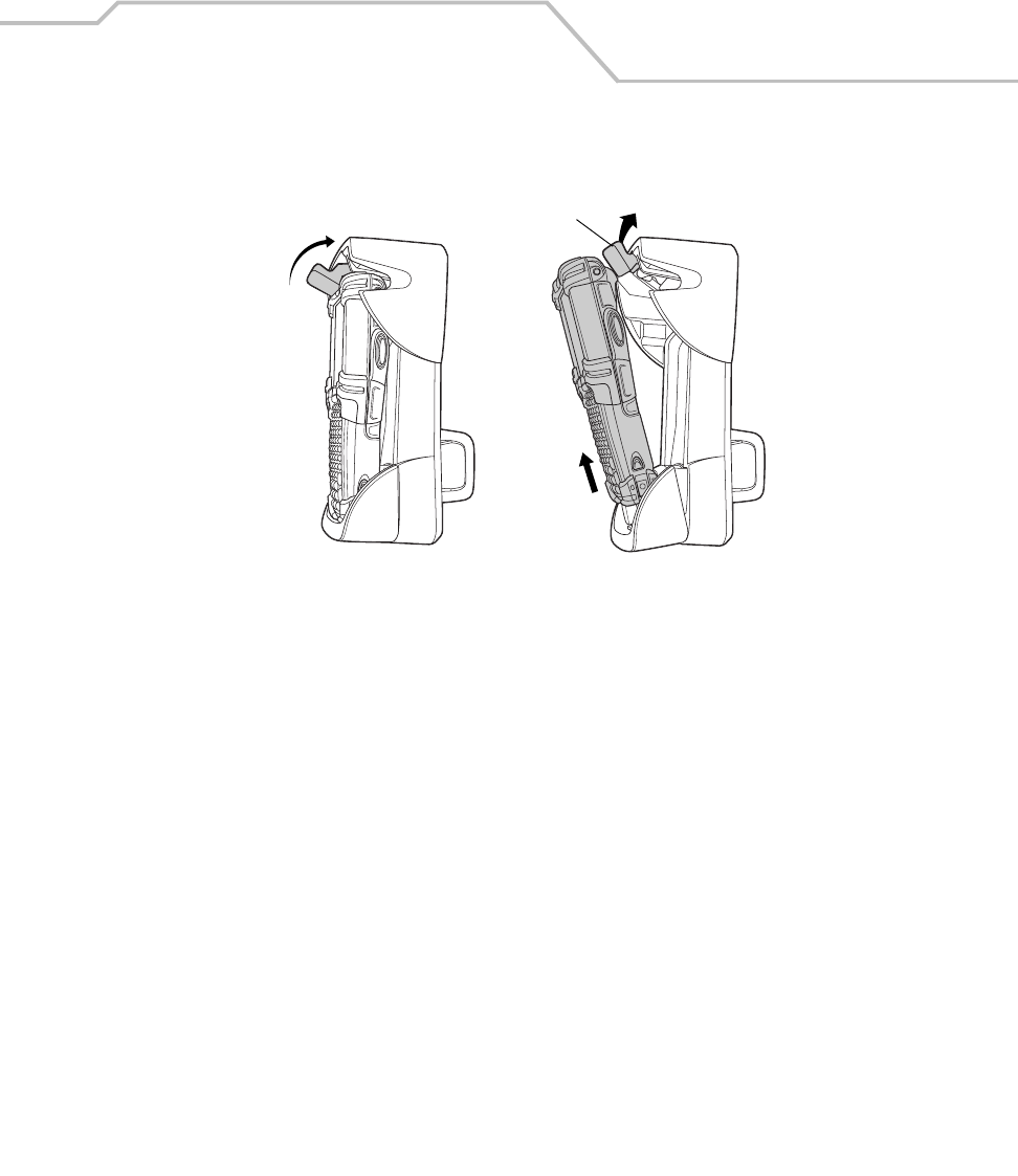
Accessories 7-25
To remove the mobile computer from the cradle, lift the release button, then lift the mobile computer
from the cradle.
Figure 7-15. Removing the Vehicle Cradle
Mobile Computer Battery Charging
To charge the mobile computer battery:
1. Ensure the cradle is connected to a power source, see Power Connection on page 7-20.
2. Insert the mobile computer into the cradle, see Mobile Computer Insertion and Removal on
page 7-24.
The mobile computer starts charging when inserted. This does not deplete the vehicle battery
significantly.
The mobile computer battery charging LED blinks amber to indicate charging, then turns solid amber
when the battery is completely charged. The battery charges in approximately four hours, see LED
Indicators on page 7-27 for other indications.
Release button
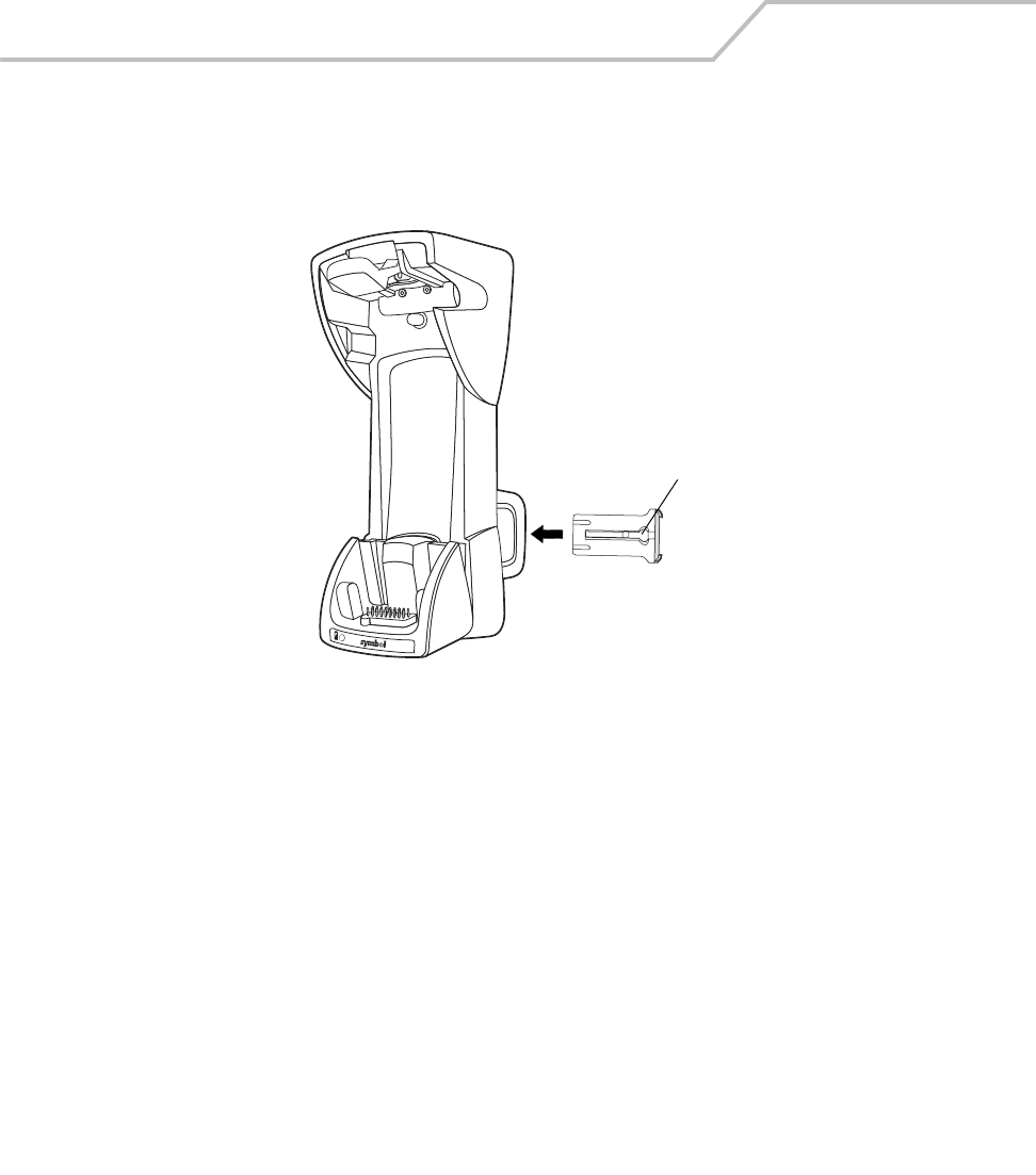
MC9000-K/S for Embedded Windows® CE .NET Product Reference Guide
7-26
Spare Battery Insertion and Removal
To insert a spare battery:
1. Insert the battery into the spare battery charging slot in the back of the cradle as shown.
Figure 7-16. Inserting the Vehicle Cradle
2. Push the battery in. Listen for the click that signifies the battery’s latch has locked the
battery into place.
To remove the spare battery, press in the battery latch, then remove the battery from the spare battery
slot.
Spare Battery Charging
1. Ensure the cradle is connected to a power source, see Power Connection on page 7-20.
2. Insert the spare battery into the cradle, see Spare Battery Insertion and Removal on
page 7-26.
The spare battery charging LED blinks amber to indicate charging, then turns solid amber when the
battery is completely charged. The battery charges in approximately four hours, see LED Indicators on
page 7-27 for other indications.
Spare battery
latch
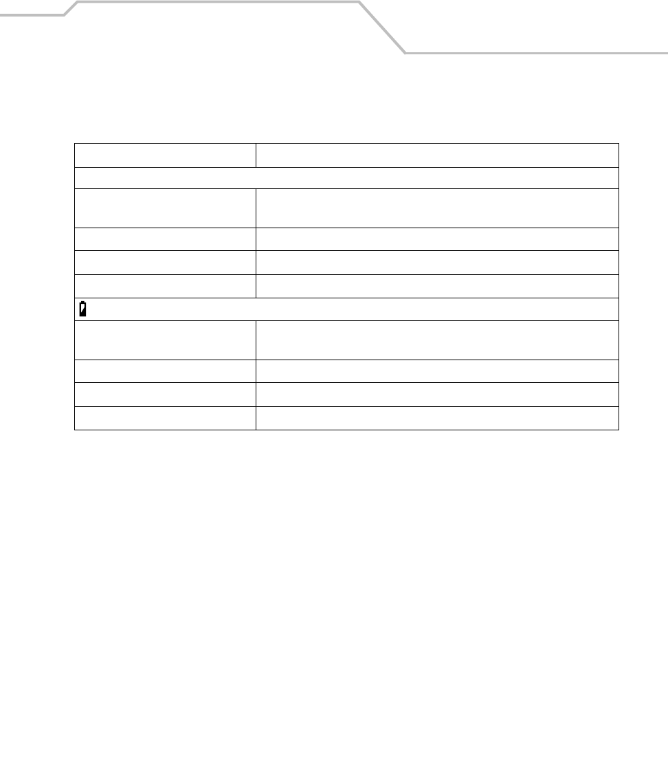
Accessories 7-27
LED Indicators
Care and Cleaning
Avoid getting oils, grease, or gasoline on the cradle, and do not let debris gather in the bottom of the
cradle slot. When necessary, clean the cradle with a mild cleaner. If necessary, contact Symbol for
advice on whether to use a particular cleaner.
Table 7-3. LED Charging Indicators
Cradle LED Indication
Mobile Computer Battery Charging LED
Off Mobile computer is not in cradle; mobile computer is not inserted correctly;
cradle is not powered.
Fast Blinking Amber Error in charging; check placement of mobile computer.
Slow Blinking Amber Mobile computer is charging.
Solid Amber Charging complete.
Spare Battery Charging LED (on Cradle)
Off No spare battery in slot; spare battery is not inserted correctly; cradle is not
powered.
Fast Blinking Amber Error in charging; check placement of spare battery.
Slow Blinking Amber Spare battery is charging.
Solid Amber Charging is complete.
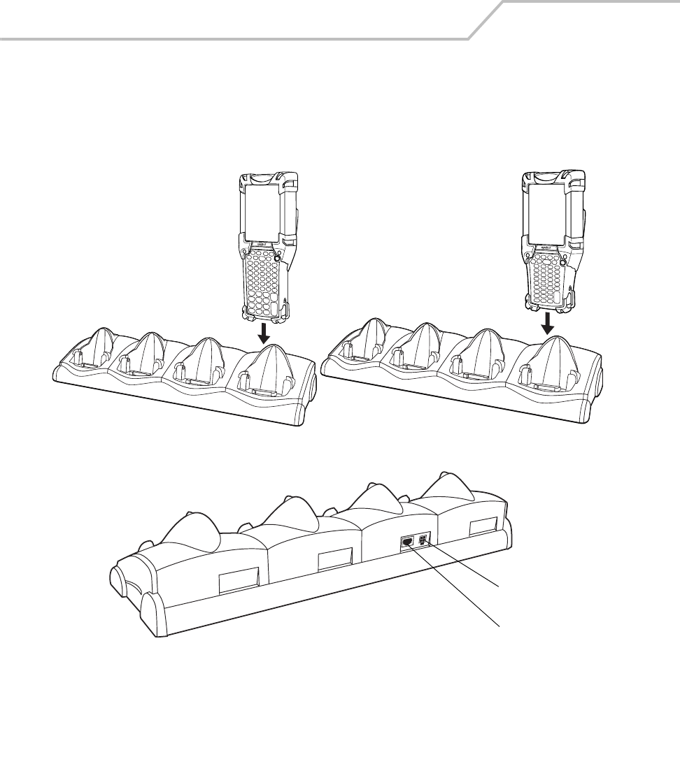
MC9000-K/S for Embedded Windows® CE .NET Product Reference Guide
7-28
Four Slot Ethernet Cradle
This section describes how to set up and use a Four Slot Ethernet cradle. For cradle communication
setup procedures, see Ethernet Setup on page 4-16.
Figure 7-17. Four Slot Ethernet Cradle
Power Port
Ethernet
Communication Port
MC9000-K MC9000-S
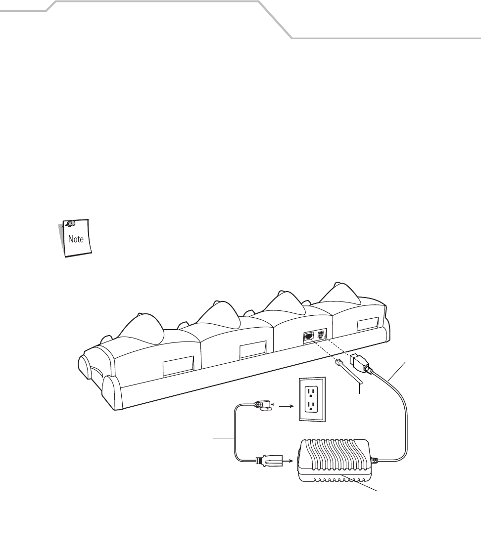
Accessories 7-29
The Four Slot Ethernet cradle has the following attributes:
• Provides 12VDC power for operating the mobile computer.
• Enables data communication between the mobile computer (up to four) and a host computer,
over an Ethernet network (using a standard 10Base-T Ethernet cable).
• Synchronizes information between the mobile computer and a host computer. (With
customized or third party software, it can also be used to synchronize the mobile computer
with corporate databases.)
• Simultaneously charges up to four batteries in the mobile computer.
Setup
The Ethernet cradle must be connected to a power source and to an Ethernet Hub (when
applicable).
Figure 7-18. Four Slot Ethernet Cradle Power Connection
AC Line Cord
Power Supply
DC Cable
To Ethernet Hub
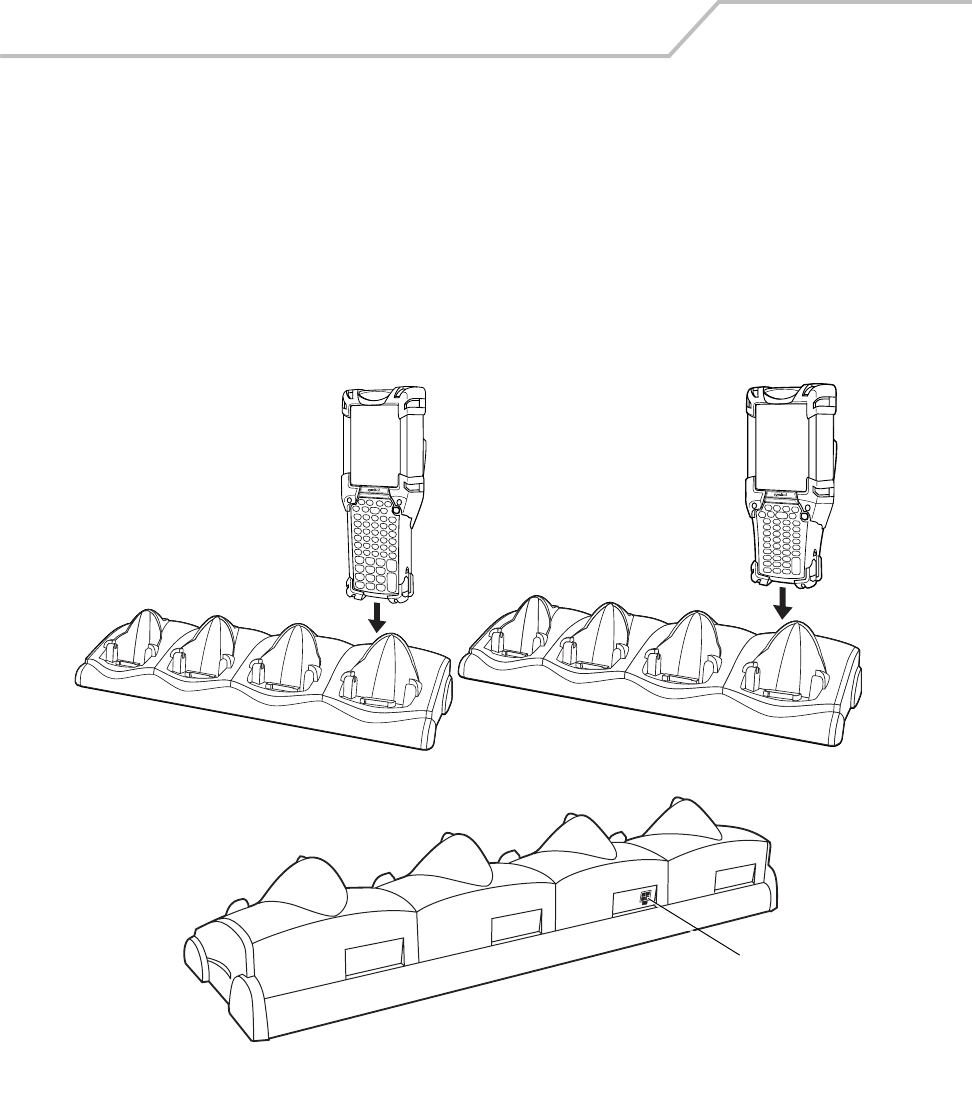
MC9000-K/S for Embedded Windows® CE .NET Product Reference Guide
7-30
Battery Charging Indicators
The mobile computer’s amber charge LED, located in the Indicator LED Bar, see Figure 1-1 on page 1-
3, shows the battery charging status. See Table 7-1 on page 7-13 for charging status indications.
The battery usually charges in less than four hours.
Four Slot Charge Only Cradle
This section describes how to set up and use a Four Slot Charge Only Cradle with the mobile
computer.
Figure 7-19. Four Slot Charge Only Cradle
MC9000-K MC9000-S
Power Port
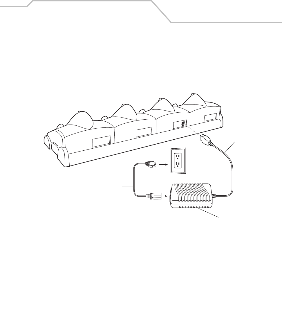
Accessories 7-31
The Four Slot Charge Only Cradle has the following attributes:
• Provides 12VDC power for operating the mobile computer.
• Simultaneously charges up to four batteries in the mobile computer.
Setup
Figure 7-20. Four Slot Cradle Power Connections
Battery Charging Indicators
The mobile computer’s amber charge LED, located in the Indicator LED Bar, see Figure 1-1 on page 1-
3, shows the battery charging status. See Table 7-1 on page 7-13 for charging status indications.
The battery usually charges in less than four hours.
AC Line Cord
Power Supply
DC Cable
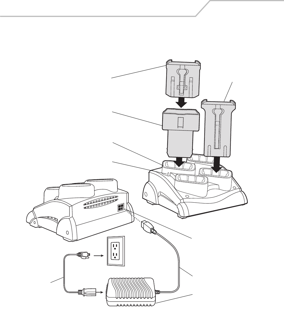
MC9000-K/S for Embedded Windows® CE .NET Product Reference Guide
7-32
Four Slot Spare Battery Charger
This section describes how to set up and use the Four Slot Spare Battery Charger to charge up to four
MC9000-K or MC9000-S spare batteries.
Figure 7-21. Four Slot Spare Battery Charger
Power Port
DC Cable
Power Supply
MC9000-S
Spare
Battery
Spare
Battery
Charging
Slot
Spare Battery
Charging LEDs (4)
AC Cord
Short
Battery
Adapter
MC9000-K
Spare
Battery

Accessories 7-33
Spare Battery Charging with the Four Slot Spare Battery Charger
1. Connect the charger to a power source.
2. For MC9000-K battery charging, insert the battery into a spare battery charging slot and
gently press down on the battery to ensure proper contact.
3. For MC9000-S battery charging use the Short Battery Adapter, see Figure 7-5 on page 7-11
and gently press down on the battery to ensure proper contact.
LED Charge Indications
An amber LED is provided on the Four Slot Spare Battery Charger to indicate spare battery charging
status, see Table 7-1 on page 7-13 for charging indication details.
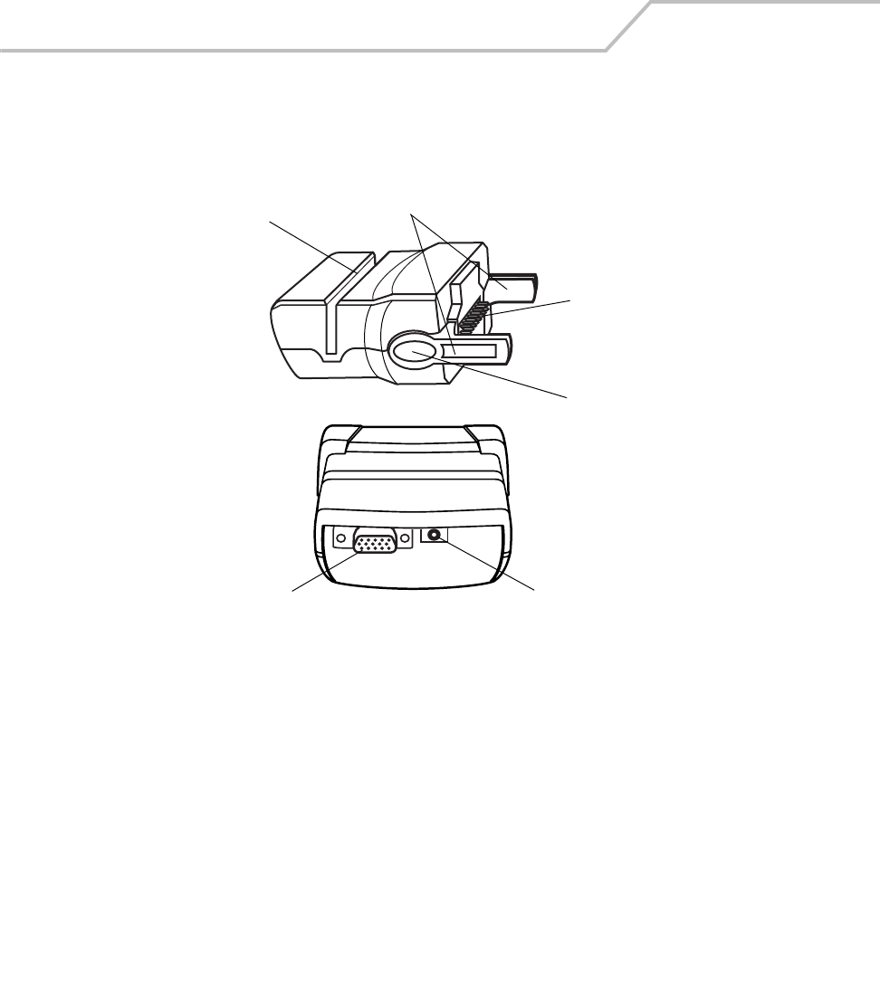
MC9000-K/S for Embedded Windows® CE .NET Product Reference Guide
7-34
Magnetic Stripe Reader
This section describes how to set up and use the snap-on MSR with the MC9000-K and the MC9000-
S. The MSR snaps on to the mobile computer and can be removed easily when not in use.
Figure 7-22. MSR
The MSR:
• Provides mobile computer’s operating power and battery charging power when used with
the Symbol approved power supply and cable.
• Allows the mobile computer to capture data from magnetic stripe cards. (To download MSR
data capture software, visit: http://devzone.symbol.com.)
• Provides serial connection through the serial pass-through port for communication with a
serial device, such as a host computer. For communication setup procedures, see Serial
Communications Setup on page 4-10.
• Provides USB connection through the USB pass-through port for communication with a USB
device, such as a host computer. For communication setup procedures, see USB Connection
Setup on page 4-13.
Card Reader Slot Latches
Power Port
Communications Port
Pogo Pin Passthrough
Connector
Latch Grip
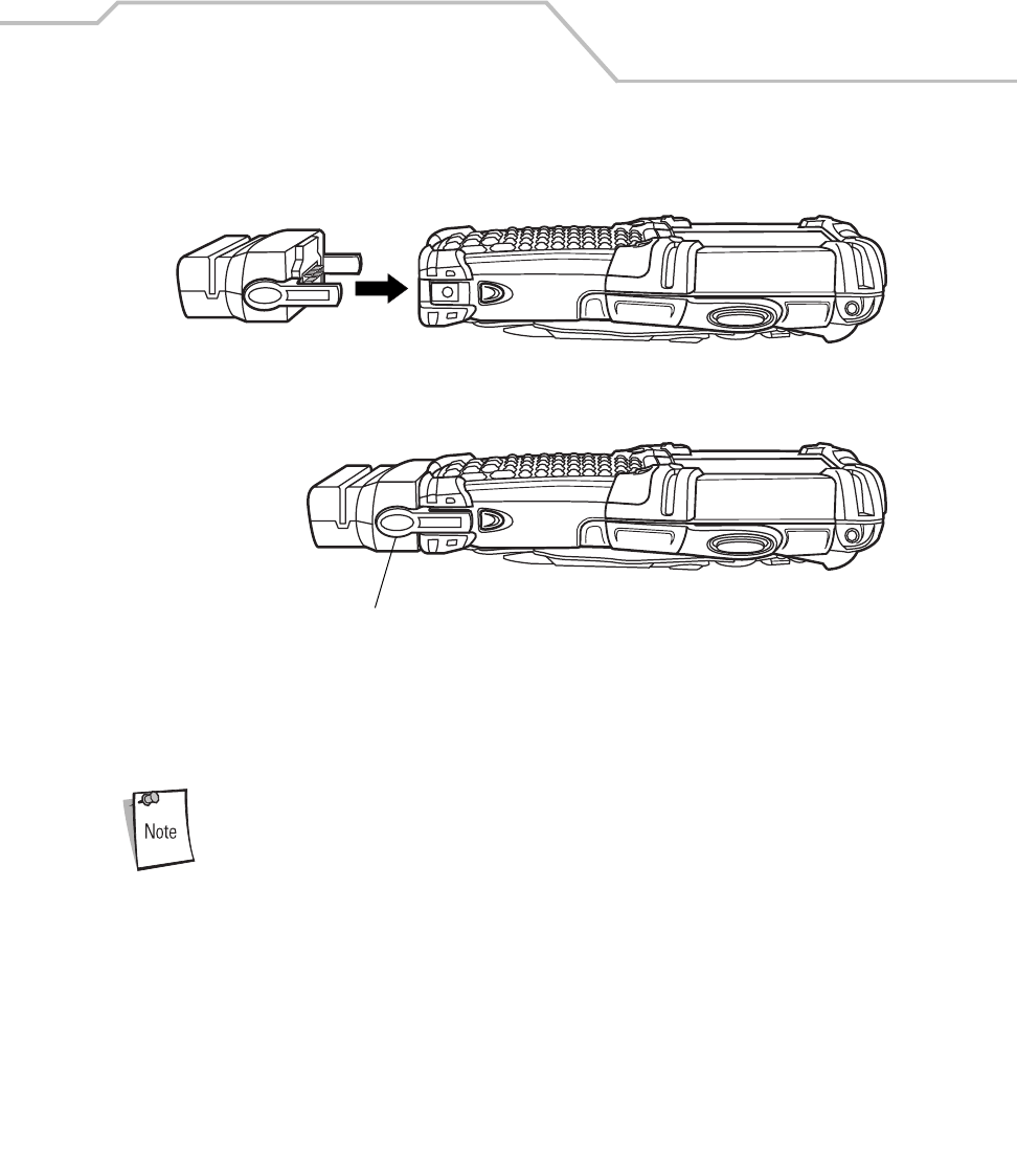
Accessories 7-35
MSR and CAM Installation/Removal
To attach, snap the MSR or the CAM onto the bottom of the mobile computer.
Figure 7-23. MSR and CAM Installation
To remove, squeeze the latch grips and pull the MSR or the CAM from the mobile computer.
Remove the MSR from the bottom of the mobile computer before using a
cradle for charging and communication.
Latch Grip
(one on each side)
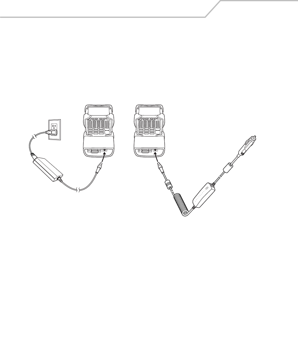
MC9000-K/S for Embedded Windows® CE .NET Product Reference Guide
7-36
Power Connection
The MSR or CAM can accept power from either a standard AC plug or from a 12 VDC vehicle power
source:
1. Select either the universal AC power supply or the 12VDC power cable.
2. Plug the power cord into the unit.
3. Plug the other end of the power cord into the power source.
Figure 7-24. MSR or CAM Power Connection
LED Charge Indications
The mobile computer’s charging LED blinks amber to indicate that the battery is charging and turns
solid amber when battery is completely charged. The battery usually charges in less than four hours.
See Table 7-1 on page 7-13 for charging indication details.
Vehicle Power Supply
AC Power Supply
OR
Or
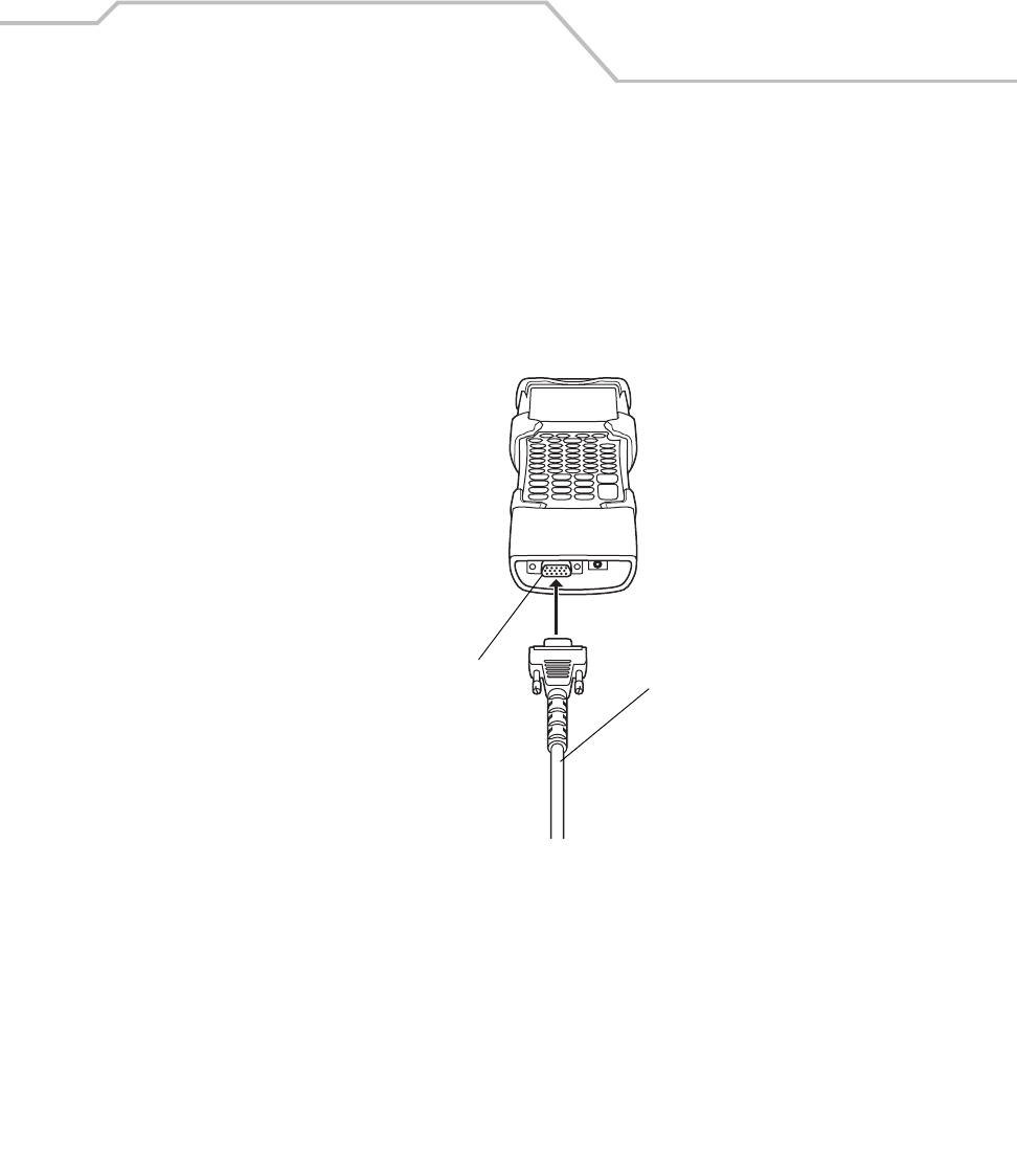
Accessories 7-37
Serial/USB Connection
The MSR can connect to and communicate with a serial/USB device, such as a printer or host
computer, through its serial port. See CAM and MSR Communications Setup on page 7-41 for the host
computer communication setup procedure.
To connect the MSR to a serial/USB device, connect one end of the serial device cable into the
communications port on the MSR and the other end into the serial/USB port on the device.
Figure 7-25. MSR or CAM Serial/USB Connection
To Device
Communications Port

MC9000-K/S for Embedded Windows® CE .NET Product Reference Guide
7-38
Magnetic Stripe Reading
The MSR9000 application is designed to work with the MSR. This sample application illustrates how
an application should handle MSR inputs. From the Test Applications window, double-tap the
MSR9000 icon. The MSR window appears, see MSR9000 on page 5-25 or MSR Cameo on page 5-26.
The card may be swiped in either direction, from left to right or from right to left, with the magnetic
stripe facing towards the mobile computer. For best results, gently press down on the card while
swiping to ensure contact with the bottom of the reader.
The MSR does not need to be attached to the power supply to read magnetic
stripes.
When creating software applications involving the CAM or MSR, the
application developer should be aware that the devices are designed to
breakaway from the terminal if accidentally dropped. The application should
always check for the snap-on presence before talking to the device.
To use the MSR:
1. Attach the MSR, see MSR and CAM Installation/Removal on page 7-35.
2. Power on the mobile computer.
3. Tap the MSR or the MSR Cameo icon to start the application.
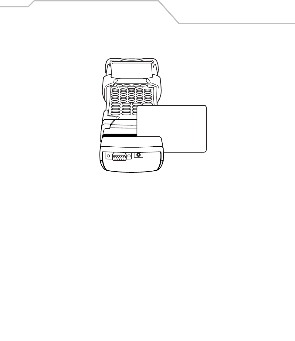
Accessories 7-39
4. Swipe the magnetic stripe card through the reader, ensuring the magnetic stripe on the card
is positioned as shown below.
Figure 7-26. MSR Magnetic Stripe Card Swiping
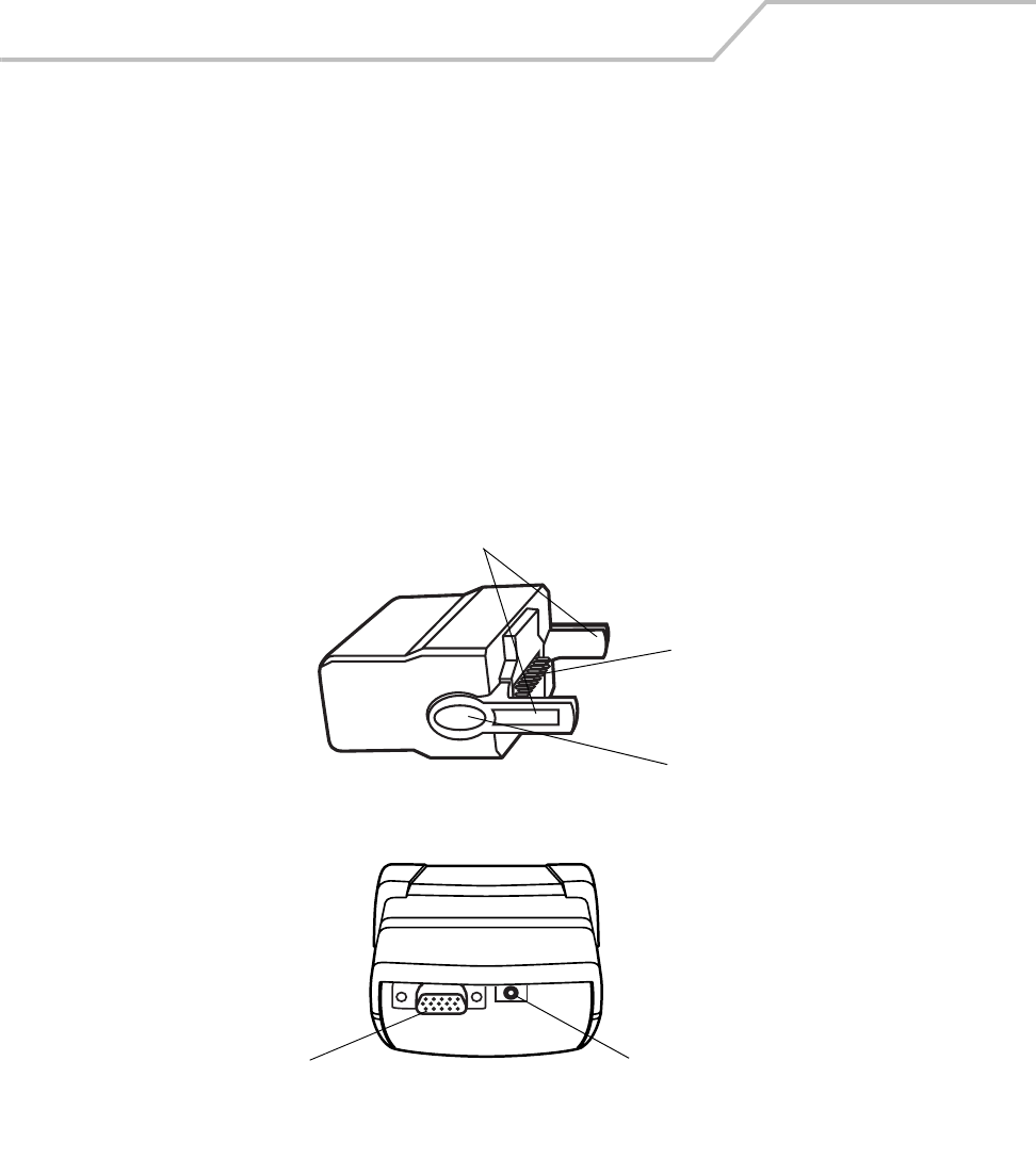
MC9000-K/S for Embedded Windows® CE .NET Product Reference Guide
7-40
Cable Adapter Module
This section describes how to set up and use the CAM. Both the CAM and the MSR attach to the
mobile computer the same way, see Figure 7-23 on page 7-35. They also share the same power
connection, see Figure 7-24 on page 7-36 and the same serial/USB connection, see Figure 7-25 on
page 7-37. The CAM and the MSR allow connection and charging of the MC9000-K and the MC9000-
S using the following cables:
• Auto Charge Cable
• DEX Cable
• Serial Cable
• Printer Cable
•USB Cable.
Figure 7-27. CAM
Latches
Power PortCommunications Port
Pogo Pin Connector
Latch Grip
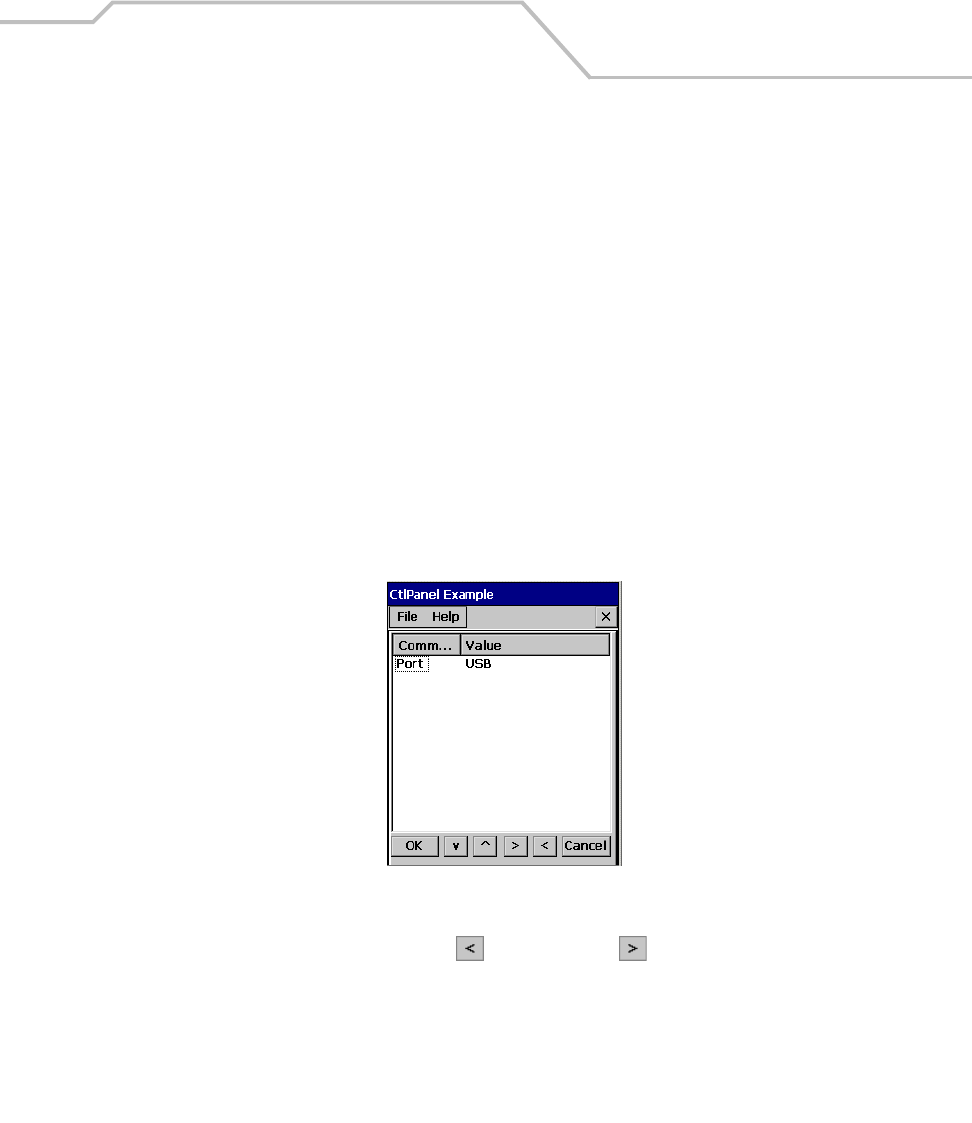
Accessories 7-41
The CAM:
• Provides mobile computer’s operating power and battery charging power when used with
the Symbol approved power supply and cable.
• Provides serial connection through the serial pass-through port for communication with a
serial device, such as a host computer. For communication setup procedures, see Serial
Communications Setup on page 4-10.
• Provides USB connection through the USB pass-through port for communication with a USB
device, such as a host computer. For communication setup procedures, see USB Connection
Setup on page 4-13.
CAM and MSR Communications Setup
Both the CAM and MSR can be set up to communicate either with a serial connection or a USB
connection and both devices use the same setup procedure. For detailed communications setup
procedures, see Communication Setup on page 4-9.
1. On the mobile computer double-tap the Ctl Panel icon and double-tap Comm Settings to
enter the Comm Settings, window.
Figure 7-28. Comm Settings Window
2. With Port highlighted, use the left and right arrow buttons to select the value.
Select the Comm port setting appropriate for the host computer, choose the default value of
USB, or set to Serial1 @ 115200.
3. Tap OK to exit the Comm Settings window and tap Exit to exit the Control Panel window.
4. Ensure that ActiveSync was installed on the host computer and a partnership was created.
See Installing ActiveSync on page 4-3 and Setting up a Partnership on page 4-4.
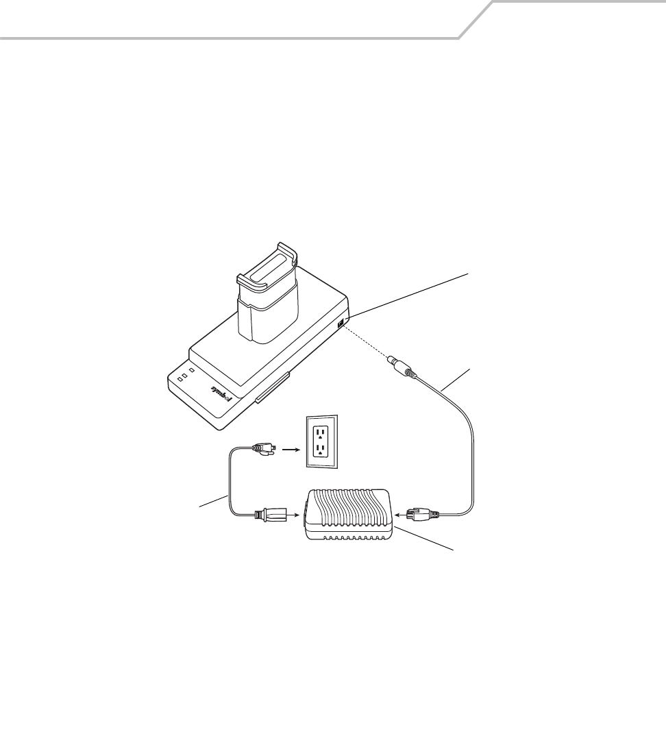
MC9000-K/S for Embedded Windows® CE .NET Product Reference Guide
7-42
Universal Battery Charger (UBC) Adapter
There are two UBC Adapters, one for the MC9000-K/G Batteries and one for the MC9000-S Batteries.
The UBCs can be used with a power supply as a standalone spare battery charger or it can be used
with the four station UBC2000 to provide charging to simultaneously charge up to four spare
batteries. For additional information on the UBC 2000 see the UBC 2000 Quick Reference Guide 70-
33188-xx.
1. Connect the power supply to the power port on the side of the UBC Adapter.
Figure 7-29. UBC Adapter Power Connection
Power Supply
AC Line Cord
DC Cable
Power Port
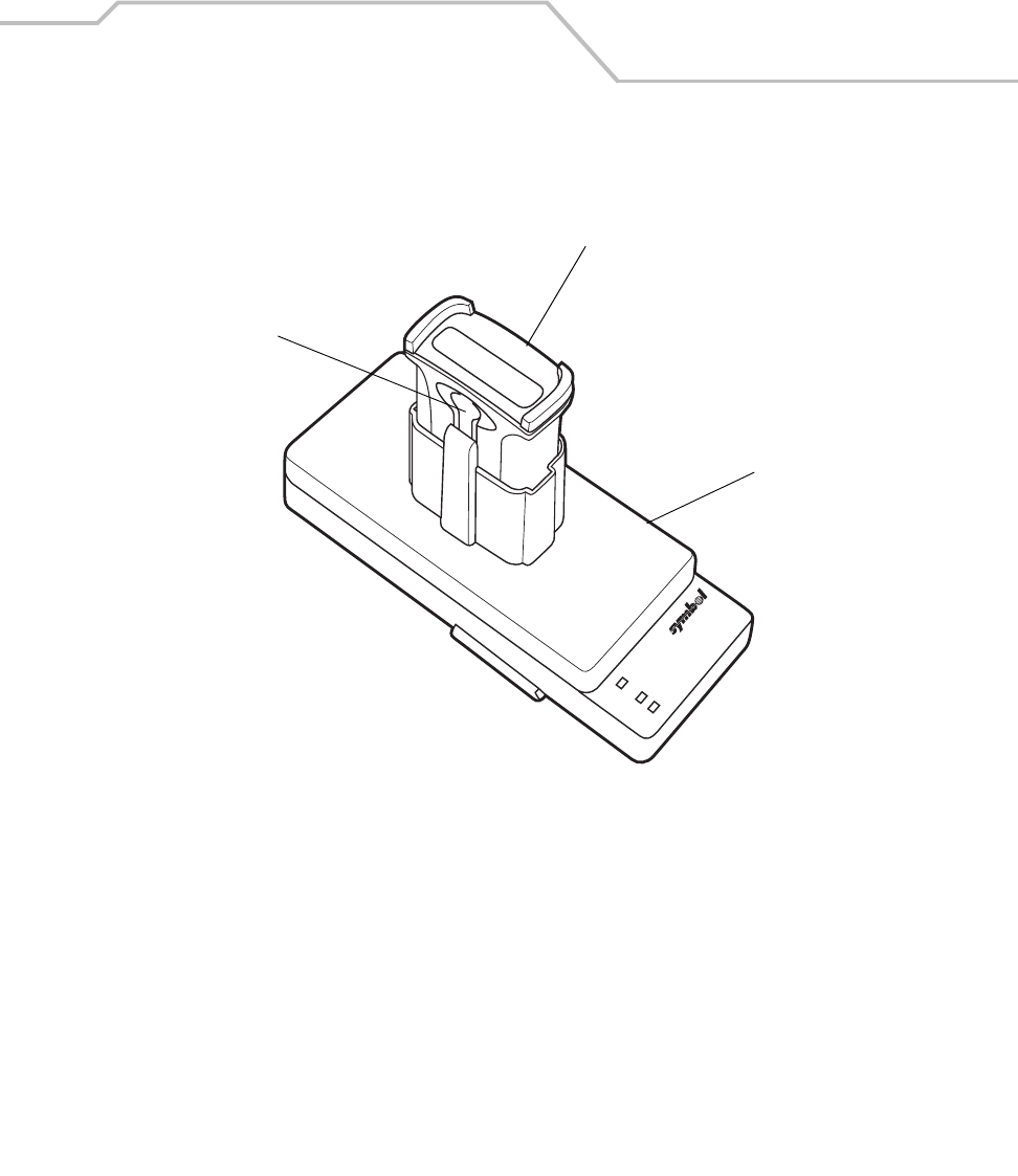
Accessories 7-43
2. Insert the battery into the battery slot with the charging contacts facing down (over charging
pins) and gently press down on the battery to ensure proper contact. See Table 7-4 for the
UBC Adapter LED indications.
Figure 7-30. Battery Insertion
3. To remove the battery, press the battery release and lift battery out of slot.
UBC Adapter
Battery Release
Battery
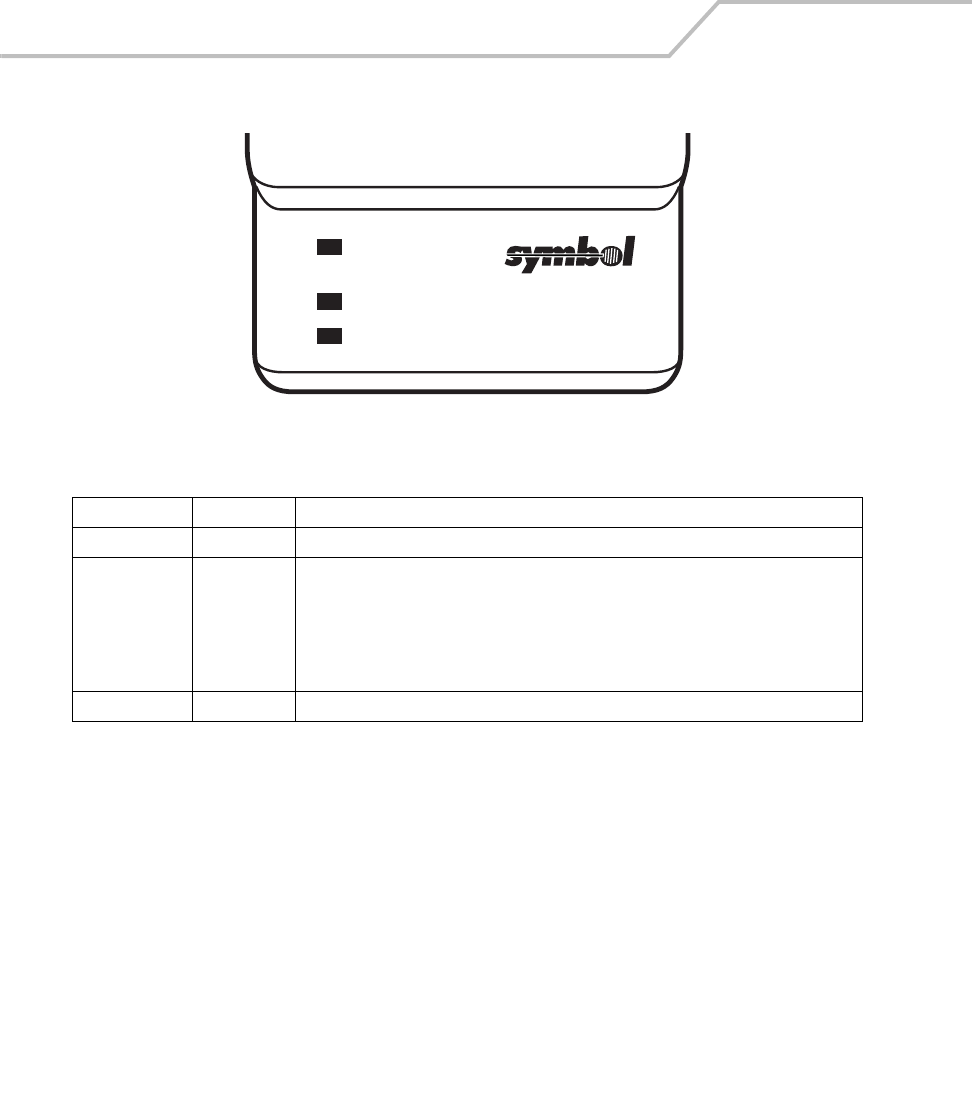
MC9000-K/S for Embedded Windows® CE .NET Product Reference Guide
7-44
Figure 7-31. UBC Adapter LEDs
Table 7-4. UBC Adapter Charge LED Status Indications
LED Indication Description
POWER Green Power is connected to the UBC Adapter.
READY or Green Charging complete.
STANDBY or Flashing-
Yellow
The battery was deeply discharged and is being trickle charged to bring the voltage up
to the operating level. After operating level voltage is achieved the battery charges
normally.
FAULT Yellow Charging error, check placement of mobile computer/spare battery.
CHARGING Yellow Normal charge.
POWER
READY or STANDBY or FAULT
CHARGING
(Green) (Flashing Yellow) (Solid Yellow)
(Solid Yellow)
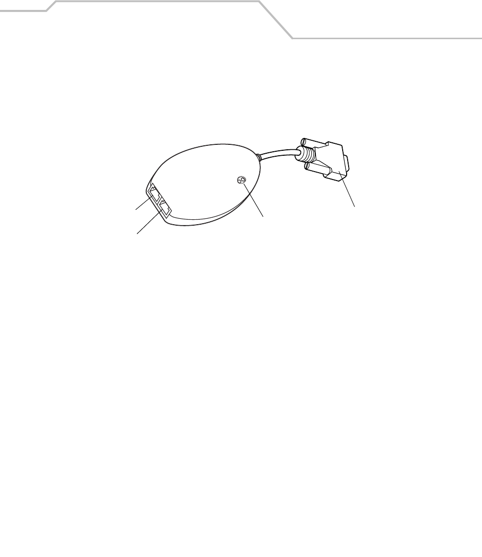
Accessories 7-45
Modem Module
The MDM9000 Modem Module enables data communication between the MC9000 mobile computer
and a host computer, remotely through the phone lines, and synchronizes information between the
MC9000 and a host computer. This section describes how to setup and use the MDM9000 Modem
Module.
Figure 7-32. Modem Module
The Modem Module enables data communication between the mobile computer and a host computer,
remotely through the phone lines, and synchronizes information between the mobile computer and a
host computer.
The following items are required for a modem connection:
• Telephone number, IP address and DNS/WINS address information from the dial-in server
administrator
• Dial-in account on the host system, including a user ID and password
• RJ11 or RJ12 modem cable
• Telephone jack that supports plug-in modems connected to the local telephone system
• Setup of Country Codes to use the modem with the appropriate country’s telephone network.
The following items are required for communication:
• MC9000 Series mobile computer
• Cable Adapter Module (CAM), Symbol p/n ADP9000-100 (see Cable Adapter Module on
page 7-40)
• Serial Adapter Cable (for communication via cradle), Symbol p/n 25-63856-01
• Microsoft ActiveSync
• Setup of host computer and mobile computer.
Serial Port
Line In Port LEDs
Phone Port
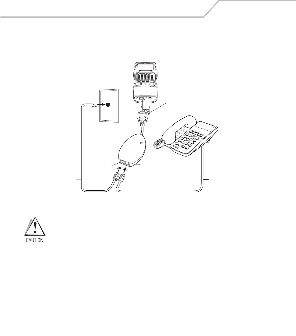
MC9000-K/S for Embedded Windows® CE .NET Product Reference Guide
7-46
Setup
Connecting to the Mobile Computer
Figure 7-33. Modem Module Connection - Mobile Computer
Do not connect the modem's 15-pin connector into a VGA port of a host
computer.
Using the Correct Telephone Line Type
Use a standard analog phone line, as in most households. In an office, use a line connected to a fax
machine or modem. In a hotel, request a room with a standard phone line or data port. If necessary,
check with the local phone company or administrator to make sure you are using the right type of line
before sending data.
3
DEF
2
ABC
1
6
MNO
5
JKL
4
GHI
9
WXY
CNF
FNC
RECALL
8
TUV
7
PRS
#
0
OPER
HOLD
TRF ANS SPKR
LNR SPD
*
CAM
Male 15-pin connector
Phone cord
Line In port
Phone cord
Phone port
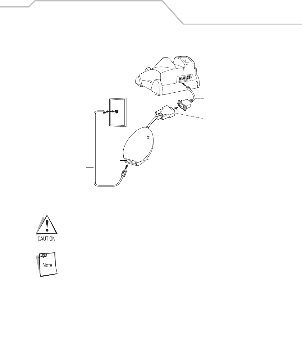
Accessories 7-47
Connecting to the Single Slot Serial/USB Cradle
Figure 7-34. Modem Module Connection - Single Slot Serial/USB Cradle
Do not connect the modem's 15-pin connector into a VGA port of a host
computer.
If using a phone, connect the cord from the phone to the Phone port on the
modem.
Configuring the Mobile Computer for the Modem
To create a modem connection on the mobile computer:
1. Connect the modem to the mobile computer, see Connecting to the Mobile Computer on
page 7-46.
2. On the MC9000, tap Settings - Control Panel. Double-tap the Network and Dial-up
Connections icon.
Adapter cable
Phone cord
Male 15-pin connector
Line In port Phone port
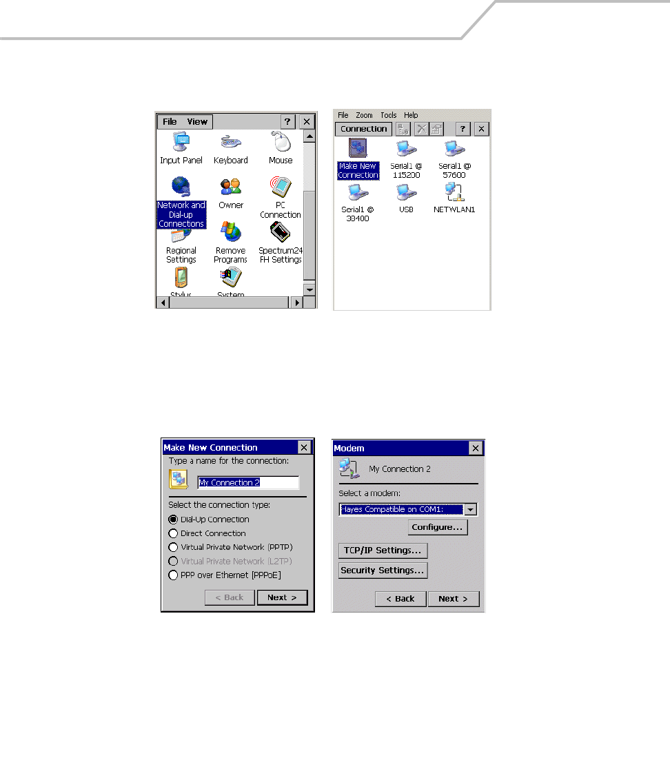
MC9000-K/S for Embedded Windows® CE .NET Product Reference Guide
7-48
3. In the Connection window, double-tap Make New Connection to create a connection.
Figure 7-35. Network and Connections Windows
4. Enter a name for the connection on the Make New Connection window, then tap Next.
5. In the Select a modem list, select Hayes Compatible on COM1, then tap Next.
Figure 7-36. New Connection and Modem Windows
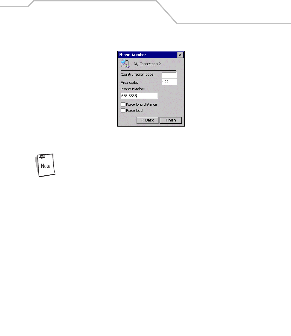
Accessories 7-49
6. In the Phone Number window, enter the phone number for the connection, then tap Finish.
Figure 7-37. Phone Number Window
Depending on the location when dialing, additional numbers may need to be
dialed (e.g., a 9 prefix is often required if dialing from work; a country code is
needed if dialing internationally). To avoid creating new modem connections
for each situation, tap use dialing rules to define frequently used dialing
locations.
Connecting the Modem
To connect to the host computer using the modem connection created in the last section:
1. Tap Start - Settings - Control Panel. Double-tap the Network and Dialup Connections icon.
2. In the Connection window, double-tap the name of the connection
3. created in Creating a Modem Connection on page 8.
4. To modify dial-up properties, tap Dial Properties..., make the selections in the Device
Properties window, then tap OK.
5. Tap Connect. The modem attempts to connect.
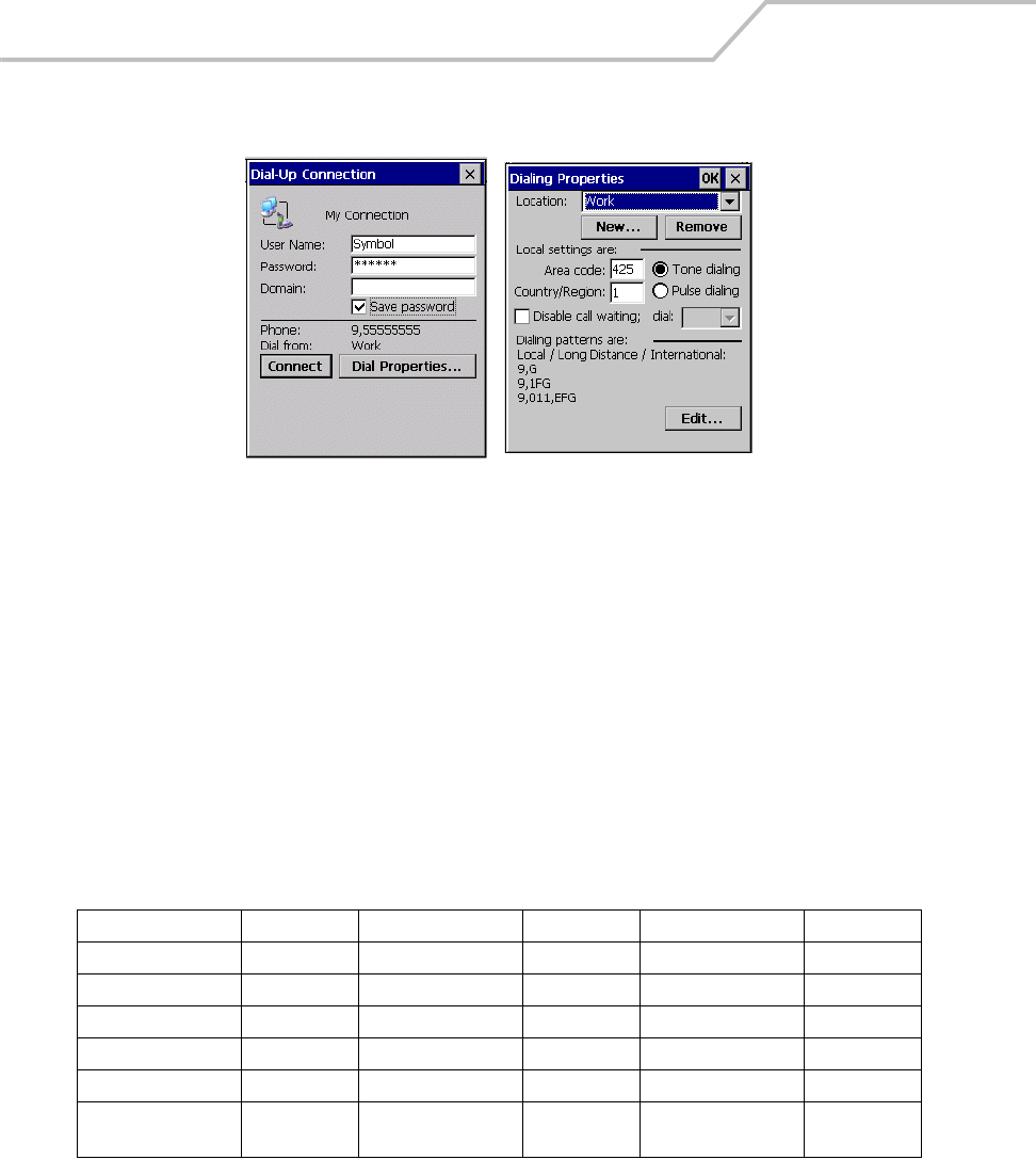
MC9000-K/S for Embedded Windows® CE .NET Product Reference Guide
7-50
Figure 7-38. Dial-Up and Dial Properties Window
Modem Country Setup
The modem defaults to operation with US telephone networks (country code: B5). To operate the
modem with other country telephone networks, enter the Country of Installation command. The
modem adjusts its operating parameters to comply with the telephone network in the country
specified.
Syntax
+GCI=<country_code>
Enter this command in the MC9000 when setting up comunication via modem connection.
Table 7-5. Supported Countries
Country Code Country Code Country Code
Australia 09 Greece FD or 46 Norway FD or 82
Austria FD or 0A Iceland FD Portugal FD or 8B
Belgium FD or 0F Ireland FD or 57 Spain FD or A0
Brazil 16 Italy FD or 59 Sweden FD or A5
Canada 20 Liechtenstein FD Switzerland FD or A6
Denmark FD or 31 Luxembourg FD TBR-21
(Europe)
FD
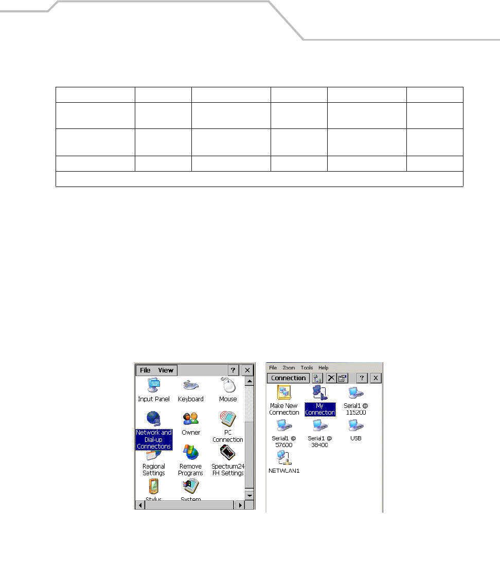
Accessories 7-51
AT Commands
The AT Command Set allows you to custom-configure the modem. Only experienced users having
difficulty with default settings should use this.
Changing the Initialization String
To enter AT commands:
1. On the MC9000, tap Settings -Control Panel. Double-tap the Network and Dial-up
Connections icon.
2. In the Connection window, double-tap the My Connection icon to edit the settings.
Figure 7-39. Network and Connections Windows
Finland FD or 3C Mexico 73 United
Kingdom
FD or B4
France FD or 3D Netherlands FD or 7B United States B5
(Default)
Germany FD or 42 New Zeland 7E
Note: Use FD where possible. If connection problems occur, use the alternate code where provided.
Table 7-5. Supported Countries (Continued)
Country Code Country Code Country Code
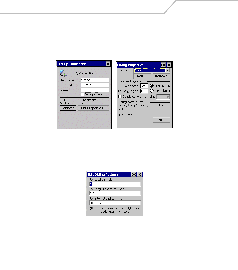
MC9000-K/S for Embedded Windows® CE .NET Product Reference Guide
7-52
3. To modify dial-up properties, tap Dial Properties, make the selections in the Device
Properties window.
4. To edit the Dialing Patterns, tap Edit.
Figure 7-40. Dial-Up and Dial Properties Window
5. The Edit Dialing Patterns window appears.
.
Figure 7-41. Edit Dialing Patterns Window
6. Edit the dialing properties, see Table 7-6 on page 7-54.
7. Tap OK to exit the Edit Dialing Patterns window.
8. Tap OK to exit the Dialing Patterns window.
9. Tap Connect at the Dial-Up Connection window. The modem attempts to connect.

Accessories 7-53
Basic AT Command Syntax
A command line is made up of three elements:
•Prefix - consists of the characters “AT” or “at” or, to repeat the execution of the previous
command line, “A/” or “a/”.
•Body - made up of individual commands described later. Space characters (IA5 2/0) are
ignored and may be used for formatting purposes, unless they are embedded in numeric or
string constants. The termination character may not appear in the body. The modem can
accept at least 40 characters in the body.
•Termination character - may be selected by a user option (parameter S3). The default is
CR.
The format of Basic Syntax commands, except for the D and S commands, is as follows:
<command>[<number>]
where:
• <command> is either a single character, or the “&” character followed by a single character
per V.250; or the “%” character followed by a single character, the “*” character followed
by a single character, or the “^” character followed by a single character.
• <number> is a string of one or more characters from “0” through “9” representing a decimal
integer value. Commands expecting a <number> are noted in the description of the
command. If <number> is missing from such a command (<command> is immediately
followed by another <command> or the termination character), the value “0” is assumed. If
a command does not expect a <number> and a number is present, an error occurs. All
leading “0”s in <number> are ignored by the modem.
Additional commands may follow a command (and associated parameter, if any) on the same
command line with a separation character. The actions of some commands cause the rest of the
command line to be ignored.
S-Parameters
Commands that begin with the letter “S” are known as “S-parameters”. The number following the
“S” indicates the “parameter number” referenced. If the number is not recognized as a valid
parameter number, an ERROR result code issues. Immediately following this number, either a “?” or
“=” character must appear. “?” is used to read the current value of the indicated S-parameter; “=”
sets the S-parameter to a new value.
S<parameter_number>?

MC9000-K/S for Embedded Windows® CE .NET Product Reference Guide
7-54
S<parameter_number>=[<value>]
If the “=” is used, the new value to be stored in the S-parameter is specified in decimal following the
“=”. If no value is given (i.e., the end of the command line occurs or the next command follows
immediately), the S-parameter specified may be set to 0, or an ERROR result code issues and the
stored value remains. The ranges of acceptable values are given in the description of each S-
parameter.
If the “?” is used, the modem transmits a single line of information text to the DTE. The text portion
of this information text consists of exactly three characters, giving the value of the S-parameter in
decimal, with leading zeroes included.
Commands
The tables that follow summarize the AT commands, result codes, and S-Registers for the MDM 3000.
<string> represents a letter, number, or symbol to be entered. <value> represents a number to be
entered. Possible values are listed below the command.
Table 7-6. AT Command Table
Command Description
Country
Specific
DDial “D<string>”
0-9 DTMF digits 0-9
*The ‘star’ digit (tone dialing only)
#The ‘gate’ digit (tone dialing only)
A-D DTMF digits A,B,C,D X
LRe-dial last number
PPulse dialing X
TTone dialing
WWait for dial tone. (Modem waits for dial tone before dialing digits
following “W”.)
@Wait for silence. (Modem waits for at least 5 seconds of silence in the
call progress
frequency band before continuing with next dial string parameter.)
&Wait for credit card dialing tone before
continuing with the dial string.

Accessories 7-55
‘Dial pause. (Modem pauses for a time specified by S8 before dialing
the digits following “,”)
;Return to command state. (Modem goes off hook and allows entering
additional AT commands. Use “H” to go back to on hook.)
() - <space> Ignored. (Might be used to format the dial string.)
AOff-hook and attempt to answer a call
H Disconnect – Hang UP
O Return to On-Line Data Mode. O <value>
0 Enters on-line data mode without a retrain.
1 Enters on-line data mode with a retrain.
LSpeaker volume (Not used)
MSpeaker control. M <value>
0 Always off.
1 On during call establishment. Off when receiving carrier. (default)
2 Always on.
3 Off when receiving carrier and during dialing. On during answering.
&G Guard tone. &G<value> X
0 Disables guard tone. (default)
1 Disables guard tone.
2 Select 1800 Hz guard tone.
&V1 Displays last connection statistics
+MS Modulation Selection. +MS=<carrier> X
B103 Bell 103 (300)
B212 Bell 212 (1200 Rx/75 or 75Rx/1200 Tx)
V21 300
V22 1200
V22B 2400 or 1200
Table 7-6. AT Command Table (Continued)
Command Description
Country
Specific

MC9000-K/S for Embedded Windows® CE .NET Product Reference Guide
7-56
V23C 1200
V32 9600 or 4800
V32B 14400, 12000, 9600, 7200 or 4800
V34 33600, 31200, 28800, 26400, 2400, 21600, 19200, 16800, 14400,
12000, 9600, 7200, 4800 or 2400
%E
Enable/Disable Line Quality Monitor and Auto-Retrain or Fall back/Fall
forward. %E<value>
0 Disable line quality monitor and auto re-train.
1 Enable line quality monitor and auto re-train.
2 Enable line quality monitor and fallback/fall forward. (default).
B CCITT or Bell. B<value>
0Select CCITT operation at 300 or 1200 bauds.
1Selects Bell operation at 300 or 1200 bauds.
&L Leased Line Operation. &L<value>
0Requests dial-up operation. Dial-up operation continues.
Table 7-7. S-Register Settings
Reg Function Range
Default
UnitsDe-fault Saved
S0 Rings to Auto Answer 0-255 0 * rings
S1 Ring Counter 0-255 0 * rings
S2 Escape Character 0-255 43 ASCII
S3 Carriage Return Character 0-127 13 ASCII
S4 Line Feed Character 0-127 10 ASCII
* Register value may be stored in on of two user
** Country-dependent
Table 7-6. AT Command Table (Continued)
Command Description
Country
Specific

Accessories 7-57
S5 Backspace Character 0-255 8 ASCII
S6 Wait Time before Blind Dialing or Dial Tone 2-255 2 * S
S7 Wait Time for Carrier, Silence or Dial Tone 1-255 50 * S
S8 Pause Time for Dial Delay Modifier 0-255 2 * S
S9 Carrier Detect Response Time 1-255 6 * 0.1 S
S10 Lost Carrier to Hangup Delay 1-255 14 * 0.1 S
S11 DTMF Tone Duration 50-255 95 * mS
S12 Escape Prompt Delay (EPD) 0-255 50 * .02 S
S14 General Bit Mapped Options Status - 138 (8Ah)
S16 Test Mode Bit Mapped Options Status - 0
S19 Reserved - 0
S20 Reserved - 0
S21 V.24 Bit Mapped Options Status - 52 (34h)
S22 Speaker/Results Bit Mapped Options - 117 (75h)
S23 General Bit Mapped Options Status - 62 (3Dh)
S24 Sleep Inactivity Timer 0-255 0 S
S25 Delay to DTR off 0-255 5 S
S26 RTS-to-CTS Delay 0-255 1 .01 S
S27 General Bit Mapped Options Status - 73 (49h)
S28 General Bit Mapped Options Status - 0
S29 Flash Dial Modifier Time 0-255 70 10 mS
S30 Disconnect Inactivity Timer 0-255 0 10 S
S31 General Bit Mapped Options Status - 195 (C0h)
S36 LAPM Failure Control - 7 *
Table 7-7. S-Register Settings (Continued)
Reg Function Range
Default
UnitsDe-fault Saved
* Register value may be stored in on of two user
** Country-dependent

MC9000-K/S for Embedded Windows® CE .NET Product Reference Guide
7-58
Modem LED Indicators
S38 Delay Before Forced Hangup 0-255 20 S
S39 Flow Control Bit Mapped Options Status - 3
S40 General Bit Mapped Options Status - 104 (68h) *
S41 General Bit Mapped Options Status - 195 (C3h) *
S46 Data Compression Control - 138 *
S48 V.42 Negotiation Control - 7
S86 Call Failure Indication 0-26 0
S91 PSTN Transmit Attenuation Level 0-15 10** dBm
S92 Fax Transmit Attenuation Level 0-15 10** dBm
S95 Extended Result Codes Control 0 *
S210 V.34 Symbol Rate 0-255 13 (0Dh)
Table 7-8. Modem LED Indicators
LED Indication
Off Modem is not properly connected to the mobile computer; modem is not receiving
power.
Green Modem is connected to the mobile computer and is receiving power.
Solid Amber Mobile computer is communicating with the host computer.
Table 7-7. S-Register Settings (Continued)
Reg Function Range
Default
UnitsDe-fault Saved
* Register value may be stored in on of two user
** Country-dependent
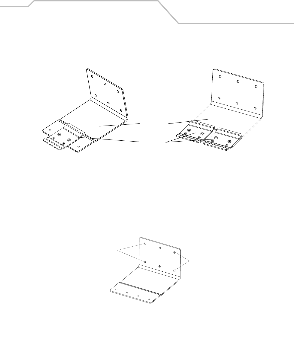
Accessories 7-59
Wall Mounting Bracket and Shelf Slide
This section describes how to install and set up the MC9000 Wall Mount Bracket and Shelf Slide to
mount cradles to a wall.
Figure 7-42. Wall Mounting Bracket with Shelf Slide
When installed on a wall, the mounting bracket and shelf slide enable mounting one or two single
slot cradles to a wall. Use two brackets to mount a four slot cradle.
Installing the Wall Mount Bracket
To install the wall mount bracket for use with one or two single slot cradles or four slot chargers,
place the smaller surface of the bracket against the wall or vertical support structure, and secure with
four 1/4” screws (use two of the three screw holes in each row).
Figure 7-43. Wall Mounting Bracket Mounting Screws
If using the bracket and slide with a four slot cradle, secure a second bracket to the wall next to the
first, aligning the horizontal screw holes on the second with those of the first.
Wall Mounting
Bracket
Shelf Slides
Mounting two single slot cradlesMounting one single slot cradle
Insert screws
Insert screws
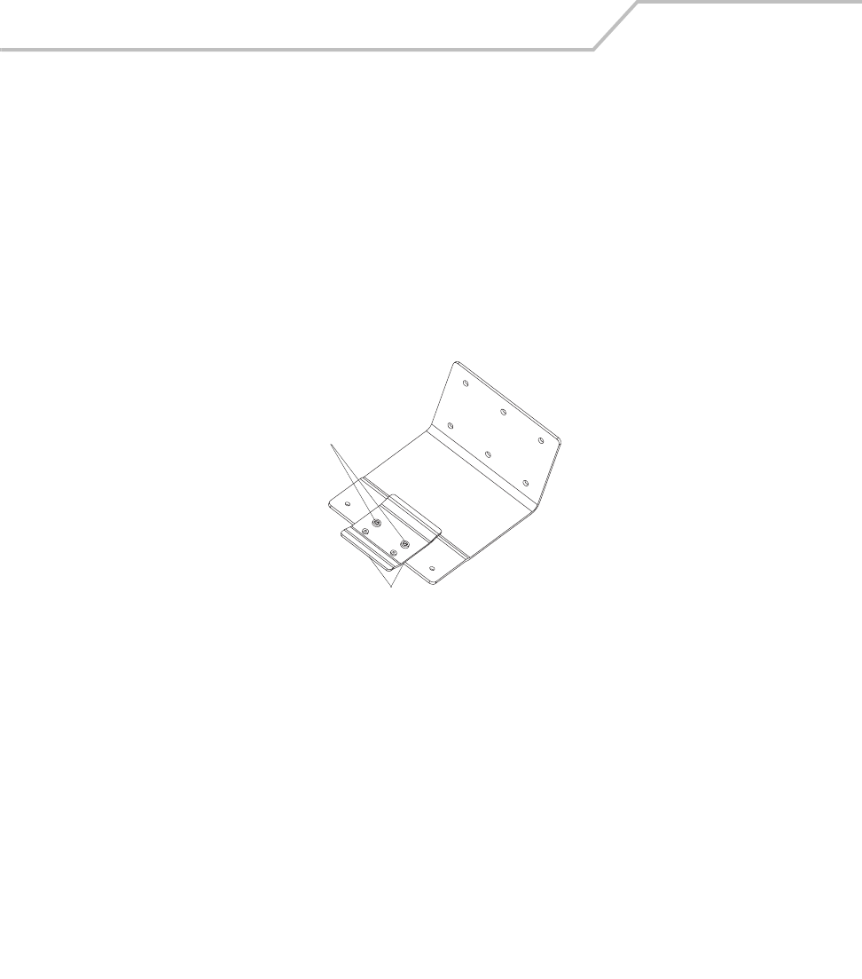
MC9000-K/S for Embedded Windows® CE .NET Product Reference Guide
7-60
Attaching the Shelf Slide to the Wall Mount Bracket
One Single Slot Cradle/Four Slot Battery Charger
To attach the shelf slide to the wall mount bracket for use with one single slot cradle or four slot
battery charger:
1. Place the slide on the bracket, aligning the larger pan-head screw holes in the slide with the
center two screw holes on the bracket.
2. Secure the slide to the bracket by inserting the two pan-head screws provided from below
the bracket, up through the bracket’s screw holes and then through the slide’s pan-head
screw holes.
Figure 7-44. Attaching One Shelf Slide
Two Single Slot Cradles/Four Slot Battery Chargers
To attach the shelf slide to the wall mount bracket for use with two single slot cradles or two four
slot battery chargers:
1. Place the slide on the bracket, aligning the larger pan-head screw holes in the slide with the
left or right two screw holes on the bracket.
2. Secure the slide to the bracket by inserting the two pan-head screws provided from below
the bracket, up through the bracket’s screw holes and then through the slide’s pan-head
screw holes.
3. Secure a second slide to the remaining two screw holes on the bracket in the same manner.
Insert screws from below
Pan-head Screw Holes
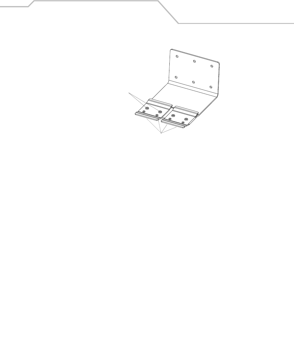
Accessories 7-61
Figure 7-45. Attaching Two Shelf Slides
Four Slot Cradle
To attach the shelf slide to the wall mount bracket for use with a four slot cradle:
1. Place a slide on the left-hand bracket, aligning the larger pan-head screw holes in the slide
with the left two screw holes on the bracket.
2. Secure the slide to the bracket by inserting the two pan-head screws provided from below
the bracket, up through the bracket’s screw holes and then through the slide’s pan-head
screw holes.
3. Place a slide on the right-hand bracket, aligning the larger pan-head screw holes in the slide
with the right two screw holes on the bracket.
4. Secure the second slide to the bracket as described in Step 2.
Insert screws from below
Pan-head
screw holes
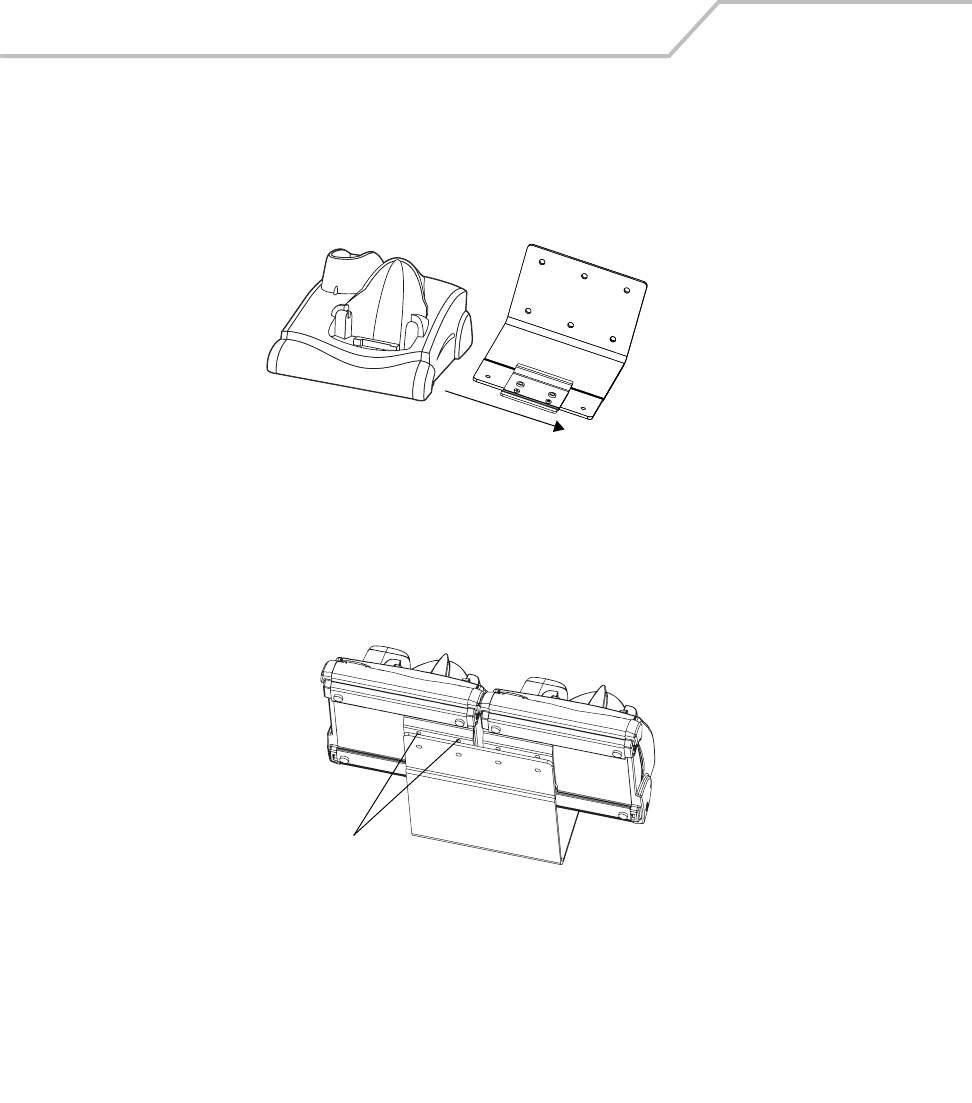
MC9000-K/S for Embedded Windows® CE .NET Product Reference Guide
7-62
Installing the Cradle/Charger on the Bracket
Install the cradle or charger onto the bracket, inserting the bracket’s slide into the grooves on the
bottom of the cradle/charger and sliding the cradle/charger into the desired position.
1. For one single slot cradle/four slot charger, center it on the bracket.
Figure 7-46. Attaching Two Shelf Slides
2. For two single slot cradles/four slot chargers, slide one onto the left-hand slide, and one
onto the right-hand slide
Figure 7-47. Attaching Two Shelf Slides
3. For a four slot cradle, slide the cradle on to the slides, across both brackets.
4. Secure each cradle or charger to its slide using the two set screws provided.
5. Position the power supply on the shelf, behind the cradle.
Slide grooves on bottom of
cradle/charger over bracket
Insert set screws
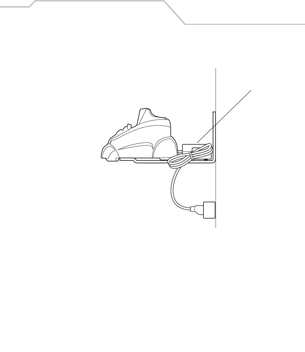
Accessories 7-63
Figure 7-48. Positioning the Power Supply
Power Supply

MC9000-K/S for Embedded Windows® CE .NET Product Reference Guide
7-64

Software Installation
Chapter Contents
Introduction. . . . . . . . . . . . . . . . . . . . . . . . . . . . . . . . . . . . . . . . . . . . . . . . . . . . . . . . . . . . . . . . . . . . . . . . .8-3
Symbol Windows CE SMDK. . . . . . . . . . . . . . . . . . . . . . . . . . . . . . . . . . . . . . . . . . . . . . . . . . . . . . . . . . . .8-3
Hardware Requirements. . . . . . . . . . . . . . . . . . . . . . . . . . . . . . . . . . . . . . . . . . . . . . . . . . . . . . . . . . .8-3
Software Requirements . . . . . . . . . . . . . . . . . . . . . . . . . . . . . . . . . . . . . . . . . . . . . . . . . . . . . . . . . . .8-3
SMDK Components . . . . . . . . . . . . . . . . . . . . . . . . . . . . . . . . . . . . . . . . . . . . . . . . . . . . . . . . . . . . . .8-4
Installing the SMDK . . . . . . . . . . . . . . . . . . . . . . . . . . . . . . . . . . . . . . . . . . . . . . . . . . . . . . . . . . . . . .8-4
Software Updates. . . . . . . . . . . . . . . . . . . . . . . . . . . . . . . . . . . . . . . . . . . . . . . . . . . . . . . . . . . . . . . .8-4

MC9000-K/S for Embedded Windows® CE .NET Product Reference Guide
8-2

Software Installation 8-3
Introduction
The Symbol Windows CE SMDK for Series 9000 allows users to develop Windows CE applications
for Series 9000 mobile computers. This SMDK contains libraries and other Symbol value-add
software not available in the standard Microsoft® Windows® CE Platform SMDK.
Symbol Windows CE SMDK
The SMDK installation program loads the required Windows CE components on the development
computer used to create the image files for download to the mobile computer.
Hardware Requirements
The minimum system configuration required to install the SMDK is:
• IBM-compatible Personal Computer with Pentium 450 MHz processor or higher
• Microsoft Windows XP®, or Microsoft Windows 2000® operating system
• 128 MB RAM
• 100 MB available hard disk space
•CD-ROM drive
• One available serial port
•Mouse.
Software Requirements
Before installing the Symbol Windows CE SMDK for Series 9000, install the following tools:
• Microsoft eMbedded Visual C++ v4.0 and Service Pack 1
• Microsoft ActiveSync version 3.7 or higher
• Adobe® Acrobat® Reader® 3.0 or higher.

MC9000-K/S for Embedded Windows® CE .NET Product Reference Guide
8-4
SMDK Components
The SMDK installation program loads all of the SMDK, Series 9000 components onto the
development computer. Once installed, the SMDK allows users to create applications and deploy the
applications to mobile computers.
The Symbol Windows CE SMDK for Series 9000 includes the following components:
• Help HTML-based help file containing the Symbol API definitions.
• PRG Product Reference Guide containing information about the setup and use of the
mobile computer.
• Readme HTML-based file containing release notes and last minute help updates.
• Samples Sample source code, showing how to interface with Symbol API functions.
• Emulator Series 9000 Desktop emulation environment.
• TCM Terminal Configuration Manager program used to customize and load software.
Installing the SMDK
1. Download the SMDK from the Symbol website, http://devzone.symbol.com.
2. Double-click the executable file and follow the install screen prompts.
3. Once installed, the major components of the SMDK can be accessed from the Symbol
Windows CE SMDK (PDT9000) program group of the Windows Start Menu. The components
include: Help, PRG, Readme, Samples, TCM, Emulator and Updates.
4. The sample applications provide a good overview of the SMDK usage. To build a sample
application, open the Samples folder from the Windows Start menu. Open the folder for the
desired sample and then open the project file. The project file has an extension of VCP.
Microsoft Visual C++ v4.0 will automatically launch. Select PDT9000 as the Active WCE
Configuration. Select Win32 (WCE ARMV4) Debug as the Active Configuration.
If both Microsoft Visual C++ v3.0 and Microsoft Visual C++ v4.0 are installed
on the development computer then confirm that Microsoft Visual C++ v4.0 is
the one being launched.
Software Updates
Updates to the SMDK can be downloaded from the Symbol Developer Zone web site at http://
devzone.symbol.com. This site can be easily accessed using a shortcut added to the Windows start
menu. It should be checked periodically for important updates and new software versions.

AirBEAM Smart
Chapter Contents
Introduction. . . . . . . . . . . . . . . . . . . . . . . . . . . . . . . . . . . . . . . . . . . . . . . . . . . . . . . . . . . . . . . . . . . . . . . . .9-3
AirBEAM Package Builder . . . . . . . . . . . . . . . . . . . . . . . . . . . . . . . . . . . . . . . . . . . . . . . . . . . . . . . . . . . . .9-3
AirBEAM Smart Client . . . . . . . . . . . . . . . . . . . . . . . . . . . . . . . . . . . . . . . . . . . . . . . . . . . . . . . . . . . . . . . .9-3
AirBEAM Smart License. . . . . . . . . . . . . . . . . . . . . . . . . . . . . . . . . . . . . . . . . . . . . . . . . . . . . . . . . . .9-4
Configuring the AirBEAM Smart Client . . . . . . . . . . . . . . . . . . . . . . . . . . . . . . . . . . . . . . . . . . . . . . .9-4
Packages(1) Tab . . . . . . . . . . . . . . . . . . . . . . . . . . . . . . . . . . . . . . . . . . . . . . . . . . . . . . . . . . . . .9-5
Packages(2) Tab . . . . . . . . . . . . . . . . . . . . . . . . . . . . . . . . . . . . . . . . . . . . . . . . . . . . . . . . . . . . .9-5
Server Tab . . . . . . . . . . . . . . . . . . . . . . . . . . . . . . . . . . . . . . . . . . . . . . . . . . . . . . . . . . . . . . . . .9-6
Misc(1) Tab. . . . . . . . . . . . . . . . . . . . . . . . . . . . . . . . . . . . . . . . . . . . . . . . . . . . . . . . . . . . . . . . .9-7
Misc(2) Tab. . . . . . . . . . . . . . . . . . . . . . . . . . . . . . . . . . . . . . . . . . . . . . . . . . . . . . . . . . . . . . . . .9-8
Misc(3) Tab. . . . . . . . . . . . . . . . . . . . . . . . . . . . . . . . . . . . . . . . . . . . . . . . . . . . . . . . . . . . . . . .9-10

MC9000-K/S for Embedded Windows® CE .NET Product Reference Guide
9-2
Synchronizing with the Server . . . . . . . . . . . . . . . . . . . . . . . . . . . . . . . . . . . . . . . . . . . . . . . . . . . . .9-10
Manual Synchronization. . . . . . . . . . . . . . . . . . . . . . . . . . . . . . . . . . . . . . . . . . . . . . . . . . . . . .9-10
Automatic Synchronization. . . . . . . . . . . . . . . . . . . . . . . . . . . . . . . . . . . . . . . . . . . . . . . . . . . .9-11
AirBEAM Smart Staging. . . . . . . . . . . . . . . . . . . . . . . . . . . . . . . . . . . . . . . . . . . . . . . . . . . . . . . . . . . . . .9-11

AirBEAM Smart 9-3
Introduction
The AirBEAM Smart product allows specially designed software packages to be transferred between
a host server and Symbol wireless handheld devices. Before transfer, AirBEAM Smart checks and
compares package version, so that only updated packages are loaded.
AirBEAM Smart resides on radio-equipped client devices and allows them to request, download and
install software, as well as to upload files and status data. Both download and upload of files can be
accomplished in a single communications session. The ability to transfer software over a radio
network can greatly reduce the logistical efforts of client software management.
In an AirBEAM Smart system, a network-accessible host server acts as the storage point for the
software transfer. The AirBEAM Smart Client uses the industry standard FTP or TFTP file transfer
protocols to check the host system for updates and if necessary, to transfer updated software.
AirBEAM Package Builder
In a typical distributed AirBEAM Smart system, software to be transferred is organized into packages.
In general, an AirBEAM Smart package is simply a set of files that are assigned attributes both as an
entire package and as individual component files. The package is assigned a version number and the
transfer occurs when an updated version is available.
An AirBEAM Smart package can optionally contain developer-specified logic to be used to install the
package. Installation logic is typically used to update client device flash images or radio firmware.
Examples of common AirBEAM Smart packages would include packages for custom client application
software, radio firmware and AirBEAM Smart Client software.
Once these packages are built, they are installed on the host server for retrieval by the handheld
device. The AirBEAM Package Builder is a utility used to define, generate and install AirBEAM
packages to a server. The packages are then loaded from the server onto a client device equipped
with an AirBEAM Smart Client executable.
For detailed instructions on how to define, generate and install AirBEAM packages to the server, refer
to the AirBEAM Package Builder Product Reference Guide, p/n 72-55769-xx.
AirBEAM Smart Client
The AirBEAM Smart Client is installed on the handheld mobile computer. It is configured with the
server access information, the names of the packages to be downloaded and other controlling
parameters. When the AirBEAM Smart Client is launched, the device connects to the specified FTP
server and checks the packages it is configured to look for. If the package version was updated, the
client requests the transfer.
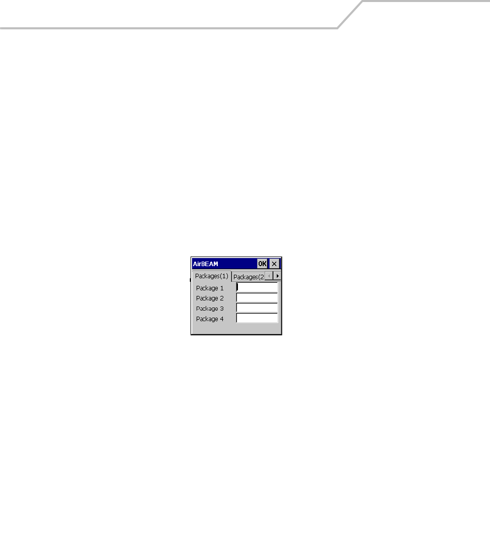
MC9000-K/S for Embedded Windows® CE .NET Product Reference Guide
9-4
AirBEAM Smart License
The AirBEAM Smart Client is a licensed software product. The AirBEAM Smart Client's version
synchronization functionality is enabled through a license key file that is stored on the client device.
The license key file can be built into AirBEAM Smart Client's image, or downloaded in a special
AirBEAM package. The AirBEAM Smart license key file contains a unique key and a customer specific
banner that is displayed when the AirBEAM Smart Client version synchronization logic is invoked.
The AirBEAM Smart Client package that is included on the mobile computer does not include a
licence key. This software version is limited to downloading of specific Symbol software products. A
license key can be purchased that will allow the downloading of custom applications and other non-
Symbol software products.
Configuring the AirBEAM Smart Client
1. Select Start - Programs - AirBEAM Client. The AirBEAM CE window appears.
2. Tap File - Configure. The AirBEAM configuration window appears
Figure 9-1. AirBEAM Smart Configuration Window
The configuration window is used to view and edit AirBEAM Smart Client configurations. This dialog
box has six tabs that can be modified - Packages(1), Packages(2), Server, Misc(1), Misc(2) and Misc(3).
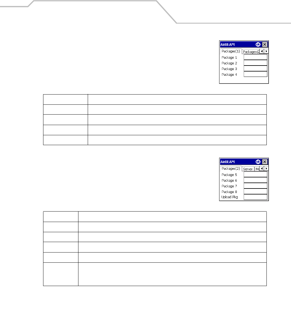
AirBEAM Smart 9-5
Packages(1) Tab
This tab is used to specify the package name of the first four of eight packages
that are to be loaded during the AirBEAM Smart synchronization process. The
specified package name must correspond to a package that is available on the
specified package server.
Packages(2) Tab
This tab is used to specify the package name of the last four of eight packages
that are to be loaded during the AirBEAM Smart synchronization process. The
specified package name must correspond to a package that is available on the
specified package server.
Table 9-1. Package (1) Tab
Field Description
Package 1 Package name of the first of eight packages. This is an optional field.
Package 2 Package name of the second of eight packages. This is an optional field.
Package 3 Package name of the third of eight packages. This is an optional field.
Package 4 Package name of the fourth of eight packages. This is an optional field.
Table 9-2. Package (2) Tab
Field Description
Package 5 Package name of the fifth of eight packages. This is an optional field.
Package 6 Package name of the sixth of eight packages. This is an optional field.
Package 7 Package name of the seventh of eight packages. This is an optional field.
Package 8 Package name of the eighth of eight packages. This is an optional field.
Upload Pkg Package name of a package that is to be processed for “upload files” during the AirBEAM Smart
synchronization process. The specified package name must correspond to a package that is
available on the specified package server. This is an optional field.
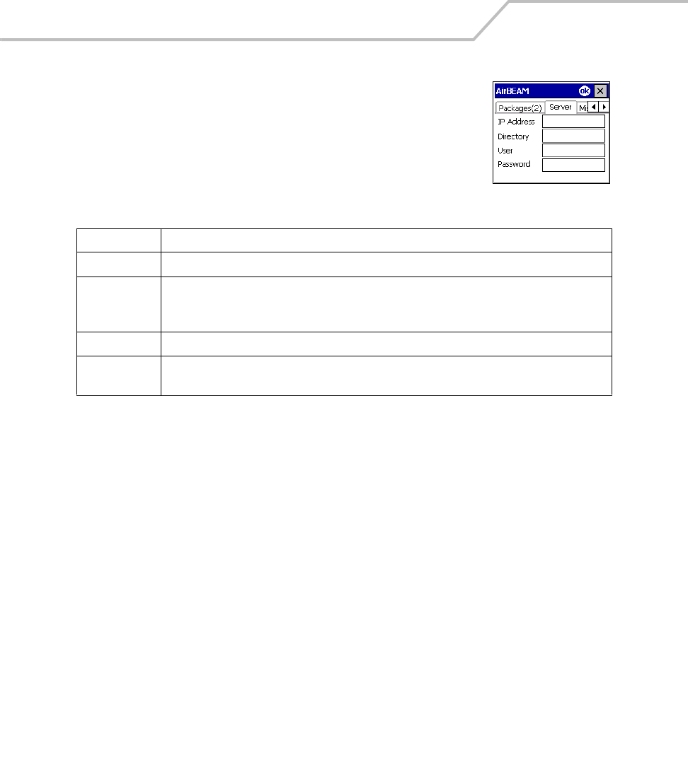
MC9000-K/S for Embedded Windows® CE .NET Product Reference Guide
9-6
Server Tab
This tab is used to specify the configurations of the server to which the client
connects during the package synchronization process.
Table 9-3. Server Tab
Field Description
IP Address The IP Address of the server. It may be a host name or a dot notation format.
Directory The directory on the server that contains the AirBEAM Smart package definition files. All
AirBEAM Smart package definition files are retrieved from this directory during the package
synchronization process.
User The FTP user name that is used during the login phase of the package synchronization process.
Password The FTP password that corresponds to the FTP user specified in the User field. The specified
password is used during the login phase of the package synchronization process.
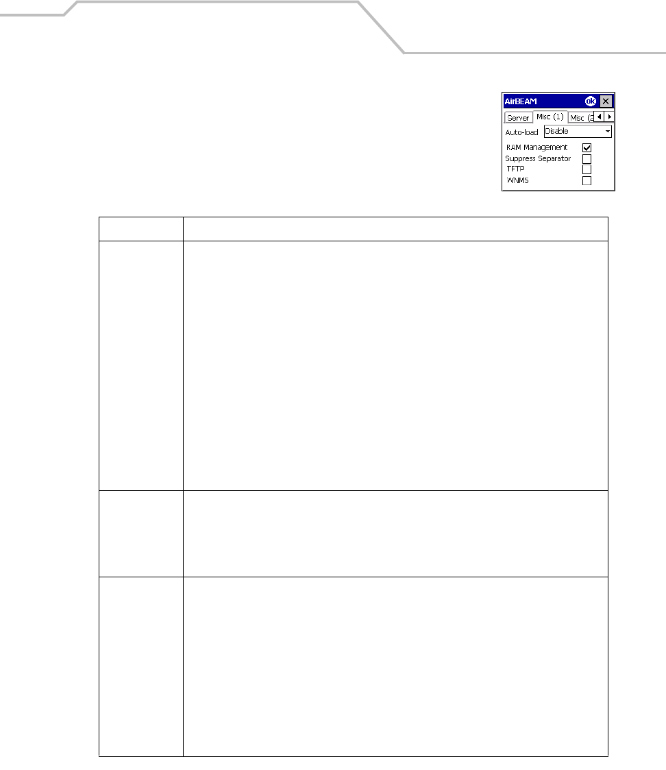
AirBEAM Smart 9-7
Misc(1) Tab
This tab is used to configure various miscellaneous features.
Table 9-4. Misc (1) Tab
Field Description
Auto-load This drop-down list is used to specify how the AirBEAM Smart Client is to be invoked
automatically when the client device is rebooted. The selections are:
Disable: the AirBEAM Smart Client is not invoked automatically during the boot
sequence.
Interactive: the AirBEAM Smart Client is invoked automatically during the boot sequence.
The package synchronization process is started automatically. The Synchronization
Dialog box appears and the user is required to press the OK button when the process is
complete.
Non-interactive: the AirBEAM Smart Client is invoked automatically during the boot
sequence. The package synchronization process is started automatically. The
Synchronization Dialog box is displayed, but the user is not required to tap OK when the
process is complete. The Synchronization Dialog box terminates automatically.
Background: the AirBEAM Smart Client is invoked automatically during the boot
sequence. The package synchronization process is started automatically. Nothing is
displayed while the synchronization process is occurring.
RAM
Management
This checkbox specifies whether the automatic RAM management is enabled during the
package synchronization process.
If enabled, RAM management logic is invoked when there is not enough free disk space to
download a package. The RAM management logic attempts to remove any discardable
AirBEAM Smart packages resident on the client.
Suppress
Separator
This checkbox specifies whether the automatic insertion of a file path separator character
should be suppressed when the client generated server package definition file names.
When enabled, the parameter also disables the appending of .apd to the package. This feature
is useful for AS/400 systems, in which the file path separator character is a period. When this
feature is enabled, the server directory (Directory) and package name (Package 1, Package 2,
Package 3 and Package 4) are appended "as is” when building the name for the server package
definition file.
When this feature is disabled, a standard file path separator is used to separate the server
directory (Directory) and package name (Package 1, Package 2, Package 3 and Package 4) when
building the name for the server package definition file. In addition, an .apd extension is
appended automatically.
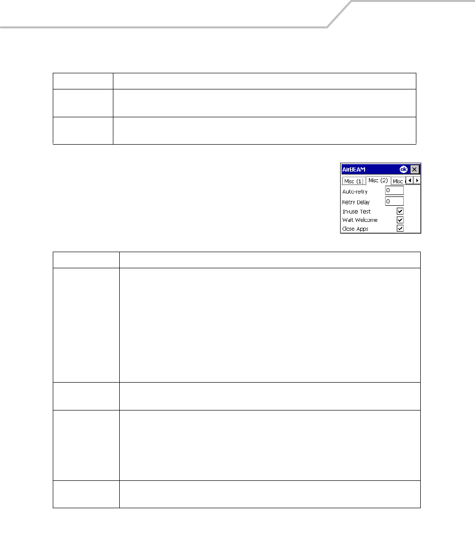
MC9000-K/S for Embedded Windows® CE .NET Product Reference Guide
9-8
Misc(2) Tab
This tab is used to configure various miscellaneous features.
TFTP This checkbox specifies whether the TFTP protocol is to be used to download files. By default,
the AirBEAM Smart Client uses the FTP protocol.
WNMS This checkbox specifies whether the AirBEAM Smart Client uploads a WNMS information file
at the end of each version synchronization.
Table 9-5. Misc (2) Tab
Field Description
Auto-retry This field is used to specify whether the AirBEAM Smart Client automatically retries if there
is a failure during the synchronization process.
If this feature is enabled, the AirBEAM Smart Client displays a popup dialog indicating the
attempt of a retry. The popup dialog is displayed for the number of seconds specified in the
Retry Delay field.
The valid values for this field are:
-1: the AirBEAM Smart Client automatically retries indefinitely.
0: the AirBEAM Smart Client does not automatically retry.
-0: the AirBEAM Smart Client automatically retries up to the number of times specified.
Retry Delay This field specifies the amount of time, in seconds, that the AirBEAM Smart Client will delay
before automatically retrying after a synchronization failure.
In-use Test This checkbox specifies whether the AirBEAM Smart Client tests to determine if a file is in-
use before downloading. If the In-use Test feature is enabled, the AirBEAM Smart Client
downloads a temporary copy of any files that are in-use. If any temporary in-use files are
downloaded the AirBEAM Smart Client automatically resets the client to complete the copy of
the in-use files. If the In-use Test feature is disabled, the synchronization process fails (-813)
if any download files are in-use.
Wait Welcome This checkbox specifies whether the AirBEAM Smart Client waits for the WELCOME windows
to be completed before automatically launching the synchronization process after a reset.
Table 9-4. Misc (1) Tab (Continued)
Field Description

AirBEAM Smart 9-9
Close Apps This checkbox specifies whether the AirBEAM Smart Client automatically attempts to close
non-system applications prior to resetting the mobile unit. If enabled the AirBEAM Smart
Client sends a WM_CLOSE message to all non-system applications before resetting the
mobile unit. This feature offers applications the opportunity to prepare (i.e. close open files)
for the pending reset.
Table 9-5. Misc (2) Tab (Continued)
Field Description
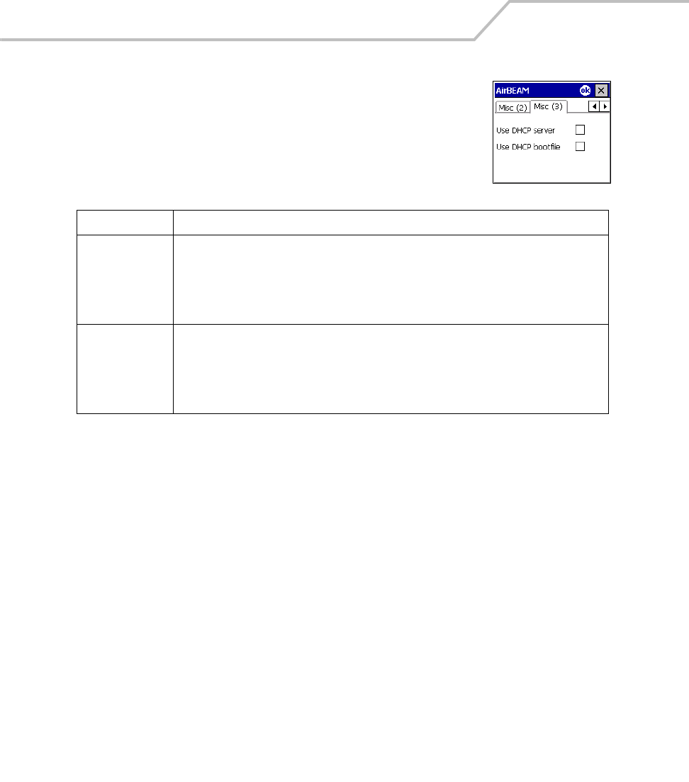
MC9000-K/S for Embedded Windows® CE .NET Product Reference Guide
9-10
Misc(3) Tab
This tab is used to configure various miscellaneous features.
Synchronizing with the Server
When the synchronization process is initiated, the AirBEAM Smart Client attempts to open an FTP
session using the AirBEAM Smart Client configuration. Once connected, the client processes the
specified packages. Packages are loaded only if the server version of a given package is different from
the version loaded on the client. Once the upload process is complete, the AirBEAM Smart Client
closes the FTP session with the server.
The AirBEAM Smart Client can launch an FTP session with the server either manually, when initiated
by the user, or automatically.
Manual Synchronization
1. Configure the AirBEAM Smart Client. See Configuring the AirBEAM Smart Client on page
9-4.
2. From the main AirBEAM Smart window, select File - Synchronize.
Table 9-6. Misc (3) Tab
Field Description
Use DHCP server This checkbox control specifies whether the AirBEAM Smart Client uses the DHCP response
option 66 to specify the IP address of the FTP/TFTP server.
If enabled, special RF network registry settings are required to force the DHCP server to return
the "TFTP server name" field (option 66). The special RF network registry settings are included,
but commented out, in the radio network registry initialization files (essid_xxxx_yy.reg).
Use DHCP bootfile This check box control specifies whether the AirBEAM Smart Client uses the DHCP response
option 67 to specify the Package and Package 1 parameters.
If enabled, special RF network registry settings are required to force the DHCP server to return
the "Bootfile name" field (option 67). The special RF network registry settings are included, but
commented out, in the radio network registry initialization files (essid_xxxx_yy.reg).
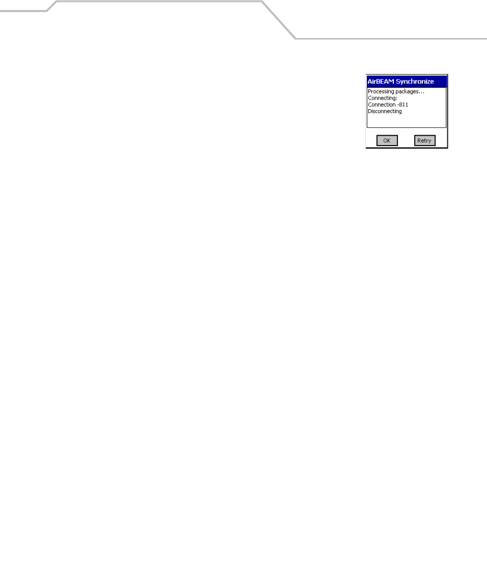
AirBEAM Smart 9-11
3. Once connected, the AirBEAM Synchronize window appears.
• The Status List displays status messages that indicate the
progress of the synchronization process.
• Tap OK to return to the Main Menu. This button remains inactive
until the synchronization process is complete.
• Tap Retry to restart the synchronization process. This button is
activated only if there is an error during the synchronization
process.
Automatic Synchronization
The AirBEAM Smart Client can be configured to launch automatically using the Misc(1) Preference
tab, see Misc(1) Tab on page 9-7. When setting automatic synchronization, use the Auto-load drop-
down list is to specify how the AirBEAM Smart Client should be invoked automatically when the
client device is rebooted. See Misc(1) Tab on page 9-7 for instructions on enabling Auto Sync.
AirBEAM Smart Staging
The AirBEAM Smart staging support is intended to speed up and simplify the process of staging
custom or updated operating software onto mobile devices directly from manufacturing. The staging
support is part of the AirBEAM Smart CE Client that is integrated into the mobile computer.
The AirBEAM Smart support works by defaulting the AirBEAM Smart Client configuration to a known
set of values and launching the AirBEAM Smart package download logic. A staging environment,
including an RF network, FTP server and AirBEAM Smart packages must be setup. Ideally a staging
network and server should be setup to match the default AirBEAM Staging client configuration.
The AirBEAM Smart staging utility is invoked by selecting the Files icon from the Series 9000 Demo
screen, select \Platform\AirBeam\ and double tap on the abstage.lnk file.
The AirBEAM Staging support provides several benefits:
• Many devices can be simultaneously loaded over the RF network.
• The AirBEAM staging utility provides a simple single dialog user interface that is used to
quickly start the software installation process.

MC9000-K/S for Embedded Windows® CE .NET Product Reference Guide
9-12

Mobile Computer Configuration
Chapter Contents
Introduction. . . . . . . . . . . . . . . . . . . . . . . . . . . . . . . . . . . . . . . . . . . . . . . . . . . . . . . . . . . . . . . . . . . . . . . .10-3
Starting Terminal Configuration Manager . . . . . . . . . . . . . . . . . . . . . . . . . . . . . . . . . . . . . . . . . . . . . . . .10-4
Defining Script Properties . . . . . . . . . . . . . . . . . . . . . . . . . . . . . . . . . . . . . . . . . . . . . . . . . . . . . . . . . . . .10-7
Creating the Script for the Hex Image . . . . . . . . . . . . . . . . . . . . . . . . . . . . . . . . . . . . . . . . . . . . . . . . . . .10-8
Opening a New or Existing Script . . . . . . . . . . . . . . . . . . . . . . . . . . . . . . . . . . . . . . . . . . . . . . . . . .10-9
Updating TCM 1.X Scripts . . . . . . . . . . . . . . . . . . . . . . . . . . . . . . . . . . . . . . . . . . . . . . . . . . . . . . . .10-9
Copying Components to the Script. . . . . . . . . . . . . . . . . . . . . . . . . . . . . . . . . . . . . . . . . . . . . . . . . .10-9
Saving the Script . . . . . . . . . . . . . . . . . . . . . . . . . . . . . . . . . . . . . . . . . . . . . . . . . . . . . . . . . . . . . . .10-9
Building the Image . . . . . . . . . . . . . . . . . . . . . . . . . . . . . . . . . . . . . . . . . . . . . . . . . . . . . . . . . . . . . . . . .10-10
Sending the Hex Image . . . . . . . . . . . . . . . . . . . . . . . . . . . . . . . . . . . . . . . . . . . . . . . . . . . . . . . . . . . . .10-11
TCM Error Messages . . . . . . . . . . . . . . . . . . . . . . . . . . . . . . . . . . . . . . . . . . . . . . . . . . . . . . . . . . . . . . .10-21
IPL Error Detection . . . . . . . . . . . . . . . . . . . . . . . . . . . . . . . . . . . . . . . . . . . . . . . . . . . . . . . . . . . . . . . . .10-23
Creating a Splash Screen . . . . . . . . . . . . . . . . . . . . . . . . . . . . . . . . . . . . . . . . . . . . . . . . . . . . . . . . . . . .10-26
Splash Screen Format. . . . . . . . . . . . . . . . . . . . . . . . . . . . . . . . . . . . . . . . . . . . . . . . . . . . . . . . . . .10-26

MC9000-K/S for Embedded Windows® CE .NET Product Reference Guide
10-2
Flash Storage . . . . . . . . . . . . . . . . . . . . . . . . . . . . . . . . . . . . . . . . . . . . . . . . . . . . . . . . . . . . . . . . . . . . 10-27
FFS Partitions . . . . . . . . . . . . . . . . . . . . . . . . . . . . . . . . . . . . . . . . . . . . . . . . . . . . . . . . . . . . . . . . 10-27
Working with FFS Partitions. . . . . . . . . . . . . . . . . . . . . . . . . . . . . . . . . . . . . . . . . . . . . . . . . . . . . 10-27
RegMerge.dll . . . . . . . . . . . . . . . . . . . . . . . . . . . . . . . . . . . . . . . . . . . . . . . . . . . . . . . . . . . . 10-28
CopyFiles. . . . . . . . . . . . . . . . . . . . . . . . . . . . . . . . . . . . . . . . . . . . . . . . . . . . . . . . . . . . . . . . 10-29
Non-FFS Partitions . . . . . . . . . . . . . . . . . . . . . . . . . . . . . . . . . . . . . . . . . . . . . . . . . . . . . . . . . . . . 10-29
Downloading Partitions to the Terminal . . . . . . . . . . . . . . . . . . . . . . . . . . . . . . . . . . . . . . . . . . . 10-30
IPL . . . . . . . . . . . . . . . . . . . . . . . . . . . . . . . . . . . . . . . . . . . . . . . . . . . . . . . . . . . . . . . . . . . . . . . . . . . . . 10-30
Partition Update vs. File Update. . . . . . . . . . . . . . . . . . . . . . . . . . . . . . . . . . . . . . . . . . . . . . . . . . 10-30
Upgrade Requirements. . . . . . . . . . . . . . . . . . . . . . . . . . . . . . . . . . . . . . . . . . . . . . . . . . . . . . . . . 10-31

Mobile Computer Configuration 10-3
Introduction
Terminal Configuration Manager (TCM) is an application used to customize flash file system
partitions for the mobile computer. The most common use is to create an application partition hex file
that contains the customer's application. TCM can also be used to load hex files to the flash memory
of the mobile computer.
The program resident on the mobile computer that receives the hex file and burns it to the flash
memory is called Initial Program Loader (IPL).
The customization of partitions is controlled by TCM scripts. The scripts contain all of the necessary
information for building an image. The script is a list of copy commands specifying the files to copy
from the development computer to the partition.
TCM works with a pair of directory windows, one displaying the script and the other displaying the
source files resident on the development computer. Using standard windows drag and drop
operations, files can be added and deleted from the script window.
The SMDK includes scripts used by Symbol Technologies to build the standard factory installed
Platform and Application partitions provided on the mobile computer. The standard Platform partition
contains drivers while the Application partition contains demo applications and optional components.
The standard TCM scripts can be found in the following folder: C:\Program Files\Symbol Windows CE
SMDK (PDT9000)\SymbolPlatforms \PDT9000\TCMScripts.
Before creating a script to build a hex image, identify the files required
(system files, drivers, applications, etc.) and locate the files’ source
directories to make the script building process easier.
The required processes for building a hex image in TCM include:
• Starting TCM
• Defining script properties
• Creating the script for the hex image
• Building the image
• Sending the hex image
• Creating a splash screen
• Flash storage.
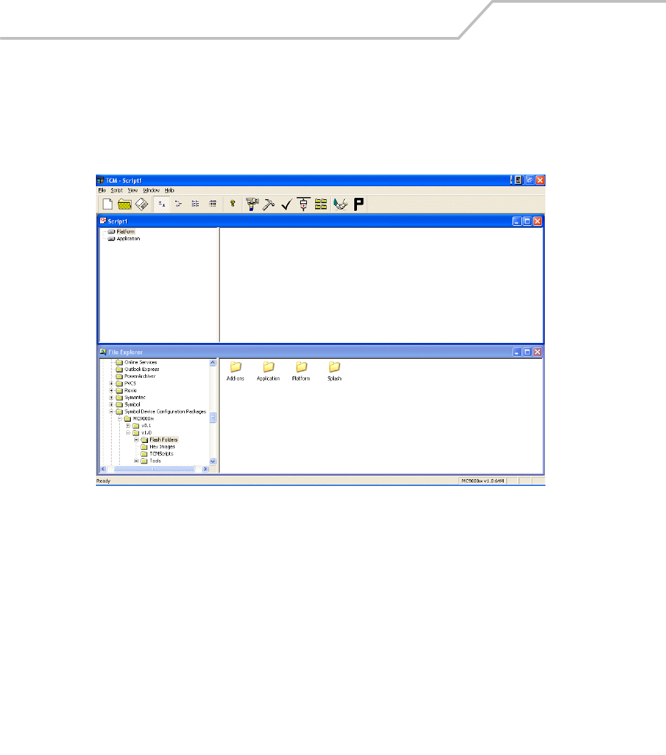
MC9000-K/S for Embedded Windows® CE .NET Product Reference Guide
10-4
Starting Terminal Configuration Manager
Click the Windows start menu TCM icon (Symbol Windows CE SMDK for Series 9000) to start TCM.
The TCM window appears displaying two child windows: Script1 and File Explorer. The Script1
window contains a newly created script and the File Explorer window contains a file explorer view
used for selecting files to be placed in the script.
Figure 10-1. TCM Startup Window
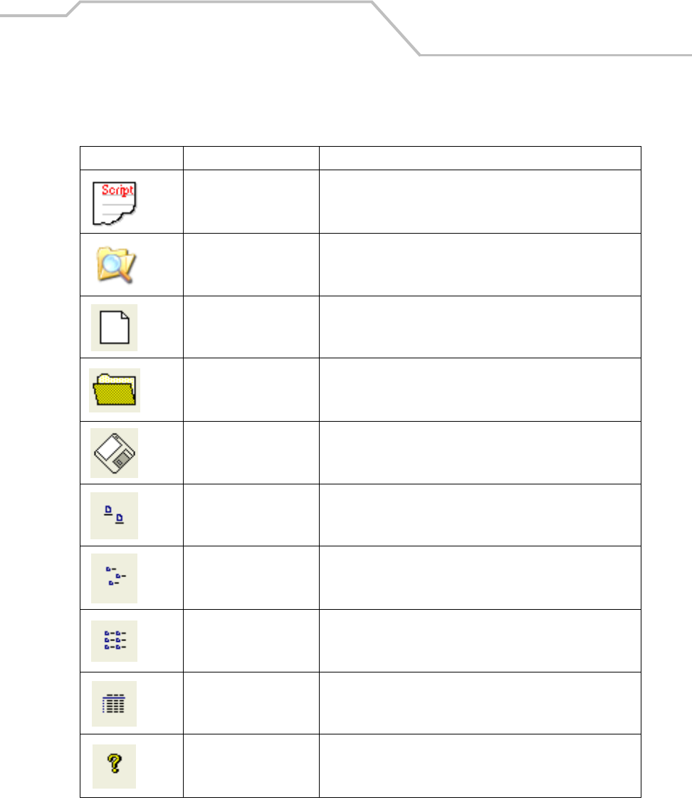
Mobile Computer Configuration 10-5
The following table lists the components of the TCM window.
Table 10-1. TCM Components
Icon Component Function
Script Window Displays the files to be used in the creation of the partition(s).
File Explorer Window Used to select the files to be added to the script.
Create button Create a new script file.
Open button Open an existing script file.
Save button Save the current script file.
Large icons button View the current script items as large icon.
Small icons button View the current script items as small icon.
List button View the current script items as a list.
Details button View the current script items with more details.
About button Display version information for TCM.
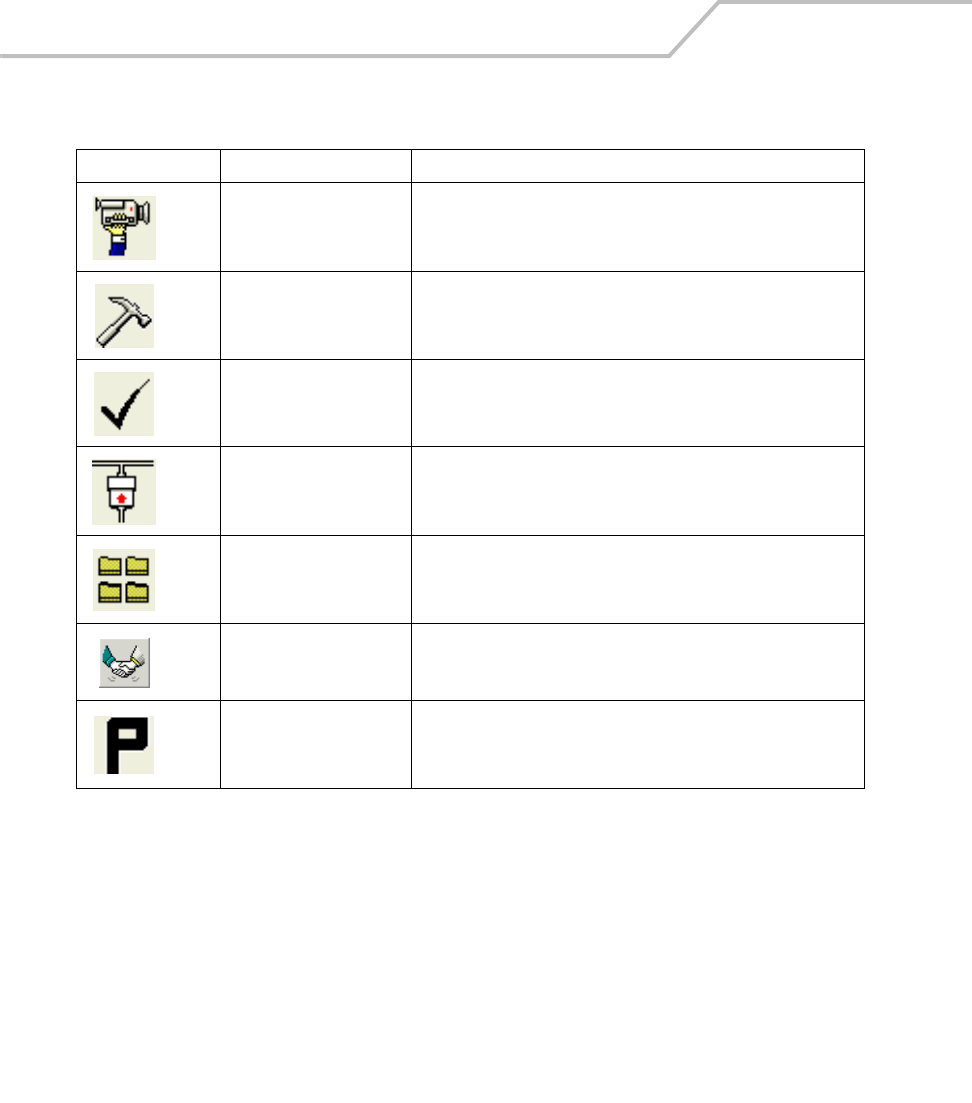
MC9000-K/S for Embedded Windows® CE .NET Product Reference Guide
10-6
Properties button View/change the current script properties.
Build button Build the current script into a set of hex files.
Check button Check the script for errors (files not found).
Send button Download the hex image to the terminal.
Tile button Arrange the sub-windows in a tiled orientation.
Build and Send Build the current script into a set of hex images and send the hex
images to the mobile computer.
Preferences button View/change the global TCM options.
Table 10-1. TCM Components (Continued)
Icon Component Function
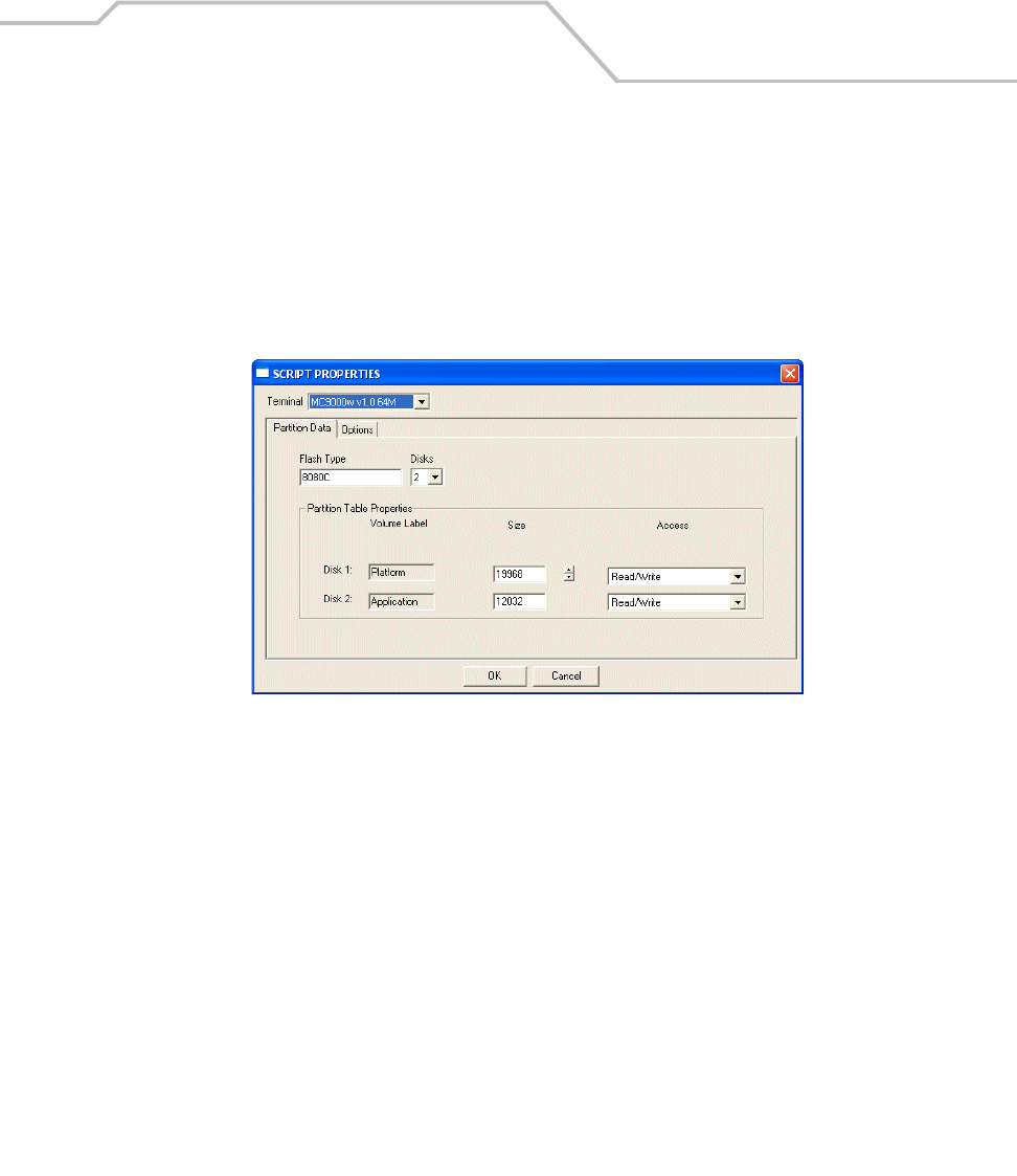
Mobile Computer Configuration 10-7
Defining Script Properties
Before a script is created, the script properties must be defined. This defines the type of terminal,
flash type, number of disks being created and the memory configuration of each disk partition.
To define the script properties:
1. Select the Script window to make it active.
2. Click the Properties button. The Script Properties window - Partition Data tab appears.
Figure 10-2. Script Properties Window - Partition Data Tab
3. In the Terminal drop-down list, the MC9000w v1.0 64M entry is already selected.
4. Use the default Flash Type.
5. In the Disks drop-down list, select the number of disk partitions to create.
6. Select the (memory) Size for each partition. Note that adding space to one disk. partition
subtracts it from another.
7. In the Access drop-down list for each disk partition, determine and select the Read/Write
access option.
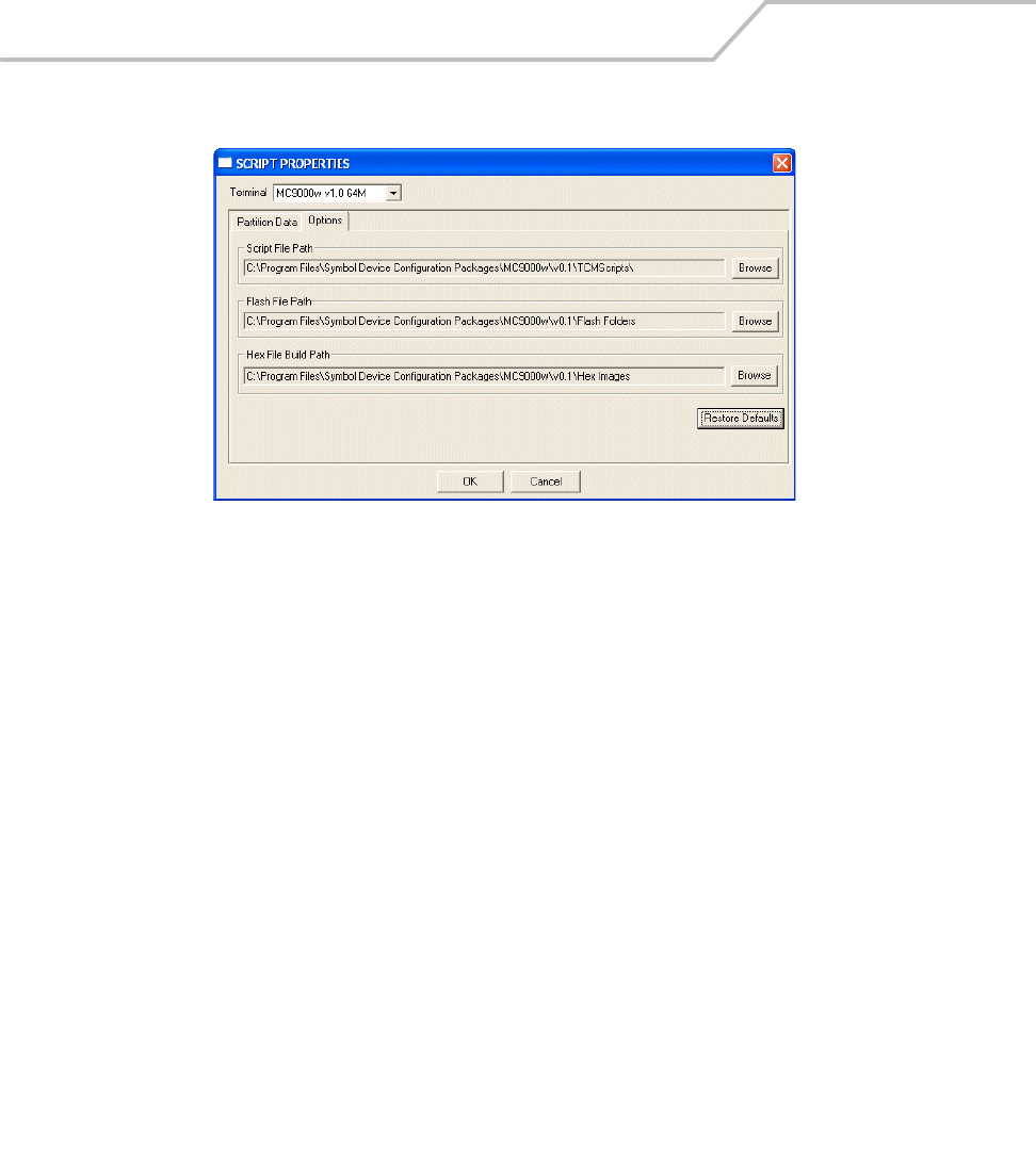
MC9000-K/S for Embedded Windows® CE .NET Product Reference Guide
10-8
8. Click the Options tab. The Script Properties window - Options tab appears.
Figure 10-3. Script Properties Window - Options Tab
9. Set the paths for the Script File, Flash File and Hex File Build.
10. Click OK.
Creating the Script for the Hex Image
On start-up, TCM displays the TCM window with the Script1 window and File Explorer window
pointing to the following directory:
\Program Files\Symbol Device Configuration Packages\MC9000w\v0.1\TCMScripts\
The Script1 window directory pane displays two partitions: Platform and Application. Depending on
the type of flash chip, the number of partitions may change. Files can be added to each of the
partitions. TCM functionality includes:
• Opening a new or existing script file
• Copying components to the script window
• Saving the script file.
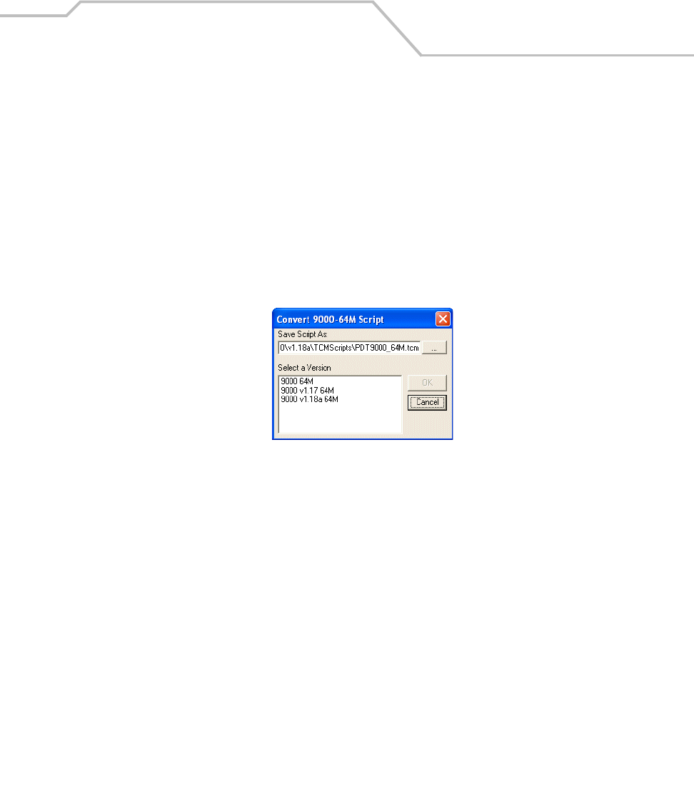
Mobile Computer Configuration 10-9
Opening a New or Existing Script
A script file can be created from scratch or based on an existing script file. Click Create to create a
new script or click Open to open an existing script (for example, a script provided in the Series 9000
SMDK). If an existing script is opened and changes are made, saving the changes overwrites the
original script. To use an original or Symbol supplied standard script as a base and save the changes
in a new script, use the Save As function to save the script using a different file name.
Updating TCM 1.X Scripts
Script files that were created with older versions of TCM can be upgraded to TCM 2.0 scripts. Click
Open to open an existing script created with an older version of TCM. The Conversion window
appears automatically.
Figure 10-4. Conversion Window - Upgrading to TCM 2.0
Copying Components to the Script
Script contents are managed using standard file operations such as New Folder, Delete and Rename.
Items can be added to the script by clicking files and folders in the File Explorer window and dragging
them to the Script window. The File Explorer window supports standard windows; multiple files may
be selected by clicking while holding the SHIFT or CTRL keys.
Saving the Script
Modifications to a script file can be saved using the Save or the Save As function. Saving changes to
an existing script writes over the original script. To use a Symbol-supplied standard script as a base
and save the changes in a new script, use the Save As function.
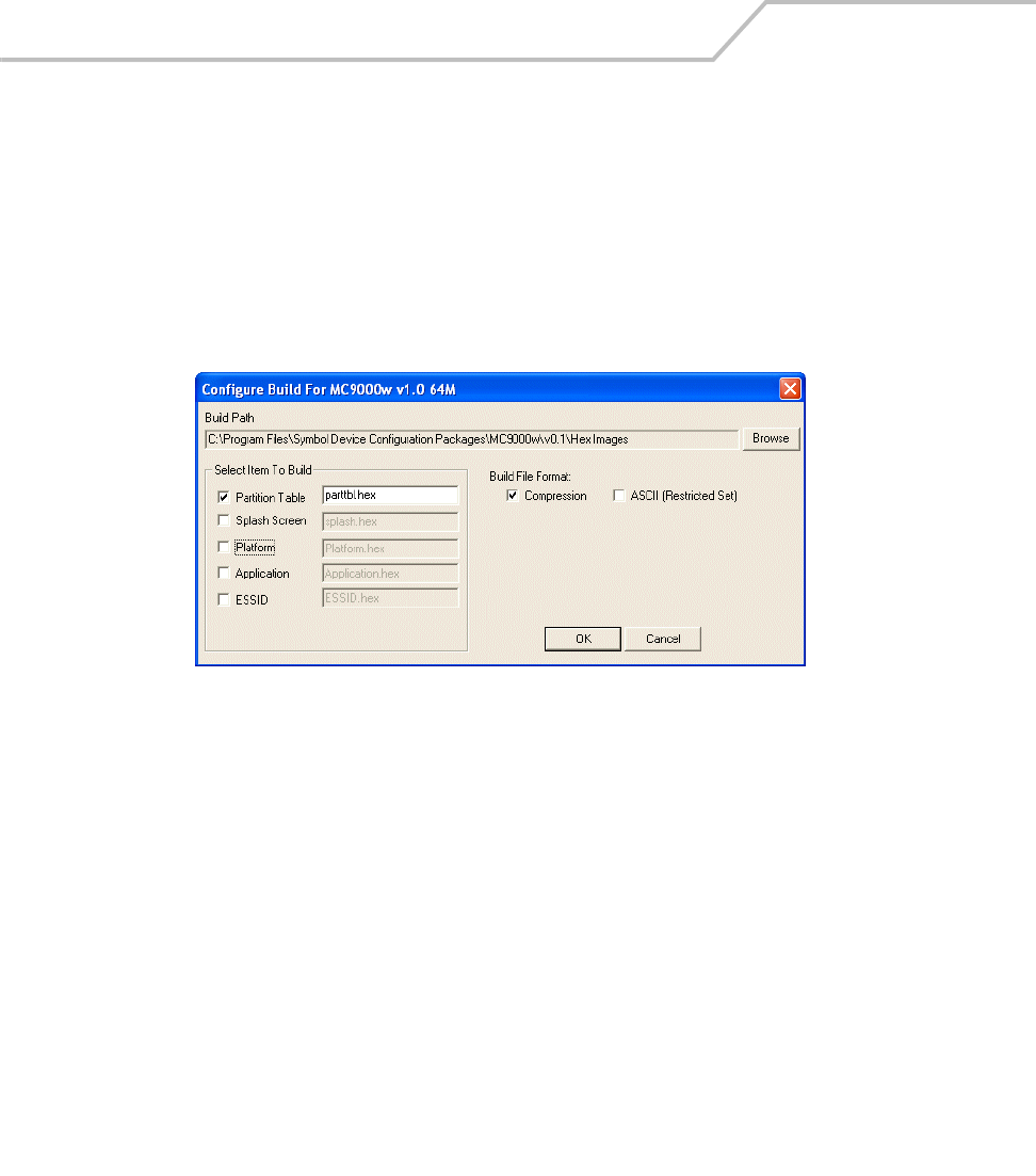
MC9000-K/S for Embedded Windows® CE .NET Product Reference Guide
10-10
Building the Image
Once the script is created, the hex image defined by the script can be built.
As part of the build, TCM performs a check on the script which verifies that all files referenced in the
script exist. This check is important for previously created scripts to ensure that files referenced in
the script are still in the designated locations.
To build scripts:
1. Click Build on the TCM toolbar. The Configure Build window appears.
Figure 10-5. Configure Build Window
2. Select the items (partitions) to build using the check box(es) to the left of each named
partition.
3. The Build Path defines where to store all built partitions.
4. Select (hex image) COMPRESSION to reduce the size and speed up the download.
5. Click OK and follow the on-screen instructions.
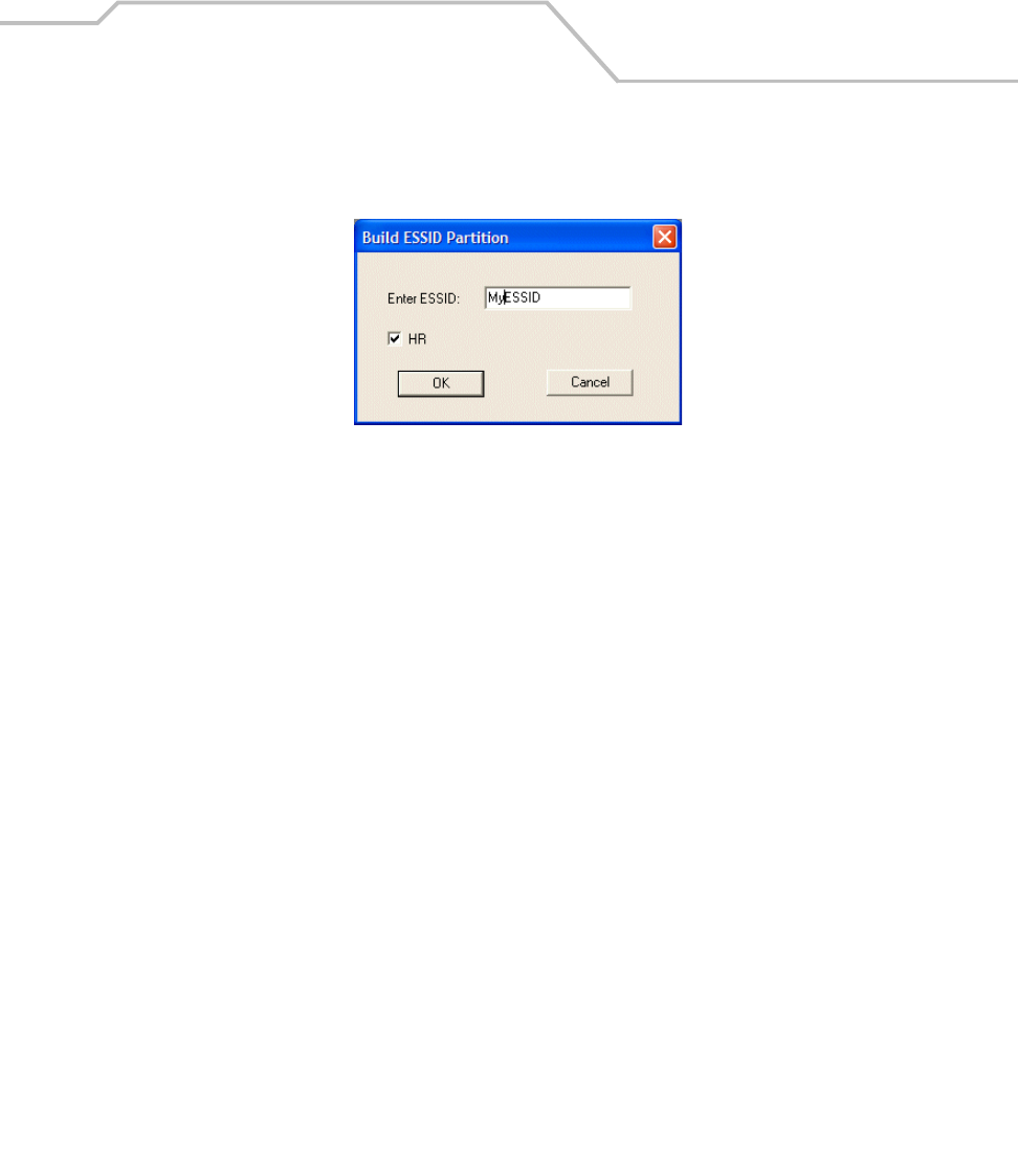
Mobile Computer Configuration 10-11
If one of the partitions being built is the ESSID, a prompt appears requesting the ESSID
value. Deselect the HR (High Rate) check box when building ESSID images for a device with
an FH radio.
Figure 10-6. Build ESSID Partition Window
If one of the partitions being built is the Splash Screen, a prompt appears requesting both
the source Bitmap file and the destination HEX file.
6. A check is performed and if there are no errors, the partition hex files are created.
If the build fails, the hex files are not be created and TCM displays an error message. Two of the most
common reasons for a build failure are:
• Files defined in the script can not be found. This error can occur when the files referenced
by the script are no longer stored on the development computer or the folders where they
are stored were renamed.
• The total amount of flash memory space required by the script exceeds the image size. To
correct this, reduce the number of files in the partition or increase the size of the partition.
See Defining Script Properties on page 10-7 for more information about setting the image
size appropriately.
Sending the Hex Image
Once the hex file is built, it can be downloaded to the mobile computer.
To load the hex files on to the mobile computer:
1. For downloads using a serial connection, connect the mobile computer to the development
computer using the Single Slot Serial/USB cradle or CAM.
2. Press and hold the left scan button and the Power button simultaneously until the mobile
computer resets into IPL.
MC9000-K/S for Embedded Windows® CE .NET Product Reference Guide
10-12
The mobile computer must be inserted in the cradle or attached to the CAM,
both with their appropriate power supplies connected to a power source, for
the mobile computer to reset into IPL.
3. When the Initial Program Loader menu appears, release the scan and Power buttons.
Figure 10-7. Initial Program Loader (IPL) Menu
To ensure a successful download, do not remove power from the mobile
computer while in IPL mode.
4. Choose Auto Select or use the up and down scroll buttons to select the partition to
download, then press Enter.
Initial Program Loader
Platform
Application
PRIMFIRM
SECFIRM
ESSID
Config Block
Windows CE
Monitor
Splash Screen
Power Micro
Partition Table
System Reset
Auto Select

Mobile Computer Configuration 10-13
Table 10-2. IPL Menu Partitions
Partition Name Description
Platform Contains the files in the Platform folder.
Application Contains the files in the Application folder.
PRIMFIRM Contains the primary radio firmware for the Spectrum24 HR radio card.
Note: These partitions must be loaded to use wireless downloads through IPL with the HR
radio. They are only used by IPL and are not required by the Operating System or the S24 FH
radios.
SECFIRM Contains the secondary radio firmware for the Spectrum24 HR radio card.
Note: These partitions must be loaded to use wireless downloads through IPL with the HR
radio. They are only used by IPL and are not required by the Operating System or the S24 FH
radios.
ESSID Identifies the ESSID, used for wireless downloads.
Note: This partition specifies the ESSID to be used for IPL downloads via all S24 radios. If the
partition is not present, then an ESSID of 101 is assumed. This partition is only used by IPL and
is not required by the Operating System.
Config Block Contains information to correctly configure the Operating System for the mobile computer. This
information is loaded by the manufacturer.
Note: Great care should be taken to ensure that an incorrect config block is not loaded into the
mobile computer. Loading an incorrect config block prevents the correct operation of the
computer.
Windows CE Contains the operating system for the mobile computer.
Monitor Contains the Monitor and IPL programs.
Splash Screen Contains the splash screen that displays while booting the mobile computer.
Note: Splash screens are generated from .bmp images and must be less than or equal to 240
pixels wide and 296 pixels deep. For mono displays, the bmp image must be 4 bpp and for color
screens the color depth must be 8 bpp. Note: 8 bits per pixel only applies to splash screen
images. Once Windows CE is running, the color density is 16 bits per pixel.
Power Micro The Power Micro is a small computer contained within the mobile computer that controls
several system resources. In the unlikely event that the Power Micro Firmware needs updating,
selecting this item allows the device to be programmed.
Partition Table Contains the partition information for all other partitions.
Note: The partition table should never need changing unless the sizes of the platform and
application images are changed within TCM. If this is done, then the new partition table should
be loaded first, followed by both platform and application in any order.
MC9000-K/S for Embedded Windows® CE .NET Product Reference Guide
10-14
If the platform or application partition sizes are changed, a new partition
table must be downloaded first.
5. IPL displays the Select Transport menu which lists the available methods of downloading the
file.
Figure 10-8. Select Transport Menu
System Reset Selecting this item provides a simple method to exit IPL and to boot the operating system.
Auto Select Selecting this item allows one or more files to be downloaded without having to manually
select the destination. (The content of the files being downloaded automatically directs the file
to the correct destination.) For technical reasons, Auto Select cannot be used to download
Monitor, Power Micro, or Partition Table. These items must be specifically selected.
Select Transport
Wireless - S24 DS
Serial
Previous
Top
Table 10-2. IPL Menu Partitions (Continued)
Partition Name Description
Mobile Computer Configuration 10-15
If the mobile computer does not have a radio, then the WirelessS24XX
selection is not available on the Transport menu.
6. Use the up and down scroll buttons to select the method of transport, then press Enter.
7. If the Serial transport method is selected, the Baud Rate Menu appears.
Figure 10-9. Baud Rate Menu
8. Use the up and down scroll buttons to select the appropriate baud rate, then press Enter.
Baud Rate Menu
115200
57600
38400
19200
9600
Previous
Top
MC9000-K/S for Embedded Windows® CE .NET Product Reference Guide
10-16
9. If the Wireless S24XX transport method was selected, the Address Configuration menu
appears.
Figure 10-10. Address Configuration Menu
For wireless downloads, the ESSID must be loaded via serial before Wireless
S24 DS can be used. The PC running TCM must be on the same network as
the terminal and the ESSID partition must be loaded with the correct ESSID.
10. Use the up and down scroll buttons to select DHCP, then press Enter.
Address Configuration
“DHCP”
Previous
Top

Mobile Computer Configuration 10-17
11. The Download File? menu appears.
Figure 10-11. Download File? Menu
Download File?
Download
Cancel
Show Parms
Previous
Top

MC9000-K/S for Embedded Windows® CE .NET Product Reference Guide
10-18
12. Use the up and down scroll buttons to select Show Parms to verify the file to download.
Press Enter to display the Parameters screen.
Figure 10-12. Parameters Screen
Partition Name is the name of the partition selected in the Initial Program Loader menu.
Device Parameters is the device selected in the Select Transport menu with the baud rate
for serial downloads, or DHCP address for wireless downloads.
13. Press Enter to return to the Download File? menu.
Downloading:
"Partition Name"
via
"Device Parameters"
Waiting for input...

Mobile Computer Configuration 10-19
14. Use the up and down scroll buttons to select Download. Press Enter. The Downloading
screen appears.
Figure 10-13. Downloading Screen
Before the download starts, if Serial was selected in the Select Transport menu, Waiting for
Data appears in the Device Status field. If Wireless S24 DS was selected in the Select
Transport menu, the IP address appears in the Device Status field.
Figure 10-14. Downloading Complete Screen
Downloading:
“Partition Name”
via
Device Parameters
Waiting for input
“Partion Name”
####________20%
Downloading:
“Partition Name”
via “Device Parameters”
Result was: Success!
Press any key to continue
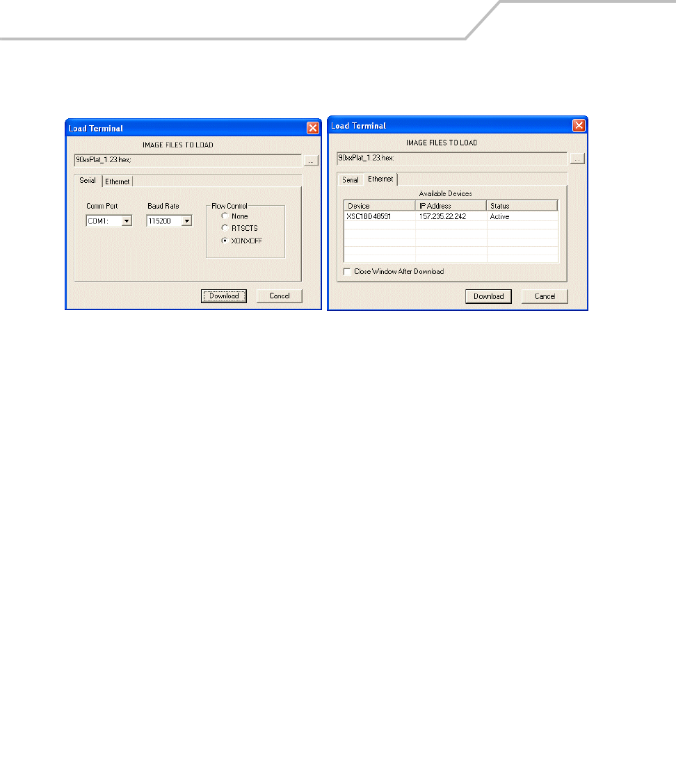
MC9000-K/S for Embedded Windows® CE .NET Product Reference Guide
10-20
15. On the development computer, click Load on the TCM toolbar. The Load Terminal window -
Serial tab appears.
Figure 10-15. Load Terminal Window - Serial and Ethernet Tabs
16. For Serial port connections, click the Serial tab and select the Image Files To Load, Comm
Port and Baud Rate from their respective drop-down lists.
For Wireless connections, click the Ethernet tab. A list of available devices and their IP
addresses appear. Only those devices placed into the Wireless transport mode of IPL appear
in this dialog. Select the files to download and the device to receive the files. To load a
device, the status must be "Active."
17. Click Download to begin the operation.
18. During download, the Downloading screen on mobile computer displays the Device Status
and a progress bar.
19. When complete, Device Status displays Result was Success, or in the case of an error, the
cause of the error.
20. On completion, press Enter to return to the IPL menu to select the next partition to
download.
21. To exit IPL, select the System Reset item from the IPL menu (see Figure 10-7 on page 10-12).

Mobile Computer Configuration 10-21
TCM Error Messages
TCM validates the cells in the partition table when the Execute button is clicked. Cells highlighted in
red contain an error. Partition loading is disabled until all errors are corrected.
Table 10-3. TCM Error Messages
Error Description/Solution
Failed to build images: flash file
system DLL not loaded!
TCM could not load the DLL required to build images for the targeting flash file
system. Reinstall TCM or recover the DLL.
Failure finding directory xxx Building process failed because directory xxx was not found.
Failure creating volume Building process failed because a certain disk volume could not be created.
Failure adding system file to
image
Build process failed because TCM failed to add a certain system file to the disk image.
INVALID PATH The path for the image file to build is not valid.
Nothing Selected To Build In the Config Build window, no item is selected to build.
Illegal ESS ID In the Build ESSID Partition window, no ESS ID was entered or the ESS ID entered was
illegal.
Disk Full TCM failed to create Hex image file at the selected path. Check available disk space.
Target Disk Full Build process failed because TCM failed to add file to the image of a disk volume.
Remove some files or increase the disk size.
Hex file is READ ONLY The Hex image file to be created exists and is read-only. Delete the existing file or
change its attribute.
Error opening the file xxx with
write access
TCM could not open file xxx with write access. Check if file is in use.
Failure creating binary file TCM failed to open/create an intermediate binary file.
Hex File To load is missing or
invalid
In Load Terminal window, the file selected to load has invalid status.
Could not locate terminal name in
TCM.ini file
While loading the Script Properties window, TCM could not find the TCM.ini section
corresponding to the terminal type specified by the current opening script. Either
TCM.ini or the script file is invalid.
Incorrect disk sizes in TCM.ini file The total disk size specified in the script does not match the total disk size defined in
the corresponding TCM.ini section. Check if the script is corrupt or the TCM.ini has
changed after the script was created.
INVALID DIRECTORY In Script Properties window, the selected System File Path is not a valid directory.

MC9000-K/S for Embedded Windows® CE .NET Product Reference Guide
10-22
One of the disk sizes is one sector
in size
In Script Properties window, one of the disks is too small (one sector in size). This may
cause problem while building images, especially when cushion is enabled. Increase
the disk size.
INVALID VOLUME NAME In Script Properties window, one of the volume labels is not valid.
Corrupt TCM.INI file! (Invalid
value of VolumeDivisor)
The VolumeDivisor entry is missing or invalid in the TCM.ini. Reinstall TCM or recover
TCM.ini.
Invalid version of TCM script file The TCM script was not created by this version of TCM.
Corrupt or missing TCM.ini file TCM could not find TCM.ini file.
FAILED CONNECTION TO COM
PORT (Could not get status)
While downloading images to terminal, TCM failed to connect to the selected COM
port. Check if the COM port is free and is properly configured.
FAILED CONNECTION TO
TERMINAL (Terminal Not
Connected Properly/Terminal Not
Ready to Receive)
While downloading images, TCM failed to connect to the terminal. Check if the
correct flow control protocol is selected and the terminal is properly connected and is
in a listening state.
Table 10-3. TCM Error Messages (Continued)
Error Description/Solution
Mobile Computer Configuration 10-23
IPL Error Detection
While receiving data, IPL performs many checks on the data to ensure that the data is received
correctly. If an error is detected, IPL immediately aborts the download, and reports the error on an
error screen.
Error screens may vary depending on the action being performed. A sample error screen may look like
the screen pictured below:
Figure 10-16. IPL Error Screen
This error message screen displays until a key is pressed. Once the screen is acknowledged, IPL
returns to the Initial Program Loader main menu to wait for a new selection.
To find the probable cause of the error, use the error number and/or the error text displayed on the
screen to look up the error in Table 10-4.
.
Downloading:
Platform
via Serial Port 115200
Error # -2 : Messages:
Cancelled by user
Press any key to continue
Table 10-4. IPL Errors
Error Text Error Number Probable Cause
Unknown error -1 A general error occurred. Retry the download. If the
failure persists, it is most likely due to a hardware
failure; the terminal requires servicing.
Cancelled by user -2 The user cancelled the download.

MC9000-K/S for Embedded Windows® CE .NET Product Reference Guide
10-24
Can't open the source -7 An error occurred opening the source device (either
radio card or Serial port). Check source device
connectivity and retry.
Can't open the destination -8 An error occurred opening the destination device
(either flash ROM or Power Micro). Retry the
download. If the failure persists, it is most likely due
to a hardware failure; the terminal requires servicing.
Can't read from the source device -9 The source device (either radio card or Serial port)
could not be read from. Check source device
connectivity and retry.
Can't write to the destination
device
-10 The destination device (either flash ROM or Power
Micro) could not be written to. Retry the download. If
the failure persists, it is most likely due to a hardware
failure; the terminal requires servicing.
Transmission checksum error -11 An error occurred during transmission from the source
device (either radio card or Serial port) and the
checksum check failed. Check source device
connectivity and retry.
Readback checksum error -12 A checksum, generated from reading back data that
was written to the destination device, was incorrect.
An error during transmission or a write error to the
destination device could cause this.
There is no more heap space
available
-14 There is no more heap space available for the
download procedure. Restart IPL and retry the
download. If the failure persists, contact service with
details of what is being downloaded.
Insufficient data available to
complete record
-21 A Symbol HEX file download was attempted but the
HEX file is invalid. Ensure the file is in Symbol HEX file
format.
Invalid Symbol HEX file -23 A Symbol HEX file download was attempted but the
HEX file is invalid. Ensure the file is in Symbol HEX file
format.
Unrecognized or unsupported HEX
record
-24 The Symbol HEX file being downloaded contains an
invalid or unrecognized HEX record. Ensure the file is
in proper Symbol HEX file format.
Table 10-4. IPL Errors (Continued)
Error Text Error Number Probable Cause

Mobile Computer Configuration 10-25
Invalid data in HEX file -25 The Symbol HEX file being downloaded contains
invalid data. Ensure the file is in proper Symbol HEX
file format with valid HEX data.
Exceeded max size -26 The download file is too large to fit into the space
allocated for it. Either make the file smaller or increase
the space allocated for it by altering the partition
table.
Partition is not valid on this device -27 The downloaded file specifies a partition entry that
does not exist on the device. Only download files that
are valid for this device, or change the partition table
so that the new file is valid on the device.
Wrong destination code -28 A specific partition was chosen from the Main Menu
(not Auto Select) but the file selected for download
was for another partition. Ensure that the partition
selected from the Main Menu matches the file
selected for download.
File type does not support IPL Auto
Select
-29 Monitor, Power Micro and Partition Table cannot be
loaded with Auto Select. Select the appropriate area,
and try again.
Non-contiguous record found -30 A Symbol HEX file download was attempted but the
HEX file is invalid. Ensure the file is in Symbol HEX file
format.
Timed Out - No data -31 IPL was waiting for data from the source device but
timed out before receiving any. Check the source
device connectivity and retry.
Fail: Buffer Overrun -32 The serial port device could not keep up with incoming
data. Retry the serial download with a lower baud
rate.
Partition Table not Valid -33 The size of flash memory is different than that
described in the partition table. Retry the download
with the correct partition table file.
Invalid file format -34 The file format is invalid. Only Symbol HEX files are
supported by IPL.
Table 10-4. IPL Errors (Continued)
Error Text Error Number Probable Cause

MC9000-K/S for Embedded Windows® CE .NET Product Reference Guide
10-26
Creating a Splash Screen
The source bitmap files used to create the default splash screens for the mobile computer are
supplied with the Series 9000 SMDK. These files can be modified using any of the standard windows
image editors, allowing customization for particular customers.
To create a custom splash screen, perform the following steps:
1. For mobile computers with monochrome screens, open the Splashmono.bmp file supplied
with the Series 9000 SMDK using an image editor.
2. For mobile computers with color screens, open the Splashcolor.bmp file supplied with the
Series 9000 SMDK using an image editor.
3. Modify the bitmap file and save.
4. Create a splash partition using the steps shown in the Building the Image on page 10-10.
Splash Screen Format
If the default files are not used to create the new splash screens, be sure to preserve the image
format. The formats are as follows:
See Sending the Hex Image on page 10-11 for information about loading the splash screen using TCM
and IPL.
Table 10-5. Splash Screen Format
Screen Type Dimensions Color Format
Monochrome 240x296 4 bits per pixel
Color 240x296 8 bits per pixel*
* 8 bits per pixel only applies to splash screen images. Once Windows CE
is running, the color density is 16 bits per pixel.

Mobile Computer Configuration 10-27
Flash Storage
In addition to the RAM-based storage standard on Windows CE terminals, the mobile computer is
also equipped with a non-volatile Flash-based storage area which can store data (partitions) that can
not be corrupted by a cold boot. This Flash area is divided into two categories: Flash File System (FFS)
Partitions and Non-FFS Partitions.
FFS Partitions
The mobile computer includes two FFS partitions. These partitions appear to the mobile computer as
a hard drive that the OS file system can write files to and read files from. Data is retained even if
power is removed.
The two FFS partitions appear as two separate folders in the Windows CE file system and are as
follows:
• Platform: The Platform FFS partition contains Symbol-supplied programs and Dynamic Link
Libraries (DLLs). This FFS is configured to include DLLs that control system operation. Since
these drivers are required for basic mobile computer operation, only experienced users
should modify the content of this partition.
• Application: The Application FFS partition is used to store application programs needed to
operate the mobile computer.
Working with FFS Partitions
Because the FFS partitions appear as folders under the Windows CE file system, they can be written
to and read like any other folder. For example, an application program can write data to a file located
in the Application folder just as it would to the Windows folder. However, the file in the Application
folder is in non-volatile storage and is not lost on a cold boot (e.g., when power is removed for a long
period of time).
Standard tools such as ActiveSync can be used to copy files to and from the FFS partitions. They
appear as the “Application” and “Platform” folders to the ActiveSync explorer. This is useful when
installing applications on the mobile computer. Applications stored in the Application folder are
retained even when the mobile computer is cold booted, just as the Demo 9000 program is retained
in memory.
There are two device drivers included in the Windows CE image to assist developers in configuring
the mobile computer following a cold boot: RegMerge and CopyFiles.

MC9000-K/S for Embedded Windows® CE .NET Product Reference Guide
10-28
RegMerge.dll
RegMerge.dll is a built-in driver that allows registry edits to be made to the Windows CE Registry.
Regmerge.dll runs very early in the boot process and looks for registry files (.reg files) in certain Flash
File System folders during a cold boot. It then merges the registry changes into the system registry
located in RAM.
Since the registry is re-created on every cold boot from the default ROM image, the RegMerge driver
is necessary to make registry modifications persistent over cold boots.
RegMerge is configured to look in the root of two specific folders for .reg files in the following order:
\Platform
\Application
Regmerge continues to look for .reg files in these folders until all folders are checked. This allows
folders later in the list to override folders earlier in the list. This way, it is possible to override Registry
changes made by the Platforms partitions folders. Take care when using Regmerge to make Registry
changes. The Series 9000 SMDK contains examples of .reg files.
Regmerge only merges the .reg files on cold boots. The merge process is
skipped during a warm boot.
Typically, do not make modifications to registry values for drivers loaded before RegMerge. However,
these values may require modification during software development. Since these early loading
drivers read these keys before RegMerge gets a chance to change them, the mobile computer must
be cold booted. The warm boot does not re-initialize the registry and the early loading driver reads
the new registry values.
Do not use Regmerge to modify built-in driver registry values, or merge the same Registry value to
two files in the same folder, as the results are undefined.

Mobile Computer Configuration 10-29
CopyFiles
Windows CE expects certain files to be in the Windows folder, residing in volatile storage. Windows
CE maintains the System Registry in volatile storage. CopyFiles copies files from one folder to another
on a cold boot. Files can be copied from a non-volatile partition (Application or Platform) to the
Windows or other volatile partition during a cold boot. During a cold boot CopyFiles looks for files
with a .CPY extension in the root of the Platform and Application FFS partitions (Platform first and
then Application). These files are text files containing the source and destination for the desired files
to be copied separated by “>”. The following example from the file application.cpy is contained on
the demo application partition included in the Series 9000 SMDK. It can also be obtained from the
Symbol web site at http://devzone.symbol.com/.
Files are copied to the Windows folder from the Flash File System using copy files (*.cpy) in the
following order:
\Platform
\Application
Example:
\Application\ScanSamp2.exe>\Windows\ScanSamp2.exe
This line directs CopyFiles to copy the ScanSamp2.exe application from the \Application folder to the
\Windows folder.
Non-FFS Partitions
Non-FFS Partitions include additional software and data pre-loaded on the mobile computer that can
be upgraded. Unlike FFS Partitions, these partitions are not visible when the operating system is
running. They also contain system information. Non-FFS partitions include the following:
• Windows CE: The complete Windows CE operating system is stored on Flash devices. If
necessary, the entire OS image may be downloaded to the mobile computer using files
provided by Symbol. The current OS partition on the mobile computer is included as part of
the TCM installation package. Any upgrades must be obtained from Symbol. This partition
is mandatory for the mobile computer.
• Splash Screen: a bitmap smaller than 16 Kb (and limited to 8 bits per pixel) is displayed as
the mobile computer cold boots. To download a customized screen to display, see Creating
a Splash Screen on page 10-26.

MC9000-K/S for Embedded Windows® CE .NET Product Reference Guide
10-30
8 bits per pixel only applies to splash screen images. Once Windows CE is
running, the color density is 16 bits per pixel.
• IPL: This program interfaces with the host computer and allows downloading via cradle or
serial cable any or all of the partitions listed above, as well as updated versions of IPL. Use
caution downloading updated IPL versions; incorrect downloading of an IPL causes
permanent damage to the mobile computer. IPL is mandatory for the mobile computer.
• Partition Table: Identifies where each partition is loaded in the mobile computer.
Downloading Partitions to the Terminal
TCM is used to specify a hex destination file for each partition and download each file to the terminal.
This download requires a program loader stored on the terminal. The terminal comes with a program
loading utility, Initial Program Loader (IPL), stored in the terminal's write-protected flash.
IPL
IPL allows the user to upgrade the mobile computer with software updates and/or feature
enhancements.
Partition Update vs. File Update
There are two types of update supported by the mobile computer: partitions and files. The file system
used by the mobile computer is the same as the file system used on a desktop computer. A file is a
unit of data that can be accessed using a file name and a location in the file system. When a file is
replaced, only the contents of the previous file are erased. The operating system must be running for
a file to be updated, so the IPL cannot perform individual file updates as it is a stand-alone program
that does not require the operating system to be running.
A typical partition is a group of files, combined into a single "partition" that represents a specific area
of storage. Examples of partitions are the flash file systems such as Platform or Application. (Using
the desktop computer comparison, these partitions are roughly equivalent to a C: or D: hard disk
drive.) In addition to the "hard disk" partitions, some partitions are used for single items such as the
operating system, monitor, or splash screen. (Again using a desktop computer comparison, these
partitions are roughly the equivalent of the BIOS or special hidden system files.) When a partition is
updated, all data that was previously in its storage region is erased - i.e. it is not a merge but rather
a replacement operation. Typically, the operating system is not running when partitions are update,
so IPL can perform partition updates.

Mobile Computer Configuration 10-31
Partition images for selected partitions can be created by TCM. All partition images suitable for use
by IPL are in hex file format for transfer by TCM from the development computer to the mobile
computer.
Upgrade Requirements
Upgrade requirements:
• The hex files to be downloaded (on development computer)
• A connection from the host computer and the mobile computer (either serial or wireless)
• TCM (on development computer) to download the files.
Once these requirements are satisfied, the mobile computer can be upgraded by invoking IPL and
navigating the menus. See Sending the Hex Image on page 10-11 for procedures on downloading a
hex file to the mobile computer.

MC9000-K/S for Embedded Windows® CE .NET Product Reference Guide
10-32

Desktop Emulator
Chapter Contents
Introduction. . . . . . . . . . . . . . . . . . . . . . . . . . . . . . . . . . . . . . . . . . . . . . . . . . . . . . . . . . . . . . . . . . . . . . . .11-3
Software Requirements . . . . . . . . . . . . . . . . . . . . . . . . . . . . . . . . . . . . . . . . . . . . . . . . . . . . . . . . . . . . . .11-3
Installation Procedures. . . . . . . . . . . . . . . . . . . . . . . . . . . . . . . . . . . . . . . . . . . . . . . . . . . . . . . . . . . . . . .11-3
Starting the Emulator . . . . . . . . . . . . . . . . . . . . . . . . . . . . . . . . . . . . . . . . . . . . . . . . . . . . . . . . . . . . . . . .11-3
Emulator Parameter Settings and Displays . . . . . . . . . . . . . . . . . . . . . . . . . . . . . . . . . . . . . . . . . . . . . . .11-7
Emulator Tab. . . . . . . . . . . . . . . . . . . . . . . . . . . . . . . . . . . . . . . . . . . . . . . . . . . . . . . . . . . . . . . . . . .11-9
Storage Tab . . . . . . . . . . . . . . . . . . . . . . . . . . . . . . . . . . . . . . . . . . . . . . . . . . . . . . . . . . . . . . . . . .11-10
Scanner Tab . . . . . . . . . . . . . . . . . . . . . . . . . . . . . . . . . . . . . . . . . . . . . . . . . . . . . . . . . . . . . . . . . .11-11
Spectrum24 Tab . . . . . . . . . . . . . . . . . . . . . . . . . . . . . . . . . . . . . . . . . . . . . . . . . . . . . . . . . . . . . . .11-12
Battery Tab . . . . . . . . . . . . . . . . . . . . . . . . . . . . . . . . . . . . . . . . . . . . . . . . . . . . . . . . . . . . . . . . . . .11-13
Status Tab. . . . . . . . . . . . . . . . . . . . . . . . . . . . . . . . . . . . . . . . . . . . . . . . . . . . . . . . . . . . . . . . . . . .11-14

MC9000-K/S for Embedded Windows® CE .NET Product Reference Guide
11-2
Using the Emulator . . . . . . . . . . . . . . . . . . . . . . . . . . . . . . . . . . . . . . . . . . . . . . . . . . . . . . . . . . . . . . . . .11-16
User Inputs . . . . . . . . . . . . . . . . . . . . . . . . . . . . . . . . . . . . . . . . . . . . . . . . . . . . . . . . . . . . . . . . . . .11-16
Mouse Inputs . . . . . . . . . . . . . . . . . . . . . . . . . . . . . . . . . . . . . . . . . . . . . . . . . . . . . . . . . . . . .11-16
Keypad Inputs. . . . . . . . . . . . . . . . . . . . . . . . . . . . . . . . . . . . . . . . . . . . . . . . . . . . . . . . . . . . .11-16
Main Menu Taskbar . . . . . . . . . . . . . . . . . . . . . . . . . . . . . . . . . . . . . . . . . . . . . . . . . . . . . . . . . . . .11-16
Start Button . . . . . . . . . . . . . . . . . . . . . . . . . . . . . . . . . . . . . . . . . . . . . . . . . . . . . . . . . . . . . .11-16
Battery/Power Status Icons . . . . . . . . . . . . . . . . . . . . . . . . . . . . . . . . . . . . . . . . . . . . . . . . . .11-17
Taskbar Icons . . . . . . . . . . . . . . . . . . . . . . . . . . . . . . . . . . . . . . . . . . . . . . . . . . . . . . . . . . . . .11-17
Open Programs . . . . . . . . . . . . . . . . . . . . . . . . . . . . . . . . . . . . . . . . . . . . . . . . . . . . . . . . . . . .11-17
Main Menu . . . . . . . . . . . . . . . . . . . . . . . . . . . . . . . . . . . . . . . . . . . . . . . . . . . . . . . . . . . . . . . . . . . . . . .11-17
Start Menu . . . . . . . . . . . . . . . . . . . . . . . . . . . . . . . . . . . . . . . . . . . . . . . . . . . . . . . . . . . . . . . . . . .11-17
Exiting the Emulator . . . . . . . . . . . . . . . . . . . . . . . . . . . . . . . . . . . . . . . . . . . . . . . . . . . . . . . . . . . . . . . .11-17
Resetting the Emulator. . . . . . . . . . . . . . . . . . . . . . . . . . . . . . . . . . . . . . . . . . . . . . . . . . . . . . . . . . . . . .11-18

Desktop Emulator 11-3
Introduction
This chapter provides basic instructions for installing and using the emulator. The emulator provides
software API emulation of the actual MC9000-K and MC9000-S. The emulator consists of the
following components:
• System Settings Dialog (SSD)
• Emulator User Interface (emulator skin)
• Simulated External File System (Flash, SD/MMC).
Software Requirements
The emulator requires the installation of eMbedded Visual C++ 4.0 and EvC 4.0 service pack 1, before
the emulator can be installed. To download eMbedded Visual C++ 4.0 go to the Microsoft download
website: http://www.microsoft.com/downloads/ and enter “eMbedded Visual C++ 4.0” into the
keyword search parameters. Follow the prompts and download eMbedded Visual C++ 4.0 and EvC 4.0
service pack 1.
Installation Procedures
The emulator is automatically installed as part of the Symbol Windows CE SMDK for Series 9000,
see Installing the SMDK on page 8-4.
Starting the Emulator
The emulator is designed to launch via the SSD. The SSD is accessed from the desktop Start menu
under the PDT9000 program group.
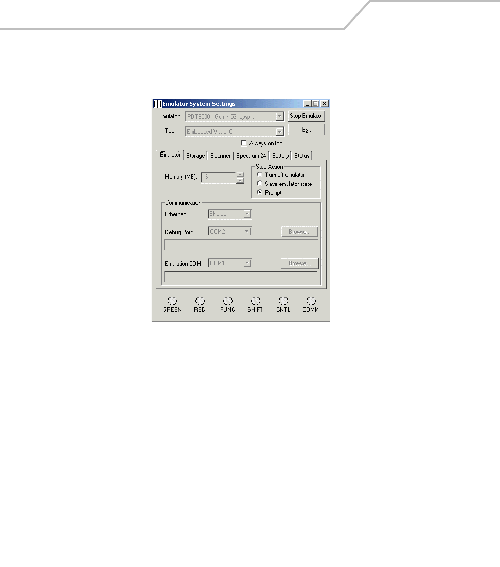
MC9000-K/S for Embedded Windows® CE .NET Product Reference Guide
11-4
1. In the PDT9000 program group, double-click SSD.exe file. The Emulator System Settings
window appears.
Figure 11-1. Emulator System Settings Window
2. Click the Storage tab to set the storage paths:
\Application - Set Path to:
C:\Program Files\Windows CE Tools\wce410\PDT9000\Emulation\Flash Partitions\Application
\Platform - Set Path to:
C:\Program Files\Windows CE Tools\wce410\PDT9000\Emulation\Flash Partitions\Platform
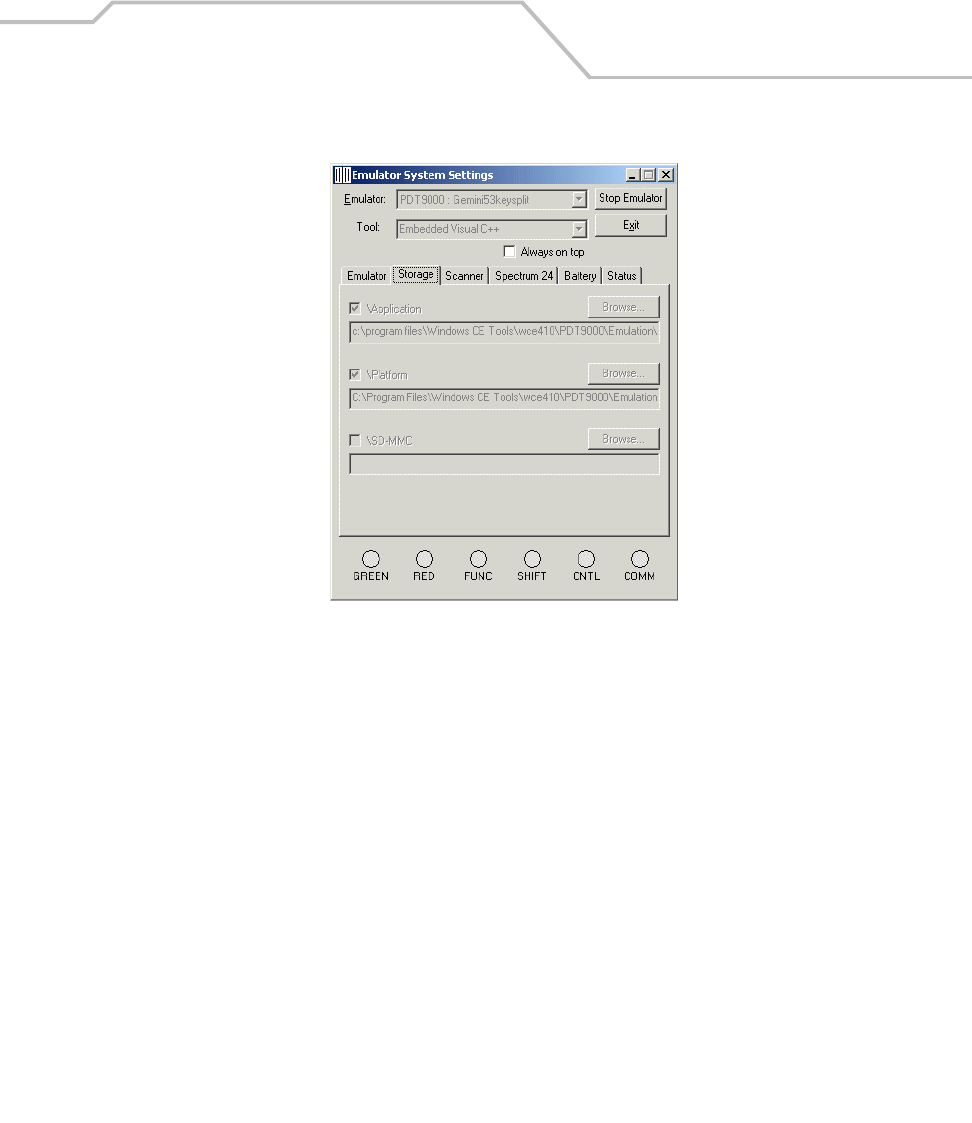
Desktop Emulator 11-5
Figure 11-2. Emulator Startup Storage Settings
3. From the Emulator drop-down list, select either:
PDT9000: Gemini53key for a full view of the mobile computer.
or
PDT9000: Gemini53keysplit for a split view of the mobile computer.
4. The Tool drop down window displays the selected Embedded Visual C++ tool.
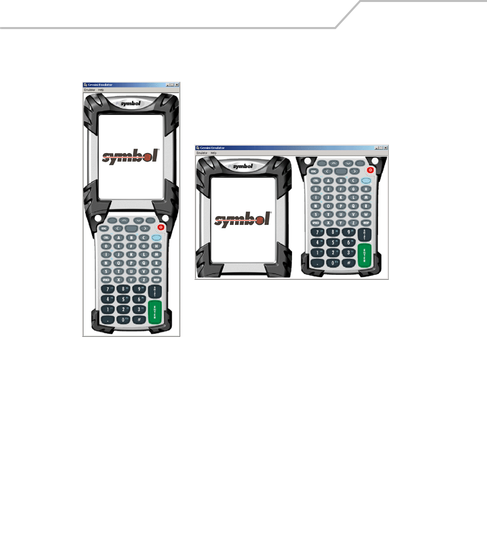
MC9000-K/S for Embedded Windows® CE .NET Product Reference Guide
11-6
Figure 11-3. Emulator View Options
5. Select the Always on top check box to keep the emulator view on top of all other programs,
or leave the box unchecked to allow other programs to display on top of the emulator view.
6. Click Launch to start the emulator.
Gemini53keysplit, Split View
Gemini53key, Full View
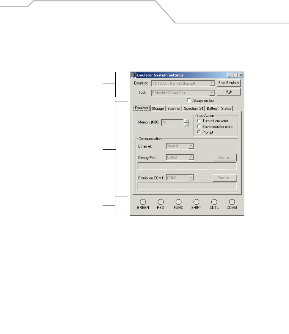
Desktop Emulator 11-7
Emulator Parameter Settings and Displays
The Emulator System Settings window is divided into three parts, emulator settings, emulator tabs
and emulator LEDs.
Figure 11-4. Emulator System Settings Window
Emulator Settings
Emulator Tabs
Emulator LEDs

MC9000-K/S for Embedded Windows® CE .NET Product Reference Guide
11-8
A detailed discussion of each of the emulator window tabs settings and displays is provided in the
following sections:
•Emulator
•Storage
• Scanner
• Spectrum24
•Battery
•Status.
Table 11-1. Emulator Window Functions
Window Functions
Emulator System Settings The Emulator drop-down list, used to select either:
PDT9000: Gemini53key for a full view of the mobile computer.
or
PDT9000: Gemini53keysplit for a split view of the mobile computer.
Launch button, starts the emulator.
Exit button, exits the emulator.
Tool drop down window displays the selected Embedded Visual C++ tool.
Always on Top checkbox.
Select to keep the Simulator System Settings window on top of other program
windows.
Emulator tabs Provide the Emulator, Storage, Scanner, Spectrum 24, Battery, and Status
parameter settings and display windows.
LED Indicators Displays the state (selected or not selected) of the indicators: GREEN, REC, FUNC,
SHIFT, COMM and POWER.
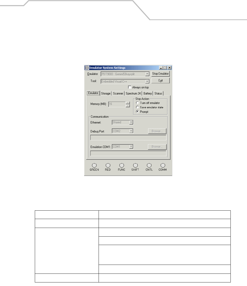
Desktop Emulator 11-9
Emulator Tab
Use the Emulator tab to set the emulator parameters, memory size, launch options and
communications.
Figure 11-5. Emulator Tab
Table 11-2. Emulator Tab Functions
Setting Description
Memory Sets the memory size.
Stop Action Sets the shut down state:
Turn off emulator - Exits the emulator program.
Save emulator state - Returns emulator to the same state when re-launched.
Platform, Application and MMC folders are NOT copied to emulator from the
desktop hard drive.
Prompt - Keeps the emulator program running.
Ethernet Select setting: None, Shared, or VirtualSwitch.
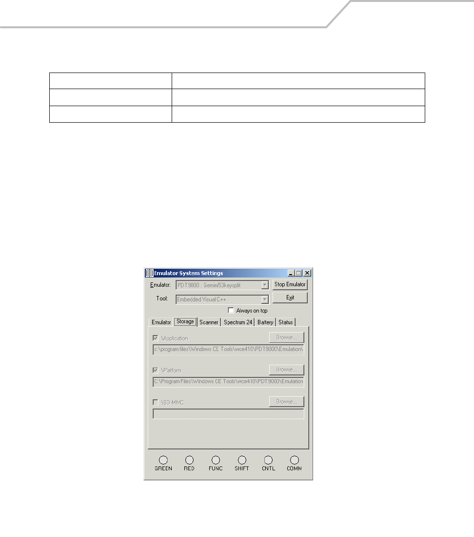
MC9000-K/S for Embedded Windows® CE .NET Product Reference Guide
11-10
Storage Tab
The Emulator Storage settings simulate the storage environment that would be provided by a flash
file system and MMC. When the emulator starts, the contents of these development computer folders
are copied to the emulator as separate folders. Once the emulator is running, changes made to the
desktop folder are not reflected in the emulator folder until the emulator is stopped and launched
again. Changes made in the emulator folder are not reflected in the desktop folder. These files must
be captured using remote file viewer.
The emulator \Application and \Platform storage paths are set when the emulator is started for the
first time. The \SD-MMC storage path is used to set the SD-MMC path.
Figure 11-6. Storage Tab
Debug Port Select setting: None, Com1, Com2, or File.
Emulation COM2 Select setting: None, Com1, Com2, or File.
Table 11-2. Emulator Tab Functions (Continued)
Setting Description
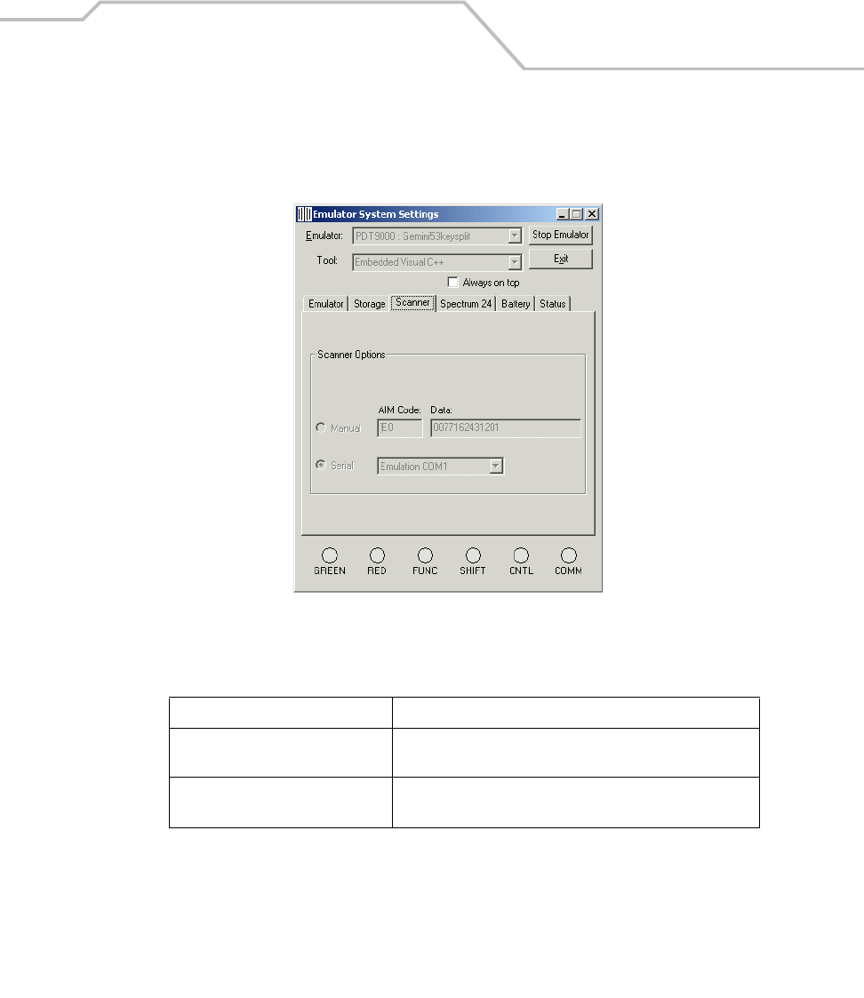
Desktop Emulator 11-11
Scanner Tab
Use the Scanner tab to allow the user to specify the type of simulated scanning provided by the
emulator (the emulator does not have an integrated scanner).
Figure 11-7. Scanner Tab
Table 11-3. Scanner Tab Functions
Setting Description
Scanner Options, Manual Enter scan data manually to be returned to the scanner
application.
Scanner Options, Serial Scan data is entered via a serial connection to the specified
serial port.
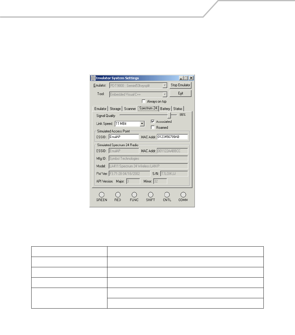
MC9000-K/S for Embedded Windows® CE .NET Product Reference Guide
11-12
Spectrum24 Tab
Use the Spectrum24 tab to allow the user to modify the simulated characteristics of the Spectrum24
interface. Both the simulated network card and the access point ESSID2MAC addresses can be
modified to simulate a specific network environment.
Figure 11-8. Spectrum24 Tab
Table 11-4. S24 Tab Functions
Setting Function
Signal Quality Set the slide bar to represent the signal quality to be simulated.
Link Speed Select the simulated date transfer rate, 1MBit, 2MBit, 5.5MBit or 11MBit
Associated and Roamed Select the simulation mode.
Simulated Access Point Enter the simulated ESSID:
Enter the simulated MAC Address:
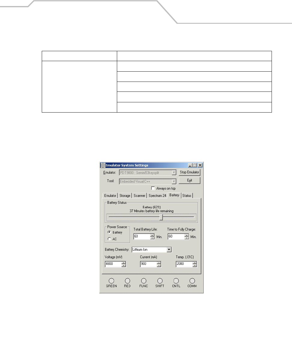
Desktop Emulator 11-13
Battery Tab
Use the Battery tab to setup the power source to A/C or battery. Battery profiles (life and discharge/
charge rate) can also be set. Battery status can be modified using the shell icon or using the Windows
CE battery API calls.
Figure 11-9. Battery Tab
Simulated Trilogy Adapter Enter the simulated MAC Address:
Enter the simulated Mfg ID:
Enter the simulated Model:
Enter the simulated FW Version:
Enter the simulated Serial #:
Table 11-4. S24 Tab Functions (Continued)
Setting Function
MC9000-K/S for Embedded Windows® CE .NET Product Reference Guide
11-14
Status Tab
The Status tab provides a visual indication of backlight, contrast and LEDs. Intensities of backlight
are indicated by the size of the backlight bar.
The desktop emulator always displays the emulated terminal screen in color. When
testing an application targeted for a color terminal, contrast APIs should not be used as
they are NOT available on actual color terminals.
Table 11-5. Battery Tab Functions
Setting Function
Battery Status Set the slide bar to represent the simulated remaining battery
life.
Power Source Select to simulate battery or AC power input.
Total Battery Life: Set to simulate battery life.
Time to Fully Charge: Set to simulate battery charge time.
Battery Chemistry Select to simulate battery type:
Alkaline, Nickel Cadmium, Nickel Metal Hydride, Lithium Ion,
Lithium Polymer or Zinc Air
Voltage (mV) Set to simulate battery voltage.
Current (mA) Set to simulate battery current.
Temp (.01C) Set to simulate battery temperature.
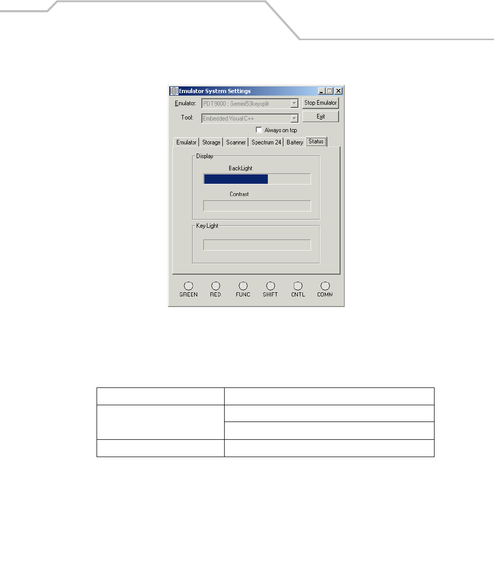
Desktop Emulator 11-15
Figure 11-10. Emulator Status Indications
Table 11-6. Status Tab Functions
Setting Description
Display Backlight - Indicates the BackLight setting.
Contrast - Indicates the contrast setting.
Key Light Indicates the Key Light setting.

MC9000-K/S for Embedded Windows® CE .NET Product Reference Guide
11-16
Using the Emulator
Once the Emulator has been launched and is running it functions like the actual terminal, see Starting
the Emulator on page 11-3.
User Inputs
The Emulator uses both the development computer mouse and the keypad for user inputs.
Mouse Inputs
The mouse cursor functions as a the stylus functions in the mobile computer. It can be used for
selecting items and entering information.
• Click: Right click the mouse once to simulate the stylus screen tap.
• Double-Click: Double click the mouse to simulate the stylus double screen tap. Use double
click to execute application software.
• Drag: Drag the mouse simulate the stylus screen drag. Use drag across the screen to select
text and images. Drag in a list to select multiple items.
Keypad Inputs
The development computer keypad can also be used for entering data.
Taskbar
The Taskbar (at the bottom of the window) displays the Start button, active programs (in this case PC
Link and Mobile Companion) battery status and the communication status..
Figure 11-11. Taskbar
Start Button
The Start button is used to launch the Start Menu, see Start Menu on page 11-17.
Start Button Open Programs and Status Icons
Keyboard Input Panel
Desktop
Menu and Application Buttons

Desktop Emulator 11-17
AC Power/Battery Status Icons
AC Power/Battery Status icons are shown in the taskbar to indicate present power supply status.
They appear and function the same as in the mobile computer, see AC Power/Battery Status Icons on
page 2-30.
Taskbar Icons and Buttons
The Taskbar icons and buttons are displayed in the taskbar. They appear and function the same as in
the mobile computer, see Taskbar Icons on page 2-27 and Taskbar Buttons on page 2-28.
Open Programs
If more than program is open, the taskbar icons can be used to toggle between the open programs
(applications). Tapping on a icon opens the associated program. These icons only appear if a program
is open.
Main Menu
On Emulator power up, the Main Menu window appears and functions the same as in the mobile
computer, see Series 9000 Demo Window on page 2-25.
Start Menu
On Emulator power up, the Main Menu window appears. The Start button functions the same as in
the mobile computer, see Series 9000 Demo Window on page 3-39.
Exiting the Emulator
The emulator may be exited in one of two ways:
• Press the “Stop Emulation” button on the SSD.
• Press the red Power button and select the “Stop Emulation Button” to turn the emulator off.
In either case two additional exit states are provided:
• Turn off emulator (re-initiate Emulator on next start)
Copies all files form the desktop flash file system and restarts the emulator.
• Save emulator state (restore previous state on next start)
Restores the last Emulator state.
To restart the emulator see Starting the Emulator on page 11-3.

MC9000-K/S for Embedded Windows® CE .NET Product Reference Guide
11-18
Resetting the Emulator
The emulator does not support a the reset function. Warm and cold boots cannot be performed on the
emulator.

Maintenance and Troubleshooting
Chapter Contents
Introduction. . . . . . . . . . . . . . . . . . . . . . . . . . . . . . . . . . . . . . . . . . . . . . . . . . . . . . . . . . . . . . . . . . . . . . . .12-3
Maintaining the Mobile Computer. . . . . . . . . . . . . . . . . . . . . . . . . . . . . . . . . . . . . . . . . . . . . . . . . . . . . .12-3
Troubleshooting . . . . . . . . . . . . . . . . . . . . . . . . . . . . . . . . . . . . . . . . . . . . . . . . . . . . . . . . . . . . . . . . . . . .12-4
Four Slot Charge Only Cradle . . . . . . . . . . . . . . . . . . . . . . . . . . . . . . . . . . . . . . . . . . . . . . . . . . . . . .12-7
Four Slot Ethernet Cradle . . . . . . . . . . . . . . . . . . . . . . . . . . . . . . . . . . . . . . . . . . . . . . . . . . . . . . . . .12-8
Four Slot Spare Battery Charger. . . . . . . . . . . . . . . . . . . . . . . . . . . . . . . . . . . . . . . . . . . . . . . . . . .12-10
Single Slot Serial/USB Cradle . . . . . . . . . . . . . . . . . . . . . . . . . . . . . . . . . . . . . . . . . . . . . . . . . . . .12-10
Cable Adapter Module . . . . . . . . . . . . . . . . . . . . . . . . . . . . . . . . . . . . . . . . . . . . . . . . . . . . . . . . . .12-12
Magnetic Stripe Reader . . . . . . . . . . . . . . . . . . . . . . . . . . . . . . . . . . . . . . . . . . . . . . . . . . . . . . . . .12-12
MDM9000 Modem Module . . . . . . . . . . . . . . . . . . . . . . . . . . . . . . . . . . . . . . . . . . . . . . . . . . . . . .12-14
VCD9000 Vehicle Cradle. . . . . . . . . . . . . . . . . . . . . . . . . . . . . . . . . . . . . . . . . . . . . . . . . . . . . . . . .12-16

MC9000-K/S for Embedded Windows® CE .NET Product Reference Guide
12-2

Maintenance and Troubleshooting 12-3
Introduction
This chapter includes instructions on cleaning and storing the mobile computer and provides
troubleshooting solutions for potential problems during mobile computer operating.
Maintaining the Mobile Computer
For trouble-free service, observe the following tips when using the mobile computer:
• Take care not to scratch the screen of the mobile computer. When working with the mobile
computer, use the supplied stylus or plastic-tipped pens intended for use with a touch-
sensitive screen. Never use an actual pen or pencil or other sharp object on the surface of
the screen.
• Although the mobile computer is water and dust resistant, do not expose it to rain or
moisture for an extended period of time.
• The touch-sensitive screen of the mobile computer contains glass. Take care not to drop the
mobile computer or subject it to strong impact.
• Protect the mobile computer from temperature extremes. Do not leave it on the dashboard
of a car on a hot day and keep it away from heat sources.
• Do not store or use the mobile computer in any location that is extremely dusty, damp or wet.
• Use a soft lens cloth to clean the mobile computer. If the surface of the screen becomes
soiled, clean it with a soft cloth moistened with a diluted window-cleaning solution.

MC9000-K/S for Embedded Windows® CE .NET Product Reference Guide
12-4
Troubleshooting
Table 12-1. Troubleshooting the Mobile Computer
Problem Cause Solution
Mobile computer does not turn
on.
Lithium-ion battery not
charged.
Charge or replace the lithium-ion battery in the mobile
computer.
Lithium-ion battery not
installed properly.
Ensure battery is installed properly. See Main Battery
Insertion and Removal on page 1-9.
System crash. Perform a warm boot. If the mobile computer still does
not turn on, perform a cold boot. See Resetting the
Mobile Computer on page 2-39.
Rechargeable lithium-ion battery
did not charge.
Battery failed. Replace battery. If the mobile computer still does not
operate, try a warm boot, then a cold boot. See
Resetting the Mobile Computer on page 2-39.
Mobile computer removed
from cradle while battery was
charging.
Insert mobile computer in cradle and begin charging.
The lithium-ion battery requires about four hours to
recharge fully.
Cannot see characters on display. Mobile computer not powered
on.
Press the Power button.
During data communication, no
data was transmitted, or
transmitted data was
incomplete.
Mobile computer removed
from cradle or unplugged from
host computer during
communication.
Replace the mobile computer in the cradle, or reattach
the Synchronization cable and re-transmit.
Incorrect cable configuration. See the System Administrator.
Communication software was
incorrectly installed or
configured.
Perform setup. See Chapter 4, Communications for
details.
No sound is audible. Volume setting is low or
turned off.
Unit may be a beeper only unit or incorrect Config
Block is programmed into device.
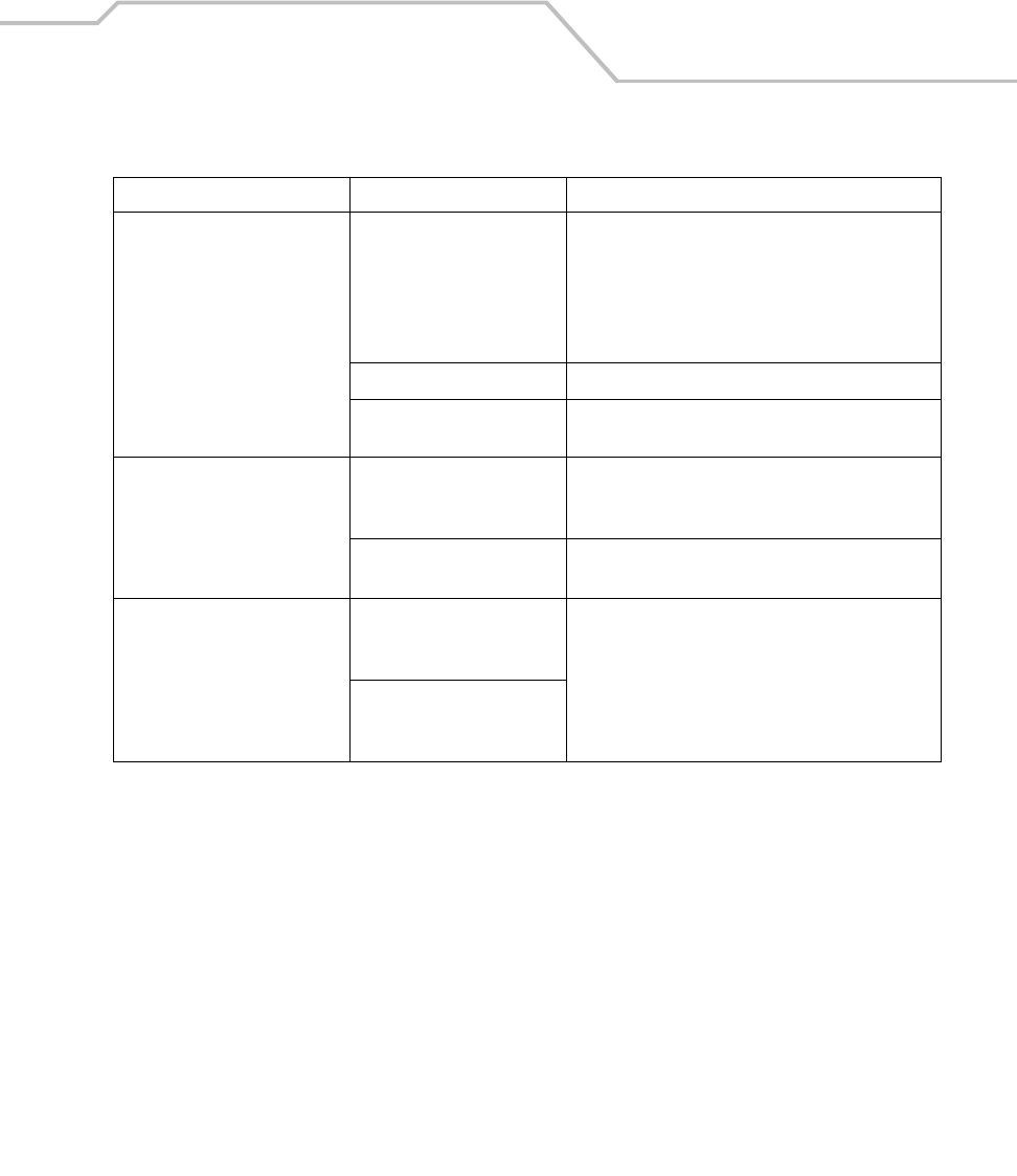
Maintenance and Troubleshooting 12-5
Mobile computer turns itself off. Mobile computer is inactive. The mobile computer turns off after a period of
inactivity. If the mobile computer is running on battery
power, this period can be set from 1 to 5 minutes, in
one-minute intervals. If the mobile computer is
running on external power, this period can be set to 1,
2, 5, 10, 15 and 30 minutes.
Battery is depleted. Replace the battery.
Battery is not inserted
properly.
Insert the battery properly, see Figure 1-4 on page 1-9.
Tapping the window buttons or
icons does not activate the
corresponding feature.
LCD screen not aligned
correctly.
Re-calibrate the screen. See Figure on page 1-18.
The system is hung. Warm boot the system. To perform a warm boot, see
Resetting the Mobile Computer on page 2-39.
A message appears stating that
the mobile computer memory is
full.
Too many files stored on the
mobile computer.
Delete unused memos and records. Save these
records on the host computer.
Too many applications
installed on the mobile
computer.
Table 12-1. Troubleshooting the Mobile Computer (Continued)
Problem Cause Solution
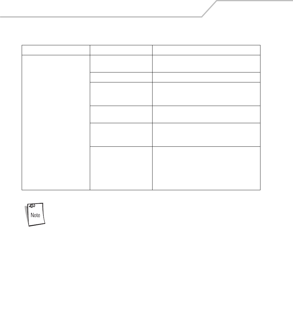
MC9000-K/S for Embedded Windows® CE .NET Product Reference Guide
12-6
If, after performing these checks, the mobile computer is still not reading
symbols, contact the distributor or Symbol Technologies.
The mobile computer does not
accept scan input.
Scanning application is not
loaded.
Verify that the unit is loaded with a scanning
application. See the System Administrator.
Unreadable bar code. Ensure the symbol is not defaced.
Distance between exit
window and bar code is
incorrect.
Ensure mobile computer is within proper scanning
range.
Mobile computer is not
programmed for the bar code.
Ensure the mobile computer is programmed to accept
the type of bar code being scanned.
Mobile computer is not
programmed to generate a
beep.
If a beep on a good decode is expected and a beep is
not heard, check that the application is set to
generate a beep on good decode.
Battery is low. If the scanner stops emitting a laser beam when the
scan button is pressed, check the battery level. When
the battery is low, the scanner shuts off before the
mobile computer low battery condition notification.
Note: If the scanner is still not reading symbols,
contact the distributor or Symbol Technologies.
Table 12-1. Troubleshooting the Mobile Computer (Continued)
Problem Cause Solution

Maintenance and Troubleshooting 12-7
Four Slot Charge Only Cradle
Table 12-2. Troubleshooting the Four Slot Charge Only Cradle
Problem Cause Solution
Mobile computer charge
indicator LED does not light.
Cradle is not receiving power. Ensure the power supply is securely connected and
receiving power.
Mobile computer is not seated
correctly in the cradle.
Ensure the battery is properly installed in the mobile
computer, and re-seat the mobile computer in the
cradle.
The battery is not properly
installed in the mobile computer.
The battery in the mobile
computer is faulty.
Verify that other batteries charge properly. If so,
replace the faulty battery.
Note: The Four Slot Charge Only Cradle has no power indication.

MC9000-K/S for Embedded Windows® CE .NET Product Reference Guide
12-8
Four Slot Ethernet Cradle
Table 12-3. Troubleshooting the Four Slot Ethernet Cradle
Symptom Cause Solution
Attempt by the mobile computer
to ActiveSync failed.
Mobile computer removed from
the cradle while the LED was
blinking green.
Wait one minute and reinsert the mobile computer in
the cradle. This allows the cradle to attempt another
synchronization.
ActiveSync on the host
computer has not yet closed the
previous ActiveSync session.
Wait one minute and reinsert the mobile computer in
the cradle. This allows the cradle to attempt another
synchronization.
Incorrect cable configuration. Check your DHCP server and determine which IP
address was allocated to the cradle, then check
connectivity by pinging the cradle.
Communications software
improperly configured.
Perform setup as described in Chapter 4,
Communications. Check your DHCP server and
determine which IP address was allocated to the
mobile computer slot, then check connectivity by
pinging the cradle.
Mobile computer ActiveSync
disabled or not configured to
accept network connection.
On the mobile computer, tap Start - ActiveSync -
Tools - Options - Options button. Then, uncheck the
Enable PC sync using this connection: check box.
Host ActiveSync disabled or not
configured to accept network
connection.
On the mobile computer, tap Start - Settings and
double tap the Network and Dial-up Connections
icon. Edit an existing connection or create a new
connection that is configured to accept the network
connection.
During communications, no data
was transmitted, or transmitted
data was incomplete.
Mobile computer removed from
cradle during communications.
Replace mobile computer in cradle and retransmit.
Mobile computer has no active
connection.
An icon will be visible in the status bar if a
connection is currently active.
Mobile computer has
successfully connected through
the cradle, but no data is being
transmitted over the
connection.
Data is being transferred over
the S24 radio link.
Temporarily disable the radio link to force data
transmission through the cradle. Tap the wireless
LAN icon and tap WLAN Profiles from the menu.
Tap the Mode tab. Enter an in-valid value in the
ESSID: text box and tap the OK button. Verify that the
radio link has been disabled. Once the data
transmission has been completed, re-enable the
radio link.

Maintenance and Troubleshooting 12-9
All Communication Status LEDs
are flashing red.
The unit could not configure
itself, or it has lost the lease on
its IP address.
Connect the unit to an Ethernet network with a
correctly functioning DHCP server.
Failed automatic cradle
configuration via local DHCP
service.
Connect a properly configured DHCP server or DHCP
relay agent to the subnet, and power cycle the cradle.
Check the DHCP server log to verify that the cradle is
receiving a response to its DHCP request.
The Ethernet link may be down. Ensure the ethernet cable is connected to an active
hub.
Communication Status LED
does not light up.
Mobile computer has been
inserted incorrectly into the
cradle.
Remove, wait a minute, and then reinsert the mobile
computer, ensuring it fits snugly onto the connector
at the bottom of the cradle.
Cradle is not receiving power. Ensure the power supply is securely connected and
receiving power.
Battery is not recharging. Mobile computer removed from
the cradle too soon.
Replace the mobile computer into the cradle. It can
take up to 4 hours to recharge a completely depleted
battery pack if mobile computer is suspended or
longer if the mobile computer is on. Tap Start -
Settings - System - Power to view battery status.
Battery is faulty. Verify that other batteries charge properly. If so,
replace the faulty battery.
Mobile computer is not inserted
correctly into the cradle.
Remove the mobile computer and reinsert it correctly.
Verify charging is active. Tap Start - Settings - System
- Power to view battery status.
Warning Message - “! Unable to
obtain a server assigned IP
address. Try again later or enter
an IP address in Network
Settings.”
This message occurs if a
suspend/resume cycle is
performed and the mobile
computer radio is not
associated (e.g. due to being out
of range)
Tap OK to close the message. The mobile computer
will obtain address information and communicate
through the ethernet cradle.
Table 12-3. Troubleshooting the Four Slot Ethernet Cradle (Continued)
Symptom Cause Solution

MC9000-K/S for Embedded Windows® CE .NET Product Reference Guide
12-10
Four Slot Spare Battery Charger
Single Slot Serial/USB Cradle
Table 12-4. Troubleshooting The Four Slot Spare Battery Charger
Symptom Possible Cause Action
Batteries not charging. Battery was removed from the
charger or charger was unplugged
from AC power too soon.
Ensure MSR is receiving power. Ensure mobile computer is
attached correctly. Confirm main battery is charging under
Start - Settings - System - Power. If a mobile computer
battery is fully depleted, it can take up to four hours to fully
recharge a battery (if the mobile computer is off and longer
if the mobile computer is operating).
Battery is faulty. Verify that other batteries charge properly. If so, replace
the faulty battery.
Battery contacts not connected to
charger.
Verify that the battery is seated in the battery well
correctly with the contacts facing down.
Table 12-5. Troubleshooting the Single Slot Serial/USB Cradle
Symptom Possible Cause Action
LEDs do not light when
mobile computer or
spare battery is
inserted.
Cradle is not receiving power. Ensure the power cable is connected securely to both the
cradle and to AC power.
Mobile computer is not seated
firmly in the cradle.
Remove and re-insert the mobile computer into the cradle,
ensuring it is firmly seated.
Spare battery is not seated firmly in
the cradle.
Remove and re-insert the spare battery into the charging
slot, ensuring it is firmly seated.
Mobile computer
battery is not charging.
Mobile computer was removed
from cradle or cradle was
unplugged from AC power too
soon.
Ensure cradle is receiving power. Ensure mobile computer
is seated correctly. Confirm main battery is charging under
Start - Settings - System - Power. If a mobile computer
battery is fully depleted, it can take up to four hours to fully
recharge a battery (if the mobile computer is off and longer
if the mobile computer is operating).
Battery is faulty. Verify that other batteries charge properly. If so, replace
the faulty battery.
The mobile computer is not fully
seated in the cradle.
Remove and re-insert the mobile computer into the cradle,
ensuring it is firmly seated.

Maintenance and Troubleshooting 12-11
Spare battery is not
charging.
Battery not fully seated in charging
slot.
Remove and re-insert the spare battery into the cradle,
ensuring it is firmly seated.
Battery inserted incorrectly. Ensure the contacts are facing down and toward the back
of the cradle.
Battery is faulty. Verify that other batteries charge properly. If so, replace
the faulty battery.
During data
communications, no
data was transmitted,
or transmitted data was
incomplete.
Mobile computer removed from
cradle during communications.
Replace mobile computer in cradle and
retransmit.
Incorrect cable configuration. See your system administrator.
Communications software is not
installed or configured properly.
Perform setup as described in Communication Setup on
page 4-9.
Table 12-5. Troubleshooting the Single Slot Serial/USB Cradle (Continued)
Symptom Possible Cause Action

MC9000-K/S for Embedded Windows® CE .NET Product Reference Guide
12-12
Cable Adapter Module
Magnetic Stripe Reader
Table 12-6. Troubleshooting The Cable Adapter Module
Symptom Possible Cause Action
Mobile computer
battery is not charging.
Mobile computer was removed
from CAM or CAM was unplugged
from AC power too soon.
Ensure CAM is receiving power. Ensure mobile computer
is attached correctly. Confirm main battery is charging
under Start - Settings - System - Power. If a mobile
computer battery is fully depleted, it can take up to four
hours to fully recharge a battery (if the mobile computer is
off and longer if the mobile computer is operating).
Battery is faulty. Verify that other batteries charge properly. If so, replace
the faulty battery.
The mobile computer is not fully
attached to the CAM.
Detach and re-attach the CAM to the mobile computer,
ensuring it is firmly connected.
During data
communications, no
data was transmitted,
or transmitted data was
incomplete.
Mobile computer detached from
CAM during communications.
Re-attach mobile computer to CAM and retransmit.
Incorrect cable configuration. See your System Administrator.
Communications software is not
installed or configured properly.
Perform setup as described in Chapter 4, Communications.
Table 12-7. Troubleshooting the Magnetic Stripe Reader
Symptom Possible Cause Action
MSR cannot read card. Mobile computer detached from
MSR during card swipe.
Re-attach mobile computer to MSR and reswipe the card.
Faulty magnetic stripe on card. See your System Administrator.
MSR application is not installed or
configured properly.
Ensure the MSR application is installed on the mobile
computer.
Ensure the MSR application is configured correctly.

Maintenance and Troubleshooting 12-13
Mobile computer
battery is not charging.
Mobile computer was removed
from MSR or MSR was unplugged
from AC power too soon.
Ensure MSR is receiving power. Ensure mobile computer is
attached correctly. Confirm main battery is charging under
Start - Settings - System - Power. If a mobile computer
battery is fully depleted, it can take up to four hours to fully
recharge a battery (if the mobile computer is off and longer
if the mobile computer is operating).
Battery is faulty. Verify that other batteries charge properly. If so, replace
the faulty battery.
The mobile computer is not fully
attached to the MSR.
Detach and re-attach the MSR to the mobile computer,
ensuring it is firmly connected.
During data
communications, no
data was transmitted,
or transmitted data was
incomplete.
Mobile computer detached from
MSR during communications.
Reattach mobile computer to MSR and retransmit.
Incorrect cable configuration. See your System Administrator.
Communications software is not
installed or configured properly.
Perform setup as described in Chapter 4, Communications.
Table 12-7. Troubleshooting the Magnetic Stripe Reader (Continued)
Symptom Possible Cause Action

MC9000-K/S for Embedded Windows® CE .NET Product Reference Guide
12-14
MDM9000 Modem Module
Table 12-8. Troubleshooting the MDM9000 Modem Module
Symptom Possible Cause Action
Mobile computer is not
communicating through
the modem.
The modem cable is not fully
connected.
Connect the modem cable securely to both the modem and
the telephone jack.
Modem is not securely connected
to the mobile computer.
Reconnect the modem to the mobile computer.
Communication software is not
installed or configured properly.
Set up the communication software.
Problem in the telephone lines. Connect a conventional telephone and dial the remote
modem to verify the telephone lines are functioning. If the
remote modem does not answer the call and emit
answering tones, contact the remote System
Administrator.
Mobile computer’s battery is low or
discharged, which shuts off power
to the modem.
Install a charged battery in the MC9000, or use an external
DC power adapter to recharge the battery.
ActiveSync fails. A partnership was not established
with the host computer.
Establish a partnership with the host computer.
Host computer is not selected in
the ActiveSync window on the
mobile computer.
Select a host computer in the ActiveSync window, and
perform setup.
Modem RAS connection not
allowed by host computer.
Select RAS connection in the host computer (File -
Connection Settings window). Refer to the ReadMe files
located in the Microsoft ActiveSync folder on the host
computer.
Mobile computer or modem was
disconnected from the telephone
line while ActiveSync was in
progress.
Disconnect the modem cable for 30 seconds to hang up
the local telephone connection. Close any open windows
on the mobile computer and any modem connections.
Synchronization occurred, but the
session is configured to close
immediately after synchronization
is complete.
Verify the synchronizing setting.

Maintenance and Troubleshooting 12-15
Dial-out fails Location setting is incorrect. Verify Dialing Locations. Verify Dialing Patterns are correct
for the current location. For example, enter ‘G’ in the For
local calls, dial: field to dial directly, or ‘9,G’ if the
telephone system requires dialing ‘9’ first to access an
outside line.
Incorrect server phone number. Verify the connection phone number in the Connecting
window.
Pulse dialing not supported for
country.
Use a connection within a tone-dialing system.
Dial-out fails
continued...
Dialtone detection not supported. The service you subscribe to (e.g., a remote answering
service) may use a different type of dialtone. Disable
dialtone detection on the modem by entering the
initialization string “ATXO” in the Extra dial-string modem
commands: text box of the Modem Settings window.
The following error message
appears:
Trouble Connecting: There is no
answer at the number dialed.
Verify the phone...’
The modem may be required to be powered before
opening the port for dial-out.
The Connection Manager routes
are incorrect.
Warm boot the mobile computer and confirm the
connection settings.
Table 12-8. Troubleshooting the MDM9000 Modem Module (Continued)
Symptom Possible Cause Action

MC9000-K/S for Embedded Windows® CE .NET Product Reference Guide
12-16
VCD9000 Vehicle Cradle
Table 12-9. Troubleshooting the VCD9000 Vehicle Cradle
Symptom Possible Cause Action
Mobile computer
battery charging LED
does not light.
Cradle is not receiving power. Ensure the power input cable is securely connected to the
cradle’s power port.
Mobile computer’s
battery is not
recharging.
Mobile computer was removed
from the cradle too soon.
Replace the mobile computer in the cradle.
If the mobile computer’s battery pack is fully depleted, it
can take four hours to fully recharge the battery.
Battery is faulty. Replace the battery.
Mobile computer was not placed
correctly in the cradle.
Remove the mobile computer from the cradle, and re-
insert correctly.
If the battery still does not charge, contact Customer
Support.
The mobile computer battery charging LED blinks amber
when the mobile computer is correctly inserted and is
charging.
No data was
transmitted, or
transmitted data was
incomplete.
Mobile computer was removed
from the cradle during
communication.
Replace the mobile computer in the cradle and retransmit.
The external device required a null
modem cable, which was not used.
Retransmit using a null modem cable.
Incorrect cable configuration. See the system administrator.

Technical Specifications
Appendix Contents
Mobile Computer Technical Specifications . . . . . . . . . . . . . . . . . . . . . . . . . . . . . . . . . . . . . . . . . . . . . . . . . . . A-3
MDM9000 Modem Module Technical Specifications. . . . . . . . . . . . . . . . . . . . . . . . . . . . . . . . . . . . . . . . . . . A-5
Mobile Computer Pin-Outs. . . . . . . . . . . . . . . . . . . . . . . . . . . . . . . . . . . . . . . . . . . . . . . . . . . . . . . . . . . . . . . . A-7
Accessory CAM and MSR Pin-Outs . . . . . . . . . . . . . . . . . . . . . . . . . . . . . . . . . . . . . . . . . . . . . . . . . . . . . . . . . A-8

MC9000-K/S for Embedded Windows® CE .NET Product Reference Guide
A-2

Technical Specifications A-3
Mobile Computer Technical Specifications
The following table summarizes the mobile computer’s intended operating environment.
Table A-1. Mobile Computer Technical Specifications
Operating Temperature -4° to 122° F (-20° to +50° C)
Storage Temperature -40° to 158° F (-40° to 70° C)
Humidity 5% to 90% non-condensing
Electrostatic Discharge (ESD) +/-15 kVDC (air); +/- 8 kVDC (contact)
Drop to Concrete 6 feet (1.8 meters) at 14° to 122° F (-10°C to 50°C)
5 feet (1.52 meters) at 14°F to -4° F (-10°C to -20°C)
Sealing IP64 (electronic enclosure)
Dimensions MC9000-K:
9.2 in. L x 3.6 in. W x 2.3 in. H
(233.7 mm L x x 91.4 mm W x 58.4 mm H)
MC9000-S:
8 in. L x 3.6 in. W x 2.3 in. H
(203.2 mm L x x 91.4 mm W x 58.4 mm H)
Weight (including battery) MC9000-K:
24 oz - 25 oz (680 g - 708.8 g)
MC9000-S:
23 oz - 24 oz (652 g - 680 g)
Display Transflective color TFT-LCD, 65K colors, 240 (W) x 320 (L) (QVGA size)
Monochrome TFT-LCD, 16 shades, 240 (W) x 320 (L) (QVGA size)
Touch Panel Polycarbonate, analog resistive touch
Main Battery MC9000-K:
Rechargeable Lithium-Ion 2200 mAh minimum (7.4V)
MC9000-S:
Rechargeable Lithium-Ion 1550 mAh minimum (7.4V)
Backup Battery Ni-MH battery (rechargeable), 20mAh (3.6V) 3 cells
CPU Intel® XScale™ PXA255 processor at 400 mHz
Operating Platform Microsoft® Embedded Windows® CE 4.1 (CE .NET)
Memory 32MB RAM/ 32MB Flash
64MB RAM/ 64MB Flash

MC9000-K/S for Embedded Windows® CE .NET Product Reference Guide
A-4
Interface RS-232, max. 115.2 kbps min. 1200bps, USB
MMC Card Slot Type II
Keypad Options MC9000-K:
53-key standard
Optional Keypads:
•28-key
•43-key
MC9000-S:
28-key standard
Data Capture:
1D Decode Capability Code 39, code 128, code 93, codabar, code 11, discrete 2 of 5, EAN-3, EAN-13,
EAN-128, interleaved 2 of 5, TLC39 (telecommunications, UPCA, UPCE and UPC/
EAN supplements.
Imaging Decode Capability Code 39, code 128, code 93, codabar, code 11, discrete 2 of 5, EAN-3, EAN-13,
EAN-128, interleaved 2 of 5, TLC39 (telecommunications, UPCA, UPCE, UPC/
EAN supplements composite code (retail), coupon code (retail), macro PDF-417,
(macro) micro PDF-417 (T&L), micro PDF-417 (telecommunications), MSI
Plessey, PDF-417 (automotive), RSS expanded, RSS limited and RSS-14Maxi
Code (UPS), Data matrix (electronics industry, US Postnet (USPS)*, US Planet
(USPS), UK 4-state, Australian 4-state, Canadian 4-state, Japanese 4-state,
Dutch Kix
*To be supported at a later date. Go to http://software.symbol.com/ for a list of
the latest supported symbologies.
Table A-1. Mobile Computer Technical Specifications (Continued)

Technical Specifications A-5
MDM9000 Modem Module Technical Specifications
Table A-2. MDM9000 Modem Module Technical Specifications
Asynchronous character format Up to 10 bits, including data, start, stop, and parity bits
Asynchronous data rates Transmission rate fallback through 300 bps
Chipset Conexant SCM
Compatible public switched network
jacks
RJ11
Dialing capability Tone and rotary pulse
Line requirements Public switched telephone network (PSTN) including international connections
Operating environment Altitude: up to 20,000 ft.
Humidity: 10% to 90% non-condensing
Operating temperature Operating: 32o to 122oF / 0o to 50oC
Storage: -4o to 149oF / -20o to 65oC
Operating modes Asynchronous, full duplex, automatic and manual call originate
Performance Line speed up to 33,600 bps
HHC to modem speed (DTE speed) up to 57,600 bps
V.42bis data compression
V.42 LAPM error correction
Current consumption 100 mA active
<10 mA sleep
Pulse dialing rate
(except where prohibited under TBR-21
rules)
10 pulses per second
Pulse dialing duty cycle: 39/61% (US) make-to-break ratio
Ringer equivalence 0.1 dBm
Standards & protocols Bell 103, Bell 212A, Hayes AT command set, and ITU Vs. 17, 21, 22 A & B, 22bis,
23, 25bis, 27 ter, 29, 32, 32bis, 42bis
Tone detected Dial, busy, ring back, modem answer tones.
Blind dialing based on time-out periods available for incompatible tones.
AC Adapter 9V, 2 amp regulated AC/DC adapter allows unlimited modem use. Do NOT
substitute an AC adapter; using an incorrect AC power supply causes electrical
damage to the mobile computer and voids warranty.

MC9000-K/S for Embedded Windows® CE .NET Product Reference Guide
A-6
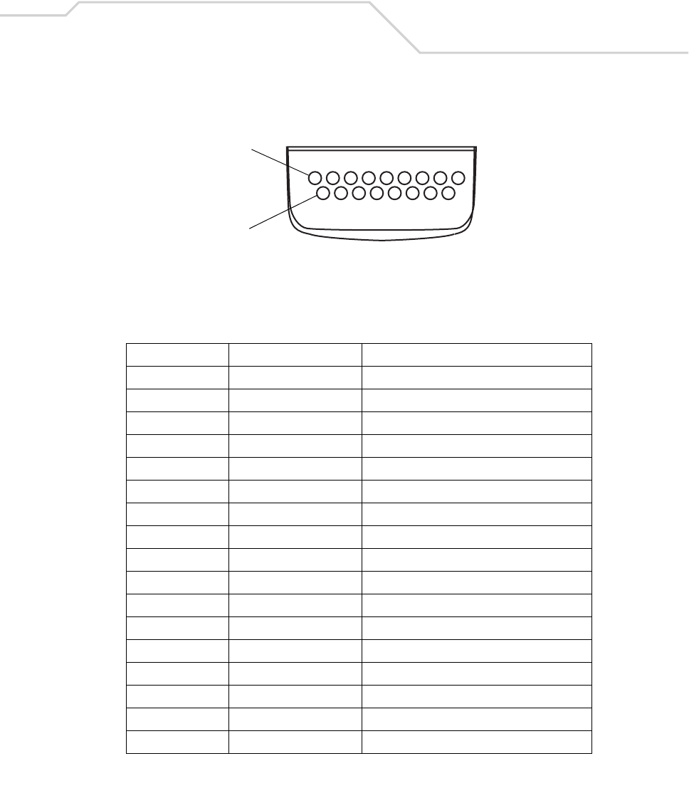
Technical Specifications A-7
Mobile Computer Pin-Outs
Figure A-1. Pin Locations
Table A-3. MC9000-K and MC9000-S, Pin-Outs
PIN Number Signal Name Function
1 USB_GND USB
2 USB_D_PLUS USB
3 TXD RS232C
4 RXD RS232C
5 DCD RS232C
6 RTS RS232C
7 DSR RS232C
8 GND Ground, 2.5A max.
9 RI RS232C
10 CRADLE_DET Grounded by cradle when in cradle
11 DTR RS232C
(12) Opended NC (not connected) NC
13 POWER_IN 12V, 2.5A max
14 CTS RS232C
15 USB_5V_DET USB
16 USB_D_MINUS USB
17 EXT_PWR_OUT 3.3V @500mA max
Pin 1
Pin 17
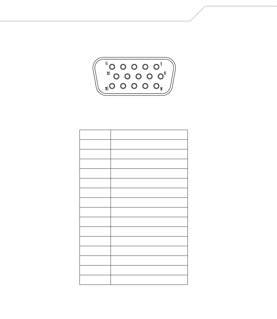
MC9000-K/S for Embedded Windows® CE .NET Product Reference Guide
A-8
Accessory CAM and MSR Pin-Outs
Figure A-2. CAM and MSR Serial Connector
Table A-4. CAM and MSR Serial Connector Pinouts
Pin Signal
1USB_5V_DET
2USB_D_MINUS
3USB_D_PLUS
4GND
5GND
6PWR_EXT_OUT
7CRADLE_DET*
8DSR
9DCD
10 TXD
11 CTS
12 DTR
13 RI
14 RTS
15 RXD

Keypad Maps
Appendix Contents
Introduction. . . . . . . . . . . . . . . . . . . . . . . . . . . . . . . . . . . . . . . . . . . . . . . . . . . . . . . . . . . . . . . . . . . . . . . . . . . . .B-3
Keypads . . . . . . . . . . . . . . . . . . . . . . . . . . . . . . . . . . . . . . . . . . . . . . . . . . . . . . . . . . . . . . . . . . . . . . . . . . . . . . .B-3
28-Key Keypad (MC9000-K) . . . . . . . . . . . . . . . . . . . . . . . . . . . . . . . . . . . . . . . . . . . . . . . . . . . . . . . . . . . .B-5
43-Key Keypad (MC9000-K) . . . . . . . . . . . . . . . . . . . . . . . . . . . . . . . . . . . . . . . . . . . . . . . . . . . . . . . . . . .B-25
53-Key Keypad (MC9000-K) . . . . . . . . . . . . . . . . . . . . . . . . . . . . . . . . . . . . . . . . . . . . . . . . . . . . . . . . . . .B-36
3270 Emulator . . . . . . . . . . . . . . . . . . . . . . . . . . . . . . . . . . . . . . . . . . . . . . . . . . . . . . . . . . . . . . . . . . . . .B-46
5250 Emulator . . . . . . . . . . . . . . . . . . . . . . . . . . . . . . . . . . . . . . . . . . . . . . . . . . . . . . . . . . . . . . . . . . . . .B-54
VT Emulator Keypad . . . . . . . . . . . . . . . . . . . . . . . . . . . . . . . . . . . . . . . . . . . . . . . . . . . . . . . . . . . . . . . . .B-62
28-Key Keypad (MC9000-S) . . . . . . . . . . . . . . . . . . . . . . . . . . . . . . . . . . . . . . . . . . . . . . . . . . . . . . . . . . .B-72

MC9000-K/S for Embedded Windows® CE .NET Product Reference Guide
B-2

Keypad Maps B-3
Introduction
This appendix contains the keypad maps for the keypad configurations. Each key is listed in the table
with its value, depending on the state of the keypad.
Keypads
Each of the MC9000-K and MC9000-S mobile computers have interchangeable modular Keypads:
• 28-key Keypad (MC9000-K)
• 43-key Keypad (MC9000-K)
• 53-key Keypad (MC9000-K)
• 3270 Emulator (MC9000-K)
• 5250 Emulator (MC9000-K)
• VT Emulator (MC9000-K)
• 28-key Keypad (MC9000-S).
The modular keypads can be changed in the field as necessary to support specialized applications.

MC9000-K/S for Embedded Windows® CE .NET Product Reference Guide
B-4
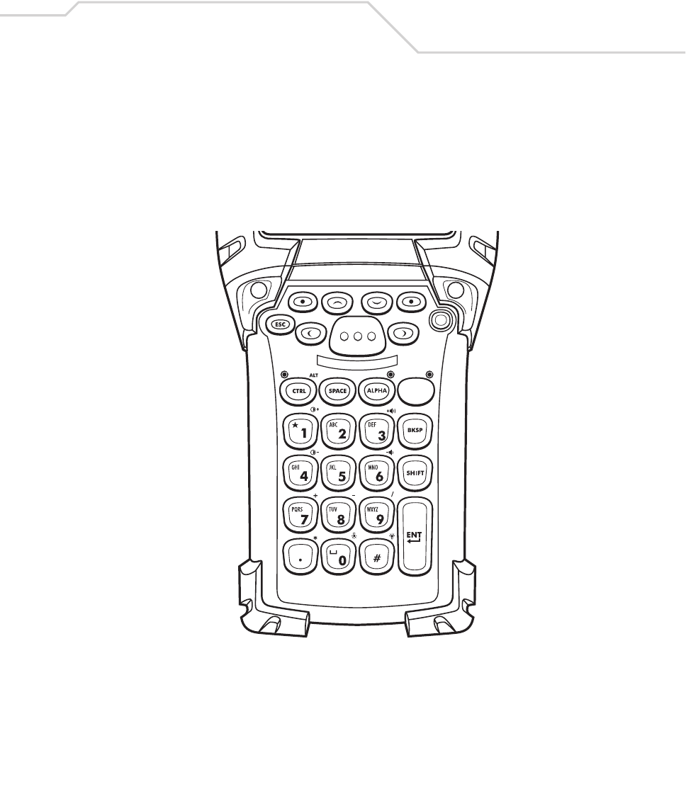
Keypad Maps B-5
28-Key Keypad (MC9000-K)
The 28-key keypad contains a Power button, application keys, scroll keys and a function key. See
Table B-3 for key functions and Table B-4 for the keypad mappings. The mapping functions include:
• 28-key functions
• 28-key character map.
Figure B-1. MC9000-K: 28-Key Keypad

MC9000-K/S for Embedded Windows® CE .NET Product Reference Guide
B-6
Table B-1. MC9000-K: 28-Key Functions
Local Function Key Sequence
Display Backlight On/Off <Func><#>
Keypad Backlight On/Off <Func><0>
Contrast + <Func><1>
Contrast - <Func><4>
Volume + <Func><3>
Volume - <Func><6>
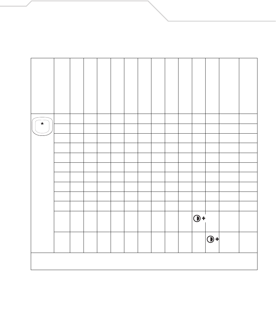
Keypad Maps B-7
Table B-2. MC9000-K: 28 Key Keypad Mapping
Key
Default State
Alpha State (1 Tap)
Alpha State (2 Taps)
Alpha State (3 Taps)
Alpha State (4 Taps)
Shift Alpha State (1 Tap)
Shift Alpha State (2 Taps)
Shift Alpha State (3 Taps)
Shift Alpha State (4 Taps)
Ctrl State
Funct State
Shift-Func State
VK Code (Decimal)
ASCII Value (Decimal)
14949
*10642
*
*
* See Table 2-7 on page 2-23 for keypad special functions.
Note: Blank lines are provided to allow the application developer to use this table as a keypad mapping worksheet.
1

MC9000-K/S for Embedded Windows® CE .NET Product Reference Guide
B-8
25050
a6597
b6698
c6799
A 160+65 65
B 160+66 66
C 160+67 67
Table B-2. MC9000-K: 28 Key Keypad Mapping (Continued)
Key
Default State
Alpha State (1 Tap)
Alpha State (2 Taps)
Alpha State (3 Taps)
Alpha State (4 Taps)
Shift Alpha State (1 Tap)
Shift Alpha State (2 Taps)
Shift Alpha State (3 Taps)
Shift Alpha State (4 Taps)
Ctrl State
Funct State
Shift-Func State
VK Code (Decimal)
ASCII Value (Decimal)
* See Table 2-7 on page 2-23 for keypad special functions.
Note: Blank lines are provided to allow the application developer to use this table as a keypad mapping worksheet.
2
ABC
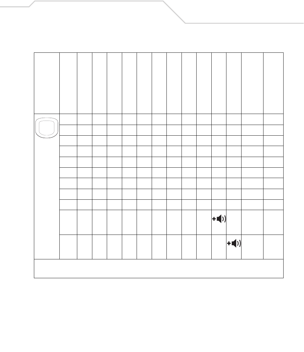
Keypad Maps B-9
35151
d68100
e69101
f70102
D 160+68 68
E 160+69 69
F 160+70 70
*
*
Table B-2. MC9000-K: 28 Key Keypad Mapping (Continued)
Key
Default State
Alpha State (1 Tap)
Alpha State (2 Taps)
Alpha State (3 Taps)
Alpha State (4 Taps)
Shift Alpha State (1 Tap)
Shift Alpha State (2 Taps)
Shift Alpha State (3 Taps)
Shift Alpha State (4 Taps)
Ctrl State
Funct State
Shift-Func State
VK Code (Decimal)
ASCII Value (Decimal)
* See Table 2-7 on page 2-23 for keypad special functions.
Note: Blank lines are provided to allow the application developer to use this table as a keypad mapping worksheet.
3
DEF
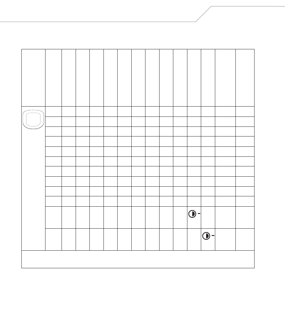
MC9000-K/S for Embedded Windows® CE .NET Product Reference Guide
B-10
45252
g71103
h72104
i73105
G 160+71 71
H 160+72 72
I 160+73 73
*
*
Table B-2. MC9000-K: 28 Key Keypad Mapping (Continued)
Key
Default State
Alpha State (1 Tap)
Alpha State (2 Taps)
Alpha State (3 Taps)
Alpha State (4 Taps)
Shift Alpha State (1 Tap)
Shift Alpha State (2 Taps)
Shift Alpha State (3 Taps)
Shift Alpha State (4 Taps)
Ctrl State
Funct State
Shift-Func State
VK Code (Decimal)
ASCII Value (Decimal)
* See Table 2-7 on page 2-23 for keypad special functions.
Note: Blank lines are provided to allow the application developer to use this table as a keypad mapping worksheet.
4
GHI

Keypad Maps B-11
55353
j74106
k75107
l76108
J 160+74 74
K 160+75 75
L 160+76 76
55353
=18761
+ 160+187 43
Table B-2. MC9000-K: 28 Key Keypad Mapping (Continued)
Key
Default State
Alpha State (1 Tap)
Alpha State (2 Taps)
Alpha State (3 Taps)
Alpha State (4 Taps)
Shift Alpha State (1 Tap)
Shift Alpha State (2 Taps)
Shift Alpha State (3 Taps)
Shift Alpha State (4 Taps)
Ctrl State
Funct State
Shift-Func State
VK Code (Decimal)
ASCII Value (Decimal)
* See Table 2-7 on page 2-23 for keypad special functions.
Note: Blank lines are provided to allow the application developer to use this table as a keypad mapping worksheet.
5
JKL
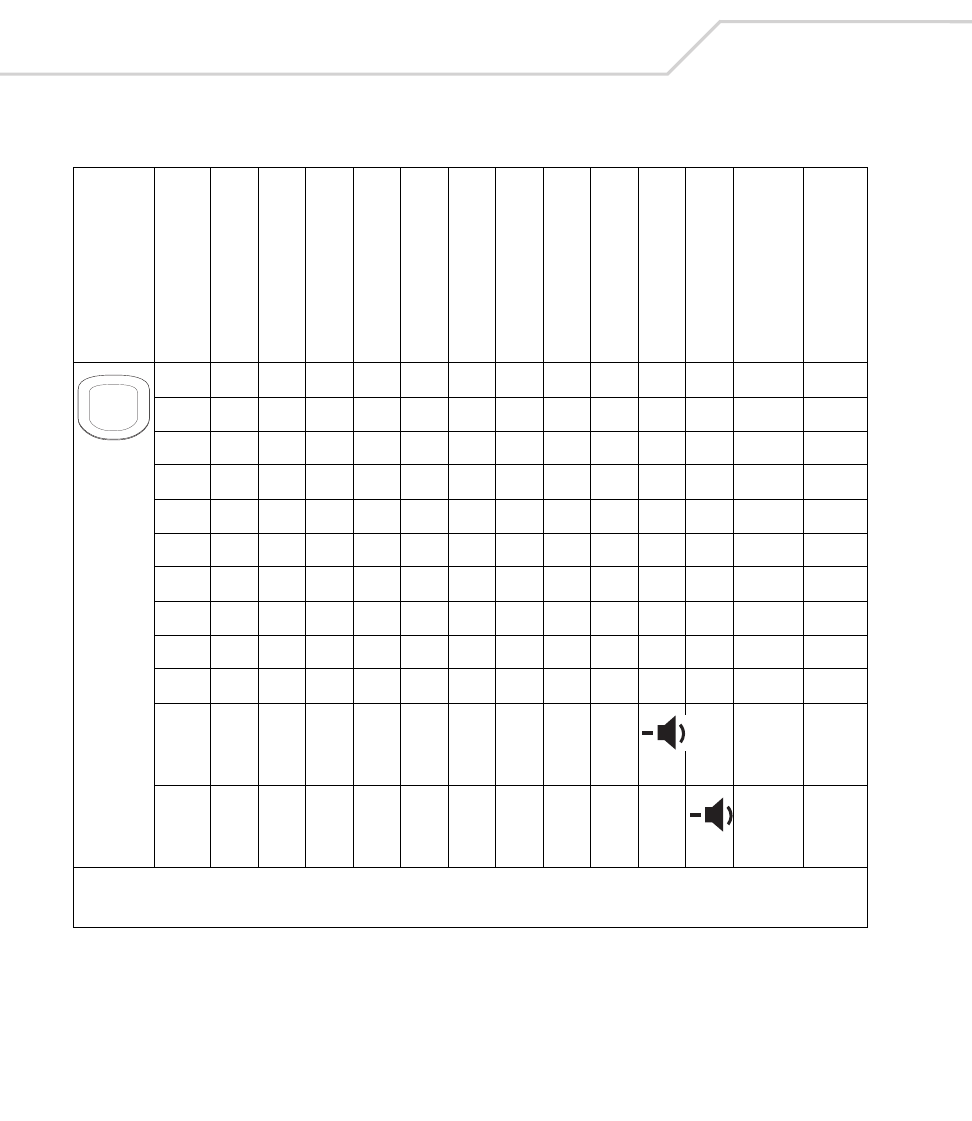
MC9000-K/S for Embedded Windows® CE .NET Product Reference Guide
B-12
65454
m77109
n78110
o79111
M 160+77 77
N 160+78 78
O 160+79 79
*
*
Table B-2. MC9000-K: 28 Key Keypad Mapping (Continued)
Key
Default State
Alpha State (1 Tap)
Alpha State (2 Taps)
Alpha State (3 Taps)
Alpha State (4 Taps)
Shift Alpha State (1 Tap)
Shift Alpha State (2 Taps)
Shift Alpha State (3 Taps)
Shift Alpha State (4 Taps)
Ctrl State
Funct State
Shift-Func State
VK Code (Decimal)
ASCII Value (Decimal)
* See Table 2-7 on page 2-23 for keypad special functions.
Note: Blank lines are provided to allow the application developer to use this table as a keypad mapping worksheet.
6
MNO

Keypad Maps B-13
75555
p80112
q81113
r82114
s83115
P 160+80 80
Q 160+81 81
R 160+82 82
S 160+83 83
+10743
+ 160+107 43
Table B-2. MC9000-K: 28 Key Keypad Mapping (Continued)
Key
Default State
Alpha State (1 Tap)
Alpha State (2 Taps)
Alpha State (3 Taps)
Alpha State (4 Taps)
Shift Alpha State (1 Tap)
Shift Alpha State (2 Taps)
Shift Alpha State (3 Taps)
Shift Alpha State (4 Taps)
Ctrl State
Funct State
Shift-Func State
VK Code (Decimal)
ASCII Value (Decimal)
* See Table 2-7 on page 2-23 for keypad special functions.
Note: Blank lines are provided to allow the application developer to use this table as a keypad mapping worksheet.
7
PQRS
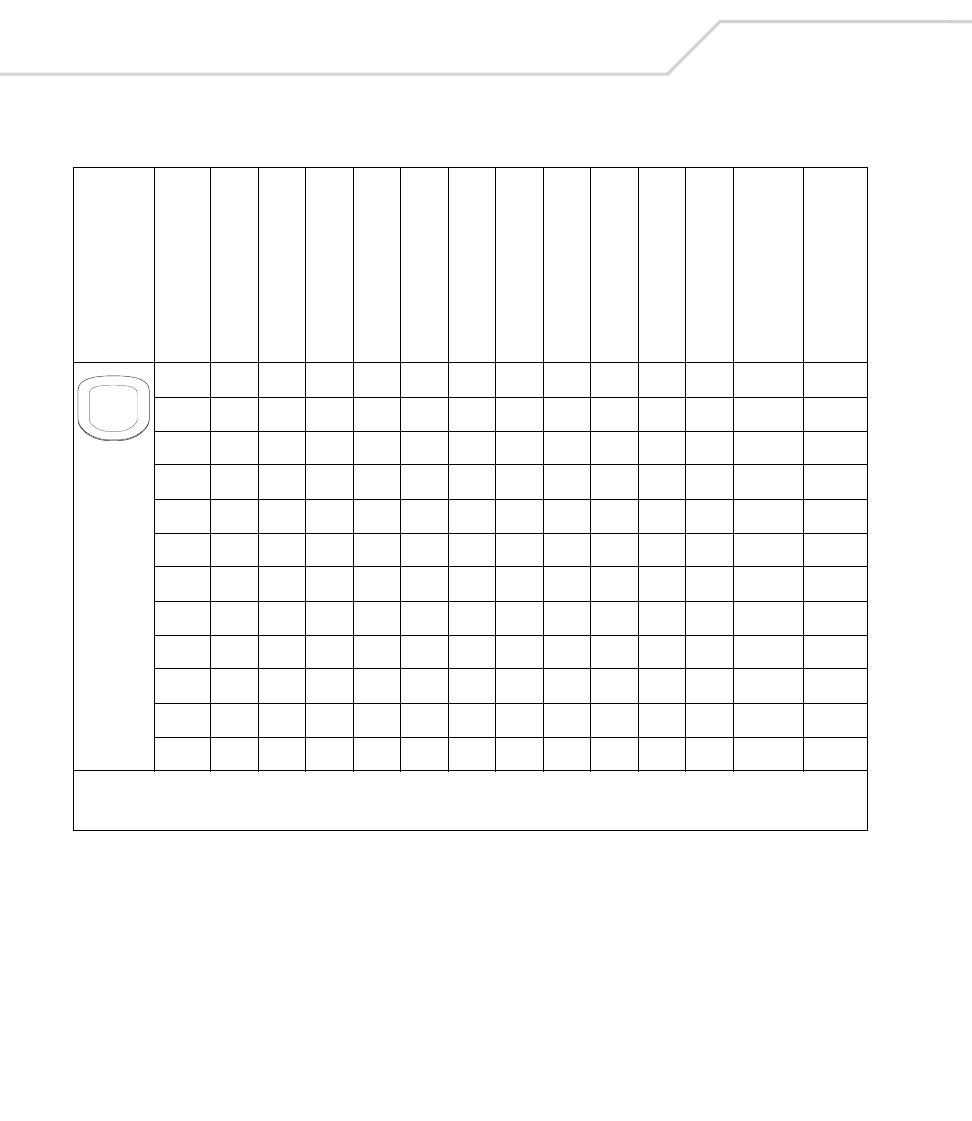
MC9000-K/S for Embedded Windows® CE .NET Product Reference Guide
B-14
85656
t84116
u85117
v86118
T 160+84 84
U 160+85 85
V 160+86 86
- 189 45
- 160+189 45
Table B-2. MC9000-K: 28 Key Keypad Mapping (Continued)
Key
Default State
Alpha State (1 Tap)
Alpha State (2 Taps)
Alpha State (3 Taps)
Alpha State (4 Taps)
Shift Alpha State (1 Tap)
Shift Alpha State (2 Taps)
Shift Alpha State (3 Taps)
Shift Alpha State (4 Taps)
Ctrl State
Funct State
Shift-Func State
VK Code (Decimal)
ASCII Value (Decimal)
* See Table 2-7 on page 2-23 for keypad special functions.
Note: Blank lines are provided to allow the application developer to use this table as a keypad mapping worksheet.
8
TUV
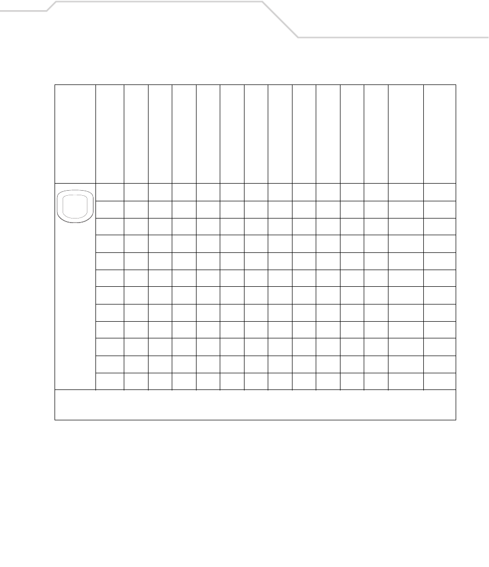
Keypad Maps B-15
95757
w87119
x88120
y89121
z90122
W 160+87 87
X 160+88 88
Y 160+89 89
Z 160+90 90
/19147
/ 160+191 47
Table B-2. MC9000-K: 28 Key Keypad Mapping (Continued)
Key
Default State
Alpha State (1 Tap)
Alpha State (2 Taps)
Alpha State (3 Taps)
Alpha State (4 Taps)
Shift Alpha State (1 Tap)
Shift Alpha State (2 Taps)
Shift Alpha State (3 Taps)
Shift Alpha State (4 Taps)
Ctrl State
Funct State
Shift-Func State
VK Code (Decimal)
ASCII Value (Decimal)
* See Table 2-7 on page 2-23 for keypad special functions.
Note: Blank lines are provided to allow the application developer to use this table as a keypad mapping worksheet.
9
WXYZ

MC9000-K/S for Embedded Windows® CE .NET Product Reference Guide
B-16
. 190 46
* 106 42
* 160+106 42
Table B-2. MC9000-K: 28 Key Keypad Mapping (Continued)
Key
Default State
Alpha State (1 Tap)
Alpha State (2 Taps)
Alpha State (3 Taps)
Alpha State (4 Taps)
Shift Alpha State (1 Tap)
Shift Alpha State (2 Taps)
Shift Alpha State (3 Taps)
Shift Alpha State (4 Taps)
Ctrl State
Funct State
Shift-Func State
VK Code (Decimal)
ASCII Value (Decimal)
* See Table 2-7 on page 2-23 for keypad special functions.
Note: Blank lines are provided to allow the application developer to use this table as a keypad mapping worksheet.
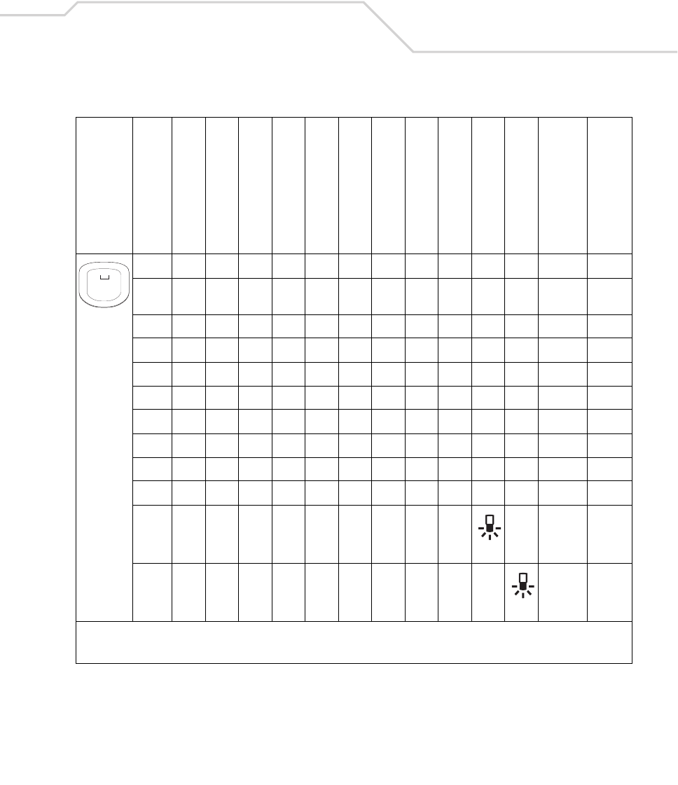
Keypad Maps B-17
04848
Space
32 32
*
*
Table B-2. MC9000-K: 28 Key Keypad Mapping (Continued)
Key
Default State
Alpha State (1 Tap)
Alpha State (2 Taps)
Alpha State (3 Taps)
Alpha State (4 Taps)
Shift Alpha State (1 Tap)
Shift Alpha State (2 Taps)
Shift Alpha State (3 Taps)
Shift Alpha State (4 Taps)
Ctrl State
Funct State
Shift-Func State
VK Code (Decimal)
ASCII Value (Decimal)
* See Table 2-7 on page 2-23 for keypad special functions.
Note: Blank lines are provided to allow the application developer to use this table as a keypad mapping worksheet.
0
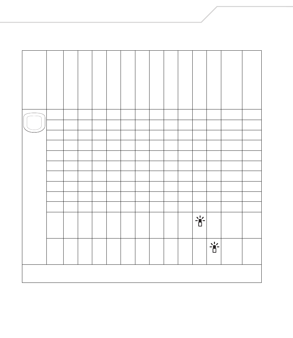
MC9000-K/S for Embedded Windows® CE .NET Product Reference Guide
B-18
# 160+51 35
*
*
Table B-2. MC9000-K: 28 Key Keypad Mapping (Continued)
Key
Default State
Alpha State (1 Tap)
Alpha State (2 Taps)
Alpha State (3 Taps)
Alpha State (4 Taps)
Shift Alpha State (1 Tap)
Shift Alpha State (2 Taps)
Shift Alpha State (3 Taps)
Shift Alpha State (4 Taps)
Ctrl State
Funct State
Shift-Func State
VK Code (Decimal)
ASCII Value (Decimal)
* See Table 2-7 on page 2-23 for keypad special functions.
Note: Blank lines are provided to allow the application developer to use this table as a keypad mapping worksheet.
#

Keypad Maps B-19
Space 32 32
Table B-2. MC9000-K: 28 Key Keypad Mapping (Continued)
Key
Default State
Alpha State (1 Tap)
Alpha State (2 Taps)
Alpha State (3 Taps)
Alpha State (4 Taps)
Shift Alpha State (1 Tap)
Shift Alpha State (2 Taps)
Shift Alpha State (3 Taps)
Shift Alpha State (4 Taps)
Ctrl State
Funct State
Shift-Func State
VK Code (Decimal)
ASCII Value (Decimal)
* See Table 2-7 on page 2-23 for keypad special functions.
Note: Blank lines are provided to allow the application developer to use this table as a keypad mapping worksheet.
SPACE

MC9000-K/S for Embedded Windows® CE .NET Product Reference Guide
B-20
BKSP 8 8
Table B-2. MC9000-K: 28 Key Keypad Mapping (Continued)
Key
Default State
Alpha State (1 Tap)
Alpha State (2 Taps)
Alpha State (3 Taps)
Alpha State (4 Taps)
Shift Alpha State (1 Tap)
Shift Alpha State (2 Taps)
Shift Alpha State (3 Taps)
Shift Alpha State (4 Taps)
Ctrl State
Funct State
Shift-Func State
VK Code (Decimal)
ASCII Value (Decimal)
* See Table 2-7 on page 2-23 for keypad special functions.
Note: Blank lines are provided to allow the application developer to use this table as a keypad mapping worksheet.
BKSP

Keypad Maps B-21
Up 38 -
Table B-2. MC9000-K: 28 Key Keypad Mapping (Continued)
Key
Default State
Alpha State (1 Tap)
Alpha State (2 Taps)
Alpha State (3 Taps)
Alpha State (4 Taps)
Shift Alpha State (1 Tap)
Shift Alpha State (2 Taps)
Shift Alpha State (3 Taps)
Shift Alpha State (4 Taps)
Ctrl State
Funct State
Shift-Func State
VK Code (Decimal)
ASCII Value (Decimal)
* See Table 2-7 on page 2-23 for keypad special functions.
Note: Blank lines are provided to allow the application developer to use this table as a keypad mapping worksheet.
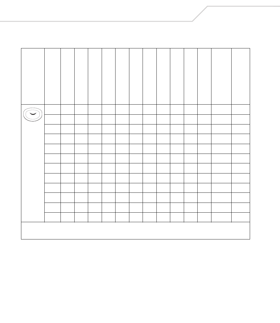
MC9000-K/S for Embedded Windows® CE .NET Product Reference Guide
B-22
Down 40 -
Table B-2. MC9000-K: 28 Key Keypad Mapping (Continued)
Key
Default State
Alpha State (1 Tap)
Alpha State (2 Taps)
Alpha State (3 Taps)
Alpha State (4 Taps)
Shift Alpha State (1 Tap)
Shift Alpha State (2 Taps)
Shift Alpha State (3 Taps)
Shift Alpha State (4 Taps)
Ctrl State
Funct State
Shift-Func State
VK Code (Decimal)
ASCII Value (Decimal)
* See Table 2-7 on page 2-23 for keypad special functions.
Note: Blank lines are provided to allow the application developer to use this table as a keypad mapping worksheet.

Keypad Maps B-23
Right 39 -
Table B-2. MC9000-K: 28 Key Keypad Mapping (Continued)
Key
Default State
Alpha State (1 Tap)
Alpha State (2 Taps)
Alpha State (3 Taps)
Alpha State (4 Taps)
Shift Alpha State (1 Tap)
Shift Alpha State (2 Taps)
Shift Alpha State (3 Taps)
Shift Alpha State (4 Taps)
Ctrl State
Funct State
Shift-Func State
VK Code (Decimal)
ASCII Value (Decimal)
* See Table 2-7 on page 2-23 for keypad special functions.
Note: Blank lines are provided to allow the application developer to use this table as a keypad mapping worksheet.

MC9000-K/S for Embedded Windows® CE .NET Product Reference Guide
B-24
Left 37 -
Table B-2. MC9000-K: 28 Key Keypad Mapping (Continued)
Key
Default State
Alpha State (1 Tap)
Alpha State (2 Taps)
Alpha State (3 Taps)
Alpha State (4 Taps)
Shift Alpha State (1 Tap)
Shift Alpha State (2 Taps)
Shift Alpha State (3 Taps)
Shift Alpha State (4 Taps)
Ctrl State
Funct State
Shift-Func State
VK Code (Decimal)
ASCII Value (Decimal)
* See Table 2-7 on page 2-23 for keypad special functions.
Note: Blank lines are provided to allow the application developer to use this table as a keypad mapping worksheet.
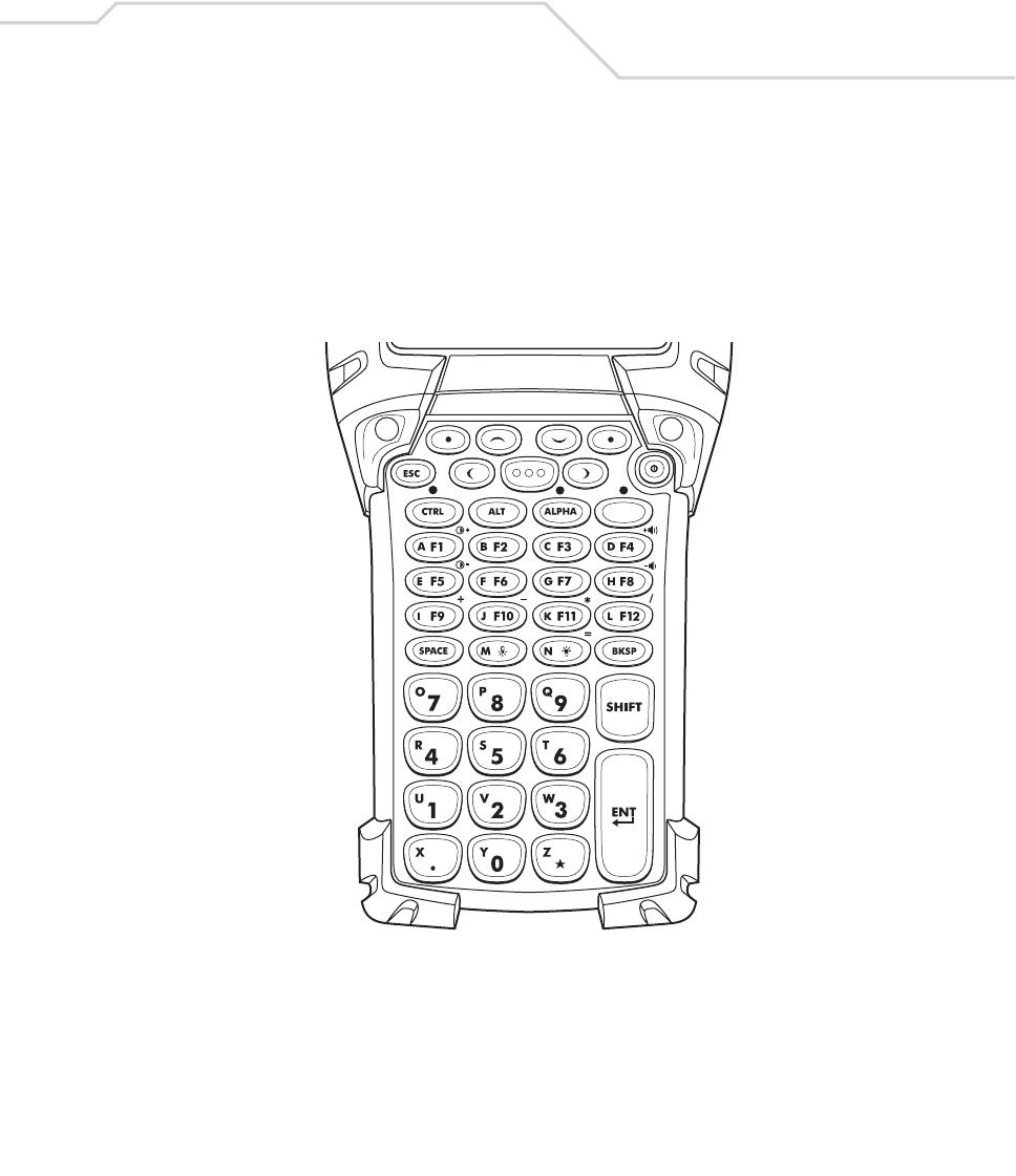
Keypad Maps B-25
43-Key Keypad (MC9000-K)
The 43-key keypad contains a Power button, application keys, scroll keys and a function key. See
Table B-3 for key functions and Table B-4 for the keypad mappings. The mapping functions include:
• 43-key functions
• 43-key character map.
Figure B-2. MC9000-K: 43-Key Keypad
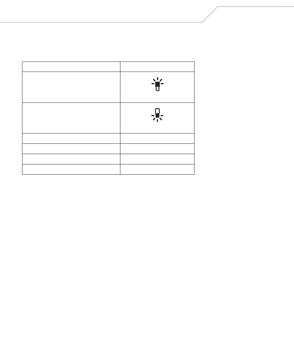
MC9000-K/S for Embedded Windows® CE .NET Product Reference Guide
B-26
Table B-3. MC9000-K: 43-Key Functions
Local Function Key Sequence
Display Backlight On/Off
Keypad Backlight On/Off
Contrast + <Func><F1>
Contrast - <Func><F5>
Volume + <Func><F4>
Volume - <Func><F8>
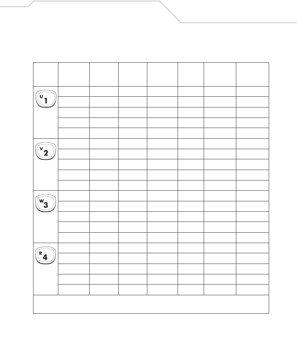
Keypad Maps B-27
Table B-4. MC9000-K: 43 Keypad Mapping
Key
Default
(Numlock)
State
Alpha
State
Shift
AlphaState Func State
Shift-
Func
State
VK Code
(Decimal)
ASCII Value
(Decimal)
14949
u85117
U 160+85 85
u85117
U 160+85 85
25050
v86118
V 160+86 86
v86118
V 160+86 86
35151
w87119
W 160+87 87
w87119
W 160+87 87
45252
r82114
R 160+82 82
r82114
R 160+82 82
* See Table 2-7 on page 2-23 for keypad special functions.
Note: Blank lines are provided to allow the application developer to use this table as a keypad mapping worksheet.
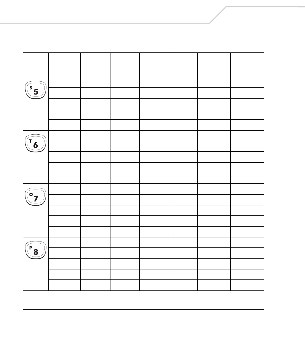
MC9000-K/S for Embedded Windows® CE .NET Product Reference Guide
B-28
55353
s83115
S 160+83 83
s83115
S 160+83 83
65454
t84116
T 160+84 84
t84116
T 160+84 84
75555
o79111
O 160+79 79
o79111
O 160+79 79
85656
p80112
P 160+80 80
p80112
P 160+80 80
Table B-4. MC9000-K: 43 Keypad Mapping (Continued)
Key
Default
(Numlock)
State
Alpha
State
Shift
AlphaState Func State
Shift-
Func
State
VK Code
(Decimal)
ASCII Value
(Decimal)
* See Table 2-7 on page 2-23 for keypad special functions.
Note: Blank lines are provided to allow the application developer to use this table as a keypad mapping worksheet.
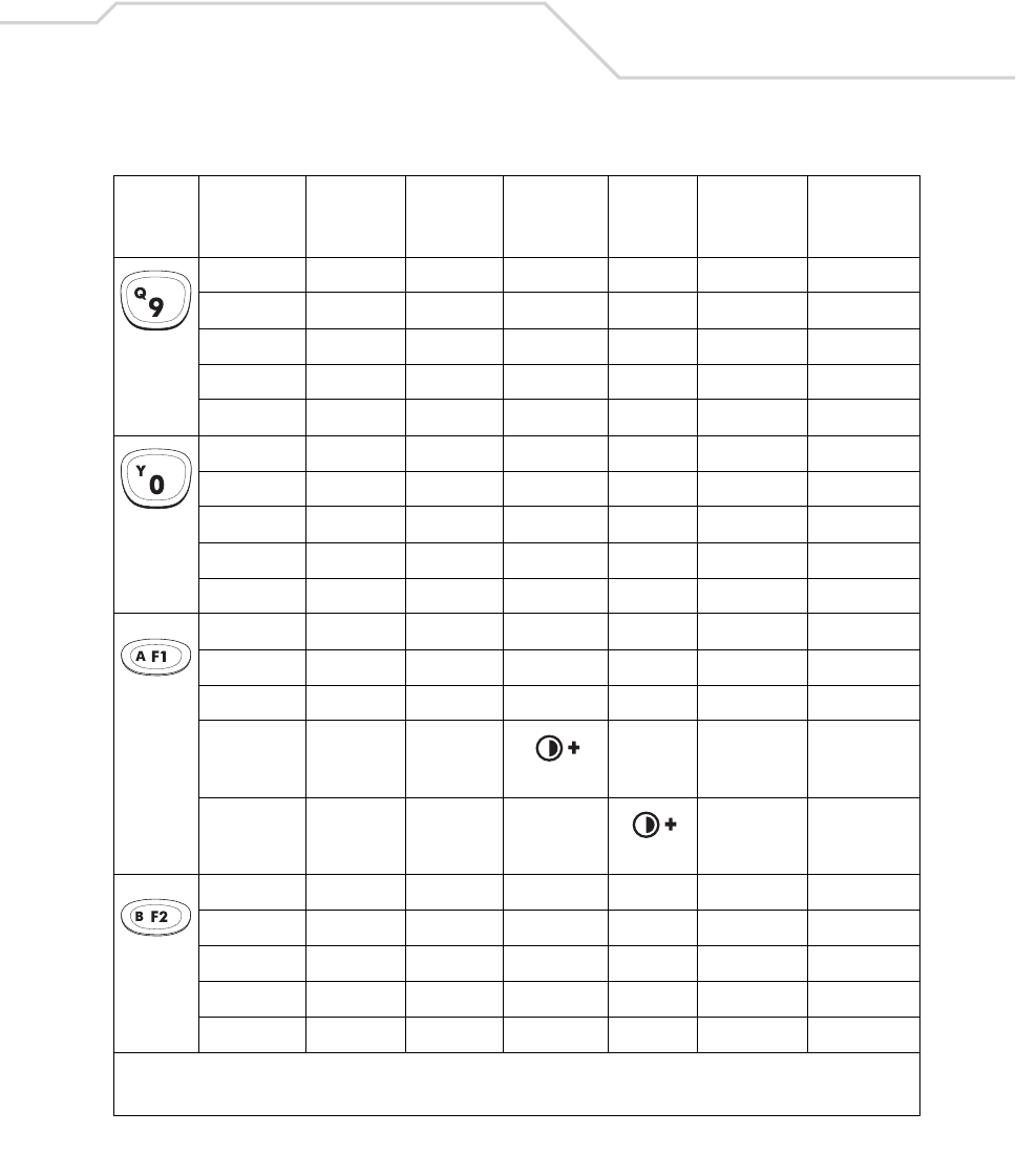
Keypad Maps B-29
95757
q81113
Q 160+81 81
q81113
Q 160+81 81
04949
y89121
Y 160+89 89
y89121
Y 160+89 89
F1
a6597
A 160+65 65
*
*
F2
b6698
B 160+66 66
b6698
B 160+66 66
Table B-4. MC9000-K: 43 Keypad Mapping (Continued)
Key
Default
(Numlock)
State
Alpha
State
Shift
AlphaState Func State
Shift-
Func
State
VK Code
(Decimal)
ASCII Value
(Decimal)
* See Table 2-7 on page 2-23 for keypad special functions.
Note: Blank lines are provided to allow the application developer to use this table as a keypad mapping worksheet.
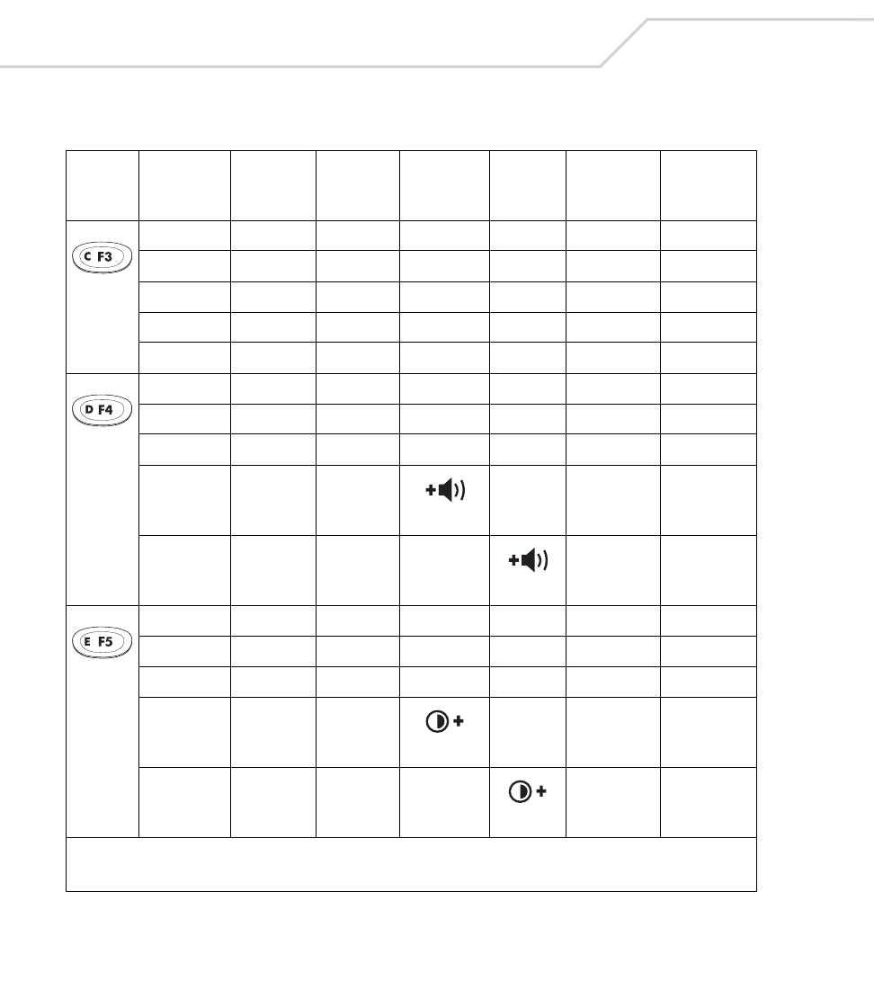
MC9000-K/S for Embedded Windows® CE .NET Product Reference Guide
B-30
F3
c6799
C 160+67 67
c6799
C 160+67 67
F4
d68100
D 160+68 68
*
*
F5
e69101
E 160+69 69
*
*
Table B-4. MC9000-K: 43 Keypad Mapping (Continued)
Key
Default
(Numlock)
State
Alpha
State
Shift
AlphaState Func State
Shift-
Func
State
VK Code
(Decimal)
ASCII Value
(Decimal)
* See Table 2-7 on page 2-23 for keypad special functions.
Note: Blank lines are provided to allow the application developer to use this table as a keypad mapping worksheet.
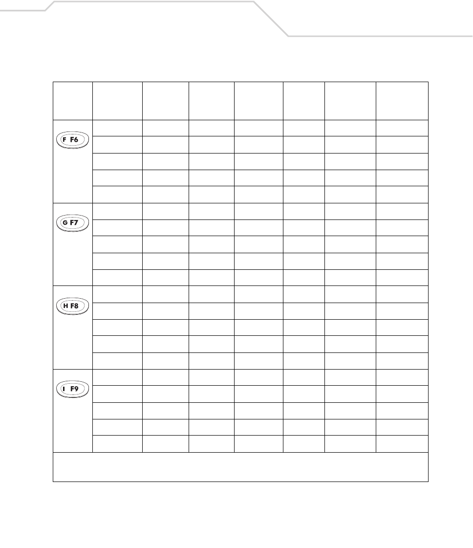
Keypad Maps B-31
F6
f70102
F 160+70 70
f70102
F 160+70 70
F7
g71103
G 160+71 71
g71103
G 160+71 71
F8
h72104
H 160+72 72
h72104
H 160+72 72
F9
i73105
I 160+73 73
+ 107 43
+ 160+107 43
Table B-4. MC9000-K: 43 Keypad Mapping (Continued)
Key
Default
(Numlock)
State
Alpha
State
Shift
AlphaState Func State
Shift-
Func
State
VK Code
(Decimal)
ASCII Value
(Decimal)
* See Table 2-7 on page 2-23 for keypad special functions.
Note: Blank lines are provided to allow the application developer to use this table as a keypad mapping worksheet.
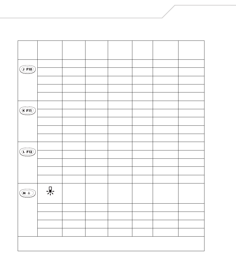
MC9000-K/S for Embedded Windows® CE .NET Product Reference Guide
B-32
F10
j74106
J 160+74 74
-18945
- 160+189 45
F11
k75107
K 160+75 75
*10642
* 160+106 42
F12
l76108
L 160+76 76
/19147
? 160+191 63
*
m77109
M 160+77 77
m77109
M 160+77 77
Table B-4. MC9000-K: 43 Keypad Mapping (Continued)
Key
Default
(Numlock)
State
Alpha
State
Shift
AlphaState Func State
Shift-
Func
State
VK Code
(Decimal)
ASCII Value
(Decimal)
* See Table 2-7 on page 2-23 for keypad special functions.
Note: Blank lines are provided to allow the application developer to use this table as a keypad mapping worksheet.
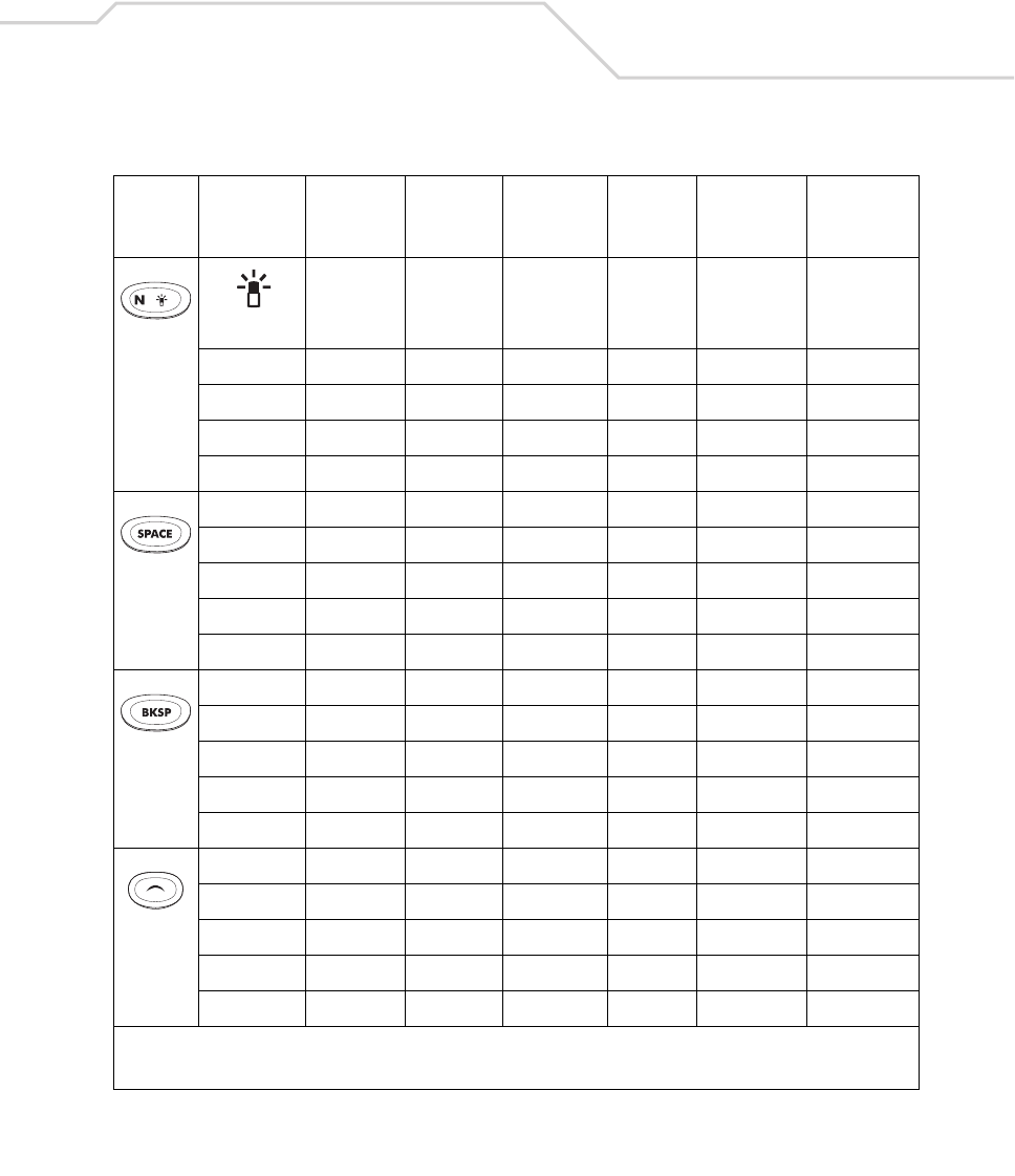
Keypad Maps B-33
*
n78110
N 160+78 78
n78110
N 160+78 78
Space 32 32
Space 32 32
Space 160+32 32
BKSP 8 8
BKSP 8 8
BKSP 160+8 8
BKSP 8 8
UP 38 -
Table B-4. MC9000-K: 43 Keypad Mapping (Continued)
Key
Default
(Numlock)
State
Alpha
State
Shift
AlphaState Func State
Shift-
Func
State
VK Code
(Decimal)
ASCII Value
(Decimal)
* See Table 2-7 on page 2-23 for keypad special functions.
Note: Blank lines are provided to allow the application developer to use this table as a keypad mapping worksheet.
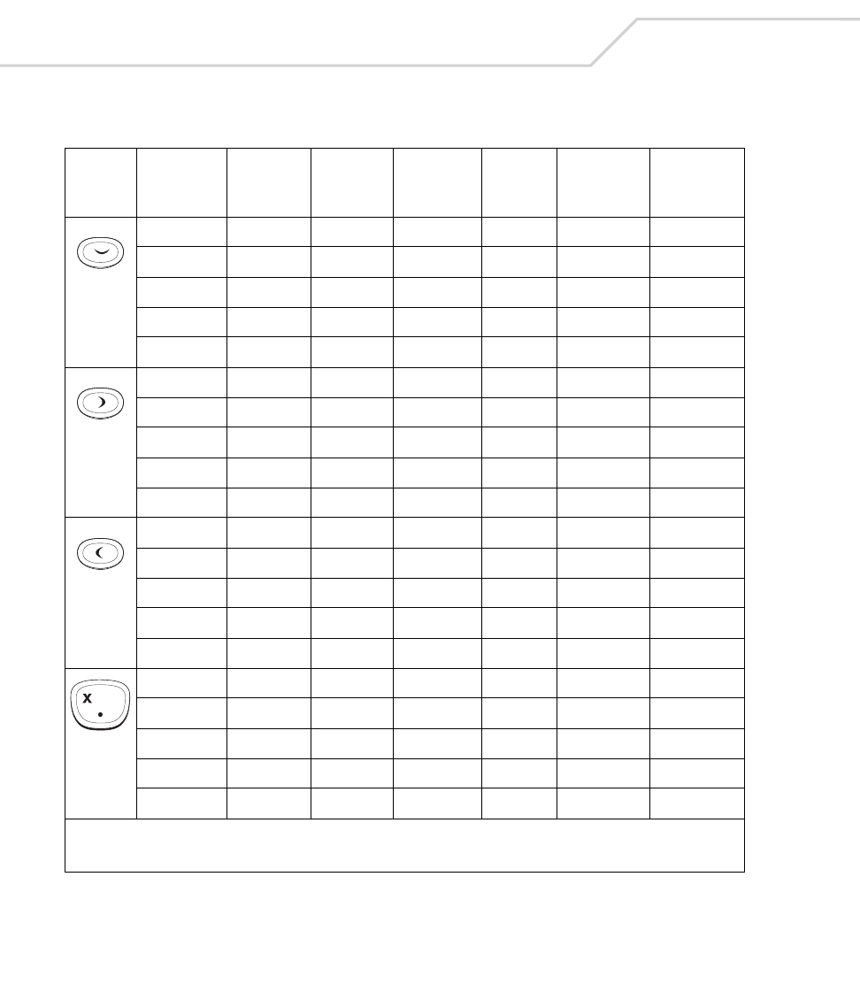
MC9000-K/S for Embedded Windows® CE .NET Product Reference Guide
B-34
Down 40 -
Right 39 -
Left 37 -
.19046
x88120
X 160+88 88
x88120
X 160+88 88
Table B-4. MC9000-K: 43 Keypad Mapping (Continued)
Key
Default
(Numlock)
State
Alpha
State
Shift
AlphaState Func State
Shift-
Func
State
VK Code
(Decimal)
ASCII Value
(Decimal)
* See Table 2-7 on page 2-23 for keypad special functions.
Note: Blank lines are provided to allow the application developer to use this table as a keypad mapping worksheet.

Keypad Maps B-35
* 106 42
z90122
Z 160+90 90
z90122
Z 160+90 90
Table B-4. MC9000-K: 43 Keypad Mapping (Continued)
Key
Default
(Numlock)
State
Alpha
State
Shift
AlphaState Func State
Shift-
Func
State
VK Code
(Decimal)
ASCII Value
(Decimal)
* See Table 2-7 on page 2-23 for keypad special functions.
Note: Blank lines are provided to allow the application developer to use this table as a keypad mapping worksheet.
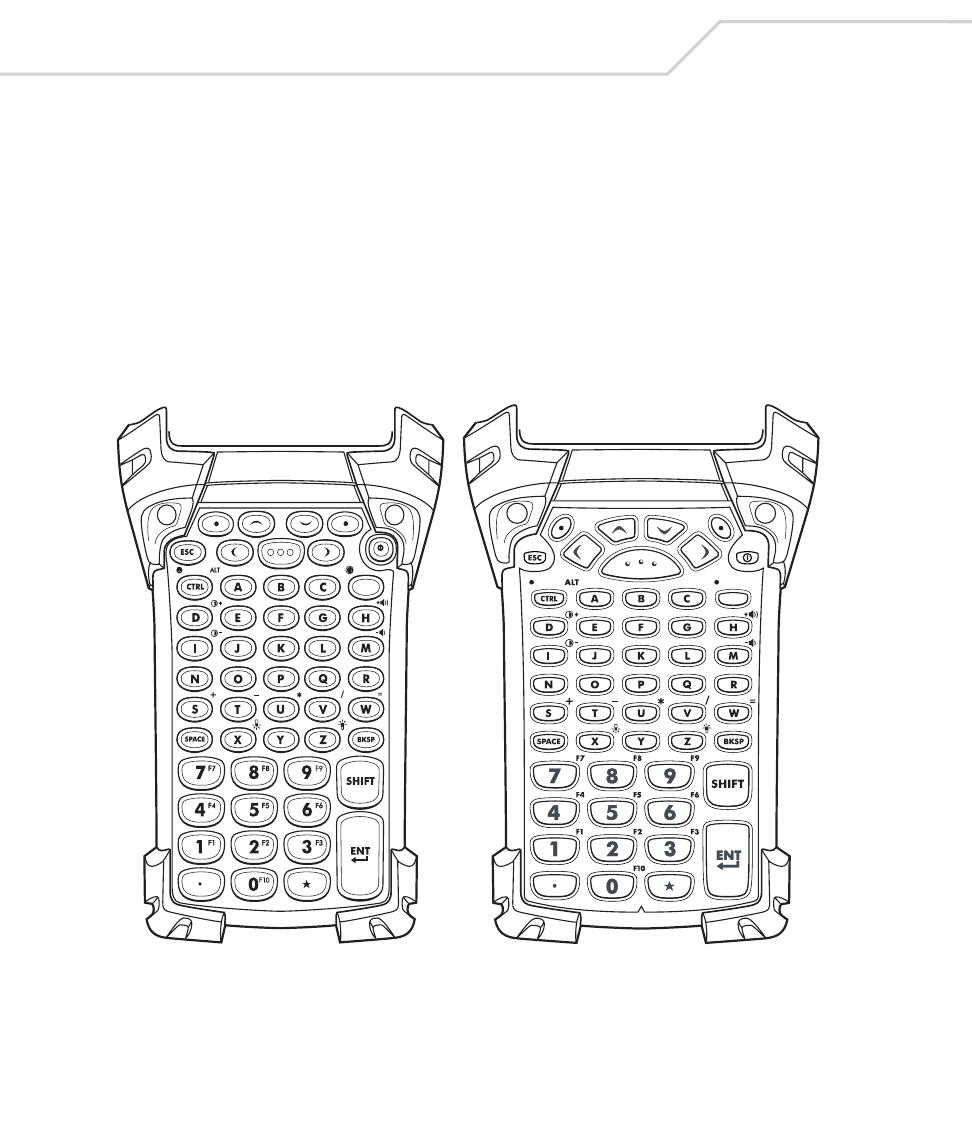
MC9000-K/S for Embedded Windows® CE .NET Product Reference Guide
B-36
53-Key Keypad (MC9000-K)
There are two physical configurations of the 53-key keypad, however both of the keypads are
functionally identical. The 53-key keypad contains a Power button, application keys, scroll keys and
function keys. See Table B-5 for key functions and Table B-6 for the keypad mappings. The mapping
functions include:
• 53-key functions
53-key character map.
Figure B-3. MC9000-K: 53 Key Keypad
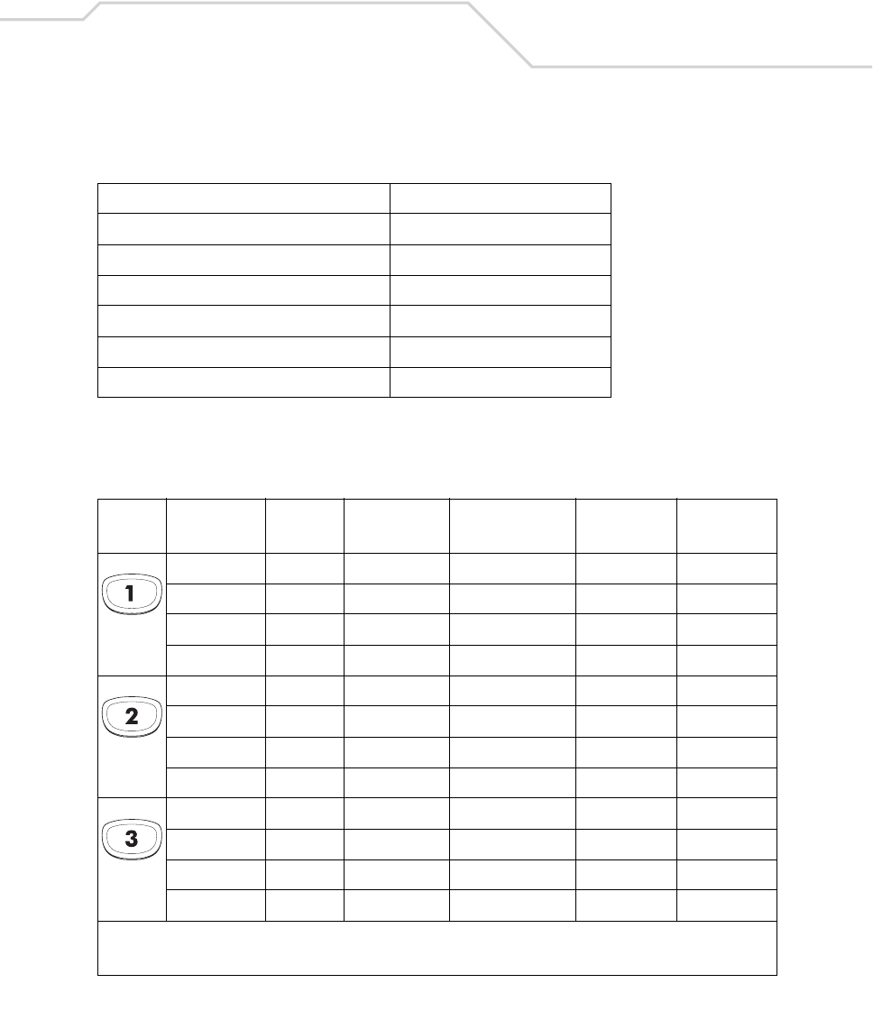
Keypad Maps B-37
Table B-5. MC9000-K: 53 Key Functions
Local Function Key Sequence
Display Backlight On/Off <Func><Z>
Keypad Backlight On/Off <Func><X>
Contrast + <Func><D>
Contrast - <Func><I>
Volume + <Func><H>
Volume - <Func><M>
Table B-6. MC9000-K: 53-Key Mapping
Key Default State Shift State Func State
Shift-Func
State
VK Code
(Decimal)
ASCII Value
(Decimal)
14949
! 160+49 33
F1 112 -
F1 1160+12 -
25050
@ 160+50 64
F2 113 -
F2 160+113 -
35151
# 160+51 35
F3 114 -
F3 160+114 -
* See Table 2-7 on page 2-23 for keypad special functions.
Note: Blank lines are provided to allow the application developer to use this table as a keypad mapping worksheet.
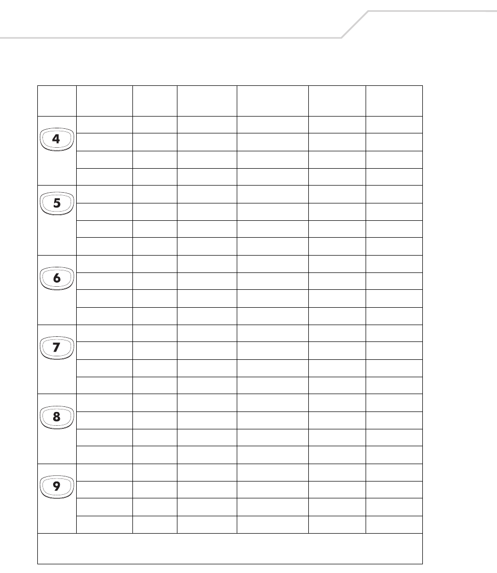
MC9000-K/S for Embedded Windows® CE .NET Product Reference Guide
B-38
45252
$ 160+52 103
F4 115 -
F4 160+115 -
55353
% 160+53 106
F5 116 -
F5 160+116 -
65454
^ 160+54 94
F6 117 -
F6 160+117 -
75555
& 160+55 112
F7 118 -
F7 160+118 -
85656
* 160+56 42
F8 119 -
F8 160+119 -
95757
( 160+57 41
F9 120 -
F9 160+120 -
Table B-6. MC9000-K: 53-Key Mapping (Continued)
Key Default State Shift State Func State
Shift-Func
State
VK Code
(Decimal)
ASCII Value
(Decimal)
* See Table 2-7 on page 2-23 for keypad special functions.
Note: Blank lines are provided to allow the application developer to use this table as a keypad mapping worksheet.
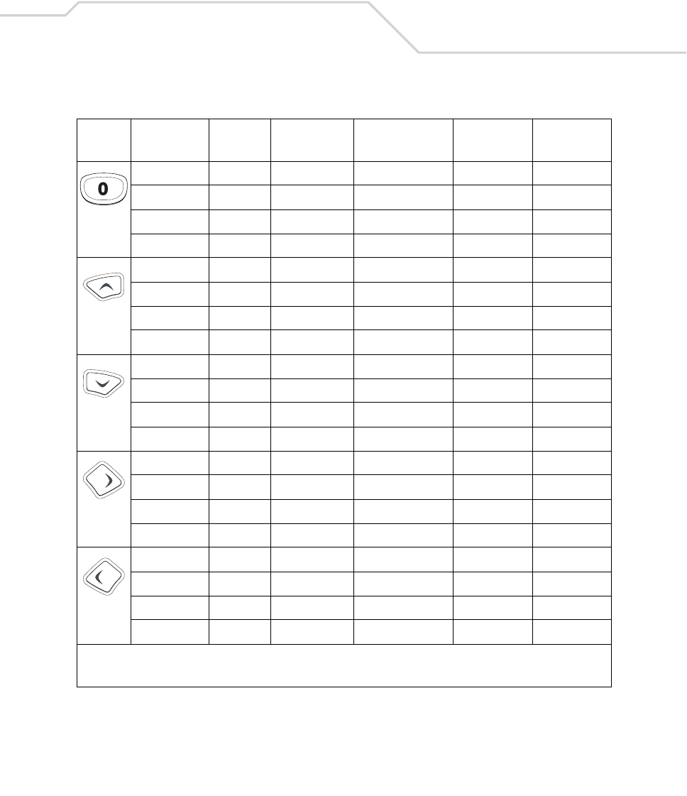
Keypad Maps B-39
04848
) 160+48 40
F10 121 -
F10 160+121 -
UP 38 -
Down 40 -
Right 39 -
Left 37 -
Table B-6. MC9000-K: 53-Key Mapping (Continued)
Key Default State Shift State Func State
Shift-Func
State
VK Code
(Decimal)
ASCII Value
(Decimal)
* See Table 2-7 on page 2-23 for keypad special functions.
Note: Blank lines are provided to allow the application developer to use this table as a keypad mapping worksheet.
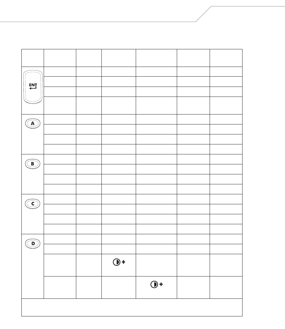
MC9000-K/S for Embedded Windows® CE .NET Product Reference Guide
B-40
ENTER 13 13
a6597
A 160+65 65
,18844
< 160+188 60
b6698
B6666
.19046
> 160+190 60
c6799
C 160+67 67
‘22239
“ 160+222 34
b68100
D 160+68 68
*
*
Table B-6. MC9000-K: 53-Key Mapping (Continued)
Key Default State Shift State Func State
Shift-Func
State
VK Code
(Decimal)
ASCII Value
(Decimal)
* See Table 2-7 on page 2-23 for keypad special functions.
Note: Blank lines are provided to allow the application developer to use this table as a keypad mapping worksheet.
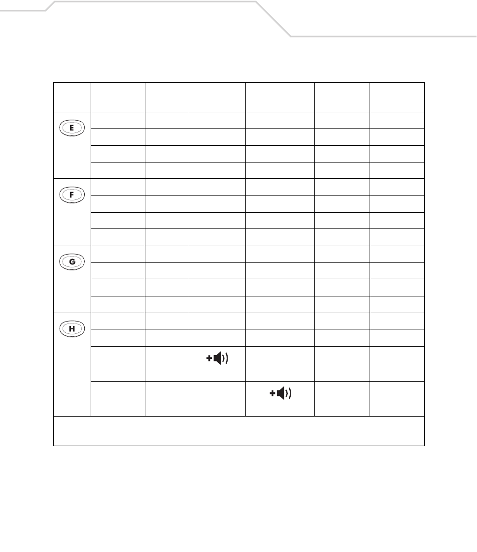
Keypad Maps B-41
e69101
E 160+69 69
[21991
{ 160+219 123
f70102
F 160+70 70
]22193
} 160+221 125
g71103
G 160+71 71
\22092
| 160+220 124
h72104
H 160+72 72
*
*
Table B-6. MC9000-K: 53-Key Mapping (Continued)
Key Default State Shift State Func State
Shift-Func
State
VK Code
(Decimal)
ASCII Value
(Decimal)
* See Table 2-7 on page 2-23 for keypad special functions.
Note: Blank lines are provided to allow the application developer to use this table as a keypad mapping worksheet.
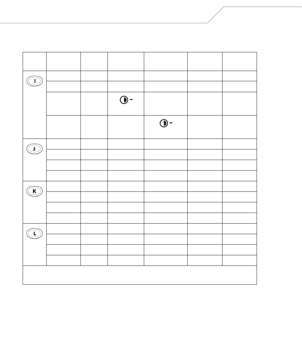
MC9000-K/S for Embedded Windows® CE .NET Product Reference Guide
B-42
i73105
I 160+73 73
*
*
j74106
J 160+74 74
‘19296
~ 160+192 126
k75107
K 160+75 75
k75107
K 160+75 75
l76108
L 160+76 76
/19147
? 160+191 63
Table B-6. MC9000-K: 53-Key Mapping (Continued)
Key Default State Shift State Func State
Shift-Func
State
VK Code
(Decimal)
ASCII Value
(Decimal)
* See Table 2-7 on page 2-23 for keypad special functions.
Note: Blank lines are provided to allow the application developer to use this table as a keypad mapping worksheet.
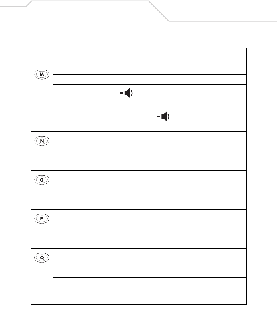
Keypad Maps B-43
m77109
M 160+77 77
*
*
n78110
N 160+78 78
-18945
_ 160+189 95
o79111
O 160+79 79
o79111
O 160+79 79
p80112
P 160+80 80
p80112
P 160+80 80
q81113
Q 160+81 81
q81113
Q 160+81 81
Table B-6. MC9000-K: 53-Key Mapping (Continued)
Key Default State Shift State Func State
Shift-Func
State
VK Code
(Decimal)
ASCII Value
(Decimal)
* See Table 2-7 on page 2-23 for keypad special functions.
Note: Blank lines are provided to allow the application developer to use this table as a keypad mapping worksheet.
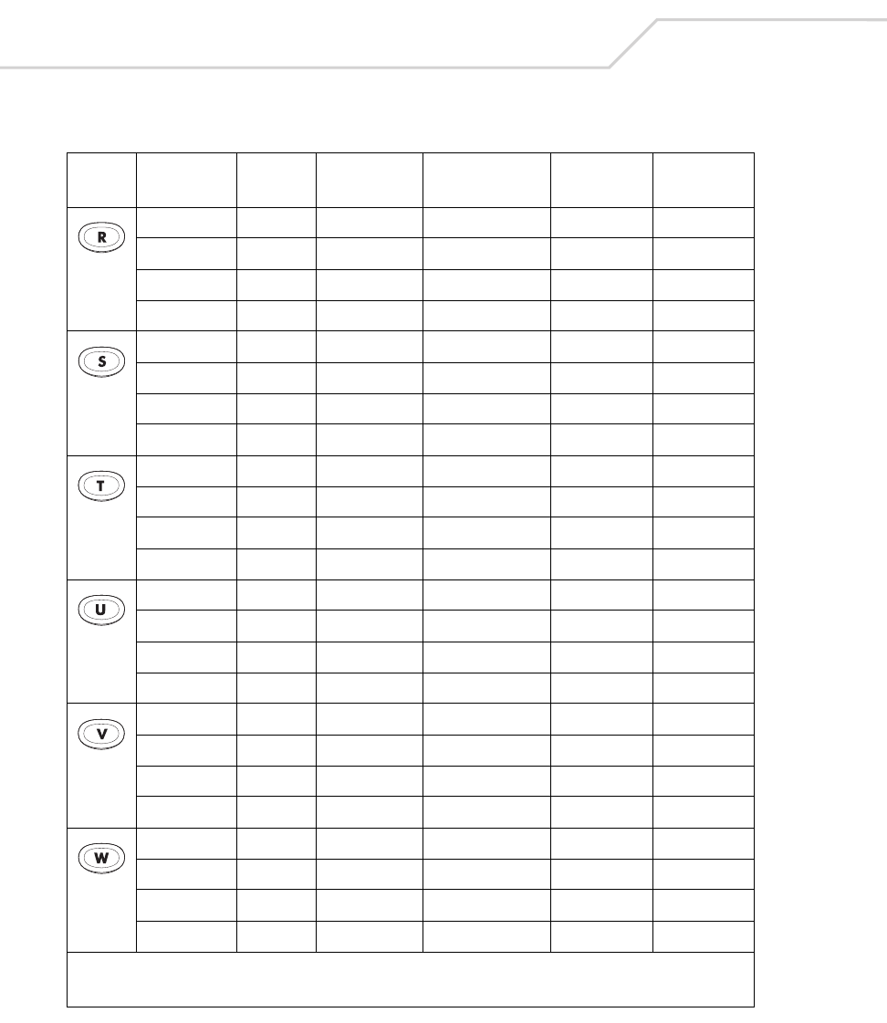
MC9000-K/S for Embedded Windows® CE .NET Product Reference Guide
B-44
r82114
R 160+82 82
;18659
: 160+186 58
s83115
S 160+83 83
+18743
+ 160+187 43
t84116
T 160+84 84
-10945
- 160+109 45
u85117
U8585
*10642
* 160+106 42
v86118
V 160+86 86
/19147
? 160+191 63
w87119
W 160+87 87
=18743
+ 160+187 43
Table B-6. MC9000-K: 53-Key Mapping (Continued)
Key Default State Shift State Func State
Shift-Func
State
VK Code
(Decimal)
ASCII Value
(Decimal)
* See Table 2-7 on page 2-23 for keypad special functions.
Note: Blank lines are provided to allow the application developer to use this table as a keypad mapping worksheet.
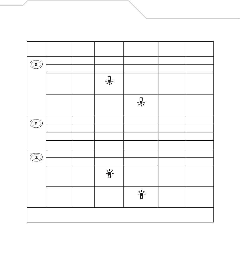
Keypad Maps B-45
x88120
X 160+88 88
*
*
y89121
Y 160+89 89
y89121
Y 160+89 89
z90122
Z9090
*
*
Table B-6. MC9000-K: 53-Key Mapping (Continued)
Key Default State Shift State Func State
Shift-Func
State
VK Code
(Decimal)
ASCII Value
(Decimal)
* See Table 2-7 on page 2-23 for keypad special functions.
Note: Blank lines are provided to allow the application developer to use this table as a keypad mapping worksheet.
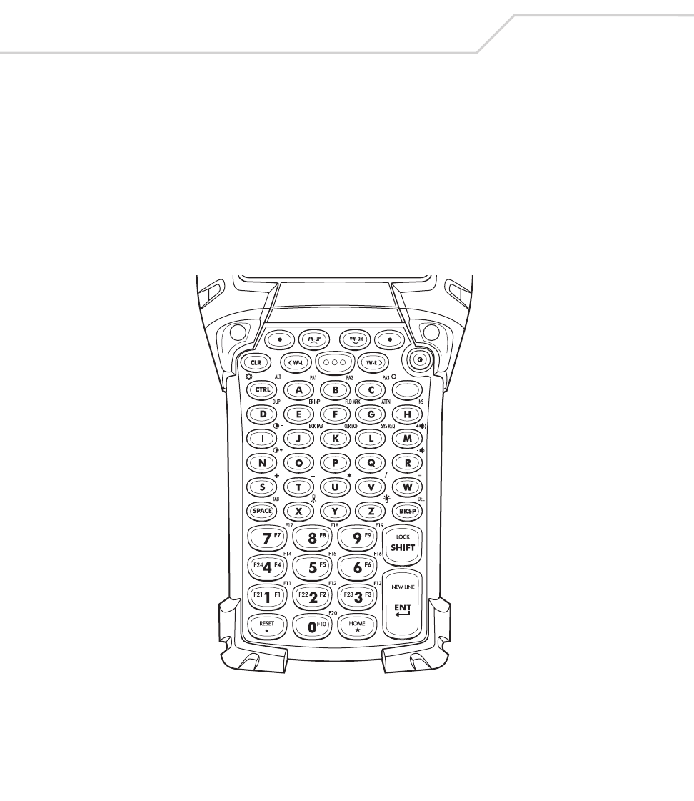
MC9000-K/S for Embedded Windows® CE .NET Product Reference Guide
B-46
3270 Emulator
The 3270 emulator keypad contains a Power button, application keys, scroll keys and a function key.
The 3270 emulator keypad uses the 53-key mapping when not in the emulator mode, see Table B-6
for descriptions for the 53-key mappings. The emulator mapping functions include:
• 3270 key functions
• 3270 emulation keys
• 3270 character map.
Figure B-4. 3270 Emulator Keypad

Keypad Maps B-47
Table B-7. 3270 Key Functions
Local Function Key Sequence
Program Information <Func><Ctrl><P>
Diagnostics <Func><Ctrl><D>
Keyclicks On/Off <Func><Ctrl><K>
Quiet Mode On/Off <Func><Ctrl><Q>
Terminal Configuration <Func><Ctrl><C>
Host Profiles <Func><Ctrl><R>
Message Recall <Func><Ctrl><M>
Free Cursor Mode <Func><Ctrl><F>
Close Session <Func><Ctrl><T>
Previous Session <Upper Left Button>
Next Session <Upper Right Button>
Caps Lock <Func><Shift>
View Mode On/Off <Func><Ctrl><Z>
Scroll Left <Ctrl><Left>
Scroll Right <Ctrl><Right>
Scroll Up <Ctrl><Up>
Scroll Down <Ctrl><Down>
Display Backlight On/Off <Func><Z>
Keypad Backlight On/Off <Func><X>
Contrast + <Func><D>
Contrast - <Func><I>
Volume + <Func><H>
Volume - <Func><M>

MC9000-K/S for Embedded Windows® CE .NET Product Reference Guide
B-48
Table B-8. 3270 Emulation Keys
3270 Key Key Sequence
Attention <Ctrl><G>
Backspace <BKSP>
Back Tab <Ctrl><J>
Clear <Esc>
Clear EOF <Ctrl><K>
Delete <Func><BKSP>
Dup <Ctrl><D>
Enter <Enter>
Erase Input <Ctrl><E>
Field Mark <Ctrl><F>
Home <Func><*>
Insert <Ctrl><H>
New Line <Ctrl><N>
Reset <Ctrl><O>
System Request <Ctrl><L>
Tab <Func><Space>
Left Arrow <Left Arrow>
Right Arrow <Right Arrow>
Up Arrow <Up Arrow>
Down Arrow <Down Arrow>
PA1 <Ctrl><A>
PA2 <Ctrl><B>
PA3 <Ctrl><C>
F1 <Func><1>
F2 <Func><2>
F3 <Func><3>

Keypad Maps B-49
F4 <Func><4>
F5 <Func><5>
F6 <Func><6>
F7 <Func><7>
F8 <Func><8>
F9 <Func><9>
F10 <Func><0>
F11 <Shift><1>
F12 <Shift><2>
F13 <Shift><3>
F14 <Shift><4>
F15 <Shift><5>
F16 <Shift><6>
F17 <Shift><7>
F18 <Shift><8>
F19 <Shift><9>
F20 <Shift><0>
F21 <Ctrl><1>
F22 <Ctrl><2>
F23 <Ctrl><3>
F24 <Ctrl><4>
Table B-8. 3270 Emulation Keys (Continued)
3270 Key Key Sequence

MC9000-K/S for Embedded Windows® CE .NET Product Reference Guide
B-50
Table B-9. 3270 Character Map
Char Key Sequence
Space <space>
! <Ctrl><5>
" <Shift><Func><C>
# <Ctrl><6>
$ <Ctrl><7>
% <Ctrl><8>
& <Ctrl><9>
' <Func><C>
( <Ctrl><0>
) <Func><Ctrl><A>
* <*>
+ <Func><S>
, <Func><A>
- <Func><T>
. <.>
/ <Func><V>
0 <0>
1 <1>
2 <2>
3 <3>
4 <4>
5 <5>
6 <6>
7 <7>
8 <8>
9 <9>

Keypad Maps B-51
: <Shift><Func><R>
; <Func><R>
< <Shift><Func><A>
= <Func><W>
> <Shift><Func><B>
? <Func><Ctrl><G>
@ <Func><Ctrl><B>
A <Shift><A>
B <Shift><B>
C <Shift><C>
D <Shift><D>
E <Shift><E>
F <Shift><F>
G <Shift><G>
H <Shift><H>
I <Shift><I>
J <Shift><J>
K <Shift><K>
L <Shift><L>
M <Shift><M>
N <Shift><N>
O <Shift><O>
P <Shift><P>
Q <Shift><Q>
R <Shift><R>
S <Shift><S>
T <Shift><T>
Table B-9. 3270 Character Map
Char Key Sequence

MC9000-K/S for Embedded Windows® CE .NET Product Reference Guide
B-52
U <Shift><U>
V <Shift><V>
W <Shift><W>
X <Shift><X>
Y <Shift><Y>
Z <Shift><Z>
[ <Func><E>
\ <Func><G>
] <Func><F>
^ <Func><Ctrl><E>
_ <Shift><Func><N>
` <Func><J>
a <A>
b <B>
c <C>
d <D>
e <E>
f <F>
g <G>
h <H>
i <I>
j <J>
k <K>
l <L>
m <M>
n <N>
o <O>
Table B-9. 3270 Character Map
Char Key Sequence

Keypad Maps B-53
p <P>
q <Q>
r <R>
s <S>
t <T>
u <U>
v <V>
w <W>
x <X>
y <Y>
z <Z>
{ <Shift><Func><E>
| <Shift><Func><G>
} <Shift><Func><F>
~ <Shift><Func><J>
Table B-9. 3270 Character Map
Char Key Sequence

MC9000-K/S for Embedded Windows® CE .NET Product Reference Guide
B-54
5250 Emulator
The 5250 emulator keypad contains a Power button, application keys, scroll keys and a function key.
The 5250 emulator keypad uses the 53-key mapping when not in the emulator mode, see Table B-6
for descriptions for the 53-key mappings. The emulator mapping functions include:
• 5250 key functions
• 5250 emulation keys
• 5250 character map.
Figure B-5. 5250 Emulator Keypad

Keypad Maps B-55
Table B-10. 5250 Key Functions
Local Function Key Sequence
Program Information <Func><Ctrl><P>
Diagnostics <Func><Ctrl><D>
Keyclicks On/Off <Func><Ctrl><K>
Quiet Mode On/Off <Func><Ctrl><Q>
Terminal Configuration <Func><Ctrl><C>
Host Profiles <Func><Ctrl><R>
Message Recall <Func><Ctrl><M>
Free Cursor Mode <Func><Ctrl><F>
Close Session <Func><Ctrl><T>
Previous Session <Upper Left Button>
Next Session <Upper Right Button>
Caps Lock <Func><Shift>
View Mode On/Off <Func><Ctrl><Z>
Scroll Left <Ctrl><Left>
Scroll Right <Ctrl><Right>
Scroll Up <Ctrl><Up>
Scroll Down <Ctrl><Down>
Display Backlight On/Off <Func><Z>
Keypad Backlight On/Off <Func><X>
Contrast + <Func><D>
Contrast - <Func><I>
Volume + <Func><H>
Volume - <Func><M>

MC9000-K/S for Embedded Windows® CE .NET Product Reference Guide
B-56
Table B-11. 5250 Emulation Keys
5250 Key Key Sequence
Attention <Ctrl><G>
Backspace <BKSP>
Back Tab <Func><Space>
Clear <Func><Ctrl><Shift><1>
Delete <Func><BKSP>
Dup <Ctrl><D>
Enter <Ent>
Erase Input <Ctrl><E>
Field Exit <Field Exit>
Field Minus <Func><*>
Help <Ctrl><C>
Home <Ctrl><A>
Insert <Ctrl><H>
Print <Ctrl><B>
Reset <Func><.>
Roll Up <Ctrl><J>
Roll Down <Ctrl><L>
System Request <Ctrl><K>
Tab <Ctrl><I>
Left Arrow <Left Arrow>
Right Arrow <Right Arrow>
Up Arrow <Up Arrow>
Down Arrow <Down Arrow>
F1 <Func><1>
F2 <Func><2>
F3 <Func><3>

Keypad Maps B-57
F4 <Func><4>
F5 <Func><5>
F6 <Func><6>
F7 <Func><7>
F8 <Func><8>
F9 <Func><9>
F10 <Func><0>
F11 <Shift><1>
F12 <Shift><2>
F13 <Shift><3>
F14 <Shift><4>
F15 <Shift><5>
F16 <Shift><6>
F17 <Shift><7>
F18 <Shift><8>
F19 <Shift><9>
F20 <Shift><0>
F21 <Ctrl><1>
F22 <Ctrl><2>
F23 <Ctrl><3>
F24 <Ctrl><4>
Table B-11. 5250 Emulation Keys (Continued)
5250 Key Key Sequence

MC9000-K/S for Embedded Windows® CE .NET Product Reference Guide
B-58
Table B-12. 5250 Character Map
Char Key Sequence
Space <space>
! <Ctrl><5>
" <Shift><Func><C>
# <Ctrl><6>
$ <Ctrl><7>
% <Ctrl><8>
& <Ctrl><9>
' <Func><C>
( <Ctrl><0>
) <Func><Ctrl><A>
* <*>
+ <Func><S>
, <Func><A>
- <Func><T>
. <.>
/ <Func><V>
0 <0>
1 <1>
2 <2>
3 <3>
4 <4>
5 <5>
6 <6>
7 <7>
8 <8>
9 <9>

Keypad Maps B-59
: <Shift><Func><R>
; <Func><R>
< <Shift><Func><A>
= <Func><W>
> <Shift><Func><B>
? <Func><Ctrl><G>
@ <Func><Ctrl><B>
A <Shift><A>
B <Shift><B>
C <Shift><C>
D <Shift><D>
E <Shift><E>
F <Shift><F>
G <Shift><G>
H <Shift><H>
I <Shift><I>
J <Shift><J>
K <Shift><K>
L <Shift><L>
M <Shift><M>
N <Shift><N>
O <Shift><O>
P <Shift><P>
Q <Shift><Q>
R <Shift><R>
S <Shift><S>
T <Shift><T>
Table B-12. 5250 Character Map
Char Key Sequence

MC9000-K/S for Embedded Windows® CE .NET Product Reference Guide
B-60
U <Shift><U>
V <Shift><V>
W <Shift><W>
X <Shift><X>
Y <Shift><Y>
Z <Shift><Z>
[ <Func><E>
\ <Func><G>
] <Func><F>
^ <Func><Ctrl><E>
_ <Shift><Func><N>
` <Func><J>
a <A>
b <B>
c <C>
d <D>
e <E>
f <F>
g <G>
h <H>
i <I>
j <J>
k <K>
l <L>
m <M>
n <N>
o <O>
Table B-12. 5250 Character Map
Char Key Sequence

Keypad Maps B-61
p <P>
q <Q>
r <R>
s <S>
t <T>
u <U>
v <V>
w <W>
x <X>
y <Y>
z <Z>
{ <Shift><Func><E>
| <Shift><Func><G>
} <Shift><Func><F>
~ <Shift><Func><J>
Table B-12. 5250 Character Map
Char Key Sequence
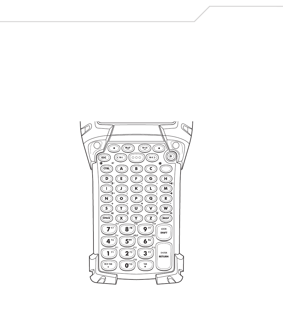
MC9000-K/S for Embedded Windows® CE .NET Product Reference Guide
B-62
VT Emulator Keypad
The VT Emulator keypad contains a Power button, application keys, scroll keys and a function key. The
VT emulator keypad uses the 53-key mapping when not in the emulator mode, see Table B-6 for
descriptions for the 53-key mappings. The emulator mapping functions include:
• VT key functions
• VT-100 emulation keys
• VT-220 emulation keys
• VT/HP character map.
Figure B-6. VT Emulator Keypad

Keypad Maps B-63
Table B-13. VT Terminal Functions
VT Function Key Sequence
Program Information <Func><Ctrl><P>
Diagnostics <Func><Ctrl><D>
Keyclicks On/Off <Func><Ctrl><K>
Quiet Mode <Func><Ctrl><Q>
Terminal Configuration <Func><Ctrl><C>
Host Profiles <Func><Ctrl><R>
Close Session <Func><Ctrl><T>
Previous Session <Func><Ctrl><Shift><1>
Next Session <Func><Ctrl><Shift><3>
Caps Lock <Func><Shift>
View Mode On/Off <Func><Ctrl><Z>
Scroll Left <Ctrl><Left>
Scroll Right <Ctrl><Right>
Scroll Up <Ctrl><Up>
Scroll Down <Ctrl><Down>
Display Backlight On/Off <Func><Z>
Keypad Backlight On/Off <Func><X>
Contrast + <Func><D>
Contrast - <Func><I>
Volume + <Func><H>
Volume - <Func><M>

MC9000-K/S for Embedded Windows® CE .NET Product Reference Guide
B-64
Table B-14. VT-100 Emulation Keys
VT-100 Key Key Sequence
Return <Return>
Backspace <BKSP>
Tab <Func><*>
Up Arrow <Up Arrow>
Left Arrow <Left Arrow>
ESC <Esc>
BS <BKSP>
LF <Ctrl><J>
Hard Terminal Reset <Func><Ctrl><H>
Enter <Return>
Backspace(Delete) <BKSP>
Backtab <Func><.>
Down Arrow <Down Arrow>
Right Arrow <Right Arrow>
PF1 <Func><1>
PF2 <Func><2>
PF3 <Func><3>
PF4 <Func><4>

Keypad Maps B-65
Table B-15. VT-220 Emulation Keys
VT-220 Key Key Sequence
Return <Return>
Backspace <BKSP>
Tab <Func><*>
Up Arrow <Up Arrow>
Left Arrow <Left Arrow>
Hard Terminal Reset <Func><Ctrl><H>
Find <Func><Ctrl><Left>
Insert Here <Func><Space>
Prev Screen <Func><Ctrl><Shift><4>
PF1 <Func><1>
PF2 <Func><2>
PF3 <Func><3>
PF4 <Func><4>
BREAK1 <Func><5>
F6 <Func><6>
F7 <Func><7>
F8 <Func><8>
F9 <Func><9>
F10 <Func><0>
F11 <Shift><1>
F12 <Shift><2>
F13 <Shift><3>
F14 <Shift><4>
F15/Help <Shift><5>
F16/Do <Shift><6>
F17 <Shift><7>

MC9000-K/S for Embedded Windows® CE .NET Product Reference Guide
B-66
F18 <Shift><8>
F19 <Shift><9>
F20 <Shift><0>
Enter <Return>
Backspace(Delete) <Ctrl><BKSP>
Backtab <Func><.>
Down Arrow <Down Arrow>
Right Arrow <Right Arrow>
Soft Terminal Reset <Func><Ctrl><S>
Select <Func><Ctrl><Shift><5>
Remove <Func><Ctrl><Shift><7>
Next Screen <Func><Ctrl><Shift><6>
Table B-15. VT-220 Emulation Keys (Continued)
VT-220 Key Key Sequence

Keypad Maps B-67
Table B-16. VT/HP Character Map
Char Key Sequence
^@
^A <Ctrl><A>
^B <Ctrl><B>
^C <Ctrl><C>
^D <Ctrl><D>
^E <Ctrl><E>
^F <Ctrl><F>
^G <Ctrl><G>
^H <Ctrl><H>
^I <Ctrl><I>
^J <Ctrl><J>
^K <Ctrl><K>
^L <Ctrl><L>
^M <Ctrl><M>
^N <Ctrl><N>
^O <Ctrl><O>
^P <Ctrl><P>
^Q <Ctrl><Q>
^R <Ctrl><R>
^S <Ctrl><S>
^T <Ctrl><T>
^U <Ctrl><U>
^V <Ctrl><V>
^W <Ctrl><W>
^X <Ctrl><X>
^Y <Ctrl><Y>

MC9000-K/S for Embedded Windows® CE .NET Product Reference Guide
B-68
^Z <Ctrl><Z>
ESC <ESC>
^\ <Ctrl><1>
^] <Ctrl><2>
^^ <Ctrl><3>
^_ <Ctrl><4>
Space <space>
! <Func><Q>
" <Shift><Func><C>
# <Ctrl><6>
$ <Ctrl><7>
% <Ctrl><8>
& <Ctrl><9>
' <Func><C>
( <Ctrl><0>
) <Func><Ctrl><A>
* <*>
+ <Func><S>
, <Func><A>
- <Func><T>
. <.>
/ <Func><V>
0 <0>
1 <1>
2 <2>
3 <3>
4 <4>
Table B-16. VT/HP Character Map
Char Key Sequence

Keypad Maps B-69
5 <5>
6 <6>
7 <7>
8 <8>
9 <9>
: <Func><P>
; <Func><R>
< <Func><K>
= <Func><W>
> <Func><L>
? <Func><Ctrl><G>
@ <Func><Ctrl><B>
A <Shift><A>
B <Shift><B>
C <Shift><C>
D <Shift><D>
E <Shift><E>
F <Shift><F>
G <Shift><G>
H <Shift><H>
I <Shift><I>
J <Shift><J>
K <Shift><K>
L <Shift><L>
M <Shift><M>
N <Shift><N>
O <Shift><O>
Table B-16. VT/HP Character Map
Char Key Sequence

MC9000-K/S for Embedded Windows® CE .NET Product Reference Guide
B-70
P <Shift><P>
Q <Shift><Q>
R <Shift><R>
S <Shift><S>
T <Shift><T>
U <Shift><U>
V <Shift><V>
W <Shift><W>
X <Shift><X>
Y <Shift><Y>
Z <Shift><Z>
[ <Func><E>
\ <Func><G>
] <Func><F>
^ <Func><Ctrl><E>
_ <Shift><Func><N>
` <Func><J>
a <A>
b <B>
c <C>
d <D>
e <E>
f <F>
g <G>
h <H>
I <I>
j <J>
Table B-16. VT/HP Character Map
Char Key Sequence

Keypad Maps B-71
k <K>
l <L>
m <M>
n <N>
o <O>
p <P>
q <Q>
r <R>
s <S>
t <T>
u <U>
v <V>
w <W>
x <X>
y <Y>
z <Z>
{ <Shift><Func><E>
| <Func><O>
} <Shift><Func><F>
~ <Shift><Func><J>
Table B-16. VT/HP Character Map
Char Key Sequence
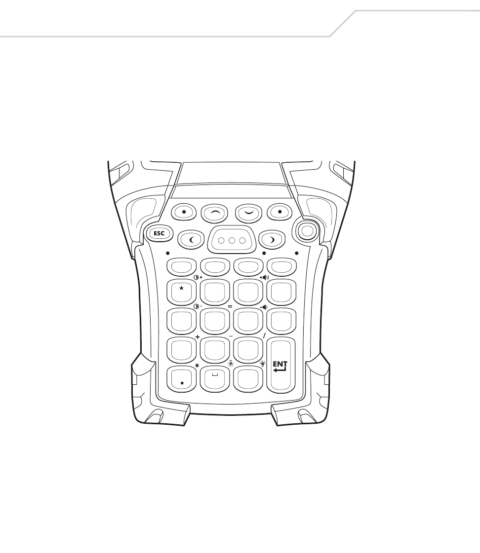
MC9000-K/S for Embedded Windows® CE .NET Product Reference Guide
B-72
28-Key Keypad (MC9000-S)
The 28-key keypad contains a Power button, application keys, scroll keys and a function key. See
Table B-3 for key functions and Table B-4 for the keypad mappings. The mapping functions include:
• 28-key functions
• 28-key character map.
Figure B-7. MC9000-S: 28-Key Keypad
CTRL
SPACE ALPHA
BKSP
SHIFT
ALT
12
ABC
3
DEF
4
GHI
7
PQRS
8
0#
TUV
9
WXYZ
5
JKL
6
MNO

Keypad Maps B-73
Table B-17. MC9000-S: 28-Key Functions
Local Function Key Sequence
Display Backlight On/Off <Func><#>
Keypad Backlight On/Off <Func><0>
Contrast + <Func><1>
Contrast - <Func><4>
Volume + <Func><3>
Volume - <Func><6>
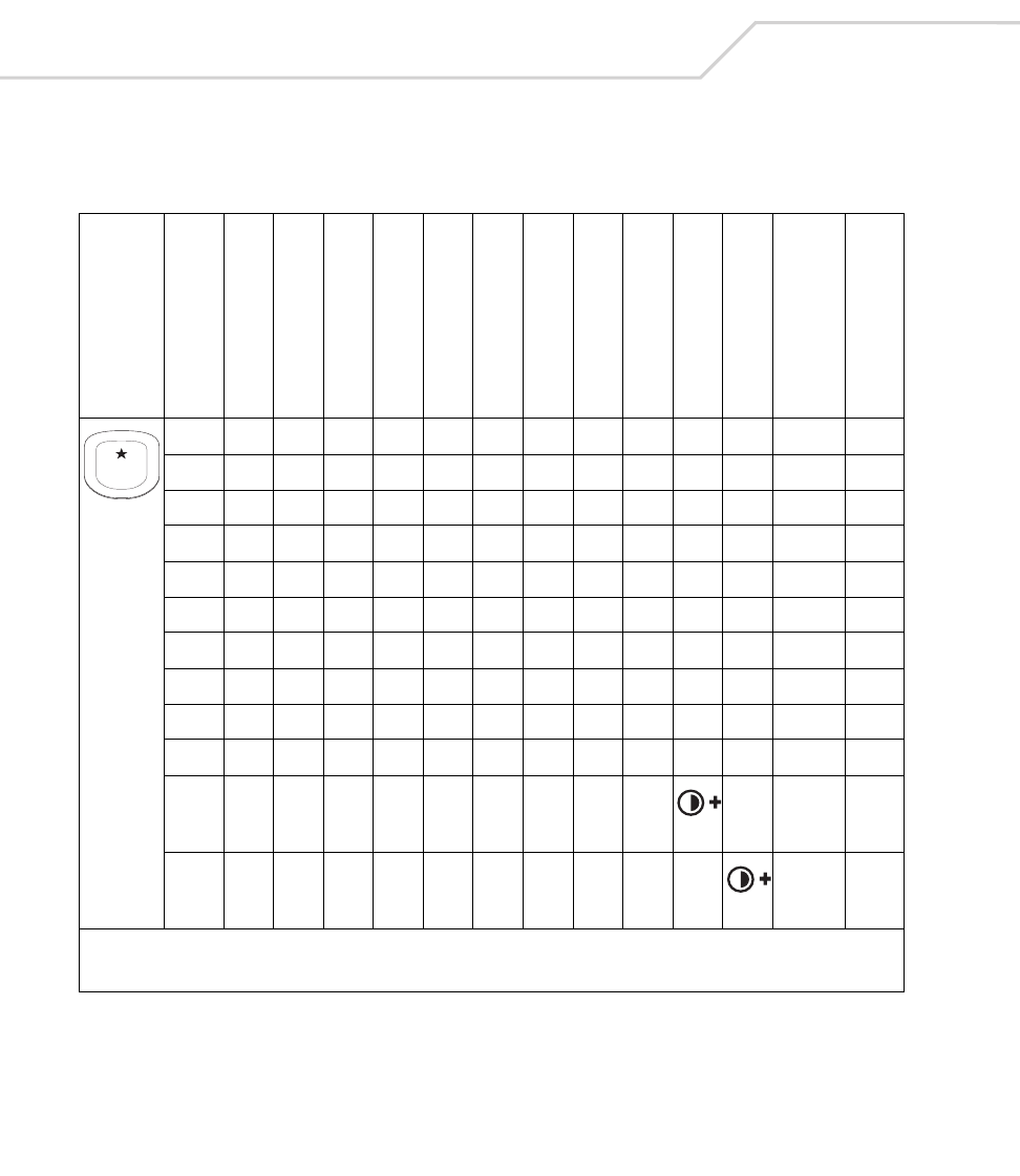
MC9000-K/S for Embedded Windows® CE .NET Product Reference Guide
B-74
Table B-18. MC9000-S: 28 Key Keypad Mapping
Key
Default State
Alpha State (1 Tap)
Alpha State (2 Taps)
Alpha State (3 Taps)
Alpha State (4 Taps)
Shift Alpha State (1 Tap)
Shift Alpha State (2 Taps)
Shift Alpha State (3 Taps)
Shift Alpha State (4 Taps)
Ctrl State
Funct State
Shift-Func State
VK Code (Decimal)
ASCII Value (Decimal)
14949
*10642
*
*
* See Table 2-7 on page 2-23 for keypad special functions.
Note: Blank lines are provided to allow the application developer to use this table as a keypad mapping worksheet.
1

Keypad Maps B-75
25050
a6597
b6698
c6799
A 160+65 65
B 160+66 66
C 160+67 67
Table B-18. MC9000-S: 28 Key Keypad Mapping (Continued)
Key
Default State
Alpha State (1 Tap)
Alpha State (2 Taps)
Alpha State (3 Taps)
Alpha State (4 Taps)
Shift Alpha State (1 Tap)
Shift Alpha State (2 Taps)
Shift Alpha State (3 Taps)
Shift Alpha State (4 Taps)
Ctrl State
Funct State
Shift-Func State
VK Code (Decimal)
ASCII Value (Decimal)
* See Table 2-7 on page 2-23 for keypad special functions.
Note: Blank lines are provided to allow the application developer to use this table as a keypad mapping worksheet.
2
ABC
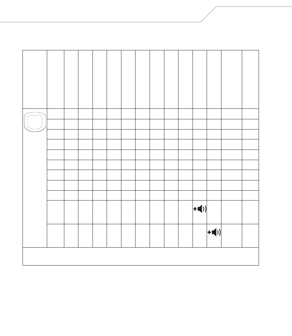
MC9000-K/S for Embedded Windows® CE .NET Product Reference Guide
B-76
35151
d68100
e69101
f70102
D 160+68 68
E 160+69 69
F 160+70 70
*
*
Table B-18. MC9000-S: 28 Key Keypad Mapping (Continued)
Key
Default State
Alpha State (1 Tap)
Alpha State (2 Taps)
Alpha State (3 Taps)
Alpha State (4 Taps)
Shift Alpha State (1 Tap)
Shift Alpha State (2 Taps)
Shift Alpha State (3 Taps)
Shift Alpha State (4 Taps)
Ctrl State
Funct State
Shift-Func State
VK Code (Decimal)
ASCII Value (Decimal)
* See Table 2-7 on page 2-23 for keypad special functions.
Note: Blank lines are provided to allow the application developer to use this table as a keypad mapping worksheet.
3
DEF

Keypad Maps B-77
45252
g71103
h72104
i73105
G 160+71 71
H 160+72 72
I 160+73 73
*
*
Table B-18. MC9000-S: 28 Key Keypad Mapping (Continued)
Key
Default State
Alpha State (1 Tap)
Alpha State (2 Taps)
Alpha State (3 Taps)
Alpha State (4 Taps)
Shift Alpha State (1 Tap)
Shift Alpha State (2 Taps)
Shift Alpha State (3 Taps)
Shift Alpha State (4 Taps)
Ctrl State
Funct State
Shift-Func State
VK Code (Decimal)
ASCII Value (Decimal)
* See Table 2-7 on page 2-23 for keypad special functions.
Note: Blank lines are provided to allow the application developer to use this table as a keypad mapping worksheet.
4
GHI
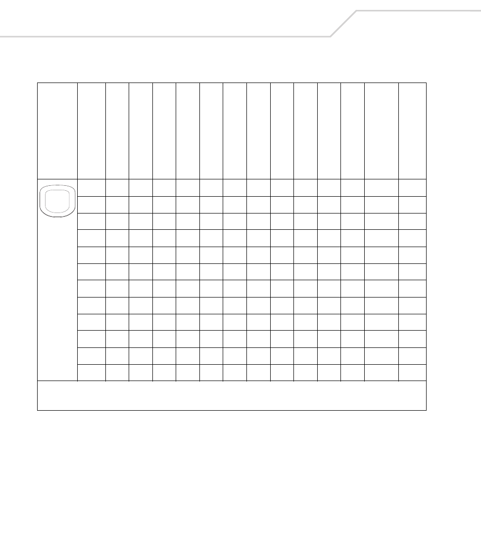
MC9000-K/S for Embedded Windows® CE .NET Product Reference Guide
B-78
55353
j74106
k75107
l76108
J 160+74 74
K 160+75 75
L 160+76 76
55353
=18761
+ 160+187 43
Table B-18. MC9000-S: 28 Key Keypad Mapping (Continued)
Key
Default State
Alpha State (1 Tap)
Alpha State (2 Taps)
Alpha State (3 Taps)
Alpha State (4 Taps)
Shift Alpha State (1 Tap)
Shift Alpha State (2 Taps)
Shift Alpha State (3 Taps)
Shift Alpha State (4 Taps)
Ctrl State
Funct State
Shift-Func State
VK Code (Decimal)
ASCII Value (Decimal)
* See Table 2-7 on page 2-23 for keypad special functions.
Note: Blank lines are provided to allow the application developer to use this table as a keypad mapping worksheet.
5
JKL
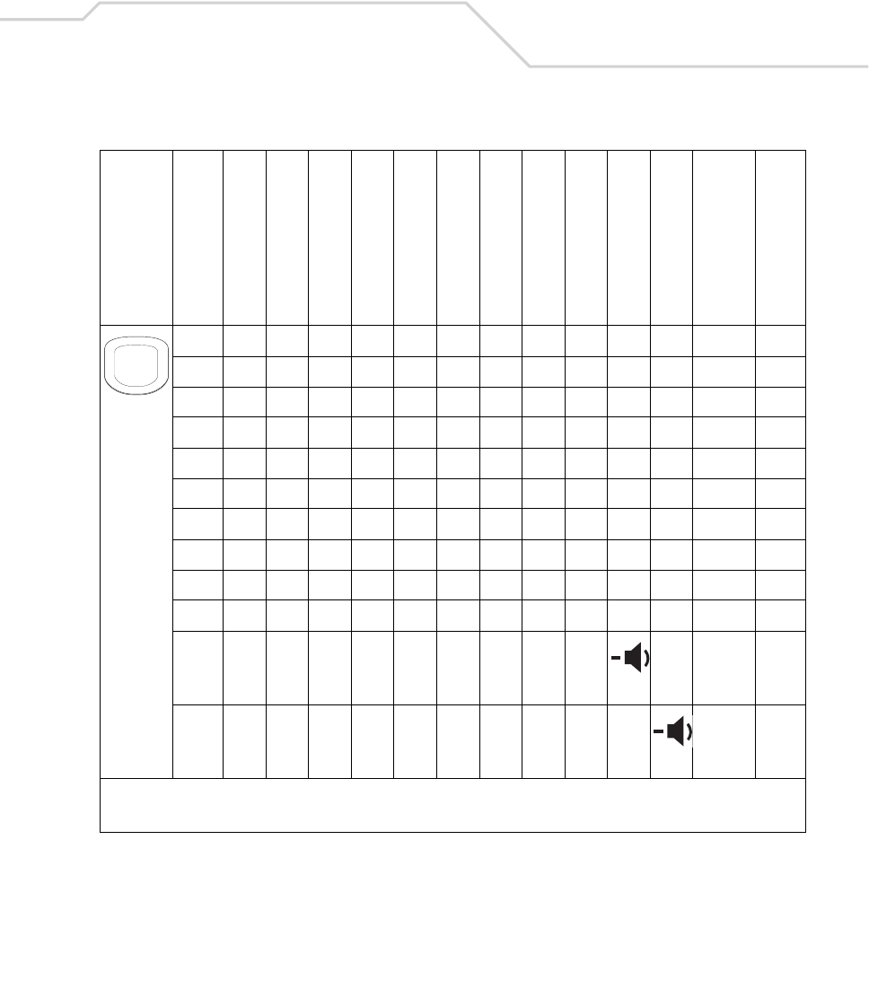
Keypad Maps B-79
65454
m77109
n78110
o79111
M 160+77 77
N 160+78 78
O 160+79 79
*
*
Table B-18. MC9000-S: 28 Key Keypad Mapping (Continued)
Key
Default State
Alpha State (1 Tap)
Alpha State (2 Taps)
Alpha State (3 Taps)
Alpha State (4 Taps)
Shift Alpha State (1 Tap)
Shift Alpha State (2 Taps)
Shift Alpha State (3 Taps)
Shift Alpha State (4 Taps)
Ctrl State
Funct State
Shift-Func State
VK Code (Decimal)
ASCII Value (Decimal)
* See Table 2-7 on page 2-23 for keypad special functions.
Note: Blank lines are provided to allow the application developer to use this table as a keypad mapping worksheet.
6
MNO

MC9000-K/S for Embedded Windows® CE .NET Product Reference Guide
B-80
75555
p80112
q81113
r82114
s83115
P 160+80 80
Q 160+81 81
R 160+82 82
S 160+83 83
+10743
+ 160+107 43
Table B-18. MC9000-S: 28 Key Keypad Mapping (Continued)
Key
Default State
Alpha State (1 Tap)
Alpha State (2 Taps)
Alpha State (3 Taps)
Alpha State (4 Taps)
Shift Alpha State (1 Tap)
Shift Alpha State (2 Taps)
Shift Alpha State (3 Taps)
Shift Alpha State (4 Taps)
Ctrl State
Funct State
Shift-Func State
VK Code (Decimal)
ASCII Value (Decimal)
* See Table 2-7 on page 2-23 for keypad special functions.
Note: Blank lines are provided to allow the application developer to use this table as a keypad mapping worksheet.
7
PQRS

Keypad Maps B-81
85656
t84116
u85117
v86118
T 160+84 84
U 160+85 85
V 160+86 86
- 189 45
- 160+189 45
Table B-18. MC9000-S: 28 Key Keypad Mapping (Continued)
Key
Default State
Alpha State (1 Tap)
Alpha State (2 Taps)
Alpha State (3 Taps)
Alpha State (4 Taps)
Shift Alpha State (1 Tap)
Shift Alpha State (2 Taps)
Shift Alpha State (3 Taps)
Shift Alpha State (4 Taps)
Ctrl State
Funct State
Shift-Func State
VK Code (Decimal)
ASCII Value (Decimal)
* See Table 2-7 on page 2-23 for keypad special functions.
Note: Blank lines are provided to allow the application developer to use this table as a keypad mapping worksheet.
8
TUV

MC9000-K/S for Embedded Windows® CE .NET Product Reference Guide
B-82
95757
w87119
x88120
y89121
z90122
W 160+87 87
X 160+88 88
Y 160+89 89
Z 160+90 90
/19147
/ 160+191 47
Table B-18. MC9000-S: 28 Key Keypad Mapping (Continued)
Key
Default State
Alpha State (1 Tap)
Alpha State (2 Taps)
Alpha State (3 Taps)
Alpha State (4 Taps)
Shift Alpha State (1 Tap)
Shift Alpha State (2 Taps)
Shift Alpha State (3 Taps)
Shift Alpha State (4 Taps)
Ctrl State
Funct State
Shift-Func State
VK Code (Decimal)
ASCII Value (Decimal)
* See Table 2-7 on page 2-23 for keypad special functions.
Note: Blank lines are provided to allow the application developer to use this table as a keypad mapping worksheet.
9
WXYZ

Keypad Maps B-83
. 190 46
* 106 42
* 160+106 42
Table B-18. MC9000-S: 28 Key Keypad Mapping (Continued)
Key
Default State
Alpha State (1 Tap)
Alpha State (2 Taps)
Alpha State (3 Taps)
Alpha State (4 Taps)
Shift Alpha State (1 Tap)
Shift Alpha State (2 Taps)
Shift Alpha State (3 Taps)
Shift Alpha State (4 Taps)
Ctrl State
Funct State
Shift-Func State
VK Code (Decimal)
ASCII Value (Decimal)
* See Table 2-7 on page 2-23 for keypad special functions.
Note: Blank lines are provided to allow the application developer to use this table as a keypad mapping worksheet.
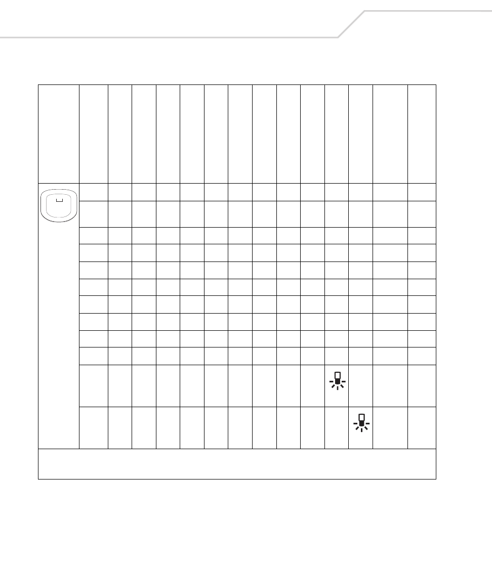
MC9000-K/S for Embedded Windows® CE .NET Product Reference Guide
B-84
04848
Space
32 32
*
*
Table B-18. MC9000-S: 28 Key Keypad Mapping (Continued)
Key
Default State
Alpha State (1 Tap)
Alpha State (2 Taps)
Alpha State (3 Taps)
Alpha State (4 Taps)
Shift Alpha State (1 Tap)
Shift Alpha State (2 Taps)
Shift Alpha State (3 Taps)
Shift Alpha State (4 Taps)
Ctrl State
Funct State
Shift-Func State
VK Code (Decimal)
ASCII Value (Decimal)
* See Table 2-7 on page 2-23 for keypad special functions.
Note: Blank lines are provided to allow the application developer to use this table as a keypad mapping worksheet.
0
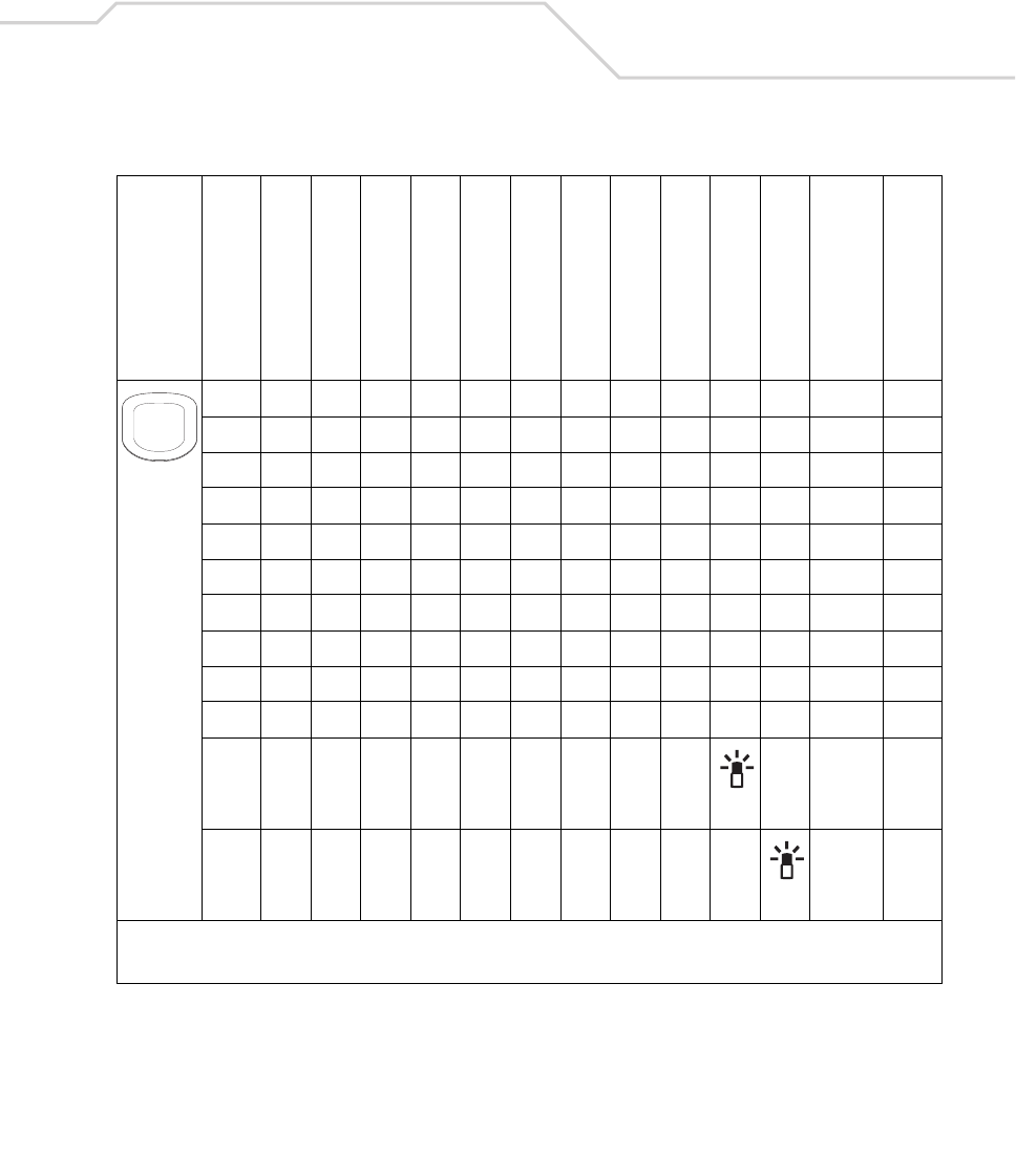
Keypad Maps B-85
# 160+51 35
*
*
Table B-18. MC9000-S: 28 Key Keypad Mapping (Continued)
Key
Default State
Alpha State (1 Tap)
Alpha State (2 Taps)
Alpha State (3 Taps)
Alpha State (4 Taps)
Shift Alpha State (1 Tap)
Shift Alpha State (2 Taps)
Shift Alpha State (3 Taps)
Shift Alpha State (4 Taps)
Ctrl State
Funct State
Shift-Func State
VK Code (Decimal)
ASCII Value (Decimal)
* See Table 2-7 on page 2-23 for keypad special functions.
Note: Blank lines are provided to allow the application developer to use this table as a keypad mapping worksheet.
#

MC9000-K/S for Embedded Windows® CE .NET Product Reference Guide
B-86
Space 32 32
Table B-18. MC9000-S: 28 Key Keypad Mapping (Continued)
Key
Default State
Alpha State (1 Tap)
Alpha State (2 Taps)
Alpha State (3 Taps)
Alpha State (4 Taps)
Shift Alpha State (1 Tap)
Shift Alpha State (2 Taps)
Shift Alpha State (3 Taps)
Shift Alpha State (4 Taps)
Ctrl State
Funct State
Shift-Func State
VK Code (Decimal)
ASCII Value (Decimal)
* See Table 2-7 on page 2-23 for keypad special functions.
Note: Blank lines are provided to allow the application developer to use this table as a keypad mapping worksheet.
SPACE

Keypad Maps B-87
BKSP 8 8
Table B-18. MC9000-S: 28 Key Keypad Mapping (Continued)
Key
Default State
Alpha State (1 Tap)
Alpha State (2 Taps)
Alpha State (3 Taps)
Alpha State (4 Taps)
Shift Alpha State (1 Tap)
Shift Alpha State (2 Taps)
Shift Alpha State (3 Taps)
Shift Alpha State (4 Taps)
Ctrl State
Funct State
Shift-Func State
VK Code (Decimal)
ASCII Value (Decimal)
* See Table 2-7 on page 2-23 for keypad special functions.
Note: Blank lines are provided to allow the application developer to use this table as a keypad mapping worksheet.
BKSP

MC9000-K/S for Embedded Windows® CE .NET Product Reference Guide
B-88
Up 38 -
Table B-18. MC9000-S: 28 Key Keypad Mapping (Continued)
Key
Default State
Alpha State (1 Tap)
Alpha State (2 Taps)
Alpha State (3 Taps)
Alpha State (4 Taps)
Shift Alpha State (1 Tap)
Shift Alpha State (2 Taps)
Shift Alpha State (3 Taps)
Shift Alpha State (4 Taps)
Ctrl State
Funct State
Shift-Func State
VK Code (Decimal)
ASCII Value (Decimal)
* See Table 2-7 on page 2-23 for keypad special functions.
Note: Blank lines are provided to allow the application developer to use this table as a keypad mapping worksheet.

Keypad Maps B-89
Down 40 -
Table B-18. MC9000-S: 28 Key Keypad Mapping (Continued)
Key
Default State
Alpha State (1 Tap)
Alpha State (2 Taps)
Alpha State (3 Taps)
Alpha State (4 Taps)
Shift Alpha State (1 Tap)
Shift Alpha State (2 Taps)
Shift Alpha State (3 Taps)
Shift Alpha State (4 Taps)
Ctrl State
Funct State
Shift-Func State
VK Code (Decimal)
ASCII Value (Decimal)
* See Table 2-7 on page 2-23 for keypad special functions.
Note: Blank lines are provided to allow the application developer to use this table as a keypad mapping worksheet.
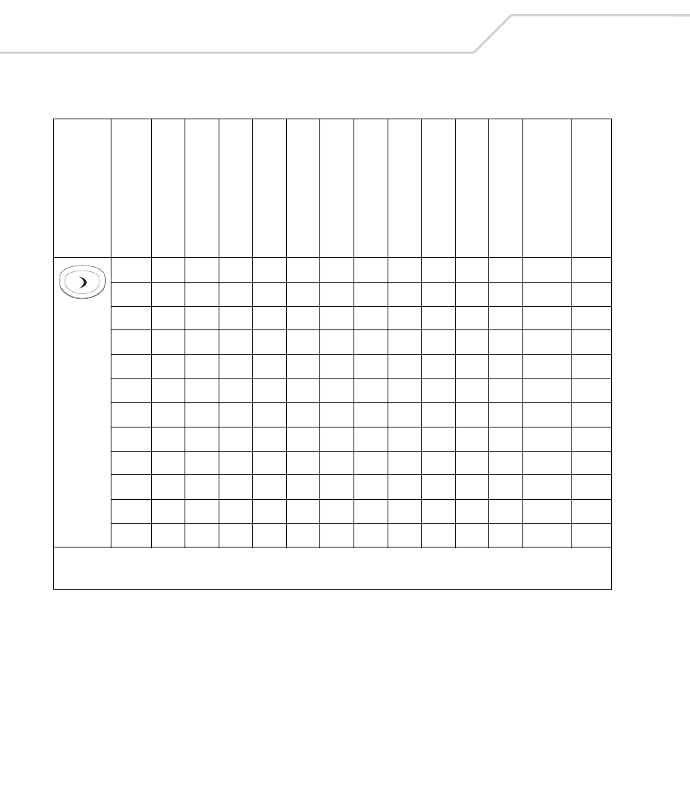
MC9000-K/S for Embedded Windows® CE .NET Product Reference Guide
B-90
Right 39 -
Table B-18. MC9000-S: 28 Key Keypad Mapping (Continued)
Key
Default State
Alpha State (1 Tap)
Alpha State (2 Taps)
Alpha State (3 Taps)
Alpha State (4 Taps)
Shift Alpha State (1 Tap)
Shift Alpha State (2 Taps)
Shift Alpha State (3 Taps)
Shift Alpha State (4 Taps)
Ctrl State
Funct State
Shift-Func State
VK Code (Decimal)
ASCII Value (Decimal)
* See Table 2-7 on page 2-23 for keypad special functions.
Note: Blank lines are provided to allow the application developer to use this table as a keypad mapping worksheet.

Keypad Maps B-91
Left 37 -
Table B-18. MC9000-S: 28 Key Keypad Mapping (Continued)
Key
Default State
Alpha State (1 Tap)
Alpha State (2 Taps)
Alpha State (3 Taps)
Alpha State (4 Taps)
Shift Alpha State (1 Tap)
Shift Alpha State (2 Taps)
Shift Alpha State (3 Taps)
Shift Alpha State (4 Taps)
Ctrl State
Funct State
Shift-Func State
VK Code (Decimal)
ASCII Value (Decimal)
* See Table 2-7 on page 2-23 for keypad special functions.
Note: Blank lines are provided to allow the application developer to use this table as a keypad mapping worksheet.

MC9000-K/S for Embedded Windows® CE .NET Product Reference Guide
B-92

Glossary
802.11/802.11b A radio protocol that may be used by the Symbol
Spectrum24 radio card. Symbol radio cards that use the
802.11 protocol also have an ESS_ID.
ACK/NAK ACK/NAK is the default software handshaking.
Access Point Access Point (AP) refers to Symbol’s Spectrum24 Ethernet
Access Point. It is a piece of communications equipment
that manages communications between the host computer
system and one or more wireless terminals. An AP connects
to a wired Ethernet LAN and acts as a bridge between the
Ethernet wired network and IEEE 802.11 interoperable
radio-equipped mobile units, such as a mobile computer.
The AP allows a mobile user to roam freely through a
facility while maintaining a seamless connection to the
wired network.

MC9000-K/S for Embedded Windows® CE .NET Product Reference Guide
GL-2
AirBEAM® Manager AirBEAM® Manager is a comprehensive wireless network
management system that provides essential functions that
are required to configure, monitor, upgrade and
troubleshoot the Spectrum24® wireless network and its
components (including networked mobile computers).
Some features include event notification, access point
configuration, diagnostics, statistical reports, auto-
discovery, wireless proxy agents and monitoring of access
points and mobile units.
AirBEAM® Smart Client AirBEAM® Smart Client is part of Symbol’s AirBEAM®
suite, which also includes AirBEAM® Safe and AirBEAM®
Manager. The AirBEAM® Smart Client system uses the
network accessible host server to store software files that
are to be downloaded to the mobile computers. The
AirBEAM® Smart Client provides the mobile computers
with the "smarts" to request software from the host. It
allows them to request, download and install software, as
well as to upload files and status data. The AirBEAM®
Smart Client uses the industry standard FTP or TFTP file
transfer protocols to check the host system for updates, and
if necessary, to transfer updated software. Most often,
AirBEAM® Smart Client is used with wireless networks,
but any TCP/IP connection can be used. For more
information, refer to the AirBEAM® Smart Windows® CE
Client Product Reference Guide (p/n 72-63060-xx).
AP See Access Point.
API An interface by means of which one software component
communicates with or controls another. Usually used to
refer to services provided by one software component to
another, usually via software interrupts or function calls
Aperture The opening in an optical system defined by a lens or baffle
that establishes the field of view.
Application Programming Interface See API.
ANSI Terminal A display terminal that follows commands in the ANSI
standard terminal language. For example, it uses escape
sequences to control the cursor, clear the screen and set
colors. Communications programs support the ANSI
terminal mode and often default to this terminal emulation
for dial-up connections to online services.

Glossary GL-3
ASCII American Standard Code for Information Interchange. A 7
bit-plus-parity code representing 128 letters, numerals,
punctuation marks and control characters. It is a standard
data transmission code in the U.S.
Autodiscrimination The ability of an interface controller to determine the code
type of a scanned bar code. After this determination is
made, the information content is decoded.
Bar The dark element in a printed bar code symbol.
Bar Code A pattern of variable-width bars and spaces which
represents numeric or alphanumeric data in machine-
readable form. The general format of a bar code symbol
consists of a leading margin, start character, data or
message character, check character (if any), stop character,
and trailing margin. Within this framework, each
recognizable symbology uses its own unique format. See
Symbology.
Bar Code Density The number of characters represented per unit of
measurement (e.g., characters per inch).
Bar Height The dimension of a bar measured perpendicular to the bar
width.
Bar Width Thickness of a bar measured from the edge closest to the
symbol start character to the trailing edge of the same bar.
Baud Rate A measure of the data flow or number of signaling events
occurring per second. When one bit is the standard "event,"
this is a measure of bits per second (bps). For example, a
baud rate of 50 means transmission of 50 bits of data per
second.
BIOS Basic Input Output System. A collection of ROM-based
code with a standard API used to interface with standard
PC hardware.
Bit Binary digit. One bit is the basic unit of binary information.
Generally, eight consecutive bits compose one byte of data.
The pattern of 0 and 1 values within the byte determines its
meaning.
Bits per Second (bps) Bits transmitted or received.

MC9000-K/S for Embedded Windows® CE .NET Product Reference Guide
GL-4
Bit Binary digit. One bit is the basic unit of binary information.
Generally, eight consecutive bits compose one byte of data.
The pattern of 0 and 1 values within the byte determines its
meaning.
bps See Bits Per Second.
Byte On an addressable boundary, eight adjacent binary digits (0
and 1) combined in a pattern to represent a specific
character or numeric value. Bits are numbered from the
right, 0 through 7, with bit 0 the low-order bit. One byte in
memory is used to store one ASCII character.
BOOTP A protocol for remote booting of diskless devices. Assigns
an IP address to a machine and may specify a boot file. The
client sends a bootp request as a broadcast to the bootp
server port (67) and the bootp server responds using the
bootp client port (68). The bootp server must have a table of
all devices, associated MAC addresses and IP addresses.
boot or boot-up The process a computer goes through when it starts. During
boot-up, the computer can run self-diagnostic tests and
configure hardware and software.
CDMA Code Division Multiple Access is a cellular technology
originally know as IS-95.
CDRH Center for Devices and Radiological Health. A federal
agency responsible for regulating laser product safety. This
agency specifies various laser operation classes based on
power output during operation.
CDRH Class 1 This is the lowest power CDRH laser classification. This
class is considered intrinsically safe, even if all laser output
were directed into the eye's pupil. There are no special
operating procedures for this class.
CDRH Class 2 No additional software mechanisms are needed to conform
to this limit. Laser operation in this class poses no danger
for unintentional direct human exposure.
Cellular Digital Packet Data See CDPD.
Character A pattern of bars and spaces which either directly
represents data or indicates a control function, such as a
number, letter, punctuation mark, or communications
control contained in a message.

Glossary GL-5
Character Set Those characters available for encoding in a particular bar
code symbology.
Check Digit A digit used to verify a correct symbol decode. The scanner
inserts the decoded data into an arithmetic formula and
checks that the resulting number matches the encoded
check digit. Check digits are required for UPC but are
optional for other symbologies. Using check digits
decreases the chance of substitution errors when a symbol
is decoded.
Codabar A discrete self-checking code with a character set
consisting of digits 0 to 9 and six additional characters: ( -
$ : / , +).
Code 128 A high density symbology which allows the controller to
encode all 128 ASCII characters without adding extra
symbol elements.
Code 3 of 9 (Code 39) A versatile and widely used alphanumeric bar code
symbology with a set of 43 character types, including all
uppercase letters, numerals from 0 to 9 and 7 special
characters (- . / + % $ and space). The code name is derived
from the fact that 3 of 9 elements representing a character
are wide, while the remaining 6 are narrow.
Code 93 An industrial symbology compatible with Code 39 but
offering a full character ASCII set and a higher coding
density than Code 39.
Code Length Number of data characters in a bar code between the start
and stop characters, not including those characters.
Cold Boot A cold boot restarts the mobile computer and erases all
user stored records and entries.
COM port Communication port; ports are identified by number, e.g.,
COM1, COM2.
Continuous Code A bar code or symbol in which all spaces within the symbol
are parts of characters. There are no intercharacter gaps in
a continuous code. The absence of gaps allows for greater
information density.
Cradle A cradle is used for charging the terminal battery and for
communicating with a host computer, and provides a
storage place for the terminal when not in use.

MC9000-K/S for Embedded Windows® CE .NET Product Reference Guide
GL-6
Data Communications Equipment (DCE) A device (such as a modem) which is designed to attach
directly to a DTE (Data Terminal Equipment) device.
DCE See Data Communications Equipment.
DCP See Device COnfiguration Package.
Dead Zone An area within a scanner's field of view, in which specular
reflection may prevent a successful decode.
Decode To recognize a bar code symbology (e.g., UPC/EAN) and
then analyze the content of the specific bar code scanned.
Decode Algorithm A decoding scheme that converts pulse widths into data
representation of the letters or numbers encoded within a
bar code symbol.
Decryption Decryption is the decoding and unscrambling of received
encrypted data. Also see, Encryption and Key.
Depth of Field The range between minimum and maximum distances at
which a scanner can read a symbol with a certain minimum
element width.
Device Configuration Package The Symbol Device Configuration Pacage provides the
Product Reference Guide (PRG), flash partitions, Terminal
Configuration Manager (TCM) and the associated TCM
scripts. With this package hex images that represent flash
partitions can be created and downloaded to the mobile
computer.
DHCP (Dynamic Host Configuration Protocol) Software that
automatically assigns IP addresses to client stations
logging onto a TCP/IP network. Similar to BOOTP, but also
permits the leasing of an IP address. It eliminates having to
manually assign permanent IP addresses. DHCP software
typically runs in servers and is also found in network
devices such as routers that allow multiple users access to
the Internet.
DHCP Server A server in the network or a service within a server that
assigns IP addresses.
Discrete Code A bar code or symbol in which the spaces between
characters (intercharacter gaps) are not part of the code.

Glossary GL-7
Discrete 2 of 5 A binary bar code symbology representing each character
by a group of five bars, two of which are wide. The location
of wide bars in the group determines which character is
encoded; spaces are insignificant. Only numeric characters
(0 to 9) and START/STOP characters may be encoded.
DNS Server The Control Panel allows you to set the IP address for a
DNS Server, if used. This allows users to use server names,
rather than IP addresses. It is set on the Network tab of the
Control Panel.
Domain Name The Control Panel allows you to set a Domain Name for the
DNS Server, if used (e.g., symbol.com). It is set on the
Network tab of the Control Panel.
DOS Disk Operating System. This is basic software that allows
you to load and use software applications on your
computer. Also see NetID.
DRAM Dynamic random access memory.
DTE See Data Terminal Equipment.
EAN European Article Number. This European/International
version of the UPC provides its own coding format and
symbology standards. Element dimensions are specified
metrically. EAN is used primarily in retail.
Element Generic term for a bar or space.
Encoded Area Total linear dimension occupied by all characters of a code
pattern, including start/stop characters and data.
ENQ (RS-232) ENQ software handshaking is also supported for the data
sent to the host.
Encryption Encryption is the scrambling and coding of data, typically
using mathematical formulas called algorithms, before
information is transmitted over any communications link or
network. A key is the specific code used by the algorithm to
encrypt or decrypt the data. Also see, Decryption and Key.
ESD Electro-Static Discharge

MC9000-K/S for Embedded Windows® CE .NET Product Reference Guide
GL-8
ESS_ID Extended Service Set Identifier, defines the coverage area.
Prior to the release of the 802.11 specification the ESS_ID
was called the Net_ID or Network Identifier. For terminals
using Spectrum24 radios with the 802.11 protocol, an
ESS_ID allows facilities to limit which Access Points a
mobile computer can communicate with. It is set on the
Network tab of the Control Panel. The terminal can only
communicate with Spectrum24 Access Points that have
matching ESS_IDs.
Ethernet Ethernet communication port. Allows a wired interface to a
radio network.
Flash Disk An additional megabyte of non-volatile memory for storing
application and configuration files.
Flash Memory Flash memory is nonvolatile, semi-permanent storage that
can be electronically erased in the circuit and
reprogrammed. Series 9000 mobile computers use Flash
memory to store the operating system (ROM-DOS), the
terminal emulators, and the Citrix ICA Client for DOS.
File Transfer Protocol (FTP) A TCP/IP application protocol governing file transfer via
network or telephone lines. See TCP/IP.
Frequency Hopping The use of a random sequence of frequency channels to
achieve spread spectrum compliance. Stations that use
frequency hopping change their communications frequency
at regular intervals. A hopping sequence determines the
pattern at which frequencies are changed. Messages take
place within a hop. See Hopping Sequence and Spread
Spectrum.
FTP See File Transfer Protocol.
Flash Memory Flash memory is responsible for storing the system
firmware and is non-volatile. If the system power is
interrupted the data is not lost.
Gateway Address An IP address for a network gateway or router. A mobile
computer may be part of a subnet as specified by its IP
address and Netmask. It can send packets directly to any
node on the same subnet. If the destination node is on a
different subnet, then the terminal sends the packet to the
gateway first. The gateway determines how to route the
packet to the destination subnet. This field is an option
used by networks that require gateways.

Glossary GL-9
Hard Reset See Cold Boot.
Hopping Sequence A set of random frequencies designed to minimize
interference with other sets of random frequencies. A
hopping sequence determines the pattern with which a
station that uses frequency hopping changes its
communications frequency. See Frequency Hopping.
Hz Hertz; A unit of frequency equal to one cycle per second.
Host Computer A computer that serves other terminals in a network,
providing such services as computation, database access,
supervisory programs and network control.
IDE Intelligent drive electronics. Refers to the solid-state hard
drive type.
IEC International Electrotechnical Commission. This
international agency regulates laser safety by specifying
various laser operation classes based on power output
during operation.
IEC (825) Class 1 This is the lowest power IEC laser classification.
Conformity is ensured through a software restriction of 120
seconds of laser operation within any 1000 second window
and an automatic laser shutdown if the scanner's
oscillating mirror fails.
IEEE Address See MAC Address.
Interleaved 2 of 5 A binary bar code symbology representing character pairs
in groups of five bars and five interleaved spaces.
Interleaving provides for greater information density. The
location of wide elements (bar/spaces) within each
group determines which characters are encoded. This
continuous code type uses no intercharacter spaces. Only
numeric (0 to 9) and START/STOP characters may be
encoded.
IOCTL Input/Output Control.
IP Internet Protocol.
imaging scanning Mobile computers with an integrated imager use digital
camera technology to take a digital picture of a bar code,
store the resulting image in memory and execute state-of-
the-art software decoding algorithms to extract the data
from the image.

MC9000-K/S for Embedded Windows® CE .NET Product Reference Guide
GL-10
Intercharacter Gap The space between two adjacent bar code characters in a
discrete code.
Interleaved Bar Code A bar code in which characters are paired together, using
bars to represent the first character and the intervening
spaces to represent the second.
Interleaved 2 of 5 A binary bar code symbology representing character pairs
in groups of five bars and five interleaved spaces.
Interleaving provides for greater information density. The
location of wide elements (bar/spaces) within each group
determines which characters are encoded. This continuous
code type uses no intercharacter spaces. Only numeric (0 to
9) and START/STOP characters may be encoded.
Internet Protocol Address See IP.
I/O Ports interface The connection between two devices, defined by
common physical characteristics, signal characteristics,
and signal meanings. Types of interfaces include RS-232
and PCMCIA.
Input/Output Ports I/O ports are primarily dedicated to passing information
into or out of the terminal’s memory. Series 9000 mobile
computers include Serial and USB ports.
IP (Internet Protocol) The IP part of the TCP/IP communications
protocol. IP implements the network layer (layer 3) of the
protocol, which contains a network address and is used to
route a message to a different network or subnetwork. IP
accepts “packets” from the layer 4 transport protocol (TCP
or UDP), adds its own header to it and delivers a
“datagram” to the layer 2 data link protocol. It may also
break the packet into fragments to support the maximum
transmission unit (MTU) of the network.
IP Address (Internet Protocol address) The address of a computer
attached to an IP network. Every client and server station
must have a unique IP address. A 32-bit address used by a
computer on a IP network. Client workstations have either
a permanent address or one that is dynamically assigned to
them each session. IP addresses are written as four sets of
numbers separated by periods; for example, 204.171.64.2.
IPX/SPX Internet Package Exchange/Sequential Packet Exchange. A
communications protocol for Novell. IPX is Novell’s Layer 3
protocol, similar to XNS and IP, and used in NetWare
networks. SPX is Novell's version of the Xerox SPP protocol.

Glossary GL-11
Kerberos Kerberos is a network authentication protocol. It is
designed to provide strong authentication for client/server
applications by using secret-key cryptography. A free
implementation of this protocol is available from the
Massachusetts Institute of Technology. Kerberos is
available in many commercial products as well.
Key A key is the specific code used by the algorithm to encrypt
or decrypt the data. Also see, Encryption and Decrypting.
LAN Local area network. A radio network that supports data
communication within a local area, such as within a
warehouse of building.
laser scanner A type of bar code reader that uses a beam of laser light.
LASER Light Amplification by Stimulated Emission of
Radiation.The laser is an intense light source. Light from a
laser is all the same frequency, unlike the output of an
incandescent bulb. Laser light is typically coherent and has
a high energy density.
Laser Diode A gallium-arsenide semiconductor type of laser connected
to a power source to generate a laser beam. This laser type
is a compact source of coherent light.
LCD See Liquid Crystal Display.
LED Indicator A semiconductor diode (LED - Light Emitting Diode) used as
an indicator, often in digital displays. The semiconductor
uses applied voltage to produce light of a certain frequency
determined by the semiconductor's particular chemical
composition.
Liquid Crystal Display (LCD) A display that uses liquid crystal sealed between two glass
plates. The crystals are excited by precise electrical
charges, causing them to reflect light outside according to
their bias. They use little electricity and react relatively
quickly. They require external light to reflect their
information to the user.
Light Emitting Diode See LED.
MAC Address (also called IEEE Address) Spectrum24® devices, like other Ethernet devices, have
unique, hardware-encoded MAC (also called IEEE
addresses). MAC addresses determine the device sending
or receiving data. The MAC address is a 48-bit number
written as six hexadecimal bytes separated by colons.

MC9000-K/S for Embedded Windows® CE .NET Product Reference Guide
GL-12
MC Mobile Computer.
MIL 1 mil = 1 thousandth of an inch.
Misread (Misdecode) A condition which occurs when the data output of a reader
or interface controller does not agree with the data
encoded within a bar code symbol.
Mobile Computer In this text, mobile computer refers to the Symbol Series
9000 wireless portable computer. It can be set up to run
as a stand-alone device, or it can be set up to communicate
with a network, using wireless radio technology.
NCU Network Control Unit.
NetBeui A non-routable LAN protocol that is an extension to
NetBIOS. Used for IBM’s OS/2-based LAN Manager and
Microsoft’s LAN Manager and Windows for Workgroups.
NetID For terminals using Spectrum24 radios with the Spring
protocol, a NetID allows facilities to limit which Access
Points a mobile computer can communicate with. It is set
on the Network tab of the Control Panel. The terminal can
only communicate with Spectrum24 Access Points that
have matching NetIDs. Also see ESS_ID.
Nominal The exact (or ideal) intended value for a specified
parameter. Tolerances are specified as positive and
negative deviations from this value.
Nominal Size Standard size for a bar code symbol. Most UPC/EAN codes
are used over a range of magnifications (e.g., from 0.80 to
2.00 of nominal).
Null Modem Cable An RS-232 cable used to connect two personal computers
together in close proximity for file transfer. It attaches to
the serial ports of both machines and simulates what would
occur naturally if modems and the phone system were
used. It crosses the sending wire with the receiving wire.
NVM Non-Volatile Memory.
ODI See Open Data-Link Interface.

Glossary GL-13
Open Data-Link Interface (ODI) Novell’s driver specification for an interface between
network hardware and higher-level protocols. It supports
multiple protocols on a single NIC (Network Interface
Controller). It is capable of understanding and translating
any network information or request sent by any other ODI-
compatible protocol into something a NetWare client can
understand and process.
Open System Authentication Open System authentication is a null authentication
algorithm.
PAN Personal area network. Using Bluetooth wireless
technology, PANs enable devices to communicate
wirelessly. Generally, a wireless PAN consists of a dynamic
group of less than 255 devices that communicate within
about a 33-foot range. Only devices within this limited area
typically participate in the network.
Parameter A variable that can have different values assigned to it.
PC Card A plug-in expansion card for laptop computers and other
devices, also called a PCMCIA card. PC Cards are 85.6mm
long x 54 mm wide, and have a 68 pin connector. There are
several different kinds:
Type I; 3.3 mm high; use - RAM or Flash RAM
Type II; 5 mm high; use - modems, LAN adaptors
Type III; 10.5 high; use - Hard Disks
PCMCIA Personal Computer Memory Card Interface Association.
See PC Card.
PDT Portable Data Terminal.
Percent Decode The average probability that a single scan of a bar code
would result in a successful decode. In a well-designed bar
code scanning system, that probability should approach
near 100%.
PING (Packet Internet Groper) An Internet utility used to
determine whether a particular IP address is online. It is
used to test and debug a network by sending out a packet
and waiting for a response.
Print Contrast Signal (PCS) Measurement of the contrast (brightness difference)
between the bars and spaces of a symbol. A minimum PCS
value is needed for a bar code symbol to be scannable. PCS
= (RL - RD) / RL, where RL is the reflectance factor of the
background and RD the reflectance factor of the dark bars.

MC9000-K/S for Embedded Windows® CE .NET Product Reference Guide
GL-14
Programming Mode The state in which a scanner is configured for parameter
values. See Scanning Mode.
Quiet Zone A clear space, containing no dark marks, which precedes
the start character of a bar code symbol and follows the
stop character.
QWERTY A standard keyboard commonly used on North American
and some European PC keyboards. “QWERTY” refers to the
arrangement of keys on the left side of the third row of
keys.
RAM Random Access Memory. Data in RAM can be accessed in
random order, and quickly written and read.
Reflectance Amount of light returned from an illuminated surface.
Resolution The narrowest element dimension which is distinguished
by a particular reading device or printed with a particular
device or method.
RF Radio Frequency.
ROM Read-Only Memory. Data stored in ROM cannot be changed
or removed.
ROM-DOS The name of the licensed Disk Operating System loaded
into the terminal’s flash file system.
Router A device that connects networks and supports the required
protocols for packet filtering. Routers are typically used to
extend the range of cabling and to organize the topology of
a network into subnets. See Subnet.
RS-232 An Electronic Industries Association (EIA) standard that
defines the connector, connector pins, and signals used to
transfer data serially from one device to another.
Scan Area Area intended to contain a symbol.
Scanner An electronic device used to scan bar code symbols and
produce a digitized pattern that corresponds to the bars and
spaces of the symbol. Its three main components are:
1. Light source (laser or photoelectric cell) - illuminates a
bar code.
2. Photodetector - registers the difference in reflected light
(more light reflected from spaces).
3. Signal conditioning circuit - transforms optical detector
output into a digitized bar pattern.

Glossary GL-15
Scanning Mode The scanner is energized, programmed and ready to read a
bar code.
Scanning Sequence A method of programming or configuring parameters for a
bar code reading system by scanning bar code menus.
SMDK Software MobilityDevelopment Kit
Self-Checking Code A symbology that uses a checking algorithm to detect
encoding errors within the characters of a bar code symbol.
Shared Key Shared Key authentication is an algorithm where both the
AP and the MU share an authentication key.
SHIP Symbol Host Interface Program.
SMDK Symbol Mobility Developer Kit.
Soft Reset See Warm Boot.
Space The lighter element of a bar code formed by the background
between bars.
Spectrum24 Symbol’s frequency-hopping, spread spectrum cellular
network.
Spectrum One Symbol’s implementation of the Spread Spectrum wireless
network, utilizing direct sequencing.
Specular Reflection The mirror-like direct reflection of light from a surface,
which can cause difficulty decoding a bar code.
Spread Spectrum A technique for uniformly distributing the information
content of a radio signal over a frequency range larger than
normally required for robust transmission of data.
Spreading the signal without adding additional information
adds significant redundancy, which allows the data to be
recovered in the presence of strong interfering signals such
as noise and jamming signals. The primary advantage of
spread spectrum technology is its ability to provide robust
communications in the presence of interfering signals.
Spring Radio Protocol A radio protocol that may be used by the Symbol
Spectrum24 radio card. Symbol Radio cards that use the
Spring protocol also have an Net ID.
Start/Stop Character A pattern of bars and spaces that provides the scanner with
start and stop reading instructions and scanning direction.
The start and stop characters are normally to the left and
right margins of a horizontal code.

MC9000-K/S for Embedded Windows® CE .NET Product Reference Guide
GL-16
STEP Symbol Terminal Enabler Program.
Subnet A subset of nodes on a network that are serviced by the
same router. See Router.
Subnet Mask A 32-bit number used to separate the network and host
sections of an IP address. A custom subnet mask subdivides
an IP network into smaller subsections. The mask is a
binary pattern that is matched up with the IP address to turn
part of the host ID address field into a field for subnets.
Default is often 255.255.255.0.
Substrate A foundation material on which a substance or image is
placed.
SVTP Symbol Virtual Terminal Program.
Symbol A scannable unit that encodes data within the conventions
of a certain symbology, usually including start/stop
characters, quiet zones, data characters and check
characters.
Symbol Aspect Ratio The ratio of symbol height to symbol width.
Symbol Height The distance between the outside edges of the quiet zones
of the first row and the last row.
Symbol Length Length of symbol measured from the beginning of the quiet
zone (margin) adjacent to the start character to the end of
the quiet zone (margin) adjacent to a stop character.
Symbology The structural rules and conventions for representing data
within a particular bar code type (e.g. UPC/EAN, Code 39,
PDF417, etc.).

Glossary GL-17
TCP/IP (Transmission Control Protocol/Internet Protocol) A
communications protocol used to internetwork dissimilar
systems. This standard is the protocol of the Internet and
has become the global standard for communications. TCP
provides transport functions, which ensures that the total
amount of bytes sent is received correctly at the other end.
UDP is an alternate transport that does not guarantee
delivery. It is widely used for real-time voice and video
transmissions where erroneous packets are not
retransmitted. IP provides the routing mechanism. TCP/IP is
a routable protocol, which means that all messages contain
not only the address of the destination station, but the
address of a destination network. This allows TCP/IP
messages to be sent to multiple networks within an
organization or around the world, hence its use in the
worldwide Internet. Every client and server in a TCP/IP
network requires an IP address, which is either
permanently assigned or dynamically assigned at startup.
Telnet A terminal emulation protocol commonly used on the
Internet and TCP/IP-based networks. It allows a user at a
terminal or computer to log onto a remote device and run a
program.
Terminal See Mobile Computer.
Terminate and Stay Resident (TSR) A program under DOS that ends its foreground execution to
remain resident in memory to service hardware/software
interrupts, providing background operation. It remains in
memory and may provide services on behalf of other DOS
programs.
Terminal Emulation A “terminal emulation” emulates a character-based
mainframe session on a remote non-mainframe terminal,
including all display features, commands and function keys.
The MC9000 Series supports Terminal Emulations in 3270,
5250 and VT220.
TFTP (Trivial File Transfer Protocol) A version of the TCP/IP FTP
(File Transfer Protocol) protocol that has no directory or
password capability. It is the protocol used for upgrading
firmware, downloading software and remote booting of
diskless devices.
Tolerance Allowable deviation from the nominal bar or space width.
Transmission Control Protocol/Internet Protocol See TCP/IP.

MC9000-K/S for Embedded Windows® CE .NET Product Reference Guide
GL-18
Trivial File Transfer Protocol See TFTP.
TSR See Terminate and Stay Resident.
UPC Universal Product Code. A relatively complex numeric
symbology. Each character consists of two bars and two
spaces, each of which is any of four widths. The standard
symbology for retail food packages in the United States.
UDP User Datagram Protocol. A protocol within the IP protocol
suite that is used in place of TCP when a reliable delivery is
not required. For example, UDP is used for real-time audio
and video traffic where lost packets are simply ignored,
because there is no time to retransmit. If UDP is used and a
reliable delivery is required, packet sequence checking and
error notification must be written into the applications.
Visible Laser Diode (VLD) A solid state device which produces visible laser light.
WAN Wide-Area Network. A radio network that supports data
communication beyond a local area. That is, information
can be sent across a city, state, or even nationwide.
Warm Boot A warm boot restarts the mobile computer by closing all
running programs. All data that is not saved to flash
memory is lost.
WEP Wired Equivalent Privacy, is specified by IEEE for encryption
and decryption of RF (wireless) communications.
WEP Encryption (Wired Equivalent Privacy encryption) The conversion of
data into a secret code for transmission over a public
network. The original text, or plaintext, is converted into a
coded equivalent called ciphertext via an encryption
algorithm. The ciphertext is decoded (decrypted) at the
receiving end and turned back into plaintext. The encryption
algorithm uses a key, which is a binary number that is
typically from 40 to 128 bits in length. The greater the
number of bits in the key (cipher strength), the more
possible key combinations and the longer it would take to
break the code. The data is encrypted, or “locked,” by
combining the bits in the key mathematically with the data
bits. At the receiving end, the key is used to “unlock” the
code and restore the original data.
Wireless Local Area Network (WLAN) See LAN.
Wireless Wide Area Network (WWAN) See WAN.

Glossary GL-19
WNMP (Wireless Network Management Protocol) This is Symbol’s
proprietary MAC layer protocol used for inter access point
communication and other MAC layer communication.
WNMS (was renamed to AirBEAM® Manager) See AirBEAM® Manager.

MC9000-K/S for Embedded Windows® CE .NET Product Reference Guide
GL-20

Index-1
Numerics
128-bit shared key . . . . . . . . . . . . . . . . . . . . . . . . . 4-30
2-D bar codes . . . . . . . . . . . . . . . . . . . . . . . . . . . . . 2-37
40-bit shared key . . . . . . . . . . . . . . . . . . . . . . . . . . 4-30
A
AC power . . . . . . . . . . . . . . . . . . . . . . . . . . . . . . . . 7-36
access points . . . . . . . . . . . . . . . . . . . . . . . . . . . . . 4-27
accessories . . . . . . . . . . . . . . . . . . . . . . . . . . . . . . . . 1-7
accessory keyboard . . . . . . . . . . . . . . . . . . . . . 1-7
auto charge cable . . . . . . . . . . . . . . . . . . 1-7, 7-6
battery charging adapter (MC9000-S) . . . . . . . 7-5
cables . . . . . . . . . . . . . . . . . . . . . . . . . . . . 1-7, 7-6
CAM . . . . . . . . . . . . . . . . . . . . . . . . .1-7, 7-6, 7-40
USB connection . . . . . . . . . . . . . . 7-34, 7-41
DEX cable . . . . . . . . . . . . . . . . . . . . . . . . . 1-7, 7-6
four slot charge only cradle . . . . . . . . . . 7-5, 7-30
four slot Ethernet cradle . . . . . . . . . . . . . . . . . 7-5
four-slot charge only cradle . . . . . . . . . . . . . . . 1-7
four-slot Ethernet cradle . . . . . . . . . . . . . . . . 7-28
Ethernet connection . . . . . . . . . . . . . . . 4-16
four-slot ethernet cradle . . . . . . . . . . . . . . . . . 1-7
headset . . . . . . . . . . . . . . . . . . . . . . . . . . . 1-7, 7-5
holster, quick release . . . . . . . . . . . . . . . . . . . . 1-7
keypad . . . . . . . . . . . . . . . . . . . . . . . . . . . . . . . 7-5
magnetic stripe reader . . . . . . . . . . . . . . . 1-7, 7-6
MSR . . . . . . . . . . . . . . . . . . . . . . . . . . . . . . . . 7-34
installation . . . . . . . . . . . . . . . . . . . . . . 7-35
magnetic stripe reading . . . . . . . . . . . . 7-38
power connection . . . . . . . . . . . . . . . . . 7-36
Index

MC9000-K/S for Embedded Windows® CE .NET Product Reference Guide
IN-2
serial connection . . . . . . . . 7-34, 7-37, 7-41
multi media card . . . . . . . . . . . . . . . . . . . . 1-7, 7-5
printer cable . . . . . . . . . . . . . . . . . . . . . . . 1-7, 7-6
serial/USB cradle . . . . . . . . . . . . . . . . . . . 1-7, 7-5
shelf slide . . . . . . . . . . . . . . . . . . . . . . . . . 1-7, 7-5
single slot serial/USB cradle . . . . . . . . . . . . .7-47
single-slot serial cradle
LED indicators . . . . . . . . . . . . . . . . . . . .7-13
single-slot serial/USB cradle . . . . . . . . . . . . .7-10
spare battery . . . . . . . . . . . . . . . . . . . . . . . . . . .1-7
spare battery adapter . . . . . . . . . . . . . . . . . . . .1-7
spare battery charger . . . . . . . . . . . . . . . . . . .7-32
power connection . . . . . . . . . . . . . . . . .7-33
stylus . . . . . . . . . . . . . . . . . . . . . . . . . . . . . . . . .1-7
UBC adapter . . . . . . . . . . . . . . . . . . . . . . . 1-7, 7-5
USB charger cable . . . . . . . . . . . . . . . . . . 1-7, 7-6
vehicle cradle . . . . . . . . . . . . . . . . . . . . . . . . .7-14
LED indicators . . . . . . . . . . . . . . . . . . . .7-27
wall mounting bracket . . . . . . . . . . . . . . . 1-7, 7-5
accessory keyboard . . . . . . . . . . . . . . . . . . . . . . . . . .1-7
active tasks . . . . . . . . . . . . . . . . . . . . . . . . . . . . . . .2-31
ActiveSync . . . . . . . . . . . . . . . . . . . . . . . . . . . . . . . .5-16
using serial/USB cradle . . . . . . . . . . . . . . . . .4-10
ad hoc . . . . . . . . . . . . . . . . . . . . . . . . . . . . . . . . . . . . .6-5
adapter, spare battery . . . . . . . . . . . . . . . . . . . . . . . .1-7
ad-hoc . . . . . . . . . . . . . . . . . . . . . . . . . . . . . . . 6-7, 6-17
adjusting memory . . . . . . . . . . . . . . . . . . . . . . . . . .3-36
aiming options
aiming pattern . . . . . . . . . . . . . . . . . . . . . . . . .2-38
aiming the imager . . . . . . . . . . . . . . . . . . . . . . . . . .2-38
AirBEAM . . . . . . . . . . . . . . . . . . . . . . . . . . . . . . . . . .9-1
Client . . . . . . . . . . . . . . . . . . . . . . . . . . . . . . . . .9-3
comfiguring . . . . . . . . . . . . . . . . . . . . . . . . . . . .9-4
package builder . . . . . . . . . . . . . . . . . . . . . . . . .9-3
Staging . . . . . . . . . . . . . . . . . . . . . . . . . . . . . .9-11
synchronization with server . . . . . . . . . . . . . .9-10
AirBEAM configuration
Misc(1) tab . . . . . . . . . . . . . . . . . . . . . . . . . . . .9-7
Misc(2) tab . . . . . . . . . . . . . . . . . . . . . . . . . . . .9-8
Packages(2) tab . . . . . . . . . . . . . . . . . . . . . . . . .9-5
Server tab . . . . . . . . . . . . . . . . . . . . . . . . . . . . .9-6
appearance . . . . . . . . . . . . . . . . . . . . . . . . . . . . . . .3-20
AT commands . . . . . . . . . . . . . . . . . . . . . . . . . . . . .7-51
attaching hand strap . . . . . . . . . . . . . . . . . . . . . . . .1-15
authentication . . . . . . . . . . . . . . . . . . . . . . . . . 4-28, 6-8
EAP-TLS . . . . . . . . . . . . . . . . . . . . . . . . . . . . . 6-11
kerberos . . . . . . . . . . . . . . . . . . . . . . . . . . . . . . 6-9
LEAP . . . . . . . . . . . . . . . . . . . . . . . . . . . . . . . 6-10
none . . . . . . . . . . . . . . . . . . . . . . . . . . . . . . . . . 6-8
PEAP . . . . . . . . . . . . . . . . . . . . . . . . . . . . . . . 6-12
auto charge cable . . . . . . . . . . . . . . . . . . . . . . . .1-7, 7-6
automatic power saving mode . . . . . . . . . . . . . . . . 6-18
B
background . . . . . . . . . . . . . . . . . . . . . . . . . . . . . . . 3-20
backlight . . . . . . . . . . . . . . . . . . . . . . . . . . . . .2-23, 3-20
backup battery
charging . . . . . . . . . . . . . . . . . . . . . . . . . . . . . 1-11
batteries
charging . . . . . . . . . . . . . . . . . . . . . . . . . . . . . 1-11
battery
backup charging . . . . . . . . . . . . . . . . . . . . . . 1-11
battery charging adapter (MC9000-S) . . . . . . . . . . . 7-5
battery status . . . . . . . . . . . . . . 2-27, 2-28, 2-30, 11-17
beeper volume . . . . . . . . . . . . . . . . . . . . . . . . . . . . 2-23
Bluetooth . . . . . . . . . . . . . . . . . . . . . . . . . . . . . . . . . 3-8
bluetooth
ad-hoc mode . . . . . . . . . . . . . . . . . . . . . . . . . . 6-7
boot
cold . . . . . . . . . . . . . . . . . . . . . . . . . . . .2-24, 6-38
warm . . . . . . . . . . . . . . . . . . . . . . . . . . . . . . . 2-24
brightness . . . . . . . . . . . . . . . . . . . . . . . . . . . . . . . . 3-20
BSS . . . . . . . . . . . . . . . . . . . . . . . . . . . . . . . . . . . . . 6-31
BSSIDs . . . . . . . . . . . . . . . . . . . . . . . . . . . . . . . . . . . 6-5
bullets . . . . . . . . . . . . . . . . . . . . . . . . . . . . . . . . . . . . .xxi
buttons
keypads . . . . . . . . . . . . . . . . . . . . . . . . . . . . . . 2-3
power . . . . . . . . . . . . . . . . . . . . . . . . . . . . . . 1-14
C
Cable Adapter Module . . . . . . . . . . . . . . . . . . . .1-7, 7-6
cables . . . . . . . . . . . . . . . . . . . . . . . . . . . . . . . . .1-7, 7-6
auto charge cable . . . . . . . . . . . . . . . . . . .1-7, 7-6
DEX cable . . . . . . . . . . . . . . . . . . . . . . . . .1-7, 7-6
printer cable . . . . . . . . . . . . . . . . . . . . . . .1-7, 7-6
USB charger . . . . . . . . . . . . . . . . . . . . . . .1-7, 7-6
calibrating the screen . . . . . . . . . . . . . . . . . . . 1-18, 3-7

Index IN-3
CAM . . . . . . . . . . . . . . . . . . . . . . . . . . . . . 1-7, 7-6, 7-40
USB connection . . . . . . . . . . . . . . . . . . 7-34, 7-41
certificates . . . . . . . . . . . . . . . . . . . . . . . . . . . 3-6, 3-15
changing profiles . . . . . . . . . . . . . . . . . . . . . . . . . . 6-26
changing the date . . . . . . . . . . . . . . . . . . . . . 3-16, 3-52
changing the time . . . . . . . . . . . . . . . . . . . . . 3-16, 3-52
charging
spare batteries . . . . . . . . . . . . . . . . . . . . . . . . 1-13
charging batteries . . . . . . . . . . . . . . . . . . . . . . . . . . 1-11
charging spare batteries . . . . . . . . . . . . . . . . . . . . . 1-13
charging the main battery . . . . . . . . . . . . . . . . . . . . 1-13
cleaning terminal . . . . . . . . . . . . . . . . . . . . . . . . . . 12-3
clock, display . . . . . . . . . . . . . . . . . . . . . . . . . . . . . . 2-32
cold boot . . . . . . . . . . . . . . . . . . 1-17, 2-24, 6-38, 10-28
contacting Symbol . . . . . . . . . . . . . . . . . . . . . . . . . . xxii
contrast . . . . . . . . . . . . . . . . . . . . . . . . . . . . . . . . . . 2-23
control panel . . . . . . . . . . . . . . . . . . . . . . . . . . . . . . . 3-5
country code . . . . . . . . . . . . . . . . . . . . . . . . . . . . . . . 6-7
cradle
performing ActiveSync . . . . . . . . . . . . . . . . . . 4-10
cradles
four slot charge only . . . . . . . . . . . . . . . 7-5, 7-30
four slot Ethernet . . . . . . . . . . . . . . . . . . . . . . . 7-5
four-slot charge only . . . . . . . . . . . . . . . . . . . . 1-7
four-slot Ethernet . . . . . . . . . . . . . . . . . . . . . . 7-28
Ethernet connection . . . . . . . . . . . . . . . 4-16
four-slot ethernet . . . . . . . . . . . . . . . . . . . . . . . 1-7
serial/USB cradle . . . . . . . . . . . . . . . . . . . 1-7, 7-5
single slot . . . . . . . . . . . . . . . . . . . . . . . . . . . . 7-47
single-slot . . . . . . . . . . . . . . . . . . . . . . . . . . . 7-10
LED indicators . . . . . . . . . . . . . . . . . . . . 7-13
spare battery charger . . . . . . . . . . . . . . . . . . . 7-32
power connection . . . . . . . . . . . . . . . . . 7-33
vehicle . . . . . . . . . . . . . . . . . . . . . . . . . . . . . . 7-14
LED indicators . . . . . . . . . . . . . . . . . . . . 7-27
creating splash screen . . . . . . . . . . . . . . . . . . . . . 10-26
currency settings . . . . . . . . . . . . . . . . . . . . . . . . . . . . 3-7
custom scheme . . . . . . . . . . . . . . . . . . . . . . . . . . . . 3-21
D
date . . . . . . . . . . . . . . . . . . . . . . . . . . . . . 3-6, 3-16, 3-52
date settings . . . . . . . . . . . . . . . . . . . . . . . . . . . . . . . 3-7
DCP for MC9000w . . . . . . . . . . . . . . . . . . . . . 1-7, 6-38
default gateway . . . . . . . . . . . . . . . . . . . . . . . . . . . 6-16
Device Configuration Package for MC9000w . 1-7, 6-38
device management . . . . . . . . . . . . . . . . . . . . 3-6, 3-17
DEX cable . . . . . . . . . . . . . . . . . . . . . . . . . . . . . 1-7, 7-6
DHCP . . . . . . . . . . . . . . . . . . . . . . . . . . . . . . . 4-31, 6-15
dial properties . . . . . . . . . . . . . . . . . . . . . . . . . . . . . 7-50
dialing . . . . . . . . . . . . . . . . . . . . . . . . . . . . . . . 3-6, 3-18
directory structure . . . . . . . . . . . . . . . . . . . . . . . . . . 2-42
display clock . . . . . . . . . . . . . . . . . . . . . . . . . . . . . . 2-32
display contrast . . . . . . . . . . . . . . . . . . . . . . . . . . . . 2-23
display settings . . . . . . . . . . . . . . . . . . . . . . . . . . . . . 3-6
diversity antenna . . . . . . . . . . . . . . . . . . . . . . . . . . . 6-36
DNS . . . . . . . . . . . . . . . . . . . . . . . . . . . . . . . . 6-16, 6-21
E
EAP-TLS . . . . . . . . . . . . . . . . . . . . . . . . . . . . . 4-29, 6-11
electro-static discharge . . . . . . . . . . . . . . . . . . . . . . 7-7
encryption . . . . . . . . . . . . . . . . . . . . . . . .4-30, 6-5, 6-13
128-bit shared key . . . . . . . . . . . . . . . . . . . . . 4-30
40-bit shared key . . . . . . . . . . . . . . . . . . . . . . 4-30
kerberos . . . . . . . . . . . . . . . . . . . . . . . . . . . . . 4-30
open system . . . . . . . . . . . . . . . . . . . . . 4-30, 6-14
TKIP (WPA) . . . . . . . . . . . . . . . . . . . . . . . . . . . 6-14
WEP . . . . . . . . . . . . . . . . . . . . . . . . . . . . . . . . 6-14
encryption algorithm . . . . . . . . . . . . . . . . . . . . . . . . 6-35
end task . . . . . . . . . . . . . . . . . . . . . . . . . . . . . . . . . . 2-31
entering data with scanner . . . . . . . . . . . . . . . . . . . 2-34
entering information . . . . . . . . . . . . . . . . . . . . . . . . 2-34
scanning . . . . . . . . . . . . . . . . . . . . . . . . . . . . . 2-34
error messages . . . . . . . . . . . . . . . . . . . . . 10-21, 10-23
ESD . . . . . . . . . . . . . . . . . . . . . . . . . . . . . . . . . . 7-7, 7-8
ESSID . . . . . . . . . . . . . . . . . . . . . . . 4-27, 6-5, 6-23, 6-31
F
file explorer . . . . . . . . . . . . . . . . . . . . . . . . . . . . . . . 10-4
file system directory structure . . . . . . . . . . . . . . . . 2-42
flash card . . . . . . . . . . . . . . . . . . . . . . . . . . .1-7, 7-5, 7-8
flash file system . . . . . . . . . . . . . . . . . . . . . . . . . . 10-27
downloading partitions . . . . . . . . . . . . . . . . 10-30
non-FFS partitions . . . . . . . . . . . . . . . . . . . . 10-29
IPL . . . . . . . . . . . . . . . . . . . . . . . . . . . . 10-30
splash screen . . . . . . . . . . . . . . . . . . . 10-29
partitions . . . . . . . . . . . . . . . . . . . . . . . . . . . 10-27

MC9000-K/S for Embedded Windows® CE .NET Product Reference Guide
IN-4
copyfile . . . . . . . . . . . . . . . . . . . . . . . . .10-29
regmerge . . . . . . . . . . . . . . . . . . . . . . .10-28
flash storage . . . . . . . . . . . . . . . . . . . . . . . . 2-43, 10-27
four slot charge only . . . . . . . . . . . . . . . . . . . . . . . . .7-5
four slot charge only cradle . . . . . . . . . . . . . . . . . . .7-30
four slot Ethernet . . . . . . . . . . . . . . . . . . . . . . . . . . . .7-5
four-slot charge only . . . . . . . . . . . . . . . . . . . . . . . . .1-7
four-slot ethernet . . . . . . . . . . . . . . . . . . . . . . . . . . . .1-7
four-slot Ethernet cradle . . . . . . . . . . . . . . . . . . . . .7-28
Ethernet connection . . . . . . . . . . . . . . . . . . . .4-16
G
G9000 Main Menu . . . . . . . . . . . . . . . . . . . . 2-25, 11-17
gateway . . . . . . . . . . . . . . . . . . . . . . . . . . . . . 6-16, 6-21
H
hand strap . . . . . . . . . . . . . . . . . . . . . . . 1-6, 1-15, 1-16
attaching . . . . . . . . . . . . . . . . . . . . . . . . . . . . .1-15
hard reset . . . . . . . . . . . . . . . . . . .2-24, 2-39, 2-40, 6-38
headset . . . . . . . . . . . . . . . . . . . . . . . . . . 1-7, 2-24, 7-5
holster . . . . . . . . . . . . . . . . . . . . . . . . . . . . . . . . . . . .1-7
host name . . . . . . . . . . . . . . . . . . . . . . . . . . . . . . . .6-22
I
imager . . . . . . . . . . . . . . . . . . . . . . . . . . . . . . . . . . .2-37
imager operational modes . . . . . . . . . . . . . . . . . . . .2-37
imager options
decode mode . . . . . . . . . . . . . . . . . . . . . . . . . .2-37
Imager scanning . . . . . . . . . . . . . . . . . . . . . . . . . . . .2-37
infrastructure . . . . . . . . . . . . . . . . . . . . . . . . . . 6-7, 6-17
Initial Program Loader . . . . . . . . . . . . . . . . . . . . . .10-30
international roaming . . . . . . . . . . . . . . . . . . . . . . .6-31
internet
wireless connection . . . . . . . . . . . . . . . . . . . .4-27
internet explorer . . . . . . . . . . . . . . . . . . . . . . . . . . .5-10
browsing web . . . . . . . . . . . . . . . . . . . . . . . . .5-10
IP . . . . . . . . . . . . . . . . . . . . . . . . . . . . . . . . . . . . . . .4-31
IP address . . . . . . . . . . . . . . . . . . . . . . . . . . . . 6-16, 6-21
IP config
DNS . . . . . . . . . . . . . . . . . . . . . . . . . . . . . . . . 6-16
gateway . . . . . . . . . . . . . . . . . . . . . . . . . . . . . 6-16
IP address . . . . . . . . . . . . . . . . . . . . . . . . . . . 6-16
subnet mask . . . . . . . . . . . . . . . . . . . . . . . . . 6-16
WINS . . . . . . . . . . . . . . . . . . . . . . . . . . . . . . . 6-16
IP status . . . . . . . . . . . . . . . . . . . . . . . . . . . . . . . . 11-17
IP type . . . . . . . . . . . . . . . . . . . . . . . . . . . . . . . . . . . 6-21
IPL . . . . . . . . . . . . . . . . . . . . . . . . . . . . . . . . . . . . . 10-30
error messages . . . . . . . . . . . . . . . . . . . . . . 10-23
error screen . . . . . . . . . . . . . . . . . . . . . . . . . 10-23
K
kerberos . . . . . . . . . . . . . . . . . . . . . 4-28, 4-30, 6-8, 6-9
keyboard . . . . . . . . . . . . . . . . . . . . . . . . . . . . . .3-6, 3-23
keypad . . . . . . . . . . . . . . . . . . . . . . . . . . . . . . . . . . . 7-5
keypad, special functions . . . . . . . . . . . . . . . . . . . . 2-23
L
LEAP . . . . . . . . . . . . . . . . . . . . . . . . . . . . . . . .4-28, 6-10
lithium-ion battery . . . . . . . . . . . . . . . . . . . . . . . . . . 1-6
locating WLANs . . . . . . . . . . . . . . . . . . . . . . . . . . . . 6-5
M
MAC address . . . . . . . . . . . . . . . . . . . . . . . . . . . . . 6-22
magnetic stripe reader . . . . . . . . . . . . . . . . . . . .1-7, 7-6
main battery
charging . . . . . . . . . . . . . . . . . . . . . . . . . .1-8, 1-11
Main Menu . . . . . . . . . . . . . . . . . . . . . . . . . . . . . . . 3-39
main menu . . . . . . . . . . . . . . . . . . . . . . . . . . . . . . . 2-25
maintenance . . . . . . . . . . . . . . . . . . . . . . . . . . . . . . 12-3
manual power saving mode . . . . . . . . . . . . . . . . . . 6-18
MDM9000 . . . . . . . . . . . . . . . . . . . . . . . . . . . . . . . 7-45
memory . . . . . . . . . . . . . . . . . . . . . . . . . . . . . . . . . . 3-36
program . . . . . . . . . . . . . . . . . . . . . . . . . . . . . 3-36
storage . . . . . . . . . . . . . . . . . . . . . . . . . . . . . 3-36
MicroAP Authentication Options . . . . . . . . . . . . . . 6-35
missed beacons . . . . . . . . . . . . . . . . . . . . . . . . . . . 6-19
MMC . . . . . . . . . . . . . . . . . . . . . . . . . . . . . 1-7, 7-5, 7-8
mobile companion . . . . . . . . . . . . . . . . . . . . . . . . . . 6-3
menu . . . . . . . . . . . . . . . . . . . . . . . . . . . . . . . 4-27

Index IN-5
mobile computer
cold boot . . . . . . . . . . . . . . . . . . . . . . . . . . . 10-28
mode
802.11 ESSID . . . . . . . . . . . . . . . . . . . . . . . . . . 6-7
ad-hoc . . . . . . . . . . . . . . . . . . . . . . . . . . . . . . . 6-7
country . . . . . . . . . . . . . . . . . . . . . . . . . . . . . . . 6-7
infrastructure . . . . . . . . . . . . . . . . . . . . . . . . . . 6-7
operating . . . . . . . . . . . . . . . . . . . . . . . . . . . . . 6-7
profile name . . . . . . . . . . . . . . . . . . . . . . . . . . . 6-7
modem . . . . . . . . . . . . . . . . . . . . . . . . . . . . . . 3-7, 3-18
modem communications . . . . . . . . . . . . . . . . . . . . . 3-18
modem module . . . . . . . . . . . . . . . . . . . . . . . . . . . . 7-45
MSR . . . . . . . . . . . . . . . . . . . . . . . . . . . . . 1-7, 7-6, 7-34
installation . . . . . . . . . . . . . . . . . . . . . . . . . . . 7-35
magnetic stripe reading . . . . . . . . . . . . . . . . . 7-38
power connection . . . . . . . . . . . . . . . . . . . . . 7-36
serial connection . . . . . . . . . . . . . 7-34, 7-37, 7-41
multi media card . . . . . . . . . . . . . . . . . . . . . . . . 1-7, 7-5
multi media mard . . . . . . . . . . . . . . . . . . . . . . . . . . . 7-8
N
network and dial-up . . . . . . . . . . . . . . . . . . . . . . . . . 3-7
notational conventions . . . . . . . . . . . . . . . . . . . . . . . xxi
numbers settings . . . . . . . . . . . . . . . . . . . . . . . . . . . 3-7
O
open system . . . . . . . . . . . . . . . . . . . . . . . . . 4-30, 6-14
operating environment . . . . . . . . . . . . . . . . . . . . . . .A-3
options . . . . . . . . . . . . . . . . . . . . . . . . . . . . . . . . . . . 6-5
owner . . . . . . . . . . . . . . . . . . . . . . . . . . . . . . . . . . . 3-26
owner profile . . . . . . . . . . . . . . . . . . . . . . . . . . . . . . . 3-7
P
partitions
downloading . . . . . . . . . . . . . . . . . . . . . . . . 10-30
FFS . . . . . . . . . . . . . . . . . . . . . . . . . . . . . . . . 10-27
non-FFS . . . . . . . . . . . . . . . . . . . . . . . . . . . . 10-29
IPL . . . . . . . . . . . . . . . . . . . . . . . . . . . . 10-30
splash screen . . . . . . . . . . . . . . . . . . . 10-29
parts
back view . . . . . . . . . . . . . . . . . . . . . . . . . . . . . 1-5
front view . . . . . . . . . . . . . . . . . . . . . . . . . . . . . 1-3
side view . . . . . . . . . . . . . . . . . . . . . . . . . . . . . 1-4
PDF417
slab raster option . . . . . . . . . . . . . . . . . . . . . . 2-37
smart raster . . . . . . . . . . . . . . . . . . . . . . . . . . 2-37
PEAP . . . . . . . . . . . . . . . . . . . . . . . . . . . . . . . 4-29, 6-12
ping . . . . . . . . . . . . . . . . . . . . . . . . . . . . . . . . . 6-5, 6-22
pin-outs
accessory . . . . . . . . . . . . . . . . . . . . . . . . . . . . .A-8
mobile computer . . . . . . . . . . . . . . . . . . . . . . .A-7
power button . . . . . . . . . . . . . . . . . . . .1-14, 2-24, 11-17
power saving mode
automatic . . . . . . . . . . . . . . . . . . . . . . . . . . . . 6-18
manual . . . . . . . . . . . . . . . . . . . . . . . . . . . . . . 6-18
Power Saving Modes . . . . . . . . . . . . . . . . . . . . . . . 6-17
power, mobile companion . . . . . . . . . . . . . . . . . . . . 6-32
printer cable . . . . . . . . . . . . . . . . . . . . . . . . . . . 1-7, 7-6
profile
create new . . . . . . . . . . . . . . . . . . . . . . . . . . . 6-26
delete . . . . . . . . . . . . . . . . . . . . . . . . . . . . . . . 6-26
edit . . . . . . . . . . . . . . . . . . . . . . . . . . . . . . . . . 6-26
profiles . . . . . . . . . . . . . . . . . . . . . . . . . . . . . . . . . . . 6-5
programs
flash file system . . . . . . . . . . . . . . . . . . . . . . 10-27
removing . . . . . . . . . . . . . . . . . . . . . . . . . 3-7, 3-32
properties . . . . . . . . . . . . . . . . . . . . . . . . . . . . . . . . 2-31
proxy settings . . . . . . . . . . . . . . . . . . . . . . . . . . . . . 5-11
Q
quick release holster . . . . . . . . . . . . . . . . . . . . . . . . . 1-7
R
radio link rate . . . . . . . . . . . . . . . . . . . . . . . . . . . . . 6-36
radio signal transmission strength . . . . . . . . . . . . . . 6-5
radio transmission power . . . . . . . . . . . . . . . . . . . . 6-17
regional settings . . . . . . . . . . . . . . . . . . . . . . . 3-7, 3-29
currency . . . . . . . . . . . . . . . . . . . . . . . . . . . . . 3-30
date . . . . . . . . . . . . . . . . . . . . . . . . . . . . . . . . 3-31
numbers . . . . . . . . . . . . . . . . . . . . . . . . . . . . . 3-30
time . . . . . . . . . . . . . . . . . . . . . . . . . . . . . . . . 3-31
remote desktop . . . . . . . . . . . . . . . . . . . . . . . . . . . . 5-12

MC9000-K/S for Embedded Windows® CE .NET Product Reference Guide
IN-6
remove battery . . . . . . . . . . . . . . . . . . . . . . . . . . . . .1-10
removing programs . . . . . . . . . . . . . . . . . . . . . . . . . .3-7
reset
hard . . . . . . . . . . . . . . . . . . . . . . . . . . . . 2-24, 6-38
soft . . . . . . . . . . . . . . . . . . . . . . . . . . . . . . . . .2-24
resetting . . . . . . . . . . . . . . . . . . . . . . . . . . . . . . . . . .2-39
RTS threshold . . . . . . . . . . . . . . . . . . . . . . . . . . . . . .6-31
S
scan status . . . . . . . . . . . . . . . . . . . . . . . . . . . . . . . .2-35
scan wedge . . . . . . . . . . . . . . . . . . . . . . . . . . . . . . .2-34
scanning . . . . . . . . . . . . . . . . . . . . . . . . . . . . . 2-34, 2-35
adjusting the distance . . . . . . . . . . . . . . . . . .2-35
angle . . . . . . . . . . . . . . . . . . . . . . . . . . . . . . . .2-36
indicator . . . . . . . . . . . . . . . . . . . . . . . . . . . . .2-35
LED indicators . . . . . . . . . . . . . . . . . . . . . . . . .2-35
range . . . . . . . . . . . . . . . . . . . . . . . . . . . . . . . .2-36
scanning example . . . . . . . . . . . . . . . . . . . . . . . . . . .5-6
scansamp2 . . . . . . . . . . . . . . . . . . . . . . . . . . . . . . . . .5-6
screen . . . . . . . . . . . . . . . . . . . . . . . . . . . . . . . . . . . . .3-7
calibration . . . . . . . . . . . . . . . . . . . . . . . . . . . .1-18
scripts
creating . . . . . . . . . . . . . . . . . . . . . . . . . . . . . .10-8
saving . . . . . . . . . . . . . . . . . . . . . . . . . . . . . . .10-9
SDK
system requirements . . . . . . . . . . . . . . . . . . . .8-3
serial cradle . . . . . . . . . . . . . . . . . . . . . . . . . . . . . . . .1-7
serial/USB cradle . . . . . . . . . . . . . . . . . . . . . . . . . . . .7-5
series 9000 SDK . . . . . . . . . . .10-9, 10-26, 10-28, 10-29
service information . . . . . . . . . . . . . . . . . . . . . . . . . xxii
setting up a partnership
partnership . . . . . . . . . . . . . . . . . . . . . . . . . . . .4-4
setup modem . . . . . . . . . . . . . . . . . . . . . . . . . . . . . .7-46
setup vehicle cradle . . . . . . . . . . . . . . . . . . . . . . . . .7-17
shared encryption key . . . . . . . . . . . . . . . . . . . . . . .6-35
shelf slide . . . . . . . . . . . . . . . . . . . . . . . . . . . . . . 1-7, 7-5
show clock . . . . . . . . . . . . . . . . . . . . . . . . . . . . . . . .2-32
signal strength . . . . . . . . . . . . . . . . . . . . . . . . . 6-4, 6-20
single slot serial/USB cradle . . . . . . . . . . . . . . . . . .7-47
single-slot serial cradle
LED indicators . . . . . . . . . . . . . . . . . . . . . . . . .7-13
single-slot serial/USB cradle . . . . . . . . . . . . . . . . . .7-10
SMDK for .NET . . . . . . . . . . . . . . . . . . . . . . . . . . . . . 1-8
soft reset . . . . . . . . . . . . . . . . . . . . . . . . . . . .2-24, 2-39
spare batteries
charging . . . . . . . . . . . . . . . . . . . . . . . . . . . . . 1-13
spare battery . . . . . . . . . . . . . . . . . . . . . . . . . . . . . . 1-7
charging . . . . . . . . . . . . . . . . . . . . . . . . . . . . . 1-13
spare battery charger . . . . . . . . . . . . . . . . . . . . . . . 7-32
power connection . . . . . . . . . . . . . . . . . . . . . 7-33
specifications . . . . . . . . . . . . . . . . . . . . . . . . . . . . . . A-1
Spectrum24 . . . . . . . . . . . . . . . . . . . . . . . . . . . . . . . 6-3
splash screen . . . . . . . . . . . . . . . . . . . . . . . . . . . . 10-29
creating . . . . . . . . . . . . . . . . . . . . . . . . . . . . 10-26
start button . . . . . . . . . . . . . . . . . . . . . . . . . .2-25, 11-17
starting the terminal . . . . . . . . . . . . . . . . . . . . . . . 1-17
startup folder . . . . . . . . . . . . . . . . . . . . . . . . . . . . . 2-43
Static . . . . . . . . . . . . . . . . . . . . . . . . . . . . . . . . . . . 6-16
static . . . . . . . . . . . . . . . . . . . . . . . . . . . . . . . . . . . . 4-31
Status . . . . . . . . . . . . . . . . . . . . . . . . . . . . . . . . . . . . 6-5
status icon . . . . . . . . . . . . . . . . . . . . . 2-27, 2-30, 11-17
status, Mobile Companion . . . . . . . . . . . . . . . . . . . 6-20
strap . . . . . . . . . . . . . . . . . . . . . . . . . . . . . . . .1-15, 1-16
stylus . . . . . . . . . . . . . 1-6, 1-7, 1-14, 3-24, 3-33, 11-16
subnet mask . . . . . . . . . . . . . . . . . . . . . . . . . . . . . . 6-16
subnet masks . . . . . . . . . . . . . . . . . . . . . . . . . . . . . 6-21
suspend . . . . . . . . . . . . . . . . . . . . . . . . . . . . . . . . . 1-10
suspend mode . . . . . . . . . . . . . . . . . . . . . . . . . . . . 2-24
Symbol Mobility Developer Kit for .NET, see SMDK for
.NET
symbol support center . . . . . . . . . . . . . . . . . . . . . . .xxiii
system information . . . . . . . . . . . . . . . . . . . . . . . . . 3-7
T
task manager . . . . . . . . . . . . . . . . . . . . . . . . . . . . . 2-31
taskbar . . . . . . . . . . . . . . . . . . . . . . . . 2-25, 2-27, 11-16
TCM
building hex image . . . . . . . . . 10-3, 10-10, 10-11
creating script . . . . . . . . . . . . . . . . . . . . . . . . 10-8
defining properties . . . . . . . . . . . . . . . . . . . . 10-7
error messages . . . . . . . . . . . . . . . . . . . . . . 10-21
hex image download . . . . . . . . . . . . . . . . . . 10-11
saving script . . . . . . . . . . . . . . . . . . . . . . . . . 10-9
starting . . . . . . . . . . . . . . . . . . . . . . . . . . . . . 10-4

Index IN-7
terminal
cold boot . . . . . . . . . . . . . . . . . . . . . . . . . . . . 1-17
customizing . . . . . . . . . . . . . . . . . . . . . . . . . . . 3-5
hard reset . . . . . . . . . . . . . . . . . . . . . . . 2-39, 2-40
power on . . . . . . . . . . . . . . . . . . . . . . 2-24, 11-17
reset . . . . . . . . . . . . . . . . . . . . . . . . . . . . . . . . 2-39
scanning . . . . . . . . . . . . . . . . . . . . . . . . . . . . . 2-35
soft reset . . . . . . . . . . . . . . . . . . . . . . . . . . . . 2-39
starting . . . . . . . . . . . . . . . . . . . . . . . . . . . . . . 1-17
wakeup . . . . . . . . . . . . . . . . . . . . . . . . . . . . . . 2-41
terminal emulator . . . . . . . . . . . . . . . . . . . . . . . . . . 2-44
time . . . . . . . . . . . . . . . . . . . . . . . . . . . . .3-6, 3-16, 3-52
time zone . . . . . . . . . . . . . . . . . . . . . . . . .3-6, 3-16, 3-52
TKIP (WPA) . . . . . . . . . . . . . . . . . . . . . . . . . . . . . . . 6-14
transmit retries . . . . . . . . . . . . . . . . . . . . . . . . . . . . 6-19
troubleshooting . . . . . . . . . . . . . . . . . . . . . . . . . . . . 12-4
txmit retries . . . . . . . . . . . . . . . . . . . . . . . . . . . . . . . 6-19
U
UBC adapter . . . . . . . . . . . . . . . . . . . . . . . . . . . 1-7, 7-5
unpacking . . . . . . . . . . . . . . . . . . . . . . . . . . . . . . . . . 1-6
USB charger . . . . . . . . . . . . . . . . . . . . . . . . . . . 1-7, 7-6
using headset . . . . . . . . . . . . . . . . . . . . . . . . . . . . . 2-24
using stylus . . . . . . . . . . . . . . . . . . . . . . . . . 1-14, 11-16
V
VCD9000 . . . . . . . . . . . . . . . . . . . . . . . . . . . . . . . . . 7-14
vehicle cradle . . . . . . . . . . . . . . . . . . . . . . . . . . . . . 7-14
LED indicators . . . . . . . . . . . . . . . . . . . . . . . . 7-27
vehicle cradle mounting template . . . . . . . . . . . . . 7-18
version, Mobile Companion . . . . . . . . . . . . . . . . . . 6-20
volume . . . . . . . . . . . . . . . . . . . . . . . . . . . . . . . . . . . 2-23
W
wall mounting bracket . . . . . . . . . . . . . . . . . . . 1-7, 7-5
warm boot . . . . . . . . . . . . . . . . . . . . . . . . . . . . . . . . 2-24
web browser . . . . . . . . . . . . . . . . . . . . . . . . . . . . . . 5-10
WEP . . . . . . . . . . . . . . . . . . . . . . . . . . . . . . . . . . . . . 6-14
WINS . . . . . . . . . . . . . . . . . . . . . . . . . . . . . . . 6-16, 6-22
wireless
internet . . . . . . . . . . . . . . . . . . . . . . . . . . . . . . 4-27
wireless LAN . . . . . . . . . . . . . . . . . . . . . . . . . . . . . . 4-27
WLAN Profiles . . . . . . . . . . . . . . . . . . . . . . . . . . . . . . 6-5

MC9000-K/S for Embedded Windows® CE .NET Product Reference Guide
IN-8

Thank you for your input—We value your comments.
Tell Us What You Think...
We’d like to know what you think about this Manual. Please take a moment to fill out this
questionnaire and fax this form to: (631) 738-3318, or mail to:
Symbol Technologies, Inc.
One Symbol Plaza M/S B-4
Holtsville, NY 11742-1300
Attention: Technical Publications Manager
IMPORTANT: If you need product support, please call the appropriate customer support
number provided. Unfortunately, we cannot provide customer support at the fax number
above.
Manual Title:___________________________________________
(please include revision level)
How familiar were you with this product before using this manual?
Did this manual meet your needs? If not, please explain.
___________________________________________________________
___________________________________________________________
What topics need to be added to the index, if applicable?
___________________________________________________________
___________________________________________________________
What topics do you feel need to be better discussed? Please be specific.
___________________________________________________________
___________________________________________________________
What can we do to further improve our manuals?
___________________________________________________________
___________________________________________________________
Very familiar Slightly familiar Not at all familiar


72-65262-03
Revision A — June 2004
