Symeo BSB00090 Local Positioning Radar User Manual Symeo dot
Symeo GmbH Local Positioning Radar Symeo dot
Symeo >
Contents
- 1. User Manual
- 2. user manual
user manual

SYMEO LOCAL POSITIONING RADAR
Product: LPR-1DXi
Product Documentation

SYMEO Local Positioning Radar System
LPR-1DXi
Product Documentation
Overview
Copyright © Symeo GmbH 2009
Page 2 of 33
Content
1 OVERVIEW ................................................................................................................ 5
1.1 Safety Instructions .................................................................................................... 5
1.2 Installation ................................................................................................................. 6
1.3 Repairs....................................................................................................................... 6
1.4 Transport and Storage .............................................................................................. 6
1.5 Power Supply ............................................................................................................ 6
1.6 Setup and Operation ................................................................................................. 6
1.7 System Extensions and Accessories ...................................................................... 7
1.8 Additional Instructions ............................................................................................. 7
2 SYSTEM DESCRIPTION ............................................................................................ 8
2.1 Mode of Operation .................................................................................................... 8
2.2 Technical Data ........................................................................................................... 8
2.3 System Configuration ............................................................................................... 9
2.4 System Design .......................................................................................................... 9
2.4.1 Station-ID (SID) ........................................................................................................... 9
2.4.2 Group-ID (GID) ........................................................................................................... 9
2.4.3 Frequency channel ................................................................................................... 10
2.5 Versions of LPR-1DXi stations ............................................................................... 10
3 HARDWARE ............................................................................................................ 11
3.1 Component setup of the LPR-1DXi station ........................................................... 11
3.2 Cable glands, interfaces and LED display of the LPR-1DXi station .................... 12
3.3 Opening angle of the integrated antenna .............................................................. 13
4 INSTALLATION ........................................................................................................ 14
4.1 Important Instructions for Installation ................................................................... 14
4.2 Power Connection .................................................................................................. 14
4.3 RS 232 Connection ................................................................................................. 15

SYMEO Local Positioning Radar System
LPR-1DXi
Product Documentation
Overview
Copyright © Symeo GmbH 2009
Page 3 of 33
4.4 Relay Connection .................................................................................................... 15
4.5 Mounting .................................................................................................................. 16
4.6 Installation notes for antennas .............................................................................. 17
4.6.1 Fresnel zone ............................................................................................................. 17
4.6.2 Alignment of LPR-1DXi stations ................................................................................ 18
5 COMMISSIONING .................................................................................................... 19
5.1 Requirements .......................................................................................................... 19
5.2 Commissioning Tool – LPR-1DXi Wizard .............................................................. 19
5.2.1 Installation of USB driver ........................................................................................... 19
5.2.2 Installation of the Symeo Wizard ............................................................................... 19
5.2.3 Parameter setting with the Symeo Wizard ................................................................. 20
5.2.3.1 Selection of application ............................................................................................. 21
5.2.3.2 Settings of LPR-1DXi System Parameters ................................................................ 23
5.2.3.3 Relay allocation ......................................................................................................... 24
5.2.3.4 Connection to the LPR-1DXi Station ......................................................................... 24
5.2.3.5 Upload Configuration ................................................................................................ 25
5.2.3.6 Download Configuration ............................................................................................ 26
5.2.3.7 Display of Distance Data ........................................................................................... 27
6 PROTOCOL DESCRIPTION .................................................................................... 28
6.1 General Description ................................................................................................ 28
6.1.1 Structure of Data Packet ........................................................................................... 28
6.1.2 Byte Stuffing ............................................................................................................. 28
6.1.3 CRC .......................................................................................................................... 29
6.2 Data Types ............................................................................................................... 29
6.2.1 Type 0x00 – Distance Data ....................................................................................... 29
6.2.2 Example of Distance Data ......................................................................................... 29
6.3 Remarks ................................................................................................................... 30
6.3.1 LPR-1DXi Address .................................................................................................... 30
6.3.2 Status field ................................................................................................................ 30
6.3.3 Error messages ......................................................................................................... 31
7 APPENDIX A: AGENCY CERTIFICATIONS ............................................................ 32
United States (FCC) and Canada (Industry Canada) ........................................................ 32
United States (FCC) ............................................................................................................ 33
Canada (Industry Canada) ................................................................................................. 33
SYMEO Local Positioning Radar System
LPR-1DXi
Product Documentation
Overview
Copyright © Symeo GmbH 2009
Page 4 of 33
The documentation for the LPR-1DXi Local Positioning Radar System is published by:
SYMEO GmbH
Prof.-Messerschmitt-Str. 3
D-85579 Neubiberg
www.symeo.de
If you have any questions or suggestions, please contact:
Email: info@symeo.com
phone: +49 89 660 7796 0
Copyright Symeo GmbH 2010
All rights reserved
HISTORY
Version
Date
Description
1.02
17.06.2010
USB driver installation changed
1.03
06.08.2010
Added notes for FCC/IC
SYMBOLS USED
The following symbols are used throughout the documentation:
This symbol appears before instructions that must be followed at all times.
Failure to comply with these instructions will result in personal injury.
This symbol appears before instructions that must be followed at all times.
Failure to comply with these instructions will result in damage to
equipment.
This symbol appears before information of particular importance.
All rights reserved, particularly those relating to the translation, reprinting, and reproduction
by photocopying or similar processes of all or part of the documentation.
All rights reserved, particularly for purposes of the award of patents or submission of utility
models.
Delivery options and technical changes reserved.
Published by SYMEO GmbH
SYMEO Local Positioning Radar System
LPR-1DXi
Product Documentation
Overview
Copyright © Symeo GmbH 2009
Page 5 of 33
1 Overview
SYMEO Industrial Local Positioning Radar (LPR) is a system for contactless, real-time
determination of distances between two devices by means of radio signals.
All components are integrated in one casing. The compact station can therefore be mounted
very easily and operate maintenance-free, even under harsh conditions. Dust, fog, or similar
impacts do not influence the system.
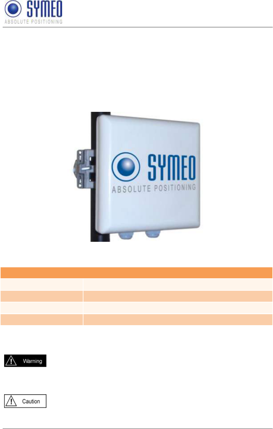
The Local Positioning Radar System LPR-1DXi consists of equal stations, which are
configured with the free software Symeo-Wizard (via Windows PC):
Figure 1 – LPR-1DXi station
The LPR-1DXi station has different interfaces. The unit has IP65 protection class.
Overview of Interfaces
Power Supply
10-36 Volt via terminal block inside casing
USB
Parameter setting with Symeo Wizard (for Windows PC)
Relays
7 dry contact relays via terminal block inside casing
RS232
Distance reading via terminal block inside casing
1.1 Safety Instructions
LPR systems are purely tracking and assistance systems. They therefore
do not satisfy the safety class 3 requirements and must not be used as
standalone systems in safety-critical applications, such as automation or
anti-collision.
Follow the safety instructions in this documentation!
Keep these safety instructions and other documents together with the device.
SYMEO Local Positioning Radar System
LPR-1DXi
Product Documentation
Overview
Copyright © Symeo GmbH 2009
Page 6 of 33
1.2 Installation
All installation, repair and servicing work must be carried out by qualified
and trained technicians!
1.3 Repairs
Repairs to the device must be carried out by authorized technicians.
Unauthorized opening and incorrect repairs could result in severe danger to
the user (danger of electric shock, radiated energy, fire hazard).
1.4 Transport and Storage
Use the original packaging or other suitable packaging for returns and
whenever the system is to be transported. This ensures protection from
crushing, impacts, moisture and electrostatic discharge.
During setup and before operation, refer to the instructions for
environmental conditions included in the operating instructions for the
device.
Route the wires in such a way that they do not cause a hazard and are not
damaged. When connecting the wires, refer to the corresponding
instructions in the operating instructions for the device.
Do not drop the device and do not expose it to strong vibrations.
1.5 Power Supply
A safety-inspected power cable that satisfies the regulations of the country
of use is required for the device. Devices with metal housings must only be
connected to a grounded, shock proof socket.
The device must not be operated unless the nominal voltage of the device
matches the local supply voltage. Check the supply voltage of the device in
stationary devices.
When connecting and disconnecting wires, refer to the instructions in the
operating instructions for the device.
Do not use any damaged wires (damaged insulation, exposed wires). A
faulty wire poses a risk of electric shock or fire hazard.
1.6 Setup and Operation
During installation, make sure that no objects or fluids get inside the device
(risk of electric shock, short circuit).
In emergencies (e. g. if there is damage to the housing, control elements or
the mains cable, if fluids or foreign bodies have infiltrated the equipment),
switch off the power supply to the device immediately and notify your
SYMEO Service.
SYMEO Local Positioning Radar System
LPR-1DXi
Product Documentation
Overview
Copyright © Symeo GmbH 2009
Page 7 of 33
Protect the contacts of all of the device's sockets and plugs from static
electricity. Do not touch the contacts. If it is ever necessary to touch the
contacts, take the following precautionary measures: Touch a grounded
object or carry a ground strap before touching the contacts. This will divert
static charges.
Proper operation (in accordance with IEC60950/EN60950) of the device is
only assured if the housing and integral covers for mounting slots are fully
installed (electric shock, cooling, fire protection, noise suppression). If
necessary, refer to the corresponding instructions in the operating
instructions for the device.
In the case of high outside temperatures and intense, direct solar radiation
or other radiant heat, it may be necessary to provide a sun or heat shield.
1.7 System Extensions and Accessories
Data links to peripheral devices must be provided with adequate shielding.
The warranty shall be voided if you cause defects to the device by installing
or exchanging system extensions.
1.8 Additional Instructions
The LPR-1DXi unit must not be opened except for installation. The LPR-
1DXi unit contains no serviceable components.
When opening, ensure that no fluid gets into the housing. When sealing the
station, ensure that the seal is included in the cover and that the LPR-1DXi
unit is completely closed. Otherwise, moisture can penetrate the station
and damage it.
Please take note of the safety and operating instructions in the operating
instructions for the system in which you want to install the component.

SYMEO Local Positioning Radar System
LPR-1DXi
Product Documentation
System Description
Copyright © Symeo GmbH 2009
Page 8 of 33
2 System Description
2.1 Mode of Operation
The distance is determined by measuring the transit time of radio signals. One unit initiates
the measurement and the second unit replies.
With the software Symeo-Wizard (via Windows PC) the distances for adjustable switching
points are determined and transferred to the LPR-1DXi device. Upon reaching a switching
threshold, on-board relays open dry contacts. Relays are available on both units. Remote
units can be configured via the built-in radio interface. Optional the distance reading is also
available on both of the units.
LPR-1DXi units use the same frequency band and the same hardware for communicating as
for measuring distance. This means that no external WLAN or cable networks are needed for
transmitting measurement values and setting switching relays.
2.2 Technical Data
Overview: Technical Data
Frequency range
5.725-5.875 GHz, ISM band
Transmitting power
Max. 0.025 W / 14 dBm
Positive signal control to
opposite unit
up to 1800 m
Switch thresholds /distance
reading
0 to 120 m (option – extended distance reading 0 to 500
m)
Distance output
0,5 m increments (option – higher resolution: up to ± 5
cm *1)
Repeat rate
Up to 30 Hz
Power supply
10-36 V DC
Power consumption
6 W
Ambient temperature
-40°C to +75°C
Protection class
IP 65
Casing dimensions
190 x 190 x 80 mm (without supplied mounting bracket)
Interfaces
USB for parameter setting with Symeo Wizard (for Win
PC);
Serial RS 232 with binary protocol (terminal block inside
casing);
7x dry contact relays (terminal block inside casing), each
max. 2500VA / 300 W, max. 60 VDC, max. 10 A
Compliance
CE mark, part 15 FCC*2, RSS-210*2
SYMEO Local Positioning Radar System
LPR-1DXi
Product Documentation
System Description
Copyright © Symeo GmbH 2009
Page 9 of 33
*1 Depending on distance and application parameters
*2 Only valid for FCC labeled stations
2.3 System Configuration
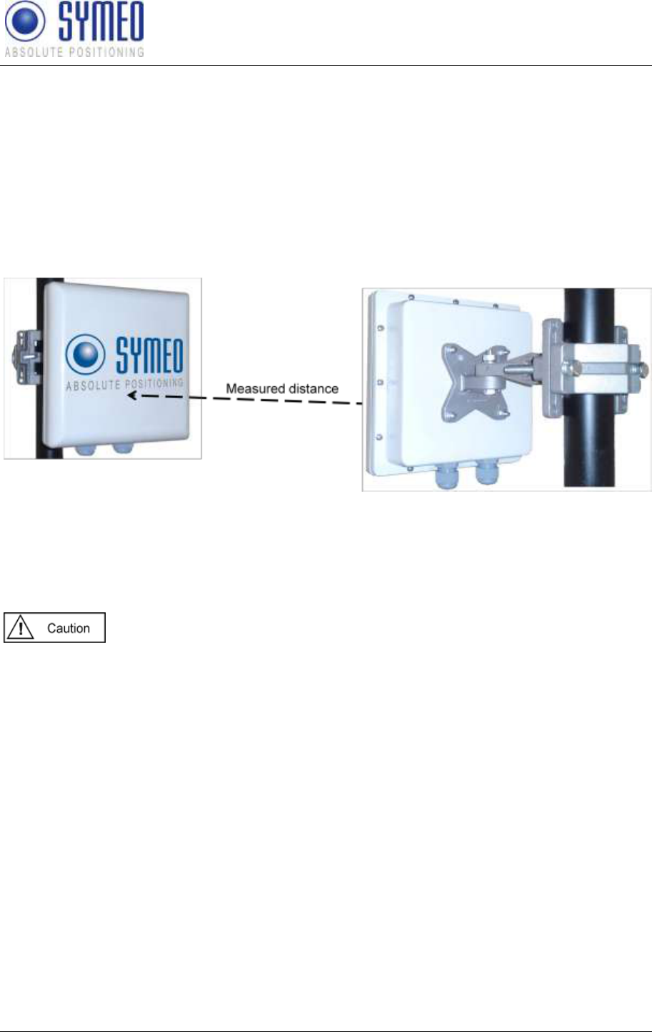
The LPR-1DXi system consists of two LPR-1DXi units. For distance measurement and
collision-avoidance, the two units are arranged as shown in Figure 2. The distance readings
and relays are available at both of the paired units.
Figure 2: LPR-1DXi system
2.4 System Design
Each LPR 1DXi station has parameters to provide an explicit allocation to a system and also
to ensure the functionality of a system. These parameters are explained in the following:
Parameters may only be set with the commissioning tool Symeo Wizard as
described in chapter 5.4. Do not change parameters manually in the
configuration files.
2.4.1 Station-ID (SID)
Each station has an explicit identification Number in one system. A system consists of 2
stations. The first station has the station number 1 (SID 1), the second station has the station
number 2 (SID 2).
2.4.2 Group-ID (GID)
A pair of LPR-1DXi stations is identified clearly by its group number. The two units in one
system have the same group number. If there is used a second, a third or more system in
your environment, all additional systems must have a different group number.
SYMEO Local Positioning Radar System
LPR-1DXi
Product Documentation
System Description
Copyright © Symeo GmbH 2009
Page 10 of 33
2.4.3 Frequency channel
The measurement takes place in a frequency band width of 5,725 to 5,875 GHz. In this band
width a frequency channel is assigned to the LPR-1DXi system. 30 different frequency
channels are available. Two units in one LPR-1DXi system need the same frequency
channel.
If there are more LPR-1DXi systems in your environment each further LPR-
1DXi system needs different frequency channels. The frequency channel is
linked to the group ID. Therefore it is required to use different group IDs for
different LPR-1DXi systems in the same environment. You can set the
group IDs with the commissioning tool LPR-1DXi Symeo Wizard (see
chapter 5).
2.5 Versions of LPR-1DXi stations
For the LPR-1DXi stations several different versions are available:
Overview: Options
ID
Switching threshold /
distance reading
Distance output
resolution
Basic device
BSB000719
0 to 120 m
0,5m increments
Option 1
BSB000754
0 to 500 m
0,5m increments
Option 2
BSB000755
0 to 120 m
Resolution up to ±5 cm
Option 3
BSB000756
0 to 500 m
Resolution up to ±5 cm
Basic device *1
BSB000900
0 to 120 m
0,5m increments
Option 1 *1
BSB000901
0 to 500 m
0,5m increments
Option 2 *1
BSB000902
0 to 120 m
Resolution up to ±5 cm
Option 3 *1
BSB000903
0 to 500 m
Resolution up to ±5 cm
*1 in compliance with part 15 off FCC rules and with RSS-210 of Industry Canada
Please take care that the distances for the switching points in your
application are within the maximum possible distance range of your version
of LPR-1DXi.
The distance for positive signal control, monitoring the functionality of two
stations, is possible up to 1800m.
SYMEO Local Positioning Radar System
LPR-1DXi
Product Documentation
Hardware
Copyright © Symeo GmbH 2009
Page 11 of 33
3 Hardware
All corresponding installation, repair and servicing work must be carried out
by qualified and trained technicians.
3.1 Component setup of the LPR-1DXi station
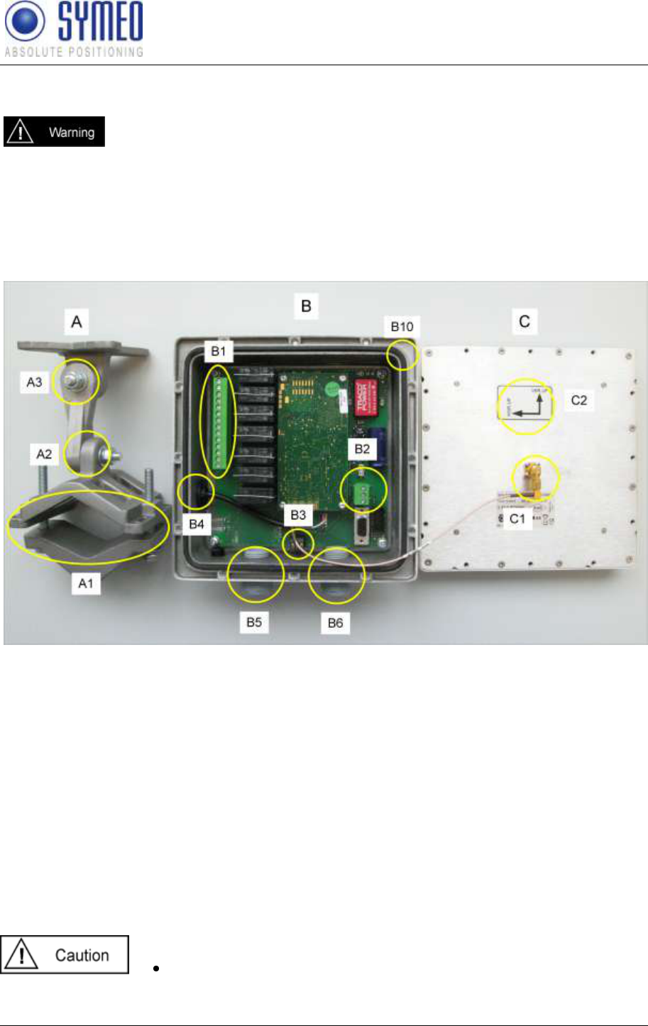
The LPR-1DXi station consists of mounting bracket A, casing with electronic devices B and
antenna C as shown in Figure 3.
Figure 3 Components of the LPR-1DXi: mounting bracket A, casing with electronic devices B and
antenna C
A: mounting bracket
A1 mounting kit for pole and wall mounting
A2 adjustment of elevation angle
A3 adjustment of azimuth angle
B: casing with electronic device
B1 terminal block for relays
B2 terminal block for power connection
B3 terminal block for serial RS232 (distance output, binary protocol)
B4 USB port for parameter setting
B5 cable gland for relay cable to relay connector
B6 cable gland for power supply cable and optional serial RS232 cable
B10 seal
C: Antenna
C1 connector for antenna cable
C2 orientation of antenna polarization
The seal (B10) seals front and rear element when it is mounted
correctly. Otherwise the housing will not be sealed in a water-proof
manner.
SYMEO Local Positioning Radar System
LPR-1DXi
Product Documentation
Hardware
Copyright © Symeo GmbH 2009
Page 12 of 33
The antenna C has to be mounted in correct polarization (C2) as
shown in Figure 3
3.2 Cable glands, interfaces and LED display of the LPR-1DXi
station
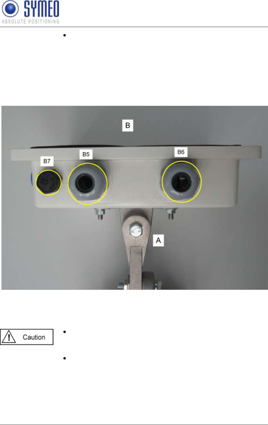
The casing B has two cable glands for power cable (B6) and cable for the connection to the
on-board relays (B5). Additionally the pressure equalization membran (B7) is shown.
Figure 4: Casing B side view with cable glands and mounting bracket A
B5 Cable gland for cable to relays
B6 Cable gland for power cable with optional wires for serial RS232
B7 pressure equalization membrane
Pressure equalization membran (B7) must not be removed or
loosened. Otherwise the housing will not be sealed in a water-proof
manner.
Power supply cable must be within 5 to 9 mm diameter, and relay
cable must be within 7 to 13 mm diameter, both with a round cross-
section.
SYMEO Local Positioning Radar System
LPR-1DXi
Product Documentation
Hardware
Copyright © Symeo GmbH 2009
Page 13 of 33
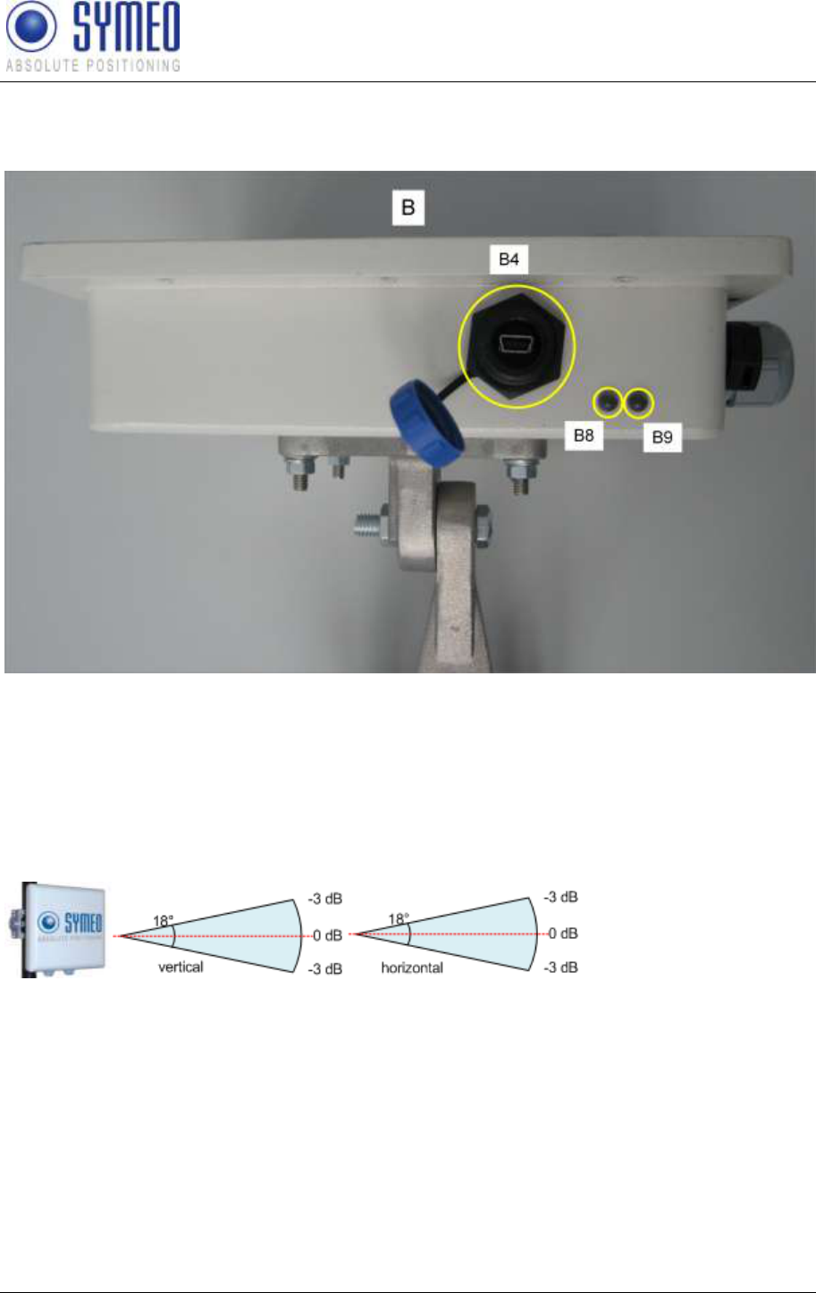
On the side of the casing the USB port (B4) for parameter setting with the software Symeo-
Wizard and two two-colored LED (B8, B9) are located, displaying different statuses of the
device.
Figure 5 Casing B side view
B4 USB port for parameter setting with software Symeo Wizard
B8 two-colored LED, green=switching status of relay 1 / blue=switching status of relay 2
B9 two-colored LED, red=power / green=measurement activity
3.3 Opening angle of the integrated antenna
The LPR-1DXi station has an integrated antenna with 18° opening angle
Figure 6: Opening angle LPR-1DXi station
SYMEO Local Positioning Radar System
LPR-1DXi
Product Documentation
Installation
Copyright © Symeo GmbH 2009
Page 14 of 33
4 Installation
4.1 Important Instructions for Installation
Avoid entry of foreign objects or liquids into the system unit,
especially on the PCB stack in casing B.
The seal (B10) seals front and rear element when it is mounted
correctly. Otherwise the housing will not be sealed in a water-proof
manner.
The antenna C has to be mounted in correct polarization (C2) as
shown in Figure 3
To achieve operation and range as specified both system units must
have the same orientation, e.g. same orientation of the writing
“SYMEO” on the integrated antenna.
Take precautionary measures against static discharges during the
installation process
4.2 Power Connection
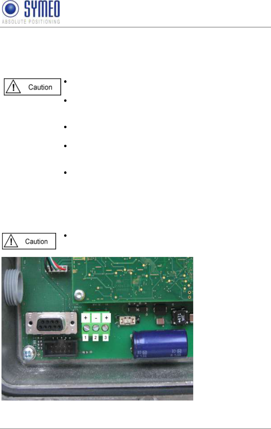
Power supply is connected using the power supply terminal block B2. Figure 7 shows the pin
assignment. Positve voltage can be connected either at pin 1 or 3, the negative or ground
voltage is connected to pin 2.
Polarity reversal or otherwise faulty connection can damage the
LPR-1DXi station. In that case the station must be send to the
SYMEO service.
Figure 7: Power supply terminal block B2
SYMEO Local Positioning Radar System
LPR-1DXi
Product Documentation
Installation
Copyright © Symeo GmbH 2009
Page 15 of 33
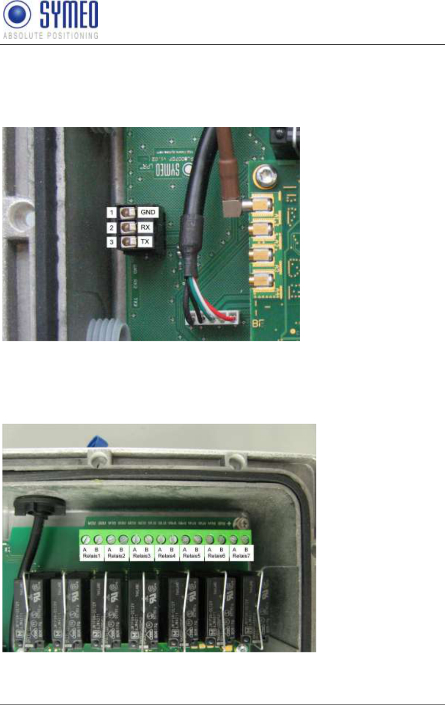
4.3 RS 232 Connection
For optional distance reading RS 232 is connected using the RS232 terminal block B3.
Figure 8 shows the pin assignment.
Please use the same cable as for the power supply with additional three wires.
Figure 8: RS232 terminal block B3
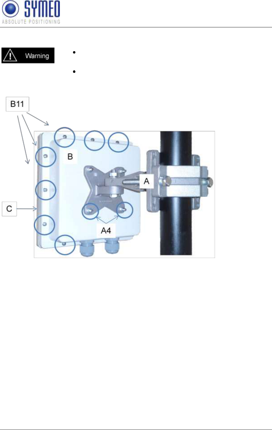
4.4 Relay Connection
Relays are connected using the relay terminal block B1. Figure 9 shows the pin assignment
for the seven switch relays with dry contacts.
Figure 9: Relay terminal block B1
SYMEO Local Positioning Radar System
LPR-1DXi
Product Documentation
Installation
Copyright © Symeo GmbH 2009
Page 16 of 33
4.5 Mounting
All installation, repair and servicing work must be carried out by
qualified and trained technicians!
When the system is mounted on fixed tubes the necessary
measures to prevent slippage of the system must be taken
Figure 10: LPR-1DXi station rear view
The LPR-1DXi station is delivered pre-mounted (casing B and antenna C), and with a
separate mounting bracket A. Figure 10 shows the complete system including mounting
bracket. The mounting bracket A is applicable for wall and pole mounting. For mounting the
system please proceed as follows:
Please use Phillips screwdriver to remove the antenna C from the casing B by
unscrewing and removing the twelve mounting screws B11
Insert the power supply cable in the cable gland B6 and connect it to the power supply
terminal block B2.
If you need distance reading please use additional 3 wires within your power supply cable
and connect these wires to the RS232 terminal block B3
Insert the cable for relay connection in the cable gland B5 and connect it to the relay
terminal block B1.
Fix the antenna C on the casing B with the twelve housing screws B11 using a Phillips
screwdriver. Take care that the seal B10 is carefully mounted.
Carefully tighten the cable glands with flat wrench SW24.
SYMEO Local Positioning Radar System
LPR-1DXi
Product Documentation
Installation
Copyright © Symeo GmbH 2009
Page 17 of 33
Mount the mounting bracket A on a pole or wall at a suitable place. Do not tighten the
screws of the adjustment yet, the system must be aligned first.
Mount the LPR-1DXi casing on the mounting bracket A with 4 hex nuts A4 using flat
wrench SW8.
Carefully align both units (refer to chapter 4.6).
When the system is powered, the red LED B9 of the display element
is turned on.
When both units are connected to the supply power and valid
measurements are made additionally the green LED B9 (two-
colored LED) is blinking at high frequency. Provided that both units
are configured properly with the configuration tool Symeo-Wizard
delivered with your LPR-1DXi station (described in chapter 5)
4.6 Installation notes for antennas
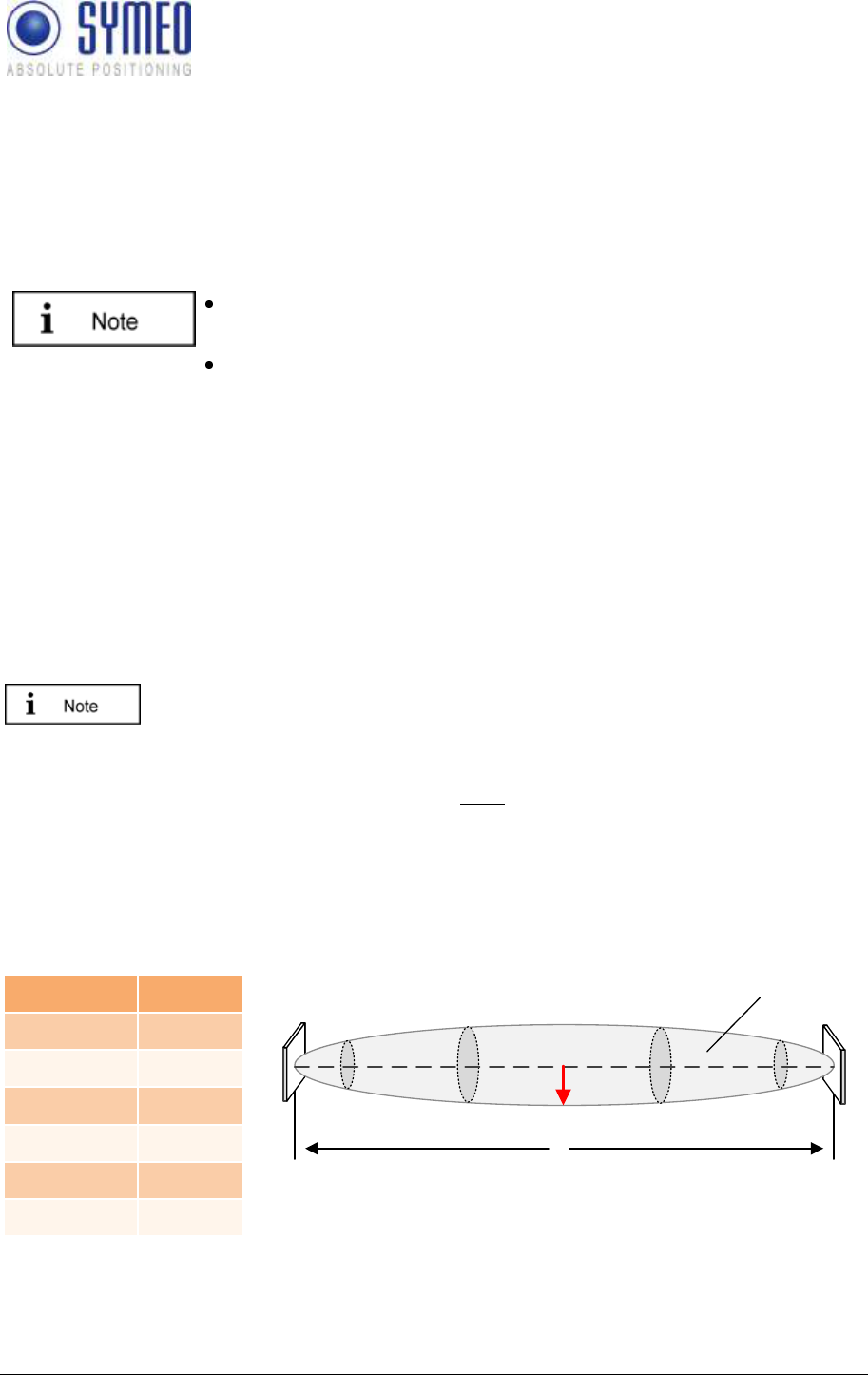
4.6.1 Fresnel zone
The area for radio transmission between two antennas is called Fresnel zone. The main part
of energy is concentrated in the first Fresnel zone.
This area has to be free of any obstacles otherwise the signal is interrupted
or attenuated.
The first Fresnel zone can be calculated as follows:
is the wave length and the distance between the two antennas. For a frequency of 5.8
GHz a wave length of approx. 0.05 m is calculated. The maximum radius between the two
antennas is indicated with . For different distances the maximum radius is given in Figure
11.
distance d
radius b
10 m
0.36 m
50 m
0.80 m
100 m
1.14 m
250 m
1. 80 m
500 m
2.54 m
1000 m
3.60 m
d
b
Antenna 1 Antenna 2
Fresnel zone
Figure 11 Calculation and figure of Fresnel zone
SYMEO Local Positioning Radar System
LPR-1DXi
Product Documentation
Installation
Copyright © Symeo GmbH 2009
Page 18 of 33
4.6.2 Alignment of LPR-1DXi stations
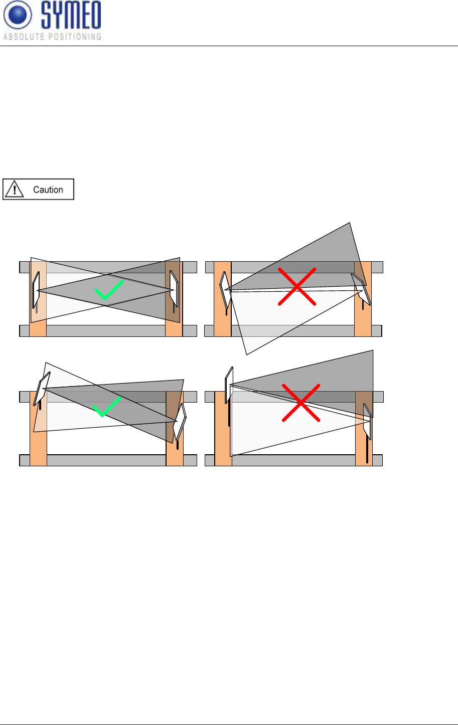
The LPR-1DXi stations with the integrated antennas have to be mounted without any offset
(no difference in height and no offset sideways). Make sure that the opening angle is
symmetric to the relative direction of motion (compare picture 1 vs. picture 2 in Figure 12).
If an offset is not inevitable the stations have to be tilted (compare picture 3 vs. picture 4 in
Figure 12).
Notice: If the distance goes below a fixed distance it is possible that no
measurements take place any longer.
Crane Rail
Crane Rail Crane Rail
Figure 1
No Offset of Antennas
Figure 3
Unavoidable Offset of Antennas
Figure 2
No Offset of Antennas
Crane Rail
Figure 4
Unavoidable Offset of Antennas
Figure 12 Antenna Position with and without Offset
SYMEO Local Positioning Radar System
LPR-1DXi
Product Documentation
Commissioning
Copyright © Symeo GmbH 2009
Page 19 of 33
5 Commissioning
5.1 Requirements
In order for a station to be successfully commissioned, the LPR-1DXi stations must have
been installed correctly:
The station has been installed.
The station has been connected to the power supply (terminal block B2)
Relays are connected to your application (terminal block B1)
Optional: For distance reading RS232 (binary protocol see chapter 6) has been
connected to your application (terminal block B3)
Configuration software Symeo-Wizard and USB-driver are installed on your Windows PC,
both on product documentation CD delivered with your LPR-1DXi devices.
Data link to your PC has been established over USB (jack B4)
Once these prerequisites have been fulfilled, you can set parameters with the software
Symeo-Wizard for each station.
5.2 Commissioning Tool – LPR-1DXi Wizard
5.2.1 Installation of USB driver
The USB driver for the LPR-1DXi station is supplied with the product on CD.
Install the USB driver with the executable file CDM20600.exe.
5.2.2 Installation of the Symeo Wizard
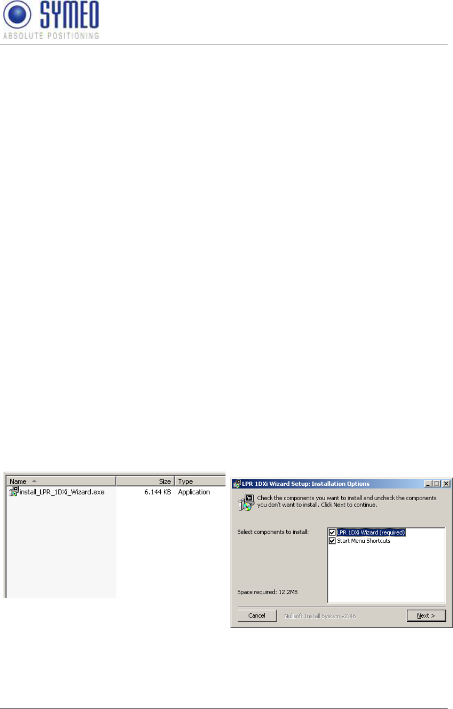
Install the LPR-1DXi Wizard .exe file supplied on your product documentation CD on your
computer.
Figure 13 – Installation File
LPR_1DXi_Wizard.exe
Figure 14 – Setup 1
SYMEO Local Positioning Radar System
LPR-1DXi
Product Documentation
Commissioning
Copyright © Symeo GmbH 2009
Page 20 of 33
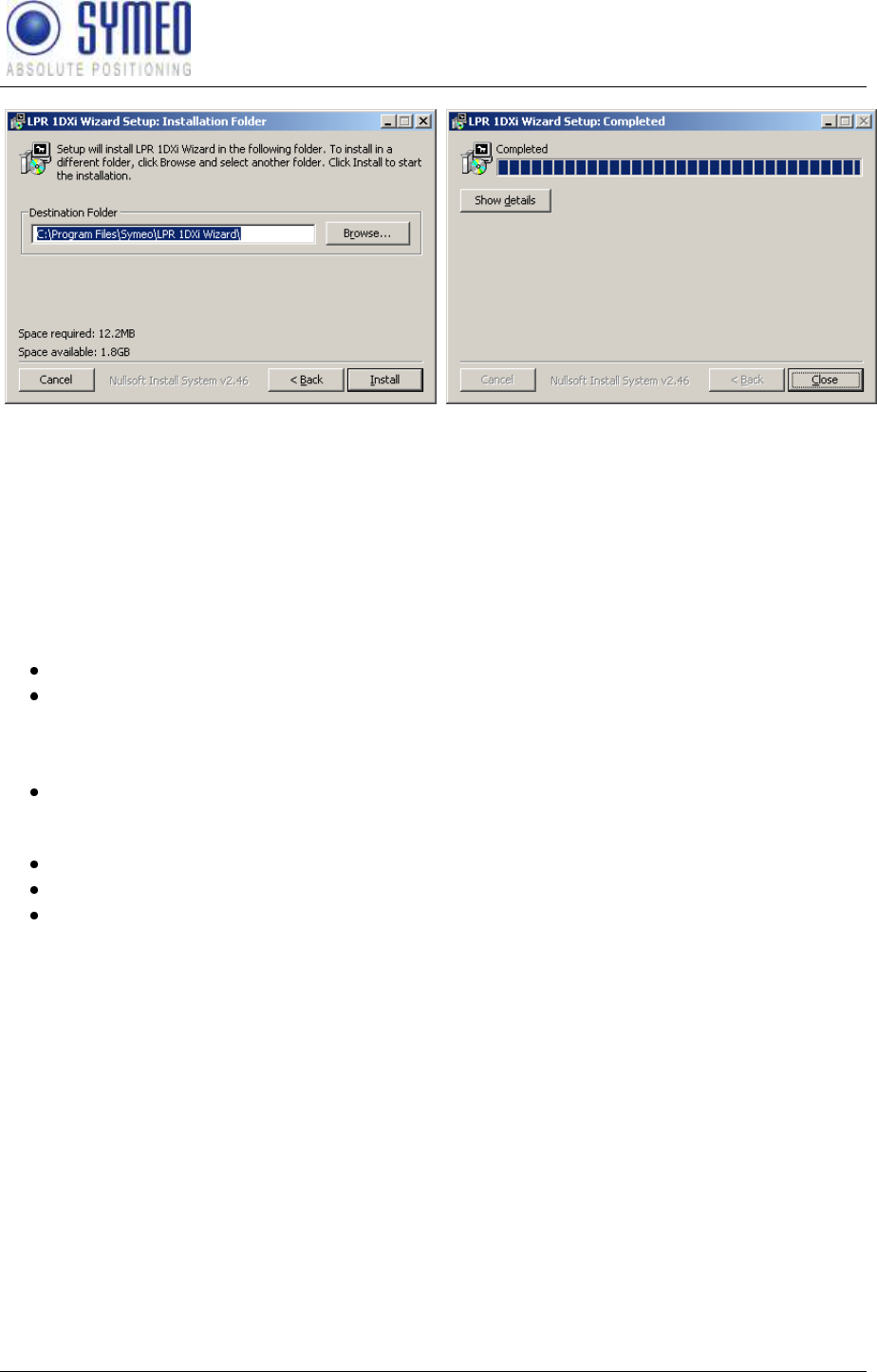
Figure 15 – Setup 2
Figure 16 – Setup 3
After finishing the installation process, you can open the LPR-1DXi Wizard via the Windows
menu.
5.2.3 Parameter setting with the Symeo Wizard
Carry out following steps with the LPR-1DXi Wizard:
1. Selection of the desired application
Settings of parameters for selected application
General setting of LPR-1DXi System (Group ID, Data Rate RS232, Measurement
Cycle)
2. Relay allocation
Relay allocation and setting of switch-off points
3. Connection to LPR-1DXi Station
Upload of selected application and parameters to the LPR-1DXi station
Download of currently applied application as backup-files
Check distance data
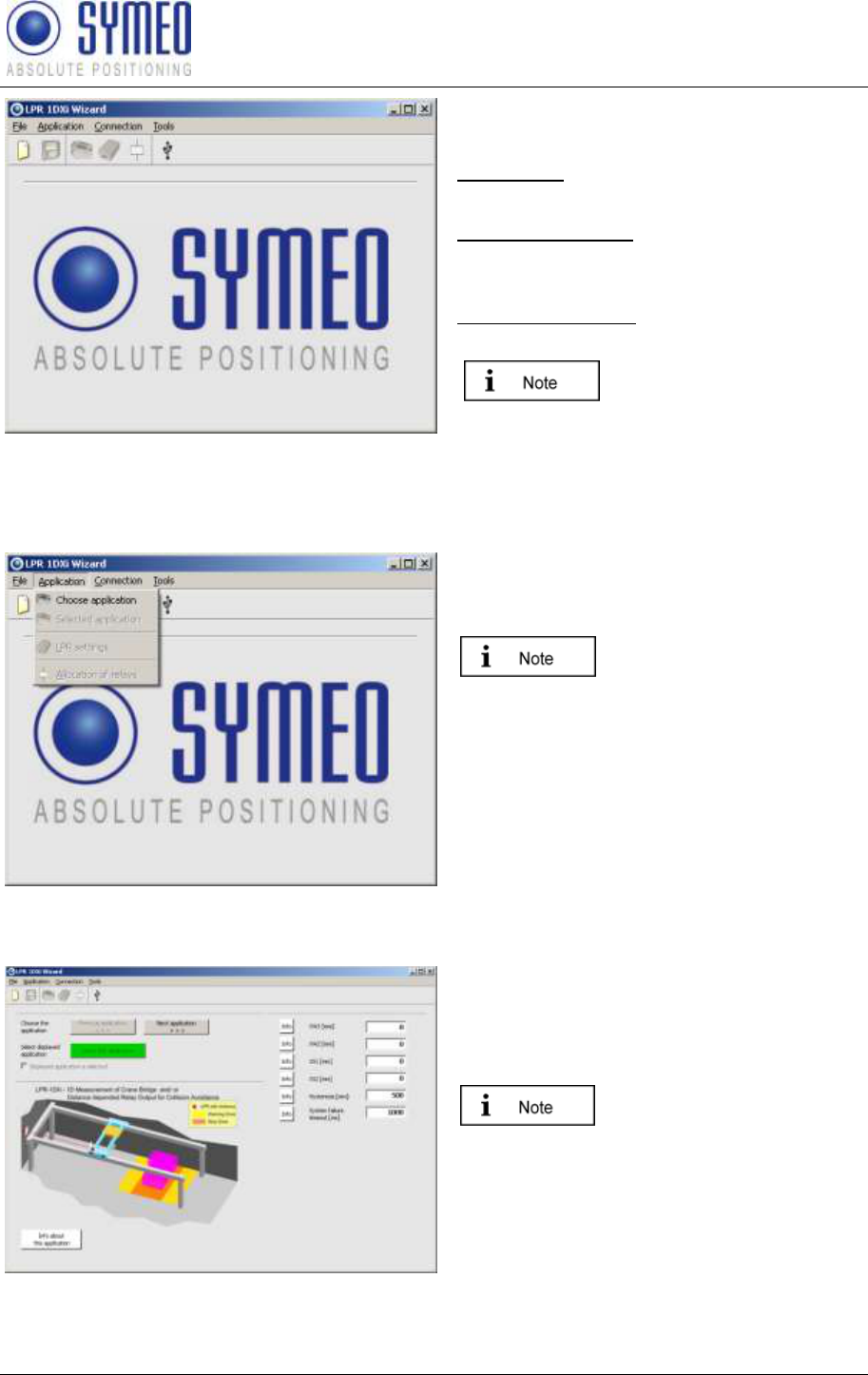
Start the LPR 1DXi Wizard. The following window appears:
SYMEO Local Positioning Radar System
LPR-1DXi
Product Documentation
Commissioning
Copyright © Symeo GmbH 2009
Page 21 of 33
Figure 17 – Start LPR-1DXi Wizard
The layout of the menu looks like the
following:
Menu ‚File„:
open and save configuration files.
Menu ‚Application„:
Selection of application and settings for
LPR-1DXi Systems
Menu ‚Connection„:
Connection to LPR-1DXi system.
The info buttons in the
wizard explains in more
detail the functionality of
the action or application.
5.2.3.1 Selection of application
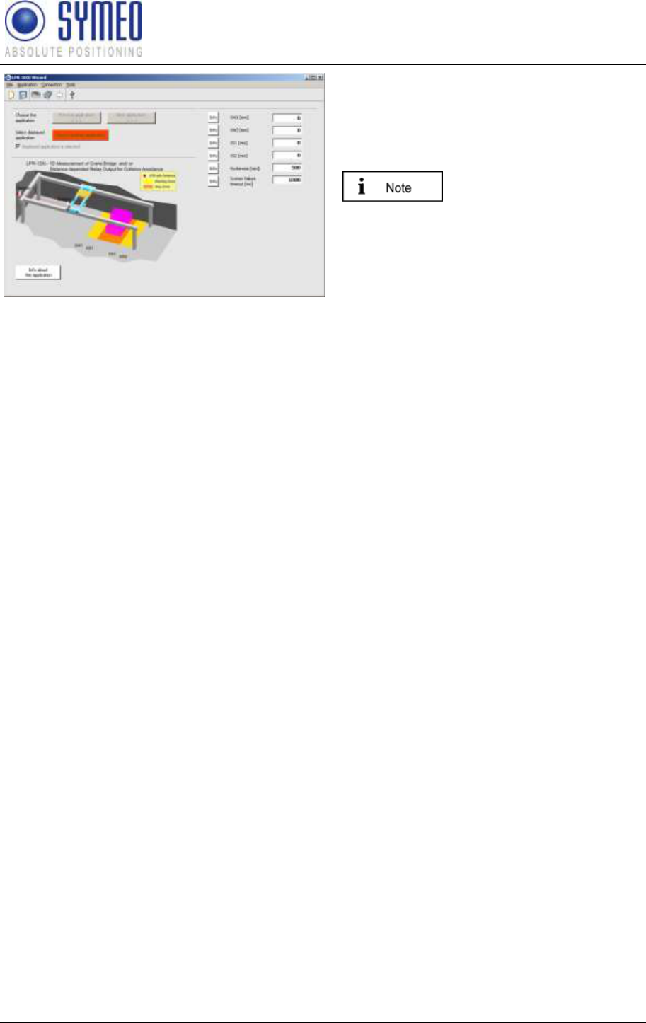
Figure 18 – Selection of application
Select in the menu ‚Application„ the
submenu ‚Choose application„ to open
possible applications..
As long as no application is
choosen no further
submenu could be selected.
Figure 19 – Overview of application
The first application is shown.
You can see other application with the
buttons ‚Next application„ or „Previous
application„.
The application is selected
when the button ‚Select
this application„ is pressed
and a tick is set.
The button ‚Info about this application„
contains a short description of the
application.
SYMEO Local Positioning Radar System
LPR-1DXi
Product Documentation
Commissioning
Copyright © Symeo GmbH 2009
Page 22 of 33
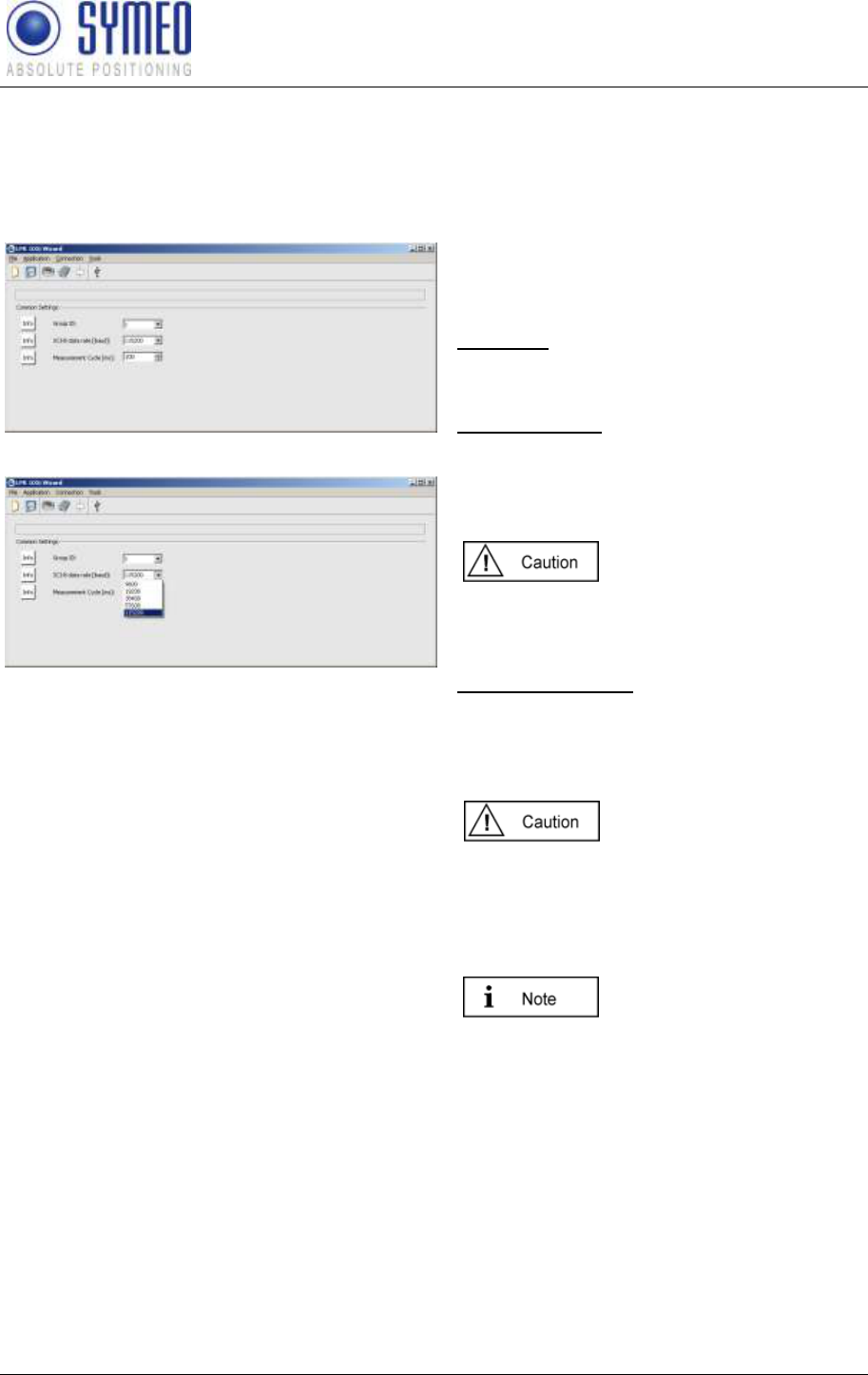
Figure 20 –Settings of parameters of selected
application
If the application is selected (The button
‚Choose this application„ is shown)
additional fields appear. Depending on the
application you have to fill out these input
fields.
The meaning of each input
field is available by
pressing the button „Info‟.
SYMEO Local Positioning Radar System
LPR-1DXi
Product Documentation
Commissioning
Copyright © Symeo GmbH 2009
Page 23 of 33
5.2.3.2 Settings of LPR-1DXi System Parameters
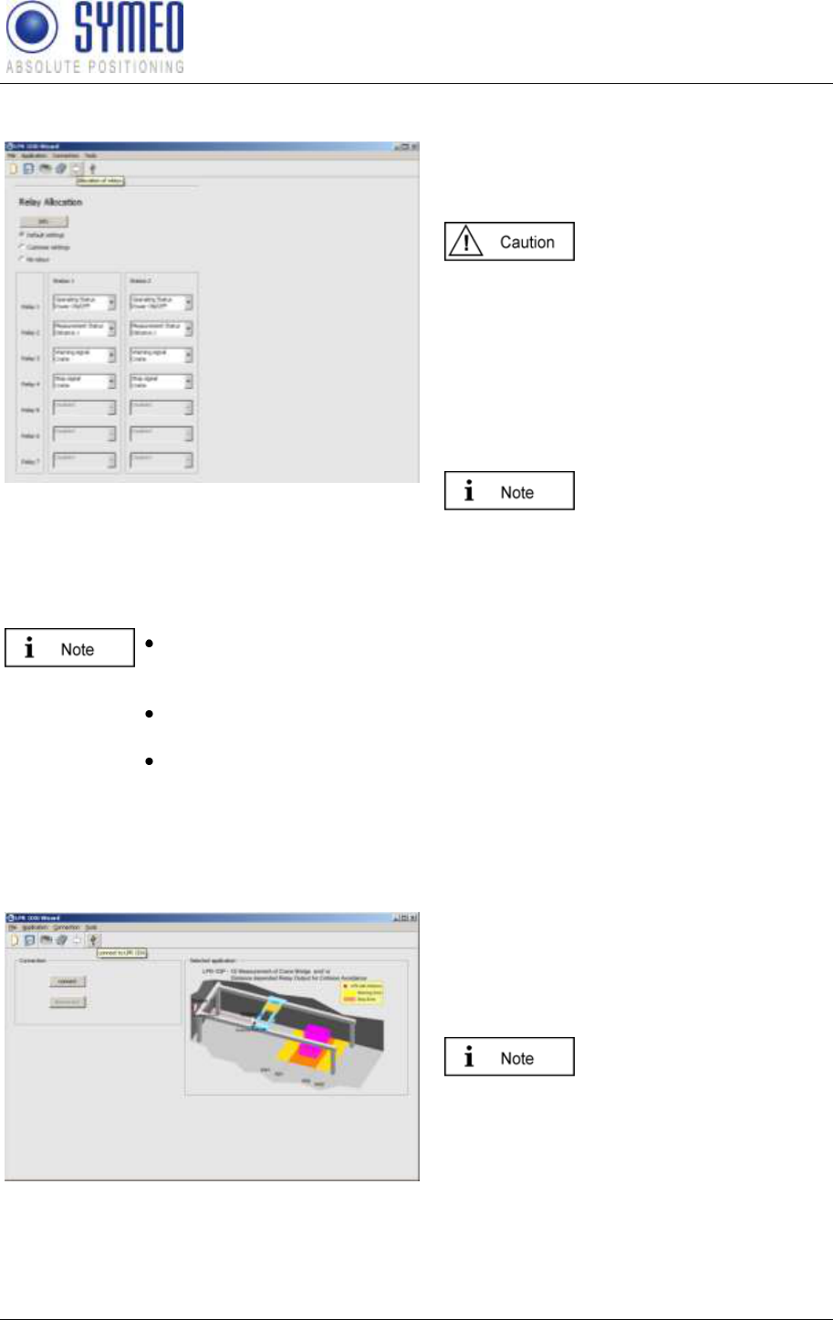
After selecting the application some common settings of the LPR-1D system must be done.
Select the menu ‚Application„ and the submenu ‚LPR settings„.
Figure 21 – General settings 1 of LPR-1D system
Figure 22 – General settings 2 of LPR-1D system
The ‚Common Settings„ include settings of
the LPR-1DXi systems. You have to set
these parameters.
Group ID: Clear ID of the LPR-1DXi
system. The two stations in one LPR-1DXi
system must have the same group ID.
SCIB-data rate: Transmission rate of the
distance reading available on the RS232
interface on terminal block B3 of the LPR-
1DXi system. Per default this value is set to
115200 baud.
If you change the baud rate,
you should also adjust the
measurement rate of the
system.
Measurement rate: Adjust the desired
measurement rate of the system.
Depending on the application you can
choose measurement rates of 35ms to
250ms.
If more than one LPR-1DXi
system is used in the same
environment you have to
use different group IDs for
each pair of LPR-1DXi
stations.
The frequency channel
used for measurements is
linked to the group ID of
the LPR-1DXi system.
SYMEO Local Positioning Radar System
LPR-1DXi
Product Documentation
Commissioning
Copyright © Symeo GmbH 2009
Page 24 of 33
5.2.3.3 Relay allocation
Figure 23 – Allocation of relays
You can allocate functionalities to each
relay in station 1 and station 2 depending
on the selected application.
The relay allocation has to
be done only for the
parameter setting upload
for station 1. If the relay
selection is skipped no
relays are switch at the
LPR-1DXi stations.
You can choose between default settings,
customer settings and no relay.
The possible functionalities
of the relays depend on the
application you have
selected.
The two-colored LED B8 (see Figure 5 Casing B side view) indicates the
switching status of relay 1 (green) and the switching status of relay 2
(blue)
The default relay setting allocates relay 1 to the operating status.
Power on = green
The default relay setting allocates relay 2 to the measurement status.
Valid Measurements = blue
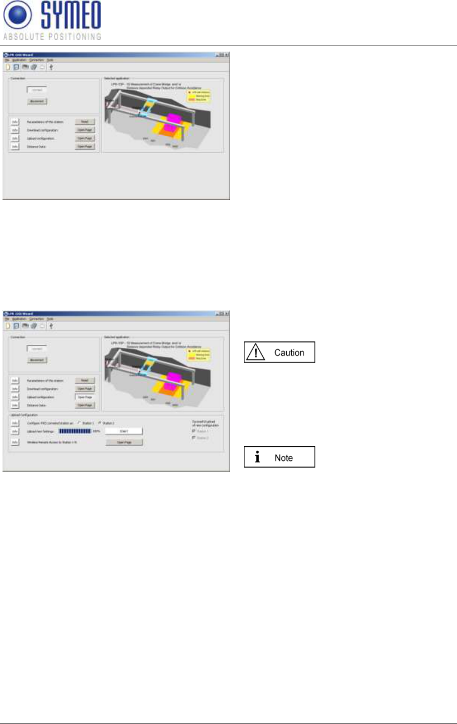
5.2.3.4 Connection to the LPR-1DXi Station
Figure 24 – USB Connection to LRB-1DXi station
To open the USB connection press the
button „connect‟
The USB-driver from the
product documentation CD
has to be installed first.
SYMEO Local Positioning Radar System
LPR-1DXi
Product Documentation
Commissioning
Copyright © Symeo GmbH 2009
Page 25 of 33
Figure 25 – Open connection
The following submenus appear:
Parameters of this station
Read out parameters of connected
station
Download Configuration
Download of current configuration of
LPR-1DXi station
Upload Configuration
Upload of application and
parameters
Distance Data
Measured Distance
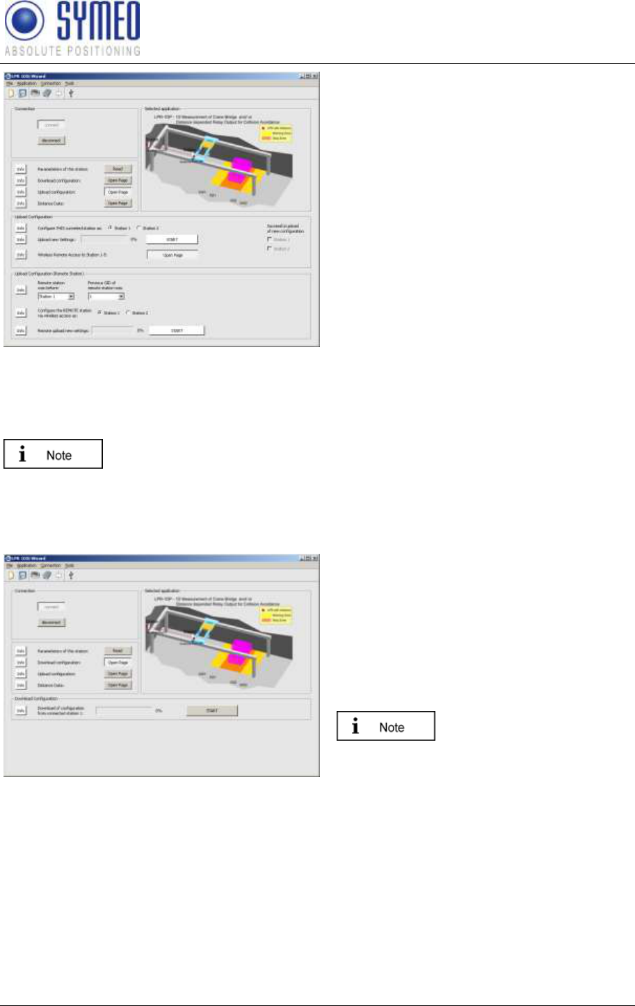
5.2.3.5 Upload Configuration
Figure 26 – Upload configuration
Pressing the button ‚Upload„ the application
can be uploaded to each LPR-1DXi station.
If settings were changed or
a new application is chosen
all stations must be
updated/ uploaded.
Select the station for the upload.
Press the ‚Start„-button.
A note appears if the
uploaded was successful
and the check box is also
marked.
SYMEO Local Positioning Radar System
LPR-1DXi
Product Documentation
Commissioning
Copyright © Symeo GmbH 2009
Page 26 of 33
Figure 27 – Wireless remote upload
At each LPR-1DXi station an upload has to
be done.
You can either connect the LPR-1DXi
station directly to your computer via USB or
you have the possibility to get wireless
access via one station via the frequency
channel to the other station
But to get wireless access to the other
station you have to know the previous
station ID and group ID of the other station
Choose first all parameters and then select
the station number which the station should
have after the upload. Press the Start-
button.
A note appears if the upload was
successful and the check box is also
marked.
.
If a new application is selected or settings are changed, you have to make
an upload for each LPR-1DXi station. Both checkboxes station 1 and
station 2 have to be marked.
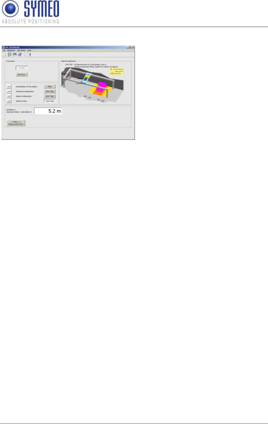
5.2.3.6 Download Configuration
Figure 28 – Download configuration
To have the current application saved as a
backup solution you should download the
application of the station to your desktop.
Press the button ‚Start‟. Enter the desired
file name. Symeo recommends entering the
station number, the group number or the
serial number to distinguish later the
configuration files of all stations.
The serial number is labeled
outside the LPR-1DXi station.
SYMEO Local Positioning Radar System
LPR-1DXi
Product Documentation
Commissioning
Copyright © Symeo GmbH 2009
Page 27 of 33
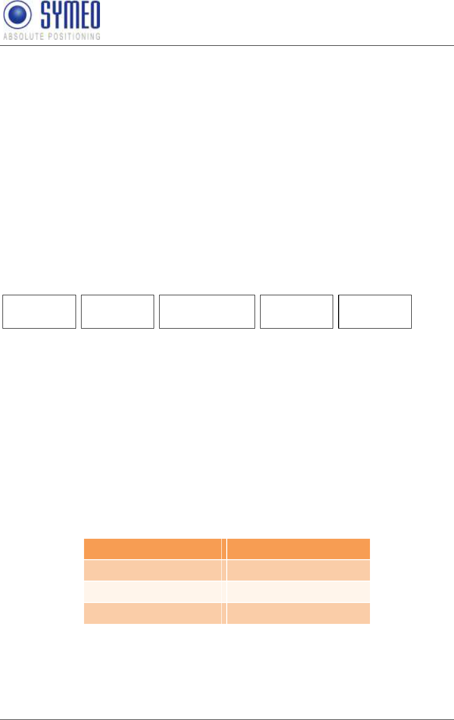
5.2.3.7 Display of Distance Data
Figure 29 – Display distance data
Click the button ‚Distance Data„ and the
distance value is shown.
SYMEO Local Positioning Radar System
LPR-1DXi
Product Documentation
Protocol Description
Copyright © Symeo GmbH 2009
Page 28 of 33
6 Protocol Description
6.1 General Description
This protocol describes the interface between a LPR-1DXi station and the user. The binary
protocol provides information in high density. Its structure ensures a simple implementation.
The transfer is done in single data frames.
The interface for the binary protocol is a serial (RS232) interface. The data rate can be
programmed to standard values (115200, 38400, 19200, 9600 baud). If a low data rate is
chosen the measurement rate of the LPR-B system may be adapted.
6.1.1 Structure of Data Packet
To apply the protocol on a RS232 interface each data packet starts and ends with a reserved
symbol. This reserved symbol cannot appear in the data stream.
Figure 30 shows the general structure of the data packet.
TYPE DATA
START
0x7e
1 byte 1 byte 1 byte
CRC
2 byte
END
0x7f
Figure 30: Structure of the data packet
The START and the STOP-field is in each data packet the reserved symbol 0x7e and 0x7f.
TYPE indicates the type of the data packet. There can be defined up to 256 different types.
The TYPE-field is following the DATA-field. The DATA field contains the real data of the
packet of the type TYPE. The CRC-field contains a check sum. The check sum is applied to
all previous data fields except the START data field.
All multi byte integers (e.g. CRC field) are encoded in Network-Byte-Order (Big Endian).
6.1.2 Byte Stuffing
The two symbols 0x7E and 0x7F are unique for START and STOP-fields. If those symbols
occurs within any other field (TYPE, DATA or CRC), they must be replaced by the following
order:
original symbol
replaced by
0x7D
0x7D 0x5D
0x7E
0x7D 0x5E
0x7F
0x7D 0x5F
This byte stuffing scheme ensures that the receiver of the protocol can identify definitely the
START-field within a flow of data, even if the symbol of the start field occurs within the
DATA-field.
Example: If the symbol 0x7d is read, it must be cancelled. The following symbol must be
XOR combined with 0x20 to recreate the original symbol.
SYMEO Local Positioning Radar System
LPR-1DXi
Product Documentation
Protocol Description
Copyright © Symeo GmbH 2009
Page 29 of 33
6.1.3 CRC
The CRC-16-IBM with polynomial x16+x15+x2+1 is used for the CRC. The CRC is calculated
over all data fields (TYPE and DATA), but not for the START and END field.
The CRC-calculation is only applied to the original symbols. The appropriate calculation for
coding must applied before byte stuffing. If receiving the data from the LPR-B system the
byte stuffing must be reserved to get the original symbol. Then the CRC is updated with the
original symbol.
6.2 Data Types
6.2.1 Type 0x00 – Distance Data
Direction: LPR-1DXi → User
Content
Length
Value
Data type
START
1
0x7E
TYPE
1
0x00
Source* (LPR
address 6.3.1)
2
0x####
see chapter 6.3.1
Destination* (LPR
address 6.3.1)
2
0x####
see chapter 6.3.1
Antenna number
1
0x11
unsigned integer
Distance [mm]
4
0x#### ####
signed integer
Velocity [mm/s]
4
0x#### ####
signed integer
Level [dB]
1
0x##
signed integer
Error 6.3.3
1
0x##
unsigned integer
Status 6.3.2
1
0x0#
unsigned integer
CRC
2
0x####
END
1
0x7F
Total length without byte stuffing: 21 byte
*) Measurements are always executed by a LPR-1DXi base station (station 1), this means, the base
station measures its distance towards a transponder unit (station 2). The source field always contains
the address of the LPR-1DXi base station (station 1). The destination field contains the address of the
measured transponder (station 2).
6.2.2 Example of Distance Data
7E 00 08 03 08 02 11 00 00 10 62 00 00 00 7A E6 00 00 AF C4 7F
Figure 31 - Protocol for a measurement of distance data
This protocol shows a simple example for 1D measurement. The Distance Data sends the
data to the user (i.e. to a PLC or to a PC/software).

SYMEO Local Positioning Radar System
LPR-1DXi
Product Documentation
Protocol Description
Copyright © Symeo GmbH 2009
Page 30 of 33
Distance data:
7E 00 08 03 08 02 11 00 00 10 62 00 00 00 7A E6 00 00 AF C4 7F
7E hex START byte
00 hex TYPE (00: Distance Data)
08 03 hex = 00001|0000000001|1 bin Source LPR address: SID: 1; GID: 1; BBt: 1 (base
station)
08 02 hex = 00001|0000000001|0 bin Destination LPR address: SID: 1; GID: 1; BBt: 0
(transponder)
11 hex = 0001|0001 bin Antenna port base station: 1 antenna port
transponder: 1
00 00 10 62 hex = 4194 dec Distance: 4194 mm
00 00 00 7A hex = 122 dec Velocity: 122 mm/s
E6 hex = 230 dec Level: 230 – 256 = -26 dB
00 hex Error status: 0 means no error; unequal 0 means
error
00 hex Status
AF C4 hex cyclic redundancy check
7F hex END byte
6.3 Remarks
6.3.1 LPR-1DXi Address
LPR-1DXi station addresses are completely defined by a 16 bit value:
15 11 10 1 0
group ID BBstation ID
BB – Base station Bit:
Indicates, if the LPR station is defined as a base station
(station 1) or as a transponder (station 2)
BB: 1=base station, 0=transponder
group ID:
group ID of the station (1..1022)
station ID:
station ID of the station (0..30)
6.3.2 Status field
The status field indicates that the measured distance is inside or outside the maximum
possible distance range of the applied version of LPR-1DXi station. If the real distance of the
LPR-1DXi stations is outside the maximum distance range the distance reading remains at
the maximum value. Depending on the applied version of LPR-1DXi the distance value
remains at 120m or 500m. (see chapter 2.5)
SYMEO Local Positioning Radar System
LPR-1DXi
Product Documentation
Protocol Description
Copyright © Symeo GmbH 2009
Page 31 of 33
Content
Description
Value
inside range
Distance inside maximum distance range
0x00
outside range
Distance outside maximum distance range
0x01
Please take care that the distances for the switching points in your
application are within the maximum possible distance range of your version
of LPR-1DXi (see chapter 2.5)
6.3.3 Error messages
The distance data contains an error field which indicates the status of the message. The
following errors can occur:
Content
Source
Description
Value
no error
Measurement valid
0x00
no peak detected
Base Station
No measurement signal
0x01
peak too low
Base Station
Measurement signal is imprecise
0x02
nothing received
Transponder
No measurement data received
0x03
implausible speed
Base Station
Velocity is to high
0x04
measurement botched
Base Station
Measurement is not feasible.
0x05
no occupying received
Master Transponder
Measurement channel is not
reserved
0x06
no results received
Master Transponder
No measurement data received
0x07
SYMEO Local Positioning Radar System
LPR-1DXi
Product Documentation
Appendix A: Agency certifications
Copyright © Symeo GmbH 2009
Page 32 of 33
7 Appendix A: Agency certifications
United States (FCC) and Canada (Industry Canada)
Radiofrequency radiation exposure Information:
This equipment complies with FCC/IC radiation exposure limits set forth for an uncontrolled
environment. This equipment should be installed and operated with minimum distance of
20 cm between the radiator and your body.
This transmitter must not be co-located or operating in conjunction with any other antenna
or transmitter.
Changes or modifications made to this equipment not expressly approved
by SYMEO GmbH may void the FCC/IC authorization to operate this
equipment.
This device complies with Part 15 of the FCC Rules and with RSS-210 of
Industry Canada.
Operation is subject to the following two conditions:
this device may not cause harmful interference, and
this device must accept any interference received, including
interference that may cause undesired operation.
Installation:
All installation, repair and servicing work must be carried out by qualified
and trained technicians!
Repairs:
Repairs to the device must be carried out by authorized technicians.
Unauthorized opening and incorrect repairs could result in severe danger
to the user (danger of electric shock, radiated energy, fire hazard).
SYMEO Local Positioning Radar System
LPR-1DXi
Product Documentation
Appendix A: Agency certifications
Copyright © Symeo GmbH 2009
Page 33 of 33
United States (FCC)
This equipment has been tested and found to comply with the limits for a
Class B digital device, pursuant to Part 15 of the FCC Rules. These limits
are designed to provide reasonable protection against harmful
interference in a residential installation. This equipment generates, uses
and can radiate radio frequency energy and, if not installed and used in
accordance with the instructions, may cause harmful interference to radio
communications. However, there is no guarantee that interference will not
occur in a particular installation. If this equipment does cause harmful
interference to radio or television reception, which can be determined by
turning the equipment off and on, the user is encouraged to try to correct
the interference by one or more of the following measures:
Reorient or relocate the receiving antenna.
Increase the separation between the equipment and receiver.
Connect the equipment into an outlet on a circuit different from that to
which the receiver is connected.
Consult the dealer or an experienced radio/TV technician for help
Canada (Industry Canada)
This Class [B] digital apparatus complies with Canadian ICES-003.
Cet appareil numérique de la classe [B] est conforme à la norme NMB-
003 du Canada.