Symmetricom S100 Users Manual S100v1.3
S100 to the manual 8e63e1d7-8b78-4dc2-a6b5-f6829605674f
2015-02-02
: Symmetricom Symmetricom-S100-Users-Manual-490663 symmetricom-s100-users-manual-490663 symmetricom pdf
Open the PDF directly: View PDF ![]() .
.
Page Count: 166 [warning: Documents this large are best viewed by clicking the View PDF Link!]
- Table of Contents
- Chapter 1
- Chapter 2
- Chapter 3
- Installation and Configuration
- Overview
- Getting Up and Running
- Unpacking Your S100
- Your CD-ROM
- Installing Your S100
- Rack Mounting
- Primary Power Connection
- Important Safety Instructions!
- Making All Connections: An Overview
- Setting Up the Hardware
- Installing the GPS Antenna
- Setting Up the IP Address
- How to Acquire Time
- The Configuration Wizard
- Using SymmTime™
- Next: Use the Web-Based Interface
- Chapter 4
- The Web-Based Interface
- Overview
- Interface: Screen Reference
- Logging In
- Administrative Interface
- Admin Interface: Base Menu
- Administrative Menu: Expanded
- System Status
- Timing Configuration
- NTP Relationships
- Timing Engine
- GPS Information
- Other Information
- Networking
- Administration
- Configuration Wizard
- Help
- Logging Off
- Chapter 5
- Chapter 6
- Frequently Asked Questions
- Questions
- How can we obtain NTP client software to use with the S100?
- What are the main differences between SNTP and NTP clients?
- Is there a way to get GPS time instead of UTC time from the S100?
- What outputs are available on the S100?
- How does the S100 handle Leap Second?
- What signal strengths are required by the S100 receiver to start tracking?
- How do I check versions of the software in the S100?
- What is the maximum number of computers that can be networked to the S100?
- How many satellites are necessary for me to operate the S100?
- How do I know if the satellite signal strength is good?
- What is the maximum antenna cable length for use with the S100?
- What are the available antenna cable lengths and antenna requirements?
- What are some guidelines for correctly cutting the cable, using splitters, and using cable connectors?
- How many NTP requests can be processed by the S100 each second?
- Does the S100 support NTP v4?
- Can the S100 utilize a certificate from an external CA?
- How is the interface to the S100 secured?
- What security functions are provided with the S100?
- Does the S100 support any functions to restrict user access to NTP service? Can the S100 set up clients' IP address to be connected?
- What is the bandwidth utilization (TCP/IP) each time an NTP client gets a time update from the NTP server?
- Is NTP v4 compatible with Network Address Translation (NAT) gateways?
- How does the S100 clock behave when a leap second is introduced?
- How-to’s and Tips
- How to install NTP v4 on a UNIX system
- How to configure an NTP v4 client to connect to an NTP v4 server with the autokey scheme
- How to verify NTP v4 autokey client connectivity with an NTP v4 server
- How to install your S100
- How to get time using dial-up
- How to get time using GPS
- How to install your GPS antenna
- How to acquire and install SymmTime™
- Use the quick “How to” guide
- How to change the root password
- How to get information about NTP
- Solutions
- Appendix A
- Appendix B
- Appendix D
- Appendix C
- Appendix E
Chapter 1
S100 User Guide
SyncServer S100 User Guide
Installation, Configuration, and Operation
for the SyncServer S100 - OS Version 1.3
Part #: S100 User Guide, Rev. D, June 2005
2S100 User Guide – Rev. D – June 2005
1
1
S100 User Guide – Rev. D – June 2005 i
2
5
3
Table of Contents
Chapter 1
Introduction and Overview 1
Conventions Used 2
Product Details 3
Time Standards 3
Global Positioning System (GPS) 3
Stratum Levels 4
Time Synchronization and Business 4
How the S100 Solves the Problem 5
National Measurement Institutes 5
Special Safety Instructions 6
Lithium Battery Disposal Instructions 6
Electrical Safety Instructions 6
Chapter 2
S100 Technology 7
Overview 7
S100 Product Overview 7
Sources of Time 7
On the Network 7
Web-based Access 8
Time Distribution Model 9
How the S100 Works 9
S100 and Time Distribution 10
S100 and Client Software 10
S100 and NTP v4’s Security Features 10
S100 and the Global Positioning System 11
Chapter 3
Installation and Configuration 13
Overview 13
Getting Up and Running 13
Unpacking Your S100 13
ii S100 User Guide – Rev. D – June 2005
1
SyncServer S100
Your CD-ROM 15
Using the Software 16
PuTTY Folder Details 16
PUTTY.EXE 16
PSCP.EXE 16
PSFTP.EXE 17
PLINK.EXE 17
PAGEANT.EXE 17
PUTTYGEN.EXE 18
Installing Your S100 19
Rack Mounting 19
Primary Power Connection 19
Important Safety Instructions! 19
Making All Connections: An Overview 20
Setting Up the Hardware 21
On the S100 Front Panel 21
On the S100 Rear Panel 22
Installing the GPS Antenna 23
Choosing an Antenna Location 23
Installing the GPS antenna 24
Connecting the Rubidium Option 24
Establishing A Serial Connection 24
Setting Up the IP Address 26
Testing Network Functionality 28
Turning Off Your S100 29
How to Acquire Time 30
Logging On 30
Administrator Log-In 31
Next Step 32
The Configuration Wizard 32
Choose Your Time Source 33
GPS 35
NTP 42
Configuring NTP 45
IRIG-B (v.120,122,123) 45
Using SymmTime™ 49
Installing SymmTime 49
To Synchronize SymmTime: 51
Next: Use the Web-Based Interface 51
Chapter 4
The Web-Based Interface 53
Overview 53
Interface: Screen Reference 53
1
S100 User Guide – Rev. D – June 2005 iii
2
5
3
Logging In 54
Administrative Interface 54
Admin Interface: Base Menu 55
Administrative Menu: Expanded 56
System Status 57
Timing Configuration 57
NTP Relationships 58
NTP Time Source Test 60
NTP Dialup 60
NTP Restart 61
NTP Status 61
Advanced: ntp.conf 63
Advanced: Keys/Certificates 64
Timing Engine 65
Main Settings 65
Timecode Settings 66
GPS Information 67
GPS Health 67
GPS Signal Strength 68
GPS Time 69
GPS Position 69
Other Information 70
Engine Time 70
Clock Settings 70
Control Settings 71
Model Information 72
Networking 72
TCP/IP 72
ifconfig Output 74
Ping 74
Traceroute 75
Administration 76
Shutdown/Reboot 76
Admin Users 77
Restart Web Interface 77
Time Zone 78
System Log Configuration 78
SNMP Configuration 79
SNMP Edit 79
Alarms 80
Configuration Wizard 80
Logs 81
NTP Log 81
Boot Log 82
System Log 82
Config Log 83
HTTP Log 83
Help 84
iv S100 User Guide – Rev. D – June 2005
1
SyncServer S100
SyncServer Help 84
NTPD Help 84
Search NTPD Manual 84
Logging Off 85
Chapter 5
Operations & Time-Protocols 87
S100: Operations and Time Protocols 87
Sysplex Timer 87
Time Protocol (RFC 868) 89
Daytime Protocol (RFC 867) 89
Simple Network Time Protocol (RFC 2030) 90
Network Time Protocol (RFC 1305) 90
NTP Authentication 93
Authentication: NTP v3 93
Authentication: NTP v4 Autokey 94
Public Domain NTP Package 94
Typical NTP Configuration Considerations 94
Other NTP Considerations 95
Clients 95
Basic NTP Configuration 96
Peers 103
Security 103
ACTS Interface: Dial-up 103
ACTS Operation 104
SNMP (Simple Network Management Protocol) 104
Version 1 105
Version 3 106
Chapter 6
Frequently Asked Questions 109
Questions 109
How can we obtain NTP client software to use with the S100? 109
What are the main differences between SNTP and NTP clients? 109
Is there a way to get GPS time instead of UTC time from the S100? 109
What outputs are available on the S100? 109
How does the S100 handle Leap Second? 110
What signal strengths are required by the S100 receiver to start tracking? 110
How do I check versions of the software in the S100? 110
What is the maximum number of computers that can be networked to the
S100? 110
1
S100 User Guide – Rev. D – June 2005 v
2
5
3
How many satellites are necessary for me to operate the S100? 111
How do I know if the satellite signal strength is good? 111
What is the maximum antenna cable length for use with the S100? 111
What are the available antenna cable lengths and antenna requirements? 111
What are some guidelines for correctly cutting the cable, using splitters, and
using cable connectors? 111
How many NTP requests can be processed by the S100 each second? 112
Does the S100 support NTP v4? 112
Can the S100 utilize a certificate from an external CA? 112
How is the interface to the S100 secured? 112
What security functions are provided with the S100? 112
Does the S100 support any functions to restrict user access to NTP service? Can
the S100 set up clients' IP address to be connected? 112
What is the bandwidth utilization (TCP/IP) each time an NTP client gets a time
update from the NTP server? 112
Is NTP v4 compatible with Network Address Translation (NAT) gateways? 113
How does the S100 clock behave when a leap second is introduced? 113
How-to’s and Tips 113
How to install NTP v4 on a UNIX system 114
How to configure an NTP v4 client to connect to an NTP v4 server with the
autokey scheme 114
How to verify NTP v4 autokey client connectivity with an NTP v4 server 114
How to install your S100 114
How to get time using dial-up 114
How to get time using GPS 114
How to install your GPS antenna 115
How to acquire and install SymmTime™ 115
Use the quick “How to” guide 115
How to change the root password 115
How to get information about NTP 116
Solutions 116
The S100 does not respond to ping command 116
The S100 does not respond to NTP queries 116
I cannot establish a serial connection with the S100 116
My S100 won’t track satellites 117
Appendix A
S100 Specifications 119
S100 Data Sheet Specifications 119
Pin Descriptions 120

1
S100 User Guide – Rev. D – June 2005 1
2
5
3
Chapter 1
Introduction and Overview
The S100 provides computers and network devices secure synchronization to UTC time
using Network Time Protocol (NTP). The S100 can use the Global Positioning System
(GPS), NIST's Automated Computer Time Service (ACTS), or another NTP server as a time
reference.
This User Guide describes the installation and operation of the S100. It is written for network
administrators familiar with network configuration and operations.
The chapters and appendices address topics including:
• Installation, configuration, and operation
• The User Interface
• How the S100 works
• FAQ and Solutions
Here are shortcuts to those sections that answer frequently-asked “how to” or “How do I...?”
questions.
How to... Go here for the answer
Acquire time “How to Acquire Time” on page 30
Choose and configure your time source “Choose Your Time Source” on
page 33
Determine the default User Name and
Password “Setting Up the IP Address” on
page 26
Get Technical Support “Appendix D” on page 137
Get time from ACTS dial-up “Dialup Settings dialog” on page 38
Get time from GPS “GPS” on page 35
Figure 1-1: The S100

2S100 User Guide – Rev. D – June 2005
1
SyncServer S100
Conventions Used
The most common conventions used here are:
Install the GPS antenna “Installing the GPS Antenna” on
page 23
Install my S100 “Installing Your S100” on page 19
Install SymmTime “Installing SymmTime” on page 49
Learn how the S100 works “How the S100 Works” on page 9
Establish an IP address and other settings “Setting Up the IP Address” on
page 26
Set up the optimal operating environment for
my S100 “S100 Specifications” on page 119
Set up all hardware connections “Making All Connections: An
Overview” on page 20
Synchronize SymmTime “To Synchronize SymmTime:” on
page 51
Test for NTP functionality “Testing Network Functionality” on
page 28
Use the web-based interface “The Web-Based Interface” on page 53
Table 1: Type Conventions
Term Definition
Bold Boldface type is used for menu and
command names; field, tab, and button
labels; and special terms.
Courier The Courier typeface is used to
designate file names, folder names,
code, and URLs.
The warning symbol alerts the user to
information that if improperly used could
be harmful to people, equipment, or
data.
How to... Go here for the answer

1
S100 User Guide – Rev. D – June 2005 3
2
5
3
Product Details
Details about the physical description and operating environment of the S100 are found in
Appendix A, “S100 Specifications” on page 119 of this User Guide.
Details about S100 operations are in “The Web-Based Interface” on page 53, as well as
“Chapter 3” on page 13, and “Operations & Time-Protocols” on page 87.
Time Standards
The international time standard is called Coordinated Universal Time or, more commonly,
UTC. This standard was agreed upon in 1972 by worldwide representatives within the
International Telecommunications Union; today, the Internet Engineering Task Force (IETF)
sets standards based on the 1972 work. Today UTC is coordinated by the world’s
International Bureau of Weights and Measures, or BIPM. (The designations “UTC” and
“BIPM” were chosen as a compromise among all the countries’ abbreviations for the terms.)
The global availability and precision of UTC time makes it the ideal source of time for Time.
The S100 uses UTC as its time standard.
Global Positioning System (GPS)
The U.S. Department of Defense Global Positioning System (GPS) is a constellation of
approximately 29 satellites that orbit Earth twice a day. Their orbits are inclined 56 degrees to
the equator. The GPS satellites signals are used by a GPS receiver to precisely determine its
own position and time.
The orbits of these satellites and the offset (relative to international standard time, UTC) of
their on-board Cesium atomic clocks is precisely tracked by the U.S. Air Force control
network. Position and time correction information is uplinked from the ground control stations
and maintained in the satellites in what are termed ephemeris tables, or tables of data that
describe the satellite’s position when compared to specified coordinates. Each satellite
transmission reports the satellite’s current position, GPS time, and the offset of the satellite’s
clock relative to UTC, international standard time.
The “S100 GPS” model uses GPS to obtain time. (The “S100 ACTS” model obtains time by
dialing NIST's Automated Computer Time Service (ACTS).)

4S100 User Guide – Rev. D – June 2005
1
SyncServer S100
Stratum Levels
The Internet Engineering Task Force (IETF) established standards for Network Time Protocol
(NTP) in IETF RFC 1305. These hold that the source of time for each server is defined by a
number called its stratum. The highest level is 0; Stratum 0 devices, such as GPS or radio
clocks, are connected to a primary time reference, such as the national atomic clock. Each
level “away” from this primary time reference adds on another number. The Stratum of a
primary server, which gets its time from the GPS system, for example, is assigned as 1.
Devices that get their time from a Stratum 1 primary server through NTP are Stratum 2,
Stratum 3, and so forth. A Stratum 2 or 3 server simultaneously acts as a client, deriving its
time from an NTP process with a Stratum 1 (or 2) Server, and acts as a server for clients
further down the hierarchy.
Here is a summary:
Obviously, the further away a network is from the primary source, the higher the possibility of
time degradation because of variations in communication paths and the stability of the local
clock.
The S100 can be a Stratum 1 device, as well as Stratum 2 or 3.
Time Synchronization and Business
Reliable time synchronization is essential for doing business today.
Ensuring that all components of a network are synchronized to the global UTC time standard
is critical for accurate time stamps, operational logs, and security applications. Many complex
data processing tasks are dependent upon precise event sequences and accurate time
stamping of events.
Not using a dedicated time server can give rise to the following problems:
• Security risks: Users who retrieve time from an outside source, such as the Internet, are
going outside your firewall.
Table Intro-1: Stratum Levels: Summary
Stratum Level Significance
Stratum 0 Connected to a primary time reference, this device—usually a GPS or
radio clock—is synchronized to national standard time.
Stratum 1 A Stratum 1 time server derives time from a Stratum 0 time source
Stratum 2...n A Stratum 2 (and so on) device derives its time from a Stratum 1 server,
or other Stratum 2...n device from NTP.

1
S100 User Guide – Rev. D – June 2005 5
2
5
3
• Bandwidth consumption: Synchronizing the time over a WAN (wide area network)
consumes expensive bandwidth and degrades time accuracy (versus synchronizing
over a LAN).
• Lost time: If your network synchronization relies on a time reference outside your
network, your network can be seriously compromised if the one connection to that
outside time reference is lost.
How the S100 Solves the Problem
The S100 provides your network with a single unbiased time reference based on one or more
external time references. Should all external time references become unavailable, the S100
uses its own high-performance crystal oscillator to keep time.
The S100, using its internal GPS receiver, operates as a Stratum 1 time server, with accuracy
to the nearest microsecond relative to UTC as maintained by the U.S. Naval Observatory,
one of the National Measurement Institutes (NMIs) in the U.S.
Time is distributed using the Network Time Protocol (NTP), and between multiple sites. The
result is that with the S100, network users can get time from within your firewall.
Full specifications are found in “S100 Specifications” on page 119.
National Measurement Institutes
The S100 synchronizes to UTC. This time standard is maintained by the International Bureau
of Weights and Measures (BIPM). By international agreement, each country’s National
Measurement Institute (NMI) maintains audit records of their synchronization with BIPM UTC,
thus providing verifiable sources of UTC within their countries. NMI clocks are disciplined to
be within nanoseconds of UTC time.
Country Name of NMI Abbreviation
United States National Institute of Standards and Technology NIST
France Laboratoire Primaire du Temps et des Fréquences LPTF
United Kingdom National Physical Laboratory NPL
Japan Communications Research Laboratory CRL

6S100 User Guide – Rev. D – June 2005
1
SyncServer S100
Special Safety Instructions
Lithium Battery Disposal Instructions
Electrical Safety Instructions
Caution: Replace lithium battery only with one of the same
type and ratings. Dispose of the battery in accordance with all
local codes. Contact your local environmental control or dis-
posal agency for details.
Caution: Do not install the modem (phone) cord during an
electrical storm.
Note: minimum 26AWG phone cord is recommended
for added safety.
Note: A minimum 26AWG phone cord is recommended
for added safety.
Note: POWER CORD SELECTION: If your unit is not
provided with a power cord-set, purchase only a Certi-
fied cord-set suitable for your location (voltage source)
with a minimum 6A current rating.

1
S100 User Guide – Rev. D – June 2005 7
2
5
3
Chapter 2
S100 Technology
Overview
This chapter gives a review of the S100 technology.
There is additional information in “S100 Specifications” on page 119.
S100 Product Overview
The S100 network time server synchronizes secure network time. The following sections
describe this technology.
Sources of Time
The S100 obtains time from GPS, ACTS, or another S100, and delivers it to computers and
other devices on a network. It acquires UTC (Universal Coordinated Time) from GPS signals,
or using ACTS dial-up to the National Institute of Standards and Technology (in the U.S.). If
there are several S100s on your network, only a few S100s need acquire UTC directly. They
can then distribute that time to other S100s.
On the Network
Clients on a network synchronize with a time source using NTP, the Network Time Protocol,
to exchange packets of time. The S100 implements NTP Version 4. This prevents intruders
from spoofing time packets and using NTP to gain access to your systems. Unlike previous
versions, NTP Version 4 implements asymmetric encryption. This is the same technique used

8S100 User Guide – Rev. D – June 2005
1
SyncServer S100
by secure web sites to protect credit card numbers and other sensitive information from
unintended interception.
The S100 also supports SNMP v1.8 and SNMP v3 (Simple Network Management Protocol)
for easy integration into your existing management hierarchy.
Web-based Access
The S100 management is web-based. Using a standard browser, you can set up and
configure an S100 from any point on the Internet.
See Chapter 3 for more about this web access.
There is a detailed section about this web-based interface in Chapter 4, “The Web-Based
Interface” on page 53.
1
S100 User Guide – Rev. D – June 2005 9
2
5
3
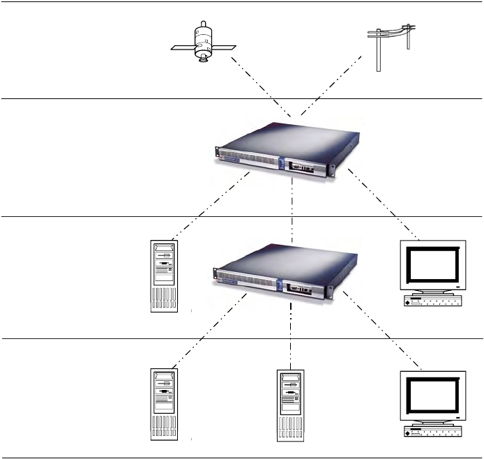
Time Distribution Model
Network time distribution systems use a hierarchical time distribution model, as shown in this
figure:
In hierarchical systems, primary time source clocks are Stratum 0 (zero), including GPS
satellites, National Institute of Standards and Technology (NIST) ACTS dial-up service, or
similar national time standards organizations.
The S100 acts as a Stratum 1 time server that derives its time from GPS and distributes this
time over a TCP/IP network using NTP. Stratum 2 NTP clients can distribute time to Stratum 3
computers.
How the S100 Works
The following describes how the S100 acquires and secures time.
Computer
Systems
(NTP
Clients)
SyncServers
or Computer
Systems
(NTP Clients)
Symmetricom
SyncServer
GPS
Satellites or
NMI Dial-Up
Service
Stratum 3 Stratum 2 Stratum 1 Stratum 0
Figure 2-1: The S100 in the Time Distribution Hierarchy

10 S100 User Guide – Rev. D – June 2005
1
SyncServer S100
More details are found in “Chapter 3” on page 13 and “The Web-Based Interface” on
page 53.
S100 and Time Distribution
Time is distributed over an IP network using Network Time Protocol (NTP), Simple Network
Time Protocol (SNTP), Time Protocol, and Daytime Protocol over TCP/IP.
S100s can be distributed throughout a LAN or intranet. Also, a single GPS antenna is all that
is required to acquire UTC time for an array of S100s, making the network less vulnerable to
damage or attack. (Note: The GPS antenna described in this manual has been replaced as
described in “Appendix E” on page 141.)
Once the S100 is locked with its time source, it will continuously provide time even if the
timing signal is lost. If the GPS time signal is lost, the NTP message returned by the S100 will
indicate—from the Reference Timestamp—when it last obtained time updates from the timing
signal.
The S100 maintains the year value as a four-digit number. The S100 maintains time as binary
seconds and has no problem with leap-years and the introduction of leap seconds.
S100 and Client Software
Install NTP client software on the client machines in order to synchronize those clients with
S100’s NTP server.
Obtain the SymmTime™ NTP client for Windows at http://www.ntp-systems.com/
symmtime.asp.
Details about installing SymmTime are found in “Installing SymmTime” on page 49.
Unix/Linux clients can be synchronized using the public domain NTP daemon or equivalent
NTP client software. If an NTP daemon is not available for your system, you can obtain a
copy of RFC 1305 or 2030 from the Network Information Center (NIC) at http://
www.ietf.org/rfc/rfc1305.txt, in order to implement an NTP daemon for your system.
S100 and NTP v4’s Security Features
NTP is the de facto standard of communicating time in IP network environments. Developed
at the University of Delaware in the United States, NTP is public domain software. It can
provide time without opening the NTP port and exposing the firewall to possible intrusion. The
S100 supports NTP v4 (Secure NTP), and can support NTP v2 and v3, as well.
The S100 generates keys, which take the form of a file composed of random numerical
sequences. These key files are recognized by the cryptographic authentication components
of NTP. These keys are symmetric, or private (in NTP v3 and v4), and asymmetric or public or
Autokey (NTP v4); Autokey protocol, therefore, can recognize the key files as well. The
contents of the key files include the public/private key pair, a certificate request, a certificate,
and Diffie-Hellman parameters.

1
S100 User Guide – Rev. D – June 2005 11
2
5
3
Digitally signed public certificates are required by the Autokey protocol. (See the interface at
“Advanced: Keys/Certificates” on page 64.) All of this data goes into your certificate
request (X.509) to a trusted Certificate Authority (CA). The CA can be an outside trust
authority, such as VeriSign, or the device can certify itself. The S100 itself is “self-signed”, or
shipped to you with an authenticated certificate. The S100 CA digitally signs (authenticates)
the request and sends it back, along with the certificate, to the person requesting it.
More details of the NTP protocol and synchronization techniques can be found in the Help file
included with the interface, or at:
•
http://www.ntp.org
•
http://www.ietf.org/rfc/rfc1305.txt
S100 and the Global Positioning System
The Global Positioning System (GPS) receiver in the S100 tracks GPS satellites as they pass
overhead and determines the range of the satellite in relation to its antenna. The GPS
receiver uses the following four properties of the satellite to determine its own position and
derive the time:
• x, or latitude
• y, or longitude
• z, or altitude
• t, or time
However, once the GPS receiver has calculated its position, only one satellite is needed to
solve for time (t). This is because the receiver has tracked at least four satellites and has
positioned itself. GPS time is expressed as the number of weeks since midnight, January 6,
1980 (GPS Week) and the number of seconds in the week. These two values are transmitted
as binary integers from the satellites and converted into conventional date or day (UTC Time)
by the GPS receiver.
12 S100 User Guide – Rev. D – June 2005
1
SyncServer S100

S100 User Guide – Rev. D – June 2005 13
2
5
3
Chapter 3
Installation and Configuration
Overview
Installation, setup, and getting started with the S100 are reviewed in this section.
Symmetricom recommends you review before
beginning your installation so that you are already familiar with the references to the interface
once you begin to use it.
Getting Up and Running
This chapter guides you through the following basic steps:
1. Set up the hardware and make all connections (Optional: Install GPS antenna, connect
phone line).
2. Using the serial cable, establish the S100’s IP address.
3. Test for network functionality (ping).
4. Using the web-based interface, choose and configure the time source.
Unpacking Your S100
Unpack and inspect each item in the box. If there is any damage, or any items are missing,
please contact Symmetricom Customer Assistance (see “Appendix D” on page 137).
Note: The GPS and bullet antennas and antenna cables described in this manual have been
replaced as described in .
The following items should be included:
For the S100-Dial-up/ACTS For the S100-GPS
S100 S100
A/C Power Cord with US-style wall plug A/C Power Cord with US-style wall plug

14 S100 User Guide – Rev. D – June 2005
SyncServer S100
CD with NTP Clients, SymmTime™ software,
User Guide PDF CD with NTP Clients, SymmTime™ software,
User Guide PDF
Six-foot RS-232 Cable Six-foot RS-232 Cable
Phone cord Phone cord
D-BNC Signal Breakout Cable BC11576-1000 D-BNC Signal Breakout Cable BC11576-1000
Bullet Antenna
Antenna Mast - aluminium mast threaded to
screw into the bottom of antenna
Mounting Bracket Hardware - for attaching
mast to railing
50-foot RG58 (Belden 8240 or equivalent)
cable
For the S100-Dial-up/ACTS For the S100-GPS

S100 User Guide – Rev. D – June 2005 15
2
5
3
Your CD-ROM
The CD does not autoload when inserted into the CD-ROM drive. Use the file browser to view
the contents of the CD. The CD contains: SymmTime, PuTTY, and TermPro23. PuTTY and
TermPro23 are shareware.
• SymmTime synchronizes a Windows-based PC’s clock with the time from an S100 unit
or other NTP server. When executed, a small pop-up containing four clocks appears.
Once installed, visit http://www.ntp-systems.com/symmtime.asp for the latest file
downloads.
Antenna Cable
CD with
NTP Clients,
SymmTime,
User Guide
SyncServer
S100
RS-232 Cable
AC Power
Cord
Phone Cord
For GPS option:
Bullet
Antenna Antenna Mast and
Brackets
D-BNC Signal
Breakout Cable
Figure 3-1: S100 and Accessories

16 S100 User Guide – Rev. D – June 2005
SyncServer S100
• TermPro23.exe is used to install Tera Term terminal emulation software, if desired. The
manual refers to using Hyperterminal. Either will work (as well as any others). This
version supports Win 95, NT 3.51 and 4.0.
• PuTTY is described below.
Using the Software
None of the files in the PuTTY folder must be installed. They are provided in case you require
them and do not have them. The SymmTime (click SymmTime200x.exe to launch) file must
be used for synchronization. The TTermPro23 is also optional.
PuTTY Folder Details
PuTTY contains the following optional executable files:
• pageant.exe (Secure Shell [SSH] authentication agent for PuTTY, PSCP, and Plink)
• plink.exe (a command line interface to PuTTY back end)
• pscp.exe (SCP client using command line secure file copy)
• psftp.exe (SFTP client for general file transfer session similar to FTP)
• putty.exe (a Telnet and SSH client)
• puttygen.exe (RSA key generation utility)
PUTTY.EXE
is a secure shell client utility that allows you to log into a multi-user computer from another
computer over the network.
The file, Putty.exe, only runs on full Win32 systems (Windows 95, 98, ME, NT, 2000, XP, not
CE).
Most of its data (saved sessions, SSH host keys) is in the Registry at:
HKEY_CURRENT_USER\Software\SimonTatham\PuTTY
PSCP.EXE
is a Secure Copy client and a tool for transferring files securely between computers using an
SSH connection. PSCP.EXE is a command line application only. It uses the Windows MS-
WARNING!
Using PuTTY, PSCP, PSFTP, Plink is illegal in
countries where encryption is forbidden. See
http://rechten.kub.nl/koops/cryptolaw/cls-
sum.htm
S100 User Guide – Rev. D – June 2005 17
2
5
3
DOS Prompt (in 95, 98, ME) or the Command Prompt (in NT, 2000). This is available from the
Programs section of your Start Menu.
To start PSCP, add the directory containing PSCP to your PATH environment variable, enter
the following in the console window:
set PATH=C:\path\to\putty\directory;%PATH%
This will only work for the lifetime of that particular console window. To set your PATH more
permanently on Windows NT, use the Environment tab of the System Control Panel. On
Windows 95, 98, and ME, you will need to edit your AUTOEXEC.BAT to include a set
command like the one above.
Further, PSCP.EXE is a command line application, not a GUI application. If you run it without
arguments, it will simply print a help message and terminate. It runs on every SSH server.
PSCP is designed to do a single file transfer operation and immediately terminate.
PSFTP.EXE
is a tool for transferring files securely between computers using an SSH connection.
PSFTP differs from PSCP in the following ways:
• PSFTP uses the new SFTP protocol, which is a feature of SSH 2 only (PSCP will also
use this protocol if it can, but there is an SSH 1 equivalent it can fall back to if it cannot).
• PSFTP allows you to run an interactive file transfer session, much like the Windows FTP
program.
You can list the contents of directories, browse around the file system, issue multiple get and
put commands, and eventually log out.
PLINK.EXE
is a command line connection tool similar to UNIX SSH. It is mostly used for automated
operations, such as making CVS access a repository on a remote server. Do not use Plink if
you want to run an interactive session in a console window. Plink is a command line
application in the same manner as PSCP.
PAGE ANT. EXE
is for public-key authentication and allows open multiple SSH sessions without having to type
a pass phrase every time. It provides you with the security benefit of never storing a
decrypted private key on disk. Holding your decrypted private keys in Pageant is better than
storing them in disk files. The drawbacks are:
• Windows does not protect pieces of memory from being written to the system swap file. If
Pageant is holding your private keys, it's possible that decrypted private key data may
be written to the system swap file, and an intruder who gained access to your hard disk
might be able to recover that data.

18 S100 User Guide – Rev. D – June 2005
SyncServer S100
• Windows prevents programs from accidentally accessing one another's memory space
and it allows programs to access one another's memory space deliberately (e.g.,
debugging). If a virus, trojan, or other malicious program attaches onto your Windows
system while Pageant is running, it could access the memory of the Pageant process,
extract your decrypted authentication keys, and send them back to its master.
Before you run Pageant, you need to have a private key. Use Puttygen.exe to do this. When
you run Pageant, it will put an icon of a “computer wearing a hat” into the System tray. It will
remain there and do nothing until you load a private key into it.
PUTTYGEN.EXE
is a key generator. It generates pairs of public and private keys to be used with PuTTY, PSCP,
Plink, as well as the PuTTY authentication agent, Pageant. PuTTYgen generates RSA and
DSA keys. Use it as an alternative means of identifying yourself to a login server, instead of
typing a password.
In conventional password authentication, you prove you are who you claim to be by knowing
the correct password. The only way to prove you know the password is to enter it. If the
server has been compromised, an intruder could learn your password.
Public key authentication (Puttygen.exe) solves this problem. You generate a key pair,
consisting of a public key—which everybody is allowed to know, and a private key—
which you keep secret and not give to anyone. The private key is able to generate signatures.
A signature created using your private key cannot be forged by anyone unless they have that
key. Anyone who has your public key can verify that a particular signature is genuine.
So you generate a key pair on your own computer, and you copy the public key to the server.
Then, when the server asks you to prove who you are, Putty.exe can generate a signature
using your private key. The server can verify that signature (since it has your public key) and
allow you to log in.
Note: Keep the packing materials for future use. These materials are custom designed to
protect the S100 during storage and shipping. Use them if you need to return the unit to
Symmetricom (for Customer Assistance see “Appendix D” on page 137).

S100 User Guide – Rev. D – June 2005 19
2
5
3
Installing Your S100
Install the S100 in a physically secure location with strong physical access controls.
Symmetricom recommends that you read the operating environment requirements and other
specifications in “S100 Specifications” on page 119, before starting.
Rack Mounting
The S100 is designed for mounting in a standard 19-inch (48.26 cm) rack. It is important to
keep the fan inlet and outlet areas clear to maintain air flow. If the unit is installed in a closed
or multi-unit rack assembly, the operating ambient temperature of the rack environment may
become greater than that of the room. Be sure that the ambient temperature is no higher than
50°C/122°F. Make sure the unit is properly balanced and grounded.
Primary Power Connection
The S100 uses external AC power.
The unit has a power cable with a PH-386, IEC 320-C-13 three-conductor female connector
on the computer end of the cable. The other end of the cable has a NEMA 6-15P grounding
plug (US Standard, 15-amp, 125-volt, straight-blade plug).
Important Safety Instructions!
When using your telephone equipment, basic safety precautions should always be followed
to reduce the risk of fire, electric shock and injury to persons. Do not use this product near
water or in a damp location.
Caution: To reduce the risk of fire, use only No. 26 AWG or larger telecommunication line cord.
WARNING!
To prevent electrical shock or
injury, DO NOT remove the S100
cover.
Dangerous voltages exist within
this enclosure!
20 S100 User Guide – Rev. D – June 2005
SyncServer S100
Making All Connections: An Overview
Use your standard PC workstation to configure the S100.
Refer to the illustrations in this section when you install the S100.
You will need to make a network connection (you may or may not require a hub to do this). It
is suggested you obtain an IP address from your IT department. The Serial cord connects the
S100 to your computer. Connect the S100 to your network using the network port. Use your
verified IP address in your web browser to reach the S100’s Configuration Wizard online.
S100 User Guide – Rev. D – June 2005 21
2
5
3
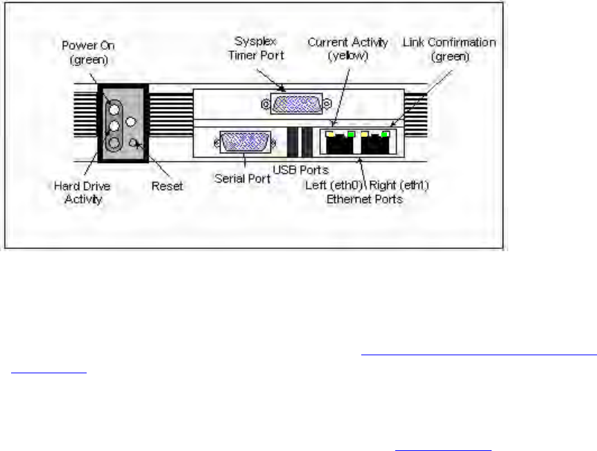
Setting Up the Hardware
On the S100 Front Panel
Complete the following steps before turning on the power:
1. Connect the 9-pin serial cable from the PC workstation to the S100 serial port. You are
doing this so to configure the S100 using a PC; see “Establishing A Serial Connection”
on page 24 in the next section.
2. Connect the RJ45-terminated Ethernet cable to one or both network ports on the S100.
Note: If only one network connection is required, use the left Ethernet port (eth0). The
two USB ports are not functionable on this S100 release. Sysplex Timer Port: This port
outputs UTC only.
Figure 3-2: S100 Front Panel Close-up
22 S100 User Guide – Rev. D – June 2005
SyncServer S100
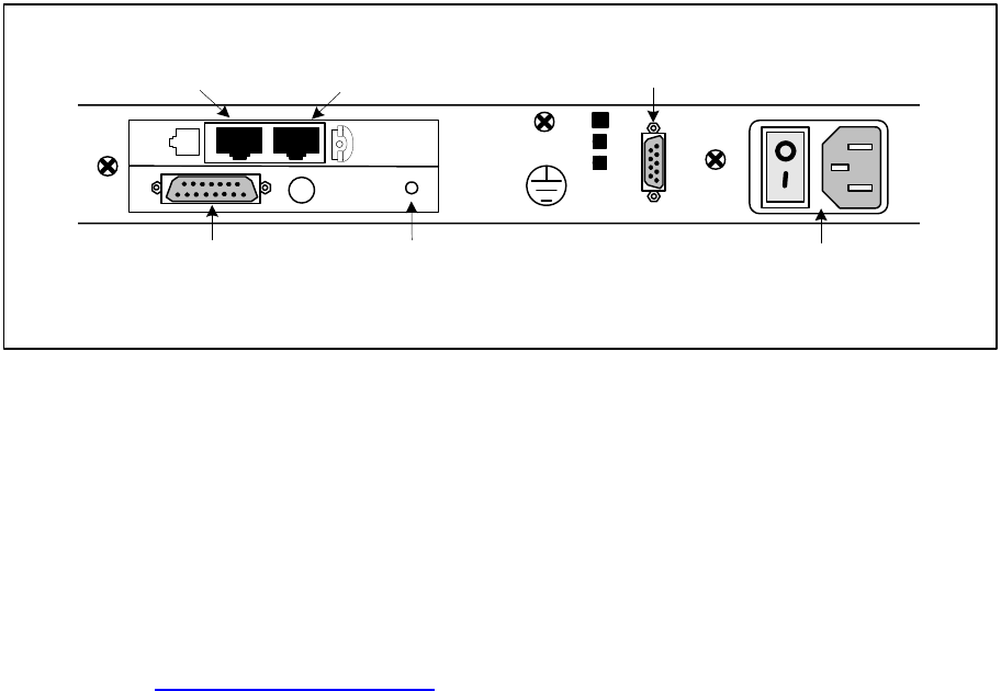
On the S100 Rear Panel
Complete the following steps to complete the S100 installation:
1. Connect the power cable to the S100.
2. GPS Option: Install GPS Antenna by connecting it to the GPS Antenna connector shown in
Figure 3-3. Connect the Phone cord to a telephone line.
Note: The GPS antenna described in this manual has been replaced as described in
“Appendix E” on page 141
3. If you are not using a Rubidium oscillator, connect the D-BNC Signal Breakout Cable
(BC11576-1000) to the DB15 Connector shown in Figure 3-3. If you are using the S100
with an optional Rubidium oscillator, connect the external rubidium cable (furnished with
the Rubidium oscillator) from the DB9 Connector to the DB15 connector (see Figure 3-
3).
Note: The D-BNC Signal Breakout Cable BC11576-1000 has five connectors on it. The three
connectors labelled “Time Code Output”, “Time Code Input”, and “1 PPS Output” are
available for use with on the S100. The connectors labelled “Event Input” and “Heartbeat” are
not applicable for use on the S100.
J 1
GPS
ANT.
Telephone cable
to phone
DB15
Connector
DB9 Connector
(optional)
Power Panel
Telephone
cable to wall
GPS Antenna
Connector
Figure 3-3: S100 Rear Panel Close-up

S100 User Guide – Rev. D – June 2005 23
2
5
3
Installing the GPS Antenna
If you are installing an S100 with the GPS option, a bullet antenna is provided. The bullet
antenna provided with the S100 GPS version comes with a weatherproof housing, suitable
for permanent installation in an outdoor location.
Note: The GPS and bullet antennas and cables described in this manual have been
replaced as described in “Appendix E” on page 141.
Choosing an Antenna Location
Global Positioning System (GPS) satellites orbit at an 56 degree inclination to the equator.
The further north you are in the northern hemisphere, the more probable it is that satellites
will be passing to the south of you. And if you are in the southern hemisphere, the satellites
will be passing to the north of you. Please consider this as you install your antenna.
The antenna should be located with an unobstructed, clear view of the sky for optimum
tracking conditions. The satellite signals cannot penetrate foliage, or dense wood or metal
structures. The antenna’s operation is not affected if it is partially covered with snow, provided
the snow is dry and does not form a continuous ice sheet on the surface. The shape of the
bullet antenna is designed to prevent accumulation of rain, snow, or ice on its surface. (Note:
The bullet antenna described in this manual has been replaced as described in “Appendix
E” on page 141.)
The GPS transmission is a 1.5 GHz (L1Band) spread-spectrum signal. Being spread-
spectrum means it is relatively immune to interference. But high energy sources, especially
those with significant in-band energy, can swamp the receiver’s radio frequency (RF)
processing circuitry. In addition, it is difficult to operate GPS at power substations or in close
proximity to high-voltage 60 Hz sources. Symmetricom offers an optional high-gain antenna
that is useful in heavy interference situations. Still, it is best to locate the antenna away from
radiating sources to avoid degradation in antenna performance.
Outdoors
Install the antenna, using the mast and mounting brackets, with a clear view of the sky, and
away from radio frequency interference. It should be mounted vertically, in a location with an
unobstructed view of 30° above the horizon. Be sure to position it at least two meters above
other active receiving antennas, and shield it from transmitting antennas.
WARNING: Do not cut the cable to a shorter length. Instead,
bundle any excess cable. Correct antenna cable length—
even if you do not “use it all”—is critical to proper S100
operation. The cable should have a gain within 15dB–25dB.

24 S100 User Guide – Rev. D – June 2005
SyncServer S100
Installing the GPS antenna
Note: The GPS antenna and cable described in this manual have been replaced as described
in “Appendix E” on page 141.
1. Slide the antenna mounting pole down over the antenna cable so that the cable passes
through the center of the pole.
2. Take the end of the cable that has passed through the pole and screw the antenna onto
the cable by turning the antenna.
3. Screw the antenna down on the mounting pole by turning the pole.
4. Use the saddle straps to mount the antenna mast in an area where the antenna has an
unobstructed view of 30° above the horizon.
5. After running the cable from the S100 location to the antenna, attach the cable to the
antenna.
6. Optional: Connect the modem phone line to the card on the back of the S100.
7. Optional: Connect the chassis ground and install nut (not provided).
8. On the back panel of the S100, turn on the Power switch. The Power green LED in the
front panel comes on. When the hard drive is active, a red LED light comes on.
Connecting the Rubidium Option
If you are using the optional Rubidium oscillator, the external SS X72 cable needs to be
attached for proper operation. Facing the rear panel of the S100, connect the SS X72 cable
from the DB15 connector to the DB9 connector, forming a single loop. If your unit has no DB9
connector, there is no rubidium in the S100.
Establishing A Serial Connection
This step is necessary to establish the S100’s IP address. The only time you will need to
make a serial connection with the S100 is during setup. Once the S100 has an IP address,
improper shutdown or power failures will not cause the IP address to be lost, also, you will
use the web-based interface for communication.
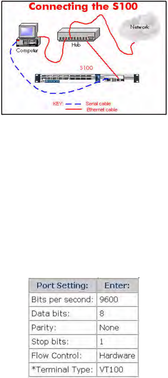
Note: To test the S100 prior to installation, you will need three Ethernet cables and a hub
(see diagram below). Connect the supplied Serial cable from your computer to the front of
the S100. Connect the S100 and the computer to the hub using two Ethernet cables. You
can perform an off-network test at this point. When you have completed the test, connect
S100 User Guide – Rev. D – June 2005 25
2
5
3
the hub directly to the network using the third Ethernet cable and perform an on-network
test.
Figure 3-4: Connecting the S100
The following instructions assume you are using Windows OS. With your computer turned
on:
1. Use and configure Hyperterminal, click Start->Programs->Accessories-
>Communications>HyperTerminal.
2. The “Connection Description” dialog box appears. In the Name field, enter a name.
In this example, it is S100.
3. Click OK.
4. In the “Connect to” dialog, select the COM Port number you are connected to. In
this example, COM Port 1 is selected.
5. Click OK.
6. In the “COM1 Port Properties” dialog, enter the following Port Settings.

26 S100 User Guide – Rev. D – June 2005
SyncServer S100
Figure 3-5: COM Port Properties
* To set the Terminal Type, select File>Properties>Settings.
7. Click OK.
8. In the terminal emulation (e.g., hyperterminal) window, select File->Properties. The
“Properties” dialog opens. Click Settings tab. Verify the Telnet Terminal ID is set
at VT100.
9. Click OK.
Note: When your Hyperterminal is connected and operational, at the bottom of the win-
dow you should see the following :
Setting Up the IP Address
1. Power on the S100 unit. The Linux system boots. Various bootup data scrolls on the
terminal emulator’s (e.g., Hyperterminal) screen. This may last a few minutes. When
prompted, at the User ID login, type: root <Enter>. At the Password prompt, type:
symmetricom <Enter>.
Note: The following anomaly occurs when using Hyperterminal in WIN 95: “boot: e”
appears at the prompt interrupting the boot process. Use your backspace key to delete the
“e”. Then press <Enter>. This will continue the bootup process. If using Tera Term or other
terminal emulation program, this anomaly may not occur. For security purposes, the root,
or superuser, password should immediately be changed using the passwd utility. To do
this, see “How to change the root password” on page 115.
Keep your newly created password in a safe and secure place. If you should lose it, there is
NO PASSWORD RECOVERY capability with the S100. This means that you will have to
send the S100 back to Symmetricom for recovery!
2. Additional Linux boot-up data appears. When prompted, enter the Login and Password.
Type each one and press <Enter>.
syncserv1 login:
Password:
S100 User Guide – Rev. D – June 2005 27
2
5
3
Figure 3-6: Login and Command Line
3. A command line appears.
4. Type netconfig and press <Enter>.
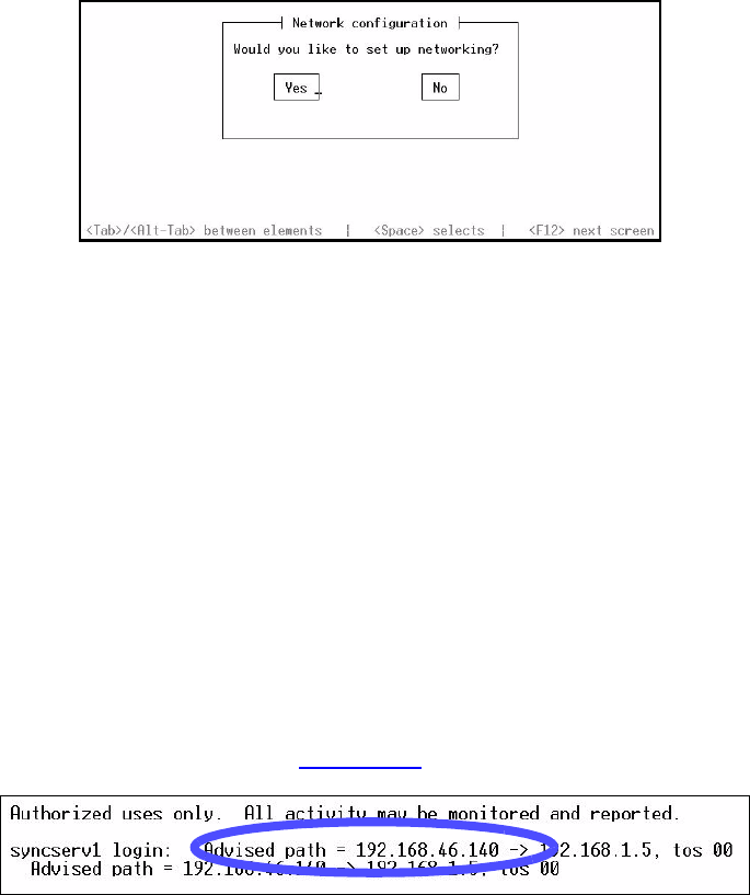
5. The Network Config screen pop-up appears, “Would you like to setup networking?” This
screen should appear as follows:
Figure 3-7: Network Configuration Screen
6. If your screen does not appear this way, check the settings on your Hyperterminal. Select
Yes <Enter>.
7. Another Network Config screen appears. If you select the DHCP box, setup will
automatically find an IP address. Otherwise, enter your assigned IP address and any
other information in the appropriate area . When completed, press <Enter>.
Note: Most users will use a static IP address. Using the DHCP (Dynamic Host-Configura-
tion Protocol) is an automatic way to obtain an IP address. However, this IP address may
later be reassigned if it is not used for a period of time, depending on your IT network
guidelines.
8. A command line appears. Type reboot <Enter>. The S100 reboots, several Linux boot-
up screens appear. A similar message should appear (if you selected DHCP)
confirming an IP address (see Figure 3-10 also):
Figure 3-8: DCHP Confirmation Screen
The S100 unit now has an IP address recorded. This IP address will remain even if there is a
sudden power failure or improper shutdown. Make a note of the IP address for future
reference. Use your Password and Login again when requested as in Step 2 (under Setting
up the IP Address). Jot down the IP address.
28 S100 User Guide – Rev. D – June 2005
SyncServer S100
Testing Network Functionality
To ensure that your network is functioning correctly, check to see if the S100 is on the
network.
First, check the Ethernet connection between the client computer and the S100:
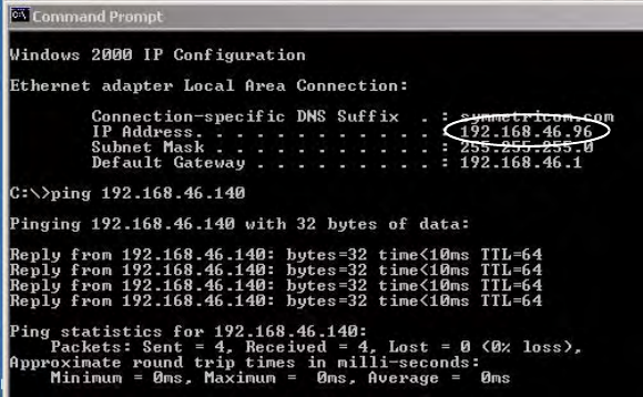
1. Call up the client computer’s command prompt. Use the Windows MS-DOS command
prompt. At the command line, type: IPCONFIG<Enter>. Your computer’s IP address
appears (see A).
Figure 3-9: IPCONFIG and PING Screen
Note: In Win95, type WINIPCFG at the command line in Step 1.
At the command prompt (See Figure 3-9), type a ping command to verify that the S100 is
visible on the network. Use the IP address for the S100. For example:
ping xxx.xxx.xxx.xxx (where xxx = the IP address of the S100).
2. Press <Enter>. The message shown in Figure 3-9 indicates the ping command was
successful. Four packets were sent and none were lost. An unsuccessful ping results in
packets lost and a Timed Out message.
If there is an affirmative response, the S100 is visible to the network.
Note: If there is no response, then troubleshoot and fix the connection problem before
proceeding with the next steps. Problems may include physical network connections or IP
addresses.
A
B
C
S100 User Guide – Rev. D – June 2005 29
2
5
3
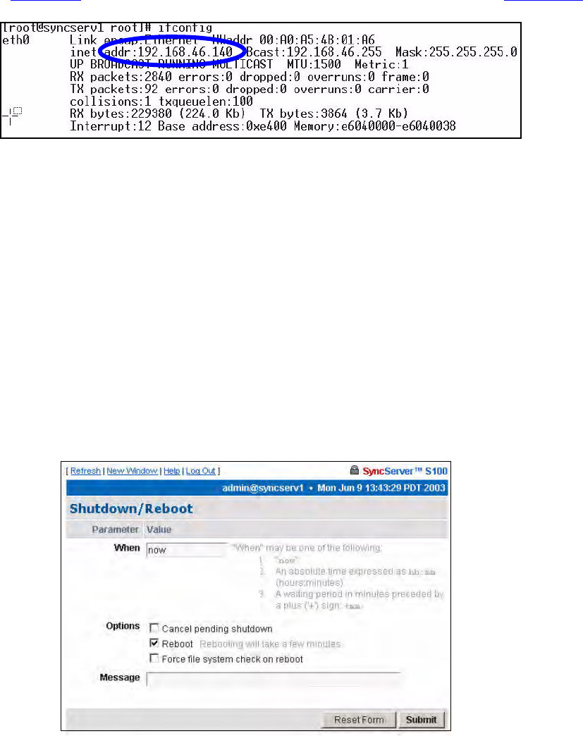
3. Now, verify the S100’s IP address. At the Unix command prompt, at the command line
(Figure 3-6), type IFCONFIG and press <Enter>. The following appears (Figure 3-10).
Figure 3-10: Linux IP Confirmation Screen
4. Open your web browser, enter the IP address in the browser Address field and
press<Enter>. The Configuration Wizard link appears. Use the Wizard to complete the
S100 configuration process.
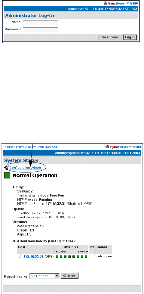
Turning Off Your S100
Normal
If you have configured the unit correctly and it is running normally, select (Administrative
Menu) Administration>Shutdown/Reboot from the S100’s web interface. The following screen
appears:
Figure 3-11: S100 Shutdown Screen
If you are using SSH or TTY, at the prompt type: shutdown -h now<Enter>.

30 S100 User Guide – Rev. D – June 2005
SyncServer S100
How to Acquire Time
With the S100, you can choose your source of secure time.
Each of the time references described in this section is configured using the web-based
interface’s Configuration Wizard.
First, log on.
Logging On
In your browser, enter the IP address of the S100 (use this format: “http://ipaddress”). Add the
S100 home page to your ‘Favorites’ list for future convenience. If the link/icon is not present,
in your browser address window, enter the S100 IP address <Enter>.
On your first log-in, the first screen you see is the System Status screen.
The System Status screen gives you the status of the S100’s Timing, Uptime, and
Versions.
The color of the box on the top left side of the screen is your guide. It follows the traffic light
convention:
• Green = Normal Operation: The S100 is up and running with the correct time.
• Amber = Unsatisfactory: System not yet ready to issue time.
• Red = Unsatisfactory: Some settings still need attention before secure time can be
issued.
Note: Log-ins after this first log-in will bring you to the last screen you accessed in your
most recent session.
Figure 3-12: Initial System Status
S100 User Guide – Rev. D – June 2005 31
2
5
3
Administrator Log-In
On the System Status Screen, click the Administrator Log-In link. After the security alert,
the following dialog is displayed.
Enter the default user name, admin, and default password, symmetricom. We strongly
recommend you change these settings as soon as possible.
(You may log off by clicking Log Out at the top of each screen in the interface. More about
logging off can be found in “Logging Off” on page 85.)
System Status: Logged In
Once logged in, you see the System Status screen again except now it has more information.
In Versions, this information refers to the current software in the S100. In the NTP Host
Reachability, this example shows that the IP address was accessed eight times and provides
additional details.
Figure 3-13: Logging In
Figure 3-14: Full System Status
Configuration Wizard
32 S100 User Guide – Rev. D – June 2005
SyncServer S100
Next Step
If this is your first log-in, your next step is to select the Configuration Wizard link at the top
of the System Status page (see Figure 3-14).
If you have logged in before and have already configured your S100, skip the Configuration
Wizard and instead choose the item you want from the Administrative Index in the left pane.
Details are then provided in the right window pane. If you have established the S100's IP
address, type it in the browser's Address field and press <Enter>. The browser displays the
screen in Figure 3-15.
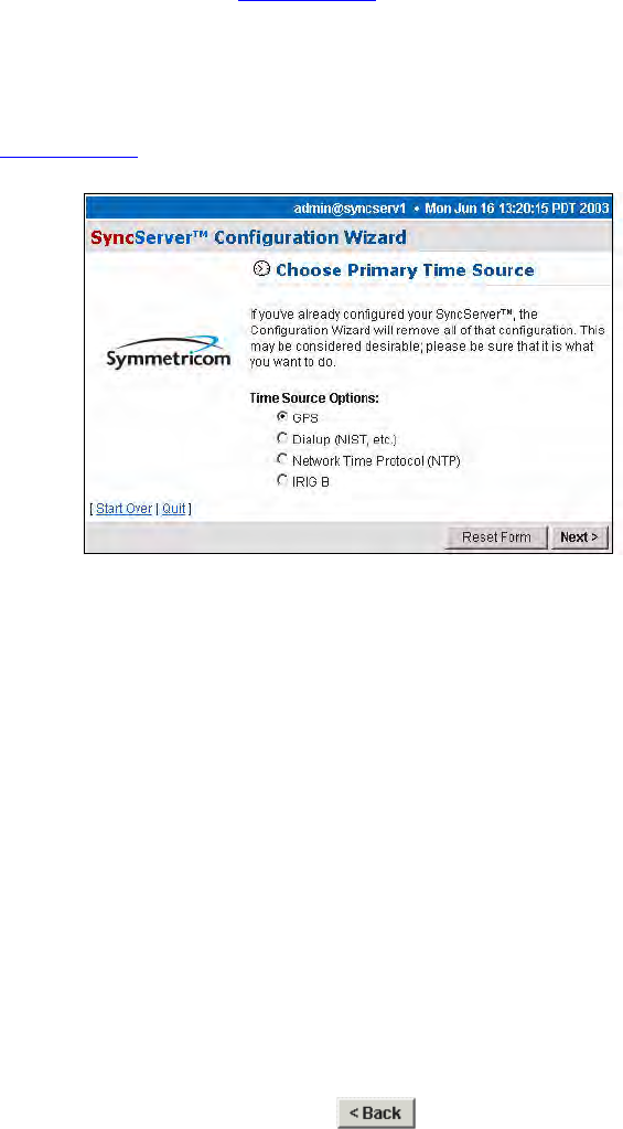
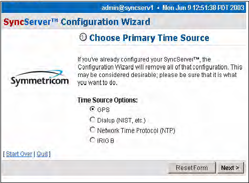
Figure 3-15: Configuration Wizard: Choose Primary Time Source
Note: The Configuration Wizard is the most convenient way to configure the S100.
The Configuration Wizard
Using your browser, follow this easy-to-direct sequence of dialogs to configure the S100’s
source of time. You will need the wizard only once, unless you change the time source for the
S100.
Every screen in the wizard lets you start over, reset, or (for a screen in a sequence) go back
to the previous screen.
Note: When within the Configuration Wizard, do not use your browser’s back button. Use
the Wizard’s back button instead:
Use the Reset button to clear the fields of previously typed information.
S100 User Guide – Rev. D – June 2005 33
2
5
3
Choose Your Time Source
The first dialog in the Configuration Wizard asks you to choose the source of time.
The choices are:
• Global Positioning System (GPS)
• Dial-up (to NIST's Automated Computer Time Service (ACTS))
• Network Time Protocol (NTP)
• IRIG-B
Figure 3-17 shows the screen flow after choosing the time source option you prefer.
Warning: If you've already configured your timing engine, the Configuration
Wizard will remove all of that configuration. This may be considered
desirable; please be sure that this is what you want to do.
Figure 3-16: Choose Your Time Source

34 S100 User Guide – Rev. D – June 2005
SyncServer S100
Beginning on the following pages, you will be walked through each of the various
configuration screens used in the Wizard. Most information is self-explanatory. Regardless of
the time source chosen for configuration, the Wizard uses a common set of screens and only
the specific information relating to the time source chosen may be different on any particular
screen.
Figure 3-17: Configuring the S100 Time Source

S100 User Guide – Rev. D – June 2005 35
2
5
3
GPS
If you choose GPS (see Figure 3-16) and click Next, the Dialup Backup dialog is
displayed. If you wish to use dial-up as a backup time source to GPS, click the checkbox next
to Use dialup as backup to GPS, then click the Next button.
If you do not want to back up your GPS time source with dial-up, leave the checkbox
unselected, and click Next, which will open the System Information dialog (see Figure 3-
20).
If you check Use dialup as backup for GPS, this Dialup Settings dialog is displayed. In
Options, if you wish to use ATDP (pulse dialing), check the box, otherwise the S100 uses
standard ATDT (dial tone) dialing.
In the Modem Phone Number field, enter the NIST phone number preceded by any
prefixes that might be required to reach those numbers. A “9,” (nine comma) prefix gets an
outside line from an office phone; the comma introduces a one-second delay before the
remaining numbers are dialed. The “1” prefix is required for long distance dialing in the US.
Figure 3-18: Dialup Backup
Figure 3-19: Dial-up Settings
36 S100 User Guide – Rev. D – June 2005
SyncServer S100
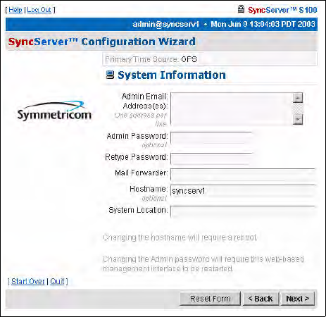
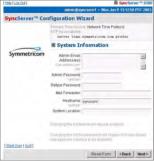
Then click Next for the System Information dialog.
• Admin e-mail, for the administrator of the S100. After a test is conducted, this email
address receives the notice.
• Mail forwarder, or the SMTP server
• Host name
• System (S100) location
Confirm the data that is in the fields. If it is not accurate, change it to the correct information.
Click Next.
Note: All the fields are optional. A unit can be configured and tested with all the fields
blank.
Figure 3-20: System Information
S100 User Guide – Rev. D – June 2005 37
2
5
3
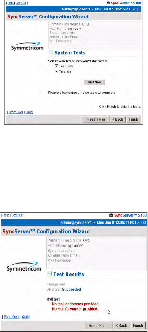
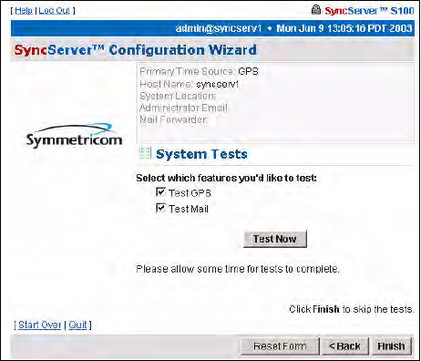
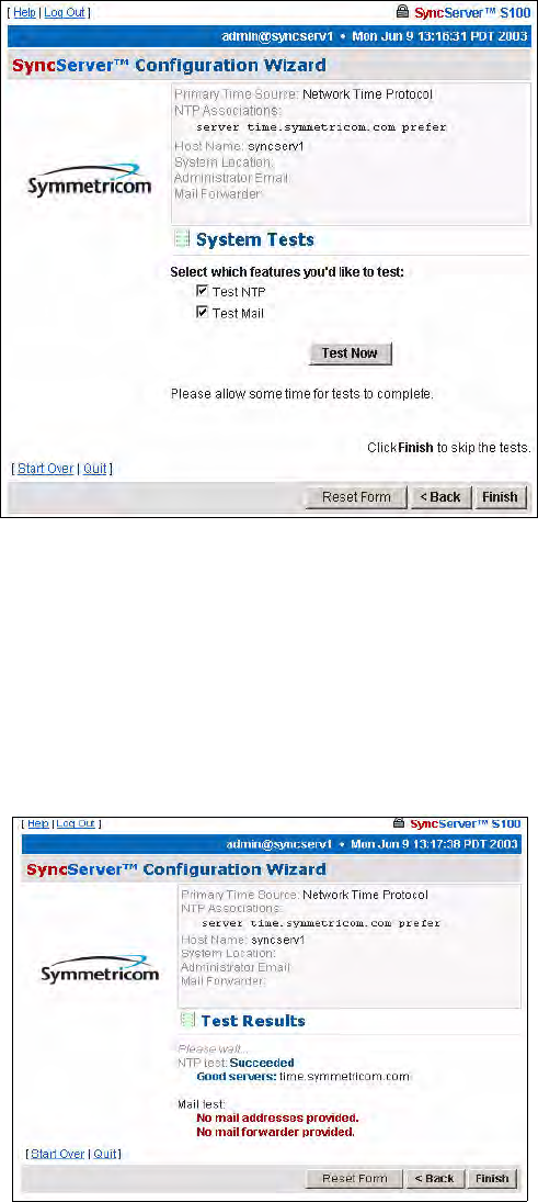
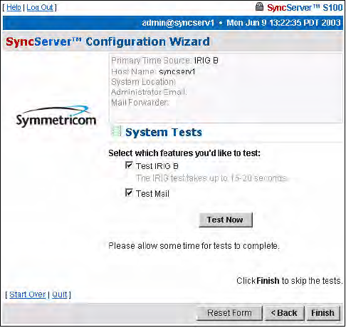
System Tests Dialog
You can skip the test by clicking Finish, or initiate the test by clicking Test Now.
The default is to test all the services, so unless you un-check them, they all will be tested. If
you do not use dial-up as backup, it will not be listed here nor will it be tested. Initiate the test
by clicking Test Now.
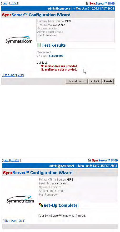
Test Results dialog
This displays the results of your test. This tells you if the S100’s GPS receiver is functioning
properly. In this example, it is. However, failed tests are also shown.
Figure 3-21: System Testing options
Figure 3-22: Test Results shown
38 S100 User Guide – Rev. D – June 2005
SyncServer S100
There is no output to the “Mail test” field. That is because mail is tested by sending an e-mail
to the address that was not provided earlier.
Click Finish.
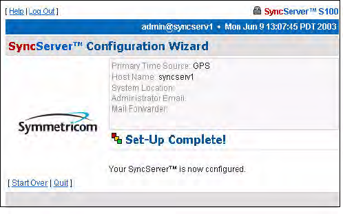
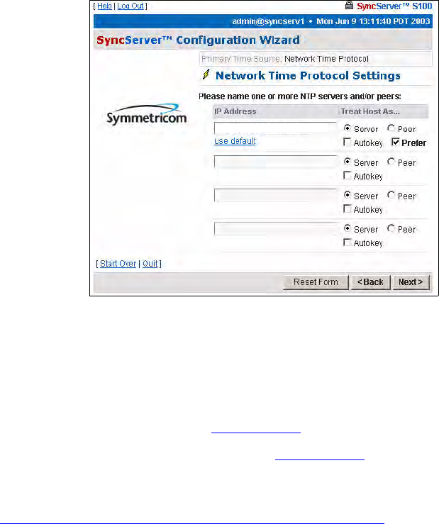
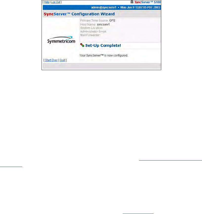
Setup Complete dialog
This screen verifies your configuration of the S100:
• Its time source
• Modem phone number (if you designated dial-up as the backup source for time)
• Host name and System location
• Administrator e-mail
Dialup Settings dialog
When using dial-up, the time reference is coming from an analog phone line through the built-
in modem. Automated Computer Time System (ACTS) is maintained by NIST.
In the US, use either of the following phone numbers to access time:
• Colorado: (303) 494-4774
• Hawaii: (808) 335-4721
Outside the US, connect with your local measurement institute.
Figure 3-23: Your GPS set-up is complete

S100 User Guide – Rev. D – June 2005 39
2
5
3
If you choose the Dialup radio button and click Next, the Dialup Settings dialog is
displayed.
In the field, enter or paste your modem phone number.
Then click Next for the System Information dialog.
System Information dialog
This shows:
• Admin e-mail, for the administrator of the S100
• Admin Password
• Mail forwarder, or the SMTP server
Figure 3-24: Dial-up Settings
Figure 3-25: System Information fields
40 S100 User Guide – Rev. D – June 2005
SyncServer S100
• Host name
• System (S100) location
Confirm the data that is in the fields. If it is not accurate, change it to the correct information.
Click Next.
System Tests dialog
You can skip the test by clicking Finish, or initiate the test by clicking Test Now.
The default is to test all the designated services, so Dialup and E-Mail, unless you un-
check them, will be tested.
To initiate the test, click Test Now.
Figure 3-26: System Testing options
S100 User Guide – Rev. D – June 2005 41
2
5
3
Test Results dialog
This screen tells you if the dial-up time source for your S100 is functioning properly. In this
example, failed tests are shown.
There is no output to the “Mail test” field. That is because mail is tested by sending an e-mail
to the address that you indicated earlier.
Click Finish.
Setup Complete dialog
This screen verifies your configuration of the S100:
• Its time source
• Modem phone number
• Host name
• System location
• Administrator e-mail
Figure 3-27: Test Results shown
Figure 3-28: Your Dial-up set-up is complete
42 S100 User Guide – Rev. D – June 2005
SyncServer S100
NTP
You can also acquire time through other NTP servers and S100s.
Note: If you have not configured DNS, use IP addresses rather than hostnames.
Choose the NTP radio button (see Figure 3-16) and click Next.
The Network Time Protocol Settings dialog (Figure 3-29) appears. On this screen, name
one (or more) NTP servers or peers.
NTP v4’s Autokey requires digitally signed certificates. For more about the Autokey protocol,
see “S100 and NTP v4’s Security Features” on page 10.
Then click Next.
Figure 3-29: Defining Your NTP Settings
ntp1.symmetricom.com
S100 User Guide – Rev. D – June 2005 43
2
5
3
System Information dialog
The System Information dialog shows you:
• Admin e-mail, for the administrator of the S100
• Mail forwarder, or the SMTP server
• Host name
• System (S100) location
Confirm the data that is in the fields. If it is not accurate, change it to the correct information.
Click Next.
Figure 3-30: System Information fields
44 S100 User Guide – Rev. D – June 2005
SyncServer S100
System Tests dialog
You can skip the test by clicking Finish, or initiate the test by clicking Test Now.
The default is to test all the services, so NTP and E-Mail, unless you un-check them, will be
tested.
Click Test Now.
Test Results dialog
This screen tells you if the NTP time source for your S100 is functioning properly or if there is
a test problem.
Figure 3-31: System Testing options
Figure 3-32: Test Results shown
S100 User Guide – Rev. D – June 2005 45
2
5
3
There is no output to the “Mail test” field. That is because mail is tested by sending an e-mail
to the address that you indicated earlier.
Click Finish.
Setup Complete dialog
This screen verifies your configuration of the S100:
• Its time source
• Host name
• System location
• Administrator e-mail
Configuring NTP
To configure NTP, use the NTP Relationships dialog (See “NTP Relationships” on
page 58). Use the dialog to view the NTP status and create the NTP associations.
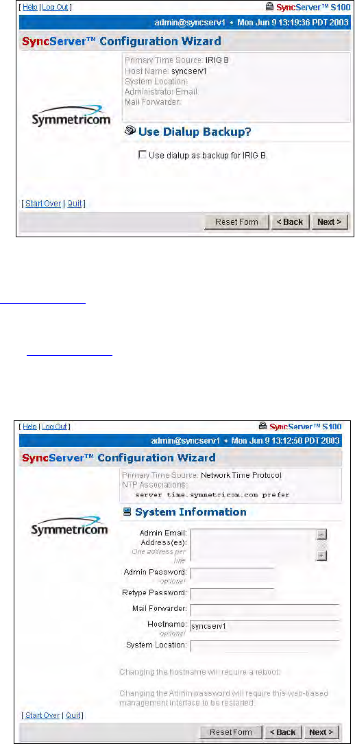
IRIG-B (v.120,122,123)
Both the D-BNC Signal Breakout Cable and the optional Rubidium oscillator cable provide a
Timecode Input connector. To use IRIG time code as a reference, connect the IRIG signal to
the Timecode Input connector, select IRIG-B (see Figure 3-16), and click Next.
If you wish to use dial-up as a backup time source to GPS, click the checkbox next to Use
dialup for backup to IRIG-B, then the Next button.
If you do not want to back up your IRIG with dial-up, leave the checkbox unselected, and click
Next.
Figure 3-33: Your set-up is complete
46 S100 User Guide – Rev. D – June 2005
SyncServer S100
Dialup Backup dialog
If you check Use dialup as backup for IRIG-B, a similar Dialup Settings dialog is
displayed (see Figure 3-24).
In the field, enter or paste in your modem phone number. Then click Next.
A screen similar to Figure 3-35 now appears.
System Information dialog
This shows:
• Admin e-mail, for the administrator of the S100
• Mail forwarder, or the SMTP server
Figure 3-34: Dial-up Settings
Figure 3-35: System Information fields
S100 User Guide – Rev. D – June 2005 47
2
5
3
• Host name
• System (S100) location
Confirm the data that is in the fields. If it is not accurate, change it to the correct information.
Click Next.
System Tests dialog
You can skip the test by clicking Finish, or initiate the test by clicking Test Now.
The default is to test all the services, so unless you un-check them, they all will be tested. If
you do not use dial-up as backup, it will not be listed here nor will it be tested.
Figure 3-36: System Testing options
48 S100 User Guide – Rev. D – June 2005
SyncServer S100
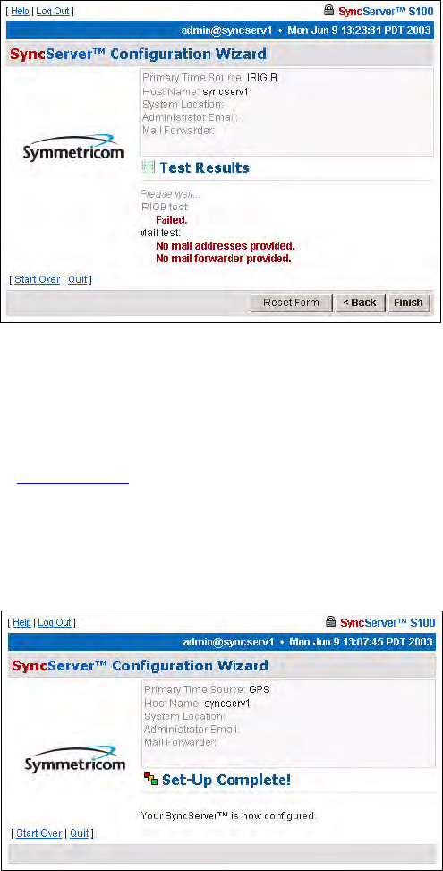
Test Results dialog
This screen shows whether the IRIG-B for your S100 failed or passed. In this example, the
IRIG-B failed.
There is no output to the “Mail test” field as no addresses had been provided in the System
Information dialog (Figure 3-35).
Click Finish.
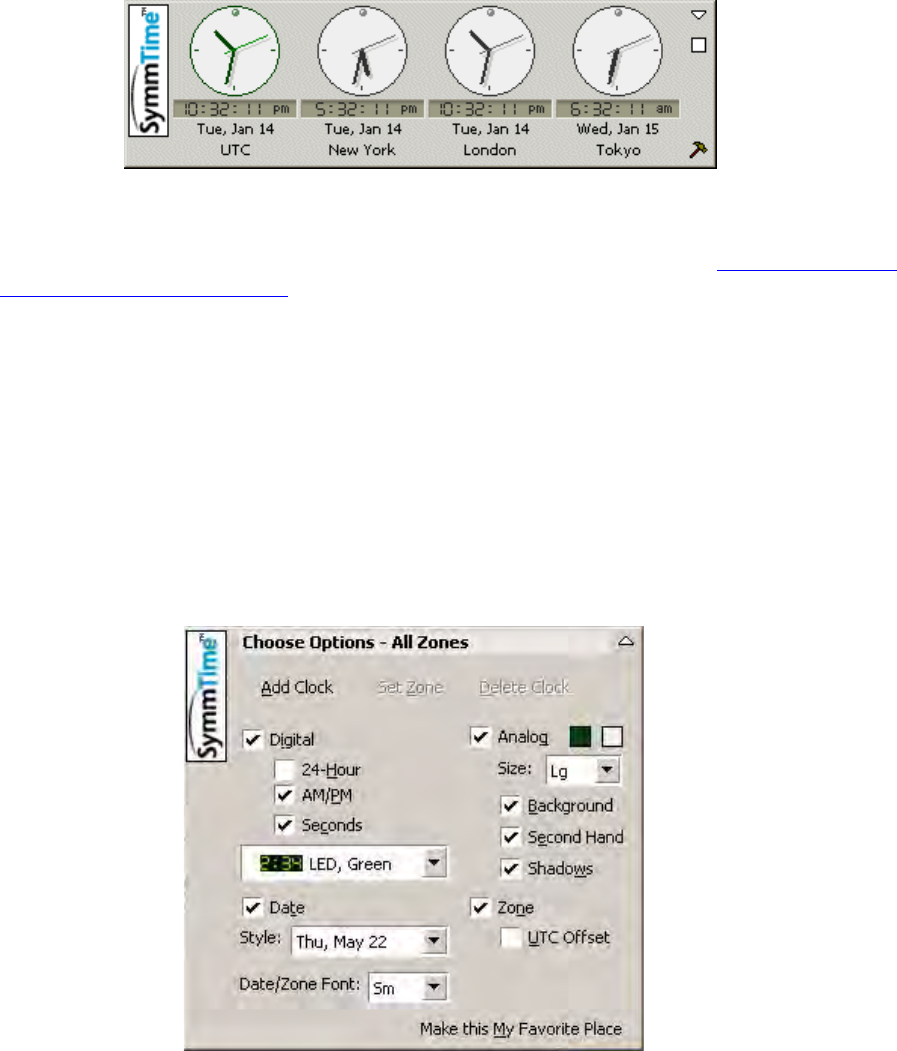
Setup Complete dialog
This screen verifies your configuration of the S100:
• Its time source
• Modem phone number (if you designated dial-up as the backup source for time)
• Host name
• System location
• Administrator e-mail
Figure 3-37: Test Results shown
Figure 3-38: Your IRIG set-up is complete
S100 User Guide – Rev. D – June 2005 49
2
5
3
Using SymmTime™
Next, you need to install client software to test NTP (Windows installation).
The SymmTime utility is a handy way of doing this. It keeps accurate time on your client
Windows computer.
Use SymmTime200x.exe to launch SymmTime on your PC. When executed from the CD-
ROM, a small pop-up containing four clocks appears. Once installed, visit http://www.ntp-
systems.com/symmtime.asp and download the latest updated files.
Installing SymmTime
1. On the client computer’s hard drive, create a separate directory for SymmTime.
2. Copy the SymmTime200x.exe file from the utility disk into this directory.
3. Double-click Symmtime.exe. This will install the program onto your computer.
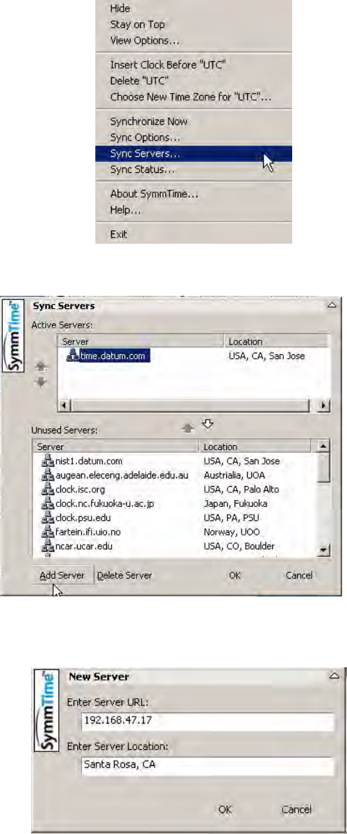
4. Configure the clocks as you desire using the Build tool (select the hammer in the lower
right corner, the following appears).
Figure 3-39: SymmTime™ Utility and Clock Display
50 S100 User Guide – Rev. D – June 2005
SyncServer S100
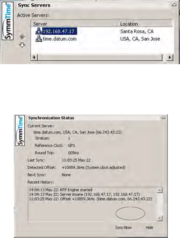
5. Right-click the displayed clocks for the menu and select Sync Servers
6. The following screen appears. Click Add Server.
7. New Server dialog box, enter the IP address and location of the S100. Click OK. The IP
address you use will be the one obtained in the setup of the S100.
S100 User Guide – Rev. D – June 2005 51
2
5
3
8. The IP is added to the Active Servers window. Click OK. The IP address is listed under
Active Servers.
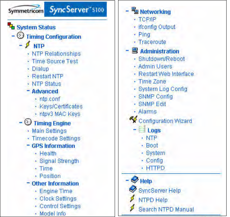
To Synchronize SymmTime:
1. Right-click anywhere on the clocks. Select Sync Status from the menu to tell your
computer to automatically get time from the S100. A similar screen will appear.
2. Click Sync Now. If you receive a no response, it is because you have not yet configured
the S100; configure it now. An affirmative response confirms you have configured the
S100.
Next: Use the Web-Based Interface
Now that you have established the S100, configured your time source, and installed your
client software, you can use the web-based interface to manage S100 operations. See
Chapter 4 for a complete description.
52 S100 User Guide – Rev. D – June 2005
SyncServer S100

S100 User Guide – Rev. D – June 2005 53
2
5
3
Chapter 4
The Web-Based Interface
Overview
The following is a description of the web-based software interface that you use to manage the
S100.
This material is designed to be a reference for you as you use the S100. It also describes
some of the procedures that will help you begin using the S100.
Symmetricom recommends you review this section before beginning the permanent
installation of the S100, so that you will be familiar with it when you need to use it.
For detailed information about NTP (Network Time Protocol), use the NTPD Help link (see
“NTPD Help” on page 84) embedded in the S100’s web interface to review the NTP
Distribution document (source: University of Delaware).
Additional information is available at http://www.ntp.org/.
Interface: Screen Reference
The S100 management interface has been designed with ease of use in mind. As a result,
you access the management interface S100 through any web browser. This section
describes the screens used in the interface, including their functions. It supplies some
procedural instructions, as well.
Each dialog or screen, except in the Configuration Wizard, lets you refresh that screen or
open a new window, and all will let you log out.
For security reasons, the interface will time out after 30 minutes if there is no activity.

54 S100 User Guide – Rev. D – June 2005
SyncServer S100
Logging In
Using your browser, the following dialog is displayed once you enter the S100’s IP address or
click the link to or icon for the S100.
Enter the default user name, admin, and default password, symmetricom.
Assuming this is the first time you have logged in, you will see the System Status screen (see
“System Status” on page 57).
Log-ins after this first log-in will bring you to the last screen you accessed in your most recent
session.
Administrative Interface
This is the main tool for administering the S100.
If you click Refresh at the top of any screen, it will remove any confirmation or error
messages on the screen.
If you click New Window at the top of any screen, it opens a second browser window without
the admin menu.
Figure 4-1: Logging In

S100 User Guide – Rev. D – June 2005 55
2
5
3
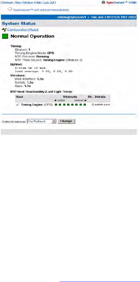
Admin Interface: Base Menu
The first thing you see on the left of your screen is the base Administrative (Admin)
Menu. This is the starting point for administration tasks on the S100. Click “+” to expand the
sub-menu.
Figure 4-2: Administrative Interface: Base Menu
56 S100 User Guide – Rev. D – June 2005
SyncServer S100
Administrative Menu: Expanded
Expanding each item on the base menu shows you all the available options. Click Collapse
(at the bottom of the menu) to revert to the base version of the menu.
Figure 4-3: Interface Admin Menu, expanded
S100 User Guide – Rev. D – June 2005 57
2
5
3
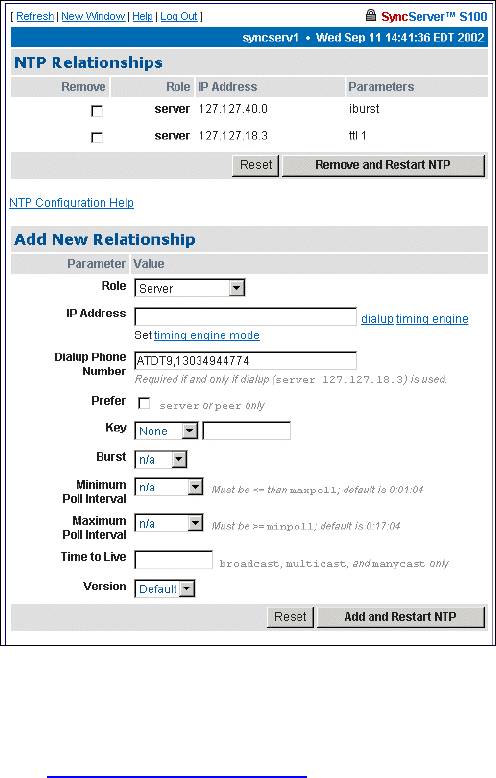
System Status
Clicking this item, you will quickly see the status of the S100.
The color of the box on the left side of the page is your guide. It follows the traffic light
convention:
• Green = Normal Operation: the S100 is up and running with the correct time
• Amber = Unsatisfactory: Some settings still need attention before secure time can be
issued
• Red = Unsatisfactory: System not yet ready to issue time
Timing Configuration
These menu options let you manage NTP, the heart of the S100 system. For more details on
each of the NTP terms used here, see “NTPD Help” on page 84.
Figure 4-4: Checking the Status
58 S100 User Guide – Rev. D – June 2005
SyncServer S100
NTP Relationships
Use this option to configure NTP
.
Define the relationships between and among this host and other hosts.
For more details, see “NTPD Help” on page 84 or click HTPD Help embedded in the S100
web interface.
In the NTP Associations panel of this screen you see the configuration of the network that
you are putting the S100 on. These are all the devices from which the S100 can get time.
They are named as server or peer, depending on their relationship to the S100.
In this section, clicking Reset clears any data you’ve just added, and clicking Remove and
Restart NTP deletes the checked host(s).
The Add New Relationships panel lets you add a host to your configuration. Next to each
parameter, enter the values for the clients you are adding to the configuration:
Role - The host you add can serve in any one of the following roles:
• Peer
Figure 4-5: Configuring New Clients and Servers

S100 User Guide – Rev. D – June 2005 59
2
5
3
• Server
• Broadcast
• Manycast Client
• Broadcast Client
• Manycast Server
• Multicast Client
Address - Enter the IP address or host name for the host you are adding.
Dialup, timing engine, and Set timing engine mode links - Use these links to populate the
address field appropriately.
Dialup Phone Number - Enter the modem phone number you will be using. Enter a 9, (nine
comma) if required to get an outside line. (The comma introduces a one second delay, which
gives time for the outside dial tone to become available.)
Prefer - This marks the server as “preferred”, meaning this server, of all the correctly
operating hosts and if all things are equal, will be the host chosen for synchronization.
Key - All packets sent to and received from the server or peer will include authentication
fields encrypted using the specified key.
• None: The default, no encryption field.
• Key= : This is the index of the key in the keystore.
• Autokey: All packets sent to and received from the server or peer include authentication
fields encrypted using the autokey scheme. (NTP v4)
Burst - Data grouped for transmission, in the following ways:
• N/A: If you choose this option, the Burst command will not be executed.
• Burst: Selecting this option tells the system that when the server is reachable, send
eight packets instead of one.
• iBurst: Selecting this option tells the system that when the server is not reachable, send
eight packets and keep trying every 16 seconds.
Minimum Poll Interval - Indicate in seconds the smallest measure of time in which you want
the S100 to check the network hosts’ time. If you enter nothing here, the S100 will use the
default, 0:01:04 seconds.
Maximum Poll Interval - Indicate in seconds the largest measure of time in which you want
the S100 to check the network hosts’ time. If you enter nothing here, the S100 will use the
default, 0:17:04 seconds.
Time to Live - Data in the Internet Protocol that specifies how many more hops a packet can
travel before being discarded or returned, here entered in the form of whole numbers.
Version - These are Default, 1, 2, 3, or 4.
Clicking Reset clears the data you’ve just entered.
Clicking Add and Restart NTP adds the data you’ve just entered and restarts NTP.
When you are finished with the addition of any new clients, they will display in the NTP
Relationships panel (see “NTP Relationships” on page 58) at the top of the screen.
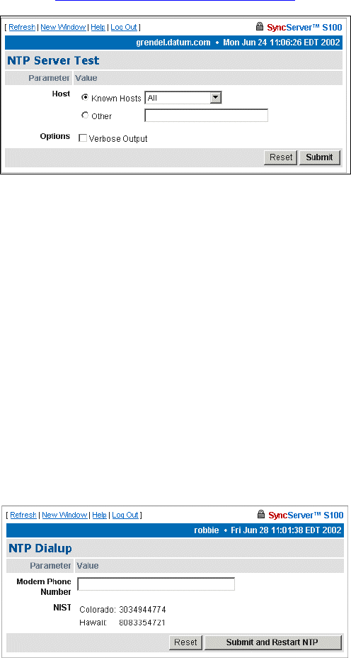
60 S100 User Guide – Rev. D – June 2005
SyncServer S100
NTP Time Source Test
The NTP Server Test dialog lets you test the servers you designated in the NTP
Relationships panel (see “NTP Relationships” on page 58.
Host -
• All
• 127.127.40.0 (onboard GPS/IRIG reference clock driver)
• 127.127.18.3 (NIST ACTS reference clock driver)
• localhost
Options - Use the checkbox to enable Verbose Output.
NTP Dialup
In the following dialog, enter or paste in your modem phone number.
Then click Submit.
Figure 4-6: Testing the NTP Time Source
Figure 4-7: NTP Dialup
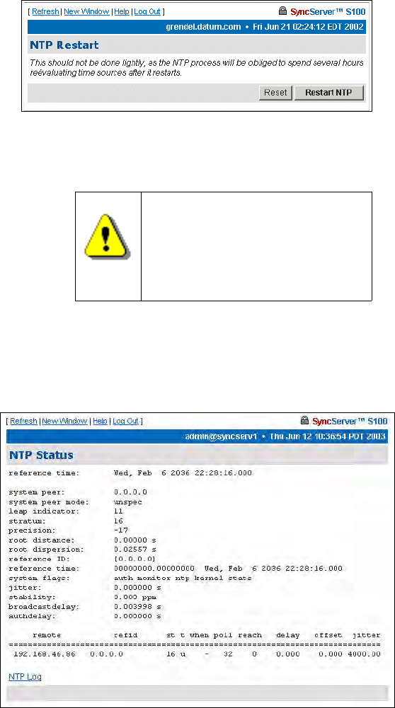
S100 User Guide – Rev. D – June 2005 61
2
5
3
NTP Restart
Here, you can restart the NTP daemon, for troubleshooting purposes only.
However, please note the following warning:
NTP Status
This screen gives you the following information:
Reference Time - This is the last time it synced.
System Peer - This tells you which NTP server the S100 is synced to.
System Peer Mode - This tells you what the S100 is—client or otherwise—to the NTP server
it is synced to.
Warning!
It can take NTP a significant
period of time to go through its
processes. If you choose to
restart, you will be required to
reset your time source.
Figure 4-8: Restart NTP
Figure 4-9: Snapshot of NTP Status
62 S100 User Guide – Rev. D – June 2005
SyncServer S100
Leap Indicator - This is a two-bit code warning of an impending leap second. The numbers
mean:
00 = no warning
01 = the last minute has 61 seconds
10 = the last minute has 59 seconds
11 = alarm condition (clock not synchronized)
Stratum - This is the stratum level of the S100.
Precision - This is an eight-bit signed integer indicating the precision of the local clock, in
seconds to the nearest power of two. The range is -6 to -18.
Root Distance, or root delay - This is a signed fixed-point number indicating the total round-
trip delay to the primary reference source at the root of the synchronization subnet, in
seconds. It can be expressed as either a positive or negative number.
Root Dispersion - A 32-bit unsigned fixed point number indicating the maximum error
relative to the primary reference source, in seconds (milliseconds).
Reference ID - A 4-byte code indicating the reference source. If the reference source is
stratum 0, this string will identify the type of source (GPS or dial-up, for example). If the
source is stratum 1 or higher, this 4-byte code will contain the IP address of the reference
source.
Reference Time - The local time at which the local clock was last set or corrected, in a 64-bit
time-stamp format.
System Flags - These are various flags that can be enabled or disabled using the
configuration commands.
Jitter - Distortion of a signal caused by some weakness in synchronization, here shown in
seconds (milliseconds).
Stability - This is the residual frequency error remaining after the system frequency
correction is applied. Used most often in maintenance, the value starts as high as 500 ppm
but settles into the .01 to 0.1 ppm range.
Broadcastdelay - This shows the default broadcast delay.
authdelay - This is the default authentication delay.NTP Advanced Configuration
Here you will find advanced configuration features of NTP. You probably won’t need to access
these, but they are here if you need to edit the configuration.
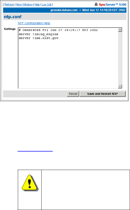
S100 User Guide – Rev. D – June 2005 63
2
5
3
Advanced: ntp.conf
The following dialog is only for those with advanced knowledge of NTP.
The dialog in Figure 4-10 displays the NTP configuration file. It allows you to edit the config
text file.
If you need help with the NTP config file, click the NTP Configuration Help link near the top of
the screen, and you will be directed to NTP Help. Additional information about NTP is
available is available at www.ntp.org
.
Warning!
If you improperly configure the
ntp.conf, you will render the S100
unable to sync to any time source.
Be certain you know NTP well
enough to do this.
Figure 4-10: Viewing the NTP Configuration File
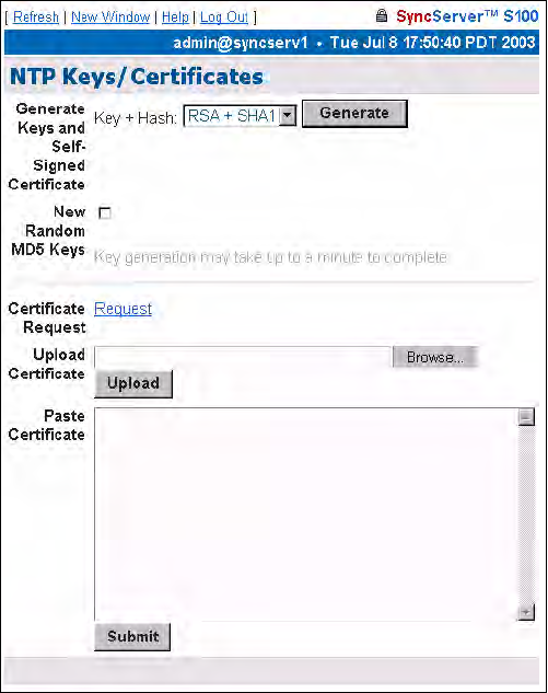
64 S100 User Guide – Rev. D – June 2005
SyncServer S100
Advanced: Keys/Certificates
Use this NTP Keys/Certificates dialog to obtain a digital certificate that verifies the identity of
the S100.
Working from top to bottom:
Generate Keys - Select the key algorithm and hash algorithm you wish to use:
• RSA + MD5
• RSA + SHA1
• DSA + SHA1
DSA + SHA1 is the default.
New Random MD5 Keys - Select this checkbox to generate random MD5 keys.
Then click Generate.
The screen refreshes and a “keys generated” message displays in the upper left corner.
Next to the Certificate Request field, click Request to issue a certificate request. A
confirmation dialog will prompt you to tell the system where you want the certificate; respond
to the prompt.
If you choose Upload Certificate, browse to the certificate request, as sent to you by the
Certificate Authority, or enter its name. Then click Upload.
Figure 4-11: Obtaining and Generating Keys
and Certificates
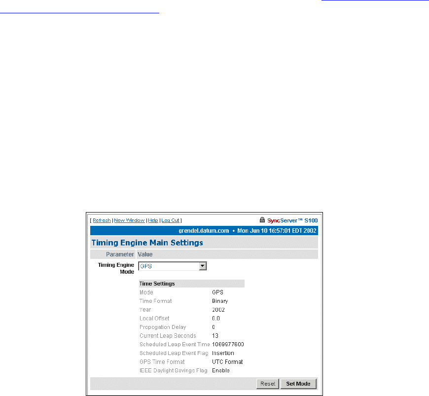
S100 User Guide – Rev. D – June 2005 65
2
5
3
Alternatively, you can use Paste Certificate to copy and paste the certificate from the
certreq.jsp file into this field. Open the certreq.jsp file using a text editor (e.g., Notepad)
and copy the contents. The certificate should be base 64 encoded. Paste the contents in the
Paste Certificate field here, then click Submit.
The S100 is self-signed, thus it can verify your certificate.
For more about how the S100 uses NTP keys and certificates, see “S100 and NTP v4’s
Security Features” on page 10.
Timing Engine
This section of the interface lets you view various aspects of the Symmetricom bc635/637
PCI board—the timing engine of the S100.
Main Settings
The timing engine mode choices you see in the drop-down list box are:
• GPS is the default, which obtains the time from GPS receiver and antenna.
• IRIG, which obtains the time from the IRIG time code input. (Note: IRIG time code
doesn’t include the year with its time information. Be sure to enter the year in the Year
field.)
• Free Running means there is no external timing source used, that the time is set
manually
• One Pulse Per Second, or 1PPS, syncs the oscillator to a user-supplied 1PPS
Figure 4-12: Timing Engine Main Settings
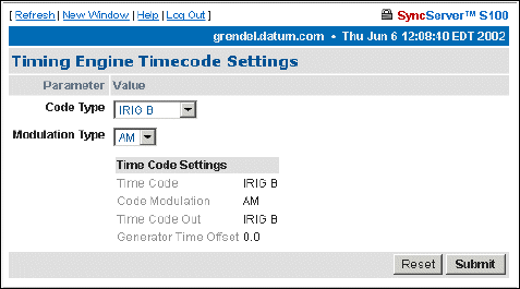
66 S100 User Guide – Rev. D – June 2005
SyncServer S100
• Real-Time Clock, or RTC, synchronizes the oscillator to the 1PPS signal from the
timing engine itself
Mode - How time is being acquired.
Time Format - The timing engine uses Binary code time.
Year - Set the year here. (Note: You must enter the year if you are using IRIG as the primary
reference source).
Local Offset - Allowed values are -16 through +16, and can include half-hour offsets.
Propagation Delay - If there is any propagation delay from the reference source, the timing
engine will adjust for it. Values range from -9999999 to +9999999.
Current Leap Seconds - This figure accounts for the local offset.
Scheduled Leap Event Time - This is a 32-bit binary value corresponding to the number of
seconds elapsed since 0 hour January 1, 1970 UTC.
Scheduled Leap Event Flag - This will alert you to an upcoming leap event.
GPS Time Format - UTC is the default.
IEEE Daylight Savings Flag - This alerts you to an upcoming Daylight Savings Time event.
Timecode Settings
Code type choices in the drop-down list box are:
• IRIG-A
• IRIG-B
• IEEE 1344
• NASA 36
Code Type - This identifies the time code in setting.
Modulation Type - The type associated with the time code signal:
• AM, for amplitude modulated
• DC, for direct current level shift, or digital IRIG
Figure 4-13: Timecode Settings
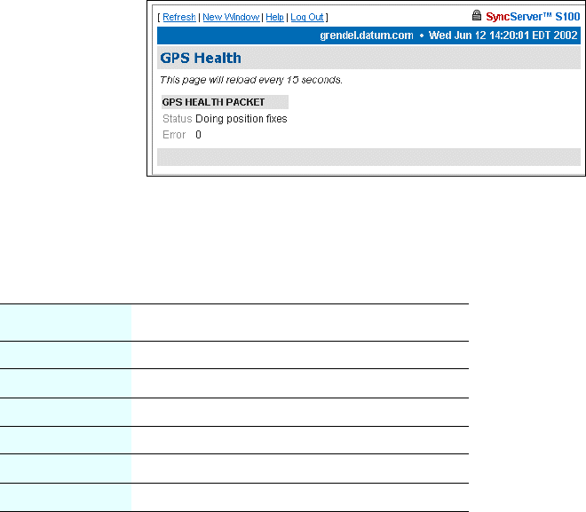
S100 User Guide – Rev. D – June 2005 67
2
5
3
The default modulation envelope is AM.
Time Code Settings - This confirms the settings:
• Time Code = The time code in setting
• Code Modulation = The modulation type associated with the time code signal
• Time Code Out = The time code out setting
• Generator Time Offset = This shows any offset to the time code signal being produced by
the timing engine.
Clicking Reset lets you clear any data you’ve entered, and Submit implements changes
you have made.
GPS Information
This section of the admin menu appears only if you have the GPS option on the S100.
The following items give details on GPS activity:
GPS Health
This screen updates the signal status. This example shows a normal screen.
The error codes are encoded into individual bits within the byte. The bit positions and their
meanings are shown below.
Bit Position Meaning if bit value = 1
0 Battery back-up failed (1)(4)
1 Signal processor error (1)
2 Alignment error, channel or chip 1 (1)
3 Alignment error, channel or chip 2 (1)
4 Antenna feed line fault (2)
5 Excessive ref freq. error (3)
Figure 4-14: GPS Health Status

68 S100 User Guide – Rev. D – June 2005
SyncServer S100
Notes:
(1) After this error is detected, its bit remains set until the GPS receiver is reset.
(2) This bit follows the current status of the antenna feed line fault-detection circuitry. Since
GPS receiver has an integral antenna assembly, this information of little import; it is only
shown for the sake of completeness, being important for sensors with separate antennas.
(3) This bit is ‘1’ if the last computed reference frequency error indicated that the reference
oscillator is out of tolerance. (Packet 2D requests the oscillator offset and packet 4D returns
the oscillator offset to the user.)
(4) this bit is always set as the GPS receiver battery backup is not installed.
GPS Signal Strength
Here, the signal strength are displayed.
The data is for the satellites that are currently being tracked:
• The satellite number
• The signal level for each satellite
6 (Unused)
7 (MSB) (Unused)
Figure 4-15: GPS Signal Strength
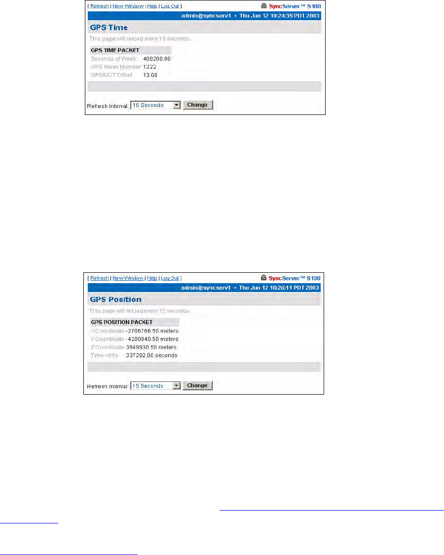
S100 User Guide – Rev. D – June 2005 69
2
5
3
GPS Time
GPS time is noted here.
Seconds of Week - This is expressed in the number of seconds since January 6, 1980 (GPS
Week).
GPS Week Number -This is expressed in the number of weeks since January 6, 1980.
GPS/UTC Offset - Currently this is 13 seconds.
GPS Position
This screen shows you the calculated coordinates of the gps antenna.
X Coordinate = Latitude
Y Coordinate = Longitude
Z Coordinate = Altitude
Time-of-fix = Time
For more about GPS position, see Chapter 2, “S100 and the Global Positioning System”
on page 11.
Note: The GPS antenna described in this manual has been replaced as described in
“Appendix E” on page 141.
Figure 4-16: GPS Time
Figure 4-17: GPS Position
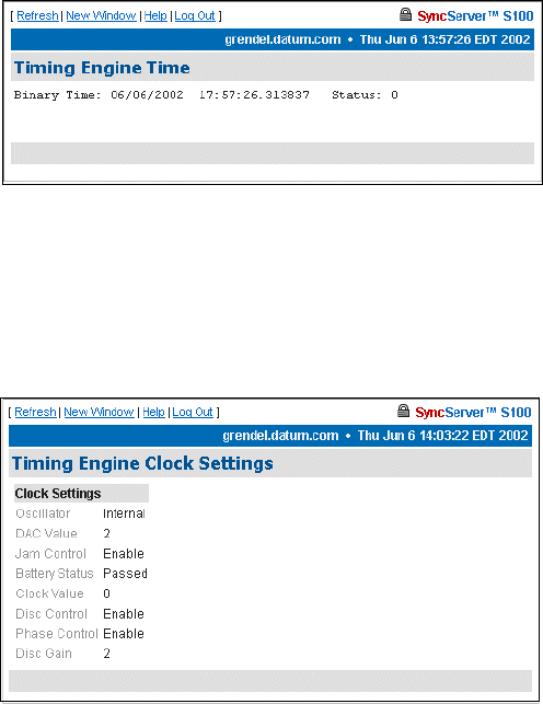
70 S100 User Guide – Rev. D – June 2005
SyncServer S100
Other Information
The following screens give additional information about the S100.
Engine Time
The engine time is read directly from the timing engine.
Clock Settings
The clock settings here are:
Oscillator - This is internal to the timing engine.
DAC Value - A 16-bit Digital Analog Converter is used to set the frequency on the oscillator.
The value here shows a rate match between the hardware clock frequency and the selected
time reference source.
Jam Control - “Jam” refers to jam synchronization. This controls whether or not the
software may “jam” the clock circuitry if a phase discontinuity of greater than 1 millisecond is
found.
Battery Status - The timing engine’s battery status is noted here.
Clock Value - This register shows the number of 100ns steps needed to advance or slow
down the phase of the local clock circuit.
Figure 4-18: Timing Engine Time
Figure 4-19: Clock Settings
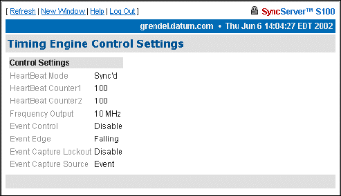
S100 User Guide – Rev. D – June 2005 71
2
5
3
Disc Control - Short for disciplining control, this disciplining function is the part of the
software that matches the local clock phase and frequency with the selected time reference
function.
Phase Control - Short for local clock phase shifting, this function shows if the software is
shifting the one-second rollover point of the local hardware clock by a specified amount.
Disc Gain - Short for oscillator disciplining function gain value, this is a scalar value that
sets the gain for the Kalman filter so it can discipline the local oscillator to the selected time
reference.
Control Settings
The timing engine control settings are viewable here.
They are:
HeartBeat Mode - The heartbeat is the specified frequency.
HeartBeat Counter1 and 2 - These are internal counters to the timing engine.
Frequency Output - The available frequencies are 1, 5, and 10 MHz.
Event Control - This setting enables or disables the ability of the internal clock to capture the
time at which an external event occurs.
Event Edge - This is either the rising or falling edge of the heartbeat signal.
Event Capture Lockout - If enabled, the capture lockout can be used to control whether or
not subsequent signals will overwrite the data in the timing engine’s event time registers.
Event Capture Source - This setting controls the source of the external event—an external
event input or strobe, for example.
Figure 4-20: Control Settings

72 S100 User Guide – Rev. D – June 2005
SyncServer S100
Model Information
The following page provides basic data about the bc635/637 PCI board, the timing engine of
the S100.
Figure 4-21: Timing Engine Model Information
Networking
Use the following dialogs to configure several parameters of the S100 on your network.
TCP/IP
The following dialog enables you to define the following parameters:
Network Interface - Here, choose the Ethernet port you are using. If there is only one
interface, use eth0, the default. A local loopback refers to a loopback plug inserted in one
Figure 4-22: Configuring TCP/IP

S100 User Guide – Rev. D – June 2005 73
2
5
3
of the ports; a signal is transmitted and returned to the sending device and the returned
signal is compared with the transmitted signal in order to evaluate the integrity of the
equipment or transmission path.
DHCP - This is the Dynamic Host Configuration Protocol, which assigns an IP address to
each node in a network. Here, the default is Enable.
Static IP - Click the radio button to Enable, then enter the S100’s IP address, subnet mask,
and default gateway.
The setting for On Boot is defaulted to Enable. Uncheck this box if you do not want the IP
address when you reboot.
Local Domain - This is your local domain name.
Search Domains - The system will search these domains—which usually include your local
domain as well as others—so it can resolve any unresolved host names that may be missing
the host, local, or top level portion of the name.
Hostname - Enter the S100’s name here.
IP Forwarding - You can redirect data from one IP address to another by selecting Enable
here.
DNS Nameservers - These are the DNS servers on the network.
Reset - Click this button to return to the previous settings.
Update/Reboot - Click this button to reboot the server, but please note the warning:
If you do choose to do this, a confirmation message will display at the top if this screen.
Warning
If you click Update/Reboot, you will
reboot the server, and will need to
reacquire time. Be certain you want to do
this.
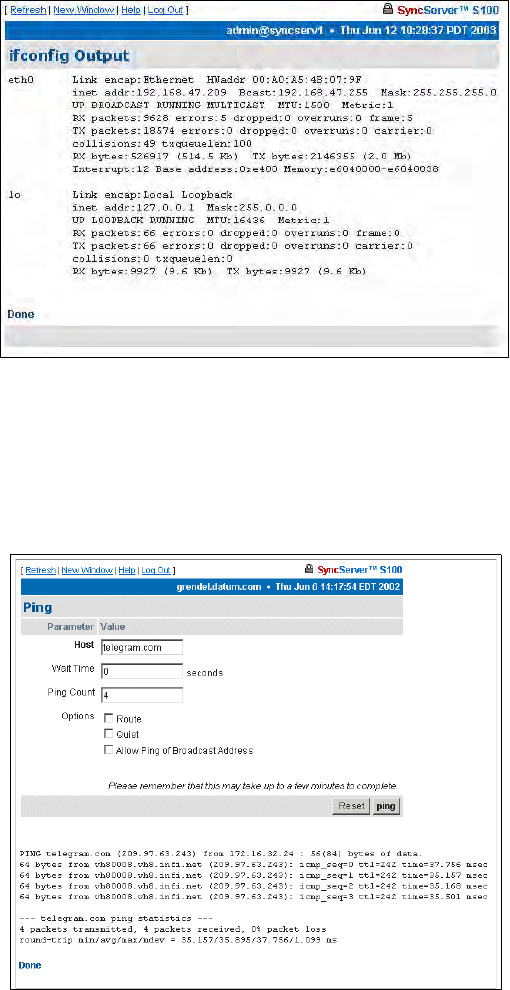
74 S100 User Guide – Rev. D – June 2005
SyncServer S100
ifconfig Output
This screen gives you information about the network configuration of the S100. It lets you
troubleshoot network problems.
Ping
Use the ping command to test the network route between the S100 and a remote host.
This is a diagnostic tool that confirms that all is well between the two devices.
The dialog shown in Figure 4-24 lets you define the following parameters:
Host - URL of the remote host
Figure 4-23: Configuration Information
Figure 4-24: Pinging the Remote Host
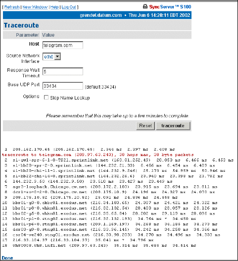
S100 User Guide – Rev. D – June 2005 75
2
5
3
Wait time - Response time between pings
Ping count - Try to ping this number of times before quitting
Options -
• Route: Gives detailed information about the route followed between two hosts
• Quiet: No output until done
• Allow Ping of Broadcast Address: Lets you ping broadcast addresses so all
machines in a broadcast group can respond
Traceroute
Traceroute shows you the network route between the S100 and a remote host. Use it as a
diagnostic tool.
The dialog shown in Figure 4-25 lets you determine the following parameters:
Host - Remote server’s IP address
Source Network Interface - The S100 has two Ethernet cards, 0 (zero, left) and 1 (right).
The default is eth0, as you see here.
Response Wait Timeout - This is how long the S100 should wait for a host to respond.
Base UDP Port - This refers to the User Datagram Protocol port number. The default is port
33434.
Options -
Figure 4-25: Seeing the Traceroute

76 S100 User Guide – Rev. D – June 2005
SyncServer S100
• Skip Name Lookup: If you check this, the S100 will not take the time to look up the
host names of the intermediate hosts along the path.
Administration
Here, configure non-NTP features of the S100. You can also shut down or restart the S100.
Shutdown/Reboot
This option shuts down the network connection.
When - Using a 24-hour clock, enter the time here.
Options - These are:
• Cancel Pending Shutdown: Lets you cancel a shutdown
• Reboot: The default setting. Useful if you need to shut down and restart the hardware
and software. This is very handy if the S100 is remote
• File System Check on Reboot: Here the system checks for errors, lost clusters, and
other problems
Message - Here, enter a message that would be sent only to someone who might be logged
in using Secure Shell.
WARNING!
If you click Shutdown, you
will shut down the S100’s
network connection.
Figure 4-26: Shutdown/Reboot
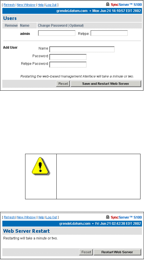
S100 User Guide – Rev. D – June 2005 77
2
5
3
Reset - Click Reset to clear the data you have entered.
Submit - Clicking Submit to disconnect the server from the network.
Admin Users
Use this dialog to change, delete, or add a user.
Restart Web Interface
This page lets you do a clean restart of the web server.
The restart affects only the management of the system, not the time or service.
WARNING
If you click Restart, you will
shut down the webserver,
then it will restart. This will
take a minute or two to
complete.
Figure 4-27: Changing or Adding Users
Figure 4-28: Server Restart option
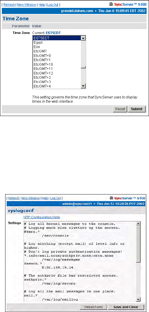
78 S100 User Guide – Rev. D – June 2005
SyncServer S100
Time Zone
Use this option to set the time zone displayed in the web-based admin interface.
The time zone is for display purposes only. It will not affect NTP, the output, or clients.
Highlight the time zone you want, then click Submit to set the time zone.
System Log Configuration
Use this option to configure the System Log.
Note: Remote logging is available by specifying an IP address preceded by an @ sign.
Figure 4-29: Setting the Time Zone
Figure 4-30: System Log Configuration
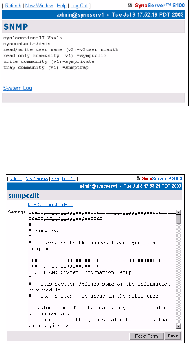
S100 User Guide – Rev. D – June 2005 79
2
5
3
SNMP Configuration
When populated with text, this screen is a summary of the SNMP configuration commands
entered in the SNMP Edit screen.
SNMP Edit
Use this screen to enter your SNMP commands for configuration and any other related
information.
Figure 4-31: SNMP Configuration
Figure 4-32: SNMP Edit
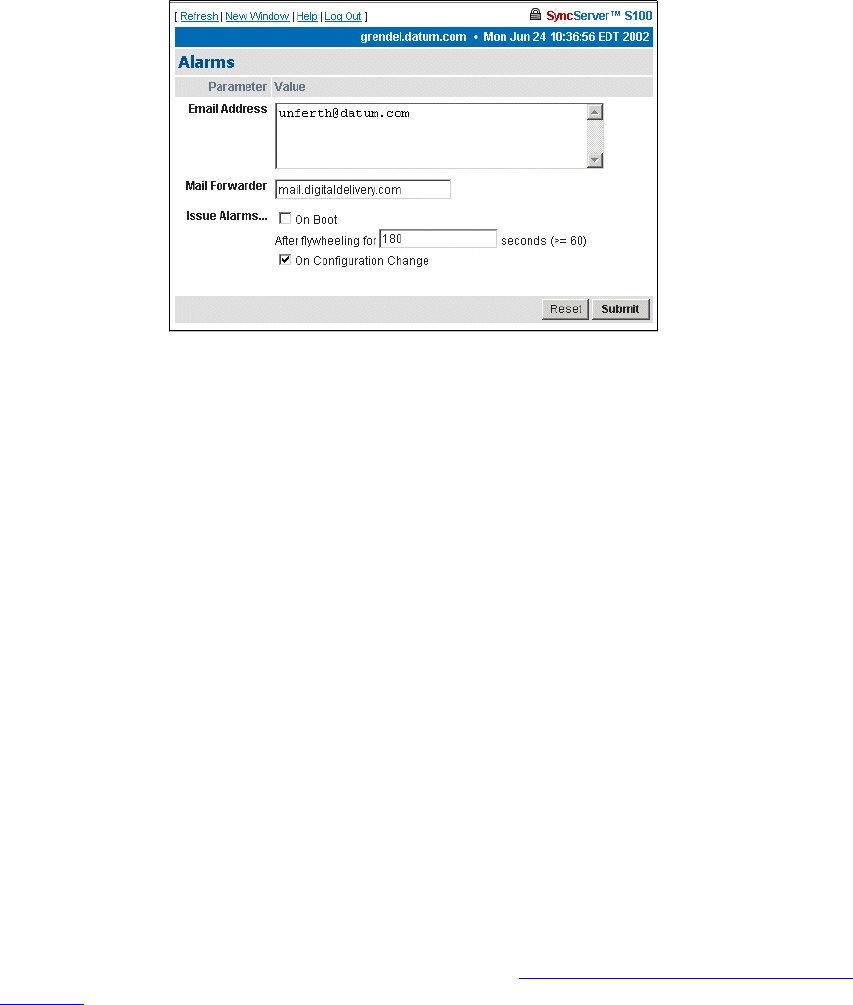
80 S100 User Guide – Rev. D – June 2005
SyncServer S100
Alarms
This page lets you configure alarm activity
.
E-mail Address - This e-mail address is where any alarm messages will be sent.
Mail forwarder - The server that will handle the e-mail.
Issue Alarms - Here, check when you want alarms sent:
• Upon boot, and if Flywheeling continues for more than 60 seconds. If you check here
for this alarm, it will tell you that the system has lost contact with its source of time but
will keep going for some period.
• If there has been a Configuration Change, you can check here for an alarm to be
sent.
Reset lets you clear the entered data, and Submit tells the system you are finished.
Configuration Wizard
The next item on the Admin menu is the Configuration Wizard. This helps you select and
configure your time reference.
Step-by-step Configuration Wizard instructions are in “The Configuration Wizard” on
page 32.
Figure 4-33: Setting Alarm Parameters
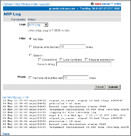
S100 User Guide – Rev. D – June 2005 81
2
5
3
Logs
You can access the NTP, Boot, System, Config and HTTPD logs through either the
admin menu or in the drop-down list box in the Logs parameter. All the logs have the
following parameters and values:
Logs - This drop-down list box lets you access other logs from this screen. The size of the log
you choose will be displayed beneath the drop-down box.
Filter -
• No filter: Displays all logs.
• Display only the last __ lines: Useful for avoiding screen clutter.
• Search: Search feature allows you to see what has happened on any given day.
•Selecting the case-blind option lets the search ignore case in your search.
•Selecting the line numbers option limits the search to log line numbers.
•Choosing regular expression allows for pattern matching in your search.
Prune -
• Remove all but the last __ lines: Lets you pare down the log after you have viewed
it.
NTP Log
Use this log to see NTP activity.
Figure 4-34: NTP Log

82 S100 User Guide – Rev. D – June 2005
SyncServer S100
Boot Log
Use this log to see messages created during the boot process.
System Log
Use this log to monitor system activity.
Figure 4-35: Boot Log
Figure 4-36: System Log
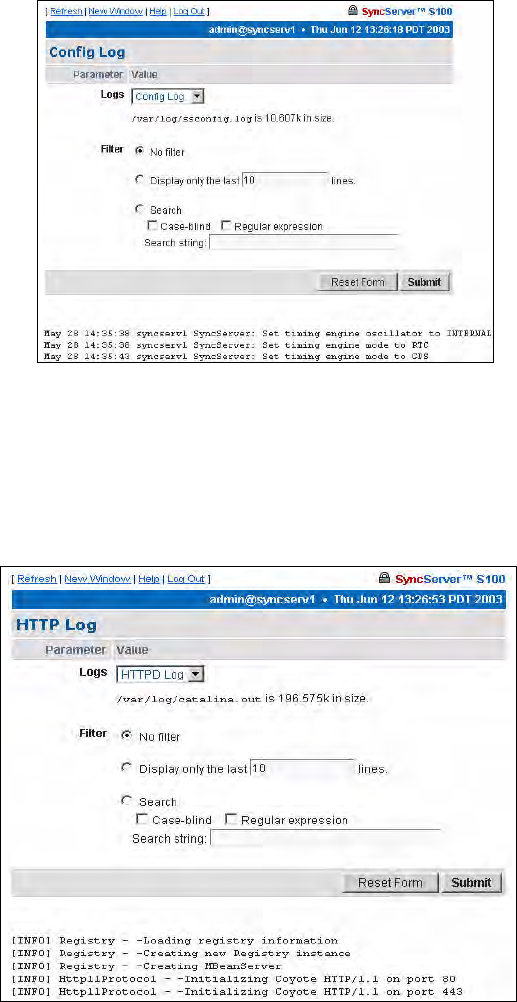
S100 User Guide – Rev. D – June 2005 83
2
5
3
Config Log
This log shows you S100 configuration and status messages.
HTTP Log
This log shows webserver messages.
Figure 4-37: Config Log
Figure 4-38: HTTP Log
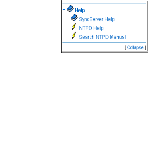
84 S100 User Guide – Rev. D – June 2005
SyncServer S100
Help
This is the last section of the S100 admin menu. Available Help functions are:
SyncServer Help
This is the application Help. Use the Table of Contents, Index, or Search to find information.
NTPD Help
For detailed information about NTP (Network Time Protocol), use the NTPD Help link (see
“NTPD Help” on page 84) embedded in the S100’s web interface to review the NTP
Distribution document (source: University of Delaware).
Additional information is available at http://www.ntp.org/.
Search NTPD Manual
This option gives you the ability to do basic searches within the NTPD Help.
Collapse Button
Click the Collapse button at the bottom right of the admin menu to reduce the menu down to
its main elements.
Figure 4-39: Help Options
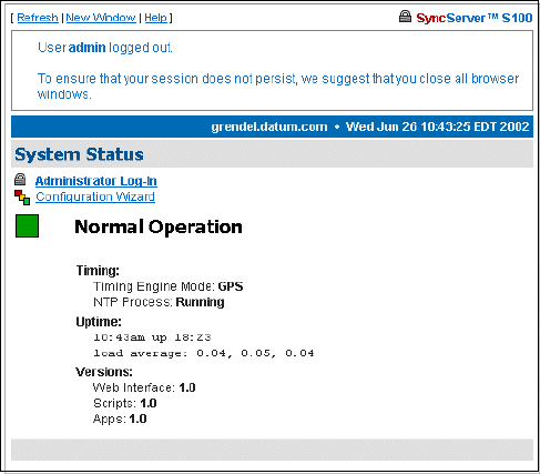
S100 User Guide – Rev. D – June 2005 85
2
5
3
Logging Off
Log off by clicking Log Out, at the top of each screen within the interface.
You will see the System Status screen with some prompts. At this point, you can choose
among the following options:
• Log back in
• Go to the Configuration Wizard, which will require you to log back in but will then take you
directly to the wizard
• Continue the logoff by closing your browser
Figure 4-40: Log Off screen
86 S100 User Guide – Rev. D – June 2005
SyncServer S100

S100 User Guide – Rev. D – June 2005 87
2
5
3
Chapter 5
Operations & Time-Protocols
S100: Operations and Time Protocols
Sysplex Timer
“Sysplex” means SYStem comPLEX, a term often used to describe continuous computing on
clusters of computers. The Sysplex Timer is sometimes called an External Time Reference
(ETR). The Sysplex Timer provides a synchronized Time-of-Day (TOD) clock for multiple
attached computers. A Sysplex is needed when two or more systems are configured in a
Sysplex. One Sysplex Timer can do the job, but it’s a good idea for you to have a second
duplex timer on the cluster as a backup in case the primary timer fails.
How the S100 Uses the Sysplex Timer
The S100 receives the signal from the GPS antenna, then provides Sysplex Timer output
through its Serial Port A. The Serial Port A supplies an ASCII broadcast of UTC time that is
often used by computers that cannot or do not use NTP.
Note: The GPS antenna described in this manual has been replaced as described in
“Appendix E” on page 141.
Be sure your computer is set up with the correct Serial Port parameters—the correct baud
rate, data bits, stop bits, and parity. The Serial Port will start broadcasting the time only after it
receives a c or C character. It will stop broadcast when it receives an r or R character. If you
set the Sysplex Timer to Auto on, the Sysplex Timer starts automatically on power up.
The following time information string is transmitted once per second, when started with the c
or C character. The DDD field represents three ASCII digits of days (001–366). The Quality
Indicator indicates the validity of the time. The Carriage Return character is transmitted on-
time. The first rising edge of the Carriage Return character occurs within 100 microseconds
after the S100 1PPS signal transitions from low to high.
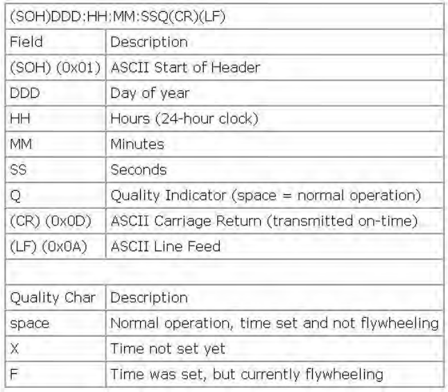
88 S100 User Guide – Rev. D – June 2005
SyncServer S100
Figure 5-41: Time Information String Parameters
Comm parameters can be controlled by modifying the /etc/.ss_profile file.
Various operational parameters for the sysplex daemon can be controlled using parameters
in the .ss_profile file. Use the serial connection or SSH to login to the S100 in order to
change this file. Set the value of the SYSPLEX_PROGRAM environment variable by adding
or removing the # comment character in the first column. For example:
# which sysplex program shall we run
SYSPLEX_PROGRAM=sysplex
#SYSPLEX_PROGRAM=sysplexoddp
#SYSPLEX_PROGRAM=sysplexnof
#SYSPLEX_PROGRAM=sysplexoddpnof
SYSPLEX_OPTIONS=on
will run the standard (9600,8,n,1) version of the protocol while:
# which sysplex program shall we run
#SYSPLEX_PROGRAM=sysplex
SYSPLEX_PROGRAM=sysplexoddp
#SYSPLEX_PROGRAM=sysplexnof
#SYSPLEX_PROGRAM=sysplexoddpnof
SYSPLEX_OPTIONS=on

S100 User Guide – Rev. D – June 2005 89
2
5
3
will run the odd parity (9600,8,o,1) version of the protocol. The currently available versions of
the protocol are:
• sysplex (9600,8,n,1)
• sysplexoddp (9600,8,o,1)
• sysplexnof (9600,8,n,1) with the 'F' (see sysplex definition) suppressed.
• sysplexoddpnof (9600,8,o,1) with the 'F' (see sysplex definition) suppressed.
The SYSPLEX_OPTIONS environment variable can be set to either "on" or blank. A value of
"on" will result in the sysplex protocol broadcast being automatically started instead of waiting
for a start character. An empty or blank value will not.
Note: NOTE: The sysplex daemon must be restarted in order for the changes to take effect. The
easiest way to do this is to reboot the box using either the web interface or the reboot com-
mand. If there are any problems, a copy of the factory profile is kept in the /etc directory with
the name .ss_profile.original . The factory settings may be restored by copying the backup file
over the modified version using:
cp /etc/.ss_profile.original /etc/.ss_profile
Time Protocol (RFC 868)
This protocol provides a site-independent, machine-readable date and time. The time service
on the S100 responds to the originating source with the time in seconds since midnight of
January 1, 1900. The time is the number of seconds since 00:00 (midnight) January 1, 1900
GMT. So the time “1” is 12:00:01 A.M. on January 1, 1900 GMT. This base will serve until the
year 2036.
If the server is unable to determine the time, it either refuses the connection or it closes the
connection without sending any response.
When used over the Transmission Control Protocol (TCP), the S100 listens for a connection
on port 37; once the connection is established, the server returns a 32-bit time value and
closes the connection. When used over the User Datagram Protocol (UDP), the S100 listens
for a datagram on port 37. When a datagram arrives, the S100 returns a datagram containing
the 32-bit time value.
For additional information, see http://www.faqs.org/rfcs/rfc868.html
Daytime Protocol (RFC 867)
The Daytime protocol sends the current date and time as a character string without regard to
the input.
When used over TCP, the S100 listens for a connection on port 13; once a connection is
established the current date and time is sent out as an ASCII character string. The service
closes the connection after sending the quote.

90 S100 User Guide – Rev. D – June 2005
SyncServer S100
When used over UDP, the S100 listens for a datagram on port 13. The S100 responds to the
UDP request with the current date and time as an ASCII character string.
For additional information, see: http://www.faqs.org/rfcs/rfc867.html.
Simple Network Time Protocol (RFC 2030)
Simple Network Time Protocol (SNTP) is a simplified access protocol for servers and clients
using NTP as it is now used on the Internet. The access paradigm is identical to the UDP/
Time client implementation. SNTP is also designed to operate on a dedicated server
configuration, including an integrated radio clock. SNTP uses the standard NTP time stamp
format described in RFC 1305 and previous versions of that document. NTP stamps are
represented as a 64-bit unsigned, fixed-point number, in seconds relative to 0h on January 1,
1900.
For additional information, see: http://www.faqs.org/rfcs/rfc2030.html.
Network Time Protocol (RFC 1305)
The Network Time Protocol (NTP) is used to synchronize computer clocks in a TCP/IP
computer network. It provides a comprehensive mechanism for accessing national time and
frequency distribution services, for organizing the time-synchronization subnet, and for
adjusting the local clocks. NTP provides accuracy of 1-10 milliseconds (ms), depending on
the jitter characteristics of the synchronization source and network paths. NTP uses User
Datagram Protocol (UDP), which is a sub-protocol of the Internet Protocol (IP).
Some definitions follow. For more, see “Time Glossary” on page 121.
For additional information, see http://www.faqs.org/rfcs/rfc1305.html.
NTP Data Format
The format of the NTP message data area, which immediately follows the UDP header, is
shown in Figure 3-2. NTP time stamps are represented as a 64 bit unsigned fixed-point
number, in seconds relative to 0h on 1 January 1900. The integer portion is in the first 32 bits
and the fractional portion is in the last 32 bits.
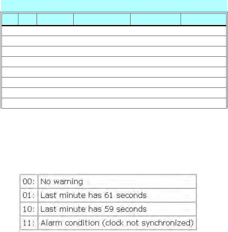
S100 User Guide – Rev. D – June 2005 91
2
5
3
Leap Indicator (LI)
This is a two-bit code warning of an impending leap second that will be inserted or deleted in
the last minute of the current day, with bit 0 and bit 1, respectively, coded as follows:
Figure 5-42: Two-bit Leap Second Indicator Code
You are alerted to an alarm condition when the S100 is first powered on—in other words,
before time is initially acquired from the timing signal. An alarm condition will also signal when
the timing parameters are changed. This alarm condition will persist until the S100 acquires
time. It should not signal again until the unit is powered off and on.
Version Number (VN)
This is a three-bit integer indicating the NTP version number. The S100 will return the version
number from the incoming NTP message.
Table Intro-1: NTP Message Data
LI VN MODE Stratum Poll Precision
Synchronizing Distance (Root Distance) (32 bits)
Synchronizing Dispersion (Root Dispersion) (32 bits)
Reference Identifier (32 bits)
Reference Time Stamp (64 bits)
Originate Time Stamp (64 bits)
Receive Time Stamp (64 bits)
Transmit Time Stamp (64 bits)
Authenticator (Optional) (96 bits)
0 8 16 24 31
92 S100 User Guide – Rev. D – June 2005
SyncServer S100
Mode
This is a three-bit integer indicating the mode. The S100 can be operated in any mode.
Stratum
This is an eight-bit integer indicating the stratum level of the local clock. For the S100 this
field is set to one indicating a primary reference, if the S100 is relying on its GPS receiver or
dial-up modem connection for timing information. Otherwise, it will accurately reflect its
location in a timing hierarchy.
Poll Interval
This is an eight-bit signed integer indicating the maximum interval between successive
messages, in seconds to the nearest power of two. The S100 will return the poll interval from
the incoming NTP message.
Precision
This is an eight-bit signed integer indicating the precision of the local clock, in seconds to the
nearest power of two. For the S100 this field is set to –19 (minus nineteen), which is the value
closest to the 1u sec precision of the S100 when operating in GPS mode.
Synchronizing Distance (Root Distance Version 3)
This is a 32-bit fixed-point number indicating the estimated round-trip delay to the primary
synchronizing source, in seconds with fraction point between bits 15 and 16. Set to zero in
the S100 for GPS mode and a corresponding value when operating with another time source.
Synchronizing Dispersion (Root Dispersion Version 3)
Synchronizing Dispersion is a 32 bit fixed-point number indicating the estimated dispersion to
the primary synchronizing source, in seconds. Root Dispersion indicates the maximum error
relative to the primary reference source.
Reference Clock Identifier
This is a 32-bit code identifying the particular reference clock. In the case of Stratum 1
(primary reference), this is a four-octet, left justified, zero-padded ASCII string. For the S100
the four-octet string is dependent on the time source selected, ‘GPS’ for GPS and ‘FREE’ for
Free Running Clock. If the unit is synchronizing to another S100, the reference clock identifier
will contain the four-byte address of the selected S100.
Reference Timestamp
This is the local time at which the local clock was last set or corrected, in 64-bit timestamp
format. With the S100, the Reference Timestamp is the last time that a valid timing signal was
S100 User Guide – Rev. D – June 2005 93
2
5
3
detected. Therefore, the Reference Timestamp will indicate the time at which the timing
signal was lost. When the timing signal returns, the Reference Timestamp will be updated.
Originate Timestamp
This is the local time at which the request departed the client host for the service host, in 64-
bit time stamp format.
Receive Time stamp
This is the local time at which the request arrived at the service host, in 64-bit time stamp
format.
Transmit Time stamp
This is the local time at which the reply departed the service host for the client host, in 64-bit
time stamp format.
Authenticator
This field is used to hold a cryptochecksum if authentication has been enabled. Refer to the
next section for more information about this mechanism.
Autokey
This field contains various autokey parameter requests and responses if autokey is enabled
for the association. These parameters can include signatures, certificates, or other data.
NTP Authentication
NTP authentication enables an NTP client to ensure two things: that the time stamp received
has come from a trusted source, and that it has not been modified in transit. Because
Symmetricom has extended the authentication method, you can use it to deny service to
unauthorized clients who submit NTP time stamp requests.
The NTP protocol includes space for two variables related to authentication: an
authentication key identifier field and a cryptochecksum field.
Authentication: NTP v3
The NTP client can operate with both non-authenticated and authenticated servers. This
approach uses symmetric-key cryptography. Thus, keys and key identifiers are determined in
advance and distributed in traditional ways.

94 S100 User Guide – Rev. D – June 2005
SyncServer S100
The message digest is computed using preferred Message Digest 5 (MD5). An alternative is
the Digital Encryption Standard, Cipher Block Chaining (DES-CBC).
The Message Authentication Code (MAC) is made up of a key identifier, then the message
digest. Keys are held in a key cache; the cache is initialized from a private file.
Authentication: NTP v4 Autokey
NTP v4 uses public-key cryptography, meaning all keys are random, and private keys are
never revealed. A certificate scheme binds the public key to the server identification.
Symmetric-key cryptography uses fixed private keys that must be distributed in advance. The
Diffie-Hellman model defines the key agreement, and is required for private random keys.
Public Domain NTP Package
For clients not using the public domain NTP package, the NTP packet is enlarged by 8 bytes
to handle the entire cryptochecksum, which is 16 bytes (128 bits) in size as generated by the
MD5. Since this field is the last in the packet, it should not present any difficulty.
How NTP Defines the Authentication Process
If authentication is enabled, and a valid authentication key identifier and cryptochecksum is
received, then the NTP packet is filled in and a new cryptochecksum is computed and added
to the packet. The packet is then sent back to the client.
More information
For more about NTP authentication, see both the NTP help available from the S100 web
interface and from:
http://www.ntp.org.
Typical NTP Configuration Considerations
This section provides additional information on using NTP and network configuration. The
examples provided for explanatory purposes only.
S100 User Guide – Rev. D – June 2005 95
2
5
3
Other NTP Considerations
The following are information modules regarding NTP. They are used here as a FYI.
Clients
An NTP client can have a number of servers, and broadcast and non-broadcast servers can
be used by the same client. NTP clients synchronize their time to match NTP servers, while
NTP servers never synchronize their time to match NTP clients. However, NTP clients can
also be NTP servers to clients of their own.
There are several points to consider for various client configurations. Normal NTP clients are
set up with the server keyword, while broadcast and multicast clients are setup with the
broadcastclient and multicastclient keywords. There is no client keyword.
Setting up a computer as an NTP client requires adding several lines to the ntp.conf file and
restarting ntpd.
For example, configure the NTP client to synchronize with a couple of alternate NTP servers
in the event the primary NTP server is unavailable. This is important since an failure of the
primary NTP server is unlikely to be noticed promptly.
The client servers should be as independent as possible. The dependency chain of an NTP
server can be determined by running the ntptrace command with each server. If possible,
servers should not share common NTP parents. To identify a server as preferred, enter the
keyword “prefer” to the right of the server name/IP address. A preferred server will be used
as a synchronization source if it meets a minimum accuracy level, even if there are other
more accurate servers. However, if a preferred server is far outside of the accuracy bounds
determined by consulting other servers, it will be discarded. In general, a server will not fall
outside these accuracy bounds unless it or the majority of other servers are misconfigured.
Using preferred servers allows setting up clients to prefer a clock that is known to be very
accurate. The time exchange between the client and server can also be protected with an
authentication key.
Clients can also be configured to respond to broadcast or multicast packets sent by a
broadcast or multicast NTP server.
Broadcast and multicast are generally used as the primary server on a LAN or subnet. Using
broadcast or multicast allows synchronizing a large number of clients without creating large
amounts of NTP traffic. In addition, servers can be changed easily, since clients do not listen
for a specific server when they are in broadcast mode. Because the links are mostly local,
this allows accurate synchronization for the clients. The important NTP servers within an
enterprise (generally low stratum numbers) and any servers separated by large distances or
low latency links should use non-broadcast mode in order to maintain close synchronization.
If the clients are not configured to synchronize with a specific group of servers, a rogue
system can influence the synchronization process by broadcasting invalid time information.
To defend against this threat, authentication and access control should be used to help limit
potential synchronization sources.
96 S100 User Guide – Rev. D – June 2005
SyncServer S100
Basic NTP Configuration
No special configuration is required for a machine with a running NTP to be used by other
network nodes as a standard server (as opposed to a broadcast server or peer). However,
access control is needed to prevent a machine from acting as an NTP server to clients.
Further, operating as a broadcast server or a peer server involves additional configuration.
Basic guidelines for architecting an NTP solution, should include:
1. Limiting single points of failure and maximizing independence
2. Controlling network impact
3. Enabling access control
4. Selecting appropriate reference clocks
Single points of failure can be reduced by assuring that client servers are as independent as
possible. Using a number of independent servers reduces the effectiveness of an incorrectly
configured server spoofing the time, and thus increases security. Verifying NTP server
independence can be difficult. To effectively map the dependencies on an NTP subnet, each
of the peers and servers must be mapped. Use ntptrace to determine the hierarchy of time
sources used by a client. It can then be easily identified if two machines share common time
servers. A client should always receive time from at least four servers. This will reduce the
chances of it losing synchronization when a server fails. If fewer than four servers are used,
the agreement algorithm cannot reliably detect a clique including a majority of trusted
sources. An easy solution is to use three servers from a lower stratum number and one
unrelated peer from the same stratum.
The goals of an NTP architect are two-fold: to limit NTP’s network activity and increase the
accuracy of the clocks. To achieve high clock accuracy, the network latency needs to be low.
NTP can achieve a high level of accuracy and remain a good network citizen if local NTP
servers are used and NTP servers use the appropriate modes.
The easiest way to increase accuracy in an NTP configuration is to reduce the latency
between the connections by putting NTP servers on the same LAN as their clients. If a LAN is
very large, it is a good idea to have multiple servers in different geographic or network
segments. However, if several independent servers are used, the NTP clock selection
algorithms will probably help mitigate the effects of any increased latency. Another advantage
to using local servers is that they tend to reduce the load on the WAN, though NTP is unlikely
to be a big source of network load.
Another way of reducing NTP traffic, while keeping clock accuracy, is to use appropriate
server modes. Central servers (generally stratum 1 and 2 servers) should use non-broadcast
server/client mode or peer mode, which allows more accurate time distribution. These
servers are generally geographically distributed; therefore, the accuracy of the time
distribution is critical.
Broadcasting over high latency links can lead to very inaccurate time, both because of the
latency and because it is likely the latency will be variable and unpredictable. Using
broadcasting or multicasting over relatively local connections is acceptable. In fact, for a local
server with a large number of clients and a fairly constant network latency broadcasting or
S100 User Guide – Rev. D – June 2005 97
2
5
3
multicasting is likely to be nearly as accurate as using a nonbroadcast server. Multicasting is
preferable to broadcasting because it makes identifying NTP traffic easier and does not affect
non-NTP clients on the network. Broadcasting or multicasting is a good fit in some
environments, however, it is not appropriate for all environments. In particular, architectural or
security concerns may preclude the use of broadcasting or multicasting. Multicast NTP
transactions open the network to denial of service attacks.
For security conscious environments, monitoring should be turned off because it could allow
an attacker to obtain sensitive information about hosts or networks. In most other
environments, disabling monitoring is an unnecessary restriction and only makes it more
difficult to solve NTP problems. Requiring authorization keys for queries is another option.
Limiting access to NTP queries prevents intruders from probing for information using the ntpq
command. While the information obtained from ntpq may seem trivial, an intruder could
discover sensitive information, including network delays (which could lead to determining
network architecture), hostnames, IP addresses, and OS versions. In addition to
authenticated transactions, NTP also provides the capability to restrict access to its services.
This function is provided using the restrict keyword. This keyword is defined in the ntp.conf
file and has the following syntax.
The address and mask are both representations of the IP address and network subnet mask
to be restricted. The flags indicate what function is to be controlled. For example, if all
communication from IP address 192.xxx.x.x is to be ignored, the following access restriction
can be used. The restrict command is often used with the default keyword, which limits the
specified access from all IP addresses.
restrict address [ mask numeric_mask ] [ flag ] [ ... ]
restrict 192.xxx.x.x ignore
restrict default ignore
Any restrict statements that do not contain a keyword will enable (rather than restrict) access.
Additional keywords such as noquery are also useful. Noquery restricts who can query the
run time configuration of the time server. While having the ability to query the server would
appear to be harmless, the query function can be useful in mapping network time
architectures and locating potential security weaknesses. For example, with the ntpsweep
command (supplied from the open-source NTP software distribution), it is possible to
determine the operating system and processor type of NTP peers. This function can be
restricted using the noquery option, otherwise queries are allowed. The version information
seen by outsiders could be modified to mask the OS version, but few administrators take the
time to obscure this information. This allows system intruders to easily obtain information
about the operating system platforms and versions. Security is only as strong as the weakest
link. For NTP, this means not only its access control and authentication but also the platform
security of its servers and clients. If a platform cannot be sufficiently protected, it is possible
that the NTP configuration and authentication key files can be stolen or compromised.
A reference clock is needed to synchronize an NTP network to a useful standard. Clients
cannot sync to a potential NTP server unless a reference clock exists in the server’s
synchronization path. There are three different ways to set up an NTP server for a large
number of clients:
• Set up a reference clock on a secured network that uses accurate public NTP servers
• Set up a reference clock directly on a secured network

98 S100 User Guide – Rev. D – June 2005
SyncServer S100
• Use a server’s local clock as a reference clock (not a good idea)
Synchronizing the server to a public NTP server is the most common route for most small
installations. Use the ntptrace command to obtain a general idea of the server's quality. It is
important to find a server that is peered with several other servers to provide robustness. The
NTP protocol is designed as a hierarchy to prevent large numbers of clients from accessing
the same primary time sources. A large number of clients should not be configured to hit a
busy stratum 1 time server. Networks should be designed to minimize the number of servers
that interact with public NTP servers. In addition, because public stratum 1 servers are often
overloaded, stratum 2 servers should be used except for large (over 100 clients) NTP
configurations where highly accurate time is critical. A list of public NTP servers (along with a
list of things to consider when using them) is available at: . For additional information about
NTP, see
http://www.eecis.udel.edu/~mills/ntp/servers.html.
For secure environments where synchronized time is critical, it may not be appropriate to use
a public reference clock. However, it is still important to use an external time source;
otherwise, if the primary clock in the data center wanders, it causes all of the NTP clients
connected to it to wander with it. Another option is to place the main NTP sources for the
enterprise on secure management networks and have them receive time from external
servers. However, as with any externally provided service, it is also an entry point for
attackers. Therefore it is important to keep the servers independent and well secured. A
layered security approach should be used that encompasses isolated network segments and
systems, in addition to platform and NTP security measures. For example, NTP servers could
be deployed on independent platforms running only the NTP service. In addition, the servers
should use the access control and authentication facilities in NTP to further restrict access to
the service. If possible, only authenticated NTP packets should be accepted. The server
should also only accept packets from known, approved sources. For additional security, the
NTP packets could be tunneled between the NTP sources and their external servers over
encrypted connections.
As a rule, the preferred configuration is at least three coordinated time servers providing
service throughout the administrative domain including campus networks and subnetworks.
Each of these should obtain service from at least two different outside sources of
synchronization, preferably using a different gateways and access paths. These sources
should all operate at the same stratum level, which is one less than the stratum level to be
used by the local time servers themselves. In addition, each of these time servers should
peer with all of the other time servers in the local administrative domain at the stratum level
used by the local time servers, as well as at least one (different) outside source at this level.
This configuration results in the use of six outside sources at a lower stratum level (toward the
primary source of synchronization, usually a radio clock), plus three outside sources at the
same stratum level, for a total of nine outside sources of synchronization. The actual load on
network resources is minimal, since the interval between polling messages exchanged
between peers usually ratchets back to no more than one message every 17 minutes.
The stratum level to be used by the local time servers is an engineering choice. As a matter
of policy, and in order to reduce the load on the primary servers, it is desirable to use the
highest stratum consistent with reliable, accurate time synchronization throughout the
administrative domain. In the case of enterprise networks serving hundreds or thousands of
client file servers and workstations, conventional practice is to obtain service from stratum-1
primary servers. It is important to avoid loops and possible common points of failure when
S100 User Guide – Rev. D – June 2005 99
2
5
3
selecting these sources. Note that, while NTP detects and rejects loops involving neighboring
servers, it does not detect loops involving intervening servers.
It is strongly advised, and in practice for most primary servers today, to employ the
authentication or access-control features of the NTP specification in order to protect against
hostile intruders and possible destabilization of the time service. Using this or similar
strategies, the remaining hosts in the same administrative domain can be synchronized to the
three (or more) selected time servers. Assuming these servers are synchronized directly to
stratum-1 sources and operate normally as stratum-2, the next level away from the primary
source of synchronization, for instance various campus file servers, will operate at stratum 3
and dependent workstations at stratum 4. Engineered correctly, such a subnet will survive all
but the most exotic failures or even hostile penetrations of the various, distributed
timekeeping resources.
When planning your network, keep in mind a few generic don'ts, in particular:
• Don't synchronize a local time server to another peer at the same stratum,
unless the latter is receiving time from lower stratum sources the former
doesn't talk to directly. This minimizes the occurrence of common points
of failure, but does not eliminate them in cases where the usual chain of
associations to the primary sources of synchronization are disrupted due
to failures.
• Don't configure peer associations with higher stratum servers. Let the
higher strata configure lower stratum servers, but not the reverse. This
greatly simplifies configuration file maintenance, since there is usually
much greater configuration churn in the high stratum clients such as
personal workstations.
• Don't synchronize more than one time server in a particular
administrative domain to the same time server outside that domain. Such
a practice invites common points of failure, as well as raises the possibility
of massive abuse, should the configuration file be automatically
distributed do a large number of clients.
The following diagrams depict typical NTP configurations from large to small networks. Use
these as a guide when creating your own.
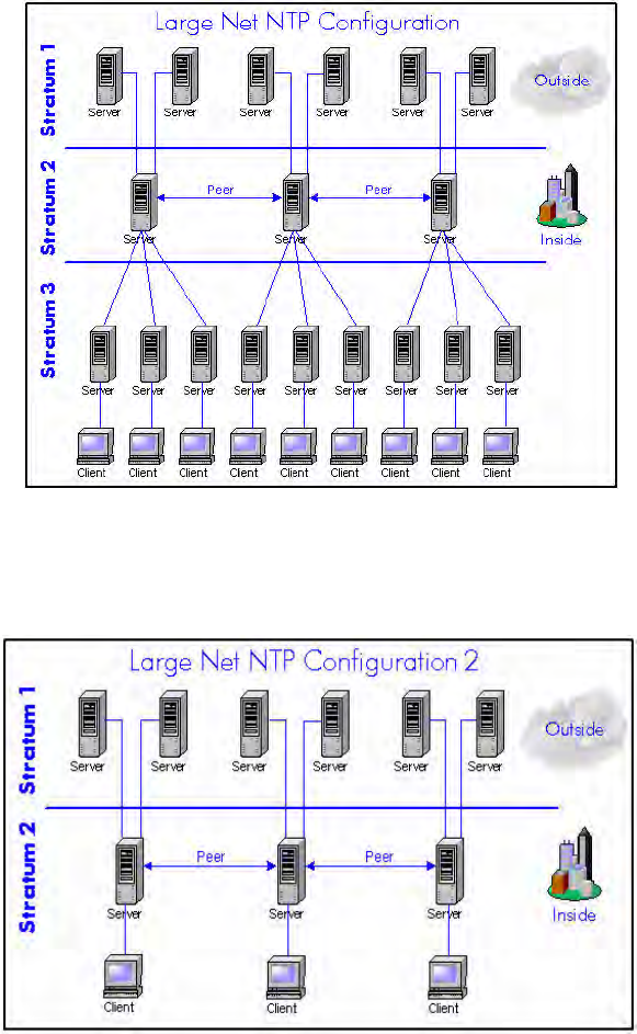
100 S100 User Guide – Rev. D – June 2005
SyncServer S100
Figure 5-43: Large Net NTP Configuration
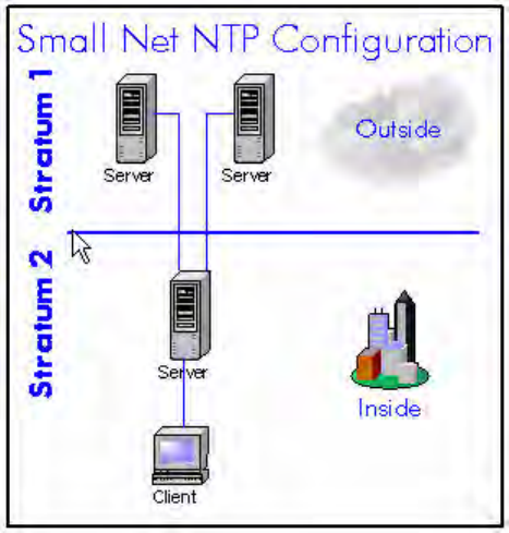
S100 User Guide – Rev. D – June 2005 101
2
5
3
Figure 5-44: Large Net NTP Configuration 2
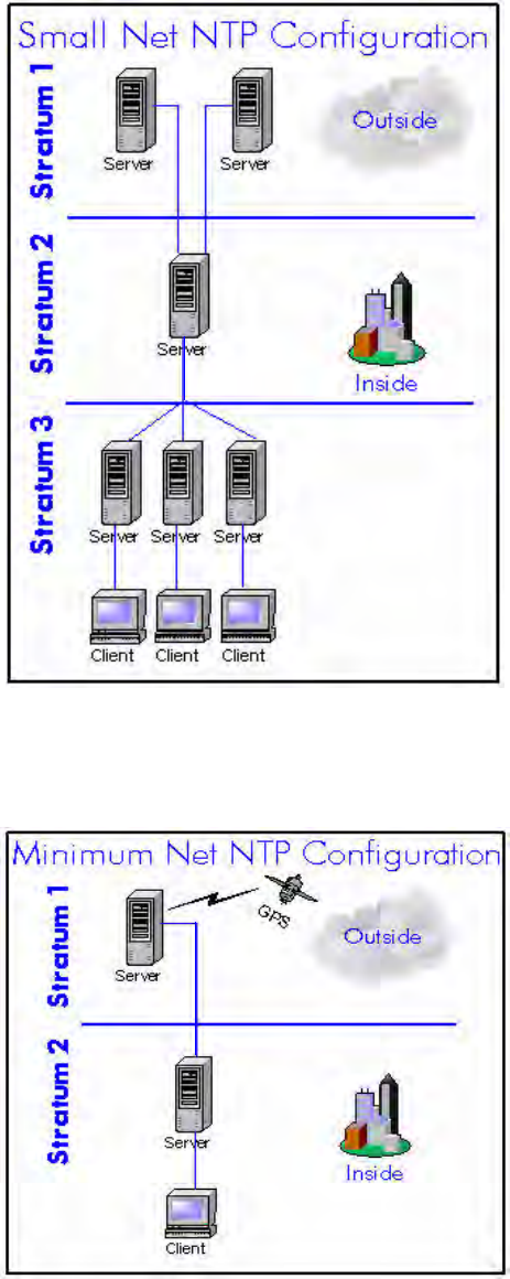
102 S100 User Guide – Rev. D – June 2005
SyncServer S100
Figure 5-45: Small Net NTP Configuration
Figure 5-46: Small Net NTP Configuration
S100 User Guide – Rev. D – June 2005 103
2
5
3
Figure 5-47: Minimum Net NTP Configuration
Peers
Setting up a peer can be accomplished by adding the peer command to the ntp.conf file. The
configuration of a peer is basically the same as setting up a client: an address or host name
needs to be specified, along with a key and possibly the prefer keyword. Peers also have an
associated polling interval that can be set in the ntp.conf file. While a set of peers can use
different polling intervals, true peers use the same polling interval. The defaults should be
acceptable except when peers are connected by very slow links. Setting the polling range is
described in the ntpd man page. Generally, peer connections are used to improve the time
accuracy at the base of the NTP tree (low numbered strata), or provide additional
redundancy at the leaves of the NTP tree (high numbered strata). Using peer connections
allows both of these without resorting to creating a new level of hierarchy.
Security
NTP provides the capability for NTP clients and servers to authenticate each other. This is
accomplished with symmetric authentication keys and key identifiers. The term symmetric
means that the keys must be the same on both the client and the server. Because NTP keys
are stored outside of the ntp.conf file, the NTP keys file must be specified in the ntp.conf file
for any configuration that will use keys. This is accomplished using the keys keyword,
followed by the absolute path to the file.
With NTP version 3, authentication keys must be manually distributed to each of the client
systems (NTP version 4 can use an automatic public key distribution, which is fully described
in the NTP version 4 documentation). Caution must be exercised when transferring these
keys to each client system. Be sure to use a protocol that supports strong authentication and
encryption.
Establishing authenticated communication between a client and server requires configuration
on both the client and the server. In order for authentication to work, both the client and the
server must have a keys.conf file specified in ntp.conf that contains the same key with the
same key ID. In other words, both the client and the server should have a line in the
keys.conf file that is identical.
ACTS Interface: Dial-up
The Automated Computer Time Service (ACTS) is maintained by the U. S. National Institute
of Standards and Technology (NIST). More information is in the next section. In most of this
guide, the term dial-up is used instead.

104 S100 User Guide – Rev. D – June 2005
SyncServer S100
ACTS Operation
Use the S100’s web-based interface to configure this method of access to time (for
information, see “Main Settings” on page 65). ACTS provides a backup time service
through an ASCII time broadcast, and supports a measured delay mode for enhanced
accuracy. This service is based on the use of asynchronous modems. It is designed to
coexist with a standard IRIG B time code input.
The S100’s ACTS operation includes simultaneous support of both client and server modes.
This means the S100 can obtain time information from a remote site through an ACTS client
connection while providing server capabilities such as distributing time information to local
clients or other S100 units.
When services are available, an ACTS client call will not modify the S100 clock if the unit is
currently decoding a valid time code signal.
More Information
For more about NIST and ACTS:
http://www.boulder.nist.gov/timefreq/service/acts.htm
SNMP (Simple Network Management Protocol)
By default, the S100 has both SNMP version 1 and SNMP version 3 enabled upon bootup.
Version 1 can be configured using the S100 web interface. The S100 supports MIB 2.
The Simple Network Management Protocol (SNMP) is an application layer protocol that
facilitates the exchange of management information between network devices. It is part of the
Transmission Control Protocol/Internet Protocol (TCP/IP) protocol suite. SNMP enables
network administrators to manage network performance, find and solve network problems,
and plan for network growth.
Three versions of SNMP exist: SNMP version 1 (SNMP v1), SNMP version 2 (SNMP v2), and
SNMP v3. All versions have a number of features in common, but SNMP v2 offers additional
protocol operations. SNMP Version 3 (SNMP v3) provides much greater security than the
previous two. The S100 supports SNMP v1 and v3.
An SNMP-managed network consists of three key components: managed devices, agents,
and network-management systems (NMSs).
A managed device is a network element that contains an SNMP agent and that resides on a
managed network. These devices collect and store management information and make this
information available to Network Management Systems using SNMP. Managed devices, or
called network elements, can be routers and access servers, switches and bridges, hubs,
computer hosts, or printers.
An agent is a software module that resides in a managed device. This agent has local
knowledge of management information and translates that information into a form compatible
with SNMP.

S100 User Guide – Rev. D – June 2005 105
2
5
3
NMS executes applications that monitor and control managed devices. One or more NMSs
must exist on any managed network.
There are four basic SNMP commands: read, write, trap, and operations:
• The read command is used to monitor managed devices. The NMS examines different
variables that are maintained by managed devices.
• The write command is used to control managed devices. The NMS changes the values of
variables stored within managed devices.
• The trap command is used to report events to the NMS. When certain types of events
occur, a managed device sends a trap to the NMS.
• Operations are used to determine which variables a managed device supports and to
gather information in tables, such as a routing table.
A Management Information Base (MIB) is a collection of information that is organized
hierarchically. MIBs are accessed using a network-management protocol such as SNMP.
They are managed objects and are identified by object identifiers.
A managed object (called a MIB object, an object, or a MIB) is one of any number of
characteristics of a managed device. Managed objects are comprised of one or more object
instances or variables. The SNMP manager is part of the Network Management System such
as Spectrum, HP Open View or Cisco Works. Information is traded between the NMS and the
network. NMS gathers, controls and monitors using information from the network. There are
three catagories: Statistics, Current Status and Alerts. Statistics (Traffic, CPU process) are
gathered and stored. Current Status data is monitored (i.e., links). Alerts are reports of any
unusual activity in the network.
There are two types of managed objects: single objects and multiple related objects. An
example of a single object is atInput, which is an object that contains an integer value that
indicates the total number of input packets on a router interface.
An object identifier (or object ID) uniquely identifies a single object in the MIB hierarchy. The
MIB hierarchy can be depicted as a tree with a nameless root, the levels of which are
assigned by different organizations.
The top-level MIB object IDs belong to different organizations, while lower-level object IDs
are allocated by associated organizations.
Vendors can define private branches that include managed objects for their own products.
There are MIBs for Ethernet, Token Rings, Routing, ATM, Frame Relay etc.
Version 1
SNMP version 1 (SNMP v1) was the first implementation of the SNMP protocol. It is
described in Request For Comments 1157 (RFC 1157) and functions within the specifications
of the Structure of Management Information (SMI). SNMP v1 operates over protocols such as
User Datagram Protocol (UDP), Internet Protocol (IP), OSI Connectionless Network Service
(CLNS), AppleTalk Datagram-Delivery Protocol (DDP), and Novell Internet Packet Exchange
(IPX). SNMP v1 is widely used and is the de facto network-management protocol in the
Internet community.

106 S100 User Guide – Rev. D – June 2005
SyncServer S100
SNMP is a simple request/response protocol. The network-management system issues a
request, and managed devices return responses. This is implemented using one of four
operations: Get, GetNext, Set, and Trap. The Get operation is used to retrieve the value of
one or more object instances from an agent. If the agent responding to the Get operation
cannot provide values for all the objects in a list, it does not provide any values. The GetNext
operation is used to retrieve the value of the next object in a table or a list within an agent.
The Set operation is used to set the values of object instances within an agent. The Trap
operation is used by agents to inform the NMS of a significant event.
SNMP v1 has no authentication capabilities, which increases vulnerability to security threats.
These include masquerading occurrences, modification of information, message sequence
and timing modifications, and disclosure. Masquerading consists of an unauthorized entity
attempting to perform management operations by assuming the identity of an authorized
management entity. Modification of information involves an unauthorized entity attempting to
alter a message generated by an authorized entity so that the message results in
unauthorized accounting management or configuration management operations. Message
sequence and timing modifications occur when an unauthorized entity reorders, delays, or
copies and later replays a message generated by an authorized entity. Disclosure results
when an unauthorized entity extracts values stored in managed objects, or learns of notifiable
events by monitoring exchanges between managers and agents. SNMP does not implement
authentication, many vendors do not implement Set operations, thereby reducing SNMP to a
monitoring facility.
Note: The S100 does not support SNMP Version 2.
Version 3
This contains many new security features that have been missing from the previous versions.
Both SNMP v1 and SNMP v2c are highly insecure.
SNMP v3 introduces advanced security splitting the authentication and the authorization into
two facets:
• The default User-based Security Module (USM) lists the users and their attributes. The
USM is described by RFC 2574.
• The VACM is the Version-based Access Control Module and controls which users (and
SNMP v1/v2c communities as well) are allowed to access and how they can access
sections of the MIB tree. The VACM is described by RFC 2575.
In this version, each user has a name (called a securityName), an authentication type
(authProtocol), and a privacy type (privProtocol) as well as associated keys for each of these
(authKey and privKey).
Authentication is performed using a user’s authKey to sign the message being sent. The
authProtocol can be either MD5 or SHA. The authKeys (and privKeys) are generated from a
passphrase that must be at least 8-10 characters in length.
Authentication is performed using a user’s privKey to encrypt the data portion the message
being sent. The privProtocol can only be DES at this time.
Messages can be be sent unauthenticated, authenticated, or authenticated and encrypted by
setting the securityLevel to use.

S100 User Guide – Rev. D – June 2005 107
2
5
3
All of this information is passed to commands using the command line arguments described
in the table below.
An authenticated request example:
COMMAND: snmpget -v 3 -n "" -u MD5User -a MD5 -A "The UCD Demo Password" -l
authNoPriv 255.255.255.255 sysUpTime.0
RESPONSE: system.sysUpTime.0 = Timeticks: (83491735) 9 days, 15:55:17.35
An authenticated and encrypted request example:
COMMAND: snmpget -v 3 -n "" -u MD5DESUser -a MD5 -A "The UCD Demo Password" -x
DES -X "The UCD Demo Password" -l authPriv 255.255.255.255 sysUp-
Time.0
RESPONSE: system.sysUpTime.0 = Timeticks: (83493111) 9 days, 15:55:31.11
The host shown above allows us to look at it using any level of authentication. Any hosts you
set up should be more restricted than that and require at least a level of authNoPriv when you
configure the VACM access control.
Setting up your snmp.conf file to look like this, makes your commands much simpler:
defContext none
defSecurityName MD5User
defAuthPassphrase The UCD Demo Password
defVersion 3
defAuthType MD5
defSecurityLevel authNoPriv
COMMAND: snmpget test.net-snmp.org sysUpTime.0
RESPONSE: system.sysUpTime.3.0 = Timeticks: (83517052) 9 days, 15:59:30.52
Table 2: Command Line Arguments
Parameter Command Line Flag Snmp.conf token
securityName -u NAME defSecurityName NAME
authProtocol -a (MD5|SHA) defAuthType (MD5|SHA)
privProtocol -x DES defPrivType DES
authKey -A PASSPHRASE defAuthPassphrase PASSPHRASE
privKey -X PASSPHRASE defPrivPassphrase PASSPHRASE
securityLevel -l (noAuthNoPriv|authNoPriv|authPriv) defSecurityLevel (noAuthNoPriv|authNoPriv|authPriv)
context -n CONTEXTNAME defContext CONTEXTNAME
108 S100 User Guide – Rev. D – June 2005
SyncServer S100

S100 User Guide – Rev. D – June 2005 109
2
5
3
Chapter 6
Frequently Asked Questions
Questions
How can we obtain NTP client software to use with the S100?
NTP client software information and configuration details are available from http://
www.ntp-systems.com
Client software and configuration information for Unix platforms can be downloaded from
http://www.ntp.org.
SNTP client software is included with the S100 hardware.
What are the main differences between SNTP and NTP clients?
SNTP (Simple Network Time Protocol), based on RFC 1361/RFC 2030, gets its time from the
specified time servers of the machine on which it is installed.
NTP, Network Time Protocol, is based on RFCs 1305 and 1119, and can be configured to
obtain and distribute the time on the network. It has a built-in algorithm that calculates the
time accurately up to 1-10 milliseconds. The algorithm can be configured to obtain time from
an alternate source in case the original time server fails or gets out of synchronization.
Is there a way to get GPS time instead of UTC time from the S100?
The S100 normally provides UTC time. However, it can be configured to output GPS time—
currently UTC + 13 seconds—by making several hardware changes to the unit. Contact your
Symmetricom representative about this.
What outputs are available on the S100?
These are:
• Dual Ethernet 10/100BaseT (RJ 45)
• RS-232 Serial Console (DCE)
• Sysplex timer port
110 S100 User Guide – Rev. D – June 2005
SyncServer S100
• With an optional Rubidium oscillator installed, an IRIG time code output and an IRIG time
code input are available from the Rubidium oscillator cable. On units without the
Rubidium oscillator, a D-BNC Signal Breakout Cable BC11576-1000 provides a 1 PPS
output, an IRIG time code output, and an IRIG time code input.
How does the S100 handle Leap Second?
Today’s clocks keep pace with one another to within two or three millionths of a second over
a year’s time. However, the earth on its rotation can accumulate almost a full second of error
in a year. This time is deleted (or added, if needed) as a leap second from (or to) the UTC
time on the last day of June or December in the affected year. This way, the clocks stay in
step with the earth’s rotation.
The GPS satellites send notice of an upcoming leap second about two months in advance.
The S100 receives this notice and, following NTP specifications, starts advising clients 24
hours in advance. At the leap second event, the S100 will add or delete the leap second from
the transmitted time.
Note: The S100 will do the same to an IEEE 1344 IRIG B signal. However, in the event of
a leap second, if the time source is regular IRIG B, dial-up, 1PPS, or Freerun (including
ACTS), you must pre-program the leap second event with the command leap so that the
S100 can be notified and maintain time correctly.
What signal strengths are required by the S100 receiver to start tracking?
The S100 requires four satellite signals with strengths greater than 6 to turn the tracking LED
on. After tracking, the S100 requires only one satellite signal to maintain its time. If it loses the
fourth signal, the S100 enters a holdover state and continues providing time.
How do I check versions of the software in the S100?
To check the software version, use the web-based administrative interface main admin menu,
System Status page.
What is the maximum number of computers that can be networked to the S100?
The S100 acts as a standalone time server. Average time to process the NTP request is less
than 1 millisecond. Testing has shown the S100 can handle approximately 10,000 requests
per second. However, clients running as Stratum 2 computers access the S100 in an interval
of 64 to 65,536 seconds as the time progresses. The optimum number of computers is based
on the capability of the network and on the acceptable level on load on the network.

S100 User Guide – Rev. D – June 2005 111
2
5
3
How many satellites are necessary for me to operate the S100?
Four. The unit will usually track six to eight satellites.
How do I know if the satellite signal strength is good?
Any signal over 6 is good and usable by the S100. The unit will continue to track a satellite
down to 3 once it has acquired it at a level 6 or over.
What is the maximum antenna cable length for use with the S100?
A maximum length of 300 feet can be used with the standard (Bullet II) antenna. From 300–
500 feet, the High-gain Antenna option is required. If you need longer lengths, please contact
Symmetricom Customer Assistance (see “Appendix D” on page 137).
Note: The GPS and bullet antennas and antenna cables described in this manual have been
replaced as described in “Appendix E” on page 141.
What are the available antenna cable lengths and antenna requirements?
Use the following table:
Note: The bullet antenna cable described in this manual has been replaced as described in
“Appendix E” on page 141.
What are some guidelines for correctly cutting the cable, using splitters, and using cable connectors?
Some critical “do’s and don’ts” are:
• Do use pre-made kits from Symmetricom.
• Do install the antenna where there are no obstructions—either on the roof, or an
unobstructed view of at least 30-degrees above the horizon.
• Do not split the antenna cable signal to try to use the signal to drive other GPS devices.
• Do not cut the cable to a shorter length. Instead, bundle any excess cable. Correct
antenna cable length—even if you do not “use it all”—is critical to proper S100
operation. The cable should have a gain within 15dB–25dB.
Cable length and Type Antenna
50-100 feet (15-30m), Belden RG-58 Standard Bullet-type
100-300 feet (30-91m), Belden 9913 Standard Bullet-type
100-300 feet (91-152m), Belden 9913 High-gain
Over 500 feet (152m) Contact Symmetricom
112 S100 User Guide – Rev. D – June 2005
SyncServer S100
How many NTP requests can be processed by the S100 each second?
More than 5,000 requests per second can be processed.
Does the S100 support NTP v4?
The S100 does incorporate the added functions of NTP v4. Specifically, the S100 supports
the autokey scheme to secure the delivery of the NTP packets to NTP v4 clients as well as
authentication of the server to the client.
Can the S100 utilize a certificate from an external CA?
The S100 can acquire a digital certificate from a public or private CA. The ability to generate
a PKCS 10
certificate request is supported from the S100 secure web interface.
How is the interface to the S100 secured?
The S100 supports a https (SSL) interface for remote client management.
What security functions are provided with the S100?
• NTP v3: crypto check sum
• NTP v4: Autokey
• Https: SSL v3 (web based user interface)
• SSH: SSL v3 remote login (secure terminal interface)
Does the S100 support any functions to restrict user access to NTP service? Can the S100 set up
clients' IP address to be connected?
The S100 can be configured with a IP address-based restrict list to selectively deny NTP
service to a subnet or a single network client. Refer to the “restrict” command in the NTP
documentation.
What is the bandwidth utilization (TCP/IP) each time an NTP client gets a time update from the NTP
server?
Standard NTP request is a 48-byte UDP packet and the reply is the same. NTP v3
authentication adds 12 or 16 bytes to that, on request and reply. NTP v4 adds about the same
with a few extra overhead packets.

S100 User Guide – Rev. D – June 2005 113
2
5
3
Depending on the type of client software, requests can be made by a client anywhere from 1
per minute to 1 per day but a good average for Unix clients is 1 every 15 minutes and 1 every
60 minutes per Windows client.
So, for every 1,000 clients (guessing 90% Windows and 10% Unix), you would see 900
packets per hour from the Windows clients and 400 packets per hour from the Unix clients.
Or, 1300 packets / hours * (48 bytes/packet request + 48 bytes/packet response) = 124800
bytes/hour or about 35 bytes/sec.
A generous estimate would be about one 48-byte packet per second (UDP) for every 1,000
clients. So, the network bandwidth for NTP over a 10Mbit network is very small and even less
over higher rate networks, 100Mbit, 1Gbit, or 10Gbit.
Is NTP v4 compatible with Network Address Translation (NAT) gateways?
NTP v4 autokey sessions do not work when the client and/or server are installed on a
network behind a Network Address Translation (NAT) gateway. S100 users who wish to use
NTP v4 should be aware that a NAT device cannot exist between the client and server.
This issue is addressed in the IETF draft doc Public key Cryptography for the Network Time
Protocol - Version 2, at http://www.eecis.udel.edu/~mills/database/rfc/draft-
ietf-stime-ntpauth-04.txt.
Specifically, there are some scenarios where the use of endpoint IP addresses may be
difficult or impossible. These include configurations where network address translation (NAT)
devices are in use or when addresses are changed during an association lifetime due to
mobility constraints. For Autokey, the only restriction is that the addresses visible in the
transmitted packet must be the same as those used to construct the autokey sequence and
key list and that these addresses be the same as those visible in the received packet.
How does the S100 clock behave when a leap second is introduced?
NTP uses binary time so there is no concept of an hour, minute, or second count. NTP counts
the number of seconds since Jan. 1, 1900 UTC time. When a leap second is introduced, the
same major time will appear in the NTP packet for two seconds. The fractional minor time will
cycle through twice.
How-to’s and Tips
Here are some guideposts to often-asked “how to” questions. Some answers will direct you to
another part of this material, in Chapter 4, where there is more detail.

114 S100 User Guide – Rev. D – June 2005
SyncServer S100
How to install NTP v4 on a UNIX system
Requirements: A Unix system with compiler, standard tools and openssl installed.
1. Download NTP tarball from www.ntp.org
2. Extract the source using tar -xvf <ntp tarball>
3. Run the configuration and specify autokey using ./configure --with-
crypto=autokey
4. Run make.
5. Make install.
How to configure an NTP v4 client to connect to an NTP v4 server with the autokey scheme
1. Create or modify /etc/ntp.conf and add a server line using vi (server <ipaddress>
autokey)
2. Run ntpd and verify proper operation.
How to verify NTP v4 autokey client connectivity with an NTP v4 server
To confirm that a secure NTP v4 session with autokey has been established with a server, do
one of the following :
1. ntpdc command showpeer <server ip> and look for the auth flag
2. ntpq command associations and look for auth category (ok)
3. Run ntpd -ddd and watch output for crypto statements and packet sizes
How to install your S100
All information about this is covered in “Installing Your S100” on page 19.
How to get time using dial-up
See “Dialup Settings dialog” on page 38 for details about this.
How to get time using GPS
See “GPS” on page 35.

S100 User Guide – Rev. D – June 2005 115
2
5
3
How to install your GPS antenna
See “Installing the GPS Antenna” on page 23.
How to acquire and install SymmTime™
To acquire SymmTime, download this free software from
http://www.ntp-systems.com/symmtime.asp
Directions on its installation are found in “Installing SymmTime” on page 49.
Use the quick “How to” guide
This is found in “Introduction and Overview” on page 1 of this book.
How to change the root password
The S100 is shipped with a default root password of symmetricom. For security reasons, it is
a very good idea to change that password immediately.
To change the root password, use the following steps:
1. Use HyperTerminal or Tera Term (included on the enclosed CD) on the serial port, or
SecureShell using PuTTY (included on the enclosed CD). Log in as User root with
Password symmetricom.
2. Type the command passwd, all lower-case (UNIX commands are always case-sensitive).
3. You will be prompted to type your new password, and then to type it again to confirm.
This is what you will see:
[root@syncserv1 /root]# passwd
New UNIX password:
Retype new UNIX password:
passwd: all authentication tokens updated successfully
[root@syncserv1 /root]#
Note: The password command “prefers” passwords containing a random variety of letters
and numbers, and no common words. So if you use a recognizable word as the new pass-
word, you may get an error message that looks like this:
[root@syncserv1 /root]# passwd
New UNIX password:
BAD PASSWORD: it is based on a dictionary word
Retype new UNIX password:

116 S100 User Guide – Rev. D – June 2005
SyncServer S100
passwd: all authentication tokens updated successfully
[root@syncserv1 /root]#
This is really an advisory in the form of an error message. The S100 will still accept a
“dictionary” word as your password, despite this error message. However, we suggest that
you take its advice seriously and use a random combination of letters and numbers.
How to get information about NTP
To learn more about NTP, use the following links:
•http://www.ntp.org
•http://www.faqs.org/rfcs/rfc1305.html
Solutions
This section offers solutions to some situations you may run into as you use the S100.
If you need assistance contact Customer Assistance (see “Appendix D” on page 137).
The S100 does not respond to ping command
Use the S100 web interface to ping your client (see “Ping” on page 74). If your client cannot
be reached with the ping command, the S100 provides a traceroute utility to show the path
data is taking.
Also check the Ethernet 10/100baseT cable connections between the RJ45 connector and
the hub or network.
The S100 does not respond to NTP queries
If the S100 can be pinged, but it doesn’t respond to NTP queries, then verify that the NTP
software on your computers is set up properly, and also verify that the client has the correct
IP address of the S100.
I cannot establish a serial connection with the S100
Make sure that the connection is made with the front panel serial console in the S100.
Make sure you are using the correct COM port on your management PC (com1).

S100 User Guide – Rev. D – June 2005 117
2
5
3
Also check that the configuration settings are set to a VT100 ASCII terminal using 9600, 8, N,
1 and hardware flow control.
Try pinging the S100 from your management PC, and the PC from the S100. Then use
traceroute (see “Traceroute” on page 75) to check the path between the two; this should
give you some useful data that will solve the problem.
My S100 won’t track satellites
Possible cause of tracking problems: How to fix:
Antenna not positioned correctly Be sure antenna is on the roof or location with
at least a 30-degree view above the horizon,
and at least two meters above other active
receiving antennas and shielded from
transmitting antennas
Cable is cut to the wrong length, causing dB
gain problems Replace with cable of correct length
Incorrect connector(s) at the end(s) of the
cable(s) or along the cable run, causing dB
gain problems
Replace with correct connector
Incorrect use of splitters, including signal
splitting to another GPS device or cable cut to
wrong length
Replace with splitter that does not “share”
signal, on a cable of correct length
118 S100 User Guide – Rev. D – June 2005
SyncServer S100

S100 User Guide – Rev. D – June 2005 119
2
5
3
Appendix A
S100 Specifications
Note: The GPS antenna described in this manual has been replaced as described in
“Appendix E” on page 141.
S100 Data Sheet Specifications
Component Specifics Description
Network Interface Ethernet over 10/100Base-T IEEE 802.3 specifications
Connection Dual 10/100BaseT, Twisted Pair RJ45
Time Protocols NTP v2 (RFC 1119), NTP v3 (RFC 1305), NTP
v4 (IETF Draft Standard), SNTP (RFC 2030),
Time Protocol (RFC 868), Daytime Protocol
(RFC 867) IRIG-B (120,122,123)
Supported Protocols SNMP v3, TCP/IP, MD5 Authentication (NTP),
SNMP v1 (RFC 1157), DHCP (RFC 2131), SSH
(Secure Shell), HTTP/HTML/HTTPS (RFC
2616)
Serial Connection Serial Port RS-232/DB9 DTE
Software Time Utility (MS Windows) SymmTime™ (www.ntp-systems.com/
symmtime.asp)
Timing Accuracy Network 1–10 milliseconds, typical
GPS <1 microsecond ( relative to UTC, GPS
tracking)
Dial-up service <1-10 milliseconds, on sync
Oscillator Rate stability: 5 x 10⁻⁷
GPS Input Channels and Frequency Eight, C/A code
Cable Type 50 feet (15.25m) /RG58
Antenna Size: 3.04”d x 2.94”h (7.72cm x 7.47cm)
Operating temperature: -40°C to +85°C
Acquisition <5 minutes
Chassis A/C Power In 100–240VAC, Auto-switching 50-60 Hz
Size and Weight 1.75”H x 17.0”W x 18”D (4.45cm x 43.2cm x
45.7cm)
1U Height Rack Mount, 18 lbs. (8.2Kg)

120 S100 User Guide – Rev. D – June 2005
SyncServer S100
Pin Descriptions
Operating & Storage
Environments Temperature and Humidity 0°C to +45°C/5-95% @ 40°C
Options Long Antenna Cable (Belden 9913), Lightning Arrester, High-gain GPS Antenna,
GPS In-Line Amplifier, Rack Mount Slides
P1: Ethernet RJ45
Description: 8-pin Phone Jack,
Mfr: AMP, Part # 555153-1
Pin Number Description
1TX (+)
2TX (-)
3RX (+)
4N/C
5N/C
6RX (-)
7N/C
8N/C
P3: Serial A (Data Terminal Port/DTE)
Description: 9-pin “D” Plug, Mfr: AMP, Part #
869436
Pin Number Description
1 RS-232 Data Carrier Detect (in)
2 RS-232 Receive Data (in)
3 RS-232 Transmit Data (out)
4 RS-232 Data Terminal Ready
(out)
5Ground
6 RS-232 Data Set Ready (in)
7 RS-232 Request to Send (out)
8 RS-232 Clear to Send (in)
9 RS-232 Ring Indicator (in)
S100 Data Sheet Specifications
Component Specifics Description

S100 User Guide – Rev. D – June 2005 121
2
5
3
Appendix B
Time Glossary
Access Control
The mechanisms of limiting entry to resources based on users’ identities and their
membership in various predefined groups. The network resources with these access
restrictions typically are servers, directories, and files.
ACTS
Automated Computer Time System, a NIST service that provides announced time by
telephone.
Advanced Encryption Standard (AES)
Developed by NIST and private companies, this standard is 256-bit based and is a stronger
defense for sensitive material when compared to 40-bit or 128-bit.
Algorithm
A clearly specified mathematical process for computation, or set of rules, which, if followed,
gives a prescribed result.
ANSI
American National Standards Institute, the organization responsible for approving US
standards in many categories, including computers and communications. Standards
approved by this organization are often called ANSI standards.
Antiwarrant
Attribute certificate that has the same expire date as its valid date; in other words, it was
never valid. This is still sent, at times, because it contains other information that the system
needs. See also Warrant
API
Application Program Interface. This interface allows software developers to write their
software so that it can communicate with the computer's operating system or other programs.
ASCII
American Standards Code Information Interchange, a code in which each alphanumeric
character is represented as a number from 0 to 127, in binary code so the computer can
understand it. Its simplicity allows diverse computers to understand one another.
ATM
Asynchronous Transfer Mode, or ATM switching. This is a type of packet switching that
makes it possible to transmit data at high speeds over a network. It also allows dynamic

122 S100 User Guide – Rev. D – June 2005
SyncServer S100
allocation of bandwidth, meaning users get only the bandwidth they need and are charged
accordingly.
Attribute Certificate
A type of certificate that emphasizes certification of access rights and constraints. This is in
contrast to Identity Certificate, which binds a distinguished name (DN) and a public key.
Commonly, attribute certificates are issued with short validity periods and do not contain a
public key value.
Audit Trail
A series of events, usually kept in and managed by a computer-based log, that give proof of a
defined activity.
Authentication
The process by which people (or applications) who receive a certificate can verify the identity
of the certificate’s owner and the validity of the certificate. Certificates are used to identify the
author of a message or an entity such as a Web server or StampServer.
Authorization
The granting of access rights to a user, program, or process. Once you have authenticated a
user, the user may be allowed different types of access or activity.
BCD
Binary Coded Decimal. Also called packed decimal, this is the representation of a number
using 0s and 1s, or four-bit binary numbers. So the number 29 would be encoded as 0010
1001.
Bureau International de l’Heure (BIPM)
The worldwide organization that coordinates standard frequencies and time signals, the
BIPM maintains Coordinated Universal Time (UTC).
Calibration
To fix the graduations of time measurement against the established national standard,
including any periodic corrections that should be made.
CDMA
Code Division Multiple Access, a technique of multiplexing, also called spread spectrum, in
which analog signals are converted into digital form for transmission.
CDSA
Common Data Security Architecture describes the security structure for an entire network. It
is unique to each network because security is managed differently for each.
Certificate
Certificates are used to verify the identity of an individual, organization, Web server, or
hardware device. They are also used to ensure non-repudiation in business transactions, as
well as enable confidentiality through the use of public-key encryption.

S100 User Guide – Rev. D – June 2005 123
2
5
3
Certificate Authority (CA)
A trusted entity that issues a certificate after verifying the identity of the person or program or
process that the certificate is intended to identify. A CA also renews and revokes certificates
and, at regular intervals, generates a list of revoked certificates.
Certificate Extension
An extension of the X.509 standard that lets the certificate hold additional identifying
information.
Certificate Request
A request containing a user’s public key, distinguished name (DN), and other data that is
submitted to a Certificate Authority (CA) in order to receive a certificate.
Certificate Revocation List (CRL)
CRLs list certificates that have been revoked by a particular CA. Revocation lists are vital
when certificates have been stolen, for example.
Certification Path
A specified sequence of issued certificates necessary for the user to get their key.
Confidentiality
Keeping secret data from unauthorized eyes.
Content Filtering
A filter that screens out data by checking (for example) URLs or key words.
Coordinated Universal Time (UTC)
The international time standard is called Coordinated Universal Time or, more commonly,
UTC, for “Universal Time, Coordinated”. This standard has been in effect since being decided
upon in 1972 by worldwide representatives within the International Telecommunication Union.
UTC is maintained by the Bureau International de l’Heure (BIPM), which forms the basis of a
coordinated dissemination of standard frequencies and time signals. The acronyms UTC and
BIPM are each a compromise among all the participating nations.
CR
See Certificate Request
Credential(s)
Much like a photo ID or birth certificate, electronic credentials are recognized as proof of a
party's identity and security level. Examples: certificate, logon ID, secure ID, and so forth.
Cross-Certificate
Two or more Certificate Authorities (CAs) that issue certificates (cross-certificates) to
establish a trust relationship between themselves.
Cryptography
See Encryption

124 S100 User Guide – Rev. D – June 2005
SyncServer S100
Data Encryption Standard (DES)
Encryption method in which both the sender and receiver of a message share a single key
that decrypts the message.
Symmetricom Secure Network Time Protocol (SS/NTP)
The protocol created by Symmetricom, based on NTP, that includes additional security
features.
DCLS
Direct Current Level Shift, or digital IRIG.
See also: IRIG
Decryption
The transformation of unintelligible data (“ciphertext”) into original data (“clear text”).
Denial of Service
When a network is flooded with traffic through any of a variety of methods, the systems
cannot respond normally, so service is curtailed or denied. This is a favorite technique of
network saboteurs.
DES
See Data Encryption Standard (DES)
DHCP
Dynamic Host Configuration Protocol is a standards-based protocol for dynamically allocating
and managing IP addresses. DHCP runs between individual computers and a DHCP server
to allocate and assign IP addresses to the computers as well as limit the time for which the
computer can use the address.
Diffie-Hellman
A key-agreement algorithm used to create a random number that can be used as a key over
an insecure channel.
Digital Certificates
Digital Certificates are issued by a Certificate Authority (CA), which verifies the identification
of the sender. The certificate is attached to an electronic message, so the recipient knows the
sender is really who they claim to be.
Digital Fingerprint
Similar to digital signature, a digital fingerprint is the encryption of a message digest with a
private key.
Digital Signature
Like a digital certificate, a digital signature is a data string that is verified by a Certificate
Authority, and is attached to an electronic message so that it can verify that the sender is
really who they claim to be. The difference between a digital certificate and a digital signature
is found in how the message is encrypted and decrypted.

S100 User Guide – Rev. D – June 2005 125
2
5
3
Digital Signature Algorithm (DSA)
The asymmetric algorithm that is at the core of the digital signature standard. DSA is a public-
key method based on the discrete logarithm problem.
Digital Signature Standard (DSS)
A NIST standard for digital signatures, used to authenticate both a message and the signer.
DSS has a security level comparable to RSA (Rivest-Shamir-Adleman) cryptography, having
1,024-bit keys.
Digital Time-Stamp
See Time-Stamp
Directory
The directory is the storage area for network security information such as keys or server
names.
DSA
See Digital Signature Algorithm (DSA).
SS/NTP
Symmetricom Secure Network Time Protocol, the protocol created by Symmetricom, based
on NTP, that includes additional security features.
DSS
See Digital Signature Standard (DSS)
DTT
Symmetricom Temporal Token
Element Manager (ENMTMS)
Software that manages the components of an application.
Encryption
The transformation of clear data (clear text) into unintelligible data (ciphertext). Asymmetric
encryption, also known as Public Key encryption, allows for the trading of information without
having to share the key used to encrypt the information. Information is encrypted using the
recipient’s public key and then the recipient decrypts the information with their private key.
Symmetric encryption, also known as Private Key encryption, allows information to be
encrypted and decrypted with the same key. Thus the key must be shared with the decrypting
party. Anyone who intercepts the key can also use it.
Ephemeris Time
Time obtained from observing the motion of the moon around the earth.
FIPS
Federal (US) Information Processing Standards are a set of standards for document
processing and for working within documents. Some commonly-used FIPS standards are
140-1, 140-2, and 180.

126 S100 User Guide – Rev. D – June 2005
SyncServer S100
Firewall
Firewalls are software and hardware systems that define access between two networks,
offering protection from outside data that could be harmful, such as a virus sent using the
Internet.
GMT
Greenwich Mean Time, the mean solar time of the meridian of Greenwich, England, used
until 1972 as a basis for calculating standard time throughout the world.
GPS
Global Positioning System. The GPS is a constellation of ~29 (or more) US Department of
Defense satellites orbiting the earth twice a day.
Hash
Also called “hash function” or hashing, used extensively in many encryption algorithms.
Hashing transforms a string of characters usually into a shorter, fixed-length value or key.
Information in a database is faster to search when you use a hashed key, than if you were to
try to match the original data.
HTML
HyperText Markup Language, the computer language used to create pages for the World
Wide Web.
HTTP
HyperText Transfer (or Transport) Protocol, the protocol most often used to transfer
information from World Wide Web servers to users of the Web.
HTTPS
HTTP over an SSL connection.
Identity Certificate
Also called Digital Certificates. The hash creates a message digest based on the contents of
the message. The message is then encrypted using the publisher's private key, then it is
appended to the original message.
IEEE
Institute of Electrical and Electronic Engineers, an international organization that sets
standards for electrical and computer engineering.
IETF
Internet Engineering Task Force, an international organization which sets standards for
Internet protocols in their Request for Comment (RFC) papers.
These papers are numbered (RFC 1305, RFC 868, and so on) and are referred to by
engineers worldwide as they work on technologies that support IETF standards.

S100 User Guide – Rev. D – June 2005 127
2
5
3
IKE
Internet Key Exchange, a security system that uses a private key and an exchange key that
encrypts private keys. Passwords are delivered over the Internet.
In-band Authentication
When you use PKI—which involves public keys and a private key— for authentication, it is
called in-band authentication.
See also: Out-of-band Authentication
Integrity
Data that has retained its integrity has not been modified or tampered with.
IPSec
Internet Protocol Security describes the IETF protocols that protect the secure exchange of
packets on the IP layer.
IRIG
InteRange Instrumentation Group is an analog standard for serial time formats.
Irrefutable
See Non-repudiation
ITU
International Telecommunications Union, the international organization that sets standards
for data communication.
Key
An alphanumeric string that encrypts and decrypts data.
Key Escrow
A secure storage maintained by a trusted third party, which holds keys.
Key Generation
Creation of a key.
Key Management
The process by which keys are created, authenticated, issued, distributed, stored, recovered,
and revoked.
Key Pair
Two integrated keys: one public, one private.
Key Recovery
The process of recovering a private decryption key from a secure archive for the purposes of
recovering data that has been encrypted with the corresponding encryption key.

128 S100 User Guide – Rev. D – June 2005
SyncServer S100
L1 Band, L2 Band
Each Navstar GPS satellite currently transmits in two dedicated frequency bands: L1 and L2,
which is centered on 1227.6 MHz. L1 carries one encrypted signal, as does L2, both being
reserved for the military. L1 also carries one unencrypted signal, for civilian use.
LAN
Local area network (LAN): A data communications system that (a) lies within a limited spatial
area, (b) has a specific user group, (c) has a specific topology, and (d) is not a public switched
telecommunications network, but may be connected to one. Note 1: LANs are usually
restricted to relatively small areas, such as rooms, buildings, ships, and aircraft. Note 2: An
interconnection of LANs within a limited geographical area, such as a military base, is
commonly referred to as a campus area network. An interconnection of LANs over a city-wide
geographical area is commonly called a metropolitan area network (MAN). An
interconnection of LANs over large geographical areas, such as nationwide, is commonly
called a wide area network (WAN). Note 3: LANs are not subject to public
telecommunications regulations.
LDAP
The Lightweight Directory Access Protocol is the standard Internet protocol for accessing
directory servers over a network.
Leap Seconds
Today’s scientists and engineers have perfected clocks based on a resonance in Cesium
atoms to an accuracy of better than one part in 10 trillion. These clocks keep pace with each
other to within one two- or three-millionth of a second over a year’s time. The earth, on the
other hand, can accumulate nearly a full second of error during a given year. To keep
coordinated with the rotation of the earth, this error is added to (or deleted from) UTC time as
a leap second, on the last day of the June or December in that year.
MD5
An algorithm for creating a cryptographic hash (or “fingerprint”) of a message or of data.
Message Authentication Code (MAC)
A MAC is a function that takes a variable length input and a key to produce a fixed-length
output.
Message Digest
The hash of a message.
See also: Hash
MIB
Management Information Base, a database on the network that tracks, records, and corrects
performance for each device on the network.
MTBF
Mean Time Between Failure, a measure of reliability. The longer the time span between
failures, the more reliable the device.

S100 User Guide – Rev. D – June 2005 129
2
5
3
Multiplexing
Process during which two or more signals are combined into one; at the other end, signals
are “unbundled” by a demultiplexer. TDM is Time Division Multiplexing, FDM is Frequency
Division Multiplexing, and CDMA is Code Division Multiple Access.
National Measurement Institute (NMI)
Also known as National Metrology Institute(s), the National Measurement Institute(s) is the
national authority in each country that is usually recognized as the source of official time.
Network Time Management System (NTMS)
Symmetricom's architecture for the use of its family of products.
NIST
National Institute of Standards and Technology, the National Measurement Institute in the
United States. NIST produces standards for security and cryptography (see FIPS
documents).
NMI Server
National Measurement Institute Server
NOC
A Network Operations Center is a centralized point of network management within a large-
scale data network.
Non-repudiation
The time-stamp creates an evidentiary trail to a reliable time source that prevents a party in a
transaction from later denying when the transaction took place.
Notarization
Certification of the identity of the party in a transaction based on identifying credentials.
NTMS
Network Time Management System is a Symmetricom network management platform that
provides secure management of infrastructure devices.
NTP
Network Time Protocol is a protocol that provides a reliable way of transmitting and receiving
the time over the TCP/IP networks. The NTP, defined in IETF RFC 1305, is useful for
synchronizing the internal clock of the computers to a common time source.
OCSP
Online Certificate Status Protocol, a protocol defined in RFC 2560, enables applications to
check the status of a certificate every time the certificate is used.
OID
Object Identifier

130 S100 User Guide – Rev. D – June 2005
SyncServer S100
Online validation
A way of validating a key each time before it is used to verify that it has not expired or been
revoked.
OSI
Operations System Interface
Out-of-band Authentication
When authentication is performed using relatively insecure methods, such as over the
telephone, it is called out-of-band authentication. In-band authentication, which uses PKI, is
preferred.
See also: In-band Authentication
PCI
Peripheral Component Interconnect, a local bus that supports high-speed connection with
peripherals. It plugs into a PCI slot on the motherboard.
PKCS
Public Key Cryptography Standards. These standards allow compatibility among different
cryptographic products.
PKI
Public Key Infrastructure. The PKI includes the Certificate Authority (CA), key directory, and
management. Other components such as key recovery, and registration, may be included.
The result is a form of cryptography in which each user has a Public Key and a Private Key.
Messages are sent encrypted with the receiver's public key; the receiver decrypts them using
the private key.
PKI Certificate
See Digital Certificates
PKIX
Extended Public Key Infrastructure, or PKI with additional features approved by the IETF.
Private Key
This is a secret key, known to only one of the parties involved in a transaction.
PSTN
Public Switched Telephone Network, a voice and data communications service for the
general public that uses switched lines.
Public Key
Messages are sent encrypted with the recipient's public key, which is known to others; the
recipient decrypts them using their private key.

S100 User Guide – Rev. D – June 2005 131
2
5
3
Public Key Certificate
Certificate in the form of data that holds a public key, authentication information, and private
key information.
RA
A Registration Authority (RA) does not issue certificates, but does the required identification
for certain certificate data.
Resolution
Resolution of a time code refers to the smallest increment of time, whether it is days, hours,
seconds, or other.
Revocation
The withdrawing of a certificate by a Certificate Authority before its expiration date or time.
Also see Certificate Revocation List (CRL)
Risk Management
The tasks and plans that help avoid security risk, and if security is breached, helps minimize
damage.
Root CA
A Certificate Authority (CA) whose certificate is self-signed; that is, the issuer and the subject
are the same. A root CA is at the top of a hierarchy.
Root Time Trust Authority (RTTA)
Also called Root Time Trust Services, these are end user organizations who provide time
calibration and auditing services. Examples include Seiko Instruments, Inc., and Sovereign
Time.
RSA
The RSA (Rivest-Shamir-Andleman) algorithm is a public-key encryption technology
developed by RSA Data Security.
SHA-1
Secure Hash Algorithm is an algorithm developed by the US National Institute of Standards
and Technology (NIST). SHA-1 is used to create a cryptographic hash of a message or data.
It has a larger message digest, so it is considered to be somewhat stronger than MD5.
Smart card
A card the size of a credit card, which holds a microprocessor that stores information.
S/MIME
Secure Multipurpose Internet Mail Extensions. The standard for secure messaging.
132 S100 User Guide – Rev. D – June 2005
SyncServer S100
SNMP
Simple Network Management Protocol is the Internet standard protocol for network
management software. It monitors devices on the network, and gathers device performance
data for management information (data)bases (“MIB”).
Solar Time
Time based on the revolution of the earth around the sun.
SSL
Secure Sockets Layer, a protocol that allows secure communications on the World Wide
Web/Internet.
SSL Client Authentication
Part of the SSL “handshake” process, when the client responds to server requests for a key.
SSL-LDAP
Secure Sockets Layer-Lightweight Directory Access Protocol.
SSL Server Authentication
Part of the SSL “handshake” process, when the server informs the client of its certificate (and
other) preferences.
Stratum Levels
These are standards set using the Network Time Protocol RFC 1305. The highest level are
Stratum 0 devices such as GPS, which get their time from a primary time source such as a
national atomic clock. Stratum 1 servers source their time from a Stratum 0 device. Stratum 2
and beyond obtain their time from Stratum 1 servers. The further removed in stratum layers a
network is from a primary source, the greater the chance of signal degradations due to
variations in communications lines and other factors.
Sysplex Timer
The Sysplex Timer provides a synchronized Time-of-Day clock for multiple attached
computers.
TCCert
Time Calibration Certificate
TCP/IP
A mainstay of the Internet, the Transmission Control Protocol (TCP) provides dependable
communication and multiplexing. It is connection-oriented, meaning it requires that a
connection be established data transfer. It sits on top of the Internet Protocol (IP), which
provides packet routing. This is connectionless, meaning each data packet has its source and
destination data embedded, so it can bounce around a network and still get to its destination.
Telnet
Telnet is a terminal emulation application protocol that enables a user to log in remotely
across a TCP/IP network to any host supporting this protocol. The keystrokes that the user

S100 User Guide – Rev. D – June 2005 133
2
5
3
enters at the computer or terminal are delivered to the remote machine, and the remote
computer response is delivered back to the user’s computer or terminal.
TFTP
TFTP is a UDP-based, connectionless protocol.
Time Signing
The process by which a StampServer issues a digital signature of the time stamp, then
encrypts it.
Time-Stamp
A record mathematically linking a piece of data to a time and date.
Time-Stamp Request
The client computer or application sends a time-stamp request to a StampServer.
Time-Stamp Token
The essential part of the time-stamp. It contains the time, the message digest/the message
imprint (hash), and it is signed to verify the accuracy of that time. In detail, it is a signed data
object where the encapsulated content is a TSTInfoObject, thus it verifies the stamp as
coming from the device you submitted it to, and it is bound to the file you are working with.
Time-Stamping Authority
An authorized device that issues time-stamps, and its owner.
TLS
Transport Layer Security, security that protects the OSI layer that is responsible for reliable
end-to-end data transfer between end systems.
Token
See Time-Stamp Token
Tool box
A group of software applications that have similar functions.
TMC
See Time Master Clock (TMC)
TPC
Third-party Certificate
See also: Certificate
TPCA
Third-party Certification/Certificate Authority.
See also: Certificate Authority (CA)

134 S100 User Guide – Rev. D – June 2005
SyncServer S100
Traceability
Traceability infers that the time standard used on the Time StampServer was set using time
directly or indirectly from a National Measurement Institute (NMI).
Transaction
An activity, such as a request or an exchange.
Triple-DES
Also called Triple Data Encryption Algorithm (TDEA), Data Encryption Standard is an
algorithm that encrypts blocks of data.
Trust
In the network security context, trust refers to privacy (the data is not viewable by
unauthorized people), integrity (the data stays in its true form), non-repudiation (the publisher
cannot say they did not send it), and authentication (the publisher--and recipient--are who
they say they are).
NMI Server
NMI Server, or NMI Server, is a standalone secure server based on the Master Clock, which
is dedicated to the creation of trusted UTC time at the NMI.
Time StampServer (TSS)
Symmetricom’s Time StampServer (TSS) services time-stamp requests from applications,
transactions, or computer logs.
Time Master Clock (TMC)
Symmetricom’s Master Clock is a Rubidium-based master clock synchronized to UTC time
and certified by a National Measurement Institute (NMI).
TSA
See Time-Stamping Authority
TSP
Time-Stamp Protocol
TSR
See Time-Stamp Request
UDP/IP
User Datagram Protocol/Internet Protocol is a communications protocol that provides service
when messages are exchanged between computers in a network that uses the Internet
Protocol. It is an alternative to the Transmission Control Protocol.
USNO
U.S. Naval Observatory, in Washington, D.C., where the atomic clock that serves as the
official source of time for the United States is maintained.

S100 User Guide – Rev. D – June 2005 135
2
5
3
UTC
See Coordinated Universal Time (UTC)
Vault
Secure data storage facility.
Verification
The process of making sure the identity of the parties involved in a transaction is what they
claim it to be.
Virus
An unwanted program that hides “behind” legitimate code, and which is activated when the
legitimate program is activated.
VPN
Virtual Private Network, a way that authorized individuals can gain secure access to an
organization's intranet, usually over the Internet.
W3C
The World Wide Web Consortium, based at the Massachusetts Institute of Technology (MIT),
is an international organization that creates standards for the World Wide Web.
WAN
Wide area network (WAN): A physical or logical network that provides data communications
to a larger number of independent users than are usually served by a local area network
(LAN) and is usually spread over a larger geographic area than that of a LAN. Note 1: WANs
may include physical networks, such as Integrated Services Digital Networks (ISDNs), X.25
networks, and T1 networks. Note 2: A metropolitan area network (MAN) is a WAN that serves
all the users in a metropolitan area. WANs may be nationwide or worldwide.
Warrant
An attribute certificate that attests to the time of the device. It is used to adjust the clock. See
also: PKI Certificate
Wireless Application Protocol (WAP)
Wireless Application Protocol, a worldwide standard for applications used on wireless
communication networks.
WPKI
Wireless Public Key Infrastructure
WTLS
Wireless Transport Layer Security
X.509
The ITU's X.509 standard defines a standard format for digital certificates, the most-widely
used PKI standard.


S100 User Guide – Rev. D – June 2005 137
2
5
3
Appendix D
Customer Assistance
Symmetricom's Customer Assistance Centers are a centralized resource to handle all your
customer needs. Our Centers are staffed with logistics personnel to handle product quotes,
order status and scheduling as well as technical personnel for technical support, installations
or service quotes.
Technical support is operated as a fee-based service, either under contract or on an hourly
basis. Visa, Mastercard are accepted as well as Purchase Orders from established
customers.
US Assistance Center
For the United States, Canada, Latin America, Caribbean, and the Pacific Rim (including
Asia, Australia and New Zealand) call:
Tel +1 888 367 7966 (+1 888 FOR SYMM) or +1 408 428 7907 (Worldwide)
Customer Service
For product quotes, service quotes, installations, order status and scheduling
7:00 am to 5:00 pm Pacific Time, Monday through Friday, excluding U.S. Holidays.
Technical Support
For technical support 24 hours a day, 7 days a week, every day of the year contact us at:
support@symmetricom.com
EMEA Assistance Center
For Europe, Middle East, and Africa, call:
Tel +44 (0) 1189 699 799 or +1 408 428 7907 (Worldwide)

138 S100 User Guide – Rev. D – June 2005
SyncServer S100
Customer Service
For product quotes, service quotes, installations, order status and scheduling
8:00 am to 5:00 pm Greenwhich Mean Time, Monday through Friday, excluding UK Holidays.
Technical Support
For technical support 24 hours a day, 7 days a week, every day of the year, contact us at:
emea_support@symmetricom.com
Comments, complaints and suggestions are always gladly accepted.
customer_relations@symmetricom.com

S100 User Guide – Rev. D – June 2005 139
2
5
3
Appendix C
Declaration of Conformity
DECLARATION OF CONFORMITY
In accordance with ISO/IEC GUIDE 22 and EN 45014
Symmetricom, Inc.
3750 Westwind Blvd.
Santa Rosa, Ca. 95403 USA
Declares that the
MODEL S100
NETWORK TIME SERVER
MODEL NO. S100
MODEL NO. S100/GPS
MODEL NO. S100/RB
MODEL NO. S100/GRB/GPS
CONFORMS TO THE FOLLOWING EUROPEAN UNION DIRECTIVES:
Safety
73/23/EEC Low Voltage Safety as amended by 93/68/EEC
EN 60950 (Edition 1992) as amended by A1:1993, A2:1993, A3:1995, A4:1997
Electromagnetic Compatibility
89/336/EEC Electromagnetic Compatibility as amended by 92/31/EEC, 93/68/EEC, 98/13/EC
EN55022 (1998) EMC Emissions for ITE, Class A
EN55024 (1998) EMC Immunity for ITE, Class A
EN61000-3-2 (1995) Harmonic Current Emissions as amended by A1 (1998), A2 (1998)
EN61000-3-3 (1995) Voltage Fluctuation and Flicker Immunity as amended by A1 (1998)
Note:
The Model XLi is compliant with the supplied standard antenna.
Initial Certification Issued: 01 August 2003 Certification Updated: 13 November 2003
First Date of Marketing with CE Mark: 01 August 2003
I declare that the equipment specified above conforms to the above Directives and Standards.
13 Novembert 2003 Robert Mengelberg Quality Engineer
Date Name Title Signature
I declare that the equipment specified above conforms to the above Directives and Standards.
European Representative:
Company Name and Address
Date Name Title Signature

140 S100 User Guide – Rev. D – June 2005
1
SyncServer S100
FCC
NOTICE AND COMPLIANCE STATEMENT
Class A
Symmetricom, Inc.
3750 Westwind Blvd.
Santa Rosa, Ca. 95403 USA
Declares that the following Model:
MODEL S100
NETWORK TIME SERVER
MODEL NO. S100
MODEL NO. S100/GPS
MODEL NO. S100/RB
MODEL NO. S100/GRB/GPS
CONFORM TO THE FOLLOWING FCC NOTICE:
This device has been tested and found to fully compliant with the limits with the FCC Part 15, Subpart B, Section
15.109 and ICES-003 Class A Limits, using the CISPR 22:1997 specifications and ANSI C63.4:1992 Test
Methods. These limits are designed to provide reasonable protection against harmful interference in a residential
installation. This device generates, uses, and can radiate radio frequency energy and, if installed and used in
accordance with the instruction manual, may cause harmful interference to radio communications. However,
there is no guarantee that interference will not occur in a particular installation. If this device does cause harmful
interference to radio or television reception, the user is encouraged to try to correct the interference by one or
more of the following measures:
• Reorient or relocate the receiving antenna.
• Increase the separation between the computer and receiver.
• Connect the computer into an outlet on a circuit different from that to which the receiver is connected.
• Consult the dealer or an experienced radio/TV technician for help.
Caution: Any changes or modifications not expressly approved by the grantee of this device could void the user’s
authority to operate the equipment.
FCC Compliance Statement
This device complies with Part 15 of the FCC rules. Operation is subject to the following two conditions:
(1) this device may not cause harmful interference, and
(2) this device must accept any interference received, including interference that may cause undesired operation.
Note: The Model XLi is compliant with the supplied standard antenna.
I declare that the equipment specified above conforms to the above Directives and Standards.
01 August 2003 Robert Mengelberg Quality Engineer
Date Name Title Signature
1
S100 User Guide – Rev. D – June 2005 141
2
5
3
Appendix E
Antenna Replacement
Please note that the GPS antenna equipment described in this manual has been superseded
by the following Standard Antenna Kit, consisting of:
• One wide-range 5-12 VDC L1 antenna
• One 50 ft. length of Belden 9104 coaxial cable with BNC(m) and TNC(m) connectors
• Adaptors are included for GPS receivers that have a non-BNC antenna connector
The Antenna Kit can be ordered with optional cable lengths and accessories. Please note the
following when setting up longer cable runs:
• Using Belden 9104, the maximum cable length without amplification is 150 feet
• Using Belden 9104, the maximum cable length using the optional in-line amplifier is 300
feet
• For cable runs longer than 300 feet, an optional GPS Down/Up Converter kit is available
Other GPS Antenna Options:
• A Lightning Arrestor kit
• A 1:2 splitter (distributes the signal from a single antenna to two GPS receivers)
142 S100 User Guide – Rev. D – June 2005
1
SyncServer S100
1
S100 User Guide – Rev. D – June 2005 143
2
5
3
Index
Numerics
1PPS 65
A
About This Book 1
Access Control 121
ACTS 103, 121
Operation 104
Add New Relationships panel 58
Address 59
Admin
Alarms 80
Admin Interface 54
Base Menu 55
Expanded menu 56
Administration 76
Admin Users 77
Logs 81
Restart Web Interface 77
Shutdown/Reboot 76
Time Zones 78, 79
Administrator Log-In 31
Advanced
Keys/Certificates 64
ntp.conf 63
Advanced Encryption Standard (AES) 121
Alarms 80
Algorithm 121
Allow Broadcast Address 75
AM 66
ANSI 121
Antenna
Cable length 23
Antenna Replacement Kit 141
Antiwarrant 121
API 121
ASCII 121
ATM 121
144 S100 User Guide – Rev. D – June 2005
1
SyncServer S100
Attribute Certificate 122
Audit Trail 122
authdelay 62
Authentication 122
Authentication fields 59
Authorization 122
Autokey 10, 59, 93
Automated Computer Time Service (ACTS) 103
B
Base UDP Port 75
Battery Status 70
BC11576-1000 14, 22
bc635/637 PCI board 65, 72
BCD 122
BIPM 3
Boot Log 82
Broadcast client role 59
Broadcast role 59
Broadcastdelay 62
Bureau International de l’Heure (BIPM) 122
Burst 59
C
Calibration 122
Cancel Pending Shutdown 76
Case-blind 81
CDMA 122
CDSA 122
Certificate 122
Certificate Authority 11
Certificate Authority (CA) 123
Certificate Extension 123
Certificate Request 11, 64, 112
Certificate Request Message 123
Certificate Revocation List (CRL) 123
Certification Path 123
Chassis 119
Client role 59
1
S100 User Guide – Rev. D – June 2005 145
2
5
3
Client Software 10
Clock Settings 70
Clock Value 70
Code Modulation 67
Code Type 66
Collapse 84
Confidentiality 123
Config Wizard 32, 80
Configuration Change alarm 80
Configuring NTP 45
Connecting the Rubidium Option 24
Connections 20
Content Filtering 123
Control Settings 71
Coordinated Universal Time (UTC) 123
Credential(s) 123
CRM 123
Cross-Certificate 123
Cryptochecksum 93
Cryptography 123
Current Leap Seconds 66
Customer Assistance 137
Customer Service 137, 138
D
DAC Value 70
Data Encryption Standard (DES) 124
Daylight Savings Time 66
Daytime Protocol (RFC 867) 89
D-BNC Signal Breakout Cable 22, 45
D-BNC Signal Breakout Cable BC11576-1000 14
DC 66
DCLS 124
Declaration of Conformity 139
Decryption 124
Default gateway 73
Default password 54
Default user name 54
146 S100 User Guide – Rev. D – June 2005
1
SyncServer S100
Denial of Service 124
DES 124
DHCP 73, 124
Dial-up 103
Dialup Backup dialog 35
Dialup Settings dialog 35, 39, 46
Diffie-Hellman 10, 124
Digital Analog Converter 70
Digital Certificates 124
Digital Fingerprint 124
Digital Signature 124
Digital Signature Algorithm (DSA) 125
Digital Signature Standard (DSS) 125
Digital time-stamp 125
Directory 125
Disc Control 71
Disc Gain 71
Disciplining control 71
Display only the last __ lines 81
Disposal Instructions 6
DNS Nameservers 73
DSA 125
DSS 125
DTT 125
Dynamic Host Configuration Protocol 73
E
Electrical Safety Instructions 6
Element Manager (ENMTMS) 125
E-mail Address 80
EMEA Assistance Center 137
Encryption 59, 125
Engine Time 70
Ephemeris Time 125
eth0 72
Ethernet 28
Event Capture Lockout 71
Event Capture Source 71
1
S100 User Guide – Rev. D – June 2005 147
2
5
3
Event Control 71
Event Edge 71
Event Input 22
F
Falling edge 71
File System Check on Reboot 76
Filter 81
FIPS 125
Firewall 126
Flywheeling alarms 80
Free Running 65
Frequency Output 71
Functionality, network 28
G
Generate Keys 64
Generator Time Offset 67
Global Positioning System (GPS) 3, 65, 126
Antenna installation 23
Lost time signal 10
Glossary 121
GMT 126
GPS Health 67
GPS Position 69
GPS Receiver 119
GPS Signal Strength 68
GPS Time 69
GPS Time Format 66
GPS Week 11
GPS Week Number 69
GPS/UTC Offset 69
H
Hack/crack 126
Hardware setup 21, 23
Hash 126
HeartBeat 71
Heartbeat 22
HeartBeat Counter 71
148 S100 User Guide – Rev. D – June 2005
1
SyncServer S100
HeartBeat Mode 71
Help 84
Host 58, 74, 75
Hostname 73
How do I...? 1
How to
Acquire and install SymmTime™ 115
Acquire Time 30
Change the root password 115
Configure an NTP v4 client 114
Get info about NTP 116
Get time using dial-up 114
Get time using GPS 114
Install NTPv4 on a UNIX system 114
Install your GPS antenna 115
Install your SyncServer 114
Log on to the interface 30
See how SyncServer works 9
Set the IP address 26
Verify NTP v4 autokey client connectivity 114
How-tos and Tips 113
HTML 126
HTTP 126
HTTPS 126
HyperTerminal 25
I
iBurst 59
Identity Certificate 126
IEEE 126
IEEE 1344 66
IEEE Daylight Savings Flag 66
IETF 3, 4, 126
IKE 127
Important Safety Instructions! 19
In-band Authentication 127
installations 137
Installing Your SyncServer S100 13
Integrity 127
Interface
NTP Status 61
Web-based 8, 53
International Bureau of Weights and Measures (BIPM) 3
Internet Protocol 59
1
S100 User Guide – Rev. D – June 2005 149
2
5
3
IP address 73
IP Forwarding 73
IPSec 127
IRIG 65, 127
IRIG A 66
IRIG B 66, 104
Irrefutable 127
Issue Alarms 80
ITU 127
J
Jam Control 70
Jam synchronization 70
Jitter 62
K
Kalman filter 71
Key 59, 127
Key Escrow 127
Key Generation 127
Key Management 127
Key Pair 127
Key Recovery 127
L
L1 Band, L2 Band 128
LAN 128
LDAP 128
Leap
Second 10
Leap Indicator 62
Leap Seconds 128
Line numbers 81
Lithium Battery Disposal Instructions 6
Local area network 128
Local clock phase shifting 71
Local Domain 73
Local Offset 66
Log Out 31, 85
150 S100 User Guide – Rev. D – June 2005
1
SyncServer S100
Logging Off 85
Logging On 30
Logs 81
M
Mail forwarder 80
Mail Log 82
Main Settings 65
Manycast client role 59
Manycast server role 59
Maximum Poll Interval 59
MD5 128
Message 76
Message Authentication Code (MAC) 128
Message Digest 128
MIB 128
Minimum Poll Interval 59
Mode 66
Model Info 72
Modem phone number 35, 39, 46
Modulation Type 66
MTBF 128
Multicast client role 59
Multiplexing 129
N
NASA 36 66
National Institute of Standards and Technology (NIST) 103
National Measurement Institute 5, 129
National Measurement Institutes 5
Network configuration 58
Network Interface 72, 119
Network Time Management System (NTMS) 129
Network Time Protocol (RFC 1305 and RFC 1119) 90
Networking 72
ifconfig Output 74
Ping 74
TCP/IP Configuration 72
Traceroute 75
NIST 9, 103, 129
1
S100 User Guide – Rev. D – June 2005 151
2
5
3
NMIServer 129, 134
No filter 81
NOC 129
Non-repudiation 129
Notarization 129
NTMS 129
NTP 4, 5, 7, 10, 42, 90, 129
Authentication 93
Authenticator 93
How it defines the authentication process 94
Leap Indicator 91
Message Data 91
Mode 92
Network Time Protocol 90
NTP Data Format 90
Originate Timestamp 93
Poll Interval 92
Receive Time stamp 93
Reference Clock Identifier 92
Reference Timestamp 92
Stratum 92
Synchronizing Dispersion 92
Synchronizing Distance 92
Transmit Time stamp 93
Version 91
NTP Dialup 60
NTP Keys/Certificates dialog 64
NTP Log 81
NTP Server Test dialog 60
NTP Start/Stop 61
NTP Status 61
NTP Test 60
NTPD Help 53, 84
NTPv3 93
NTPv4 7, 10, 94
O
OCSP 129
OID 129
One Pulse Per Second (1PPS) 65
Online validation 130
Operating and Storage Environments 120
order status 137
order status and scheduling 137
Oscillator 65, 70
152 S100 User Guide – Rev. D – June 2005
1
SyncServer S100
Oscillator disciplining function gain value 71
OSI 130
Out-of-band Authentication 130
outputs 109
P
Password, default 31
Paste Certificate 65
PCI 130
Peer role 58
Phase Control 71
Pin Descriptions 120
Ping count 75
PKCS 130
PKI 130
PKI Certificate 130
PKIX 130
Power Connection 19
Precision 62, 92
Prefer 59
Private Key 130
Product Overview 7
product quotes 137
Propagation Delay 66
Prune 81
PSTN 130
Public Domain xNTP Package 94
Public Key 130
Public Key Certificate 131
Q
Quiet 75
quotes 137
R
RA 131
Rack Mounting 19
Real-Time Clock 66
Reboot 76
1
S100 User Guide – Rev. D – June 2005 153
2
5
3
Reference ID 62
Reference Time 61, 62
Registers 71
Regular expression 81
Remove all but the last __ lines 81
replacement kit, antenna 141
Reset 73, 77
Resolution 131
Response Wait Timeout 75
Revocation 131
RFC 1119 10
RFC 1305 4, 90
Rising edge 71
Risk Management 131
Role 58
Root CA 131
Root delay 62
Root Dispersion 62
Root Dispersion Version 3 92
Root Distance 62
Root Distance Version 3 92
Root Trust Time Services (RTTS) 131
Route 75
RSA 131
RTC 66
S
S/MIME 131
Safety Instructions 6
Scheduled Leap Event Flag 66
Scheduled Leap Event Time 66
Search 81
Search Domains 73
Search NTPD Manual 84
Seconds of Week 69
Secure NTP 10
Serial Connection 24, 119
Serial port 21
154 S100 User Guide – Rev. D – June 2005
1
SyncServer S100
Server role 59
service quotes 137
Setup Complete screen 38, 45, 48
SHA-1 131
Simple Network Time Protocol (RFC 1361) 90
Simple Status screen 30
Skip Name Lookup 76
Smart card 131
SNMP 8, 132
SNTP 10, 90
Solar Time 132
Source Network Interface 75
Special Safety Instructions 6
Spread-spectrum signal 23
SS/NTP 125
ss_profile 88
SSL 132
SSL Client Authentication 132
SSL Server Authentication 132
SSL-LDAP 132
Stability 62
Static IP 73
Stratum 4, 9, 62
Levels 4
Stratum Levels 132
Subnet mask 73
Symmetricom Secure Network Time Protocol (SS/NTP) 124
SymmTime™ client 10
SymmTime™ Time Utility 49
SyncServer
How it uses the Sysplex timer 87
SyncServer Operations and Time-Related Protocols 87
SyncServer Product Specifications 119
SyncServer S100
Accessories 15
Photo of 1
The technology 7
Sysplex Timer 87, 132
SYSPLEX_PROGRAM environment variable 88
System Flags 62
1
S100 User Guide – Rev. D – June 2005 155
2
5
3
System Information 36
System Information dialog 39, 46
System Peer 61
System Peer Mode 61
System Status screen 57
System Tests 37
System Tests dialog 44
T
TCCert 132
TCP/IP 10, 132
Technical Support 3, 137, 138
Telnet 132
Test Results dialog 37, 41, 44, 48
TFTP 133
Time
Sources 7
Time Code Input 22
Time Code Out 67
Time Code Output 22
Time Distribution 10
Time Distribution Model 9
Time Format 66
Time Glossary 121
Time Master Clock (TMC) 134
Time Protocols 87
Time Signing 133
Time Source, choosing 33
Time StampServer (TSS) 134
Time to Live 59
Timecode Settings 66
Time-of-fix 69
Time-Stamp 133
Time-Stamp Request 133
Time-Stamp Token 133
Time-Stamping Authority 133
Timing Accuracy 119
Timing Configuration 57
Timing Engine 65
156 S100 User Guide – Rev. D – June 2005
1
SyncServer S100
TLS 133
TMC 133
Token 133
Tool box 133
TPC 133
TPCA 133
Traceability 134
Transaction 134
Transmission Control Protocol (TCP) 89
Triple-DES 134
Trust 134
TSA 134
TSP 134
TSR 134
U
U.S. Naval Observatory 5
UDP/IP 134
University of Delaware 53, 84
Update 73
Upload Certificate 64
US Assistance Center 137
User Datagram Protocol (UDP) 89
User name, default 31
Using the Online Help 3
USNO 134
UTC 3, 5, 135
V
Vault 135
Verification 135
Version 59
Virus 135
VPN 135
W
W3C 135
Wait time 75
WAN 135
158 S100 User Guide – Rev. D – June 2005
1
SyncServer S100
