Synapse Wireless RF220SU RF220SU User Manual 15 0531 Exhibit Cover
Synapse Wireless Inc. RF220SU 15 0531 Exhibit Cover
Manual

5015 B.U. Bowman Drive Buford, GA 30518 USA Voice: 770-831-8048 Fax: 770-831-8598
Certification Exhibit
FCC ID: U9O-RF220SU
IC: 7084A-RF220SU
FCC Rule Part: 15.247
IC Radio Standards Specification: RSS-247
ACS Project Number: 15-0531
Manufacturer: Synapse Wireless Inc.
Model: RF220
Manual

DATASHEET
RF220SU Module
©20 0 8-20 1 6 Syn aps e Wir e le ss , All Righ ts Re se r ved. All Syn aps e pr odu ct s a r e
pa te nt pe nd in g. Syn a pse , th e Syn a ps e lo go, SN A P, a n d Por ta l a r e all r e gis ter e d tr a de ma r ks
of Syn a pse Wir ele ss , I nc.
Doc# 1 1 6-1 1 1 50 7-0 1 2-B 0 0 0
6723 Odys se y Dr ive // H u nts ville , AL 3 580 6 // ( 877) 982-7888 // Syn a ps e-Wir ele ss .com
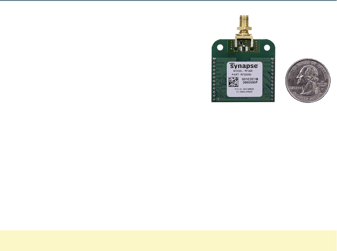
SNAP Engine RF220SU Module Overview
The SNAP Engine Model RF220SU is an IEEE 802.15.4, low-power,
highly reliable solution for embedded wireless control and monitoring
networks.
The RF220SU embeds Synapse’s SNAP OS, the industry’s first
Internet-enabled, wireless mesh network operating system, into the
Atmel ATmega128RFA1 single-chip AVR®microcontroller with an
integrated transceiver that delivers up to 2Mbits/sec. This low-cost
module can have current consumption under 390nA to enable a new
generation of battery-driven systems.
The RF220SU also includes a Skyworks SE2431L front-end module, which provides a power amplifier and LNAfor
increased range.
SNAP’s on-board Python interpreter provides for rapid application development and over-the-air programming. The
modules provide up to 15 channels of operation in the ISM 2.4GHz frequency band.
By default, the SNAPoperating system automatically forms a mesh network with other nodes immediately on
receiving power. No further configuration is necessary. Multiple unrelated SNAPnetworks can exist within the same
area through several configuration options outlined in the SNAPUser Guide available from www.synapse-
wireless.com.
NOTE: Channel 15 is receive-only due to FCCpower restrictions.
This data sheet covers part number RF220SU :
• 20 GPIO with up to 7 A/D inputs
• 128k flash, 58.5k free for over-the-air uploaded user apps
• Two UART ports for control or transparent data
• Low power modes:
• Timed Sleep Mode 1: 1.27 µA
• Timed Sleep Mode 2 : 1.47 µA
• Untimed Sleep Mode : < 390 nA
• Spread Spectrum (DSSS) technology

• Up to 2 Mbps radio data rate
• 2.4 GHz RF Frequency
• AES 128-bit encryption
• RP-SMAAntenna or U.FL connecter
• Solder-able or socket-able
• 4K internal EEPROM
• 6 PWM outputs
• Supports over the air firmware upgrades.
(This process is further defined in the Portal User Guide.)
Specifications
Performance
Outdoor LOS Range Up to 3 miles at 250 Kbps using a 5.5dBi antenna
Transmit Power Output up to +20 dBm
RF Data Rate 250Kbps, 500Kbps, 1Mbps, 2Mbps
Receiver Sensitivity -103 dBm (1% PER, 250Kbps)
Power
Requirements
Supply Voltage 2.0 - 3.6 V
Transmit Current (Typ@3.3V) at +20 dBm: 150 mA
at +6 dBm: 55 mA
Idle/Receive On (Typ@3.3V) 22 mA
Idle/Receive Off (Typ@3.3V) 7.8 mA
Sleep Mode Current
(Typ@3.3V)
Timed Sleep: 1.27 µA
Untimed Sleep Mode : 390 nA
Table 1: RF220SU Specifications at 23° C and 3.3Vunless otherwise noted

General
Frequency ISM 2.4 GHz
Spreading Method Direct Sequence (DSSS)
Modulation O-QPSK
Dimensions 33.86mm x 33.86mm
Operating Temperature - 40 to 85 deg C.
Antenna Options U.FL and RP-SMA
Weight 9 grams
Networking
Topology SNAP
Error Handling Retries and acknowledgement
Number of Channels 15 channels. To avoid exceeding FCClimits, channel 15 operates in
a receive only state.
Available I/O
UARTS with optional HW
Flow Control 2 Ports
GPIO 20 total; 7 can be analog-in with 10bit ADC
Agency
Approvals
FCC Part 15.247 U9O-RF220SU
Industry Canada (IC) 7084A-RF220SU
RF220SU Module Pin Definitions
For pin locations, consult RF220SUMechanical Drawing on page 7. later in this document.
RF220SU
Pin Pin Name SNAPpy
IO
ATmega128RFA1 Pin
Name Pin Description
1 GND GND Power Supply
2 GPIO0 7 PB7_OC0A_OC1C_PCINT7 IO or PWM or Interrupt
3 GPIO1 6 PB6_OC1B_PCINT6 IO or PWM or Interrupt
4 GPIO2 5 PB5_OC1A_PCINT5 IO or PWM or Interrupt
Table 2: RF220SU Pin Assignments

RF220SU
Pin Pin Name SNAPpy
IO
ATmega128RFA1 Pin
Name Pin Description
5 GPIO3 16 PE0_RXD0_PDI_PCINT8 IO or UART0 Rx or Interrupt
6 GPIO4 17 PE1_TXD0 IO or UART0 Tx
7 GPIO5 20 PE4_CTS0_OC3B_INT4 IO or UART0 CTS Output or PWM
or Interrupt
8 GPIO6 21 PE5_RTS0_OC3C_INT5 IO or UART0 RTS Input or PWM or
Interrupt
9 GPIO7 10 PD2_RXD1_INT2 IO or UART1 Rx or Interrupt
10 GPIO8 11 PD3_TXD_INT3 IO or UART1 Data Out or
Interrupt
11 GPIO9 12 PD4_CTS1_ICP1 IO or UART1 CTS output or Input
Capture
12 GPIO10 23 PE7_RTS1_ICP3_INT7_CLK0 IO or UART1 RTS input or Clock
Output Buffer or Interrupt
13 GPIO11 24 PF0_ADC0 IO or Analog0
14 GPIO12 25 PF1_ADC1 IO or Analog1 or software SPI
MOSI
15 GPIO13 26 PF2_ADC2_DIG2
IO or Analog2 or software SPI
CLK1 or Antenna Diversity
Control
16 GPIO14 18 PE2_XCK0_AIN0
IO or software SPI1 MISO or
Analog Comparator or External
Clock
17 GPIO15 28 PF4_ADC4_TCK IO or Analog4 or JTAG Test Clock
18 GPIO16 29 PF5_ADC5_TMS IO or Analog5 or JTAG Test Mode
Select
RF220SU
Pin Pin Name SNAPpy
IO
ATmega128RFA1 Pin
Name Pin Description
19 GPIO17 30 PF6_ADC6_TDO IO or Analog6 or JTAG Test Data
Out or software I2C SDA
20 GPIO18 31 PF7_ADC7_TDI IO or Analog7 or JTAG Test Data
In or software I2C SCL
21 VCC VCC Power Supply
22 GPIO19 19 PE3_OC3A_AIN1 IO or Analog Comparator or PWM
or Output Compare Match
23 RESET# RESET# Module Reset, Active Low
24 GND GND Power Supply
Electrical Characteristics
Unless otherwise specified in this document, all electrical characteristics conform to the Atmel ATmega 128RFA1
microcontroller. Detailed specifications on all electrical characteristics are available on the Atmel website at
http://www.atmel.com/
Symbol Parameter Condition Min Typ Max Units
VCC
1Supply Voltage 2.0 3.3 3.6 V
Table 3: RF220SU DC Characteristics at 25° C
Symbol Parameter Condition Min Typical Max Unit
VREFH
2ADC Voltage Reference, High Programmable 1.5 1.6 1.8 V
VINDC Analog input voltage Single Ended 0 1.8 V
Differential30 3.3
Table 4: ADC Electrical Characteristics (Operating)
1 Absolute maximum stress rated voltage for VCC is -0.3 to 3.6. It is recommended that bulk capacitance be located as close as possible
to the VCC pin on the host board. Ideally, use a single 47µF capacitor rated at 10V directly at the VCC pin.
2 VREFH is programmable to three fixed values; 1.5V, 1.6V, and 1.8V. The VREFH value will be 1.6 volts if you do not explicitly adjust it
by poking the ATmega128RFA1 registers.
3 Each differential analog input may be as high as 3.3V but the single-ended voltage is still limited to the voltage reference.
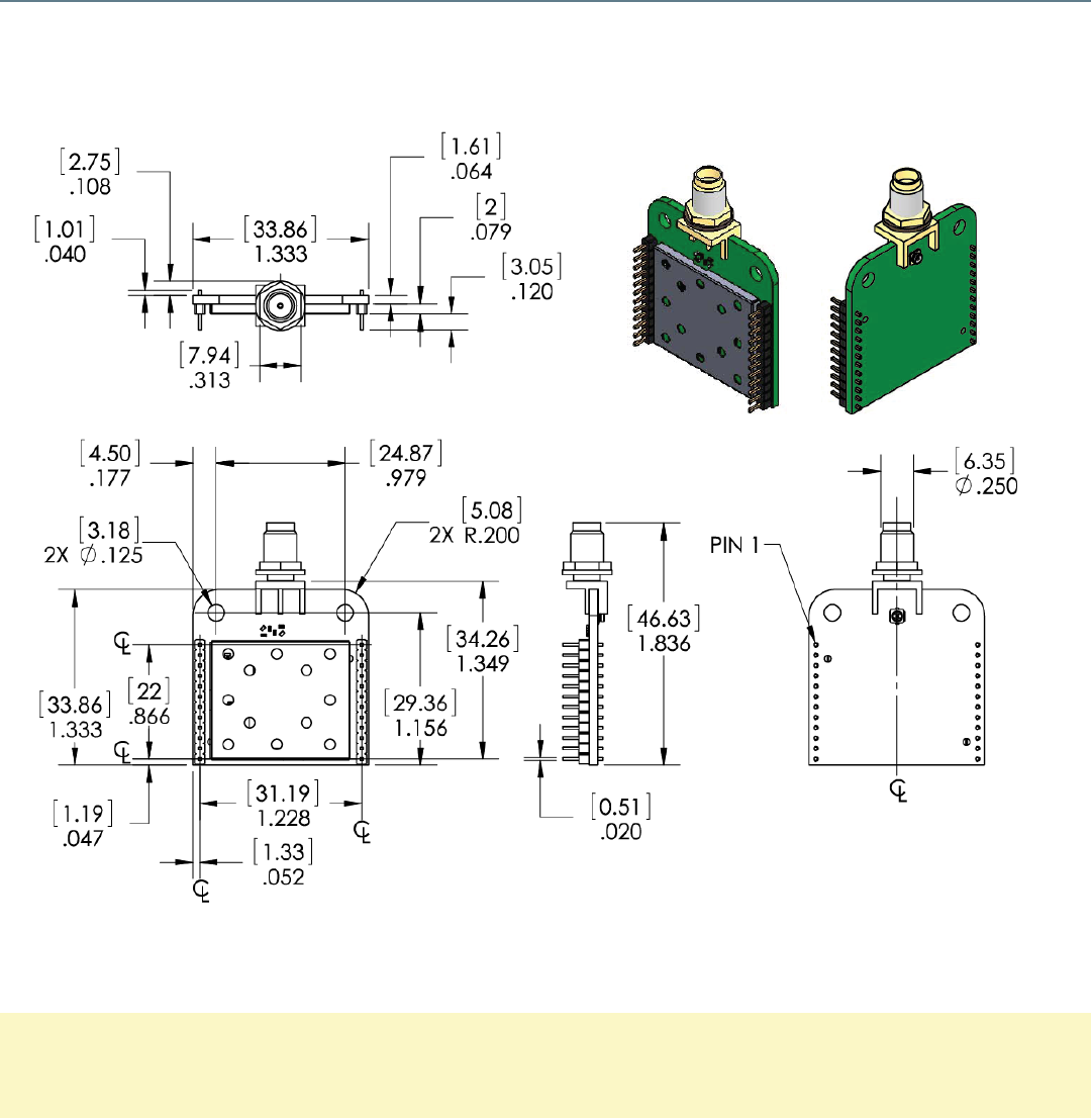
Mechanical Drawings
RF220SUMechanical Drawing on page 7. and Block diagram showing the major subsystems comprising Model
RF220SU on page 8. are for modules with the compact F antenna and U.FL Connector options.
Figure 1: RF220SUMechanical Drawing
NOTE: The area under the module's antenna (marked KEEPOUTAREA)should have no components, no traces,
and no copper on any layer of the printed circuit board.
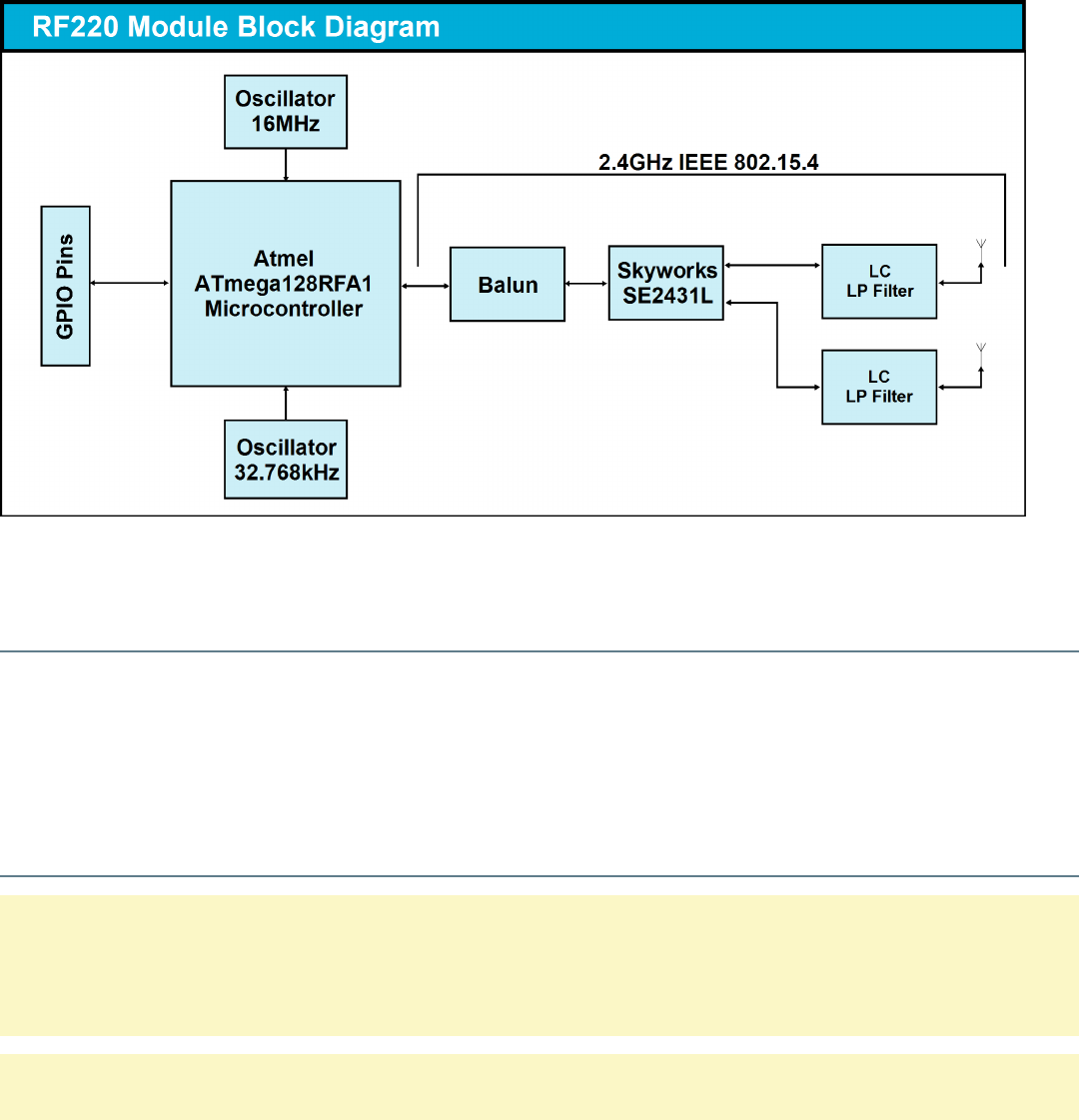
Figure 2: Block diagram showing the major subsystems comprising Model RF220SU
Selecting an Antenna
The RF220SU uses the RP-SMAconnector by default. If you wish to use an external U.FL antenna with your
application, you will need to set bit 0x0010 of NV ID 64 to 1 and reboot your node. This is a one-time change that will
persist through reboots and program changes. To revert to the RP-SMA antenna, change bit 0x0010 of NV ID 64
back to 0 and reboot the node.
Antenna Gain Performance
NOTE: Antenna gain performance information is based on information from the individual companies at the time
this document's release. For added assurance, it's best to obtain antenna performance information directly from
that antenna's manufacturer.
NOTE: A u.fl to SMA cable is included for use of the u.fl port.
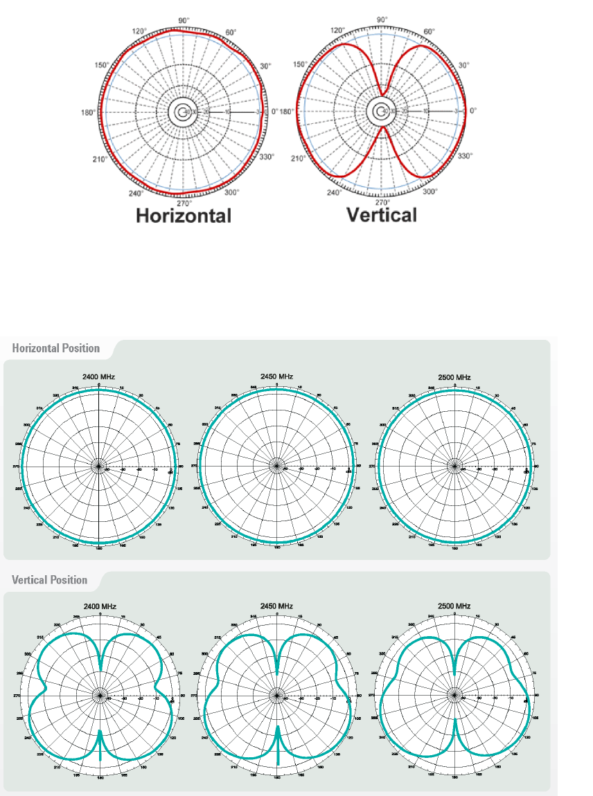
HyperLink Technologies HG2405RD-RSP
Figure 3: HyperLink Technologies HG2405RD-RSP Antenna Gain Performance
Pulse W1027
Figure 4: Pulse W1027 Antenna Gain Performance

Agency Certifications
United States (FCC)
The Model RF220 modules comply with Part 15 of the FCC rules and regulations. Compliance with the labeling
requirements, FCC notices, and antenna usage guidelines is required. In order to comply with FCC Certification
requirements, the Original Equipment Manufacturer (OEM) must fulfill the following requirements.
1. The system integrator must place an exterior label on the outside of the final product housing the RF220
Modules. FCCLabel on page 10. shows the contents that must be included on this label.
2. RF220 Modules may only be used with the antenna that has been tested and approved for use with the
module. Please refer to the antenna table provided in this section.
OEM Labeling Requirements
NOTICE: The OEM must make sure that FCC labeling requirements are met. This includes a clearly visible exterior
label on the outside of the final product housing that displays the contents shown in FCCLabel on page 10. .
MANUFACTURERSNAME
BRANDNAMEor TRADENAME
Contains FCC ID: U9O-RF220SU
This device complies with Part 15 of the FCCRules. Operation is subject to the following two conditions:(1) This
device may not cause harmful interferences, and (2) this device must accept any interference received, including
interference that may cause undesired operation.
Figure 5: FCCLabel
FCC Notices
WARNING: The RF220 modules have been tested by the FCC for use with other products without further
certification (as per FCC Section 2.1091). Changes or modifications to this device not expressly approved by
Synapse Wireless Inc. could void the user’s authority to operate the equipment.
NOTICE: OEM’s must certify final end product to comply with unintentional radiators (FCC Sections 15.107 and
15.109) before declaring compliance of their final product to Part 15 of the FCC Rules.

NOTICE: The RF220 modules have been certified for remote and base radio applications. If the module will be used
for portable applications as defined by the FCC, the device must undergo SAR testing.
This equipment has been tested and found to comply with the limits for a Class B digital device, pursuant to Part 15 of
the FCC Rules. These limits are designed to provide reasonable protection against harmful interference in a
residential installation. This equipment generates, uses, and can radiate radio frequency energy, and if not installed
and used in accordance with the instructions, may cause harmful interference to radio communications. However,
there is no guarantee that interference will not occur in a particular installation.
If this equipment does cause harmful interference to radio or television reception, which can be determined by
turning the equipment off and on, the user is encouraged to try to correct the interference by one or more of the
following measures:
• Reorient or relocate the receiving antenna.
• Increase the separation between the equipment and receiver.
• Connect the equipment into an outlet on a circuit different from that to which the receiver is connected.
• Consult the dealer or an experienced radio/TV technician for help.
FCC Approved Antennas
The RF220SU modules are FCC-approved for fixed base station and mobile applications.
Notice: To reduce potential radio interference to other users, the antenna type and its gain should be chosen so that
the equivalent isotropically radiated power (EIRP) is not more than that permitted for successful communication. This
module has been designed to operate with the antennas listed in RF220SU Approved FCC Antennas on page 11. .
The required antenna impedance is 50 ohms.
Part Number Type Gain Impedance Application Min.
Separation
Pulse W1027 Dipole (quarter-
wave RPSMA)
3.2
dBi 50Ω Fixed/Mobile 20 cm.
HyperLink
HG2405RD-RSP
Dipole (quarter-
wave RPSMA)
5.5
dBi 50Ω Fixed/Mobile 20 cm.
Table 5: RF220SU Approved FCC Antennas
For more information on approved antennas, please consult the manufacturer’s website.

WARNING: RF Exposure: This equipment complies with FCC radiation exposure limits set forth for an
uncontrolled environment. This equipment should be installed and operated with minimum distance 20 cm
between the radiator and your body. This transmitter must not be co-located or operating in conjunction with any
other antenna or transmitter.
NOTICE: The preceding statement must be included as a CAUTION statement in OEM product manuals in order to
alert users of FCC RF exposure compliance.
NOTE: Antenna and transmitters may be co-located or operated in conjunction with this device only if the
transmitters do not simultaneously transmit. Otherwise, additional regulatory requirements will apply.
Canada (IC)
This device complies with Industry Canada license-exempt RSS standard(s). Operation is subject to the following two
conditions: (1) this device may not cause interference, and (2) this device must accept any interference, including
interference that may cause undesired operation of the device.
Le présent appareil est conforme aux CNR d'Industrie Canada applicables aux appareils radio exempts de
licence. L'exploitation est autorisée aux deux conditions suivantes : (1) l'appareil ne doit pas produire de
brouillage, et (2) l'utilisateur de l'appareil doit accepter tout brouillage radioélectrique subi, même si le brouillage
est susceptible d'en compromettre le fonctionnement.
Under Industry Canada regulations, this radio transmitter may only operate using an antenna of a type and
maximum (or lesser) gain approved for the transmitter by Industry Canada. To reduce potential radio interference to
other users, the antenna type and its gain should be so chosen that the equivalent isotropically radiated power (EIRP)
is not more than that necessary for successful communication.
Conformément à la réglementation d'Industrie Canada, le présent émetteur radio peut fonctionner avec une
antenne d'un type et d'un gain maximal (ou inférieur) approuvé pour l'émetteur par Industrie Canada. Dans le but
de réduire les risques de brouillage radioélectrique à l'intention des autres utilisateurs, il faut choisir le type
d'antenne et son gain de sorte que la puissance isotrope rayonnée équivalente (p.i.r.e.) ne dépasse pas l'intensité
nécessaire à l'établissement d'une communication satisfaisante.
This radio transmitter Model: RF220SU, IC: 7084A-RF220SU has been approved by Industry Canada to operate with
the listed antenna types with the maximum permissible gain and required antenna impedance for each antenna type

indicated. Antenna types not included in this list, having a gain greater than the maximum gain indicated for that type,
are strictly prohibited for use with this device.
Le présent émetteur radio Model : RF220SU, IC: 7084A-RF220SU a été approuvé par Industrie Canada pour
fonctionner avec les types d'antenne énumérés ci-dessous et ayant un gain admissible maximal et l'impédance
requise pour chaque type d'antenne. Les types d'antenne non inclus dans cette liste, ou dont le gain est
supérieur au gain maximal indiqué, sont strictement interdits pour l'exploitation de l'émetteur.
Part Number Type Gain Application Min. Separation
Pulse W1027 Dipole (quarter-wave
RPSMA) 3.2 dBi Fixed/Mobile 20 cm.
HyperLink HG2405RD-
RSP
Dipole (quarter-wave
RPSMA) 5.5 dBi Fixed/Mobile 20 cm.
Table 6: RF220SU Approved IC Antennas
IC OEM Labeling Requirements
Labeling requirements for Industry Canada are similar to those of the FCC. A clearly visible label on the outside of the
final product housing must display the contents shown in ICLabel on page 13. .
MANUFACTURERSNAME
BRANDNAMEor TRADENAME
MODEL:
Contains IC: 7084A-RF220SU
Figure 6: ICLabel
NOTE: The OEM can choose to implement a single label combined for both FCC and IC labeling requirements. If
a combined single label is chosen, there must be a clearly visible label on the outside of the final product housing
displaying the contents shown in Combined FCCand IC Label on page 14. .

MANUFACTURERSNAME
BRANDNAMEor TRADENAME
Contains FCC ID: U90-RF220SU
Contains IC: 7084A-RF220SU
This device complies with Part 15 of the FCCRules. Operation is subject to the following two conditions:(1) This
device may not cause harmful interferences, and (2) this device must accept any interference received, including
interference that may cause undesired operation.
Figure 7: Combined FCCand IC Label