Synapse Wireless SM220 SNAP OS-enabled 2.4GHz modular radio User Manual My
Synapse Wireless Inc. SNAP OS-enabled 2.4GHz modular radio My
Manual

DATA SHEET
SNAP Engine SM220
Series
©2008-2014 Synapse, All Rights Reserved. All Synapse products are patent
pending. Synapse, the Synapse logo, SNAP, and Portal are all registered
trademarks of Synapse Wireless, Inc.
Doc# 430000-01A
6723 Odyssey Drive // Huntsville, AL 35806 // (877) 982-7888 // Synapse-Wireless.com

DRAFT COPY
Generated on 9/16/2014
SNAP Engine SM220 Modules Overview
The SNAP Engine Model SM220 series currently consists of the SM220UF1. It is an IEEE 802.15.4,
low-power, highly reliable solution for embedded wireless control and monitoring networks that
require high data rates. The Model SM220 embeds Synapse’s SNAP OS, the industry’s first
Internet-enabled, wireless mesh network operating system, into the Atmel ATmega128RFA1
single-chip AVR®microcontroller with an integrated transceiver that delivers up to 2Mbits/sec. This
low-cost module can have current consumption under 390nA to enable a new generation of battery-
driven systems. The SM220 also includes a Skyworks SE2431L front-end module, which provides a
power amplifier and LNAfor increased range.
SNAP’s on-board Python interpreter provides for rapid application development and over-the-air
programming, while Atmel’s low-power RF single-chip design saves board space and lowers power
consumption. The modules provide up to 15 channels of operation in the ISM 2.4GHz frequency
band.
This data sheet covers part number SM220UF1:
• 36 GPIO with up to 7 A/D inputs
• 128k flash, 58.5k free for over-the-air uploaded user apps
• Two UART ports for control or transparent data
• Low power modes:
• Timed Sleep Mode 1: 1.27 µA
• Timed Sleep Mode 2 : 1.47 µA
• Untimed Sleep Mode : < 390 nA
• Spread Spectrum (DSSS) technology
• Up to 2 Mbps radio data rate
• 2.4 GHz RF Frequency
• AES 128-bit encryption
• Integrated compact F antenna or U.FL connecter
• Surface Mount, Solder-able
• 4K internal EEPROM
• 8 PWM outputs
1
SNAP Engine SM220 Series Data Sheet — 430000-01A
DRAFT COPY
Generated on 9/16/2014
2SNAP Engine SM220 Series Data Sheet — 430000-01A
Specifications
Performance
Outdoor LOS Range 3 miles
Transmit Power Output up to +20 dBm
RF Data Rate 250Kbps, 500Kbps, 1Mbps, 2Mbps
Receiver Sensitivity -103 dBm (1% PER, 250Kbps)
Power
Requirements
Supply Voltage 2.0 - 3.6 V
Transmit Current
(Typ@3.3V)
at +20 dBm: 150 mA
at +6 dBm: 55 mA
Idle/Receive On
(Typ@3.3V) 22 mA
Idle/Receive Off
(Typ@3.3V) 7.8 mA
Sleep Mode Current
(Typ@3.3V)
Timed Sleep: 1.27 µA
Untimed Sleep Mode : 390 nA
General
Frequency ISM 2.4 GHz
Spreading Method Direct Sequence (DSSS)
Modulation O-QPSK
Dimensions 29.8mm x 19mm
Operating Temperature - 40 to 85 deg C.
Antenna Options U.FL and Internal F
Weight 3 grams
Networking
Topology SNAP
Error Handling Retries and acknowledgement
Number of Channels 15 fully operational channels, and channel 15
operates in a receive only state
Available I/O
UARTS with optional HW
Flow Control 2 Ports
GPIO 36 total; 7 can be analog-in with 10bit ADC
Agency
Approvals
FCC Part 15.247 FCCID: U9O-SM220
Industry Canada (IC) 7084A-SM220
CE Certified Certified to EN300 328 Version 1.8.1
Table 1: SM220 Specifications at 23° C and 3.3Vunless otherwise noted
DRAFT COPY
Generated on 9/16/2014
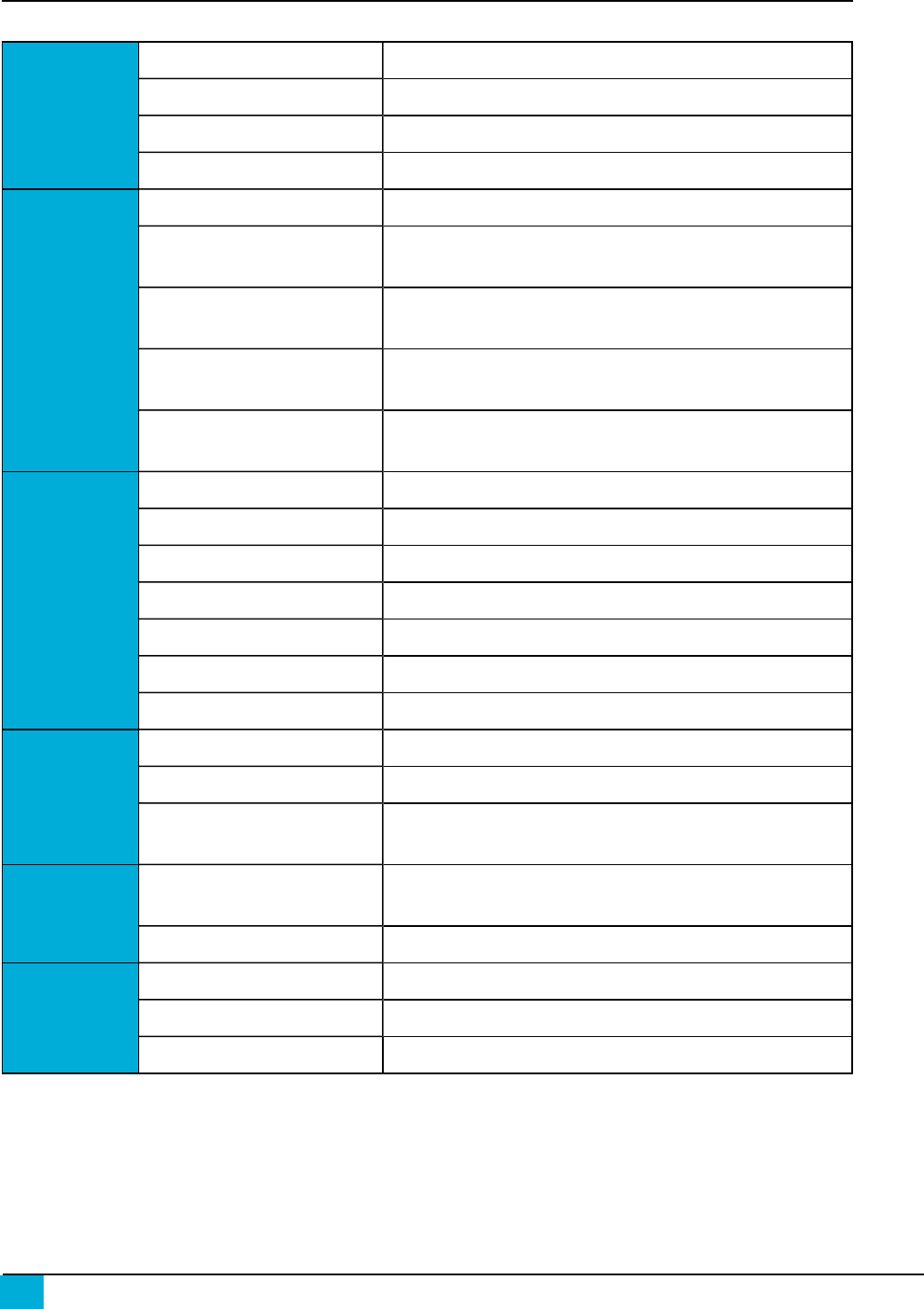
SM220 Module Pin Definitions
For pin locations, consult the SM220 Mechanical drawing later in this document.
SM220
Pin Pin Name Pin Description
A1 GND Power Supply
A2 VCC Power Supply
A3 VCC Power Supply
A4 PF0_ADC0 IO or Analog0
A5 PF2_ADC2_DIG2 IO or Analog2 or software SPI CLK1or Antenna Diversity
Control
A6 PF4_ADC4_TCK IO or Analog4 or JTAG Test Clock
A7 PF6_ADC6_TDO IO or Analog6 or JTAG Test Data Out or software I2C1SDA
A8 GND Power Supply
B1 PE2_XCK0_AIN0 IO or software SPI1MISO or Analog Comparator or External
Clock
B2 PE3_OC3A_AIN1 IO or Analog Comparator or PWM or Output Compare Match
B3 PE5_OC3C_INT5 IO or UART0 RTS Input or PWM or Interrupt
B4 PF1_ADC1 IO or Analog1 or software SPI1MOSI
B5 Test Point - Do Not Use
B6 PF5_ADC5_TMS IO or Analog5 or JTAG Test Mode Select
B7 PF7_ADC7_TDI IO or Analog7 or JTAG Test Data In or software I2C1SCL
B8 GND Power Supply
C1 PE0_RXD0_PDI_
PCINT8 IO or UART0 Data In or Interrupt
C2 PE1_TXD0_PDO IO or UART0 Data Out
C3 PE4_OC3B_INT4 IO or UART0 CTS Output or PWM or Interrupt
C4 PE6_T3_INT6 IO or Interrupt
C5 PE7_ICP3_INT7_CLK0 IO or UART1 RTS input or Clock Output Buffer or Interrupt
C6 PF3_ADC3_DIG4 IO or ADCchannel 3
Table 2: SM220UF1 Pin Assignments
1 Software generated SPIand I2C functions.
3
SNAP Engine SM220 Series Data Sheet — 430000-01A
DRAFT COPY
Generated on 9/16/2014
4SNAP Engine SM220 Series Data Sheet — 430000-01A
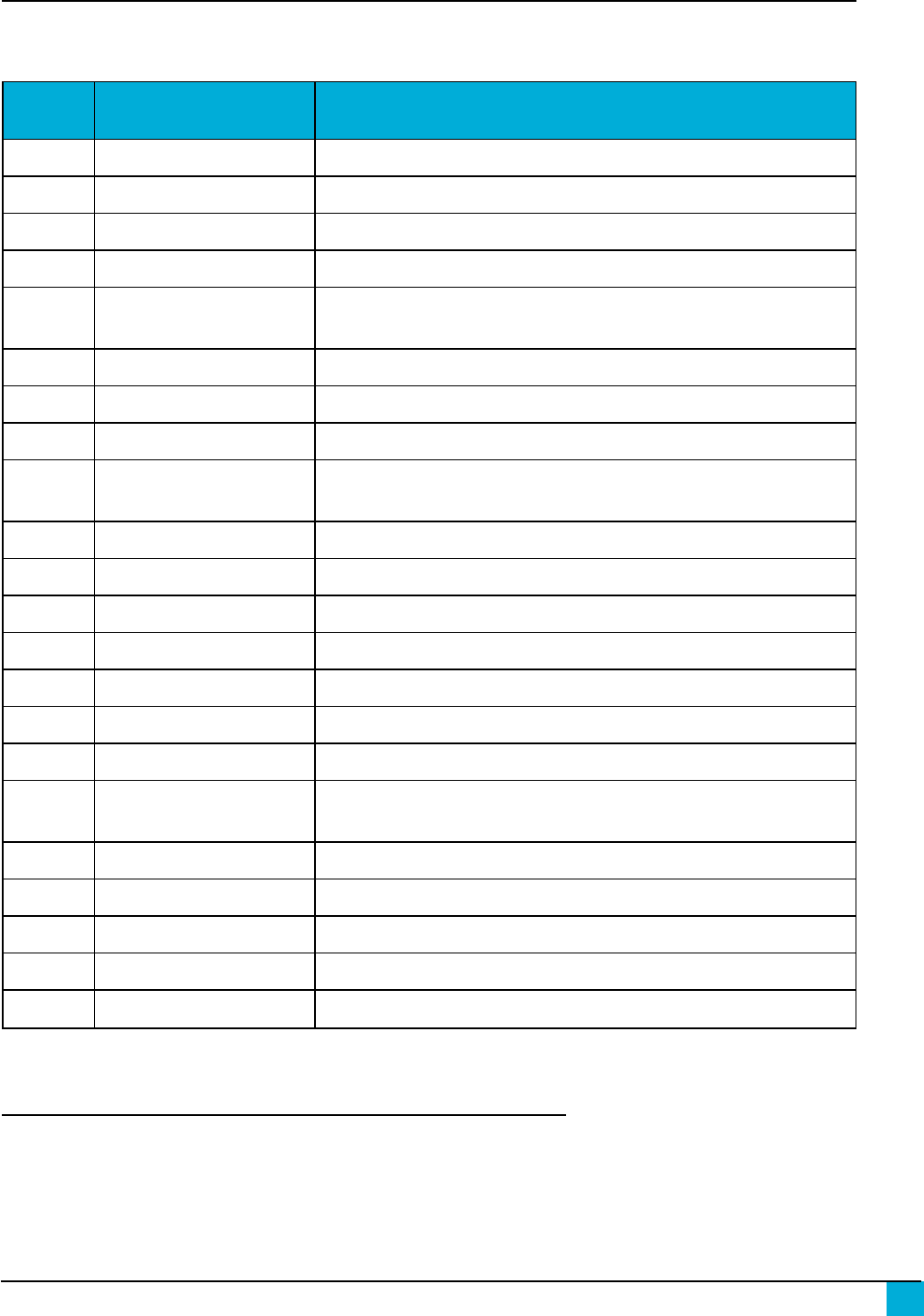
SM220
Pin Pin Name Pin Description
C7 NC
C8 NC
D1 PB5_OC1A_PCINT5 IO or PWM or Interrupt
D2 PB6_OC1B_PCINT6 IO or PWM or Interrupt
D3 PB7_OC0A_OC1C_P
CINT7 IO or PWM or Interrupt
D4 NC
D5 NC
D6 NC
D7 NC
D8 GND Power Supply
E1 PB2_MOSI_ PCINT22IO or Interrupt
E2 PB3_MISO_ PCINT32IO or Interrupt
E3 PB4_OC2A_PCINT4 IO or PWM or Interrupt
E4 NC
E5 NC
E6 NC
E7 NC
E8 NC
F1 PB0_SSN_PCINT02IO or Interrupt
F2 PB1_SCK_PCINT12IO or Interrupt
F3 PD1_SDA_INT13IO or Interrupt
F4 PD0_SCL_INT03IO or Interrupt
F5 Test Point - Do Not Use
F6 Test Point - Do Not Use
F7 NC
2 These pins have special SPI hardware that is not natively supported by SNAP. You can use PEEKand POKE to initiate and enable this
hardware functionality, but it is not supported by Synapse and we cannot guarentee your results.
3 These pins have special I2C hardware that is not natively supported by SNAP. You can use PEEKand POKE to initiate and enable this
hardware functionality, but it is not supported by Synapse and we cannot guarentee your results.
DRAFT COPY
Generated on 9/16/2014
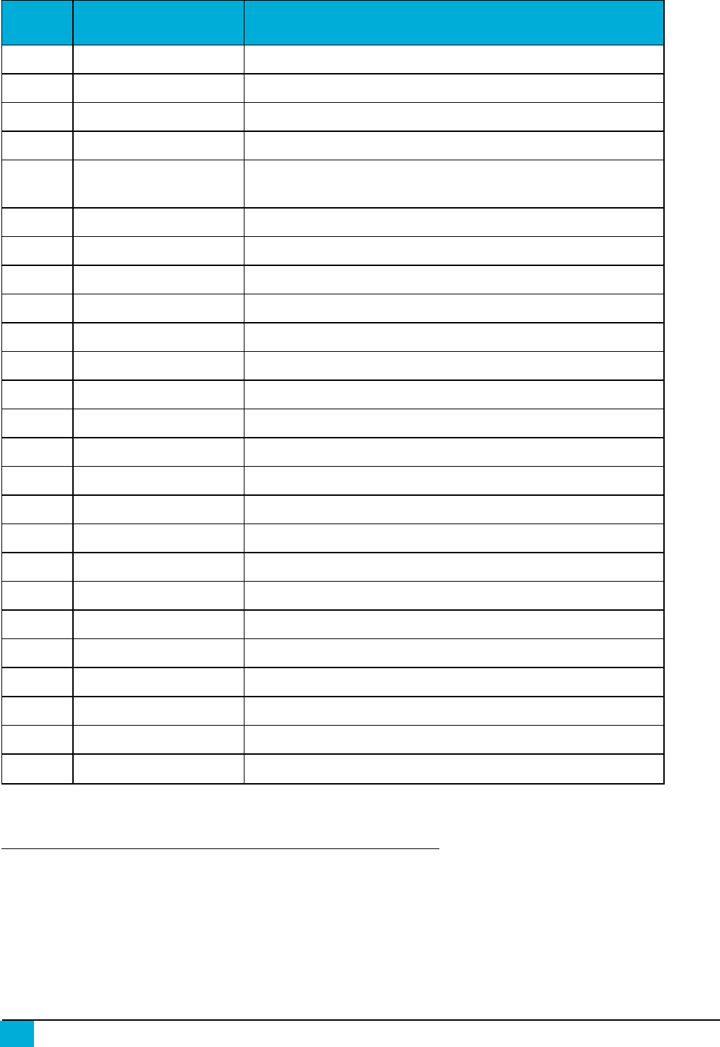
SM220
Pin Pin Name Pin Description
F8 GND Power Supply
G1 CLKI Must be pulled low during normal operation
G2 PD7_T0 IO
G3 PD4_ICP1 IO or UART1 CTS output or Input Capture
G4 PD2_RXD1_INT2 IO or UART1 Data In or Interrupt
G5 PG5_OC0B IO or PWM
G6 NC
G7 NC
G8 GND Power Supply
H1 GND Power Supply
H2 PD6_T1 IO or Timer/Counter1 clock input
H3 PD5_XCK1 IO
H4 PD3_TXD1_INT3 IO or UART1 Data Out or Interrupt
H5 RESET# Module Reset, Active Low
H6 NC
H7 NC
H8 GND Power Supply
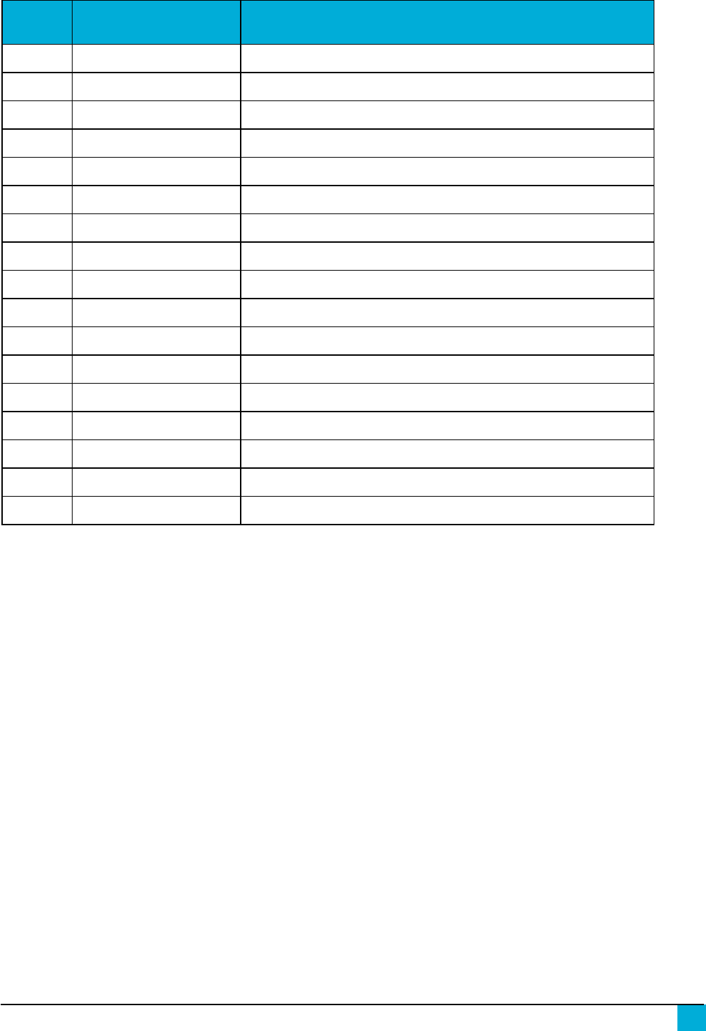
As a convenience, here is a cross reference from SM220 pad back to SNAPpy IO.
5
SNAP Engine SM220 Series Data Sheet — 430000-01A
DRAFT COPY
Generated on 9/16/2014
6SNAP Engine SM220 Series Data Sheet — 430000-01A
Pad SNAPpy IO
A4 24
A5 26
A6 28
A7 30
B1 18
B2 19
B3 21
B4 25
B5 33
B6 29
B7 31
C1 16
C2 17
C3 20
C4 22
C5 23
D1 5
Table 3: SM220/SNAPpy IO Cross
Reference Pad SNAPpy IO
D2 6
D3 7
E1 2
E2 3
E3 4
F1 0
F2 1
F3 9
F4 8
G2 15
G3 12
G4 10
G5 37
H2 14
H3 13
H4 11
- -
Electrical Characteristics
Unless otherwise specified in Table 4 , all electrical characteristics conform to the Atmel ATmega
128RFA1 microcontroller. Detailed specifications on all electrical characteristics are available on the
Atmel website at http://www.atmel.com/
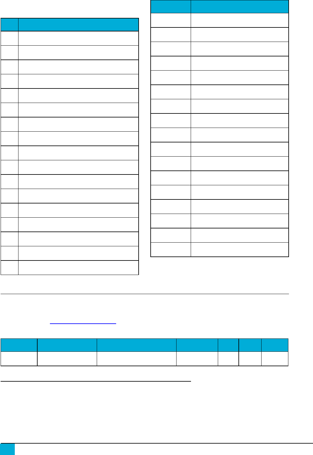
Symbol Parameter Condition Min Typ Max Units
VCC
4Supply Voltage 2.0 3.3 3.6 V
Table 4: SM220 DC Characteristics at 25° C
4 Absolute maximum stress rated voltage for VCC is -0.3 to 3.6. It is recommended that bulk capacitance be located as close as possible
to the VCC pin on the host board. Ideally, use a single 47µF capacitor rated at 10V directly at the VCC pin.
DRAFT COPY
Generated on 9/16/2014
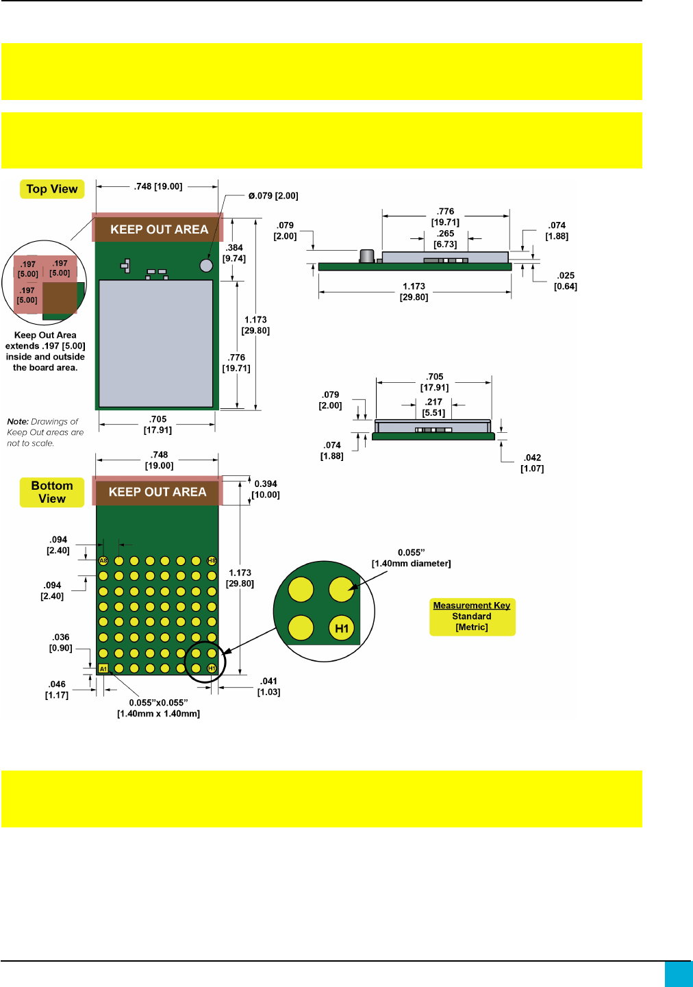
Mechanical Drawings
Figure 1 and Figure 2 show the modules with the compact F antenna ad U.FL Connector options.
NOTE: The area under the module's antenna (marked KEEPOUTAREA)should have no
components, no traces, and no copper on any layer of the printed circuit board.
NOTE: For best performance, the module should be mounted on the outside edge of the circuit
board with the antenna side as close to the edge of the board as possible.
Figure 1: SM220UF1 Mechanical Drawing
NOTE: The area under the module's antenna (marked KEEPOUTAREA)should have no
components, no traces, and no copper on any layer of the printed circuit board.
7
SNAP Engine SM220 Series Data Sheet — 430000-01A
DRAFT COPY
Generated on 9/16/2014
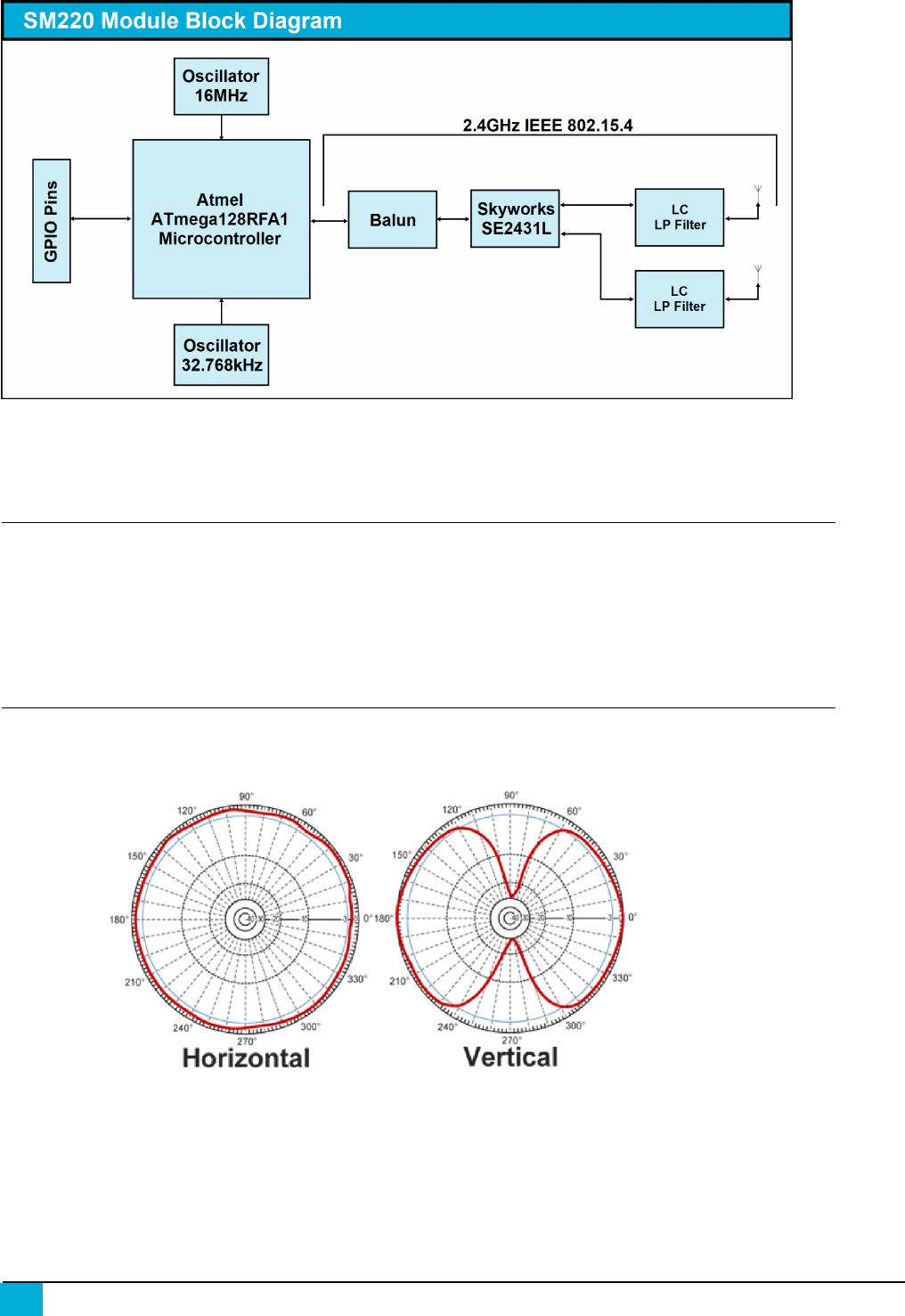
8SNAP Engine SM220 Series Data Sheet — 430000-01A
Figure 2: Block diagram showing the major subsystems comprising Model SM220
Selecting an Antenna
The SM220 uses the internal Compact F antenna by default. If you wish to use an external U.FL
antenna with your application, you will need to set bit 0x0010 of NV ID 64 to 1. This is a one-time
change that will persist through reboots and program changes. To revert to the internal antenna,
change bit 0x0010 of NV ID 64 back to 0.
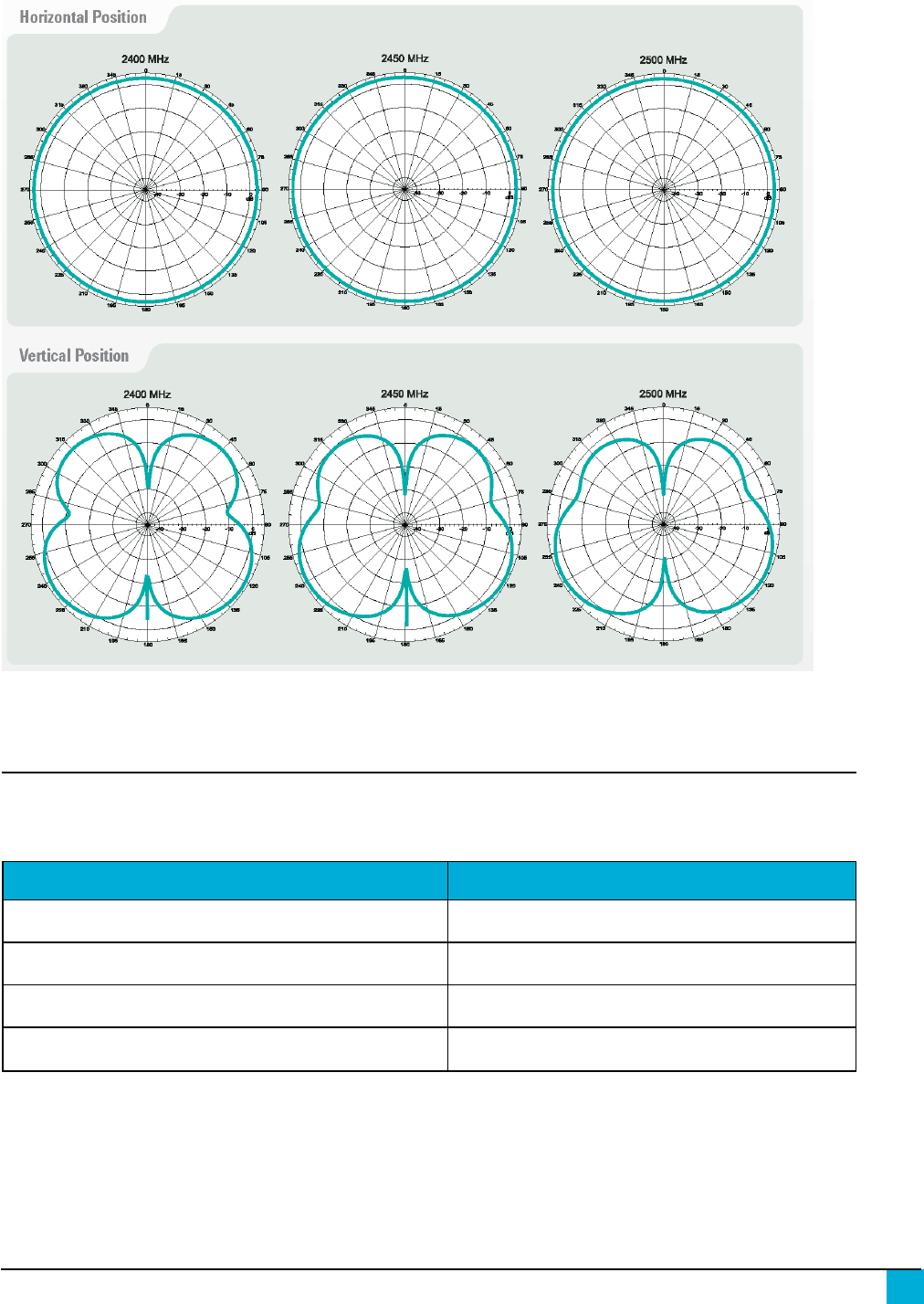
Antenna Gain Performance
HyperLink Technologies HG2405RD-RSP
Figure 3: HyperLink Technologies HG2405RD-RSP Antenna Gain Performance
DRAFT COPY
Generated on 9/16/2014
Pulse W107
Figure 4: Pulse W107 Antenna Gain Performance
Board Mounting Considerations
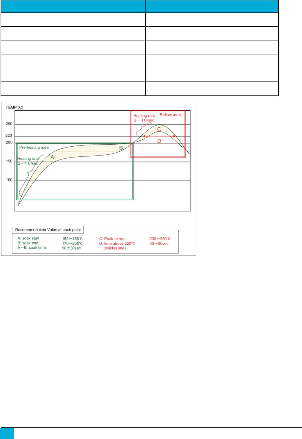
Processing
Parameter Value
Ramp up rate (from Tsoakmax to Tpeak) 3º/sec max
Minimum Soak Temperature 150ºC
Maximum Soak Temperature 200ºC
Soak Time 60-120 sec
Table 5: Recommended Reflow Profile
9
SNAP Engine SM220 Series Data Sheet — 430000-01A
DRAFT COPY
Generated on 9/16/2014
10 SNAP Engine SM220 Series Data Sheet — 430000-01A
Parameter Value
TLiquidus 217ºC
Time above TL 30-60 sec (recommended: 40 sec)
Tpeak 230º - 250ºC (recommended: 235ºC)
Time within 5º of Tpeak 20-30 sec
Time from 25º to Tpeak 8 min max
Ramp down rate 6ºC/sec max
Figure 5: Reflow Profile Graph
Pb-Free Soldering Paste
Use of “No Clean” soldering paste is strongly recommended, as it does not require cleaning after the
soldering process.
Cleaning
In general, cleaning the populated modules is strongly discouraged. Residuals under the module
cannot be easily removed with any cleaning process.
• Cleaning with water can lead to capillary effects where water is absorbed into the gap
between the host board and the module. The combination of soldering flux residuals and
encapsulated water could lead to short circuits between neighboring pads. Water could also
damage any stickers or labels.

DRAFT COPY
Generated on 9/16/2014
• Cleaning with alcohol or a similar organic solvent will likely flood soldering flux residuals into
the two housings, which is not accessible for post-washing inspection. The solvent could
also damage any stickers or labels.
• Ultrasonic cleaning could damage the module permanently.
The recommended approach is to consider using a “no clean” soldering paste and eliminate the
post-soldering cleaning step.
Repeating Reflow Soldering
Only a single reflow soldering process is encouraged for host boards.
Rework
The Model SM220 Module can be unsoldered from the host board, but the process is likely to
damage the chip and not recommended. If attempting this, use of a hot air rework tool and hot plate
for pre-heating from underneath is recommended. Avoid overheating.
WARNING!: Never attempt a rework on the module itself (e.g. replacing individual
components). Such actions will terminate warranty coverage.
Additional Grounding
Attempts to improve module or system grounding by soldering braids, wires, or cables onto the
module RF shield cover is done at the customers own risk. The numerous ground pins at the module
perimeter should be sufficient for optimum immunity to external RF interference.
11
SNAP Engine SM220 Series Data Sheet — 430000-01A

DRAFT COPY
Generated on 9/16/2014
12 SNAP Engine SM220 Series Data Sheet — 430000-01A
Agency Certifications
United States (FCC)
The Model SM220 modules comply with Part 15 of the FCC rules and regulations. Compliance with
the labeling requirements, FCC notices, and antenna usage guidelines is required. In order to
comply with FCC Certification requirements, the Original Equipment Manufacturer (OEM) must fulfill
the following requirements.
1. The system integrator must place an exterior label on the outside of the final product housing
the SM220 Modules. Figure 6 below shows the contents that must be included on this
label.
2. SM220 Modules may only be used with the antenna that has been tested and approved for
use with the module. Please refer to the antenna table provided in this section.
OEM Labeling Requirements
NOTICE: The OEM must make sure that FCC labeling requirements are met. This includes a
clearly visible exterior label on the outside of the final product housing that displays the contents
shown in Figure 6 below.
MANUFACTURERSNAME
BRANDNAMEor TRADENAME
Contains SM220 FCC ID: U9O-SM220
This device complies with Part 15 of the FCCRules. Operation is subject to the following two
conditions:(1) This device may not cause harmful interferences, and (2) this device must accept
any interference received, including interference that may cause undesired operation.
Figure 6: FCCLabel
FCC Notices
WARNING!: The SM220 modules have been tested by the FCC for use with other
products without further certification (as per FCC Section 2.1091). Changes or
modifications to this device not expressly approved by Synapse Wireless Inc.
could void the user’s authority to operate the equipment.
NOTICE: OEM’s must certify final end product to comply with unintentional radiators (FCC
Sections 15.107 and 15.109) before declaring compliance of their final product to Part 15 of the FCC
Rules.
NOTICE: The SM220 modules have been certified for remote and base radio applications. If the
module will be used used for portable applications as defined by the FCC, the device must undergo
SAR testing.
DRAFT COPY
Generated on 9/16/2014
NOTE: This equipment has been tested and found to comply with the limits for a Class B digital
device, pursuant to Part 15 of the FCC Rules. These limits are designed to provide reasonable
protection against harmful interference in a residential installation. This equipment generates, uses,
and can radiate radio frequency energy and, if not installed and used in accordance with the
instructions, may cause harmful interference to radio communications. However, there is no
guarantee that interference will not occur in a particular installation. If this equipment does cause
harmful interference to radio or television reception, which can be determined by turning the
equipment off and on, the user is encouraged to try to correct the interference by one or more of the
following measures:
• Reorient or relocate the receiving antenna.
• Increase the separation between the equipment and receiver.
• Connect the equipment into an outlet on a circuit different from that to which the receiver is
connected.
• Consult the dealer or an experienced radio/TV technician for help.
This device complies with Industry Canada licence-exempt RSS standard(s). Operation is subject to
the following two conditions: (1) this device may not cause interference, and (2) this device must
accept any interference, including interference that may cause undesired operation of the device.
Le présent appareil est conforme aux CNR d'Industrie Canada applicables aux appareils radio
exempts de licence. L'exploitation est autorisée aux deux conditions suivantes : (1) l'appareil ne doit
pas produire de brouillage, et (2) l'utilisateur de l'appareil doit accepter tout brouillage
radioélectrique subi, même si le brouillage est susceptible d'en compromettre le fonctionnement.
FCC Approved Antennas
The SM220 modules are FCC-approved for fixed base station and mobile applications.
Notice: To reduce potential radio interference to other users, the antenna type and its gain should
be chosen so that the equivalent isotropically radiated power (EIRP) is not more than that permitted
for successful communication. This module has been designed to operate with the antennas listed in
Table 6 and Table 7 . The required antenna impedance is 50 ohms.
Part Number Type Gain Impedance Application Min.
Separation
Compact F
Antenna
PCBoard Trace
Antenna
0.0
dBi 50Ω Fixed/Mobile 20 cm.
Table 6: SM220UF1 Approved FCC Antennas
13
SNAP Engine SM220 Series Data Sheet — 430000-01A
DRAFT COPY
Generated on 9/16/2014
14 SNAP Engine SM220 Series Data Sheet — 430000-01A
Part Number Type Gain Impedance Application Min.
Separation
Pulse W1027 Dipole (quarter-
wave RPSMA)
3.2
dBi 50Ω Fixed/Mobile 20 cm.
HyperLink
HG2405RD-RSP
Dipole (quarter-
wave RPSMA)
5.5
dBi 50Ω Fixed/Mobile 20 cm.
Table 7: SM220UF1 Approved FCC Antennas
For more information on approved antennas, please consult the manufacturer’s website.
WARNING!: RF Exposure: This equipment complies with FCC radiation exposure
limits set forth for an uncontrolled environment. This equipment should be
installed and operated with minimum distance 20 cm between the radiator and
your body. This transmitter must not be co-located or operating in conjunction
with any other antenna or transmitter.
NOTICE: The preceding statement must be included as a CAUTION statement in OEM product
manuals in order to alert users of FCC RF exposure compliance.
NOTE: Antenna and transmitters may be co-located or operated in conjunction with this device
only if the transmitters do not simultaneously transmit. Otherwise, additional regulatory
requirements will apply.
Canada (IC)
This device complies with Industry Canada license-exempt RSS standard(s). Operation is subject to
the following two conditions: (1) this device may not cause interference, and (2) this device must
accept any interference, including interference that may cause undesired operation of the device.
Le présent appareil est conforme aux CNR d'Industrie Canada applicables aux appareils radio
exempts de licence. L'exploitation est autorisée aux deux conditions suivantes : (1) l'appareil ne
doit pas produire de brouillage, et (2) l'utilisateur de l'appareil doit accepter tout brouillage
radioélectrique subi, même si le brouillage est susceptible d'en compromettre le fonctionnement.
Under Industry Canada regulations, this radio transmitter may only operate using an antenna of a
type and maximum (or lesser) gain approved for the transmitter by Industry Canada. To reduce
potential radio interference to other users, the antenna type and its gain should be so chosen that the
equivalent isotropically radiated power (EIRP) is not more than that necessary for successful
communication.
Conformément à la réglementation d'Industrie Canada, le présent émetteur radio peut
fonctionner avec une antenne d'un type et d'un gain maximal (ou inférieur) approuvé pour
l'émetteur par Industrie Canada. Dans le but de réduire les risques de brouillage radioélectrique
à l'intention des autres utilisateurs, il faut choisir le type d'antenne et son gain de sorte que la
DRAFT COPY
Generated on 9/16/2014
puissance isotrope rayonnée équivalente (p.i.r.e.) ne dépasse pas l'intensité nécessaire à
l'établissement d'une communication satisfaisante.
This radio transmitter Model: SM220, IC: 7084A-SM220 has been approved by Industry Canada to
operate with the antenna types listed below with the maximum permissible gain and required
antenna impedance for each antenna type indicated. Antenna types not included in this list, having a
gain greater than the maximum gain indicated for that type, are strictly prohibited for use with this
device.
Le présent émetteur radio Model : SM220, IC : 7084A-SM220 a été approuvé par Industrie
Canada pour fonctionner avec les types d'antenne énumérés ci-dessous et ayant un gain
admissible maximal et l'impédance requise pour chaque type d'antenne. Les types d'antenne
non inclus dans cette liste, ou dont le gain est supérieur au gain maximal indiqué, sont
strictement interdits pour l'exploitation de l'émetteur.
Part Number Type Gain Application Min. Separation
Compact F
Antenna PCBoard Trace Antenna 0.0
dBi Fixed/Mobile 20 cm.
Table 8: SM220UF1 Approved IC Antennas
Part Number Type Gain Application Min.
Separation
Pulse W1027 Dipole (quarter-wave
RPSMA)
3.2
dBi Fixed/Mobile 20 cm.
HyperLink HG2405RD-
RSP
Dipole (quarter-wave
RPSMA)
5.5
dBi Fixed/Mobile 20 cm.
Table 9: SM220UF1 Approved IC Antennas
OEM Labeling Requirements
Labeling requirements for Industry Canada are similar to those of the FCC. A clearly visible label on
the outside of the final product housing must display the contents shown in Figure 7 below.
MANUFACTURERSNAME
BRANDNAMEor TRADENAME
MODEL:
Contains SM220 IC: 7084A-SM220
Figure 7: ICLabel
15
SNAP Engine SM220 Series Data Sheet — 430000-01A
DRAFT COPY
Generated on 9/16/2014
16 SNAP Engine SM220 Series Data Sheet — 430000-01A
NOTE: The OEM can choose to implement a single label combined for both FCC and IC
labeling requirements. If a combined single label is chosen, there must be a clearly visible label
on the outside of the final product housing displaying the contents shown in Figure 8 below.
MANUFACTURERSNAME
BRANDNAMEor TRADENAME
Contains SM220 FCC ID: U9O-SM220
Contains SM220 IC: 7084A-SM220
This device complies with Part 15 of the FCCRules. Operation is subject to the following two
conditions:(1) This device may not cause harmful interferences, and (2) this device must accept
any interference received, including interference that may cause undesired operation.
Figure 8: Combined FCCand IC Label
OEM Labeling Requirements for the European Union
The “CE” mark must be placed on the OEM product in a visible location. The CE mark will consist of
the Initials “CE” with the following form:
If the CE marking is reduced or enlarged, the proportions given in the following
drawing must be adhered too.
The CE mark must be a minimum of 5mm in height.
The CE marking must be affixed visibly, legibly, and indelibly.
Since the 2400-2483.5 MHz band is not harmonized by a few countries
throughout Europe, the Restriction sign must be placed to the right of the
CE marking as shown in the drawing.
NOTE: The OEM can choose to implement a single label combined for FCC, CE and IC labeling
requirements. If a combined single label is chosen, there must be a clearly visible label on the
outside of the final product housing displaying the contents shown in Figure 9 .
DRAFT COPY
Generated on 9/16/2014
MANUFACTURERSNAME
BRANDNAMEor TRADENAME
Contains SM220 FCC ID: U9O-SM220
Contains SM220 IC: 7084A-SM220
This device complies with Part 15 of the FCCRules. Operation is subject to the following two
conditions:(1) This device may not cause harmful interferences, and (2) this device must accept
any interference received, including interference that may cause undesired operation.
Figure 9: Combined FCC,CE and ICLabel
17
SNAP Engine SM220 Series Data Sheet — 430000-01A