Synergistics Visio MSLR1 Wiring Diagram KOW3 001
User Manual: Synergistics MSLR1 Wiring Diagram Wiring Diagram
Open the PDF directly: View PDF ![]() .
.
Page Count: 2

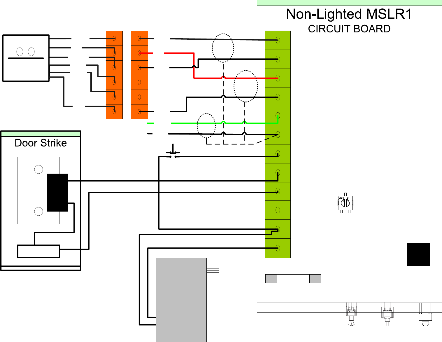
GND
C-1
NC-1
+12V
CDATA
CCLK
GND
+5V
EXIT
LED
SHLD
NO-1
Relay
5
6
3
1
2
4
White
Red
Black
Green
Black
Black
1
2
3
5
6
3
1
2
4
Brown
Red
Orange
White
Green
B
C
Card Reader
IR1051
1
1
Power Supply
+12 v 300ma
Out
120 VAC
In
Supply
(not Supplied)
Blue
Reader
Connector
Test
Strike
Power
Switch
Pin 12
Pin 1
Fuse ¼ Amp Slow Blow
Not Connected
Power
LED
Relay Timing
Note: Turn Counter Clockwise to increase time
PAIR 1:
WHITE
BLACK
SHIELD
PAIR 2:
RED
BLACK
PAIR 3:
GREEN ONLY
GND
C-1
NC-1
+12V
CDATA
CCLK
GND
+5V
EXIT
LED
SHLD
NO-1
Relay
5
6
3
1
2
4
White
Red
Black
Green
Black
Black
1
2
3
5
6
3
1
2
4
Brown
Red
Orange
White
Green
B
C
Card Reader
IR1051
1
1
Power Supply
+12 v 300ma
Out
120 VAC
In
Supply
(not Supplied)
Blue
Reader
Connector
Test
Strike
Power
Switch
Pin 12
Pin 1
Fuse ¼ Amp Slow Blow
Not Connected
Power
LED
Relay Timing
Note: Turn Counter Clockwise to increase time
Not Connected
PAIR 1:
WHITE
BLACK
SHIELD
PAIR 2:
RED
BLACK
PAIR 3:
GREEN ONLY
