Sysgration JRVCS105DC JRVCS105 Display Commander User Manual JRVCS105 MANUAL 04112016
Sysgration Ltd. JRVCS105 Display Commander JRVCS105 MANUAL 04112016
UserManual.wiki
>
Sysgration
>
JRVCS105DC User Manual
>
User manual
Contents
1.
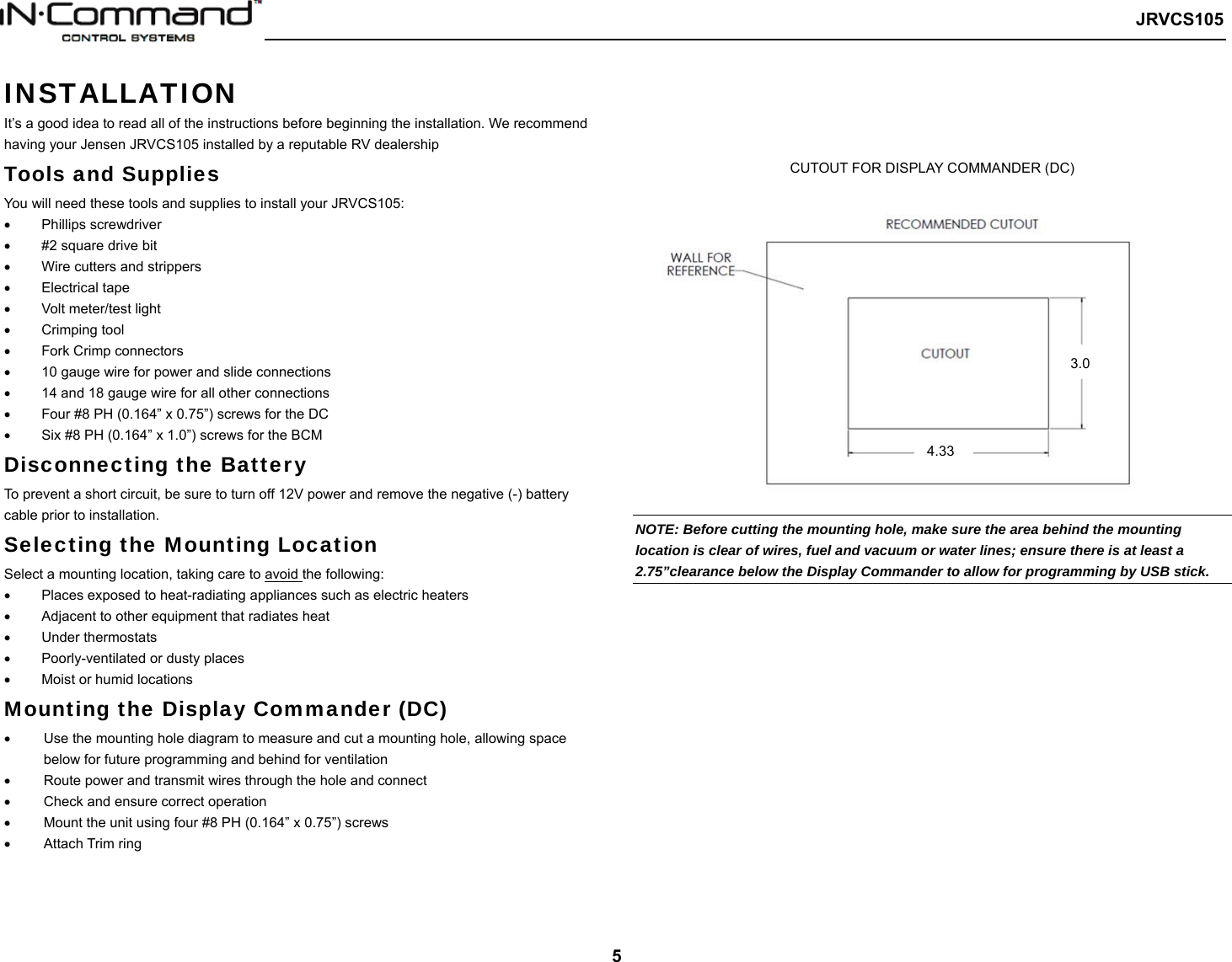
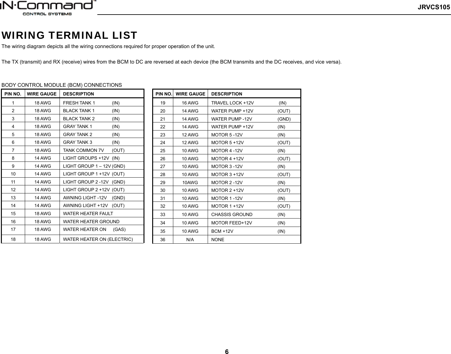
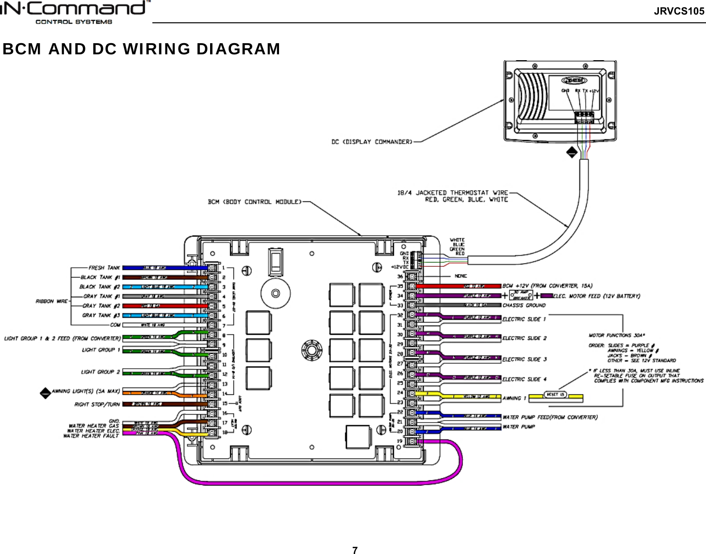
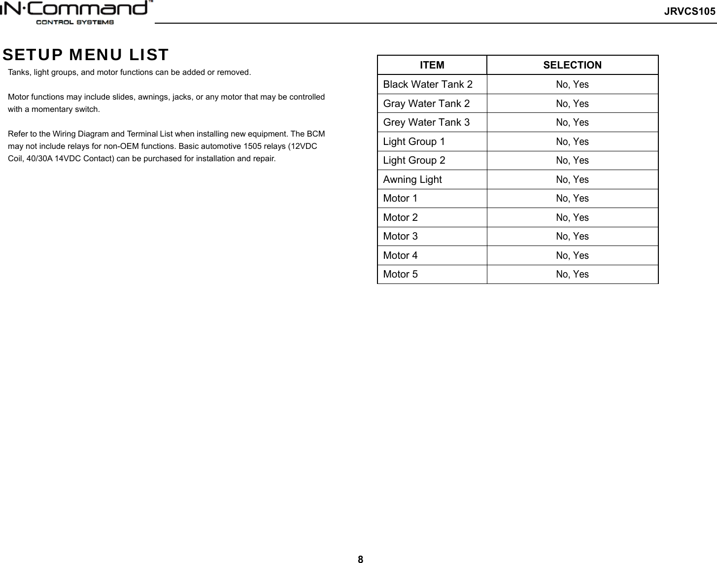
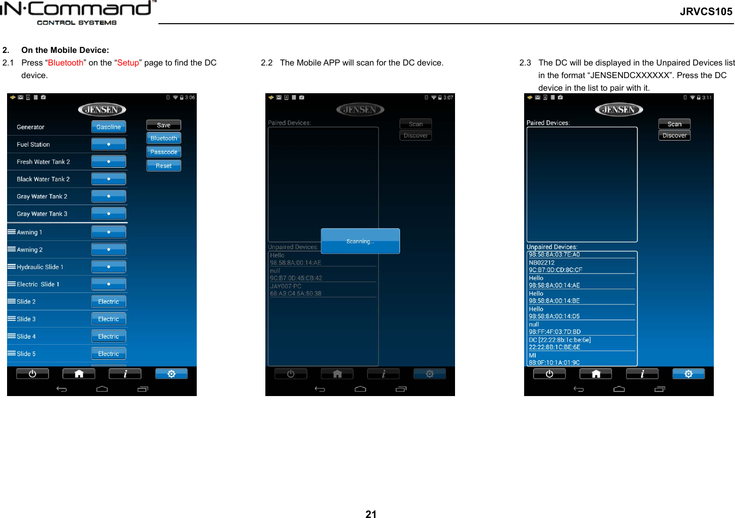
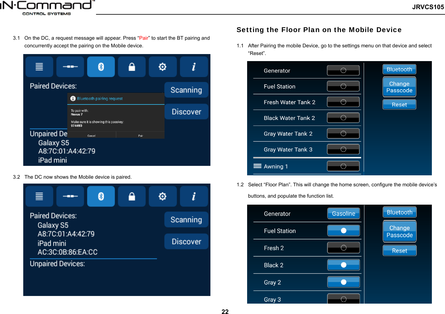
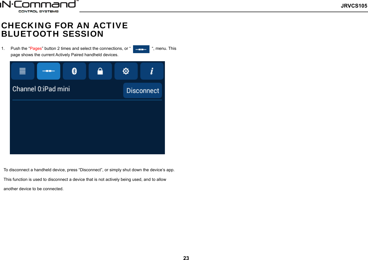
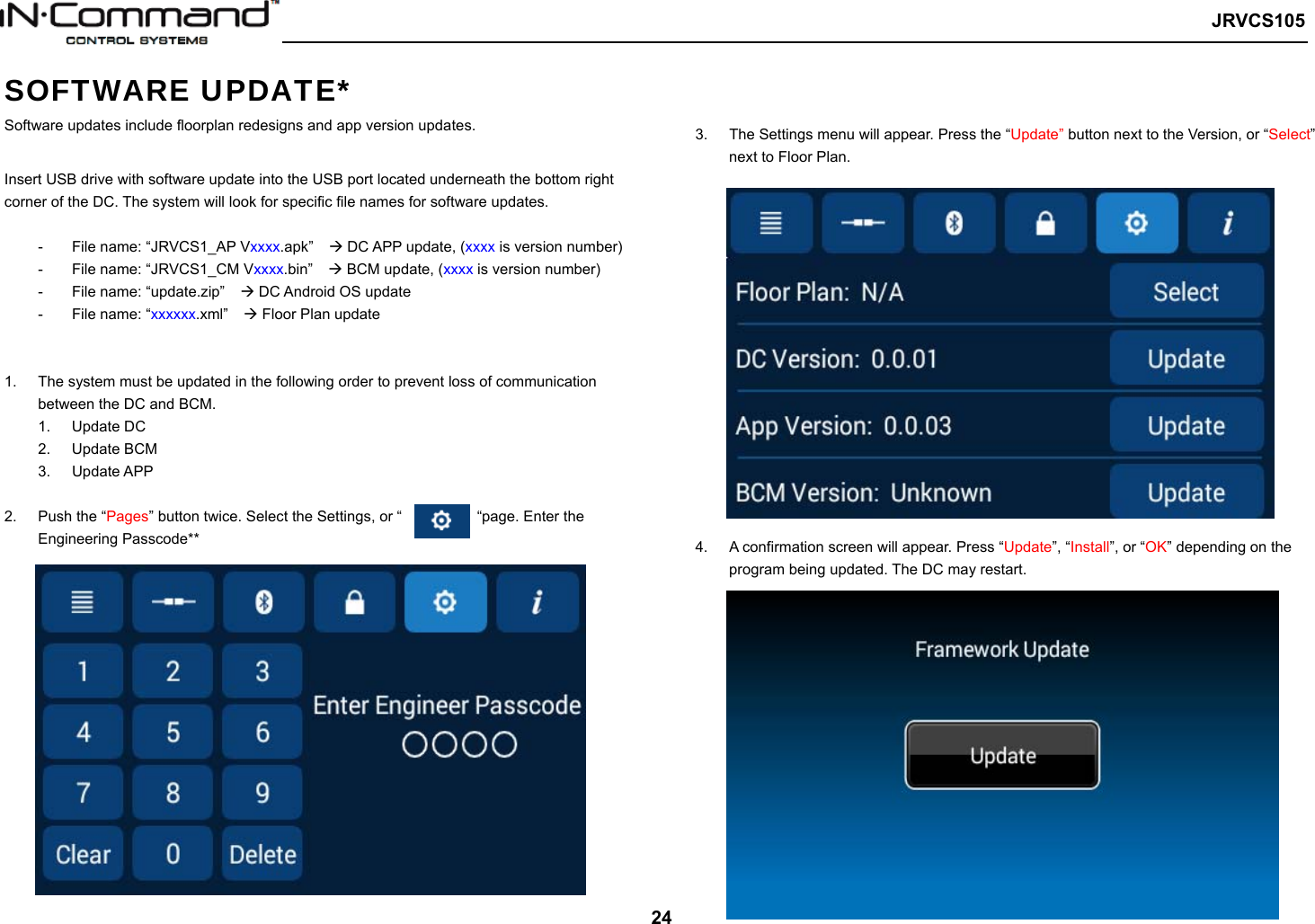
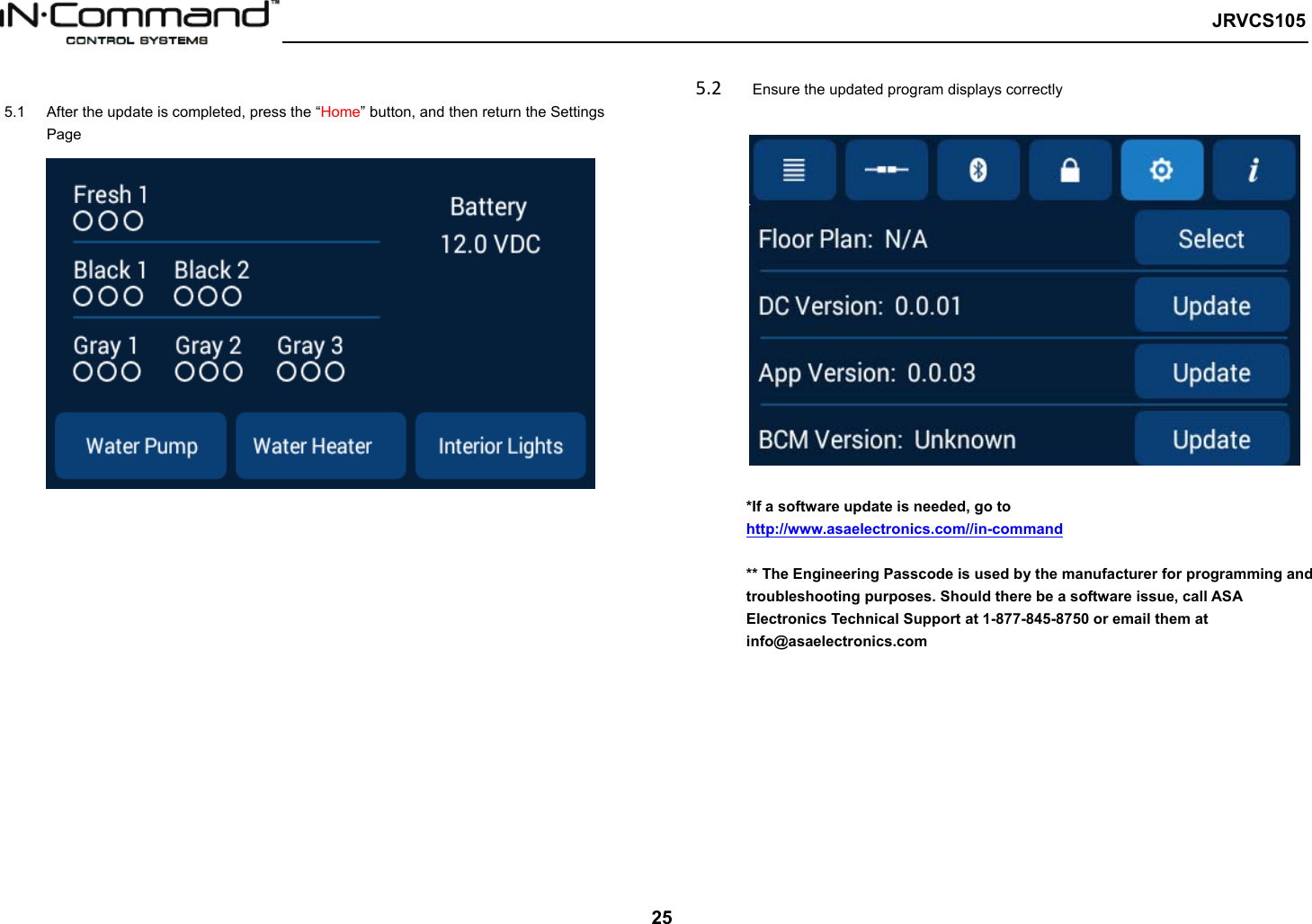
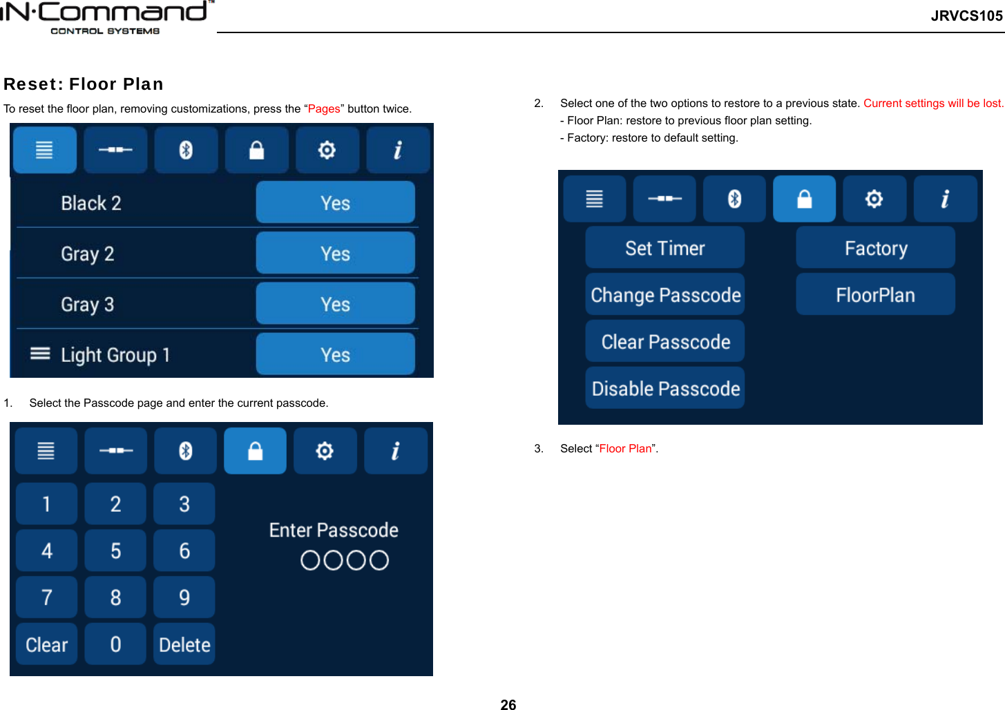
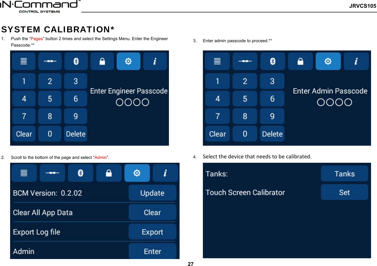
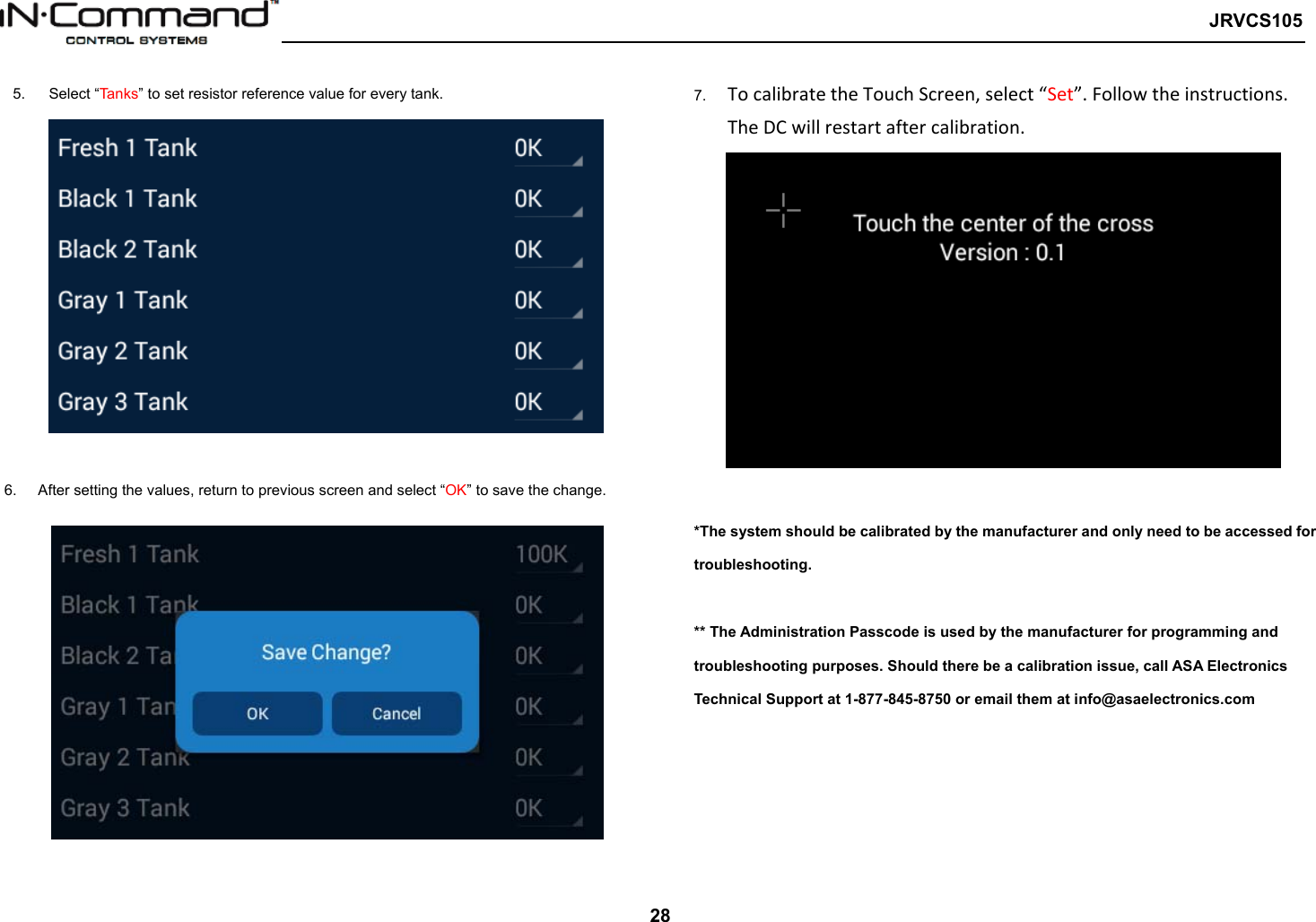
User manual
2.
User manaul
User manual
Navigation menu
Upload a User Manual
Namespaces
Wiki Guide
HTML
PDF
Info
Views
User Manual
Discussion / Help
Navigation