Sysgration NCS50SP NCS50 Switch Plate User Manual
Sysgration Ltd. NCS50 Switch Plate Users Manual
UserManual.wiki
>
Sysgration
>
NCS50SP User Manual
Users Manual
Navigation menu
Upload a User Manual
Namespaces
Wiki Guide
HTML
PDF
Info
Views
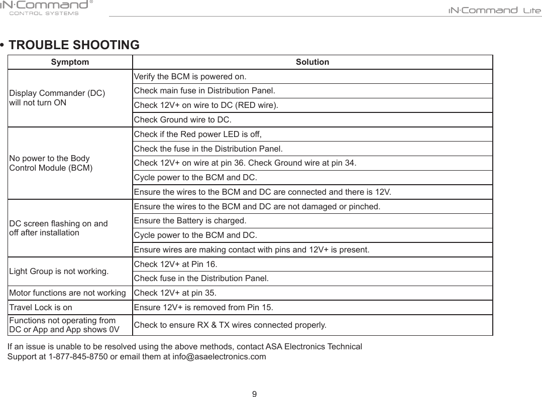
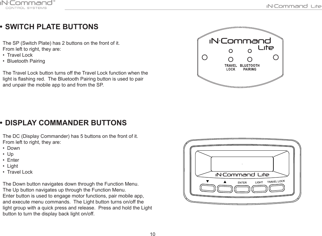
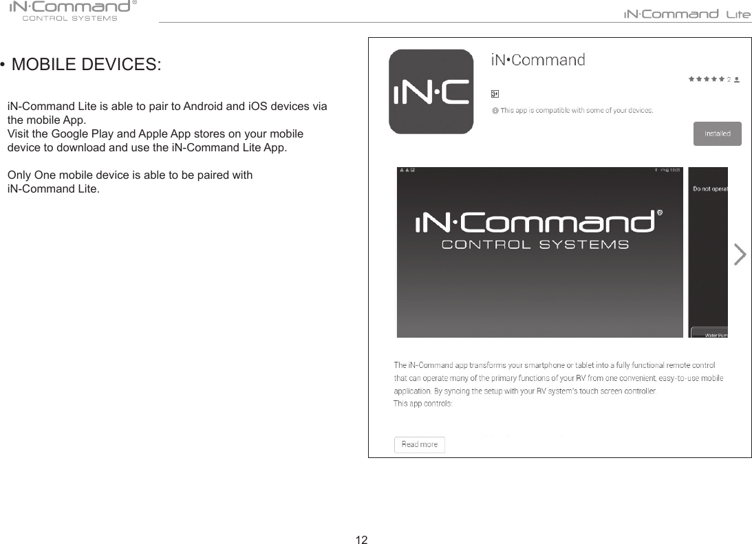
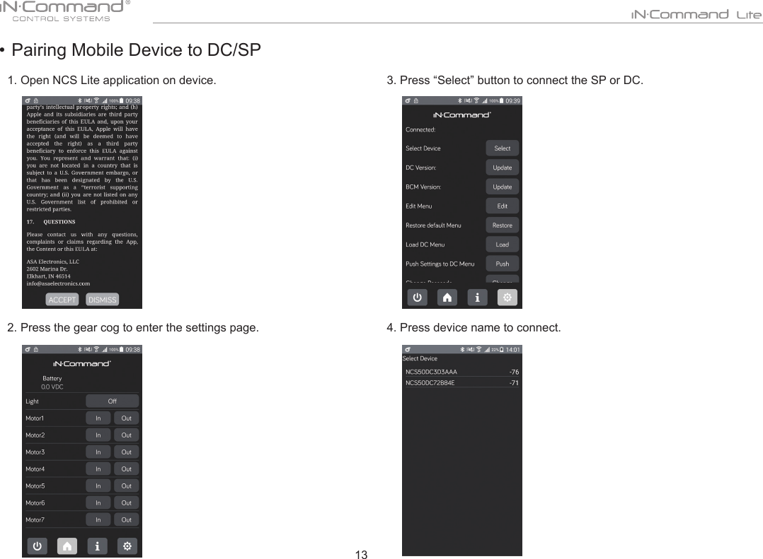
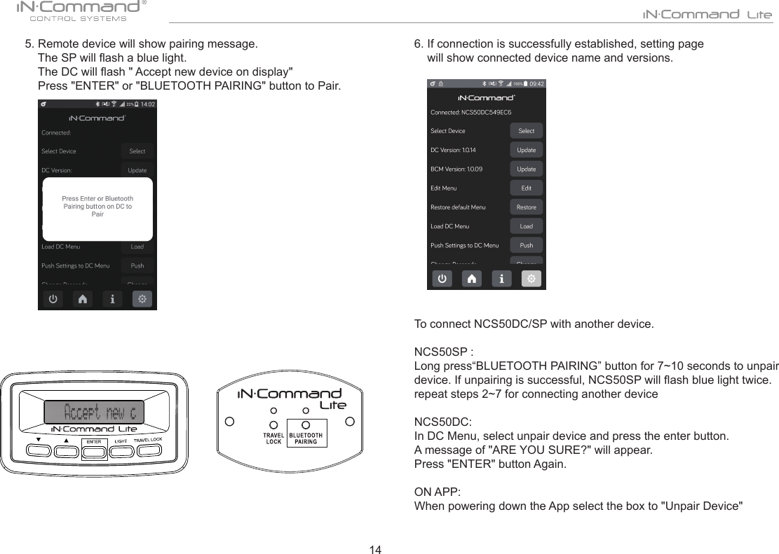
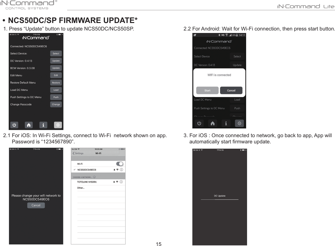
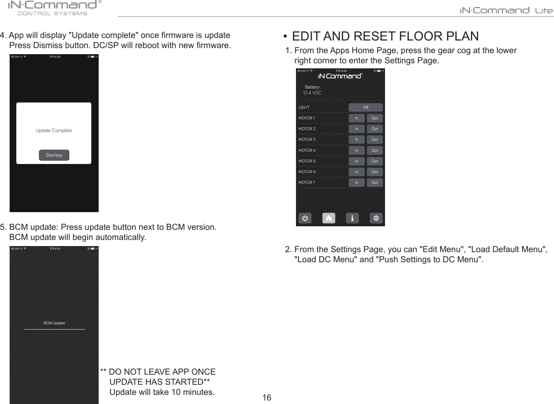
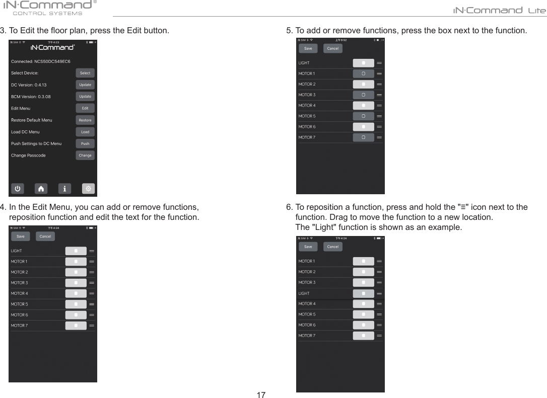
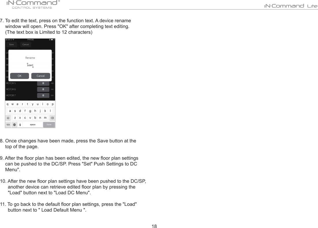
User Manual
Discussion / Help
Navigation