SystemBase EDDY-WIFIV3 WiFi Module User Manual Manual
SystemBase Co., Ltd. WiFi Module Manual
UserManual.wiki
>
SystemBase
>
EDDY WIFIV3 User Manual
Manual
Navigation menu
Upload a User Manual
Namespaces
Wiki Guide
HTML
PDF
Info
Views
User Manual
Discussion / Help
Navigation


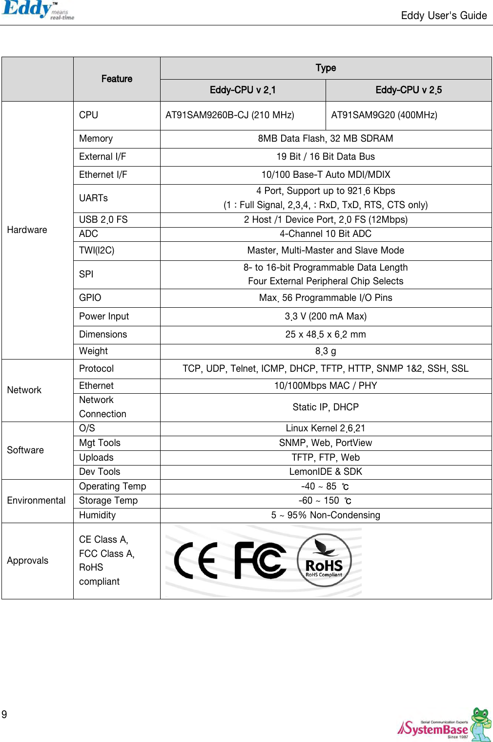
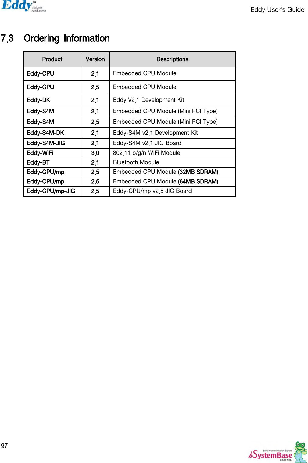
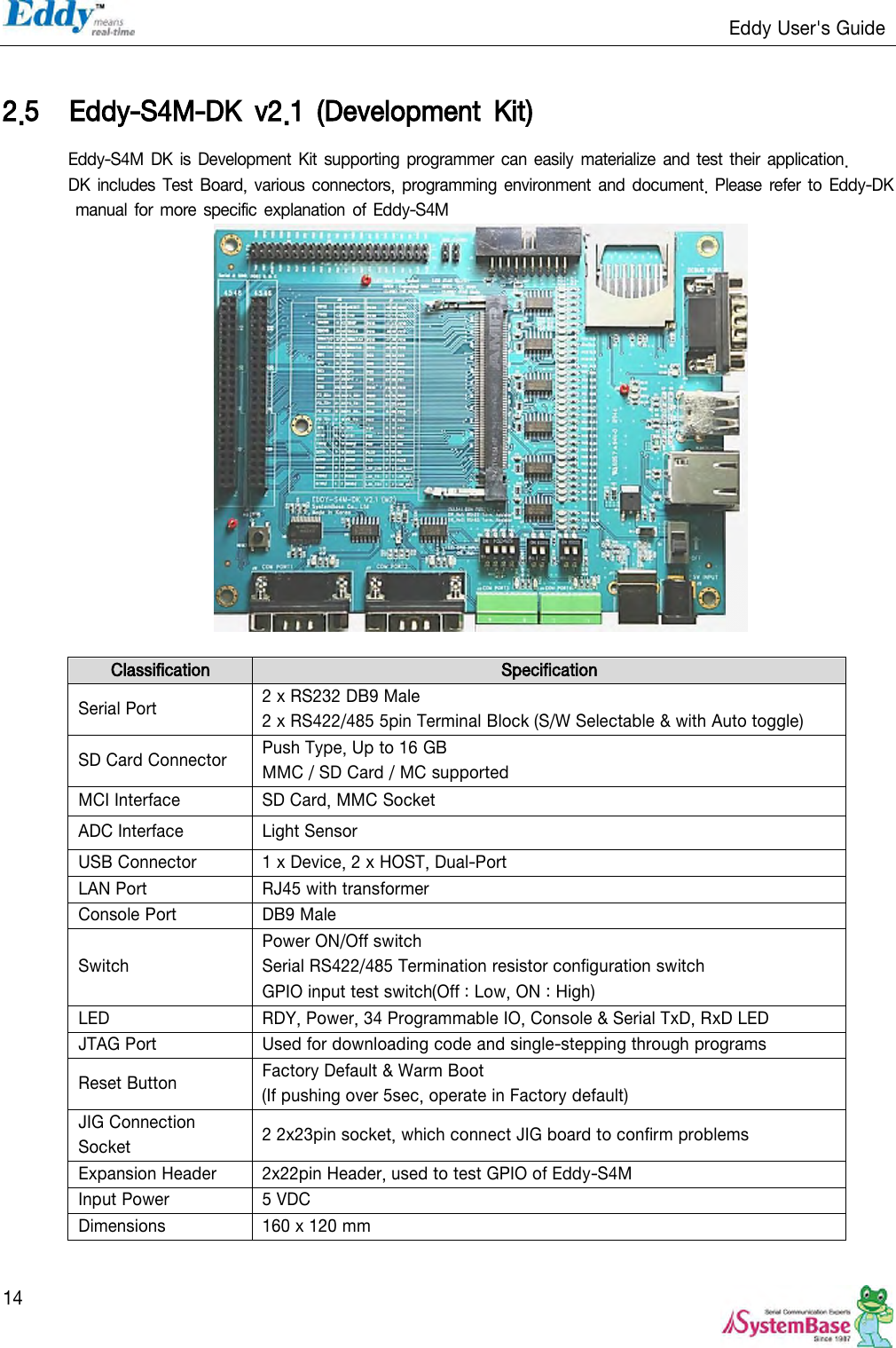
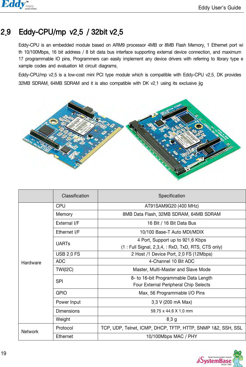
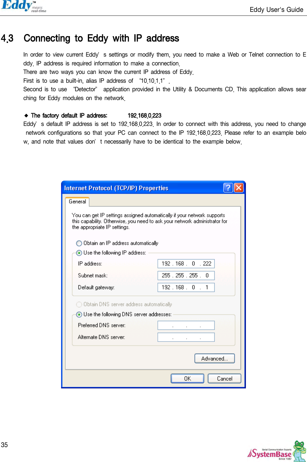
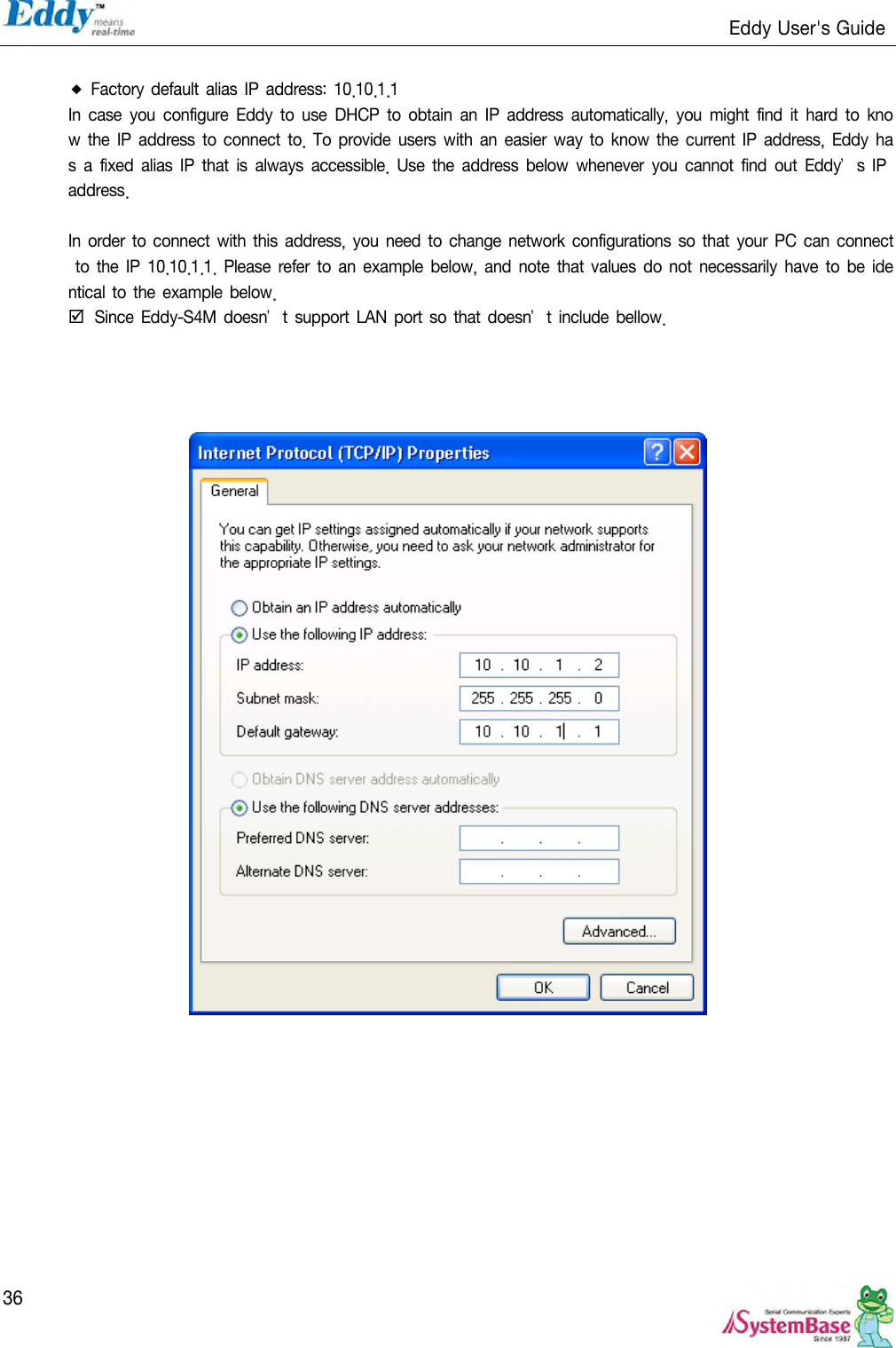
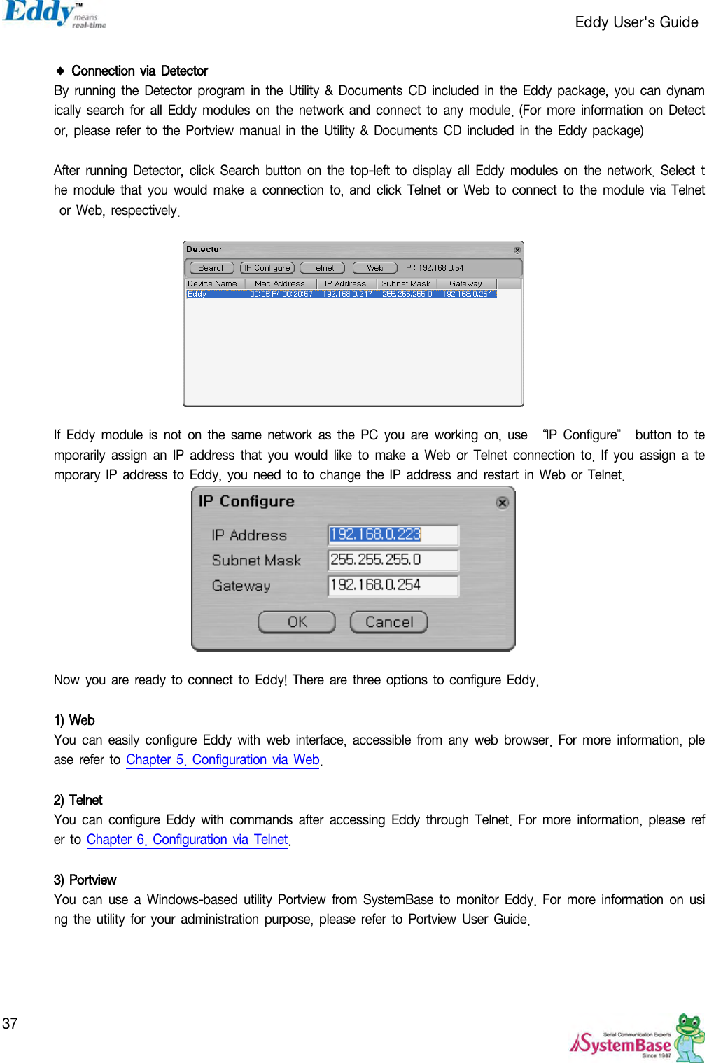
![Eddy User's Guide 13 Classification Type Eddy-S4M v2.1 Eddy-S4M v2.5 SPI 8 to 16-bit Programmable Data Length Four External Peripheral Chip Selects MCI SD Spec V2.0 [SDHC], MMC Spec V4.2 support USB to SD Controller, 16GB, 12Mbits/s GPIO Max. 34 Programmable I/O Pins LED Ready LED Software Protocol TCP, UDP, Telnet, ICMP, DHCP, TFTP, HTTP, SNMP1&2, SSH, SSL Network Connection Static IP, DHCP O/S Linux Kernel 2.6.21 Mgt Tools SNMP, Web, PortView Uploads TFTP, FTP, Web Dev Tools LemonIDE & SDK Physical characteristics Power Input 3.3 V (200mA Max) Dimensions 59.75 x 61.80 x 4 mm Weight 15 g Environment Operating Temp -40 ~ 85°C Storage Temp -66 ~ 150°C Humidity 5 ~ 95% Non-Condensing CE Class A, FCC Class A, RoHS compliant](https://usermanual.wiki/SystemBase/EDDY-WIFIV3/User-Guide-1667238-Page-13.png)
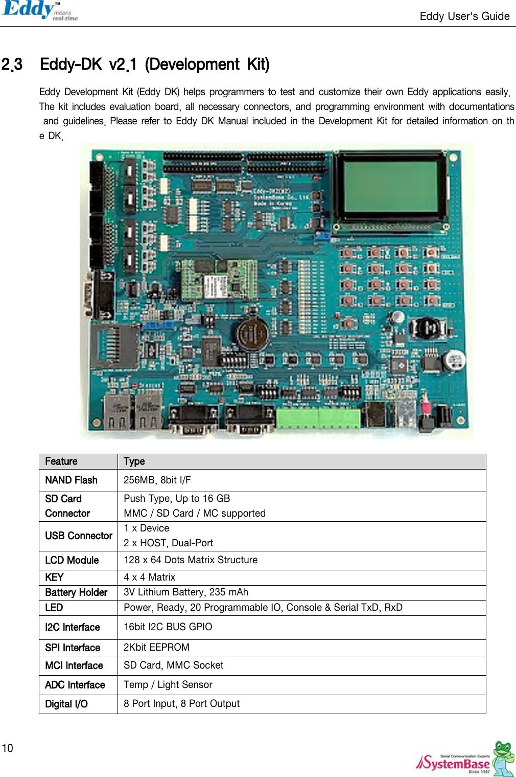
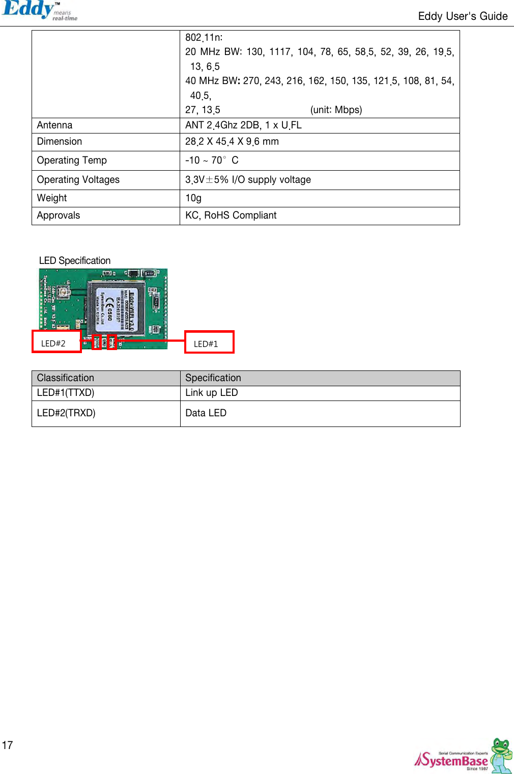
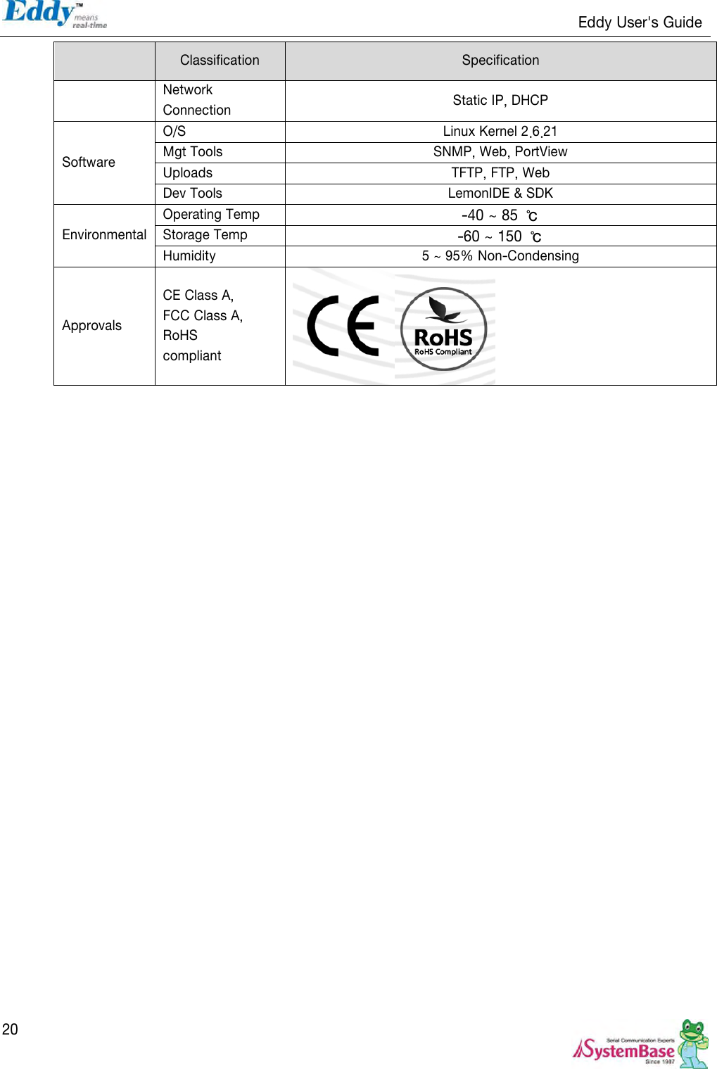
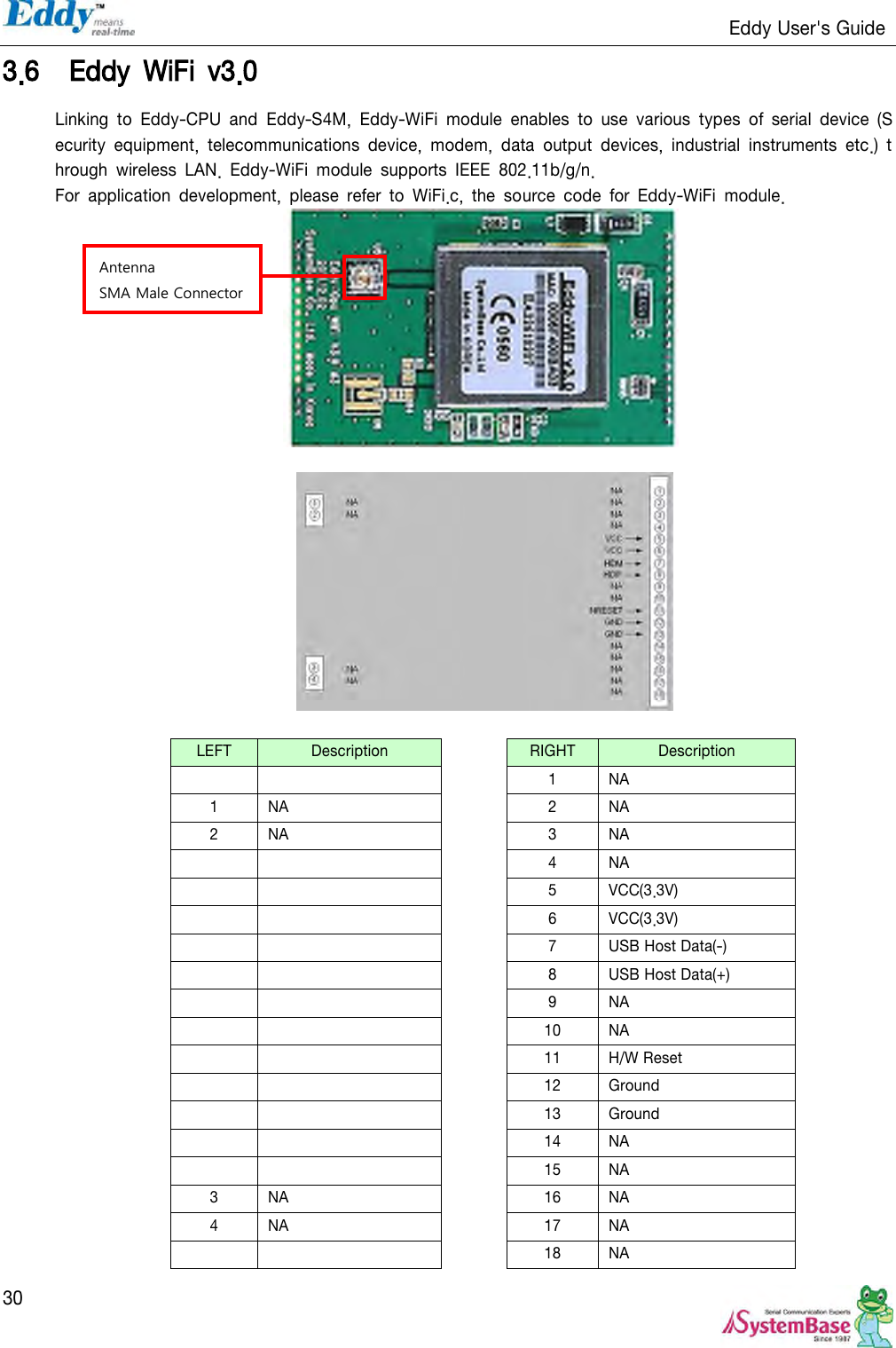
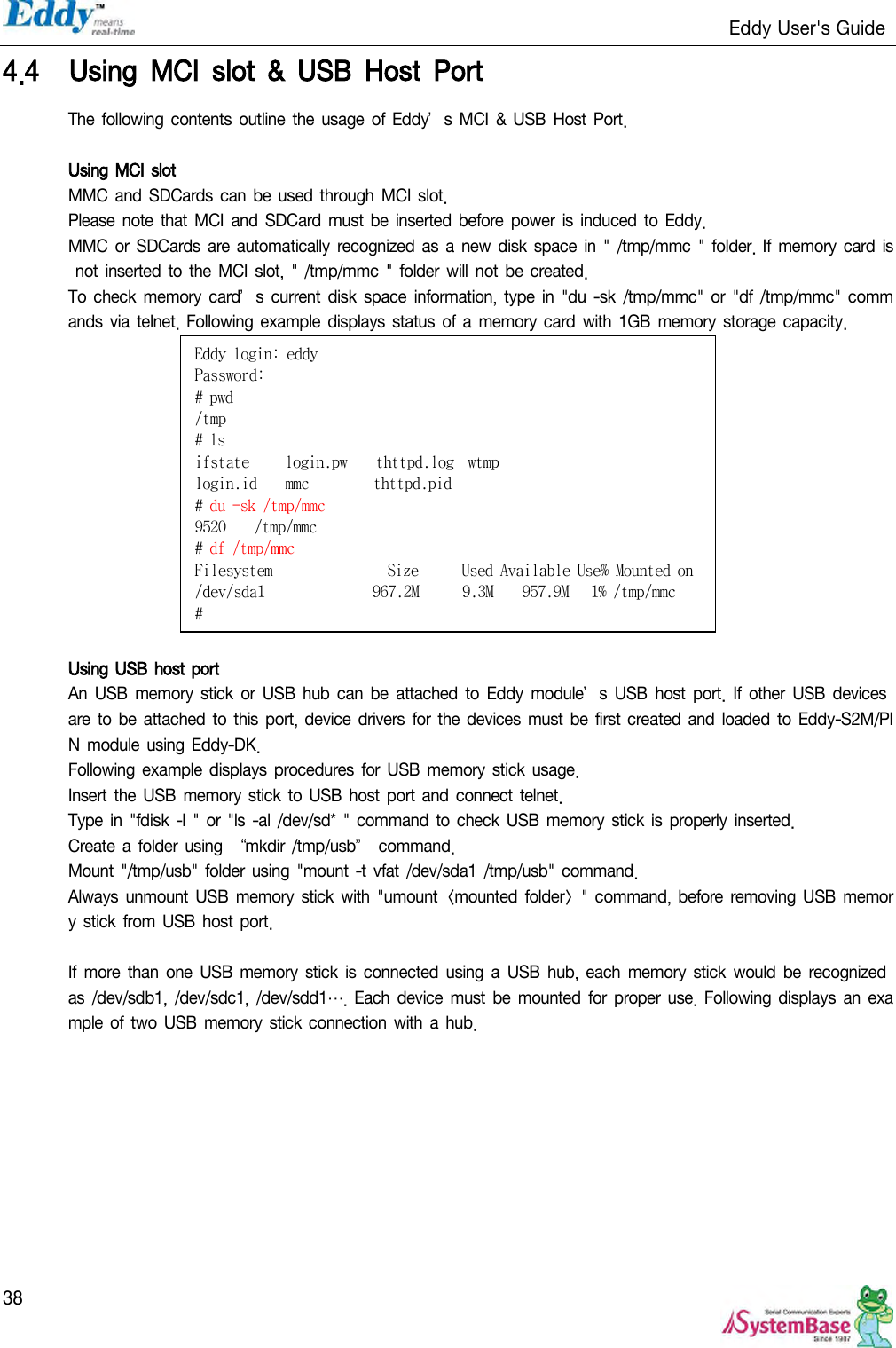
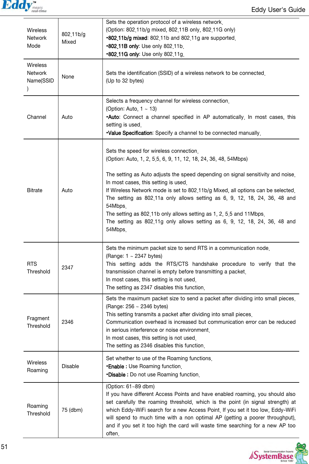
![Eddy User's Guide 16 2.7 Eddy-WiFi v 3.0 (* Eddy-WiFi v2.1 is not compatible. please check the previous manual.) Eddy WiFi joined with Eddy-CPU v2.1/v2.5, Eddy-S4M v2.1 enables various serial devices (secure device, communication device, modem, print data device, industrial measuring instrument) to connect wireless LAN. Eddy-WiFi module supports IEEE 802.11 b/g/n wireless specification. You can set the wireless network parameters. After changing values, you need to click [Submit] button. Then you will see the same page with modified values. Please note that you have to [Save & Reboot] in order to see these changes in effect. Changes will be discarded if you do not save current settings. + Classification Specification Standard 802.11b, 802.11g, 802.11n Modulation 802.11b:CCK, DQPSK, DBPSK 802.11g:64 QAM, 16 QAM, QPSK, BPSK 802.11n:BPSK, QPSK, 16-QAM, 64-QAM Frequency Band ISM band 2.4GHz ~ 2.4884GHz Output Power 802.11b:16 dBm (11Mbps) 802.11g:14 dBm (54Mbps) 802.11n:14 dBm (20MHz BW,MCS7) 13 dBm (40MHz BW,MCS7) RX sensitivity 802.11b:-84dBm@11MHz 802.11g:-73dbm@54MHz 802.11n:-71dBm(MCS 7_HT20) -68dBm(MCS 15_HT20) -68dBm(MCS 7_HT40) -65dBm(MCS 15_HT40) Security WPA, WPA-PSK, WPA2, WPA2-PSK , WEP 64bit & 128bit , IEEE 802.11x, IEEE 802.11i Working distance 60 - 120m, depending on surrounding Environment Data Rate 802.11b: 11, 5.5, 2, 1 802.11g: 54, 48, 36, 24, 18, 12, 9, 6](https://usermanual.wiki/SystemBase/EDDY-WIFIV3/User-Guide-1667238-Page-16.png)
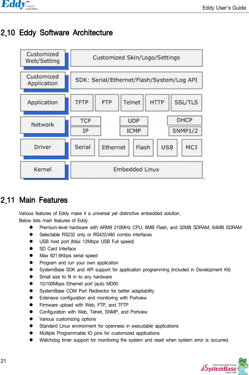
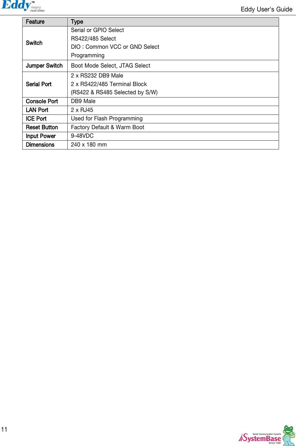
![Eddy User's Guide 26 [Internal Device Feature]](https://usermanual.wiki/SystemBase/EDDY-WIFIV3/User-Guide-1667238-Page-26.png)
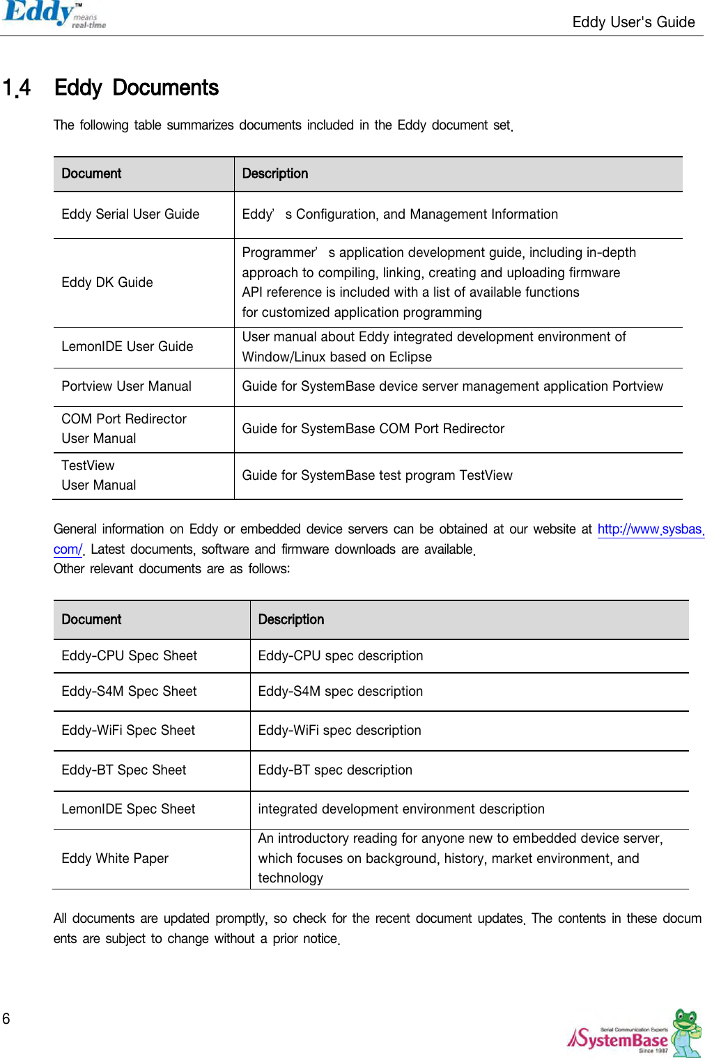
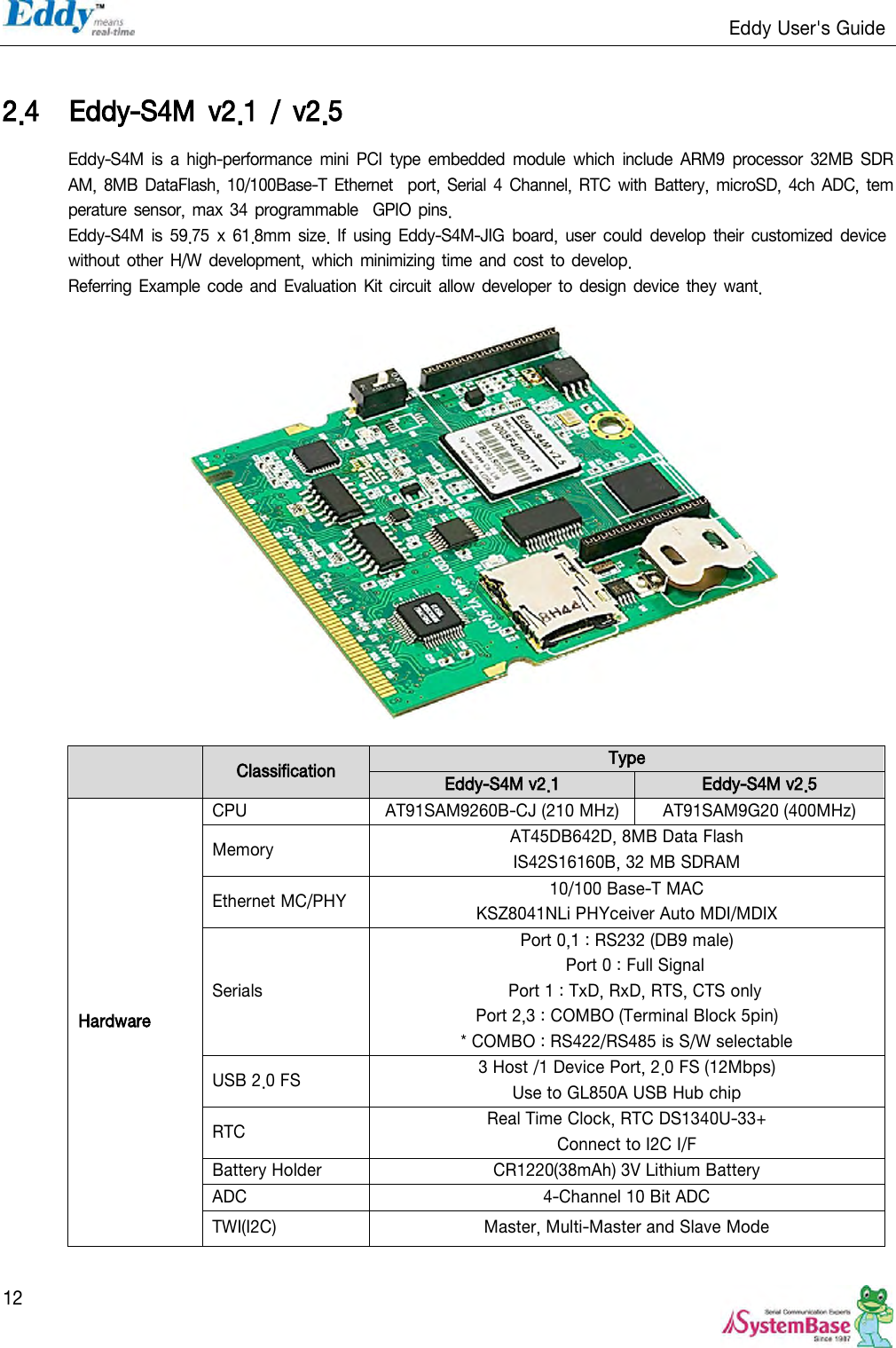
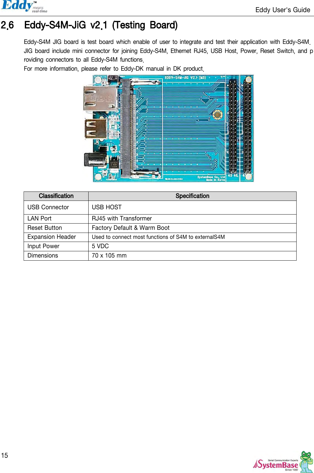
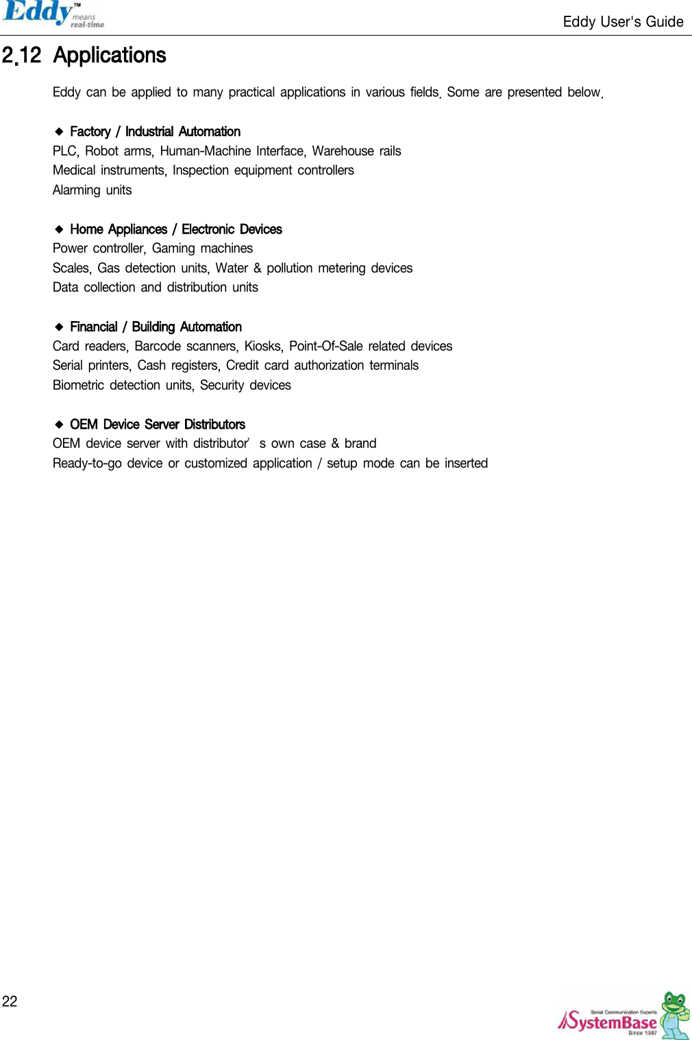
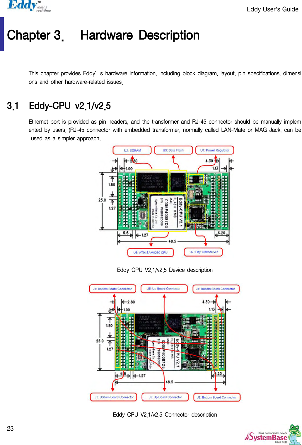
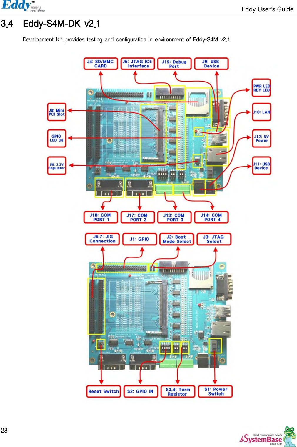
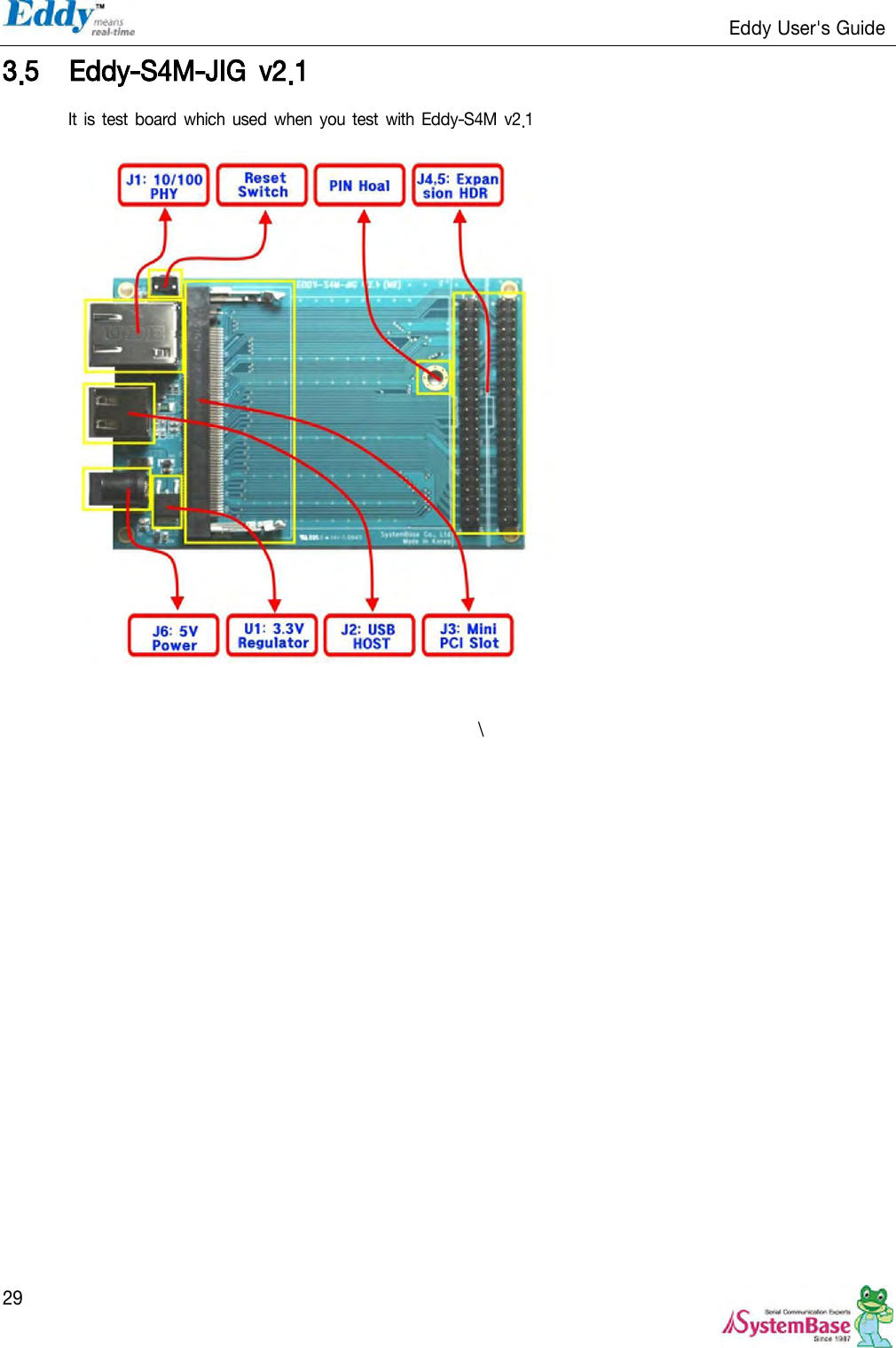
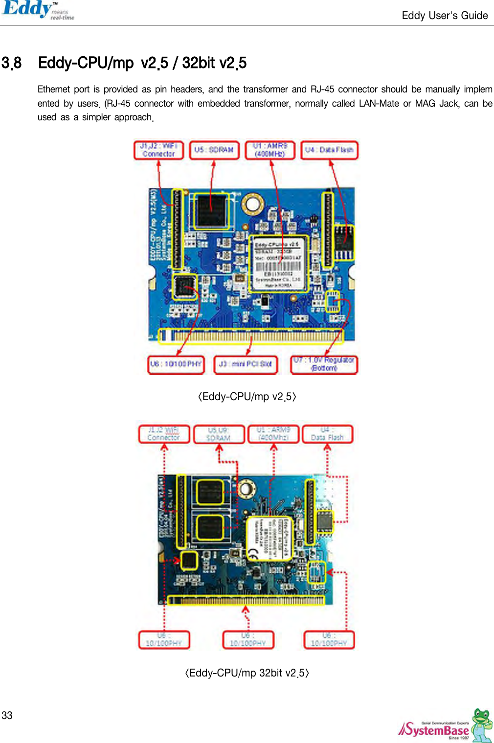
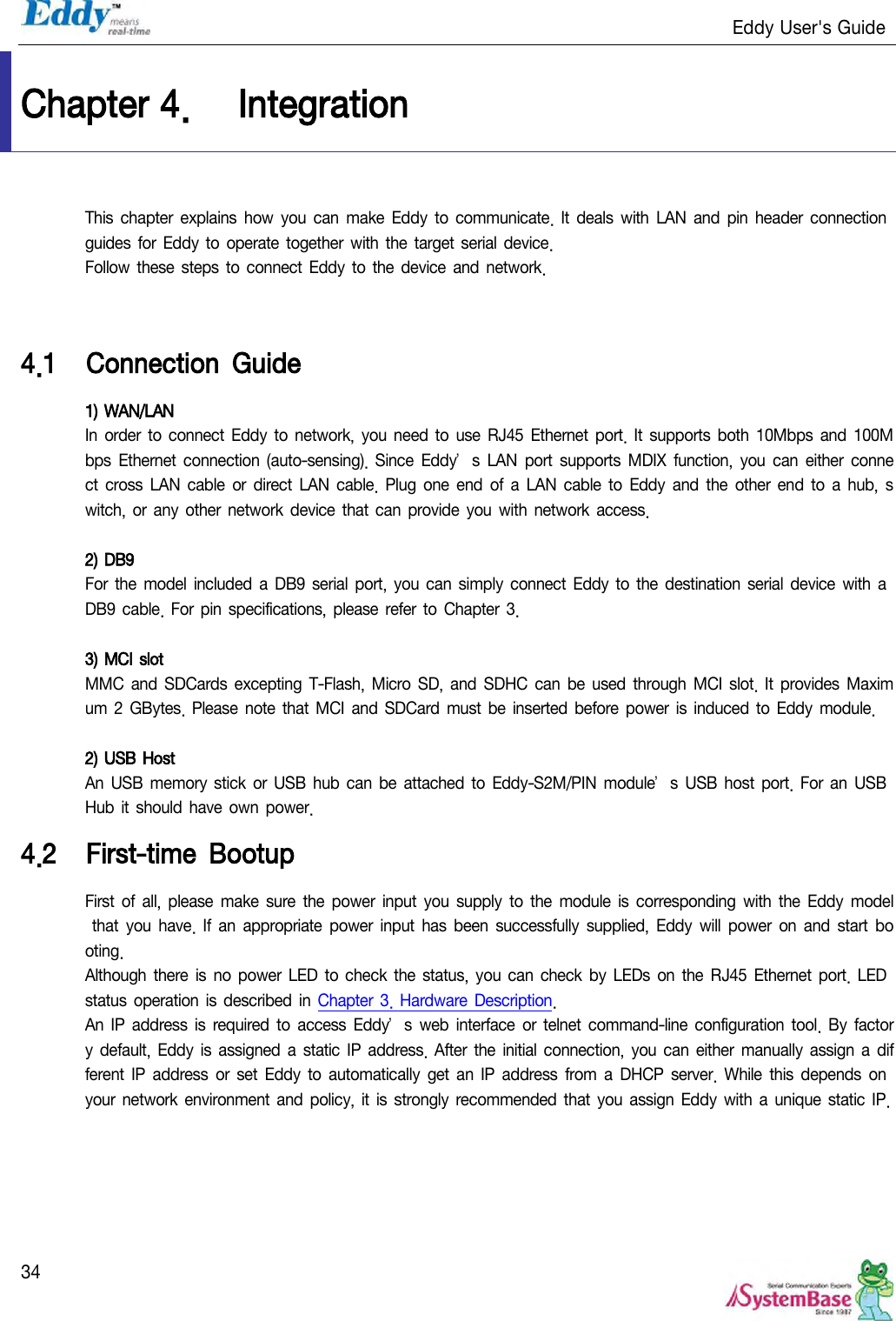
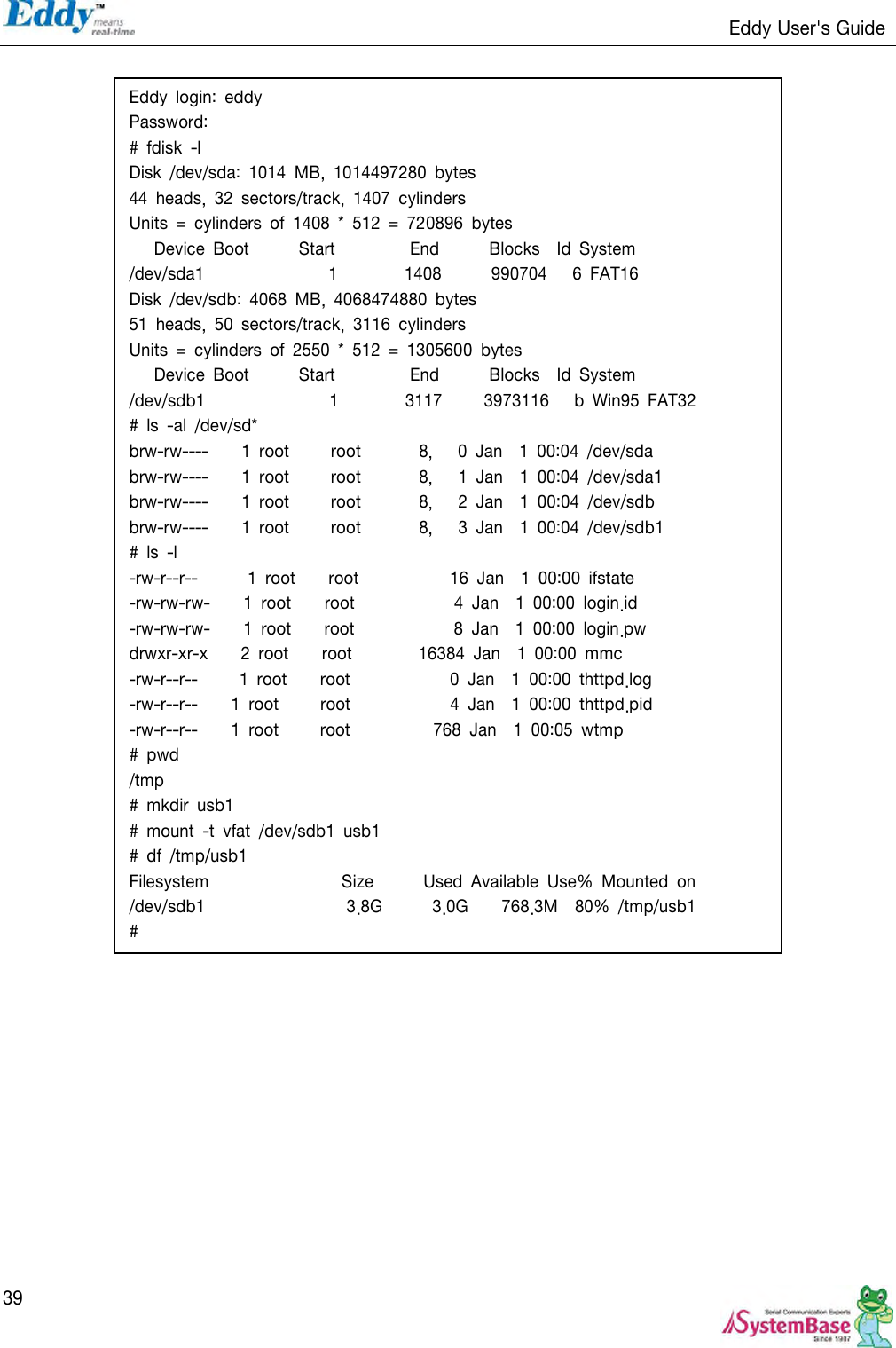
![Eddy User's Guide 27 3.3 Eddy-S4M v2.1/v2.5 Mini PCI Type Slot.. Eddy-S4M v2.5 is compatible with Eddy-S4M v2.1. When developing main board, user must materialize transformer and RJ-45 connector (or RJ45 in which transformer is included (LAN-Mate or MAC Jack)). Since Driver IC is in Eddy-S4M, Serial port can be integrated easily only by attach connector. [Eddy-S4M v2.1] [Eddy-S4M v2.5]](https://usermanual.wiki/SystemBase/EDDY-WIFIV3/User-Guide-1667238-Page-27.png)
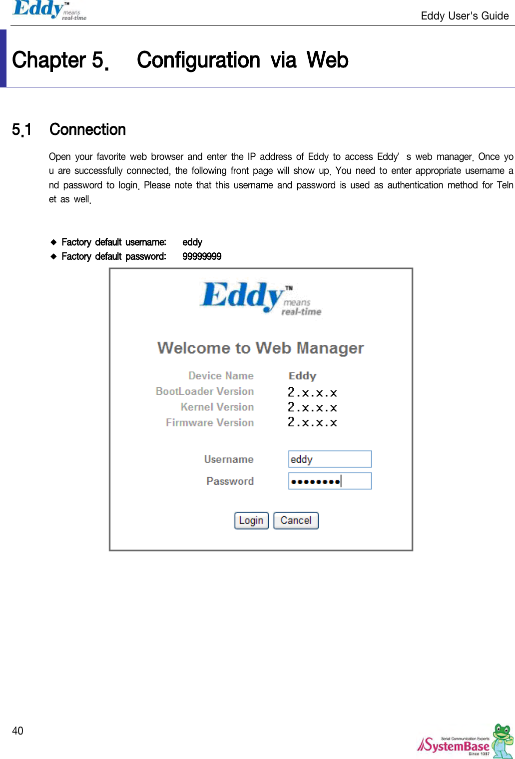
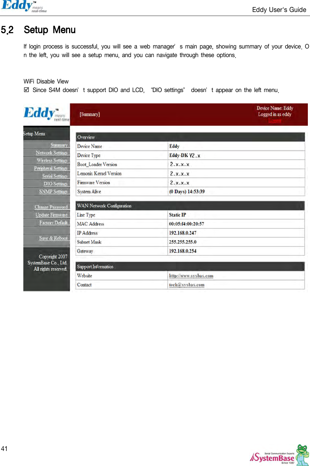
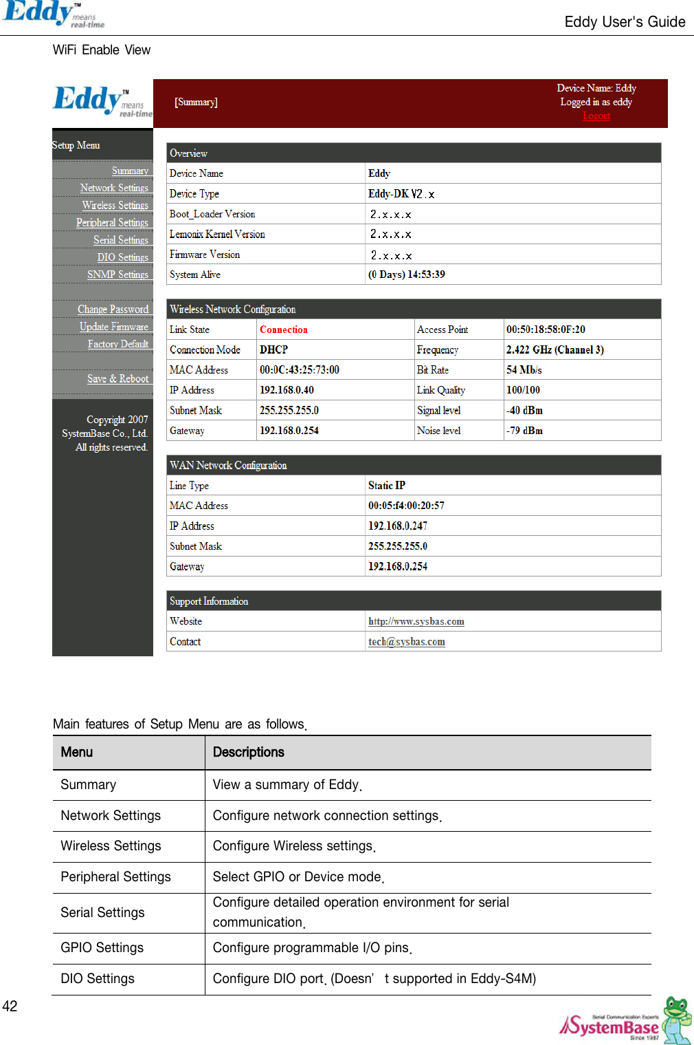
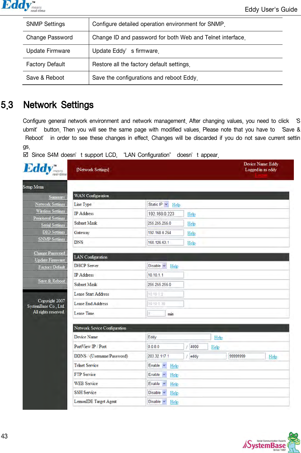
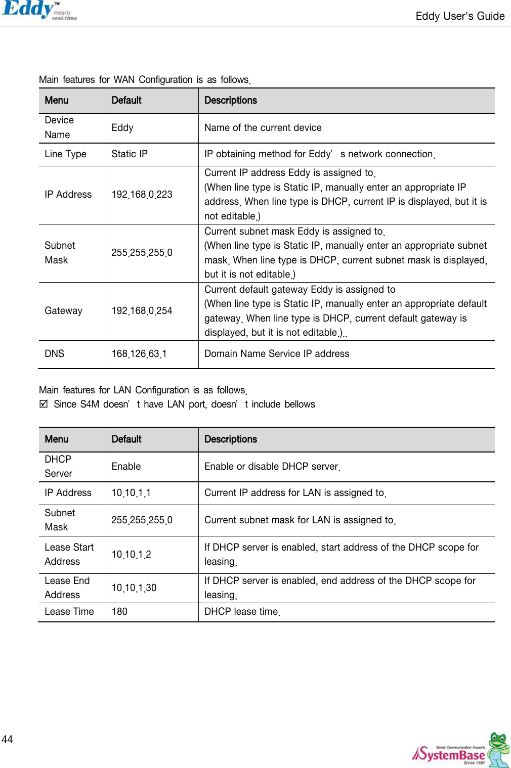
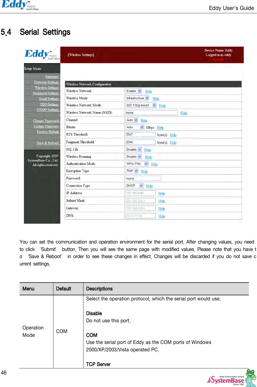
![Eddy User's Guide 50 5.5 Wireless Settings (* Eddy-WiFi v2.1 is not compatible. please check the previous manual.) You can set the wireless network parameters. After changing values, you need to click [Submit] button. Then you will see the same page with modified values. Please note that you have to [Save & Reboot] in order to see these changes in effect. Changes will be discarded if you do not save current settings. Menu Default Description Wireless Network Disable When enabled, Eddy-WiFi is available. •Disable: Eddy-WiFi is not available. •Enable: Eddy-WiFi is available. Wireless Mode Infrastructure Set the wireless LAN mode. (Option: Infrastructure, Ad-Hoc) •Infrastructure : Use Eddy-WiFi under the Infrastructure mode. This mode is used for connecting to the wireless AP (Access Point) as a client to connect to other network. •Ad-Hoc : Use Eddy-WiFi under the Ad-hoc mode. This mode is used for 1:1 communication with another Ad-hoc client.](https://usermanual.wiki/SystemBase/EDDY-WIFIV3/User-Guide-1667238-Page-50.png)

![Eddy User's Guide 59 5.8 SNMP Settings You can set the communication and operation environment for the SNMP Agent. After changing values, you need to click ‘Submit’ button. Then you will see the same page with modified values. Please note that you have to ‘Save & Reboot’ in order to see these changes in effect. Changes will be discarded if you do not save current settings. In order to use the SNMP Agent, SNMP v1/v2/v3 Agent become enabled and pushes the [Submit] button. Feature Default Descriptions SNMP v1/v2/v3 Agent Disable Enable or disable Simple Network Management Protocol (SNMP) support. (Options : Disable/Enable) V1/2 Attribution ReadOnly SNMP V1/2 Attributes can read and write by SNMP Agent. In order to read attributes only, change the feature to "ReadOnly". In order to read and write attributes, change the feature to "ReadWrite". (Options : ReadOnly/ ReadWrite) V3 Attribution ReadOnly SNMP V3 Attributes can read and write by SNMP Agent. In order to read attributes only, change the feature to "ReadOnly". In order to read and write attributes, change the feature to "ReadWrite". (Options : ReadOnly/ ReadWrite) V3 Username/ Password eddy/administrator Configure the Username and the password when use SNMP V3. The Password is at least 8 character string TRAP IP/ Port 0.0.0.0/162 Configure the server IP address and Port which receive the TRAP information.](https://usermanual.wiki/SystemBase/EDDY-WIFIV3/User-Guide-1667238-Page-59.png)
![Eddy User's Guide 63 Chapter 6. Configuration via Telnet 6.1 Connection Open your telnet client and enter Eddy’s IP address to connect. You need to enter appropriate username and password to login. Please note that this username and password is used as authentication method for Web as well. This means if username or/and password has been modified from the telnet interface, modified values have to be entered to connect to web, and vice versa. ◆ Factory default username : eddy ◆ Factory default password : 99999999 Connection via Telnet [def] command - you can view or configure Eddy’s settings [def help] command - you can see help for [def] command After changing values, you can see modified values with [def view] commands. But be careful because these values are not in effect unless you issue a [def save] command. Changes will be discarded if you do not save current settings. 6.2 View commands Commands related to View are as follows. Commands Descriptions def view Show all information about Eddy. def view wan Show WAN network settings.](https://usermanual.wiki/SystemBase/EDDY-WIFIV3/User-Guide-1667238-Page-63.png)
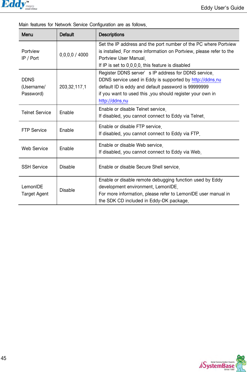
![Eddy User's Guide 64 def view lan Show LAN network settings. def view wifi Show WiFi network settings. def view management Show managing items settings. def view port Show serial port settings. def view gpio Show GPIO pin settings. def view dio Show DIO pin settings. def help Show command list and help. 6.3 Network commands Configure general network environment and network management. Commands Default Descriptions def mac <Mac Address> 00:05:f4:00:20:57 Register Eddy’s MAC address. def line [ip/dhcp] Static IP IP obtaining method for Eddy’s network connection. def ip <IP Address> 192.168.0.223 Set the current IP address Eddy is assigned to. When line type is Static IP, manually enter an appropriate IP address. When line type is DHCP, it is not editable. Instead, current IP address is shown. def mask <Subnet mask> 255.255.255.0 Set the subnet mask Eddy is assigned to. When line type is Static IP, manually enter an appropriate subnet mask. When line type is DHCP, it is not editable. Instead, current subnet mask is shown. def gateway <Gateway address> 192.168.0.1 Set the default gateway Eddy is assigned to. When line type is DHCP, it is not editable. Instead, current gateway address is shown. def dns <IP address> 168.126.63.1 Set the Domain Name Service IP address. def portviewip <IP address> 0.0.0.0 Configures IP of PC which Portview is installed If IP is set to 0.0.0.0, NMS feature is disabled. (Please refer to Portview User’s Manual for detailed information.)](https://usermanual.wiki/SystemBase/EDDY-WIFIV3/User-Guide-1667238-Page-64.png)
![Eddy User's Guide 65 def portviewport <Port Number> 4000 Set the socket number of the PC with Portview installed. def telnet [Enable / Disable] Enable Enable or disable Telnet service. If disabled, you cannot connect to Eddy via Telnet. def ftp [Enable / Disable] Enable Enable or disable FTP service. If disabled, you cannot connect to Eddy via FTP. def ssh [Enable / Disable] Disable Enable or disable SSH service. If enabled, you can connect to Eddy via SSH. Def ddns [IP Address] 203.32.117.1 If you set DDNS server IP , DDNS service will be enable. But you set ‚0.0.0.0‛ ,this service will disable. Def ddnsuser [username] eddy You can access DDNS server with this ID. Def ddnspass [password] 99999999 You can access DDNS server with this password. def web [Enable / Disable] Enable Enable or disable Web service. If disabled, you cannot connect to Eddy via Web. def target_agent [Enable / Disable] Disable Enable or disable remote debugging function used by Eddy development environment, LemonIDE. For more information, please refer to LemonIDE user manual in the SDK CD included in Eddy DK package. def name <Eddy name> Name of the module Set the name of Eddy module. (Max 32 bytes) def snmp [Enable / Disable] Disable SNMP V1/2 Attributes can read and write by SNMP Agent. In order to read attributes only, change the feature to "ReadOnly.‛ In order to read and write attributes change the feature to "ReadWrite.‛ (Options : ReadOnly/ ReadWrite) def v1readwrite [enable, disable] Disable SNMP V1/V2 Attributes can read and write by SNMP Agent. In order to read attributes only change the feature to "ReadOnly.‛ In order to read and write attributes change the feature to "ReadWrite.‛ (Options : ReadOnly/ ReadWrite) def v3readwrite [enable, disable] Disable SNMP V3 Attributes can read and write by SNMP Agent. In order to read attributes only change the feature to "ReadOnly.‛ In order to read and write attributes change the feature to](https://usermanual.wiki/SystemBase/EDDY-WIFIV3/User-Guide-1667238-Page-65.png)
![Eddy User's Guide 66 "ReadWrite.‛ (Options : ReadOnly/ ReadWrite) def v3username [string] eddy Configure the Username when use SNMP V3. def v3password [string] none Configure the password when use SNMP V3. def trapip [address] 0.0.0.0 Configure the server IP address which receives the TRAP information. def trapoprt [Socket No.] 162 Configure the server Port which receives the TRAP information. def trap_reset [enable, disable] Enable If Enable is selected, inform the "System reset info". def trap_connect [enable, disable] Disable If Enable is selected, inform the "Serial Port opened info". def trap_disconnect [enable, disable] Disable If Enable is selected, inform the "Serial Port Closed info". def landhcp [enable, disable] Enable If Enable is selected, DHCP server service will be enabled on the LAN port. def lanip <IP Address> 10.10.1.1 Set the IP address on the LAN port. def lanmask <Subnet Mask> 255.255.255.0 Set the subnet mask address on the LAN port. def lanstart <IP Addrss> 10.10.1.2 Set the start address for the DHCP range on the LAN port. def lanend <IP Address> 10.10.1.30 Set the end address for the DHCP range on the LAN port. def leasetime <msec> 180 Set lease time for DHCP. 6.4 WiFi commands Bellow are instruction and function which enable WiFi Network. Commands Default Descriptions def wifi wireless <Enable/ disable) disable Determine whether to use Eddy-WiFi module det wifi mode [infrastructure / ad-hoc] infrastructure Configure the active mode of wireless LAN](https://usermanual.wiki/SystemBase/EDDY-WIFIV3/User-Guide-1667238-Page-66.png)
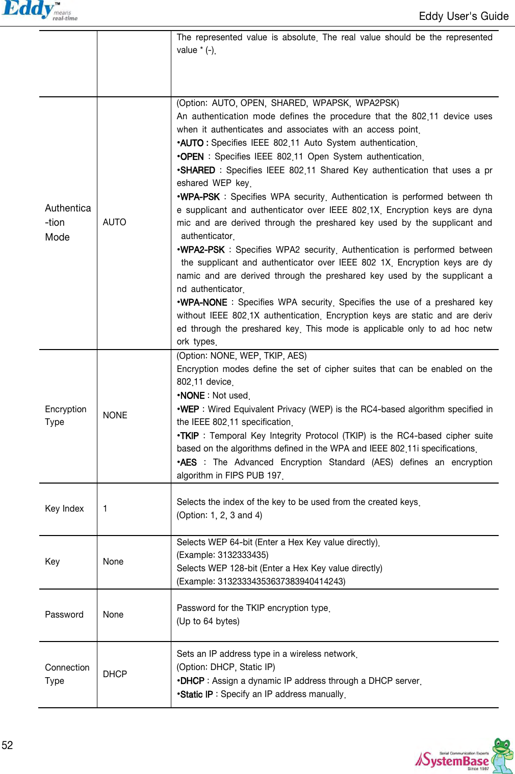
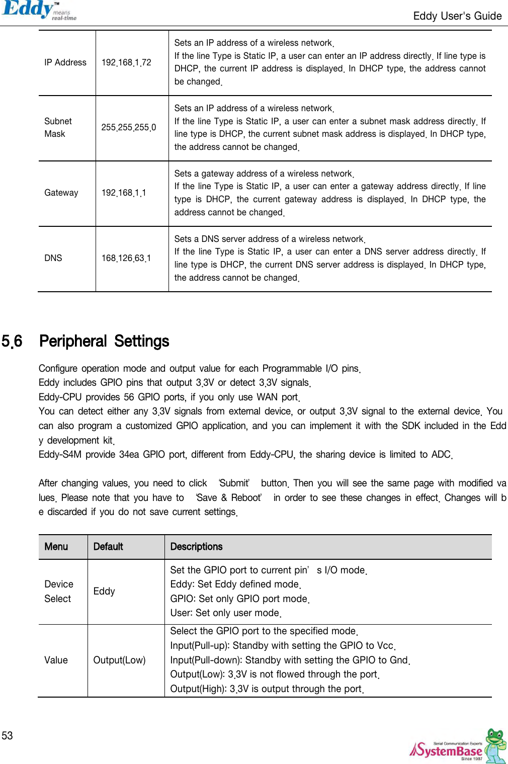
![Eddy User's Guide 67 def wifi network <802.11 b/g mixed, 802.11b only, 802,11g only, 802.11 b/g mixed Configure the active protocol of wireless network. def wifi ssid <SSID string> None Configure wireless network name (SSID) you want connect. def wifi channel <Auto, 1 ~ 13) Auto Select frequency which used for wireless connection. def wifi bitrate <auto, 1,2,5,6,9,11,12,18,24,36,48,54> Auto Configure the speed of wireless connection. def wifi rts (1 ~ 2347) 2347 Configure minimum packets which enable RTS in communication node. def wifi fragment <256 ~ 2346> 2346 Configure Maximum packet when sending with small pieces of packet. def wifi roamming [Enable/ Disable] Disable Configure whether to use roaming function of wireless network. def wiri authentication [open, shared, wpa-psk, wpa2-psk, wpa-none] WPA2-PSK Select certification way when testing access point. def wifi encryption [none, wep, tkip, aes] TKIP Configure the way of encryption def wifi keyindex [1 ~ 4] 1 Select the index when Encryption is WEB def wifi key [wep key string] None Register key to use when Encryption is WEB. def wifi password [wpa password] None Register password to use when Encryption is TKIP. def wifi line [dhcp, static ip] DHCP Select acquiring way of IP in wireless network def wifi ip [IP address] 192.168.1.72 Register IP address when acquiring way of IP is Static IP. def wifi gateway [router Address] 192.168.1.1 Register GW address when acquiring way of IP is Static IP. def wifi mask [Mask Address] 255.255.255.0 Register Mask address when acquiring way of IP is Static IP. def wifi dns [DNS Address] 168.126.63.1 Register DNS server address.](https://usermanual.wiki/SystemBase/EDDY-WIFIV3/User-Guide-1667238-Page-67.png)
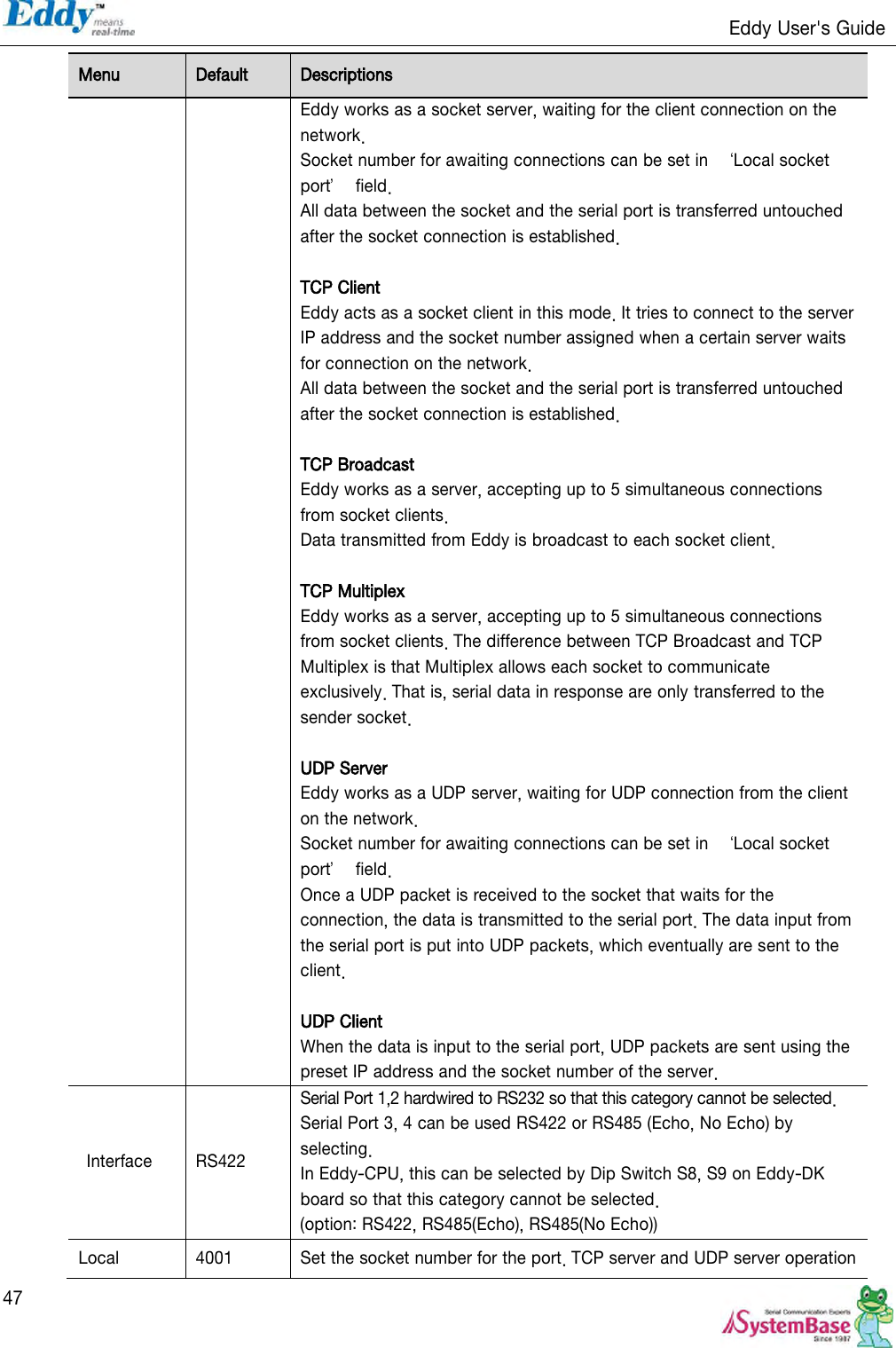
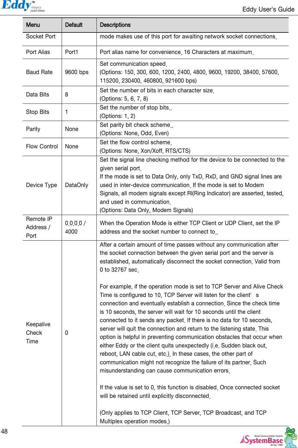
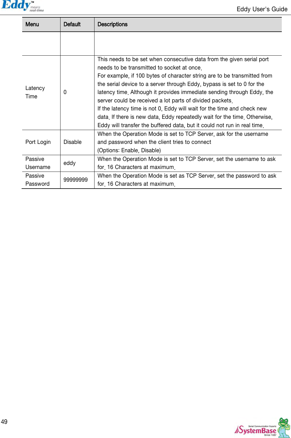
![Eddy User's Guide 68 6.5 Serial Commands You can set the communication and operation environment for the serial port. Chapter 5 describes each option in detail. Only a summary of each option is presented here. Commands Default Descriptions def port 1 protocol [disable / com/ tcp_server/tcp_client/ tcp_broadcast / tcp_multiplex/ udp_server/udp_client] com Select the operation protocol, which the serial port would use. def port 1 socket <port number> 4001 Set the socket number for the port. TCP Server, TCP Broadcase, TCP Multiplex, and UDP server operation modes make use of this port for awaiting network socket connections. def port 1 name <name> Port 1 Port alias name for convenience. 16 Characters at maximum def port 1 speed [150/300/600/1200/2400/4800/9600/19200/38400/57600/ 115200/230400/460800 /921600] 9600bps Set communication speed. def port 1 data [5 / 6 / 7 / 8] 8 Set the number of bits in each character size. Def po 1 interface [rs422, rs485e, rs485ne] RS422 Configure interface of serial 3,4 port on Eddy-S4M (In Eddy-DK, this can be selected by Dip Switch on Eddy-DK board so that this category cannot be selected. ) def port 1 stop [1 / 2] 1 Set the number of stop bits. def port 1 parity [none/odd/even] none Set parity bit check scheme. def port 1 flow [none/xon/rts] none Set the flow control scheme. def port 1 signal [data/modem] data Set the signal line checking method for the device to be connected to the given serial port. def port 1 remote <IP address> 0.0.0.0 When the Operation Mode is set to TCP Client or UDP Client, set the IP address to connect to. def port 1 remoteport <socket number> 4000 When the Operation Mode is set to TCP Client or UDP Client, set the socket number to connect to. def port 1 keepalive <0 ~ 65535> 0 After a certain amount of time passes without any communication after the socket connection between the given serial port and the server is established, automatically disconnect the socket connection. def port 1 latency <msec> 180 This needs to be set when consecutive data from the given serial port needs to be transmitted to socket at once.](https://usermanual.wiki/SystemBase/EDDY-WIFIV3/User-Guide-1667238-Page-68.png)
![Eddy User's Guide 69 Commands Default Descriptions def port 1 login [Enable / Disable] Disable When the Operation Mode is set to TCP Server, ask for the username and password when the client tries to connect. Set to 1 to enable. def port 1 loginname <username> None When the Operation Mode is set to TCP Server, set the username to ask for(Max 8 bytes) def port 1 loginpass <password> None When the Operation Mode is set as TCP Server, set the password to ask for( Max 8 bytes) 6.6 Username/Password Commands Configure username and password for Web/Telnet/FTP. Commands Default Descriptions def username <username> eddy Set username to use in Web, Telnet, or FTP. 16 Characters at maximum. def password <password> 99999999 Set password to use in Web, Telnet, or FTP. 16 Characters at maximum. 6.7 System Commands Commands Descriptions def default Restore all settings to factory default. Requires reboot for changes to take effect. def save Save current configuration settings. Requires reboot for changes to take effect. reboot Reboot Eddy.](https://usermanual.wiki/SystemBase/EDDY-WIFIV3/User-Guide-1667238-Page-69.png)
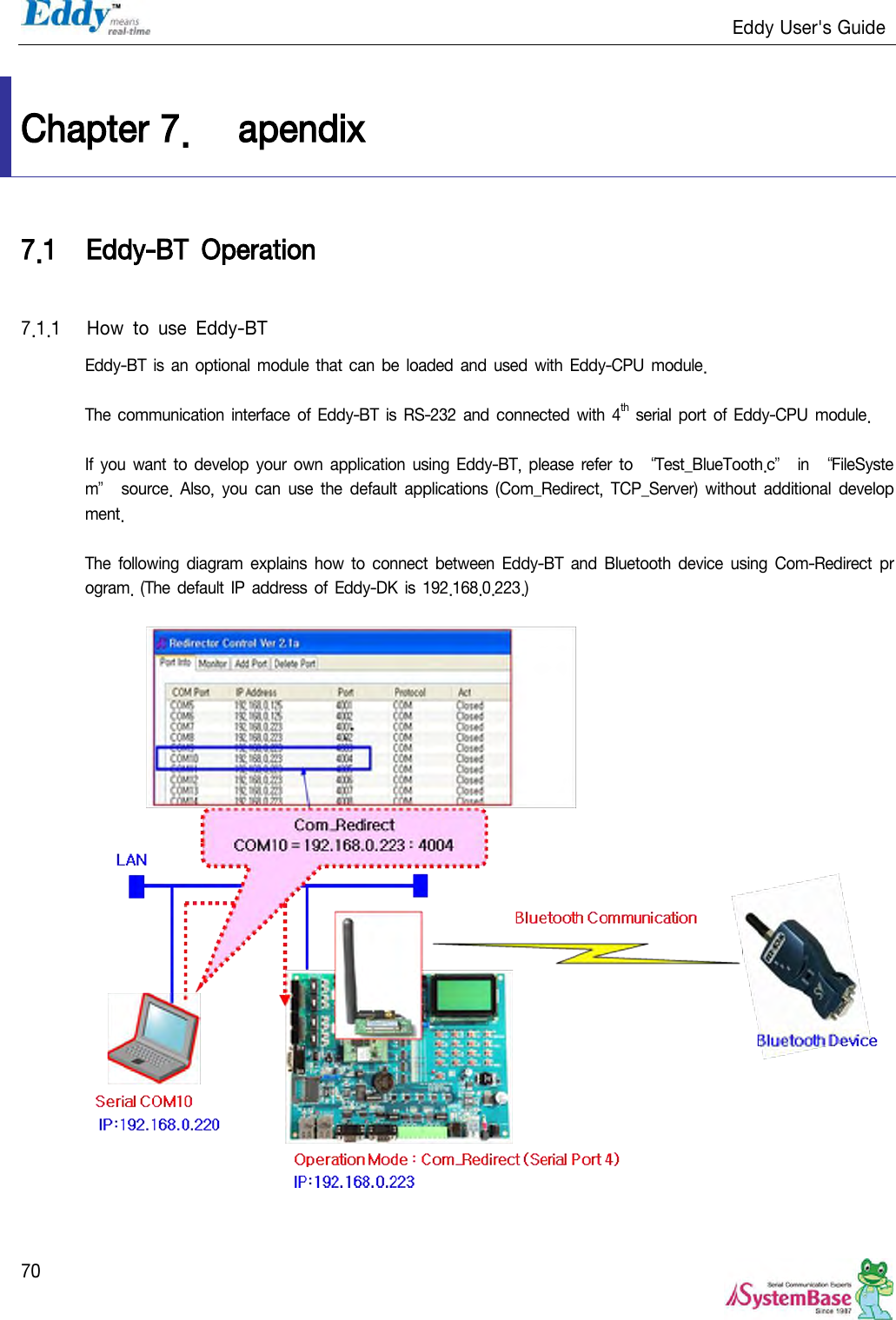
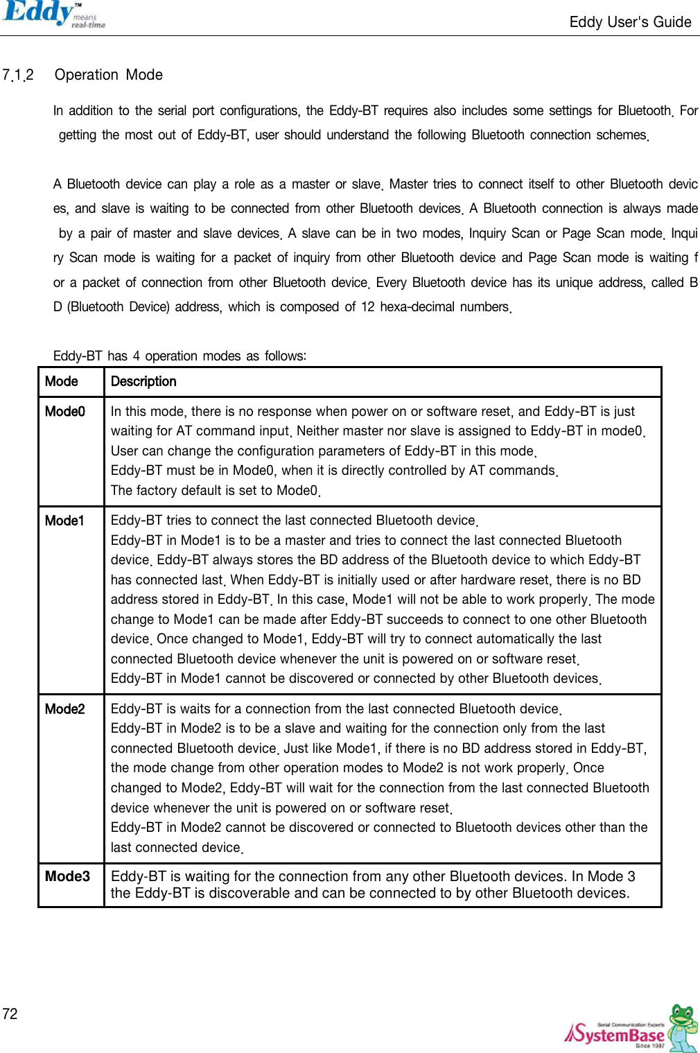
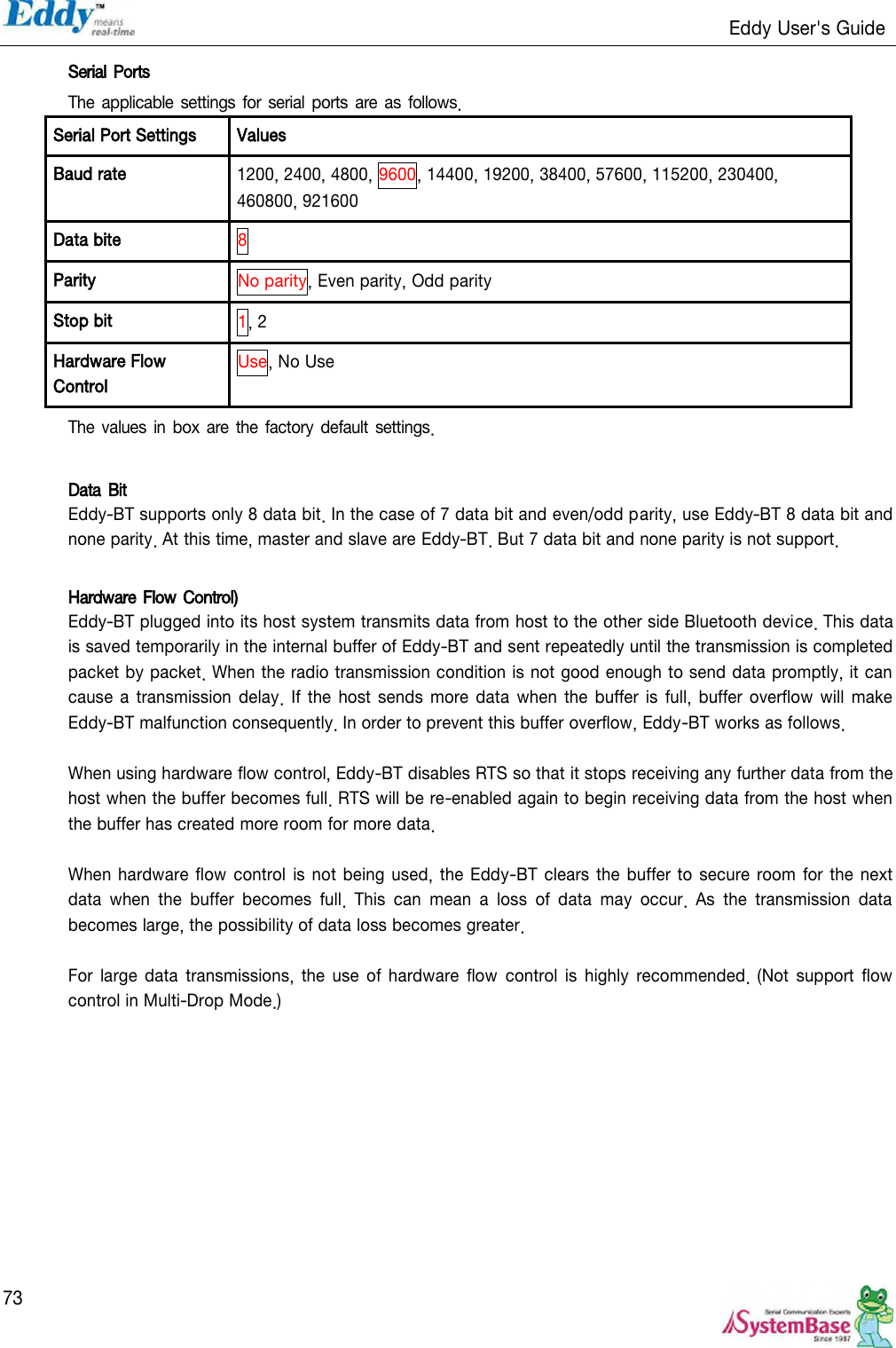
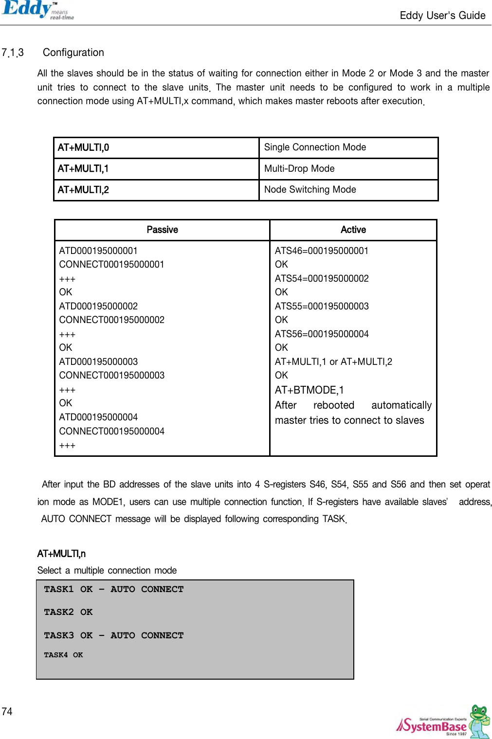
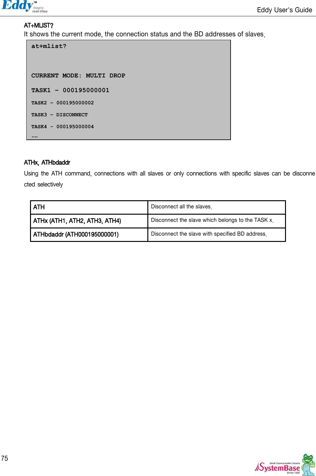
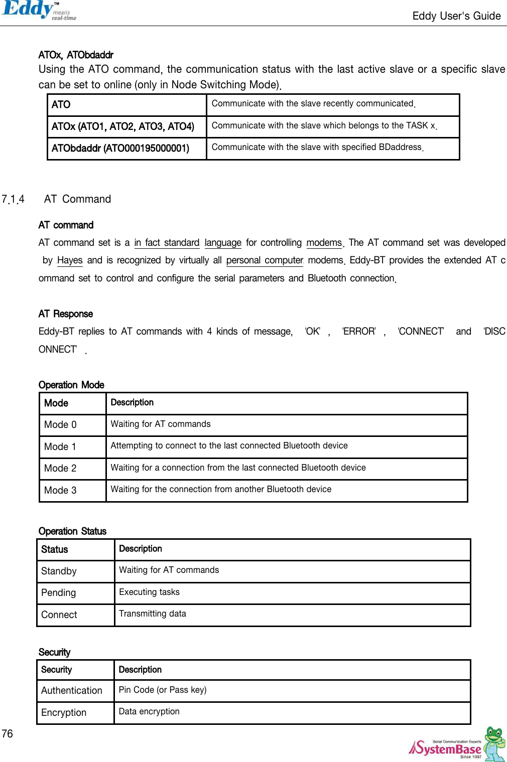
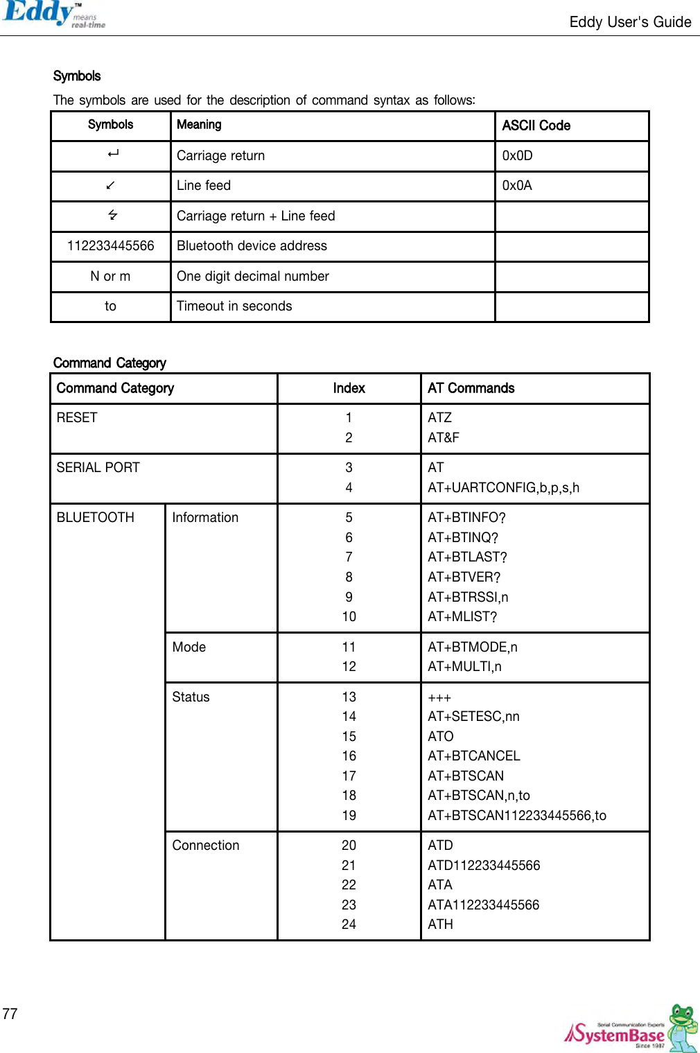
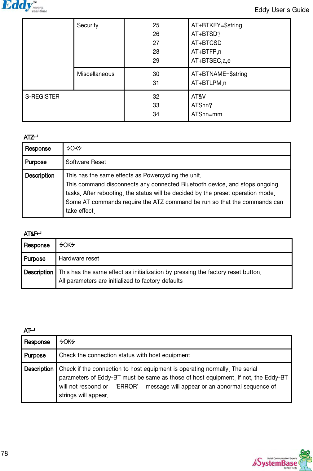
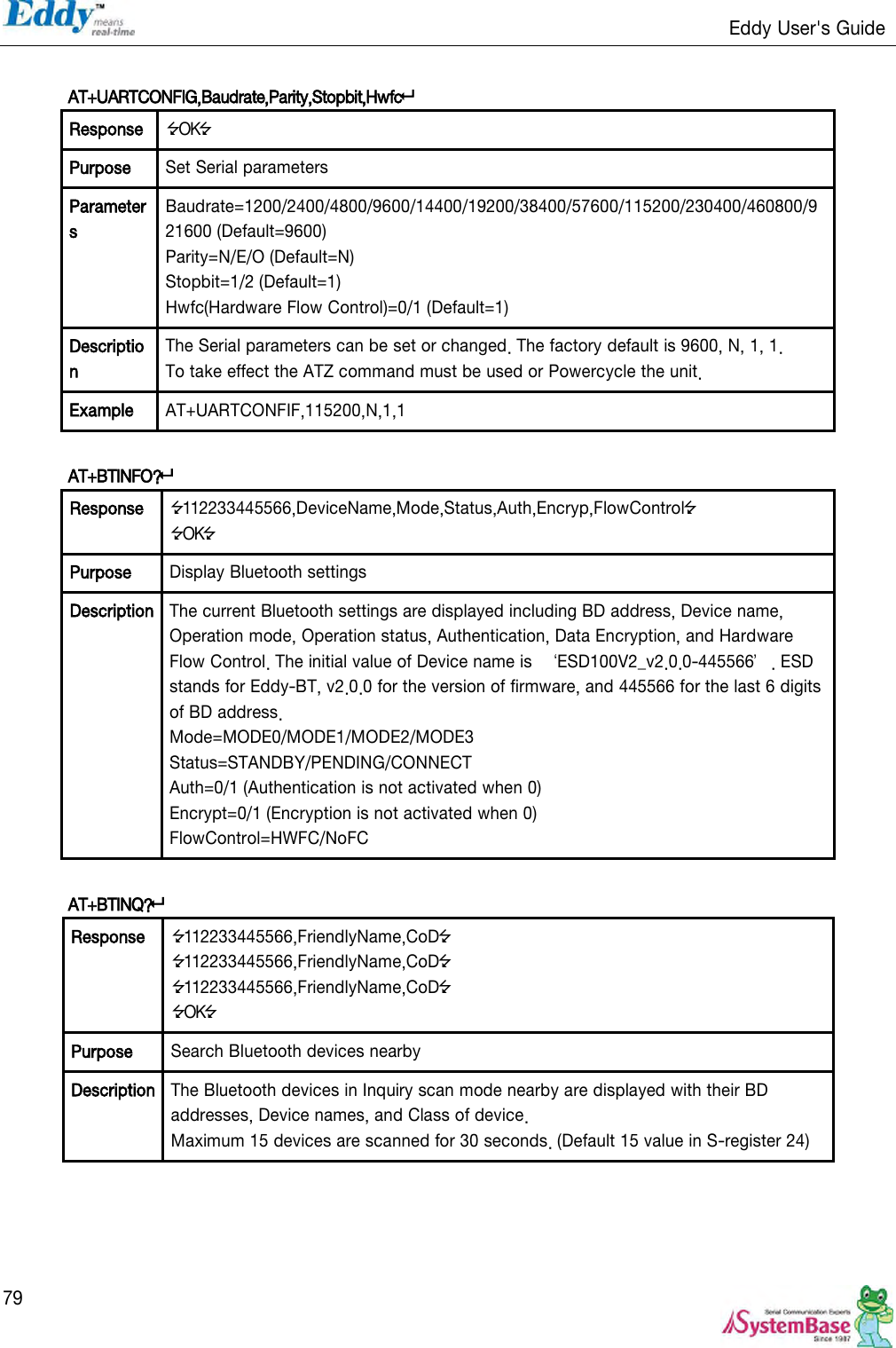
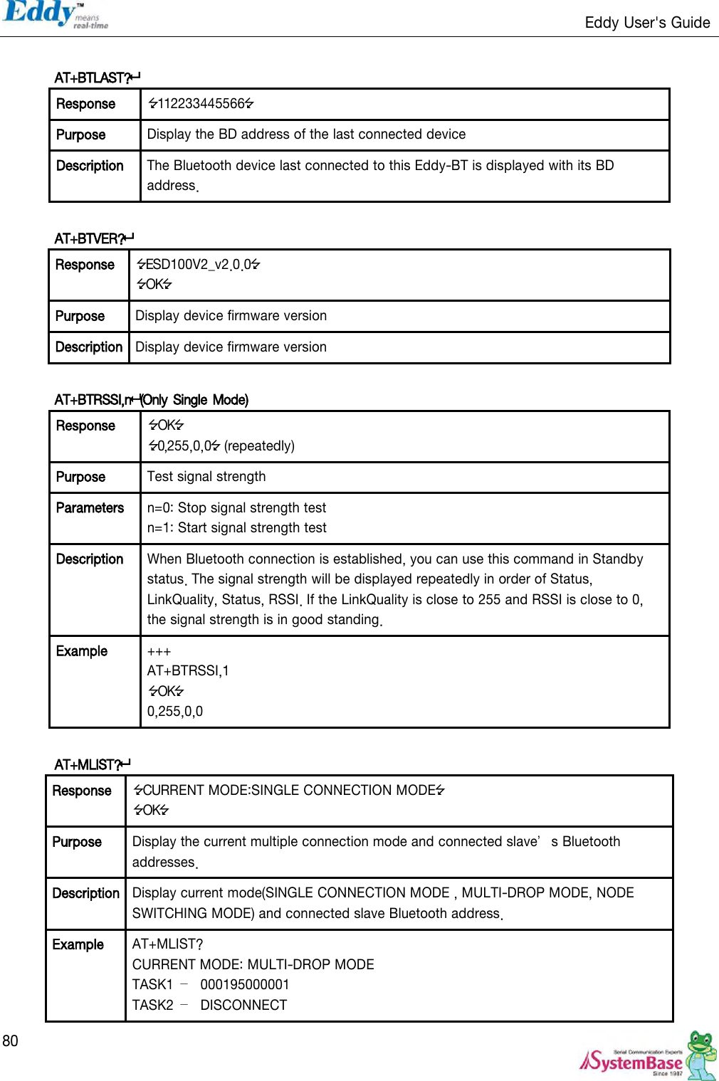
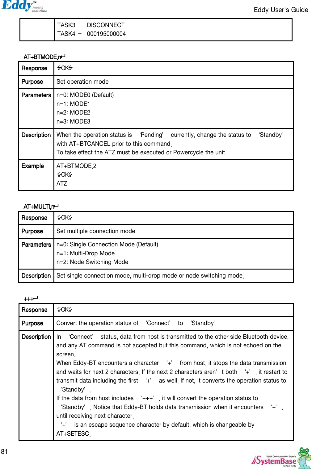
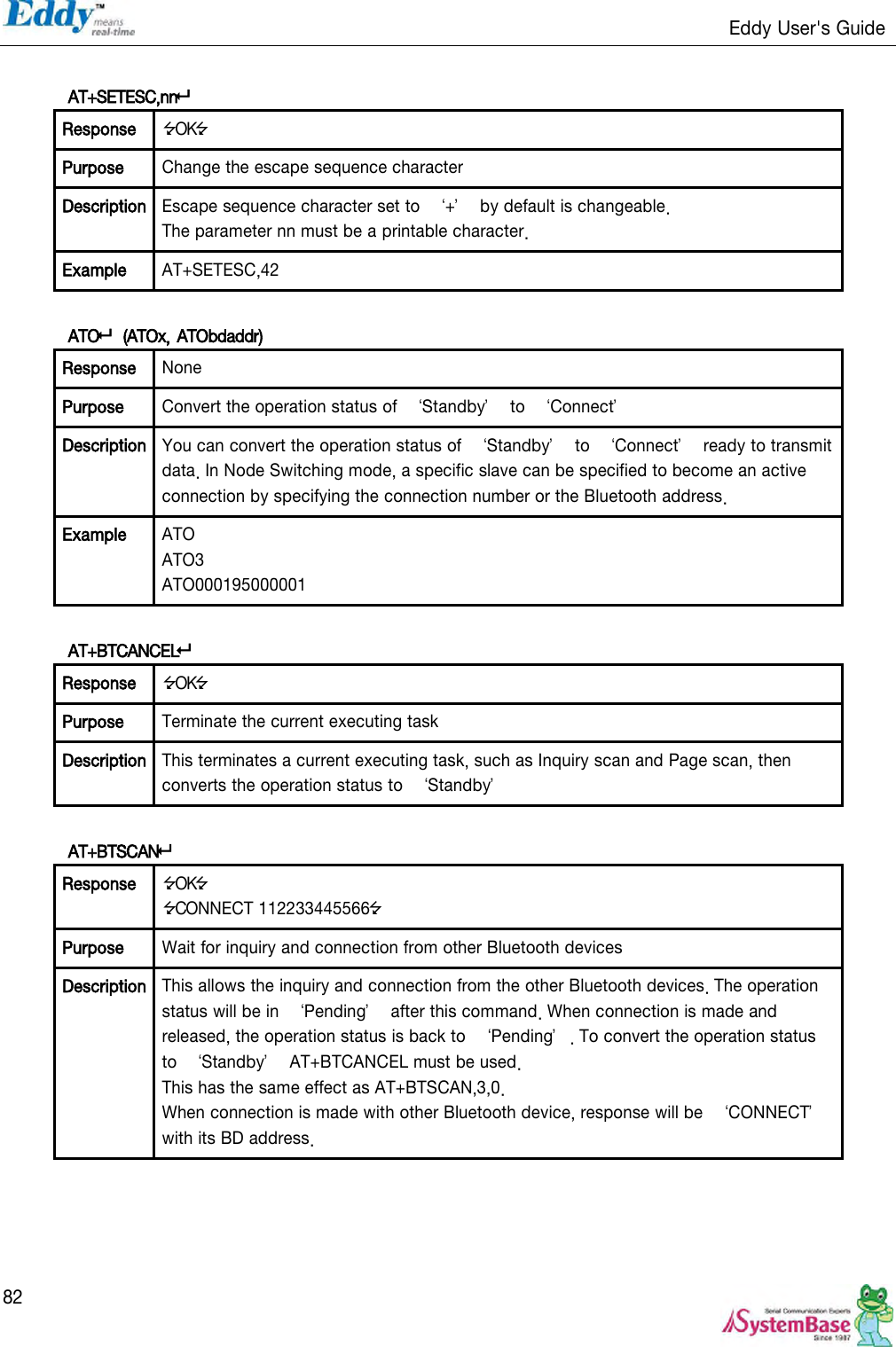
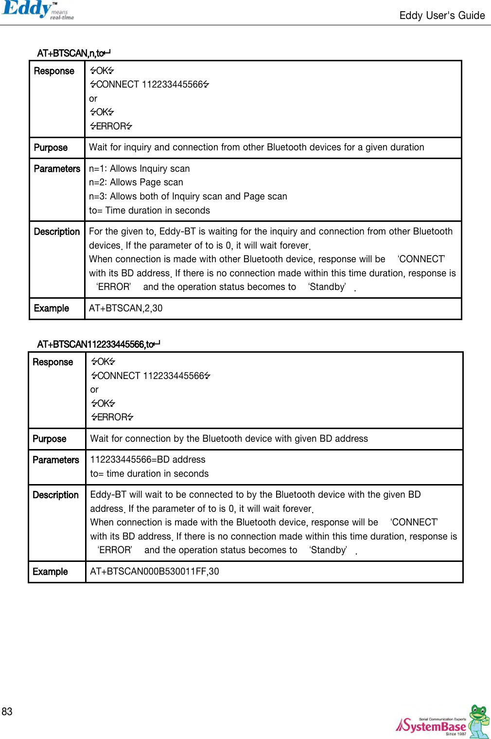
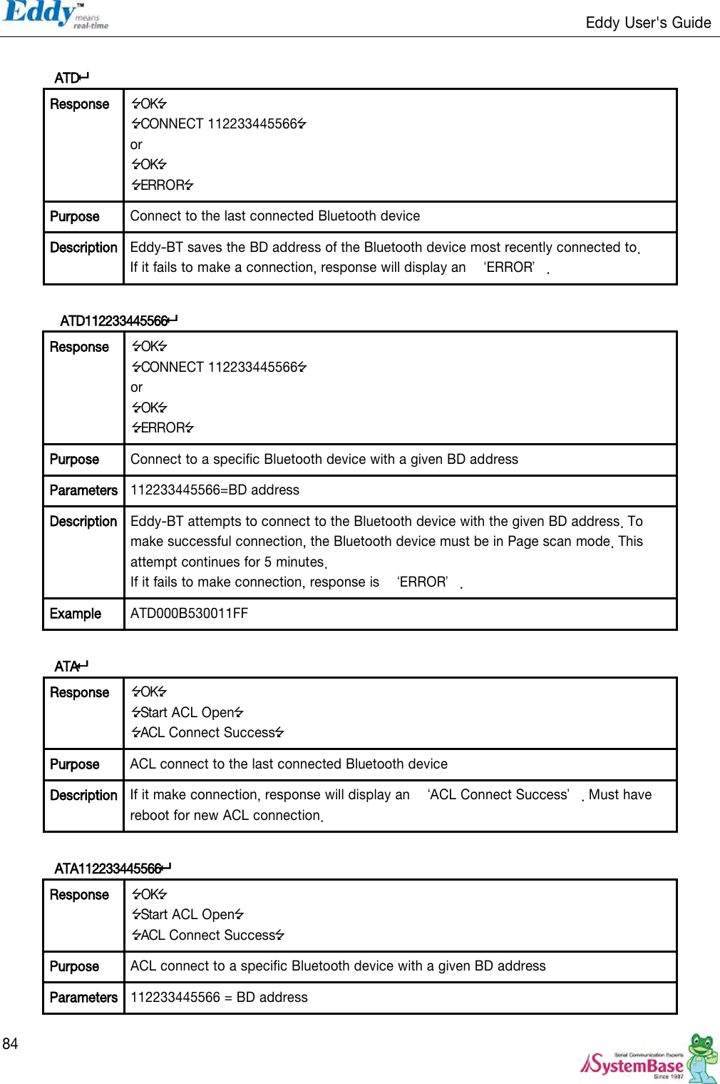
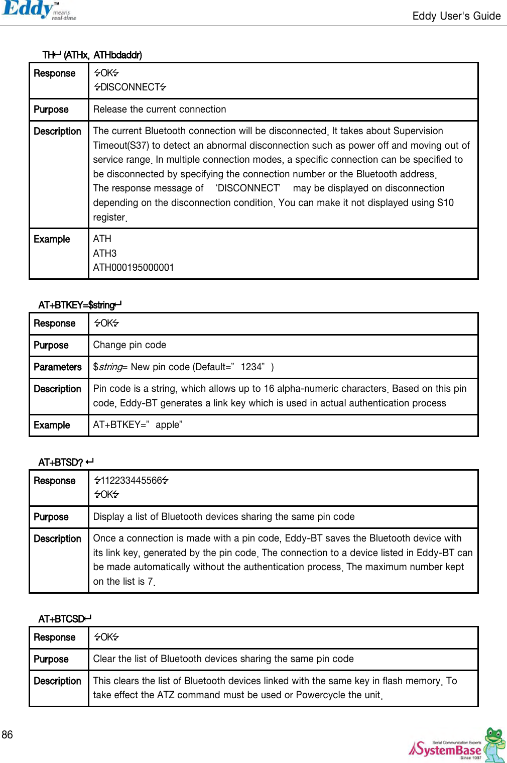
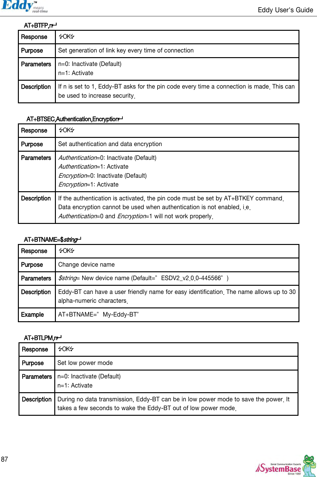
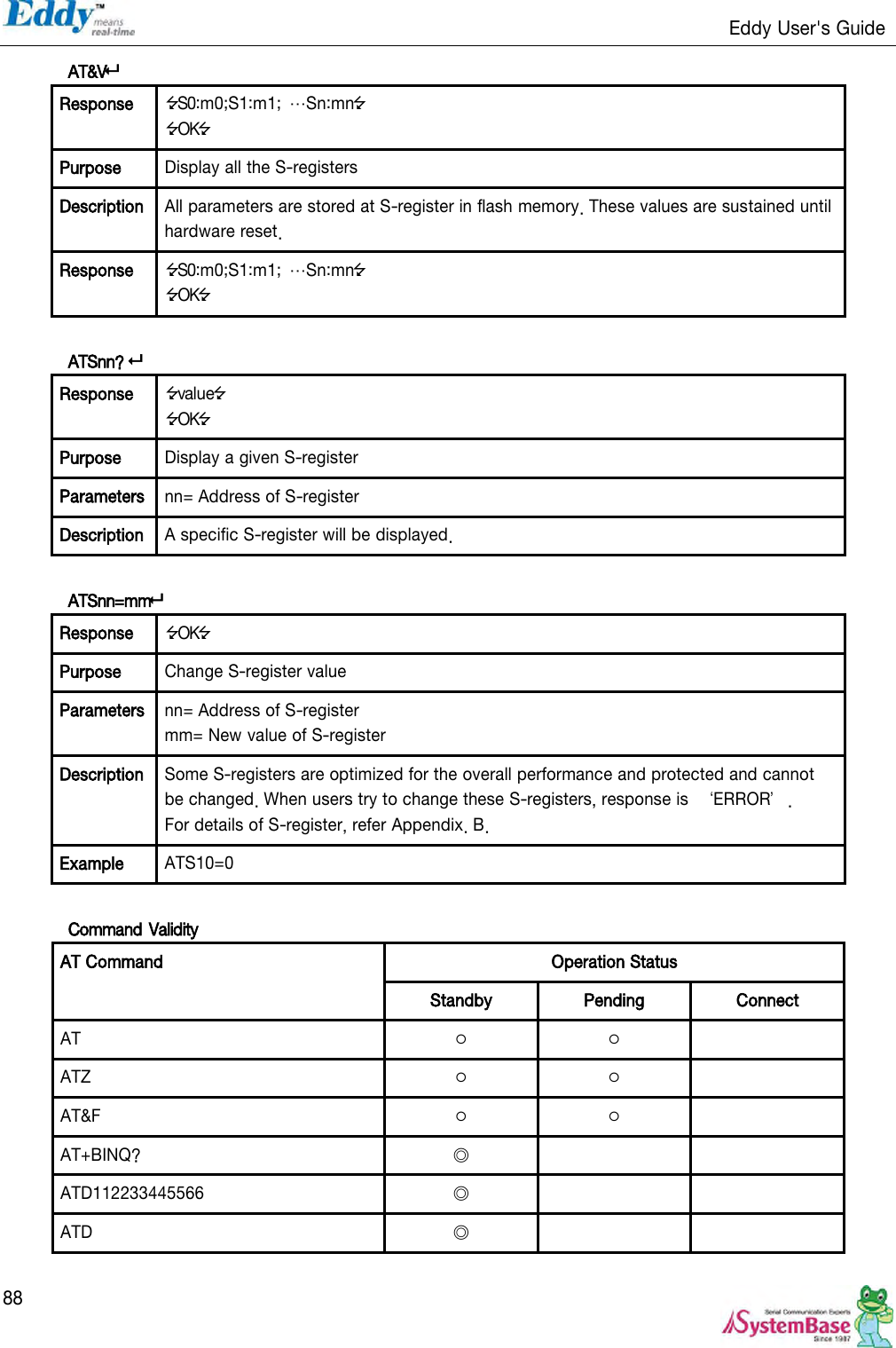
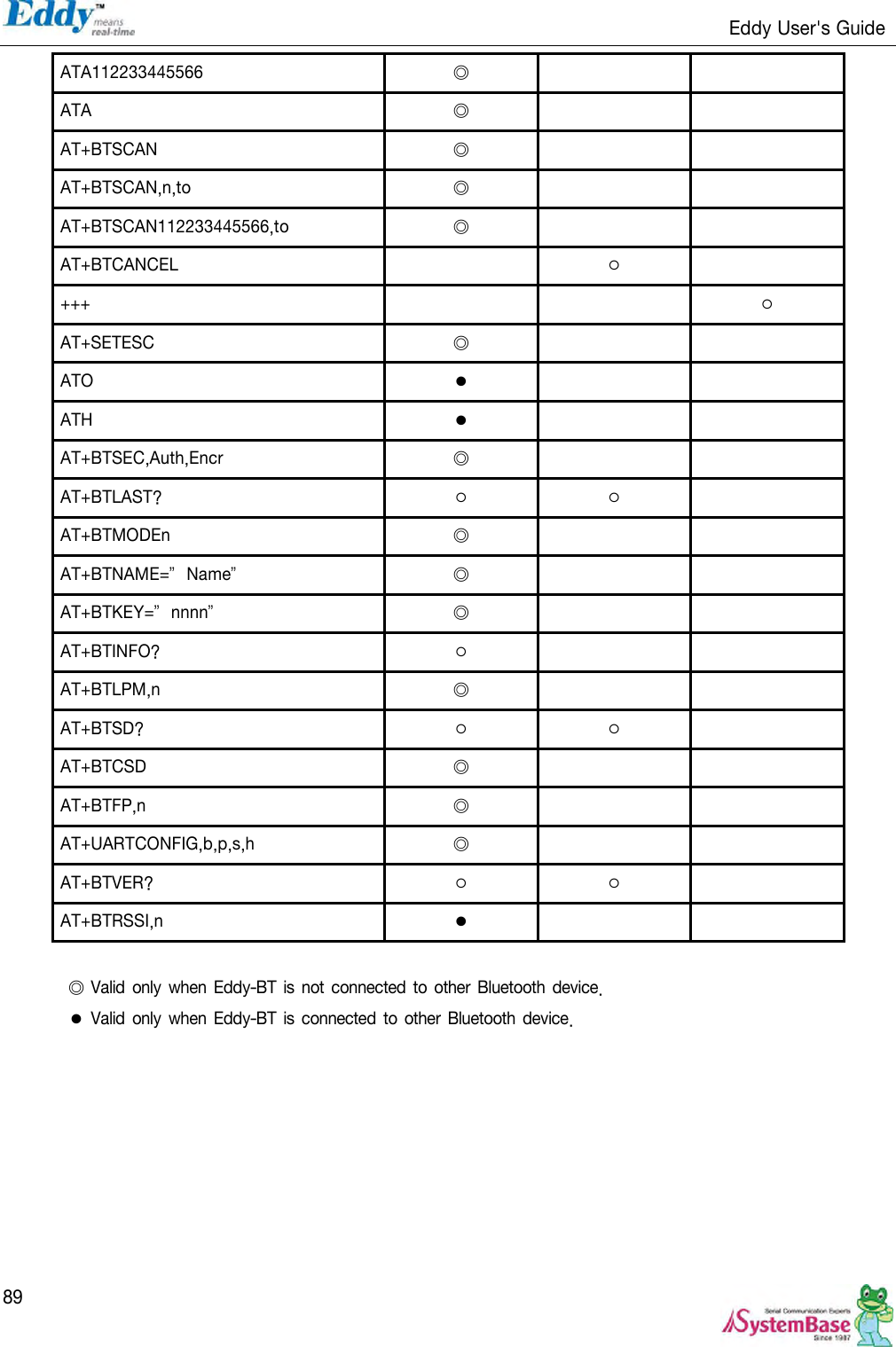
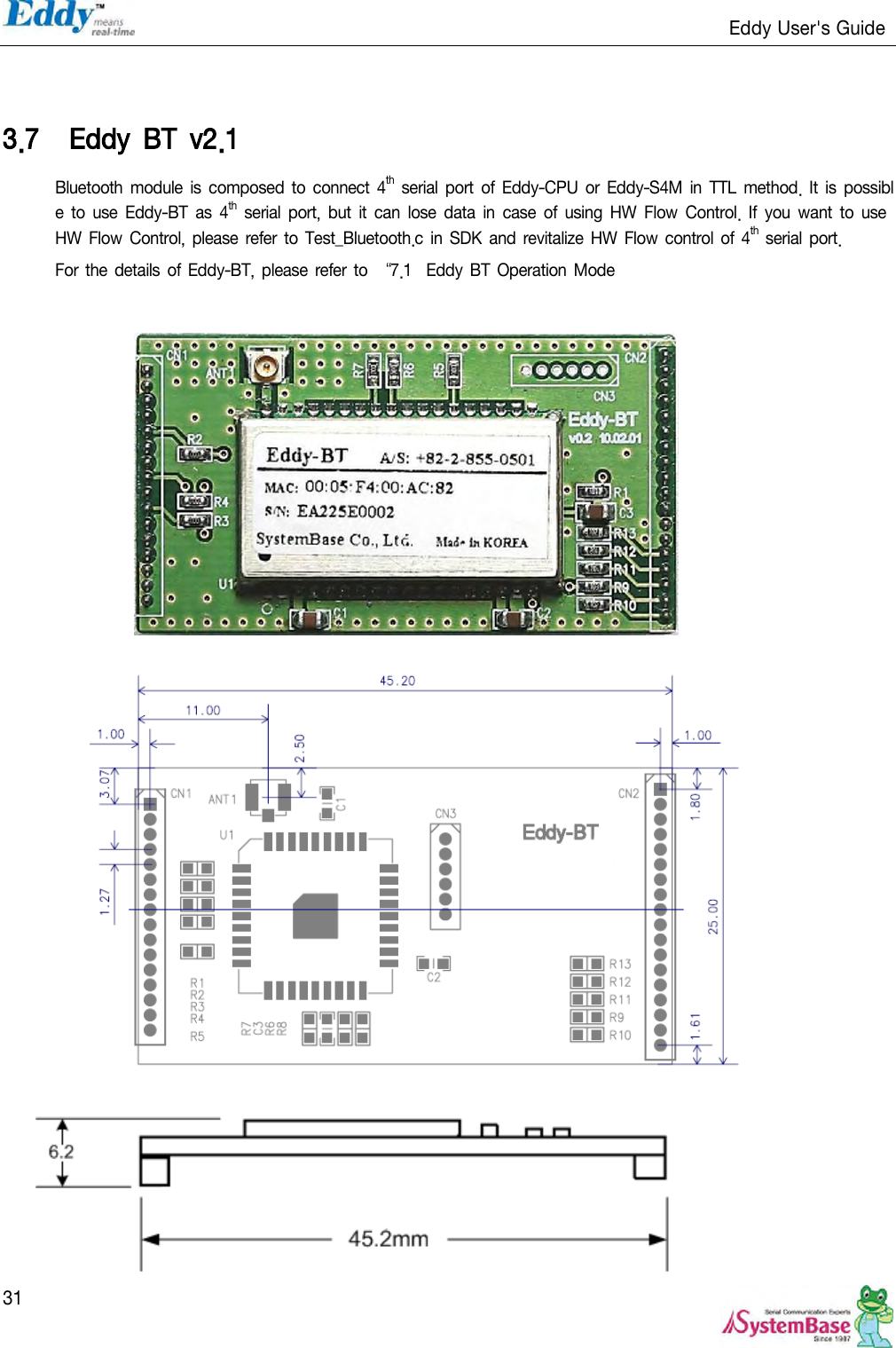
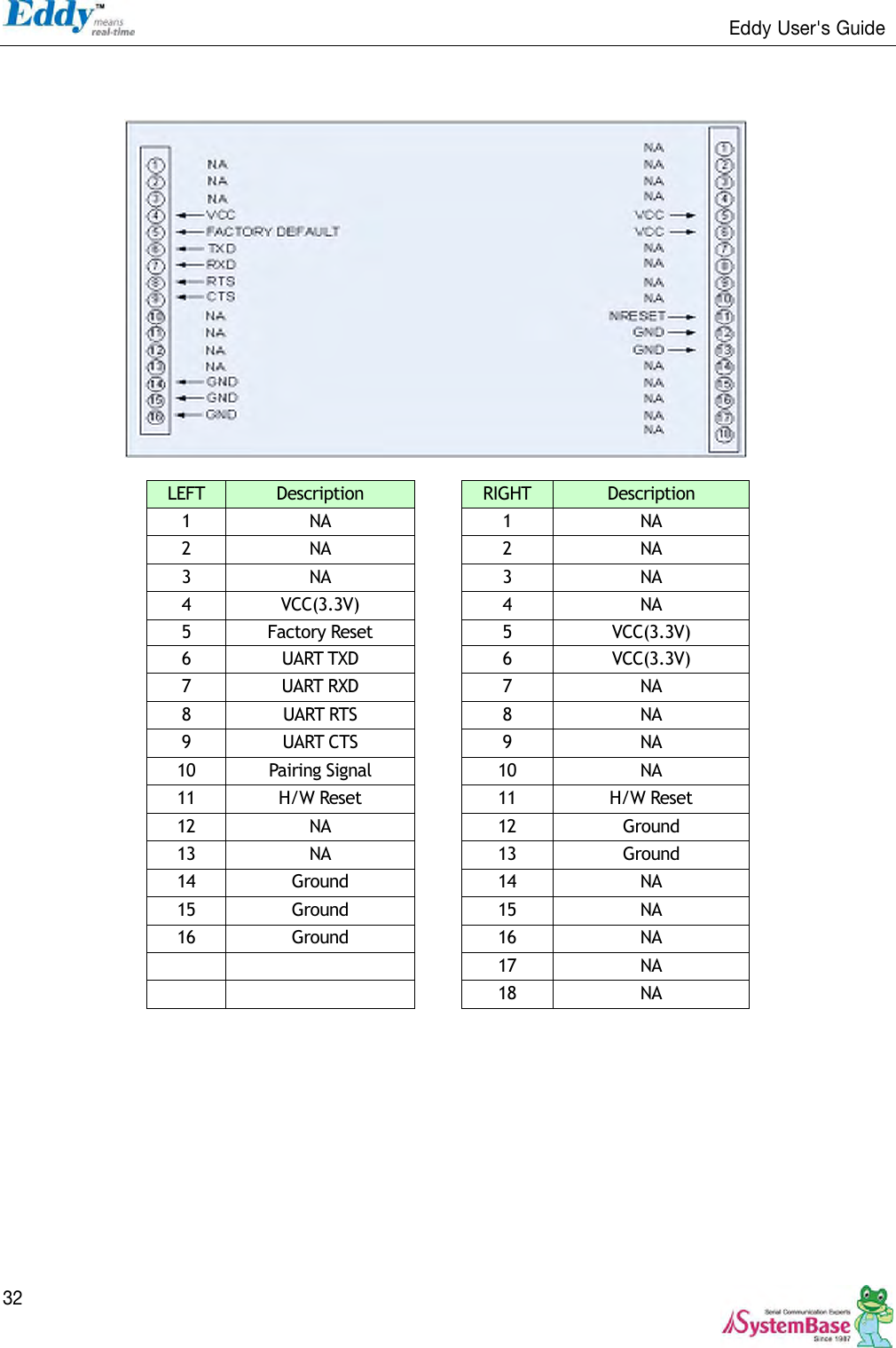
![Eddy User's Guide 71 1. Please power on Eddy-DK after you connect Eddy-BT with Eddy-CPU module. 2. Please set the ‚Operation Mode‛ of 4th serial port as ‚Com_Redirector‛ mode. And then, press ‚Save‛ button. 3. Please press ‚Save & Reboot‛ button of ‚Save & Reboot‛ menu. And then, Eddy-DK will be rebooted. 4. Please install COM_Redirector program on PC. (For more information, please refer to the manual of Com_Redirector program.) 5. Please add port from COM_Redirect Control Panel after the installation of the program. [* You can see that the 4th serial port(192.168.0.223, Port 4004) of Eddy-DK is assigned as COM10.] 6. Please open the port of PC as the default values (9600 bps, None Parity, 8 Data Bits, 1 Stop Bits) using HyperTermanal. 7. You can connect Eddy-BT with Bluetooth device using AT commands. (For more information, please refer to ‚Chapter 7.1.4. The meaning of AT commands‛.) Please press ‚ATZ+‛ and press ‚Enter‛ key. And then, you can see the ‚OK‛ message. If you see the ‚OK‛ message, Eddy-BT is normally loaded with Eddy-CPU module. Now you can connect Eddy-BT with Bluetooth device using ‚ATD+Address of the Bluetooth device‛ command. If Eddy-BT normally connects with Bluetooth device, you can see the ‚Connect‛ message.](https://usermanual.wiki/SystemBase/EDDY-WIFIV3/User-Guide-1667238-Page-71.png)