Systems and Processes Engineering STR7200-1 Barcode Reader User Manual STR7200 UserManual
Systems and Processes Engineering Corporation Barcode Reader STR7200 UserManual
Manual

Universal Handheld
Interrogator
User Manual
Version 1.1
July 23, 2002
Document Control Number
2025-00751-000
ConnectedWireless Corporation
101 W. 6th Street
Suite 200
Austin, TX 78701
UHI User Manual v1.0 DCN: 2025-00750-000
i
Table of Contents
1. Introduction.....................................................................................................................1
1.1 Purpose..........................................................................................................................1
1.2 Background....................................................................................................................1
1.3 Objective .......................................................................................................................1
1.4 Referenced Documents ..................................................................................................1
1.5 Changes from Previous Versions....................................................................................1
1.6 System Overview...........................................................................................................1
1.6.1 Components .................................................................................................................................... 1
1.6.2 Handheld Memory........................................................................................................................... 2
1.7 Handheld Concept of Operation .....................................................................................2
2. Preparation......................................................................................................................3
2.1 Software Installation ......................................................................................................3
2.1.1 Installation Files.............................................................................................................................. 3
2.1.2 Installation Steps ............................................................................................................................. 3
2.2 Program Settings............................................................................................................4
2.3 Using the PDT7200........................................................................................................5
2.3.1 Parts................................................................................................................................................ 5
2.3.2 Controls .......................................................................................................................................... 5
2.3.3 Trigger............................................................................................................................................ 6
2.3.4 Using the Keyboard......................................................................................................................... 6
2.3.5 Using the Laser Scanner .................................................................................................................. 6
2.3.6 Restarting the PDT7200................................................................................................................... 7
2.3.6.1 Warm Boot.................................................................................................................................. 7
2.3.6.2 Cold Boot.................................................................................................................................... 7
2.3.6.3 Hard Reset................................................................................................................................... 7
2.4 Using the STR7200........................................................................................................7
2.4.1 Attaching the STR7200 ................................................................................................................... 7
2.4.2 STR7200 Controls........................................................................................................................... 8
2.4.3 Powering On the Reader.................................................................................................................. 9
2.4.4 Powering Off the Reader ................................................................................................................. 9
2.4.5 Removing the STR7200................................................................................................................... 9
3. Universal Handheld Interrogator Software Operation ...............................................10
3.1 Starting the Program ....................................................................................................10
3.1.1 Method 1 – Start Menu.................................................................................................................. 10
3.1.2 Method 2 – Reboot........................................................................................................................ 10
3.1.3 Method 3 – File Browser ............................................................................................................... 10
3.2 Main Screen.................................................................................................................11
3.3 Setup/Help...................................................................................................................12
3.3.1 Setup............................................................................................................................................. 12
3.3.2 Log File ........................................................................................................................................ 12
3.3.3 Configure...................................................................................................................................... 13
3.3.3.1 RF Tag Reader .......................................................................................................................... 13
3.3.3.2 Data Transfer............................................................................................................................. 14
3.3.4 Help.............................................................................................................................................. 14
3.4 ID Card........................................................................................................................15
3.4.1 Scanning ID Card Data.................................................................................................................. 15
3.4.2 Manual ID Card Data Entry........................................................................................................... 16
3.4.3 Reviewing ID Card Records .......................................................................................................... 16
3.5 Cargo Label .................................................................................................................17
3.5.1 Scanning the 2D Cargo Bar Code................................................................................................... 17
3.5.2 Scanning the Linear Cargo Bar Codes............................................................................................ 18
UHI User Manual v1.0 DCN: 2025-00750-000
ii
3.5.3 Manual Cargo Data Entry.............................................................................................................. 19
3.5.4 Reviewing Cargo Records ............................................................................................................. 19
3.6 Cargo Tag....................................................................................................................20
3.6.1 Select Cargo Tag Menu ................................................................................................................. 20
3.6.1.1 Scanning the Tag ID.................................................................................................................. 20
3.6.1.2 Manual Tag ID Entry................................................................................................................. 20
3.6.1.3 Scanning All Readable Tags ...................................................................................................... 20
3.6.1.4 Beep a Tag ................................................................................................................................ 21
3.6.1.5 Reader Status............................................................................................................................. 21
3.6.2 Reading a RF Tag.......................................................................................................................... 22
3.6.3 Reviewing RF Tag Records ........................................................................................................... 22
3.7 File Backup..................................................................................................................23
3.7.1 Open File ...................................................................................................................................... 23
3.7.2 Remove Record............................................................................................................................. 23
3.7.3 Save Data...................................................................................................................................... 24
3.7.4 Clear RAM.................................................................................................................................... 24
3.7.5 Done ............................................................................................................................................. 24
3.8 File Transfer ................................................................................................................25
3.8.1 Transfer RAM Data....................................................................................................................... 26
3.8.2 Transfer File.................................................................................................................................. 26
3.8.3 Finishing Data Transfer on the MA................................................................................................ 27
3.8.4 Removing Data Files on the PDT7200 ........................................................................................... 29
4. Exiting the UHI program..............................................................................................30
5. Error Messages..............................................................................................................31
5.1 Program Start Errors ....................................................................................................31
5.2 Setup & Help Errors.....................................................................................................31
5.3 Bar Code Scan Errors...................................................................................................32
5.4 STR7200 Reader Errors ...............................................................................................32
5.5 Data Entry Errors.........................................................................................................33
5.5.1 General ......................................................................................................................................... 33
5.5.2 ID Card Data Errors....................................................................................................................... 33
5.5.3 Cargo Data Errors.......................................................................................................................... 33
5.6 File Backup Errors .......................................................................................................33
5.7 Data Transfer Errors.....................................................................................................33
5.7.1 General Errors............................................................................................................................... 33
5.7.2 RAM Transfer Errors..................................................................................................................... 34
5.7.3 File Transfer Errors ....................................................................................................................... 34
5.8 Clearing RAM Errors...................................................................................................34
6. STR7200 Hardware Information..................................................................................35
6.1 General Description .....................................................................................................35
6.2 Parts of the STR7200 ...................................................................................................35
6.3 Specifications...............................................................................................................36
6.3.1 Physical......................................................................................................................................... 36
6.3.2 Environmental............................................................................................................................... 36
6.3.3 Radio Frequency (RF) Interrogator ................................................................................................ 36
6.3.4 Digital........................................................................................................................................... 37
6.4 Regulatory Information................................................................................................37
6.5 STR7200 Controls .......................................................................................................37
6.6 Batteries.......................................................................................................................37
6.6.1 Removing the Battery.................................................................................................................... 37
6.6.2 Charging the Battery...................................................................................................................... 37
6.6.2.1 Charging in the Stand-Alone Charger/L-Band UHH Carry Case................................................. 38
UHI User Manual v1.0 DCN: 2025-00750-000
iii
6.6.2.2 Charging in the RITV Fly-Away Case........................................................................................ 38
6.6.3 Installing the Battery ..................................................................................................................... 39
Table of Figures
Figure 1 Parts of the PDT7200 ............................................................................................................................... 5
Figure 2 PDT7200 Screen Icons ............................................................................................................................. 5
Figure 3 Example Linear Scan................................................................................................................................ 6
Figure 4 Example 2D Scan..................................................................................................................................... 7
Figure 5 Modified Battery Base.............................................................................................................................. 8
Figure 6 STR7200 Controls.................................................................................................................................... 8
Figure 7 UHI Main Screen ................................................................................................................................... 11
Figure 8 Setup & Help Screen .............................................................................................................................. 12
Figure 9 Configure Ports Screen........................................................................................................................... 13
Figure 10 Passenger Data Screen.......................................................................................................................... 15
Figure 11 2D Bar Code......................................................................................................................................... 15
Figure 12 Cargo Label Screen .............................................................................................................................. 17
Figure 13 Military Shipping Label........................................................................................................................ 18
Figure 14 Cargo RF Tag Menu............................................................................................................................. 20
Figure 15 STR7200 Status Screen......................................................................................................................... 21
Figure 16 Cargo RF Tag Screen............................................................................................................................ 22
Figure 17 File Export Screen................................................................................................................................ 23
Figure 18 Confirm Clear Memory......................................................................................................................... 24
Figure 19 File Transfer Screen.............................................................................................................................. 25
Figure 20 MA Attach Handheld Message.............................................................................................................. 25
Figure 21 MA Data Transfer Agent ...................................................................................................................... 26
Figure 22 MA Data Transfer Complete................................................................................................................. 27
Figure 23 MA Re-attach Transceiver .................................................................................................................... 28
Figure 24 MA Transfer Data File Names .............................................................................................................. 28
Figure 25 MA Add Files....................................................................................................................................... 29
Figure 26 STR7200 Top....................................................................................................................................... 35
Figure 27 STR7200 Bottom.................................................................................................................................. 36
Figure 28 Battery Chargers................................................................................................................................... 38
Figure 29 Battery Contact Location ...................................................................................................................... 38
UHI User Manual v1.0 DCN: 2025-00750-000
A-1
1. Introduction
1.1 Purpose
The purpose of the Universal Handheld Interrogator project is to tightly integrate the operation of the Savi Radio
Frequency (RF) Identification (ID) miniature interrogator into a commercial off-the-shelf (COTS) bar code scanner,
the Symbol PDT7200. The Universal Handheld Interrogator (UHI) application program is designed to integrate the
operation of a bar code scanner, for personnel ID cards and shipping labels, with the Savi RF tags.
1.2 Background
In 1999, the U.S.A.F. Air Mobility Command (AMC) sponsored the development of the Universal Hand Held
interrogator prototype that could read existing bar codes and RF tags with the growth potential to add new
tags/technology in the future. The purpose of the handheld was to allow loadmasters on AMC missions to easily
collect cargo and passenger manifest data and use the existing L-Band SATCOM system onboard AMC aircraft to
transmit the data to AMC and DoD logistic databases. The prototype was developed and delivered in 1999. In early
2000, AMC requested two more prototype units to undergo field-testing on actual AMC missions with AMC crews.
The results of field-testing showed the prototypes needed further development to reduce the size, weight, and
increase the ruggedness of the unit. AMC wanted to keep the WinCE interface and software that was easy to use.
At that time, commercial bar code scanners were becoming available that met many of the requirements for AMC,
but lacked an RF capability. Instead of continuing development of the prototype, AMC decided to take an existing
scanner, the Symbol PDT7200 and integrate the RF capability into it.
1.3 Objective
The objective of this document is to provide the user with instructions for using the UHI software. This user
manual will explain software installation and operations. It will also describe the procedures to transfer the data to
the Falcon Gateway system.
1.4 Referenced Documents
• United States European Command (EUCOM) Demonstration Label Specification, dated 12 June 1998
• Code 39 Bar Code Formats for Uniformed Services Identification Cards, dated 11 August 1998
• Joint Total Asset Visibility (JDTAV) RF-Tag Data Format, version 1.01, dated January 16,1996
• *DT - SMRF Message Definition Document, version 6.0.2, dated 23 February 2000
• Symbol PDT7200 Quick Reference Guide, revision A, dated October 2000
1.5 Changes from Previous Versions
None
1.6 System Overview
1.6.1 Components
The Universal Handheld Interrogator is composed of three major components, the Symbol PDT7200 handheld, the
SPEC STR7200 Savi interrogator, and the UHI software.
1. The Symbol PDT7200 is a ruggedized, commercial off-the-shelf (COTS) handheld computer that uses a touch
screen display and Windows CE operating system and has an integrated laser bar code scanner.
2. The STR7200 is a Savi RF tag interrogator comprised of two circuit boards developed by Savi for integration
into a handheld. SPEC has integrated these two circuit boards and SPEC’s Personality Board into a single, easy
to use component that was designed specifically to interface with the PDT7200.
UHI User Manual v1.0 DCN: 2025-00750-000
A-2
3. The UHI application is written to run on the PDT7200 and seamlessly integrates the operation of the bar code
scanner and STR7200. The UHI software can be used without the STR7200 to read ID cards and cargo labels if
necessary, however you will not be able to read Savi RF tags without it. Besides interfacing with the Savi
interrogator, the UHI software also interfaces with the Falcon Gateway system used by the L-Band SATCOM
program. Data captured with the UHI software is fed directly into the load and passenger messages for global
Intransit Visibility (ITV) of cargo and passengers moving on AMC aircraft.
1.6.2 Handheld Memory
The PDT7200 internal memory is divided into two segments, Random Access Memory (RAM) and compact Flash.
The RAM memory is “volatile”, which means that when the handheld is restarted with a “cold boot”, any data in
RAM is lost. Compact Flash memory is “non-volatile”, which means that data written to Compact Flash is
permanent and won’t be lost until the user deletes it.
If the UHI is installed according to the procedures in paragraph 2.1.2, then it will reside in the Compact Flash and
will be present however the handheld is restarted. However, records scanned by the UHI program, ID cards, cargo
labels, or cargo RF tags, reside in RAM memory and will be lost when the system is “cold booted” unless the data is
first saved to a file.
The UHI program has the capacity to store a number of records. The exact number depends on the amount of RAM
installed in the PDT7200. The following is the number of records that a PDT7200 equipped with 16 Mbytes of
RAM will approximately hold:
• 11,000 ID Card Records - OR -
• 12,000 Cargo Labels - OR -
• 10,000 Cargo RF Tags
1.7 Handheld Concept of Operation
Usually, the handheld will be used in conjunction with the L-Band Falcon Gateway system. Below is an example of
how the two will be used together.
1. Arrive at Aircraft
2. Set up L-Band system and unpack PDT7200/STR7200
3. Send L-Band On Station message
4. Set up the APOE/APOD ICAO codes on the handheld setup screen.
5. Scan cargo labels or RF tags prior or after loading cargo
6. If necessary, save cargo data to a file
7. Scan passenger ID cards during or after loading passengers
8. If necessary, save passenger data to a file
9. Transfer data to the L-Band laptop.
10. Send the L-Band Load and Passenger message
11. Pack up the PDT7200/STR7200. If necessary, keep the case plugged in to recharge batteries.
12. Depart location.
UHI User Manual v1.0 DCN: 2025-00750-000
A-3
2. Preparation
2.1 Software Installation
If the UHI Interrogator (UHI) software components are not installed, then install as follows. You will need to use
either the PDT7200 cradle, available from Symbol, or use the handheld com 1 port (which requires a “null modem”
connector) on the back of the handheld.
2.1.1 Installation Files
You will need to have the following installation files loaded on your PC prior to loading the software on the
handheld.
1. UHI.EXE
2. UHI.INI
3. UHI.RUN
4. HELP.TXT
5. SHELLAPPL_7200.REG
You will also need to have Microsoft’s Active Sync v3.1 or higher in order to transfer the program from a
personal computer. Please refer to Microsoft’s web site for instructions in downloading and installing Active Sync.
2.1.2 Installation Steps
1. Ensure the cradle or the handheld com 1 port is connected to the PC serial port.
2. Ensure no other software is currently running on the hand held. If other software is running, then exit the
programs. If you can’t exit, then run the “Task Manager” from the “Start” menu and “kill” that program.
3. Ensure PDT7200 communication is set to “Com6 Cradle” or “Comm1@57600”.
a. Run “Start” -> “Symbol Settings”
b. Select “Communications”. You should see the parameter “Comm Setting” set to the serial port
you are using, “COM6 Cradle” or “COM1@57600”.
c. If not, then press the “Comm Setting” label until it is set to the desired setting.
d. Click “Accept”.
e. Click “Exit”. You should see a blank screen with the “Start” button at the bottom.
4. If using a cradle, place the Symbol PDT7200 into the cradle. If using COM1, connect the serial cable to
the PC serial port.
5. In order for the PC and handheld to communicate, you must run the PC Link program on the handheld and
ActiveSync on the PC at the same time.
a. On the Hand Held, run “Start” -> “PC Link” then on the PC, start Microsoft ActiveSync and run
“File”-> “Get Connected”. ActiveSync will appear as a circle icon with two arrows inside. The
icon should be in the icon tray next to the PC time.
b. When the “Get Connected” wizard box appears, click “Cancel”.
c. ActiveSync status will show “Connecting…”.
d. On the PC, ActiveSync will establish the connection. Be patient, this can take a few minutes.
e. If ActiveSync cannot make a connection, retry from step a, above.
6. When ActiveSync connects, select “No, I do not want to synchronize”. ActiveSync status will be
“Connected” and the icon will change to green.
7. On the ActiveSync window, click the “Explore” button or from the ActiveSync File menu, select
“Explore”. This will open a “Mobile Device” window that shows the directories and files on the handheld.
8. In the “Mobile Device” window, create the following directories on the handheld, if they do not already
exist.
• \Application\User\UHI
• \Application\User\UHI\Data
• \Application\User\UHI\Log
9. On the PC, select the files to be copied: UHI.EXE, UHI.INI, and HELP.TXT and copy them to the
\Application\User\UHI directory on the Handheld explorer window.

UHI User Manual v1.0 DCN: 2025-00750-000
A-4
10. On the PC, select the file UHI.RUN and copy it to the Handheld explorer directory “\Application\Startup”.
11. Examine the “\Application\Startup” directory on the handheld and ensure it only has two run files,
“UHI.RUN” and “POPUPKBD.RUN”. If there are any other run files, delete them.
12. On the PC, select the file SHELLAPPL_7200.REG and copy it to the Handheld explorer directory
“\Application\User\Regs”. You will be asked if you want to overwrite the existing file, answer YES.
13. On the PC, close the ActiveSync explorer window.
14. Remove the handheld from the cradle or disconnect the serial cable.
15. Perform a cold reboot by powering off the handheld and then hold the power button for 16 seconds. The
handheld will restart and the UHI program will now be installed in the “Start” menu.
2.2 Program Settings
The UHI initialization file (UHI.ini) settings are shown below along with a brief explanation of each, default settings
are shown.
LogFile=FALSE When set to true, the handheld will keep a
log file of actions performed. The settings
are “TRUE” or “FALSE”.
ReaderComPort=4 This is the PDT7200 serial port used to
communicate with the STR7200. Settings
are 4 for the IrDA port or 1 for the external
port.
BaudRate1=115200 Speed for serial communications with the
STR7200. Use 115200 as the baud rate
for using the IrDA port. Use 19200 as the
baud rate for com port 1.
StopBits1=1 Stop bits for serial communications with
the STR7200. Do not change this setting
DataBits1=8 Data bits used for serial communications
with the STR7200. Do not change this
setting.
Parity1=None Parity type used for serial communications
with the STR7200. Do not change this
setting.
XferCommPort=1 Serial port used for transferring data to the
laptop. Settings are 1 for the external
serial port or 4 for the IR port in the handle
BaudRate2=9600 Speed for serial communications with the
laptop. Do not change this setting.
StopBits2=1 Stop bits for serial communications with
the laptop. Do not change this setting
DataBits2=8 Data bits used for serial communications
with the laptop. Do not change this
setting.
Parity2=None Parity type used for serial communications
with the laptop. Do not change this
setting.
DataFileDir=\Application\User\UHI\Data Directory on the handheld for the saved
data files.
LogFileDir=\Application\User\UHI\Log Directory on the handheld for the log file.
HelpFile=\Application\User\UHI\help.txt Directory on the handheld for the help file.
ListCargoData = 0
BatteryCheckTime=1 Time in seconds that the UHI program will
wait between checks of the STR7200
UHI User Manual v1.0 DCN: 2025-00750-000
A-5
battery.
BatteryLowVoltage = 6.5 Threshold voltage of the STR7200 battery
that will cause a warning on the UHI
program that the battery is low.
2.3 Using the PDT7200
2.3.1 Parts
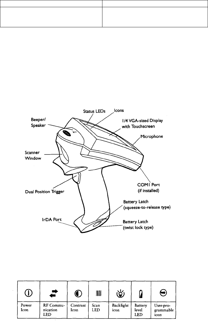
Before using the UHI software, it will be helpful to familiarize yourself with features and general use of the
PDT7200 handheld. Figure 1 is a drawing of the PDT7200 and the general parts. Please refer to the PDT7200 user
manual for a more detailed explanation.
Figure 1 Parts of the PDT7200
2.3.2 Controls
Figure 2 PDT7200 Screen Icons
Figure 2 is a diagram of the control and status icons displayed on the PDT7200 screen. The main icons are
explained below.
1. Power Icon – Use this icon to turn power on/off to the handheld display. The display will auto-time out
and turn itself off after a few minutes of non-use. Press this icon to restore the screen.
2. RF Communications LED – This LED is lit when the handheld is communicating through the serial port.
UHI User Manual v1.0 DCN: 2025-00750-000
A-6
3. Contrast Icon – Use this icon to adjust the display contrast. Press and hold the icon to decrease the
contrast, repeatedly tap the icon to increase contrast.
4. Scan LED – This LED is lit when the handheld is scanning a bar code.
5. Backlight Icon – Use this icon to turn on the screen backlight. This is useful for viewing the screen in
dimly lit conditions.
2.3.3 Trigger
The PDT7200 has a two-position trigger. Pull the trigger back to the first “click”. This is the first position and will
display the popup keyboard for manual data entry. Pull the trigger all the way back to the handle and it will activate
the laser bar code scanner.
2.3.4 Using the Keyboard
The PDT7200 is equipped with a popup keyboard for manual data entry or editing scanned data. The keyboard is in
two parts, an alpha keyboard and a numeric keyboard.
• Display the keyboard by pulling the trigger back to the first “click”.
• On the alpha keyboard, you can switch to the numeric keyboard by pressing the “123” button.
• On the numeric keyboard, you can switch to the alpha keyboard by pressing the “ABC” button.
• Clear the keyboard by pulling the trigger back to the first “click” again.
2.3.5 Using the Laser Scanner
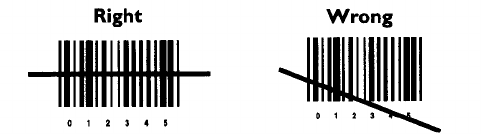
To scan a linear bar code:
1. Make sure the UHI application is running and a data entry screen is displayed, i.e. ID Card, Cargo Label,
Cargo Tag.
2. Point the scanner at the bar code and pull the trigger all the way to the handle.
3. Ensure that the scan beam crosses all the bars and spaces on the bar code symbol, as shown in Figure 3.
Hold the scanner farther away for larger symbols, and closer for symbols with bars that are close together.
Figure 3 Example Linear Scan
4. The Scan LED will turn from yellow to green for successful scans.
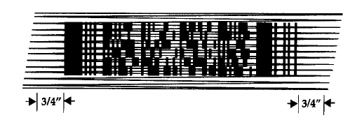
The PDF417 is also known as a 2 dimensional bar code. The scan laser beam will not only read the symbol from
side to side, but it will also automatically move the beam up and down. To scan PDF417 (2D) bar codes:
1. Make sure the UHI application is running and one of the data entry screens capable of reading a 2D bar
code, i.e. ID Card and Cargo Label is displayed.
2. Point the scanner at the bar code and press the trigger all the way to the handle.
3. Center the aiming pattern on the bar code.
4. As the raster pattern spreads, keep the pattern in the same horizontal plane as the bar code, as shown in
Figure 4.
UHI User Manual v1.0 DCN: 2025-00750-000
A-7
Figure 4 Example 2D Scan
5. The terminal indicates a successful scan by changing the LED from yellow to green, beeping one or more
times, and displaying data on the screen.
2.3.6 Restarting the PDT7200
If for some reason the handheld should stop responding to inputs, you can reboot the handheld in several ways.
2.3.6.1 Warm Boot
A warm boot restarts the handheld and saves all stored records and entries. However, data stored in memory will
not be retained.
• Press and hold down the power icon, refer to Figure 2, for 6 seconds, then release.
2.3.6.2 Cold Boot
A cold boot restarts the handheld. The registry and objects stored are reset to their original settings. Data files
stored on the handheld will be saved.
• Press and hold down the power icon, refer to Figure 2, for 16 seconds, then release.
2.3.6.3 Hard Reset
A hard reset also restarts the PDT7200 handheld, but also erases all stored records and files. Therefore, never
perform a hard reset unless a warm/cold boot does not restore the handheld. The UHI application will not be erased
if installed according to the procedures in paragraph 2.1.2, but any data not saved to a file will be lost.
• Remove the battery for 20 minutes or longer
• Replace the battery in the terminal
• The calibration screen starts
2.4 Using the STR7200
2.4.1 Attaching the STR7200
In order to read cargo RF tags with the STR7200, you must first attach the reader to the handheld. You cannot
operate the STR7200 without the handheld UHI program. The handheld must have the modified battery with the
“grip” attached in order for the reader to attach to the handheld, as shown in Figure 5.
** N O T E **
The STR7200 will not successfully attach without the proper battery modification.
UHI User Manual v1.0 DCN: 2025-00750-000
A-8
Figure 5 Modified Battery Base
1. Position the handheld over the top of the reader socket pointing forward.
2. Incline the handheld slightly forward.
3. Insert the toe of the handheld into the reader socket.
4. Rock the handheld backward until it “clicks” into place.
** N O T E **
Make sure the handheld lanyard is in the slot in the socket or the reader will not attach
correctly.
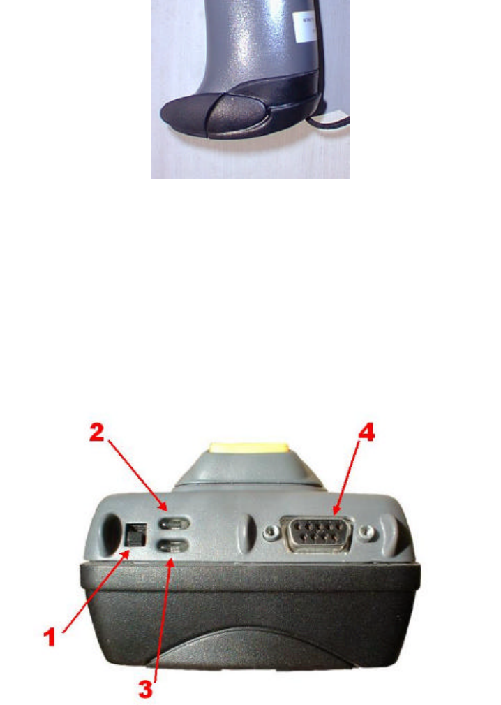
2.4.2 STR7200 Controls
Figure 6 STR7200 Controls
The controls for the STR7200 are shown in Figure 6
1. Power Switch
2. In-use LED (Amber)
3. Power On LED (Green)
4. Serial Port
UHI User Manual v1.0 DCN: 2025-00750-000
A-9
***WARNING***
Do not connect cables to or disconnect cables from the Serial Port connector in
hazardous environments that may contain explosive gases.
2.4.3 Powering On the Reader
The reader power switch is located on the back-left of the reader.
1. Power on the unit by moving the switch upward
2. You will see an amber light followed by a blinking green light. The reader is performing the software load
and Power On Self Test (POST).
3. When the green light is solid, the reader is ready for use.
2.4.4 Powering Off the Reader
There are no software actions that need to be performed prior to shutting off the reader. Simply place the power
switch on the down position and the green light will go off.
2.4.5 Removing the STR7200
The reader can be removed from the handheld at any time. You can remove the reader with either power on or off.
1. Press the yellow release button on the back of the reader shoe.
2. Incline the handheld forward until the battery boot is out of the shoe.
3. Pull the handheld slightly backward and upward to remove.
UHI User Manual v1.0 DCN: 2025-00750-000
A-10
3. Universal Handheld Interrogator Software Operation
** N O T E **
The UHI program does not perform any validation checks on scanned or manually entered
data. Data entered with the UHI program will be checked when the data is uploaded to the
Falcon Gateway System.
3.1 Starting the Program
There are three methods to start the UHI program. When the program starts you will see the UHI Main Screen.
3.1.1 Method 1 – Start Menu
1. Press the “Start” menu button at the lower left corner of the screen.
2. Press the “UHI” entry on the menu.
3.1.2 Method 2 – Reboot
1. Press the “Start” menu button at the lower left corner of the screen.
2. Press the “Warm Boot” entry. This will reboot the handheld and the UHI program will auto-start.
3.1.3 Method 3 – File Browser
1. Press the “Start” menu button at the lower left corner of the screen.
2. Press the “File Browser” entry. This will start the “InkWIZ File Browser”.
3. Press the “+” symbol next to the “Application” directory.
4. Scroll down and press the “+” symbol next to the “User” directory.
5. Scroll down and press the “+” symbol next to the UHI directory.
6. Select the UHI.EXE entry and press the “Open” button. The UHI program will start.
UHI User Manual v1.0 DCN: 2025-00750-000
A-11
3.2 Main Screen
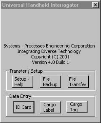
The main menu has two main areas Data Entry and Transfer/Setup. A sample of the main screen is in Figure 7.
Below is a summary if the options available from the main screen. A detailed description of each screen is shown
after this section.
Figure 7 UHI Main Screen
The Setup and Data Transfer options are:
1. Setup & Help – Use this option to enter a list of ICAO codes that correspond to your flight itinerary that
you can use later when scanning in data. The help file is also displayed in this window
2. File Backup – Use this option to save scanned in data to a file on the handheld and to clear all records in
memory.
3. File Transfer – Use this option to transfer data in memory or in a file to the Falcon Gateway system.
The Data Entry area has three buttons to select the appropriate input device:
1. ID Card – Use this option to scan the 2D bar code on the back of the Military ID card.
2. Cargo Label - Use this option to scan the linear or 2D bar codes on the Military Shipping Label.
3. Cargo Tag – Use this option to find and read Savi RF tags.
UHI User Manual v1.0 DCN: 2025-00750-000
A-12
3.3 Setup/Help
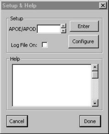
When the user selects the “Setup & Help” button, they will see the screen in Figure 8.
Figure 8 Setup & Help Screen
3.3.1 Setup
The Setup portion of this screen is for the user to enter a list of ICAO codes for the different Aerial Port of
Embarkation (APOE) or Aerial Port of Debarkation (APOD) locations. These codes are stored in memory until the
UHI program exits. These codes will be displayed on the passenger data and cargo data input screens in the
APOE/APOD pull-down list.
1. Ensure the cursor is in the input box by tapping the “APOE/APOD” input area on the screen.
2. Display the popup keyboard by pressing the trigger to the first “Click”.
3. Enter the ICAO code and press “Enter” button to store it.
4. Repeat for as many codes as you need.
5. Clear the popup keyboard by pressing the trigger again to the first “Click”.
6. Multiple APOE/APOD codes can be entered here and will be visible when the drop down button is used.
3.3.2 Log File
The “Log File On” checkbox will be used to turn on the handheld log file.
UHI User Manual v1.0 DCN: 2025-00750-000
A-13
3.3.3 Configure
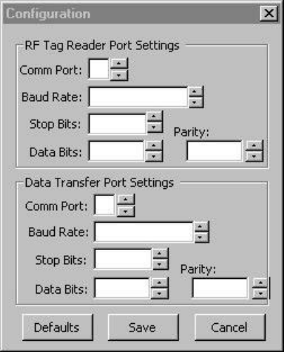
The configure button will display the Configure screen, shown in Figure 9. This allows you to dynamically change
which ports are used for talking to the STR7200 and for transferring data to a PC computer. The Configure screen is
divided into two sections, RF Tag Reader and Data Transfer.
Figure 9 Configure Ports Screen
3.3.3.1 RF Tag Reader
These settings control which port the PDT7200 uses to communicate with the STR7200. Default settings are in
bold font.
• Comm Port: Physical port used by the handheld to communicate with the STR7200
1 = serial port on back of PDT7200
4 = IrDA * * N O T E * *
The Comm port settings must match those used by the STR7200.
• Baud Rate: Speed that the port communicates at.
9600
19200 (This is the max speed that the handheld can communicate with the STR7200 over the
COM1 port)
36400
57600
115200
• Stop Bits: The number of bits used to indicate the end of data transmission.
1
2
• Data Bits: The number of bits used to indicate one character of data transmission.
7
8
• Parity: Type of error detection.
None
Even
UHI User Manual v1.0 DCN: 2025-00750-000
A-14
Odd
3.3.3.2 Data Transfer
These settings control which port the PDT7200 uses to transfer data to a PC or laptop computer. Default settings are
in bold font.
• Comm Port: Physical port used by the handheld to communicate with the STR7200
1 = serial port on back of PDT7200
4 = IrDA
6 = PDT7200 Cradle * * N O T E * *
The Comm port settings must match those use by the STR7200.
• Baud Rate: Speed that the port communicates at.
9600
19200
36400
57600
115200
• Stop Bits: The number of bits used to indicate the end of data transmission.
1
2
• Data Bits: The number of bits used to indicate one character of data transmission.
7
8
• Parity: Type of error detection.
None
Even
Odd
3.3.4 Help
The help file is displayed in the lower portion of the window. Use the scroll bar on the right side of the window to
locate and view the portion of the file you need help on.
UHI User Manual v1.0 DCN: 2025-00750-000
A-15
3.4 ID Card
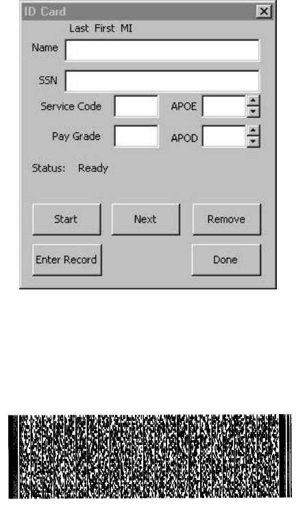
After selecting the “ID Card” option from the main screen, the passenger ID card screen is displayed. This screen is
shown in Figure 10. After scanning, you can use this screen to edit the data prior to entering the record. There are
two methods to enter ID card data, scanning and manual input.
Figure 10 Passenger Data Screen
3.4.1 Scanning ID Card Data
Scanning the 2D bar code on the ID card will fill in the Name, SSN, Grade, and Service code fields, but not the
APOE/APOD fields. Figure 11 is an example of a 2D bar code on the back of the ID card bar code.
Figure 11 2D Bar Code
1. The 2D bar code is located on the back of the military ID card. Newer Common Access Cards have a bar
code, but it currently is not compatible with the UHI software.
2. Aim the handheld at the center of the 2D bar code and press the trigger all the way back to the handle.
3. Aim the beam as shown in Figure 4. Hold the scanner until it completes reading, as indicated by a beep.
This may take a few seconds because of the amount of data in the bar code.
4. The ID Card screen will show the data read from the bar code. You can use the handheld to perform any
edits that may be necessary.
5. Enter the APOE with either the drop down list or the keyboard. This is the ICAO code for the airfield you
are departing from.
6. Enter the APOD with either the drop down list or the keyboard. This is the ICAO code for the airfield of
the passenger’s destination.
7. Press the “Enter Record” button to save the data and add it to the list of ID cards in memory.
8. The handheld will respond with a beep and the screen will say “Record Entered”. All data except the
APOE/APOD codes are cleared.
UHI User Manual v1.0 DCN: 2025-00750-000
A-16
9. If the ID card has already been entered, then the handheld will respond with the error message “ID already
entered.
Press “Done” to return to the Main Screen.
3.4.2 Manual ID Card Data Entry
On occasion, the passenger will not have an ID card or the card cannot be scanned. In these cases, you may have to
manually enter the data. Some entries are required and others are optional.
1. Name (required): Enter the passenger name in format: Last First MI with no punctuation.
2. SS: Social Security Number, if they have one. You may have to enter a passport number if required.
3. Grade: Enter the rank code of the individual. Use the table in Appendix 1 to determine the appropriate
code to use.
4. Service code: Enter the appropriate code for the branch of service. Use the table in Appendix 1 to
determine the appropriate code to use.
5. APOE (required): Enter the APOE with either the drop down list or the keyboard. This is the ICAO code
for the airfield you are departing from. After entering a code, the handheld will “remember” it and use that
code for the next record entered.
6. APOD (required): Enter the APOD with either the drop down list or the keyboard. This is the ICAO code
for the airfield of the passenger’s destination.
7. Press the “Enter Record” button to save the data to memory.
8. The handheld will respond with a beep and the screen will say “Record Entered”. All data except the
APOE/APOD codes are cleared.
9. If the ID card has already been entered, then the handheld will respond with the error message “ID already
entered”.
Press “Done” to return to the Main Screen.
3.4.3 Reviewing ID Card Records
ID cards are stored in the handheld memory as a list. You can see what ID cards are in memory by using the
navigation buttons on the ID Card screen.
• Start: Displays the ID card at the beginning of the list in memory. You must use the Start button
before you can navigate through the records.
• Next: (Disabled until “Start” is pressed) Displays the next record in memory.
• Remove: (Disabled until “Start” is pressed) Removes the ID card that is currently displayed. This
only works after an ID card has been entered into memory with the “Enter Record” button.
Press “Done” to return to the Main Screen.
UHI User Manual v1.0 DCN: 2025-00750-000
A-17
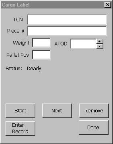
3.5 Cargo Label
After selecting the “Cargo Label” option from the main screen, the cargo label screen is displayed. This screen is
shown in Figure 12. After scanning, you can use this screen to edit the data prior to entering the record. There are
two methods to enter cargo label data, scanning and manual input.
Figure 12 Cargo Label Screen
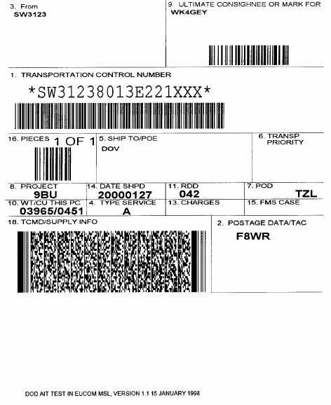
3.5.1 Scanning the 2D Cargo Bar Code
Scanning the 2D bar code on the cargo label will fill in the TCN, pieces, weight, and APOD but not the pallet
position field. Figure 13 is an example of a Military Shipping Label with the 2D bar code.
UHI User Manual v1.0 DCN: 2025-00750-000
A-18
Figure 13 Military Shipping Label
1. The 2D bar code is located in block 18 “TCMD/SUPPLY INFO” on the shipping label.
2. Aim the handheld at the center of the 2D bar code and press the trigger all the way back to the handle.
3. Aim the beam as shown in Figure 4. Hold the scanner until it completes reading, as indicated by a beep.
This may take a few seconds because of the amount of data in the bar code.
4. The Cargo Label screen will show the data read from the bar code. You can use the handheld to perform
any edits that may be necessary.
5. “Tap” the screen anywhere in the Pallet Position input area. Enter the Pallet Position with the popup
keyboard. However, this field is not mandatory.
6. Press the “Enter Record” button to save the data to memory.
7. The handheld will respond with a beep and the screen will say “Record Entered”. All data except the
APOD code is cleared.
8. If this TCN has already been entered, then the handheld will respond with the error message “Cargo
already entered”.
Press “Done” to return to the Main Screen.
3.5.2 Scanning the Linear Cargo Bar Codes
Most military shipping labels will not have a 2D bar code on them however they should still have a linear bar code
for the TCN and pieces fields. The example label in Figure 13 shows the linear bar codes in blocks 1, 9, and 16.
The weight, pallet position and APOD fields will have to be entered manually.
1. The linear bar code can be scanned in any order. If you accidentally scan the Consignee bar code, it will be
ignored.
2. Aim the handheld at the center of the bar code for TCN and press the trigger all the way back to the handle.
3. Aim the beam as shown in Figure 3. Hold the scanner until it completes reading, as indicated by a beep.
4. The TCN data will be shown in the Cargo Label screen.
UHI User Manual v1.0 DCN: 2025-00750-000
A-19
5. Aim the handheld at the center of the bar code for pieces and press the trigger all the way back to the
handle. Hold the scanner until it completes reading, as indicated by a beep.
6. The pieces data will be shown in the Cargo Label screen.
7. You can use the handheld to perform any edits that may be necessary.
8. “Tap” the screen anywhere in the weight input area. Enter the weight using the popup keyboard.
9. Use the pull down menu to add the APOD. An alternative is to “Tap” the screen anywhere in the APOD
input area and use the popup keyboard to enter the APOD.
10. “Tap” the screen anywhere in the Pallet Position input area. Enter the Pallet Position with the popup
keyboard. However, this field is not mandatory.
11. Press the “Enter Record” button to save the data to memory.
12. The handheld will respond with a beep and the screen will say “Record Entered”. All data except the
APOD code is cleared.
13. If this TCN has already been entered, then the handheld will respond with the error message “Cargo
already entered”.
Press “Done” to return to the Main Screen.
3.5.3 Manual Cargo Data Entry
On occasion, the cargo label will not have either the linear or 2D bar codes. In these cases, you may have to
manually enter the data. Some entries are required and others are optional.
1. TCN (required): Enter the cargo TCN from block 1 using the popup keyboard.
2. Piece # (required): Enter the piece number from block 16 using the popup keyboard. The label may be in
the format “1 of 2”. In this case, just enter the number of the piece your entering.
3. Weight (required): Enter the weight of the cargo from block 10 using the popup keyboard.
4. Pallet Pos: Enter the pallet position number using the software keyboard.
5. APOD (required): Enter the APOD from block 7 with either the drop down list or the popup keyboard.
This code can be entered as either the 3-character transportation code or the 4-character ICAO code.
6. Press the “Enter Record” button to save the data to memory.
7. The handheld will respond with a beep and the screen will say “Record Entered”. All data except the
APOD code is cleared.
8. If this TCN has already been entered, then the handheld will respond with the error message “Cargo
already entered”.
Press “Done” to return to the Main Screen.
3.5.4 Reviewing Cargo Records
Cargo data is stored in the handheld memory as a list. You can see what Cargo data is in memory by using the
navigation buttons on the Cargo Label screen.
* * N O T E * *
When using the navigation buttons, you will see ALL cargo data entered on the handheld,
no matter if the source is a label or an RF tag.
• Start: Displays the cargo data at the beginning of the list in memory. You must use the Start button
before you can navigate through the records.
• Next: (Disabled until “Start” is pressed) Displays the next record in memory.
• Remove: (Disabled until “Start” is pressed) Removes the cargo data that is currently displayed. This
only works after a cargo label has been entered into memory with the “Enter Record” button.
Press “Done” to return to the Main Screen.
UHI User Manual v1.0 DCN: 2025-00750-000
A-20
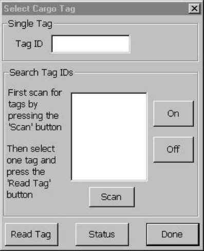
3.6 Cargo Tag
** N O T E **
Before attempting to read a cargo tag, you must first attach the STR7200 according to
paragraph 2.4.1
After selecting the “Cargo Tag” option from the main screen, the “Select Cargo Tag” sub-menu is displayed, as
shown in Figure 14. This menu is used to give the user a choice of searching for all tags to see which tags are within
range of the reader, or reading one specific tag. The entry box is for the Savi Tag ID.
Figure 14 Cargo RF Tag Menu
3.6.1 Select Cargo Tag Menu
You will need the Savi Tag Id, a 5 digit numeric field located on the front of the tag. The functions you can perform
from this menu are:
3.6.1.1 Scanning the Tag ID
1. Aim the handheld at the center of the bar code and press the trigger all the way back to the handle.
2. Aim the beam as shown in Figure 3. Hold the scanner until it completes reading, as indicated by a beep.
3. The tag ID scanned will show on the “Single Tag” section of the Cargo Tag screen.
3.6.1.2 Manual Tag ID Entry
1. “Tap” the screen anywhere in the Tag ID input area.
2. Enter the Tag ID with the popup keyboard.
3.6.1.3 Scanning All Readable Tags
1. Press the “Scan” button to collect all tag Ids within the range of the reader.
2. The handheld will display a list of tag IDs.
3. Select the tag you wish to read by “tapping” in the tag number in the list. The tag number will appear in
the Tag ID field.
UHI User Manual v1.0 DCN: 2025-00750-000
A-21
3.6.1.4 Beep a Tag
1. First enter the tag ID using one of the methods above.
2. Press the “On” button and the tag will start to beep
3. Press the “Off” button to turn off the beep.
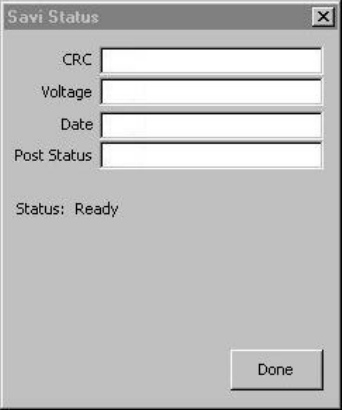
3.6.1.5 Reader Status
You can get the status of the STR7200 Savi reader by pressing the “Status” button. The status screen is shown in
Figure 15.
Figure 15 STR7200 Status Screen
1. CRC: Cyclic Redundancy Check. The STR7200 Power On Self Test (POST) generates this number. You
may be asked to provide this number to a maintenance technician.
2. Voltage: Normal voltage range is between 7 and 8 volts. Once the voltage drops below 6 volts, the battery
should be recharged or replaced.
3. Date: This is the create date of the STR7200 embedded software
4. Post Status: This displays the result of the STR7200 POST. Possible values are:
• GOOD STATUS
• BAD STATUS
UHI User Manual v1.0 DCN: 2025-00750-000
A-22
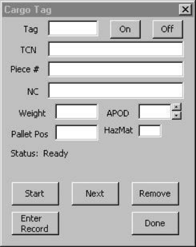
3.6.2 Reading a RF Tag
You must enter the Savi RF Tag ID number using one of the methods in paragraph 3.6.1.
Figure 16 Cargo RF Tag Screen
1. After entering the Tag ID, press the “Read Tag” button.
2. You will see the Cargo RF Tag screen, as shown in Figure 16. Reading the data from the cargo RF tag will
fill the TCN, pieces, NC (Nomenclature), weight, APOD, and HazMat but not the pallet position field. The
HazMat field is shown for display purposes only, this data is not stored nor transferred.
3. You can use the popup keyboard to edit any of the data.
4. When finished, press the “Enter Record” button to store the data from the cargo tag in the handheld. You
will then see the Cargo Tag Menu.
5. If the tag data has already been entered, then the handheld will beep and display the message “Tag Already
Entered”.
3.6.3 Reviewing RF Tag Records
Cargo data is stored in the handheld memory as a list. You can see what Cargo data is in memory by using the
navigation buttons on the Cargo Label screen.
* * N O T E * *
When using the navigation buttons, you will see ALL cargo data entered on the handheld,
no matter if the source is a label or an RF tag.
• Start: Displays the cargo data at the beginning of the list in memory. You must use the Start button
before you can navigate through the records.
• Next: (Disabled until “Start” is pressed) Displays the next record in memory.
• Remove: (Disabled until “Start” is pressed) Removes the cargo data that is currently displayed. This
only works after a cargo label has been entered into memory with the “Enter Record” button.
Press “Done” to return to the Main Screen.
UHI User Manual v1.0 DCN: 2025-00750-000
A-23
3.7 File Backup
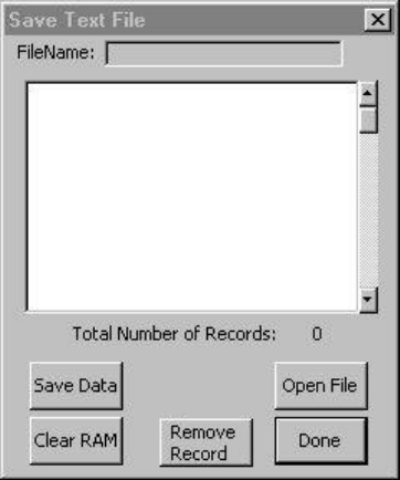
After selecting the “File Backup” data export option, the user will see the Save Text File screen. When you select
this function from the main screen, you will first see data that is in RAM. This screen is shown in Figure 17. This
screen gives you several options:
• A “viewer” for the data stored in RAM
• A “viewer” for data stored in a file
• Button to remove a record from RAM or a file
• Button to save data to a file
• Button to clear RAM
Figure 17 File Export Screen
3.7.1 Open File
To view data in a file, you must use the “Open File” button.
1. Press the “Open File” button.
2. You will see the “Open File” dialog to choose the file you want to view. Select one file and press the
“Open” button.
3. The viewer will display the records that are in the file.
3.7.2 Remove Record
You can use this function to delete records that are stored in RAM or in a file.
1. If you want to edit a file, use the “Open File” button first, to open the file you want to view.
2. Select the record by touching the record in the viewer window. The selected record will be highlighted.
3. Press the “Remove Record” button
4. The viewer will be updated to show the record was deleted.
5. Press “Save Data” button to keep any changes you have made. If you are viewing an existing file, then the
data will be saved under the same filename. If you are viewing data in RAM, then the data will be saved in
a new file.
UHI User Manual v1.0 DCN: 2025-00750-000
A-24
3.7.3 Save Data
1. Press the “Save Data” button to save data displayed in the viewer to a file. If you are viewing a file, then
the data seen in the viewer will be saved with the same filename. If you are viewing data in RAM, then the
data will be saved to a new file.
2. A popup message will inform you when the save is complete.
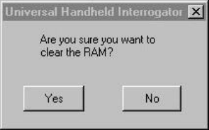
3.7.4 Clear RAM
1. After saving RAM data, the user can press the “Clear Ram” button to remove the accumulated data still
saved in the handheld’s RAM. The “Clear Ram” button will be “turned off” until the user transfers the data
in RAM.
** N O T E **
Failure to clear RAM after transferring data may result in duplicate records being
transmitted with the Falcon Gateway system.
2. After pressing the “Clear Ram” button, the user must confirm the action by pressing the “Yes” button on
the confirm delete screen, shown in Figure 18.
Figure 18 Confirm Clear Memory
3.7.5 Done
1. If you want to save any changes you made to the viewer, then you must first use the “Save Data” function
prior to using the “Done” button. Pressing the “Done” without saving changes will discard any changes
you’ve made.
2. Press “Done” to return to the Main Screen.
UHI User Manual v1.0 DCN: 2025-00750-000
A-25
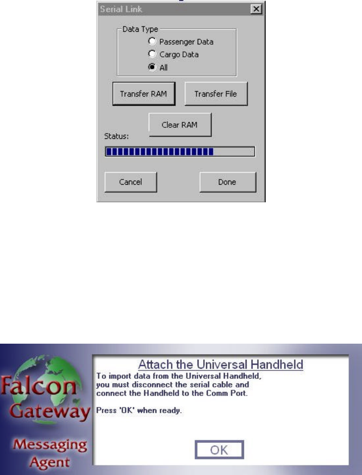
3.8 File Transfer
After selecting the “File Transfer” option from the main screen, the user will see the File Transfer screen. This
screen is shown in Figure 19. This option is used to transfer the data from the handheld to the Falcon Gateway
computer. Prior to transferring any data, you must perform the following steps:
Figure 19 File Transfer Screen
1. Boot the Falcon Gateway laptop
2. Start the Falcon Gateway software
3. Select UHI data transfer from the “File” menu. If you are working “online”, you’ll be notified that the
Messaging Agent (MA) is shutting down the Transport Service Agent (TSA), respond by pressing “OK”.
4. You will be prompted to attach the handheld to the laptop, shown in Figure 20. If using the RITV Flyaway
case, then ensure the handheld is connected to the 9-pin serial connector in the case and place the serial
select switch in the “Handheld” position. If not, then disconnect any connection currently on the serial
port. Connect the handheld serial cable on the back of the handheld to the 9-pin serial connector on the
back of the laptop.
Figure 20 MA Attach Handheld Message
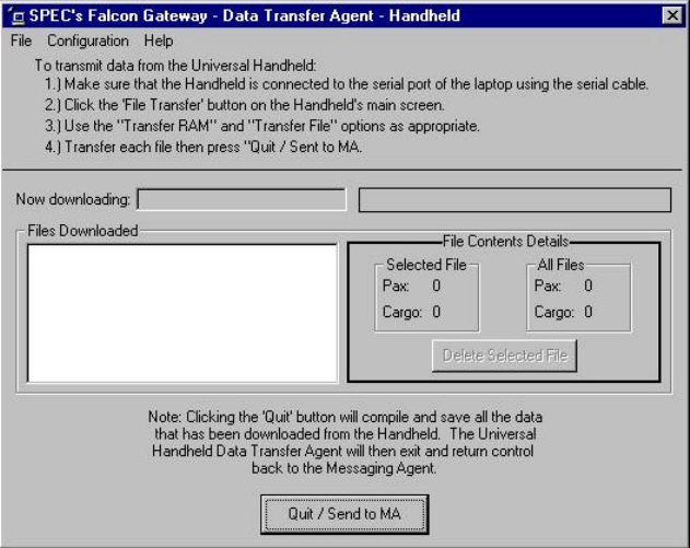
5. Press “OK”. The MA will start the Data Transfer Agent (DTA) on the laptop. You will see the screen
shown in Figure 21. Instructions are located at the top of the screen. There are two types of data transfer,
transfer Random Access Memory (RAM) or transfer file.
UHI User Manual v1.0 DCN: 2025-00750-000
A-26
Figure 21 MA Data Transfer Agent
3.8.1 Transfer RAM Data
As data is collected with the handheld, it is stored in Random Access Memory (RAM). This memory is volatile and
the data will be lost if the handheld is rebooted. Using the transfer RAM option will copy the records stored in
RAM to the Falcon Gateway laptop computer.
1. Select the type of data they want to transfer: passenger data, cargo data, or all.
2. Start transfer by pressing “Transfer RAM” button. You will see the status bar fill from left to right.
3. The Laptop DTA will inform you when transfer is complete and what filename the data was saved as.
4. After transferring, the user can press the “Clear Ram” button to remove the accumulated data still saved in
the handheld’s RAM. The “Clear Ram” button will not allow RAM to be cleared until you save or transfer
the data in RAM.
** N O T E **
Failure to clear RAM after transferring data may result in duplicate records being
transmitted with the Falcon Gateway system.
5. After pressing the “Clear Ram” button, the user must confirm the action by pressing the “Yes” button on
the confirm delete screen, shown in Figure 18.
Press “Done” to return to the Main Screen.
3.8.2 Transfer File
If data in RAM was previously stored as a file on the handheld, then the user can transfer a data file with the
“Transfer File” option.
1. The “Data Type” selection has no effect on the File Transfer function. All data stored in the file will be
transferred.
2. Start transfer by pressing “Transfer File” button.
3. You will see the “Open File” dialog box appear. Select the file you wish to transfer and press “OK”.
UHI User Manual v1.0 DCN: 2025-00750-000
A-27
4. You will see the status bar fill from left to right.
5. The Laptop DTA will inform you when transfer is complete and what filename the data was saved as.
Press “Done” to return to the Main Screen.
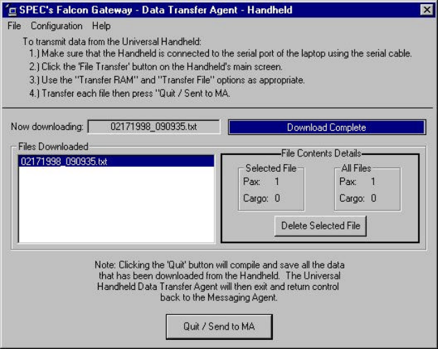
3.8.3 Finishing Data Transfer on the MA
After the handheld completes transferring data to the Falcon Gateway system, the DTA screen will display the files
that were created on the laptop, as shown in Figure 22.
Figure 22 MA Data Transfer Complete
1. If multiple files were transferred, the file names will be shown in the “Files Downloaded” section.
2. The “File Contents Detail” section will show what type of data is stored in the selected file.
3. You can delete a file with the “Delete Selected File” button.
4. Exit the DTA by pressing the “Quite/Send to MA” button. You will be prompted if you really want to quit.
If you select “Yes”, the DTA will notify the MA if any new data was transferred from the handheld then
exit.
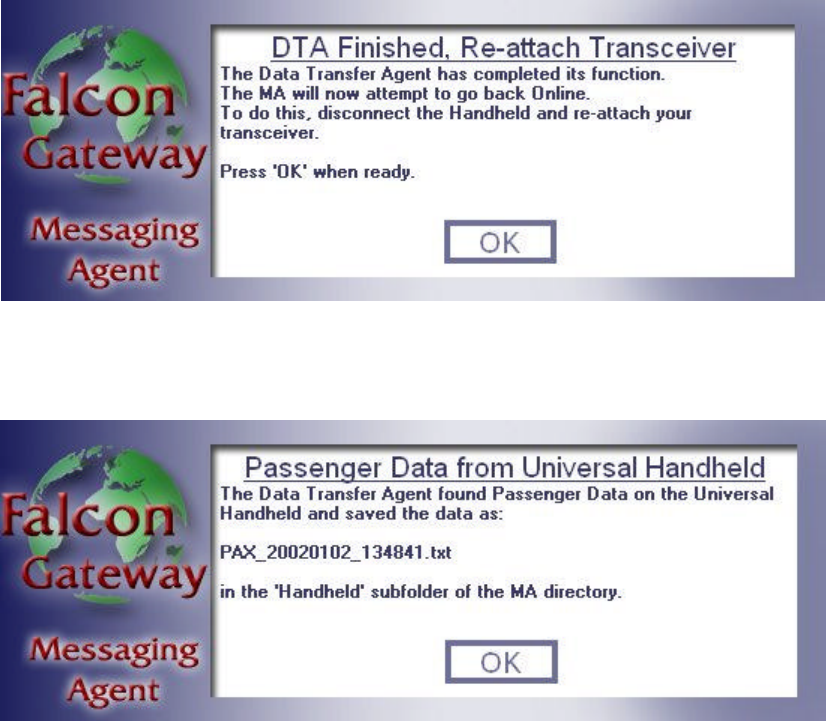
5. When the DTA has exited, the MA will display a message reminding you to re-attach the hardware
transceiver, as shown in Figure 23. If using the RITV Flyaway case, then place the serial select switch in
the “M-Phone” position. If not, then remove the handheld serial cable and re-attach the transceiver cable to
the back of the laptop. Press “OK” when finished reattaching the transceiver. The MA will restart the
Transport Service Agent (TSA) that was running, if working “online”, prior to transferring data from the
handheld.
** N O T E **
You must re-attach the Falcon Gateway transceiver or you will not be able to send/receive
messages.
UHI User Manual v1.0 DCN: 2025-00750-000
A-28
Figure 23 MA Re-attach Transceiver
6. The MA will display a popup box showing the files that were transferred by the DTA, as shown in Figure
24. Press “OK” to continue.
Figure 24 MA Transfer Data File Names
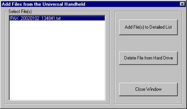
7. Finally, if you used the “Import UHI Data” button on the Passenger Details or Cargo Detail tabs, then you
will see the box shown in Figure 25. From this screen you can:
• Select the files you want to import into the Passenger/Cargo Details section.
• Delete a data file from the laptop. Use this when you have finished importing the data into the details
tab and no longer need the file.
UHI User Manual v1.0 DCN: 2025-00750-000
A-29
Figure 25 MA Add Files
8. When finished, press the “Close Window” button.
3.8.4 Removing Data Files on the PDT7200
After the handheld completes transferring data files to the Falcon Gateway system, you may want to delete these
files from the handheld.
1. Press the “Start” menu button at the lower left corner of the screen.
2. Press the “File Browser” entry. This will start the “InkWIZ File Browser”.
3. Press the “up” or “down” scroll bar next to the Directory Tree display.
4. Locate the file you want to delete and highlight it by “tapping” the file name.
5. Press the “Del” button.
6. The file browser will ask if you really want to delete the file. If you respond “Yes”, the file will be deleted.
If you respond “No”, then the file will remain on the handheld.
7. When finished, press the “Exit” button to quit the file browser.
UHI User Manual v1.0 DCN: 2025-00750-000
A-30
4. Exiting the UHI program
You can exit the UHI program from the main screen.
** N O T E **
Exiting the UHI program without first saving or transferring data in RAM will result in
the loss of data. You must first save data stored in RAM with the “File Backup” or “File
Transfer” option from the main screen.
1. Press the “X” button in the window title bar. If there are any records in memory you will be prompted to
confirm you want to exit.
2. If you are ready to exit, answer “OK”
3. If not, answer “No” and you will return to the main screen.
You can restart the UHI program by following instructions in paragraph 0.
UHI User Manual v1.0 DCN: 2025-00750-000
A-31
5. Error Messages
5.1 Program Start Errors
"Could Not Open Handle to File "UHI.ini". Application Will Terminate."
"File I/O Error"
"Unable to Determine the Size of File "UHI.ini". Application Will Terminate."
"Warning: File "UHI.ini" could not be closed."
The UHI program is unable to open the initialization file, “UHI.INI”. The file may be corrupted or not in the
correct location. You can use the “File Browser” application in the handheld “Start” menu to locate the file. If it is
not on the handheld, you will have to obtain a new copy and load it according to the instructions in section 2.1.1.
"Out Of Memory! Cannot Parse File "UHI.ini". Application Will Terminate"
The PDT7200 does not have sufficient memory to read and process the initialization file. There may be other
programs running or other copies of the UHI program running. Exit any currently running programs. If the error
persists, then there may be an internal memory problem with the PDT7200.
"Error Parsing .ini File "UHI.ini". Application Will Terminate."
"Error Translating .ini File "UHI.ini". Application Will Terminate."
"Could not obtain xxxx value from File "UHI.ini". Application Will Terminate"
(xxxx = ReaderCommPort, BaudRate1, StopBits1, DataBits1, Parity1, XferCommPort, BaudRate2, StopBits2,
DataBits2, Parity2, LogFile, DataFileDir)
The UHI initialization file, “UHI.INI”, may be corrupted or have values missing. You will have to obtain a new
copy and load it according to the instructions in section 2.1.1.
"Error opening log file. Log file will be disabled."
"Error writing to log file. Log file will be disabled."
The UHI program is unable to access the log file. The program will continue with logging disabled.
5.2 Setup & Help Errors
“Out of Memory”
The PDT7200 no longer has sufficient memory to store any new APOE/APOD pairs. You must clear some memory
before adding any more APOE/APOD codes. Clear RAM by using the “File Backup” menu to save anyy cargo or
personnel data to file then use the “Clear RAM” button. If you want to clear the existing APOE/APOD list, then
exit the UHI program and restart but be sure to save any existing records. All existing APOE/APOD codes will be
removed when the program restarts.
"Error opening help file."
The UHI program was not able to open the help file, “help.txt”. The file may be corrupted or not in the correct
location. You can use the “File Browser” application in the handheld “Start” menu to locate the file. If it is not on
the handheld, you will have to obtain a new copy and load it according to the instructions in section 2.1.1.
"Error moving file pointer to beginning of the help file."
"Error obtaining line offsets in the help file."
"Error obtaining scroll bar position."
The UHI program is unable to correctly display the help file in the help window due to an internal memory problem.
Please restart the UHI program according to instruction in section 0. Be sure to first save any data you have entered
using the “File Backup” function.
"Error obtaining number of lines in the help file."
The UHI program is unable to correctly display the help file in the help window due to an error reading the file.
The file may be corrupted and you may have to obtain a new copy and load it according to the instructions in section
2.1.1.
UHI User Manual v1.0 DCN: 2025-00750-000
A-32
"Error closing help file."
The UHI program was not able to close the help file, “help.txt”. The file may be corrupted or was moved from its
proper location. You can use the “File Browser” application in the handheld “Start” menu to locate the file. If it is
not on the handheld, you will have to obtain a new copy and load it according to the instructions in section 2.1.1.
5.3 Bar Code Scan Errors
"Scanner could not initialize."
"Scanner could not start read cycle."
"Scanner could not re-start read cycle."
The bar code scanner in the PDT7200 has an error. Perform a hard reset as described in section 2.3.6.3. If that fails
to correct the problem, then contact Symbol for maintenance.
"Format Not Supported"
The bar code read is not in a format that is recognized by the UHI program. Either the bar code is damaged beyond
the ability to read it or it is not a valid Cargo or ID card bar code.
5.4 STR7200 Reader Errors
"Cannot open Port."
The UHI program has detected an error trying to communicate through the PDT7200 serial port. Perform a hard
reset as described in section 2.3.6.3. If that fails to correct the problem, contact Symbol for maintenance.
"Communication Error"
The UHI program is unable to communicate with the STR7200 reader. Cycle power on the reader. Ensure there is
nothing blocking the IR port in the reader shoe.
"An appropriate SerialCommunication could not be found"
The UHI program was not able to use the designated serial port in the UHI.INI file. Please check this file and
ensure it specifies the correct port. If you make changes to the INI file, you will have to restart the program
according to instruction in section 2.1.1.
"Operation Timed Out"
The UHI program was not able to complete the requested STR7200 operation. Cycle power on the STR7200 and
try the operation again.
"Tag Not Found"
An attempt was made to read a Savi tag that is no longer responding. Make sure the tag number entered is correct
and that the tag is on.
"Collect Failed."
"Full Report Failed."
The STR7200 is unable to complete the Savi “Collect” command to obtain a list of tag IDs. Cycle power on the
STR7200 and retry. If the error persists, then contact maintenance.
"License Plate Data Not Found for Tag: nnnn”
The STR7200 is unable to read the data from the indicated Savi Tag. Ensure the tag ID entered is correct and that
the tag is turned on. Also, try cycling power on the STR7200 reader.
UHI User Manual v1.0 DCN: 2025-00750-000
A-33
5.5 Data Entry Errors
5.5.1 General
"Out of Memory!"
The PDT7200 no longer has sufficient memory to store any new records. You must clear some memory before
reading any more ID cards or Cargo. Clear memory by using the “File Backup” menu to save existing cargo or
personnel data to file then use the “Clear RAM” button.
5.5.2 ID Card Data Errors
"Name value not present"
"APOE value not present"
"APOD value not present"
An attempt was made to enter a record with some required data missing. Please enter the appropriate data and enter
the record.
"ID already entered"
This ID card data has already been entered in the handheld. The record already exists.
5.5.3 Cargo Data Errors
"TCN value not present"
"Piece Number not present"
"Weight value not present"
"APOD value not present"
An attempt was made to enter a record with some required data missing. Please enter the appropriate data and enter
the record.
"TCN/Piece already entered"
This cargo has already been entered in the handheld. The record already exists.
5.6 File Backup Errors
"List File could not be created."
The UHI program could not create the backup file. You may be able to transfer data stored in RAM in order to save
the data, then restart the program according to instruction in section 2.1.1.
"Could not write header information to the list file."
"Error writing cargo data to the list file"
"Error writing ID data to the list file"
The UHI program could not write the appropriate information to the backup file. You may be able to transfer data
stored in RAM in order to save the data, and then restart the program according to instruction in section 2.1.1.
5.7 Data Transfer Errors
5.7.1 General Errors
"An appropriate SerialCommunication could not be found"
The UHI program was not able to use the designated serial port in the UHI.INI file. Please check this file and
ensure it specifies the correct port. If you make changes to the INI file, you will have to restart the program
according to instruction in section 2.1.1.
UHI User Manual v1.0 DCN: 2025-00750-000
A-34
"An error occurred deleting the temporary file nnnn"
The UHI program was unable to delete the indicated temporary file. This error should not impact the operation of
the UHI program. If desired, the file can be manually deleted using the “File Browser” on the handheld “Start”
menu.
5.7.2 RAM Transfer Errors
"No id data in RAM to transfer."
"No cargo data in RAM to transfer."
"No data in RAM to transfer."
The UHI program does not have any records of the type indicated in memory to transfer.
5.7.3 File Transfer Errors
"A filename must be specified to open."
You have attempted to close the “Open File” dialog without specifying a file name. Please enter or select a file to
transfer before pressing “Open”.
"Error retrieving files for list view."
"Error closing list view file."
"Error inserting filename into the list view."
"Error loading in images for files."
"Error adding bitmap to image list."
"Error retrieving all images from bitmap."
The UHI program is unable to collect the appropriate information from the handheld operating system in order to
display the list of files on the handheld in the “Open File” dialog. Please restart the PDT7200.
"Cannot obtain the size of the file to transfer."
The UHI program is unable to open the file indicated in the “Open File” dialog for transfer. Please ensure the
filename is correct and that the file exists.
"Not all data from the serial transfer file was sent."
The UHI program was not able to transfer all the data in the selected file. The file may be corrupted or you may
want to re-transfer the data to the Falcon Gateway system.
"Transfer file could not be closed."
The file selected for transfer has been transferred, but the UHI program is not able to close the file.
5.8 Clearing RAM Errors
"New Records Exist! RAM cannot be cleared!"
This error occurs when the Clear RAM button is pressed without first saving or transferring data in the handheld.
Use the “File Backup” to create a disk file with the handheld data or use the “File Transfer” function to copy the
data to the Falcon Gateway system.
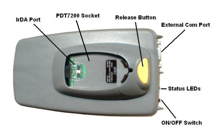
UHI User Manual v1.0 DCN: 2025-00750-000
A-35
6. STR7200 Hardware Information
6.1 General Description
The Savi Tag Reader (STR) 7200 is a fully functional Savi RF tag reader. The STR7200 has many of the same
capabilities as Savi’s fixed interrogators, i.e. read and write to the Savi Seal Tags, 410 tag, and 412 tag. (However,
the UHI software will only read tags at this time.) The reader is comprised of two circuit boards developed by Savi
for integration into a handheld. SPEC has integrated these two circuit boards and SPEC’s Personality Board into a
single, easy to use component that was designed specifically to interface with the PDT7200. The STR7200 will
interface with any host computer using the external com port and appropriate software.
Warning: Changes or modifications not expressly approved by ConnectedWireless Corporation may void the
user’s authority to operate the STR-7200.
NOTE: This equipment has been tested and found to comply with the limits for aClass B digital device,
pursuant to Part 15 of the FCC Rules. These limits aredesigned to provide reasonable protection against harmful
interference in aresidential installation. This equipment generates, uses and can radiate radio
frequency energy and, if not installed and used in accordance with theinstructions, may cause harmful
interference to radio communications. However,there is no guarantee that interference will not occur in a
particular installation. If this equipment does cause harmful interference to radio or television reception,
which can be determined by turning the equipment off and on, the user is encouraged to try to correct the
interference by one or more of the following measures:
-- Reorient or relocate the receiving antenna.
-- Increase the separation between the equipment and receiver.
-- Connect the equipment into an outlet on a circuit different from that to which the receiver is connected.
-- Consult the dealer or an experienced radio/TV technician for help.
6.2 Parts of the STR7200
Figure 26 STR7200 Top
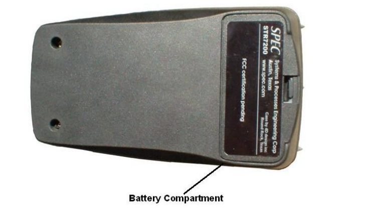
UHI User Manual v1.0 DCN: 2025-00750-000
A-36
• IrDA Port: This is the Infrared communications port that communicates with the PDT7200
handheld.
• PDT7200 Socket: This is where the PDT7200 connects to the STR7200.
• Release Button: This button is used to release the PDT7200 from the reader.
• External Com Port: This is a standard 9-pin RS232 communications port.
• On-Off Switch: This switch is used to turn the STR7200 on or off.
• Status LEDs: The amber LED indicates when the reader is active. The green LED indicates power
on and POST results. If there is an error in the reader, the green LED will blink red.
Figure 27 STR7200 Bottom
• Battery Compartment: This compartment has a removable door and holds the rechargeable
battery.
6.3 Specifications
6.3.1 Physical
Length 6.25 in
Width 3.5 in
Height (maximum) 2.75 in
Height (nominal) 2 in
Weight 1.5 lbs
Material Polycarbonate-ABS blend
6.3.2 Environmental
Temperature -20 C to +50 C (Operating)
-20 C to +60 C (Storage)
6.3.3 Radio Frequency (RF) Interrogator
Frequency 433.92 MHz (transmit and receive)
UHI User Manual v1.0 DCN: 2025-00750-000
A-37
Modulation FSK; 100 kHz (P-P)
Receiver Type Superheterodyne
IF Frequency 10.7 MHz
IF Bandwidth 500 kHz
Range (unobstructed) Up to 300 feet
Receiver Sensitivity -97 dBm
6.3.4 Digital
Date Rate 9.6 and 28 kbps RF tag communications
Memory 512Kbytes onboard, Handheld memory – 16 Mbytes; support for PCMCIA memory
6.4 Regulatory Information
• FCC Part 15 Certified.
• Hero
Testing is scheduled for HERO certification
• ARDEC
Rated for use within 2” of ordinance.
• Hazardous Environment
Class 1, Div. 2, Groups A,B,C,D; Class 2, Div. 2, Groups F, G; Class 3 Div 2
6.5 STR7200 Controls
Instructions for the using the controls on the STR7200 are explained in paragraph 2.4.2.
6.6 Batteries
The STR7200 contains a removable Lithium Ion (LiION) battery that is rated at 7.2 volts, 1600 mAh.
** WARNING **
Do not expose the battery pack to temperatures over 140°° F (60°° C). Do not disassemble,
incinerate, or short circuit the battery pack.
6.6.1 Removing the Battery
1. Turn off the STR7200.
2. Remove the battery compartment door from the STR7200. You should see a nylon strap that runs under
the battery.
3. Pull gently on the removal strap and the battery will slide out of the compartment.
4. If desired, replace the battery compartment door.
6.6.2 Charging the Battery
There are two different methods for charging the battery depending on what equipment is available. It will take
approximately four hours to completely re-charge a battery.
** N O T E **
The L-Band UHH Carry Case and RITV Fly-Away Case are both equipped with a power
supply and two internal battery chargers. These chargers are identical to the battery
chargers supplied by Symbol for the PDT7200 batteries. The internal chargers can be used
with either the STR7200 or the PDT7200 batteries.
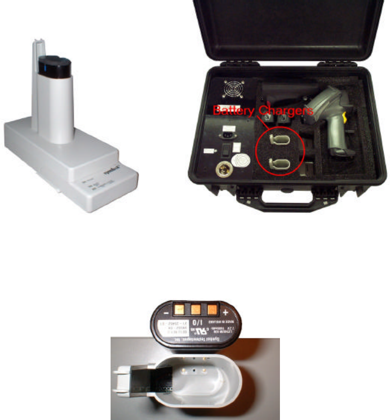
UHI User Manual v1.0 DCN: 2025-00750-000
A-38
6.6.2.1 Charging in the Stand-Alone Charger/L-Band UHH Carry Case
Figure 28 Battery Chargers
1. Plug the Symbol Single Slot battery charger, left in Figure 28, into a suitable AC power source. If using
the L-Band UHH Carry Case, right in Figure 28, then the case must be plugged into a suitable power
source. The case can be connected to either 28 VDC aircraft power or AC ground power. The green
“Power” LED will light.
Figure 29 Battery Contact Location
2. Insert the battery into the charger opening, contact first. The contacts on the battery are offset to one side,
as shown in Figure 29. Ensure that the contacts on the battery are aligned with the contacts inside the
charger opening.
3. The charging LED will turn solid amber while charging. If the LED blinks amber, the battery is faulty.
When the battery is finished, the charging LED will go out, the “Ready” LED will turn green and the
circuits in the charger will cut off automatically.
4. Remove the battery from the charger when charging is complete.
6.6.2.2 Charging in the RITV Fly-Away Case
1. Plug the Infomaster Case into a suitable power source, either 28 VDC aircraft power or AC ground power,
and turn on the case. The green “Power” LED on the Infomaster control panel will light.
2. The chargers are located under the inside lid of the case.
UHI User Manual v1.0 DCN: 2025-00750-000
A-39
3. Open the lid and insert the battery into the charger opening, contact first. The contacts on the battery are
offset to one side, as shown in Figure 29. Ensure that the contacts on the battery are aligned with the
contacts inside the charger opening.
4. Secure the battery with the Velcro strap. This will ensure the battery doesn’t jar loose when the case is
moved.
5. The charging LED will turn solid amber while charging. If the LED blinks amber, the battery is faulty.
When the battery is finished, the charging LED will turn green and the circuits in the charger will cut off
automatically.
6. Loosen the Velcro strap and remove the battery.
6.6.3 Installing the Battery
1. Remove the battery compartment door, if necessary.
2. Check the location of the contacts on the battery. The contacts are offset to one side, as shown in Figure
29. Ensure that the contacts on the battery are aligned with the contacts inside the STR7200.
3. Slide the battery into the battery compartment. Ensure the nylon removal strap is under the battery.
4. Replace the battery door.