Systems and Technology STAVL1234 GPS Vehicle Tracking Device User Manual User Guide CAREU U1 Lite v2 20120327 indd
Systems & Technology Corp. GPS Vehicle Tracking Device User Guide CAREU U1 Lite v2 20120327 indd
UserManual.wiki
>
Systems and Technology
>
STAVL1234 User Manual
Users Manual
Navigation menu
Upload a User Manual
Namespaces
Wiki Guide
HTML
PDF
Info
Views
User Manual
Discussion / Help
Navigation
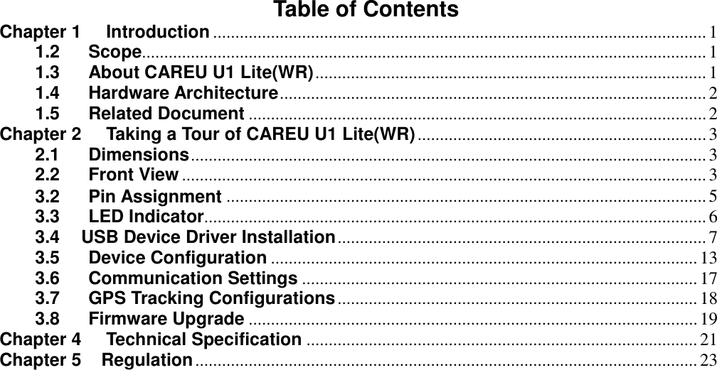
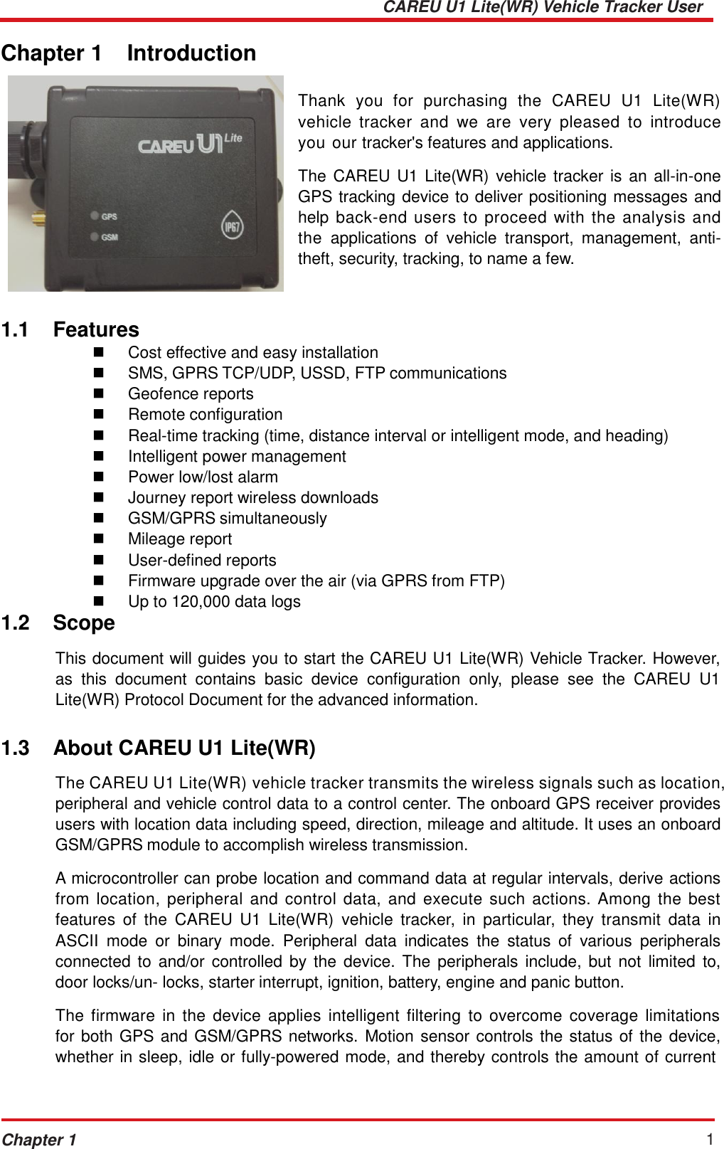
![CAREU U1 Lite(WR) Vehicle Tracker User Guide 2 Chapter 1 consumed by the device. Backup battery and tamper sensing GPS Antennas primarily indicate the loss of Main Power and the interruption of GPS antenna connectivity. The device supports over-the-air firmware upgrade to deliver additional functionality without physically touching the device once installed. The firmware of the CAREU U1 Lite(WR) can be upgraded through USB without disassembling the device. In consideration of technicality and marketability, the CAREU U1 Lite(WR) has so many excellences to be competitive enough to stand out in the market. With regard to the technicality, the CAREU U1 Lite(WR) saves and records more data even under inactive communication status, and it also provides better power management, coexistence of GPRS and SMS modes. 1.4 Hardware Architecture As hardware is concerned, the CAREU U1 Lite(WR) is comprised of a micro-controller, regulator, GPS receiver, GSM/GPRS modem, G-Force sensor, flash memory data storage, I/O interface and LED status indicators. Users can connect PC's HyperTerminal to the Diagnostic/setting port for the AVL configuration. G-Sensor for car accident prevention, car tow-away warning and power management. The audio interface supports hand-free phone call. GPIO that connects to any customer monitoring points by door switch, anti-thief or actuators. The A/D input that connects the analog signal sensor to the AVL, such as the fuel or temperature sensor. SPI FLASH I/O Ports External Device G-Sensor USB CPU GPS Power GSM Modem RS-232 Transceiver Support Accessory 1.5 Related Document [1] CAREU U1 Lite(WR) Protocol Document](https://usermanual.wiki/Systems-and-Technology/STAVL1234/User-Guide-1854230-Page-6.png)
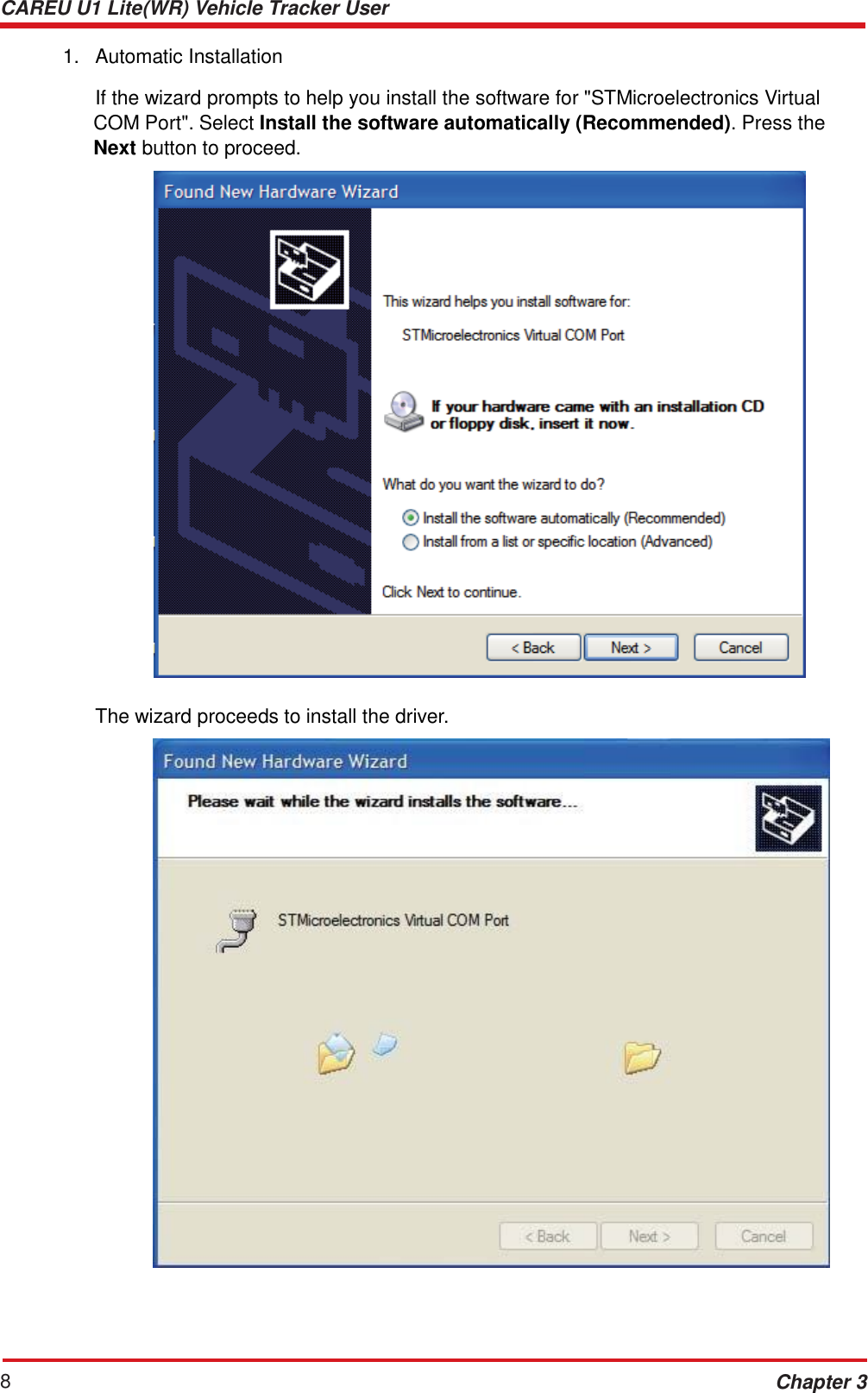
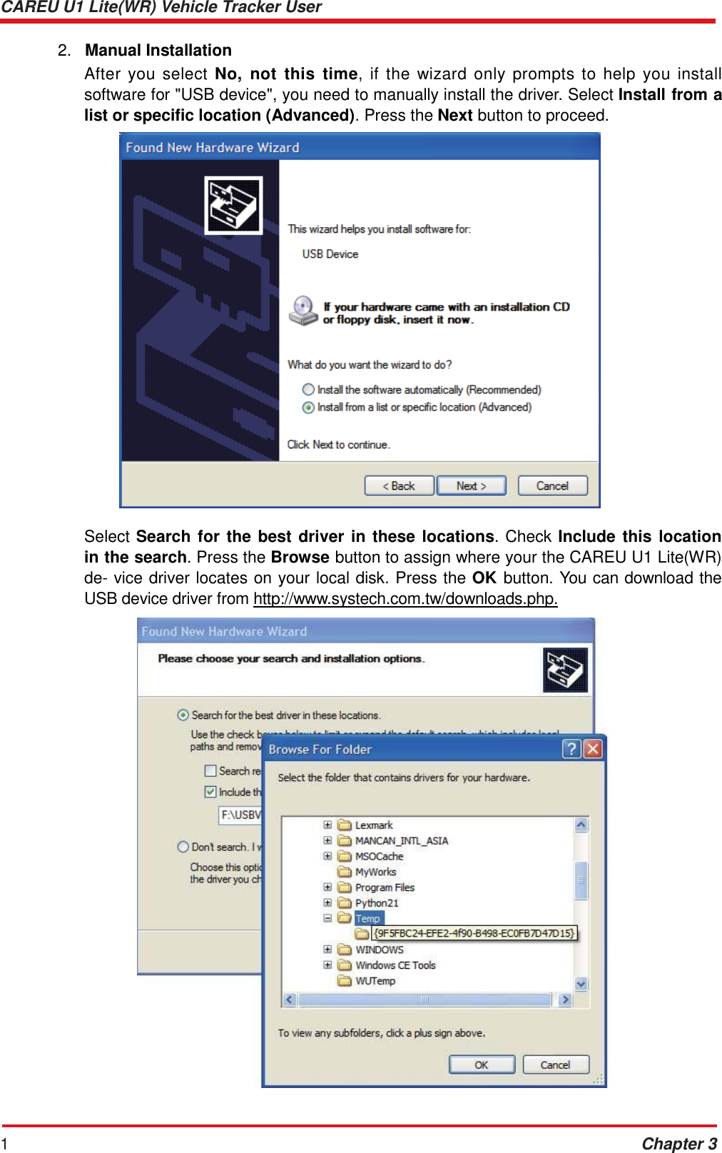
![CAREU U1 Lite(WR) Vehicle Tracker User Guide Chapter 3 7 3.4 USB Device Driver Installation The CAREU U1 Lite(WR) communicates with your host computer by either RS-232 or USB interface. In some newer editions of Windows XP, the CAREU U1 Lite(WR) device can be installed as a "virtual COM port" device whereby the CAREU U1 Lite(WR) would automatically access Windows XP's inbox USB drivers. While in some other earlier editions of Windows XP, you would need to manually install the USB driver for the CAREU U1 Lite(WR) device. In the following content of this section, you will be guided to how the installation can be done in both cases. To install the device driver for the CAREU U1 Lite(WR), connect the CAREU U1 Lite(WR) device to your system with an USB cable as mentioned in Mini USB Cable Connection on section 3.1. As soon as the connection is made between the CAREU U1 Lite(WR) and your computer, a balloon appears above the notification area saying an USB device is found. Click on this balloon to start the [Found New Hardware] wizard. Select No, not this time. Press the Next button to proceed.](https://usermanual.wiki/Systems-and-Technology/STAVL1234/User-Guide-1854230-Page-11.png)
![CAREU U1 Lite(WR) Vehicle Tracker User Guide Chapter 3 9 The installation completes. In [Device Manager], the CAREU U1 Lite(WR) device is included under Ports (COM & LPT) as"STMicroelectronics Virtual COM Port". COM port number is displayed as well.](https://usermanual.wiki/Systems-and-Technology/STAVL1234/User-Guide-1854230-Page-13.png)
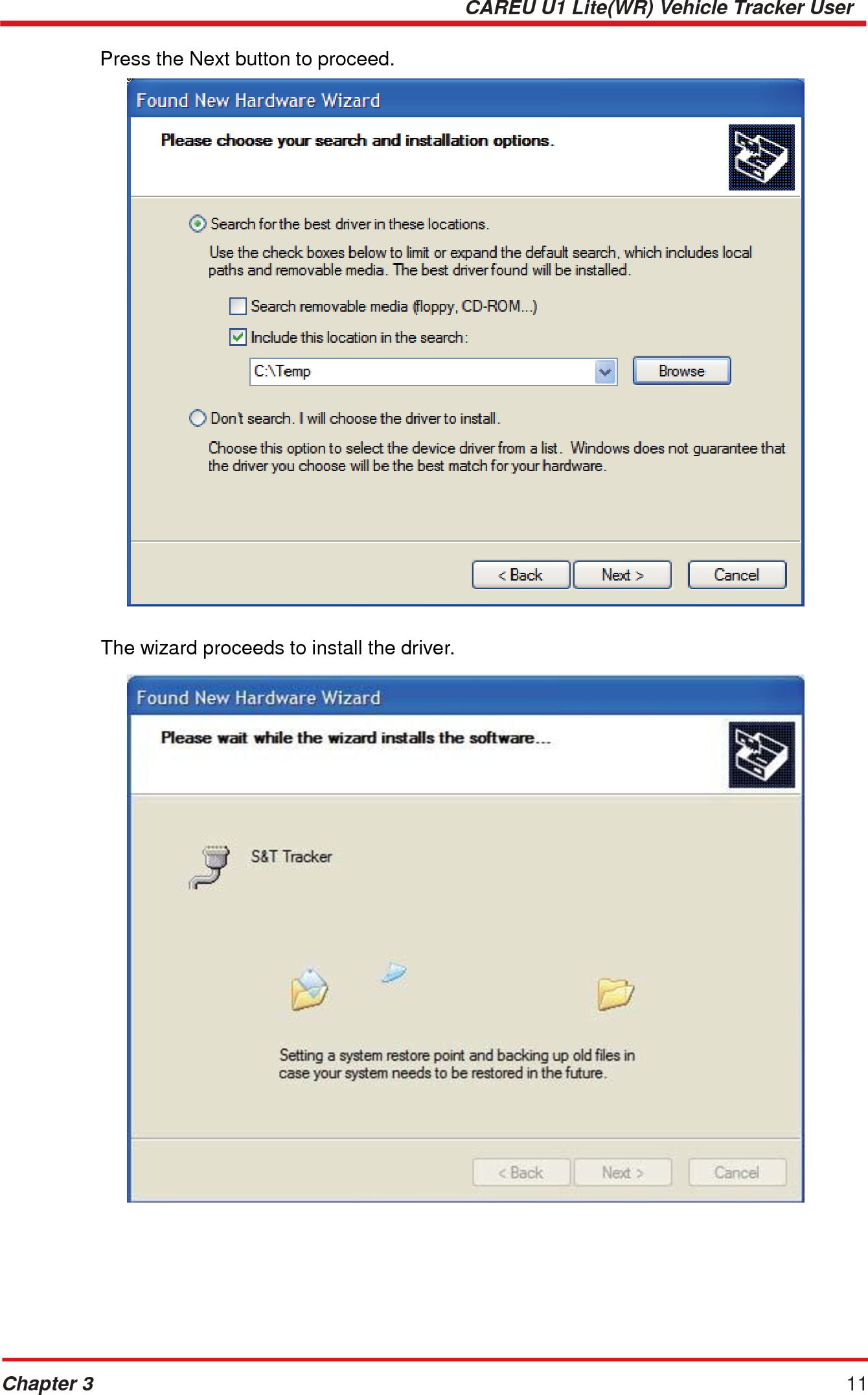
![CAREU U1 Lite(WR) Vehicle Tracker User Guide 12 Chapter 3 The installation completes. In [Device Manager], the CAREU U1 Lite(WR) device is included under Ports (COM & LPT) as "S&T Tracker". COM port number is displayed as well.](https://usermanual.wiki/Systems-and-Technology/STAVL1234/User-Guide-1854230-Page-16.png)
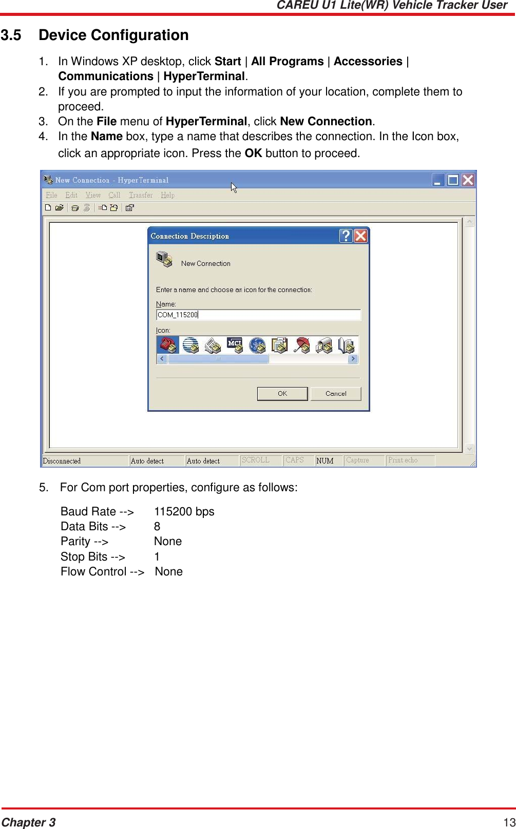
![CAREU U1 Lite(WR) Vehicle Tracker User Guide 14 Chapter 3 6. In the connection that you have just set up, click File | Properties. Select the [Connect To] tab. From the [Connect using] drop down list, select the correct com port by checking it up at Windows XP's [DeviceManager] as previously mentioned on page 10 and page 13. Go there by clicking Start | Control Panel | System | Hardware | Device Manager.](https://usermanual.wiki/Systems-and-Technology/STAVL1234/User-Guide-1854230-Page-18.png)
![CAREU U1 Lite(WR) Vehicle Tracker User Guide Chapter 3 15 7. In the File menu, click Properties. Click the [Settings] tab. Press the ASCII Setup button. 8. In the [ASCII Sending] group box. Select both Send line ends with line feeds and Echo typed characters locally. Press the OK button.](https://usermanual.wiki/Systems-and-Technology/STAVL1234/User-Guide-1854230-Page-19.png)
![CAREU U1 Lite(WR) Vehicle Tracker User Guide 16 Chapter 3 9. Connect your the CAREU U1 Lite(WR) device to power as mentioned in Power and I/O Cable Connection on page 5. The device startup message will be displayed. 10. In [HyperTerminal] window, type in the command "AT$VERSION?" and press the Enter key. The hardware and firmware version will show. As long as your [HyperTerminal] window appears as the screenshot below, a connection between the device and your system has already been built up and working. It is time to send all configuration commands.](https://usermanual.wiki/Systems-and-Technology/STAVL1234/User-Guide-1854230-Page-20.png)